experiments on cylindrical shells under pure bending and external pressure
TRANSCRIPT
According to the publisher’s rules, authors can post or share
their accepted papers as their own write-up for academic
purposes. Final formatted paper is available at:
http://www.sciencedirect.com/science/article/pii/S0143974X1300134X
Please cite this paper as: Ghanbari Ghazijahani T, Showkati H, Experiments on Cylindrical Shells under Pure
Bending and External Pressure, Journal of Constructional Steel Research, 88 (2013) 109-122.
doi:10.1016/j.jcsr.2013.04.009
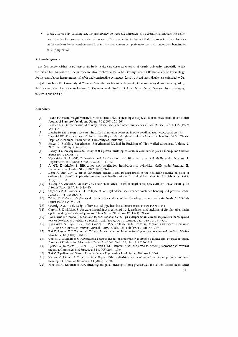

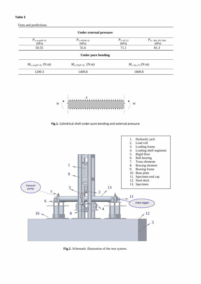
Table 3
Tests and predictions.
Under external pressure
Pcr-exp(M=0) (kPa)
Pcr-FE(M=0) (kPa)
Pcr-ECCS (kPa)
Pm - BSI, PD 5500
(kPa)
50.55 55.6 71.1 81.3
Under pure bending
Mcr-exp(P=0) (N.m) Mcr-FE(P=0) (N.m) Mu -Eq. (7) (N.m)
1209.3 1409.8 1809.8
Fig.1. Cylindrical shell under pure bending and external pressure.
Fig.2. Schematic illustration of the test system.
P
M M
Data logger
1
9
3 13
7 2
11
6
4
10 8 12
5
Vacuum pump
1. Hydraulic jack
2. Load cell
3. Loading frame
4. Loading shell segments
5. Rigid floor
6. Ball bearing
7. Truss elements
8. Bracing element
9. Bearing frame
10. Base plate
11. Specimen end cap
12. Steel deck
13. Specimen
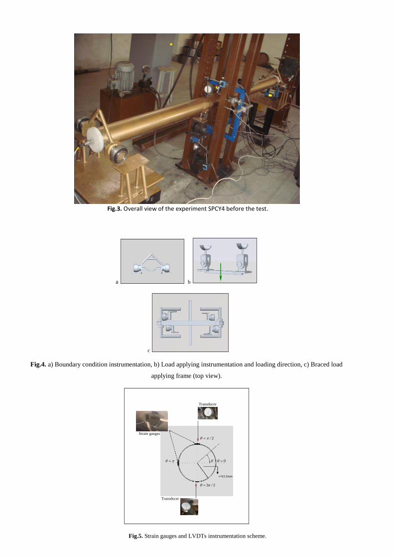
Fig.3. Overall view of the experiment SPCY4 before the test.
a b
c
Fig.4. a) Boundary condition instrumentation, b) Load applying instrumentation and loading direction, c) Braced load
applying frame (top view).
Fig.5. Strain gauges and LVDTs instrumentation scheme.
Transducer
Strain gauges
2/
0
r=63.5mm
2/3
Transducer
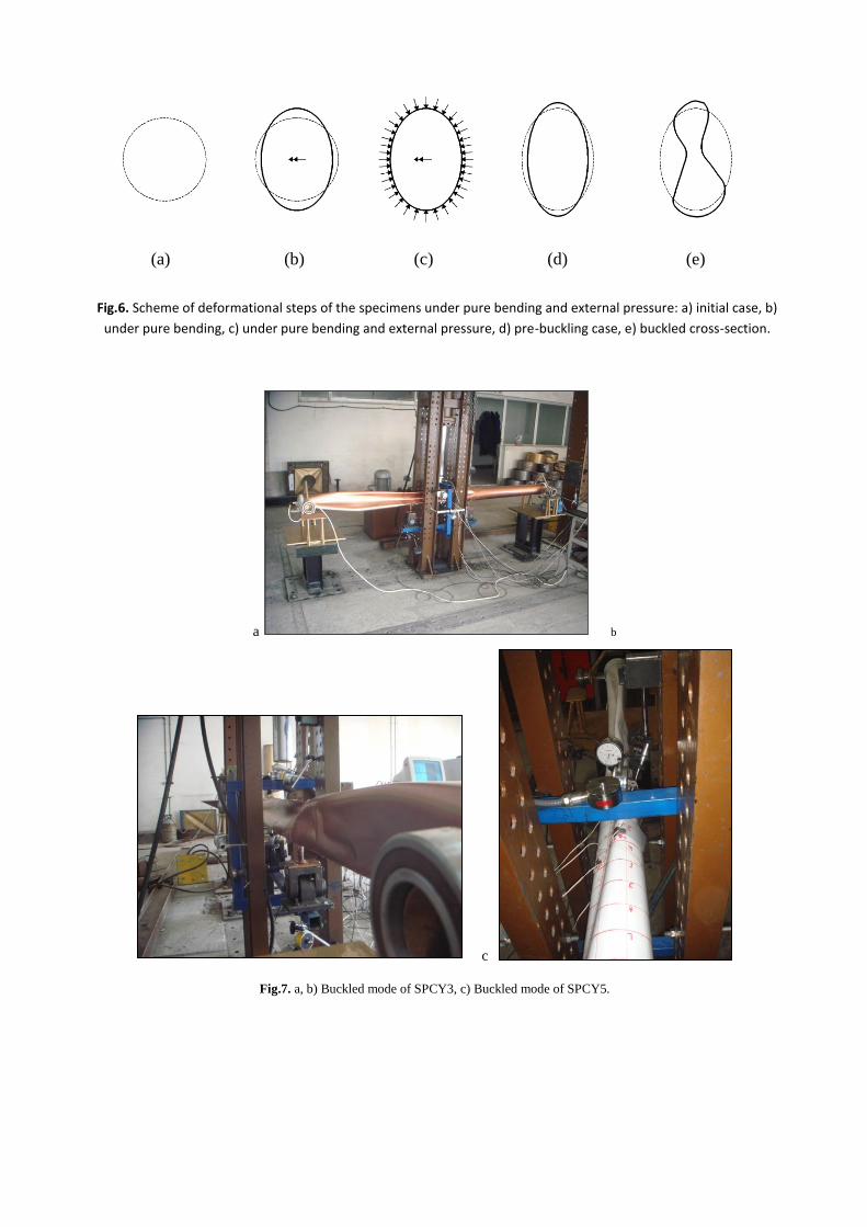
Fig.6. Scheme of deformational steps of the specimens under pure bending and external pressure: a) initial case, b)
under pure bending, c) under pure bending and external pressure, d) pre-buckling case, e) buckled cross-section.
a b
c
Fig.7. a, b) Buckled mode of SPCY3, c) Buckled mode of SPCY5.
(a) (b) (c) (d) (e)
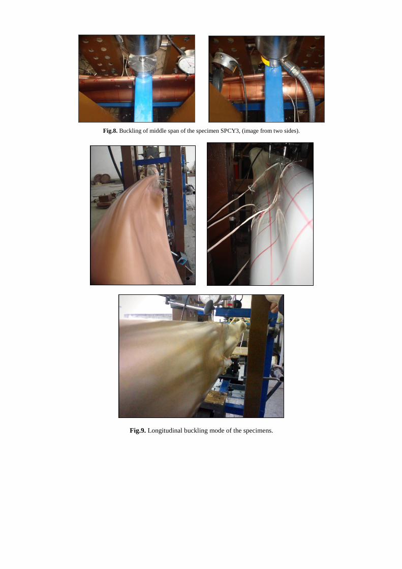
Fig.8. Buckling of middle span of the specimen SPCY3, (image from two sides).
Fig.9. Longitudinal buckling mode of the specimens.
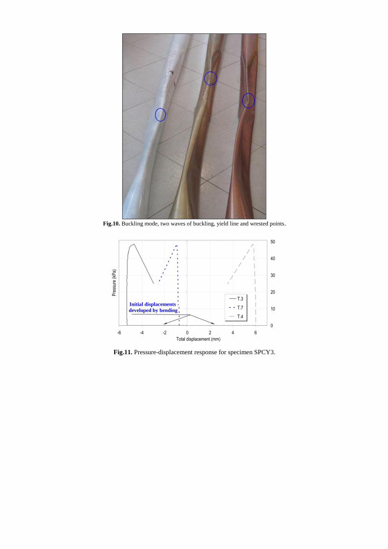
Fig.10. Buckling mode, two waves of buckling, yield line and wrested points.
Fig.11. Pressure-displacement response for specimen SPCY3.
0
10
20
30
40
50
-6 -4 -2 0 2 4 6
Total displacement (mm)
Pre
ssur
e (k
Pa)
T.3
T.7
T.4
Initial displacements
developed by bending
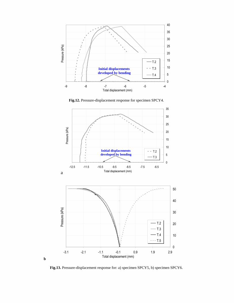
Fig.12. Pressure-displacement response for specimen SPCY4.
a
b
Fig.13. Pressure-displacement response for: a) specimen SPCY5, b) specimen SPCY6.
0
5
10
15
20
25
30
35
40
-9 -8 -7 -6 -5 -4
Total displacement (mm)
Pre
ssur
e (k
Pa)
T.2
T.3
T.4
Initial displacements
developed by bending
0
5
10
15
20
25
30
35
-12.5 -11.5 -10.5 -9.5 -8.5 -7.5 -6.5
Total displacement (mm)
Pre
ssur
e (k
Pa)
T.2
T.3
Initial displacements
developed by bending
0
10
20
30
40
50
-3.1 -2.1 -1.1 -0.1 0.9 1.9 2.9
Total displacement (mm)
Pre
ssur
e (k
Pa)
T.2
T.3
T.4
T.5
a b
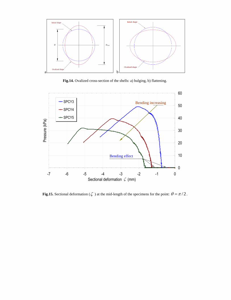
Fig.14. Ovalized cross-section of the shells: a) bulging, b) flattening.
Fig.15. Sectional deformation ( ) at the mid-length of the specimens for the point: 2/ .
Initial shape
D Doval
Ovalized shape
Initial shape
Ovalized shape
0
10
20
30
40
50
60
-7 -6 -5 -4 -3 -2 -1 0
Sectional deformation (mm)
Pre
ssur
e (k
Pa)
SPCY3
SPCY4
SPCY5
Bending increasing
Bending effect
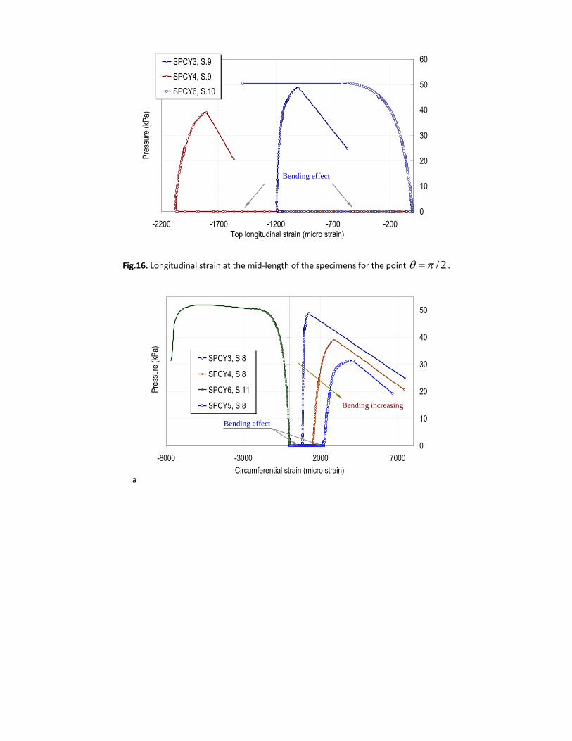
Fig.16. Longitudinal strain at the mid-length of the specimens for the point 2/ .
a
0
10
20
30
40
50
60
-2200 -1700 -1200 -700 -200Top longitudinal strain (micro strain)
Pre
ssur
e (k
Pa)
SPCY3, S.9
SPCY4, S.9
SPCY6, S.10
Bending effect
0
10
20
30
40
50
-8000 -3000 2000 7000
Circumferential strain (micro strain)
Pre
ssur
e (k
Pa)
SPCY3, S.8
SPCY4, S.8
SPCY6, S.11
SPCY5, S.8
Bending increasing
Bending effect
b
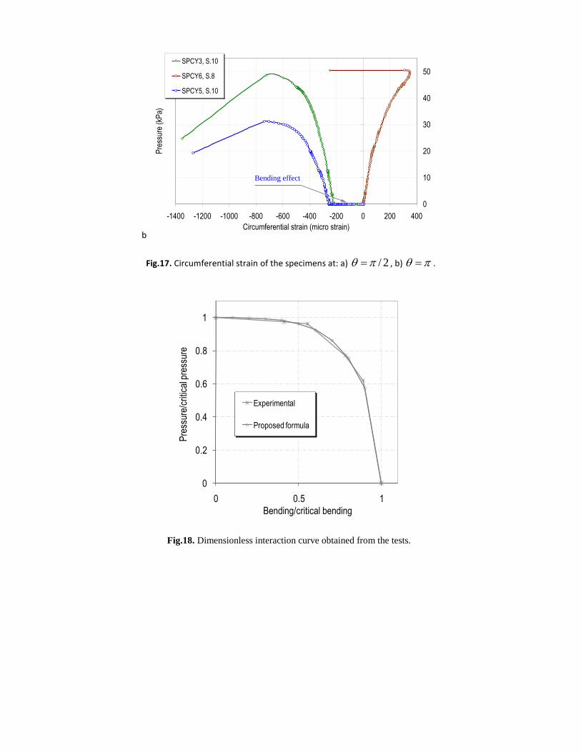
Fig.17. Circumferential strain of the specimens at: a) 2/ , b) .
0
0.2
0.4
0.6
0.8
1
0 0.5 1
Pre
ssur
e/cr
itica
l pre
ssur
e
Bending/critical bending
Experimental
Proposed formula
Fig.18. Dimensionless interaction curve obtained from the tests.
0
10
20
30
40
50
-1400 -1200 -1000 -800 -600 -400 -200 0 200 400
Circumferential strain (micro strain)
Pre
ssur
e (k
Pa)
SPCY3, S.10
SPCY6, S.8
SPCY5, S.10
Bending effect
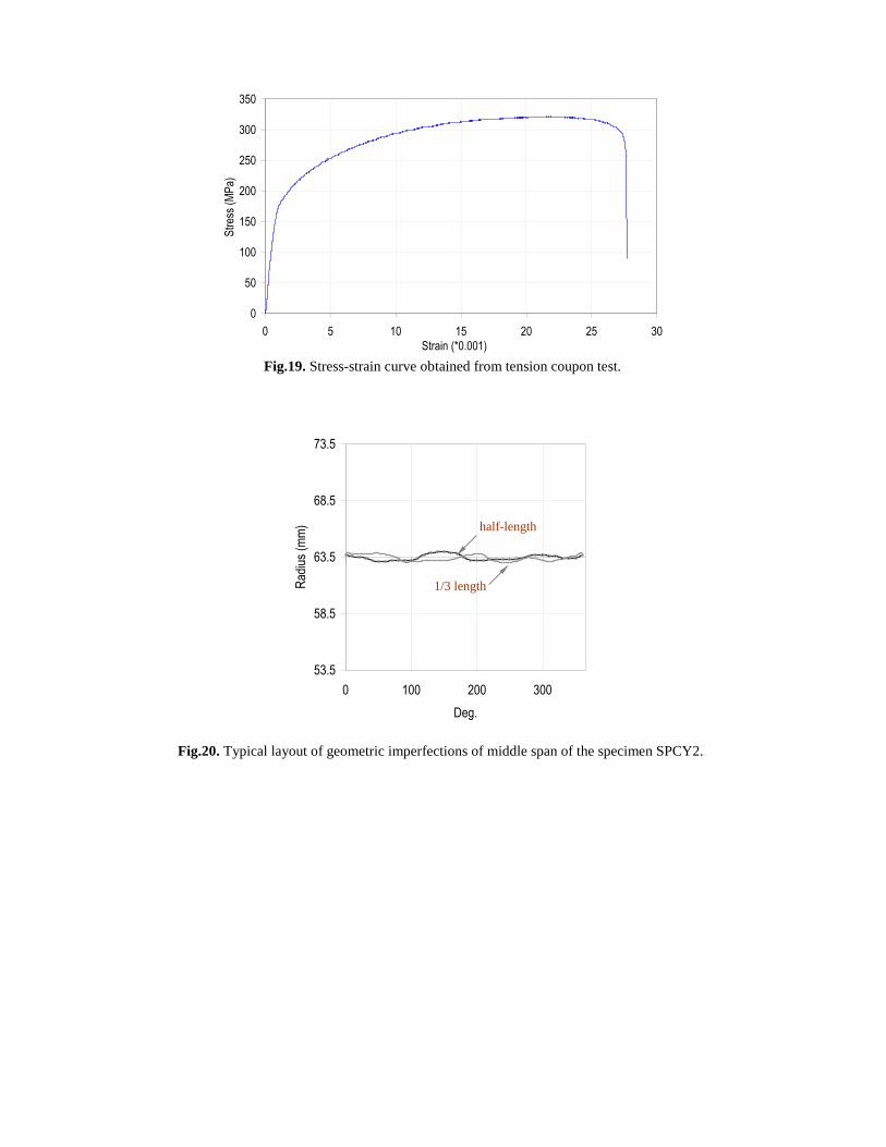
Fig.19. Stress-strain curve obtained from tension coupon test.
Fig.20. Typical layout of geometric imperfections of middle span of the specimen SPCY2.
0
50
100
150
200
250
300
350
0 5 10 15 20 25 30
Strain (*0.001)
Str
ess
(MP
a)
1/3 length
half-length
53.5
58.5
63.5
68.5
73.5
0 100 200 300
Deg.
Rad
ius
(mm
)
half-length
1/3 length
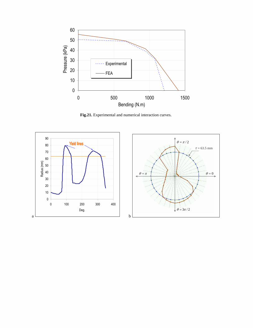
Fig.21. Experimental and numerical interaction curves.
a b
0
10
20
30
40
50
60
0 500 1000 1500
Bending (N.m)
Pre
ssur
e (k
Pa)
Experimental
FEA
0
10
20
30
40
50
60
70
80
90
0 100 200 300 400
Deg.
Rad
ius
(mm
)
r = 63.5 mm
0
2/
2/3
c
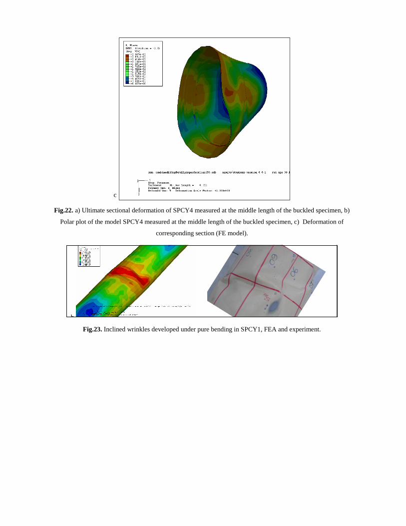
Fig.22. a) Ultimate sectional deformation of SPCY4 measured at the middle length of the buckled specimen, b)
Polar plot of the model SPCY4 measured at the middle length of the buckled specimen, c) Deformation of
corresponding section (FE model).
Fig.23. Inclined wrinkles developed under pure bending in SPCY1, FEA and experiment.
b
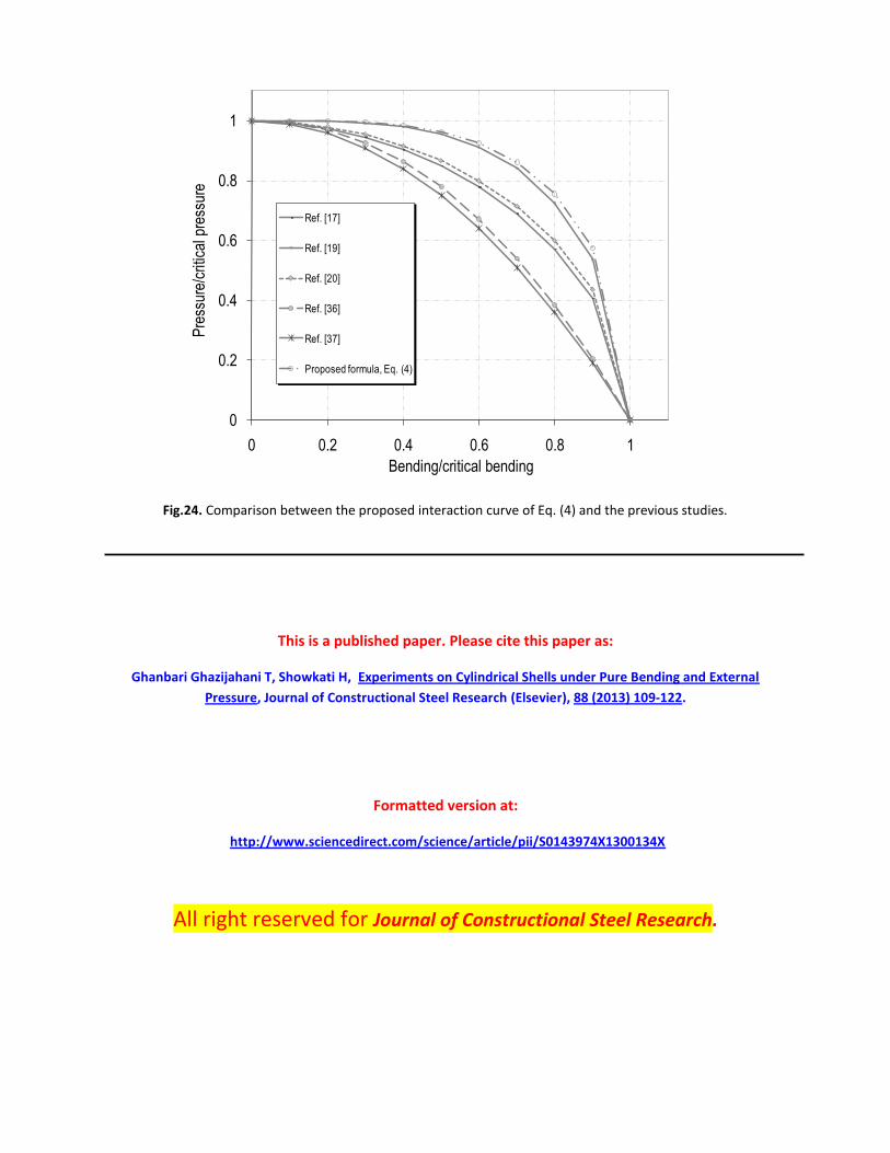
Fig.24. Comparison between the proposed interaction curve of Eq. (4) and the previous studies.
This is a published paper. Please cite this paper as:
Ghanbari Ghazijahani T, Showkati H, Experiments on Cylindrical Shells under Pure Bending and External
Pressure, Journal of Constructional Steel Research (Elsevier), 88 (2013) 109-122.
Formatted version at:
http://www.sciencedirect.com/science/article/pii/S0143974X1300134X
All right reserved for Journal of Constructional Steel Research.
0
0.2
0.4
0.6
0.8
1
0 0.2 0.4 0.6 0.8 1
Pre
ssur
e/cr
itica
l pre
ssur
e
Bending/critical bending
Ref. [17]
Ref. [19]
Ref. [20]
Ref. [36]
Ref. [37]
Proposed formula, Eq. (4)