experience with the deep salvage tool grab and application for nuclear products and oil recovery in...
TRANSCRIPT
Paper No. 2003- Last (family) name of the first author Page number
Experience with the deep salvage tool GRAB and application for nuclear products and oil recovery in deep sea wrecks
Pierre Valdy
Ifremer, Toulon, France David Mearns
Blue Water Recoveries Limited, London, United Kingdom
ABSTRACT The deep sea salvage tool Grab 3000 was a remotely operated tool, deployed from a standard drill ship and able to penetrate inside wrecks for recovering valuable cargoes. It was specially developed by Ifremer in 1994 for recovering silver inside the wreck of SS John Barry, a WWII Liberty ship sunk at a depth of 2600 metres. Following the success of this operation, Blue Water Recoveries (BWR), acquired this tool and operated it on numerous targets in Atlantic and Mediterranean Sea. One year later, a new tool, Grab 6000, based on the same concept, but able to operate at 6000 metres with greatly enhanced performance, entered into service. However, despite great technical successes, allowing to recover several thousands tons of valuable cargoes from depths of nearly 4000 metres, the activity stopped after two years of continuous operations. All pilots that have operated the Grab have been amazed by the simplicity of operating such a safe and powerful tool with such accurate control. The authors, which have been fully involved at Ifremer and BWR in the development and the operation of this salvage tool strongly believe that this proven concept cannot be forgotten and is applicable for an European environmental tool ready to operate in emergency situations concerning nuclear products and oil recovery from deep sea wrecks. KEY WORDS: deep-sea salvage; deep-sea handling; nuclear products salvage; tanker salvage; oil recovery; oil spill control. INTRODUCTION The Grab 3000 was developed by Ifremer under contract with the government of Oman for recovering silver cargo inside the Liberty Ship John Barry sunk in Oman Sea in 2600 metres of water. In 1992, during a previous operation using the manned submarine Cyana, the remote operated video frame Scampi and 500 kgs of explosives, a complete survey of the wreck was made but the explosives did not succeed to open the wreck and the cargo was not discovered. A new operational concept had to be found.
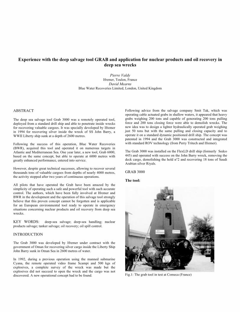
Following advice from the salvage company Smit Tak, which was operating cable actuated grabs in shallow waters, it appeared that heavy grabs weighing 200 tons and capable of generating 200 tons pulling force and 200 tons closing force were able to demolish wrecks. The new idea was to design a lighter hydraulically operated grab weighing just 50 tons but with the same pulling and closing capacity and to operate it on a standard dynamic positioned drill ship. The concept was patented in 1994 and the Grab 3000 was constructed and integrated with standard ROV technology (from Perry Tritech and Ifremer). The Grab 3000 was installed on the FlexLD drill ship (formerly Sedco 445) and operated with success on the John Barry wreck, removing the deck cargo, demolishing the hold n°2 and recovering 18 tons of Saudi Arabian silver Riyals. GRAB 3000 The tool: Fig.1: The grab tool in test at Comeca (France)
Paper No. 2003- Last name of first author Page number
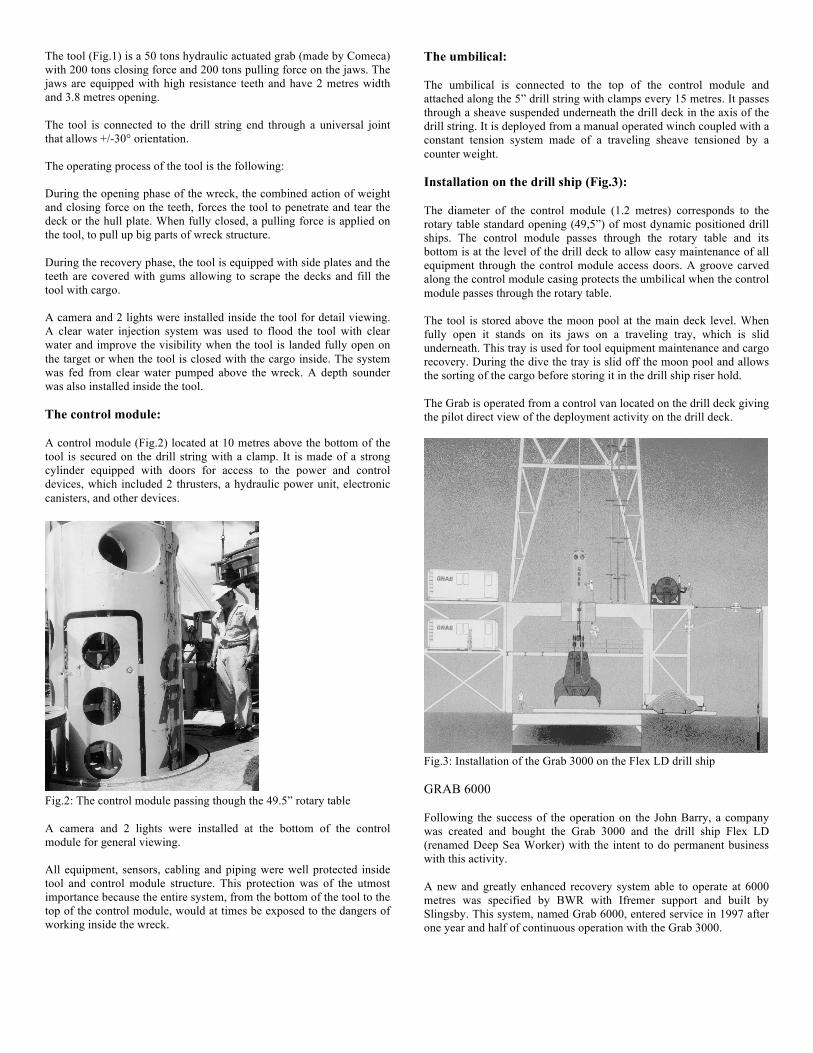
The tool (Fig.1) is a 50 tons hydraulic actuated grab (made by Comeca) with 200 tons closing force and 200 tons pulling force on the jaws. The jaws are equipped with high resistance teeth and have 2 metres width and 3.8 metres opening. The tool is connected to the drill string end through a universal joint that allows +/-30° orientation. The operating process of the tool is the following: During the opening phase of the wreck, the combined action of weight and closing force on the teeth, forces the tool to penetrate and tear the deck or the hull plate. When fully closed, a pulling force is applied on the tool, to pull up big parts of wreck structure. During the recovery phase, the tool is equipped with side plates and the teeth are covered with gums allowing to scrape the decks and fill the tool with cargo. A camera and 2 lights were installed inside the tool for detail viewing. A clear water injection system was used to flood the tool with clear water and improve the visibility when the tool is landed fully open on the target or when the tool is closed with the cargo inside. The system was fed from clear water pumped above the wreck. A depth sounder was also installed inside the tool. The control module: A control module (Fig.2) located at 10 metres above the bottom of the tool is secured on the drill string with a clamp. It is made of a strong cylinder equipped with doors for access to the power and control devices, which included 2 thrusters, a hydraulic power unit, electronic canisters, and other devices. Fig.2: The control module passing though the 49.5” rotary table A camera and 2 lights were installed at the bottom of the control module for general viewing. All equipment, sensors, cabling and piping were well protected inside tool and control module structure. This protection was of the utmost importance because the entire system, from the bottom of the tool to the top of the control module, would at times be exposed to the dangers of working inside the wreck.
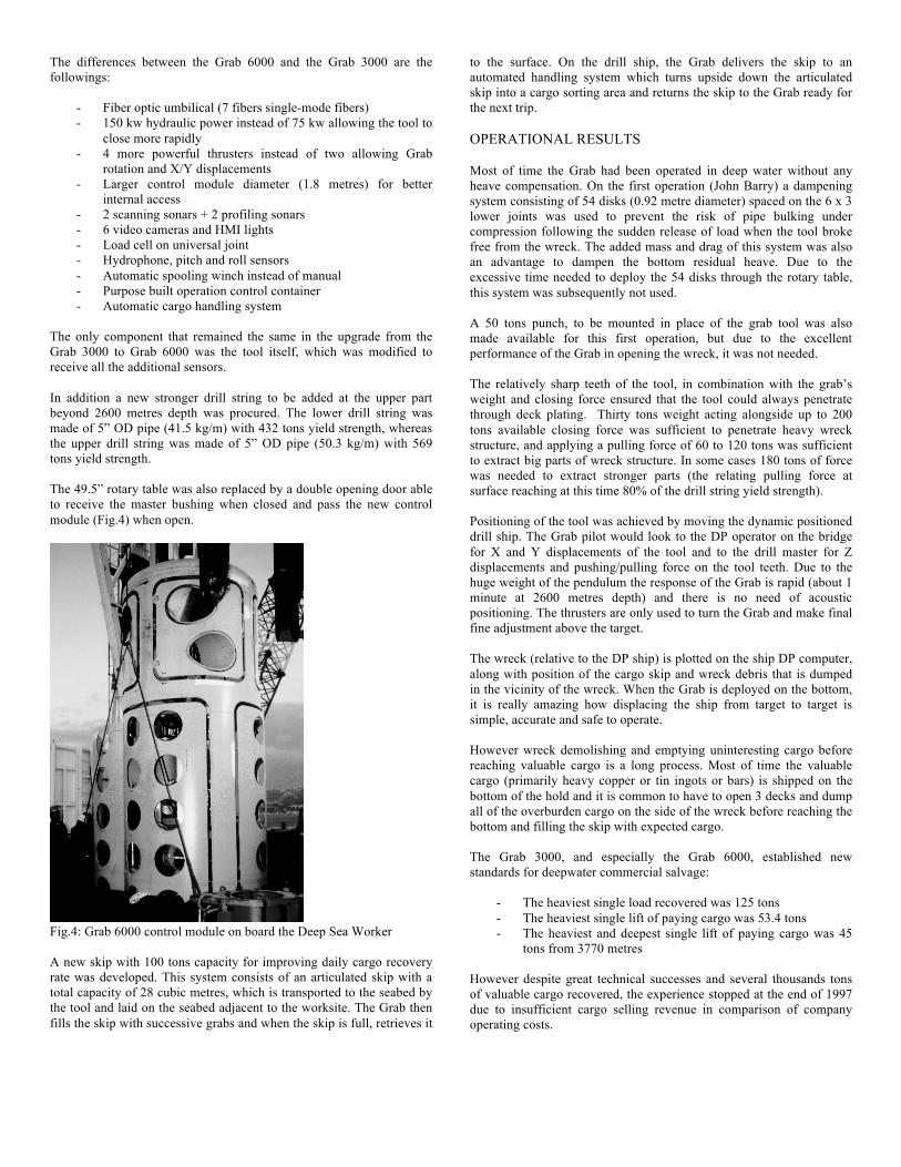
The umbilical: The umbilical is connected to the top of the control module and attached along the 5” drill string with clamps every 15 metres. It passes through a sheave suspended underneath the drill deck in the axis of the drill string. It is deployed from a manual operated winch coupled with a constant tension system made of a traveling sheave tensioned by a counter weight. Installation on the drill ship (Fig.3): The diameter of the control module (1.2 metres) corresponds to the rotary table standard opening (49,5”) of most dynamic positioned drill ships. The control module passes through the rotary table and its bottom is at the level of the drill deck to allow easy maintenance of all equipment through the control module access doors. A groove carved along the control module casing protects the umbilical when the control module passes through the rotary table. The tool is stored above the moon pool at the main deck level. When fully open it stands on its jaws on a traveling tray, which is slid underneath. This tray is used for tool equipment maintenance and cargo recovery. During the dive the tray is slid off the moon pool and allows the sorting of the cargo before storing it in the drill ship riser hold. The Grab is operated from a control van located on the drill deck giving the pilot direct view of the deployment activity on the drill deck. Fig.3: Installation of the Grab 3000 on the Flex LD drill ship GRAB 6000 Following the success of the operation on the John Barry, a company was created and bought the Grab 3000 and the drill ship Flex LD (renamed Deep Sea Worker) with the intent to do permanent business with this activity. A new and greatly enhanced recovery system able to operate at 6000 metres was specified by BWR with Ifremer support and built by Slingsby. This system, named Grab 6000, entered service in 1997 after one year and half of continuous operation with the Grab 3000.
Paper No. 2003- Last name of first author Page number
The differences between the Grab 6000 and the Grab 3000 are the followings:
- Fiber optic umbilical (7 fibers single-mode fibers) - 150 kw hydraulic power instead of 75 kw allowing the tool to
close more rapidly - 4 more powerful thrusters instead of two allowing Grab
rotation and X/Y displacements - Larger control module diameter (1.8 metres) for better
internal access - 2 scanning sonars + 2 profiling sonars - 6 video cameras and HMI lights - Load cell on universal joint - Hydrophone, pitch and roll sensors - Automatic spooling winch instead of manual - Purpose built operation control container - Automatic cargo handling system
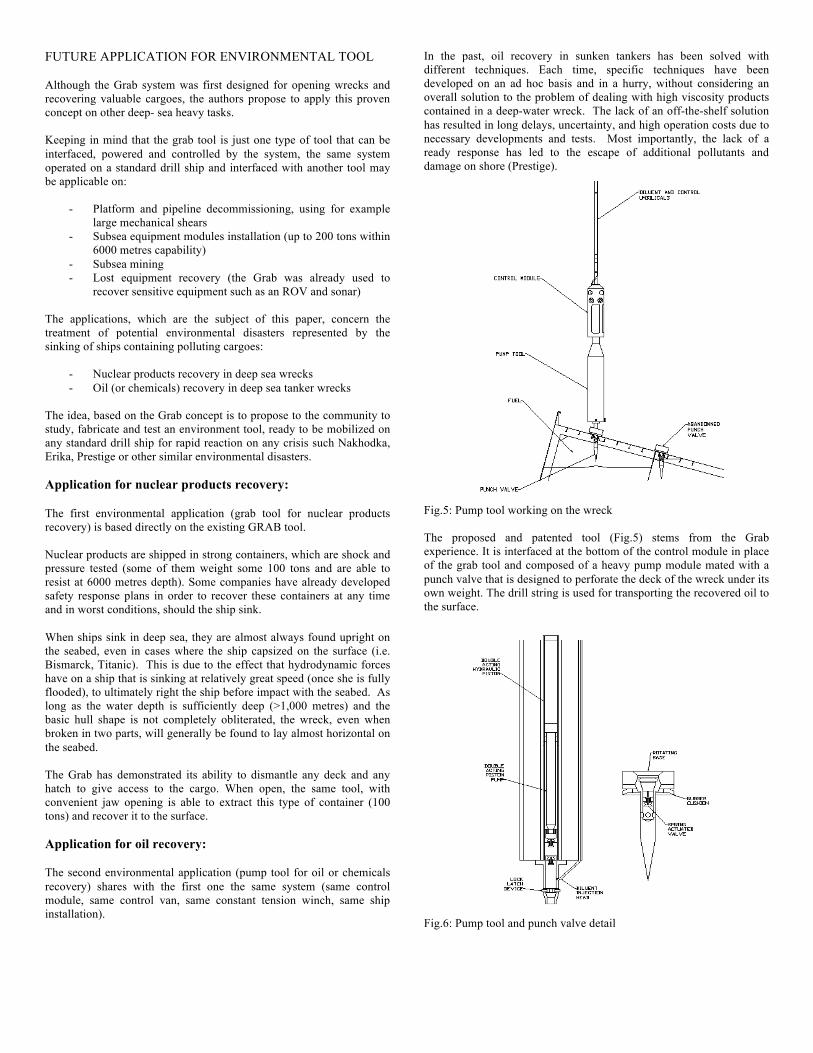
The only component that remained the same in the upgrade from the Grab 3000 to Grab 6000 was the tool itself, which was modified to receive all the additional sensors. In addition a new stronger drill string to be added at the upper part beyond 2600 metres depth was procured. The lower drill string was made of 5” OD pipe (41.5 kg/m) with 432 tons yield strength, whereas the upper drill string was made of 5” OD pipe (50.3 kg/m) with 569 tons yield strength. The 49.5” rotary table was also replaced by a double opening door able to receive the master bushing when closed and pass the new control module (Fig.4) when open. Fig.4: Grab 6000 control module on board the Deep Sea Worker A new skip with 100 tons capacity for improving daily cargo recovery rate was developed. This system consists of an articulated skip with a total capacity of 28 cubic metres, which is transported to the seabed by the tool and laid on the seabed adjacent to the worksite. The Grab then fills the skip with successive grabs and when the skip is full, retrieves it
to the surface. On the drill ship, the Grab delivers the skip to an automated handling system which turns upside down the articulated skip into a cargo sorting area and returns the skip to the Grab ready for the next trip. OPERATIONAL RESULTS Most of time the Grab had been operated in deep water without any heave compensation. On the first operation (John Barry) a dampening system consisting of 54 disks (0.92 metre diameter) spaced on the 6 x 3 lower joints was used to prevent the risk of pipe bulking under compression following the sudden release of load when the tool broke free from the wreck. The added mass and drag of this system was also an advantage to dampen the bottom residual heave. Due to the excessive time needed to deploy the 54 disks through the rotary table, this system was subsequently not used. A 50 tons punch, to be mounted in place of the grab tool was also made available for this first operation, but due to the excellent performance of the Grab in opening the wreck, it was not needed. The relatively sharp teeth of the tool, in combination with the grab’s weight and closing force ensured that the tool could always penetrate through deck plating. Thirty tons weight acting alongside up to 200 tons available closing force was sufficient to penetrate heavy wreck structure, and applying a pulling force of 60 to 120 tons was sufficient to extract big parts of wreck structure. In some cases 180 tons of force was needed to extract stronger parts (the relating pulling force at surface reaching at this time 80% of the drill string yield strength). Positioning of the tool was achieved by moving the dynamic positioned drill ship. The Grab pilot would look to the DP operator on the bridge for X and Y displacements of the tool and to the drill master for Z displacements and pushing/pulling force on the tool teeth. Due to the huge weight of the pendulum the response of the Grab is rapid (about 1 minute at 2600 metres depth) and there is no need of acoustic positioning. The thrusters are only used to turn the Grab and make final fine adjustment above the target. The wreck (relative to the DP ship) is plotted on the ship DP computer, along with position of the cargo skip and wreck debris that is dumped in the vicinity of the wreck. When the Grab is deployed on the bottom, it is really amazing how displacing the ship from target to target is simple, accurate and safe to operate. However wreck demolishing and emptying uninteresting cargo before reaching valuable cargo is a long process. Most of time the valuable cargo (primarily heavy copper or tin ingots or bars) is shipped on the bottom of the hold and it is common to have to open 3 decks and dump all of the overburden cargo on the side of the wreck before reaching the bottom and filling the skip with expected cargo. The Grab 3000, and especially the Grab 6000, established new standards for deepwater commercial salvage:
- The heaviest single load recovered was 125 tons - The heaviest single lift of paying cargo was 53.4 tons - The heaviest and deepest single lift of paying cargo was 45
tons from 3770 metres However despite great technical successes and several thousands tons of valuable cargo recovered, the experience stopped at the end of 1997 due to insufficient cargo selling revenue in comparison of company operating costs.
Paper No. 2003- Last name of first author Page number
FUTURE APPLICATION FOR ENVIRONMENTAL TOOL Although the Grab system was first designed for opening wrecks and recovering valuable cargoes, the authors propose to apply this proven concept on other deep- sea heavy tasks. Keeping in mind that the grab tool is just one type of tool that can be interfaced, powered and controlled by the system, the same system operated on a standard drill ship and interfaced with another tool may be applicable on:
- Platform and pipeline decommissioning, using for example large mechanical shears
- Subsea equipment modules installation (up to 200 tons within 6000 metres capability)
- Subsea mining - Lost equipment recovery (the Grab was already used to
recover sensitive equipment such as an ROV and sonar) The applications, which are the subject of this paper, concern the treatment of potential environmental disasters represented by the sinking of ships containing polluting cargoes:
- Nuclear products recovery in deep sea wrecks - Oil (or chemicals) recovery in deep sea tanker wrecks
The idea, based on the Grab concept is to propose to the community to study, fabricate and test an environment tool, ready to be mobilized on any standard drill ship for rapid reaction on any crisis such Nakhodka, Erika, Prestige or other similar environmental disasters. Application for nuclear products recovery: The first environmental application (grab tool for nuclear products recovery) is based directly on the existing GRAB tool. Nuclear products are shipped in strong containers, which are shock and pressure tested (some of them weight some 100 tons and are able to resist at 6000 metres depth). Some companies have already developed safety response plans in order to recover these containers at any time and in worst conditions, should the ship sink. When ships sink in deep sea, they are almost always found upright on the seabed, even in cases where the ship capsized on the surface (i.e. Bismarck, Titanic). This is due to the effect that hydrodynamic forces have on a ship that is sinking at relatively great speed (once she is fully flooded), to ultimately right the ship before impact with the seabed. As long as the water depth is sufficiently deep (>1,000 metres) and the basic hull shape is not completely obliterated, the wreck, even when broken in two parts, will generally be found to lay almost horizontal on the seabed. The Grab has demonstrated its ability to dismantle any deck and any hatch to give access to the cargo. When open, the same tool, with convenient jaw opening is able to extract this type of container (100 tons) and recover it to the surface. Application for oil recovery: The second environmental application (pump tool for oil or chemicals recovery) shares with the first one the same system (same control module, same control van, same constant tension winch, same ship installation).
In the past, oil recovery in sunken tankers has been solved with different techniques. Each time, specific techniques have been developed on an ad hoc basis and in a hurry, without considering an overall solution to the problem of dealing with high viscosity products contained in a deep-water wreck. The lack of an off-the-shelf solution has resulted in long delays, uncertainty, and high operation costs due to necessary developments and tests. Most importantly, the lack of a ready response has led to the escape of additional pollutants and damage on shore (Prestige). Fig.5: Pump tool working on the wreck The proposed and patented tool (Fig.5) stems from the Grab experience. It is interfaced at the bottom of the control module in place of the grab tool and composed of a heavy pump module mated with a punch valve that is designed to perforate the deck of the wreck under its own weight. The drill string is used for transporting the recovered oil to the surface. Fig.6: Pump tool and punch valve detail
Paper No. 2003- Last name of first author Page number
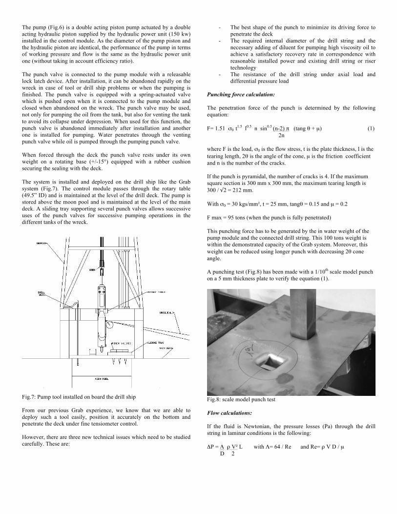
The pump (Fig.6) is a double acting piston pump actuated by a double acting hydraulic piston supplied by the hydraulic power unit (150 kw) installed in the control module. As the diameter of the pump piston and the hydraulic piston are identical, the performance of the pump in terms of working pressure and flow is the same as the hydraulic power unit one (without taking in account efficiency ratio). The punch valve is connected to the pump module with a releasable lock latch device. After installation, it can be abandoned rapidly on the wreck in case of tool or drill ship problems or when the pumping is finished. The punch valve is equipped with a spring-actuated valve which is pushed open when it is connected to the pump module and closed when abandoned on the wreck. The punch valve may be used, not only for pumping the oil from the tank, but also for venting the tank to avoid its collapse under depression. When used for this function, the punch valve is abandoned immediately after installation and another one is installed for pumping. Water penetrates through the venting punch valve while oil is pumped through the pumping punch valve. When forced through the deck the punch valve rests under its own weight on a rotating base (+/-15°) equipped with a rubber cushion securing the sealing with the deck. The system is installed and deployed on the drill ship like the Grab system (Fig.7). The control module passes through the rotary table (49.5” ID) and is maintained at the level of the drill deck. The pump is stored above the moon pool and is maintained at the level of the main deck. A sliding tray supporting several punch valves allows successive uses of the punch valves for successive pumping operations in the different tanks of the wreck. Fig.7: Pump tool installed on board the drill ship From our previous Grab experience, we know that we are able to deploy such a tool easily, position it accurately on the bottom and penetrate the deck under fine tensiometer control. However, there are three new technical issues which need to be studied carefully. These are:
- The best shape of the punch to minimize its driving force to penetrate the deck
- The required internal diameter of the drill string and the necessary adding of diluent for pumping high viscosity oil to achieve a satisfactory recovery rate in correspondence with reasonable installed power and existing drill string or riser technology
- The resistance of the drill string under axial load and differential pressure load
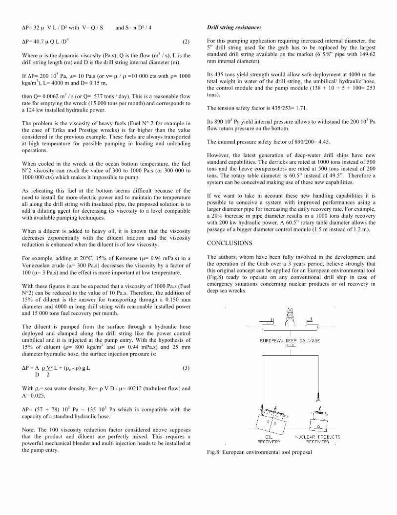
Punching force calculation: The penetration force of the punch is determined by the following equation: F= 1.51 σ0 t1.5 l0.5 n sin0.5 (n-2) π (tang θ + µ) (1) 2n where F is the load, σ0 is the flow stress, t is the plate thickness, l is the tearing length, 2θ is the angle of the cone, µ is the friction coefficient and n is the number of the cracks. If the punch is pyramidal, the number of cracks is 4. If the maximum square section is 300 mm x 300 mm, the maximum tearing length is 300 / √2 = 212 mm. With σ0 = 30 kgs/mm², t = 25 mm, tangθ = 0.15 and µ = 0.2 F max = 95 tons (when the punch is fully penetrated) This punching force has to be generated by the in water weight of the pump module and the connected drill string. This 100 tons weight is within the demonstrated capacity of the Grab system. Moreover, this weight can be reduced using longer punch with decreasing 2θ cone angle. A punching test (Fig.8) has been made with a 1/10th scale model punch on a 5 mm thickness plate to verify the equation (1). Fig.8: scale model punch test Flow calculations: If the fluid is Newtonian, the pressure losses (Pa) through the drill string in laminar conditions is the following: ΔP = Λ ρ V² L with Λ= 64 / Re and Re= ρ V D / µ D 2
Paper No. 2003- Last name of first author Page number
ΔP= 32 µ V L / D² with V= Q / S and S= π D² / 4 ΔP= 40.7 µ Q L /D4 (2) Where µ is the dynamic viscosity (Pa.s), Q is the flow (m3 / s), L is the drill string length (m) and D is the drill string internal diameter (m). If ΔP= 200 105 Pa, µ= 10 Pa.s (or ν= µ / ρ =10 000 cts with ρ= 1000 kgs/m3), L= 4000 m and D= 0.15 m, then Q= 0.0062 m3 / s (or Q= 537 tons / day). This is a reasonable flow rate for emptying the wreck (15 000 tons per month) and corresponds to a 124 kw installed hydraulic power. The problem is the viscosity of heavy fuels (Fuel N° 2 for example in the case of Erika and Prestige wrecks) is far higher than the value considered in the previous example. These fuels are always transported at high temperature for possible pumping in loading and unloading operations. When cooled in the wreck at the ocean bottom temperature, the fuel N°2 viscosity can reach the value of 300 to 1000 Pa.s (or 300 000 to 1000 000 cts) which makes it impossible to pump. As reheating this fuel at the bottom seems difficult because of the need to install far more electric power and to maintain the temperature all along the drill string with insulated pipe, the proposed solution is to add a diluting agent for decreasing its viscosity to a level compatible with available pumping techniques. When a diluent is added to heavy oil, it is known that the viscosity decreases exponentially with the diluent fraction and the viscosity reduction is enhanced when the diluent is of low viscosity. For example, adding at 20°C, 15% of Kerosene (µ= 0.94 mPa.s) in a Venezuelan crude (µ= 300 Pa.s) decreases the viscosity by a factor of 100 (µ= 3 Pa.s) and the effect is more important at low temperature. With these figures it can be expected that a viscosity of 1000 Pa.s (Fuel N°2) can be reduced to the value of 10 Pa.s. Therefore, the addition of 15% of diluent is the answer for transporting through a 0.150 mm diameter and 4000 m long drill string with reasonable installed power and 15 000 tons fuel recovery per month. The diluent is pumped from the surface through a hydraulic hose deployed and clamped along the drill string like the power control umbilical and it is injected at the pump entry. With the hypothesis of 15% of diluent (ρ= 800 kgs/m3 and µ= 0.94 mPa.s) and 25 mm diameter hydraulic hose, the surface injection pressure is: ΔP = Λ ρ V² L + (ρe - ρ) g L (3) D 2 With ρe= sea water density, Re= ρ V D / µ= 40212 (turbulent flow) and Λ= 0.025, ΔP= (57 + 78) 105 Pa = 135 105 Pa which is compatible with the capacity of a standard hydraulic hose. Note: The 100 viscosity reduction factor considered above supposes that the product and diluent are perfectly mixed. This requires a powerful mechanical blender and multi injection heads to be installed at the pump entry.
Drill string resistance: For this pumping application requiring increased internal diameter, the 5” drill string used for the grab has to be replaced by the largest standard drill string available on the market (6 5/8” pipe with 149.62 mm internal diameter). Its 435 tons yield strength would allow safe deployment at 4000 m the total weight in water of the drill string, the umbilical/ hydraulic hose, the control module and the pump module (138 + 10 + 5 + 100= 253 tons). The tension safety factor is 435/253= 1.71. Its 890 105 Pa yield internal pressure allows to withstand the 200 105 Pa flow return pressure on the bottom. The internal pressure safety factor of 890/200= 4.45. However, the latest generation of deep-water drill ships have new standard capabilities. The derricks are rated at 1000 tons instead of 500 tons and the heave compensators are rated at 500 tons instead of 200 tons. The rotary table diameter is 60.5” instead of 49.5”. Therefore a system can be conceived making use of these new capabilities. If we want to take in account these new handling capabilities it is possible to conceive a system with improved performances using a larger diameter pipe for increasing the daily recovery rate. For example, a 20% increase in pipe diameter results in a 1000 tons daily recovery with 200 kw hydraulic power. A 60.5” rotary table diameter allows the passage of a bigger diameter control module (1.5 m instead of 1.2 m). CONCLUSIONS The authors, whom have been fully involved in the development and the operation of the Grab over a 3 years period, believe strongly that this original concept can be applied for an European environmental tool (Fig.8) ready to operate on any conventional drill ship in case of emergency situations concerning nuclear products or oil recovery in deep sea wrecks. Fig.8: European environmental tool proposal

Paper No. 2003- Last name of first author Page number
Having demonstrated in this paper the possibilities of development of such tools, the authors propose to the European community to study, design and test the critical components (grab tool, punch valve, flow insurance, drill pipe) in association with radioactive material transportation companies, oil companies and drill ship operators. They propose after, to build this tool, to test it at sea and to consign it to an operator in charge of its maintenance and operation.
REFERENCES Argillier, JF (2001). “Influence of asphaltenes content and dilution on heavy oil rheology”, SPE 69711. Mearns, DL and Hudson ARF (2000). “Development of a controllable grab system for deep water recovery”. Rowe, SJ (2001). “Deep water installation of subsea hardware” , Society of naval architects and marine engineers. Valette-Fontaine M (1997). “Transport of irradiated nuclear fuel by sea”, International journal of radioactive materials transport. Wang, G (2002). “Damage predictions for ship’s structural performance in accidents”, MARTECH.