epson rc+ 7.0 - user's guide
TRANSCRIPT
Rev.4 EM179S3539F
EPSON RC+ 7.0
User's Guide Project Management and Development
Ver.7.3

EPSO
N R
C+ 7.0 (V
er.7.3) User's G
uide Project Managem
ent and Developm
ent Rev.4

EPSON RC+ 7.0 (Ver.7.3) User's Guide Rev.4 i
EPSON RC+ 7.0 (Ver.7.3)
User's Guide Rev.4
Copyright 2012-2017 SEIKO EPSON CORPORATION. All rights reserved.
ii EPSON RC+ 7.0 (Ver.7.3) User's Guide Rev.4
FOREWORD Thank you for purchasing our robot products. This manual contains the information necessary for the correct use of the Manipulator. Please carefully read this manual and other related manuals before installing the robot system. Keep this manual handy for easy access at all times.
WARRANTY
The robot and its optional parts are shipped to our customers only after being subjected to the strictest quality controls, tests, and inspections to certify its compliance with our high performance standards. Product malfunctions resulting from normal handling or operation will be repaired free of charge during the normal warranty period. (Please ask your Regional Sales Office for warranty period information.) However, customers will be charged for repairs in the following cases (even if they occur during the warranty period): 1. Damage or malfunction caused by improper use which is not described in the manual, or
careless use.
2. Malfunctions caused by customers’ unauthorized disassembly.
3. Damage due to improper adjustments or unauthorized repair attempts.
4. Damage caused by natural disasters such as earthquake, flood, etc.
Warnings, Cautions, Usage:
1. If the robot or associated equipment is used outside of the usage conditions and product specifications described in the manuals, this warranty is void.
2. If you do not follow the WARNINGS and CAUTIONS in this manual, we cannot be responsible for any malfunction or accident, even if the result is injury or death.
3. We cannot foresee all possible dangers and consequences. Therefore, this manual cannot warn the user of all possible hazards.
EPSON RC+ 7.0 (Ver.7.3) User's Guide Rev.4 iii
TRADEMARKS Microsoft, Windows, Windows logo, Visual Basic, and Visual C++ are either registered trademarks or trademarks of Microsoft Corporation in the United States and/or other countries. Pentium is a trademark of Intel Corporation. XVL is a registered trademark of Lattice Technology, Co., Ltd. Other brand and product names are trademarks or registered trademarks of the respective holders.
TRADEMARK NOTATION IN THIS MANUAL Microsoft® Windows® XP Operating system Microsoft® Windows® Vista Operating system Microsoft® Windows® 7 Operating system Microsoft® Windows® 8 Operating system Microsoft® Windows® 10 Operating system Throughout this manual, Windows XP, Windows Vista, Windows 7, Windows 8, and Windows 10 refer to above respective operating systems. In some cases, Windows refers generically to Windows XP, Windows Vista, Windows 7, Windows 8, and Windows 10.
NOTICE No part of this manual may be copied or reproduced without authorization. The contents of this manual are subject to change without notice. Please notify us if you should find any errors in this manual or if you have any comments regarding its contents.
MANUFACTURER

iv EPSON RC+ 7.0 (Ver.7.3) User's Guide Rev.4
Table of Contents
EPSON RC+ 7.0 (Ver.7.3) User's Guide Rev.4 v
1. Introduction 1
1.1 Welcome to EPSON RC+ 7.0.................................................................. 1
1.2 System Overview ..................................................................................... 2 1.2.1 Controller .................................................................................... 2 1.2.2 Software ...................................................................................... 3 1.2.3 Simulator ..................................................................................... 3 1.2.4 System Block Diagram ............................................................... 4
1.3 Options .................................................................................................... 5
1.4 Precautions When Using Windows 7 ...................................................... 5
1.5 EPSON RC+ 5.x and 6.x Users .............................................................. 5
1.6 EPSON RC+ 3.x and 4.x Users .............................................................. 5
1.7 SPEL for Windows Users ........................................................................ 5
1.8 Documentation ........................................................................................ 6
2. Safety 7
2.1 Overview .................................................................................................. 7
2.2 Definitions ................................................................................................ 7 2.2.1 Robot Power ................................................................................ 7 2.2.2 Safeguard ................................................................................... 8 2.2.3 Operation Modes ........................................................................ 8 2.2.4 Start Mode .................................................................................. 8 2.2.5 Changing Operation Mode ......................................................... 9 2.2.6 Emergency Stop ......................................................................... 9 2.2.7 Teach Control Device.................................................................. 9
2.3 Safety-related Requirements ................................................................. 10
2.4 Installation and Design Precautions ...................................................... 11 2.4.1 Designing a Safe Robot System .............................................. 11 2.4.2 Robot System Installation, Start-up, and Testing ..................... 14
2.5 Precautions regarding Robot Operation................................................ 16 2.5.1 General Precautions ................................................................. 16 2.5.2 Automatic Operation ................................................................. 16 2.5.3 Teaching Robot Points .............................................................. 16 2.5.4 Return to Automatic Operation ................................................. 17 2.5.5 Program Verification ................................................................. 17 2.5.6 Troubleshooting ........................................................................ 17 2.5.7 Maintenance ............................................................................. 17 2.5.8 Backup of Projects and Controller ............................................ 18
2.6 End User Instruction Manual ................................................................. 19
2.7 End User Training .................................................................................. 19
Table of Contents
vi EPSON RC+ 7.0 (Ver.7.3) User's Guide Rev.4
3. Getting Started 20
3.1 Hardware Installation ............................................................................. 20
3.2 Software Installation .............................................................................. 20
3.3 Windows Security Administration .......................................................... 20
4. Operation 21
4.1 System Power Up Procedure ................................................................ 21
4.2 Starting EPSON RC+ 7.0 ...................................................................... 21 4.2.1 Startup Sequence ..................................................................... 21 4.2.2 Startup Configuration ................................................................ 24 4.2.3 Start Mode ................................................................................. 24 4.2.4 Start Mode Dialog ..................................................................... 25 4.2.5 Start Mode: Program................................................................. 25 4.2.6 Start Mode: Auto ....................................................................... 26 4.2.7 Auto Start .................................................................................. 26 4.2.8 Using Monitor Mode .................................................................. 27 4.2.9 Windows Login .......................................................................... 27 4.2.10 Command Line Options .......................................................... 28 4.2.11 Using Command Line Options ................................................ 29
4.3 Communications with Controller ............................................................ 30 4.3.1 Configuring Communications with the Controller ..................... 30 4.3.2 USB Communications ............................................................... 30 4.3.3 Ethernet Communications ........................................................ 31 4.3.4 Connecting When Control Device is not PC ............................. 31
4.4 Writing your first Program ...................................................................... 33
5. The EPSON RC+ 7.0 GUI 38
5.1 GUI Overview ......................................................................................... 38
5.2 Project Explorer Pane ............................................................................ 39 Context Menu ...................................................................................... 39
5.3 Status Window Pane ............................................................................. 39
5.4 Status Bar .............................................................................................. 40
5.5 Online Help ............................................................................................ 41
5.6 [File] Menu ............................................................................................. 42 5.6.1 New Command (File Menu) ...................................................... 42 5.6.2 Open Command (File Menu) .................................................... 43 5.6.3 Close Command (File Menu) .................................................... 43 5.6.4 Save Command (File Menu) ..................................................... 44 5.6.5 Save As Command (File Menu) ................................................ 44 5.6.6 Restore Command (File Menu) ................................................ 44 5.6.7 Rename Command (File Menu) ............................................... 44 5.6.8 Delete Command (File Menu) ................................................... 45
Table of Contents
EPSON RC+ 7.0 (Ver.7.3) User's Guide Rev.4 vii
5.6.9 Import Command (File Menu) .................................................. 46 5.6.10 Print Command (File Menu) ................................................... 47 5.6.11 Exit Command (File Menu) ..................................................... 48
5.7 [Edit] Menu............................................................................................. 49 5.7.1 [Undo] Command (Edit Menu) .................................................. 49 5.7.2 [Redo] Command (Edit Menu) .................................................. 49 5.7.3 [Cut] Command (Edit Menu) ..................................................... 49 5.7.4 [Copy] Command (Edit Menu) .................................................. 49 5.7.5 [Paste] Command (Edit Menu) ................................................. 49 5.7.6 [Find] Command (Edit Menu) ................................................... 50 5.7.7 [Find Next] Command (Edit Menu) ........................................... 50 5.7.8 [Replace] Command (Edit Menu) ............................................. 51 5.7.9 [Select All] Command (Edit Menu) ........................................... 51 5.7.10 [Indent] Command (Edit Menu) .............................................. 51 5.7.11 [Outdent] Command (Edit Menu) ............................................ 52 5.7.12 [Comment Block] Command (Edit Menu) ............................... 52 5.7.13 [Uncomment Block] Command (Edit Menu) ........................... 52 5.7.14 [Go To Definition] Command (Edit Menu) .............................. 52
5.8 [View] Menu ........................................................................................... 53 5.8.1 [Project Explorer] Command (View Menu) ............................... 53 5.8.2 Status Window Command (View Menu)................................... 53 5.8.3 System History Command (View Menu) .................................. 54
5.9 [Project] Menu ....................................................................................... 55 5.9.1 [New] Command (Project Menu) .............................................. 55 5.9.2 [Open] Command (Project Menu) ............................................ 56 5.9.3 Recent Projects Submenu (Project Menu) ............................... 57 5.9.4 [Close] Command (Project Menu) ............................................ 57 5.9.5 [Edit] Command (Project Menu) ............................................... 57 5.9.6 [Save] Command (Project Menu) ............................................. 59 5.9.7 [Save As] Command (Project Menu) ........................................ 59 5.9.8 [Rename] Command (Project Menu)........................................ 60 5.9.9 [Import] Command (Project Menu) ........................................... 61 5.9.10 [Export] Command (Project Menu) ......................................... 65 5.9.11 [Copy] Command (Project Menu) ........................................... 67 5.9.12 [Delete] Command (Project Menu) ......................................... 68 5.9.13 [Build] Command (Project Menu) ........................................... 68 5.9.14 [Rebuild] Command (Project Menu) ....................................... 68 5.9.15 [Properties] Command (Project Menu) ................................... 69
5.10 [Run] Menu .......................................................................................... 79 5.10.1 [Run Window] Command (Run Menu) ................................... 79 5.10.2 [Operator Window] Command (Run Menu) ............................ 79 5.10.3 [Step Into] Command (Run Menu) ......................................... 79 5.10.4 [Step Over] Command (Run Menu) ........................................ 79
Table of Contents
viii EPSON RC+ 7.0 (Ver.7.3) User's Guide Rev.4
5.10.5 [Walk] Command (Run Menu) ................................................ 80 5.10.6 [Resume] Command (Run Menu) ........................................... 80 5.10.7 [Stop] Command (Run Menu) ................................................. 80 5.10.8 [Toggle Breakpoint] Command (Run Menu) ........................... 80 5.10.9 [Clear All Breakpoints] Command (Run Menu) ...................... 81 5.10.10 [Display Variables] Command (Run Menu) .......................... 81 5.10.11 [Call Stack] Command (Run Menu) ...................................... 82
5.11 [Tools] Menu ......................................................................................... 83 5.11.1 [Robot Manager] Command (Tools Menu).............................. 83 5.11.2 [Command Window] Command (Tools Menu) ...................... 127 5.11.3 [I/O Monitor] Command (Tools Menu) ................................... 129 5.11.4 Task Manager Command (Tools Menu) ................................ 131 5.11.5 Macros Command (Tools Menu) ........................................... 134 5.11.6 [I/O Label Editor] Command (Tools Menu) ........................... 135 5.11.7 User Error Editor Command (Tools Menu) ........................... 137 5.11.8 [Controller] Command (Tools Menu) ..................................... 138
5.12 [Setup] Menu ...................................................................................... 142 5.12.1 [PC to Controller Communications] Command (Setup Menu)142 5.12.2 [System Configuration] Command (Setup Menu) ................. 143 5.12.3 [Preferences] Command (Setup Menu) ................................ 160 5.12.4 [Options] Command (Setup Menu) ....................................... 167
5.13 [Window] Menu .................................................................................. 168 5.13.1 [Cascade] Command (Window Menu) .................................. 168 5.13.2 [Tile Vertical] Command (Window Menu) ............................. 168 5.13.3 [Tile Horizontal] Command (Window Menu) ......................... 169 5.13.4 [Arrange Icons] Command (Window Menu) ......................... 169 5.13.5 [Close All] Command (Window Menu) .................................. 170 5.13.6 1, 2, 3 Command (Window Menu) ........................................ 170 5.13.7 [Windows] Command (Window Menu) ................................. 170
5.14 [Help] Menu ........................................................................................ 171 5.14.1 [How Do I] Command (Help Menu) ...................................... 171 5.14.2 [Contents] Command (Help Menu) ....................................... 171 5.14.3 [Index] Command (Help Menu)............................................. 172 5.14.4 [Search] Command (Help Menu) .......................................... 172 5.14.5 [Manuals] Submenu (Help Menu) ......................................... 173 5.14.6 [About EPSON RC+ 7.0] Command (Help Menu) ................ 173
6. The SPEL+ Language 174
6.1 Overview .............................................................................................. 175
6.2 Program Structure ............................................................................... 175 6.2.1 What is a SPEL+ program? .................................................... 175 6.2.2 Calling functions ...................................................................... 175
Table of Contents
EPSON RC+ 7.0 (Ver.7.3) User's Guide Rev.4 ix
6.3 Commands and Statements ................................................................ 176
6.4 Function and Variable Names (Naming restriction) ............................ 176
6.5 Data Types ........................................................................................... 177
6.6 Operators ............................................................................................. 177
6.7 Working with Variables ........................................................................ 178 6.7.1 Variable scopes ...................................................................... 178 6.7.2 Local variables ........................................................................ 178 6.7.3 Module variables..................................................................... 178 6.7.4 Global variables ...................................................................... 179 6.7.5 Global Preserve variables ...................................................... 179 6.7.6 Arrays ...................................................................................... 180 6.7.7 Initial values ............................................................................ 180 6.7.8 Clearing arrays ....................................................................... 180
6.8 Working with Strings ............................................................................ 181
6.9 Working with Files ............................................................................... 182
6.10 Multi-statements ................................................................................ 184
6.11 Labels ................................................................................................ 184
6.12 Comments ......................................................................................... 184
6.13 Error Handling ................................................................................... 185
6.14 Multi-tasking ...................................................................................... 187
6.15 Using Multiple Robots ....................................................................... 188
6.16 Coordinate Systems .......................................................................... 189 6.16.1 Overview ............................................................................... 189 6.16.2 Robot Coordinate Systems................................................... 190 6.16.3 Local Coordinate Systems.................................................... 193 6.16.4 Tool Coordinate Systems ...................................................... 194 6.16.5 ECP Coordinate Systems (Option) ....................................... 197
6.17 Robot Arm Orientations ..................................................................... 200 6.17.1 SCARA robot arm orientations ............................................. 200 6.17.2 6-axis robot arm orientations ................................................ 201 6.17.3 RS series arm orientations ................................................... 205 6.17.4 N series arm orientations....................................................... 209
6.18 Robot Motion Commands .................................................................. 214 6.18.1 Homing the robot .................................................................. 214 6.18.2 Point to point motion ............................................................. 214 6.18.3 Linear motion ........................................................................ 214 6.18.4 Curves................................................................................... 215 6.18.5 Joint motion .......................................................................... 215 6.18.6 Controlling position accuracy ............................................... 215 6.18.7 CP Motion Speed / Acceleration and Tool Orientation ......... 216 6.18.8 PTP Speed / Acceleration for Small Distances .................... 216
Table of Contents
x EPSON RC+ 7.0 (Ver.7.3) User's Guide Rev.4
6.18.9 Pressing Motion .................................................................... 216 6.18.10 Collision Detection Function ............................................... 217 6.18.11 Torque Restriction Function ................................................ 219
6.19 Working with Robot Points ................................................................. 221 6.19.1 Defining points ...................................................................... 222 6.19.2 Referencing points by point label ......................................... 222 6.19.3 Referencing points with variables ......................................... 223 6.19.4 Using points in a program ..................................................... 223 6.19.5 Importing points into program ............................................... 223 6.19.6 Saving and loading points ..................................................... 223 6.19.7 Point attributes ...................................................................... 224 6.19.8 Extracting and setting point coordinates .............................. 225 6.19.9 Alteration of points ................................................................ 225
6.20 Input and output control ..................................................................... 226 6.20.1 Hardware I/O ......................................................................... 226 6.20.2 Memory I/O ........................................................................... 226 6.20.3 I/O Commands ...................................................................... 226
6.21 Using Traps ........................................................................................ 227 6.21.1 Cautions of Trap when it triggers the system condition ........ 228
6.22 Special Tasks ..................................................................................... 229 6.22.1 Precautions to Use the Special Tasks .................................. 229 6.22.2 NoPause/NoEmgAbort task specification ............................. 231 6.22.3 NoPause/NoEmgAbort task example ................................... 232
6.23 Background Task ............................................................................... 233 6.23.1 Primary features of background task .................................... 233 6.23.2 Setup and start the background task .................................... 233 6.23.3 Holding background task (from being activated) .................. 234 6.23.4 Commands that will cause error in background task ........... 236 6.23.5 Background task and Remote control .................................. 236
6.24 Predefined Constants ........................................................................ 237
6.25 Calling Native Functions in Dynamic Link Libraries .......................... 242
7. Building SPEL+ Applications 247
7.1 Designing Applications ......................................................................... 247 7.1.1 Creating the simplest application ............................................ 247 7.1.2 Application layout .................................................................... 247 7.1.3 Auto start at power up ............................................................. 249
7.2 Managing Projects ............................................................................... 250 7.2.1 Overview ................................................................................. 250 7.2.2 Creating a new project ............................................................ 251 7.2.3 Configuring a project ............................................................... 251 7.2.4 Building a project .................................................................... 252
Table of Contents
EPSON RC+ 7.0 (Ver.7.3) User's Guide Rev.4 xi
7.2.5 Backing up a project ............................................................... 252
7.3 Editing Programs ................................................................................. 253 7.3.1 Program rules ......................................................................... 253 7.3.2 Typing in program code .......................................................... 253 7.3.3 Syntax Help ............................................................................ 254 7.3.4 Syntax Errors .......................................................................... 255
7.4 Editing Points ....................................................................................... 256
7.5 Running and Debugging Programs ..................................................... 258 7.5.1 The Run window ..................................................................... 258 7.5.2 Debugging .............................................................................. 260
7.6 The Operator Window ......................................................................... 264 7.6.1 Operator window configuration ............................................... 265 7.6.2 Auto start configuration ........................................................... 265
7.7 Using Remote Control ......................................................................... 265
7.8 Using Encrypt Files .............................................................................. 266
8. Simulator 267
8.1 Simulator Functions ............................................................................. 267 8.1.1 Overview ................................................................................. 267 8.1.2 System Requirements ............................................................ 268
8.2 Using the Simulator ............................................................................. 269 8.2.1 Working with the samples ....................................................... 269 8.2.2 Working with the user created system ................................... 271
8.3 Description of Functions ...................................................................... 279 8.3.1 Simulator window layout ......................................................... 279 8.3.2 Simulator Settings................................................................... 298 8.3.3 Collision detection................................................................... 300 8.3.4 CAD To Point .......................................................................... 302 8.3.5 Virtual controller ...................................................................... 310 8.3.6 Connection with controller ...................................................... 311 8.3.7 Motion restriction by BOX ....................................................... 313
8.4 Simulator Specifications and Restrictions ........................................... 314 8.4.1 EPSON RC+ 7.0 package ...................................................... 314 8.4.2 Specifications and precautions for the 3D display ................. 314 8.4.3 Specifications and precautions for Simulation (program execution
on PC) ..................................................................................... 315 8.4.4 Specifications and precautions of EPSON RC+ .................... 317 8.4.5 Restriction on SPEL+ command execution ............................ 318 8.4.6 Specifications and precautions of EPSON RC+ 7.0 Trial ...... 321
9. Motion System 322
9.1 Standard Motion System ..................................................................... 322
Table of Contents
xii EPSON RC+ 7.0 (Ver.7.3) User's Guide Rev.4
9.2 Drive Module Software Configuration .................................................. 322
9.3 PG Motion System ............................................................................... 322
10. Robot Configuration 323
10.1 Setting the Robot Model .................................................................... 323 10.1.1 Adding a standard robot ........................................................ 323 10.1.2 Calibrating a standard robot ................................................. 324 10.1.3 Changing robot system parameters ..................................... 324 10.1.4 Deleting a standard robot ..................................................... 325 10.1.5 Changing the Robot .............................................................. 326
10.2 Configuration of Additional Axes ........................................................ 327 10.2.1 Adding the additional S axis .................................................. 327 10.2.2 Adding the additional T axis .................................................. 327 10.2.3 Changing the parameters of robot with additional axes installed
................................................................................................. 327 10.2.4 Differences of the standard robot and robot with additional axes
................................................................................................. 328 10.2.5 Deleting the additional axes .................................................. 330
11. Inputs and Outputs 331
11.1 Overview ............................................................................................ 331
11.2 I/O Commands ................................................................................... 331
11.3 I/O Configuration ................................................................................ 332
11.4 Monitoring I/O ..................................................................................... 332
11.5 Virtual I/O ........................................................................................... 332
11.6 Fieldbus Master I/O ............................................................................ 332
11.7 Fieldbus Slave I/O .............................................................................. 333 11.7.1. ModBus Slave ...................................................................... 333 11.7.2. Supported Functions ............................................................ 333 11.7.3. Address map ........................................................................ 334 11.7.4. ModBus RTU ........................................................................ 335 11.7.5. ModBus TCP ........................................................................ 335 11.7.6. How to Configure ModBus ................................................... 335
12. Remote Control 338
12.1 Remote I/O ......................................................................................... 338 12.1.1 Remote Control Input Output Configuration ......................... 339 12.1.2 Control Device Configuration ................................................ 339 12.1.3 Auto Mode with Remote Control ........................................... 340 12.1.4 Teach Mode with Remote Control......................................... 340 12.1.5 Debugging Remote Control .................................................. 340 12.1.6 Remote Inputs ....................................................................... 341
Table of Contents
EPSON RC+ 7.0 (Ver.7.3) User's Guide Rev.4 xiii
12.1.7 Remote Outputs.................................................................... 345 12.1.8 Remote Input Handshake Timing ......................................... 348
12.2 Remote Ethernet ............................................................................... 351 12.2.1 Remote Ethernet Configuration ............................................ 351 12.2.2 Control Device Configuration ............................................... 351 12.2.3 Remote Ethernet Control Execution ..................................... 352 12.2.4 Debugging Remote Ethernet Control ................................... 352 12.2.5 Remote Ethernet Command ................................................. 353 12.2.6 Monitoring command ............................................................ 356 12.2.7 Response .............................................................................. 357 12.2.8 Response timing of Remote Ethernet control ...................... 359
12.3 Remote RS232 .................................................................................. 359 12.3.1 Remote RS232 setting ......................................................... 359 12.3.2 Control device setting ........................................................... 360 12.3.3 Execution of remote RS232 control...................................... 360 12.3.4 Debugging remote RS232 control ........................................ 361 12.3.5 Remote RS232 Command ................................................... 361 12.3.6 Monitoring command ............................................................ 367 12.3.7 Response .............................................................................. 367 12.3.8 Response timing of Remote Ethernet control ...................... 370
12.4 User-defined Remote Output I/O ...................................................... 370 12.4.1 What is user-defined remote output I/O? ............................. 370 12.4.2 Output conditions .................................................................. 370 12.4.3 Output ................................................................................... 371 12.4.4 Restrictions ........................................................................... 373 12.4.5 How to set the user-defined output remote I/O .................... 374 12.4.6 Usage example ..................................................................... 376
13. RS-232C Communications 378
13.1 RS-232C Software Configuration ...................................................... 378
13.2 RS-232C Commands ........................................................................ 380
14. TCP/IP Communications 381
14.1 TCP/IP Setup ..................................................................................... 381 14.1.1 Ethernet Hardware ............................................................... 381 14.1.2 IP Addresses ......................................................................... 381 14.1.3 IP Gateway ........................................................................... 382 14.1.4 Testing Windows TCP/IP setup ............................................ 382
14.2 TCP/IP Software Configuration ......................................................... 383
14.3 TCP/IP Commands ............................................................................ 383
15. Security 384
15.1 Overview ............................................................................................ 384
Table of Contents
xiv EPSON RC+ 7.0 (Ver.7.3) User's Guide Rev.4
15.2 Security Configuration ....................................................................... 384
15.3 Security Audit Viewer ......................................................................... 388
15.4 SPEL+ Security Command ................................................................ 388
16. Conveyor Tracking 389
16.1 Overview ............................................................................................ 389
16.2 Conveyor Tracking Processes ........................................................... 391
16.3 System Structure ............................................................................... 392
16.4 Hardware Installation ......................................................................... 394
16.5 Wiring example of Vision Conveyor Tracking System ....................... 402
16.6 Conveyor Encoder Configuration ..................................................... 403
16.7 Verifying Encoder Operation .............................................................. 404
16.8 Verifying Hardware Conveyor Trigger / Vision Trigger ...................... 405
16.9 Key Terms .......................................................................................... 406
16.10 Conveyor Tracking Commands ....................................................... 407
16.11 Creating Conveyors in a Project ...................................................... 409
16.12 Configuring Conveyors .................................................................... 410
16.13 Vision Conveyors ............................................................................. 412
16.14 Sensor Conveyors ........................................................................... 433
16.15 Pickup Area ...................................................................................... 449
16.16 Adjusting the Z value ....................................................................... 457
16.17 Queue Sorting .................................................................................. 459
16.18 Cnv_QueReject ............................................................................... 460
16.19 Sample Program .............................................................................. 461
16.20 Multiple Conveyors .......................................................................... 467
16.21 Multi-robot Conveyor ....................................................................... 472
16.22 Abort Tracking .................................................................................. 477
16.23 Conveyor Tracking with 6-Axis Robot ............................................. 477
16.24 Tracking Mode ................................................................................. 477
16.25 How to shorten the picking cycle time ............................................. 478
16.26 Manipulator Posture ......................................................................... 478
16.27 Tracking Abort Line .......................................................................... 479
16.28 Tips for Accuracy Improvement of Conveyor Tracking .................... 484 16.28.1 Overview ............................................................................. 484 16.28.2 Tips for System Construction .............................................. 484 16.28.3 Tips for Vision Calibration ................................................... 486 16.28.4 Tips for Conveyor Calibration ............................................. 487 16.28.5 Troubleshooting for Work Piece Detection ......................... 488 16.28.6 Offset ................................................................................... 491
Table of Contents
EPSON RC+ 7.0 (Ver.7.3) User's Guide Rev.4 xv
17. ECP Motion 493
17.1 Overview ............................................................................................ 493
18. Force Sensing 495
18.1 Overview ............................................................................................ 495
18.2 Specifications .................................................................................... 495
18.3 Installation.......................................................................................... 496
18.4 Force Sensing Commands ................................................................ 501
18.5 Using the Force Sensing Trigger ....................................................... 502
19. Real-Time I/O 503
19.1 Overview ............................................................................................ 503
19.2 Specifications .................................................................................... 503
19.3 Usage ................................................................................................ 505
20. Additional Axis 508
20.1 Overview ............................................................................................ 508
20.2 Specifications .................................................................................... 508
20.3 Usage ................................................................................................ 510
21. Calibration of Commercial Vision Sensor and Robot 512
21.1 Overview ............................................................................................ 512
21.2 Specifications .................................................................................... 513
21.3 Camera Installation............................................................................ 514
21.4 Reference Points ............................................................................... 515
21.5 Reference Points for Mobile Camera ................................................ 515
21.6 Reference Points for Fixed Camera .................................................. 515
21.7 Command List ................................................................................... 516
22. Installing Controller Options 517
23. Software License Agreement 518

Table of Contents
xvi EPSON RC+ 7.0 (Ver.7.3) User's Guide Rev.4
Appendix A: Automatic Processing of Project Import A-1
Project Import for EPSON RC+ 6.* ............................................................ A-1
Project Import for EPSON RC+ 5.* ............................................................ A-1
Project Import for EPSON RC+ 3.* / 4.* .................................................... A-1
Project Import for SPEL for Windows 2.* ................................................... A-3
Appendix B: EPSON RC+ 7.0 Software B-1
Before Installing EPSON RC+ 7.0 Software ............................................... B-1
EPSON RC+ 7.0 Software Installation ...................................................... B-3
EPSON RC+ 7.0 Software Update ............................................................ B-5
1. Introduction
EPSON RC+ 7.0 (Ver.7.3) User's Guide Rev.4 1
1. Introduction
1.1 Welcome to EPSON RC+ 7.0 Welcome to the EPSON RC+ 7.0 Project Management and Development Environment. EPSON RC+ 7.0 is used to develop application software for the Robot Controller.
EPSON RC+ 7.0 features
Operable on Windows -
Integrated application development environment -
Communicates with the Controller by USB or Ethernet -
Allows you to connect one computer with multiple Controllers -
Multi simultaneous session -
SPEL+ programming language -A powerful, easy to use BASIC-like programming language that supports multi-tasking, robot motion control, I/O control, and networking.
I/O systems including Digital I/O boards and Fieldbus I/O -
TCP/IP and RS-232 communications -
Background task -Controls entire system
Database access -
Vision Guide option -Integrated vision robot guidance
RC+ API option -Enables you to control the system using standard Microsoft .NET programming environments including Microsoft Visual Basic and Microsoft Visual C++.
Security option -Allows you to administrate all EPSON RC+ users on your system. It also includes usage auditing, so you can track how many hours are spent using the system, and if changes were made.
Conveyor Tracking option -Enables one or more robots to pick parts from moving conveyors using vision or sensors.
PG Motion System option -Allows you to use third party motors and drivers to control auxiliary equipment such as XY tables, slides, etc.
ECP option -Supports CP motion relative to a fixed point.
GUI Builder option -Integrated GUI development tool
Force Sensing option -Allows a robot to use torque/force sensing and measurement
Force Control -Force is controlled or measured by force sensor.
1. Introduction
2 EPSON RC+ 7.0 (Ver.7.3) User's Guide Rev.4
1.2 System Overview EPSON RC+ 7.0 software, which is installed to the computer connected to the robot controller, contains several components that enable you to control an entire robotic work cell. EPSON RC+ 7.0 communicates with the controller using USB or Ethernet.
EPSON RC+ 7.0 and the Controller can be used in following environments:
Slave system The Controller is PLC or PC cell slave. Application is developed with EPSON RC+ 7.0.
After saving the object code to the Controller, it does not need to be connected to the computer. The Controller is controlled by I/O or fieldbus.
Standalone system Controls the robot and peripheral equipment as the robot controller. EPSON RC+ 7.0 displays the simple operator window in AUTO mode.
By using RC+ API option, .NET application can be controlled.
Offline development system
Program edition and project build can be checked on the offline PC.
Simulation system EPSON RC+ 7.0 on the PC which is connected to the Controller can execute the program without the actual I/O or robot by using the virtual I/O and dry run.
1.2.1 Controller
RC700
The RC700 Controller is a powerful robotic work cell controller that controls our SCARA robots and 6-axis robots.
Controller features
Sophisticated yet achieving reliability and stability - Built in Motion System -
The motion drive system can control up to 6 axes simultaneously and 1 robot, and can add up to three drive units
Includes standard I/O - Wide variety of options -
For detailed information on the Controller, refer to the controller manual.
RC90
The RC90 Controller with the following label attached can be used in combination with EPSON RC+ 7.0.
EPSON RC+ 7.0 RC90 Controller firmware
Ver.7.0.2.0
Before Ver.7.0.1 !!!
Ver.7.0.2 or later OK
OK: Compatible All functions of the EPSON RC+ 7.0 and the Controller are available.
!!!: Compatible Connection is OK. We recommend using EPSON RC+7.0 Ver. 7.0.2 or later.
This option is not available for Robot Controller RC90 (EPSON RC+ 5.0) without the label.
NOTE
1. Introduction
EPSON RC+ 7.0 (Ver.7.3) User's Guide Rev.4 3
Manual PDF for this robot system is available from EPSON RC+ 7.0 Ver. 7.0.2
The RC90 Controller is a robot controller that can drive LS series manipulators.
Features:
Built in motion drive system. The motion drive system can control one robot. -
Standard I/O -
Optional digital I/O expansion boards -
Optional Fieldbus slave support for DeviceNet, PROFIBUS-DP, CC-Link Ethernet/IP, -PROFINET, and EtherCat.
RS232 ports (standard + optional) -For details on the Controller, refer to the RC90 controller manual.
1.2.2 Software
EPSON RC+ 7.0 needs to be installed to your development PC. To communicate with the Controller, the computer should support USB 1.1 / 2.0 or Ethernet communication.
You can purchase options with the product or add them later.
Using EPSON RC+ 7.0, you can develop application software for the SPEL+ language that runs in the RC700 controller.
1.2.3 Simulator
Simulator functions enable easy robot motion check on your PC, which gives you flexibility to consider the system layout, measure the operation time, and create the robot programs.
They are useful in all the way from introduction stage of robot automation to launch of robot system.
Simulator is supported by EPSON RC+ 7.0 Ver.7.0.0 or later as standard.
For details, refer to 8. Simulator.
NOTE
1. Introduction
4 EPSON RC+ 7.0 (Ver.7.3) User's Guide Rev.4
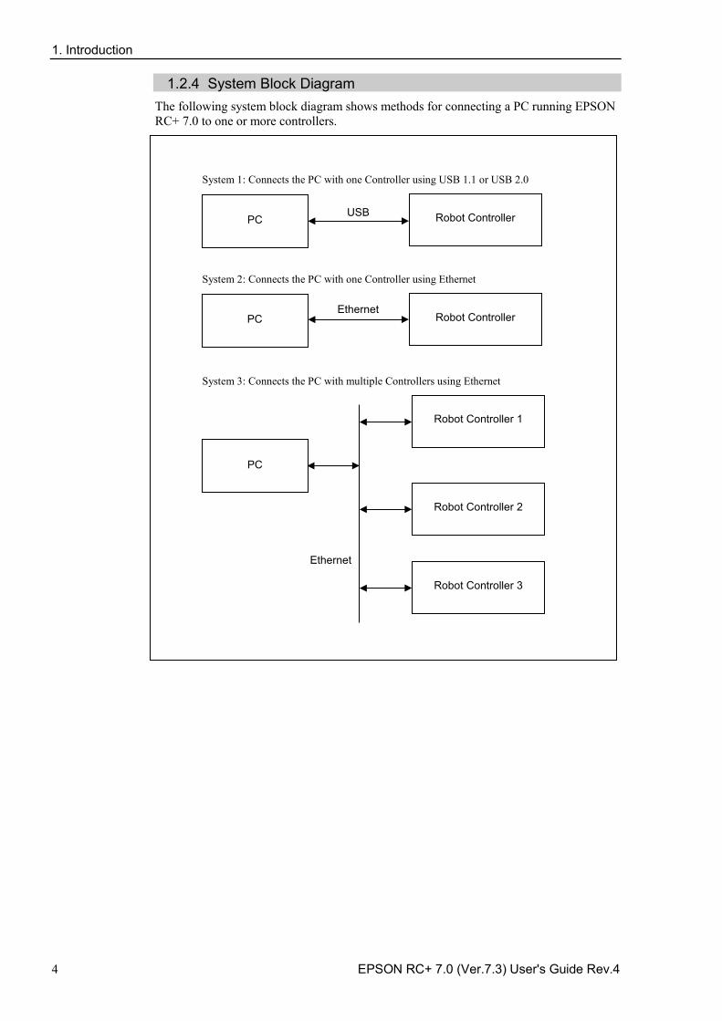
1.2.4 System Block Diagram The following system block diagram shows methods for connecting a PC running EPSON RC+ 7.0 to one or more controllers.
Ethernet
PC
Robot Controller USB
PC
Robot Controller
System 1: Connects the PC with one Controller using USB 1.1 or USB 2.0
System 2: Connects the PC with one Controller using Ethernet
PC
Robot Controller 1
System 3: Connects the PC with multiple Controllers using Ethernet
Robot Controller 2
Robot Controller 3
Ethernet
1. Introduction
EPSON RC+ 7.0 (Ver.7.3) User's Guide Rev.4 5
1.3 Options EPSON RC+ 7.0 enables the purchased Controller options.
Refer to 22. Installing Controller Options for details.
1.4 Precautions When Using Windows 7 Connecting development PC to Robot Controller using Ethernet The robot controller does not support internet protocol version 6 (TCP/IPv6). When connecting the development PC to the robot controller using the Ethernet, be sure to use the internet protocol version 4 (TCP/IPv4).
1.5 EPSON RC+ 5.x and 6.x Users EPSON RC+ 7.0 is compatible with EPSON RC+ 5.x and 6.x for the operation and language.
For EPSON RC+ 7.0, you can use all commands of EPSON RC+ 5.x and 6.x.
You can use the current numbers for the I/O and communication port.
To enable the EPSON RC+ 5.x and 6.x project in EPSON RC+ 7.0 environment, convert the project using [Project] menu-[Import].
With above conversion, the entire project will be copied by EPSON RC+ 7.0.
\EPSONRC50\Project directory → \EpsonRC70\Project directory
\EPSONRC60\Project directory → \EpsonRC70\Project directory
1.6 EPSON RC+ 3.x and 4.x Users EPSON RC+ 7.0 is compatible with EPSON RC+ 3.x and 4.x for the operation.
For EPSON RC+ 7.0, there are new commands added to SPEL+ language. Though there are also some commands deleted or amended, most commands are available.
To enable the project of EPSON RC+ 3.x or 4.x in EPSON RC+ 7.0 environment, convert the project using [Project] menu-[Import].
With above conversion, the entire project will be copied by EPSON RC+ 7.0.
\EPSONRC\Project directory → \EpsonRC70\Project directory
Refer to Appendix A: Automatic Processing of Project Import for the details.
1.7 SPEL for Windows Users EPSON RC+ 7.0 is compatible with SPEL for Windows 1.x and 2.x for the operation.
For EPSON RC+ 7.0, there are many new commands added to SPEL+ language, which replaces SPEL. Also there are some commands deleted or amended.
To enable the project of SPEL for Windows 2.x in EPSON RC+ 7.0 environment, convert the project using [Project] menu-[Import].
With above conversion, the file will be copied to a new directory or the program will optionally be converted by EPSON RC+ 7.0.
Refer to Appendix A: Automatic Processing of Project Import for the details.
1. Introduction
6 EPSON RC+ 7.0 (Ver.7.3) User's Guide Rev.4
1.8 Documentation All documentation is installed on the PC in PDF format.
To view manuals on the PC:
Select [Manuals] from the [Help] menu in EPSON RC+ 7.0 -
From Windows desktop, click <Start>-[Programs]-[EPSON RC+ 7.0] -
Available manuals are shown in the table below.
Title Contents EPSON RC+ 7.0 Users Guide Information for the entire system SPEL+ Language Reference Information for the SPEL+ Language Vision Guide 7.0 Hardware
Information for options
Vision Guide 7.0 Software Vision Guide 7.0 Reference Force Control 7.0 Force Control 7.0 Reference RC+ API 7.0 GUI Builder 7.0 Fieldbus IO PG Motion System TP1 TP2 TP3
Remote Control Reference Information for Remote I/O control extended function
Manipulator manual Information for the purchased robot Each series has its own manual
Controller manual Information for the purchased robot
Safety & Installation Information for installing the robot system safely Paper manual will come with the product
The “NOTE” sections describe important information to be followed for operating the Robot system.
The "TIP" sections describe hints for easier or alternative operations.
NOTE
TIP
2. Safety
EPSON RC+ 7.0 (Ver.7.3) User's Guide Rev.4 7
2. Safety
2.1 Overview This chapter describes the important safety requirements for robotic systems using EPSON RC+ 7.0 and the Controller.
Installation of robots and robotic equipment should only be performed by qualified personnel in accordance with national and local codes. Please read and understand this entire chapter before using your EPSON RC+ 7.0 system.
Safety is the most important consideration when designing and operating any robotic system.
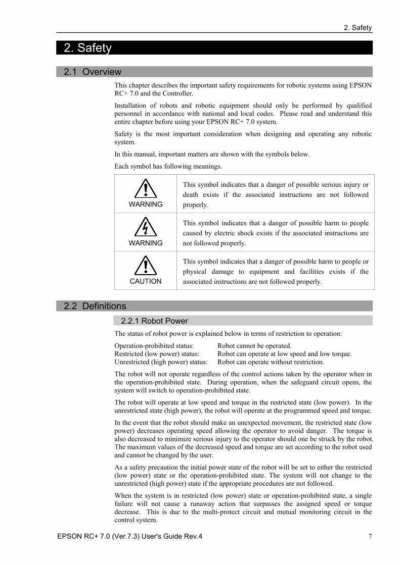
In this manual, important matters are shown with the symbols below.
Each symbol has following meanings.
WARNING
This symbol indicates that a danger of possible serious injury or death exists if the associated instructions are not followed properly.
WARNING
This symbol indicates that a danger of possible harm to people caused by electric shock exists if the associated instructions are not followed properly.
CAUTION
This symbol indicates that a danger of possible harm to people or physical damage to equipment and facilities exists if the associated instructions are not followed properly.
2.2 Definitions
2.2.1 Robot Power The status of robot power is explained below in terms of restriction to operation:
Operation-prohibited status: Robot cannot be operated. Restricted (low power) status: Robot can operate at low speed and low torque. Unrestricted (high power) status: Robot can operate without restriction.
The robot will not operate regardless of the control actions taken by the operator when in the operation-prohibited state. During operation, when the safeguard circuit opens, the system will switch to operation-prohibited state.
The robot will operate at low speed and torque in the restricted state (low power). In the unrestricted state (high power), the robot will operate at the programmed speed and torque.
In the event that the robot should make an unexpected movement, the restricted state (low power) decreases operating speed allowing the operator to avoid danger. The torque is also decreased to minimize serious injury to the operator should one be struck by the robot. The maximum values of the decreased speed and torque are set according to the robot used and cannot be changed by the user.
As a safety precaution the initial power state of the robot will be set to either the restricted (low power) state or the operation-prohibited state. The system will not change to the unrestricted (high power) state if the appropriate procedures are not followed.
When the system is in restricted (low power) state or operation-prohibited state, a single failure will not cause a runaway action that surpasses the assigned speed or torque decrease. This is due to the multi-protect circuit and mutual monitoring circuit in the control system.
2. Safety
8 EPSON RC+ 7.0 (Ver.7.3) User's Guide Rev.4
2.2.2 Safeguard To ensure safe operation, install a safety system using safety doors, light curtains, safety floor mats, etc.
WARNING
■ The EMERGENCY connector on the controller has a safeguard input circuit to connect the safety device interlock switch. To protect operators working near the robot, be sure to connect the interlock switch and make sure that it works properly.
If a closed safeguard is open during robot motion, the robot stops immediately and enters into pause state. Then, all robot motors are turned off. The descriptions below explain how the safeguard input works.
Safeguard closed: The safeguard input is turned ON. The robot can automatically operate in unrestricted (high power) state.
Safeguard open: The safeguard input is turned OFF, and the interlock function operates. The robot stops immediately, motors are turned off, and further operation is impossible until either the safeguard is closed or Teach or TEST mode is turned ON and the enable circuit is engaged.
For further details on the safeguard and interlock, refer to 2.4 Installation and Design Precautions later in this chapter. For detailed wiring instructions, refer to the Robot Controller manual, Setup & Operation: 9. EMERGENCY.
2.2.3 Operation Modes The operation mode is defined as the single control point for the controller, therefore you cannot use more than one operation mode at the same time.
There are four operation modes for the controller: AUTO, PROGRAM, TEACH, and TEST.
AUTO operation modes allow you to execute programs in the controller when the -safeguard is closed.
PROGRAM operation mode allows you to execute and debug programs when the -safeguard is closed.
TEACH operation mode allows you to jog and teach the robot at slow speed while -inside the safeguarded area.
TEST operation mode allows you to execute a program at slow speed while the -safeguard is opened.
2.2.4 Start Mode
The Start mode specifies the operation mode for EPSON RC+ 7.0 when it starts.
You can set the EPSON RC+ 7.0 to start in AUTO or PROGRAM mode.
For information on how to change the start mode, refer to 4. Operation.
2. Safety
EPSON RC+ 7.0 (Ver.7.3) User's Guide Rev.4 9
2.2.5 Changing Operation Mode You can change from AUTO operation mode or PROGRAM operation mode to TEACH mode by setting the mode selector key switch on the Teach Pendant to the TEACH position.
TP1, TP2: Teach TP3: TEACH/T1, TEACH/T2
When the mode selector key switch is changed back to Auto (TP1, TP2) or AUTO (TP3), the operation mode is returned to previous operation mode (AUTO or PROGRAM).
The AUTO operation mode can be changed to PROGRAM mode during the EPSON RC+ 7.0 startup sequence. A password can be used to allow only certain personnel to change the startup operation mode.
When EPSON RC+ 7.0 starts in AUTO operation mode, the AUTO operation mode cannot be changed to PROGRAM operation mode after the system has started. To change the operation mode, restart the system and log into PROGRAM mode, then set the start mode again and restart EPSON RC+ 7.0.
For more information, refer to 4. Operation.
To change to TEST operation mode:
TP1: Switch the mode selector key switch on the Teach Pendant to Teach, and then select Function key F1: Test Mode.
TP3: Switch the mode selector key switch on the Teach Pendant to TEACH/T1 or TEACH/T2, and then tap the [Test] tab.
For more information, refer to the following manuals.
Robot Controller option Teach Pendant TP1 or TP3 manual, 4. Operation Mode (TEACH/AUTO/TEST).
Robot Controller option Teach Pendant TP2 manual, 4. Operation Mode (TEACH/AUTO).
T2 mode cannot be used on RC700-A for complying with the UL standard.
2.2.6 Emergency Stop The controller is equipped with an emergency stop input terminal. If the normally closed emergency stop circuit is broken, the power supplied to all motors will be shut off (and enter servo-free status) and the robot will be stopped by dynamic braking.
CAUTION
■ The path that the robot will follow from the time the emergency stop switch is pressed until the device stops, as well as the stop position itself, cannot be positively determined. In many cases, the stop position will not exceed the target position for the operation prior the emergency stop. Depending on the robot’s loading condition and operation speed, overruns are inevitable. Taking this into consideration, be sure the layout for the peripheral equipment includes extra space.
For detailed wiring instructions, refer to the Robot Controller manual, Setup & Operation: 9. EMERGENCY.
2.2.7 Teach Control Device Operators can use the TP1 teach pendant to operate the robot in the TEACH or TEST operation mode.
For operation instructions, refer to the following manuals.
Robot Controller option Teach Pendant TP1, TP2, or TP3 manual.
NOTE
2. Safety
10 EPSON RC+ 7.0 (Ver.7.3) User's Guide Rev.4
2.3 Safety-related Requirements Specific tolerances and operating conditions for safety are contained in the manuals for the robot, controller and other devices. Be sure to read those manuals as well.
For the installation and operation of the robot system, be sure to comply with the applicable local and national regulations.
Robot systems safety standards and other examples are given in this chapter. Therefore, to ensure that safety measures are complete, please refer to the other standards listed as well.
(Note: The following is only a partial list of the necessary safety standards.)
EN ISO 10218-1 Robots and robotic devices -- Safety requirements for industrial robots -- Part 1: Robots
EN ISO 10218-2 Robots and robotic devices -- Safety requirements for industrial robots -- Part 2: Robot systems and integration
ANSI/RIA R15.06 American National Standard for Industrial Robots and Robot Systems -- Safety Requirements
EN ISO 12100 Safety of machinery -- General principles for design -- Risk assessment and risk reduction
EN ISO 13849-1 Safety of machinery -- Safety-related parts of control systems -- Part 1: General principles for design
EN ISO 13850 Safety of machinery -- Emergency stop -- Principles for design EN ISO 13855 Safety of machinery -- Positioning of safeguards with respect to the
approach speeds of parts of the human body. EN ISO 13857 Safety of machinery -- Safety distances to prevent hazard zones
being reached by upper and lower limbs. ISO 14120 EN953
Safety of machinery -- Guards -- General requirements for the design and construction of fixed and movable guards
IEC 60204-1 EN 60204-1
Safety of machinery -- Electrical equipment of machines -- Part 1: General requirements
CISPR11 EN 55011
Industrial, scientific and medical (ISM) radio-frequency equipment -- Electromagnetic disturbance characteristics -- Limits and methods of measurement
IEC 61000-6-2 EN 61000-6-2
Electromagnetic compatibility (EMC) -- Part 6-2: Generic standards -- Immunity for industrial environments
2. Safety
EPSON RC+ 7.0 (Ver.7.3) User's Guide Rev.4 11
2.4 Installation and Design Precautions
2.4.1 Designing a Safe Robot System It is important to operate robots safely. It is also important for robot users to give careful consideration to the safety of the overall robot system design.
This section summarizes the minimum conditions that should be observed when using EPSON robots in your robot systems.
Please design and manufacture robot systems in accordance with the principles described in this and the following sections.
Environmental Conditions Carefully observe the conditions for installing robots and robot systems that are listed in the “Environmental Conditions” tables included in the manuals for all equipment used in the system.
System Layout When designing the layout for a robot system, carefully consider the possibility of error between robots and peripheral equipment. Emergency stops require particular attention, since a robot will stop after following a path that is different from its normal movement path. The layout design should provide enough margins for safety. Refer to the manuals for each robot, and ensure that the layout secures ample space for maintenance and inspection work.
When designing a robot system to restrict the area of motion of the robots, do so in accordance with the methods described in each manipulator manual. Utilize both software and mechanical stops as measures to restrict motion.
Install the emergency stop switch at a location near the operation unit for the robot system where the operator can easily press and hold it in an emergency.
Do not install the controller at a location where water or other liquids can leak inside the controller. In addition, never use liquids to clean the controller.
Disabling Power to the System using lock out / tag out The power connection for the robot controller should be such that it can be locked and tagged in the off position to prevent anyone from turning on power while someone else is in the safeguarded area. For further details, refer to the section Procedure of Lockout/Tagout in the chapter Safety Precautions in the controller manual.
End Effector Design Provide wiring and piping that will prevent the robot end effector from releasing the object held (the work piece) when the robot system power is shut off.
Design the robot end effector such that its weight and moment of inertia do not exceed the allowable limits. Use of values that exceed the allowable limits can subject the robot to excessive loads. This will not only shorten the service life of the robot but can lead to unexpectedly dangerous situations due to additional external forces applied to the end effector and the work piece.
Design the size of the end effector with care, since the robot body and robot end effector can interfere with each other.
2. Safety
12 EPSON RC+ 7.0 (Ver.7.3) User's Guide Rev.4
Peripheral Equipment Design When designing equipment that removes and supplies parts and materials to the robot system, ensure that the design provides the operator with sufficient safety. If there is a need to remove and supply materials without stopping the robot, install a shuttle device or take other measures to ensure that the operator does not need to enter a potentially dangerous zone.
Ensure that an interruption to the power supply (power shutoff) of peripheral equipment does not lead to a dangerous situation. Take measures that not only prevent a work piece held from being released as mentioned in “End effector Design” but that also ensure peripheral equipment other than the robots can stop safely. Verify equipment safety to ensure that, when the power shuts off, the area is safe.
Remote Control To prevent operation by remote control from being dangerous, start signals from the remote controller are allowed only when the control device is set to REMOTE, TEACH mode is OFF, and the system is configured to accept remote signals. Also when remote is valid, motion command execution and I/O output are available only from remote. For the safety of the overall system, however, safety measures are needed to eliminate the risks associated with the start-up and shutdown of peripheral equipment by remote control.
Emergency Stop Each robot system needs equipment that will allow the operator to immediately stop the system’s operation. Install an emergency stop device that utilizes emergency stop input from the controller and all other equipment.
During an emergency stop, the power that is supplied to the motor driving the robot is shut off, and the robot is stopped by dynamic braking.
The emergency stop circuit should also remove power from all external components that must be turned off during an emergency. Do not assume that the robot controller will turn off all outputs if configured to. For example, if an I/O card is faulty, the controller cannot turn off a component connected to an output. The emergency stop on the controller is hardwired to remove motor power from the robot, but not external power supplies.
Do not press the Emergency Stop switch unnecessarily while the Robot is operating. Pressing the switch during the operation makes the brakes work. This will shorten the life of the brakes due to the worn friction plates.
Normal brake life cycle: About 2 years (when the brakes are used 100 times/day or 1000 times of emergency stops for H8)
Do not turn OFF the Controller while the Manipulator is operating. If you attempt to stop the Manipulator in emergency situations such as “Safeguard Open”, make sure to stop the Manipulator using the Emergency Stop switch of the Controller. If the Manipulator is stopped by turning OFF the Controller while it is operating, following problems may occur. Reduction of the life and damage of the reduction gear unit Position gap at the joints In addition, if the Controller was forced to be turned OFF by blackouts and the like while the Manipulator is operating, make sure to check the following points after power restoration. Whether or not the reduction gear is damaged Whether or not the joints are in their proper positions
2. Safety
EPSON RC+ 7.0 (Ver.7.3) User's Guide Rev.4 13
If there is a position gap, perform calibration by referring to the Maintenance: Calibration in the Manipulator manual.
Following manuals contain information on the Emergency Stop.
Robot System Safety and Installation (RC700 / RC700-A, EPSON RC+7.0) Manipulator manual
Please also read the descriptions in the manuals and use the robot system properly.
Before using the Emergency Stop switch, be aware of the followings. - The Emergency Stop (E-STOP) switch should be used to stop the Robot only in case
of emergencies. - To stop the Robot operating the program except in emergency, use Pause (halt) or
STOP (program stop) commands, or release the Safeguard system. Pause and STOP commands do not turn OFF the motors. Therefore, the brake does not function. Releasing the Safeguard system stops the Robot with a quick pause, and makes the brakes work. Pushing the Emergency Stop switch (E-STOP) turns OFF the motors and makes the brakes work. The brakes lock while the Robot is operating.
- For the Safeguard system, do not use the circuit for E-STOP.
For details of the Safeguard system, refer to the following manuals. Safety and Installation 2.6 Connection to EMERGENCY Connector
To check brake problems, refer to the following manuals. Manipulator Manual
Maintenance 2.1.2 Inspection Point - Inspection While the Power is ON (Robot is operating)
Safety and Installation 5.1.1 Manipulator - Inspection While the Power is ON (Robot is operating)
Safeguard System To ensure safety, a safeguard system should be installed for the robot system.
When installing the safeguard system, strictly observe the following points:
Refer to each manipulator manual, and install the safeguard system outside the maximum space. Carefully consider the size of the end effector and the work pieces to be held so that there will be no error between the moving parts and the safeguard system.
Manufacture the safeguard system to withstand calculated external forces (forces that will be added during operation and forces from the surrounding environment).
When designing the safeguard system, make sure that it is free of sharp corners and projections, and that the safeguard system itself is not a hazard.
Make sure that the safeguard system can only be removed by using a tool.
There are several types of safeguard devices, including safety doors, safety barriers, light curtains, safety gates, and safety floor mats. Install the interlocking function in the safeguard device. The safeguard interlock must be installed so that the safeguard interlock is forced to work in case of a device failure or other unexpected accident. For example, when using a door with a switch as the interlock, do not rely on the switch’s own spring force to open the contact. The contact mechanism must open immediately in case of an accident.
Connect the interlock switch to the safeguard input of the drive unit’s EMERGENCY connector. The safeguard input informs the robot controller that an operator may be inside the safeguard area. When the safeguard input is activated, the robot stops immediately and enters pause status, as well as either operation-prohibited status or restricted status (low power status).
Make sure not to enter the safeguarded area except through the point where the safeguard interlock is installed.
The safeguard interlock must be installed so that it can maintain a safe condition until the interlock is released on purpose once it initiates. The latch-release input is provided for the EMERGENCY connector on the Controller to release the latch condition of the
2. Safety
14 EPSON RC+ 7.0 (Ver.7.3) User's Guide Rev.4
safeguard interlock. The latch release switch of the safeguard interlock must be installed outside of the safeguarded area and wired to the latch-release input.
It is dangerous to allow someone else to release the safeguard interlock by mistake while the operator is working inside the safeguarded area. To protect the operator working inside the safeguarded area, take measures to lock out and tag out the latch-release switch.
Presence Sensing Device The above mentioned safeguard interlock is a type of presence sensing device, since it indicates the possibility of somebody being inside the safeguard system. When separately installing a presence sensing device, however, perform a satisfactory risk assessment and pay thorough attention to its dependability.
Here are precautions that should be noted:
Design the system so that when the presence sensing device is not activated or a -dangerous situation still exists that no personnel can go inside the safeguard area or place their hands inside it.
Design the presence sensing device so that regardless of the situation the system -operates safely.
If the robot stops operating when the presence sensing device is activated, it is -necessary to ensure that it does not start again until the detected object has been removed. Make sure that the robot cannot automatically restart.
Resetting the Safeguard Ensure that the robot system can only be restarted through careful operation from outside the safeguarded system. The robot will never restart simply by resetting the safeguard interlock switch. Apply this concept to the interlock gates and presence sensing devices for the entire system.
Robot Operation Panel The robot operation panel must not be located inside of the robot work envelope / workcell. Ensure that the robot system can be operated from outside of the safeguard.
2.4.2 Robot System Installation, Start-up, and Testing Installation When installing the robot and robot system, follow the instructions contained in each of the robot and robot controller manuals.
Start-up and Functional Testing If the safeguard system is not ready at the time of start-up and functional testing, specify an area to install the safeguard system (as a temporary measure) and then begin.
During start-up and functional testing, do not allow workers inside the safeguarded area until the safeguard function is activated.
Before start-up and functional testing, carefully read the related manuals and obtain a good understanding of safety-related precautions.
Before supplying the robot and robot system with power for the first time, verify the items listed below.
Items to check before supplying with power Prescribed bolts are securely tightened to the robot. -
Electrical connections are set up correctly, and power supply conditions (including -voltage, frequency, and error level) are within the specified range.
Compressed air source (if applicable) is properly connected. -
Peripheral devices are properly connected. -
Safety device is equipped with an interlock switch, and it functions properly. -
Operating environment conditions conform to the conditions specified in the robot and -controller manuals.
2. Safety
EPSON RC+ 7.0 (Ver.7.3) User's Guide Rev.4 15
Items to check after supplying with power Start/stop, mode selection, and other functions work properly. -
Moving axes operate normally, and that the area of motion is limited as stipulated in -the specifications.
Emergency stop circuit functions correctly. -
Power supply can be shut off. -
Teach operation mode is functioning properly. -
Safety device and interlock switch function correctly. -
Other safeguards (if applicable) are installed correctly in their prescribed locations. -
Robot operates accurately in restricted status (low power status). -
Robot operates properly under rated loads and at maximum speed. -
Restarting after a Change When restarting the robot system after its hardware or software has been corrected or serviced, strictly observe the following:
Before supplying the system with power, check the locations where the hardware was -modified.
Test the functions of the robot system to make sure that it operates correctly. -
2. Safety
16 EPSON RC+ 7.0 (Ver.7.3) User's Guide Rev.4
2.5 Precautions regarding Robot Operation
2.5.1 General Precautions Before operation, become familiar with the location of all emergency stop switches.
During an emergency, always press the nearest emergency stop switch. There should never be any emergency stop switches in the system that do not operate.
After an emergency, do not restore the emergency stop circuit until it has been determined that the entire system is safe to restart.
If your robot is a 6-axis type, record the pulse values of the reference points used for the calibration. For details, refer to Setup & Operation 3.7 Checking the Basic Orientation in the Manipulator manual.
2.5.2 Automatic Operation Ensure that system automatic operation is enabled only while the following requirements are being met:
Emergency stop switches are installed in the prescribed location and operate correctly. -
No personnel are inside the safeguarded area of the system. -
Safety procedures that are established separately for the robot system (if applicable) are -being followed.
2.5.3 Teaching Robot Points
If possible, teaching should be performed with no personnel inside the safeguarded area.
Teach mode can be used to allow the robot to be jogged or moved at slow speed when the safeguard is open. Before going inside the safeguarded area, robot operators that need to move the robot under servo control must switch Teach mode to ON by using the mode selector key switch of the teach pendant. Operators then carry the teach pendant while inside the safeguarded area. As a result, the operation mode cannot be changed from outside the safeguarded system while somebody is inside the safeguarded area.
Auto Mode and Program Mode With the safeguard circuit open, the robot motors will be turned off and the robot cannot be jogged under power. However, the robot can be moved by hand to a position with the safeguard circuit open and the position can then be taught.
Teach Mode The robot can be jogged or moved at slow speed as long as the three position enable (dead man) switch is engaged.
Please observe the following guidelines for teaching points:
Robot operators must receive training that utilizes the same type of robot. Before -teaching, the operator should be thoroughly familiar with teaching procedures.
Before teaching, remove all errors and malfunctions. -
Before the robot operator goes inside the safeguard system, confirm that the robot -motors go off when the safeguard is open and that emergency stop switches are functioning correctly.
The robot operator should visually check the robot system and safeguard system -interior to ensure that there are no potential hazards.
Design the system in such a way that prevents the overall robot system from being -started up from any location while the operator is inside the safeguarded area.
2. Safety
EPSON RC+ 7.0 (Ver.7.3) User's Guide Rev.4 17
If there is a possibility of a dangerous situation arising from the operation of a device -other than the robot, such as an actuator, take steps to prevent such operation or ensure that these devices can only be controlled by the teaching operator.
2.5.4 Return to Automatic Operation
If there are safety devices that have been temporarily disabled for system inspection or other reasons, always return them to their original status before restarting automatic operation.
2.5.5 Program Verification If it is necessary to verify a program on the EPSON RC+ 7.0 while the system is in unrestricted (high power) status, first make sure that no personnel are inside the safeguarded area.
If it is necessary to verify a program on Teach Pendant TP1, TP3 (TEST operation mode), follow the rules below.
An operator must receive training about the robot of the same type. Program -verification should be done after the operator has a thorough knowledge about the operation procedure of TEST operation mode.
Remove all obstacles and failures before the program verification. -
An operator should check that the Motor is turned OFF when the safeguard is opened, -and check if the Emergency Stop switch functions properly before entering inside the safeguard.
An operator should check the possibility of risk by checking the robot system and -inside of the safeguard visually.
If someone is inside the safeguard, do not allow the whole robot system to be -controlled to start operation from outside.
If there is a possibility that operation of equipment other than the robot, such as an -actuator, may cause danger, do not allow the operation of equipment, or allow only the program verifier to control the equipment.
2.5.6 Troubleshooting
Troubleshoot from outside the safeguard system. If that is not possible, strictly observe the requirements below.
Operators responsible for troubleshooting should be trained and qualified to perform -such work.
Establish work safety procedures to minimize the danger that operators inside the -safeguard system will be exposed to.
2.5.7 Maintenance
In order to keep the robot and robot system operating safely, maintenance (and inspection) is important. Adequately trained personnel should perform the procedures required to do the maintenance work safely. Make sure that maintenance is performed according to the instructions in the robot and controller manuals (maintenance editions).
2. Safety
18 EPSON RC+ 7.0 (Ver.7.3) User's Guide Rev.4
If maintenance is required inside the safeguarded area, take the following precautions:
Shut off the power supply using lockout / tagout to prevent anyone from turning ON -the robot power supply by mistake. For further details, refer to the section Procedure of Lockout/Tagout in the chapter Safety Precautions in the controller manual.
If the robot system power supply cannot be shut off, strictly observe the following: -
(1) Visually inspect the robot system to ensure that there are no conditions that could lead to a malfunction.
(2) If it is discovered that the robot system is damaged or malfunctioning, perform the required repairs and retest it before allowing the operator to go inside the safeguard system.
Grant full control of the robot and robot system to those performing maintenance -and/or repairs inside the safeguard system.
Ensure that the robot system does not respond to any remote control devices. -
Ensure that all emergency stop devices are functioning correctly. -
Before starting the robot system in automatic operation, return all temporarily disabled -safety devices to their original enabled status.
Do not use tweezers or other metal tools to aid in battery replacement. This could -cause a battery short. Replace a battery using only the specified type and be careful to observe the polarity of the battery.
2.5.8 Backup of Projects and Controller
After a project has been created or edited, or after system data including robot parameters has been edited, the project and controller files should be copied and stored in media other than the hard disk on the PC (e.g. USB memory key). Keep the backup media in a safe place in case of damaged data on the hard disk
To backup, select [Controller] from the EPSON RC+ 7.0 [Tools] menu and execute Backup Controller. Refer to the section 5.11.8 Controller Command. Backup Controller is a function to backup both the project and the controller.
To backup only the project data, select [Copy] from the [Project] menu. Refer to the section 5.9.11 Copy Command.
CAUTION
■ If your system cannot be restored by Restore Controller, you must restore robot calibration parameters (Hofs, CalPls) before operating the robot. If you fail to do so, the robot will move to incorrect positions.
2. Safety
EPSON RC+ 7.0 (Ver.7.3) User's Guide Rev.4 19
2.6 End User Instruction Manual Be sure that the robot system instruction manual supplies a list of all the equipment included in the system (such as the robots, associated equipment, and safety devices) as well as a description of how to use each.
Be sure to provide the following in the manual:
An easy to follow explanation of the robot system and how to install it, as well as a -step by step summary of the system installation and external power supply connections.
A description of all hazards and how to avoid them. -
A description (including interconnection diagrams) of the safety devices, interacting -functions, and safeguard’s interlocking function against hazardous conditions, in particular, the safeguard’s interlocking function for devices installed to perform interactively.
Precise instructions regarding usage of the system. -
2.7 End User Training
Be sure those in charge of safety management confirm that the operators who program, operate, and maintain the robot and robot system obtain proper training and have the expertise to conduct the work safely.
Training should include at least the following:
Study of regulation safety procedures, and safety-related recommendations by robot -manufacturers and system designers.
Clear explanation of the work involved. -
Description of all control equipment required for the work and their functions. -
Explanation of potential hazards involved in the work. -
Work safety procedures and specific methods of avoiding potential hazards. -
Safety device and interlock function testing and confirmation methods are working -properly.
3. Getting Started
20 EPSON RC+ 7.0 (Ver.7.3) User's Guide Rev.4
3. Getting Started This chapter contains instructions for setting up and using EPSON RC+ 7.0. It is recommended that first time users first read the preceding Safety chapter, then read through this chapter to get more familiar with the system.
Contents
Hardware Installation -
Software Installation -
Windows Security Administration -
3.1 Hardware Installation EPSON RC+ 7.0 is used with the Controller. You need to install the controller and robot before you can use EPSON RC+ 7.0 to develop and run SPEL+ applications.
You need to prepare the PC which has Windows which can run the EPSON RC+7.0, and which can connect with the Controller using USB or Ethernet. The Controller comes pre-configured at the factory. For instructions on installation, refer to the Robot Controller manual.
3.2 Software Installation EPSON RC+ 7.0 should be installed to the PC with Windows. For details of adding the options, version upgrade, and re-installation, refer to Appendix B: EPSON RC+ 7.0 Software.
3.3 Windows Security Administration Users need Administrator rights to use the EPSON RC+. Other users such as Power User, Limited User, Guest User cannot use EPSON RC+.
To provide security within the EPSON RC+ environment, a Security software option is available. This option allows you to manage EPSON RC+ users and audit development activity. Refer to 15. Security for details.
4. Operation
EPSON RC+ 7.0 (Ver.7.3) User's Guide Rev.4 21
4. Operation This chapter contains instructions for operation of the EPSON RC+ 7.0 system. The main topics are:
System Power Up Procedure - Starting EPSON RC+ 7.0 - System Shutdown Procedure - Writing your first program -
4.1 System Power Up Procedure
Follow this procedure to power up the system:
1. Ensure that all safeguards are in place and that all personnel are clear of the equipment.
2. Apply power to the Controller, monitor, and I/O devices.
3. Start the EPSON RC+ 7.0 software on the PC, if the PC is used in the system.
4.2 Starting EPSON RC+ 7.0 There are three ways to start EPSON RC+ 7.0. You can also configure the mode that EPSON RC+ 7.0 starts in.
Start Method 1
1. Double click on the EPSON RC+ 7.0 robot icon located on the Windows desktop.
Start Method 2
1. Click the Windows <Start> button. 2. Select the EPSON RC+ 7.0 [Program] group. 3. Select [EPSON RC+ 7.0]-[EPSON RC+ 7.0].
Start Method 3
Configure EPSON RC+ 7.0 to start automatically after Windows starts. For details, refer to 4.2.7 Auto Start.
When using the RC+ API option, you do not need to start EPSON RC+ 7.0. The library provided with RC+ API will load EPSON RC+ 7.0 into your .NET application process automatically.
4.2.1 Startup Sequence When EPSON RC+ 7.0 starts, it reads initial settings for the current user and local system from the Windows registry.
The startup sequence depends on the following two factors:
a. Control device
b. Independent mode
When start mode is other than Independent mode (Any control device) If there is no project file specified in the startup command line, the last-opened project will be opened.
If the start mode is Auto, the [Start Mode] dialog will be displayed (see 4.2.4 Start Mode Dialog).
If the start mode is Program, the EPSON RC+ 7.0 GUI will be displayed.
NOTE
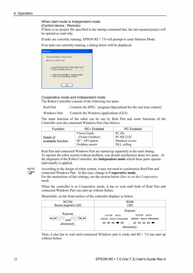
4. Operation
22 EPSON RC+ 7.0 (Ver.7.3) User's Guide Rev.4
When start mode is Independent mode (Control device : Remote) If there is no project file specified in the startup command line, the last-opened project will be opened as read only.
If tasks are currently running, EPSON RC+ 7.0 will prompt to enter Monitor Mode.
If no tasks are currently running, a dialog below will be displayed.
Cooperative mode and Independent mode The Robot Controller consists of the following two parts.
Real Part : Controls the SPEL+ program (Specialized for the real time control)
Windows Part : Controls the Windows applications (GUI)
The main function of the robot can be run by Real Part and some functions of the Controller uses the connected Windows Part (See below).
Function RC+ Enabled PC Enabled
Detail of available function
Vision Guide (Frame Grabber) RC+ API option Fieldbus master
PC file PC RS-232C Database access DLL calling
Real Part and connected Windows Part are started up separately at the each timing. To operate the robot system without problem, you should synchronize these two parts. At the shipment of the Robot Controller, the Independent mode which these parts operate individually is applied.
According to the design of robot system, it may not need to synchronize Real Part and connected Windows Part. In this case, change to Cooperative mode. For the instructions of this settings, see the section below How to set the Cooperative mode.
When the controller is in Cooperative mode, it has to wait until both of Real Part and connected Windows Part can start up without failure.
Meanwhile, on the front surface of the controller displays as below: RC700
Seven-segment LED RC90 LED
Repeats
and alternately.
Repeats
, alternately.
Then, it also has to wait until connected Windows part is ready and RC+ 7.0 can start up without failure.
NOTE
4. Operation
EPSON RC+ 7.0 (Ver.7.3) User's Guide Rev.4 23
The table below shows the startup sequence when the controller is in Cooperative mode:
RC700 Seven-segment LED
RC90 LED
Console instruction
Background task
(1) Power
ON
No display Blinking
Not available
Not started
yet
(2) Real Part starts up
Repeats
and alternately.
Repeats
and alternately.
Not available
Not started
yet
(3) Windows
part starts up
Repeats
and alternately.
and alternately.
Not available
Not started
yet
(4) RC+
starts up
Blinking Blinking
Available Already started
(Includes the startup of the Operator Window and RC+ API application)
The table below shows the startup sequence when the controller is in Independent mode:
RC700 Seven-segment LED
RC90 LED
Console instruction
Background task
(1) Power
ON
No display Blinking
Not available
Not started yet
(2) Real Part starts up
Blinking
Blinking
Available *1
Already started
(3) Windows
part starts up
Blinking
Blinking
Available *1 Running
(4) RC+
starts up
Blinking Blinking
Available Running
*1 When the control device is “PC”: It waits the command execution from the Operator Window or RC+ API application. When the control device is other than “PC”: (2) At Real Part starts up, Remote function becomes enable and starts operating.
When the controller is in Cooperative mode, the state does not back to wait for the RC+ connection even after RC+ shutdown. Also when the control device is other than “PC”, you need to be careful during the RC+ shutdown because the remote command is still executable.
NOTE
4. Operation
24 EPSON RC+ 7.0 (Ver.7.3) User's Guide Rev.4
How to set the Cooperative mode (1) Select [Setup]-[System Configuration] from the main menu and displays the [System
Configuration] dialog box as shown below.
(2) Select [SPEL Controller Board]-[Preferences].
(2)
(5)
(3)
(4)
(3) Uncheck the [Independent mode] checkbox.
(4) Click <Apply> button.
(5) Click the <Close> button.
4.2.2 Startup Configuration To configure startup, select [System Configuration] from the [Setup] menu. The [Startup] section has pages for Start Mode, Auto Start, and Windows Login.
4.2.3 Start Mode This page has settings for the EPSON RC+ 7.0 start mode.
There are two start modes:
Auto This mode starts the system and displays the Operator Window.
Program This mode allows you to develop your projects. This is the default startup mode.
Use the <Password> button to change the start mode password.
4. Operation
EPSON RC+ 7.0 (Ver.7.3) User's Guide Rev.4 25
4.2.4 Start Mode Dialog When the start mode is set for Auto, then a dialog is displayed at start up that allows you to change the startup mode using a password. After a few seconds, if the <Change To Program Mode> button has not been clicked, the system will initialize and the Operator Window will be displayed.
You can disable this startup dialog using command line options described later in this section, 4.2.10 Command Line Options.
If you click the <Change To Program Mode> button, another dialog will be displayed, as shown below:
To change to Program mode, you must supply the password and click <OK>, or you can abort startup all together by clicking <Cancel>.
This allows authorized personnel to enter Program mode temporarily to make changes or adjustments.
When you change to PROGRAM mode from this dialog, it is only temporary. The next time EPSON RC+ 7.0 runs, the original start mode setting will be used.
4.2.5 Start Mode: Program
Program mode is the default start mode. This is the EPSON RC+ 7.0 development environment, from which you can:
Create / edit projects. -
Configure the controller and set preferences. -
Run and debug programs. -
NOTE
4. Operation
26 EPSON RC+ 7.0 (Ver.7.3) User's Guide Rev.4
4.2.6 Start Mode: Auto Auto mode displays the Operator Window. The Operator Window is configured according to the settings in [Project]-[Properties].
The Auto mode is set by the control device as follows:
Control Device Description
PC The Operator Window can be used as a simple operator interface for production.
Remote I/O Remote Ethernet Remote RS232
TP3
The Operator window is displayed with no operator buttons to allow any diagnostic messages to be viewed.
4.2.7 Auto Start
You can configure EPSON RC+ 7.0 to automatically start when Windows starts.
From [Setup]-[System Configuration]-[Auto Start] page, set the [Start EPSON RC+ 7.0 after Windows start] check box.
In addition, if you set the checkbox above, you can specify EPSON RC+ 7.0 command line options (/auto, /nosplash, etc.) in the [Command line options] text box. Refer to the section 4.2.10 Command Line Options.
When the startup mode is Auto, a main function of the SPEL+ program can be started automatically. Check the [Auto start SPEL+ program in ## seconds] check box. Time from the EPSON RC+ 7.0 startup until a main function starts can be specified in the textbox on the right. In the example below, a main function starts 10 seconds after the EPSON RC+ 7.0 run. Startup of the main function can be aborted if it is within the specified time. When using auto start, ensure that your application can automatically start safely and inform operators how to abort the startup.
When using the Windows 8, select the [Desktop] tile on the start screen and then check if the EPSON RC+ 7.0 starts up automatically.
NOTE
NOTE
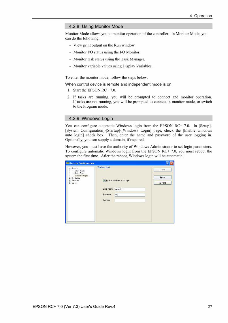
4. Operation
EPSON RC+ 7.0 (Ver.7.3) User's Guide Rev.4 27
4.2.8 Using Monitor Mode Monitor Mode allows you to monitor operation of the controller. In Monitor Mode, you can do the following:
- View print output on the Run window
- Monitor I/O status using the I/O Monitor.
- Monitor task status using the Task Manager.
- Monitor variable values using Display Variables.
To enter the monitor mode, follow the steps below.
When control device is remote and independent mode is on 1. Start the EPSON RC+ 7.0.
2. If tasks are running, you will be prompted to connect and monitor operation. If tasks are not running, you will be prompted to connect in monitor mode, or switch to the Program mode.
4.2.9 Windows Login
You can configure automatic Windows login from the EPSON RC+ 7.0. In [Setup]-[System Configuration]-[Startup]-[Windows Login] page, check the [Enable windows auto login] check box. Then, enter the name and password of the user logging in. Optionally, you can supply a domain, if required.
However, you must have the authority of Windows Administrator to set login parameters. To configure automatic Windows login from the EPSON RC+ 7.0, you must reboot the system the first time. After the reboot, Windows login will be automatic.
4. Operation
28 EPSON RC+ 7.0 (Ver.7.3) User's Guide Rev.4
4.2.10 Command Line Options Refer to 4.2.11 Using Command Line Options to see how to use the command line options.
There are command line options for the EPSON RC+ 7.0 that provide the following functions:
Starting EPSON RC+ 7.0 for a specific project When you start the EPSON RC+ 7.0, you can optionally specify a project name in the command line. ERC70.EXE [drive:project_name] drive:project_name The drive letter and name of a project. The name can include a
subfolder of the \EpsonRC70\Projects directory.
Example: Open project myapp on drive C: at startup: ERC70.EXE c:myapp
Change EPSON RC+ 7.0 startup mode You can select the startup mode and override the startup dialog using command line options.
To start in Program mode (no password required) ERC70.EXE /PROG
To start in Auto mode ERC70.EXE /AUTO
Use these command line options to override and hide the startup dialog and open the Operator Window directly.
If only the AUTO flag is supplied and the control device is PC, EPSON RC+ 7.0 will open the project from the last session and display the operator window. EPSON RC+ 7.0 will only be visible in the Windows Task Manager. When the operator window is closed, EPSON RC+ 7.0 will be terminated.
When the control device is PC, you cannot close the operator window while tasks are running.
Example: Open project myapp on drive C and display the operator window: ERC70.EXE c:myapp /AUTO
The Controller should be ON before starting EPSON RC+ 7.0 with the /AUTO command line option. If EPSON RC+ 7.0 cannot communicate with the controller, then an error message will be displayed with a retry button.
For more details, see 7.6 Operator Window.
Login You can automatically login from the command line if you are not using the Auto Login feature for the security Option: ERC70.EXE /LOGIN "userID", "password" This is especially useful when you are starting in operator mode.
If the user I/D or password is invalid, it will display an error dialog and exit the EPSON RC+ 7.0.
NOTE
NOTE
4. Operation
EPSON RC+ 7.0 (Ver.7.3) User's Guide Rev.4 29
Starting EPSON RC+ 7.0 specifying the language You can specify the language to use in EPSON RC+ 7.0 GUI.
Japanese : ERC70.EXE /LANG_JAPANESE *1 English : ERC70.EXE /LANG_ENGLISH German : ERC70.EXE /LANG_GERMAN *2 French : ERC70.EXE /LANG_FRENCH *2
Chinese (Simplified) : ERC70.EXE /LANG_CHINESE_SIMP *3
Chinese (Traditional) : ERC70.EXE /LANG_CHINESE_TRAD *3
*1 Available for Japanese OS *2 Available for English, German, and French OS *3 Available for Chinese OS
Disabling the EPSON RC+ 7.0 splash window You can suppress the splash window displayed at startup using the following syntax:
ERC70.EXE /NOSPLASH
4.2.11 Using Command Line Options
Examples of command line options are:
Running from the Windows Run Box You can specify a command from the Windows [Start] menu-[Run]-[Open] text box.
e.g. C:\EpsonRC70\exe\erc70.exe C:myapp
Making startup icons for your projects You can create icons that automatically start EPSON RC+ 7.0 for different projects and start Auto or Program modes.
1. Right click on your desktop and select [New]-[Shortcut].
2. Click <Browse…> in the [Create Shortcut] dialog box. Select “C:\EpsonRC70\exe\erc70.exe” and click the <OK> button. After the dialog changes, click the <Next> button.
3. Type a name for the shortcut and click <Finish>.
4. Right click the created icon and select [Properties]. Add an option such as “/AUTO” or “/PROG” to [Target:].
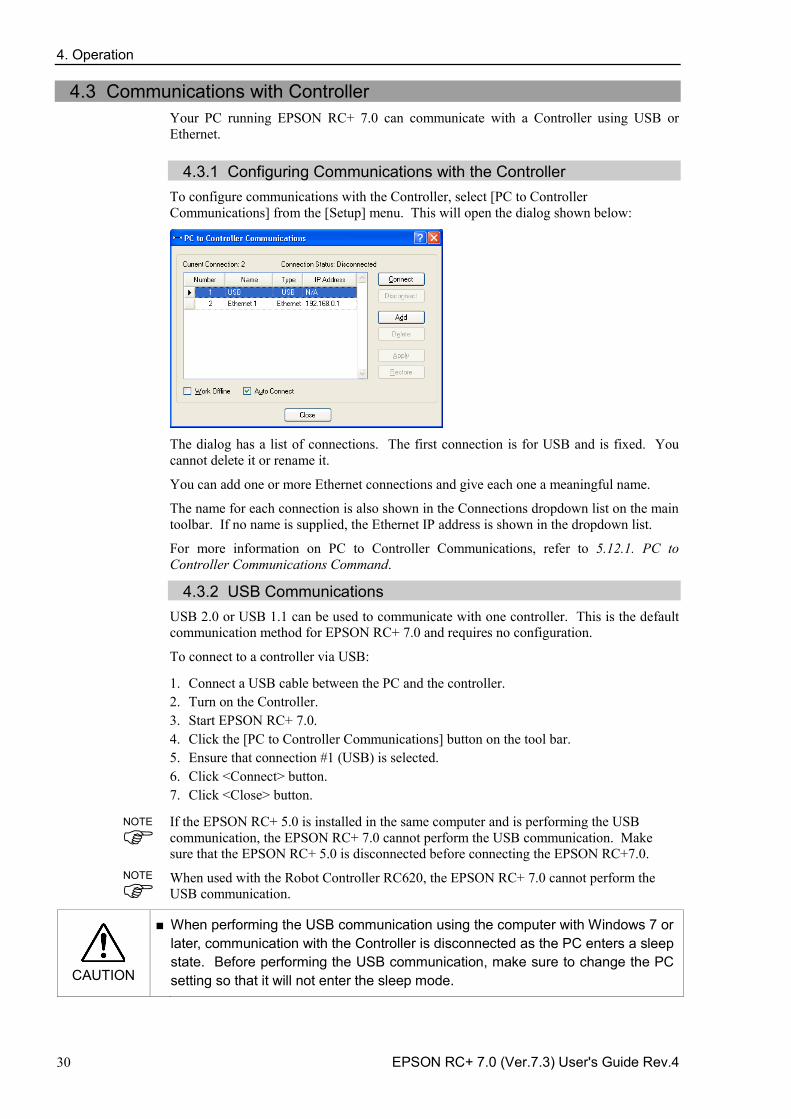
4. Operation
30 EPSON RC+ 7.0 (Ver.7.3) User's Guide Rev.4
4.3 Communications with Controller Your PC running EPSON RC+ 7.0 can communicate with a Controller using USB or Ethernet.
4.3.1 Configuring Communications with the Controller To configure communications with the Controller, select [PC to Controller Communications] from the [Setup] menu. This will open the dialog shown below:
The dialog has a list of connections. The first connection is for USB and is fixed. You cannot delete it or rename it.
You can add one or more Ethernet connections and give each one a meaningful name.
The name for each connection is also shown in the Connections dropdown list on the main toolbar. If no name is supplied, the Ethernet IP address is shown in the dropdown list.
For more information on PC to Controller Communications, refer to 5.12.1. PC to Controller Communications Command.
4.3.2 USB Communications USB 2.0 or USB 1.1 can be used to communicate with one controller. This is the default communication method for EPSON RC+ 7.0 and requires no configuration.
To connect to a controller via USB:
1. Connect a USB cable between the PC and the controller. 2. Turn on the Controller. 3. Start EPSON RC+ 7.0. 4. Click the [PC to Controller Communications] button on the tool bar. 5. Ensure that connection #1 (USB) is selected. 6. Click <Connect> button. 7. Click <Close> button. If the EPSON RC+ 5.0 is installed in the same computer and is performing the USB communication, the EPSON RC+ 7.0 cannot perform the USB communication. Make sure that the EPSON RC+ 5.0 is disconnected before connecting the EPSON RC+7.0.
When used with the Robot Controller RC620, the EPSON RC+ 7.0 cannot perform the USB communication.
CAUTION
■ When performing the USB communication using the computer with Windows 7 or later, communication with the Controller is disconnected as the PC enters a sleep state. Before performing the USB communication, make sure to change the PC setting so that it will not enter the sleep mode.
NOTE
NOTE
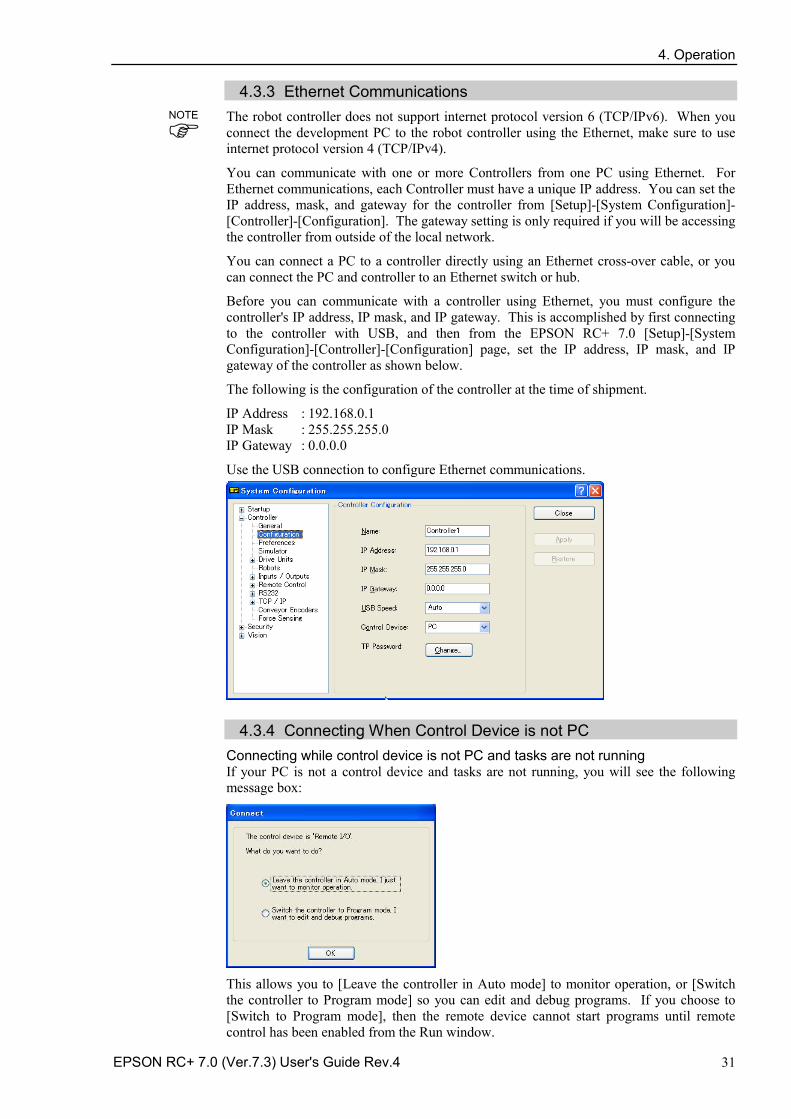
4. Operation
EPSON RC+ 7.0 (Ver.7.3) User's Guide Rev.4 31
4.3.3 Ethernet Communications The robot controller does not support internet protocol version 6 (TCP/IPv6). When you connect the development PC to the robot controller using the Ethernet, make sure to use internet protocol version 4 (TCP/IPv4).
You can communicate with one or more Controllers from one PC using Ethernet. For Ethernet communications, each Controller must have a unique IP address. You can set the IP address, mask, and gateway for the controller from [Setup]-[System Configuration]-[Controller]-[Configuration]. The gateway setting is only required if you will be accessing the controller from outside of the local network.
You can connect a PC to a controller directly using an Ethernet cross-over cable, or you can connect the PC and controller to an Ethernet switch or hub.
Before you can communicate with a controller using Ethernet, you must configure the controller's IP address, IP mask, and IP gateway. This is accomplished by first connecting to the controller with USB, and then from the EPSON RC+ 7.0 [Setup]-[System Configuration]-[Controller]-[Configuration] page, set the IP address, IP mask, and IP gateway of the controller as shown below.
The following is the configuration of the controller at the time of shipment.
IP Address : 192.168.0.1 IP Mask : 255.255.255.0 IP Gateway : 0.0.0.0
Use the USB connection to configure Ethernet communications.
4.3.4 Connecting When Control Device is not PC Connecting while control device is not PC and tasks are not running If your PC is not a control device and tasks are not running, you will see the following message box:
This allows you to [Leave the controller in Auto mode] to monitor operation, or [Switch the controller to Program mode] so you can edit and debug programs. If you choose to [Switch to Program mode], then the remote device cannot start programs until remote control has been enabled from the Run window.
NOTE
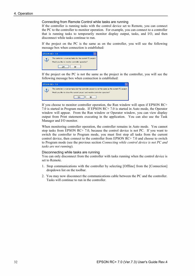
4. Operation
32 EPSON RC+ 7.0 (Ver.7.3) User's Guide Rev.4
Connecting from Remote Control while tasks are running If the controller is running tasks with the control device set to Remote, you can connect the PC to the controller to monitor operation. For example, you can connect to a controller that is running tasks to temporarily monitor display output, tasks, and I/O, and then disconnect while tasks continue to run.
If the project on the PC is the same as on the controller, you will see the following message box when connection is established:
If the project on the PC is not the same as the project in the controller, you will see the following message box when connection is established:
If you choose to monitor controller operation, the Run window will open if EPSON RC+ 7.0 is started in Program mode. If EPSON RC+ 7.0 is started in Auto mode, the Operator window will appear. From the Run window or Operator window, you can view display output from Print statements executing in the application. You can also use the Task Manager and I/O monitor.
When monitoring controller operation, the controller remains in Auto mode. You cannot stop tasks from EPSON RC+ 7.0, because the control device is not PC. If you want to switch the controller to Program mode, you must first stop all tasks from the current control device, then connect to the controller from EPSON RC+ 7.0 and choose to switch to Program mode (see the previous section Connecting while control device is not PC and tasks are not running).
Disconnecting while tasks are running You can only disconnect from the controller with tasks running when the control device is set to Remote.
1. Stop communications with the controller by selecting [Offline] from the [Connection] dropdown list on the toolbar.
2. You may now disconnect the communications cable between the PC and the controller. Tasks will continue to run in the controller.
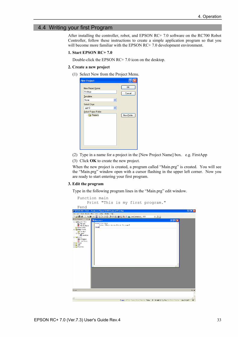
4. Operation
EPSON RC+ 7.0 (Ver.7.3) User's Guide Rev.4 33
4.4 Writing your first Program After installing the controller, robot, and EPSON RC+ 7.0 software on the RC700 Robot Controller, follow these instructions to create a simple application program so that you will become more familiar with the EPSON RC+ 7.0 development environment.
1. Start EPSON RC+ 7.0
Double-click the EPSON RC+ 7.0 icon on the desktop.
2. Create a new project
(1) Select New from the Project Menu.
(2) Type in a name for a project in the [New Project Name] box. e.g. FirstApp (3) Click OK to create the new project. When the new project is created, a program called “Main.prg” is created. You will see the “Main.prg” window open with a cursor flashing in the upper left corner. Now you are ready to start entering your first program.
3. Edit the program
Type in the following program lines in the “Main.prg” edit window. Function main Print "This is my first program." Fend
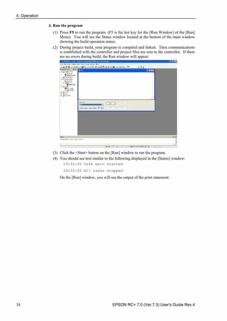
4. Operation
34 EPSON RC+ 7.0 (Ver.7.3) User's Guide Rev.4
4. Run the program
(1) Press F5 to run the program. (F5 is the hot key for the [Run Window] of the [Run] Menu). You will see the Status window located at the bottom of the main window showing the build operation status.
(2) During project build, your program is compiled and linked. Then communications is established with the controller and project files are sent to the controller. If there are no errors during build, the Run window will appear.
(3) Click the <Start> button on the [Run] window to run the program. (4) You should see text similar to the following displayed in the [Status] window:
19:32:45 Task main started
19:32:45 All tasks stopped
On the [Run] window, you will see the output of the print statement.
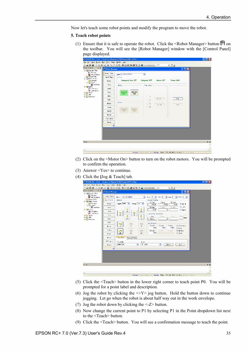
4. Operation
EPSON RC+ 7.0 (Ver.7.3) User's Guide Rev.4 35
Now let's teach some robot points and modify the program to move the robot.
5. Teach robot points
(1) Ensure that it is safe to operate the robot. Click the <Robot Manager> button on the toolbar. You will see the [Robot Manager] window with the [Control Panel] page displayed.
(2) Click on the <Motor On> button to turn on the robot motors. You will be prompted
to confirm the operation. (3) Answer <Yes> to continue. (4) Click the [Jog & Teach] tab.
(5) Click the <Teach> button in the lower right corner to teach point P0. You will be
prompted for a point label and description. (6) Jog the robot by clicking the <+Y> jog button. Hold the button down to continue
jogging. Let go when the robot is about half way out in the work envelope. (7) Jog the robot down by clicking the <-Z> button. (8) Now change the current point to P1 by selecting P1 in the Point dropdown list next
to the <Teach> button. (9) Click the <Teach> button. You will see a confirmation message to teach the point.
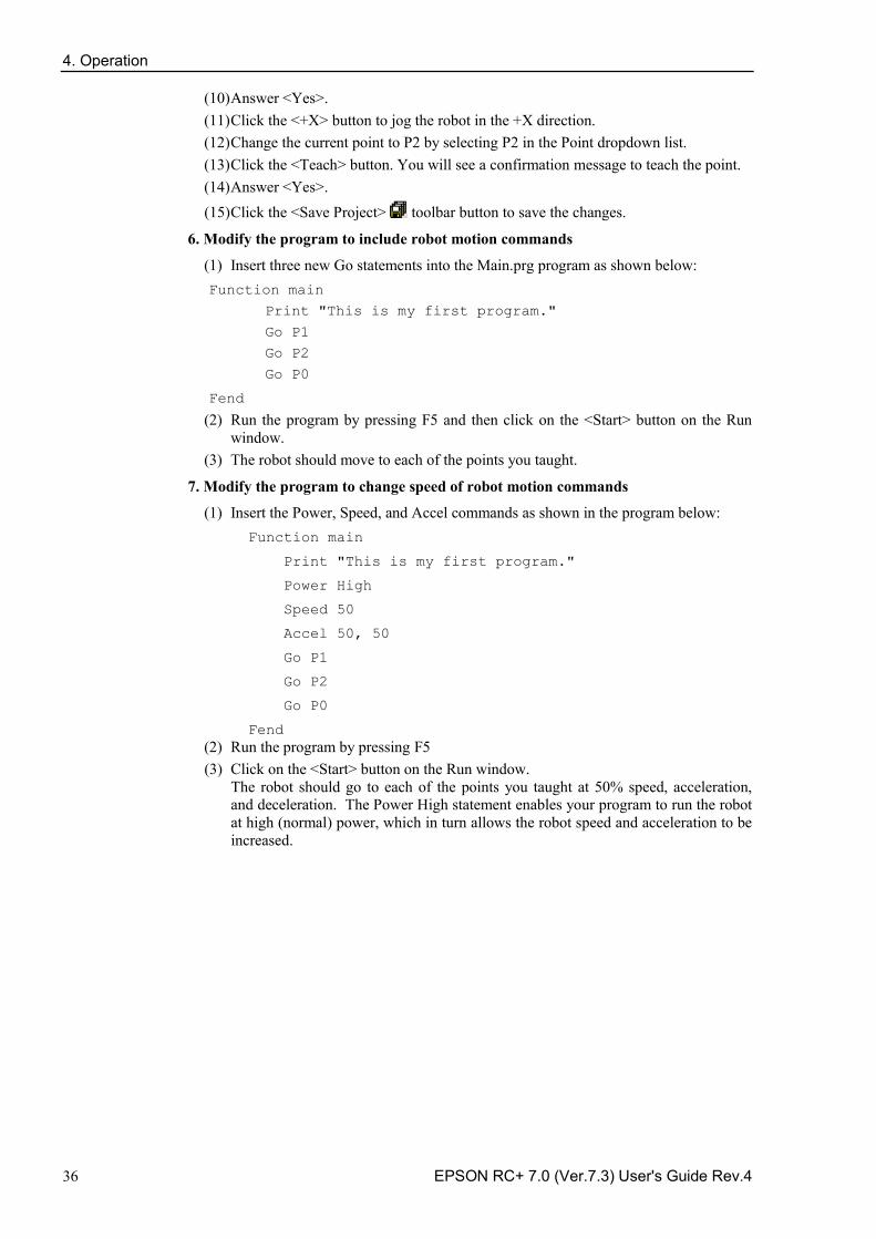
4. Operation
36 EPSON RC+ 7.0 (Ver.7.3) User's Guide Rev.4
(10) Answer <Yes>. (11) Click the <+X> button to jog the robot in the +X direction. (12) Change the current point to P2 by selecting P2 in the Point dropdown list. (13) Click the <Teach> button. You will see a confirmation message to teach the point. (14) Answer <Yes>. (15) Click the <Save Project> toolbar button to save the changes.
6. Modify the program to include robot motion commands
(1) Insert three new Go statements into the Main.prg program as shown below: Function main
Print "This is my first program."
Go P1
Go P2
Go P0
Fend
(2) Run the program by pressing F5 and then click on the <Start> button on the Run window.
(3) The robot should move to each of the points you taught.
7. Modify the program to change speed of robot motion commands
(1) Insert the Power, Speed, and Accel commands as shown in the program below: Function main
Print "This is my first program."
Power High
Speed 50
Accel 50, 50
Go P1
Go P2
Go P0
Fend (2) Run the program by pressing F5 (3) Click on the <Start> button on the Run window.
The robot should go to each of the points you taught at 50% speed, acceleration, and deceleration. The Power High statement enables your program to run the robot at high (normal) power, which in turn allows the robot speed and acceleration to be increased.
4. Operation
EPSON RC+ 7.0 (Ver.7.3) User's Guide Rev.4 37
8. Backup the project and system configuration
Even though this is only a sample project, we will backup the project and controller configuration. This is easy to do with EPSON RC+ 7.0. It is important that you keep regular backups of your applications on an external media such as a USB memory key.
Follow these steps to backup the project and system configuration:
(1) From the [Project] menu, select [Copy]. (2) Change the [Destination Drive] to an arbitrary drive. (3) Click <OK>. The project will be copied to the external media. (4) From the [Tools] menu, select [Controller]. (5) Click on the <Backup Controller> button. (6) Select the arbitrary drive. (7) Click <OK>. The system configuration will be backed up on the external media.
Now that you have written your first program, you should read 7.1.1 Creating the simplest application.
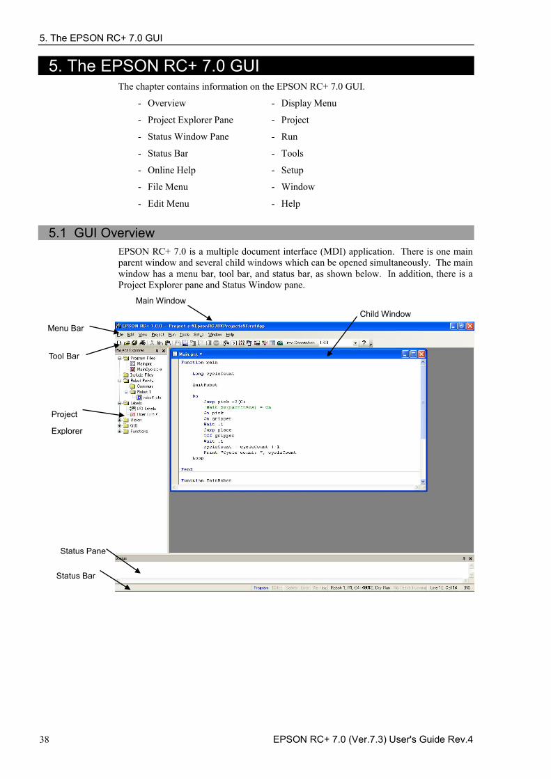
5. The EPSON RC+ 7.0 GUI
38 EPSON RC+ 7.0 (Ver.7.3) User's Guide Rev.4
5. The EPSON RC+ 7.0 GUI The chapter contains information on the EPSON RC+ 7.0 GUI.
Overview - Display Menu -
Project Explorer Pane - Project -
Status Window Pane - Run -
Status Bar - Tools -
Online Help - Setup -
File Menu - Window -
Edit Menu - Help -
5.1 GUI Overview
EPSON RC+ 7.0 is a multiple document interface (MDI) application. There is one main parent window and several child windows which can be opened simultaneously. The main window has a menu bar, tool bar, and status bar, as shown below. In addition, there is a Project Explorer pane and Status Window pane.
Main Window
Child Window
Menu Bar
Tool Bar
Project
Explorer
Status Pane
Status Bar
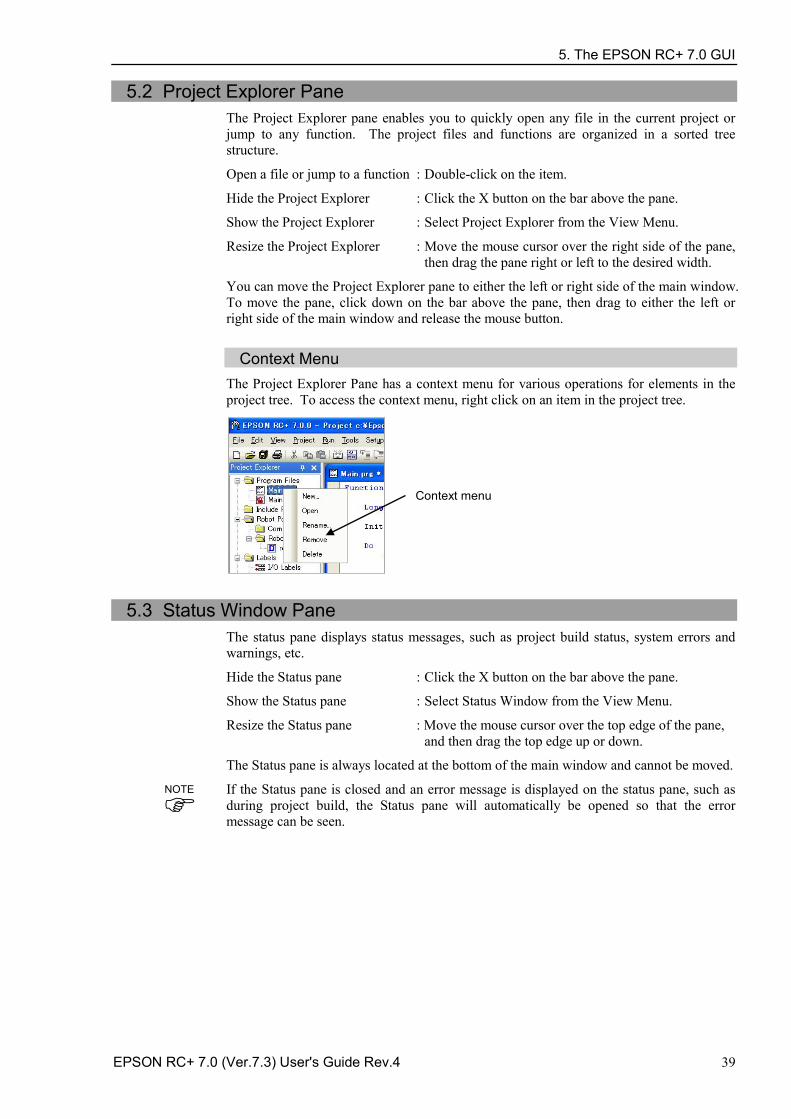
5. The EPSON RC+ 7.0 GUI
EPSON RC+ 7.0 (Ver.7.3) User's Guide Rev.4 39
5.2 Project Explorer Pane The Project Explorer pane enables you to quickly open any file in the current project or jump to any function. The project files and functions are organized in a sorted tree structure.
Open a file or jump to a function : Double-click on the item.
Hide the Project Explorer : Click the X button on the bar above the pane.
Show the Project Explorer : Select Project Explorer from the View Menu.
Resize the Project Explorer : Move the mouse cursor over the right side of the pane, then drag the pane right or left to the desired width.
You can move the Project Explorer pane to either the left or right side of the main window. To move the pane, click down on the bar above the pane, then drag to either the left or right side of the main window and release the mouse button.
Context Menu The Project Explorer Pane has a context menu for various operations for elements in the project tree. To access the context menu, right click on an item in the project tree.
Context menu
5.3 Status Window Pane The status pane displays status messages, such as project build status, system errors and warnings, etc.
Hide the Status pane : Click the X button on the bar above the pane.
Show the Status pane : Select Status Window from the View Menu.
Resize the Status pane : Move the mouse cursor over the top edge of the pane, and then drag the top edge up or down.
The Status pane is always located at the bottom of the main window and cannot be moved.
If the Status pane is closed and an error message is displayed on the status pane, such as during project build, the Status pane will automatically be opened so that the error message can be seen.
NOTE
5. The EPSON RC+ 7.0 GUI
40 EPSON RC+ 7.0 (Ver.7.3) User's Guide Rev.4
5.4 Status Bar The status bar located at the bottom of the main window displays the following:
Message area Displays the syntax error for the current line and system messages.
Operation Mode status Indicates the controller operation mode.
Emergency Stop status Indicates if emergency stop is active.
Safeguard status Indicates if one or more safeguard circuits is open.
Error status Indicates if the controller is in the error state. Put the mouse cursor over the Error status area to see the warning message.
Warning status Indicates if there is a warning. Put the mouse cursor over the Warning status area to see the warning message.
Current robot Displays the currently selected robot number, name, type number, and the dry run status.
Tasks running status Indicates that one or more tasks are running.
Current Line and Column When a program editor window is active, the current line and column are displayed.
INS / OVR status Indicates insert or overtype mode.
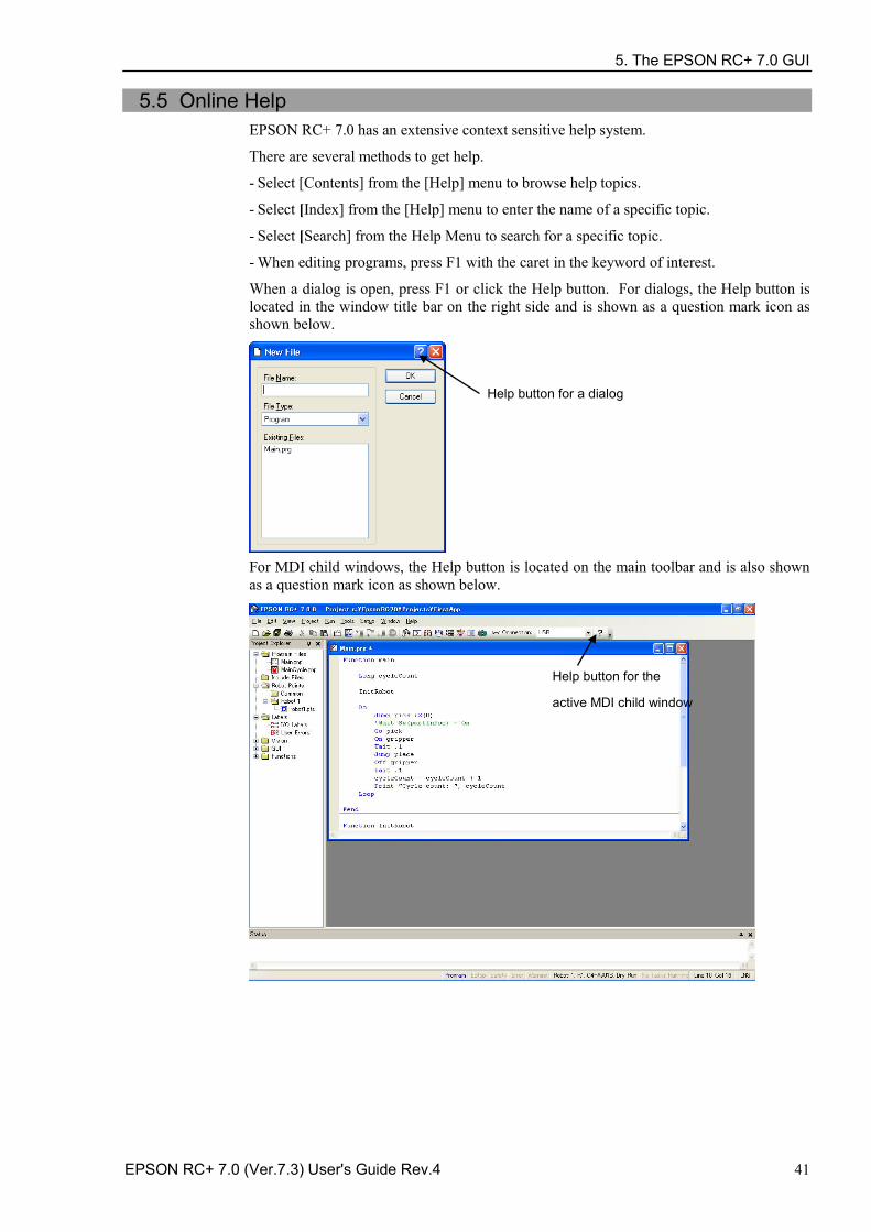
5. The EPSON RC+ 7.0 GUI
EPSON RC+ 7.0 (Ver.7.3) User's Guide Rev.4 41
5.5 Online Help EPSON RC+ 7.0 has an extensive context sensitive help system.
There are several methods to get help.
Select [Contents] from the [Help] menu to browse help topics. -
Select [Index] from the [Help] menu to enter the name of a specific topic. -
Select [Search] from the Help Menu to search for a specific topic. -
When editing programs, press F1 with the caret in the keyword of interest. -
When a dialog is open, press F1 or click the Help button. For dialogs, the Help button is located in the window title bar on the right side and is shown as a question mark icon as shown below.
Help button for a dialog
For MDI child windows, the Help button is located on the main toolbar and is also shown as a question mark icon as shown below.
Help button for the
active MDI child window
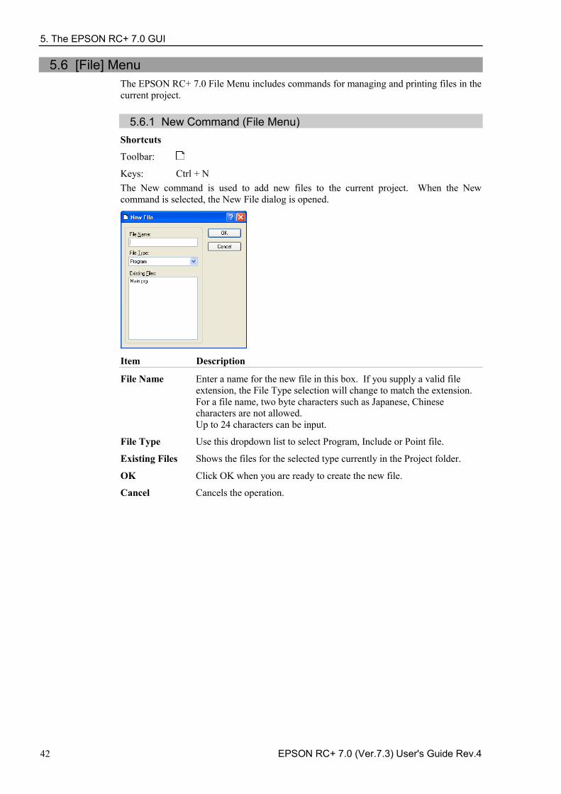
5. The EPSON RC+ 7.0 GUI
42 EPSON RC+ 7.0 (Ver.7.3) User's Guide Rev.4
5.6 [File] Menu The EPSON RC+ 7.0 File Menu includes commands for managing and printing files in the current project.
5.6.1 New Command (File Menu) Shortcuts
Toolbar:
Keys: Ctrl + N The New command is used to add new files to the current project. When the New command is selected, the New File dialog is opened.
Item Description
File Name Enter a name for the new file in this box. If you supply a valid file extension, the File Type selection will change to match the extension. For a file name, two byte characters such as Japanese, Chinese characters are not allowed. Up to 24 characters can be input.
File Type Use this dropdown list to select Program, Include or Point file.
Existing Files Shows the files for the selected type currently in the Project folder.
OK Click OK when you are ready to create the new file.
Cancel Cancels the operation.
5. The EPSON RC+ 7.0 GUI
EPSON RC+ 7.0 (Ver.7.3) User's Guide Rev.4 43
5.6.2 Open Command (File Menu) Shortcuts
Toolbar:
Keys: Ctrl + O Open one or more files in the current project for editing. You can open program files, include files, or point files.
If there is a file in the current project folder (as shown in the Edit Project dialog box) and the file is not in the current project, you will not be able to open the file. You must add the file to the project before you can open it. This also applies to include files and point files.
Item Description
Program Select this radio button to show a list of program files in the current project.
Include Select this radio button to show a list of include files in the current project.
Points Select this radio button to show a list of point files in the current project.
Select file to open Click on the file name you want to open. You can select more than one file by using the Ctrl key or Shift key. The Ctrl key allows you to select or deselect any file. The Shift key allows you to select a group of files.
Open Opens the selected file(s).
Cancel Cancels the open operation.
You can also double click on a file name in the [Select file to open] list box to open the file without having to choose the <OK> button.
5.6.3 Close Command (File Menu)
Shortcuts
Keys: Ctrl + D
Close the currently active window.
Any of the windows can be closed with this command: Programs, Include files, Point files, Command Window, Run window, I/O Label Editor, user errors.
You can also close a window or dialog box by double clicking on the control box button located in the upper left corner of the window or dialog box.
TIP
TIP
5. The EPSON RC+ 7.0 GUI
44 EPSON RC+ 7.0 (Ver.7.3) User's Guide Rev.4
5.6.4 Save Command (File Menu) Shortcuts
Keys: Ctrl + S
The [Save] command writes the current file to disk. The current file can be a program file, include file, points file, I/O label editor, etc. This command is disabled if the current file does not need to be saved.
5.6.5 Save As Command (File Menu)
Save the program, include file, or point file in the currently active window with a new file name. The original file will be removed from the project but will remain on the disk. The new name will be used throughout the current project in place of the old name.
If you use [Save As] on an include file, you must rename the file in each of your #include statements that refer to it. For a file name, two byte characters such as Japanese, Chinese characters are not allowed.
5.6.6 Restore Command (File Menu)
Restores the currently active program, include file, I/O labels, user errors, or point files from disk.
Use this function to change a document to the state it was in since last saved.
You will be prompted to confirm this operation.
5.6.7 Rename Command (File Menu)
Use [Rename] to change the name of the program, include file, or point file you are currently editing.
5. The EPSON RC+ 7.0 GUI
EPSON RC+ 7.0 (Ver.7.3) User's Guide Rev.4 45
To rename a file Click anywhere on the program window -
Select the Open command from the File Menu -
Select the Window from the Window Menu -
Select from the Window Menu list - Select Rename from the File Menu. Type in a new name for the file and click <OK>.
The new file name cannot be the same as the existing files. You will get an error message if you enter a new name that is already being used.
If you use [Rename] on an include file, you must rename the file in each of your #include statements that refer to it.
For a file name, two byte characters such as Japanese, Chinese characters are not allowed.
5.6.8 Delete Command (File Menu)
This command allows you to delete a file in the current project folder. You can delete program files, include files, and point files. The file does not have to be registered in the project to delete.
Item Description
Select file to delete Click on the file name you want to delete. This file list displays all .PRG, .INC, and .PTS files in the current project folder.
Delete Deletes the selected file. You will be prompted with a confirmation message before the file is deleted. If the file is currently open, it will be closed and removed from the current project before it is deleted from disk.
Cancel Cancels the delete operation.
5. The EPSON RC+ 7.0 GUI
46 EPSON RC+ 7.0 (Ver.7.3) User's Guide Rev.4
5.6.9 Import Command (File Menu) Import a file from other EPSON RC+ 7.0 projects. Use this command to import program files, include files, point files, I/O labels, user errors, and macros.
Program file names for importing must have a .PRG extension. -
Include file names for importing must have a .INC extension. -
Point file names for importing must have a .PTS extension. -
I/O labels must have the file name IOLABEL.DAT -
User errors must have the file name USERERRORS.DAT. -
Macros must have the .MAC extension. -
To import a file 1. Select the file type from the [File Type] list box.
2. Navigate to the file you want to import.
3. Click <Open> to continue. If a file name is already used in the project folder, you will be prompted to confirm overwrite. The file will then be copied to the current project's folder.
If you need to import files from previous versions of EPSON RC+ or from SPEL for Windows 2.0, you must first import the project using [Project]-[Import], which converts the point files and label files into EPSON RC+ 7.0 formats. Then you can use File Import to import the desired files.
NOTE
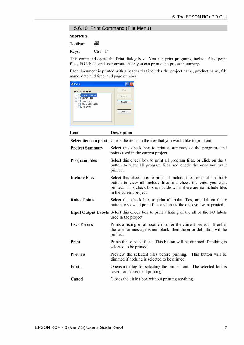
5. The EPSON RC+ 7.0 GUI
EPSON RC+ 7.0 (Ver.7.3) User's Guide Rev.4 47
5.6.10 Print Command (File Menu) Shortcuts
Toolbar:
Keys: Ctrl + P
This command opens the Print dialog box. You can print programs, include files, point files, I/O labels, and user errors. Also you can print out a project summary.
Each document is printed with a header that includes the project name, product name, file name, date and time, and page number.
Item Description
Select items to print Check the items in the tree that you would like to print out.
Project Summary Select this check box to print a summary of the programs and points used in the current project.
Program Files Select this check box to print all program files, or click on the + button to view all program files and check the ones you want printed.
Include Files Select this check box to print all include files, or click on the + button to view all include files and check the ones you want printed. This check box is not shown if there are no include files in the current project.
Robot Points Select this check box to print all point files, or click on the + button to view all point files and check the ones you want printed.
Input Output Labels Select this check box to print a listing of the all of the I/O labels used in the project.
User Errors Prints a listing of all user errors for the current project. If either the label or message is non-blank, then the error definition will be printed.
Print Prints the selected files. This button will be dimmed if nothing is selected to be printed.
Preview Preview the selected files before printing. This button will be dimmed if nothing is selected to be printed.
Font... Opens a dialog for selecting the printer font. The selected font is saved for subsequent printing.
Cancel Closes the dialog box without printing anything.
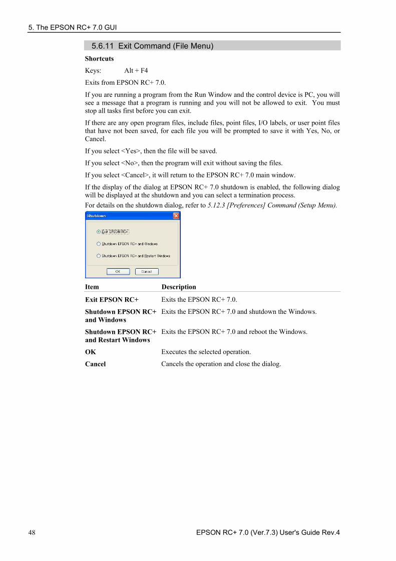
5. The EPSON RC+ 7.0 GUI
48 EPSON RC+ 7.0 (Ver.7.3) User's Guide Rev.4
5.6.11 Exit Command (File Menu) Shortcuts
Keys: Alt + F4
Exits from EPSON RC+ 7.0.
If you are running a program from the Run Window and the control device is PC, you will see a message that a program is running and you will not be allowed to exit. You must stop all tasks first before you can exit.
If there are any open program files, include files, point files, I/O labels, or user point files that have not been saved, for each file you will be prompted to save it with Yes, No, or Cancel.
If you select <Yes>, then the file will be saved.
If you select <No>, then the program will exit without saving the files.
If you select <Cancel>, it will return to the EPSON RC+ 7.0 main window.
If the display of the dialog at EPSON RC+ 7.0 shutdown is enabled, the following dialog will be displayed at the shutdown and you can select a termination process. For details on the shutdown dialog, refer to 5.12.3 [Preferences] Command (Setup Menu).
Item Description
Exit EPSON RC+ Exits the EPSON RC+ 7.0.
Shutdown EPSON RC+ and Windows
Exits the EPSON RC+ 7.0 and shutdown the Windows.
Shutdown EPSON RC+ and Restart Windows
Exits the EPSON RC+ 7.0 and reboot the Windows.
OK Executes the selected operation.
Cancel Cancels the operation and close the dialog.
5. The EPSON RC+ 7.0 GUI
EPSON RC+ 7.0 (Ver.7.3) User's Guide Rev.4 49
5.7 [Edit] Menu The EPSON RC+ 7.0 <Edit> menu includes commands for editing files.
You can also access the <Edit> menu by right-clicking anywhere in a program editor window.
5.7.1 [Undo] Command (Edit Menu) Shortcuts
Keys: Ctrl + Z
Undo the changes to the currently active program since it was open.
5.7.2 [Redo] Command (Edit Menu) Shortcuts
Keys: Ctrl+Y
Redo the previous undo.
5.7.3 [Cut] Command (Edit Menu) Shortcuts
Toolbar:
Keys: Ctrl + X
Copies the current selection into the Clipboard and then deletes the selection.
5.7.4 [Copy] Command (Edit Menu) Shortcuts
Toolbar:
Keys: Ctrl + C
Copies the current selection into the Clipboard.
5.7.5 [Paste] Command (Edit Menu) Shortcuts
Toolbar:
Keys: Ctrl + V
Puts the contents of the Clipboard into the currently active document starting at the insertion point.
TIP
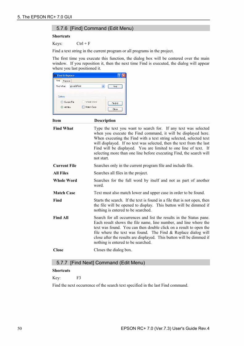
5. The EPSON RC+ 7.0 GUI
50 EPSON RC+ 7.0 (Ver.7.3) User's Guide Rev.4
5.7.6 [Find] Command (Edit Menu) Shortcuts
Keys: Ctrl + F
Find a text string in the current program or all programs in the project.
The first time you execute this function, the dialog box will be centered over the main window. If you reposition it, then the next time Find is executed, the dialog will appear where you last positioned it.
Item Description
Find What Type the text you want to search for. If any text was selected when you execute the Find command, it will be displayed here. When executing the Find with a text string selected, selected text will displayed. If no text was selected, then the text from the last Find will be displayed. You are limited to one line of text. If selecting more than one line before executing Find, the search will not start.
Current File Searches only in the current program file and include file.
All Files Searches all files in the project.
Whole Word Searches for the full word by itself and not as part of another word.
Match Case Text must also match lower and upper case in order to be found.
Find Starts the search. If the text is found in a file that is not open, then the file will be opened to display. This button will be dimmed if nothing is entered to be searched.
Find All Search for all occurrences and list the results in the Status pane. Each result shows the file name, line number, and line where the text was found. You can then double click on a result to open the file where the text was found. The Find & Replace dialog will close after the results are displayed. This button will be dimmed if nothing is entered to be searched.
Close Closes the dialog box.
5.7.7 [Find Next] Command (Edit Menu) Shortcuts
Key: F3
Find the next occurrence of the search text specified in the last Find command.
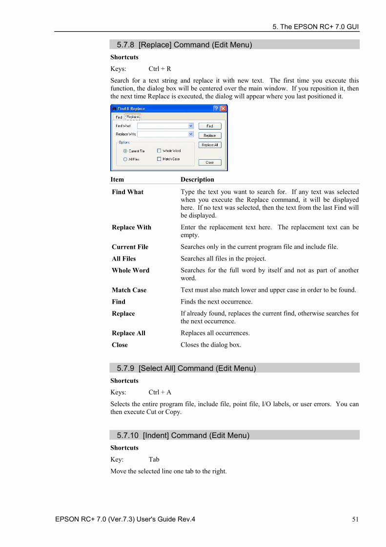
5. The EPSON RC+ 7.0 GUI
EPSON RC+ 7.0 (Ver.7.3) User's Guide Rev.4 51
5.7.8 [Replace] Command (Edit Menu) Shortcuts
Keys: Ctrl + R
Search for a text string and replace it with new text. The first time you execute this function, the dialog box will be centered over the main window. If you reposition it, then the next time Replace is executed, the dialog will appear where you last positioned it.
Item Description
Find What Type the text you want to search for. If any text was selected when you execute the Replace command, it will be displayed here. If no text was selected, then the text from the last Find will be displayed.
Replace With Enter the replacement text here. The replacement text can be empty.
Current File Searches only in the current program file and include file.
All Files Searches all files in the project.
Whole Word Searches for the full word by itself and not as part of another word.
Match Case Text must also match lower and upper case in order to be found.
Find Finds the next occurrence.
Replace If already found, replaces the current find, otherwise searches for the next occurrence.
Replace All Replaces all occurrences.
Close Closes the dialog box.
5.7.9 [Select All] Command (Edit Menu)
Shortcuts
Keys: Ctrl + A
Selects the entire program file, include file, point file, I/O labels, or user errors. You can then execute Cut or Copy.
5.7.10 [Indent] Command (Edit Menu)
Shortcuts
Key: Tab
Move the selected line one tab to the right.
5. The EPSON RC+ 7.0 GUI
52 EPSON RC+ 7.0 (Ver.7.3) User's Guide Rev.4
5.7.11 [Outdent] Command (Edit Menu) Shortcuts
Keys: Shift + Tab
Move the selected line one tab to the left.
5.7.12 [Comment Block] Command (Edit Menu)
Comments out the selected block of lines by adding the comment character to the beginning of each line.
To use, select one or more lines to be commented. Then :
Select Comment Block from the Edit Menu. -
Right click and select Comment Block from the Context Menu. -
A comment character will be added to the beginning of each of the selected lines.
5.7.13 [Uncomment Block] Command (Edit Menu)
Removes leading comment character from the selected block of lines.
To use, select one or more lines to be uncommented. Then:
Select Uncomment Block from the Edit Menu. -
Right click and select Uncomment Block from the Context Menu. -
The first comment character from each of the selected lines will be removed.
5.7.14 [Go To Definition] Command (Edit Menu)
Opens the window and sets the line where a function, variable, macro, point label, I/O label, or user error label is defined.
To use,
Click on an identifier in a program window, -and select Go To Definition from the Edit Menu.
Right click on the identifier, -and select Go To Definition from the Context Menu.
Identifier type Display
Function name or variable
Program window where a function name or variable is declared.
Pont label Point file which a label is defined.
I/O label I/O label editor which a label is defined.
User error label User error which a label is defined.
5. The EPSON RC+ 7.0 GUI
EPSON RC+ 7.0 (Ver.7.3) User's Guide Rev.4 53
5.8 [View] Menu The EPSON RC+ 7.0 View Menu includes commands for opening the Project Explorer and Status window. In addition, there is a command for viewing the system history.
5.8.1 [Project Explorer] Command (View Menu) If you have closed the [Project Explorer] pane, you can open it by using this command.
For details, refer to 5.2 Project Explorer Pane.
5.8.2 Status Window Command (View Menu) If you have closed the [Status Window] pane, you can open it by using this command.
For details, refer to 5.3 Status Window Pane.
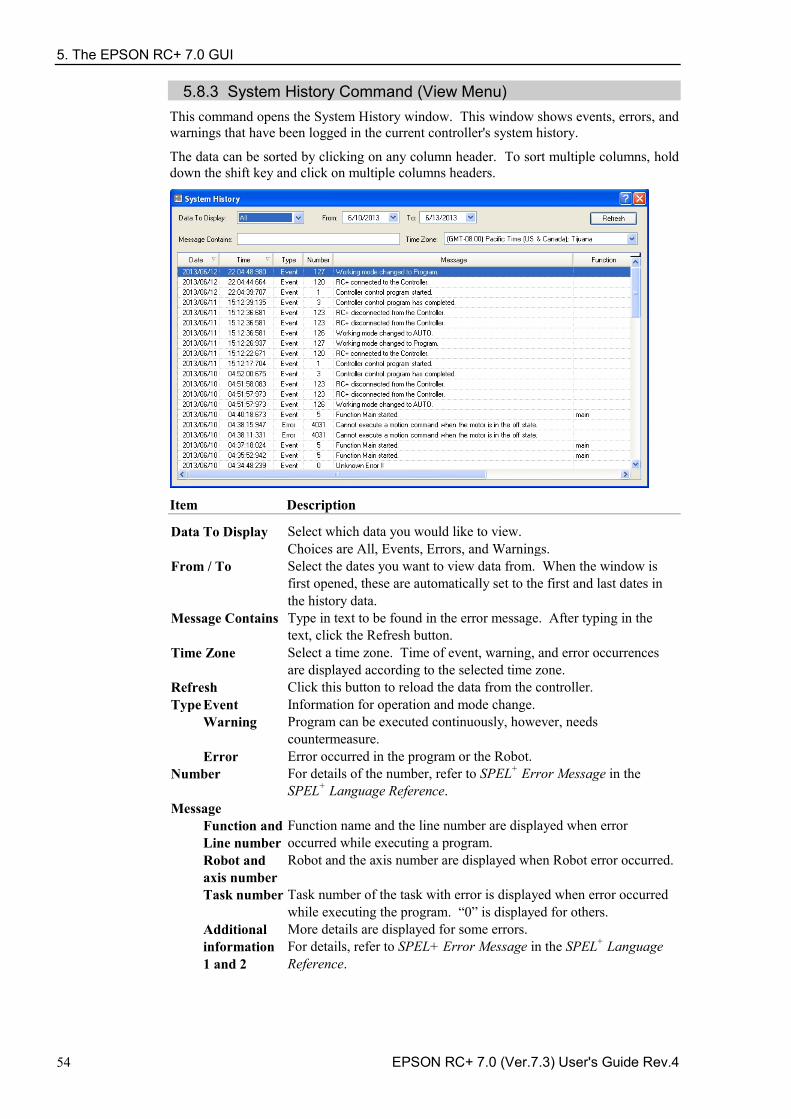
5. The EPSON RC+ 7.0 GUI
54 EPSON RC+ 7.0 (Ver.7.3) User's Guide Rev.4
5.8.3 System History Command (View Menu) This command opens the System History window. This window shows events, errors, and warnings that have been logged in the current controller's system history.
The data can be sorted by clicking on any column header. To sort multiple columns, hold down the shift key and click on multiple columns headers.
Item Description
Data To Display Select which data you would like to view. Choices are All, Events, Errors, and Warnings.
From / To Select the dates you want to view data from. When the window is first opened, these are automatically set to the first and last dates in the history data.
Message Contains Type in text to be found in the error message. After typing in the text, click the Refresh button.
Time Zone Select a time zone. Time of event, warning, and error occurrences are displayed according to the selected time zone.
Refresh Click this button to reload the data from the controller. Type Event Information for operation and mode change.
Warning Program can be executed continuously, however, needs countermeasure.
Error Error occurred in the program or the Robot. Number For details of the number, refer to SPEL+ Error Message in the
SPEL+ Language Reference. Message
Function and Line number
Function name and the line number are displayed when error occurred while executing a program.
Robot and axis number
Robot and the axis number are displayed when Robot error occurred.
Task number Task number of the task with error is displayed when error occurred while executing the program. “0” is displayed for others.
Additional information 1 and 2
More details are displayed for some errors. For details, refer to SPEL+ Error Message in the SPEL+ Language Reference.
5. The EPSON RC+ 7.0 GUI
EPSON RC+ 7.0 (Ver.7.3) User's Guide Rev.4 55
5.9 [Project] Menu The EPSON RC+ 7.0 Project Menu includes commands for managing and building projects.
5.9.1 [New] Command (Project Menu) The New command is used to create a new EPSON RC+ 7.0 project. Projects can be on any disk drive on the system. They are stored in the \EpsonRC70\Projects folder on the selected drive. Subfolder can also be created.
Item Description
Project Name Type in a new name for the project. The name can include alphanumeric characters along with underscores. For a project name, two byte characters such as Japanese, Chinese characters are not allowed.
Template Select a project template. The new project will be a copy of the template project.
Select Drive Select the desired disk drive for the new project.
Select Project Folder This is a list of folders and projects on the selected drive. If you click on a name in this list, it will be displayed in the New Project Name text box. You can then edit the name, or you can create a new project with the same name as one that has already been created. In the later case, you will be prompted to overwrite the old project if it is in the same folder.
New Folder Creates a new folder in the currently selected folder.
OK Creates the new project.
Cancel Aborts creating a new project.
5. The EPSON RC+ 7.0 GUI
56 EPSON RC+ 7.0 (Ver.7.3) User's Guide Rev.4
5.9.2 [Open] Command (Project Menu) Use this command to open an EPSON RC+ 7.0 project. When the project is opened, the previous project is closed. You will be prompted to save changes.
Item Description
Select Drive Select the desired disk drive for the project you want to open.
Select Project to Open Select a project name from the list box. To open a folder, double click on the folder or click the + box located to the left of the folder.
Read Only If you set this check box and open a project, you cannot edit the program file, include file, point file, I/O label, and user error.
Open Opens the selected project.
Cancel Cancels the operation.
Project Info Displays general project properties for the selected project. To view project information, first select a project in the list, then click the <Project Info> button.
Project information for a project can be changed by selecting [Properties] from the [Project] menu after opening the project.
NOTE
5. The EPSON RC+ 7.0 GUI
EPSON RC+ 7.0 (Ver.7.3) User's Guide Rev.4 57
5.9.3 Recent Projects Submenu (Project Menu) The Recent Projects submenu contains up to eight of the most recently used projects. When you select a project in the menu, the current project is closed and the selected project is opened the same as if you used the [Open] command from the [Project] menu.
5.9.4 [Close] Command (Project Menu) Use the [Close] command to close the current project. Several menu and toolbar commands will be disabled after the project is closed.
5.9.5 [Edit] Command (Project Menu) The [Edit] command is used to define which program files, include files, and point files are to be used in the current project. The [Project Files] contains a list of files in the current project folder. You can select which files to view from the [File Type] list box. The [Project Make] contains a project make tree that includes program files, include files, and point files.
The files shown in the file list are in the current project disk directory. Before you can use a file in the project, you must put it into the project make tree using the <Add> button.
To create a new program 1. Type the name of program file in the [File Name] text box in the Program Files section.
Add the PRG extension to the file name. For a file name, two byte characters such as Japanese, Chinese characters are not allowed.
2. Click the <Add> button. You will be prompted to create a new file. Answer <Yes> to create the file and put it in Program Files folder in the project make tree.
To add an existing program file
1. Select the Program in the [File Type] list box.
2. Select the program file name you want to add to the project from the list box.
3. Click the <Add> button, or double click on the program file name in the file list box.
The file will be added to the Program Files folder in the project make tree.
5. The EPSON RC+ 7.0 GUI
58 EPSON RC+ 7.0 (Ver.7.3) User's Guide Rev.4
To create a new include file 1. Type the name of the include file in the [File Name] text box.
Add the INC extension to the file name. The name of the include file can also be the same name as a program. For a file name, two byte characters such as Japanese, Chinese characters are not allowed.
2. Click the <Add> button. You will get a message asking if it is okay to create the new file. Click <Yes> to create the file and put it in the Include Files folder in the project make tree.
To add an existing include file to the project 1. Select Include in the <File Type> list box.
2. Select the include file name you want to add to the project from the list box.
3. Click the <Add> button, or double click on the include file name in the file list box. The file will be added to the list of include files of [Project Build] tree.
To add a new point file 1. Type the name of the point file you want to create into the [File Name] text box.
Add the PTS extension. For a project name, two byte characters such as Japanese, Chinese characters are not allowed.
2. Select the robot folder you want to register from the Robot Points folder in the [Project Build] tree.
3. Click the <Add> button. You will be prompted to create a new file. Click <Yes> to create the file and put it in the selected robot of the Robot Points folder.
To add an existing point file to the project
1. Select Points from the [File Type] list box.
2. Select the robot folder you want to register from the Robot Points folder in the [Project Build] tree.
3. Select the point file name you want to add to the project from the list.
4. Click the <Add> button. The file will be put in the selected robot of the Robot Points folder.
To remove a program file, include file, or point file 1. Select the file you want to remove in the [Project Build] tree.
2. Click the <Remove> button to remove the file from the [Project Build]. The file is not deleted from the project folder, so you will still see the file in the file list.
To add a new robot
Click the <New Robot> button. A robot will be added to the Robot Points folder in the [Project Build] tree.
To set a default point file 1. Select a point file to set as the default from each robot of Robot Points folder in the
[Project Build] tree.
2. Click the <Set as default> button. The file will be set as the default of the registered robot.
The common point file is a point file that is available for all robots on the controller. To use this point file, you need to load it from the SPEL+ program to the robot using LoadPoints command.
The default point file is a point file that is automatically loaded to a robot with the project load. Each robot can have one point file as the default.
NOTE
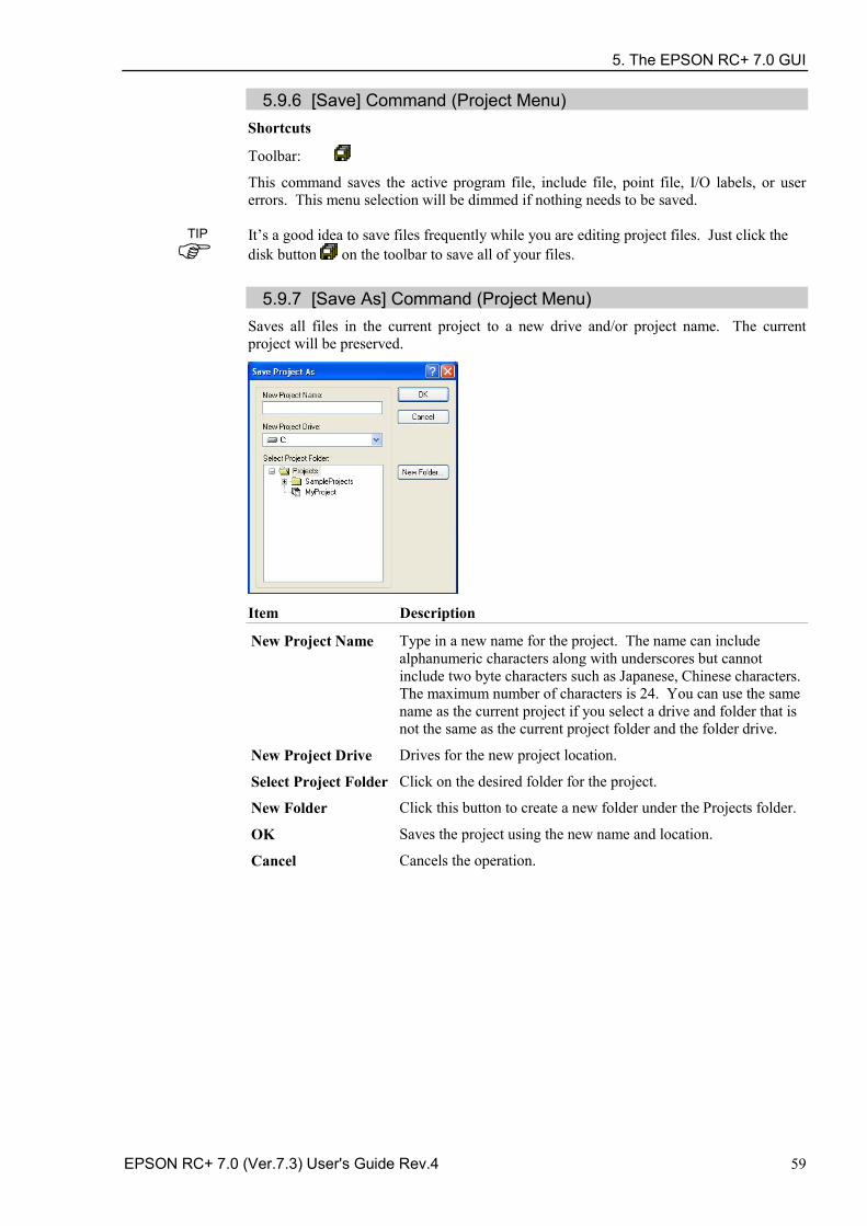
5. The EPSON RC+ 7.0 GUI
EPSON RC+ 7.0 (Ver.7.3) User's Guide Rev.4 59
5.9.6 [Save] Command (Project Menu) Shortcuts
Toolbar:
This command saves the active program file, include file, point file, I/O labels, or user errors. This menu selection will be dimmed if nothing needs to be saved.
It’s a good idea to save files frequently while you are editing project files. Just click the disk button on the toolbar to save all of your files.
5.9.7 [Save As] Command (Project Menu) Saves all files in the current project to a new drive and/or project name. The current project will be preserved.
Item Description
New Project Name Type in a new name for the project. The name can include alphanumeric characters along with underscores but cannot include two byte characters such as Japanese, Chinese characters. The maximum number of characters is 24. You can use the same name as the current project if you select a drive and folder that is not the same as the current project folder and the folder drive.
New Project Drive Drives for the new project location.
Select Project Folder Click on the desired folder for the project.
New Folder Click this button to create a new folder under the Projects folder.
OK Saves the project using the new name and location.
Cancel Cancels the operation.
TIP
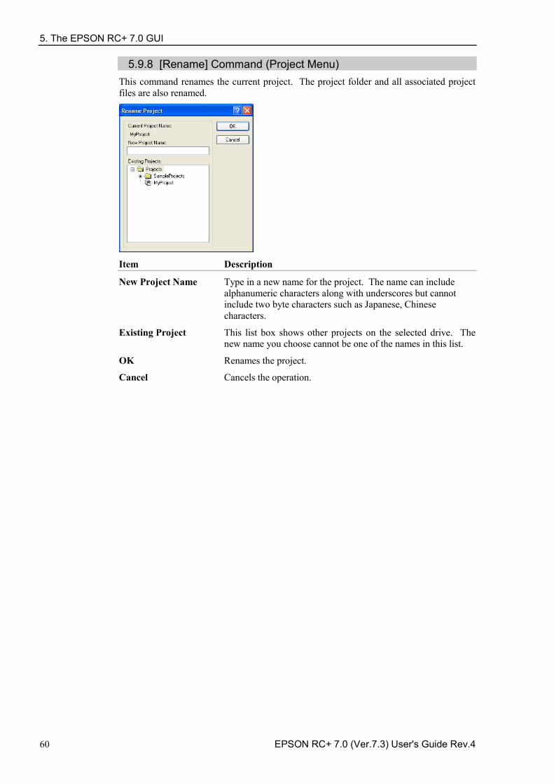
5. The EPSON RC+ 7.0 GUI
60 EPSON RC+ 7.0 (Ver.7.3) User's Guide Rev.4
5.9.8 [Rename] Command (Project Menu) This command renames the current project. The project folder and all associated project files are also renamed.
Item Description
New Project Name Type in a new name for the project. The name can include alphanumeric characters along with underscores but cannot include two byte characters such as Japanese, Chinese characters.
Existing Project This list box shows other projects on the selected drive. The new name you choose cannot be one of the names in this list.
OK Renames the project.
Cancel Cancels the operation.
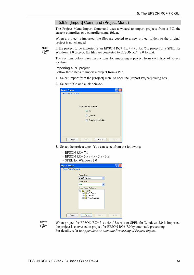
5. The EPSON RC+ 7.0 GUI
EPSON RC+ 7.0 (Ver.7.3) User's Guide Rev.4 61
5.9.9 [Import] Command (Project Menu) The Project Menu Import Command uses a wizard to import projects from a PC, the current controller, or a controller status folder.
When a project is imported, the files are copied to a new project folder, so the original project is not changed.
If the project to be imported is an EPSON RC+ 3.x / 4.x / 5.x /6.x project or a SPEL for Windows 2.0 project, the files are converted to EPSON RC+ 7.0 format.
The sections below have instructions for importing a project from each type of source location.
Importing a PC project Follow these steps to import a project from a PC:
1. Select Import from the [Project] menu to open the [Import Project] dialog box.
2. Select <PC> and click <Next>.
3. Select the project type. You can select from the following:
- EPSON RC+ 7.0 - EPSON RC+ 3.x / 4.x / 5.x / 6.x - SPEL for Windows 2.0
When project for EPSON RC+ 3.x / 4.x / 5.x /6.x or SPEL for Windows 2.0 is imported, the project is converted to project for EPSON RC+ 7.0 by automatic processing. For details, refer to Appendix A: Automatic Processing of Project Import.
NOTE
NOTE
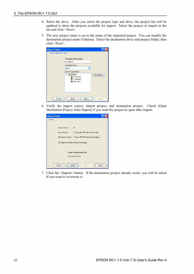
5. The EPSON RC+ 7.0 GUI
62 EPSON RC+ 7.0 (Ver.7.3) User's Guide Rev.4
4. Select the drive. After you select the project type and drive, the project list will be updated to show the projects available for import. Select the project to import in the list and click <Next>.
5. The new project name is set to the name of the imported project. You can modify the destination project name if desired. Select the destination drive and project folder, then click <Next>.
6. Verify the import source, import project, and destination project. Check [Open
Destination Project After Import] if you want the project to open after import.
7. Click the <Import> button. If the destination project already exists, you will be asked
if you want to overwrite it.
5. The EPSON RC+ 7.0 GUI
EPSON RC+ 7.0 (Ver.7.3) User's Guide Rev.4 63
Importing a Controller project Follow these steps to import a project from a controller:
1. Select Import from the [Project] menu to open the [Import Project] dialog box. 2. Select <Controller> and click <Next>.
3. The new project name is set to the name of the current project in the controller. You
can modify the new project name if desired. Select the destination drive and project folder, then click <Next>.
4. Verify the import source, import project, and destination project. Check [Open
Destination Project After Import] if you want the project to open after import.
5. Click the <Import> button. If the destination project already exists, you will be asked
if you want to overwrite it. 6. The project in the destination project will be built.
5. The EPSON RC+ 7.0 GUI
64 EPSON RC+ 7.0 (Ver.7.3) User's Guide Rev.4
Importing a Controller Status project
The projects using Vision Guide cannot be imported from the Controller Status Folder.
Follow these steps to import a project from a Controller Status Folder:
1. Select [Import] from the [Project] menu to open the [Import Project] dialog box. 2. Select <Controller Status Folder> and click [Next].
3. Select a controller status folder and click <OK>.
4. The new project name is set to the project found in the controller status folder. You
can modify the new project name if desired. Select the destination drive and folder, then click <Next>.
NOTE
5. The EPSON RC+ 7.0 GUI
EPSON RC+ 7.0 (Ver.7.3) User's Guide Rev.4 65
5. Verify the import source, import project, and destination project. Check [Open Destination Project After Import] if you want the project to open after import.
6. Click the <Import> button. If the destination project already exists, you will be asked
if you want to overwrite it.
5.9.10 [Export] Command (Project Menu)
The Project Menu Export Command uses a wizard to export projects to EPSON RC+ 6.0 projects.
When a project is exported, the files are copied to a new project folder, so the original project is not changed.
SPEL+ commands and syntax added to the EPSON RC+ 7.0 are not supported by EPSON RC+ 6.0. It is recommended to change the compiler version according to the version of your controller and check the compatibility before exporting projects. For details, refer to [Project]-[Properties]-[Compiler] Page in 5.9.15 [Properties] Command (Project Menu).
Follow these steps to export a project:
1. Select EPSON RC+ 7.0 menu-[Project]-[Export] to display the [Export Project] dialog. 2. Select a drive. A project list will be refreshed and exportable projects will be displayed.
Select a project you want to export from the list and click <Next> button.
NOTE
5. The EPSON RC+ 7.0 GUI
66 EPSON RC+ 7.0 (Ver.7.3) User's Guide Rev.4
3. Name of a new project is set to the name of the exported project. The name of the new project can be changed. Select the destination drive and project folder. Then, click <Next>.
4. Confirm the export source and destination.
5. Click <Export>. If the destination already exists, you will be asked whether or not to
overwrite the project.
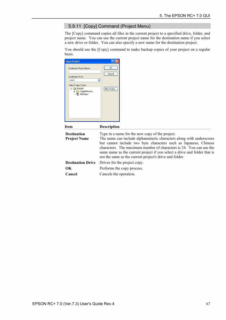
5. The EPSON RC+ 7.0 GUI
EPSON RC+ 7.0 (Ver.7.3) User's Guide Rev.4 67
5.9.11 [Copy] Command (Project Menu) The [Copy] command copies all files in the current project to a specified drive, folder, and project name. You can use the current project name for the destination name if you select a new drive or folder. You can also specify a new name for the destination project.
You should use the [Copy] command to make backup copies of your project on a regular basis.
Item Description
Destination Project Name
Type in a name for the new copy of the project. The name can include alphanumeric characters along with underscores but cannot include two byte characters such as Japanese, Chinese characters. The maximum number of characters is 24. You can use the same name as the current project if you select a drive and folder that is not the same as the current project's drive and folder.
Destination Drive Drives for the project copy. OK Performs the copy process. Cancel Cancels the operation.
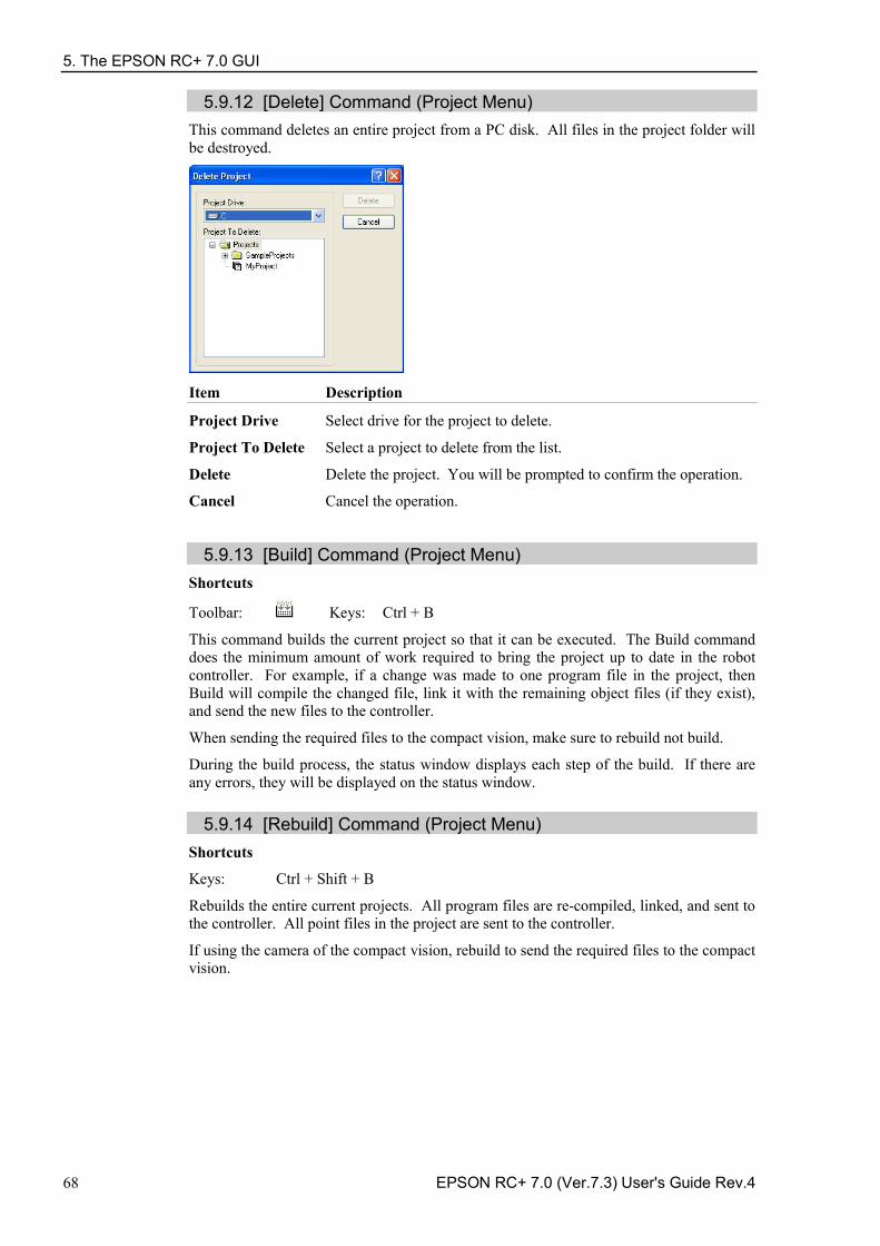
5. The EPSON RC+ 7.0 GUI
68 EPSON RC+ 7.0 (Ver.7.3) User's Guide Rev.4
5.9.12 [Delete] Command (Project Menu) This command deletes an entire project from a PC disk. All files in the project folder will be destroyed.
Item Description
Project Drive Select drive for the project to delete.
Project To Delete Select a project to delete from the list.
Delete Delete the project. You will be prompted to confirm the operation.
Cancel Cancel the operation.
5.9.13 [Build] Command (Project Menu)
Shortcuts
Toolbar: Keys: Ctrl + B
This command builds the current project so that it can be executed. The Build command does the minimum amount of work required to bring the project up to date in the robot controller. For example, if a change was made to one program file in the project, then Build will compile the changed file, link it with the remaining object files (if they exist), and send the new files to the controller.
When sending the required files to the compact vision, make sure to rebuild not build.
During the build process, the status window displays each step of the build. If there are any errors, they will be displayed on the status window.
5.9.14 [Rebuild] Command (Project Menu) Shortcuts
Keys: Ctrl + Shift + B
Rebuilds the entire current projects. All program files are re-compiled, linked, and sent to the controller. All point files in the project are sent to the controller.
If using the camera of the compact vision, rebuild to send the required files to the compact vision.
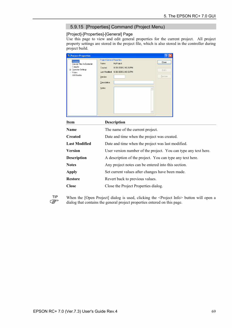
5. The EPSON RC+ 7.0 GUI
EPSON RC+ 7.0 (Ver.7.3) User's Guide Rev.4 69
5.9.15 [Properties] Command (Project Menu) [Project]-[Properties]-[General] Page Use this page to view and edit general properties for the current project. All project property settings are stored in the project file, which is also stored in the controller during project build.
Item Description
Name The name of the current project.
Created Date and time when the project was created.
Last Modified Date and time when the project was last modified.
Version User version number of the project. You can type any text here.
Description A description of the project. You can type any text here.
Notes Any project notes can be entered into this section.
Apply Set current values after changes have been made.
Restore Revert back to previous values.
Close Close the Project Properties dialog.
When the [Open Project] dialog is used, clicking the <Project Info> button will open a dialog that contains the general project properties entered on this page.
TIP
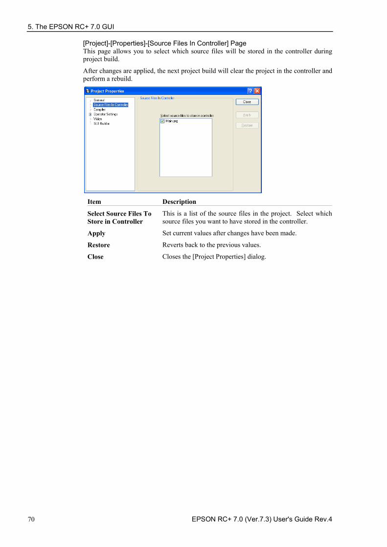
5. The EPSON RC+ 7.0 GUI
70 EPSON RC+ 7.0 (Ver.7.3) User's Guide Rev.4
[Project]-[Properties]-[Source Files In Controller] Page This page allows you to select which source files will be stored in the controller during project build.
After changes are applied, the next project build will clear the project in the controller and perform a rebuild.
Item Description
Select Source Files To Store in Controller
This is a list of the source files in the project. Select which source files you want to have stored in the controller.
Apply Set current values after changes have been made.
Restore Reverts back to the previous values.
Close Closes the [Project Properties] dialog.
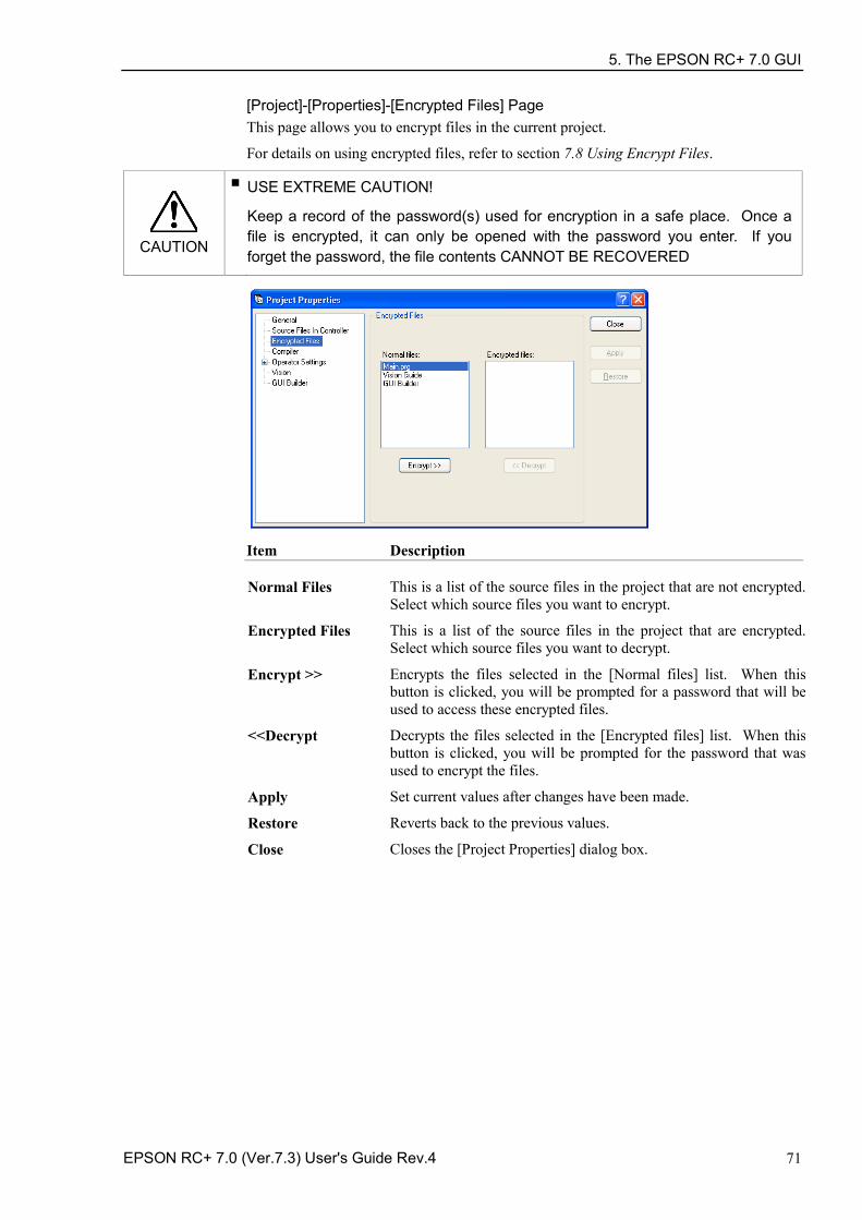
5. The EPSON RC+ 7.0 GUI
EPSON RC+ 7.0 (Ver.7.3) User's Guide Rev.4 71
[Project]-[Properties]-[Encrypted Files] Page This page allows you to encrypt files in the current project.
For details on using encrypted files, refer to section 7.8 Using Encrypt Files.
CAUTION
■ USE EXTREME CAUTION!
Keep a record of the password(s) used for encryption in a safe place. Once a file is encrypted, it can only be opened with the password you enter. If you forget the password, the file contents CANNOT BE RECOVERED
Item Description
Normal Files This is a list of the source files in the project that are not encrypted. Select which source files you want to encrypt.
Encrypted Files This is a list of the source files in the project that are encrypted. Select which source files you want to decrypt.
Encrypt >> Encrypts the files selected in the [Normal files] list. When this button is clicked, you will be prompted for a password that will be used to access these encrypted files.
<<Decrypt Decrypts the files selected in the [Encrypted files] list. When this button is clicked, you will be prompted for the password that was used to encrypt the files.
Apply Set current values after changes have been made.
Restore Reverts back to the previous values.
Close Closes the [Project Properties] dialog box.
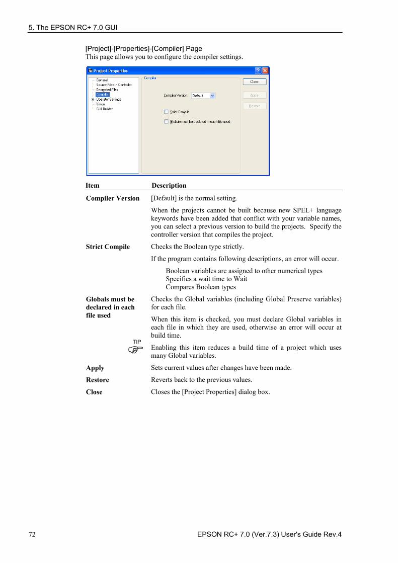
5. The EPSON RC+ 7.0 GUI
72 EPSON RC+ 7.0 (Ver.7.3) User's Guide Rev.4
[Project]-[Properties]-[Compiler] Page This page allows you to configure the compiler settings.
Item Description
Compiler Version [Default] is the normal setting.
When the projects cannot be built because new SPEL+ language keywords have been added that conflict with your variable names, you can select a previous version to build the projects. Specify the controller version that compiles the project.
Strict Compile Checks the Boolean type strictly.
If the program contains following descriptions, an error will occur.
Boolean variables are assigned to other numerical types Specifies a wait time to Wait Compares Boolean types
Globals must be declared in each file used
Checks the Global variables (including Global Preserve variables) for each file.
When this item is checked, you must declare Global variables in each file in which they are used, otherwise an error will occur at build time.
Enabling this item reduces a build time of a project which uses many Global variables.
Apply Sets current values after changes have been made.
Restore Reverts back to the previous values.
Close Closes the [Project Properties] dialog box.
TIP
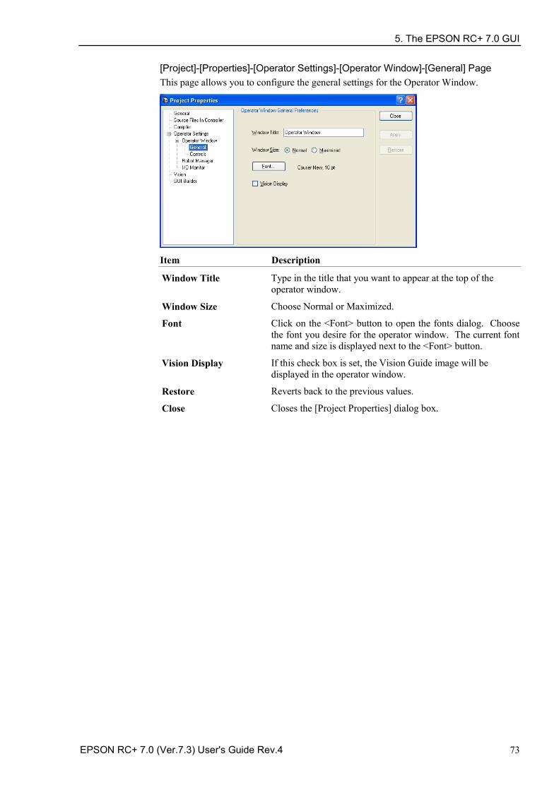
5. The EPSON RC+ 7.0 GUI
EPSON RC+ 7.0 (Ver.7.3) User's Guide Rev.4 73
[Project]-[Properties]-[Operator Settings]-[Operator Window]-[General] Page This page allows you to configure the general settings for the Operator Window.
Item Description
Window Title Type in the title that you want to appear at the top of the operator window.
Window Size Choose Normal or Maximized.
Font Click on the <Font> button to open the fonts dialog. Choose the font you desire for the operator window. The current font name and size is displayed next to the <Font> button.
Vision Display If this check box is set, the Vision Guide image will be displayed in the operator window.
Restore Reverts back to the previous values.
Close Closes the [Project Properties] dialog box.
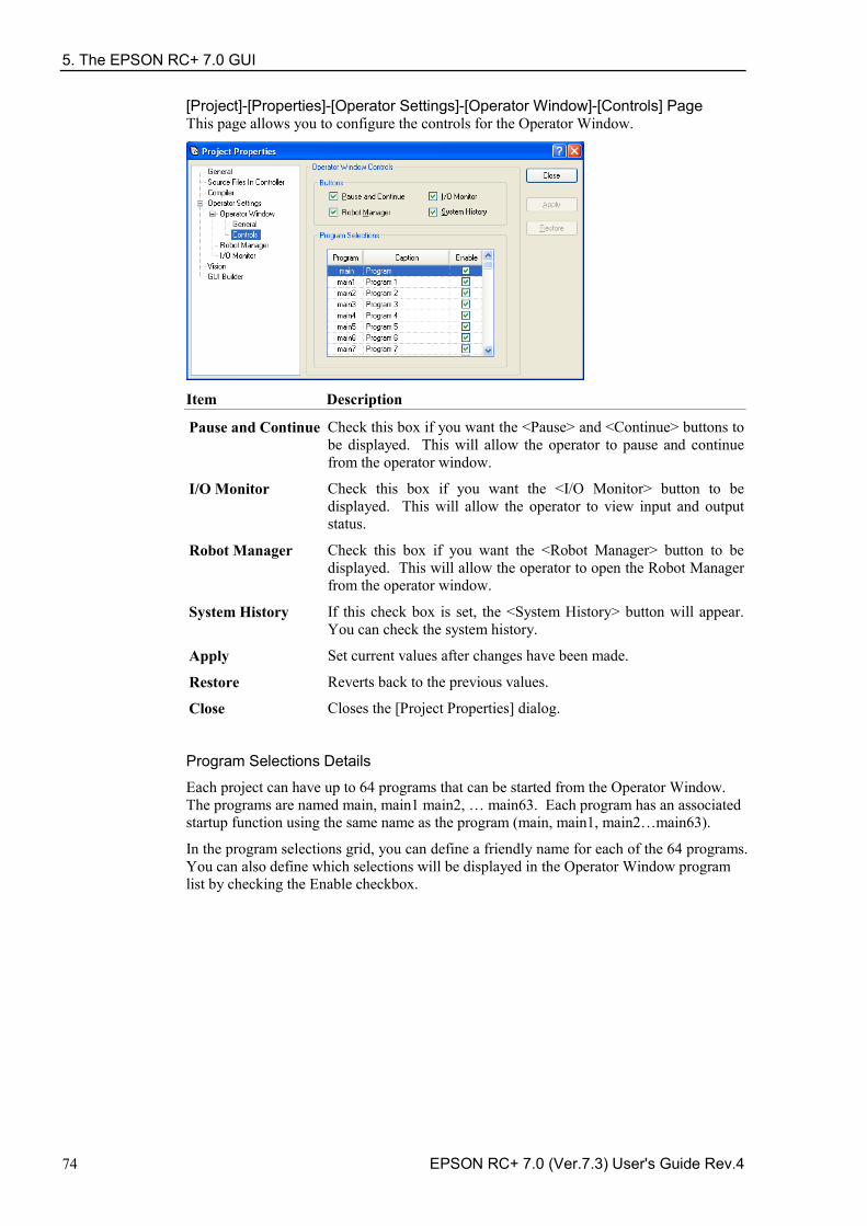
5. The EPSON RC+ 7.0 GUI
74 EPSON RC+ 7.0 (Ver.7.3) User's Guide Rev.4
[Project]-[Properties]-[Operator Settings]-[Operator Window]-[Controls] Page This page allows you to configure the controls for the Operator Window.
Item Description
Pause and Continue Check this box if you want the <Pause> and <Continue> buttons to be displayed. This will allow the operator to pause and continue from the operator window.
I/O Monitor Check this box if you want the <I/O Monitor> button to be displayed. This will allow the operator to view input and output status.
Robot Manager Check this box if you want the <Robot Manager> button to be displayed. This will allow the operator to open the Robot Manager from the operator window.
System History If this check box is set, the <System History> button will appear. You can check the system history.
Apply Set current values after changes have been made.
Restore Reverts back to the previous values.
Close Closes the [Project Properties] dialog.
Program Selections Details
Each project can have up to 64 programs that can be started from the Operator Window. The programs are named main, main1 main2, … main63. Each program has an associated startup function using the same name as the program (main, main1, main2…main63).
In the program selections grid, you can define a friendly name for each of the 64 programs. You can also define which selections will be displayed in the Operator Window program list by checking the Enable checkbox.
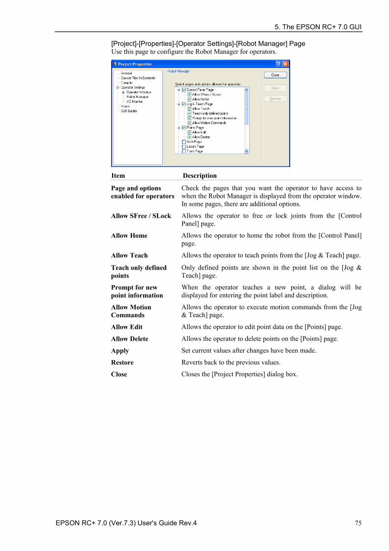
5. The EPSON RC+ 7.0 GUI
EPSON RC+ 7.0 (Ver.7.3) User's Guide Rev.4 75
[Project]-[Properties]-[Operator Settings]-[Robot Manager] Page Use this page to configure the Robot Manager for operators.
Item Description
Page and options enabled for operators
Check the pages that you want the operator to have access to when the Robot Manager is displayed from the operator window. In some pages, there are additional options.
Allow SFree / SLock Allows the operator to free or lock joints from the [Control Panel] page.
Allow Home Allows the operator to home the robot from the [Control Panel] page.
Allow Teach Allows the operator to teach points from the [Jog & Teach] page.
Teach only defined points
Only defined points are shown in the point list on the [Jog & Teach] page.
Prompt for new point information
When the operator teaches a new point, a dialog will be displayed for entering the point label and description.
Allow Motion Commands
Allows the operator to execute motion commands from the [Jog & Teach] page.
Allow Edit Allows the operator to edit point data on the [Points] page.
Allow Delete Allows the operator to delete points on the [Points] page.
Apply Set current values after changes have been made.
Restore Reverts back to the previous values.
Close Closes the [Project Properties] dialog box.
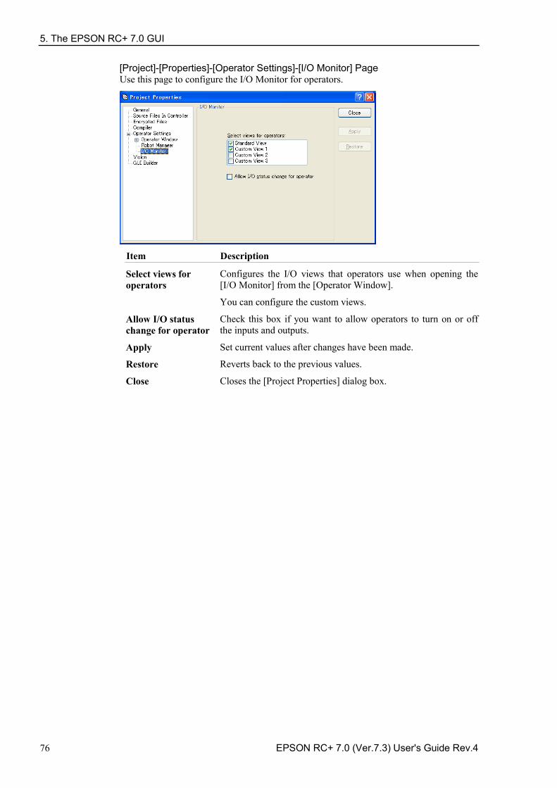
5. The EPSON RC+ 7.0 GUI
76 EPSON RC+ 7.0 (Ver.7.3) User's Guide Rev.4
[Project]-[Properties]-[Operator Settings]-[I/O Monitor] Page Use this page to configure the I/O Monitor for operators.
Item Description
Select views for operators
Configures the I/O views that operators use when opening the [I/O Monitor] from the [Operator Window].
You can configure the custom views.
Allow I/O status change for operator
Check this box if you want to allow operators to turn on or off the inputs and outputs.
Apply Set current values after changes have been made.
Restore Reverts back to the previous values.
Close Closes the [Project Properties] dialog box.
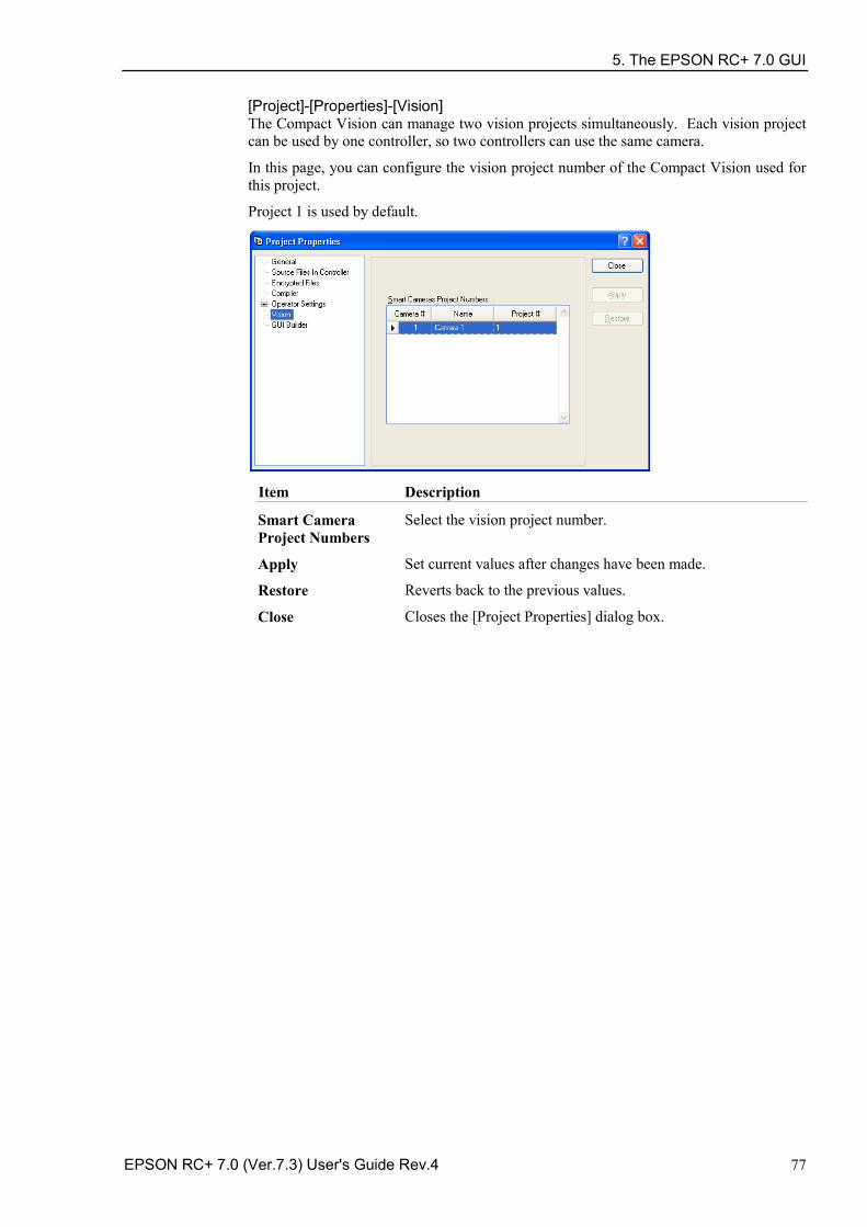
5. The EPSON RC+ 7.0 GUI
EPSON RC+ 7.0 (Ver.7.3) User's Guide Rev.4 77
[Project]-[Properties]-[Vision] The Compact Vision can manage two vision projects simultaneously. Each vision project can be used by one controller, so two controllers can use the same camera.
In this page, you can configure the vision project number of the Compact Vision used for this project.
Project 1 is used by default.
Item Description
Smart Camera Project Numbers
Select the vision project number.
Apply Set current values after changes have been made.
Restore Reverts back to the previous values.
Close Closes the [Project Properties] dialog box.
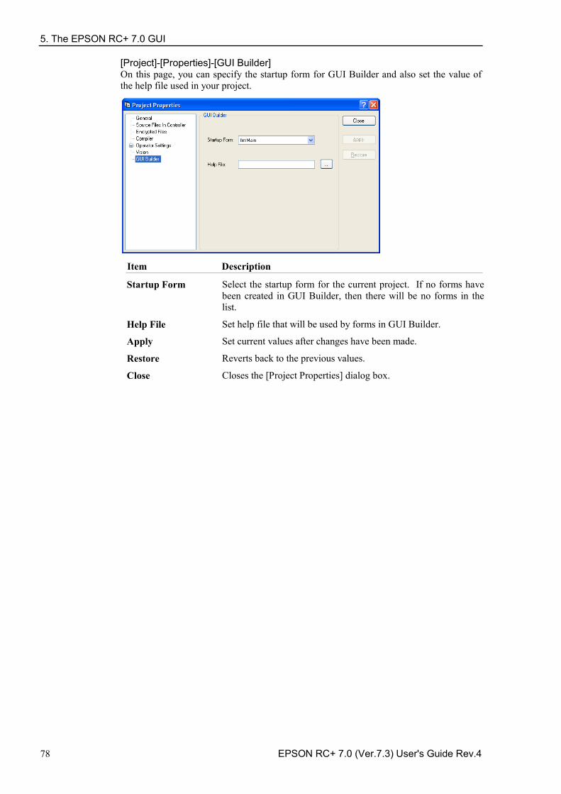
5. The EPSON RC+ 7.0 GUI
78 EPSON RC+ 7.0 (Ver.7.3) User's Guide Rev.4
[Project]-[Properties]-[GUI Builder] On this page, you can specify the startup form for GUI Builder and also set the value of the help file used in your project.
Item Description
Startup Form Select the startup form for the current project. If no forms have been created in GUI Builder, then there will be no forms in the list.
Help File Set help file that will be used by forms in GUI Builder.
Apply Set current values after changes have been made.
Restore Reverts back to the previous values.
Close Closes the [Project Properties] dialog box.
5. The EPSON RC+ 7.0 GUI
EPSON RC+ 7.0 (Ver.7.3) User's Guide Rev.4 79
5.10 [Run] Menu The EPSON RC+ 7.0 [Run] menu includes commands for running and debugging programs.
5.10.1 [Run Window] Command (Run Menu) Shortcuts
Toolbar: Key: F5
Opens the [Run] window to run a program.
Before opening the [Run] window, all files will be saved automatically if there are any unsaved files and then the project will be built. If there are any errors during build, the Run window will not be opened.
(If the Auto File Save preference is off in [Setup]-[Preferences]-[Workspace], you will be prompted to save all files if there are any unsaved files.)
After the [Run] window opens, you must click the <Start> button to initialize program execution.
For more information, see 7.5.1 Run Window.
5.10.2 [Operator Window] Command (Run Menu) Shortcuts
Keys: Shift + F5
Opens the [Operator] window.
Before opening the [Operator] window, all files will be saved automatically if there are any unsaved files and then the project will be built. If there are any errors during build, the [Operator] window will not be opened.
(If the Auto File Save preference is off in [Setup]-[Preferences]-[Workspace], you will be prompted to save all files if there are any unsaved files.)
If the project is ready to run (last build was successful), then the [Operator] window will be opened.
For more information, see 7.6 Operator Window.
5.10.3 [Step Into] Command (Run Menu) Shortcuts
Toolbar: Key: F11
Execute the current source line. If the current line is a function, the next step will be the first line in the function.
5.10.4 [Step Over] Command (Run Menu)
Shortcuts
Toolbar: Key: F10
Execute the current source line. If the current line is a function, the entire function will be executed.
5. The EPSON RC+ 7.0 GUI
80 EPSON RC+ 7.0 (Ver.7.3) User's Guide Rev.4
5.10.5 [Walk] Command (Run Menu) Shortcuts
Key: F12
Execute lines until after the next motion command or output command, depending on the Walk stops for output commands preference on the [Setup]-[System Configuration]-[Controller]-[General] page.
5.10.6 [Resume] Command (Run Menu)
Shortcuts
Toolbar: Key: F7
Opens the [Resume Tasks] dialog box. Use this command to resume one or more halted tasks. This command is available only when one or more tasks are in halt mode.
Item Description
Select tasks to resume A list of all currently halted tasks. Click on one or more tasks to resume.
Resume Click to resume.
Select All Click to select all of the tasks in the list.
Cancel Cancel the operation and close the dialog.
5.10.7 [Stop] Command (Run Menu)
Shortcuts
Toolbar:
Stops all tasks. This command is disabled when no tasks are running.
5.10.8 [Toggle Breakpoint] Command (Run Menu)
Shortcuts
Toolbar: Key: F9
Sets the selected line as a breakpoint or returns it to normal. When a line is a breakpoint, a breakpoint icon is displayed in the program window left margin.
You can set breakpoints while tasks are running.
If a line cannot be a breakpoint (such as a blank line), then the breakpoint icon will not appear for that line.
5. The EPSON RC+ 7.0 GUI
EPSON RC+ 7.0 (Ver.7.3) User's Guide Rev.4 81
5.10.9 [Clear All Breakpoints] Command (Run Menu) Shortcuts
Keys: Ctrl + Shift + F9
Clears all breakpoints.
5.10.10 [Display Variables] Command (Run Menu)
Shortcuts
Key: F4
Displays a dialog box that shows the values for all variables in robot controller memory.
To change a variable value 1. Check the [Edit] checkbox.
2. Type the new value in the [Value] column. As you type in new values, the text color changes to red, indicating that the value is new and as not been written.
3. Click the <Write> button to save the changes. Click <Read> or uncheck [Edit] to cancel changes and restore the previous values.
When an array is displayed, the first element is shown. You can change which element to view by typing in the desired array subscript and then clicking the <Read> button.
The Preserved page displays the Global Preserve variables. The numbers of used and available bytes for preserved variables are also displayed. You can save the values of Global Preserve variables in the controller to a file on the PC by clicking the <Save> button. The default file name is “GlobalPreserves.dat”.
A “GlobalPreserves.dat” file is also saved by using Backup Controller from the Tools Menu.
You can load the global preserve variables that are stored in the file on the PC by clicking <Load> button.
For module variables, you must select the desired program.
Local variables are not displayed unless one or more tasks have reached a breakpoint or have been halted from the Task Manager. You can view local variables for each function in the call stack for each halted task.
5. The EPSON RC+ 7.0 GUI
82 EPSON RC+ 7.0 (Ver.7.3) User's Guide Rev.4
5.10.11 [Call Stack] Command (Run Menu) The Call Stack dialog displays the function call stack for one task.
The Call Stack command is available when a program window is clicked which contains a function that is currently halted.
The most recent function is at the top of the list, and parent functions are listed afterwards in descending order. The last function is the task function.
Each row in the list shows a program, function, and line number.
You can view the code for any of the function calls in the list by selecting a function, then clicking <Show>. The program window for the function you selected is then displayed and the line of the function call is marked by a yellow arrow in the editor left margin.
5. The EPSON RC+ 7.0 GUI
EPSON RC+ 7.0 (Ver.7.3) User's Guide Rev.4 83
5.11 [Tools] Menu EPSON RC+ 7.0 has several GUI tools to support the system development. All tools can be accessed from the [Tools] menu. Many also have tool bar buttons and hot keys.
The Tools Menu includes the following selections:
Robot Manager -Motor control, Jog & Teach, change robot parameters. Command Window -Execute SPEL+ commands directly. I/O Monitor -Monitor and change I/O status. Task Manager -Monitor and control task status. Macros -Opens the Macro Window. I/O Label Editor -Edit I/O labels. User Error Editor -Edit user errors. Controller -Do maintenance on the controller, such as backup, restore, and export status.
5.11.1 [Robot Manager] Command (Tools Menu)
Shortcuts
Toolbar: Key: F6
This command opens the Robot Manager window. This window contains several tabs that are used to control the robot motors and power, jog the robot and teach points, and view/edit several parameters for the robot.
You can configure how the Robot Manager window can be viewed in the development environment from the [Setup]-[Preferences]-[Robot Manager]-[General] page.
MDI window The Robot Manager is displayed as a child window along with the other child windows inside the EPSON RC+ 7.0 development environment main window.
Dialog The Robot Manager is displayed as a modal dialog which is displayed in the foreground over the development environment main window.
If the screen resolution is less than 1024 x 768, the Robot Manager will always be displayed in dialog mode so it can fit on the screen.
NOTE
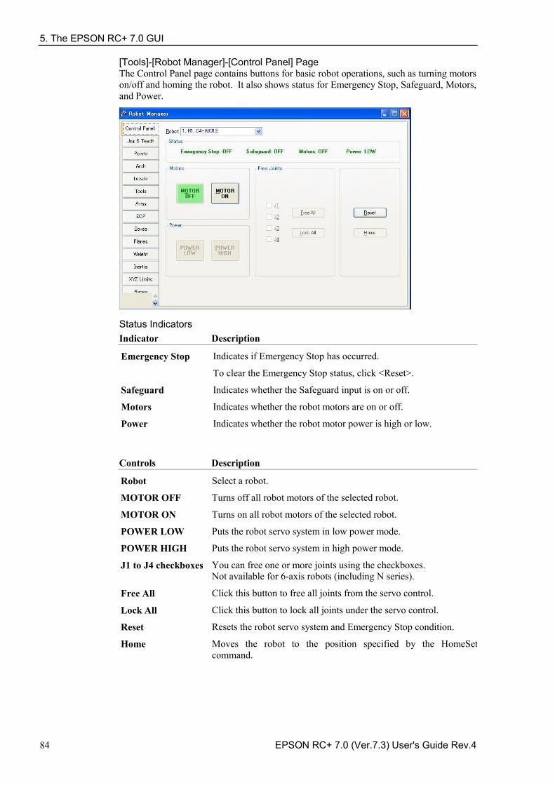
5. The EPSON RC+ 7.0 GUI
84 EPSON RC+ 7.0 (Ver.7.3) User's Guide Rev.4
[Tools]-[Robot Manager]-[Control Panel] Page The Control Panel page contains buttons for basic robot operations, such as turning motors on/off and homing the robot. It also shows status for Emergency Stop, Safeguard, Motors, and Power.
Status Indicators Indicator Description
Emergency Stop Indicates if Emergency Stop has occurred.
To clear the Emergency Stop status, click <Reset>.
Safeguard Indicates whether the Safeguard input is on or off.
Motors Indicates whether the robot motors are on or off.
Power Indicates whether the robot motor power is high or low.
Controls Description
Robot Select a robot.
MOTOR OFF Turns off all robot motors of the selected robot.
MOTOR ON Turns on all robot motors of the selected robot.
POWER LOW Puts the robot servo system in low power mode.
POWER HIGH Puts the robot servo system in high power mode.
J1 to J4 checkboxes You can free one or more joints using the checkboxes. Not available for 6-axis robots (including N series).
Free All Click this button to free all joints from the servo control.
Lock All Click this button to lock all joints under the servo control.
Reset Resets the robot servo system and Emergency Stop condition.
Home Moves the robot to the position specified by the HomeSet command.
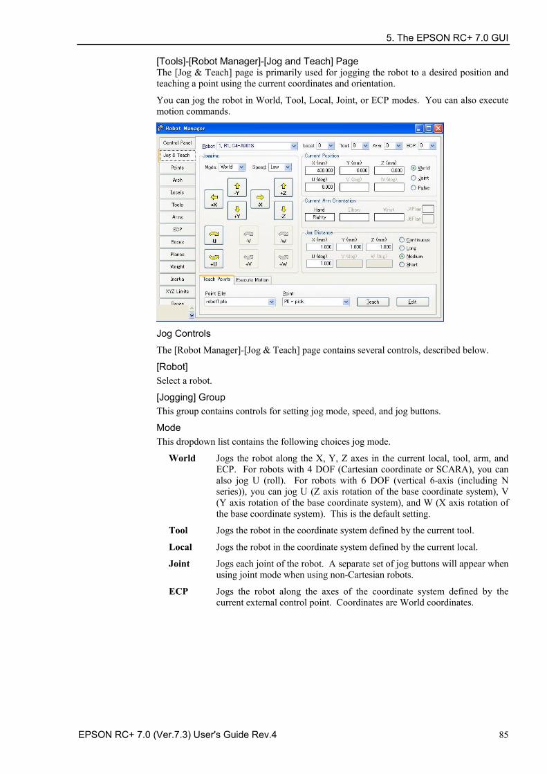
5. The EPSON RC+ 7.0 GUI
EPSON RC+ 7.0 (Ver.7.3) User's Guide Rev.4 85
[Tools]-[Robot Manager]-[Jog and Teach] Page The [Jog & Teach] page is primarily used for jogging the robot to a desired position and teaching a point using the current coordinates and orientation.
You can jog the robot in World, Tool, Local, Joint, or ECP modes. You can also execute motion commands.
Jog Controls
The [Robot Manager]-[Jog & Teach] page contains several controls, described below.
[Robot] Select a robot.
[Jogging] Group This group contains controls for setting jog mode, speed, and jog buttons.
Mode This dropdown list contains the following choices jog mode.
World Jogs the robot along the X, Y, Z axes in the current local, tool, arm, and ECP. For robots with 4 DOF (Cartesian coordinate or SCARA), you can also jog U (roll). For robots with 6 DOF (vertical 6-axis (including N series)), you can jog U (Z axis rotation of the base coordinate system), V (Y axis rotation of the base coordinate system), and W (X axis rotation of the base coordinate system). This is the default setting.
Tool Jogs the robot in the coordinate system defined by the current tool.
Local Jogs the robot in the coordinate system defined by the current local.
Joint Jogs each joint of the robot. A separate set of jog buttons will appear when using joint mode when using non-Cartesian robots.
ECP Jogs the robot along the axes of the coordinate system defined by the current external control point. Coordinates are World coordinates.
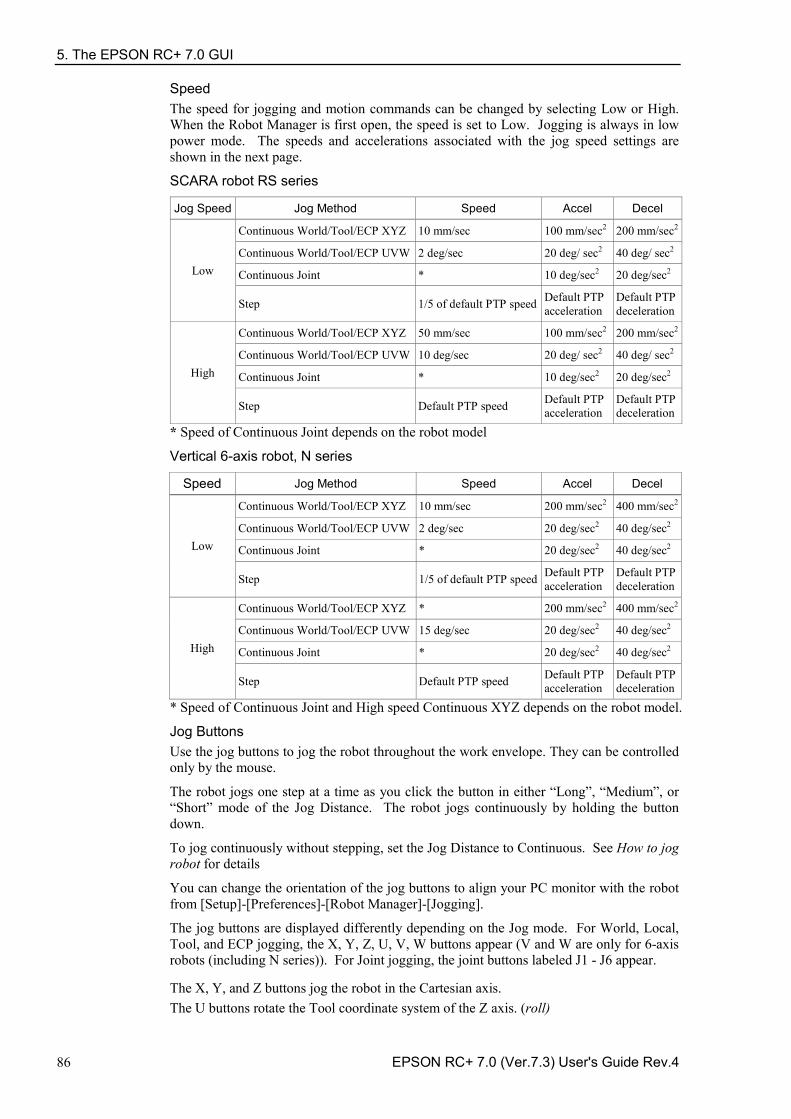
5. The EPSON RC+ 7.0 GUI
86 EPSON RC+ 7.0 (Ver.7.3) User's Guide Rev.4
Speed The speed for jogging and motion commands can be changed by selecting Low or High. When the Robot Manager is first open, the speed is set to Low. Jogging is always in low power mode. The speeds and accelerations associated with the jog speed settings are shown in the next page.
SCARA robot RS series
Jog Speed Jog Method Speed Accel Decel
Low
Continuous World/Tool/ECP XYZ 10 mm/sec 100 mm/sec2 200 mm/sec2
Continuous World/Tool/ECP UVW 2 deg/sec 20 deg/ sec2 40 deg/ sec2
Continuous Joint * 10 deg/sec2 20 deg/sec2
Step 1/5 of default PTP speed Default PTP acceleration
Default PTP deceleration
High
Continuous World/Tool/ECP XYZ 50 mm/sec 100 mm/sec2 200 mm/sec2
Continuous World/Tool/ECP UVW 10 deg/sec 20 deg/ sec2 40 deg/ sec2
Continuous Joint * 10 deg/sec2 20 deg/sec2
Step Default PTP speed Default PTP acceleration
Default PTP deceleration
* Speed of Continuous Joint depends on the robot model
Vertical 6-axis robot, N series
Speed Jog Method Speed Accel Decel
Low
Continuous World/Tool/ECP XYZ 10 mm/sec 200 mm/sec2 400 mm/sec2
Continuous World/Tool/ECP UVW 2 deg/sec 20 deg/sec2 40 deg/sec2
Continuous Joint * 20 deg/sec2 40 deg/sec2
Step 1/5 of default PTP speed Default PTP acceleration
Default PTP deceleration
High
Continuous World/Tool/ECP XYZ * 200 mm/sec2 400 mm/sec2
Continuous World/Tool/ECP UVW 15 deg/sec 20 deg/sec2 40 deg/sec2
Continuous Joint * 20 deg/sec2 40 deg/sec2
Step Default PTP speed Default PTP acceleration
Default PTP deceleration
* Speed of Continuous Joint and High speed Continuous XYZ depends on the robot model.
Jog Buttons Use the jog buttons to jog the robot throughout the work envelope. They can be controlled only by the mouse.
The robot jogs one step at a time as you click the button in either “Long”, “Medium”, or “Short” mode of the Jog Distance. The robot jogs continuously by holding the button down.
To jog continuously without stepping, set the Jog Distance to Continuous. See How to jog robot for details
You can change the orientation of the jog buttons to align your PC monitor with the robot from [Setup]-[Preferences]-[Robot Manager]-[Jogging].
The jog buttons are displayed differently depending on the Jog mode. For World, Local, Tool, and ECP jogging, the X, Y, Z, U, V, W buttons appear (V and W are only for 6-axis robots (including N series)). For Joint jogging, the joint buttons labeled J1 - J6 appear.
The X, Y, and Z buttons jog the robot in the Cartesian axis. The U buttons rotate the Tool coordinate system of the Z axis. (roll)
5. The EPSON RC+ 7.0 GUI
EPSON RC+ 7.0 (Ver.7.3) User's Guide Rev.4 87
For 6-axis robots (including N series), the V buttons rotate the Tool coordinate system of the Y axis. (pitch). The W buttons rotate the Tool coordinate system of the X axis. (yaw). Local
This drop down list is used to select the current Local for jogging and teaching. Only Locals that have been defined are shown in the list. When you teach a point, the Local point attribute defaults to the current local number.
Tool
This drop down list is used to select the current Tool for jogging and teaching. Only Tools that have been defined are shown in the list.
Arm
This drop down list is used to select the current Arm for jogging and teaching. Only Arms that have been defined are shown in the list. Arms are not used with 6-axis robots (including N series).
ECP
This drop down list is used to select the current ECP for jogging. Only ECPs that have been defined are shown in the list. ECPs are only allowed if the External Control Point option has been activated.
Current Position Group This group displays the current position of the robot. There are three ways to display position. World displays the current position and tool orientation in the selected local coordinate system, Joint displays the current joint values, and Pulse displays the current encoder pulse count for each joint.
Current Arm Orientation Group This group displays the current arm orientation.
6-axis robot : Hand orientation, Elbow orientation, wrist orientation, J1Flag value, J4Flag value, J6Flag value
N : Hand orientation, Elbow orientation, wrist orientation, J4Flag value, J6Flag value
RS series : Hand orientation, J1Flag value, J2Flag value Others : Hand orientation
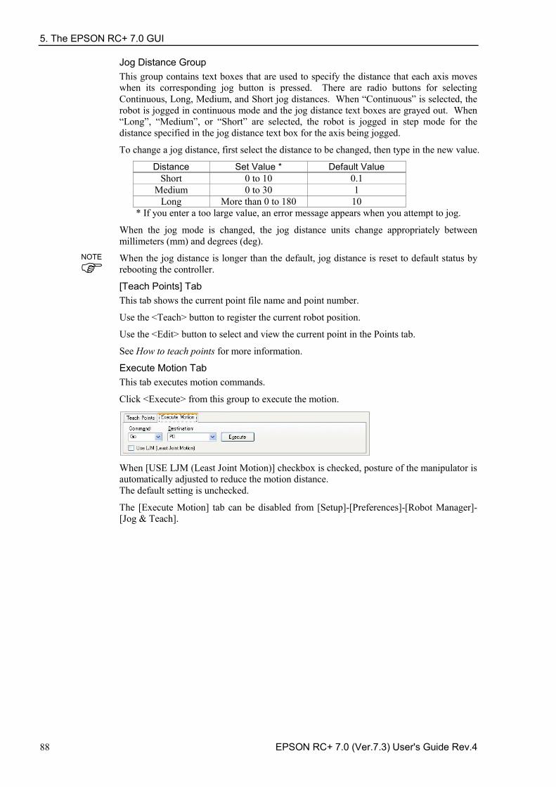
5. The EPSON RC+ 7.0 GUI
88 EPSON RC+ 7.0 (Ver.7.3) User's Guide Rev.4
Jog Distance Group This group contains text boxes that are used to specify the distance that each axis moves when its corresponding jog button is pressed. There are radio buttons for selecting Continuous, Long, Medium, and Short jog distances. When “Continuous” is selected, the robot is jogged in continuous mode and the jog distance text boxes are grayed out. When “Long”, “Medium”, or “Short” are selected, the robot is jogged in step mode for the distance specified in the jog distance text box for the axis being jogged.
To change a jog distance, first select the distance to be changed, then type in the new value.
Distance Set Value * Default Value Short 0 to 10 0.1
Medium 0 to 30 1 Long More than 0 to 180 10
* If you enter a too large value, an error message appears when you attempt to jog.
When the jog mode is changed, the jog distance units change appropriately between millimeters (mm) and degrees (deg).
When the jog distance is longer than the default, jog distance is reset to default status by rebooting the controller.
[Teach Points] Tab This tab shows the current point file name and point number.
Use the <Teach> button to register the current robot position.
Use the <Edit> button to select and view the current point in the Points tab.
See How to teach points for more information.
Execute Motion Tab This tab executes motion commands.
Click <Execute> from this group to execute the motion.
When [USE LJM (Least Joint Motion)] checkbox is checked, posture of the manipulator is automatically adjusted to reduce the motion distance. The default setting is unchecked.
The [Execute Motion] tab can be disabled from [Setup]-[Preferences]-[Robot Manager]-[Jog & Teach].
NOTE
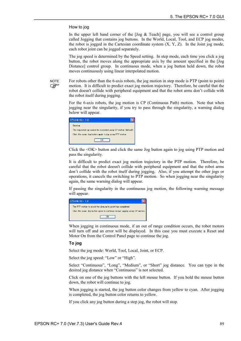
5. The EPSON RC+ 7.0 GUI
EPSON RC+ 7.0 (Ver.7.3) User's Guide Rev.4 89
How to jog
In the upper left hand corner of the [Jog & Teach] page, you will see a control group called Jogging that contains jog buttons. In the World, Local, Tool, and ECP jog modes, the robot is jogged in the Cartesian coordinate system (X, Y, Z). In the Joint jog mode, each robot joint can be jogged separately.
The jog speed is determined by the Speed setting. In step mode, each time you click a jog button, the robot moves along the appropriate axis by the amount specified in the [Jog Distance] control group. In continuous mode, when a jog button held down, the robot moves continuously using linear interpolated motion.
For robots other than the 6-axis robots, the jog motion in step mode is PTP (point to point) motion. It is difficult to predict exact jog motion trajectory. Therefore, be careful that the robot doesn't collide with peripheral equipment and that the robot arms don’t collide with the robot itself during jogging.
For the 6-axis robots, the jog motion is CP (Continuous Path) motion. Note that when jogging near the singularity, if you try to pass through the singularity, a warning dialog below will appear.
Click the <OK> button and click the same Jog button again to jog using PTP motion and pass the singularity.
It is difficult to predict exact jog motion trajectory in the PTP motion. Therefore, be careful that the robot doesn't collide with peripheral equipment and that the robot arms don’t collide with the robot itself during jogging. Also, if you attempt the other jogs or operations, it cancels the switching to PTP motion. So when jogging near the singularity again, the same warning dialog will appear.
If passing the singularity in the continuous jog motion, the following warning message will appear.
When jogging in continuous mode, if an out of range condition occurs, the robot motors will turn off and an error will be displayed. In this case you must execute a Reset and Motor On from the Control Panel page to continue the jog.
To jog Select the jog mode: World, Tool, Local, Joint, or ECP.
Select the jog speed: “Low” or “High”.
Select “Continuous”, “Long”, “Medium”, or “Short” jog distance. You can type in the desired jog distance when “Continuous” is not selected.
Click on one of the jog buttons with the left mouse button. If you hold the mouse button down, the robot will continue to jog.
When jogging is started, the jog button color changes from yellow to cyan. After jogging is completed, the jog button color returns to yellow.
If you click any jog button during a step jog, the robot will stop.
NOTE
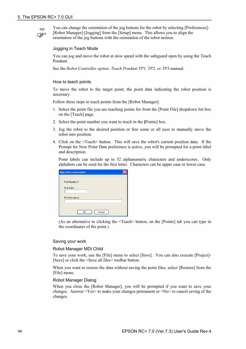
5. The EPSON RC+ 7.0 GUI
90 EPSON RC+ 7.0 (Ver.7.3) User's Guide Rev.4
You can change the orientation of the jog buttons for the robot by selecting [Preferences]-[Robot Manager]-[Jogging] from the [Setup] menu. This allows you to align the orientation of the jog buttons with the orientation of the robot motion.
Jogging in Teach Mode
You can jog and move the robot at slow speed with the safeguard open by using the Teach Pendant.
See the Robot Controller option: Teach Pendant TP1, TP2, or TP3 manual.
How to teach points
To move the robot to the target point, the point data indicating the robot position is necessary.
Follow these steps to teach points from the [Robot Manager]:
1. Select the point file you are teaching points for from the [Point File] dropdown list box on the [Teach] page.
2. Select the point number you want to teach in the [Points] box.
3. Jog the robot to the desired position or free some or all axes to manually move the robot into position.
4. Click on the <Teach> button. This will save the robot's current position data. If the Prompt for New Point Data preference is active, you will be prompted for a point label and description.
Point labels can include up to 32 alphanumeric characters and underscores. Only alphabets can be used for the first letter. Characters can be upper case or lower case.
(As an alternative to clicking the <Teach> button, on the [Points] tab you can type in the coordinates of the point.)
Saving your work
Robot Manager MDI Child To save your work, use the [File] menu to select [Save]. You can also execute [Project]-[Save] or click the <Save all files> toolbar button.
When you want to restore the data without saving the point files, select [Restore] from the [File] menu.
Robot Manager Dialog When you close the [Robot Manager], you will be prompted if you want to save your changes. Answer <Yes> to make your changes permanent or <No> to cancel saving of the changes.
TIP
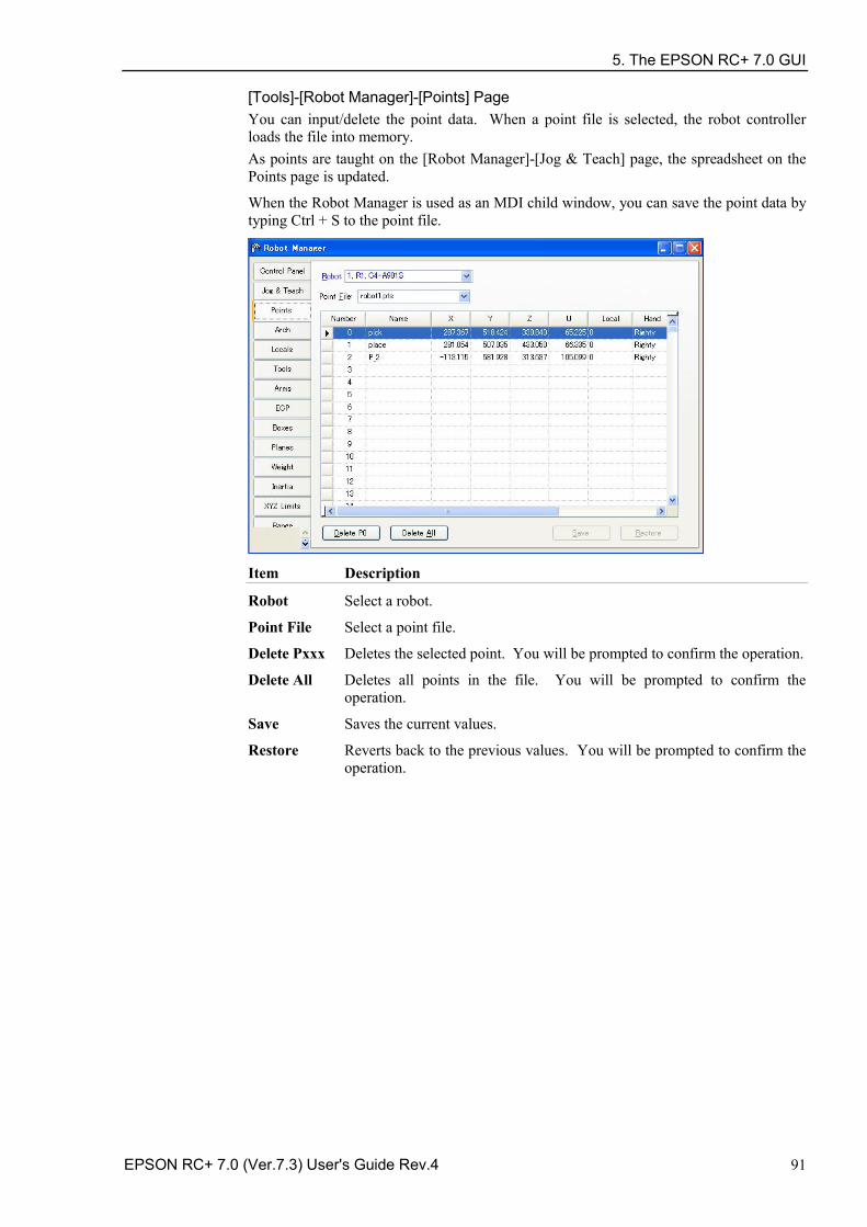
5. The EPSON RC+ 7.0 GUI
EPSON RC+ 7.0 (Ver.7.3) User's Guide Rev.4 91
[Tools]-[Robot Manager]-[Points] Page You can input/delete the point data. When a point file is selected, the robot controller loads the file into memory. As points are taught on the [Robot Manager]-[Jog & Teach] page, the spreadsheet on the Points page is updated.
When the Robot Manager is used as an MDI child window, you can save the point data by typing Ctrl + S to the point file.
Item Description
Robot Select a robot.
Point File Select a point file.
Delete Pxxx Deletes the selected point. You will be prompted to confirm the operation.
Delete All Deletes all points in the file. You will be prompted to confirm the operation.
Save Saves the current values.
Restore Reverts back to the previous values. You will be prompted to confirm the operation.
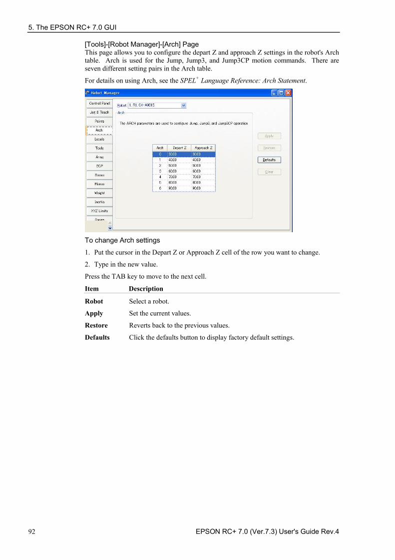
5. The EPSON RC+ 7.0 GUI
92 EPSON RC+ 7.0 (Ver.7.3) User's Guide Rev.4
[Tools]-[Robot Manager]-[Arch] Page This page allows you to configure the depart Z and approach Z settings in the robot's Arch table. Arch is used for the Jump, Jump3, and Jump3CP motion commands. There are seven different setting pairs in the Arch table.
For details on using Arch, see the SPEL+ Language Reference: Arch Statement.
To change Arch settings
1. Put the cursor in the Depart Z or Approach Z cell of the row you want to change.
2. Type in the new value.
Press the TAB key to move to the next cell.
Item Description
Robot Select a robot.
Apply Set the current values.
Restore Reverts back to the previous values.
Defaults Click the defaults button to display factory default settings.
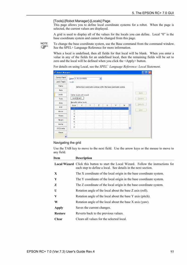
5. The EPSON RC+ 7.0 GUI
EPSON RC+ 7.0 (Ver.7.3) User's Guide Rev.4 93
[Tools]-[Robot Manager]-[Locals] Page This page allows you to define local coordinate systems for a robot. When the page is selected, the current values are displayed.
A grid is used to display all of the values for the locals you can define. Local “0” is the base coordinate system and cannot be changed from this page.
To change the base coordinate system, use the Base command from the command window. See the SPEL+ Language Reference for more information.
When a local is undefined, then all fields for that local will be blank. When you enter a value in any of the fields for an undefined local, then the remaining fields will be set to zero and the local will be defined when you click the <Apply> button.
For details on using Local, see the SPEL+ Language Reference: Local Statement.
Navigating the grid
Use the TAB key to move to the next field. Use the arrow keys or the mouse to move to any field.
Item Description
Local Wizard Click this button to start the Local Wizard. Follow the instructions for each step to define a local. See details in the next section.
X The X coordinate of the local origin in the base coordinate system.
Y The Y coordinate of the local origin in the base coordinate system.
Z The Z coordinate of the local origin in the base coordinate system.
U Rotation angle of the local about the base Z axis (roll).
V Rotation angle of the local about the base Y axis (pitch).
W Rotation angle of the local about the base X axis (yaw).
Apply Saves the current changes.
Restore Reverts back to the previous values.
Clear Clears all values for the selected local.
NOTE
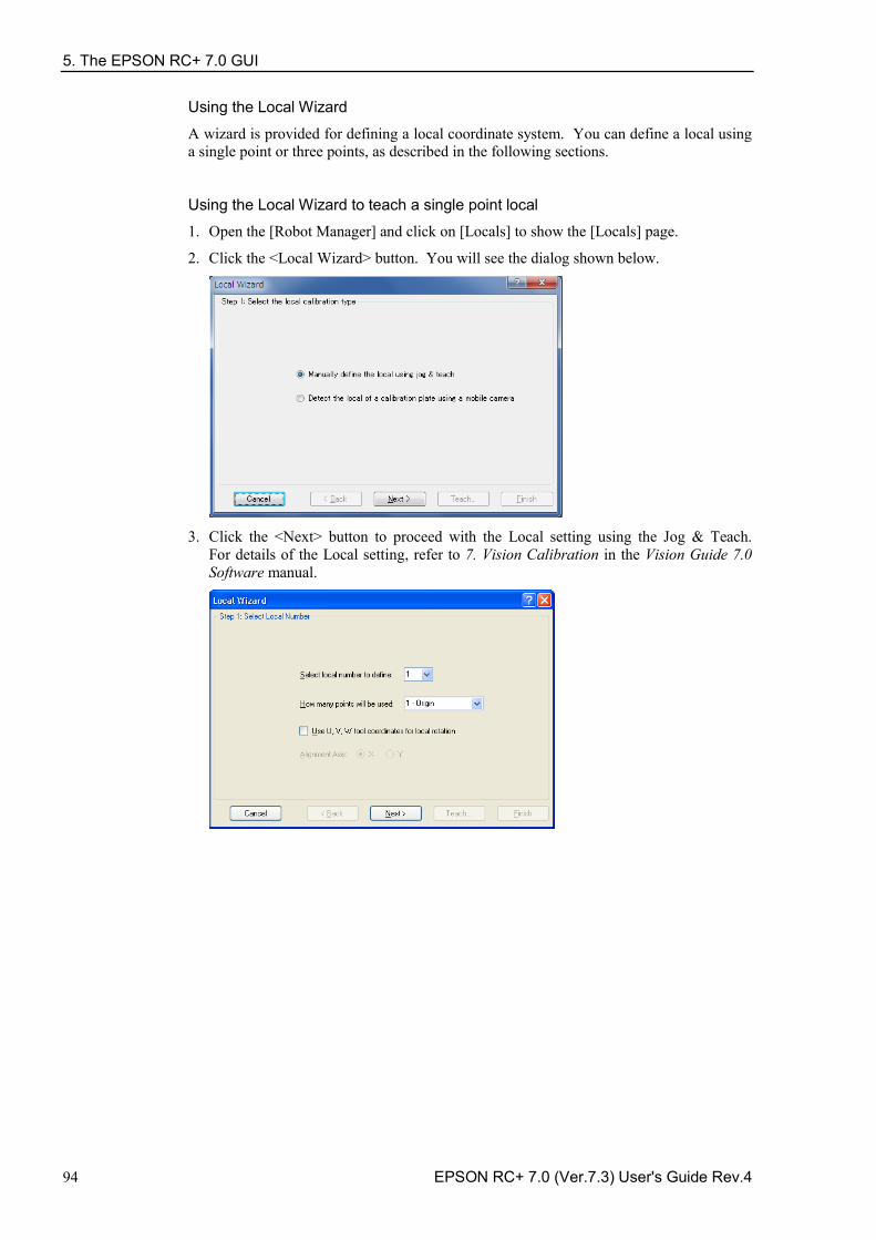
5. The EPSON RC+ 7.0 GUI
94 EPSON RC+ 7.0 (Ver.7.3) User's Guide Rev.4
Using the Local Wizard
A wizard is provided for defining a local coordinate system. You can define a local using a single point or three points, as described in the following sections.
Using the Local Wizard to teach a single point local
1. Open the [Robot Manager] and click on [Locals] to show the [Locals] page.
2. Click the <Local Wizard> button. You will see the dialog shown below.
3. Click the <Next> button to proceed with the Local setting using the Jog & Teach.
For details of the Local setting, refer to 7. Vision Calibration in the Vision Guide 7.0 Software manual.
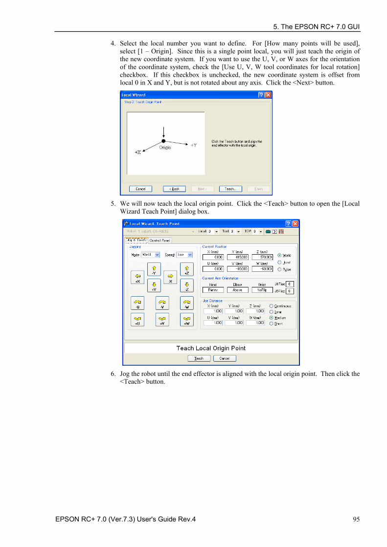
5. The EPSON RC+ 7.0 GUI
EPSON RC+ 7.0 (Ver.7.3) User's Guide Rev.4 95
4. Select the local number you want to define. For [How many points will be used], select [1 – Origin]. Since this is a single point local, you will just teach the origin of the new coordinate system. If you want to use the U, V, or W axes for the orientation of the coordinate system, check the [Use U, V, W tool coordinates for local rotation] checkbox. If this checkbox is unchecked, the new coordinate system is offset from local 0 in X and Y, but is not rotated about any axis. Click the <Next> button.
5. We will now teach the local origin point. Click the <Teach> button to open the [Local
Wizard Teach Point] dialog box.
6. Jog the robot until the end effector is aligned with the local origin point. Then click the
<Teach> button.
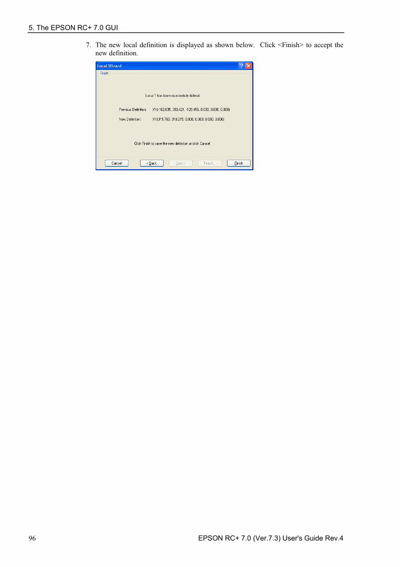
5. The EPSON RC+ 7.0 GUI
96 EPSON RC+ 7.0 (Ver.7.3) User's Guide Rev.4
7. The new local definition is displayed as shown below. Click <Finish> to accept the new definition.
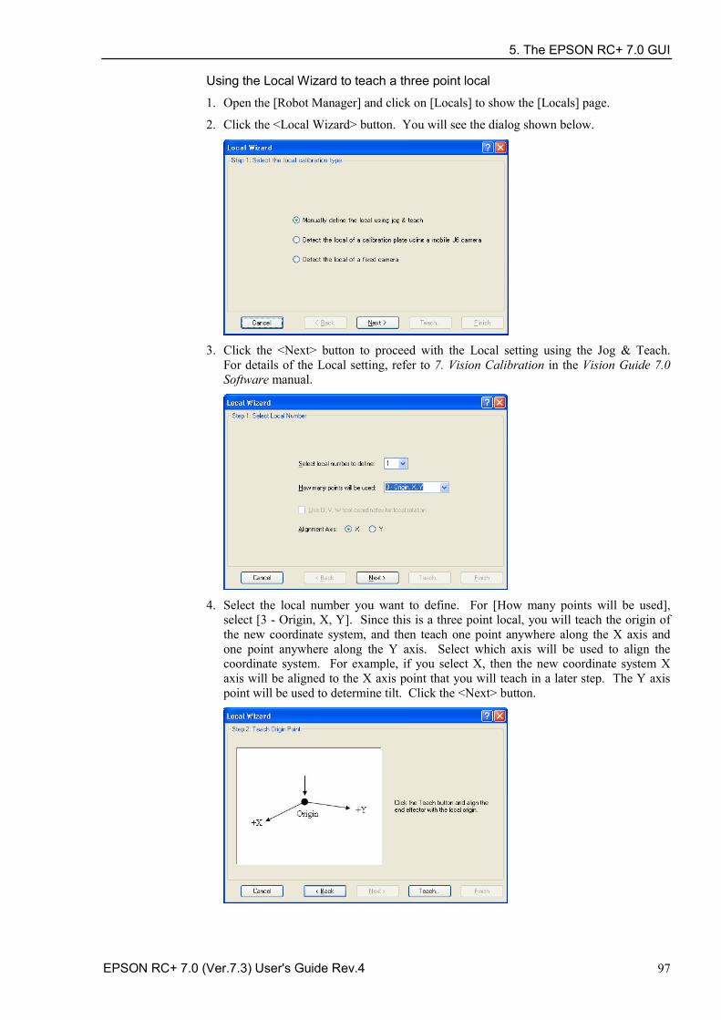
5. The EPSON RC+ 7.0 GUI
EPSON RC+ 7.0 (Ver.7.3) User's Guide Rev.4 97
Using the Local Wizard to teach a three point local
1. Open the [Robot Manager] and click on [Locals] to show the [Locals] page.
2. Click the <Local Wizard> button. You will see the dialog shown below.
3. Click the <Next> button to proceed with the Local setting using the Jog & Teach.
For details of the Local setting, refer to 7. Vision Calibration in the Vision Guide 7.0 Software manual.
4. Select the local number you want to define. For [How many points will be used],
select [3 - Origin, X, Y]. Since this is a three point local, you will teach the origin of the new coordinate system, and then teach one point anywhere along the X axis and one point anywhere along the Y axis. Select which axis will be used to align the coordinate system. For example, if you select X, then the new coordinate system X axis will be aligned to the X axis point that you will teach in a later step. The Y axis point will be used to determine tilt. Click the <Next> button.
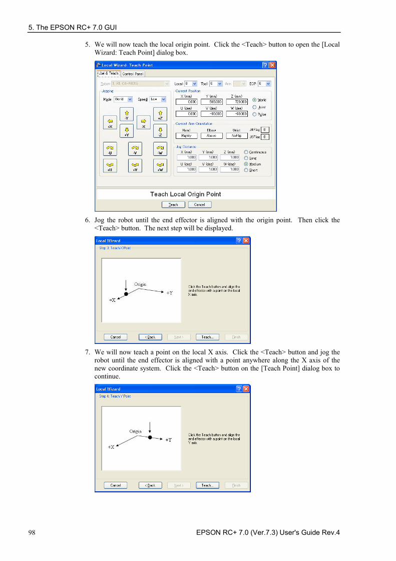
5. The EPSON RC+ 7.0 GUI
98 EPSON RC+ 7.0 (Ver.7.3) User's Guide Rev.4
5. We will now teach the local origin point. Click the <Teach> button to open the [Local Wizard: Teach Point] dialog box.
6. Jog the robot until the end effector is aligned with the origin point. Then click the
<Teach> button. The next step will be displayed.
7. We will now teach a point on the local X axis. Click the <Teach> button and jog the
robot until the end effector is aligned with a point anywhere along the X axis of the new coordinate system. Click the <Teach> button on the [Teach Point] dialog box to continue.
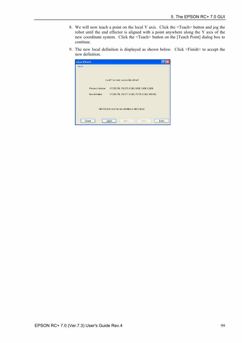
5. The EPSON RC+ 7.0 GUI
EPSON RC+ 7.0 (Ver.7.3) User's Guide Rev.4 99
8. We will now teach a point on the local Y axis. Click the <Teach> button and jog the robot until the end effector is aligned with a point anywhere along the Y axis of the new coordinate system. Click the <Teach> button on the [Teach Point] dialog box to continue.
9. The new local definition is displayed as shown below. Click <Finish> to accept the new definition.
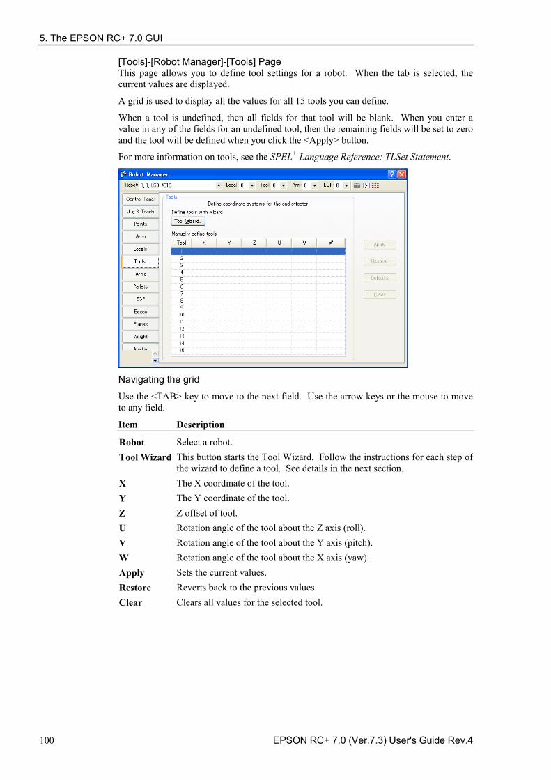
5. The EPSON RC+ 7.0 GUI
100 EPSON RC+ 7.0 (Ver.7.3) User's Guide Rev.4
[Tools]-[Robot Manager]-[Tools] Page This page allows you to define tool settings for a robot. When the tab is selected, the current values are displayed.
A grid is used to display all the values for all 15 tools you can define.
When a tool is undefined, then all fields for that tool will be blank. When you enter a value in any of the fields for an undefined tool, then the remaining fields will be set to zero and the tool will be defined when you click the <Apply> button.
For more information on tools, see the SPEL+ Language Reference: TLSet Statement.
Navigating the grid
Use the <TAB> key to move to the next field. Use the arrow keys or the mouse to move to any field.
Item Description
Robot Select a robot. Tool Wizard This button starts the Tool Wizard. Follow the instructions for each step of
the wizard to define a tool. See details in the next section. X The X coordinate of the tool. Y The Y coordinate of the tool. Z Z offset of tool. U Rotation angle of the tool about the Z axis (roll). V Rotation angle of the tool about the Y axis (pitch). W Rotation angle of the tool about the X axis (yaw). Apply Sets the current values. Restore Reverts back to the previous values Clear Clears all values for the selected tool.
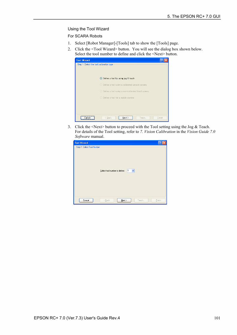
5. The EPSON RC+ 7.0 GUI
EPSON RC+ 7.0 (Ver.7.3) User's Guide Rev.4 101
Using the Tool Wizard
For SCARA Robots
1. Select [Robot Manager]-[Tools] tab to show the [Tools] page. 2. Click the <Tool Wizard> button. You will see the dialog box shown below.
Select the tool number to define and click the <Next> button.
3. Click the <Next> button to proceed with the Tool setting using the Jog & Teach.
For details of the Tool setting, refer to 7. Vision Calibration in the Vision Guide 7.0 Software manual.
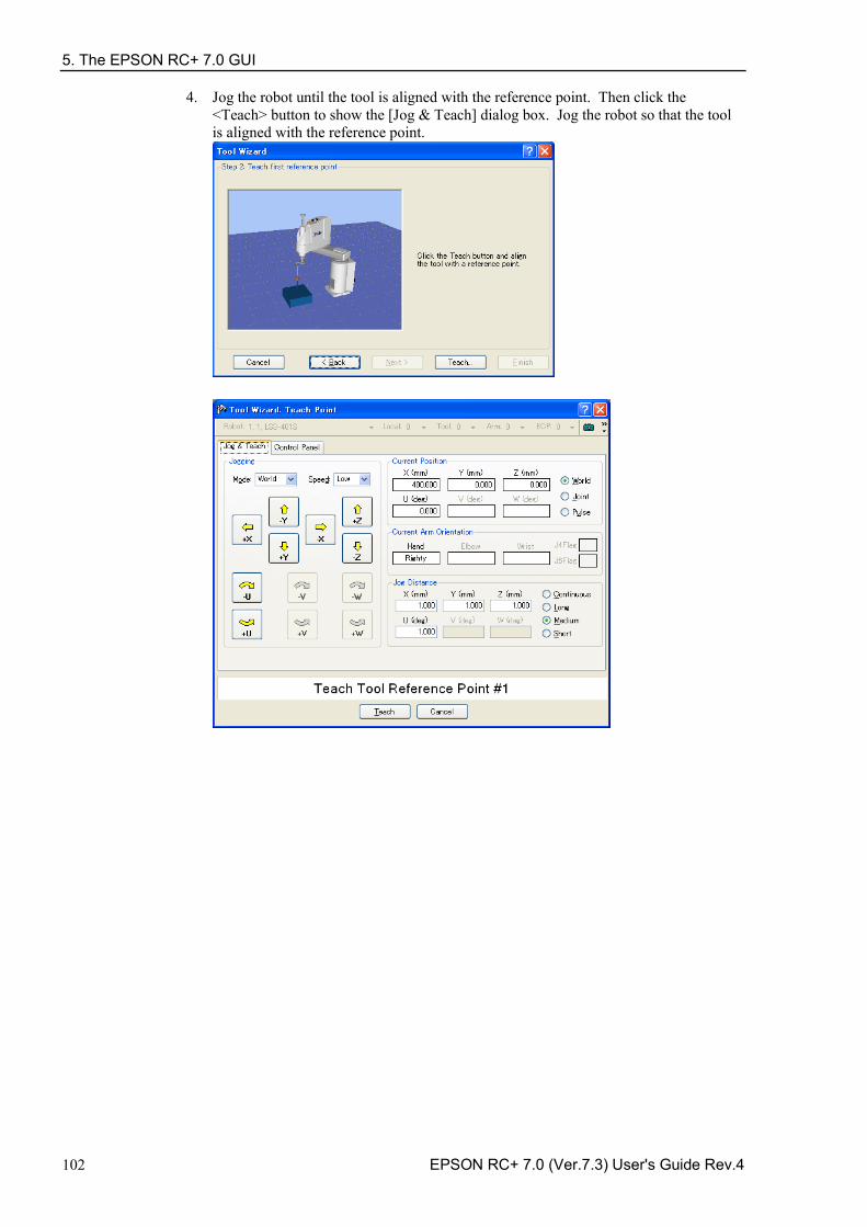
5. The EPSON RC+ 7.0 GUI
102 EPSON RC+ 7.0 (Ver.7.3) User's Guide Rev.4
4. Jog the robot until the tool is aligned with the reference point. Then click the <Teach> button to show the [Jog & Teach] dialog box. Jog the robot so that the tool is aligned with the reference point.
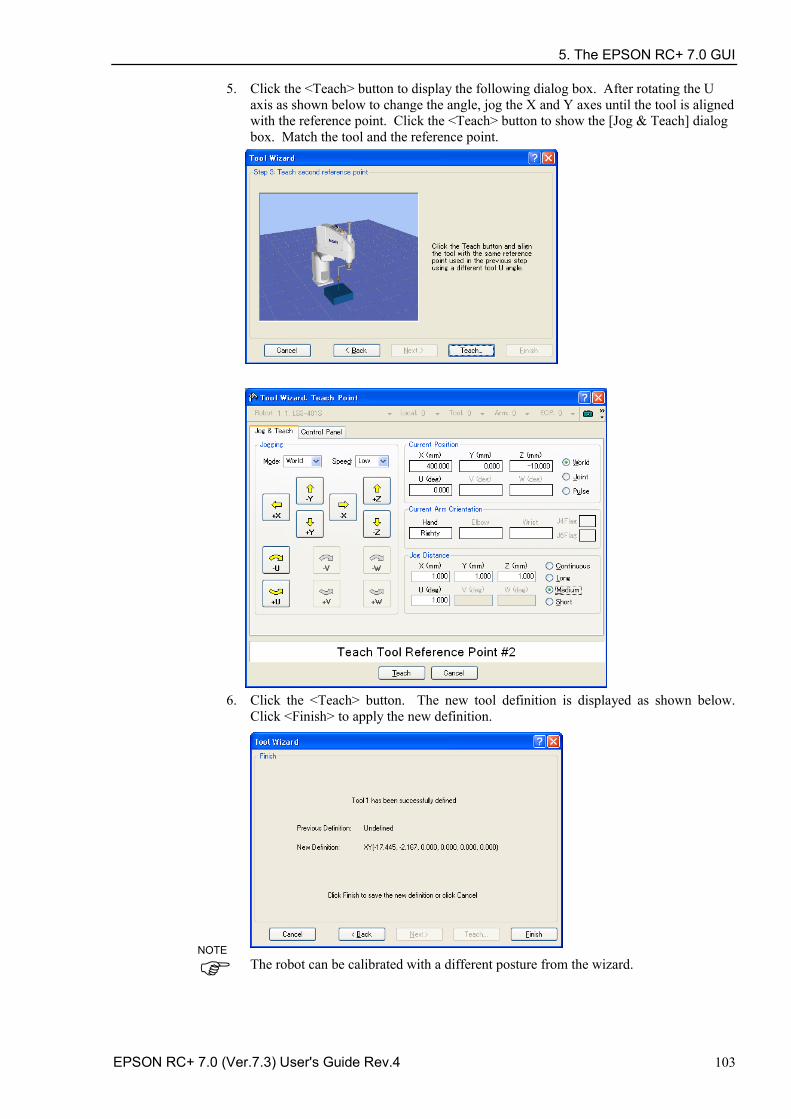
5. The EPSON RC+ 7.0 GUI
EPSON RC+ 7.0 (Ver.7.3) User's Guide Rev.4 103
5. Click the <Teach> button to display the following dialog box. After rotating the U axis as shown below to change the angle, jog the X and Y axes until the tool is aligned with the reference point. Click the <Teach> button to show the [Jog & Teach] dialog box. Match the tool and the reference point.
6. Click the <Teach> button. The new tool definition is displayed as shown below.
Click <Finish> to apply the new definition.
The robot can be calibrated with a different posture from the wizard.
NOTE
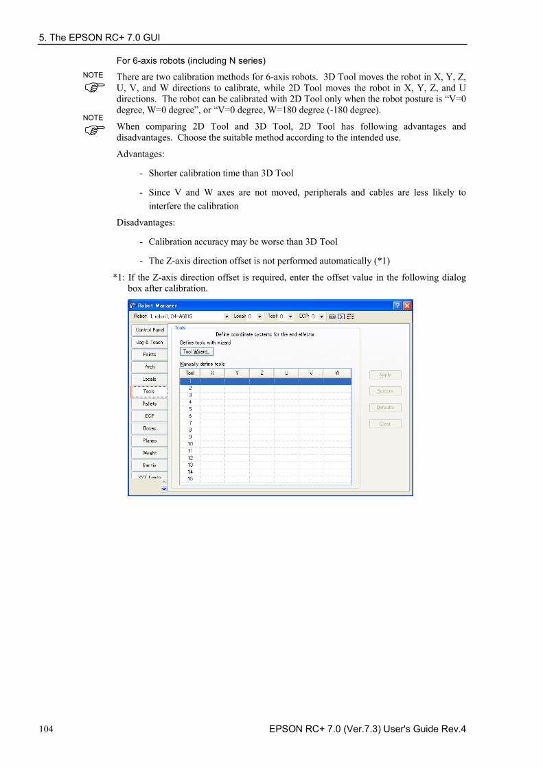
5. The EPSON RC+ 7.0 GUI
104 EPSON RC+ 7.0 (Ver.7.3) User's Guide Rev.4
For 6-axis robots (including N series)
There are two calibration methods for 6-axis robots. 3D Tool moves the robot in X, Y, Z, U, V, and W directions to calibrate, while 2D Tool moves the robot in X, Y, Z, and U directions. The robot can be calibrated with 2D Tool only when the robot posture is “V=0 degree, W=0 degree”, or “V=0 degree, W=180 degree (-180 degree).
When comparing 2D Tool and 3D Tool, 2D Tool has following advantages and disadvantages. Choose the suitable method according to the intended use.
Advantages:
- Shorter calibration time than 3D Tool
- Since V and W axes are not moved, peripherals and cables are less likely to interfere the calibration
Disadvantages:
- Calibration accuracy may be worse than 3D Tool
- The Z-axis direction offset is not performed automatically (*1)
*1: If the Z-axis direction offset is required, enter the offset value in the following dialog box after calibration.
NOTE
NOTE
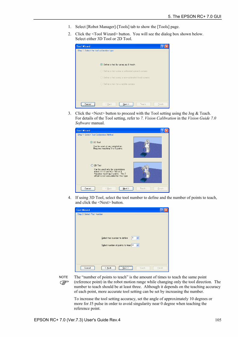
5. The EPSON RC+ 7.0 GUI
EPSON RC+ 7.0 (Ver.7.3) User's Guide Rev.4 105
1. Select [Robot Manager]-[Tools] tab to show the [Tools] page.
2. Click the <Tool Wizard> button. You will see the dialog box shown below. Select either 3D Tool or 2D Tool.
3. Click the <Next> button to proceed with the Tool setting using the Jog & Teach.
For details of the Tool setting, refer to 7. Vision Calibration in the Vision Guide 7.0 Software manual.
4. If using 3D Tool, select the tool number to define and the number of points to teach,
and click the <Next> button.
The “number of points to teach” is the amount of times to teach the same point (reference point) in the robot motion range while changing only the tool direction. The number to teach should be at least three. Although it depends on the teaching accuracy of each point, more accurate tool setting can be set by increasing the number.
To increase the tool setting accuracy, set the angle of approximately 10 degrees or more for J5 pulse in order to avoid singularity near 0 degree when teaching the reference point.
NOTE
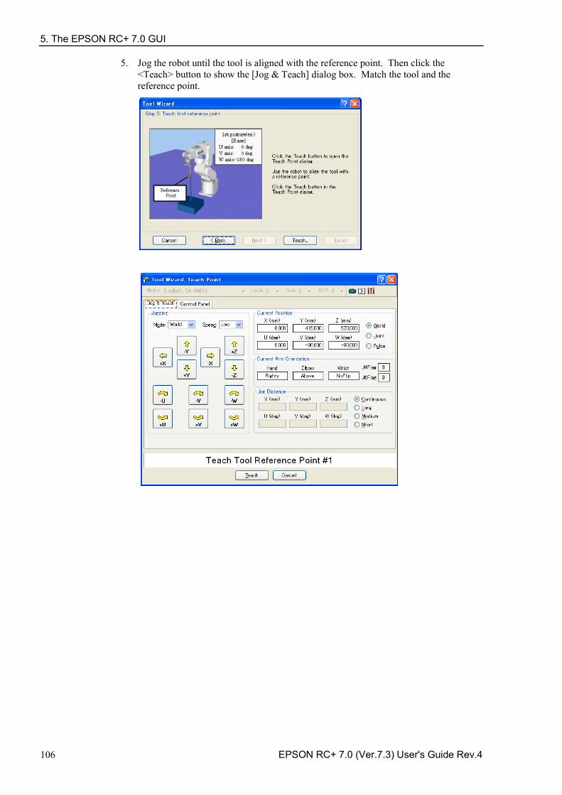
5. The EPSON RC+ 7.0 GUI
106 EPSON RC+ 7.0 (Ver.7.3) User's Guide Rev.4
5. Jog the robot until the tool is aligned with the reference point. Then click the <Teach> button to show the [Jog & Teach] dialog box. Match the tool and the reference point.
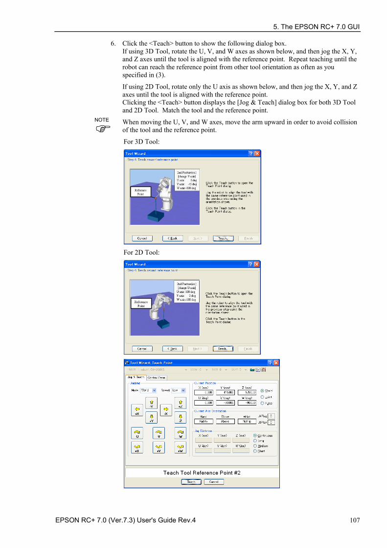
5. The EPSON RC+ 7.0 GUI
EPSON RC+ 7.0 (Ver.7.3) User's Guide Rev.4 107
6. Click the <Teach> button to show the following dialog box. If using 3D Tool, rotate the U, V, and W axes as shown below, and then jog the X, Y, and Z axes until the tool is aligned with the reference point. Repeat teaching until the robot can reach the reference point from other tool orientation as often as you specified in (3).
If using 2D Tool, rotate only the U axis as shown below, and then jog the X, Y, and Z axes until the tool is aligned with the reference point. Clicking the <Teach> button displays the [Jog & Teach] dialog box for both 3D Tool and 2D Tool. Match the tool and the reference point.
When moving the U, V, and W axes, move the arm upward in order to avoid collision of the tool and the reference point.
For 3D Tool:
For 2D Tool:
NOTE
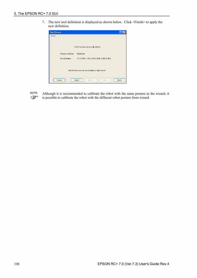
5. The EPSON RC+ 7.0 GUI
108 EPSON RC+ 7.0 (Ver.7.3) User's Guide Rev.4
7. The new tool definition is displayed as shown below. Click <Finish> to apply the new definition.
Although it is recommended to calibrate the robot with the same posture as the wizard, it is possible to calibrate the robot with the different robot posture from wizard.
NOTE
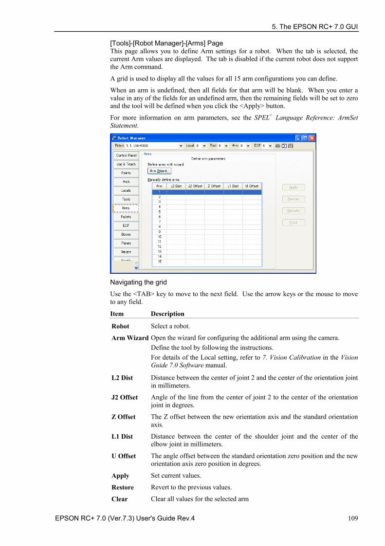
5. The EPSON RC+ 7.0 GUI
EPSON RC+ 7.0 (Ver.7.3) User's Guide Rev.4 109
[Tools]-[Robot Manager]-[Arms] Page This page allows you to define Arm settings for a robot. When the tab is selected, the current Arm values are displayed. The tab is disabled if the current robot does not support the Arm command.
A grid is used to display all the values for all 15 arm configurations you can define.
When an arm is undefined, then all fields for that arm will be blank. When you enter a value in any of the fields for an undefined arm, then the remaining fields will be set to zero and the tool will be defined when you click the <Apply> button.
For more information on arm parameters, see the SPEL+ Language Reference: ArmSet Statement.
Navigating the grid
Use the <TAB> key to move to the next field. Use the arrow keys or the mouse to move to any field.
Item Description
Robot Select a robot.
Arm Wizard Open the wizard for configuring the additional arm using the camera. Define the tool by following the instructions. For details of the Local setting, refer to 7. Vision Calibration in the Vision Guide 7.0 Software manual.
L2 Dist Distance between the center of joint 2 and the center of the orientation joint in millimeters.
J2 Offset Angle of the line from the center of joint 2 to the center of the orientation joint in degrees.
Z Offset The Z offset between the new orientation axis and the standard orientation axis.
L1 Dist Distance between the center of the shoulder joint and the center of the elbow joint in millimeters.
U Offset The angle offset between the standard orientation zero position and the new orientation axis zero position in degrees.
Apply Set current values.
Restore Revert to the previous values.
Clear Clear all values for the selected arm
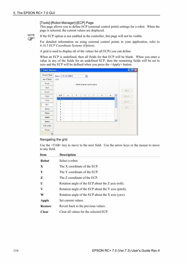
5. The EPSON RC+ 7.0 GUI
110 EPSON RC+ 7.0 (Ver.7.3) User's Guide Rev.4
[Tools]-[Robot Manager]-[ECP] Page This page allows you to define ECP (external control point) settings for a robot. When the page is selected, the current values are displayed.
If the ECP option is not enabled in the controller, this page will not be visible.
For detailed information on using external control points in your application, refer to 6.16.5 ECP Coordinate Systems (Option).
A grid is used to display all of the values for all ECPs you can define.
When an ECP is undefined, then all fields for that ECP will be blank. When you enter a value in any of the fields for an undefined ECP, then the remaining fields will be set to zero and the ECP will be defined when you press the <Apply> button.
Navigating the grid
Use the <TAB> key to move to the next field. Use the arrow keys or the mouse to move to any field.
Item Description
Robot Select a robot.
X The X coordinate of the ECP.
Y The Y coordinate of the ECP.
Z The Z coordinate of the ECP.
U Rotation angle of the ECP about the Z axis (roll).
V Rotation angle of the ECP about the Y axis (pitch).
W Rotation angle of the ECP about the X axis (yaw).
Apply Set current values.
Restore Revert back to the previous values.
Clear Clear all values for the selected ECP.
NOTE
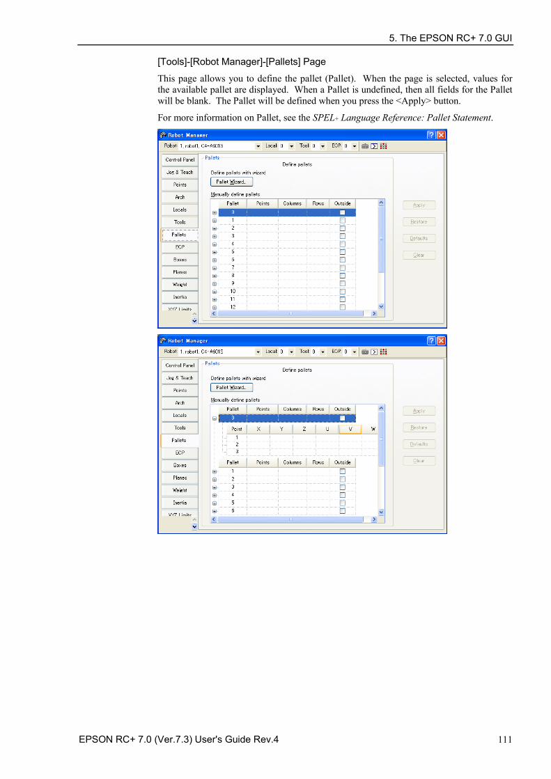
5. The EPSON RC+ 7.0 GUI
EPSON RC+ 7.0 (Ver.7.3) User's Guide Rev.4 111
[Tools]-[Robot Manager]-[Pallets] Page
This page allows you to define the pallet (Pallet). When the page is selected, values for the available pallet are displayed. When a Pallet is undefined, then all fields for the Pallet will be blank. The Pallet will be defined when you press the <Apply> button.
For more information on Pallet, see the SPEL+ Language Reference: Pallet Statement.
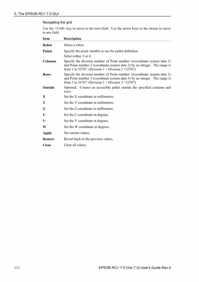
5. The EPSON RC+ 7.0 GUI
112 EPSON RC+ 7.0 (Ver.7.3) User's Guide Rev.4
Navigating the grid
Use the <TAB> key to move to the next field. Use the arrow keys or the mouse to move to any field.
Item Description
Robot Select a robot.
Points Specify the point variable to use for pallet definition. Select either 3 or 4.
Columns Specify the division number of Point number 1(coordinate system data 1) and Point number 2 (coordinate system data 2) by an integer. The range is from 1 to 32767. (Division 1 × Division 2 <32767)
Rows Specify the division number of Point number 1(coordinate system data 1) and Point number 3 (coordinate system data 3) by an integer. The range is from 1 to 32767. (Division 1 × Division 3 <32767)
Outside Optional. Creates an accessible pallet outside the specified columns and rows
X Set the X coordinate in millimeters.
Y Set the Y coordinate in millimeters.
Z Set the Z coordinate in millimeters.
U Set the U coordinate in degrees.
V Set the V coordinate in degrees.
W Set the W coordinate in degrees.
Apply Set current values.
Restore Revert back to the previous values.
Clear Clear all values.
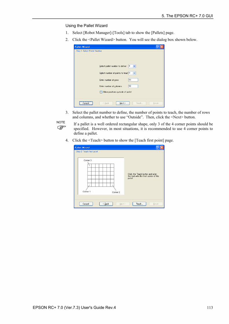
5. The EPSON RC+ 7.0 GUI
EPSON RC+ 7.0 (Ver.7.3) User's Guide Rev.4 113
Using the Pallet Wizard
1. Select [Robot Manager]-[Tools] tab to show the [Pallets] page.
2. Click the <Pallet Wizard> button. You will see the dialog box shown below.
3. Select the pallet number to define, the number of points to teach, the number of rows
and columns, and whether to use “Outside”. Then, click the <Next> button.
If a pallet is a well ordered rectangular shape, only 3 of the 4 corner points should be specified. However, in most situations, it is recommended to use 4 corner points to define a pallet.
4. Click the <Teach> button to show the [Teach first point] page.
NOTE
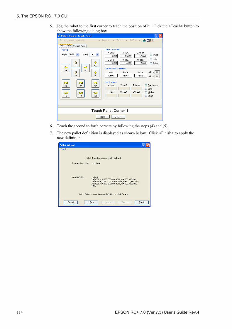
5. The EPSON RC+ 7.0 GUI
114 EPSON RC+ 7.0 (Ver.7.3) User's Guide Rev.4
5. Jog the robot to the first corner to teach the position of it. Click the <Teach> button to show the following dialog box.
6. Teach the second to forth corners by following the steps (4) and (5).
7. The new pallet definition is displayed as shown below. Click <Finish> to apply the new definition.
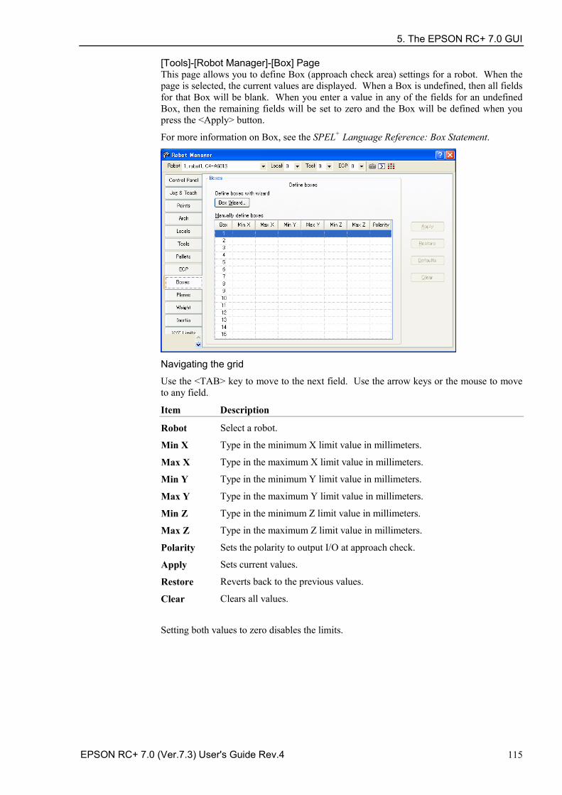
5. The EPSON RC+ 7.0 GUI
EPSON RC+ 7.0 (Ver.7.3) User's Guide Rev.4 115
[Tools]-[Robot Manager]-[Box] Page This page allows you to define Box (approach check area) settings for a robot. When the page is selected, the current values are displayed. When a Box is undefined, then all fields for that Box will be blank. When you enter a value in any of the fields for an undefined Box, then the remaining fields will be set to zero and the Box will be defined when you press the <Apply> button.
For more information on Box, see the SPEL+ Language Reference: Box Statement.
Navigating the grid
Use the <TAB> key to move to the next field. Use the arrow keys or the mouse to move to any field.
Item Description
Robot Select a robot.
Min X Type in the minimum X limit value in millimeters.
Max X Type in the maximum X limit value in millimeters.
Min Y Type in the minimum Y limit value in millimeters.
Max Y Type in the maximum Y limit value in millimeters.
Min Z Type in the minimum Z limit value in millimeters.
Max Z Type in the maximum Z limit value in millimeters.
Polarity Sets the polarity to output I/O at approach check.
Apply Sets current values.
Restore Reverts back to the previous values.
Clear Clears all values.
Setting both values to zero disables the limits.
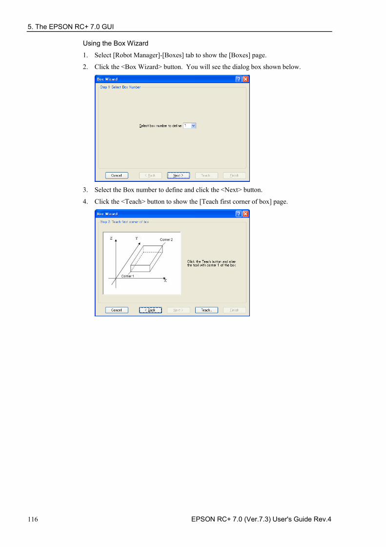
5. The EPSON RC+ 7.0 GUI
116 EPSON RC+ 7.0 (Ver.7.3) User's Guide Rev.4
Using the Box Wizard 1. Select [Robot Manager]-[Boxes] tab to show the [Boxes] page.
2. Click the <Box Wizard> button. You will see the dialog box shown below.
3. Select the Box number to define and click the <Next> button.
4. Click the <Teach> button to show the [Teach first corner of box] page.
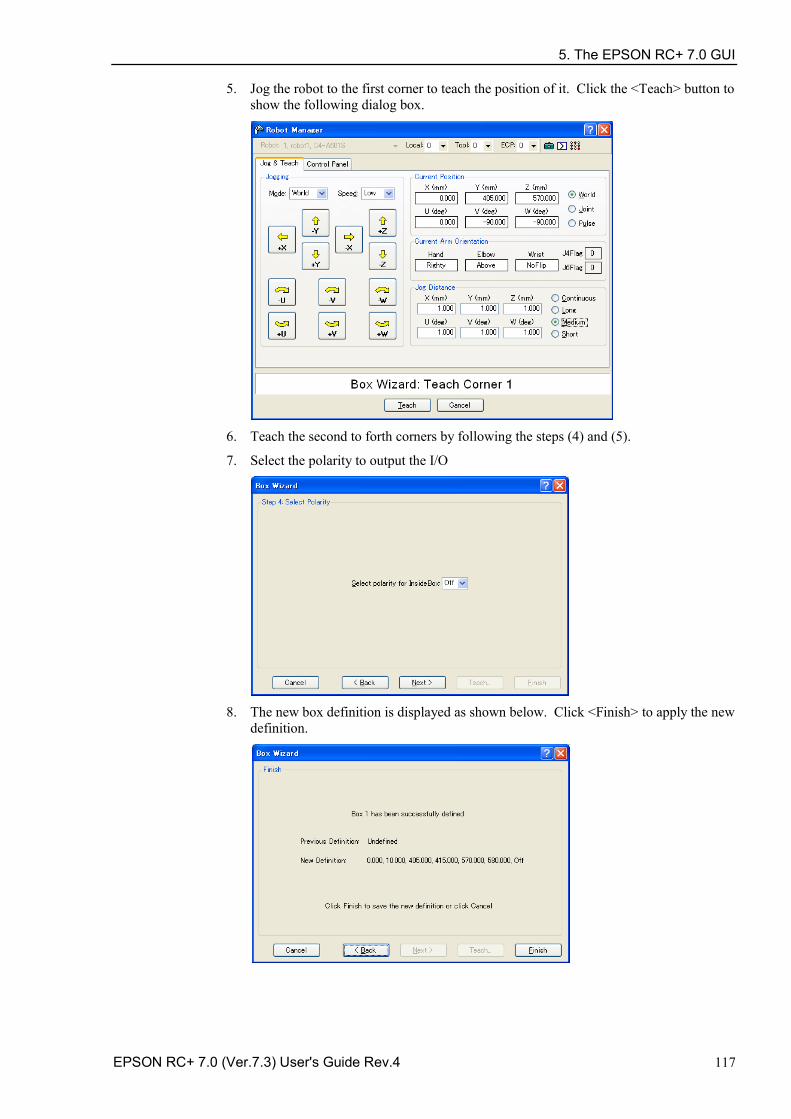
5. The EPSON RC+ 7.0 GUI
EPSON RC+ 7.0 (Ver.7.3) User's Guide Rev.4 117
5. Jog the robot to the first corner to teach the position of it. Click the <Teach> button to show the following dialog box.
6. Teach the second to forth corners by following the steps (4) and (5).
7. Select the polarity to output the I/O
8. The new box definition is displayed as shown below. Click <Finish> to apply the new
definition.
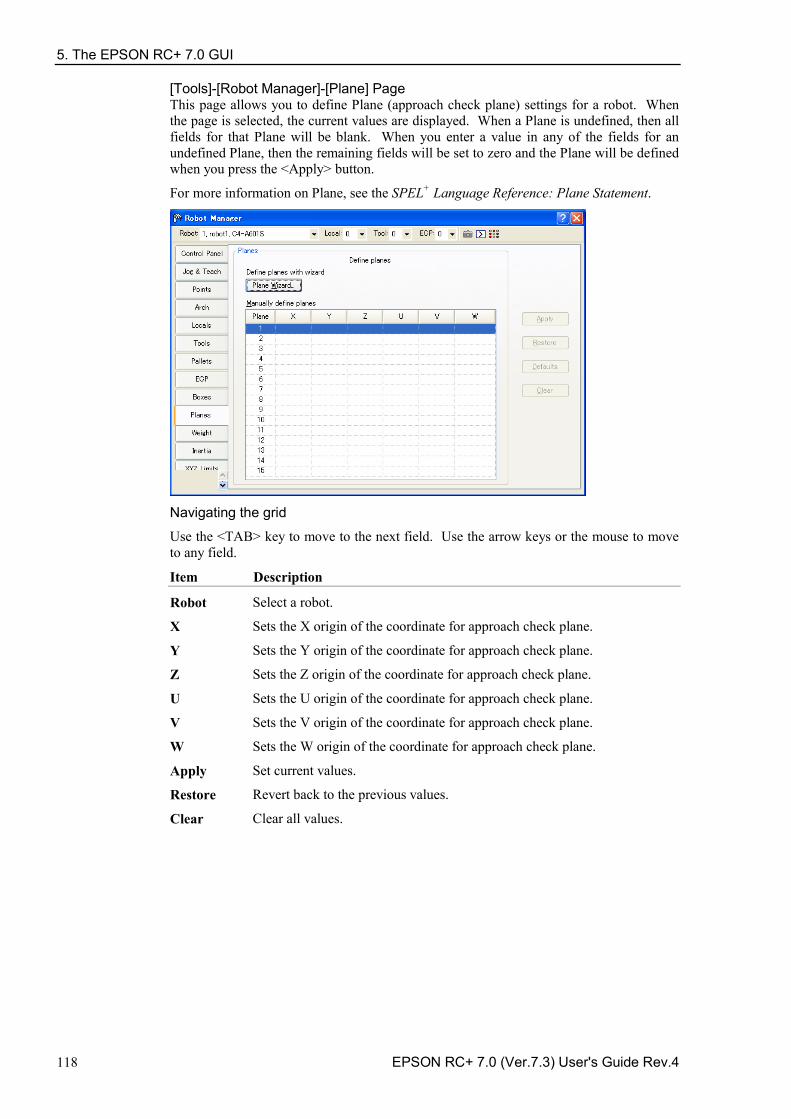
5. The EPSON RC+ 7.0 GUI
118 EPSON RC+ 7.0 (Ver.7.3) User's Guide Rev.4
[Tools]-[Robot Manager]-[Plane] Page This page allows you to define Plane (approach check plane) settings for a robot. When the page is selected, the current values are displayed. When a Plane is undefined, then all fields for that Plane will be blank. When you enter a value in any of the fields for an undefined Plane, then the remaining fields will be set to zero and the Plane will be defined when you press the <Apply> button.
For more information on Plane, see the SPEL+ Language Reference: Plane Statement.
Navigating the grid
Use the <TAB> key to move to the next field. Use the arrow keys or the mouse to move to any field.
Item Description
Robot Select a robot.
X Sets the X origin of the coordinate for approach check plane.
Y Sets the Y origin of the coordinate for approach check plane.
Z Sets the Z origin of the coordinate for approach check plane.
U Sets the U origin of the coordinate for approach check plane.
V Sets the V origin of the coordinate for approach check plane.
W Sets the W origin of the coordinate for approach check plane.
Apply Set current values.
Restore Revert back to the previous values.
Clear Clear all values.
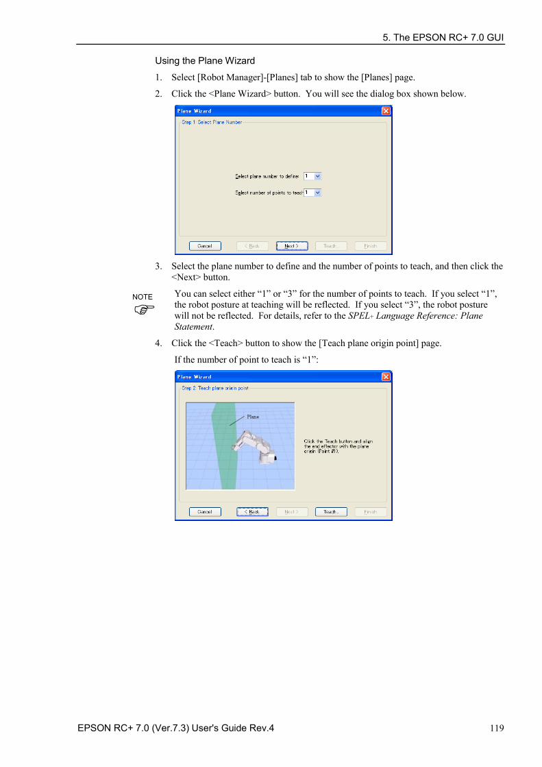
5. The EPSON RC+ 7.0 GUI
EPSON RC+ 7.0 (Ver.7.3) User's Guide Rev.4 119
Using the Plane Wizard 1. Select [Robot Manager]-[Planes] tab to show the [Planes] page.
2. Click the <Plane Wizard> button. You will see the dialog box shown below.
3. Select the plane number to define and the number of points to teach, and then click the
<Next> button.
You can select either “1” or “3” for the number of points to teach. If you select “1”, the robot posture at teaching will be reflected. If you select “3”, the robot posture will not be reflected. For details, refer to the SPEL+ Language Reference: Plane Statement.
4. Click the <Teach> button to show the [Teach plane origin point] page.
If the number of point to teach is “1”:
NOTE
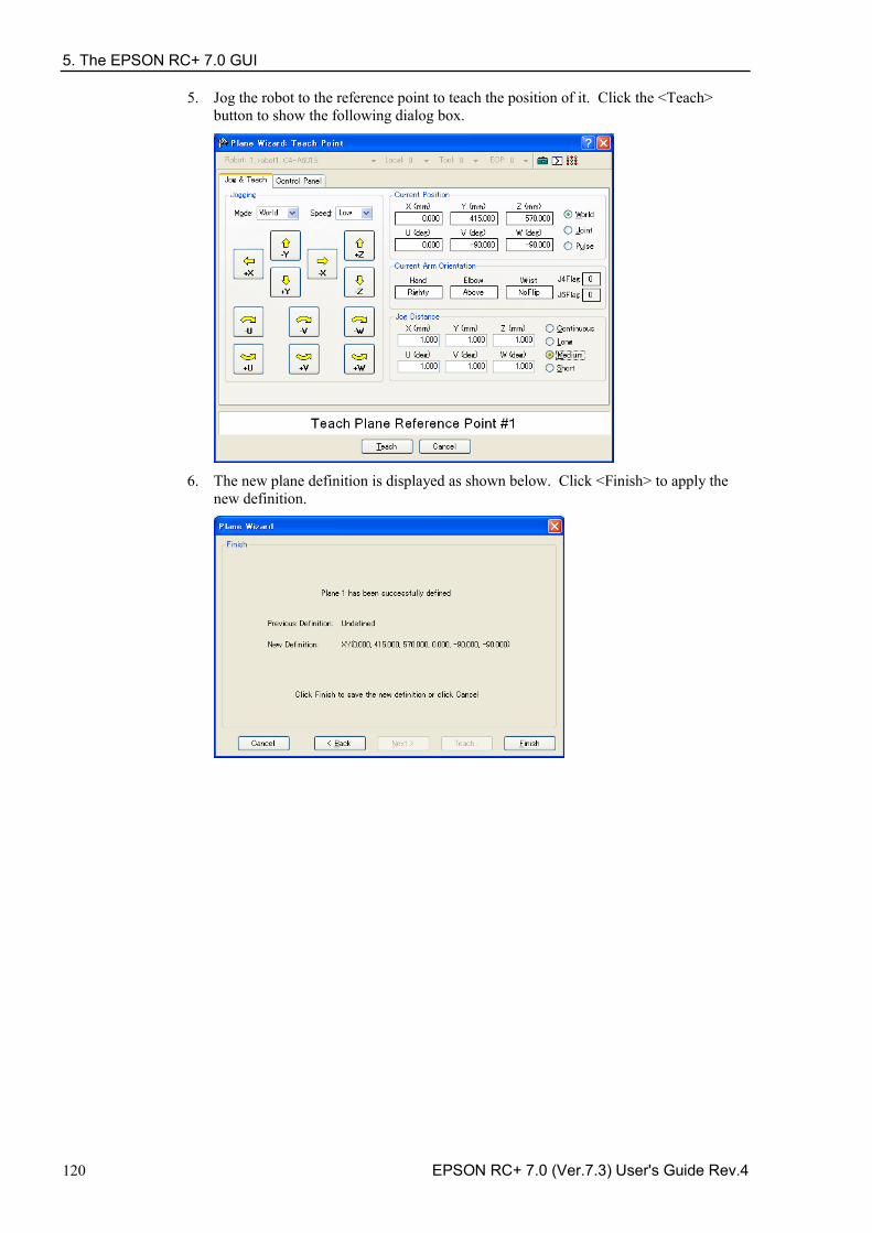
5. The EPSON RC+ 7.0 GUI
120 EPSON RC+ 7.0 (Ver.7.3) User's Guide Rev.4
5. Jog the robot to the reference point to teach the position of it. Click the <Teach> button to show the following dialog box.
6. The new plane definition is displayed as shown below. Click <Finish> to apply the
new definition.
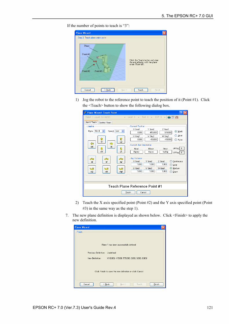
5. The EPSON RC+ 7.0 GUI
EPSON RC+ 7.0 (Ver.7.3) User's Guide Rev.4 121
If the number of points to teach is “3”:
1) Jog the robot to the reference point to teach the position of it (Point #1). Click the <Teach> button to show the following dialog box.
2) Teach the X axis specified point (Point #2) and the Y axis specified point (Point #3) in the same way as the step 1).
7. The new plane definition is displayed as shown below. Click <Finish> to apply the new definition.
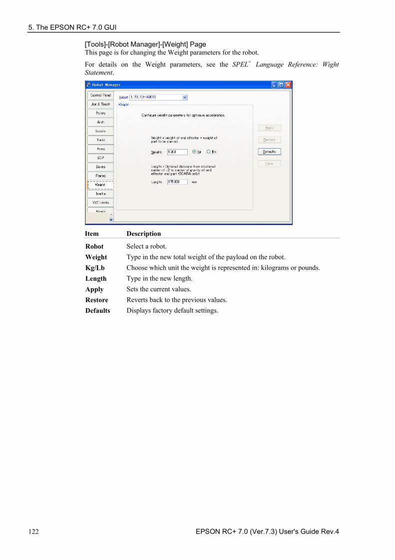
5. The EPSON RC+ 7.0 GUI
122 EPSON RC+ 7.0 (Ver.7.3) User's Guide Rev.4
[Tools]-[Robot Manager]-[Weight] Page This page is for changing the Weight parameters for the robot.
For details on the Weight parameters, see the SPEL+ Language Reference: Wight Statement.
Item Description
Robot Select a robot. Weight Type in the new total weight of the payload on the robot. Kg/Lb Choose which unit the weight is represented in: kilograms or pounds. Length Type in the new length. Apply Sets the current values. Restore Reverts back to the previous values. Defaults Displays factory default settings.
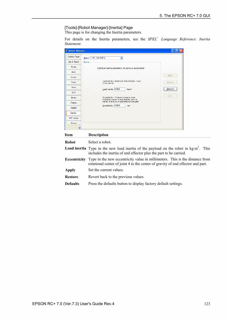
5. The EPSON RC+ 7.0 GUI
EPSON RC+ 7.0 (Ver.7.3) User's Guide Rev.4 123
[Tools]-[Robot Manager]-[Inertia] Page This page is for changing the Inertia parameters.
For details on the Inertia parameters, see the SPEL+ Language Reference: Inertia Statement.
Item Description
Robot Select a robot. Load inertia Type in the new load inertia of the payload on the robot in kg⋅m2. This
includes the inertia of end effector plus the part to be carried. Eccentricity Type in the new eccentricity value in millimeters. This is the distance from
rotational center of joint 4 to the center of gravity of end effector and part. Apply Set the current values.
Restore Revert back to the previous values.
Defaults Press the defaults button to display factory default settings.
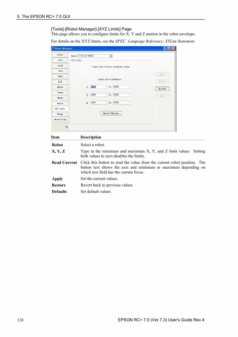
5. The EPSON RC+ 7.0 GUI
124 EPSON RC+ 7.0 (Ver.7.3) User's Guide Rev.4
[Tools]-[Robot Manager]-[XYZ Limits] Page This page allows you to configure limits for X, Y and Z motion in the robot envelope.
For details on the XYZ limits, see the SPEL+ Language Reference: XYLim Statement.
Item Description
Robot Select a robot. X, Y, Z Type in the minimum and maximum X, Y, and Z limit values. Setting
both values to zero disables the limits. Read Current Click this button to read the value from the current robot position. The
button text shows the axis and minimum or maximum depending on which text field has the current focus.
Apply Set the current values. Restore Revert back to previous values. Defaults Set default values.
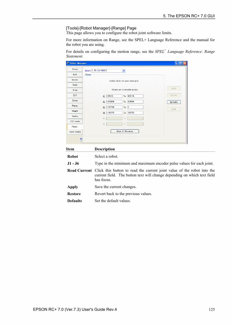
5. The EPSON RC+ 7.0 GUI
EPSON RC+ 7.0 (Ver.7.3) User's Guide Rev.4 125
[Tools]-[Robot Manager]-[Range] Page This page allows you to configure the robot joint software limits.
For more information on Range, see the SPEL+ Language Reference and the manual for the robot you are using.
For details on configuring the motion range, see the SPEL+ Language Reference: Range Statement.
Item Description
Robot Select a robot.
J1 - J6 Type in the minimum and maximum encoder pulse values for each joint.
Read Current Click this button to read the current joint value of the robot into the current field. The button text will change depending on which text field has focus.
Apply Save the current changes.
Restore Revert back to the previous values.
Defaults Set the default values.
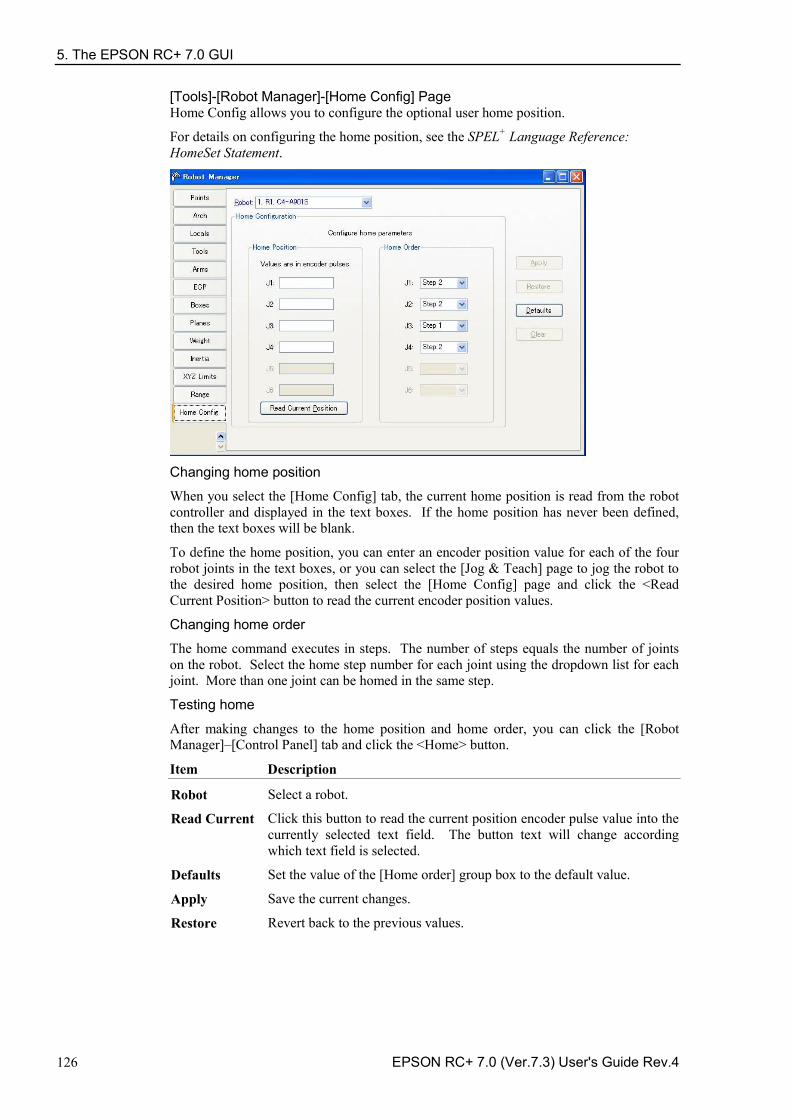
5. The EPSON RC+ 7.0 GUI
126 EPSON RC+ 7.0 (Ver.7.3) User's Guide Rev.4
[Tools]-[Robot Manager]-[Home Config] Page Home Config allows you to configure the optional user home position.
For details on configuring the home position, see the SPEL+ Language Reference: HomeSet Statement.
Changing home position
When you select the [Home Config] tab, the current home position is read from the robot controller and displayed in the text boxes. If the home position has never been defined, then the text boxes will be blank.
To define the home position, you can enter an encoder position value for each of the four robot joints in the text boxes, or you can select the [Jog & Teach] page to jog the robot to the desired home position, then select the [Home Config] page and click the <Read Current Position> button to read the current encoder position values.
Changing home order
The home command executes in steps. The number of steps equals the number of joints on the robot. Select the home step number for each joint using the dropdown list for each joint. More than one joint can be homed in the same step.
Testing home
After making changes to the home position and home order, you can click the [Robot Manager]–[Control Panel] tab and click the <Home> button.
Item Description
Robot Select a robot.
Read Current Click this button to read the current position encoder pulse value into the currently selected text field. The button text will change according which text field is selected.
Defaults Set the value of the [Home order] group box to the default value.
Apply Save the current changes.
Restore Revert back to the previous values.
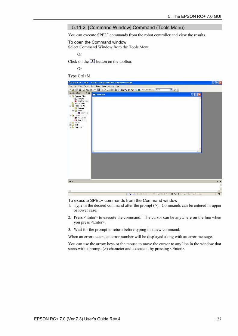
5. The EPSON RC+ 7.0 GUI
EPSON RC+ 7.0 (Ver.7.3) User's Guide Rev.4 127
5.11.2 [Command Window] Command (Tools Menu) You can execute SPEL+ commands from the robot controller and view the results.
To open the Command window Select Command Window from the Tools Menu
Or
Click on the button on the toolbar.
Or
Type Ctrl+M
To execute SPEL+ commands from the Command window 1. Type in the desired command after the prompt (>). Commands can be entered in upper
or lower case.
2. Press <Enter> to execute the command. The cursor can be anywhere on the line when you press <Enter>.
3. Wait for the prompt to return before typing in a new command.
When an error occurs, an error number will be displayed along with an error message.
You can use the arrow keys or the mouse to move the cursor to any line in the window that starts with a prompt (>) character and execute it by pressing <Enter>.
5. The EPSON RC+ 7.0 GUI
128 EPSON RC+ 7.0 (Ver.7.3) User's Guide Rev.4
Command Window Keys
Key Action
Ctrl+A Select entire window. Ctrl+C Stop the program and initialize robot controller. If a robot motion
command is in progress, the prompt will return when the command has been completed.
Ctrl+V Execute Paste command. Paste from Clipboard to current selection. Ctrl+W Re-display last command line after the prompt. Ctrl+X Execute Cut command. Cut current selection and put in Clipboard. Ctrl+Z Undo last change. Ctrl+Home Go to the top of the window. Ctrl+End Go to last prompt at end of the window. ? Translates to "PRINT " when used as the first character of a command.
This can be used to display variables or any statement that requires a PRINT command.
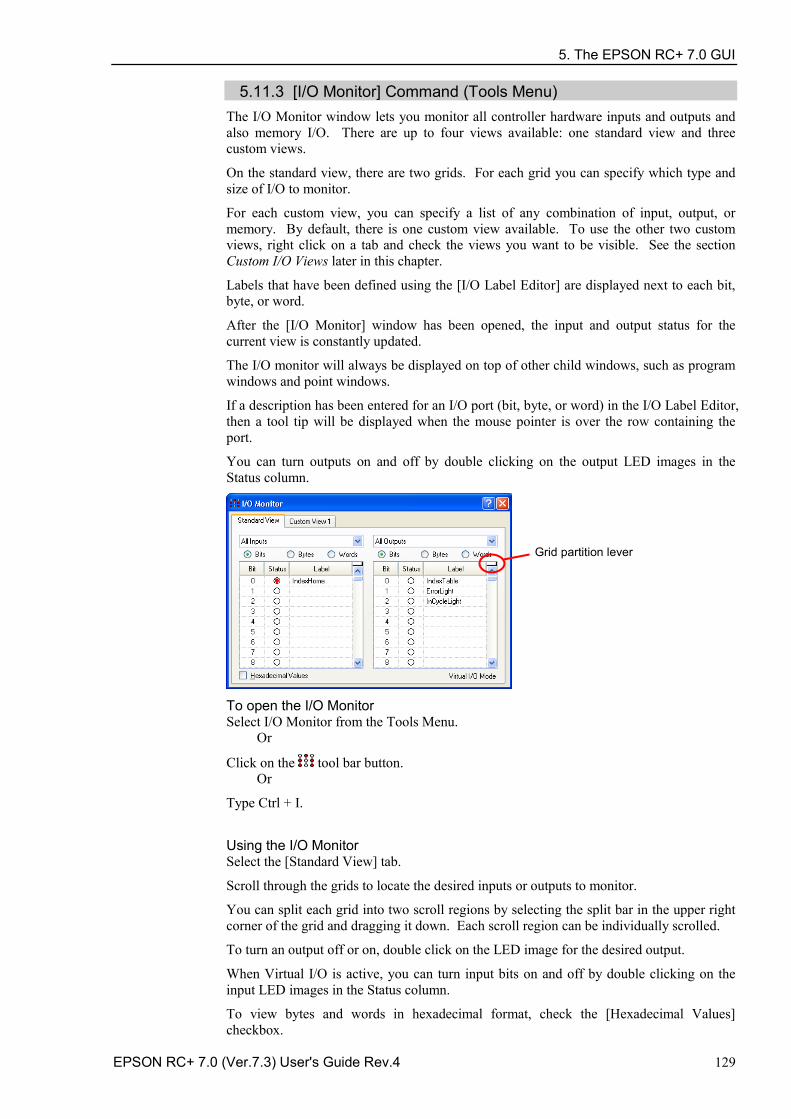
5. The EPSON RC+ 7.0 GUI
EPSON RC+ 7.0 (Ver.7.3) User's Guide Rev.4 129
5.11.3 [I/O Monitor] Command (Tools Menu) The I/O Monitor window lets you monitor all controller hardware inputs and outputs and also memory I/O. There are up to four views available: one standard view and three custom views.
On the standard view, there are two grids. For each grid you can specify which type and size of I/O to monitor.
For each custom view, you can specify a list of any combination of input, output, or memory. By default, there is one custom view available. To use the other two custom views, right click on a tab and check the views you want to be visible. See the section Custom I/O Views later in this chapter.
Labels that have been defined using the [I/O Label Editor] are displayed next to each bit, byte, or word.
After the [I/O Monitor] window has been opened, the input and output status for the current view is constantly updated.
The I/O monitor will always be displayed on top of other child windows, such as program windows and point windows.
If a description has been entered for an I/O port (bit, byte, or word) in the I/O Label Editor, then a tool tip will be displayed when the mouse pointer is over the row containing the port.
You can turn outputs on and off by double clicking on the output LED images in the Status column.
To open the I/O Monitor Select I/O Monitor from the Tools Menu. Or
Click on the tool bar button. Or
Type Ctrl + I.
Using the I/O Monitor Select the [Standard View] tab.
Scroll through the grids to locate the desired inputs or outputs to monitor.
You can split each grid into two scroll regions by selecting the split bar in the upper right corner of the grid and dragging it down. Each scroll region can be individually scrolled.
To turn an output off or on, double click on the LED image for the desired output.
When Virtual I/O is active, you can turn input bits on and off by double clicking on the input LED images in the Status column.
To view bytes and words in hexadecimal format, check the [Hexadecimal Values] checkbox.
Grid partition lever
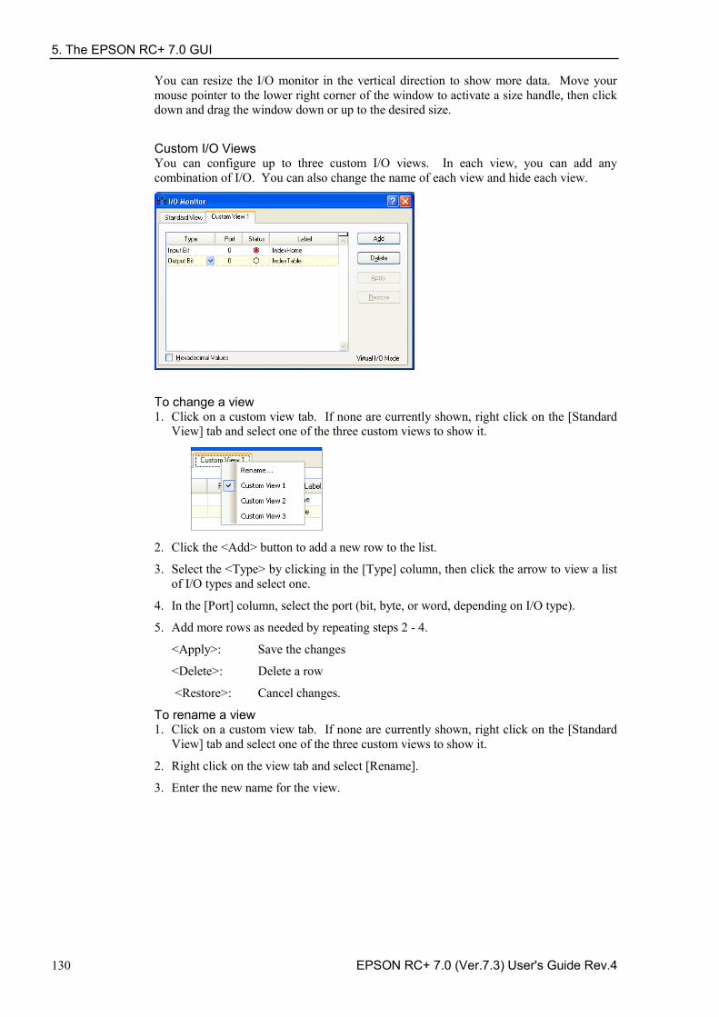
5. The EPSON RC+ 7.0 GUI
130 EPSON RC+ 7.0 (Ver.7.3) User's Guide Rev.4
You can resize the I/O monitor in the vertical direction to show more data. Move your mouse pointer to the lower right corner of the window to activate a size handle, then click down and drag the window down or up to the desired size.
Custom I/O Views You can configure up to three custom I/O views. In each view, you can add any combination of I/O. You can also change the name of each view and hide each view.
To change a view 1. Click on a custom view tab. If none are currently shown, right click on the [Standard
View] tab and select one of the three custom views to show it.
2. Click the <Add> button to add a new row to the list.
3. Select the <Type> by clicking in the [Type] column, then click the arrow to view a list of I/O types and select one.
4. In the [Port] column, select the port (bit, byte, or word, depending on I/O type).
5. Add more rows as needed by repeating steps 2 - 4.
<Apply>: Save the changes
<Delete>: Delete a row
<Restore>: Cancel changes.
To rename a view 1. Click on a custom view tab. If none are currently shown, right click on the [Standard
View] tab and select one of the three custom views to show it.
2. Right click on the view tab and select [Rename].
3. Enter the new name for the view.
5. The EPSON RC+ 7.0 GUI
EPSON RC+ 7.0 (Ver.7.3) User's Guide Rev.4 131
5.11.4 Task Manager Command (Tools Menu) The Task Manager window allows you to Halt (suspend), Resume (continue), and Quit (abort) tasks.
To open the Task Manager Select Task Manager from the Tools Menu.
Or
Type Ctrl + T.
Or
Click on the button on the toolbar.
Operation The Task Manager is used for suspending, resuming, stepping, and stopping tasks.
When Task Manager is started, you will see a grid containing status information for 32 tasks standard tasks and 11 trap tasks. Also, you will see the status information of 16 background tasks if the background task is enabled. There are 8 items shown for each task. To view all of the columns, use the scroll bar or resize the window.
Task Number of task from 1 to 32 and 11 trap tasks.
Name Name of the function that was started as a task.
Status Current task status: Run, Wait, Halt, Pause, Aborted, Finished.
Type Task types Normal This task is a normal task NoPause This task does not pause with Pause statement or when
Pause input or Safety Door open occur. NoEmgAbort This task continuously processes during the Emergency
Stop or error occurrence.
Line Current task line number.
Function Current task function name.
Program Current task program name.
Start The date and time that the task was started.
CPU CPU load factor of each task. This function assists problem detection of the user created tasks.
In the following Example 1, the function repeats until the standard input I/O bit port 1 turns ON.
Since Sw() is the command in which the tasks are not switched, this task occupies the process. It may affect other user tasks or the whole system of the Controller. In order to specify such tasks, use the CPU load factor display.
5. The EPSON RC+ 7.0 GUI
132 EPSON RC+ 7.0 (Ver.7.3) User's Guide Rev.4
Restrictions
Displayed values do not guarantee the accuracy. Due to limitations of measuring method, some differences are included. The load factor of the properly created program is minimal. Also, in a program like Example 2, commands are executed by other system tasks. Therefore, the load factor is displayed as “0”.
Example 1) Function main
Do Do
If Sw(1) = On Then Exit Do Loop Go P(0)
Loop Fend
Example 2)
Function main Do Print "TEST"
Loop Fend
Item Description
Halt Suspends the selected task. The halted task can be resumed by the <Resume> button. Halt can only be executed when a task is running (status is Run). When Halt is executed, the <Resume> button will be enabled. If a motion command associated with Halt is executed, the motion will be completed before the task reaches the Halt state.
The task also temporarily stops when the task is NoPause type or NoEmgAbort type.
Resume After one or more tasks are suspended with the <Halt> button, clicking <Resume> make the halted tasks continue where they left off. First, a confirmation dialog is displayed.
Quit This button stops the selected task permanently. You cannot resume a task once you have executed Quit. To restart the task, you must start it from within a program or from the Run window. The task also stops when the task is NoPause type or NoEmgAbort type.
Pause This button pauses tasks that can be paused. After pause, you must use either <Continue> or <Stop>. The task does not pause when the task is NoPause type or NoEmgAbort type.
Continue This button continues all tasks that were paused with the <Pause> button.
Stop This button stops all tasks.
5. The EPSON RC+ 7.0 GUI
EPSON RC+ 7.0 (Ver.7.3) User's Guide Rev.4 133
To Halt, Step, Walk, and Resume a task The <Halt> button will become active after you select a running task.
Click the <Halt> button to stop the task you selected for a moment.
After a task has been halted, the source code will be displayed and the next step will be indicated. You can click on the <Resume> button to resume execution. (You can also execute [Step Into], [Step Over], or [Walk] from the [Run] Menu.)
To Pause and Continue tasks Pause allows you to "suspend" all tasks that can be suspended.
Click on the <Pause> button to pause available tasks. The robot will decelerate to a stop immediately.
After executing Pause, click on <Continue> to resume all suspended tasks.
To view source code at the current execution line Select a task row. Then right click and select [Go To Line]. The program editor will be opened at the current execution line
5. The EPSON RC+ 7.0 GUI
134 EPSON RC+ 7.0 (Ver.7.3) User's Guide Rev.4
5.11.5 Macros Command (Tools Menu) You can create SPEL+ command macros using the Macro Editor. Macros consist of one or more SPEL+ statements that can be executed from the command window. A macro statement may use global variables, I/O labels, and point labels. You can assign a macro to each of the Alt function keys except for Alt+F4, which is a Windows shortcut to close the application.
1. Select [Tools]-[Macros] to open the [Command Macros] dialog box.
2. Type the macro statements in the [Macro] text box.
3. Click the <Apply> button to save changes.
4. Click <Execute> to run the macro.
5. Click <Close> to close the dialog. You will be prompted to save the macros you have created or changed.
To open a macro and execute it, type <Alt> + function key. Then click <Execute> to run it. Macros never execute by pressing the function key. The separate execute step is provided for safety, since macros can move the robot and control I/O.
Macros can be executed while tasks are running. If invalid commands are executed while tasks are running, an error will occur.
5. The EPSON RC+ 7.0 GUI
EPSON RC+ 7.0 (Ver.7.3) User's Guide Rev.4 135
5.11.6 [I/O Label Editor] Command (Tools Menu) The I/O label editor lets you define meaningful names for inputs, outputs, and memory I/O for each project. The labels can be used in your programs, from the Command window, or in macros. They are also displayed in the I/O Monitor window.
To open the I/O Label Editor Select I/O Label Editor from the Tools Menu.
Or
Type Ctrl + L.
Or
Click on the button on the toolbar.
The I/O Label Spreadsheet When you select [I/O Label Editor] from the [Tools] menu, a window opens that contains a tree and a spreadsheet editor.
The tree on the left side of the window shows the various types of I/O for the controller. For each type of I/O you can view and edit labels for bits, bytes (8 bits), and words (16 bits).
The first column of the spreadsheet shows the bit, byte, or word number, depending on which type of I/O you are viewing.
The second column contains the label for each bit, byte, or word in column 1. You can type in up to 32 characters for a label. Label characters can be alphanumeric or underscore.
The third column contains the description associated with the label.
If you add a description to an I/O point, then the description will be displayed as a tool tip on the I/O Monitor.
- The I/O Label Editor shows all available I/O types on your controller.
- For the Editor version, the I/O Label Editor shows the all I/O types. For example, you can edit Fieldbus I/O labels, but you may not have a Fieldbus board installed in the controller.
NOTE
5. The EPSON RC+ 7.0 GUI
136 EPSON RC+ 7.0 (Ver.7.3) User's Guide Rev.4
To add or edit a label Select the type of I/O you want to label in the tree. After you select the I/O type, the spreadsheet will be refreshed to display the labels for that type. The number of rows in the spreadsheet equals the number of bits, bytes, or words available for the type you have selected.
Use the mouse to scroll through the spreadsheet and put the cursor in the [Label] field next to the bit, bytes, or words number that you want to add a label to. Type in the label, which can be up to 32 alphanumeric characters without any spaces. Optionally, you can type a description for the label in the [Description] field.
After adding or editing labels, save the changes by executing [Save] from the [File] menu or by clicking on the <Save Project> toolbar button. If any duplicate labels are detected, an error message will be displayed and the save operation will be aborted. You must correct the duplication before you can save the labels successfully.
To cut and paste labels and descriptions You can cut and paste labels and descriptions by selecting with the mouse, then executing [Copy], [Cut], and [Paste] from the [Edit] menu.
You can also cut and paste entire rows using the following steps:
1. Select one or more rows by using the row selectors on the left and execute either the [Cut] or [Copy] command from the [Edit] menu. When selecting multiple rows, hold down the shift or control key while selecting rows with the mouse.
2. Select the row where you want to start the paste by clicking the row selector on the left of the row.
3. Execute the [Paste] command from the [Edit] menu.
5. The EPSON RC+ 7.0 GUI
EPSON RC+ 7.0 (Ver.7.3) User's Guide Rev.4 137
5.11.7 User Error Editor Command (Tools Menu) The User Error Editor allows you to define user errors.
User error numbers can be from 8000 to 8999.
Labels can be up to 16 characters in length.
It is recommended that you use the ER_ prefix for each error label and use all caps for the label. This makes it easy to see error labels in your code.
Some user error examples:
Error # Label Message
8000 ER_VACUUM Vacuum error has occurred.
8001 ER_INDEXOT Indexer overtime has occurred. In your program code, use the Error statement to generate a user error. For example:
On Vacuum
Wait Sw(VacOn), 1
If Tw = 1 Then
Error ER_VACUUM
EndIf The user error information is stored in the current project directory in a file called UserErrors.dat.
You can use the [Import] command from the [File] menu to import user errors from other projects.
After adding new error definitions, save the changes by executing Save from the [File] menu or by clicking on the <Save Project> toolbar button. If any duplicate labels are detected, an error message will be displayed and the save operation will be aborted. You must correct the duplication before you can save the labels successfully.
5. The EPSON RC+ 7.0 GUI
138 EPSON RC+ 7.0 (Ver.7.3) User's Guide Rev.4
5.11.8 [Controller] Command (Tools Menu) Select Controller from the [Tools] menu to open the [Controller Tools] dialog box.
From the [Controller Tools] dialog box, you can save and restore the complete controller configuration and the project using the [Backup Controller] and [Restore Controller] commands. You can also save and view controller status, and reset the controller.
Before servicing the system, you should execute [Backup Controller] and store the system configuration on an external media such as a USB memory key.
If required, you can use [Restore Controller] to restore previously stored data.
Backup Controller Use Backup Controller to save controller configuration data on your PC. The current status is saved in a folder containing several files. The controller configuration settings, task status, I/O status, robot status, etc. are saved in these files. This is useful for users to send a snapshot of the controller status to a system vendor or to Epson technical support, should the need arise.
Backup Controller is equivalent to connecting a USB memory key to the controller and pressing the TRIG button on the controller to save controller status. Controller status is stored in a folder named “B” followed by the controller type, the controller serial number, and the date / time.
You can configure the controller whether to save the project files in the status folder or not. See [Setup]-[System Configuration]-[Controller]-[Preferences].
1. Select [Tools]-[Controller].
2. Click on the <Backup Controller> button to open the [Browse For Folder] dialog box.
NOTE
5. The EPSON RC+ 7.0 GUI
EPSON RC+ 7.0 (Ver.7.3) User's Guide Rev.4 139
3. Select the disk drive and parent folder where you want to save the information. You can create a new parent folder by clicking the <Make New Folder> button.
4. Click <OK>. A new folder containing the backup files will be created in the selected folder named “B” followed by the controller type, the controller serial number, and the date / time.
Restore Controller Use Restore Controller to load controller settings from previously saved backup data. You cannot restore the controller data while tasks are running. If you attempt to do so, an error message will be displayed.
To restore controller configuration:
1. Select [Tools]-[Controller].
2. Click on the <Restore Controller> button to open the [Browse For Folder] dialog box.
3. Select the drive and folder where the information is stored. Controller backup
information is stored in a folder that is named “B” followed by the controller type, the controller serial number, and the date / time.
You can also select a folder containing export controller status information.
4. Click <OK> to display the dialog to select the restore data.
Robot names, serial numbers, calibrations checkbox This checkbox allows you to restore the robot name, robot serial number, Hofs data, and CalPls data. Make sure that the correct Hofs data is restored. If the wrong Hofs data is restored, the robot may move to wrong positions. The default setting is unchecked.
Robot maintenance configuration checkbox
This checkbox allows you to restore the parts consumption data. For details, refer to the following manual. Robot controller RC700 / RC700-A Maintenance 6 Alarm. This is not checked by the default setting.
NOTE
5. The EPSON RC+ 7.0 GUI
140 EPSON RC+ 7.0 (Ver.7.3) User's Guide Rev.4
Project checkbox This checkbox allows you to restore the files related to projects. The default setting is unchecked. When the project is restored, all the values of Global Preserve variables are restored. For details about Global Preserve variable backup, refer to 5.10.10 [Display Variables] Command (Run Menu).
Vision hardware configuration checkbox This checkbox allows you to restore the vision hardware configuration. For details, refer to the EPSON RC+ 7.0 option: Vision Guide 7.0. This is not checked by the default setting.
Security configuration checkbox This checkbox allows you to restore the security configuration. For details, refer to 15. Security. This is not checked by the default setting.
Force Sensing I/F configuration checkbox This checkbox allows you to restore the Force Sensing I/F configuration. For details, refer to EPSON RC+ 7.0 option Force Control 7.0. This is not checked by the default setting.
5. Click the <OK> button to restore the system information.
Restore the system configuration saved using Backup Controller only for the same system. When different system information is restored, the following warning message appears.
Click the <No> button to cancel restoration of data except for special situations such as controller replacement.
When restoring the backup which includes the data of the robot configured to the Drive Unit, be sure to restore the data while the Drive Unit is connected and turned on. When restoring the backup including the unsupported robot information to the target controller, an error occurs.
You cannot restore the backup including PG to the virtual controller.
View Controller Status Click the <View Controller Status> button to view the status data stored from a previous status export (see the Export Controller Status section above).
NOTE
NOTE
NOTE
NOTE
5. The EPSON RC+ 7.0 GUI
EPSON RC+ 7.0 (Ver.7.3) User's Guide Rev.4 141
To view controller status:
1. Select [Tools]-[Controller]. 2. Click on the <View Controller Status> button to open the [Browse For Folder] dialog.
3. Select the drive and folder where the information is stored. Controller status
information is stored in a folder that is named “B” followed by the controller type, the controller serial number, and the date / time.
4. Click <OK> to view the selected controller status. 5. The [Controller Status Viewer] dialog will be displayed.
6. Select items to view from the tree on the left side of the dialog. 7. To view another controller status, click the ellipses button next to the Status Folder
name and select a new status folder.
Reset Controller Use the <Reset Controller> button to reset the SPEL controller.
Maintenance It shows the parts consumption data for the Controller or Manipulator parts.
For details, refer to Maintenance 6. Alarm in the RC700 / RC700-A Controller Manual.
5. The EPSON RC+ 7.0 GUI
142 EPSON RC+ 7.0 (Ver.7.3) User's Guide Rev.4
5.12 [Setup] Menu The [Setup] menu contains the following commands:
PC to Controller Communications - System Configuration - Preferences - Options - 5.12.1 [PC to Controller Communications] Command (Setup Menu)
To configure communications with the Controller, select [PC to Controller Communications] from the [Setup] menu. The [PC to Controller Communications] dialog will be displayed as shown below:
Item Description Connect Connect the selected communication. Disconnect Disconnect the communication. Add Add communication information of Ethernet or a virtual controller.
Clicking this button opens the dialog to specify the communication type.
Program execution time In the virtual controller, programs will execute continuously for up to one hour. If continuous execution is over one hour, a warning message appears. You can execute the program again after the warning is displayed, and the continuous execution timer will be reset.
Delete Deletes selected communication information. Connection #1 “USB” cannot be deleted.
Apply Saves changes. Restore Restores to previous settings. Work Offline You can build a project without connecting to the controller in Offline
mode. Some functions such as Robot Manager are not available in this mode.
Auto Connect If the connection is enabled, connects to the controller automatically. Close Closes the dialog.
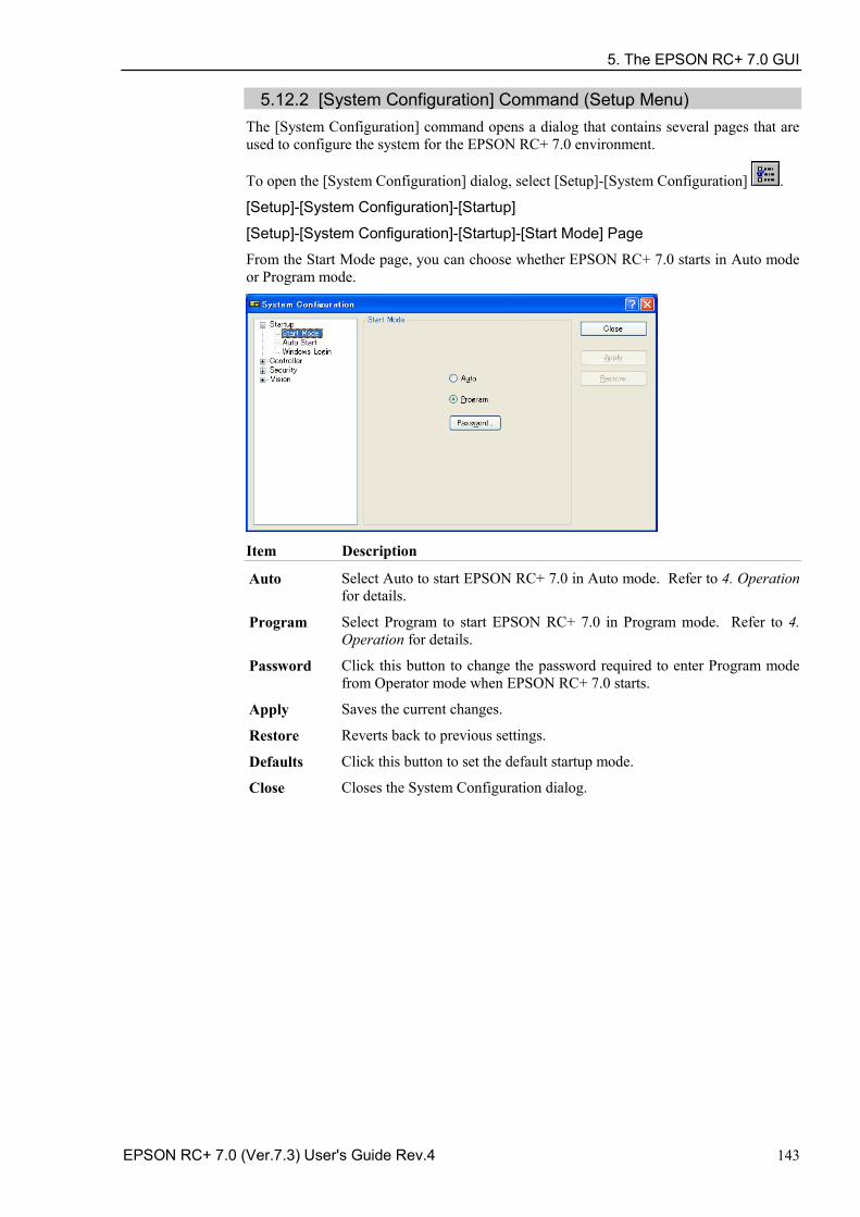
5. The EPSON RC+ 7.0 GUI
EPSON RC+ 7.0 (Ver.7.3) User's Guide Rev.4 143
5.12.2 [System Configuration] Command (Setup Menu) The [System Configuration] command opens a dialog that contains several pages that are used to configure the system for the EPSON RC+ 7.0 environment.
To open the [System Configuration] dialog, select [Setup]-[System Configuration] .
[Setup]-[System Configuration]-[Startup]
[Setup]-[System Configuration]-[Startup]-[Start Mode] Page
From the Start Mode page, you can choose whether EPSON RC+ 7.0 starts in Auto mode or Program mode.
Item Description
Auto Select Auto to start EPSON RC+ 7.0 in Auto mode. Refer to 4. Operation for details.
Program Select Program to start EPSON RC+ 7.0 in Program mode. Refer to 4. Operation for details.
Password Click this button to change the password required to enter Program mode from Operator mode when EPSON RC+ 7.0 starts.
Apply Saves the current changes.
Restore Reverts back to previous settings.
Defaults Click this button to set the default startup mode.
Close Closes the System Configuration dialog.
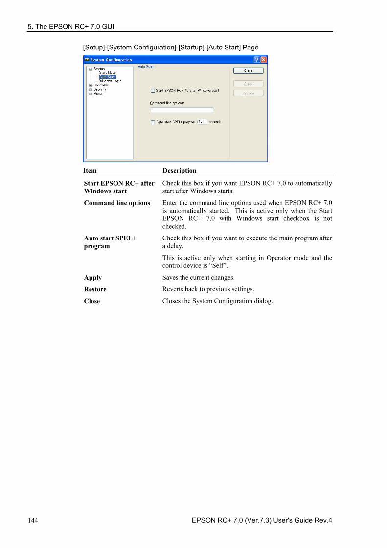
5. The EPSON RC+ 7.0 GUI
144 EPSON RC+ 7.0 (Ver.7.3) User's Guide Rev.4
[Setup]-[System Configuration]-[Startup]-[Auto Start] Page
Item Description
Start EPSON RC+ after Windows start
Check this box if you want EPSON RC+ 7.0 to automatically start after Windows starts.
Command line options Enter the command line options used when EPSON RC+ 7.0 is automatically started. This is active only when the Start EPSON RC+ 7.0 with Windows start checkbox is not checked.
Auto start SPEL+ program
Check this box if you want to execute the main program after a delay.
This is active only when starting in Operator mode and the control device is “Self”.
Apply Saves the current changes.
Restore Reverts back to previous settings.
Close Closes the System Configuration dialog.
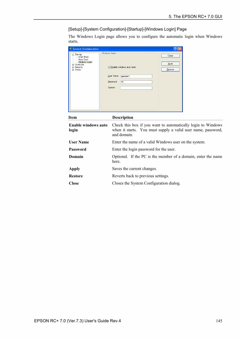
5. The EPSON RC+ 7.0 GUI
EPSON RC+ 7.0 (Ver.7.3) User's Guide Rev.4 145
[Setup]-[System Configuration]-[Startup]-[Windows Login] Page
The Windows Login page allows you to configure the automatic login when Windows starts.
Item Description
Enable windows auto login
Check this box if you want to automatically login to Windows when it starts. You must supply a valid user name, password, and domain.
User Name Enter the name of a valid Windows user on the system.
Password Enter the login password for the user.
Domain Optional. If the PC is the member of a domain, enter the name here.
Apply Saves the current changes.
Restore Reverts back to previous settings.
Close Closes the System Configuration dialog.
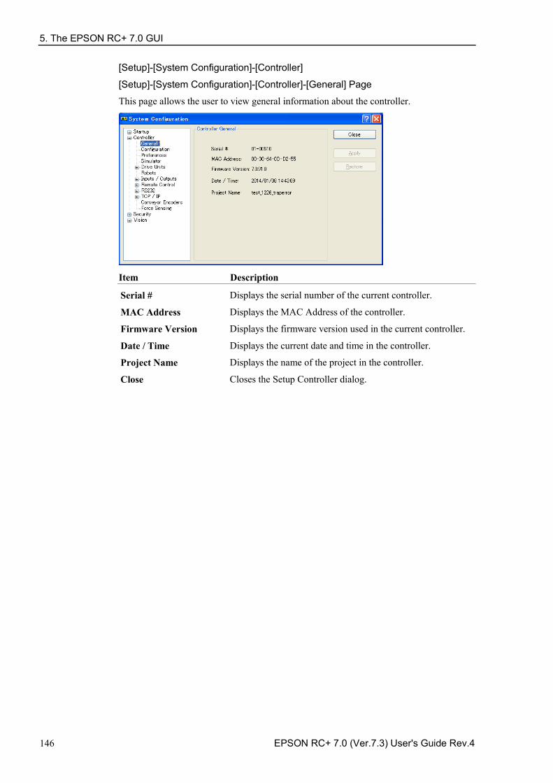
5. The EPSON RC+ 7.0 GUI
146 EPSON RC+ 7.0 (Ver.7.3) User's Guide Rev.4
[Setup]-[System Configuration]-[Controller]
[Setup]-[System Configuration]-[Controller]-[General] Page
This page allows the user to view general information about the controller.
Item Description
Serial # Displays the serial number of the current controller.
MAC Address Displays the MAC Address of the controller.
Firmware Version Displays the firmware version used in the current controller.
Date / Time Displays the current date and time in the controller.
Project Name Displays the name of the project in the controller.
Close Closes the Setup Controller dialog.
5. The EPSON RC+ 7.0 GUI
EPSON RC+ 7.0 (Ver.7.3) User's Guide Rev.4 147
[Setup]-[System Configuration]-[Controller]-[Configuration] Page
This page allows the user to view and change the controller configuration settings.
Item Description
Name Use this text box to change the controller name. You may use any name up to 16 characters long using alphanumeric characters and underscore.
IP Address Use this text box to set current IP address of the LAN-1 port. The IP Address must be on the same subnet as the PC.
IP Mask Use this text box to set the IP mask of the LAN-1 port. Note that the IP Mask must match the IP mask used for your network.
IP Gateway Use this text box to set the IP gateway of the LAN-1 port. This is only required if you will be accessing the controller from outside of the local network.
Control Device Allows you to select the Control Device.
TP Password Allows you to change the TP password.
T2 Password Allows you to change the TP2 password.
Apply Saves the current changes. If necessary, the controller will be reset to use the new settings.
Restore Reverts back to previous settings.
Close Closes the Setup Controller dialog.
5. The EPSON RC+ 7.0 GUI
148 EPSON RC+ 7.0 (Ver.7.3) User's Guide Rev.4
[Setup]-[System Configuration]-[Controller]-[Preferences] Page
This page contains controller preference settings.
RESET command turns off outputs When this preference is turned on, all outputs other than remote control outputs will be turned off when a Reset instruction is executed. The default setting is off.
The outputs of the standard I/O, expansion I/O, and Fieldbus I/O are included in the “outputs” mentioned in the above preferences [RESET command turns off outputs] and [Outputs off during Emergency Stop]. Memory I/O is not affected by these preferences. Therefore, memory I/O bits are not turned off by the RESET command execution or during Emergency Stop.
Outputs off during Emergency Stop When this preference is turned on, all outputs other than remote control outputs will be turned off when emergency stop occurs. Also, no outputs can be turned on until the emergency stop condition is cleared. The default setting is on.
Uncheck this preference to execute I/O On/Off using the NoEmgAbort task or background task after Emergency Stop. If it remains checked, the execution order of turn off by this preference and turn on using the task are not guaranteed.
You should design your system to always remove all power to output devices when emergency stop occurs. Even if the controller turns off outputs, the I/O hardware could malfunction.
Allow motion with one or more joints free When this preference is turned on, motion commands can be executed after SFree has been used to free one or more joints. The default setting is off.
Walk stops for output commands When checked, the Walk command from the Run Menu will execute lines until after the next motion or output statement (whichever comes first). When unchecked, the Walk command will execute lines until after the next motion statement and will not stop for output statements. The default setting is on.
Dry run This preference allows you to run programs without a robot connected to the controller. All program statements will work. Motion statements will execute approximately the same amount of time as when connected to a robot.
NOTE
NOTE
5. The EPSON RC+ 7.0 GUI
EPSON RC+ 7.0 (Ver.7.3) User's Guide Rev.4 149
Virtual I/O This preference allows you to run programs using virtual I/O. When Virtual I/O is enabled, I/O commands do not affect the hardware I/O. There are also several commands available for turning on inputs from within a program. The default setting is off.
Remote function is also available when virtual I/O is enabled.
Include project files when status exported
This preference allows you to configure whether project files are included or not when the controller status is exported. Refer to 5.11.8 [Controller] Command (Tools Menu). The default setting is on. Safeguard open stops all tasks Check this option to cause all normal tasks and NoPause task to stop when the safeguard is open. Only NoEmgAbort task and background tasks will continue. This option can be used in applications where pause / continue are not required. The default setting is off. Auto safeguard position recovery This preference allows you to move a robot back to the position where it was at the safeguard opened when continuing the program execution.
Auto recover ON Automatically turns ON a motor and moves a robot in low power status to the position where it was when the safeguard opened.
Continues the usual cycle. (Default)
Auto recover OFF In the Run Window and Operator Window, when an operator clicks the Continue button, a dialog with a Recover button will be shown. The operator needs to hold down the Recover button until the motor is ON and the robot’s return is finished. Otherwise the robot will stop before reaching final position. After verifying that the robot’s return is finished, the operator clicks the Continue button to continue the usual cycle.
For more information, refer to 15. Security – Recover motion to safeguard open position. Independent Mode
This preference allows you to use the controller without interfacing with the Windows (Independent mode). Use this option when you want to use the controller through the external device using Remote I/O. This option is checked by default.
Initialize global variables when Main XX function started
This preference allows you to initialize the global variables as the main function becomes active. Turn off this preference when you sue the global variables from the background task. Otherwise, the variables will be initialized by the controller and the variable-access conflict from tasks will occur. This is turned on by default.
NOTE
5. The EPSON RC+ 7.0 GUI
150 EPSON RC+ 7.0 (Ver.7.3) User's Guide Rev.4
Enable background tasks This preference allows you to execute background tasks. This is turned off by default.
Enable advanced task commands This preference allows you to execute StartMain, Cont, Recover, Reset Error commands. This is turned off by default.
CAUTION
■ Before you execute StartMain, Cont, Recover, Reset Error commands, you should understand each command's specification and verify that the system has the appropriate condition to execute these commands.
Improper use, such as executing commands continuously in a loop, can reduce the security of system.
Enable CP – PTP connection when CP is ON This preference allows you to overlap the trajectories of CP motion and PTP motion during CP ON.
Over-speed error or Over-acceleration-speed error may occur according to the motion acceleration / deceleration speed setting. If the error occurs, adjust the acceleration / deceleration speed setting or uncheck this checkbox.
Auto LJM (Least Joint Motion) This preference allows you to enable Auto LJM at the controller start up. To disable Auto LJM temporarily, use AutoLJM Off command.
If Auto LJM is enabled at all times, this function automatically adjusts the posture of the robot to reduce the motion distance, even when you intended to move the joint widely. Therefore, it is recommended to disable Auto LJM at the controller start up and operate the robot as you desired using AutoLJM On command or LJM function.
Disable LJM in Teach Mode This preference allows you to invalidate LJM in the TEACH mode. The LJM function becomes invalid regardless of the command of AutoLJM. The default setting is unchecked.
Disable Point flag check This preference allows you to continue operation even when point flags, one was specified as a target point and the other one after the motion completion, do not match in a CP motion.
However, if the flags do not match at the transferring point while CP On is used, the robot will stop at the point and the motion will not become a path motion.
Motor off when Enable switch off in Teach Mode This preference is read-only. It shows whether motors will be turned off when the Enable switch is off during Teach Mode.
Enable robot maintenance data
This preference allows you to enable the parts consumption management for the Controller and robot parts. The default setting is unchecked.
Initial status (at shipment) of controller firmware Ver.7.2.0.x or later is enabled.
NOTE
NOTE
NOTE
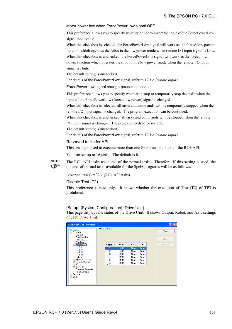
5. The EPSON RC+ 7.0 GUI
EPSON RC+ 7.0 (Ver.7.3) User's Guide Rev.4 151
Motor power low when ForcePowerLow signal OFF
This preference allows you to specify whether or not to invert the logic of the ForcePowerLow signal input value. When this checkbox is selected, the ForcePowerLow signal will work as the forced low power function which operates the robot in the low power mode when remote I/O input signal is Low. When this checkbox is unchecked, the ForcePowerLow signal will work as the forced low power function which operates the robot in the low power mode when the remote I/O input signal is High. The default setting is unchecked. For details of the ForcePowerLow signal, refer to 12.1.6 Remote Inputs.
ForcePowerLow signal change pauses all tasks
This preference allows you to specify whether to stop or temporarily stop the tasks when the input of the ForcePowerLow (forced low power) signal is changed. When this checkbox is selected, all tasks and commands will be temporarily stopped when the remote I/O input signal is changed. The program execution can be continued. When this checkbox is unchecked, all tasks and commands will be stopped when the remote I/O input signal is changed. The program needs to be restarted. The default setting is unchecked. For details of the ForcePowerLow signal, refer to 12.1.6 Remote Inputs.
Reserved tasks for API This setting is used to execute more than one Spel class methods of the RC+ API.
You can set up to 16 tasks. The default is 0.
The RC+ API tasks use some of the normal tasks. Therefore, if this setting is used, the number of normal tasks available for the Spel+ programs will be as follows:
(Normal tasks) = 32 - (RC+ API tasks)
Disable Test (T2) This preference is read-only. It shows whether the execution of Test (T2) of TP3 is prohibited.
[Setup]-[System Configuration]-[Drive Unit] This page displays the status of the Drive Unit. It shows Output, Robot, and Axis settings of each Drive Unit.
NOTE
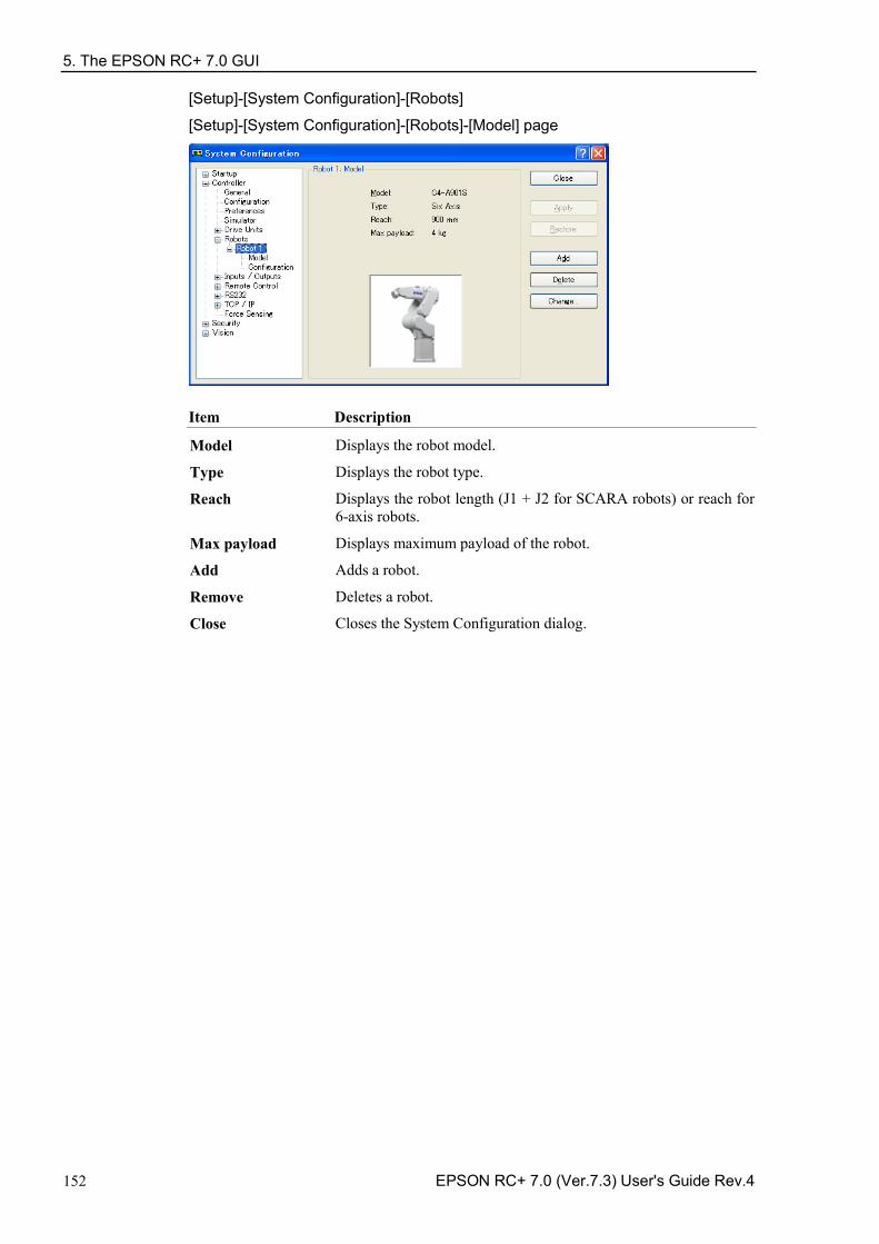
5. The EPSON RC+ 7.0 GUI
152 EPSON RC+ 7.0 (Ver.7.3) User's Guide Rev.4
[Setup]-[System Configuration]-[Robots]
[Setup]-[System Configuration]-[Robots]-[Model] page
Item Description
Model Displays the robot model.
Type Displays the robot type.
Reach Displays the robot length (J1 + J2 for SCARA robots) or reach for 6-axis robots.
Max payload Displays maximum payload of the robot.
Add Adds a robot.
Remove Deletes a robot.
Close Closes the System Configuration dialog.
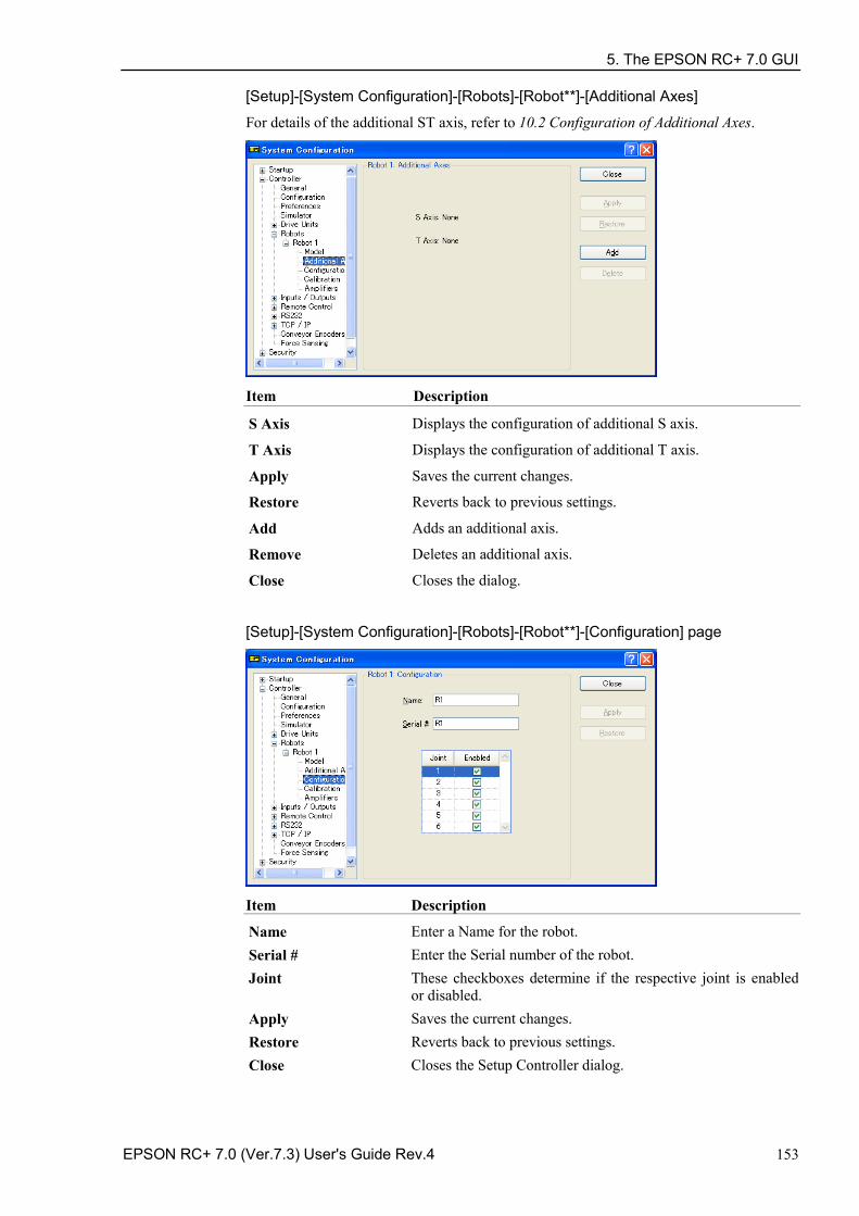
5. The EPSON RC+ 7.0 GUI
EPSON RC+ 7.0 (Ver.7.3) User's Guide Rev.4 153
[Setup]-[System Configuration]-[Robots]-[Robot**]-[Additional Axes]
For details of the additional ST axis, refer to 10.2 Configuration of Additional Axes.
Item Description
S Axis Displays the configuration of additional S axis.
T Axis Displays the configuration of additional T axis.
Apply Saves the current changes.
Restore Reverts back to previous settings.
Add Adds an additional axis.
Remove Deletes an additional axis.
Close Closes the dialog.
[Setup]-[System Configuration]-[Robots]-[Robot**]-[Configuration] page
Item Description
Name Enter a Name for the robot. Serial # Enter the Serial number of the robot. Joint These checkboxes determine if the respective joint is enabled
or disabled. Apply Saves the current changes. Restore Reverts back to previous settings. Close Closes the Setup Controller dialog.
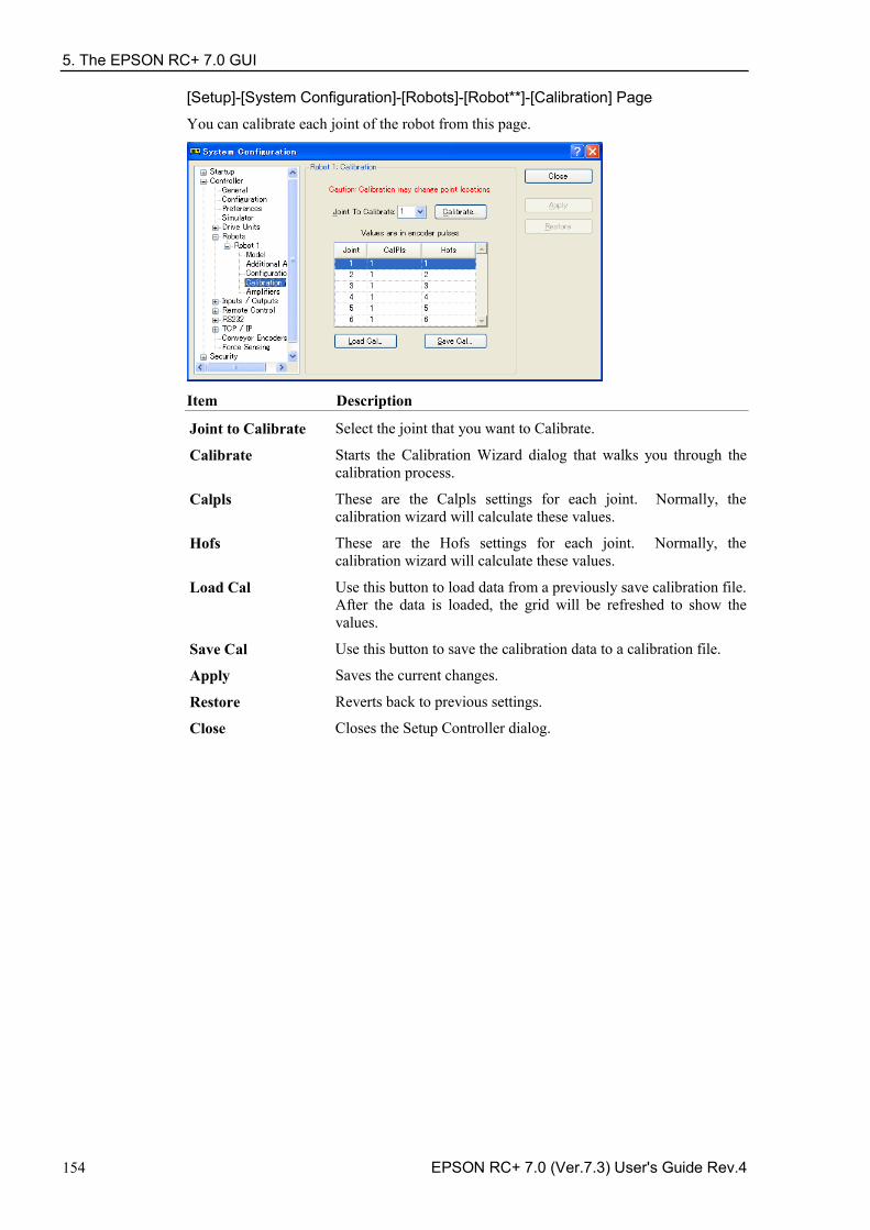
5. The EPSON RC+ 7.0 GUI
154 EPSON RC+ 7.0 (Ver.7.3) User's Guide Rev.4
[Setup]-[System Configuration]-[Robots]-[Robot**]-[Calibration] Page
You can calibrate each joint of the robot from this page.
Item Description
Joint to Calibrate Select the joint that you want to Calibrate.
Calibrate Starts the Calibration Wizard dialog that walks you through the calibration process.
Calpls These are the Calpls settings for each joint. Normally, the calibration wizard will calculate these values.
Hofs These are the Hofs settings for each joint. Normally, the calibration wizard will calculate these values.
Load Cal Use this button to load data from a previously save calibration file. After the data is loaded, the grid will be refreshed to show the values.
Save Cal Use this button to save the calibration data to a calibration file.
Apply Saves the current changes.
Restore Reverts back to previous settings.
Close Closes the Setup Controller dialog.
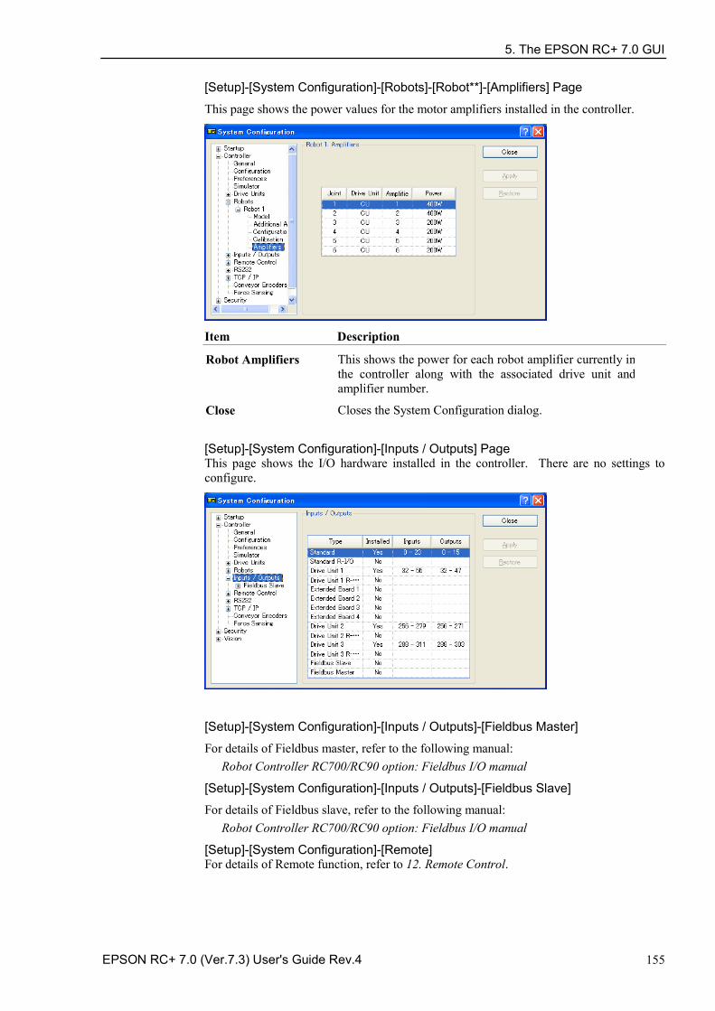
5. The EPSON RC+ 7.0 GUI
EPSON RC+ 7.0 (Ver.7.3) User's Guide Rev.4 155
[Setup]-[System Configuration]-[Robots]-[Robot**]-[Amplifiers] Page
This page shows the power values for the motor amplifiers installed in the controller.
Item Description
Robot Amplifiers This shows the power for each robot amplifier currently in the controller along with the associated drive unit and amplifier number.
Close Closes the System Configuration dialog.
[Setup]-[System Configuration]-[Inputs / Outputs] Page This page shows the I/O hardware installed in the controller. There are no settings to configure.
[Setup]-[System Configuration]-[Inputs / Outputs]-[Fieldbus Master]
For details of Fieldbus master, refer to the following manual: Robot Controller RC700/RC90 option: Fieldbus I/O manual
[Setup]-[System Configuration]-[Inputs / Outputs]-[Fieldbus Slave]
For details of Fieldbus slave, refer to the following manual: Robot Controller RC700/RC90 option: Fieldbus I/O manual
[Setup]-[System Configuration]-[Remote] For details of Remote function, refer to 12. Remote Control.
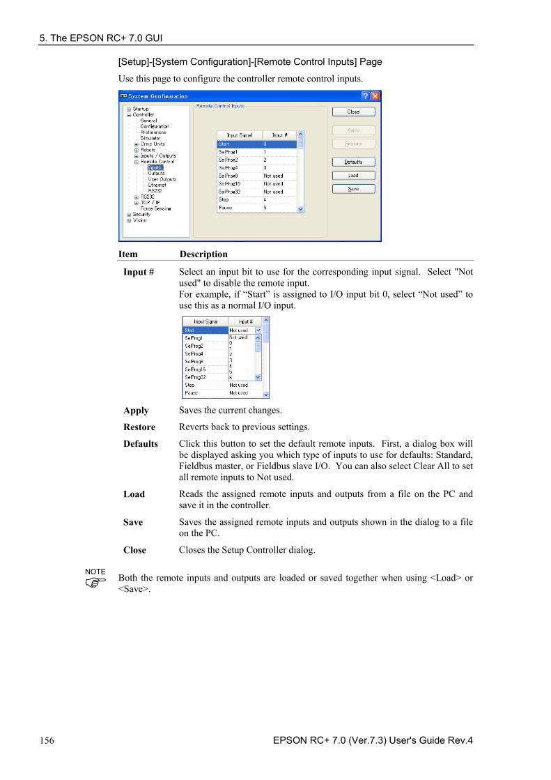
5. The EPSON RC+ 7.0 GUI
156 EPSON RC+ 7.0 (Ver.7.3) User's Guide Rev.4
[Setup]-[System Configuration]-[Remote Control Inputs] Page
Use this page to configure the controller remote control inputs.
Item Description
Input # Select an input bit to use for the corresponding input signal. Select "Not used" to disable the remote input. For example, if “Start” is assigned to I/O input bit 0, select “Not used” to use this as a normal I/O input.
Apply Saves the current changes.
Restore Reverts back to previous settings.
Defaults Click this button to set the default remote inputs. First, a dialog box will be displayed asking you which type of inputs to use for defaults: Standard, Fieldbus master, or Fieldbus slave I/O. You can also select Clear All to set all remote inputs to Not used.
Load Reads the assigned remote inputs and outputs from a file on the PC and save it in the controller.
Save Saves the assigned remote inputs and outputs shown in the dialog to a file on the PC.
Close Closes the Setup Controller dialog.
Both the remote inputs and outputs are loaded or saved together when using <Load> or <Save>.
NOTE
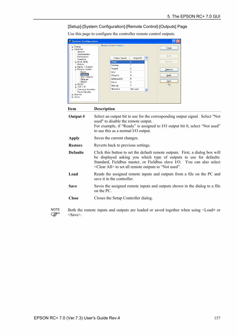
5. The EPSON RC+ 7.0 GUI
EPSON RC+ 7.0 (Ver.7.3) User's Guide Rev.4 157
[Setup]-[System Configuration]-[Remote Control]-[Outputs] Page
Use this page to configure the controller remote control outputs.
Item Description
Output # Select an output bit to use for the corresponding output signal. Select "Not used" to disable the remote output. For example, if “Ready” is assigned to I/O output bit 0, select “Not used” to use this as a normal I/O output.
Apply Saves the current changes.
Restore Reverts back to previous settings.
Defaults Click this button to set the default remote outputs. First, a dialog box will be displayed asking you which type of outputs to use for defaults: Standard, Fieldbus master, or Fieldbus slave I/O. You can also select <Clear All> to set all remote outputs to “Not used”.
Load Reads the assigned remote inputs and outputs from a file on the PC and save it in the controller.
Save Saves the assigned remote inputs and outputs shown in the dialog to a file on the PC.
Close Closes the Setup Controller dialog.
Both the remote inputs and outputs are loaded or saved together when using <Load> or <Save>.
NOTE
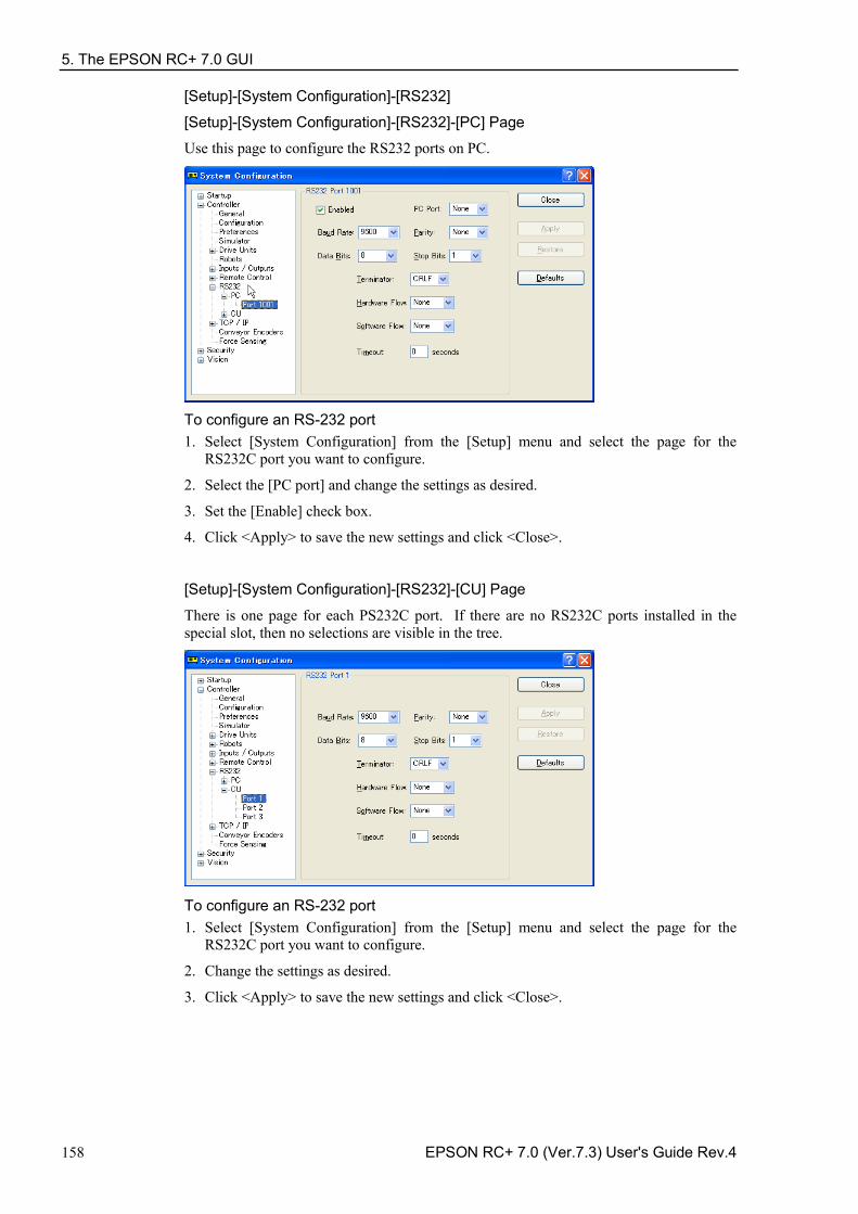
5. The EPSON RC+ 7.0 GUI
158 EPSON RC+ 7.0 (Ver.7.3) User's Guide Rev.4
[Setup]-[System Configuration]-[RS232]
[Setup]-[System Configuration]-[RS232]-[PC] Page
Use this page to configure the RS232 ports on PC.
To configure an RS-232 port 1. Select [System Configuration] from the [Setup] menu and select the page for the
RS232C port you want to configure.
2. Select the [PC port] and change the settings as desired.
3. Set the [Enable] check box.
4. Click <Apply> to save the new settings and click <Close>.
[Setup]-[System Configuration]-[RS232]-[CU] Page
There is one page for each PS232C port. If there are no RS232C ports installed in the special slot, then no selections are visible in the tree.
To configure an RS-232 port 1. Select [System Configuration] from the [Setup] menu and select the page for the
RS232C port you want to configure.
2. Change the settings as desired.
3. Click <Apply> to save the new settings and click <Close>.
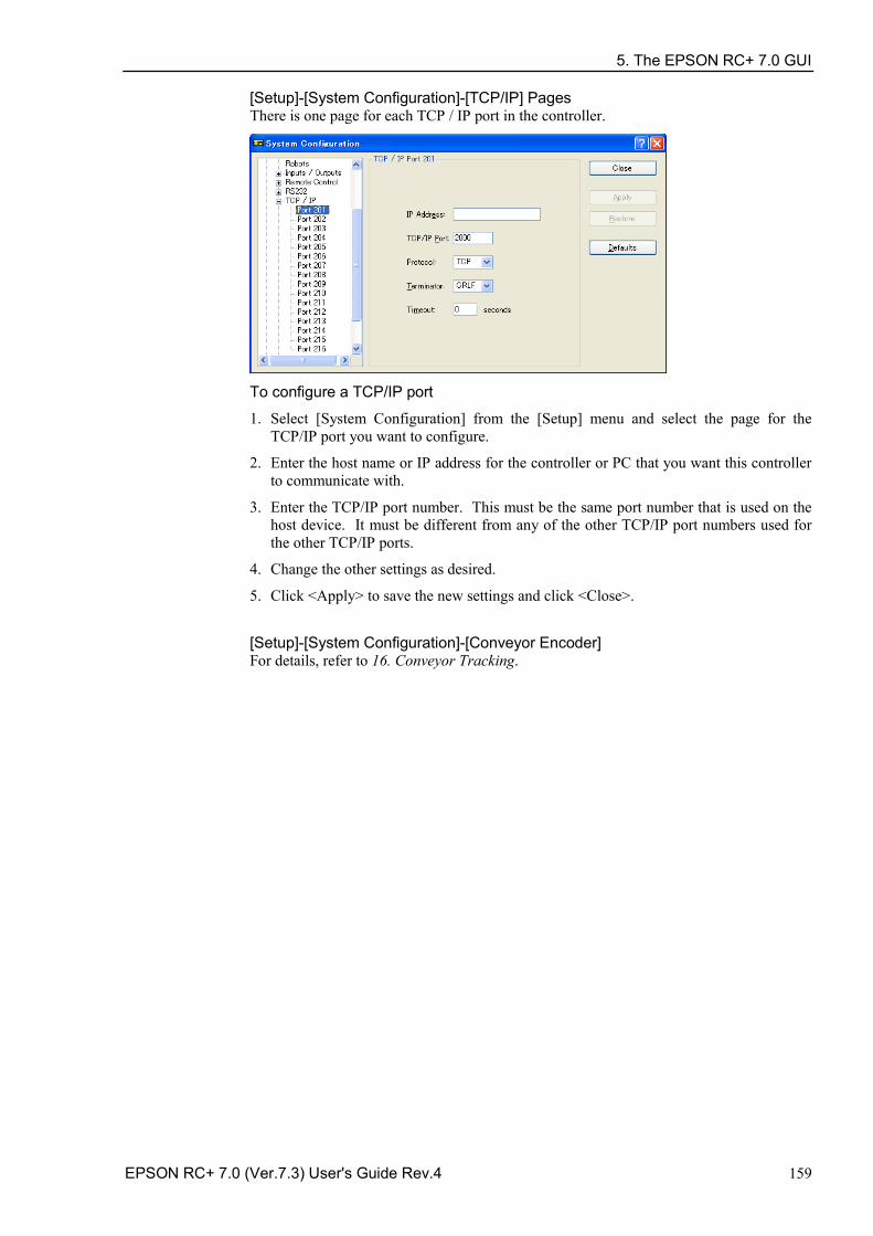
5. The EPSON RC+ 7.0 GUI
EPSON RC+ 7.0 (Ver.7.3) User's Guide Rev.4 159
[Setup]-[System Configuration]-[TCP/IP] Pages There is one page for each TCP / IP port in the controller.
To configure a TCP/IP port
1. Select [System Configuration] from the [Setup] menu and select the page for the TCP/IP port you want to configure.
2. Enter the host name or IP address for the controller or PC that you want this controller to communicate with.
3. Enter the TCP/IP port number. This must be the same port number that is used on the host device. It must be different from any of the other TCP/IP port numbers used for the other TCP/IP ports.
4. Change the other settings as desired.
5. Click <Apply> to save the new settings and click <Close>.
[Setup]-[System Configuration]-[Conveyor Encoder] For details, refer to 16. Conveyor Tracking.
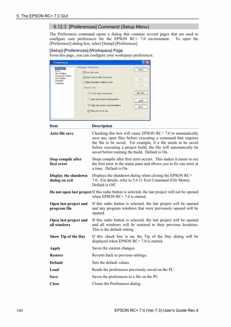
5. The EPSON RC+ 7.0 GUI
160 EPSON RC+ 7.0 (Ver.7.3) User's Guide Rev.4
5.12.3 [Preferences] Command (Setup Menu) The Preferences command opens a dialog that contains several pages that are used to configure user preferences for the EPSON RC+ 7.0 environment. To open the [Preferences] dialog box, select [Setup]-[Preferences].
[Setup]-[Preferences]-[Workspace] Page From this page, you can configure your workspace preferences.
Item Description
Auto file save Checking this box will cause EPSON RC+ 7.0 to automatically save any open files before executing a command that requires the file to be saved. For example, if a file needs to be saved before executing a project build, the file will automatically be saved before running the build. Default is On.
Stop compile after first error
Stops compile after first error occurs. This makes it easier to see the first error in the status pane and allows you to fix one error at a time. Default is On.
Display the shutdown dialog on exit
Displays the shutdown dialog when closing the EPSON RC+ 7.0. For details, refer to 5.6.11 Exit Command (File Menu). Default is Off.
Do not open last project If this radio button is selected, the last project will not be opened when EPSON RC+ 7.0 is started.
Open last project and program file
If this radio button is selected, the last project will be opened and any program windows that were previously opened will be opened.
Open last project and all windows
If this radio button is selected, the last project will be opened and all windows will be restored to their previous locations. This is the default setting.
Show Tip of the Day If this check box is on, the Tip of the Day dialog will be displayed when EPSON RC+ 7.0 is started.
Apply Saves the current changes.
Restore Reverts back to previous settings.
Default Sets the default values.
Load Reads the preferences previously saved on the PC.
Save Saves the preferences to a file on the PC.
Close Closes the Preferences dialog.
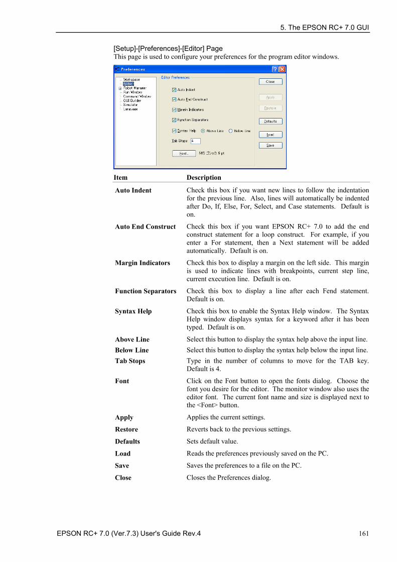
5. The EPSON RC+ 7.0 GUI
EPSON RC+ 7.0 (Ver.7.3) User's Guide Rev.4 161
[Setup]-[Preferences]-[Editor] Page This page is used to configure your preferences for the program editor windows.
Item Description
Auto Indent Check this box if you want new lines to follow the indentation for the previous line. Also, lines will automatically be indented after Do, If, Else, For, Select, and Case statements. Default is on.
Auto End Construct Check this box if you want EPSON RC+ 7.0 to add the end construct statement for a loop construct. For example, if you enter a For statement, then a Next statement will be added automatically. Default is on.
Margin Indicators Check this box to display a margin on the left side. This margin is used to indicate lines with breakpoints, current step line, current execution line. Default is on.
Function Separators Check this box to display a line after each Fend statement. Default is on.
Syntax Help Check this box to enable the Syntax Help window. The Syntax Help window displays syntax for a keyword after it has been typed. Default is on.
Above Line Select this button to display the syntax help above the input line. Below Line Select this button to display the syntax help below the input line. Tab Stops Type in the number of columns to move for the TAB key.
Default is 4.
Font Click on the Font button to open the fonts dialog. Choose the font you desire for the editor. The monitor window also uses the editor font. The current font name and size is displayed next to the <Font> button.
Apply Applies the current settings.
Restore Reverts back to the previous settings.
Defaults Sets default value.
Load Reads the preferences previously saved on the PC.
Save Saves the preferences to a file on the PC.
Close Closes the Preferences dialog.
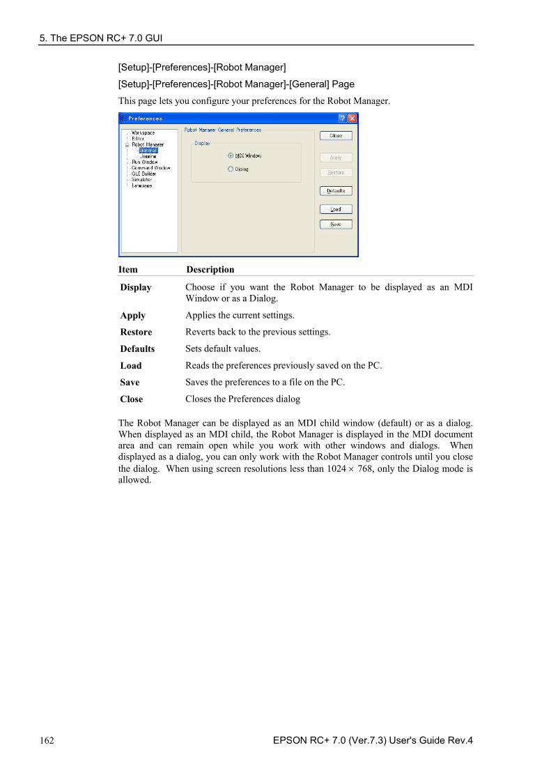
5. The EPSON RC+ 7.0 GUI
162 EPSON RC+ 7.0 (Ver.7.3) User's Guide Rev.4
[Setup]-[Preferences]-[Robot Manager]
[Setup]-[Preferences]-[Robot Manager]-[General] Page
This page lets you configure your preferences for the Robot Manager.
Item Description
Display Choose if you want the Robot Manager to be displayed as an MDI Window or as a Dialog.
Apply Applies the current settings.
Restore Reverts back to the previous settings.
Defaults Sets default values.
Load Reads the preferences previously saved on the PC.
Save Saves the preferences to a file on the PC.
Close Closes the Preferences dialog The Robot Manager can be displayed as an MDI child window (default) or as a dialog. When displayed as an MDI child, the Robot Manager is displayed in the MDI document area and can remain open while you work with other windows and dialogs. When displayed as a dialog, you can only work with the Robot Manager controls until you close the dialog. When using screen resolutions less than 1024 × 768, only the Dialog mode is allowed.
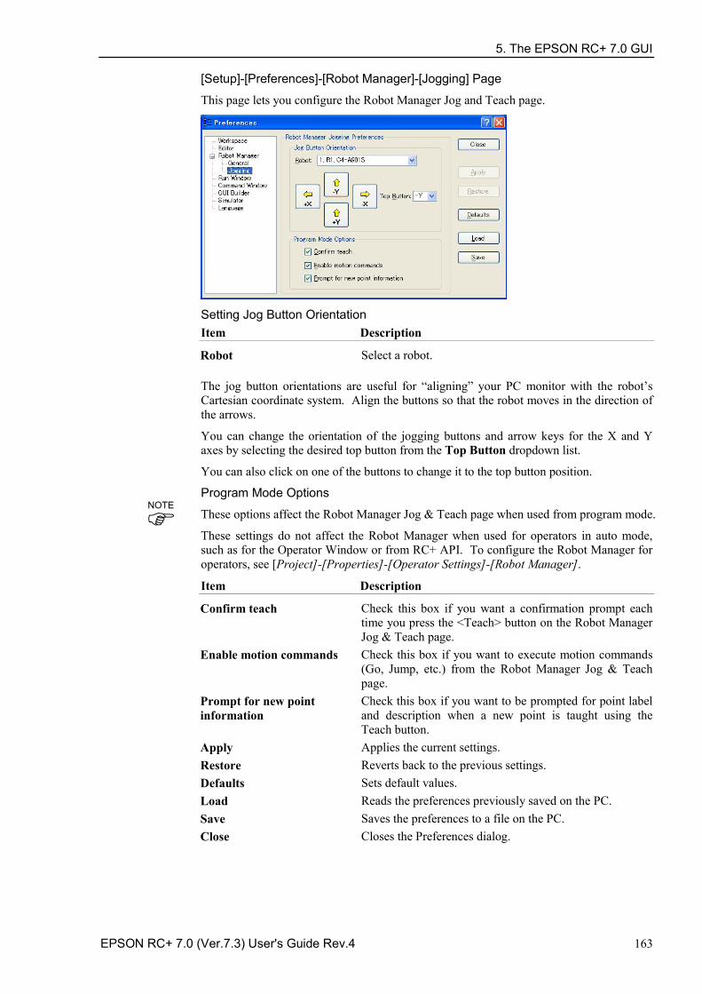
5. The EPSON RC+ 7.0 GUI
EPSON RC+ 7.0 (Ver.7.3) User's Guide Rev.4 163
[Setup]-[Preferences]-[Robot Manager]-[Jogging] Page
This page lets you configure the Robot Manager Jog and Teach page.
Setting Jog Button Orientation Item Description
Robot Select a robot. The jog button orientations are useful for “aligning” your PC monitor with the robot’s Cartesian coordinate system. Align the buttons so that the robot moves in the direction of the arrows.
You can change the orientation of the jogging buttons and arrow keys for the X and Y axes by selecting the desired top button from the Top Button dropdown list.
You can also click on one of the buttons to change it to the top button position.
Program Mode Options
These options affect the Robot Manager Jog & Teach page when used from program mode.
These settings do not affect the Robot Manager when used for operators in auto mode, such as for the Operator Window or from RC+ API. To configure the Robot Manager for operators, see [Project]-[Properties]-[Operator Settings]-[Robot Manager].
Item Description
Confirm teach Check this box if you want a confirmation prompt each time you press the <Teach> button on the Robot Manager Jog & Teach page.
Enable motion commands Check this box if you want to execute motion commands (Go, Jump, etc.) from the Robot Manager Jog & Teach page.
Prompt for new point information
Check this box if you want to be prompted for point label and description when a new point is taught using the Teach button.
Apply Applies the current settings. Restore Reverts back to the previous settings. Defaults Sets default values. Load Reads the preferences previously saved on the PC. Save Saves the preferences to a file on the PC. Close Closes the Preferences dialog.
NOTE
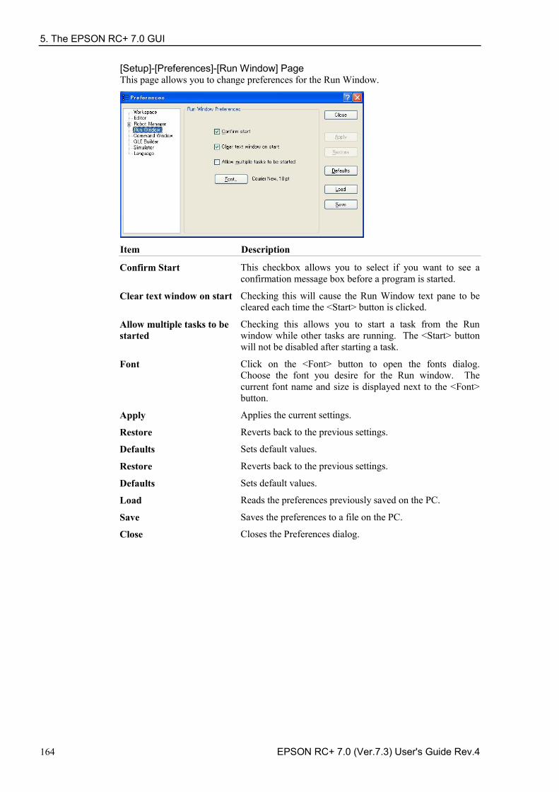
5. The EPSON RC+ 7.0 GUI
164 EPSON RC+ 7.0 (Ver.7.3) User's Guide Rev.4
[Setup]-[Preferences]-[Run Window] Page This page allows you to change preferences for the Run Window.
Item Description
Confirm Start This checkbox allows you to select if you want to see a confirmation message box before a program is started.
Clear text window on start Checking this will cause the Run Window text pane to be cleared each time the <Start> button is clicked.
Allow multiple tasks to be started
Checking this allows you to start a task from the Run window while other tasks are running. The <Start> button will not be disabled after starting a task.
Font Click on the <Font> button to open the fonts dialog. Choose the font you desire for the Run window. The current font name and size is displayed next to the <Font> button.
Apply Applies the current settings.
Restore Reverts back to the previous settings.
Defaults Sets default values.
Restore Reverts back to the previous settings.
Defaults Sets default values.
Load Reads the preferences previously saved on the PC.
Save Saves the preferences to a file on the PC.
Close Closes the Preferences dialog.
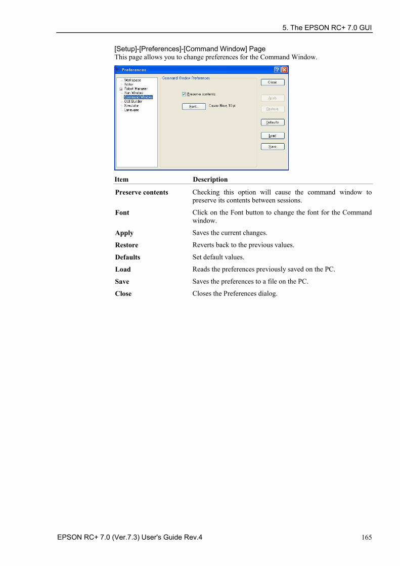
5. The EPSON RC+ 7.0 GUI
EPSON RC+ 7.0 (Ver.7.3) User's Guide Rev.4 165
[Setup]-[Preferences]-[Command Window] Page This page allows you to change preferences for the Command Window.
Item Description
Preserve contents Checking this option will cause the command window to preserve its contents between sessions.
Font Click on the Font button to change the font for the Command window.
Apply Saves the current changes.
Restore Reverts back to the previous values.
Defaults Set default values.
Load Reads the preferences previously saved on the PC.
Save Saves the preferences to a file on the PC.
Close Closes the Preferences dialog.
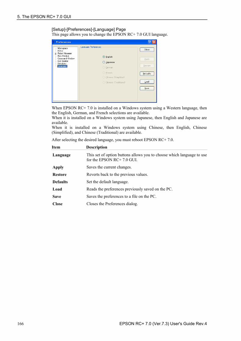
5. The EPSON RC+ 7.0 GUI
166 EPSON RC+ 7.0 (Ver.7.3) User's Guide Rev.4
[Setup]-[Preferences]-[Language] Page This page allows you to change the EPSON RC+ 7.0 GUI language.
When EPSON RC+ 7.0 is installed on a Windows system using a Western language, then the English, German, and French selections are available. When it is installed on a Windows system using Japanese, then English and Japanese are available. When it is installed on a Windows system using Chinese, then English, Chinese (Simplified), and Chinese (Traditional) are available.
After selecting the desired language, you must reboot EPSON RC+ 7.0.
Item Description
Language This set of option buttons allows you to choose which language to use for the EPSON RC+ 7.0 GUI.
Apply Saves the current changes.
Restore Reverts back to the previous values.
Defaults Set the default language.
Load Reads the preferences previously saved on the PC.
Save Saves the preferences to a file on the PC.
Close Closes the Preferences dialog.
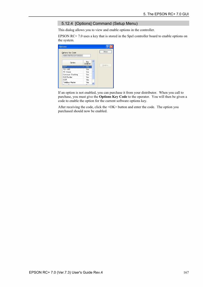
5. The EPSON RC+ 7.0 GUI
EPSON RC+ 7.0 (Ver.7.3) User's Guide Rev.4 167
5.12.4 [Options] Command (Setup Menu) This dialog allows you to view and enable options in the controller.
EPSON RC+ 7.0 uses a key that is stored in the Spel controller board to enable options on the system.
If an option is not enabled, you can purchase it from your distributor. When you call to purchase, you must give the Options Key Code to the operator. You will then be given a code to enable the option for the current software options key.
After receiving the code, click the <OK> button and enter the code. The option you purchased should now be enabled.
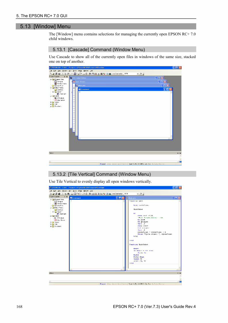
5. The EPSON RC+ 7.0 GUI
168 EPSON RC+ 7.0 (Ver.7.3) User's Guide Rev.4
5.13 [Window] Menu The [Window] menu contains selections for managing the currently open EPSON RC+ 7.0 child windows.
5.13.1 [Cascade] Command (Window Menu) Use Cascade to show all of the currently open files in windows of the same size, stacked one on top of another.
5.13.2 [Tile Vertical] Command (Window Menu) Use Tile Vertical to evenly display all open windows vertically.
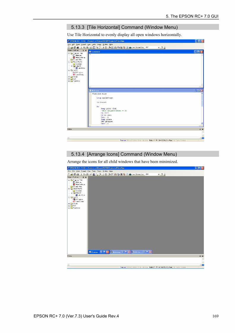
5. The EPSON RC+ 7.0 GUI
EPSON RC+ 7.0 (Ver.7.3) User's Guide Rev.4 169
5.13.3 [Tile Horizontal] Command (Window Menu) Use Tile Horizontal to evenly display all open windows horizontally.
5.13.4 [Arrange Icons] Command (Window Menu)
Arrange the icons for all child windows that have been minimized.
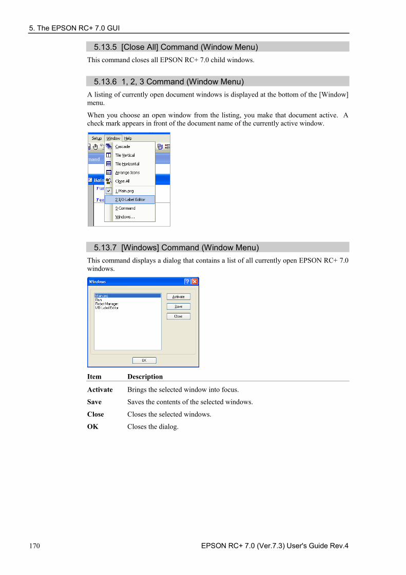
5. The EPSON RC+ 7.0 GUI
170 EPSON RC+ 7.0 (Ver.7.3) User's Guide Rev.4
5.13.5 [Close All] Command (Window Menu) This command closes all EPSON RC+ 7.0 child windows.
5.13.6 1, 2, 3 Command (Window Menu)
A listing of currently open document windows is displayed at the bottom of the [Window] menu.
When you choose an open window from the listing, you make that document active. A check mark appears in front of the document name of the currently active window.
5.13.7 [Windows] Command (Window Menu)
This command displays a dialog that contains a list of all currently open EPSON RC+ 7.0 windows.
Item Description
Activate Brings the selected window into focus.
Save Saves the contents of the selected windows.
Close Closes the selected windows.
OK Closes the dialog.
5. The EPSON RC+ 7.0 GUI
EPSON RC+ 7.0 (Ver.7.3) User's Guide Rev.4 171
5.14 [Help] Menu The [Help] menu contains selections for accessing the help system and manuals along with version information.
5.14.1 [How Do I] Command (Help Menu)
Select [How Do I] to view topics that contain information for performing common tasks in EPSON RC+ 7.0.
Shortcuts
Keys: Ctrl + F1
5.14.2 [Contents] Command (Help Menu)
This command opens the Contents view for the EPSON RC+ 7.0 online help system.
From the Contents view, you can navigate through all of the topics in the help system. Double-click on a book icon to open or close the subtopic list contained within the book folder.
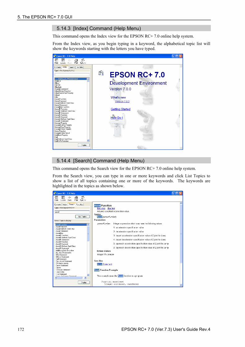
5. The EPSON RC+ 7.0 GUI
172 EPSON RC+ 7.0 (Ver.7.3) User's Guide Rev.4
5.14.3 [Index] Command (Help Menu) This command opens the Index view for the EPSON RC+ 7.0 online help system.
From the Index view, as you begin typing in a keyword, the alphabetical topic list will show the keywords starting with the letters you have typed.
5.14.4 [Search] Command (Help Menu) This command opens the Search view for the EPSON RC+ 7.0 online help system.
From the Search view, you can type in one or more keywords and click List Topics to show a list of all topics containing one or more of the keywords. The keywords are highlighted in the topics as shown below.
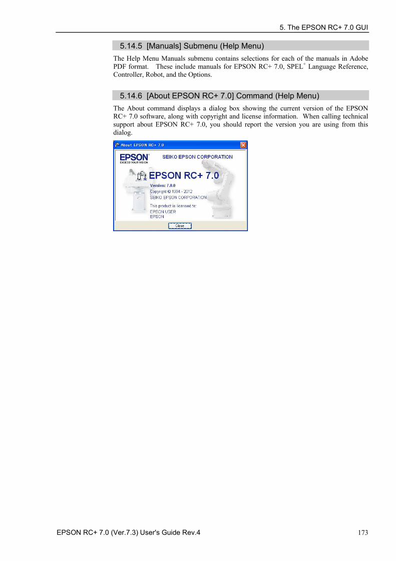
5. The EPSON RC+ 7.0 GUI
EPSON RC+ 7.0 (Ver.7.3) User's Guide Rev.4 173
5.14.5 [Manuals] Submenu (Help Menu) The Help Menu Manuals submenu contains selections for each of the manuals in Adobe PDF format. These include manuals for EPSON RC+ 7.0, SPEL+ Language Reference, Controller, Robot, and the Options.
5.14.6 [About EPSON RC+ 7.0] Command (Help Menu)
The About command displays a dialog box showing the current version of the EPSON RC+ 7.0 software, along with copyright and license information. When calling technical support about EPSON RC+ 7.0, you should report the version you are using from this dialog.
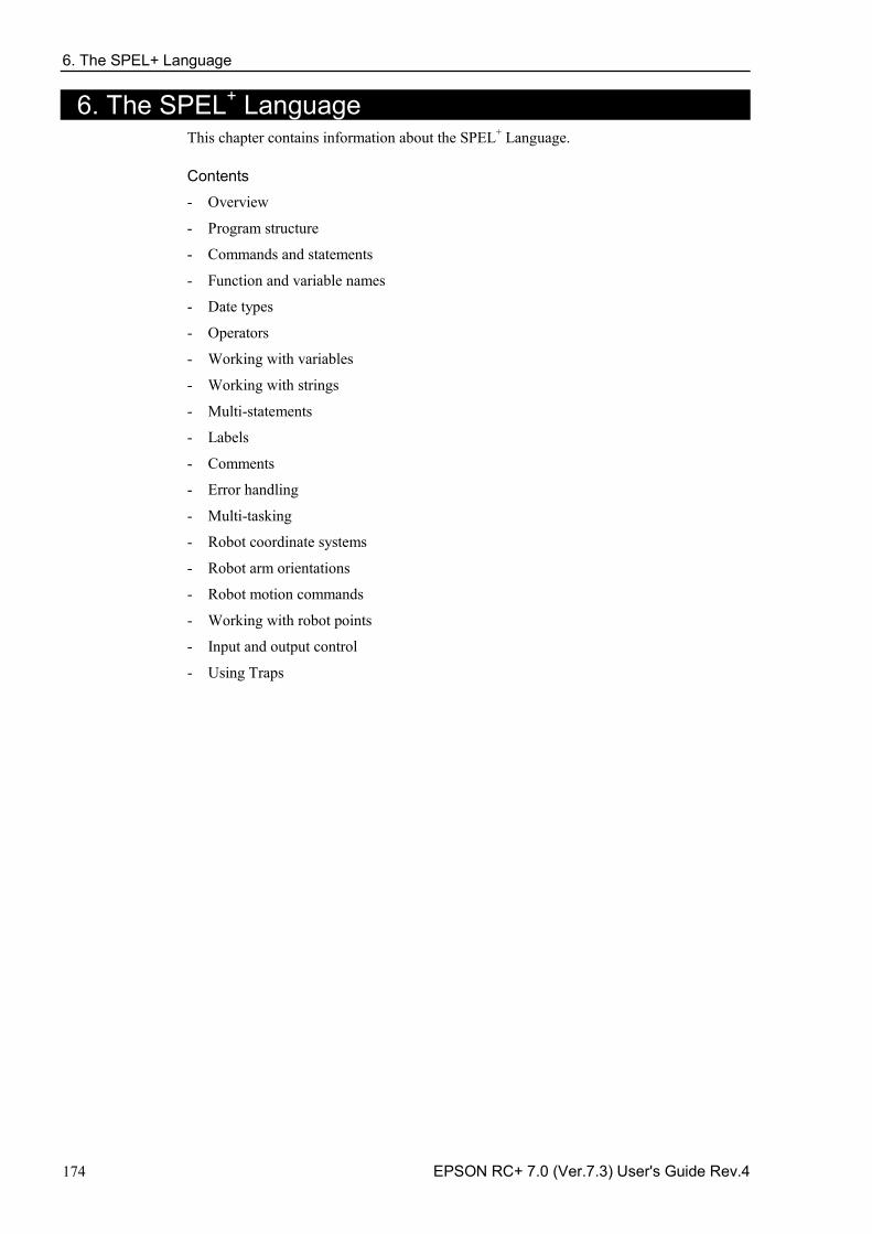
6. The SPEL+ Language
174 EPSON RC+ 7.0 (Ver.7.3) User's Guide Rev.4
6. The SPEL+ Language This chapter contains information about the SPEL+ Language. Contents
Overview -
Program structure -
Commands and statements -
Function and variable names -
Date types -
Operators -
Working with variables -
Working with strings -
Multi-statements -
Labels -
Comments -
Error handling -
Multi-tasking -
Robot coordinate systems -
Robot arm orientations -
Robot motion commands -
Working with robot points -
Input and output control -
Using Traps -
6. The SPEL+ Language
EPSON RC+ 7.0 (Ver.7.3) User's Guide Rev.4 175
6.1 Overview SPEL+ is a BASIC-like programming language that runs in the controller. It supports multitasking, motion control, I/O control.
Programs are written in ASCII text and then compiled into executable object files. Several language instructions can also be executed in immediate mode from the Command window.
6.2 Program Structure
6.2.1 What is a SPEL+ program? A SPEL+ program is a collection of functions, variables, and macros. You can put one or more statement in each line of a program (Multi-Statement). Every program file has a “.prg” extension and is stored in the project directory.
Each project must include at least one program and define the function called "main". "Function main" is the default definition. If “Function main” is not found, an error occurs.
In addition, you can define other 63 main functions in the same project. Each program has own start function: main1, main2…main63. Each of the main functions can be started from the [Operator window], the remote console, or RC+ API.
A function definition begins with the Function statement and ends with the Fend statement.
The following program file contains two function definitions. Function Main calls function “Func1”.
MAIN.PRG
Function Main
Call Func1
...
Fend
Function Func1
Jump pickpnt
...
Fend
6.2.2 Calling functions You can execute a user function by using the Call statement. The function can reside in any program file in the current project. You can also omit the Call statement if you don't need the return value. When Call is omitted, then parentheses for the arguments must not be supplied. To get a return value, use the function in the right hand side of an expression.
Here are some examples: Call MyFunc(1, 2)
MyFunc 1, 2
Print MyFunc(1, 2)
6. The SPEL+ Language
176 EPSON RC+ 7.0 (Ver.7.3) User's Guide Rev.4
6.3 Commands and Statements Commands and statements consist of a SPEL+ instruction followed by the parameters for that instruction.
A command is executed immediately. You can execute commands from the Command window or from the Macros dialog box.
Statements can be used only in programs.
Statements can include more than one SPEL+ instruction. When you put several statements in a line of a program (Multi-Statement), use a semi-colon (;) to separate instructions.
The maximum length for a line is 512 characters.
6.4 Function and Variable Names (Naming restriction) The function name can include up to 64 characters. The variable name can include up to 32 alphanumeric, Japanese, or underscore characters. Characters can be upper case or lower case.
The following names are valid: Function main
Real real_var
Integer IntVar
Function and variable names cannot begin with an underscore.
SPEL+ keywords cannot be used as function or variable names.
String variables must have an additional dollar sign ('$') suffix, as shown in the example below:
Function Test
String modname$
Print "Enter model name:"
Line Input modname$
Print "model is ", modname$
Fend
Restrictions for naming in SPEL+ language
- Characters can be alphanumeric, Japanese, or underscore character.
- Use alphabets for the first letter.
- Characters can be upper case or lower case.
- No keywords can be used.
- Maximum limits of names are as follows. (For one –byte character)
Name Max. limit Point label 32 I/O label 32
User error label 16 Function name 64 Variable name 32
Line label 32
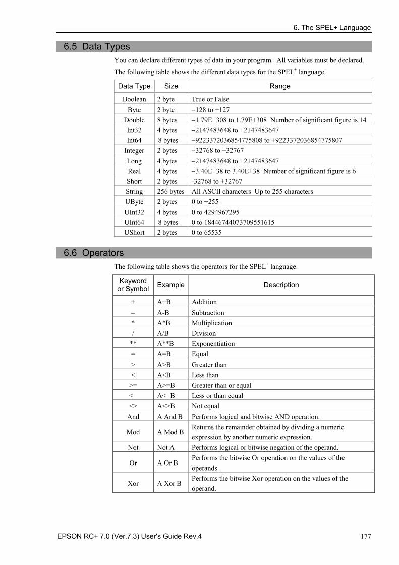
6. The SPEL+ Language
EPSON RC+ 7.0 (Ver.7.3) User's Guide Rev.4 177
6.5 Data Types You can declare different types of data in your program. All variables must be declared.
The following table shows the different data types for the SPEL+ language.
Data Type Size Range
Boolean 2 byte True or False Byte 2 byte −128 to +127
Double 8 bytes −1.79E+308 to 1.79E+308 Number of significant figure is 14 Int32 4 bytes −2147483648 to +2147483647 Int64 8 bytes −9223372036854775808 to +9223372036854775807
Integer 2 bytes −32768 to +32767 Long 4 bytes −2147483648 to +2147483647 Real 4 bytes −3.40E+38 to 3.40E+38 Number of significant figure is 6 Short 2 bytes -32768 to +32767 String 256 bytes All ASCII characters Up to 255 characters UByte 2 bytes 0 to +255 UInt32 4 bytes 0 to 4294967295 UInt64 8 bytes 0 to 18446744073709551615 UShort 2 bytes 0 to 65535
6.6 Operators
The following table shows the operators for the SPEL+ language.
Keyword or Symbol Example Description
+ A+B Addition − A-B Subtraction * A*B Multiplication / A/B Division
** A**B Exponentiation = A=B Equal > A>B Greater than < A<B Less than
>= A>=B Greater than or equal <= A<=B Less or than equal <> A<>B Not equal
And A And B Performs logical and bitwise AND operation.
Mod A Mod B Returns the remainder obtained by dividing a numeric expression by another numeric expression.
Not Not A Performs logical or bitwise negation of the operand.
Or A Or B Performs the bitwise Or operation on the values of the operands.
Xor A Xor B Performs the bitwise Xor operation on the values of the operand.
6. The SPEL+ Language
178 EPSON RC+ 7.0 (Ver.7.3) User's Guide Rev.4
6.7 Working with Variables
6.7.1 Variable scopes There are three different scopes for variables in SPEL+:
Local -
Module -
Global -
6.7.2 Local variables Local variables are available to all statements in the same function. Functions using local variable names cannot refer to the same local variables in other functions. This is why they are called locals, because they are local to the function they are being used in.
To declare local variables in a function, use one of the variable declaration instructions at the beginning of the function after the Function statement:
Boolean, Byte, UByte, Integer, Short, UShort, Long, Int32, UInt32, Int64, UInt64, Real, Double, String
For example, the following function declares several local variables: Function test
Integer intVar1, intVar2
Real realVar
String dataStr$
Integer array(10)
.....
Fend
6.7.3 Module variables Module variables are available to all functions in the same program file.
To declare module variables in a program, use one of the variable declaration instructions at the beginning of the program before any Function statements:
Boolean, Byte, UByte, Integer, Short, UShort, Long, Int32, UInt32, Int64, UInt64, Real, Double, String
In order to indicate that a variable is module level, precede the name with "m_", as shown in the example below. With this, you can improve the program readability.
For example, the following function declares several module level variables:
' Module level vars, used by all functions in this file Integer m_IntVar1, m_IntVar2 Real m_RealVar String m_DataStr$ Integer m_Array(10) Function main
m_IntVar1 = 25 Call test
Fend Function test
Print m_IntVar1 Fend
TIP
6. The SPEL+ Language
EPSON RC+ 7.0 (Ver.7.3) User's Guide Rev.4 179
6.7.4 Global variables Global variables can be shared between all functions in a project. The Global instruction is used to declare a global variable.
To declare global variables in a program, use the Global instruction with the desired variable type (Boolean, Byte, UByte, Integer, Short, UShort, Long, Int32, UInt32, Int64, UInt64, Real, Double, String) at the beginning of the program before any Function statements:
In order to indicate that variables are global, precede the name with "g_", as shown in the example below. With this, you can improve the program readability. Program: MAIN.PRG
Global Integer g_TotalCycles
Function main
Call LoadPart ... ...
Fend
Program: LOADPART.PRG Function LoadPart
Jump pick
On gripper
Wait .1
Jump place
Off gripper
Wait .1
g_TotalCycles = g_TotalCycles + 1
Fend
For more information, see Data Types.
6.7.5 Global Preserve variables You can preserve global variable values by using the optional Preserve parameter when you declare global variables.
Preserved variables are stored in the controller’s SRAM.
If the data type of a preserved variable or the number of dimensions is changed, the variable values will be cleared. Be careful about the backup battery power, because you will lose the data of global preserve variables stored in SRAM if the battery is weak.
TIP
NOTE
6. The SPEL+ Language
180 EPSON RC+ 7.0 (Ver.7.3) User's Guide Rev.4
6.7.6 Arrays You can declare local, module, and global variables with up to three dimensions as arrays for all data types.
To declare an array, use this syntax:
dataType name ( ubound1 [ , ubound2 [ , ubound3] ] )
SPEL+ arrays are zero based. The first element is referenced with a value of zero.
The total available number of array elements for local variables is 200 for strings and 2000 for all other types.
The total available number of array elements for global preserve variables is 400 for strings and 4000 for all other types.
The total available number of array elements for global and module variables is 10,000 for strings and 100,000 for all other types.
To calculate the total elements used in an array, use the following formula. (If a dimension is not used, substitute 0 for the ubound values.) total elements = (ubound1 + 1) * (ubound2 + 1) * (ubound3 + 1)
Array declaration examples: ' Global string array
Global String gData$(10)
Function main
' Arrays local to this function Integer intArray(10)
Real coords(20, 10)
Use Redim to change the bounds of an array at run time. Integer a(10)
Redim a(20)
To preserve values when using Redim, add the Preserve optional argument. Integer a(10)
Redim Preserve a(20)
Use UBound to get the maximum element number. Integer i, a(10)
For i = 1 to UBound(a)
a(i) = i
Next i
6.7.7 Initial values
All variables are initialized when first used except for Global Preserve variables. Strings are set to empty, and all other variables are set to zero.
6.7.8 Clearing arrays Execute Redim (without Preserve) to clear all of the elements of array variables.
6. The SPEL+ Language
EPSON RC+ 7.0 (Ver.7.3) User's Guide Rev.4 181
6.8 Working with Strings A string in SPEL+ is a set of ASCII characters (Code &h01 ~ &hff) with a maximum length of 255.
You must declare strings in your programs with the String instruction.
All string variable names must end with a dollar sign ($) suffix.
The following table shows the string commands available in SPEL+.
Keyword Description
Asc Returns the decimal ASCII value of the first character in a string.
Chr$ Converts an ASCII value into a one character string.
FmtStr Formats a numerical or date/time expression.
FmtStr$ Formats a numerical or date/time expression.
Hex$ Returns a string containing the hexadecimal value of a number.
InStr Returns the position of a substring within a string.
LCase$ Returns the specified string in lower case characters.
Left$ Returns a substring beginning with the first character of a string.
Len Returns the length (number of characters) of a string.
LTrim$ Returns the specified string with left spaces removed.
Mid$ Returns a substring of a string.
ParseStr Parses a string into an array of tokens.
Right$ Returns a substring from the end of a string.
RTrim$ Returns the specified string with right spaces removed.
Space$ Returns a string containing a specified number of space (ASCII 32) characters.
Str$ Converts a number to a string.
String Declare a string variable in a program.
Tab$ Returns a tab string.
UCase$ Returns the specified string in upper case characters.
Val Converts a string to a number.
6. The SPEL+ Language
182 EPSON RC+ 7.0 (Ver.7.3) User's Guide Rev.4
6.9 Working with Files SPEL+ has several commands for handling files.
Keyword Description
AOpen Opens a file for append.
BOpen Opens a file for binary access.
Close Closes a file.
FileExists Checks if a file exists.
FolderExists Check if a folder exists.
FreeFile Returns an unused file handle.
Input Inputs one or more variables from a file
Kill Deletes a file.
Line Input Inputs line from a file.
Read Reads a specified number of bytes into a string variable.
ReadBin Reads binary data.
ROpen Opens a file for reading.
Seek Sets the current file pointer.
Flush Writes data buffer to disk.
WOpen Opens a file for writing.
Write Writes out a variable at the current file pointer without appending a line terminator.
WriteBin Writes binary data.
6. The SPEL+ Language
EPSON RC+ 7.0 (Ver.7.3) User's Guide Rev.4 183
Before using a file you must open it with one of the following commands: AOpen, Bopen, ROpen, and WOpen. And specify a file number in the Open statement. File number can be 30 ~ 63.
Here is an example to save a text file and read it. Function SaveData(ByRef data$() As String) Integer fNum, i fNum = FreeFile WOpen "c:\mydata\data.txt" As #fNum ' Store the count Print #fNum, UBound(data$) For i = 0 To UBound(data$) Print #fNum, data$(i) Next i Close #fNum Fend Function LoadData(ByRef data$() As String) Integer fNum, i fNum = FreeFile ROpen "c:\mydata\data.txt" As #fNum Input #fNum, i Redim data$(i) For i = 0 To UBound(data$) Input #fNum, data$(i) Next i Close #fNum Fend
6. The SPEL+ Language
184 EPSON RC+ 7.0 (Ver.7.3) User's Guide Rev.4
6.10 Multi-statements A program statement can contain several statements separated by semi-colons. The total length of a multi-statement program line cannot exceed 255 characters.
For example: Function Test
Pass P1; Pass P2; Go P3 ' Multi-statement
Fend
It is not recommended to use multi-statements. Multi-statements can make your code more difficult to read and debug.
6.11 Labels
A program line is an alphanumeric name followed by a colon (":") that marks a location in a program for a GoTo or GoSub statement. The name may be up to 32 characters long and can include alphanumeric characters and the underscore ("_") character if it is not the first character. You cannot use any SPEL+ keywords as labels.
For example: Function Main
Do
Jump P1
Jump P2
If Sw(1) Then GoTo MainAbort
Loop
MainAbort: ' Program label Print "Program aborted"
Fend
6.12 Comments Use comments to add notes to your programs. An apostrophe character (') starts a comment.
Example: Function Main
' ****** Main Demo Program ******
Xqt conveyor ' Start up the task for conveyor Do
Print "Press ENTER to run demo cycle"
Print "Press CTRL+C to quit"
Input dumy
Call demo ' Execute the demo function Loop ' Return to start of main loop
6. The SPEL+ Language
EPSON RC+ 7.0 (Ver.7.3) User's Guide Rev.4 185
6.13 Error Handling When an error occurs in a SPEL+ function, you can cause execution to be transferred to an error handling routine for processing the error. The routine must be inside a function definition.
The table on the next page shows the program instructions that are used for error handling.
Item Purpose
OnErr Use the OnErr statement to define the location of the error handling routine.
Err Use Err to retrieve the number for the current error status. Use this in the error handling routine to determine which error has occurred.
Error Generate a user defined error which can be caught by an error handler.
Era Use Era to retrieve the axis number for which the error occurred. This is normally used in the error handling routine.
Erl Use Erl to retrieve the line number in which the error occurred. This is normally used in the error handling routine.
Ert Use Ert to retrieve the task number in which the error occurred. This is normally used in the error handling routine.
ErrMsg$ Use ErrMsg$ to retrieve the error message associated with a specified error number.
Errb Use Errb to retrieve the robot number in which the error occurred. This is normally used in the error handling routine.
User Errors You can define your own error messages by using the User Error Editor which is available from the Tools Menu. For details refer to 5.11.7 User Error Editor Command (Tools Menu).
6. The SPEL+ Language
186 EPSON RC+ 7.0 (Ver.7.3) User's Guide Rev.4
Example
The following example shows a simple error handling routine. When an error occurs, program execution goes to the ErrHandler label, where the error handler starts. The error number is displayed and the operator is asked to continue or not. If the operator enters "N" then the program executes the Quit All statement to end the program.
Function Main
String cont$
Integer i
OnErr Goto Errhandler
For i = 1 To 10
Jump P(i)
Next i
Exit Function
' *** Error handler ***
Errhandler:
enum = Err
Print "Error #", enum, " occurred"
Print "Continue (Y or N)?"
Line Input cont$
Select cont$
Case "y", "Y"
EResume Next
Default
Quit All
Send
Fend
6. The SPEL+ Language
EPSON RC+ 7.0 (Ver.7.3) User's Guide Rev.4 187
6.14 Multi-tasking For some applications, you may want to control other equipment besides the robot, such as conveyors, pick and place units, etc. By using multi-tasking, you can control this other equipment with their own tasks.
SPEL+ supports up to 32 normal tasks and 16 background tasks (48 tasks in total) running simultaneously. A task is a function that has been started by the system or by the Xqt statement.
Use the Xqt statement to start another task from within a function. You can optionally specify a task number from 1 to 32 in the Xqt statement.
A task started from a background task is started as a background task. You can execute up to 16 background tasks simultaneously.
The table below shows the program instructions that are used for multitasking.
Statement Purpose
Xqt Starts a function as a task.
Halt Temporarily suspends execution of a task.
Resume Resumes a task that has been halted.
Quit Stops a task.
Signal Sends a signal to one or more tasks that are waiting for the signal using WaitSig.
SyncLock Locks a resource for use by the current task and blocks other tasks from using the resource until SyncUnlock is executed.
WaitSig Waits for a signal from another task.
Pause Pause all tasks.
One example for starting another task is to run a conveyor system for the robot work cell.
Program: MAINTASK.PRG Function Main
Xqt Conveyor ' Start the conveyor task Do
...
...
Loop
Fend
Program: CONVTASK.PRG Function Conveyor
Do
Select True
Case Sw(10) = On
Off convCtrl
Case Sw(11) = On
On convCtrl
Send
Loop
Fend
6. The SPEL+ Language
188 EPSON RC+ 7.0 (Ver.7.3) User's Guide Rev.4
6.15 Using Multiple Robots You can control more than one robot in the same project. Use the Robot statement to switch the current robot for the current task. For most applications, you should use a separate task for each robot.
Each robot has its own set of point files. You can configure which point files to use in the Project Editor. The default point file you configure for each robot is automatically loaded into memory when the main task is started.
The following program is an example where two robots run simultaneously, each with its own task.
Function main
Xqt Robot1
Xqt Robot2
Fend
Function Robot1
Robot 1
Speed 50
Do
Jump pick
On gripper1
Wait .1
Jump place
Off gripper1
Wait .1
Loop
Fend
Function Robot2
Robot 2
Speed 50
Do
Jump pick
On gripper2
Wait .1
Jump place
Off gripper2
Wait .1
Loop
Fend
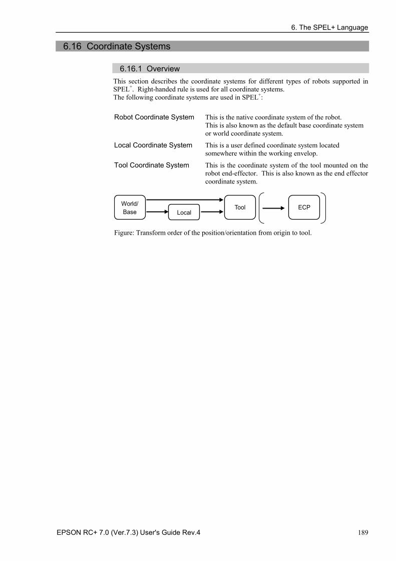
6. The SPEL+ Language
EPSON RC+ 7.0 (Ver.7.3) User's Guide Rev.4 189
6.16 Coordinate Systems
6.16.1 Overview This section describes the coordinate systems for different types of robots supported in SPEL+. Right-handed rule is used for all coordinate systems. The following coordinate systems are used in SPEL+:
Robot Coordinate System This is the native coordinate system of the robot. This is also known as the default base coordinate system or world coordinate system.
Local Coordinate System This is a user defined coordinate system located somewhere within the working envelop.
Tool Coordinate System This is the coordinate system of the tool mounted on the robot end-effector. This is also known as the end effector coordinate system.
World/Base
Tool Local
ECP
Figure: Transform order of the position/orientation from origin to tool.
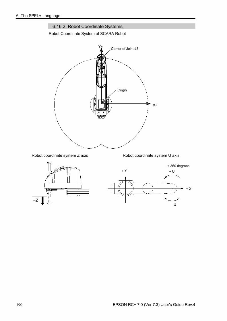
6. The SPEL+ Language
190 EPSON RC+ 7.0 (Ver.7.3) User's Guide Rev.4
6.16.2 Robot Coordinate Systems Robot Coordinate System of SCARA Robot
Origin
Center of Joint #3 Y+
X+
Robot coordinate system Z axis Robot coordinate system U axis
−Z
+ X
+ Y + U
- U
± 360 degrees
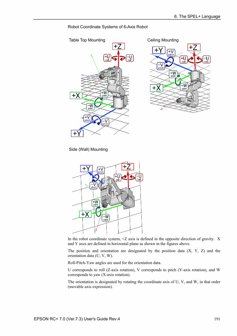
6. The SPEL+ Language
EPSON RC+ 7.0 (Ver.7.3) User's Guide Rev.4 191
Robot Coordinate Systems of 6-Axis Robot
Table Top Mounting Ceiling Mounting
Side (Wall) Mounting
In the robot coordinate system, +Z axis is defined in the opposite direction of gravity. X and Y axes are defined in horizontal plane as shown in the figures above.
The position and orientation are designated by the position data (X, Y, Z) and the orientation data (U, V, W).
Roll-Pitch-Yaw angles are used for the orientation data.
U corresponds to roll (Z-axis rotation), V corresponds to pitch (Y-axis rotation), and W corresponds to yaw (X-axis rotation).
The orientation is designated by rotating the coordinate axis of U, V, and W, in that order (movable axis expression).
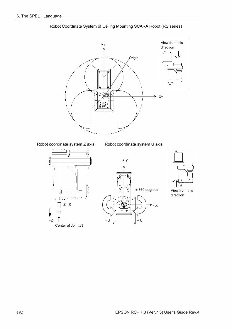
6. The SPEL+ Language
192 EPSON RC+ 7.0 (Ver.7.3) User's Guide Rev.4
Robot Coordinate System of Ceiling Mounting SCARA Robot (RS series)
Origin
Y+
X+
View from this direction
Robot coordinate system Z axis Robot coordinate system U axis
-Z
Z=0
Center of Joint #3
- X
+ Y
+ U - U
± 360 degrees View from this direction
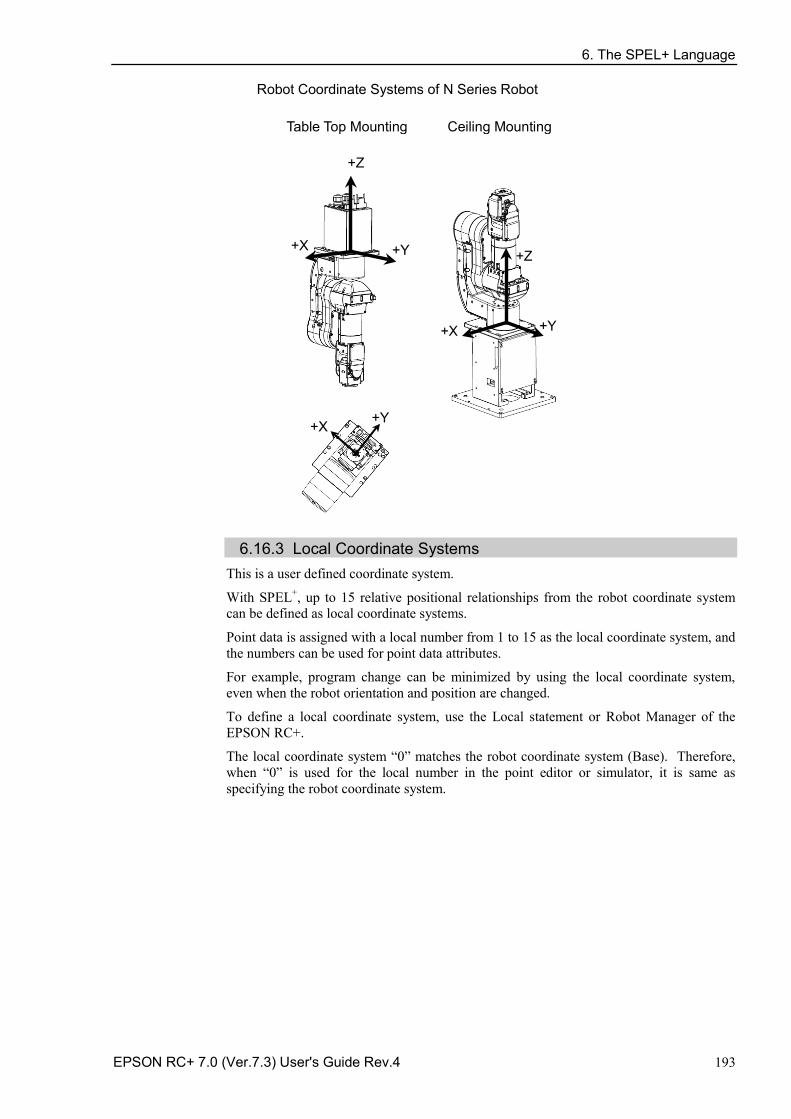
6. The SPEL+ Language
EPSON RC+ 7.0 (Ver.7.3) User's Guide Rev.4 193
Robot Coordinate Systems of N Series Robot
Table Top Mounting Ceiling Mounting
+Z
+X +Y
+X +Y
+Z
+X +Y
6.16.3 Local Coordinate Systems
This is a user defined coordinate system.
With SPEL+, up to 15 relative positional relationships from the robot coordinate system can be defined as local coordinate systems.
Point data is assigned with a local number from 1 to 15 as the local coordinate system, and the numbers can be used for point data attributes.
For example, program change can be minimized by using the local coordinate system, even when the robot orientation and position are changed.
To define a local coordinate system, use the Local statement or Robot Manager of the EPSON RC+.
The local coordinate system “0” matches the robot coordinate system (Base). Therefore, when “0” is used for the local number in the point editor or simulator, it is same as specifying the robot coordinate system.
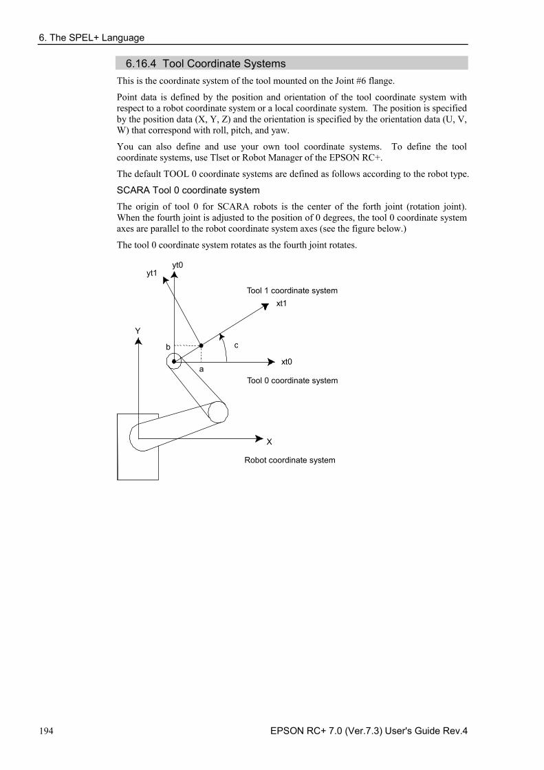
6. The SPEL+ Language
194 EPSON RC+ 7.0 (Ver.7.3) User's Guide Rev.4
6.16.4 Tool Coordinate Systems This is the coordinate system of the tool mounted on the Joint #6 flange.
Point data is defined by the position and orientation of the tool coordinate system with respect to a robot coordinate system or a local coordinate system. The position is specified by the position data (X, Y, Z) and the orientation is specified by the orientation data (U, V, W) that correspond with roll, pitch, and yaw.
You can also define and use your own tool coordinate systems. To define the tool coordinate systems, use Tlset or Robot Manager of the EPSON RC+.
The default TOOL 0 coordinate systems are defined as follows according to the robot type.
SCARA Tool 0 coordinate system
The origin of tool 0 for SCARA robots is the center of the forth joint (rotation joint). When the fourth joint is adjusted to the position of 0 degrees, the tool 0 coordinate system axes are parallel to the robot coordinate system axes (see the figure below.)
The tool 0 coordinate system rotates as the fourth joint rotates.
Tool 1 coordinate system
Tool 0 coordinate system
Robot coordinate system
X
Y
xt0
xt1
yt0 yt1
a
b c
6. The SPEL+ Language
EPSON RC+ 7.0 (Ver.7.3) User's Guide Rev.4 195
6-axis Tool 0 coordinate system
Table and ceiling mounting robots:
The origin of tool 0 is the center of the flange on the sixth joint. When all joint angles are 0 degree, the vertically upward direction is the tool X axis, the tool Y is the same direction of X axis in the base coordinate system, and the tool Z axis is perpendicular to the sixth joint flange. (See the figure below).
The tool 0 coordinate system moves as the 6-axis robot changes its orientation.
Wall mounting robots:
The tool 0 coordinate system is defined as below. (tl: abbreviation of Tool) Table Top Mounting Ceiling Mounting
Side (Wall) Mounting
6. The SPEL+ Language
196 EPSON RC+ 7.0 (Ver.7.3) User's Guide Rev.4
N series Tool 0 coordinate system
Ceiling mounting robots:
When all joint angles are 0 degree, the tool 0 coordinate system has the X axis in –X axis direction, Y axis in the Y axis direction, and the Z axis in the –Z axis direction on the robot coordinate system. (See the figure below)
Wall mounting robots:
When all joint angles are 0 degree, the tool 0 coordinate system has the X axis in –X axis direction, Y axis in the Y axis direction, and the Z axis in the Z axis direction on the robot coordinate system. (See the figure below)
Table Top Mounting Ceiling Mounting
+Z
+X
+Y
+Z
+X +Y
6. The SPEL+ Language
EPSON RC+ 7.0 (Ver.7.3) User's Guide Rev.4 197
6.16.5 ECP Coordinate Systems (Option) Specify a coordinate system whose origin point is on the tip of the outside fixed tool (hereafter referred to as the external control point or ECP) to move the robot arm holding a part in the trajectory made on the external control point along with the part’s edges.
The following figures give a concrete example. An ordinal Move statement controls the moving speed and orientation change of the tool center point (TCP). In the case of Move statement with the ECP argument, the part’s edge is controlled to take a straight and constant-speed trajectory instead of TCP. In the following example of no ECP, TCP takes a straight trajectory but the part’s edge is distant from ECP.
If there is no orientation change, the trajectory is the same as normal operation of Move command.
6. The SPEL+ Language
198 EPSON RC+ 7.0 (Ver.7.3) User's Guide Rev.4
External Control Point
ECP coordinate system Robot coordinate system
Teaching start point
Teaching end point Want to move at a constant speed / posture change along this side
Path along ECP
TCP path
TCP path
6. The SPEL+ Language
EPSON RC+ 7.0 (Ver.7.3) User's Guide Rev.4 199
The following commands are available for optional ECP: Move command - Arc3 command - Curve and CVMove commands - ECP jog motion in Robot Manager -
Use the ECPSet statement for defining an ECP coordinate system. A maximum of 15 ECP coordinate systems can be defined.
For details, refer to 17. ECP Motion.
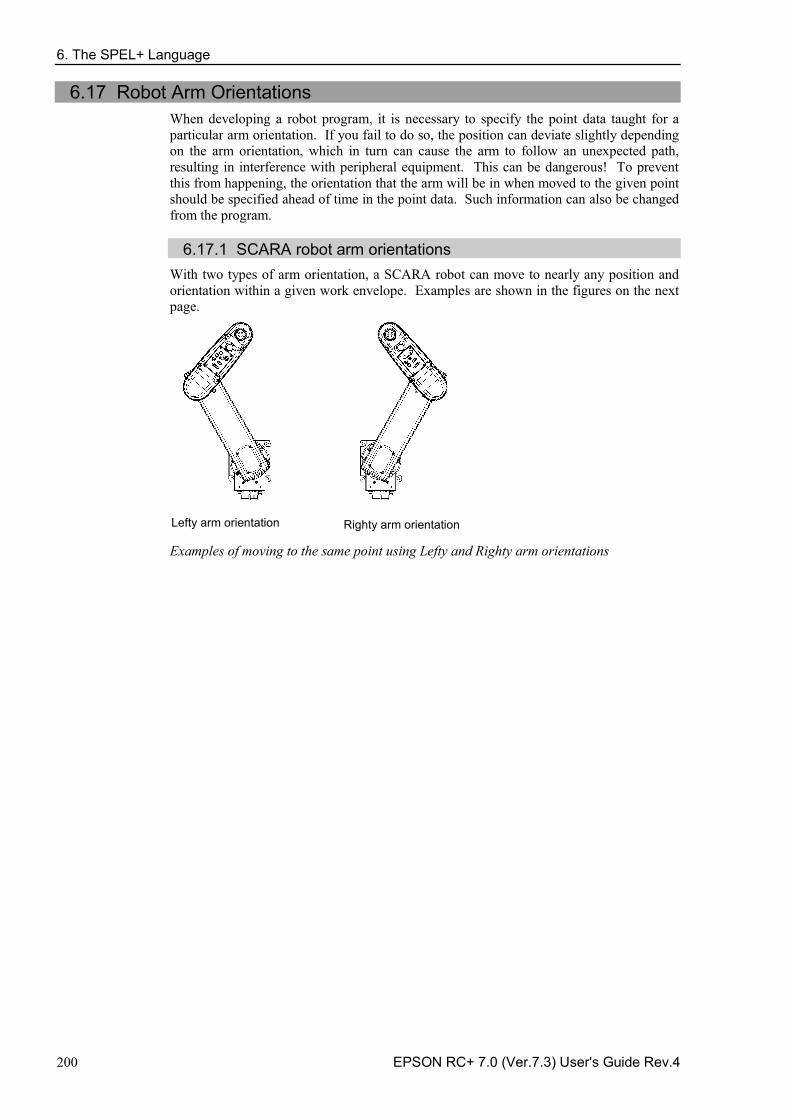
6. The SPEL+ Language
200 EPSON RC+ 7.0 (Ver.7.3) User's Guide Rev.4
6.17 Robot Arm Orientations When developing a robot program, it is necessary to specify the point data taught for a particular arm orientation. If you fail to do so, the position can deviate slightly depending on the arm orientation, which in turn can cause the arm to follow an unexpected path, resulting in interference with peripheral equipment. This can be dangerous! To prevent this from happening, the orientation that the arm will be in when moved to the given point should be specified ahead of time in the point data. Such information can also be changed from the program.
6.17.1 SCARA robot arm orientations
With two types of arm orientation, a SCARA robot can move to nearly any position and orientation within a given work envelope. Examples are shown in the figures on the next page.
Lefty arm orientation Righty arm orientation Examples of moving to the same point using Lefty and Righty arm orientations
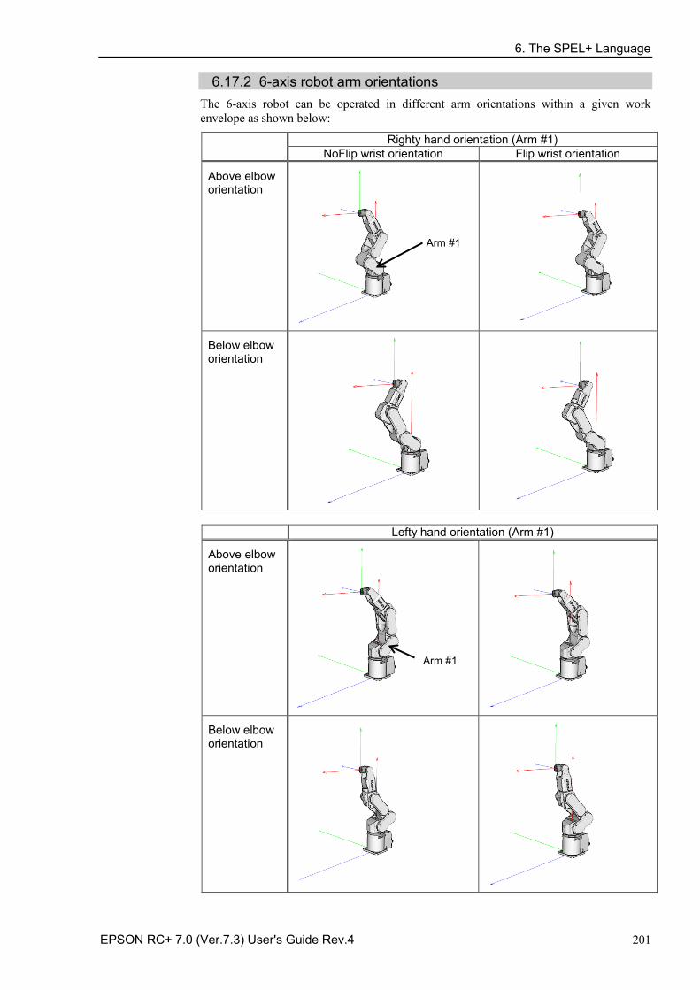
6. The SPEL+ Language
EPSON RC+ 7.0 (Ver.7.3) User's Guide Rev.4 201
6.17.2 6-axis robot arm orientations The 6-axis robot can be operated in different arm orientations within a given work envelope as shown below:
Righty hand orientation (Arm #1) NoFlip wrist orientation Flip wrist orientation
Above elbow orientation
Arm #1
Below elbow orientation
Lefty hand orientation (Arm #1)
Above elbow orientation
Arm #1
Below elbow orientation
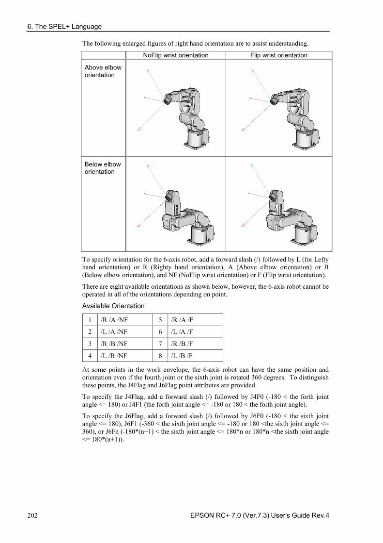
6. The SPEL+ Language
202 EPSON RC+ 7.0 (Ver.7.3) User's Guide Rev.4
The following enlarged figures of right hand orientation are to assist understanding.
NoFlip wrist orientation Flip wrist orientation
Above elbow orientation
Below elbow orientation
To specify orientation for the 6-axis robot, add a forward slash (/) followed by L (for Lefty hand orientation) or R (Righty hand orientation), A (Above elbow orientation) or B (Below elbow orientation), and NF (NoFlip wrist orientation) or F (Flip wrist orientation).
There are eight available orientations as shown below, however, the 6-axis robot cannot be operated in all of the orientations depending on point.
Available Orientation
1 /R /A /NF 5 /R /A /F
2 /L /A /NF 6 /L /A /F
3 /R /B /NF 7 /R /B /F
4 /L /B /NF 8 /L /B /F
At some points in the work envelope, the 6-axis robot can have the same position and orientation even if the fourth joint or the sixth joint is rotated 360 degrees. To distinguish these points, the J4Flag and J6Flag point attributes are provided.
To specify the J4Flag, add a forward slash (/) followed by J4F0 (-180 < the forth joint angle <= 180) or J4F1 (the forth joint angle <= -180 or 180 < the forth joint angle).
To specify the J6Flag, add a forward slash (/) followed by J6F0 (-180 < the sixth joint angle <= 180), J6F1 (-360 < the sixth joint angle <= -180 or 180 <the sixth joint angle <= 360), or J6Fn (-180*(n+1) < the sixth joint angle <= 180*n or 180*n <the sixth joint angle <= 180*(n+1)).
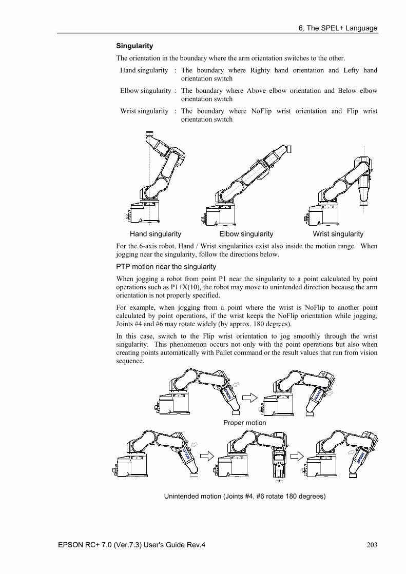
6. The SPEL+ Language
EPSON RC+ 7.0 (Ver.7.3) User's Guide Rev.4 203
Singularity The orientation in the boundary where the arm orientation switches to the other.
Hand singularity : The boundary where Righty hand orientation and Lefty hand orientation switch
Elbow singularity : The boundary where Above elbow orientation and Below elbow orientation switch
Wrist singularity : The boundary where NoFlip wrist orientation and Flip wrist orientation switch
Hand singularity Elbow singularity Wrist singularity
For the 6-axis robot, Hand / Wrist singularities exist also inside the motion range. When jogging near the singularity, follow the directions below.
PTP motion near the singularity
When jogging a robot from point P1 near the singularity to a point calculated by point operations such as P1+X(10), the robot may move to unintended direction because the arm orientation is not properly specified.
For example, when jogging from a point where the wrist is NoFlip to another point calculated by point operations, if the wrist keeps the NoFlip orientation while jogging, Joints #4 and #6 may rotate widely (by approx. 180 degrees).
In this case, switch to the Flip wrist orientation to jog smoothly through the wrist singularity. This phenomenon occurs not only with the point operations but also when creating points automatically with Pallet command or the result values that run from vision sequence.
Proper motion
Unintended motion (Joints #4, #6 rotate 180 degrees)
6. The SPEL+ Language
204 EPSON RC+ 7.0 (Ver.7.3) User's Guide Rev.4
However in the cases, it is difficult for users to specify the proper arm orientations by a program. For this LJM function is a useful command. LJM function switches the arm orientations to enable the least motion of the joints. For the details of LJM function, refer to SPEL+ Language Reference manual.
Also, AutoLJM command can automatically apply LJM function to the motion commands which are included in a particular section of the program without using LJM function. For details of AutoLJM command, refer to the SPEL+ Language Reference.
In addition, you can set AutoLJM function to be enabled at the controller start up by setting preferences of the controller. However, if Auto LJM is enabled in preferences, this function automatically adjusts the posture of the manipulator to reduce the motion distance, even when you intend to move the joint widely. Therefore, it is recommended to build a program using AutoLJM command or LJM function to operate the manipulator as you desired.
If you specify all points by teaching, the arm orientations are also recorded. Therefore, the manipulator moves to the taught position without using LJM function or AutoLJM. Instead, the manipulator may move differently from the taught position by the use of LJM and AutoLJM.
LJM function for CP motion command
LJM function and AutoLJM command described above are also available for CP motion commands. However, since CP motion commands give priority to operate based on specified trajectories, the manipulator sometimes reach to the point with a different posture from the specified one. At this time, if CP motion command is used with CP On, an error from 4274 to 4278 will occur according to the mismatched point flag. To avoid the error, operate the manipulator with CP Off, or match the point flag of a target point and the one after motion completion. If operated with CP Off, the error does not occur and the manipulator can continue operation from the point where the mismatch happened.
Also, you can set the controller’s preference so that the mismatches of flags are not considered as an error at the controller startup. However, path motions which use CP On will be disabled.
CP motion near the singularity (singularity avoiding function in CP motion)
When executing Move or CP motion near the singularity, the joint speed may increase rapidly. The overspeed error will occur and the joints will move widely and interfere with peripherals. In particular, the position of Joint #1 near the hand singularity and Joints #2 - #6 near the wrist singularity change greatly.
EPSON RC+ 7.0 has a singularity avoiding function to prevent acceleration errors during the execution of CP motion commands that pass the wrist singularity described above. With this function, the manipulator takes a detour to avoid an acceleration error by passing a different trajectory and returns to the original trajectory after passing the singularity. For details of the singularity avoiding function, refer to AvoidSingularity in the SPEL+ Language Reference.
Singularity avoiding function is enabled as default. If you want to avoid the error by reducing the motion speed in order to maintain the trajectory accuracy, you can disable the function temporarily by setting “0” to AvoidSingularity.
If you cannot avoid errors even if you use the singularity avoiding function, use PTP motion to enable the least motion of the joints or arrange the manipulator installation position and hand offset volume to prevent the CP motion near the singularity.
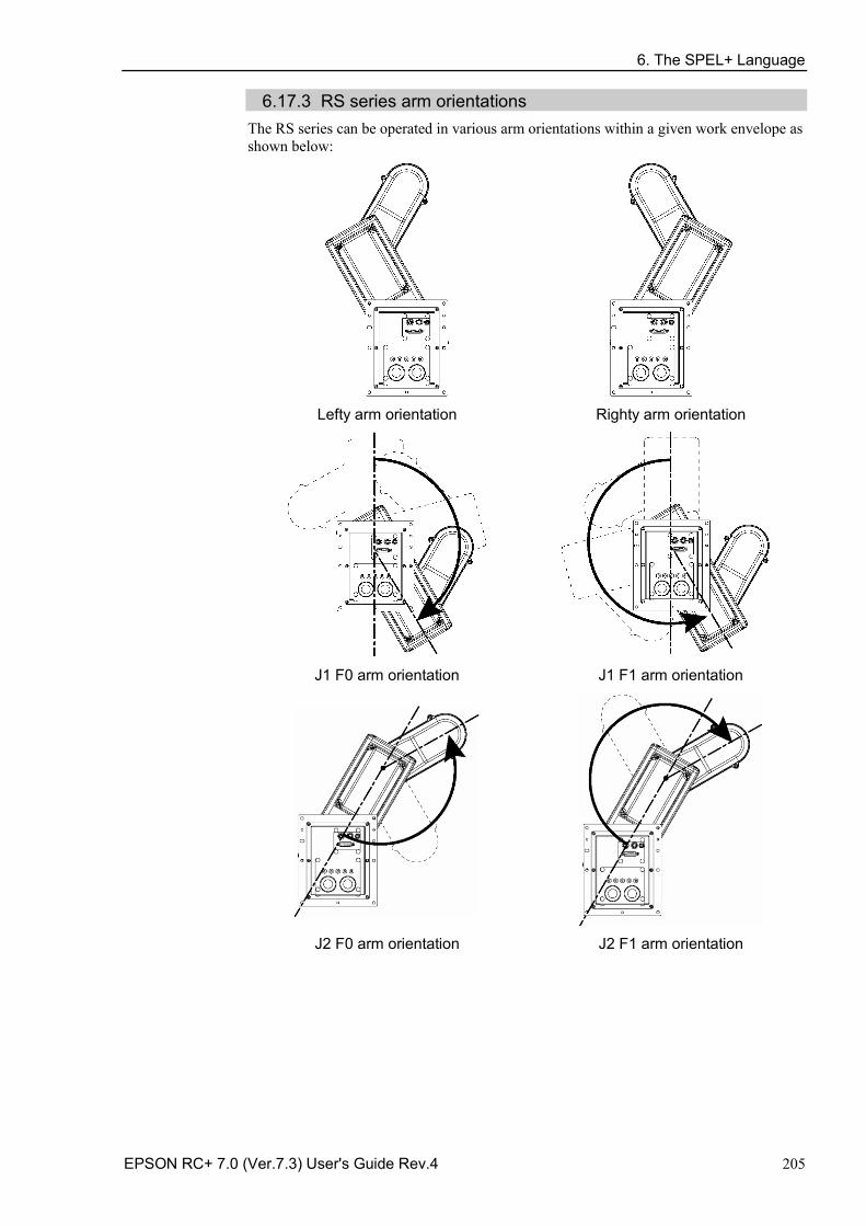
6. The SPEL+ Language
EPSON RC+ 7.0 (Ver.7.3) User's Guide Rev.4 205
6.17.3 RS series arm orientations The RS series can be operated in various arm orientations within a given work envelope as shown below:
Lefty arm orientation Righty arm orientation
J1 F0 arm orientation J1 F1 arm orientation
J2 F0 arm orientation J2 F1 arm orientation
6. The SPEL+ Language
206 EPSON RC+ 7.0 (Ver.7.3) User's Guide Rev.4
To specify the arm orientation of the RS series, add a forward slash (/) followed by: - L (for Lefty hand orientation) or R (Righty hand orientation) - J1F0 or J1F1 - J2F0 or J2F1.
For the RS series robots, some points in the work envelope can have the same position and orientation even if J1 or J2 is rotated 360 degrees. To distinguish these points, the J1Flag and J2Flag point attributes are provided.
To specify the J1Flag, add a forward slash (/) followed by:
- J1F0 (−90 < the first joint angle <= 270), or - J1F1 (−270 < the first joint angle <= −90 or 270 < the first joint angle <= 450)
To specify the J2Flag, add a forward slash (/) followed by:
- J2F0 (−180 < the second joint angle <= 180), or - J2F1 (−360 < the second joint angle <= −180 or 180 < the second joint angle <= 360)
There are eight available orientations as shown below. Note that some combinations are not available depending on the point.
Available Orientation
1 /R /J1F0 /J2F0
2 /L /J1F0 /J2F0
3 /R /J1F1 /J2F0
4 /L /J1F1 /J2F0
5 /R /J1F0 / J2F1
6 /L /J1F0 / J2F1
7 /R /J1F1 / J2F1
8 /L /J1F1 / J2F1
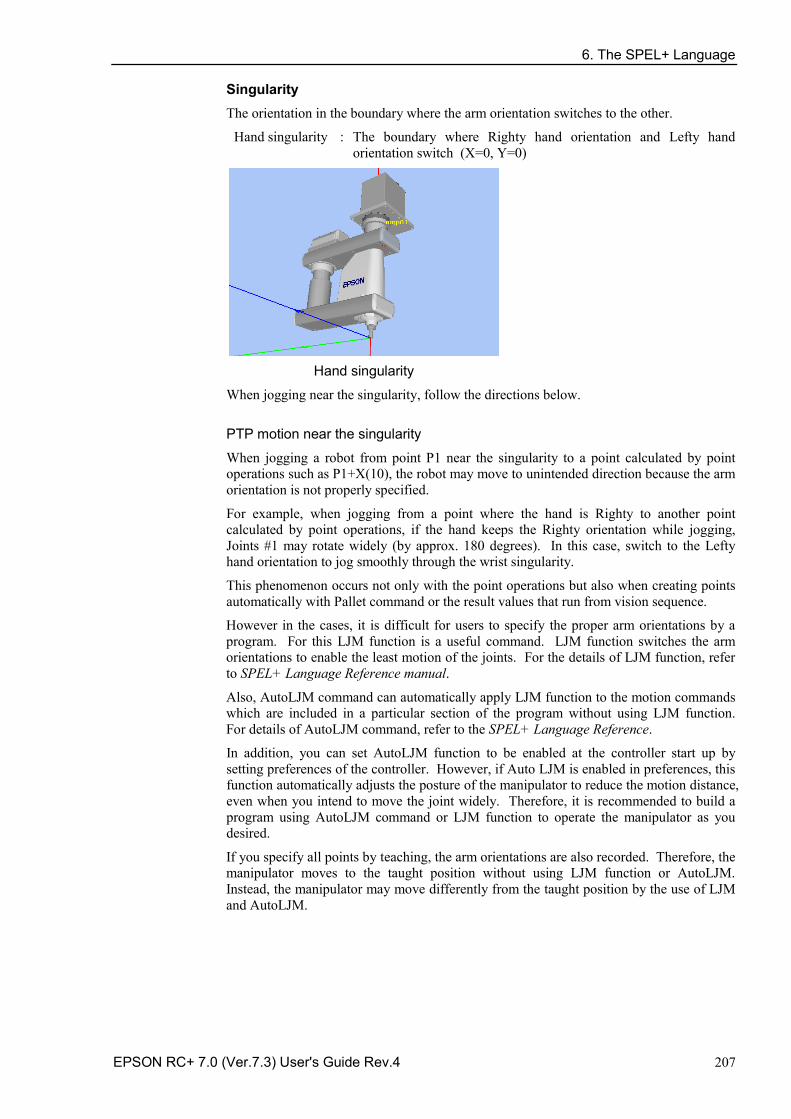
6. The SPEL+ Language
EPSON RC+ 7.0 (Ver.7.3) User's Guide Rev.4 207
Singularity The orientation in the boundary where the arm orientation switches to the other.
Hand singularity : The boundary where Righty hand orientation and Lefty hand orientation switch (X=0, Y=0)
Hand singularity
When jogging near the singularity, follow the directions below.
PTP motion near the singularity
When jogging a robot from point P1 near the singularity to a point calculated by point operations such as P1+X(10), the robot may move to unintended direction because the arm orientation is not properly specified.
For example, when jogging from a point where the hand is Righty to another point calculated by point operations, if the hand keeps the Righty orientation while jogging, Joints #1 may rotate widely (by approx. 180 degrees). In this case, switch to the Lefty hand orientation to jog smoothly through the wrist singularity.
This phenomenon occurs not only with the point operations but also when creating points automatically with Pallet command or the result values that run from vision sequence.
However in the cases, it is difficult for users to specify the proper arm orientations by a program. For this LJM function is a useful command. LJM function switches the arm orientations to enable the least motion of the joints. For the details of LJM function, refer to SPEL+ Language Reference manual.
Also, AutoLJM command can automatically apply LJM function to the motion commands which are included in a particular section of the program without using LJM function. For details of AutoLJM command, refer to the SPEL+ Language Reference.
In addition, you can set AutoLJM function to be enabled at the controller start up by setting preferences of the controller. However, if Auto LJM is enabled in preferences, this function automatically adjusts the posture of the manipulator to reduce the motion distance, even when you intend to move the joint widely. Therefore, it is recommended to build a program using AutoLJM command or LJM function to operate the manipulator as you desired.
If you specify all points by teaching, the arm orientations are also recorded. Therefore, the manipulator moves to the taught position without using LJM function or AutoLJM. Instead, the manipulator may move differently from the taught position by the use of LJM and AutoLJM.
6. The SPEL+ Language
208 EPSON RC+ 7.0 (Ver.7.3) User's Guide Rev.4
CP motion near the singularity (singularity avoiding function in CP motion)
When executing Move or CP motion near the singularity, the joint speed may increase rapidly. The overspeed error will occur and the joints will move widely and interfere with peripherals. In particular, the position of Joint #1 near the hand singularity changes greatly.
EPSON RC+ 7.0 has a singularity avoiding function to prevent acceleration errors during the execution of CP motion commands that pass the hand singularity described above. With this function, the manipulator takes a detour to avoid an acceleration error by passing a different trajectory and returns to the original trajectory after passing the singularity. For details of the singularity avoiding function, refer to AvoidSingularity in the SPEL+ Language Reference.
Singularity avoiding function is enabled as default. If you want to avoid the error by reducing the motion speed in order to maintain the trajectory accuracy, you can disable the function temporarily by setting “0” to AvoidSingularity.
If you cannot avoid errors even if you use the singularity avoiding function, use PTP motion to enable the least motion of the joints or arrange the manipulator installation position and hand offset volume to prevent the CP motion near the singularity.
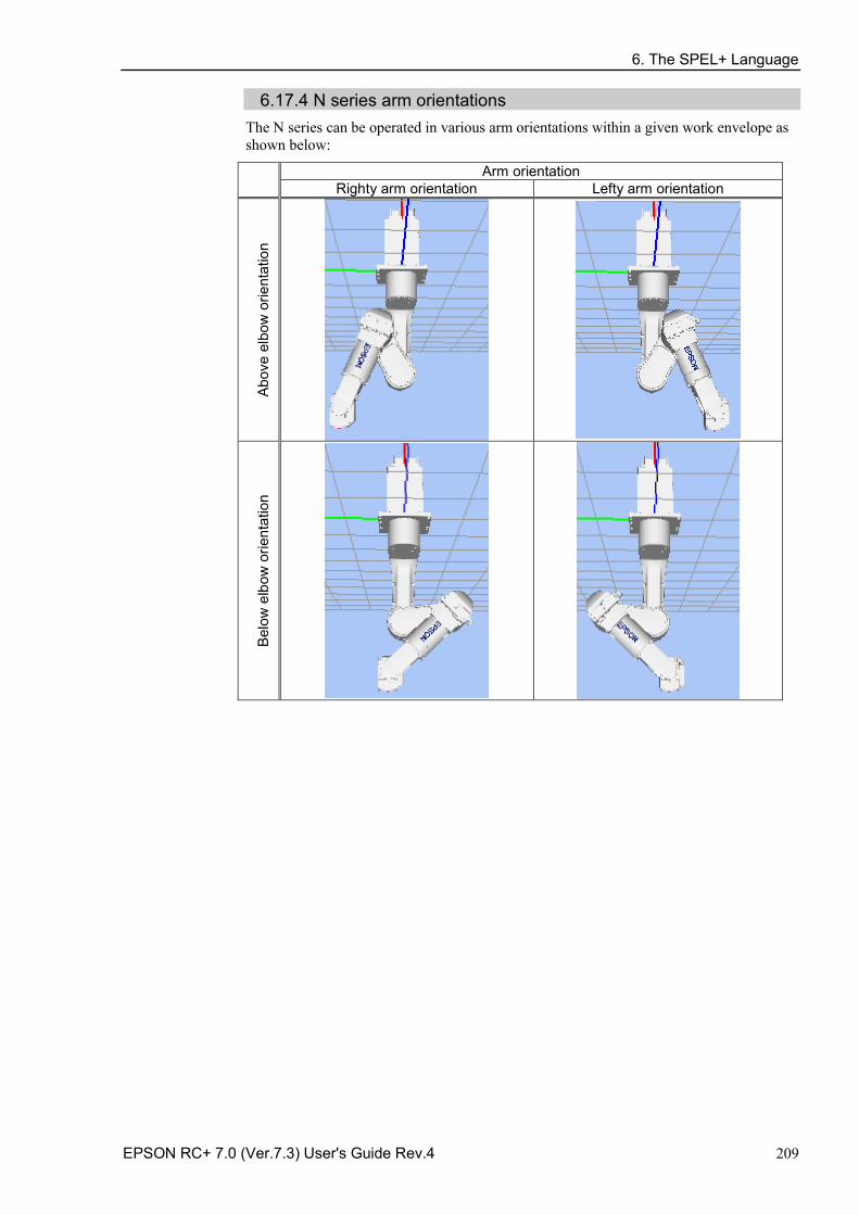
6. The SPEL+ Language
EPSON RC+ 7.0 (Ver.7.3) User's Guide Rev.4 209
6.17.4 N series arm orientations The N series can be operated in various arm orientations within a given work envelope as shown below:
Arm orientation Righty arm orientation Lefty arm orientation
Abov
e el
bow
orie
ntat
ion
Belo
w e
lbow
orie
ntat
ion
6. The SPEL+ Language
210 EPSON RC+ 7.0 (Ver.7.3) User's Guide Rev.4
To specify orientation for the N series robot, add a forward slash (/) followed by L (for Lefty hand orientation) or R (Righty hand orientation), A (Above elbow orientation) or B (Below elbow orientation), and NF (NoFlip wrist orientation) or F (Flip wrist orientation).
There are eight available orientations as shown below, however, the 6-axis robot cannot be operated in all of the orientations depending on point.
Available Orientation
1 /R /A /NF 5 /R /A /F
2 /L /A /NF 6 /L /A /F
3 /R /B /NF 7 /R /B /F
4 /L /B /NF 8 /L /B /F
At some points in the work envelope, the 6-axis robot can have the same position and orientation even if the fourth joint or the sixth joint is rotated 360 degrees. To distinguish these points, the J4Flag and J6Flag point attributes are provided.
To specify the J4Flag, add a forward slash (/) followed by J4F0 (-180 < the forth joint angle <= 180) or J4F1 (the forth joint angle <= -180 or 180 < the forth joint angle).
To specify the J6Flag, add a forward slash (/) followed by J6F0 (-180 < the sixth joint angle <= 180), J6F1 (-360 < the sixth joint angle <= -180 or 180 <the sixth joint angle <= 360), or J6Fn (-180*(n+1) < the sixth joint angle <= 180*n or 180*n <the sixth joint angle <= 180*(n+1)).
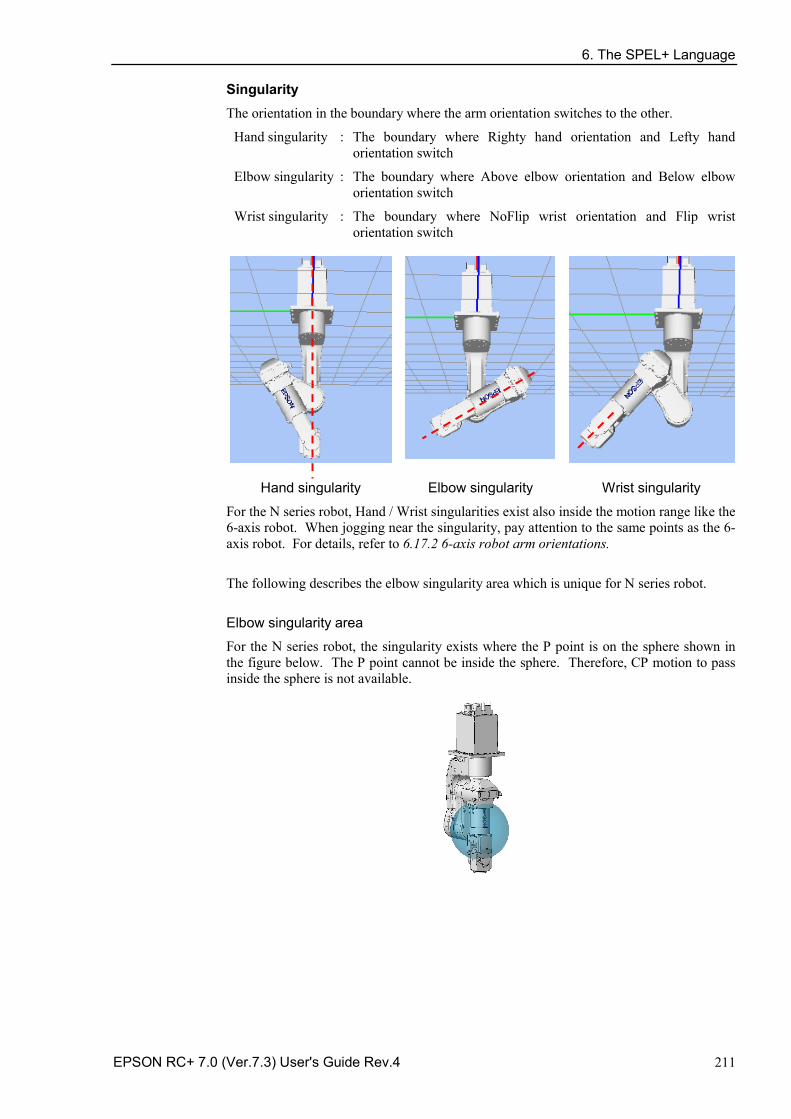
6. The SPEL+ Language
EPSON RC+ 7.0 (Ver.7.3) User's Guide Rev.4 211
Singularity The orientation in the boundary where the arm orientation switches to the other.
Hand singularity : The boundary where Righty hand orientation and Lefty hand orientation switch
Elbow singularity : The boundary where Above elbow orientation and Below elbow orientation switch
Wrist singularity : The boundary where NoFlip wrist orientation and Flip wrist orientation switch
Hand singularity Elbow singularity Wrist singularity
For the N series robot, Hand / Wrist singularities exist also inside the motion range like the 6-axis robot. When jogging near the singularity, pay attention to the same points as the 6-axis robot. For details, refer to 6.17.2 6-axis robot arm orientations.
The following describes the elbow singularity area which is unique for N series robot.
Elbow singularity area
For the N series robot, the singularity exists where the P point is on the sphere shown in the figure below. The P point cannot be inside the sphere. Therefore, CP motion to pass inside the sphere is not available.
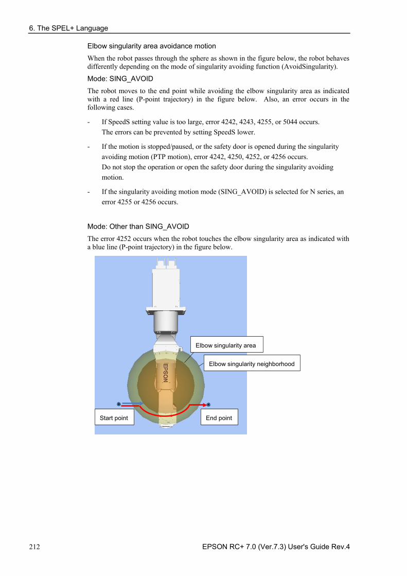
6. The SPEL+ Language
212 EPSON RC+ 7.0 (Ver.7.3) User's Guide Rev.4
Elbow singularity area avoidance motion
When the robot passes through the sphere as shown in the figure below, the robot behaves differently depending on the mode of singularity avoiding function (AvoidSingularity).
Mode: SING_AVOID
The robot moves to the end point while avoiding the elbow singularity area as indicated with a red line (P-point trajectory) in the figure below. Also, an error occurs in the following cases.
- If SpeedS setting value is too large, error 4242, 4243, 4255, or 5044 occurs. The errors can be prevented by setting SpeedS lower.
- If the motion is stopped/paused, or the safety door is opened during the singularity avoiding motion (PTP motion), error 4242, 4250, 4252, or 4256 occurs. Do not stop the operation or open the safety door during the singularity avoiding motion.
- If the singularity avoiding motion mode (SING_AVOID) is selected for N series, an error 4255 or 4256 occurs.
Mode: Other than SING_AVOID
The error 4252 occurs when the robot touches the elbow singularity area as indicated with a blue line (P-point trajectory) in the figure below.
Elbow singularity area
End point Start point
Elbow singularity neighborhood
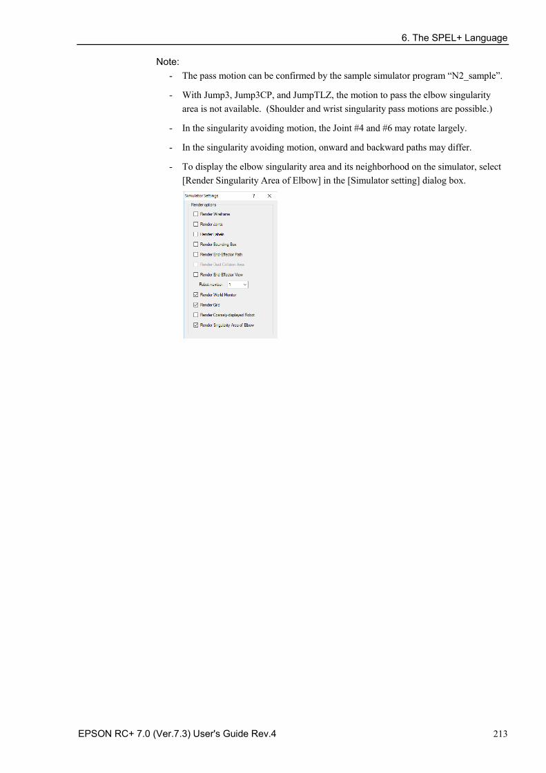
6. The SPEL+ Language
EPSON RC+ 7.0 (Ver.7.3) User's Guide Rev.4 213
Note: - The pass motion can be confirmed by the sample simulator program “N2_sample”.
- With Jump3, Jump3CP, and JumpTLZ, the motion to pass the elbow singularity area is not available. (Shoulder and wrist singularity pass motions are possible.)
- In the singularity avoiding motion, the Joint #4 and #6 may rotate largely.
- In the singularity avoiding motion, onward and backward paths may differ.
- To display the elbow singularity area and its neighborhood on the simulator, select [Render Singularity Area of Elbow] in the [Simulator setting] dialog box.
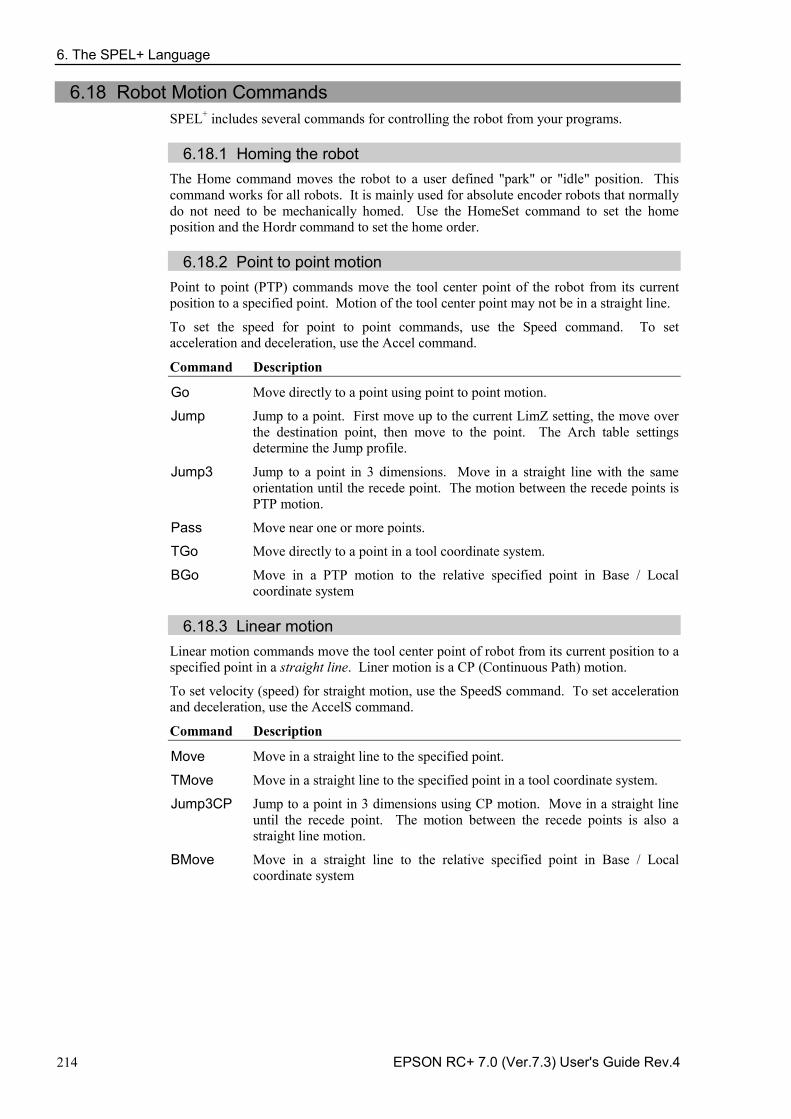
6. The SPEL+ Language
214 EPSON RC+ 7.0 (Ver.7.3) User's Guide Rev.4
6.18 Robot Motion Commands SPEL+ includes several commands for controlling the robot from your programs.
6.18.1 Homing the robot The Home command moves the robot to a user defined "park" or "idle" position. This command works for all robots. It is mainly used for absolute encoder robots that normally do not need to be mechanically homed. Use the HomeSet command to set the home position and the Hordr command to set the home order.
6.18.2 Point to point motion Point to point (PTP) commands move the tool center point of the robot from its current position to a specified point. Motion of the tool center point may not be in a straight line.
To set the speed for point to point commands, use the Speed command. To set acceleration and deceleration, use the Accel command.
Command Description
Go Move directly to a point using point to point motion.
Jump Jump to a point. First move up to the current LimZ setting, the move over the destination point, then move to the point. The Arch table settings determine the Jump profile.
Jump3 Jump to a point in 3 dimensions. Move in a straight line with the same orientation until the recede point. The motion between the recede points is PTP motion.
Pass Move near one or more points.
TGo Move directly to a point in a tool coordinate system.
BGo Move in a PTP motion to the relative specified point in Base / Local coordinate system
6.18.3 Linear motion
Linear motion commands move the tool center point of robot from its current position to a specified point in a straight line. Liner motion is a CP (Continuous Path) motion.
To set velocity (speed) for straight motion, use the SpeedS command. To set acceleration and deceleration, use the AccelS command.
Command Description
Move Move in a straight line to the specified point.
TMove Move in a straight line to the specified point in a tool coordinate system.
Jump3CP Jump to a point in 3 dimensions using CP motion. Move in a straight line until the recede point. The motion between the recede points is also a straight line motion.
BMove Move in a straight line to the relative specified point in Base / Local coordinate system
6. The SPEL+ Language
EPSON RC+ 7.0 (Ver.7.3) User's Guide Rev.4 215
6.18.4 Curves Curves commands move the robot in a circular arc. Curves is a CP (Continuous Path) motion.
To set velocity (speed) for Curves, use the SpeedS command. To set acceleration and deceleration, use the AccelS command.
Command Description
Arc Move the robot through one point to another point using circular interpolation.
Arc3 Move the robot in 3D using circular interpolation.
Curve Creates a file containing a path specification.
CVMove Executes a path specified by Curve.
6.18.5 Joint motion Command Description
JTran The JTran command can be used to move one joint of the robot to a position specified in degrees or millimeters, depending on the joint type. The speed and acceleration are the same as for point to point motion commands -- i.e., specified with Speed or Accel commands.
PTran The PTran command can be used to move one joint of the robot to an encoder pulse position. The speed and acceleration are the same as for point to point motion commands -- i.e., specified with Speed or Accel commands.
Pulse The Pulse command can be used to move all joints of the robot to encoder pulse positions. The speed and acceleration are the same as for point to point motion commands -- i.e., specified with Speed or Accel commands.
PG_Scan The PG_Scan command can be used to rotate a pulse generator axis of a Joint-type single axis PG robot continuously in CW/CCW directions. (To rotate it continuously, you need to enable the continuous rotation parameter.) The speed and acceleration are the same as for point to point motion commands -- i.e., specified with Speed or Accel commands.
6.18.6 Controlling position accuracy
Use the Fine command to adjust position accuracy for the end of a motion command. Fine specifies, for each joint, the allowable positioning error for detecting completion of any given move. The lower the Fine settings, the more accurate the final position of the joint, which can cause slower performance. Conversely, large Fine settings can speed up motion commands, but position accuracy will decrease. For many applications, the default settings can be used.
6. The SPEL+ Language
216 EPSON RC+ 7.0 (Ver.7.3) User's Guide Rev.4
6.18.7 CP Motion Speed / Acceleration and Tool Orientation When you attempt to change only the tool orientation while keeping the tool tip of the robot arm at the specified coordinate point or when the tool orientation variation is larger than the travel distance of the tool tip, moving the arm by normal CP motion commands will cause an increase in the variation of speed, acceleration and deceleration of tool orientation. In some cases, an error will occur.
To prevent these situations, add the ROT parameter to the CP motion commands. The arm will be moved based on the specified angular velocity and acceleration/deceleration of the main axis regarding the orientation variation.
The angular velocity and acceleration/deceleration of the main axis regarding the orientation variation should be specified with the SpeedR and AccelR commands in advance.
For example: SpeedR 50 ' degree/sec AccelR 200, 200 ' degree/sec2 Move P1 ROT
The tool orientation variation is normally comprised of orientation variations of more than one rotation axis.
The SpeedR and AccelR parameters specify the angular velocity and acceleration/ deceleration of the main axis regarding the orientation variation. Therefore, actual angular velocity and acceleration/deceleration of the orientation variation are different from the parameters except for the case where the rotation axis of the orientation is only one. While the motion command with the ROT parameter is executed, the specified SpeedS and AccelS parameters are invalid.
The ROT parameter can be used with the following motion commands: Move BMove Arc TMove Arc3 Jump3CP
6.18.8 PTP Speed / Acceleration for Small Distances
You can change the speed and acceleration for small distances using PTPBoost and PTPBoostOK. Normally, PTPBoost is not required. In certain cases, you may want to shorten the cycle time even if vibration becomes larger, or conversely you may want to reduce vibration even if cycle time becomes longer. PTPBoost is a robot parameter with values from 0 – 100 that affects the speed and acceleration for small distances. Normally, for small distance motion, the desired speed cannot be attained using the current acceleration. By increasing PTPBoost, acceleration, deceleration, and speed are increased for small distance motion. To check if a motion command will be affected by PTPBoost, use the PTPBoostOK function. See PTPBoost and PTPBoostOK in the SPEL+ Language Reference manual for more details.
6.18.9 Pressing Motion To use the pressing motion, use the following torque control mode commands.
TC (Returns the torque control mode setting and current mode.) TCSpeed (Specifies / returns the speed limit in the torque control.) TCLim (Specifies the torque limit of each joint for the torque control mode.)
The low power mode is limited by a low power upper limit. Therefore, normally use the High power mode. For details and usage of the above commands, refer to “TC Statement”, “TCSpeed”, and “TCLim” in the SPEL+ Language Reference manual.
NOTE
6. The SPEL+ Language
EPSON RC+ 7.0 (Ver.7.3) User's Guide Rev.4 217
6.18.10 Collision Detection Function (Detection Function of Robot Motion Error)
Detect the robot motion error from differentiation between desired speed and the actual speed (speed deviation value). Errors can be detected by this function is classified into A and B.
A: Collision or contact of robot arm or hand occurs B: Robot motion errors other than collision or contact
Also, error B is classified into below according to the power condition.
Error in high power B1: Torque saturation due to a low Weight or Inertia setting. B2: Torque saturation due to combined motion of multiple joints and movement of a long
object. B3: Torque saturation due to supply voltage reduction. B4: Error motion due to hardware error or software malfunction.
Error in low power B4: Error motion due to hardware error or software malfunction. B5: Torque saturation in low power due to a hand or a long object that exceeds the weight
described in the specifications.
Display either message below and stop the robot when detecting an error A or B. Reduce the damage of the robot or equipment.
Error 5057: detect the collision in high power. (Detect the robot motion error.) Error 5058: detect the collision in low power. (Detect the robot motion error.)
The following error has been existed, however, this function can detect the above errors quickly.
Error 5042, 5043: Position error.
Error is not detected by torque saturation in short time. Detect a state with high risk that causes a malfunction and stop the robot. The following phenomena may occur if continuing robot operation in a state of B1 or B2. Make a state that errors not occur. Loose binding parts such as screws. Reduction gear is damaged. Increase a risk of robot damage Turn ON CollsionDetect command and detection is enabled. (Default in ON) Default is different depending on the firmware version.
Ver.7.2.1.x or later: default: ON Before Ver.7.2.0.x: default: OFF When upgrading before Ver.7.2.0.x or Ver7.2.1.x or later: default: OFF
Reboot a controller to return to the default. The following describes the detail of error B when error 5057 or 5058 is detected without a collision or contact of the robot or arm.
In high power mode Check the torque saturation by using PTRQ command. Torque saturation is occurred if the joint outputs “1” in PTRQ command.
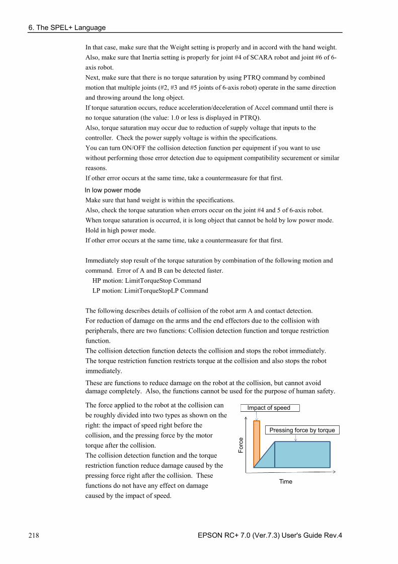
6. The SPEL+ Language
218 EPSON RC+ 7.0 (Ver.7.3) User's Guide Rev.4
In that case, make sure that the Weight setting is properly and in accord with the hand weight. Also, make sure that Inertia setting is properly for joint #4 of SCARA robot and joint #6 of 6-axis robot. Next, make sure that there is no torque saturation by using PTRQ command by combined motion that multiple joints (#2, #3 and #5 joints of 6-axis robot) operate in the same direction and throwing around the long object. If torque saturation occurs, reduce acceleration/deceleration of Accel command until there is no torque saturation (the value: 1.0 or less is displayed in PTRQ). Also, torque saturation may occur due to reduction of supply voltage that inputs to the controller. Check the power supply voltage is within the specifications. You can turn ON/OFF the collision detection function per equipment if you want to use without performing those error detection due to equipment compatibility securement or similar reasons. If other error occurs at the same time, take a countermeasure for that first.
In low power mode Make sure that hand weight is within the specifications. Also, check the torque saturation when errors occur on the joint #4 and 5 of 6-axis robot. When torque saturation is occurred, it is long object that cannot be hold by low power mode. Hold in high power mode. If other error occurs at the same time, take a countermeasure for that first. Immediately stop result of the torque saturation by combination of the following motion and command. Error of A and B can be detected faster.
HP motion: LimitTorqueStop Command LP motion: LimitTorqueStopLP Command
The following describes details of collision of the robot arm A and contact detection. For reduction of damage on the arms and the end effectors due to the collision with peripherals, there are two functions: Collision detection function and torque restriction function. The collision detection function detects the collision and stops the robot immediately. The torque restriction function restricts torque at the collision and also stops the robot immediately.
These are functions to reduce damage on the robot at the collision, but cannot avoid damage completely. Also, the functions cannot be used for the purpose of human safety.
The force applied to the robot at the collision can be roughly divided into two types as shown on the right: the impact of speed right before the collision, and the pressing force by the motor torque after the collision. The collision detection function and the torque restriction function reduce damage caused by the pressing force right after the collision. These functions do not have any effect on damage caused by the impact of speed.
Impact of speed
Pressing force by torque
Forc
e
Time
6. The SPEL+ Language
EPSON RC+ 7.0 (Ver.7.3) User's Guide Rev.4 219
The collision detection function detects collision by the speed deviation value for robot motion control (differentiation between the desired speed and the actual speed) showing an abnormal value which is greatly different from normal motion due to the collision. Turn ON CollsionDetect command and the detection is enabled. (Default: ON) Default is different depending on the firmware version.
Ver.7.2.1.x or later: default: ON Before Ver.7.2.0.x : default: OFF
Reboot a controller to return to the default.
When enabled, this function reduces the time of pressing force by the motor torque, by detecting the collision and stopping the robot immediately. This reduces the pressing force by about 20%. To reduce the damage more, use this function together with the torque restriction function.
The collision detection function is automatically disabled during the pressing motion and the force sensing operation described in “6.18.9 Pressing Motion”. Also, the function may have false detection in cases of powerful contact motion and significant acceleration and deceleration which may have consecutive torque saturation. To confirm if there is a risk of false detection, use PTRQ. If PTRQ is less than 1 for all axes, there is no risk of false detection. If PTRQ is one, torque saturation is occurring on the axis. This means excessive acceleration and deceleration are applied, and it is not preferable for motor control. It also has a risk of damage on the manipulator. In such a situation, take the following countermeasures.
For contacting operation, - Check if Weight and Inertia settings are appropriate - Lower acceleration and deceleration - Lower speed When performing contacting motion: - Lower acceleration and deceleration at a contact - Set a contacting depth shallow
If you want to operate the manipulator without taking the above countermeasures, you can enable and disable the function for each axis. Set the function off for the axis which you want to disable the function. For details of the command and function, refer to the following manual.
EPSON RC+ 7.0 SPEL+ Language Reference CollisionDetect Statement CollisionDetect Function
6.18.11 Torque Restriction Function
The torque restriction function reduces damage at the collision similarly with “6.18.10 Collision Detection Function”.
The torque restriction value used for this function is defined by adding the margin to the upper limit torque value used in the program in order to avoid malfunction. By using the torque restriction function, the pressing force can be reduced.
For example, if the torque is restricted at 30%, the pressing force can also be reduced to 30%. Also, the robot immediately stops when the torque reaches the upper limit value. By stopping the robot immediately, a further 20-30% reduction effect can be obtained.
6. The SPEL+ Language
220 EPSON RC+ 7.0 (Ver.7.3) User's Guide Rev.4
When the torque is restricted at 30% and the robot is stopped immediately, the total of less than 25% or equivalent reduction effect can be obtained. For SCARA robots, the end of the extended shaft may get caught and bent. To reduce occurrence of the bent shaft, it is recommended to use this function to reduce the pressing force to the maximum degree.
If malfunction occurs, take any of the following measures for the axis of malfunction. - Set LimitTorqueStop or LimitTorqueStopLp off - Increase the threshold value of LimitTorque or LimitTorqueLp
To use the torque restriction function for jogging motion, follow the steps below.
(1) Execute PTCLR and start torque measurement.
(2) Execute the jogging motion.
(3) Measure the maximum torque value by PTRQ, and then add the margin to it.
(4) Set LimitTorqeLP and LimitTorqeLPStop.
If the robot is temporarily stopped in the low power motion, the value larger than the normal program operation or jogging motion may be obtained. In such case, execute the temporary stop while measuring PTRQ and include it into measurement.
For details of the command and function, refer to the following manual. EPSON RC+ 7.0 SPEL+ Language Reference
LimitTorque Statement, LimitTorque Function, LimitTorqueLP Statement, LimitTorqueLP Function, LimitTorqueStop Statement, LimitTorqueStop Function, LimitTorqueStopLP Statement, LimitTorqueStopLP Function
The following is a sample program which automatically configures the collision detection function and the torque restriction function. The program repeats the motion called “all_ax_move”. The program enables the collision detection function, measures the maximum torque in the first five moves, adds the margin to the measured value (1.2 times if HighPower, 1.4 times if LowPower), and sets the upper limit torque value to stop the robot at the upper limit torque. This is the example of automatic setting to repeat motion with the above settings from the sixth time. When the upper limit torque value is changed, the changed value will be considered as “1.0” for the subsequent PTRQ measurement. If the margin of 1.2 times is set, PTRQ will be slightly larger than 0.8, and if the margin of 1.4 rimes is set, PTRQ will be slightly smaller than 0.7. Setting example) Function main Integer icnt Real rtrq(6) Motor On Power High ‘ Power Low Weight 8 Speed 50 Accel 80, 80 icnt = 1 PTCLR
6. The SPEL+ Language
EPSON RC+ 7.0 (Ver.7.3) User's Guide Rev.4 221
LimitTorque 100 'init HighPower limit torque LimitTorqueLP 100 'init LowPower limit torque CollisionDetect On Do Call all_ax_move Print PTRQ(1), PTRQ(2), PTRQ(3), PTRQ(4), PTRQ(5), PTRQ(6) icnt = icnt + 1 If icnt = 5 Then If Power = 1 Then 'High power case Print "LimitTorque set" rtrq(1) = PTRQ(1) * 1.2 * LimitTorque(1) + 1.0 rtrq(2) = PTRQ(2) * 1.2 * LimitTorque(2) + 1.0 rtrq(3) = PTRQ(3) * 1.2 * LimitTorque(3) + 1.0 rtrq(4) = PTRQ(4) * 1.2 * LimitTorque(4) + 1.0 rtrq(5) = PTRQ(5) * 1.2 * LimitTorque(5) + 1.0 rtrq(6) = PTRQ(6) * 1.2 * LimitTorque(6) + 1.0 Print LimitTorque(1), LimitTorque(2), LimitTorque(3), LimitTorque(4), LimitTorque(5), LimitTorque(6) LimitTorque rtrq(1), rtrq(2), rtrq(3), rtrq(4), rtrq(5), rtrq(6) Print LimitTorque(1), LimitTorque(2), LimitTorque(3), LimitTorque(4), LimitTorque(5), LimitTorque(6) LimitTorqueStop On Else 'Low poser case Print "LimitTorqueLP set" rtrq(1) = PTRQ(1) * 1.4 * LimitTorqueLP(1) + 1.0 rtrq(2) = PTRQ(2) * 1.4 * LimitTorqueLP(2) + 1.0 rtrq(3) = PTRQ(3) * 1.4 * LimitTorqueLP(3) + 1.0 rtrq(4) = PTRQ(4) * 1.4 * LimitTorqueLP(4) + 1.0 rtrq(5) = PTRQ(5) * 1.4 * LimitTorqueLP(5) + 1.0 rtrq(6) = PTRQ(6) * 1.4 * LimitTorqueLP(6) + 1.0 Print LimitTorqueLP(1), LimitTorqueLP(2), LimitTorqueLP(3), LimitTorqueLP(4), LimitTorqueLP(5), LimitTorqueLP(6) LimitTorqueLP rtrq(1), rtrq(2), rtrq(3), rtrq(4), rtrq(5), rtrq(6) Print LimitTorqueLP(1), LimitTorqueLP(2), LimitTorqueLP(3), LimitTorqueLP(4), LimitTorqueLP(5), LimitTorqueLP(6) LimitTorqueStopLP On EndIf If icnt > 5 Then icnt = 6 Endif Loop While icnt > 0 Fend Function all_ax_move Integer icount Go JA(10, 10, 10, 10, 10, 10) Go JA(-10, -10, -10, -10, -10, -10) Fend
6.19 Working with Robot Points A robot point is a set of coordinates that define a position in the robot work envelope. For SCARA and Cartesian robots, a point is defined by the position data (X, Y, Z) within the reference rectangular coordinate space and the orientation data (U) which is the rotation about the Z axis of the rectangular coordinate.
For 6-axis robots, a point is defined by the position and orientation of the tool coordinate system with respect to a reference rectangular coordinate system. The point is specified by the position data (X, Y, Z) and the orientation is specified by the orientation data (U, V, W) which correspond with roll (rotation about the Z axis), pitch (rotation about the Y axis), and yaw (rotation about the X axis).
When the additional ST axis is installed, the point is specified by the position data of each additional axis (S, T).
6. The SPEL+ Language
222 EPSON RC+ 7.0 (Ver.7.3) User's Guide Rev.4
The X, Y, and Z coordinates of a point are specified in millimeters. The U, V, and W coordinates are specified in degrees.
The S and T coordinates of a point are specified in millimeters or degrees, according to the type of axis.
Points are referenced using the letter P followed by an integer number or integer expression or by a label defined in the point file editor or [Robot Manager]-[Jog & Teach] page.
6.19.1 Defining points You can define points in a program statement, points editor window, [Robot Manager]-[Jog & Teach] page, or at the [Command] window.
In a program statement or at the Command window, you can assign coordinates to a point, or define a point that is the current robot arm position.
P1 = XY(200, 100, -25, 0) 'Assign coordinates to point P1
Pick = XY(300, 200, -45, 0) 'Assign coordinates to point pick
P10 = Here 'Assign a point to current position
6.19.2 Referencing points by point label You can assign names to point numbers so you can refer to points by name in a program. Assign names from the point editor (see Editing Points) or the [Robot Manager]-[Jog & Teach] page. Names must be unique for each point number when used in the same point file. Point labels can include up to 32 one-byte alphanumeric, Japanese, and the underscore characters, or 16 two-byte characters. Characters can be upper case or lower case. Only alphabets and Japanese can be used for the first letter.
For i = 0 To 10
Go pick
Jump place
Next i
6. The SPEL+ Language
EPSON RC+ 7.0 (Ver.7.3) User's Guide Rev.4 223
6.19.3 Referencing points with variables Use the letter P followed by a variable name within parentheses that represents the point number you are referencing.
For i = 0 To 10
Go P(i)
Next i
Although you can define points at the [Command] window for test purposes, it is recommended that all points be defined in a program, point editor, or with the [Robot Manager]-[Jog & Teach] page. Points defined at the [Command] window will be cleared from memory when you build a project or run a program unless you execute “SavePoints”.
6.19.4 Using points in a program When starting programs, the default point file for the robot is loaded. You can also load other points in the program using the LoadPoints statement.
Function main
Integer i
LoadPoints "model1.pts"
For i = 0 To 10
Jump pick
Jump place
Next i
Fend
6.19.5 Importing points into program You can import points into the current project while the program is running using the ImportPoints statement. Function main
Integer i
ImportPoints "c:\models\model1.pnt", "robot1.pnt"
LoadPoints "robot1.pnt"
For i = 0 To 10
Jump pick
Jump place
Next i
Fend
6.19.6 Saving and loading points Use “LoadPoints” to load a point file in the current project. You can optionally specify the Merge parameter to combine points in a file with points that have already been loaded.
Use “SavePoints” to save the points in a point file. If the point file is in the current project, it will be updated on the PC when it is connected and the same project is open.
If the point file is not the current project, it will not be automatically updated on the PC. Use Project Synchronize to copy the file to the PC if desired.
CAUTION
■ Rebuild the program if Project Synchronize is performed.
NOTE
6. The SPEL+ Language
224 EPSON RC+ 7.0 (Ver.7.3) User's Guide Rev.4
6.19.7 Point attributes Each point definition can optionally specify a local number and various arm orientations, depending on the robot type. You can specify point attributes in point assignment statements or use individual statements and functions to change the attributes of a previously defined point.
Local point attribute
To specify a local coordinate system number for a point in an assignment statement, add a forward slash (/) followed by the local number after the coordinates of the point.
P1 = XY(300, -125.54, -42.3, 0) /1 ' P1 is in local 1 The local number can also be an expression enclosed in parentheses.
P2 = P3 /(mylocal)
Use the PLocal function and statement to read and set the local attribute of a point.
Hand point attribute
To specify orientation for the SCARA or 6-axis robot, add a forward slash (/) followed by L (for Lefty hand orientation) or R (for Righty hand orientation).
P2 = XY(200, 100, -20, -45) /L ' Hand orientation is Lefty
P3 = XY(50, 0, 0, 0) /2 /R ' Righty in Local 2 You can read and set point hand orientation using the Hand statement and function.
Hand P1, Righty
Elbow point attribute
To specify elbow orientation for the 6-axis robot in a point assignment statement, add a forward slash (/) followed by A (Above elbow orientation) or B (Below elbow orientation),
Elbow orientation is Below. P1 = XY(0, 600, 400, 90, 0, 180) /B
You can read and set point elbow orientation using the Elbow statement and function.
Wrist point attribute
To specify wrist orientation for the 6-axis robot in a point assignment statement, add a forward slash (/) followed by NF (NoFlip wrist orientation) or F (Flip wrist orientation). Wrist orientation is Flip.
P2 = XY(0, 600, 400, 90, 0, 180) /F
You can read and set point wrist orientation using the Wrist statement and function.
J4Flag and J6Flag point attributes
At some points in the work envelope, the 6-axis robot can have the same position and orientation even if the fourth joint or the sixth joint is rotated 360 degrees. To distinguish these points, the J4Flag and J6Flag point attributes are provided. These flags allow you to specify a position range for joint 4 and joint 6 for a given point.
To specify the J4Flag in a point assignment statement, add a forward slash (/) followed by J4F0 (−180 < the forth joint angle <= 180) or J4F1 (the forth joint angle <= −180 or 180 < the forth joint angle).
P2 = XY(0, 600, 400, 90, 0, 180) /J4F1
To specify the J6Flag in a point assignment statement, add a forward slash (/) followed by J6F0 (−180 < the sixth joint angle <= 180), J6F1 (−360 < the sixth joint angle <= −180 or 180 < the sixth joint angle <= 360), or J6Fn (−180*(n+1) < the sixth joint angle <= 180*n or 180*n < the sixth joint angle <= 180*(n+1)).
P2 = XY(50, 400, 400, 90, 0, 180) /J6F2
6. The SPEL+ Language
EPSON RC+ 7.0 (Ver.7.3) User's Guide Rev.4 225
J1Flag and J2Flag point attributes
At some points in the work envelope, the RS series can have the same position and orientation even if the first joint or the second joint is rotated 360 degrees. To distinguish these points, the J1Flag and J2Flag point attributes are provided. These flags allow you to specify a position range for joint 1 and joint 2 for a given point.
To specify the J1Flag in a point assignment statement, add a forward slash (/) followed by J1F0 (−90 < the first joint angle <= 270) or J1F1 (−270 <= the first joint angle <= −90 or 270 < the first joint angle <= 450).
P2 = XY(-175, -175, 0, 90) /J1F1
To specify the J2Flag in a point assignment statement, add a forward slash (/) followed by J2F0 (−180 < the second joint angle <= 180), J2F1 (−360 < the second joint angle <= −180 or 180 < the second joint angle <= 360).
P2 = XY(300, 175, 40, 90) /J2F1
J1Ang and J2Flag point attributes
At the origin of the robot coordinate system, the RS series can have the same position and orientation even if the first joint is rotated. To distinguish these points, the J1Ang point attributes are provided.
6.19.8 Extracting and setting point coordinates Use the CX, CY, CZ, CU, CV, CW, CS, and CT commands to get a coordinate of a point and set it.
xcoord = CX(P1)
P2 = XY(xcoord, 200, -20, 0)
ycoord = CY(P*) ' Gets current Y position coordinate
CX(pick) = 25.5
CY(pick) = CY(pick) + 2.3
6.19.9 Alteration of points
There are several ways of modifying a point without re-teaching it. You can change one or more coordinate values with relative offsets or absolute values.
To set an absolute value for a coordinate, use a colon followed by the axis letter and the value.
To add a relative offset to a coordinate, use an axis letter followed by the offset value or expression in parentheses. If the offset is negative, then precede the axis letter with the minus sign. If parentheses are omitted, they will be automatically added. Go P1 -Z(20) Move to P1 with a z offset of −20mm Go P1 :Z(-25) Move to P1 with a z absolute position of −25mm Go P1 -X(20) +Y(50) :Z(-25) Move to P1 with offsets for X and Y relative
offsets and an absolute position for Z
Point alternation of 6-axis robot
When changing the orientation by roll (U), pitch (V), and yaw (W) in the SPEL+ program, adding the angles to V and W axes (e.g. +V(10), +W(10)) does not mean the rotation of Y and X axes in the robot coordinate system. To change the orientation (U, V, and W) after teaching the points, set the robot to actual posture by Jog & Teach in the Robot Manager.
6. The SPEL+ Language
226 EPSON RC+ 7.0 (Ver.7.3) User's Guide Rev.4
6.20 Input and output control
6.20.1 Hardware I/O There are 24 DC inputs and 16 DC outputs on a standard controller. By purchasing I/O boards, you can add additional 128 inputs and 128 outputs. You can expand the I/O by using the Fieldbus I/O master option and Fieldbus I/O slave option. Also, you can input/output the Analog signal by using the Analog I/O board option. Refer to 11. Inputs and Outputs for details.
6.20.2 Memory I/O There are 128 bytes (1024 bits) of memory I/O. Memory I/O is especially useful for synchronizing multi-tasking. Each memory bit can be treated as both an input and an output.
Use the commands with the "Mem" prefix for memory I/O.
6.20.3 I/O Commands Command Description
In Reads one byte (eight bits) of input data.
InW Reads one word (sixteen bits) of input data.
MemIn Reads one byte (eight bits) of Memory I/O.
MemInW Reads one word (sixteen bits) of Memory I/O.
MemOff Turns off one Memory I/O bit.
MemOn Turns on one Memory I/O bit.
MemSw Read status of one bit of memory I/O.
Off Turns off one output bit.
On Turns on one output bit.
Out Sets/reads one byte (eight bits) of output data.
OutW Sets/reads one word (sixteen bits) of output data.
Oport Reads the status of one output bit.
InBCD Reads one byte of input data in BCD (binary coded decimal) format.
OpBCD Outputs one byte of output data in BCD format.
Sw Read status of one bit of hardware inputs or memory inputs.
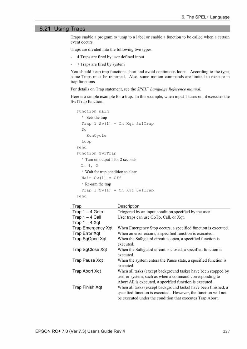
6. The SPEL+ Language
EPSON RC+ 7.0 (Ver.7.3) User's Guide Rev.4 227
6.21 Using Traps Traps enable a program to jump to a label or enable a function to be called when a certain event occurs.
Traps are divided into the following two types:
4 Traps are fired by user defined input -
7 Traps are fired by system -
You should keep trap functions short and avoid continuous loops. According to the type, some Traps must be re-armed. Also, some motion commands are limited to execute in trap functions.
For details on Trap statement, see the SPEL+ Language Reference manual.
Here is a simple example for a trap. In this example, when input 1 turns on, it executes the Sw1Trap function.
Function main
' Sets the trap Trap 1 Sw(1) = On Xqt Sw1Trap
Do
RunCycle
Loop
Fend
Function Sw1Trap
' Turn on output 1 for 2 seconds On 1, 2
' Wait for trap condition to clear Wait Sw(1) = Off
' Re-arm the trap Trap 1 Sw(1) = On Xqt Sw1Trap
Fend
Trap Description Trap 1 – 4 Goto Trap 1 – 4 Call Trap 1 – 4 Xqt
Triggered by an input condition specified by the user. User traps can use GoTo, Call, or Xqt.
Trap Emergency Xqt When Emergency Stop occurs, a specified function is executed. Trap Error Xqt When an error occurs, a specified function is executed. Trap SgOpen Xqt When the Safeguard circuit is open, a specified function is
executed. Trap SgClose Xqt When the Safeguard circuit is closed, a specified function is
executed. Trap Pause Xqt When the system enters the Pause state, a specified function is
executed. Trap Abort Xqt When all tasks (except background tasks) have been stopped by
user or system, such as when a command corresponding to Abort All is executed, a specified function is executed.
Trap Finish Xqt When all tasks (except background tasks) have been finished, a specified function is executed. However, the function will not be executed under the condition that executes Trap Abort.
6. The SPEL+ Language
228 EPSON RC+ 7.0 (Ver.7.3) User's Guide Rev.4
6.21.1 Cautions of Trap when it triggers the system condition
CAUTION
■ Forced Flag
Specify Forced flag in the I/O output commands such as On/Off command to enable On/ Off of the I/O outputs during Emergency Stop, Safety Door open, Teach mode, and error condition.
Do not connect external equipment that operates mechanically such as actuator to the I/O output that specifies Forced flag. Otherwise, the external equipment may move during Emergency Stop, Safety Door Open, Teach mode, or error condition and this will cause serious safety problems.
Forced flag is designed to be specified for I/O outputs connected to external equipment without mechanical motion such as status display LEDs.
Outputs off during Emergency Stop
Uncheck “Outputs off during Emergency Stop” in the Preferences page of System Configuration SPEL Controller Board to execute I/O On/Off using the Trap Emergency Xqt task after Emergency Stop. If this checkbox is checked, the execution order of turning Off by the controller and turning On using the task are not guaranteed.

6. The SPEL+ Language
EPSON RC+ 7.0 (Ver.7.3) User's Guide Rev.4 229
6.22 Special Tasks Each task of SPEL+ pauses by Pause input or Safety Door open and stops by Emergency Stop or Error. Therefore you cannot create a system that monitors the whole system.
To enable the Robot Controller to monitor the whole system, the following special tasks are provided:
NoPause/NoEmgAbort task
You can create a task that continues a processing even when the Pause is input or safeguard is open by specifying NoPause or NoEmgAbort as a task type when creating Xqt data task.
Background task
You can create a task that starts as the controller power is turned ON and continues a processing even when the Pause is input or safeguard is open.
These special tasks are useful tasks but may reduce the safety of the system by using them improperly.
Be sure to understand the following items when using these tasks.
6.22.1 Precautions to Use the Special Tasks
CAUTION
■ Forced Flag
Specify Forced flag in the I/O output commands such as On/Off command to enable On/ Off of the I/O outputs during Emergency Stop, Safety Door open, and error.
Do not connect external equipment that operates mechanically such as actuator to the I/O output that specifies Forced flag. Connecting external equipment may cause serious safety problems and operate the external equipment during Emergency Stop, Safety Door Open, or error occurrence.
Forced flag is designed to be specified for I/O outputs connected to external equipment without mechanical motion such as status display LEDs.
NoEmgAbort Task
When Emergency Stop or errors occur, finish the task promptly after completing the error handling.
If you do not complete the NoEmgAbort task, the controller does not change to Ready status and you cannot cancel the Emergency Stop or the error. You cannot execute Reset command from the NoEmgAbort task to cancel the Emergency Stop or the error automatically.
NoEmgAbort task is designed for I/O process without motion and communication with external device using the Ethernet. Therefore there are commands such as robot motion commands that cannot be executed in the NoEmgAbort task. An error occurs if you use these commands. The list of these commands is in the next section.
For details, refer to EPSON RC+ 7.0 Online Help or Xqt in SPEL+ Language Reference. NoPause Task
NoPause task continues the operation during the Pause or Safety Door open condition. However, when a robot is operating NoPause task, the task pauses as the robot pauses. Background task
Background task always exists while the controller is working, and it is designed for monitor of the entire system and communication with external device. Therefore there are commands such as robot motion commands that cannot be executed in the background
6. The SPEL+ Language
230 EPSON RC+ 7.0 (Ver.7.3) User's Guide Rev.4
task. An error occurs if you use these commands. The list of these commands is in the next section.
In addition, the background task continues processing even when Pause is input or safeguard is open, so it doesn’t affect the controller state transition.
For details, refer to 6.23 Background Task. Outputs off during Emergency Stop
Uncheck this preference to execute I/O On/Off using the NoEmgAbort task or background task after Emergency Stop. If this checkbox is checked, the execution order of turn Off by the controller and turn On using the task are not guaranteed. Setting of Safeguard open stops all tasks
When this preference is checked, NoPause task stops by Safety Door open. NoEmgAbort task or background task continues the task. Setting of [Enable the Background task]
Set this preference when you use the background task. Setting of [Initialize global variables as the MainXX starts]
Uncheck this preference when you use the global variables from the background task. When this checkbox is checked, the controller will initialize the variables and the variable-access conflict from tasks will occur.
CAUTION
■ Setting of [Enable advanced task commands]
Check this preference when you execute the commands below from a background task.
StartMain, Cont, Recover, Reset Error, Reset When you execute these commands from a task, you should understand each command specification and verify that the system has the appropriate conditions.
Improper use, such as executing commands continuously in a loop, can reduce the security of system.
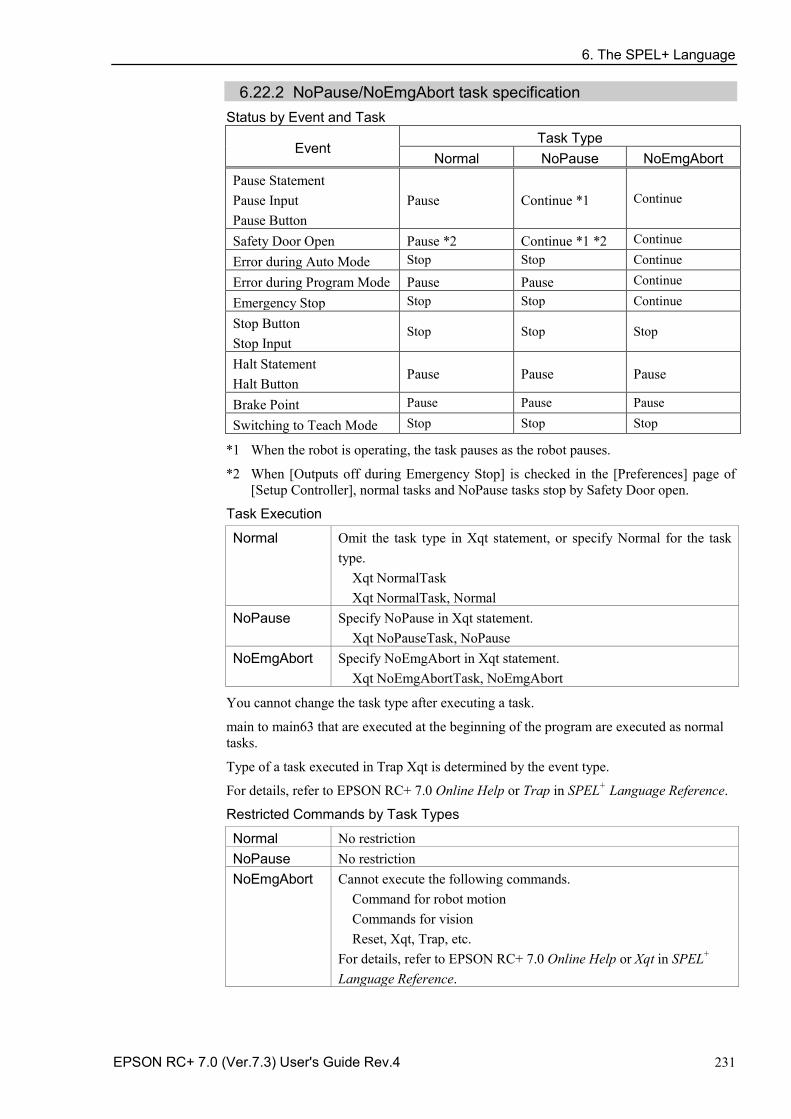
6. The SPEL+ Language
EPSON RC+ 7.0 (Ver.7.3) User's Guide Rev.4 231
6.22.2 NoPause/NoEmgAbort task specification Status by Event and Task
Event Task Type
Normal NoPause NoEmgAbort Pause Statement Pause Input Pause Button
Pause Continue *1 Continue
Safety Door Open Pause *2 Continue *1 *2 Continue
Error during Auto Mode Stop Stop Continue
Error during Program Mode Pause Pause Continue
Emergency Stop Stop Stop Continue
Stop Button Stop Input
Stop Stop Stop
Halt Statement Halt Button
Pause Pause Pause
Brake Point Pause Pause Pause
Switching to Teach Mode Stop Stop Stop
*1 When the robot is operating, the task pauses as the robot pauses.
*2 When [Outputs off during Emergency Stop] is checked in the [Preferences] page of [Setup Controller], normal tasks and NoPause tasks stop by Safety Door open.
Task Execution
Normal Omit the task type in Xqt statement, or specify Normal for the task type.
Xqt NormalTask Xqt NormalTask, Normal
NoPause Specify NoPause in Xqt statement. Xqt NoPauseTask, NoPause
NoEmgAbort Specify NoEmgAbort in Xqt statement. Xqt NoEmgAbortTask, NoEmgAbort
You cannot change the task type after executing a task.
main to main63 that are executed at the beginning of the program are executed as normal tasks.
Type of a task executed in Trap Xqt is determined by the event type.
For details, refer to EPSON RC+ 7.0 Online Help or Trap in SPEL+ Language Reference.
Restricted Commands by Task Types
Normal No restriction NoPause No restriction NoEmgAbort Cannot execute the following commands.
Command for robot motion Commands for vision Reset, Xqt, Trap, etc.
For details, refer to EPSON RC+ 7.0 Online Help or Xqt in SPEL+ Language Reference.
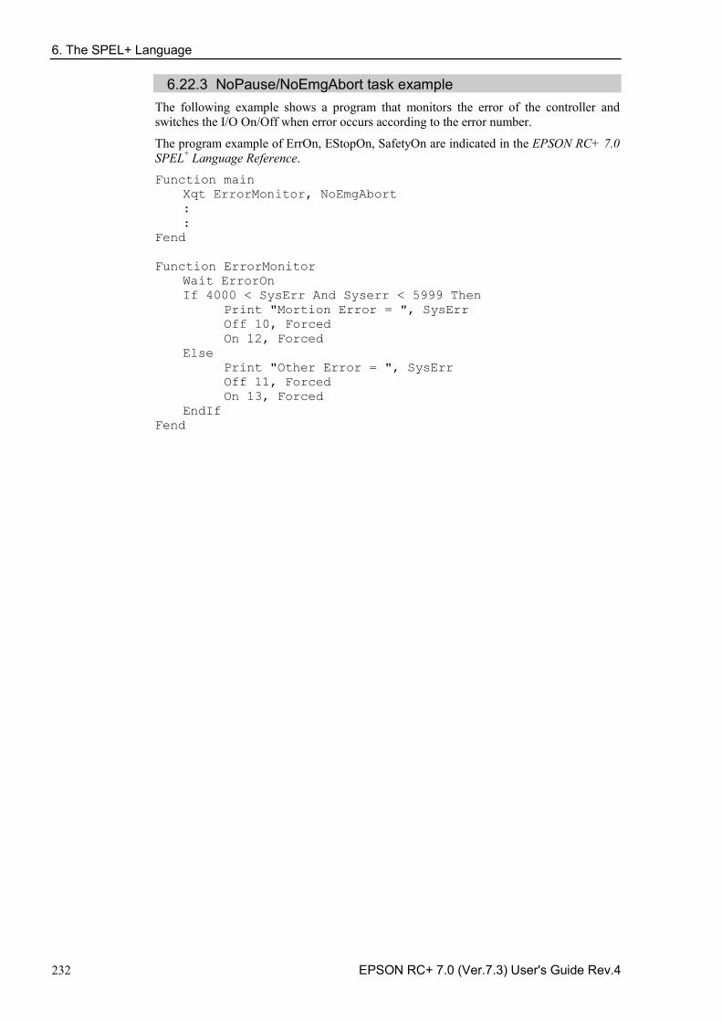
6. The SPEL+ Language
232 EPSON RC+ 7.0 (Ver.7.3) User's Guide Rev.4
6.22.3 NoPause/NoEmgAbort task example The following example shows a program that monitors the error of the controller and switches the I/O On/Off when error occurs according to the error number.
The program example of ErrOn, EStopOn, SafetyOn are indicated in the EPSON RC+ 7.0 SPEL+ Language Reference. Function main
Xqt ErrorMonitor, NoEmgAbort : :
Fend Function ErrorMonitor Wait ErrorOn If 4000 < SysErr And Syserr < 5999 Then Print "Mortion Error = ", SysErr Off 10, Forced On 12, Forced Else Print "Other Error = ", SysErr Off 11, Forced On 13, Forced EndIf Fend
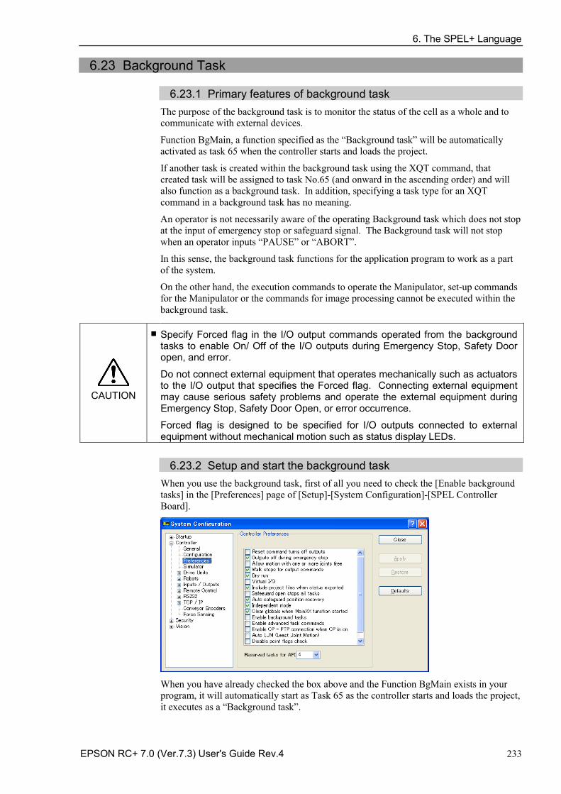
6. The SPEL+ Language
EPSON RC+ 7.0 (Ver.7.3) User's Guide Rev.4 233
6.23 Background Task
6.23.1 Primary features of background task The purpose of the background task is to monitor the status of the cell as a whole and to communicate with external devices.
Function BgMain, a function specified as the “Background task” will be automatically activated as task 65 when the controller starts and loads the project.
If another task is created within the background task using the XQT command, that created task will be assigned to task No.65 (and onward in the ascending order) and will also function as a background task. In addition, specifying a task type for an XQT command in a background task has no meaning.
An operator is not necessarily aware of the operating Background task which does not stop at the input of emergency stop or safeguard signal. The Background task will not stop when an operator inputs “PAUSE” or “ABORT”.
In this sense, the background task functions for the application program to work as a part of the system.
On the other hand, the execution commands to operate the Manipulator, set-up commands for the Manipulator or the commands for image processing cannot be executed within the background task.
CAUTION
■ Specify Forced flag in the I/O output commands operated from the background tasks to enable On/ Off of the I/O outputs during Emergency Stop, Safety Door open, and error.
Do not connect external equipment that operates mechanically such as actuators to the I/O output that specifies the Forced flag. Connecting external equipment may cause serious safety problems and operate the external equipment during Emergency Stop, Safety Door Open, or error occurrence.
Forced flag is designed to be specified for I/O outputs connected to external equipment without mechanical motion such as status display LEDs.
6.23.2 Setup and start the background task When you use the background task, first of all you need to check the [Enable background tasks] in the [Preferences] page of [Setup]-[System Configuration]-[SPEL Controller Board].
When you have already checked the box above and the Function BgMain exists in your program, it will automatically start as Task 65 as the controller starts and loads the project, it executes as a “Background task”.
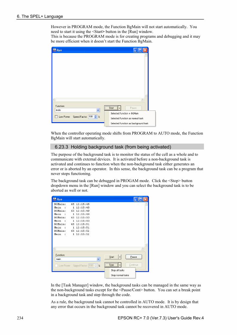
6. The SPEL+ Language
234 EPSON RC+ 7.0 (Ver.7.3) User's Guide Rev.4
However in PROGRAM mode, the Function BgMain will not start automatically. You need to start it using the <Start> button in the [Run] window. This is because the PROGRAM mode is for creating programs and debugging and it may be more efficient when it doesn’t start the Function BgMain.
When the controller operating mode shifts from PROGRAM to AUTO mode, the Function BgMain will start automatically.
6.23.3 Holding background task (from being activated) The purpose of the background task is to monitor the status of the cell as a whole and to communicate with external devices. It is activated before a non-background task is activated and continues to function when the non-background task either generates an error or is aborted by an operator. In this sense, the background task can be a program that never stops functioning.
The background task can be debugged in PROGAM mode. Click the <Stop> button dropdown menu in the [Run] window and you can select the background task is to be aborted as well or not.
In the [Task Manager] window, the background tasks can be managed in the same way as the non-background tasks except for the <Pause/Cont> button. You can set a break point in a background task and step through the code.
As a rule, the background task cannot be controlled in AUTO mode. It is by design that any error that occurs in the background task cannot be recovered in AUTO mode.
6. The SPEL+ Language
EPSON RC+ 7.0 (Ver.7.3) User's Guide Rev.4 235
Therefore, thorough debugging in PROGRAM mode is recommended. Be particularly careful that the communication errors are handled properly without fail before using the background task in AUTO mode. The following tables show how the background will (or will not) be affected by operation from the console. Operator Window
Button Background task START It will not be affected. Abort It will not be affected. Pause It will not be affected. Continue It will not be affected.
Remote Input Button Background task
Start / Stop It will not be affected. Pause / Continue It will not be affected. Reset It will not be affected. Shutdown It will be stopped.
Run Window (PROGRAM mode)
Button Background task Start You can select how to start the task. Abort You can select how to abort the task:
abort only non-background task or abort all tasks including the background task.
Pause It will not be affected. Continue It will not be affected.
Task Manager (PROPGRAM mode)
Button Background task Halt / Resume When the background task is selected, you cannot execute
Halt/Resume. Quit When the background task is selected, you can execute Quit. Pause/Cont It will not be affected. Stop All tasks including the background task will stop.
Break point (PROGRAM mode)
Switch name Background task Set a break point You can set a breakpoint to the background task.
It will pause at the break point. Step Into Available Step Over Available Continue Available Walk Available, but the motion commands are not available to execute from
the background task.
6. The SPEL+ Language
236 EPSON RC+ 7.0 (Ver.7.3) User's Guide Rev.4
6.23.4 Commands that will cause error in background task The following commands are prohibited in background tasks and execution will result in error: commands that relate to the Manipulator operation or operation settings - commands that relate to the Vision relation instruction - TRAP commands -
If a program that is to be executed as the background task includes any of the following commands, it will result in error when executed.
However, using the command related to the Manipulator operation settings or the Manipulator settings to gain the current setting values or refer to them will not result in error:
Commands that will cause error are almost the same as with NoEmgAbort, but there are some commands such as Xqt that can be executed in a background task.
For details, refer to EPSON RC+ 7.0 Online Help or Xqt in SPEL+ Language Reference.
6.23.5 Background task and Remote control No matter whether the background task is being executed or not, it doesn’t affect the remote I/O outputs Ready, Running, and Pause. For example, even if the background task is being executed, when no non-background tasks (Task No. 1 - 32) are being executed, the READY output will be ON.
6. The SPEL+ Language
EPSON RC+ 7.0 (Ver.7.3) User's Guide Rev.4 237
6.24 Predefined Constants There are several predefined constants for use in SPEL+ program. A project build time, the values for these constants are substituted for the constant name.
Constant name Value Use TRUE -1 Boolean expression FALSE 0 Boolean expression High 1 Low 0 Off 0 On 1 Above 1 Below 2 NoFlip 1 Flip 2 Righty 1 Lefty 2 J1 1 J2 2 J3 4 J4 8 J5 16 J6 32 J7 64 CR CHR$(13)
CRLF CHR$(13)+ CHR$(10)
LF CHR$(10) MB_OK 0 MsgBox flags MB_OKCANCEL 1 MsgBox flags MB_ABORTRETRYIGNORE 2 MsgBox flags MB_YESNOCANCEL 3 MsgBox flags MB_YESNO 4 MsgBox flags MB_RETRYCANCEL 5 MsgBox flags MB_ICONSTOP 16 MsgBox flags MB_ICONQUESTION 32 MsgBox flags MB_ICONEXCLAMATION 48 MsgBox flags MB_ICONINFORMATION 64 MsgBox flags MB_DEFBUTTON1 0 MsgBox flags MB_DEFBUTTON2 256 MsgBox flags IDOK 1 MsgBox return IDCANCEL 2 MsgBox return IDABORT 3 MsgBox return IDRETRY 4 MsgBox return IDIGNORE 5 MsgBox return IDYES 6 MsgBox return IDNO 7 MsgBox return BACKCOLORMODE_VISUALSTYLE 0 For GUI Builder BACKCOLORMODE_USER 1 For GUI Builder BORDERSTYLE_NONE 0 For GUI Builder BORDERSTYLE_FIXEDSINGLE 1 For GUI Builder BORDERSTYLE_FIXED3D 2 For GUI Builder CNV_QUELEN_ALL 0 Cnv_QueLen CNV_QUELEN_UPSTREAM 1 Cnv_QueLen CNV_QUELEN_PICKUPAREA 2 Cnv_QueLen CNV_QUELEN_DOWNSTREAM 3 Cnv_QueLen DEVID_SELF 21 CLS DEVID_TP 24 CLS DEVID_TP3 30 CLS DIALOGRESULT_NOE 0 For GUI Builder DIALOGRESULT_OK 1 For GUI Builder DIALOGRESULT_CANCEL 2 For GUI Builder
6. The SPEL+ Language
238 EPSON RC+ 7.0 (Ver.7.3) User's Guide Rev.4
Constant name Value Use DLG_IOMON 102 RunDialog DLG_ROBOTMNG 100 RunDialog DLG_ROBOTPANEL 100 ShowDialog DLG_VGUIDE 110 ShowDialog DROPDOWNSTYLE_SIMPLE 0 For GUI Builder DROPDOWNSTYLE_DROPDOWN 1 For GUI Builder DROPDOWNSTYLE_DROPDOWNLIST 2 For GUI Builder ERROR_DOINGMOTION 2999 For GUI Builder ERROR_NOMOTION 2998 For GUI Builder EVENTTASKTYPE_NORMAL 0 For GUI Builder EVENTTASKTYPE_NOPAUSE 1 For GUI Builder EVENTTASKTYPE_NOEMGABORT 2 For GUI Builder FORCE_LESS 0 Force_SetTrigger FORCE_GREATER 1 Force_SetTrigger FORCE_XFORCE 2 Force_SetTrigger FORCE_YFORCE 3 Force_SetTrigger FORCE_ZFORCE 4 Force_SetTrigger FORCE_XTORQUE 5 Force_SetTrigger FORCE_YTORQUE 6 Force_SetTrigger FORCE_ZTORQUE 7 Force_SetTrigger FORMBORDERSTYLE_NONE 0 For GUI Builder FORMBORDERSTYLE_FIXEDSINGLE 1 For GUI Builder FORMBORDERSTYLE_FIXED3D 2 For GUI Builder FORMBORDERSTYLE_FIXEDDIALOG 3 For GUI Builder FORMBORDERSTYLE_SIZABLE 4 For GUI Builder IMAGEALIGN_TOPLEFT 1 For GUI Builder IMAGEALIGN_TOPCENTER 2 For GUI Builder IMAGEALIGN_TOPRIGHT 3 For GUI Builder IMAGEALIGN_MIDDLELEFT 4 For GUI Builder IMAGEALIGN_MIDDLECENTER 5 For GUI Builder IMAGEALIGN_MIDDLERIGHT 6 For GUI Builder IMAGEALIGN_BOTTOMLEFT 7 For GUI Builder IMAGEALIGN_BOTTOMCENTER 8 For GUI Builder IMAGEALIGN_BOTTOMRIGHT 9 For GUI Builder IOTYPE_INPUT 0 IOLabel function IOTYPE_OUTPUT 1 IOLabel function IOTYPE_MEMORY 2 IOLabel function IOSIZE_BIT 1 IOLabel function IOSIZE_BYTE 8 IOLabel function IOSIZE_WORD 16 IOLabel function LANGID_ENGLISH 0 ErrMsg$ LANGID_JAPANESE 1 ErrMsg$ LANGID_GERMAN 2 ErrMsg$ LANGID_FRENCH 3 ErrMsg$ LANGID_SIMPLIFIED_CHINESE 4 ErrMsg$ LANGID_TRADITIONAL_CHINESE 5 ErrMsg$ MODE_STANDARD 1 PerformMode MODE_HIGH_SPEED 2 PerformMode MODE_LOW_OSCILLATION 3 PerformMode SCROLLBARS_NONE 0 For GUI Builder SCROLLBARS_HORIZ 1 For GUI Builder SCROLLBARS_VERT 2 For GUI Builder SCROLLBARS_BOTH 3 For GUI Builder SETLATCH_PORT_CU_0 24 SetLatch SETLATCH_PORT_CU_1 25 SetLatch SETLATCH_PORT_DU1_0 56 SetLatch SETLATCH_PORT_DU1_1 57 SetLatch SETLATCH_PORT_DU2_0 280 SetLatch SETLATCH_PORT_DU2_1 281 SetLatch SETLATCH_TRIGGERMODE_LEADINGEDGE 1 SetLatch SETLATCH_TRIGGERMODE_TRAILINGEDGE 0 SetLatch
6. The SPEL+ Language
EPSON RC+ 7.0 (Ver.7.3) User's Guide Rev.4 239
Constant name Value Use SHUTDOWN_ALL 0 Shutdown SHUTDOWN_RESTART 1 Shutdown SHUTDOWN_EPSONRC 2 Shutdown SING_NONE 0 AvoidSingularity SING_THRU 1 AvoidSingularity SING_THRUROT 2 AvoidSingularity SING_VSD 3 AvoidSingularity SING_AUTO 4 AvoidSingularity STARTPOSITION_MANUAL 0 For GUI Builder STARTPOSITION_CENTERSCREEN 1 For GUI Builder STARTPOSITION_CENTERPARENT 2 For GUI Builder TEXTALIGN_LEFT 1 For GUI Builder TEXTALIGN_CENTER 2 For GUI Builder TEXTALIGN_RIGHT 3 For GUI Builder TEXTALIGN_TOPLEFT 1 For GUI Builder TEXTALIGN_TOPCENTER 2 For GUI Builder TEXTALIGN_TOPRIGHT 3 For GUI Builder TEXTALIGN_MIDDLELEFT 4 For GUI Builder TEXTALIGN_MIDDLECENTER 5 For GUI Builder TEXTALIGN_MIDDLERIGHT 6 For GUI Builder TEXTALIGN_BOTTOMLEFT 7 For GUI Builder TEXTALIGN_BOTTOMCENTER 8 For GUI Builder TEXTALIGN_BOTTOMRIGHT 9 For GUI Builder VISION_SORT_NONE 0 For Vision Guide VISION_SORT_PIXELX 1 For Vision Guide VISION_SORT_PIXELY 2 For Vision Guide VISION_SORT_PIXELXY 3 For Vision Guide VISION_SORT_CAMERAX 4 For Vision Guide VISION_SORT_CAMERAY 5 For Vision Guide VISION_SORT_CAMERAXY 6 For Vision Guide VISION_SORT_ROBOTX 7 For Vision Guide VISION_SORT_ROBOTY 8 For Vision Guide VISION_SORT_ROBOTXY 9 For Vision Guide VISION_SIZETOFIND_ANY 0 For Vision Guide VISION_SIZETOFIND_LARGEST 1 For Vision Guide VISION_SIZETOFIND_SMALLEST 2 For Vision Guide VISION_BACKCOLOR_NONE 0 For Vision Guide VISION_BACKCOLOR_BLACK 1 For Vision Guide VISION_BACKCOLOR_WHITE 2 For Vision Guide VISION_CAMORIENT_STANDALONE 1 For Vision Guide VISION_CAMORIENT_FIXEDDOWN 2 For Vision Guide VISION_CAMORIENT_FIXEDUP 3 For Vision Guide VISION_CAMORIENT_MOBILEJ2 4 For Vision Guide VISION_CAMORIENT_MOBILEJ4 5 For Vision Guide VISION_CAMORIENT_MOBILEJ5 6 For Vision Guide VISION_CAMORIENT_MOBILEJ6 7 For Vision Guide VISION_FOUNDCOLOR_LIGHTGREEN 1 For Vision Guide VISION_FOUNDCOLOR_DARKGREEN 2 For Vision Guide VISION_GRAPHICS_ALL 1 For Vision Guide VISION_GRAPHICS_POSONLY 2 For Vision Guide VISION_GRAPHICS_NONE 3 For Vision Guide VISION_OPERATION_OPEN 1 For Vision Guide VISION_OPERATION_CLOSE 2 For Vision Guide VISION_OPERATION_ERODE 3 For Vision Guide VISION_OPERATION_DILATE 4 For Vision Guide VISION_OPERATION_SMOOTH 5 For Vision Guide VISION_OPERATION_SHARPEN1 6 For Vision Guide VISION_OPERATION_SHARPEN2 7 For Vision Guide VISION_OPERATION_HORIZEDGE 8 For Vision Guide VISION_OPERATION_VERTEDGE 9 For Vision Guide VISION_OPERATION_EDGEDETECT1 10 For Vision Guide
6. The SPEL+ Language
240 EPSON RC+ 7.0 (Ver.7.3) User's Guide Rev.4
Constant name Value Use VISION_OPERATION_EDGEDETECT2 11 For Vision Guide VISION_OPERATION_LAPLACE1 12 For Vision Guide VISION_OPERATION_LAPLACE2 13 For Vision Guide VISION_OPERATION_THIN 14 For Vision Guide VISION_OPERATION_THICKEN 15 For Vision Guide VISION_OPERATION_BINARIZE 16 For Vision Guide VISION_OPERATION_ROTATE 17 For Vision Guide VISION_OPERATION_FLIPHORIZ 18 For Vision Guide VISION_OPERATION_FLIPVERT 19 For Vision Guide VISION_OPERATION_FLIPBOTH 20 For Vision Guide VISION_OPERATION_COLORFILTER 21 For Vision Guide VISION_OPERATION_SUBTRACTABS 22 For Vision Guide VISION_OPERATION_ZOOM 23 For Vision Guide VISION_ACQUIRE_NONE 0 For Vision Guide VISION_ACQUIRE_STATIONARY 1 For Vision Guide VISION_ACQUIRE_STROBED 2 For Vision Guide VISION_TRIGGERMODE_LEADINGEDGE 1 For Vision Guide VISION_TRIGGERMODE_TRAILINGEDGE 2 For Vision Guide VISION_THRESHCOLOR_BLACK 1 For Vision Guide VISION_THRESHCOLOR_WHITE 2 For Vision Guide VISION_OBJTYPE_CORRELATIO 1 For Vision Guide VISION_OBJTYPE_BLOB 2 For Vision Guide VISION_OBJTYPE_EDGE 3 For Vision Guide VISION_OBJTYPE_POLAR 4 For Vision Guide VISION_OBJTYPE_LINE 5 For Vision Guide VISION_OBJTYPE_POINT 6 For Vision Guide VISION_OBJTYPE_FRAME 7 For Vision Guide VISION_OBJTYPE_IMAGEOP 8 For Vision Guide VISION_OBJTYPE_OCR 9 For Vision Guide VISION_OBJTYPE_CODEREADER 10 For Vision Guide VISION_OBJTYPE_GEOMETRIC 11 For Vision Guide VISION_DETAILLEVEL_MEDIUM 1 For Vision Guide VISION_DETAILLEVEL_HIGH 2 For Vision Guide VISION_DETAILLEVEL_VERYHIGH 3 For Vision Guide VISION_IMAGESOURCE_CAMERA 1 For Vision Guide VISION_IMAGESOURCE_FILE 2 For Vision Guide VISION_CODETYPE_AUTO 0 For Vision Guide VISION_CODETYPE_EAN13 2 For Vision Guide VISION_CODETYPE_CODE39 3 For Vision Guide VISION_CODETYPE_INTERLEAVED25 4 For Vision Guide VISION_CODETYPE_CODE128 5 For Vision Guide VISION_CODETYPE_CODABAR 6 For Vision Guide VISION_CODETYPE_PDF417 8 For Vision Guide VISION_CODETYPE_QR 10 For Vision Guide VISION_CODETYPE_EAN8 13 For Vision Guide VISION_CODETYPE_UPCA 18 For Vision Guide VISION_CODETYPE_UPCE 19 For Vision Guide VISION_CODETYPE_UPC 20 For Vision Guide VISION_EDGETYPE_SINGLE 1 For Vision Guide VISION_EDGETYPE_PAIR 2 For Vision Guide VISION_IMAGECOLOR_ALL 1 For Vision Guide VISION_IMAGECOLOR_RED 2 For Vision Guide VISION_IMAGECOLOR_GREEN 3 For Vision Guide VISION_IMAGECOLOR_BLUE 4 For Vision Guide VISION_IMAGECOLOR_GRAYSCALE 5 For Vision Guide VISION_POINTTYPE_POINT 0 For Vision Guide VISION_POINTTYPE_ENDPOINT 1 For Vision Guide VISION_POINTTYPE_MIDPOINT 2 For Vision Guide VISION_POINTTYPE_PERPTOLINE 3 For Vision Guide VISION_POINTTYPE_STARTPOINT 4 For Vision Guide VISION_POINTTYPE_PERPTOSTARTPOINT 5 For Vision Guide
6. The SPEL+ Language
EPSON RC+ 7.0 (Ver.7.3) User's Guide Rev.4 241
Constant name Value Use VISION_POINTTYPE_PERPTOMIDPOINT 6 For Vision Guide VISION_POINTTYPE_PERPTOENDPOINT 7 For Vision Guide VISION_REFTYPE_TAUGHTPOINTS 1 For Vision Guide VISION_REFTYPE_UPWARDCAMERA 2 For Vision Guide VISION_IMAGESIZE_320X240 1 For Vision Guide VISION_IMAGESIZE_640X480 2 For Vision Guide VISION_IMAGESIZE_800X600 3 For Vision Guide VISION_IMAGESIZE_1024X768 4 For Vision Guide VISION_IMAGESIZE_1280X1024 5 For Vision Guide VISION_IMAGESIZE_1600X1200 6 For Vision Guide VISION_IMAGESIZE_2048X1536 7 For Vision Guide VISION_IMAGESIZE_2560X1920 8 For Vision Guide VISION_WINTYPE_RECTANGLE 1 For Vision Guide VISION_WINTYPE_ROTATEDRECT 2 For Vision Guide VISION_WINTYPE_CIRCLE 3 For Vision Guide VISION_ORIENT_BOTH 1 For Vision Guide VISION_ORIENT_HORIZ 2 For Vision Guide VISION_ORIENT_VERT 3 For Vision Guide VISION_DIRECTION_INSIDEOUT 1 For Vision Guide VISION_DIRECTION_OUTSIDEIN 2 For Vision Guide VISION_POLARITY_DARK 1 For Vision Guide VISION_POLARITY_LIGHT 2 For Vision Guide VISION_PASSTYPE_SOMEFOUND 1 For Vision Guide VISION_PASSTYPE_ALLFOUND 2 For Vision Guide VISION_PASSTYPE_SOMENOTFOUND 3 For Vision Guide VISION_PASSTYPE_ALLNOTFOUND 4 For Vision Guide WIN_IOMON -1 For GUI Builder WIN_TASKMGR -2 For GUI Builder WIN_FORCEMON -3 For GUI Builder WIN_SIMULATOR -4 For GUI Builder WINDOWSTATE_NORMAL 0 WindowsStatus WINDOWSTATE_MINIMIZED 1 WindowsStatus WINDOWSTATE_MAXIMIZED 2 WindowsStatus WithMove 0 Recover WithoutMove 1 Recover
6. The SPEL+ Language
242 EPSON RC+ 7.0 (Ver.7.3) User's Guide Rev.4
6.25 Calling Native Functions in Dynamic Link Libraries EPSON RC+ 7.0 allows you to call native functions in Dynamic Link Libraries (DLLs).
This is used for complicated arithmetic processing and call for a native function of an external device.
To call the native DLL function, use a Declare statement which is a function definition command from the SPEL+ program and write a function call as normal.
For details, refer to the Declare in the EPSON RC+ 7.0 SPEL+ Language Reference.
Sample of calling a native DLL By using a development tool such as Microsoft Visual Studio 2008, you can create a native DLL that can be called from SPEL+. Here, it uses Visual Studio 2008 as a sample to create a function that executes the arithmetic operator.
Step 1: Decide on variable type for a native DLL You need to plan the data type to use for transferring with the native DLL in the EPSON RC+ 7.0. Correspondence table for the EPSON RC+ 7.0 data type and the C/C++ variable type is shown below. You cannot use the C/C++ byte type and structure because the EPSON RC+ 7.0 has no correspond data for them. Data correspondence
EPSON RC+ 7.0 C/C++ Boolean short Byte short Short short Integer short Long int Real float Double double String char [256] * Null included
6. The SPEL+ Language
EPSON RC+ 7.0 (Ver.7.3) User's Guide Rev.4 243
Step 2: Create a native DLL
(1) Start Visual Studio 2008.
(2) Select the [File]-[New]-[Project] from the Visual Studio 2008 menu. Select the Win32 in the [Project type (P):]. Select the Win32 project in the [Template (T):]. Type in a project name in the [Project (N):]. (Here types in “MyCalculator”.) Click the <OK> button.
(3) Start the Win32 application wizard. Click the <Next> button.
6. The SPEL+ Language
244 EPSON RC+ 7.0 (Ver.7.3) User's Guide Rev.4
(4) Select the <DLL> option button in the [Application type:]. Check the [Export symbols] box in the [Additional options:]. Click the <Finish> button.
(5) A simple example of function fnMyCalculator will be created in MyCalculato.cpp. Add a function MyArithmetic which executes the arithmetic operator to this file.
MYCALCULATOR_API float MyArithmetic(short value1, short value2, char * kind ) { if ( !strcmp(kind, "add") ) { return (float)(value1 + value2); } else if ( !strcmp(kind, "sub") ) { return (float)(value1 - value2); } else if ( !strcmp(kind, "mul") ) { return (float)(value1 * value2); } else if ( !strcmp(kind, "div") ) { return (float)(value1) / (float)(value2); } else { strcat_s(kind, 10, " NG"); return 0; } }
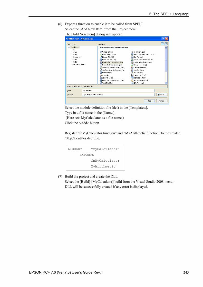
6. The SPEL+ Language
EPSON RC+ 7.0 (Ver.7.3) User's Guide Rev.4 245
(6) Export a function to enable it to be called from SPEL+. Select the [Add New Item] from the Project menu. The [Add New Item] dialog will appear.
Select the module definition file (def) in the [Templates:]. Type in a file name in the [Name:]. (Here sets MyCalculator as a file name.) Click the <Add> button. Register “fnMyCalculator function” and “MyArithmetic function” to the created “MyCalculator.def” file.
LIBRARY "MyCalculator"
EXPORTS
fnMyCalculator
MyArithmetic
(7) Build the project and create the DLL.
Select the [Build]-[MyCalculator] build from the Visual Studio 2008 menu. DLL will be successfully created if any error is displayed.
6. The SPEL+ Language
246 EPSON RC+ 7.0 (Ver.7.3) User's Guide Rev.4
Step 3: Call the DLL function from SPEL+ You can now try your DLL function from SPEL+.
Before you call your function from the EPSON RC+ 7.0, you must debug it and check thoroughly if it can work without errors. In case that error occurs (such as system error) in the native function, the EPSON RC+ 7.0 will not work normally. (1) Copy the created MyCalculator.dll to the EPSON RC+ 7.0 project folder (e.g.
C:\EpsonRC70\projects\dllcall).
(2) Define a DLL function which executes the arithmetic operator in the SPEL+ program and write a function call for MyArithmetic in Function main.
Declare MyArithmetic, "MyCalculator.dll"(value1 As Integer, value2 As Integer, ByRef calc$ As String) As Real
Function main
Real result;
String calc$
calc$ = "add"
result = MyArithmetic(1, 2, ByRef calc$);
Print "1+2=", Str$(result)
calc$ = "sub"
result = MyArithmetic(1, 2, ByRef calc$);
Print "1-2=", Str$(result)
calc$ = "mul"
result = MyArithmetic(1, 2, ByRef calc$);
Print "1*2=", Str$(result)
calc$ = "div"
result = MyArithmetic(1, 2, ByRef calc$);
Print "1/2=", Str$(result)
Fend (3) Build and execute the project.
The following result will be displayed.
1+2=3
1-2=-1
1*2=2
1/2=0.5
Before you build the project, be sure to copy the native DLL to the project folder without fail. If you fail, a warning or error will occur.
NOTE
NOTE
7. Building SPEL+ Applications
EPSON RC+ 7.0 (Ver.7.3) User's Guide Rev.4 247
7. Building SPEL+ Applications
7.1 Designing Applications
7.1.1 Creating the simplest application The simplest SPEL+ application has one program and one point file. This is what is automatically defined for you when you create a new project. A blank program named “Main.prg” and a blank point file named “Points.pts” are created. To write and run a simple application
1. Select [New Project] from the [Project] menu to create a new project.
2. Write your program source code in the file that was created for you called “Main.prg”.
3. Teach the robot points using the [Robot Manager]-[Jog & Teach] page.
4. Run the program by selecting [Run] Window from the [Run] menu or by pressing F5 (the shortcut key for the [Start] command).
7.1.2 Application layout
Before writing your application, you need to decide what your application will accomplish and how the project will be structured. Here are some general guide lines.
Programs
Each project can contain up to 64 programs that can be started from the Operator Window, Remote Control, RC+ API, or GUI Builder. Each program has a start function, as shown in the table below.
Program # Program Name Start Function 0 main main 1 main1 main1 2 main2 main2 3 main3 main3 4 main4 main4 5 main5 main5 6 main6 main6 7 main7 main7 … … … 63 main63 main63
Your project must always define function main so that the main program can be started. The other programs are optional. If you use the Operator Window for your operator interface, you can define meaningful names for each of the programs used in your project in [Project]-[Properties]-[Operator setting]-[Operator Window].
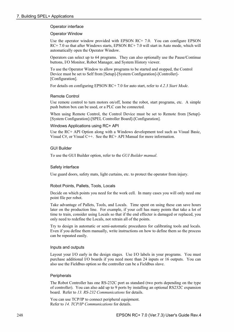
7. Building SPEL+ Applications
248 EPSON RC+ 7.0 (Ver.7.3) User's Guide Rev.4
Operator interface
Operator Window
Use the operator window provided with EPSON RC+ 7.0. You can configure EPSON RC+ 7.0 so that after Windows starts, EPSON RC+ 7.0 will start in Auto mode, which will automatically open the Operator Window.
Operators can select up to 64 programs. They can also optionally use the Pause/Continue buttons, I/O Monitor, Robot Manager, and System History viewer.
To use the Operator Window to allow programs to be started and stopped, the Control Device must be set to Self from [Setup]-[System Configuration]-[Controller]-[Configuration].
For details on configuring EPSON RC+ 7.0 for auto start, refer to 4.2.3 Start Mode.
Remote Control Use remote control to turn motors on/off, home the robot, start programs, etc. A simple push button box can be used, or a PLC can be connected.
When using Remote Control, the Control Device must be set to Remote from [Setup]-[System Configuration]-[SPEL Controller Board]-[Configuration].
Windows Applications using RC+ API Use the RC+ API Option along with a Windows development tool such as Visual Basic, Visual C#, or Visual C++. See the RC+ API Manual for more information.
GUI Builder
To use the GUI Builder option, refer to the GUI Builder manual.
Safety interface
Use guard doors, safety mats, light curtains, etc. to protect the operator from injury.
Robot Points, Pallets, Tools, Locals
Decide on which points you need for the work cell. In many cases you will only need one point file per robot.
Take advantage of Pallets, Tools, and Locals. Time spent on using these can save hours later on the production line. For example, if your cell has many points that take a lot of time to train, consider using Locals so that if the end effecter is damaged or replaced, you only need to redefine the Locals, not retrain all of the points.
Try to design in automatic or semi-automatic procedures for calibrating tools and locals. Even if you define them manually, write instructions on how to define them so the process can be repeated easily.
Inputs and outputs
Layout your I/O early in the design stages. Use I/O labels in your programs. You must purchase additional I/O boards if you need more than 24 inputs or 16 outputs. You can also use the Fieldbus option so the controller can be a Fieldbus slave.
Peripherals
The Robot Controller has one RS-232C port as standard (two ports depending on the type of controller). You can also add up to 9 ports by installing an optional RS232C expansion board. Refer to 13. RS-232 Communications for details.
You can use TCP/IP to connect peripheral equipment. Refer to 14. TCP/IP Communications for details.
7. Building SPEL+ Applications
EPSON RC+ 7.0 (Ver.7.3) User's Guide Rev.4 249
7.1.3 Auto start at power up Your application can automatically log in a Windows user and start you SPEL+ project after Windows boots.
Refer to 4.2.7 Auto Start.
7. Building SPEL+ Applications
250 EPSON RC+ 7.0 (Ver.7.3) User's Guide Rev.4
7.2 Managing Projects
7.2.1 Overview What is an EPSON RC+ 7.0 Project?
An EPSON RC+ 7.0 project is a collection of SPEL+ program files, include files, robot point files, I/O labels, user errors, Vision settings, and conveyor settings used to run a SPEL+ application.
Why do you need projects?
Projects are a safe and convenient way to manage your SPEL+ applications. All the information for each application is kept in one project. By keeping all of your application code and point definitions in one project, it is easy to open a project and begin running or editing. Also, it is easy to create new versions of an application and run older versions.
Projects make it easier to maintain your application code with less chance of a program being lost.
There are also functions for copying and renaming projects, making it easy to create new projects from previous versions and for backing up projects to an external media such as a USB memory key.
What does an EPSON RC+ 7.0 project consist of?
Each project is stored in the \EpsonRC70\Projects directory.
The following paragraphs describe the components of a project.
Project file This file contains all of the information that describes the project. This file is automatically created by EPSON RC+ 7.0. You should never edit this file. Doing so may cause errors when you open the project. The file extension is “.sprj”.
Program files A program file is an ASCII text file that contains one or more SPEL+ functions. Each function in SPEL+ can be run as a separate task (thread) in the controller or called from other functions.
Include files can also be used. These contain macro definitions and must be included in a program file using the #include statement. The file extension is “.prg”.
Point files A point file contains a list of robot points. The file extension is “.pts”.
Include files
In the include file, you can declare variables and macros. The file extension is “.inc”.
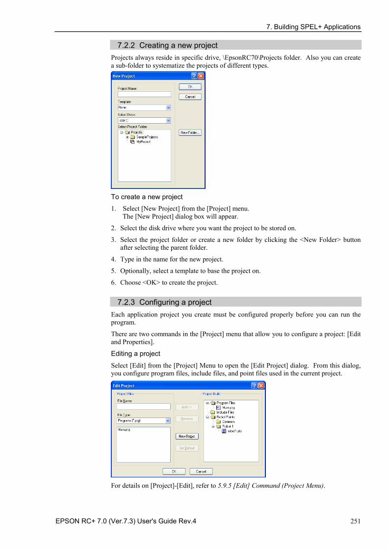
7. Building SPEL+ Applications
EPSON RC+ 7.0 (Ver.7.3) User's Guide Rev.4 251
7.2.2 Creating a new project Projects always reside in specific drive, \EpsonRC70\Projects folder. Also you can create a sub-folder to systematize the projects of different types.
To create a new project
1. Select [New Project] from the [Project] menu. The [New Project] dialog box will appear.
2. Select the disk drive where you want the project to be stored on.
3. Select the project folder or create a new folder by clicking the <New Folder> button after selecting the parent folder.
4. Type in the name for the new project.
5. Optionally, select a template to base the project on.
6. Choose <OK> to create the project.
7.2.3 Configuring a project Each application project you create must be configured properly before you can run the program.
There are two commands in the [Project] menu that allow you to configure a project: [Edit and Properties].
Editing a project
Select [Edit] from the [Project] Menu to open the [Edit Project] dialog. From this dialog, you configure program files, include files, and point files used in the current project.
For details on [Project]-[Edit], refer to 5.9.5 [Edit] Command (Project Menu).
7. Building SPEL+ Applications
252 EPSON RC+ 7.0 (Ver.7.3) User's Guide Rev.4
7.2.4 Building a project Before you run any program in your application, you must build the project. To build your application project
Select [Build] from the [Project] menu or click on the <Build> button on the toolbar. Or
Select [Rebuild] from the [Project] menu. This will rebuild the entire project. Or
Select [Run Window] from the [Run] menu or click the <Run> button on the toolbar. The project will be built before the [Run] Window appears. Or
Select [Operator Window] from the [Run] Menu. The project will be built before the [Operator Window appears.
After the files have been compiled and linked, the project files are sent to the controller.
Status Pane
This window shows progress messages and error messages during project build.
When errors occur during the build process, a message is displayed that includes the error number, program file name, and line number. Double click on the line with the error to go directly to the source code that caused the error.
7.2.5 Backing up a project
To make a backup copy of the current project, use the [Copy Project] command in the [Project] menu to copy the project to another disk drive or folder. You can also save the project under a different name.
This command is useful for transferring a project to an external media such as a USB memory.
Double click this line to go to the source code.
7. Building SPEL+ Applications
EPSON RC+ 7.0 (Ver.7.3) User's Guide Rev.4 253
7.3 Editing Programs Before you can edit a program, it must be in the current project and opened in a program window. To open a program for editing
1. Select [Open] from the [File] menu.
2. Select the file(s) you want to open.
3. Choose <OK> to open the file.
7.3.1 Program rules A program contains one or more SPEL+ function definitions.
Lines can be blank. You can insert any number of blank lines to separate subroutines and functions, if desired.
The maximum length for each line is 512 characters, including the line number, if used.
7.3.2 Typing in program code You can enter program statements in upper or lower case. Whenever you leave a line that has been changed, the line will be formatted. SPEL+ keywords are case formatted and spaces are inserted around operators and after semi-colons and commas.
Consider using mixed case or lower case for variables and function names instead of all CAPs. This will make your code easier to read.
Use indentation for statements within loops. The “Auto Indent” feature automatically moves the cursor under the start of the previous line. It also indents lines after If, Else, For, Select, Case, and Do statements.
For i = 1 To 10
Jump P(i)
Jump P0
Next i
Use the “Auto End Construct” feature to automatically add the end construct statement. For example, when you enter a For statement and press <Enter>, a Next statement is automatically created with an indented blank line above it.
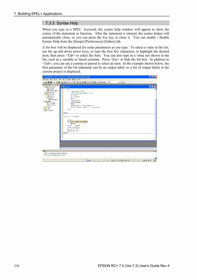
7. Building SPEL+ Applications
254 EPSON RC+ 7.0 (Ver.7.3) User's Guide Rev.4
7.3.3 Syntax Help When you type in a SPEL+ keyword, the syntax help window will appear to show the syntax of the statement or function. After the statement is entered, the syntax helper will automatically close, or you can press the Esc key to close it. You can enable / disable Syntax Help from the [Setup]-[Preferences]-[Editor] tab.
A list box will be displayed for some parameters as you type. To select a value in the list, use the up and down arrow keys, or type the first few characters, to highlight the desired item, then press <Tab> to select the item. You can also type in a value not shown in the list, such as a variable or literal constant. Press <Esc> to hide the list box. In addition to <Tab>, you can use a comma or period to select an item. In the example shown below, the first parameter of the On statement can be an output label, so a list of output labels in the current project is displayed.
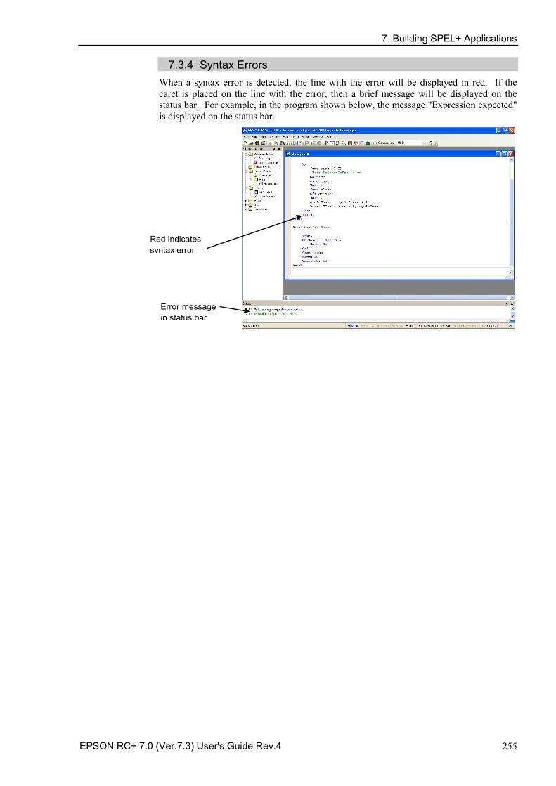
7. Building SPEL+ Applications
EPSON RC+ 7.0 (Ver.7.3) User's Guide Rev.4 255
7.3.4 Syntax Errors When a syntax error is detected, the line with the error will be displayed in red. If the caret is placed on the line with the error, then a brief message will be displayed on the status bar. For example, in the program shown below, the message "Expression expected" is displayed on the status bar.
Red indicates syntax error
Error message in status bar
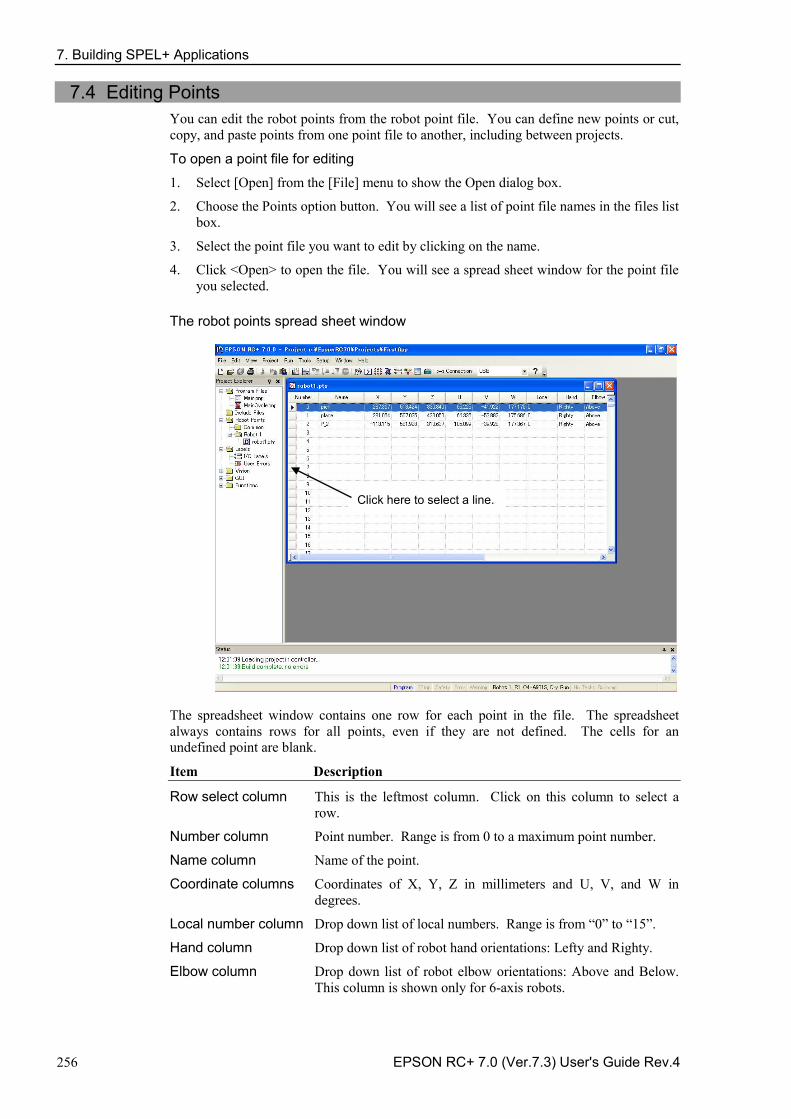
7. Building SPEL+ Applications
256 EPSON RC+ 7.0 (Ver.7.3) User's Guide Rev.4
7.4 Editing Points You can edit the robot points from the robot point file. You can define new points or cut, copy, and paste points from one point file to another, including between projects.
To open a point file for editing
1. Select [Open] from the [File] menu to show the Open dialog box.
2. Choose the Points option button. You will see a list of point file names in the files list box.
3. Select the point file you want to edit by clicking on the name.
4. Click <Open> to open the file. You will see a spread sheet window for the point file you selected.
The robot points spread sheet window
Click here to select a line.
The spreadsheet window contains one row for each point in the file. The spreadsheet always contains rows for all points, even if they are not defined. The cells for an undefined point are blank.
Item Description
Row select column This is the leftmost column. Click on this column to select a row.
Number column Point number. Range is from 0 to a maximum point number.
Name column Name of the point.
Coordinate columns Coordinates of X, Y, Z in millimeters and U, V, and W in degrees.
Local number column Drop down list of local numbers. Range is from “0” to “15”.
Hand column Drop down list of robot hand orientations: Lefty and Righty.
Elbow column Drop down list of robot elbow orientations: Above and Below. This column is shown only for 6-axis robots.
7. Building SPEL+ Applications
EPSON RC+ 7.0 (Ver.7.3) User's Guide Rev.4 257
Wrist column Drop down list of robot wrist orientations: Flip and NoFlip. This column is shown only for 6-axis robots.
J4Flag column Drop down list of robot J4Flag: “0” and “1”. This column is shown only for 6-axis robots.
J6Flag column Drop down list of robot J6Flag: “0” – “127”. This column is shown only for 6-axis robots.
J1Flag column Drop down list of robot J1Flag: “0” and “1”. This column is shown only for RS series and 6-axis robots.
J2Flag column Drop down list of robot J2Flag: “0” and “1”. This column is shown only for RS series and N series.
J1Angle Coordinate in units of degrees. This column is shown only for RS series.
J4Angle Coordinate in units of degrees. This column is shown only for N series.
To select one or more rows Click on the row select column (leftmost column) to select a row. To select more than one row, point to the row select column of the first row you want to select. Hold down the left mouse button and drag the mouse down or up to select more rows.
To select all rows
Execute Select All from the Edit Menu, or type <Ctrl> + A.
To define a new point Move the cursor anywhere in the row of the point you want to define using the mouse, and then click a cell you want to type in. Enter information for the point. This automatically defines the point, which means it will be sent to the robot controller at the next project build or Jog and Teach command.
For example, click on the Name column and type in a name of the point. Press the <TAB> key to move to the X coordinate column. Type a coordinate value and then press <Enter>. You will see zeros automatically entered in all of the other coordinates. This means that the point is defined.
To delete a point Select the row containing the point and cut it by selecting [Cut] from the [Edit] menu or by typing <Ctrl> + X.
To cut and paste points 1. Select one or more rows and execute either [Cut] or [Copy] from the [Edit] menu.
2. Select the row where you want to start the paste.
3. Select [Paste] from the [Edit] menu.
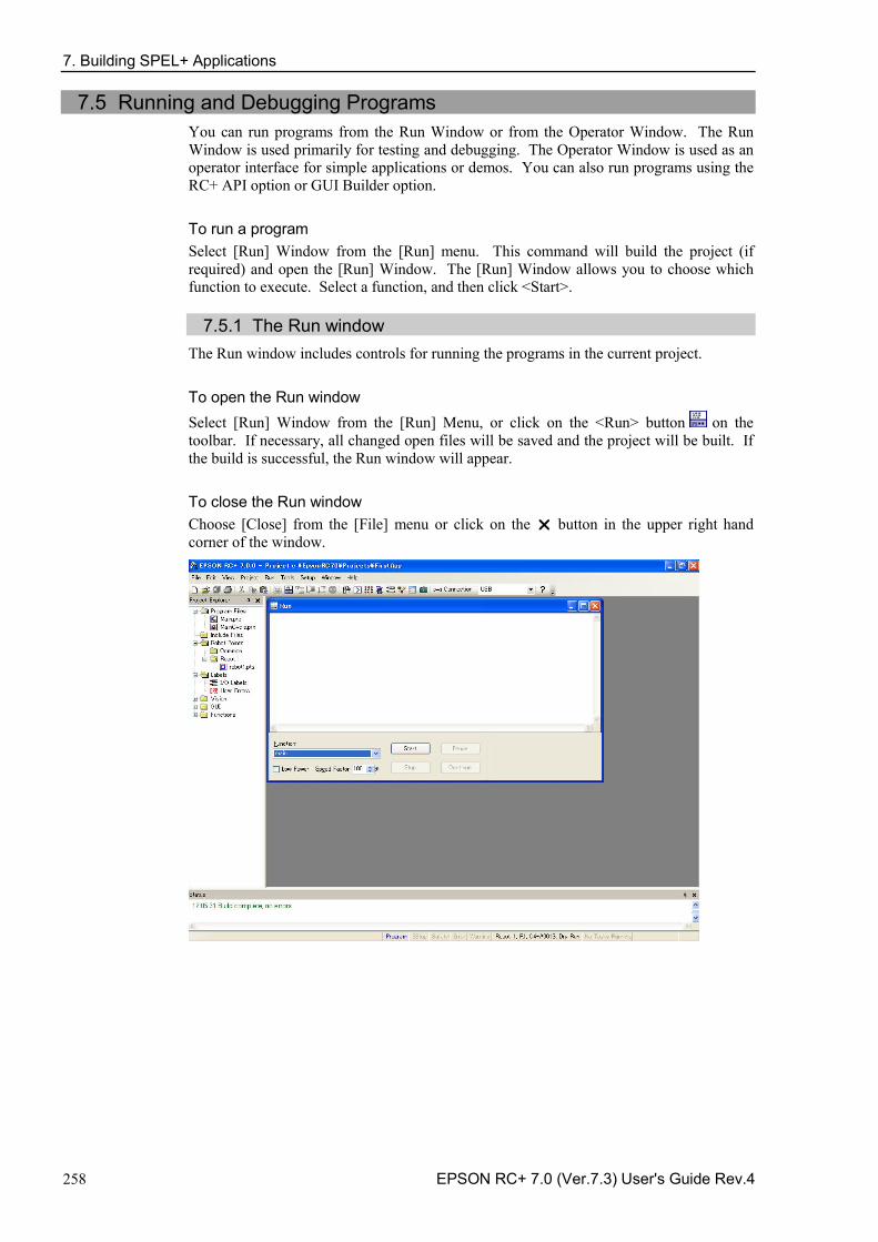
7. Building SPEL+ Applications
258 EPSON RC+ 7.0 (Ver.7.3) User's Guide Rev.4
7.5 Running and Debugging Programs You can run programs from the Run Window or from the Operator Window. The Run Window is used primarily for testing and debugging. The Operator Window is used as an operator interface for simple applications or demos. You can also run programs using the RC+ API option or GUI Builder option.
To run a program Select [Run] Window from the [Run] menu. This command will build the project (if required) and open the [Run] Window. The [Run] Window allows you to choose which function to execute. Select a function, and then click <Start>.
7.5.1 The Run window The Run window includes controls for running the programs in the current project.
To open the Run window Select [Run] Window from the [Run] Menu, or click on the <Run> button on the toolbar. If necessary, all changed open files will be saved and the project will be built. If the build is successful, the Run window will appear.
To close the Run window Choose [Close] from the [File] menu or click on the button in the upper right hand corner of the window.
7. Building SPEL+ Applications
EPSON RC+ 7.0 (Ver.7.3) User's Guide Rev.4 259
Item Description
Text area This is the area that takes up most of the run window. Output from your programs is displayed here. When your program uses an Input statement, you can type in the requested input from this text box. You can use the scroll bars to view the entire text buffer. If an error occurs while running a program, the error number, program file name, line number and function name will be displayed in this text area. You can double click on the line where the error is displayed to directly go to the source line that caused the problem.
Function Select a function to start. Functions are sorted alphabetically. Function main is selected by default.
Low Power When this box is checked, SPEL+ ignores the Power High command. This allows you to run your program in low power mode to verify operation without having to change the program.
Speed Factor Specifies the robot motion speed factor. The speed factor is a percentage of maximum point to point speed and linear interpolated speed. For example, if you program executes Speed 80 and the speed factor is 50%, the robot will move at speed 40.
Start Starts the function shown in the function drop down list.
Stop Stops all tasks. If the robot is executing a motion command when this button is pressed, the robot will decelerate to a stop.
Pause Pauses all tasks with pause enabled. Activates the <Continue> button. If the robot is executing a motion command when this button is pressed, the robot will decelerate to a stop.
Continue Continues paused tasks.
CTRL+C Same as <Stop> button.
7. Building SPEL+ Applications
260 EPSON RC+ 7.0 (Ver.7.3) User's Guide Rev.4
7.5.2 Debugging EPSON RC+ 7.0 supports source level debugging. You can set breakpoints and step through your source code. You can also pause / continue a program or halt a task using the Task Manager.
Setting and clearing breakpoints Open the program where you want to set a breakpoint, and then click on the line where you want to stop. Use one of the following methods to set a breakpoint:
If Margin Indicators are enabled, then click in the margin next to the line on the left. -You will see a breakpoint symbol next to the line.
Or
Type F9. -
Or
Select Toggle Breakpoint from the [Run] menu. -
Execute one of the methods above to clear a breakpoint, or select [Clear All Breakpoints] from the [Run] menu.
You cannot set a breakpoint on non-executing statements, such as #define, #include, or blank lines.
After setting a breakpoint, the task will halt when the execution line is reached the breakpoint. You can set or clear a breakpoint while a task is running.
When reached a breakpoint, the program window containing the program source line at the breakpoint is opened and the line is highlighted in yellow. The task number is shown in the title of the program window.
If more than one task reaches a breakpoint, then a program window will be opened for each task. This allows you to step through each task that reached the breakpoint.
7. Building SPEL+ Applications
EPSON RC+ 7.0 (Ver.7.3) User's Guide Rev.4 261
Stepping through a program There are three commands on the [Run] Menu that are used for stepping through code.
[Step Into] steps through each line and also steps into functions when a step is executed on a Call statement.
[Step Over] steps through each line but when a Call statement is encountered, the function in the statement is executed completely.
Walk executes lines until after the next motion command and then halts the task. It will halt after the next output command if the [Setup]-[System Configuration]-[Controller]-[Preferences]-[Walk stops for outputs] checkbox is checked.
To step through code, you must set a breakpoint and run until the breakpoint is reached, or suspend a task from the Task Manager using the <Halt> button.
Viewing the Call Stack Sometimes you may want to examine the call stack for the current task after you halt the task from the task manager, or reach a break point.
To view the call stack, select [Call Stack] from the [Run] Menu. The [Call Stack] list will be displayed, as shown below.
7. Building SPEL+ Applications
262 EPSON RC+ 7.0 (Ver.7.3) User's Guide Rev.4
After you double click a function in the Call Stack list, the function will be displayed in a program window and an arrow in the left margin will point to the line where the next function in the call stack is being called. In the example below, the arrow in the SingleCycle function is pointing to the Gripper On statement to indicate that Gripper was called from SingleCycle.
Displaying variables To view variable values, you can do one of the following:
1. When a task is halted by halt or breakpoint, you can view the value for a variable by moving the mouse cursor over the variable name. The value will be displayed in a tool tip type window above the variable name.
7. Building SPEL+ Applications
EPSON RC+ 7.0 (Ver.7.3) User's Guide Rev.4 263
2. Select [Display Variables] from the [Run] menu to display the variable display dialog. This dialog has three tabs for viewing Global, Module, and Local variables.
Up to 600 variables can be displayed on each tab.
You can change the value of a variable by checking the [Edit] checkbox, then type in the new value in the value column. Next, click the <Write> button to change the variable. When the [Edit] box is checked, the variable values are not automatically updated. You can click the <Read> button to update all values.
NOTE
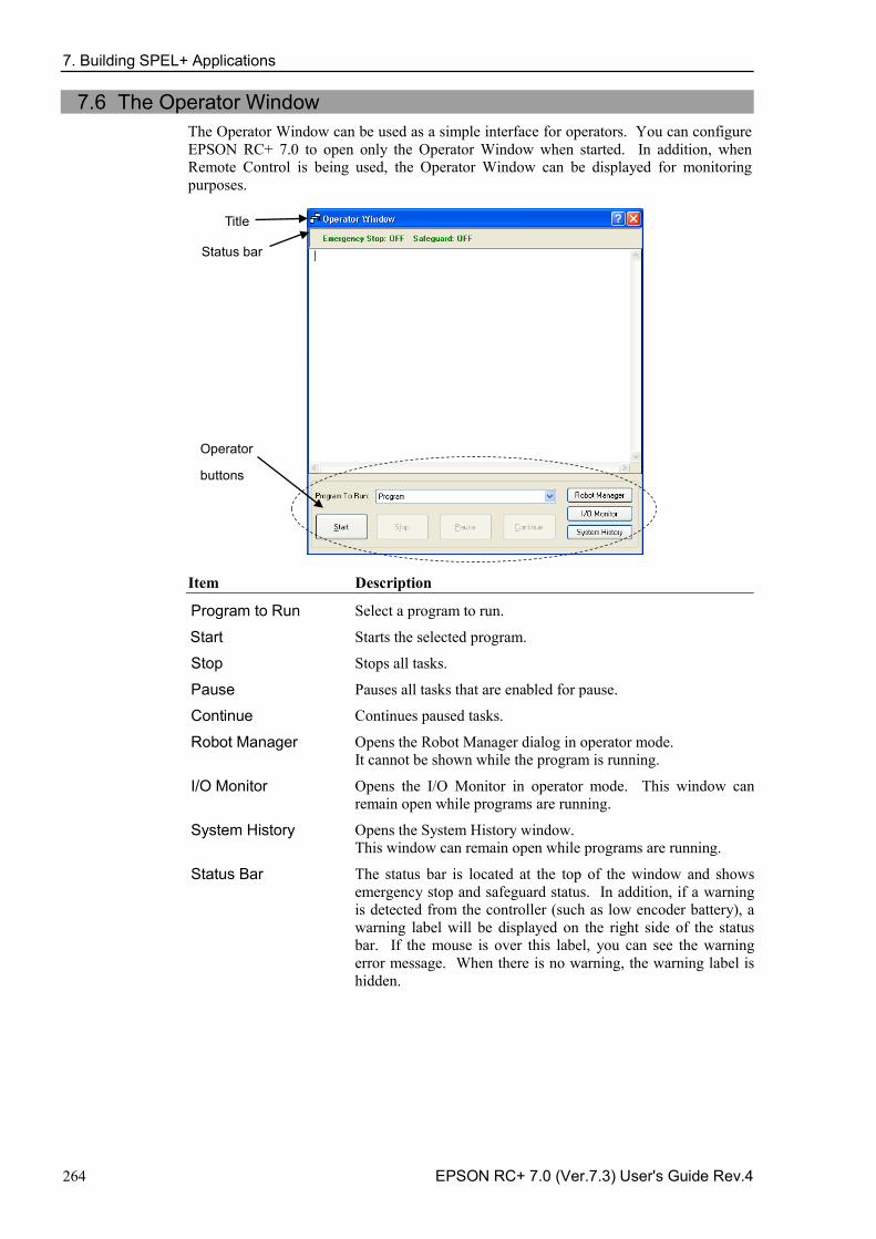
7. Building SPEL+ Applications
264 EPSON RC+ 7.0 (Ver.7.3) User's Guide Rev.4
7.6 The Operator Window The Operator Window can be used as a simple interface for operators. You can configure EPSON RC+ 7.0 to open only the Operator Window when started. In addition, when Remote Control is being used, the Operator Window can be displayed for monitoring purposes.
Title
Status bar
Operator
buttons
Item Description
Program to Run Select a program to run.
Start Starts the selected program.
Stop Stops all tasks.
Pause Pauses all tasks that are enabled for pause.
Continue Continues paused tasks.
Robot Manager Opens the Robot Manager dialog in operator mode. It cannot be shown while the program is running.
I/O Monitor Opens the I/O Monitor in operator mode. This window can remain open while programs are running.
System History Opens the System History window. This window can remain open while programs are running.
Status Bar The status bar is located at the top of the window and shows emergency stop and safeguard status. In addition, if a warning is detected from the controller (such as low encoder battery), a warning label will be displayed on the right side of the status bar. If the mouse is over this label, you can see the warning error message. When there is no warning, the warning label is hidden.
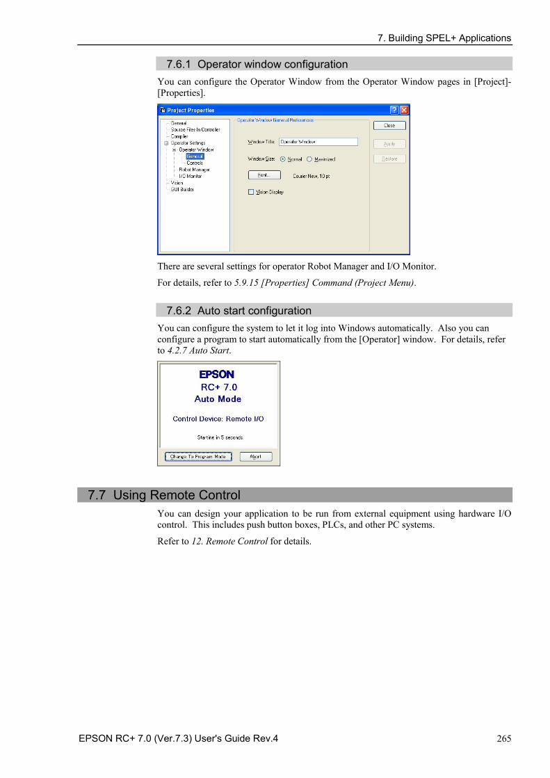
7. Building SPEL+ Applications
EPSON RC+ 7.0 (Ver.7.3) User's Guide Rev.4 265
7.6.1 Operator window configuration You can configure the Operator Window from the Operator Window pages in [Project]-[Properties].
There are several settings for operator Robot Manager and I/O Monitor.
For details, refer to 5.9.15 [Properties] Command (Project Menu).
7.6.2 Auto start configuration You can configure the system to let it log into Windows automatically. Also you can configure a program to start automatically from the [Operator] window. For details, refer to 4.2.7 Auto Start.
7.7 Using Remote Control You can design your application to be run from external equipment using hardware I/O control. This includes push button boxes, PLCs, and other PC systems.
Refer to 12. Remote Control for details.
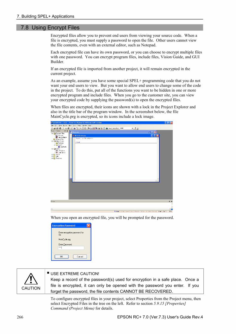
7. Building SPEL+ Applications
266 EPSON RC+ 7.0 (Ver.7.3) User's Guide Rev.4
7.8 Using Encrypt Files Encrypted files allow you to prevent end users from viewing your source code. When a file is encrypted, you must supply a password to open the file. Other users cannot view the file contents, even with an external editor, such as Notepad.
Each encrypted file can have its own password, or you can choose to encrypt multiple files with one password. You can encrypt program files, include files, Vision Guide, and GUI Builder.
If an encrypted file is imported from another project, it will remain encrypted in the current project.
As an example, assume you have some special SPEL+ programming code that you do not want your end users to view. But you want to allow end users to change some of the code in the project. To do this, put all of the functions you want to be hidden in one or more encrypted program and include files. When you go to the customer site, you can view your encrypted code by supplying the password(s) to open the encrypted files.
When files are encrypted, their icons are shown with a lock in the Project Explorer and also in the title bar of the program window. In the screenshot below, the file MainCycle.prg is encrypted, so its icons include a lock image.
When you open an encrypted file, you will be prompted for the password.
CAUTION
■ USE EXTREME CAUTION! Keep a record of the password(s) used for encryption in a safe place. Once a file is encrypted, it can only be opened with the password you enter. If you forget the password, the file contents CANNOT BE RECOVERED.
To configure encrypted files in your project, select Properties from the Project menu, then select Encrypted Files in the tree on the left. Refer to section 5.9.15 [Properties] Command (Project Menu) for details.
8. Simulator
EPSON RC+ 7.0 (Ver.7.3) User's Guide Rev.4 267
8. Simulator
8.1 Simulator Functions Simulator functions enable easy robot motion checking on your PC, which gives you flexibility to consider the system layout, measure the operation time, and create robot programs.
They are useful from the introduction stage to the launch of robot system.
8.1.1 Overview The following are the major simulator functions:
Robot motion 3D display
Shows robot orientation and motion in a 3D display from various viewpoints. Offers accurate display data based on design data. (X5 series cannot use this function.)
Interference check
Checks whether the robot (including the hand and devices installed on the robot) interferes with itself or its peripherals. (X5 series cannot use this function.)
Robot operation time prediction
Predicts the robot operation time for a program. Considers the speed setting (Speed, etc.) and acceleration / deceleration setting (Accel, etc.) when predicting the robot motion time.
SPEL+ program execution
Allows you to create, execute, and debug SPEL+ programs.
The restrictions on the simulator functions are described in 8.4 Simulator Specifications and Restrictions.
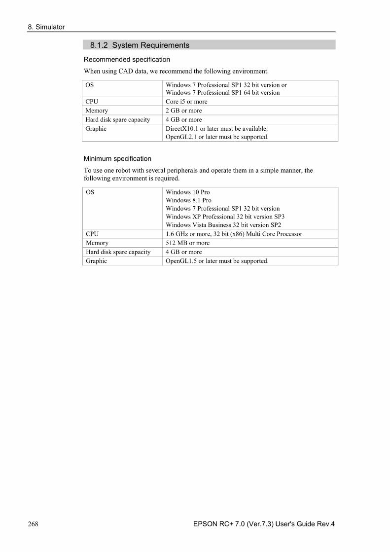
8. Simulator
268 EPSON RC+ 7.0 (Ver.7.3) User's Guide Rev.4
8.1.2 System Requirements
Recommended specification When using CAD data, we recommend the following environment. OS Windows 7 Professional SP1 32 bit version or
Windows 7 Professional SP1 64 bit version CPU Core i5 or more Memory 2 GB or more Hard disk spare capacity 4 GB or more Graphic DirectX10.1 or later must be available.
OpenGL2.1 or later must be supported.
Minimum specification To use one robot with several peripherals and operate them in a simple manner, the following environment is required. OS Windows 10 Pro
Windows 8.1 Pro Windows 7 Professional SP1 32 bit version Windows XP Professional 32 bit version SP3 Windows Vista Business 32 bit version SP2
CPU 1.6 GHz or more, 32 bit (x86) Multi Core Processor Memory 512 MB or more Hard disk spare capacity 4 GB or more Graphic OpenGL1.5 or later must be supported.
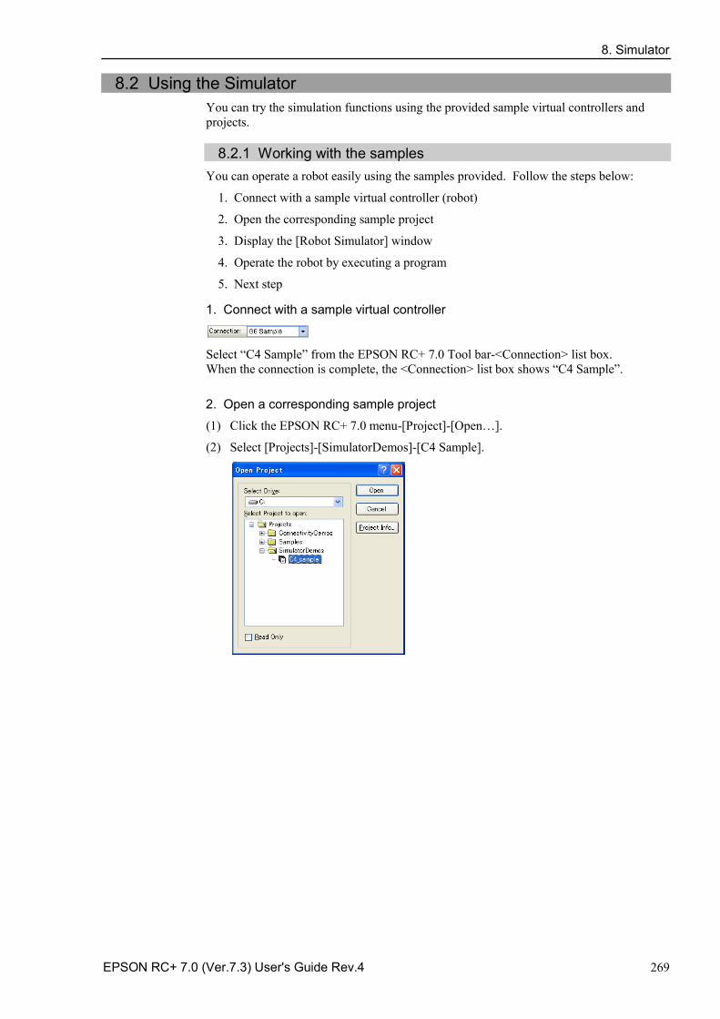
8. Simulator
EPSON RC+ 7.0 (Ver.7.3) User's Guide Rev.4 269
8.2 Using the Simulator You can try the simulation functions using the provided sample virtual controllers and projects.
8.2.1 Working with the samples
You can operate a robot easily using the samples provided. Follow the steps below:
1. Connect with a sample virtual controller (robot)
2. Open the corresponding sample project
3. Display the [Robot Simulator] window
4. Operate the robot by executing a program
5. Next step
1. Connect with a sample virtual controller
Select “C4 Sample” from the EPSON RC+ 7.0 Tool bar-<Connection> list box. When the connection is complete, the <Connection> list box shows “C4 Sample”.
2. Open a corresponding sample project
(1) Click the EPSON RC+ 7.0 menu-[Project]-[Open…].
(2) Select [Projects]-[SimulatorDemos]-[C4 Sample].
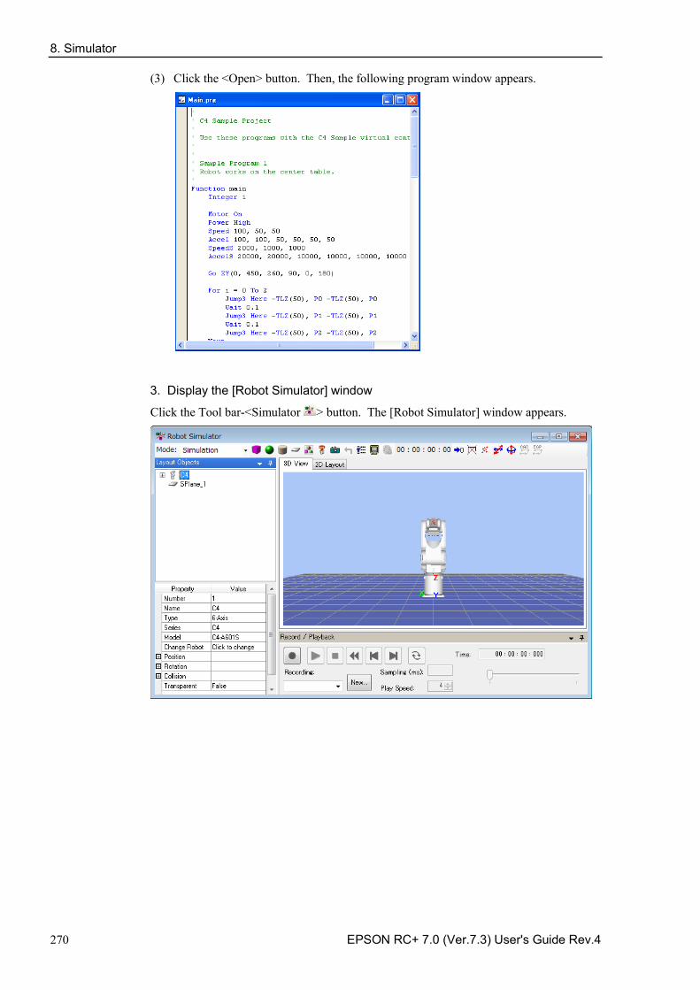
8. Simulator
270 EPSON RC+ 7.0 (Ver.7.3) User's Guide Rev.4
(3) Click the <Open> button. Then, the following program window appears.
3. Display the [Robot Simulator] window
Click the Tool bar-<Simulator > button. The [Robot Simulator] window appears.
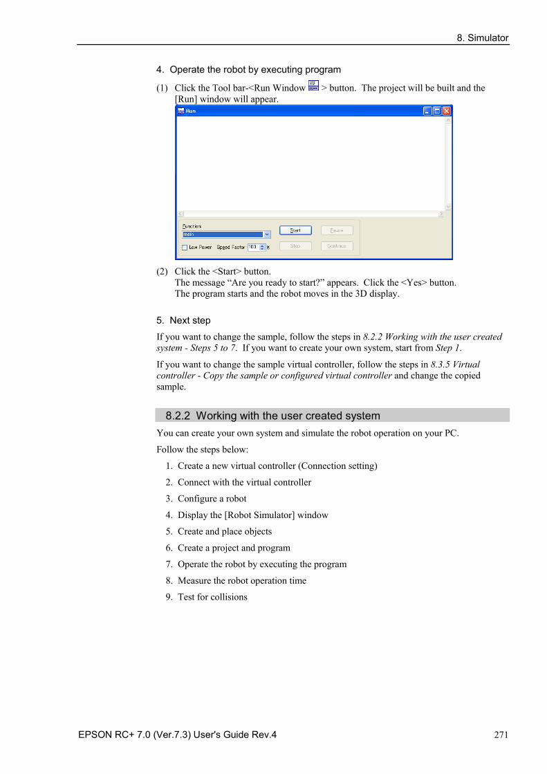
8. Simulator
EPSON RC+ 7.0 (Ver.7.3) User's Guide Rev.4 271
4. Operate the robot by executing program
(1) Click the Tool bar-<Run Window > button. The project will be built and the [Run] window will appear.
(2) Click the <Start> button.
The message “Are you ready to start?” appears. Click the <Yes> button. The program starts and the robot moves in the 3D display.
5. Next step
If you want to change the sample, follow the steps in 8.2.2 Working with the user created system - Steps 5 to 7. If you want to create your own system, start from Step 1.
If you want to change the sample virtual controller, follow the steps in 8.3.5 Virtual controller - Copy the sample or configured virtual controller and change the copied sample.
8.2.2 Working with the user created system You can create your own system and simulate the robot operation on your PC.
Follow the steps below:
1. Create a new virtual controller (Connection setting)
2. Connect with the virtual controller
3. Configure a robot
4. Display the [Robot Simulator] window
5. Create and place objects
6. Create a project and program
7. Operate the robot by executing the program
8. Measure the robot operation time
9. Test for collisions

8. Simulator
272 EPSON RC+ 7.0 (Ver.7.3) User's Guide Rev.4
1. Create a new virtual controller (Connection setting)
(1) Click the EPSON RC+7.0 Tool bar-<Setup PC to robot controller communications. > button. The [PC to Controller Communications] dialog appears.
(2) Click the <Add> button. The [New Controller Connection] dialog appears.
(3) Select the [Connection to new virtual controller] and click the <OK> button.
(4) A new virtual controller named “Virtual 1” is created. Click the <Apply> button.
Note: In the virtual controller, programs will execute continuously for up to one hour.
If continuous execution is over one hour, a warning message appears. You can execute the program again after the warning is displayed, and the continuous execution timer will be reset.
(5) Close the dialog to return to the EPSON RC+ 5.0 main window.
2. Connect with the virtual controller
(1) Select the created “Virtual 1” connection from the EPSON RC+ 7.0 Tool bar-<Connection> list box. When the connection is complete, the <Connection> list box shows “Virtual 1”.
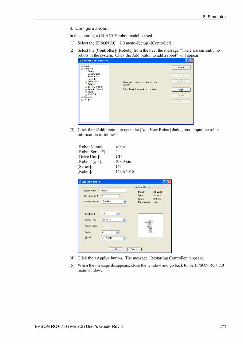
8. Simulator
EPSON RC+ 7.0 (Ver.7.3) User's Guide Rev.4 273
3. Configure a robot
In this tutorial, a C4-A601S robot model is used.
(1) Select the EPSON RC+ 7.0 menu-[Setup]-[Controller].
(2) Select the [Controller]-[Robots] from the tree, the message “There are currently no robots in the system. Click the Add button to add a robot” will appear.
(3) Click the <Add> button to open the [Add New Robot] dialog box. Input the robot
information as follows:
[Robot Name]: robot1 [Robot Serial #]: 1 [Drive Unit]: CU [Robot Type]: Six Axis [Series]: C4 [Robot]: C4-A601S
(4) Click the <Apply> button. The message “Restarting Controller” appears.
(5) When the message disappears, close the window and go back to the EPSON RC+ 7.0 main window.
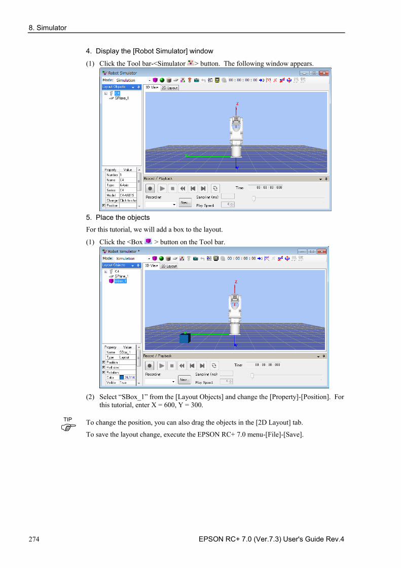
8. Simulator
274 EPSON RC+ 7.0 (Ver.7.3) User's Guide Rev.4
4. Display the [Robot Simulator] window
(1) Click the Tool bar-<Simulator > button. The following window appears.
5. Place the objects
For this tutorial, we will add a box to the layout.
(1) Click the <Box > button on the Tool bar.
(2) Select “SBox_1” from the [Layout Objects] and change the [Property]-[Position]. For
this tutorial, enter X = 600, Y = 300.
To change the position, you can also drag the objects in the [2D Layout] tab.
To save the layout change, execute the EPSON RC+ 7.0 menu-[File]-[Save].
TIP
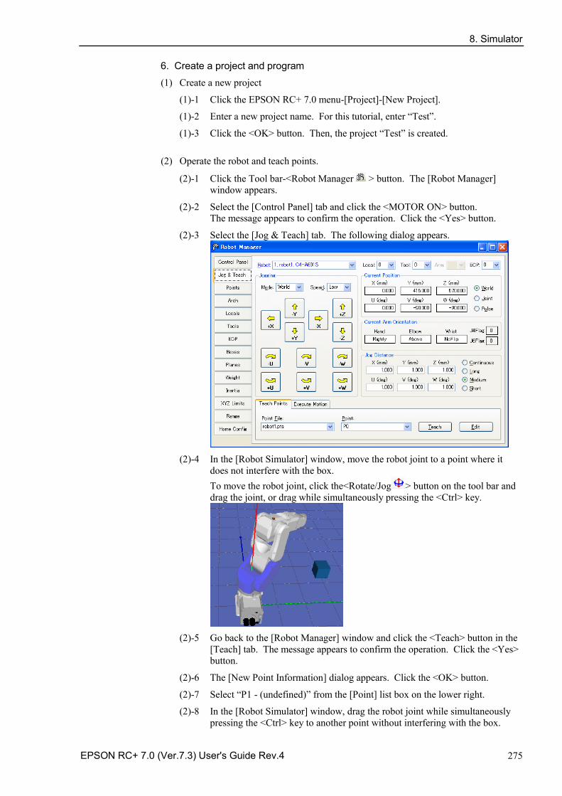
8. Simulator
EPSON RC+ 7.0 (Ver.7.3) User's Guide Rev.4 275
6. Create a project and program
(1) Create a new project
(1)-1 Click the EPSON RC+ 7.0 menu-[Project]-[New Project].
(1)-2 Enter a new project name. For this tutorial, enter “Test”.
(1)-3 Click the <OK> button. Then, the project “Test” is created.
(2) Operate the robot and teach points.
(2)-1 Click the Tool bar-<Robot Manager > button. The [Robot Manager] window appears.
(2)-2 Select the [Control Panel] tab and click the <MOTOR ON> button. The message appears to confirm the operation. Click the <Yes> button.
(2)-3 Select the [Jog & Teach] tab. The following dialog appears.
(2)-4 In the [Robot Simulator] window, move the robot joint to a point where it
does not interfere with the box. To move the robot joint, click the<Rotate/Jog > button on the tool bar and drag the joint, or drag while simultaneously pressing the <Ctrl> key.
(2)-5 Go back to the [Robot Manager] window and click the <Teach> button in the
[Teach] tab. The message appears to confirm the operation. Click the <Yes> button.
(2)-6 The [New Point Information] dialog appears. Click the <OK> button.
(2)-7 Select “P1 - (undefined)” from the [Point] list box on the lower right.
(2)-8 In the [Robot Simulator] window, drag the robot joint while simultaneously pressing the <Ctrl> key to another point without interfering with the box.
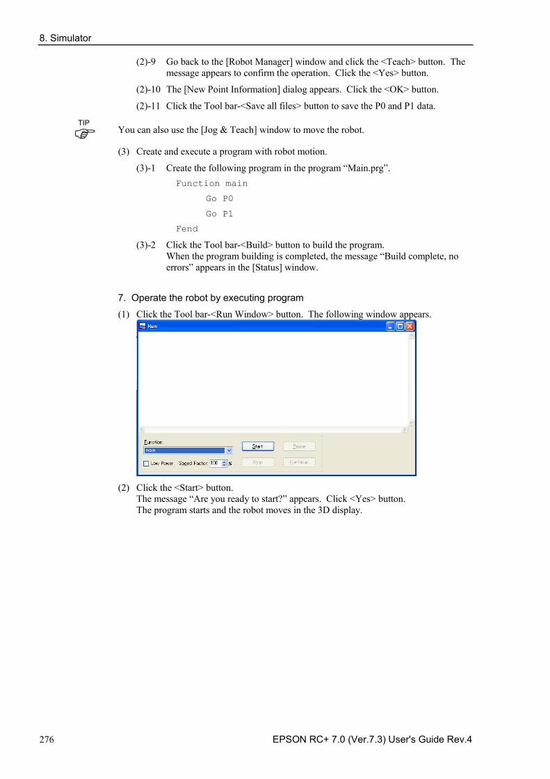
8. Simulator
276 EPSON RC+ 7.0 (Ver.7.3) User's Guide Rev.4
(2)-9 Go back to the [Robot Manager] window and click the <Teach> button. The message appears to confirm the operation. Click the <Yes> button.
(2)-10 The [New Point Information] dialog appears. Click the <OK> button.
(2)-11 Click the Tool bar-<Save all files> button to save the P0 and P1 data.
You can also use the [Jog & Teach] window to move the robot.
(3) Create and execute a program with robot motion.
(3)-1 Create the following program in the program “Main.prg”. Function main
Go P0
Go P1
Fend
(3)-2 Click the Tool bar-<Build> button to build the program. When the program building is completed, the message “Build complete, no errors” appears in the [Status] window.
7. Operate the robot by executing program
(1) Click the Tool bar-<Run Window> button. The following window appears.
(2) Click the <Start> button.
The message “Are you ready to start?” appears. Click <Yes> button. The program starts and the robot moves in the 3D display.
TIP
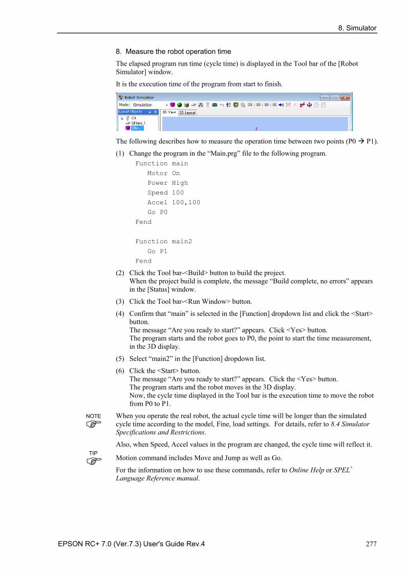
8. Simulator
EPSON RC+ 7.0 (Ver.7.3) User's Guide Rev.4 277
8. Measure the robot operation time
The elapsed program run time (cycle time) is displayed in the Tool bar of the [Robot Simulator] window.
It is the execution time of the program from start to finish.
The following describes how to measure the operation time between two points (P0 P1).
(1) Change the program in the “Main.prg” file to the following program. Function main
Motor On
Power High
Speed 100
Accel 100,100
Go P0
Fend
Function main2
Go P1
Fend
(2) Click the Tool bar-<Build> button to build the project. When the project build is complete, the message “Build complete, no errors” appears in the [Status] window.
(3) Click the Tool bar-<Run Window> button.
(4) Confirm that “main” is selected in the [Function] dropdown list and click the <Start> button. The message “Are you ready to start?” appears. Click <Yes> button. The program starts and the robot goes to P0, the point to start the time measurement, in the 3D display.
(5) Select “main2” in the [Function] dropdown list.
(6) Click the <Start> button. The message “Are you ready to start?” appears. Click the <Yes> button. The program starts and the robot moves in the 3D display. Now, the cycle time displayed in the Tool bar is the execution time to move the robot from P0 to P1.
When you operate the real robot, the actual cycle time will be longer than the simulated cycle time according to the model, Fine, load settings. For details, refer to 8.4 Simulator Specifications and Restrictions.
Also, when Speed, Accel values in the program are changed, the cycle time will reflect it. Motion command includes Move and Jump as well as Go.
For the information on how to use these commands, refer to Online Help or SPEL+ Language Reference manual.
NOTE
TIP
8. Simulator
278 EPSON RC+ 7.0 (Ver.7.3) User's Guide Rev.4
9. Test the collision detection
(1) Go back to the [Robot Simulator] window.
(2) Drag the robot joint while simultaneously pressing the <Ctrl> key to a point where it interferes with the box. When the robot joint hits the box, the display turns to red.
(3) In the [Robot Manager] window, select “P2 - (undefined)” from the [Point] list box in the [Teach] tab.
(4) Click the <Teach> button. The message to confirm the operation appears. Click the <Yes> button.
(5) The [New Point Information] dialog appears. Click the <OK> button.
(6) Click the Tool bar-<Save all files> button and save the P2 information.
(7) Go back to the [Robot Simulator] window and drag the robot joint while simultaneously pressing the <Ctrl> key to the point where it does not interfere with the box.
(8) Click the Tool bar-<Reset Collision > button. Then, the red display returns to normal.
(9) Add the following function to the “Main.prg” program file. Function main3
Go P2
Fend
(10) Click the Tool bar-<Build> button to build the project. When the project build is complete, the message “Build complete, no errors” appears in the [Status] window.
(11) Click the Tool bar-<Run Window> button.
(12) Select “main2” in the [Function].
(13) Click the <Start> button. The message “Are you ready to start?” appears. Click the <Yes> button. The program starts and the robot moves in the 3D display. When the robot joint hits the box, the display turns to red.
When a collision happens, the users can stop the controller program execution with an error. For details, refer to 8.3.3 Collision detection.
TIP
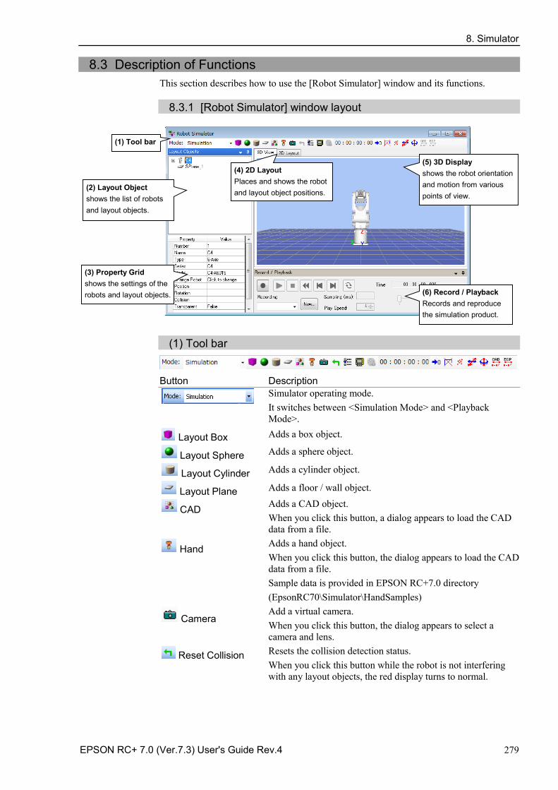
8. Simulator
EPSON RC+ 7.0 (Ver.7.3) User's Guide Rev.4 279
8.3 Description of Functions This section describes how to use the [Robot Simulator] window and its functions.
8.3.1 [Robot Simulator] window layout
(5) 3D Display shows the robot orientation and motion from various points of view.
(2) Layout Object shows the list of robots and layout objects.
(3) Property Grid shows the settings of the robots and layout objects. (6) Record / Playback
Records and reproduce the simulation product.
(4) 2D Layout Places and shows the robot and layout object positions.
(1) Tool bar
(1) Tool bar
Button Description
Simulator operating mode. It switches between <Simulation Mode> and <Playback Mode>.
Layout Box Adds a box object.
Layout Sphere Adds a sphere object.
Layout Cylinder Adds a cylinder object.
Layout Plane Adds a floor / wall object.
CAD Adds a CAD object. When you click this button, a dialog appears to load the CAD data from a file.
Hand Adds a hand object. When you click this button, the dialog appears to load the CAD data from a file. Sample data is provided in EPSON RC+7.0 directory (EpsonRC70\Simulator\HandSamples)
Camera Add a virtual camera. When you click this button, the dialog appears to select a camera and lens.
Reset Collision Resets the collision detection status. When you click this button while the robot is not interfering with any layout objects, the red display turns to normal.
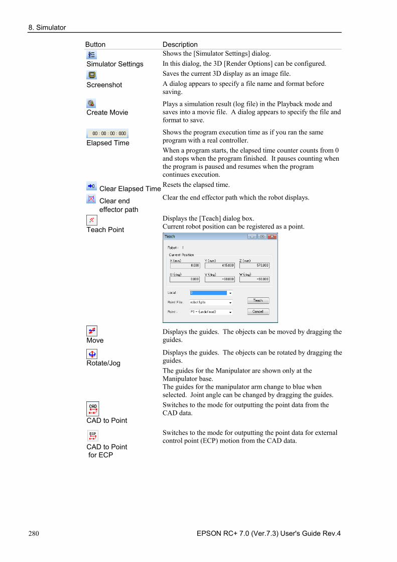
8. Simulator
280 EPSON RC+ 7.0 (Ver.7.3) User's Guide Rev.4
Button Description
Simulator Settings
Shows the [Simulator Settings] dialog. In this dialog, the 3D [Render Options] can be configured.
Screenshot
Saves the current 3D display as an image file. A dialog appears to specify a file name and format before saving.
Create Movie
Plays a simulation result (log file) in the Playback mode and saves into a movie file. A dialog appears to specify the file and format to save.
Elapsed Time
Shows the program execution time as if you ran the same program with a real controller. When a program starts, the elapsed time counter counts from 0 and stops when the program finished. It pauses counting when the program is paused and resumes when the program continues execution.
Clear Elapsed Time Resets the elapsed time.
Clear end effector path
Clear the end effector path which the robot displays.
Teach Point
Displays the [Teach] dialog box. Current robot position can be registered as a point.
Move
Displays the guides. The objects can be moved by dragging the guides.
Rotate/Jog
Displays the guides. The objects can be rotated by dragging the guides. The guides for the Manipulator are shown only at the Manipulator base. The guides for the manipulator arm change to blue when selected. Joint angle can be changed by dragging the guides.
CAD to Point
Switches to the mode for outputting the point data from the CAD data.
CAD to Point for ECP
Switches to the mode for outputting the point data for external control point (ECP) motion from the CAD data.
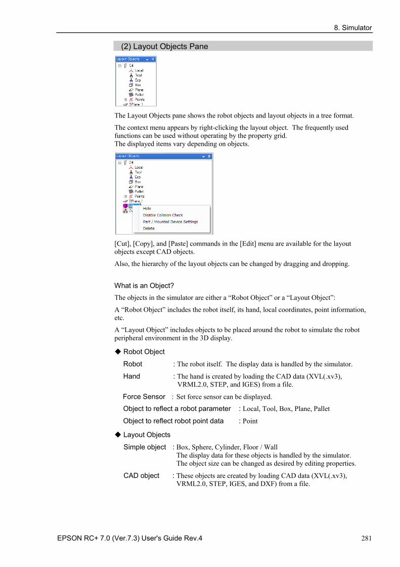
8. Simulator
EPSON RC+ 7.0 (Ver.7.3) User's Guide Rev.4 281
(2) Layout Objects Pane
The Layout Objects pane shows the robot objects and layout objects in a tree format.
The context menu appears by right-clicking the layout object. The frequently used functions can be used without operating by the property grid. The displayed items vary depending on objects.
[Cut], [Copy], and [Paste] commands in the [Edit] menu are available for the layout objects except CAD objects.
Also, the hierarchy of the layout objects can be changed by dragging and dropping.
What is an Object?
The objects in the simulator are either a “Robot Object” or a “Layout Object”:
A “Robot Object” includes the robot itself, its hand, local coordinates, point information, etc.
A “Layout Object” includes objects to be placed around the robot to simulate the robot peripheral environment in the 3D display.
◆ Robot Object
Robot : The robot itself. The display data is handled by the simulator.
Hand : The hand is created by loading the CAD data (XVL(.xv3), VRML2.0, STEP, and IGES) from a file.
Force Sensor : Set force sensor can be displayed.
Object to reflect a robot parameter : Local, Tool, Box, Plane, Pallet
Object to reflect robot point data : Point
◆ Layout Objects
Simple object : Box, Sphere, Cylinder, Floor / Wall The display data for these objects is handled by the simulator. The object size can be changed as desired by editing properties.
CAD object : These objects are created by loading CAD data (XVL(.xv3), VRML2.0, STEP, IGES, and DXF) from a file.
8. Simulator
282 EPSON RC+ 7.0 (Ver.7.3) User's Guide Rev.4
Camera Objects : The following devices can be displayed. Devices that are supported in EPSON RC+ 7.0 Option Vision Guide 7.0 Hardware & Setup can be selected..
Camera : USB and GigE camera can be selected.
Lens : Each model of standard camera lens and megapixel camera lens can be selected.
Extension tube : Each length of tubes can be selected.
(3) Property Grid Pane In the Property Grid pane, you can view and change the settings of the robot objects and layout objects in the Layout Object pane.
◆ Robot Object Properties Robot
Property Value Number Robot number
Name Robot name You can specify any name for a robot.
Type Robot type The robot type (Scara and 6-Axis) is shown. This property is read-only.
Series Robot series The robot series is shown. This property is read-only.
Model Robot model name The robot model is shown. This property is read-only.
Change Robot If you want to change the robot model, click on button. When you click on this button, a dialog appears to change the robot. For details, see Changing the robot model described later in this chapter.
Position Robot position Specifies the robot's base center in the simulator World coordinates.
Rotation Robot angle
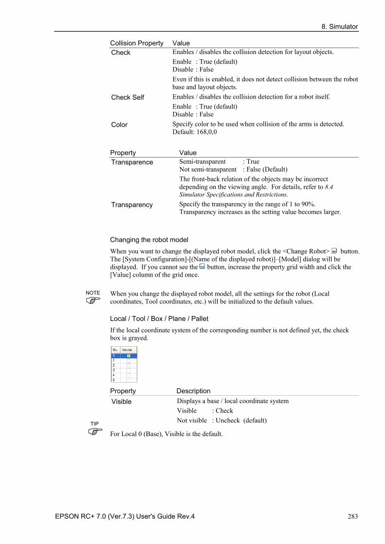
8. Simulator
EPSON RC+ 7.0 (Ver.7.3) User's Guide Rev.4 283
Collision Property Value Check Enables / disables the collision detection for layout objects.
Enable : True (default) Disable : False Even if this is enabled, it does not detect collision between the robot base and layout objects.
Check Self Enables / disables the collision detection for a robot itself. Enable : True (default) Disable : False
Color Specify color to be used when collision of the arms is detected. Default: 168,0,0
Property Value Transparence Semi-transparent : True
Not semi-transparent : False (Default) The front-back relation of the objects may be incorrect depending on the viewing angle. For details, refer to 8.4 Simulator Specifications and Restrictions.
Transparency Specify the transparency in the range of 1 to 90%. Transparency increases as the setting value becomes larger.
Changing the robot model
When you want to change the displayed robot model, click the <Change Robot> button. The [System Configuration]-[(Name of the displayed robot)]–[Model] dialog will be displayed. If you cannot see the button, increase the property grid width and click the [Value] column of the grid once.
When you change the displayed robot model, all the settings for the robot (Local coordinates, Tool coordinates, etc.) will be initialized to the default values.
Local / Tool / Box / Plane / Pallet
If the local coordinate system of the corresponding number is not defined yet, the check box is grayed.
Property Description Visible Displays a base / local coordinate system
Visible : Check Not visible : Uncheck (default)
For Local 0 (Base), Visible is the default.
TIP
NOTE
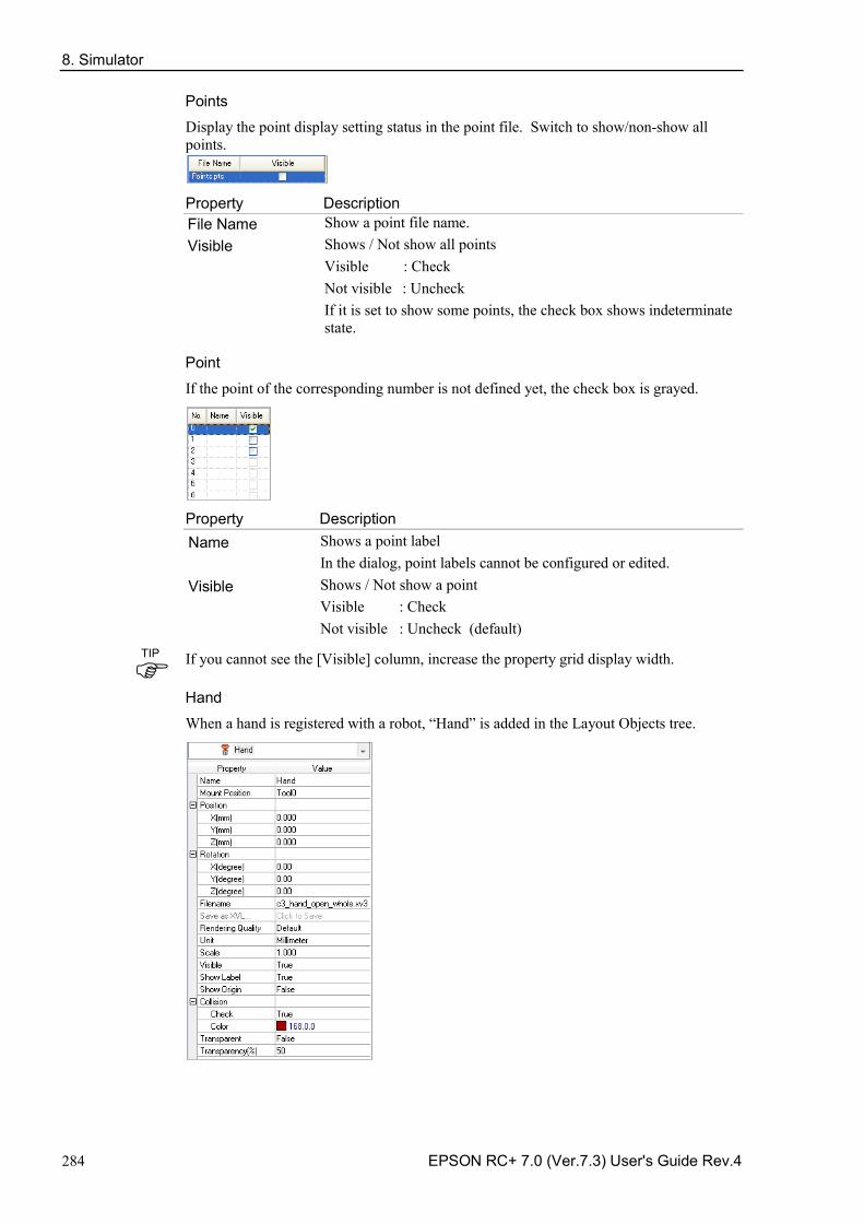
8. Simulator
284 EPSON RC+ 7.0 (Ver.7.3) User's Guide Rev.4
Points
Display the point display setting status in the point file. Switch to show/non-show all points.
Property Description File Name Show a point file name. Visible Shows / Not show all points
Visible : Check Not visible : Uncheck If it is set to show some points, the check box shows indeterminate state.
Point
If the point of the corresponding number is not defined yet, the check box is grayed.
Property Description Name Shows a point label
In the dialog, point labels cannot be configured or edited. Visible Shows / Not show a point
Visible : Check Not visible : Uncheck (default)
If you cannot see the [Visible] column, increase the property grid display width.
Hand
When a hand is registered with a robot, “Hand” is added in the Layout Objects tree.
TIP
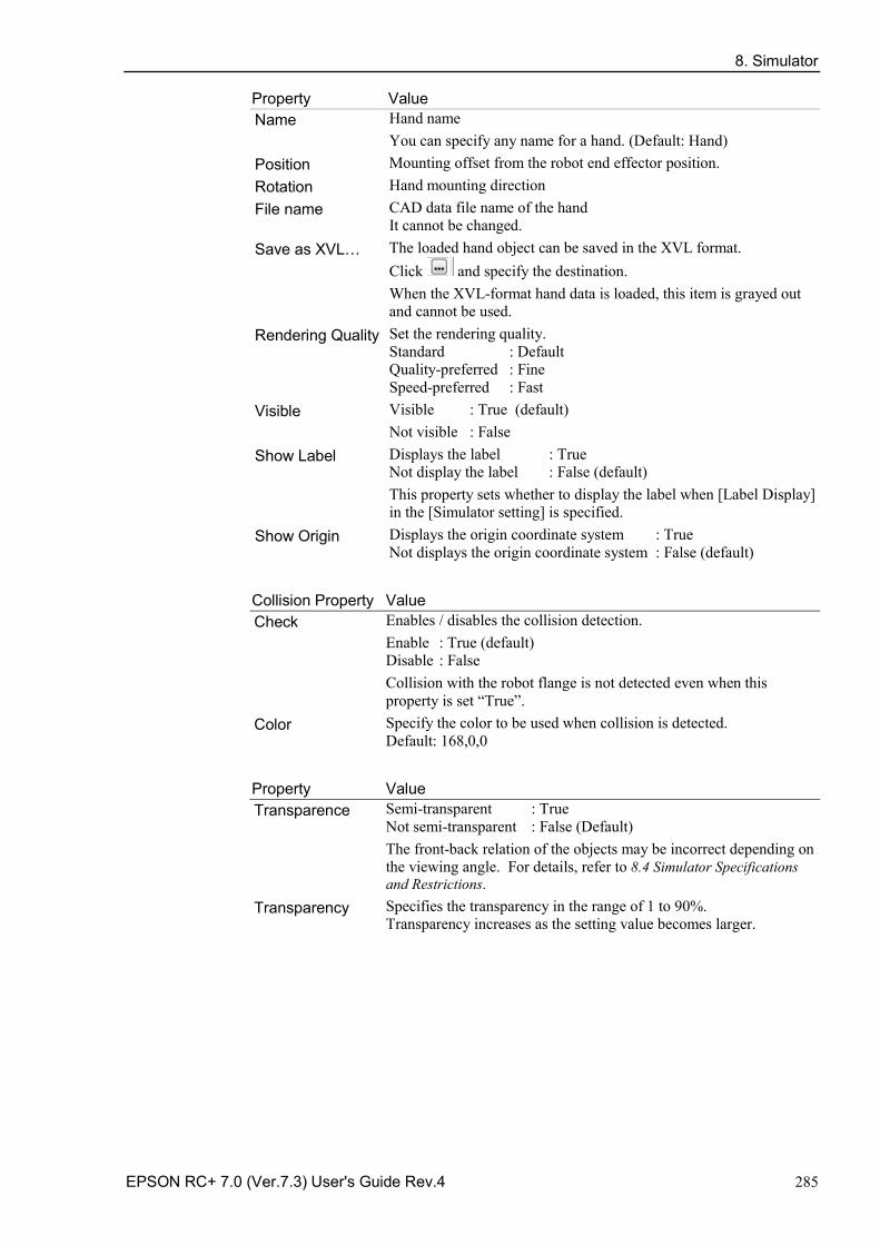
8. Simulator
EPSON RC+ 7.0 (Ver.7.3) User's Guide Rev.4 285
Property Value Name Hand name
You can specify any name for a hand. (Default: Hand) Position Mounting offset from the robot end effector position. Rotation Hand mounting direction File name CAD data file name of the hand
It cannot be changed. Save as XVL… The loaded hand object can be saved in the XVL format.
Click and specify the destination. When the XVL-format hand data is loaded, this item is grayed out and cannot be used.
Rendering Quality Set the rendering quality. Standard : Default Quality-preferred : Fine Speed-preferred : Fast
Visible Visible : True (default) Not visible : False
Show Label Displays the label : True Not display the label : False (default) This property sets whether to display the label when [Label Display] in the [Simulator setting] is specified.
Show Origin Displays the origin coordinate system : True Not displays the origin coordinate system : False (default)
Collision Property Value Check Enables / disables the collision detection.
Enable : True (default) Disable : False Collision with the robot flange is not detected even when this property is set “True”.
Color Specify the color to be used when collision is detected. Default: 168,0,0
Property Value Transparence Semi-transparent : True
Not semi-transparent : False (Default) The front-back relation of the objects may be incorrect depending on the viewing angle. For details, refer to 8.4 Simulator Specifications and Restrictions.
Transparency Specifies the transparency in the range of 1 to 90%. Transparency increases as the setting value becomes larger.
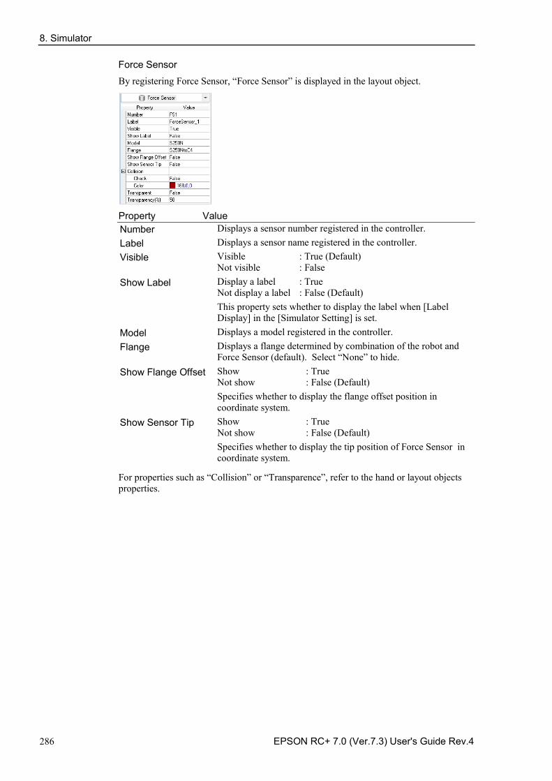
8. Simulator
286 EPSON RC+ 7.0 (Ver.7.3) User's Guide Rev.4
Force Sensor
By registering Force Sensor, “Force Sensor” is displayed in the layout object.
Property Value Number Displays a sensor number registered in the controller. Label Displays a sensor name registered in the controller. Visible Visible : True (Default)
Not visible : False Show Label Display a label : True
Not display a label : False (Default) This property sets whether to display the label when [Label Display] in the [Simulator Setting] is set.
Model Displays a model registered in the controller. Flange Displays a flange determined by combination of the robot and
Force Sensor (default). Select “None” to hide. Show Flange Offset Show : True
Not show : False (Default) Specifies whether to display the flange offset position in coordinate system.
Show Sensor Tip Show : True Not show : False (Default) Specifies whether to display the tip position of Force Sensor in coordinate system.
For properties such as “Collision” or “Transparence”, refer to the hand or layout objects properties.
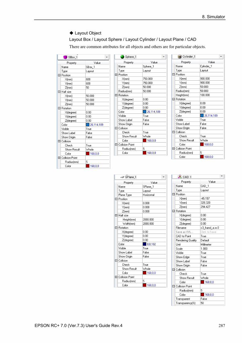
8. Simulator
EPSON RC+ 7.0 (Ver.7.3) User's Guide Rev.4 287
◆ Layout Object Layout Box / Layout Sphere / Layout Cylinder / Layout Plane / CAD
There are common attributes for all objects and others are for particular objects.
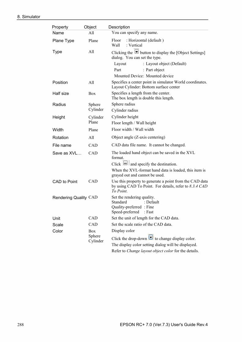
8. Simulator
288 EPSON RC+ 7.0 (Ver.7.3) User's Guide Rev.4
Property Object Description Name All You can specify any name.
Plane Type Plane Floor : Horizontal (default ) Wall : Vertical
Type All Clicking the button to display the [Object Settings] dialog. You can set the type.
Layout : Layout object (Default) Part : Part object Mounted Device : Mounted device
Position All Specifies a center point in simulator World coordinates. Layout Cylinder: Bottom surface center
Half size Box Specifies a length from the center. The box length is double this length.
Radius Sphere Cylinder
Sphere radius Cylinder radius
Height Cylinder Plane
Cylinder height Floor length / Wall height
Width Plane Floor width / Wall width
Rotation All Object angle (Z-axis centering)
File name CAD CAD data file name. It cannot be changed.
Save as XVL… CAD The loaded hand object can be saved in the XVL format. Click and specify the destination. When the XVL-format hand data is loaded, this item is grayed out and cannot be used.
CAD to Point CAD Use this property to generate a point from the CAD data by using CAD To Point. For details, refer to 8.3.4 CAD To Point.
Rendering Quality CAD Set the rendering quality. Standard : Default Quality-preferred : Fine Speed-preferred : Fast
Unit CAD Set the unit of length for the CAD data. Scale CAD Set the scale ratio of the CAD data. Color Box
Sphere Cylinder
Display color
Click the drop-down to change display color. The display color setting dialog will be displayed. Refer to Change layout object color for the details.
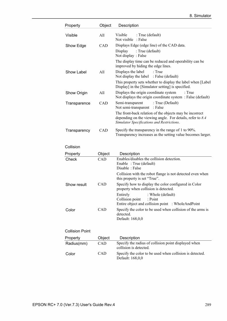
8. Simulator
EPSON RC+ 7.0 (Ver.7.3) User's Guide Rev.4 289
Property Object Description
Visible All Visible : True (default) Not visible : False
Show Edge CAD Displays Edge (edge line) of the CAD data. Display : True (default) Not display : False The display time can be reduced and operability can be improved by hiding the edge lines.
Show Label All Displays the label : True Not display the label : False (default) This property sets whether to display the label when [Label Display] in the [Simulator setting] is specified.
Show Origin All Displays the origin coordinate system : True Not displays the origin coordinate system : False (default)
Transparence CAD Semi-transparent : True (Default) Not semi-transparent : False The front-back relation of the objects may be incorrect depending on the viewing angle. For details, refer to 8.4 Simulator Specifications and Restrictions.
Transparency CAD Specify the transparency in the range of 1 to 90%. Transparency increases as the setting value becomes larger.
Collision
Property Object Description Check CAD Enables/disables the collision detection.
Enable : True (default) Disable : False Collision with the robot flange is not detected even when this property is set “True”.
Show result CAD Specify how to display the color configured in Color property when collision is detected. Entirely : Whole (default) Collision point : Point Entire object and collision point : WholeAndPoint
Color CAD Specify the color to be used when collision of the arms is detected. Default: 168,0,0
Collision Point
Property Object Description Radius(mm) CAD Specify the radius of collision point displayed when
collision is detected. Color CAD Specify the color to be used when collision is detected.
Default: 168,0,0
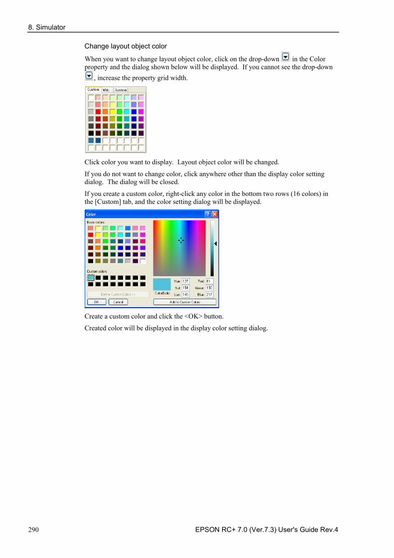
8. Simulator
290 EPSON RC+ 7.0 (Ver.7.3) User's Guide Rev.4
Change layout object color
When you want to change layout object color, click on the drop-down in the Color property and the dialog shown below will be displayed. If you cannot see the drop-down
, increase the property grid width.
Click color you want to display. Layout object color will be changed.
If you do not want to change color, click anywhere other than the display color setting dialog. The dialog will be closed.
If you create a custom color, right-click any color in the bottom two rows (16 colors) in the [Custom] tab, and the color setting dialog will be displayed.
Create a custom color and click the <OK> button.
Created color will be displayed in the display color setting dialog.
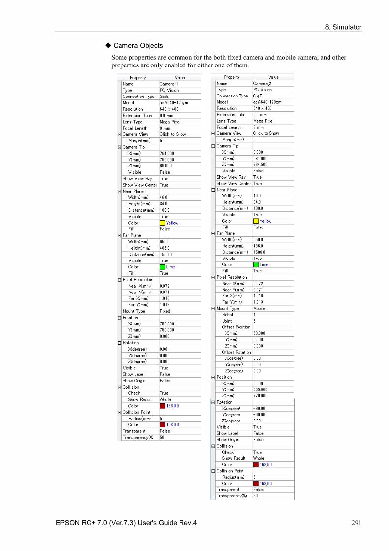
8. Simulator
EPSON RC+ 7.0 (Ver.7.3) User's Guide Rev.4 291
Camera Objects
Some properties are common for the both fixed camera and mobile camera, and other properties are only enabled for either one of them.
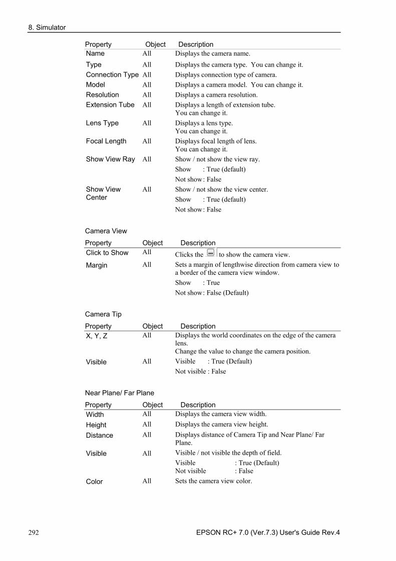
8. Simulator
292 EPSON RC+ 7.0 (Ver.7.3) User's Guide Rev.4
Property Object Description
Camera View
Property Object Description Click to Show All Clicks the to show the camera view. Margin All Sets a margin of lengthwise direction from camera view to
a border of the camera view window. Show : True Not show : False (Default)
Camera Tip
Property Object Description X, Y, Z All Displays the world coordinates on the edge of the camera
lens. Change the value to change the camera position.
Visible All Visible : True (Default) Not visible : False
Near Plane/ Far Plane
Property Object Description Width All Displays the camera view width. Height All Displays the camera view height. Distance All Displays distance of Camera Tip and Near Plane/ Far
Plane. Visible
All Visible / not visible the depth of field. Visible : True (Default) Not visible : False
Color All Sets the camera view color.
Name All Displays the camera name. Type All Displays the camera type. You can change it. Connection Type All Displays connection type of camera. Model All Displays a camera model. You can change it. Resolution All Displays a camera resolution. Extension Tube All Displays a length of extension tube.
You can change it. Lens Type All Displays a lens type.
You can change it. Focal Length All Displays focal length of lens.
You can change it. Show View Ray All Show / not show the view ray.
Show : True (default) Not show : False
Show View Center
All Show / not show the view center. Show : True (default) Not show : False
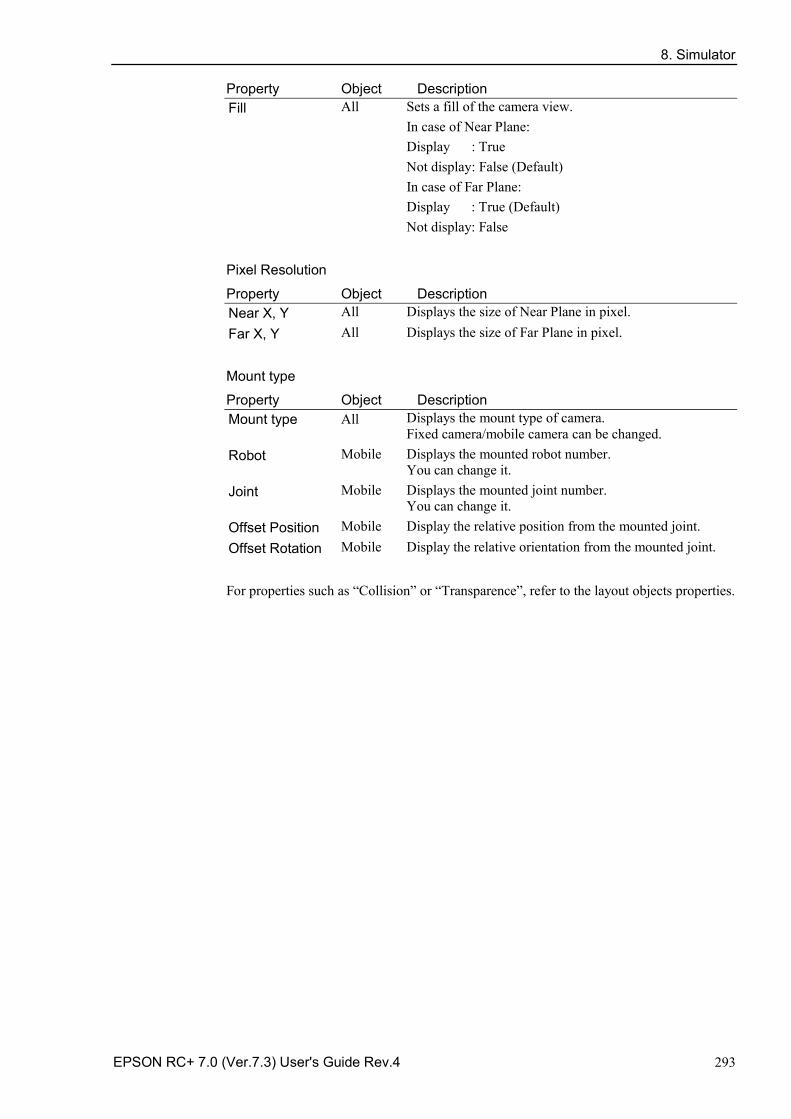
8. Simulator
EPSON RC+ 7.0 (Ver.7.3) User's Guide Rev.4 293
Property Object Description Fill All Sets a fill of the camera view.
In case of Near Plane: Display : True Not display : False (Default) In case of Far Plane: Display : True (Default) Not display: False
Pixel Resolution
Property Object Description Near X, Y All Displays the size of Near Plane in pixel. Far X, Y All Displays the size of Far Plane in pixel.
Mount type
Property Object Description Mount type
All Displays the mount type of camera. Fixed camera/mobile camera can be changed.
Robot
Mobile Displays the mounted robot number. You can change it.
Joint Mobile Displays the mounted joint number. You can change it.
Offset Position Mobile Display the relative position from the mounted joint. Offset Rotation Mobile Display the relative orientation from the mounted joint.
For properties such as “Collision” or “Transparence”, refer to the layout objects properties.
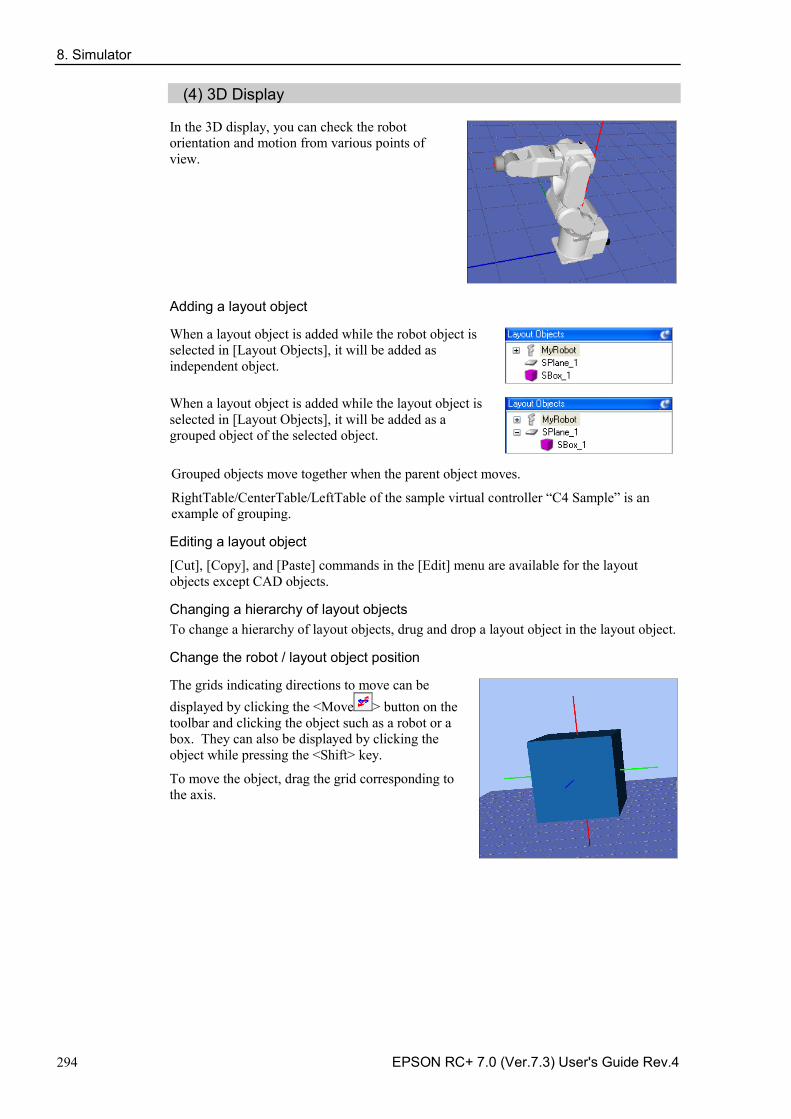
8. Simulator
294 EPSON RC+ 7.0 (Ver.7.3) User's Guide Rev.4
(4) 3D Display
In the 3D display, you can check the robot orientation and motion from various points of view.
Adding a layout object
When a layout object is added while the robot object is selected in [Layout Objects], it will be added as independent object.
When a layout object is added while the layout object is selected in [Layout Objects], it will be added as a grouped object of the selected object.
Grouped objects move together when the parent object moves.
RightTable/CenterTable/LeftTable of the sample virtual controller “C4 Sample” is an example of grouping.
Editing a layout object
[Cut], [Copy], and [Paste] commands in the [Edit] menu are available for the layout objects except CAD objects.
Changing a hierarchy of layout objects To change a hierarchy of layout objects, drug and drop a layout object in the layout object.
Change the robot / layout object position
The grids indicating directions to move can be displayed by clicking the <Move > button on the toolbar and clicking the object such as a robot or a box. They can also be displayed by clicking the object while pressing the <Shift> key.
To move the object, drag the grid corresponding to the axis.
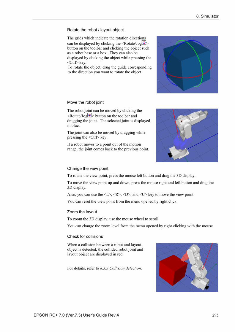
8. Simulator
EPSON RC+ 7.0 (Ver.7.3) User's Guide Rev.4 295
Rotate the robot / layout object
The grids which indicate the rotation directions can be displayed by clicking the <Rotate/Jog > button on the toolbar and clicking the object such as a robot base or a box. They can also be displayed by clicking the object while pressing the <Ctrl> key. To rotate the object, drug the guide corresponding to the direction you want to rotate the object.
Move the robot joint
The robot joint can be moved by clicking the <Rotate/Jog > button on the toolbar and dragging the joint. The selected joint is displayed in blue.
The joint can also be moved by dragging while pressing the <Ctrl> key.
If a robot moves to a point out of the motion range, the joint comes back to the previous point.
Change the view point
To rotate the view point, press the mouse left button and drag the 3D display.
To move the view point up and down, press the mouse right and left button and drag the 3D display.
Also, you can use the <L>, <R>, <D>, and <U> key to move the view point.
You can reset the view point from the menu opened by right click.
Zoom the layout
To zoom the 3D display, use the mouse wheel to scroll.
You can change the zoom level from the menu opened by right clicking with the mouse.
Check for collisions
When a collision between a robot and layout object is detected, the collided robot joint and layout object are displayed in red.
For details, refer to 8.3.3 Collision detection.
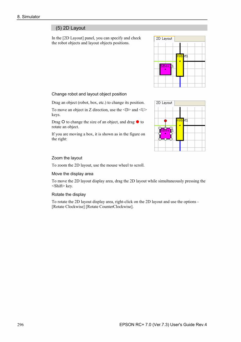
8. Simulator
296 EPSON RC+ 7.0 (Ver.7.3) User's Guide Rev.4
(5) 2D Layout
In the [2D Layout] panel, you can specify and check the robot objects and layout objects positions.
Change robot and layout object position
Drag an object (robot, box, etc.) to change its position.
To move an object in Z direction, use the <D> and <U> keys.
Drag to change the size of an object, and drag to rotate an object.
If you are moving a box, it is shown as in the figure on the right:
Zoom the layout
To zoom the 2D layout, use the mouse wheel to scroll.
Move the display area
To move the 2D layout display area, drag the 2D layout while simultaneously pressing the <Shift> key.
Rotate the display
To rotate the 2D layout display area, right-click on the 2D layout and use the options - [Rotate Clockwise] [Rotate CounterClockwise].
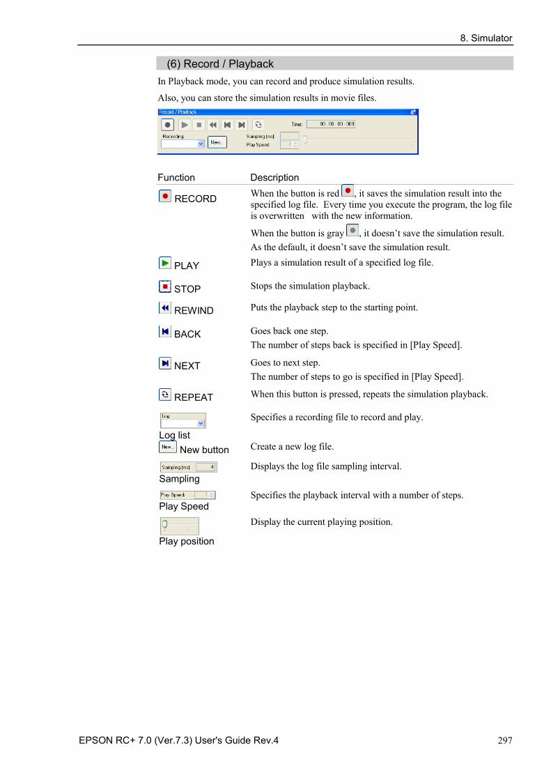
8. Simulator
EPSON RC+ 7.0 (Ver.7.3) User's Guide Rev.4 297
(6) Record / Playback In Playback mode, you can record and produce simulation results.
Also, you can store the simulation results in movie files.
Function Description
RECORD When the button is red , it saves the simulation result into the specified log file. Every time you execute the program, the log file is overwritten with the new information.
When the button is gray , it doesn’t save the simulation result. As the default, it doesn’t save the simulation result.
PLAY Plays a simulation result of a specified log file.
STOP Stops the simulation playback.
REWIND Puts the playback step to the starting point.
BACK Goes back one step. The number of steps back is specified in [Play Speed].
NEXT Goes to next step. The number of steps to go is specified in [Play Speed].
REPEAT When this button is pressed, repeats the simulation playback.
Log list
Specifies a recording file to record and play.
New button Create a new log file.
Sampling
Displays the log file sampling interval.
Play Speed
Specifies the playback interval with a number of steps.
Play position
Display the current playing position.
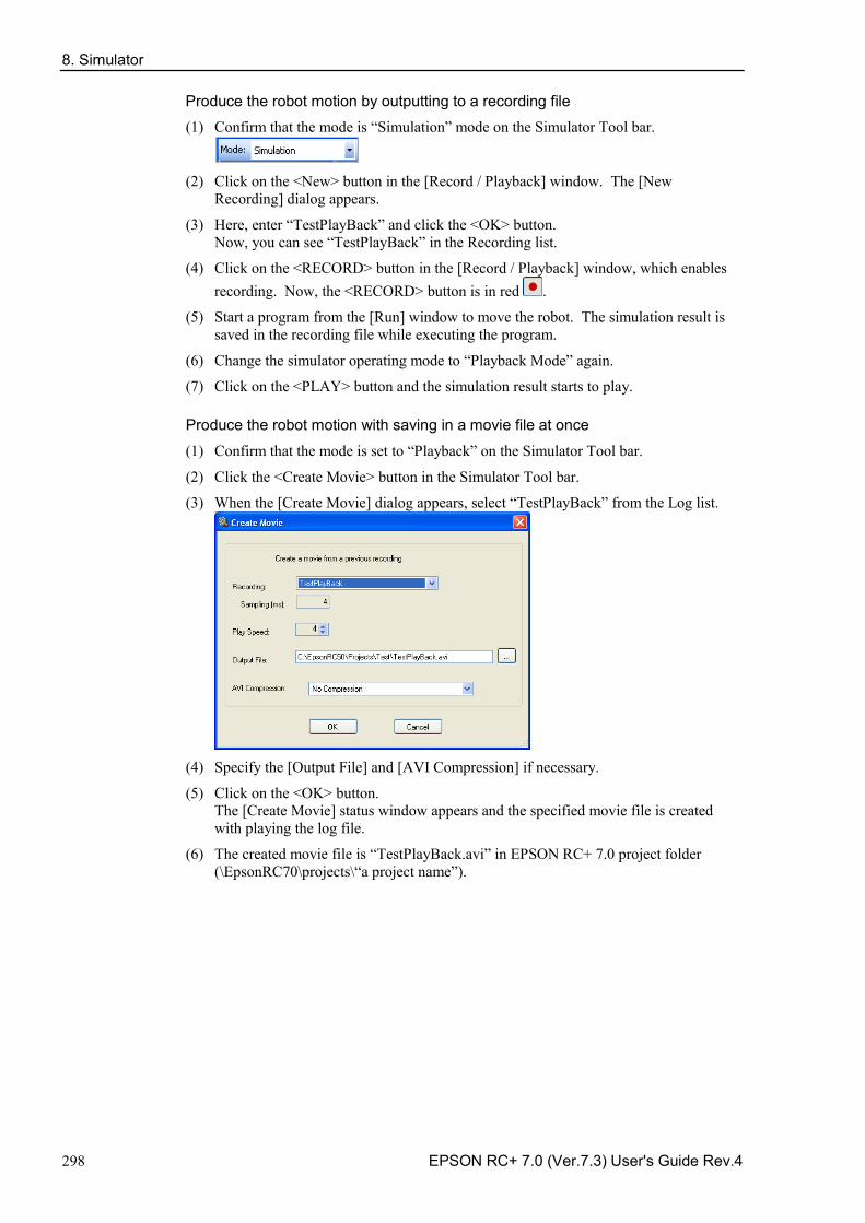
8. Simulator
298 EPSON RC+ 7.0 (Ver.7.3) User's Guide Rev.4
Produce the robot motion by outputting to a recording file
(1) Confirm that the mode is “Simulation” mode on the Simulator Tool bar.
(2) Click on the <New> button in the [Record / Playback] window. The [New
Recording] dialog appears.
(3) Here, enter “TestPlayBack” and click the <OK> button. Now, you can see “TestPlayBack” in the Recording list.
(4) Click on the <RECORD> button in the [Record / Playback] window, which enables recording. Now, the <RECORD> button is in red .
(5) Start a program from the [Run] window to move the robot. The simulation result is saved in the recording file while executing the program.
(6) Change the simulator operating mode to “Playback Mode” again.
(7) Click on the <PLAY> button and the simulation result starts to play.
Produce the robot motion with saving in a movie file at once
(1) Confirm that the mode is set to “Playback” on the Simulator Tool bar.
(2) Click the <Create Movie> button in the Simulator Tool bar.
(3) When the [Create Movie] dialog appears, select “TestPlayBack” from the Log list.
(4) Specify the [Output File] and [AVI Compression] if necessary.
(5) Click on the <OK> button. The [Create Movie] status window appears and the specified movie file is created with playing the log file.
(6) The created movie file is “TestPlayBack.avi” in EPSON RC+ 7.0 project folder (\EpsonRC70\projects\“a project name”).
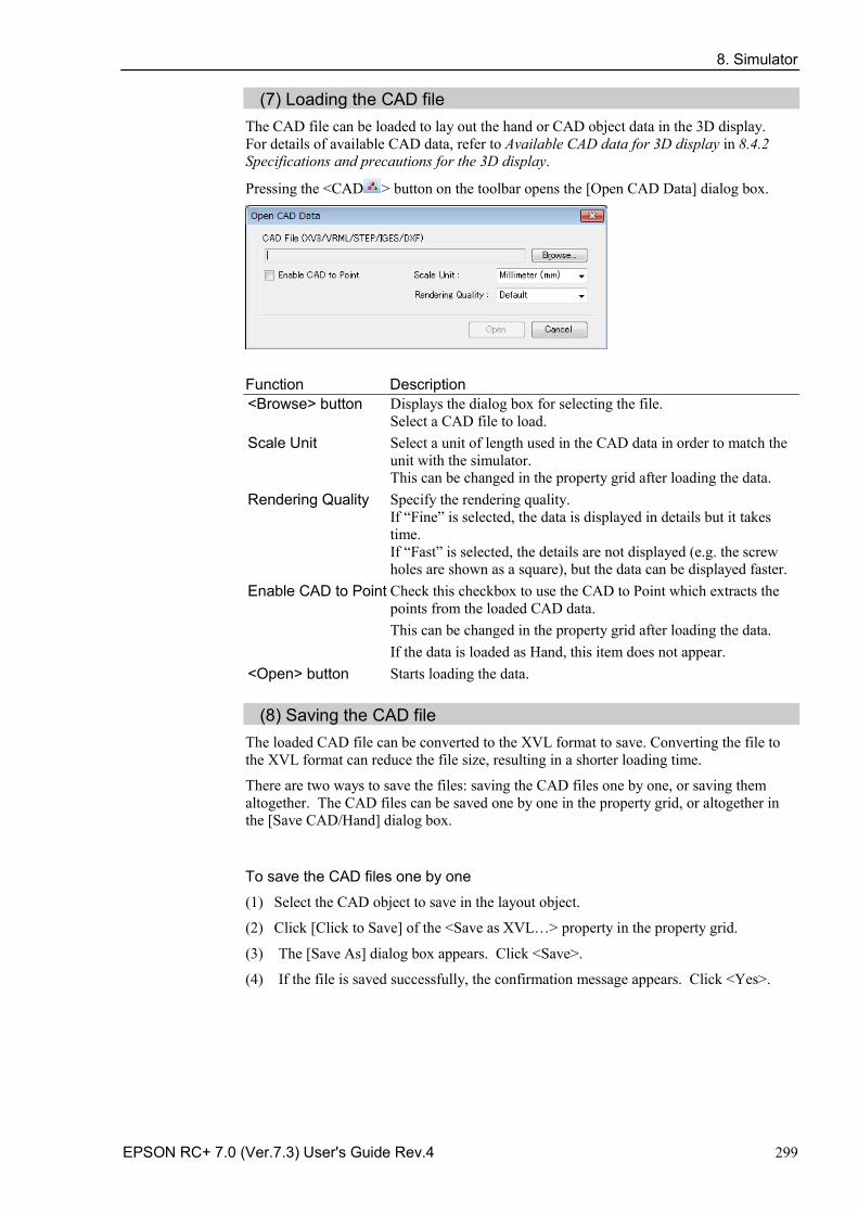
8. Simulator
EPSON RC+ 7.0 (Ver.7.3) User's Guide Rev.4 299
(7) Loading the CAD file The CAD file can be loaded to lay out the hand or CAD object data in the 3D display. For details of available CAD data, refer to Available CAD data for 3D display in 8.4.2 Specifications and precautions for the 3D display.
Pressing the <CAD > button on the toolbar opens the [Open CAD Data] dialog box.
Function Description <Browse> button Displays the dialog box for selecting the file.
Select a CAD file to load. Scale Unit Select a unit of length used in the CAD data in order to match the
unit with the simulator. This can be changed in the property grid after loading the data.
Rendering Quality Specify the rendering quality. If “Fine” is selected, the data is displayed in details but it takes time. If “Fast” is selected, the details are not displayed (e.g. the screw holes are shown as a square), but the data can be displayed faster.
Enable CAD to Point Check this checkbox to use the CAD to Point which extracts the points from the loaded CAD data. This can be changed in the property grid after loading the data. If the data is loaded as Hand, this item does not appear.
<Open> button Starts loading the data.
(8) Saving the CAD file The loaded CAD file can be converted to the XVL format to save. Converting the file to the XVL format can reduce the file size, resulting in a shorter loading time.
There are two ways to save the files: saving the CAD files one by one, or saving them altogether. The CAD files can be saved one by one in the property grid, or altogether in the [Save CAD/Hand] dialog box.
To save the CAD files one by one
(1) Select the CAD object to save in the layout object.
(2) Click [Click to Save] of the <Save as XVL…> property in the property grid.
(3) The [Save As] dialog box appears. Click <Save>.
(4) If the file is saved successfully, the confirmation message appears. Click <Yes>.
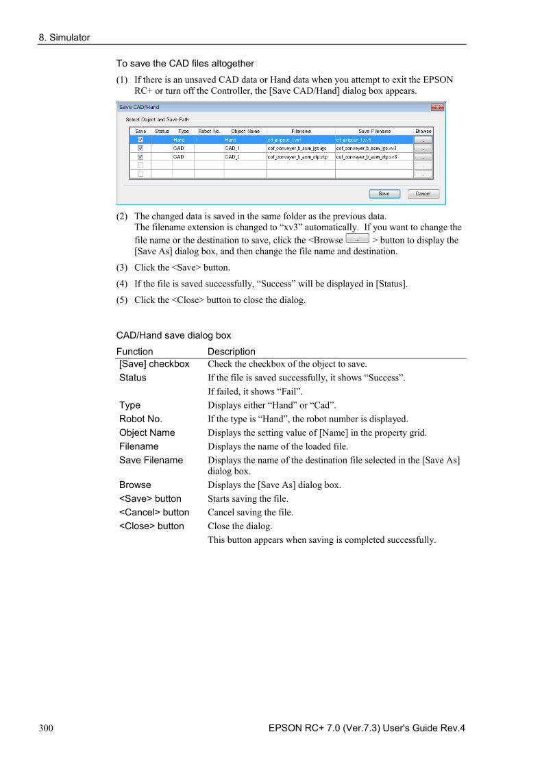
8. Simulator
300 EPSON RC+ 7.0 (Ver.7.3) User's Guide Rev.4
To save the CAD files altogether
(1) If there is an unsaved CAD data or Hand data when you attempt to exit the EPSON RC+ or turn off the Controller, the [Save CAD/Hand] dialog box appears.
(2) The changed data is saved in the same folder as the previous data.
The filename extension is changed to “xv3” automatically. If you want to change the file name or the destination to save, click the <Browse > button to display the [Save As] dialog box, and then change the file name and destination.
(3) Click the <Save> button.
(4) If the file is saved successfully, “Success” will be displayed in [Status].
(5) Click the <Close> button to close the dialog.
CAD/Hand save dialog box
Function Description [Save] checkbox Check the checkbox of the object to save. Status If the file is saved successfully, it shows “Success”.
If failed, it shows “Fail”. Type Displays either “Hand” or “Cad”. Robot No. If the type is “Hand”, the robot number is displayed. Object Name Displays the setting value of [Name] in the property grid. Filename Displays the name of the loaded file. Save Filename Displays the name of the destination file selected in the [Save As]
dialog box. Browse Displays the [Save As] dialog box. <Save> button Starts saving the file. <Cancel> button Cancel saving the file. <Close> button Close the dialog.
This button appears when saving is completed successfully.
8. Simulator
EPSON RC+ 7.0 (Ver.7.3) User's Guide Rev.4 301
8.3.2 Simulator Settings Pressing the <Simulator Settings > button displays the [Simulator Settings] dialog box.
This dialog box is used to configure the 3D display. The settings will be kept after restarting the EPSON RC+ 7.0.
Render Robot Options
Function Description Render Joints Displays the supporting point of the robot joints.
Render Coarsely-displayed Robot
Displays the simplified robot data. The setting is effective the next time you connect the robot. This option is useful when the computer capacity is insufficient or the CAD data is large.
Render Duct Collision Area Displays the range of collision detection at the robot duct with a bounding box. This option is available for G1 and LS series.
Render Singularity Area of Elbow (N series only)
Displays the elbow singularity area and elbow singularity neighborhood on the simulator.
Render TCP Path Options
Function Description Render TCP Path Displays the trajectory of the origin point on active Tool
coordinate system for a fixed time.
Style Select line or dot to indicate the trajectories.
Width Specify the line width of trajectories.
Radius Specify the diameter of dots indicating trajectories.
Color Specify the color of trajectories.
8. Simulator
302 EPSON RC+ 7.0 (Ver.7.3) User's Guide Rev.4
Render Point Options
Function Description Radius Specify the diameter of dots indicating points.
Color Specify the color of dots indicating points.
Render Orientation Displays arrows indicating direction of points.
Size Displays the robot and layout objects with a bounding box.
Label Label : Label registered in point file. Number : Point number NumberAndLabel: Point number and label
Render Axis Options
Function Description Render World Monitor Displays the World coordinates.
Render Rotation Direction Displays the rotation direction of the coordinate axes.
Render Axis Name Displays the name of coordinates (X, Y, Z).
Render Other Options
Function Description Render Back Face Displays the surface of polygons.
Render Wireframe Changes to the wire frame model (3D image only using lines and dots)
Render Labels Displays the names of the robot and layout objects.
Render Bounding Box Displays the robot and layout objects with a bounding box.
Render Grid Displays the grids on the simulator.
CAD/Hand Save Options
Function Description Confirm save as XVL Displays the [Save CAD/Hand] dialog box if there is CAD
data or Hand object in other than XVL format when starting the simulator.
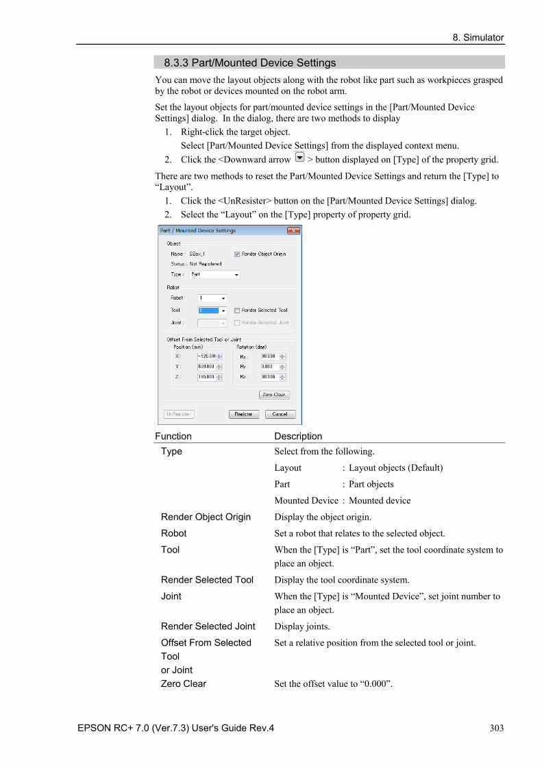
8. Simulator
EPSON RC+ 7.0 (Ver.7.3) User's Guide Rev.4 303
8.3.3 Part/Mounted Device Settings You can move the layout objects along with the robot like part such as workpieces grasped by the robot or devices mounted on the robot arm.
Set the layout objects for part/mounted device settings in the [Part/Mounted Device Settings] dialog. In the dialog, there are two methods to display
1. Right-click the target object. Select [Part/Mounted Device Settings] from the displayed context menu.
2. Click the <Downward arrow > button displayed on [Type] of the property grid.
There are two methods to reset the Part/Mounted Device Settings and return the [Type] to “Layout”.
1. Click the <UnResister> button on the [Part/Mounted Device Settings] dialog. 2. Select the “Layout” on the [Type] property of property grid.
Function Description
Type Select from the following.
Layout : Layout objects (Default)
Part : Part objects
Mounted Device : Mounted device
Render Object Origin Display the object origin.
Robot Set a robot that relates to the selected object.
Tool When the [Type] is “Part”, set the tool coordinate system to place an object.
Render Selected Tool Display the tool coordinate system.
Joint When the [Type] is “Mounted Device”, set joint number to place an object.
Render Selected Joint Display joints.
Offset From Selected Tool or Joint
Set a relative position from the selected tool or joint.
Zero Clear Set the offset value to “0.000”.
8. Simulator
304 EPSON RC+ 7.0 (Ver.7.3) User's Guide Rev.4
Function Description Register Register an object to the selected type.
UnRegister Return the registered [Type] of the object to “Layout”.
Cancel Cancel the settings.
8.3.4 Collision detection In the simulation, collisions can be detected between the robots including its hand and the layout objects. (X5 series cannot use this function.)
Here we describe the settings and details of collision detection.
Basic settings for collision detection
In the [Property Grid] of the robot, the following can be configured.
Property Value
Check Collision Enables / disables the collision detection for layout objects. Enable: True (default) Disable: False Collision between the robot base and layout objects is not detected even when this property is set “True”.
Check Self Collision Enables / disables the collision detection for a robot itself. Enable: True (default) Disable: False
Target of collision detection
In the Property Grid of the layout objects, the following can be configured.
Collision
Property Object Value
Check CAD Enables / disables the collision detection for a robot. Enable: True (default) Disable: False Collision with the robot flange is not detected even when this property is set “True”.
Show result CAD Specify how to display the color configured in Color property when a collision is detected. Entirely : Whole (default) Collision point : Point Entire object and collision point : WholeAndPoint
Color CAD Specify a color to be used when collision is detected. Default: 168,0,0
Collision Point
Property Object Value Radius(mm) CAD Specify the radius of collision point displayed when
collision is detected. Color CAD Specify the color to be used when collision of the arms
is detected. Default: 168,0,0
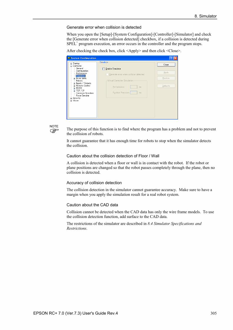
8. Simulator
EPSON RC+ 7.0 (Ver.7.3) User's Guide Rev.4 305
Generate error when collision is detected
When you open the [Setup]-[System Configuration]-[Controller]-[Simulator] and check the [Generate error when collision detected] checkbox, if a collision is detected during SPEL+ program execution, an error occurs in the controller and the program stops.
After checking the check box, click <Apply> and then click <Close>.
The purpose of this function is to find where the program has a problem and not to prevent the collision of robots.
It cannot guarantee that it has enough time for robots to stop when the simulator detects the collision.
Caution about the collision detection of Floor / Wall
A collision is detected when a floor or wall is in contact with the robot. If the robot or plane positions are changed so that the robot passes completely through the plane, then no collision is detected.
Accuracy of collision detection
The collision detection in the simulator cannot guarantee accuracy. Make sure to have a margin when you apply the simulation result for a real robot system.
Caution about the CAD data
Collision cannot be detected when the CAD data has only the wire frame models. To use the collision detection function, add surface to the CAD data.
The restrictions of the simulator are described in 8.4 Simulator Specifications and Restrictions.
NOTE
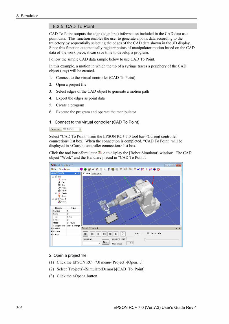
8. Simulator
306 EPSON RC+ 7.0 (Ver.7.3) User's Guide Rev.4
8.3.5 CAD To Point CAD To Point outputs the edge (edge line) information included in the CAD data as a point data. This function enables the user to generate a point data according to the trajectory by sequentially selecting the edges of the CAD data shown in the 3D display. Since this function automatically register points of manipulator motion based on the CAD data of the work piece, it can save time to develop a program.
Follow the simple CAD data sample below to use CAD To Point.
In this example, a motion in which the tip of a syringe traces a periphery of the CAD object (tray) will be created.
1. Connect to the virtual controller (CAD To Point)
2. Open a project file
3. Select edges of the CAD object to generate a motion path
4. Export the edges as point data
5. Create a program
6. Execute the program and operate the manipulator
1. Connect to the virtual controller (CAD To Point)
Select “CAD To Point” from the EPSON RC+ 7.0 tool bar-<Current controller connection> list box. When the connection is completed, “CAD To Point” will be displayed in <Current controller connection> list box.
Click the tool bar-<Simulator > to display the [Robot Simulator] window. The CAD object “Work” and the Hand are placed in “CAD To Point”.
2. Open a project file
(1) Click the EPSON RC+ 7.0 menu-[Project]-[Open…].
(2) Select [Projects]-[SimulatorDemos]-[CAD_To_Point].
(3) Click the <Open> button.
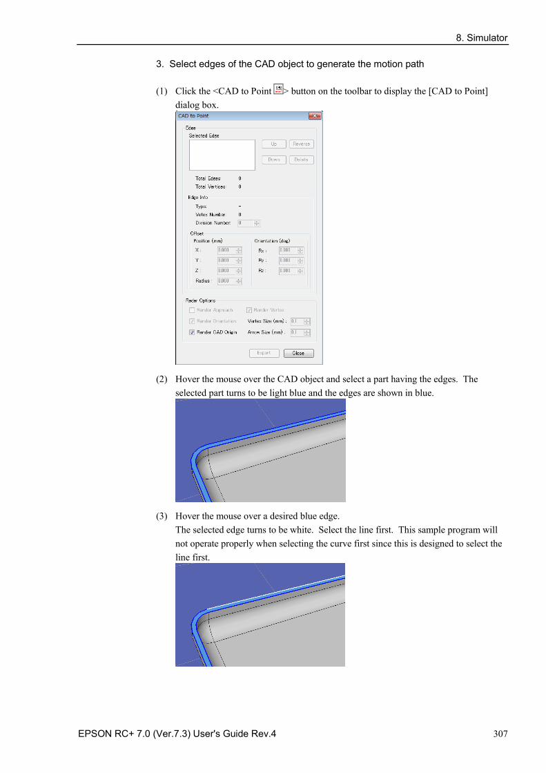
8. Simulator
EPSON RC+ 7.0 (Ver.7.3) User's Guide Rev.4 307
3. Select edges of the CAD object to generate the motion path
(1) Click the <CAD to Point > button on the toolbar to display the [CAD to Point] dialog box.
(2) Hover the mouse over the CAD object and select a part having the edges. The selected part turns to be light blue and the edges are shown in blue.
(3) Hover the mouse over a desired blue edge. The selected edge turns to be white. Select the line first. This sample program will not operate properly when selecting the curve first since this is designed to select the line first.
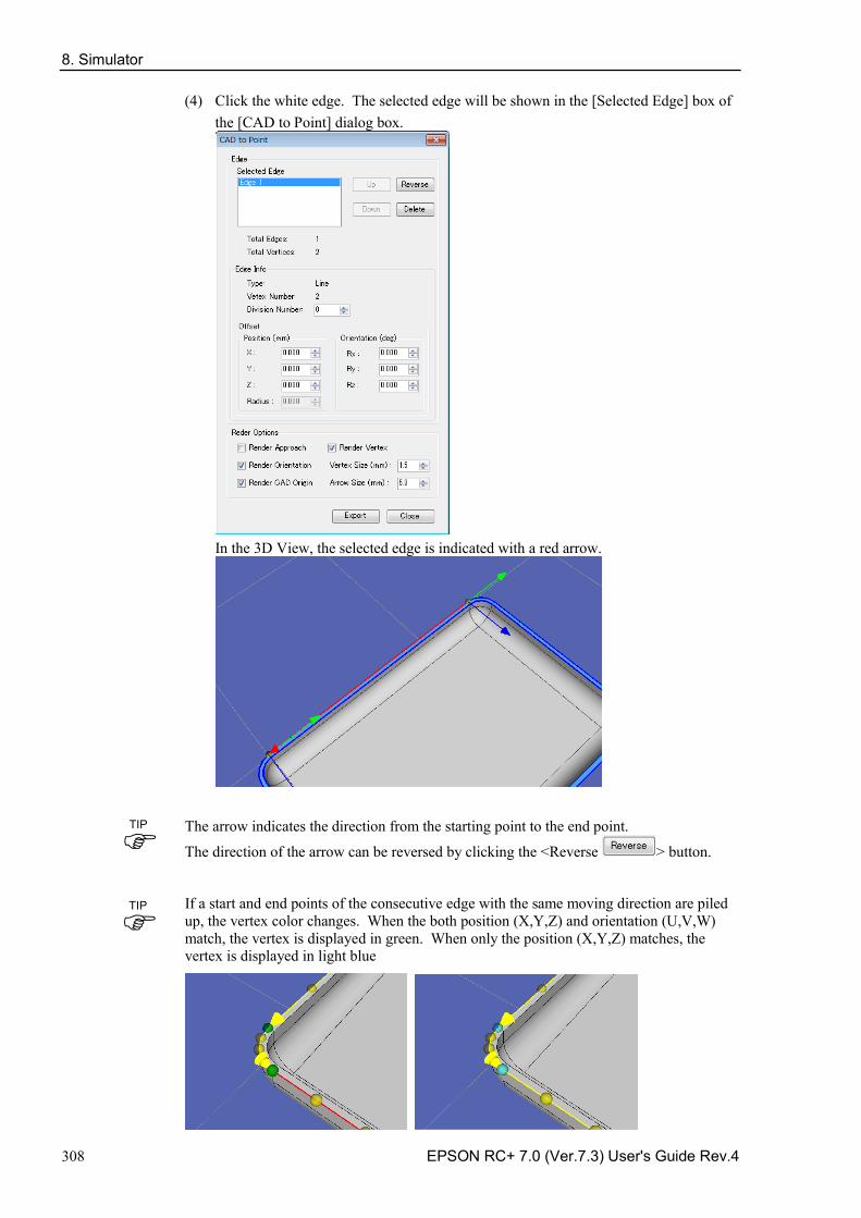
8. Simulator
308 EPSON RC+ 7.0 (Ver.7.3) User's Guide Rev.4
(4) Click the white edge. The selected edge will be shown in the [Selected Edge] box of the [CAD to Point] dialog box.
In the 3D View, the selected edge is indicated with a red arrow.
The arrow indicates the direction from the starting point to the end point.
The direction of the arrow can be reversed by clicking the <Reverse > button.
If a start and end points of the consecutive edge with the same moving direction are piled up, the vertex color changes. When the both position (X,Y,Z) and orientation (U,V,W) match, the vertex is displayed in green. When only the position (X,Y,Z) matches, the vertex is displayed in light blue
TIP
TIP
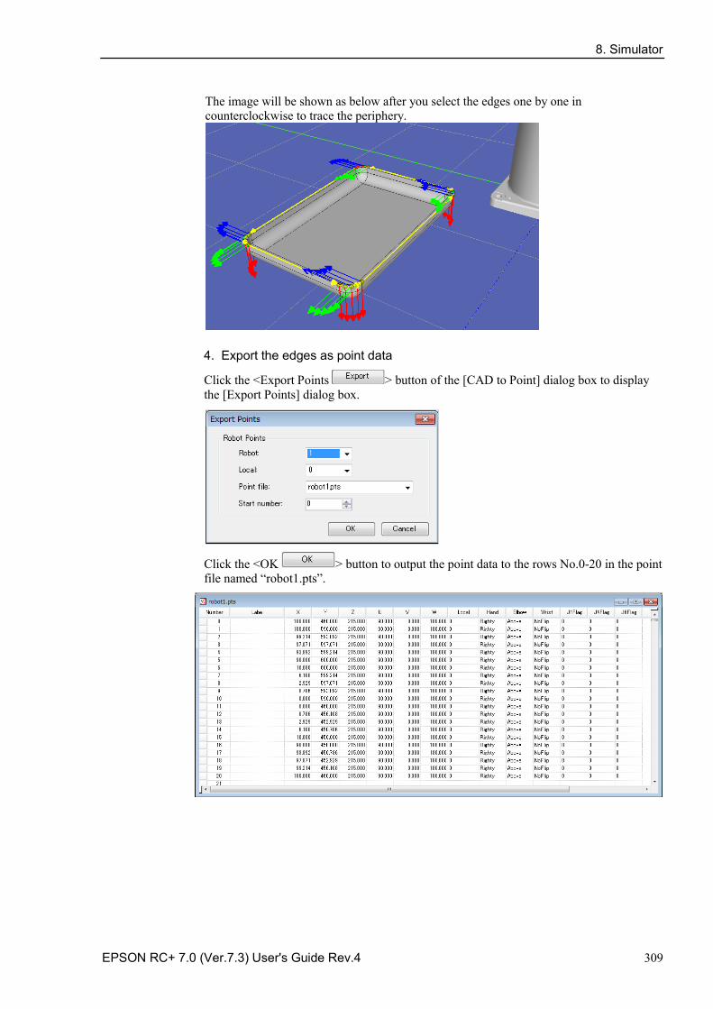
8. Simulator
EPSON RC+ 7.0 (Ver.7.3) User's Guide Rev.4 309
The image will be shown as below after you select the edges one by one in counterclockwise to trace the periphery.
4. Export the edges as point data
Click the <Export Points > button of the [CAD to Point] dialog box to display the [Export Points] dialog box.
Click the <OK > button to output the point data to the rows No.0-20 in the point file named “robot1.pts”.
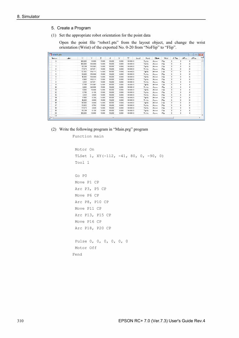
8. Simulator
310 EPSON RC+ 7.0 (Ver.7.3) User's Guide Rev.4
5. Create a Program
(1) Set the appropriate robot orientation for the point data
Open the point file “robot1.pts” from the layout object, and change the wrist orientation (Wrist) of the exported No. 0-20 from “NoFlip” to “Flip”.
(2) Write the following program in “Main.prg” program Function main
Motor On
TLSet 1, XY(-112, -41, 80, 0, -90, 0)
Tool 1
Go P0
Move P1 CP
Arc P3, P5 CP
Move P6 CP
Arc P8, P10 CP
Move P11 CP
Arc P13, P15 CP
Move P16 CP
Arc P18, P20 CP
Pulse 0, 0, 0, 0, 0, 0
Motor Off
Fend
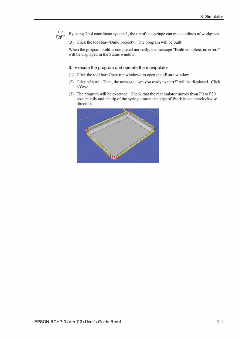
8. Simulator
EPSON RC+ 7.0 (Ver.7.3) User's Guide Rev.4 311
By using Tool coordinate system 1, the tip of the syringe can trace outlines of workpiece.
(3) Click the tool bar-<Build project>. The program will be built.
When the program build is completed normally, the message “Build complete, no errors” will be displayed in the Status window.
6. Execute the program and operate the manipulator
(1) Click the tool bar<Open run window> to open the <Run> window
(2) Click <Start>. Then, the message “Are you ready to start?” will be displayed. Click <Yes>.
(3) The program will be executed. Check that the manipulator moves from P0 to P20 sequentially and the tip of the syringe traces the edge of Work in counterclockwise direction.
TIP
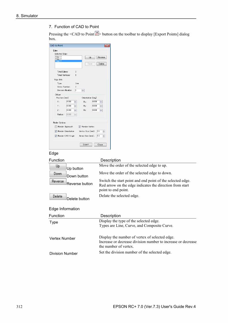
8. Simulator
312 EPSON RC+ 7.0 (Ver.7.3) User's Guide Rev.4
7. Function of CAD to Point
Pressing the <CAD to Point > button on the toolbar to display [Export Points] dialog box.
Edge
Function Description
Up button Move the order of the selected edge to up.
Down button Move the order of the selected edge to down.
Reverse button Switch the start point and end point of the selected edge. Red arrow on the edge indicates the direction from start point to end point.
Delete button Delate the selected edge.
Edge Information
Function Description Type Display the type of the selected edge.
Types are Line, Curve, and Composite Curve.
Vertex Number Display the number of vertex of selected edge. Increase or decrease division number to increase or decrease the number of vertex.
Division Number Set the division number of the selected edge.
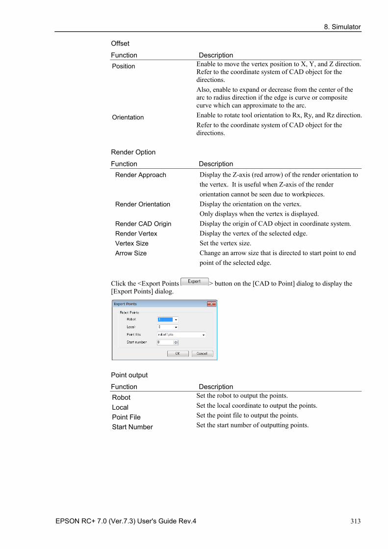
8. Simulator
EPSON RC+ 7.0 (Ver.7.3) User's Guide Rev.4 313
Offset
Function Description Position Enable to move the vertex position to X, Y, and Z direction.
Refer to the coordinate system of CAD object for the directions. Also, enable to expand or decrease from the center of the arc to radius direction if the edge is curve or composite curve which can approximate to the arc.
Orientation Enable to rotate tool orientation to Rx, Ry, and Rz direction. Refer to the coordinate system of CAD object for the directions.
Render Option
Function Description Render Approach Display the Z-axis (red arrow) of the render orientation to
the vertex. It is useful when Z-axis of the render orientation cannot be seen due to workpieces.
Render Orientation Display the orientation on the vertex. Only displays when the vertex is displayed.
Render CAD Origin Display the origin of CAD object in coordinate system. Render Vertex Display the vertex of the selected edge. Vertex Size Set the vertex size. Arrow Size Change an arrow size that is directed to start point to end
point of the selected edge.
Click the <Export Points > button on the [CAD to Point] dialog to display the [Export Points] dialog.
Point output
Function Description Robot Set the robot to output the points.
Local Set the local coordinate to output the points.
Point File Set the point file to output the points.
Start Number Set the start number of outputting points.
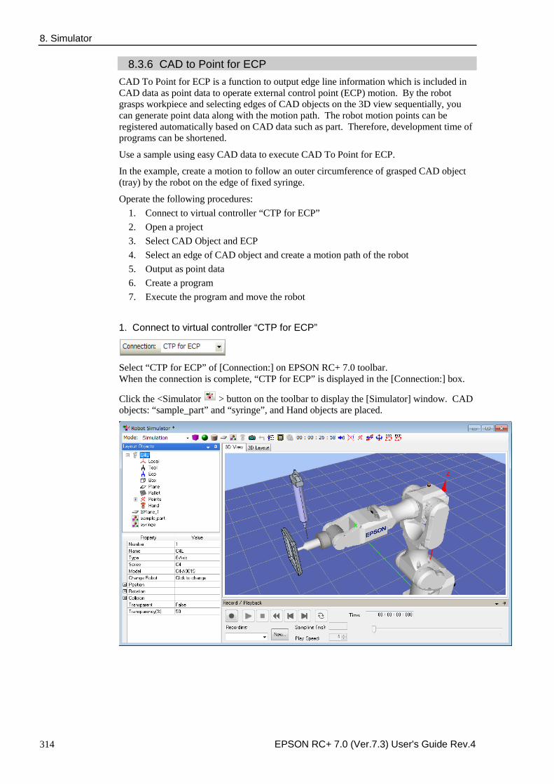
8. Simulator
314 EPSON RC+ 7.0 (Ver.7.3) User's Guide Rev.4
8.3.6 CAD to Point for ECP CAD To Point for ECP is a function to output edge line information which is included in CAD data as point data to operate external control point (ECP) motion. By the robot grasps workpiece and selecting edges of CAD objects on the 3D view sequentially, you can generate point data along with the motion path. The robot motion points can be registered automatically based on CAD data such as part. Therefore, development time of programs can be shortened.
Use a sample using easy CAD data to execute CAD To Point for ECP.
In the example, create a motion to follow an outer circumference of grasped CAD object (tray) by the robot on the edge of fixed syringe.
Operate the following procedures: 1. Connect to virtual controller “CTP for ECP” 2. Open a project 3. Select CAD Object and ECP 4. Select an edge of CAD object and create a motion path of the robot 5. Output as point data 6. Create a program 7. Execute the program and move the robot
1. Connect to virtual controller “CTP for ECP”
Select “CTP for ECP” of [Connection:] on EPSON RC+ 7.0 toolbar. When the connection is complete, “CTP for ECP” is displayed in the [Connection:] box.
Click the <Simulator > button on the toolbar to display the [Simulator] window. CAD objects: “sample_part” and “syringe”, and Hand objects are placed.
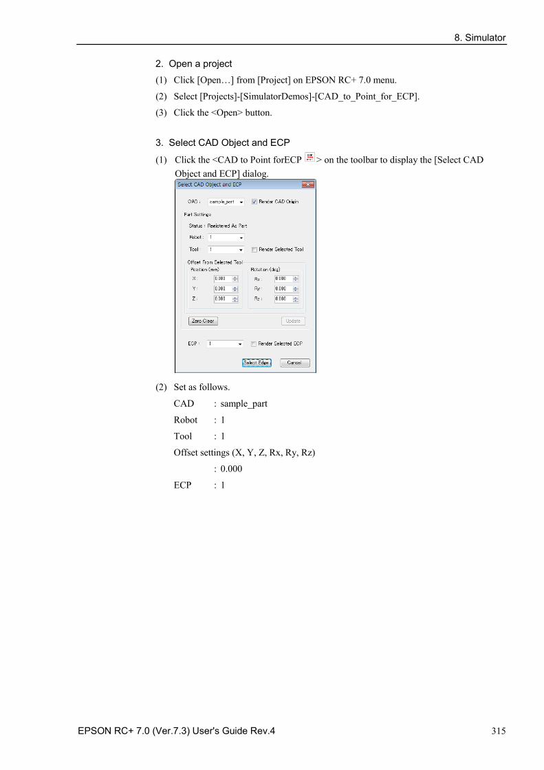
8. Simulator
EPSON RC+ 7.0 (Ver.7.3) User's Guide Rev.4 315
2. Open a project
(1) Click [Open…] from [Project] on EPSON RC+ 7.0 menu.
(2) Select [Projects]-[SimulatorDemos]-[CAD_to_Point_for_ECP].
(3) Click the <Open> button.
3. Select CAD Object and ECP
(1) Click the <CAD to Point forECP > on the toolbar to display the [Select CAD Object and ECP] dialog.
(2) Set as follows.
CAD : sample_part
Robot : 1
Tool : 1
Offset settings (X, Y, Z, Rx, Ry, Rz)
: 0.000
ECP : 1
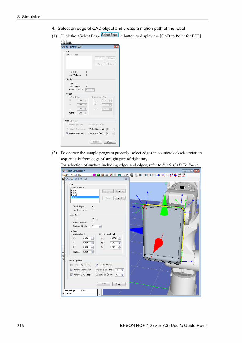
8. Simulator
316 EPSON RC+ 7.0 (Ver.7.3) User's Guide Rev.4
4. Select an edge of CAD object and create a motion path of the robot
(1) Click the <Select Edge > button to display the [CAD to Point for ECP] dialog.
(2) To operate the sample program properly, select edges in counterclockwise rotation sequentially from edge of straight part of right tray. For selection of surface including edges and edges, refer to 8.3.5 CAD To Point.
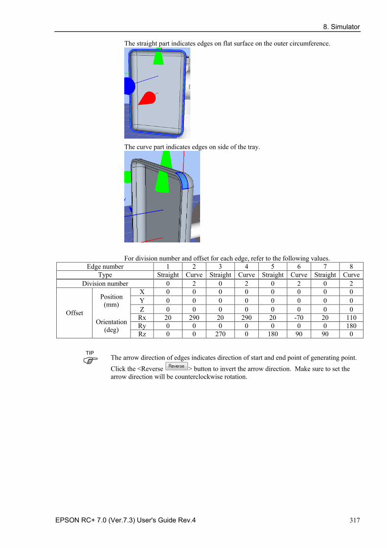
8. Simulator
EPSON RC+ 7.0 (Ver.7.3) User's Guide Rev.4 317
The straight part indicates edges on flat surface on the outer circumference.
The curve part indicates edges on side of the tray.
For division number and offset for each edge, refer to the following values. Edge number 1 2 3 4 5 6 7 8
Type Straight Curve Straight Curve Straight Curve Straight Curve Division number 0 2 0 2 0 2 0 2
Offset
Position (mm)
X 0 0 0 0 0 0 0 0 Y 0 0 0 0 0 0 0 0 Z 0 0 0 0 0 0 0 0
Orientation (deg)
Rx 20 290 20 290 20 -70 20 110 Ry 0 0 0 0 0 0 0 180 Rz 0 0 270 0 180 90 90 0
The arrow direction of edges indicates direction of start and end point of generating point. Click the <Reverse > button to invert the arrow direction. Make sure to set the arrow direction will be counterclockwise rotation.
TIP
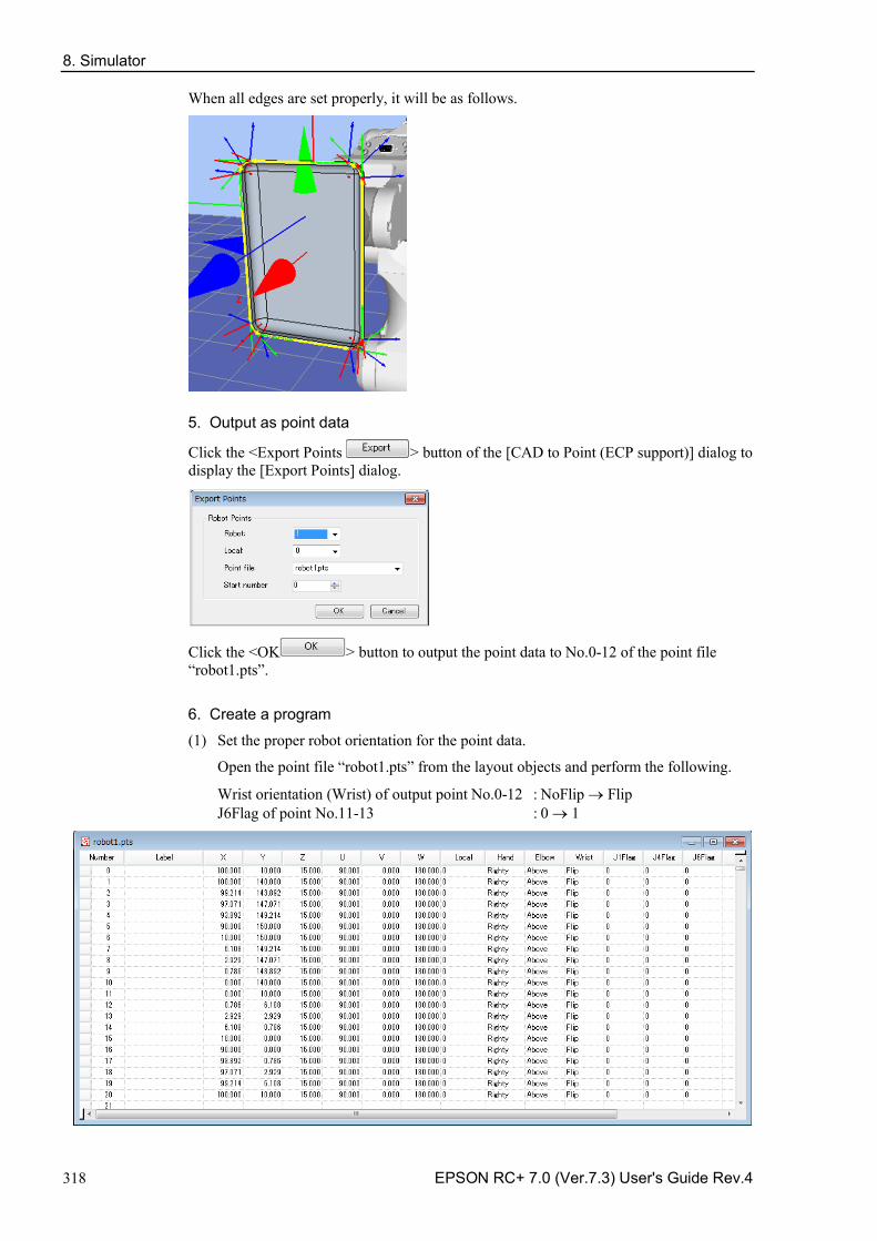
8. Simulator
318 EPSON RC+ 7.0 (Ver.7.3) User's Guide Rev.4
When all edges are set properly, it will be as follows.
5. Output as point data
Click the <Export Points > button of the [CAD to Point (ECP support)] dialog to display the [Export Points] dialog.
Click the <OK > button to output the point data to No.0-12 of the point file “robot1.pts”.
6. Create a program
(1) Set the proper robot orientation for the point data.
Open the point file “robot1.pts” from the layout objects and perform the following.
Wrist orientation (Wrist) of output point No.0-12 : NoFlip → Flip J6Flag of point No.11-13 : 0 → 1
8. Simulator
EPSON RC+ 7.0 (Ver.7.3) User's Guide Rev.4 319
(2) Create the following program in Main.prg program. Function main
Motor On Power High Tool 1 ECP 1 Go P0 Move P1 ECP CP Arc3 P2, P3 ECP CP Move P4 CP Arc3 P5, P6 ECP CP Move P7 CP Arc3 P8, P9 ECP CP Move P10 CP Arc3 P11, P12 ECP CP Pulse 0, 0, 0, 0, 0, 0 Motor Off Fend
(3) Click the <Build> button on the toolbar. Build the program.
When the build is complete normally, the message “Build complete, no errors” appears in the [Status] window.
7. Execute the program and move the robot
(1) Click the <Run> window button on the tool bar to display the Run window.
(2) Click the <Start> button. When the message “Are you ready to start?” is appeared, click the <Yes>.
(3) Confirm that the program is executed and follow an outer circumference of grasped CAD object (tray) by the robot on the edge of fixed syringe to operate ECP motion.
Functions of CAD to Point for ECP
Click the < CAD to Point for ECP > button on the toolbar to display the [CAD to Point (ECP support)] dialog. For functions, refer to 8.3.5 CAD to Point - 7. Function of CAD to Point.
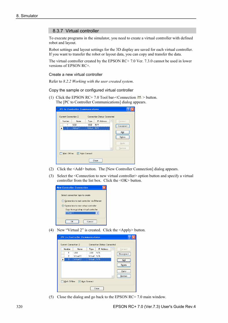
8. Simulator
320 EPSON RC+ 7.0 (Ver.7.3) User's Guide Rev.4
8.3.7 Virtual controller
To execute programs in the simulator, you need to create a virtual controller with defined robot and layout.
Robot settings and layout settings for the 3D display are saved for each virtual controller. If you want to transfer the robot or layout data, you can copy and transfer the data.
The virtual controller created by the EPSON RC+ 7.0 Ver. 7.3.0 cannot be used in lower versions of EPSON RC+.
Create a new virtual controller
Refer to 8.2.2 Working with the user created system.
Copy the sample or configured virtual controller
(1) Click the EPSON RC+ 7.0 Tool bar-<Connection > button. The [PC to Controller Communications] dialog appears.
(2) Click the <Add> button. The [New Controller Connection] dialog appears.
(3) Select the <Connection to new virtual controller> option button and specify a virtual controller from the list box. Click the <OK> button.
(4) New “Virtual 2” is created. Click the <Apply> button.
(5) Close the dialog and go back to the EPSON RC+ 7.0 main window.
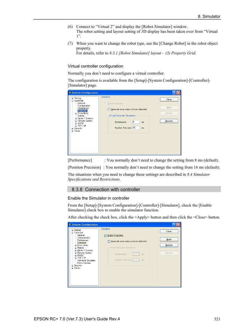
8. Simulator
EPSON RC+ 7.0 (Ver.7.3) User's Guide Rev.4 321
(6) Connect to “Virtual 2” and display the [Robot Simulator] window. The robot setting and layout setting of 3D display has been taken over from “Virtual 1”.
(7) When you want to change the robot type, use the [Change Robot] in the robot object property. For details, refer to 8.3.1 [Robot Simulator] layout – (3) Property Grid.
Virtual controller configuration
Normally you don’t need to configure a virtual controller.
The configuration is available from the [Setup]-[System Configuration]-[Controller]-[Simulator] page.
[Performance] : You normally don’t need to change the setting from 8 ms (default).
[Position Precision] : You normally don’t need to change the setting from 16 ms (default).
The situations when you need to change these settings are described in 8.4 Simulator Specifications and Restrictions.
8.3.8 Connection with controller
Enable the Simulator in controller
From the [Setup]-[System Configuration]-[Controller]-[Simulator], check the [Enable Simulator] check box to enable the simulator function.
After checking the check box, click the <Apply> button and then click the <Close> button.
8. Simulator
322 EPSON RC+ 7.0 (Ver.7.3) User's Guide Rev.4
If collision with the simulator object is detected during a Jog motion or a robot motion command execution when the Simulator is enabled, the Manipulator stops operation and a Warning occurs.
To avoid collision with peripherals by using the Simulator, set 15 mm or greater margins to the simulator object.
Function restrictions when connected with controller - You cannot change the manipulator from the [Robot Simulator] window. - You cannot select and move the manipulator arms in the [Robot Simulator]
window, except during the controller Dry run. - When the manipulator connected to the controller is not supported in the Simulator,
the object list and the manipulator in 2D layout and 3D window are not displayed. - The [Record/Playback] functions are not available.
Operator Window
When you enable the Simulator, the <Simulator> button is added to the Operator Window. When you click on the <Simulator> button, the 3D display window appears.
8. Simulator
EPSON RC+ 7.0 (Ver.7.3) User's Guide Rev.4 323
8.3.9 Virtual Camera Settings and Camera View Display Virtual camera settings are function to select camera or lens, and install as the fixed camera or mount as the mobile camera to the robot. Display of the camera view is a function to display images of the set camera. You can select the camera or lens and verify the layout by the simulator.
Add virtual cameras
Click the <Camera > button on the toolbar to display the [Add Cameras] dialog. After selecting devices and setting the mounting type, click the <Add> button.
If setting [Type] to “Mobile”, right click on the camera object of the layout object to display the context menu. Select [Camera Mount Settings] to display the [Camera Mount Settings] dialog. Set the relative position to joints.
Camera view display
By clicking the [Show Camera View] from the context menu of the camera objects, the camera view is displayed.
8. Simulator
324 EPSON RC+ 7.0 (Ver.7.3) User's Guide Rev.4
8.3.10 Motion restriction by BOX By using the BOX command together with the GetRobotInsideBox function or the OnErr command, robot power and motion can be restricted when the tool center point (TCP) enters the approach check area (BOX).
Sample project using BOX
In the sample project, BOX2 is set outside BOX1. When the tool center point calculated based on the currently selected tool enters BOX2, the robot will stop temporarily. If the program execution is continued, the robot will resume operation in the restricted status (low speed, low power). Then, when the robot enters BOX1 inside BOX2, the robot will abort operation.
Use the sample project to execute the motion restriction using BOX. The sample project is in \EpsonRC70\projects\SimulatorDemos\BOX_sample. For details of the usage of the project, refer to 8.2.1 Working with the samples.
8. Simulator
EPSON RC+ 7.0 (Ver.7.3) User's Guide Rev.4 325
8.4 Simulator Specifications and Restrictions This section describes the simulator specification, its restrictions, and precautionary statements.
8.4.1 EPSON RC+ 7.0 package
EPSON RC+ 7.0 has two packages: EPSON RC+ 7.0 : Standard package for developing the robot system EPSON RC+ 7.0 Trial : Trial package for limited use (program execution on PC)
* It cannot connect with a robot controller. Program execution
on PC Connection with
controller Connection with controller
+ 3D display
EPSON RC+ 7.0 OK *2 OK OK *1
EPSON RC+ 7.0 Trial OK *2 - -
*1 Requires the configuration to enable the simulator functions in EPSON RC+ 7.0. Refer to 8.3.6 Connection with controller for the detail information.
*2 Continuous execution time of program is limited.
8.4.2 Specifications and precautions for the 3D display
Available robots for 3D display
In the future, we will add more robots for 3D display. Call your EPSON Regional Sales Manager for the latest information. (X5 series cannot use this function.)
The flexible duct is displayed roughly.
- Check the dimensions in the manipulator manual.
- The duct actually vibrates while the manipulator is moving, the simulator doesn’t display the vibration. Check how the duct vibrates with your real manipulator.
The bellow for Cleanroom or Protection model is displayed roughly
- Check the dimensions in the manipulator manual.
Available CAD data for 3D display
The following format is available for 3D display to show the robot hand and CAD object.
- VRML 2.0 Limits of reading: VRML2.0 prototype is not supported.
- STEP (AP203/AP214) Limits of reading: If Color is configured in Face, the specified Color is displayed.
- IGES
- DXF DXF Format (DXF R13, DXF R14, DXF 2000/2000i, DXF 2002 ) of AutoCAD ® software
The data file must be saved in the specified folder on the PC and not saved in EPSON RC+.
NOTE
NOTE
8. Simulator
326 EPSON RC+ 7.0 (Ver.7.3) User's Guide Rev.4
Memory usage of CAD data
The memory usage of 32 bit applications is limited to 2 GB. The CAD data cannot be loaded when the total of memory usage of the application and the CAD exceeds 2 GB. Therefore, there is a limit of the total number of polygons and polylines. When the error message appears, reduce the number of polygons and polylines.
CAD data setup orientation
Some CAD data coordinates may be different from those of the simulator.
Adjust the coordinates to the correct position by changing [Property]-[ Rotation] after loading the CAD data.
When loading CAD data as a hand, set the origin of the CAD data in the Tool0 position of the manipulator. Set the coordinates to the correct position by changing [Property]-[ Position] after loading the CAD data.
Number of available layout objects
You can create as many layout objects as you want.
However, when there are many objects to display, the display update interval becomes longer and the judgment of collision detection becomes rough. Especially for CAD data, displaying data that is too complicated is not recommended.
Shape of CAD object
The shape of objects may be displayed incorrectly (such as a clearance arises between the faces) depending on the CAD data. In such a case, the shape may be improved by converting the data to a different format.
Front-back relation of objects in semi-transparent display
The front-back relation of the objects may be incorrect when displaying the CAD and Hand objects in semi-transparent display.
Rendering speed
It may take a few seconds to render the objects depending on the display adapter, and operability such as in selecting the object may be decreased. It is recommended to update the driver to the latest version.
8.4.3 Specifications and precautions for Simulation (program execution on PC)
Overview
The Simulator produces the robot motions virtually on your PC.
It is designed to make the performance gap between the real system and the virtual system as small as possible. However, a few differences in the virtual system are inevitable. The operation time prediction and collision detection do not guarantee the precision.
Fully understand the contents in this chapter and check if the real system operates without any problems before you go to full-scale operation.
8. Simulator
EPSON RC+ 7.0 (Ver.7.3) User's Guide Rev.4 327
Operation time prediction
Operation time displayed in the [Robot Simulator] window is approximate time required for executing the program.
Time for the motion commands such as Go, Jump reflects the Speed and Accel values in the program. The operation time may vary when you operate the real robots from the displayed operation time according to conditions such as the Fine setting and servo delay.
In particular, when small ranges are used with the Fine instruction, the real robots need a longer operation time for accurate positioning.
The simulation cannot guarantee the precision but the margin of error in the operation time is within 10% when you execute motions with the standard cycle time (with the default Fine settings).
Considered in the operation time prediction Not considered in the operation time prediction
Robot model
Speed settings (Speed, Speeds, etc.)
Acceleration settings (Accel, Accels, etc.)
Load (Weight, Inertia)
Others (ARCH, CP)
Fine setting
Error within 10% from the default (Motions of standard cycle time)
With larger setting than the default, the operation time will be shorter.
With smaller setting than the default, the operation time will be shorter.
Servo delay
With the real robots, the operation will be longer.
Time for the other commands than the motion commands is a virtually executed time on PC; therefore the actual time varies widely depending on the PC performance.
When measuring the motion time between two points, as simple program as possible is recommended. Refer to 8.2.2 Working with the user created system - 8. Measure the robot operation time.
Collision Detection Precision
The Simulator Collision Detection provides an indication whether robots collide with the peripheral equipment or not when the program is executed. It does not consider the error in trajectory due to servo delay. Be aware that a margin is necessary for the real robot system.
The Simulator judges collisions more accurately when the robot motion speed is slow.
The judgment of collision detection during program execution is accomplished with the 3D display update. When your PC has high graphics performance, the collision judgment becomes more accurate.
In Playback mode, the Simulator judges collisions in all steps and is useful when you need accurate detection.
The Simulator cannot guarantee the precision but the margin of error in the collision detection is within 10 mm when you execute motions with Speed 100% on a PC of the recommended specifications.
8. Simulator
328 EPSON RC+ 7.0 (Ver.7.3) User's Guide Rev.4
Motion duty and Overload error
In the Simulator, you cannot detect the overload error. Even when the motion duty is too high and the robot should have the overload error and stop, it keeps moving.
Duty 50% - As a measure of possible duty, the robot can really keep moving at duty 50% with the maximum acceleration/deceleration speed and without the overload error. However, it depends on the robot model type, load, points to go to, and acceleration/deceleration speed setting, etc.
Time progress difference by PC condition
On a PC that meets the system condition, progress of the time in the Simulator and the real time (as you see on the watch) are almost the same (few percentages difference).
If you are running other applications such as Windows Media Player simultaneously, the time progress in the Simulator can widely vary from the real time. In this case, use the Simulator function while other applications are not running.
Also, on some PC models, the time progress in the Simulator may widely vary from the real time. In this case, set the [Performance] at 16 ms and the [Position Precision] at 20 ms, which may close the gap of the time progress.
Time confirmation program (If the two printed times are within 27 to 33 seconds, there is no problem.)
Function main
Print Time$
Wait 30
Print Time$
Fend
Execution on PC below the minimum of specification
You can install the EPSON RC+ and use the Simulator functions on a PC that doesn’t meet the minimum of the specification.
However, it doesn’t guarantee the correct motions because the following may happen: - Operation time prediction is not accurate - Collision Detection has a large margin of error - 3D display skips updates
8.4.4 Specifications and precautions of EPSON RC+
Restriction on the controller settings
When you connect with a virtual controller, the following items are grayed and become unavailable to change. Setup: System Configuration: Controller: Configuration Page: IP Address, etc. - Setup: System Configuration: Controller: Preference Page: Dry run, etc. -
Backup and restore of the controller setting
The setting data that you backup in the virtual controller can be restored in a controller. Also, the setting data that you backup in a controller can be restored in a virtual controller. However, there are restrictions. For more details, refer to 5.11.8 [Maintenance] (Tools menu)-[Backup Controller] and [Restore Controller].
TIP
8. Simulator
EPSON RC+ 7.0 (Ver.7.3) User's Guide Rev.4 329
8.4.5 Restriction on SPEL+ command execution
(1) I/O operation and commands (On, Off, SW, Ctr, etc.)
All I/O including the option boards are available in a virtual controller. Operating I/O data is stored in the PC memory (virtual I/O mode). The I/O input status can be changed from the EPSON RC+ I/O Monitor window. Also, the I/O input status can be changed using the SetSw or SetIn statements in a SPEL+ program.
Even if you specify an asynchronous On/Off command, the I/O status cannot be changed after the specified time and the Ctr function always returns 0.
(2) Ethernet / RS-232C communication command (Print #, Input #, OpenCom, OpenNet, etc.)
All 16 Ethernet ports are available. However, an Ethernet port requires configuration of the IP address and TCP/IP port.
For RS-232C, all 8 ports including the option RS-232C board are available.
NOTE For RC700/RC700-A Controller and RC90 Controller, up to 5 ports including the standard port and the option RC-232C board are available. Be careful of the number of the ports when using the project created in the virtual controller to the Controller.
As a default, Ethernet / RS-232C communication commands do not perform actual communication.
To use the actual Ethernet/RC-232C ports, be sure to configure as described in (3).
Output data from Print #, etc. is saved in the communication output file. In the input by Input#, etc, the return value is 0 (numeric data) or blank (string). However, if you create a communication response file, the return value depends on the file content.
Communication output file
When calling OpenCom or OpenNet command, a communication output file is created in the \EpsonRC70\Virtual\Mounted Volume\Project folder on the PC.
DummySend***.dat : Communication output file (*** is the port number)
When a communication output file already exists, the previous output data is deleted. The file is deleted when you switch the project; save the file in a proper folder if you need.
When executing the following program, OpenCom #1 Print #1, 123 Print #1, "TEST DATA" CloseCom #1
the DummySend001.dat file will contain...
123 TEST DATA
NOTE
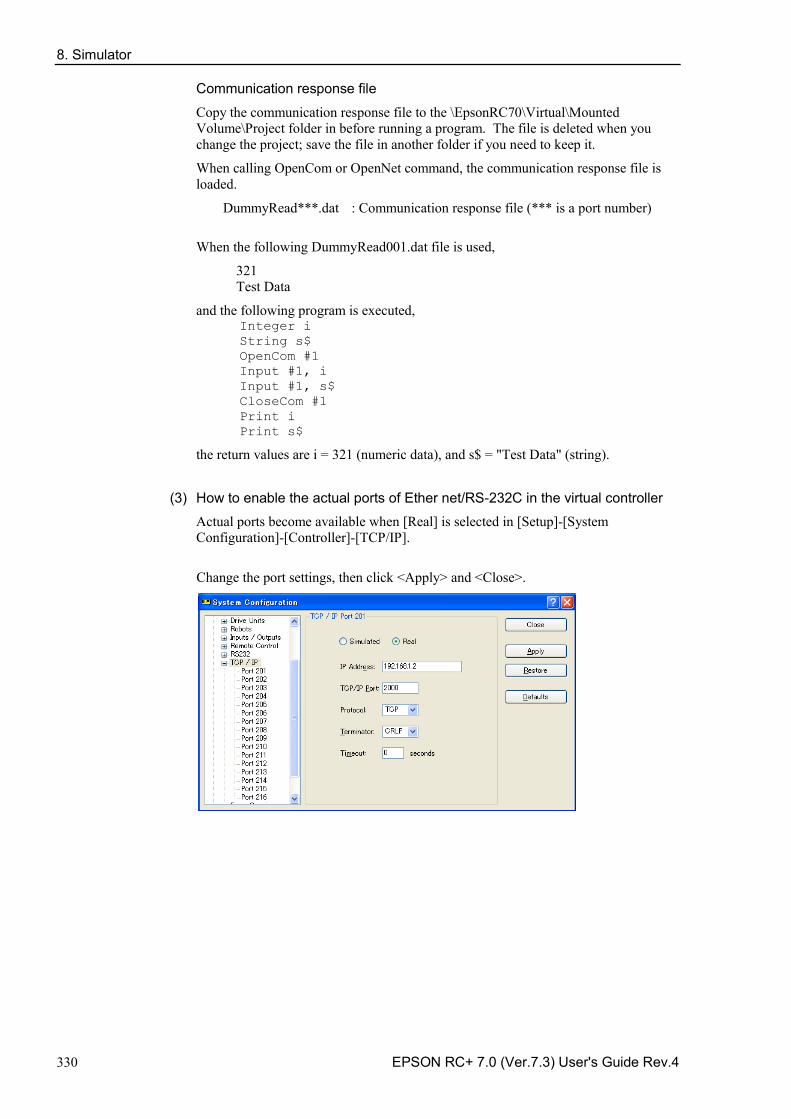
8. Simulator
330 EPSON RC+ 7.0 (Ver.7.3) User's Guide Rev.4
Communication response file
Copy the communication response file to the \EpsonRC70\Virtual\Mounted Volume\Project folder in before running a program. The file is deleted when you change the project; save the file in another folder if you need to keep it.
When calling OpenCom or OpenNet command, the communication response file is loaded.
DummyRead***.dat : Communication response file (*** is a port number)
When the following DummyRead001.dat file is used,
321 Test Data
and the following program is executed, Integer i String s$ OpenCom #1 Input #1, i Input #1, s$ CloseCom #1 Print i Print s$
the return values are i = 321 (numeric data), and s$ = "Test Data" (string).
(3) How to enable the actual ports of Ether net/RS-232C in the virtual controller
Actual ports become available when [Real] is selected in [Setup]-[System Configuration]-[Controller]-[TCP/IP].
Change the port settings, then click <Apply> and <Close>.
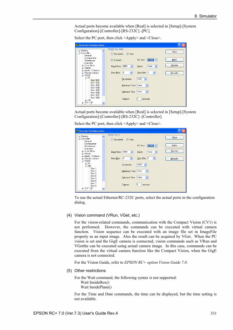
8. Simulator
EPSON RC+ 7.0 (Ver.7.3) User's Guide Rev.4 331
Actual ports become available when [Real] is selected in [Setup]-[System Configuration]-[Controller]-[RS-232C] -[PC].
Select the PC port, then click <Apply> and <Close>.
Actual ports become available when [Real] is selected in [Setup]-[System Configuration]-[Controller]-[RS-232C] -[Controller].
Select the PC port, then click <Apply> and <Close>.
To use the actual Ethernet/RC-232C ports, select the actual ports in the configuration dialog.
(4) Vision command (VRun, VGet, etc.)
For the vision-related commands, communication with the Compact Vision (CV1) is not performed. However, the commands can be executed with virtual camera function. Vision sequence can be executed with an image file set in ImageFile property as an input image. Also the result can be acquired by VGet. When the PC vision is set and the GigE camera is connected, vision commands such as VRun and VGetthe can be executed using actual camera image. In this case, commands can be executed from the virtual camera function like the Compact Vision, when the GigE camera is not connected.
For the Vision Guide, refer to EPSON RC+ option Vision Guide 7.0.
(5) Other restrictions
For the Wait command, the following syntax is not supported: Wait InsideBox() Wait InsidePlane()
For the Time and Date commands, the time can be displayed, but the time setting is not available.
8. Simulator
332 EPSON RC+ 7.0 (Ver.7.3) User's Guide Rev.4
(6) Program execution time
In the virtual controller, programs will execute continuously for up to one hour.
If continuous execution is over one hour, a warning message appears.
You can execute the program again after the warning is displayed, and the continuous execution timer will be reset.
8.4.6 Specifications and precautions of EPSON RC+ 7.0 Trial
Version upgrade from EPSON RC+ 7.0 Trial to EPSON RC+ 7.0 Follow the procedures in Appendix A: Software Installation to upgrade to EPSON RC+ 7.0. The EPSON RC+ 7.0 Trial version doesn’t need to be uninstalled.
You can continue to use the projects and virtual controllers (layout) that you used in the EPSON RC+ 7.0 Trial in the EPSON RC+ 7.0 Standard version.
NOTE
9. Motion System
EPSON RC+ 7.0 (Ver.7.3) User's Guide Rev.4 333
9. Motion System EPSON RC+ supports the motion systems listed below.
- Standard Motion System
- PG Motion System
9.1 Standard Motion System The standard motion system consists of the Control Units and the Drive Units (optional, up to three units).
You can connect one robot to the Control Unit directly. For details on the Robot Controller and maintenance, refer to the Robot Controller manual.
The Drive Units are automatically recognized at the startup of the Control Unit if they are connected to the system.
When addition and removal of the Drive Units are automatically recognized, the startup time becomes longer in order to reboot the Control Unit.
9.2 Drive Module Software Configuration
The drive module is configured at the factory before shipment. It is automatically recognized by the controller and you do not have to configure the settings.
Also, you do not have to configure the settings for the drive module in the Drive Unit which is automatically recognized.
9.3 PG Motion System
The PG (Pulse Generator) Motion System is an option.
When a PG board is installed in the controller, it is automatically recognized. You can select it in the robot configuration dialog.
For instructions on using the PG Motion System, refer to the Robot Controller Option PG Motion System manual.
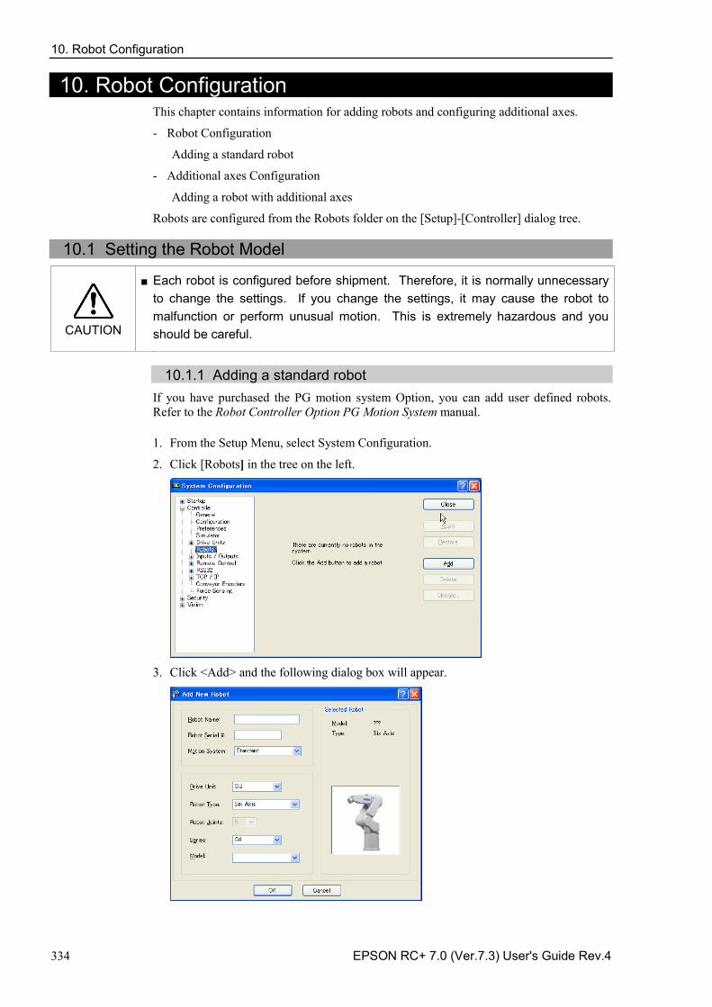
10. Robot Configuration
334 EPSON RC+ 7.0 (Ver.7.3) User's Guide Rev.4
10. Robot Configuration This chapter contains information for adding robots and configuring additional axes.
Robot Configuration -
Adding a standard robot
Additional axes Configuration -
Adding a robot with additional axes
Robots are configured from the Robots folder on the [Setup]-[Controller] dialog tree.
10.1 Setting the Robot Model
CAUTION
■ Each robot is configured before shipment. Therefore, it is normally unnecessary to change the settings. If you change the settings, it may cause the robot to malfunction or perform unusual motion. This is extremely hazardous and you should be careful.
10.1.1 Adding a standard robot
If you have purchased the PG motion system Option, you can add user defined robots. Refer to the Robot Controller Option PG Motion System manual.
1. From the Setup Menu, select System Configuration.
2. Click [Robots] in the tree on the left.
3. Click <Add> and the following dialog box will appear.
10. Robot Configuration
EPSON RC+ 7.0 (Ver.7.3) User's Guide Rev.4 335
4. Type in a name for the new manipulator and enter the serial number on the manipulator’s nameplate. Any serial number can be used, but it is recommended that you use the number that is stamped on the manipulator.
5. Select a motion system to use from the [Motion System] dropdown list. If there are no other motion systems installed, then “Standard” will already be selected.
6. Select a Drive Unit for your manipulator from the [Drive Unit] dropdown list.
7. Select a manipulator type from the [Robot type] box.
8. Select a manipulator series from the [Series] dropdown list.
9. Select a manipulator model from the [Model] dropdown list. After you select a manipulator model, all manipulators available for the type of motor driver currently installed in the controller will be displayed. If you use [Dry run], all robots selected in step 9 will be shown.
10. Click <OK> and the controller will be rebooted.
10.1.2 Calibrating a standard robot
The calibration method differs according to the manipulator model.
For details, refer to the Manipulator manual: Maintenance section: Calibration.
10.1.3 Changing robot system parameters
The following system parameters for the robot can be changed from EPSON RC+ 7.0:
Enable/Disable Joints -You can disable one or more joints from [Setup]-[System Configuration]-[Robots]-[Robot**]-[Configuration]. On robots with a ball screw Z axis, you must disable both joints 3 and 4 together.
Hofs -Hofs are the joint home offsets. You can view and edit the values from [System Configuration]-[Robots]-[Robot**]-[Calibration]. However, it is recommended that you use the Robot Calibration wizard to set these values. These values are unique for each robot and are supplied from the factory. Hofs are especially important for SCARA robots because the values determine that both lefty and righty hand orientation will position the robot at the same point.
CalPls -CalPls values are joint calibration offsets. You can view and edit the values from [System Configuration]-[Robots]-[Robot**]-[Calibration]. However, it is recommended that you use the Robot Calibration wizard to set these values. These values are unique for each robot and are supplied from the factory. CalPls values are used to calibrate joint position after replacing a motor or encoder.
These are one-time settings for each robot. Additional robot parameters can be set from the Robot Manager.
To change robot parameters, follow these steps:
1. Select [System Configuration] from the [Setup Menu].
2. Under the [Robot] folder in the tree on the left, select [Robot**]-[Calibration].
3. Execute the calibration wizard or change values for Hofs or CalPls.
4. Click <Apply> to make the changes permanent.
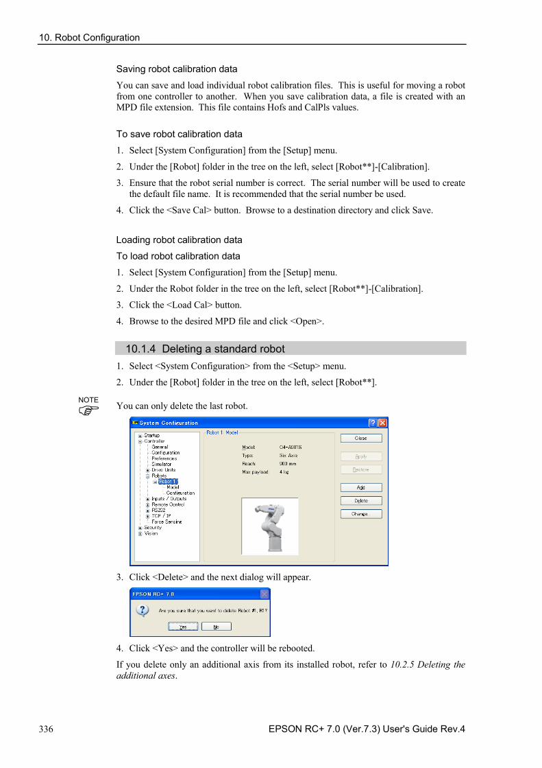
10. Robot Configuration
336 EPSON RC+ 7.0 (Ver.7.3) User's Guide Rev.4
Saving robot calibration data
You can save and load individual robot calibration files. This is useful for moving a robot from one controller to another. When you save calibration data, a file is created with an MPD file extension. This file contains Hofs and CalPls values.
To save robot calibration data
1. Select [System Configuration] from the [Setup] menu.
2. Under the [Robot] folder in the tree on the left, select [Robot**]-[Calibration].
3. Ensure that the robot serial number is correct. The serial number will be used to create the default file name. It is recommended that the serial number be used.
4. Click the <Save Cal> button. Browse to a destination directory and click Save.
Loading robot calibration data
To load robot calibration data
1. Select [System Configuration] from the [Setup] menu.
2. Under the Robot folder in the tree on the left, select [Robot**]-[Calibration].
3. Click the <Load Cal> button.
4. Browse to the desired MPD file and click <Open>.
10.1.4 Deleting a standard robot 1. Select <System Configuration> from the <Setup> menu.
2. Under the [Robot] folder in the tree on the left, select [Robot**].
You can only delete the last robot.
3. Click <Delete> and the next dialog will appear.
4. Click <Yes> and the controller will be rebooted.
If you delete only an additional axis from its installed robot, refer to 10.2.5 Deleting the additional axes.
NOTE
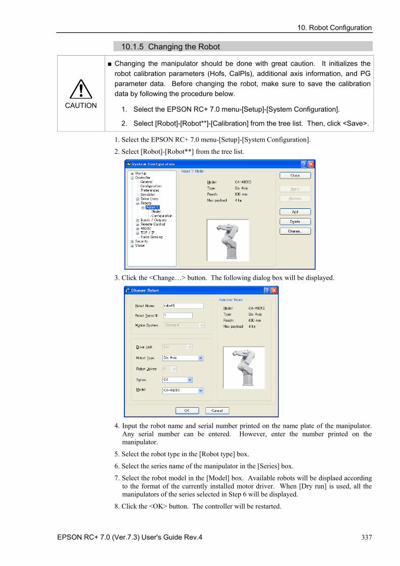
10. Robot Configuration
EPSON RC+ 7.0 (Ver.7.3) User's Guide Rev.4 337
10.1.5 Changing the Robot
CAUTION
■ Changing the manipulator should be done with great caution. It initializes the robot calibration parameters (Hofs, CalPls), additional axis information, and PG parameter data. Before changing the robot, make sure to save the calibration data by following the procedure below.
1. Select the EPSON RC+ 7.0 menu-[Setup]-[System Configuration].
2. Select [Robot]-[Robot**]-[Calibration] from the tree list. Then, click <Save>.
1. Select the EPSON RC+ 7.0 menu-[Setup]-[System Configuration].
2. Select [Robot]-[Robot**] from the tree list.
3. Click the <Change…> button. The following dialog box will be displayed.
4. Input the robot name and serial number printed on the name plate of the manipulator.
Any serial number can be entered. However, enter the number printed on the manipulator.
5. Select the robot type in the [Robot type] box.
6. Select the series name of the manipulator in the [Series] box.
7. Select the robot model in the [Model] box. Available robots will be displaed according to the format of the currently installed motor driver. When [Dry run] is used, all the manipulators of the series selected in Step 6 will be displayed.
8. Click the <OK> button. The controller will be restarted.
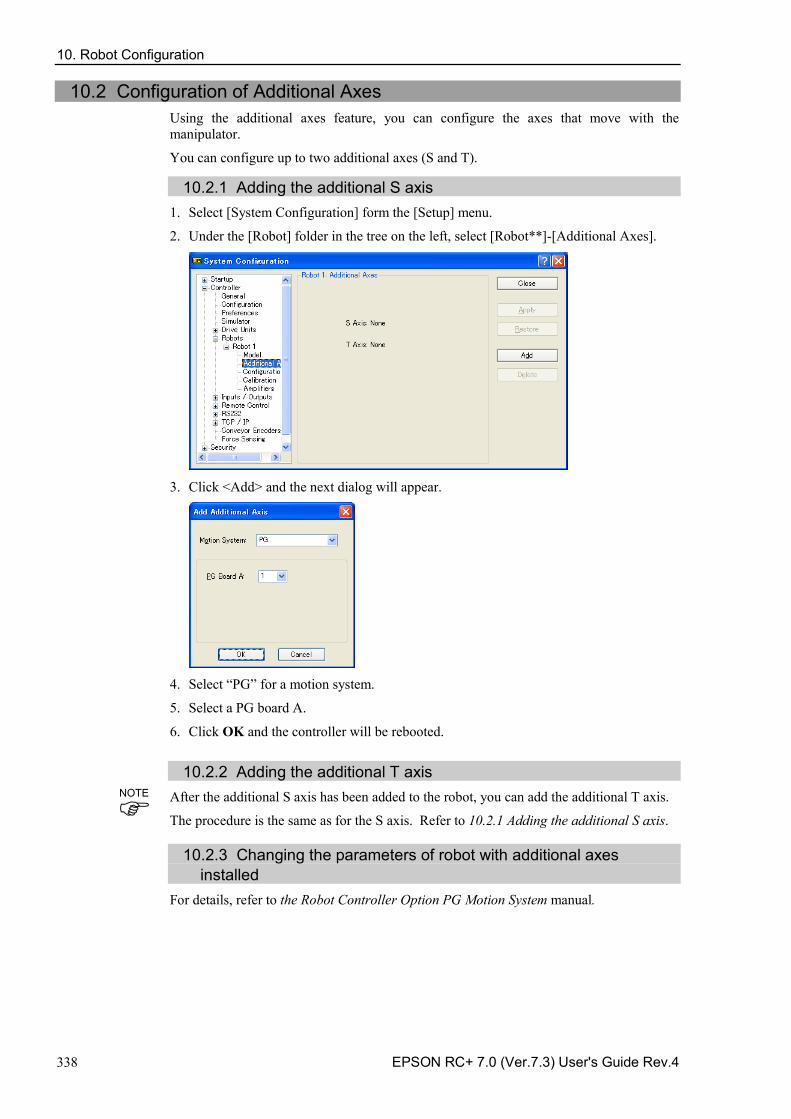
10. Robot Configuration
338 EPSON RC+ 7.0 (Ver.7.3) User's Guide Rev.4
10.2 Configuration of Additional Axes Using the additional axes feature, you can configure the axes that move with the manipulator.
You can configure up to two additional axes (S and T).
10.2.1 Adding the additional S axis 1. Select [System Configuration] form the [Setup] menu.
2. Under the [Robot] folder in the tree on the left, select [Robot**]-[Additional Axes].
3. Click <Add> and the next dialog will appear.
4. Select “PG” for a motion system.
5. Select a PG board A.
6. Click OK and the controller will be rebooted.
10.2.2 Adding the additional T axis After the additional S axis has been added to the robot, you can add the additional T axis.
The procedure is the same as for the S axis. Refer to 10.2.1 Adding the additional S axis.
10.2.3 Changing the parameters of robot with additional axes installed For details, refer to the Robot Controller Option PG Motion System manual.
NOTE
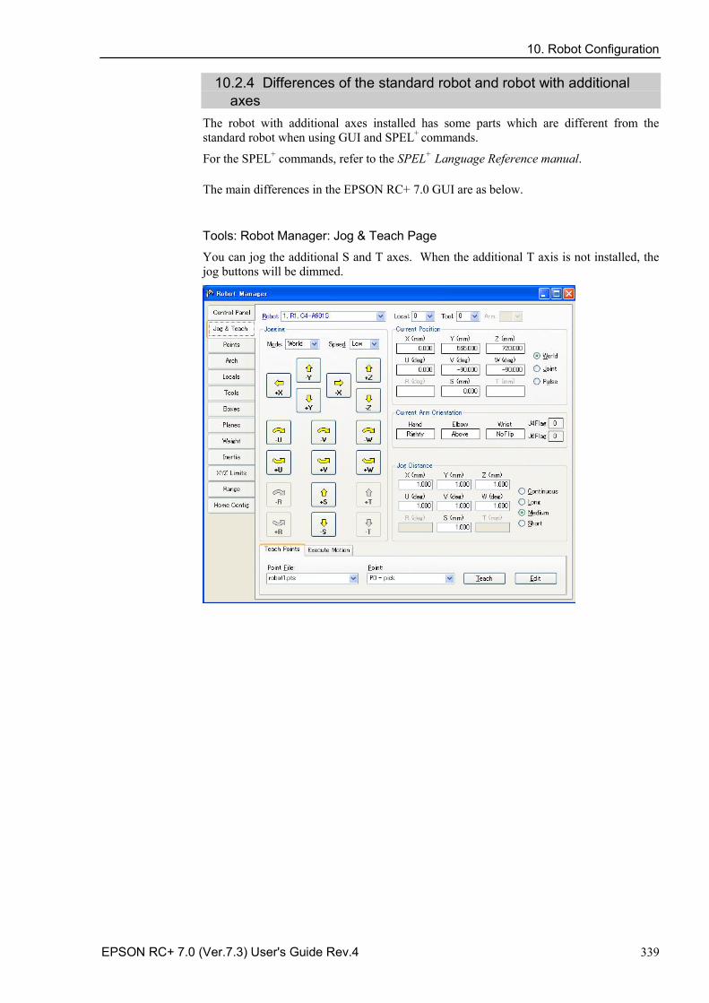
10. Robot Configuration
EPSON RC+ 7.0 (Ver.7.3) User's Guide Rev.4 339
10.2.4 Differences of the standard robot and robot with additional axes The robot with additional axes installed has some parts which are different from the standard robot when using GUI and SPEL+ commands.
For the SPEL+ commands, refer to the SPEL+ Language Reference manual.
The main differences in the EPSON RC+ 7.0 GUI are as below.
Tools: Robot Manager: Jog & Teach Page
You can jog the additional S and T axes. When the additional T axis is not installed, the jog buttons will be dimmed.
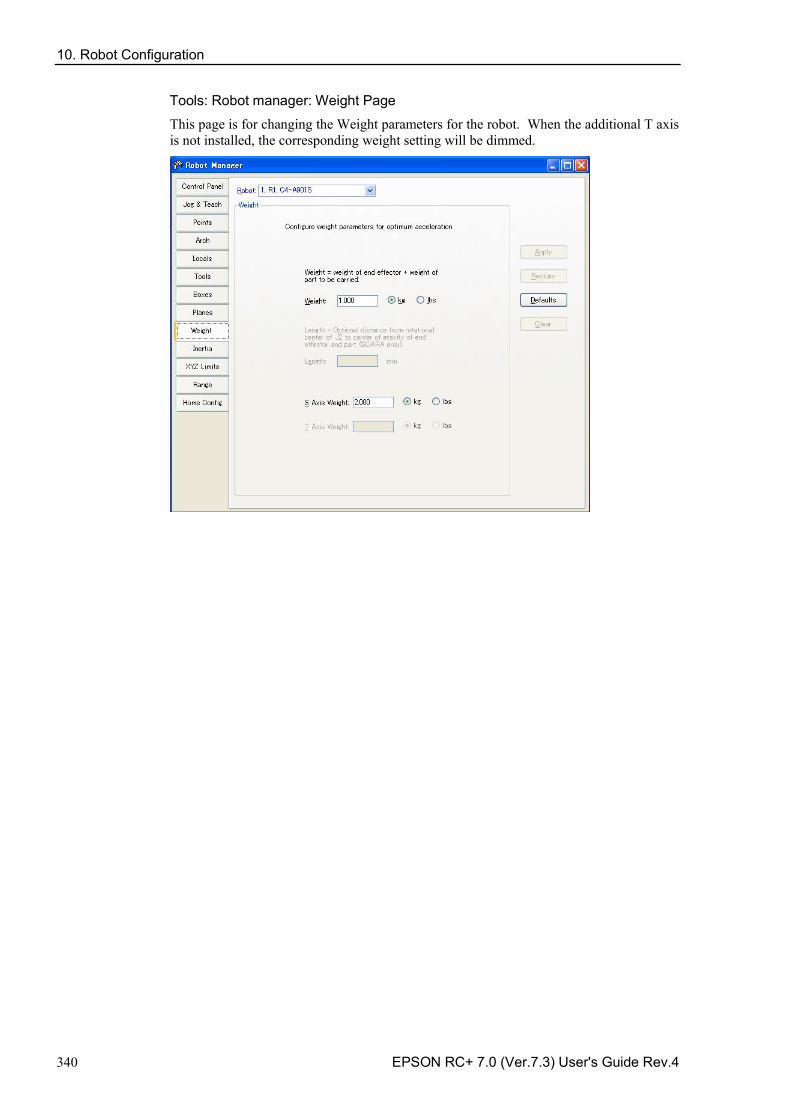
10. Robot Configuration
340 EPSON RC+ 7.0 (Ver.7.3) User's Guide Rev.4
Tools: Robot manager: Weight Page
This page is for changing the Weight parameters for the robot. When the additional T axis is not installed, the corresponding weight setting will be dimmed.
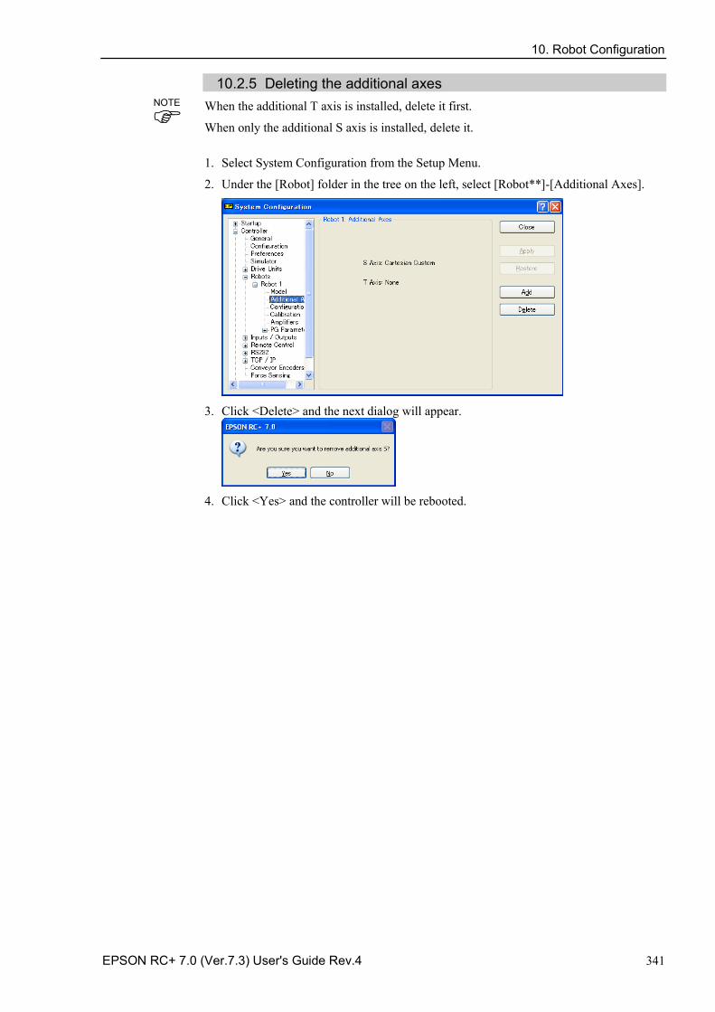
10. Robot Configuration
EPSON RC+ 7.0 (Ver.7.3) User's Guide Rev.4 341
10.2.5 Deleting the additional axes When the additional T axis is installed, delete it first.
When only the additional S axis is installed, delete it.
1. Select System Configuration from the Setup Menu.
2. Under the [Robot] folder in the tree on the left, select [Robot**]-[Additional Axes].
3. Click <Delete> and the next dialog will appear.
4. Click <Yes> and the controller will be rebooted.
NOTE
11. Inputs and Outputs
342 EPSON RC+ 7.0 (Ver.7.3) User's Guide Rev.4
11. Inputs and Outputs
11.1 Overview The controller I/O has the following types of I/O:
Standard I/O This digital I/O comes standard with the controller.
Expansion I/O This is optional digital I/O that can be added to the controller to expand standard I/O. Up to four boards can be added, each with 24 inputs and 16 outputs.
Fieldbus master I/O An optional board for the controller to expand the standard I/O. You can add one of the following boards which support the fieldbus master board: DeviceNet, EtherNet/IP, PROFIBUS-DP
Fieldbus slave I/O An optional board for the controller to expand the standard I/O. You can add one of the following boards which support the Fieldbus slave mode: DeviceNet, EtherNet/IP, PROFIBUS-DP, CC-Link, PROFINET, EtherCAT
Memory I/O This is built-in memory bits that can be used for inter-task communications.
Analog I/O This is option to add analog input/output function to the controller.
For Standard, Expansion, Fieldbus master, and Fieldbus slave I/O, there are input bits numbered starting with 0, and output bits numbered starting with 0.
For memory I/O, each memory bit is both an input and an output. For specifications and instructions on wiring I/O, refer to the Robot Controller manual.
11.2 I/O Commands The SPEL+ language has several commands for inputs and outputs listed below. For details on each command, see the SPEL+ Language Reference. Input Commands In Reads one byte of input bits. InBCD Reads one byte of input bits in Binary Coded Decimal format. InW Reads one word of input bits. Oport Reads one output bit. Sw Reads one input bit. Output Commands Off Turns off one output bit with optional time. On Turns on one output bit with optional time. OpBCD Sets one byte of output bits in Binary Coded Decimal format. Out Sets / reads one byte of output bits. OutW Sets / reads one word of output bits. Memory I/O Commands MemOff Turns off one memory bit. MemOn Turns on one memory bit. MemOut Sets / reads one byte of memory bits. MemSw Reads one bit of memory.
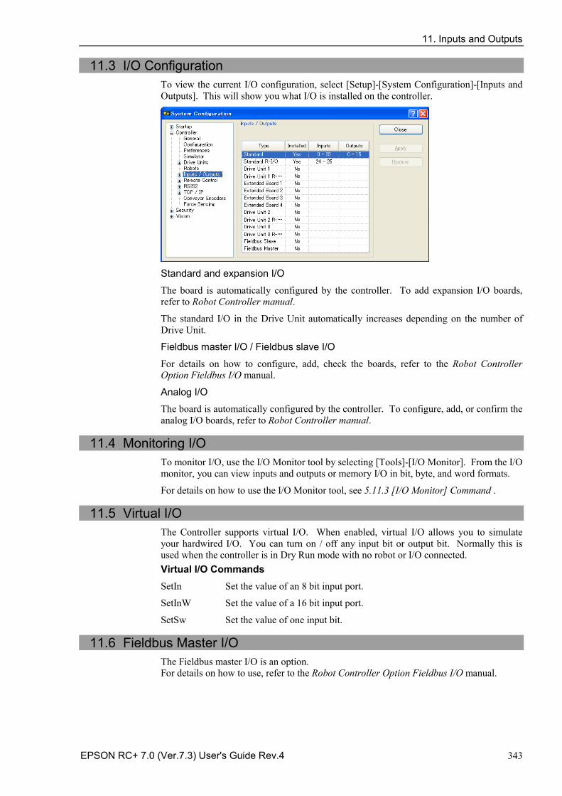
11. Inputs and Outputs
EPSON RC+ 7.0 (Ver.7.3) User's Guide Rev.4 343
11.3 I/O Configuration To view the current I/O configuration, select [Setup]-[System Configuration]-[Inputs and Outputs]. This will show you what I/O is installed on the controller.
Standard and expansion I/O
The board is automatically configured by the controller. To add expansion I/O boards, refer to Robot Controller manual.
The standard I/O in the Drive Unit automatically increases depending on the number of Drive Unit.
Fieldbus master I/O / Fieldbus slave I/O
For details on how to configure, add, check the boards, refer to the Robot Controller Option Fieldbus I/O manual.
Analog I/O
The board is automatically configured by the controller. To configure, add, or confirm the analog I/O boards, refer to Robot Controller manual.
11.4 Monitoring I/O
To monitor I/O, use the I/O Monitor tool by selecting [Tools]-[I/O Monitor]. From the I/O monitor, you can view inputs and outputs or memory I/O in bit, byte, and word formats.
For details on how to use the I/O Monitor tool, see 5.11.3 [I/O Monitor] Command .
11.5 Virtual I/O The Controller supports virtual I/O. When enabled, virtual I/O allows you to simulate your hardwired I/O. You can turn on / off any input bit or output bit. Normally this is used when the controller is in Dry Run mode with no robot or I/O connected. Virtual I/O Commands SetIn Set the value of an 8 bit input port.
SetInW Set the value of a 16 bit input port.
SetSw Set the value of one input bit.
11.6 Fieldbus Master I/O The Fieldbus master I/O is an option. For details on how to use, refer to the Robot Controller Option Fieldbus I/O manual.
11. Inputs and Outputs
344 EPSON RC+ 7.0 (Ver.7.3) User's Guide Rev.4
11.7 Fieldbus Slave I/O The Fieldbus slave I/O includes the standard functions (ModBusRTU and ModBusTCP), and the options.
For types and usage of the optional Fieldbus slaves, refer to the Robot Controller option Fieldbus I/O manual.
11.7.1. ModBus Slave
ModBus TCP and ModBus RTU can be used as the Fieldbus slave I/O as standard.
ModBus cannot be used when other Fieldbus slave boards are installed.
ModBus is a protocol which has a dialect. Although connection with the standard ModBus protocol has been confirmed, use the ModBus slave in the system after checking connectivity with equipment to be connected.
11.7.2. Supported Functions
The Controller supports following ModBus functions.
Function code Function name Description
1 Read Coil Status Use this function to read the status of the input bit port. No broadcast.
2 Read Input Status Use this function to read the status of the output bit port. No broadcast.
3 Read Holding Registers Use this function to read the status of the input word port. No broadcast.
4 Read Input Registers Use this function to read the status of the output word port. No broadcast.
5 Force Single Coil Use this function to configure an input bit port. 6 Preset Single Register Use this function to configure an input word port. 15 Force Multiple Coils Use this function to configure several input bit ports. 16 Preset Multiple Registers Use this function to configure several input word port.
NOTE
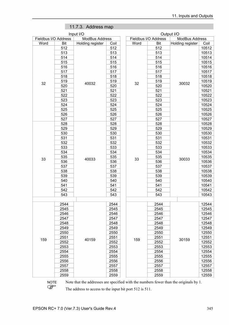
11. Inputs and Outputs
EPSON RC+ 7.0 (Ver.7.3) User's Guide Rev.4 345
11.7.3. Address map Input I/O Output I/O
Fieldbus I/O Address ModBus Address Fieldbus I/O Address ModBus Address Word Bit Holding register Coil Word Bit Holding register Coil
32
512
40032
512
32
512
30032
10512 513 513 513 10513 514 514 514 10514 515 515 515 10515 516 516 516 10516 517 517 517 10517 518 518 518 10518 519 519 519 10519 520 520 520 10520 521 521 521 10521 522 522 522 10522 523 523 523 10523 524 524 524 10524 525 525 525 10525 526 526 526 10526 527 527 527 10527
33
528
40033
528
33
528
30033
10528 529 529 529 10529 530 530 530 10530 531 531 531 10531 532 532 532 10532 533 533 533 10533 534 534 534 10534 535 535 535 10535 536 536 536 10536 537 537 537 10537 538 538 538 10538 539 539 539 10539 540 540 540 10540 541 541 541 10541 542 542 542 10542 543 543 543 10543
159
2544
40159
2544
159
2544
30159
12544 2545 2545 2545 12545 2546 2546 2546 12546 2547 2547 2547 12547 2548 2548 2548 12548 2549 2549 2549 12549 2550 2550 2550 12550 2551 2551 2551 12551 2552 2552 2552 12552 2553 2553 2553 12553 2554 2554 2554 12554 2555 2555 2555 12555 2556 2556 2556 12556 2557 2557 2557 12557 2558 2558 2558 12558 2559 2559 2559 12559
Note that the addresses are specified with the numbers fewer than the originals by 1.
The address to access to the input bit port 512 is 511.
NOTE
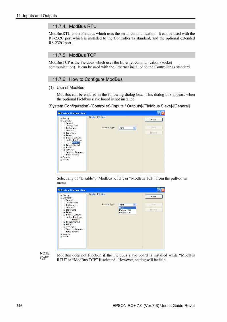
11. Inputs and Outputs
346 EPSON RC+ 7.0 (Ver.7.3) User's Guide Rev.4
11.7.4. ModBus RTU ModBusRTU is the Fieldbus which uses the serial communication. It can be used with the RS-232C port which is installed to the Controller as standard, and the optional extended RS-232C port.
11.7.5. ModBus TCP
ModBusTCP is the Fieldbus which uses the Ethernet communication (socket communication). It can be used with the Ethernet installed to the Controller as standard.
11.7.6. How to Configure ModBus
(1) Use of ModBus
ModBus can be enabled in the following dialog box. This dialog box appears when the optional Fieldbus slave board is not installed.
[System Configuration]-[Controller]-[Inputs / Outputs]-[Fieldbus Slave]-[General]
Select any of “Disable”, “ModBus RTU”, or “ModBus TCP” from the pull-down menu.
ModBus does not function if the Fieldbus slave board is installed while “ModBus RTU” or “ModBus TCP” is selected. However, setting will be held.
NOTE
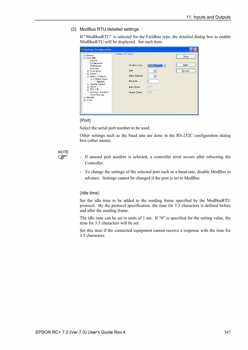
11. Inputs and Outputs
EPSON RC+ 7.0 (Ver.7.3) User's Guide Rev.4 347
(2) ModBus RTU detailed settings
If “ModBusRTU” is selected for the Fieldbus type, the detailed dialog box to enable ModBusRTU will be displayed. Set each item.
[Port]
Select the serial port number to be used.
Other settings such as the baud rate are done in the RS-232C configuration dialog box (other menu).
- If unused port number is selected, a controller error occurs after rebooting the Controller.
- To change the settings of the selected port such as a baud rate, disable ModBus in advance. Settings cannot be changed if the port is set to ModBus.
[Idle time]
Set the idle time to be added to the sending frame specified by the ModBusRTU protocol. By the protocol specification, the time for 3.5 characters is defined before and after the sending frame.
The idle time can be set in units of 1 ms. If “0” is specified for the setting value, the time for 3.5 characters will be set.
Set this item if the connected equipment cannot receive a response with the time for 3.5 characters.
NOTE
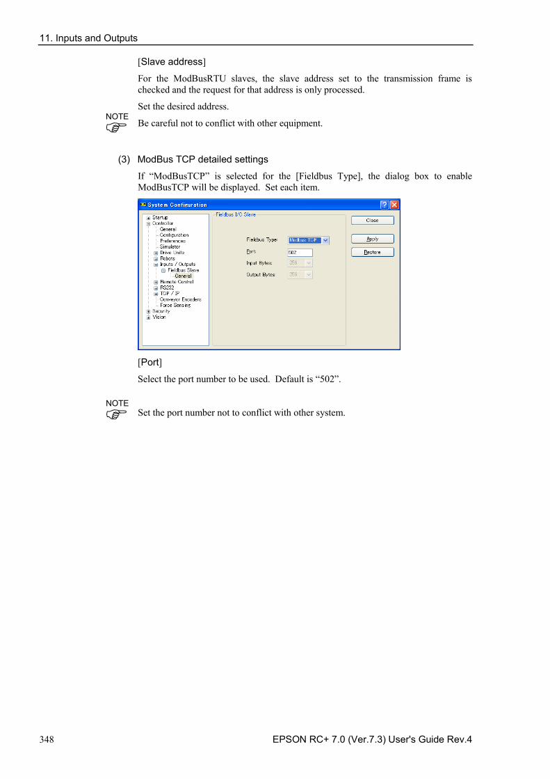
11. Inputs and Outputs
348 EPSON RC+ 7.0 (Ver.7.3) User's Guide Rev.4
[Slave address]
For the ModBusRTU slaves, the slave address set to the transmission frame is checked and the request for that address is only processed.
Set the desired address.
Be careful not to conflict with other equipment.
(3) ModBus TCP detailed settings
If “ModBusTCP” is selected for the [Fieldbus Type], the dialog box to enable ModBusTCP will be displayed. Set each item.
[Port]
Select the port number to be used. Default is “502”.
Set the port number not to conflict with other system.
NOTE
NOTE
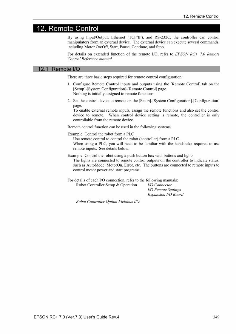
12. Remote Control
EPSON RC+ 7.0 (Ver.7.3) User's Guide Rev.4 349
12. Remote Control By using Input/Output, Ethernet (TCP/IP), and RS-232C, the controller can control manipulators from an external device. The external device can execute several commands, including Motor On/Off, Start, Pause, Continue, and Stop.
For details on extended function of the remote I/O, refer to EPSON RC+ 7.0 Remote Control Reference manual.
12.1 Remote I/O
There are three basic steps required for remote control configuration:
1. Configure Remote Control inputs and outputs using the [Remote Control] tab on the [Setup]-[System Configuration]-[Remote Control] page. Nothing is initially assigned to remote functions.
2. Set the control device to remote on the [Setup]-[System Configuration]-[Configuration] page. To enable external remote inputs, assign the remote functions and also set the control device to remote. When control device setting is remote, the controller is only controllable from the remote device.
Remote control function can be used in the following systems.
Example: Control the robot from a PLC Use remote control to control the robot (controller) from a PLC. When using a PLC, you will need to be familiar with the handshake required to use remote inputs. See details below.
Example: Control the robot using a push button box with buttons and lights The lights are connected to remote control outputs on the controller to indicate status, such as AutoMode, MotorOn, Error, etc. The buttons are connected to remote inputs to control motor power and start programs.
For details of each I/O connection, refer to the following manuals: Robot Controller Setup & Operation I/O Connector
I/O Remote Settings Expansion I/O Board
Robot Controller Option Fieldbus I/O
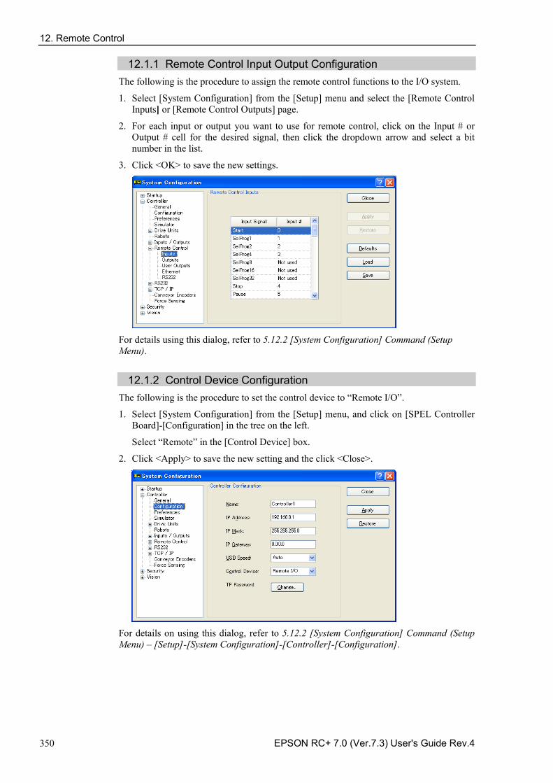
12. Remote Control
350 EPSON RC+ 7.0 (Ver.7.3) User's Guide Rev.4
12.1.1 Remote Control Input Output Configuration The following is the procedure to assign the remote control functions to the I/O system.
1. Select [System Configuration] from the [Setup] menu and select the [Remote Control Inputs] or [Remote Control Outputs] page.
2. For each input or output you want to use for remote control, click on the Input # or Output # cell for the desired signal, then click the dropdown arrow and select a bit number in the list.
3. Click <OK> to save the new settings.
For details using this dialog, refer to 5.12.2 [System Configuration] Command (Setup Menu).
12.1.2 Control Device Configuration The following is the procedure to set the control device to “Remote I/O”.
1. Select [System Configuration] from the [Setup] menu, and click on [SPEL Controller Board]-[Configuration] in the tree on the left.
Select “Remote” in the [Control Device] box.
2. Click <Apply> to save the new setting and the click <Close>.
For details on using this dialog, refer to 5.12.2 [System Configuration] Command (Setup Menu) – [Setup]-[System Configuration]-[Controller]-[Configuration].
12. Remote Control
EPSON RC+ 7.0 (Ver.7.3) User's Guide Rev.4 351
12.1.3 Auto Mode with Remote Control
To run in auto cycle with remote control
1. The host device (e.g. PLC) should wait for the AutoMode or Ready remote output to turn on before issuing remote commands.
2. Now the remote input commands will be accepted.
To monitor remote operation from the EPSON RC+ 7.0 Operator Window
1. Set the EPSON RC+ 7.0 Start Up Mode to “Auto”. For details, refer to 4.2.3 Start Mode.
2. The PC should also be configured to automatically log into Windows and start EPSON RC+ 7.0 at Windows start. Refer to 4.2.7 Auto Start.
12.1.4 Teach Mode with Remote Control
When using a remote control with Teach Mode ON, no remote input commands can be used. Remote status outputs will still operate.
WARNING
■ Remote status outputs (such as MotorOn, Home, etc.) will operate when Teach Mode is ON, even when the enable switch (dead man’s switch) is disengaged. Therefore, DO NOT use remote status outputs to drive any devices that cause motion or any other safety hazard.
You can monitor teach mode status using the TeachMode remote output.
12.1.5 Debugging Remote Control
You can debug programs using Remote Control from the EPSON RC+ 7.0 development environment.
To run programs by remote control for debugging:
1. Create a program (in the same manner as usual).
2. Open the Run Window and click Enable Remote I/O.
3. Now the remote commands will be accepted.
You can set breakpoints and print messages to the Run window.
If you cannot wire the I/O, use virtual I/O mode for debugging. Remote function is also available when virtual I/O is enabled.
NOTE
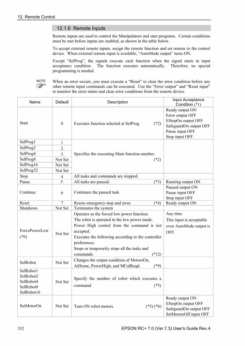
12. Remote Control
352 EPSON RC+ 7.0 (Ver.7.3) User's Guide Rev.4
12.1.6 Remote Inputs Remote inputs are used to control the Manipulators and start programs. Certain conditions must be met before inputs are enabled, as shown in the table below.
To accept external remote inputs, assign the remote function and set remote to the control device. When external remote input is available, “AutoMode output” turns ON.
Except “SelProg”, the signals execute each function when the signal starts in input acceptance condition. The function executes automatically. Therefore, no special programming is needed. When an error occurs, you must execute a “Reset” to clear the error condition before any other remote input commands can be executed. Use the “Error output” and “Reset input” to monitor the error status and clear error conditions from the remote device.
Name Default Description Input Acceptance Condition (*1)
Start 0 Executes function selected at SelProg. (*2)
Ready output ON Error output OFF EStopOn output OFF SafeguardOn output OFF Pause input OFF Stop input OFF
SelProg1 1
Specifies the executing Main function number. (*2)
SelProg2 2 SelProg4 3 SelProg8 Not Set SelProg16 Not Set SelProg32 Not Set Stop 4 All tasks and commands are stopped. Pause 5 All tasks are paused. (*3) Running output ON
Continue 6 Continues the paused task. Paused output ON Pause input OFF Stop input OFF
Reset 7 Resets emergency stop and error. (*4) Ready output ON Shutdown Not Set Terminates the system
ForcePowerLow (*6)
Not Set
Operates as the forced low power function. The robot is operated in the low power mode. Power High control from the command is not accepted. Executes the following according to the controller preferences. Stops or temporarily stops all the tasks and commands. (*12)
Any time This input is acceptable even AutoMode output is OFF.
SelRobot Not Set Changes the output condition of MotorsOn, AtHome, PowerHigh, and MCalReqd. (*9)
SelRobot1 SelRobot2 SelRobot4 SelRobot8 SelRobot16
Not Set Specify the number of robot which executes a command. (*5)
SetMotorOn Not Set Turn ON robot motors. (*5) (*6)
Ready output ON EStopOn output OFF SafeguardOn output OFF SetMotorsOff input OFF
NOTE
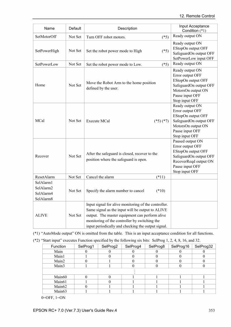
12. Remote Control
EPSON RC+ 7.0 (Ver.7.3) User's Guide Rev.4 353
Name Default Description Input Acceptance Condition (*1)
SetMotorOff Not Set Turn OFF robot motors. (*5) Ready output ON
SetPowerHigh Not Set Set the robot power mode to High (*5)
Ready output ON EStopOn output OFF SafeguardOn output OFF SetPowerLow input OFF
SetPowerLow Not Set Set the robot power mode to Low. (*5) Ready output ON
Home Not Set Move the Robot Arm to the home position defined by the user.
Ready output ON Error output OFF EStopOn output OFF SafeguardOn output OFF MotorsOn output ON Pause input OFF Stop input OFF
MCal Not Set Execute MCal (*5) (*7)
Ready output ON Error output OFF EStopOn output OFF SafeguardOn output OFF MotorsOn output ON Pause input OFF Stop input OFF
Recover Not Set After the safeguard is closed, recover to the position where the safeguard is open.
Paused output ON Error output OFF EStopOn output OFF SafeguardOn output OFF RecoverReqd output ON Pause input OFF Stop input OFF
ResetAlarm Not Set Cancel the alarm (*11) SelAlarm1 SelAlarm2 SelAlarm4 SelAlarm8
Not Set Specify the alarm number to cancel (*10)
ALIVE Not Set
Input signal for alive monitoring of the controller. Same signal as the input will be output to ALIVE output. The master equipment can perform alive monitoring of the controller by switching the input periodically and checking the output signal.
(*1) “AutoMode output” ON is omitted from the table. This is an input acceptance condition for all functions.
(*2) “Start input” executes Function specified by the following six bits: SelProg 1, 2, 4, 8, 16, and 32. Function SelProg1 SelProg2 SelProg4 SelProg8 SelProg16 SelProg32
Main 0 0 0 0 0 0 Main1 1 0 0 0 0 0 Main2 0 1 0 0 0 0 Main3 1 1 0 0 0 0 . . . Main60 0 0 1 1 1 1 Main61 1 0 1 1 1 1 Main62 0 1 1 1 1 1 Main63 1 1 1 1 1 1
0=OFF, 1=ON
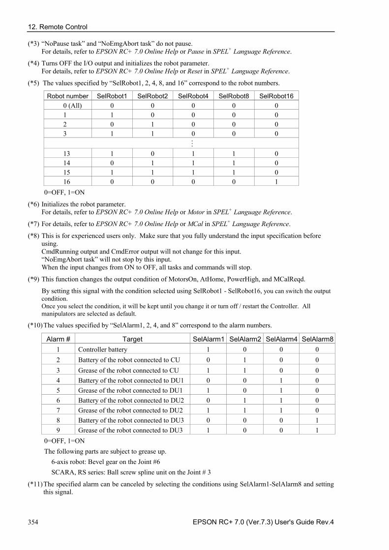
12. Remote Control
354 EPSON RC+ 7.0 (Ver.7.3) User's Guide Rev.4
(*3) “NoPause task” and “NoEmgAbort task” do not pause. For details, refer to EPSON RC+ 7.0 Online Help or Pause in SPEL+ Language Reference.
(*4) Turns OFF the I/O output and initializes the robot parameter. For details, refer to EPSON RC+ 7.0 Online Help or Reset in SPEL+ Language Reference.
(*5) The values specified by “SelRobot1, 2, 4, 8, and 16” correspond to the robot numbers.
Robot number SelRobot1 SelRobot2 SelRobot4 SelRobot8 SelRobot16 0 (All) 0 0 0 0 0 1 1 0 0 0 0 2 0 1 0 0 0 3 1 1 0 0 0 . . . 13 1 0 1 1 0 14 0 1 1 1 0 15 1 1 1 1 0 16 0 0 0 0 1
0=OFF, 1=ON
(*6) Initializes the robot parameter. For details, refer to EPSON RC+ 7.0 Online Help or Motor in SPEL+ Language Reference.
(*7) For details, refer to EPSON RC+ 7.0 Online Help or MCal in SPEL+ Language Reference.
(*8) This is for experienced users only. Make sure that you fully understand the input specification before using. CmdRunning output and CmdError output will not change for this input. “NoEmgAbort task” will not stop by this input. When the input changes from ON to OFF, all tasks and commands will stop.
(*9) This function changes the output condition of MotorsOn, AtHome, PowerHigh, and MCalReqd.
By setting this signal with the condition selected using SelRobot1 - SelRobot16, you can switch the output condition. Once you select the condition, it will be kept until you change it or turn off / restart the Controller. All manipulators are selected as default.
(*10) The values specified by “SelAlarm1, 2, 4, and 8” correspond to the alarm numbers.
Alarm # Target SelAlarm1 SelAlarm2 SelAlarm4 SelAlarm8 1 Controller battery 1 0 0 0 2 Battery of the robot connected to CU 0 1 0 0 3 Grease of the robot connected to CU 1 1 0 0 4 Battery of the robot connected to DU1 0 0 1 0 5 Grease of the robot connected to DU1 1 0 1 0 6 Battery of the robot connected to DU2 0 1 1 0 7 Grease of the robot connected to DU2 1 1 1 0 8 Battery of the robot connected to DU3 0 0 0 1 9 Grease of the robot connected to DU3 1 0 0 1
0=OFF, 1=ON The following parts are subject to grease up.
6-axis robot: Bevel gear on the Joint #6 SCARA, RS series: Ball screw spline unit on the Joint # 3
(*11) The specified alarm can be canceled by selecting the conditions using SelAlarm1-SelAlarm8 and setting this signal.
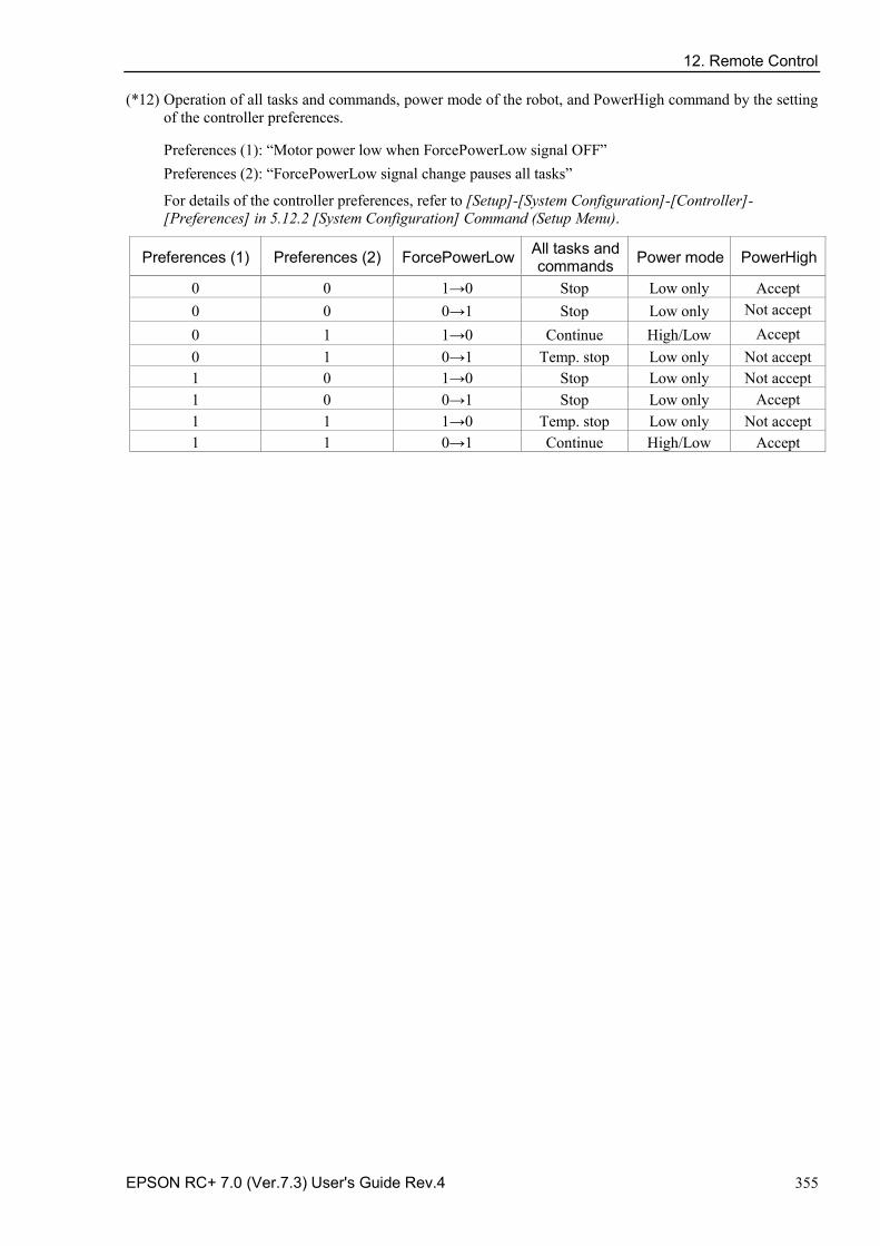
12. Remote Control
EPSON RC+ 7.0 (Ver.7.3) User's Guide Rev.4 355
(*12) Operation of all tasks and commands, power mode of the robot, and PowerHigh command by the setting of the controller preferences.
Preferences (1): “Motor power low when ForcePowerLow signal OFF” Preferences (2): “ForcePowerLow signal change pauses all tasks”
For details of the controller preferences, refer to [Setup]-[System Configuration]-[Controller]-[Preferences] in 5.12.2 [System Configuration] Command (Setup Menu).
Preferences (1) Preferences (2) ForcePowerLow All tasks and commands Power mode PowerHigh
0 0 1→0 Stop Low only Accept 0 0 0→1 Stop Low only Not accept 0 1 1→0 Continue High/Low Accept 0 1 0→1 Temp. stop Low only Not accept 1 0 1→0 Stop Low only Not accept 1 0 0→1 Stop Low only Accept 1 1 1→0 Temp. stop Low only Not accept 1 1 0→1 Continue High/Low Accept
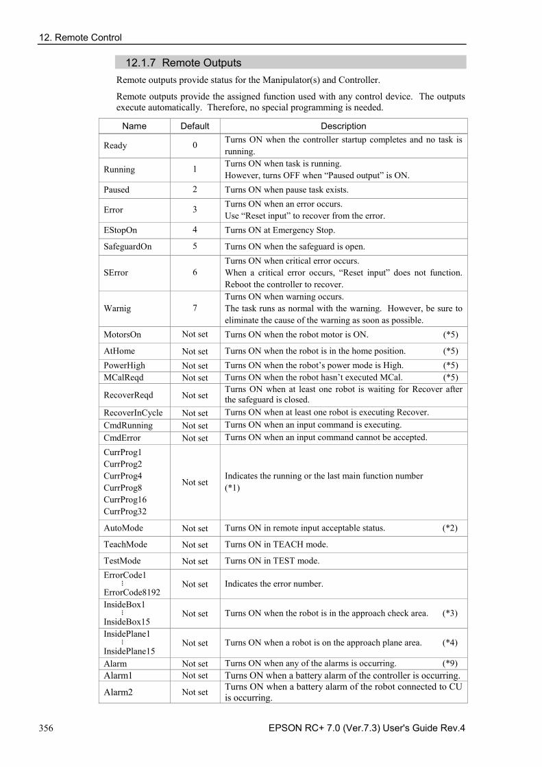
12. Remote Control
356 EPSON RC+ 7.0 (Ver.7.3) User's Guide Rev.4
12.1.7 Remote Outputs Remote outputs provide status for the Manipulator(s) and Controller.
Remote outputs provide the assigned function used with any control device. The outputs execute automatically. Therefore, no special programming is needed.
Name Default Description
Ready 0 Turns ON when the controller startup completes and no task is running.
Running 1 Turns ON when task is running. However, turns OFF when “Paused output” is ON.
Paused 2 Turns ON when pause task exists.
Error 3 Turns ON when an error occurs. Use “Reset input” to recover from the error.
EStopOn 4 Turns ON at Emergency Stop.
SafeguardOn 5 Turns ON when the safeguard is open.
SError 6 Turns ON when critical error occurs. When a critical error occurs, “Reset input” does not function. Reboot the controller to recover.
Warnig 7 Turns ON when warning occurs. The task runs as normal with the warning. However, be sure to eliminate the cause of the warning as soon as possible.
MotorsOn Not set Turns ON when the robot motor is ON. (*5)
AtHome Not set Turns ON when the robot is in the home position. (*5) PowerHigh Not set Turns ON when the robot’s power mode is High. (*5) MCalReqd Not set Turns ON when the robot hasn’t executed MCal. (*5)
RecoverReqd Not set Turns ON when at least one robot is waiting for Recover after the safeguard is closed.
RecoverInCycle Not set Turns ON when at least one robot is executing Recover. CmdRunning Not set Turns ON when an input command is executing. CmdError Not set Turns ON when an input command cannot be accepted.
CurrProg1 CurrProg2 CurrProg4 CurrProg8 CurrProg16 CurrProg32
Not set Indicates the running or the last main function number (*1)
AutoMode Not set Turns ON in remote input acceptable status. (*2)
TeachMode Not set Turns ON in TEACH mode.
TestMode Not set Turns ON in TEST mode. ErrorCode1 . . . ErrorCode8192
Not set Indicates the error number.
InsideBox1 . . . InsideBox15
Not set Turns ON when the robot is in the approach check area. (*3)
InsidePlane1 . . . InsidePlane15
Not set Turns ON when a robot is on the approach plane area. (*4)
Alarm Not set Turns ON when any of the alarms is occurring. (*9) Alarm1 Not set Turns ON when a battery alarm of the controller is occurring.
Alarm2 Not set Turns ON when a battery alarm of the robot connected to CU is occurring.
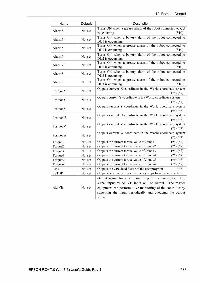
12. Remote Control
EPSON RC+ 7.0 (Ver.7.3) User's Guide Rev.4 357
Name Default Description
Alarm3 Not set Turns ON when a grease alarm of the robot connected to CU is occurring. (*10)
Alarm4 Not set Turns ON when a battery alarm of the robot connected to DU1 is occurring.
Alarm5 Not set Turns ON when a grease alarm of the robot connected to DU1 is occurring. (*10)
Alarm6 Not set Turns ON when a battery alarm of the robot connected to DU2 is occurring.
Alarm7 Not set Turns ON when a grease alarm of the robot connected to DU2 is occurring. (*10)
Alarm8 Not set Turns ON when a battery alarm of the robot connected to DU3 is occurring.
Alarm9 Not set Turns ON when a grease alarm of the robot connected to DU3 is occurring. (*10)
PositionX Not set Outputs current X coordinate in the World coordinate system (*6) (*7)
PositionY Not set Outputs current Y coordinate in the World coordinate system (*6) (*7)
PositionZ Not set Outputs current Z coordinate in the World coordinate system (*6) (*7)
PositionU Not set Outputs current U coordinate in the World coordinate system (*6) (*7)
PositionV Not set Outputs current V coordinate in the World coordinate system (*6) (*7)
PositionW Not set Outputs current W coordinate in the World coordinate system (*6) (*7)
Torque1 Not set Outputs the current torque value of Joint #1 (*6) (*7) Torque2 Not set Outputs the current torque value of Joint #2 (*6) (*7) Torque3 Not set Outputs the current torque value of Joint #3 (*6) (*7) Torque4 Not set Outputs the current torque value of Joint #4 (*6) (*7) Torque5 Not set Outputs the current torque value of Joint #5 (*6) (*7) Torque6 Not set Outputs the current torque value of Joint #6 (*6) (*7) CPU Not set Outputs the CPU load factor of the user program (*8) ESTOP Not set Outputs how many times emergency stops have been executed.
ALIVE Not set
Output signal for alive monitoring of the controller. The signal input by ALIVE input will be output. The master equipment can perform alive monitoring of the controller by switching the input periodically and checking the output signal.
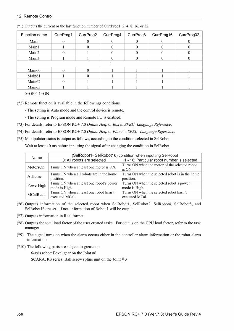
12. Remote Control
358 EPSON RC+ 7.0 (Ver.7.3) User's Guide Rev.4
(*1) Outputs the current or the last function number of CurrProg1, 2, 4, 8, 16, or 32.
Function name CurrProg1 CurrProg2 CurrProg4 CurrProg8 CurrProg16 CurrProg32
Main 0 0 0 0 0 0 Main1 1 0 0 0 0 0 Main2 0 1 0 0 0 0 Main3 1 1 0 0 0 0 . . . Main60 0 0 1 1 1 1 Main61 1 0 1 1 1 1 Main62 0 1 1 1 1 1 Main63 1 1 1 1 1 1
0=OFF, 1=ON
(*2) Remote function is available in the followings conditions.
- The setting is Auto mode and the control device is remote.
- The setting is Program mode and Remote I/O is enabled.
(*3) For details, refer to EPSON RC+ 7.0 Online Help or Box in SPEL+ Language Reference.
(*4) For details, refer to EPSON RC+ 7.0 Online Help or Plane in SPEL+ Language Reference.
(*5) Manipulator status is output as follows, according to the condition selected in SelRobot.
Wait at least 40 ms before inputting the signal after changing the condition in SelRobot.
Name (SelRobot1- SelRobot16) condition when inputting SelRobot 0: All robots are selected 1 - 16: Particular robot number is selected
MotorsOn Turns ON when at least one motor is ON. Turns ON when the motor of the selected robot is ON.
AtHome Turns ON when all robots are in the home position.
Turns ON when the selected robot is in the home position.
PowerHigh Turns ON when at least one robot’s power mode is High.
Turns ON when the selected robot’s power mode is High.
MCalReqd Turns ON when at least one robot hasn’t executed MCal.
Turns ON when the selected robot hasn’t executed MCal.
(*6) Outputs information of the selected robot when SelRobot1, SelRobot2, SelRobot4, SelRobot8, and SelRobot16 are set. If not, information of Robot 1 will be output.
(*7) Outputs information in Real format.
(*8) Outputs the total load factor of the user created tasks. For details on the CPU load factor, refer to the task manager.
(*9) The signal turns on when the alarm occurs either in the controller alarm information or the robot alarm information.
(*10) The following parts are subject to grease up. 6-axis robot: Bevel gear on the Joint #6 SCARA, RS series: Ball screw spline unit on the Joint # 3
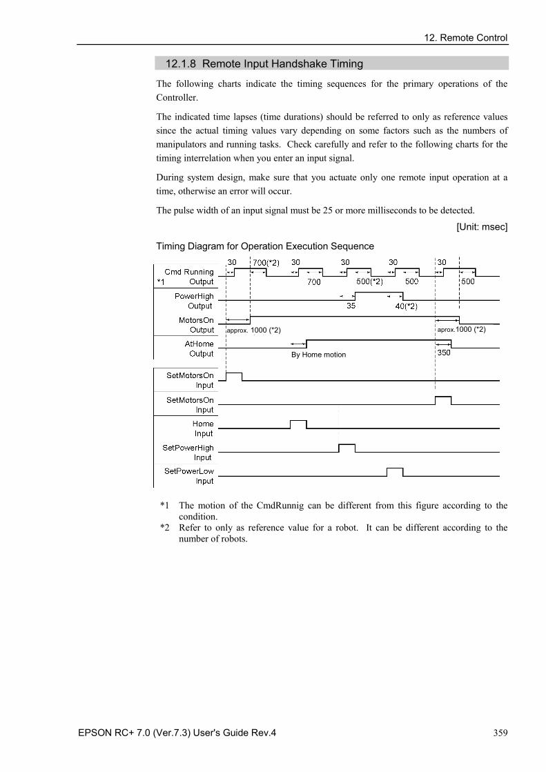
12. Remote Control
EPSON RC+ 7.0 (Ver.7.3) User's Guide Rev.4 359
12.1.8 Remote Input Handshake Timing
The following charts indicate the timing sequences for the primary operations of the Controller.
The indicated time lapses (time durations) should be referred to only as reference values since the actual timing values vary depending on some factors such as the numbers of manipulators and running tasks. Check carefully and refer to the following charts for the timing interrelation when you enter an input signal.
During system design, make sure that you actuate only one remote input operation at a time, otherwise an error will occur.
The pulse width of an input signal must be 25 or more milliseconds to be detected.
[Unit: msec]
Timing Diagram for Operation Execution Sequence
approx. 1000 (*2) aprox.1000 (*2)
By Home motion
*1 The motion of the CmdRunnig can be different from this figure according to the
condition. *2 Refer to only as reference value for a robot. It can be different according to the
number of robots.
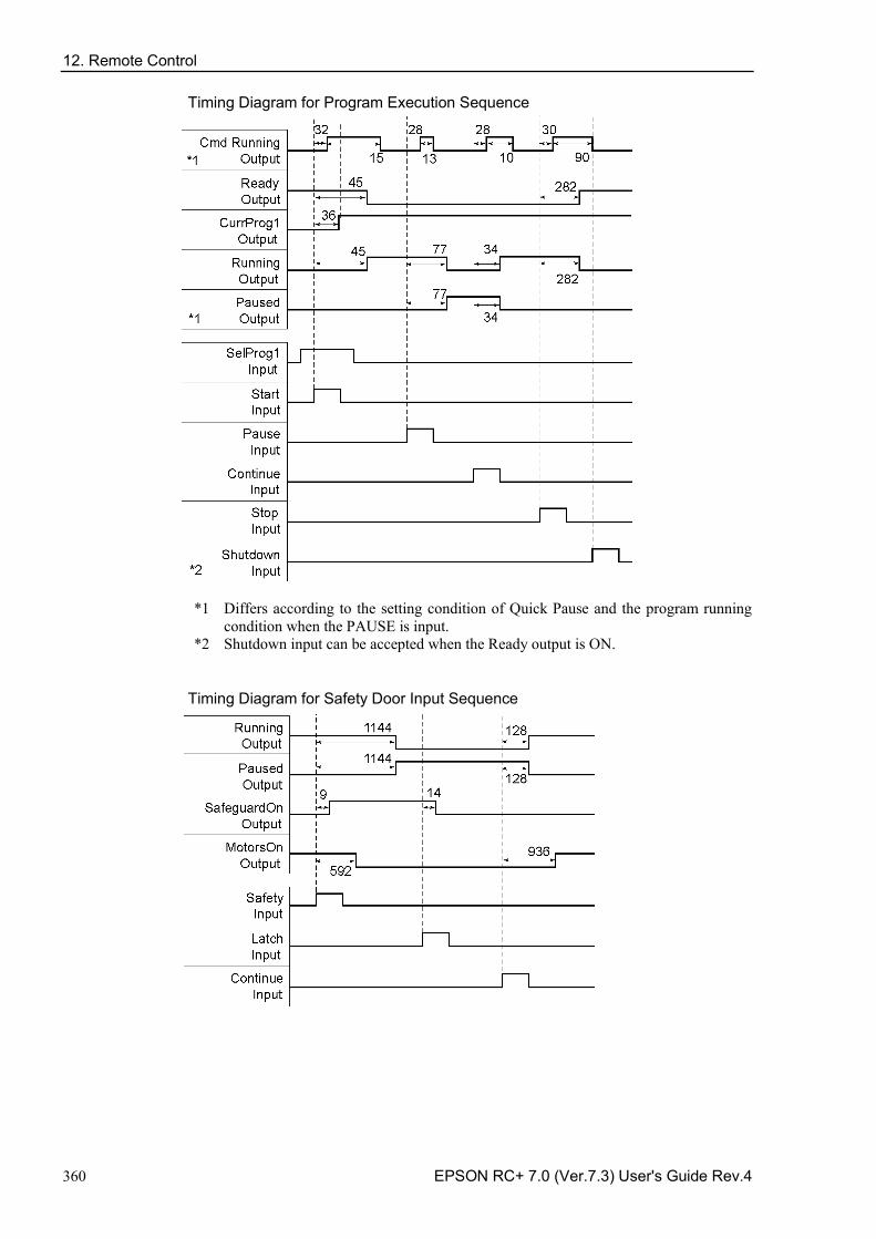
12. Remote Control
360 EPSON RC+ 7.0 (Ver.7.3) User's Guide Rev.4
Timing Diagram for Program Execution Sequence
*1 Differs according to the setting condition of Quick Pause and the program running
condition when the PAUSE is input. *2 Shutdown input can be accepted when the Ready output is ON.
Timing Diagram for Safety Door Input Sequence
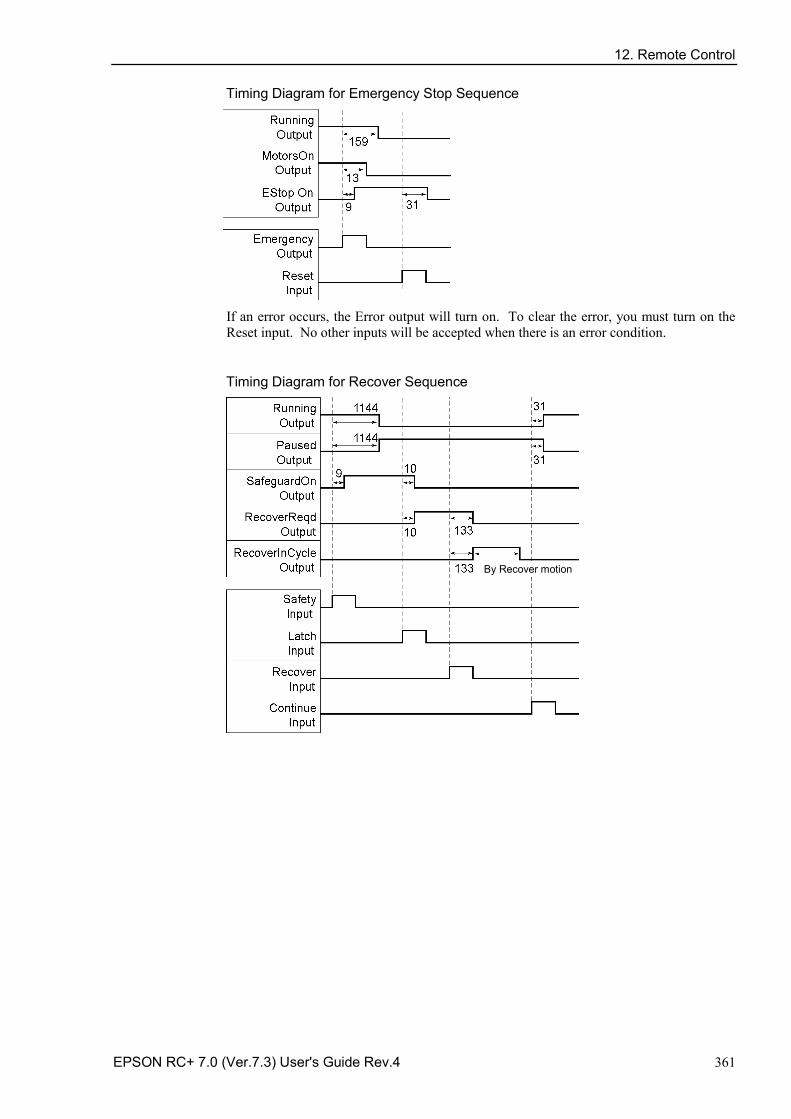
12. Remote Control
EPSON RC+ 7.0 (Ver.7.3) User's Guide Rev.4 361
Timing Diagram for Emergency Stop Sequence
If an error occurs, the Error output will turn on. To clear the error, you must turn on the Reset input. No other inputs will be accepted when there is an error condition.
Timing Diagram for Recover Sequence
By Recover motion
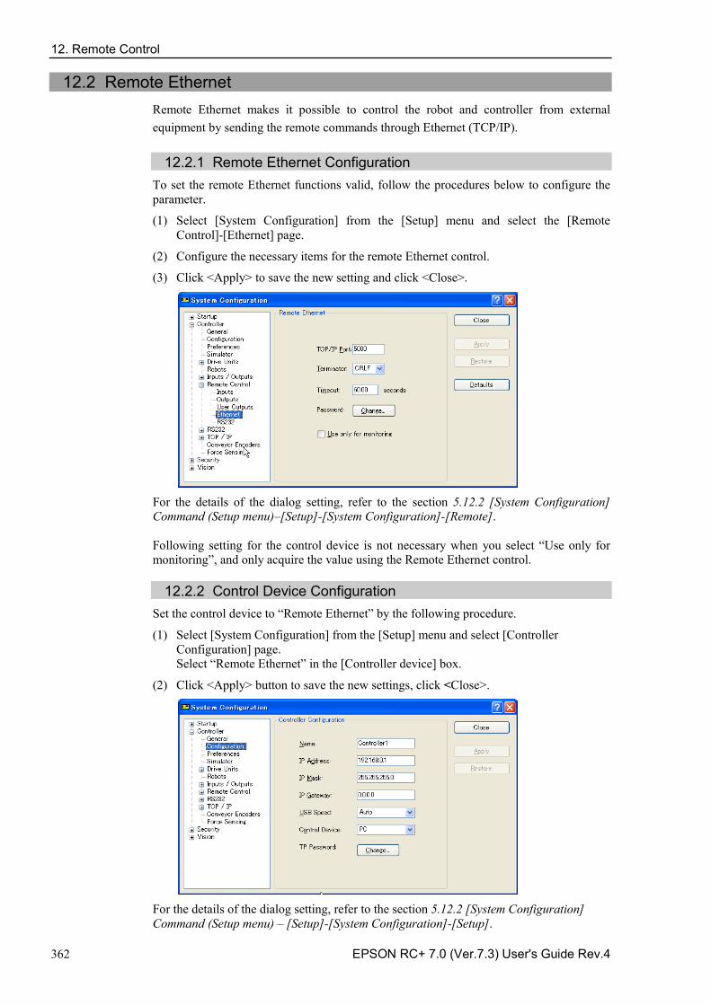
12. Remote Control
362 EPSON RC+ 7.0 (Ver.7.3) User's Guide Rev.4
12.2 Remote Ethernet Remote Ethernet makes it possible to control the robot and controller from external equipment by sending the remote commands through Ethernet (TCP/IP).
12.2.1 Remote Ethernet Configuration To set the remote Ethernet functions valid, follow the procedures below to configure the parameter.
(1) Select [System Configuration] from the [Setup] menu and select the [Remote Control]-[Ethernet] page.
(2) Configure the necessary items for the remote Ethernet control.
(3) Click <Apply> to save the new setting and click <Close>.
For the details of the dialog setting, refer to the section 5.12.2 [System Configuration] Command (Setup menu)–[Setup]-[System Configuration]-[Remote]. Following setting for the control device is not necessary when you select “Use only for monitoring”, and only acquire the value using the Remote Ethernet control.
12.2.2 Control Device Configuration Set the control device to “Remote Ethernet” by the following procedure.
(1) Select [System Configuration] from the [Setup] menu and select [Controller Configuration] page. Select “Remote Ethernet” in the [Controller device] box.
(2) Click <Apply> button to save the new settings, click <Close>.
For the details of the dialog setting, refer to the section 5.12.2 [System Configuration] Command (Setup menu) – [Setup]-[System Configuration]-[Setup].
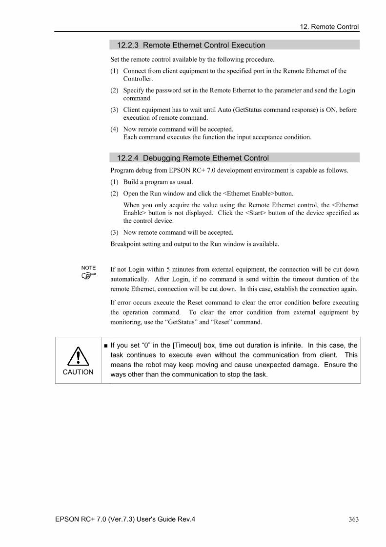
12. Remote Control
EPSON RC+ 7.0 (Ver.7.3) User's Guide Rev.4 363
12.2.3 Remote Ethernet Control Execution
Set the remote control available by the following procedure.
(1) Connect from client equipment to the specified port in the Remote Ethernet of the Controller.
(2) Specify the password set in the Remote Ethernet to the parameter and send the Login command.
(3) Client equipment has to wait until Auto (GetStatus command response) is ON, before execution of remote command.
(4) Now remote command will be accepted. Each command executes the function the input acceptance condition.
12.2.4 Debugging Remote Ethernet Control
Program debug from EPSON RC+ 7.0 development environment is capable as follows.
(1) Build a program as usual.
(2) Open the Run window and click the <Ethernet Enable>button.
When you only acquire the value using the Remote Ethernet control, the <Ethernet Enable> button is not displayed. Click the <Start> button of the device specified as the control device.
(3) Now remote command will be accepted.
Breakpoint setting and output to the Run window is available.
If not Login within 5 minutes from external equipment, the connection will be cut down automatically. After Login, if no command is send within the timeout duration of the remote Ethernet, connection will be cut down. In this case, establish the connection again.
If error occurs execute the Reset command to clear the error condition before executing the operation command. To clear the error condition from external equipment by monitoring, use the “GetStatus” and “Reset” command.
CAUTION
■ If you set “0” in the [Timeout] box, time out duration is infinite. In this case, the task continues to execute even without the communication from client. This means the robot may keep moving and cause unexpected damage. Ensure the ways other than the communication to stop the task.
NOTE
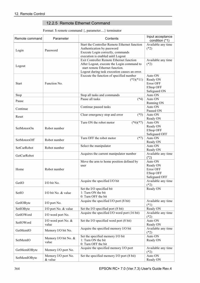
12. Remote Control
364 EPSON RC+ 7.0 (Ver.7.3) User's Guide Rev.4
12.2.5 Remote Ethernet Command
Format: $ remote command {, parameter....} terminator
Remote command Parameter Contents Input acceptance condition (*1)
Login Password
Start the Controller Remote Ethernet function Authentication by password Execute Login correctly, commands execution is enabled until Logout
Available any time (*2)
Logout
Exit Controller Remote Ethernet function After Logout, execute the Login command to
start remote Ethernet function. Logout during task execution causes an error.
Available any time (*2)
Start Function No.
Execute the function of specified number (*3)(*11)
Auto ON Ready ON Error OFF EStop OFF Safeguard ON
Stop Stop all tasks and commands Auto ON
Pause Pause all tasks (*4) Auto ON Running ON
Continue Continue paused tasks Auto ON Paused ON
Reset Clear emergency stop and error (*5) Auto ON Ready ON
SetMotorsOn Robot number
Turn ON the robot motor (*6)(*7) Auto ON Ready ON EStop OFF Safeguard OFF
SetMotorsOff Robot number Turn OFF the robot motor (*7) Auto ON Ready ON
SetCurRobot Robot number Select the manipulator Auto ON Ready ON
GetCurRobot Acquires the current manipulator number Available any time (*2)
Home Robot number
Move the arm to home position defined by user
Auto ON Ready ON Error OFF EStop OFF Safeguard OFF
GetIO I/O bit No. Acquire the specified I/O bit Available any time (*2)
SetIO I/O bit No. & value Set the I/O specified bit 1: Turn ON the bit 0: Turn OFF the bit
Ready ON
GetIOByte I/O port No. Acquire the specified I/O port (8 bit) Available any time (*1)
SetIOByte I/O port No. & value Set the I/O specified port (8 bit) Ready ON
GetIOWord I/O word port No. Acquire the specified I/O word port (16 bit) Available any time (*2)
SetIOWord I/O word port No. & value
Set the I/O specified word port (8 bit) Auto ON Ready ON
GetMemIO Memory I/O bit No. Acquire the specified memory I/O bit Available any time (*2)
SetMemIO Memory I/O bit No. & value
Set the specified memory I/O bit 1: Turn ON the bit 0: Turn OFF the bit
Auto ON Ready ON
GetMemIOByte Memory I/O port No. Acquire the specified memory I/O port Available any time (*2)
SetMemIOByte Memory I/O port No. & value
Set the specified memory I/O port (8 bit)
Auto ON Ready ON
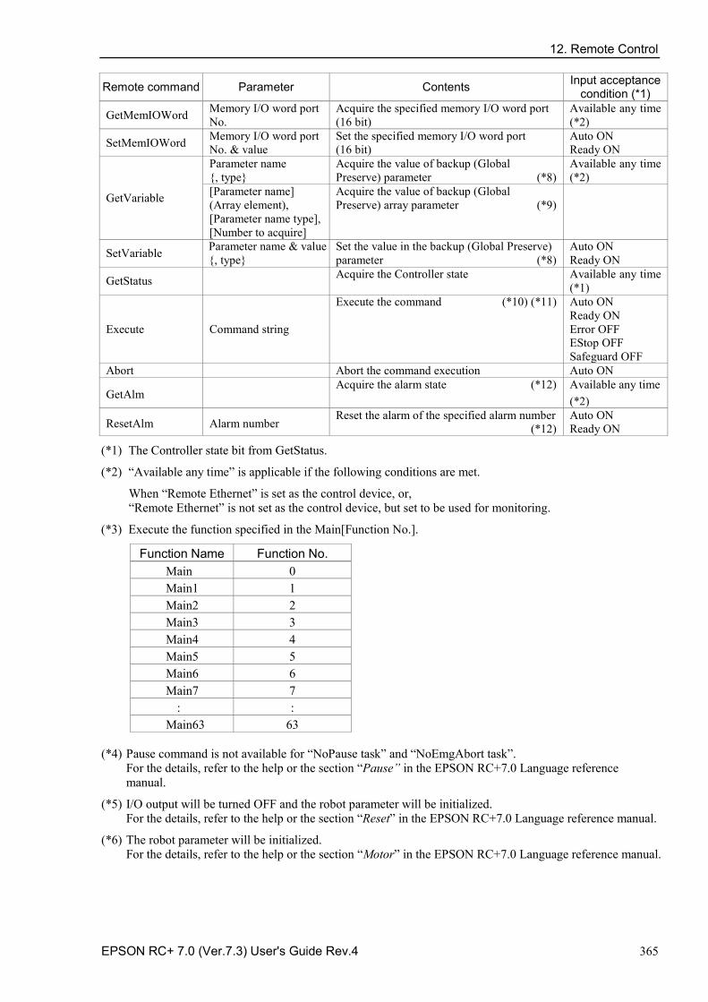
12. Remote Control
EPSON RC+ 7.0 (Ver.7.3) User's Guide Rev.4 365
Remote command Parameter Contents Input acceptance condition (*1)
GetMemIOWord Memory I/O word port No.
Acquire the specified memory I/O word port (16 bit)
Available any time (*2)
SetMemIOWord Memory I/O word port No. & value
Set the specified memory I/O word port (16 bit)
Auto ON Ready ON
GetVariable
Parameter name {, type}
Acquire the value of backup (Global Preserve) parameter (*8)
Available any time (*2)
[Parameter name] (Array element), [Parameter name type], [Number to acquire]
Acquire the value of backup (Global Preserve) array parameter (*9)
SetVariable Parameter name & value {, type}
Set the value in the backup (Global Preserve) parameter (*8)
Auto ON Ready ON
GetStatus Acquire the Controller state Available any time (*1)
Execute Command string
Execute the command (*10) (*11) Auto ON Ready ON Error OFF EStop OFF Safeguard OFF
Abort Abort the command execution Auto ON
GetAlm Acquire the alarm state (*12) Available any time
(*2)
ResetAlm Alarm number Reset the alarm of the specified alarm number (*12)
Auto ON Ready ON
(*1) The Controller state bit from GetStatus.
(*2) “Available any time” is applicable if the following conditions are met.
When “Remote Ethernet” is set as the control device, or, “Remote Ethernet” is not set as the control device, but set to be used for monitoring.
(*3) Execute the function specified in the Main[Function No.].
Function Name Function No. Main 0 Main1 1 Main2 2 Main3 3 Main4 4 Main5 5 Main6 6 Main7 7
: : Main63 63
(*4) Pause command is not available for “NoPause task” and “NoEmgAbort task”. For the details, refer to the help or the section “Pause” in the EPSON RC+7.0 Language reference manual.
(*5) I/O output will be turned OFF and the robot parameter will be initialized. For the details, refer to the help or the section “Reset” in the EPSON RC+7.0 Language reference manual.
(*6) The robot parameter will be initialized. For the details, refer to the help or the section “Motor” in the EPSON RC+7.0 Language reference manual.
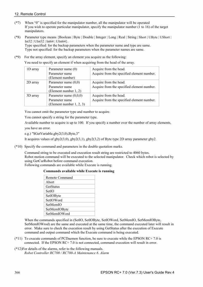
12. Remote Control
366 EPSON RC+ 7.0 (Ver.7.3) User's Guide Rev.4
(*7) When “0” is specified for the manipulator number, all the manipulator will be operated If you wish to operate particular manipulator, specify the manipulator number (1 to 16) of the target manipulators.
(*8) Parameter type means {Boolean | Byte | Double | Integer | Long | Real | String | Short | UByte | UShort | Int32 | UInt32 | Int64 | UInt64}. Type specified: for the backup parameters when the parameter name and type are same. Type not specified: for the backup parameters when the parameter names are same.
(*9) For the array element, specify an element you acquire as the following: You need to specify an element if when acquiring from the head of the array.
1D array Parameter name (0) Acquire from the head. Parameter name (Element number)
Acquire from the specified element number.
2D array Parameter name (0,0) Acquire from the head. Parameter name (Element number 1, 2)
Acquire from the specified element number.
3D array Parameter name (0,0,0) Acquire from the head. Parameter name (Element number 1, 2, 3)
Acquire from the specified element number.
You cannot omit the parameter type and number to acquire. You cannot specify a string for the parameter type. Available number to acquire is up to 100. If you specify a number over the number of array elements, you have an error. e.g.) "$GetVariable,gby2(3,0),Byte,3" It acquires values of gby2(3,0), gby2(3,1), gby2(3,2) of Byte type 2D array parameter gby2.
(*10) Specify the command and parameters in the double quotation marks.
Command string to be executed and execution result string are restricted to 4060 bytes. Robot motion command will be executed to the selected manipulator. Check which robot is selected by using GetCurRobot before command execution. Following commands are available while Execute is running.
Commands available while Execute is running
Remote Command Abort GetStatus SetIO SetIOByte SetIOWord SetMemIO SetMemIOByte SetMemIOWord
When the commands specified in (SetIO, SetIOByte, SetIOWord, SetMemIO, SetMemIOByte, SetMemIOWrod) are the same and executed at the same time, the command executed later will result in error. Make sure to check the execution result by using GetStatus after the execution of Execute command and output command which the Execute command is being executed.
(*11) To execute commands of PCDaemon function, be sure to execute while the EPSON RC+ 7.0 is connected. If the EPSON RC+ 7.0 is not connected, command execution will result in error.
(*12)For details of the alarms, refer to the following manuals. Robot Controller RC700 / RC700-A Maintenance 6. Alarm
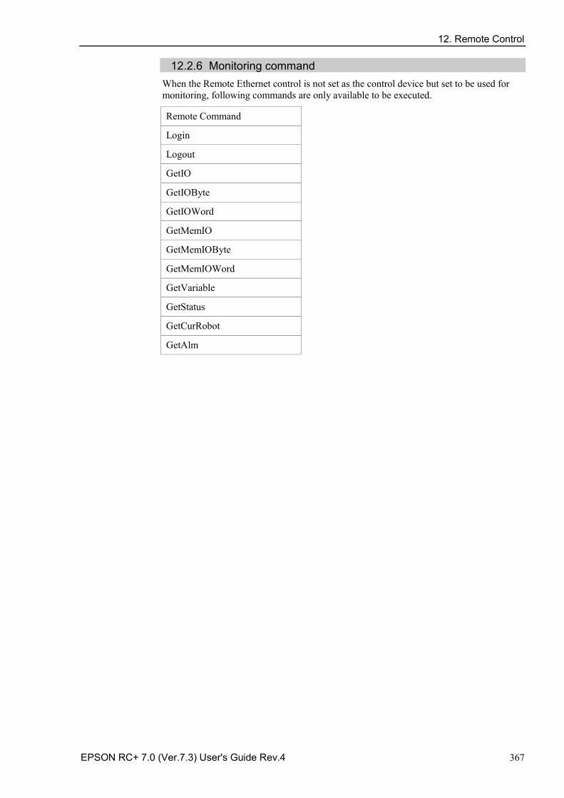
12. Remote Control
EPSON RC+ 7.0 (Ver.7.3) User's Guide Rev.4 367
12.2.6 Monitoring command When the Remote Ethernet control is not set as the control device but set to be used for monitoring, following commands are only available to be executed.
Remote Command
Login
Logout
GetIO
GetIOByte
GetIOWord
GetMemIO
GetMemIOByte
GetMemIOWord
GetVariable
GetStatus
GetCurRobot
GetAlm
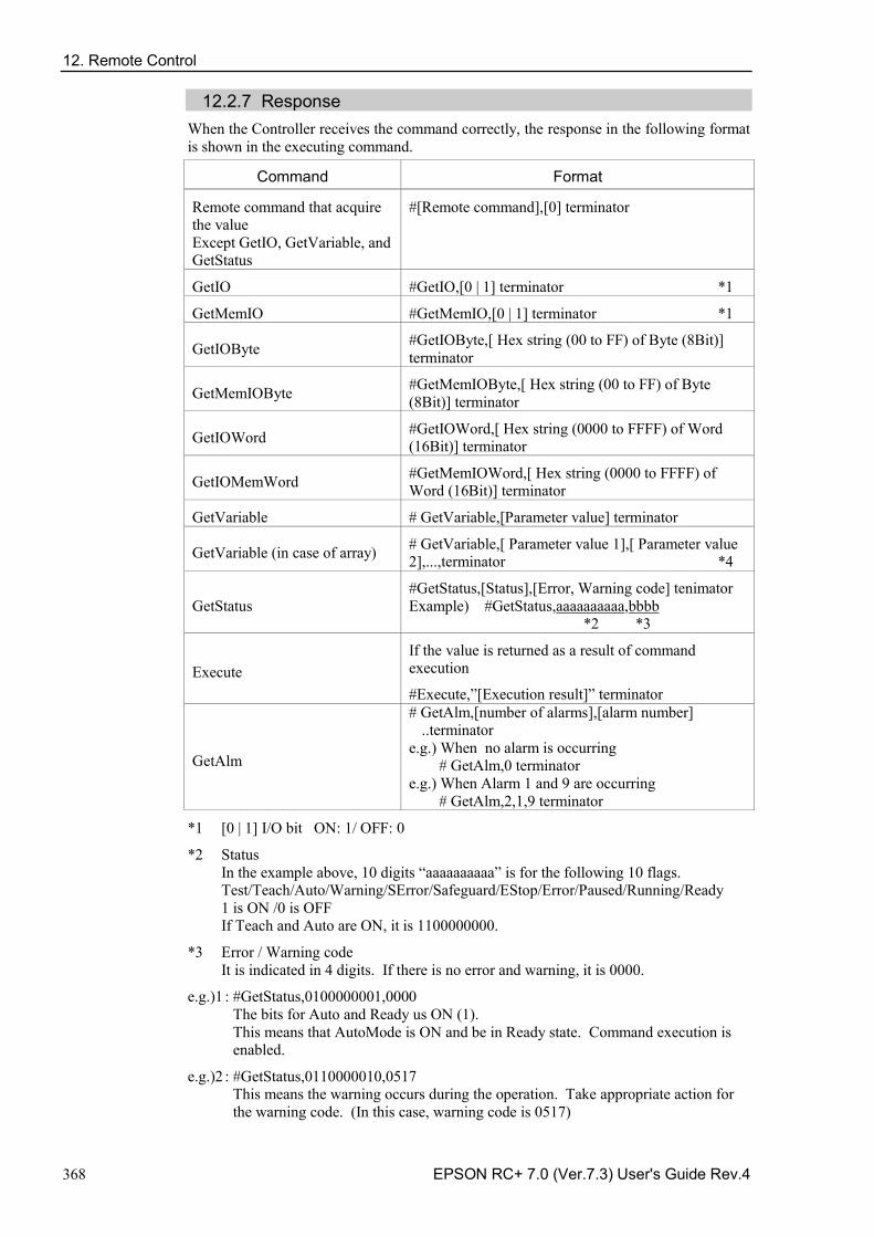
12. Remote Control
368 EPSON RC+ 7.0 (Ver.7.3) User's Guide Rev.4
12.2.7 Response When the Controller receives the command correctly, the response in the following format is shown in the executing command.
Command Format
Remote command that acquire the value Except GetIO, GetVariable, and GetStatus
#[Remote command],[0] terminator
GetIO #GetIO,[0 | 1] terminator *1
GetMemIO #GetMemIO,[0 | 1] terminator *1
GetIOByte #GetIOByte,[ Hex string (00 to FF) of Byte (8Bit)] terminator
GetMemIOByte #GetMemIOByte,[ Hex string (00 to FF) of Byte (8Bit)] terminator
GetIOWord #GetIOWord,[ Hex string (0000 to FFFF) of Word (16Bit)] terminator
GetIOMemWord #GetMemIOWord,[ Hex string (0000 to FFFF) of Word (16Bit)] terminator
GetVariable # GetVariable,[Parameter value] terminator
GetVariable (in case of array) # GetVariable,[ Parameter value 1],[ Parameter value 2],...,terminator *4
GetStatus #GetStatus,[Status],[Error, Warning code] tenimator Example) #GetStatus,aaaaaaaaaa,bbbb *2 *3
Execute If the value is returned as a result of command execution
#Execute,”[Execution result]” terminator
GetAlm
# GetAlm,[number of alarms],[alarm number] ..terminator
e.g.) When no alarm is occurring # GetAlm,0 terminator
e.g.) When Alarm 1 and 9 are occurring # GetAlm,2,1,9 terminator
*1 [0 | 1] I/O bit ON: 1/ OFF: 0
*2 Status In the example above, 10 digits “aaaaaaaaaa” is for the following 10 flags. Test/Teach/Auto/Warning/SError/Safeguard/EStop/Error/Paused/Running/Ready 1 is ON /0 is OFF If Teach and Auto are ON, it is 1100000000.
*3 Error / Warning code It is indicated in 4 digits. If there is no error and warning, it is 0000.
e.g.)1 : #GetStatus,0100000001,0000 The bits for Auto and Ready us ON (1). This means that AutoMode is ON and be in Ready state. Command execution is enabled.
e.g.)2 : #GetStatus,0110000010,0517 This means the warning occurs during the operation. Take appropriate action for the warning code. (In this case, warning code is 0517)
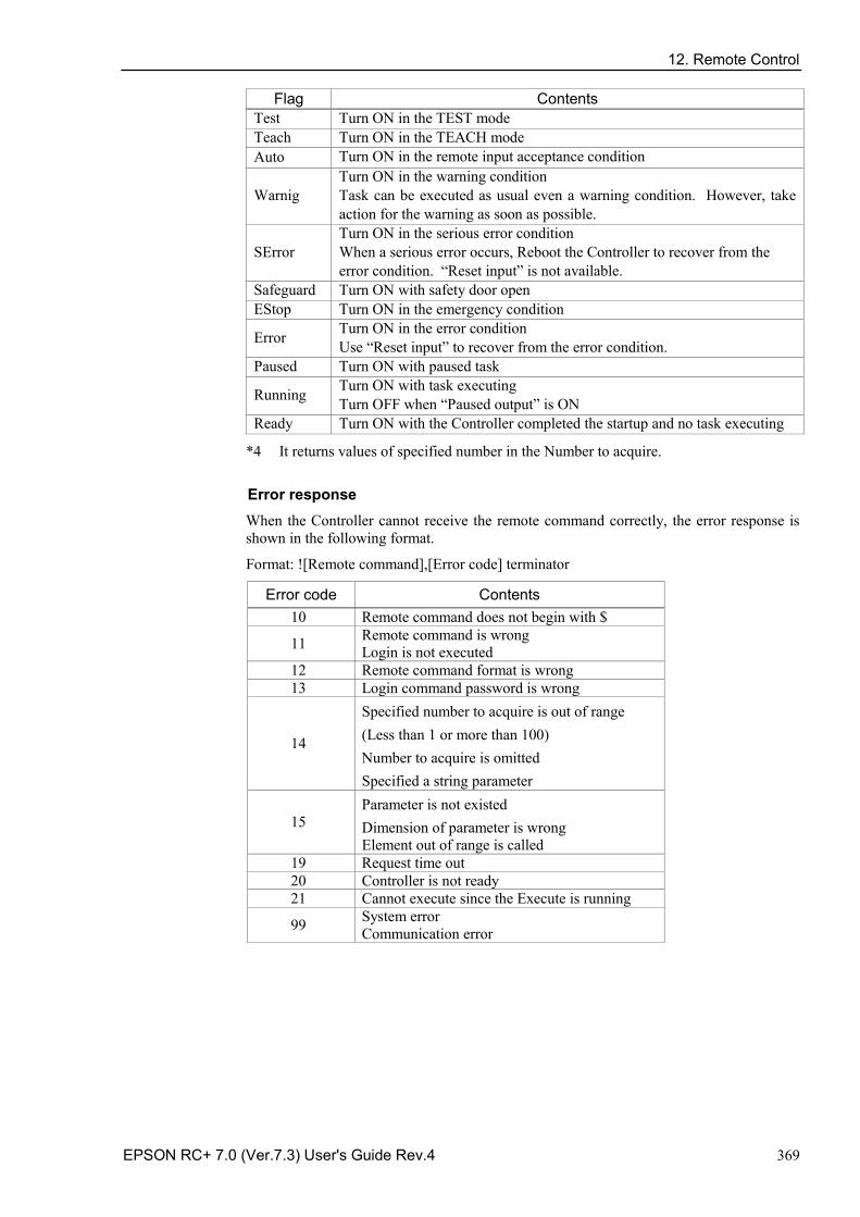
12. Remote Control
EPSON RC+ 7.0 (Ver.7.3) User's Guide Rev.4 369
Flag Contents Test Turn ON in the TEST mode Teach Turn ON in the TEACH mode Auto Turn ON in the remote input acceptance condition
Warnig Turn ON in the warning condition Task can be executed as usual even a warning condition. However, take action for the warning as soon as possible.
SError Turn ON in the serious error condition When a serious error occurs, Reboot the Controller to recover from the error condition. “Reset input” is not available.
Safeguard Turn ON with safety door open EStop Turn ON in the emergency condition
Error Turn ON in the error condition Use “Reset input” to recover from the error condition.
Paused Turn ON with paused task
Running Turn ON with task executing Turn OFF when “Paused output” is ON
Ready Turn ON with the Controller completed the startup and no task executing
*4 It returns values of specified number in the Number to acquire.
Error response When the Controller cannot receive the remote command correctly, the error response is shown in the following format.
Format: ![Remote command],[Error code] terminator
Error code Contents 10 Remote command does not begin with $
11 Remote command is wrong Login is not executed
12 Remote command format is wrong 13 Login command password is wrong
14
Specified number to acquire is out of range (Less than 1 or more than 100) Number to acquire is omitted Specified a string parameter
15 Parameter is not existed Dimension of parameter is wrong Element out of range is called
19 Request time out 20 Controller is not ready 21 Cannot execute since the Execute is running
99 System error Communication error
12. Remote Control
370 EPSON RC+ 7.0 (Ver.7.3) User's Guide Rev.4
12.2.8 Response timing of Remote Ethernet control Communication sequence
Controller
IP xxx.xxx.xxx.xxx
Ethernet Client
IP zzz.zzz.zzz.zzz
(1) Login
(2) Response
(3) Command request
(4) Response
(5) Logout
(6) Response
Request from zzz.zzz.zzz.zzz:zz is only available :
:
12.3 Remote RS232 Remote RS232 makes it possible to control the robot and controller from external equipment by sending the remote commands through RS-232C.
12.3.1 Remote RS232 setting
To set the remote RS232 functions valid, follow the procedures below to configure the remote RS232.
(1) Select [Controller] from the [Setup] menu-[System Configuration] and display the [System Configuration] dialog box. Select [RS232] from the tree structure-[Controller]-[Remote].
(2) Configure the necessary items for the remote RS232 control.
(3) Click <Apply> to save the new setting and click <Close>.
For the details of the dialog setting, refer to the section 5.12.2 [System Configuration] (Setup menu) – [Setup]-[System Configuration]-[Remote].
When you only acquire the value using the Remote RS232 control, the RS232 Enable button is not displayed. Click the Start button of the device specified as the control device. Following setting for the control device is not necessary when you select “Use only for monitoring”, and only acquire the value using the remote RS232 control.
12. Remote Control
EPSON RC+ 7.0 (Ver.7.3) User's Guide Rev.4 371
12.3.2 Control device setting Set the control device to “Remote RS232” by the following procedure.
(1) Select Controller from the [Setup] menu and select [System Configuration] to display the [System Configuration] dialog box. Select “Remote RS232” in the [Control Device] box.
(2) Click <Apply> to save the new settings, and then click <Close>.
For the details of the dialog setting, refer to the section 5.12.2 [System Configuration] (Setup menu) – [Setup]-[ System Configuration]-[Controller]-[Configuration].
12.3.3 Execution of remote RS232 control
Set the remote RS232 control available by the following procedure.
(1) Open RS-232C port that is connected from client equipment to the specified port in the Remote RS232 of the Controller, using the communication parameter specified in the RS-232C port setting.
(2) Send the remote start command (EOT).
(3) Specify the password set in the Remote RS232 to the parameter and send the Login command.
(4) Client equipment has to wait until Auto (GetStatus command response) is ON, before execution of remote command.
(5) Now remote command will be accepted. Each command executes the function when the input acceptance condition is satisfied.
12. Remote Control
372 EPSON RC+ 7.0 (Ver.7.3) User's Guide Rev.4
12.3.4 Debugging remote RS232 control Program debug from EPSON RC+ 7.0 development environment is capable as follows.
(1) Build a program as usual.
(2) Open the Run window and click the <RS232 Enable> button.
When you only acquire the value using the Remote RS232 control, the <RS232 Enable> button is not displayed. Click the Start button of the device specified as the control device.
(3) Now remote command will be accepted.
Breakpoint setting and output to the Run window is available.
After Login, if no command is send within the timeout duration of the RS-232C, the timeout error will be returned. In this case, re-execute from sending remote start command.
If error occurs, execute the Reset command to clear the error condition before executing the operation command. To clear the error condition from external equipment by monitoring, use the “GetStatus” and “Reset” command.
CAUTION
■ If you set “0” in the [Timeout] box, time out duration is infinite. In this case, the task continues to execute even without the communication from client. This means the robot may keep moving and cause unexpected damage. Ensure the ways other than the communication to stop the task.
12.3.5 Remote RS232 Command
Remote start
Start the Remote RS232 function of the Controller.
EOT
1byte
EOT : &H04(&H is hexadecimal)
Request format
STX
1byte
Command
1Byte
Data
Variable
ETX
1Byte
BCC
1Byte
STX : &H02
ETX : &H03
BCC : Checksum of sent and received data
XOR value from the command to ETX per 1Byte
NOTE
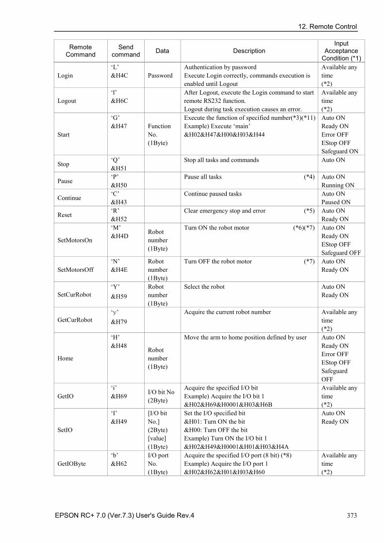
12. Remote Control
EPSON RC+ 7.0 (Ver.7.3) User's Guide Rev.4 373
Remote Command
Send command Data Description
Input Acceptance
Condition (*1)
Login ‘L’ &H4C Password
Authentication by password Execute Login correctly, commands execution is enabled until Logout
Available any time (*2)
Logout ‘l’ &H6C
After Logout, execute the Login command to start remote RS232 function. Logout during task execution causes an error.
Available any time (*2)
Start
‘G’ &H47 Function
No. (1Byte)
Execute the function of specified number(*3)(*11) Example) Execute ‘main’ &H02&H47&H00&H03&H44
Auto ON Ready ON Error OFF EStop OFF Safeguard ON
Stop ‘Q’ &H51
Stop all tasks and commands Auto ON
Pause ‘P’ &H50
Pause all tasks (*4) Auto ON Running ON
Continue ‘C’ &H43 Continue paused tasks Auto ON
Paused ON
Reset ‘R’ &H52 Clear emergency stop and error (*5) Auto ON
Ready ON
SetMotorsOn
‘M’ &H4D Robot
number (1Byte)
Turn ON the robot motor (*6)(*7) Auto ON Ready ON EStop OFF Safeguard OFF
SetMotorsOff ‘N’ &H4E
Robot number (1Byte)
Turn OFF the robot motor (*7) Auto ON Ready ON
SetCurRobot ‘Y’ &H59
Robot number (1Byte)
Select the robot Auto ON Ready ON
GetCurRobot ‘y’ &H79
Acquire the current robot number Available any time (*2)
Home
‘H’ &H48 Robot
number (1Byte)
Move the arm to home position defined by user Auto ON Ready ON Error OFF EStop OFF Safeguard OFF
GetIO ‘i’ &H69 I/O bit No
(2Byte)
Acquire the specified I/O bit Example) Acquire the I/O bit 1 &H02&H69&H0001&H03&H6B
Available any time (*2)
SetIO
‘I’ &H49
[I/O bit No.] (2Byte) [value] (1Byte)
Set the I/O specified bit &H01: Turn ON the bit &H00: Turn OFF the bit Example) Turn ON the I/O bit 1 &H02&H49&H0001&H01&H03&H4A
Auto ON Ready ON
GetIOByte ‘b’ &H62
I/O port No. (1Byte)
Acquire the specified I/O port (8 bit) (*8) Example) Acquire the I/O port 1 &H02&H62&H01&H03&H60
Available any time (*2)
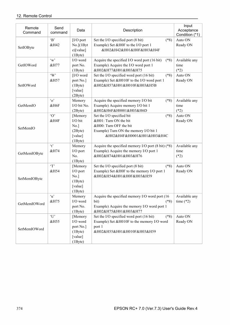
12. Remote Control
374 EPSON RC+ 7.0 (Ver.7.3) User's Guide Rev.4
Remote Command
Send command Data Description
Input Acceptance
Condition (*1)
SetIOByte
‘B’ &H42
[I/O port No.](1Byte)[value] (1Byte)
Set the I/O specified port (8 bit) (*8) Example) Set &H0F to the I/O port 1
&H02&H42&H01&H0F&H03&H4F
Auto ON Ready ON
GetIOWord ‘w’ &H77
I/O word port No. (1Byte)
Acquire the specified I/O word port (16 bit) (*8) Example) Acquire the I/O word port 1 &H02&H77&H01&H03&H75
Available any time (*2)
SetIOWord
‘W’ &H57
[I/O word port No.] (1Byte) [value] (2Byte)
Set the I/O specified word port (16 bit) (*8) Example) Set &H010F to the I/O word port 1 &H02&H57&H01&H010F&H03&H5B
Auto ON Ready ON
GetMemIO ‘o’ &H6F
Memory I/O bit No. (2Byte)
Acquire the specified memory I/O bit (*8) Example) Acquire memory I/O bit 1 &H02&H6F&H0001&H03&H6D
Available any time (*2)
SetMemIO
‘O’ &H4F
[Memory I/O bit No.] (2Byte) [value] (1Byte)
Set the I/O specified bit (*8) &H01: Turn ON the bit &H00: Turn OFF the bit Example) Turn ON the memory I/O bit 1
&H02&H4F&H0001&H01&H03&H4C
Auto ON Ready ON
GetMemIOByte
‘t’ &H74
Memory I/O port No. (1Byte)
Acquire the specified memory I/O port (8 bit) (*8) Example) Acquire the memory I/O port 1 &H02&H74&H01&H03&H76
Available any time (*2)
SetMemIOByte
‘T’ &H54
[Memory I/O port No.] (1Byte) [value] (1Byte)
Set the I/O specified port (8 bit) (*8) Example) Set &H0F to the memory I/O port 1 &H02&H54&H01&H0F&H03&H59
Auto ON Ready ON
GetMemIOWord
‘u’ &H75
Memory I/O word port No. (1Byte)
Acquire the specified memory I/O word port (16 bit) (*8) Example) Acquire the memory I/O word port 1 &H02&H75&H01&H03&H77
Available any time (*2)
SetMemIOWord
‘U’ &H55
[Memory I/O word port No.] (1Byte) [value] (1Byte)
Set the I/O specified word port (16 bit) (*8) Example) Set &H010F to the memory I/O word port 1 &H02&H55&H01&H010F&H03&H59
Auto ON Ready ON
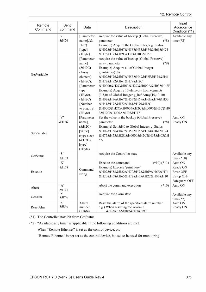
12. Remote Control
EPSON RC+ 7.0 (Ver.7.3) User's Guide Rev.4 375
Remote Command
Send command Data Description
Input Acceptance
Condition (*1)
GetVariable
‘v’ &H76
[Parameter name],(&H2C) [type] (1Byte)
Acquire the value of backup (Global Preserve) parameter (*8) Example) Acquire the Global Integer g_Status &H02&H76&H67&H5F&H53&H74&H61&H74&H75&H73&H2C&H03&H03&H56
Available any time (*2)
[Parameter name] (&H2C) (Array element) (&H2C), [Parameter type] (1Byte), (&H2C) [Number to acquire] (2Byte)
Acquire the value of backup (Global Preserve) array parameter (*9) Example) Acquire all of Global Integer g_intArray(10) &H02&H76&H67&H5F&H69&H6E&H74&H41&H72&H72&H61&H79&H2C &H0000&H2C&H03&H2C&H000A&H03&H42E Example) Acquire 10 elements from elements (3,5,0) of Global Integer g_int3Array(10,10,10) &H02&H76&H67&H5F&H69&H6E&H74&H33&H41&H72&H72&H61&H79&H2C &H0003&H2C&H0005&H2C&H0000&H2C&H03&H2C&H000A&H03&H77
SetVariable
‘V’ &H56
[Parameter name], (&H2C) [value] (type size) (&H2C), [type] (1Byte)
Set the value in the backup (Global Preserve) parameter (*8) Example) Set &H0 to Global Integer g_Status &H02&H56&H67&H5F&H53&H74&H61&H74&H75&H73&H2C&H0000&H2C&H03&H03&H5A
Auto ON Ready ON
GetStatus ‘S’ &H53 Acquire the Controller state Available any
time (*10)
Execute
‘X’ &H58 Command
string
Execute the command (*10) (*11) Example) Execute ‘print here’ &H02&H58&H22&H70&H72&H69&H6E&H74&H20&H68&H65&H72&H65&H22&H03&H10
Auto ON Ready ON Error OFF EStop OFF Safeguard OFF
Abort ‘A’ &H41 Abort the command execution (*10) Auto ON
GetAlm ‘z’ &H7A
Acquire the alarm state Available any time (*2)
ResetAlm ‘Z’ &H5A
Alarm number (1 Byte)
Reset the alarm of the specified alarm number e.g.) When resetting the Alarm 5
&H02&H5A&H05&H03&H5C
Auto ON Ready ON
(*1) The Controller state bit from GetStatus.
(*2) “Available any time” is applicable if the following conditions are met.
When “Remote Ethernet” is set as the control device, or,
“Remote Ethernet” is not set as the control device, but set to be used for monitoring.
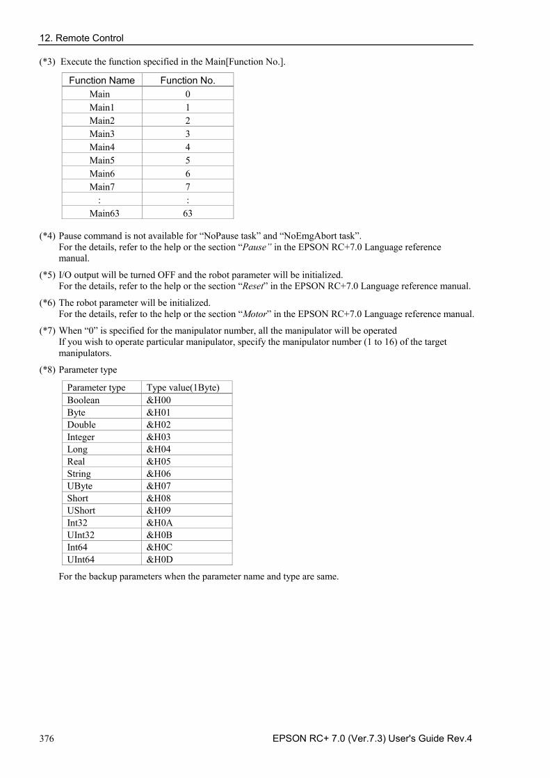
12. Remote Control
376 EPSON RC+ 7.0 (Ver.7.3) User's Guide Rev.4
(*3) Execute the function specified in the Main[Function No.].
Function Name Function No. Main 0 Main1 1 Main2 2 Main3 3 Main4 4 Main5 5 Main6 6 Main7 7
: : Main63 63
(*4) Pause command is not available for “NoPause task” and “NoEmgAbort task”. For the details, refer to the help or the section “Pause” in the EPSON RC+7.0 Language reference manual.
(*5) I/O output will be turned OFF and the robot parameter will be initialized. For the details, refer to the help or the section “Reset” in the EPSON RC+7.0 Language reference manual.
(*6) The robot parameter will be initialized. For the details, refer to the help or the section “Motor” in the EPSON RC+7.0 Language reference manual.
(*7) When “0” is specified for the manipulator number, all the manipulator will be operated If you wish to operate particular manipulator, specify the manipulator number (1 to 16) of the target manipulators.
(*8) Parameter type
Parameter type Type value(1Byte) Boolean &H00 Byte &H01 Double &H02 Integer &H03 Long &H04 Real &H05 String &H06 UByte &H07 Short &H08 UShort &H09 Int32 &H0A UInt32 &H0B Int64 &H0C UInt64 &H0D
For the backup parameters when the parameter name and type are same.
12. Remote Control
EPSON RC+ 7.0 (Ver.7.3) User's Guide Rev.4 377
(*9) For the array element, specify an element you acquire as the following: You need to specify an element when acquiring from the head of the array.
Specify the array element in 2Byte value.
1D array Parameter name&H2C&H0000 Acquire from the head. Parameter name, element number. Acquire from the specified
element number. 2D array Parameter name
&H2C&H0000&H2C&H0000 Acquire from the head.
Parameter name, element number 1, element number 2
Acquire from the specified element number.
3D array Parameter name &H2C&H0000&H2C&H0000&H2C&H0000
Acquire from the head.
Parameter name, element number 1, element number 2, element number 3
Acquire from the specified element number.
You cannot specify a string for the parameter type. Available number to acquire is up to 100. If you specify a number over the number of array elements, you have an error.
(*10) Specify the command and parameters in the double quotation marks.
Command string to be executed and execution result string are restricted to 4060 bytes. Robot motion command will be executed to the selected manipulator. Check which robot is selected by using GetCurRobot before command execution.
Following commands are available while Execute is running.
Commands available while Execute is running
Remote Command
Abort
GetStatus
SetIO
SetIOByte
SetIOWord
SetMemIO
SetMemIOByte
SetMemIOWord
When the commands specified in (SetIO, SetIOByte, SetIOWord, SetMemIO, SetMemIOByte, SetMemIOWrod) are the same and executed at the same time, the command executed later will result in error. Make sure to check the execution result by using GetStatus after the execution of Execute command and output command which the Execute command is being executed.
(*11) To execute commands of PCDaemon function, be sure to execute while the EPSON RC+ 7.0 is connected. If the EPSON RC+ 7.0 is not connected, command execution will result in error.
12. Remote Control
378 EPSON RC+ 7.0 (Ver.7.3) User's Guide Rev.4
12.3.6 Monitoring command When the remote RS232 control is not set as the control device but set to be used for monitoring, following commands are only available to be executed.
Remote Command
Login
Logout
GetIO
GetIOByte
GetIOWord
GetMemIO
GetMemIOByte
GetMemIOWord
GetVariable
GetStatus
GetCurRobot
GetAlm
12.3.7 Response When the Controller receives the command correctly, the response in the following format is shown in the executing command.
Response Format
ACK
1Byte
Command
1Byte
Data
Variable
ETX
1Byte
BCC
1Byte
ACK : &H06
ETX : &H03
BCC : Checksum of sent and received data
XOR value from the command to ETX per 1Byte
Command Format
Remote command that acquire the value Except the following commands
[ACK][Command](1Byte)[ETX][BCC]
GetCurRobot [ACK]’y’[Robot number] [ETX][BCC]
GetIO [ACK] ‘i’[&H00 | &H01] [ETX][BCC] *1
GetMemIO [ACK] ‘o’[&H00 | &H01] [ETX][BCC] *1
GetIOByte [ACK] ‘b’[ Byte value (8Bit) (&H00 to &HFF)] [ETX][BCC]
12. Remote Control
EPSON RC+ 7.0 (Ver.7.3) User's Guide Rev.4 379
Command Format
GetMemIOByte [ACK] ‘t’[ Byte value (8Bit) (&H00 to &HFF)] [ETX][BCC]
GetIOWord [ACK] ‘w’[Word value (16Bit) (&H0000 to &HFFFF)] [ETX][BCC]
GetIOMemWord [ACK] ‘u’[Word value (16Bit) (&H0000 to &HFFFF)] [ETX][BCC]
GetVariable [ACK] ‘u’[Parameter value] [ETX][BCC]
GetVariable (in case of array) [ACK] ‘u’[Parameter value 1][Parameter value 2]... [ETX][BCC] *4
GetStatus
[ACK] ‘S’[Status][Error, Warning code] [ETX][BCC] Example: [ACK] ‘S’[aaaaaaaaaaa][bbbb][ETX][BCC] *2 *3
Execute If the value is returned as a result of command execution
[ACK] ‘X’”[Execution result]” [ETX][BCC]
GetAlm
[ACK] ‘z’ [number of alarms][alarm number]... [ETX][BCC] e.g) When no alarm is occurring
&H06&H7A&H00&H03&H79 e.g.) When Alarm 1 and 9 are occurring
&H06&H7A&H02&H01&H09&H03&H73
*1 [&H00 | &H01] I/O bit ON: &H01/ OFF: &H00
*2 Status In the example above, 11 digits [aaaaaaaaaaa] is for the following 11 flags. Test/Teach/Auto/Warning/SError/Safeguard/EStop/Error/Paused/Running/Ready &H01 is ON /&H00 is OFF If Ready and Auto are ON, it is [&H00&H00&H01&H00&H00&H00&H00&H00&H00&H00&H01].
*3 Error / Warning code It is indicated in 4 digits. If there is no error and warning, it is “0000”(&H30&H30&H30&h30).
e.g.)1 : [ACK] ‘S[&H00&H00&H01&H00&H00&H00&H00&H00&H00&H00&H01][ &H30&H30&H30&h30] The bits for Auto and Ready are &H01. This means that AutoMode is ON and in Ready state. Command execution is enabled.
e.g.)2 : [ACK] ‘S[&H00&H00&H01&H01&H00&H00&H00&H00&H00&H01&H00][ &H30&H35&H31&h37] This means the warning occurs during the operation. Take appropriate action according to the warning code. (In this case, warning code is 0517)
Flag Contents Test Turn ON in the TEST mode Teach Turn ON in the TEACH mode Auto Turn ON in the remote input acceptance condition
12. Remote Control
380 EPSON RC+ 7.0 (Ver.7.3) User's Guide Rev.4
Flag Contents
Warnig Turn ON in the warning condition Task can be executed as usual even a warning condition. However, take action for the warning as soon as possible.
SError Turn ON in the serious error condition When a serious error occurs, Reboot the Controller to recover from the error condition. “Reset input” is not available.
Safeguard Turn ON with safety door open EStop Turn ON in the emergency condition
Error Turn ON in the error condition Use “Reset input” to recover from the error condition.
Paused Turn ON with paused task
Running Turn ON with task executing Turn OFF when “Paused output” is ON
Ready Turn ON with the Controller completed the startup and no task executing
*4 It returns values of specified number in the Number to acquire. Error response When the Controller cannot receive the remote command correctly, the error response is shown in the following format.
NAK
1Byte
Command
1Byte
Error code
2Byte
ETX
1Byte
BCC
1Byte
NAK : &H15
ETX : &H03
BCC : Checksum of sent and received data
XOR value from the command to ETX per 1Byte
Error code Contents 10 Remote command does not begin with $ 11 Remote command is wrong
Login is not executed 12 Remote command format is wrong 13 Login command password is wrong 14 Specified number to acquire is out of range
(Less than 1 or more than 100) Number to acquire is omitted Specified a string parameter
15 Parameter is not existed Dimension of parameter is wrong Element out of range is called
19 Request time out 20 Controller is not ready 21 Cannot execute since the Execute is running 99 System error
Communication error
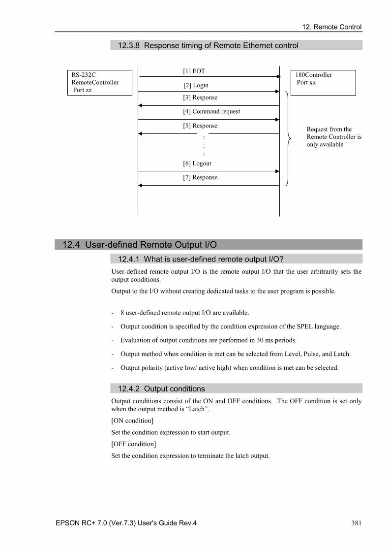
12. Remote Control
EPSON RC+ 7.0 (Ver.7.3) User's Guide Rev.4 381
12.3.8 Response timing of Remote Ethernet control
12.4 User-defined Remote Output I/O 12.4.1 What is user-defined remote output I/O?
User-defined remote output I/O is the remote output I/O that the user arbitrarily sets the output conditions.
Output to the I/O without creating dedicated tasks to the user program is possible.
- 8 user-defined remote output I/O are available.
- Output condition is specified by the condition expression of the SPEL language.
- Evaluation of output conditions are performed in 30 ms periods.
- Output method when condition is met can be selected from Level, Pulse, and Latch.
- Output polarity (active low/ active high) when condition is met can be selected.
12.4.2 Output conditions
Output conditions consist of the ON and OFF conditions. The OFF condition is set only when the output method is “Latch”.
[ON condition]
Set the condition expression to start output.
[OFF condition]
Set the condition expression to terminate the latch output.
180Controller Port xx
RS-232C RemoteController Port zz
[2] Login
[3] Response
[4] Command request [5] Response
[6] Logout
[7] Response
Request from the Remote Controller is only available
: : :
[1] EOT
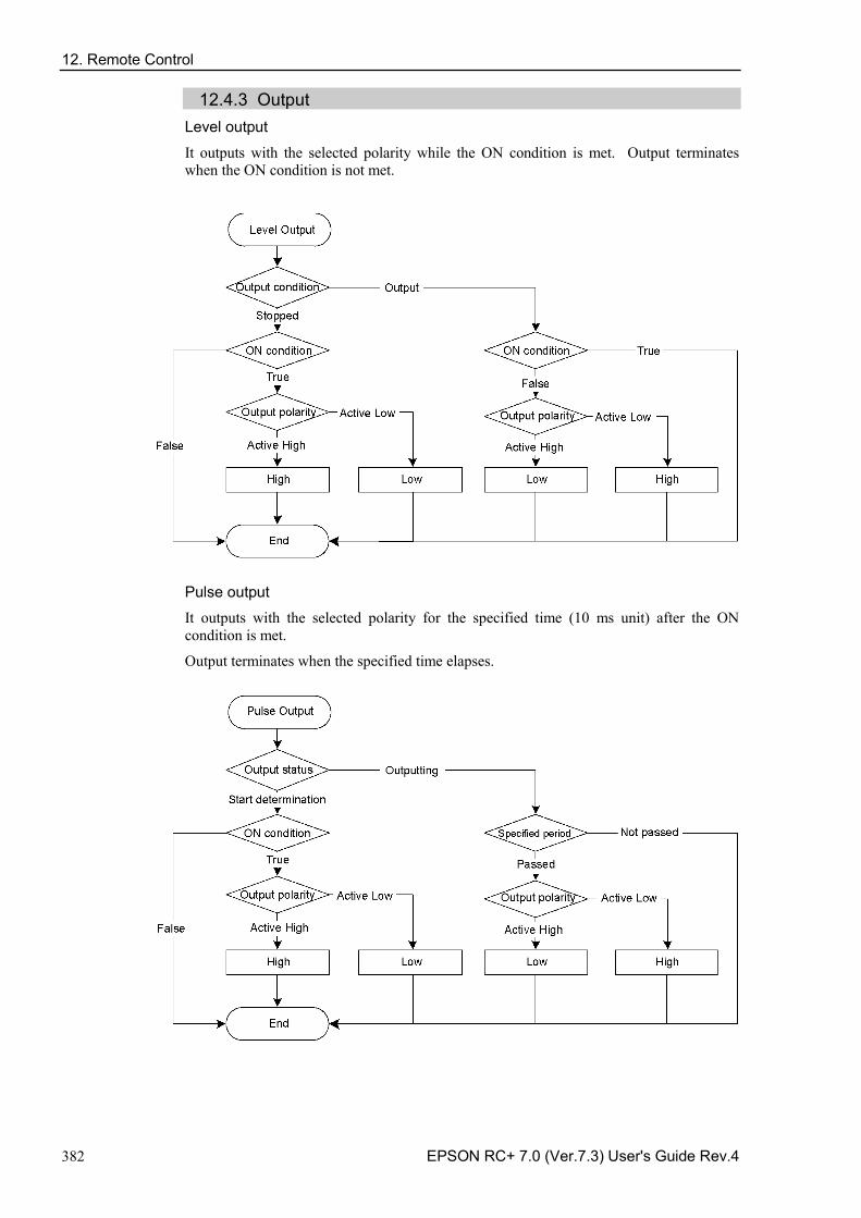
12. Remote Control
382 EPSON RC+ 7.0 (Ver.7.3) User's Guide Rev.4
12.4.3 Output Level output
It outputs with the selected polarity while the ON condition is met. Output terminates when the ON condition is not met.
Pulse output
It outputs with the selected polarity for the specified time (10 ms unit) after the ON condition is met.
Output terminates when the specified time elapses.
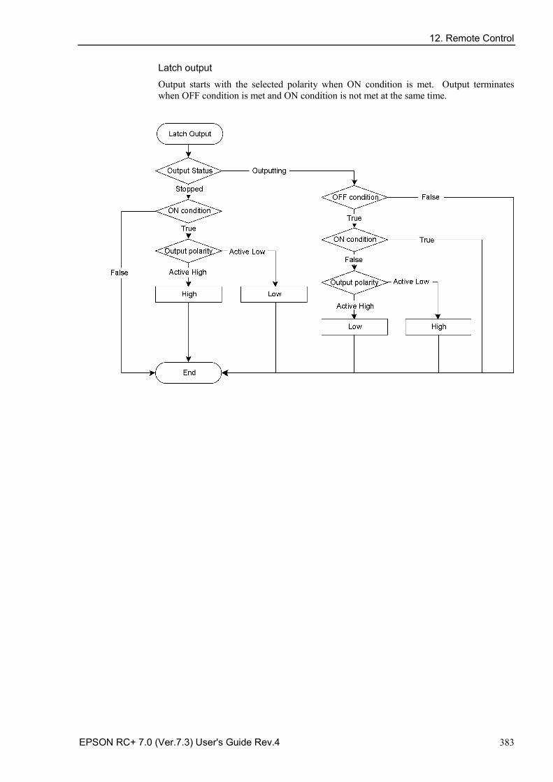
12. Remote Control
EPSON RC+ 7.0 (Ver.7.3) User's Guide Rev.4 383
Latch output
Output starts with the selected polarity when ON condition is met. Output terminates when OFF condition is met and ON condition is not met at the same time.
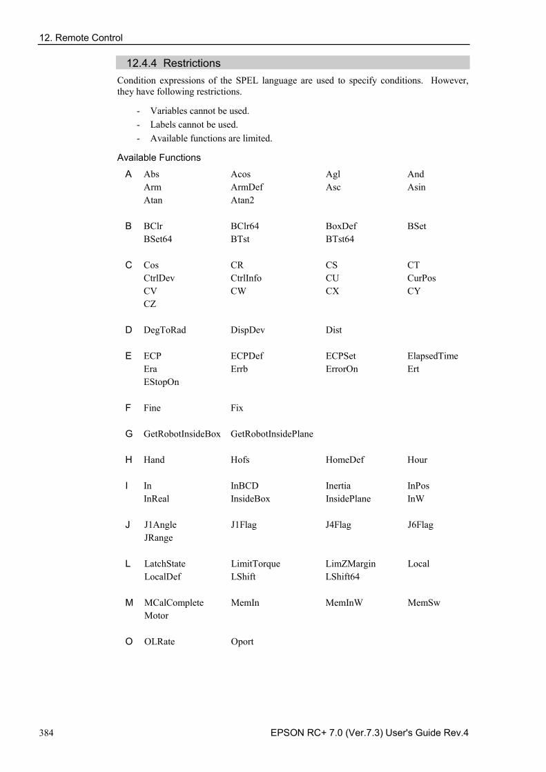
12. Remote Control
384 EPSON RC+ 7.0 (Ver.7.3) User's Guide Rev.4
12.4.4 Restrictions Condition expressions of the SPEL language are used to specify conditions. However, they have following restrictions.
- Variables cannot be used. - Labels cannot be used. - Available functions are limited.
Available Functions
A Abs Acos Agl And Arm ArmDef Asc Asin Atan Atan2 B BClr BClr64 BoxDef BSet BSet64 BTst BTst64 C Cos CR CS CT CtrlDev CtrlInfo CU CurPos CV CW CX CY CZ D DegToRad DispDev Dist E ECP ECPDef ECPSet ElapsedTime Era Errb ErrorOn Ert EStopOn F Fine Fix G GetRobotInsideBox GetRobotInsidePlane H Hand Hofs HomeDef Hour I In InBCD Inertia InPos InReal InsideBox InsidePlane InW J J1Angle J1Flag J4Flag J6Flag JRange L LatchState LimitTorque LimZMargin Local LocalDef LShift LShift64 M MCalComplete MemIn MemInW MemSw Motor O OLRate Oport
12. Remote Control
EPSON RC+ 7.0 (Ver.7.3) User's Guide Rev.4 385
P PAgl PauseOn PDef PG_Lspeed Plane PlaneDef PLocal Pls PPls Power PTPBoost Q QPDecelR QPDecelS R RadToDeg RealAccel RealPls RealPos RecoverPos Rnd RobotInfo RobotType RShift RShift64 S SafetyOn Sgn Sin Speed SpeedFactor SpeedR SpeedS Sqr Stat Sw SyncRobots SysErr T Tan TaskDone TaskInfo TaskState TCLim TcSpeed TeachOn Time TLDef TLSet Tool V Val W Weight X XY XYLimDef
12.4.5 How to set the user-defined output remote I/O
(1) Add the use-defined output remote I/O
The user-defined output remote I/O are not defined as default. To use them, add the output remote I/O in the configuration dialog box and configure the output condition. The added I/O will be available in the remote output setting.
[System Configuration] - [Controller] – [Remote Control] – [User Outputs]
12. Remote Control
386 EPSON RC+ 7.0 (Ver.7.3) User's Guide Rev.4
Click the <Add> button. The following dialog box will appear.
Select the items and set the condition expressions. Then, click the <Apply> button.
[Name] Set the name of the signal. Default is “UseroutputX”.
X = I/O number
The name specified here is displayed in the remote output setting and the I/O monitor.
[Type] Select the output type.
[Polarity] Select the polarity to output when the condition is met.
Active high: High Active low: Low
[On Condition] Set the condition to start output. Setting is required for all output types.
[Off Condition] Setting is required if the Latch output is selected.
[Robot] Setting is required if the expression related to the manipulator is used for On and Off conditions. The conditions for only one robot can be set. This setting is not necessary if the manipulator-related condition is not used.
If unregistered robot number is specified, an initialization error occurs at the Controller restart.
NOTE
12. Remote Control
EPSON RC+ 7.0 (Ver.7.3) User's Guide Rev.4 387
(2) Setting of remote outputs
To enable the added I/O outputs, assign the registered user definition to the target I/O. Assignment is done by the remote output.
[System Configuration] – [Controller] – [Remote Controller] – [Outputs]
The names of the added signals appear in [Output Signal]. Select the bit to output.
12.4.6 Usage example If you want to turn ON the bit port 8 of the standard I/O for 500 ms when the bit port 0 of the standard I/O input is ON and the bit port 1 is OFF:
(1) User definition
1. Set “LED_1” for the [Name] in this example. Change the setting if necessary.
2. Select “Pulse” for [Type].
3. Select [Active High] for [Polarity] in order to output ON.
4. Set the On condition. In this example, set the following condition expression.
Sw(0) = On And Sw(1) = Off
5. Set “500” for [Pulse Width].
6. Click the <Apply> button.
12. Remote Control
388 EPSON RC+ 7.0 (Ver.7.3) User's Guide Rev.4
(2) Setting in the [Remote Control Outputs]
1. Select the output bit “8” for the configured name (LED_1).
2. Click the <Apply> button.
Now, output to the I/O will be executed according to the condition expression after rebooting.
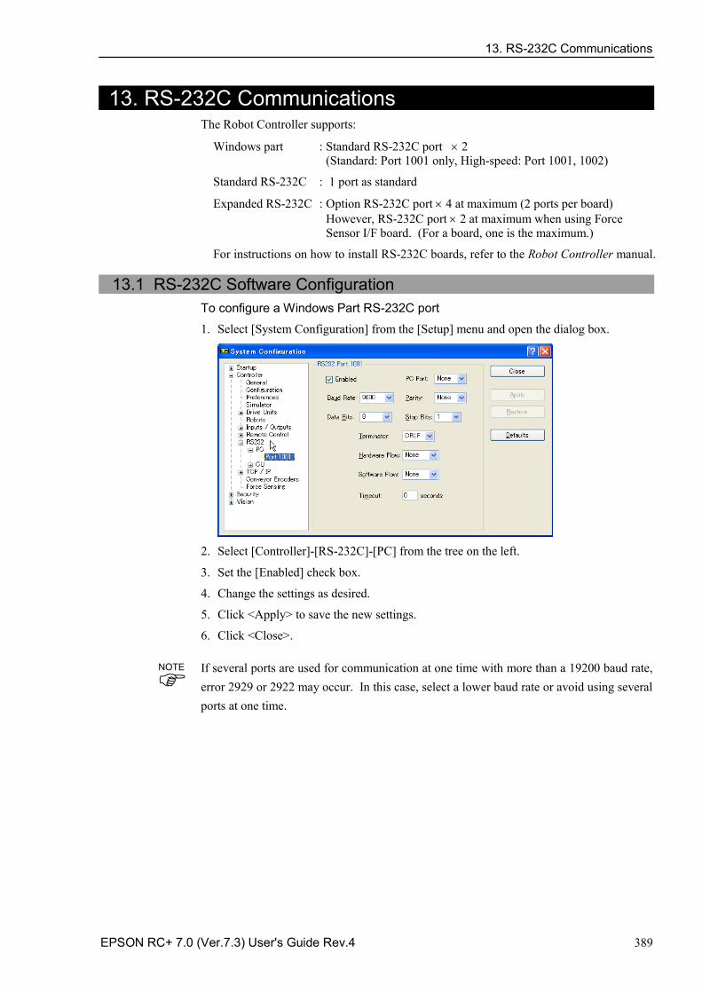
13. RS-232C Communications
EPSON RC+ 7.0 (Ver.7.3) User's Guide Rev.4 389
13. RS-232C Communications The Robot Controller supports:
Windows part : Standard RS-232C port × 2 (Standard: Port 1001 only, High-speed: Port 1001, 1002)
Standard RS-232C : 1 port as standard
Expanded RS-232C : Option RS-232C port × 4 at maximum (2 ports per board) However, RS-232C port × 2 at maximum when using Force Sensor I/F board. (For a board, one is the maximum.)
For instructions on how to install RS-232C boards, refer to the Robot Controller manual.
13.1 RS-232C Software Configuration To configure a Windows Part RS-232C port
1. Select [System Configuration] from the [Setup] menu and open the dialog box.
2. Select [Controller]-[RS-232C]-[PC] from the tree on the left.
3. Set the [Enabled] check box.
4. Change the settings as desired.
5. Click <Apply> to save the new settings.
6. Click <Close>.
If several ports are used for communication at one time with more than a 19200 baud rate, error 2929 or 2922 may occur. In this case, select a lower baud rate or avoid using several ports at one time.
NOTE
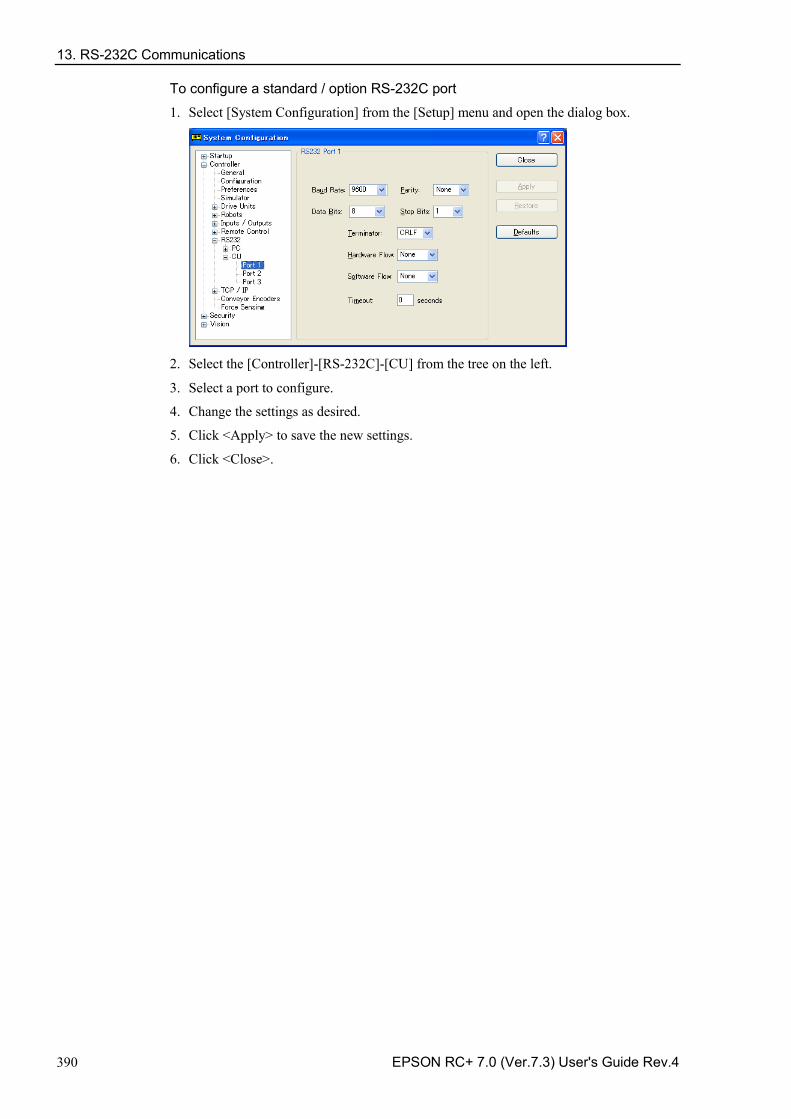
13. RS-232C Communications
390 EPSON RC+ 7.0 (Ver.7.3) User's Guide Rev.4
To configure a standard / option RS-232C port
1. Select [System Configuration] from the [Setup] menu and open the dialog box.
2. Select the [Controller]-[RS-232C]-[CU] from the tree on the left.
3. Select a port to configure.
4. Change the settings as desired.
5. Click <Apply> to save the new settings.
6. Click <Close>.
13. RS-232C Communications
EPSON RC+ 7.0 (Ver.7.3) User's Guide Rev.4 391
13.2 RS-232C Commands The following is a list of all of the commands associated with RS-232C communications. For details, please see the online help or SPEL+ Language Reference Manual.
OpenCom Opens a communications port.
ChkCom Returns port status: the number of bytes waiting to be read or error condition.
CloseCom Closes a communications port.
SetCom Sets communications port parameters at runtime or from the Command window.
Print # Sends characters out of the port.
Input # Receives characters from the port into one or more variables.
Line Input # Receives one line characters from the port into one string variable.
Read # Receives one or more characters from the port into one string variable.
ReadBin # Receives one or more bytes from the port.
Write # Sends characters out of the port.
WriteBin # Sends one or more bytes out of the port.
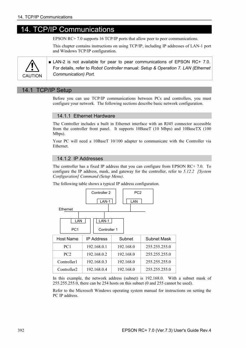
14. TCP/IP Communications
392 EPSON RC+ 7.0 (Ver.7.3) User's Guide Rev.4
14. TCP/IP Communications EPSON RC+ 7.0 supports 16 TCP/IP ports that allow peer to peer communications.
This chapter contains instructions on using TCP/IP, including IP addresses of LAN-1 port and Windows TCP/IP configuration.
CAUTION
■ LAN-2 is not available for pear to pear communications of EPSON RC+ 7.0. For details, refer to Robot Controller manual: Setup & Operation 7. LAN (Ethernet Communication) Port.
14.1 TCP/IP Setup
Before you can use TCP/IP communications between PCs and controllers, you must configure your network. The following sections describe basic network configuration.
14.1.1 Ethernet Hardware The Controller includes a built in Ethernet interface with an RJ45 connector accessible from the controller front panel. It supports 10BaseT (10 Mbps) and 10BaseTX (100 Mbps).
Your PC will need a 10BaseT 10/100 adapter to communicate with the Controller via Ethernet.
14.1.2 IP Addresses The controller has a fixed IP address that you can configure from EPSON RC+ 7.0. To configure the IP address, mask, and gateway for the controller, refer to 5.12.2 [System Configuration] Command (Setup Menu).
The following table shows a typical IP address configuration.
PC1 Controller 1
LAN-1 LAN
PC2 Controller 2
Ethernet
LAN LAN-1
Host Name IP Address Subnet Subnet Mask
PC1 192.168.0.1 192.168.0 255.255.255.0
PC2 192.168.0.2 192.168.0 255.255.255.0
Controller1 192.168.0.3 192.168.0 255.255.255.0
Controller2 192.168.0.4 192.168.0 255.255.255.0
In this example, the network address (subnet) is 192.168.0. With a subnet mask of 255.255.255.0, there can be 254 hosts on this subnet (0 and 255 cannot be used).
Refer to the Microsoft Windows operating system manual for instructions on setting the PC IP address.
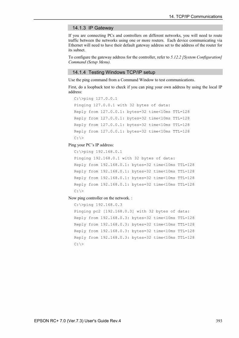
14. TCP/IP Communications
EPSON RC+ 7.0 (Ver.7.3) User's Guide Rev.4 393
14.1.3 IP Gateway If you are connecting PCs and controllers on different networks, you will need to route traffic between the networks using one or more routers. Each device communicating via Ethernet will need to have their default gateway address set to the address of the router for its subnet.
To configure the gateway address for the controller, refer to 5.12.2 [System Configuration] Command (Setup Menu).
14.1.4 Testing Windows TCP/IP setup Use the ping command from a Command Window to test communications.
First, do a loopback test to check if you can ping your own address by using the local IP address:
C:\>ping 127.0.0.1
Pinging 127.0.0.1 with 32 bytes of data:
Reply from 127.0.0.1: bytes=32 time<10ms TTL=128
Reply from 127.0.0.1: bytes=32 time<10ms TTL=128
Reply from 127.0.0.1: bytes=32 time<10ms TTL=128
Reply from 127.0.0.1: bytes=32 time<10ms TTL=128
C:\>
Ping your PC’s IP address: C:\>ping 192.168.0.1
Pinging 192.168.0.1 with 32 bytes of data:
Reply from 192.168.0.1: bytes=32 time<10ms TTL=128
Reply from 192.168.0.1: bytes=32 time<10ms TTL=128
Reply from 192.168.0.1: bytes=32 time<10ms TTL=128
Reply from 192.168.0.1: bytes=32 time<10ms TTL=128
C:\>
Now ping controller on the network. : C:\>ping 192.168.0.3
Pinging pc2 [192.168.0.3] with 32 bytes of data:
Reply from 192.168.0.3: bytes=32 time<10ms TTL=128
Reply from 192.168.0.3: bytes=32 time<10ms TTL=128
Reply from 192.168.0.3: bytes=32 time<10ms TTL=128
Reply from 192.168.0.3: bytes=32 time<10ms TTL=128
C:\>
14. TCP/IP Communications
394 EPSON RC+ 7.0 (Ver.7.3) User's Guide Rev.4
14.2 TCP/IP Software Configuration You can configure TCP/IP settings for the controller in a SPEL+ program using the SetNet command. You can also configure settings from the [TCP/IP] tab on the [Setup]-[System Configuration] dialog.
To configure a TCP/IP port
1. Select the TCP/IP port you want to configure from [Setup]-[System Configuration]-[Controller]-[TCP/IP].
2. Enter the IP address for the controller or PC that you want this controller to communicate with.
The controller does not support DNS, so you must specify an IP address for the host you are communicating with. You cannot specify a name for the host.
3. Enter the TCP/IP port number. This must be the same port number that is used on the host device. It must be different from any of the other TCP/IP port numbers used for the other TCP/IP ports.
4. Change the other settings as desired.
5. Click <Apply> to save the new settings and click <Close>.
14.3 TCP/IP Commands Here is a list of all of the commands associated with TCP/IP communications. For details, please see the online help or SPEL+ Language Reference Manual.
OpenNet Opens a TCP/IP port.
ChkNet Returns port status: the number of bytes waiting to be read or error condition.
CloseNet Closes a TCP/IP port.
SetNet Sets communications port parameters at runtime or from the Command window.
Print # Sends characters out of the port.
Input # Receives characters from the port into one or more variables.
Line Input # Receives one line characters from the port into one string variable.
Read # Receives one or more characters from the port into one string variable.
ReadBin # Receives one or more bytes from the port.
Write # Sends characters out of the port.
WriteBin # Sends one or more bytes out of the port.
15. Security
EPSON RC+ 7.0 (Ver.7.3) User's Guide Rev.4 395
15. Security
15.1 Overview The Security function allows you to manage EPSON RC+ 7.0 users and also monitor usage.
When the Security function is activated, administrators can add groups and users. Each group can have one or more rights associated with it. For example, you can create a group called Maintenance that has rights to edit robot points, use Jog & Teach, and enable you to use the Command Window. When a user attempts to do something that he/she does not have a right for, a message “Permission denied” will be displayed.
Each login session is recorded in a Microsoft Access compatible data base. Security Log Viewer is included that allows you to view each session’s activity.
User can login to EPSON RC+ with a name and password. Optionally, EPSON RC+ can use the Windows user name to log in automatically.
15.2 Security Configuration
EPSON RC+ 7.0 requires a path for security files. If you have more than one system on a network, it is recommended that you setup the security files path for all systems to store the security logs in a server on the network.
To administer EPSON RC+ 7.0 security:
1. Start EPSON RC+ 7.0.
2. Select [Setup]-[System Configuration].
3. Click on the [Security] tree.
4. On the [General] tree, type in the path for your security files or click the <Browse> button.
5. Click on the [Users] tree.
6. For each user on your system, click <New> button. Each new user belongs to the Guest group by default. Click in the group field, then click the dropdown button to select the desired group.
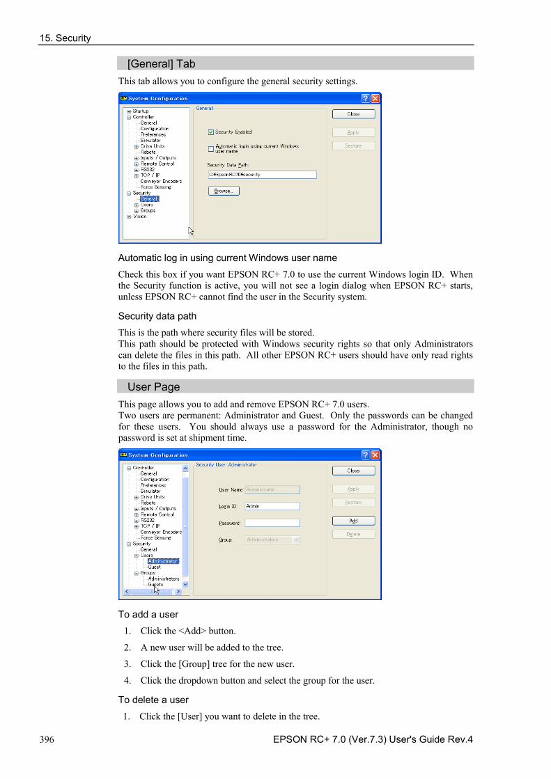
15. Security
396 EPSON RC+ 7.0 (Ver.7.3) User's Guide Rev.4
[General] Tab This tab allows you to configure the general security settings.
Automatic log in using current Windows user name
Check this box if you want EPSON RC+ 7.0 to use the current Windows login ID. When the Security function is active, you will not see a login dialog when EPSON RC+ starts, unless EPSON RC+ cannot find the user in the Security system.
Security data path
This is the path where security files will be stored. This path should be protected with Windows security rights so that only Administrators can delete the files in this path. All other EPSON RC+ users should have only read rights to the files in this path.
User Page This page allows you to add and remove EPSON RC+ 7.0 users. Two users are permanent: Administrator and Guest. Only the passwords can be changed for these users. You should always use a password for the Administrator, though no password is set at shipment time.
To add a user
1. Click the <Add> button.
2. A new user will be added to the tree.
3. Click the [Group] tree for the new user.
4. Click the dropdown button and select the group for the user.
To delete a user
1. Click the [User] you want to delete in the tree.
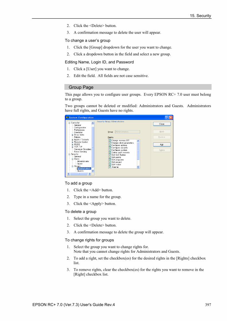
15. Security
EPSON RC+ 7.0 (Ver.7.3) User's Guide Rev.4 397
2. Click the <Delete> button.
3. A confirmation message to delete the user will appear.
To change a user’s group
1. Click the [Group] dropdown for the user you want to change.
2. Click a dropdown button in the field and select a new group.
Editing Name, Login ID, and Password
1. Click a [User] you want to change.
2. Edit the field. All fields are not case sensitive.
Group Page This page allows you to configure user groups. Every EPSON RC+ 7.0 user must belong to a group.
Two groups cannot be deleted or modified: Administrators and Guests. Administrators have full rights, and Guests have no rights.
To add a group
1. Click the <Add> button.
2. Type in a name for the group.
3. Click the <Apply> button.
To delete a group
1. Select the group you want to delete.
2. Click the <Delete> button.
3. A confirmation message to delete the group will appear.
To change rights for groups
1. Select the group you want to change rights for. Note that you cannot change rights for Administrators and Guests.
2. To add a right, set the checkbox(es) for the desired rights in the [Rights] checkbox list.
3. To remove rights, clear the checkbox(es) for the rights you want to remove in the [Right] checkbox list.
15. Security
398 EPSON RC+ 7.0 (Ver.7.3) User's Guide Rev.4
Group Rights The list below shows the rights that are available for user groups. Administrators have full rights, and Guests have no rights.
Right Description
Configure options Users can change option settings in [Setup]-[Options].
Use Command Window Users can open the command window and execute commands.
Configure system Users can configure the entire EPSON RC+ system.
Jog Users can open the [Jog & Teach] dialog and jog a robot.
Check security log Users can see security logs.
Delete security log Users can delete security logs in [Tools]-[Audit Viewer].
Teach points Users can teach points and delete points from the Jog & Teach dialog.
Edit vision Users can edit vision parameters.
Edit programs Users can edit program.
Edit projects Users can edit projects.
Edit points Users can change points.
Change memory I/O Users can turn ON/OFF memory I/O bits.
Change robot parameter Users can open the [Robot Manager] dialog and change the settings.
Output port ON Users can turn ON/OFF outputs.
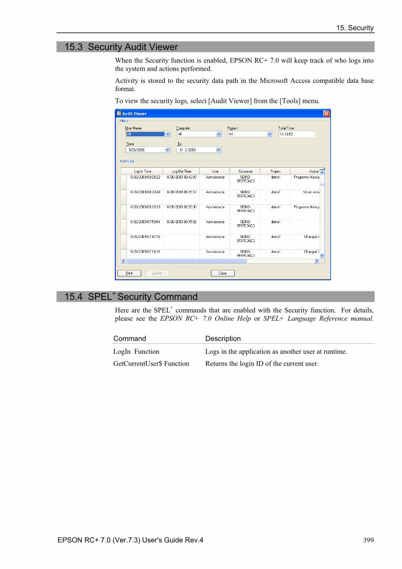
15. Security
EPSON RC+ 7.0 (Ver.7.3) User's Guide Rev.4 399
15.3 Security Audit Viewer When the Security function is enabled, EPSON RC+ 7.0 will keep track of who logs into the system and actions performed.
Activity is stored to the security data path in the Microsoft Access compatible data base format.
To view the security logs, select [Audit Viewer] from the [Tools] menu.
15.4 SPEL+ Security Command Here are the SPEL+ commands that are enabled with the Security function. For details, please see the EPSON RC+ 7.0 Online Help or SPEL+ Language Reference manual.
Command Description
LogIn Function Logs in the application as another user at runtime.
GetCurrentUser$ Function Returns the login ID of the current user.
16. Conveyor Tracking
400 EPSON RC+ 7.0 (Ver.7.3) User's Guide Rev.4
16. Conveyor Tracking
16.1 Overview Conveyor Tracking is a process in which a robot picks up parts from a stationary or moving conveyor that are found by a vision system or sensor.
The EPSON RC+ 7.0 Conveyor Tracking option supports both tracking and indexed conveyor systems.
• Tracking conveyor system Conveyor moves constantly. Vision system or sensor system finds the parts on it and robot picks them up as they move. During tracking, the robot can move along with the part as it picks up parts.
• Indexed conveyor system Conveyor moves a specified distance and then stops. The vision system finds the parts and robot picks up each part. After finding and picking up all parts, the conveyor moves again.
A total of 16 physical conveyors can be defined on each system. A physical conveyor has one encoder whose signals are received by an encoder board.
Up to 16 logical conveyors can be defined in each project. To define a logical conveyor, set a conveyor number, a robot number, encoder number and select vision or sensor.
Multiple conveyors and multiple-robot conveyors are supported.
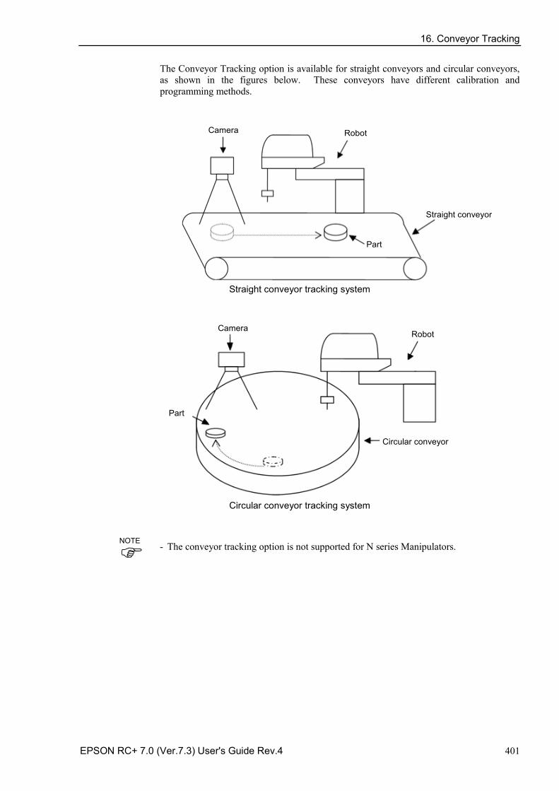
16. Conveyor Tracking
EPSON RC+ 7.0 (Ver.7.3) User's Guide Rev.4 401
The Conveyor Tracking option is available for straight conveyors and circular conveyors, as shown in the figures below. These conveyors have different calibration and programming methods.
Robot Camera
Straight conveyor
Part
Straight conveyor tracking system
Robot Camera
Circular conveyor
Part
Circular conveyor tracking system
The conveyor tracking option is not supported for N series Manipulators. -
NOTE
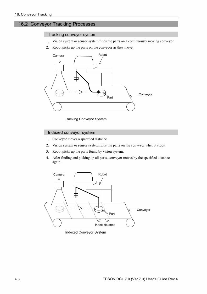
16. Conveyor Tracking
402 EPSON RC+ 7.0 (Ver.7.3) User's Guide Rev.4
16.2 Conveyor Tracking Processes
Tracking conveyor system 1. Vision system or sensor system finds the parts on a continuously moving conveyor.
2. Robot picks up the parts on the conveyor as they move.
Robot Camera
Conveyor Part
Tracking Conveyor System
Indexed conveyor system
1. Conveyor moves a specified distance.
2. Vision system or sensor system finds the parts on the conveyor when it stops.
3. Robot picks up the parts found by vision system.
4. After finding and picking up all parts, conveyor moves by the specified distance again.
Index distance
Robot Camera
Conveyor Part
Indexed Conveyor System
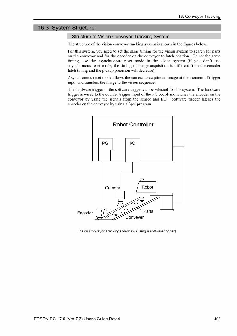
16. Conveyor Tracking
EPSON RC+ 7.0 (Ver.7.3) User's Guide Rev.4 403
16.3 System Structure Structure of Vision Conveyor Tracking System
The structure of the vision conveyor tracking system is shown in the figures below.
For this system, you need to set the same timing for the vision system to search for parts on the conveyor and for the encoder on the conveyor to latch position. To set the same timing, use the asynchronous reset mode in the vision system (if you don’t use asynchronous reset mode, the timing of image acquisition is different from the encoder latch timing and the pickup precision will decrease).
Asynchronous reset mode allows the camera to acquire an image at the moment of trigger input and transfers the image to the vision sequence.
The hardware trigger or the software trigger can be selected for this system. The hardware trigger is wired to the counter trigger input of the PG board and latches the encoder on the conveyor by using the signals from the sensor and I/O. Software trigger latches the encoder on the conveyor by using a Spel program.
Robot Controller
PG I/O
Robot Camera
Conveyer Encoder Parts
Vision Conveyor Tracking Overview (using a software trigger)
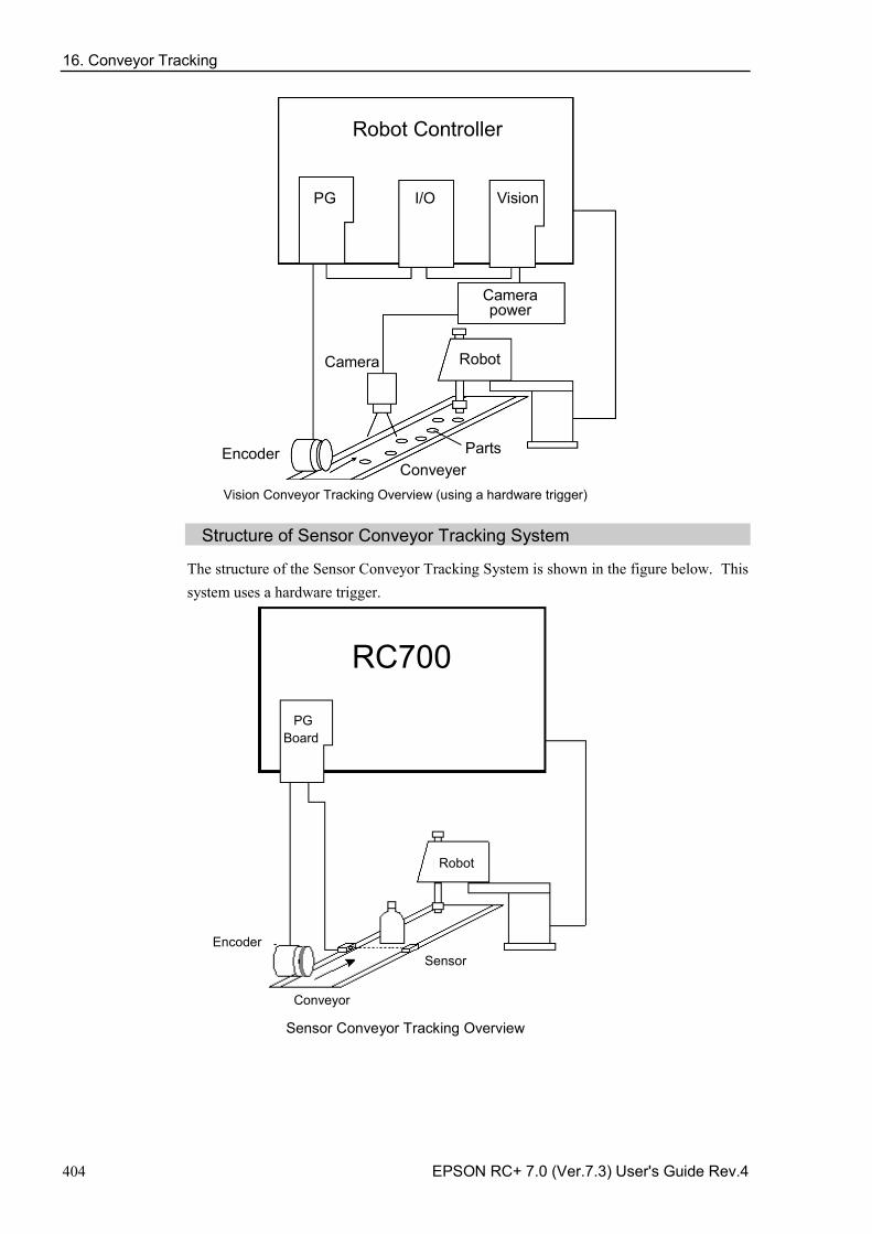
16. Conveyor Tracking
404 EPSON RC+ 7.0 (Ver.7.3) User's Guide Rev.4
Robot Controller
PG I/O
Robot Camera
Conveyer Encoder Parts
Vision
Camera power
Vision Conveyor Tracking Overview (using a hardware trigger)
Structure of Sensor Conveyor Tracking System
The structure of the Sensor Conveyor Tracking System is shown in the figure below. This system uses a hardware trigger.
PG Board
Robot
Sensor
Conveyor
Encoder
RC700
Sensor Conveyor Tracking Overview
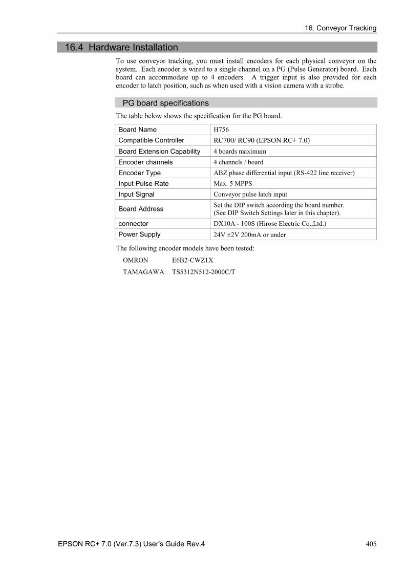
16. Conveyor Tracking
EPSON RC+ 7.0 (Ver.7.3) User's Guide Rev.4 405
16.4 Hardware Installation To use conveyor tracking, you must install encoders for each physical conveyor on the system. Each encoder is wired to a single channel on a PG (Pulse Generator) board. Each board can accommodate up to 4 encoders. A trigger input is also provided for each encoder to latch position, such as when used with a vision camera with a strobe.
PG board specifications
The table below shows the specification for the PG board.
Board Name H756 Compatible Controller RC700/ RC90 (EPSON RC+ 7.0) Board Extension Capability 4 boards maximum Encoder channels 4 channels / board Encoder Type ABZ phase differential input (RS-422 line receiver) Input Pulse Rate Max. 5 MPPS Input Signal Conveyor pulse latch input
Board Address Set the DIP switch according the board number. (See DIP Switch Settings later in this chapter).
connector DX10A - 100S (Hirose Electric Co.,Ltd.) Power Supply 24V ±2V 200mA or under
The following encoder models have been tested:
OMRON E6B2-CWZ1X
TAMAGAWA TS5312N512-2000C/T
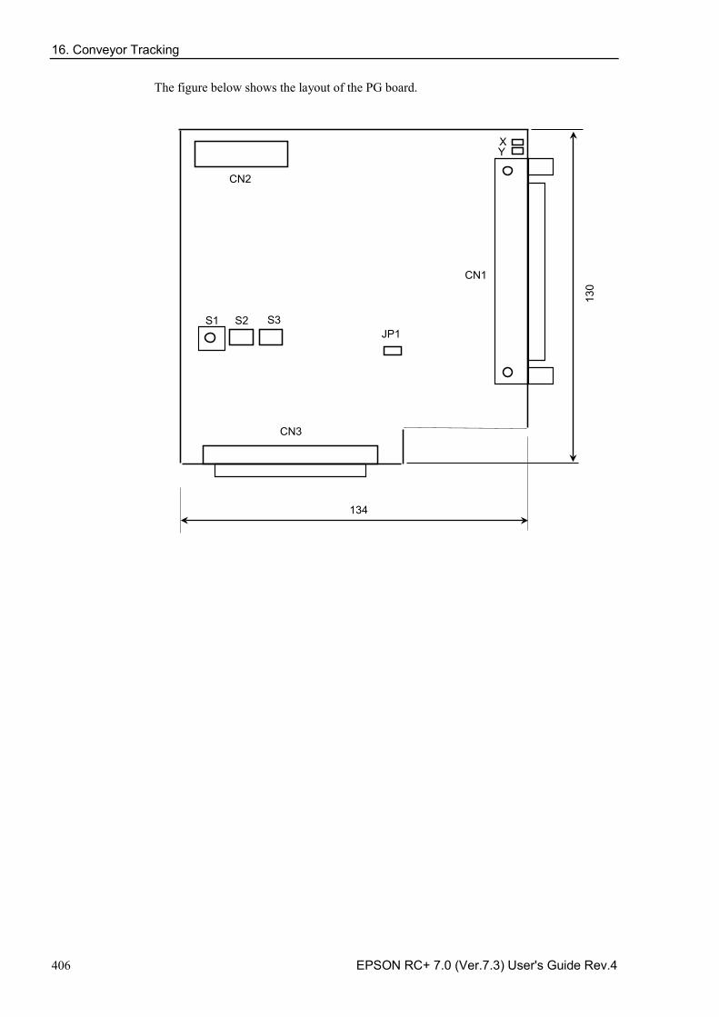
16. Conveyor Tracking
406 EPSON RC+ 7.0 (Ver.7.3) User's Guide Rev.4
The figure below shows the layout of the PG board.
JP1
CN2
134
130
CN1
CN3
X Y
S3 S2 S1
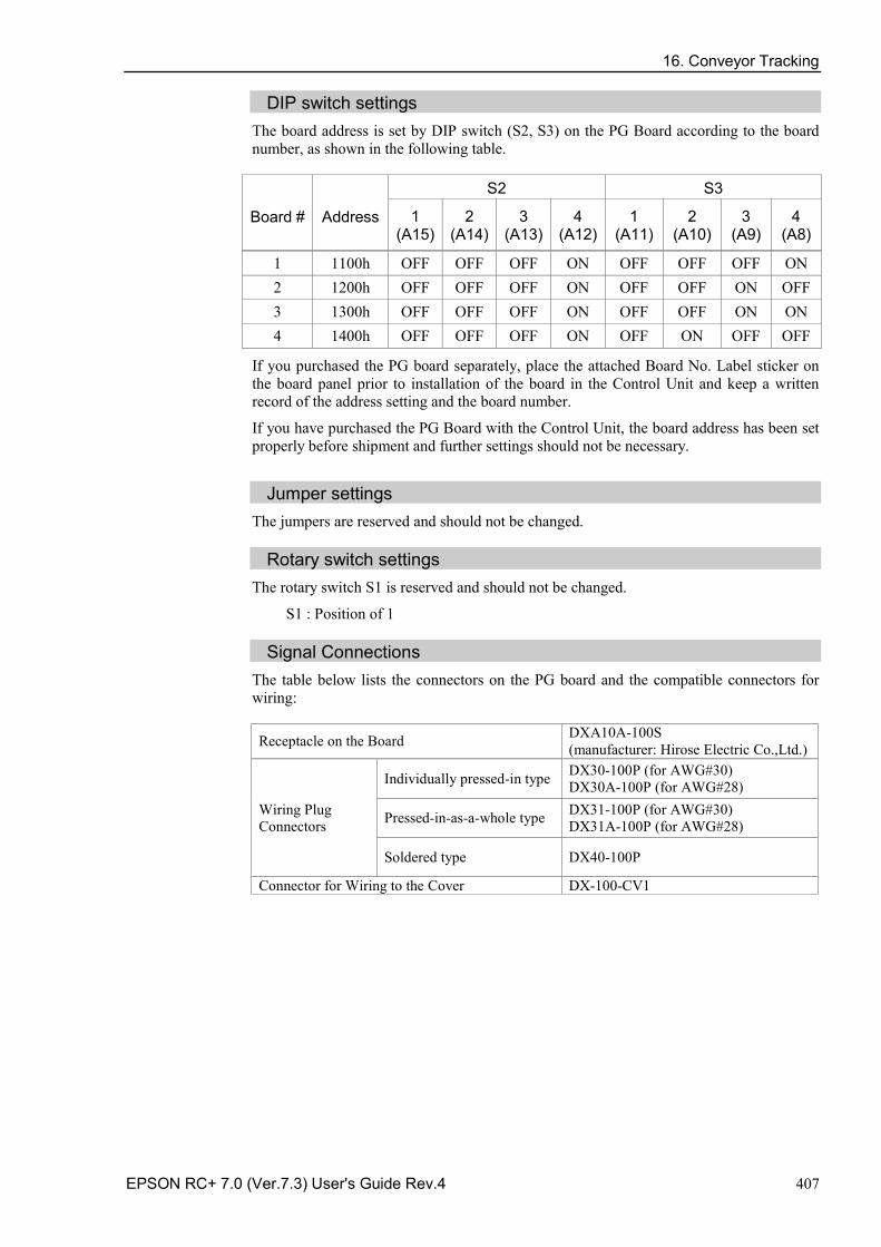
16. Conveyor Tracking
EPSON RC+ 7.0 (Ver.7.3) User's Guide Rev.4 407
DIP switch settings The board address is set by DIP switch (S2, S3) on the PG Board according to the board number, as shown in the following table.
Board # Address
S2 S3
1 (A15)
2 (A14)
3 (A13)
4 (A12)
1 (A11)
2 (A10)
3 (A9)
4 (A8)
1 1100h OFF OFF OFF ON OFF OFF OFF ON 2 1200h OFF OFF OFF ON OFF OFF ON OFF 3 1300h OFF OFF OFF ON OFF OFF ON ON 4 1400h OFF OFF OFF ON OFF ON OFF OFF
If you purchased the PG board separately, place the attached Board No. Label sticker on the board panel prior to installation of the board in the Control Unit and keep a written record of the address setting and the board number.
If you have purchased the PG Board with the Control Unit, the board address has been set properly before shipment and further settings should not be necessary.
Jumper settings
The jumpers are reserved and should not be changed.
Rotary switch settings The rotary switch S1 is reserved and should not be changed.
S1 : Position of 1
Signal Connections The table below lists the connectors on the PG board and the compatible connectors for wiring:
Receptacle on the Board DXA10A-100S (manufacturer: Hirose Electric Co.,Ltd.)
Wiring Plug Connectors
Individually pressed-in type DX30-100P (for AWG#30) DX30A-100P (for AWG#28)
Pressed-in-as-a-whole type DX31-100P (for AWG#30) DX31A-100P (for AWG#28)
Soldered type DX40-100P
Connector for Wiring to the Cover DX-100-CV1
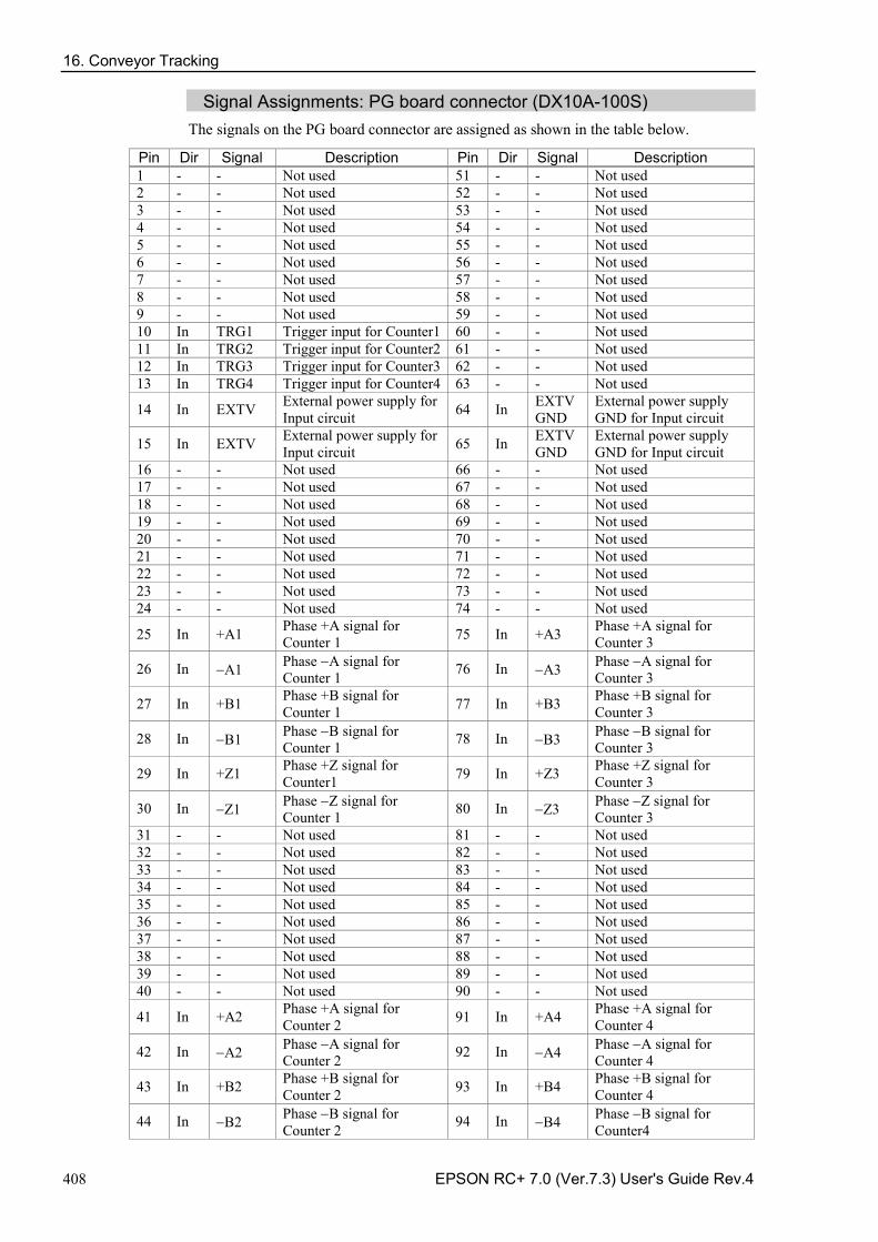
16. Conveyor Tracking
408 EPSON RC+ 7.0 (Ver.7.3) User's Guide Rev.4
Signal Assignments: PG board connector (DX10A-100S) The signals on the PG board connector are assigned as shown in the table below.
Pin Dir Signal Description Pin Dir Signal Description 1 - - Not used 51 - - Not used 2 - - Not used 52 - - Not used 3 - - Not used 53 - - Not used 4 - - Not used 54 - - Not used 5 - - Not used 55 - - Not used 6 - - Not used 56 - - Not used 7 - - Not used 57 - - Not used 8 - - Not used 58 - - Not used 9 - - Not used 59 - - Not used 10 In TRG1 Trigger input for Counter1 60 - - Not used 11 In TRG2 Trigger input for Counter2 61 - - Not used 12 In TRG3 Trigger input for Counter3 62 - - Not used 13 In TRG4 Trigger input for Counter4 63 - - Not used
14 In EXTV External power supply for Input circuit 64 In EXTV
GND External power supply GND for Input circuit
15 In EXTV External power supply for Input circuit 65 In EXTV
GND External power supply GND for Input circuit
16 - - Not used 66 - - Not used 17 - - Not used 67 - - Not used 18 - - Not used 68 - - Not used 19 - - Not used 69 - - Not used 20 - - Not used 70 - - Not used 21 - - Not used 71 - - Not used 22 - - Not used 72 - - Not used 23 - - Not used 73 - - Not used 24 - - Not used 74 - - Not used
25 In +A1 Phase +A signal for Counter 1 75 In +A3 Phase +A signal for
Counter 3
26 In −A1 Phase −A signal for Counter 1 76 In −A3 Phase −A signal for
Counter 3
27 In +B1 Phase +B signal for Counter 1 77 In +B3 Phase +B signal for
Counter 3
28 In −B1 Phase −B signal for Counter 1 78 In −B3 Phase −B signal for
Counter 3
29 In +Z1 Phase +Z signal for Counter1 79 In +Z3 Phase +Z signal for
Counter 3
30 In −Z1 Phase −Z signal for Counter 1 80 In −Z3 Phase −Z signal for
Counter 3 31 - - Not used 81 - - Not used 32 - - Not used 82 - - Not used 33 - - Not used 83 - - Not used 34 - - Not used 84 - - Not used 35 - - Not used 85 - - Not used 36 - - Not used 86 - - Not used 37 - - Not used 87 - - Not used 38 - - Not used 88 - - Not used 39 - - Not used 89 - - Not used 40 - - Not used 90 - - Not used
41 In +A2 Phase +A signal for Counter 2 91 In +A4 Phase +A signal for
Counter 4
42 In −A2 Phase −A signal for Counter 2 92 In −A4 Phase −A signal for
Counter 4
43 In +B2 Phase +B signal for Counter 2 93 In +B4 Phase +B signal for
Counter 4
44 In −B2 Phase −B signal for Counter 2 94 In −B4 Phase −B signal for
Counter4
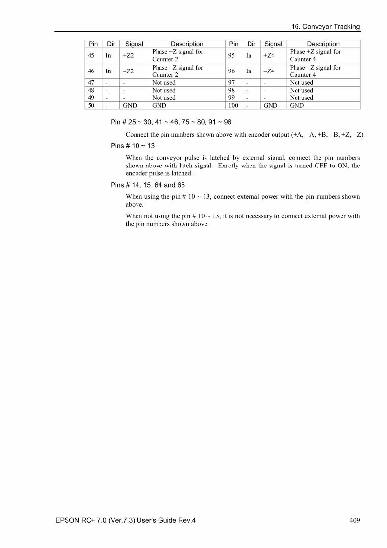
16. Conveyor Tracking
EPSON RC+ 7.0 (Ver.7.3) User's Guide Rev.4 409
Pin Dir Signal Description Pin Dir Signal Description
45 In +Z2 Phase +Z signal for Counter 2 95 In +Z4 Phase +Z signal for
Counter 4
46 In −Z2 Phase −Z signal for Counter 2 96 In −Z4 Phase −Z signal for
Counter 4 47 - - Not used 97 - - Not used 48 - - Not used 98 - - Not used 49 - - Not used 99 - - Not used 50 - GND GND 100 - GND GND
Pin # 25 ~ 30, 41 ~ 46, 75 ~ 80, 91 ~ 96
Connect the pin numbers shown above with encoder output (+A, −A, +B, −B, +Z, −Z).
Pins # 10 ~ 13
When the conveyor pulse is latched by external signal, connect the pin numbers shown above with latch signal. Exactly when the signal is turned OFF to ON, the encoder pulse is latched.
Pins # 14, 15, 64 and 65
When using the pin # 10 ~ 13, connect external power with the pin numbers shown above.
When not using the pin # 10 ~ 13, it is not necessary to connect external power with the pin numbers shown above.
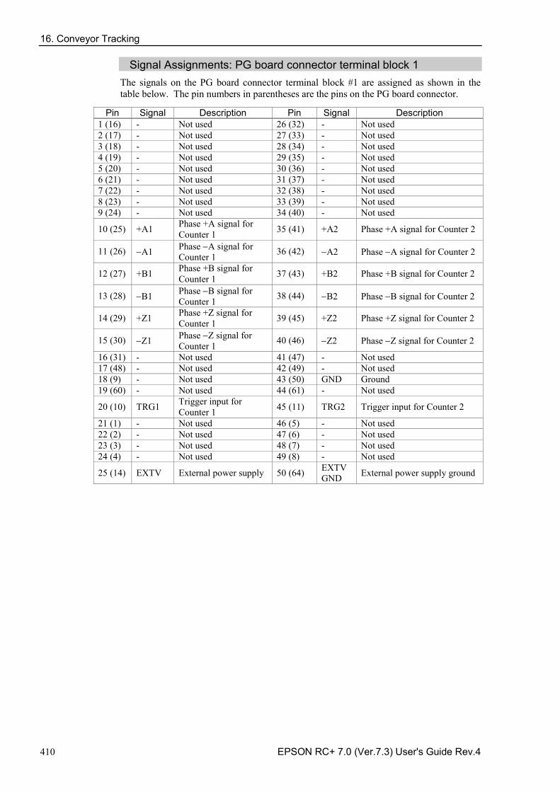
16. Conveyor Tracking
410 EPSON RC+ 7.0 (Ver.7.3) User's Guide Rev.4
Signal Assignments: PG board connector terminal block 1 The signals on the PG board connector terminal block #1 are assigned as shown in the table below. The pin numbers in parentheses are the pins on the PG board connector.
Pin Signal Description Pin Signal Description 1 (16) - Not used 26 (32) - Not used 2 (17) - Not used 27 (33) - Not used 3 (18) - Not used 28 (34) - Not used 4 (19) - Not used 29 (35) - Not used 5 (20) - Not used 30 (36) - Not used 6 (21) - Not used 31 (37) - Not used 7 (22) - Not used 32 (38) - Not used 8 (23) - Not used 33 (39) - Not used 9 (24) - Not used 34 (40) - Not used
10 (25) +A1 Phase +A signal for Counter 1 35 (41) +A2 Phase +A signal for Counter 2
11 (26) −A1 Phase −A signal for Counter 1 36 (42) −A2 Phase −A signal for Counter 2
12 (27) +B1 Phase +B signal for Counter 1 37 (43) +B2 Phase +B signal for Counter 2
13 (28) −B1 Phase −B signal for Counter 1 38 (44) −B2 Phase −B signal for Counter 2
14 (29) +Z1 Phase +Z signal for Counter 1 39 (45) +Z2 Phase +Z signal for Counter 2
15 (30) −Z1 Phase −Z signal for Counter 1 40 (46) −Z2 Phase −Z signal for Counter 2
16 (31) - Not used 41 (47) - Not used 17 (48) - Not used 42 (49) - Not used 18 (9) - Not used 43 (50) GND Ground 19 (60) - Not used 44 (61) - Not used
20 (10) TRG1 Trigger input for Counter 1 45 (11) TRG2 Trigger input for Counter 2
21 (1) - Not used 46 (5) - Not used 22 (2) - Not used 47 (6) - Not used 23 (3) - Not used 48 (7) - Not used 24 (4) - Not used 49 (8) - Not used
25 (14) EXTV External power supply 50 (64) EXTVGND External power supply ground
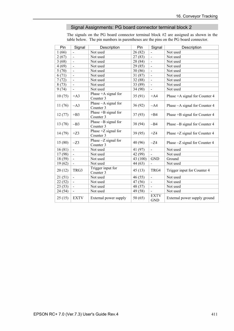
16. Conveyor Tracking
EPSON RC+ 7.0 (Ver.7.3) User's Guide Rev.4 411
Signal Assignments: PG board connector terminal block 2 The signals on the PG board connector terminal block #2 are assigned as shown in the table below. The pin numbers in parentheses are the pins on the PG board connector.
Pin Signal Description Pin Signal Description 1 (66) - Not used 26 (82) - Not used 2 (67) - Not used 27 (83) - Not used 3 (68) - Not used 28 (84) - Not used 4 (69) - Not used 29 (85) - Not used 5 (70) - Not used 30 (86) - Not used 6 (71) - Not used 31 (87) - Not used 7 (72) - Not used 32 (88) - Not used 8 (73) - Not used 33 (89) - Not used 9 (74) - Not used 34 (90) - Not used
10 (75) +A3 Phase +A signal for Counter 3 35 (91) +A4 Phase +A signal for Counter 4
11 (76) −A3 Phase −A signal for Counter 3 36 (92) −A4 Phase −A signal for Counter 4
12 (77) +B3 Phase +B signal for Counter 3 37 (93) +B4 Phase +B signal for Counter 4
13 (78) −B3 Phase −B signal for Counter 3 38 (94) −B4 Phase −B signal for Counter 4
14 (79) +Z3 Phase +Z signal for Counter 3 39 (95) +Z4 Phase +Z signal for Counter 4
15 (80) −Z3 Phase −Z signal for Counter 3 40 (96) −Z4 Phase −Z signal for Counter 4
16 (81) - Not used 41 (97) - Not used 17 (98) - Not used 42 (99) - Not used 18 (59) - Not used 43 (100) GND Ground 19 (62) - Not used 44 (63) - Not used
20 (12) TRG3 Trigger input for Counter 3 45 (13) TRG4 Trigger input for Counter 4
21 (51) - Not used 46 (55) - Not used 22 (52) - Not used 47 (56) - Not used 23 (53) - Not used 48 (57) - Not used 24 (54) - Not used 49 (58) - Not used
25 (15) EXTV External power supply 50 (65) EXTVGND External power supply ground
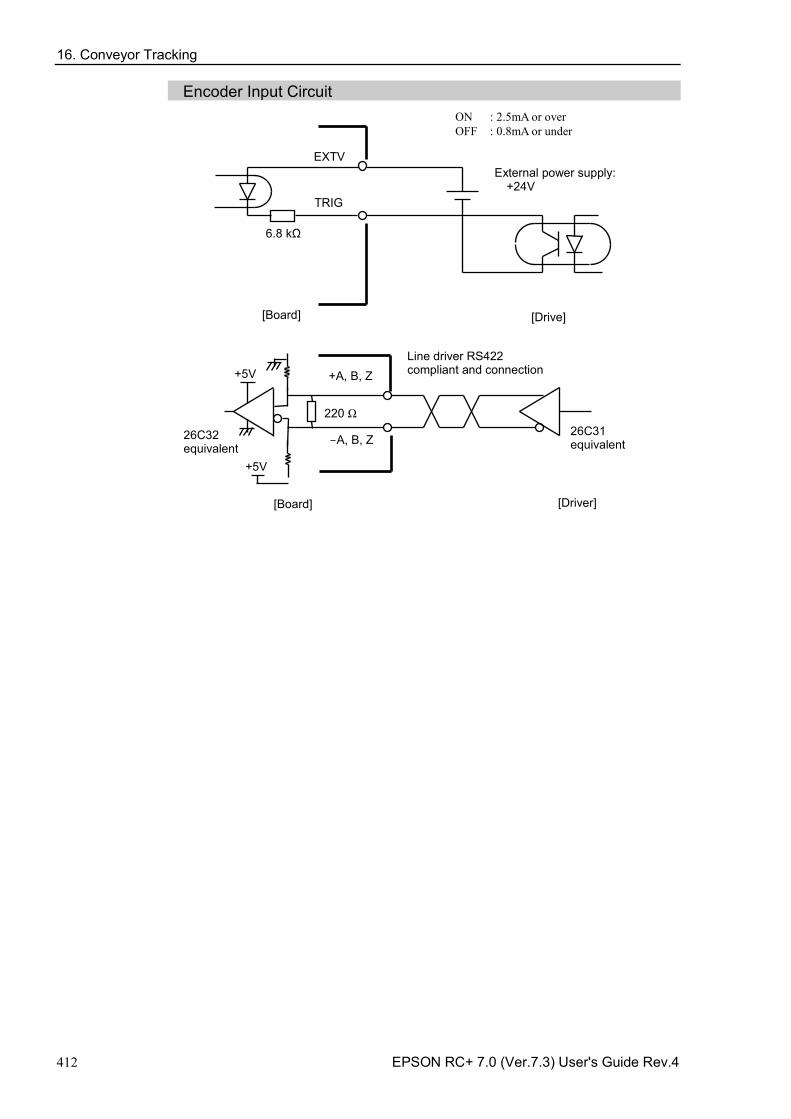
16. Conveyor Tracking
412 EPSON RC+ 7.0 (Ver.7.3) User's Guide Rev.4
Encoder Input Circuit
EXTV
TRIG
[Board] [Drive]
External power supply: +24V
ON : 2.5mA or over OFF : 0.8mA or under
6.8 kΩ
+A, B, Z
-A, B, Z
[Board] [Driver]
220 Ω 26C31 equivalent
Line driver RS422 compliant and connection
+5V
+5V
26C32 equivalent
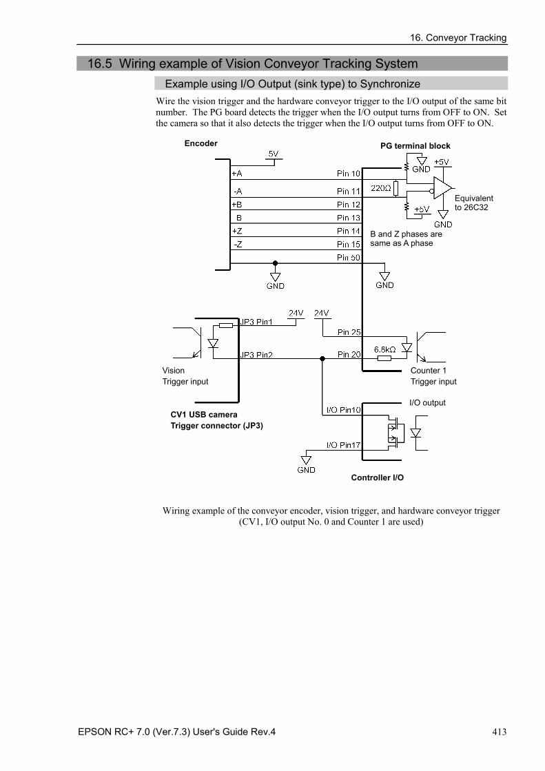
16. Conveyor Tracking
EPSON RC+ 7.0 (Ver.7.3) User's Guide Rev.4 413
16.5 Wiring example of Vision Conveyor Tracking System Example using I/O Output (sink type) to Synchronize
Wire the vision trigger and the hardware conveyor trigger to the I/O output of the same bit number. The PG board detects the trigger when the I/O output turns from OFF to ON. Set the camera so that it also detects the trigger when the I/O output turns from OFF to ON.
Controller I/O
Encoder PG terminal block
Equivalent to 26C32
Vision Trigger input
I/O output
Counter 1 Trigger input
B and Z phases are same as A phase
CV1 USB camera Trigger connector (JP3)
Wiring example of the conveyor encoder, vision trigger, and hardware conveyor trigger (CV1, I/O output No. 0 and Counter 1 are used)
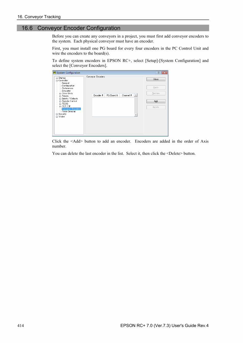
16. Conveyor Tracking
414 EPSON RC+ 7.0 (Ver.7.3) User's Guide Rev.4
16.6 Conveyor Encoder Configuration Before you can create any conveyors in a project, you must first add conveyor encoders to the system. Each physical conveyor must have an encoder.
First, you must install one PG board for every four encoders in the PC Control Unit and wire the encoders to the board(s).
To define system encoders in EPSON RC+, select [Setup]-[System Configuration] and select the [Conveyor Encoders].
Click the <Add> button to add an encoder. Encoders are added in the order of Axis number.
You can delete the last encoder in the list. Select it, then click the <Delete> button.
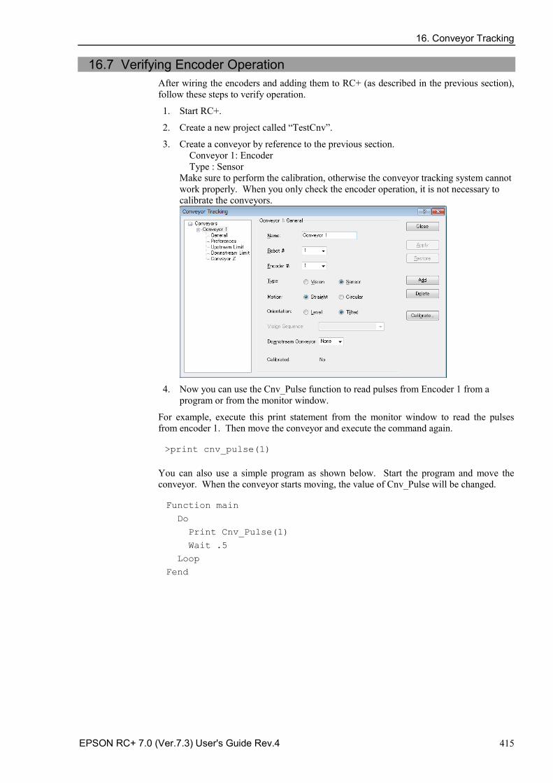
16. Conveyor Tracking
EPSON RC+ 7.0 (Ver.7.3) User's Guide Rev.4 415
16.7 Verifying Encoder Operation After wiring the encoders and adding them to RC+ (as described in the previous section), follow these steps to verify operation.
1. Start RC+.
2. Create a new project called “TestCnv”.
3. Create a conveyor by reference to the previous section. Conveyor 1: Encoder Type : Sensor Make sure to perform the calibration, otherwise the conveyor tracking system cannot work properly. When you only check the encoder operation, it is not necessary to calibrate the conveyors.
4. Now you can use the Cnv_Pulse function to read pulses from Encoder 1 from a
program or from the monitor window.
For example, execute this print statement from the monitor window to read the pulses from encoder 1. Then move the conveyor and execute the command again. >print cnv_pulse(1)
You can also use a simple program as shown below. Start the program and move the conveyor. When the conveyor starts moving, the value of Cnv_Pulse will be changed. Function main
Do
Print Cnv_Pulse(1)
Wait .5
Loop
Fend
16. Conveyor Tracking
416 EPSON RC+ 7.0 (Ver.7.3) User's Guide Rev.4
16.8 Verifying Hardware Conveyor Trigger / Vision Trigger Verifying the Hardware Conveyor Trigger
1. Move the conveyor and stop it.
2. Check the encoder pulse. Enter the following to the command window.
> Print Cnv_Pulse (Conveyor number)
3. Turn ON the I/O output number which the trigger is wired to. Latch the encoder pulse.
4. Check the latch pulse. Enter the following to the command window.
> Print Cnv_LPulse (Conveyor number)
- If the same value as obtained in the Step 2 is latched, the verification is completed.
- If not, check the hardware conveyor trigger wiring.
Verifying the Vision Trigger
1. Set the RuntimeAcquire property of the vision sequence to “Strobed” and the TriggerMode property to “Leading”.
2. Execute the vision sequence and put it into the trigger waiting state.
3. Turn ON the I/O output number which the trigger is wired to and release the shutter.
- If the captured image is displayed on the VisionGuide window, the verification is completed.
- If not, check the vision trigger wiring.
16. Conveyor Tracking
EPSON RC+ 7.0 (Ver.7.3) User's Guide Rev.4 417
16.9 Key Terms Here explains key terms used in this section.
Queue Waiting queue of the FIFO (First-In, First-Out) type for each conveyor.
With the queue, you can register the pose data of work pieces running on the conveyor and user data. When you add data, it will be registered to the end of the queue. When you delete data from the queue, the remaining data in the queue will be moved up automatically.
Queue depth The number of data entries registered in a queue. Maximum number of queue data is 1000.
Queue user data
Optional real value that can be registered in a queue.
You can store additional information such as sorted data or part type determined by the image processing.
Downstream Conveyor
Use this when using multiple conveyors and you run them continuously. By making an association (upstream/downstream) between conveyors, you can move a queue using the Cnv_QueMove command. “Multiple conveyors” is not necessarily more than one conveyor. You can use one long physical conveyor and set upstream side and downstream side as different logical conveyors. This enables the robots cooperative work, for instance, robot at the downstream side can pick up the work pieces that the robot at upstream fails to pick in time.
Upstream Limit
Dividing line in the upstream side of the Pickup Area.
Downstream Limit
Dividing line in the downstream side of the Pickup Area.
Pickup Area The area between the upstream limit and downstream limit.
The robot picks parts which flow in the Pickup Area. The robot starting pickup near the downstream limit continues its operation over the downstream limit. Make sure that the Pickup Area covers the whole robot motion range.
For details, refer to 16.15 Pickup Area.
16. Conveyor Tracking
418 EPSON RC+ 7.0 (Ver.7.3) User's Guide Rev.4
16.10 Conveyor Tracking Commands All Conveyor Tracking commands begin with the same prefix: "Cnv_". Here is a list of all of the commands. For details, please see the EPSON RC+ Online Help or SPEL+ Language Reference manual.
Command Description / Usage
Cnv_AbortTrack Aborts a motion command to a conveyor queue point.
Cnv_Accel Function Sets/ returns acceleration and deceleration of the conveyor.
Cnv_Accel Sets acceleration and deceleration of the conveyor.
Cnv_DownStream Function Returns the downstream limit for the specified conveyor.
Cnv_Downstream Sets the downstream limit of the conveyor.
Cnv_Fine Function Returns the setting of the range to judge if the tracking motion is completed or not for the specified conveyor.
Cnv_Fine Sets / returns the value of Cnv_Fine for one conveyor.
Cnv_Mode Function Returns the conveyor mode setting value.
Cnv_Mode Sets the conveyor mode setting value.
Cnv_LPulse Function Returns the pulse latched by a conveyor trigger.
Cnv_Name$ Function Returns the name of the specified conveyor.
Cnv_Number Function Returns the number of a conveyor specified by name.
Cnv_OffsetAngle Sets the angle offset. Usage: This command is available only for the circular conveyor.
Cnv_OffsetAngle Function Returns the offset angle.
Cnv_Point Function Returns a robot point in the specified conveyor's coordinate system derived from sensor coordinates. Usage: Use this function when registering a point in the queue.
Cnv_PosErr Function Returns deviation in current tracking position compared to tracking target.
Cnv_Pulse Function Returns the current position of a conveyor in pulses.
Cnv_QueAdd Adds a robot point to a conveyor queue. Usage: Use this command to register a point in the queue.
Cnv_QueGet Function Returns a point from the specified conveyor's queue. Usage: Use this command for robot tracking motion.
Cnv_QueLen Function Returns the number of items in the specified conveyor's queue. Usage: Use this command to keep the robot waiting until the part (queue) enters the tracking area.
Cnv_QueList Displays a list of items in the specified conveyor's queue.
Cnv_QueMove Moves data from upstream conveyor queue to downstream conveyor queue. Usage: Use this command for the multi conveyor system.
Cnv_QueReject Sets / displays the minimum distance to prevent the double conveyors register.
For details, refer to Cnv_QueReject.
Cnv_QueReject Function Sets / returns and displays the queue reject distance for a conveyor.
Cnv_QueRemove Removes items from a conveyor queue.
Cnv_QueUserData Function Sets / returns and displays user data associated with a queue entry.
16. Conveyor Tracking
EPSON RC+ 7.0 (Ver.7.3) User's Guide Rev.4 419
Cnv_RobotConveyor Function Returns the conveyor being tracked by a robot.
Cnv_Speed Function Returns the current speed of a conveyor.
Cnv_Trigger Latches current conveyor position for the next Cnv_QueAdd statement. Usage: Use this command when using the software trigger.
Cnv_Upstream Function Returns the upstream limit for the specified conveyor.
Cnv_Upstream Sets the upstream limit of the conveyor.
To track a part as the conveyor moves, you must use Cnv_QueGet in a motion command statement. For example:
Jump Cnv_QueGet(1) ' this tracks the part
You cannot assign the result from Cnv_QueGet to a point and then track it by moving to the point.
P1 = Cnv_QueGet(1) Jump P1 ' this does not track the part!
When you assign the result from Cnv_QueGet to a point, the coordinate values correspond to the position of the part when the point assignment was executed.
NOTE
16. Conveyor Tracking
420 EPSON RC+ 7.0 (Ver.7.3) User's Guide Rev.4
16.11 Creating Conveyors in a Project
Conveyors are configured for each EPSON RC+ project. Up to 16 conveyors can be created per project. A conveyor is a logical entity that combines a robot with one or more conveyors.
There are two types of conveyors: vision and sensor. If you will be using a vision camera to find the parts on the conveyor, you must first create a vision sequence to find the parts. This vision sequence is required when you define the conveyor.
To add a conveyor to a project
1. Select [Tools]-[Conveyor Tracking] to open the [Conveyor Tracking] configuration dialog.
2. To add a conveyor, click the <Add> button. The following dialog will appear.
3. Enter a name for the conveyor, then specify the Robot #, Encoder #, Type, Motion,
and Orientation.
A default conveyor name is created automatically when a new conveyor is added. -You can change the name as desired. When you use a straight conveyor, select “Line” for [Motion]. - When you use a circular conveyor, select “Circular” for [Motion]. -
NOTE
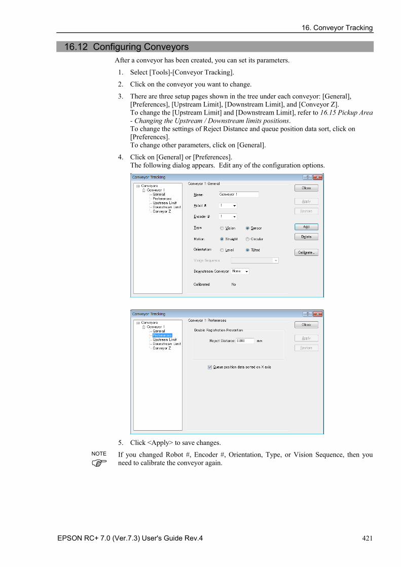
16. Conveyor Tracking
EPSON RC+ 7.0 (Ver.7.3) User's Guide Rev.4 421
16.12 Configuring Conveyors After a conveyor has been created, you can set its parameters.
1. Select [Tools]-[Conveyor Tracking].
2. Click on the conveyor you want to change.
3. There are three setup pages shown in the tree under each conveyor: [General], [Preferences], [Upstream Limit], [Downstream Limit], and [Conveyor Z]. To change the [Upstream Limit] and [Downstream Limit], refer to 16.15 Pickup Area - Changing the Upstream / Downstream limits positions. To change the settings of Reject Distance and queue position data sort, click on [Preferences]. To change other parameters, click on [General].
4. Click on [General] or [Preferences]. The following dialog appears. Edit any of the configuration options.
5. Click <Apply> to save changes.
If you changed Robot #, Encoder #, Orientation, Type, or Vision Sequence, then you need to calibrate the conveyor again.
NOTE
16. Conveyor Tracking
422 EPSON RC+ 7.0 (Ver.7.3) User's Guide Rev.4
The following table explains the parameters you can edit in the [General] and [Preferences] pages.
Name You can name conveyors. There is a restriction on the number of characters to be input. 1-byte characters: up to 15 characters 2-byte characters: up to 7 characters
Robot # You can select a robot number from the robots currently configured in the controller.
Encoder # You can select an encoder number from the encoders currently configured in the controller.
Type Vision: Detects work pieces using vision search.
Sensor: Detects work pieces using a sensor.
Motion You can select the conveyor motion; Straight conveyor or Circular conveyor.
Orientation When you selected Straight conveyor, you can specify if the conveyor is level or tilted.
<Tilted> is selected by default and normally you don’t have to change it.
Tilted: Conveyor slope is detected during the calibration.
Level: Conveyor slope is not detected during the calibration. You need to observe the following: The conveyor must be level with the robot X and Y planes.
Vision Sequence Select a vision sequence for the calibration.
This is only necessary when using the vision type.
Downstream Conveyor
When two or more conveyors have been set, you can select a conveyor number for the downstream conveyor.
Calibrate… Click this button to execute the calibration.
The calibration procedure is different for each type and conveyor orientation.
Adjust Z After the calibration is completed, you can calibrate the Z coordinate value of the conveyor again.
Reject Distance You can set a minimum distance to prevent the registration of duplicate conveyors.
・ The distance also can be set from the SPEL program using the Cnv_QueReject command.
・ If the distance is different from the one set by Cnv_QueReject command, the Cnv_QueReject command setting has precedence.
Queue position data sorted on X axis
You can select whether to sort the queue or not.
After the calibration, change the parameters for Robot #, Encoder #, Type, Motion, Orientation, Vision Sequence, Adjust Z, and Upstream/Downstream limit.
NOTE
16. Conveyor Tracking
EPSON RC+ 7.0 (Ver.7.3) User's Guide Rev.4 423
16.13 Vision Conveyors A vision conveyor uses a camera to locate parts that will be retrieved by one or more robots. In this section, instructions are provided for vision conveyor calibration.
The straight conveyor and the circular conveyor have different calibration methods.
Vision conveyor camera and lighting
It is important to choose the correct camera and lighting for the vision conveyors used in your application.
For applications with a slow moving conveyor and non-critical pick up constraints, you may be able to use a Vision Guide camera and simple lighting with no strobe.
For applications with fast moving parts, you will need to use a camera that is capable of asynchronous reset along with a strobe lamp. This method is more expensive.
If you are using multiple asynchronous reset cameras in multiple tasks, you must use SyncLock to lock the vision system during VRun and waiting until the picture is acquired.
For example: SyncLock 1 ' Lock vision for this task
VRun FindPart
On strobe, .2
Do
VGet FindPart.AcquireState, state
Loop Until state = 3
SyncUnlock 1 ' Unlock vision
Vision calibration sequence
Before you can calibrate a vision conveyor, you must first create a calibration sequence. This sequence is used by the system during the calibration process and must be linked to a camera calibration. The conveyor system commands use camera coordinates in millimeters. Although you can use any type of Vision Guide camera calibration, you only need to use a Standalone calibration.
The calibration sequence needs a sequence that uses one object for each work piece.
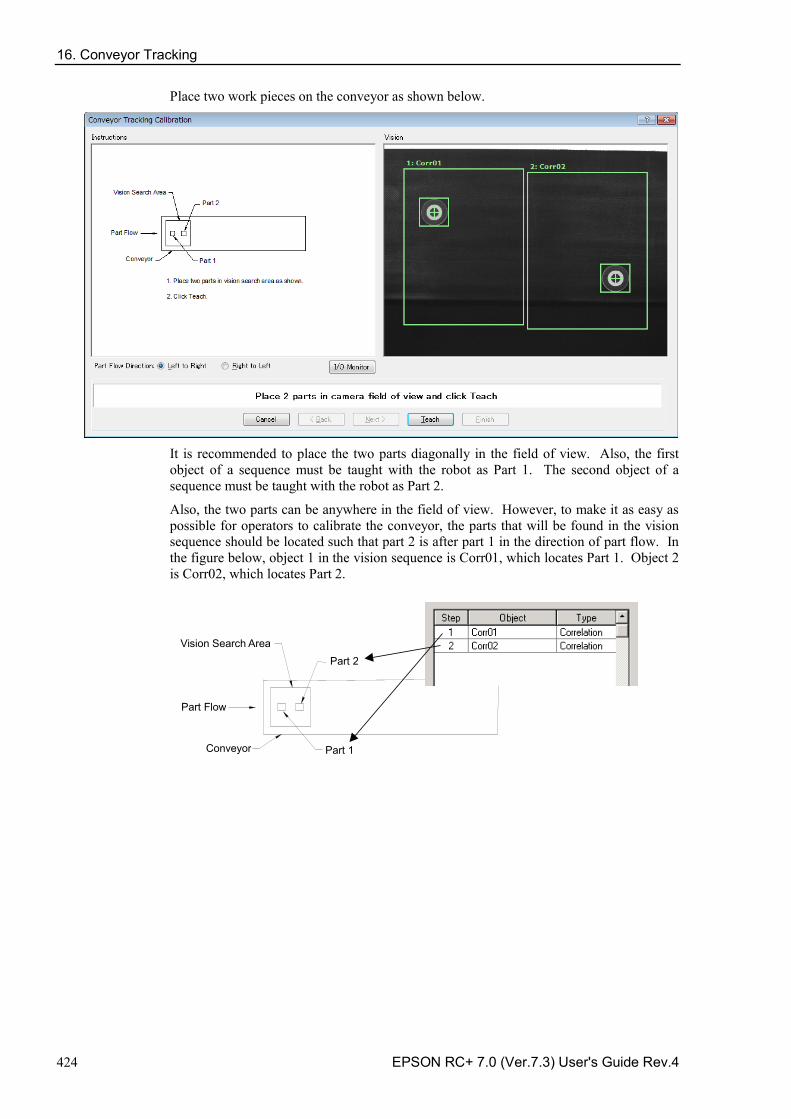
16. Conveyor Tracking
424 EPSON RC+ 7.0 (Ver.7.3) User's Guide Rev.4
Place two work pieces on the conveyor as shown below.
It is recommended to place the two parts diagonally in the field of view. Also, the first object of a sequence must be taught with the robot as Part 1. The second object of a sequence must be taught with the robot as Part 2.
Also, the two parts can be anywhere in the field of view. However, to make it as easy as possible for operators to calibrate the conveyor, the parts that will be found in the vision sequence should be located such that part 2 is after part 1 in the direction of part flow. In the figure below, object 1 in the vision sequence is Corr01, which locates Part 1. Object 2 is Corr02, which locates Part 2.
Conveyor
Vision Search Area Part 2
Part Flow
Part 1
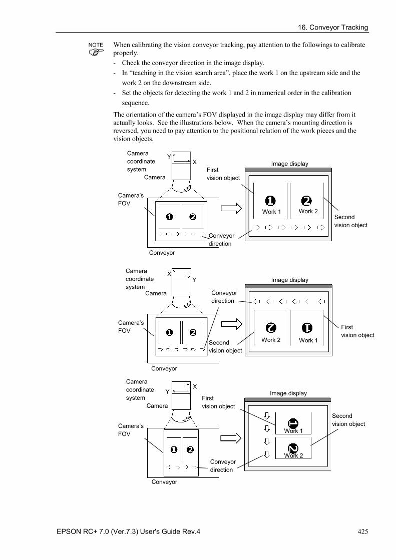
16. Conveyor Tracking
EPSON RC+ 7.0 (Ver.7.3) User's Guide Rev.4 425
When calibrating the vision conveyor tracking, pay attention to the followings to calibrate properly. - Check the conveyor direction in the image display. - In “teaching in the vision search area”, place the work 1 on the upstream side and the
work 2 on the downstream side. - Set the objects for detecting the work 1 and 2 in numerical order in the calibration
sequence.
The orientation of the camera’s FOV displayed in the image display may differ from it actually looks. See the illustrations below. When the camera’s mounting direction is reversed, you need to pay attention to the positional relation of the work pieces and the vision objects.
Conveyor
Work 1 Work 2
First vision object
Image display
Conveyor direction
Camera’s FOV
Camera
Camera coordinate system
X Y
Second vision object
Camera coordinate system
X Y
Second vision object
Camera’s FOV
Work 1 Work 2
Conveyor direction
Conveyor
Image display
Camera
First vision object
Camera coordinate system
Y
Work 1
Work 2 Conveyor direction
Image display
Camera
X
Conveyor
Camera’s FOV
Second vision object
First vision object
NOTE
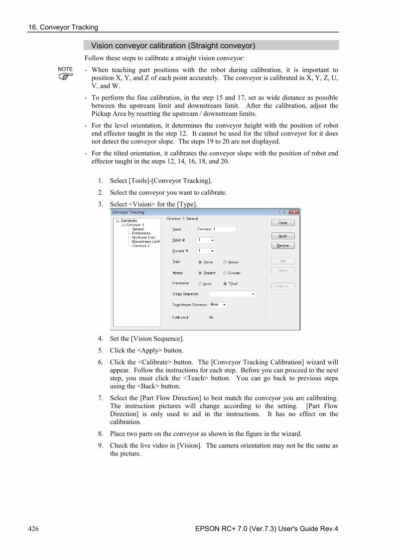
16. Conveyor Tracking
426 EPSON RC+ 7.0 (Ver.7.3) User's Guide Rev.4
Vision conveyor calibration (Straight conveyor) Follow these steps to calibrate a straight vision conveyor:
- When teaching part positions with the robot during calibration, it is important to position X, Y, and Z of each point accurately. The conveyor is calibrated in X, Y, Z, U, V, and W.
- To perform the fine calibration, in the step 15 and 17, set as wide distance as possible between the upstream limit and downstream limit. After the calibration, adjust the Pickup Area by resetting the upstream / downstream limits.
- For the level orientation, it determines the conveyor height with the position of robot end effector taught in the step 12. It cannot be used for the tilted conveyor for it does not detect the conveyor slope. The steps 19 to 20 are not displayed.
- For the tilted orientation, it calibrates the conveyor slope with the position of robot end effector taught in the steps 12, 14, 16, 18, and 20.
1. Select [Tools]-[Conveyor Tracking].
2. Select the conveyor you want to calibrate.
3. Select <Vision> for the [Type].
4. Set the [Vision Sequence].
5. Click the <Apply> button.
6. Click the <Calibrate> button. The [Conveyor Tracking Calibration] wizard will appear. Follow the instructions for each step. Before you can proceed to the next step, you must click the <Teach> button. You can go back to previous steps using the <Back> button.
7. Select the [Part Flow Direction] to best match the conveyor you are calibrating. The instruction pictures will change according to the setting. [Part Flow Direction] is only used to aid in the instructions. It has no effect on the calibration.
8. Place two parts on the conveyor as shown in the figure in the wizard.
9. Check the live video in [Vision]. The camera orientation may not be the same as the picture.
NOTE
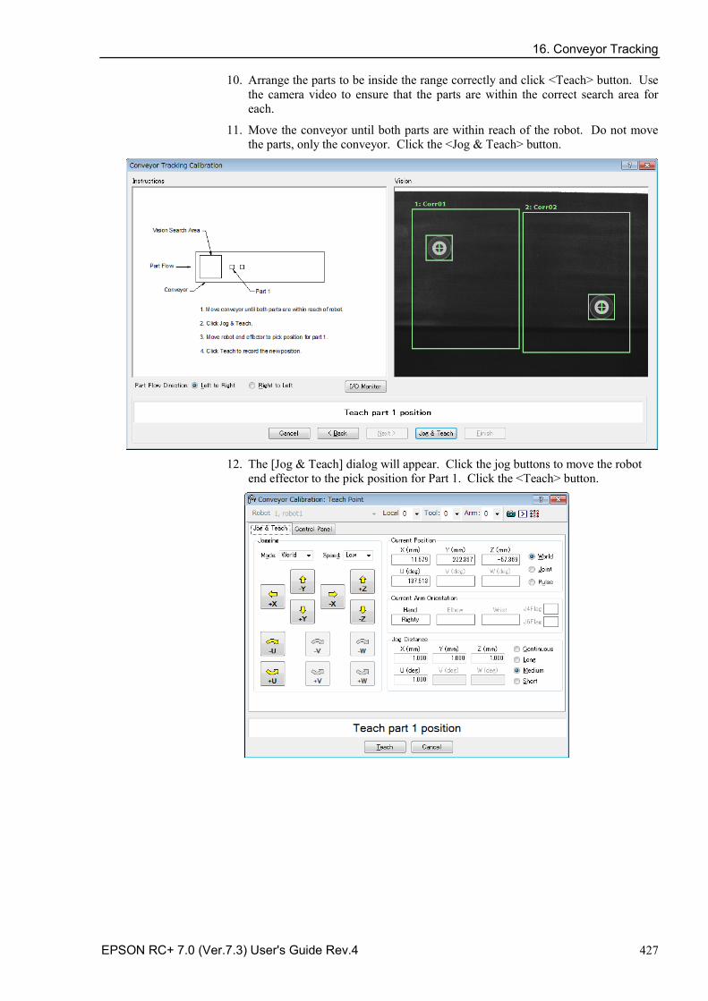
16. Conveyor Tracking
EPSON RC+ 7.0 (Ver.7.3) User's Guide Rev.4 427
10. Arrange the parts to be inside the range correctly and click <Teach> button. Use the camera video to ensure that the parts are within the correct search area for each.
11. Move the conveyor until both parts are within reach of the robot. Do not move the parts, only the conveyor. Click the <Jog & Teach> button.
12. The [Jog & Teach] dialog will appear. Click the jog buttons to move the robot
end effector to the pick position for Part 1. Click the <Teach> button.
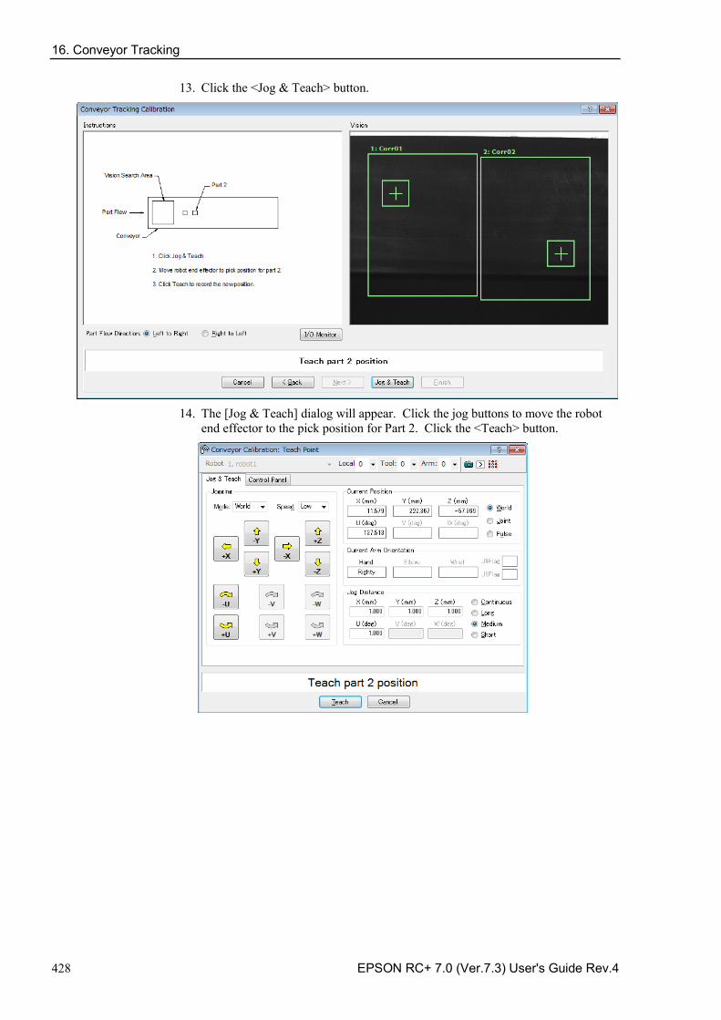
16. Conveyor Tracking
428 EPSON RC+ 7.0 (Ver.7.3) User's Guide Rev.4
13. Click the <Jog & Teach> button.
14. The [Jog & Teach] dialog will appear. Click the jog buttons to move the robot
end effector to the pick position for Part 2. Click the <Teach> button.
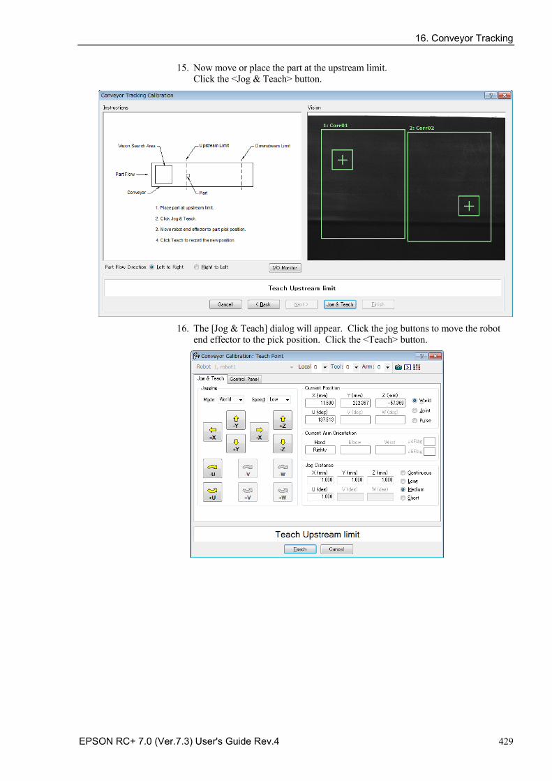
16. Conveyor Tracking
EPSON RC+ 7.0 (Ver.7.3) User's Guide Rev.4 429
15. Now move or place the part at the upstream limit. Click the <Jog & Teach> button.
16. The [Jog & Teach] dialog will appear. Click the jog buttons to move the robot
end effector to the pick position. Click the <Teach> button.
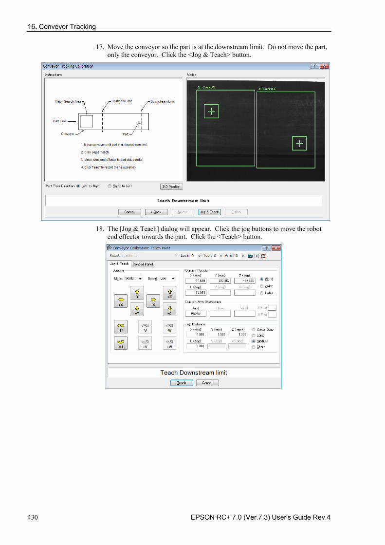
16. Conveyor Tracking
430 EPSON RC+ 7.0 (Ver.7.3) User's Guide Rev.4
17. Move the conveyor so the part is at the downstream limit. Do not move the part, only the conveyor. Click the <Jog & Teach> button.
18. The [Jog & Teach] dialog will appear. Click the jog buttons to move the robot
end effector towards the part. Click the <Teach> button.
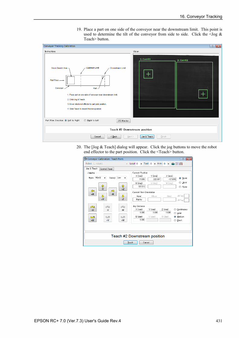
16. Conveyor Tracking
EPSON RC+ 7.0 (Ver.7.3) User's Guide Rev.4 431
19. Place a part on one side of the conveyor near the downstream limit. This point is used to determine the tilt of the conveyor from side to side. Click the <Jog & Teach> button.
20. The [Jog & Teach] dialog will appear. Click the jog buttons to move the robot
end effector to the part position. Click the <Teach> button.
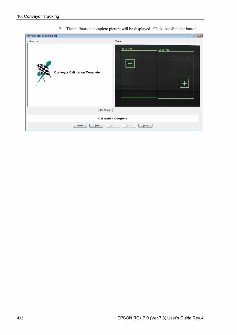
16. Conveyor Tracking
432 EPSON RC+ 7.0 (Ver.7.3) User's Guide Rev.4
21. The calibration complete picture will be displayed. Click the <Finish> button.
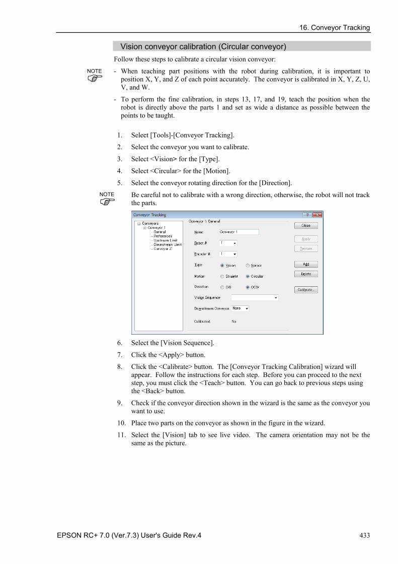
16. Conveyor Tracking
EPSON RC+ 7.0 (Ver.7.3) User's Guide Rev.4 433
Vision conveyor calibration (Circular conveyor) Follow these steps to calibrate a circular vision conveyor:
- When teaching part positions with the robot during calibration, it is important to position X, Y, and Z of each point accurately. The conveyor is calibrated in X, Y, Z, U, V, and W.
- To perform the fine calibration, in steps 13, 17, and 19, teach the position when the robot is directly above the parts 1 and set as wide a distance as possible between the points to be taught.
1. Select [Tools]-[Conveyor Tracking].
2. Select the conveyor you want to calibrate.
3. Select <Vision> for the [Type].
4. Select <Circular> for the [Motion].
5. Select the conveyor rotating direction for the [Direction].
Be careful not to calibrate with a wrong direction, otherwise, the robot will not track the parts.
6. Select the [Vision Sequence].
7. Click the <Apply> button.
8. Click the <Calibrate> button. The [Conveyor Tracking Calibration] wizard will appear. Follow the instructions for each step. Before you can proceed to the next step, you must click the <Teach> button. You can go back to previous steps using the <Back> button.
9. Check if the conveyor direction shown in the wizard is the same as the conveyor you want to use.
10. Place two parts on the conveyor as shown in the figure in the wizard.
11. Select the [Vision] tab to see live video. The camera orientation may not be the same as the picture.
NOTE
NOTE
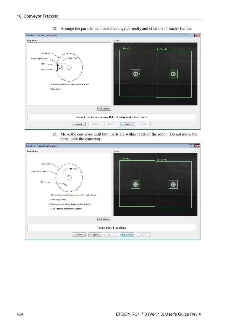
16. Conveyor Tracking
434 EPSON RC+ 7.0 (Ver.7.3) User's Guide Rev.4
12. Arrange the parts to be inside the range correctly and click the <Teach> button.
13. Move the conveyor until both parts are within reach of the robot. Do not move the
parts, only the conveyor.
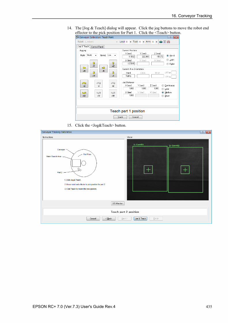
16. Conveyor Tracking
EPSON RC+ 7.0 (Ver.7.3) User's Guide Rev.4 435
14. The [Jog & Teach] dialog will appear. Click the jog buttons to move the robot end effector to the pick position for Part 1. Click the <Teach> button.
15. Click the <Jog&Teach> button.
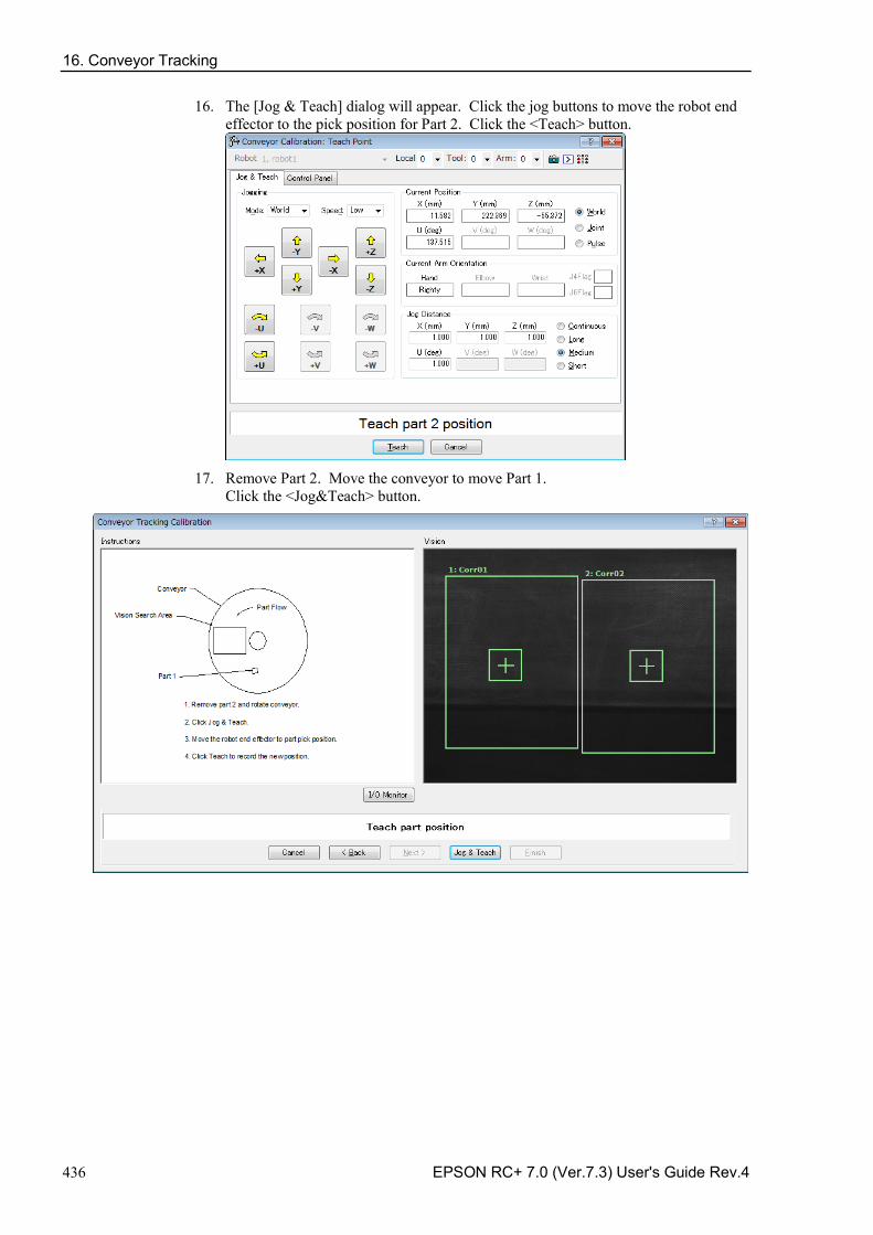
16. Conveyor Tracking
436 EPSON RC+ 7.0 (Ver.7.3) User's Guide Rev.4
16. The [Jog & Teach] dialog will appear. Click the jog buttons to move the robot end effector to the pick position for Part 2. Click the <Teach> button.
17. Remove Part 2. Move the conveyor to move Part 1.
Click the <Jog&Teach> button.
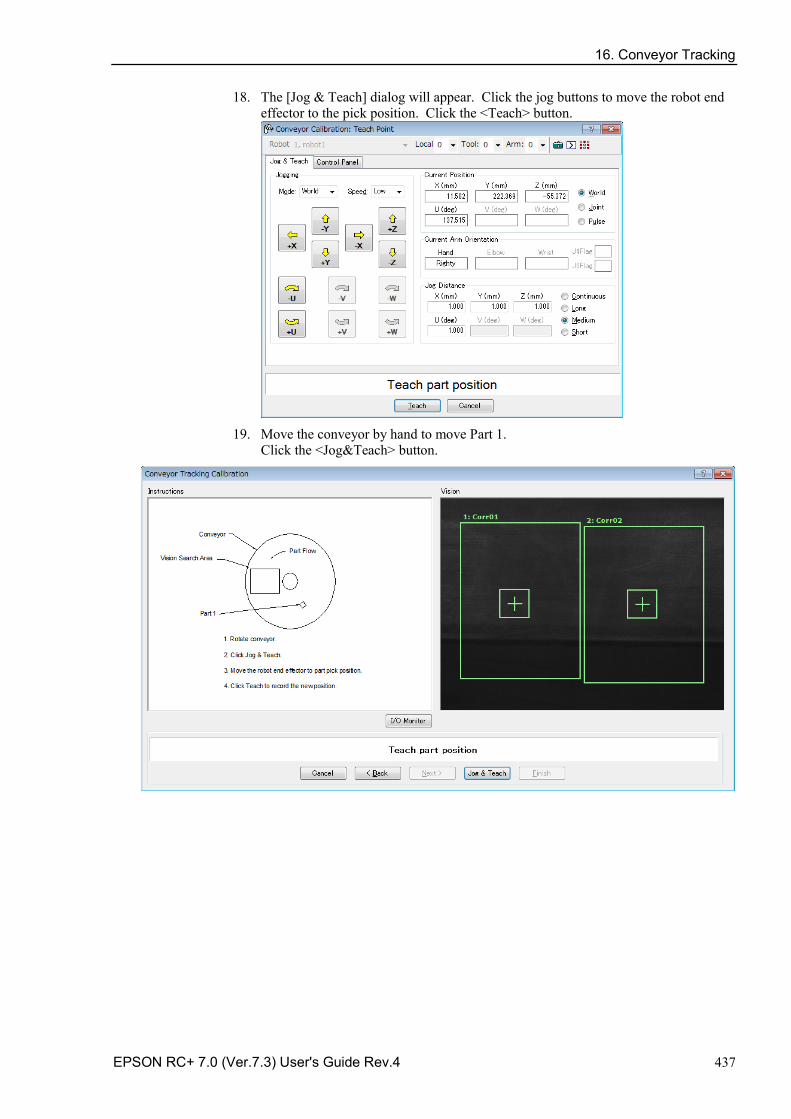
16. Conveyor Tracking
EPSON RC+ 7.0 (Ver.7.3) User's Guide Rev.4 437
18. The [Jog & Teach] dialog will appear. Click the jog buttons to move the robot end effector to the pick position. Click the <Teach> button.
19. Move the conveyor by hand to move Part 1.
Click the <Jog&Teach> button.
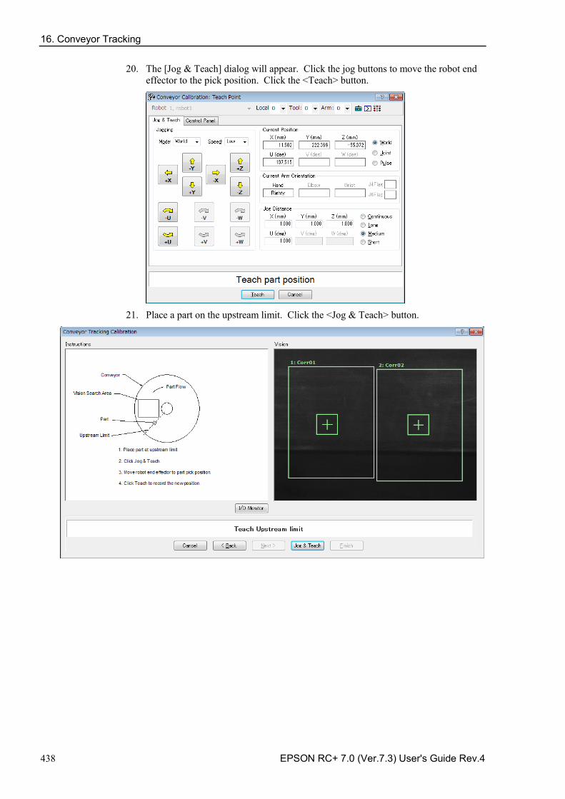
16. Conveyor Tracking
438 EPSON RC+ 7.0 (Ver.7.3) User's Guide Rev.4
20. The [Jog & Teach] dialog will appear. Click the jog buttons to move the robot end effector to the pick position. Click the <Teach> button.
21. Place a part on the upstream limit. Click the <Jog & Teach> button.
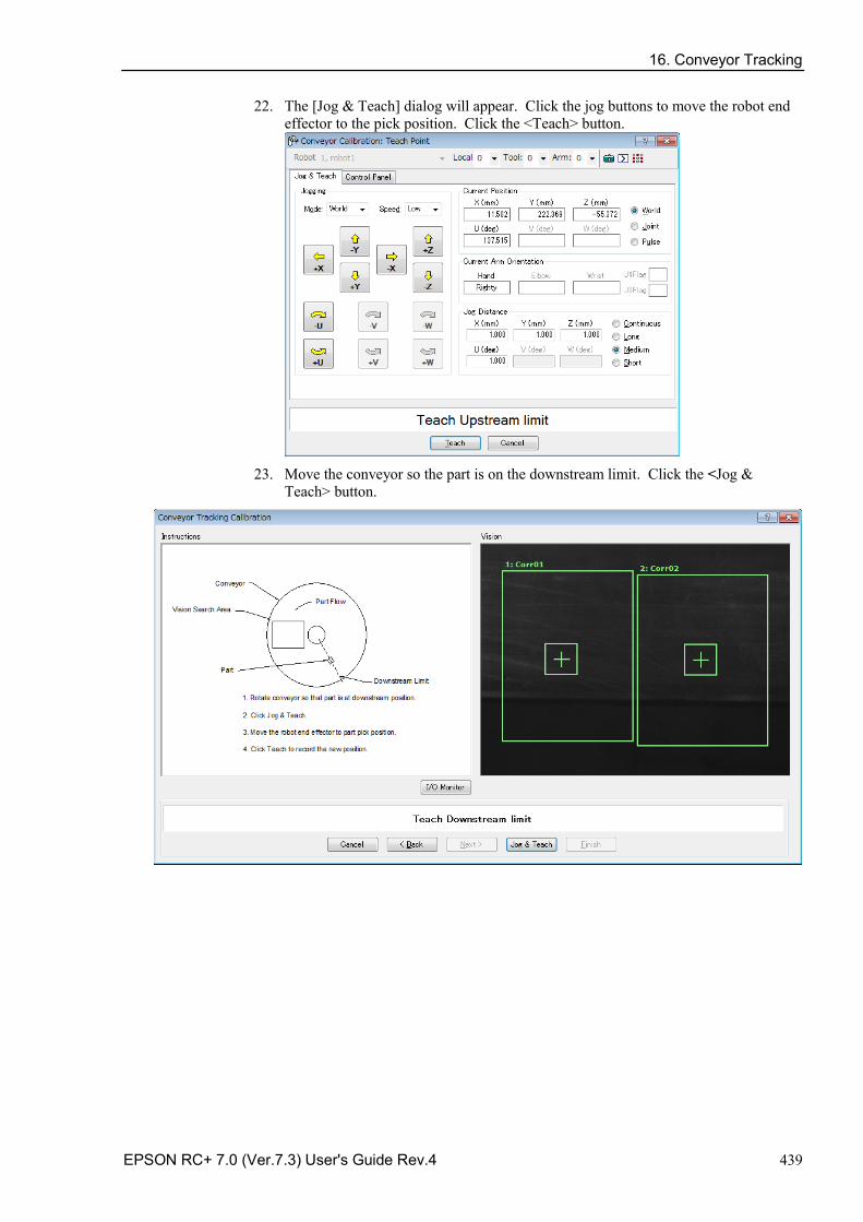
16. Conveyor Tracking
EPSON RC+ 7.0 (Ver.7.3) User's Guide Rev.4 439
22. The [Jog & Teach] dialog will appear. Click the jog buttons to move the robot end effector to the pick position. Click the <Teach> button.
23. Move the conveyor so the part is on the downstream limit. Click the <Jog &
Teach> button.
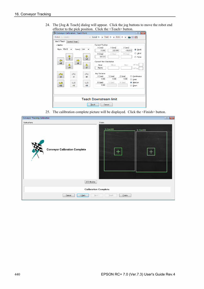
16. Conveyor Tracking
440 EPSON RC+ 7.0 (Ver.7.3) User's Guide Rev.4
24. The [Jog & Teach] dialog will appear. Click the jog buttons to move the robot end effector to the pick position. Click the <Teach> button.
25. The calibration complete picture will be displayed. Click the <Finish> button.
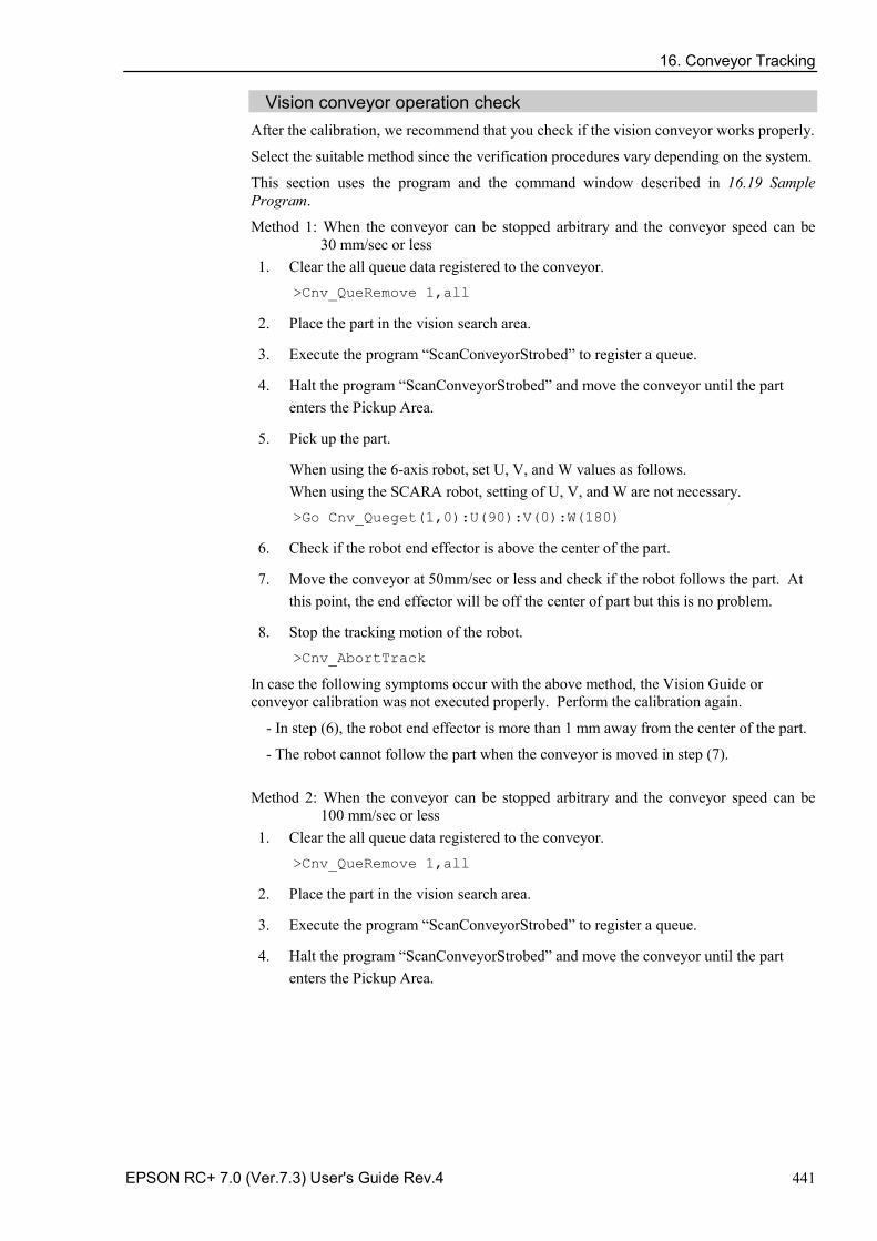
16. Conveyor Tracking
EPSON RC+ 7.0 (Ver.7.3) User's Guide Rev.4 441
Vision conveyor operation check After the calibration, we recommend that you check if the vision conveyor works properly.
Select the suitable method since the verification procedures vary depending on the system.
This section uses the program and the command window described in 16.19 Sample Program.
Method 1: When the conveyor can be stopped arbitrary and the conveyor speed can be 30 mm/sec or less
1. Clear the all queue data registered to the conveyor. >Cnv_QueRemove 1,all
2. Place the part in the vision search area.
3. Execute the program “ScanConveyorStrobed” to register a queue.
4. Halt the program “ScanConveyorStrobed” and move the conveyor until the part enters the Pickup Area.
5. Pick up the part.
When using the 6-axis robot, set U, V, and W values as follows. When using the SCARA robot, setting of U, V, and W are not necessary. >Go Cnv_Queget(1,0):U(90):V(0):W(180)
6. Check if the robot end effector is above the center of the part.
7. Move the conveyor at 50mm/sec or less and check if the robot follows the part. At this point, the end effector will be off the center of part but this is no problem.
8. Stop the tracking motion of the robot. >Cnv_AbortTrack
In case the following symptoms occur with the above method, the Vision Guide or conveyor calibration was not executed properly. Perform the calibration again.
- In step (6), the robot end effector is more than 1 mm away from the center of the part.
- The robot cannot follow the part when the conveyor is moved in step (7).
Method 2: When the conveyor can be stopped arbitrary and the conveyor speed can be 100 mm/sec or less
1. Clear the all queue data registered to the conveyor. >Cnv_QueRemove 1,all
2. Place the part in the vision search area.
3. Execute the program “ScanConveyorStrobed” to register a queue.
4. Halt the program “ScanConveyorStrobed” and move the conveyor until the part enters the Pickup Area.
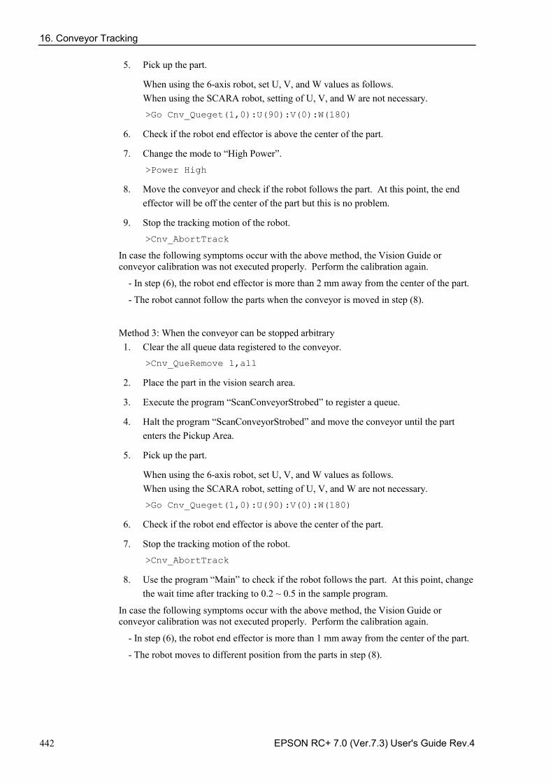
16. Conveyor Tracking
442 EPSON RC+ 7.0 (Ver.7.3) User's Guide Rev.4
5. Pick up the part.
When using the 6-axis robot, set U, V, and W values as follows. When using the SCARA robot, setting of U, V, and W are not necessary. >Go Cnv_Queget(1,0):U(90):V(0):W(180)
6. Check if the robot end effector is above the center of the part.
7. Change the mode to “High Power”. >Power High
8. Move the conveyor and check if the robot follows the part. At this point, the end effector will be off the center of the part but this is no problem.
9. Stop the tracking motion of the robot. >Cnv_AbortTrack
In case the following symptoms occur with the above method, the Vision Guide or conveyor calibration was not executed properly. Perform the calibration again.
- In step (6), the robot end effector is more than 2 mm away from the center of the part.
- The robot cannot follow the parts when the conveyor is moved in step (8).
Method 3: When the conveyor can be stopped arbitrary 1. Clear the all queue data registered to the conveyor.
>Cnv_QueRemove 1,all
2. Place the part in the vision search area.
3. Execute the program “ScanConveyorStrobed” to register a queue.
4. Halt the program “ScanConveyorStrobed” and move the conveyor until the part enters the Pickup Area.
5. Pick up the part.
When using the 6-axis robot, set U, V, and W values as follows. When using the SCARA robot, setting of U, V, and W are not necessary. >Go Cnv_Queget(1,0):U(90):V(0):W(180)
6. Check if the robot end effector is above the center of the part.
7. Stop the tracking motion of the robot. >Cnv_AbortTrack
8. Use the program “Main” to check if the robot follows the part. At this point, change the wait time after tracking to 0.2 ~ 0.5 in the sample program.
In case the following symptoms occur with the above method, the Vision Guide or conveyor calibration was not executed properly. Perform the calibration again.
- In step (6), the robot end effector is more than 1 mm away from the center of the part.
- The robot moves to different position from the parts in step (8).
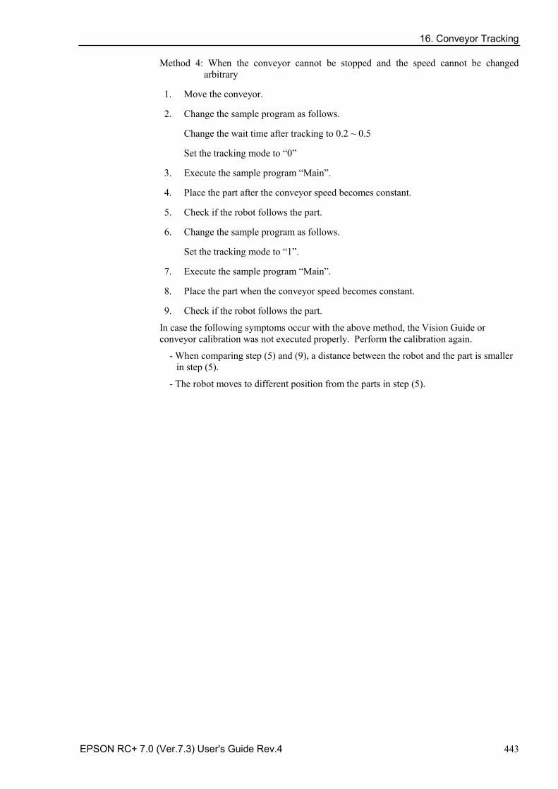
16. Conveyor Tracking
EPSON RC+ 7.0 (Ver.7.3) User's Guide Rev.4 443
Method 4: When the conveyor cannot be stopped and the speed cannot be changed arbitrary
1. Move the conveyor.
2. Change the sample program as follows.
Change the wait time after tracking to 0.2 ~ 0.5
Set the tracking mode to “0”
3. Execute the sample program “Main”.
4. Place the part after the conveyor speed becomes constant.
5. Check if the robot follows the part.
6. Change the sample program as follows.
Set the tracking mode to “1”.
7. Execute the sample program “Main”.
8. Place the part when the conveyor speed becomes constant.
9. Check if the robot follows the part.
In case the following symptoms occur with the above method, the Vision Guide or conveyor calibration was not executed properly. Perform the calibration again.
- When comparing step (5) and (9), a distance between the robot and the part is smaller in step (5).
- The robot moves to different position from the parts in step (5).
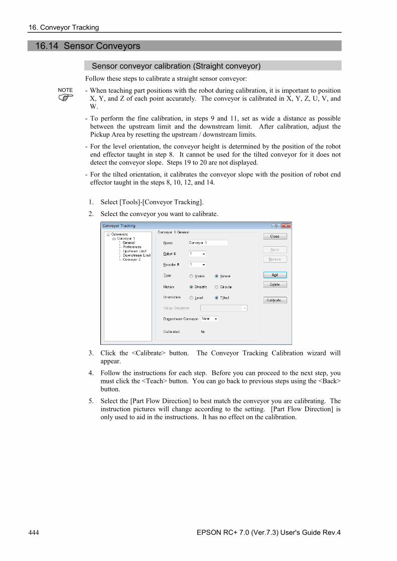
16. Conveyor Tracking
444 EPSON RC+ 7.0 (Ver.7.3) User's Guide Rev.4
16.14 Sensor Conveyors
Sensor conveyor calibration (Straight conveyor) Follow these steps to calibrate a straight sensor conveyor:
- When teaching part positions with the robot during calibration, it is important to position X, Y, and Z of each point accurately. The conveyor is calibrated in X, Y, Z, U, V, and W.
- To perform the fine calibration, in steps 9 and 11, set as wide a distance as possible between the upstream limit and the downstream limit. After calibration, adjust the Pickup Area by resetting the upstream / downstream limits.
- For the level orientation, the conveyor height is determined by the position of the robot end effector taught in step 8. It cannot be used for the tilted conveyor for it does not detect the conveyor slope. Steps 19 to 20 are not displayed.
- For the tilted orientation, it calibrates the conveyor slope with the position of robot end effector taught in the steps 8, 10, 12, and 14.
1. Select [Tools]-[Conveyor Tracking].
2. Select the conveyor you want to calibrate.
3. Click the <Calibrate> button. The Conveyor Tracking Calibration wizard will
appear.
4. Follow the instructions for each step. Before you can proceed to the next step, you must click the <Teach> button. You can go back to previous steps using the <Back> button.
5. Select the [Part Flow Direction] to best match the conveyor you are calibrating. The instruction pictures will change according to the setting. [Part Flow Direction] is only used to aid in the instructions. It has no effect on the calibration.
NOTE
16. Conveyor Tracking
EPSON RC+ 7.0 (Ver.7.3) User's Guide Rev.4 445
6. For the first wizard step, place a part on the conveyor and move the conveyor toward the sensor until the sensor just turns on. Click the <Teach> button.
7. Move the conveyor by hand until the part is within reach of the robot. Do not move
the part itself, only the conveyor. Click the <Jog & Teach> button.

16. Conveyor Tracking
446 EPSON RC+ 7.0 (Ver.7.3) User's Guide Rev.4
8. The Jog & Teach dialog will appear. Click the jog buttons to move the robot end effector to the pick position. Click the <Teach> button.
9. Now move or place the part at the upstream limit. Click the <Jog & Teach> button.
16. Conveyor Tracking
EPSON RC+ 7.0 (Ver.7.3) User's Guide Rev.4 447
10. The Jog & Teach dialog will appear. Click the jog buttons to move the robot end effector to the pick position. Click the <Teach> button.
11. Move the conveyor so the part is at the downstream limit. Do not move the part,
only the conveyor. Click the <Jog & Teach> button.
16. Conveyor Tracking
448 EPSON RC+ 7.0 (Ver.7.3) User's Guide Rev.4
12. The [Jog & Teach] dialog will appear. Click the jog buttons to move the robot end effector to the pick position. Click the <Teach> button.
13. Place a part on one side of the conveyor near the downstream limit. This point is
used to determine the tilt of the conveyor from side to side. Click the <Jog & Teach> button.

16. Conveyor Tracking
EPSON RC+ 7.0 (Ver.7.3) User's Guide Rev.4 449
14. The [Jog & Teach] window will appear. Click the jog buttons to move the robot end effector to the pick position. Click the <Teach> button.
15. The calibration complete picture will be displayed. Click the <Finish> button.
16. Conveyor Tracking
450 EPSON RC+ 7.0 (Ver.7.3) User's Guide Rev.4
Sensor Conveyor Calibration (Circular conveyor) Follow these steps to calibrate a circular sensor conveyor:
- When teaching part positions with the robot during calibration, it is important to position X, Y, and Z of each point accurately. The conveyor is calibrated in X, Y, Z, U, V, and W.
- To perform the fine calibration, in steps 10, 12, and 14, teach the position when the robot is directly above the parts and set as wide a distance as possible between the points being taught.
1. Select [Tools]-[Conveyor Tracking].
2. Select the conveyor you want to calibrate.
3. Select <Sensor> for the [Type].
4. Select <Circular> for the [Motion].
5. Select the conveyor rotating direction for the [Direction].
Be careful not to calibrate with a wrong direction, otherwise, the robot will not track the parts.
6. Click the <Apply> button.
7. Click the <Calibrate> button. The [Conveyor Tracking Calibration] wizard will appear. Follow the instructions for each step. Before you can proceed to the next step, you must click the <Teach> button. You can go back to previous steps using the <Back> button.
8. Check if the conveyor direction shown in the wizard is the same as the conveyor you want to use.
NOTE
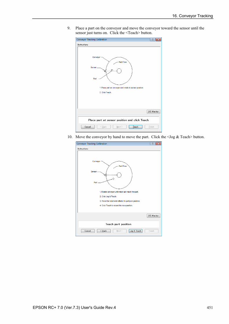
16. Conveyor Tracking
EPSON RC+ 7.0 (Ver.7.3) User's Guide Rev.4 451
9. Place a part on the conveyor and move the conveyor toward the sensor until the sensor just turns on. Click the <Teach> button.
10. Move the conveyor by hand to move the part. Click the <Jog & Teach> button.
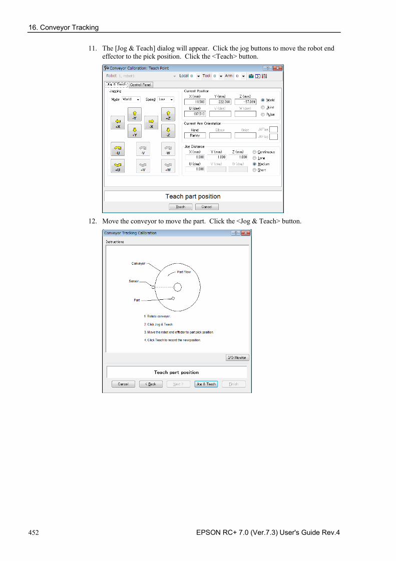
16. Conveyor Tracking
452 EPSON RC+ 7.0 (Ver.7.3) User's Guide Rev.4
11. The [Jog & Teach] dialog will appear. Click the jog buttons to move the robot end effector to the pick position. Click the <Teach> button.
12. Move the conveyor to move the part. Click the <Jog & Teach> button.
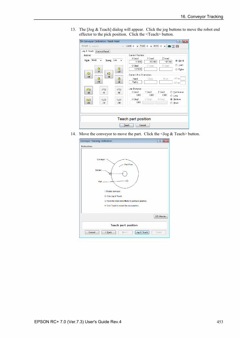
16. Conveyor Tracking
EPSON RC+ 7.0 (Ver.7.3) User's Guide Rev.4 453
13. The [Jog & Teach] dialog will appear. Click the jog buttons to move the robot end effector to the pick position. Click the <Teach> button.
14. Move the conveyor to move the part. Click the <Jog & Teach> button.
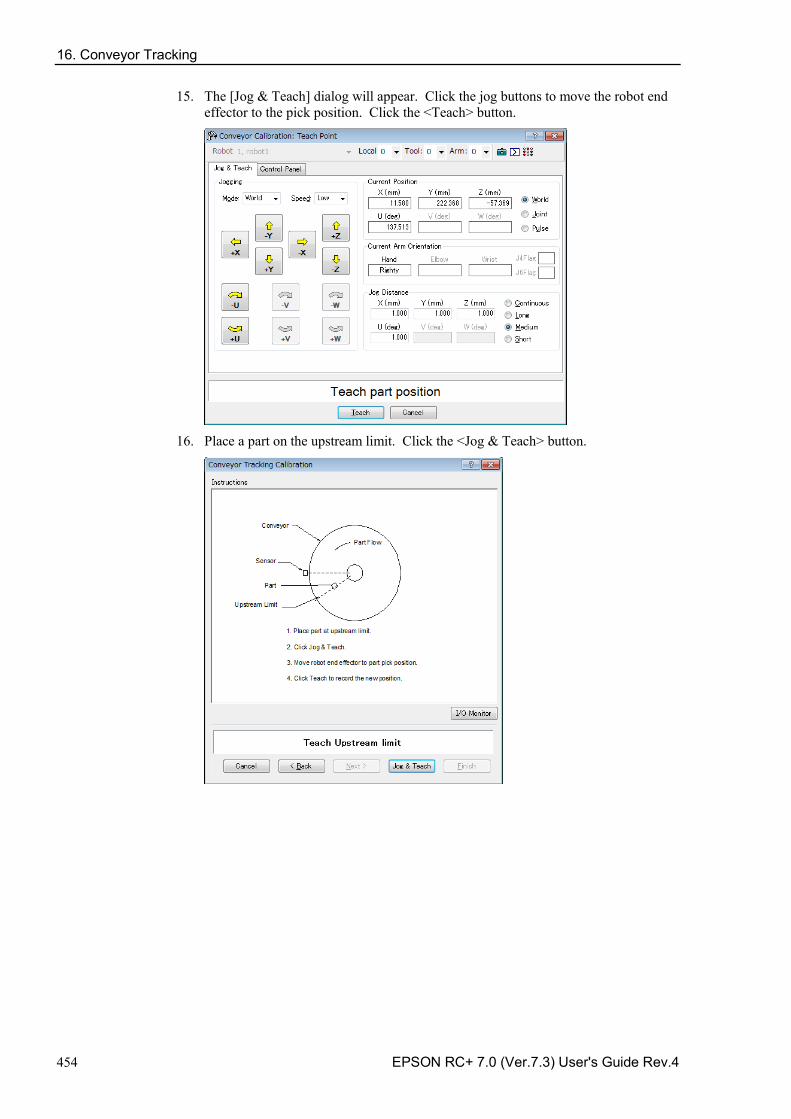
16. Conveyor Tracking
454 EPSON RC+ 7.0 (Ver.7.3) User's Guide Rev.4
15. The [Jog & Teach] dialog will appear. Click the jog buttons to move the robot end effector to the pick position. Click the <Teach> button.
16. Place a part on the upstream limit. Click the <Jog & Teach> button.
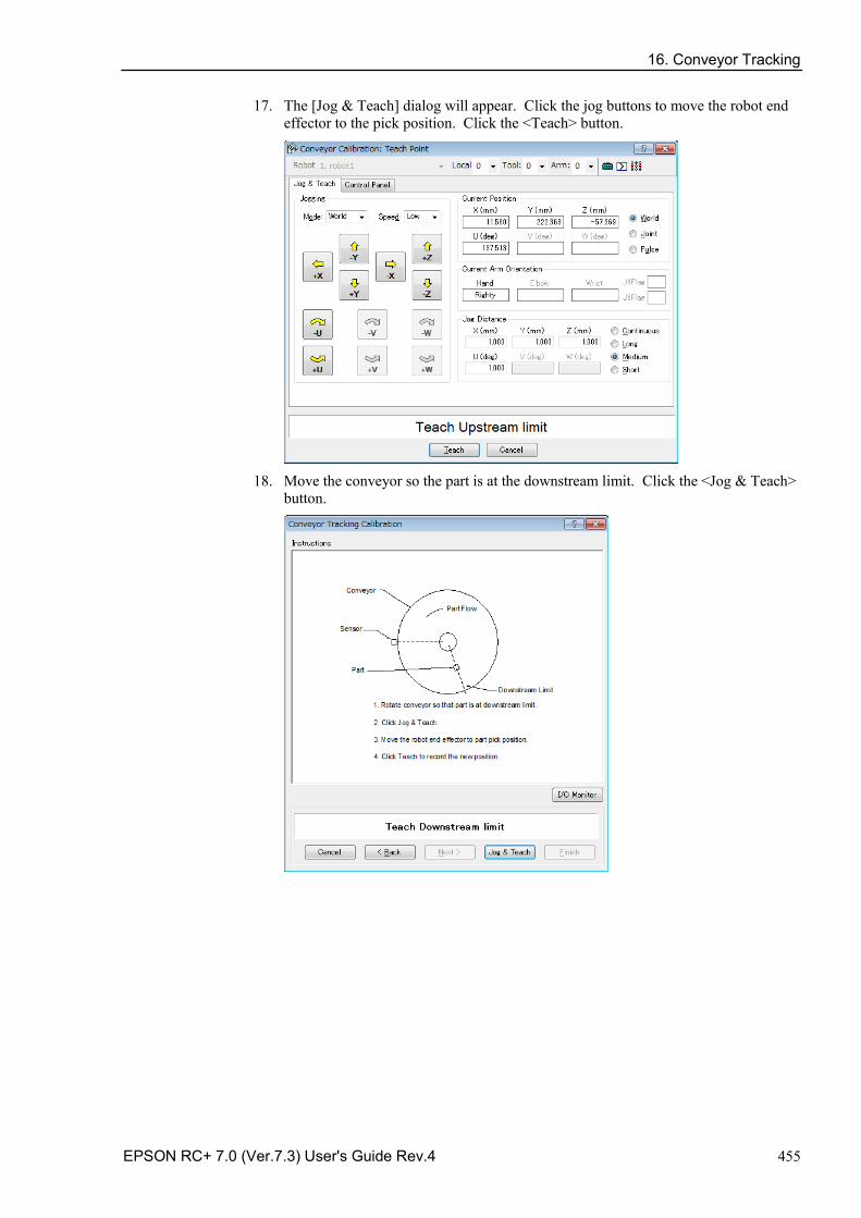
16. Conveyor Tracking
EPSON RC+ 7.0 (Ver.7.3) User's Guide Rev.4 455
17. The [Jog & Teach] dialog will appear. Click the jog buttons to move the robot end effector to the pick position. Click the <Teach> button.
18. Move the conveyor so the part is at the downstream limit. Click the <Jog & Teach>
button.
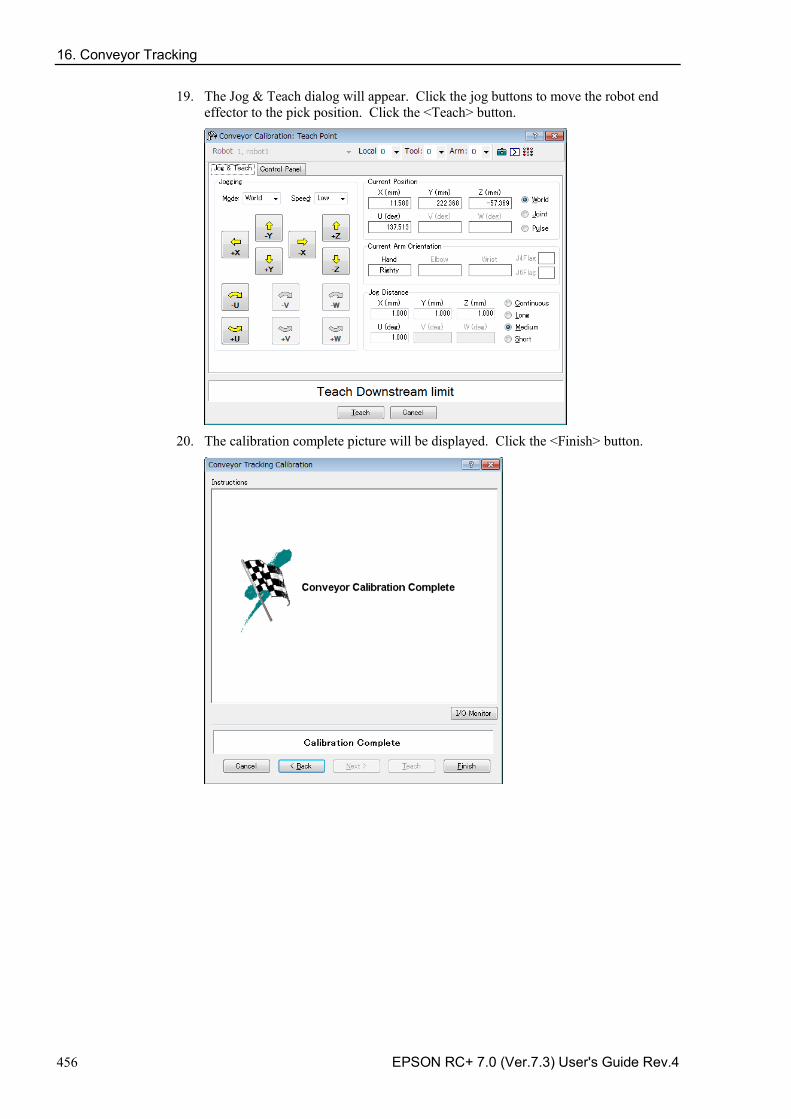
16. Conveyor Tracking
456 EPSON RC+ 7.0 (Ver.7.3) User's Guide Rev.4
19. The Jog & Teach dialog will appear. Click the jog buttons to move the robot end effector to the pick position. Click the <Teach> button.
20. The calibration complete picture will be displayed. Click the <Finish> button.
16. Conveyor Tracking
EPSON RC+ 7.0 (Ver.7.3) User's Guide Rev.4 457
Sensor conveyor operation check After the calibration, we recommend that you check if the sensor conveyor works properly. Select the suitable method since the verification procedures vary depending on the system.
This section uses the program and the command window described in 16.19 Sample Program.
Method 1: When the conveyor can be stopped arbitrary and the conveyor speed can be 30 mm/sec or less
1. Clear the all queue data registered to the conveyor. >Cnv_QueRemove 1,all
2. Detect the part using the sensor.
3. Execute the program “ScanConveyor” to register a queue.
4. Halt the program “ScanConveyor” and move the conveyor until the part enters the Pickup Area.
5. Pick up the part.
When using the 6-axis robot, set U, V, and W values as follows. When using the SCARA robot, setting of U, V, and W are not necessary. >Go Cnv_Queget(1,0):U(90):V(0):W(180)
6. Check if the robot end effector is above the center of the part.
7. Move the conveyor at 50mm/sec or less and check if the robot follows the part. At this point, the end effector will be off the center of the part but this is no problem.
8. Stop the tracking motion of the robot. >Cnv_AbortTrack
In case the following symptoms occur with the above method, the conveyor calibration was not executed properly. Perform the calibration again.
- In step (6), the robot end effector is more than 1 mm away from the center of the part.
- The robot cannot follow the part when the conveyor is moving in step (7).
Method 2: When the conveyor can be stopped arbitrary and the conveyor speed can be 100 mm/sec or less
1. Clear the all queue data registered to the conveyor. >Cnv_QueRemove 1,all
2. Detect the part using the sensor.
3. Execute the program “ScanConveyor” to register a queue.
4. Halt the program “ScanConveyor” and move the conveyor until the part enters the Pickup Area.
16. Conveyor Tracking
458 EPSON RC+ 7.0 (Ver.7.3) User's Guide Rev.4
5. Pick up the part.
When using the 6-axis robot, set U, V, and W values as follows.
When using the SCARA robot, setting of U, V, and W are not necessary. >Go Cnv_Queget(1,0):U(90):V(0):W(180)
6. Check if the robot end effector is above the center of the part.
7. Change the mode to “High Power”. >Power High
8. Move the conveyor and check if the robot follows the part. At this point, the end effector will be off the center of the part but this is no problem.
9. Stop the tracking motion of the robot. >Cnv_AbortTrack
In case the following symptoms occur with the above method, the conveyor calibration was not executed properly. Perform the calibration again.
- In step (6), the robot end effector is more than 2 mm away from the center of the part.
- The robot cannot follow the part when the conveyor is moving in step (8).
Method 3: When the conveyor can be stopped arbitrary 1. Clear the all queue data registered to the conveyor.
>Cnv_QueRemove 1,all
2. Detect the part using the sensor.
3. Execute the program “ScanConveyor” to register a queue.
4. Halt the program “ScanConveyor” and move the conveyor until the part enters the Pickup Area.
5. Pick up the part.
When using the 6-axis robot, set U, V, and W values as follows. When using the SCARA robot, setting of U, V, and W are not necessary. >Go Cnv_Queget(1,0):U(90):V(0):W(180)
6. Check if the robot end effector is above the center of the part.
7. Stop the tracking motion of the robot. >Cnv_AbortTrack
8. Use the program “Main” to check if the robot follows the part. At this point, change the wait time after tracking to 0.2 ~ 0.5 in the sample program.
In case the following symptoms occur with the above method, the conveyor calibration was not executed properly. Perform the calibration again.
- In step (6), the robot end effector is more than 1 mm away from the center of the part.
- The robot moves to a different position from the part in step (8).

16. Conveyor Tracking
EPSON RC+ 7.0 (Ver.7.3) User's Guide Rev.4 459
Method 4: When the conveyor cannot be stopped and the speed cannot be changed arbitrary
1. Move the conveyor.
2. Change the sample program as follows.
Change the wait time after tracking to 0.2 ~ 0.5 Set the tracking mode to “0”
3. Execute the sample program “Main”.
4. Place the part after the conveyor speed becomes constant.
5. Check if the robot follows the part.
6. Change the sample program as follows.
Set the tracking mode to “1”.
7. Execute the sample program “Main”.
8. Place the part when the conveyor speed becomes constant.
9. Check if the robot follows the part.
In case the following symptoms occur with the above method, the conveyor calibration was not executed properly. Perform the calibration again.
- When comparing step (5) and (9), the distance between the robot and the part is smaller in step (5).
- The robot moves to the different position from the parts in step (5).
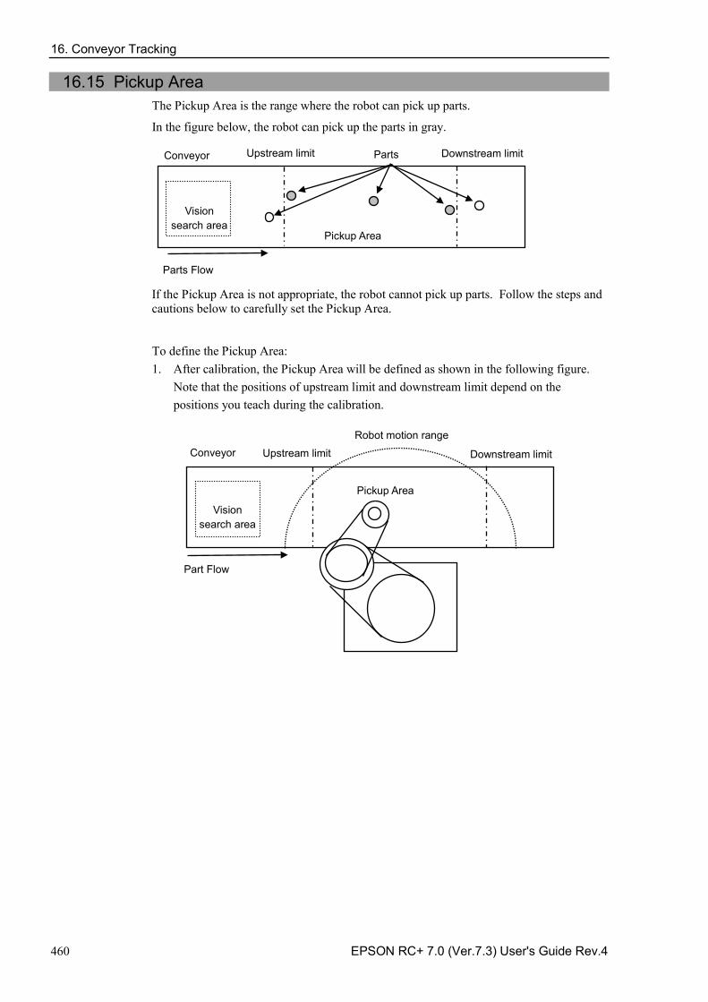
16. Conveyor Tracking
460 EPSON RC+ 7.0 (Ver.7.3) User's Guide Rev.4
16.15 Pickup Area The Pickup Area is the range where the robot can pick up parts.
In the figure below, the robot can pick up the parts in gray.
Parts Flow
Conveyor Downstream limit Upstream limit Parts
Vision search area
Pickup Area
If the Pickup Area is not appropriate, the robot cannot pick up parts. Follow the steps and cautions below to carefully set the Pickup Area.
To define the Pickup Area: 1. After calibration, the Pickup Area will be defined as shown in the following figure.
Note that the positions of upstream limit and downstream limit depend on the positions you teach during the calibration.
Downstream limit
Robot motion range Conveyor
Part Flow
Upstream limit
Pickup Area
Vision search area
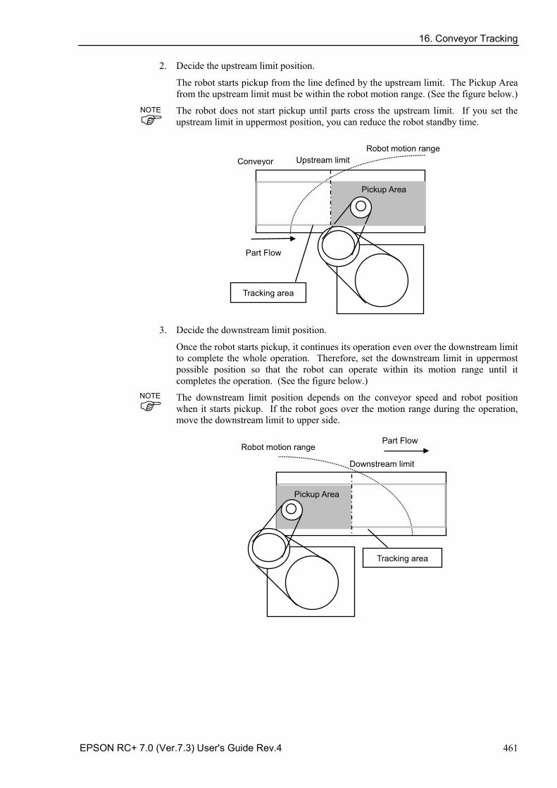
16. Conveyor Tracking
EPSON RC+ 7.0 (Ver.7.3) User's Guide Rev.4 461
2. Decide the upstream limit position.
The robot starts pickup from the line defined by the upstream limit. The Pickup Area from the upstream limit must be within the robot motion range. (See the figure below.)
The robot does not start pickup until parts cross the upstream limit. If you set the upstream limit in uppermost position, you can reduce the robot standby time.
Robot motion range
Part Flow
Conveyor Upstream limit
Tracking area
Pickup Area
3. Decide the downstream limit position.
Once the robot starts pickup, it continues its operation even over the downstream limit to complete the whole operation. Therefore, set the downstream limit in uppermost possible position so that the robot can operate within its motion range until it completes the operation. (See the figure below.)
The downstream limit position depends on the conveyor speed and robot position when it starts pickup. If the robot goes over the motion range during the operation, move the downstream limit to upper side.
Downstream limit
Robot motion range Part Flow
Tracking area
Pickup Area
NOTE
NOTE
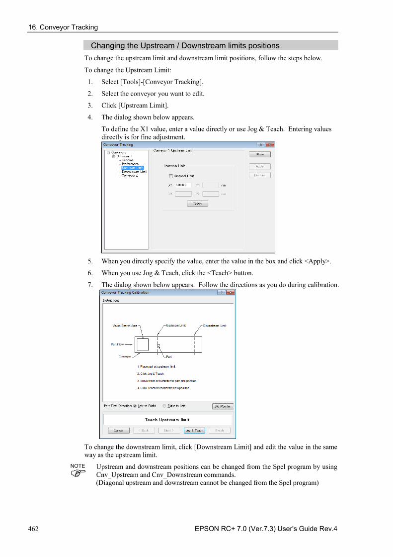
16. Conveyor Tracking
462 EPSON RC+ 7.0 (Ver.7.3) User's Guide Rev.4
Changing the Upstream / Downstream limits positions To change the upstream limit and downstream limit positions, follow the steps below.
To change the Upstream Limit:
1. Select [Tools]-[Conveyor Tracking].
2. Select the conveyor you want to edit.
3. Click [Upstream Limit].
4. The dialog shown below appears.
To define the X1 value, enter a value directly or use Jog & Teach. Entering values directly is for fine adjustment.
5. When you directly specify the value, enter the value in the box and click <Apply>.
6. When you use Jog & Teach, click the <Teach> button.
7. The dialog shown below appears. Follow the directions as you do during calibration.
To change the downstream limit, click [Downstream Limit] and edit the value in the same way as the upstream limit.
Upstream and downstream positions can be changed from the Spel program by using Cnv_Upstream and Cnv_Downstream commands. (Diagonal upstream and downstream cannot be changed from the Spel program)
NOTE
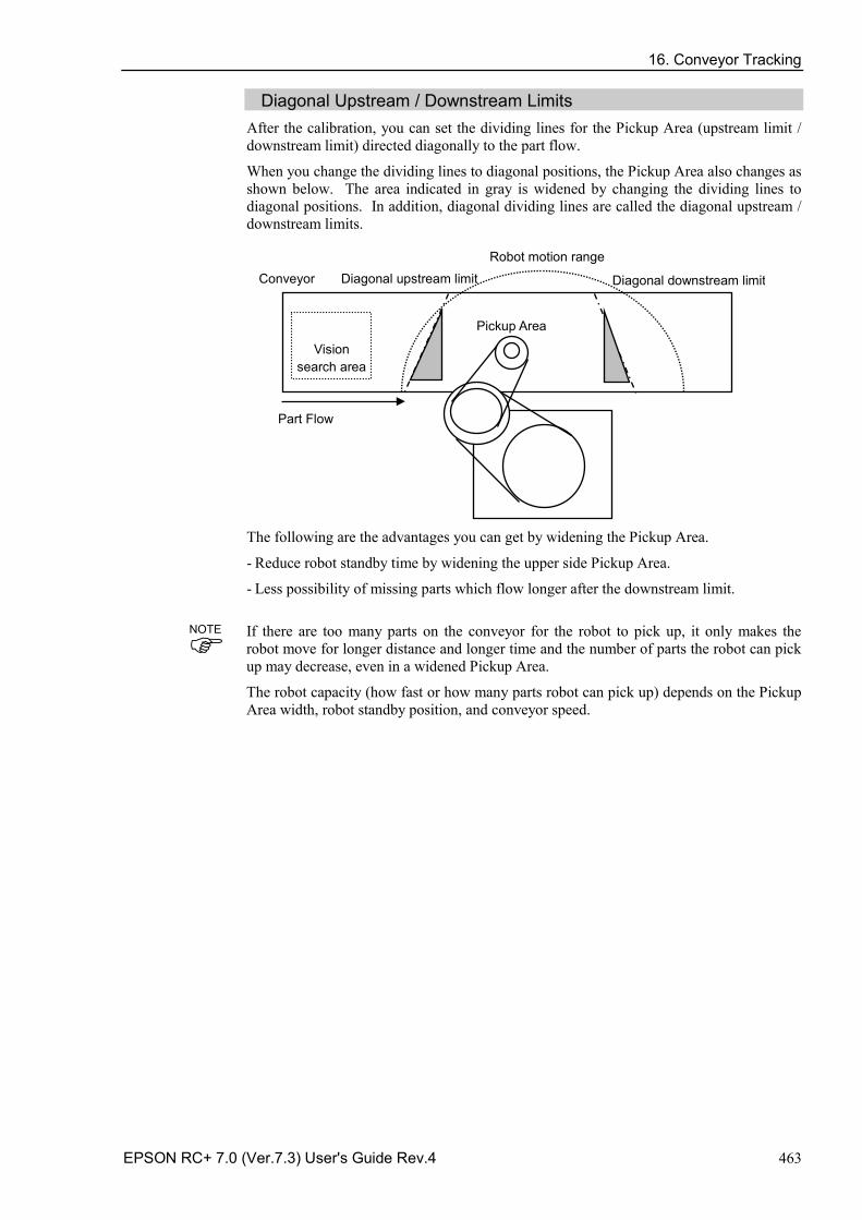
16. Conveyor Tracking
EPSON RC+ 7.0 (Ver.7.3) User's Guide Rev.4 463
Diagonal Upstream / Downstream Limits After the calibration, you can set the dividing lines for the Pickup Area (upstream limit / downstream limit) directed diagonally to the part flow.
When you change the dividing lines to diagonal positions, the Pickup Area also changes as shown below. The area indicated in gray is widened by changing the dividing lines to diagonal positions. In addition, diagonal dividing lines are called the diagonal upstream / downstream limits.
Part Flow
Conveyor Diagonal downstream limit Diagonal upstream limit
Robot motion range
Pickup Area
Vision search area
The following are the advantages you can get by widening the Pickup Area.
Reduce robot standby time by widening the upper side Pickup Area. -
Less possibility of missing parts which flow longer after the downstream limit. -
If there are too many parts on the conveyor for the robot to pick up, it only makes the robot move for longer distance and longer time and the number of parts the robot can pick up may decrease, even in a widened Pickup Area.
The robot capacity (how fast or how many parts robot can pick up) depends on the Pickup Area width, robot standby position, and conveyor speed.
NOTE
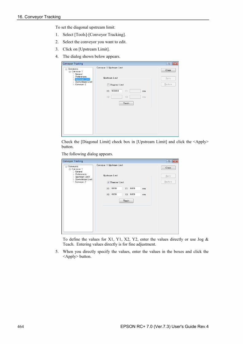
16. Conveyor Tracking
464 EPSON RC+ 7.0 (Ver.7.3) User's Guide Rev.4
To set the diagonal upstream limit:
1. Select [Tools]-[Conveyor Tracking].
2. Select the conveyor you want to edit.
3. Click on [Upstream Limit].
4. The dialog shown below appears.
Check the [Diagonal Limit] check box in [Upstream Limit] and click the <Apply> button.
The following dialog appears.
To define the values for X1, Y1, X2, Y2, enter the values directly or use Jog & Teach. Entering values directly is for fine adjustment.
5. When you directly specify the values, enter the values in the boxes and click the <Apply> button.
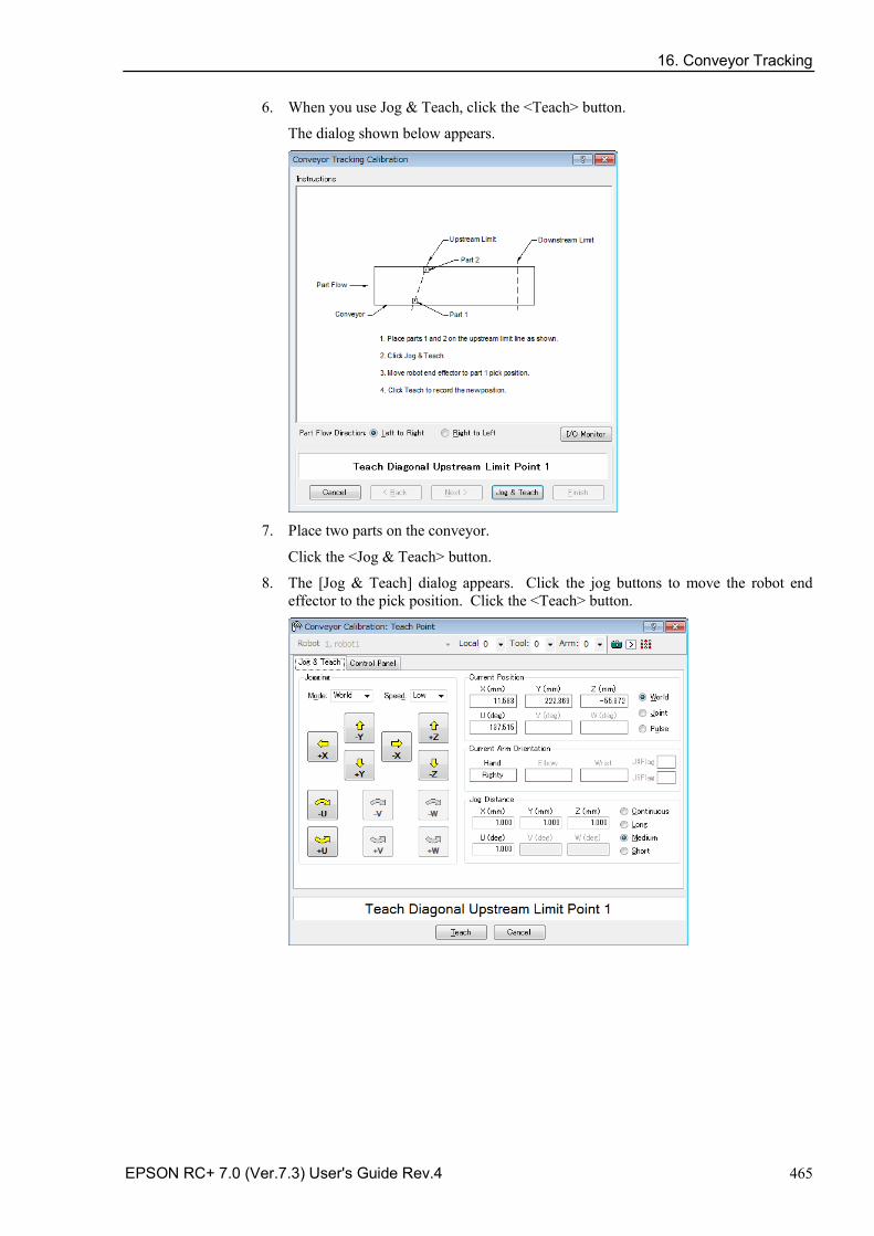
16. Conveyor Tracking
EPSON RC+ 7.0 (Ver.7.3) User's Guide Rev.4 465
6. When you use Jog & Teach, click the <Teach> button.
The dialog shown below appears.
7. Place two parts on the conveyor.
Click the <Jog & Teach> button.
8. The [Jog & Teach] dialog appears. Click the jog buttons to move the robot end effector to the pick position. Click the <Teach> button.
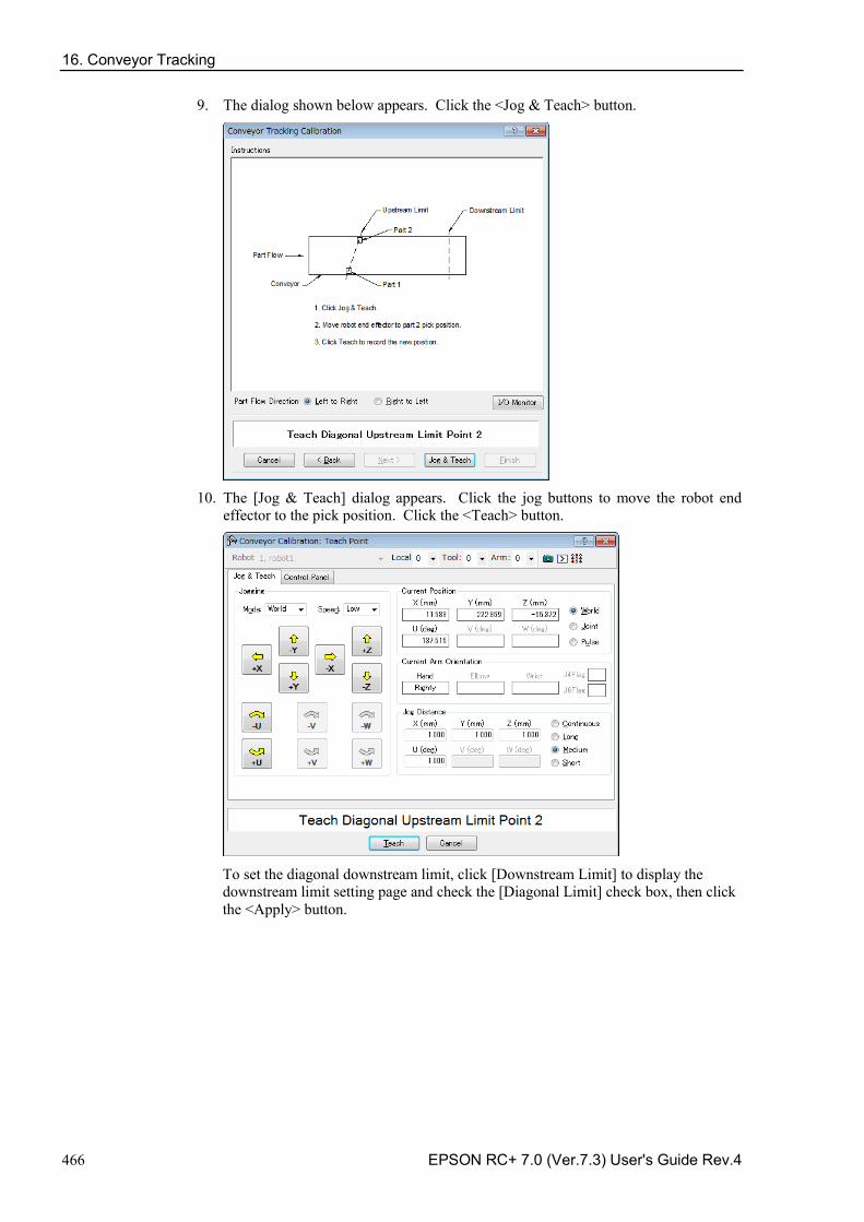
16. Conveyor Tracking
466 EPSON RC+ 7.0 (Ver.7.3) User's Guide Rev.4
9. The dialog shown below appears. Click the <Jog & Teach> button.
10. The [Jog & Teach] dialog appears. Click the jog buttons to move the robot end
effector to the pick position. Click the <Teach> button.
To set the diagonal downstream limit, click [Downstream Limit] to display the downstream limit setting page and check the [Diagonal Limit] check box, then click the <Apply> button.
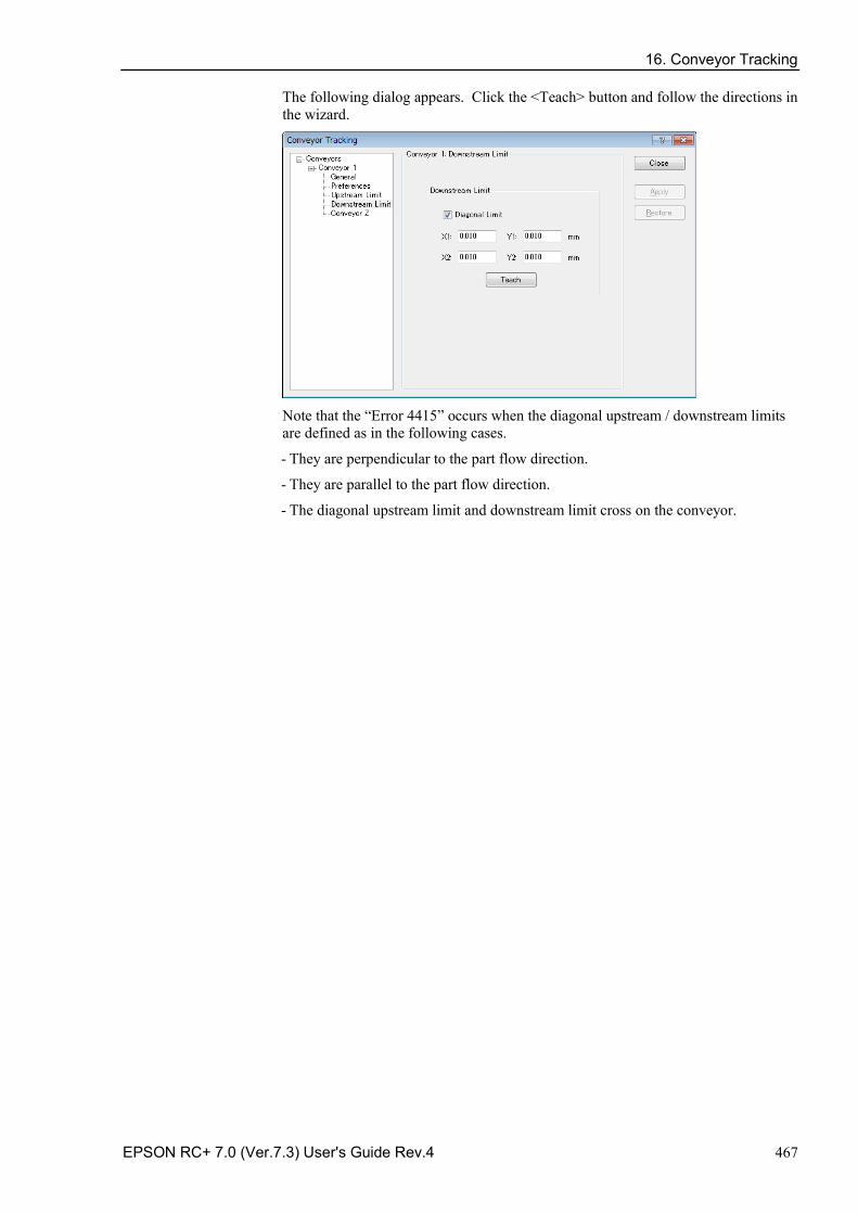
16. Conveyor Tracking
EPSON RC+ 7.0 (Ver.7.3) User's Guide Rev.4 467
The following dialog appears. Click the <Teach> button and follow the directions in the wizard.
Note that the “Error 4415” occurs when the diagonal upstream / downstream limits are defined as in the following cases.
They are perpendicular to the part flow direction. -
They are parallel to the part flow direction. -
The diagonal upstream limit and downstream limit cross on the conveyor. -
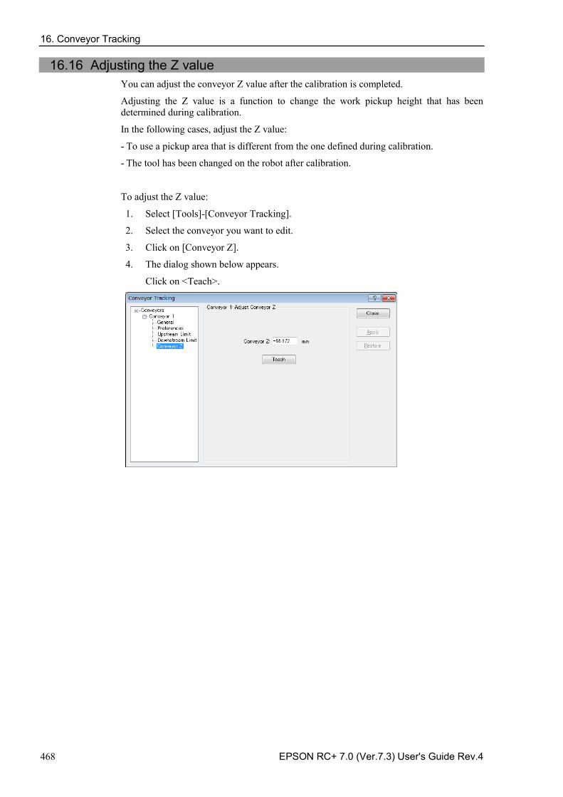
16. Conveyor Tracking
468 EPSON RC+ 7.0 (Ver.7.3) User's Guide Rev.4
16.16 Adjusting the Z value You can adjust the conveyor Z value after the calibration is completed.
Adjusting the Z value is a function to change the work pickup height that has been determined during calibration.
In the following cases, adjust the Z value:
To use a pickup area that is different from the one defined during calibration. -
The tool has been changed on the robot after calibration. -
To adjust the Z value:
1. Select [Tools]-[Conveyor Tracking].
2. Select the conveyor you want to edit.
3. Click on [Conveyor Z].
4. The dialog shown below appears.
Click on <Teach>.
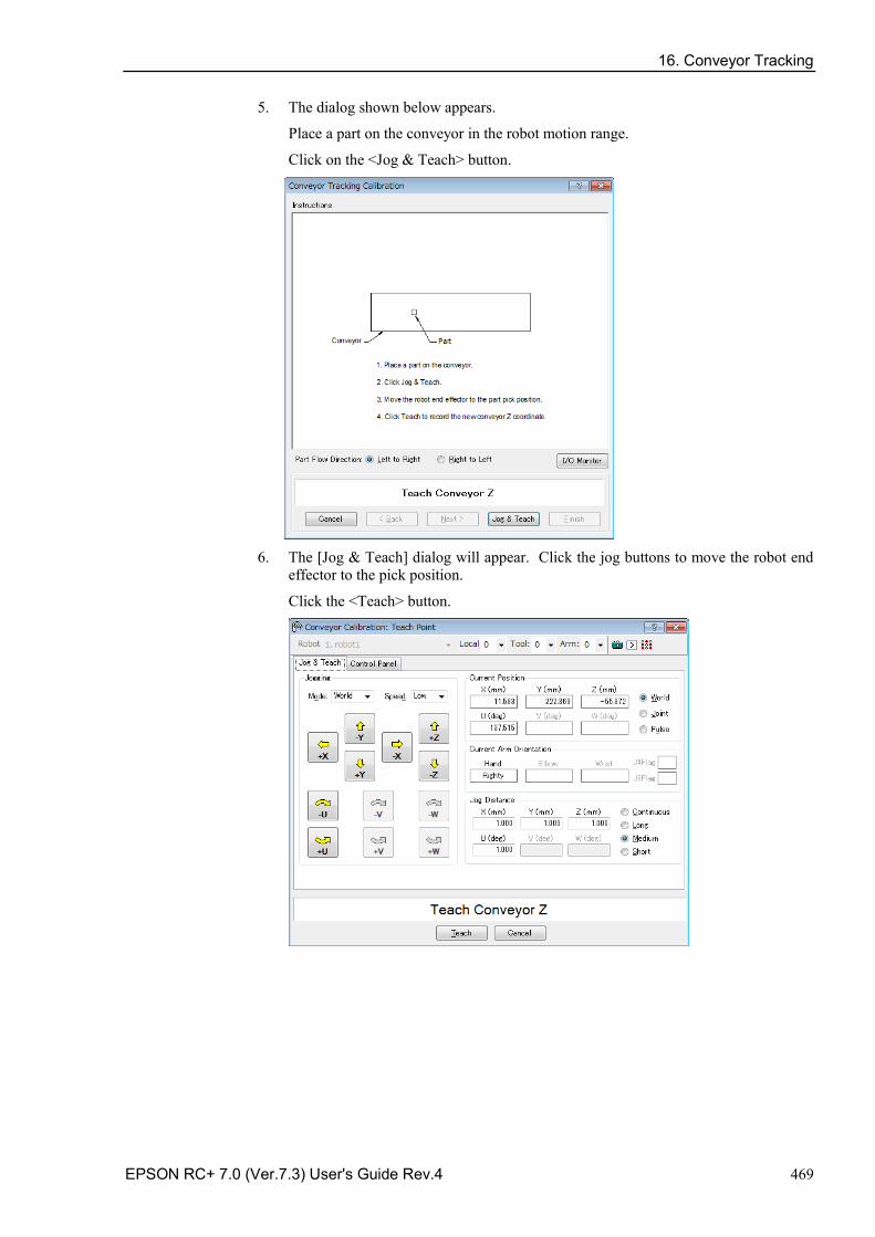
16. Conveyor Tracking
EPSON RC+ 7.0 (Ver.7.3) User's Guide Rev.4 469
5. The dialog shown below appears.
Place a part on the conveyor in the robot motion range.
Click on the <Jog & Teach> button.
6. The [Jog & Teach] dialog will appear. Click the jog buttons to move the robot end
effector to the pick position.
Click the <Teach> button.
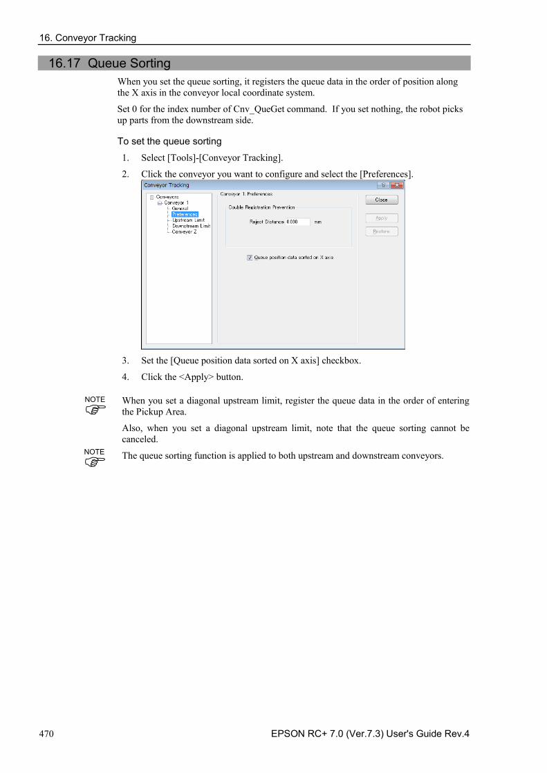
16. Conveyor Tracking
470 EPSON RC+ 7.0 (Ver.7.3) User's Guide Rev.4
16.17 Queue Sorting When you set the queue sorting, it registers the queue data in the order of position along the X axis in the conveyor local coordinate system.
Set 0 for the index number of Cnv_QueGet command. If you set nothing, the robot picks up parts from the downstream side. To set the queue sorting
1. Select [Tools]-[Conveyor Tracking].
2. Click the conveyor you want to configure and select the [Preferences].
3. Set the [Queue position data sorted on X axis] checkbox.
4. Click the <Apply> button.
When you set a diagonal upstream limit, register the queue data in the order of entering the Pickup Area.
Also, when you set a diagonal upstream limit, note that the queue sorting cannot be canceled.
The queue sorting function is applied to both upstream and downstream conveyors.
NOTE
NOTE
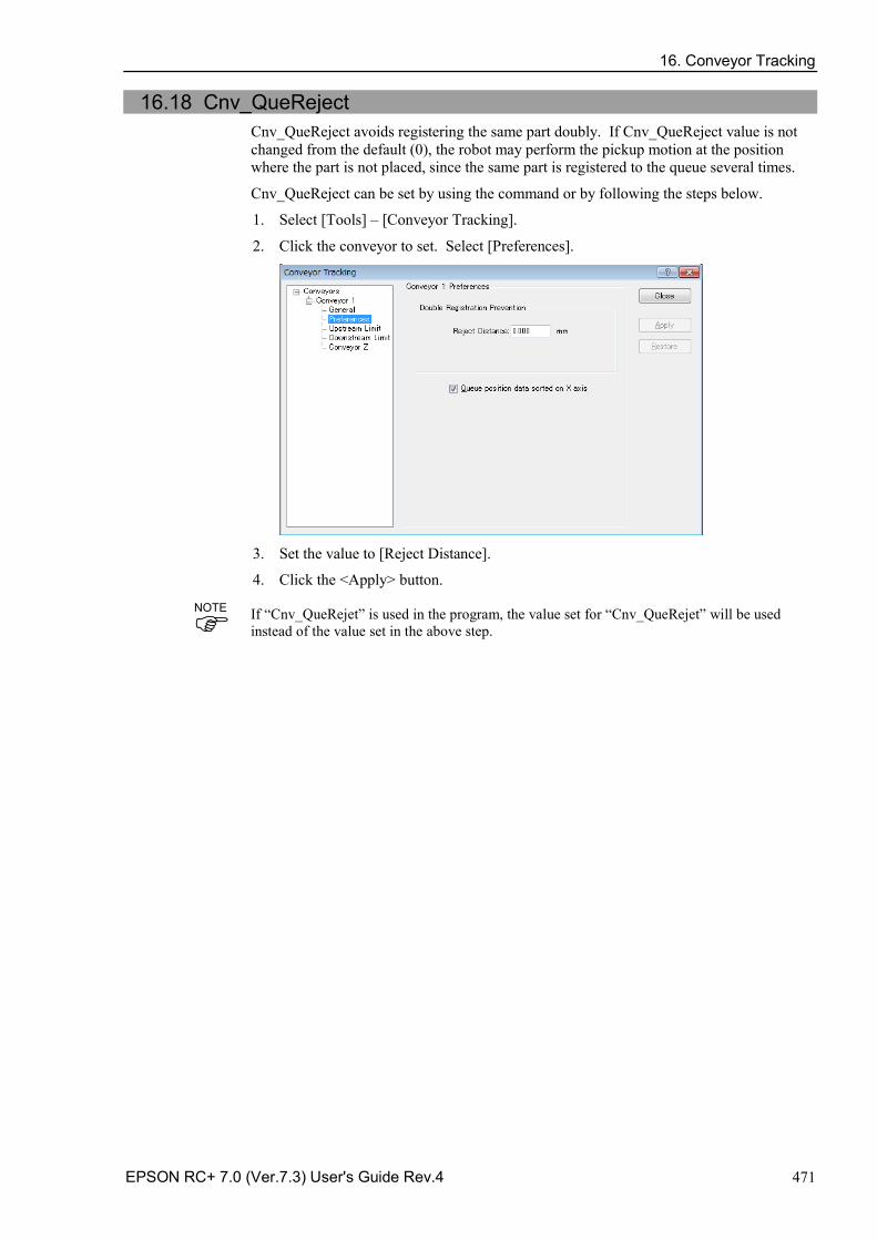
16. Conveyor Tracking
EPSON RC+ 7.0 (Ver.7.3) User's Guide Rev.4 471
16.18 Cnv_QueReject Cnv_QueReject avoids registering the same part doubly. If Cnv_QueReject value is not changed from the default (0), the robot may perform the pickup motion at the position where the part is not placed, since the same part is registered to the queue several times.
Cnv_QueReject can be set by using the command or by following the steps below.
1. Select [Tools] – [Conveyor Tracking].
2. Click the conveyor to set. Select [Preferences].
3. Set the value to [Reject Distance].
4. Click the <Apply> button.
If “Cnv_QueRejet” is used in the program, the value set for “Cnv_QueRejet” will be used instead of the value set in the above step.
NOTE
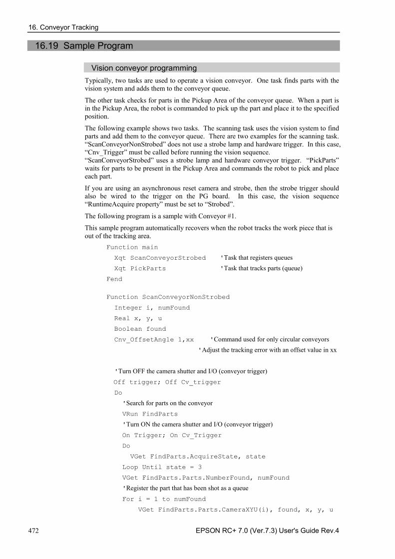
16. Conveyor Tracking
472 EPSON RC+ 7.0 (Ver.7.3) User's Guide Rev.4
16.19 Sample Program
Vision conveyor programming Typically, two tasks are used to operate a vision conveyor. One task finds parts with the vision system and adds them to the conveyor queue.
The other task checks for parts in the Pickup Area of the conveyor queue. When a part is in the Pickup Area, the robot is commanded to pick up the part and place it to the specified position.
The following example shows two tasks. The scanning task uses the vision system to find parts and add them to the conveyor queue. There are two examples for the scanning task. “ScanConveyorNonStrobed” does not use a strobe lamp and hardware trigger. In this case, “Cnv_Trigger” must be called before running the vision sequence. “ScanConveyorStrobed” uses a strobe lamp and hardware conveyor trigger. “PickParts” waits for parts to be present in the Pickup Area and commands the robot to pick and place each part.
If you are using an asynchronous reset camera and strobe, then the strobe trigger should also be wired to the trigger on the PG board. In this case, the vision sequence “RuntimeAcquire property” must be set to “Strobed”.
The following program is a sample with Conveyor #1.
This sample program automatically recovers when the robot tracks the work piece that is out of the tracking area.
Function main
Xqt ScanConveyorStrobed 'Task that registers queues Xqt PickParts 'Task that tracks parts (queue) Fend
Function ScanConveyorNonStrobed
Integer i, numFound
Real x, y, u
Boolean found
Cnv_OffsetAngle 1,xx 'Command used for only circular conveyors 'Adjust the tracking error with an offset value in xx
'Turn OFF the camera shutter and I/O (conveyor trigger) Off trigger; Off Cv_trigger
Do
'Search for parts on the conveyor VRun FindParts
'Turn ON the camera shutter and I/O (conveyor trigger) On Trigger; On Cv_Trigger
Do
VGet FindParts.AcquireState, state
Loop Until state = 3
VGet FindParts.Parts.NumberFound, numFound
'Register the part that has been shot as a queue For i = 1 to numFound
VGet FindParts.Parts.CameraXYU(i), found, x, y, u
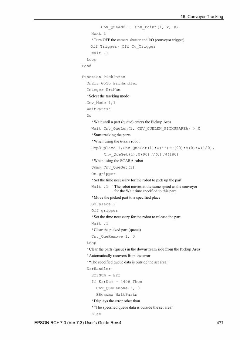
16. Conveyor Tracking
EPSON RC+ 7.0 (Ver.7.3) User's Guide Rev.4 473
Cnv_QueAdd 1, Cnv_Point(1, x, y)
Next i
'Turn OFF the camera shutter and I/O (conveyor trigger) Off Trigger; Off Cv_Trigger
Wait .1
Loop
Fend
Function PickParts
OnErr GoTo ErrHandler
Integer ErrNum
'Select the tracking mode Cnv_Mode 1,1
WaitParts:
Do
'Wait until a part (queue) enters the Pickup Area Wait Cnv_QueLen(1, CNV_QUELEN_PICKUPAREA) > 0
'Start tracking the parts 'When using the 6-axis robot Jmp3 place_1,Cnv_QueGet(1):Z(**):U(90):V(0):W(180),
Cnv_QueGet(1):U(90):V(0):W(180)
'When using the SCARA robot Jump Cnv_QueGet(1)
On gripper
'Set the time necessary for the robot to pick up the part Wait .1 ' The robot moves at the same speed as the conveyor ' for the Wait time specified to this part. 'Move the picked part to a specified place Go place_2
Off gripper
'Set the time necessary for the robot to release the part Wait .1
'Clear the picked part (queue) Cnv_QueRemove 1, 0
Loop
'Clear the parts (queue) in the downstream side from the Pickup Area 'Automatically recovers from the error '“The specified queue data is outside the set area” ErrHandler:
ErrNum = Err
If ErrNum = 4406 Then
Cnv_QueRemove 1, 0
EResume WaitParts
'Displays the error other than '“The specified queue data is outside the set area” Else
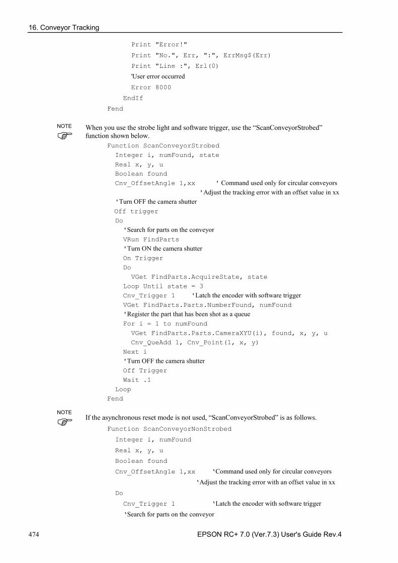
16. Conveyor Tracking
474 EPSON RC+ 7.0 (Ver.7.3) User's Guide Rev.4
Print "Error!"
Print "No.", Err, ":", ErrMsg$(Err)
Print "Line :", Erl(0)
'User error occurred Error 8000
EndIf
Fend
When you use the strobe light and software trigger, use the “ScanConveyorStrobed” function shown below.
Function ScanConveyorStrobed Integer i, numFound, state Real x, y, u Boolean found Cnv_OffsetAngle 1,xx ' Command used only for circular conveyors 'Adjust the tracking error with an offset value in xx 'Turn OFF the camera shutter Off trigger Do 'Search for parts on the conveyor VRun FindParts 'Turn ON the camera shutter On Trigger Do VGet FindParts.AcquireState, state Loop Until state = 3 Cnv_Trigger 1 'Latch the encoder with software trigger VGet FindParts.Parts.NumberFound, numFound 'Register the part that has been shot as a queue For i = 1 to numFound VGet FindParts.Parts.CameraXYU(i), found, x, y, u Cnv_QueAdd 1, Cnv_Point(1, x, y) Next i 'Turn OFF the camera shutter Off Trigger Wait .1 Loop Fend
If the asynchronous reset mode is not used, “ScanConveyorStrobed” is as follows. Function ScanConveyorNonStrobed
Integer i, numFound
Real x, y, u
Boolean found
Cnv_OffsetAngle 1,xx ‘Command used only for circular conveyors ‘Adjust the tracking error with an offset value in xx Do
Cnv_Trigger 1 ‘Latch the encoder with software trigger ‘Search for parts on the conveyor
NOTE
NOTE
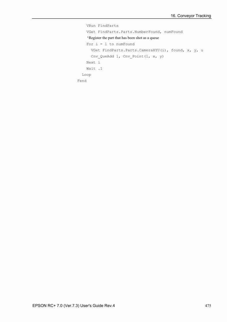
16. Conveyor Tracking
EPSON RC+ 7.0 (Ver.7.3) User's Guide Rev.4 475
VRun FindParts
VGet FindParts.Parts.NumberFound, numFound
‘Register the part that has been shot as a queue For i = 1 to numFound
VGet FindParts.Parts.CameraXYU(i), found, x, y, u
Cnv_QueAdd 1, Cnv_Point(1, x, y)
Next i
Wait .1
Loop
Fend
16. Conveyor Tracking
476 EPSON RC+ 7.0 (Ver.7.3) User's Guide Rev.4
Sensor conveyor programming Typically, two tasks are used to operate a sensor conveyor. One task waits for a part to trip the sensor and add it to the conveyor queue. The other task checks for parts in the Pickup Area of the conveyor queue. When a part is in the Pickup Area, the robot is commanded to pick up the part and place it to the specified position.
This sample program automatically recovers when the robot tracks the work piece that is out of the tracking area.
Function main
Xqt ScanConveyor 'Task that registers queues
Xqt PickParts 'Task that tracks parts (queue) Fend
Function ScanConveyor
Double lpulse1 'Previous latch pulse
lpulse1 = Cnv_LPulse(1) 'Register the latch pulse as lpulse1
Do
'Register a part as a queue only when it passes the sensor If lpulse1 <> Cnv_LPulse(1) Then
Cnv_QueAdd 1, Cnv_Point(1, 0, 0)
lpulse1 = Cnv_LPulse(1) 'Update lpulse1
EndIf
Loop
Fend
Function PickParts
OnErr GoTo ErrHandler
Integer ErrNum
‘Select teh tracking mode Cnv_Mode 1,1
WaitParts:
Do
'Wait until a part (queue) enters the Pickup Area Wait Cnv_QueLen(1, CNV_QUELEN_PICKUPAREA) > 0
‘Start tracking the parts
‘When using the 6-axis robot Jump3 place_1,Cnv_QueGet(1):Z(**):U(90):V(0):W(180),
Cnv_QueGet(1):U(90):V(0):W(180)
'When using the SCARA robot Jump Cnv_QueGet(1)
On gripper
'Set the time necessary for the robot to pick up the part
Wait .1 ' The robot moves at the same speed as the conveyor ' for the Wait time specified to this part. 'Move the picked part to a specified place
16. Conveyor Tracking
EPSON RC+ 7.0 (Ver.7.3) User's Guide Rev.4 477
Go place_2
Off gripper
'Set the time necessary for the robot to release the part Wait .1
'Clear the picked part (queue)
Cnv_QueRemove 1, 0
Loop
'Clear the parts (queu) in the downstream side from the Pickup Area
'Automatically recovers from the error '“The specified queue data is outside the set area” ErrHandler:
ErrNum = Err
If ErrNum = 4406 Then
Cnv_QueRemove 1, 0
EResume WaitParts
'Displays the error other than '“The specified queue data is outside the set area” Else
Print "Error!"
Print "No.", Err, ":", ErrMsg$(Err)
Print "Line :", Erl(0)
'User error occurred Error 8000
EndIf
Fend
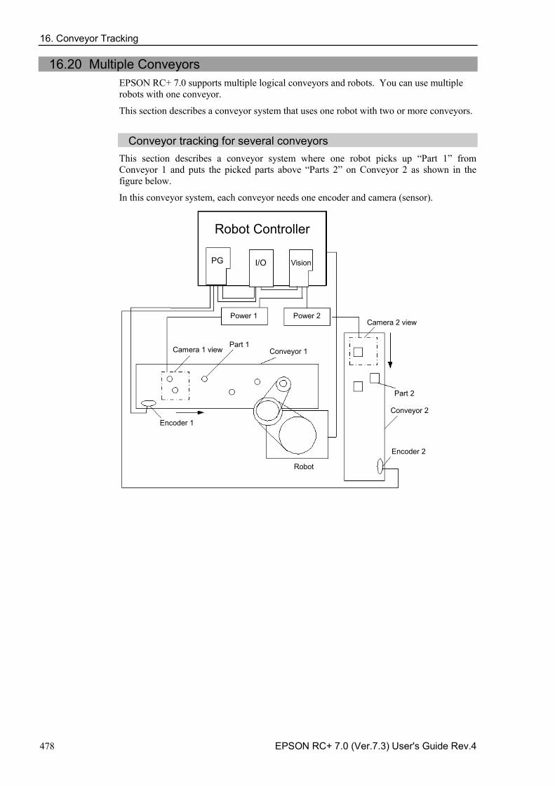
16. Conveyor Tracking
478 EPSON RC+ 7.0 (Ver.7.3) User's Guide Rev.4
16.20 Multiple Conveyors EPSON RC+ 7.0 supports multiple logical conveyors and robots. You can use multiple robots with one conveyor.
This section describes a conveyor system that uses one robot with two or more conveyors.
Conveyor tracking for several conveyors
This section describes a conveyor system where one robot picks up “Part 1” from Conveyor 1 and puts the picked parts above “Parts 2” on Conveyor 2 as shown in the figure below.
In this conveyor system, each conveyor needs one encoder and camera (sensor).
Robot Controller
PG I/O Vision
Power 1 Power 2
Camera 1 view Part 1
Conveyor 1
Conveyor 2
Part 2
Encoder 1
Encoder 2
Robot
Camera 2 view
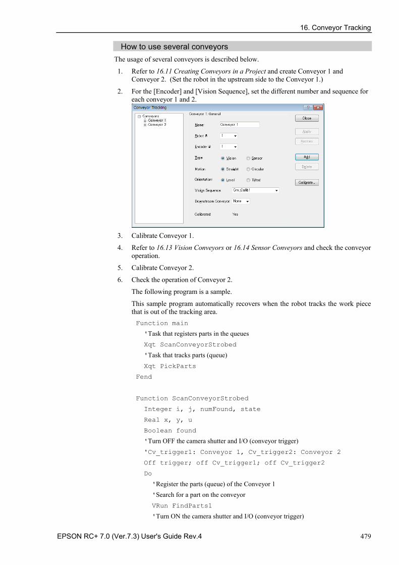
16. Conveyor Tracking
EPSON RC+ 7.0 (Ver.7.3) User's Guide Rev.4 479
How to use several conveyors The usage of several conveyors is described below.
1. Refer to 16.11 Creating Conveyors in a Project and create Conveyor 1 and Conveyor 2. (Set the robot in the upstream side to the Conveyor 1.)
2. For the [Encoder] and [Vision Sequence], set the different number and sequence for each conveyor 1 and 2.
3. Calibrate Conveyor 1.
4. Refer to 16.13 Vision Conveyors or 16.14 Sensor Conveyors and check the conveyor operation.
5. Calibrate Conveyor 2.
6. Check the operation of Conveyor 2.
The following program is a sample.
This sample program automatically recovers when the robot tracks the work piece that is out of the tracking area. Function main
'Task that registers parts in the queues Xqt ScanConveyorStrobed
'Task that tracks parts (queue) Xqt PickParts
Fend
Function ScanConveyorStrobed
Integer i, j, numFound, state
Real x, y, u
Boolean found
'Turn OFF the camera shutter and I/O (conveyor trigger) 'Cv_trigger1: Conveyor 1, Cv_trigger2: Conveyor 2
Off trigger; off Cv_trigger1; off Cv_trigger2
Do
'Register the parts (queue) of the Conveyor 1 'Search for a part on the conveyor VRun FindParts1
'Turn ON the camera shutter and I/O (conveyor trigger)
16. Conveyor Tracking
480 EPSON RC+ 7.0 (Ver.7.3) User's Guide Rev.4
On Trigger; On Cv_Trigger1
Do
VGet FindParts1.AcquireState, state
Loop Until state = 3
VGet FindParts1.Parts.NumberFound, numFound
'Register the part that has been shot as a queue For i = 1 to numFound
VGet FindParts.Parts.CameraXYU(i), found, x, y, u
Cnv_QueAdd 1, Cnv_Point(1, x, y)
Next i
'Turn OFF the camera shutter and I/O (conveyor trigger) Off Trigger; Off Cv_Trigger
Wait .1
'Register the parts (queue) of the Conveyor 2 'Search for part on the conveyor VRun FindParts2
'Turn ON the camera shutter and I/O (conveyor trigger) On Trigger; On Cv_Trigger1
Do
VGet FindParts2.AcquireState, state
Loop Until state = 3
VGet FindParts2.Parts.NumberFound, numFound
'Register the part that has been shot as a queue For j = 1 to numFound
VGet FindParts2.Parts.CameraXYU(j), found, x, y, u
Cnv_QueAdd 2, Cnv_Point(2, x, y)
Next j
'Turn OFF the camera shutter and I/O (conveyor trigger) Off Trigger; Off Cv_Trigger2
Wait .1
Loop
Fend
Function PickParts
OnErr GoTo ErrHandler
Integer ErrNum
MemOff 1
MemOff 2
Do
'Tracking of Conveyor 1 WaitPickup1:
'Turn ON the memory I/O when the Conveyor 1 tracking phase starts MemOn 1
16. Conveyor Tracking
EPSON RC+ 7.0 (Ver.7.3) User's Guide Rev.4 481
'Clear the parts (queue) in the downstream side from the downstream limit Do While Cnv_QueLen(1, CNV_QUELEN_DOWNSTREAM) > 0
Cnv_QueRemove 1, 0
Loop
'Move to the standby position when there is no part (queue) in the Pickup Area If Cnv_QueLen(1, CNV_QUELEN_PICKUPAREA) = 0 Then
Jump place
EndIf
'Wait until a part (queue) enters the Pickup Area Wait Cnv_QueLen(1, CNV_QUELEN_PICKUPAREA) > 0
'Start tracking the parts Jump Cnv_QueGet(1)
On gripper
Wait .1
'Clear the picked part (queue) Cnv_Queremove 1,0
'Finish the Conveyor 1 tracking phase MemOff 1
'Tracking of the Conveyor 2 WaitPickup2:
'Start the Conveyor 2 tracking phase MemOn 2
'Clear the parts (queue) in the downstream side from the downstream limit Do While Cnv_QueLen(2, CNV_QUELEN_DOWNSTREAM) > 0
Cnv_QueRemove 2, 0
Loop
'Move to the standby position when there is no part (queue) in the Pickup Area If Cnv_QueLen(2, CNV_QUELEN_PICKUPAREA) = 0 Then
Jump place
EndIf
'Wait until a part (queue) enters the Pickup Area Wait Cnv_QueLen(2, CNV_QUELEN_PICKUPAREA) > 0
'Start tracking the parts Jump Cnv_QueGet(2)
Off gripper
Wait .1
'Clear the picked part (queue) Cnv_QueRemove 2, 0
'Finish the Conveyor 2 tracking phase MemOff 2
Loop
'Clear the parts (queue) in the downstream side from the Pickup Area 'Automatically recovers from the error
16. Conveyor Tracking
482 EPSON RC+ 7.0 (Ver.7.3) User's Guide Rev.4
'“The specified queue data is outside the set area” ErrHandler:
ErrNum = Err
If ErrNum = 4406 Then
If MemSw(1) = On Then
Cnv_QueRemove 1
EResume WaitPickup1
EndIf
If MemSw(2) = On Then
Cnv_QueRemove 2
EResume WaitPickup2
EndIf
'Automatically recovers from the error '“The specified queue data is outside the set area” Else
Print "Error!"
Print "No.", Err, ":", ErrMsg$(Err)
Print "Line :", Erl(0)
'User error occurred Error 8000
EndIf
Fend
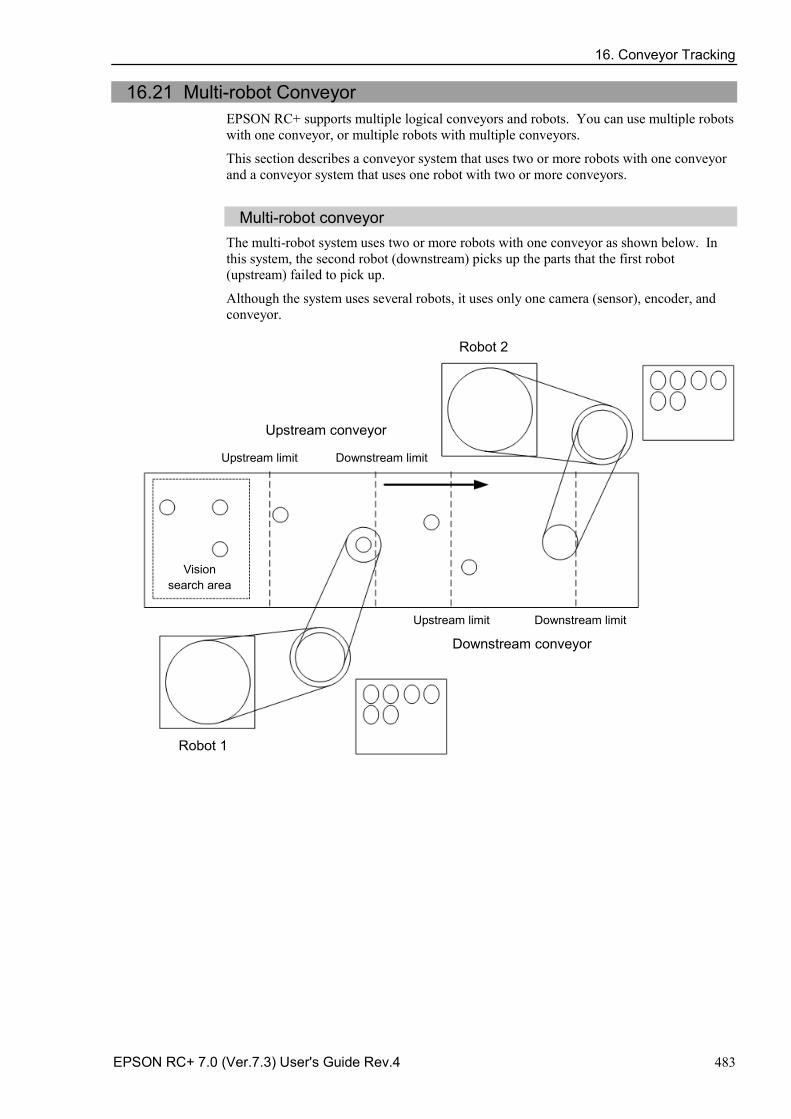
16. Conveyor Tracking
EPSON RC+ 7.0 (Ver.7.3) User's Guide Rev.4 483
16.21 Multi-robot Conveyor EPSON RC+ supports multiple logical conveyors and robots. You can use multiple robots with one conveyor, or multiple robots with multiple conveyors.
This section describes a conveyor system that uses two or more robots with one conveyor and a conveyor system that uses one robot with two or more conveyors.
Multi-robot conveyor
The multi-robot system uses two or more robots with one conveyor as shown below. In this system, the second robot (downstream) picks up the parts that the first robot (upstream) failed to pick up.
Although the system uses several robots, it uses only one camera (sensor), encoder, and conveyor.
Robot 2
Upstream conveyor
Upstream limit Downstream limit
Robot 1
Upstream limit Downstream limit
Downstream conveyor
Vision search area
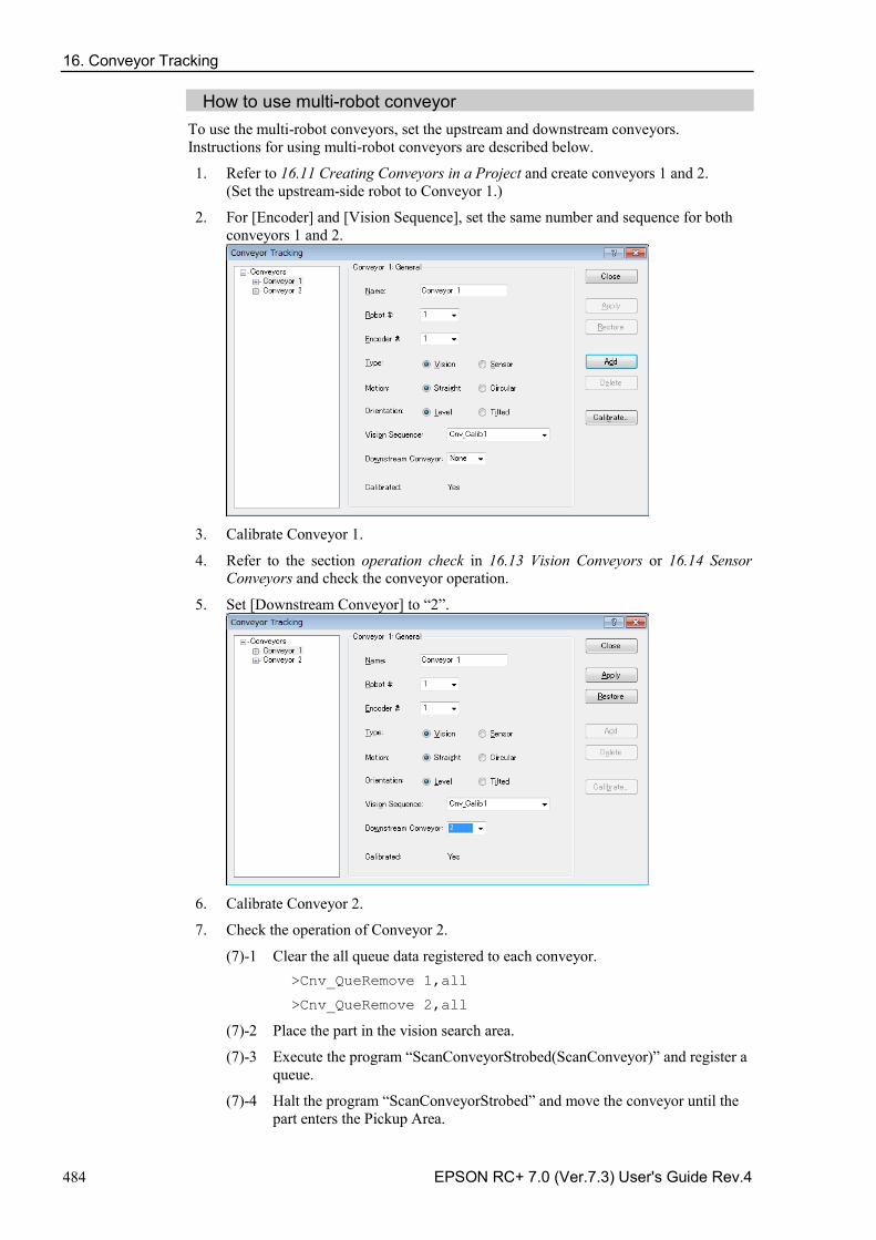
16. Conveyor Tracking
484 EPSON RC+ 7.0 (Ver.7.3) User's Guide Rev.4
How to use multi-robot conveyor To use the multi-robot conveyors, set the upstream and downstream conveyors. Instructions for using multi-robot conveyors are described below.
1. Refer to 16.11 Creating Conveyors in a Project and create conveyors 1 and 2. (Set the upstream-side robot to Conveyor 1.)
2. For [Encoder] and [Vision Sequence], set the same number and sequence for both conveyors 1 and 2.
3. Calibrate Conveyor 1.
4. Refer to the section operation check in 16.13 Vision Conveyors or 16.14 Sensor Conveyors and check the conveyor operation.
5. Set [Downstream Conveyor] to “2”.
6. Calibrate Conveyor 2.
7. Check the operation of Conveyor 2.
(7)-1 Clear the all queue data registered to each conveyor. >Cnv_QueRemove 1,all
>Cnv_QueRemove 2,all
(7)-2 Place the part in the vision search area.
(7)-3 Execute the program “ScanConveyorStrobed(ScanConveyor)” and register a queue.
(7)-4 Halt the program “ScanConveyorStrobed” and move the conveyor until the part enters the Pickup Area.
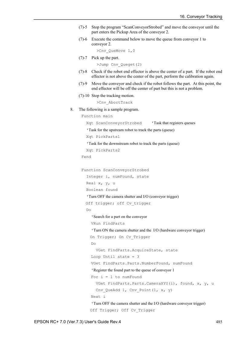
16. Conveyor Tracking
EPSON RC+ 7.0 (Ver.7.3) User's Guide Rev.4 485
(7)-5 Stop the program “ScanConveyorStrobed” and move the conveyor until the part enters the Pickup Area of the conveyor 2.
(7)-6 Execute the command below to move the queue from conveyor 1 to conveyor 2.
>Cnv_QueMove 1,0
(7)-7 Pick up the part. >Jump Cnv_Queget(2)
(7)-8 Check if the robot end effector is above the center of a part. If the robot end effector is not above the center of the part, perform the calibration again.
(7)-9 Move the conveyor and check if the robot follows the part. At this point, the end effector will be off the center of part but this is not a problem.
(7)-10 Stop the tracking motion. >Cnv_AbortTrack
8. The following is a sample program. Function main
Xqt ScanConveyorStrobed 'Task that registers queues
'Task for the upstream robot to track the parts (queue) Xqt PickParts1
'Task for the downstream robot to track the parts (queue) Xqt PickParts2
Fend
Function ScanConveyorStrobed
Integer i, numFound, state
Real x, y, u
Boolean found
'Turn OFF the camera shutter and I/O (conveyor trigger)
Off trigger; off Cv_trigger
Do
'Search for a part on the conveyor
VRun FindParts
'Turn ON the camera shutter and the I/O (hardware conveyor trigger) On Trigger; On Cv_Trigger
Do
VGet FindParts.AcquireState, state
Loop Until state = 3
VGet FindParts.Parts.NumberFound, numFound
'Register the found part to the queue of conveyor 1
For i = 1 to numFound
VGet FindParts.Parts.CameraXYU(i), found, x, y, u
Cnv_QueAdd 1, Cnv_Point(1, x, y)
Next i
'Turn OFF the camera shutter and the I/O (hardware conveyor trigger)
Off Trigger; Off Cv_Trigger
16. Conveyor Tracking
486 EPSON RC+ 7.0 (Ver.7.3) User's Guide Rev.4
Wait .1
Loop
Fend
Function PickParts1
OnErr GoTo ErrHandler
Integer ErrNum
WaitParts:
Do
'Wait until a part (queue) enters the Pickup Area
Wait Cnv_QueLen(1, CNV_QUELEN_PICKUPAREA) > 0
'Start tracking the part Jump Cnv_QueGet(1)
On gripper
Wait .1
'Move the picked part to a specified place
Jump place
Off gripper
Wait .1
'Clear the picked part (queue) Cnv_QueRemove 1, 0
Loop
'Move the parts (queue) in the downstream side than the Pickup Area of conveyor 1
' to the conveyor 2
ErrHandler:
ErrNum = Err
If ErrNum = 4406 Then
Cnv_QueMove 1, 0
EResume WaitParts
'When an error except the conveyor tracking motion range error occurs, 'display the error
Else
Print "Error!"
Print "No.", Err, ":", ErrMsg$(Err)
Print "Line :", Erl(0)
'User error occurred Error 8000
EndIf
Fend
16. Conveyor Tracking
EPSON RC+ 7.0 (Ver.7.3) User's Guide Rev.4 487
Function PickParts2
OnErr GoTo ErrHandler
Integer ErrNum
WaitParts:
Do
'Wait until a part (queue) enters the Pickup Area Wait Cnv_QueLen(2, CNV_QUELEN_PICKUPAREA) > 0
'Start tracking the part
Jump Cnv_QueGet(2)
On gripper
Wait .1
'Move the picked part to a specified place Jump place
Off gripper
Wait .1
'Clear the picked part (queue) Cnv_QueRemove 2, 0
Loop
'Clear the parts (queue) in the downstream side than the Pickup Area of conveyor 2
'Automatically recovers from the error '“The specified queue data is outside the set area” ErrHandler:
ErrNum = Err
If ErrNum = 4406 Then
Cnv_QueRemove 2, 0
EResume WaitParts
'When an error except “The specified queue data is outside the set area” 'occurs, display the error
Else
Print "Error!"
Print "No.", Err, ":", ErrMsg$(Err)
Print "Line :", Erl(0)
'User error occurred Error 8000
EndIf
Fend
16. Conveyor Tracking
488 EPSON RC+ 7.0 (Ver.7.3) User's Guide Rev.4
16.22 Abort Tracking There are some situations when you want to abort tracking a part that moves out of the Pickup Area while the robot is tracking the part. In this case, use the Cnv_AbortTrack command in a separate task that monitors the conveyor queue.
Function MonitorDownstream Robot 1 Do If Cnv_QueLen(1, CNV_QUELEN_DOWNSTREAM) > 0 Then Cnv_AbortTrack 0 EndIf Wait .1 Loop Fend
16.23 Conveyor Tracking with 6-Axis Robot
When you use a 6-axis robot in a conveyor tracking system, you need to set the values of U, V, and W. For this, use the Cnv_QueGet command.
The following shows the case where the robot end effector moves toward a part during the pickup.
Go Cnv_Queget(Conveyor number,[Index]):U(90):V(0):W(180)
To use the Jump3 command, write a program as follows: Jmp3 P1,Cnv_QueGet(1):Z(**):U(90):V(0):W(180),
Cnv_QueGet(1):U(90):V(0):W(180)
P1 and Z(**) height should be the same.
The followings are points to be known before setting the Z(**) height.
Home position of Z in the tracking coordinate is the calibration position. -
To raise the Z height in the tracking coordinate, offset in a positive (+) direction. -
To lower the Z height in the tracking coordinate, offset in a minus (-) direction. -
Robot coordinate P1 can be converted to the conveyor coordinate and displayed. -> print P1@cnv1
16.24 Tracking Mode
There are two tracking modes: picking quantity-priority mode and picking accuracy-priority mode. The mode can be selected by the Cnv_Mode command.
Tracking mode selection is only available for linear conveyors. For circular conveyors, the picking quantity-priority mode is only available.
Picking quantity-priority mode
Picking quantity-priority mode prioritizes reducing time to catch up with the work piece (queue) over the picking accuracy. This mode is suitable for the conveyor tracking system in which space between the work pieces is narrow.
NOTE
16. Conveyor Tracking
EPSON RC+ 7.0 (Ver.7.3) User's Guide Rev.4 489
When the picking quantity-priority mode is selected, tracking delay (situation in which the Manipulator does picking motion at the posterior part of the work piece to the direction of the conveyor motion) may occur. If the tracking delay occurs, write the program as follows.
Go Cnv_Queget(Conveyor number,[Index])+X(**)
Picking accuracy-priority mode
Picking accuracy-priority mode improves the picking accuracy while it takes more time to catch up with the work piece. This mode is suitable for the conveyor tracking system for small work pieces.
Picking accuracy-priority mode should be used for the conveyors of 350 mm/sec or less.
When the conveyor of 350 mm/sec or more is used, the tracking mode will be picking quantity-priority mode regardless of the setting of Cnv_Mode.
Although the tracking delay does not occur in the picking accuracy-priority mode, the Manipulator may slide to the direction of the conveyor motion in Go, Move, or Jump3 motions after the downward motion of the Z-axis. If this occurs, take following countermeasures (these may not be effective for Go and Move motions)
For Go motion: Change to Jump motion. Or, reduce the values of Accel and Speed. -
For Move and Jump3 motions: Reduce the values of AccelS and SpeedS. -
16.25 How to shorten the picking cycle time
There are following two methods to shorten the picking cycle time.
・Use the Arch command
・Use the Cnv_Accel command
The followings are the points to consider when using the Cnv_Accel command.
Maximum Cnv_Accel value is 5000 mm/sec2. -
If the Cnv_Accel setting value is 0 or exceeds 5001, the default value (2000 mm/sec2) -will be set.
If the acceleration error occurs, greater Cnv_Accel value cannot be specified. Decrease -the Cnv_Accel value or decrease Accel or AccelS.
When Cnv_Accel is used in the picking accuracy-priority mode, the manipulator may -slide to the direction of the conveyor motion after the downward motion of the Z-axis.
16.26 Manipulator Posture
Manipulator posture during the tracking motion is always the default posture regardless of the posture at the conveyor tracking calibration. To specify the posture for the tracking, write a program as follows.
Example: tracks the work piece with Lefty arm position jump Cnv_Queget(Conveyor number,[Index])/L
During tracking motion, singularity avoiding function cannot be used. Therefore, set the positions of the Manipulator and the conveyor so that the Manipulator does not pass through the singularity.
NOTE
NOTE
NOTE
NOTE
NOTE
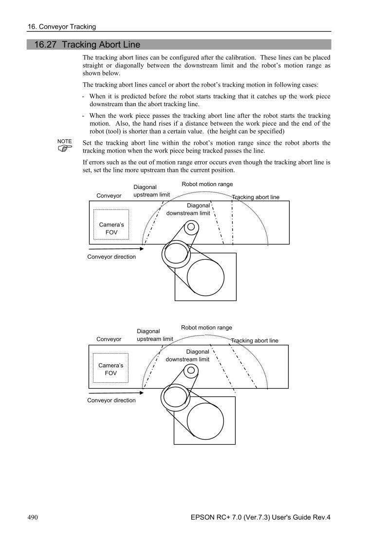
16. Conveyor Tracking
490 EPSON RC+ 7.0 (Ver.7.3) User's Guide Rev.4
16.27 Tracking Abort Line The tracking abort lines can be configured after the calibration. These lines can be placed straight or diagonally between the downstream limit and the robot’s motion range as shown below.
The tracking abort lines cancel or abort the robot’s tracking motion in following cases:
- When it is predicted before the robot starts tracking that it catches up the work piece downstream than the abort tracking line.
- When the work piece passes the tracking abort line after the robot starts the tracking motion. Also, the hand rises if a distance between the work piece and the end of the robot (tool) is shorter than a certain value. (the height can be specified)
Set the tracking abort line within the robot’s motion range since the robot aborts the tracking motion when the work piece being tracked passes the line.
If errors such as the out of motion range error occurs even though the tracking abort line is set, set the line more upstream than the current position.
Conveyor direction
Conveyor Diagonal upstream limit
Diagonal downstream limit
Robot motion range
Camera’s FOV
Tracking abort line
Conveyor direction
Conveyor
Diagonal upstream limit
Diagonal downstream limit
Robot motion range
Camera’s FOV
Tracking abort line
NOTE
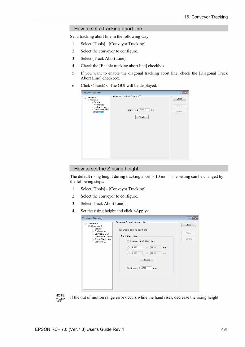
16. Conveyor Tracking
EPSON RC+ 7.0 (Ver.7.3) User's Guide Rev.4 491
How to set a tracking abort line Set a tracking abort line in the following way.
1. Select [Tools] - [Conveyor Tracking].
2. Select the conveyor to configure.
3. Select [Track Abort Line].
4. Check the [Enable tracking abort line] checkbox.
5. If you want to enable the diagonal tracking abort line, check the [Diagonal Track Abort Line] checkbox.
6. Click <Teach>. The GUI will be displayed.
How to set the Z rising height The default rising height during tracking abort is 10 mm. The setting can be changed by the following steps.
1. Select [Tools] - [Conveyor Tracking].
2. Select the conveyor to configure.
3. Select[Track Abort Line].
4. Set the rising height and click <Apply>.
If the out of motion range error occurs while the hand rises, decrease the rising height.
NOTE
16. Conveyor Tracking
492 EPSON RC+ 7.0 (Ver.7.3) User's Guide Rev.4
How to check the tracking abort state Tracking abort state can be checked by using the Cnv_Flag command.
If the return value for Cnv_Flag is as follows, take the countermeasures as described below.
If the return value is 0:
Tracking motion was completed.
If the return value is 1:
Tracking motion was canceled.
The downstream limit position is not proper. Set the downstream limit more upstream than the current position.
If the return value is 2:
Tracking motion was aborted.
The downstream limit position or the robot’s waiting position is not proper. Set the downstream limit more upstream than the current position, or set the robot’s waiting position closer to the downstream limit.
If the return value is 3:
Tracking motion was aborted.
The downstream limit position or the picking time is not proper. Set the downstream limit more upstream than the current position, or shorten the picking time.
If the return value is 4:
Cancel the tracking motion.
The robot tracked the work piece that is out of the tracking area. Pickup failure is occurring. To reduce the missed work pieces, take the following measures.
- Reduce the number of work pieces
- Increase the acceleration by Cnv_Accel
- Set the downstream conveyor
When the tracking motion is canceled or aborted, the program executes the next command without stopping.
Program
If the tracking abort line is configured, the error 4406 does not occur. When you set the tracking abort line, use Cnv_Flag as in the following program. Do not use this program when the abort line is not used.
Use the program 2 after the downstream limit is configured in the program 1 and Cnv_Flag do not return 2 and 3.
When using the program 1, the robot can operate without an error even though the downstream setting is not adequate since the robot aborts the tracking motion. However, abort of tracking increases the cycle time. It is recommended to adjust the downstream line if you are using the program 1.
NOTE
NOTE
NOTE
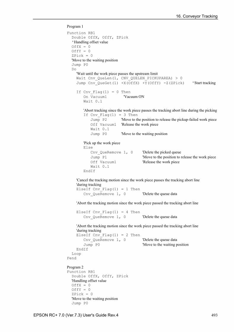
16. Conveyor Tracking
EPSON RC+ 7.0 (Ver.7.3) User's Guide Rev.4 493
Program 1 Function RB1 Double OffX, OffY, ZPick 'Handling offset value OffX = 0 OffY = 0 ZPick = 0 'Move to the waiting position Jump P0 Do 'Wait until the work piece passes the upstream limit Wait Cnv_QueLen(1, CNV_QUELEN_PICKUPAREA) > 0 Jump Cnv_QueGet(1) +X(OffX) +Y(OffY) -Z(ZPick) 'Start tracking If Cnv_Flag(1) = 0 Then On Vacuum1 'Vacuum ON Wait 0.1 'Abort tracking since the work piece passes the tracking abort line during the picking If Cnv_Flag(1) = 3 Then Jump P2 'Move to the position to release the pickup-failed work piece Off Vacuum1 'Release the work piece Wait 0.1 Jump P0 'Move to the waiting position 'Pick up the work piece Else Cnv_QueRemove 1, 0 'Delete the picked queue Jump P1 'Move to the position to release the work piece Off Vacuum1 'Release the work piece Wait 0.1 EndIf 'Cancel the tracking motion since the work piece passes the tracking abort line 'during tracking ElseIf Cnv_Flag(1) = 1 Then Cnv_QueRemove 1, 0 'Delete the queue data 'Abort the tracking motion since the work piece passed the tracking abort line ElseIf Cnv_Flag(1) = 4 Then Cnv_QueRemove 1, 0 'Delete the queue data 'Abort the tracking motion since the work piece passed the tracking abort line 'during tracking ElseIf Cnv_Flag(1) = 2 Then Cnv_QueRemove 1, 0 'Delete the queue data Jump P0 'Move to the waiting position EndIf Loop Fend Program 2 Function RB1 Double OffX, OffY, ZPick 'Handling offset value OffX = 0 OffY = 0 ZPick = 0 'Move to the waiting position Jump P0
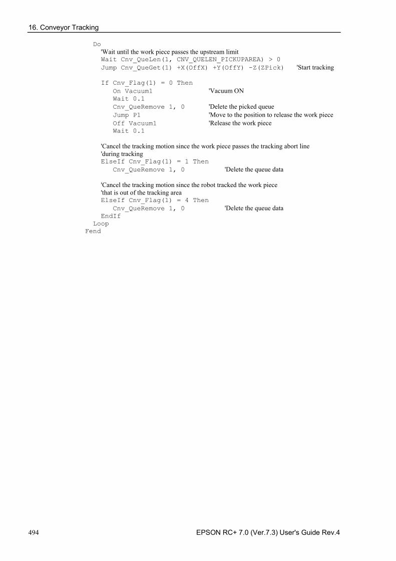
16. Conveyor Tracking
494 EPSON RC+ 7.0 (Ver.7.3) User's Guide Rev.4
Do 'Wait until the work piece passes the upstream limit Wait Cnv_QueLen(1, CNV_QUELEN_PICKUPAREA) > 0 Jump Cnv_QueGet(1) +X(OffX) +Y(OffY) -Z(ZPick) 'Start tracking If Cnv_Flag(1) = 0 Then On Vacuum1 'Vacuum ON Wait 0.1 Cnv_QueRemove 1, 0 'Delete the picked queue Jump P1 'Move to the position to release the work piece Off Vacuum1 'Release the work piece Wait 0.1 'Cancel the tracking motion since the work piece passes the tracking abort line 'during tracking ElseIf Cnv_Flag(1) = 1 Then Cnv_QueRemove 1, 0 'Delete the queue data 'Cancel the tracking motion since the robot tracked the work piece 'that is out of the tracking area ElseIf Cnv_Flag(1) = 4 Then Cnv_QueRemove 1, 0 'Delete the queue data EndIf Loop Fend
16. Conveyor Tracking
EPSON RC+ 7.0 (Ver.7.3) User's Guide Rev.4 495
16.28 Tips for Accuracy Improvement of Conveyor Tracking
16.28.1 Overview This section provides the tips for improving the robot’s performance to handle the work pieces in the Conveyor Tracking, which uses the vision system to detect the work pieces.
Process of Accuracy Improvement
Prepare the conveyor tracking in the following steps. 1. System construction
2. Vision calibration
3. Conveyor calibration
4. Check of the work piece detection accuracy and the detection rate
5. Check of the work piece handling accuracy
In order to improve the handling accuracy, proper preparations and adjustments in each step are necessary. The following sections describe tips for accuracy improvement for each step.
Subsequent descriptions use the SCARA robot. Please note that the tips are common in SCARA and 6-Axis robots.
16.28.2 Tips for System Construction
Tool Settings
In order to realize precise pickups, the end effector of the robot needs to pick up the work pieces correctly with a tool such as a vacuum pad attached.
To pick up the work piece accurately by the tool, it is necessary to configure the tool in [Tools] page. Eccentricity of the tool causes a constant pickup position gap. Make sure to configure the tool settings.
Also, adjustment by the tool settings is not effective for the improper tool such as a randomly-distorted vacuum pad due to the degenerated rubber. Make sure to use the proper tool.
For details on the tool setting, refer to 5.11.1 [Robot Manager] Command (Tools Menu) - [Tools] page
For details on the tool number selection, refer to 5.11.1 [Robot Manager] Command (Tools Menu) - [Jog and Teach] page
After adjusting the tool, make sure to check the operation and ensure that the calibration result is accurate.
NOTE
NOTE
NOTE
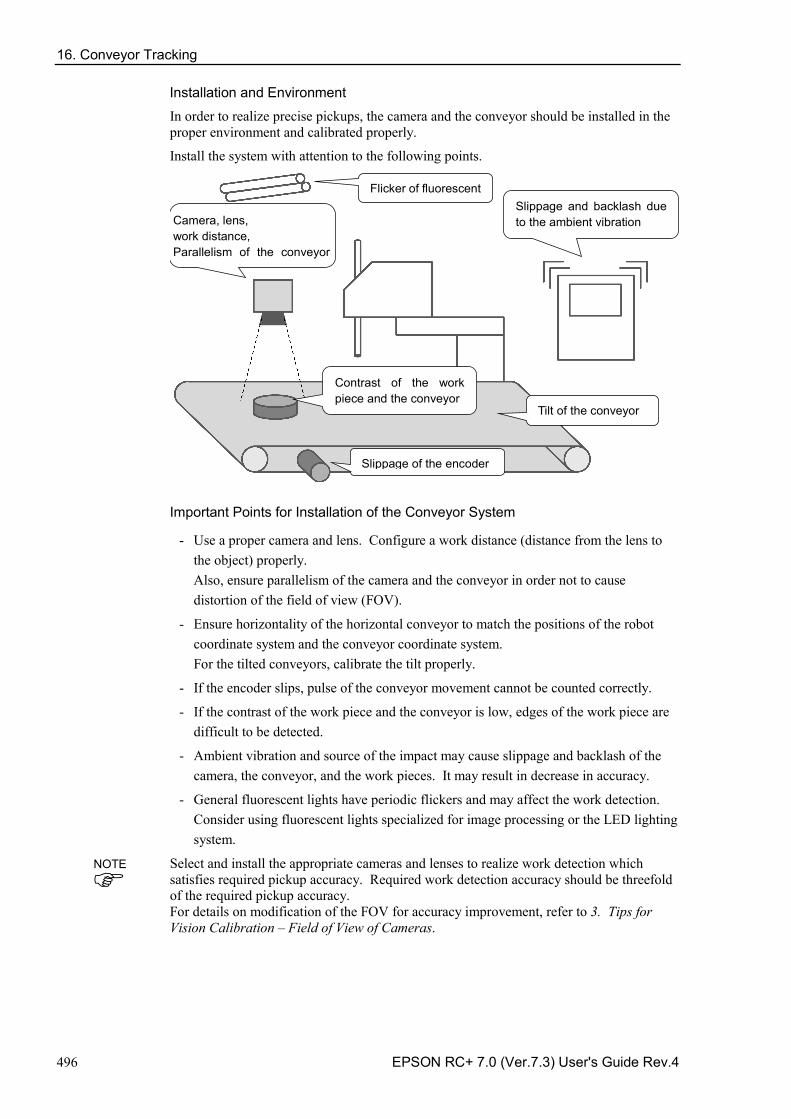
16. Conveyor Tracking
496 EPSON RC+ 7.0 (Ver.7.3) User's Guide Rev.4
Installation and Environment
In order to realize precise pickups, the camera and the conveyor should be installed in the proper environment and calibrated properly.
Install the system with attention to the following points.
Flicker of fluorescent
Camera, lens, work distance, Parallelism of the conveyor
Contrast of the work piece and the conveyor
Slippage of the encoder
Slippage and backlash due to the ambient vibration
Tilt of the conveyor
Important Points for Installation of the Conveyor System
- Use a proper camera and lens. Configure a work distance (distance from the lens to the object) properly. Also, ensure parallelism of the camera and the conveyor in order not to cause distortion of the field of view (FOV).
- Ensure horizontality of the horizontal conveyor to match the positions of the robot coordinate system and the conveyor coordinate system. For the tilted conveyors, calibrate the tilt properly.
- If the encoder slips, pulse of the conveyor movement cannot be counted correctly.
- If the contrast of the work piece and the conveyor is low, edges of the work piece are difficult to be detected.
- Ambient vibration and source of the impact may cause slippage and backlash of the camera, the conveyor, and the work pieces. It may result in decrease in accuracy.
- General fluorescent lights have periodic flickers and may affect the work detection. Consider using fluorescent lights specialized for image processing or the LED lighting system.
Select and install the appropriate cameras and lenses to realize work detection which satisfies required pickup accuracy. Required work detection accuracy should be threefold of the required pickup accuracy. For details on modification of the FOV for accuracy improvement, refer to 3. Tips for Vision Calibration – Field of View of Cameras.
NOTE
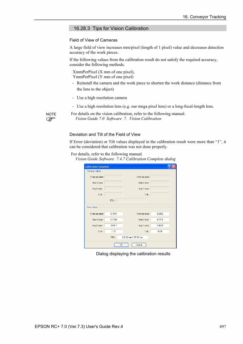
16. Conveyor Tracking
EPSON RC+ 7.0 (Ver.7.3) User's Guide Rev.4 497
16.28.3 Tips for Vision Calibration
Field of View of Cameras
A large field of view increases mm/pixel (length of 1 pixel) value and decreases detection accuracy of the work pieces.
If the following values from the calibration result do not satisfy the required accuracy, consider the following methods.
XmmPerPixel (X mm of one pixel), YmmPerPixel (Y mm of one pixel)
- Reinstall the camera and the work piece to shorten the work distance (distance from the lens to the object)
- Use a high resolution camera
- Use a high resolution lens (e.g. our mega pixel lens) or a long-focal-length lens.
For details on the vision calibration, refer to the following manual. Vision Guide 7.0 Software 7. Vision Calibration
Deviation and Tilt of the Field of View
If Error (deviation) or Tilt values displayed in the calibration result were more than “1”, it can be considered that calibration was not done properly.
For details, refer to the following manual. Vision Guide Software 7.4.7 Calibration Complete dialog
Dialog displaying the calibration results
NOTE
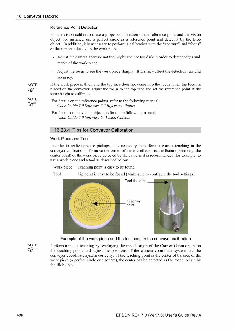
16. Conveyor Tracking
498 EPSON RC+ 7.0 (Ver.7.3) User's Guide Rev.4
Reference Point Detection
For the vision calibration, use a proper combination of the reference point and the vision object; for instance, use a perfect circle as a reference point and detect it by the Blob object. In addition, it is necessary to perform a calibration with the “aperture” and “focus” of the camera adjusted to the work piece.
- Adjust the camera aperture not too bright and not too dark in order to detect edges and marks of the work piece.
- Adjust the focus to see the work piece sharply. Blurs may affect the detection rate and accuracy.
If the work piece is thick and the top face does not come into the focus when the focus is placed on the conveyor, adjust the focus to the top face and set the reference point at the same height to calibrate.
For details on the reference points, refer to the following manual. Vision Guide 7.0 Software 7.2 Reference Points
For details on the vision objects, refer to the following manual. Vision Guide 7.0 Software 6. Vision Objects
16.28.4 Tips for Conveyor Calibration
Work Piece and Tool
In order to realize precise pickups, it is necessary to perform a correct teaching in the conveyor calibration. To move the center of the end effector to the feature point (e.g. the center point) of the work piece detected by the camera, it is recommended, for example, to use a work piece and a tool as described below.
Work piece : Teaching point is easy to be found
Tool : Tip point is easy to be found (Make sure to configure the tool settings.)
Example of the work piece and the tool used in the conveyor calibration
Perform a model teaching by overlaying the model origin of the Corr or Geom object on the teaching point, and adjust the positions of the camera coordinate system and the conveyor coordinate system correctly. If the teaching point is the center of balance of the work piece (a perfect circle or a square), the center can be detected as the model origin by the Blob object.
Teaching point
NOTE
NOTE
NOTE
Tool tip point
16. Conveyor Tracking
EPSON RC+ 7.0 (Ver.7.3) User's Guide Rev.4 499
Z Value Adjustment
The work piece and the tool used in the conveyor calibration can have a different height from those used in actual work piece handling. By adjusting the Z value after replacing the tool and the work piece, errors related to the Z offset can be solved.
In the following cases, Z value adjustment is effective.
Tool cannot reach and pick up the work piece. (Z offset is too large) Robot collides with the work piece and damages it. (Z offset is too small)
Like the above cases, redoing of the whole conveyor calibration process may not be required. If there is a problem in the pickup height, adjust the Z value as a first step.
For details on the Z value adjustment, refer to 16.16 Adjusting the Z value.
16.28.5 Troubleshooting for Work Piece Detection
Teaching of Pickup Position
In order to realize precise pickups, the pickup position of the work piece should be detected properly as a model origin. To compensate the constant pickup position gap in work piece handling due to the gap between the pickup position and the model origin, following methods are effective.
- Perform a model teaching by overlaying the model origin of the Corr or Geom object on the teaching point and set the CameraX and CameraY as the pickup position.
- To set the center of balance as a pickup position, detect it as a model origin by the Blob object and set the CameraX and CameraY as the pickup position.
CameraX: X coordinate of the detected work piece position in the camera coordinate system CameraY: Y coordinate of the detected work piece position in the camera coordinate system
For details on the vision objects, refer to the following manual. Vision Guide 7.0 Software 6. Vision Objects
If the Work Piece Cannot Be Detected in the Search Area
If the work piece which is in the search area cannot be detected and an image processing error occurs, it can be improved by adjusting the vision properties. See the following points.
- Adjust the camera’s exposure time Long exposure time affects the work detection since it may blur the image of the moving work piece. Use the ExposureTime property to shorten the exposure time.
- Adjust the shape score value If the work detection rate is unstable, it may be improved by adjusting the Accept property of the vision object.
For details on the vision properties, refer to the following manual. Vision Guide 7.0 Properties and Results Reference
NOTE
NOTE
NOTE
NOTE
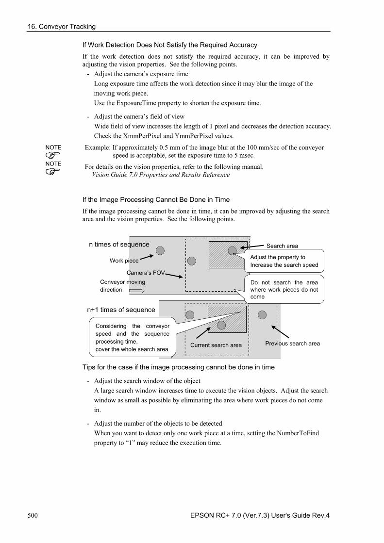
16. Conveyor Tracking
500 EPSON RC+ 7.0 (Ver.7.3) User's Guide Rev.4
If Work Detection Does Not Satisfy the Required Accuracy
If the work detection does not satisfy the required accuracy, it can be improved by adjusting the vision properties. See the following points.
- Adjust the camera’s exposure time Long exposure time affects the work detection since it may blur the image of the moving work piece. Use the ExposureTime property to shorten the exposure time.
- Adjust the camera’s field of view Wide field of view increases the length of 1 pixel and decreases the detection accuracy. Check the XmmPerPixel and YmmPerPixel values.
Example: If approximately 0.5 mm of the image blur at the 100 mm/sec of the conveyor speed is acceptable, set the exposure time to 5 msec.
For details on the vision properties, refer to the following manual. Vision Guide 7.0 Properties and Results Reference
If the Image Processing Cannot Be Done in Time
If the image processing cannot be done in time, it can be improved by adjusting the search area and the vision properties. See the following points.
n times of sequence
n+1 times of sequence
Conveyor moving direction
Previous search area
Current search area
Do not search the area where work pieces do not come
Considering the conveyor speed and the sequence processing time, cover the whole search area
Work piece
Search area
Adjust the property to Increase the search speed Camera’s FOV
Tips for the case if the image processing cannot be done in time
- Adjust the search window of the object A large search window increases time to execute the vision objects. Adjust the search window as small as possible by eliminating the area where work pieces do not come in.
- Adjust the number of the objects to be detected When you want to detect only one work piece at a time, setting the NumberToFind property to “1” may reduce the execution time.
NOTE
NOTE
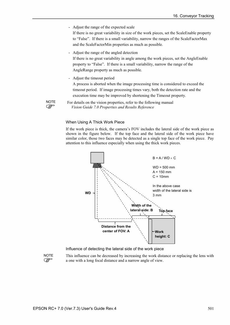
16. Conveyor Tracking
EPSON RC+ 7.0 (Ver.7.3) User's Guide Rev.4 501
- Adjust the range of the expected scale If there is no great variability in size of the work pieces, set the ScaleEnable property to “False”. If there is a small variability, narrow the ranges of the ScaleFactorMax and the ScaleFactorMin properties as much as possible.
- Adjust the range of the angled detection If there is no great variability in angle among the work pieces, set the AngleEnable property to “False”. If there is a small variability, narrow the range of the AngleRange property as much as possible.
- Adjust the timeout period A process is aborted when the image processing time is considered to exceed the timeout period. If image processing times vary, both the detection rate and the execution time may be improved by shortening the Timeout property.
For details on the vision properties, refer to the following manual Vision Guide 7.0 Properties and Results Reference
When Using A Thick Work Piece
If the work piece is thick, the camera’s FOV includes the lateral side of the work piece as shown in the figure below. If the top face and the lateral side of the work piece have similar color, those two faces may be detected as a single top face of the work piece. Pay attention to this influence especially when using the thick work pieces.
Work height: C
Top face
Width of the lateral side: B
WD
Distance from the center of FOV: A
B = A / WD × C WD = 500 mm A = 150 mm C = 10mm In the above case width of the lateral side is 3 mm
Influence of detecting the lateral side of the work piece
This influence can be decreased by increasing the work distance or replacing the lens with a one with a long focal distance and a narrow angle of view.
NOTE
NOTE
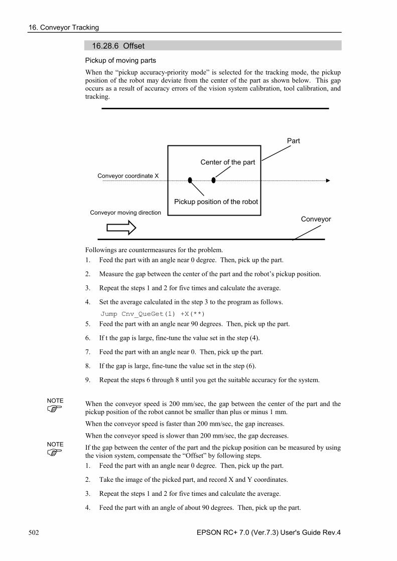
16. Conveyor Tracking
502 EPSON RC+ 7.0 (Ver.7.3) User's Guide Rev.4
16.28.6 Offset
Pickup of moving parts
When the “pickup accuracy-priority mode” is selected for the tracking mode, the pickup position of the robot may deviate from the center of the part as shown below. This gap occurs as a result of accuracy errors of the vision system calibration, tool calibration, and tracking.
Conveyor
Part
Conveyor moving direction
Conveyor coordinate X
Center of the part
Pickup position of the robot
Followings are countermeasures for the problem. 1. Feed the part with an angle near 0 degree. Then, pick up the part.
2. Measure the gap between the center of the part and the robot’s pickup position.
3. Repeat the steps 1 and 2 for five times and calculate the average.
4. Set the average calculated in the step 3 to the program as follows.
Jump Cnv_QueGet(1) +X(**)
5. Feed the part with an angle near 90 degrees. Then, pick up the part.
6. If t the gap is large, fine-tune the value set in the step (4).
7. Feed the part with an angle near 0. Then, pick up the part.
8. If the gap is large, fine-tune the value set in the step (6).
9. Repeat the steps 6 through 8 until you get the suitable accuracy for the system.
When the conveyor speed is 200 mm/sec, the gap between the center of the part and the pickup position of the robot cannot be smaller than plus or minus 1 mm.
When the conveyor speed is faster than 200 mm/sec, the gap increases.
When the conveyor speed is slower than 200 mm/sec, the gap decreases.
If the gap between the center of the part and the pickup position can be measured by using the vision system, compensate the “Offset” by following steps. 1. Feed the part with an angle near 0 degree. Then, pick up the part.
2. Take the image of the picked part, and record X and Y coordinates.
3. Repeat the steps 1 and 2 for five times and calculate the average.
4. Feed the part with an angle of about 90 degrees. Then, pick up the part.
NOTE
NOTE
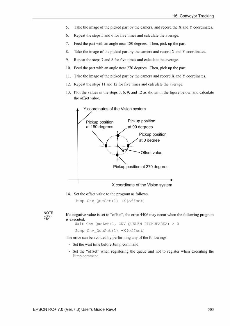
16. Conveyor Tracking
EPSON RC+ 7.0 (Ver.7.3) User's Guide Rev.4 503
5. Take the image of the picked part by the camera, and record the X and Y coordinates.
6. Repeat the steps 5 and 6 for five times and calculate the average.
7. Feed the part with an angle near 180 degrees. Then, pick up the part.
8. Take the image of the picked part by the camera and record X and Y coordinates.
9. Repeat the steps 7 and 8 for five times and calculate the average.
10. Feed the part with an angle near 270 degrees. Then, pick up the part.
11. Take the image of the picked part by the camera and record X and Y coordinates.
12. Repeat the steps 11 and 12 for five times and calculate the average.
13. Plot the values in the steps 3, 6, 9, and 12 as shown in the figure below, and calculate the offset value.
Offset value
X coordinate of the Vision system
Pickup position at 0 degree
Pickup position at 270 degrees
Y coordinates of the Vision system
Pickup position at 90 degrees
Pickup position at 180 degrees
14. Set the offset value to the program as follows.
Jump Cnv_QueGet(1) +X(offset)
If a negative value is set to “offset”, the error 4406 may occur when the following program is executed.
Wait Cnv_QueLen(1, CNV_QUELEN_PICKUPAREA) > 0
Jump Cnv_QueGet(1) -X(offset)
The error can be avoided by performing any of the followings.
- Set the wait time before Jump command.
- Set the “offset” when registering the queue and not to register when executing the Jump command.
NOTE
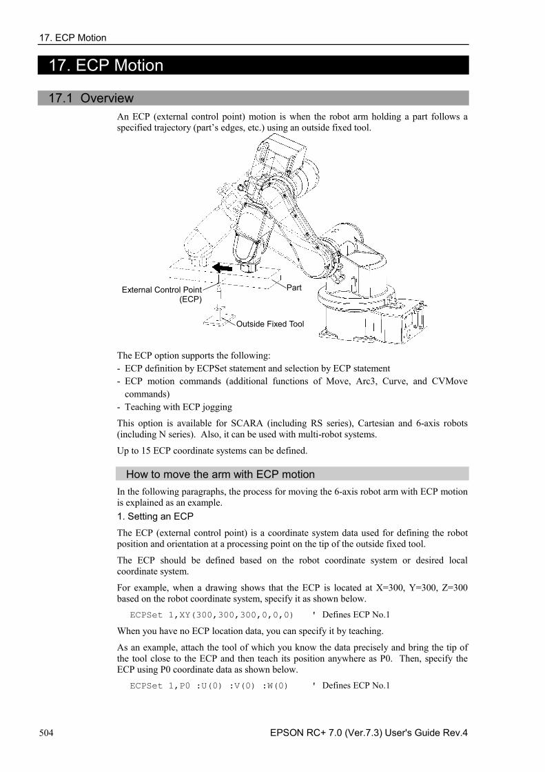
17. ECP Motion
504 EPSON RC+ 7.0 (Ver.7.3) User's Guide Rev.4
17. ECP Motion
17.1 Overview An ECP (external control point) motion is when the robot arm holding a part follows a specified trajectory (part’s edges, etc.) using an outside fixed tool.
External Control Point (ECP)
Outside Fixed Tool
Part
The ECP option supports the following: ECP definition by ECPSet statement and selection by ECP statement - ECP motion commands (additional functions of Move, Arc3, Curve, and CVMove -commands)
Teaching with ECP jogging -
This option is available for SCARA (including RS series), Cartesian and 6-axis robots (including N series). Also, it can be used with multi-robot systems.
Up to 15 ECP coordinate systems can be defined.
How to move the arm with ECP motion In the following paragraphs, the process for moving the 6-axis robot arm with ECP motion is explained as an example. 1. Setting an ECP
The ECP (external control point) is a coordinate system data used for defining the robot position and orientation at a processing point on the tip of the outside fixed tool.
The ECP should be defined based on the robot coordinate system or desired local coordinate system.
For example, when a drawing shows that the ECP is located at X=300, Y=300, Z=300 based on the robot coordinate system, specify it as shown below.
ECPSet 1,XY(300,300,300,0,0,0) ' Defines ECP No.1
When you have no ECP location data, you can specify it by teaching.
As an example, attach the tool of which you know the data precisely and bring the tip of the tool close to the ECP and then teach its position anywhere as P0. Then, specify the ECP using P0 coordinate data as shown below.
ECPSet 1,P0 :U(0) :V(0) :W(0) ' Defines ECP No.1
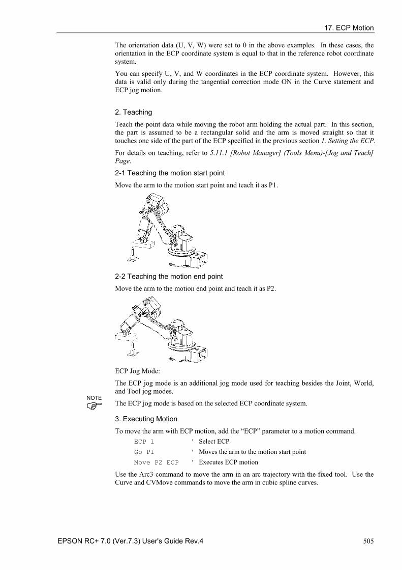
17. ECP Motion
EPSON RC+ 7.0 (Ver.7.3) User's Guide Rev.4 505
The orientation data (U, V, W) were set to 0 in the above examples. In these cases, the orientation in the ECP coordinate system is equal to that in the reference robot coordinate system.
You can specify U, V, and W coordinates in the ECP coordinate system. However, this data is valid only during the tangential correction mode ON in the Curve statement and ECP jog motion.
2. Teaching
Teach the point data while moving the robot arm holding the actual part. In this section, the part is assumed to be a rectangular solid and the arm is moved straight so that it touches one side of the part of the ECP specified in the previous section 1. Setting the ECP.
For details on teaching, refer to 5.11.1 [Robot Manager] (Tools Menu)-[Jog and Teach] Page.
2-1 Teaching the motion start point
Move the arm to the motion start point and teach it as P1.
2-2 Teaching the motion end point
Move the arm to the motion end point and teach it as P2.
ECP Jog Mode:
The ECP jog mode is an additional jog mode used for teaching besides the Joint, World, and Tool jog modes.
The ECP jog mode is based on the selected ECP coordinate system. 3. Executing Motion
To move the arm with ECP motion, add the “ECP” parameter to a motion command. ECP 1 ' Select ECP Go P1 ' Moves the arm to the motion start point Move P2 ECP ' Executes ECP motion
Use the Arc3 command to move the arm in an arc trajectory with the fixed tool. Use the Curve and CVMove commands to move the arm in cubic spline curves.
NOTE
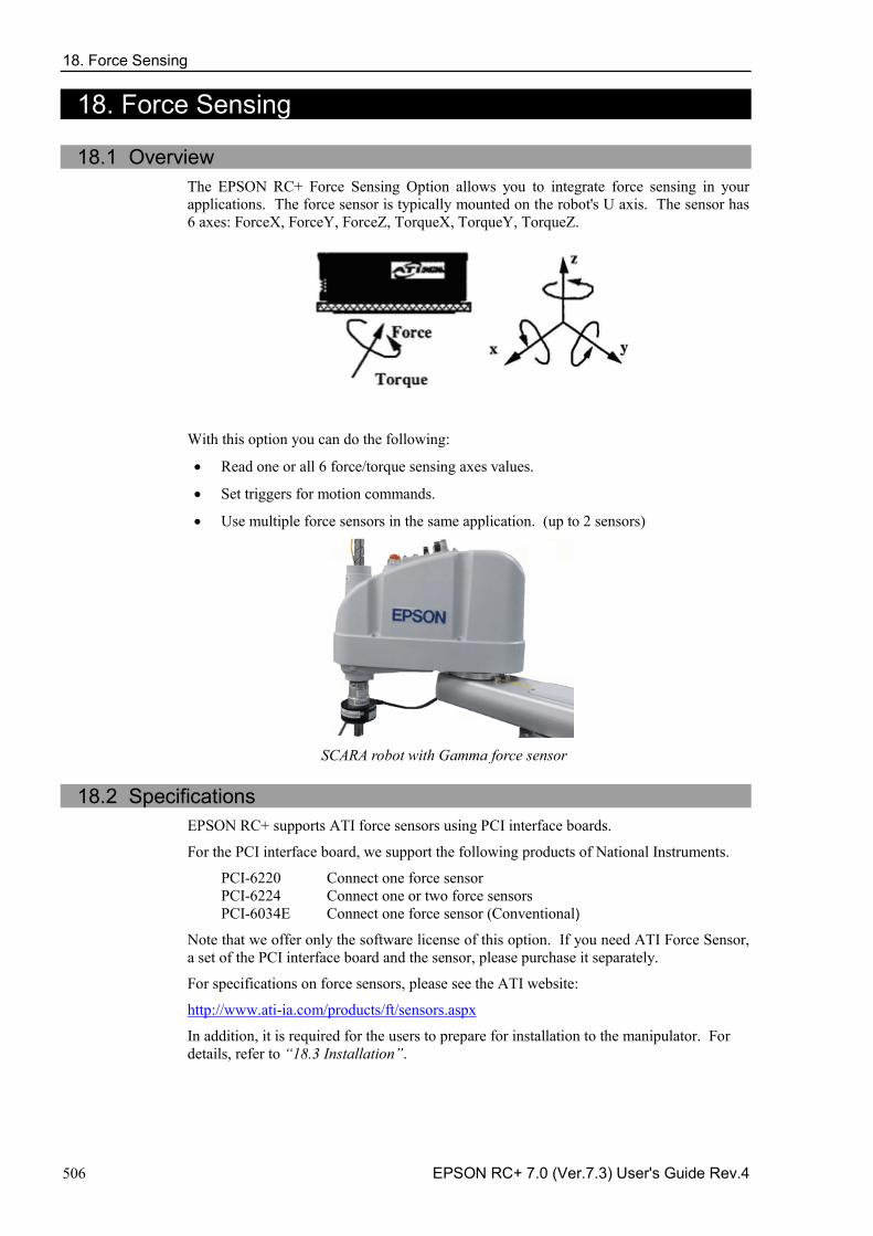
18. Force Sensing
506 EPSON RC+ 7.0 (Ver.7.3) User's Guide Rev.4
18. Force Sensing
18.1 Overview The EPSON RC+ Force Sensing Option allows you to integrate force sensing in your applications. The force sensor is typically mounted on the robot's U axis. The sensor has 6 axes: ForceX, ForceY, ForceZ, TorqueX, TorqueY, TorqueZ.
With this option you can do the following:
• Read one or all 6 force/torque sensing axes values.
• Set triggers for motion commands.
• Use multiple force sensors in the same application. (up to 2 sensors)
SCARA robot with Gamma force sensor
18.2 Specifications EPSON RC+ supports ATI force sensors using PCI interface boards.
For the PCI interface board, we support the following products of National Instruments.
PCI-6220 Connect one force sensor PCI-6224 Connect one or two force sensors PCI-6034E Connect one force sensor (Conventional)
Note that we offer only the software license of this option. If you need ATI Force Sensor, a set of the PCI interface board and the sensor, please purchase it separately.
For specifications on force sensors, please see the ATI website:
http://www.ati-ia.com/products/ft/sensors.aspx
In addition, it is required for the users to prepare for installation to the manipulator. For details, refer to “18.3 Installation”.
18. Force Sensing
EPSON RC+ 7.0 (Ver.7.3) User's Guide Rev.4 507
18.3 Installation The Force Sensing Option must be enabled in the RC700 controller. If you purchased the option with your system, the option will already be installed and configured.
You can also purchase the Force Sensing Option and install it in the field. See the chapter Installing EPSON RC+ Options for details.
Installing the force transducer circuit board
If you are adding Force Sensing in the field, you must install the force transducer board(s) in your system, and then run the NI-DAQmx driver installer.
Board Installation
Before installing the force sensing circuit board(s), you must first install the National Instruments DAQmx drivers that came with the board. To install the National Instruments DAQ drivers:
1. Run the NI-DAQmx driver installer.
2. Accept defaults for each step of the installation wizard.
3. Shutdown the system.
4. Install the board(s).
5. Start the system.
6. Run the National Instruments Measurement & Automation Explorer program once to verify that the board(s) that were installed are recognized.
You do not need to install the ATI software that came with the force transducer.
The calibration for the transducer must be loaded into memory. EPSON RC+ 7.0 handles this when you import the calibration data file as described in the section Software Configuration later in this chapter. The calibration data file can be located on the CD that came with the force transducer.
Mounting the force transducer To mount the force transducer to the robot:
1. Remove the top cover of the transducer.
2. Remove the robot's end effector axis coupling and mount it to the transducer cover.
3. Install the transducer cover / coupling assembly onto the transducer.
4. Install the entire assembly on the end effector axis.
NOTE
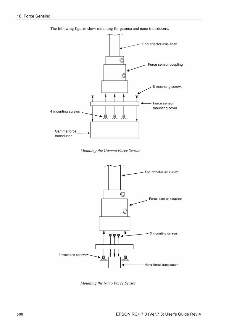
18. Force Sensing
508 EPSON RC+ 7.0 (Ver.7.3) User's Guide Rev.4
The following figures show mounting for gamma and nano transducers.
End effector axis shaft
Gamma force transducer
Force sensor coupling
8 mounting screws
Force sensor mounting cover 4 mounting screws
Mounting the Gamma Force Sensor
End effector axis shaft
Force sensor coupling
3 mounting screws
Nano force transducer
4 mounting screws
Mounting the Nano Force Sensor
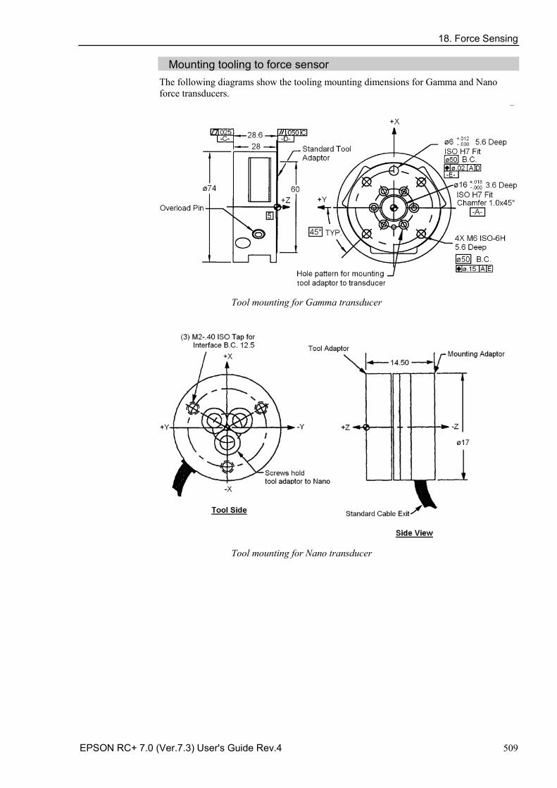
18. Force Sensing
EPSON RC+ 7.0 (Ver.7.3) User's Guide Rev.4 509
Mounting tooling to force sensor The following diagrams show the tooling mounting dimensions for Gamma and Nano force transducers.
Tool mounting for Gamma transducer
Tool mounting for Nano transducer
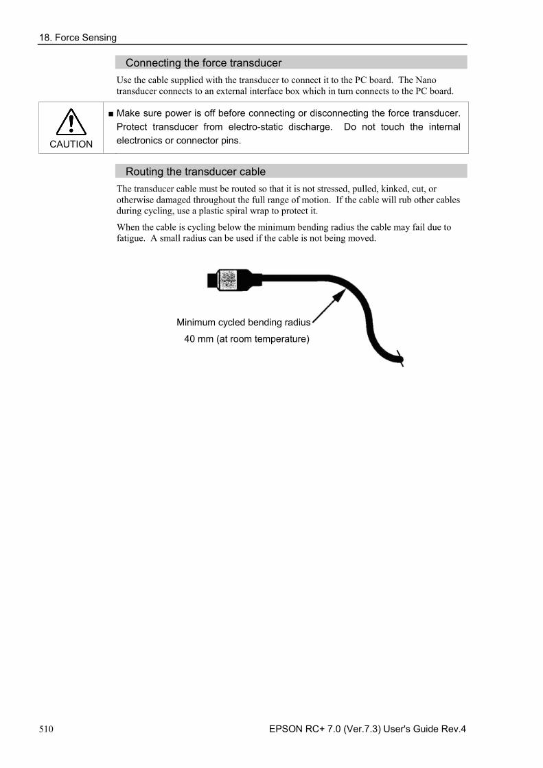
18. Force Sensing
510 EPSON RC+ 7.0 (Ver.7.3) User's Guide Rev.4
Connecting the force transducer Use the cable supplied with the transducer to connect it to the PC board. The Nano transducer connects to an external interface box which in turn connects to the PC board.
CAUTION
■ Make sure power is off before connecting or disconnecting the force transducer. Protect transducer from electro-static discharge. Do not touch the internal electronics or connector pins.
Routing the transducer cable
The transducer cable must be routed so that it is not stressed, pulled, kinked, cut, or otherwise damaged throughout the full range of motion. If the cable will rub other cables during cycling, use a plastic spiral wrap to protect it.
When the cable is cycling below the minimum bending radius the cable may fail due to fatigue. A small radius can be used if the cable is not being moved.
Minimum cycled bending radius
40 mm (at room temperature)
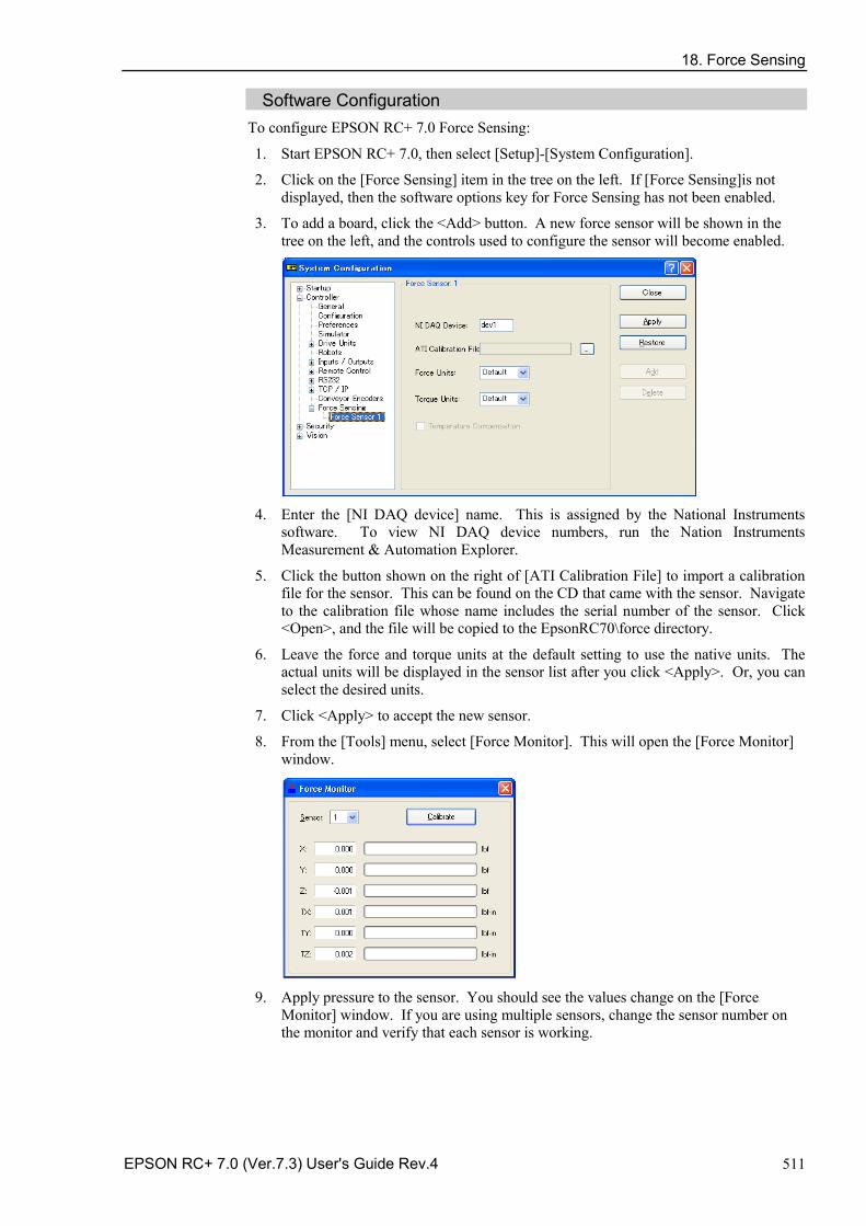
18. Force Sensing
EPSON RC+ 7.0 (Ver.7.3) User's Guide Rev.4 511
Software Configuration To configure EPSON RC+ 7.0 Force Sensing:
1. Start EPSON RC+ 7.0, then select [Setup]-[System Configuration].
2. Click on the [Force Sensing] item in the tree on the left. If [Force Sensing]is not displayed, then the software options key for Force Sensing has not been enabled.
3. To add a board, click the <Add> button. A new force sensor will be shown in the tree on the left, and the controls used to configure the sensor will become enabled.
4. Enter the [NI DAQ device] name. This is assigned by the National Instruments
software. To view NI DAQ device numbers, run the Nation Instruments Measurement & Automation Explorer.
5. Click the button shown on the right of [ATI Calibration File] to import a calibration file for the sensor. This can be found on the CD that came with the sensor. Navigate to the calibration file whose name includes the serial number of the sensor. Click <Open>, and the file will be copied to the EpsonRC70\force directory.
6. Leave the force and torque units at the default setting to use the native units. The actual units will be displayed in the sensor list after you click <Apply>. Or, you can select the desired units.
7. Click <Apply> to accept the new sensor.
8. From the [Tools] menu, select [Force Monitor]. This will open the [Force Monitor] window.
9. Apply pressure to the sensor. You should see the values change on the [Force
Monitor] window. If you are using multiple sensors, change the sensor number on the monitor and verify that each sensor is working.
18. Force Sensing
512 EPSON RC+ 7.0 (Ver.7.3) User's Guide Rev.4
18.4 Force Sensing Commands All Force Sensing commands begin with the same prefix: "Force_". Here is a list of all of the commands. For details, please see the online help or SPEL+ Language Reference Manual.
Force_Calibrate Zeros out all axes for the current sensor.
Force_ClearTrigger Clears all trigger conditions for the current sensor.
Force_GetForce Returns the current value for one axis for the current sensor.
Force_GetForces Returns the current values for all axes for the current sensor in an array.
Force_Sensor Sets / returns the current sensor for the current task.
Force_SetTrigger Sets /displays the force limit triggers for the current sensor.
18. Force Sensing
EPSON RC+ 7.0 (Ver.7.3) User's Guide Rev.4 513
18.5 Using the Force Sensing Trigger You can configure the system to stop the robot after the force sensing trigger has been activated. You can set the trigger to activate when one or more force sensing axes reaches a preset limit. You use the Till command to check the trigger condition during motion.
Stopping Motion along Z axis
Use a trigger on the ZForce axis to stop the robot during Z axis motion.
For example:
' Set the force trigger to fire when force on Z axis is less than −10
Force_ClearTrigger
Force_SetTrigger FORCE_ZFORCE, -10, FORCE_LESS
Till Force
Jump P1
Speeds 1
Move P2 Till
You can combine other conditions with Force in the Till command:
Till Sw(1) = On Or Force
You can combine other force/torque conditions by calling Force_SetTrigger more than once. In this case, clear all triggers first before setting them.
Force_ClearTrigger
Force_SetTrigger FORCE_ZFORCE, -10, FORCE_LESS
Force_SetTrigger FORCE_XFORCE, 5, FORCE_GREATER
Stopping Motion along X or Y axes Use a trigger on the XForce, XTorque, YForce, YTorque axes to stop the robot during Z axis motion. You need to align the force sensor by rotating the robot's U axis. The X and Y axes of the force sensor are marked on the transducer.
For example:
' Set the force trigger to fire when torque or force on X axis is less than −10
Force_ClearTrigger
Force_SetTrigger FORCE_XFORCE, -10, FORCE_LESS
Force_SetTrigger FORCE_XTORQUE, -10, FORCE_LESS
Till Force
Jump P1
Speeds 1
Move P2 Till
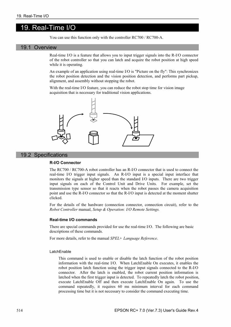
19. Real-Time I/O
514 EPSON RC+ 7.0 (Ver.7.3) User's Guide Rev.4
19. Real-Time I/O You can use this function only with the controller RC700 / RC700-A.
19.1 Overview
Real-time I/O is a feature that allows you to input trigger signals into the R-I/O connector of the robot controller so that you can latch and acquire the robot position at high speed while it is operating.
An example of an application using real-time I/O is "Picture on the fly": This synchronizes the robot position detection and the vision position detection, and performs part pickup, alignment, and assembly without stopping the robot.
With the real-time I/O feature, you can reduce the robot stop time for vision image acquisition that is necessary for traditional vision applications.
19.2 Specifications R-I/O Connector The RC700 / RC700-A robot controller has an R-I/O connector that is used to connect the real-time I/O trigger input signals. An R-I/O input is a special input interface that monitors the signals at higher speed than the standard I/O inputs. There are two trigger input signals on each of the Control Unit and Drive Units. For example, set the transmission type sensor so that it reacts when the robot passes the camera acquisition point and use the R-I/O connector so that the R-I/O input is detected at the moment shutter clicked.
For the details of the hardware (connection connector, connection circuit), refer to the Robot Controller manual, Setup & Operation: I/O Remote Settings. Real-time I/O commands There are special commands provided for use the real-time I/O. The following are basic descriptions of these commands.
For more details, refer to the manual SPEL+ Language Reference.
LatchEnable
This command is used to enable or disable the latch function of the robot position information with the real-time I/O. When LatchEnable On executes, it enables the robot position latch function using the trigger input signals connected to the R-I/O connector. After the latch is enabled, the robot current position information is latched when the first trigger input is detected. To repeatedly latch the robot position, execute LatchEnable Off and then execute LatchEnable On again. To use the command repeatedly, it requires 60 ms minimum interval for each command processing time but it is not necessary to consider the command executing time.
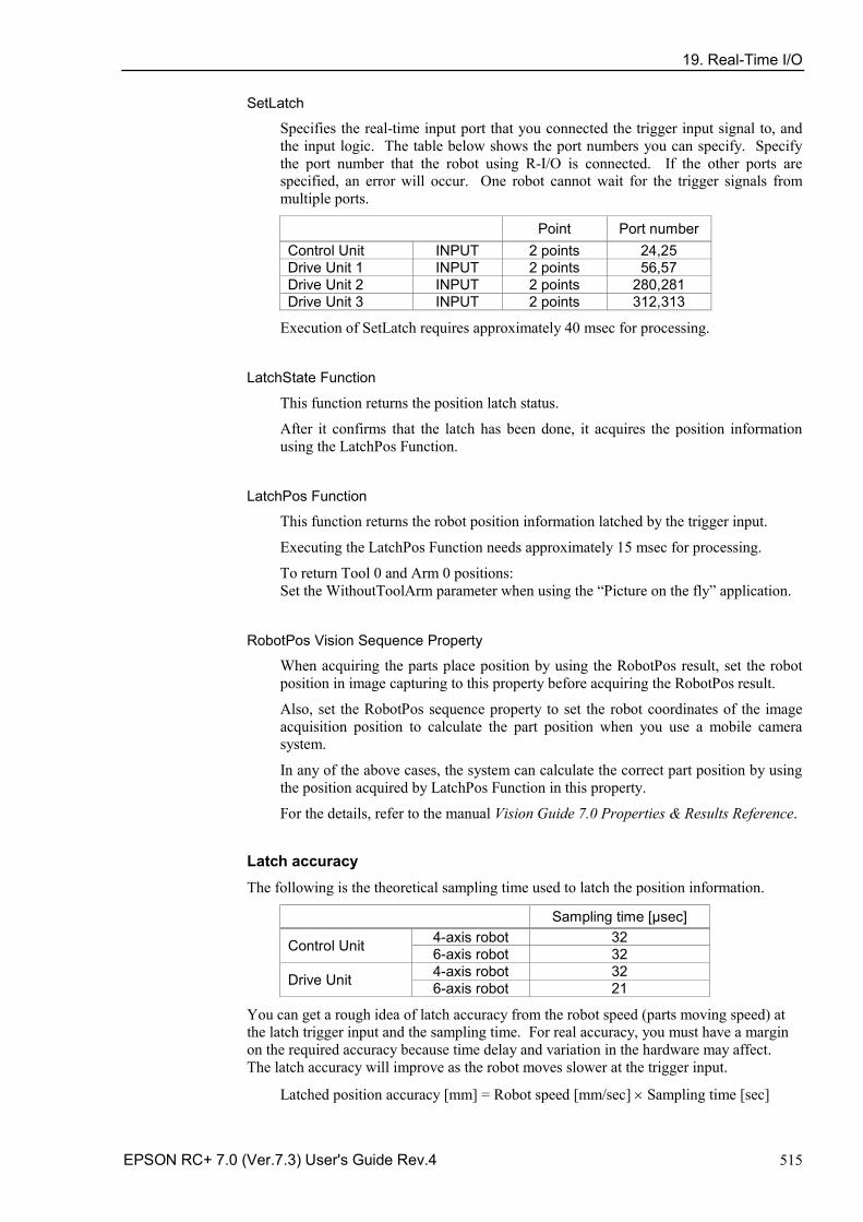
19. Real-Time I/O
EPSON RC+ 7.0 (Ver.7.3) User's Guide Rev.4 515
SetLatch
Specifies the real-time input port that you connected the trigger input signal to, and the input logic. The table below shows the port numbers you can specify. Specify the port number that the robot using R-I/O is connected. If the other ports are specified, an error will occur. One robot cannot wait for the trigger signals from multiple ports.
Point Port number Control Unit INPUT 2 points 24,25 Drive Unit 1 INPUT 2 points 56,57 Drive Unit 2 INPUT 2 points 280,281 Drive Unit 3 INPUT 2 points 312,313
Execution of SetLatch requires approximately 40 msec for processing.
LatchState Function
This function returns the position latch status.
After it confirms that the latch has been done, it acquires the position information using the LatchPos Function.
LatchPos Function
This function returns the robot position information latched by the trigger input.
Executing the LatchPos Function needs approximately 15 msec for processing.
To return Tool 0 and Arm 0 positions: Set the WithoutToolArm parameter when using the “Picture on the fly” application.
RobotPos Vision Sequence Property
When acquiring the parts place position by using the RobotPos result, set the robot position in image capturing to this property before acquiring the RobotPos result.
Also, set the RobotPos sequence property to set the robot coordinates of the image acquisition position to calculate the part position when you use a mobile camera system.
In any of the above cases, the system can calculate the correct part position by using the position acquired by LatchPos Function in this property.
For the details, refer to the manual Vision Guide 7.0 Properties & Results Reference.
Latch accuracy The following is the theoretical sampling time used to latch the position information.
Sampling time [μsec]
Control Unit 4-axis robot 32 6-axis robot 32
Drive Unit 4-axis robot 32 6-axis robot 21
You can get a rough idea of latch accuracy from the robot speed (parts moving speed) at the latch trigger input and the sampling time. For real accuracy, you must have a margin on the required accuracy because time delay and variation in the hardware may affect. The latch accuracy will improve as the robot moves slower at the trigger input.
Latched position accuracy [mm] = Robot speed [mm/sec] × Sampling time [sec]
19. Real-Time I/O
516 EPSON RC+ 7.0 (Ver.7.3) User's Guide Rev.4
19.3 Usage 1. Basic example The following program is a sample to connect any trigger signal to the R-I/O connector of the controller, latch the robot position information while it is operating at the trigger input, and show the latched position information.
Function Main
Motor On Power High
Speed 50; Accel 50, 50 SpeedS 500; AccelS 5000 Go P0 'Start point SetLatch SETLATCH_PORT_CU_0, SETLATCH_TRIGGERMODE_LEADINGEDGE LatchEnable On 'Enable the latch Move P1 'Start the operation, trigger input while operating Wait LatchState = True 'Confirmed the latch is complete P3 = LatchPos 'Acquire the latched position LatchEnable Off 'Disable the latch
Print P3 'Show the latched position
Fend
2. Example with Vision system This is an example that uses the robot end effector to handle parts, passes above the external fixed upward camera acquisition point without stopping, and assembles the parts with an appropriate position correction.
Sensor
Shooting trigger
Controller
R-I/O Input
Trigger signal This system has a transmission type sensor that outputs the trigger signal when the robot end effector handles a part and passes the camera acquisition point. Then, it connects the sensor output with both the R-I/O and the camera trigger input for external tuning and synchronizes the latched robot position information and the camera image. It calculates the part position error and offsets the position comparing the robot position information from the camera image to the robot position information from the real-time I/O. In this case, the robot vision system must be calibrated as the upward fixed camera. Also, by registering the parts place position in advance, robot position information can be acquired for precise parts placement by CalRobotPlacePos result. Parts place position can be set in the CalRobotPlacePos property wizard.
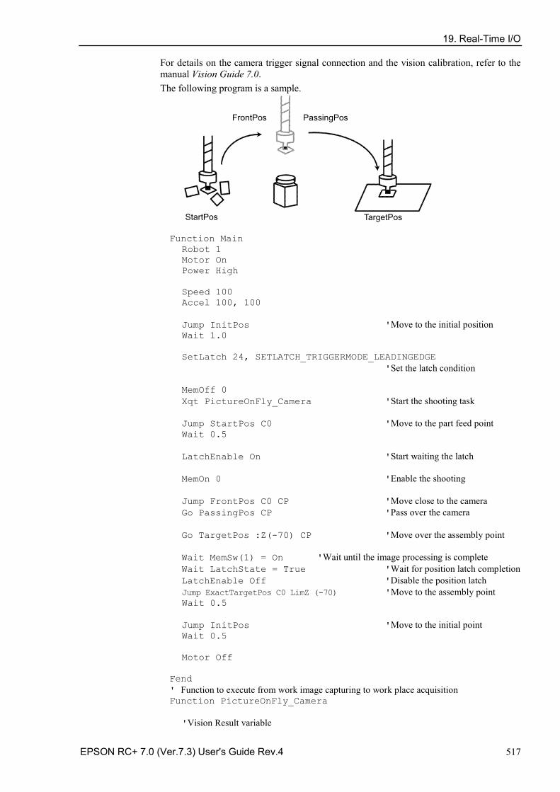
19. Real-Time I/O
EPSON RC+ 7.0 (Ver.7.3) User's Guide Rev.4 517
For details on the camera trigger signal connection and the vision calibration, refer to the manual Vision Guide 7.0. The following program is a sample.
StartPos
FrontPos
TargetPos
PassingPos
Function Main Robot 1 Motor On Power High Speed 100 Accel 100, 100 Jump InitPos 'Move to the initial position Wait 1.0 SetLatch 24, SETLATCH_TRIGGERMODE_LEADINGEDGE 'Set the latch condition MemOff 0 Xqt PictureOnFly_Camera 'Start the shooting task Jump StartPos C0 'Move to the part feed point Wait 0.5 LatchEnable On 'Start waiting the latch MemOn 0 'Enable the shooting Jump FrontPos C0 CP 'Move close to the camera Go PassingPos CP 'Pass over the camera Go TargetPos :Z(-70) CP 'Move over the assembly point Wait MemSw(1) = On 'Wait until the image processing is complete Wait LatchState = True 'Wait for position latch completion LatchEnable Off 'Disable the position latch Jump ExactTargetPos C0 LimZ (-70) 'Move to the assembly point Wait 0.5 Jump InitPos 'Move to the initial point Wait 0.5 Motor Off Fend ' Function to execute from work image capturing to work place acquisition Function PictureOnFly_Camera 'Vision Result variable
19. Real-Time I/O
518 EPSON RC+ 7.0 (Ver.7.3) User's Guide Rev.4
Integer AcqStat 'Strobe imaging completion flag Boolean Found 'Work detection status Wait MemSw(0) = On 'Waits the imaging start flag MemOff 1 'Clear the imaging completion flag MemOff 0 'Clear the imaging start flag AcqStat = 0 'Clear the strobe imaging flag VRun PictureOnFly_i Do Until AcqStat = 3 'Wait for strobe VGet PictureOnFly_i.AcquireState, AcqStat Loop 'Check the work detection VGet PictureOnFly_i.Geom01.Found, Found If Found = False Then Print “Work NotFound” Pause Else MemOn 1 'Change the camera imaging flag EndIf Wait LatchState = True 'Wait for the trigger 'Set the image capturing position (trigger position) to the Vision VSet PictureOnFly_i.RobotPos, LatchPos (WithoutToolArm) 'Acquire the robot position VGet PictureOnFly_i.Geom01.RobotPlacePos, Found, ExactTargetPos Fend
20. Additional Axis
EPSON RC+ 7.0 (Ver.7.3) User's Guide Rev.4 519
20. Additional Axis
20.1 Overview You can attach up to two additional drive axes (per manipulator) which can operate in association with the manipulator. The position data of the additional axis is saved with the robot point data. The additional axis can move simultaneously with the manipulator by motion commands and you can design an application using a traveling axis (manipulator on the straight axis) with simple programming.
If you want to operate the manipulator and drive axis separately, you need to define the additional axis as another manipulator using the multi-manipulators feature.
CAUTION
■ When you use the additional axis as traveling axis and mount a manipulator(s) on the axis, the reaction force of manipulator(s) is put on the traveling axis. Therefore, you should limit the acceleration/deceleration speed with the Accel setting so that it is within the allowable inertia of traveling axis. In addition, the manipulator may swing widely at the positioning and possibly break the additional axis.
20.2 Specifications Types of additional axis The supported additional axis is the PG axis, controlled by the pulse generator board. However, note that the PG axis has some limitations.
Limitations of a PG additional axis a. Synchronizes with the manipulator to start motion but not to finish. b. Does not support Path motion with CP On and Pass. Stops for every motion. c. Does not go through the CVMove series of points d. Calibration is necessary using the MCAL command. Cannot operate the
additional axis and the robot together until the calibration is complete. If movement of the PG additional axis is “0”, and Go and Move are executed to the point where only the robot moves, the robot will move singly.
Number of additional axis Up to two additional axes are available for each of the SCARA robot series (including RS series), Cartesian coordinate robot, 6-axis robot (including N series), and Joint type robot. However, the number of axes you can add is determined by how many axes are available with your controller.
Position data management The additional axes are allocated to Joint #8 and #9 for all robot types. The position data are shown in the S and T coordinate values of point data of the manipulator to which you add the additional axes. The additional axis as Joint #8 is called the additional S axis and Joint #9 is the additional T axis. The coordinate values of additional axes are saved with the robot point data but don’t have any effect on the robot coordinate system.
NOTE
20. Additional Axis
520 EPSON RC+ 7.0 (Ver.7.3) User's Guide Rev.4
How to operate The additional axis can move simultaneously with the manipulator (synchronous start / stop). However, if you use the PG axis, it doesn’t synchronize with manipulator to finish and operate by the different acceleration/deceleration speed from the manipulator. See below for the details of motion commands. Also, you can operate the additional axis and manipulator separately by proper management of the point data. However, you cannot operate separately both of them in arbitrary timing. In this case, use the multi-manipulators function and set the drive axis as another manipulator.
Command specification Pulse, Go, BGo, TGo, Pass The additional axis can operate in association with the manipulator motion. However, if
you use the PG axis, it synchronizes only to start the motion and a motion command completes when both the manipulator and axis finish each motion. In addition, if the PG additional axis has a travel distance, the Path motion with CP On and Pass are prohibited and the axis moves with CP Off automatically.
Move, BMove, Tmove The additional axis can operate in association with the manipulator motion. However, if
you use the PG axis, it synchronizes only to start the motion and a motion command completes when both the manipulator and axis finish each motion. In addition, if the PG additional axis has a travel distance, the Path motion with CP On is prohibited and the axis moves with CP Off automatically.
Arc, Arc3
The additional axis can operate in association with the manipulator motion. It doesn’t go through the specified midPoint and directly goes to the end point. If you use the PG axis, it synchronizes only to start the motion and a motion command completes when both the manipulator and axis finish each motion. In addition, if the PG additional axis has a travel distance, the Path motion with CP On is prohibited and the axis moves with CP Off automatically.
CVMove
The additional axis can operate in association with the manipulator motion. If you use a servo axis for the additional axis, for each of the S and T axis it creates a curve going through the S and T coordinates specified by a series of point data. However, if you use the PG axis for the additional axis, it doesn’t go through the series of points and directly goes to the end point. Also, it synchronizes only to start the motion and a motion command completes when both the manipulator and axis finish each motion. In addition, if the PG additional axis has a travel distance, the Path motion with CP On is prohibited and the axis moves with CP Off automatically.
Jump The additional axis executes PTP motion in association with the manipulator horizontal
motion. However, if you use the PG axis, it synchronizes only to start the motion and a motion command completes when both the manipulator and axis finish each motion. In addition, if the PG additional axis has a travel distance, the Path motion with CP On is prohibited and the axis moves with CP Off automatically.
Jump3, Jump3CP
The additional axis can operate in association with the manipulator depart / span / approach motion. However, if you use the PG axis, it synchronizes only to start the motion and a motion command completes when both the manipulator and axis finish each motion. In addition, if the PG additional axis has a travel distance, the Path motion with CP On and Pass are prohibited and the axis moves with CP Off automatically.
20. Additional Axis
EPSON RC+ 7.0 (Ver.7.3) User's Guide Rev.4 521
JTran, PTran The additional axis can operate separately by specifying as Joint #8, #9.
Example: > JTran 8, 90 'Move the additional S axis by 90 mm > PTran 9, 10000 'Move the additional T axis by 10000 pulse
20.3 Usage
Additional axis configuration
For the instruction of configuring the additional axis, refer to 10.2 Configuration of Additional Axes. If you use the PG axis for the additional axis, you need to set the PG parameters. For the details of PG parameters, refer to the Robot Controller option: PG Motion System manual.
Point data usage This example specifies the position data of manipulator and additional ST axes and substitutes them to the point data. P1 = XY(10, 20, 30, 40) :ST(10, 20) ' SCARA robot P1 = XY(10, 20, 30, 40, 50, 60) :ST(10, 20) ' 6-axis robot
This example specifies the position data of manipulator and additional ST axes and executes a PTP motion. Go XY(10, 20, 30, 40) :ST(10, 20) Go XY(10, 20, 30, 40, 50, 60) :ST(10, 20)
This example specifies the position data of additional ST axes individually P1 = XY(10, 20, 30, 40) :S(10) :T(20) P1 = XY(10, 20, 30, 40) :S(10) P1 = XY(10, 20, 30, 40) :T(20)
This example omits the robot position assignment XY( ) and specifies only the additional axis position. Then, the point data is defined so that the manipulator doesn’t move (undefined). P1 = ST(10, 20) Go P1 ' Only additional axis moves and the manipulator remains at the current position.
This example operates only the additional axis. Go ST(10, 20) ' Only the additional axis moves.
This example omits the additional axis position assignment ST( ) and specifies only the manipulator position. Then, the point data is defined so that the additional axis doesn’t move (undefined). P1 = XY(10, 20, 30, 40) Go P1 ' Only the manipulator moves and the additional axis remains at the current position.
This example operates the manipulator only. Go XY(10, 20, 30, 40) ' Only the manipulator moves.
This example calculates the additional axis coordinate value using a point operator expression. P1 = XY(10, 20, 30, 40, 50, 60) :ST(10, 20) P2 = P1 + S(10) + T(20) ' Add the offset amount to the additional ST axes for P1.
20. Additional Axis
522 EPSON RC+ 7.0 (Ver.7.3) User's Guide Rev.4
Note that you cannot use the point operator for undefined points. P1 = XY(10, 20, 30, 40, 50, 60) P2 = P1 + S(10) + T(20) ‘ Error (ST are undefined for P1 and you cannot use the point operator) P1 = XY(10, 20, 30, 40, 50, 60) +ST(10, 20) ‘ Error P1 = XY(10, 20, 30, 40, 50, 60) +S(10) +T(20) ‘ Error Go ST(10, 20) + X(10) ‘ Error (XY are undefined and you cannot use the point operator)
This example shows the additional ST axes coordinate values retrieved from the point data. Print CS(P1), CT(P1)
Pallet motion When you specify a pallet with the point data including the position data of additional axis, the position data of additional axis is also calculated by the pallet operator. If you use the additional axis as traveling axis, you can define a wide range pallet than for a single manipulator. Also, if you want to use the additional axis not as traveling axis and exclude the additional axis position from the pallet operator, define the pallet with the point data that clears the additional axis position data.
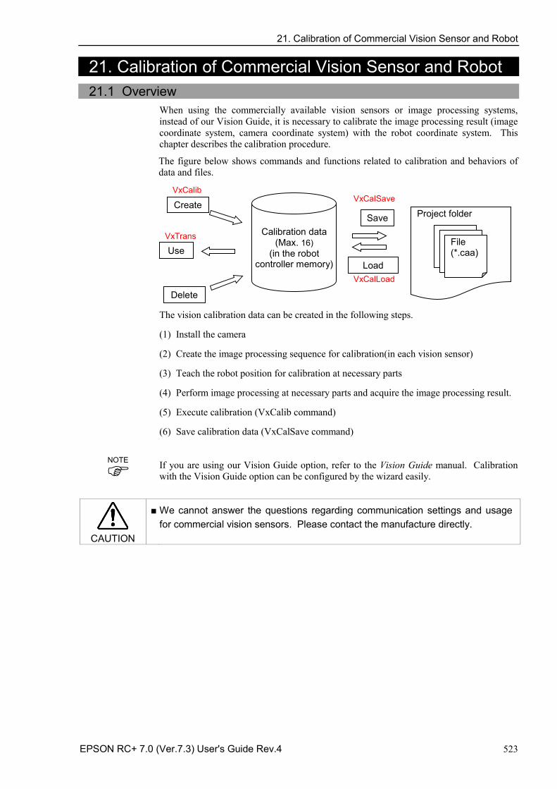
21. Calibration of Commercial Vision Sensor and Robot
EPSON RC+ 7.0 (Ver.7.3) User's Guide Rev.4 523
21. Calibration of Commercial Vision Sensor and Robot
21.1 Overview When using the commercially available vision sensors or image processing systems, instead of our Vision Guide, it is necessary to calibrate the image processing result (image coordinate system, camera coordinate system) with the robot coordinate system. This chapter describes the calibration procedure.
The figure below shows commands and functions related to calibration and behaviors of data and files.
Create
VxCalib
Project folder
File (*.caa)
Delete
Save
Load
Calibration data
(Max. 16) (in the robot
controller memory)
VxCalSave
VxCalLoad
Use VxTrans
The vision calibration data can be created in the following steps.
(1) Install the camera
(2) Create the image processing sequence for calibration(in each vision sensor)
(3) Teach the robot position for calibration at necessary parts
(4) Perform image processing at necessary parts and acquire the image processing result.
(5) Execute calibration (VxCalib command)
(6) Save calibration data (VxCalSave command)
If you are using our Vision Guide option, refer to the Vision Guide manual. Calibration with the Vision Guide option can be configured by the wizard easily.
CAUTION
■ We cannot answer the questions regarding communication settings and usage for commercial vision sensors. Please contact the manufacture directly.
NOTE
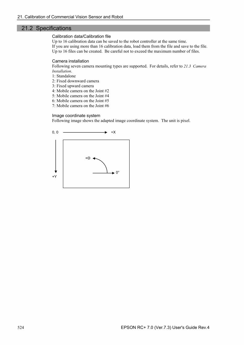
21. Calibration of Commercial Vision Sensor and Robot
524 EPSON RC+ 7.0 (Ver.7.3) User's Guide Rev.4
21.2 Specifications Calibration data/Calibration file Up to 16 calibration data can be saved to the robot controller at the same time. If you are using more than 16 calibration data, load them from the file and save to the file. Up to 16 files can be created. Be careful not to exceed the maximum number of files. Camera installation Following seven camera mounting types are supported. For details, refer to 21.3 Camera Installation. 1: Standalone 2: Fixed downward camera 3: Fixed upward camera 4: Mobile camera on the Joint #2 5: Mobile camera on the Joint #4 6: Mobile camera on the Joint #5 7: Mobile camera on the Joint #6 Image coordinate system Following image shows the adapted image coordinate system. The unit is pixel.
+X
+Y
0, 0
0°
+Θ
21. Calibration of Commercial Vision Sensor and Robot
EPSON RC+ 7.0 (Ver.7.3) User's Guide Rev.4 525
21.3 Camera Installation Camera installation method can be selected for each calibration data. The data set required for calibration differs depending on mounting types. Note that the wrong setting may result in improper calibration.
EPSON RC+ 7.0 supports the following camera installations: Camera Installation Description
Standalone
Camera can be installed anywhere. Camera does not have a relation with the robot. With this method, position information in the Robot coordinate system cannot be acquired. However, it can be converted from the image coordinate system to the camera coordinate system. That is, simple length measurement can be performed.
Fixed downward
Camera and target objects do not move and is looking down into robot work envelope. The camera acquires position information in the Robot coordinate system. The camera must be installed vertically to the XY plane of the specified coordinate system. (Angle gap may result in poor accuracy) Specified coordinate systems are Robot coordinate system and Local coordinate system. Uses nine reference points.
Fixed upward
Camera does not move and is looking up into a portion of the robot work envelope. For example, this installation method is used to check the position of the object which is carried by the robot. It does not require a reference point. The calibration target is on the end effector or the object held by the robot.
Mobile camera on the Joint #2 Camera is mounted on Joint 2 on SCARA robot or Cartesian robot. It reports robot world coordinates. Uses one reference point.
Mobile camera on the Joint #4 Camera is mounted on Joint 4 on SCARA robot or Cartesian robot. It reports robot world coordinates. Uses one reference point.
Mobile camera on the Joint #5 Camera is mounted on Joint 5 on 6-Axis robot. It reports robot world coordinates. Uses one reference point.
Mobile camera on the Joint #6 Camera is mounted on Joint 6 on 6-Axis robot. It reports robot world coordinates. Uses one reference point.
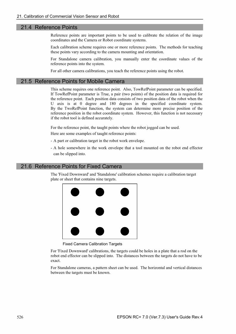
21. Calibration of Commercial Vision Sensor and Robot
526 EPSON RC+ 7.0 (Ver.7.3) User's Guide Rev.4
21.4 Reference Points Reference points are important points to be used to calibrate the relation of the image coordinates and the Camera or Robot coordinate systems.
Each calibration scheme requires one or more reference points. The methods for teaching these points vary according to the camera mounting and orientation.
For Standalone camera calibration, you manually enter the coordinate values of the reference points into the system.
For all other camera calibrations, you teach the reference points using the robot.
21.5 Reference Points for Mobile Camera This scheme requires one reference point. Also, TowRefPoint parameter can be specified. If TowRefPoint parameter is True, a pair (two points) of the position data is required for the reference point. Each position data consists of two position data of the robot when the U axis is at 0 degree and 180 degrees in the specified coordinate system. By the TwoRefPoint function, the system can determine more precise position of the reference position in the robot coordinate system. However, this function is not necessary if the robot tool is defined accurately. For the reference point, the taught points where the robot jogged can be used. Here are some examples of taught reference points:
- A part or calibration target in the robot work envelope.
- A hole somewhere in the work envelope that a tool mounted on the robot end effector can be slipped into.
21.6 Reference Points for Fixed Camera
The 'Fixed Downward' and 'Standalone' calibration schemes require a calibration target plate or sheet that contains nine targets.
Fixed Camera Calibration Targets
For 'Fixed Downward' calibrations, the targets could be holes in a plate that a rod on the robot end effector can be slipped into. The distances between the targets do not have to be exact.
For Standalone cameras, a pattern sheet can be used. The horizontal and vertical distances between the targets must be known.

21. Calibration of Commercial Vision Sensor and Robot
EPSON RC+ 7.0 (Ver.7.3) User's Guide Rev.4 527
21.7 Command List Following table shows the commands and functions related to Vision calibration.
For details, refer to the SPEL+ Language Reference. Command name Function VxCalib Statement Creates calibration data for the vision system. VxCalDelete Statement Deletes the calibration data. VxCalLoad Statement Loads the calibration data from a file. VxCalInfo Function Returns the calibration completion status and the calibration
result. VxCalSave Statement Saves the calibration data to a file. VxTrans Function Converts pixel coordinates to robot coordinates and returns
the converted point data
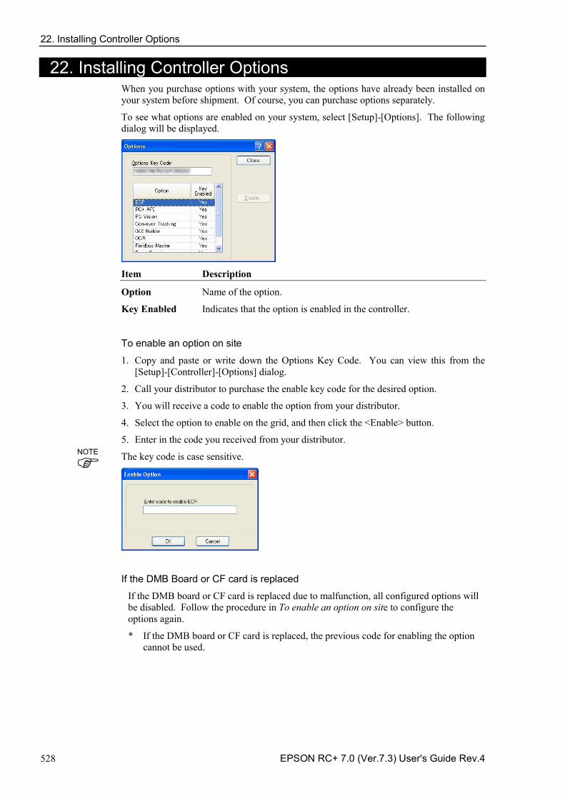
22. Installing Controller Options
528 EPSON RC+ 7.0 (Ver.7.3) User's Guide Rev.4
22. Installing Controller Options When you purchase options with your system, the options have already been installed on your system before shipment. Of course, you can purchase options separately.
To see what options are enabled on your system, select [Setup]-[Options]. The following dialog will be displayed.
Item Description
Option Name of the option.
Key Enabled Indicates that the option is enabled in the controller.
To enable an option on site
1. Copy and paste or write down the Options Key Code. You can view this from the [Setup]-[Controller]-[Options] dialog.
2. Call your distributor to purchase the enable key code for the desired option.
3. You will receive a code to enable the option from your distributor.
4. Select the option to enable on the grid, and then click the <Enable> button.
5. Enter in the code you received from your distributor.
The key code is case sensitive.
If the DMB Board or CF card is replaced
If the DMB board or CF card is replaced due to malfunction, all configured options will be disabled. Follow the procedure in To enable an option on site to configure the options again.
* If the DMB board or CF card is replaced, the previous code for enabling the option cannot be used.
NOTE
23. Software License Agreement
EPSON RC+ 7.0 (Ver.7.3) User's Guide Rev.4 529
23. Software License Agreement SOFTWARE LICENSE AGREEMENT
IMPORTANT! READ THIS SOFTWARE LICENSE AGREEMENT CAREFULLY BEFORE INSTALLING OR USING THIS SOFTWARE.
This software products and/or any accompanying explanatory written materials (the “Software”) should only be installed or used by the Licensee (“you”) on the condition you agree with SEIKO EPSON CORPORATION (including its affiliates and licensors, “EPSON”) to the terms and conditions of this Agreement. By installing or using the Software, you are representing to agree with all the terms and conditions of this Agreement. If you do not agree with the terms and conditions of this Agreement, you are not permitted to install or use the Software. In this Agreement, affiliates mean any corporation or entity of which EPSON owns, directly or indirectly, a majority of the assets or voting stock. 1. License.
EPSON grants you a personal, nonexclusive, limited license to
(i) install and use the Software on any single computer or EPSON’s robot controller products, following the instructions, terms and conditions under the “Epson RC+7.0 User’s Guide” and its “Appendix B: EPSON RC +7.0 Software”;
(ii) make one copy of the Software for backup and archival purposes. For clarity, such backup and archival copy so made shall be treated as the Software herein; 2. Limitations.
You shall use the Software in a manner permitted herein. You agree not to (i) modify, adapt, translate or make any derivative works from the Software and (ii) attempt to reverse engineer, decompile, disassemble or otherwise attempt to discover the source code of the Software. Unless otherwise provided herein, you shall not share, rent, lease, encumber, sublicense, lend or distribute the Software.
3. Third Party Software
The Software may contain third party’s software (“Third Party Software”, including open-source software, such as GNU General Public License and GNU Lesser/ Library GPL). For clarity, a Third Party Software named XVL Kernel, owned by Lattice Technology Co.,Ltd (“XVL Kernel”) is included in the Software. If the Software contains the Third Party Software, you shall review and comply with the terms and conditions applicable to such Third Party Software before using the Software.
4. Ownership.
Excluding the Third Party Software, any title, ownership, intellectual property rights and any other rights in and to the Software shall remain with EPSON. Any title, ownership, intellectual property rights and any other rights in and to XVL Kernel, which is a Third Party Software, shall remain with Lattice Technology Co.,Ltd. You shall not be granted any title, ownership, intellectual property rights or any other rights in and to the Software unless explicitly provided herein. The Software is protected by Japanese Copyright Law and international copyright treaties, as well as other intellectual property laws and treaties. You agree not to remove or alter any copyright and other proprietary notices on any copies of the Software.
23. Software License Agreement
530 EPSON RC+ 7.0 (Ver.7.3) User's Guide Rev.4
5. Protection and Security.
You agree to use your best efforts and take all reasonable steps to safeguard the Software to ensure that no unauthorized person has access to it and that no unauthorized copy, publication, disclosure or distribution of the Software is made. You acknowledge that the Software contains valuable, confidential information and trade secrets and that unauthorized use and copy are harmful to EPSON. You shall hold in strict confidence the Software and any information obtained in connection with the Software.
6. No Warranty.
You acknowledge and agree that the use of the Software is at your sole risk. THE SOFTWARE IS PROVIDED “AS IS” AND WITHOUT ANY WARRANTY OF ANY KIND. EPSON DOES NOT AND CANNOT WARRANT THE PERFORMANCE OR RESULTS YOU MAY OBTAIN BY USING THE SOFTWARE. EPSON MAKES NO WARRANTIES OF ANY KIND, EXPRESS OR IMPLIED, INCLUDING, BUT NOT LIMITED TO THE IMPLIED WARRANTIES OF NON-INFRINGEMENT, MERCHANTABILITY OR FITNESS FOR ANY PARTICULAR PURPOSE.
7. Limitation of Liability.
IN NO EVENT WILL EPSON BE LIABLE TO YOU, WHETHER ARISING UNDER CONTRACT, TORT (INCLUDING NEGLIGENCE), STRICT LIABILITY, BREACH OR WARRANTY, MISREPRESENTATION OR OTHERWISE, FOR ANY DIRECT, INDIRECT, CONSEQUENTIAL, INCIDENTAL OR SPECIAL DAMAGES, INCLUDING ANY LOST PROFITS OR LOST SAVINGS, EVEN IF EPSON OR ITS REPRESENTATIVE HAS BEEN ADVISED OF THE POSSIBILITY OF SUCH DAMAGES, OR FOR ANY CLAIM BY ANY THIRD PARTY. IN THE EVENT LIMITATION OF LIABILITY HEREUNDER IS FOUND INVALID OR UNENFORCEABLE BY A COURT OF COMPETENT JURISDICTION, THE AGGREGATE LIABILITY OF EPSON TO YOU FOR ANY DAMAGES OR LOSS SHALL NOT EXCEED THE TOTAL AMOUNT PAID BY YOU TO EPSON IN CONSIDERATION OF THE SOFTWARE.
8. Termination.
Without prejudice to any other rights EPSON has, this Agreement shall immediately terminate without any notice upon failure by you to comply with its terms. You may also terminate this Agreement at any time by uninstalling and destroying the Software. For clarity, you shall not be released from any obligations imposed prior to the termination of this Agreement.
9. Export Restriction.
You agree not to transfer, export or re-export the Software and any data or information which you obtained from the Software or in connection with this Agreement without a proper license under Japanese law, restrictions and regulations or the laws of the jurisdiction in which you obtained the Software.
10. Governing Law and Severability
This Agreement shall be governed by and construed under the laws of Japan without regard to its conflicts of law rules. If any provision herein is found invalid or unenforceable by a court of competent jurisdiction, it will not affect the validity of the balance of this Agreement, which shall remain valid and enforceable according to its terms.
23. Software License Agreement
EPSON RC+ 7.0 (Ver.7.3) User's Guide Rev.4 531
11. Updating Software Version.
Epson may provide you an updated version of the Software for the purpose of improvement and bug-fixes. Such updated Software shall be deemed to be the Software and be governed by this Agreement.
12. Entire Agreement.
This Agreement is the entire agreement between the parties with respect to the Software and supersedes any communication, advertisement, or representation concerning the Software. This Agreement shall be binding upon and inure to the benefit of the parties hereto and their respective successors, assigns and legal representatives.
13. General Provisions.
(1) EPSON may change, modify or otherwise alter this Agreement in its sole discretion at any time with or without notice to you. You shall review this Agreement on a regular basis to acknowledge such changes. By using the Software after any such changes have been made, you are deemed to agree to comply with, and to be bound by, the modified Agreement.
(2) Any translation of this Agreement is provided solely for your convenience and is not intended to modify the terms and conditions of this Agreement. In the event of a conflict between the Japanese version and any versions in other languages of this Agreement, the Japanese version shall prevail and govern.
14. U.S. Government End Users.
If you are acquiring the Software on behalf of any unit or agency of the United States Government, the following provisions apply. The Government agrees:
(i) if the Software is supplied to the Department of Defense (DoD), the Software is classified as “Commercial Computer Software” and the Government is acquiring only “restricted rights” in the Software and its documentation as that term is defined in Clause 252.227-7013(c)(1) of the DFARS; and (ii) if the Software is supplied to any unit or agency of the United States Government other than DoD, the Government’s rights in the Software and its documentation will be as defined in Clause 52.227-19(c)(2) of the FAR or, in the case of NASA, in Clause 18-52.227-86(d) of the NASA supplement to the FAR.
©Seiko Epson Corporation 2016. All rights reserved.
Appendix A: Automatic Processing of Project Import
EPSON RC+ 7.0 (Ver.7.3) User's Guide Rev.4 A-1
Appendix A: Automatic Processing of Project Import
Project Import for EPSON RC+ 6.* When projects created in EPSON RC+ 6.* are imported, all project files are copied to the new EPSON RC+ 7.0 project directory.
Vision Guide Conversion When using the smart camera or flame grabber, model images of each object (Correlation object, Geometric object, etc.) are not imported. Perform model teaching again after importing them.
Project Import for EPSON RC+ 5.*
When projects created in EPSON RC+ 5.* are imported, all project files are copied to the new EPSON RC+ 7.0 project directory. In addition, the following processes are executed automatically:
- Point file update - User Program Conversion
Point File Update For EPSON RC+ 5.*, the .PTS files are updated automatically to the EPSON RC+ 6.0 .PTS file version.
User Program Conversion
Project Import for EPSON RC+ 3.* / 4.* When projects created in EPSON RC+ 3.* / 4.* are imported, the following processes are executed automatically:
- User program conversion - Point file conversion - I/O label file conversion - User error label file conversion - Vision Guide conversion
User Program Conversion The tables below show the syntax conversions from EPSON RC+ 3.* / 4.* to EPSON RC+ 7.0.
Project Type EPSON RC+ 4.* EPSON RC+ 7.0
Syntax While Do While Wend Loop Trap...Call Trap...Xqt
Project Type EPSON RC+ 3.* EPSON RC+ 7.0
Syntax
While Do While Wend Loop Trap...Call Trap...Xqt On $, Off $ MemOn, MemOff Sw($ MemSw( Sw $( MemSw( In($ MemIn( In $( MemIn( Out $ MemOut
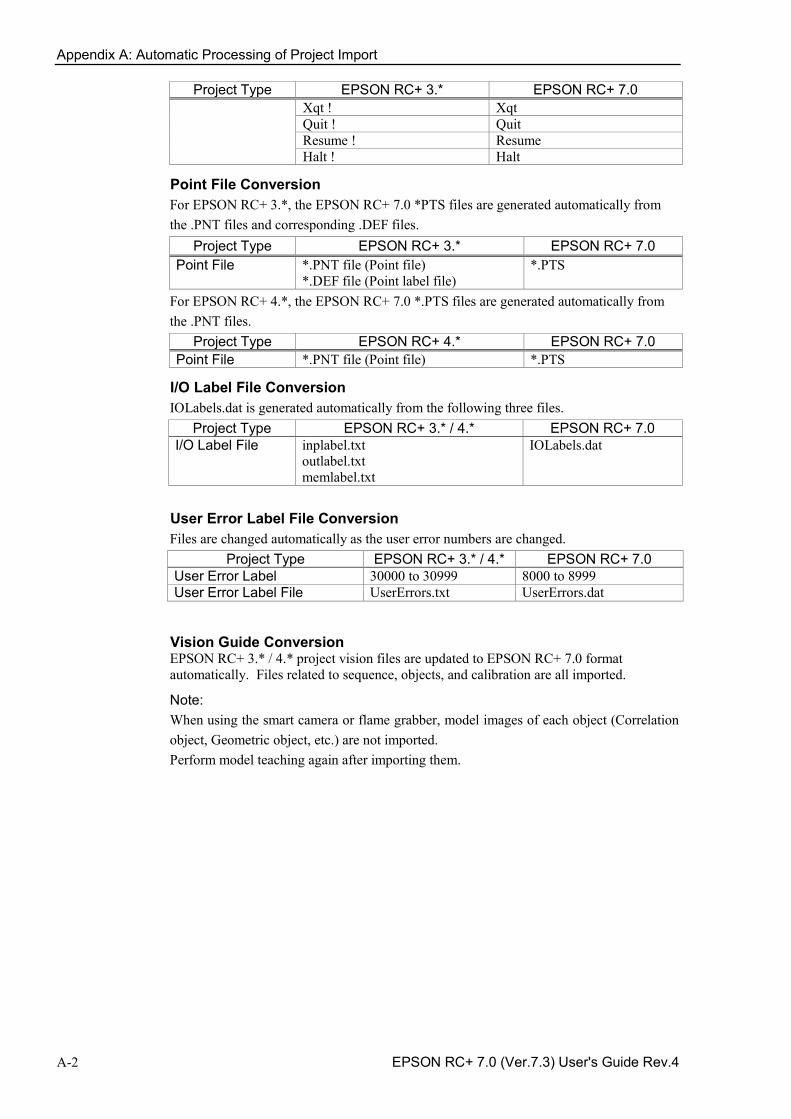
Appendix A: Automatic Processing of Project Import
A-2 EPSON RC+ 7.0 (Ver.7.3) User's Guide Rev.4
Project Type EPSON RC+ 3.* EPSON RC+ 7.0 Xqt ! Xqt Quit ! Quit Resume ! Resume Halt ! Halt
Point File Conversion For EPSON RC+ 3.*, the EPSON RC+ 7.0 *PTS files are generated automatically from the .PNT files and corresponding .DEF files.
Project Type EPSON RC+ 3.* EPSON RC+ 7.0 Point File *.PNT file (Point file)
*.DEF file (Point label file) *.PTS
For EPSON RC+ 4.*, the EPSON RC+ 7.0 *.PTS files are generated automatically from the .PNT files.
Project Type EPSON RC+ 4.* EPSON RC+ 7.0 Point File *.PNT file (Point file) *.PTS
I/O Label File Conversion IOLabels.dat is generated automatically from the following three files.
Project Type EPSON RC+ 3.* / 4.* EPSON RC+ 7.0 I/O Label File inplabel.txt
outlabel.txt memlabel.txt
IOLabels.dat
User Error Label File Conversion Files are changed automatically as the user error numbers are changed.
Project Type EPSON RC+ 3.* / 4.* EPSON RC+ 7.0 User Error Label 30000 to 30999 8000 to 8999 User Error Label File UserErrors.txt UserErrors.dat
Vision Guide Conversion EPSON RC+ 3.* / 4.* project vision files are updated to EPSON RC+ 7.0 format automatically. Files related to sequence, objects, and calibration are all imported.
Note: When using the smart camera or flame grabber, model images of each object (Correlation object, Geometric object, etc.) are not imported. Perform model teaching again after importing them.
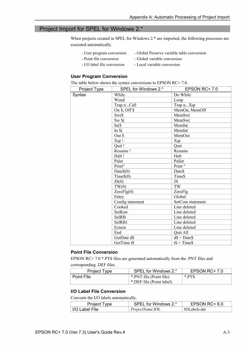
Appendix A: Automatic Processing of Project Import
EPSON RC+ 7.0 (Ver.7.3) User's Guide Rev.4 A-3
Project Import for SPEL for Windows 2.* When projects created in SPEL for Windows 2.* are imported, the following processes are executed automatically.
- User program conversion - Point file conversion - I/O label file conversion
- Global Preserve variable table conversion - Global variable conversion - Local variable conversion
User Program Conversion The table below shows the syntax conversions to EPSON RC+ 7.0.
Project Type SPEL for Windows 2.* EPSON RC+ 7.0 Syntax While Do While
Wend Loop Trap n...Call Trap n...Xqt On $, Off $ MemOn, MemOff Sw($ MemSw( Sw $( MemSw( In($ MemIn( In $( MemIn( Out $ MemOut Xqt ! Xqt Quit ! Quit Resume ! Resume Halt ! Halt Palet Pallet Print" Print " Date$(0) Date$ Time$(0) Time$ JS(0) JS TW(0) TW ZeroFlg(0) ZeroFlg Entry Global Config statement SetCom statement Cooked Line deleted SetRaw Line deleted SelRB Line deleted SelRB1 Line deleted Extern Line deleted End Quit All GetDate d$ d$ = Date$ GetTime t$ t$ = Time$
Point File Conversion EPSON RC+ 7.0 *.PTS files are generated automatically from the .PNT files and corresponding .DEF files.
Project Type SPEL for Windows 2.* EPSON RC+ 7.0 Point File *.PNT file (Point file)
*.DEF file (Point label) *.PTS
I/O Label File Conversion Converts the I/O labels automatically.
Project Type SPEL for Windows 2.* EPSON RC+ 6.0 I/O Label File ProjectName.IOL IOLabels.dat
Appendix A: Automatic Processing of Project Import
A-4 EPSON RC+ 7.0 (Ver.7.3) User's Guide Rev.4
Global Preserve Variable Table Conversion Backup variable definitions created in the SPEL for Windows 2.* Project Menu are converted into Global Preserve declaration statements in the first program file.
(Example) If the SPEL for Windows 2.* project defines an integer backup variable called “s_iValue”, the following statement is generated in the first program of the project.
Global Preserve Integer s_iValue
Global Variable Conversion Global variables (Entry / Extern) in SPEL for Windows 2.* projects are converted to Global variables in EPSON RC+ 7.0.
Project Type SPEL for Windows 2.* EPSON RC+ 7.0 Global Variable (Command) Entry / Extern command Global command
Local Variable Conversion Local variables in SPEL for Windows 2.* functions can be used throughout the entire file in which they are declared. These variables are converted to module variables or local variables in EPSON RC+ 7.0, depending on their scope.
If the variable is used in only one function, it is converted to a local variable in that function.
If the variable is used in more than one function, it is converted to a module variable.
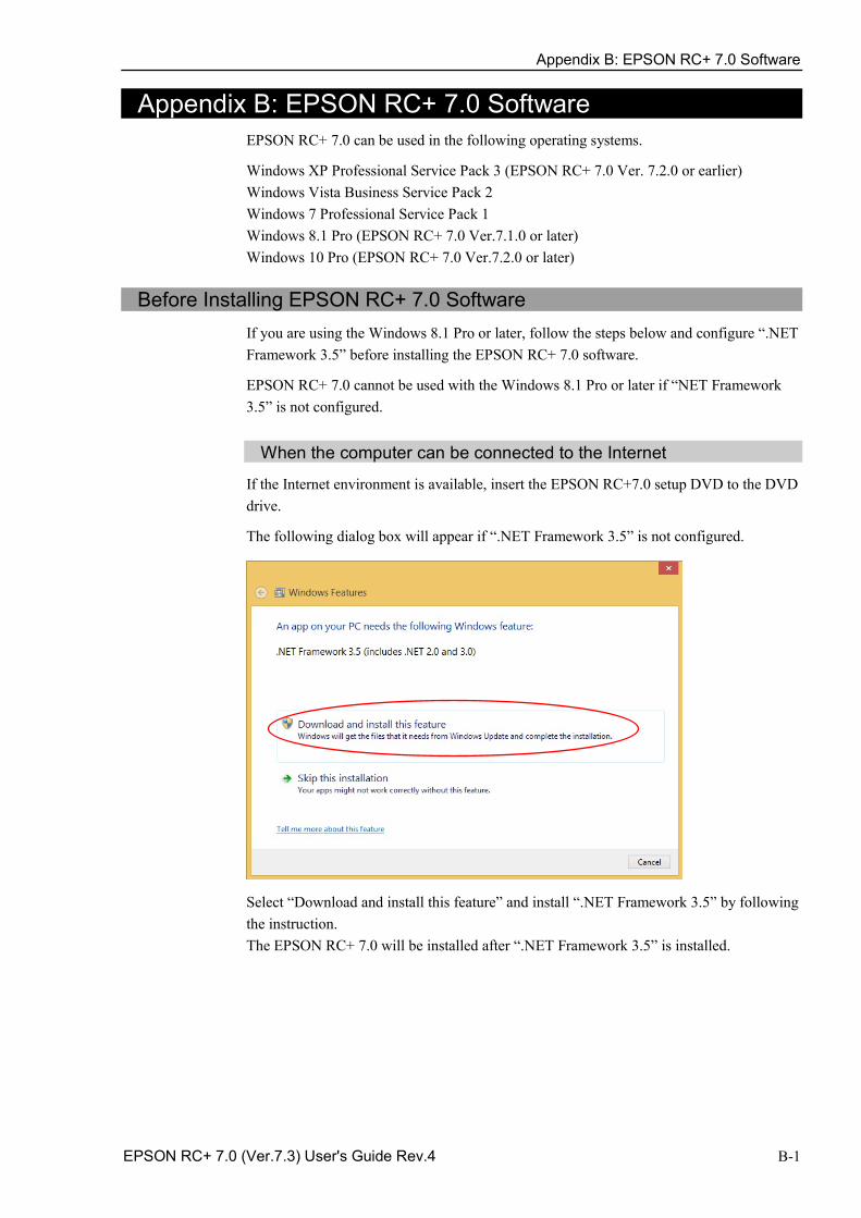
Appendix B: EPSON RC+ 7.0 Software
EPSON RC+ 7.0 (Ver.7.3) User's Guide Rev.4 B-1
Appendix B: EPSON RC+ 7.0 Software EPSON RC+ 7.0 can be used in the following operating systems.
Windows XP Professional Service Pack 3 (EPSON RC+ 7.0 Ver. 7.2.0 or earlier) Windows Vista Business Service Pack 2 Windows 7 Professional Service Pack 1 Windows 8.1 Pro (EPSON RC+ 7.0 Ver.7.1.0 or later) Windows 10 Pro (EPSON RC+ 7.0 Ver.7.2.0 or later)
Before Installing EPSON RC+ 7.0 Software If you are using the Windows 8.1 Pro or later, follow the steps below and configure “.NET Framework 3.5” before installing the EPSON RC+ 7.0 software.
EPSON RC+ 7.0 cannot be used with the Windows 8.1 Pro or later if “NET Framework 3.5” is not configured.
When the computer can be connected to the Internet
If the Internet environment is available, insert the EPSON RC+7.0 setup DVD to the DVD drive.
The following dialog box will appear if “.NET Framework 3.5” is not configured.
Select “Download and install this feature” and install “.NET Framework 3.5” by following the instruction. The EPSON RC+ 7.0 will be installed after “.NET Framework 3.5” is installed.
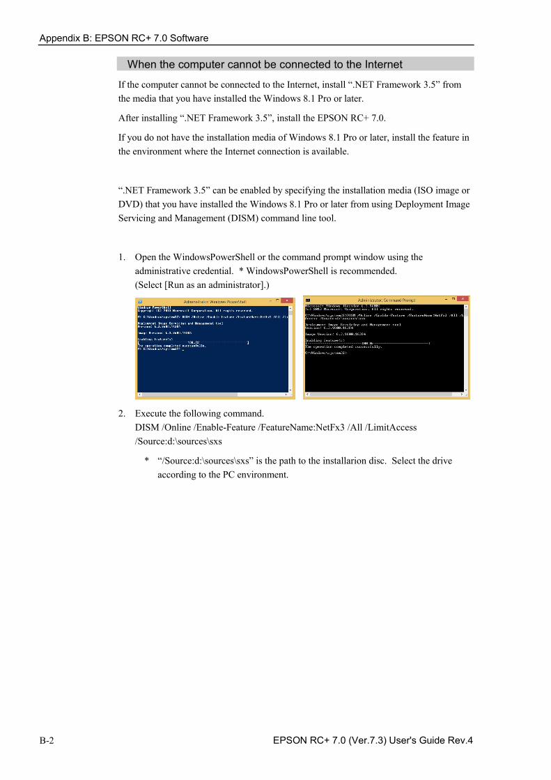
Appendix B: EPSON RC+ 7.0 Software
B-2 EPSON RC+ 7.0 (Ver.7.3) User's Guide Rev.4
When the computer cannot be connected to the Internet
If the computer cannot be connected to the Internet, install “.NET Framework 3.5” from the media that you have installed the Windows 8.1 Pro or later.
After installing “.NET Framework 3.5”, install the EPSON RC+ 7.0.
If you do not have the installation media of Windows 8.1 Pro or later, install the feature in the environment where the Internet connection is available.
“.NET Framework 3.5” can be enabled by specifying the installation media (ISO image or DVD) that you have installed the Windows 8.1 Pro or later from using Deployment Image Servicing and Management (DISM) command line tool.
1. Open the WindowsPowerShell or the command prompt window using the administrative credential. * WindowsPowerShell is recommended. (Select [Run as an administrator].)
2. Execute the following command. DISM /Online /Enable-Feature /FeatureName:NetFx3 /All /LimitAccess /Source:d:\sources\sxs
* “/Source:d:\sources\sxs” is the path to the installarion disc. Select the drive according to the PC environment.
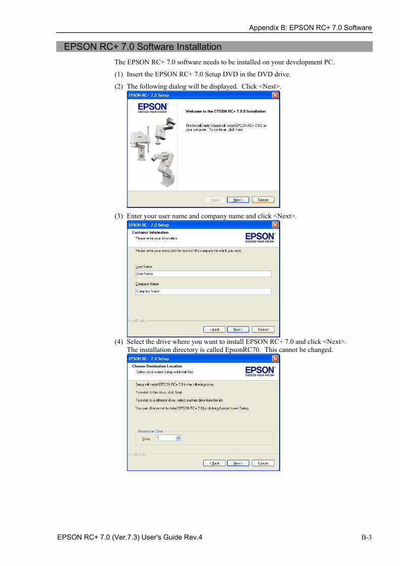
Appendix B: EPSON RC+ 7.0 Software
EPSON RC+ 7.0 (Ver.7.3) User's Guide Rev.4 B-3
EPSON RC+ 7.0 Software Installation The EPSON RC+ 7.0 software needs to be installed on your development PC.
(1) Insert the EPSON RC+ 7.0 Setup DVD in the DVD drive.
(2) The following dialog will be displayed. Click <Nest>.
(3) Enter your user name and company name and click <Next>.
(4) Select the drive where you want to install EPSON RC+ 7.0 and click <Next>.
The installation directory is called EpsonRC70. This cannot be changed.
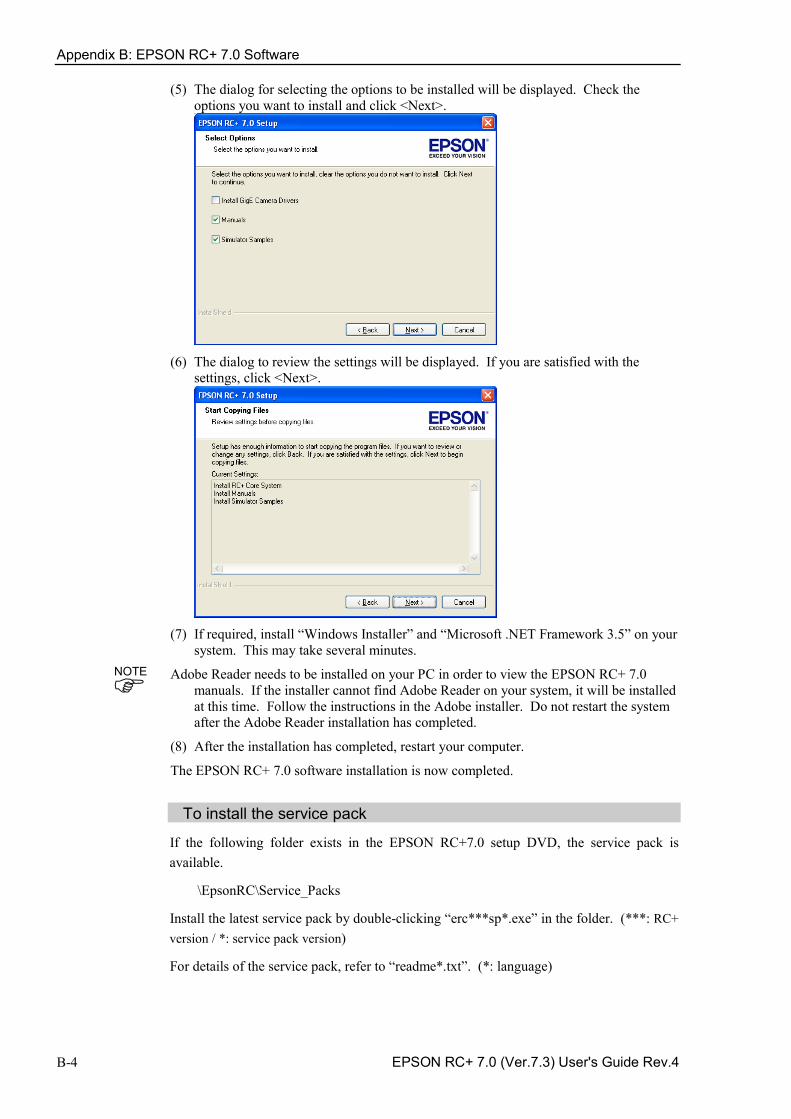
Appendix B: EPSON RC+ 7.0 Software
B-4 EPSON RC+ 7.0 (Ver.7.3) User's Guide Rev.4
(5) The dialog for selecting the options to be installed will be displayed. Check the options you want to install and click <Next>.
(6) The dialog to review the settings will be displayed. If you are satisfied with the
settings, click <Next>.
(7) If required, install “Windows Installer” and “Microsoft .NET Framework 3.5” on your
system. This may take several minutes.
Adobe Reader needs to be installed on your PC in order to view the EPSON RC+ 7.0 manuals. If the installer cannot find Adobe Reader on your system, it will be installed at this time. Follow the instructions in the Adobe installer. Do not restart the system after the Adobe Reader installation has completed.
(8) After the installation has completed, restart your computer.
The EPSON RC+ 7.0 software installation is now completed.
To install the service pack
If the following folder exists in the EPSON RC+7.0 setup DVD, the service pack is available.
\EpsonRC\Service_Packs
Install the latest service pack by double-clicking “erc***sp*.exe” in the folder. (***: RC+ version / *: service pack version)
For details of the service pack, refer to “readme*.txt”. (*: language)
NOTE
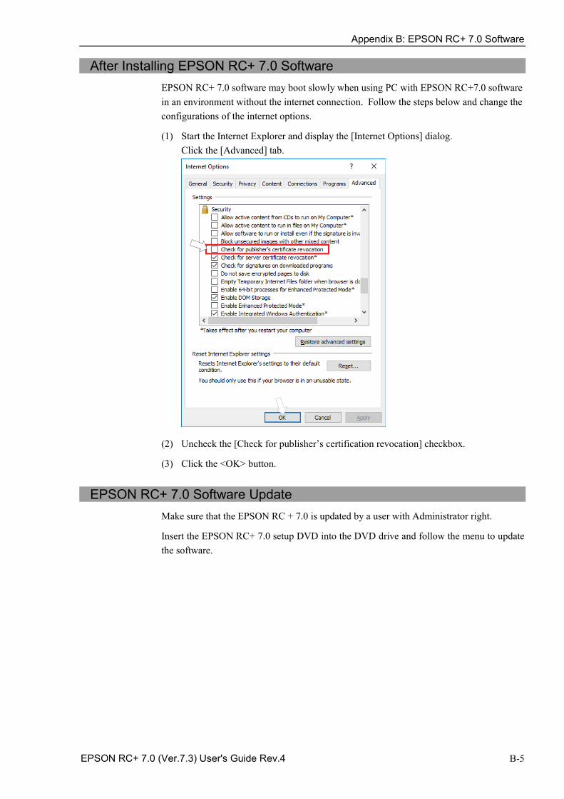
Appendix B: EPSON RC+ 7.0 Software
EPSON RC+ 7.0 (Ver.7.3) User's Guide Rev.4 B-5
After Installing EPSON RC+ 7.0 Software EPSON RC+ 7.0 software may boot slowly when using PC with EPSON RC+7.0 software in an environment without the internet connection. Follow the steps below and change the configurations of the internet options.
(1) Start the Internet Explorer and display the [Internet Options] dialog. Click the [Advanced] tab.
(2) Uncheck the [Check for publisher’s certification revocation] checkbox.
(3) Click the <OK> button.
EPSON RC+ 7.0 Software Update
Make sure that the EPSON RC + 7.0 is updated by a user with Administrator right.
Insert the EPSON RC+ 7.0 setup DVD into the DVD drive and follow the menu to update the software.

Appendix B: EPSON RC+ 7.0 Software
B-6 EPSON RC+ 7.0 (Ver.7.3) User's Guide Rev.4