ep lectron cs - world radio history
TRANSCRIPT

EVERYDAY JULY 1998 r
E PLECTRON http://www.epemag.wimborne.co.uk
EPE PIC 102c1341 TOOLKIT High speed programmer, disassembler and TASM/MPASM translator with FREE software
1
NOISE CANCELLING UNIT Reduce noise with 'anti-sound' GREENHOUSE COMPUTER Microcontrolled monitoring & control LOW BATTERY INDICATOR Micropower battery condition indicator
THE Noll MAGAZINE FOR ELECTRONIC TECHNOLOGY & COMPUTER PROJECTS
1
9 1
Cs
1 770262
£2.65
1 1 361089
07
1
16 Ingenuity Unlimited New Technology Update II V Techniques Innovations Circuit Surgery

WIND GENERATORS 380 WATT 1 14 metre da blades carbon matrix blades 3 year warranty. 12vdc output, 24v version available control electronics included brushless neodymium cubic curve alternator only two moving parts maintenance free simple roof top installation start up speed 7mph max output (30mph) 380w £499 ref 8IR1
HYDROPONICS DO YOU GROW YOUR OWN?
W e have a full colour hydroponics catalogue
11% ailable containing nutrients, pu mps, fittings,
enviro mental control, light fittings, plants, test
equip ment etc
Ring for your free copy.
PORTABLE X RAY MACHINE PLANS Easy to construct plans on a simple and cheap way to build a home X-ray machine' Effective device X-ray sealed assemblies can be used for experimental purposes Not a toy or for minors, £6/5et Ref F/XPI
TELEKINETIC ENHANCER PLANS Mystify and amaze your
friends by creating motion with no known apparent means or cause Uses no electrical or mechanical connections no special gimmicks yet produces positive motion and effect Excellent for science projects magic shows party demonstrations or serious research & development of this strange and amazing phychic phenomenon
£4/set Ref F/TKE1
ELECTRONIC HYPNOSIS PL ANS & DATA This data shows several ways to put subjects under your control Included is a full volume reference text and several construction plans that when assembled can produce highly effective stimuli This material must be used cautiously It is for use as entertainment at parties etc only by those experienced in as use 1 5/set Ref F/EH2
GRAVITY GENERATOR PLANS This unique plan demonstrates a simple electrical phenomena that produces an anti-gravity effect You can actually build a small mock spaceship out of simple materials and without any visible means cause it to levitate LID/set Ref F/GRA1
W ORLDS SMALLEST TESLA COIL/LIGHTENING
DISPLAY GLOBE PLANS Produces up to 750 000 volts of discharge experiment with extraordinary I-IV effects 'Plasma in a jar' St Elmo's fire Corona excellent science project or conversation piece £5/set Ref F/BTC1/LG5
COPPER VAPOUR LASER PLANS Produces 100mw of visible green light High coherency and spectral quality similar to Argon
laser but easier and less costly to build yet far more efficient This particular design was developed at the Atomic Energy Commision of NEGEV in Israel £10/set Ref F/CVL1
VOICE SCRAMBLER PLANS Minature solid state system turns
speech sound into indecipherable noise that cannot be understood without a second matching unit Use on telephone to prevent third party listening and bugging £6/set Ref ENS9
PULSED TV JOKER PLANS Little hand held device utilises pulse techniques that will completely disrupt TV picture and sound, works on FM tool DISCRETON ADVISED £8/set Ref FTTJ5
BODYHEAT TELESCOPE PLANS Highly directional long range device uses recent technology to detect the presence of living bodies warm and hot spots heat leaks etc Intended for security law enforcement research and development etc Excellent security device or very interesting science project £8/set Ref F/BHT1
BURNING, CUTTING CO2 LASER PLANS Projects an
invisible beam of heat capable of burning and melting materials over a considerable distance This laser is one of the most efficient converting 10% input power into useful output Not only is this device a workhorse in welding cutting and heat processing materials but ills also a likely candidate as an effective directed energy beam weapon against missiles aircraft ground-to-ground etc Particle beams may very well utilize a laser of this type to blast a channel in the atmosphere for a high energy stream of neutrons or other particles The device is easily applicable to burning and etching wood cutting plastics textiles etc £12/set Ref F/LC7 DYNAMO FLASHLIGHT Interesting concept no batteries needed just squeeze the trigger for instant light apparently even works under water
in an emergency although we haven't tried it yeti £6 99 ref SC152
ULTRASONIC BLASTER PLANS Laboratory source of sonic shock waves Blow holes in metal produce 'cold' steam atomize liquides Many cleaning uses for PC boards jewflery coins small parts etc £6/set Ref F/ULB1
ANTI DOG FORCE FIELD PLANS Highly effective circuit produces time variable pulses of accoustical energy that dogs cannot
tolerate Hi/set Ref FffYX-2
LASER BOUNCE LISTENER SYSTEM PLANS Allows you
to hear sounds from a premises without gaining access £12/set Ref F/
LLISTI
PHASOR BLAST W AVE PISTOL SERIES PLANS Handheld has large transducer and battery capacity with external
controls £6/set Ref F/PSP4
INFINITY TRANSMITTER PLANS Telephone line grabber/ room monitor The ultimate in home/office security and safety, simple to use, Call your home or office phone push a secret tone on your telephone to access either A) On premises sound and voices or B)
Existing conversation with break incapability foremergency messages £7 Ref FITELEGRAB
BUG DETECTOR PLANS is that someone getting the goods on you? Easy to construct device locates any hidden source of radio
energy' Sniffs out and finds bugs and other sources of bothersome interference Detects low high and UHF frequencies £5/set Ref Ft BD1
ELECTROMAGNETIC GUN PLANS Projects a metal object
a considerable distance-requir es adult supervision £5 ref F/EML2
ELECTRIC MAN PLANS, SHOCK PEOPLE WITH THE
TOUCH OF YOUR HAND! £5/set Ref F/EMA1
SOLAR PO WERED WIND UP RADIOS BACK IN! These
FWAM radio's have a solar panel and a hand operated charger, £17 99 ref SOLRAD
PARABOLIC DISH MICROPHONE PLANS Listen to distant
sounds and voices open windows sound sources in 'hard to get or
hostile premises Uses satellite technology to gather distant sounds and focus them to our ultra sensitive electronics Plans also show an optional wireless link system £8/set ref FIPM5
2 FOR 1 MULTIFUNCTIONAL HIGH FREQUENCY
AND HIGH DC VOLTAGE, SOLID STATE TESLA COIL
AND VARIABLE 100,000 VDC OUTPUT GENERATOR
PLANS Operates on 9-12vdc many possible experiments £10 Ref F/HVM TCL4
N
COLOUR CCTV VIDEO
CAMERAS, B R AN D NE W A N D, C ASE D, FR O M £99.
W orks with m ost m odern video's, TV's,
Co m posite m onitors, video grabber cards.
Pal, lv P-P, co mposite, 7 5oh m, 1/3" CCD, 4m m F28.
500x582. 12vdc, mounting bracket, auto shutter,
100x50x180 m m. 3 months warranty,1 off price £119
ref XEF150, 10 or more £99 ea 100+ £89
OiRCUIT PACKS Packs of 35 circuit diagrams covering lasers, SW radios geigers bugs char etc Packl Pack2 Pack3 £499 each
SMOKE ALARMS Mains powered, made by the famous Gent company easy fit next to light fittings , power point £4 99 ref SMKX
CONVERT YOUR TV INTO A VGA MONITOR FOR £25!
Converts a colour TV into a basic VGA screen Complete with built in psu, lead and s/ware Ideal for laptops or a cheap upgrade Supplied in kit form for home assembly SALE PRICE £25 REF SA34
*15 W ATT FM TRANSMITTER Already assembled but some
RF knowledge will be useful for setting up Prearnp reld 4 stage 80-108mhz, 12-18vdc, can use ground plane yogi or dipole E69 ref 1021
*4 W ATT FM TRANSMITTER KIT Small but powerful FM
transmitter kit 3 RF stages, mic & audio preamp included £24 ref 1028
YUASHA SEALED LEAD ACID BATTERIES 12v 15AH at £18 ref LOTH and below spec 6v 10AH at £5 a pair
ELECTRIC CAR WINDO W DE-ICERS Complete with cable
plug etc SALE PRICE JUST £4.99 REF SA28
AUTO SUNCHARGER 155x300mm solar panel with diode and 3 metre lead fitted with a cigar plug 12v 2watt £12.99 REF AUGIOP3
SOLAR PO WER LAB SPECIAL You gel 2 6"x6" 6v 130mA
cells 4 LED's, wire, buzzer switch 4, 1 relay or motor £7.99 REF
SA27
SOLAR NICAD CHARGERS 4 x AA size £999 ref 6P476 2 x
C size £999 ref 6P477
GIANT HOT AIR BALLOON KIT Build a 4 5m circumfrence fully functioning balloon can be launched with home made burner etc
Reusable (until you loose di) £1250 ref HAI
AIR RIFLES .22 As used by the Chinese army for training
puposes, so there is a lot about, £3995 Ref EF78 500 pellets £4 50 ref EF 80
REGISTER FOR OUR ELECTRONIC NEWSLE TTERS
BULL-ELECTRICAL.COM
BULL ELECTRICAL 250 P ORTLAN D R O AD, H OVE, SUSSEX.
BN3 5QT. (ESTABLISHED 50 YEARS). MAIL O RDE R TE R MS: C AS H, P O O R C HE QUE
W I T H O R DE R PLUS f3.50 P &P P LUS V AT.
24 H OU R SE R VI CE £5.00 PLUS V AT.
OVERSEAS ORDERS AT COST PIA'S £3.50
(AC CESS,VISA, S WIT CH, A ME RI CAN EXPRESS)
'phone orders : 01273 203500 FAX 01273 323077
INFRA RED FILM 6" square piece of flexible infra red film that will only allow IR light through Perfect for converting ordinary torches lights, headlights etc to infra red output only using standard light bulbs
Easily cut to shape 6" square £15 ref IRF2
HYDROGEN FUEL CELL PLANS Loads of information on
hydrogen storage and production Practical plans to build a Hydrogen fuel cell (good workshop facilities required) £8 set ref FCP1
STIRLING ENGINE PLANS Interesting information pack covenng all aspects of Stirling engines pictures of home made engines made from an aerosol can running on a candle' £12 ref STIR2
12V OPERATED SMOKE BOMBS Type 3 is a 12v trigger and 3 smoke cannisters each cannister will fill a room in a very short space of time, £14 99 ref S83 Type 2 is 20 smaller cannisters (suitable for simulated equipment fires etc) and 1 trigger module for £29 ref SB2 Type 1 is a 120 trigger and 20 large cannisters £49 ref SB1
HI PO WER ZENON VARIABLE STROBES Useful I 20 PCB fitted with hi power strobe tube and control electronics and speed control potentiometer Perfect for interesting projects etc 70x55mm
12wdc operation £6 caret FLS1, pack of 10 £49 ref FLS2
RUSSIAN BORDER GUARD BINOCULARS £1799 Probably the best binoculars in the world' ring for colour brochure
NE W LASER POINTERS 4 5mw, 75 metre range hand held unit
runs on two AA batteries (supplied) 670nm £29 ref DEC49
HO W TO PRODUCE 35 BOTTLES OF W HISKY FROM
A SACK OF POTATOES Comprehensive 270 page book
covers all aspects of spirit production from everyday materials Includes construction details of simple stills etc £12 ref MS3
NE W HIGH PO WER MINI BUG With a range of up to 800
metres and a 3 days use from a PP3 this is our top selling bug, less
than 1" square and a 10m voice pickup range £28 Ref LOT102
BUILD YOU O WN WINDFARM FROM SCRAP New publication gives step by step guide to building wind generators and
propellors Armed with this publication and a good local scrap yard
could make you self suffiment in electricity' £12 ref LOT81
NE W LO W COST VEHICLE TRACKING TRANSMITTER
KIT £29 range 1 5-5 miles S000 hours on M batteries transmits info on car direction, left and right turns start and stop information
Works with any good FM radio £29 ref LOT101a
CCTV CAMERA MODULES 46X70X29mm 30 grams 12v 100mA auto electronic shutter 3 6mm F2 lens, CCIR 512x492 pixels video output is lv p-p (75 ohm) Works directly into a scan or video input on a to or video IR sensitive £7995 ref EF 137
IR LAMP KIT Suitable for the above camera enables the camera to be used in total darkness, £6 ref EF138
UK SCANNING DIRECTORY As supplied to Police MOD MIS and GCHQ' coverers everything from secret government frequencies eye in the sky prisons, military aviation etc £1650 ref SCANB
INFRA RED PO WERBEAM Handheld battery powered lamp. 4
inch reflector, gives out powerful pure infrared light( perfect for CCTV use. nightsights etc £29 ref P81
SUPER WIDEBAND RADAR DETECTOR Detects both
radar and laser X K and KS bands speed cameras and all known speed detection systems 360 degree coverage. front
&eanwaveguides 1 1N2 7-x4 fits on sun visor or dash £149 ref
CHIEFTAN TANK DOUBLE LASERS 9 WATT+3 WATT+LASER OPTICS Could be adapted for laser listener long range communications etc Double beam units designed to fit in the gun barrel of a tank each una has M P semi conductor lasers and motor drive units for alignement 7 mile range no circuit diagrams due to MOD new price £50 WO? us? £199 Each unit has two gallium Arsenide injection lasers. 1 x 9 watt,
1 x 3 watt 900nm wavelength. 28v4c 600hz pulse frequency The units also contain an electronic receiver to detect reflected signals
from targets £199 for one Ref LOT4
NE W LO W PRICED COMPUTER/ WORKSHOP/HI-Fl
ROB UNITS Complete protection from faulty equipment I or
everybody' Inline unit fits in standard IEC lead (extends it by 750mm) fitted in less than 10 seconds reset/test button 10A rating £6 99 each tel LOTS Or a pack 01 10 at £4990 ref LOT6 If you want a box of 103 you can have one for £250'
DIGITAL PROPORTIONAL B GRADE RADIO
CONTROLLED CARS From World famous manufacturer these are returns so they will need attention (usually physical damage) cheap way of buying TX and RX plus servos etc for new projects etc
£20 each sold as seen ref LOT2DP
MAGNETIC CREDIT CARD READERS AND ENCODING
MANUAL £9.95 Cased with flyleads designed to read standard
credit cards, complete with control elctrontos PCB and manual covering everything you could want to know about whats hidden in that magnetic strip on your cardi just £995 ref BAR31
W ANT TO MAKE SOME MONEY? STUCK FOR AN
IDEA? We have collated 140 business manuals that give you
information on setting up different businesses, you peruse these at your leisure using the text editor on your PC Also included is the certificate enabling you to reproduce (and sell) the manuals as much
as you like, £14 ref EP74
HIGH PO WER DC M OTORS, PERNI,XNENT
M AGNET
12. 24v operation probably about 1/4 horse power body measures 100m x 75mm with a 60mm x 5mm output shaft with a machined flat on rt Fixing is sim ple using the two th readed bolts protruding frorn the front
£22ea REF mot4

EVERYDAY ISSN 0262 3617 PROJECTS.. . THEORY. . . NE WS COMMENT POPULAR FEATURES...
Cover Photo: Stephen Hunt - Image Bank
VOL. 27 No. 7 JULY 1998
PRACTICAL
ELECTRONICS http://www.epemag.wini c
The No. 1 Magazine for Electronics Technology and Computer Projects
o Wimborne Publishing Ltd 1998. Copyright in all drawings, photographs and articles published in EVERYDAY PRACTICAL ELECTRONICS is fully protected, and reproduction or imitations in whole or in part are expressly forbidden.
Our August '98 issue will be published on Friday, 3 July 1998. See page 475 for details.
Ey< riday Prociical Electomics, ./u/v
?JsOiC aS an? Cillettlis
LOW BATTERY INDICATOR by Andy Rind Micropowered in-circuit battery condition monitor
GREENHOUSE COMPUTER - 1 by Colin Meikle Microcontrolled plant (and gardener) pampering for all seasons
NOISE CANCELLING UNIT by Robert Penfold Tune in to the sound of silence
PIC16x84 TOOLKIT by John Becker At last, a versatile PIC '84 programmer, disassembler and bi-lingual translator with TASM and MPASM compatibility!
INGENUITY UNLIMITED hosted by Alan Winstanley Electronic Dice; Generating Short Pulses with Ripple Counters; Linear Regulator Performance Monitor; Enthusiast's Radio
i5coies an? geed/43.'0.s
484
492
518
526
541
NEW TECHNOLOGY UPDATE by Ian Poole 491 Research into keeping chips cool is hotting-up!
INTERFACE by Robert Penfold 506 Team quiz monitoring via the PC's printer port
TEACH-IN '98 - An Introduction to Digital Electronics - 9 508 by Ian Bell, Rob Miles, Dr Tony Wilkinson, Alan Winstanley This month: Counters and Shifters
PEAK DCA50 COMPONENT ANALYSER by Andy Flind Reviewing a neat device for automatic analysis of discrete semiconductors
USING THE L200CV VOLTAGE REGULATOR by Andy Flind Variable voltage regulation with all the protection you could ask for
CIRCUIT SURGERY by Alan Winstanley and Ian Bell Lightly Awoken; Resets Cause Upsets; Trailing the Light Fantastic; Ingenious Neon Torch
NET WORK - THE INTERNET PAGE surfed by Alan Winstanley More on FTP from DOS; Latest News
Xe6ulaos an? 45couices EDITORIAL
INNOVATIONS - Barry Fox highlights technology's leading edge Plus everyday news from the world of electronics
CD-ROMS FOR ELECTRONICS Parts Gallery + Electronic Circuits and Components; Digital Electronics
READOUT John Becker addresses general points arising
BACK ISSUES Did you miss these?
SHOPTALK with David Barrington The essential guide to component buying for EPE projects
DIRECT BOOK SERVICE A wide range of technical books available by mail order
ELECTRONICS VIDEOS Our range of educational videos
PRINTED CIRCUIT BOARD SERVICE PCBs for EPE projects. Plus EPE software
ADVERTISERS INDEX
Readers Services • Editorial and Advertisement Departments 483
536
538
539
549
483
487
500
503
505
537
544
547
548
552
473

I ' Surplus always wanted for cash!
THE ORIGINAL SURPLUS WONDERLAND! Surplus always THIS MONTH'S SELECTION FROM OUR VAST EVER CHANGING STOCKS wanted for cash!
LOW COST PC's
SPECIAL BUY A T 286'
40Mb HD + 3Mb Ram
Industrial grade 1211fu HI GRADE 286 systems Made in the USA to an industrial specification, the system was designed for total relia-bility. The compact case houses the motherboard, PSU and EGA video card with single 554" 1.2 Mb floppy disk drive & Integral 40Mb herd disk drive to the front. Real time clock with battery backup is provided as standard. Supplied in good used condition complete with enhanced keyboard, 640k + 21,113 RAM, DOS 4.01 and 90 DAY Full Guarantee. Ready to Run! Order as HIGRADE 286 oivi y £ 99. eves (E)
Optional Rtted extras: VGA graphics card 1.4Mb 3W floppy disk dnve (instead of 1.2 Mb) Wordpedect 6.0 for Dos- when 3W FDD option ordered NE2000 Ethernet (thick, thin or twisted) network card
£29.00 £19.95 £12.50 £29.00
INTEL 486DX-33 SYSTEMS Umked quantity of this 2nd user, superb small size desktop unit. Fully featured with standard sewn connectors 30 & 72 pin. Supplied with keyboard, 4 Mb of RAM, SVGA monitor output, 256k cache and integral 120 Mb IDE drive with single 1.44 Mb 3.5 floppy disk drive. Fully tested and guaranteed. Fully expandable Only Many other options available - call for details. El 99.0o (,)
FLOPPY DISK DRIVES 3W'- 8" Massive purchases of standard 5%' and 3W drives enables us to present prime product at industry beating low prices! All units (unless stated) are BRAND NEW or removed from often brand new equip-ment and are fully tested, aligned and shipped to you with a full 90 day guarantee. Cantor over 2000 unlisted dnves for spares or repair
38" Panasonic JU363/4 720K or equivalent RFE £24.95 31/2 " Mitsubishi MF355C-L 1.4 Meg. Laptops only £25.95 3W Mitsubishi MF355C-D. 1.4 Meg. Non laptop £18.95 514' Teac FD-55GFR 1.2 Meg (for IBM pc's) RFE £18.95 514' Tem FD-55F-03-U 720K 40/80 (for BBC's etc) RFE £29.95 5W BRAND NEW Mitsubishi MF501B 360K £22.95 Table top case with integral PSU for HH 514"Flopp or HD £29.95 8" Shugart 800/801 8' SS refurbished 8 tested £210.00 0" Shugart 8108" SS HH Brand New £195.00 8" Shugart 851 8' double sided refurbished 8 tested £260.00 8" Mitsubishi M2894-63 double sided NEW £295.00 8' Mitsubishi M2896-63-02U DS slimine NEW £295.00 Dual 8' cased drives with integral power supply 2 Mb £499.00
HARD DISK DRIVES 214" TOSHIBA.(19 mm H) MK2101MAN 2.16 Gb. New f199.00 28" TOSH.(12.5 mm H) MK1002MAV 1.1 Gb laptop. New L115.00 2W 10 354" conversion kit for Pc's, complete with connectors £15.95 3W FUJI FK-309-26 20mb MFM VF RFE £59.95 3W CONNER CP3024 20mb IDE VF (or equiv.) RFE £59.95 31/2' CONNER CP3044 40mb IDE VF (or equiv.) RFE £69.00 3W RODIME R03057S 45mb SCSI I/F (Mac 8 Acorn) £69.00 3W QUANTUM 40S ProdrNe 42mb SCSI VF, New RFE £49.00 38" WESTERN DIGITAL 850mb IDE VF New £185.00 51.• MINISCRIBE 3425 20mb MFM I/F (or equiv.) RFE £49.95 58' SEAGATE ST-238R 30 mb RLL Refurb £69.95 5A' CDC 94205-51 40mb HH MFM VF RFE tested £69.95 514" HP 97548 850 Mb SCSI RFE tested £99.00 514' HP C3010 2 Gbyte SCSI differential RFE tested £195.00 8" NEC D2246 85 Mb SMD interface. New £199.00 8' FUJITSU M2322K 160Mb SMD VF RFE tested £195.00 8' FUJITSU M2392K 2 Gb SMD I/F RFE tested £345.00 Many other drives In stock- Shlipping on all drives Is code (D)
THE AMAZING TELEBOX Converts your colour monitor Into a QUALITY COLOUR TV!
TV SOUND & VIDEO TUNER CABLE COMPATIBLE
The TELEBOX is an attractive fully cased mains powered unit, con-taining all electionics ready to plug into a host of video monitors made by makers such as MICROVFTEC, ATARI, SANYO, SONY, COMMODORE, PHIUPS, TATUNG, AMSTRAD etc. The composite video output will also plug directly into most video recorders, allowing reception of TV channels not normally receivable on most televi-sion receivers' (TELEBOX MB). Push button controls on the front panel allow reception of 8 fully tuneable 'off air' UHF colour television channels. TELEBOX MB covers virtually all television frequencies VHF and UHF including the HYPERBAND as used by most cable TV operators. A composite video output is located on the rear panel for direct connection to most makes of monitor or desktop computer video systems. For complete compatibility- even for monitors with-out sound - an integral 4 wan audio amplifier and low level Hi Fi audio output are provided as standard. TELEBOX ST for composite video input type monitors £36.95 TELEBOX STL as ST but fitted with integral speaker £39.50 TELEBOX MB Multiband VHF/UHF/Cable/Flyperband tuner £69.95 For overseas PAL versions state 5.5 or 6 mHz sound specification. 'For cable / hyperband signal reception Telebox MB should be con-nected to a cable type service. Shipping on all Teleboxe's, code (S)
DC POWER SUPPLIES Virtually .very typ• of po wsir supply you can Imagin•. Over
10,000 Po wer Supplies Ex Stock Call for Info / flat.
IC's -TRANSISTORS - DIODES OBSOLETE - SHORT SUPPLY - BULK
6,000,000 items EX STOCK For MAJOR SAVINGS- CALL FOR SIEIMPONDOP TOR HOTUST
VIDEO MONITOR SPECIALS
One of the highest specification 9 monitors you will ever see - Aik
Ar 11 ' At this price - Don't miss MI Mitsubishi FA.3415ETKL 14" SVGA Multisync colour monitor with fne
028 clot pitch tube arid rasolubm of 1024 x 768 A i.entity of inputs a s cornecton to a host a/ em riclus4pg SM PC's it M A EGA. VGA & SVGA modes, BBC, COMMODORE (nducing Amiga 1200), ARCHPAEDES and APPLE Many Natures Etched kioapktle, tee swiching and LAW RACIA11ON 1APR specification. Fuly guaranteed, supplied in EXCEL-
LENT Me used condton. Order as Tlt Swivel Bemi £4.75 Only £119l sirrS-SvC.A VGA cable for 1881 PC included. External cabins for other types of computers CALL
As New- Ex Demo 17' 0.28 SVGA Mitsubishi Diamond Pro monitors
Full multisync etc. Full 90 day guarantee. 025.00 (E)
Just In - MIcrovitec 20' VGA (800x 600 res.) colour monitors. Good SH condition - from £299 - CALL for Info
PHIUPS HCS35 (same style as CM8833) attractively styled 14" colour monitor with Int81 RGB and standard composite 15.625 Khz video inputs via SCART socket and separate phono kicks. Integral audio power amp and speaker for all audio visual uses. Will connect direct to Amiga and Atari BBC computers. Ideal for all video monitoring / security applications with direct connection to most colour cameras. High quality with many features such as front concealed flap controls, VCR correction button etc. Good used condition - fully tested - guaranteed Dimensions: W14' H1214' x 15 W D. Only £99 (E) PHIUPS HCS31 Ultra compact 9" colour video monitor with stan-dard composite 15.625 Khz video input via SCART socket. Ideal for all monitoring / security applications. High quality, ex-equipment fully tested & guaranteed (possible minor screen bums). In attrac-tive square black plastic case measuring W10* x H10" x 1314" D. 240 V AC mains powered. Only £79.00 (D) KME 10" 15M10009 high definition colour monitors with 0.28' dot pitch. Superb clarity and modern styling........ ... ..
Operates from any 15.625 khz sync RGB video source, with RGB analog and composite sync such as Atari, Commodore Amiga, Acorn Archimedes 8 BBC. Measures only 13 W x 12" x 11'. Good used condition. Only £125 (E)
20" 22" and 26" AV SPECIALS Superbly made UK manufacture. PIL all solid state colour monitors, complete with composite video & optional sound input. Attractive teak style case. Perfect for Schools, Shops, Disco, Clubs, etc.In EXCELLENT little used condition with full 90 day guarantee.
20"....£135 225....£155 26"...1185 (
SPECIAL INTEREST ITEMS MITS. A FA3445ETICL 14' Industrial spec SVGA monitors £245 1kW to 400 kW - 4001443 phase power 901/011111- ex Mock £P0A IBM 8230 Type 1, Token ring base unit driver £760 Wayne Kerr RA200 Audio frequency response analyser £2500 IBM 53F5501 Token Ring ICS 20 port lobe modules £750 IBM MAU Token rin9 distribution panel 8228-23-5050N £95 AIM 501 Low distortion Oscillator 9Hz to 330Khz, IEEE £550 Trend DSA 274 Data Analyser with G703(2M) 64 i/o £P0A Marconi 6310 Programmable 2 to 22 GHz sweep generator £6500 HP1650B Logic Analyser 750 HP3781A Pattern generator & HP3762A Error Detector £P0A HP6621A Dual Programmable GPIB PSU 0-7 V 160 watts £1800 HP6264 Rack mount variable 0-20V 0 20A metered PSU £675 HP54121A DC to 22 GHz four channel test set £P0A HP7580A Al 8 pen HPGL high speed drum plotter £1850 F88 Wardrobe size, insurance spec 1 hour rated fire safe £650 EG+G Brookdeal 95035C Precision lock in amp £650 View Eng. Mod 1200 computerised inspection system fP0A Sony DXC-3000A High quality CCD colour TV camera £1100 CSZ VERY Large 3 cavity thermal shock chamber EPOA Philips PW1730/10 XRAY generator with accessories £P0A Kelthley 590 CV capacitor / voltage analyser £P0A Racal ICR40 dual 40 channel voice recorder system £3750 Flskers 45KVA 3 ph On Line UPS- New batteries £9500 ICI R5030UV34 Cleanline ultrasonic cleaning system CP0A Mann Tally M1'645 High speed line printer £2200 Intel SBC 486/133SE Multibus 486 system. 8Mb Ram £945 Intel SBC 486/125C08 Enhanced Multibus (MSA) NEW £1450 Zeta 3220-05 AO 4 pen HPGL last drum plotters £1150 Nikon HFX-11 (Ephiphot) exposure control unit £1450 Motorola VME Bus Boards & Components List. SAE / CALL £P0A Trio 0-18 vdc linear, metered 30 amp bench PSU. New £550 Fujitsu M3041R 600 LPM band printer £1950 Fujitsu M30410 600 LPM printer with network interface £1250 Perkin Eimer 2998 Infrared spectrophotometer £500 Perkin Elmer 597 Infrared spectro Ootometer £3500 VG Electronics 1035 TELETEXT Decoding Margin Meter £3750 UghtBand 60 output high spec 2u rack mount Video VDA's £495 Sokonlc SD 150H 18 channel digital Hybrid chart recorder £1995 Taylor Hobson Tallysurf amplifier / recorder £750 System Video 1152 PAL waveform monitor £485 Siemens K4400 64Kb to 140Mb dernux analyser £2950
19" RACK CABINETS Superb quality 6 foot 40U
Virtually New, Ultra Smart Less than Half Price!
Top quality 19' rack cabinets made in UK by Optima Enclosures Ltd. Units feature designer, smoked acrylic lockable front door, full height lockable half louvered back door and louvered removable side panels. Fully adjustable internal fixing struts, ready punched for any configuration of equipment mounting plus ready mounted integral 12 way 13 amp socket switched mains distribution strip make these racks some of the most versatile we
have ever sold. Racks may be stacked side by side and therefore require only two side panels to stand singly or in multiple bays. Overall dimensions are: 77 W H a 32 W D x 22' W. Order as: OPT Rack I Complete with removable side panels. £345.00 (6) PT
Over 1000 racks, shelves, accessories 19" 22" & 24" wide 3 to 46 U high. Available from stock !!.
32U - High Quality - All steel RakCab Made by Eurocraft Enclosures Ltd to the highest possible spec, rack features all steel construction with removable side, front and back doors. Front and back doors are hinged for easy access and all are lockable with five secure 5 lever barrel locks. The front door is constructed of double walled steel with a 'designer style' smoked acrylic front panel to enable status indicators to be seen through the panel, yet remain unobtrusive. Internally the rack features fully slotted reinforced vertical fixing members to take the heaviest of 19" rack equipment. The two movable vertical fixing struts (extras available) are pre punched for standard 'cage nuts'. A mains distribution panel internal-ly mounted to the bottom rear, provides 8s IEC 3 pin Euro sockets and 1 x 13 amp 3 pin switched utility socket. Overall ventilation is provided by fully louvered back door and double skinned top section with top and side louvres. The top panel may be removed for fitting of Integral fans to the sub plate etc. Other features include: filled castors and floor levelers, prepunched utility panel at lower rear for cable / connector access etc. Supplied in excellent, slightly used condition with keys. Colour Royal blue. External dimensions mm-'1625H x 6350 x603 W. ( 64" li x25" D x2314" W)
Sold at LESS than a third of makers price II
A superb buy at only £245.00 (G)
42U version of the above only £345- CALL
BATTERY SCOOP - 50% off!! A special bulk purchase from a cancelled export order brings you the most envying savings on these ultra high spec 12v DC 14 Alt rechargeable batteries. Made by Hawker Energy Ltd, type S8S15 featuring pure lead plates which offer a far superior shot! .5 guaran-teed 15 year service life. Fully BT & BS6290 approved. Supplied BRAND NEW and boxed. Dimensions 200 wide, 137 high, 77 M6 bolt terminals. Fully guaranteed. Current makers price over £70
each O ur Price £35 each (c) or 4 for £99 (0)
RELAYS - 200,000 FROM STOCK Save ffff's by choosing your next relay from our Massive stocks covering types such as - Military, Octal, Cradle, Hermetically Sealed, Contactors, Time Delay, Reed, Mercury Wetted, Solid State, Printed Circuit Mounting, CALL US v YOUR NEEDS. Many obsolete types from stock. Save M rs
LOW COST RAM & CPU'S INTEL 'ABOVE' Memory Expansion Board. Full length PC-XT and PC-AT compatible card with 2 Mbytes of memory on board. Card is fully selectable for Expanded or Extended (286 processor and above) memory. Full data and driver disks supplied. RFE. Fully tested and guaranteed. Windows compatible. £59.95 Half length 8 bit memory upgrade cards for PC AT XT expands memory either 256k or 512k in 64k steps. May also be used to fill in RAM above 640k DOS limit. Complete with data. Order as: XT RAM UG. 256k. £34.95 or 512k £39.95 1 MB x9 SIMM 9 chipSIMM12Ons SPECIALS Only £8.50 1 MB x 9 SIMM 3 chip 80 ns E10.50 or 70n5 £11.95 1 MB x 9 SIMM 9 chip 80 ns E10.50 or 7015 £11.75 4 MB 70 ns 72 pin SIMM -with parity- Only £35.00 ar m_ 4860X33 CPU £19.95 K m_ 486-DX66 CPU £59.00 FULL RANGE OF CO-PROCESSOR'S EX STOCK - CALL FOR EIS
MOTOROLA 25 Mhz 68040 (XC68040RC25M) CPU'S £59.00
shipping charges for RAM / CPU upgrades is code B
SOFTWARE SPECIALS NT4 WorkStation, complete with service pack 3 and licence - OEM packaged.
Special Price ONLY 09.00 Microsoft - Windows for Workgroups 3.114 DOS 6.22. Supplied on 314* disks with license & documentation documentation. f39.95 DOS 5.0 on 354" disks with concise books cAv ()Basic. £14.95 Wordperfect 6 for DOS supplied on 344* disks with manual £24.95
shipping charges for software is code B
Visit our London shop for a full range of Test Equipment and other bargains 000
000 .
.000 .
• 000 . : 00 0
00 0 .
00 0 ' • • 0 .. . 0
• • •
• : :
- EL EC TROIVICS -
ALL MAIL & OFFICES Open Mon • Frt 9.00- 5:30
Dept PE , 32 Biggin Way
Upper Norwood
LONDON SE19 3XF
LONDON SHOP Open Mon - Sat 9:00- 5:30 215 Whitehorse Lane South Norwood On SSA B US Route Nr.Ilvernton Heath
Solhunit Park SR Roil Ststlons 4
PT.4' DISTELO Visit our web site
www.distel.co.uk email edmlnodlst.l.co.uk
ALL .zr ENQUIRIES 4
0181 679 4414 FAX 0181 679 1927
Al prnes fcr UK Veriand UK customers add 17.5% VAT to TOTAL ceder amoint. Ifrintrn cider £10. Bona Fide account orders accepted kin Gover ment. Schcds, UfWerSIOSS and Local Artutes - minimum =out order £50. ChltIOUSS over £103 are MO M 10 10 clays deci mal Carriage charges (A).£3.03, (Al 4.6). (B)=£5.50, (C KEL50, (D)-E12.00, (E).£15.03, (F)--£18.00, (G).CALL Ake appox 6 days fcr * pig - tasierCALL Al wore suppled ki our rd Ccncknns cit Sate arid trees sosted pre mised kx GO days. Al warm:lees on a return to base basis Al rights maenad to change prtes / specifications without poor notice. Orders subject to Nod( Deo:arts fix Lokrne. Top CASH pa s paid for surplus gond& Al tradernancs le c ado Despt3y Bectrcncs 19E17. E & 0 E 01/8 = 25
YEARS

NEXT MONTH PC TRANSISTOR TESTER Put your PC to practical work. This PC Transistor Tester connects to the parallel printer port of a PC, and provides a digital readout of d.c. current gain via the monitor. This full constructional project is an "improved" version of a circuit first featured in the September 1996 issue of EPE (Interface, pp. 690 and 691). It is also the first of several PC test gear projects having their origins in past articles in the
Interface series. This PC Transistor Tester, in common with the other designs, is very simple and quite inexpensive to build, but offers a high level of performance. There is a big advantage in basing test gear projects on a PC in that it provides a sophisticated
digital readout at virtually no cost, provided you already have access to a PC. Where necessary, the PC and the software can effectively provide much of the control logic for the program. Both NPN and PNP transistors can be checked using this system.
FLOAT CHARGER Don't get caught flat in an emergency. Keep your sealed lead/acid batteries in tip-top condition with this low-cost charger. In recent years, small sealed lead/acid batteries have become
widely available, and are becoming recognised as a useful alternative to nickel-cadmium cells for many applications. They are available in a wide range of capacities and usually have
a nominal voltage of either 6V (3 cells) or 12V (6 cells). They can provide very high output currents and do not exhibit the "memory" effect of NiCads, making them ideal for situations where they are to be continuously topped up by a "float" charger, ready to supply emergency power when required. This unit provides a precisely regulated voltage, together with a
current limit to prevent excessive charging currents and therefore prolong the life of the battery.
EVERYDAY
PRACTICAL
ELECTRONICS
LAMPSAVER Lightbulbs tend to blow when they are switched on, this is because when the filament is cold its resistance is low and it can be instantly placed across the peak mains voltage of 325 volts. A 100W bulb, which would normally draw around 430mA, could therefore pass up to 5A instantaneously. If you arrange to always connect the bulb to the mains when the mains alternating voltage is at zero volts - which it is 100 times a second - you can prolong the life of the bulb. This simple, inexpensive circuit does just that using an
opto-isolator i.c, to provide zero voltage switching. Users will not be aware of the operation of the circuit until they relise that the time between bulb changes has increased.
DON'T MISS AN ISSUE - PLACE YOUR ORDER NOW!
AUG ISSUE ON SALE FRIDAY, JULY 3
NEW for 1998
Crownhill Associates Limited The Old Bakery. New Barns Road, Ely. Cambs I
Tel: 01353 666709 Fax: 01353 666710 email: [email protected] http://www.crownhill.co.uk
PIC1 2 C508/509 DEVELOPMENT SYSTEM
This integrated development environment offers a unique software development tool for the PIC 12C506 509. The package consists of 508/509 In-Circuit Emulator. Programmer. Ed10E a fully integrated Assembler with trace functions & ICE508 tracer disassembler. The development system is supplied with MPASM assembler/disassembler and 10 projects. including circuit diagrams and unprotected source code. Projects cover subjects from simple sound effect generator through to an accurate Digital Volt Meter. Smoke Alarm. Stop Watch. LCD display driver, Keypad encoder and more
Introductory Price £59.95 VAT P&P
Look out for more kits soon!
NEW! PIC PROGRAMMER KIT Programs the Popular PIC 16C84, 16F84, 12C508 9 and 24xx series serial memory devices. Connects to . the serial port of a PC and requires No EXTERNAL power supply. The kit includes instructions for assembly. circuit diagram and component layout.
This handy little programmer is easy to build, taking no more than 30 mins. to assemble and test The Professional quality PCB is double-sided, through-plated with solder resist and screen printing to aid efficient assembly. It is supplied with driver software to run in DOS on a 286 PC upwards and under Windows 95 on 486 or Pentium and a Disk full of interesting protects, tips and data sheets for PIC devices. including FREE Assembler and Simulator (requires 9-pin 0-type to 9-pin D-type cable to connect to serial port of PC) CABLE £5 INC. VAT AND DELIVERY.
COMPLETE KIT just £15.00 including VAT and Delivery (UK Only) Or READY BUILT £20.00 INCLUDING VAT AND DELIVERY (UK ONLY)
AMAZING LOW PRICES PIC 84 & MEMORY
PIC16C84 /04p 1-10 £2.00 11-100 £1.90 101-500 £1.80
PIC16C620 £1.95 PIC16C621 £2.25 PIC16C622 £2.50
PIC 12C508/509 DIL 1-10 £1.20 11-50 £1.10 51-100 £1.05
24LC65 1-50 £1.50
24LC16 1-50 £1.00
PIC Prices exclude VAT + P&P
1998 Microchip CD ROM • Packed with information • All current data sheets • Programs and Diagrams • Application notes • PDF Viewer £10 inc. VAT P&P (in UK)
M ASK
PIC BASIC COMPILER • Expanded BASIC Stamp I compatible instruction set • True compiler provides faster program execution and longer programs than BASIC interpreters
• 12CIN and I2COUT instructions to access external serial EEPROMs and other I2C devices
• More user variables • Peek and Poke instructions to access any PIC register from BASIC
• Serial speeds to 9600 baud • In-line assembler and Call support • Supports all most popular PICs PIC16C55x, 6x. 7x, 8x. 92x and PIC14000 micros
• Use with any PIC programmer
Write your PIC programs in BASIC! The PicBasic Compiler converts BASIC programs into hex or bi-nary files that can be programmed directly into a PIC microcontroller. The easy-to-use BASIC language makes PIC programming available to everyone with its English-like instruction set.
Supplied with Universal PIC CHIP Programmer, con-nects to Parallel port of PC and programs all popular PIC micros. Complete with programming toolkit - Editor. Assembler & Programming software. Supplied with sample programs including circuit diagrams
PACKAGE with programmer & PIC 16x134
£99.95 - P&P VAT PIG BASIC without programmer or PIC84
£49.95 -P&P VAT
http://www.crownhill.co.uk/picbasic
Everyday Practical Electronics, fah 1998 475

EUR OCAR O
NOW AVAILABLE RANGER 2 for Windows 95m The Complete, Integrated Schematic & PCB Layout Package Windows Ranger 2 For Windows 95 & NT • New Hierarchical Circuit
• Split Wvices • Gate & Pin Swap • New Edit Devices in Circuit • Copper Fill • Power Planes
• Autorouter • Back Annotation
Windows Ranger 2 with Specctra SP2 Ranger & Specctra Autorouter provide the most cost effective PCB Design system available.A powerful, intuitive system at
an outstanding price!
Windows Ranger 2 Upgrade Upgrade your existing PCB Package to Windows Ranger 2.
Ranger 2 Outputs: Full Windows Outputs
Plus - HP-GL Gerber NC Drill
AutoCod DXF
SPECIAL OFFER Ranger 2 Lite £35 (Prices exc VAT/P&P)
Demo Software -download from http://biz.ukonline.co.uk/seetrax
Call 01730 260062 Fax 01730 267273 Oki Bunton Limeworks. Kiln Lane.
Peterstield, Hants. GLI3 I 5SJ
De mo Software - available from our Web Address
XEETHI1X Advanced Systems & Technology for PCB Manufacture
SQUIRES MODEL AND CRAFT TOOLS
A comprehensive range of miniature hand and power tools featured in a fully illustrated
144 page Mail Order Catalogue
1998 Issue SAME DAY DESPATCH FREE POST & PACKING For your free copy of our catalogue
write, telephone or fax to:
Squires, The Old Corn Store, Chessels Farm, Hoe Lane, Bognor Regis, West Sussex
P022 8NW Tel/Fax: 01243 587009 I 4 I
nadio - Tech Radio Modules at Lower Prices than any catalogue, Guaranteed!
raM TXM-418-A or F Transmitter
II SILRX-418-A or F Receiver
13111418-F Approved lo MPT1340 ! m ai
TYJ4173.225-4489 Somirity Trans/no/Ur
RX14173.225-46116-63 VHF S•opfly RSONVIN
Prices Exclude VAT and Carriage P & P add £1.50 for orders <£ 100 00 otherwise £6.00 of next day delivery.
Telephone Sales 01992 576107 Fax 01992 561994 at
Part Catalogue RRP— Our Pnc.e
TXM-418-A
(8V) £ 14 50 E 10 99
TXM-418-F
13V)
SILRX-418-A
or E 29 95 E 22.48
SILRX-418-F
8IM-418-F
138.4-433-F E 58 00 £4992
TXM-173.225
(1mVV) or E 42 00 £20.48
TXM-173.225-
(10m W)
RXM-173-4666 E 64 75 £24.65
505.4
—Typecal Calaiogue Company RAP eflectwo Jan 1998 at VAT
hitp://www.radio-lech.co.uA e-mail: saleva .radtec.demon.co.uk
476 Everyday Practical Electronics, July 1998

H O W D OES YOUR EQUIP MENT M EASURE UP? AT STE WART OF READING THERE'S AL WAYS 'SC OPE' FOR IMPROVE MENT! CAN YOU BELIEVE IT 4 TRACE TEXTRONIX 7704A
FOR ONLY f350
TEXTRONN U15 • DUAL TRACE 604142
• .roes 2 probes ONLY 2103
PNIUPS PI13217 • Dual Trece 5011112 Elegy Thrs may 51 Nr, good osososcope inctoarg 2 Probes. Pout tr Env Corer
ONy MOO
TEIGRONIX 400 SERIES
IN OcIal &Drage Duel Trace 1001114 Delay NS Wage Sbrage Duel Twos 10311140 Dag 410 Dual Deco MAINZ Deity Sweep 476 Dual Trace 200/111Z MINS/Nes 416 Dui Trox 100114 Delay Sweep
2650 1:395 E750 £000 NCO
HC 3502 Cue Trace 20MHZ SmIn20V Or. 02u secs-0 5 SecOry
X•Y XS Garter TI/Syrn etc Hardly Uwe rig) UNUeed MOO
Access
PHILIPS RC M Dui Trece 1001/C Dui TB Delay Caws IEEE 12250 RUNE P1131312 2.213 10061PQ Dilw Marion 0999 TEUTONS 9165 1 CA 3013114Z Wry Diew Cursors et 52030 TEKTRONIX 24492446A 4 Ch 1 O n Deley Ste w Iran Cor m * £1000 TEKTRONG TA M DLit Trice I5014 Delery Cursors DU TEKTRONIX 22I5 Dual TI10) tome Delay Sweep £750 MATSU 235711 1 Ch 100/192 Delay Sweep £050 PH1UPS 3065 2.1 CH 501fra Way Dea n 375 GOULD OS100 Dui Trace 3C6INZ £200 WWI Delay £240 GOULD 0S300 Dui Trace 231112 0200
MARCONI 2019 Syn A.WFM Srgse Gen 80/04-1010MHZ £1400 NAMPO 2017 Phased Lock AIACIA Squi Gen 10104Z-102411H2 £1750
CAN YOU BELIEVE IT - A 1GHZ GENERATOR FOR ONLY £450
H.P 66401 MAFIA SO Gan 50:1012-1021664 - ALdoOplin FARRELL 550520 S. NOMA 5r34 Gen 10-620614 PARNELL P30520 Sm1.1311 Sig Our 10-5201194Z Pongee MARCONI 6311 Norm** Sa w Gen 101/10-206550 H.P. 0656A Sr Gen 0.1 - MAW PHILPS P66193 Pwarremble Sim Fur Gen 0.1VH2-501142 NIPS 316102 Progurrentle Syr Func Gina NW-23 W RR =SA Se. Funclin Gen 211112 PICAS P116134 Sweep Fur Gen 000912-201/4 PHR.IPS P115132 Sweep Furor Gen 0.1111-21/12
325 E450 3503 E1500 E1500 E1000 3250 ta 350
S. CLASSC AVO IETER
A Depul AVO DA116 312 4i Corniele Barre ard Leads
Only EX
5035 Ballery Ile w Is towel bailee, ler boll fednol
Carpels *A Wenn Rol Ludt
S0UNI131171* 4 112 d,11 II**1 Yard* sill la*
CIO
SOLARTA0117161 CON 61653y. IEEE 350 SOLARTRDN 7150 DWI 61/2dINCEE True MS MOO
STE WART of READING 110 WYKEHAM ROAD, READING. BERKS. RG6 1PL Telephone: (0118) 9268041. Fax: (0118) 9351696
Callers Welcome 9 am - 530 pm Monday to Fnday (other limes by arrangement)
LOOK!! BRAND NEW OSCILLOSCOPES — NEVER
USED LIMITED STOCK
a-of4
DVS 39509 DIGITAL STORAGE/DUO Flaryleid LCD Donny 2 Dunne 50SSS Am range 1 rtep DMIACapacitanaNFreciancy CON& Bantry Operabon or eelerNil
7 5-99DC r AC Adaior sup06031 95232 Cones., Black Carryng Purl, carpels OM soaps pram, DPW leads. Manual
FOR OW TAO
CRS 40 Mi nt STORAGE OW Trace 101142 20I4SS Singe Cursors On Screen POONA Steep Dirf. 9*0.1*191 * Suppled Unue* el copal box comolele nth 2
PnEeIS len* NAIDIG VALUE AT t1100
PTA 20 Nil TWO 20111112 MIlleg1111111 *. tSeaed& bowl stifled 34 12 eelpoe Ihnui 1226
16(665.1. 19603 50 K M • 1GHZ i S Ansfe eemol O General,' •
WO W El r Used t955
PAMELA A MON SOPINTAATED /*a* **N W Ile* Kle • 21GrtZ (Ledo senior lo above OS UMI
Uneleed CIAO
WANE KERR AI MS Ningbo MAW= lader AVM 191€ -2 3112 Doc
9*5,1450
DIARY LOAD IN TYPE 5065. 75 Was IheUesd 30
NEW & HARDLY USED
- -7r 7 i 3 ,1111 . ,:i :170-7- ) I _ • ',1-17C-C- .. An " .ge.- -
v gi Lk
PANASONIC VP0177A FWAN SIGNAL GENERATOR 100012-1001.1112. RI 0 -1001042: Oulput -10cIB-0313 09 (2.10' 32 Presn
Memory Cegtal DeNay Frewercy d. abut Need MO Welhed 2750
0E935000 FUCA WOW/FLUTTER METER 0 003,,--13Ii Fog 1014Z7 195112
RLISAVERAGEPEAK Werled Fens. Dcen Degay or rpm 4 60 Frep Cane, OIKHZ -9 999KNZOONKZ-55101Z1
Used £400 Ue-Used
POWER SUPPLY MODEL NSP3010 O .10 vol., kno,
Me,rs Used 0160 Un-Used E200
GOOOVALL G3-427 DUAL CHANNEL AC IILLNOLTICTER INV 300V .1 12 RaNes -mono. 19(Z - 11.1H2
Used £100 Un-Used 51 25
GOODWILL GFC 10100 FREQUENCY COUNTY Range 1112 - 120MHZ
DillOmpiay 1940 %merely 000.6 075
MIALOONE MULTINETER Model 11C210111ACAC *I* DC Cerwil 05099* 17 Ren AndCcreney Nu m Transistor Taster
IM MO AUCOO M AKE* UNBAIANCED CONVERTOR Fice Ca, Redo Santing UNUsed CIO
ii ,A . I : • 194 50.62.16 Pee/ Sq Cleolool ICHZ 1000 .6 051
19 50 911050 cRAEc ki,001310.100VONI530M/F41/4108.94 ,s.NE Li. 46025 onVels Osteaels ,seNEL 7S07 50 16 9* *up ARNELL 1.12.10C PI M& 0. RNELL 1.710-2 ; ,,NE.1. LTV., 5006616. 0499011 9* "HALEIY.TMANDAP 33 50Pn 9*1900 WNW Weals '.uRLB,NAHDAR•SP3/22 Ropewalk STIelk VeNtens GPO DOM ',JRLBY PL320 0,2MVICIPB1Ipli 'MuC11.8.1 PL310 kops NNW
turfy MORE POWS SUPPLIES AVA/LABLE
3030 30) ECG 375
Ein 1275 C* CISO cue
Used Equipment - GUARANTEED. Manuals supplied Thts is a VERY SMALL SAMPLE OF STOCK SAE or Telephone for lists Please check availability before
ordering CARRIAGE all units £16 VAT to be added to Total of Goods and Carriage
FREE! • FREE! FREE FREE! FREE! FREE FREE!
FREE! F FREE! FREE FR FR FRE FE
F E
irt998 :CATA DGUE .1714
!L ;L ATEST LIISTE!
A N BARGAI FFrR ABS ciLUiliE Ft _a,
FREE! FREE! E
FREE!
FREE! EE
F-KLEi FREE! FREE! EE! EE! E! EE! EE!
ZE! A(EE! REE! FREE! FREE! FREE! FREE!
PHONE, FA X OR W RITE TODAY!
G REE N W ELD EL.E C T R O NI C C O M P O NE N T S
27D Park Road • Southampton • S015 3UQ TELEPHONE: 01703 236363 FAX: 01703 236307 E-Mail: greenweldPaol.com INTERNET: http://www.greenweld.co.uk
Everyday Practical Electronics, July 1998 477

SURVEIL IA A N C E
PROFESSIONAL QUALITY KITS
No. I for Kits Whether your requirement for surveillance equipment is amateur. professional or you are just fascinated by this unique area of electronics SUMA DESIGNS has a kit to fit the bill. We have been designing electronic surveillance equipment for over 12 years and you can be sure that all our kits are very well tried, tested and proven and come complete with full instructions. circuit diagrams. assembly details and all high quality components including fibreglass PCB. Unless otherwise stated all transmitters are tuneable and can be received on an ordinary VHF FM radio.
Genuine SUMA kits available only direct from Suma Designs. Beware inferior imitations! UTX Ultra-miniature Room Transmitter Smallest room transmitter kit in the world! Incredible 10mm x 20mm including mic. 3V-12V operation. 500m range £16.45
MTX Micro-miniature Room Transmitter Best-selling micro-miniature Room Transmitter. Just 17mm x 17mm including mic. 3V-12V operation 1000m range £13.45
STX High-performance Room Transmitter High performance transmitter with a buffered output stage for greater stability and range. Measures 22mm x 22m. including mic. 6V-12V operation. 1500m range. £15.45
VT500 High-power Room Transmitter Powerful 250mW output providing excellent range and performance. Size 20mm x 40mm 9V-12V operation. 3000m range £16.45
VXT Voice-Activated Transmitter Triggers only when sounds are detected. Very low standby current. Variable sensitivity and delay with LED indicator. Size 20mm x 67mm. 9V operation. 1000m range. £19.45
HVX400 Mains Powered Room Transmitter Connects directly to 240V AL. supply for long-term monitoring. Size 30mm x 35mm. 500m range £19.45
SCRX Subcarrier Scrambled Room Transmitter Scrambled output from this transmitter cannot be monitored without the SCDM decoder connected to the receiver. Size 20mm x 67mm 9V operation. 1000m range £22.95
SCLX Subcarrier Telephone Transmitter Connects to telephone line anywhere. requires no batteries. Output scrambled so requires SCDM connected to receiver. Size 32mm x 37mm. 1000m range £23.95
SCDM Subcarrier Decoder Unit for SCRX Connects to receiver earphone socket and provides decoded audio output to headphones. Size 32mm x 70mm. 9V-12V operation £22.95
ATR2 Micro-Size Telephone Recording Interface Connects between telephone line (anywhere) and cassette recorder. Switches tape automatically as phone is used. All conversations recorded. Size 16mm x 32mm. Powered from line £13.45
*** Specials *** DLTX/DLRX Radio Control Switch Remote control anything around your home or garden. outside lights, alarms, paging system etc. System consists of a small VHF transmitter with digital encoder and receiver unit with decoder and relay output, momentary or alternate. 8-way di!. switches on both boards set your own unique security code. TX size 45mm x 45mm. RX size 35mmx 90mm. Both 9V operation. Range up to 200m. Complete System (2 kits) £50.95 Individual Transmitter DLTX £19.95 Individual Receiver DLRX £37.95
MBX•1 Hi.Fi Micro Broadcaster Not technically a surveillance device but a great idea! Connects to the headphone output of your Hi-Fl, tape or CD and transmits Hi-Fl quality to a nearby radio. Listen to your farvourite music anywhere around the house. garden, in the bath or in the garage and you don't have to put up with the DJ's choice and boring waffle. Size 27mm x 60mm. 9V operation. 250m range £20.95
SUMA DESIGNS
UTLX Ultra-miniature Telephone Transmitter Smallest telephone transmitter kit available. Incredible size of lOmm x 20mmi Connects to line (anywhere) and switches on and off with phone use. All conversation transmitted. Powered from line. 500m range 05.95
TLX 700 Micro-miniature Telephone Transmitter Best-selling telephone transmitter. Being 20mm x 20mm it is easier to assemble than UTLX. Connects to line (anywhere) and switches on and off with phone use All conversations transmitted. Powered from line. 1000m range 03.45
STLX High-performance Telephone Transmitter High performance transmitter with buffered output stage providing excellent stability. and performance. Connects to line (anywhere) and switches on and off with phone use. All conversations transmitted. Powered from line. Size 22mm x 22mm. 1500m range £16.45
TKX900 Signalling/Tracking Transmitter Transmits a continuous stream of audio pulses with variable tone and rate. Ideal for signalling or tracking purposes. High power output giving range up to 3000m. Size 25mm x 63mm. 9V operation £22.95
CD400 Pocket Bug Detector/Locator LED and piezo bleeper pulse slowly, rate of pulse and pitch of tone increase as you approach signal. Gain control allows pinpointing of source. Size 45mm x 54mm. 9V operation £30.95
CD600 Professional Bug Detector/Locator Multicolour readout of signal strength with variable rate bleeper and variable sensitivity used to detect and locate hidden transmitters. Switch to AUDIO CONFORM mode to distinguish between localised bug transmission and normal legitimate signals such as pagers cellular. taxis etc. Size 70mm x 100mm. 9V operation £50.95
QTX180 Crystal Controlled Room Transmitter Narrow band FM transmitter for the ultimate in privacy. Operates on 180MHz and requires the use of a scanner receiver or our QRX180 kit (see catalogue). Size 20mm x 67mm 9V operation 1000m range £40.95
OLX180 Crystal Controlled Telephone Transmitter As per QTX180 but connects to telephone line to monitor both sides of conversations. 20mm x 67mm. 9V operation. 1000m range £40.95
OSX180 Line Powered Crystal Controlled Phone Transmitter As per OLX180 but draws power requirements from line. No batteries required Size 32mm x 37mm Range 500m £35.95
ORX 180 Crystal Controlled FM Receiver For monitoring any of the 'CY range transmitters. High sensitivity unit. All RF secticy supplied as pre-built and aligned module ready to connect on board so no difficulty setting up. Output to headphones. 60mm x 75mm. 9V operation £60.95
A build•up service is available on all our kits if required.
UK customers please send cheques. POs or registered cash. Please add £2.00 per order for P&P. Goods despatched ASAP allowing for cheque clearance. Overseas customers send Sterling Bank Draft and add £5.00 per order for shipment. Credit card orders welcomed on 01827 714476
OUR LATEST CATALOGUE CONTAINING MANY MORE NEW SURVEILLANCE KITS NOW AVAILABLE. SEND TWO
ND TWO IRCS FIRST CLASS STAMPS OR OVE
DEPT. EE THE W ORKSHOPS, 95 MAIN ROAD,
BAXTERLEY, NEAR ATHERSTONE, W ARWICKSHIRE CV9 2LE
VISITORS STRICTLY BY APPOINTMENT ONLY
Tel/Fax: 01827 714476
478 Everyday Practical Electronics. July 1998

e A temative •sci oscope '.." ••:•-K -...i*k•-•• 3*. •• tl•••
Pico Technology provides an alternative to costly, bulky and complicated oscilloscopes. The ADC range of virtual , instrumentation enables your PC to perform as an ,scilloscope, spectrum analyser and digital multimeter.
Upto 100 MS/s sampling and 50 MHz spectrum analysis j "
VA fraction of the price of comparable benchtop DSOs
V Simple Windows based user interface
The practical alternative Connection to a PC gives virtual instruments the edge over traditional
"...the most powerful, flexible
test equipment in my lab"
oscilloscopes: the ability to print and save waveforms is just one example. Advanced trigger modes, such as save to disk on trigger, make tracking
down elusive intermittent faults easy. Combining several instruments into one small unit means it is lighter and m o r e
portable. When used with a notebook computer, field engineers can carry a complete electronics lab in their PC.
The simple alternative Virtual instruments eradicate the need for bewildering arrays of switches and dials associated with traditional tenchtop . scopes. The units are supplied with PicoScope for Windows software. Controlled using the standard Windows interface, the software is easy to use with full on line help. Installation is easy and no configuration is required; simply plug into the parallel port and it is ready to go. We provide a two year guarantee and free technical support via phone, fax or E-mail.
',mend 4•••
1-; The mow cost alternative The Pico range of PC based
oscilloscopes work with your PC - anything from a dustbin-ready 8086 to the latest pentium. The PicoScope software utilises your monitor to
display data. This gives you a larger, clearer display than any scope, at a fraction of the price. The savings don't stop there: All those expensive upgrades needed for traditional oscilloscopes: such as FFT maths, disk drives and printers are already built into your computer. The PC has made computing affordable. now Pico has made test equipment affordable too. Seeing is understanding
Call for a FREE demo disk or visit our %% eh site.
Fax: (0)1954 211880Tel: (0)1954211716
E:mail: [email protected] http:www. picotech. corn
Broadway House 149-151 St Neots Road Hardwick Cambridge CB3 70J UK
The complete monitoring system
Temperature11 .1:he 5"44i4.4714N stem, from Pico Technology is one of the
1 most versatile and cost effective monitoring systems on the market today. It can measure Open Door
- - lac temperatures from -55 to 300°C,
Humidity . record the position of a switched . n check light and humidity levels or
system. Its applications are endless; from food storage & preparation to energy management.
Light
analysis using for Windows.
At the core of the system is the logger, which stores up to 15,000 readings and displays them from each sensor in turn. Reports can be printed on a stand-alone printer or data sent to a PC for long term storage and graphical
the powerful supplied software, EnviroMon
The EnviroMon system records data 24 hours a day, 365 days a year, even if the mains power fails. Should a parameter goes out of range, it alerts you with various alarms or a telephone message.
Eavelt.,,Hoa Starter kit £395 + VAT Call for full product range and FREE demo disk or visit our web site. Pico Technology Limited, Broadway House,
149-151 St. Neots Rd, Hardwick, Cambridge, CB3 7QJ U
Tel: 01954 -211716 Fax: 01954 -211880 E-mail: [email protected] http:www.picotech.com
10.4V 310kHz
The best things come in small packages
Only
£80 exc. VAT
V Up to 20 MS/s V Sample rates from
50ns to 1ms
Oscilloseopes are becoming smaller and lighter: Now Pico Technology brings you the latest development, the osziFOX hand held scope. Despite its small size, its performance can match that of a service oscilloscope. With sampling rates of up to 20 MSs, even signals in microprocessor circuits can be measured. The osziFOX is ideal for taking measurements in digital circuits, telephone installations, hobby electronics, production line tests and on-the-spot measuring.It provides the ultimate in portability and flexibility. As with the rest of the Pico Technology range, the PC link gives the osziFOX the edge: the ability to print and save waveforms is just one example. Complete price £98.11 including VAT + P&P (UK), cables and software included.
Tel: 01954 -211716 Fax: 01954 -211880 E-mail: [email protected]
Visit our web site: www.picotech.com Pico Technology Limited. Broadway House, 149-151 St.
Neots Rd Hardwick Cambrid. e CB3 7QJ

EL E C T R O NI C S LT D
EE191 135 Hunter Street, Burton-on-Trent, Staffs. DE14 2S1 Tel 01283 565435 Fax 546932 E-mail: [email protected] Homepage: http://ourworld.compuserve.com/homepages/Magenta_Electronics
All Prices include V.A.T. Add f3.00 per order p&p. £6.99 next day
MAIL ORDER ONLY • CALLERS BY APPOINTMENT
EPE MICROCONTROLLER1 RI. TREASURE HUNTER!
I The latest MAGENTA DESIGN - highly I stable & sensitive - with \IC control I I of all timing functions and advanced I pulse separation techniques. I • New circuit design 1994
e
e e e e
I • High stability I drift cancelling I • Easy to build
& use • No ground I effect, works
in seawater
• Detects gold, silver, ferrous E non-ferrous metals
• Efficient quartz controlled microcontroller pulse generation.
• Full kit with headphones 6 all hardware
KIT 847 £63.95
PIC PIPE DESCALER • SIMPLE TO BUILD • SWEPT • HIGH POWER OUTPUT FREQUENCY • AUDIO Et VISUAL MONITORING
An affordable circuit which sweeps the incoming water supply with variable frequency electromagnetic signals. May reduce scale formation, dissolve existing scale and improve lathering ability by altering the way salts in the water behave. Kit includes case, PC.B, coupling coil and all components. High coil current ensures maximum effect. L.E.D. monitor
KIT 868 £22.95 POWER UNIT £3.99
MICRO PEsT
PORTABLE ULTRASONIC PEsT SCARER A powerful 23kHz ultrasound generator in a compact hand-held case. MOSFET output drives a special sealed transducer with in-tense pulses via a special tuned transformer. Sweeping frequency output is designed to give maximum output without any special setting up.
KIT 842 £22.56
SUPER ACOUSTIC PROBE Our very popular project - now with ready built probe assembly and diecast box. Picks up vibrations amplifies, and drives head-phones. Sounds from engines, watches, and speech through walls can be heard clearly. Useful for mechanics, instrument engineers and nosey parkers! A very useful piece of kit.
KIT 865 £29.95
DC Motor/Gearboxes Our Popular and Versatile DC motor/Gearbox sets. Ideal for Models, Robots, Buggies etc. 1.5 to 4.5V Multi ratio gearbox gives wide range of speeds.
LARGE TYPE - MGL £6.95 SMALL - MGS - £4.77
Stepping Motors
MD38...Mini 48 step...£8.65 MD35...Std 48 step...£9.99 MD200...200 step...£12.99 MD24...Large 200 step...£22.95
SCARER Our latest design - The ultimate scarer for the garden. Uses special microchip to give random delay and pulse time. Easy to build reliable circuit. Keeps pets/ pests away from newly sown areas, play areas, etc. Uses power source from 9 to 24 volts.
• RANDOM PULSES • HIGH POWER • DUAL OPTION Plug-in power supply £4.99 KIT 867 £1 9 . 9 9 KIT+ SLAVE UNIT £32.50
WINDICATOR A novel wind speed indicator with LED readout. Kit comes complete with sensor cups, and weatherproof sensing head. Mains power unit £5.99 extra.
KIT 856 £28.00
* TENS UNIT * DUAL OUTPUT TENS UNIT As featured in March '97 issue. Magenta have prepared a FULL KIT for this excellent new project. All components, PCB, hardware and electrodes are included. Designed for simple assembly and testing and providing high level dual output drive.
KIT 866.... Full kit including four electrodes £32.90
( Set of 4 spare electrodes £6.50
1000V Et 500V INSULATION TESTER
Superb new design. Regulated output, efficient circuit. Dual-scale meter, compact case. Reads up to 200 Megohms. Kit includes wound coil, cut-out case, meter scale, PCB Er ALL components.
KIT 848 £32.95
MOSFET Mk11 VARIABLE BENCH POWER SUPPLY 0-25V 2-5A. Based on our Mk1 design and preserving all the features, but now with switching pre-regulator for much higher efficiency. Panel meters indicate Volts and Amps. Fully variable down to zero. Toroidal mains trans-former. Kit includes punched and printed case and all parts. As featured in April 1994 EPE. An essential piece of equipment. Kit No. 845 £64.95
3-NOTE DOORCHIME IDEAL BEGINNERS PROJECT Uses SAB0600 chip to produce natural sounding 3-note chime. Adjustable pitch - so that two can be used for front and back doors. Kit includes PC.B., all parts and instructions. No case or battery
KIT 869 £5.99
I SPACEWRITER I An innovative and exciting I project. Wave the wand through cia,it, the air and your message appears. si
I Programmable to hold any message I up to 16 digits long. Comes pre-loaded ▪ with "MERRY XMAS". Kit includes 117 I PCB, all components Er tube plus 4 ▪ instructions for message loading.
KIT 849 £16.99 ▪ mm mm mm mm um mm mm mm mm mm mm mm mm
e
12V EPROM ERASER A safe low cost eraser for up to 4 EPROMS at a time in less than 20 minutes. Operates from a 12V supply 1400mA). Used extensively for mobile work - up-dating equipment in the field etc. Also in educa-tional situations where mains supplies are not al-lowed. Safety interlock prevents contact with UV.
KIT 790 £28.51
SUPER BAT ,z4 DETECTOR 1 WATT 0/P, BUILT IN
SPEAKER, COMPACT CASE 20kHz-140kHz
NEW DESIGN WITH 40kHz MIC. A new circuit using a 'full bridge' audio amplifier i.c., internal speaker, and head-phone/tape socket. The latest sensitive transducer, and 'double balanced mixer' give a stable, high peformance superheterodyne design.
KIT 861 £24.99 ALSO AVAILABLE Built & Tested ....£39.99
E.E. TREASURE HUNTER PI. METAL DETECTOR MKI Magenta's highly developed & acclaimed design. Quartz crystal controlled circuit MOSFET coil drive. D.C. coupled amplification. Full kit includes PCB, handle, case & search coil.
• KIT INC. HEADPHONES
• EFFICIENT CMOS DESIGN
• POWERFUL COIL DRIVE
• DETECTS FERROUS AND NON-FERROUS METAL - GOLD, SILVER, COPPER ETC.
• 190mm SEARCH COIL
• NO 'GROUND EFFECT'
KIT 815 £45.95
ULTRASONIC PEsT SCARER Keep pets/pests away from newly sown areas, fruit, vegetable and flower beds, children's play areas, patios etc. This project produces intense pulses of ultrasound which deter visiting animals.
• KIT INCLUDES ALL COMPONENTS, PCB & CASE
• EFFICIENT 100V TRANSDUCER OUTPUT • UP TO 4 METRES
• COMPLETELY INAUDIBLE RANGE TO HUMANS • LOW CURRENT DRAIN
KIT 812 £14.81
P U O L W T E R R A
:40 ;0 PEsT SCARER 6
. . . . . . •NO .00 MIM
480 Everyday Practical Electronics, July /998

SIMPLE PIC PROGRAMMER INCREDIBLE LOW Kit
PRICE! 857 £12.99 Power Supply £3.99 INCLUDES 1-PIC16C84 CHIP
SOFTWARE DISK, LEAD CONNECTOR, PROFESSIONAL PC BOARD Et INSTRUCTIONS
EXTRA CHIPS: PIC 16C84 £4.84
'96 EPE article, and kit for this
Program switch, 5V are also extra all A and B port pins.
Based on the design in February Magenta have made a proper PCB project. PCB has 'reset' switch, regulator and test L.E.D.s. There connection points for access to
PIC16C84 LCD DISPLAY DRIVER Kit 860 £19 99 INCLUDES 1-PIC16C84
WITH DEMO PROGRAM SOFTWARE DISK, PCB, INSTRUCTIONS AND 24-CHARACTER 2-LINE LCD DISPLAY
Power Supply £3.99
FULL PROGRAM SOURCE CODE SUPPLIED - DEVELOP YOUR OWN APPLICATION!
Another super PIC project from Magenta. Supplied with PCB, industry standard 2-LINE x 24-character display, data, all components, and software to include in your own programs. Ideal develpment base for meters, terminals, calculators, counters, timers - Just waiting for your application!
* Chip is pre-programmed with demo display *
PIC16C84 MAINS POWER 4-CHANNEL CONTROLLER Er LIGHT CHASER
• WITH PROGRAMMED 16C84 AND DISK WITH SOURCE CODE IN MPASM
• ZERO VOLT SWITCHING - 10 CHASE PATTERNS
• OPTO ISOLATED • 4 X 3 KEYPAD CONTROL • SPEED CONTROL POT. • HARD FIRED TRIACS • 4 CHANNELS p5 AMPS
Now features full 4-channel chaser software on DISK and pre-programmed PIC16C84 chip. Easily re-programmed for your own applications. Software source code is fully 'commented' so that it can be followed easily.
Kit 855 £39.95 LOTS OF OTHER APPLICATIONS
68000 DEVELOPMENT AND TRAINING KIT
• USED WORLD WIDE IN SCHOOLS COLLEGES
• FULL FEATURED MONITOR, LINE ASSEMBLER & CROSS ASSEMBLER DISK
• NOW WITH EXPANDED RAM & ROM
• FULL 8MHz 68000 16-BIT DATA BU • FULL MANUAL, DATA COMMS SOFTWARE DISK
• 2 SERIAL PORTS Er EXPANDABLE I/O
KIT 601 , £69.95
PSU £12.99 (*5V. +12V. 12V
SERIAL LEAD KIT 9 way 8. 25-way £4.99
Mini-Lab & Micro Lab Electronics Teach-In 7 As featured in EPE and now published as Teach-In 7. All parts are supplied by Magenta. Teach-In 7 is £3.95 from us or EPE Full Mini Lab Kit - £119.95 - Power supply extra - £22.55 Full Micro Lab Kit -£155.95 Built Micro Lab - £189.95
EPE PIC Tutorial 4 la_
At Last! A Real, Practical, Hands-On Series 3-Part Series - Starting March '98
• Learn Programming from scratch
• Uses Re-Programmable PIC16C84 Chip
• Start by lighting an led. and work up through over 30 tutorials to Sound Generation, Data Display, and a Security System
• PIC TUTOR Board has Input Switches, Output I.e.d.s, and on board programmer
PIC TUTOR BOARD KIT Includes: PIC16C84 Chip, TOP Quality PCB printed with Component Layout and all components* (*not ZIF Socket or Displays). Included with the Magenta Kit is a disk with Test and Demonstration routines.
KIT 870 £27.95, Built Er Tested £42.95 Optional: Power Supply -£3.99, ZIF Socket -£9.99
LCD Display With Software and Connection details £7.99
LED Display Including Software £6.99
PIC TOOLKIT • PROGRAMS PIC16C84 and 16F84 • ACCEPTS TASM AND MPASM CODE Full kit includes PIC16C84 chip, top quality p.c.b. printed with com-ponent layout, turned pin PIC socket, all components and software* *Needs QBASIC or QUICKBASIC
KIT 871 .. . £13.99. Built and tested £21.99
SUPER PIC PROGRAMMER • READS, PROGRAMS, AND VERIFIES
• WINDOWS' 9 SOFTWARE • PIC16C6X, 7X, AND 8X
• USES ANY PC PARALLEL PORT • USES STANDARD MICROCHIP • HEX FILES
• OPTIONAL DISASSEMBLER SOFTWARE (EXTRA) • PCB, LEAD, ALL COMPONENTS, TURNED PIN SOCKETS FOR 18, 28, AND 40 PIN ICS.
• SEND FOR DETAILED Kit 862 £29.99
INFORMATION - A SUPERB PRODUCT AT AN
Power Supply £3.99
UNBEATABLE LOW PRICE. DISASSEMBLER SOFTWARE £11.75
PIC STEPPING MOTOR DRIVER INCLUDES: PCB, PIC16C84 WITH Kit 863 £18.99 DEMO PROGRAM, SOFTWARE DISK, INSTRUCTIONS AND MOTOR.
FULL SOURCE CODE SUPPLIED. ALSO USE FOR DRIVING OTHER PO WER DEVICES e.g. SOLENOIDS.
Another NEW Magenta PIC project. Drives any 4-phase unipolar motor - up to 24V and 1A. Kit includes all components and 48 step motor Chip is pre-programmed with demo software, then write your own, and re-program the same chip! Circuit accepts inputs from switches etc and drives motor in response. Also runs standard demo sequence from memory.
All pricesinclude VAT Add £3.00 p&p. Next Day £6.99
Tel: 01283 565435 Fax: 01283 546932 E-mail: Magenta_Electronics @compuserve.com
Everyday Practical Electronics, July /998 48 1

0798
JI M \ I( (: O M P O N E N TS
Station Road, Cullercoats, Tyne & Wear, NE30 4P0
-7- Z 61,iT r r All Major Credit cards Accepted Emma sm.
Prices Exclude Vot 0174%. Add £1.25 carriage & Vat to all orders. Cheques / Postal orders payable to ESR Electronic Components. DIL Sockets 0 ?yp. Connectors
SOMISpell Phi 6 Pin DIL Or 8 Pin DIL 0.3' 14 Pin DIL Or 16 Pin DIL 0.3' 18 Pin DIL 0.3' 20 Pin DIL 0.3' 24 Pin DIL 0.6" 28 Pin DIL 0.6' 40 Pin DIL 0.6' Tensed Pin 8 Pm DIL 0.3" 14 Pin DIL 0.3" 16 Pin DIL 0.3' 18 Pin DIL 0.3" 20 Pin DIL 07 24 Pin DIL 0.6' 28 Pin DIL 0.6'
£0.06 £0.06 £0.11 £0.11 £0.12 £0.11 £0.13 £0.13 £0.19
£0.11 £0.20 £0.23 £0.26 £0.28 £0.35 £0.41
1111. Pin Meader Strip 1 x 36 Way Straight £0-.38 2 x 36 Way Straight £0.56 1 x 36 Way 90 £0.54 2 x 36 Way 90' £0.80 Available in 2,3 4,5 & 10 way. Also femde PCB sockets 8 iumper links. 20 Way Socket Strip £0.54 Transistor Semicets 1018.4 Base Socket £0.24 TOS Base Socket £0.24 IDC Cable Sockets
10 Way Socke 14 Way Socket 16 Way Socket 20 Way Socket 26 Way Socket 34 Way Socket 40 Way Socket 50 Way Socket PC. fox Nemmaers
10 Way Straight 14 Way Straight 16 Way Straight 20 Way Straight 26 Way Straight 34 Way Straight 40 Way Straight 50 Way Straight 10 Way 90' 16 Way 90" 20 Way 90' 26 Way 90" 34 Way 90" 40 Way 90* 50 Way 90
riczaws
10 Way Straight 16 Way Straight 20 Way Straight 26 Way Straight 34 Way Straight 40 Way Straight 50 Way Straight 10 Way 90 16 Way 90' 20 Way 90' 26 Way 90 34 Way 90 40 Way 90 50 Way 90
DIL Headers
wiry.
£0.23 £0.34 £0.31 £0.26 £0.35 £0.52 £0.66 £0.75
£0.27 £0.36 £0.36 £0.41 £0.57 £0.57 £0.63 £0.96 £0.33 £0.42 £0.53 £0.70 £0.72 £0.83 £0.95
£0.50 £0.70 £0.78 £0.81 £0.86 £1.56 £1.29 £0.58 £0.78 £0.82 £1.06 £1.14 £1.26 £1.74
14 Way DIL £0.54 16 Way DIL £0.59 3.1 Wor DIL £0.90
£1.02
Transistion Headers 10 Way Transistion £0.49 14 Way Transistion £0.47 16 Way Transistion £0.47 20 Way Transistion £0.54 26 Way Transistion £0.62 34 Way Transistion £0.67 40 Way Transistion £0.90 50 Way Transistion £1.02
RF Connectors
BNC Plug 500 Solder £0.93 BNC Plug 50f1 Crimp £0.62 BNC Plug 75c1 Solder £0.95 BNC Plug 750 Crimp £0.70 BNC Chassis Socket £0.83 F Plug - Twist £0.24 F Plug - Crimp £0.26 INC Plug 50D Solder £1.24 INC Plug 50n Crimp £0.85 INC Plug 75.D Solder £1.40 INC Plug 75f1 Crimp £1.16 UHF Plug 5mm Cable £0.63 UHF Plug Ilmm Cable£0.83 UHF Chassis Skt- Sqr £0.50 UHF Chassis Skt- Rnd £0.73 Extensive range of RF con-nectors in stock inc.FME, SMA, Mini uHr8, N Type.
Colours Red, Black, Green, Solder Docket Blue, White or Yellow 9 Way Male Plug £0.29 2mm Solder Plugs £0.18 9 Way Female socket £0.28 2mm Chassis Sockets £0.26 15 Way Male Plug £0.39 4mm Solder Plugs £0.30 15 Way Female S-ocket £0.39 4mm Stackable Plugs £0.40 15 Way H.D. Plug £0.47 4mm Chass is Soc kets £0.23 15 Way H.D. Socket £0.78 4mm Binding Posts £0.54 23 Way Male Plug £0.49 33mm Crocodile Clips £0.13 23 Way Female S-ocket £0.49 25 Way Male Plug £0.46 " Wee DNS_ _084114 ms 25 Way Female Plug £0.41 DC Lew Vommago IOC Ribbon Memontinp 9 Way Mole Plug £1.08 9 Way Female Socket £1.08 25 Way Male Plug £1.18 DC Plug 0.7ID 2.350D £0.46 25 Way Female Socket £1.13 DC Plug 1.3ID 3.40D £0.32 Right llIngled PCS DC Plug 1.7ID 4.00D £0.50
DC Plug 1.7ID 4.750D £0.46 DC Plug 2.1ID 5.00D £0.24 DC Plug 2.5ID 5.0013 £0.24 DC Plug 3.1ID 6.30D £0.46 DC Line Socket 2.1mm £0.56
9 Way Mole Plug £0.37 DC Line Socket 2.5mm £0.56 9 Way Female Socket £0.35 DC Chassis Skt 2.1mm £0.46 15 Way H.D. Socket £0.77 DC Chassis Skt 2.5mm £0.46 25 Way Mole Plug £0.53 WC Wales 66 250Vas 25 Way Female S-ocket £0.51 Plastie 0 Covers 9 Way Cover - Grey £0.30 9 Way Cover. Black £0.30 15 Way Cover - Grey £0.33 23 Way Cover. Grey £0.36 3 Pin IEC tTkie Socket 23 Way Cover - Black £0.36 3 Pin IEC Line Plug 25 Way Cover - Grey £0.36 3 Pin Chassis Socket 25 Way Cover - Bled( £0.36 3 Pin Chassis Plug 9 to 9 over / Case £0.96 D Wolf IWO. 25 to 25 Cover / Case £0.84 9 to 25 Cover / Case £0.96 Audio Connecters
£1.14 £1.83 £0.56 £0.72
2.5mm Jack Plug £0.21 8 Pin Line Plug P55I £4.08 8 Pin Chassis -Skt P552 £1.39
2.5mm Line Socket £0.16 2.5mm Chassis Socket £0.09 Toggle 3.5mm Mono Plug £0.24 Switches 3.5mm Mono Line Skt £0.30 3.5mm Mono Chassis £0.14 3.5mm Stereo Plug £0.33 3.5mm Stereo Line Skt £0.37 3.5mm Stereo Chassis £0.34 Dub-Mhdatur• 1/4" Mono Plug £0.30 3A 125V 1A 250V V." Mono Line Socket £0.35 5mm 0 Mounting Hole ¼' Mono Chassis Sk £0.40 SPST 5. 1 Omm £0.58 V." Stereo Plug £0.40 SPDT 5 x lOmm £0.60 V. Stereo Line Socket £0.38 SPDT C/Off 5. lOmm £0.86 ./," Stereo Chassis Skt £0.44 DPDT_._._ . 9.2 x lOmm £0.66 Nor ms Speakon Plug £2.65 fillellurolo DIN Series 6A 125V 3A 250V 2 Pin Line Plug £0.21 6.2mm 0 Mounting Hole 2 Pin Chassis -Socket £0.15 SPST 8. 13mm £0.70 3 Pin Line Plug £0.27 SPDT 8. 13mm £0.60 3 Pin Chassis-Socket £0.28 SPDT c/off 8 x 13mm £0.60 4 Pin Line Plug £0.24 SPDT c/o Biased 2 way£1.10 4 Pin Chassis -Socket £026 SPDT c/o Biased 1 way£1.04 5 Pin Line Plug 180' £0.30 DPDT 12, 13mm £0.72 5 Pin ChassisSkt 180' £0.32 DPDT c/off 12 x 13mm £0.80 5 Pin Line Plug 240' £0.24 DPDT c/o Biased 2 way£1.28 5 Pin Chassis Ski 240' £0.32 DPDT chaliased 1 way£1.28 . 5 in Lone Plug 360 £0.24 5 Pin Chassis Skt 360' £0.32 6 Pin Line Plug £0.27 6 Pin Chassis 'Socket £0.32 7 Pin Line Plug £0.35 7 Pin Chassis Socket £0.37 8 Pin Line Plug £0.44 8 Pin Chassis -Socket £0.36 M ono Series
Red Line Plug £0.20 Black Line P ug £0.20 Yellow line Plug £0.20 White Line Plug £0.20 Red Line Socket £0.20 Black Line Socket £0.20 Yellow Line Socket £0.20 White Line Socket £0.20 Red Chassis Socket £0.20 Black Chassis Socket £0.20 Gold Plated Plug Red £0.76 Gold Plated Plug Black£0.76 XL! Swiss - motel
3 Pin Line Plug 3 Pin Line Socket 3 Pin Chassis Plug 3 Pin Chassis Socket Neutrik Line Plug Neutrik Line Socket Neutrik Chassis Plug Net/frit, Chassis Sock
£1.50 EL82 150mA 250V £1 .50 Make before Break 22mm 0 0 .70 9.8mm 0 Mounting Hole £1 .73 1 Pole 12 Way £0.84 nag 2 Pole 6 Way £0.84 E2.13 3 Pole 4 Way £0.84
0 12 32 4 Pole 3 Way £064
10A 250V Push on terminals llmm 0 Mounting Hole SPST 18 x 30mm £1.44 SPIN 18 A 30mm £1.42 SPDT c/off 18 x 30mm £1.52 DPDT 21 x 30mm £1.78 DPDT c/off 21 x 30mm £2.02 Slid* Switdoes
Ministers 300mA 125V 7 x 15mm Mounting Hole DPDT 7x _23mm £0.15 Standard IA 125V 5.5 x 12mm Mounting Hole DPDT 12 x 35mm £0.24 DPDT c/o 12 x 35mm £0.27 Rotary Switelums
Push Switches
04101' Mishmtere Round 250mA 125V 28 x lOmm 7mm 0 Mounting Hole Non Latching Push to Make Black PTM £0.24 Red PTM £0.24 Yellow PTM £0.24 Green PTM £0.24 Blue PTM £0.24 White PTM £0.24 Non Latching Push to Break Black PTB £0.24 Standard Square
IA 250V 39 x 15MM 12mm 0 Mou ing Hole Non Latching Push to Make Black PTM £0.60 Red PTM £0.60 Blue PTM £0.60 White PTM £0.60 Latching -push On push Off Black £0.65 Red £0.65 Blue £0.65 White £0.65 Rocker Switches Miniature 6A 250V Solder Tags SPST 21 x 14 x 16mm £0.69 DPDT 21 x 24 x 22mm £0.96 SPST. Red Neon £1.02 SPST - Green Neon £1.02 SPST - Amber Neon £1.02 Standard 15A 250V Push on Tags SPST 30, 11 x 22mm £0.62 DPDT 30.25. 22mm £1.12 Illuminated 15A 250V Push on Tags SPST 30x14mm Red £0.84 DPST 30x25mm Red £1.40 DPST 30x25mm Amber£1.40 DPST 30x25mm Green£1.40 M A WS
11?214VducnI A T 5V IA 24Vdc DPDT 12V 3A 110V SPDT 6V 3A 110V SPOT 12V 5A 110V SPOT 6V 5A 110V SPDT 12V 5A 110V DPDT 6V 5A 110V DPDT 12V 5A 240V DPDT 6V 5A 240V DPDT 12V 10A 240V SPDT 6V 10A 240V SPDT 12V 10A 240V SPDT 24V
£1.44 £1.44 £0.58 £0.58 £0.72 £0.72 £0.93 £0.93 £1.76 £1.76 £1.25 £1.44 £1.44
Compater Assesseries Adaptors
9M Gender Changer £2.18 9F Gender Changer £2.29 25M Gender Changer £2.60 25F Gender Changer £2.80 9 Male -25 Female £1.90 9 Female- 25 Male £1.90 9M -6 Mini Din Male £2.40 9F - 6 Mini Din Female £2.40 5M Din - 6F Mini Din £2.08 5F Din - 6M Mini Din £2.08 Testers / Pat& De us Mini Tester 7 LEDs £6.68 Check Tester 18 LEDs £6.98 Enhanced + Switches £15.25 25D Jumper Box M-F £2.90 25D Patch Box M-F £7.32 Anti-Static Wrist Strap £4.76 RS232 Surge Protector £5.43 Mains Surge Protector£11.99 4"Geaa Su m Block £15.50
IL ambles
1.5m Printer Lea £3.40 5m Printer Lead £9.38 10m Printer Lead £12.38 Serial Printer 25M-9F £4.50 Serial Printer 25M-25F £4.45 Nell Madam Leads 9 Female - 9 Female £3.45 25 Female- 25 Female £4.63 9 Female - 25 Female £2.90 9&25F to 98.25F £5.54 Modem Leads 25Male to 9Fema1e £4.08 25Male to 25F male £4.75 PC Link Sands Interlink 25M to 25M £5.70 Patch Lead 25Male to 25Male £4.12 36Male tp 36Male £5.90 internal Leads Floppy Cable A/B £4.70 Hard Disk 2xIDE £2.32 Power 31',-2 .31', £1.88 Power 5'4-2 x 51'. £1.50 Power 514-2 x 314 £2.24 Power 514-314,51/4 £2.24 Netwerkini BNC T Piece -FMF £2.40 BNC T Piece FFF £2.40 BNC Coupler F £1.02 BNC Coupler M £1.65 BNC Ratchet Crimper£17.44 50(1 BNC Terminator £1.24 Thinnet Coble per m £0.39
General Purpose Plastic 75 x 56 x 25mm £0.93 75 x 51 .22mm £0.93 111 x 57 x 22mm £1.05 79.61 x 40mm £1.58 100 x 76 x 41mm £1.69 118 x 98 x 45mm £1.95 150. 100 x 60mm £2.65 150 x 80. 50mm £2.47 Discuss Ahuninleam 50 x 50 x 31mm £2.24 100. 50 x 25mm £2.98 112 x 62 x 31mm £3.55 120 x 65 x 40mm £4.02 150 x 80 x 50mm £5.36 121x9 x 61mm £5.99 Tuve Plea Aleamialeme 133. 70 x 37mm £2.08 102 x 102 x 37mm £1.94 102 x 70 x 37mm £1.76 133 x 102 x 37mm £2.19 102 x 63 x 50mm £1.86 76 x 51 x 25mm £1.34 152 x 102 x 50mm £2.90 178 x 127 x 63mm £3.62 203, 152 x 76mm £4.68 102 x 102 x 63mm £2.15 133 x 102 x 63mm £2.57 152 x 102 x 76mm £3.23 Steel/ Aluminium Plastic coated steel top, Aluminium base 152 x 114 x 44mm £4.19 203 x 127 x 51mm £4.99 229 x 127 x 63mm £5.62 114 x 63 x 57mm £3.04 Wire A Cable Ribbon Cable Price per 300mm (1ft) 10 Way Grey Ribbon £0.11 16 Way Grey Ribbon £0.17 20 Way Grey Ribbon £0.22 26 Way Grey Ribbon £0.28 34 Way Grey Ribbon £0.38 40 Way Grey Ribbon £0.48 50 Way Grey Ribbon £0.53 60 Way Grey Ribbon £0.64 lOOSOOMINIF Center Wire
791°N gEmaavZ iede 16 SWG Enamelled
Boxes & Cases Many ma sizes available
Equipment Wire Colours Black, Brown, Red, Orange, Yellow, Green Blue Purple, Grey & White Per i0Om Reel Solid 1/0.6mm £2.72 Stranded 7/0.2mm £2.53
illedreake
3mm Red Led £0.08 3mm Green Led £0.09 3mm Y_elow Led £0.10 3mm Orange Led £0.10 5mm Red Led £0.08 5mm Green Led £0.10 5mm Yelow Led £0.10 5mm Orortge Led £0.10 5mm Red Flashing £0.44 5mm Green Flashing £0.50 5mm Yellow Flashing £0.54 5mm Bi-Colour Led £0.33 5mm Tri-Colour a., 10.28
0.5116117d.rC a th o d e £0.78 0.51' Red C.Anode £0.78 0.3' Red C.Cathode £0.78 0.3' Red C.Anode £0.78 Infra Red Devises 3mm IR Emitter £0.23 5mm IR Emitter £0.39 3mm Photo-Transistor £0.26 5mm Photo-Transistor £0.64 Photo Diode £0.75 4N25 Opto-Coupler £0.38 4N26 Opto-Coupler £0.36 4N32 Opto-Coupler £0.45 6N135 Opto-Coupler £1.30 6N136 Opto-Coupler £0.85 6N137 Opto-Coupler £0.90 6N138 0p10-Coupler £1.30 6NI39 Opto-Coupler £0.90 CNYI7-1 0-Coupler £0.47 CNY17-2 0-Coupler £0.38 CNY17-3 0-Coupler £0.47 IS-74 Opt-Coupler £0.45 ISD-74 Opto-Coupler £0.99 ISQ-74 0_pto-Coupler £1.52 MOC3020 Opto-Triac£0.68 M0C3041 0pto-Trioc£0.96 ORP12 LDR £0.89 Sa m Cab 0.45V Screw Terminals 100mA 26 x 46mm £0.85 200mA 35 x 56mm £1.19 400mA 45. 75mm £1.70 800mA 66 x 95mm £2.96 1000mA 76 x 95mm £3.52
£0.95 32.768KHz -311 Swell Cu. stela
£0.95 Na49/II Case £0.95 1.8432MHZ £0.95 2.0MHZ £0.99 2.4576MHz ELIO 3.2768MHz £1.12 3.579545MHz £1.18 3.6864MHz •
20 £1.22 4.194304MHz 4.0MHz
34 SWG Enamelled £1.24 4.433619MHz 36 SWG Enamelled £1.25 4.9152MHz 38 SWG Enamelled £1.50 6.0MHz
TIO•041 CO W I N 7.3728MHz 40 SWG Enamelled £1.81
£0.95 10.0MHz
6.144MHz
MHz 81.10.0: Hz z
£££08.:999995 812.186:0°M57922H3M8z Hz £1.01 14.7456MHz
16.0MHz 20.0MHz
Per 50g (?oz) Re
18 SWG Enamelled 20 SWG Enamelled 22 SWG Enamelled 24 SWG Enamelled 26 SWG Enamelled 28 SWG Enamelled 30 SWG Enamelled 32 SWG Enamelled
Per 50g (20i1 Reel 500g reels available 16 W/G Tinned 18 SWG Tinned 20 SWG Tinned 22 SWG Tinned 24 SWG Tinned Continued....
£0.42
£1.49 £1.49 £1.24 £0.96 £0.81 £0.81 £0.81 £0.81 £0.81 £0.81 £0.81 £0.81 £0.81 £0.81 £0.81 £0.81 £0.81 £0.83 £0.83 £0.83 £0.83 £0 90
EVERDAY PRACTICAL ELECTRONICS PROJECTS Discounted Component Kits Now Available
Full details on our Web site. hnia//waniv.ese.co.uk
Pvlsotl Pais° Sound., High output peizo sounder with flying leads, built driver &
in pulsed circuit.
3-20Vdc 18mA, 85c18 (Min 9Vdc), 42mm0. it
E0.05 *a, £0.79(25+) \-.... -. Normal Price £1.60
DA11330 Digital Multinattor A sturdy well designed 3%, Digit LCD multimeter ideal hobby or professional use. Coveringtive functions 18 range including 10Adc Current --DC Volts, AC DC Current, Resistance, Diode Test also with simple function generator output. Supplied complete with tery, test leads & operating instructions. CE Approved.
for with Volts,
bat-
i* , ) i ., . 4.4 l
,1111inipr\17
AC Volts DC Volts ( '". sr"' r:CL-t.''. 0-200-750V • , Iwo • ---
0-200mV-2-20-200-1000V ..... DC Current 0-200mA-2-20-200mA-10A Resistance 0-200D-2-20-200k11-2Mcz Dimensions 126. 70. 24mm
PCB Material Si Equipment FREE Fully Irlu ,,t•ffieri c mologue, send SAE (60p Stamps)
Tel: 0191 2514363 Fax: 0191 2522296 Email: [email protected] http: //www.esr.co.uk
482 Everyday Practical Electronics, July 1998

EVERYDAY
PRACTICAL
ELECTRONICS VOL. 27 No. 7 JULY '98
Editorial Offices: EVERYDAY PRACTICAL ELECTRONICS EDITORIAL ALLEN HOUSE, EAST BOROUGH, WIMBORNE DORSET BH21 1PF Phone: Wimborne (01202) 881749 Fax: (01202) 841692. Due to the cost we cannot reply to overseas orders or queries by Fax. E-mail: editorial0 epemag.wimborne.co.uk Web Site: http://www.epemag.wimborne.co.uk See notes on Readers' Enquiries below - we regret lengthy technical enquiries cannot be answered over the telephone. Advertisement Offices: EVERYDAY PRACTICAL ELECTRONICS ADVERTISEMENTS MILL LODGE, MILL LANE THORPE-LE-SOKEN, ESSEX C016 OED Phone/Fax: (01255) 861161
EXPENSIVE? It is interesting to note how various readers view the hobby of electronics: we sometimes get response from readers regarding the cost of the hobby being rather high, what with the price of test gear and tools, plus components and hardware by mail order for projects. etc. However, if we see any response from industry, perhaps on the price of the magazine, books or manuals, it is usually commenting on the excellent value for money we can offer. It all comes down to how you view electronics - as a constructional hobby or for training and
education. Do you simply want to be able to construct the equivalent of a commercial product at a significant saving? - often no longer possible with the manufacturers' buying power and mass production savings; or do you look upon it as a true hobby which gives the pleasure of doing, learning and developing your skills? There is, of course, the added fillip with some projects of being able to build something which ou cannot buy, or of being able to tailor a design to meet your own individual requirements.
I.C. INSIDE Sometimes ,,se are asked to explain what goes on inside i.c.s and perhaps to give an internal
circuit. Basically that is not possible; when you think that the latest Pentium chip contains over seven million (yes million) active devices and that even a very basic op.amp or timer i.e. probably has hundreds of active components inside it. it would take nearly the whole magazine to give a reasonable explanation of the circuit, including a circuit diagram. Such knowledge is really unnecessary: provided you understand what the chip does and what the figures on the data sheet mean, then you can use it simply as an active component. Few equipment design engineers will have any knowledge of the "component level" internal circuitry of the i.c.s they use. Our Teach-In 't)8 series lets you into the secrets of operation of digital i.c.s and how to design
circuits which use them. With the whole world becoming more digital every month, it is useful knowledge.
ON-LINE Observant readers will notice another name on our list of EPE workers (right). Alan Winstan-ley has been producing our Web Pages from the start of our electronic presence. Alan works for us on a freelance basis, but our Web site and lip site are such an important part of the operation.
and Alan has total control over them, that we felt it was high time we recognised his contribution in that area. Regular readers will also be aware of his not insignificant editorial contributions: he is a valuable member of our team and the one who keeps EPE in front of an ever-growing high tech. Web audience.
AVAILABILITY Copies of EPE are available on subscription any-where in the world (see below), from all UK newsagents (distributed by Seymour) and from the following UK electronic component retailers: Maplin - all stores throughout the UK (and in S. Africa); Greenweld Electronics; Omni Electronics. EPE can also be purchased from retail magazine outlets around the world.
W ald ? boo m
6011.101 ,N0/1 1111110111itttl
'Nun = 1111041 01111111111 RI; 'annals, Ime
SUBSCRIPTIONS Annual subscriptions for delivery direct to any address in the UK: £26. Overseas: £32 standard air service, £49.50 express airmail. Cheques or bank drafts (in f sterling only) payable to Everyday Practical Electronics and sent to EPE Subscrip-tions Dept., Allen House, East Borough, Wimborne, Dorset BH21 1PE Tel: 01202 881749. Subscrip-tions start with the next available issue. We accept MasterCard or Visa. (For past issues see the Back Issues page.)
BINDERS Binders to hold one volume (12 issues) are avail-able from the above address. These are finished in blue p.v.c., printed with the magazine logo in gold on the spine. Price £5.95 plus £3.50 post and packing (for overseas readers the postage is £6.00 to everywhere except Australia and Papua New Guinea which cost £10.50). Normally sent within seven days but please allow 28 days for delivery - more for overseas orders.
Payment in f sterling only please. Visa and Master-Card accepted, minimum credit card order £5. Send, fax or phone your card number and card expiry date with your name, address etc. Or order on our secure server via our web site.
Editor: MIKE KENWARD
Secretary: PAM BROWN
Deputy Editor: DAVID BARRINGTON
Technical Editor: JOHN BECKER
On-Line Editor: ALAN WINSTANLEY
Business Manager: DAVID J. LEAVER
Subscriptions: MARILYN GOLDBERG
Editorial: Wimborne (01202) 881749
Advertisement Manager: PETER J. MEW, Frinton (01255) 861161
Advertisement Copy Controller: PETER SHERIDAN, Wimborne (01202) 882299
READERS' ENQUIRIES We are unable to offer any advice on the use, purchase, repair or modification of com-mercial equipment or the incorporation or modification of designs published in the magazine. We regret that we cannot provide data or answer queries on articles or projects that are more than five years old. Letters requiring a personal reply must be accom-panied by a stamped self-addressed en-velope or a self-addressed envelope and international reply coupons. Due to the cost we cannot reply to overseas queries by Fax. All reasonable precautions are taken to ensure that the advice and data given to readers is reliable. We cannot, however, guarantee it and we cannot accept legal responsibility for it.
COMPONENT SUPPLIES We do not supply electronic components or kits for building the projects featured, these can be supplied by advertisers (see Shoptalk). We advise readers to check that all parts are still available before commencing any project in a back-dated issue. We regret that we cannot provide data, or answer queries, on projects that are more than five years old.
ADVERTISEMENTS Although the proprietors and staff of EVERYDAY PRACTICAL ELECTRONICS take reasonable precautions to protect the inter-ests of readers by ensuring as far as practicable that advertisements are bona fide, the magazine and its Publishers cannot give any undertakings in respect of statements or claims made by advertisers, whether these advertisements are printed as part of the magazine, or in inserts. The Publishers regret that under no cir-cumstances will the magazine accept liability for non-receipt of goods ordered, or for late delivery, or for faults in manufacture. Legal remedies are available in respect of some of these circumstances, and readers who have complaints should first address them to the advertiser.
TRANSMITTERS/BUGS/TELEPHONE EQUIPMENT We advise readers that certain items of radio transmitting and telephone equipment which may be advertised in our pages cannot be legally used in the UK. Readers should check the law before buying any transmitting or telephone equipment as a fine, confiscation of equipment and/or imprisonment can result from illegal use or ownership. The laws vary from country to country; overseas readers should check local laws.
Everyday Practical Electronic.s...luly /998 483

Constructional Project
LOW BArrEpr INDICATOR ANDY FUND
A micropo wer battery condition indicator for your projects.
Tills project began life as a battery condition monitor for the EPE Mood-Changer design described in
last month's issue. As it is not immediately apparent to the user whether the EPE Mood-Changer is operating or not a low-battery warning of some kind is essential. However the usual method, using an I.e.d. that remains lit above a pre-set supply voltage, appeared unsatis-factory as it would inevitably draw more current than the main circuit!
MICROPO WER Thoughts on the problem eventually led
to the design of this circuit and it was then realised that, with micropower opera-tion and a wide supply voltage range, it could be used in many other designs. Be-cause of this it is presented here as a completely separate project. The use of a compact stripboard layout allows it to be constructed cheaply and fitted into an odd corner of space that will exist in almost any project, and it can be adjusted to work with most common battery voltages.
In use the circuit gives one long flash of the I.e.d. (light emitting diode) when first switched on to confirm that the bat-tery is actually present and not com-pletely "dead". If the supply voltage subsequently falls below a pre-set voltage, generally about two thirds of the original value given by a fresh battery, it will flash briefly at intervals of about five seconds. This minimal use of the I.e.d. coupled
with a CMOS control circuit keeps the average current consumption below 501..A for most supply voltages, which is con-siderably less than that of most battery indicators.
CIRCUIT DESCRIPTION The full circuit diagram for the Low
Battery Indicator appears in Fig.l. The first part, constructed around two CMOS NAND gates ICla and IC lb, is an oscil-lator with a period of about five seconds. The output of this oscillator drives in-
put pin 13 of ICId through a differen-tiating circuit consisting of capacitor C2 and resistor R6, pulsing it high for about
100ms each cycle. At the same time the output from the oscillator passes through a potential divider consisting of pre-set VR1 with resistors R3 and R4 to the base of transistor TR1. So long as the battery supply voltage is
sufficient for the voltage to TR I base (b) to exceed about half a volt TR1 will be turned on and its collector (c) voltage will go low. This low voltage goes to the other input, pin 12, of ICId, ensuring that the output of IC Id remains high whilst the bat-tery voltage is above the pre-set "failure" level. When it falls below this level however,
transistor TR I will not conduct, so the voltage at pin 12 will remain high. When this happens the output of 'Cid will pulse low each time pin 13 is pulsed high. The output from ICId pin 11 goes to pin
9, an input to [Cie. The other input to this gate, pin 8, is normally high as capacitor C3 is kept charged by resistor R7, so the output at ICIc pin 10 is normally low, but begins pulsing high when the negative-going pulses start appearing from IC Id. These positive-going output pulses drive the output stage for the I.e.d. DI. On power-up, charging of capacitor
C3, with current from R7, takes a couple of seconds. During this period, input pin 8 of ICIc is effectively pulled low so the output from pin 10 goes high to provide a
HI 10M
Fig. 1. Complete circuit diagram for the Low Battery Indicator. The value of resistor R3 is selected by reference to Table 1.
484 Everyday Practical Electronics, July 1998

single long flash from DI. This confirms that the battery is initially present and working.
CONSTANT BRIGHTNESS The Le.d. 1)1 is dm, en by a "constant
current" circuit built with transistors TR2 and TR3. The purpose of this is to ensure almost constant brightness over a wide range of supply voltages and to avoid the need to adjust resistor values in this part of the circuit to suit the voltage to be used. It also gives better results at the extreme low end of the operating supply range, which is around two volts. A disadvantage of this type of current
generator is a tendency to oscillate at high frequencies. During "breadboard" testing of this design oscillation was found to be taking place at about 60MHz, but the addi-tion of capacitor C4 completely eliminated the problem. For initial adjustment the two test points
TP1 and TP2 can be forced high by connecting them directly to the positive supply. This stops the oscillator with pin 4 high, and also holds pin 13 high. The I.e.d. will now illuminate continuously when transistor TR1 is "off" and go out when it "conducts".
O N THE THRESHOLD If the supply voltage is set to the
proposed "battery failure" value, preset VR I can easily be adjusted to the point where the I.e.d. DI is on the threshold of operation. The value of resistor R3 must be chosen to suit the supply voltage as shown in Table I. A minor disadvantage of using the
base-emitter junction voltage of a transis-tor as a reference is that it varies with temperature at the rate of about 2mV per degree Centigrade. If the operating tem-perature range is assumed to be zero to 35 degrees, which is probably wider than will be encountered in most applications, this will result in a total change of about 70mV.
The threshold voltage for conduction at normal room temperature is about 550mV, so the overall variation is about 13 per cent. If the unit is set up at mid-tempera-ture this will mean a maximum error of about plus or minus 6.5 per cent. When applied to a 9V supply, with a
"failure" voltage set to 6V the maximum error will be plus or minus 380mV. In practice operation at these temperature ex-tremes is unlikely so the errors encoun-tered will normally be much smaller. For this simple application they should be per-fectly acceptable.
CONSTRUCTION To avoid the need to purchase or make a
p.c.b. (printed circuit board) whenever one of these units is required the circuit is con-structed on a piece of OA in. matrix strip-board with 11 strips of 22 holes. The com-ponent layout is shown in Fig.2, together with the copper side showing the breaks required in the copper tracks. There are nineteen breaks in all. As
always, it's a good idea to inspect them carefully with a strong magnifying glass as minute strips of copper sometimes remain around their edges and can subsequently prove difficult to trace. There are fourteen link wires, all of
which are short so they can be made using bare tinned wire for simplicity. A di!. socket is recommended for ICI. Although not essential this will simplify testing if any problems arise at this stage. The resistors are all placed horizontally
to give the unit a low profile. The value of R3 should be chosen from Table 1 for the intended operating voltage. The circuit can be operated with battery voltages from 3V to 12V, with "failure" voltages between around 2V and 9V respectively. Preset VR1 should be a multi-turn type,
the horizontal 18-turn unit shown was chosen mainly for it's low profile com-pared to the square multi-turn types. Connection pins for the supply, I.e.d. and test points simplify setting up and making the external connections.
Component layout on the completed prototype circuit board.
Table 1: Selection of Failure Voltage resistor
Nominal Voltage Failure Voltage R3 Value
3 2 2k2
4.5 3 2k2
6 4 15k
9 6 47k
12 9 100k
5
COMPONENTS Resistors R1 10M R2. R7 4M7 (2 off) R3 see text R4 10k R5 100k R6 1M R8 4k7 R9 150i1 All 0.6W 1% metal film
See
TALK Page
Potentiometer VR1 100k 18-turn cermet
preset. horizontal
Capacitors Cl. C3 470n resin-dipped ceramic
(2 off) C2 100n resin-dipped ceramic C4 in resin-dipped ceramic
Semiconductors D1 2mA red led. TR1, TR2. TR3 BC184L npn transistors
IC1 4011B CMOS quad 2-input NAND gate
Miscellaneous Stnpboard, Olin. matrix, size 11
stripsx22 holes; 14-pin socket; supply hook-up wire; single-sided solder pins; solder etc.
Approx Cost Z6,50 Guidance Only
TESTING Testing is best carried out using a
variable voltage bench power supply and ideally should be done at about the normal operating temperature. The two test points, TP1 and TP2, are shorted to the positive supply, I.e.d. DI is connected to the board, then the supply voltage is set to the proposed "failure" value and preset VR1 is adjusted to the operating point of DI. To assist in finding this easily it may
be helpful to remember that clockwise
• 0 0 • 0 0 0 0 0 0 0 0 • • 0 • 0 0 • 0 0
0 0 0 0 • • 0 • • 0 • 0 • 1:11211:X1 • XXX] CO M • XXX • 1:11X1 • • 0 0 0 • •
0 • 0 0 0 0 0 0 0 • 0
0 • 0 0 0 •
0 • 0 0 • • • Erin • 0 • • 0 0 • LIMLIZI • XXXIX21
• 0 0 • 0 • 0 • 0 0 0 • 0 0 0 0 0 0 0 • 0
0 0 • • 0 • 0 • • • 0 0 • 0 • XXI • EC M 0 • 0 • • 0 0 0 0 0 0 0 0 0 0
0 0 0 0 0 0 0 0 • 0 • • • • 0 0 0 • • 0 0
Fig.2. Stripboard component layout. wiring and underside details of breaks required in the copper tracks.
Everyday Practical Electronics, July 1998 485

rotation of VR1 lowers the operating point, moving towards turning DI off, whilst anti-clockwise rotation raises it and moves towards turning DI on. Once the desired point has been found and set, the connec-tions to the test points can be removed and a final operational check can be made.
FINAL CHECKS The supply voltage should be raised to
the normal operating value. When it is applied to the circuit DI should give one long flash of about two seconds and then remain "off". If the supply voltage is now gradually reduced, when the "failure" value is reached DI should begin to flash briefly about once every five seconds. The operating voltage of a typical red
I.e.d, is about 1-5V to 2V. It follows that it may not be possible to set the circuit to operate at 2V so where it is used for monitoring a 3V battery supply it may be necessary to set operation to about 2.25V. This should prove to be acceptable for most applications. The only other precaution is that the
circuit may generate a small amount of local electrical noise since the oscillator produces a square-wave output and has a gradually changing input to one of its two CMOS gates. If use with a radio receiver circuit is planned it would be wise to check first that there will be no problems with this. For most other projects, espe-cially ones using very low supply currents, this should prove a very useful addition.
With the finished circuit board being small
and compact, there should be no problem in finding room
for it within the case of most battery driven projects.
Here it is installed, using pieces of Blu-Tack, in the lid of last month's EPE
Mood Changer project.
New Easy-PC
ansi . _ - I I
Crain•••••1".••• ta• ••• ISJP
Professional CAD
for Windows 95 and NT
• Produce Complex Designs Faster • Revolutionary Time Saving Features Dramatically Improve productivity.
• Track and Component Editing - a dream! • Full links to our Analogue, Digital and Electromagnetic Simulators.
• NO pin, net or layer limits! • Powerful, high speed Shape based Autorouters available.
• Very Competitive Pricing.
Number One Systems Ask for demo disc or download working demo from web site
UK/EEC: Ref: EVD, Harding Way, St.lves, Cambridgeshire, PE17 4WR, United Kingdom Tel: 01480 461778 Fax: 01480 494042 International: +44 1480 461778 /494042
USA: Ref: EVD, 126 Smith Creek Drive, Los Gatos, CA 95030 Tel/Fax: (408) 395-0249 http://www.numberone.com
486 Everyday Practical Electronics, July 1998

In ovations A roundup of the latest Everyday News from the world of
electronics
Listening is a Lost Cause Packing more data onto audio discs is a desirable objective — but
what quality will we accept? asks Barry Fox.
IN AN humiliating climb-down, record industry trade bodies the IFPI (International Federation of the Phonographic Industry) and RIAA
(Recording Industry Association of America) have had to abandon the listening tests they promised to choose the best technology for DVD-Audio, the next generation hifi disc. The Interna-tional Steering Committee set up by the IFPI and RIAA 18 months ago had said it would report to the world's record companies, by the end of 1997. Now the ISC admits it cannot "choose a winning sound format". DVD, the new digital video disc, al-
ready has surround sound to accompany the movie pictures but it is digitally compressed by a "lossy" system which throws away some data on the assump-tion that the human ear will not notice. The hifi and record companies want to use the full 4.7GB capacity of the disc for lossless surround sound, with noth-ing thrown away, to give much higher sound quality than a CD.
HOW TO JUDGE? The ISC underestimated the difficulty
of finding a test method that satisfies the hifi industry, which has never been able to agree on the best way to judge sound quality. The Committee did not foresee the heavy political and commercial agendas which create disagreement on what system is best even within record companies and between their own art-ists. North America's draconian anti-trust laws stop business competitors collaborating. The number of systems on offer is still growing, with disagree-ments hardening. Until recently Philips and Sony had
been coy about plans for their DSD, Direct Stream Digital, system which codes sound as a very rapid stream of single bits, instead of the long PCM words used by CD and all other proposals for DVD Audio. Now they are promoting DSD as the
"digital Rosetta Stone" and telling con-sumers they "need to migrate from the Compact Disc". Bob Stuart, founder of hifi industry group the Acoustic Renais-sance for Audio, and Managing Director of British hifi company Meridian Audio, has published a paper which attacks DSD technology as "unacceptable". Dolby Laboratories already provides
the lossy compression system, Dolby Digital AC-3, used for DVD movie discs. Now Dolby is licensing a lossless PCM system invented by British
engineers Peter Craven and (the late) Michael Gerzon, and owned by Meridian. Pioneer, Panasonic and Samsung all
have rival PCM systems.
AGAIN A STANDARDS BATTLE
"Abandoning centralised listening tests does not mean that the introduc-tion of DVD Audio will be slowed" say the IFPI and RIAA, hoping that "the availability of a number of sound formats need not result in separate DVD players in the marketplace". The record companies have unhappy
experience of past standards battles, like
VHS versus Betamax and Mini Disc versus the Digital Compact Cassette, so they want the ISC to finish the job it started. The ISC says the electronics industry should develop a DVD Audio player that automatically self-adjusts to whatever disc standard the owner tries to play on it. Says Tony Griffiths, who pioneered
digital recording with Decca, "The ISC shouldn't abandon testing, just because it's difficult, they should just alter the time-scale". Bob Stuart believes the ISC has overlooked a simple solution to the whole mess. "If you have a lossless sys-tem, you don't need to do a listening test. All you have to do is check what data comes out".
(A nIt 11141 .1.1 0 .
4.1 7,1 *1£6
etkaj ,s . m ew.,
T iT:•tttttf VijWtAl Thli t ttit qt AfJI. W* 14, w
mitimommis marmusynnowswwwwwwom
EASY-PC FOR WINDOWS 95 Easy-PC for Windows is the fourth generation Schematic Capture and PCB CAD product from Number One Systems. Many readers, and contributors to EPE. use Easy-PC in its various forms and will undoubtedly be pleased to know about this latest product. The original Easy-PC was introduced ten years ago. winning a British Design
Award in 1989. The new product is completely new and has been written to take advantage of the facilities offered by the Windows 32-bit operating system. There are no limits to any of the major parameters: no limits to pin counts, net counts, layers, track widths or pad dimensions. "If you run out of capacity anywhere", says Adrian Espin, MD at Number One Systems. "simply add more memory"! For more information contact Number One Systems Ltd., Dept EPE, Harding
Way. St Ives, Cambs PE17 4WR. Tel: 01480 461778. Fax: 01480 494042. Web: http://www.numberone.com.
Everyday Practical Electronics, July 1998 487

Y2K AND MICROSOFT By Barry Fox
MICROSOFT admits that software released only four years ago cannot cope with the date change from 1999 to 2000. The company is still testing some products and will never test others. Microsoft has split its products into five categories; fully Year 2000 compliant,
compliant with minor problems, not compliant, still under test, and too old to warrant testing. Details are posted in a "resource centre" on the Internet at www.microsoft.com/year2000. Older versions of Windows 3.1 and 95 are not fully compliant. Some dates will
have to be entered manually, and by keyboard not mouse. Microsoft is still "investigating" and does not yet have a full set of software fixes which users can download from the Internet. Seven pages of daunting jargon reveal that Version 2 of Access, Microsoft's
database software released in April 1994, will misinterpret 00 as 1900. Version 4.3 of the Office Professional suite of programs will also give problems because it contains Access. Version 5 of the popular DOS wordprocessor, Word, gives the most serious
problems. Documents dated 2000 or later may be corrupted when saved. The PC then freezes and refuses to work until shut down and re-started. Microsoft has not yet been able to produce a fix and suggests that users try updating to Version 5.5 or 6. Already there is something new for computer users to worry about. The
recently announced Euro currency sign is a strange E with two lines added. The European Union says the E was inspired by the Greek letter Epsilon, and is also the first letter of Europe. The lines represent the hoped-for stability of the currency. "The sign is very convenient and will soon be on every new computer or
typewriter keyboard" assures the EU. Maybe. But it is not on any existing keyboard or included in any existing computer character set. Microsoft pledges that when Windows 98 goes on sale, it will "support the
Euro currency symbol". Win 95 can be upgraded but Microsoft is doing nothing about Windows 3 or DOS. Microsoft recently sent out a four page press release on the Euro sign. But
there was no sign of any Euro signs. Microsoft denies that this is because the company cannot yet print them.
700MHz PENTIUM AT the recent CeBIT Trade Fair, Intel demonstrated a Pentium II processor running at 702MHz, which is more than twice as fast as its current produc-tion processor, which runs at 333MHz. Intel's spokesman Michael Sullivan
said that "This is still a technology demonstration, but that is where we are going". The company also demonstrated
technology that will be used in its future Merced processor. Michael Sullivan would not say how fast Merced chips would run, but pointed out that they will be based on a more advanced process than the Pentium II. "Past history is that a new process eventually gets you more speed", he said. Current trends have been for a
doubling of computer speeds every 18 months. Browsing Intel's web site revealed a
report which stated that the Merced chip is the first microprocessor based on IA-64 technology and is scheduled for production in 1999. The report said that last October,
Intel and Hewlett Packard revealed the first details of their jointly defined Explicitly Parallel Instruction Comput-ing (EPIC) technology, the foundation for the new 64-bit Instruction Set Architecture (ISA). EPIC technology breaks through
the sequential nature of conventional processor architectures by allowing the software to communicate explicitly to the processor when operations can be done in parallel. Increased performance is realised by reducing the number of branches and branch mis-predicts, and reducing the effects of memory-to-processor latency (the time taken to retrieve data from memory). The future 64-bit Intel Architecture
(IA-64) applies EPIC technology to deliver explicit parallelism, massive resources and inherent scalability not available with conventional RISC (Reduced Instruction Set Computing) architectures. For more information, browse Intel's
web site at http://www.intel.com.
Windows 98
BROWSING the Net recently for infor-mation about the forthcoming Windows 98 operating system revealed a news item from Microsoft, of which the fol-lowing is a precis: On 7 January '98, Microsoft began a
limited Consumer Beta Preview Pro-gram, with the goal of letting home users of the Windows 95 operating sys-tem get an early experience with Win-dows 98 Beta 3 before general product availability. "We developed this program based
on feedback from users of Windows 95 who wanted a chance to preview the next version of Windows before release", said Jonathan Roberts, Di-rector of Windows marketing at Microsoft. Windows 98 has improvements in
key areas of overall product quality, Internet functionality, entertainment features, and support for the latest hardware. With Windows 98, users can speed up their system, so programs load faster and hard-drive storage is used more efficiently to gain up to 30 per cent more free hard-drive space without compressing the drive. Also featured are new desktop
navigation options, including single-click program launch, forward and back buttons, and an easier-to-customize Start Menu. The system is intended to make your computer more entertaining with better 3-D support for exciting, immersive gaming, as well as support for DVD drives that provide better sound and video, and can hold 15 times more information than a CD-ROM. Universal Serial Bus (USB) is broadly
supported in Windows 98. With USB you can connect joysticks, video-conferencing cameras, scanners, and more to your PC easily and without rebooting. The full production version of Win-
dows 98, will allow users of Windows 3.1 and '95 to upgrade their system. Your local Microsoft agent should be able to tell you more. There is also a Microsoft web page with questions and answers about the program and its expansion at: http://www.microsoft.com/windows98/ info/preview.htm.
A Few Dates for Your Diary 25-26 Sept '98: 27th Leicester Amateur Radio Show, Donington International
Exhibition Centre, Donington Park, Castle Donington Leics. For stand and table bookings contact John Theodorson, G4MTP, tel/fax 01664 790966, E-mail G4MTP(a)mail.com. Other enquiries to Geoff Dover, G4AFJ, tel 01455 823344, fax 01455 828273. Also: http://members.aol.com/jtheotIc/LARS. 14 Nov '98: AMS'98 Computer and Electronics Show. Bingley Hall, Staffordshire
Showground, Weston Road, Stafford. More details from Sharwood Promotions, tel: 01473 741533, fax: 01473 741361, E-mail: [email protected]. Don't forget that there is now a fast route to finding out about computer fairs via
the Net: http://www.computerfairs.co.uk and http://www.netxtra.co.uk. Those we publicise in EPE have been advised to us directly by their organisers. If you want to publicise an event, let us know — can't promise to include it, but we'll try.
488 Everyday Practical Electronics, July 1998

TM
QUICKROUTE
Quickroute Makes it Easy
SPECIFICATION
• Modern user interface with dockable tool bars & active buttons
• Multi-sheet schematic capture at the press of a button
• Power rail & data bus support
• 32 Bit mixed mode analogue & digital simulation
• Support for a range of SPICE MODEL statements.
• Copper flood fill
• Netlist import & export
• CAD/CAM file import/export Gerber Viewer.
• PCB Design with 1-8
layer autorouter
• WMF, DXF, & SPICE file export
• 1000+ Library Symbols
• Engineering Change & Design Checking
FREE DEMO
Download a free demonstration version from
our web site at http://www.quickroute.co.uk
30 DAY MONEY
BACK GUARANTEE
It's not hard to see why Quickroute is so easy to use! We've integrated mixed mode
simulation, schematic capture, PCB design with autorouting and CAD-CAM support into
one integrated environment. Best of all, prices start at just £99.88 inclusive* for the
complete system with support for 300 pins - less than the price of some simulators alone!
Quickroute 4.0 features a modern user interface with active buttons and dockable tool
bars. Frequently used tools can appear on floating tool pallettes for quick access, and
with tool-tips and on-line help you can be sure of getting information on Quickroute's
features fast.
To create a schematic in Quickroute 4.0, simply click on the symbol browser and select
and place symbols onto the design area. Use the 'intelligent' wires, power rails and data
bus elements to
quickly wire up your
schematic and
simulate the design
as required. When
completed, simply
press a button to
capture the
schematic, a PCB
rats nest will then
appear (no messy
netlists required!).
Use the multi layer
autorouter, and/or
manual routing to complete your PCB together with copper
fill, etc as required. Finally print your design, or create CADCAM files suitable for
manufacture (we even include a Gerber viewer for checking).
Eng. Change
CADCAM
rillimuL "m"
- Simulate
Capture
But it doesn't end there! Quickroute 4.0 includes engineering change for automatic
updating of your PCB from the schematic, netlist import & export so that you can link to
other EDA packages (including many simulators), DXF, SPICE, and WMF file export
together with over 1000 library symbols.
Call us now and find out why Quickroute 4.0 Makes it Easy!
Pr,,e UK Inclusive Price•
QR4 300 Pin £79.00 £99.88
QR4 800 Pin £149.00 £182.13
QR4 Full £249.00 £299.63
FREEphone Ref 411
0800 731 28 24

Electronics Principles 5.0 'A COMPLETE PC BASED ELECTRONICS COURSE' If you are looking for an easy and enjoyable way of studying or
improving your knowledge of electronics then this is the software for you.
Now includes the P1016084 & PIC16C71 hardware and instruction set, Electronics Principles 5.0.
DC AC Power Sern-Cond OpAnsa* Maths Logic Measure Moo PIC He,
AN NI Pl TO 0 G1TAL: Selection.
X
CHS1 : CHSO Binary ADCONO' • 1)1 010011' I I
Ni TRANSISTOR THEORY Equivalent NPN lians,slo, Cucuil
4.‘
(*)
(*)
(,)
Mains •
lee tets 1
Calculations
Cacti paiameters set iss in previous wean
To Notes
749.99'39R
hfe • 25 hoe 416.03668S tire • 0 125 RI
R2. 12k RL.
Rou t • 2.4k
J. AT • A-2 • • 697 0953R
7 C wren, gar. • P*1- • 1 3043
Prntng
PIED
Resistance R1*
I56k
Rev:tame R2.'
112k
Re:tetance IPL 1
12 2k
IEquivalent NPN Iran:00f 1._.1.:Ult
Topic N Calculations I Topc Nole* II
!
5V
Aocorio
53h
ADCON1
1
Basic 555 T
Graphics presentation has boon enhanced and speeded-up with new menus and indexing which enables a quicker access and more informative description of the extended range of five hundred and sixty electronics and mathematics topics.
The PIC16C84 microcontroller hardware and instruction set has been introduced and brought to life through colourful interactive graphics where you can study the architecture of this device by changing the data values to simulate all of the registers,
direct/indirect addressing, program/data memory and input/output port configuration. Along with those analogue to digital functions of the PIC16C71. If you would like to learn more about the principles of these popular microcontrollers then it could not be made easier.
Electronics Principles software is currently used in hundreds of UK and overseas schools and colleges to support City & Guilds, GCSE, A-Level, BTEC and university foundation courses Also NVQ's and GNVQ's where students are required to have an understanding of electronics principles
Still only £99195*
Electronics Principles 5.0 is a signific upgrade of our popukar electron educational software. Now containi even more analogue, digital microcomputer theory. PLUS over hundred new mathematics topics further your understanding of formul and calculations. Telephone for comprehensive list or upgrade details.
This software has been developed teach electronics and is suited to both complete novice and the m
advanced student or hobbyist wanting quick revision and access to hundreds electronics formulae It is extremely
to use Just select a topic, which is alw presented as a default diagram (no bla screens!) and input your own valu Alternatively, use those from any stand
electronics text book to see the results frequency response curves, calculatio logic states, voltages and currents etc
1;11 ..11111 11 I F. 1 I
25
20
15
10
5
0
-5
-10
-15
.20 -25
N.
Degrees
vR. • • 100 Resultant Vollege 15 01140
11411 DANCE WC & t PaidNel Impedance
IR . • 5 • 500nrk
29/ • • 71 5i5.1'
50 iC • Ti m • 1 5707% • 1 5708k
50 IL • 15707%• 3183399 • 318 3099mk
I 9 .11 570796 • 3183099r • 1 3486 • 1 34864
1.11,0 1 5/11/94 31E0099 - Se 2378 . 5 100 15707%. 31 83099
157 07913, 31 83059 • 109 • I 15707% 31 83039? • 370755R
EPT Educational Software. Pump House, Lockram Lane, Witham, Essex, UK. CM8 2BJ. Tel/Fax: 01376 514008. [email protected] http://www.eptsoft.demon.co.uk
*UK and EC countries add £2 per order for post & packing. VAT should be added to the total. Outside Europe £3.50 for air mail postage by return.
Switch, Delta, Visa and Mastercard orders accepted - please give card number and expiry date. Cheques & Postal Orders should be made payable to EPT Educational software.
3613.
El

New Technoiogy U Dilate Research is
uinptioiakneepoinogle crhei ppso rctoso I
NE of the major problems facing i.c. designers is that of heat dissipation.
T e increasing complexity of i.c.s means that there are greater amounts of heat generated within them. The problem has been with designers
since the very earliest days of i.c.s. Originally it was thought that the limit for the number of components on a chip would be reached very quickly. For-tunately CMOS technology enabled the brick wall that was being approached to be surmounted. Now i.c.s, in particular some of today's processors, have enormous numbers of transistors. However, new ideas will shortly be
required to enable the levels of heat currently being generated to be easily dissipated if development of i.c.s is not to stop. The problem is highlighted by the fact that the current Pentium processor, which contains around 7.2 million transis-tors, needs its own fan to remove the heat. This is fine for present technologies but, with ever larger, faster and more compli-cated i.c.s being devised, new techniques will shortly be required. The rate of development in this area of
technology is very fast. A law has even been devised. Known as Moore's Law, it is named after Dr Gordon Moore, the founder of Intel. It states that semiconduc-tor transistor density, and hence perfor-mance, doubles approximately every 18 months. Along with this, there is an in-crease in the amount of heat generated. He made this prediction in the 1970s and so far he has been proved to be correct.
PC Freezer There are a number of advantages to be
gained in keeping i.c.s cool. Not only does their reliability improve, but it is also found that CMOS devices run faster at lower temperatures. There is a 30 per cent improvement in speed gained by reducing the temperature of a device from about 100°C down to 0°C. If the temperature is reduced still further, much greater gains can be made. The reason arises from the increased carrier mobility and other second order effects. To achieve this, a company called
KryoTech have demonstrated a system where the processor is cooled to a tem-perature of around — 40°C using vapour phase refrigeration. This process is about 50 times as effective as forced air and it is very convenient because it uses a well proven technology. The temperature reduction to — 40°C
gives a speed increase of about a third for a processor and can be easily guaranteed. At a recent exhibition the company demonstrated a 300MHz processor running at 400MHz.
The temperature of — 40°C has been chosen because it is the practical lower limit for this type of refrigeration. If lower temperatures were used then further increases in speed would be possible, but a different cooling technology would have to be used. For example, decreasing the temperature to around — 100°C would enable the speed to be doubled. The technology, which has been
patented, uses standard refrigerator parts. The compressor uses an environmentally friendly refrigerant gas and the refrigerant unit is designed to sit under the PC case. A cooler unit is plugged into the processor socket on the motherboard, and then the processor sits in this. A cooler block with the same gas circulating is placed over the processor to ensure the temperature is maintained over the whole of the processor. Some of the heat extracted from the
processor itself is returned to the PC case. This is done to ensure that condensation does not form in the case and cause failures due to moisture formation. The current technology is well proven
and is being used in a variety of products. However, development is ongoing and in a recent announcement a link with another company, MMR Technologies, has been made. Their expertise is with lower tem-perature refrigeration (down to — 123°C) and this will enable further improvements in performance to be obtained.
New I.C. Package Many forms of i.e. package are now
reaching their limits. The requirements for the increased number of connections com-bined with improved heat dissipation are forcing designers to look for new ideas. Most applications do not require the same amount of heat to be dissipated as in the case of a processor, but even so improve-ments over existing packages are required. A new package called a polymer stud
grid array (p.s.g.a.) has been produced. Looking like a cross between a conven-tional pin grid array and a ball grid array it consists of a plastic injection moulded body with a cavity for mounting the chip. The pins which make contact with the p.c.b. are arranged around the cavity and are made of a polymer/metal combina-tion. The pins are referred to as studs and consist of a plastic base with a met-allic coating. They measure 400pm in diameter; they are 500p,m long; and they are on a lmm pitch. The advantage of this type of stud is that
it causes less thermal mismatch between the package and the board. This creates less stress between the package and the board that may lead to a reduction in reliability.
The package has a metallised back. This distributes the heat from the chip, giving an improved heat dissipation figure over many existing packages. If further im-provements in heat dissipation are required then a full metal insert can be placed into the package moulding onto which the die is placed.
Surface Mount Power Transistors It is not only in the field of i.c.s that
new methods of heat dissipation need to be investigated. With the increasing trend towards surface mount technology, new difficulties are being encountered and overcome, enabling these small com-ponents to dissipate much larger amounts of heat. In view of the reduced size of surface
mount components new development is required to enable some of the medium power transistors, or their equivalents, to be transferred to this technology. In past years, the 10220 package has been very popular for transistors and other devices includ-ing the famous 78xx series of voltage regulators. Whilst these are still available for the home experimenter or construction enthusiast, surface mount equivalents are required for mass production. One of the first transistor packages to
address this market was the Motorola D2PAK which was introduced in the early 1990s. This provided a replace-ment for many devices contained in the 10220 package but only allowed dissipa-tion levels up to about 2-5 watts. Dissipation levels are being pushed up-
wards as are the die sizes which require mounting in the packages. As a result of these requirements Motorola developed a new package. Known as their D3PAK, it had a number of advantages over previous offerings. It was a true surface mount package and enabled easier soldering using infra-red reflow and other processes. The package was targeted at housing
power MOSFETs but was equally well suited for a host of other devices includ-ing bipolar power transistors, IGBTs and rectifiers. Unlike many other packages, it can
handle high voltages, up to 1 kV, and is able to dissipate powers up to four watts when mounted on an ordinary fibreglass board. By using other techniques, includ-ing the use of intermetallic substrate materials, the power dissipation can be increased four-fold. However, for normal use the power dissipation can be increased by increasing the p.c.b. copper thickness and/or the area of copper through which heat can be dissipated.
Everyday Practical Electronics, July 1998 491

Constructional Project
GREENHOUSE COMPUTER COL IN MEIKLE 11- 111ILL Part I--
Pa mper your plants land yourself) with micnocontrollec/ heating and watering, includes Radio Link.
Till, greenhouse computer was designed to control and monitor a
small greenhouse, conservatory or similar. The controller's main function is to attend to the heating and watering requirements of the plants. An additional feature of this controller
is that it has the option of a radio link to a remote display unit, so you can view and log the status of the greenhouse from the comfort of your home.
FEATURES A typical setup for the main components
of the system is shown in Fig.!. Here a heating cable is used to heat a bed of sand, which in turn heats seed trays, pots, etc. The temperature of the sand is monitored and controlled by the microcontroller. The watering feature is intended for use
with plants that require frequent watering, such as tomato plants. This function is separate from the heating. Watering is controlled by measuring the soil mois-ture, therefore ensuring accurate watering. (Most commercial systems use a timer — which is an inaccurate technique.) There are two separate temperature
sensors, one for monitoring air tempera-ture and one for monitoring soil tempera-ture. Both temperatures, along with the associated minimum and maximum values, are displayed on the I.c.d. separately. The air temperature is for information
purposes only. The soil temperature con-trols a relay which can switch a soil heat-ing cable on or off, to maintain a constant soil temperature. The temperature at which the heater is switched on and off is user-definable, via a setup menu. Rather than controlling a soil heating
cable, you may wish to control an electric heater to heat the whole greenhouse. Here you could use one temperature channel (previously the soil channel) to control the greenhouse temperature. The other chan-nel would be spare; you could use it to monitor the outside temperature. The controller has an optional 2-level
heating setting (Normal and Boost). For example, you could have a "normal"
setting for your heater, say 15°C and a higher "boost" level, say 20°C. Under normal circumstances, the heat-
ing will be maintained at a minimum of 15°C. However, if you temporarily want to boost the temperature to the higher level (20°C), you simply press the Boost On button on the front panel. This feature saves the trouble of having
to alter the temperature setting between two common values. This can be useful if you want to boost the soil temperature for seed germination, or the lower temperature could be a frost prevention level. The Setup section explains how to implement this. A separate power supply unit contains
all the mains voltages and the switch-ing relays. This keeps the potentially dan-gerous voltages away from the control box, which contains the user interfaces.
Specification —
• Two separate channels for monitoring temperature
• Current, minimum and maximum temperature display
• 2-level thermostatic heater control • Soil moisture monitoring • Automatic plant watering • Monitoring of water reservoir level • 2-line 20-character liquid crystal display • Optional Radio Link to remote display unit
The power supply box also contains the battery back-up pack, so the controller is unaffected hy temporary power loss.
SOIL M OISTURE AND WATERING Soil moisture monitoring plus automatic
plant watering is very useful if you have thirsty plants such as tomatoes. Two probes placed in the soil monitor
its moisture and a number between zero
TO NEXT WATERING AREA
BOIL TE WERATURE TFERMISTOR
WOODEN STAKES
B • I Omm HOLES copper,
PIPE
laT,XPE CABLE
PVC TUBING
ALTERNATIVELY USE COMMERCIAL SPRAY SYSTEMS
7 1 METAL PROBES
SEED TRAYS
HEATING CABLE DAIAP SAND TO SOIL PROBE INPUTS
MANS IN I
PUMP
ICOrf CAPACITOR
10 WAIL" PRORF INPUTS
METAL RODS
WATER TANK
CONTROL BOX
(I) PUMP ON
0 HEATER ON
L.C.O.
• UP/BOOST ON DOWN/BOOST SELECT/SETUP
OFF
Fig. I. Typical Greenhouse monitoring system setup for the controller.
492 Everyday Practical Electronics, July 1998
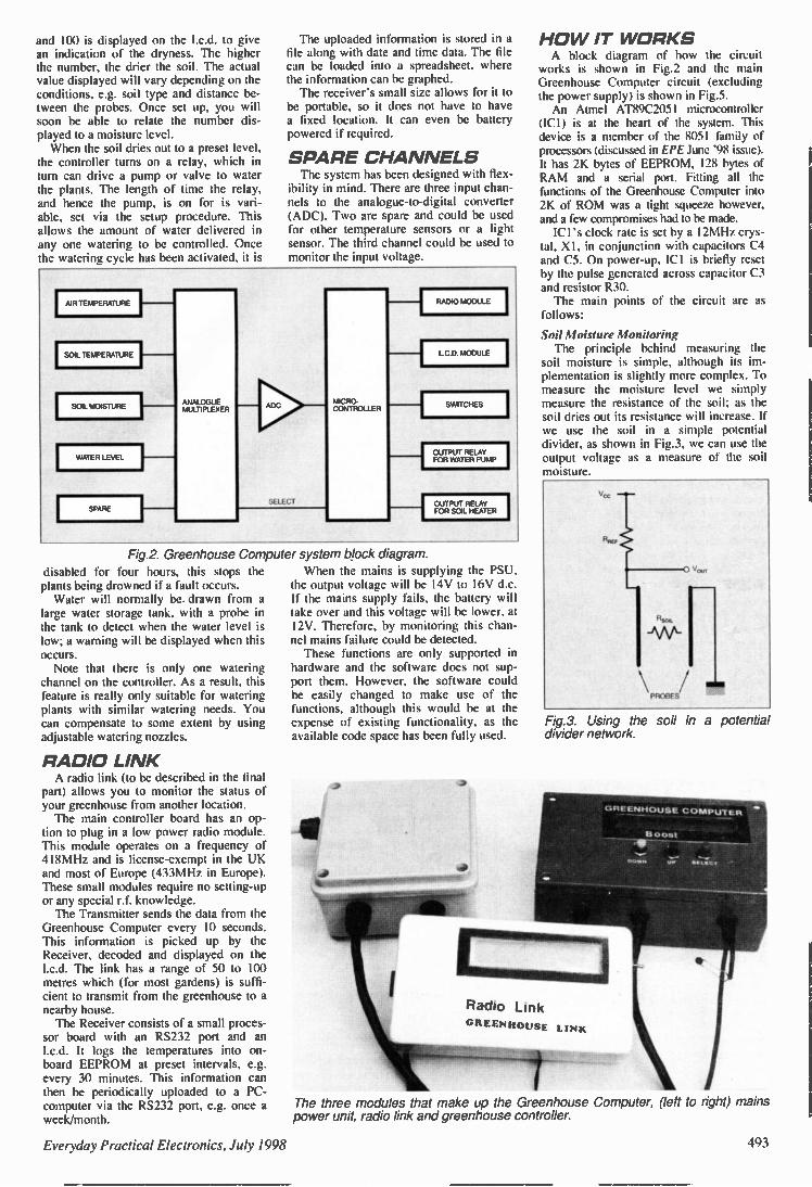
and 100 is displayed on the I.c.d. to give an indication of the dryness. The higher the number, the drier the soil. The actual value displayed will vary depending on the conditions, e.g. soil type and distance be-tween the probes. Once set up, you will soon be able to relate the number dis-played to a moisture level. When the soil dries out to a preset level,
the controller turns on a relay, which in turn can drive a pump or valve to water the plants. The length of time the relay, and hence the pump, is on for is vari-able, set via the setup procedure. This allows the amount of water delivered in any one watering to be controlled. Once the watering cycle has been activated, it is
The uploaded information is stored in a file along with date and time data. The file can be loaded into a spreadsheet, where the information can be graphed. The receiver's small size allows for it to
be portable, so it does not have to have a fixed location. It can even be battery powered if required.
SPARE CHANNELS The system has been designed with flex-
ibility in mind. There are three input chan-nels to the analogue-to-digital converter (ADC). Two are spare and could be used for other temperature sensors or a light sensor. The third channel could be used to monitor the input voltage.
AIR TEMPERATURE
SOIL TEMPERATURE
SOIL MOISTURE
WATER LEVEI
disabled for four hours, this stops the plants being drowned if a fault occurs. Water will normally be drawn from a
large water storage tank, with a probe in the tank to detect when the water level is low; a warning will be displayed when this occurs. Note that there is only one watering
channel on the controller. As a result, this feature is really only suitable for watering plants with similar watering needs. You can compensate to some extent by using adjustable watering nozzles.
RADIO LINK A radio link (to be described in the final
part) allows you to monitor the status of your greenhouse from another location. The main controller board has an op-
tion to plug in a low power radio module. This module operates on a frequency of 418MHz and is license-exempt in the UK and most of Europe (433MHz in Europe). These small modules require no setting-up or any special r.f. knowledge. The Transmitter sends the data from the
Greenhouse Computer every 10 seconds. This information is picked up by the Receiver, decoded and displayed on the I.c.d. The link has a range of 50 to 100 metres which (for most gardens) is suffi-cient to transmit from the greenhouse to a nearby house. The Receiver consists of a small proces-
sor board with an RS232 port and an I.c.d. It logs the temperatures into on-board EEPROM at preset intervals, e.g. every 30 minutes. This information can then be periodically uploaded to a PC-computer via the RS232 port, e.g. once a week/month.
RADIO MODUI
LCD MODULE
I 1
SWITCHES
I
IOUTPUT RELAY I FOR WATER PUMP
IOUTPUT RELAY I FOR SOIL HEATER
Fig.2. Greenhouse Computer system block diagram. When the mains is supplying the PSU,
the output voltage will be I4V to 16V d.c. If the mains supply fails, the battery will take over and this voltage will be lower, at 12V. Therefore, by monitoring this chan-nel mains failure could be detected. These functions are only supported in
hardware and the software does not sup-port them. However, the software could be easily changed to make use of the functions, although this would be at the expense of existing functionality, as the available code space has been fully used.
HO W IT WORKS A block diagram of how the circuit
works is shown in Fig.2 and the main Greenhouse Computer circuit (excluding the power supply) is shown in Fig.5. An Atmel AT89C2051 microcontroller
(ICI) is at the heart of the system. This device is a member of the 8051 family of processors (discussed in EPE June '98 issue). It has 2K bytes of EEPROM, 128 bytes of RAM and a serial port. Fitting all the functions of the Greenhouse Computer into 2K of ROM was a tight squeeze however, and a few compromises had to be made. ICI's clock rate is set by a 12MHz crys-
tal, XI, in conjunction with capacitors C4 and C5. On power-up, ICI is briefly reset by the pulse generated across capacitor C3 and resistor R30. The main points of the circuit are as
follows:
Soil Moisture Monitoring The principle behind measuring the
soil moisture is simple, although its im-plementation is slightly more complex. To measure the moisture level we simply measure the resistance of the soil; as the soil dries out its resistance will increase. If we use the soil in a simple potential divider, as shown in Fig.3, we can use the output voltage as a measure of the soil moisture.
PROBES
Crn
11101111
Fig.3. Using the soil in a potential divider network.
Boost
Radio Link
GREENHOUSE LINK
The three modules that make up the Greenhouse Computer, (left to right) mains power unit, radio link and greenhouse controller.
Everyday Practical Electronics, July 1998 493

Display window on the completed control box.
NON-CORROSIVE The problem with the simple potential
divider is that we are passing a direct current (d.c.) through the probes in the soil. Over time, one probe will gather deposits and the other will corrode away, which will give erratic results as well as limited probe life. To avoid this problem, an alternating current (a.c.) is used, which prevents the electrolysis effect. The equiv-alent circuit is shown in Fig.4. The practical implementation of Fig.4 is
the circuit around IC3a and IC3b in Fig.5. IC3a is configured as an oscillator whose frequency is set at about 4kHz by resistor R23 and capacitor C14. The resulting a.c. signal is output to the
soil moisture probes (P1) via R 19 and C13. The value of resistor R19 sets one arm of the potential divider, the other arm being the soil resistance. Discussion of the best value for R19 takes place when set-ting up is described next month. From the soil probes, the return signal
is buffered by IC3b, rectified by Schottky diode D4, plus C16 and R25. The amplitude of the voltage appearing across C16 thus represents the soil resistance - high voltage when dry, low voltage when wet. The output voltage is fed to the 8-way
multiplexer IC2, into which the output voltages of the other sensors are also fed. The selection of which signal is routed to
Water dispenser and pump.
Table 1: Relationship between tem-perature, resistance, voltage and time.
TEMP
-10
R(5K)
27520
Voltage
3.67
Time/256
34.2
Lookup
136.7 -8 24663 3.56 33.2 132.7 -6 22140 3.44 32.1 128.4 -4 19906 3.33 31.0 124.1 -2 17926 3.21 29.9 119.7 0 16168 3.09 28.8 115.2 2 14604 2.97 27.7 110.7 4 13210 2.85 26.5 106.1 6 11967 2.72 25.4 101.6 8 10856 2.60 24.3 97.0 10 9862 2.48 23.1 92.6 12 8971 2.36 22.0 88.2 14 8171 2.25 21.0 83.8 16 7452 2.14 19.9 79.6 18 6805 2.02 18.9 75.5 20 6222 1.92 17.9 71.5 22 5696 1.81 16.9 67.7 24 5220 1.71 16.0 63.9 25 5000 1.67 15.5 62.1 26 4790 1.62 15.1 60.4 28 4400 1.53 14.2 57.0 30 4047 1.44 13.4 53.7
the microprocessor is determined by the code applied by ICI to IC2's control pins A, B. C and INH. Three switches (S1 to S3) are also
connected to the same lines that ICI uses to control IC2. The switches, though, are not
intended to provide
Fig.4. Using a.c. helps to prevent probe corrosion.
additional control over IC2. Rather, they are used to control and set up the various modes of operation via ICI. They have different functions depending on the mode selected, as discussed later. In the set-up procedure, the switch functions are displayed on the bottom line of the I.c.d.
Temperature Measurement There are a num-
ber of devices on the market that can make temperature measure-
ment very simple. However, these devices are relatively expensive. In an application such as this, inexpensive ones are preferred as they could get damaged easily in a greenhouse. The devices used here are NTC thermis-
tors, R26 and R27; these small devices are cheap and reasonably accurate (±2%). The only drawback is that their resistance does not vary linearly with temperature. This is not a great problem, though, since the processor can easily calculate the tempera-ture via a look-up table. The formula for calculating resistance is as follows:
Rh 1 = RT2e x (B/T1 - B/T2) where RT = resistance R at Temperature T (in °K), B =characteristic temperature for the thermistor (see comp. list) and e =exponential factor (i.e. 2.718282)
Table 1 shows the relationship between temperature, resistance, voltage and time for the the rmistor specified. Column 2 shows the thermistor resistance for various temperatures shown in column 1. Column 3 shows the voltage input to the ADC, i.e. the result of the voltage divider. Column 4 shows the time taken for the
comparator to trip within the ADC func-tion of ICI. A I6-bit timer measures this time, although only the upper eight bits of the timer are used, hence the time is divided by 256. The look-up value is that used by the software and is actually the previous time multiplied by four (this gives better resolution).
Water Level Monitoring Monitoring of the water level in, say, a
rain water butt, is based on a similar prin-ciple to soil moisture monitoring, except that only a d.c. voltage is needed across the probes (P2). The amount by which the probes are immersed in water will vary the resistance between them. This forms one arm of another potential divider, the other arm being resistor R9.
DIGITAL CONVERSION The AT89C205 I microcontroller has
built-in analogue processing facilities which make it ideal for use as a sort of analogue-to-digital converter when monitoring sensor voltages, although it is not really an ADC! It's more like a voltage-to-time converter and its operation is quite simple.
494 Everyday Practical Electronics, July 1998

4-
'J,
-t R28 5k NTC
-t R27 5k NTC
SPARE R16
TEl 10k
9
R15 R 4 50 150
R10 150k
16
AIR TEMP 13
SOIL TEMP 4
WATER LEVEL 15
SPARE 12
4
P2
WATER LEVEL PROBES (SEE TEXT)
624 100
622 100k
ro Lo-
SPARE
S3
'SELECT
C17 •110 018 1 C19•11111C20 MIN C6 1 10n M N 10n T 10n T lOn T''' 7
TB2
D7 BATES ki 4 a
06 RATES k a
SPARE
VOLTAGE 5
SPARE 2
SOIL
MOISTURE
6
SEL 1
SEL2 10
TR6 E37 11144
D5 BATES
614 4
SEL3
02
X3
04
05
06
X7
IC2 40518
INS
8
TR2 BC557 RI
10 DI C2 r l
66 3V3 AIL 10p a m
TR1 12 00547
10k
03)
10011
105 rem"" V„
TX1
TX M-418-F RE GND
DATA RE OUT
GND
07
D6
D5
04
1
20
13
14
15
P11 1 00
513
014 100n
IC3b TL C272
do
a
VAT85 k
525
03 11,44148
02 1N4148
513
R11 56k
VR I 206
TR5 BC557
01 22 ,
"B3 11 11,
PI SOIL MOISTURE PROBES (SEE TEXT)
TB4
2 GND
+7.5V TO 4-18 0' (SEE TEXT)
C4 330
16
17
18
19
1251Hz T
PI I A-
PI ,
I, 3
P14
P1 5
PI 6
51 7
Von
AT89C2051
501E7, XTAL I
.4(.> XTAL2
030
RESET GNL,
P3.0
P3.1
P32
P3 3
P34
P3-5
P3 7
2 RS
RADIO TRANSMITTER
3
6
10
612 267
RR 217
D8 17.4,46
IN
C15 10,,
618 10k
621 2k2
IC4 7805
OUT
COM
C8 1 -7 711M (11' M N C12 MEN 1 1 1. 100n N M 100n 100n 100n
TR3 BSI 70
TR4 BS170
63 lk
2
7
1
0
CONTRAST'
W 64
270E/
TB5
HEATER
OUTPUT RELAYS
D9 0A 010
R28 13
079
LCD
X2

5
GURFELK I SOURCE PI V., PI
CAPACITOR
MICROCONTROLLER
Pie
P11 OUTPUT TRANSISTCfl
Fig.6. Producing a "reference voltage".
Referring to Fig.6, the voltage from the signal source (V4,) is applied to one in-put (PI.0) of the microcontroller's internal comparator. The other input (P1.1) is sup-plied by a current-limited reference volt-age, which is also coupled to a capacitor. To obtain a \fin voltage value, software
first turns on the microcontroller's out-put transistor connected to P1.1, discharg-ing the capacitor. It then turns off the transistor, allowing the capacitor to begin recharging. Now the software measures the time it takes the capacitor voltage to reach the same level as Vin (at which point the comparator output changes state). This time is proportional to the input voltage (C = dv/dt). In Fig.5, the reference voltage is set by
the network around transistor TR5. The timing capacitor is C7, and preset VR1 is used to fine-tune the timing/reference rate.
L.C.D. INTERFACE The display is shown on a 2-line 20-
character intelligent I.c.d. (X2), connec-tions to which are via PL I . The interface will work with most intel-
ligent I.c.d.s that operate off a single 5V supply. Due to the shortage of I/O lines on the processor, the I.c.d. is set up to use a 4-bit data bus rather than its full 8-bit bus. The contrast for the display is controlled by preset potentiometer VR2. The I.c.d. must be of the single voltage
( + 5V) supply type, i.e. the type that does not need a negative voltage on its contrast pin.
RADIO INTERFACE The radio interface uses the processor's
serial port to output the current status and setting to the r.f. module. This design will he explained fully in the final part. In a nut-shell, though, data is sent from
the controller as a single block every 10 seconds. The link is one-way, so the con-trol board cannot receive any messages. The receiver decodes the data from
processor and displays the information on the I.c.d. It also stores the data in non-volatile memory, so that it can be downloaded to a PC for further processing (e.g. temperature graphs can be generated).
PO WER SUPPLY The controller circuit has its own 5V
regulator on board, as shown in Fig.5. It can be fed at between 7.5V and 18V, which is attenuated to 5V by IC4.
496
Resistors R18 and R21 form a potential divider which supplies a reference voltage which could be read by the microcontroller via IC2, but is not implemented in the prototype. Diode D8 protects the regulator when
the power is removed (i.e. the bulk capacitors are discharged via the diode rather than through the regulator). The controller can be supplied with
power from any suitably rated d.c. power source, although the circuit illustrated in Fig.7 is recommended. The control board consumes less than 100mA; the pump is likely to require between IA and 3A. Mains a.c. power is brought into trans-
former TI whose dual 12V a.c. output is rectified by diodes DI I and D12, resulting in a d.c. voltage of about 18V at smooth-ing capacitor C21. This 18V is fed to the 5V regulator on the controller board. Addi-tionally, a 5V6 Zener diode (D15) drops the 18V to 12-4V to supply the relays.
RELAYS Also shown in Fig.7 is the power cir-
cuit for the relays, RLA and RLB. These are responsible for switching the Heater and the Pump. They are controlled from ICI via f.e.t. power transistors TR3 and TR4 (see Fig.5). Their status is indicated by I.e.d.s D9 and DIO. Returning to Fig.7, rechargeable NiCad
batteries are used to provide the power for the pump. The mains power supply keeps the batteries topped up and provides power for the control board, it does not power the pump. The batteries also give backup to the controller, so you will not lose your setting during power interruptions. Switch S4 is provided to give a choice
of charge rates for the batteries. The low rate is set at approximately 7mA and the high rate at 20mA. These rates are con-trolled by resistors R33 and R32, respec-tively. If the watering function is not used, the low setting should be selected.
Al BATTERY PACK
TB11
12V BATTERY OUT TB10
I12V BATTERY IN
TB7 EE mEE
0
0
2
Al= 116,
MAINS IN
THE
I UVE OUT I
TB9
NEATER '7 5 +18V
GNU
GNU
GNU
PUMP
014 1N4001 a ip.ik
R33 162
R31 39011
STAND-BY S4 NORMAL
-- Mt -
1 7V
011 1N4001 alo e
CHARGE
012 C21 I= 1N4001# 4701,
013 1N4001
C27 1008
I CONTROLLER
016 1N4148 a mk
270
D17 1N4148 a mk
RLB 270
015 5V6
2 TBEI 13
N C
2 FS2 3A
HEATER
TB12 13
PUMP
Fig.7. Recommended power supply circuit diagram for the Greenhouse Controller. The legends around the relay contacts indicate the pole or moving contact (p), the normal open (n.o.) and the normal closed (n.c.) terminal.
Everyday Practical Electronics, July 1998

COMPONENTS Approx. Cost Guidance Only £6.5
excluding trans mitter and greenhouse hardware
Resistors R1 R2', R5', R6', R13 to R16, R18, R20 10k (10 off)
R3, R28, R29 1k (3 off)
R4 27011 R7 15012. R8, R12 2k7 (2 off) R9, R10 150k (2 off) R11 56k R17, R22, R24, R30 100k (4 off)
R19 2k2 (see text) R21 2k2 R23 2k R25 2M2 R26, R27 NTC thermistor, 5k at
25°C, 30011 at 100°C, B value 4100
R31 100D R32 39011 R33 1k2
All 0-25W 5% carbon film unless marked.
Potentiometers VR1 20k multiturn, top adjust. VR2 1k multiturn, top adjustable
Capacitors Ci*, C8, C10 to C14, C22 100n ceramic disc (8 off)
C2*, C3, C15 1011 elect. axial, 25V
(3 off) 33p ceramic disc (2 off) C4, C5
C6, C17 to C20
C7 C9 C16 C21
Items marked • are for the Radio Transmitter Interface (seetext).
10n ceramic disc (5 off) 22n polystyrene 47p, elect. axial, 16V tantalum bead, by
470k radial elect., 25V
Semiconductors D1' 3V3 Zener diode 400mW D2, D3, D8 1N4148 signal diode (3 off) D4 to 07 BAT85 Schottky diode (4 off) D9, D10 red led. D11 to D14 1N4001 rect. diode (4 off) D15 5V6 IW Zener diode D16, D17 IN4148 signal diode (2 off) TRI*, TR6 BC547B npn transistor
(2 off) TR2', TR5 8C557 pnp transistor (2 off) TR3, TR4 BS170 MOSFET (2 off) ICI AT89C2051 pre-programmed
microcontroller (see text) IC2 4051B 1-of-8 analogue
multiplexer IC3 TLC272 dual op.amp IC4 7805 5V IA voltage reg.
Miscellaneous FSI 1A 20mm fuse, plus p.c.b.
mounting clip FS2 3A 20mm fuse, plus p.c.b.
mounting clip and cover L1 4 .71.t H inductor, bobbin or
axial PL1 14-way IDC plug RLA, RLB s.p.d.t. relay, 12V 10A,
p.c.b. mounting (2 off) Si to S3 s.p. push-to-make
switch (3 off) S4 s.p.d.t. min. slide switch,
p.c.b. mounting Ti transformer, 12V-0-12V
3VA, p.c.b. mounting TB1 10-way terminal block,
p.c.b. mounting, 0-2in. pitch
TB2, TB5 4-way pin header, 0.1in. pitch (2 off)
2-way terminal block, p.c.b. mounting, 0.2in. pitch (7 off)
4-way terminal block, p.c.b. mounting, 0.2in. pitch
6-way pin header, 0.1in. pitch
TXM-418-F transmitter module (see text)
XI 12MHz crystal X2 2-line 20-character I.c.d.
module ( + 5V supply - see text)
Printed circuit boards, available from the EPE PCB Service, coded 197 (controller), 198 (power supply); 20-pin d.j.!. socket; 8-pin d.i.l. socket; 14-way IDC connector; plastic case, 154mm x 88mm x 58mm, waterproof; plastic case, 104mm x 104mm x 55mm. waterproof; 12V battery pack, AA-size rechargeable (1.2V cells, 10 off); cable gland, waterproof, locking (3 off); cable grommet, sleeved (3 off); miniature water pump, 12V, e.g. car windscreen washer pump; tubing to suit pump (e.g. 4mm for car washer pump); soil heating cable (see text); connecting wire; solder, etc.
SPARE WATER THERMISTOFI CHANNEL LEVEL SOIL (R27
TB3, TB4, TB6, TB8, TB10 to TBI 2
TB7
TB9
TX1
ANTENNA
oo01r0
• b TR2 • • TR1 I
c e k
d
• • •
TR3
NO PUMP
TR5 •
HEATER ONO
THERMISTOR AIR (R26)
SPARE CHANNEL
A
OUT a
COM
iN
SOIL MOISTURE PROSES
. 1
+9V,18V
GND
Fig.8. Printed circuit board component layout, wiring details and full size copper track master for the control board. Note R30 is soldered to underside.
Everyday Practical Electronics, July 1998 497

CONSTRUCTION Warning: parts ot this circuit carry
mains voltage. Take care when construct-ing and testing the design. If a heating cable is used, ensure it is one with an earth shield (i.e. one meant for this purpose). Remember that greenhouses can be wet, ensure that equipment is suitably protected. It is also advisable that all mains equipment in a greenhouse is protected by an earth leakage breaker (ELB or RCCB). During assembly, if you have to
desolder any components use the mini-mum amount of heat as tracks will lift easily. There are two printed circuit boards
(p.c.b.$), one for the main circuit and one for the power supply. Both boards are available from the EPE PCB Service, codes 197 and 198 respectively.
CONTROL BOARD Start with the control board, layout and
tracking details of which are shown in Fig.8. The usual order of links, resistors, diodes, capacitors etc. should be followed to simplify the assembly. There are a num-ber of polarized components, take care to insert them correctly. Note that capacitors C17 to C21 and resistor R30 are soldered on the rear (trackside) of the board. Transistors TR3 and TR4 are shown as
BS170 MOSFETS, but in fact general pur-pose npn transistors can be used in their place, such as BC547 for example. Inductor LI is shown as a bobbin type,
but you can use an axial one by standing it on its end. Regulator IC4 should be mounted face up, i.e. metal tab against the board. Use d.i.l. sockets for ICI and IC2. Use
good quality sockets, especially if you are developing code yourself, as the processor may be in and out a few times. If you are developing your own code, use two sock-ets for the processor. When removing the processor, remove it in a socket, therefore if you damage a pin, it will be a socket pin, not a processor pin! If you are going use the radio interface to
be described in the last pan, it would probably be best to populate all the components now, with the exception of the radio module and its antenna. If you are not intending to build it, omit the components associated with it. All the off-board connections are made
via connectors rather than directly soldering wires to the p.c.b. This adds a little to the cost but makes testing and installation much simpler. Connection to the I.c.d. is made by a 14-
way ribbon cable with an IDC connector at the control board end. The connection at the other end will depend on the 1.c.d. used, you may be able to use an IDC connector at the other end too. Some I.c.d. connections are a single row of 14 rather than 2 x 7, but in either case the connection numbering is the same.
PSU ASSEMBLY For the power supply board (p.s.u.) fol-
low the layout shown in Fig.9. Take care to ensure the diodes are inserted the correct way round. Pin-outs for the transformer secondary
vary between suppliers. The p.c.b. tracks have been laid out so that modifications can be made easily.
UVE OUT
LIVE IN
EARTH
NEUTRAL IN I
NEUTRAL OUT A
HEATER
.1*
• • NO NC
RLA COR
PS
+ 12v uND
CND
+12V 11.
PUMP
Fig.9. Power supply printed circuit board component layout, wiring details and lull size copper foil track master. The completed p.s.u. is shown at the top.
Everyday Practical Electronics. July 199S 498

It is suggested that ten rechargeable cells are used for battery back-up. These will produce a total output voltage of 12V to 13V (1.2V apiece). Most pumps will work between 11V and I4V. For safety purposes, ensure the mains
fuse (FS1) has a cover and is not an open type fuseholder.
SOFTWARE The software source code is written in C.
The main reason for using C was for speed and maintainability (the original design was experimental and a number of changes were envisaged and implemented). Despite being written in C. the code is
very efficient (few library functions are used to make the code more efficient). Although writing the code in assembler might have resulted in slightly more effi-cient use of the ROM, the advantages of writing in a high level language often outweigh the disadvantages. Because it is written in a high level
language, the code is much more readable and, therefore, if you want to make changes you should find it reasonably simple (providing you have C facilities, of course). However, if you want to make changes
to the code, some functionality may have to be sacrificed, as every byte in the avail-able code space is currently used! Note that if you do alter the code you must keep the variables in the same order if you want to use the Radio Interface.
Completed controller unit. The display module is mounted in the lid.
RESOURCES Software for the Greenhouse Computer
is available from the EPE Editorial Office on a 3.5 inch disk, order as PIC-Disk I. See EPE PCB Service page for postage charges. The software is also available free from
our Web site: ftp://ftp.epemag.wimborne.co.uk/Pub/ 8051/Greenhouse Controller ICI is available as a
pre-programmed device direct from the
author: Colin Meikle, 9 Coldstream Drive, Strathaven, Lanarkshire, ML 10 6UD. Make cheques payable to him. The price, inclusive of UK postage is £12 (add El for overseas post). You can also contact the author via E-
mail at [email protected].
Next Month: We test each com-pleted circuit board, complete final assembly and explain the software functions.
DESIGN INIERNATIONAL
Frererigtml gir,1",1".
0, ,k4gg 10; j 64153151 ii1gsi1 .,
2, ° <144:7:.1 a /Qv
The complete, B11 j 6 6_
powerful schematic and PCB layout tools for Windows.
CI Design your schematic with WinDraft...
- Choose from over 10,000 parts in WinDraft's complete library of components.
- All the utilities you need are included in the package from an Electrical Rules Checker to netlist output to printing and plotting outputs.
- Cut and Paste into other Windows applications such as Microsoft Word. Makes it easy to document your projects!
0 Create a Gerber photoplot, NC Drill, pick and place, and other manufacturing outputs!
SPECCTRA Autorouter
Will aGRAD PcT Isryout
mistaorpo ....yorctifED-z-74:1 •a•
"AO .
• mil5o.4,..,51?eu • .
- trutort ftelt
— - -
0 Create the artwork for the PCB with WinBoard...
- Quickly route boards on up to 16 layers.
- Use SMD or through-hole components — or mix them for maximum flexibility.
- Unique pad-stack editor can create pads of virtually any size or shape.
-Rotate components in 0.01 increments
Tel 0181 926 1161 The PC Solution, 2a High Road Layton, London, E15 2BP. Fax 0181 926 1160 http:Hwww.thepcsoldemon.co.uk
Everyday Practical Electronics. July 1998 499

Everyday Practical Electronics are pleased to be able to offer all readers these
ELECTRONICS CD-RO MS TWO
APPLICATIONS
ON ONE CD-ROM
ELECTRONIC CIRCUITS & COMPONENTS + THE PARTS GALLERY by Mike Tooley
ELECTRONIC CIRCUITS & COMPONENTS Electronic Circuits & Components • 1. provides an introduction to the principles and application of the most common types of electronic components and shows how they are used to form complete circuits. The virtual laboratories, worked examples and pre-designed circuits allow students to learn, experiment and check their understanding as they proceed through the sections on the CD-ROM. Sections on the disk include: Fundamentals: units & multiples. electricity, electric circuits. alternating circuits. Passive Components: resistors, capacitors, inductors, transformers. Semiconductors: diodes, transistors, op.amps, logic gates. Passive Circuits Active Circuits
THE PARTS GALLERY Many students have a good understanding of electronic theory but still have difficulty in recognising the vast number of different types of electronic components and symbols. The Parts Gallery helps overcome this problem: it will help students to recognise common electronic components and their corresponding symbols in circuit diagrams. Selections on the disk include: Components Components Quiz Symbols Symbols Quiz Circuit Technology
Hobbyist/Student
liandantentais 14••••••
N MI
• I. I • I Ift Jo •
''••••••••• 7.7 E.: • f
0
j.f ern f I. • , Virtual laboratory - sinusoids 3 See. ondif<14,+
CECIL.
Logic laboratory
Circuit technology screen
£34 inc VAT Institutional (Schools/HE/FE/Industry) £89 plus VAT Institutional 10 user (Network Licence) £169 plus VAT
DIGITAL ELECTRONICS by Mike Tooley Digital Electronics builds on the knowledge of logic gates covered in Electronic Circuits & Components, and takes users through the subject of digital electronics up to the operation and architecture of microprocessors. The virtual laboratories allow users to operate many circuits on screen.
I), tal Fundamentals
el 81.1111.4.041. MOW*
roe.. • W. • 011111 .1 .Mi
-
I
I .4
— izacuza Virtual laboratory - flip-flops
fraent. Sem ar watior
F41171 7-.7
Virtual laboratory - traffic liahts
FUNDAMENTALS Fundamentals introduces the basics of digital electronics including binary and hexadecimal numbering systems, ASCII, basic logic gates and their operation, monostable action and circuits, and bistables - including JK and 0-type flip-flops
COMBINATIONAL LOGIC Multiple gate circuits, equivalent logic functions and specialised logic functions such as majority vote, parity checker, scrambler, half and full adders. Includes fully interactive virtual laboratories for all circuits
SEQUENTIAL LOGIC Introduces sequential logic including clocks and clock circuitry, counters, binary coded decimal and shift registers.
DIGITAL SYSTEMS /VD and D/A converters and their parameters, traffic light controllers. memories and microprocessors - architecture, bus systems and their arithmetic logic unit.
GALLERY A catalogue of commonly used IC schematics taken from the 74xx and 40xx series. Also includes photographs of common digital integrated circuits and circuit technology.
£45 inc VAT Institutional (Schools/HE/FE Industry) £99 plus VAT
Institutional 10 user (Network Licence) £199 plus VAT
Microprocessor
Hobbyist/Student
Minimum system requirements: PC with 486/33MHz, VGA+256 colours, CD-ROM drive, 8MB RAM, 8MB hard disk space. Windows 3.1/95/NT, mouse, sound card. Demo available from Web site http://www.MatrixMultimedia.co.uk
CD-ROM ORDER FORM Please send me: Version required: I J Electronic Circuits Er Components + Parts Gallery I r] Digital Electronics
Post code' Tel. No.
Signature•
enclose cheque/PO in £ sterling payable to WIMBORNE PUBLISHING LTD for £
I [I Please charge my Visa/Mastercard: £ Card expiry date'
Card No•
Hobbyist/Student Institutional Institutional 10 user
Full name•
Address.
ORDERING Prices include UK postage
Student Version - price includes postage to most countries in the world
EU residents outside the UK add f5 for airmail postage per order
OVERSEAS ORDERS: Institutional Ver. sions - overseas readers add £5 to the basic price of each CD-ROM for airmail postage (do not add VAT unless you live in an EU country, then add 171/2 % VAT or provide your official VAT registration number).
Send your order to: Direct Book Service 33 Gravel Hill, Merley Wimborne
Dorset BH21 1RW
(Mail Order Only) Direct Book Service is a division of Wimborne Publishing Ltd. To order by phone ring
01202 881749. Fax: 01202 841692 We cannot reply to overseas orders by Fax
CD-RO Ms are normally sent within seven days

*Produces attractive schematics like you see in the magazines. *Netlist, Parts List & ERG reports. *Hierarchical Design. *Full support for buses including bus pins. *Extensive component/model libraries. *Advanced Property Management. *Seamless integration with simulation and PCB design.
Simulation
EM POW OmEt Gagth Tapir SAAR Imo
u,iCe
vi‘DI
U2 ,01 ,
.15
-i3
• NEM 1:7=1'111 FF. 1E1
II
FORT IMPAIR VPROBE PROBE TAPE GENERATOR TERMINAL SUGOROAT
-- 11%— exc
*Non-Linear & Linear Analogue Simulation *Event driven Digital Simulation with modelling language. *Partitioned simulation of large designs with multiple analogue & digital
*Graphs displayed directly on the schematic.
REE SOFTWARE ISIS & ARES Lite Schematic & PCB
Design
SHAREWARE VERSIONS AVAILABLE TO DOWNLOAD FROM OUR WEINITE
http://www.labcenterco.uk
Ne w Features-Component Auto-Placer
Pinswap/Gateswap Optimizer Background Regeneration of Power Planes Enhanced Autorouting with Tidy Pass Full Control of Schematic Appearance Extenshm New Component Libraries
Available in 5 levels - prices from £295 to £1625 + VAT. Call now for further information & upgrade prices.
—
PCB Design
Gsei. thd• fie
eat ttett..t.ttett
.3.1e r melt 14 In Mit
RELIEF SIDTRACT 110 11
*Automatic Component Placement. •Rip-Up & Retry Autorouter with tidy pass. •Pinswap/Gateswap Optimizer & Backannotation. *32 bit high resolution database. *Full DRC and Connectivity Checking. *Shape based gridless power planes. *Gerber and DXF Import capability
particularly
7A13-4)
good EWW January 1997
cen er E l e c t r o n i c s
Write, phone or fax for your free demo disk, or ask about our full evaluation kit. Tel: 01758 753440. Fax: 01758 752857. EMAIL: [email protected] 53-55 Main Si, Grassington. BD23 5AA. WWW: http://www.labcenterco.uk
Fully interactive demo versions available for download from our WVVVV site. Call for educational, multi-user and dealer pricing - new dealers always wanted. Prices exclude VAT and delivery. All manufacturer's trademarks acknowledged.

IT! • A
C o en i Analyser
DCA50 Component Analyser
4( Tr.u1,37 amazin
DTA30 Transistor Analyser
Bipolar MOSFETs Diodes LEDs
Diode J;Anction RGB4A—K
• FU LY I vat
P-Chante RGIE W,0'.72,
1 MOSFET
AS VIE ED IN JULY EPE! An incredibly versatile unit that will
identify almost any transistor,
MOSFET, diode or LED as well as
identify pinouts! It will even measure
transistor gain. Just apply the colour-
coded gold plated test clips in an
order and press the button. Fits in the
pal m of your hand.
Supplied with battery and
manual. NPN Transistor RGB*BCE HFE=236
The user can connect any bipolar transistor to the three
test clips in any configuration and the DTA30 will verify device operation and identify all three leads as well as the transistor type (NPN/PNP).
HMA20 MOSFET Anal ser
A truly unique instrument that will verify the operation of MOSFETs. Of course, it will identify the three leads and the MOSFET type too.
DCH1 0 Diode Tester '
A simple device that will test and identify the leads of diodes, zeners, LEDs and other semiconductor junctions. It will even illuminate an LED under test regardless of the connected orientation. The DCHIO can identify open. short and normal semiconductor junctions. tie
All units feature auto power-on and auto power -off an d are supp lied with an operation guide and long life battery. Replacemen t batter ies ava ilable. You can order by credit card, cheque or pos tal or der , remem ber there 's no VAT or P+P to add, what you see is what you pay! Goods are norma lly despatc hed w ithin 24 hours and are guaranteed for 12 months following rece ipt of or der. Government an d educational establishments qualify for 30 days paymen t terms . For delivery outside the UK please add £5.
SU49$ k l tt!jo. uk . eae
z6
INC

RE AD OUT J ohn B ecker addresses so me of the general points readers
have raised. H ave you anything
interesting to say?
D rop us a line!
TUT, TRIS AND TASM Dear 1:13E, Nice to see the PIC Tutorial in the mag,
just what we've been waiting for. I have programmed a few 16C84s but some EPE projects have left me a little non-plussed! Like when I bought an I.c.d. module that met all the criteria stated in the How to Use Intelligent L.C.D.s article (Feb/Mar '97), but could I get it to work?! Looking at the code on page 194 March
'97, I now understand why this code never worked for me. Where, oh where, is the page switching code to drive and control Port B? I very much welcome PIC-Tutor, I've
already learned something from Part 1 as I didn't realise the significance of PAGE switching for port control and output. Keep up the good work chaps! Incidentally, I have in fact been using
TASM for many years to program the good old Z80 CPU, having developed and built a Z80 development system.
Mel Saunders, Leicester
Your I.c.d. might, perhaps, be. failing to initialise correctly when power is first ap-plied and the software run. 1 favour a dif-ferent command sequence to that published in March '97 (there are several ways it can be done). Try the sequence published in the Tutorial Part 3. It is unlikely that Paging is the cause. The
use of TRIS in the March '97 code is an alternative to the PAGE instructions I dis-cuss in the Tutorial, and having the same effect. Command TRIS is one which fell it best
not to include in the Tutorial as Microchip recommend that, although it is available in the P1C16C84 set, it should not be used in order to maintain upward compatibility of code with later devices, which do not in-clude the command. Whilst I have not used TRIS as a com-
mand, the PIC Data Book says that "all Port pins have data direction bits (TRIS registers) which can configure these pins as output or input". The use of TRIS with a Port A or Port B address directly accesses these bits. The March '97 code you refer to has
the following statements (with revised com-ments from me):
CLRF 05 CLRF 06 MOVLW OF8 TR1S 05
MOVLW 00 TRIS 06
; clear PORTA ; clear PORTB ; load W with %11111000 ; to set RAO to RA2 as ; outputs ; and RA3. RA4 as inputs ; load W with 0 : to set RBO to RB7 as : outputs
Win a Peak DTA30 Transistor Analyser The DTA30 will test and identify the type (npnipnp) and the leads
of any bipolar transistor connected to it.
Every month Peak Electronic Design Ltd will be giving a
DTA30 to the author of the best Readout letter published.
This seems to me to have the same effect as what 1 would write for the same function (having defined all names in the initialisation heading):
CLRF PORTA CLRF PORTB PAGE] MOVLW %11111000 MOVWF TRISA CLRF TRISB PAGEO
I'm interested to learn of your use of TASM with other processors, it is a versatile assembler.
CHARACTER PIC Deal EI'L, I am considering using a PIC to con-
trol a circuit which generates alphanumeric characters on segmented I.e.d.s. I need to have two digit select lines, six data inputs, eight outputs to I.e.d. segments and four outputs to the I.e.d. common electrodes, a total of 20 lines required to create characters from 0 to 9 and A to Z. However, the PIC16C84 only has 13 I/0
lines and is thus not suited to the design. The next device size up, the PICI6C57 I think, has two 8-bit ports and one 4-bit port, but you have not yet covered this PIC in the same detail as you have the '84 and I am not familiar with its use. Can you help? It would also be useful if you published a table of info on the various PICs.
John Gray, London NIO 2NU
First, unless many readers suggest other-wise, we cannot immediately see the benefit of covering non-EEPROM type PICs in the same detail as given to the '84. The '84 justified the coverage because of its ease of immediate reprogrammability. Other PICs are less easy to experiment with as they require time-consuming erasure by UV-light. The information we gave in the '84
Tutorial, though, is basically applicable in terms of coding to other PIC members and anyone familiar with the '84 should be able to use other PICs in conjunc-tion with their own data sheets. As far as physically programming them is con-cerned, it is advisable to use Microchip's MPASMIMPLAB hardware/software suite which covers all PIC devices. Returning to your character drive
problem, you are assuming that an '84's 13 lines cannot be used in your 20-line requirement. Not so! Remember that each line can have its
input/output direction changed from within a program, which thus provides you with the equivalent of 26 lines to play with, as
TRANSIS T Rs'
Aikuts..vsan
BASE iP
EMI ITER •
C 01 CTOR •
PO N •
PNP
long as you take suitable precautions to prevent conflict between the devices on the lines when in bi-directional use. This may be as simple as simply using biasing or current limiting resistors, or may re-quire the addition of external signal routing gates. Your imagination and a data book of logic devices should be used jointly for the latter! Furthermore, you do not need to control
external devices by parallel output data from the PIC. You could consider serial control using just two of the PIC' s lines. one for Data, one for Clock. You might need a third as a Latch control, but that's still only three lines, leaving ten available. This would allow SIPO (serial-in, paral-
lel-out) shift registers to be used in series fed by data from the PIC with their out-puts controlling the segments. Some of the other lines could be used to control com-mon electrode multiplexing if desired. For the latter, three lines could control eight common electrodes via a 3-to-8 gate plus transistor drivers. Obviously, 7-segment displays cannot be
used for all the characters you want, but alphanumeric displays are readily avail-able (Maplin, for example), as are matrixed multi-l.e.d. modules. Regarding PIC info tables, you appear
to have missed our giant PIC Data Chart given away free as part of the Jan '98 issue — we still have some back issues available (see Back Issues page). Complete PIC data is available from
Arizona Microchip Technology Ltd., Microchip House, 505 Eskdale Road, Winnersh Triangle, Woking, Berks RG4I 5TU. Tel: 0118 921 5800. Fax 0118 921 4820. Web: htip:11www.microchip.com.
TEN CHEERS Dear LYE, I have just seen your web site support for
PIC projects, and thanks very much! Now I have ordered three PICs after
studying many of your past PLC projects. I have electronics experience and some pro-gramming ability too, so, together with your excellent tutorial/intro projects and articles, am confident of many happy hours fiddling with PICs. I also intend making your Simple Dual
Output TENS Unit (March '97) for my sister and I appreciate the info you've put on your web site. I'll be directing her to the site to read for herself too. Thanks very much, it's magazines like
yours that keep electronics alive, may you be most successful.
David Vandenberg, via the Net
Thanks. PICs and TENS projects have proved incredibly popular.
Everyday Practical Electronics, July 1998 503

* LETTER OF THE MONTH * REVERSING THE TIDE Dear EPE, I sympathise with Mark McGuinness in
his sadness over the (apparent) decline of electronics as a hobby (Readout April '98), but wonder whether his culprits (PC simulations and low cost consumer elec-tronics products) are the whole of the reason. He has concentrated on the educa-tion of electronics, and there are a lot of hobbyists like me who only got inter-ested in electronics after finishing formal education. I followed an arts course at school, so I
only had a rudimentary exposure to physics and that was in the early 1960s: I learned Ohm's Law, how to determine which magnetic pole would appear at which end of a coil when current was passed through it, and which way the current had to flow to electroplate something. All good stuff, but hardly a complete foundation for electronics. What got me interested in electronics was
an aunt buying me a build your own transis-tor radio kit for a Christmas present just after I left school. It was Medium Wave only, had only a handful of components and needed an aerial the length of a washing line for a reasonable reception, but it did have a circuit diagram as well as wiring instructions. I got curious about how these components could produce music, but only when they were wired up the way the in-structions said. At that time all the books in the public
library and the hobby magazines available described valve circuits and, whilst I was interested, it was not until I encountered transistor circuits and discovered Veroboard that I constructed anything. It became a real challenge to lay out components on Veroboard within the limits of the wires on the components, yet cutting the least num-ber of tracks. I also teamed to improvise on circuits
provided for other purposes. When I slowed down an oscillator of a tone generator to one cycle a minute and used it to switch an SCR my battered Ford Cortina had an inter-mittent wipe facility! Bigger and better things followed and I
also learned Murphy's Law: that if there is a construction fault, the component ruined is either the most expensive or the most dif-ficult to get a replacement for, and that the only dry joint in a circuit is the one you
CHARGING THE FENCE Dear EPE, I have been a reader and user of your
top rate magazine for 15 years and have never seen a design for an electric fence charger/energiser. Have you a circuit dia-gram using, perhaps, an automobile coil for the charge oscillator?
Peter Thorpe, via the Net
Following our E-mailed reply to Peter that it was not something we had come across, he responded:
That's rather disappointing, I would have thought that a magazine with your
forget to check. Computer simulations can't provide that sort of education! The pinnacle of my hobby was probably
the solid state room thermostat with 15 transistors to generate a variable mark/space ratio according to the tempera-ture differential, and providing zero voltage switching of a SCR man enough for a 2kW electric fire. Then suddenly everything published was
using integrated circuits. Circuits became a few passive components surrounding a mys-tery with a dual-in-line pin layout, and they only make sense once it is established from data sheets whether "ICI" is a timer, a NAND gate, an op.amp or whatever. The hobbyist is provided with pre-designed cir-cuit boards and is deprived of the underlying basic principles of a circuit and so the fas-cination is lost. I can understand why interest in elec-
tronics might be waning: I have constructed very little recently. I can also understand why PIC projects have reversed the tide. I have been following the Tutorials avidly, because once again I can see, instruction by instruction, why a circuit works, and the potential for variants of the basic idea. For the non-PIC projects, I have a sugges-
tion. Patents and copyrights permitting, why not show one circuit occasionally with the equivalent of the resistor, transistor, capacitor internals of the i.c.s, so that it is possible to see both what a circuit does, and why it does it. And by building a component equivalent of an i.c., the hobbyist can not only appreciate the complexity inside an i.c. but can test voltages, currents, etc. at intermediate points to aid understanding. Chips with everything is not good for anyone.
J.F. Warren, Bath
It is the fascination with "how and why things work" that has been the inspiration for many who have taken up electronics as a hobby and/or career. There does seem, though, to be a general malaise amongst the UK public in an apparent unwillingness to question or delve into the nature of such things. Indeed it almost seems to be a proud claim amongst some that they do not under-stand technology and have no wish to do so. I am frequently left fuming by some media personalities, and politicians, who seem to boast about having this attitude.
stature would have direct access to elec-tronics engineers who could provide the relevant info.
Whilst we do have access to designers, the cost of supplying individual designs to meet the needs of readers is exces-sive, and an electric fence charger is not a project that would have wide ap-peal. When we have already published a design, then we can obviously supply information, but we cannot offer a design service. However, if quite a few readers ask
for a particular design, we do take steps to try and satisfy that need, suggesting
It is a lamentable outlook that is in danger of keeping us on the path towards becoming a mere service-providing nation rather than one that is a technological innovator and producer. Whatever has happened to the enquiring attitudes that prevailed in the days of Brunel, Stevenson, Babbidge and Faraday, and even more recently with figures like Frank Whittle, Alan Turing, Clive Sinclair and Trevor Baylis? (Readers, who are your recent British herostnotables in science and technology?) To return to immediate practicalities,
it is gratifying that the P/C Tutorials should provide you with insights that you have found missing. We do try to explain how things work in many other ways as well. However, the state of electronic technology has now reached the point at which demonstrating exactly how a modern device such as a simple logic chip or a complex microprocessor works in terms of individual transistors etc. has become impossible. It would also be meaningless at the ‘'et.\
least, and incomprehensible at the most (even if one could actually draw it on a large enough sheet of paper). The sheer quantities of transistor-like components in a modern digital chip (7.5 million in the Pentium ii processor) prohibit simple illustration of current and voltage flows and their effects. It's not like the days of the Eagle comic
that I was brought up on in the 1950s — it used to show cut-away illustrations of how all sorts of things worked. You can't slice open a microprocessor to reveal how it works. Sometime, though, we might try to give a hint of the complexity — if we can find something simple enough! To begin to understand modern elec-
tronics, you have to start well down the ladder of sophistication. To this end we publish such series as Teach-In and PIC Tutorials from which we hope readers will grasp the fundamentals, and can then begin to comprehend how the basic principles might be expanded to achieve such things as simple wipe devices at one end, to sophisti-cated microcontrolled marvels at the other. Irrespective of what non-technophiles
might believe, to me two things continue to remain clear: that technology is a fascinat-ing subject, and that its basic principles can be understood if one has the inclination to look into them. Always encourage an enquiring mind!
to some of our regular contributors that they might consider doing a project. It's up to them, though, as to whether or not they follow up our suggestion. Also (and not many readers know
this, perhaps), many larger reference libraries might well be able to help. Where a design concept and its possible solutions are within the public domain, the information is often available in published form and held at selected libraries (they tend to specialise in subjects). It's a facility well worth researching. Returning to fences, can any readers
help on this design problem?
504 Everyday Practical Electronics, July 1998

ELECTRONICS BACK ISSUES EVERYDAY
PRACTICAL
We can supply back issues of EPE by post, most issues from the past five years are available. An index for the last five years is also available - see order form. Alternatively, indexes are published in the December issue for that year. Where we are unable to provide a back issue a photostat of any one article (or one part of a series) can be purchased for the same price.
DID YOU MISS THESE? FEB '97 PROJECTS • Pacific Waves • How To Use Intelligent L.C.D.s, Part 1 • PsiCom Experi-mental Controller • Earth Resistivity Meter, Part 2 • Theremin MIDI/CV Interface, Part 2. FEATURES • Ingenuity Unlimited • Build Your Own Projects, Part 4 • Circuit Surgery • Interface • Net Work - Internet News.
MARCH '97 PROJECTS • Simple Dual-Output TENS Unit • Video Negative Viewer • Tr-Colour NiCad Checker • How To Use Intelligent L.C.D.s - 2 • Oil Check Reminder. FEATURES • Interface • Ingenuity Unlimited • Build Your Own Projects, Part 5 • Digital TV - The Reality • Circuit Surgery • Net Work.
APRIL '97 PROJECTS • 418MHz Remote Control Sys-tem • Midi Matrix • Puppy Puddle Probe • PIC-Agoras Wheelie Meter - 1. FEATURES • Interface • Ingenuity Unlimited • Digital TV and MPEG2 • EDWin NC Software Review • Circuit Surgery • Net Work.
MAY '97 PROJECTS • 2 Metre FM. Receiver • EPE PIC-A-Tuner • Alarm Operated Car Window Winder • Quasi-Bell Door Alert • PIC-Agoras - 2. FEATURES • Ingenuity Unlimited • Circuit Surgery • Techniques - Actually Doing It • Great Experimenters - 1 • Type 7660 Voltage Converters • Net Work.
t a STRONICS
JUNE '97 PROJECTS • PIC Digilogue Clock • Child Minder Protection Zone • Pyrotechnic Controller • Narrow Range Thermometer.
FEATURES • Great Experimenters - 2 • Circuit Surgery • Interface • Reactobot and Virtual Reality • Ingenuity Unlimited • Net Work.
JULY '97 PROJECTS • Micro PEsT Scarer • Karaoke Echo Unit • !nfra-Red Remote Repeater • Computer Dual User Interface • Micropower PIR Detector - 1. FEATURES • Ingenuity Unlimited •Techniques - Actually Doing It • Circuit Surgery • Great Experimenters - 3 • Electronics Workbench V5.0 Review • Net Work.
AUG. '97 PROJECTS • Variable Bench Power Supply • PIC-olo Music Maker • Universal Input Amplifier • Micropower PIR Detector - 2. FEATURES • Interface • Ingenuity Unlimited • Colossus Recreated • Circuit Surgery • Great Experimenters -45 Net Work.
SEPT '97 PROJECTS • PIC-Noughts Et Crosses Game • Ironing Safety Device • Active Receiving An-tenna • Soldering Iron Controller • Micropower PIR Detector -3. FEATURES • Ingenuity Unlimited • Raising the Pressure - RC4190 Switch-Mode IC. • Circuit Surgery • Techniques - Actually Doing It • Great Experimenters - 5 • Net Work.
OCT '97 PROJECTS ISPIC Water Descaler • Remote Control Finder • Multi-Station Quiz Monitor • Rechargeable Handlamp. FEATURES • Ingenuity Unlimited • It's Prob-ably Murphy's Law • Interface • Circuit Sur-gery • Kanda PIC Explorer Review • Network
PIC WAN i; g--DESCALEP
EI r
aattorri,:. 4 •
NOV '97 PROJECTS • Portable 12V PSU/Charger Case Alarm • Auto-Dim Bedlight • EPE Time Machine. FEATURES • Satellite Celebration • Ingenuity Unlimited • TEACH-IN '98 - An Introduction to Digital Electronics-1 • Techniques - Actually Doing It • Circuit Surgery • Net Work • Free Greenweld Catalogue.
DEC '97 PROJECTS • Safe and Sound - Security Bleeper • Active Microphone • Car Immobi-liser • Mini Organ. FEATURES • TEACH-IN '98 - An Introduc-tion to Digital Electronics-2 • Circuit Surgery • Interface • B2 Spice Review • Ingenuity Unlimited • Alternative and Future Tech-nologies-1 • Net Work - The Internet • Free Giant Data Chart- Formulae.
JAN '98 PROJECTS • Disco Lights Flasher • Simple M.W. Radio • EPE Virtual Scope-1 • Surface Thermometer. FEATURES • TEACH-IN '98 - An Introduction to Digital Electronics-3 • Circuit Surgery • Ingenuity Unlimited • Alternative and Future Technologies-2 • Net Work - The Internet • Free- Giant PIC Data Chart.
FEB '98 PROJECTS • Water Wizard • Kissometer • Woo-Woo Effects Pedal • EPE Virtual Scope - 2. FEATURES • TEACH-IN '98 - 4 • Ingenuity Unlimited • Techniques-Actually Doing It • Circuit Surgery • Net Work - The Internet • Chip Special - HT7630 PIR Controller.
MAR '98 PROJECTS • Lighting-Up Reminder • The Handy Thing • Switch-Activated Burglar Alarm • Audio System Remote Controller. FEATURES • Teach-In '98 - 5 • Ingenuity Unlimited • Interface • Stripboard Magic Review • Circuit Surgery • Net Work • EPE PIC Tutorial Supplement 1
APRIL '98 PROJECTS • Simple Metal Detector • Single or Dual Tracking Power Supply • Experimental Piezo-Cable Projects - Distributed Microphone - Vibration Alarm • RC-Meter FEATURES • Ingenuity Unlimited • Patent Your Invention • Teach-In '98 - 6 • Circuit Surgery • Net Work • Techniques - Actually Doing It • EPE PIC Tutorial Supplement 2
MAY '98 PROJECTS • Dice Lott • Security Auto-Light • Stereo Tone Control plus 20W Stereo Amplifier • Improved Infra-Red Remote Repeater FEATURES • Teach-In '98 - 7 • Net Work • EPE PIC Tutorial Supplement 3
JUNE '98 PROJECTS • EPE Mood Changer • Simple SW Receiver • Atmel AT89C2051/1051 Pro-grammer • Reaction Timer FEATURES • 8051-based EEPROM Microcontrollers • Teach-In '98 - An Introduction to Digital Electronics - 8 • Circuit Surgery • Techniques - Actually Doing It • Ingenuity Unlimited
BACK ISSUES ONLY £2.75 each inc. UK p&p. Overseas prices £3.35 each surface mail, £4.35 each airmail.
We can also supply issues from earlier years: 1990 (except Jan., March, April, Oct. and Dec.), 1991 (except May, June, Aug., Sept. and Nov.), 1992 (except April and Dec.), 1993 (except Jan. to May and Dec.), 1994 (except April, May, June and Nov.), 1995 (except Jan., March, May, June, July, Aug., Sept., Nov. and Dec.), 1996 (except Feb., April, July, Aug., Nov.), 1997. Please note we are not able to supply copies (or 'stets of articles) of Practical Electronics prior to the merger of the two magazines in November 1992. Where we do not have an issue a photostat of any one article or one part of a series can be provided at the same price.
. . 1=11 O M O E r ...... ORDER FORM - BACK ISSUES - PHOTOSTATS - INDEXES
I r7 Send back issues dated
Send photostats of (article title and issue date)
Send copies of last five years indexes (f2.75 for five inc. p&p - Overseas £3.35 surface, f4.35 airmail)
Name
I Address
] I enclose cheque/P0./bank draft to the value of f
• Li Please charge my Visa/Mastercard f
I Card No. Card Expiry Date I Note: Minimum order for credit cards £5. Please supply name and address of cardholder if different from that shown above I
SEND TO: Everyday Practical Electronics, Allen House, East Borough, Wimbome, Dorset BH21 I Tel: 01202 881749. Fax: 01202 841692. (Due to the cost we cannot reply to overseas queries or orders by Fax.) I
E-mail:[email protected] Payments must be in C sterling - cheque or bank draft drawn on a UK bank. Normally supplied within seven days of receipt of order.
Send a copy of this form, or order by letter if you do not wish to cut your issue. . . . . . . . . . . . . . . . .
Everyday Practical Electronics, July 1998 505

INTER Robert Penfold TEAM QUIZ MONITORING VIA THE PRINTER PORT
I HAVE noticed over the years, that for every project you design there is al-
ways at least one reader who requires a slightly modified version. It could simply be that some EPE readers like being awkward, but the more likely reason is that most projects can be used in a variety of ways, and it is tempting to customise them to precisely match your requirements. One of the main advantages of do-it-
yourself electronics is that you can tinker with the designs in an attempt to make your ideal gadget. Sometimes a simple modification is all that is needed in order to make a project operate in the fashion required by the reader. In other cases a totally different approach is needed.
Pressing Needs A recent reader's letter inquired about
a quiz monitor. A conventional four-station device of this type was described in a recent issue of EPE (Oct '97), and a multi-station PC based system was featured some time ago in an Inter-face article. In both cases they were designed for standard television style quizzes where the first person to press their pushbutton switch gets the oppor-tunity to answer the question. The reader required something rather
more sophisticated than this, with the monitor indicating who pressed first, second, third and fourth. Presumably, if the first contestant answered the ques-tion incorrectly, or was unable to answer it at all, whoever pressed second would be given a chance, then whoever pressed third and fourth. This may seem to be simple enough,
but it cannot be implemented as simply as a basic "first past the post" quiz monitor. Well, this is certainly true of the system based on conventional logic cir-cuits, but it can be implemented quite simply using some form of computer-based system. The hardware can then be kept to the minimum, with the com-plexities being handled by the software. The hardware for a PC-based system
of this type can consist of little more than the four pushbutton switches them-selves. The system I devised uses the ultra-simple circuit of Fig.l. Four pushbutton switches (Si to S4)
are connected to data lines DO to D3 (pins 2 to 5) of the PC printer port. The printer port must be capable of bi-directional operation because the data lines are used as inputs. Internal pull-up resistors take the inputs high under standby conditions, but operating one of the switches takes the relevant input low. At switch-on, the data lines will
default to the output mode. Protection resistors 121 to R4 provide current limiting if someone should operate one of the switches while data lines are in the output mode.
R1 18011
Pin 2
R2
180S1
Pin 3
R3 180f1
Pin 4
R4 180f1
Pin 5
ElSi El S2 El• S3 El S4 Team A ? Team B Team C Team D
o Pin 23
110d .113)U1.1cl Ocl 0.1
Fig. 1. Circuit diagram for the QUI.Z Monitor interface.
Quiz monitors are mainly used for teams rather than individual com-petitors, and it will normally be more convenient to have an individual switch for each team member rather than just a single switch for each team. This is easily achieved, and it is just a matter of replacing the individual switches with banks of pushbutton switches wired in parallel. The circuit diagram in Fig.2 shows
how the single switch for team A can be replaced by a bank of four pushbut-ton switches. Operating any of these switches pulls the relevant data line low and activates the system. In theory at any rate, any number of switches can be used. Of course, all four stations would have to be modified in the same way. The connections to the printer port are
made by way of a 25-way male D-type connector (Fig.3). As this project uses
very few components there is probably no point in bothering with a circuit board. The four resistors can simply be hard wired to the D-connector. The switches are mounted in in-
dividual cases, and a project of this type inevitably has a lot of cables. The most practical approach would probably be to have the printer port connected to a sort of junction box, with the switches connecting to the junction unit via something like 3.5mm jack plugs and sockets.
Software The accompanying program listing
will run under GW-BASIC or QBasic. Lines 20 and 30 set variables PORT1 and PORT2 at the appropriate values for the printer port addresses. Where ap-propriate, these addresses should be changed to &H378 and &H37A or
Fig.2. Each team can have several switches connected in parallel.
E l• S1a Sib Player 1 U1 Player 2
R1 180f1
Sic El Sid ? Player 3 ? Player 4
1 o Pin 23
Pin 2
506 Everyday Practical Electronics, July 1998

Listing 1
10 REM 1st, 2nd, 3rd, 4th Press Quiz Monitor Prog 20 PORT) = &H278 30 PORT2 = &H27A 40 OUT PORT2,32 50 CLS 60 LOCATE 1,10 70 PRINT TRESS R KEY TO RESET OR S KEY TO STOP PROGRAM" 80 LOCATE 5,10 90 PRINT "FIRST TO PRESS IS 100 LOCATE 10,10 110 PRINT "SECOND TO PRESS IS 120 LOCATE 15,10 130 PRINT "THIRD TO PRESS IS 140 LOCATE 20,10 150 PRINT "FOURTH TO PRESS IS 160A = 170 B = 1 180C = 1 190 D = 1 200 P = 1 210X = INP(PORT1) 220 IF (X AND 1) = 0 THEN GOSUB 290 230 IF (X AND 2) = 0 THEN GOSUB 380 240 IF (X AND 4) = 0 THEN GOSUB 470 250 IF (X AND 8) =0 THEN GOSUB 560 260 IF 1NKEY$ = "r" THEN GOTO 80 270 IF 1NKEY$ = "s" THEN END 280 GOTO 210 290 IF A = 2 THEN RETURN 300 IF P = 1 THEN LOCATE 5,32 310 IF P = 2 THEN LOCATE 10,32 320 IF P = 3 THEN LOCATE 15,32 330 IF P = 4 THEN LOCATE 20,32 340 PRINT 'TEAM A" 350 A = 2 360 P = P + 1 370 RETURN 380 IF B = 2 THEN RETURN 390 IF P = 1 THEN LOCATE 5,32 400 IF P = 2 THEN LOCATE 10,32
Fig. 3. Connection details for the 25-way D-connector. The four resistors can be mounted on this connector.
S4 S3 S2 Si
0 0 0 0 0 0 0 13 25
o op 000000006
410 IF P = 3 THEN LOCATE 15,32 420 IF P = 4 THEN LOCATE 20,32 430 PRINT 'TEAM B" 440 B = 2 450P=P+ 1 460 RETURN 470 IF C = 2 THEN RETURN 480 IF P = 1 THEN LOCATE 5,32 490 IF P = 2 THEN LOCATE 10,32 500 IF P = 3 THEN LOCATE 15,32 510 IF P = 4 THEN LOCATE 20,32 520 PRINT 'TEAM C" 530 C = 2 540P=P+ 1 550 RETURN 560 IF D = 2 THEN RETURN 570 IF P = I THEN LOCATE 5,32 580 IF P = 2 THEN LOCATE 10,32 590 IF P = 3 THEN LOCATE 15,32 600 IF P = 4 THEN LOCATE 20,32 610 PRINT "TEAM D" 620 D = 2 630P=P+ 1 640 RETURN
&H3BC and &H3BE (see Interface May '98). The next two lines set the printer port to input operation and clear the screen. After this, some simple instructions
are printed at the top of the screen. Below this, on separate lines and well spaced out, the program prints "FIRST TO PRESS IS", "SECOND TO PRESS IS", and so on. If team C is the first to respond to a question, the program will print "TEAM C' immediately after "FIRST TO PRESS IS". If team A is the next to respond, the program prints "TEAM A" immediately to the right of "SECOND TO PRESS IS", and so on.
One slight problem the sottware must overcome is that once a switch has been activated and read, it will not be released immediately. Therefore, once a switch has been read and the ap-propriate message has been printed on the screen, that switch must be ignored until another round of questioning is commenced. This is achieved by giving each switch a variable (variables A to D), and starting that variable with a value of 1. The routines that write "TEAM A",
etc. on the screen check that the ap-propriate variable is at 1, and only proceed if it is. At the end of the routine
the variable is set at 2, thus ensuring that multiple operations of the routine are avoided. Obviously the system will only per-
form correctly if the routines print the team identifications in the correct places on the screen, and variable P controls this function. Initially this is set at 1, but it is incremented by 'I each time a switch is operated and a message is printed on the screen. A series of conditional instructions print the message on the screen at a point that is dependent on the value of P. For example, by the time the third
switch is operated variable P will have been augmented to a value of 3. This results in the message being printed on line 15, to the right of the "THIRD TO PRESS" message.
Port Reading The input port is read at line 210,
and the next four lines check inputs DO to D3, one-by-one. If a switch has been operated, the program branches to the appropriate subroutine, the correct response is printed on the screen, two of the variables are incremented, and the program then returns to the main loop. Once the switches have been
operated, pressing the "R" key resets the program. This is detected at line 260, and from here the program branches back to line 80. Lines 80 to 150 then return the screen to its original state by overwriting the appropriate areas with spaces. The variables are returned to their original values and the program functions as before. Pressing the "S" key exits the
program (line 270), or the usual CONTROL-BREAK combination has the same affect.
EPE BINDERS KEEP YOUR MAGAZINES SAFE - RING US NOW! This ring binder uses a special system to allow the issues to be easily removed and reinserted without any damage. A nylon strip slips over each issue and this passes over the four rings in the binder, thus holding the magazine in place. The binders are finished in hard-wearing royal blue p.v.c. with the magazine logo in gold on the spine. They will keep your issues neat and tidy but allow you to remove them for use easily. The price is £5.95 plus £3.50 post and packing. If you order more than one binder add £1 postage for each binder after the initial £3.50 postage charge (overseas readers the postage is £6.00 each to everywhere except Australia and Papua New Guinea which costs £10.50 each). Send your payment in E's sterling cheque or PO (Overseas readers send £ sterling bank draft, or cheque drawn on a
UK bank or pay by credit card), to Everyday Practical Electronics, Allen House, East Borough, Wimborne, Dorset BH21 1PF. Tel: 01202 881749. Fax: 01202 841692. E-mail: [email protected]. Web site:http: www.epemag.wimborne.co.uk (We cannot reply to queries or confirm orders by Fax.)
We also accept credit card payments. Mastercard or Visa (minimum credit card order £5). Send your card number and card expiry date plus cardholders address (if different to the delivery address). a',.
Everyday Practical Electronics, July 1998 507

TEACH-IN '98
An Introduction to
DIGITAL ELECTRONICS Ian Bell, Rob Miles, Dr. Tony Wilkinson, Alan Winstanley
Ti,„ II-IN is a series designed to support candidates following City and Guilds (C&G) 726 Information Technology, with
reference to the following specific syllabuses: *7261/301 Intro-ductory Digital Electronics, *726/321 Elementary Digital Elec-tronics, *726/341 Intermediate Digital Electronics. Even if you are not undertaking the City and Guilds syllabus,
there is much to be learned from Teach-In.
Lab Work hroughout leach-In, attempts are made to involve the stu-
dent with practical "Lab Work" experiments and demonstra-tions, and complex mathematics will be avoided unless really necessary - and even then, plenty of help is to hand! We make a point of identifying practical components in special sections of Teach-In, so that you will learn to recognise parts.
Part Nine: COUNTERS AND SHIFTERS
IIN l'ART 8 we designed a number of 3-bit binary counters, both asynchronous and synchronous. We have used an
intuitive approach (this means that we make up the designs as we go along) looking at the patterns of Is and Os in the binary count sequence to derive rules about how they changed and hence the logic we required. A combination of intuition, reasoning
and experience often serves a designer well, but there are always problems which due to their size, complexity or simple lack of obvious patterns defeat this ap-proach. In such cases we need more sys-tematic techniques if we are to obtain the circuit required. To illustrate this we will show how you can design a simple 3-bit counter using a systematic approach. Recall our introduction to sequential
logic in Part 6, where we described a traffic light control circuit in which com-binational logic was used to work out what the next pattern of lights in the
3 BITS
sequence was to be. Fig.9.1 shows our counter drawn in the same form, and in fact any synchronous logic circuit can be drawn in a similar way. We need to design the combination cir-
cuit which works out the next number in the count sequence from the current one. We can start by writing out the Truth Table for the "Next Value" in terms of the "Current Value". Each value has three bits in our counter so we effectively need three truth tables, one for each bit of the next value. We will label the current bits C2, Cl and CO and the next value bits N2, Ni and NO. A combined truth table is given in Table 9.1. Now we can use any combinational
logic design technique we like to obtain the circuits for getting N2, N1 and NO from C2, Cl and CO. Looking at the truth tables it is obvious
that NO = CO but N1 and N2 need a bit more work. We can use K-maps for NI and N2 as shown in Fig.9.2.
CURRENT VALUE C2, CI, CO
(a)
(b)
CLOCK 0
NEXT VALUE LOGIC
NEXT VALUE N2, NI, NO
3 BITS
3 BIT
REGISTER o
COUNTER OUTPUT
\--1> 3 BITS
Fig. 9.1 3 bit synchronous counter block diagram.
NI CI CO
0 0
CI CO
0 1
Cl CO
1 1
CI CO
1 0
0 0 1 0 1 C2
1 0 1 0 1 /P--' It'-'
N2 CI CO
0 0
CI CO
0 1
Cl CO
1 1 CI CO
1 0
C2 0 0 0 C r. 0 -"
1 (1 ) 1 ) o (T...
Fig.9.2 (left) K-maps for 3-bit binary synchronous up counter
Fig. 9.3 (right) 3-bit binary synchronous up counter.
Table 9.1 Truth table for next value logic for 3-bit binary up counter
CURRENT VALUE
NEXT VALUE
C2 CI CO N2 NI NO
0 0 0 0 0 1
0 0 1 0 1 0 0 1 0 0 1 1 0 1 1 1 0 0 1 0 0 1 0 1 1 0 1 1 1 0 1 1 0 1 1 1 1 1 1 0 0 0
From the K-maps for N1(a) we see two loops. Loop 1 is Cl • CO and loop 21s Cl • CO. So we get N1 =C1 • CO +Cl • CO which is the XOR function, i.e. N1 = C1C)CO. Experienced designers may have spotted the XOR function directly from the Truth Table or K-maps. From the K-map for N2 (b) we see three
loops. Loop 3 is C2 • CO • Cl, loop 2 is C2 • CO and loop 1 is C2 • Cl. So for N2 we get:
N2 = C2 • CO + C2 .0 +C2 • CO • Cl
=C2. (CO + C1)+ 0 • (CO • Cl)
=C2. (CO • C1)+ C2 • (CO .C1)
=C2(:)(CO • Cl)
,C2 _Cl _Cu
NO-CO „
ri>
30
0. 01
0. 02
NB 00=C0 01-CI 02-C2
(1)
(2)
(3)
(4)
508 Everyday Practical Electronics, July 1998

We could use any form of the N2 equation to build the circuit. The XOR form we derived above corresponds with Fig.8.16. The third version of the N2 equation corresponds with Fig.8.14. The final circuit developed from these equations is given in Fig.9.3.
Ups and Downs of Counters So far all the counters have been
3-bit up counters which have served well to illustrate most of the design issues, but in reality we often need more bits and additional features such as count/inhibit controls. Per-haps one immediate question is how do we count down. If we repeat our observation of
patterns in the binary numbers we find that an asynchronous down counter is obtained simply by using positive edge clocks instead of negative. This is shown in Fig.9.4, in which the toggle flip flop can be either form as for the up counter shown in Fig.8.9 of the previous part.
Fig.9.4. A 3-bit binary asynchronous down counter.
If availability of either positive and negative edge clocked flip-flops is limited the Q outputs of the flip-flop can be used to give the same effect as the opposite clock edge. An inverter will also be needed at the input if the counter itself requires the opposite clock edge. The use of Q and negative edge clocks to form a down counter is shown in Fig.9.5.
CL°C1: El • •
CI
•
Fig.9.5. A 3-bit binary asynchronous down counter using negative edge trig-gered flip-flops.
We can use the fact that choosing be-tween Q and Q to drive the next clock alters the direction of counting to ob-tain an up/down counter. The circuit is shown in Fig.9.6 and consists of an asynchronous counter with a multiplexer to select the clock source for each flip-flop. The circuit used in Fig.9.6 is actually
rather difficult to use because the control logic is connected to the flip-flop clocks. Any glitches (tiny pulses caused by timing problems in the logic) on the up/down selector will clock part of the counter. Furthermore, simply chang-ing direction may also cause unwanted changes in the counter's flip-flops.
Synchronous up/down counters do not suffer from this problem. To obtain a synchronous down counter we could either observe that a bit changes when all lesser bits are zero or use a systematic design technique. Either way we can arrive at the circuit shown in Fig.9.7. You should be able to see the sym-
metry between Fig. 8.13 and Fig.9.7, noting that the control logic has shifted across to the Q outputs. We can obtain a synchronous up/down counter by using multiplexers connected to the JK inputs which select between the up and down control logic. Since the flip-flops are not clocked by
the JK inputs glitches or changes in the up/down control cannot directly affect the state of the counters. The circuit is shown in Fig.9.8.
It's Size that Counts How do we make counters larger than
3-bits? Basically it's more of the same. The
UP UO WN 0
asynchronous counter is just a chain of flip-flops. You can make it as long as you like but you must remember the "ripple" delay and the intermediate outputs. For a synchronous counter it is simply a
matter of designing the next value logic, intuitively or systematically. However, from the patterns we have discussed so far it should be clear that a 4-bit counter requires a 3-input AND gate connected to the three least significant bits to control the fourth bit. By logical extension a 24-bit counter would require a 23-input AND gate for the most significant bit. This gets rather cumbersome but fortunately is not necessary. We noted in Part 5 that a large AND
or OR gate could be built from a set of smaller ones, and in the counter we al-ready have the AND function for the pre-vious stages. All we have to do is add a two input AND gate to add the next stage to the existing AND function. This is il-lustrated in Fig.9.9 which shows a five-bit synchronous up counter.
• •
LP
Fig.9.6. A 3-bit binary asynchronous up/down counter.
Fig.9.7. A 3-bit binary synchronous down counter.
Fig.9.8. A 3-bit binary synchronous up/down counter.
•
(J,
LOGIC 1 0
>
,11 111111 M Mik.
•
(.1.1
Fig.9.9. A 5-bit synchronous up counter.
Everyday Practical Electronics, July 1998 509

If we extend the circuit in Fig.9.9 to a large number of stages we get a problem with the chain of AND gates slowing the circuit down. For example, the clock to a 24-bit counter would have to be slower than 23 gate delays plus one flip-flop delay. A compromise between the multi-in-
put AND and AND chain approaches provides the best solution. It also helps us build counter blocks which are readily cascaded to form larger counters. You will find that 7400 and 4000
series synchronous counter i.c.s are often 4-bit but can be connected together to form larger counters. To form cas-cadable counter -blocks" we need to be able to inhibit the counter (so that a given counter block can stop subsequent blocks when required). A synchronously controlled inhibit in-
put is generally useful as it provides a means of stopping the counter without having to gate the clock (gating the clock is susceptible to glitches). We also need an output to indicate when the counter block has reached full count - which is when the next block needs to count. A 4-bit counter with an inhibit (INH)
input and a terminal count (TC) output is shown in Fig.9.10. (Note that the terminal count is also called the carry-out on some counters). These four-bit counter blocks can be cascaded to form larger counters as shown in Fig.9.11.
Synchronous Counter Chips The 40163 and 74163 i.c.s are examples
of 4-bit cascadable synchronous counters. The inhibit circuitry in these circuits is slightly different from that in Fig.9.10. These chips have two enable inputs, both of which must be high for the counter to count. One of the enables connects di-rectly to the IC logic. The two inputs are ANDed together to provide control of the count. This idea is illustrated in Fig.9.I2a, but
note this is not a full schematic of these chips (check the databooks for the full story). Fig.9.12b shows how these chips are cascaded. The 74193 is a synchronous up/down
counter which has two clocks - one for up and one for down. For the circuit to func-tion correctly, the clock input which is not being used must be high. For example, to count down the up
clock is set high and the down clock is pulsed. The two clocks must never change at the same instant.
The circuitry used by the 74913 to achieve dual clocking is shown in Fig.9.13, this can be connected to an up/down counter like the one shown in Fig.9.8.
Loaded Counters It is sometimes useful to be able to load
a particular number into a counter, for ex-ample so that we can count down from any value to zero. To do this we need a presettable counter. There are a couple of ways of doing
this and we will be discussing this in
more detail in the context of shift regist-ers later (the basic principles are the same). For the moment let's consider Fig.9.14, this shows a block diagram of a presettable counter. The multiplexer (MUX) is used to
select whether the count logic outputs or the data inputs are loaded into the counter's flip-flops when they are clocked. The 40163 and 74163 i.c.s are presettable using an active low load enable control which is independent of the count enables.
Fig.9.10. Cascadable 4-bit binary synchronous up counter.
Fig.9.11. A 12-bit binary synchronous up counter using three copies of the circuit from Fig.9.10.
CLOCK 0
LOGIC 1 0
CLOCK 0
• D
• IP
Fig.9.12a. Form of enable circuitry used in the 40163 and 74163.
CARRY OUT
CARRY OUT
CARRY OUT
00 01 02 03
CARRY OUT
00 01 02 03
• 1r 1r • 04 05 06 07 09 010 011
CARRY OUT
00 01 02 03
012 0 3 014 015
Fig.9.12b. Schematic for a 16-bit counter showing connection of cascade signals for 40163 and 74163 i.c.s. Not all the chip pins/functions are shown.
Fig.9.13 (left). Cir-cuit to provide a dual clock for a synchronous up/down counter, (a) schematic and (b) timing diagram. As used in the 74193 Lc.
Fig.9.14. Block diagram of a presettable counter.
Everyday Practical Electronics, July 1998 510

Any Number You Like All the counters so far have been binary,
but we may require other counter types, for example BCD (Binary Coded Decimal). A BCD counter has 4-bits and counts from 0000(0) to 1001 (9) and then returns to O. There are a number of ways of achiev-
ing this. First, we can use a binary counter with a combinational circuit to detect when the counter's output is 10 (1010) and use this to activate the asynchronous reset. This is illustrated in Fig.9.15 together with its timing diagram. The timing diagram illustrates the
problem with this approach — the output of the counter is 10 briefly before the reset takes effect. This problem can be over-come by using a synchronously reset counter. Such a counter could use the synchronously resettable flip-flop des-cribed in the previous part. The reset is applied when the count oc-
curs and takes effect on the following clock pulse. The schematic and timing diagram are shown in Fig.9.16. An alternative approach would be to use
the systematic design technique described earlier and design the BCD counter from scratch. You could use this technique to design counters which not only count a limited range of numbers, but also circuits which produce output sequences other than straightforward binary counting. For example, you could design a circuit
to count in steps of three rather than one (why not have a go!). In fact with the appropriate logic in the "next value" box in Fig.9.14 or Fig.9.1 you can produce any arbitrary "count" sequence. Just write down the list of current and next values and churn out the circuits using K-maps.
Getting Into a State At the start of our discussion on
counters we showed you a state diagram for a 3-bit binary up counter (Fig.8.6). Diagrams like this become extremely useful when you want to display how control inputs can change the way that a counter behaves. They provide a good way of defining and visualising what the counter will do when it gets a clock pulse in any of its states. For each state we draw a circle, with an
arrow leaving that state for each possible next state. We can then label each arrow with the logical condition which will send it down that particular path. Fig.9.17 shows the behaviour of an up/down counter (a), a counter with a hold con-trol (b) and a synchronously re-settable counter (c).
Serial Data The registers we have met so far load
all their bits simultaneously from a set of parallel inputs. Similarly, all bits are avail-able in parallel at the outputs. To transfer data from one register to another we need one wire per bit. This is simple, fast and very con-
venient, as long as the distances in-volved are not too great, so within chips and equipment we find parallel multi-bit buses as we have previously described. Over longer distances the cost of the cable becomes prohibitive and if we wanted to use radio we would have to use eight different channels (frequencies) to send 8-bit data.
Fig.9.15. BCD Counter (a) schematic representation (b) timing diagram.
Fig.9.16. BCD Counter without false output (a) schematic (b) timing diagram.
U/D=1 U/D=1
U/D=0 U/D=0
U DO U/D=0 HOLD=
D= \ U/D=1
(a)
HOLD=1
/ 4. HOLD =0
HOLD =0
(b)
HOLD=0
HOLD.°
HOLD=1
Fig.9.17. State diagrams for 2-bit binary counters: (a) up/down counter which counts up with UD = 1 and down when UD =0 counter with enable/inhibit input. (b) Counts when hold = 0 counter with synchronous reset. (c) When R =1 the counter is reset on the next clock edge.
Sending 32-bit values down phone lines in parallel would require 32 telephones! In such situations we must send the data one bit at a time in what is called serial data transfer. At any given instant the sig-nal will reflect the state of one-bit of the parallel data you want to send. Parallel data is often converted into serial data for transmission, and then re-constructed at the receiving end. One way of getting serial data from a
parallel source is to use a multiplexer as in Fig.9.18a. A multiplexer lets you select one of several inputs as its output. The input that you want the multiplexer to send out is selected by a number of con-trol lines. By selecting each input in turn the parallel data bits appear in sequence on the multiplexer's output as shown on the timing diagram in Fig.9.18b. The select signals could be ob-
tained from a two-bit binary counter synchronised to count through a complete cycle for each input data word. Each bit would be sent out in turn and received by a complementary circuit at the other end of the serial connection.
DO
PARALLEL Dl DATA INPUTS D2
D3
SERIAL SDO DATA
OUT
So S
SELECT SIGNALS CONNECTED TO
2•BIT BINARY COUNTER
(a)
DO D3
So
S1
SDO
(b)
Fig.9.18a. Creating Serial Data with a multiplexer. (b) Timing diagram for data transfer.
Everyday Practical Electronics, July 1998 5 1 1

LOGIC
PARALLEL DATA IN
DATA AVAILABLE
READY TO SEND
SERIAL SDO DATA
OUT
DO-D3
AVAILABLE DATA
i
READY j
So I
S
S2 I
SDO
I 4 -4.1
• LINE START IDLE
BIT
Clit Clio Cal
SERIAL DATA
(b) STOP BIT
LINE IDLE
Fig.9.19. Improved serial multiplexer which adds start and stop bits needed for synchronous transfer. (a) schematic (note inputs 15 and 17 of 8-input multiplexer not used). (b) timing diagram.
Fig.9.20. Shift Register implemented as a chain of flip-flops (a) schematic (b) symbol.
Package Deal A problem with the circuit in Fig.9.18 is
that it is impossible to know when one data word ends and the next starts simply by looking at the serial data. We need to send the SO and S1 signals too. This means that the simple system in Fig.9.18 needs at least three signals (plus a ground) to transmit the data. This problem is overcome by creating a
recognisable start and end to each block of parallel data on the serial output. This forms what is called a data packet. The simplest way of doing this is to put an extra bit at each end, say a I at the start and a 0 at the end. These are called start and stop bits. This is illustrated in Fig.9.19 which is
similar to Fig.9.18a but with two extra inputs to the multiplexer. To convert the data from the parallel inputs to serial form, the multiplexer select lines count through the sequence from 0 to 5. This causes a 1 (start bit) to be output followed by 4 data bits and then a zero (the stop
SDI
CLOCK
RESET
00 01 02
SDI # D1 SD01 -0 SDO SIPO CLOCK oo 01 02 03
RESET 0 b b
03
Fig.9.21 Serial In Parallel Out shift register.
PARALLEL INPUT
FROM 0 OUTPUT OF PREVIOUS STAGE
CLOCK
SHIFT/LOAD
RESET
TOO INPUT OF NEXT STAGE
CLOCK
SHIFT/LOAD
(SDO)
Fig.9.22. One stage of a parallel (P/SO) load shift register.
PARALLEL INPUT D
FROM 0 OUTPUT OF PREVIOUS STAGE
CLOCK
SHIFT/LOAD
RESET
TO MULTIPLEXER 10 INPUT OF NEXT STAGE
CLOCK
SHIFT/LOAD
RESET
CLOCK
RESET
SERIAL DATA OUT
bit). The select lines are then held at 5 until the next parallel data is to be trans-mitted so that the send line remains at 0. The select lines connected to a control
circuit are shown in Fig.9.I9. This receives a signal indicating that parallel data is awaiting transmission. When it is ready the controller counts through 0 to 5 on the select lines as described. When it has finished it outputs a signal to indicate it is ready to send the next data packet. With the lines at zero when no data is
present the receiver simply looks for a 1 which will be the start bit of a packet. As long as the speed at which the data is sent (baud rate, in bits per second) is known at the receiver there is no need to transmit select signals or clocks. All the receiver has to do is look for
the start bit and wait the appropriate time before reading the data bits. The stop bit ensures that the line is idle for a short while so that the receiver can detect the 0 to 1 (in this case) transition which in-dicates the start of the next data packet, even if it follows immediately. The fact that the transmitter and
receiver have separate clocks which they use to send and receive the data (i.e. they
Fig.9.23 Alternative parallel load shift register and 4-bit PISO symbol.
are not synchronised together) means that we refer to this form of data transfer as asynchronous.
Shifting Data with Shift Registers To convert data from serial to parallel
we could use a de-multiplexer and a set of independently controlled latches, how-ever an alternative approach is to use a shift register, which can be loaded using serial data. We can also use shift registers to convert parallel data to serial by load-ing the data in parallel (as in a normal register) and shifting out in serial form. The most basic form of the shift register
is simply a "chain" of D-type flip-flops as shown in Fig.9.20. On each positive clock edge (in our example) data is passed from each flip-flop to the next one in the chain. The data in the final flip-flop is "lost" un-less it is stored elsewhere. The first flip-flop is connected to the
serial input (labelled SDI - Serial Data In) in Fig.9.20, and the last flip-flop is the serial output (labelled SDO). This type of shift register is called a SISO (Serial In Serial Out) shift register.
512 Everyday Practical Electronics, July 1998

SHIFT LEFT OUT
SHIFT RIGHT IN
So
PARALLEL INPUT
PARALLEL OUTPUT
SHIFT RIGHT OUT
SHIFT LEFT IN
SDI
CLOCK
RESET
DO DI D2 03
MODE
00 01 02 03
Fig. 9.24. Three-stage (parallel/serial, in/out, left/right), four mode shift register.
It is easy to obtain a parallel output from a shift register simply by using the Q outputs from all of the flip-flops, giving us a Serial In Parallel Out or SIPO shift register. This is shown in Fig.9.21. Shift registers may also have parallel
inputs (so that we get PISO and PIPO shift registers), but this requires some extra circuitry. There are two basic ap-proaches hacshei fst gi rteotshteisr.. The first is shown in Fig.9.22 which is one stage of a parallel-
lo If the shift/load line is low the circuit acts as a shift register, shifting data on the clock edge. When the shift/load line is high the paral-lel input directly influences the asynchronous set/reset inputs of the flip-flops. On the negative transition of the shift/load the data at the parallel inputs is latched into the shift register irrespective of the state of the clock input. Thus, for Fig.9.22 shift/load acts as
an asynchronous parallel load clock. The 74165 8-bit shift register's internal circuitry is based on this design.
Multiplexed Another approach to parallel load-
ing, and that most commonly used in the 4000 and 7400 series of i.c.s is to use a multiplexer on the D input of each flip-flop. This is shown in Fig.9.23 where shift/load selects either the pre-vious stage (when it is high) or the parallel input (when it is low) for con-nection to the flip-flop's input. Unlike Fig.9.22 the load operation
for Fig.9.23 is synchronous. When shift/load is low data is loaded on the clock edge. The internal circuitry of the 7495 and 4035 i.c.s (both 4-bit) are based on this approach. The TTL 7495 uses a logic gate (similar to Fig.5.4a) multiplexer and the 4035 uses trans-mission gates (similar to Fig.5.4b). So far we have described all our
shift registers as moving data in one direction (left to right across the page in our schematics). Sometimes we may want to shift in both directions using the same register. This is easily achieved by using an extension of the multiplexer arrangement used for parallel load in Fig.9.23. Three stages of a shift register which has four modes of operation are shown in Fig.9.24.
Everyday Practical Electronics, July 1998
SDI
01 02
• maNION= K
CLOCK 0
Fig.9.25. Shift register from JK Flip-Flops.
The four modes correspond to the four inputs of the multiplexers con-nected to the flip-flops' inputs. The multiplexer select inputs are all con-nected together but this is not drawn on the diagram to prevent crowding it too much. The modes of operation are as follows:
SO SI Operation Multiplexer Input Used
0 0 Shift Right IO
0 1 Parallel Load 11
I 0 Shift Left 12
I 1 Hold 13
You should be able to confirm these operations by tracing the multiplexer input wires on the schematic. This type of multi-function shift register is sometimes called a universal shift register. All the shift registers we have en-
countered so far have been made using D-type flip-flops. We can use JK flip-flops by connecting the Q of one stage to the J of the following stage and the Q to the K. This is shown in Fig.9.25.
03
SDO
Shifting for Fun and Profit We have described serial data trans-
fer and this is obviously a potential use for the shift register, however they have many other uses. Shifting a binary num-ber left and right by one bit is equivalent to multiplying or dividing it by two. Shift registers therefore find uses in arithmetic calculations. Most microprocessors have "shift" instructions allowing data to be shifted left or right. If we are not dealing with a serial
stream of input data the question arises as to what to shift into the register. In practice this may be a fixed "0" or "1" or we may loop the shift register back on itself (i.e. connect SDI to SDO) so that the data is re-circulated. In the next Teach-In we ring the changes
and look at ring counters, opto-electronics and serial comms (memories). Now have a look at the Lab Work section and build an 8-bit Synchronous Up/Down Counter demonstration circuit. The Teach-In writers are delighted to
receive your comments, feedback and queries. You can write to us at Teach-In c/o the Editorial address, or E-mail Teach_ln980 epemag.demon.co.uk.
TEACH-IN MEET A DAY OUT TO MEET THE EXPERTS!
Following on from the success of Teach-In 98, the University of Hull and EPE are organising a Teach-In 98 Meet which (subject to response) will take place early in September this year in Hull. Followers of the series will be able to meet up with the writers of Teach-In, including a special guest appearance of Lord Faversham Wills. Hull will be presenting some Teach-In related material and making
space in their hardware laboratories for you to "bring out your dead" in the form of labs which might not have worked quite right! If you are interested in attending our Teach-In Meet send your name
and address to: Rob Miles Department of Electronic Engineering The University of Hull Cottingham Road HULL HU6 7RX
Or you can register your interest via the EPE web page: http://www.epemag.wimborne.co.uk
• ItA"'S -";
513

More than
solo 2 1 5 i 8 ;
Electronic
NISIGNIRs know how to get their
PROT TYPE PCBs from their usual manufacturer for a
FRACTION f te nt
DO YOU? STOP WASTiN& YOUR MONEY!
CALL NOK0035361101110 f et ial °
L AY O U T EURO
Ale-Transfer
701160
analog
[t--11 .Ac )n
rr © 00353 61 701170 FAX 701164
pcbpool@betalayout. ie PC11-POOL http://www.pcb-pool.com
on-Demand 701165
BB 701166 701168

TEACH-IN '98
LAB W ORK Objectives: Build a clock pulse generator Assemble an
8-bit up/down counter and parallel-load numbers into it.
Cascade two 4-bit universal shift registers. Experiment with pseudo-random sequences.
Lab 9.1 Construct a Clock
I\I RODUCING an interesting device: the 4046 chip. This is described as a phase-locked loop" chip which is used for detecting the frequency of an applied signal, and "locking" on to it. All we are interested in, though, is the
voltage-controlled oscillator (VCO) built into a 4046. They can be used to generate a highly stable clock signal.
There are many other ways of generating a clock signal, including the venerable 555 timer i.c., and there is nothing preventing you using such an alternative if desired. All we want is a source of square wave clock signals. A 4046 configured as a simple but
highly stable clock pulse generator is shown in Fig.9.26. You can use any family of device, depending on price and availability. We tested with a cheap 4046 and with a very expensive 74HCF4046, without problems.
Using the first 20 rows of contacts and observing the usual anti-static precau-tions, construct this circuit on the breadboard. The two variable resistors VR1 and VR2 are "trimmer" preset potentiometers which will push-fit directly onto the breadboard: these are used to alter the frequency.
Fig.9.26. Clock pulse generator using a 4046 phase-locked loop i.c.
You Will Need Resistors 330 ohm (10 off) 10k (4 off)
All 0.25W 5% carbon film
Potentiometers 10k miniature enclosed preset (to fit breadboard) 220k miniature enclosed preset (to fit breadboard)
Capacitor 10µF non-polarised capacitor (see text)
Semiconductors 4046 or 74HCT4046 phase-locked loop 74LS193 4-bit synchronous up/down counter (2 off) 74LS04 or 74HCT04 hex inverter buffer 74LS194 4-bit universal shift register (2 off) 74LS86 quad XOR (optional) 3mm high-efficiency led. (10 off)
Miscellaneous Solderless breadboard: 5V d.c regulated power supply unit
(p.s.u.); hook-up wire.
• •
(Check the size before you buy.) The timing capacitor Cl should preferably be a 10µF non-polarised type, although in this low energy circuit we used an ordinary electrolytic for 24 hours without any concerns. Test the circuit by applying an 1.e.d. with series resistor to pin 4. Adjusting the preset trimmers VR1 and
VR2 will adjust the frequency of the clock pulses displayed by the led.
Lab 9,2 Programmable Counters The 74LS193 is a synchronous up/down
4-bit counter chip. It is reversible, so it counts up or down and each of its internal flip-flops is clocked simultaneously, so this synchronous counter avoids any problems with glitches caused by delays rippling along the flip-flops. It also has a programmable input, where
a 4-bit binary number can be applied to the pins DO-D3, and this will be loaded on to the corresponding outputs when the paral-lel load pin (11) goes low. The chip is designed to be cascaded and is good for up to 32MHz or so! The chip has two clock inputs, for
count up or for count down. The "unused" clock input is pulled high. The purpose of the next lab demonstration is to produce an 8-bit counter. ICI and IC3 (Fig.9.27) are two 4-bit 74LS193 chips which have been cascaded together: pin 12 of ICI (Terminal Count Up) drives the Clock Up of IC3, and the Terminal Count Down (pin 13) of ICI causes IC3 to clock down instead. The demo circuit of Fig 9.27 can be
built on the remainder of the breadboard using 74LS193 chips (or equivalents from other families), and is driven by the clock circuit of Fig.9.26. You should be able to assemble this circuit without any problems (use fine-pointed pliers to grip wires). The circuit will fill the rest of the bread-
board and we found it best to use 3mm miniature high-efficiency I.e.d.s for the in-dicators to save space. Also, use pull-up resistors on the inputs of unused buffers on the 74LS04 inverter chip IC2.
I •A . • .. . 6 • • 4 •
• t , it • D • • • • •
• : • 6 • • • • r
• • • . • • • 4 • *
• • . • • • •
t • • • •
• • • ,
• • • . • •
• • • • •
. • • • .
•
• • • • •
• •
• • las- • • • • • ' • •
4 0.09911•1 4• ft ".
• • •
r • • • •
•.'15
A clock circuit constructed from a 4046. Note the two trim-mer resistors which fit directly onto the breadboard.
Everyday Practical Electronics, July 1998 5 1 5

Each counter has two sets of data inputs (DO-D3) and these can simply be short flying leads, hooked to either the low or the high rails (or a mixture of both) with a total of eight jumper leads. We found it useful to label all the flying leads accordingly. Finally, the Reset/Clear (pin 14) is a flying lead which is taken low in order that the chips may count. When high, the counter output clears and resets to zero. Connect the 4046 clock signal to the Clock Up input of the
counter. A binary count sequence will appear across I.e.d.s D1 to D4, and after 1 1 11 is displayed, the Carry I.e.d. D5 will blink, to signify a carry output from ICI to IC3. D7 will light so the counter has now incremented to 10000 and will continue. Use the presets of the Clock circuit to adjust the clock speed as necessary. • Notice that the duration of the carry I.e.d. D5 is the same length as the clock pulse's input. This is how synchronous counters maintain synchronisation — by using the same clock pulse through the entire circuit. • As you can see, the 74LS193 can be cascaded very easily by feeding the Carry and Borrow outputs of one chip into the count-up (CPU) and count-down (CPD) inputs of the next.
.5V 0
CLOCK UP 0
CLOCK 0 DOWN
PARALLEL LOAD 0
CLEAR 0 010 RUNI
OV 0
An 8-bit synchronous counter with Le.d. display, driven by the clock circuit of Fig.9.26.
16
DATA 13- OR -I"
9
101
2..
CPU
CPO 'Cl
74L 5193
PL
GNO 00 01 02
DO Di 02 CO
TCU
TCD
MR
03
89 330i/
C2a 8L501
RIO
05 • CARRY' 06 'BORROW'
IC2b m 741.504
10
CONNECT DO TO D3 HIGH OR LOW FOR PARALLEL LOAOING
OF DATA
DATA V" 00 r
,T T 1 13
31 2 61 7
14 .11 1
CPU
PO
Pt
DO DI 02
IC3 7415193
.o 07 02
0 5V
03
TCU N C
TCO N.0
2
•
a • • Al h
115 TO 148 33011
Di TO 04
70014
0710010
0 OV
Fig.9.27. Demonstration circuit diagram for an 8-bit synchronous up/down counter. Diodes D5 and 06 (Le.d.$) signify "carry" or "borrow". Take the "CLEAR" terminal low ("0") to run.
• If you have a logic probe (see the previous part of Teach-In), you can monitor the clock pulse audibly, whilst watching the display. Watch the entire 8-bit
sequence count up and repeat. Now put the clock signal on the Clock Down input instead, and the counter will count back-wards from 1111111 1, this time with the "Borrow" I.e.d. pulsing to indicate an "underflow" into ICI. With the clock input
disconnected from the counter, briefly touch the parallel load wire (pin 11) to OV. Notice that the combination of eight data inputs (both high and low) on the DO-D3 links has now been copied to or loaded onto the outputs on each counter. Unhook the reset (pin 14) from ground (OV) to clear the display again. You can load different numbers by re-configuring the eight jumper link wires from the data inputs to either the 5V rail or OV as desired, then send the parallel load low again.
.5V 0
SHIFT RIGHT-
SERIAL INPUT 0
ROOF 10 OR 11
CLOCK IN 0
RESET 0 II TO CLEAR)
OV 0
Lab 113 UniversalShiltRegister A universal shift register is simply a
series of latches or flip-flops, the
outputs of which can be "shifted" in a variety of ways, depending on the design of chip. The 74LS194 i.c. is described as a 4-bit bi-directional universal shift register. Containing no less than
46 gates, each chip has parallel inputs (DO-D3) and parallel outputs (Q0-Q3), plus left-shift (pin 7) and right-shift (pin 2) serial inputs. Two "mode control" pins SO and SI determine how the shift register functions. A brief logic 0 on the reset pin (pin 1) clears the shift register to zero. A demo circuit contain-
ing two '194 universal
16 31 DATA 40. OR "I'
.1 5T .1 Si
10k
DWI
SO
GNU
DO 01 03
DOE
741S194 MR
CO
00 01 02 03
'Cl
SERIAL COMMUNICATIONS BETWEEN THE TWO
DEVICES
i5 13
I6
OSA
SO
DATA V OR
31.131.1 CO DI 02 03
IC2 OSL
741S194 MR JOE
CO
Jo 01 02 03
•,1
0 50
fff 02 70 05 3300
DI TO DI .-.
MI TO 149 3301/
Fig. 9.28. Universal shift-register demonstration of serial communications.
0 OV
11414111
The universal shift register of Fig. 9.28 with XOR chip included to create a pseudo-random sequence generator.
516 Everyday Practical Electronics, July 1998

shift registers is depicted in Fig.9.28. It is easy to construct on the solderless bread-board. Connect the clock circuit of Fig.9.26 to
pin II of both chips. A binary number can be set on the parallel data inputs DO-3 of each chip as in the previous demonstration, using eight jumper wires as before. Build this circuit and explore its functions as fol-lows (to reset the Q0-Q3 outputs to low, briefly touch reset input (pin 1) to OV): If SO and SI are /ow, the outputs will do
nothing. The count is inhibited and the dis-play will freeze. If SO and SI are high, the shift register
will parallel load (or "broadside" load), i.e. the binary number on the inputs DO-D3 will be loaded to the corresponding out-puts Q0-Q3 on the next positive-going clock edge. If SO is high and SI is low, the 74LS194
is set in "shift right" serial mode: with each successive positive clock input, the data on pin 2 (shift right serial input) is loaded onto QO, QO is copied onto Q1, and Q2 is loaded onto Q3. This will be reflected in the pattern of I.e.d.s, until the display fills with logic Is. Finally, if SO is low and SI is high, the
circuit is set in "shift left" serial mode. QI is copied onto Q0, Q2 is copied onto QI, Q3 is copied onto Q2, and pin 7 (shift left serial input) is copied onto Q3. • The "shift" operations between the two registers can be viewed as the essence
of serial communication, with one chip tran,,mitting data eriall> to the other.
Lab 9,4 Pseudo-Rando m Sequences This Lab experiment is for the more ad-
venturous. By adding an EXOR gate be-tween various output pins and the serial input of the shift register, a pseudo-random binary logic sequence can be generated, Fig.9.29 shows how. Use an XOR (e.g. a 74LS86 i.c.) and
connect to the universal shift registers as shown. Select SO high and SI low, so that the registers shift right. However, we need to load a "I" some-
where into the register first, or the sequence will "stick" as a series of zeros and nothing will be seen. Simply parallel-load any num-ber (except 00000000) by making SI high. Then make Si low, and a pseudo-random sequence will be generated. Increase the clock frequency as desired, and try to ob-serve how many different patterns there are before the sequence repeats. • Observing one I.e.d. in isolation helps highlight the pseudo-random nature of the sequence. • You can change the length of the se-quence by selecting different outputs from ICI and/or IC2. A 3-input XOR gate (or a combination of XORs) would need to be used on Q4, Q5 and Q6 of the 8-bit se-quence, to generate the maximum possible length of 255 steps.
NE W SPECIAL OFFERS Amiga geolocl. : . itios it has ix- 95 a 23pi0 D lead 1., ; ....; - :._ • , ; ., and pcb Si, • •'- ; -., - .., , i• ;..; .i.a.tability stick of 4 pins for composite video III d1 ,1 ,u, a ,l'll no video 42, loinni i.,a0 batteries 1 71mrnx tfimm da with red 8 'input is connected the normal computer display is black lead, 4 8v . £5.95 shown on the composite video out when the video 5 button cell 6V 280rnAh battery with wires (Varla input is added the white areas on the screen are 54250010 .£2.45 replaced by the video image. The pcb is powered Orbdel 866 battery pack 12, 1.60A41 contains 10 sub C from the computer £19.98 cells with solder tags (the size most commonly used in WATCH SLIDES ON TV "Liesgang chatv" automatic cordless screwdrivers and drills 22 diax42mm tall) d IS slide viewer with built in high quality colour Iv easy to crack open and was manufactured in 1994 camera composite video output with a BNC plug. In £877 each oil10 50 per box 01 14 very good condition wflh few signs of USI3.... £108.00 BC! box 190x106x50rnm with slots to house a pcb the lid Board cameras all with 512x582 pixels 4.4x3.3mm contains an edge connector (12 way fIrrn pitch) and sensor with composite video out. All need to be screw terminals to connect in wires and 5 slide in cable housed In your own enclosure and have fragile ex- blanks £2.95
power supply GaAs PET low leakage current S8873 £12.95 each posed surface mount parts and require 10 to 12v4c 7segrnent cormnco anode led display 12mm
47MIR size 60x36x27mm with 6 infra red leds £9.95 10. 795100* BC547A transistor 20 for £1.00 (gives the same illumination as a small torch would) SL952 UHF Limiting amplifier LC 16 surface mounting £50.00lival= £58.7540 package . £1 95 MP size 39x38x23mm spy camera with a fixed DC-DC convtla t or Reliaboity model V12P5 12v in .5. locus pin hole lens for hiding behind a very small 200ma out 300v input to output Isolation with data £4.95 hole £57.va1 ). £66.98 each or pack of 10 £3950 40MC size 39x38x28mm camera for 'C mount lens Airpas A82903-C large stepping motor 14v 7.5' step this gives a much clearer peclure than with the small 2701r0n 690nm dia body 6.3mm shaft lefillOS £68 79 £8.95 or £20000 for a box 01 30 Standard 'C' mount lens F1.6 16mm for 40MC Polyester capacitors box type 22.5mm lead pitch 0 951 £213.43+v01 = £31.06 250v4c 18p each 14p 100* 9p 1000. tut 250Vdc 20p Waterproof camera with stylish till 8 each.15p 100+ .10p 1000* swivel case £92.76 + vat = t109.00 or Polypropylene 1 uf 400066 (Wima MKPIO) 27 5mm ptch 10+ £89 32+ vat =£104.95 32x294 17mm case 75p each 60p 100 + DTA30 Hand held transistor analyser it tells you Philips 123 series solid aluminium axial leads 33u1 10v 8 which lead is the base, the collector and emitter and 2.2u1 40, 40p each, 250 100 • il it • NPN or PNP or faulty HMA20 hand held Solid carbon resistors very low inductance deal for RF MOSE E T analyser identifies gale drain and source circuits 2701nm 250. 680hm 2W 25p each 15p each 100.. and if P or N channel DTA30 8 HMA20 we have a range of 026w 0.5w 1w and 2w solid carbon
£38.31 each resistors. please send SAE lor list DCA50 component analyser with led readout idem MX180 Digital rnultimeter 17 ranges 1000vdc 750vac lilies transistors rnosfels diodes 8 LEDs lead 2M0110r 200mA transistor Hie 90 and 1.5v battery connectrons £6995 test LS 95 Speaker cabinets 2 way speaker systems with Hand held ultrasonic remote control £395 motorola tweeters CV2486 gas relay 30410nvn dia with 3 woe terminals will speaker dia IS 17 EV also work as a neon Ight Woe, ratmg 250999I40 175995145 1 0 0 W fl M S 20p each a £8 50 per 100 Inpedance Bohm Bohm Bohm Verbatim 53001411 Streamer tape commonly used on nc keg 'ANA 40h3-2014ii 45hz20khz 606z-2007iz machines and printing presses etc. it looks like a normal senstbsidp1W IMl 9740 94416 9240 cassette with a slot cut out of the top ...£4.95 each 0.75 Sue own 500,720.340450:640,345 315060.230 100 • ) .141 21 lkg 16 Ng 7 419 Healsink compound tube £095 price each for black HV3-2405-E5 524v 50mA regulator ic 18-264v0c input 8 vinyl coabng £13995 £9999 £54.94 pm DIL package £3.49 each (100+ 2 251 grey let coating £15997" £11997" £699 All products advertised are new and unused unless isiTi-C' -not normaly in stock allow 1 week for delivery) wise stated Wide range of CMOS TTL 741iC 74F L• • Power amplifiers IT rack mount with gain controls Transistors kits rechargable batteries, capactors • S76150 24160Wrins (4ohm bad) 14kg £202.11 etc always in stock STA300 24 1 90Wrms (40hm load) 1 lkg C339 00 „- n-- i.,..-- Please add £1 95 towards P&P (orders from - STA900 2x490Wrms (40hm load) 1 5kg kn.-'-'̀ , Highlands Nonhern Ireland Isle of Man, i. . LEDs 3mm or 5mm red or green 7p each yellow lip each cable hes 1p each £5.95 per 1000 E49.50 and overseas may be subtect to hgher Psl• per 10.000 Items) VAT included in all prices
RzHchpatt rAv t er o Batteries A l AA 50c.AH „mh sooer lags £155
AA 950mAH £1 75 CIHP11) 12 68 £220 .. 2AH with sober tags E3 60 DIHP2)1.2AH £261) D 4AH with solder tags E4 95 PP3 8 4V 110mAH £495 I 25A vnth solder tags El 55 Sub C with solder lags E2.50 AAA .HP16) 18OrnAll £175 1,3 68 with tags (dulpsCTVIE1 95 Nickel Metal Hydryde AA cells high capacity with no inemory It charged at 100ina and discharged at 250ma or ,ess 1 300;nAH capaoty (lower capacity for high discharge
JPG ELECTRONICS 276-278 Chatsworth Road Chesterfield S40 2BH
Access Visa Orders: Tel: (01246) 211202 Fax: (01246)550959
Callers welcome 9 30am to 5 30pm Monday to Saturday
II
• •
+5V
iC2 00 (PIN 15)
0
1 11 0
IC2 03 (PIN 12)
SI - '1* THEN V'
OV
IC3a 741_586
3
ICI CISR (PIN 2)
•
Fig.9.29. Adding XOR feedback to Fig.9.28 will generate pseudo-random sequences (see text).
• Pseudo-random sequencing is a fas-cinating area to explore. See if you can work out a simple Truth Table for all eight outputs, applying XOR feedback on selected outputs to generate the next digit of the serial input. • Thought for the day: a 36-bit shift-register can generate a pseudo-random se-quence of 68,000,000,000 steps before it repeats! By increasing the clock frequency greatly, a source of digital "noise" can be created. In the next part of Teach-In, we delve
further into the field of shift registers and their applications, also looking at data communications standards and a simple fibre-optical experiment. In Lab Work 10: We look at opto-
electronics and serial communications.
• NA 1 I 0 Ii A I C 0 1 If GE OF TEE flf10 1 06 Y
DISTANCE LEARNING COURSES in: Analogue and Digital Electronic Circuits, Fibres Et Opto-Electronics Programmable Logic Controllers Mechanics and Mechanisms Mathematics
Courses to suit beginners
and those wishing to update
their knowledge and practical skills
Courses are delivered
as self-contained kits
No travelling or college attendance
Learning is at your own pace
Courses may have
BTEC Certification and Tutoring
For information contact: NCT Enterprises (Quote ref: EPE) Barnfield Technology Centre Enterprise Way, Luton LU3 4BU Telephone 01582 569757 • Fax 01582 492928
Everyday Practical Electronics, July 1998

Constructional Project
NOISE CANCELLING LiNIT ROBERT PENFOLD Enjoy your hi-fl without hearing the neighbours' m usic, la wn mo wer or children!
THE SUBJECT of electronic noise can-celling has been covered before (Ex-perimental Noise Cancelling Unit,
August 1994 issue), but the circuits fea-tured in that article were somewhat of an experimental nature. The device fea-tured here is fully tried and tested, and is primarily for those who prefer to make an exact copy of a project, rather than doing "their own thing" with some basic circuits. Provided the specified microphones and
headset are used the system should perform to quite high standards. Good results cannot be guaranteed if alternative microphones and (or) headphones are used. The performance of the unit is to a
large extent dependent on the quality of the microphones used, and it does not seem to be possible to obtain worthwhile results using inexpensive microphones. The quality of the headphones seems to be less important, but these must also be of reasonably high quality.
FAIR POINT It is only fair to point out that a unit
of this kind is not 100 per cent effective, and it is not just a matter of switching on and listening to total silence. When used in its normal mode the unit will provide a reasonably high degree of attenuation over the lower and middle parts of the audio spectrum. It is difficult to make precise measure-
ments on this type of equipment, but subjectively the estimated reduction in noise is around 20 to 30 decibels. In other words, the amplitude of the sound is reduced by a factor of around 10 to 30. Performance at the extremes of the
audio range tends to suffer due to in-adequacies in the phase and frequency responses of the microphones and head-phones. There will inevitably be some variations in performance over the middle frequency range where the unit performs well.
\ second mode enables the unit to operate with very high efficiency, but only over a very narrow range of frequency. Obviously this mode is of little use when combating most sounds, but it can be very effective at dealing with something like an annoying whine from a computer's cooling fan.
Fig.1. Mixing in-phase signals (a) and (b) gives a gain (c), and mixing identi-cal out of phase signals (d) and (e) produces a zero (f).
Again, it is difficult to put a precise figure on the noise reduction obtained, but with careful adjustment it is certainly pos-sible to obtain something like 40 decibels or more of attenuation at a single fre-quency in the middle part of audio range. This means the reduction is a factor of 100 or more. The unit has stereo audio inputs so
that it can be fed from a Walkman, TV, Hi-Fi System, etc. This enables the user to listen to music, television programmes, etc. while enjoying the noise reduction provided by the unit.
This is one of the primary advantages of electronic noise cancelling systems. With most mechanical means of combat-ing noise such as earplugs, the user is prevented from hearing any sounds at all. With electronic noise cancelling it is possible for the user to listen to any sounds that can be fed into the system as an electronic signal.
TWO-PHASED Electronic noise-cancelling systems rely
on the use of so-called "anti-sound". In other words, the system generates sound that is equal to the sound that must be removed, but of opposite polarity to it. We are not sure if polarity is the correct
term in this case, but what we are talk-ing about is using an increase in sound pressure to counteract a decrease, and vice versa. The effect of mixing together two equal-amplitude signals that are in-phase (top) and out of phase (bottom) is shown in Fig.1 . It does not matter whether the signals are sound waves, electrical signals, or whatever, the same mixing action is al-ways obtained. The two signals add together, which in
the case of the in-phase signals means that they produce an output signal that is double the amplitude of each input signal. The situation is very different with the two out of phase signals. As the upper waveform becomes more positive the lower waveform becomes more negative, and the signals are always equal but opposite. Adding them together therefore produces a result that is always zero. In this example we are dealing with
simple sinewaves, but the same principle applies no matter how complex or simple the signal. Provided the two signals are precisely out of phase and of equal amplitude they will always be cancelled out perfectly to produce zero output.
NO PROBLEM This phase cancelling technique is com-
monly used in electronics, and at audio frequencies there is no problem in obtain-ing a high degree of cancelling. On the face of it, there should be no problem in making a sound cancelling device that produces a high level of attenuation, but in reality things are not that simple. Electronically inverting the audio signal
is extremely simple and simply connecting
518 Everyday Practical Electronics, July 1998

the headphones the wrong way round" gives the desired effect. An electronic in-verter presents no technical problem any-way, and a signal inversion is a natural feature of many amplifiers.
ACOUSTIC PROBLEM Obtaining a high degree of sound
cancelling is not difficult from the electronic point of view, it is the acoustics that present the real problem. Audio circuits are not perfect, but using modern components it is possible to obtain extremely low levels of phase and amplitude distortion. A virtually flat frequency response
across the entire audio range is something we take for granted. The same is not true of audio transducers such as headphones and loudspeakers, which produce sig-nificant amounts of amplitude distor-tion and have far from flat frequency responses. Also, they do not normally have linear
phase responses. Thus, although the elec-tronics may be very simple and provide almost perfect performance. a noise can-celling system will have very poor per-formance unless the transducers perform reasonably well. Many inexpensive headphones seem
to provide quite respectable levels of performance. and there would seem to be relatively little to gain by opting for up-market headphones. Using cheap microphones is a very different matter though, and all attempts at using inexpen-sive units of various types failed to give worthwhile results. In some cases no perceptible reduction in sound could be detected at all! The microphones used in this sound
cancelling system are quite expensive (see Shoptalk), but unless you are prepared to pay for microphones of this quality the unit is unlikely to give satisfactory results. A good quality electret microphone seems to be the minimum requirement for worthwhile performance. Experiment with other types of
microphone by all means, but please do not write to complain if you use inexpensive dynamic microphones and the unit fails to work at all.
Fig.3. The effect of a delay on phasing is frequency dependent.
MIC
PH S • PREAMPLIFIER
PilArri AN( it
r r4,
CAIN
r11
PHE AM{ U IF a {4
PHASE ANGLE
PHASE SHIFT
R ETE-L1
GAIN
1NvE RIF R
LH IN
MIXER
Fig.2. Block diagram for the sound cancelling system.
For reasons explained below, the microphones are mounted on the ear-phones. The unit is not very practical if you have to walk around with a large stick microphone perched on each ear! The specified microphones are extremely small and light, and it is the cables connected to them that represent the main encumbrance.
MIND THE GAP The block diagram of Fig. 2 shows the
general arrangement used in this Noise Cancelling Unit. The system is based on a pair of headphones which has a microphone mounted on each earphone. It might seem better to base the system
on a loudspeaker. This would certainly be more convenient for the user, but there are practical problems in doing so. The headphone approach keeps things
simple and efficient. Each ear is very close to the transducers that process the sound it receives. Using a loudspeaker inevitably places a significant amount of distance between the user's ears and loudspeaker itself. The salient point here is that sound does not travel instantly and effectively travels at approximately one metre every three milliseconds. Even with a gap of just a metre or two
between the loudspeaker and the user there would be a significant mismatch in the sig-nal heard by the user and that produced by the loudspeaker. It has to be bome in mind here, that a delay of just 0.5ms is sufficient to bring a one kilohertz (MHz) signal in-phase where it was previously precisely out of phase. As can be seen from Fig. 3, the effect a
delay has on the phasing of two signals depends on the signal frequency. In the upper waveform the signal frequency is relatively low, and the delay has left the two signals to some extent still in-phase. In the middle waveform the signal fre-quency is twice as high, and the delay has brought the signals precisely out of phase. The frequency in the bottom waveform is twice as high again, and the phase shift is now so great that it has brought the signals back in-phase once again. The problem in using a system based on
a loudspeaker is that the sounds and anti-sounds tend to end up in-phase at some frequencies and out of phase at others. A delay circuit can be used to compensate for the time taken for the sound to travel from the loudspeaker to the user, but this
complicates matters and does not seem to work very well in practice anyway. One problem is that the sound from the
loudspeaker will travel direct to the user, but is also likely to be reflected via the walls, ceiling, etc. The reflected sounds take longer to reach the user and will therefore been randomly phased with both the original sound and the anti-sound.
EAR EAR Another problem in using a loudspeaker
is that it does not allow for the fact that we have two ears, and that the sounds they receive are slightly different. Although any differences are usually quite small, this ap-plication requires such a high degree of precision that these small differences are very significant. By using headphones it is possible to
generate separate anti-sound for each ear, which seems to produce much better results than using the same in-between sound for both ears. By having the microphone and headphone very close together it is possible to generate very accurate anti-sound without having to resort to delay circuits. In order to avoid acoustic feedback and resultant oscillation there must still be some gap between the headphone and the microphone, but it seems to be possible to use a very small gap without any feedback problems occurring.
HO W IT WORKS Returning to Fig. 2, there are two identi-
cal sets of signal processing stages, one for each ear. This description applies equally to each channel of the unit. The output signal from the microphone
will be at an extremely low level, and a low noise preamplifier is therefore used to boost the signal to a suitable amplitude. A phase shift circuit can be used to provide precise cancelling over a narrow band of frequencies, and a Phase Angle control enables the unit to be adjusted for op-timum cancelling. This stage can be bypassed if the unit must operate over the widest possible frequency span. The next stage is a simple inverter.
The sound from the headphones might produce anti-sound, or it might produce sound that is in-phase with the normal sound, effectively making it louder rather than quieter. If necessary, the inverter can be switched into circuit so that the unit
Everyday Practical Electronics, July 1998 519

Completed Noise Cancelling Unit showing pairing of front panel controls.
produces anti-sound and gives the re-quired cancelling effect. A Level control enables the volume
from the headphones to be adjusted to match the sound being cancelled so that optimum results are obtained. Finally, a mixer stage drives the headphone and combines the anti-sound signal with an external signal source from a hi-fl system, personal stereo unit, etc.
CIRCUIT OPERATION The lull circuit diagram lor the Noise
Cancelling Unit is shown in Fig.4. The two channels are identical, and only the left-hand channel will be described here. In this circuit the preamplifier is based on
ICI, which is an operational amplifier that is specifically intended for use in low noise and distortion audio stages. It is used as a standard non-inverting amplifier having a close loop voltage gain of about 27. The input circuit may look a little
strange, but it is intended for use with an electret microphone that has a built-in preamplifier. Most microphones of this type have quite long cables together with a large jack plug that contains the battery to power the preamplifier. In this application only a short
microphone cable is required, and the bulk
of two long cables and two large plugs is best avoided. With the specified microphones there is an easy solution to the problem, and this is to cut the cables short and fit them with miniature 3.5mm jack plugs. The microphones' built-in preamplifiers are then powered from the main unit, and this is the purpose of resistors RI to R3 and capacitor C2. If you would prefer not to modify the
microphones, which would almost cer-tainly invalidate their guarantees, they can be left with their original plugs and can be powered from their own batteries. Resis-tors RI to R3, R20 to R22 and capacitor C2 and C13 should then be omitted.
PHASE SHIFTER The output from ICI at pin 6 is coupled
to a conventional phase shifter circuit based on IC2. This circuit is a modified version of an inverting mode amplifier. Resistors R8 and R12 form the negative feedback network, and they set the voltage gain at unity. Capacitor C5 couples the input signal to
the non-inverting input of 1C2, but at low frequencies this has very little effect on the circuit which therefore operates as an or-dinary inverting buffer stage. At higher input frequencies a stronger coupling is
produced due to the lower reactance of C5, and the circuit gradually switches over to non-inverting operation.
It therefore provides the phase shift that varies from 180 degrees to zero degrees as the input frequency is increased. The amount of phase shift produced at a given fre-quency can be varied by means of Phase control VR1. The variable phase shifter cir-
cuit is followed by a straight-forward unity gain, inverting amplifier, which uses operational
amplifier IC3 in the standard configura-tion. With IC3 switched into circuit the total phase shift is from 180 degrees to 360 degrees. By switching the inverter in or out of
circuit using switch S2 it is possible to ob-tain a phase shift of between zero and 360 degrees. When the phase shifter is not re-quired it can be bypassed using switch SI. Potentiometer VR3 is the gain or Level
control, and from here the signal is fed to a conventional summing mode mixer circuit based on IC4. This circuit is basically just an inverting mode amplifier, but it has two sets of input resistors so that it can accom-modate two input signals. The virtual earth formed at the non-
inverting input (pin 3) of IC4 ensures that the two signal sources are totally isolated from one another. Capacitor C11 couples the output of IC4 to the headphones (via SK5) which must be a medium impedance type having an impedance of about 35 ohms. The total current consumption for both
channels of the circuit is about 18mA. In order to make the unit reasonably small and light it is preferable to use a small battery, such as a PP3 type. Due to the fairly high current consumption of the cir-cuit it is preferable to use a high power type, as a "bog standard" PP3 could have a short operating life. Alternatively, the unit can be powered
from a battery pack consisting of six AA
Layout of components inside the low-profile case.
52o Everyday Practical Electronics, July 1998

day Practical
Electronics. .111lv
1998
Fig.4. Complete
circuit diagram for the Noise Cancellin
g Unit.
RI 608
Cl I =1 10004118BI
21,2
C12 0 10000
R21
64 39k
65 39k
SK1
••0. 1 =1
LH M.:
R13 22k
PHASE SHIFT
PR 106
3'
C.1 RIO 467
R11 457
VP' 100k
PHASE
612 506
Cv
St
BYPASS
OUTI
C8 0 C9 0 4p7 4v7
VR3 4k7
LEVEL
+ -
R18 22k
SK3 (c) . 1 C11.0 lm MEE
SK5
C11 4741
PHONES
Bl 9V
SK2
C13 0 10p T
RH MIC
I C
015
R32 22k
PHASE SHIFT
C17 O R29
R30 4k7
IC6 LE351N
4
OUT I
R31 36
VR2 100k W
PHASE
S3
BYPASS
C18 0 476 224
[13,: IC-
I OUT I
536 IC8 369 LF35 N
4
C22 + 470,,
R30 10k
R37 226
C21

COMPONENTS Resistors R1. R20 6k8 (2 off) R2. R21 2k2 (2 off) R3. R22 1k (2 off) R4, R5, R23, R24 39k (4 off)
R6. R19. R25, R38 10k (4 off)
R7. R26 390i2 (2 off) R8. R12, R15, R16, R27, R31. R34, R35 5k6 (8 off)
R9. R10, R11, R28. R29. R30 4k7 (6 off)
R13. R14. R18, R32, R33, R37 22k (6 off)
R17, R36 3k9 (2 off) All 0.25W 5% carbon film
See ‘,2)0
TALK Page
Potentiometers VR1, VR2 100k, rotary carbon lin
(2 off) VR3. VR4 4k7, rotary carbon log
(2 off)
Capacitors Cl. C12
02, 06.013. C17
1000j.L radial elect. 10V (2 off)
10p. radial elect. 25V (4 off)
C3. 010, 014, C21 1p. radial elect 50V
(4 off) 04. 07, 015. 018
05. 016
08. C9. C19. 020
011.022
47i radial elect. 16V (4 off)
22n polyester. 5mm lead spacing (2 off)
47 radial elect. 50V (4 off)
470p. radial elect. 10V (2 off)
Semiconductors IC1, IC5 TLE2037CP low noise
op.amp (2 off) IC2, 103, IC4, IC6, IC7, IC8 LF351N bifet op.amp
(6 off)
Miscellaneous Mid, MIC2 min. electret microphone
(Maplin 600 ohm ultra miniature or tie-clip type — see text) (2 off)
Ski, SK2 3.5mm mono jack socket — see text (2 off)
SK3, SK4 phono socket, chassis mounting (2 off)
SK5 3.5mm stereo jack socket
Si to S4 s.p.d.t. min. toggle switch (4 off)
S5 s.p.s.t. min. toggle switch B1 9V battery (PP3 size
— see text) Case, size about 200mm x 140mm x
45mm; 0-1 inch pitch stripboard having 62 holes by 29 strips; stereo head-phones (22 to 32 ohm impedance), with headband; 8-pin d.j.!. socket (8 off); battery connector; control knob (4 off); multistrand connecting wire; single-sided solder pins; solder, etc.
Approx Cost Guidance Only .C40 excl. Microphones & Headphones
Internal wiring to front and rear mounted components.
size cells in a plastic holder. This option is much heavier and bulkier, but repre-sents a much cheaper way of powering the unit.
CONSTRUCTION A piece of 0.1 inch pitch stripboard,
having 62 holes by 29 copper strips, accommodates both channels of the Noise Cancelling Unit. The component layout, together with wiring and details of the cuts required in the underside copper strips are shown in Fig.5. A board of the required size is easily cut from a standard board measuring 62 holes by 39 copper strips. Once the breaks in the strips have
been made drill the two 3.2mm diameter mounting holes for the board. These will accept either metric M3 or 6BA mounting bolts. Most plastic stand-offs do not work well with stripboard, and with a fairly large board such as this one it is probably better to use mounting bolts and spacers. None of the integrated circuits are
static-sensitive, but it is still advisable to fit them all in holders. This is especially important for the TLE2037CP used for ICI and IC5, as this is not a particularly cheap device. Less expensive operational amplifiers can be used in place of the TLE2037CP, but this would almost cer-tainly result in a severe degradation of the signal-to-noise ratio. In most respects construction of the
board is perfectly straightforward, but with any fairly complex stripboard lay-out it is essential to proceed very care-fully making sure that every component is positioned correctly. Also, be careful not to omit any of the link-wires. There is no need to insulate the short links, but short circuits are likely to occur unless the longer link wires are fitted with pieces of p.v.c. sleeving. In order to fit into this layout properly
the electrolytic capacitors must be mini-ature printed circuit mounting types. Similarly, C5 and C16 must be mini-ature printed circuit mounting capacitors having 5mm lead spacing.
Fit single-sided solder-pins to the board at the numerous points where connections to the controls and sockets will be made. Note that electrolytic capacitors C8 and C19 are mounted directly on the controls and not on the circuit board. Do not forget to check their polarities.
ASSEMBLY The width ot the circuit board and the
large number of controls and sockets pre-clude the use of a really small case. The unit can still be made quite small and neat if a low-profile case is used. Due to lack of panel space, on the
prototype the controls are mounted on the front panel and the sockets are relegated to the rear of the unit. The general layout of the unit is not unduly critical and any sensible layout can be used, see photographs. Details of the interwiring are also
provided in Fig.5. It is probably best to start by fitting the two capacitors and the few connections between the controls and sockets. Probably, the best way to deal with the
two electrolytic capacitors, C8 and C19, is to cut their leadout wires short and then mount them on controls VR3 and VR4. Their positive ( + ) leads can then be sol-dered to switches S2 and S4 using pieces of ordinary insulated connecting wire. It is not essential to use screened cable to con-nect jack sockets SKI and SK2 to the cir-cuit board, but this helps to minimise stray pickup of mains "hum" and other electri-cal noise.
HEADSET Some types of headphone are better
suited to this application than others, and experience would suggest that the best type to choose is the lightweight variety having an adjustable headband. The speci-fied headphones (see Shoptalk) are quite inexpensive, and probably represent the cheapest headphones that will work well in this application. If you have a pair of headphones of the
correct type there is no harm in trying
522 Everyday Practical Electronics, July 1998

NOISE CANCELLING 1./NIT 2 4 6 8 10 12 14 16 18 20 22 24 26 28 30 32 34 36 38 40 42 41 46 48 50 52 54 56 58 60 62
I 3 5 7 9 11 13 15 17 19 21 23 25 27 29 31 33 35 37 39 41 43 45 47 49 51 53 55 57 59 61
CC • • 0 • 0 0 0 • • 0 0 • 0 0 0 0 0 • 0 0 0 0 0 • 0 0 0 • • • • • 0 0 0 0 0 • 0 0 0 0 0 0
BB 0 0 0 0 0 0 0 0 0 0 0 0 0 0 • 0 • 0 0 • • • • • • 0 0 0 0 0 • 0 • 0 0 0 0 0 0 0
AA • • 0 0 0 0 • 0 0 p 0 0 • 0 0 0 •
Z 0 0 0 0 0 0 0 0 0 0 0 0 0 0 0 0 0 •
• • 0 0 O 0 • • 0 0 • • • 0 • 0 0 0 0 0 0 • 0 0 0
J 0 0 0 0 0 0 0 0 0 0 0 0 0 0 0 0 0 0 0 0 0 0 0 0 0
0 0 0
0 0 0
• • •
0 0 0
0 0 0
0 0 0
1 0 0 0 0 0 0 • • 0 • 0 0
0 0 0 • • • 0 • 0 • • • 0
0 • 0 0 0 0 • • 0 • • O g
0 0 0 0 0 0 0 5 0 • 0 0 0
0 0 0 0 0 0 0 0 0 0 0 0 0 0
0 0 0 0 0 0 • 0 0 0 0 0 • •
fofo 0 e •
• •
0
O 11 •
... 0. ,• 05. 0. • 04,0 .,0000 5 0 0 0 00
0 0 0 • • • o • o
• o • o • • 0 • •
• • 0 • 11
0 • 0 • 0
o 0 . 0 0 .
0 0 1 • 0 0 0 • • 0 5 0 0 0 0 0 0 0
• 0 0 0 • 0 0 • 0 5 0 5 0 5 0 0 0
0 0 0 • 0 5 • 5 0 • • 0 0 0 0 0 0
0 0 0 0 0 0 0 5 0 • 0 0 0 0 0 0 0
0 0 0 • 0 0 0 0 0 0 0 0 0 0 0 0 0
0 0 0 0 0 • 0 0 0 0 0 • 0 0 0 0 0
S 3 0 0 0 0 0 0 0 0 0 0 0 0 0 0 0 0 • • • • 0 0 0 0 0 0 0 0 0 0 0 0 0 0 0 0 0
R • 0 0 0 0 0 0 • 0 0 0 0 0 0 • 0 0 • • • -1 0 • • 0 0 0 0 0 0 0 0 0 0 • 0 0 0 0 0 0
0 3 0 0 0 0 0 0 0 0 0 0 0 0 0 0 0 0 7 5 0 0 0 0 0 0 0 0 0 0 0 0 0 0 0 0
P 0 0 0 0 0 0 0 0 0 0 0 0 0 0 0
O 0 0 0 0 0 0 0 0 0 0 0 0 0 0 0 0
N 3 0 0 0 0 0 0 0 0 0 0 0 0 0 0 0 0
3 0 0 0 0 0 0 0 0 0 0 0 0 0 0 0 0 0
I. • 0 • 0 • 0 0 0 • • 0 0 • 0 0 0 0 0
0 0 0 0 0 0 0 0 0 0
0 0 0 0 0 0 0 0 0 0
0 0 0 0 1-
0 0 0 0
• 0 0 0 0 , • • • • • •
0 0 0 0 0 0 0 0 0 0 0 0 0 0 0
0 0 0 0 0 0 0 0 0-93-0 0 0 0 0
0 0 0 0 0 0 0 0 0 0 0 0 0 0 0
0 0 0 0 0 0 0 0 0 0 0 0 0 0 0
• 0 0 0 • 0 0 0 0 0 0 0 0 0 0 0
K 3 0 0 0 0 0 0 0 0 0
J 5 • 0 0 0 0 • 0 0 0
I 3 0 0 0 0 0 0 0 0 0
H 0 0 0 0 0 0 0 0 0 5
o 0 0 0 0 0 0 • • • 0
F • • • 0 • 0 0 0 o •
E 0 0 0 0 0 0 0 0 0 0
O 0 0 0 0 0 0 0 0 0 0
C 0 0 0 0 0 0 0 0 0 •
0 0 0 0 0 0 0 0 0 0
A • 0 0 0 0 0 O • 0 0
E
0 0 0 o • o • o
o o • 0 0 0 • o
0 0 0 0 0 0 0 •
s o ' 0 0 0 0
▪ • • • 0 0
• 0 • • 0 2 0
• 0 • 0 0 0 0
0 0 0 0 0 0 0 0
0 0 0 0 0 • • 0
0 0 0 0 0 0 0 0
0 0 0 0 • 0 0 •
0 0 0 5 • 0 0 0 g 0 5 • • go o o 0• o 0 o •o og, o o o•o• o o o o o o 0 00000000 0- • • , 00 o 0 o o • •cpo • •O• o •cio 000 0•000 50000505 , .00 000000000 00000000000000000 00000 0•• • 0 0 0 5 • 5 o • 0 0 0 0 0 0 0 • • 0 5 0 0 0 0 0 0 0
• 6 0411 • o o • 0 5 5 ••_0,. • 0• 0•• 0•• •0 00•00• 0 5 0 5 0 5 00 0 •00 00•0• 041. 0. )0•00• 0• 5 00 o•o•• • 04,4,00000o 4, 0000000 0•00 , ..-g0000• 0 • 0 oo 0000041 0.6000000o 1 000000 00 0000 00045000•0000000 00•000 000000000 0000000 000000 00 g00•00•000000 0000• 00000•0000 0 0 0 0 0 0 • 0 0 0 0 0 0 • 0 0 0 0 • 0 0 0 0 0 0 0 • 0 0 0 0 0 0 0 0 0 0 0 0 0 0 0 0 0 0
0 0 0 0 0 0 0 0 0 0 0 5 0 0 • 0 0 0 0 0 0 • 0 0 • 0 • 0 0 0 0 0 0 0 0 0 0 • 0 0 0 0 0 0
IC5
N I
0 CU M 118
cp,
0 QE D
31
T
IC2
IC6 IC7
IC4
IC8
3 5 7 9 11 13 15 4 6 8 10 12 14
SKI
19 21 8 20
23 5 27 29 26 28 10 32
35 37 39 34 30 18
43 45 47 49 1 53 48 48 50 52 84
S3
C19
59 58 5,5,
vol
Fig.5. Details of breaks required in the stnpboard underside copper tracks, topside component layout and interwiring between off-board components and board.
SK5
124-7 - 1 S8(4 SK3
Everyday Practical Electronics, July 1998 523

ADVERTISEMENT
30% discount for EPE readers on 30V 5A and 50V 3A power supplies
- RFD UTED DC POWER SUPPLY 3 - . CI ip
co) ,
305LDD 30V 5A £139 inc vat & delivery 503LDD 50V 3A £139 inc vat & delivery
Vann Draper is offering over 30% discount to readers of Everyday Practical Electronics on two of their digital display power supplies.
The 305LDD and 503LDD power supplies normally sell for £186.83 and are available to readers of EPE magazine for just £139 fully inclusive of vat and delivery.
Both power supplies are delivered ready to use complete with mains lead, operating manual and a 12 month guarantee.
To order simply post the coupon to Vann Draper Electronics Ltd at Unit 5, Premier Works, Canal St, South Wigston, Leicester LE18 2PL. Alternatively tel 0116 2771400, or fax 0116 2773945. E-mail [email protected]
Key specifications Output rating: 0-30V 5A (305LDD), 0-50V 3A (503LDD)
Output ripple: Typically 10mV
Load regulation: Typically 0.2%
Digital display: 2 x 3.5 digit, accuracy 0.1 decimal digit
Protection: Continuous short circuit, overload alarm
Size & weight: 310 x 260 x 120mm, 5.5kg
Power requirements: 220/240Vac 50/60Hz
Features Twin 3.5 digit lcd displays Coarse & fine voltage control Over current alarm Floating outputs Low noise & ripple Rugged steel case 12 month guarantee Service manual available
Use this coupon for your order
Please supply me:
305LDD power supply(s) at £139 inc vat & del
503LDD power supply(s) at £139 inc vat & del
Service manual(s) at £15 inc vat & del
Name:
Address:
Tel no:
Total £
Cheques payable to Vann Draper Electronics Ltd
Or debit my visa, master, access or switch card:
Card type:
Card No:
Expiry date: Switch iss no:
Signature:
Overseas readers can still obtain this discount but
details vary accordingly to country. Please contact.
Everyday Practical Electronics, July 1998 525

Constructional Project
PIC1 6x84 rocuar JOHN BECKER At last, TASA4 and A4PASA4 co mpatibility for P/C I 6C84 and P/C I 6F-84 users/
VERSATILITY and high speed were the two chief design objectives
for this PIC16x84 Toolkit. It can be used in conjunction with both TASM and MPASM source codes and is three tools in one: a programmer, a program disas-sembler, and a bilingual translator between the two assembly languages. The Toolkit is for use with PIC16C84
and PIC16F84 microcontrollers (jointly referred to as PIC16C84 within this text). The following options are available:
1. Configure PIC16C84 factors 2. Program PIC16C84 with TASM binary code
3. Program PICI 6C84 with MPASM hex code
4. Translate MPASM hex code to TASM binary code
5. Translate TASM binary code to MPASM hex code
6. Disassemble PIC16C84 to TASM source code
7. Disassemble PIC16C84 to MPASM source code
8. Translate TASM source code to MPASM source code
9. Translate MPASM source code to TASM source code
All modes and external switching opera-tions are controlled directly by a PC-com-patible computer ('386 and above, with or without Windows). No manual inter-vention via hardware switches is needed. The computer must have either QBasic or QuickBASIC already installed. The design may be used as a stand-
alone unit, or interfaced with the EPE P/C Tutorial printed circuit board (March '98), replacing the latter's switches SI to S4. The software can be used directly with
the Tutorial board without using the Toolkit board. In this case, though, setting of the program control switches SI to S4 is still required to be done manually. Alternatively, the software can be used
on its own purely as a "language trans-lator" (menu items 4, 5, 8 and 9), without the Toolkit or Tutorial boards.
M OTIVATION EPE's introduction to PIC16C84
microcontrollers was effectively in 1995 when Derren Crome offered us his Simple PICI6C84 Programmer, which we published in our February '96 issue. The information and the programming software which came with that design, the TASM and SEND programs, have helped open the eyes of many readers to the benefits of PIC microcontrollers. The popularity of our PIC-based con-
structional projects has been immense. Even so, the resounding response to our three recent EPE P/C Tutorial Supple-ments (March to May '98) exceeded all expectations! Obviously, many readers want to know more about programming PICs for themselves. In this context, the term programming
can be split into two definitions: actually writing the software, and then down-load-ing it into the PIC. The aim of the Toolkit is to simplify the latter. Until now, though, we have been con-
fronted by a compatibility problem, that of there being two principal languages in which the PIC program can be written - TASM and MPASM. Let's first explain this situation and its implications.
TAS M ASSE MBLER TASM is a "unRersal - Table Assembly
language which originated as a shareware product through the Public Domain Shareware Library (PDSL). It is extremely easy to use and can be user-modified to assemble the source code for any microprocessor or microcontroller, translat-ing it from "English-like" command structures into the binary or hexadecimal codes which the chosen micro can accept. It does not include facilities to send the assembled code to the micro. To allow TASM to be used for program-
ming the PIC I6C84, a special table file and SEND program were written. The file (.0BJ) generated by TASM in this applica-tion is in a linear binary coded format suited to the SEND program. MPASM cannot use this file. Nor can MPASM use the hex file
(.HEX) which TASM can be instructed to produce (-h in the command line instead of -b) since the hex byte pairs are in the reverse order of those used by MPASM. Operation of the Simple PICI6C84 Pro-
grammer is via switches. The simplicity of the programming technique is such that the few components involved can be designed into any other PIC 16C84-based circuit, should the designer wish to do so (EPE has published several examples of this technique). This basic switched programming con-
trol was used in the EPE P/C Tutorial, although two additional computer-isolating switches were also added. It is a very simple and straightforward technique to use. Indeed, an enormous benefit of both TASM and SEND is that they are so simple, and are far quicker to load and use than MPASM. The SEND program, however, has four
limitations that restrict its use by many PIC program designers: it can only accept a TASM binary file for sending to the PIC; it cannot verify the programmed code; it cannot disassemble the code from the PIC back into a source code structure; the use of manually operated switches can be an inconvenience. Additionally, the programming algo-
rithms used in SEND limit the speed at which the code can be loaded into the PIC (taking about one minute 20 seconds for a full 1024 byte transfer). The Toolkit overcomes all four limita-
tions, and speeds the transfer rate to about 12 seconds for 1024 bytes.
526 Everyday Practical Electronics, July 1998

IC2 * +12V TO 14V
78L05 By
DA3 0
DA4 0
DAO 0
DA I 0
OV 0
BUSY 0
R5 101, TR2
TR1
4.4
07 10k
RE I0k
09
03 1k
6
Rd 1k
10
5
9
VE
1C3 4053
00
01
O CTL 2 ZO
INN
Z CTL VEEGND
TR3
SEE TEXT
02 1N4148
16
61 * 1 i2768 (=I MHz .""
15
4
14
VE
'Cl
PIC16084
05C1/ CLK IN
OSC2/ CLK OUT
MCLR
RAO
RAI
RAT
RAT
700K1/RA4
INPRBO
RBI
RB2
RI33
RB4
PBS
CLK/RB6
DIO/FIB7
GND
17 - 0 15 - -0
2
3
8
10
12
5
13
RAO
RAI
0 RA2
0 RA3
0 RA4
0 RBO
0 RB1
o RB2
O RB3
0 RB4
0 RB5
Fig .1. Complete circuit diagram for the PIC16x84 Toolkit.
MPAS M ASSEMBLER MPASM is the proprietary product of
Arizona Microchip, the manufacturers of the PIC microcontrollers. In its full form, including MPLAB software and hardware, MPASM not only assembles source code, but also allows users to test, simulate and send code direct to the PIC. -It handles the full range of PIC microcontrollers. Whereas TASM generates a binary file
(.013.1), MPASM generates a hex code file (.HEX) which includes error checking and addressing values. The SEND pro-gram cannot use this file. Whilst the facilities offered by MPASM
and MPLAB far outreach those available with TASM, the author has found that, even with a 120MHz Pentium computer, getting in and out of MPASM takes con-siderably longer than getting in and out of TASM/SEND. In this context, remember that when
developing a PIC program, even if you use a simulator, sooner or later you probably have to keep swapping between a text editor for modifying the source code list-ing, and an assembler/sender for loading revised and re-assembled code into a PIC. As a result, since integrating the Toolkit
into his system, the author continues to use TASM as the assembling language in preference to MPASM. With the use of a suitable .BAT command file (discussed later), it is so easy to nip in and out be-tween DOS EDIT, TASM and TOOLKIT.
WIDER APPEAL On a wider front, though, we know that
both MPASM and TASM have a loyal fol-lowing. A great number of readers have TASM, having acquired it with our general software disk, or with our PIC-Tutor Disk. It is interesting, though, that many of
the PIC projects which we are offered for publication are written using one of the
several versions of MPASM. Of the PIC projects we've published, the split is about 50:50 between TASM and MPASM. Consequently, we have recognised the
need to publish our own software which allows easy translation between TASM and MPASM, in both directions. The Toolkit, therefore, includes this option as well. The translation routines have been
written to correct for the TASM/MPASM source code "grammar" differences as-sociated with the PIC16C84 command codes as published in the PICI6117 Microcontroller Data Book (from here on referred to as the PIC Data Book). However, whilst TASM and MPASM
can be used just as assembly programs, they are also languages in their own right and have programming structures which allow a variety of operations to be ex-pressed in a type of shorthand. With a few exceptions, Toolkit cannot translate these structures and the user must correct any source code translation if they occur, refer-ring to the TASM or MPASM documenta-tion. A summary of MPASM's special structure commands is tabled later. Interestingly, though, very few of the
special commands have been used in any of the PIC-based projects published in EPE. Details of how to obtain the software
for Toolkit and the documentation for MPASM and TASM are given at the end.
TOOLKIT CIRCUIT The complete circuit diagram of the
PIC16x84 Toolkit is shown in Fig.1 I. In essence, the circuit is very similar
to the heart of the circuits used for the Simple PICI6C84 Programmer and EPE PIC Tutorial. The difference is that, whereas the latter two pro-grams require manually switched set-ting of Program/Run switches, Toolkit's
a RBE,
) 007
switching is automatically controlled by the computer via a simple routing selection circuit, based around multiplexer IC3. In Fig.1, ICI represents the PIC
microcontroller. As with the previous two circuits, the computer's parallel printer port supplies the required clock and data signals to the PIC. Printer port line DA0 supplies program data for ICI pin RB7, and line DA1 supplies the clock signal for ICI pin RB6. The PIC's other I/O (input/output) lines,
RAO to RA4 and RBO to RB5 are not used in the Toolkit circuit, but may be made use of if the circuit is connected as part of a test-bed in a development situation for other PIC-controlled circuits. The circuit diagram shows the PIC un-
der crystal control (X1) in association with capacitors Cl and C2. These three com-ponents are only required when the cir-cuit is used as a test-bed — they may be omitted if the Toolkit is used purely as a programmer/disassembler. The value of 3.2768MHz for crystal X1 is a suggested value only, other values may be used to suit test bed requirements. PIC16C84 devices require a program-
ming supply of between 12V and 14V (henceforth referred to as 12V), and an operational supply of between 3V and 7V. For the latter supply, 5V is used here. The 12V supply is brought in to IC2, a
5V 100mA voltage regulator. The result-ing 5V output supplies power to the PIC and to the signal routing chip IC3. The network around transistors TR1,
TR2 and TR3 is responsible for switching the PIC's program control input, MCLR, between Program, Run and Reset modes. Computer line DA4 (via IC3) is respon-
sible for controlling transistor pair TR1 and TR2. When the base (b) of TR1 is set high (5V) by DA4, TR1 and TR2 are turned on, allowing the 12V supply to pass through TR2 and resistor R2 to the MCLR
Everyday Practical Electronics, July 1998 527

pin (ignoring TR3 for the moment). This puts the PLC into Program mode. Simultaneously, the same supply flows
through resistor RI and light emitting diode (I.e.d.) DI to the 5V supply line (a voltage drop of 7V). The I.e.d. is turned on whenever the 12V supply is switched through TR2. When line DA4 is low, both TR1 and
TR2 are turned off. Pin MCLR is then supplied from the 5V line via diode D2 (which, as an unimportant side-effect, drops the voltage reaching this pin by about 0.6V). In this condition, the PIC is set into Run mode. Computer line DA3 is responsible for
controlling the PIC's Reset mode via transistor TR3. When DA3 is held low (OV), TR3 is turned off, allowing the selected Program or Run voltage to reach pin MCLR. When DA3 is set high (5V), TR3 turns
on, shorting MCLR to OV. Resistor R2 prevents the 12V or 5V supply lines from being affected at this time. With MCLR low, the PLC is held in Reset mode. The PIC may also be manually held
reset by pushswitch SI. When pressed, SI feeds the 5V line via R12 to the base of TR3, overriding the status of DA3. The use of SI is beneficial when the Toolkit board is being used as a test bed, allowing programs to be reset at will. Resistor R6 prevents DA3 from being affected when SI is pressed. Note that I.e.d. DI is unaffected when
the PIC is in Reset mode, it will continue to glow whenever TR2 conducts the 12V supply, irrespective of the status of TR3. There is also a connection between the
PIC's RB7 pin and the printer port's BUSY line. This is the path along which the PIC's stored program data can be read and disassembled by the controlling software.
SELECTOR IC3 The purpose of IC3 is basically to
separate the PIC's RB6 and RB7 pins from computer lines DAO and DA1 when the PIC is in Run mode. Regardless of whether the PLC is simply
being programmed prior to insertion into another circuit, or is being used as part of a test-bed, as soon as it is put into Run mode, any program-controlled activity on RB6 and RB7 could, unless prevented, ad-versely affect lines DAO and DA1, as well as themselves. As you may have seen in other circuits,
the problem can be limited by inserting a resistor in each of the two lines. However, although the computer's lines are protected in this instance, any other circuit con-nected to RBO and RBI could still be affected by the current flowing back to the computer via the resistors. The insertion of semiconductor gate IC3 prevents this. Referring to Fig.2, IC3 is shown as a
3-pole changeover switch under control by computer line DA4. When DA4 is low (Run mode), RB7 is routed through path Y/YO from where it can be connected to any other circuit. Likewise, RB6 is routed through path Z/ZO, for the same reason. Simultaneously, the base of TR1 is held low via R7 and the X/XO path to the OV line. In this situation, DAO and DA1 are isolated from RB6 and RB7. When DA4 is high (Program mode),
Fig.2. Equivalent circuit for 1C3.
DAO is connected via path Y 1/Y to ICI RB7, DA1 is connected via Z1/Z to ICI RB6, and the base of TR1 is held high via R7 and the X/X1 path to the +5V line. In this situation ICI's RB6 and RB7 are isolated from any other external circuit. Resistors RIO and RI I hold the respec-
tive DA connection points biassed low when the computer is not connected to the Toolkit. Whereas DAO and DA1 are I/O lines,
the BUSY line is an input-only to the printer port (control register bit 6), and its isolation from pin RB7 is not necessary.
CONSTRUCTION Track layout details of the printed
circuit board (p.c.b.) for the Toolkit are shown in Fig.3a. This board is available from the EPE PCB Service, code 196. Two component layout and wiring
illustrations are shown. The one in Fig.3b should be followed if the Toolkit is to be used on its own (i.e. independent of the EPE PIG Tutorial p.c.b. Components SI, XI, Cl and C2 may be omitted if there is no intention of using the Toolkit as part of a test-bed. Sockets should be used for ICI and IC3.
It is strongly recommended that a ZIF (zero insertion force) socket should be used for ICI, allowing easy insertion and removal of the PIC. If the Toolkit is to be connected to
the EPE P/C Tutorial p.c.b., follow the details in Fig.4. Note that ICI, IC2, CI, C2 and X1 are not required in this situation. To save expense, it is recommended that the existing computer connector on the Tutorial board is desoldered and used for the Toolkit board (also see later). Additionally shown in Fig.4 are the
points on the Tutorial board to which the Toolkit should be connected.
Fig.3. (a) Full size copper foil track master. (b) Complete component layout and termination points when using the Toolkit as an independent unit.
528 Everyday Practical Electronics, July 1998

tau ra *KARI
Cl R21,1041111 L
Fig.4. Component layout and interconnections when Toolkit is used with the P/C Tutorial p.c.b.
The five wires shown connected to the switch (S1 to S4) position should be sol-dered to the trackside of the board, taking care to connect them to the correct points! If the switches are left in position, they should switched off (up). Assemble the Toolkit p.c.b. in any order
you wish, but do not insert ICI or IC3 until the correctness of the power supply has been confirmed (PIC16C84s can die if greater than 7V is present on their + VE pin 14). Ensure that the transistors, diodes and
IC2 are correctly orientated.
COMPUTER SOCKET The Toolkit p.c.b. has been designed to
accept a 36-pin p.c.b. mounting socket into which a standard (Centronics) parallel printer lead can be plugged. Most people probably already have such a lead. Those who do not, though, might prefer to avoid the expense of buying one and make up their own connector. In this case, a 25-pin Centronics con-
nector (male) is required for the computer end. Solder about two metres of 6-way rib-bon cable to the connector as shown in Fig.5. Solder the other ends to the Toolkit p.c.b. as shown. This technique is potentially more prone
to noise interference than with a proper printer lead, but the author has used it on many occasions without problems.
PO WER SUPPLY Power for the Toolkit may be supplied
by any 12V to 14V d.c. source. Even a 12V car battery could be used. Alterna-tively, the power could be taken straight from the controlling computer. Within a PC are one or more expansion
sockets which are normally used for cus-tomised interface boards. Both 12V and 5V supplies are available via these sockets, as shown in Fig.6 (check your computer manual for the orientation of the socket). A piece of 0.1 inch grid stripboard
(e.g. Veroboard) could be cut to suit the socket, and OV/12V power leads
PRINTER PORT PLUG (VIEWED FROM REAR)
65 2
0 0 0 • 0 0 0 0 • • 0 • • 0 • 010 0 0 0 0 0 0
25 BUSY
GAO
DA
A3
4
ALTERNATIVE PRINTER PORT CONNECTIONS
• iIi,. • •
PIC TOOLKIT PCB
Fig.5. Alternative computer intercon-nection method.
COMPONENTS Resistors RI R2 to R4 R5, R10, RI 1
R6 to R9, R12
2k2 1k (3 off)
100k (3 off)
10k (5 off)
See
TALK Page
Capacitors C1, C2 10p polystyrene (2 off)
(see text) C3, C4 100n polyester (2 off)
Semiconductors D1 red led. D2 1N4148 signal diode TRI. TR3 BC549 npn transistor
(2 off) TR2 BC559 pnp transistor ICI PIC16C84 or PIC16F84
microcontroller (see text)
IC2 78L05 5V 100mA regulator (see text)
IC3 4053 triple 2-channel analogue multiplexer
Miscellaneous Si s.p. pushswitch, p.c.b.
mounting X1 3.2768MHz crystal (see
text) Printed circuit board, available from
the EPE PCB Service, code 196; 16-pin d.i.l. socket; 18-pin d.i.l. ZIF socket (see text); p.c.b. supports (4 off); 36-way Centronics female parallel printer con-nector, p.c.b. mounting (see text); con-necting wire; solder, etc.
Approx Cost Guidance Only 1 6 connected accordingly. A 5V lead could be connected as well, in which case regulator IC2 can be omitted. The drawback of using the computer
as the power source is that PICs cannot be inserted or removed from the Toolkit while the computer is switched on, unless an additional switch is included in the Toolkit power lines.
.12V 4.5V GNI3
1 1 9 3
A
Fig.6. Computer expansion connector showing d.c. power slots.
PRINTER PORT Generally, PCs have their parallel
printer port configured as LFT1, using register &H378 for data output and register &H379 for such control functions as handshakes, paper-out etc. Full use of the Toolkit requires access to
both registers, the control register being the one through which the PIC's data can be read back for verifying or disassem-bling, using the BUSY line. It is possible, though. that individual
computers may be configured to use one of two other pairs of registers instead of &H378 and &H379. The most likely pair is &H278 and &H279, although &H3BC and &H3BD might be used.
Everyday Practical Electronics, July 1998 529

The Toolkit program has been written so that any of the three pairs can be selected for use. Towards the head of the Basic listing (TOOLKIT.BAS) are three statements equating the printer port register number, two preceded by an apostrophe:
portout% = &H378 'portout% = &H278 'portout% = &H3BC
The statement without the apostrophe is the one whose value will be used for printer port output by the rest of the pro-gram. As shown, &H378 is the chosen value. To select one of the others, delete its apostrophe and insert an apostrophe in front of the first line. Having done so, resave the program under the same file name. The printer port's control register value
is one greater than the output register. The program automatically allocates the cor-rect number according to the selected out-put value. You need take no action in this respect. The author has used the Toolkit in all its
input/output modes on several computers. The validity of the three codes was con-firmed by configuring a Dell Pentium to regard each of them as being LFTI when instructed.
CO MPAQ SNAG However, a snag arose when trying to
use it with a Compaq 386 machine. First, it was found that this was the only machine which did not use &H378 as the LPTI output register, being configured for &H3BC. This machine was purchased second-
hand and without documentation. No amount of investigation revealed how it could be reconfigured to one of the other values. Furthermore, it was found that the control register's BUSY line (via &H3BD) could not be read. No solution was found. It is suspected that this Compaq uses an
interface card for printer control and that the card somehow prevents handshake data etc. from being read by the rest of the sys-tem. This, though, is pure conjecture. The result is that, although this Compaq
can be used to program PICs, it cannot be used to verify or disassemble them. In the belief that other readers might
have similarly uncooperative machines, a facility to prevent the Toolkit program from trying to verify and disassemble has been included. A few lines further down from the pro-
gram's register value selection is the state-ment that verify% =1. When verify% is set for 1, the Toolkit
performs all functions. If your machine does not allow BUSY line reading, set verify% = 0. This inhibits the verify routine. It also prevents menu options 6 and 7 (disassembly) from being shown or selected. TOOLKIT.BAS should be re-saved if you amend verify%. If any reader can throw light on the
Compaq problem, we would be pleased to hear from them.
PORT CHECKING ou may be thle to check that the
correct value has been set for the printer port output by either calling MSD through DOS, or through the printer port properties
LISTING 1 Port output register check routine
portout% =&H378 'portout% = &H278 'portout% = &H3BC
checkit: OUT portout%,0 PRINT portout%, "All low" GOSUB hold OUT portout%, I PRINT portout%, "DA0 high" GOSUB hold OUT portout%,2 PRINT portout%, "DA I high" GOSUB hold OUT portout%,8 PRINT portout%, "DA3 high" GOSUB hold OUT portout%,16 PRINT portout%, "DA4 high" GOSUB hold GOTO checkit
hold: IF 1NKEY$ =" THEN GOTO hold RETURN
display in Windows. Alternatively, key in and run the Basic program in Listing I. Provided that the correct output register
value has been selected, this program first sets all printer port output lines low (OV). Each time you then press any key, in-dividual output pins go high in turn, as shown. It then loops back to repeat the procedure. At each step, the status of the printer
port lines can be checked using a multi-meter. You need only check DAO, DA1, DA3 and DA4. If the meter shows no change at any
step, select the next portout% value. Pressing CTRL/BREAK together stops the program to allow the value change. There is no check for the BUSY line
being readable until you try to verify or disassemble a programmed PIC. If you do the above output check with
the Toolkit p.c.b. connected and powered-up (with ICI omitted), you can also check that the power supply is working. When the correct register value has been chosen, 1.e.d. DI should be on when DA4 is high, but off for any other output value. Pin 4 of socket ICI should be at about
44V when all outputs are low, and when DAO or DA1 are high. It should be at OV when DA3 is high, and at I 2V when DA4 is high. This pin should always be at OV when switch SI is pressed. Pin 14 of socket ICI should always be
at 5V. You will have noticed that line DA2 is
not used, even though it seems available. The prototype Toolkit was developed on a Dell Pentium and it was found that (for reasons unknown) the default level for DA2 when the computer is first powered up was high, but with all other DA pins low. Consequently, it was decided to not use
DA2 as a control line. Ironically, other computers have been found to set various other DA pins high as their default value. So much for PC compatibility! The result is that in a test-bed situa-
tion, a circuit can be running correctly under test with the computer off and the printer port lead connected. But it might
then be disrupted (possibly held reset or in Program mode) when the computer is powered-up. This can be avoided by removing the
connecting lead until the computer has been powered up and the Toolkit program run as far as its menu display, by which time the printer port has been set with all outputs low.
INSTALLING SOFTWARE Software for the Toolkit is on the
EPE PIC-Disk 1. There are four files, TOOLKIT.BAS, TOOLKIT.COM, TOOLKIT.J and PK.BAT. TOOLKIT.BAS is the Basic program
for Toolkit. TOOLKIT.COM is the machine code program which is automatically loaded and accessed through TOOLKIT.BAS. Its source code (TOOLKIT.J) was written for the shareware assembler A86/D86. Program PK.BAT is a quick-loader "BATCH" command program that allows you to rapidly switch between DOS EDIT, TASM and TOOLK1T (PK stands for PicKit!). Place the disk into the relevant drive. It
is now assumed that your disk is in drive A and that you are working in DOS. Win-dows users must act according to the needs of their own system. From DOS, copy the three TOOLKIT
programs into the same directory in which your QBasic or QuickBASIC software is held. For example, if they are in a di-rectory named QBASIC, use the following commands (pressing <enter> after each command):
c: cd\qbasic copy a:toolkit.*
Then copy PK.BAT into the root directory of drive C:
cd\ copy a:pk.bat
Program PK.BAT consists of the follow-ing commands:
cd\qbasic qb /run toolkit/I cd\pic
If the directory names given in the above (those following the cd\ statement) differ, amend them to suit. To change the commands in PK.BAT, type the following command (while still in the root directory of drive C):
edit pk.bat
This loads the DOS EDIT program which then automatically loads and dis-plays the text of PK.BAT. Amend the statement in the first line to
suit the directory in which your Basic is held. If you are using QBasic, delete the
/I statement in line 2 (becoming qb/run toolkit). In the third line, substitute the directory
name in which your PIC files (including TASM if you use it) are held. Now resave PK.BAT to the root di-
rectory, and also save it to the directory in which your PIC files are held. This allows you to access PK.BAT from either the root or PIC directories.
530 Everyday Practical Electronics, July 1998

When you type the command pk (do not type .bat as well) the actions called for in PK.BAT will be actioned in order. First of all your Basic software is loaded, which then loads TOOLKIT.BAS and runs it. On exit from Basic, the directory is changed back to PIC (or whatever you have chosen to name it). From the latter directory, you have im-
mediate use of TASM and DOS EDIT. This allows you to modify a PIC source code in EDIT, assemble it via TASM, and then re-enter TOOLKIT using the pk command. A similar structure could be devised if
you want to use MPASM (which can be made accessible from DOS or Windows).
FILES AND DIRECTORIES The directories and extension codes
used for file inputting and outputting are allocated within the body of the TOOLKIT.BAS program. They cannot be specified when you are asked for file names in the various program modes. Should you inadvertently enter an exten-sion code (for example .ASM or .OBJ) the extension is stripped off and the allocated extension added instead. All directories and extensions can be
changed by stopping the program and amending the allocations to whatever you want (the choice of whether or not to re-save TOOLKIT.BAS is yours). The allocated names supplied with
TOOLKIT.BAS are shown in Table 1. To change a directory or extension
name, find the routing section near the beginning of the program (about line 34). Select the routine relating to the mode whose parameters you wish to change, and amend accordingly. For example, the relevant routine for Mode 4 is shown in Listing 2. Here the source directory is stated as
"C:\EPEPICV (held in dir$(4)) and its ex-tension is ".HEX" (held in dot$(4)). The destination directory is "C:\PIC\" (held in destdir$(4)) and its extension is ".OBJ" (held in destdot$(4)). You may change any of the above four
statements between quotes to whatever you wish. The "xxx" statements play no active role
and should not be changed, they simply
ETI P1C16C84 PROGRAMMING TOOLX IT
1 COWRIE PIC16014 FACTERtS 2. TI MM P1C16C04 111TH TASN BINARY FILE 3 PROGRAM PIC16C84 WITH WASH HEX FILE CONVERT NASH HEX CODE 10 TASA BINARY FILE
5 CO MM TASM BINARY FILE TO SPASM HEX CODE 6 DISASSENILE PIC16014 TO TASM SOURCE CODE 7 DISASSMILE PIC16C84 TO SPASM SOURCE CODE 8 M EAT TASN TEXT TO ANSA TEXT 3 COMMIT SPASM TEXT TO Tel TEXT P SHOO DIRECTORY PATHS Q QUIT FR011 BASIC
ANY NMI Alf U M M INI
I111101 XLICTION
The main menu for the Toolkit.
indicate that the file name chosen when running will be inserted between the di-rectory and extension names. If a directory does not exist, you must
create it from DOS. For example, to create the directory called EPEPIC on drive C, you would type:
c: cd\ md epepic
These three statements ensure that you are (1) in the C drive, (2) set for the root directory, (3) have a new directory called EPEPIC. The ability to search directories for file
names and to automatically load them has not been included as it would have compli-cated the program (a lot of code went into doing it for the EPE Virtual Scope of Jan '98!). If you need to search a directory, stop
the program by pressing any non-menu key while the main menu is on display. Then press function key F6 and search via the Files command. To restart the pro-gram, press F5.
KEYBOARD EASE So far as
Table 1. Default directory paths
Mode Source 2 C:\PIC\xxx.OBJ 3 C:\EPEPIC\xxx.HEX 4 C:\EPEPIC\xxx.HEX 5 C:\PIC\xxx.OBJ 6 PIC16C84 7 PIC16C84 8 C:\PIC\xxx.ASM 9 C:\PIC\xxx.ASM where xxx is the file name selected mode.
Destination PIC16C84 PIC16C84 C:\PIC\xxx.OBJ C:\MPASMCNVxxx.HEX C:\PIC\DECODE.ASM C:\MPASMCNV\DECODE.ASM CAMPASMCNV\xxx.ASM C:\PIC\xxx.TSM
you supply when requested in the
LISTING 2 Mode 4 file parameter statements
LOCATE 10, 20: PRINT "4 CONVERT MPASM HEX CODE TO TASM BINARY FILE"
dir$(4)="C:\EPEP1C\": dot$(4)=".HEX" destdir$(4)="C:\P1C\": destdot$(4) =".OBJ" smid$(4)="xxx": dmid$(4)= "xxx"
is reasonable, the program has been written for ease of keyboard use, in particular al-lowing the use of the <enter> key to indi-cate that you wish to accept an offered action (it's tedious to have to search for character keys when your finger is already above the <enter> key!). In most cases, all you need to do is press <enter> in answer to any of the yes/no questions. Note, though, that
when you first enter a mode, pressing <enter> returns you to the main menu.
PROGRA M M ODE 1 CONFIGURE PICI6C84 FACTORS
Program Mode 1 provides the standard facilities for configuring the PIC. From the main menu, press numeral key 1 to select it, whereupon the following menu will appear:
1 LP LOW POWER CRYSTAL 32kHz — 200kHz
2 XT MEDIUM SPEED CRYSTAL 100kHz — 4MHz
3 HS HIGH SPEED CRYSTAL 4MHz — 10MHz
4 RC RESISTOR-CAPACITOR OSCILLATOR
WHICH OSCILLATOR TYPE?
Select the required timing mode by its number. Confirmation of the choice will then be displayed, e.g.:
XT SELECTED
Three questions are then asked in turn:
ENABLE WATCHDOG TIMER Y/N (DEFAULT NO)
ENABLE POWER-UP TIMER YIN (DEFAULT YES)
LOAD CONFIGURATION YIN (DEFAULT YES)
To each as it appears press the relevant Y or N key, or press <enter> to accept the default. Confirmation of the selection is dis-played. With the LOAD question, if N is
selected, the configuration routine is abandoned and the display returns to the main menu. If LOAD is accepted, the following instructions appear:
FOR PICTUTOR PCB SET S2, SI, S3, S4 ON, THEN S2 OFF AND PRESS ANY KEY
FOR TOOLKIT PCB JUST PRESS ANY KEY
If the software is being used with the PIC Tutorial board and without the Toolkit board, follow the switching instructions. If the Toolkit board is in use (with or
without the Tutorial board) pressing any key will start the down-loading procedure and this confirmation line will appear:
Everyday Practical Electronics, July 1998 531

- -- aortas IIK36c61 mow
t Lis 1111111_915116, Mak - tout 2 n 111111M antat mot - oft 3 14NI1313 O M Ink - um%
11318111KIMICIIIIII ROW =
osciume mg n su mo 1111.2 M AIN Thi_.tII O MIT Ns) no
1.41 W WI TES) Its 61111111111.1111 TAI O MIT HSI in
mt nano to 141 14, $I. IL If a. in 14 41? me rice my EET MI INUIT Vatan HMIS air at
/MING COIFNIMIktum TO PIC16C111
H M O alltIalxT ION Pat PIC ICI 147 2 14. it, 321, 34 Urt, 111352 0/T
IMUIT Pat MIT /111:11 MI, III MT ID M S M ID MI
Typical screen display for Mode 1.
SENDING CONFIGURATION TO PIC16C84
to be followed on completion of the code being sent (about 12 seconds maximum for 1024 bytes) by:
FINISHED CONFIGURATION
FOR PICTUTOR PCB SET S2 ON, Si, S3, S4 OFF, THEN S2 OFF
FOR TOOLKIT PCB JUST PRESS ANY KEY
ANY KEY PRESS RESTORES MENU
Follow the appropriate instructions to return to the main menu. As part of the configuration procedure,
the Code Protection option (see PIC Data Book) is disabled, allowing code to be dis-assembled whenever required. The act of configuring a PIC, how-
ever, automatically erases all previous data, replacing it with code that disassembles back as ADDLW 17.
PROGRA M M ODE 2 PROGRAM PIC16C84 WITH TASM BINARY FILE
From the main menu, pressing numeral key 2 allows the PIC to be programmed by a TASM-created .OBJ file. On selection, the display confirms the menu choice and advises which directory path is being used (this advice is given in each mode from two to nine). If the verifying mode is active
(verify% = 1) the statement that VERIFY-ING IS AUTOMATIC is shown. This statement is omitted if verify% =0. You are then asked which file you want
to process (send to the PIC). Having entered the file name, the program attempts to load it. If you have given a file name that does not exist, you are told so (on screen and by a "beep") and offered the choice to enter another name. Should you choose not to send a file after
all (you might have gone into Mode 2 by mistake) just press <enter> to return to the main menu. When the chosen file has been loaded
into the computer's memory, you are ad-vised of the number of bytes to be sent to the PIC, the percentage of PIC space used and the number of bytes that will still be free. You are also offered the choice of whether or not to send the code. From here, the procedure is the same as with Mode 1 at
m aw M I MS SW 2111.11 = a nu Is cAno m om amin 13 14 ntudm 601071116 IS AtmatAnc PINCUS SIEll fat I 10727 c:NtILMUIZ/ U M 64 EMS 6x If ?le MI WI W M WES
10 SW VIM TO = MS BUS Mo w MI 7
No Ha = rcs SET 52, 31, 33, 34 14, moo sz sot is m a FM TIT re M ilt PC3 Si?? MSS MT ILI Va n CAPICMUT27.0117 TO TIC 1611/31 1131ITI14 E MS TOM M OO wens cAncmtnv
PI M UT U A l airri et ort
11111111-4 1 Tnin
Typical screen display for Mode 2.
the same point, with the same sending and closing instructions being displayed. There is a slight difference in the conclu-
sion statements though. If Verify is active, a verification check is automatically made by the program after the code has been sent to the PIC. The results of this check are then displayed. In reality, the author has never ex-
perienced an incorrectly programmed PLC, nonetheless, the inclusion of a verification process seemed preferable. It is likely that the only time when you
are told that verification errors have been found is if you have forgotten to connect the printer port lead. In this case the number of errors reported will be close to the maxi-mum number of bytes sent. The same will apply if you are trying to program a dead PIC (yes, they can die — but probably only if you power them at a voltage greater that 7V. The author has done it once!). Note, though, that in the above instances,
the reported error number is likely to be smaller than the total byte count since an unconnected BUSY line, or one that is con-nected to a dead PIC, could be read as zero, matching any zero which occurs in the file code stored in the computer's memory. There is a minor bug in the machine code
that assesses the verification (and the author can't find it!): sometimes an error count of one is reported — ignore it. If an error count of greater than one is
found, the computer "beeps" at you.
PROGRA M M ODE 3 PROGRAM PIC16C84 WITH MPASM HEX FILE
From the main menu, pressing numeral key 3 allows the PIC to be programmed by an MPASM-created .HEX file. On selec-tion, the display messages are the same as with Mode 2. During processing of the MPASM code,
the software automatically decodes the hex file and converts it into binary, which is then sent to the PIC in the same way as a TASM binary file is sent.
PROGRA M M ODE 4 CONVERT MPASM HEX CODE TO TASM BINARY FILE
In Mode 4, an MPASM hex code file is translated and output to disk as a TASM binary file. This file may then be sent to a
PIC via Mode 2, or via the original EPE SEND program. The translation takes into account any
.ORG address jumps which have occurred in the MPASM code, adding NOP padding to the binary file where necessary. The following is an example line taken
from a typical MPASM .HEX file:
:08002000792011288E081C2829
it takes the coded format:
:nnaaarrxxyyxxyyxxyyxxyycctt
where:
= record start character nn = data byte quantity in line as
hex value aaaa = address of first byte in hex rr = record type in hex (00 except
for last record which is 01) xxyy = data bytes in hex cc = checksum in hex tt = line terminator (carriage
return, line feed)
The checksum is defined by first of taking the sum as:
SUM = byte count + address high + address low + record type + (sum of all data bytes)
then the checksum (cc) = ( — SUM) AND 255.
With colon and line terminator discarded, imagine the example line split as:
08 0020 00 79 20 11 28 nn aaaa rr xx yy xx yy
8e Ob lc 28 29 xx yy xx yy CC
where:
nn = hex 08 (decimal 8) data bytes to be translated from hex into binary
swan = hex 0020 (decimal 32) is the ad-dress within the PIC at which the first of these bytes is to be placed
rr = 00 indicating that this is not the last line to be processed
cc = hex 29 (decimal 41), being the checksum for this line
The eight xx/yy bytes (quantity as indi-cated by nn) are the only values which are to be put into the binary code file. Their decimal values are:
121, 32, 17, 40, 142, 11, 28, 40
532 Everyday Practical Electronics, July 1998

oute mi r von suet cot ORM U em milaitasn
10 ON 11311 10 MIMS 1413 NOW 1/11
RIS 1131 30 St. it. $3. 33 IN, 1111 & Oft 1011 PUra MT In 1111U17 P 1 IIME1 *73 *7
11=111111108 ? MIN 111 IO W ID MS CA MII1011.1131
M UD DINION.21 M OM to tal ra 1,1011811,01,117 it Sot OM DB 32 tit
IIMUUt 1,12 allt MSS Nu KET *47 *7 MOS M gr MENU
Typical screen display for Mode 6.
The Toolkit software does not make a checksum calculation, but had it done so the addition total for the SUM would be calcu-lated as:
nn + aa + aa + rr + (sum of all xx + yy values) = 40 + 431 = 471
Checksum therefore = ( —471) AND 255 =41, which equals the value of cc. In other words, there has been no corruption of the data on the disk and the checksums match for this line. We now come to a difference
between MPASM and TASM. With MPASM/MPLAB, the xx/yy bytes are held in hex code files in the opposite order to those in the TASM binary files (and TASM hex files). Consequently, when translating from
MPASM hex to TASM binary (and vice versa), the MPASM byte pairs have to be swapped, as is done by the machine code software. On entry into Mode 4, you are asked for
the name of the MPASM file (.HEX) to be translated into TASM (.OBJ). The same file name is used for the translation, but with a .OBJ extension instead of .HEX. As with other modes so far, if the named file does not exist, you are told so.
PROGRA M MODE 5 CONVERT 'I'ASM BINARY CODE TO MPASM HEX FILE
The routine of Mode 5 performs the opposite action of Mode 4. A named TASM binary file (.OBJ) is translated into an MPASM hex file (.HEX). The software calculates the nn, aaaa, rr, xxyy and cc values, formatting them correctly. The chosen default xxyy byte count (nn) for a complete line is 16 decimal (10 hex). On entry into Mode 5. you are asked for
the name of the TASM file to be translated into MPASM. The same file name is used for the translation, but with a .HEX exten-sion instead of .OBJ. If the named file does not exist, you are told so.
PROGRA M MODE 6 DISASSEMBLE PIC16C84 TO TASM SOURCE CODE
On entry into Mode 6, you are given the option to exit this mode or proceed with reading the contents of the PLC, and creating a source code file formatted for
Listing 3 Example of disassembled PIC16C84 code. .ORG 4 GOTO JMP367 .ORG 5
IMPS: CLRF PORTA CLRF PORTB BSF STATUS,5 MOVLW 15 MOVLW 5 CLRF PORTB MOVLW 5 MOVWF TMRO BCF STATUS,5 GOTO JMP37
J MP 15: ADDWF PCL,F RETLW 77 RETLW 50 RETLW 44 RETLW 6
TASM. There is no choice of file name, it is automatically allocated as DECODE.ASM. Any existing file of the same name is overwritten. The entire 1024 bytes of the PLC are read
during disassembly. Consequently, if the PLC has been programmed before, it may not be immediately obvious where the end of the most recent program occurs — intel-ligent inspection may be needed! Be aware that any PLC which has its
Code Protection enabled cannot have its code disassembled. It is not possible to turn off Code Protection without erasing the PIC's contents. The data is output from the PIC as serial
data via the BUSY line. It is formatted in software to become 8-bit bytes. A look-up table is used to establish what source code details should be allocated to it. In the unlikely event that a code is not
recognised, the code is noted as such in the created source code file (and a screen an-nouncement is also made at the end of disassembly). Any addresses indicated in CALL and
GOTO commands are noted and destination addresses are prefixed with their numerical value as a Label. Details of how the data is evaluated are too complex for discus-sion here. For more information, study the program's data statements, the Simple PIC I6C84 Programmer article, and the PIC16C84 programming specifications sec-tion of the PIC Data Book. The disassembled source code file is
headed by an identity statement, e.g.:
; DISASSEMBLY FROM PIC16C84 TO TASM ON 02-15-1998 AT 01:16:14
It is then prefixed by various equational statements such as:
.AVSYM INDF: .EQU $00 TMRO: .EQU $01 PCL: .EQU $02 STATUS: .EQU $03 FSR: .EQU $04 PORTA: .EQU $05 PORTB: .EQU $06
As shown in the example in Listing 3, the disassembled source code commences from PIC address 4, the Interrupt vector address, which in this case holds the command to jump to address 367 (GOTO JMP367). The program itself starts at address 5 (JMP5), the reset vector address.
; %00001111 $OF "" ; %00000101 $05
; %00000101 $05
; %0100110I $4D ; %00110010 $32 "2" ; %00101100 $2C "," ; %00000110 $06
These two vector addresses are integral to the PIC16C84's operational requirements. When an Interrupt occurs, the PIC auto-matically jumps to address 4 and follows any instruction (if any) at that address, such as a GOTO command. The Reset vector at address 5 is that to
which the PIC jumps when first powered-up or reset. The command to jump to address 5 is actually held in address 0 and is automati-cally placed there when a PIC is being pro-grammed. The contents of addresses 0 to 3 are not disassembled to the source code list-ing (note that addresses 1 to 3 are not avail-able for data programming use — see PIC Data Book). In the main source code statements, any
numerical values are given in decimal. Values which do not represent register bit numbers (e.g. BCF STATUS,5) are also interpreted as binary (% prefix), hex ($ prefix), and ASCII values where appropriate (enclosed in double-quotes). They are shown as comments following a semicolon. Having disassembled the PIC to source
code, it is up to the user to examine and further notate the code (the purpose of each routine cannot be assessed through the software, of course). The numerical "com-ments" may help in this.
PROGRA M MODE 7 DISASSEMBLE PIC16C84 TO MPASM SOURCE CODE
In Mode 7, PIC disassembly operates in the same way as with Mode 6, except that certain formats are changed to suit MPASM (more about TASM/MPASM source code differences later). As with Mode 6, the destination file is
also named DECODE.ASM (but may be in a different directory).
PROGRA M M ODE El CONVERT TASM TEXT TO MPASM TEXT
Mode 8 translates a TASM source code file to one which can be recognised by MPASM. This file can then be used to create an MPASM.HEX file. The purpose of this mode is to allow users to modify an original TASM source code and tailor it to their own MPASM needs. The MPASM file retains the same name
as the TASM file, complete with .ASM extension (the two files can be held in
Everyday Practical Electronics, July 1998 533

different directories, so there need be no conflict here).
PROGRA M MODE 9 CONVERT MPASM TEXT TO TASM TEXT
Mode 9 fulfils the same purpose as Mode 8, but in the opposite direction: translation of MPASM source code to TASM source code. The two files retain the same name, but
a different extension can be given to the TASM file. TASM can be told to accept any extension instead of .ASM in its assembly command line — the following is legitimate, for example:
tasm —1684—b decode.tsm
Note that the only .ORG statements al-lowed by TASM (and hence in any conver-sion from MPASM to TASM), are those at addresses 4 and 5. Any others in an MPASM text must be removed by the user prior to conversion. In this case, of course, the MPASM text must be rewritten to no longer need any additional ORG statements.
PROGRA M MODE P SHOW DIRECTORY PATHS
Mode P shows the file names, plus source and destination paths set for Modes 2 to 9. Amendment of these names and paths was discussed earlier. Also shown is the printer port output reg-
ister number in use.
PROGRA M MODE G QUIT FROM PROGRAM
The intended use of Mode Q is to exit from the program back to the directory stated in program PK.BAT (or the directory from which TOOLKIT.BAS was called if PK.BAT is not used). For it to work correctly, the program
must first have been called and run through the allocated PK.BAT call (see later). Secondly, no modifications or re-saving of the program must have occurred. If any of these conditions are not met, the
program remains in Basic with the screen displaying the message "Press any key to continue". Pressing any key then drops the program into Basic's edit mode. This is a limitation imposed by both
QBasic and QuickBASIC and has nothing to do with the Toolkit program itself.
TASM AND MPASM DIFFERENCES The information given in this section is
an expansion on that given in the EPE PIC Tutorial, Part 3. The mnemonic codes as published in the
P/C Data Book for the PIC16C84 are common to both TASM and MPASM. Differences exist, though, in the way in which numerical values are ex-pressed. Additionally, MPASM has a few idiosyncrasies whose equivalents do not exist with TASM. First, note that different versions of
MPASM exist, having been introduced over several years. The comments here relate to the latest versiou, V01.40. Some may (unintentionally) also relate to earlier ver-sions, but we cannot be specific about this. To find out more about MPASM, refer to
111111 = 1WINS anmeamosist
NICIIIJt
2 M OM MO M WM IIMMN 3 M OM M OH VIM NMI MI 4 COM M IMIN X MN SI M '5 O MR 'MN 301011 II MIN INK 6 NINIMINS PIC 10 INIM 11 .11_ SIMINNILE PIC 111 M O W M MIDI INN Nia 101W . INitt 'I COMM M O Ur 10 INA 17:X1
Typical display Modes 2 to 9.
Microchip's current MPASM User's Guide.
NUMERICAL FORMATS TASM requires the numerical formats as
shown in the following examples:
M EI
C Magma! C:A MPoss.ND
CAIINNEAM ?num ?K WH CAI IC‘xxx.4011 CAPIC‘xxx.01
ItS1MATION
PlUkaM ?KU M C:V1CIESTwx.0111 C:41111111moot AK C.:MI NI MA!!! CNIII MMNIK1111.1111 CANIMICINNax.01 C:VINca.1311
OUll'Ut TO MU M P011 V16 RlSiU 63711
MIS RE1111 10 DU
Decimal: Hexadecimal: Binary: ASCII:
for Mode P, showing
153 $2B %10010110 'C'
Decimal requires no prefix, hex and binary need $ and % prefixes respec-tively, ASCII requires enclosing in "right-handed" single quotes ('). MPASM, though, uses styles that
(usually) require both prefix letters and enclosing "right-handed" quotes:
Decimal: D'153' Hexadecimal: H'28' Binary: B'10010110' ASCII: 'C' or A'C' Octal: 0'777'
Note the choice of two equivalent styles for ASCII, and that TASM has no equiv-alent for the Octal expression. A significant difference for MPASM
is that the user may choose to express decimal, hex or binary values without the use of a prefix and enclosing quotes, defining this requirement in an initialisation line which is prefixed with the statement "list". The term radix is used in this respect, and
the radix is then equated to be in decimal, hex or binary, according to the user's needs. This same line also states the processor for which the code is to be assembled. For example, the following line tells MPASM that the code is to be assembled for the PIC16C84 (p= 16c84) and that the radix is decimal (r = dec):
list p= 16c84, r = dec
Having specified the radix, any un-prefixed value encountered by MPASM during assembly will be taken to be in that notation. Thus if the radix is decimal (r = dec), 10 will be taken as decimal ten. If the chosen radix is hex (r = hex), then 10 will be taken as $10 (decimal 16). For a
the user-selected directory paths for
binary radix (r = bin), 10 will be interpreted as %00000010 (decimal 2). If no radix statement is made, the
default radix is hexadecimal. Toolkit is programmed to look for the radix.
OTHER LIST OPTIONS Several other equational statements may
occur following the "list" statement. These control the format process when MPASM is assembling the source code. They have no relevance to TASM and can be ignored in any translation. The options you might en-counter are shown in Table 2 (taken from the MPASM User's Guide, Chapter 3, Table 3.2). In MPASM listings, all options are
evaluated as decimal numbers.
LABELS AND DOTS Whereas TASM's labels need to be fol-
lowed by colon (:), MPASM's do not (al-though MPASM seems to accept them). A decimal point prefix is required by
TASM, but not MPASM, in the following instances:
TASM MPASM .EQU EQU .ORG ORG .END END
Additionally, note that MPASM allows ORG statements to set code to start at a variety of addresses and that these addresses may not be in numerical order. TASM does not allow this option; all source codes must follow in strict numerical address sequence from address 5 onwards. The use of #DEFINE is common to both
TASM and MPASM, e.g.:
#DEFINE PAGEO BCF 3,5 (TASM) and #DEFINE PAGEO BCF H'03',5 (MPASM)
MPASM SHORTHAND MPASM permits routines to be defined
as "macros", allowing them to be stored as library routines which can be called by name and processed during assembly run-time. Calls to these macros are made through the MPASM source code using the "#include" prefix.
534 Everyday Practical Electronics, July 1998

Table 2. MPASM List Directive Options
Option Default b= nnn 8 c=nnn 132 f =<format> INHX8M free FIXED fixed FIXED mm =ON/OFF ON n nnn 60 P=<tYPe> None r =<radix> Hex st =ON/OFF ON t =ON/OFF OFF w=0/1/2 0 x =ON/OFF ON
Description Set tab spaces Set column width Set the hex file output Use free-format parser — backward compatibility only Use fixed-format parser Print memory map in file list Set lines per page Set processor type; for example, PIC16C54 Set default radix: hex, dec, Oct Print symbol table in hex file Truncate lines of listing (otherwise wrap) Set message level (see MPASM User's Guide) Turn macro expansion on or off
Table 3. MPASM Special Instruction Mnemonics recognised by Toolkit
Mnemonic Description ADDCF f,d Add Carry to File
ADDDCF f,d Add Digit Carry to File
B k Branch BC k Branch on Carry
BDC k Branch on Digit Carry
BNC k Branch on No Carry
Branch on No Digit Carry
Branch on Zero
BNDC k
BZ k
CLRC CLRDC CLRZ MOVFW f NEGF f,d
SETC SETDC SETZ SKPC SKPDC SKPZ SUBCF f,d
SUBDCF f,d
TSTF f
Where:
Clear Carry Clear Digit Carry Clear Zero Move File to W Negate File
Set Carry Set Digit Carry Set Zero Skip on Carry Skip on Digit Carry Skip on Zero Subtract Carry from File
Subtract Digit Carry from File
Test File
= destination (0 or 1 — W or F) = file = literal value
TASM also allows macro use, as des-cribed in the text file supplied with it — TASM.DOC. Note, though, that Toolkit cannot trans-
late any macros. Consequently, before con-verting MPASM or TASM source codes, macros should be amended by the user to fully expanded lines of source code. You may also encounter mnemonics in
MPASM source codes that are not included in the standard PIC command set but which are recognised by MPASM as legitimate commands during code assembly. They are a form of "definition" allowing one state-ment to be translated as one or more other statements. In other words, they are a form of shorthand, as shown in Table 3 (taken from the MPASM User's Guide, Appendix D, Table 11). Toolkit recognises all the terms in
Table 3. In addition to the terms shown in Table 3,
MPASM recognises another group of terms which are referred to as the "Directive Language". With the exception of the
Equivalent BTFSC 3,0 INCF f,d BTFSC 3,1 INCF f,d GOTO k BTFSC 3,0 GOTO k BTFSC 3,0 GOTO k BTFSS 3,0 GOTO k BTFSS 3,1 GOTO k BTFSC 3,2 GOTO k BCF 3,0 BCF 3,1 BCF 3,2 MOVF f,0 COMF f,1 INCF f,d BSF 3,0 BSF 3,1 BSF 3,2 BTFSS 3,0 BTFSS 3,1 BTFSS 3,2 BTFSC 3,0 DECF f,d BTFSC 3,1 DECF f,d MOVF f,1
Right: prototypes of the Toolkit and P/C Tutorial p.c.b.s interconnected.
Table 4. MPASM Directive Summary
BADRAM CBLOCK • CONFIG CONSTANT DATA DB DE #DEFINE • DT DW ELSE END ENDC • ENDIF ENDM ENDW
EQU • ERROR ERROR LEVEL EXITM EXPAND FILL IDLOCS IF IFDEF IFNDEF #INCLUDE LIST LOCAL MACRO MAX RAM MESSG
• = terms recognised by Toolkit
terms CBLOCK, #DEFINE, END, ENDC, EQU, LIST and ORG. Toolkit does not recognise them. The full list supported by MPASM is shown in Table 4. It is expanded in the MPASM User's
Guide, Chapter 3, Table 3.1. Any terms not recognised by Toolkit will
be copied into the conversion file as found. Their presence will be reported when the code is assembled.
RESOURCES Software for the Toolkit is available from
the Editorial office on a 3.5 inch disk which also contains the TASM documentation. See the EPE PCB Service page for details of how to order the disk, plus the postage charges. The software is also available free via our
Web site:
ftp://ftp.epemag.wimborne.co.uk/pub/ PICS/PICtoolkit for the Toolkit and
ftp://ftp.epemag.wimborne.co.uk/pub/ PICS/TASM for TASM.
The PIC16117 Microcontroller Data Book, MPASM User's Guide and Embedded Control Handbook (which gives PIC applications notes and example program
NOEXPAND NOLIST ORG PAGE PROCESSOR RADIX RES SET SPACE SUBTITLE TITLE #UNDEFINE VARIABLE WHILE
listings) are available from various leading component suppliers, or from Arizona Microchip Technology Ltd., Microchip House, 505 Eskdale Road, Winnersh Triangle, Woking, Berks RG41 5TU. Tel: 0118 921 5800. Fax: 0118 921 4820. The contents of the books, plus the
software for MPASM and MPLAB are also on the Microchip Technical Library CD-ROM, available from Microchip and their agents. If you have a CD-ROM drive, we strongly recommend you obtain a copy of this CD-ROM — you will find it invaluable. The contents of the CD-ROM
are also available for down-load through Microchip's Web site: http://www.microchip.com. Other Microchip intemet sites are at:
http://www.microchip2.com/wwwsites.htm (Microchip links to related Web sites).
http://www.microchip2.com/enth.htm (Microchip links to enthusiasts pages).
http://www.arizona.co.uk/arizona (Microchip UK sales rep).
[email protected] (E-mail, Arizona UK Tech Desk). The Public Domain Shareware Library
(PDSL) can be contact at: PDSL, Dept EPE, Winscombe House, Beacon Road, Crow-borough, E.Sussex TN6 1U1. Tel: 01892 663298. Fax: 01892 667473. If you have any queries about the
PIC16x84 Toolkit, you can contact John Becker at the Editorial office, by phone, mail or E-mail: [email protected]
Everyday Practical Electronics, July 1998 535

Special Review
PEAK DCA50 COMPONENT ANALYSER ANDY FUND
DCA50 Component Analyser
A unit for auto matic analysis of discrete se miconductors
THE Peak DCA50 Component Analyser is designed to provide rapid testing and identification of many
types of discrete semiconductor, including diodes, I.e.d.s, bipolar transistors and MOSFETs. First impressions are of a very neat and professional-looking instrument. It is housed in a matt black plasic case, enhanced by attractive purple and gold metallic lettering. Three- colour-coded leads terminated with gold-plated crocodile clips are provided for connection to the component on test, and the only control is a single blue pushbutton which initiates the testing process. Information about the component ap-
pears on an alphanumeric I.c.d. display with two lines of sixteen characters. The instrument is very compact and can be easily slipped into a pocket where portable use is intended.
CONSTRUCTION The front of the DCA50's case simply
unclips for easy replacement of the single PP3 battery. The printed circuit board can then be seen, with the pushbutton plus an intelligent I.c.d. display module attached to it by four pillars and screws. This simply plugs into the main board, suggesting easy replacement would be possible should this ever become necessary. For those with an inquisitive turn of mind
the removal of four self-tapping screws releases the whole assembly. The board is a top-quality double-sided fibreglass product, on the underside of which are some surface-mount components. At centre-stage a 44-pin PICI 6C64 is obviously the prime mover of the circuit. The p.c.b. is shown in the photograph on the next page. In general it would be hard to fault the
design and construction of the instrument. About the only criticism the author has to make is that the croc. clips provided are difficult to attach to small transistors. Miniature test probes would be better. How-
ever it is appreciated that the makers need to supply the unit with robust connectors and most users will have no difficulty in making a set of suitable adapter leads if necessary.
OPERATION Operation could not be more simple. The
three leads (or any two in the case of single diodes) are clipped onto the component in any order and the button is pressed. The legend "Peak Electronic Design Limited" appears briefly, rapidly followed by a couple of seconds of "DCA50 Component Analyser" whilst the instrument carries out a series of tests. Component details are then shown for a period before automatic switch-off takes place. The upper display line indicates the type
of component, such as "NPN Transistor". whilst the lower line shows which colour lead is connected to which component ter-minal. For bipolar transistors a figure is given for the current gain. The information continues to be displayed for over a minute
and a useful feature is that it continues for this period even when the component is disconnected. In the event of the component being
faulty or the DCA50 being unable to iden-tify it the message "No valid pan found" is displayed for a slightly shorter period and interestingly, should the user still be watch-ing, this is followed by a brief display of the designer's name plus the date and version of the firmware. Pairs of diodes with a common connec-
tion can be tested in any configuration, the display then flashes between the two anode-cathode connections. This allows three-ter-minal packages containing two diodes to be tested, and with a little ingenuity it is also possible to test and identify the connections of bridge rectifiers. The anodes and cathodes of most Zeners
can be identified, although of course there is no indication of voltage rating. The unit is especially useful for testing I.e.d.s, since in addition to indicating anode and cathode it flashes the I.e.d. on test during the timeout period.
OTHER CO MPONENTS lhe author could not resist trying the unit
with various components it is not intended to test! In most cases, with triacs for ex-
The DCA50 together with its simple operating instructions.
536 Everyday Practical Electronics, July 1998

ample. the result is "No valid component detected" but a 2N3819 junction f.e.t. was identified as being two diodes, which of course it is when tested in this way! An extensive selection of assorted tran-
sistors was tried, ranging from ancient 0C45 and 0071 germanium types to an MPSA 14 silicon Darlington device and valid results were obtained for all of them. With Darlingtons the gain is likely to exceed 1000. Where this happens the DCA50 will give its maximum gain reading of 995 together with a "greater than" (>) sign, so the user will be aware that the actual gain is higher. A couple of T03-cased power transistors with unfamiliar numbers turned out to be pnp types with gains of several hundred, suggesting they may also be Darlington types. Further examination of these will be taking place shortly!
INDISPENSABLE So. is it worth purchasing one? The
answer depends on how many transistors and diodes the buyer intends to test. For checking just the occasional one or two it is probably not worthwhile. However, for those people who buy large bags of cheap surplus devices this instrument will rapidly become indispensable. Experimenters and circuit designers will probably also find it invaluable. The author uses transistors and I.e.d.s of
many types and frequently cannot remem-ber which lead is which. Tedious reference must then be made to data sheets, or in the case of I.e.d.s it is necessary to locate a suitable series resistor and fiddle about with
iii* .kgo ok ks (ie./pt.'
The high quality surface-mount construction of the DCA50.
the bench power supply to determine the anode and cathode through trial and error. The DCA50 eliminates all this, providing
the information in seconds, together with the bonus of a full functional check and a guide to the gain of bipolars so it is well worth keeping on hand. Another area where it will probably find many devotees is in the service industry, where portability is of-ten essential. At around £60 the instrument represents very good value for money and probably won't make a significant dent in the budget, even for hobbyists. The author would like to end with a couple
of suggestions for Peak. The concept of really simple operation with just a test button and an 1.c.d. display is excellent and could be ex-tended to all kinds of similar test equipment.
Might the ability of future models of the DCA50 be extended to include junction f.e.t.s, with an indication of mutual conduc-tance for these and MOSFETs? Best of all, how about a passive component analyser, displaying the values of L. C and R of anything connected to it? If such an instru-ment could be produced at the right price it would undoubtedly find a huge market. So how about it, Peak?
The DCA50 is available for £59 including VAT and p&p from Peak Electronic Design Ltd.. 70 Nunsfield Road, Buxton. Derbyshire, SK17 7BW. Tel. 01298 70012, Fax 01298 70046. E-mail [email protected].
SHOP -1Fil TALK with David Barrington
PIC16x84 Toolkit It is strongly recommended that a ZIF (zero insertion force) socket
is used for accommodating the PIC on the PIC16x84 Toolkit printed circuit board. The price of these sockets is not cheap in comparison with standard i.c. sockets, but is well worth the investment. The rest of the components for the Toolkit, including 16C84/16F84
PICs and Centronics connector, should be readily available. We understand that Magenta Electronics (TS 01283 565435, E-mail: [email protected]) are putting together a kit of parts, excluding a ZIF socket, for the sum of £13.99 (£21.99 built
and tested), add £3 for p&p. The printed circuit board for the Toolkit is available from the EPE
PCB Service, code 196 (see page 548). The software is also avail-able from the Editorial Offices on a 3.5 inch PC-compatible disk, which also contains the TASM documentation, order as PIC-Disk 1. See EPE PCB Service page for postage charges. Alternatively, if you are an Internet user, it is available free from our FTP site: ftp://ftp.epemag.wimborne/co.uk/pub/PIC/PICtoolkit
Greenhouse Computer With most of the components for the Greenhouse Computer
mounted on one of two printed circuit boards, it is inevitable that parts will have to be selected with care if they are to fit on the boards. In the light of this, we shall be guided by the author's sourcing experiences. Starting with the mains transformer. This was purchased
from Rapid Electronics (0 01206 751166 or E-mail: [email protected]), code 88-0160. They also supplied the specified 12V 270 ohm coil relay, with 10A contacts (code 60-0165), and the disc NTC thermistor, code 61-0310. It is quite possible that most disc thermistors with a rating of 5k at 25°C will function here. We have been unable to trace waterproof boxes to the exact
dimensions given for the prototype models, so we suggest readers select one from the range stocked by Maplin. For the power supply you could use the small version (code YM90X) and for the controller the medium size (code YM91Y). If you are contemplating the addition of the Radio Link, the
Transmitter (code TXM-418-F) module is available from Radio-Tech
(IT 01992 576107). The merits of the Receiver modules will be discussed when the Radio Link option is published. The two printed circuit boards are available from the EPE PCB
Service, codes 197 (Controller) and 198 (Power Supply) respectively. Software for the Greenhouse Computer is available from the EPE
Editorial Office on a 3.5 inch disk, order as PIC-Disk 1. See EPE PCB Service page for postage charges. The software is also available free from our Web site:
ftp://ttp.epemag.wimbome.co.uk/Pub/8051 /Greenhouse Controller IC1 is available as a pre-programmed device direct
from the author: Colin Meikle, 9 Coldstream Drive, Strathaven, Lanarkshire, ML10 6UD. Make cheques payable to him. The price, inclusive of UK postage is £12 (add £1 for overseas post). You can also contact the author via E-mail at
Noise Cancelling Unit The main concern regarding the intriguing Noise Cancelling Unit
project will be the choice of the microphones and headphones. The mics. used in this system are quite expensive, but unless you are prepared to pay for good quality types the project is unlikely to give satisfactory results. Good quality electret microphones seem to be the minimum
requirement for acceptable results. The ones used with the model came from Maplin and are from their lapel or tie-clip range, code YVV71N. An alternative, less expensive, tie-clip electret mic from the same company is coded LB69A. These are the only two microphones that have been tested with the model. The specified headphones are rated at 22 ohms to 32 ohms and
also came from Maplin, they are their lightweight type, code RJ96E. They also stock the low-profile Vero 2000 series case, code LLO5F or alternatively a slightly higher version, code LLO6G. It is best to stick with the TLE2037CP low-noise op.amp as the use
of cheaper alternatives will result in a marked degradation of the signal-to-noise ratio. This op.amp was purchased from the above, code CP87U.
Low Battery Indicator All components called up for the Low Battery Indicator project
should be readily available items from nearly all our component ad-vertisers. However, when purchasing the transistors be sure to spec-ify the suffix L for the BC184L type. This one has its collector (c) lead in the centre of the pinout
line-up. Other types have a different pinout arrangement and you would need to bend their leads to suit the stripboard layout.
Everyday Practical Electronics. July 1998 537

Chip Special
USING THE L200011 VOLTAGE REGULATOR ANDY FL/ND
Over-voltage, over-current and ther mal shutdown protection serve to make the L200 voltage regulator an easy-to-use chip for the experimenter.
THE L200CV voltage regulator is a 3V to 36V, 2A adjustable regulator.
In addition to simple voltage setting it features an easy-to-use and highly accurate current limiting circuit which makes it ideal for the construction of simple power supplies. Over-voltage, over-current and thermal
shutdown protection serve to make it prac-tically bomb-proof, enhancing its useful-ness for experimenters. The basic technical details for the regulator chip are shown in the specification panel.
REGULAR CIRCUIT Pin connections and a standard applica-
tion circuit for the L200CV are shown in Fig.1, with values to give a I2V output limited to IA. The 220n capacitor Cl and
OUTPUT
REFERENCE GROUND
LIMITING INPUT
Fig.1: Standard application circuit dia-gram and pinout details for the L200 Voltage Regulator.
Specification L200CV
Input Voltage range: 5V to 40V
Quiescent Current: 4.2mA
Output Voltage Range: 2.85V to 36V
Output Current: 2A max Short Circuit Current: 2 5A
Line Regulation: 0 03% typical Load Regulation: 0.1% typical
Ripple Rejection: 70dB typical Output Resistance: 1.5m12 Output Noise Voltage: 80pV
100n C2 are specified by the manufacturers and should be placed as close to the pins as possible to ensure stability, though it has to be said that this is not a "difficult" chip to use in this respect, the author never having experienced any stability problems even in untidy breadboard layouts. Most circuits will also have electrolytic
capacitors in parallel with these two. The one on the input side should be large enough to keep power supply ripple within reasonable limits, but the one on the output can be small as the L200CV will compen-sate for variations here. The output voltage is calculated from:
R2 V0,4=2.77 (1 + FT1 ) Volts (1)
A value of 820 ohms is often shown for resistor RI in application notes. This prob-ably provides the right impedance for the reference feedback input at pin 4, so the best method of setting voltage is to calcu-late the appropriate value of R2 to go with the value shown for RI, using the formula:
Vow — 1) x 820 Ohms (2)
In practice a preset potentiometer, wired as a variable resistor, is often used in series with a fixed resistor in this position to provide some output voltage adjustment. The action of this adjustment is linear, which can prove useful in some applications.
CURRENT AFFAIRS Readers used to the vague limiting ac-
tion of the old "723" type of regulator will find the limiting action of this i.e. something of a revelation as it is clean, sharp and accurate. The maximum output current is set
by the value of resistance used for R3. The value required is calculated from formula:
R3 0.45 — 'MAX (Amps)
for amps (A); or
(3)
R3 — ,450 (4) imAx (mA)
for milliamps (mA). Note that the full output current flows
through R3 so where this is likely to be fairly high a resistor capable of carry-ing it should be chosen. Resistor R3 will also dissipate some heat, about 0.5W at IA and 1W at 2A. However, high cur-rents require very low resistance values for R3, which will then usually be either a wirewound type or consist of several resistors in parallel which will share the current and heat dissipation. If current limiting is not required, it is
possible to ignore pin 2 and take the out-put directly from pin 5 as shown in Fig.2 for an even simpler circuit. Another op-tion is to use the device purely as a cur-rent source, with a single resistor to set the current.
538 Everyday Practical Electronics, July 1998

The circuit for this is shown in Fig.3, where both pins 3 and 4 are connected to "ground" (OV) supply. As demonstrated earlier, the output current is set by select-ing the value of resistor R3 using either formula (3) for amps (A), or (4) for mil-liamps (mA). It must be borne in mind that a supply of
at least 6V is required to operate the i.c. in this mode, but it still requires only 2V of differential between input and output. So, with a 6V supply, loads developing up to 4V at full current can be driven. It should be possible to design very
simple and versatile NiCad chargers with this circuit, which has none of the high-frequency instability problems sometimes associated with transistor current-generat-ing circuits.
DUE CONSIDERATION Mounting requirements are fairly
simple, especially as two versions of the i.e. are available. So far, this article has referred to the device having a CV suffix which has pins arranged for vertical mounting. There is also a CH version which — you've guessed it! — has angled pins for horizontal mounting.
Fig.2. Where no current limiting is needed this simple circuit can be employed.
Consideration must be given to the max-imum amount of heat the device may be called upon to dissipate. Basically this is calculated by subtracting the minimum expected output voltage from the maxi-mum input voltage and multiplying this difference by the maximum current. A suitable heatsink can then be selected to cope with this dissipation wattage. The mounting tab on the device is in-
ternally connected to pin 3, the negative
(OV) supply connection. In many circuits this corresponds to the potential on a metal chassis or case, so it might prove possible to dissipate the heat by bolting it directly to one of these. The simplicity of the L200CV, coupled
with its versatility and robust nature, makes it an ideal choice for many projects and experiments, so hopefully this ex-planation of its use will enable readers to employ it in future designs of their own. A good example of using the 1200
regulator chip is to be found in the circuit for the Float Charger appearing in next month's issue.
13 ISEE TEXT)
UT
Fig.3. Circuit diagram for using the L200-regulator purely as a constant current source.
Regular Clinic
CIRCUIT BURGER V ALAN WINSTANLEV
Advice on digital resets and "hot on the trail" of a mains power unit to help test HGV trailer lights.
With the help of the Dept. of Electronic Engineering at the University of Hull, we start this month's round-up of readers' queries and questions with a couple of problems related to digital reset signals.
I tried to design a lamp which increases in brightness in five-minute intervals to make awakening in dark winter mornings less severe. My circuit uses a 4017 counter which controls a mains power controllerl dimmer i.c. in several stages; this then drives a mains lamp directly. The problem is that my sequence sometimes starts in random order. rarely in the correct order, so the bulb is driven erratically. Could you shed some light on this — pardon the pun!
Alister Bottomley, Strathblane, Nr. Glasgow.
You are using a 555 to generate a clock pulse, which you are passing to a 4017 divide-by-ten counter. This counts up and
drives four transistor buffers, each transistor powering a relay which applies a resistor to a dimmer chip. The problem is that after powering up, the 4017 is not starting from the same count each time, so the sequence does not progress in the right order. You need a power-on reset (POR)
which sets the 4017 to a known state when the circuit is first triggered. A simple RC network using an inverter connected to pin 15 (reset) will hopefully do the trick. Note that when a 4017 chip is reset (pin 15 high), the output "0" is actually high because this is a I -of-10 counter. The following question will also be of interest, Alister!
Resets Cause Upsets! The next query was sent by a reader
following our Teach-1n '98 series — An In-troduction to Digital Electronics.
I would appreciate some help with an
item 1 saw in Teach- In 98. in the April 98 issue (Fig. 6.19). This relates to using an inverter gate as a Power-On Reset circuit. with an RC network connected to the in-put. Is there a formula to calculate the time delay of this network, as the "suck it and see" approach is a bit hit and miss? Also. could I drive a piezo sounder in-
stead of an I.e.d. without damage? Finally, will the 74L514 work from a 9V battery, as I do not yet have a variable power supply. Hope you can help me with my experiments.
Clive Conroy via CompuServe.
The circuit you referred to is a demo from Lab Work, Part 6 (see Fig. 1). The big problem is this: the time taken for the Schmitt inverter to switch over is strictly related to the "threshold" voltage of a particular gate. This parameter vanes from one example to another. My Texas Instru-ments data book quotes the "positive-going threshold voltage" for the 74LS14 as
539 Everyday Practical Electronics, July 1998

Fig.1. The Power-On Reset (POR) circuit from Teach-In 98 — Lab Work 6, Fig.6.19.
anything from I.4V to 1.9V, so there is quite a tolerance to begin with. Ian Bell of the University of Hull ex-
plains the problem: the real answer requires the use of the classic exponential capacitor charging equation, rearranged to produce a value of RC from a given period, says Ian. Assuming the capacitor is discharged on power-up, the RC value required to generate a power-on reset pulse of duration t with a supply rail voltage of VDD and a logic threshold voltage of VLT is given by the following equation:
RC— —t Vu 1 In = natural log)
In [1 V DD
By "logic threshold" we mean the volt-age on the capacitor when the Schmitt trig-ger switches, in order to end the POR pulse. As an example, if the gate switches at 1-3V on a 5V supply and we require a 10ms pulse, the value of RC is 0-033. So values of R= 100k and C= 0.331/F would do. If we assume the logic threshold is a
fixed fraction of the supply voltage then we can simplify the equation quite a lot. If, for example, we assume that the threshold is one third of the supply, then the formula becomes:
RC or RC =2-47t 0.41
As the exact length of the pulse is prob-ably not important, then RC = 2.5t would do. For a 10ms pulse we get R= 100k and C = 0.25µF, which is not much different from before. Note that if V N LT— DD is 0.63 (63%) then we get RC = t, the "standard" period associated with an RC delay. In an application like this, it's perfectly accept-able to use a rule of thumb, because that's all that is needed to calculate an approxi-mate time delay. It is also worth remembering the fact
that the timing components (especially electrolytic capacitors) can have huge tolerances, as well as an awful leakage current which contributes to the inaccuracy, and you are in any case restricted by what values are available off the shelf, so choose the capacitor first then calculate the resistor. Incidentally, we dealt with RC-related equations back in Circuit Surgery, August 1996 issue, where we explained why a capacitor can never reach the supply voltage rail when charging through a series resistor. If you wanted a more precise delay, choose the good old 555 or another timer chip. To answer your other queries, the maxi-
mum output sink current of a 74LS14 is 8mA which isn't a lot for driving external
loads (more than adequate for high-ef-ficiency I.e.d.s though). Remember that TTL is better at sinking current rather than sourcing it. If you can obtain a low-power piezo
sounder which consumes only a few milli-amps, the 74LS14 would drive it without problem. Remember too that you need a self-contained sounder (with built-in driver oscillator), not a piezo disc or "element". Finally, you couldn't run a 74LS14 chip
from a 9V battery (not twice, anyway). The absolute maximum rating is 5.5V. We des-cribed a cheap way of adding a 5V regulator onto a very cheap mains adaptor, back in the foundation parts of Teach-1n 98.
• Would you like to meet everyone at the Teach-In Team? Subject to confirmation of numbers, we plan to hold a Teach-In "Meet" in the Department of Electronic Engineering at the University of Hull during September, when you can bring along any demos which you struggled with (if any). Entry is by invitation only, so register in advance! In order that we can gauge the likely turnout, please let us know as soon as possible if you are interested — check the announcement on page 513. We hope to see you there! A.R.W.
Trailing the Light Fantastic Here's a query related to truck trailer
lighting — or at least, how to test them when you don't have half a ton of truck batteries handy.
My friend repairs the lighting circuits on articulated trucks and small trailers. I've been asked to make him a control box to test the trailer lights, using the mains sup-ply. I need a 24V d.c. 6A output and a I2V 6A output too. Nothing too elaborate!
J. Waby, Lincoln.
Our solution to this intriguing problem, a simple power supply with a difference, see Fig.2. Because of the high currents re-quired, this calls for some serious smooth-ing of a rectified d.c. supply. Truck repair shops have lorry batteries galore (trucks use 24V d.c.), so instead of using enormous and expensive capacitors, how about the twin 12V output supply of Fig. 2? It uses two lead-acid batteries on each output, to serve as "reservoirs". Each supply provides about 12V and
needs a 72VA transformer winding (144VA in total for transformer T1). To obtain 24V, place a heavy duty link as shown to wire the batteries in series. All terminals and components must be suitably rated, and two thermal cut-outs or fuses as near to the battery positive ter-minals as possible, are recommended. Wires should be as short as possible and rated for 10A or more. Lead-acid bat-
teries have enormous capacity to provide several hundred amperes peak (a car starter motor draws some 200A-300A) and must be treated with respect. It will be perfectly safe provided you observe
ON/OFF SI
L 0-o
230V A.0 MAINS
CIRCUIT THERAPY Circuit Surgery is your column. If
you have any queries or comments, please write to: Alan Winstanley, Circuit Surgery, Wimborne Publishing Ltd., Allen House, East Borough, Wimborne, Dorset, BH21 1PF, United Kingdom. E-mail [email protected]. Please indi-cate if your query is not for publication. A personal reply cannot always be guaranteed but we will try to publish representative answers in this column.
the usual safety rules concerning these types of battery. If you don't like the idea of using
I 2V batteries, then find some ex-computer power supply capacitors, e,g 10,000µF 25V and use those instead, correctly polarised: they will make as big a mess as any car battery, if mistreated, so handle everything with due respect.
Ingenious Neon Torch 1 do a lot of mountain walking and often
find myself returning after dark. The "Neon Torch" by the Rev. Thomas Scarborough (Ingenuity Unlimited, February 1998) looks a great idea to save myself a few spare bat-teries. but I can't find any of those "green fluorescent glow lamps" the Rev, used in his design. Can you help? Frederick Armour-Brown, Clwyd, Wales.
I too am stuck on this one. An ordi-nary neon bulb uses two electrodes and "strikes" when a voltage of roughly 60V to 70V or so is applied, to produce the charac-teristic orange glow. They are suitable as mains-powered indicators if a voltage-drop-per resistor is used, though the preferred way nowadays is to use an I.e.d. on the low-voltage side. The only such "green" neon-type lamp I
have ever come across was used in my desktop "Ion Prism" ioniser, as a power indicator: the green glow matched the green printing of the artwork! I think the tube used a phosphorescent coating (like that of a fluorescent tube) to provide a coloured glow, but I am unsure what gas is used. They must be available somewhere! I've sent your details on to Thomas who
has promised to mail you one, all the way from South Africa. Meantime, can any readers "shed some light" on this glow-lamp?
T 2 x 12V 6A
FS I SECONDARIES 3A
230
RECI 10A 50V
FS2 10A
THERMAL CUTOUT
n. 81 I 12V CAR
BATTERY
ez I 12V CAR
— 1 — BATTERY
LINK FOR 24V 6A OUTPUT
OUT
Fig.2. Circuit for a 12V/24V Trailer Light Tester for workshop use.
Everyday Practical Electronics, July 1998 540

INGENUITY UNLIMITED Our regular round-up of readers' own circuits. We pay between £10 and £50 for all material published, depending on length and technical merit. We're looking for novel applications and circuit tips, not simply mechanical or electrical ideas. Ideas must be the reader's own work and not have been submitted for publication elsewhere. The circuits shown have NOT been proven by us. Ingenuity Unlimited is open to ALL abilities, but items for consideration in this column should preferably be typed or word-processed, with a brief circuit description (between 100 and 500 words maximum) and full circuit diagram showing all relevant component values. Please draw all circuit schematics as clearly as possible.
Send your circuit ideas to: Alan Winstanley, Ingenuity Unlimited, Wimborne Publishing Ltd., Allen House, East Borough, Wimborne, Dorset BH21 1PF. They could earn you some real cash and a prize!
Electronic
THE CIRC HT presented in Fig. is an Electronic Dice in which seven I.c.d.s are
arranged to represent the face of a dice. Circuits performing a similar job have been designed before, several kits are available and even a dedicated i.c. However. I wanted to design a version that does not rely on hardwired OR gates, usually associated with circuits of this kind, and my design illustrates the versatility of the JK flip-flop. The I.e.d.s run through the six possible
combinations at high speed, leaving one combination displayed when a pushswitch. S2, is released. Only three chips are used. a quad 2-input NOR gate (ICI, 400113) and two dual-input JK flip-flops (IC2 and 1C3. 4027B). These inexpensive devices are widely available and they enable the circuit to be powered by a 9V battery. A common clock signal is provided by an
oscillator comprising two NOR gates ICla and IC lb, with resistor R3 and capacitor Cl providing a frequency of approximately 20Hz when the pushbutton switch S2 is pressed. All four clock inputs of the flip-flops are connected together, and the condition of the J and K inputs will determine the state of the flip-flop after the clock pulse. The first flip-flop IC2a, which controls the
central led. "A" (DI). has the 1 and K inputs held high; this is toggle mode, which means that the output state will change with every clock pulse and provide the necessary odd/even effect. (See Teach-In '98 Part 7 and Lab Work 7 in the May 98 edition, for more background information on JK flip-flops. A.R.W.) The three remaining flip-flops of IC2 and IC3 each control pairs of I.e.d.s which must be "set" in turn when the central I.e.d. extinguishes. For example, after the number "I" has been displayed the clock pulse will cause the central 1.e.d, to extinguish and I.e.d. pair "B" (D2 and D3) to light up. A JK flip-flop will set, following a clock
pulse, whenever the J input is high and the K input is low. The 1 input to IC2b is derived from the output controlling the central 1.e.d., so a "set" condition will follow a clock pulse when the central I.e.d. is on. The flip-flop IC3a controlling led. pair
"C" (D4 and D5) will be set following a clock pulse, with both the central I.e.d. and I.e.d. pair "B" switched on. In this case the display would be showing number "3". This is achieved by the J input being the result of
.t3k4
WIN A PICO PC BASED OSCILLOSCOPE
• 50MSPS Dual Channel Storage Oscilloscope .25MHz Spectrum Analyser • Multimeter • Frequency Meter • Signal Generator If you have a novel circuit idea which would be of use to other readers then a Pico Technology PC based oscilloscope could be yours. Every six months, Pico Technology will be
awarding an ADC200-50 digital storage oscilloscope for the best IU submission. In addition, two single channel ADC-40s will be presented to the runners up.
Dice - A ILog.call Cheilco
Fr
IC1a 40018
83 1206
R2 220k
9V
IC1 b 4001B
14
ow • 10(1 MEM
'THRO W"
OV
LED LAYOUT
'Cl
OUT 2
VSS
IN 2 IN 2 OUT • OUT 3
IN 3
IN 3
1141 VDD
IN I • IN 4
OUT I IN 4
1C2, 103
K1
J1
SETI VSS 1 1 1 572
CLOCK 2
J2
02
RESET 2
K2
SET 2
01 VDD
01 CLOCK 1 RESET
IC2a 402713
VDD
> CLK
S VSS R
IC2b 40270
IC3a 4172711
I 1
9V
IC1d 4001B 12
13
IC3b 40278
j VDD 0
> CLK
(-5
S VSS R
4700
NC
UV
4700
DI 84
LED 'A' 4700
R5 LED2D 'B
4700
D3 R6
LED "B"
D4
LED "C' lu)st
05
06 R9
LED *0-
D7 R10
LED "D" 4700
Fig.l. F10-flop based Electronic Dice.
an AND operation of the two I.e.d. outputs concerned. IC3b controls the I.e.d. pair "D" (D6 and D7), this time the 1 input depends upon the state of I.e.d. pair "C" and the central I.e.d.; another AND operation occurs in much the same way as for IC3a. When number "6" is displayed the K in-
put to the last three flip-flops will be made high, the effect being that on the next clock
pulse, all three flip-flops will reset and extin-guish the corresponding I.e.d.s. The central led. will re-light and display number "1". When power is first applied, the state of
the flip-flops is unpredictable, and may cause an illegal display, this is rectified within a few clock pulses. The whole circuit operates from a 9V PP3-type battery. Steve Teal,
Witney, Oxon.
Everyday Practical Electronics. July 1998 541

Linear Regulator Performance Monitor - ANOVEL circuit which will help to determine the performance of a
linear regulator which uses an external MOSFET pass transistor is shown in Fig.2. It functions by checking if the pass element "bottoms out" even on a ripple trough, hence the inclusion of capacitor Cl. If the regulator is bottoming out, the output voltage must start to fall and the I.e.d. will extinguish. If the pass element is shorted due to failure, or driven hard due to an open feedback loop, then an over-voltage condition will exist and the I.e.d. will also extinguish. The circuit, with values shown, is suitable for negative n-channel FET
linear regulators and has been built and tested on my Versatile Linear Regulator published in Ingenuity Unlimited, July 1997.
Gerard La Rooy, Christchurch, New Zealand.
Fig. 2. Linear Regulator Performance Monitor.
Generating Short Pulses With Ripple Counters - kollosedwa
T 4060 ripple counter represents a cheap method of providing system clocking for
many digital circuits because of its built-in clock generator and multiple outputs. How-ever, if low duty cycle pulses are needed, the combinational logic needed on the outputs can be difficult to design, and propagation delay glitch problems can set in (for further background reading. see Teach-In '98 Part 6, page 288— A.R.W.). The circuit of Fig. 3 generates an output
waveform with pulse width set by the clock and a repetition frequency set by the divisor. ICI is a 4060 ripple counter with internal clock, the frequency of operation of which is determined by an external RC network (RI, R2 and Cl). The output at pin 9 sets the clock output pulse width, whilst the divisor sets the repetition rate (e.g. pin I is divide by twelve). 1C2 is a 4013 dual flip-flop of which one half is used as a latch. The output is taken from the Q output, pin I and sample waveforms are also given.
Gerard La Rooy, Christchurch, New Zealand.
+5V
SET REPET11/ON RATE
'Cl 4060
+V.
OSC
16
12
R1 KOK
SET CLCCK PULSE 1MOTVI
lb)
4,1 FtST IC2 4013
00
+V.
21 121 131
NC NC NC.
— L
OV
Fig. 3. Generating short pulses with ripple counters.
Novice Enthusiast's Radio - Far IFfirM,-Tfillitua iliiffillitae
THE CIRCUIT shown in Fig.4 is my attempt at constructing a sim ple radio receiver with just a handful of components. It is hoped that
this will appeal to novices who have never experienced the thrill of listening to a home-brew radio receiver for the first time. The radio signal received induces a weak radio frequency signal
across L I b. which is wound on a ferrite rod and forms a "tank circuit" in conjunction with the tuning control, VCI. PNP transistors TR I and TR2 are in Darlington configuration and their associated components form an amplitude modulation (a.m.) detector and amplifier. The amplified signal is fed across coil L la to provide some
"regeneration". The audio frequency developed across resistor R2 is decoupled by capacitor C3 and can be heard over a crystal earpiece, Xl. Note that Lla is not on the aerial rod is magnetically coupled over an air gap. Place the two coils close together initially , then attempt to tune in
any "whistles" using tuning capacitor VC1. Slowly separate L la away from L lb and the whistles will hopefully suddenly become clear audio. Reverse the wires to L I a if you cannot hear the oscillation. The entire circuit runs from a 9V PP3- style battery.
Michael Robertson, Chasetown.
(I do indeed know the thrill of listening to one's first home-made radio. Michael: my first crystal set used a motley mixture of standard rf parts duly cobbled together. An aerial made from 20 feet of zip wire was dangled out of my upstairs bedroom window, the radio was earthed to a copper stake in Dad's flowerbed and I fed the output into my brother's Grundig tape recorder when he wasn't looking. I im-mediately tuned in to a live transmission from Nashville, Tennessee! I still have the tape in my attic. A.R.W.)
Fig. 4. Simple regenerative receiver
VC I 1.20p
I LINING
02 22n CERAMIC
II
TR1 BC307
TR2 BC307
co
ha 20 TURNS
REGEN
AIR GAP
R1 1M
:1 Llb 50 TURNS
R2 353
9V
C3 X1 10 3 ( 4.I n
CERAMIC CRYSTAL
EARPIECE
MI=
INGENUITY UNLIMITED BE INTERACTIVE
IU is your forum where you can offer other readers the benefit of your Ingenuity. Sham those ideas and earn some cash and a prize!
• 4
542 Everyday Practical Electronics, July 1998

PINHOLE CAMERA MODULE WITH AUDIO! Superb board camera with on board sound, extra small just 28mm square (including
mcrophone) cleal for covert surveillance Can be redden rnscle anything . even a matchbox' Complete wrth 15 metre cable, psu and tyNcr
connnectors £7395 ref CC6 BBC SELECTORS WITH SMART CARD SLOT AND VIDEO CRYPT Interesting new dem in Mrs week is this Selector Originally model°, the BBC to send encrypted oleo films to your VCR at night bme The protect seems to have failed Very complex units consisting of a smart card slot in the front plus several switches and an IR racer., Fully cased and measunng 230 430 x 90mm, new and boxed On the back of the un rt Is a start socket prose UHF Input and output A channel tureng control numbered 28 to 40 and an IR socket Inside is a comprehensive
tuner section, smart card reader mechanism and control electronics plus a power supply section These units are sold as strippers but we imagine you could use one to convert a monitor into a TV or maybe use the videocrypt side of things for something else Suppled complete with manual and mains lead Clearance price just £995 ref BBC1X
INLINE RCB UNITSThis in line minature earth leakage unit
instantly shut of the mains supply in the event of any current flowing between he and earth thus preventing a potentially lethal shock IEC plug one end. socket the other, fitted in seconds, reset button The ultimate safety aid when working on electronic equipment, computers
etc As these units are fitted with an in-line IEC plug on one end and
socket on the other than could even be used to extend standard IEC
computer leads Pack of 3 £9.99 ref LOTSA
THE ULTIMATE ENCLOSURE for your projects must be one
of theserWell made ABS screw together beige case measunng 1200 150 x 50mm Already fitted mill rubber feet and front mounted LED Inside is a pcb fitted with other bits and pieces you mayfind useful Sold either as a pack of trve for £10 ref MD1,pack of 20 for £1995 ref M02
17 WATT 12V SOLAR PANEL A solar panel designed to gray a
nominal 12v The solar cells are laminated within a high quality resin matenall which offers excellent protection against IN and moisture
Mounted on tempered glass in an alaurninium frame The panel is ideal for charging sealed lead acid batteries and a protection diode in the circuit prevents reversed current flow Mounting is by four adjustable hooks and connection is by screw terminals Max power 17 wattts, 35
cells, 17vdc peak, 433x402xt5rnm. 1000mA max 1 Ng Solar pallid £115 ref SO U SOLAR PO WERED AM/FM RA M A compact. AM/FM mono
radio complete wrth earphone and a solar panel that recharges Me built-
in battery when placed in direct sunlight or under a strong lamp It features a rotary Volume/On/Off control (Much must be set to 'Off for recharging). AM/FM selector swftch, rotary tun rrig control, metal belt clop and socket for external 3V DC supply Solar Radio £7.45 ref 5R23 MOTOR CYCUSTS RADAR DETECTOR New in is the M istier 1560 Laser/Radar detector complete with a speaker for motorcycle helmets Super *Id band covenng X,K and Ka plus lasers at 950nm./
- lOnm 360 deg total perim eter protection, detects laser, radar and VG-2 wherever they come from £159.96 ref R04
MAGIC EAR Unlike previous 'sound-magnifiers we have offered.
Magic Ear fits unobtrusively behind the ear Owl/ Magic Ears micro technology is very advanced. Its built-in microphone is extremely sensitive and there s also a volume control to help you adjust to all conditions In use, Magic Ear is startlingly effective It'll help you to follow every word of conversation even at a distance, and enroy theatre. cinema or I've music with stunning new sound Comes fitted with 3 long fife battenes, a free travel pouch, plus a choice of 3 different ear pieces designed to fit all shapes of ear Magic ear £16.99 ref MAGE3
RADIO METER Perhaps the best of the scientific krick-knacks of
the past and well overdue for revival! Fascinating. soothing and edu-cational In the vacuum inside the inverted bulb like container the vanes revolve, drrven round by light particles alone' (each vane is black on one side Witte on the other) Radiometer £9.99 ref SC12013
SATELLITE NAVIGATION £119 The GARMIN- GPS 38-is the one navigational tool for the great outdoors that offers big features in a small, lightweight package - all at a truly affordable price Mark your favorite fishing spot, tree stand or camp site Or retrace your steps back to the safety of your starting point using our all - new TracBack feature
The GPS 38 shows you exactly where you are, where you've been and where you're going The GPS 38 features easy. one-thumb operation
and weighs only 255g There's a resettable trip odometer, graphic compass' and highway steenng guidance And it provides up to 20 hours of use on a set of 4 AA batteries The GARMIN GPS 38 The
affordable way to bnng you back £119 ref GPS1
DIFFERENTIAL THERMOSTAT KIT An electronic self as-sembly kit designed for use in solar heating systems, heat recovery
systems etc The principle of the kit is that it has two thermrstors that are placed on the items to be measured (typically a solar panel and a
water storage tank) the controller then operates a relay all the time one temperature is higher than the other The temperature difference is adjustable A typical use would be to operate a pump all the time a
solar panel was at a higher temperature than the water storage tank Differential therrnostot kit £29 ref LOT93 10 W ATT SOLAR PANEL Amorphous silicon panel fitted on a
anodized aluminium frame Panel measures 3 by 1' with screw termi-nals for easy connectron One of these panels will run our solar water pump in full sunlight although we would recommend that for optimum performance two panels would be prefereable 3' xi' solar panel £56
ref MAG45 12V SOLAR POWERED WATER PUMP Perfect for many 129 DC uses ranging from solar fountains to hydroponics' Small and compact yet powerful Will work direct from our 10 watt solar panel in bright
sunlight Max head 17 ft Max flow rate 8 1pm Current 1 SA (Ref ACS) £1899
BOOST CELL PHONE RECEPTION ON THE * WEI Compared to high-powered carprones hand-portable mobile phones don't always work too well In movi ng vehicles Sometimes the signal
'drops out' during a call, other times there's too much Interterence to get through at all However, the affordable Cell Patch provides a major
improvement, dramatically boosting signal reception without wires or batteries The 95 a 9 5cm (3 3" X 3 r) mcrothin antenna adheres to your car window sumnsor. rdeally within 61-122cm (2-41 of the handset. or can be carried in a pocket Works with all types of portable cellular
phone Cell Patch f 1 1 99 ref CEL1
CAT SCARER produces a blanket of high sonic and low ultrasonic
sound, Much is inaudible to humans, birds and fish - so it is ideal where you want to protect your bird table or fish pond against feline predators
twill deter cats from your garden and other protected areas ttvall also deter foxes mains operated, 10 m of cable Running cost will be
approximately 1 p per day Garden watcher f 42 45 ref GW2
VIDEO PROCESSOR UNITS?/6v 10AH BATTS/24V 8A
TX Not too sure what the function of these units is but they certainly
make good stnppers1 Measures 390X320X120rnm, on the front are controls for scan speed, scan delay scan mode. loads of con nections on the rear Inside 2x 6v 10AH sealed Lead acid ba ns pub's and a 8A? 24v torrochal transformer (mains in) sold as seen may have one or
two broken knobs etc due to poor storage £995 ref VP2X
SOLAR MOTORS Another new line for us are these tiny motors
which run quite happily on voltages from3-12vdc We have tried one on our On amorphous 6- panels and you can run them from the sun , 32mm cha 20rnm thick EI 50 each
TELEPHONES Just in this week is a huge delivery of telephones
all brand new and boxed Two piece cortstruchon with the folloveng
features- Illuminated keypad nice clear easy to use keypad tone or pulse (switchatale), reacall radial and pause, highllow and off nngei swatch and quality construction Each telephone is finished in a smart off white colour and is supplied with a standard international lead (same as US or modem card sockets) rf you vnsh to have a BT lead supplied to convert the phones these are also available at £1 55 each
ref BTLX Phones £4.99 each ref PH2
INFRARED CAR PHONE KIT £7.99 Interesting boa of goodies' this kit was designed to convert car phones to enable hands free dialling, the lot contains the follow/no items 1)A keypad designed to mount in the centre of the steering wheel. It requires a 9v PF'3 battery and transmits the numbers using three on board high power infra red LEDs 140 x 120rnm 2) An infra red receiver module containing a IR photo diode. IR filter and control electronics 96030
a 15mm (cased) 3) Control boa (nice case) 100a 170 x 35mm which we understand rs the interface between the infra red and the car phone. it is also supposed to adjust the volume of your can stereo at
the same hmel made for Phillips can phones (but we don't know the model)Complere kit a £7 99 ref CPI
Hi po wer 12v xenon strobe vs cable rate flasher modules and tubes £6Useful 12v PCB fitted with control electronics and a powerful
Xenon tutiel just apply 12v DC to the input and the tube will flash On the board os a small potentiometer which can be used to vary the flash
rat, PCB measures just 70x 55mm and could be incorporated into many interesting prolects1 £6 ref FLS1 Pack of 10 is £49 ref FLS2
W ANT TO MAKE SOME MONEY? Stuck for an dee? We have collated 140 business manuals that give you informed/on on setting up different businesses, you peruse these at your leisure
using the text editor on your PC Also included is a certificate enabling you to reproduce the manuals as much as you likerf 14 ref EP74
TALKING W ATCH Yes, it actually tells you the time at the push of a button Also features a voice alarm thatwakes you up and tells you
what the time osl Lithium cell included £8 99 ref EP26A
POWERBEAM INFRA RED Lamp.All this lamp gives out is infra red light. and loads of rti perfectfcasupplimenting reghtsghtanctsurvelkance equipment Most mono CCTV video cameras are infra red sensitive so used in conjunction with this lamp would greatly enhance their operating performance Water resistant case and rubber covered switch make this unit perfect for all weathers Krypton bulb 40 cells required Powerbearn lamp £29 ref P131
GIANT SCREEN VIE WERTum your TV picture into a supersae
screen' This high precision Fresnel lens converts even the smallest screen up to a massive 26', givi ng a crystal clear picture at a traction Cl the cost of a big TV Easily fitted in minutes Also ideal for PC
monitors etc f 26 95 ref SVGA2
NOGALIGHT NIGHT VISION £129 Open up an ew world of adventures and experiences Wildlife enthusiasts and adventurers in the valderness, amateur astronomers, hunters wargamers pnvate eyes on surveillance, all find Nightspy indispensable for their use Nrghtspys unique features include a special tube protection device.
to eliminate over exposure and infrared Illuminator used in total darkness, such as in cave exploration and operations in dark rooms
The Ng htspy is light and hand held, or can be mounted one standard tripod It uses two standard AS batteries and can be operated by left or right hand users with or without optical glasses
Optical Magnification X 1 7 Field of View- 10Degrees Focusing Range 25cm to infinity obtechve Focal Length 50 mm FIN 1 6
Dopter Range •/- 3 Mechanical Length 182 mm Width 65mm Height 100 mm Weight 700 gr Electrical P ower Source 3VDC, 2AA batteries Battery Life 40 hours Infra-red Illuminator- built-in Imaging Device Night Vision Image Intensifier Tube £129 ref NOOA
STEREO MICROSOPES SACK IN STOCK Russian, 2000
complete with lenses, lights, filters etc etc very comprehensrve microscope that would normally be around the £700 mark our price is
just f299 (full money back guarantee) full details in catalogue
SECOND GENERATION NIGHT SIGHTS FROM £748
RETRON Russian night sight, 1 8x, infra red lamp 10m-int, standard
M42 lens, 1 lkg £349 ref RET1
MAINS MOTORS 180 RPM 90X70mm, 50X5mm 50x5mm
output shaft, start cap included £22 ref MGM1
Register with us at www.bull-electrical.com
for your free e-mail
NEWSLETTERS!
PC POWER SUPPLIES, CUSTOMER RETURNS, ALL FAN COOLED, OUR CHOICE,
BARGAIN AT 8 PSU'S FOR 0.99 REF XX17
DRILL OPERATED PU MP Fits to any
drill in seconds, uses standard garden hose,
will pump up to 40 gallons per hour! £8.99
ref DRL3
BULL ELECTRICAL 250 PORTLAND ROAD, HOVE, SUSSEX. BN3 5QT. (ESTABLISHED 50 YEARS).
MAIL ORDER TERMS: CASH, PO OR CHEQUE WITH ORDER PLUS £3.50 P&P PLUS VAT. 24 HOUR SERVICE £5.00 PLUS VAT. OVERSEAS ORDERS AT COST PLUS £3.50
(ACCESS,VISA, SWITCH, AMERICAN EXPRESS)
phone orders : 01273 203500 FAX 01273 323077
LO W COST CORDLESS MIC 5O7 range, 90 - 105mhz, 1159,
1930 26 a 39mm, 9v PP3 battery required £17 ref MAG15P1
JUMBO LED PACK 15 10mm bicolour leds, plus 5 giant (55mm)
seven segment displays all on a pcb ES ref JUM1 Pack of 30 55mm seven sag displays on pubs is £19 ref LEDS, peck of 50 £31 ref LE050
12 C VD 40MM FANS MADE BY PANAFLO, NEW £4 REF FAN12
ELECTRONIC SPEED CONTROLLER KIT For the above motor is £19 ref MAG17 Save £5 if you buy them both together, 1 motor plus speed controller rip is LAI. offer price £36 ref MOT5A
RUSSIAN 900X MAGNIFICATION ZOOM MICROSCOPE metal construction, built in light mirror etc Russian simmp farm!, group snewsng screen, lots of accessories £29 ref ANAYLT
AA NICAD PACK Pack of 4 tagged AS rocads £2.99 ref BAR U
RUSSIAN NIGHTSIGHTS Model TZS4 with 'nits red illuminator. 'news up to 75 metres in full darkness in Infrared mode, 150m range. 45mm lens, 134.9 angle of view, focussing range 1 5m to Infindy 2 M
batteries required 950g weight £199 net BARBI 1 years warranty
LIQUID CRYSTAL DISPLAYS Bargain prices,
20 character 2 line, 83x19m m £3.99 ref SMC2024A
16 character 4 line, 62x25 mm £5.99 ret SMC1640A
TAL-1, 110MM NE WTONIAN REFLECTOR TELESCOPE Russian Superb astronomical Scope, everything you need for some
serious star gazing, up to 169x magnification Send or fax for further information 20kg, 885x800x1650mrn net TAL-1, £249
YOUR HOME COULD BE SELF SUFFICENT IN
ELECTRICITY Comprehensive plans with loads of info on
designing systems, panels, control electronics etc £7 ref P5(1
PHOTOMULTIPLIER TUBES Boxed and unused straight from
the ministry of defence Made by EMI filth a MOO part no of 10/CV/
5114 and packed almost 30 years ago I be you have a use? do you want to count light particles'? They would look race on the mantle piecelOffered to you at 15 each (we think the MOD paid more than
Mrs rs 19581 15 each ref P143
CLOCK CAMERA WITH AUDIO Discretely monitor living rooms, reception, office, tills or any other area Fully working clock houses an invisible spy camera complete with audio Complete setup includes clock, camera, microphone, clock battery. 15 Inaba, of cable. power supply, adapter for either scant or phono Everything you need, no soldering required Full instructions included Easily installed in just
a few minutes Plugs straight into VCR or IV (scent or phono)Clock camera with audio £8995 ref CC5
AUTO RECORD KIT This automatic system will instruct your
VCR to start recording when movement is detected sea the PiR Re-
cording will stop 30 seconds after your visitor has left which saves hours of tapes as the video only records what you want to see Com-plete system with FIR, will work with all remote control video record-
ers EN ref CVC2 TELEPHONE VOICE CHANGER Changes your voice to a
new or unfamiliar one Simply place over the telephone mouth piece and speak into the changer Fully adjustable for different voices Sup-pled complete with batteries, ready to go Unit measures 90 a 60 400rnm Telephone voice changer £14.95 ref CC3
EXTERNAL CAMERA Introducing the Bulldog model 4 vandal
resistant camera in heavy steel case for interior or exterior use Top
qualrly case housing a 420 line camera module Each camera is sup-pled with a 15m cable terminating in Scant and orlon° plugs Multi angle bracket for easy installation in any situation A 1 2vdc you ris also included Easily installed in a few minutes, plugs straight into VCR or TV (phono or scart) Bargain price EWAN ref CC1
GIANT INSULATORS Just in trim week are some giant ceramic insulators, each one measures 130rnm high and about 170mm diam-
eter Finished in a high gloss brown and black glaze In the base of each insulator is a threaded hole approx 1" diameter, rather like a mop/broom head thread If you are into shortwave radio, crystal sets
or high voltage expenments then these are for you (We've got one as a door stop) Not too sure what their original purpose was, all we
know is they were made for export about 25 years ago, never ex-ported and been in store since then Price Is di each ref INSX
NATO RADIATION MONITORS Interesting new liner These
are small modules that strap on your wrest (strap supplied) and mor,
tor radiation We have stripp ed one apart and they contain a small piece of "crystal" this could be something like Naphthalene or any
other rare radiation sensitive crystal When radiation strikes the crystal, it scintillates and a small amount of light is produced in the crystal in reaction to the rathabon exposure That light is then picked up by a TICIO psi cell measuring about 2mm squarer Also in the unit is a sheet
of foil. a circular metal plate (insulation between the two) and a small pair of additional parallel metal plates NATO part no is 6665-99-225-2314 any Information gratefully received11 Alternatively if you wish to
buy one they are Just £3 each ref NATOX
WE HAD 38,000 'HITS' ON OUR WEB SITE IN FEBUARY '98
BULL-ELECTRICAL.COM See our live camera!

Everyday Practical Electronics Books
ELECTRONIC PROJECTS - BOOK 1 Published by Everyday Practical Electronics in association with Magenta Electronics. Contains twenty of the best projects from previous issues of EE each backed with a kit of components. The projects are: Seashell Sea Synthesiser, EE Treasure Hunter, Mini Strobe, Digital Capacitance Meter, Three Channel Sound to Light, BBC 16K Sideways Ram, Simple Short Wave Radio, Insula-tion Tester, Stepper Motor Interface, Eprom Eraser, 200MHz Digital Frequency Meter, Infra Red Alarm, EE Equaliser Ioniser, Bat Detector, Acoustic Probe, Mains Tester and Fuse Finder, Light Rider - (Lapel Badge, Disco Lights, Chaser Light), Musical Doorbell, Function Generator, Tilt Alarm, IOW Audio Amplifier, EE Buccaneer Induction Balance Metal Detector, BBC Midi Interface, Variable Bench Power Supply, Pet Scarer, Audio Signal Generator.
128 pages (A4 size) Order code EP1 £2.05
ELECTRONICS TEACH-IN 88 ,89 - INTRODUCING MICROPROCESSORS Mike Tooley BA (published by Everyday Practical Electronics) A complete course that can lead successful readers to the award of a City and Guilds Certificate in Introduc-tory Microprocessors (726/303). The book contains everything you need to know including full details on registering for assessment, etc. Starting with basic terminology, integrated circuits, logic families and numbering systems the text builds in stages, with revision and assessments built in, up to programming, languages, flow charts. etc. The course is ideal for the newcomer to the subject. 80 pages (A4 size) Order code TI-88 89 £2.45
TEACH-IN No. 7 plus FREE Software ANALOGUE AND DIGITAL ELECTRONIC COURSE (Published by Everyday Practical Electronics) Alan Winstanley and Keith Dye B.Eng(Tech)AMIEE The highly acclaimed Teach-In series, which included the construction and use of the Mini Lab and Micro Lab test and development units, has been put together in book form. Additionally EPT Educational Software have developed a GCSE Electronics software program to compliment the course and a FREE DISC covering the first two parts of the course is included with the book. An interesting and thorough tutorial series aimed
specifically at the novice or complete beginner in elec-tronics. The series is designed to support those un-dertaking either GCSE Electronics or GCE Advanced Levels, and starts with fundamental principles. If you are taking electronics or technology at school
or college, this book is for you. If you just want to learn the basics of electronics then this is for you. If you are teaching electronics or technology you must make sure you see it. Teach-In No. 7 will be invaluable if you are considering a career in elec-tronics or even if you are already training in one. The Mini Lab and software enable the construction and testing of both demonstration and development cir-cuits. These learning aids bring electronics to life in an enjoyable and interesting way: you will both see and hear the electron in action! The Micro Lab microprocessor add-on system will appeal to higher level students and those developing microprocessor projects.
152 pages (A4 size) Order code TI7 £3.95
Computers and Computing MULTIMEDIA ON THE PC Ian R. Sinclair In this book, you'll find out what a CD ROM is, how it works, and why it is such a perfect add-on for a PC, allowing you to buy programmes, text, graphics and sound on a CD. It also describes the installation of a CD ROM drive and a sound card, pointing out the common problems that arise, and then shows how to use them to create a complete multimedia presentation that con-tains text, photos, a soundtrack with your own voice recorded as a commentary, even animation and edited video footage. 184 pages Order code PC112 £11.95
A CONCISE INTRODUCTION TO MS-DOS N. Kantaris (Revised Edition Covers Version 6.2) This guide is written with the non-expert, busy person in mind and, as such, it has an underlying structure based on "what you need to know first, appears first". Nevertheless, the guide is also designed to be circular, which means that you don't have to start at the begin-ning and go to the end. The more experienced user can start from any section 176 pages •rder code B 232 f4.99
UNDERSTANDING PC SPECIFICATIONS R. A. Penfold )Revised Edition) If you require a microcomputer for business applica-
tions, or a high quality home computer, an IBM PC or compatible is often the obvious choice. They are com-petitively priced, and are backed up by an enormous range of applications programs, hardware add-ons, etc. The main difficulty for the uninitiated is deciding on the specification that aall best suit his or her needs. PCs range from simple systems of limited capabilities up to complex systems that can happily run applications that would have been considered beyond the abilities of a microcomputer not so long ago. It would be very easy to choose a PC system that is inadequate to run your applications efficiently, or one which goes beyond your needs and consequenrly represents poor value for money. This book explains PC specifications in detail, and the
subjects covered include the following: Differences between types of PC (XT, AT, 80386, etc); Maths co-processors; Input devices (keyboards, mice, and
digitisers); Memory, including both expanded (EMS) and extended RAM; RAM disks and disk caches; Floppy disk drive formats and compatibility; Hard disk drives (including interleave factors and access times); Display adaptors, including all standard PC types (CGA, Her-cules, Super VGA, etc); Contains everything you need to know if you can't tell your EMS from your EGA! 128 pages Order code BP282 £4.95
ICIIRECT BOOK SERVICE The books listed have been selected by Everyday Practical Electronics editorial staff as being of special interest to everyone involved in electronics and computing. Books are supplied by mail order direct to your door. Full ordering details are given on the last book page.
For another selection of books see the next two issues of EPE.
Testing and Test Gear
HOW TO USE OSCILLOSCOPES AND OTHER TEST EQUIPMENT R. A. Penfold This book explains the basic function of an oscilloscope, gives a detailed explanation of all the standard con-trols, and provides advice on buying. A separate chapter deals with using an oscilloscope for fault finding on linear and logic circuits, plenty of example waveforms help to illustrate the control functions and the effects of various fault conditions. The function and use of various other pieces of test equipment are also covered, includ-ing signal generators, logic probes, logic pulsers, and crystal calibrators. 104 pages Order code BP267 £3.50
SERVICING PER-SONAL CO M-PUTERS - 4th EDITION Mike Tooley BA The revised and enlarged forth edition has been completely re-written to cover the latest technology. such as 32-bit microprocessors and serial communica-tions servicing. It includes a diag-nostic disk of-fer. Essential for anyone concerned with the maintenance of personal computer equipment or peripherals, whether professional service technician, student or enthusiast. 387 pages Hardback Order code NE15 £30
SERVICING PERSONAL COMPUTERS
Radio, TV, Satellite PROJECTS FOR RADIO AMATEURS AND S.W.L.S. R. A. Penfold This book describes a number of electronic circuits, most of which are quite simple, which can be used to enhance the performance of most short wave radio systems. The circuits covered include: An aerial tuning unit; A
simple active aerial; An add-on b.f.o, for portable sets; A wavetrap to combat signals on spurious responses; An audio notch filter; A parametric equaliser; C.W. and S.S.B. audio filters; Simple noise limiters; A speech processor; A volume expander. Other useful circuits include a crystal oscillator, and
RTTY/C. W. tone decoder, and a RTTY serial to parallel converter. A full range of interesting and useful circuits for short wave enthusiasts. 92 pages order code 8P304 £3.95
AN INTRODUCTION TO AMATEUR RADIO I. D. Poole Amateur radio is a unique and fascinating hobby which has attracted thousands of people since it began at the turn of the century. This book gives the newcomer a comprehensive and
easy to understand guide through the subject so that the reader can gain the most from the hobby. It then remains an essential reference volume to be used time and again. Topics covered include the basic aspects of the hobby, such as operating procedures, jargon and setting up a station. Technical topics covered include propagation, receivers, transmitters and aerials etc. 150 pages Order code BP257 £0.99
SIMPLE SHORT WAVE RECEIVER CONSTRUCTION R. A. Penfold Short wave radio is a fascinating hobby, but one that seems to be regarded by many as an expensive pastime these days. In fact it is possible to pursue this hobby for a minimal monetary outlay if you are prepared to under-take a bit of d.i.y., and the receivers described in this book can all be built at low cost. All the sets are easy to costruct, full wiring diagrams etc. are provided, and they are suitable for complete beginners. The receivers only require simple aerials, and do not need any complex alignment or other difficult setting up procedures. The topics covered in this book include: The broad-
cast bands and their characteristics; The amateur bands and their characteristics; The propagation of radio sig-nals; Simple aerials; Making an earth connection; Short wave crystal set; Simple t.r.f. receivers; Single sideband reception; Direct conversion receiver. Contains everything you need to know in order to get
started in this absorbing hobby. 88 pages Order code 8P275 £3.95
Our postage is the same no matter how many books you buy — just £1.50 in the UK.
544 Everyday Practical Electronics, July 1998

Theory and Reference
Bebop To The Boolean Boogie By Clive (call me Max)
Maxfield ORDER CODE BEB1
£24.95 470 pages. Large format
Specially imported by EPE — Excellent value
An Unconventional Guide to Electronics Fundamentals, Components and Processes This book gives the "big picture" of
digital electronics. This indepth, highly readable, up-to-the-minute guide shows you how electronic devices work and how they're made. You'll discover how transistors operate, how printed circuit boards are fabricated, and what the innards of memory ICs look like. You'll also gain a working knowledge of Boolean algebra and Karnaugh maps, and understand what Reed-Muller logic is and how it's used. And there's much, MUCH more (including a recipe for a truly great seafood gumbo!). Hundreds of carefully drawn illustrations clearly show the important points of each topic. The author's tongue-in-cheek British humor makes it a delight to read, but this is a REAL technical book, extremely detailed and accurate. A great reference for your own shelf, and also an ideal gift for a friend or family member who wants to understand what it is you do all day....
DIGITAL ELECTRONICS - A PRACTICAL APPROACH With FREE Software: Number One Systems - EASY-PC Professional XM and Pulsar (Limited Functionality) Richard Monk Covers binary arithmetic, Boolean algebra and logic gates, combina-tion logic, sequential logic including the design and construction of asynchronous and synchronous circuits and register circuits. Together with a considerable practical content plus the additional attraction of its close association with computer aided design including the FREE software. There is a 'blow-by-blow' guide to the use of EASY-PC Professional XM
(a schematic drawing and printed circuit board design computer package). The guide also conducts the reader through logic circuit simulation using Pulsar software. Chapters on p.c.b. physics and p.c.b. production tech-niques make the book unique, and with its host of project ideas make it an ideal companion for the integrative assignment and common skills com-ponents required by BTEC and the key skills demanded by GNVQ. The principal aim of the book is to provide a straightforward approach to the understanding of digital electronics. Those who prefer the 'Teach-In' approach or would rather experiment
with some simple circuits should find the book's final chapters on printed circuit board production and project ideas especially useful. 250 pages £16.99 Order code NE28
Uncemtntun4 0,04e Co 101/MmenI•10. Co..pournts AA4
Bebop Bytes Back By Clive "Max" Maxfield
and Alvin Brown
ORDER CODE BEB2
£29.95 Over 500 pages. Large
format
Specially imported by EPE — Excellent value
An Unconventional Guide To Computers
Plus FREE CD-ROM which includes: Fully Functional Internet-Ready Virtual Computer with Interactive
Labs This follow-on to Bebop to the
Boolean Boogie is a multimedia ex-travaganza of information about how computers work. It picks up where "Bebop l" left off, guiding you through the fascinating world of computer design . . . and you'll have a few chuckles, if not belly laughs, along the way. In addition to over 200 megabytes of mega-cool multimedia, the accompanying CD-ROM (for Windows 95 machines only) contains a virtual microcomputer, simulating the motherboard and standard computer peripherals in an extremely realistic manner. In addition to a wealth of technical information, myriad nuggets of trivia, and hundreds of carefully drawn illustrations, the book
contains a set of lab experiments for the virtual microcomputer that let you recreate the experiences of early computer pioneers. If you're the slightest bit interested in the inner workings of computers, then don't dare
to miss this one!
;thop BYTES Back An Unconventional Guide tc
Computers
Fully Functional Internet4 Virtual Computer with Diteroctive Labs 410
DIGITAL GATES AND FLIP-FLOPS Ian R. Sinclair This book, intended for enthusiasts, students and technicians, seeks to establish a firm foundation in digital electronics by treating the topics of gates and flip-flops thoroughly and from the beginning. Topics such as Boolean algebra and Karnaugh mapping are explained,
demonstrated and used extensively, and more attention is paid to the subject of synchronous counters than to the simple but less important
ripple counters. No background other than a basic knowledge of electronics is assumed,
and the more theoretical topics are explained from the beginning, as also are many working practices. The book concludes with an explanation of microprocessor techniques as applied to digital logic. 200 pages Order code PC106 £8.95
Audio and Music AN INTRODUCTION TO LOUDSPEAKERS AND ENCLOSURE DESIGN V. Capel This book explores the various features, good points and snags of speaker designs. It examines the whys and wherefores so that the reader can understand the principles involved and so make an informed choice of design, or even design loudspeaker enclosures for him - or herself. Crossover units are also explained, the various types, how they work, the distortions they produce and how to avoid them. Finally there is a step-by-step description of the construction of the Kapellmeister loudspeaker enclosure. 148 pages Order code BP256 £3.99
ACOUSTIC FEEDBACK - HOW TO AVOID IT V. Capel Feedback is the bane of all public address systems. While feedback cannot be completely eliminated, many things can be done to reduce it to a level at which it is no longer a problem. Much of the trouble is often the hall itself, not
the equipment, but there is a simple and practical way of greatly improving acoustics. Some microphones are prone to feedback while others are not. Certain loudspeaker systems are much better than others, and the way the units are positioned can produce a reduced feedback. All these matters are fully explored as well as electronic aids such as equalizers, frequency-shifters and notch filters. The special requirements of live group concerts are
considered, and also the related problem of instability that is sometimes encountered with large set-ups. We even take a look at some unsuccessful attempts to cure feedback so as to save readers wasted time and effort
duplicating them. Also included is the circuit and layout of an inexpen-
sive but highly successful twin-notch filter, and how to operate it. 92 pages Order code BP310 £4.99
PREAMPLIFIER AND FILTER CIRCUITS R. A. Penfold This book provides circuits and background information for a range of preamplifiers, plus tone controls, fil-ters, mixers, etc. The use of modern low noise opera-tional amplifiers and a specialist high performance audio preamplifier i.c. results in circuits that have excellent performance, but which are still quite simple. All the circuits featured can be built at quite low cost (just a few pounds in most cases). The preamplifier cir-cuits featured include: Microphone preamplifiers (low
impedance, high impedance, and crystal). Magnetic cartridge pick-up preamplifiers with R.I.A.A. equalisa-tion. Crystal/ceramic pick-up preamplifier. Guitar pick-up preamplifier. Tape head preamplifier (for use with com-
pact cassette systems). Other circuits include: Audio limiter to prevent
overloading of power amplifiers. Passive tone controls. Active tone controls. PA filters (highpass and lowpass). Scratch and rumble filters. Loudness filter. Audio mixers. Volume and b,iiance control, 92 pages order code B• 309 £4.99
COMPUTERS AND MUSIC - AN INTRODUCTION R. A. Penfold Computers are playing an increasingly important part in the world of music, and the days when com-puterised music was strictly for the fanatical few are long gone. If you are more used to the black and white keys of a
synth keyboard than the OWERTY keyboard of a com-puter, you may be understandably confused by the jar-gon and terminology bandied about by computer buffs.
But fear not, setting up and using a computer-based music making system is not as difficult as you might think. This book will help you learn the basics of computing,
running applications programs, wiring up a MIDI system and using the system to good effect, in fact just about
everything you need to know about hardware and the programs, with no previous knowledge of computing needed or assumed. This book will help you to choose the right components for a system to suit your personal needs, and equip you to exploit that system fully 174 pages Order code PC107 £8.95
ELECTRONIC PROJECTS FOR GUITAR R. A. Penfold This book contains a collection of guitar effects and some general purpose effects units, many of which are suitable for beginners to project building. An introduc-tory chapter gives guidance on construction. Each project has an introduction, an explanation
of how it works, a circuit diagram, complete instruc-tions on stripboard layout and assembly, as well as notes on setting up and using the units. Contents include: Guitar tuner; Guitar preamplifier; Guitar head-phone amplifier; Soft distortion unit; Compressor; En-velope waa waa; Phaser; Dual tracking effects unit; Noise gate/expander; Treble booster; Dynamic treble booster; Envelope modifier; Tremelo unit; DI box.
110 pages Order code PC110 £8.95
HIGH POWER AUDIO AMPLIFIER CONSTRUCTION
R. A. Penfold Practical construction details of how to build a number of audio power amplifiers ranging from about 50 to 300/400 watts r.m.s. includes MOSFET and bipolar tran-sistor designs. 96 pages Temporarily out of print
Everyday Practical Electronics, July 1998 545

Circuits, Data and Design PRACTICAL ELECTRONIC FILTERS Owen Bishop This book deals with the subject in a non•mathematical way. It reviews the main types of filter, explaining in simple terms how each type works and how it is used. The book also presents a dozen filter-based projects
with applications in and around the home or in the constructors workshop. These include a number of audio projects such as a rythm sequencer and a multi-voiced electronic organ. Concluding the book is a practical step-by-step guide
to designing simple filters for a wide range of purposes, with circuit diagrams and worked examples 88 pages Order code BP299 £4.99
ELECTRONIC HOBBYISTS DATA BOOK R. A. Penfold This book should tell you everything you are ever likely to want to know about hobby electronics, but did not know where to ask or refer. Comprehensive contents pages makes it easy to quickly locate the data you re-quire. The subjects covered include: Common circuits, and
related data (including helpful graphs and tables of values); Colour codes for resistors, capacitors and in-ductors; Pinout details for a wide range of CMOS and TTL devices, plus basic data on the various logic families; Pinout details and basic data for a wide range of operational amplifiers; Data and leadout information for a wide range of transistors, FETs, power FETs, triacs, thyristors, diodes, etc; General data including MIDI message coding, radio data, ASCII/Baudot coding, decibel ratios, etc. 242 pages Order code BP396 £5.95
50 SIMPLE LED CIRCUITS R. N. Soar Contains 50 interesting and useful circuits and applica-tions, covering many different branches of electronics, using one of the most inexpensive and freely available components - the light-emitting diode (LED). Also in-cludes circuits for the 707 common anode display. 64 pages Order code BP42 £2.99
BOOK 2 50 more I.e.d. circuits. 50 pages Order code BP87 E2.99
CIRCUIT SOURCE BOOK 1 A. Penfold Written to help you create and experiment with your own electronic designs by combining and using the various standard "building block" circuits provided. Where applicable, advice on how to alter the circuit parameters is given. The circuits covered in this book are mainly con-
cerned with analogue signal processing and include: Audio amplifiers lop.amp and bipolar transistors); audio power amplifiers; d.c. amplifiers; highpass, lowpass, bandpass and notch filters; tone controls; voltage con-trolled amplifiers and filters; triggers and voltage com-parators; gates and electronic switching; bargraphs; mixers; phase shifters, current mirrors, hold circuits, etc. Over 150 circuits are provided, which it is hoped will be
useful to all those involved in circuit design and applica-tion, be they professionals, students or hobbyists. 182 pages Order code BP321 £4.99
A BEGINNER'S GUIDE TO TTL DIGITAL ICs R. A. Penfold This book first covers the basics of simple logic circuits in general, and then progresses to specific TTL logic integrated circuits. The devices covered include gates, oscillators, timers, flip/flops, dividers, and decoder circuits. Some practical circuits are used to illustrate the use of TTL devices in the "real world" 142 pages Order code BP332 £4.95
HOW TO USE OPAMPS E. A. Parr This book has been written as a designer's guide cover-ing many operational amplifiers, serving both as a source book of circuits and a reference book for design calcula-tions. The approach has been made as non-mathematical as possible. 160 pages Order code 8P88 £3.99
CIRCUIT SOURCE BOOK 2 R. A. Penf old This book will help you to create and experiment with your own electronic designs by combining and using the various standard "building blocks" circuits provided. Where applicable, ads:ce on how to alter the circuit parameters is provided. The circuits covered are mainly concerned with signal
generation, power supplies, and digital electronics. The topics covered in this book include: 555 oscillators;
sinewave oscillators; function generators; CMOS oscil-
lators; voltage controlled oscillators; radio frequency oscillators; 555 monostables; CMOS monostables; TTL monostables; precision long timers; power supply and regulator circuits; negative supply generators and volt-age boosters; digital dividers; decoders, etc; counters and display drivers; D/A and ND converters; opto-
isolators, flip/flops, noise generators, tone decoders, etc. Over 170 circuits are provided, which it is hoped wilt be
useful to all those involved in circuit design and applica-tion, be they professionals, students or hobbyists. 192 pages Order code BP322 £4.99
Project Building ANDROIDS, ROBOTS AND ANIMATRONS John Lovine Build your own working robot or android using both off-the-shelf and workshop constructed materials and devices. Computer control gives these robots and androids two types of artificial intelligence (an expert system and a neural network). A lifelike android hand can be built and programmed to function doing repetitive tasks. A fully animated robot or android can also be built and programmed to perform a wide variety of functions. The contents include an Overview of State-of-the-Art
Robots; Robotic Locomotion; Motors and Power Con-trollers; All Types of Sensors; Tilt; Bump; Road and Wall Detection; Light; Speech and Sound Recognition; Robotic Intelligence (Expert Type) Using a Single-Board Computer Programmed in BASIC; Robotic Intelligence (Neutral Type) Using Simple Neural Networks (Insect Intelligence); Making a Lifelike Android Hand; A Com-puter-Controlled Robotic Insect Programmed in BASIC; Telepresence Robots With Actual Arcade and Virtual Reality Applications; A Computer-Controlled Robotic Arm; Animated Robots and Androids; Real-World Robotic Applications. 224 pages Order code MGH1 £19.99
ELECTRONIC PROJECTS FOR EXPERIMENTERS R. A. Penfold Many electronic hobbyists who have been pursuing their hobby for a number of years seem to suffer from the dreaded "seen it all before" syndrome. This book is fairly and squarely aimed at sufferers of this complaint, plus any other electronics enthusiasts who yearn to try something a bit different. No doubt many of the projects featured here have practical applica-tions, but they are all worth a try for their interest value alone. The subjects covered include:- Magnetic field detec-
tor, Basic Hall effect compass, Hall effect audio isolator, Voice scrambler/descrambler, Bat detector, Bat style echo location, Noise cancelling, LED stroboscope, Infra-red "torch", Electronic breeze detector, Class D power amplifier, Strain gauge amplifier. Super hearing aid. 138 pages Order code BP371 £4.95
PRACTICAL FIBRE-OPTIC PROJECTS R. A. Penfold While fibre-optic cables may have potential advantages over ordinary electric cables, for the electronics en-thusiast it is probably their novelty value that makes them worthy of exploration. Fibre-optic cables provide
an innovative interesting alternative to electric cables, but in most cases they also represent a practical ap-proach to the problem. This book provides a number of tried and tested circuits for projects that utilize fibre-optic cables. The projects include:- Simple audio links, F.M. audio
link, P.W.M. audio links, Simple d.c. links, P.W.M. d.c. link, P.W.M. motor speed control, R5232C data links, MIDI link, Loop alarms, RPM. meter. All the components used in these designs are readily
available, none of them require the constructor to take out a second mortgage. 132 pages Order code BP374 £4.95
ELECTRONIC PROJECT BUILDING FOR BEGINNERS R. A. Penfold This book is for complete beginners to electronic project building. It provides a complete introduction to the prac• tical side of this fascinating hobby, including the follow-ing topics: Component identification, and buying the right parts;
resistor colour codes, capacitor value markings, etc; advice on buying the right tools for the lob; soldering; making easy work of the hard wiring; construction methods, including stripboard, custom printed circuit boards, plain matrix boards, surface mount boards and wire-wrapping; finishing off, and adding panel labels; getting "problem" projects to work, including simple methods of fault-finding. In fact everything you need to know in order to get
started in this absorbing and creative hobby. 135 pages Order code BP392 £4.95
A BEGINNER'S GUIDE TO MODERN ELECTRONIC COMPONENTS R. A. Pent old The purpose of this book is to provide practical in-formation to help the reader sort out the bewilder-ing array of components currently on offer, An ad-vanced knowledge of the theory of electronics is not needed, and this book is not intended to be a course in electronic theory. The main aim is to explain the differences between components of the same basic type (e.g. carbon, carbon film, metal film, and wire-wound resistors) so that the right component for a given application can be selected. A wide range of components are included, with the emphasis firmly on those components that are used a great deal in projects for the home constructor. 166 pages Order code BP285 £4.99
BOOK ORDERING DETAILS Our postage price is the same no matter how many books you order, just add £1.50 to your total order for postage and packing (overseas readers add £3 for countries in the EEC, or add £6 for all countries outside the EEC, surface mail postage) and send a PO, cheque, interna-tional money order (E sterling only) made payable to Direct Book Service or credit card details, Visa or Mastercard - minimum credit card order is £5 - to: DIRECT BOOK SERVICE, 33 GRAVEL HILL, MERLEY, WIMBORNE, DORSET BH21 1RW (mail order only). Books are normally sent within seven days of receipt of order, but please allow 28 days for
delivery (more for overseas orders). Please check price and availability (see latest issue of Everyday Practical Electronics) before ordering from old lists.
For a further selection of books see the next two issues of EPE. DIRECT BOOK SERVICE IS A DIVISION OF WIMBORNE PUBLISHING LTD. Tel 01202 881749
Fax 01202 841692. Due to the cost we cannot reply to overseas orders or queries by Fax. E-mail:editorial @epemag. wi mborne.co.uk
BOOK ORDER FORM Full name:
Address:
Post code: Telephone No:
Signature:
I enclose cheque/PO payable to WIMBORNE PUBLISHING LTD for
Please charge my Visa/Mastercard Card expiry date
Card Nu mber
Please send book order codes'
Please continue on separate sheet of paper if necessary 2a
546 Everyday Practical Electronics, July 1998

VIDEOS ON ELECTRONICS A range of videos (selected by EPE editorial staff) designed to provide instruction on electronics theory. Each video gives a sound introduction and grounding in a specialised area of the subject. The tapes make learning both easier and more enjoyable than pure textbook or magazine study. Each video uses a mixture of animated current flow in circuits plus text, plus cartoon instruction etc., and a very full commentary to get the points across. The tapes originate from VCR Educational Products Co, an American supplier.
(All videos are to the UK PAL standard on VHS tapes.)
BASICS VT201 to V1206 is a basic electronics course and is designed to be used as a complete series, if required.
V1201 54 minutes. Part One; D.C. Circuits. This video is an absolute must for the beginner. Series circuits, parallel circuits, Ohms law, how to use the digital multimeter and much more. Order Code VT201 V1202 62 minutes. Part Two; AC. Circuits. This is your next step in understanding the basics of electronics. You will learn about how coils, transformers, capacitors, etc are used in com-mon circuits. Order Code VT202 V1203 57 minutes. Part Three; Semiconductors. Gives you an exciting look into the world of semiconductors. With basic semiconduc-tor theory. Plus 15 different semiconductor devices explained. Order Code VT203
V204 56 minutes. Part Four; Power Supplies. Guides you step-by-step through different sec-tions of a power supply. Order Code V1'204 VT205 57 minutes. Part Five; Amplifiers. Shows you how amplifiers work as you have never seen them before. Class A, class B. class C. op.amps. etc. Order Code V1205 V1'206 54 minutes. Part Six; Oscillators. Oscil-lators are found in both linear and digital cir-cuits. Gives a good basic background in oscil-lator circuits. Order Code VT206
c 3 4 • 5 each
inc. VAT & postage Order 8 or more get one extra FREE
Order 16 get two extra FREE
VCR MAINTENANCE V1'102 84 minutes: Introduction to VCR Repair. Warning, not for the beginner. Through the use of block diagrams this video will take you through the various circuits found in the NTSC VHS system. You will follow the signal from the input to the audio/video heads then from the heads back to the output.
Order Code VT102 VT103 35 minutes: A step-by-step easy to follow procedure for professionally clean-ing the tape path and replacing many of the belts in most VHS VCR's. The viewer will also become familiar with the various parts found in the tape path.
Order Code VT103
DIGITAL Now for the digital series of six videos. This series is designed to provide a good grounding in digital and computer technology.
VT301 54 minutes. Digital One; Gates begins with the basics as you learn about seven of the most common gates which are used in almost every digital circuit, plus Binary notation. Order Code VT301 1/1302 55 minutes. Digital Two; Flip Flops will further enhance your knowledge of digi-tal basics. You will learn about Octal and Hexadecimal notation groups, flip-flops, counters, etc. Order Code VT302 VT303 54 minutes. Digital Three; Registers and Displays is your next step in obtaining a solid understanding of the basic circuits found in today's digital designs. Gets into multiplexers. registers, display devices, etc.
Order Code VT303 1T304 59 minutes. Digital Four; DAC and ADC shows you how the computer is able to com-municate with the real world. You will learn about digital-to-analogue and analogue-to-digi-tal converter circuits. Order Code V1304 V1305 56 minutes. Digital Five; Memory Devices introduces you to the technology used in many of today's memory devices. You will learn all about ROM devices and then proceed into PROM, EPROM, EEPROM, SRAM, DRAM, and MBM devices. Order Code V1305 )T306 56 minutes. Digital Six; The CPU gives you a thorough understanding in the basics of the central processing unit and the input/output circuits used to make the system work.
Order Code VT306
VIDEO ORDER FORM Full name.
Address:
Post code: Telephone No
Signature:
LI I enclose cheque/PO payable to WIMBORNE PUBLISHING LTD Ifl Please charge my Visa/Mastercard: Card expiry date
I Card No:
I Please send video order codes'
Please continue on a separate sheet of paper if necessary.
RADIO V1401 61 minutes. AM. Radio Theory. The most complete video ever produced on a.m. radio. Begins with the basics of a.m, transmission and proceeds to the five major stages of a.m. recep-tion. Learn how the signal is detected, converted and reproduced. Also covers the Motorola C-QUAM a.m. stereo system. Order Code VT401 V1402 58 minutes. F.M. Radio Part 1. EM. basics including the functional blocks of a receiver. Plus r.f. amplifier, mixer oscillator, i.f, amplifier, limiter and f.m. decoder stages of a typical f.m. receiver. Order Code V1402 VT403 58 minutes. F.M. Radio Part 2. A con-tinuation of f.m. technology from Part 1. Begins with the detector stage output, proceeds to the 19kHz amplifier, frequency doubler, stereo demultiplexer and audio amplifier stages. Also covers RDS digital data encoding and decoding. Order Code VT403
MISCELLANEOUS V1'501 58 minutes. Fine Optics. From the fun-damentals of fibre optic technology through cable manufacture to connectors, transmitters and receivers. Order Code VT501 VT502 57 minutes. Laser Technology A basic in-troduction covering some of the common uses of laser devices, plus the operation of the Ruby Rod laser, HeNe laser. CO2 gas laser and semi-conductor laser devices. Also covers the basics of CD and bar code scanning.
Order Code vr502
ORDERING: Price includes postage to anywhere in the
world.
OVERSEAS ORDERS: We use the VAT portion of the price to pay for airmail postage and packing, wherever you live in the world. Just send £34.95 per tape. All payments in £ sterling only (send cheque or money order drawn on a UK bank).
Send your order to: Direct Book Service, 33 Gravel Hill,
Merley, Wirnborne, Dorset BH21 1R W (Mail Order Only)
Direct Book Service is a division of Wimbome Publishing Ltd.
Tel: 01202 881749 Fmc 01202 841692
Videos are normally sent within seven days of receipt of order. E22
Everyday Practical Electronics, July 1998 547

PCB SERVICE Printed circuit boards for certain EPE constructional projects are available from the PCB Service, see list. These are fabricated in glass fibre, and are fully drilled and roller tinned. All prices include VAT and postage and packing. Add £1 per board for airmail outside of Europe. Remittances should be sent to The PCB Serv-ice, Everyday Practical Electronics, Allen House, East Borough, Wimborne, Dorset BH21 1PF. Tel: 01202 881749; Fax 01202 841692 (NOTE, we cannot reply to orders or queries by Fax); E-mail: [email protected]. Cheques should be crossed and made payable to Everyday Practical Electronics (Payment in £ sterling only).
NOTE: While 95% of our boards are held in stock and are dispatched within seven days of receipt of order, please allow a maximum of 28 days for delivery - overseas readers allow extra if ordered by surface mail.
Back numbers or photostats of articles are available if required - see the Back Issues page for details. Please check price and availability in the latest issue. Boards can only be supplied on a payment with order basis.
PROJECT TITLE Order Code Cost B.F.O. and Bat Band Converter MAY'96 984a/b £5.80 Versatile PIR Detector Alarm 988 £6.76 Mind machine Mk III - Tape Controller 989 £6.70 Midi Analyser 992 £6.74 Countdown Timer (Teach-In '96) 993 £9.44 Sarah's Light JUNE'96 996 £7.17 Home Telephone Link 997 (pr) £10.72 • PulStar 998 £6.60 VU Display and Alarm 999 £7.02 Ultra-Fast Frequency Generator JULY'96
994/995 (pr) £12.72 and Counter - Oscillator/L.C.D. Driver Timed NiCad Charger 100 £6.99 Single-Station Radio 4 Tuner 101 £7.02 Twin-Beam Infra-Red Alarm -Transmitter/Receiver 102/103 (pr) £10.50 *Games Compendium 104 £6.09 Mono "Cordless" Headphones AUG .96
990/991 (pr) £10.16 - Transmitter/Receiver Component Analyser (double-sided p.t.h.) 105 £12.18 Garden Mole-Ester 106 £6.07 Mobile Miser 107 £6.36 Bike Speedo 108 £6.61 • PIC-Tock Pendulum Clock SEPT 96 109 £6.31 Power Check 110 £6.42 Analogue Delay/Flanger 111 £7.95 Draught Detector 112 £6.22 Simple Exposure Timer 113 £6.63 Video Fade-to-White OCT'96 114 £6.98 Direct Conversion 80m Receiver 116 £7.52 Vehicle Alert 117 £6.55 10MHz Function Generator- Main Board 118 £7.33
-PSU 119 £5.39 Tuneable Scratch Filter NO 96 115 £7.83 Central Heating Controller 120 £7.85 D.C. to D.C. Converters - Negative Supply Generator 122 £5.96
- Step-Down Regulator 123 £6.01 - Step-Up Regulator 124 £6.12
EPE Elysian Theremin DEC'96 121 £22.00 (double-sided p.t.h.)
• PIC Digital/Analogue Tachometer 127 £7.23 Stereo Cassette Recorder Playback/PSU 128 £7.94 Record/Erase 129 £9.04 • Earth Resistivity Meter JAN .97 Current Gen. - Amp/Rect. 131/132 (pr) £12.70 Theremin MIDI/CV Interface (double-sided p.t.h.) 130 (set) £40.00 Mains Failure Warning 126 £6.77 Pacific Waves FEB 97 136 £9.00 PsiCom Experimental Controller 137 £6.78 Oil Check Reminder MAR 97 125 £7.16 Video Negative Viewer 135 £6.75 Tr-Colour NiCad Checker 138 £6.45 Dual-Output TENS Unit (plus Free TENS info.) 139 £7.20 • PIC-Agoras - Wheelie Meter APRIL'97 141 £6.90 418MHz Remote Control - Transmitter 142 £5.36
- Receiver 143 £6.04 Puppy Puddle Probe 145 £6.10 MIDI Matrix - PSU 147 £5.42
- Interface 148 £5.91 Quasi-Bell Door Alert MAY'97 133 £6.59 2M F.M. Receiver 144 £7.69 *PIC-A-Tuner 149 £7.83 Window Closer - Trigger 150 £4.91
-Closer 151 £4.47 Child Minder Protection Zone JUN'97 - Transmitter 153 £6.58 - Receiver 154 £6.42 Pyrotechnic Controller 155 £6.93 • PIC Digilogue Clock 156 £7.39 Narrow Range Thermometer 158 £6.37 Micropower PIR Detector - 1 JULY'97 152 £6.69
932 £3.00
Infra-Red Remote Control Repeater (Multi-project P.C.B.) Karaoke Echo Unit - Echo Board 159 £6.40
- Mixer Board 160 £6.75 Computer Dual User Interface 161 £6.70 • PEsT Scarer 162 £6.60
PROJECT TITLE Order Code Cost Variable Bench Power Supply AUG'97 932 £3.00 Universal Input Amplifier 146 £6.55 Micropower PIR Detector -2 Controller 163 £6.72 • PIC-OLO 164 £7.02 Active Receiving Antenna = JI M 140 £6.59 Soldering Iron Controller 157 £6.63 • PIC Noughts & Crosses Game 165 £7.82 Micropower PIR Detector -3 Alarm Disarm/Reset Switch 166 £5.72 Ironing Safety Device 167 £5.12 Remote Control Finder OCT'97 168 £6.32 Rechargeable Handlamp 169 £6.23 *PIC Water Descaler 170 £6.90 . EPE Time Machine ILIALI M 171 £8.34 Auto-Dim Bedlight 172 £6.63 Portable 12V PSU/Charger 173 £6.61 Car Immobiliser I C 9 175 £7.00 Safe and Sound (Security Bleeper) 179 £7.32 Surface Thermometer M AL . 174 £7.64 Disco Lights Flasher 178 £8.30 Waa-Waa Pedal (Multi-project PCB) M U M 932 £3.00 • Virtual Scope- Digital Board 176 £14.49 Analogue Board (per board) 177 £7.34 • Water Wizard 180 £7.69 Kissometer 181 £7.67 * *EPE PIG Tutorial 111),MILIII 182 £7.99 The Handy Thing (Double-Sided) 183 £6.58 Lighting-Up Reminder 184 £5.90 ',Audio System Remote Controller - PSU 185 £7.05
Main Board 186 £8.29 Simple Metal Detector Waiiit al (Multi-project PCB) 932 £3.00
Single or Dual-Tracking Power Supply 187 £7.90 *RC-Meter 188 £7.66 Security Auto-Light Stereo Tone Control plus 20W Stereo Anillpt erE M
189 £8.10
Tone Control 190 £7.78 20W Amplifier 191 £8.58 • Dice Lott 192 £8.05 EPE Mood Changer I NE 98 193 £7.75 • AT89C2051/1051 Programmer Main Board 194 £8.50 Test Board 195 £8.69 • Reaction Timer Software only - - • PIC16x84 Toolkit JUL 98 196 £6.96 • Greenhouse Computer Control Board 197 £9.08 PSU Board 198 £8.10
EPE SOFTWARE Software programs for EPE projects are available on 3.5 inch PC-compatible disks or via our Internet site. Those marked with a single asterisk * are all on one disk, order code PIC-DISK1, this disk also contains the Simple PIC16C84 Programmer (Feb '96). The EPE P/C Tutorial (* *) files are on their own disk, order code PIC-TUTOR. The disks are obtainable from the EPE PCB Service at £2.75 each (UK) to cover our admin costs (the software itself is free). Overseas (each): £3.35 surface mail, £4.35 airmail. All files can be downloaded free from our Internet FTP site: ftp://ftp.epemag.wimborne.co.uk.
r 1
' EPE PRINTED CIRCUIT , , i BOARD SERVICE ' . 1
Order Code Project Quantity Price
I Name
I Address
I
I
I I enclose payment of £ (cheque/PO in £ sterling only) to I I I
1 Everyday EUR VCA R U I
I VLSI Practical Electronics 1 = 0 I I Access (MasterCard) or Visa No. I I Minimum order for credit cards £5 I I I I I I I I I Signature Card Exp. Date I
I I Please supply name and address of cardholder if different from the address shown I I I NOTE: You can order p.c.b.s via our Internet site on a secure server: 1
http://www.epemag.wimborne.co.uk I. I
548 Everyday Practical Electronics, July 1998

SURFING THE INTERNET
NET WORK ALAN WINSTANLEY AfET WORK is the page specially written for readers
having access to the Internet, and for anything related to t e EPE Internet presence, either on our popular web site www.epemag.wimborne.co.uk or our FTP file area at ftp.epemag.wimborne.co.uk. New on the web site is the "Teach-In Meet" page (at Teach_ln.htm), where you can register your interest in our proposed September meeting at the University of Hull. New additions to the FTP site are this month's project files, available for free access by FTP at pub/8051/Greenhouse and pub/PICS/PICtoolkit.
More on FTP from DOS Last month we saw how to initiate a command-line FTP ses-
sion using the open command, then how to navigate to the re-quired target on the FTP site in question. You usually start in the /pub directory of the remote FTP site. Now some more Unix commands:
asc sets ASCII file transfers (pure text files only) bin sets binary transfers (images, programs, word processor
documents etc.) type displays the currently set file type (ASCII or binary) cd PICS/Reaction.Timer takes you to the sub-directory con-
taining the Reaction Timer files cd#.. takes you back up to a higher level directory (the # is a
space) dir displays the contents and all the file data of the present
working directory Is lists the current files and folder names of the current di-
rectory Is#-R gives a recursive listing of the files and directories (the
# is a space) — avoid on a large FTP site! pwd (print working directory) prompts you with your current
directory name cd (change directory) takes you back to the login root get filename will fetch a file onto your system mget filenames fetches multiple files However, not all commands or variations work on every FTP
site: it depends on the server software. Once at the target di-rectory, use get to fetch the file, remembering to select either binary or ASCII by typing bin or ascii at the prompt: Windows 95 defaults to ASCII file type. The command mget is used to fetch multiple files in one batch, rather than individually. It can be used with wildcards (* or?) to fetch several files in one batch. In directories you will often see a string of letters adjacent to file
names. Ever wondered what they mean? A typical example might be: dnvxr-xr-x 26 ftpuser ftpusers 512 Apr 1 22:16 PICS. The ten characters at the start tell you about the "ownership" of
the file or directory. The first character will either be a "d" for directory (as in this example), or it will be a dash, indicating it is a file or program. The remaining nine characters are sub-divided into three groups of three, to indicate the permissions or rights available to the user. These denote the "owner" of the file or directory, then others from the same group, and finally other users anywhere else (e.g. anonymous FTP'ers). In this example the letters signify:
d directory (a "-" would signify a file) rwx the owner has permission to read, write and execute the file r-x others in the same group can read or execute, but not write to
that file or directory r-x everybody else can also read or execute the file/directory, but
not write to it.
Let's navigate to the "PlColo" project folder held in our PICS directory. A dir command reveals the following screen dump:
ftp> cd PIColo 250 "/pub/PICS/PIColo" is new cwd.
ftp> dir 200 PORT command successful. 150 Opening ASCII mode data connection for/bin/Is. -rw-r--r-- 1 ftpuser ftpusers 496 Jul 4 1997 picolo.txt -rw-r--r-- 1 ftpuser ftpusers 9856 Jul 4 1997 pico1o56.asm -rw-r--r-- 1 ftpuser ftpusers 472 Jul 4 1997 pico1o56.obj
There are three files, as signified by the dash at the start of each permission. As an anonymous user, you can read them all, as denoted by the final three characters, r--. The only other thing of interest is the file size in bytes, and of
course the filename. Unix allows case sensitive names, and some-times you may need to edit the name on the fly, in order to save it to your local system in a format recognised by your operating system. For large files (say 1MB or more) it is better to use software which allows you to re-commence (or "reget") an FTP session if the transfer fails halfway through, instead of having to repeat the transfer from scratch. A typical sign of bandwidth famine is where an FTP transfer slowly grinds to a halt, until you decide to abandon it. At times like that, having a "reget" function available is extremely valuable, and is one reason why an uninter-ruptible FTP client rather than web-style browser transfer is some-times preferable. As you will imagine. FTP at the command line is not to the
liking of Joe Public, but the ability to recognise basic Unix com-mands is useful. With the widespread acceptance of graphical user interfaces, the process of FTP has been simplified to the point where it takes just a few mouse clicks to execute a file transfer. Macintosh and Windows users can utilise popular FTP programs including WS_FTP Pro (www.ipswitch.com) and Vicom's FTP Client for Mac (www.vicomtech.com). Both support the "reget" function.
Latest News A roundup of the latest news: Demon Internet Services of
London has been acquired by Scottish Telecom; rumours you now need a "Macintosh" to dial-in via Demon were soon "scotched"! Hopefully ST will knock some rough edges off this renegade pioneer of "all you can eat for a tenner-a-month". Whether the same price regime will continue, remains to be seen. Version 4 of Demon's Turnpike access software for Windows has been released in beta, which now at last includes multiple POP3 mailbox support. Presently for W95 users only, check www.turnpike.com. At the time of writing, Microsoft continues to slug it out with
the Department of Justice anti-trust moves over the incorpora-tion of Internet Explorer into the forthcoming Windows 98. Bill Gates is indignant at this supposed "stifling of innovation" yet Microsoft spectacularly failed to anticipate the impact of the In-ternet from the start, while everybody else (e.g. Netscape) was busily innovating without them. Remember MSN? Attempting to include an MSN "handle" in its desktop OS (e.g. Windows 95 has several blatant plugs for signing up to the Microsoft Network) crystallises fears that Microsoft is attempting to use its OS to corner the market, but in the event the Internet turns out to be bigger than Microsoft. Judging by my Internet address book con-taining probably a thousand addresses or more, exactly six of them end in msn-dot-com. Macintosh owners will (maybe) cheer to hear that Apple have
finally recognised that if nothing else, IBM-compatible PC tech-nology offers bucketloads of cheap upgrade paths including PCI local bus, AGP graphics and the USB serial bus, and Apple are finally set to buy these in. Don't forget to check the Net Work page of the EPE web site
for my latest suggested links for you to try. My E-mail address is [email protected].
Everyday Practical Electronics, July 1998 549

EVERYDAY
PRACTICAL CLASSIFIED
ELECTRONICS Everyday Practical Electronics reaches nearly twice as many UK readers as any other independent monthly hobby electronics magazine, our audited sales figures prove it. We have been the leading independent monthly magazine in this market for the last thirteen years.
If you want your advertisements to be seen by the largest readership at the most economical price our classified and semi-display pages offer the best value. The prepaid rate for semi-display space is £8 ( + VAT) per single column centimetre (minimum 2.5cm). The prepaid rate for classified adverts is 30p ( + VAT) per word (minimum 12 words).
All cheques, postal orders, etc., to be made payable to Everyday Practical Electronics. VAT must be added. Advertisements, together with remittance, should be sent to Everyday Practical Electronics Advertisements, Mill Lodge, Mill Lane, Thorpe-le-Soken, Essex C016 OED. Phone/Fax (01255) 861161.
For rates and information on display and classified advertising please contact our Advertisement Manager, Peter Mew as above.
RCS VARIABLE VOLTAGE D.C. BENCH POWER SUPPLY Up to 20 volts d.c, at 1 amp continous 1.5 amps peak, fully variable from 1 to 20 volts Twin Voltage and inc. Current meters E45 VAT for easy read- Post £41 out. 240 volt az.
input Fully smoothed, size 23cmx14cmx8cm.
RADIO COMPONENT SPECIALISTS
et 337 WHITEHORSE ROAD, CROYDON SURREY, CRO2HS. Tel:0181-6841665
Lots of trukskimsors. high soh com, nhes, output tanskowis. spooky, Phone or send your wants Mike quote
VISA
BTEC ELECTRONICS TECHNICIAN TRAINING GNVQ ADVANCED ENGINEERING (ELECTRONIC) - PART-TIME
HND ELECTRONICS - FULL-TIME B.Eng FOUNDATION - FULL-TIME
Next course commences Monday 14th September 1998 FULL PROSPECTUS FROM
LONDON ELECTRONICS COLLEGE (Dept EPE) 20 PENYWERN ROAD EARLS COURT, LONDON SW5 9SU
TEL: 0171-373 8721
ELECTRONIC KITS • 88-108MHz FM transmitters from under £5 • Many educational and hobby electronic kits covering all technical abilities, from beginners' circuits to MCU/MPU designs
• Low cost PCB services and equipment
• Send 4x151 class stamps for catalogue
DIE MICROSYSTEMS. 112 SHOBNALL ROAD. BURTON -0N-TRENT, STAFFS 0E14 2BB
PHONE or FAX: 01283 542229 http: www.btinternet.com -dlemicrosystems
COAST ELECTRONICS 12-BIT PRINTER PORT A D INTERFACE WITH WINDOWS 95 SOFTWARE 2V5 INPUT RANGE USES 10x SCOPE PROBE TO GIVE 25V RANGE 40MHz SAMPLE RATE MIN (PENTIUM) COMES WITH SCOPE METEFLOATA LOGGER/SPECTRUM ANALYSER SOFTWARE ON CD.ROM. £80
COAST ELECTRONICS 48 SUNDRIDGE DRIVE WALDERSLADE KENT ME5 8HT TEL 01634 660157 FAX - 01634 672093
Carriage £250 next day £10. VAT is added to total of goods and carriage Phone tax visit us Ost@coastel demon co uk ) tor current stock list We also offer design PCB layout device pro. gramming servces
THE BRITISH AMATEUR ELECTRONICS CLUB exists to help electronics
enthusiasts by personal contact and through a quarterly Newsletter.
For membership details, write to the Secretary:
Mr. J. F. Davies, 70 Ash Road, Cuddington, Northwich, Cheshire CW8 2PB.
Space donated by Everyday Practical Electronics
Miscellaneous
C O a ll
N RECONDITIONED
BRAND NEW SINCLAIR SPECTRUM Et QL PARTS
ZX MICRODRIVES £15, INTERFACE ONE £20, CARTRIDGES 10 FOR £15, 50 FOR £50.
a. BOARDS 5.6 57. POPULATED WITH JS ROMS, f30; UNPOPULATED, f12; MICRODRIVES
£10 EACH. TOP S BOTTOM CASES £15, MEMBRANES f15.
THE P.C., MAC and OL's "Little Friend" MAC LINK £10- P.C. LINK £25 -01 LINK El 2
CA MBRIf S'E Z88 A4 NOTEBOOK COMPUTER AVAILABLE AGAIN f99,
C60 ONLY 1" THICK, sixAA BATTS. 20 HOURS WORK. LCD SCREEN. 72 Crs, 6 LINES, 32K RAM, EXTRA
RAMS Es E PROMS, 9 pin D SERIAL PORT, ROM HAS BBC BASIC, W PROCESSOR, SPREADSHEET, DATA BASE, IMRE XPORT TO PC etc, V52 TERMINAL.
W.N. RICHARDSON ft CO. PHONE/FAX 01494 871319
6 RAVENS MEAD, CHALFONT ST PETER, BUCKS, SL9 ONB.
DVPAs PSUs BATTERIES Neal Multimeters. All ranges up to 600V. 2M0lv5. 29A , - yak* £14 73 Tenmeralure probe .f2 34. Plug Pats - .. • . .. only £3 71. 750mA orgy E5.68. Battenes al trade pnces. 'e 3 tan .i:,.s s, nu weight as standard sub C Noted cells of only 1-2AH capacny 57mmx 15mm da - the most incredble cells our company has ever sourced Only £8.71.
For mere delat phase A.C.E. on (01754) 890567 or Fax (07070) 710613
Fog Machines We make these Phone lor details. Trade dstrbyto, r.quired.
THE BARGAIN MASTERS
FREE MOBILE PHONES You (um p,,, ,._' .' 5ii • - ,, ,CS ,., OU worth of call time free - aba., . • • ,nen you pay lo, the call time by the second. 401 • - • . - and Mat is it
SPECIAL OFFER FREE ACCESSORY PACK AND N iNNECTION CHARGE IF
PAID BY VISA OR I.,- i .; I- DEBIT Accessories include personal hands ,,,,, kit in car holder desktop stand £20 accessory voucher loan phone. warranty in car charger. carry case, rapid charger, also free delivery
PHONE W60(0800) 783 3161 All we ask is that you quote this advert 15324
PRINTED CIRCUIT BOARDS - QUICK SERVICE. Prototype and Production. Artwork raised from magazines or draft designs at low cost. PCBs also designed from schematics. Production assembly also undertaken. For details send to P. Agar, Unit 5, East Belfast Enterprise Park. 308 Albertbridge Road. Belfast. BT5 4GX. or phone/fax 01232 738897.
HIGH POWER AUDIO AMPLIFIER, 500W-plus into 8 ohms, ideal professional disco. PA. installation etc. High quality p.c.b. and plans £15.00 or s.a.e. for more info. Bruce Omond Audio, 34A Craiglockhart Avenue, Edinburgh EH14 I LX.
ANYONE REPAIRING TOYOTA/other engine management control units, car spares marketing/distribution company seeks supplier. Malcolm Jackson, Phone/Fax 0181 467 6671.
VALVE ENTHUSIASTS: Capacitors and other parts in stock. For free advice/lists please ring. Geoff Davies (Radio), Tel. 01788 574774. PROTOTYPE PRINTED CIRCUIT BOARDS one offs and quantities, for details send s.a.e. to B. M. Ansbro, 38 Poynings Drive. Hove, Sussex BN3 8GR, or phone Brighton 883871. fax 01273 706670.
G.C.S.E. ELECTRONIC KITS, at pocket money prices. S.A.E. for FREE catalogue. SIR-KIT Electronics. 52 Sevem Road, Clacton, C015 3RB.
CD-ROM massive servicing and troubleshoot-ing "Technical Encyclopaedia 1997", learn to repair everything electronic and electrical. computers, monitors, printers to TV. VCR, Hi-Fi, domestic appliances and copiers, over 200 volumes on one CD. RRP £99. bargain £20. 01633 283371. EXPLORE THE (4(h) DIMENSION, hear eerie sounds generated on Earth/in space/from UFOs. Special scientific receiver converts car-rier emissions, 10Hz to 14kHz into audio. A.E. for info: P.O. Box 694. Saint Helier. JE4 9PZ, Jersey. Channel Islands (UK).
88-108MHz MINIATURE FM TRANSMIT-TER KITS: Range 1000m, size only 15mm x 15mm. Please send cheques/POs for £11 (includes p&p), payable to BESSS. 42 Torfrida Drive. Bourne, Lincolnshire, PE W 9QF.
OSCILLOSCOPE, Hitachi V-302 dual beam, 30MHz, excellent condition. £135. Tel: Evenings 01929 471291.
100 WATT AMPLIFIER PANELS, heal-sinks and controls attached, leads, glass p.c.b.. ex-equipment, £7.00. K.I.A., 1 Regent Road, Ilkley, LS29 9EA.
FOR SALE: Wavetek 171 synthesiser, 0-1Hz to 2MHz. £170; AVO transistor tester. 11'169 (new). £55; Level transistor tester TM12 (new). £60; RS logic probe (new), £20; RS logic pulser (new), £20; Thandar TG102 function generator, £50; Black Star Meteor 100 frequency counter, 5-100MHz, £45; Wayne Kerr Midge Thermo-Meter, -150°C + 150°C, £40. Telephone 01296 748763 (Bucks).
PROJECT KITS at reasonable prices: Voice Changer. £10.95; Sound Activated Switch, £9.95; Solar Energy Kit. £7.95; many more, s.a.e. for list. Postage/packing £1.50 (no VAT). Trax Controls, PO Box 419. Norwich NR I 3BZ.
EPE NET ADDRESSES EPE FTP site: ttp://ftp.epemag.wi mbo me.co.uk
Access the FTP site by typing the above into your web browser, or by setting up an FTP session using appropriate FTP software, then go into quoted sub-direclories:
PIC-project source code files: /pub/PICS PIC projects each have their own folder: navigate to the correct folder and open it, then fetch all the files contained
within. Do not try to download the folder itself!
EPE text files: /pub/does Basic Soldering Guide: solder.txt EPE TENS Una user advice: tens.doc and tens.txt Ingenuity Unlimited submission guidance: Ing_unit.txt New readers and subscribers into, epe_Into.txt Newsgroups or Usenet users advice: usenet.txt Ni-Cad discussion: nicadtaq.zip and n1cad2.zip UK Sources FAO: uksource.zip Writing for EPE advice: write4us.txt
Ensure you set your FTP software to ASCII transfer when fetching text files, or they may be unreadable.
Everyday Practical Electronics, July 1998

TRAIN TODAY FOR A BETTER FUTURE Electrical Contracting 8 Installation Electrical Engineering
C8G Basic Electronic Engineering C&G Basic Mechanical Engineering TV and Video Servicing Radio and Hi-Fl Servicing Refrigeration Heating 8 Air Conditioning
Motorcycle Maintenance
Now you can get the skills and qualifications you need to, career success with an ICS Home Study Course Learn in the comfort of your own home at the pace and times that Suit you CS is the world's largest. most experienced
home study school Over the past 100 years ICS have helped nearly 10 million people to improve their lob prospects Find out how we can help YOU. Post or phone
today for FREE INFORMATION on the course of your
FREEPHONE 0500 581 557 Or write to International Correspondence Schools. FREEPOST 882. 8 Elliot Place.
Clydeway Skypark, Glasgow. 03 88R Tel 0500 581 557 or Tel/Fax Ireland 01 285 2533
Please send me my Free Information on your Electronics Courses
Mr Mrs Ms Miss BLOCK CAPITALS PLEASE:
Address
Occupation
Postcode
Tel No
Date of Birth
\IA: Wm to Arne we permit other carefully screened oganisations to roe to you wou. products and semces I you would prefer rot to hear tion such organisations please AP So.
Dept. 2E7)4050698 i
Professional 88-108MHz FM Broadcasting Kits All Our huts Include Detailed Instructions with Schematics High Quality Screen Printed PCBs High Quality Components
,:uur Product Range Includes
Transmitters from 0.06W to 220W FM Stereo Coders Audlo Compressor Limiters Antennas RF Power Amps Link Transmitters and Receivers
Our hits Are Also Available Fully Assembled And Tested
- VA OELIVERWOPLAVADE Aiw ACCEPT 1.10.10aCPEDIT CARDS
Contact Us Now For A Free Brochure Tel 01274 883434 Fax 01274 816200 email veronica4glegend.co.uk ,e v arre w. thasnelaav www. legend. co. uk./-ve ronica/ grad:ord. 8013 1AR
tit TECHNICAL INFORMATION SERVICES 31: 76 Church St, Larkhall, Lanarks, ML9 1HE Tel: 01698 883334/884585 Fax: 01698 884825
PHONE NO W FOR YOUR FREE QUOTE
We have the World's Largest Collection of
SERVICE M ANUALS Why not join Europe's fastest growing
"Information Library Service" Buy ANY Service Manual for £10.00 and return any
manual no longer needed for a £5.00 credit CALL WRITE NO W FOR FURTHER DETAILS
Initial joining fee of £65 : Thereafter £20 Yearly
Join Now: Get your first Manual FREE!
= =i: 1.23ii- I SPECIAL El PACKS *EACH PACK ONLY El * SPECIAL El PACKS 2 CA3080E Transconductrve Op amps 4 LM301AN Low Input Current Op amps I 1.1.4382N Low Noise Dual Pre-amp I 5N76001N i Watt 8 ohm 12V Audio Amp 5 400113 CMOS Quad 2 Input NOR Gate 5 40708 CMOS Quad Exclusive OR Gate 5 407713 CMOS Quad Exclusive NOR Gate 4 7401N TTL Quad 2 Input NAND Gate 3 7451N TTL Dual AND/OR Gate 2 7475N TTL Quad B-stable Latch 1 7494N TTL 4 Bit Shift Register 4 78105 100mA 4.5V Voltage Regulators 2 786418 0.5A 4. 18V Voltage Regulators 4 7905 IA - 5V Voltage Regulators 4 C10681 2.5A 100V Thynstors (T0202) 2 AF 139 WV/ Power pop Ge RF Transistors 5 8C142 Medium Power npn Si Transistors 6 8C171B Low Power ripe Si Transistors 4 BC303-5 Medium Power pop Si Transistors 4 8C413 Low Power npn Si RF Transistors 4 130237 High Power npn Si Transistors 3 8FX88 Low Power pm Si RF Transistors 5 noon Low Power npn Si Transistors 6 115212 Low Power pop Si Transistors 5 210302 Low Power npn Si Transistors 5 215502 Low Power pop Si Transistors 5 2N3053 Medium power npn Si Transistors 9 2N33710 Low Power npn Si Transistors 2 2N5485 N-Channel JFET
1 40673 RCA N-Channel JFET 2 BA102 20V 50mA Signal Diodes 20 8 pin DIL Sockets 20 3.3uP63V Radial Electrolytics 5 331iF/160V Radial Electrohlics 5 3300F/10V Radial Electrolyhos 5 47pF/63V Axial Electrolytics 3 470 PlOOV Axial Electrolybcs 3 2200F/63V Anal Electrolyhcs 4 10004F/15V Anal Electrolytics 2 2200LLF, 1 6V Axial Electrolybcs 25 0.047µF 250V C280 Radial Polyester 15 0.33µF 250V C280 Radial Polyester 30 10.000 pF 63V 20/130% Sub-Min Ceramics 12 500mA 20mm Quick Blow Fuses 2 SPST 3A 125V Ultra Mm Toggle Switches 2 °PDT 3A 125V Medium Toggle Switches 5 35mm Mono Ptaslmc Line Sockets 3 2-pin DIN Swnched Chassis Sockets 2 PL259 UHF RF Plugs 2 S0259 UHF Square Sockets 15 PPE 9V Battery Connectors See LAST/NEXT MONTH for more f I SPECIALS UK PAP only I per order. No VAT Please send large SA E for FREE Lists Ofhoal Orders Govt Schools etc Welcome Cheques or POs wrth order please to FOAL ELECTRONICS, FI POST NEA3627, BEDALE, mown, YORKSHIRE, DLB 2BR.
Service Manuals Available for most equipment, from the earliest Valve Wireless to the latest Video Recorder, Television, Computer Monitor, Test Equipment. Satellite, all Audio, Amateur Radio, etc., etc. If you need a Service Manual give us a call or check out the full stock list now on our web site. For your FREE PC Disc catalogue of Technical Books and repair guides - plus details of our manuals on CD-ROM send 4 x first class stamps.
MAURITRON TECHNICAL SERVICES 8 Cherry Tree Road, Chinnor, Oxon, 0X9 4QY
Tel: 01844-351694. Fax: 01844-352554. E-mail: [email protected]
Web site at: http://www.mauritron.co.uk/mauritron/
PINHOLE SPY CAMERAS WITH FREE AUDIO - SEE AND HEAR!
ONLY £49.95 AS USED BY POLICE FORCES. DETECTIVES, SHOPS. PUBS AND PARENTS THIS TINY CAMERA CAN BE HIDDEN INSIDE JUST ABOUT ANYTHING CLOCKS, PICTURES, SMOKE DETECTORS, EVEN A MATCHBOX COMPLETE WITH SOFT. FLEX, POWER SUPPLY, SCART/PHONO
CONNECTIONS PLUGS INTO ANY TV/VIDEO AND CAN BE WORKING WITHIN MINUTES
COMPLETE RANGE OF CCTV, COVERT SYSTEMS, AUTO-RECORD SYSTEMS, HOUSINGS, DUMMY CAMERAS
AND SURVEILLANCE KITS AVAILABLE
ORDER TODAY - DELIVERED TOMORROW
STORM CPS 30 STANHOPE GROVE
MIDDLESBROUGH, CLEVELAND TS5 7S0 01642 281158
N. R. BARD WELL LTD (EPE) 100 SOMA diodes 144148 .21.00 75 Rectifier Diodes 1N4C01 £1.00 50 Rectifier Diodes 1144007 £1.00 10 WO1 &Asa Rectifiers £1.00 10 555 Timer I C S £1 .00 4 741 Op Amps £1.00 50 Assorted Liner Diodes 400inW C100 12 ssorted 7-segment Displays Et DO 25 SrrImle.tA red. green or yellow £1.00 25 3rnm I e.d.s, red. green or yellow £1.00 50 Anal I ads, 2mc4 red Diode Package £1 .00 25 Asstd High Brghtness led s var cots £1.00 20 8C182L Transistors £1.00 25 8C212L Transistors Ei .00 30 8C237 Transistors El 00 20 8C327 Transistors £1.00 30 8C328 Transistors £I.00 30 8C547 Transistors £1.00 30 8C548 Transistors flee 30 8C549 Transistors Cl AO 25 8C557 Transistors £1.00 30 9C558 Transistors E1.00 30 BC559 Transistors E1.00 20 2N3904 Transistors £1.00 100 500 wkg Anal Capacnors lnl £1.00 100 50v **9 A4Ifil CaPacnors 4N7 £1.00 100 50v wkg sub-miniature Capacnors 33n1....£1.00 12 luf 250v encapsulated radial plastic Meld
capacitors £1.00 80 Asstd capacnors electrolytic- £1.00 BO Asstd capacnors 1nF to 105 £1.00
200 Asset die eine * £1.00 50 Mod. Sher Presets (sm. amid, cermet) E1.00 50 Asstd RF CAOMS (Inductees) £1 .00 50 Mold gronintett £1.00 80 Asstd solder tags. pi ne. temtinals £1.00 10 Asstd crystals - plug in £1.00 24 Asstd col formers £1.00 8 Asstd Oil switches £1.00 20 Miniature slide switches spa, £1.00 10 Standard slide switches dpdt £1.00 30 Asstd ml transformers £1 00 100 Asstd beads (ceramic teflon hsh spool £1.00 80 Asstd small stand olfs. LRhroughs etc Cl 00 30 Amid cal sockets up to 40 waY £1 00 10 TY coax plugs. piastic £1 00 20 Saul spring loaded ternvnalS £1.00 40 metres vent then connecting woe red £1.00 20 lin glass reed mulches 0.00 20 Magnetic ear pips with lead and plug £1.00 100 Any one value 1/4141 5% cl resistors range
11310 i064 £0.45
Prices include VAT postage it 25 31p stamp 'or Lists
288 Abbeydale Road. Sheffield S7 1FL Phone (0114) 2552886 F )2500689
brefellstioxieteeroe.corn Cr:09mm comtarnepages8AROWELIS
NEW COMPONENTS ORDERS OF £10 AND OVER RECEIVE A FURTHER 25".
WORTH OF YOUR CHOICE FREE 250 mixed value 025Wieslakerbee Mm reelelers 21 100 mixed ceramic pleteldise agesteiMe 4 71305 I SA 3V Pos. vellege teguldgell £1 4 78121A 12V Pos. ro bes resublime £1 4 2A in-line 50V bridge re aler' £1 20 4-7 u 40V radol elec. cum 21 30 10 u 50V racial elec. cap 21 30 22 16V regal elec. caps 21 25 22 u 50V recital °let caps 21 25 4.7 63V radial elec caps 21 12 330 p 10V radial eiec caps 20 4100 16V radel Eden COM 20 1000 100V axial elec. caps LI 10 470 50V radel elec. caps El 30 5mm red i.e d s 30 3mun led 1.e.d.e 30 8C2128 transistors 25 13C546 transistors 25 8C557 transistors 25 Assorted 'roue hock. FINN resistors 2 TV to yahoo 1 metre lade....,........,,._ .... TI 2 PL259 to Phono 1 metre leads £1 15 100 ohms 3W w'w reS1110111 £1
El
50 118401 100Y 3A Medea E1 Security Alarm System, consols wire loop, pressure dad tvezo alarm sounder. lay mach in small pLasbc case needs PP3 battery £4.50
VALVE ASSOCIATED REISS 32 • 32u ca, ek%ctrolytucs, 350V *kg ....... 2 tor E7 VaNs holders, Octal. 89k 87G . ..... ......Any 5 for £2 MES 411 butte, 6-3V. 0.3A....................Boo of 10 lt2.95 Vintage one wed carbon reek* "
0.1 u 1,000V Mc moot chslecec. tst• mad --. 5 V f:3 OOP toy Mylar 5 Ice 13 µ1144.1padk, 350Y eft, wee etxted 5 for 13
Please add ft 25 per order Op Callers welcome at our shop - address below
DEPT. (E) CHE VET SUPPLIES LTD 157 Dickson Road, Blackpool IFY1 2EU
• Tel: 101253) 751858 =
I = Fax: 01253 302979
Everyday Practical Electronics, July 1998 551

N. R. BARD WELL LTD (EPE) 100 Signal diodes 1N4148 El 00 200 Asstd disc ceramic capacitors f 1 00 75 Rectifier Diodes 154001 £1 00 50 Asstd Skel Presets ism stand cermet) 0, 00 50 Rectifier Diodes 1144007 £1 00 50 Asstd RF chokes (inductors) £1 00 10 W01 Bridge Rectiliers £1 00 50 Asstd grommets f 1 00 10 555 Timer IC s El 00 80 Asstd solder tags. p corms teenrnalS £1 00 4 741 Op Amps El 00 ICI Asstd crystals - plug in El 00 50 Assorted Zeno, Diodes 400mW Cl 00 24 Assld coil formers Cl 00 12 Assorted 7-segment Drsplays El 00 8 Assld di switches Cl 00 25 5min led s, red green or yellow El 00 20 Miniature slide switches sp co Cl DO 25 3rnm led s red green or yellow El 00 10 Standard slide switches dpdt Cl 00 CO Axial led s 2mcd red Diode Package £1 00 30 Assld il transformers f 1 00 25 Asstd High Brightness led s. oar cols £1 00 100 Asstd beads (ceramic. !ellen fish spine) £1 00 20 8C182L Transistors Et 00 80 Asstd small stand offs I !houghs etc El 00 25 8C212L Transistors Et 00 30 Asstd dot SOCkelS up to 40 way CI 00 30 80237 Transistors El DO 10 TV coax plugs plastic El 00 20 BC327 Transistors El 00 20 Small spring loaded termtnals Et 00 10 0C328 Transistors El 00 40 rnetres very thin connecting wire red El 00 30 80547 Transistors El DO 20 lin glass reed switches Cl 00 30 80548 Transistors El 00 20 Magneto ear pips with lead and plug Cl 00 30 80549 Transistors Cl 00 100 Any one value ' AN 5°, cf resistors range 25 8C557 Transistors f 1 00 IA to 10M £045 30 30
80558 Transistors 80559 Transistors
Cl 00 fl 00
20 100
253904 Transistors 505 wkg Axial Caeaoters int £1 00
Et 00 rices include VAT. postage C1.25. 31p stamp for Lists 100 50v wkg Axial Capacitors 457 £1 00 288 Abbeydale Road. Sheffield S7 1FL 100 12
50v wkg sub miniature Capacitors 33n1 tut 250v encapsulated radial plastic cased
Et 00 Phone (0114)2552886 Fax (0114)2500689
80 CapaCilerS Asstd capacitors electrolytic-
Et 00 Or 00 filet Bardwells,compuserve com
80 Asstd capacitors InF to It,F Or 00 Web site hilly cunvorto Compusente corn homepages BARDWELLS
COVERT VIDEO CAMERAS Black and White Pin Hole Board Cameras with Audio. Cameras in P.I.R.. Radios, Clocks. Briefcases etc. Transmitting Cameras with Receivers (Wireless). Cameras as above with colour.
Audio Surveillance Kits and Ready Built Units, Bug Detector etc.
A.L. ELECTRONICS Please phone 0181 203 0161 for free catalogue.
Fax 0181 201 5359
New DTI approved Video Transmitters and Receivers (Wireless)
SHERWOOD ELECTRONICS FREE COMPONENTS
Buy 10 x Et Special Packs and choose another one FREE SP1 SP2 SP3 SP10 Spit SP12 SP18 SP20 SP21 SP22 SP23 SP24 SP25 SP26 SP28 SP29 SP33 SP36 SP37 SP39 SP40 SP41 SP42 SP46 SP47 SP102 SP103 SP104 SP105 SP109 SP112 SP115 SP116 SP118 SP120 SP121
SP122
15 a 5mm Red Leds 12 x 5mm Green Leds 12 x 5mm Yellow Leds 100 x 1N418 diodes 30 x 1144001 diodes 30 x 1N4002 diodes 20 x BC182 transistors 20 x BC184 transistors 20 x BC212 transistors 20 x BC214 transistors 20 x BC549 transistors 4 x Cmos 4001 4 x 555 timers 4 x 741 Op amps 4 x Cmos 4011 4 n Cmos 4013 4 x Cmos 4081 25 x 10,25V radial elect caps 15 x 100,35V radial elect. caps 10 x 47016V radial elect caps 15 x BC237 transistors 20 x Mixed transistors 200 x Mixed 025W C F resistors 20 x 400mW zener diodes 5 x Min PB switches 20 x 8-pin OIL sockets 15 x 14-pin DIL sockets 15 x 16-pin OIL sockets 5 x 74LSOO 15 x BC557 transistors 4 x Cmos 4093 3 x 10mm Red Leds 3 a 10mm Green Leds 2 x Cmos 4047 3 n 74LS93 6 x Rectangular Red Leds
5x2mm 6 a Rectangular Green Leds
.5x2mm
RESISTOR PACKS - C Film RP3 5 each value - total 365 0.25W £2 80 RP7 10 each value - total 730 0.25W £4.00 RP10 1000 popular values 0.25W £580 RP4 5 each value-total 365 0-5W £3 75 RP8 10 each value-tMal 730 0.5W £635 RP11 1000 popular values 0.5W £8.10
SP130 100 x Mixed 0.5W C F resistors SP131 2 x TL071 Op amps SP132 2 x TL082 Op amps SP133 20 x 1144004 diodes SP134 15 x 1N4007 diodes SP136 3 x BFY50 transistors SP137 4 x W005 1.5A bridge rectifiers SP138 20 a 2-263V radial elect. caps. SP140 3 x W04 1.5A bridge rectifiers SP142 2 x Cmos 4017 SP144 3 a TIP31A transistors SP145 6 x ZTX300 transistors SP146 10 x 2143704 transistors SP147 5 x Stripboard 9 strips x25 holes SP151 4 x 8mm Red Leds SP152 4 x 8mm Green Leds 5P153 4 x Yellow Leds SP154 15 x 00548 transistors SP156 3 x Stripboard. 14 strips x
27 holes SP160 10 x 2143904 transistors SP161 10 x 2N3906 transistors SP165 2 x LF351 Op amps SP167 6 a BC107 transistors SP168 6 a BC108 transistors 5P175 20 x 1 63V radial elect. caps SP177 10 x 1A 20mm quick blow
fuses SP182 20 a 4.7..50V radial elect. caps. SP183 20 x BC547 transistors SP187 15 x BC239 transistors SP191 3 x Cmos 4023 SP192 3 x Cmos 4066 SP193 20 x BC213 transistors SP194 10 x 0A90 diodes SP195 3 e 10mm Yellow Leds SP197 6 x 20 pin DIL sockets SP198 5 x 24 pin DIL sockets
1998 Catalogue £1 inc. P&P or FREE with first order.
P&P £1.25 per order. NO VAT. Orders to:
Sherwood Electronics, 7 Williamson St., Mansfield,
Notts. NG19 6TD.
Millions of quality co mponents at lowest ever prices!
Plus anything from bankruptcy — theft recovery — frustrated orders — over production etc.
NO VAT to add on. Send 45p stamped self addressed label or
envelope for clearance lists. Brian J Reed
6 Queensmead Avenue, East Ewell Epsom, Surrey KT17 3EQ
Tel: 0181-393 9055 Mail order UK only. Lists are updated and only 40 are sent out every 2 weeks. This normally ensures that orders can be fulfilled where only a few thousand of an item is available. (Payment is returned if sold out. I do not deal in credit notes). This will sometimes entail a delay of up to eight weeks - but the prices will be worth the wait!
ADVERTISERS INDEX A.L. ELECTRONICS 552 N. R. BARDWELL 551 BETA LAYOUT 514 B.K. ELECTRONICS Cover (iii) BRIAN J. REED 552 BULL ELECTRICAL Cover (ii)/543 CHEVET SUPPLIES 551 COMPELEC 552 CROWNH ILL ASSOCIATES 475 DISPLAY ELECTRONICS 474 EPT EDUCATIONAL SOFTWARE 490 ESR ELECTRONIC COMPONENTS 482 FML ELECTRONICS 551 GREENWELD 477 ICS 551 JPG ELECTRONICS 517 LABCENTER ELECTRONICS 501 MAGENTA ELECTRONICS 480,481 MARLIN ELECTRONICS Cover (iv) MAURITRON 551 NATIONAL COLLEGE OF TECH 517 NUMBER ONE SYSTEMS 486 PC SOLUTION 499 PEAK ELECTRONIC DESIGN 502 PICO TECHNOLOGY 479 QUICKROUTE SYSTEMS 489 RADIO-TECH 476 SEETRAX CAE 476 SHERWOOD ELECTRONICS 552 SQUIRES 476 STEWART OF READING 477 STORM CPS 551 SUMA DESIGNS 478 TECHNICAL INFORMATION SERVICES.. .551 VANN DRAPER ELECTRONICS 525 VERONICA KITS 551
ADVERTISEMENT MANAGER: PETER J. MEW ADVERTISEMENT OFFICES: EVERYDAY PRACTICAL ELECTRONICS. ADVERTISEMENTS. MILL LODGE. MILL LANE. THORPE-LE-SOKEN, ESSEX C016 OED Phone/Fax: (01255) 861161
For Editorial address and phone numbers see page 483.
Pubh.lied on approximately the first Eriday of each month by Winihorne Publishing Ltd.. Allen I Liu,. East Borough. Wiiiihorne, 1)orset 111121 I PL. Printed in England by Wiltshire (Bristol( Prime, Ltd.. Bristol. 18S2.11 9XP. Distributed hy Seymour. Windsor House. 127(1 London Road. Norhury. London SW lh 41)11. Subscriptions INLAND I:26 and OVERSEAS (32 standard air service 1E49.511 express airmail) payable to "Everyday Practical Electronics". Sub. Dept. Allen house. Last Borough. Wimhorne. Dorset 131121 111'. EVERYDAY PRACTICAL ELECTRONICS is sold subject hr the following conditions, namely that it shall not, without the written consent of the Publishers first has ing heen given. he lent. resold, hired out or otherwise disposed of by way of Trade at more than the recommended selling price shown on the eine,. and dial it shall not Ive km, resold. hired out sir otherwise disposed of in a mutilated condition or in an, unauthorised cover by way of Trade or Mixed 10 or as part or ally publication or advertising, literary m pictorial matter whatsoever.

P O W E R A M P LI FI E R M O D U L E S- T U R N T A B L E S- DI M M E R S- I n g ili ±yea ffi f d E ft i gi a
L O U D S P E A K E R S-1 9 IN C H S T E R E O R A C K A M P LI FI E R S
O M P M OS-F ET P O WE R A M PLIFI E RS
HIGH PO WER, TWO CHANNEL 19 INCH RACK
T H O U S A N DS P U R C H AS E D
B Y PR OFESSI O N AL U S ER S
T H E R E N O W N E D M X F S E RI E S O F P O W E R A M P LI FI E R S
FO U R M O DELS:- M X F2 0 0 (1 00 W 100 W) M X F 4 0 0 (200 W • 200 W)
M X F6 0 0 (300 W • 300 W) M X F 9 0 0 (450 W 450 W)
ALL PO WER RATINGS R.M.S. INTO 4 OHMS, BOTH CHANNELS DRIVEN
FEATURES: *Independent power supplies with Iwo toroidal transformers * Twin L E D Vu meters * Level controls * Illuminated on/off switch * ALA connectors * Standard 775rnV inputs * Open and short circuit drool • Latest Mos-Fels for stress free power delivery into virtually any load * High slew rate * Very low distortion * Aluminium cases * MXF600 ft MXF900 fan cooled with DC loudspeaker and thermal protection
USED THE WORLD OVER IN CLUBS, PUBS, CINEMAS, DISCOS ETC.
SIZES:- MXF200 W1 9 xH3' 2 (2U)sD1 1" MXF400 Wig .145' • (3U)sD1 2" MXF600 W1 9 x1.45' (3U)sD1 3" MXF900 W1 9 •H5̀ (3U)s014.."
PRICES:- MXF200 £1 75.00 M XF400 £233.85
M XF600 £329.00 M XF900 £449.1 5 SPECIALIST CARRIER DEL. £12 50 EACH
:01,v, I :.:(ek1F-1111 l 4 4.1:101-1-1Celvl 4:
Advanced 3-Way Stereo Active Cross-Over, housed in a 19" a 1U case. Each channel has three level controls: bass. mid & top. The removable front fast's allows access to the programmable OIL switches to adjust the cross-over frequency; Bass-Mid 250/500/800Hz. Mid-Top 1.8/3/5KHz all at 24dB per octave. Bass invert switches on each bass channel. Nominal 775mV input/output. Fully compatible with OMP rack amplifier and modules.
Price £11 7.44 t £ 5. 00 P A P
27.i FiTTTil Y1 7-4SIFTTF T-47 *
STEREO DISCO MIXER with 2 a 7 band L & R graphic equalisers with bar graph LED Vu meters MANY OUTSTANDING FEATURES:. including Echo with repeat & speed control. DJ Mic with talk-over switch, 6 Channels with individual faders plus cross fade, Cue Headphone Monitor. 8 Sound Effects. Useful combination of the following inputs:- 3 turntables (mag), 3 mics, 5 Line for CD. Tape, Video etc.
Price £1 44.99 • £5.00 P A P
E C H O & S O U N D E FFE CTS *
SIZES 4821 240 it 120 m m
irrI T-1-47TA NTTOT TO TTII M
Join the Piezo revolution: The low dynamic mass (no voice coil) of a Piezo hveeter produces an improved transient response with a lower distortion level than ordinary dynamic tweeters. As a crossover is not required these units can be added to existing speaker systems of up to 100 watts (more if two are put in series FREE EXPLANATORY LEAFLETS ARE SUPPLIED WITH EACH TWEETER.
TYPE 'A' (KSN1036A) 3 round with protective wire mesh. Ideal for
sj bookshelf and medium sized Hi-Ft apeakers. Price £4.90 50p P&P.
TYPE 'B' (KSN1005A) 3', super horn for general purpose speakers,
disco and P.A. systems etc. Price £5.99 50p P&P.
TYPE 'C' (KSN1016A) 2 x5 wide dispersion horn for quality Hi-Fi sys-
tems and quality discos etc. Price £6.99 50p P&P.
TYPE '0' (KSN1025A) 2 x6 wide dispersion horn. Upper frequency
response retained extending down to mid-range (2KHz). Suitable for high
quality Hi-Fi systems and qualify discos. Price £9.99 50p P&P.
TYPE 'E' (K5N1038A) 3'. horn tweeter with attractive silver finish trim.
Suitable for Hi-Fi monitor systems etc. Price £5.99 50p P&P.
LEVEL CONTROL Combines, on a recessed mounting plate. level control
and cabinet input jack socket. 85x85mm. Price £4.10 50p P&P.
TYPE C
TYPE
(1 3
TYPE -E
IIII-311 MT1 ErTT-1-4-4 =
Anew range of quality loudspeakers designed to take advantage of the latest speaker technology and enclosure designs Both models utilize studio quality 12 cast aluminium loudspeakers with factory fitted grilles wide dispersion constant directivity horns extruded aluminium corner protection and steel ball corners complimented with heavy duty black covering The enclosures are fitted as standard with tor i's or optional loudspeaker stands
PO WER RATINGS QUOTED IN WATTS RMS FOR EACH CABINET FREQUENCY RESPONSE FULL RANGE 45Hz - 20KHz
ibl FC 12-100WATTS (100dB) PRICE £1 5 9.00 PER PAIR ibl FC 12-200 WATTS (100dB) PRICE C175.00 PER PAIR
SPECIALIST CARRIER DEL £12V0 PER PAIR
OPTIONAL STANDS PRICE PER PAIR £49.00 Delivery C6.00 per pair
1 ETT V1-'11-41-Tv IE14:4111-471 TTU -.4
PRICES: 150 W £49.99 250 W £99.99 400W £109.95 P&P £2.00 EACH
3 ,1.1.11144..4 SUPPLIED READY BUILT AND TESTED.
These modules now enjoy a world-wide reputation for quality, reliability and performance at a realistic price Four models are available to suit the needs of the professional and hobby market i e Industry. Leisure Instrumental and NI.Ft etc When comparing prices. NOTE that all models include toroidal power supply I nlegral heal sink glass libre PC B and drive circuits to poorer a compatible Vu meter All models are open and shod circuit proof
T H O U S A N DS O F M O D ULES P U R C H ASE D B Y P R OFESSI O N AL U S ERS
O MP/ MF 100 Mos-Fet Output power 110 watts
R. M.S. into 4 oh ms, frequency response 1Hz- 100KHz
-3dB. Da mping Factor 300, Slew Rate 45V/uS.
T.H.D. typical 0.002 %, Input Sensitivity 500 mV. S.N.R.
-110 dB. Size 300 x 123 x 60 m m.
PRICE £40.85 • £3.50 P&P
O MP/ MF 200 Mos-Fet Output power 200 watts
R. M.S. into 4 oh ms, frequency response 1Hz- 100KHz
-3d13, Da mping Factor 300. Slew Rate 50V/uS,
T.H.D. typical 0.001 %. Input Sensitivity 500 mV. S.N.R.
-110 dB. Size 3000 155 x 100 m m.
PRICE £64.35 £4.00 P&P
O MP/ MF 300 Mos-Fet Output power 300 watts
R. M.S. into 4 oh ms, frequency response 1Hz - 100KHz
-3dB. Da mping Factor '300, Slew Rate 60V/uS.
T.H.D. typical 0.001 %. Input Sensitivity 500 mV, S.N.R.
-110 dB. Size 3300 175 x 100 m m.
PRICE £81.75 £5.00 P&P
O MP/ MF 450 Mos-Fet Output power .450 watts
R. M.S. into 4 oh ms, frequency response 1Hz- 100KHz
-3dB. Da mping Factor 300 Slew Rate 75V/uS.
T.H.D. typical 0.001 %, Input Sensitivity 500 mV. S.N.R.
-110 dB. Fan Cooled. D.C. Loudspeaker Protection, 2
Second Anti-Thu mp Delay. Size 385 x 210 x 105m m.
PRICE £1 32.85 - £5.00 PAP -
O MP/ MF 1000 Mos-Fet Output power 1000 watts
R. M.S. into 2 oh ms. 725 watts R. M.S. into 4 oh ms,
frequency response 1Hz - 100KHz -3dB. Da mping
Factor 300, Slew Rate 75V/uS, T.H.D. typical
0.002',, Input Sensitivity 500 mV. S.N.R. -110 dB. Fan
Cooled. D.C. Loudspeaker Protection. 2 Second
Anti-Thu mp Delay. Size 422 x 300x 125 m m.
PRICE £259.00 C1 2.00 P&P
NOTE: mOS.Frr MODULES ARE AVAILABLE IN TWO VERSIONS: STANDARD- INPUT SENS 50OrnV BAND WIDTH 10010Ix. PEC (PROFESSIONAL EQUIPMENT COMPATIBLE) - INPUT saNs 775mV, BAND WIDTH 50104, ORDER STANDARD OR PEC.
LARGE SELECTI ON OF SPECIALIST LOU DSPEAKERS
AVAILABLE, INCLU DIN G CABINET FITTIN GS, SPEAKER
GRILLES, CROSS-OVERS AN D HIGH PO WER, HI GH
FREQUENCY BULLETS AN D HORNS, LARGE (A4) S.A.E.
(60p STA MPED) FOR CO MPLETE LIST.
McKenzie and Fane Loudspeakers are also available.
7 7111 1-4 7-q-39 W 7I TITITT-4 1 TIF X WI STql-1 4-P
ALL EMINENCE UNITS 8 OHMS IMPEDANCE 8" 100 WATT R.M.S. ME8-100 GEN. PURPOSE. LEAD GUITAR. EXCELLENT MID. DISCO RES. FREO. 72Hz. FREO. RESP. TO 4KHz. SENS 97dB. PRICE £32.71 £2.00 P&P 10 100 WATT R.M.S. ME10-100 GUITAR. VOCAL. KEYBOARD. DISCO, EXCELLENT MID RES. FREO 71Hz. FREO RESP. TO 7KHz. SENS97dB. PRICE £33.74 £2.50 P&P 10 200 WATT R.M.S. ME10-200 GUITAR. KEYB'D. DISCO. VOCAL. EXCELLENT HIGH POWER MID. RES. FREO 65Hz. FREO. RESP, TO 3,5KHz. SENS 99dB. PRICE £43.47 C2.5017911. 12 100 WATT R.M.S. MEI 2-100LE GEN. PURPOSE. LEAD GUITAR. DISCO. STAGE MONITOR RES.FREO 49Hz. FREO. RESP. TO 6KHz. SENS 100dB. PRICE £35.64 £3.50 P&P 12 100 WATT R.M.S. ME12-100LT (TWIN CONE) WIDE RESPONSE. PA.. VOCAL. STAGE MONITOR RES. FRED 42Hz, FREQ. RESP. TO 10K Hz. SENS 98dB. PRICE £36.67 C3.50 P&P 12 200 WATT R.M.S. ME12-200 GEN. PURPOSE. GUITAR. DISCO. VOCAL. EXCELLENT MID. RES. FREQ. 58Hz. FREQ. RESP TO 66Hz. SENS 98dB. PRICE £46.71 £3.50 P&P 12 300 WATT R.M.S ME12-300GP HIGH POWER BASS. LEAD GUITAR. KEYBOARD. DISCO ETC. RES. FREO. 47Hz. FR B), RESP. TO 56Hz. SENS 103dB. PRICE £70.19 £3.50 P&P 15 - 200 WATT R.M.S. ME15-200 GEN. PURPOSE BASS. INCLUDING BASS GUITAR. RES. FREO. 46Hz. FREO. RESP. TO 56Hz. SENS 99dB. PRICE £50.72 £4.00 P&P 18 300 WATT R.M.S. ME15-300 HIGH POWER BASS, INCLUDING BASS GUITAR RES. FREO. 35Hz, FREQ. RESP. TO 3KHz, SENS 103dB. PRICE £73.34 £4.00 P&P
7 1-1-1-4 7-i14 I-T 51114 4-111N NIIT'I WI llrif«
ALL EARBENDER UNITS 8 OHMS (Except EM-SO I E1310-50 which are dual impedance tapped ii 4A8 ohm) BASS, SINGLE CONE, HIGH COMPLIANCE, ROLLED SURROUND 8" 50watt EBB-50 DUAL IMPEDENCE. TAPPED 4/8 OHM BASS, HI-Fl. IN-CAR. RES. FREO. 40Hz. FREQ. RESP TO 7KHz SENS 97dB. PRICE £8.90 £2.00 P&P 10' 50 WATT EB10-50 DUAL IMPEDENCE. TAPPED 4/8 OHM BASS. HI-Fl. IN-CAR RES. FREQ. 40Hz. FREQ. RESP. TO 5KHz. SENS. 99dB. PRICE £13.65 10' 100 WATT EB10-100 BASS. HI-Fl. STUDIO. RES. FREQ. 35Hz. FREO RESP. TO 36Hz. SENS 96dB. PRICE £30.39 £3.50 P&P 12' 100 WATT EB12-100 BASS. STUDIO. HI-Fl. EXCELLENT DISCO. RES, FREO 26Hz. FREO. RESP. TO 3 KHz. SENS 93dB. PRICE £42.12 FULL RANGE TWIN CONE, HIGH COMPLIANCE, ROLLED SURROUND 5'. 60 WATT EB5-60TC (TWIN CONE) HI-Fl. MULTI-ARRAY DISCO ETC RES. FRED. 63Hz. FREO, RESP. TO 20KHz. SENS 92dB. PRICE £9.99 £1.50 P&P S'v 60 WATT EB6-60TC (TWIN CONE) HI-Fl. MULTI-ARRAY DISCO ETC RES. FREO 38Hz. FREO. RESP. TO 20KHz. SENS 94dB. PRICE £10.99 1.50 P&P 8" 60 WATT EB8-60TC (TWIN CONE) HI-Fl. MILTI-ARRAY DISCO ETC RES. FREO 40Hz. FREO. RESP. TO 18KHz. SENS 89dB. PRICE £12.99 £1.50 P&P 10 - 60 WATT EB10-60TC (TWIN CONE) HI-Fl. MULTI ARRAY DISCO ETC RES. FREQ. 35Hz. FREQ. RESP. TO 12KHz. SENS 98dB, PRICE £16.49 £2.00 P&P
THREE SUPERB HIGH PO WER CAR STEREO BOOSTER AMPLIFIERS 150 WATTS (75 75) Stereo. 150W Bridged Mono 250 WATTS (125 125) Stereo. 250W Bridged Mono 400 WATTS (200 • 200) Stereo. 400W Bridged Mono ALL PO WERS INTO 4 OHMS Features: * Stereo. bridgable mono * Choice of high & low level inputs Ix L & R level controls * Remote on-off * Speaker & thermal DrOteCtIon.
II:r1 N-1,'11•14:11:1•1:1:1 A:41 C?
PROVEN TRANSMITTER DESIGNS INCLUDING GLASS FIBRE PRINTED CIRCUIT BOARD AND HIGH QUALITY COMPONENTS
COMPLETE WITH CIRCUIT AND INSTRUCTIONS
SW TRANSMITTER 80-108MHz VARICAP CONTROLLED PROFESSIONAL PERFORMANCE RANGE UP TOT MILES SIZE 38. 123mm SUPPLY 12V 0 SOAP
PRICE £14.85 £1.00 PAP
FM MICRO TRANSMITTER 100 108MHz VARICAP TUNED COMPLETE WITH VERY SENS FAT MC RANGE 100.300m SIZE % x 46mm SUPPLY 99 BATTERY
PRICE C8.80 C1.00 PAP
£2.50 P&P
£3.50 P&P
PHOTO: 3W FM TRANSMITTER
B. K. ELECTR O NICS POSTAL CHARGES PER ORDER £1.00 MINI MU M. OFFICIAL ORDERS FRO M SCHOOLS, COLLEGES, GOVT. BODIES, PLCe ETC. PRICES INCLUSIVE OF V.A.T. SALES COUNTER VISA AND
ACCESS ACCEPTED GY POST, PHONE OR FAX.
ri •If,,i) i
V/SA U NI T S 1 & S C O M E T W A Y, S O U T H E N D- O N- S E A,
E S S E X, S S 2 S T R.
T el.: 0 1 7 0 2- 5 2 7 5 7 2 F ax.: 0 1 7 0 2- 4 2 0 2 4 3

PROJECTS AND /MARIN MODULES FROM ELECTRONICS
PROJECTS SENTINEL FAN FAILURE ALERT
FEATURES
• Automatic detection of expensive CPU cooling fan failure
* No special connections or mounting required
* Suitable for beginners
* Clear audible warning
* Compatible with most PCs
* Plugs into PC power supply
* Accessibility option
APPLICATIONS
* CPU overheat protection
* Power supply protection
* Other fan cooled equipment
LU73Q Fan Failure Alert Kit £16.99
NATIONAL LOTTERY PREDICTOR FEATURES
* Ideal beginners
project
* Generates random
numbers
* Simple to use - one
switch operation
* Automatic switch off saves batteries
* Full source code
available
APPLICATIONS
* Use to choose your lottery numbers!
* Excellent introduction to microcontrollers
* Produce random numbers for games
LU61R Lottery Predictor Kit £9.99
MODULES
418MHZ AM TRANSMITTER AND RECEIVER MODULES
APPLICATIONS * Pagers * Car alarms
FEATURES TRANSMITTER (GT39N)
* Transmitting range up to 100 metres
* SAW controlled frequency stability
* No adjustable components * Only two connections
* Domestic alarms * Garage door openers * Nurse-call systems
RECEIVER (CR755)
* RF sensitivity typically - 105 dBm
* Extremely high accuracy laser trimmed inductor
* Receiving range 30 metres typically
NW43W 418MHz AM TxRx pair £14.99
STAMP BUG KIT FEATURES
* Fully autonomous
* Collision detection and avoidance
* Fully illustrated construction manual
* Approximate size 200x50x150mm when completed
APPLICATIONS
* Educational - robotics and simple * Hobbyist - great introduction to embedded control and robotics
* Novelty - thrill friends and family
NW34M NW23A NW25C NW32K NW33L
Stamp Bug Dev Kit 1 Dev Kit 2 Basic Stamp 1 Basic Stamp 2
£86.95 £98.70 £122.20 £32.90 £51.70
M APLIN ELECTRONICS
1.3GHZ SUPAVISION VIDEO LINK FEATURES
* Easy connection * Low power consumption
* Automatic control of video * Learns video commands * Optional PIR activation * Licence exempt
APPLICATIONS * Remote security surveillance * Covert surveillance * Building security
NW24B Videolink £199.99 NW2OW Case £25.99 NW39N Antenna £6.99
ORDER NOW! Tel: 01702 554000, Fax: 01702 554001, E-mail: [email protected]. Or write to Maplin Electronics, P.O. Box 777, Rayleigh, Essex, SS6 8LU. Or Tel: 01702 554002 for details of your nearest Maplin store. Please quote Priority Reference Code MA066 When ordering.
For orders over £30.00 inc VAT goods are dispatched free of handling charges. A small order charge of £3.95 inc VAT is applied to orders less than £30.00 inc VAT. All items subject to availability. All prices are inclusive of VAT and are subject to change. EWE.