enforcing scene constraints in single view reconstruction
TRANSCRIPT
Computer Graphics International 2007, Petropolis, RJ, Brazil.
Accurate Constraint-Based Modeling From A Single Perspective View?
Manolis I.A. Lourakis, Antonis A. Argyros
Institute of Computer ScienceFoundation for Research and Technology - HellasVassilika Vouton, P.O.Box 1385GR 711 10, Heraklion, Crete, GreeceTel.: +30 2810 391716, Fax: +30 2810 391601e-mail: {lourakis|argyros}@ics.forth.gr
Abstract Recovery of a 3D model from a single im-age is possible provided that adequate geometric knowl-edge about the imaged scene is a priori available. Thisprior knowledge is essential for disambiguating amongthe infinitely many 3D reconstructions that are com-patible with a given 2D image. In practice, single viewreconstruction methods employ geometric knowledge inthe form of constraints such as coplanarity, parallelism,perpendicularity, etc, that are assumed to be suppliedby a user based on his/her interpretation of the scene.Most of the existing methods, however, produce recon-structions that only approximately satisfy the suppliedgeometric constraints. This paper puts forward a singleview reconstruction method which produces reconstruc-tions that accurately satisfy all specified geometric con-straints. This is achieved by first obtaining a preliminaryreconstruction and then refining it in an extendable, con-strained minimization framework. Sample experimentalresults demonstrate the approach.
1 Introduction
Image-based geometric modeling strives to derive 3Dmodels directly from a set of images [2]. It is an attrac-tive paradigm for photorealistic modeling of geometricobjects that has generated considerable interest in re-lated techniques during recent years. This paper focuseson a particular class of such techniques, specifically thosedealing with Single View Reconstruction (SVR), whoseaim is to create a 3D graphical model correspondingto a scene for which only a single image is available.Due to their use of a very limited amount of input data,SVR techniques usually call for a priori geometric sceneknowledge that is supplied in the form of user input.
? This work was partially supported by the EU COOP-CT-2005-017405 project RECOVER.
During the last decade, research in visual geometryhas produced several methods for SVR. The tour into the
picture (TIP) technique of Horry et al. [8] is one of theearliest such methods. Assuming images with one-pointperspective, TIP roughly models a scene using an axis-aligned box. Foreground objects are manually modeledas “billboards” by separate polygons. A “spidery mesh”interface facilitates the interactive manipulation of themodeling box as well as its vanishing point, resulting innovel rendered views. The applicability of TIP is limitedby the fact that the front and back faces of the employedbox should be parallel to the image plane. When applica-ble, however, TIP produces visually convincing results.Two more flexible methods for SVR are proposed byLiebowitz et al. in [9]. The first is based on measuringthe heights of points above a ground plane. To achievethis, however, the vertical projection on the ground planeof each point whose height is to be measured has to bevisible in the image. Clearly, this requirement restrictsthe number of objects that can be reconstructed. Thesecond method reconstructs planes sequentially and ne-cessitates the computation of the vanishing line of eachplane being reconstructed. As is the case with all sequen-tial approaches, this second method may suffer from ac-cumulated errors, unless the scene includes a referenceground plane that has visible intersections with all otherplanes being reconstructed.
Sturm and Maybank [13] develop a method for recon-structing a piecewise planar scene from a single image.Their method relies on the availability of user-providedconstraints regarding perpendicularity, parallelism andcoplanarity that are used for camera calibration and 3Dreconstruction. Compared to the methods of [9], thatin [13] is capable of reconstructing planes with arbi-trary orientations whose vanishing lines are not known,provided that they share enough common points withalready reconstructed planes. Therefore, [13] accepts awider class of scenes that are amenable to SVR. Onthe other hand, perpendicularity and parallelism con-straints are used only for camera calibration and not dur-
2 Manolis I.A. Lourakis, Antonis A. Argyros
ing reconstruction. Furthermore, coplanarity constraintsare only approximately satisfied by the final reconstruc-tion. User-provided geometric knowledge such as copla-narity, distance ratios, and plane angles is also employedby Grossman et al. [5], who describe an algebraic SVRmethod that employs this knowledge to disambiguatean imaged scene and obtain a unique reconstruction.Inspired by TIP [8], Hoiem et al. [7] propose an auto-matic method for SVR that models a scene as a collec-tion of several planar billboards. Using statistical learn-ing techniques, planar image regions are labeled intocoarse categories depending on their orientation in thescene. Then, using simple assumptions on the relativeorientation of regions from different categories, labelsare used to derive a pop-up model by cutting and fold-ing. Overall, and despite being limited to outdoor im-ages with a ground plane and vertical planar structures,the method is interesting since it is the first attempttowards fully automatic SVR. All SVR methods brieflyreviewed above are restricted to surfaces that are eitherplanar or can be approximated by planes. The work ofZhang et al. [14] addresses the problem of reconstruct-ing free-form curved surfaces by employing a sparse setof user-specified constraints on the local scene shape toformulate a constrained variational optimization prob-lem whose solution yields a smooth 3D surface satisfyingthe constraints. Evidently, the resulting 3D surface is notnecessarily geometrically accurate or even viable. Fur-thermore, owing to the employment of an orthographicprojection model, the method is applicable only to im-ages with limited perspective distortion.
In this paper, we propose a novel geometric approachfor reconstructing a piecewise planar scene from a sin-gle perspective view and a set of user-supplied geometricconstraints. Similar to most of the proposed SVR meth-ods, we choose to model the surface of objects ratherthan their volume. Thus, we reconstruct planar faces asopposed to polyhedral primitive solids such as the prismsand pyramids employed in [2]. This is because solid prim-itives are often not fully visible in a single image due toocclusions and field of view limitations, therefore theirreconstruction is not possible without considerable gen-eralization. The proposed approach models objects usingsurface representations to which geometric constraintsare added. It is inspired by the work of [13] since thelatter is the most flexible of the SVR methods that havebeen proposed in the literature and builds upon it byaccepting a richer repertoire of user-supplied geometricconstraints and guaranteeing that the recovered modelaccurately satisfies all of them. More specifically, start-ing with an initial reconstruction obtained as in [13],our approach refines it in a constrained nonlinear leastsquares framework until it exactly adheres to the sup-plied constraints.
The rest of the paper is organized as follows. Section2 introduces the notation that is used in the remainderof the paper and reviews some background material. Sec-
tion 3 describes how the initial reconstruction is obtainedand section 4 presents the proposed method for refiningit according to geometric constraints. Some implementa-tion details are given in section 5. Experimental resultsfrom a prototype implementation are presented in sec-tion 6 and the paper concludes with a brief discussion insection 7.
2 Elements of Single View Geometry
2.1 Camera Model
In the following, vectors and arrays appear in boldfaceand are represented using projective (homogeneous) co-ordinates [6]. An image point with Euclidean coordi-nates (x, y) is represented by the homogeneous 3-vectorx = (x, y, 1)T with T denoting transposition. Homoge-neous vectors that are equal up to a common scale fac-tor are equivalent. Similarly, an image line is representedby a homogeneous 3-vector l such that lT x = 0 for allpoints x lying on it.
A pinhole camera is a device that perspectively projectspoints in space onto a plane. Let the center of projec-tion be the origin of a Euclidean coordinate system andassume that the image plane is defined by Z = f , f
being the camera’s focal length. A point in space withcoordinates X = (X,Y, Z)T projects on the image pointdefined as ( fX
Z, fY
Z)T . Using homogeneous coordinates,
perspective projection can be expressed by the followinglinear mapping between the 3D space and a 2D image[6]:
fX
fY
Z
=
f 0 0 00 f 0 00 0 1 0
X
Y
Z
1
. (1)
The 3 × 4 matrix in the right side of the above ex-pression is the camera projection matrix, which is usu-ally denoted by P and written more compactly as P =diag(f, f, 1) [I|0], where diag(f, f, 1) is a diagonal 3 × 3matrix, I is the 3 × 3 identity matrix and [I|0] is ma-trix I augmented with a fourth column equal to the zerovector.
The previous analysis of perspective projection hasassumed that the origin of image coordinates coincideswith the principal point (i.e., the intersection of the nor-mal from the center of projection to the image plane) andthat pixel units are equal along the two image axes (i.e.,pixels are square). In practice, these assumptions are notalways convenient and, therefore, they can be relaxed asfollows. When the origin of the image plane coordinatesis not at the principal point, let the coordinates of thelatter be (u0, u0). Then, the camera projection matrixcan be written as P = K [I|0], where K is the intrinsic
Accurate Constraint-Based Modeling From A Single Perspective View 3
calibration parameters matrix, defined as [6]:
K =
fu s u0
0 fv v0
0 0 1
. (2)
The parameters fu and fv correspond to the focal lengthexpressed in pixel units along the two axes of the image,s is the skew parameter and (u0, v0) are the coordinatesof the image principal point in pixels. Parameter s isrelated to the angle between the two image axes andis zero for most cameras. Furthermore, the aspect ratio
r = fv
fufor a certain camera is fixed and equal to one
in most cases. A camera with zero skew and unit aspectratio is commonly referred to as a natural camera.
2.2 Vanishing Points and Homographies
Vanishing points and planar homographies are geometricobjects that arise from properties of perspective projec-tion and are of foremost importance in the context ofSVR. Assuming an infinite 3D line that is imaged underperspective, a point on it that is infinitely far away fromthe camera projects to a finite image point known as thevanishing point that depends only on the 3D line’s di-rection and not on its position. Thus, parallel 3D linesshare the same vanishing points. In a similar manner,the vanishing points of sets of non-parallel, coplanar 3Dlines lie on the same image line, which is known as thevanishing line of the underlying plane. Parallel planesshare the same vanishing line. The transformation thatmaps a plane to another under perspective projection(e.g. a scene plane to image mapping) is a general plane-to-plane projective transformation that is known as ahomography. A homography that maps the image planeto another one so that it removes the effects of projectivedistortion is referred to as a metric rectification homog-
raphy [10]. Such a homography allows metric propertiesof the imaged plane, such as angles, length and area ra-tios, to be directly measured from its perspective image.
2.3 Intrinsic Camera Calibration
The process of estimating the intrinsic calibration pa-rameters (i.e. interior orientation) of a camera is referredto as (intrinsic) camera calibration. Customarily, singleview camera calibration is performed by determining theimage of the absolute conic (IAC). The absolute conicis a special imaginary conic, having the property thatits image projection depends on the intrinsic parametersbut not on the camera orientation or position. The IAC isitself a conic whose equation is defined by a homogeneous3×3 symmetric matrix ω given by ω = (KKT )−1. Work-ing with the IAC is more convenient than working withK since the constraints involved in single view cameracalibration are linear in the elements of ω, thus admitting
a simple algebraic solution. Suitable such constraints re-sult from pairs of vanishing points corresponding to per-pendicular directions [1] and metric rectification homo-graphies [10]. Assuming that enough constraints for achosen parametrization of the IAC exist, ω can be esti-mated by solving a homogeneous linear system formedby all available constraints; more details can be found in[11]. Having estimated ω, K can finally be determinedfrom its Cholesky decomposition.
3 Obtaining an Initial Reconstruction
This section is an overview of the SVR method of Sturmand Maybank [13] that we employ to obtain an initialreconstruction of points and planes that is to be refinedlater. Planes are represented in the so-called Hessian
normal form nT X = −d, where n is the unit normalvector and d is the distance of the plane from the ori-gin. It is assumed that vanishing lines of planes havebeen computed using user-supplied information concern-ing groups of parallel 3D lines and that the camera hasbeen intrinsically calibrated as outlined in section 2.3.
Consider an image point xi that is the projection ofan unknown 3D point Xi that is to be reconstructed.The depth information of point Xi is lost after its pro-jection on the image plane. Thus, Xi can lie anywherealong the ray defined by xi and the center of projection.Knowledge of the camera calibration matrix K permitsthe definition of a parametric representation of this back-projected ray as λi x
′
i, where λi is a scalar that corre-sponds to the distance of a point on the ray from theoptical center and x
′
i = N (K−1xi) with N (·) denotingnormalization to unit vector norm. In other words, toreconstruct a 3D point, it suffices to estimate a singleparameter λi. Camera calibration also facilitates the es-timation of a plane’s normal n from its vanishing line l
as [6]:
n = N (KT l). (3)
Thus, for the plane to be fully reconstructed, its onlyparameter that remains to be determined is its distanced from the origin.
The key observation behind the method of [13] is thatthe reconstruction of a plane permits the reconstructionof all points on it. Conversely, the reconstruction of atleast one or three (depending on whether the normal vec-tor has been estimated or not) points on a plane enablesthe reconstruction of the latter. Owing to the well-knowndepth/scale ambiguity, reconstruction from one or moreimages is possible only up to an unknown overall scalefactor. For this reason, the position of the first planeto be reconstructed is determined arbitrarily by settingits parameter d to some value d0. Having completed theestimation of the parameters of one plane, its intersec-tions with the backprojected rays of all points lying on itallows these points to be reconstructed by determining
4 Manolis I.A. Lourakis, Antonis A. Argyros
their corresponding λi from λi = − d
nT x′
i
. Then, the re-
constructed points that belong to planes that have notyet been reconstructed facilitate the reconstruction ofsuch planes, which in turn allows the recovery of more3D points and so on. This scheme that alternates be-tween reconstructing points and planes allows the recon-struction of points and planes that are “linked” togetherby means of common points. Despite them being essen-tial for expanding a reconstruction, common points inthe presence of noise cannot simultaneously satisfy theequations of all planes they belong to. This problem isdealt with in [13] by directly estimating a reconstructionwhich is such that minimizes the sum of squared dis-tances from common points to planes. More specifically,the signed Euclidean distance of point i on a backpro-jected ray from plane j is given by
Dij = nTj x
′
iλi + dj . (4)
Observing that Eq. (4) is linear in λi and dj , all suchdistances can be concatenated together leading to a ma-trix expression of the form Mr, where M depends onthe plane normals nj and image projections x
′
i and thevector of unknowns r consists of the λi’s and dj ’s forall points and planes, respectively. Then, a reconstruc-tion can be computed up to scale by minimizing ||Mr||subject to ||r|| = 1. The solution to this minimizationproblem is the eigenvector of MT M corresponding to itssmallest eigenvalue [6]. More details on the exact defini-tion of matrix M as well as the complete reconstructionalgorithm can be found in [13].
Despite its elegance, the method of [13] has the majordrawback that it cannot directly incorporate geometricconstraints other than coplanarity. Recall, for instance,that the normals nj of the various planes are kept fixedto the values computed from their vanishing lines withthe aid of Eq. (3). Therefore, even if the user could sup-ply constraints related to the perpendicularity or paral-lelism of certain planes, they cannot be directly imposedon the reconstruction. Furthermore, no constraints suchas length or area ratios, segment angles, etc, can be ex-ploited for increasing the accuracy of the reconstruction.Even the coplanarity constraints are approximately sat-isfied since the method minimizes the point to plane dis-tances of Eq. (4) rather than demanding them to beexactly zero. All the above contribute to geometric inac-curacies in the reconstruction that manifest themselvesas skewed planes and not perfectly parallel and/or per-pendicular planes. We have found that such problemsare most noticeable after mapping on skewed planes tex-tures with regular patterns such as tiles. In the followingsection, we propose an approach that allows these short-comings to be remedied.
4 Refining the Initial 3D Reconstruction
Suppose that n image points and m 3D planes have beenidentified by the user and that an initial reconstruction
of them has been obtained from a single view. Our SVRmethod of choice for this initial reconstruction is thatof [13] presented in section 3. However, as it will soonbecome clear, our proposed refinement is not tailored toit but can be used with any other SVR method produc-ing a piecewise planar reconstruction. Assume furtherthat the user has supplied his/her prior knowledge ofthe scene in the form of geometric constraints such aspoint coplanarity and known plane relative orientations(i.e., dihedral angles). Let Xi, i = 1 . . . n be the re-constructed estimates of 3D points that project on im-age points xi, i = 1 . . . n. Also, let Πj , j = 1 . . . m
denote the scene’s planes whose initial parameter es-timates are given by nj , dj , j = 1 . . . m and let Π ={Πj | j = 1 . . . m} be the set of all such planes. Finally,let A ⊆ Π × Π be the set of plane pairs (Πi, Πj) whosedihedral angles are a priori known and are equal to θij .Notice that this set includes parallel and perpendicularplane pairs, since their dihedral angles are equal to 0◦
and 90◦, respectively. The rest of this section explainshow can the available geometric constraints be imposedon the initial reconstruction.
The idea is to jointly refine the set of initial point andplane parameter estimates for finding the set of param-eters that most accurately predict the locations of theobserved n points on the image and, at the same time,satisfy the supplied geometric constraints. Formally, thiscan be formulated as minimizing the average reprojection
error with respect to all point and plane parameters sub-ject to the geometric constraints, specifically
minXi,nj ,dj
n∑
i=1
d(KXi, xi)2 (5)
subject to
dk = d0,
{nTj Xi + dj = 0, Xi on Πj},
{||nj || = 1, Πj ∈ Π},
{nTi nj = cos(θij), (Πi, Πj) ∈ A },
where KXi is the predicted projection of point i on theimage (cf. Eq. (1)) and d(x, y) denotes the reprojec-tion error defined as the Euclidean distance between theimage points represented by the homogeneous vectors x
and y. The first constraint in (5) specifies that the d pa-rameter of some plane k is kept fixed to d0 so that overallscale remains unchanged. Expressions in curly bracketsof the form {C,P} denote sets of constraints C definedby the geometric property P .
Clearly, (5) amounts to a non-linear least squaresminimization problem under non-linear constraints. Itinvolves 3 unknowns for each 3D point and 4 for eachplane, which amount to a total of 3n + 4m. Image pro-jections are 2D, thus the total number of image measure-ments defining the average reprojection error equals 2n.Regarding constraints, each plane introduces one con-straint specifying that its normal vector should have unit
Accurate Constraint-Based Modeling From A Single Perspective View 5
norm. Furthermore, each point yields one constraint foreach plane on which it lies and the known dihedral an-gles introduce |A| additional constraints. In practice, theplanes to be reconstructed are “interconnected” withseveral common points, therefore the number of avail-able constraints plus that of projected image point co-ordinates to be fitted well exceeds the total number ofunknowns. Constraints in (5) model the prior geometricscene knowledge and being hard ones, force a constrainedminimizer to exactly satisfy them. In addition, the crite-rion minimized is not an algebraic but rather a geomet-ric one, therefore it is physically meaningful. Imposingall constraints simultaneously has the advantage of dis-tributing the error to the whole reconstruction, avoidingthe error build-up inherent in sequential reconstruction.It should also be noted that other types of geometricconstraints such as known length ratios and angles canbe incorporated into (5) in a straightforward manner.Finally, the set of minimization unknowns in (5) can beextended to include the parameters of K, allowing in-trinsic calibration to be refined as well.
5 Implementation Details
Image line segments that are necessary for detecting van-ishing points are defined manually. Maximum likelihoodestimates (MLE) of the vanishing points correspondingto imaged parallel line segments are computed with thenonlinear technique suggested in [10]. Vanishing linesof planes are estimated from pairs of vanishing pointscorresponding to at least two sets of parallel, coplanarlines. Calibration matrix estimates are obtained by com-bining linear constraints arising from orthogonal vanish-ing points and metric rectification homographies, as de-scribed in [11]. In cases where the available calibrationconstraints are not enough to employ a natural cameramodel (i.e., their number is less than three), the princi-pal point is approximated by the image center and onlythe focal length is estimated. The minimization in (5)is carried out numerically with the aid of the nlscon
constrained non-linear least squares routine [12], whichimplements a damped affine invariant Gauss-Newton al-gorithm. Bootstrapped with the initial reconstruction,nlscon iteratively refines it until it converges to a localminimizer satisfying the specified constraints. Despitethem being infeasible with respect to the constraintsof (5), we have found experimentally that initial recon-structions computed as described in section 3 are suffi-ciently close to constrained minimizers, thus facilitatingconstrained minimization convergence. The Jacobian ofthe objective function as well as that of the constraintsin (5) with respect to the reconstruction parameters thatare necessary for the non-linear minimization have beencomputed analytically with the aid of maple’s symbolicdifferentiation facilities. The recovered reconstructionsare saved in the VRML format, which is very convenient
for visualizing them by means of virtual walk-throughsand also allows them to be imported by a wide varietyof 3D graphics software for further use. To increase real-ism, textures are first extracted from the original image,then corrected for perspective distortion effects by warp-ing according to their estimated metric rectification ho-mographies and finally mapped on the recovered planarfaces. Finally, it is worth mentioning that the analysis ofsection 4 has assumed that the radial lens distortion inthe image is negligible. If this is not the case, the effectsof distortion can be corrected by applying a preprocess-ing technique such as [3].
6 Experimental Results
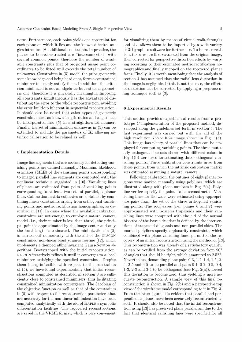
This section provides experimental results from a pro-totype C implementation of the proposed method, de-veloped along the guidelines set forth in section 5. Thefirst experiment was carried out with the aid of thehigh resolution 768 × 1024 image shown in Fig. 1(a).This image has plenty of parallel lines that can be em-ployed for computing vanishing points. The three mutu-ally orthogonal line sets shown with different colors inFig. 1(b) were used for estimating three orthogonal van-ishing points. Three calibration constraints arise fromthese points, from which the intrinsic calibration matrixwas estimated assuming a natural camera.
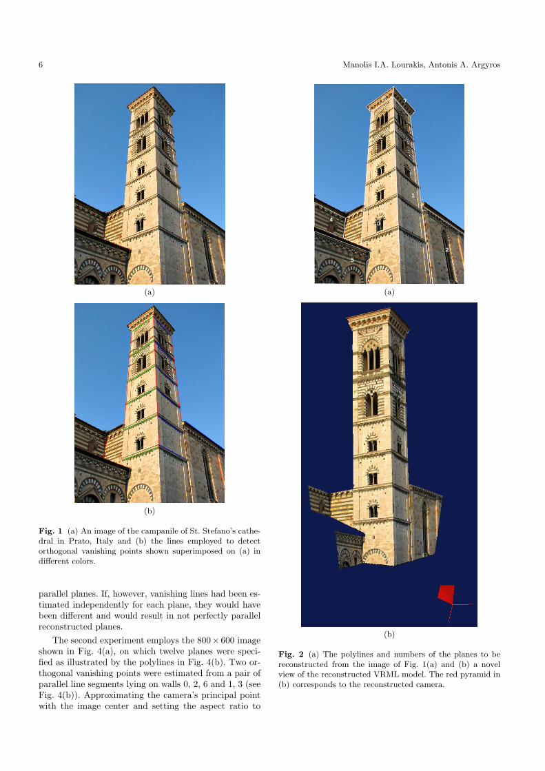
Following calibration, the outlines of eight planar re-gions were marked manually using polylines, which areillustrated along with plane numbers in Fig. 2(a). Poly-line vertices specify the points to be reconstructed. Van-ishing lines for the walls were estimated using appropri-ate pairs from the set of the three orthogonal vanish-ing points. The roof eaves (i.e., planes 6 and 7) wereapproximated with isosceles trapezoids and their van-ishing lines were computed with the aid of the normalbisector of the base sides that is defined by the intersec-tions of trapezoid diagonals and non-parallel sides. Themarked polylines specify coplanarity constraints, whichcombined with plane vanishing lines, permitted the re-covery of an initial reconstruction using the method of [13].This reconstruction was already of a satisfactory quality,as can be verified from the average deviation from 90◦
of angles that should be right, which amounted to 2.52◦.Nevertheless, demanding plane pairs 0-3, 1-2, 1-4, 1-5, 2-4, 2-5 and 4-5 to be parallel and pairs 0-1, 0-2, 0-5, 0-4,1-3, 2-3 and 3-4 to be orthogonal (see Fig. 2(a)), forcedthis deviation to become zero, thus yielding a more ac-curate reconstruction. A sample view of this final re-construction is shown in Fig. 2(b) and a perspective topview of the wireframe model corresponding to it in Fig. 3.From the latter figure, it is evident that parallel and per-pendicular planes have been accurately reconstructed assuch. It should also be noted that the initial reconstruc-tion using [13] has preserved plane parallelism due to thefact that identical vanishing lines were specified for all
6 Manolis I.A. Lourakis, Antonis A. Argyros
(a)
(b)
Fig. 1 (a) An image of the campanile of St. Stefano’s cathe-dral in Prato, Italy and (b) the lines employed to detectorthogonal vanishing points shown superimposed on (a) indifferent colors.
parallel planes. If, however, vanishing lines had been es-timated independently for each plane, they would havebeen different and would result in not perfectly parallelreconstructed planes.
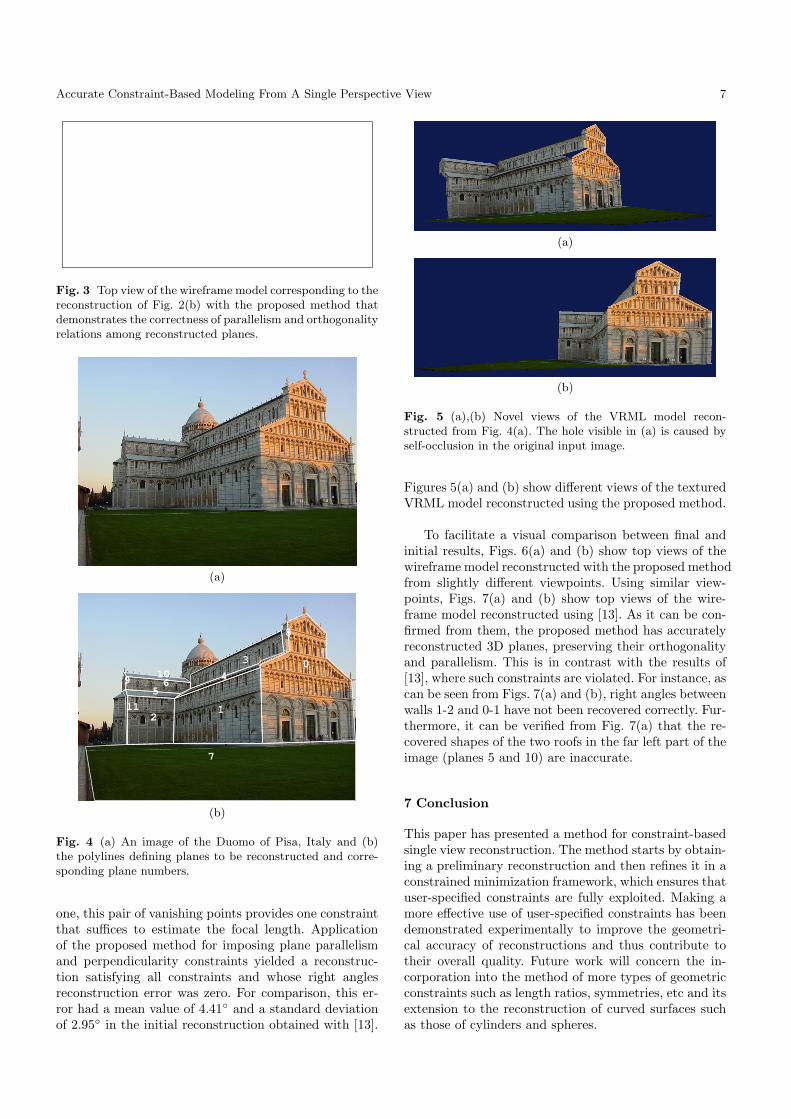
The second experiment employs the 800× 600 imageshown in Fig. 4(a), on which twelve planes were speci-fied as illustrated by the polylines in Fig. 4(b). Two or-thogonal vanishing points were estimated from a pair ofparallel line segments lying on walls 0, 2, 6 and 1, 3 (seeFig. 4(b)). Approximating the camera’s principal pointwith the image center and setting the aspect ratio to
0
1
2
34
5
6 7
(a)
(b)
Fig. 2 (a) The polylines and numbers of the planes to bereconstructed from the image of Fig. 1(a) and (b) a novelview of the reconstructed VRML model. The red pyramid in(b) corresponds to the reconstructed camera.
Accurate Constraint-Based Modeling From A Single Perspective View 7
Fig. 3 Top view of the wireframe model corresponding to thereconstruction of Fig. 2(b) with the proposed method thatdemonstrates the correctness of parallelism and orthogonalityrelations among reconstructed planes.
(a)
0
12
3
4
56
7
8
910
11
(b)
Fig. 4 (a) An image of the Duomo of Pisa, Italy and (b)the polylines defining planes to be reconstructed and corre-sponding plane numbers.
one, this pair of vanishing points provides one constraintthat suffices to estimate the focal length. Applicationof the proposed method for imposing plane parallelismand perpendicularity constraints yielded a reconstruc-tion satisfying all constraints and whose right anglesreconstruction error was zero. For comparison, this er-ror had a mean value of 4.41◦ and a standard deviationof 2.95◦ in the initial reconstruction obtained with [13].
(a)
(b)
Fig. 5 (a),(b) Novel views of the VRML model recon-structed from Fig. 4(a). The hole visible in (a) is caused byself-occlusion in the original input image.
Figures 5(a) and (b) show different views of the texturedVRML model reconstructed using the proposed method.
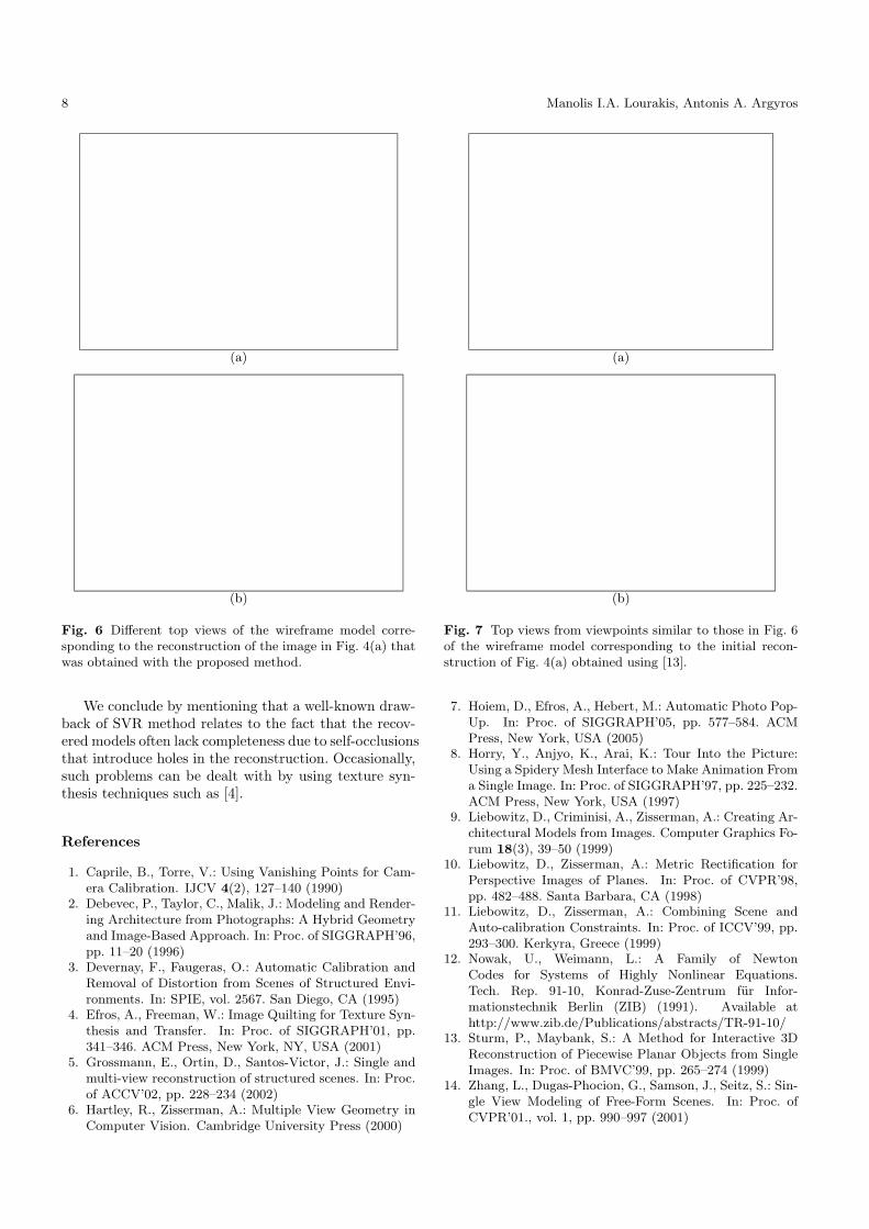
To facilitate a visual comparison between final andinitial results, Figs. 6(a) and (b) show top views of thewireframe model reconstructed with the proposed methodfrom slightly different viewpoints. Using similar view-points, Figs. 7(a) and (b) show top views of the wire-frame model reconstructed using [13]. As it can be con-firmed from them, the proposed method has accuratelyreconstructed 3D planes, preserving their orthogonalityand parallelism. This is in contrast with the results of[13], where such constraints are violated. For instance, ascan be seen from Figs. 7(a) and (b), right angles betweenwalls 1-2 and 0-1 have not been recovered correctly. Fur-thermore, it can be verified from Fig. 7(a) that the re-covered shapes of the two roofs in the far left part of theimage (planes 5 and 10) are inaccurate.
7 Conclusion
This paper has presented a method for constraint-basedsingle view reconstruction. The method starts by obtain-ing a preliminary reconstruction and then refines it in aconstrained minimization framework, which ensures thatuser-specified constraints are fully exploited. Making amore effective use of user-specified constraints has beendemonstrated experimentally to improve the geometri-cal accuracy of reconstructions and thus contribute totheir overall quality. Future work will concern the in-corporation into the method of more types of geometricconstraints such as length ratios, symmetries, etc and itsextension to the reconstruction of curved surfaces suchas those of cylinders and spheres.
8 Manolis I.A. Lourakis, Antonis A. Argyros
(a)
(b)
Fig. 6 Different top views of the wireframe model corre-sponding to the reconstruction of the image in Fig. 4(a) thatwas obtained with the proposed method.
We conclude by mentioning that a well-known draw-back of SVR method relates to the fact that the recov-ered models often lack completeness due to self-occlusionsthat introduce holes in the reconstruction. Occasionally,such problems can be dealt with by using texture syn-thesis techniques such as [4].
References
1. Caprile, B., Torre, V.: Using Vanishing Points for Cam-era Calibration. IJCV 4(2), 127–140 (1990)
2. Debevec, P., Taylor, C., Malik, J.: Modeling and Render-ing Architecture from Photographs: A Hybrid Geometryand Image-Based Approach. In: Proc. of SIGGRAPH’96,pp. 11–20 (1996)
3. Devernay, F., Faugeras, O.: Automatic Calibration andRemoval of Distortion from Scenes of Structured Envi-ronments. In: SPIE, vol. 2567. San Diego, CA (1995)
4. Efros, A., Freeman, W.: Image Quilting for Texture Syn-thesis and Transfer. In: Proc. of SIGGRAPH’01, pp.341–346. ACM Press, New York, NY, USA (2001)
5. Grossmann, E., Ortin, D., Santos-Victor, J.: Single andmulti-view reconstruction of structured scenes. In: Proc.of ACCV’02, pp. 228–234 (2002)
6. Hartley, R., Zisserman, A.: Multiple View Geometry inComputer Vision. Cambridge University Press (2000)
(a)
(b)
Fig. 7 Top views from viewpoints similar to those in Fig. 6of the wireframe model corresponding to the initial recon-struction of Fig. 4(a) obtained using [13].
7. Hoiem, D., Efros, A., Hebert, M.: Automatic Photo Pop-Up. In: Proc. of SIGGRAPH’05, pp. 577–584. ACMPress, New York, USA (2005)
8. Horry, Y., Anjyo, K., Arai, K.: Tour Into the Picture:Using a Spidery Mesh Interface to Make Animation Froma Single Image. In: Proc. of SIGGRAPH’97, pp. 225–232.ACM Press, New York, USA (1997)
9. Liebowitz, D., Criminisi, A., Zisserman, A.: Creating Ar-chitectural Models from Images. Computer Graphics Fo-rum 18(3), 39–50 (1999)
10. Liebowitz, D., Zisserman, A.: Metric Rectification forPerspective Images of Planes. In: Proc. of CVPR’98,pp. 482–488. Santa Barbara, CA (1998)
11. Liebowitz, D., Zisserman, A.: Combining Scene andAuto-calibration Constraints. In: Proc. of ICCV’99, pp.293–300. Kerkyra, Greece (1999)
12. Nowak, U., Weimann, L.: A Family of NewtonCodes for Systems of Highly Nonlinear Equations.Tech. Rep. 91-10, Konrad-Zuse-Zentrum fur Infor-mationstechnik Berlin (ZIB) (1991). Available athttp://www.zib.de/Publications/abstracts/TR-91-10/
13. Sturm, P., Maybank, S.: A Method for Interactive 3DReconstruction of Piecewise Planar Objects from SingleImages. In: Proc. of BMVC’99, pp. 265–274 (1999)
14. Zhang, L., Dugas-Phocion, G., Samson, J., Seitz, S.: Sin-gle View Modeling of Free-Form Scenes. In: Proc. ofCVPR’01., vol. 1, pp. 990–997 (2001)