emulsion sheet doublets as interface trackers for the opera experiment
TRANSCRIPT
2008 JINST 3 P07005
PUBLISHED BY INSTITUTE OFPHYSICS PUBLISHING AND SISSA
RECEIVED: April 12, 2008ACCEPTED: June 18, 2008PUBLISHED: July 17, 2008
Emulsion sheet doublets as interface trackers forthe OPERA experiment
A. Anokhina, w S. Aoki, q A. Ariga, y,∗ L. Arrabito, s D. Autiero, s A. Badertscher, al
F. Bay,a F. Bersani Greggio, ai A. Bertolin, ad M. Besnier, b D. Bick, n C. Bozza,ag
T. Brugiere, s R. Brugnera, ae G. Brunetti, h S. Buontempo, z E. Carrara, ae A. Cazes,k
L. Chaussard, s M. Chernyavsky, v V. Chiarella, k N. Chon-Sen, ah A. Chukanov, z
L. Consiglio, h M. Cozzi,h V. Cuha,a F. Dal Corso, ad G. D’Amato, ag N. D’Ambrosio, c
G. De Lellis, aa Y. Déclais, s M. De Serio, e F. Di Capua, z D. Di Ferdinando, g
A. Di Giovanni, r N. Di Marco, r C. Di Troia, k S. Dmitrievski, j A. Dominjon, s
M. Dracos, ah D. Duchesneau, b S. Dusini, ad J. Ebert, n O. Egorov, u R. Enikeev, t
A. Ereditato, f L.S. Esposito, c J. Favier, b G. Felici, k T. Ferber, n R. Fini, e D. Frekers, x
T. Fukuda, y V.I. Galkin, w V.A. Galkin, ac A. Garfagnini, ae G. Giacomelli, h M. Giorgini, h
C. Goellnitz, n J. Goldberg, m D. Golubkov, u Y. Gornushkin, j G. Grella, ag F. Grianti, ai
M. Guler, a G. Gusev, v C. Gustavino, c C. Hagner, n T. Hara,q M. Hierholzer, n
S. Hiramatsu, y K. Hoshino, y M. Ieva,e K. Jakovcic, ak J. Janicsko Csathy, ab
B. Janutta, n C. Jollet, ah F. Juget, ab T. Kawai, y M. Kazuyama, y S. H. Kim, o,1
J. Knuesel, f K. Kodama, p M. Komatsu, y U. Kose, a I. Kreslo, f I. Laktineh, s
C. Lazzaro, al J. Lenkeit, n A. Ljubicic, ak A. Longhin, ad G. Lutter, ab K. Manai, s
G. Mandrioli, g A. Marotta, z J. Marteau, s T. Matsuo, l H. Matsuoka, y N. Mauri, h
F. Meisel, ab A. Meregaglia, ah M. Messina, f P. Migliozzi, z S. Mikado, l ,2 S. Miyamoto, y
P. Monacelli, r K. Morishima, y U. Moser, f M.T. Muciaccia, d N. Naganawa, y T. Naka,y
M. Nakamura, y T. Nakamura, y T. Nakano, y V. Nikitina, w K. Niwa, y Y. Nonoyama, y
S. Ogawa, l V. Osedlo, w D. Ossetski, ac A. Paoloni, k B.D. Park, o I.G. Park,o A. Pastore, d
L. Patrizii, g E. Pennacchio, s H. Pessard, b V. Pilipenko, x C. Pistillo, f N. Polukhina, v
M. Pozzato, h K. Pretzl, f P. Publichenko, w F. Pupilli, r T. Roganova, w G. Rosa,a f
I. Rostovtseva, u A. Rubbia, al A. Russo, z O. Ryazhskaya, t D. Ryzhikov, ac O. Sato,y
Y. Sato,a j V. Saveliev, ac G. Sazhina, w A. Schembri, c L. Scotto Lavina, z H. Shibuya, l
S. Simone, d M. Sioli, h C. Sirignano, ag G. Sirri, g J. S. Song, o M. Spinetti, k L. Stanco, ad
N. Starkov, v M. Stipcevic, ak T. Strauss, al P. Strolin, aa V. Sugonyaev, ad Y. Taira,y
S. Takahashi, y M. Tenti, h F. Terranova, k I. Tezuka,a j V. Tioukov, z P. Tolun, a V. Tsarev, v
S. Tufanli, a N. Ushida, p P. Vilain, i M. Vladimirov, v L. Votano, k J.L. Vuilleumier, ab
G. Wilquet, i B. Wonsak, n C. S. Yoon, o J. Yoshida, y Y. Zaitsev, u S. Zemskova, j
A. Zghiche b and R. Zimmermann n
– 1 –

2008 JINST 3 P07005
a METU-Middle East Technical University, TR-06531 Ankara, Turkeyb LAPP, Université de Savoie, CNRS/IN2P3, 74941 Annecy-le-Vieux, Francec Laboratori Nazionali del Gran Sasso dell’INFN, 67010 Assergi (L’Aquila), Italyd Dipartimento di Fisica dell’Università di Bari and INFN, 70126 Bari, Italye INFN Sezione di Bari, 70126 Bari, Italyf University of Bern, CH-3012 Bern, Switzerlandg INFN Sezione di Bologna, I-40127 Bologna, Italyh Dipartimento di Fisica dell’Università di Bologna and INFN, I-40127 Bologna, Italyi IIHE-Inter-University Institute for High Energies, Université Libre de Bruxelles,B-1050 Brussels, Belgium
j JINR-Joint Institute for Nuclear Research, 141980 Dubna, Russiak Laboratori Nazionali di Frascati dell’INFN, 00044 Frascati (Roma), Italyl Toho University, 274-8510 Funabashi, Japan
m Department of Physics, Technion, 32000 Haifa, Israeln Hamburg University, 22043 Hamburg, Germanyo Gyeongsang National University, 900 Gazwa-dong, Jinju 660-300, Koreap Aichi University of Education, 448 Kariya (Aichi-Ken), Japanq Kobe University, 657 Kobe, Japanr Dipartimento di Fisica dell’Università dell’Aquila and INFN, Gr. Coll. L’Aquila, Italys IPNL, Université Claude Bernard Lyon 1, CNRS/IN2P3, 69622 Villeurbanne, Francet INR-Institute for Nuclear Research of the Russian Academy of Sciences,117312 Moscow, Russia
u ITEP-Institute for Theoretical and Experimental Physics,117259 Moscow, Russiav LPI-Lebedev Physical Institute of the Russian Academy of Sciences, 117924 Moscow, Russiaw SINP MSU-Skobeltsyn Institute of Nuclear Physics of MoscowState University,119992 Moscow, Russia
x University of Münster, 48149 Münster, Germanyy Nagoya University, 464-01 Nagoya, Japanz INFN Sezione di Napoli, 80125 Napoli, Italy
aa Dipartimento di Fisica dell’Università Federico II di Napoli and INFN, 80125 Napoli, Italyab Université de Neuchâtel, CH 2000 Neuchâtel, Switzerlandac Obninsk State University, Institute of Nuclear Power Engineering, 249020 Obninsk, Russiaad INFN Sezione di Padova, 35131 Padova, Italyae Dipartimento di Fisica dell’Università di Padova and INFN,35131 Padova, Italya f Dipartimento di Fisica dell’Università di Roma “La Sapienza" and INFN, 00185 Roma, Italyag Dipartimento di Fisica dell’Università di Salerno and INFN, 84084 Fisciano, Salerno, Italyah IPHC, Université Louis Pasteur, CNRS/IN2P3, 67037 Strasbourg, Franceai CSAAE - Universita’ di Urbino and Laboratori Nazionali di Frascati dell’INFNa j Utsunomiya University, 321-8505 Utsunomiya, Japanak IRB-Rudjer Boskovic Institute, 10002 Zagreb, Croatiaal ETH-Eidgenössische Technische Hochschulen Zürich, CH-8092 Zurich, Switzerland1 Now at Chonnam National University2 Now at Nihon UniversityE-mail: [email protected]
– 2 –
2008 JINST 3 P07005
ABSTRACT: New methods for efficient and unambiguous interconnectionbetween electronic po-sition sensitive detectors and target units based on nuclear photographic emulsion films have beendeveloped. The application to the OPERA experiment, that aims at detectingνµ ⇋ ντ oscillationsin the CNGS neutrino beam, is reported in this paper. In orderto reduce background due to latenttracks collected before installation in the detector, on-site large-scale treatments of the emulsions(“refreshing”) have been applied. Changeable Sheet (CSd) packages, each made of a doublet ofemulsion films, have been designed, assembled and coupled tothe OPERA target units (“ECCbricks”). A device has been built to print X-ray spots for accurate interconnection both within theCSd and between the CSd and the related ECC brick. Sample emulsion films have been exten-sively scanned with state-of-the-art automated optical microscopes. Efficient track-matching andpowerful background rejection have been achieved in tests with electronically tagged penetratingmuons. Further improvement of in-doublet film alignment wasobtained by matching the patternof low-energy electron tracks. The commissioning of the overall OPERA alignment procedure isin progress.
KEYWORDS: Particle tracking detectors; Detector design and construction technologies andmaterials; Large detector systems for particle and astroparticle physics; Detector alignment andcalibration methods (lasers, sources, particle-beams).
∗Corresponding author.
c© 2008 IOP Publishing Ltd and SISSA http://www.iop.org/EJ/jinst/

2008 JINST 3 P07005
Contents
1. Introduction 1
2. The OPERA experiment 2
3. Changeable Sheets for OPERA 3
4. Emulsion film handling and CSd production 44.1 Film background reduction 44.2 Overview of the CSd production 6
4.2.1 Refreshing apparatus 74.2.2 Packing 7
4.3 Performance 8
4.4 Production and quality control. 9
5. Alignment issues 115.1 Connection between TT and CSd 115.2 CSd film-to-film connection 12
5.2.1 Experimental results with X-ray fiducial marks 145.2.2 Experimental results with low energy electrons 15
5.3 Connection between CSd and ECC brick 15
6. Conclusions 16
1. Introduction
After decades of successful application in high-energy physics experiments, the nuclear photo-graphic emulsion technique is still attractive for its unique tracking accuracy. Owing to the evo-lution of fast automated optical microscope systems, it caneventually meet the challenge of ever-increasing scanning areas.
In fact, after the remarkable improvements of the techniquein the recent “hybrid” experi-ments1 CHORUS [1] at CERN and DONuT [2] at Fermilab, new challenges had to be taken up forthe OPERA project [3]. OPERA is searching for the appearanceof ντ in the CNGSνµ beam, a con-sequence of neutrino oscillation over the long distance separating the source at CERN, Switzerland,from the detector, in the Gran Sasso underground laboratorynear L’Aquila, Italy.
1i.e. electronic position sensitive counters to tag and locate neutrino interactions, coupled to a pure emulsion targetor to a sandwich metal-emulsion (“ECC”) target to select rare topologies.
– 1 –
2008 JINST 3 P07005
In this paper we report the design of interface emulsion film doublets called Changeable Sheets(CSd), suitable for the OPERA purposes, their implementation and the initial performance. Thebasic concepts of the OPERA experiment are recalled in section 2 with a brief overview of theexperimental apparatus and of its basic target units, the so-called ECC bricks. The motivationsto insert CSd units and the strategy for their exploitation are outlined in section 3. The detailsof the large-scale film handling, the CSd packing and initialperformance is reported in section 4.The alignment methods exploited in experimental tests performed during the commissioning runin 2007 are scrutinized in section 5. Conclusions and outlook are presented in section 6.
2. The OPERA experiment
The OPERA experiment [3] has been designed to directly validate the flavor-mixing neutrino os-cillation model that explains the disappearance ofνµ in atmospheric neutrino experiments [4 – 6]and in accelerator experiments [7, 8]. For this purpose the appearance ofντ in a pureνµ beam at along distance from the neutrino source is searched for. The distinctive feature ofντ charged-currentinteractions is the production of a short-livedτ lepton (cτ =87 µm). Thus, one has to accomplishthe very difficult task of detecting sub-millimeterτ decay topologies out of the huge backgroundof νµ interactions in a target of several kilotons. This is achieved in OPERA using the nuclearemulsion technique that features an unrivaled spatial resolution (≤ 1 µm). The same method wasadopted in the DONuT experiment to achieve the first observation of theντ [2].
Theνµ source is the wide-band CNGS neutrino beam [9] with mean energy 〈Eν〉 = 17 GeVtraveling 730 km through the earth from CERN to the underground Laboratori Nazionali del GranSasso (LNGS) where the OPERA detector is placed. In 5 years ofCNGS run about 25,000 neu-trino interactions will be collected by OPERA, out of which about 12 identifiedντ charge currentinteractions are expected with a background of less than 1. This number of events is estimated atthe nominal value of the oscillation parameter∆m2 = 2.5×10⁻³ eV2 and full mixing [4].
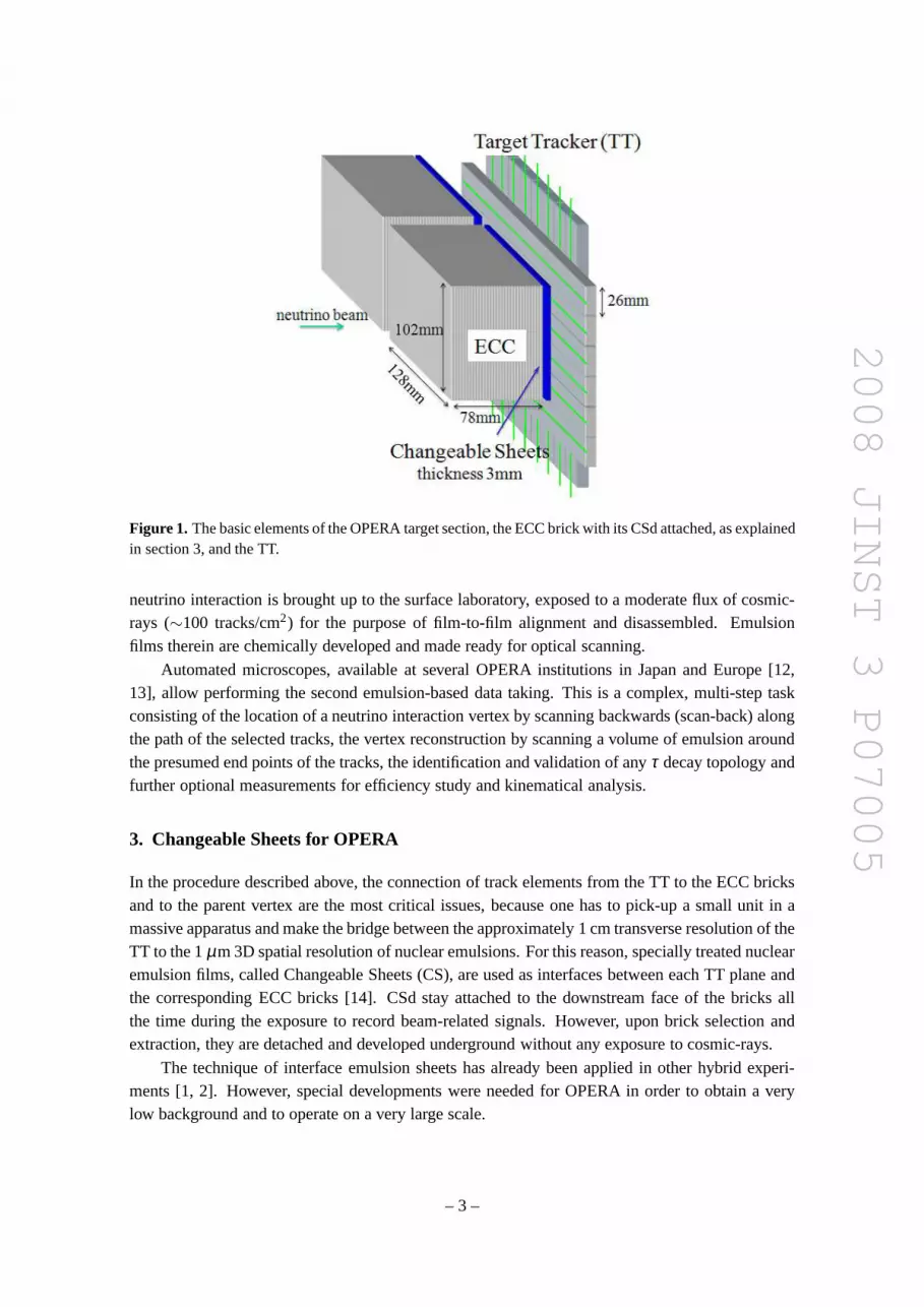
OPERA is a large detector (10 m× 10 m× 20 m) placed in the underground LNGS HallC [10]. It consists of two identical super-modules aligned along the CNGS beam direction, eachmade of a target section and a muon spectrometer. Each targetsection consists of a multi-layerarray of 29 target walls interleaved with pairs of planes of plastic scintillator strips. Each planeconsists of 256 6.3-m long strips of 26.4 mm× 10 mm cross-section and measures one of the twotransverse coordinates. This constitutes the Target Tracker (TT) [11]. A target wall is an assemblyof horizontal trays each loaded with Emulsion Cloud Chambertarget units called ECC bricks.Each brick consists of 57 emulsion films interleaved by 56 Pb plates, 1 mm thick, tightly packedand safe-light secured. It has 128 mm× 102 mm× 79 mm outer dimensions and weighs 8.3 kg.Interface emulsion detectors (CSd) are attached to the downstream face of each brick. There aremore than 150,000 bricks in total for a target mass of 1.35 kilotons. The modular structure of theOPERA target section is sketched in figure 1.
During the exposure to the CNGS beam, data taking, emulsion scanning and analysis arerequired to progress in parallel. Event-by-event, first of all hit reconstruction andµ tagging areperformed based on triggered electronic signals in the TT and the muon spectrometers. Then,one or more selected bricks, candidates to contain the latent image of a neutrino interaction, areextracted from the apparatus. The corresponding CSd is firstscanned. The brick which contains
– 2 –
2008 JINST 3 P07005
Figure 1. The basic elements of the OPERA target section, the ECC brickwith its CSd attached, as explainedin section 3, and the TT.
neutrino interaction is brought up to the surface laboratory, exposed to a moderate flux of cosmic-rays (∼100 tracks/cm2) for the purpose of film-to-film alignment and disassembled.Emulsionfilms therein are chemically developed and made ready for optical scanning.
Automated microscopes, available at several OPERA institutions in Japan and Europe [12,13], allow performing the second emulsion-based data taking. This is a complex, multi-step taskconsisting of the location of a neutrino interaction vertexby scanning backwards (scan-back) alongthe path of the selected tracks, the vertex reconstruction by scanning a volume of emulsion aroundthe presumed end points of the tracks, the identification andvalidation of anyτ decay topology andfurther optional measurements for efficiency study and kinematical analysis.
3. Changeable Sheets for OPERA
In the procedure described above, the connection of track elements from the TT to the ECC bricksand to the parent vertex are the most critical issues, because one has to pick-up a small unit in amassive apparatus and make the bridge between the approximately 1 cm transverse resolution of theTT to the 1µm 3D spatial resolution of nuclear emulsions. For this reason, specially treated nuclearemulsion films, called Changeable Sheets (CS), are used as interfaces between each TT plane andthe corresponding ECC bricks [14]. CSd stay attached to the downstream face of the bricks allthe time during the exposure to record beam-related signals. However, upon brick selection andextraction, they are detached and developed underground without any exposure to cosmic-rays.
The technique of interface emulsion sheets has already beenapplied in other hybrid experi-ments [1, 2]. However, special developments were needed forOPERA in order to obtain a verylow background and to operate on a very large scale.
– 3 –

2008 JINST 3 P07005
The CS play two major roles. The first one is to confirm that the ECC brick which containsthe neutrino interaction vertex is the one pointed to by the TT reconstruction. The second one is toprovide the neutrino-related tracks for the ECC brick scan-back analysis.
Brick confirmation is required in the OPERA analysis given the resolution of the TT and theconsequent sizable probability to misidentify the ECC brick (e.g.∼30% for ντ charged-currentinteractions). The information obtained after the CS scanning is highly beneficial to avoid uselessfilm handling and processing of the misidentified bricks and minimize the corresponding waste oftarget mass, also to avoid useless scanning overload of the ECC bricks. Thanks to the CS the brickswrongly identified by the TT are not dismantled but put back inthe target with a fresh CS attachedto them. Moreover, where the TT reconstruction is compatible with two or more bricks, these areordered by probability and their CS are scrutinized accordingly. This significantly increases theevent finding efficiency.
As described in the previous section, the ECC brick is exposed to cosmic-rays. Consequently,there will be a few tracks in the brick related to the neutrinointeraction and a large number ofcosmic-ray tracks (∼10,000 tracks/brick). The CS provides a clear identification of the neutrino-related tracks to be searched in the most downstream film of the corresponding ECC brick as aclean start-up of the scan-back procedure aiming at vertex location. In order to recognize genuineneutrino-related tracks and allow brick confirmation, the background in the CS must be suppresseddown to extremely low levels.
The final choice of CS geometry for OPERA has been to assemble two adjacent emulsionfilms as adoublet (CSd), coupled as an independent, detachable package to thedownstream faceof an ECC brick as shown in figure 2. A film has two emulsion layers. The requirement of acoincidence between two emulsion films (more than any of 3 recognized track segments out of4 measured layers) results in a strong background reductionand a high tracking efficiency. Theoverall configuration of a brick unit and a schematic illustration of the OPERA scan-back methodfor event location is shown in figure 3.
Since the background level is due to single-film track density and their fake coincidences,keeping it low requires: a) to reduce the single-film physicsbackground due to the continuoussensitivity of the emulsion films;2 b) to pack very precisely the two films in a doublet; c) to exploitextremely accurate alignment tools and methods. What is especially challenging with OPERA isto do this on a very large scale for 150,000 bricks.
4. Emulsion film handling and CSd production
4.1 Film background reduction
Custom emulsion films jointly developed by the Nagoya University group and Fuji Film Corpora-tion, calledOPERA films[15], are employed both for ECC bricks and CS. Mass-producible OPERAfilms consist of two 44µm thick emulsion layers sensitive to minimum ionizing particles placedon both sides of 205µm thick plastic base. Their size is (12.46 ± 0.04) cm× (9.90 ± 0.02) cmat 40% relative humidity (RH).3 Film composition (small, regular, finely dispersed sensitive AgBr
2All the time from the film production till the chemical development, any ionizing radiation induces persistent pho-tographic recording of latent tracks.
3The expansion factor as a function of RH is 1.4×10⁻⁴%.
– 4 –

2008 JINST 3 P07005
Figure 2. The schematic drawing of the CS doublet. Two double-side emulsion films (OPERA films) areadjacently coupled.
Figure 3. Schematics of the CS - Scan-back method. Only the CSd tracks are intended for the neutrinovertex location analysis (∼4 tracks/event), although there are a lot of cosmic-ray tracks in the ECC brick(10,000 tracks/ECC brick).
crystals) and geometry allow in principle a position resolution of 0.05µm and an angular resolutionof 0.4 mrad [16].
A procedure to erase to a large extent any previously recorded latent-image track due to ion-
– 5 –

2008 JINST 3 P07005
Table 1. Track density on single CSd emulsion films. Scanning was doneby the UTS automated scanningsystem at the Nagoya University in a standard configuration (95% detection efficiency for 10 GeVπ− beamtracks). Only tracks recognized on both emulsion layers areaccounted for. Tracks were topologicallyclassified as due to cosmic-rays (very straight penetratingtracks) or radioactivity.
Track density [tracks/cm2]Total Cosmic-ray Radioactivity
Non-Refreshed 1410±125 870±95 540±80Refreshed 76±9 37±6 39±6
ization was developed for the OPERA films. Such amemory resetcalled “refresh” is obtainedby keeping the films at high humidity (95-99% RH) and high temperature (25-30◦C) for a fewdays [15].
Films produced for the OPERA experiment in the Fuji facilityin Japan were first transported tothe Tono Refresh Facility (Gifu, Japan) to erase the cosmic-ray tracks earlier accumulated. Here thetrack density is reduced from 5,000 tracks/cm2 to≤ 100 tracks/cm2. Afterwards, the refreshed filmstemporary vacuum-packed as brick-wise slots were shipped to LNGS. Hence, additional cosmic-ray tracks (∼1400 tracks/cm2) was accumulated during the 1 month journey from Japan to Italy.In the case of the ECC bricks, such cosmic-ray tracks are not backgrounds. Since the films aregrouped into each 57 films (i.e. a group of films for a brick) during the journey and also the orderof films is definitely kept in the ECC brick assembling processat LNGS, all the cosmic-ray trackscan be reconstructed and rejected by analysing scanning data on the assumption that the films arenot interleaved with lead plates, called “Virtual erasing”.
For the CSd, the two films are assembled at random and disassembled underground at theLNGS where the cosmic-ray flux is very low. Thus, the residualbackground is mainly due toaccidental coincidences between early tracks on each film. They could still spoil the required un-ambiguous ECC brick confirmation because they compete with the average flux of beam-relatedtracks expected to be extremely small (e.g. inντ charged-current interactions about 4 tracks areexpected), although the scanning area of the CSd is extremely large (∼100 cm2). Thus, the back-ground density must be kept well below 10−3 tracks/cm2 for |tanθ | < 0.5 rad withθ being theangle with respect to the normal to the film plane. This requirement is much stronger than that inthe ECC films (100 tracks/cm2).
AsNBackground∝ (Single f ilm track density)2× (Alignment accuracy)2 (4.1)
constraints are very demanding on both factors.In order to reduce the track density in the emulsion films, a second refreshing is performed
underground at LNGS to erase tracks accumulated during transportation, since the Virtual erasingmethod is not available for the CSd films. Observed track densities before and after this processare listed in table 1. The single-film track density after refreshing is below 100 tracks/cm2.
4.2 Overview of the CSd production
The CSd film handling, production and development are hostedin a specially designed facilitysituated in the underground Hall-B of LNGS. The production facility arranged to produce 1,000
– 6 –

2008 JINST 3 P07005
Figure 4. A schematic drawing of the refresh chamber and the trays.
CSd/day is partitioned in three rooms. The first two are safe-light darkrooms assigned to refreshingand packing. The last steps (envelope folding and insertionin a rigid plastic box) are performed inthe third room. Five operators may simultaneously work in this facility.
4.2.1 Refreshing apparatus
In the refreshing room there are two refresh chambers. Each chamber (figure 4)∼ 1 m× 1 m× 2 m,contains 760 trays. Each tray contains 9 films. In total 6840 films are processed at the same time.The component in front of the chamber is a two-fan humidifier which provides humidity throughwet paper filters. Demineralized water is used. The air flows from right to left inside the chamber.The ducts have tapered structures to provide uniform ventilation. The air flow can be in open circuit(air from outside, evacuated outside) or in closed circuit (air circulation without exchange).
The air in the refreshing room is kept at 26-27◦C and 40% RH. A refreshing cycle takes oneweek. The sequence is the following: open circuit mode at≥85% RH for one day, close circuitmode at≃98% RH for three days, slow-dry mode from 98% to 60% RH for one day, complete-drymode down to 40% RH for one day (open circuit).
4.2.2 Packing
The two emulsion films of a CSd are packed together by using an aluminum-laminated tissue. Thestructure of the laminated tissue is (from outside to inside): /Nylon 15 µm/ Polyethylene 13µm/Aluminum 7 µm/ Polyethylene 13µm/ Carbon-mixed-polyethylene 35µm/. The light tightnessis provided by the aluminum layer and by the Carbon-mixed-polyethylene layer. The mechanicalstrength is given by the nylon layer. The laminated tissue isshaped as an envelope. The CSd istemporarily vacuum packed. Sealing is done by welding the polyethylene. The welded parts (three
– 7 –
2008 JINST 3 P07005
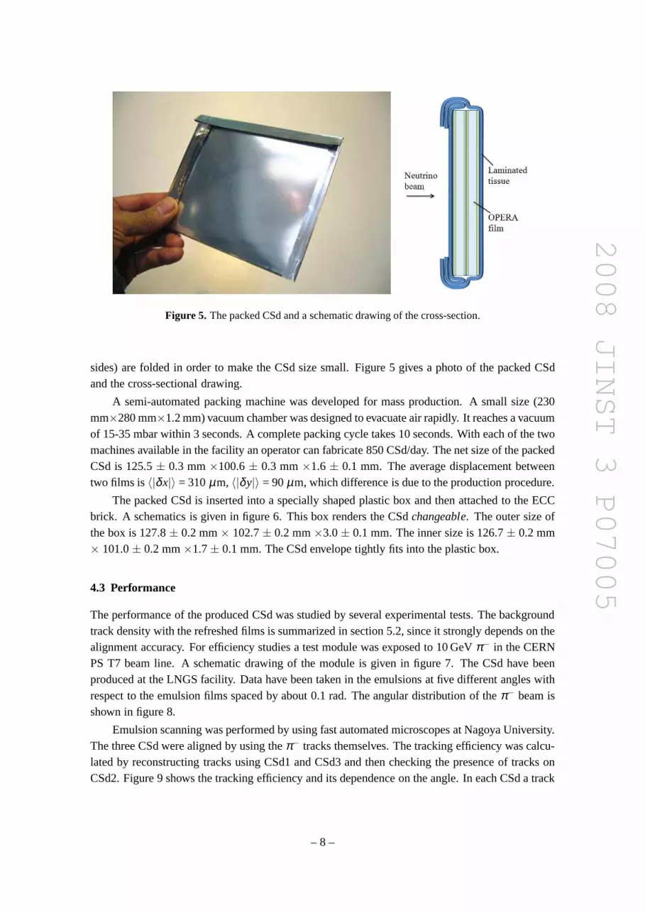
Figure 5. The packed CSd and a schematic drawing of the cross-section.
sides) are folded in order to make the CSd size small. Figure 5gives a photo of the packed CSdand the cross-sectional drawing.
A semi-automated packing machine was developed for mass production. A small size (230mm×280 mm×1.2 mm) vacuum chamber was designed to evacuate air rapidly.It reaches a vacuumof 15-35 mbar within 3 seconds. A complete packing cycle takes 10 seconds. With each of the twomachines available in the facility an operator can fabricate 850 CSd/day. The net size of the packedCSd is 125.5± 0.3 mm×100.6± 0.3 mm×1.6± 0.1 mm. The average displacement betweentwo films is〈|δx|〉 = 310µm, 〈|δy|〉 = 90µm, which difference is due to the production procedure.
The packed CSd is inserted into a specially shaped plastic box and then attached to the ECCbrick. A schematics is given in figure 6. This box renders the CSdchangeable. The outer size ofthe box is 127.8± 0.2 mm× 102.7± 0.2 mm×3.0± 0.1 mm. The inner size is 126.7± 0.2 mm× 101.0± 0.2 mm×1.7± 0.1 mm. The CSd envelope tightly fits into the plastic box.
4.3 Performance
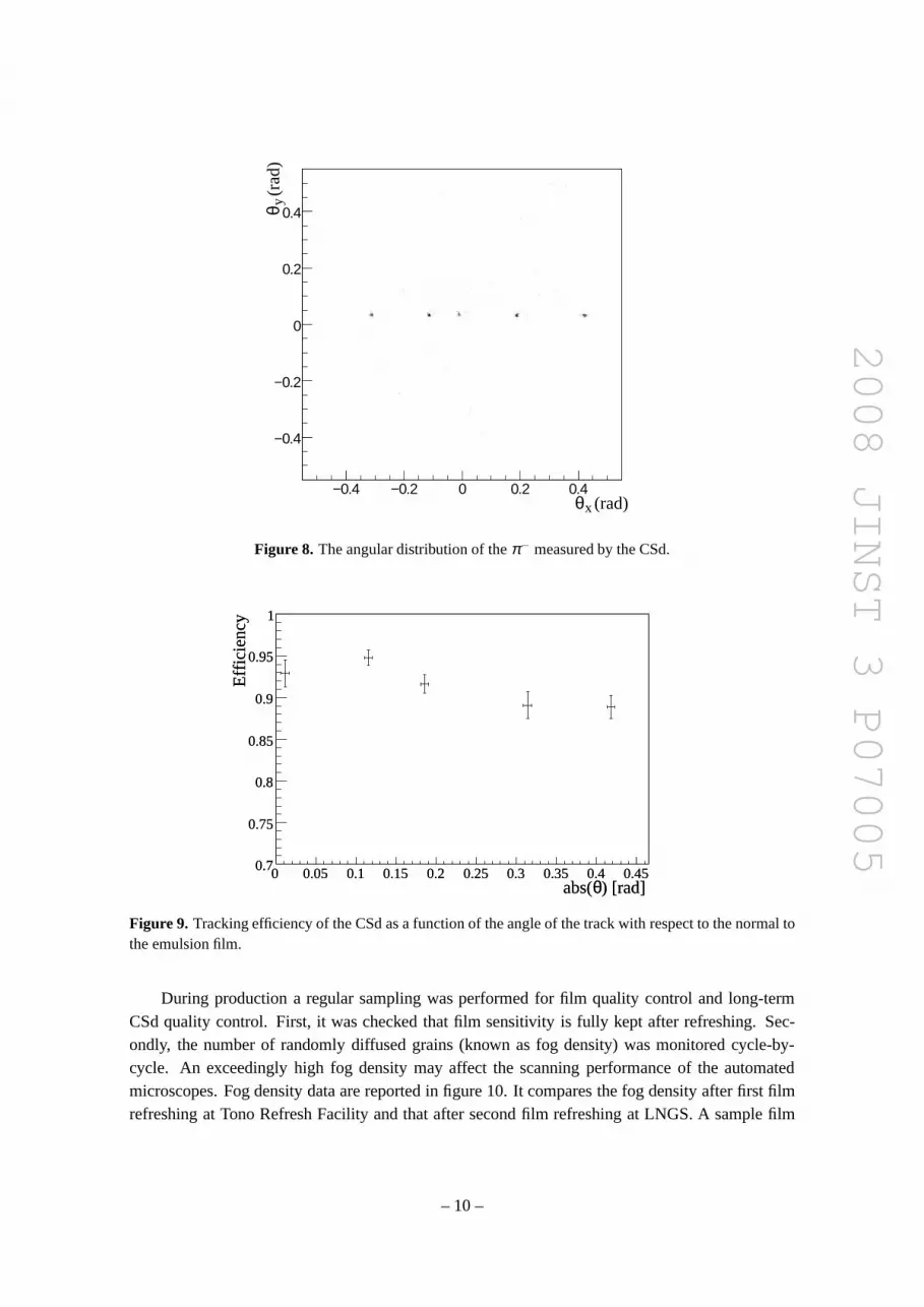
The performance of the produced CSd was studied by several experimental tests. The backgroundtrack density with the refreshed films is summarized in section 5.2, since it strongly depends on thealignment accuracy. For efficiency studies a test module wasexposed to 10 GeVπ− in the CERNPS T7 beam line. A schematic drawing of the module is given in figure 7. The CSd have beenproduced at the LNGS facility. Data have been taken in the emulsions at five different angles withrespect to the emulsion films spaced by about 0.1 rad. The angular distribution of theπ− beam isshown in figure 8.
Emulsion scanning was performed by using fast automated microscopes at Nagoya University.The three CSd were aligned by using theπ− tracks themselves. The tracking efficiency was calcu-lated by reconstructing tracks using CSd1 and CSd3 and then checking the presence of tracks onCSd2. Figure 9 shows the tracking efficiency and its dependence on the angle. In each CSd a track
– 8 –

2008 JINST 3 P07005
Figure 6. Mounting the CSd on the ECC brick.
Figure 7. A schematic drawing of the module exposed at CERN. The tracking efficiency of the CSd wasevaluated by checking the presence in CSd2 of tracks reconstructed using CSd1 and CSd3.
is defined by a coincidence of four track segments in the four emulsion layers. A good trackingefficiency of more than 90% for small angle is found.
A method to require a coincidence of any of three track segments in the four emulsion layersrecovers the rest of efficiency. This method is under development, however, some applications canbe found in section 5.
4.4 Production and quality control.
The production of the CSd for the OPERA experiment has started on November 2006 and it ispresently going on (Apr 2008).
– 9 –
2008 JINST 3 P07005
(rad)xθ−0.4 −0.2 0 0.2 0.4
(ra
d)yθ
−0.4
−0.2
0
0.2
0.4
Figure 8. The angular distribution of theπ− measured by the CSd.
) [rad] θabs(0 0.05 0.1 0.15 0.2 0.25 0.3 0.35 0.4 0.45
Effi
cien
cy
0.7
0.75
0.8
0.85
0.9
0.95
1
) [rad] θabs(0 0.05 0.1 0.15 0.2 0.25 0.3 0.35 0.4 0.45
Effi
cien
cy
0.7
0.75
0.8
0.85
0.9
0.95
1
Figure 9. Tracking efficiency of the CSd as a function of the angle of thetrack with respect to the normal tothe emulsion film.
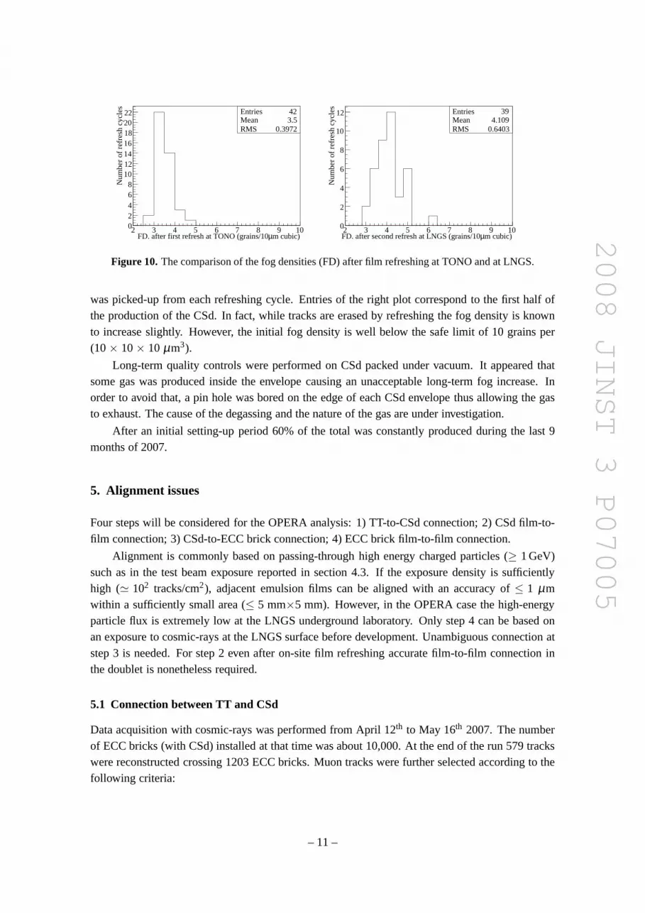
During production a regular sampling was performed for film quality control and long-termCSd quality control. First, it was checked that film sensitivity is fully kept after refreshing. Sec-ondly, the number of randomly diffused grains (known as fog density) was monitored cycle-by-cycle. An exceedingly high fog density may affect the scanning performance of the automatedmicroscopes. Fog density data are reported in figure 10. It compares the fog density after first filmrefreshing at Tono Refresh Facility and that after second film refreshing at LNGS. A sample film
– 10 –
2008 JINST 3 P07005
m cubic)µFD. after first refresh at TONO (grains/102 3 4 5 6 7 8 9 10
Num
ber
of r
efre
sh c
ycle
s
02468
10121416182022 Entries 42
Mean 3.5RMS 0.3972
m cubic)µFD. after second refresh at LNGS (grains/102 3 4 5 6 7 8 9 10
Num
ber
of r
efre
sh c
ycle
s
0
2
4
6
8
10
12 Entries 39Mean 4.109RMS 0.6403
Figure 10. The comparison of the fog densities (FD) after film refreshing at TONO and at LNGS.
was picked-up from each refreshing cycle. Entries of the right plot correspond to the first half ofthe production of the CSd. In fact, while tracks are erased byrefreshing the fog density is knownto increase slightly. However, the initial fog density is well below the safe limit of 10 grains per(10× 10× 10 µm3).
Long-term quality controls were performed on CSd packed under vacuum. It appeared thatsome gas was produced inside the envelope causing an unacceptable long-term fog increase. Inorder to avoid that, a pin hole was bored on the edge of each CSdenvelope thus allowing the gasto exhaust. The cause of the degassing and the nature of the gas are under investigation.
After an initial setting-up period 60% of the total was constantly produced during the last 9months of 2007.
5. Alignment issues
Four steps will be considered for the OPERA analysis: 1) TT-to-CSd connection; 2) CSd film-to-film connection; 3) CSd-to-ECC brick connection; 4) ECC brick film-to-film connection.
Alignment is commonly based on passing-through high energycharged particles (≥ 1 GeV)such as in the test beam exposure reported in section 4.3. If the exposure density is sufficientlyhigh (≃ 102 tracks/cm2), adjacent emulsion films can be aligned with an accuracy of≤ 1 µmwithin a sufficiently small area (≤ 5 mm×5 mm). However, in the OPERA case the high-energyparticle flux is extremely low at the LNGS underground laboratory. Only step 4 can be based onan exposure to cosmic-rays at the LNGS surface before development. Unambiguous connection atstep 3 is needed. For step 2 even after on-site film refreshingaccurate film-to-film connection inthe doublet is nonetheless required.
5.1 Connection between TT and CSd
Data acquisition with cosmic-rays was performed from April12th to May 16th 2007. The numberof ECC bricks (with CSd) installed at that time was about 10,000. At the end of the run 579 trackswere reconstructed crossing 1203 ECC bricks. Muon tracks were further selected according to thefollowing criteria:
– 11 –
2008 JINST 3 P07005
• A slope smaller than 0.550 rad with respect to the z axis, the horizontal projection of the beamdirection, to which the emulsion films are orthogonal. The automatic scanning systems havemaximum efficiency for tracks perpendicular to the emulsionfilms, i.e. close to the beamdirection. Most of cosmic-ray tracks are useless, being nearly vertical. The smallest slopewith respect to the z axis in the sample was 0.350 rad.
• A minimum number of 28 hits in the TT in order to have a long and clean track.
• A reconstructed impact point at more than 1 cm from the emulsion film edge to ensure thatthe prediction falls in the CSd fiducial area.4
30 bricks were selected corresponding to 21 events, since a cosmic-ray muon can cross morethan one brick. The bricks were extracted, X-ray marked as explained later and the associatedCSd was developed in the underground CS facility. The scanning was performed at the ScanningStation at LNGS with the European Scanning System [13]. An area of 5×3 cm2 centered aroundthe prediction was measured on both films. For each CSd film, track segments (hereafter calledmicro-tracks) were measured in each of the two emulsion layers. Then, two micro-tracks on bothsides of the film plastic base were associated to form a line (hereafter called base-track) by usingthe points where each of the two micro-tracks intercept the nearest surface of the plastic base.Contrary to the micro-track the slope of a base-track is largely unaffected by distortions causedto the emulsion layer during film processing. A CSd track candidate is defined by the matchingof either both base-tracks, thus all 4 micro-tracks, or a base-track and a single micro-track, thus 3micro-tracks. 28 muon track candidates out of 30 predictions were located in the CSd scanning.Out of those, 23 had all 4 micro-tracks found. Figure 11 showsthe distributions of the position andangular residuals of the emulsion measurement with respectto the TT reconstruction for both Xand Y transverse projections.
5.2 CSd film-to-film connection
The film-to-film-connection inside the CSd is a key alignmentissue to reduce the CSd background(eq. 4.1). It has been performed by two different methods andwas experimentally tested by usingthe samples of events from CNGS commissioning runs in 2007.
The first method is based on circular X-ray marks of about 100µm diameter printed on thefour corners, penetrating both emulsion films in the CSd and the most downstream film of the ECCbrick. This provides a common, accurate reference frame forscanning of those 3 films.
A custom system for X-ray marking of emulsion has been realized (figure 12). It is basedon a small X-ray generator capable to produce a beam in the range 50 kV to 80 kV with a 0.1 to2s duration. The beam is collimated through a 100-µm hole in a 3-mm thick lead shield. A spotobserved in the emulsion is shown in figure 13. Accurate positioning of ≃ 5µm on both axes ofthe brick with respect to the collimated beam is obtained using a motorized stage. A safe lead boxshielding hosts the system. An user-friendly software interface was developed to allow the operatorto move the bricks and control the shutter of the X-ray generator. The complete sequence to printthe 4 X-ray spots can be done in a fully automatic mode with on-line safety sensor checks.
4There is a few mm space between a CSd and the neighbor CSd.
– 12 –

2008 JINST 3 P07005
Figure 11. Distributions of the position and angular residuals of the emulsion measurements with respect tothe TT reconstruction.
Figure 12. Schematic view of the X-ray system.
However, for films in contact, the accuracy of the X-ray mark method is limited by any localdeformations of the emulsion films that could amount to about1 µm/cm. Thus, the tolerance forposition displacement is limited to about 30µm on the whole surface of films.
Another method based on the use of sub-MeV electron tracks from natural radioactive sourceswas recently proposed [17]. With this method more accurate local alignment parameters can beassured and the position tolerance can be reduced to≃ 10 µm. The potentialities of both methodsfor the purpose of reducing the combinatorial background are shown in table 2. Application toreal-case neutrino events is in progress.
– 13 –

2008 JINST 3 P07005
Figure 13. X-ray spot on an emulsion sheet (∼100µm).
Table 2. The alignment accuracy and the estimated background from accidental coincidence between twoemulsion films in a CSd (125 cm2). The estimation is done on the assumption that the track density on singlefilms is 100 tracks/cm2 and that the angular tolerance between two emulsion films is 10 mrad.
Method X-ray mark Sub-MeV electron
Position tolerance 30µm 10µmAccidental coincidence BG 0.018 track/CSd 0.002 track/CSd
m) µx (∆-30 -20 -10 0 10 20 30
Num
ber
of tr
acks
0
2
4
6
8
10
12
Entries 28
/ ndf 2χ 1.5 / 3
Constant 3.0± 12
Mean 1.3± 2.5
Sigma 1.0± 6.3
(mrad) θ∆-40 -30 -20 -10 0 10 20 30 40
Num
ber
of tr
acks
0
2
4
6
8
10
Entries 28
/ ndf 2χ 0.52 / 2
Constant 2.8± 9.6
Mean 1.3± 1.9
Sigma 1.3± 5.8
Figure 14. Distributions of the position and angular residuals between CSd emulsion films. For angularresiduals open boxes refer to tracks formed by two base-tracks while filled boxes refer to tracks formed by abase-track and a single micro-track.
5.2.1 Experimental results with X-ray fiducial marks
Results on alignment based on the X-ray mark method are shownin figure 14. As track slopesare large the angular resolution is worse than what is anticipated for tracks from neutrino interac-tions. In the plot relative to the angular residuals the entries referring to 3-micro-track candidatesare marked since the angular resolution is substantially worse for micro-tracks compared to base-tracks. The 3-micro-track candidates contribute, as expected, to the distribution tails.
The width of the position residuals distribution is attributed, as discussed above, to local de-
– 14 –

2008 JINST 3 P07005
m) µx (∆-5 0 5 10 15 20 25
Num
ber
of tr
acks
0
1
2
3
4
5
6
7
8
9
Entries 32 / ndf 2χ 2.9 / 6
Constant 1.9± 7.3 Mean 0.3± 8.6 Sigma 0.3± 1.6
m) µy (∆-10 -5 0 5 10 15
Num
ber
of tr
acks
0
2
4
6
8
10
12
14
16
Entries 32 / ndf 2χ 3.1 / 2
Constant 6.5± 16 Mean 0.8± 2.9 Sigma 0.8± 2.2
Figure 15. Distributions of the position residuals between CSd emulsion films. The entries refer to tracksrelated to a single neutrino event.
formations of the films. To illustrate this effect, data froma single, high-multiplicity neutrinointeraction that occurred during the beam commissioning run from October 2007 were analyzed.As many as 34 secondary tracks were detected as CSd coincidences. Among those tracks 32 wereselected as impinging on the CSd within a rather limited areaof the order of 1 cm2. Figure 15shows the distributions of the position residuals between the two films of the same CSd. The posi-tion offset is a measurement of a local discrepancy with respect to the X-ray mark reference systemwhile the standard deviation is approaching the emulsion intrinsic resolution.
5.2.2 Experimental results with low energy electrons
The local offset resulting from the global X-ray alignment which has been exemplified in the pre-vious section can be measured by using a local alignment method based on low-energy electrontracks crossing both films. This method was applied to all CSdextracted during the beam commis-sioning runs in 2007. A nearly full area scan of 115 mm× 90 mm was performed at the NagoyaUniversity with the S-UTS system [12]. The scanning area wasdivided into cells of 5 mm×5 mm.The two films were first aligned by the X-ray mark and then the local offsets were calculated foreach cell with low-energy electrons. Figure 16 shows the global map of the offsets on one CSd.The arrows and their gradients demonstrate a relative deformation of the films induced by the dif-ference of the strain before and after the processing and by the stress due to the setting of films onthe microscope stages.
The process was applied to 59 CSd. The fraction of the area where the tracks were successfullyaligned is estimated for each CSd and its distribution is given in figure 17. The local alignment withlow energy electrons is most often successful.
Figure 18 shows the distribution of the position residuals between emulsion films after thecorrection for the local offsets. A clear improvement in theposition displacement is obtainedcompared to the X-ray mark method.
5.3 Connection between CSd and ECC brick
The X-ray marks allow aligning the CSd with the most downstream film of the corresponding ECCbrick. An alignment accuracy of∼ 100 µm and of∼ 20 mrad has been obtained, as shown in
– 15 –

2008 JINST 3 P07005
0
20
40
60
80
100
0 20 40 60 80 100 120X mm
Y m
m
Figure 16. Local alignment parameters as a vector map for all cells. Thethick line represents the edge ofthe CS.
0
10
20
30
40
50
0.5 0.6 0.7 0.8 0.9 1
Entries 59
Area fraction
Nu
mb
er
of C
Sd
Figure 17. The distribution of the film surface fraction successfully aligned locally with low energy elec-trons.
figure 19. Distributions of the position and angular residuals of high energy cosmic-ray tracksmeasured in the CSd and in the most downstream emulsion film ofthe ECC brick are shown.Understanding of systematics (e.g. CSd planarity, actual distance between the CSd and the last filmof a brick, etc.) that alter the alignment accuracy is in progress. More information will be providedby the on-going study of the neutrino events collected in theneutrino run of 2007.
6. Conclusions
An interface nuclear emulsion detector allowing for very low background detection of ionizingtracks has been realized for the purposes of the OPERA experiment. It is made of a doublet ofemulsion films called CSd. The CSd play the central role of being the interface between the elec-tronic position sensitive detectors and the ECC bricks thatconstitute the target.
– 16 –

2008 JINST 3 P07005
m)µy (∆x, ∆-10 -8 -6 -4 -2 0 2 4 6 8 10
Num
ber
of tr
acks
0
2
4
6
8
10
12
14
16
18Entries 44Mean -0.7279RMS 2.503
Figure 18. The distribution of the position residuals between CSd emulsion films after the local offsetcorrection. A CSd track has two entries referring to the residuals for the X and Y projections.
Entries 18 2.148 / 2
Constant 6.026Mean -28.81Sigma 36.98
∆x (µm)
0
2
4
6
-200 -100 0 100
Nu
mb
er
of tr
ack
s
Entries 18 0.2350 / 1
Constant 8.316Mean 0.3179Sigma 8.831
∆θ (mrad)
0
2
4
6
8
10
-20 -10 0 10 20
Nu
mb
er
of tr
ack
s
Figure 19. Distributions of the position and angular residuals of highenergy cosmic-ray tracks measured inthe CSd and in the most downstream emulsion film of the ECC brick.
The adoption of the refreshing technique that washes away most of the latent images of cosmic-ray tracks recorded before the film storage in the underground laboratory, the accurate packingprocedure, and the exploitation of refined alignment methods to tag genuine track coincidences,allow to keep the CSd backgrounds below 0.1 tracks/100 cm2. Ultimately, starting with a globalalignment based on X-ray marks of the two films of a CSd and thenimproving the alignment locallyby tracking low energy electrons, the fake tracks background is reduced to 0.02–0.005 per CSd.
A production facility was constructed underground at LNGS to manufacture 154,000 CSd,60% of which were produced by the end of 2007. The commissioning of the CSd demonstratesgood tracking performance in view of the neutrino interaction location and analysis for the OPERAexperiment.
– 17 –
2008 JINST 3 P07005
The partially installed OPERA detector has been commissioned with low-flux undergroundcosmic-rays since April 2007 and was exposed to the CNGS neutrino beam in October 2007. 28tracks out of 30 triggered cosmic-ray tracks were successfully relocated in target units allowingalignment procedures to be developed and tested. The location of 38 neutrino interactions is inprogress and will be the subject of a forthcoming publication. More details about the proceduresand results presented in this paper can be found in [18].
Although developed for the OPERA experiment, the CSdoubletconcept may have other ap-plications. Indeed, a coincidence between a doublet of nuclear emulsion films with extremely lowbackground in principle adds a sort of time resolution to emulsion detectors. Applications may befound in accelerator and cosmic-ray experiments and in muonradiography [19].
Acknowledgments
We warmly acknowledge funding from our national agencies:Fonds de la Recherche Scientifique- FNRS et Institut Interuniversitaire des Sciences Nucléaires for Belgium, MoSES for Croatia,IN2P3-CNRS for France, BMBF for Germany, INFN for Italy, theJapan Society for the Pro-motion of Science(JSPS), theMinistry of Education, Culture, Sports, Science and Technology(MEXT) and thePromotion and Mutual Aid Corporation for Private Schools ofJapanfor Japan,SNF and ETHZ for Switzerland, theRussian Foundation for Basic Researchgrants 06-02-16864-aand 08-02-91005-CERN-a for Russia, theKorea Research Foundation(KRF-2007-313-C00161)for Korea.
We thank INFN for providing fellowships and grants to non Italian researchers, ILIAS-TARIfor access to the LNGS research infrastructure and for the financial support through EU contractsP2006-01-LNGS and P2006-16-LNGS.
We are finally indebted to our technical collaborators for the excellent quality of their workover many years of design, prototyping and construction of the OPERA detector and of its facilities.
References
[1] CHORUS collaboration, E. Eskut et al.,The CHORUS experiment to search forνµ toντ oscillation,Nucl. Instrum. Meth.A 401 (1997) 7.
[2] DONUT collaboration, K. Kodama et al.,Observation of tau neutrino interactions, Phys. Lett.B 504(2001) 218.
[3] The OPERA collaboration, M. Güler et al.,OPERA: An appearance experiment to search forνµντoscillations in the CNGS beam: experimental proposal, CERN-SPSC-2000-028;OPERA experiment: http://operaweb.web.cern.ch/.
[4] SUPER-KAMIOKANDE collaboration, Y. Fukuda et al.,Evidence for Oscillation of AtmosphericNeutrinos, Phys. Rev. Lett.81 (1998) 1562;SUPER-KAMIOKANDE collaboration, Y. Ashie et al.,A Measurement of atmospheric neutrinooscillation parameters by Super-Kamiokande I, Phys. Rev.D 71 (2005) 112005.
[5] MACRO collaboration, M. Ambrosio et al.,Measurement of the atmospheric neutrino-inducedupgoing muon flux using MACRO, Phys. Lett.B 434(1998) 451;MACRO collaboration, M. Ambrosio et al.,Measurements of atmospheric muon neutrino oscillations,global analysis of the data collected with MACRO detector, Eur. Phys. J.C 36 (2004) 323.
– 18 –
2008 JINST 3 P07005
[6] SOUDAN2 collaboration, W.W.M. Allison et al.,The atmospheric neutrino flavor ratio from a 3.9fiducial kiloton-year exposure of Soudan 2, Phys. Lett.B 449(1999) 137.
[7] K2K collaboratio, M.H. Ahn et al.,Measurement of neutrino oscillation by the K2K experiment,Phys. Rev.D 74 (2006) 072003.
[8] MINOS collaboration, D.G. Michael et al.,Observation of Muon Neutrino Disappearance with theMINOS Detectors in the NuMI Neutrino Beam, Phys. Rev. Lett.97 (2006) 191801.
[9] CNGS project, http://proj-cngs.web.cern.ch/proj-cngs/;G. Acquistapace et al.,The CERN neutrino beam to Gran Sasso (NGS) : conceptual technical design,CERN-98-02 (1998);R. Bailey et al.,The CERN Neutrino beam to Gran Sasso (NGS), CERN-SL-99-034-DI (1999);A.E. Ball et al.,CNGS: Update on secondary beam layout, CERN-SL-Note-2000-063 (2000).
[10] R. Acquafredda et al.,First events from the CNGS neutrino beam detected in the OPERA experiment,New J. Phys.8 (2006) 303.
[11] M. Dracos et al.,The neutrino oscillation OPERA experiment Target Tracker, Nucl. Instrum. Meth.A581(2007) 465.
[12] T. Nakano,Automated Emulsion Read-out System, (2008) to be published inJ. SPSTJ..
[13] N. Armenise et al.,High-speed particle tracking in nuclear emulsion by last-generation automaticmicroscopes, Nucl. Instrum. Meth.A 551 (2005) 261;L. Arrabito et al.,Hardware performance of a scanning system for high speed analysis of nuclearemulsions, Nucl. Instrum. Meth.A 568 (2006) 578;L. Arrabito et al.,Track reconstruction in the emulsion-lead target of the OPERA experiment usingthe ESS microscope, 2007JINST2 P05004.
[14] The OPERA collaboration,The Changeable Sheet detector in OPERA, CERN-SPSC-2002-021,SPSC-M-687.
[15] T. Nakamura et al.,The OPERA film: New nuclear emulsion for large-scale, high-precisionexperiments, Nucl. Instrum. Meth.A 556 (2006) 80.
[16] M. De Serio et al.,High precision measurements with nuclear emulsions using fast automatedmicroscopes, Nucl. Instrum. Meth.A 554 (2005) 247.
[17] S. Miyamoto et al.,Sub-micron alignment for nuclear emulsion plates using lowenergy electronscaused by radioactive isotopes, Nucl. Instrum. Meth.A 575 (2007) 466.
[18] A. Ariga, The development and practical application of the interfacetracker for the neutrino vertexlocation in the OPERA experiment, Ph.D. thesis, Nagoya University (2008).
[19] H.K.M. Tanaka et al.,Development of an emulsion imaging system for cosmic-ray muon radiographyto explore the internal structure of a volcano, Mt. Asama, Nucl. Instrum. Meth.A 575 (2007) 489.
– 19 –