emulation of circuits under test using low-cost embedded
TRANSCRIPT
electronics
Article
Emulation of Circuits under Test Using Low-CostEmbedded Platforms
José-María Guerrero-Rodríguez 1 , Clemente Cobos Sánchez 1,* , Ángel Quirós-Olozábal 1
and Juan A. Leñero-Bardallo 2
Citation: Guerrero-Rodríguez, J.-M.;
Cobos Sánchez, C.; Quirós-Olozábal,
Á.; Leñero-Bardallo, J.A. Emulation of
Circuits under Test Using Low-Cost
Embedded Platforms. Electronics 2021,
10, 1990. https://doi.org/10.3390/
electronics10161990
Academic Editors: Iouliia Skliarova
and Arkaitz Zubiaga
Received: 29 June 2021
Accepted: 15 August 2021
Published: 18 August 2021
Publisher’s Note: MDPI stays neutral
with regard to jurisdictional claims in
published maps and institutional affil-
iations.
Copyright: © 2021 by the authors.
Licensee MDPI, Basel, Switzerland.
This article is an open access article
distributed under the terms and
conditions of the Creative Commons
Attribution (CC BY) license (https://
creativecommons.org/licenses/by/
4.0/).
1 Area of Electronic, Escuela Superior de Ingeniería, University of Cádiz, 11519 Puerto Real, Spain;[email protected] (J.-M.G.-R.); [email protected] (Á.Q.-O.)
2 Electronic and Electromagnetism Department, University of Seville, 41012 Seville, Spain; [email protected]* Correspondence: [email protected]
Abstract: Electrical engineering education requires the development of the specific ability and skillsto address the design and assembly of practical electronic circuits, as well as the use of advancedelectronic instrumentation. However, for electronic instrumentation courses or any other relatedspecialty that pursues to gain expertise testing a physical system, the circuit assembly process itselfcan represent a bottleneck in a practical session. The time dedicated to the circuit assembly issubtracted both to the measurements and the final decision-making time. Therefore, the student’spractical experience is limited. This article presents a reconfigurable physical system based on theArduino™ shield pin-out, which (after specific programming) can virtually behave as a device undertest to carry out measurement procedures on it, emulating any system or process. Although it hasbeen mainly oriented to the Arduino boards, it is possible to add different control devices with aconnector compatible. The user does not need to assemble any circuit. Our approach does not onlypursue the correct instrument handling as a goal, but it also immerses the student in the context ofthe functional theory of the proposed circuit under test. Consequently, the same emulation platformcan be utilized for other techno-scientific specialties, such as electrical engineering, automatic controlsystems or physics courses. Besides that, it is a compact product that can be adapted to the needs ofany teaching institution.
Keywords: electronic instrumentation training; circuit emulation; simulation; embedded platformand Arduino; electronic engineering education; courseware
1. Introduction
Measurement and instrumentation usage are the essential means of experimentationand checking in the natural sciences as well as in the engineering tasks. For this reason,learning about measurement art is a basic topic of scientific and technical high education.In this sense, the laboratory practices should provide practical competencies destined togive value to the theoretical knowledge acquired by the students. In the case of particularsubjects of electronic engineering specialties, these practices must allow them to masterthe techniques necessary for the assembly of components, as well as to know and handlethe different types of measurement equipment. However, in electronic instrumentationsubjects teaching, two general limitations must be considered when addressing practicalcontents in the laboratory:
1. On the one hand, the circuits, the required components and the measurement instru-ments, with the consequent expenditure of economic resources for the different purchases.
2. On the other hand, the temporal distribution of lab experiences, which requiresan optimized learning plan to provide a maximum benefit of practice-time targeted to theelectronic instrumentation handling.
Usually, the main problems that we face when performing practical electronic measure-ments at the laboratory are due to the fact that a device (component, circuit, or equipment)
Electronics 2021, 10, 1990. https://doi.org/10.3390/electronics10161990 https://www.mdpi.com/journal/electronics
Electronics 2021, 10, 1990 2 of 19
is required to carry out the measuring. The accumulated experience as teachers allows usto guarantee that one of the main difficulties detected is the excessive time to assemblyinteresting prototypes. Next, several tests and measurements are required to check thecorrect assembly and operation of the circuit. Due to this required extra-time, the funda-mental objective of the instrumentation laboratory experiences must be to accelerate thecircuit-under-test assembly process to accommodate the required measurements stage.
For this reason, different manufacturers of educational training equipment offer avariety of circuits and engineering training kits to facilitate the specific learning of the mainfunctional modules of each specialty (digital, power or analog electronics, control systems,etc.). This method allows decreasing the assembly periods during the lab sessions. On theother hand, other manufacturers of educational equipment or instrumentation have placedon the market several solutions to operate and to learn on electronic instruments suchas oscilloscopes or logic analyzers. However, most of the solutions presented are ad-hocproducts to provide a set of explicit measurements, but predominantly the device-under-test (DUT) is not configurable.
For example, Naugra® offers an oscilloscope demonstrator/trainer kit specifically de-signed for the study of the oscilloscope as open equipment [1]. This company also offers abox (product code CON-024-NE) [2] which presents a variety of output signals and simulatedwaveforms for training on digital storage oscilloscope (DSO) measurement techniques.
Moreover, the company Velleman® offers a simple printed circuit board (PCB) [3] tolearn to use the oscilloscope. This board generates a set of different waveforms whichcan be used to perform measurements using a DSO. In this case, the developed learningproduct is a non-configurable DUT.
In addition, STB (discontinued) and STB-3 boards from Siglent® [4] are intended forteaching and demonstrating about the use of an oscilloscope. These boards generate severaloutput waveforms for the oscilloscope operation training.
Rigol® has presented the DS6000 Demo board [5] for illustrating the basic functions ofthe oscilloscope. This product can output 25 kinds of signals for the explanation of diversetechniques and oscilloscope setups. This amount of complex output signal allows learningan efficient use of the oscilloscope.
Additionally, GW Intek Co., Ltd. (New Taipei City, Taiwan) [6] has developed theGDB-02 (discontinued) or the updated GDB-03 training kit. This one allows learning bothbasic and advanced testing operation of the GDS-3000 Series DSO. This demo board canactuate as a sophisticated signal generator module capable of producing stimulus whichrepresents different real-life scenarios typical on electronics.
Tektronix® has introduced a software tool to learn oscilloscope operation usingArduinoTM IDE and a few discrete components added to actuate as DUT [7]. The pro-posed 22 lab experiments, around the Arduino platform, include amplitude and timingmeasurements, as well as, advanced practice of the DSO. In this learning method, theArduino board is configured using a computer to select a particular program code to carryout a specific test procedure. However, the card programming pursues to simulate noneelectronic particular architecture.
Carullo et al. [8] have presented an educational kit based on a computer equippedwith a general-purpose audio-card and open-source software to drive this card and atest-board proposed by them. The PC audio-card actuates both as a function generator(outputs) and a software-based basic oscilloscope (inputs). The authors only provideinformation about blocks of the test-card: different active filters, a mixer, and an astablebuffered-oscillator. Therefore, it follows that the test-card is not easily reconfigurable andrequires hardware changes.
Potkonjak et al. [9] have reviewed several virtualization proposals to achieve virtuallaboratories applying new emerging software topics. However, software-based virtualiza-tion can be an excessive solution in the case of electronic instrumentation practices. A higheffort (for modeling and programming) is required to achieve a true immersion of the
Electronics 2021, 10, 1990 3 of 19
student in the laboratory experience, and the contact with the real electronic circuits andinstruments would be lost.
Grimaldi and Rapuano [10] have analyzed the virtual laboratory (VL) and distributedVL (DVL) concepts for education in instrumentation and measurement using virtualinstruments software, physical instruments, and computer networks. However, referringto the fundamentals of the measurement procedure, we consider that direct manipulationof the instruments is mandatory in the first stages of learning.
Angrisani et al. [11] have utilized the reconfigurable features of Field ProgrammableAnalog Array (FPAA) devices embedded in the Anadigm QuadApex commercial boardfrom Anadigm® to configure a remote lab method for practices in electronic. In this case,the users can uniquely remotely choose one topology from a set of available pre-configuredanalog circuits that can be implemented by the FPAA and carry out the measurements,but without direct manipulation of the instruments.
Letowski et al. [12] have proposed a remote hardware laboratory (Laborem) basedon the Rasp-Pi board computer, using a multiplexing method that interconnects a largenumber of functional physical boards, as well as diverse electronic instrumentation. Again,the purpose is orientated to remote education on electronics by making the correspondingmeasurements, but without particular handling of the instruments nor oriented to thespecific learn about the measurement techniques.
Considering the above solutions, we propose a ‘dummy’ DUT based on a reconfigurable-platform, which can emulate/simulate (in [13], the interrelation of the emulation and simulationconcepts is analyzed) any basic circuit to learn measurement methods by operating electronicinstrumentation.
The paper is organized as follows: Section 2 briefly describes the designed circuit andpresents the simulation-procedure basics. Section 3 presents a concise review of severalsuggested programming techniques to implement an emulation project by employing thiscard. Section 4 explains some typical circuit examples and results. In Sections 5 and 6,future works and conclusions are discussed, respectively.
2. Description of the Emulation Platform2.1. Emulator Overview
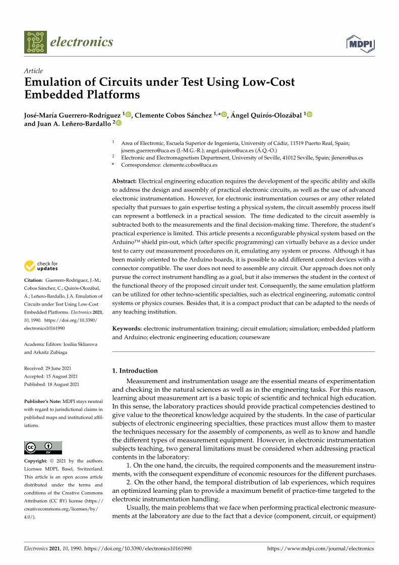
Our proposal consists of a 16 cm × 10 cm flat work-panel (Figure 1). The differentelements (electronic components, knobs, and switches) are mounted below this level, onthe PCB bottom-side. The top smooth work surface can support a graphical cover (inter-changeable) that shows an illustrated reference of the emulated circuit. The emulation willbe running on a microcontroller-based development card. Our choice was the Arduinoboard for two reasons: first, this is a known worldwide device and supported by numerouspublications of technical documentation and programming tutorials. Second, it features aninterface connector that has imposed a standard pin-out arrangement, which is now usedby other programmable platforms from other companies (e.g., some PSoC based develop-ment platform from Cypress MicrosystemsTM or Galileo series boards from Intel®) [14].In the same way, many of these programmable boards use the Arduino IDE (IntegratedDevelopment Environment).
Another example of the Arduino open-source hardware phenomenon may be thecase of TSXpert (an award-winning National InstrumentsTM Alliance Partner), whichhas introduced the Arduino compatible compiler for LabVIEWTM. This software is acompiler that takes a virtual instrument program and compiles and downloads it toArduino compatible platforms [15]. National Instrument also facilitates (free) the LabVIEWInterface for Arduino (LIFA) Toolkit which allows developers to acquire data from theArduino microcontroller and process them in the LabVIEW environment. On the otherhand, MathWorks® has taken advantage of Arduino’s acquisition capabilities to use it asan interface with the real world toward its Matlab® and Simulink® software [16].
Electronics 2021, 10, 1990 4 of 19Electronics 2021, 10, x FOR PEER REVIEW 4 of 20
Figure 1. A picture of the emulator proposed. In this case, the “dummy” shows a cover-illustration
(interchangeable) to emulate the classical 555-IC oscillator circuit.
Another example of the Arduino open-source hardware phenomenon may be the
case of TSXpert (an award-winning National InstrumentsTM Alliance Partner), which has
introduced the Arduino compatible compiler for LabVIEWTM. This software is a compiler
that takes a virtual instrument program and compiles and downloads it to Arduino com-
patible platforms [15]. National Instrument also facilitates (free) the LabVIEW Interface
for Arduino (LIFA) Toolkit which allows developers to acquire data from the Arduino
microcontroller and process them in the LabVIEW environment. On the other hand, Math-
Works® has taken advantage of Arduino’s acquisition capabilities to use it as an interface
with the real world toward its Matlab® and Simulink® software [16].
Given this background, exploiting the Arduino platform as the project core is a justi-
fied choice. Based on that, two Arduino development card types could be the project
driver, namely:
The Arduino UNO edition [17], an AVR® MCU version (includes the 8 bits
ATmega328 microcontroller from Microchip/Atmel running at 16 MHz).
The Arduino ZERO [17] (or your clone), a product ARM®-SAND21 based (a 32 bits
Cortex M0 MCU from Atmel) at 48 MHz clock, or Arduino DUE card, powered by a
SAM3X8E ARM Cortex®-M3 CPU (from Atmel3) running at 84 MHz. These ARM-
based cards will be able to run more efficiently the required simulation software,
regard to the eight-bit MCU. However, it should be noted that in these two cards, the
microcontroller works from a 3.3 V power supply instead of a 5 V one as the original
Arduino UNO. This power supply change requires small re-adjustments in the
program variables and some hardware reworks (potentiometers and pull-up
resistors must be connected to 3.3 V).
2.2. Emulation Platform Board
Figure 2 shows a block diagram of the proposed emulator circuit. It consists of an
extension of the Arduino card. There are two main groups of input/outputs elements, re-
garding analog or digital actuation.
First, referring us to the analog signals, the emulator can use four of six 10-bits-ADC
channels available inside of the microcontroller. Therefore, it is possible to dedicate one
ADC input to acquire an external analog signal, two more to enter variables manually
(Pot-1 and Pot-2), and the fourth channel is reserved for an on-card analog sensor.
Figure 1. A picture of the emulator proposed. In this case, the “dummy” shows a cover-illustration(interchangeable) to emulate the classical 555-IC oscillator circuit.
Given this background, exploiting the Arduino platform as the project core is a justifiedchoice. Based on that, two Arduino development card types could be the project driver, namely:
• The Arduino UNO edition [17], an AVR® MCU version (includes the 8 bits ATmega328microcontroller from Microchip/Atmel running at 16 MHz).
• The Arduino ZERO [17] (or your clone), a product ARM®-SAND21 based (a 32 bitsCortex M0 MCU from Atmel) at 48 MHz clock, or Arduino DUE card, powered by aSAM3X8E ARM Cortex®-M3 CPU (from Atmel3) running at 84 MHz. These ARM-based cards will be able to run more efficiently the required simulation software,regard to the eight-bit MCU. However, it should be noted that in these two cards,the microcontroller works from a 3.3 V power supply instead of a 5 V one as theoriginal Arduino UNO. This power supply change requires small re-adjustmentsin the program variables and some hardware reworks (potentiometers and pull-upresistors must be connected to 3.3 V).
2.2. Emulation Platform Board
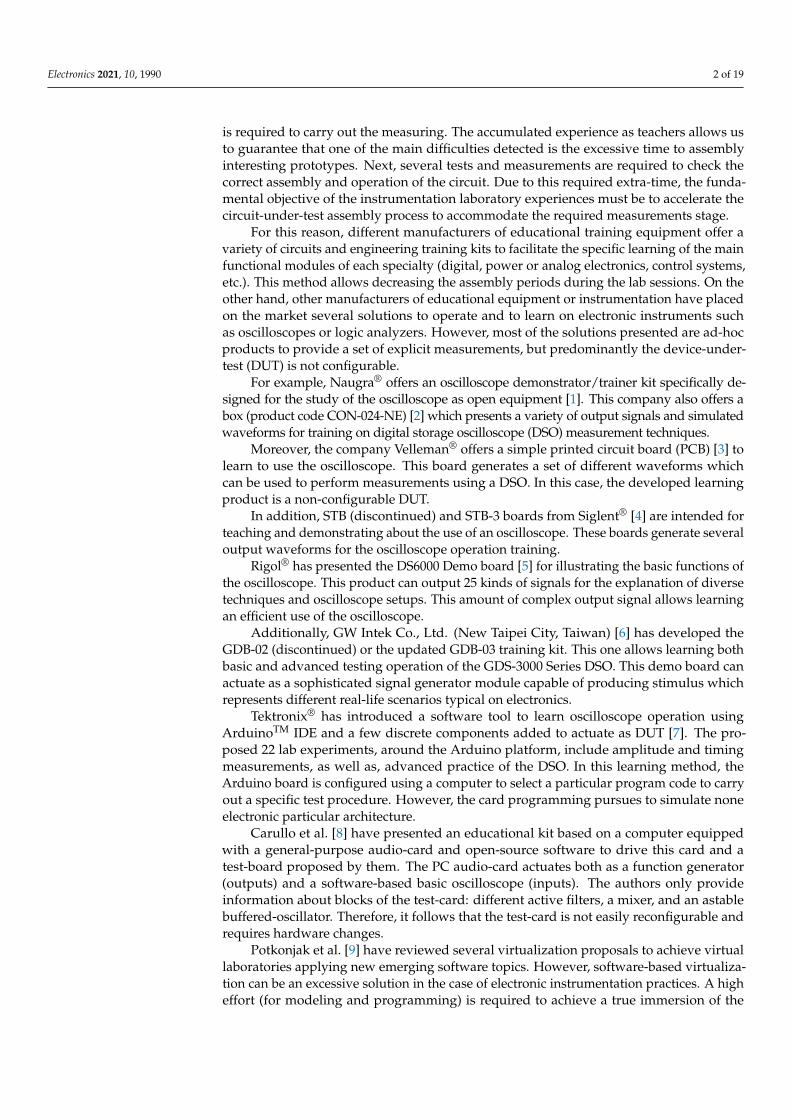
Figure 2 shows a block diagram of the proposed emulator circuit. It consists of anextension of the Arduino card. There are two main groups of input/outputs elements,regarding analog or digital actuation.
Electronics 2021, 10, x FOR PEER REVIEW 5 of 20
Figure 2. Block diagram of the training platform proposed.
The external analog signal goes to ADC through a manually adjustable gain amplifier
(from one to ten, handling Pot-4). This amplifier with two imposed poles works as a sec-
ond-order anti-aliasing filter. Since the ATmega series does not integrate a DAC module,
a converter (10 bits, DAC101S101 from Texas Instrument) and its output buffer have been
externally added. Again, two-poles imposing, achieve that this buffer works as a second-
order aliasing filter.
The in/out interfacing operational amplifiers are mounted on DIP sockets. In case of
damage as a result of mishandling during practice, this provides a fast and easy repair.
Second, referring now to the logic events, two push-buttons (Sw1 and Sw2) are added
as discrete interaction inputs. As digital outputs, the board uses some microcontroller spe-
cific pins (e.g., timer-count outputs or standard digital ports). In addition, the emulator
board presents two signaling LEDs to report particular states during the simulation
runtime.
The ATmega328 AVR microcontroller has an embedded analog-comparator. The
logic result can decide to execute a specific interrupt routine. The comparator non-inverter
input is accessible on the emulation card (OUT-2 pin), while the inverter pin is connected
to the Pot-3 potentiometer out for a manual adjustment of the comparator threshold level
(from 0 to 5 V DC). This microcontroller multiplexes on the same pin the non-inverter
input from the comparator, and a standard digital out. The programmer can decide the
identity of this pin at each time by configuring it.
The controller board plugs on the backside of the emulation card (Figure 3a). On this
same side are mounted the external components associated with the Arduino board. In
addition, a located reset-button on this one side let us to initialize the emulator if neces-
sary.
Figure 2. Block diagram of the training platform proposed.
First, referring us to the analog signals, the emulator can use four of six 10-bits-ADCchannels available inside of the microcontroller. Therefore, it is possible to dedicate oneADC input to acquire an external analog signal, two more to enter variables manually(Pot-1 and Pot-2), and the fourth channel is reserved for an on-card analog sensor.
Electronics 2021, 10, 1990 5 of 19
The external analog signal goes to ADC through a manually adjustable gain amplifier(from one to ten, handling Pot-4). This amplifier with two imposed poles works as asecond-order anti-aliasing filter. Since the ATmega series does not integrate a DAC module,a converter (10 bits, DAC101S101 from Texas Instrument) and its output buffer havebeen externally added. Again, two-poles imposing, achieve that this buffer works as asecond-order aliasing filter.
The in/out interfacing operational amplifiers are mounted on DIP sockets. In case ofdamage as a result of mishandling during practice, this provides a fast and easy repair.
Second, referring now to the logic events, two push-buttons (Sw1 and Sw2) are added asdiscrete interaction inputs. As digital outputs, the board uses some microcontroller specificpins (e.g., timer-count outputs or standard digital ports). In addition, the emulator boardpresents two signaling LEDs to report particular states during the simulation runtime.
The ATmega328 AVR microcontroller has an embedded analog-comparator. The logicresult can decide to execute a specific interrupt routine. The comparator non-inverter inputis accessible on the emulation card (OUT-2 pin), while the inverter pin is connected tothe Pot-3 potentiometer out for a manual adjustment of the comparator threshold level(from 0 to 5 V DC). This microcontroller multiplexes on the same pin the non-inverter inputfrom the comparator, and a standard digital out. The programmer can decide the identityof this pin at each time by configuring it.
The controller board plugs on the backside of the emulation card (Figure 3a). On thissame side are mounted the external components associated with the Arduino board. In ad-dition, a located reset-button on this one side let us to initialize the emulator if necessary.
Electronics 2021, 10, x FOR PEER REVIEW 6 of 20
Figure 3. The emulator PCB: (a) lateral view, showing the Arduino UNO plugged. (b) Top side
(work area).
The emulator card is raised using four brass 20 mm long separators. This height is
enough to host the Arduino board and the taller electronic components mounted under
the PCB.
The total cost is approximately 31 € (15.6 € for electronic components, and 15.2 € for
printed circuit board), excluding the controller board.
2.3. The Work Surface
We aim to achieve a smooth work-surface and to show an interchangeable graphical
illustration representative of the DUT (equipment, circuit, or component) to be emulated
(Figure 3b). Therefore, the printed circuit must be flat to accommodate the plastic or lam-
inate paper cover which includes a DUT illustrative drawing. Only the connection termi-
nals for the test instruments must remain on the upper side. The potentiometer knobs
must appear flat respect to the surface and not exert any impediment. In some experi-
ences, the unused components could stay hidden under the illustrated cover. Figure 4
shows the lower-side of the emulator PCB. The potentiometers are positioned under the
PCB plane. A hole permits to adjust the input parameters using a plastic screwdriver.
These actuate as variable parameters after being converted by a 10-bit ADC.
Figure 4. Emulator PCB, bottom side (with a DUE board plugged).
Beginning an emulation procedure requires choosing a symbolic figure of the simu-
lated circuit. The laboratory instructor has the help of a graphical template where the ele-
ments appear in their real physical positions (Figure 5). Over this starting template, we
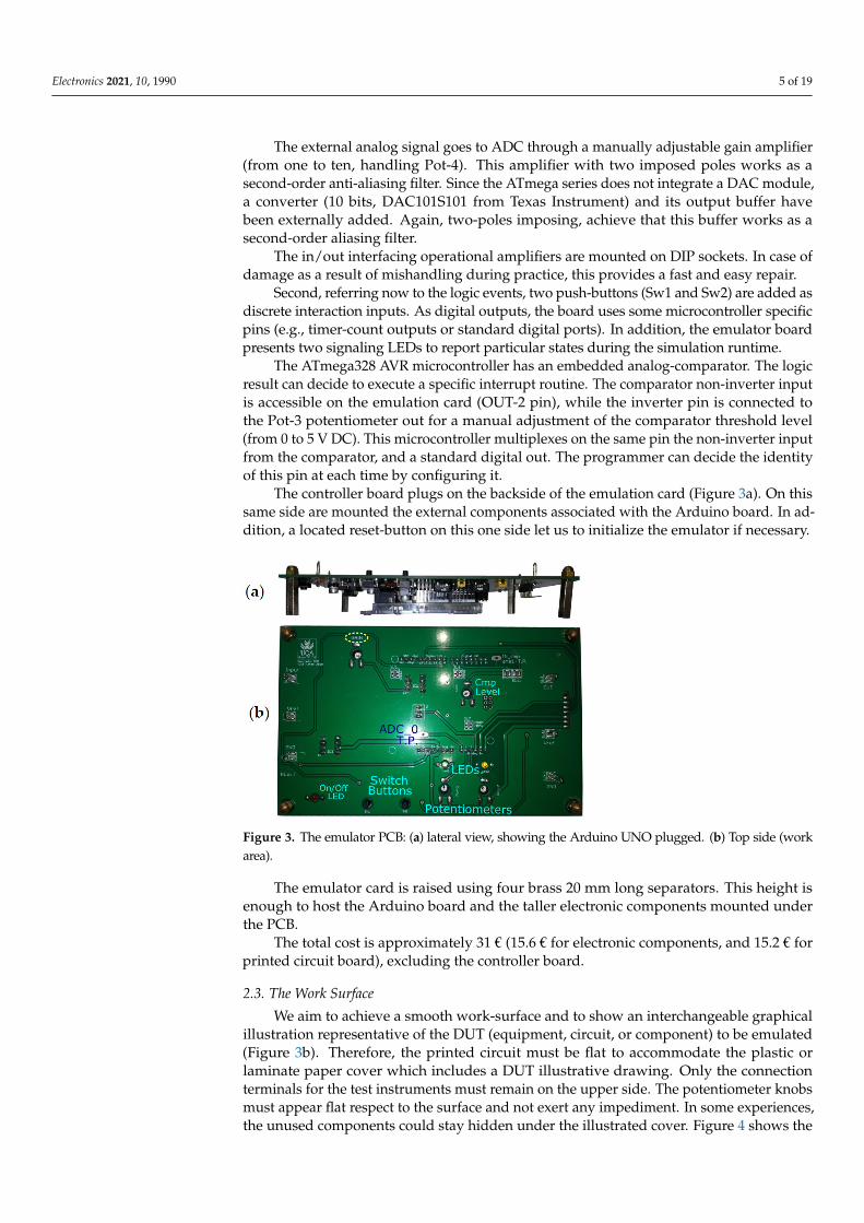
Figure 3. The emulator PCB: (a) lateral view, showing the Arduino UNO plugged. (b) Top side (workarea).
The emulator card is raised using four brass 20 mm long separators. This height isenough to host the Arduino board and the taller electronic components mounted underthe PCB.
The total cost is approximately 31 € (15.6 € for electronic components, and 15.2 € forprinted circuit board), excluding the controller board.
2.3. The Work Surface
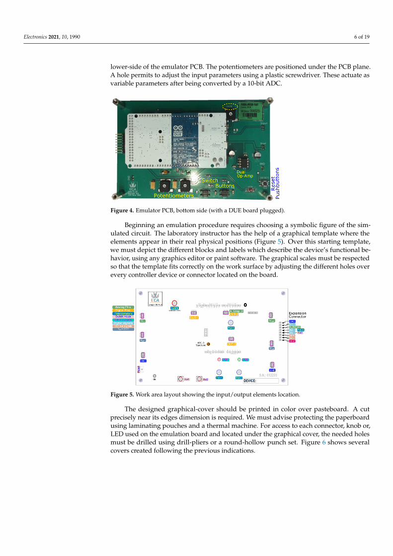
We aim to achieve a smooth work-surface and to show an interchangeable graphicalillustration representative of the DUT (equipment, circuit, or component) to be emulated(Figure 3b). Therefore, the printed circuit must be flat to accommodate the plastic orlaminate paper cover which includes a DUT illustrative drawing. Only the connectionterminals for the test instruments must remain on the upper side. The potentiometer knobsmust appear flat respect to the surface and not exert any impediment. In some experiences,the unused components could stay hidden under the illustrated cover. Figure 4 shows the
Electronics 2021, 10, 1990 6 of 19
lower-side of the emulator PCB. The potentiometers are positioned under the PCB plane.A hole permits to adjust the input parameters using a plastic screwdriver. These actuate asvariable parameters after being converted by a 10-bit ADC.
Electronics 2021, 10, x FOR PEER REVIEW 6 of 20
Figure 3. The emulator PCB: (a) lateral view, showing the Arduino UNO plugged. (b) Top side
(work area).
The emulator card is raised using four brass 20 mm long separators. This height is
enough to host the Arduino board and the taller electronic components mounted under
the PCB.
The total cost is approximately 31 € (15.6 € for electronic components, and 15.2 € for
printed circuit board), excluding the controller board.
2.3. The Work Surface
We aim to achieve a smooth work-surface and to show an interchangeable graphical
illustration representative of the DUT (equipment, circuit, or component) to be emulated
(Figure 3b). Therefore, the printed circuit must be flat to accommodate the plastic or lam-
inate paper cover which includes a DUT illustrative drawing. Only the connection termi-
nals for the test instruments must remain on the upper side. The potentiometer knobs
must appear flat respect to the surface and not exert any impediment. In some experi-
ences, the unused components could stay hidden under the illustrated cover. Figure 4
shows the lower-side of the emulator PCB. The potentiometers are positioned under the
PCB plane. A hole permits to adjust the input parameters using a plastic screwdriver.
These actuate as variable parameters after being converted by a 10-bit ADC.
Figure 4. Emulator PCB, bottom side (with a DUE board plugged).
Beginning an emulation procedure requires choosing a symbolic figure of the simu-
lated circuit. The laboratory instructor has the help of a graphical template where the ele-
ments appear in their real physical positions (Figure 5). Over this starting template, we
Figure 4. Emulator PCB, bottom side (with a DUE board plugged).
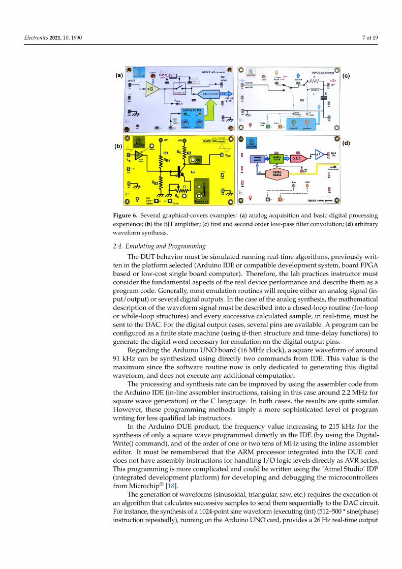
Beginning an emulation procedure requires choosing a symbolic figure of the sim-ulated circuit. The laboratory instructor has the help of a graphical template where theelements appear in their real physical positions (Figure 5). Over this starting template,we must depict the different blocks and labels which describe the device’s functional be-havior, using any graphics editor or paint software. The graphical scales must be respectedso that the template fits correctly on the work surface by adjusting the different holes overevery controller device or connector located on the board.
Electronics 2021, 10, x FOR PEER REVIEW 7 of 20
must depict the different blocks and labels which describe the device’s functional behav-
ior, using any graphics editor or paint software. The graphical scales must be respected so
that the template fits correctly on the work surface by adjusting the different holes over
every controller device or connector located on the board.
Figure 5. Work area layout showing the input/output elements location.
The designed graphical-cover should be printed in color over pasteboard. A cut pre-
cisely near its edges dimension is required. We must advise protecting the paperboard
using laminating pouches and a thermal machine. For access to each connector, knob or,
LED used on the emulation board and located under the graphical cover, the needed holes
must be drilled using drill-pliers or a round-hollow punch set. Figure 6 shows several
covers created following the previous indications.
Figure 6. Several graphical-covers examples: (a) analog acquisition and basic digital processing
experience; (b) the BJT amplifier; (c) first and second order low-pass filter convolution; (d) arbi-
trary waveform synthesis.
2.4. Emulating and Programming
The DUT behavior must be simulated running real-time algorithms, previously writ-
ten in the platform selected (Arduino IDE or compatible development system, board
FPGA based or low-cost single board computer). Therefore, the lab practices instructor
must consider the fundamental aspects of the real device performance and describe them
Figure 5. Work area layout showing the input/output elements location.
The designed graphical-cover should be printed in color over pasteboard. A cutprecisely near its edges dimension is required. We must advise protecting the paperboardusing laminating pouches and a thermal machine. For access to each connector, knob or,LED used on the emulation board and located under the graphical cover, the needed holesmust be drilled using drill-pliers or a round-hollow punch set. Figure 6 shows severalcovers created following the previous indications.
Electronics 2021, 10, 1990 7 of 19
Electronics 2021, 10, x FOR PEER REVIEW 7 of 20
must depict the different blocks and labels which describe the device’s functional behav-
ior, using any graphics editor or paint software. The graphical scales must be respected so
that the template fits correctly on the work surface by adjusting the different holes over
every controller device or connector located on the board.
Figure 5. Work area layout showing the input/output elements location.
The designed graphical-cover should be printed in color over pasteboard. A cut pre-
cisely near its edges dimension is required. We must advise protecting the paperboard
using laminating pouches and a thermal machine. For access to each connector, knob or,
LED used on the emulation board and located under the graphical cover, the needed holes
must be drilled using drill-pliers or a round-hollow punch set. Figure 6 shows several
covers created following the previous indications.
Figure 6. Several graphical-covers examples: (a) analog acquisition and basic digital processing
experience; (b) the BJT amplifier; (c) first and second order low-pass filter convolution; (d) arbi-
trary waveform synthesis.
2.4. Emulating and Programming
The DUT behavior must be simulated running real-time algorithms, previously writ-
ten in the platform selected (Arduino IDE or compatible development system, board
FPGA based or low-cost single board computer). Therefore, the lab practices instructor
must consider the fundamental aspects of the real device performance and describe them
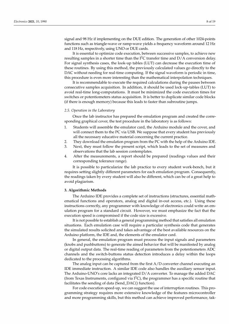
Figure 6. Several graphical-covers examples: (a) analog acquisition and basic digital processingexperience; (b) the BJT amplifier; (c) first and second order low-pass filter convolution; (d) arbitrarywaveform synthesis.
2.4. Emulating and Programming
The DUT behavior must be simulated running real-time algorithms, previously writ-ten in the platform selected (Arduino IDE or compatible development system, board FPGAbased or low-cost single board computer). Therefore, the lab practices instructor mustconsider the fundamental aspects of the real device performance and describe them as aprogram code. Generally, most emulation routines will require either an analog signal (in-put/output) or several digital outputs. In the case of the analog synthesis, the mathematicaldescription of the waveform signal must be described into a closed-loop routine (for-loopor while-loop structures) and every successive calculated sample, in real-time, must besent to the DAC. For the digital output cases, several pins are available. A program can beconfigured as a finite state machine (using if-then structure and time-delay functions) togenerate the digital word necessary for emulation on the digital output pins.
Regarding the Arduino UNO board (16 MHz clock), a square waveform of around91 kHz can be synthesized using directly two commands from IDE. This value is themaximum since the software routine now is only dedicated to generating this digitalwaveform, and does not execute any additional computation.
The processing and synthesis rate can be improved by using the assembler code fromthe Arduino IDE (in-line assembler instructions, raising in this case around 2.2 MHz forsquare wave generation) or the C language. In both cases, the results are quite similar.However, these programming methods imply a more sophisticated level of programwriting for less qualified lab instructors.
In the Arduino DUE product, the frequency value increasing to 215 kHz for thesynthesis of only a square wave programmed directly in the IDE (by using the Digital-Write() command), and of the order of one or two tens of MHz using the inline assemblereditor. It must be remembered that the ARM processor integrated into the DUE carddoes not have assembly instructions for handling I/O logic levels directly as AVR series.This programming is more complicated and could be written using the ‘Atmel Studio’ IDP(integrated development platform) for developing and debugging the microcontrollersfrom Microchip® [18].
The generation of waveforms (sinusoidal, triangular, saw, etc.) requires the execution ofan algorithm that calculates successive samples to send them sequentially to the DAC circuit.For instance, the synthesis of a 1024-point sine waveform (executing (int) (512–500 * sine(phase)instruction repeatedly), running on the Arduino UNO card, provides a 26 Hz real-time output
Electronics 2021, 10, 1990 8 of 19
signal and 98 Hz if implementing on the DUE edition. The generation of other 1024-pointsfunctions such as triangle-wave or ramp-wave yields a frequency waveform around 12 Hzand 118 Hz, respectively, using UNO or DUE cards.
It is essential to optimize code execution, between successive samples, to achieve newresulting samples in a shorter time than the I2C transfer time and D/A conversion delay.For signal synthesis cases, the look-up tables (LUT) can decrease the execution time ofthese routines. By using this method, the previously calculated values go directly to theDAC without needing for real-time computing. If the signal waveform is periodic in time,this procedure is even more interesting than the mathematical interpolation techniques.
It is recommendable to execute the required calculations during the pauses betweenconsecutive samples acquisition. In addition, it should be used lock-up-tables (LUT) toavoid real-time long-computations. It must be minimized the code execution times forswitches or potentiometers status acquisition. It is better to duplicate similar code blocks(if there is enough memory) because this leads to faster than subroutine jumps.
2.5. Operation in the Laboratory
Once the lab instructor has prepared the emulation program and created the corre-sponding graphical cover, the test procedure in the laboratory is as follows:
1. Students will assemble the emulator card, the Arduino module and the cover, andwill connect them to the PC via USB. We suppose that every student has previouslyall the necessary educative material concerning the current practice.
2. They download the emulation program from the PC with the help of the Arduino IDE.3. Next, they must follow the present script, which leads to the set of measures and
observations that the lab session contemplates.4. After the measurements, a report should be prepared (readings values and their
corresponding tolerance range).
It is possible to particularize the lab practice to every student work-bench, but itrequires setting slightly different parameters for each emulation program. Consequently,the readings taken by every student will also be different, which can be of a great help toavoid plagiarism.
3. Algorithmic Methods
The Arduino IDE provides a complete set of instructions (structures, essential math-ematical functions and operators, analog and digital in-out access, etc.). Using theseinstructions correctly, any programmer with knowledge of electronics could write an em-ulation program for a standard circuit. However, we must emphasize the fact that theexecution speed is compromised if the code size is excessive.
It is not possible to establish a general programming method that satisfies all emulationsituations. Each emulation case will require a particular synthesis code that generatesthe simulated results solicited and takes advantage of the best available resources on theArduino platform, the IDE and, the elements of the emulator card.
In general, the emulation program must process the input signals and parameters(knobs and pushbuttons) to generate the aimed behavior that will be manifested by analogor digital output data. The real-time reading of parameters from the potentiometers ADCchannels and the switch-buttons status detection introduces a delay within the loopsdedicated to the processing algorithms.
The analog input can be captured from the first A/D converter channel executing anIDE immediate instruction. A similar IDE code also handles the auxiliary sensor input.The Arduino-UNO’s core lacks an integrated D/A converter. To manage the added DAC(from Texas Instruments, configured via I2C), the programmer has a specific routine thatfacilitates the sending of data (Send_DAC() function).
For code execution speed-up, we can suggest the use of interruption routines. This pro-gramming strategy requires more extensive knowledge of the features microcontrollerand more programming skills, but this method can achieve improved performance, tak-
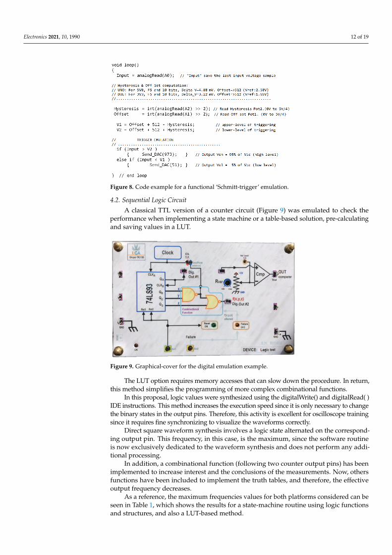
Electronics 2021, 10, 1990 9 of 19
ing advantage of the A/D acquiring times or avoid the polling method by reading theinput switch-buttons and the potentiometers. Below, a list of several methodologicalrecommendations to address the simulation of some specific devices is exposed:
3.1. State Machines
Basically, decision structures such as the if and else blocks, and the conditionalloops do -while and while are used. All instructions are fully documented in theArduino reference page [17].
The decision variables will be the discrete status from buttons SW1 and SW2 (when press-ing), as well as a particular level of the input signal captured by the main ADC. The ArduinoIDE has direct instructions to read digital (DigitalRead()) and analog (AnalogRead()) ports.
The outputs will be the available digital ports or then analog output and will dependon the determinate current state, according to the flow chart of the sequential system.
3.2. LUT Based Combinational Logic
Combinational circuits can easily be emulated reading a software array-based LUT,which previously contains the corresponding truth tables for all output pins. In order touse this option, it needs to decide the involved input and output pins. A Boolean equationfor each digital output must be created (from the truth tables). These values will appear inthe different columns of the array. The decoded inputs place a pointer at a particular arrayposition, and the corresponding binary data will directly go to the output pins. This methodcan also be applied to generate the output values corresponding to the current state in thesequential-circuits simulation cases (Mealy/Moore).
3.3. Convolution and Transfer Function
Equation (1) presents the expression for the discrete-time convolution [19]:
y(i) =N−1
∑k=0
h(k)x(i − k) (1)
Basically, this equation allows us to determine the response y(i) of the circuit toemulate, according to its discrete transfer function h(k), from the sampled sequence ofdiscrete excitation x(n). The operation is simple and primarily based on the use of a MACalgorithm (Multiply and Accumulate). Therefore, it is possible a real-time execution inmicroprocessors and programmable devices [20].
When the discrete transfer function h(k) from a particular circuit is known (impulseresponse), this algorithm allows the real device response synthesis from the current analoginput and the stated parameters. However, this routine could be considerably slow whenthe emulated circuit requires massive calculations due to a high k index value.
3.4. Digital Filters
The convolution algorithms, which establish the finite impulse response (FIR) orinfinite impulse response (IIR) digital filter routines, are well documented in the currentextensive literature. There is also a vast bibliography about the implementation of digitalprocessing routines and filters, running at low-level, using simple processors such as thoseshown in [21,22]. In [23], Fernandez et al. propose some methods for the implementation ofdigital filters in the Arduino DUE, taking advantage of its ARM SAM3X8E core controller.
Referring us to the FIR case, the general equation that represents this digital fil-ter type is:
y =n
∑i=0
bix[n − i] = b0x[n] + b1x[n − 1] + · · ·+ bnx[0] (2)
where x[ ] is the acquired input signal array, y is the current output sample to send to DAC,n is the filter order, and bi the different filter coefficients. The complexity of the algorithmdepends on the filter order: the number of calculations increases according to the n index.
Electronics 2021, 10, 1990 10 of 19
For lower order filters, it is possible the real-time computing of all necessary operationsto obtain the output data flux by processing the current input sample and the previouslyacquired input samples. The programmer can simplify this task using specific librariesavailable for signal processing in Arduino [24].
In order to find the bi filter coefficients, there is a diversity of software tools (licensedor freeware) to aid the digital filter design process. After the required filter design andverification process, these tools provide a list of parameters to directly synthesize the digitalfilter algorithm.
To accelerate the filter algorithms, it is interesting the C-language or assembler codeas programming options. For the first case, the lab instructor has available mathematical li-braries for the Atmel Studio IPE [25]. It is also possible to directly program filter algorithmsin assembler code [26–28] or any filter architecture on FPGA based.
In any case, it is always possible to perform a DUT’s emulation by scaling the fre-quency axis, taking advantage of the impedance and frequency scaling theorems. It isachievable to simulate a DUT or circuit at a different frequency regarding the originally(nominally) required. This allows executing a feasible emulation-code in real-time. Follow-ing the required measurements, the results must be reconsidered according to the originalfrequency, undoing the previous scaling.
Similarly, IIR filters type are expressed by
y[n] =n∑
i=0bix[n − i]−
n∑
i=1aiy[n − i] =
= b0x[n] + b1x[n − 1] + · · ·+ bnx[0]− a1y[n − 1]− a2y[n − 2]− · · · − any[0](3)
where now x[ ] is the acquired input signal array, y[ ] is the output previous samples array,y[n] the current sample to send to DAC, n is the filter order, and ai and bi the differentfilter coefficients. In this case, the complexity is higher and the algorithm is, even more,dependent on the filter order.
3.5. Wave Synthesis Method
Wave digital filter (WDF) is another method to model classic filters. This techniqueallows real-time emulation of analog topologies. Although a vast amount of literatureexists on this subject, an extensive exposition of this topic may be found in the workof Fettweis [29]. The structures based on LC groups are easily implemented using thismethod on fixed-point processors [30,31] or configurable devices [32,33]. That representsan advantage to execute the real-time emulation of small circuits.
3.6. Custom Libraries
To simplify the emulator’s programming tasks, we have generated a particular librarywith specific functions to optimize the emulation card. For this, a new platform declarationtitled DOCENTIA has been created (file package_docentia_index.json). After the correctinstallation, it can be chosen as a single device within the Arduino IDE (Tools -> Boards-> Boards Manager -> DOCENTIA platform). This allows us to particularize some IDEvariables to decrease the A/D conversion time, incorporate some specific instructionsfor handling the external DAC, and simplify the filters programming by adding severaluseful functions.
3.7. Communication between the Emulator and a PC
The Arduino IDE provides an instruction set for sending and receiving data froma personal computer, via USB. The execution of a specific PC application allows datadownload and the modification, in real-time, of the emulated DUT behavior or status.In addition, this application could evaluate any results from the platform and process themwith other entered data from typical computer inputs (keyboard, mouse, etc.).
PC and emulator combination facilitates to create smarter trainer equipment. A PCapplication can supervise different measures sequences and could automatically generate
Electronics 2021, 10, 1990 11 of 19
any simulated failure that the students must solve following the expected troubleshootingprocess. The use of the Rand() function allows particular configurations slightly differentfor each emulation board. Therefore, the results measured by the students will be differenttoo. In addition, the use of barcodes can help to simplify the identification between theillustrated cover, the corresponding program to load from the IDE and the educationalmaterial necessary to perform the lab practice.
4. Examples and Results
The proposed emulator presents a very varied possibilities set. Our group has exploreda significant number of feasible applications that include not only circuit simulation forelectronic instrumentation training, but also other specialties such as electrical engineeringor physical sciences. For sake of brevity, in the following we mention just a few examples:
4.1. Comparator with Hysteresis
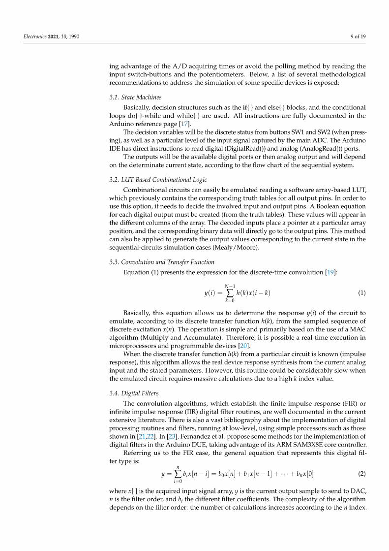
The purpose of this experience is to learn the comparator with hysteresis performance(Schmitt-trigger emulation, Figure 7), as well as to get used to the two channels measure-ments using the digital oscilloscope. Taking advantage of the analog output (via DAC), thesimulated output waveform can include the voltage drops for low and high output levels(VOL and VOH) during the synthesis process.
Electronics 2021, 10, x FOR PEER REVIEW 12 of 20
measurements using the digital oscilloscope. Taking advantage of the analog output (via
DAC), the simulated output waveform can include the voltage drops for low and high
output levels (VOL and VOH) during the synthesis process.
Figure 7. Schmitt-trigger circuit emulation.
The excitation-signal to be used is a triangular waveform, 5 V peak to peak, with 2.5
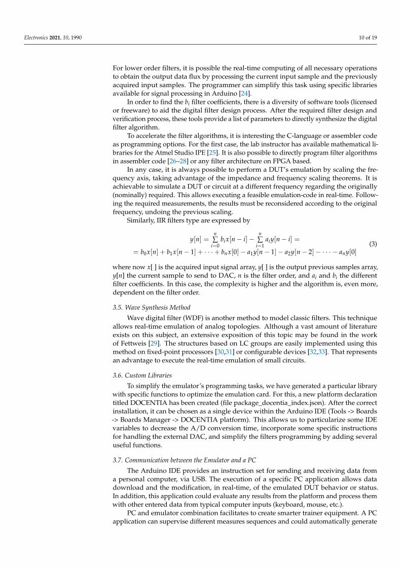
V offset and frequency around 100 Hz. A very simplified code, which takes into account
only the logic states transitions and the output, is shown in Figure 8.
Figure 8. Code example for a functional ‘Schmitt-trigger’ emulation.
4.2. Sequential Logic Circuit
A classical TTL version of a counter circuit (Figure 9) was emulated to check the per-
formance when implementing a state machine or a table-based solution, pre-calculating
and saving values in a LUT.
The LUT option requires memory accesses that can slow down the procedure. In re-
turn, this method simplifies the programming of more complex combinational functions.
In this proposal, logic values were synthesized using the digitalWrite() and digi-
talRead( ) IDE instructions. This method increases the execution speed since it is only nec-
essary to change the binary states in the output pins. Therefore, this activity is excellent
for oscilloscope training since it requires fine synchronizing to visualize the waveforms
correctly.
Figure 7. Schmitt-trigger circuit emulation.
The excitation-signal to be used is a triangular waveform, 5 V peak to peak, with 2.5 Voffset and frequency around 100 Hz. A very simplified code, which takes into account onlythe logic states transitions and the output, is shown in Figure 8.
Electronics 2021, 10, 1990 12 of 19
Electronics 2021, 10, x FOR PEER REVIEW 12 of 20
measurements using the digital oscilloscope. Taking advantage of the analog output (via
DAC), the simulated output waveform can include the voltage drops for low and high
output levels (VOL and VOH) during the synthesis process.
Figure 7. Schmitt-trigger circuit emulation.
The excitation-signal to be used is a triangular waveform, 5 V peak to peak, with 2.5
V offset and frequency around 100 Hz. A very simplified code, which takes into account
only the logic states transitions and the output, is shown in Figure 8.
Figure 8. Code example for a functional ‘Schmitt-trigger’ emulation.
4.2. Sequential Logic Circuit
A classical TTL version of a counter circuit (Figure 9) was emulated to check the per-
formance when implementing a state machine or a table-based solution, pre-calculating
and saving values in a LUT.
The LUT option requires memory accesses that can slow down the procedure. In re-
turn, this method simplifies the programming of more complex combinational functions.
In this proposal, logic values were synthesized using the digitalWrite() and digi-
talRead( ) IDE instructions. This method increases the execution speed since it is only nec-
essary to change the binary states in the output pins. Therefore, this activity is excellent
for oscilloscope training since it requires fine synchronizing to visualize the waveforms
correctly.
Figure 8. Code example for a functional ‘Schmitt-trigger’ emulation.
4.2. Sequential Logic Circuit
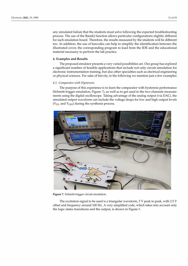
A classical TTL version of a counter circuit (Figure 9) was emulated to check theperformance when implementing a state machine or a table-based solution, pre-calculatingand saving values in a LUT.
Electronics 2021, 10, x FOR PEER REVIEW 13 of 20
Direct square waveform synthesis involves a logic state alternated on the correspond-
ing output pin. This frequency, in this case, is the maximum, since the software routine is
now exclusively dedicated to the waveform synthesis and does not perform any addi-
tional processing.
Figure 9. Graphical-cover for the digital emulation example.
In addition, a combinational function (following two counter output pins) has been
implemented to increase interest and the conclusions of the measurements. Now, others
functions have been included to implement the truth tables, and therefore, the effective
output frequency decreases.
As a reference, the maximum frequencies values for both platforms considered can
be seen in Table 1, which shows the results for a state-machine routine using logic func-
tions and structures, and also a LUT-based method.
Table 1. Digital synthesis: maximum output frequency according to the type of platform.
Parameter UNO DUE
Square wave synthesis:
- CLK output 125 kHz 4 MHz
State machine algorithm:
- CLK output 19.23 kHz 51.28 kHz
- QA output 9.59 kHz 25.97 kHz
LUT based algorithm:
- CLK output 22.2 kHz 46.51 kHz
- QA output 11.1 kHz 23.53 kHz
4.3. Classical 555 Timer Emulation
We propose the simulation of the well-known timer NE555 (Signetics®), one of the
most transcendental ICs in the history of electronic technology [34], implemented as an
astable oscillator (Figure 10). For this case, the emulation routine should consider the
equation that represents the period for the 555 astable-oscillator [35]:
1.44 1.44a b bR R C R C
T
(4)
The code considers the main functions of the timer 555: the reset pin is simulated by
keeping a low-level output permanently; the triangular waveform generated by the
Figure 9. Graphical-cover for the digital emulation example.
The LUT option requires memory accesses that can slow down the procedure. In return,this method simplifies the programming of more complex combinational functions.
In this proposal, logic values were synthesized using the digitalWrite() and digitalRead( )IDE instructions. This method increases the execution speed since it is only necessary to changethe binary states in the output pins. Therefore, this activity is excellent for oscilloscope trainingsince it requires fine synchronizing to visualize the waveforms correctly.
Direct square waveform synthesis involves a logic state alternated on the correspond-ing output pin. This frequency, in this case, is the maximum, since the software routineis now exclusively dedicated to the waveform synthesis and does not perform any addi-tional processing.
In addition, a combinational function (following two counter output pins) has beenimplemented to increase interest and the conclusions of the measurements. Now, othersfunctions have been included to implement the truth tables, and therefore, the effectiveoutput frequency decreases.
As a reference, the maximum frequencies values for both platforms considered can beseen in Table 1, which shows the results for a state-machine routine using logic functionsand structures, and also a LUT-based method.
Electronics 2021, 10, 1990 13 of 19
Table 1. Digital synthesis: maximum output frequency according to the type of platform.
Parameter UNO DUE
Square wave synthesis:
- CLK output 125 kHz 4 MHz
State machine algorithm:
- CLK output 19.23 kHz 51.28 kHz
- QA output 9.59 kHz 25.97 kHz
LUT based algorithm:
- CLK output 22.2 kHz 46.51 kHz
- QA output 11.1 kHz 23.53 kHz
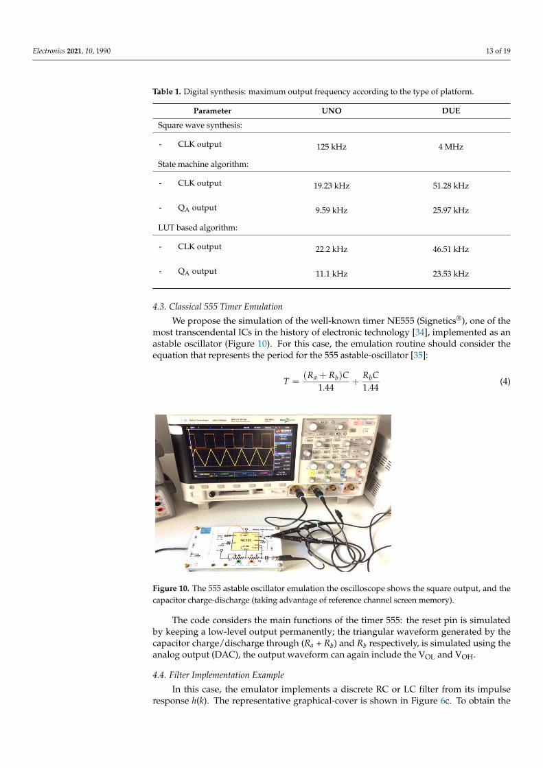
4.3. Classical 555 Timer Emulation
We propose the simulation of the well-known timer NE555 (Signetics®), one of themost transcendental ICs in the history of electronic technology [34], implemented as anastable oscillator (Figure 10). For this case, the emulation routine should consider theequation that represents the period for the 555 astable-oscillator [35]:
T =(Ra + Rb)C
1.44+
RbC1.44
(4)
Electronics 2021, 10, x FOR PEER REVIEW 14 of 20
capacitor charge/discharge through (Ra + Rb) and Rb respectively, is simulated using the
analog output (DAC), the output waveform can again include the VOL and VOH.
Figure 10. The 555 astable oscillator emulation the oscilloscope shows the square output, and the
capacitor charge-discharge (taking advantage of reference channel screen memory).
4.4. Filter Implementation Example
In this case, the emulator implements a discrete RC or LC filter from its impulse re-
sponse h(k). The representative graphical-cover is shown in Figure 6c. To obtain the filter
response must be used the Equation (1). The program analyzes the input waveform sam-
ples and calculates the convolution, that is, the output signal.
However, in the frequency domain, this same RC/LC circuit can be analyzed as a
first-order or second-order filters, respectively, where the coefficients depend on the val-
ues of the resistor, the inductor and the capacitor. In this way, it could be used the corre-
sponding expression to an FIR filter (2).
The analysis of the LC circuit can be addressed by applying the Kirchhoff’s voltage
law (KVL) along an RLC closed-network and thus obtain the expression [36]:
2
2
( ) ( )( )C C
C in
d V t dV tLC RC V T V
dt dt (5)
where VC(t) represents the output voltage (low-pass filter) when the RLC circuit is excited
from an input source Vin. For a discrete-time approach, this equation can be modified to
achieve a difference equation referred to Ts sampling period:
1 2( ) ( ) ( 1) ( 2)
1 1 1O in O O
A B BV n V n V n V n
A B A B A B
(6)
with A = R·C/Ts and B = L·C/Ts, and Ts the sampling time. Equation (6) allows us to syn-
thesize a general filter function that may to accommodate RLC, LC, and RC filters, de-
pending on the R, L, and C values. On the one hand, it is possible to annul the B value to
obtain an RC group. In this case, the capacitor charge/discharge in an RC network will be
emulated. The A value represents the product of resistance and capacitance real values.
For this motive, it is easy to simulate the RC phenomenon implementing (6) as a MAC
algorithm.
On the other hand, for the implemented simulation (Figure 6c) when R = 0, we obtain
a second-order LC-filter, and the response uniquely depends on L and C parameters (A =
0). This case is shown in Figure 11 emulating an R = 0 Ω, C = 68 µF and L = 100 mH network.
In the same way, an RC integrator may be synthesized for L = 0 and consequently B = 0.
Optimizing the algorithm, the possible minimum sampling time, TSmin are shown in Table
Figure 10. The 555 astable oscillator emulation the oscilloscope shows the square output, and thecapacitor charge-discharge (taking advantage of reference channel screen memory).
The code considers the main functions of the timer 555: the reset pin is simulatedby keeping a low-level output permanently; the triangular waveform generated by thecapacitor charge/discharge through (Ra + Rb) and Rb respectively, is simulated using theanalog output (DAC), the output waveform can again include the VOL and VOH.
4.4. Filter Implementation Example
In this case, the emulator implements a discrete RC or LC filter from its impulseresponse h(k). The representative graphical-cover is shown in Figure 6c. To obtain the
Electronics 2021, 10, 1990 14 of 19
filter response must be used the Equation (1). The program analyzes the input waveformsamples and calculates the convolution, that is, the output signal.
However, in the frequency domain, this same RC/LC circuit can be analyzed as a first-order or second-order filters, respectively, where the coefficients depend on the values ofthe resistor, the inductor and the capacitor. In this way, it could be used the correspondingexpression to an FIR filter (2).
The analysis of the LC circuit can be addressed by applying the Kirchhoff’s voltagelaw (KVL) along an RLC closed-network and thus obtain the expression [36]:
LCd2VC(t)
dt2 + RCdVC(t)
dt+ VC(T) = Vin (5)
where VC(t) represents the output voltage (low-pass filter) when the RLC circuit is excitedfrom an input source Vin. For a discrete-time approach, this equation can be modified toachieve a difference equation referred to Ts sampling period:
VO(n) =1
1 + A + BVin(n) +
A + 2B1 + A + B
VO(n − 1)− B1 + A + B
VO(n − 2) (6)
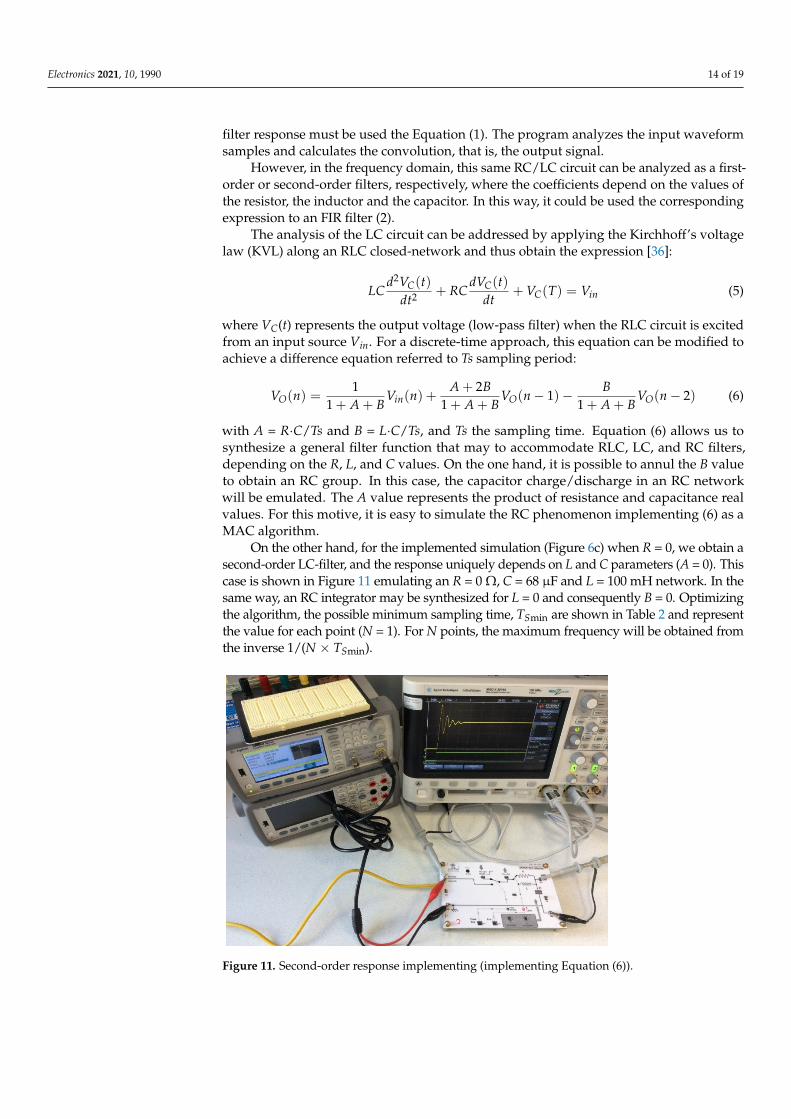
with A = R·C/Ts and B = L·C/Ts, and Ts the sampling time. Equation (6) allows us tosynthesize a general filter function that may to accommodate RLC, LC, and RC filters,depending on the R, L, and C values. On the one hand, it is possible to annul the B valueto obtain an RC group. In this case, the capacitor charge/discharge in an RC networkwill be emulated. The A value represents the product of resistance and capacitance realvalues. For this motive, it is easy to simulate the RC phenomenon implementing (6) as aMAC algorithm.
On the other hand, for the implemented simulation (Figure 6c) when R = 0, we obtain asecond-order LC-filter, and the response uniquely depends on L and C parameters (A = 0). Thiscase is shown in Figure 11 emulating an R = 0 Ω, C = 68 µF and L = 100 mH network. In thesame way, an RC integrator may be synthesized for L = 0 and consequently B = 0. Optimizingthe algorithm, the possible minimum sampling time, TSmin are shown in Table 2 and representthe value for each point (N = 1). For N points, the maximum frequency will be obtained fromthe inverse 1/(N × TSmin).
Electronics 2021, 10, x FOR PEER REVIEW 15 of 20
2 and represent the value for each point (N = 1). For N points, the maximum frequency
will be obtained from the inverse 1/(N × TSmin).
Figure 11. Second-order response implementing (implementing Equation (6)).
Table 2. FIR algorithms execution times according to the type of platform.
Parameter UNO DUE
LC filter algorithm:
Min. sampling time Ts 264.5 µs 75.6 µs
RC filter algorithm:
Min. sampling time Ts 222 µs 72 µs
4.5. The Analog–Digital Converter and a PC Interactive Application for Intelligent Aid
To study the possibilities of interaction between a personal computer (PC) and the
emulator card, we present a laboratory experience to check the process of the A/D conver-
sion and perform a set of measurements with the oscilloscope (Figure 12). In this case, a
specific C++ application using the LabWINDOWSTM software (from National Instru-
mentTM) was programmed.
It was also necessary to design a graphical-cover to present the idea of the experi-
ment. This lab practice takes advantage of the embedded A/D converter into the Arduino
card microcontroller to understand the sampling frequency concepts, the resolution effect
(the binary word length of the converter), and the basic implementation of the digital fil-
ters (applying (2) or (3) equations, for low-order stages).
Figure 11. Second-order response implementing (implementing Equation (6)).
Electronics 2021, 10, 1990 15 of 19
Table 2. FIR algorithms execution times according to the type of platform.
Parameter UNO DUE
LC filter algorithm:
Min. sampling time Ts 264.5 µs 75.6 µsRC filter algorithm:
Min. sampling time Ts 222 µs 72 µs
4.5. The Analog–Digital Converter and a PC Interactive Application for Intelligent Aid
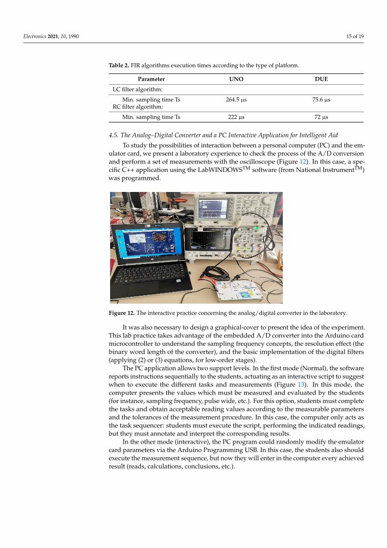
To study the possibilities of interaction between a personal computer (PC) and the em-ulator card, we present a laboratory experience to check the process of the A/D conversionand perform a set of measurements with the oscilloscope (Figure 12). In this case, a spe-cific C++ application using the LabWINDOWSTM software (from National InstrumentTM)was programmed.
Electronics 2021, 10, x FOR PEER REVIEW 16 of 20
Figure 12. The interactive practice concerning the analog/digital converter in the laboratory.
The PC application allows two support levels. In the first mode (Normal), the soft-
ware reports instructions sequentially to the students, actuating as an interactive script to
suggest when to execute the different tasks and measurements (Figure 13). In this mode,
the computer presents the values which must be measured and evaluated by the students
(for instance, sampling frequency, pulse wide, etc.). For this option, students must com-
plete the tasks and obtain acceptable reading values according to the measurable param-
eters and the tolerances of the measurement procedure. In this case, the computer only
acts as the task sequencer: students must execute the script, performing the indicated
readings, but they must annotate and interpret the corresponding results.
In the other mode (interactive), the PC program could randomly modify the emulator
card parameters via the Arduino Programming USB. In this case, the students also should
execute the measurement sequence, but now they will enter in the computer every
achieved result (reads, calculations, conclusions, etc.).
Once the measurement results are entered, the system (which knows the previously
loaded parameters and consequent solutions) will validate the obtained readings. If the
results are incorrect, the computer could also order a new reading set. In addition, it is
automatically possible to evaluate conclusions, applying a Boolean-response method.
Figure 13. PC application screen for the interactive A/D converter practice.
Figure 12. The interactive practice concerning the analog/digital converter in the laboratory.
It was also necessary to design a graphical-cover to present the idea of the experiment.This lab practice takes advantage of the embedded A/D converter into the Arduino cardmicrocontroller to understand the sampling frequency concepts, the resolution effect (thebinary word length of the converter), and the basic implementation of the digital filters(applying (2) or (3) equations, for low-order stages).
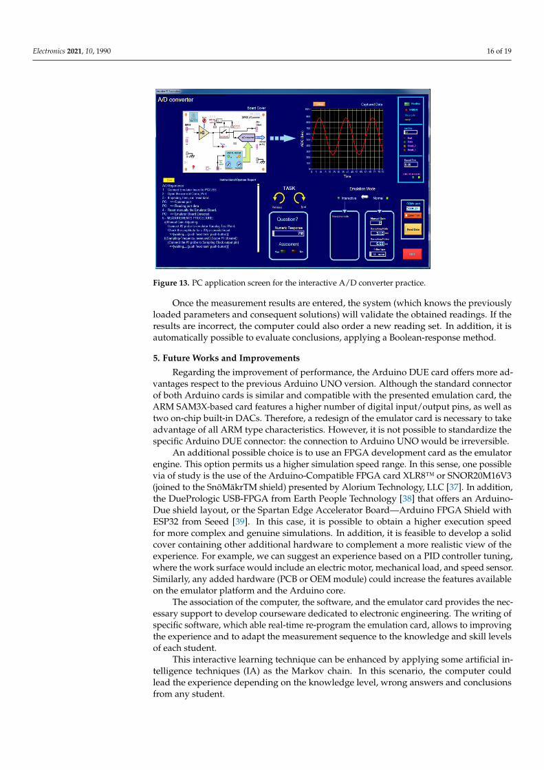
The PC application allows two support levels. In the first mode (Normal), the softwarereports instructions sequentially to the students, actuating as an interactive script to suggestwhen to execute the different tasks and measurements (Figure 13). In this mode, thecomputer presents the values which must be measured and evaluated by the students(for instance, sampling frequency, pulse wide, etc.). For this option, students must completethe tasks and obtain acceptable reading values according to the measurable parametersand the tolerances of the measurement procedure. In this case, the computer only acts asthe task sequencer: students must execute the script, performing the indicated readings,but they must annotate and interpret the corresponding results.
In the other mode (interactive), the PC program could randomly modify the emulatorcard parameters via the Arduino Programming USB. In this case, the students also shouldexecute the measurement sequence, but now they will enter in the computer every achievedresult (reads, calculations, conclusions, etc.).
Electronics 2021, 10, 1990 16 of 19
Electronics 2021, 10, x FOR PEER REVIEW 16 of 20
Figure 12. The interactive practice concerning the analog/digital converter in the laboratory.
The PC application allows two support levels. In the first mode (Normal), the soft-
ware reports instructions sequentially to the students, actuating as an interactive script to
suggest when to execute the different tasks and measurements (Figure 13). In this mode,
the computer presents the values which must be measured and evaluated by the students
(for instance, sampling frequency, pulse wide, etc.). For this option, students must com-
plete the tasks and obtain acceptable reading values according to the measurable param-
eters and the tolerances of the measurement procedure. In this case, the computer only
acts as the task sequencer: students must execute the script, performing the indicated
readings, but they must annotate and interpret the corresponding results.
In the other mode (interactive), the PC program could randomly modify the emulator
card parameters via the Arduino Programming USB. In this case, the students also should
execute the measurement sequence, but now they will enter in the computer every
achieved result (reads, calculations, conclusions, etc.).
Once the measurement results are entered, the system (which knows the previously
loaded parameters and consequent solutions) will validate the obtained readings. If the
results are incorrect, the computer could also order a new reading set. In addition, it is
automatically possible to evaluate conclusions, applying a Boolean-response method.
Figure 13. PC application screen for the interactive A/D converter practice.
Figure 13. PC application screen for the interactive A/D converter practice.
Once the measurement results are entered, the system (which knows the previouslyloaded parameters and consequent solutions) will validate the obtained readings. If theresults are incorrect, the computer could also order a new reading set. In addition, it isautomatically possible to evaluate conclusions, applying a Boolean-response method.
5. Future Works and Improvements
Regarding the improvement of performance, the Arduino DUE card offers more ad-vantages respect to the previous Arduino UNO version. Although the standard connectorof both Arduino cards is similar and compatible with the presented emulation card, theARM SAM3X-based card features a higher number of digital input/output pins, as well astwo on-chip built-in DACs. Therefore, a redesign of the emulator card is necessary to takeadvantage of all ARM type characteristics. However, it is not possible to standardize thespecific Arduino DUE connector: the connection to Arduino UNO would be irreversible.
An additional possible choice is to use an FPGA development card as the emulatorengine. This option permits us a higher simulation speed range. In this sense, one possiblevia of study is the use of the Arduino-Compatible FPGA card XLR8™ or SNOR20M16V3(joined to the SnoMakrTM shield) presented by Alorium Technology, LLC [37]. In addition,the DuePrologic USB-FPGA from Earth People Technology [38] that offers an Arduino-Due shield layout, or the Spartan Edge Accelerator Board—Arduino FPGA Shield withESP32 from Seeed [39]. In this case, it is possible to obtain a higher execution speedfor more complex and genuine simulations. In addition, it is feasible to develop a solidcover containing other additional hardware to complement a more realistic view of theexperience. For example, we can suggest an experience based on a PID controller tuning,where the work surface would include an electric motor, mechanical load, and speed sensor.Similarly, any added hardware (PCB or OEM module) could increase the features availableon the emulator platform and the Arduino core.
The association of the computer, the software, and the emulator card provides the nec-essary support to develop courseware dedicated to electronic engineering. The writing ofspecific software, which able real-time re-program the emulation card, allows to improvingthe experience and to adapt the measurement sequence to the knowledge and skill levelsof each student.
This interactive learning technique can be enhanced by applying some artificial in-telligence techniques (IA) as the Markov chain. In this scenario, the computer couldlead the experience depending on the knowledge level, wrong answers and conclusionsfrom any student.
Electronics 2021, 10, 1990 17 of 19
6. Conclusions
This work presents the emulation equipment and programming methods to addressthe real-time simulation of electronic circuits (DUTs) to test in bench. The possible usesthat offer this emulator are varied. We highlight especially its utilization for electronicinstrumentation training. The performed tests with a set of emulated varied circuits(Schmitt-trigger, NE555 timer, sequential logic circuits, Nyquist and the AD/DA conversion,low-order digital filter, common emitter amplifier, RFID principles, quasi-random sourceand serial data generator for bit error rate (BER) test, etc.) have validated that this platformis a very powerful and versatile aid to learn and practice laboratory instrumentation.
Although these essays have been carried out with boards UNO and DUE from Ar-duino, we want to emphasize that they could be carried out with any other type of cardArduino-Shield compatible (based on a microprocessor, microcontrollers, or FPGA devel-opment boards).
As an assay, a comparative laboratory practice was carried out around the 555-timerintegrated circuit, in its hardware (classic lab practice) and then its corresponding emulatedoption, and obtained an important result about times: with a fixed time minimum forpreparing the emulator card and for download the corresponding software, the emulated-practice option maintains a constant preparation time regardless of the complexity of theexperience. In contrast, the preparation and assembly time of a physical device stronglydepends on the complexity of the assembly.
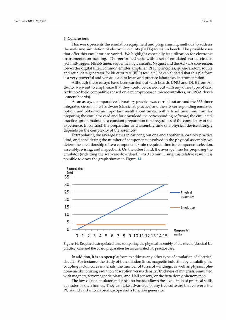
Extrapolating the average times in carrying out one and another laboratory practicekind, and considering the number of components involved in the physical assembly, wedetermine a relationship of two components/min (required time for component selection,assembly, wiring, and inspection). On the other hand, the average time for preparing theemulator (including the software download) was 3.18 min. Using this relative result, it ispossible to draw the graph shown in Figure 14.
Electronics 2021, 10, x FOR PEER REVIEW 18 of 20
Extrapolating the average times in carrying out one and another laboratory practice
kind, and considering the number of components involved in the physical assembly, we
determine a relationship of two components/min (required time for component selection,
assembly, wiring, and inspection). On the other hand, the average time for preparing the
emulator (including the software download) was 3.18 min. Using this relative result, it is
possible to draw the graph shown in Figure 14.
Figure 14. Required extrapolated time comparing the physical assembly of the circuit (classical lab
practice) case and the board preparation for an emulated lab practice case.
In addition, it is an open platform to address any other type of emulation of electrical
circuits. For instance, the study of transmission lines, magnetic induction by emulating
the coupling factor, cores materials, the number of turns of windings, as well as physical
phenomena like ionizing radiation absorption versus density/thickness of materials, sim-
ulated with magnets, ferromagnetic plates, and Hall sensors, or the beta decay phenome-
non.
The low cost of emulator and Arduino boards allows the acquisition of practical skills
at student’s own homes. They can take advantage of any free software that converts the
PC sound card into an oscilloscope and a function generator.
Author Contributions: Conceptualization and validation, J.-M.G.-R., C.C.S., Á.Q.-O. and J.-A.L.-B.;
methodology, Á.Q.-O.; software, J.-M.G.-R.; writing—original draft preparation, J.-M.G.-R.; writ-
ing—review and editing, C.C.S.; visualization and supervision, J.-A.L.-B.; funding acquisition, J.-
M.G.-R. All authors have read and agreed to the published version of the manuscript.
Funding: This work was performed as an innovation and teaching improvement project and sup-
ported by grant SOL-201700083174-TRA from Vicerrectorado de Recursos Docentes y de la Comuni-
cación, University of Cadiz.
Conflicts of Interest: The authors declare no conflict of interest.
References
1. NAUGRA®, P. Code: CON-008-NE. India. Available online: https://www.naugraexport.com/oscilloscope-trainer-oscilloscope-
lab-kit-for-training-for-vocational-training-and-didactic-labs (accessed on 20 June 2021).
2. NAUGRA®, P. Code: CON-024-NE. India. Available online: https://www.naugraexport.com/digital-storage-oscilloscope-
trainer-lab-demonstration-kit-for-vocational-training-and-didactic-labs (accessed on 20 June 2021).
3. VELLEMAN®, Oscilloscope tutor board, France. Available online: https://www.velleman.eu/products/view/?id=387510 (ac-
cessed on 20 June 2021).
4. SIGLENT®, STB-3Signal Test Board, The Netherlands. Available online: https://www.siglent.eu/product/1142628/siglent-stb-3-
oscilloscope-demo-training-board (accessed on 20 June 2021).
5. RIGOL®, DK-DS600 Oscilloscope Trainer Board, USA. Available online: https://www.rigolna.com/education/
(https://www.rigol-uk.co.uk/product/rigol-ds6000-dk-demo-board/) (accessed on 20 June 2021).
0
5
10
15
20
25
30
35
0 1 2 3 4 5 6 7 8 9 10 11 12 13 14 15
Physicalassembly
Emulation
Components number
Required time (min)
Figure 14. Required extrapolated time comparing the physical assembly of the circuit (classical labpractice) case and the board preparation for an emulated lab practice case.
In addition, it is an open platform to address any other type of emulation of electricalcircuits. For instance, the study of transmission lines, magnetic induction by emulating thecoupling factor, cores materials, the number of turns of windings, as well as physical phe-nomena like ionizing radiation absorption versus density/thickness of materials, simulatedwith magnets, ferromagnetic plates, and Hall sensors, or the beta decay phenomenon.
The low cost of emulator and Arduino boards allows the acquisition of practical skillsat student’s own homes. They can take advantage of any free software that converts thePC sound card into an oscilloscope and a function generator.
Electronics 2021, 10, 1990 18 of 19
Author Contributions: Conceptualization and validation, J.-M.G.-R., C.C.S., Á.Q.-O. and J.-A.L.-B.;methodology, Á.Q.-O.; software, J.-M.G.-R.; writing—original draft preparation, J.-M.G.-R.; writing—review and editing, C.C.S.; visualization and supervision, J.-A.L.-B.; funding acquisition, J.-M.G.-R.All authors have read and agreed to the published version of the manuscript.
Funding: This work was performed as an innovation and teaching improvement project and sup-ported by grant SOL-201700083174-TRA from Vicerrectorado de Recursos Docentes y de la Comunicación,University of Cadiz.
Conflicts of Interest: The authors declare no conflict of interest.
References1. NAUGRA®, P. Code: CON-008-NE. India. Available online: https://www.naugraexport.com/oscilloscope-trainer-oscilloscope-
lab-kit-for-training-for-vocational-training-and-didactic-labs (accessed on 20 June 2021).2. NAUGRA®, P. Code: CON-024-NE. India. Available online: https://www.naugraexport.com/digital-storage-oscilloscope-
trainer-lab-demonstration-kit-for-vocational-training-and-didactic-labs (accessed on 20 June 2021).3. VELLEMAN®, Oscilloscope Tutor Board, France. Available online: https://www.velleman.eu/products/view/?id=387510
(accessed on 20 June 2021).4. SIGLENT®, STB-3Signal Test Board, The Netherlands. Available online: https://www.siglent.eu/product/1142628/siglent-stb-
3-oscilloscope-demo-training-board (accessed on 20 June 2021).5. RIGOL®, DK-DS600 Oscilloscope Trainer Board, USA. Available online: https://www.rigolna.com/education/; https://www.
rigol-uk.co.uk/product/rigol-ds6000-dk-demo-board/ (accessed on 20 June 2021).6. GW INTEK®, GDB-03 Oscilloscope Education and Training Kit, Taiwan. Available online: https://www.gwinstek.com/en-
global/products/detail/GDB-03 (accessed on 20 June 2021).7. TEKTRONIX®, Learn Digital Oscilloscope Operation Using Arduino Board as DUT Signal Generator, USA. Available online:
https://download.tek.com/courseware/ST_Arduino_Labs_Package.zip (accessed on 26 June 2019).8. Carullo, A.; Parvis, M.; Vallan, A. An Audio Card-Based Kit for Educational Purposes. IEEE Trans. Instrum. Meas. 2003, 52,
733–737. [CrossRef]9. Potkonjak, V.; Gardner, M.; Pasi Mattila, V.; Guetl, C.; Petrovic, V.M.; Jovanovic, K. Virtual laboratories for education in science,
technology, and engineering: A reviews. Comput. Educ. 2016, 95, 309–327. [CrossRef]10. Grimaldi, D.; Rapuano, S. Hardware and software to design virtual laboratory for education in instrumentation and measurement.
Meas. J. Int. Meas. Confed. 2009, 42, 485–493. [CrossRef]11. Angrisani, L.; Bonavolontá, F.; D’Arco, M.; Liccardo, A. A Flexible Remote Laboratory with Programmable Device under Test.
Measurement. 2020, 156, 1–15. [CrossRef]12. Lavayssière, C.; Larroque, B.; Schröder, M.; Luthon, F. A Fully Open Source Remote Laboratory for Practical Learning. Electronics
2020, 9, 1832. [CrossRef]13. McGregor, I. The Relation Between Simulation and Emulation. In Proceedings of the 2002 Winter Simulation Conference, San
Diego, CA, USA, 8–11 December 2001; pp. 1683–1688. [CrossRef]14. List of Arduino Boards and Compatible Systems (Wikipedia). Available online: https://en.wikipedia.org/wiki/List_of_Arduino_
boards_and_compatible_systems (accessed on 20 June 2021).15. TSXPERTS. Arduino™ Compatible Compiler for LabVIEW, USA. Available online: https://www.tsxperts.com/arduino-
compatible-compiler-for-labview/ (accessed on 20 June 2021).16. MATHWORKS®, Arduino Support from MATLAB. USA. Available online: https://es.mathworks.com/hardware-support/
arduino-matlab.html (accessed on 20 June 2021).17. Arduino Official Products list. From the Company Home Page. Available online: https://www.arduino.cc/en/main/products
(accessed on 20 June 2021).18. Atmel STUDIO 7®, Integrated Development Platform (IDP) for AVR® and SAM Microcontroller Applications from Microchip®.
USA. Available online: https://www.microchip.com/mplab/avr-support/atmel-studio-7 (accessed on 20 June 2021).19. Smith, S.W. Convolution and Properties of Convolution. The Scientist and Engineer’s Guide to Digital Signal Processing, 2nd ed.;
California Technical Publishing: San Diego, CA, USA, 1999; pp. 140–147. ISBN 0-9660176-7-6.20. Tertel, P.; Hedrich, L. Real-time emulation of block-based analog circuits on an FPGA. Integration 2018, 68, 373–382. [CrossRef]21. Ibrahim, D. Practical Digital Signal Processing Using Microcontrollers, 2nd ed.; Elektor Verlag International Media: Aachen, Germany,
2013; ISBN 978-1907920219.22. Reay, D.S. Digital Signal Processing Using the ARM® Cortex®-M4; John Wiley & Sons, Inc.: Hoboken, NJ, USA, 2016; ISBN
978-1-118-85904-9.23. Fernández, J.; Gemin, W.; Rivera, R.; Revuelta, M.; Kuzman, M.; Hidalgo, R. Digital filter design with Arduino DUE and Matlab.
In Proceedings of the XVI Workshop on Information Processing and Control (RPIC), Cordoba, Argentina, 6–9 October 2015; pp.1–6. Available online: https://ieeexplore-ieee-org.bibezproxy.uca.es/document/7497060 (accessed on 20 June 2021). [CrossRef]
24. Molina-Cantero, A.J.; Castro-García, J.A.; Lebrato-Vázquez, C.; Gómez-González, I.M.; Merino-Monge, M. Real-Time ProcessingLibrary for Open-Source Hardware Biomedical Sensors. Sensors 2018, 18, 1033. [CrossRef] [PubMed]
Electronics 2021, 10, 1990 19 of 19
25. Microchip, AVR Libc Reference Manual Modules (<math.h>: Mathematics). USA. Available online: https://www.nongnu.org/avr-libc/user-manual/group__avr__math.html (accessed on 20 June 2021).
26. Microchip, AN-AVR223: Digital Filters with AVR. USA. Available online: http://ww1.microchip.com/downloads/en/AppNotes/doc2527.pdf (accessed on 20 June 2021).
27. Microchip, AN852: Implementing FIR and IIR Digital Filters Using PIC18 Microcontrollers. USA. Available online: http://ww1.microchip.com/downloads/en/appnotes/00852a.pdf (accessed on 20 June 2021).
28. Varshney, V.; Tiwari, M. Realization of an FIR filter using ATMEGA32 microcontroller. In Proceedings of the 2017 ICETCCT,Dehradun, India, 17–18 November 2017; pp. 1–4. Available online: https://ieeexplore.ieee.org/document/8280325 (accessed on20 June 2021). [CrossRef]
29. Fettweis, A. Wave digital filters: Theory and practice. Proc. IEEE 2018, 74, 270–327. [CrossRef]30. Karjalainen, M.; Erkut, C. Digital Waveguides vs. Wave Digital Filters in physical modeling: Theoretical and computational
aspects. In Proceedings of the EUROSIPCO, Vienne, Austria, 6–10 September 2004; pp. 289–292.31. Davidek, V.; Antosova, M. Design and Implementation of Wave Digital Filters. Radioengineering 2001, 34, 11–14, ISSN 1210-2512
(Print); 1805-9600 (Online).32. Wei, W.; Yen-Lung, C.; Yue, M.; Chien-Nan, J.L.; Jing-Yang, J.; Sudhakar, P.; Lei, H. Wave Digital Filter based Analog Circuit
Emulation on FPGA. In Proceedings of the 2016 ISCAS, Montreal, QC, Canada, 22–25 May 2016; pp. 107–120. [CrossRef]33. Mita, R.; Palumbo, G. Modeling of analog blocks by using standard hardware. Analog Integr. Circuits Signal Process 2006, 48,
107–120. [CrossRef]34. Santo, B.R. 25 microchips that shook the world. IEEE Spectrum. 2009, 46, 34–43. [CrossRef]35. Camenzind, H.R.; Kash, R.B. A low-voltage IC timer. IEEE J. Solid-State Circuits 1978, 13, 847–852. [CrossRef]36. Agarwal, A.; Lang, J.H. Foundations of Analog and Digital Electronic Circuits. In Morgan Kaufmann Publishers; Elsevier: San
Francisco, CA, USA, 2005; pp. 640–664.37. Alorium Technology, LLC. XLR8™ Arduino-Compatible FPGA Development Board. Available online: https://www.intel.
com/content/www/us/en/programmable/solutions/partners/partner-profile/alorium-technology--llc/board/xlr8-max-10-development-board.html?wapkw=xlr (accessed on 20 June 2021).
38. Earth People Technology. DuePrologic, FPGA Development Board (Arduino-Due Shield Layout). Available online: https://earthpeopletechnology.com/products-page-2/modules/dueprologic (accessed on 16 June 2021).
39. Seeed Studio. Spartan Edge Accelerator Board—Arduino FPGA Shield with ESP32. Available online: https://www.seeedstudio.com/Spartan-Edge-Accelerator-Board-p-4261.html (accessed on 16 June 2021).