electrochemical deposition of black nickel solar absorber coatings on copper substrate for solar...
TRANSCRIPT

ARTICLE IN PRESS
Solar Energy Materials & Solar Cells 87 (2005) 685–694
0927-0248/$ -
doi:10.1016/j
�CorrespoE-mail ad
(P. Gomez-R
www.elsevier.com/locate/solmat
Electrochemical deposition of black nickel solarabsorber coatings on stainless steel AISI316L
for thermal solar cells
Monica Lira-Cantua,�, Angel Morales Sabiob, Alex Brustengac,Pedro Gomez-Romeroa
aInstitut de Ciencia de Materials de Barcelona (CSIC), Campus UAB, Bellaterra, Barcelona E-08193, SpainbCentro de Investigaciones Energeticas, Medioambientales y Tecnologicas (CIEMAT),
Avda. Complutense 22, E-28040, Madrid, SpaincSOLECO, S.L. Via Augusta 242, E-08021, Barcelona, Spain
Received 15 May 2004; received in revised form 10 July 2004; accepted 14 July 2004
Available online 23 November 2004
Abstract
We report the electrochemical deposition of nanostructured nickel-based solar absorber
coatings on stainless steel AISI type 316L. A sol–gel silica-based antireflection coating, from
TEOS, was also applied to the solar surface by the dip-coating method. We report our initial
results and analyze the influence of the stainless steel substrate on the final total reflectance
properties of the solar absorber. The relation between surface morphology, observed by SEM
and AFM, the composition of the electrodeposited surfaces analyzed by X-ray powder
diffraction and the study of different electrodeposition conditions and silica sol–gel coatings is
described. The best solar absorptance and thermal emittance values obtained on stainless steel
substrates were 0.91and 0.1, respectively.
r 2004 Elsevier B.V. All rights reserved.
Keywords: Thermal solar cells; Selective absorber coatings; Electrochemical deposition; Black nickel;
Stainless steel substrate
see front matter r 2004 Elsevier B.V. All rights reserved.
.solmat.2004.07.045
nding author.
dresses: [email protected] (M. Lira-Cantu), [email protected]
omero).

ARTICLE IN PRESS
M. Lira-Cantu et al. / Solar Energy Materials & Solar Cells 87 (2005) 685–694686
1. Introduction
An efficient conversion of incident solar radiation into useful heat is characterizedby the capacity of the solar device to absorb solar radiation and minimize thermalback-radiation. Thus, high values of solar absoptance (a) and low values of thermalemittance (�) are required, these values are controlled by the solar absorber materialused for the thermal solar collector. For the fabrication of a final device several typesof substrates have been used for the deposition of the selective solar absorber. Thesematerials can be used as a base substrate or as a protection barrier between thesubstrate and the solar absorber coating. These materials have great influence overthe thermal emittance values of the final solar collector due to the direct physicalcontact between them and the selective solar absorber coating. Some examples ofsubstrates are Al [1], Cu [2], Ni-chrome alloys [3,4], nickel–vanadium [5],nickel–copper alloys [6], among others. These materials are characterized by theirlow emittivity value that makes them good alternatives as panel substrates.Nevertheless, the application of stainless steel as substrate for solar panels presentseveral advantages to industry due to its price and to the well-known manufacturingtechniques required for its utilization. The main objective of the present work is toanalyze the possibility of application of stainless steel AISI type 316L (�10:16wt%nickel:chromium) as substrate. In our quest we choose to analyze and compare theperformance of different solar absorber coatings deposited by different methods butthis work describes only our initial findings for an electrochemically deposited solarabsorber coating based on black nickel. The effect of an antireflection coating ofSiO2, from TEOS, and the effect of drying temperatures is also discussed.
2. Experimental
2.1. Materials and techniques
Sheets of stainless steel 316L of 25 cm (wide)� 50 cm (long)� 3mm (thick) weresupplied by SOLECO S.L. High porosity nickel foam was brought from Woodfellowand used as received. Nickel sulfate, nickel chloride and sodium chloride werepurchased from Aldrich and used without further purification. Tetraethylorthosi-licate (TEOS), DYNASYLs, was supplied by Degussa and kept closed at 4 1C andunder N2 when not in use. The antireflection coating, from TEOS, was made by thedip-coating technique applying a constant immersion and withdraw speed of 30 cm/min.For the electrochemical deposition, a three-electrode configuration was employed
with a PARC 273 EG&G electrochemical equipment. A constant distance betweenthe working and counter electrode was carefully controlled to be 2 cm, ensuring aparallel configuration between them. Due to electrochemical cell set-up (to ensureworking and counter electrode in the correct position) a platinum wire was used asreference electrode, the platinum electrode was carefully cleaned before each

ARTICLE IN PRESS
M. Lira-Cantu et al. / Solar Energy Materials & Solar Cells 87 (2005) 685–694 687
experiment. As counter electrode nickel foam plate and a stainless steel AISI type316L plate as working electrode were applied.SEM analyses were performed in a Stereoscan S-360 equipped with EDX. If
required, the samples were embeled in an epoxy resin and polished. Allsamples where mounted on aluminum stubs and sputter-coated with gold.X-ray diffraction analyses were performed in a Rigaku, Rotaflex Ru-200B withCuKa (l ¼ 1:5418 (A), from 5 to 1201 and step interval of 0.021. A Perkin–ElmerLAMBDA 9 double beam spectrophotometer equipped with an integratingsphere was used in the UV–Vis-nIR spectra in the range 300–2500 nm.An FTIR spectrophotometer with an integrating sphere was applied for the spectrarange between 2500 and 25000 nm.The effectiveness of the coatings was calculatedby averaging the transmittance data over the AM1.5 solar photon spectraldistribution.
2.2. Electrodeposition of nickel coatings
Two different nickel coatings were electroplated on stainless steel AISI type 316Lsubstrate. The first coating was a thin layer of bright metallic nickel and the secondcoating was the black nickel solar absorber coating. A detail description of themethodology applied for the application of each coating follows:
Substrate preparation. The as-received sheets of stainless steel were cut inrectangles of 3 cm (wide)� 4 cm (long)� 3mm (thick). 1 cm from the longestside was left outside the electrochemical bath for electrical contact. Thus, 3 cm� 3cmactive area was use as working electrode. The counter electrode was made ofnickel foam rectangles of 3.5 cm (wide)� 4 cm (long)� 1 mm (thick). A platinumwire was used as reference electrode. The stainless steel sheets were washed withacetone, ethanol, a concentrated solution of NaOH and finally rinsed withdistilled water before use. Failure to do so let to inhomogeneous coatings or nocoating at all.
Bright nickel coating. Since the stainless steel AISI316L is not a goodinfrared reflector, a thin film of bright nickel coating was electrochemicaldeposited using a modification of the method described by S. John [7]. Theelectrochemical bath used was: nickel sulfate 300 g/L; nickel chloride 35 g/L; totalwater volume 1L; pH 6.1–6.5; current density 200mA; temperature 50 1C;deposition time 100 s. The solution was kept at constant temperature of 50 1C usingan oil bath.
Black nickel solar absorber coating. Once deposited, the bright-nickel coatedstainless steel substrate was dried at room temperature in air and a deposit of theblack nickel coating was made. The electrochemical bath employed for this purposewas based on a methodology described before [2]. Different current densitiesconditions and deposition times were applied, the following receipt gave the bestconditions for a good solar absorber coating: nickel chloride 75 g/L; sodium chloride30 g/L; water volume 1L; current density 1 (CD1): 1.4mA/cm2; deposition time 1(DT1): 90 s; current density 2 (CD2): 2.6mA/cm2; deposition time 2 (DT2): 60 s,room temperature (25–27 1C).

ARTICLE IN PRESS
M. Lira-Cantu et al. / Solar Energy Materials & Solar Cells 87 (2005) 685–694688
2.3. Antireflection coating based on TEOS
After the black nickel coating was applied, a final antireflection coating was madebased on TEOS. The preparation of the TEOS solution was made as follows: 10mLof TEOS were dissolved in 100mL of ethanol and kept at constant temperature of20 1C by submerging the glass baker in fresh water during the preparation. Then2.7mL of an acid solution (HCl, 35%) of pH 1.92 was slowly added to the TEOSwith constant stirring. The pH of the solution was controlled with a pHmeter. Theinitial 2-phase solution becomes homogeneous after 2 h approximately. The solutionis stable over several months under nitrogen. The TEOS coating was applied to theblack nickel solar absorber layer by the deep-coating method with control of theimmersion velocity (with constant immersion and withdraw speed of 30 cm/min).The coating was let to dry at room temperature and then two different temperatureswere studied, 200 1C or 300 1C.
3. Results and discussion
3.1. Optical characterization
Different current densities and deposition times were used in order to obtain solarabsorber coatings with good optical characteristics (see experimental section).Electrodeposits were obtained applying one or two-step current densities. Weobserve that thermal emittance values for our samples were not higher than 0.8 whensingle current density was used. The best results were observed when two differentcurrent densities were applied with an intermediate drying step between them (fromnow on we will call CD1 and CD2 to the first and second current densities applied).This 3step electrodeposition technique has been described before by Wackelgard etal. [2] and even though their substrates were copper or aluminum, the technique hasbeen effectively applied on our stainless steel substrates. The current density rangeswith the best total reflectance values obtained were between 10 and 25mA for CD1and CD2, respectively. In our experiments we observed that current density is not ascritical as the deposition time. We were able to vary the applied current density asmuch as +/�20% from the original applied values (10 and 25mA for CD1 andCD2, respectively). Nevertheless, deposition times must be controlled, depositiontimes longer than 90 and 60 s, for the first and second deposition electrodepositsrespectively, develop in thicker coatings and higher emittance values. The best CDvalues for the deposition of the selective black nickel coating were 12.6 and 26.4mAwith deposition times of 90 and 60 s for first and second electrodeposits, respectively.In all cases, an intermediate step of drying with nitrogen was required. We were ableto increase solar absorptance up to 0.96 by modifying the deposition times but itaffected negatively the thermal emittivity values obtained.Fig. 1 shows the percentage reflectance measured for three different samples
electrodeposited using the same current densities but different deposition times asshown in the inside table (times in seconds). It can clearly be observed the influence

ARTICLE IN PRESS
Fig. 1. Percentage of total reflectance of black nickel solar absorber coating on stainless steel AISI316L
under different electrochemical synthesis conditions. The deposits were made at two different current
values (12.6 and 23.4mA), the insight table shows the time (in seconds) applied for each current density
and the corresponding a and � values obtained.
M. Lira-Cantu et al. / Solar Energy Materials & Solar Cells 87 (2005) 685–694 689
of the deposition time on the final total reflectance. Increasing the first depositiontime from 90 to 180 s improves solar absorptance, a slightly change in a from 0.91 to0.94 was registered; nevertheless the thermal emittance of the sample was affectednegatively since � changed from 0.10 to 0.18 (see Fig. 1b). Increasing deposition timesshowed worse performance as can be observed in Fig. 1c. In our experimentalconditions we were not able to increase the solar absorptance, a; without affectingthe thermal emittance, �: The best values of solar absorptance and thermal emittanceobtained were a ¼ 0:91 and � ¼ 0:1 as shown in Fig. 1a.
Antireflection coating. An antireflection coating should improve the solarabsorptance characteristics of the black nickel solar absorber coating, thus, somesamples were coated with a sol–gel based TEOS solution. Fig. 2 shows thepercentage reflectance of a sample obtained by the application of two currentdensities with a drying step between them. The deposition conditions applied were12.6mA/90 s+drying in nitrogen+23.4mA/60 s+drying in nitrogen (Fig. 3). Afterthe black nickel coating was made on the nickel-platted stainless steel, the plate wassubmerged in a TEOS solution prepared as described before (see experimentalsection). For dip coating the as-prepared solution was diluted in ethanol with aTEOS:ethanol ratio of 175:20. The velocity at which the plates were dip-coated wascontrolled at 30 cm/min. Fig. 2a shows the sample after the black nickel waselectrodeposited, initially a ¼ 0:91: Once the antireflection coating was applied to thesame sample, it was dried in air at 200 1C. Even though the degradation of nickel

ARTICLE IN PRESS
Fig. 2. Percentage of total reflectance of black nickel solar absorber coating for sample of Fig. 3a (a) and
the same sample with a coating of TEOS dried at 200 1C (b) and dried at 300 1C (c).
Fig. 3. SEM images of the surface of the stainless steel AISI316L before (a) and after (b) the
electrochemical coating of black nickel. (c) A magnification of (b). The conditions applied to obtain the
deposit shown in (b) are: applied current 12.6mA for 90 s and 23.4mA for 60 s. Working electrode active
area: 9 cm2 (one side).
M. Lira-Cantu et al. / Solar Energy Materials & Solar Cells 87 (2005) 685–694690
with temperature have been reported earlier at 200 1C [2], our results showed anincrease in the admittance value from 0.91 to 0.922. Nevertheless, degradation wasobserved when the same sample was subject to higher temperatures, 300 1C where weobserved that its solar absorptance value decreased from 0.922 down to 0.88. Thesechanges in absorptivity indicate that solar absorber coating properties can beimproved when a TEOS antireflection coating is applied, nevertheless the drying

ARTICLE IN PRESS
M. Lira-Cantu et al. / Solar Energy Materials & Solar Cells 87 (2005) 685–694 691
temperature should be controlled below 300 1C. In order to understand thesechanges further studies at longer treatment time are being performed.
3.2. X-ray diffraction analyses
In order to ensure the deposition of black metallic nickel, and no nickel oxide, X-ray diffraction analysis was performed after each electrodeposition. Fig. 4 shows theX-ray diffractograms of the stainless steel substrate, the bright nickel coating and theblack nickel solar absorber coating. We observed the presence of the stainless steel(Fig. 4a) even after the deposition of the bright nickel (Fig. 4b) and black nickelcoating (Fig. 4c) were applied possible be due to the thickness of the deposited layers.In Fig. 4b and c the peaks of metallic nickel are present and no impurities from NiOare observed. The strong presence of the stainless steel peaks let us think about ahigh influence on the solar absorbance and thermal emittance values obtained anddescribed before. These results are in well agreement with reports from Gelin et al.where the influence of the substrate on the final properties of the solar absorbercoating is well documented [6].
3.3. Surface morphology
SEM images of the stainless steel AISI316L show an ‘‘islands-like’’ topography asshown in Fig. 3a. The same topography is maintained after the black nickel is
Fig. 4. X-ray diffraction analysis obtained for (a) stainless steel AISI316L, (b) bright nickel coated
stainless steel and (c) black nickel solar absorber deposited on (b).
ARTICLE IN PRESS
M. Lira-Cantu et al. / Solar Energy Materials & Solar Cells 87 (2005) 685–694692
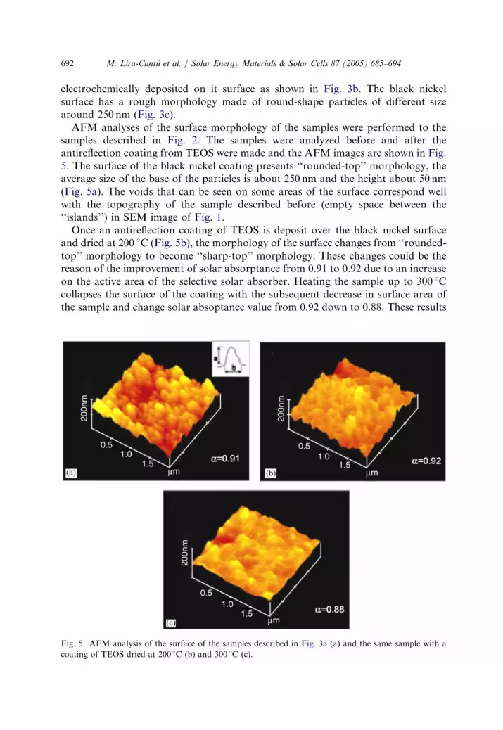
electrochemically deposited on it surface as shown in Fig. 3b. The black nickelsurface has a rough morphology made of round-shape particles of different sizearound 250 nm (Fig. 3c).AFM analyses of the surface morphology of the samples were performed to the
samples described in Fig. 2. The samples were analyzed before and after theantireflection coating from TEOS were made and the AFM images are shown in Fig.5. The surface of the black nickel coating presents ‘‘rounded-top’’ morphology, theaverage size of the base of the particles is about 250 nm and the height about 50 nm(Fig. 5a). The voids that can be seen on some areas of the surface correspond wellwith the topography of the sample described before (empty space between the‘‘islands’’) in SEM image of Fig. 1.Once an antireflection coating of TEOS is deposit over the black nickel surface
and dried at 200 1C (Fig. 5b), the morphology of the surface changes from ‘‘rounded-top’’ morphology to become ‘‘sharp-top’’ morphology. These changes could be thereason of the improvement of solar absorptance from 0.91 to 0.92 due to an increaseon the active area of the selective solar absorber. Heating the sample up to 300 1Ccollapses the surface of the coating with the subsequent decrease in surface area ofthe sample and change solar absoptance value from 0.92 down to 0.88. These results
Fig. 5. AFM analysis of the surface of the samples described in Fig. 3a (a) and the same sample with a
coating of TEOS dried at 200 1C (b) and 300 1C (c).

ARTICLE IN PRESS
Fig. 6. Cross section image by SEM of the samples described in Fig. 3b. From left to right: stainless steel
AISI type 316L substrate, bright nickel coating, black nickel coating and SiO2 coating from TEOS.
M. Lira-Cantu et al. / Solar Energy Materials & Solar Cells 87 (2005) 685–694 693
shows the direct relation between the morphology of the solar absorber substratewith the solar absoptance capacity showing that a careful control of the dryingtemperature must be considered.In order to analyze the thickness of each coating on the stainless steel substrate,
SEM analysis of a lateral side of the final plate was made. The plate was embeled inan epoxy resin, polished and gold-coated before analysis. Due to the hardness of thestainless steel and softness of the SiO2 coating, a good polished surface was notpossible and the SiO2 coating was separated from the surface. Fig. 6 shows the SEMimage of the stainless steel substrate and each of the different coatings. The SEMimage can clearly be divide in four parts: (from left to right) the stainless steelsubstrate, the bright nickel coating, the black nickel solar absorber coating andfinally the SiO2 coating from TEOS. The thickness of the bright nickel coatingdepends on the homogeneity of the stainless steel surface and varied from 600 nm to1.7 mm. The black nickel coating thickness is observed to be between 1.3 and 1.7 mm,and no distinction can be observed between the first and second deposition baths.Finally the antireflection coating of SiO2 (far right) presented a thickness of about400 nm.
4. Conclusion
Stainless steel AISI type 316L was effectively use as substrate for theelectrodeposition of black nickel solar absorber coating. The substrate was firstelectrochemically coated with a bright metallic nickel film before the final blacknickel coating was applied. For the solar absorber coating it was necessary to appliedtwo different current densities with an intermediate drying step in nitrogenatmosphere. The current densities applied are in the range of 10 and 25mA forthe first and second deposit, respectively. Small variation of the current density

ARTICLE IN PRESS
M. Lira-Cantu et al. / Solar Energy Materials & Solar Cells 87 (2005) 685–694694
applied from the original value did not have high influence on the solar absorptanceand thermal emittance values of the sample. Nevertheless we observed that thedeposition time is an important parameter and must be carefully controlled.Deposition times greater than 60 and 90 s for the first and second electrodepositsrespectively developed in high solar absorptance but poor thermal emittance. Theelectrochemical deposition parameters which give the best performance are: for thefirst coating12.6mA for 60 s was applied followed by a drying step under nitrogenand finally the second coating at 23.6mA for 90 s. Values of absortivity of a ¼ 0:91and emitivity of � ¼ 0:1 were obtained. These values are in well agreement with thosereported by Wackelgard [2] applying the same conditions on nickel and aluminumsubstrates. In our case we were not able to obtain emittivity values higher than 0.1possibly due to the limitation of the stainless steel substrate. An antireflectioncoating based on TEOS was made by the dip-coating technique and showed toimprove the absorptivity value of the sample when drying at 200 1C, neverthelessheating the sample at 300 1C decreases the absorptivity values due to the degradationof the black nickel surface. The thickness of the black nickel coating was obtainedbetween 1.3 and 1.7 mm and is directly influenced by deposition time. The SiO2
antireflection coating from TEOS was shown to be of about 400 nm on thicknesswhen dip-coated at constant speed of 30 cm/min.
Acknowledgements
M. Lira Cantu acknowledges the work contract from SOLECO (2002 Barcelona,Spain) for the realization of the present research work and the useful help from Dr.Angel Morales Sabio (CIEMAT).
References
[1] T. Tesfamichael, E. Wackelgard, Sol. Energy 68 (4) (2000) 335–341.
[2] E. Wackelgard, Sol. Energy Mater. Sol. Cells 56 (1) (1998) 35–44.
[3] M. Farooq, A.A. Green, M.G. Hutchins, Sol. Energy Mater. Sol. Cells 54 (1–4) (1998) 67–73.
[4] E. Wackelgard, G. Hultmark, Sol. Energy Mater. Sol. Cells 54 (1–4) (1998) 165–170.
[5] E. Avendano, A. Azens, G.A. Niklasson, in: Proceedings of SPIE—The International Society of
Optical Engineering, San Diego, USA, 2001.
[6] K. Gelin, T. Bostrom, E. Wackelgard, Sol. Energy 77 (1) (2004) 115–119.
[7] S. John, Met. Finish. 95 (6) (1997) 84–86.