electrical products - frank keerl
TRANSCRIPT

IDE
AL
EL
EC
TR
ICA
L P
RO
DU
CT
S F
UL
L-L
INE
CA
TA
LO
G
IDEAL INDUSTRIES, INC.1375 PARK AVENUE, SYCAMORE, IL 60178, USA
815-895-5181 • 800-435-0705 IN USA
INTERNATIONAL OFFICES:
AUSTRALIA / BRAZIL / CANADA / CHINA / FRANCE / GERMANY / INDIA / MEXICO / PUERTO RICO / UK
FOR COMPLETE SALES OFFICE CONTACT INFORMATION, V IS IT US AT:
WWW.IDEALIND.COM
P-070 2/16
FULL-LINE CATALOG
ELECTRICAL PRODUCTS
1 9 1 6 2 0 1 6

An American Original.AT HOME IN THE HEART OF AMERICA.
Entrepreneurial in spirit, grounded in the values of American ingenuity, IDEAL was founded on the basis that every product we make will exceed the value of the price paid for it. When it comes to creating value, IDEAL is an American original. Today, we exemplify those values in our vision, our mission and the future of our business. We are investing in the success and revitalization of American innovation and we are committed to manufacturing American Value In Every Tool We Make.
IDEAL IS WITH YOU EVERY STEP OF THE WAY.
We believe in innovative ideas for hardworking professionals — skilled tradesmen like electricians, contractors, mechanics, data communications pros and systems builders. These unsung problem solvers demand smart, tough, high-performance products that work right the first time. They also demand the innovations that keep them a step ahead of the challenges that drive the industries in which they work.
We innovate by listening. While most companies tell customers “Here’s what we’ve got,” we’re constantly asking, “What do you need?”
Wire Connectors
IDEAL is the leader in wire connectors. For wire termination, IDEAL is the industry standard.
Wire Pulling Lubricants
The environmentally safe lubes from IDEAL provide exceptional lubricity for rapid pulls.
Fish Tapes
IDEAL manufactures a variety of fish tapes for all applications, and our durable impact-resistant cases are the best in the market.
Conduit Benders
IDEAL benders are constructed of exceptionally durable materials and reinforced at stress points for long life.
Wire Strippers
Ergonomically designed in a variety of models for every application, IDEAL manufactures the finest wire strippers on the market.
MerchandisingMAXIMIZE YOUR SALES BY MAKING KEY PRODUCTS STAND OUT.
Your store’s shelf is a battleground for the electrician’s dollar. If it’s advertising that gets customers into the store, it’s merchandising that gets them to select the right products for the job once they are there. At IDEAL Electrical, we are dedicated to building in-store merchandising to maximize your sales by making key products stand out, educating the tradesman on the right tools for the job and giving them one stop shop options to get everything they need and get back on the job site.
IDEAL Electrical merchandising solutions include our most basic racks and signage to our compelling and powerful Profit Center solutions. As the market leader in many of the categories we serve, you can count on IDEAL Electrical to be your category partner to drive profitable growth and deliver a shopping experience that is meaningful to the electrician.
Counter Displays
Perfect for showing off impulse items or specialty SKUs. Available to help maximize your point-of- purchase sales.
Floor Displays
Maximize your floor space with an attractive design. IDEAL floor displays make it easy for your customers to browse for specific products.
Rolling Displays
Arrange your displays and move them anywhere on your showroom floor with ease.
Wall Displays
Gondolas, specialty displays, signage and accessories provide a clutter-free organized area in your store.
Ask your IDEAL Sales Rep about our Merchandising Seminars!

J. WALTER BECKERFOUNDER
Celebrating 100 yearsof Success with YOU!
We at IDEAL would like to thank all of our channel
partners and customers for helping us to achieve
this milestone! Since the beginning, this family-run
enterprise has been committed to building
ideal relationships with its customers,
employees and communities.
IDEAL_2016_Catalog_100_Ad.indd 1 1/27/16 1:59 PM
Table of ConTenTs
www.idealind.Com • 1-800-435-0705 CusTomer assisTanCe
wire TerminaTion PreCision wire sTriPPing
TesT & measuremenT
daTaComm/neTworksTools & suPPlies
A
D
EB
Twist-on Wire Connectors . . . . . . . . . . . . . A-6
WeatherProof™ & UnderGround™ Wire Connectors . . . . . . . . . . . . . . . . . . . . A-9
BUCHANAN Wire Connectors . . . . . . . .A-11
SpliceLine® In-Line Wire Connectors . . .A-14
In-Sure® Push-In Wire Connectors . . . . .A-14
PowerPlug® Luminaire Disconnects . . . .A-16
Grounding Products . . . . . . . . . . . . . . . . .A-18
SLK® Disconnect Fuse Kits . . . . . . . . . . .A-22
Crimp Terminals & Splices . . . . . . . . . . . .A-29
Terminal Strips . . . . . . . . . . . . . . . . . . . . . .A-34
BUCHANAN B-TAP® Connectors . . . . . .A-37
Stripmaster® Wire Strippers . . . . . . . . . . . .C-5
Custom Stripmaster® Wire Strippers . . . . .C-7
Pneumatic Wire Strippers . . . . . . . . . . . . C-10
Circuit Tracers . . . . . . . . . . . . . . . . . . . . . . .D-3
Clamp Meters . . . . . . . . . . . . . . . . . . . . . . .D-6
Circuit Analyzers . . . . . . . . . . . . . . . . . . . D-11
Multimeters . . . . . . . . . . . . . . . . . . . . . . . D-13
Specialty Testers . . . . . . . . . . . . . . . . . . . D-14
Accessories . . . . . . . . . . . . . . . . . . . . . . . D-16
Testers . . . . . . . . . . . . . . . . . . . . . . . . . . . . . . E-3
Compression Tools & Connectors . . . . . . . E-5
Crimp Tools/Die Sets . . . . . . . . . . . . . . . . . . E-7
Tools . . . . . . . . . . . . . . . . . . . . . . . . . . . . . . . E-8
Modular Plugs . . . . . . . . . . . . . . . . . . . . . .E-10
Strippers . . . . . . . . . . . . . . . . . . . . . . . . . . .E-11
Splitters . . . . . . . . . . . . . . . . . . . . . . . . . . . .E-13
Kits . . . . . . . . . . . . . . . . . . . . . . . . . . . . . . .E-13
Fiber Optics . . . . . . . . . . . . . . . . . . . . . . . .E-16
Fish Tapes & Accessories . . . . . . . . . . . . . .B-4
Fishing Poles . . . . . . . . . . . . . . . . . . . . . . . .B-7
Wire Pulling Lubricants & Accessories . . . . B-8
Pulling Supplies . . . . . . . . . . . . . . . . . . . . B-12
Conduit Benders . . . . . . . . . . . . . . . . . . . B-14
Wire Strippers . . . . . . . . . . . . . . . . . . . . . B-16
Pliers . . . . . . . . . . . . . . . . . . . . . . . . . . . . . B-21
Miscellaneous Hand Tools . . . . . . . . . . . B-24
Cable Cutters . . . . . . . . . . . . . . . . . . . . . . B-28
Screwdrivers . . . . . . . . . . . . . . . . . . . . . . B-31
Industrial Bits & Accessories . . . . . . . . . B-39
Insulated Hand Tools . . . . . . . . . . . . . . . . B-42
Tool Carriers & Bags . . . . . . . . . . . . . . . . B-49
Hand Tool Kits . . . . . . . . . . . . . . . . . . . . . B-52
Cutting & Holemaking Tools . . . . . . . . . . B-56
Cable Ties . . . . . . . . . . . . . . . . . . . . . . . . . B-70
Cable Staples . . . . . . . . . . . . . . . . . . . . . . B-77
Wire Markers . . . . . . . . . . . . . . . . . . . . . . B-78
Switches . . . . . . . . . . . . . . . . . . . . . . . . . . B-79
Heat Shrink . . . . . . . . . . . . . . . . . . . . . . . . B-86
Heat Guns . . . . . . . . . . . . . . . . . . . . . . . . B-91
Lockout/Tagout . . . . . . . . . . . . . . . . . . . . B-92
Safety Signs . . . . . . . . . . . . . . . . . . . . . . B-101
Safety Tapes . . . . . . . . . . . . . . . . . . . . . . B-102
Commutator Maintenance . . . . . . . . . . B-113
C
A-1
Wire TerminATion
WWW.ideAlind.com • 1-800-435-0705 cusTomer AssisTAnce
Twist-On Wire Connectors Wire-Nut® Wire Connectors ....................................A-6 Wing-Nut® Wire Connectors ...................................A-7 Twister® Wire Connectors ........................................A-8 WeatherProof™/UnderGround™ Wire Connectors .....................................................A-9 Twister® Al/Cu Wire Connectors ..........................A-10 B-CAP® Wire Connectors .......................................A-11 WireTwist™/WingTwist™ Wire Connectors ........A-12
Push-In Wire Connectors SpliceLine™ In-Line Wire Connectors .................A-15 In-Sure™ Push-In Wire Connectors .....................A-15
Luminaire Disconnects PowerPlug® Luminaire Disconnects ....................A-17
Grounding Products Grounding Pigtails ....................................................A-19 Grounding Screws ....................................................A-20
Crimp Connectors ......................................................A-21
Streetlight Kits SLK® ............................................................................A-23 BUCHANAN Streetlight Kits .................................A-26
Electrical Terminals, Crimp and Screw Connectors Ring ............................................................................. A-30 Spade.......................................................................... A-30 Disconnects ...............................................................A-31 Splices .........................................................................A-32
Terminal Strips ............................................................ A-34
Tap Connectors B-TAP® Insulation-Piercing Connectors ..............A-37

WWW.ideAlind.com • 1-800-435-0705 cusTomer AssisTAnce
Wire TerminATion
A-2
WWW.ideAlind.com • 1-800-435-0705 cusTomer AssisTAnce
Wire TerminATion
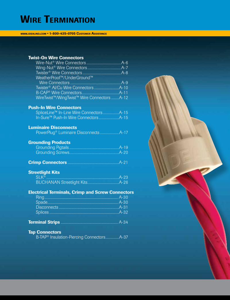
Ingenuity & PerformanceFrom the introduction of our first twist-on wire connector in 1928, IDEAL has been the leading force in wire termination technology. Through ingenuity, proven performance and innovative engineering, IDEAL continues to lead the electrical industry with products that deliver more than the price paid.
WWW.ideAlind.com • 1-800-435-0705 cusTomer AssisTAnce
A-2
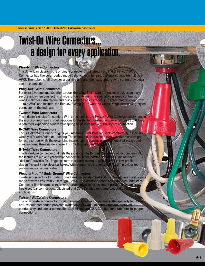
Twist-On Wire Connectors... a design for every application.Wire-Nut® Wire ConnectorsThis American classic is the original connector that started it all. The Wire-Nut® Wire Connector has five color-coded models that cover a full range of applications from 20 to 6 AWG. The ribbed shell provides a positive grip and the fixed, square-wire spring provides a secure connection.
Wing-Nut® Wire ConnectorsFor extra leverage and superior torque, the Wing-Nut® Wire Connector provides an easy, secure grip when connecting a wide range of wires. The specially designed contoured wings make for extra torque and quick work on any electrical job. Three models cover from 18 to 6 AWG and include, the Red 452® Wing-Nut® with the widest range of any wing-styled connector in the industry.
Twister® Wire ConnectorsThe industry’s choice for comfort. With three models, the Twister® Wire Connector easily handles the most common wiring configurations for residential construction projects from 22 to 6 AWG. A patented, expanding square-wire spring helps to ensure a quick, secure connection.
B-CAP® Wire ConnectorsThe B-CAP® Wire Connector gets you into those hard-to-reach spots comfortably, especially when you’re retrofitting or updating. The contoured classic fin design provides a secure grip for extra torque, while the expanding interior spring accepts a wide range of wire sizes and combinations. Three models cover from 22 through 6 AWG.
B-Twist™ Wire ConnectorsThe All-in-One connector that gets the job done. The B-Twist™ Wire Connector combines all the features of red and yellow wire connectors in one outstanding design. The rounded “dial-top” provides fast, fingertip starts that come to torque quickly and the low-profile design fits easily into electrical boxes. With a super-wide range, the B-Twist™ provides top performance at a great value.
WeatherProof™ / UnderGround™ Wire ConnectorsTwist-on connectors for underground and wet location installations. Six models cover a wide range of wire sizes from 22 through 6 AWG. The WeatherProof™ and UnderGround™ Wire Connector line features a 100% non-hardening silicone sealant to provide safe, moisture-free electrical connections. UL Listed and CSA Certified for damp/wet and direct burial applications.
Twister® Al/Cu Wire ConnectorsThe only twist-on connector for aluminum-to-copper connections. The specially formulated anti-oxidant compound prevents oxidation on aluminum conductors for improved conductivity and cooler connections. UL Listed and CSA Certified for aluminum-to-copper connections.
A-3
From the introduction of our first twist-on wire connector in 1928, IDEAL has been the leading force in wire termination technology. Through ingenuity, proven performance and innovative engineering, IDEAL continues to lead the electrical industry with products that deliver more than the price paid.
WWW.ideAlind.com • 1-800-435-0705 cusTomer AssisTAnce
A-3
A-4
Wire TerminATionWWW.ideAlind.com • 1-800-435-0705 cusTomer AssisTAnce
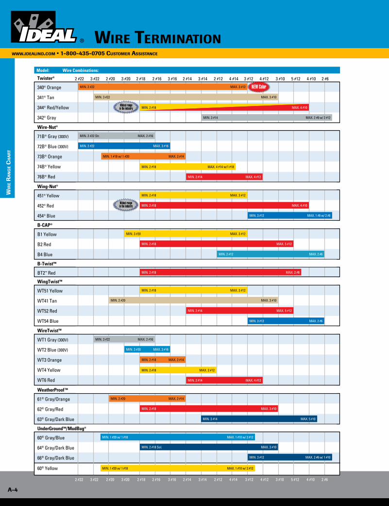
MIN. 2 #18 MAX. 4 #10
2 #22 3 #22 2 #20 3 #20 2 #18 2 #16 3 #16 2 #14 3 #14 2 #12 4 #14 3 #12 4 #12 3 #10 5 #12 4 #10 2 #6
Wire-Nut®
71B® Gray (300V)
72B® Blue (300V)
73B® Orange
74B® Yellow
76B® Red
Wing-Nut®
451® Yellow
452® Red
454® Blue
Twister®
340® Orange
341® Tan
344® Red/Yellow
342® Gray
B-CAP®
B1 Yellow
B2 Red
B4 Blue
MIN. 2 #22 MAX. 3 #16
MIN. 2 #22 MAX. 3 #12
MIN. 1 #18 w/ 1 #20 MAX. 2 #14
MIN. 2 #18 MAX. 4 #14 w/1 #18
MIN. 2 #14 MAX. 4 #12
MIN. 2 #14 MAX. 4 #12
MIN. 2 #22 Str. MAX. 2 #16
MIN. 2 #18 MAX. 4 #10
MIN. 2 #18 MAX. 5 #12
MIN. 2 #18 MAX. 3 #10
MIN. 2 #14 MAX. 5 #12
MIN. 3 #22 MAX. 3 #10
MIN. 3 #22 MAX. 2 #16
MIN. 2 #20 MAX. 3 #10
MIN. 2 #20 MAX. 2 #14
MIN. 2 #18 MAX. 3 #12
MIN. 2 #18 MAX. 3 #12
MIN. 2 #18 MAX. 2 #14
MIN. 3 #20 MAX. 3 #12
MIN. 3 #20 MAX. 3 #16
MIN. 2 #18 MAX. 2 #12
MIN. 3 #12 MAX. 1 #6 w/ 2 #8
MIN. 3 #12 MAX. 2 #6
MIN. 3 #14 MAX. 2 #8 w/ 2 #12
MIN. 3 #14 MAX. 5 #10
MIN. 2 #12 MAX. 2 #6
MIN. 2 #18 MAX. 4 #10
B-TwistTM
BT2™ Red MIN. 2 #18 MAX. 2 #8
Model: Wire Combinations:
2 #22 3 #22 2 #20 3 #20 2 #18 2 #16 3 #16 2 #14 3 #14 2 #12 4 #14 3 #12 4 #12 3 #10 5 #12 4 #10 2 #6
Wir
e r
An
ge
ch
Ar
T
60® Yellow
UnderGroundTM/MudBug®
60® Gray/Blue
64® Gray/Dark Blue
66® Gray/Dark Blue
WeatherProof TM
61® Gray/Orange
62® Gray/Red
63® Gray/Dark Blue
WingTwistTM
WT51 Yellow
WT41 Tan
WT52 Red
WT54 Blue
WireTwistTM
WT1 Gray (300V)
WT2 Blue (300V)
WT3 Orange
WT4 Yellow
WT6 Red
NEW Color
Widest range in the industry
Widest range in the industry
MIN. 1 #20 w/ 1 #18 MAX. 1 #10 w/ 2 #12
MIN. 2 #18 Sol. MAX. 3 #10
MIN. 3 #12 MAX. 2 #6 w/ 1 #10
MIN. 1 #20 w/ 1 #18 MAX. 1 #10 w/ 2 #12
A-5
WWW.ideAlind.com • 1-800-435-0705 cusTomer AssisTAnce
Model: Wire Combinations:
2 #22 3 #22 2 #20 3 #20 2 #18 2 #16 3 #16 2 #14 3 #14 2 #12 4 #14 3 #12 4 #12 3 #10 5 #12 4 #10 2 #6
Wir
e co
nn
ecTo
r Ap
plic
ATio
n gu
ide
Twister®
340® Orange l l l l l l l l
341® Tan l l l l l l l l l
344® Red/Yellow l l l l l l l l l l l
342® Gray l l l l l
Wire-Nut®
71B® Gray l l l
72B® Blue l l l l l
73B® Orange l l l l l l l
74B® Yellow l l l l l l
76B® Red l l l l l l l l l l
Wing-Nut®
451® Yellow l l l l l l l
452® Red l l l l l l l l l l
454® Blue l l l l l
B-CAP®
B1 Yellow l l l l l l l l
B2 Red l l l l l l l l l l
B4 Blue l l l l l
B-Twist™
BT2™ Red l l l l l l l l l l
WingTwist™
WT51 Yellow l l l l l l l l
WT41 Tan l l l l l l l l l
WT52 Red l l l l l l l l l l
WT54 Blue l l l l l
WireTwist™
WT1 Gray l l l
WT2 Blue l l l l l
WT3 Orange l l l l l l l
WT4 Yellow l l l l l l l
WT6 Red l l l l l l l l l l
WeatherProof™
61® Gray/Orange l l l l l l l l
62® Gray/Red l l l l l l l l l
63® Gray/Dk. Blue l l l l l l l l l
UnderGround™
60® Gray/Blue l l l l l l l l l l
64® Gray/Dk. Blue l l l l l l l
66® Gray/Dk. Blue l l
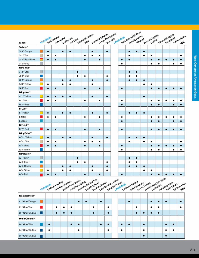
RESIDENTIAL
COMMERCIAL
Light Switches
Can Lights
Receptacles
Thermostat Controls
Smoke/CO Detectors
Ceiling Fans
HVACGarage Door Openers
Door Bells
Multi-Gang Switch Boxes
Security Systems
Intercoms
Recessed Lighting
ControlsIllu
minated Signage
Receptacles
3-Phase Motors
HVAC
RESIDENTIAL
COMMERCIAL
Landscape Lighting
Patio/Deck Lighting
Pool Filters/Controls
Bathroom/Spa Vent Fans
Basement/Garage
Outdoor Power Outlets
Security Systems
Lawn-Sprinkler Controls
Sump/Well Pumps
Landscape Lighting
Security Systems
Exterior Lighting
Street/Parking Lot Lighting
Car Washes
Processing Plants
Traffic Signals
Ejection Pumps
HVAC
Model
Wire TerminaTion
A-6
www.idealind.com • 1-800-435-0705 customer assistance
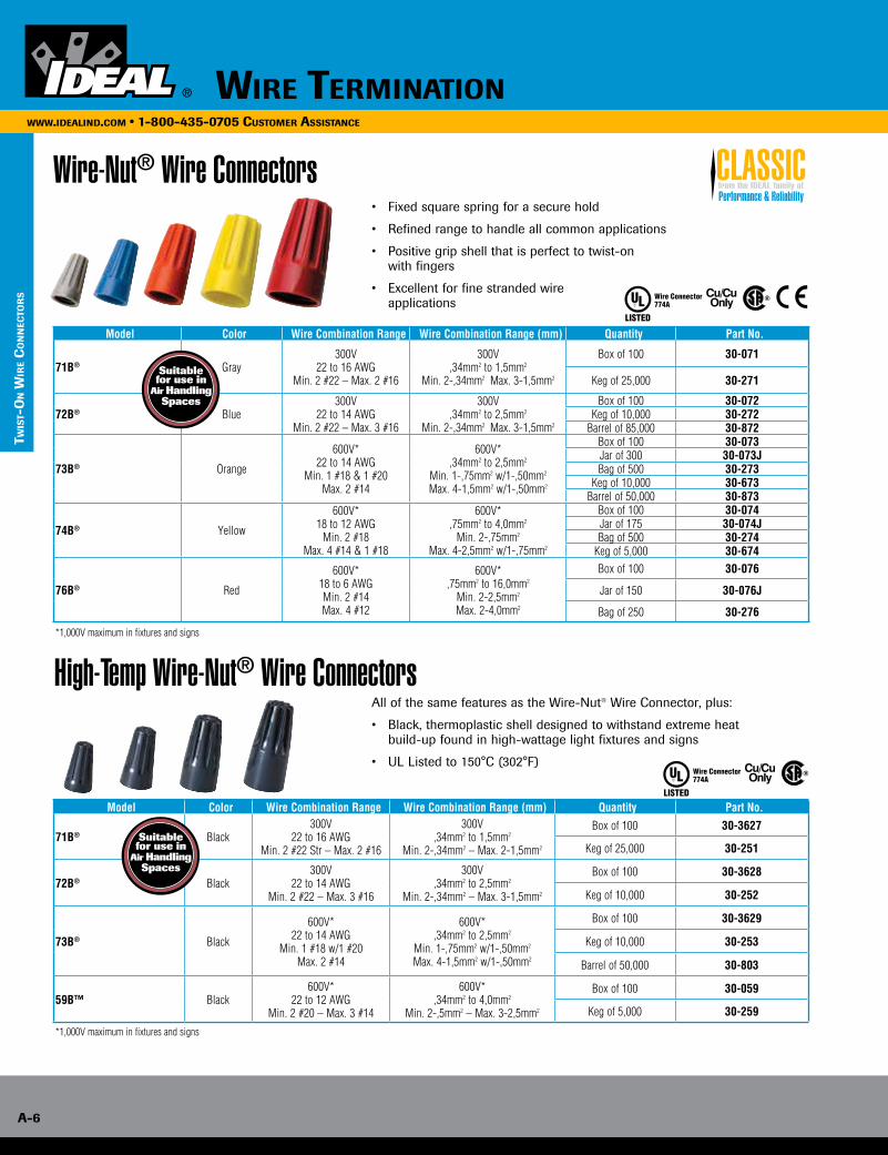
Wire-Nut® Wire Connectors• Fixed square spring for a secure hold
• Refined range to handle all common applications
• Positive grip shell that is perfect to twist-on with fingers
• Excellent for fine stranded wire applications
Model Color Wire Combination Range Wire Combination Range (mm) Quantity Part No.
71B® Gray300V
22 to 16 AWGMin. 2 #22 – Max. 2 #16
300V,34mm2 to 1,5mm2
Min. 2-,34mm2 Max. 3-1,5mm2
Box of 100 30-071
Keg of 25,000 30-271
72B® Blue300V
22 to 14 AWGMin. 2 #22 – Max. 3 #16
300V,34mm2 to 2,5mm2
Min. 2-,34mm2 Max. 3-1,5mm2
Box of 100 30-072Keg of 10,000 30-272
Barrel of 85,000 30-872
73B® Orange
600V*22 to 14 AWG
Min. 1 #18 & 1 #20Max. 2 #14
600V*,34mm2 to 2,5mm2
Min. 1-,75mm2 w/1-,50mm2
Max. 4-1,5mm2 w/1-,50mm2
Box of 100 30-073Jar of 300 30-073JBag of 500 30-273
Keg of 10,000 30-673Barrel of 50,000 30-873
74B® Yellow
600V*18 to 12 AWG
Min. 2 #18Max. 4 #14 & 1 #18
600V*,75mm2 to 4,0mm2
Min. 2-,75mm2
Max. 4-2,5mm2 w/1-,75mm2
Box of 100 30-074Jar of 175 30-074JBag of 500 30-274
Keg of 5,000 30-674
76B® Red
600V*18 to 6 AWGMin. 2 #14Max. 4 #12
600V*,75mm2 to 16,0mm2
Min. 2-2,5mm2
Max. 2-4,0mm2
Box of 100 30-076
Jar of 150 30-076J
Bag of 250 30-276
*1,000V maximum in fixtures and signs
Suitable for use in
Air Handling Spaces
High-Temp Wire-Nut® Wire ConnectorsAll of the same features as the Wire-Nut® Wire Connector, plus:
• Black, thermoplastic shell designed to withstand extreme heat build-up found in high-wattage light fixtures and signs
• UL Listed to 150°C (302°F)
Model Color Wire Combination Range Wire Combination Range (mm) Quantity Part No.
71B® Black300V
22 to 16 AWGMin. 2 #22 Str – Max. 2 #16
300V,34mm2 to 1,5mm2
Min. 2-,34mm2 – Max. 2-1,5mm2
Box of 100 30-3627
Keg of 25,000 30-251
72B® Black300V
22 to 14 AWGMin. 2 #22 – Max. 3 #16
300V,34mm2 to 2,5mm2
Min. 2-,34mm2 – Max. 3-1,5mm2
Box of 100 30-3628
Keg of 10,000 30-252
73B® Black
600V*22 to 14 AWG
Min. 1 #18 w/1 #20Max. 2 #14
600V*,34mm2 to 2,5mm2
Min. 1-,75mm2 w/1-,50mm2
Max. 4-1,5mm2 w/1-,50mm2
Box of 100 30-3629
Keg of 10,000 30-253
Barrel of 50,000 30-803
59B™ Black 600V*
22 to 12 AWGMin. 2 #20 – Max. 3 #14
600V*,34mm2 to 4,0mm2
Min. 2-,5mm2 – Max. 3-2,5mm2
Box of 100 30-059
Keg of 5,000 30-259
*1,000V maximum in fixtures and signs
Performance & Reliabilityfrom the IDEAL family ofCLASSIC
TWis
T-o
n W
ire
co
nn
ecTo
rs
Suitable for use in
Air Handling Spaces
Wire TerminaTion A-7
www.idealind.com • 1-800-435-0705 customer assistance
TW
isT-o
n Wir
e co
nn
ecTo
rs
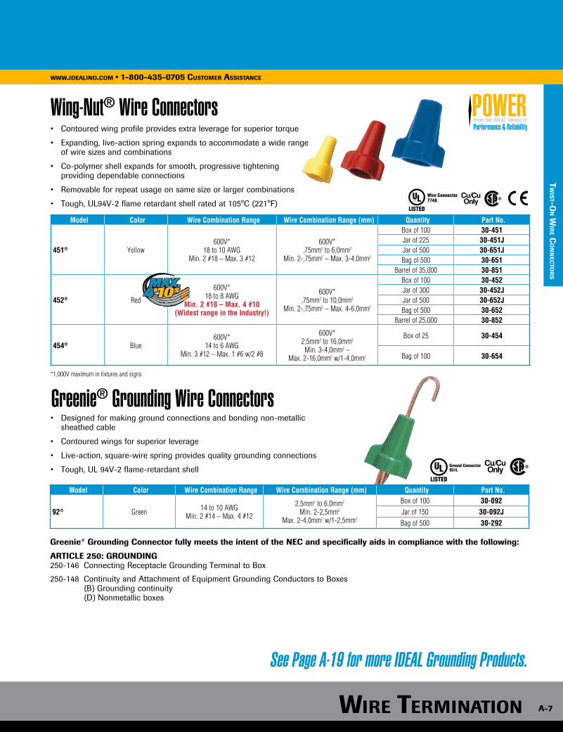
Wing-Nut® Wire Connectors• Contoured wing profile provides extra leverage for superior torque
• Expanding, live-action spring expands to accommodate a wide range of wire sizes and combinations
• Co-polymer shell expands for smooth, progressive tightening providing dependable connections
• Removable for repeat usage on same size or larger combinations
• Tough, UL94V-2 flame retardant shell rated at 105°C (221°F)
• Designed for making ground connections and bonding non-metallic sheathed cable
• Contoured wings for superior leverage
• Live-action, square-wire spring provides quality grounding connections
• Tough, UL 94V-2 flame-retardant shell
Greenie® Grounding Connector fully meets the intent of the NEC and specifically aids in compliance with the following:
ARTICLE 250: GROUNDING250-146 Connecting Receptacle Grounding Terminal to Box
250-148 Continuity and Attachment of Equipment Grounding Conductors to Boxes (B) Grounding continuity (D) Nonmetallic boxes
Greenie® Grounding Wire Connectors
See Page A-19 for more IDEAL Grounding Products.
Model Color Wire Combination Range Wire Combination Range (mm) Quantity Part No.
451® Yellow600V*
18 to 10 AWGMin. 2 #18 – Max. 3 #12
600V*,75mm2 to 6,0mm2
Min. 2-,75mm2 – Max. 3-4,0mm2
Box of 100 30-451Jar of 225 30-451JJar of 500 30-651JBag of 500 30-651
Barrel of 35,000 30-851
452® Red
600V*18 to 8 AWG
Min. 2 #18 – Max. 4 #10(Widest range in the Industry!)
600V*,75mm2 to 10,0mm2
Min. 2-,75mm2 – Max. 4-6,0mm2
Box of 100 30-452Jar of 300 30-452JJar of 500 30-652JBag of 500 30-652
Barrel of 25,000 30-852
454® Blue 600V*
14 to 6 AWGMin. 3 #12 – Max. 1 #6 w/2 #8
600V*2,5mm2 to 16,0mm2
Min. 3-4,0mm2 – Max. 2-16,0mm2 w/1-4,0mm2
Box of 25 30-454
Bag of 100 30-654
*1,000V maximum in fixtures and signs
Model Color Wire Combination Range Wire Combination Range (mm) Quantity Part No.
92® Green 14 to 10 AWGMin. 2 #14 – Max. 4 #12
2,5mm2 to 6,0mm2 Min. 2-2,5mm2
Max. 2-4,0mm2 w/1-2,5mm2
Box of 100 30-092Jar of 150 30-092JBag of 500 30-292
Performance & Reliabilityfrom the IDEAL family ofPOWER
Wire TerminaTion
A-8
www.idealind.com • 1-800-435-0705 customer assistance
TWis
T-o
n W
ire
co
nn
ecTo
rs
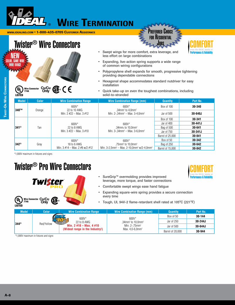
Twister® Wire Connectors• Swept wings for more comfort, extra leverage, and less effort on large combinations
• Expanding, live-action spring supports a wide range of common wiring configurations
• Polypropylene shell expands for smooth, progressive tightening providing dependable connections
• Hexagonal shape accommodates standard nutdriver for easy installation
• Quick take-up on even the toughest combinations, including solid-to-stranded
Model Color Wire Combination Range Wire Combination Range (mm) Quantity Part No.
340™ Orange600V*
22 to 10 AWGMin. 2 #22 – Max. 3 #12
600V*,34mm2 to 4,0mm2
Min. 2-,34mm2 – Max. 3-4,0mm2
Box of 100 30-340
Jar of 500 30-640J
341® Tan600V*
22 to 8 AWGMin. 3 #22 – Max. 3 #10
600V*,34mm2 to 10,0mm2
Min. 3-,34mm2 – Max. 3-6,0mm2
Box of 100 30-341Jar of 400 30-441JBag of 500 30-641Jar of 750 30-341J
Barrel of 25,000 30-841
342® Gray 600V*
18 to 6 AWGMin. 3 #14 – Max. 2 #8 w/2 #12
600V*,75mm2 to 10,0mm2
Min. 3-2,5mm2 – Max. 2-10,0mm2 w/2-4,0mm2
Box of 50 30-342Bag of 250 30-642
Barrel of 15,000 30-842
*1,000V maximum in fixtures and signs
Preferred ChoiCe for residential
Jobs
Twister® Pro Wire Connectors• SureGrip™ overmolding provides improved leverage, more torque, and faster connections
• Comfortable swept wings ease hand fatigue
• Expanding square-wire spring provides a secure connection every time
• Tough, UL 94V-2 flame-retardant shell rated at 105°C (221°F)
Model Color Wire Combination Range Wire Combination Range (mm) Quantity Part No.
344® Red/Yellow
600V*22 to 8 AWG
Min. 2 #18 – Max. 4 #10(Widest range in the Industry!)
600V*,34mm2 to 10,0mm2
Min. 2-,75mm2
Max. 4,0-6,0mm2
Box of 50 30-144
Jar of 250 30-244J
Jar of 500 30-644J
Barrel of 20,000 30-944 *1,000V maximum in fixtures and signs
Performance & Reliabilityfrom the IDEAL family ofCOMFORT
Performance & Reliabilityfrom the IDEAL family ofCOMFORT
neW Color, same Wide
Wire range

Wire TerminaTion A-9
www.idealind.com • 1-800-435-0705 customer assistance
TW
isT-o
n Wir
e co
nn
ecTo
rs
WeatherProof™ Wire Connectors
WeatherProof™ Wire ConnectorsModel Color Wire Combination Range Wire Combination Range (mm) Quantity Part No.
61® Gray/Orange600V*
22 to 14 AWGMin. 2 #20 – Max. 2 #14
600V*,34mm2 to 4,0mm2
Min. 2-,5mm2 – Max. 2-2,5mm2
Card of 25 30-1161Jar of 150 30-1261J
Carton of 1,000 30-1361
62® Gray/Red600V*
18 to 8 AWGMin. 2 #16 – Max. 2 #10
600V*,75mm2 to 10,0mm2
Min. 2-1,5mm2 – Max. 2-6,0mm2
Card of 20 30-1162Jar of 100 30-1262J
Carton of 1,000 30-1362
63® Gray/Dk. Blue600V*
16 to 6 AWGMin. 3 #14 – Max. 5 #10
600V*1,5mm2 to 16,0mm2
Min. 3-2,5mm2 – Max. 5-6,0mm2
Card of 15 30-1163Jar of 50 30-1263J
Carton of 1,000 30-1363
• 100% Silicone-based sealant protects against moisture and corrosion
• UL Listed to 486D for use in damp/wet locations or above-grade applications
• Easy to apply, pre-filled twist-on wire connectors
• Swept wing design is built for comfort and efficiency
• Eliminates the need for heat-shrink or excessive taping
• Tough, UL 94V-2 flame- retardant shell rated at 105°C (221°F)
UnderGround™ Wire Connectors
• 100% Silicone-based sealant protects against moisture and corrosion
• UL Listed to 486D for use in damp/wet locations or direct burial/below-grade applications
• Easy to apply, pre-filled twist-on wire connectors
• Expanding, live-action square-wire spring for fast, secure and long-lasting connections
• Deep skirt provides superior moisture resistance to protect connections
• Tough, UL 94V-2 flame-retardant shell rated at 105°C (221°F)
UnderGround™ Wire ConnectorsModel Color Wire Combination Range Wire Combination Range (mm) Quantity Part No.
60® Gray/Gray
600V*20 to 10 AWG
Min. 1 #20 w/1 #18Max. 1 #10 w/2 #12
600V*,5mm2 to 6,0mm2
Min. 1-,5mm2 w/1,75mm2
Max. 1-6,0mm2 w/2-4,0mm2
Card of 25 30-1160
Box of 100 30-1260
64® Gray/Dk. Blue600V*
18 to 8 AWGMin. 2 #18 Sol. – Max. 3 #10
600V*,75mm2 to 10,0mm2
Min. 2-,75mm2 Sol. – Max. 3-6,0mm2Box of 50 30-1264
66™ Gray/Dk. Blue600V*
14 to 6 AWGMin. 3 #12 – Max. 2 #6 w/1 #10
600V*2,5mm2 to 16,0mm2
Min. 3-4,0mm2 Sol. – Max. 2-16,0mm2 w/1-6,0mm2Box of 50 30-1066
Combination PackagesModel Color Quantity Part No.
61®/62® Gray/Orange • Gray/Red WeatherProof™ Wire Connectors Card of 10 (5 ea.) 30-616260®/64® Gray/Blue • Gray/Dk. Blue UnderGround™ Wire Connectors Card of 10 (5 ea.) 30-6064*1,000V maximum in fixtures and signs WARNING: One time use only. Do not reuse connector.
Combo PaCksavailable
Wire TerminaTion
A-10
www.idealind.com • 1-800-435-0705 customer assistance
TWis
T-o
n W
ire
co
nn
ecTo
rs
For A compleTe lisTing oF ul Approved Wire combinATions, visiT us AT WWW.ideAlind.com
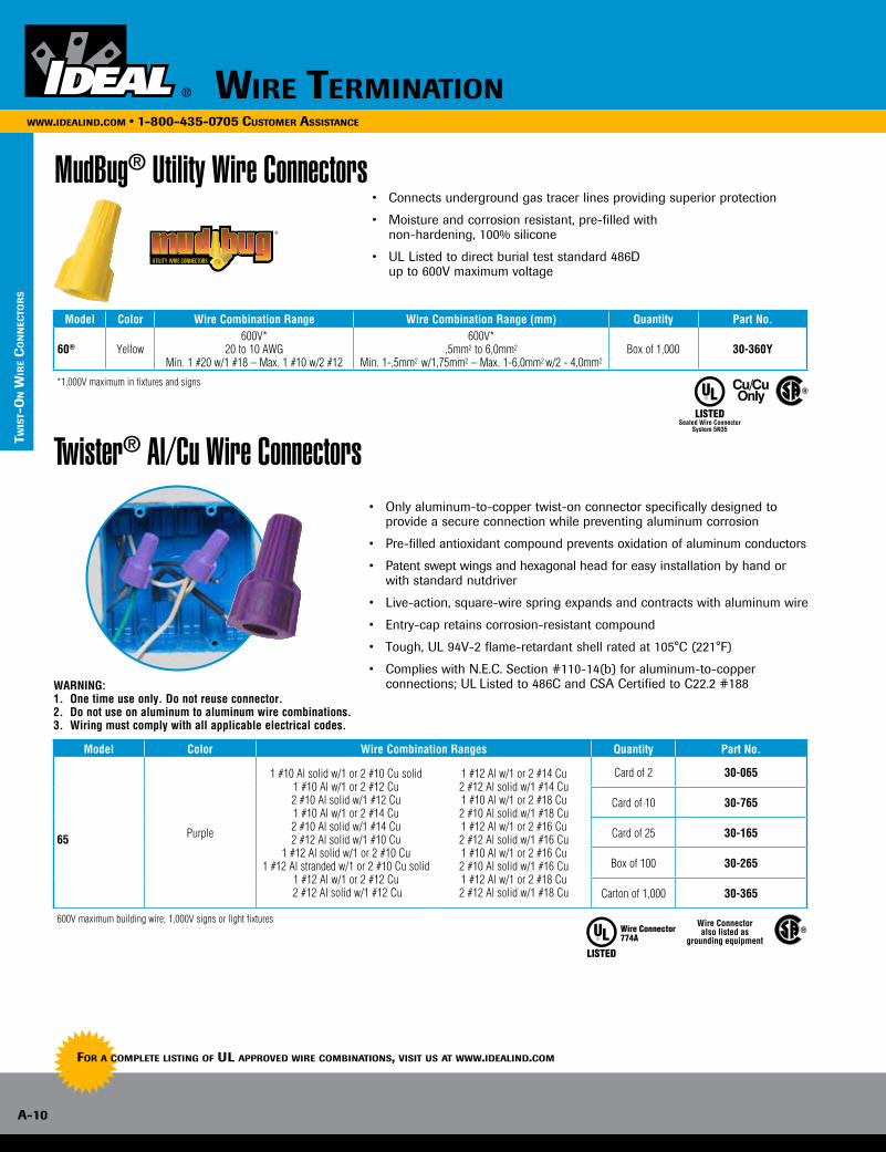
MudBug® Utility Wire Connectors• Connects underground gas tracer lines providing superior protection
• Moisture and corrosion resistant, pre-filled with non-hardening, 100% silicone
• UL Listed to direct burial test standard 486D up to 600V maximum voltage
Model Color Wire Combination Range Wire Combination Range (mm) Quantity Part No.
60® Yellow600V*
20 to 10 AWGMin. 1 #20 w/1 #18 – Max. 1 #10 w/2 #12
600V*,5mm2 to 6,0mm2
Min. 1-,5mm2 w/1,75mm2 – Max. 1-6,0mm2 w/2 - 4,0mm2Box of 1,000 30-360Y
*1,000V maximum in fixtures and signs
FILLED WIRE CONNECTORS
FILLED WIRE CONNECTORS
WEATHERPROOF™ WIRE CONNECTORS
UTILITY WIRE CONNECTORS
UNDERGROUND™ WIRE CONNECTORS
UTILITY WIRE CONNECTORS
UTILITY WIRE CONNECTORS
®
Twister® Al/Cu Wire Connectors• Only aluminum-to-copper twist-on connector specifically designed to
provide a secure connection while preventing aluminum corrosion
• Pre-filled antioxidant compound prevents oxidation of aluminum conductors
• Patent swept wings and hexagonal head for easy installation by hand or with standard nutdriver
• Live-action, square-wire spring expands and contracts with aluminum wire
• Entry-cap retains corrosion-resistant compound
• Tough, UL 94V-2 flame-retardant shell rated at 105°C (221°F)
• Complies with N.E.C. Section #110-14(b) for aluminum-to-copper connections; UL Listed to 486C and CSA Certified to C22.2 #188
Model Color Wire Combination Ranges Quantity Part No.
65 Purple
1 #10 Al solid w/1 or 2 #10 Cu solid1 #10 Al w/1 or 2 #12 Cu2 #10 Al solid w/1 #12 Cu 1 #10 Al w/1 or 2 #14 Cu 2 #10 Al solid w/1 #14 Cu 2 #12 Al solid w/1 #10 Cu
1 #12 Al solid w/1 or 2 #10 Cu 1 #12 Al stranded w/1 or 2 #10 Cu solid
1 #12 Al w/1 or 2 #12 Cu 2 #12 Al solid w/1 #12 Cu
1 #12 Al w/1 or 2 #14 Cu 2 #12 Al solid w/1 #14 Cu 1 #10 Al w/1 or 2 #18 Cu 2 #10 Al solid w/1 #18 Cu 1 #12 Al w/1 or 2 #16 Cu 2 #12 Al solid w/1 #16 Cu 1 #10 Al w/1 or 2 #16 Cu 2 #10 Al solid w/1 #16 Cu 1 #12 Al w/1 or 2 #18 Cu 2 #12 Al solid w/1 #18 Cu
Card of 2 30-065
Card of 10 30-765
Card of 25 30-165
Box of 100 30-265
Carton of 1,000 30-365
600V maximum building wire; 1,000V signs or light fixtures Wire Connectoralso listed as
grounding equipment
WARNING:1. One time use only. Do not reuse connector. 2. Do not use on aluminum to aluminum wire combinations. 3. Wiring must comply with all applicable electrical codes.
Wire TerminaTion A-11
www.idealind.com • 1-800-435-0705 customer assistance
TW
isT-o
n Wir
e co
nn
ecTo
rs
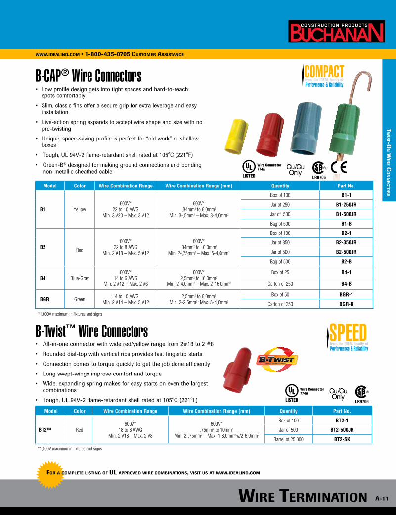
B-CAP® Wire Connectors• Low profile design gets into tight spaces and hard-to-reach
spots comfortably
• Slim, classic fins offer a secure grip for extra leverage and easy installation
• Live-action spring expands to accept wire shape and size with no pre-twisting
• Unique, space-saving profile is perfect for “old work” or shallow boxes
• Tough, UL 94V-2 flame-retardant shell rated at 105°C (221°F)
• Green-B® designed for making ground connections and bonding non-metallic sheathed cable
B-Twist™ Wire Connectors• All-in-one connector with wide red/yellow range from 2#18 to 2 #8
• Rounded dial-top with vertical ribs provides fast fingertip starts
• Connection comes to torque quickly to get the job done efficiently
• Long swept-wings improve comfort and torque
• Wide, expanding spring makes for easy starts on even the largest combinations
• Tough, UL 94V-2 flame-retardant shell rated at 105°C (221°F)
Model Color Wire Combination Range Wire Combination Range (mm) Quantity Part No.
B1 Yellow600V*
22 to 10 AWGMin. 3 #20 – Max. 3 #12
600V*,34mm2 to 6,0mm2
Min. 3-,5mm2 – Max. 3-4,0mm2
Box of 100 B1-1
Jar of 250 B1-250JR
Jar of 500 B1-500JR
Bag of 500 B1-B
B2 Red
600V*22 to 8 AWG
Min. 2 #18 – Max. 5 #12
600V*,34mm2 to 10,0mm2
Min. 2-,75mm2 – Max. 5-4,0mm2
Box of 100 B2-1
Jar of 350 B2-350JR
Jar of 500 B2-500JR
Bag of 500 B2-B
B4 Blue-Gray600V*
14 to 6 AWGMin. 2 #12 – Max. 2 #6
600V*2,5mm2 to 16,0mm2
Min. 2-4,0mm2 – Max. 2-16,0mm2
Box of 25 B4-1
Carton of 250 B4-B
BGR Green 14 to 10 AWGMin. 2 #14 – Max. 5 #12
2,5mm2 to 6,0mm2
Min. 2-2,5mm2 – Max. 5-4,0mm2
Box of 50 BGR-1
Carton of 250 BGR-B
*1,000V maximum in fixtures and signs
*1,000V maximum in fixtures and signs
Model Color Wire Combination Range Wire Combination Range (mm) Quantity Part No.
BT2™ Red600V*
18 to 8 AWGMin. 2 #18 – Max. 2 #8
600V*,75mm2 to 10mm2
Min. 2-,75mm2 – Max. 1-8,0mm2 w/2-6,0mm2
Box of 100 BT2-1
Jar of 500 BT2-500JR
Barrel of 25,000 BT2-SK
Performance & Reliabilityfrom the IDEAL family ofCOMPACT
Performance & Reliabilityfrom the IDEAL family ofSPEED
For A compleTe lisTing oF ul Approved Wire combinATions, visiT us AT WWW.ideAlind.com
Wire TerminATion
A-12
WWW.ideAlind.com • 1-800-435-0705 cusTomer AssisTAnce
TWis
T-o
n W
ire
co
nn
ecTo
rs
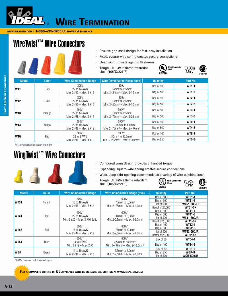
WireTwist™ Wire Connectors• Positive grip shell design for fast, easy installation
• Fixed, square-wire spring creates secure connections
• Deep skirt protects against flash-over
• Tough, UL 94V-2 flame-retardant shell (105°C/221°F)
WingTwist™ Wire Connectors• Contoured wing design provides enhanced torque
• Expanding, square-wire spring creates secure connections
• Wide, deep skirt opening accommodates a variety of wire combinations
• Tough, UL 94V-2 flame retardant shell (105°C/221°F)
Model Color Wire Combination Range Wire Combination Range (mm) Quantity Part No.
WT1 Gray300V
22 to 14 AWGMin. 3 #22 – Max. 2 #16
300V,34mm2 to 2,5mm2
Min. 3-,34mm2 – Max. 2-1,5mm2
Box of 100 WT1-1
Bag of 500 WT1-B
WT2 Blue300V
22 to 14 AWGMin. 3 #20 – Max. 3 #16
300V,34mm2 to 2,5mm2
Min. 3-,50mm2 – Max. 3-1,5mm2
Box of 100 WT2-1
Bag of 500 WT2-B
WT3 Orange600V*
22 to 14 AWGMin. 2 #18 – Max. 2 #14
600V*,34mm2 to 2,5mm2
Min. 2-,75mm2 – Max. 2-2,5mm2
Box of 100 WT3-1
Bag of 500 WT3-B
WT4 Yellow600V*
22 to 10 AWGMin. 2 #18 – Max. 2 #12
600V* ,75mm2 to 6,0mm2
Min. 2-,75mm2 – Max. 2-4,0mm2
Box of 100 WT4-1
Bag of 500 WT4-B
WT6 Red 600V*
20 to 8 AWGMin. 2 #14 – Max. 4 #12
600V*,50mm2 to 10,0mm2
Min. 2-2,5mm2 – Max. 4-4,0mm2
Box of 100 WT6-1
Bag of 250 WT6-B
Model Color Wire Combination Range Wire Combination Range (mm) Quantity Part No.
WT51 Yellow600V*
18 to 10 AWGMin. 2 #18 – Max. 3 #12
600V*,75mm2 to 6,0mm2
Min. 2-,75mm2 – Max. 3-4,0mm2
Box of 100 WT51-1Bag of 500 WT51-BJar of 500 WT51-500JR
Barrel of 25,000 WT51-SK
WT41 Tan600V*
22 to 10 AWGMin. 2 #20 – Max. 3 #10 Solid
600V*,34mm2 to 6,0mm2
Min. 2-0,5mm2 – Max. 3-6,0mm2
Box of 100 WT41-1Bag of 500 WT41-BJar of 500 WT41-500JR
Barrel of 25,000 WT41-SK
WT52 Red600V*
18 to 10 AWGMin. 2 #14 – Max. 5 #12
600V*,75mm2 to 6,0mm2
Min. 2-2,5mm2 – Max. 5-4,0mm2
Box of 100 WT52-1Bag of 500 WT52-BJar of 500 WT52-500JR
Barrel of 25,000 WT52-SK
WT54 Blue600V*
14 to 6 AWGMin. 3 #12 – Max. 2 #6
600V*2,5mm2 to 16,0mm2
Min. 3-4,0mm2 – Max. 2-16,0mm2
Box of 50 WT54-1
Bag of 100 WT54-B
WGR Green 14 to 10 AWGMin. 2 #14 – Max. 5 #12
2,5mm2 to 6,0mm2
Min. 2-2,5mm2 – Max. 5-4,0mm2
Box of 50 WGR-1Bag of 250 WGR-BJar of 500 WGR-500JR
*1,000V maximum in fixtures and signs
*1,000V maximum in fixtures and signs
For A compleTe lisTing oF ul Approved Wire combinATions, visiT us AT WWW.ideAlind.com
Wire TerminATion A-13
WWW.ideAlind.com • 1-800-435-0705 cusTomer AssisTAnce
TW
isT-o
n Wir
e co
nn
ecTo
rs
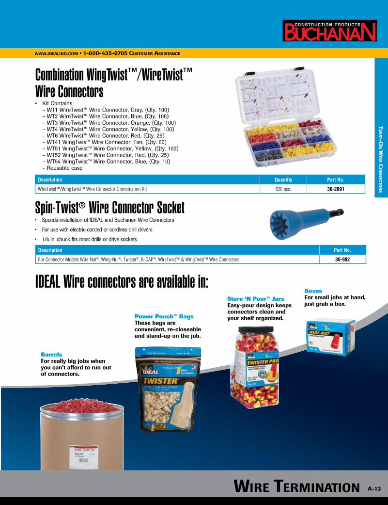
Combination WingTwist™/WireTwist™ Wire Connectors• Kit Contains: – WT1 WireTwist™ Wire Connector, Gray, (Qty. 100) – WT2 WireTwist™ Wire Connector, Blue, (Qty. 100) – WT3 WireTwist™ Wire Connector, Orange, (Qty. 100) – WT4 WireTwist™ Wire Connector, Yellow, (Qty. 100) – WT6 WireTwist™ Wire Connector, Red, (Qty. 25) – WT41 WingTwis™ Wire Connector, Tan, (Qty. 60) – WT51 WingTwist™ Wire Connector, Yellow, (Qty. 100) – WT52 WingTwist™ Wire Connector, Red, (Qty. 25) – WT54 WingTwist™ Wire Connector, Blue, (Qty. 10) – Reusable case
Description Quantity Part No.
WireTwist™/WingTwist™ Wire Connector Combination Kit 620 pcs. 30-2091
BarrelsFor really big jobs when you can’t afford to run out of connectors.
Power Pouch™ BagsThese bags are convenient, re-closeable and stand-up on the job.
Store ‘N Pour™ JarsEasy-pour design keeps connectors clean and your shelf organized.
BoxesFor small jobs at hand, just grab a box.
Spin-Twist® Wire Connector Socket• Speeds installation of IDEAL and Buchanan Wire Connectors
• For use with electric corded or cordless drill drivers
• 1/4 in. chuck fits most drills or drive sockets
Description Part No.
For Connector Models Wire-Nut®, Wing-Nut®, Twister®, B-CAP®, WireTwist™ & WingTwist™ Wire Connectors 30-902
IDEAL Wire connectors are available in:
Wire TerminATionWWW.ideAlind.com • 1-800-435-0705 cusTomer AssisTAnce
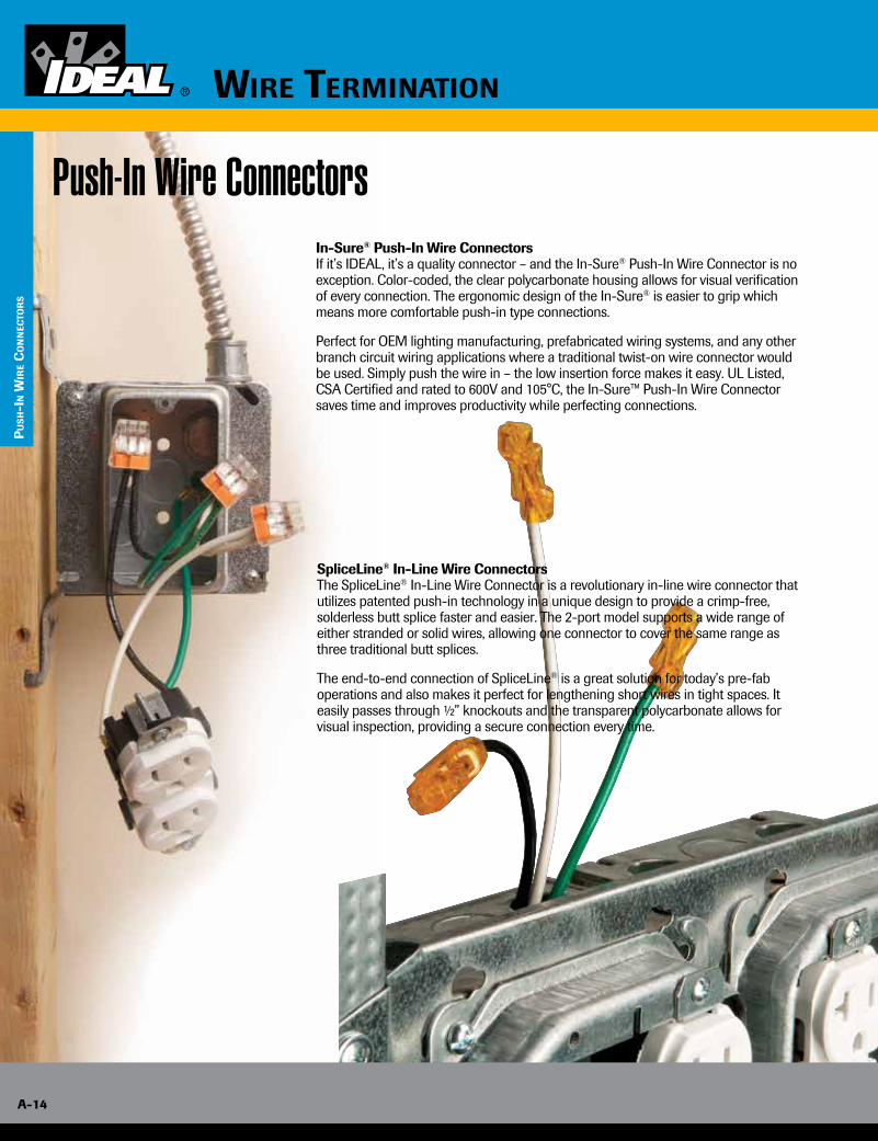
In-Sure® Push-In Wire ConnectorsIf it’s IDEAL, it’s a quality connector – and the In-Sure® Push-In Wire Connector is no exception. Color-coded, the clear polycarbonate housing allows for visual verification of every connection. The ergonomic design of the In-Sure® is easier to grip which means more comfortable push-in type connections.
Perfect for OEM lighting manufacturing, prefabricated wiring systems, and any other branch circuit wiring applications where a traditional twist-on wire connector would be used. Simply push the wire in – the low insertion force makes it easy. UL Listed, CSA Certified and rated to 600V and 105°C, the In-Sure™ Push-In Wire Connector saves time and improves productivity while perfecting connections.
SpliceLine® In-Line Wire ConnectorsThe SpliceLine® In-Line Wire Connector is a revolutionary in-line wire connector that utilizes patented push-in technology in a unique design to provide a crimp-free, solderless butt splice faster and easier. The 2-port model supports a wide range of either stranded or solid wires, allowing one connector to cover the same range as three traditional butt splices.
The end-to-end connection of SpliceLine® is a great solution for today’s pre-fab operations and also makes it perfect for lengthening short wires in tight spaces. It easily passes through ½” knockouts and the transparent polycarbonate allows for visual inspection, providing a secure connection every time.
Push-In Wire Connectors
pu
sh-i
n W
ire
co
nn
ecTo
rs
A-14
Wire TerminATion
Wire TerminATion A-15
WWW.ideAlind.com • 1-800-435-0705 cusTomer AssisTAnce
pu
sh-in W
ire c
on
nec
Tor
s
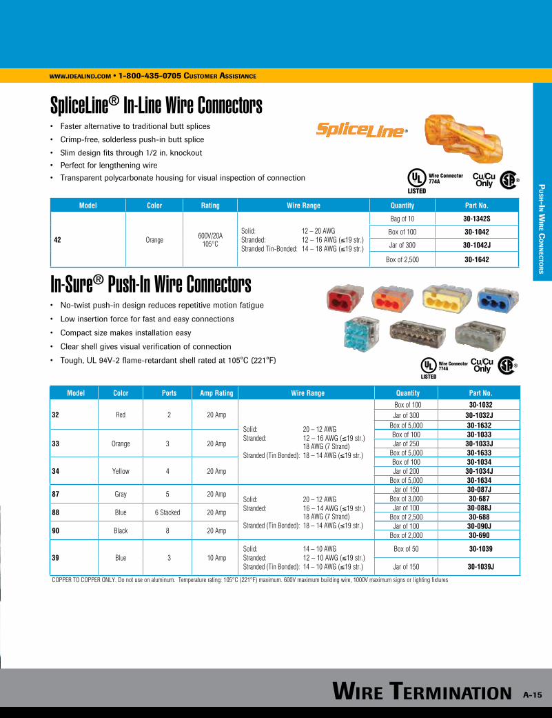
SpliceLine® In-Line Wire Connectors• Faster alternative to traditional butt splices
• Crimp-free, solderless push-in butt splice
• Slim design fits through 1/2 in. knockout
• Perfect for lengthening wire
• Transparent polycarbonate housing for visual inspection of connection
In-Sure® Push-In Wire Connectors• No-twist push-in design reduces repetitive motion fatigue
• Low insertion force for fast and easy connections
• Compact size makes installation easy
• Clear shell gives visual verification of connection
• Tough, UL 94V-2 flame-retardant shell rated at 105°C (221°F)
Model Color Rating Wire Range Quantity Part No.
42 Orange 600V/20A105°C
Solid: 12 – 20 AWGStranded: 12 – 16 AWG (≤19 str.)Stranded Tin-Bonded: 14 – 18 AWG (≤19 str.)
Bag of 10 30-1342S
Box of 100 30-1042
Jar of 300 30-1042J
Box of 2,500 30-1642
Model Color Ports Amp Rating Wire Range Quantity Part No.
32 Red 2 20 Amp
Solid: 20 – 12 AWGStranded: 12 – 16 AWG (≤19 str.) 18 AWG (7 Strand)Stranded (Tin Bonded): 18 – 14 AWG (≤19 str.)
Box of 100 30-1032Jar of 300 30-1032J
Box of 5,000 30-1632
33 Orange 3 20 AmpBox of 100 30-1033Jar of 250 30-1033J
Box of 5,000 30-1633
34 Yellow 4 20 AmpBox of 100 30-1034Jar of 200 30-1034J
Box of 5,000 30-1634
87 Gray 5 20 AmpSolid: 20 – 12 AWGStranded: 16 – 14 AWG (≤19 str.) 18 AWG (7 Strand)Stranded (Tin Bonded): 18 – 14 AWG (≤19 str.)
Jar of 150 30-087JBox of 3,000 30-687
88 Blue 6 Stacked 20 AmpJar of 100 30-088J
Box of 2,500 30-688
90 Black 8 20 AmpJar of 100 30-090J
Box of 2,000 30-690
39 Blue 3 10 AmpSolid: 14 – 10 AWGStranded: 12 – 10 AWG (≤19 str.)Stranded (Tin Bonded): 14 – 10 AWG (≤19 str.)
Box of 50 30-1039
Jar of 150 30-1039J
COPPER TO COPPER ONLY. Do not use on aluminum. Temperature rating: 105°C (221°F) maximum. 600V maximum building wire, 1000V maximum signs or lighting fixtures
Wire TerminaTion
A-16
www.idealind.com • 1-800-435-0705 customer assistance
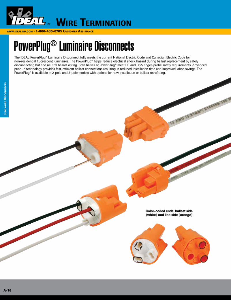
PowerPlug® Luminaire DisconnectsThe IDEAL PowerPlug® Luminaire Disconnect fully meets the current National Electric Code and Canadian Electric Code for non-residential fluorescent luminaires. The PowerPlug® helps reduce electrical shock hazard during ballast replacement by safely disconnecting hot and neutral ballast wiring. Both halves of PowerPlug® meet UL and CSA finger-probe safety requirements. Advanced push-in technology provides fast, efficient ballast connections resulting in reduced installation time and improved labor savings. The PowerPlug® is available in 2-pole and 3-pole models with options for new installation or ballast retrofitting.
Color-coded ends: ballast side (white) and line side (orange)
lum
inA
ire
dis
co
nn
ecTs
A-16
Wire TerminATionWWW.ideAlind.com • 1-800-435-0705 cusTomer AssisTAnce
Wire TerminATion A-17
lu
min
Air
e dis
co
nn
ecTs
WWW.ideAlind.com • 1-800-435-0705 cusTomer AssisTAnce
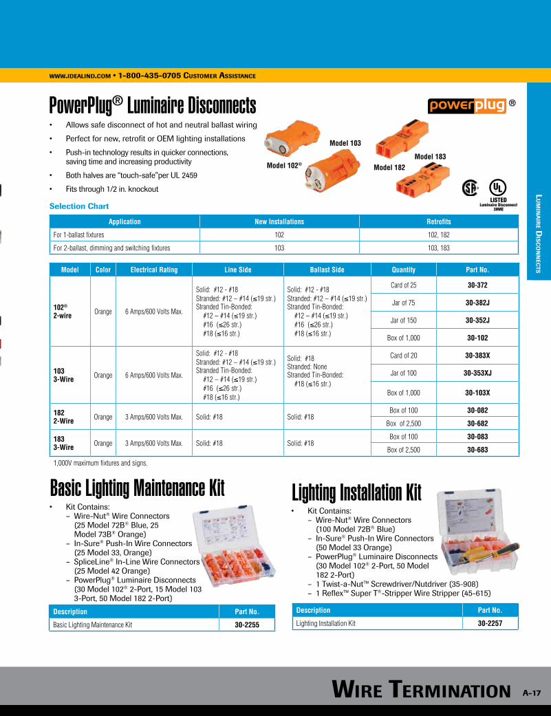
PowerPlug® Luminaire Disconnects
Lighting Installation Kit
®
Model Color Electrical Rating Line Side Ballast Side Quantity Part No.
102®
2-wire Orange 6 Amps/600 Volts Max.
Solid: #12 - #18Stranded: #12 – #14 (≤19 str.)Stranded Tin-Bonded: #12 – #14 (≤19 str.) #16 (≤26 str.) #18 (≤16 str.)
Solid: #12 - #18Stranded: #12 – #14 (≤19 str.)Stranded Tin-Bonded: #12 – #14 (≤19 str.) #16 (≤26 str.) #18 (≤16 str.)
Card of 25 30-372
Jar of 75 30-382J
Jar of 150 30-352J
Box of 1,000 30-102
1033-Wire Orange 6 Amps/600 Volts Max.
Solid: #12 - #18Stranded: #12 – #14 (≤19 str.)Stranded Tin-Bonded: #12 – #14 (≤19 str.) #16 (≤26 str.) #18 (≤16 str.)
Solid: #18Stranded: NoneStranded Tin-Bonded: #18 (≤16 str.)
Card of 20 30-383X
Jar of 100 30-353XJ
Box of 1,000 30-103X
1822-Wire Orange 3 Amps/600 Volts Max. Solid: #18 Solid: #18
Box of 100 30-082
Box of 2,500 30-682
1833-Wire Orange 3 Amps/600 Volts Max. Solid: #18 Solid: #18
Box of 100 30-083
Box of 2,500 30-683
1,000V maximum fixtures and signs.
Application New Installations Retrofits
For 1-ballast fixtures 102 102, 182
For 2-ballast, dimming and switching fixtures 103 103, 183
Luminaire Disconnect3HME
• Allows safe disconnect of hot and neutral ballast wiring
• Perfect for new, retrofit or OEM lighting installations
• Push-in technology results in quicker connections, saving time and increasing productivity
• Both halves are “touch-safe”per UL 2459
• Fits through 1/2 in. knockout
Selection Chart
Description Part No.
Lighting Installation Kit 30-2257
Model 102®
Model 103
Model 182Model 183
• Kit Contains: – Wire-Nut® Wire Connectors (100 Model 72B® Blue) – In-Sure® Push-In Wire Connectors (50 Model 33 Orange) – PowerPlug® Luminaire Disconnects (30 Model 102® 2-Port, 50 Model 182 2-Port) – 1 Twist-a-Nut™ Screwdriver/Nutdriver (35-908) – 1 Reflex™ Super T®-Stripper Wire Stripper (45-615)
Basic Lighting Maintenance Kit • Kit Contains: – Wire-Nut® Wire Connectors (25 Model 72B® Blue, 25 Model 73B® Orange) – In-Sure® Push-In Wire Connectors (25 Model 33, Orange) – SpliceLine® In-Line Wire Connectors (25 Model 42 Orange) – PowerPlug® Luminaire Disconnects (30 Model 102® 2-Port, 15 Model 103 3-Port, 50 Model 182 2-Port)
Description Part No.
Basic Lighting Maintenance Kit 30-2255

WWW.ideAlind.com • 1-800-435-0705 cusTomer AssisTAnce
Wire TerminATion
A-18
WWW.ideAlind.com • 1-800-435-0705 cusTomer AssisTAnce
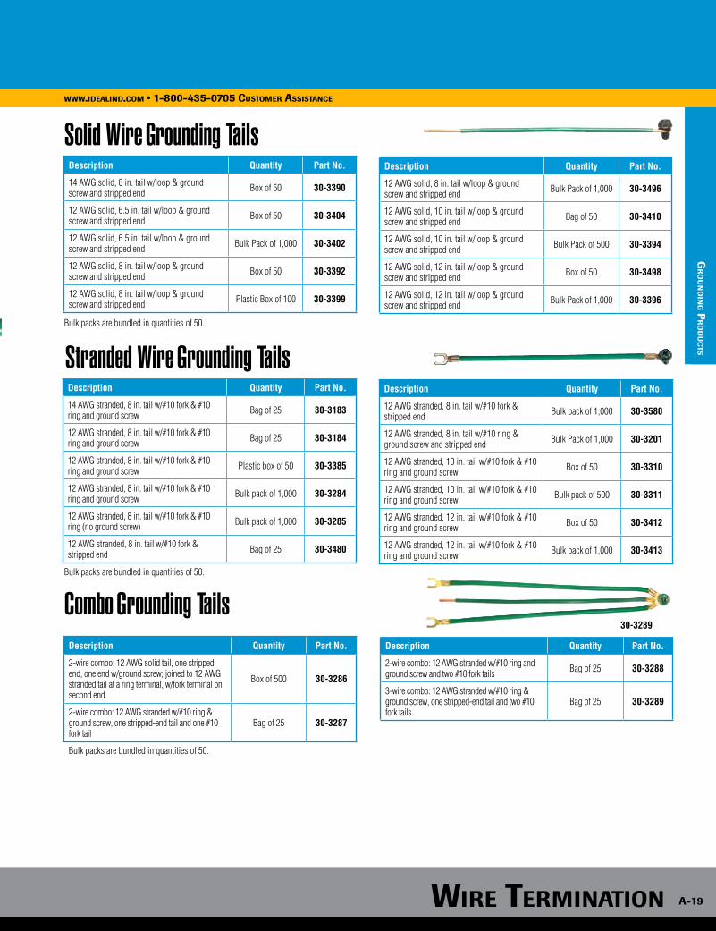
Grounding ProductsWe’ve got grounding covered!Grounding pigtails are designed for a wide variety of grounding applications. The ultra-flexible lead wire and bonding jumpers make fast and efficient pigtailing. • Convenient for device grounding applications• Safe, fast and efficient for cost-effective grounding jobs• Ensures compliance with Article 250 of the National Electrical Code
Stranded• Heavy-duty fork terminals attach easily to device grounding screw
Solid
Combination
Screws• Thread-forming, hole-finding ground screw with combination Slotted, Phillips, Hex and #2 Robertson head. Sold individually or factory-assembled on to pigtails.
thread forming
WWW.ideAlind.com • 1-800-435-0705 cusTomer AssisTAnce
Wire TerminATion
gr
ou
nd
ing p
ro
du
cTs
Wire TerminATion A-19
gr
ou
nd
ing p
ro
du
cTs
Grounding ProductsWWW.ideAlind.com • 1-800-435-0705 cusTomer AssisTAnce
Solid Wire Grounding Tails Description Quantity Part No.
14 AWG solid, 8 in. tail w/loop & ground screw and stripped end Box of 50 30-3390
12 AWG solid, 6.5 in. tail w/loop & ground screw and stripped end Box of 50 30-3404
12 AWG solid, 6.5 in. tail w/loop & ground screw and stripped end Bulk Pack of 1,000 30-3402
12 AWG solid, 8 in. tail w/loop & ground screw and stripped end Box of 50 30-3392
12 AWG solid, 8 in. tail w/loop & ground screw and stripped end Plastic Box of 100 30-3399
Description Quantity Part No.
14 AWG stranded, 8 in. tail w/#10 fork & #10 ring and ground screw Bag of 25 30-3183
12 AWG stranded, 8 in. tail w/#10 fork & #10 ring and ground screw Bag of 25 30-3184
12 AWG stranded, 8 in. tail w/#10 fork & #10 ring and ground screw Plastic box of 50 30-3385
12 AWG stranded, 8 in. tail w/#10 fork & #10 ring and ground screw Bulk pack of 1,000 30-3284
12 AWG stranded, 8 in. tail w/#10 fork & #10 ring (no ground screw) Bulk pack of 1,000 30-3285
12 AWG stranded, 8 in. tail w/#10 fork & stripped end Bag of 25 30-3480
Stranded Wire Grounding Tails
Combo Grounding Tails Description Quantity Part No.
2-wire combo: 12 AWG solid tail, one stripped end, one end w/ground screw; joined to 12 AWG stranded tail at a ring terminal, w/fork terminal on second end
Box of 500 30-3286
2-wire combo: 12 AWG stranded w/#10 ring & ground screw, one stripped-end tail and one #10 fork tail
Bag of 25 30-3287
Bulk packs are bundled in quantities of 50.
30-3289
Description Quantity Part No.
12 AWG solid, 8 in. tail w/loop & ground screw and stripped end Bulk Pack of 1,000 30-3496
12 AWG solid, 10 in. tail w/loop & ground screw and stripped end Bag of 50 30-3410
12 AWG solid, 10 in. tail w/loop & ground screw and stripped end Bulk Pack of 500 30-3394
12 AWG solid, 12 in. tail w/loop & ground screw and stripped end Box of 50 30-3498
12 AWG solid, 12 in. tail w/loop & ground screw and stripped end Bulk Pack of 1,000 30-3396
Bulk packs are bundled in quantities of 50.
Bulk packs are bundled in quantities of 50.
Description Quantity Part No.
12 AWG stranded, 8 in. tail w/#10 fork & stripped end Bulk pack of 1,000 30-3580
12 AWG stranded, 8 in. tail w/#10 ring & ground screw and stripped end Bulk Pack of 1,000 30-3201
12 AWG stranded, 10 in. tail w/#10 fork & #10 ring and ground screw Box of 50 30-3310
12 AWG stranded, 10 in. tail w/#10 fork & #10 ring and ground screw Bulk pack of 500 30-3311
12 AWG stranded, 12 in. tail w/#10 fork & #10 ring and ground screw Box of 50 30-3412
12 AWG stranded, 12 in. tail w/#10 fork & #10 ring and ground screw Bulk pack of 1,000 30-3413
Description Quantity Part No.
2-wire combo: 12 AWG stranded w/#10 ring and ground screw and two #10 fork tails Bag of 25 30-3288
3-wire combo: 12 AWG stranded w/#10 ring & ground screw, one stripped-end tail and two #10 fork tails
Bag of 25 30-3289
Wire TerminATion
A-20
WWW.ideAlind.com • 1-800-435-0705 cusTomer AssisTAnce
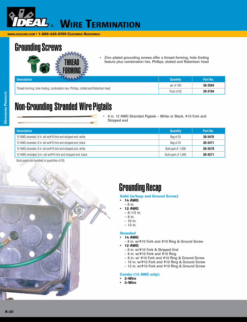
Grounding Screws • Zinc-plated grounding screws offer a thread-forming, hole-finding
feature plus combination hex, Phillips, slotted and Robertson head
Grounding Recap Solid (w/loop and Ground Screw)• 14 AWG – 8 in. • 12 AWG – 6-1/2 in. – 8 in. – 10 in. – 12 in.
Stranded• 14 AWG – 8 in. w/#10 Fork and #10 Ring & Ground Screw• 12 AWG – 8 in. w/#10 Fork & Stripped End – 8 in. w/#10 Fork and #10 Ring – 8 in. w/ #10 Fork and #10 Ring & Ground Screw – 10 in. w/#10 Fork and #10 Ring & Ground Screw – 12 in. w/#10 Fork and #10 Ring & Ground Screw
Combo (12 AWG only):• 2-Wire• 3-Wire
Non-Grounding Stranded Wire Pigtails • 8 in. 12 AWG Stranded Pigtails – White or Black, #10 Fork and
Stripped end
Description Quantity Part No.
Thread-forming, hole-finding, combination hex, Phillips, slotted and Robertson headJar of 100 30-3594
Pack of 50 30-3194
Description Quantity Part No.
12 AWG stranded, 8 in. tail w/#10 fork and stripped end, white Bag of 25 30-3470
12 AWG stranded, 8 in. tail w/#10 fork and stripped end, black Bag of 25 30-3471
12 AWG stranded, 8 in. tail w/#10 fork and stripped end, white Bulk pack of 1,000 30-3570
12 AWG stranded, 8 in. tail w/#10 fork and stripped end, black Bulk pack of 1,000 30-3571
Bulk packs are bundled in quantities of 50.
thread forming
gr
ou
nd
ing p
ro
du
cTs
Wire TerminATion A-21
WWW.ideAlind.com • 1-800-435-0705 cusTomer AssisTAnce
Grounding Recap
cr
imp c
on
nec
Tor
s
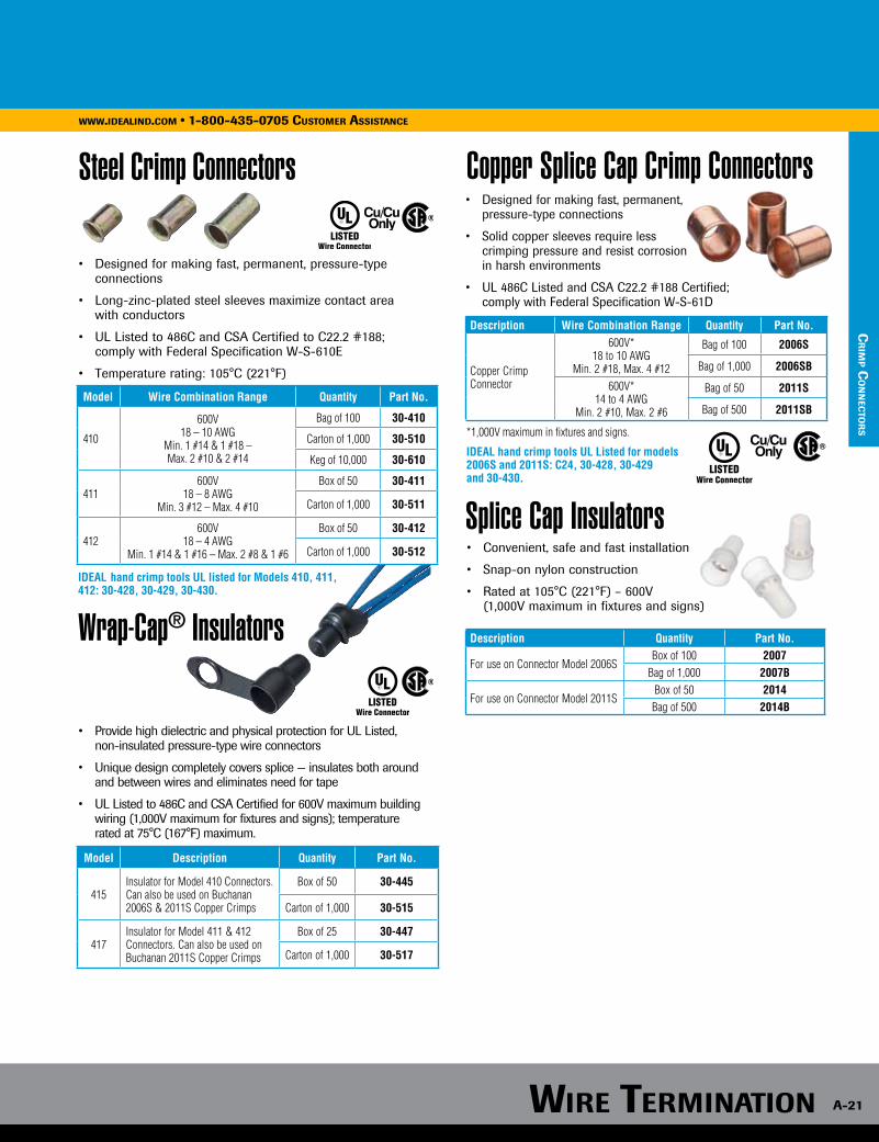
Steel Crimp Connectors
Model Wire Combination Range Quantity Part No.
410
600V18 – 10 AWG
Min. 1 #14 & 1 #18 – Max. 2 #10 & 2 #14
Bag of 100 30-410
Carton of 1,000 30-510
Keg of 10,000 30-610
411600V
18 – 8 AWGMin. 3 #12 – Max. 4 #10
Box of 50 30-411
Carton of 1,000 30-511
412600V
18 – 4 AWGMin. 1 #14 & 1 #16 – Max. 2 #8 & 1 #6
Box of 50 30-412
Carton of 1,000 30-512
Wrap-Cap® Insulators
Model Description Quantity Part No.
415Insulator for Model 410 Connectors. Can also be used on Buchanan 2006S & 2011S Copper Crimps
Box of 50 30-445
Carton of 1,000 30-515
417Insulator for Model 411 & 412 Connectors. Can also be used on Buchanan 2011S Copper Crimps
Box of 25 30-447
Carton of 1,000 30-517
IDEAL hand crimp tools UL listed for Models 410, 411, 412: 30-428, 30-429, 30-430.
• Designed for making fast, permanent, pressure-type connections
• Long-zinc-plated steel sleeves maximize contact area with conductors
• UL Listed to 486C and CSA Certified to C22.2 #188; comply with Federal Specification W-S-610E
• Temperature rating: 105°C (221°F)
• Provide high dielectric and physical protection for UL Listed, non-insulated pressure-type wire connectors
• Unique design completely covers splice — insulates both around and between wires and eliminates need for tape
• UL Listed to 486C and CSA Certified for 600V maximum building wiring (1,000V maximum for fixtures and signs); temperature rated at 75°C (167°F) maximum.
Description Wire Combination Range Quantity Part No.
Copper Crimp Connector
600V*18 to 10 AWG
Min. 2 #18, Max. 4 #12
Bag of 100 2006S
Bag of 1,000 2006SB
600V*14 to 4 AWG
Min. 2 #10, Max. 2 #6
Bag of 50 2011S
Bag of 500 2011SB
Copper Splice Cap Crimp Connectors• Designed for making fast, permanent, pressure-type connections
• Solid copper sleeves require less crimping pressure and resist corrosion in harsh environments
• UL 486C Listed and CSA C22.2 #188 Certified; comply with Federal Specification W-S-61D
LISTED
*1,000V maximum in fixtures and signs.
IDEAL hand crimp tools UL Listed for models 2006S and 2011S: C24, 30-428, 30-429 and 30-430.
Description Quantity Part No.
For use on Connector Model 2006SBox of 100 2007
Bag of 1,000 2007B
For use on Connector Model 2011SBox of 50 2014Bag of 500 2014B
Splice Cap Insulators• Convenient, safe and fast installation
• Snap-on nylon construction
• Rated at 105°C (221°F) – 600V (1,000V maximum in fixtures and signs)

• Breakaway fuseholder for use in: – Roadway & street lighting – Parking lot & area lighting
• UL Listed for submersible installations
• Bright orange color for ease of visibility
• Large selection of configurations
• Set screw or crimp terminations available
The IDEAL SLK® Disconnect Fuse Kit is a waterproof breakaway safety device that de-energizes roadway lights, streetlights, parking lot lights, and other freestanding electrical fixtures in the event of a knockdown, or when the fixtures need main-tenance. This helps protect first responders, bystanders, and service personnel from potentially life-threatening electrical shock hazards.
The SLK® is the first Disconnect Fuse Kit listed to UL’s ECIS category for special purpose connectors. This new category contains a set of rigorous tests from a host of UL standards, including UL 486D, the standard for submersibility. This means that the SLK® will stand up to the wet conditions often seen in and around pole bases, junction boxes, and hand holes.
In addition, the bright orange color of the SLK® makes the product easy to locate in dark junction boxes, in hand holes, or in a nighttime knockdown situation when the connector is often buried amongst dirt, mud, and debris.
• Accepts 13/32” x 1-1/2” midget-style fuse (Note: Fuse not included)• Wire Range: 2-14 AWG (Cu & Al rated)• Ratings: 30A, 600V, 105°C• Maximum available short circuit current of 10,000
SLK® Disconnect Fuse Kits
High visibility orange material (UL94V-2 flame rated)
Fuse stays on de-energized load side when separated
Large, clear markings
Neutral configurations come with white fuseholder and dummy fuse
Crimp or set screw terminations
Paired (hot/neutral) configurations are keyed to prevent reverse polarities
Ribbed boots provide superior grip
Wire TerminATion
A-22
WWW.ideAlind.com • 1-800-435-0705 cusTomer AssisTAnce
sTr
eeTl
igh
T K
iTs
Wire TerminATion A-23
WWW.ideAlind.com • 1-800-435-0705 cusTomer AssisTAnce
sTr
eeTligh
T KiTs
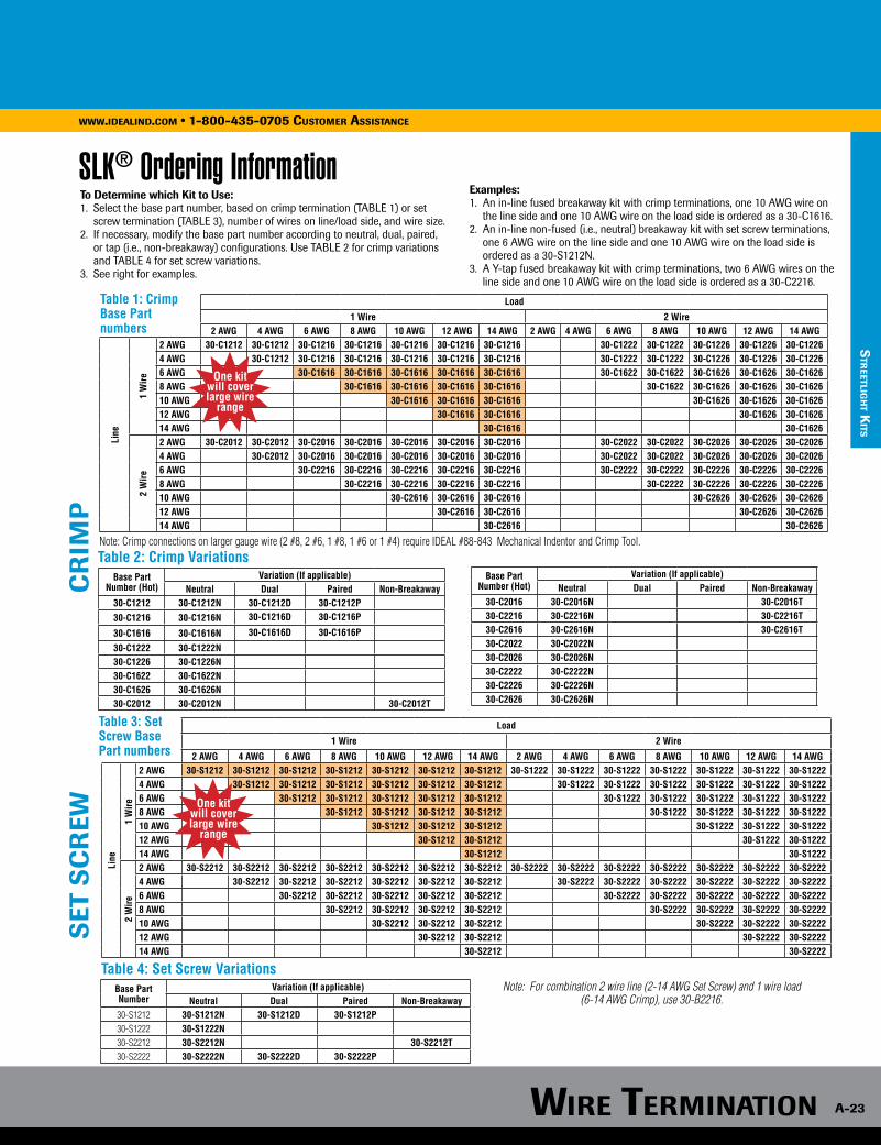
Table 4: Set Screw Variations
Table 1: Crimp Base Part numbers
Load
1 Wire 2 Wire2 AWG 4 AWG 6 AWG 8 AWG 10 AWG 12 AWG 14 AWG 2 AWG 4 AWG 6 AWG 8 AWG 10 AWG 12 AWG 14 AWG
Line
1 W
ire
2 AWG 30-C1212 30-C1212 30-C1216 30-C1216 30-C1216 30-C1216 30-C1216 30-C1222 30-C1222 30-C1226 30-C1226 30-C12264 AWG 30-C1212 30-C1216 30-C1216 30-C1216 30-C1216 30-C1216 30-C1222 30-C1222 30-C1226 30-C1226 30-C12266 AWG 30-C1616 30-C1616 30-C1616 30-C1616 30-C1616 30-C1622 30-C1622 30-C1626 30-C1626 30-C16268 AWG 30-C1616 30-C1616 30-C1616 30-C1616 30-C1622 30-C1626 30-C1626 30-C162610 AWG 30-C1616 30-C1616 30-C1616 30-C1626 30-C1626 30-C162612 AWG 30-C1616 30-C1616 30-C1626 30-C162614 AWG 30-C1616 30-C1626
2 W
ire
2 AWG 30-C2012 30-C2012 30-C2016 30-C2016 30-C2016 30-C2016 30-C2016 30-C2022 30-C2022 30-C2026 30-C2026 30-C20264 AWG 30-C2012 30-C2016 30-C2016 30-C2016 30-C2016 30-C2016 30-C2022 30-C2022 30-C2026 30-C2026 30-C20266 AWG 30-C2216 30-C2216 30-C2216 30-C2216 30-C2216 30-C2222 30-C2222 30-C2226 30-C2226 30-C22268 AWG 30-C2216 30-C2216 30-C2216 30-C2216 30-C2222 30-C2226 30-C2226 30-C222610 AWG 30-C2616 30-C2616 30-C2616 30-C2626 30-C2626 30-C262612 AWG 30-C2616 30-C2616 30-C2626 30-C262614 AWG 30-C2616 30-C2626
Table 2: Crimp VariationsBase Part
Number (Hot)Variation (If applicable)
Neutral Dual Paired Non-Breakaway30-C1212 30-C1212N 30-C1212D 30-C1212P30-C1216 30-C1216N 30-C1216D 30-C1216P
30-C1616 30-C1616N 30-C1616D 30-C1616P
30-C1222 30-C1222N30-C1226 30-C1226N30-C1622 30-C1622N30-C1626 30-C1626N30-C2012 30-C2012N 30-C2012T
Base Part Number
Variation (If applicable)Neutral Dual Paired Non-Breakaway
30-S1212 30-S1212N 30-S1212D 30-S1212P30-S1222 30-S1222N30-S2212 30-S2212N 30-S2212T30-S2222 30-S2222N 30-S2222D 30-S2222P
cr
imp
seT
sc
reW
Note: Crimp connections on larger gauge wire (2 #8, 2 #6, 1 #8, 1 #6 or 1 #4) require IDEAL #88-843 Mechanical Indentor and Crimp Tool.
One kit will cover large wire
range
SLK® Ordering Information
Table 3: Set Screw Base Part numbers
Load
1 Wire 2 Wire
2 AWG 4 AWG 6 AWG 8 AWG 10 AWG 12 AWG 14 AWG 2 AWG 4 AWG 6 AWG 8 AWG 10 AWG 12 AWG 14 AWG
Line
1 W
ire
2 AWG 30-S1212 30-S1212 30-S1212 30-S1212 30-S1212 30-S1212 30-S1212 30-S1222 30-S1222 30-S1222 30-S1222 30-S1222 30-S1222 30-S12224 AWG 30-S1212 30-S1212 30-S1212 30-S1212 30-S1212 30-S1212 30-S1222 30-S1222 30-S1222 30-S1222 30-S1222 30-S12226 AWG 30-S1212 30-S1212 30-S1212 30-S1212 30-S1212 30-S1222 30-S1222 30-S1222 30-S1222 30-S12228 AWG 30-S1212 30-S1212 30-S1212 30-S1212 30-S1222 30-S1222 30-S1222 30-S122210 AWG 30-S1212 30-S1212 30-S1212 30-S1222 30-S1222 30-S122212 AWG 30-S1212 30-S1212 30-S1222 30-S122214 AWG 30-S1212 30-S1222
2 W
ire
2 AWG 30-S2212 30-S2212 30-S2212 30-S2212 30-S2212 30-S2212 30-S2212 30-S2222 30-S2222 30-S2222 30-S2222 30-S2222 30-S2222 30-S22224 AWG 30-S2212 30-S2212 30-S2212 30-S2212 30-S2212 30-S2212 30-S2222 30-S2222 30-S2222 30-S2222 30-S2222 30-S22226 AWG 30-S2212 30-S2212 30-S2212 30-S2212 30-S2212 30-S2222 30-S2222 30-S2222 30-S2222 30-S22228 AWG 30-S2212 30-S2212 30-S2212 30-S2212 30-S2222 30-S2222 30-S2222 30-S222210 AWG 30-S2212 30-S2212 30-S2212 30-S2222 30-S2222 30-S222212 AWG 30-S2212 30-S2212 30-S2222 30-S222214 AWG 30-S2212 30-S2222
Note: For combination 2 wire line (2-14 AWG Set Screw) and 1 wire load (6-14 AWG Crimp), use 30-B2216.
To Determine which Kit to Use:1. Select the base part number, based on crimp termination (TABLE 1) or set screw termination (TABLE 3), number of wires on line/load side, and wire size.2. If necessary, modify the base part number according to neutral, dual, paired, or tap (i.e., non-breakaway) configurations. Use TABLE 2 for crimp variations and TABLE 4 for set screw variations.3. See right for examples.
Base Part Number (Hot)
Variation (If applicable)Neutral Dual Paired Non-Breakaway
30-C2016 30-C2016N 30-C2016T30-C2216 30-C2216N 30-C2216T30-C2616 30-C2616N 30-C2616T30-C2022 30-C2022N30-C2026 30-C2026N30-C2222 30-C2222N30-C2226 30-C2226N30-C2626 30-C2626N
Examples:1. An in-line fused breakaway kit with crimp terminations, one 10 AWG wire on the line side and one 10 AWG wire on the load side is ordered as a 30-C1616.2. An in-line non-fused (i.e., neutral) breakaway kit with set screw terminations, one 6 AWG wire on the line side and one 10 AWG wire on the load side is ordered as a 30-S1212N.3. A Y-tap fused breakaway kit with crimp terminations, two 6 AWG wires on the line side and one 10 AWG wire on the load side is ordered as a 30-C2216.
One kit will cover large wire
range

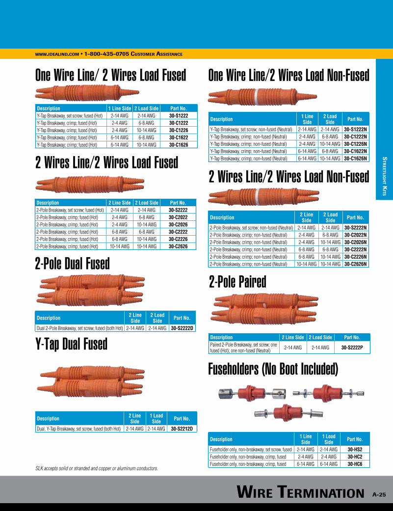
SLK accepts solid or stranded and copper or aluminum conductors.
Wire TerminATion
A-24
WWW.ideAlind.com • 1-800-435-0705 cusTomer AssisTAnce
sTr
eeTl
igh
T K
iTs
A-24
Wire TerminATionWWW.ideAlind.com • 1-800-435-0705 cusTomer AssisTAnce
In-Line Fused In-Line Non-Fused
Non-Breakaway Fused
Y-Tap Fused Y-Tap Non-Fused
Dual In-Line Fused
Description 1 Line Side 1 Load Side Part No.In-Line Breakaway, set screw; fused (Hot) 2-14 AWG 2-14 AWG 30-S1212In-Line Breakaway, crimp; fused (Hot) 2-4 AWG 2-4 AWG 30-C1212In-Line Breakaway, crimp; fused (Hot) 2-4 AWG 6-14 AWG 30-C1216In-Line Breakaway, crimp; fused (Hot) 6-14 AWG 6-14 AWG 30-C1616
Description 1 Line Side
1 Load Side Part No.
Dual In-Line Breakaway, set screw; fused (both Hot) 2-14 AWG 2-14 AWG 30-S1212DDual In-Line Breakaway, crimp; fused (both Hot) 2-4 AWG 2-4 AWG 30-C1212DDual In-Line Breakaway, crimp; fused (both Hot) 2-4 AWG 6-14 AWG 30-C1216DDual In-Line Breakaway, crimp; fused (both Hot) 6-14 AWG 6-14 AWG 30-C1616D
Description 1 Line Side 1 Load Side Part No.Paired In-Line Breakaway, set screw; one fused (Hot); one non-fused (Neutral) 2-14 AWG 2-14 AWG 30-S1212P
Paired In-Line Breakaway, crimp; one fused (Hot); one non-fused (Neutral) 6-14 AWG 6-14 AWG 30-C1212P
Paired In-Line Breakaway, crimp; one fused (Hot); one non-fused (Neutral) 2-4 AWG 6-14 AWG 30-C1216P
Paired In-Line Breakaway, crimp; one fused (Hot); one non-fused (Neutral) 2-4 AWG 2-4 AWG 30-C1616P
Description 1 Line Side
1 Load Side Part No.
In-Line Breakaway, set screw; non-fused (Neutral) 2-14 AWG 2-14 AWG 30-S1212NIn-Line Breakaway, crimp; non-fused (Neutral) 2-4 AWG 2-4 AWG 30-C1212NIn-Line Breakaway, crimp; non-fused (Neutral) 2-4 AWG 6-14 AWG 30-C1216NIn-Line Breakaway, crimp; non-fused (Neutral) 6-14 AWG 6-14 AWG 30-C1616N
Description 2 Line Side
1 Load Side Part No.
Y-Tap Non-Breakaway, set screw; fused (Hot) 2-14 AWG 2-14 AWG 30-S2212TY-Tap Non-Breakaway, crimp; fused (Hot) 2-4 AWG 2-4 AWG 30-C2012TY-Tap Non-Breakaway, crimp; fused (Hot) 2-4 AWG 6-14 AWG 30-C2016TY-Tap Non-Breakaway, crimp; fused (Hot) 6-8 AWG 6-14 AWG 30-C2216TY-Tap Non-Breakaway, crimp; fused (Hot) 10-14 AWG 6-14 AWG 30-C2616T
Description 2 Line Side 1 Load Side Part No.Y-Tap Breakaway, set screw; fused (Hot) 2-14 AWG 2-14 AWG 30-S2212
Y-Tap Breakaway, crimp; fused (Hot) 2-4 AWG 2-4 AWG 30-C2012Y-Tap Breakaway, crimp; fused (Hot) 2-4 AWG 6-14 AWG 30-C2016Y-Tap Breakaway, crimp; fused (Hot) 6-8 AWG 6-14 AWG 30-C2216Y-Tap Breakaway, crimp; fused (Hot) 10-14 AWG 6-14 AWG 30-C2616Combination Y-Tap Breakaway, fused (Hot)
2-14 AWGset screw
6-14 AWGcrimp 30-B2216
Description 2 Line Side
1 Load Side Part No.
Y-Tap Breakaway, set screw; non-fused (Neutral) 2-14 AWG 2-14 AWG 30-S2212NY-Tap Breakaway, crimp; non-fused (Neutral) 2-4 AWG 2-4 AWG 30-C2012NY-Tap Breakaway, crimp; non-fused (Neutral) 2-4 AWG 6-14 AWG 30-C2016NY-Tap Breakaway, crimp; non-fused (Neutral) 6-8 AWG 6-14 AWG 30-C2216NY-Tap Breakaway, crimp; non-fused (Neutral) 10-14 AWG 6-14 AWG 30-C2616N
Single-Pole In-Line Paired
SLK accepts solid or stranded and copper or aluminum conductors. SLK accepts solid or stranded and copper or aluminum conductors.
Wire TerminATion A-25
WWW.ideAlind.com • 1-800-435-0705 cusTomer AssisTAnce
sTr
eeTligh
T KiTs
Description 2 Line Side 2 Load Side Part No.2-Pole Breakaway, set screw; fused (Hot) 2-14 AWG 2-14 AWG 30-S22222-Pole Breakaway, crimp; fused (Hot) 2-4 AWG 6-8 AWG 30-C20222-Pole Breakaway, crimp; fused (Hot) 2-4 AWG 10-14 AWG 30-C20262-Pole Breakaway, crimp; fused (Hot) 6-8 AWG 6-8 AWG 30-C22222-Pole Breakaway, crimp; fused (Hot) 6-8 AWG 10-14 AWG 30-C22262-Pole Breakaway, crimp; fused (Hot) 10-14 AWG 10-14 AWG 30-C2626
Description 1 Line Side
1 Load Side Part No.
Fuseholder only, non-breakaway, set screw, fused 2-14 AWG 2-14 AWG 30-HS2Fuseholder only, non-breakaway, crimp, fused 2-4 AWG 2-4 AWG 30-HC2Fuseholder only, non-breakaway, crimp, fused 6-14 AWG 6-14 AWG 30-HC6
Description 2 Line Side 2 Load Side Part No.Paired 2-Pole Breakaway, set screw; one fused (Hot); one non-fused (Neutral) 2-14 AWG 2-14 AWG 30-S2222P
Description 2 Line Side
2 Load Side Part No.
Dual 2-Pole Breakaway, set screw; fused (both Hot) 2-14 AWG 2-14 AWG 30-S2222D
Description 2 Line Side
1 Load Side Part No.
Dual, Y-Tap Breakaway, set screw; fused (both Hot) 2-14 AWG 2-14 AWG 30-S2212D
2 Wires Line/2 Wires Load Fused
2-Pole Dual Fused2-Pole Paired
Y-Tap Dual Fused
Fuseholders (No Boot Included)
Description 2 Line Side
2 Load Side Part No.
2-Pole Breakaway, set screw; non-fused (Neutral) 2-14 AWG 2-14 AWG 30-S2222N2-Pole Breakaway, crimp; non-fused (Neutral) 2-4 AWG 6-8 AWG 30-C2022N2-Pole Breakaway, crimp; non-fused (Neutral) 2-4 AWG 10-14 AWG 30-C2026N2-Pole Breakaway, crimp; non-fused (Neutral) 6-8 AWG 6-8 AWG 30-C2222N2-Pole Breakaway, crimp; non-fused (Neutral) 6-8 AWG 10-14 AWG 30-C2226N2-Pole Breakaway, crimp; non-fused (Neutral) 10-14 AWG 10-14 AWG 30-C2626N
2 Wires Line/2 Wires Load Non-Fused
Description 1 Line Side
2 Load Side Part No.
Y-Tap Breakaway, set screw; non-fused (Neutral) 2-14 AWG 2-14 AWG 30-S1222NY-Tap Breakaway, crimp; non-fused (Neutral) 2-4 AWG 6-8 AWG 30-C1222NY-Tap Breakaway, crimp; non-fused (Neutral) 2-4 AWG 10-14 AWG 30-C1226NY-Tap Breakaway, crimp; non-fused (Neutral) 6-14 AWG 6-8 AWG 30-C1622NY-Tap Breakaway; crimp; non-fused (Neutral) 6-14 AWG 10-14 AWG 30-C1626N
One Wire Line/2 Wires Load Non-Fused
Description 1 Line Side 2 Load Side Part No.Y-Tap Breakaway, set screw; fused (Hot) 2-14 AWG 2-14 AWG 30-S1222Y-Tap Breakaway, crimp; fused (Hot) 2-4 AWG 6-8 AWG 30-C1222Y-Tap Breakaway, crimp; fused (Hot) 2-4 AWG 10-14 AWG 30-C1226Y-Tap Breakaway, crimp; fused (Hot) 6-14 AWG 6-8 AWG 30-C1622Y-Tap Breakaway; crimp; fused (Hot) 6-14 AWG 10-14 AWG 30-C1626
One Wire Line/ 2 Wires Load Fused
Wire TerminaTion
A-26
www.idealind.com • 1-800-435-0705 customer assistance
sTr
eeTl
igh
T K
iTs
Wire TerminATionWWW.ideAlind.com • 1-800-435-0705 cusTomer AssisTAnce
A-26
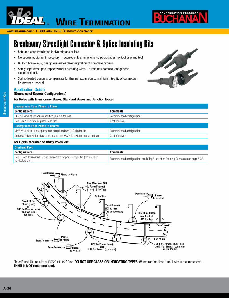
Breakaway Streetlight Connector & Splice Insulating Kits• Safe and easy installation in five minutes or less
• No special equipment necessary – requires only a knife, wire stripper, and a hex tool or crimp tool
• Built-in break-away design eliminates de-energization of complete circuits
• Safely separates upon impact without breaking wires – eliminates potential danger and electrical shock
• Spring-loaded contacts compensate for thermal expansion to maintain integrity of connection (breakaway models)
Application Guide(Examples of Several Configurations)
For Poles with Transformer Bases, Standard Bases and Junction Boxes
For Lights Mounted to Utility Poles, etc.
Underground Feed Phase to Phase
Configurations Comments
D65 dual-in-line for phases and two 84S kits for taps Recommended configuration
Two 82S Y-Tap Kits for phases and taps Cost effective
Underground Feed Phase to Neutral
DP65PN dual-in-line for phase and neutral and two 84S kits for tap Recommended configuration
One 82S Y-Tap Kit for phase and tap and one 83S Y-Tap Kit for neutral and tap Cost effective
Overhead Feed
Configurations Comments
Two B-Tap® Insulation Piercing Connectors for phase and/or tap (for insulated conductors only) Recommended configuration, see B-Tap® Insulation Piercing Connectors on page A-37.
Transformer
Transformer82S for Phase (fuse)
and83S for Neutral (common)
Two 82S forPhase (fuse)
orD65 for Phases (fuse)
and two 84Sfor Taps
End of run
65 Kit for Phase (fuse) and20 Kit for Neutral (common)
or D65PN Kit
Two 65 or oneD65 to fuseTap unnecessary
Two 65 or one D65to Fuse (Phases)84 or 84S for Taps
D65PN for Phaseand Neutral84S for Tap
Phaseto Phase
Transformer Phaseto Neutral
Phase to Phase
TransformerPhase
to NeutralEnd of Run
Note: Fused kits require a 13/32” x 1-1/2” fuse. DO NOT USE GLASS OR INDICATING TYPES. Waterproof or direct burial wire is recommended. THHN is NOT recommended.
Wire TerminATion A-27
WWW.ideAlind.com • 1-800-435-0705 cusTomer AssisTAnce
sTr
eeTligh
T KiTs
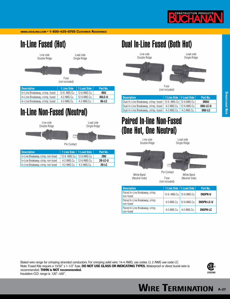
In-Line Fused (Hot)
In-Line Non-Fused (Neutral)
Dual In-Line Fused (Both Hot)
Paired In-line Non-Fused (One Hot, One Neutral)
Line sideDouble Ridge
Load sideSingle Ridge
Fuse(not included)Description 1 Line Side 1 Load Side Part No.
In-Line Breakaway, crimp, fused 12-6 AWG Cu 12-6 AWG Cu 65UIn-Line Breakaway, crimp, fused 4-2 AWG Cu 12-6 AWG Cu 65LC-UIn-Line Breakaway, crimp, fused 4-2 AWG Cu 4-2 AWG Cu 65-LC
Description 1 Line Side 1 Load Side Part No.Dual In-Line Breakaway, crimp, fused 12-6 AWG Cu 12-6 AWG Cu D65UDual In-Line Breakaway, crimp, fused 4-2 AWG Cu 12-6 AWG Cu D65-LC-UDual In-Line Breakaway, crimp, fused 4-2 AWG Cu 4-2 AWG Cu D65-LC
Description 1 Line Side 1 Load Side Part No.Paired In-Line Breakaway, crimp, non-fused 12-6 AWG Cu 12-6 AWG Cu D65PN-U
Paired In-Line Breakaway, crimp, non-fused 4-2 AWG Cu 12-6 AWG Cu D65PN-LC-U
Paired In-Line Breakaway, crimp, non-fused 4-2 AWG Cu 4-2 AWG Cu D65PN-LC
Description 1 Line Side 1 Load Side Part No.In-Line Breakaway, crimp, non-fused 12-6 AWG Cu 12-6 AWG Cu 20UIn-Line Breakaway, crimp, non-fused 4-2 AWG Cu 12-6 AWG Cu 20-LC-UIn-Line Breakaway, crimp, non-fused 4-2 AWG Cu 4-2 AWG Cu 20-LC
Stated wire range for crimping stranded conductors. For crimping solid wire: 14-4 AWG, use codes. U, 2 AWG use code LC. Note: Fused Kits require a 13/32” x 1-1/2” fuse. DO NOT USE GLASS OR INDICATING TYPES. Waterproof or direct burial wire is recommended. THHN is NOT recommended. Insulation O.D. range is .120”-.430”.
Line sideDouble Ridge
Load sideSingle Ridge
Line sideDouble Ridge
Load sideSingle Ridge
Fuse(not included)
Pin ContactLine side
Double RidgeLoad side
Single Ridge
White Band (Neutral Side)
White Band (Neutral Side)
Pin Contact
Fuse(not included)
LISTEDLR32565
Wire TerminATion
A-28
WWW.ideAlind.com • 1-800-435-0705 cusTomer AssisTAnce
sTr
eeTl
igh
T K
iTs
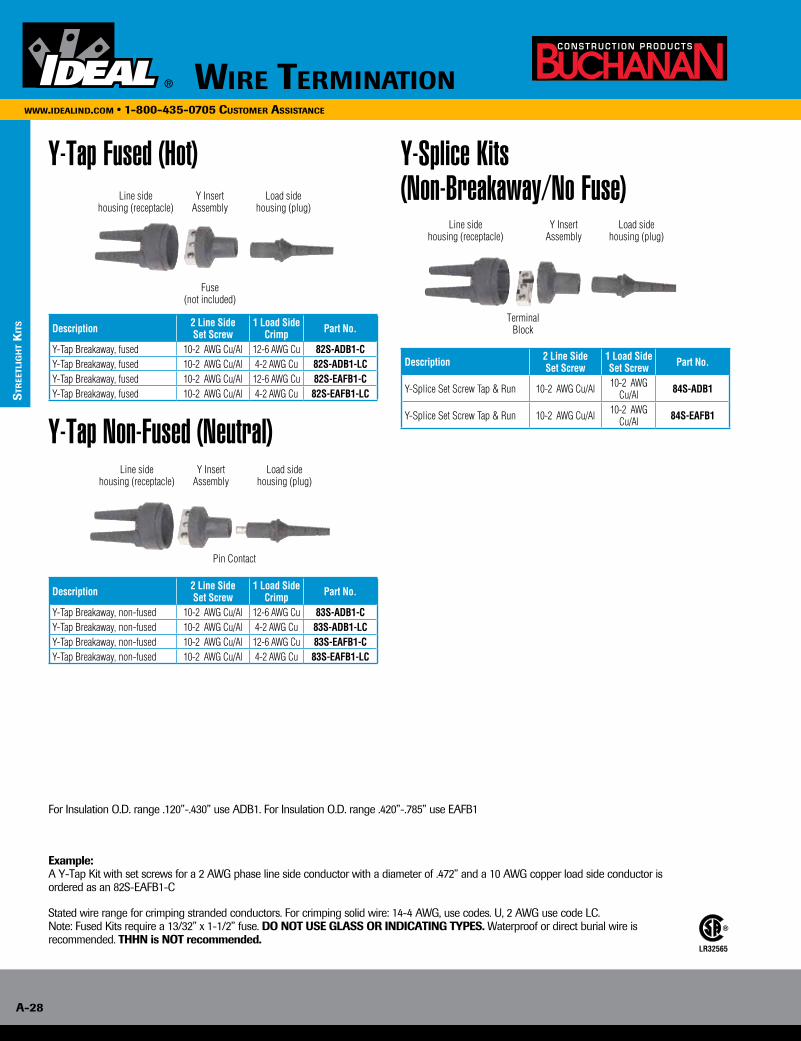
Y-Tap Fused (Hot) Y-Splice Kits (Non-Breakaway/No Fuse)
Y-Tap Non-Fused (Neutral)
Description 2 Line Side Set Screw
1 Load SideCrimp Part No.
Y-Tap Breakaway, fused 10-2 AWG Cu/Al 12-6 AWG Cu 82S-ADB1-CY-Tap Breakaway, fused 10-2 AWG Cu/Al 4-2 AWG Cu 82S-ADB1-LCY-Tap Breakaway, fused 10-2 AWG Cu/Al 12-6 AWG Cu 82S-EAFB1-CY-Tap Breakaway, fused 10-2 AWG Cu/Al 4-2 AWG Cu 82S-EAFB1-LC
Description 2 Line Side Set Screw
1 Load SideSet Screw Part No.
Y-Splice Set Screw Tap & Run 10-2 AWG Cu/Al 10-2 AWG Cu/Al 84S-ADB1
Y-Splice Set Screw Tap & Run 10-2 AWG Cu/Al 10-2 AWG Cu/Al 84S-EAFB1
Description 2 Line Side Set Screw
1 Load SideCrimp Part No.
Y-Tap Breakaway, non-fused 10-2 AWG Cu/Al 12-6 AWG Cu 83S-ADB1-CY-Tap Breakaway, non-fused 10-2 AWG Cu/Al 4-2 AWG Cu 83S-ADB1-LCY-Tap Breakaway, non-fused 10-2 AWG Cu/Al 12-6 AWG Cu 83S-EAFB1-CY-Tap Breakaway, non-fused 10-2 AWG Cu/Al 4-2 AWG Cu 83S-EAFB1-LC
Stated wire range for crimping stranded conductors. For crimping solid wire: 14-4 AWG, use codes. U, 2 AWG use code LC. Note: Fused Kits require a 13/32” x 1-1/2” fuse. DO NOT USE GLASS OR INDICATING TYPES. Waterproof or direct burial wire is recommended. THHN is NOT recommended.
For Insulation O.D. range .120”-.430” use ADB1. For Insulation O.D. range .420”-.785” use EAFB1
LISTEDLR32565
Line sidehousing (receptacle)
Load sidehousing (plug)
Y InsertAssembly
Fuse (not included)
Line sidehousing (receptacle)
Pin Contact
Load sidehousing (plug)
Y InsertAssembly
Line sidehousing (receptacle)
Load sidehousing (plug)
Y InsertAssembly
Terminal Block
Example: A Y-Tap Kit with set screws for a 2 AWG phase line side conductor with a diameter of .472” and a 10 AWG copper load side conductor is ordered as an 82S-EAFB1-C

Electrical Crimp Terminals
Rings & Forks Disconnects
Splices
Durable plastic package for easy storage.
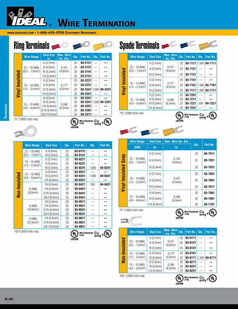
The complete line of IDEAL crimp terminals, disconnects and splices offer the right product for any electrical system that might be encountered. From rings and spades to insulated disconnects, there’s a product for any wire range. All insulated terminals are color-coded for easy identification and come in durable plastic packaging for easy storage.
• Butted seam-construction prevents splitting under maximum pressure• Internal barrel serrations grip wires tightly to resist pull-out and reduce electrical resistance• Tin-plated brass construction for corrosion resistance• Shouldered barrel insulation quickly positions terminal for proper crimping• Expanded insulation entry accommodates a wide variety of insulation diameters and provides additional insulation support
Wire TerminATion A-29
WWW.ideAlind.com • 1-800-435-0705 cusTomer AssisTAnce
elec
Tric
Al c
rim
p Ter
min
Als
Wire TerminATion
A-30
WWW.ideAlind.com • 1-800-435-0705 cusTomer AssisTAnce
Ter
min
Als
Ring Terminals
Vin
yl In
sula
ted
Wire Range Stud Sizein.
Max. Wire Ins. Dia. Qty. Part No. Qty. Part No.
22 – 18 AWG(0,5 – 1,0mm2)
6 (3,7mm)0.157
(4,0mm)
25 83-2121 — —8 (4,3mm) 25 83-2131 — —
10 (5,3mm) 25 83-2141 — —1/4 (6,4mm) 25 83-2151 — —
16 – 14 AWG(1,5 – 2,5mm2)
6 (3,7mm)
0.177(4,5mm)
25 83-2221 — —8 (4,3mm) 25 83-2231 — —
10 (5,3mm) 25 83-2241 1,000 84-22411/4 (6,4mm) 25 83-2251 — —
12 – 10 AWG(4,0 – 6,0mm2)
8 (4,3mm)
0.248(6,3mm)
25 83-2331 — —10 (5,3mm) 25 83-2341 1,000 84-23411/4 (6,4mm) 25 83-2351 — —
5/16 (8,4mm) 25 83-2361 — —3/8 (10,5mm) 25 83-2371 — —
75° C/600 Volts max.
Non-
Insu
late
d
Wire Range Stud Size Qty. Part No. Qty. Part No.
22 – 18 AWG(0,5 – 1,0mm2)
8 (4,3mm) 25 83-0131 — —10 (5,3mm) 25 83-0141 — —
16 – 14 AWG(1,5 – 2,5mm2)
6 (3,7mm) 25 83-0221 — —8 (4,3mm) 25 83-0231 — —
10 (5,3mm) 25 83-0241 1,000 84-0241
12 – 10 AWG(4,0 – 6,0mm2)
8 (4,3mm) 25 83-0331 — —10 (5,3mm) 25 83-0341 1,000 84-03411/4 (6,4mm) 25 83-0351 — —
8 AWG(8,0mm2)
10 (5,3mm) 25 83-0421 500 84-04211/4 (6,4mm) 25 83-0431 — —
5/16 (8,4mm) 25 83-0441 — —3/8 (10,5mm) 25 83-0451 — —
6 AWG(14,0mm2)
10 (5,3mm) 20 83-0511 — —1/4 (6,4mm) 20 83-0521 — —
5/16 (8,4mm) 20 83-0531 — —3/8 (10,5mm) 20 83-0541 — —
4 AWG(22,0mm2)
1/4 (6,4mm) 20 83-0611 — —5/16 (8,4mm) 20 83-0621 — —3/8 (10,5mm) 20 83-0631 — —
105°C/600 Volts max.
774A ListedPressure Wire Connector
Cuonly
774A ListedPressure Wire Connector
Cuonly
774A ListedPressure Wire Connector
Cuonly
774A ListedPressure Wire Connector
Cuonly
774A ListedPressure Wire Connector
Cuonly
Spade Terminals
Viny
l Ins
ulat
ed
Wire Range Stud Size Max. Wire Ins. Dia. Qty. Part No. Qty. Part No.
22 – 18 AWG(0,5 – 1,0mm2)
6 (3,7mm)0.157
(4,0mm)
25 83-7111 1,000 84-7111
8 (4,3mm) 25 83-7121 — —
10 (5,3mm) 25 83-7131 — —
16 – 14 AWG(1,5 – 2,5mm2)
6 (3,7mm)0.177
(4,5mm)
25 83-7151 — —
8 (4,3mm) 25 83-7161 1,000 84-7161
10 (5,3mm) 25 83-7171 1,000 84-7171
12 – 10 AWG(4,0 – 6,0mm2)
6 (3,7mm)0.248
(6,3mm)
25 83-7201 — —8 (4,3mm) 25 83-7211 — —
10 (5,3mm) 25 83-7221 500 84-72211/4 (6,4mm) 25 83-7231 — —
75° C/600 Volts max.
Viny
l Ins
ulat
ed S
nap
Wire Range Stud Size Max. Wire Ins. Dia.Qty. Part No.
AWG In. In.
22 – 18 AWG(0,5 – 1,0mm2)
6 (3,7mm)
0.134(4,0mm)
25 83-7011
8 (4,3mm) 25 83-7021
10 (5,3mm) 25 83-7031
16 – 14 AWG(1,5 – 2,5mm2)
6 (3,7mm)0.161
(4,5mm)
25 83-7051
8 (4,3mm) 25 83-7061
10 (5,3mm) 25 83-7071
12 – 10 AWG(4,0 – 6,0mm2)
8 (4,3mm)0.248
(6,0mm)
25 83-7081
10 (5,3mm) 25 83-7091
1/4 (6,4mm) 25 83-7101
75° C/600 Volts max.
Non-
Insu
late
d
Wire Range Stud Size Max. Wire Ins. Dia. Qty. Part No. Qty. Part No.
22 – 18 AWG(0,5 – 1,0mm2)
6 (3,7mm)0.157
(4,0mm)
25 83-6111 — —8 (4,3mm) 25 83-6121 — —
10 (5,3mm) 25 83-6131 — —
16 – 14 AWG(1,5 – 2,5mm2)
8 (4,3mm) 0.177(4,5mm)
25 83-6161 — —10 (5,3mm) 25 83-6171 1,000 84-6171
12 – 10 AWG(4,0 – 6,0mm2)
8 (4,3mm)0.248
(6,3mm)
25 83-6211 — —10 (5,3mm) 25 83-6221 — —1/4 (6,4mm) 25 83-6231 — —
105° C/600 Volts max.
Wire TerminATion A-31
WWW.ideAlind.com • 1-800-435-0705 cusTomer AssisTAnce
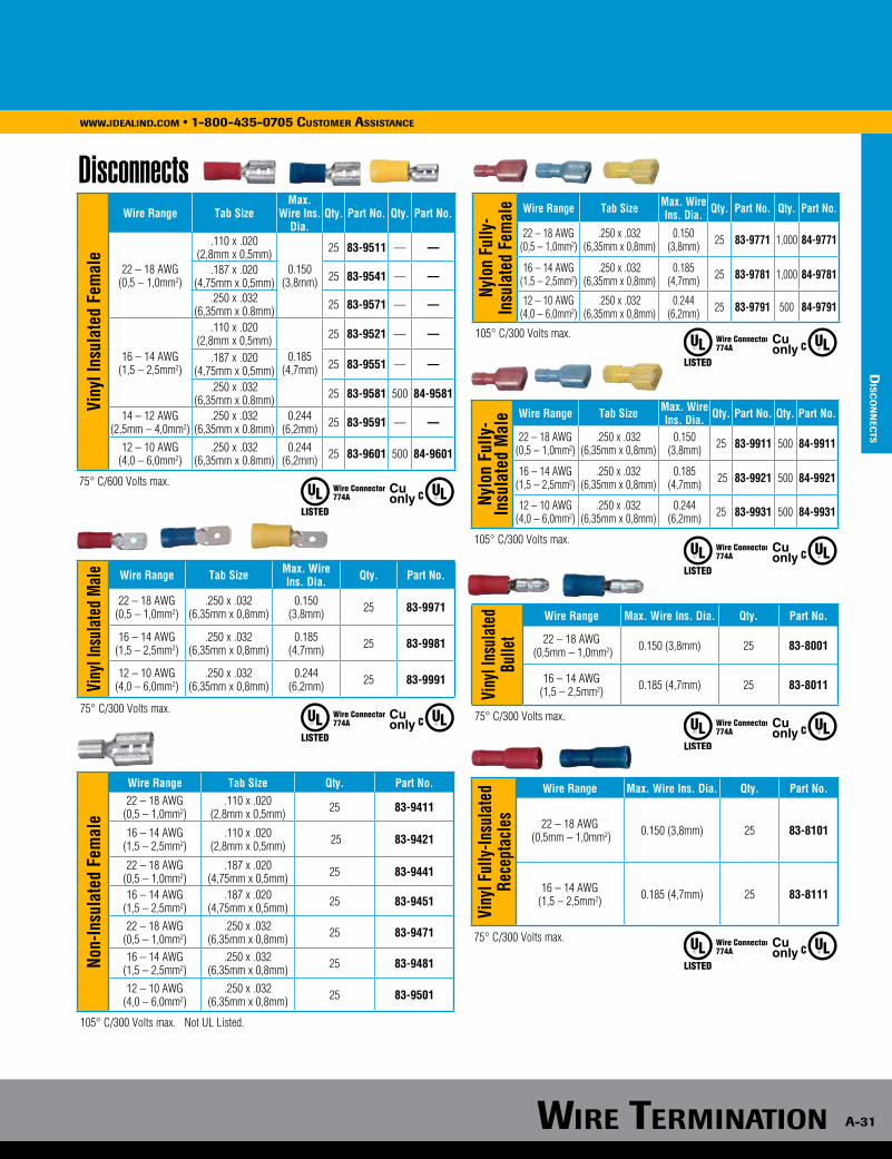
dis
co
nn
ecTs
Disconnects
774A ListedPressure Wire Connector
Cuonly
774A ListedPressure Wire Connector
Cuonly
774A ListedPressure Wire Connector
Cuonly
Viny
l Ins
ulat
ed F
emal
e
Wire Range Tab Size Max.
Wire Ins. Dia.
Qty. Part No. Qty. Part No.
22 – 18 AWG(0,5 – 1,0mm2)
.110 x .020(2,8mm x 0,5mm)
0.150(3,8mm)
25 83-9511 — —
.187 x .020(4,75mm x 0,5mm) 25 83-9541 — —
.250 x .032 (6,35mm x 0.8mm) 25 83-9571 — —
16 – 14 AWG(1,5 – 2,5mm2)
.110 x .020(2,8mm x 0,5mm)
0.185(4,7mm)
25 83-9521 — —
.187 x .020(4,75mm x 0,5mm) 25 83-9551 — —
.250 x .032 (6,35mm x 0.8mm) 25 83-9581 500 84-9581
14 – 12 AWG(2,5mm – 4,0mm2)
.250 x .032 (6,35mm x 0.8mm)
0.244(6,2mm) 25 83-9591 — —
12 – 10 AWG(4,0 – 6,0mm2)
.250 x .032(6,35mm x 0.8mm)
0.244(6,2mm) 25 83-9601 500 84-9601
75° C/600 Volts max.
Viny
l Ins
ulat
ed M
ale Wire Range Tab Size Max. Wire
Ins. Dia. Qty. Part No.
22 – 18 AWG(0,5 – 1,0mm2)
.250 x .032(6,35mm x 0,8mm)
0.150(3,8mm) 25 83-9971
16 – 14 AWG(1,5 – 2,5mm2)
.250 x .032(6,35mm x 0,8mm)
0.185(4,7mm) 25 83-9981
12 – 10 AWG(4,0 – 6,0mm2)
.250 x .032(6,35mm x 0,8mm)
0.244(6,2mm) 25 83-9991
75° C/300 Volts max.
Nylo
n Fu
lly-
Insu
late
d Fe
mal
e Wire Range Tab Size Max. Wire Ins. Dia. Qty. Part No. Qty. Part No.
22 – 18 AWG(0,5 – 1,0mm2)
.250 x .032(6,35mm x 0,8mm)
0.150(3,8mm) 25 83-9771 1,000 84-9771
16 – 14 AWG(1,5 – 2,5mm2)
.250 x .032(6,35mm x 0,8mm)
0.185(4,7mm) 25 83-9781 1,000 84-9781
12 – 10 AWG(4,0 – 6,0mm2)
.250 x .032(6,35mm x 0,8mm)
0.244(6,2mm) 25 83-9791 500 84-9791
105° C/300 Volts max.t
Nylo
n Fu
lly-
Insu
late
d M
ale Wire Range Tab Size Max. Wire
Ins. Dia. Qty. Part No. Qty. Part No.
22 – 18 AWG(0,5 – 1,0mm2)
.250 x .032(6,35mm x 0,8mm)
0.150(3,8mm) 25 83-9911 500 84-9911
16 – 14 AWG(1,5 – 2,5mm2)
.250 x .032(6,35mm x 0,8mm)
0.185(4,7mm) 25 83-9921 500 84-9921
12 – 10 AWG(4,0 – 6,0mm2)
.250 x .032(6,35mm x 0,8mm)
0.244(6,2mm) 25 83-9931 500 84-9931
105° C/300 Volts max.
Viny
l Ins
ulat
edBu
llet
Wire Range Max. Wire Ins. Dia. Qty. Part No.
22 – 18 AWG (0,5mm – 1,0mm2) 0.150 (3,8mm) 25 83-8001
16 – 14 AWG(1,5 – 2,5mm2) 0.185 (4,7mm) 25 83-8011
75° C/300 Volts max.
Viny
l Ful
ly-In
sula
ted
Rece
ptac
les
Wire Range Max. Wire Ins. Dia. Qty. Part No.
22 – 18 AWG (0,5mm – 1,0mm2) 0.150 (3,8mm) 25 83-8101
16 – 14 AWG(1,5 – 2,5mm2) 0.185 (4,7mm) 25 83-8111
75° C/300 Volts max.
774A ListedPressure Wire Connector
Cuonly
774A ListedPressure Wire Connector
Cuonly
774A ListedPressure Wire Connector
CuonlyNo
n-In
sula
ted
Fem
ale
Wire Range Tab Size Qty. Part No.22 – 18 AWG
(0,5 – 1,0mm2).110 x .020
(2,8mm x 0,5mm) 25 83-9411
16 – 14 AWG(1,5 – 2,5mm2)
.110 x .020(2,8mm x 0,5mm) 25 83-9421
22 – 18 AWG(0,5 – 1,0mm2)
.187 x .020(4,75mm x 0,5mm) 25 83-9441
16 – 14 AWG(1,5 – 2,5mm2)
.187 x .020(4,75mm x 0,5mm) 25 83-9451
22 – 18 AWG(0,5 – 1,0mm2)
.250 x .032 (6,35mm x 0,8mm) 25 83-9471
16 – 14 AWG(1,5 – 2,5mm2)
.250 x .032 (6,35mm x 0,8mm) 25 83-9481
12 – 10 AWG(4,0 – 6,0mm2)
.250 x .032 (6,35mm x 0,8mm) 25 83-9501
105° C/300 Volts max. Not UL Listed.
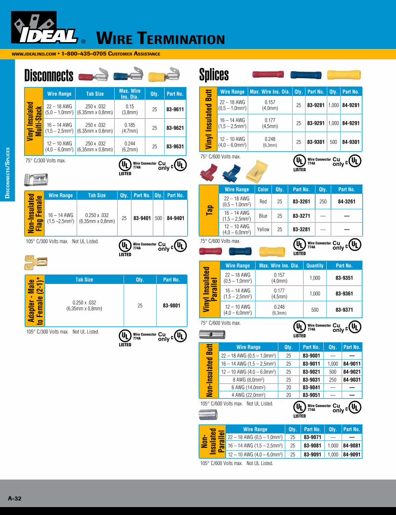
Wire TerminaTion
A-32
www.idealind.com • 1-800-435-0705 customer assistance
dis
co
nn
ecTs
/sp
lic
es
A-32
Wire TerminATionWWW.ideAlind.com • 1-800-435-0705 cusTomer AssisTAnce
Disconnects Splices
Non-
Insu
late
dFl
ag F
emal
e Wire Range Tab Size Qty. Part No. Qty. Part No.
16 – 14 AWG(1,5 –2,5mm2)
0.250 x .032(6,35mm x 0,8mm) 25 83-9401 500 84-9401
105° C/300 Volts max. Not UL Listed.
Adap
ter -
Mal
e to
Fem
ale
(2-1
)* Tab Size Qty. Part No.
0.250 x .032(6,35mm x 0,8mm) 25 83-9801
105° C/300 Volts max. Not UL Listed.
774A ListedPressure Wire Connector
Cuonly
774A ListedPressure Wire Connector
Cuonly
774A ListedPressure Wire Connector
Cuonly
774A ListedPressure Wire Connector
Cuonly
774A ListedPressure Wire Connector
Cuonly
774A ListedPressure Wire Connector
Cuonly
774A ListedPressure Wire Connector
Cuonly
Viny
l Ins
ulat
ed
Mul
ti-St
ack
Wire Range Tab Size Max. Wire Ins. Dia. Qty. Part No.
22 – 18 AWG(5,0 – 1,0mm2)
.250 x .032(6,35mm x 0,8mm)
0.15(3,8mm) 25 83-9611
16 – 14 AWG(1,5 – 2,5mm2)
.250 x .032(6,35mm x 0,8mm)
0.185(4,7mm) 25 83-9621
12 – 10 AWG(4,0 – 6,0mm2)
.250 x .032(6,35mm x 0,8mm)
0.244(6,2mm) 25 83-9631
75° C/300 Volts max.
Viny
l Ins
ulat
ed B
utt Wire Range Max. Wire Ins. Dia. Qty. Part No. Qty. Part No.
22 – 18 AWG(0,5 – 1,0mm2)
0.157(4,0mm) 25 83-9281 1,000 84-9281
16 – 14 AWG(1,5 – 2,5mm2)
0.177(4,5mm) 25 83-9291 1,000 84-9291
12 – 10 AWG(4,0 – 6,0mm2)
0.248(6,3mm)
25 83-9301 500 84-9301
75° C/600 Volts max.
Viny
l Ins
ulat
ed
Para
llel
Wire Range Max. Wire Ins. Dia. Quantity Part No.
22 – 18 AWG(0,5 – 1,0mm2)
0.157(4,0mm) 1,000 83-9351
16 – 14 AWG(1,5 – 2,5mm2)
0.177(4,5mm) 1,000 83-9361
12 – 10 AWG(4,0 – 6,0mm2)
0.248(6,3mm)
500 83-9371
75° C/600 Volts max.
Tap
Wire Range Color Qty. Part No. Qty. Part No.
22 – 18 AWG(0,5 – 1,0mm2) Red 25 83-3261 250 84-3261
16 – 14 AWG(1,5 – 2,5mm2) Blue 25 83-3271 — —
12 – 10 AWG(4,0 – 6,0mm2) Yellow 25 83-3281 — —
75° C/600 Volts max.
Non-
Insu
late
d Pa
ralle
l Wire Range Qty. Part No. Qty. Part No.22 – 18 AWG (0,5 – 1,0mm2) 25 83-9071 — —
16 – 14 AWG (1,5 – 2,5mm2) 25 83-9081 1,000 84-9081
12 – 10 AWG (4,0 – 6,0mm2) 25 83-9091 1,000 84-9091
105° C/600 Volts max. Not UL Listed.
Non-
Insu
late
d Bu
tt Wire Range Qty. Part No. Qty. Part No.
22 – 18 AWG (0,5 – 1,0mm2) 25 83-9001 — —16 – 14 AWG (1,5 – 2,5mm2) 25 83-9011 1,000 84-901112 – 10 AWG (4,0 – 6,0mm2) 25 83-9021 500 84-9021
8 AWG (8,0mm2) 25 83-9031 250 84-90316 AWG (14,0mm2) 20 83-9041 — —4 AWG (22,0mm2) 20 83-9051 — —
105° C/600 Volts max. Not UL Listed.
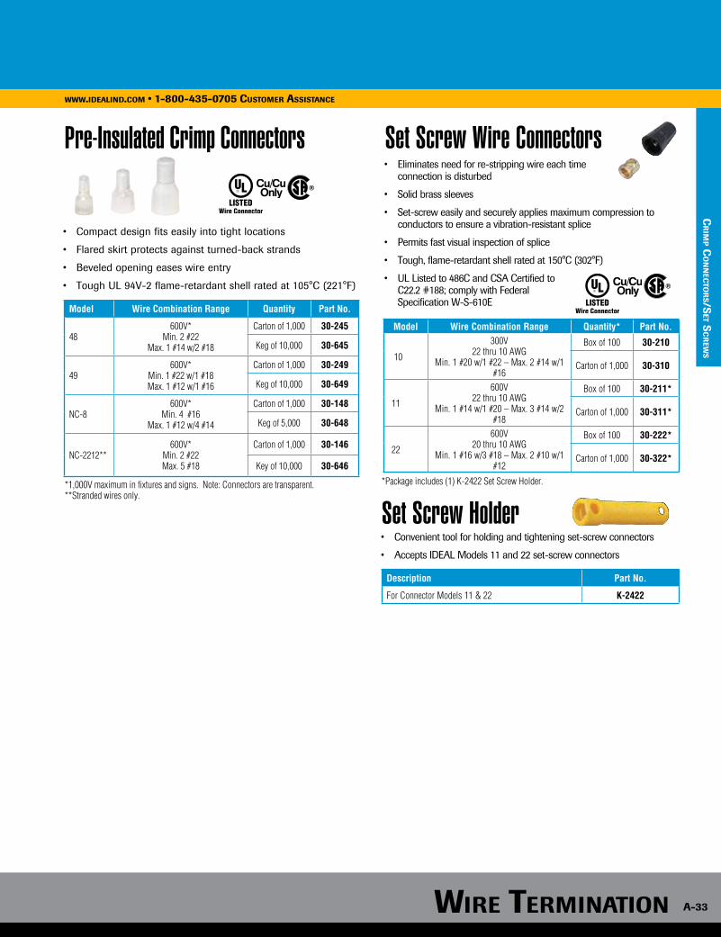
Wire TerminATion A-33
WWW.ideAlind.com • 1-800-435-0705 cusTomer AssisTAnce
cr
imp c
on
nec
Tor
s/seT s
cr
eWs
Description Part No.
For Connector Models 11 & 22 K-2422
Set Screw Holder• Convenient tool for holding and tightening set-screw connectors
• Accepts IDEAL Models 11 and 22 set-screw connectors
Set Screw Wire Connectors• Eliminates need for re-stripping wire each time connection is disturbed
• Solid brass sleeves
• Set-screw easily and securely applies maximum compression to conductors to ensure a vibration-resistant splice
• Permits fast visual inspection of splice
• Tough, flame-retardant shell rated at 150°C (302°F)
• UL Listed to 486C and CSA Certified to C22.2 #188; comply with Federal Specification W-S-610E
Model Wire Combination Range Quantity* Part No.
10
300V22 thru 10 AWG
Min. 1 #20 w/1 #22 – Max. 2 #14 w/1 #16
Box of 100 30-210
Carton of 1,000 30-310
11
600V22 thru 10 AWG
Min. 1 #14 w/1 #20 – Max. 3 #14 w/2 #18
Box of 100 30-211*
Carton of 1,000 30-311*
22
600V20 thru 10 AWG
Min. 1 #16 w/3 #18 – Max. 2 #10 w/1 #12
Box of 100 30-222*
Carton of 1,000 30-322*
Pre-Insulated Crimp Connectors
• Compact design fits easily into tight locations
• Flared skirt protects against turned-back strands
• Beveled opening eases wire entry
• Tough UL 94V-2 flame-retardant shell rated at 105°C (221°F)
Model Wire Combination Range Quantity Part No.
48600V*
Min. 2 #22 Max. 1 #14 w/2 #18
Carton of 1,000 30-245
Keg of 10,000 30-645
49600V*
Min. 1 #22 w/1 #18 Max. 1 #12 w/1 #16
Carton of 1,000 30-249
Keg of 10,000 30-649
NC-8600V*
Min. 4 #16 Max. 1 #12 w/4 #14
Carton of 1,000 30-148
Keg of 5,000 30-648
NC-2212**600V*
Min. 2 #22Max. 5 #18
Carton of 1,000 30-146
Key of 10,000 30-646
*1,000V maximum in fixtures and signs. Note: Connectors are transparent.**Stranded wires only.
*Package includes (1) K-2422 Set Screw Holder.
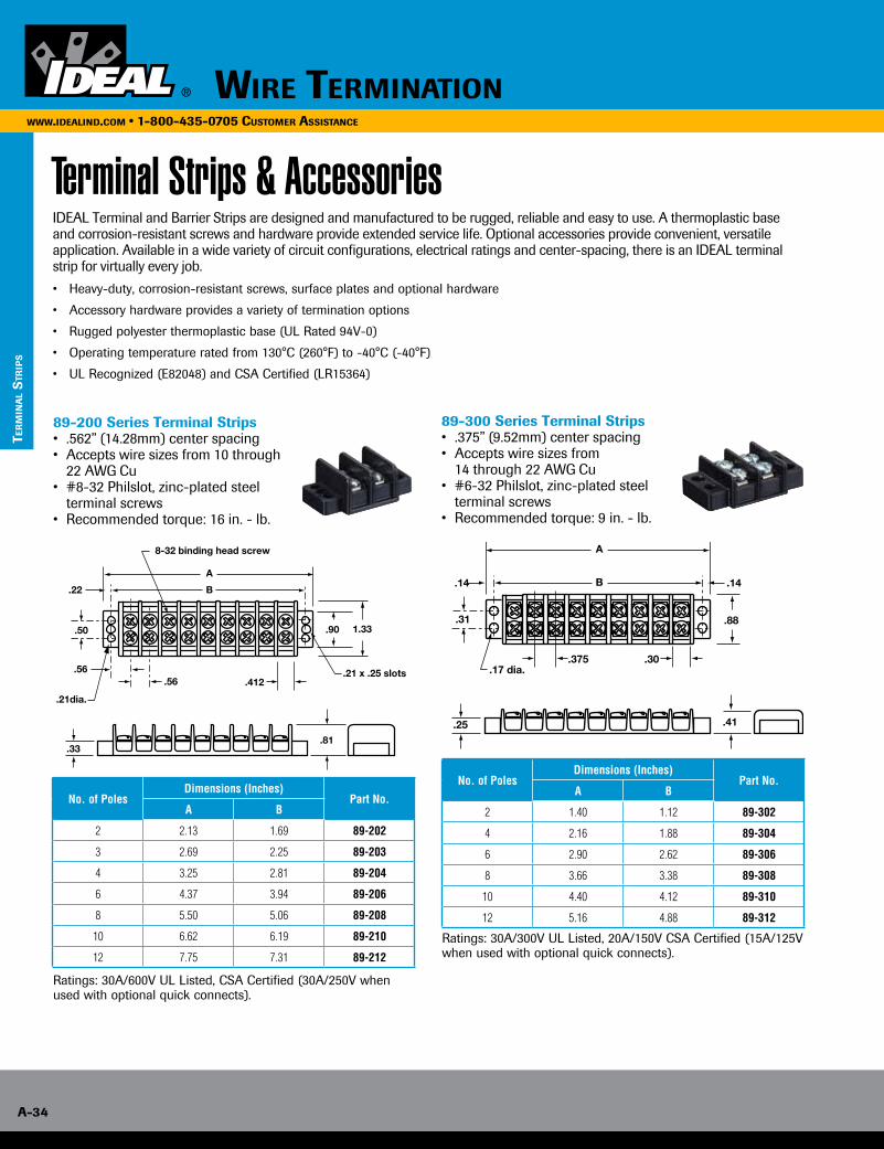
Wire TerminATion
A-34
WWW.ideAlind.com • 1-800-435-0705 cusTomer AssisTAnce
Ter
min
Al
sTr
ips
No. of PolesDimensions (Inches)
Part No.A B
2 2.13 1.69 89-202
3 2.69 2.25 89-203
4 3.25 2.81 89-204
6 4.37 3.94 89-206
8 5.50 5.06 89-208
10 6.62 6.19 89-210
12 7.75 7.31 89-212
No. of PolesDimensions (Inches)
Part No.A B
2 1.40 1.12 89-302
4 2.16 1.88 89-304
6 2.90 2.62 89-306
8 3.66 3.38 89-308
10 4.40 4.12 89-310
12 5.16 4.88 89-312
Terminal Strips & AccessoriesIDEAL Terminal and Barrier Strips are designed and manufactured to be rugged, reliable and easy to use. A thermoplastic base and corrosion-resistant screws and hardware provide extended service life. Optional accessories provide convenient, versatile application. Available in a wide variety of circuit configurations, electrical ratings and center-spacing, there is an IDEAL terminal strip for virtually every job.
• Heavy-duty, corrosion-resistant screws, surface plates and optional hardware
• Accessory hardware provides a variety of termination options
• Rugged polyester thermoplastic base (UL Rated 94V-0)
• Operating temperature rated from 130°C (260°F) to -40°C (-40°F)
• UL Recognized (E82048) and CSA Certified (LR15364)
89-200 Series Terminal Strips• .562” (14.28mm) center spacing • Accepts wire sizes from 10 through 22 AWG Cu• #8-32 Philslot, zinc-plated steel terminal screws• Recommended torque: 16 in. - lb.
89-300 Series Terminal Strips• .375” (9.52mm) center spacing• Accepts wire sizes from 14 through 22 AWG Cu• #6-32 Philslot, zinc-plated steel terminal screws• Recommended torque: 9 in. - lb.
Ratings: 30A/600V UL Listed, CSA Certified (30A/250V when used with optional quick connects).
Ratings: 30A/300V UL Listed, 20A/150V CSA Certified (15A/125V when used with optional quick connects).
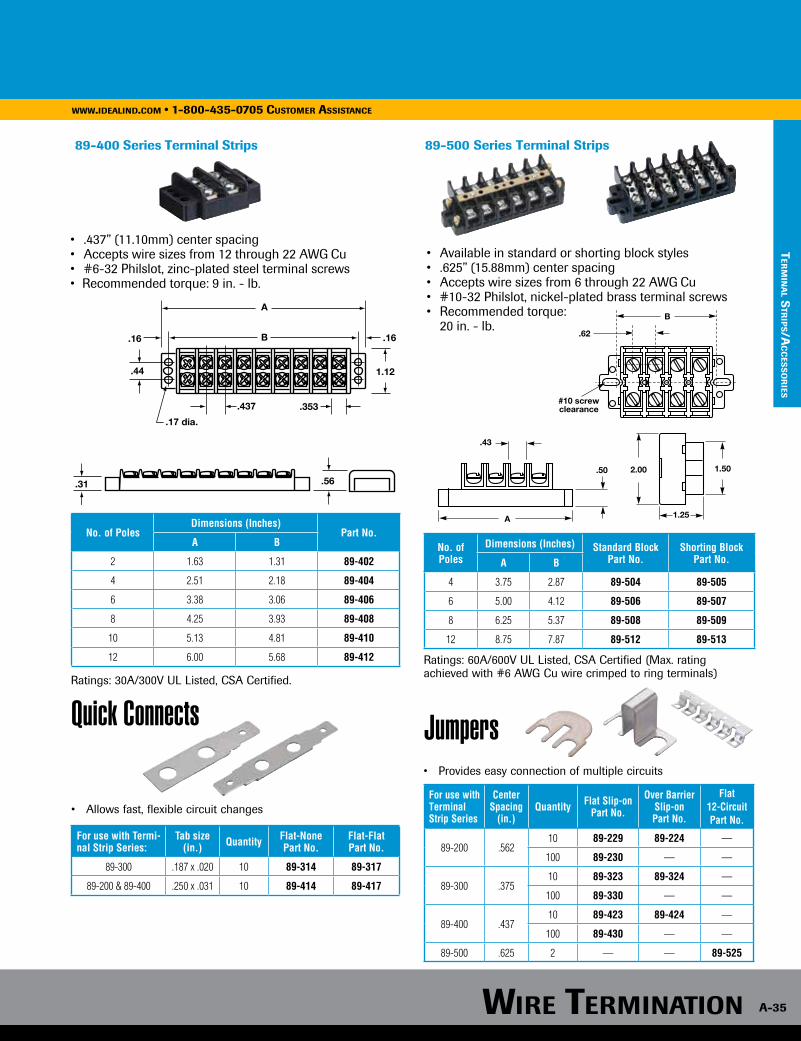
Wire TerminATion A-35
WWW.ideAlind.com • 1-800-435-0705 cusTomer AssisTAnce
Ter
min
Al s
Trip
s/Ac
ces
so
ries
89-400 Series Terminal Strips
• .437” (11.10mm) center spacing• Accepts wire sizes from 12 through 22 AWG Cu• #6-32 Philslot, zinc-plated steel terminal screws• Recommended torque: 9 in. - lb.
89-500 Series Terminal Strips
• Available in standard or shorting block styles• .625” (15.88mm) center spacing• Accepts wire sizes from 6 through 22 AWG Cu• #10-32 Philslot, nickel-plated brass terminal screws• Recommended torque: 20 in. - lb.
Ratings: 60A/600V UL Listed, CSA Certified (Max. rating achieved with #6 AWG Cu wire crimped to ring terminals)
No. of PolesDimensions (Inches)
Part No.A B
2 1.63 1.31 89-402
4 2.51 2.18 89-404
6 3.38 3.06 89-406
8 4.25 3.93 89-408
10 5.13 4.81 89-410
12 6.00 5.68 89-412
No. of Poles
Dimensions (Inches) Standard Block Part No.
Shorting BlockPart No.A B
4 3.75 2.87 89-504 89-505
6 5.00 4.12 89-506 89-507
8 6.25 5.37 89-508 89-509
12 8.75 7.87 89-512 89-513
Ratings: 30A/300V UL Listed, CSA Certified.
Quick Connects
• Allows fast, flexible circuit changes
For use with Termi-nal Strip Series:
Tab size (in.) Quantity Flat-None
Part No.Flat-Flat Part No.
89-300 .187 x .020 10 89-314 89-317
89-200 & 89-400 .250 x .031 10 89-414 89-417
Jumpers• Provides easy connection of multiple circuits
For use with Terminal Strip Series
Center Spacing
(in.)Quantity Flat Slip-on
Part No.
Over Barrier Slip-on Part No.
Flat 12-CircuitPart No.
89-200 .56210 89-229 89-224 —
100 89-230 — —
89-300 .37510 89-323 89-324 —
100 89-330 — —
89-400 .43710 89-423 89-424 —
100 89-430 — —
89-500 .625 2 — — 89-525
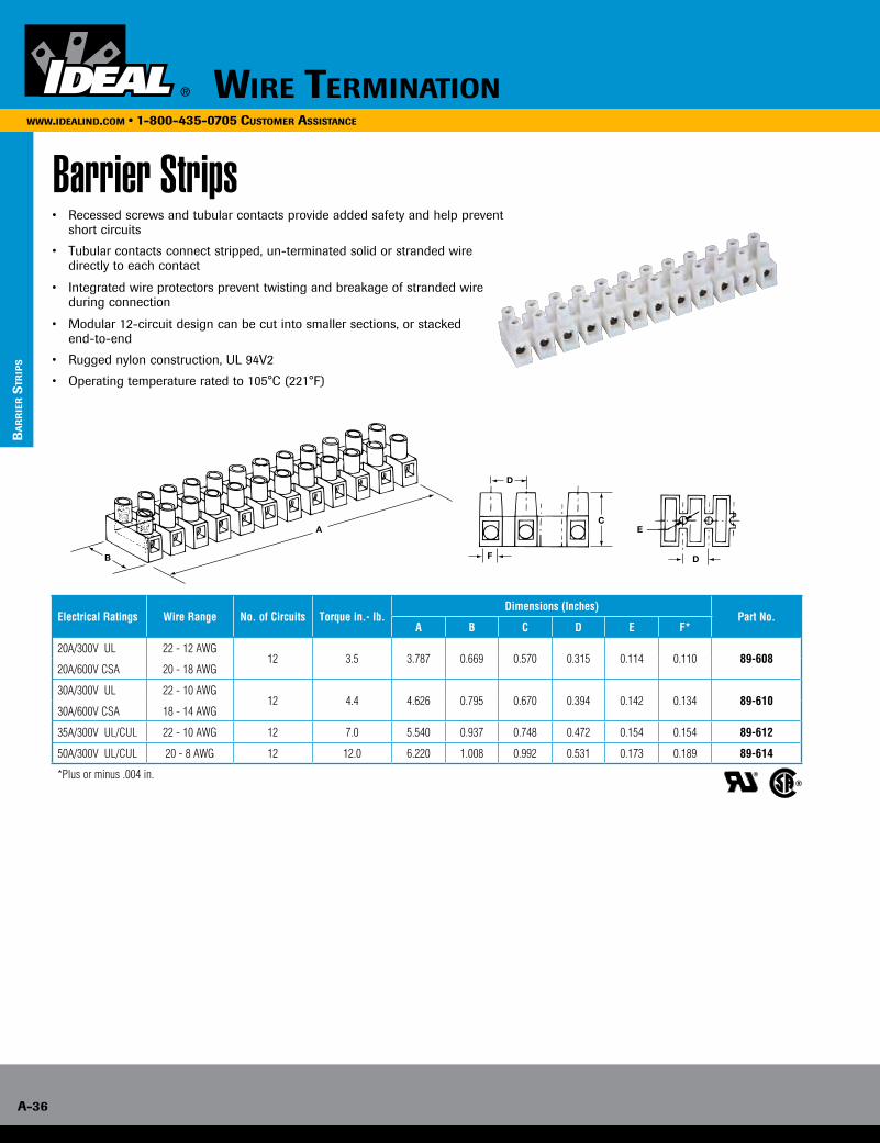
Wire TerminaTion
A-36
www.idealind.com • 1-800-435-0705 customer assistance
Barrier Strips• Recessed screws and tubular contacts provide added safety and help prevent
short circuits
• Tubular contacts connect stripped, un-terminated solid or stranded wire directly to each contact
• Integrated wire protectors prevent twisting and breakage of stranded wire during connection
• Modular 12-circuit design can be cut into smaller sections, or stacked end-to-end
• Rugged nylon construction, UL 94V2
• Operating temperature rated to 105°C (221°F)
Electrical Ratings Wire Range No. of Circuits Torque in.- lb.Dimensions (Inches)
Part No.A B C D E F*
20A/300V UL 22 - 12 AWG12 3.5 3.787 0.669 0.570 0.315 0.114 0.110 89-608
20A/600V CSA 20 - 18 AWG
30A/300V UL 22 - 10 AWG12 4.4 4.626 0.795 0.670 0.394 0.142 0.134 89-610
30A/600V CSA 18 - 14 AWG
35A/300V UL/CUL 22 - 10 AWG 12 7.0 5.540 0.937 0.748 0.472 0.154 0.154 89-612
50A/300V UL/CUL 20 - 8 AWG 12 12.0 6.220 1.008 0.992 0.531 0.173 0.189 89-614
*Plus or minus .004 in. ®
bA
rr
ier s
Trip
s
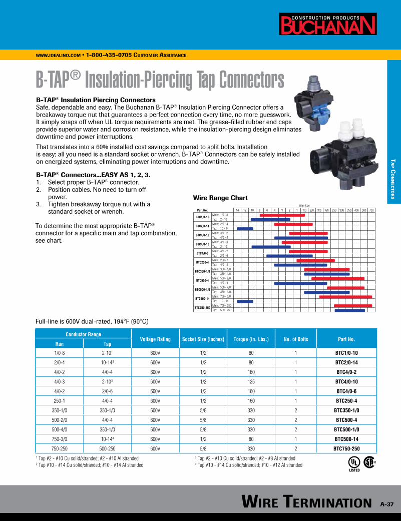
Wire TerminaTion A-37
www.idealind.com • 1-800-435-0705 customer assistance
B-TAP® Insulation-Piercing Tap ConnectorsB-TAP® Insulation Piercing ConnectorsSafe, dependable and easy. The Buchanan B-TAP® Insulation Piercing Connector offers abreakaway torque nut that guarantees a perfect connection every time, no more guesswork. It simply snaps off when UL torque requirements are met. The grease-filled rubber end caps provide superior water and corrosion resistance, while the insulation-piercing design eliminates downtime and power interruptions.
That translates into a 60% installed cost savings compared to split bolts. Installation is easy; all you need is a standard socket or wrench. B-TAP® Connectors can be safely installed on energized systems, eliminating power interruptions and downtime.
B-TAP® Connectors...EASY AS 1, 2, 3.1. Select proper B-TAP® connector.2. Position cables. No need to turn off power.3. Tighten breakaway torque nut with a standard socket or wrench.
Wire SizePart No. 14 12 10 8 6 4 3 2 1 1/0 2/0 3/0 4/0 250 300 350 400 500 750
BTC1/0-10Main: 1/0 - 8Tap: 2 - 10
BTC2/0-14Main: 2/0 - 4Tap: 10 - 14
BTC4/0-12Main: 4/0 - 2Tap: 4/0 - 4
BTC4/0-10Main: 4/0 - 3Tap: 2 - 10
BTC4/0-6Main: 4/0 - 2Tap: 2/0 - 6
BTC250-4Main: 250 - 1Tap: 4/0 - 4
BTC350-1/0Main: 350 - 1/0Tap: 350 - 1/0
BTC500-4Main: 500 - 2/0Tap: 4/0 - 4
BTC500-1/0Main: 500 - 4/0Tap: 350 - 1/0
BTC500-14Main: 750 - 3/0Tap: 10 - 14
BTC750-250Main: 750 - 250Tap: 500 - 250
LISTED
Conductor RangeVoltage Rating Socket Size (Inches) Torque (In. Lbs.) No. of Bolts Part No.
Run Tap
1/0-8 2-101 600V 1/2 80 1 BTC1/0-10
2/0-4 10-142 600V 1/2 80 1 BTC2/0-14
4/0-2 4/0-4 600V 1/2 160 1 BTC4/0-2
4/0-3 2-103 600V 1/2 125 1 BTC4/0-10
4/0-2 2/0-6 600V 1/2 160 1 BTC4/0-6
250-1 4/0-4 600V 1/2 160 1 BTC250-4
350-1/0 350-1/0 600V 5/8 330 2 BTC350-1/0
500-2/0 4/0-4 600V 5/8 330 2 BTC500-4
500-4/0 350-1/0 600V 5/8 330 2 BTC500-1/0
750-3/0 10-144 600V 1/2 80 1 BTC500-14
750-250 500-250 600V 5/8 330 2 BTC750-2501 Tap #2 - #10 Cu solid/stranded; #2 - #10 Al stranded 3 Tap #2 - #10 Cu solid/stranded; #2 - #8 Al stranded2 Tap #10 - #14 Cu solid/stranded; #10 - #14 Al stranded 4 Tap #10 - #14 Cu solid/stranded; #10 - #12 Al stranded
To determine the most appropriate B-TAP® connector for a specific main and tap combination, see chart.
Full-line is 600V dual-rated, 194°F (90°C)
Wire Range Chart
TA
p co
nn
ecTo
rs
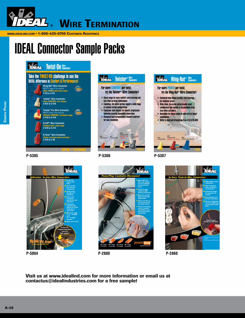
www.idealind.com • 1-800-435-0705 customer assistance
Wire TerminATion
A-38
WWW.ideAlind.com • 1-800-435-0705 cusTomer AssisTAnce
IDEAL Connector Sample Packs
Visit us at www.idealind.com for more information or email us at [email protected] for a free sample!
Twist-OnTake the TWIST-ON challenge to see the IDEAL difference in Comfort & Performance!
COMFORT • PERFORMANCE
Wing-Nut® Wire Connector WIDEST range in the industry! More POWER with every twist2 #18 to 4 #10
Twister® Wire Connector More COMFORT, less fatigue3 #22 to 3 #10
Twister® Pro Wire Connector WIDEST range in the industry! Ultimate COMFORT, maximum range2 #18 to 4 #10
B-CAP® Wire Connector Compact size, wide range2 #18 to 5 #12
B-Twist™ Wire Connector Comes to torque quick and easy2 #18 to 2 #8
Wire Connectors
SpliceLine™ In-Line Wire ConnectorsCrimp-free, push-in butt splice
Low insertion force for fast connections
Easily passes through 1/2” knockouts
End-to-end connection ideal for pre-fab operations
Transparent polycarbonate window for visual inspection of connection
Wide wire range of 12 – 20 AWG solid 12 – 16 AWG stranded
Made in the U.S.A.
™
Perfect for lengthening short
wires in tight spaces
Meets NEC and CEC code changes for non-residential fluorescent lumi-naires
Perfect for new, retrofit or OEM lighting installations
Meets UL and CSA finger-probe safety requirements
Allows safe discon-nect of neutral and hot ballast wiring
Push-in technology results in quicker connections, saves time and increases productivity
PowerPlug® Luminaire DisconnectElectrical Rating Wire Range Line Side/Ballast Side
6 Amps/600 Volts Max. Solid #12 – #18
Stranded #12 – #14 (19 strand or less)
Stranded Tin-Bonded #12 – #14 (19 strand or less)#16 (26 strand or less)#18 (16 strand or less)
Electrical Rating
Wire Range Line Side Ballast Side
6 Amps/600 Volts Max.
Solid #12 – #18 #18
Stranded #12 – #14 (19 strand or less) None
Stranded Tin-Bonded
#12 – #14 (19 strand or less)#16 (26 strand or less)#18 (16 strand or less)
#18 (16 strand or less)
Electrical Rating Wire Range Line Side
3.0 Amps/600 Volts Solid #18
Model 103 3-Pole Cat. No.
Card of 20 30-383X
Jar of 50 30-383XJ
Jar of 100 30-353XJ
Carton of 1,000 30-103X
Model 183 3-Pole Cat. No.
Box of 100 30-083
Carton of 2,500 30-683
102 2-Pole6 Amp/600V
182 2-Pole3 Amp/600V
183 3-Pole3 Amp/600V
103 3-Pole6 Amp/600V
®
Luminaire Disconnect
In-Sure™ Push-In Wire Connectors
Available in 2, 3 and 4 port models (6 port model available soon)
Easily Accepts Stranded or Solid Wire
High quality, secure connections
Clear shell gives visual verification of connection
Ergonomic design for easy grip and comfort
Low insertion force for fast connections
Fits any combination of #12-18 AWG solid and stranded copper wires
Great for residential applications as well.
IDEAL INDUSTRIES, INC.Becker Place, Sycamore, IL 60178, USA / 815-895-5181 • 800-435-0705 in USAInternational offices:Australia • Brazil • Canada • China • Germany • Mexico • UKFor complete sales office contact information, visit us at: www.idealind.com
Twister®
For more COMFORT per twist, try the Twister® Wire Connector! • Swept wings for more comfort, extra leverage and less effort on large combinations• Expanding, live-action springs support a wide range of common wiring configurations• Copolymer shell expands for smooth, progressive tightening ensuring dependable connections• Hexagonal head accommodates standard nutdriver for easy installation
Wire Connectors
340™
2 #22 to 3 #12
344®
2 #18 to 4 #10WIDEST in the industry!
341®
3 #22 to 3 #10
342®
3 #14 to 2 #8 with 2 #12
COMFORT
Wing-Nut®
For more POWER per twist, try the Wing-Nut® Wire Connector! • Contoured wing design provides extra leverage for maximum torque• Wide-range, live-action spring handles small combinations and expands to accommodate large sizes when you need it• Removable for repeat usage on same size or larger combinations• Ability to dead-end terminations from #16 to #6 AWG
Wire Connectors
451®
2 #18 to 3 #12
452®
2 #18 to 4 #10WIDEST in the industry!
453®
3 #12 to 1 #6 with 2 #8
POWER
P-5305
P-5004 P-2880 P-2860
P-5306 P-5307
sA
mp
le p
Ac
Ks
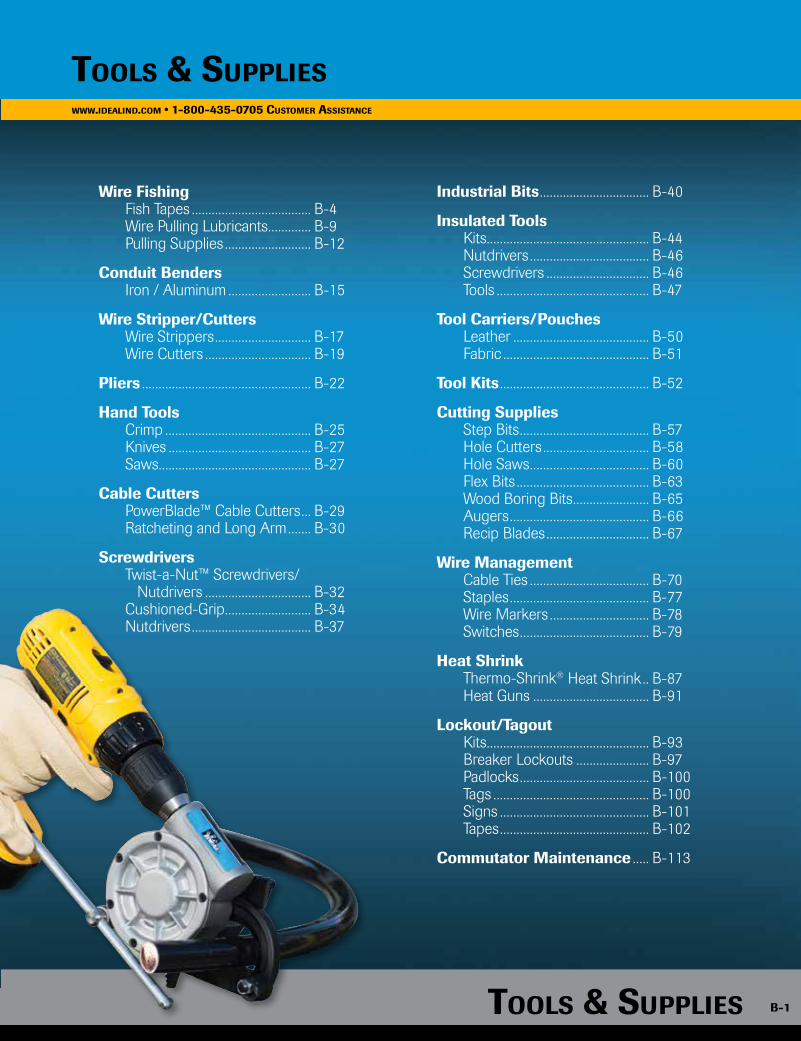
Tools & supplies B-1
www.idealind.com • 1-800-435-0705 customer assistance
Tools & supplies B-1
www.idealind.com • 1-800-435-0705 cusTomer assisTance
Tools & supplies
Wire Fishing Fish Tapes .................................... B-4 Wire Pulling Lubricants ............. B-9 Pulling Supplies .......................... B-12
Conduit Benders Iron / Aluminum ......................... B-15
Wire Stripper/Cutters Wire Strippers ............................. B-17 Wire Cutters ................................ B-19
Pliers ................................................... B-22
Hand Tools Crimp ............................................ B-25 Knives ........................................... B-27 Saws.............................................. B-27
Cable Cutters PowerBlade™ Cable Cutters ... B-29 Ratcheting and Long Arm ....... B-30
Screwdrivers Twist-a-Nut™ Screwdrivers/ Nutdrivers ................................ B-32 Cushioned-Grip .......................... B-34 Nutdrivers .................................... B-37
Industrial Bits ................................. B-40
Insulated Tools Kits................................................. B-44 Nutdrivers .................................... B-46 Screwdrivers ............................... B-46 Tools .............................................. B-47
Tool Carriers/Pouches Leather ......................................... B-50 Fabric ............................................ B-51
Tool Kits ............................................. B-52
Cutting Supplies Step Bits ....................................... B-57 Hole Cutters ................................ B-58 Hole Saws .................................... B-60 Flex Bits ........................................ B-63 Wood Boring Bits ....................... B-65 Augers .......................................... B-66 Recip Blades ............................... B-67
Wire Management Cable Ties .................................... B-70 Staples .......................................... B-77 Wire Markers .............................. B-78 Switches ....................................... B-79
Heat Shrink Thermo-Shrink® Heat Shrink .. B-87 Heat Guns ................................... B-91
Lockout/Tagout Kits................................................. B-93 Breaker Lockouts ...................... B-97 Padlocks ....................................... B-100 Tags ............................................... B-100 Signs ............................................. B-101 Tapes ............................................. B-102
Commutator Maintenance ..... B-113

B-2
www.idealind.com • 1-800-435-0705 customer assistance
tools & suppliesTools & supplies
B-2
www.idealind.com • 1-800-435-0705 cusTomer assisTance
PROFESSIONAL QUALITY, INNOVATIVE SOLUTIONSWhen it comes to quality, performance and durability, IDEAL is the professional choice for tools, cutting tools, fish tapes, benders and lubes. The community of professionals know what it takes to succeed in today’s electrical world and IDEAL fills those needs with high-quality innovative solutions. The expansion of the IDEAL U.S. manufacturing and engineering supported by strategic international facilities has been providing professional electricians with quality tools since 1916.
Tools & supplieswww.idealind.com • 1-800-435-0705 cusTomer assisTance
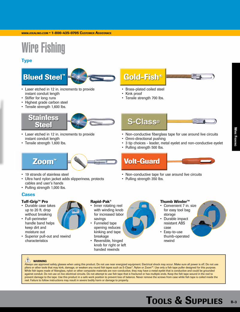
Tools & supplies B-3
www.idealind.com • 1-800-435-0705 customer assistance
Tools & supplies B-3
www.idealind.com • 1-800-435-0705 cusTomer assisTance
Wire FishingType
Cases
WARNING Always use approved safety glasses when using this product. Do not use near energized equipment. Electrical shock may occur. Make sure all power is off. Do not use pliers or other tools that may kink, damage, or weaken any round fish tapes such as S-Class®, Nylon or Zoom™. Use only a fish tape puller designed for this purpose. While fish tapes made of fiberglass, nylon or other composite materials are non-conductive, they may have a metal eyelet that is conductive and could be grounded against conduit. Do not use on live electrical circuits. Do not attempt to use fish tape that is fractured or has multiple ends. Keep the fish tape wound in the reel to prevent damage to the tape. Use this product in a safe work position to prevent loss of balance. Never remove the screws from case while fish tape is coiled inside the reel. Failure to follow instructions may result in severe bodily harm or damage to property.
wir
e Fis
hin
g
• Laser etched in 12 in. increments to provide instant conduit length• Stiffer for long runs• Highest grade carbon steel • Tensile strength 1,600 lbs.
• Brass-plated coiled steel• Kink proof• Tensile strength 700 lbs.
• Laser etched in 12 in. increments to provide instant conduit length• Tensile strength 1,600 lbs.
• Non-conductive fiberglass tape for use around live circuits• Omni-directional pushing• 3 tip choices - leader, metal eyelet and non-conductive eyelet• Pulling strength 500 lbs.
• 19 strands of stainless steel• Ultra hard nylon jacket adds slipperiness, protects cables and user’s hands• Pulling strength 1,000 lbs.
• Non-conductive tape for use around live circuits• Pulling strength 350 lbs.
Tuff-Grip™ Pro• Durable case takes up to 20 ft. drop without breaking• Full-perimeter handle band helps keep dirt and moisture out• Superior pull-out and rewind characteristics
Rapid-Pak®
• Inner rotating reel with winding knob for increased labor savings• Funneled tape opening reduces kinking and tape breakage• Reversible, hinged knob for right or left handed rewinds
Thumb Winder™ • Convenient 7 in. size for easy tool bag storage• Durable impact resistant ABS case• Easy-to-use thumb-operated rewind
www.idealind.com • 1-800-435-0705 cusTomer assisTance

B-4
www.idealind.com • 1-800-435-0705 cusTomer assisTance
Tools & supplies
Length (ft.) Width & Thickness Case Diameter End Type Tuff-Grip™ Pro Thumb-Winder™ Replacement Tapes (No Case)
25 1/8 in. x .045 in. 7 in. Formed hook – 31-012 –
50 1/8 in. x .045 in. 7 in. Formed hook – 31-010 –
50 1/8 in. x .060 in. 9 in. Formed hook 31-033 – 31-004
60 1/8 in. x .060 in. 12 in. Formed hook 31-055 – 31-035
120 1/8 in. x .060 in. 12 in. Formed hook 31-056 – 31-036
240 1/8 in. x .060 in. 12 in. Formed hook 31-057 – 31-038
50 1/4 in. x .060 in. 12 in. Formed hook 31-059 – 31-051
100 1/4 in. x .060 in. 12 in. Formed hook 31-058 – 31-050
200 1/4 in. x .060 in. None Formed hook – – 31-052
400 1/4 in. x .060 in. None Formed hook – – 31-2128
— 1/4 in. x .060 in. None Formed hook – – 31-2982*
*Bulk roll 750 lbs. (approximately 12,000 ft.)
Blued-Steel™ Fish Tapes
wir
e Fi
sh
ing
• Laser etched in 12”increments to provide instant conduit length
• Tape will not rust or corrode in humid environments
• Stainless steel design provides a smooth pay-out
Stainless Steel Fish Tapes
• Great for hard to navigate conduit with multiple bends
• Nylon jacket protects the stainless steel core while adding to the
slipperiness of Zoom™
Zoom™ Fish Tapes
Length (ft.) Width & Thickness Case Diameter End Type Tuff-Grip™ Pro Replacement Tape (No Case)
120 1/8 in. x .060 in. 12 in. Formed hook 31-066 —
240 1/8 in. x .060 in. 12 in. Formed hook 31-067 31-074
Length (ft.) Diameter Case Diameter End Type Tuff-Grip™ Pro Replacement Tapes (No Case)
50 3/16 in. 12 in. Metal Eyelet 31-090 31-091
100 3/16 in. 12 in. Metal Eyelet 31-092 31-093
200 3/16 in. 16 in.* Metal Eyelet 31-096 —
*Traditional handle
• Laser etched in 12 in. increments to provide instant conduit length
• High column strength for longer runs
• Non-oily finish resists rust
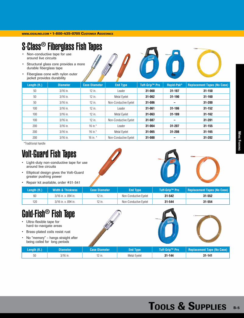
Tools & supplies B-5
www.idealind.com • 1-800-435-0705 cusTomer assisTance
• Non-conductive tape for use around live circuits
• Structural glass core provides a more durable fiberglass tape
• Fiberglass cone with nylon outer jacket provides durability
S-Class® Fiberglass Fish Tapes
Volt-Guard Fish Tapes
Gold-Fish® Fish Tape
Length (ft.) Width & Thickness Case Diameter End Type Tuff-Grip™ Pro Replacement Tapes (No Case)
60 3/16 in. x .094 in. 12 in. Non-Conductive Eyelet 31-542 31-552
120 3/16 in. x .094 in. 12 in. Non-Conductive Eyelet 31-544 31-554
Length (ft.) Diameter Case Diameter End Type Tuff-Grip™ Pro Replacement Tape (No Case)
50 3/16 in. 12 in. Metal Eyelet 31-144 31-141
• Light-duty non-conductive tape for use around live circuits
• Elliptical design gives the Volt-Guard greater pushing power
• Repair kit available, order #31-541
• Ultra-flexible tape for hard-to-navigate areas
• Brass-plated coils resist rust
• No “memory” – hangs straight after being coiled for long periods
wir
e Fis
hin
g
Length (ft.) Diameter Case Diameter End Type Tuff-Grip™ Pro Rapid-Pak® Replacement Tapes (No Case)
50 3/16 in. 12 in. Leader 31-060 31-187 31-150
50 3/16 in. 12 in. Metal Eyelet 31-062 31-190 31-160
50 3/16 in. 12 in. Non-Conductive Eyelet 31-086 – 31-200
100 3/16 in. 12 in. Leader 31-061 31-186 31-152
100 3/16 in. 12 in. Metal Eyelet 31-063 31-189 31-162
100 3/16 in. 12 in. Non-Conductive Eyelet 31-087 – 31-201
200 3/16 in. 16 in.* Leader 31-064 31-207 31-155
200 3/16 in. 16 in.* Metal Eyelet 31-065 31-208 31-165
200 3/16 in. 16 in. * Non-Conductive Eyelet 31-088 – 31-202
*Traditional handle

B-6
www.idealind.com • 1-800-435-0705 customer assistance
tools & supplies
Fish Tape Field Application Repair Kits
Fish Tape Leaders Fish Tape Swivel Ball
Fish Tape Non-Conductive Tip Replacement Kits
Tuff-Grip™ Pro Accessories
• For use on S-Class® & Zoom™ Fish Tapes
• Crimps on new eyelet or leader in minutes
• Dies can be used with Crimpmaster™ Crimp Tool
• Connection guaranteed to withstand 500 lbs.
• Easy to apply
• Each kit includes two eyelets & adhesive
Description Part No.
Field Application Kit includes: Crimpmaster™ Crimp Tool frame, die set, S-Class® eyelets (2), S-Class® leaders (2), Zoom™ eyelets (2) & instant adhesive 31-156
Die Set Kit includes: eyelets (2), leaders (2) & instant adhesive (for those who already have a Crimpmaster™ Crimp Tool) 31-164
Replacement eyelets (4) for S-Class® Fish Tapes & adhesive 31-158
Replacement leaders (4) for S-Class® Fish Tapes & adhesive 31-159
Replacement eyelets (2) for Zoom™ Fish Tapes 31-094
Die Set Only (for those who already have a Crimpmaster™ Crimp Tool) 31-166
Description Part No.
Volt-Guard Fish Tape Repair Kit 31-541
S-Class® Fish Tape Repair Kit 31-203
• Guides fish tape around bends in conduit
• Handles up to six 10 AWG bare wires
• Pulls up to 500 lbs.
Description Part No.
Fish Tape Leader for steel or stainless steel tapes 31-148
Fish Tape Leader for S-Class® Fiberglass Fish Tape 31-159
• Swivels to prevent wires from twisting during pull
• Designed for use on 1/8 in. steel or stainless steel tapes
• Eyelet holds up to four 10 AWG bare wires
• Replacement includes: Fish Tape Case (2 halves) and Handle (1)
Description Part No.
Fish Tape Swivel Ball 31-085
Description Part No.
Fish Tape Parts Kit KB-0173
Screws (not included, kit requires 4) LA-4218
Screws not included, must be ordered separately.
31-203
31-156
31-166
31-158
31-541
wir
e Fi
sh
ing
www.idealind.com • 1-800-435-0705 cusTomer assisTance
Tools & supplies
B-6
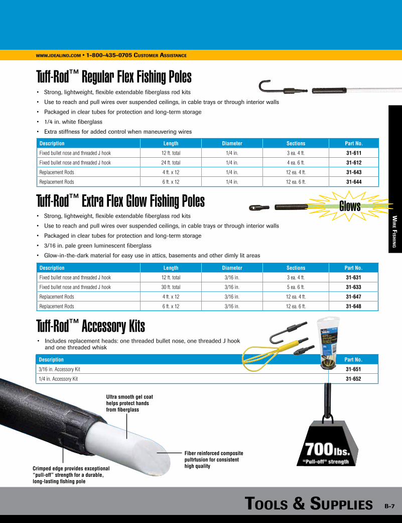
Tuff-Rod™ Extra Flex Glow Fishing Poles Glows
Tools & supplies B-7
www.idealind.com • 1-800-435-0705 cusTomer assisTance
Fish Tape Swivel Ball
wir
e Fi
sh
ing
wir
e Fis
hin
g
Tuff-Rod™ Accessory Kits
• Strong, lightweight, flexible extendable fiberglass rod kits
• Use to reach and pull wires over suspended ceilings, in cable trays or through interior walls
• Packaged in clear tubes for protection and long-term storage
• 3/16 in. pale green luminescent fiberglass
• Glow-in-the-dark material for easy use in attics, basements and other dimly lit areas
Description Length Diameter Sections Part No.
Fixed bullet nose and threaded J hook 12 ft. total 1/4 in. 3 ea. 4 ft. 31-611
Fixed bullet nose and threaded J hook 24 ft. total 1/4 in. 4 ea. 6 ft. 31-612
Replacement Rods 4 ft. x 12 1/4 in. 12 ea. 4 ft. 31-643
Replacement Rods 6 ft. x 12 1/4 in. 12 ea. 6 ft. 31-644
• Includes replacement heads: one threaded bullet nose, one threaded J hook and one threaded whisk
Description Part No.
3/16 in. Accessory Kit 31-651
1/4 in. Accessory Kit 31-652
Tuff-Rod™ Regular Flex Fishing Poles• Strong, lightweight, flexible extendable fiberglass rod kits
• Use to reach and pull wires over suspended ceilings, in cable trays or through interior walls
• Packaged in clear tubes for protection and long-term storage
• 1/4 in. white fiberglass
• Extra stiffness for added control when maneuvering wires
Description Length Diameter Sections Part No.
Fixed bullet nose and threaded J hook 12 ft. total 3/16 in. 3 ea. 4 ft. 31-631
Fixed bullet nose and threaded J hook 30 ft. total 3/16 in. 5 ea. 6 ft. 31-633
Replacement Rods 4 ft. x 12 3/16 in. 12 ea. 4 ft. 31-647
Replacement Rods 6 ft. x 12 3/16 in. 12 ea. 6 ft. 31-648
Ultra smooth gel coat helps protect hands from fiberglass
Fiber reinforced compositepultrtusion for consistenthigh qualityCrimped edge provides exceptional
“pull-off” strength for a durable, long-lasting fishing pole
www.idealind.com • 1-800-435-0705 cusTomer assisTance
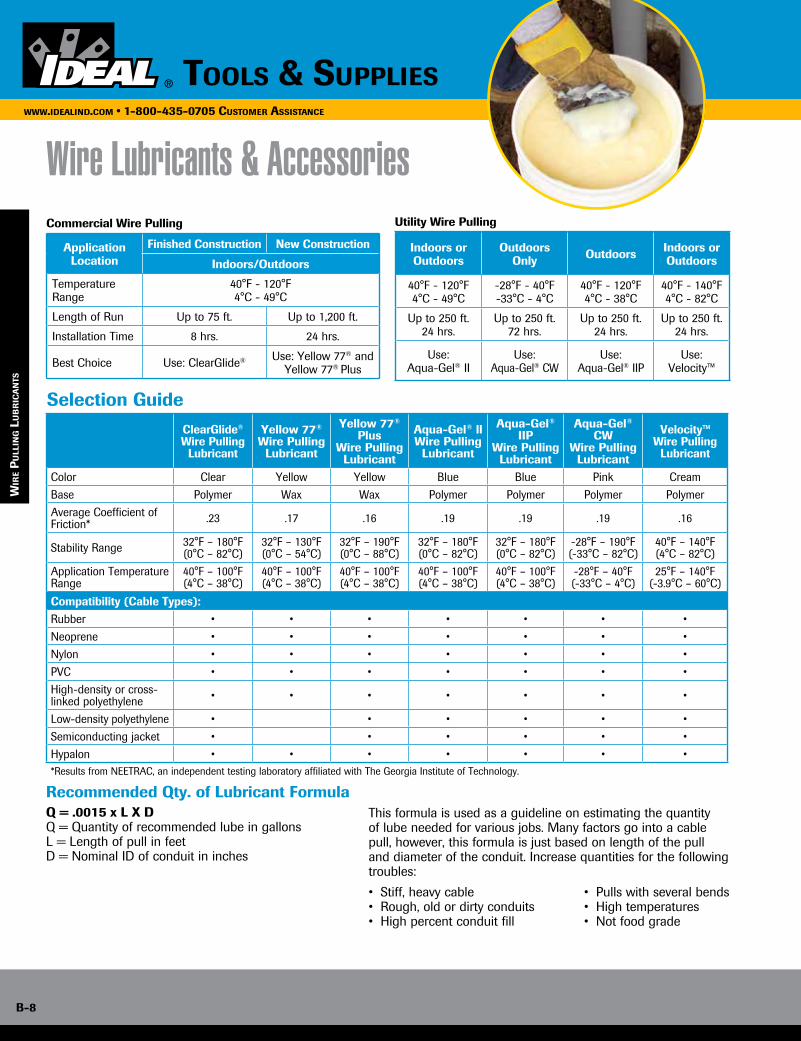
B-8
www.idealind.com • 1-800-435-0705 customer assistance
tools & supplies
wir
e Fis
hin
g
Wire Lubricants & AccessoriesCommercial Wire Pulling
Application Location
Finished Construction New Construction
Indoors/Outdoors
Temperature Range
40°F - 120°F4°C - 49°C
Length of Run Up to 75 ft. Up to 1,200 ft.
Installation Time 8 hrs. 24 hrs.
Best Choice Use: ClearGlide® Use: Yellow 77® and Yellow 77® Plus
Selection Guide
Utility Wire Pulling
Indoors orOutdoors
OutdoorsOnly Outdoors Indoors or
Outdoors
40°F - 120°F4°C - 49°C
-28°F - 40°F-33°C - 4°C
40°F - 120°F4°C - 38°C
40°F - 140°F4°C - 82°C
Up to 250 ft.24 hrs.
Up to 250 ft.72 hrs.
Up to 250 ft.24 hrs.
Up to 250 ft.24 hrs.
Use: Aqua-Gel® II
Use: Aqua-Gel® CW
Use: Aqua-Gel® IIP
Use: Velocity™
ClearGlide®
Wire PullingLubricant
Yellow 77® Wire Pulling
Lubricant
Yellow 77® Plus
Wire PullingLubricant
Aqua-Gel® llWire Pulling
Lubricant
Aqua-Gel® IIP
Wire PullingLubricant
Aqua-Gel® CW
Wire PullingLubricant
Velocity™Wire Pulling
Lubricant
Color Clear Yellow Yellow Blue Blue Pink CreamBase Polymer Wax Wax Polymer Polymer Polymer PolymerAverage Coefficient of Friction* .23 .17 .16 .19 .19 .19 .16
Stability Range 32°F – 180°F(0°C – 82°C)
32°F – 130°F(0°C – 54°C)
32°F – 190°F(0°C – 88°C)
32°F – 180°F(0°C – 82°C)
32°F – 180°F(0°C – 82°C)
-28°F – 190°F(-33°C – 82°C)
40°F – 140°F(4°C – 82°C)
Application Temperature Range
40°F – 100°F(4°C – 38°C)
40°F – 100°F(4°C – 38°C)
40°F – 100°F(4°C – 38°C)
40°F – 100°F(4°C – 38°C)
40°F – 100°F(4°C – 38°C)
-28°F – 40°F(-33°C – 4°C)
25°F – 140°F(-3.9°C – 60°C)
Compatibility (Cable Types):Rubber • • • • • • •Neoprene • • • • • • •Nylon • • • • • • •PVC • • • • • • •High-density or cross-linked polyethylene • • • • • • •
Low-density polyethylene • • • • • • Semiconducting jacket • • • • • •Hypalon • • • • • • •*Results from NEETRAC, an independent testing laboratory affiliated with The Georgia Institute of Technology.
Recommended Qty. of Lubricant FormulaQ = .0015 x L X DQ = Quantity of recommended lube in gallonsL = Length of pull in feetD = Nominal ID of conduit in inches
This formula is used as a guideline on estimating the quantity of lube needed for various jobs. Many factors go into a cable pull, however, this formula is just based on length of the pull and diameter of the conduit. Increase quantities for the following troubles:
• Stiff, heavy cable • Pulls with several bends• Rough, old or dirty conduits • High temperatures• High percent conduit fill • Not food grade
wir
e p
ull
ing l
uB
ric
an
Ts
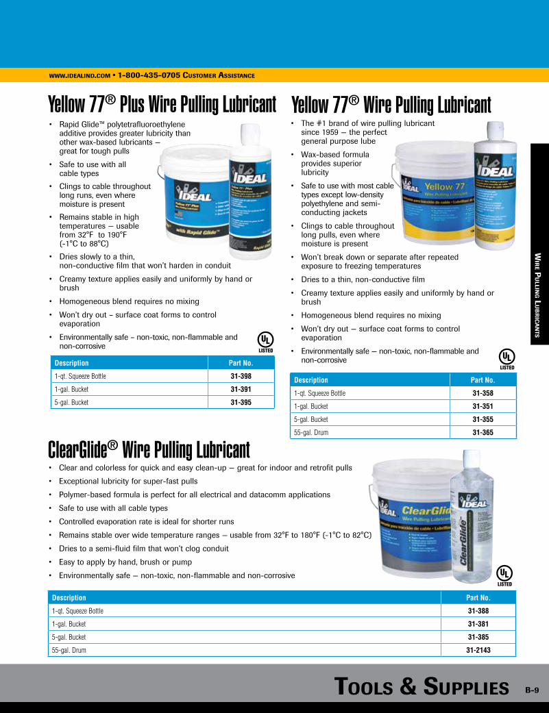
Tools & supplies B-9
www.idealind.com • 1-800-435-0705 customer assistance
Yellow 77® Plus Wire Pulling Lubricant Yellow 77® Wire Pulling Lubricant• Rapid Glide™ polytetrafluoroethylene additive provides greater lubricity than other wax-based lubricants — great for tough pulls
• Safe to use with all cable types
• Clings to cable throughout long runs, even where moisture is present
• Remains stable in high temperatures — usable from 32°F to 190°F (-1°C to 88°C)
• Dries slowly to a thin, non-conductive film that won’t harden in conduit
• Creamy texture applies easily and uniformly by hand or brush
• Homogeneous blend requires no mixing
• Won’t dry out – surface coat forms to control evaporation
• Environmentally safe – non-toxic, non-flammable and non-corrosive
Description Part No.
1-qt. Squeeze Bottle 31-398
1-gal. Bucket 31-391
5-gal. Bucket 31-395
LISTED
Description Part No.
1-qt. Squeeze Bottle 31-358
1-gal. Bucket 31-351
5-gal. Bucket 31-355
55-gal. Drum 31-365
• The #1 brand of wire pulling lubricant since 1959 — the perfect general purpose lube
• Wax-based formula provides superior lubricity
• Safe to use with most cable types except low-density polyethylene and semi- conducting jackets
• Clings to cable throughout long pulls, even where moisture is present
• Won’t break down or separate after repeated exposure to freezing temperatures
• Dries to a thin, non-conductive film
• Creamy texture applies easily and uniformly by hand or brush
• Homogeneous blend requires no mixing
• Won’t dry out — surface coat forms to control evaporation
• Environmentally safe — non-toxic, non-flammable and non-corrosive
LISTED
wir
e pu
lling l
uB
ric
an
Ts
ClearGlide® Wire Pulling Lubricant• Clear and colorless for quick and easy clean-up — great for indoor and retrofit pulls
• Exceptional lubricity for super-fast pulls
• Polymer-based formula is perfect for all electrical and datacomm applications
• Safe to use with all cable types
• Controlled evaporation rate is ideal for shorter runs
• Remains stable over wide temperature ranges — usable from 32°F to 180°F (-1°C to 82°C)
• Dries to a semi-fluid film that won’t clog conduit
• Easy to apply by hand, brush or pump
• Environmentally safe — non-toxic, non-flammable and non-corrosive
Description Part No.
1-qt. Squeeze Bottle 31-388
1-gal. Bucket 31-381
5-gal. Bucket 31-385
55-gal. Drum 31-2143
LISTED
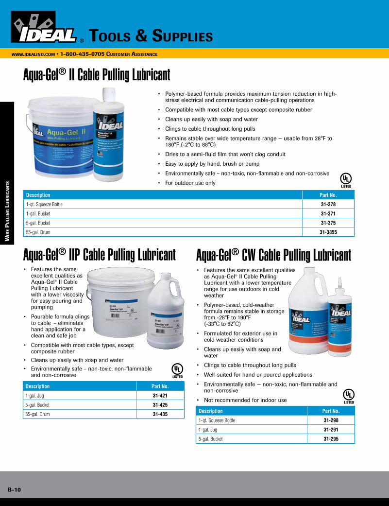
B-10
www.idealind.com • 1-800-435-0705 customer assistance
tools & supplies
Aqua-Gel® IIP Cable Pulling Lubricant Aqua-Gel® CW Cable Pulling Lubricant
Aqua-Gel® II Cable Pulling Lubricant• Polymer-based formula provides maximum tension reduction in high-
stress electrical and communication cable-pulling operations
• Compatible with most cable types except composite rubber
• Cleans up easily with soap and water
• Clings to cable throughout long pulls
• Remains stable over wide temperature range — usable from 28°F to 180°F (-2°C to 88°C)
• Dries to a semi-fluid film that won’t clog conduit
• Easy to apply by hand, brush or pump
• Environmentally safe – non-toxic, non-flammable and non-corrosive
• For outdoor use onlyLISTED
Description Part No.
1-qt. Squeeze Bottle 31-378
1-gal. Bucket 31-371
5-gal. Bucket 31-375
55-gal. Drum 31-3855
• Features the same excellent qualities as Aqua-Gel® II Cable Pulling Lubricant with a lower viscosity for easy pouring and pumping
• Pourable formula clings to cable – eliminates hand application for a clean and safe job
• Compatible with most cable types, except composite rubber
• Cleans up easily with soap and water
• Environmentally safe – non-toxic, non-flammable and non-corrosive
Description Part No.
1-gal. Jug 31-421
5-gal. Bucket 31-425
55-gal. Drum 31-435
LISTED
LISTED
• Features the same excellent qualities as Aqua-Gel® II Cable Pulling Lubricant with a lower temperature range for use outdoors in cold weather
• Polymer-based, cold-weather formula remains stable in storage from -28°F to 190°F (-33°C to 82°C)
• Formulated for exterior use in cold weather conditions
• Cleans up easily with soap and water
• Clings to cable throughout long pulls
• Well-suited for hand or poured applications
• Environmentally safe — non-toxic, non-flammable and non-corrosive
• Not recommended for indoor use
Description Part No.
1-qt. Squeeze Bottle 31-298
1-gal. Jug 31-291
5-gal. Bucket 31-295
wir
e p
ull
ing l
uB
ric
an
Ts
www.idealind.com • 1-800-435-0705 cusTomer assisTance
Tools & supplies
B-10
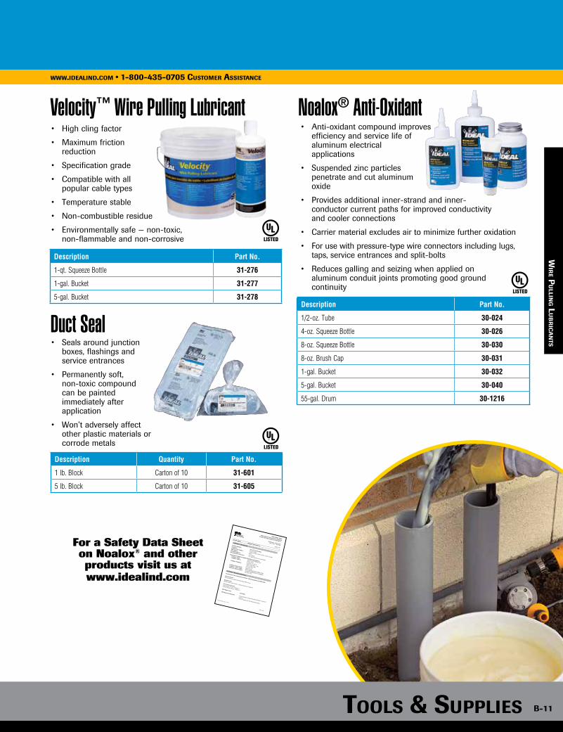
Tools & supplies B-11
www.idealind.com • 1-800-435-0705 cusTomer assisTance
wir
e pu
lling l
uB
ric
an
Ts
• Anti-oxidant compound improves efficiency and service life of aluminum electrical applications
• Suspended zinc particles penetrate and cut aluminum oxide
• Provides additional inner-strand and inner- conductor current paths for improved conductivity and cooler connections
• Carrier material excludes air to minimize further oxidation
• For use with pressure-type wire connectors including lugs, taps, service entrances and split-bolts
• Reduces galling and seizing when applied on aluminum conduit joints promoting good ground continuity
• Seals around junction boxes, flashings and service entrances
• Permanently soft, non-toxic compound can be painted immediately after application
• Won’t adversely affect other plastic materials or corrode metals
LISTED
LISTED
Description Quantity Part No.
1 lb. Block Carton of 10 31-601
5 lb. Block Carton of 10 31-605
Description Part No.
1/2-oz. Tube 30-024
4-oz. Squeeze Bottle 30-026
8-oz. Squeeze Bottle 30-030
8-oz. Brush Cap 30-031
1-gal. Bucket 30-032
5-gal. Bucket 30-040
55-gal. Drum 30-1216
Noalox® Anti-Oxidant
Duct Seal
Velocity™ Wire Pulling Lubricant• High cling factor
• Maximum friction reduction
• Specification grade
• Compatible with all popular cable types
• Temperature stable
• Non-combustible residue
• Environmentally safe — non-toxic, non-flammable and non-corrosive
Description Part No.
1-qt. Squeeze Bottle 31-276
1-gal. Bucket 31-277
5-gal. Bucket 31-278
LISTED
Safety Data Sheet
OSHA Hazard Communication Standard
29 CFR 1910.1200. Prepared to GHS Rev 3.
Revision date: Initial version
Date of issue: 04.28.2015
Page: 1/11
Trade name:
Noalox® Anti Oxidant
Revision Date: June 1, 2015
Page 1 of 11
SECTION 1: Identification
Product identifier: Noalox® Anti Oxidant.
Synonyms:
None available.
Product Code Number: 30-024, 30-026, 30-030, 30-031, 30-032, 30-040.
SDS number:
ID019
Recommended use: Anti oxidant.
Recommended restrictions: Uses other than those recommended.
Manufacturer/Importer/Supplier/Distributor information:
Company Name: IDEAL INDUSTRIES, INC.
Company Address: Becker Place,
Sycamore, IL 60178
Company Telephone: Office hours (Mon – Fri)
7AM - 5 PM (CDT)
(815)895-5181
Company Contact Name: Darryl Docter.
Company Contact Email: [email protected]
Emergency phone number: 24 HOUR EMERGENCY NUMBER:
(815)895-5181.
SECTION 2: Hazard(s) identification
Classification of the chemical in accordance with paragraph (d) of §1910.1200:
Physical hazards
Not classified as a physical hazard under GHS criteria.
Health hazards Specific target organ toxicity - repeated exposure, Category 1.
Environmental hazards
Acute aquatic toxicity, Category 2.
Chronic aquatic toxicity, Category 2.
GHS Signal word: DANGER.
GHS Hazard statement(s):
Causes damage to organs through prolonged or repeated
exposure.
Toxic to aquatic life with long lasting effects.
For a Safety Data Sheet on Noalox® and other products visit us at www.idealind.com

B-12
www.idealind.com • 1-800-435-0705 cusTomer assisTance
Tools & supplies
wir
e pu
lling l
uB
ric
an
Ts
Valu-Line™ Pull Line
Powr-Fish® Pull LinePowr-Fish® Pull Line
3-in-1 Premise MULETAPE®
• White with blue tracer for easy identification
• Continuous-fiber polyline great for blowing directly into conduit
• Will not rot or mildew
• Can be left in conduit for future use
• White with gray tracer for easy identification
• Continuous-fiber polyline great for blowing directly into conduit
• Will not rot or mildew
• Can be left in conduit for future use
• White with red tracer for easy identification
• 500 lb. tensile, our highest tensile-rated pull-line
• Continuous-fiber polyline great for blowing directly
into conduit
• Will not rot or mildew
• Can be left in conduit for future use
Description Tensile Strength Length Part No.
Valu-Line™ Pull-Line 190 lbs. 6,500 ft./ Bucket 31-338
STANDARD
Duty
Description Tensile Strength Length Part No.
Powr-Fish® Pull-Line 500 lbs. 2,200 ft./ Bucket 31-344
Description Tensile Strength Length Part No.
Powr-Fish® Pull-Line 210 lbs. 6,500 ft./ Bucket 31-340
Powr-Fish® Pull-Line 210 lbs. 500 ft./ Canister 31-348
HEAVYDuty
• Reduces installation time and saves money on premise jobs
• Blow, measure and pull with single product
• Imprinted with sequential footage
or meter markings
• Fewer installation steps, significant material and labor savings
Description Pulling Strength
Tape Width
Length/Bucket Part No.
3-in-1 Premise MULETAPE®400 lb. 1/4 in. 4,500 ft. 31-314
1,800 lb. 1/2 in. 1,300 ft. 31-315
MULETAPE® is a registered trademark of NEPTCO, INC.
3-functions
in-1
Conduit Measuring Tape• Provides quick and accurate
measurement of conduit runs
• Easy-to-read markings in sequential one-foot increments
• 160 lb. tensile strength
• Pulls rope through raceways without stretching
• Will not rot or mildew
Description Tape Width Length Part No.
Conduit Measuring Tape .188 in. 3,000 ft. 31-347
EXTRA-HEAVY
Duty 500#
pu
llin
g s
up
pli
es
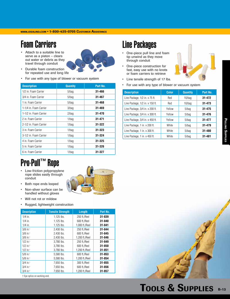
Tools & supplies B-13
www.idealind.com • 1-800-435-0705 cusTomer assisTancewww.idealind.com • 1-800-435-0705 cusTomer assisTance
pu
lling s
up
plies
Pro-Pull™ Rope• Low-friction polypropylene rope slides easily through conduit
• Both rope ends looped
• Non-sliver surface can be handled without gloves
• Will not rot or mildew
• Rugged, lightweight construction
Description Tensile Strength Length Part No.
1/4 in. 1,125 lbs. 250 ft./Reel 31-8391/4 in. 1,125 lbs. 600 ft./Reel 31-8401/4 in. 1,125 Ibs. 1,000 ft./Reel 31-8413/8 in.† 2,430 lbs. 250 ft./Reel 31-8443/8 in.† 2,430 lbs. 600 ft./Reel 31-8453/8 in.† 2,430 lbs. 1,200 ft./Reel 31-8461/2 in.† 3,780 lbs. 250 ft./Reel 31-8491/2 in.† 3,780 lbs. 600 ft./Reel 31-8501/2 in.† 3,780 Ibs. 1,200 ft./Reel 31-8515/8 in.† 5,580 Ibs. 600 ft./Reel 31-8535/8 in.† 5,580 Ibs. 1,200 ft./Reel 31-8543/4 in.† 7,650 lbs. 300 ft./Reel 31-8553/4 in.† 7,650 lbs. 600 ft./Reel 31-8563/4 in.† 7,650 lbs. 1,200 ft./Reel 31-857
† Eye splice on working end.
Foam Carriers Line Packages• Attach to a suitable line to serve as a piston – clears out water or debris as they travel through conduit
• Durable foam construction for repeated use and long life
• For use with any type of blower or vacuum system
Description Quantity Part No.
1/2 in. Foam Carrier 5/bag 31-466
3/4 in. Foam Carrier 5/bag 31-467
1 in. Foam Carrier 5/bag 31-468
1-1/4 in. Foam Carrier 3/bag 31-469
1-1/2 in. Foam Carrier 2/bag 31-470
2 in. Foam Carrier 1/bag 31-471
2-1/2 in. Foam Carrier 1/bag 31-322
3 in. Foam Carrier 1/bag 31-323
3-1/2 in. Foam Carrier 1/bag 31-324
4 in. Foam Carrier 1/bag 31-325
5 in. Foam Carrier 1/bag 31-326
6 in. Foam Carrier 1/bag 31-327
• One-piece pull line and foam tip unwind as they move through conduit
• One-piece construction for fast, easy use with no knots or foam carriers to retrieve
• Line tensile strength of 17 lbs.
• For use with any type of blower or vacuum system
Description Color Quantity Part No.
Line Package, 1/2 in. x 75 ft. Red 10/bag 31-472
Line Package, 1/2 in. x 150 ft. Red 10/bag 31-473
Line Package, 3/4 in. x 200 ft. Yellow 5/bag 31-475
Line Package, 3/4 in. x 300 ft. Yellow 5/bag 31-476
Line Package, 3/4 in. x 450 ft. Yellow 5/bag 31-477
Line Package, 1 in. x 200 ft. White 5/bag 31-479
Line Package, 1 in. x 300 ft. White 5/bag 31-480
Line Package, 1 in. x 450 ft. White 5/bag 31-481

B-14
www.idealind.com • 1-800-435-0705 cusTomer assisTance
Tools & supplies
Benders
Handles• Rugged, steel construction for long-term durability• Baked-on blue enamel finish resists corrosion and enhances visibility• Convenient bending guide for offset bends
• Available in ductile iron and aluminum heads• Exceptional, durable, materials for extra strength• Reinforced at stress points to provide longer life• Markings are raised and cast into the bender body on both sides for easy visibility• Deeply serrated step helps prevent slippage when applying force• Grooved internal hook surface helps prevent conduit from slipping• Flat hook surface provides stable starting point• Desirable bending system
co
nd
uiT
Ben
der
s
Arrow
High-strength ductile iron or light aluminum
Star-PointDegree ScaleRim Notch

The BenderBoot™ patented foot provides stability and leverage while its grooved rubber foot pad helps prevent slippage.
Tools & supplies B-15
www.idealind.com • 1-800-435-0705 cusTomer assisTance
Aluminum Benders
Ductile Iron Benders
• Withstands a lifetime of heavy use
• Ductile iron material is stronger than malleable iron or aluminum
• Lightweight aluminum for easy handling
• Strong enough for every day use
Conduit Type and SizePart No.
(head only)Part No.
(handle only)Part No.
(head and handle)
1/2 in. EMT 74-001 74-019 74-026
3/4 in. EMT, 1/2 in. Rigid & 1/2 in. IMC 74-002 74-019 74-027
1 in. EMT, 3/4 in. Rigid & 3/4 in. IMC 74-003 74-020 74-028
1-1/4 in. EMT, 1 in. Rigid & 1 in. IMC 74-006 74-021 74-034
Conduit Type and SizePart No.
(head only)Part No.
(handle only)Part No.
(head and handle)
1/2 in. EMT 74-031 74-019 74-046
3/4 in. EMT, 1/2 in. Rigid & 1/2 in. IMC 74-032 74-019 74-047
co
nd
uiT B
end
ers
Pocket Bender Guide• Convenient pocket-sized
reference guide
• Includes simple, concise bending techniques for precision stubs, back-to-back, offset and saddle bends
Description Part No.
Pocket Bender Guide P-100
Guide can be downloaded from our website at www.idealind.com.
BenderBoot™
• Grooved patented foot provides stability and leverage
• Santoprene® tread and hand grip provides support for saddle and offset bends
• Easy push-on assembly to 1/2 in. and 3/4 in. bender handles
Description Part No.
BenderBoot™ 74-037
Santoprene® is a registered trademark of Exxon Mobil Corporation.
1/2” EMT
3/4” EMT1/2” Rigid1/2” IMC
1” EMT3/4” Rigid3/4” IMC
1-1/4” EMT1” Rigid1” IMC
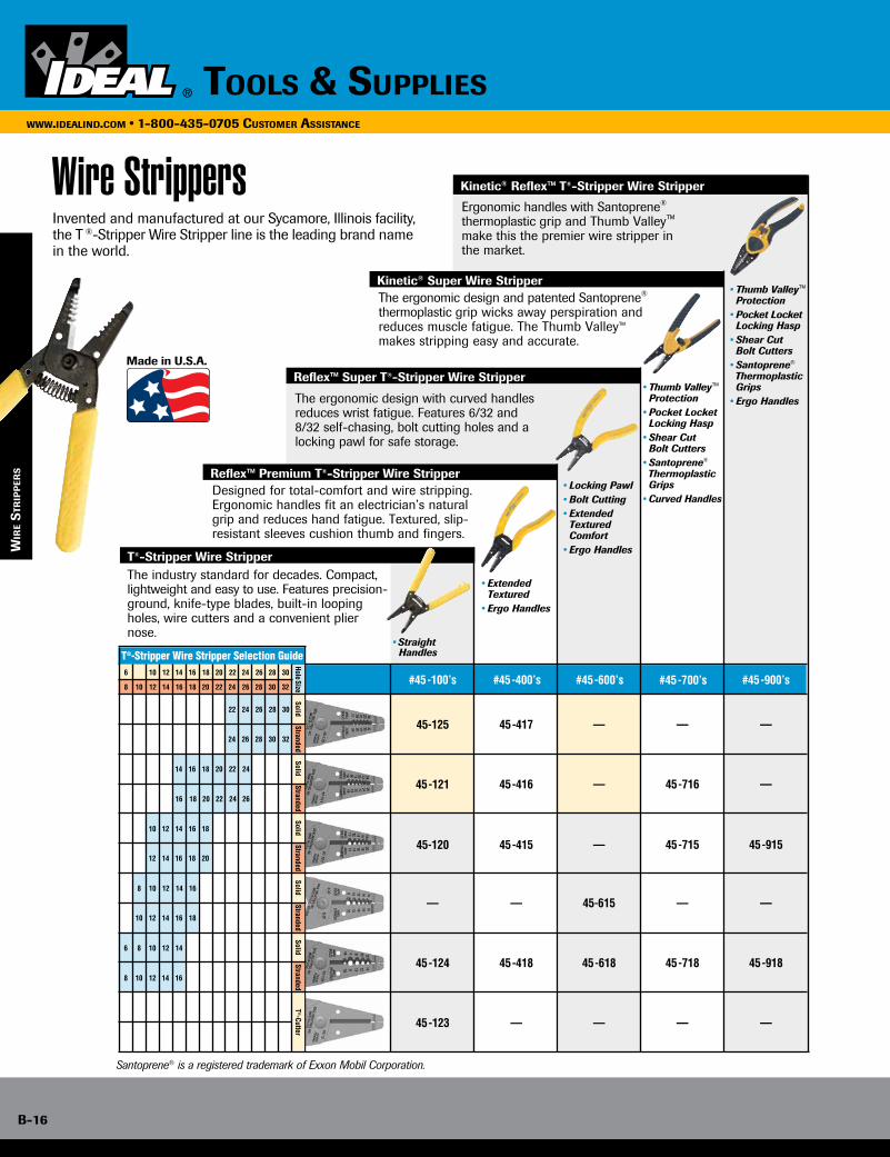
B-16
www.idealind.com • 1-800-435-0705 customer assistance
tools & supplies
wir
e s
Trip
per
s
Ergonomic handles with Santoprene® thermoplastic grip and Thumb Valley™ make this the premier wire stripper in the market.
45-125
45-121
45-120
45-124
45-123
—
45-417
45-416
45-415
45-418
—
—
—
—
—
45-618
—
45-615
—
45-716
45-715
45-718
—
—
—
—
45-915
45-918
—
—
#45-600’s #45-700’s #45-900’s#45-100’s #45-400’s
T®-Stripper Wire Stripper
Reflex™ Premium T®-Stripper Wire Stripper
Reflex™ Super T®-Stripper Wire Stripper
Kinetic® Super Wire Stripper
Kinetic® Reflex™ T®-Stripper Wire Stripper
The ergonomic design and patented Santoprene® thermoplastic grip wicks away perspiration and reduces muscle fatigue. The Thumb Valley™ makes stripping easy and accurate.
Designed for total-comfort and wire stripping. Ergonomic handles fit an electrician’s natural grip and reduces hand fatigue. Textured, slip-resistant sleeves cushion thumb and fingers.
The ergonomic design with curved handles reduces wrist fatigue. Features 6/32 and 8/32 self-chasing, bolt cutting holes and a locking pawl for safe storage.
• Straight Handles
• Extended Textured
• Ergo Handles
• Locking Pawl• Bolt Cutting• Extended
Textured Comfort
• Ergo Handles
• Thumb Valley™ Protection
• Pocket Locket Locking Hasp
• Shear Cut Bolt Cutters
• Santoprene®
Thermoplastic Grips• Curved Handles
• Thumb Valley™ Protection
• Pocket Locket Locking Hasp
• Shear Cut Bolt Cutters
• Santoprene®
Thermoplastic Grips• Ergo Handles
The industry standard for decades. Compact, lightweight and easy to use. Features precision-ground, knife-type blades, built-in looping holes, wire cutters and a convenient plier nose.
T®-Cutter
14 16 18 20 22 24
16 18 20 22 24 26
24 26 30 3228
12 14 16 18 20
8 10 12 14 16
10 12 14 16 18
6 8 10 12 14
12 14 16 1810
8 10 12 1614
24 26 28 30
3230282624222018161412108
282624222018161412106
22
SolidStranded
Hole SizeStranded
SolidStranded
SolidStranded
SolidStranded
Solid
30
T®-Stripper Wire Stripper Selection Guide
Invented and manufactured at our Sycamore, Illinois facility, the T ®-Stripper Wire Stripper line is the leading brand name in the world.
Santoprene® is a registered trademark of Exxon Mobil Corporation.
Wire Strippers
Made in U.S.A.

Tools & supplies B-17
www.idealind.com • 1-800-435-0705 customer assistance
wir
e sTr
ipp
ers
T®-Stripper Wire Strippers
Kinetic® Reflex™ T®-Stripper Wire Strippers
Kinetic® Super Wire Strippers
• Form-ground, knife-type blades for accurate, easy stripping without nicking conductor
• Laser-etched wire gauge for easy-to-read visibility
• Spring-loaded automatic opening
• Corrosion-resistant, black oxide finish
• Tough steel construction
• Non-slip textured grips and thumb rest
• Plier nose for holding and twisting wires
• Slide lock for safety and storage
• Thumb and finger valley makes stripping easy and accurate
• Non-slip textured grips and thumb rest
• Plier nose for holding and twisting wires
• Slide lock for safety and storage
• Thumb and finger valley makes stripping easy and accurate
Description Solid Stranded Part No.
T®-5 T®-Stripper Wire Stripper 10-18 AWG 12-20 AWG 45-120
T®-6 T®-Stripper Wire Stripper 14-24 AWG 16-26 AWG 45-121
T®-7 T®-Stripper Wire Stripper 22-30 AWG 24-32 AWG 45-125
T®-8 T®-Stripper Wire Stripper 6-14 AWG 8-16 AWG 45-124
T®-Stripper Wire Stripper – Metric 0,75-6mm2 45-120-341
T®-Stripper Wire Stripper – Metric 0,5-4mm2 45-125-341
Description Solid Stranded Part No.
Kinetic® Reflex™ T®-Stripper Wire Stripper
10-18 AWG 12-20 AWG 45-915
6-14 AWG 8-16 AWG 45-918
Description Solid Stranded Part No.
Kinetic® Super Wire Stripper
10-18 AWG 12-20 AWG 45-715
14-24 AWG 16-26 AWG 45-716
6-14 AWG 8-16 AWG 45-718
45-120
45-915
45-715
Reflex™ Super T®-Stripper Wire Strippers
Reflex™ Premium T®-Stripper Wire Strippers
• 6/32 and 8/32 self-chasing screw-cutting holes
• Ergonomic design for maximum comfort
• Curved handles help reduce wrist fatigue
• Textured sleeves with extra cushioning for added comfort
• Ergonomic design for maximum comfort
• Curved handles help reduce wrist fatigue
• Textured sleeves with extra cushioning for added comfort
Description Solid Stranded Part No.
Reflex™ Super T®-Stripper Wire Stripper
8-16 AWG 10-18 AWG 45-615
8-14 AWG 8-16 AWG 45-618
Reflex™ Super 12/2 & 14/2 NM Cable T®-Stripper Wire Stripper 12-2 and 14-2 AWG — 45-621
Description Solid Stranded Part No.
Reflex™ Premium T®-Stripper Wire Stripper
10-18 AWG 12-20 AWG 45-415
14-24 AWG 16-26 AWG 45-416
22-30 AWG 24-32 AWG 45-417
6-14 AWG 8-16 AWG 45-418
Reflex™ Premium T®-Stripper – Metric 0,5mm2-4,0mm2 45-425-341
45-615
45-415
T-90™ Wire Stripper• Patented bent nose design for easy, long reach into confined spaces
• Quickly removes jacket with precision cut and straight pull
• Less fatigue with straight pull versus the side twist wrist motion
• Corrosion-resistant, black oxide finish
• Tough steel construction with sheer-type blades
Description Solid Stranded Part No.
T-90™ Bent Nose 12-2 NM Wire Stripper 12 - 2 AWG 18 AWG 45-649

B-18
www.idealind.com • 1-800-435-0705 customer assistance
tools & supplies
Description Part No.
V-Notch Stripper 45-101
NM Cable Dual-Hole T®-Stripper Wire Strippers• Stripping holes for stripping two 12 AWG or two 14 AWG wires simultaneously
• Ability to strip both conductor wires of NM cable at one time
Description Solid Part No.
Premium T®-14 T®-Stripper Wire Stripper12 or 14
AWG
45-247
14/2 NM Cable T®-Stripper Wire Stripper 45-248
12/2 NM Cable T®-Stripper Wire Stripper 45-249
V-Notch Stripper
Description Part No.
Lil’ Ripper Stripper™ 45-025
• Cuts copper or aluminum wire, solid or stranded
• Rotating cam wheel adjusts to strip 10-24 AWG wire
• Looping holes for solid wire
7-in-1 Stripper
• Versatile, seven-function tool features precision-ground stripping blades, cushioned grips and plier nose
• Crimps bare and insulated terminals for 10–22 AWG wire, RG-59 coax connectors and 7 to 8mm auto ignition connectors
• Cuts unhardened wire, bolts and screws (4-40, 6-32, 8-32, 10-24 and 10-32) and reforms threads
• Cuts stranded, solid, NM wire and U.F. wire to 8 AWG
wir
e s
Trip
per
s
45-247
1000V Insulated Wire Stripper• UL Classified
• High visibility, double insulated handles provide safety, comfort and control
Description Part No.
1000V Insulated Wire Stripper 45-9120
LISTED
Description Solid Stranded Part No.
7-in-1 Stripper 8 - 16 AWG 10 - 18 AWG 45-777
Lil’ Ripper Stripper™
Underground Feeder (UF) Cable Stripper
• Rips outer jacket of NM cable cleanly and quickly
• Clips outer sheathing to remove excess wire jacket
• V-Notch strips inner wires
• Looping holes loop wire for screw-on connections
• Self-adjusting stripping blades automatically select proper position
• Strips 12/2 AWG solid to 14/2 AWG Underground Feeder (UF) Cable
• Strips Twin and Earth cable
• Open-throat construction allows unlimited strip length
• Neatly removes outer cable sheath and inner wire sheathing to desired lengths
• Lightweight, ergonomic design helps reduce user fatigue
Description Part No.
Underground Feeder Cable Stripper 45-235
Cable Ripper• Slits NM cable wire sheathing before stripping wires
• Quick, clean and easy end or mid-run removal of jacket
• Convenient built-in wire gauge
Description Part No.
Side Entry Cable Ripper 45-118SRS
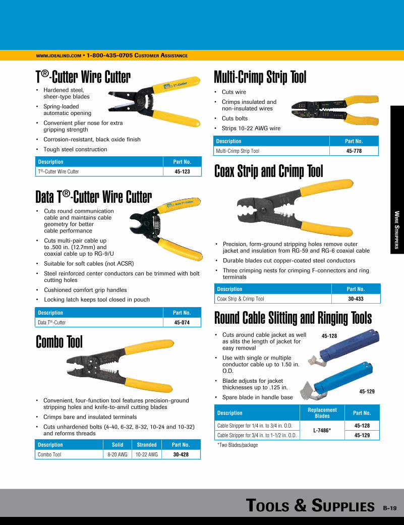
Tools & supplies B-19
www.idealind.com • 1-800-435-0705 customer assistance
V-Notch Stripper
Combo Tool
• Convenient, four-function tool features precision-ground stripping holes and knife-to-anvil cutting blades
• Crimps bare and insulated terminals
• Cuts unhardened bolts (4-40, 6-32, 8-32, 10-24 and 10-32) and reforms threads
Description Solid Stranded Part No.
Combo Tool 8-20 AWG 10-22 AWG 30-428
Multi-Crimp Strip Tool• Cuts wire
• Crimps insulated and non-insulated wires
• Cuts bolts
• Strips 10-22 AWG wire
Description Part No.
Multi-Crimp Strip Tool 45-778
Coax Strip and Crimp Tool
• Precision, form-ground stripping holes remove outer jacket and insulation from RG-59 and RG-6 coaxial cable
• Durable blades cut copper-coated steel conductors
• Three crimping nests for crimping F-connectors and ring terminals
Description Part No.
Coax Strip & Crimp Tool 30-433
Round Cable Slitting and Ringing Tools• Cuts around cable jacket as well
as slits the length of jacket for easy removal
• Use with single or multiple conductor cable up to 1.50 in. O.D.
• Blade adjusts for jacket thicknesses up to .125 in.
• Spare blade in handle base
Description Replacement Blades Part No.
Cable Stripper for 1/4 in. to 3/4 in. O.D.L-7486*
45-128
Cable Stripper for 3/4 in. to 1-1/2 in. O.D. 45-129
*Two Blades/package
45-128
45-129
T®-Cutter Wire Cutter
Data T®-Cutter Wire Cutter
• Hardened steel, sheer-type blades
• Spring-loaded automatic opening
• Convenient plier nose for extra gripping strength
• Corrosion-resistant, black oxide finish
• Tough steel construction
Description Part No.
T®-Cutter Wire Cutter 45-123
• Cuts round communication cable and maintains cable geometry for better cable performance
• Cuts multi-pair cable up to .500 in. (12.7mm) and coaxial cable up to RG-9/U
• Suitable for soft cables (not ACSR)
• Steel reinforced center conductors can be trimmed with bolt cutting holes
• Cushioned comfort grip handles
• Locking latch keeps tool closed in pouch
Description Part No.
Data T®-Cutter 45-074
wir
e sTr
ipp
ers
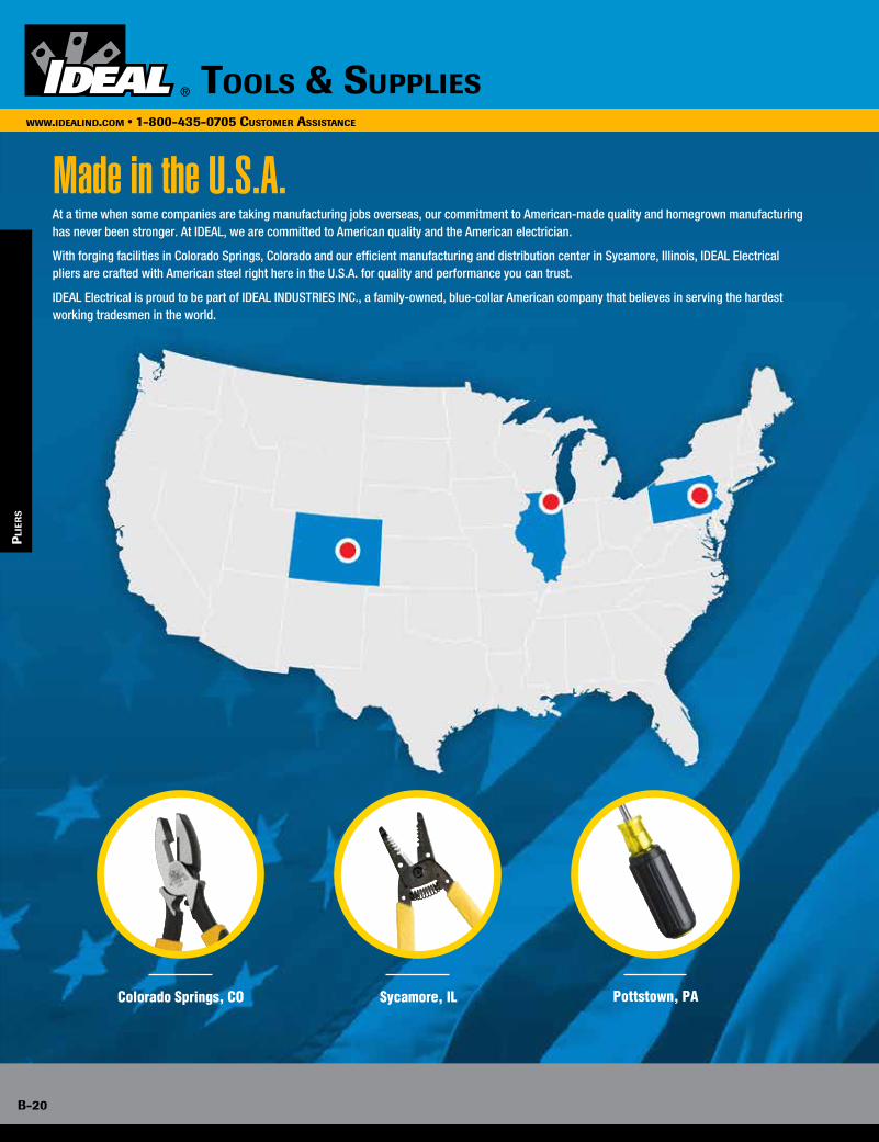
B-20
www.idealind.com • 1-800-435-0705 cusTomer assisTance
Tools & supplies
Made in the U.S.A.
Colorado Springs, CO
At a time when some companies are taking manufacturing jobs overseas, our commitment to American-made quality and homegrown manufacturing has never been stronger. At IDEAL, we are committed to American quality and the American electrician.
With forging facilities in Colorado Springs, Colorado and our efficient manufacturing and distribution center in Sycamore, Illinois, IDEAL Electrical pliers are crafted with American steel right here in the U.S.A. for quality and performance you can trust.
IDEAL Electrical is proud to be part of IDEAL INDUSTRIES INC., a family-owned, blue-collar American company that believes in serving the hardest working tradesmen in the world.
Sycamore, IL Pottstown, PA
pli
ers

B-21
www.idealind.com • 1-800-435-0705 cusTomer assisTance
Pliers
LIM
ITED LIFETIME
WARRANTY
• Custom alloyed, premium quality tool steel provides excellent cutting performance and commercial use durability
• Precision ground knife-to-knife cutting blades for accurate, quick wire cutting
• Hardened and tempered body and cutting edges for optimum performance
• High leverage pivot design provides great cutting and gripping power
Grips
DiagonalLineman’s Long Nose Tongue & Groove
Cable Cutter Crimper Slip-Joint
plier
s
Color-coding and FastFinder™ letter
markers on SmartGrip™ handles provide quick
tool identification,even by touch!
Heavy-DutyDipped Grip
Smart-Grip™Dual Durometer
Molded
1000V Grip
Made in U.S.A.
Tools & supplies
plier
s

B-22
www.idealind.com • 1-800-435-0705 cusTomer assisTance
Tools & supplies
Lineman’s Pliers Diagonal-Cutting Pliers
Long-Nose Pliers
Tongue & Groove Pliers
• Knife-to-knife blades provide excellent cutting performance
• Cuts hardened wire, bolts and stainless steel wire
Description (Smart-Grip™ Handles) Part No.
9-1/2 in. Lineman’s Plier w/New England nose and crimping die 30-3430
Description (Dipped-Grip Handles) Part No.
9-1/2 in. Lineman’s Plier w/New England nose, crimping die and fish tape puller 30-430
• Knife-to-knife blades provide excellent cutting performance
• High-leverage design provides more cutting power
• Models 35-029 and 35-3029 feature a convenient angled head for hard-to-reach areas and rocking out nails
Description (Smart-Grip™ Handles) Part No.
8 in. Diagonal-Cutting Pliers 35-3028
8 in. Diagonal-Cutting Pliers w/angled head 35-3029
Description (Dipped-Grip Handles) Part No.
8 in. Diagonal-Cutting Pliers 35-028
8 in. Diagonal-Cutting Pliers w/angled head 35-029• Narrow profile head designed for working in tight areas
• Serrated jaws provide secure gripping surface
• Drop-forged, high-carbon steel construction
• Blades provide excellent cutting performance
• Laser-hardened blades cut hardened wire, bolts and stainless steel wire
Description (Smart-Grip™ Handles) Part No.
8-1/2 in. Long-Nose Pliers w/Cutter 35-3038
Description (Dipped-Grip Handles) Part No.
6 in. Long-Nose Pliers w/Cutter 35-036
8-1/2 in. Long-Nose Pliers w/Cutter 35-038
• Reinforced flange protects against breakage
• Drop-forged, high-carbon steel construction
Description (Smart-Grip™ Handles) Jaw Opening Part No.
9-1/2 in. Tongue & Groove Pliers 2 in. 35-3420
Description (Dipped-Grip Handles) Jaw Opening Part No.
9-1/2 in. Tongue & Groove Pliers 2 in. 35-420
7 in. Tongue & Groove Pliers 1 in. 35-426
10-1/2 in. Tongue & Groove Pliers w/V-Jaw 2 in. 35-430
12 in. Tongue & Groove Pliers 2-1/4 in. 35-440
pli
ers

Tools & supplies B-23
www.idealind.com • 1-800-435-0705 cusTomer assisTance
Cable Cutters
Multi-Crimp Tools
• Drop-forged, high-carbon steel construction
• Precision-ground, hardened cutting edges provide accurate cuts without cable distortion
• Cuts 2/0 copper and 4/0 aluminum (not for use on ACSR)
Description (Smart-Grip™ Handles) Part No.
9-1/2 in. Cable Cutter 35-3052
Description (Dipped-Grip Handles) Part No.
9-1/2 in. Cable Cutter 35-052
• Crimps bare or insulated terminals and splices on 10–22 AWG wire
• Knife-to-anvil blades provide long-lasting cutting performance
• High leverage for easy crimping and cutting
• Drop-forged, high-carbon steel construction
Description (Smart-Grip™ Handles) Part No.
9-3/4 in. Multi-Crimp Tool 30-3429
Description (Dipped-Grip Handles) Part No.
9-3/4 in. Multi-Crimp Tool 30-429
Tenite® Grips• Not insulated from electrical shock
• Boil in water to soften for easy installation onto handles
Description Part No.
Replacement grips for 8 in. or 9 in. pliers (one pair) 35-008
Tenite® is a registered trademark of Eastman Chemical Company.
plier
s
Slip-Joint Pliers• Two position slip joints fit
large and small jobs
• Dipped comfort-grip handles for a secure grip
• Flush rivet
Description Part No.
6 in. Slip Joint Pliers 35-100
8 in. Slip Joint Pliers 35-102
35-100

B-24
www.idealind.com • 1-800-435-0705 cusTomer assisTance
Tools & supplies
Electrical Hand Tools
ha
nd T
oo
ls
IDEAL Electrical offers a complete range of specialized hand tools to support the dynamic needs of the professional electrician. With innovative, quality tools for professional performance, backed by one superior brand, IDEAL continues to deliver premium tools in all categories. From screwdrivers, pliers, wrenches, levels to our iconic wire strippers, cutters, saws, and more you can count on IDEAL for all of your professional hand tool needs.
LIM
ITED LIFETIME
WARRANTY

Tools & supplies B-25
www.idealind.com • 1-800-435-0705 customer assistance
SirNickless™ Cutter
Mechanical Indentor and Crimp Tool
Ratchet Crimp Tool
• Handles all common BX, MCAP®, MC and Flex cables
• Blade cuts armor without damage to internal conductors
• Splices cleanly through casings with only a few turns
• Handle knob stores up to six replacement blades
• Cutter comes with one blade installed
Description Quantity Part No.
Rotary Armored Cable Cutter — 35-782
Replacement Blades5/pack 35-781
1/pack 35-781-1
MCAP® is a registered trademark of Southwire Company.
• Use with aluminum (6 AWG to 4/0) and copper (8 AWG to 250 KCMIL) wires
• Adjustable crimping nests with clearly marked gauges
• Lightweight and easy to operate
• Rugged cast steel construction for long-term durability
Description Part No.
Mechanical Indentor & Crimp Tool 88-843
• Crimps insulated or bare terminals and splices on 10–22 AWG wire
• Ratchet action prevents release prior to crimp connection – helps ensure uniform crimps
• Vinyl-coated handles provide a solid, comfortable grip
Description Part No.
Ratchet Crimp Tool 83-001
ha
nd T
oo
ls
B-25Tools & supplies
www.idealind.com • 1-800-435-0705 cusTomer assisTance
IDEAL Wipes Multi-Purpose Towels• Durable pre- moistened fabric scrubs without tearing
• Cleans dirt, grease, lube and grime from most surfaces
• Infused with natural hand moisturizers and Vitamin E, orange citrus scent
• Meets California C.A.R.B. standards
• Available bracket for easy access storage
Description Part No.
IDEAL Wipes, 12 in. x 9 in. (82/can) 38-500
IDEAL Wipes Canister Bracket 38-500BR
Aviation Tin Snips
Description Part No.
Aviation Tin Snips 35-001
• Labor-saving design cuts straight, left and right, with one tool
• Chrome-molybdenum steel forged blades for strength and durability
• Serrated edges provide a stable hold when cutting
Four-Way Crimp Tool
• Design ensures even compression and reliable connections
• Spring-loaded, cam-actuated plungers
• Fingertip adjustment for two connector sizes
Description Part No.
Four-Way Crimp Tool for use with Buchanan 2006S and 2011S Crimp Connectors C-24
35-781
35-782

B-26
www.idealind.com • 1-800-435-0705 customer assistance
tools & supplies
Adjustable Wrenches
Measuring Tapes
Electric Engraving Tool• Forged steel construction with narrow profile head reaches
into tight spaces
• Tight tolerance on thumbscrew will not loosen or wobble with use
• Extra wide jaw capacity with standard and metric markings
Description Jaw Capacity Part No.
6 in. Adjustable Wrench 7/8 in. 35-019
8 in. Adjustable Wrench 1-1/8 in. 35-020
10 in. Adjustable Wrench 1-5/16 in. 35-021
• Measurement marks on both sides of tape
• Blade automatically stays out when extended
• Push button for smooth blade retraction
• Comfortable, shock-resistant rubber grip
Description Tape Width Part No.
Auto-Lock Tape Measure - 25 ft. 1 in. 35-242
Automatic Blade Lock w/Magnetic-Tip - 30 ft. 1 in. 35-238
• Engraves metal, glass, stone, ceramics, plastics, hard rubber, wood and many other hard materials
• Unique design reduces bouncing and provides smooth, easy writing; operating at 7,200 strokes per minute
• Stroke adjusts to vary depth of mark
• Includes carbide-tipped point for normal markings
• Diamond point available for engraving extra-hard materials (50 to 64 Rockwell, scale C)
Description Part No.
Engraver w/carbide-tipped point & 3-conductor grounded cord (7 ft.) & plug — 120V, 60 Hz 11-113
Carbide-Tipped replacement point 11-200
Diamond replacement point 11-201
ha
nd T
oo
ls
Torpedo Level• 9 in. aluminum frame with magnetic and V-grooved edges
• Windows provide easy reading of plumb level and 45° angle
• Three rare earth magnets for strong cling to conduit
Description Part No.
9 in. Torpedo Level 35-205
35-24235-238
35-021
Center Punch
Chisels
• Accurately start drilling holes on steel surfaces
• One-piece construction
• Hardened and tempered for long life
• Hardened and tempered for long life
• Use Wood Chisel by hand or mallet
Description Part No.
Center Punch 35-192
35-187
35-189
Description Part No.
Cold Chisel (for cutting cold metals) 35-187
Wood Chisel 35-189
Magnetic-tipped end hook
TIP
Drop-Forged Hammer
• One-piece drop-forged, tempered-steel polished head and handle
• Long, straight claws simplify removal of electrical fixtures
• Comfortable, perforated anti-vibe grips
Description Part No.
18 oz. x 12-1/2 in. Drop-Forged Handled Hammer 35-210
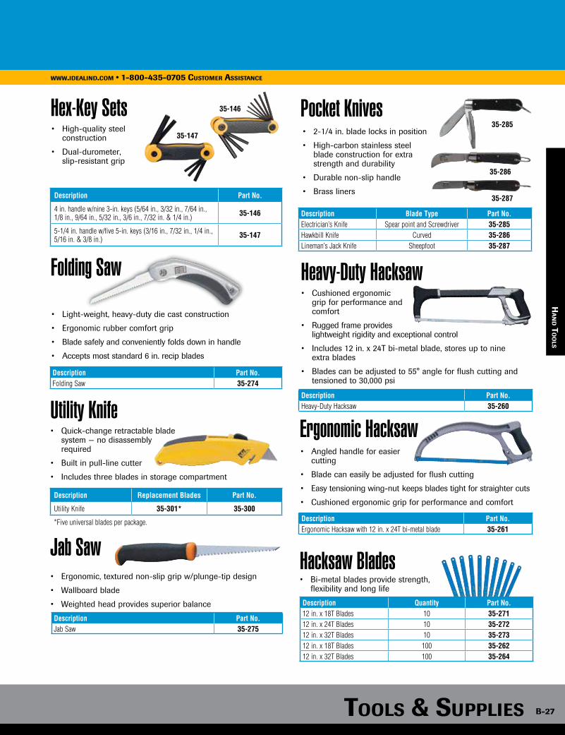
Tools & supplies B-27
www.idealind.com • 1-800-435-0705 customer assistance
35-187
35-189
ha
nd T
oo
ls
Utility Knife
• High-quality steel construction
• Dual-durometer, slip-resistant grip
Description Part No.
4 in. handle w/nine 3-in. keys (5/64 in., 3/32 in., 7/64 in., 1/8 in., 9/64 in., 5/32 in., 3/6 in., 7/32 in. & 1/4 in.) 35-146
5-1/4 in. handle w/five 5-in. keys (3/16 in., 7/32 in., 1/4 in., 5/16 in. & 3/8 in.) 35-147
• Quick-change retractable blade system — no disassembly required
• Built in pull-line cutter
• Includes three blades in storage compartment
Description Replacement Blades Part No.
Utility Knife 35-301* 35-300
*Five universal blades per package.
35-146
35-147
Hex-Key Sets• 2-1/4 in. blade locks in position
• High-carbon stainless steel blade construction for extra strength and durability
• Durable non-slip handle
• Brass liners
Pocket Knives35-285
35-286
35-287
Jab Saw• Ergonomic, textured non-slip grip w/plunge-tip design
• Wallboard blade
• Weighted head provides superior balance
Description Part No.Jab Saw 35-275
Folding Saw
• Light-weight, heavy-duty die cast construction
• Ergonomic rubber comfort grip
• Blade safely and conveniently folds down in handle
• Accepts most standard 6 in. recip blades
Description Part No.Folding Saw 35-274
Heavy-Duty Hacksaw
Ergonomic Hacksaw
Hacksaw Blades
• Cushioned ergonomic grip for performance and comfort
• Rugged frame provides lightweight rigidity and exceptional control
• Includes 12 in. x 24T bi-metal blade, stores up to nine extra blades
• Blades can be adjusted to 55° angle for flush cutting and tensioned to 30,000 psi
Description Part No.Heavy-Duty Hacksaw 35-260
• Angled handle for easier cutting
• Blade can easily be adjusted for flush cutting
• Easy tensioning wing-nut keeps blades tight for straighter cuts
• Cushioned ergonomic grip for performance and comfort
Description Part No.Ergonomic Hacksaw with 12 in. x 24T bi-metal blade 35-261
• Bi-metal blades provide strength, flexibility and long life
Description Quantity Part No.12 in. x 18T Blades 10 35-27112 in. x 24T Blades 10 35-27212 in. x 32T Blades 10 35-27312 in. x 18T Blades 100 35-26212 in. x 32T Blades 100 35-264
Description Blade Type Part No.Electrician’s Knife Spear point and Screwdriver 35-285Hawkbill Knife Curved 35-286Lineman’s Jack Knife Sheepfoot 35-287

B-28
www.idealind.com • 1-800-435-0705 customer assistance
tools & supplies
Cable Cutters
ca
Ble
cu
TTer
s
The IDEAL focus on innovation is demonstrated by the PowerBlade™ line of cable cutters. Chucked into virtually any drill these robust cutters save time and money for utilities and commercial electricians.
*Drill not included.

Tools & supplies B-29
www.idealind.com • 1-800-435-0705 customer assistance
ca
Ble c
uTTer
s
Big Kahuna™ Cable Cutter
PowerBlade™ Cable Cutter Replacement Parts
• Fits most standard power drills
• Jaw opening of 3-1/2 in.
• Cuts copper cable up to 1250 MCM and aluminum cable up to 1250 MCM
• Specially hardened, rounded blades minimize cable distortion for professional quality
Description Replacement Blade* Part No.
Big Kahuna™ Cable Cutter KB-0276R 35-076
*Two blades per package, 1 upper blade and 1 lower blade.
Replacement Parts Part No.
Gearbox Assembly H-3400
Replacement Parts Part No.
PowerBlade™ Replacement Folding Assembly H-3507
PowerBlade™ Replacement Torque Arm Assembly K-8909
(Drill not included)
(Drill not included)
(Drill not included)
check ouT our powerBlade videos aT www.idealind.com
PowerBlade™ 750 Cable Cutter
Description Replacement Blade* Part No.
PowerBlade™ 750 Cable Cutter K-8906R 35-078
*Two blades per package, 1 upper blade and 1 lower blade.
• Fits most standard power drills
• Jaw opening of 1-1/2 in.
• Cuts copper cable up to 750 MCM and aluminum cable up to 1000 MCM
• Specially hardened, rounded blades minimize cable distortion for professional quality
Merlin™ ACSR Cable Cutter
Description Replacement Blade* Part No.
Merlin™ ACSR Cable Cutter KB-0278R 35-077
*Two blades per package, 1 upper blade and 1 lower blade.
• Fits most standard power drills
• Jaw opening of 3/4 in. for precision and accuracy
• Especially designed for reinforced aluminum cable
• Cuts up to Merlin ACSR cable size or 250 MCM Copper or Aluminum

B-30
www.idealind.com • 1-800-435-0705 customer assistance
tools & supplies
ca
Ble
cu
TTer
s
Ratcheting Cable Cutter
BigFoot™ Ratcheting Cable Cutter• Designed to cut 750 KCMIL (MCM) and smaller hard-
drawn copper and aluminum cables
• Hardened steel blades ensure consistent cuts and long-term durability
• Rounded blade design minimizes cable distortion during cutting
• Quick release mechanism simplifies blade back-out
• Locking mechanism keeps handles closed for easy storage
• Molded-in foot provides stability and leverage when making multiple cuts
• High strength forged blades for ultimate durability
• Precision-ground jaws make clean cuts with minimal cable distortion
• Replaceable blades
• For copper and aluminum only.
Not designed for steel or ACSR.
Description Length Replacement Head Part No.
250 MCM Long-Arm Cable Cutter 14 in. 35-031B 35-031
500 MCM Long-Arm Cable Cutter 22 in. 35-032B 35-032
1000 MCM Long-Arm Cable Cutter 32 in. 35-033B 35-033
CAUTION: Comfort-grip handles are not designed for protection against electrical shock. Do not use on live circuits.
• Cuts hard drawn copper up to 400 KCMIL (MCM) and soft copper, aluminum and multiple conductor cable up to 600 KCMIL (MCM)
• Hardened steel blades ensure consistent cuts and long-term durability
• Rounded blade design minimizes cable distortion during cutting
• Quick release mechanism simplifies blade back-out
• Locking mechanism keeps handles closed for easy storage
Description Part No.
400 KCMIL (MCM) Ratcheting Cable Cutter* 35-056
Replacement blade (movable side only) 35-085
*Max. Jaw Opening - 2 in. Not for cutting steel or ACSR.
Description Part No.
750 KCMIL (MCM) Ratcheting Cable Cutter* 35-053
Replacement blade (movable side only) 35-057
*Max. Jaw Opening - 2 in. Not for cutting steel or ACSR.
Long-Arm Cable Cutters
Hardened, long-life steel blades
Cuts up to 750 MCM (380mm2) hard-drawn copper
Handle locking mechanism
High strength ratcheting teeth
Comfort grip handles
Molded foot for stability and leverage.
Quick handle release

Tools & supplies B-31
www.idealind.com • 1-800-435-0705 customer assistance
Screwdriver Types
Screwdriver Advanced Features
Specialty • Top quality screwdrivers designed especially for the professional electrician• Multi-functional for all your fastening needs
Cushioned-Grip • Cushioned-grip provides comfort and maximum torque• Blasted tip helps prevent plate chipping• Nickel chrome steel shank for maximum strength and durability• Mini cushioned-grip tightens small fasteners easily and accurately
Nutdrivers • Hollow shanks handle longer bolts• Available in long lengths to accommodate extra long bolts• Cushioned-gripped for comfort and maximum torque
Specialty
Cushioned-Grip
Patented Wire Connector Wrench in handle
FastFinder™ iconshows tip typeon handle end
Combo Head™ tip ensures full fastener engagement
Accu-Loop™ WireLooping Holes make perfect loops!
sc
rew
dr
iver
s
LIM
ITED LIFETIME
WARRANTY

B-32
www.idealind.com • 1-800-435-0705 customer assistance
tools & supplies
21-in-1 Twist-a-Nut™ Ratcheting Screwdriver
9-in-1 Ratch-a-Nut™ Screwdriver
7-in-1 Twist-a-Nut™ Screwdriver
Replacement Tips (for 7-in-1 Twist-a-Nut™ and 9-in-1 Ratch-a-Nut™ Screwdrivers)
6-in-1 Twist-a-Nut™ Tap Tool
• Patented Wire Connector Wrench accepts a wide variety of connectors and reduces finger fatigue
• Pro-quality, 28 tooth, all metal ratchet can handle 225 lbs. of torque without failure
• Ergonomic, slip-free textured grip provides excellent torque and is impervious to perspiration, gas, oil and chemicals
• Multiple bit storage unit in handle
• Bits included: #1 Phillips, #2 Phillips, #3 Phillips, 3/16” Slotted, 1/4” Slotted, 5/16” Slotted, #1 Square, #2 Square, #15 Star, #20 Star, #25 Star, #30 Star, 3/32” Hex, 1/8” Hex, 3/16” Hex, 5/32” Hex, 1/4” Nut, 5/16” Nut and 7/16” Nut
Description Part No.
21-in-1 Twist-a-Nut™ Screwdriver 35-688
• Patented Wire Connector Wrench accepts a wide variety of connectors and reduces finger fatigue
• Pro-quality, 28 tooth, all metal ratchet can handle 225 lbs. of torque without failure
• Ergonomic, slip-free textured grip provides excellent torque and is impervious to perspiration, gas, oil and chemicals
• Accepts Twist-a-Nut™ replacement bits
• Bits included: 1/4 in. Slotted, 3/16 in. Slotted, #1 Phillips, #2 Phillips, 1/4 in. Nutdriver, 5/16 in. Nutdriver, and 7/16 in. Nutdriver
Description Part No.
9-in-1 Ratch-a-Nut™ Screwdriver 35-988
• Patented Wire Connector Wrench accepts a wide variety of connectors and reduces finger fatigue
• Ergonomic, slip-free textured grip provides excellent torque and is impervious to perspiration, gas, oil and chemicals
• Handle is interchangeable with conduit deburrer head (#35-096) and 6-in-1 Tap Tool (#35-922)
• Bits included: 1/4 in. Slotted, 3/16 in. Slotted, #1 Phillips, #2 Phillips, 1/4 in. Nutdriver and 5/16 in. Nutdriver
Description Part No.
7-in-1 Twist-a-Nut™ Screwdriver/Nutdriver 35-908
Replacement Handle K-8964
Description Part No.
1/4 in. Slotted – #2 Phillips 35-911
3/16 in. Slotted – #1 Phillips 35-912
1/4 in. Slotted – #2 Square 35-913
3/16 in. Slotted – #1 Square 35-914
#15 & #10 Star 35-915
• Forms new threads, re-forms burred threads and cleans out obstructions
• Reversible, high-carbon tap with three clearly marked thread sizes on each end
• Handle is interchangeable with 7-in-1 Screwdriver (#35-908) and Conduit Deburrer (#35-083)
• Includes: 6-32, 8-32 & 10-32 on one tapping side and 10-24, 12-24 & 1/4-20 on other side
Description Part No.
6-in-1 Twist-a-Nut™ Tapping Tool 35-922
Replacement collar and six taps 35-923
sp
ecia
lTy s
cr
ewd
riv
ers

Tools & supplies B-33
www.idealind.com • 1-800-435-0705 customer assistance
Twist-a-Nut™ Conduit Deburring Tools
• Deburrs inside and outside edges of 1/2 in., 3/4 in. and 1 in. thin wall conduit
• Hooded tip tightens EMT fitting set screws without slipping
• Square tip “seats” much more quickly on fitting screws than slotted version
• Head removes and is interchangeable with IDEAL 7-in-1 Twist-a-Nut™ Screwdriver shaft (#35-908)
• Head can be used at low speed setting in drill or cordless screwdriver
Description Tip Type Part No.
Conduit Deburring Tool Slotted 35-083
Conduit Deburring Tool #2 Square 35-075
Conduit Deburring Tool (head only) Slotted 35-096
Conduit Deburring Replacement Blade 35-097
Conduit Deburring Tool (head only) #2 Square 35-098
sp
ecia
lTy sc
rew
dr
iver
s
Twist-a-Nut™ Conduit Wiring Kit
• Includes: - Twist-a-Nut™ Screwdriver (35-908) - Twist-a-Nut™ Deburring Head - Square Tip (35-098) - Twist-a-Nut™ Tap Tool Shaft (35-923) - Three Spare Bits – 1/4 in. Slotted & #2 Square, 3/16 in. Slotted & #1 Square, #10 & #15 Star - 8-Pocket Carrying Pouch (35-927)
• Nylon carrying pouch with metal belt clip holds all three Twist-a-Nut™ tools plus room for four replacement bits or
taps
Description Part No.
Twist-a-Nut™ Conduit Wiring Kit 35-926
Twist-a-Nut™ Carrying Pouch only 35-927
Twist-a-Nut™ Pro Electrician’s Screwdrivers
• Vapor-blasted tip improves screw grip
• Tough, chrome vanadium steel shank
Description Part No.
#2 x 6 in. Square Twist-a-Nut™ Pro Electrician’s Screwdriver 30-330
1/4 in. x 4 in. Slotted Twist-a-Nut™ Pro Electrician’s Screwdriver 30-331
1/4 in. x 6 in. Slotted Cabinet Tip Twist-a-Nut™ Pro Electrician’s Screwdriver 30-333
11-in-1 Screwdriver/Nutdriver
• Includes: 1/4 in. Slotted, 3/16 in. Slotted, #2 Phillips, #1 Phillips, #1 Square, #2 Square, #15 Star, #10 Star, 5/16 in. Nutdriver & 1/4 in. Nutdriver
• Cushioned grip for comfort and performance
• Accu-Loop™ Wire looping holes
Description Part No.
11-in-1 Screwdriver/Nutdriver 35-910
Replacement Bits Part No.
1/4 in. Slotted - #2 Phillips (2/pack) 35-940
3/16 in. Slotted - #1 Phillips (2/pack) 35-941
#1 & #2 Square (2/pack) 35-942
#15 & #10 Star (2/pack) 35-943
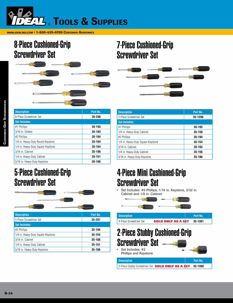
B-34
www.idealind.com • 1-800-435-0705 cusTomer assisTance
Tools & supplies
cu
sh
ion
ed-g
rip
sc
rew
dr
iver
s
7-Piece Cushioned-Grip Screwdriver Set
8-Piece Cushioned-Grip Screwdriver Set
Description Part No.
8-Piece Screwdriver Set 35-298
Set Includes:
#1 Phillips 35-193
3/16 in. Slotted 35-183
#2 Phillips 35-194
1/4 in. Heavy-Duty Round Keystone 35-164
1/4 in. Heavy-Duty Square Keystone 35-154
3/16 in. Cabinet 35-186
1/4 in. Heavy-Duty Cabinet 35-151
5/16 in. Heavy-Duty Keystone 35-166
Description Part No.
5-Piece Screwdriver Set 35-297
Set Includes:
#2 Phillips 35-194
1/4 in. Heavy-Duty Square Keystone 35-154
3/16 in. Cabinet 35-186
1/4 in. Heavy-Duty Cabinet 35-151
5/16 in. Heavy-Duty Keystone 35-166
Description Part No.
7-Piece Screwdriver Set 35-1298
Set Includes:
#1 Phillips 35-193
1/4 in. Heavy-Duty Cabinet 35-150
#2 Phillips 35-194
1/4 in. Heavy-Duty Square Keystone 35-154
3/16 in. Cabinet 35-183
1/4 in. Heavy-Duty Cabinet 35-156
3/16 in. Heavy-Duty Keystone 35-186
5-Piece Cushioned-Grip Screwdriver Set
Description Part No.
4-Piece Screwdriver Set 35-1301
Description Part No.
2-Piece Stubby Screwdriver Set 35-1300
4-Piece Mini Cushioned-Grip Screwdriver Set
2-Piece Stubby Cushioned-Grip Screwdriver Set
• Set Includes: #0 Phillips, 1/16 in. Keystone, 3/32 in. Cabinet and 1/8 in. Cabinet
• Set Includes: #2 Phillips and Keystone
SOLD ONLY AS A SET
SOLD ONLY AS A SET
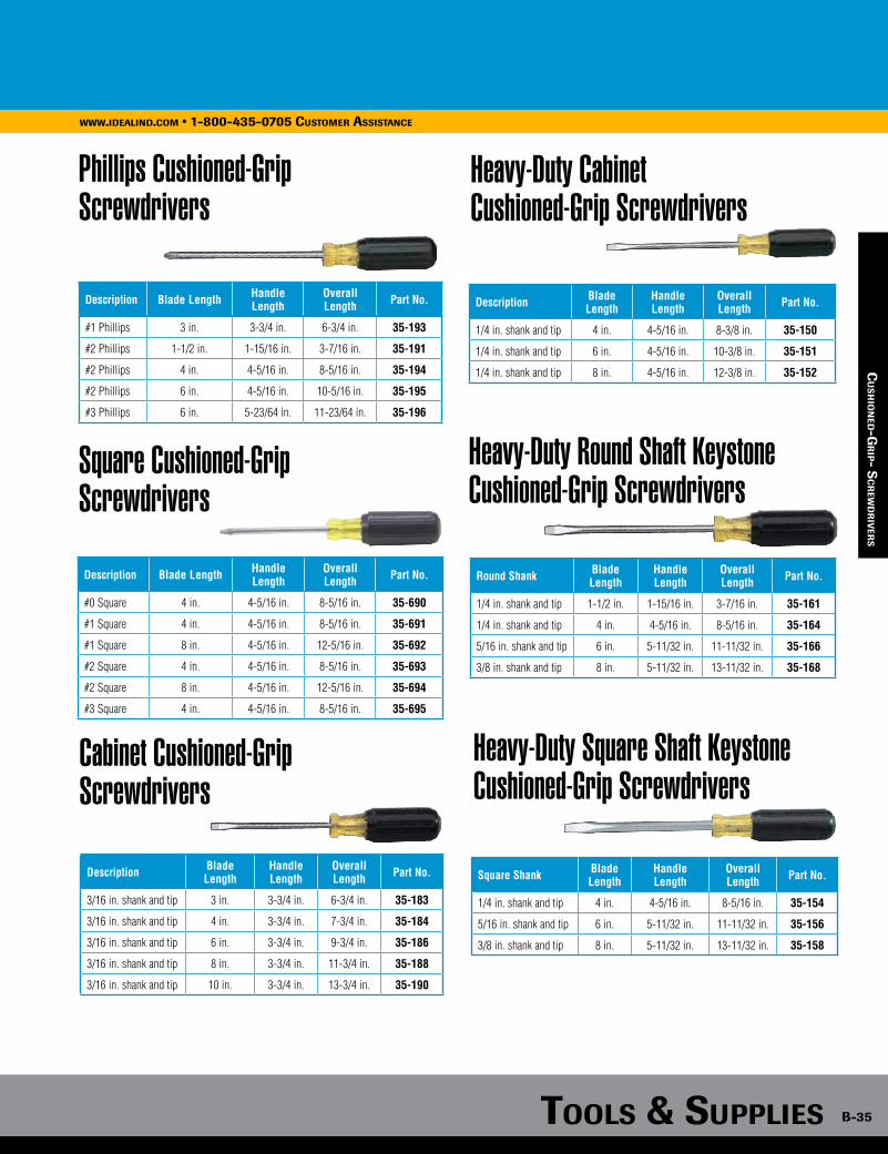
Tools & supplies B-35
www.idealind.com • 1-800-435-0705 cusTomer assisTance
cu
sh
ion
ed-gr
ip sc
rew
dr
iver
s
Phillips Cushioned-Grip Screwdrivers
Description Blade Length Handle Length
Overall Length Part No.
#1 Phillips 3 in. 3-3/4 in. 6-3/4 in. 35-193
#2 Phillips 1-1/2 in. 1-15/16 in. 3-7/16 in. 35-191
#2 Phillips 4 in. 4-5/16 in. 8-5/16 in. 35-194
#2 Phillips 6 in. 4-5/16 in. 10-5/16 in. 35-195
#3 Phillips 6 in. 5-23/64 in. 11-23/64 in. 35-196
Square Cushioned-Grip Screwdrivers
Description Blade Length Handle Length
Overall Length Part No.
#0 Square 4 in. 4-5/16 in. 8-5/16 in. 35-690
#1 Square 4 in. 4-5/16 in. 8-5/16 in. 35-691
#1 Square 8 in. 4-5/16 in. 12-5/16 in. 35-692
#2 Square 4 in. 4-5/16 in. 8-5/16 in. 35-693
#2 Square 8 in. 4-5/16 in. 12-5/16 in. 35-694
#3 Square 4 in. 4-5/16 in. 8-5/16 in. 35-695
Cabinet Cushioned-Grip Screwdrivers
Description Blade Length
Handle Length
Overall Length Part No.
3/16 in. shank and tip 3 in. 3-3/4 in. 6-3/4 in. 35-183
3/16 in. shank and tip 4 in. 3-3/4 in. 7-3/4 in. 35-184
3/16 in. shank and tip 6 in. 3-3/4 in. 9-3/4 in. 35-186
3/16 in. shank and tip 8 in. 3-3/4 in. 11-3/4 in. 35-188
3/16 in. shank and tip 10 in. 3-3/4 in. 13-3/4 in. 35-190
Heavy-Duty Cabinet Cushioned-Grip Screwdrivers
Description Blade Length
Handle Length
Overall Length Part No.
1/4 in. shank and tip 4 in. 4-5/16 in. 8-3/8 in. 35-150
1/4 in. shank and tip 6 in. 4-5/16 in. 10-3/8 in. 35-151
1/4 in. shank and tip 8 in. 4-5/16 in. 12-3/8 in. 35-152
Heavy-Duty Round Shaft Keystone Cushioned-Grip Screwdrivers
Round Shank Blade Length
Handle Length
Overall Length Part No.
1/4 in. shank and tip 1-1/2 in. 1-15/16 in. 3-7/16 in. 35-161
1/4 in. shank and tip 4 in. 4-5/16 in. 8-5/16 in. 35-164
5/16 in. shank and tip 6 in. 5-11/32 in. 11-11/32 in. 35-166
3/8 in. shank and tip 8 in. 5-11/32 in. 13-11/32 in. 35-168
Heavy-Duty Square Shaft Keystone Cushioned-Grip Screwdrivers
Square Shank Blade Length
Handle Length
Overall Length Part No.
1/4 in. shank and tip 4 in. 4-5/16 in. 8-5/16 in. 35-154
5/16 in. shank and tip 6 in. 5-11/32 in. 11-11/32 in. 35-156
3/8 in. shank and tip 8 in. 5-11/32 in. 13-11/32 in. 35-158
cu
sh
ion
ed-gr
ip- sc
rew
dr
iver
s
SOLD ONLY AS A SET

B-36
www.idealind.com • 1-800-435-0705 customer assistance
tools & supplies
cu
sh
ion
ed-g
rip
sc
rew
dr
iver
s
Combo Head™ Cushioned-Grip Screwdriver
• Designed to accurately and securely fit most fasteners
• Patented design
Description Blade Length
Handle Length
Overall Length Part No.
Combo Head™ Cushioned-Grip Screwdriver 4 in. 4-5/16 in. 8-5/16 in. 35-204
Quick Rotating Screwdriver
Awl
• Ideal for threading screws in switches, fixtures and anchors
• Quick and easy crank action
Description Blade Length
Handle Length
Overall Length Part No.
Cabinet Quick Rotating Screwdriver 5-9/16 in. 3-3/4 in. 9-3/8 in. 35-200
Phillips Quick Rotating Screwdriver 5-5/8 in. 4-5/16 in. 9-15/16 in. 35-203
• Heavy-duty construction for piercing, punching and scribing
Description Blade Length
Handle Length
Overall Length Part No.
Awl 3 in. 3-3/4 in. 6-3/4 in. 35-202
Grip-n-Screw™ Screwdriver
Off-Set Screwdriver Set
• Holds screw when collar is extended
• Non-magnetic screw-holding screwdriver
Description Blade Length
Handle Length
Overall Length Part No.
3/16 Slotted Grip-n-Screw™ Screwdriver 5-7/8 in. 3-3/4 in. 9-5/8 in. 35-406
#2 Phillips Grip-n-Screw™ Screwdriver 6-7/8 in. 4-15/16 in. 11-1/4 in. 35-404
Description Overall Length Part No.
Off-Set Screwdriver Set 4 in. 35-219
• 1/4 in. x 1/4 in. Slotted tips and #1 Phillips x #2 Phillips tips
• Designed to tighten fasteners in hard to reach places
Phillips Square CabinetHeavy-Duty
Cabinet KeystoneHeavy-Duty
Keystone Combo
Patented Combo Head™ tip ensures full fastener engagement

Tools & supplies B-37
www.idealind.com • 1-800-435-0705 customer assistance
cu
sh
ion
ed-gr
ip nu
Tdr
iver
s
Quick-Change Screwdriver• Patented Sure-Loc™ Quick Change chuck securely holds bits
• Built-in bit storage container in handle holds up to five extra insert bits
• Bits fit most standard multi-bit screwdrivers
• E-Z Spin™ high torque rotating flip cap
Description Blade Length Handle Length Overall Length Part No.
Quick Change Screwdriver (Driver only) 3-1/16 in. 4-3/16 in. 7-1/4 in. 35-932
33-Piece Quick Change Screwdriver Set - Quick Change Screwdriver and 32-Piece Tamper-Proof Bit Block 3-1/16 in. 4-3/16 in. 7-1/4 in. 35-933
33-Piece Quick Change Screwdriver Set - Quick Change Screwdriver and 32-Piece Standard Bit Block 3-1/16 in. 4-3/16 in. 7-1/4 in. 35-934
32-Piece Tamper-Proof Bit Block 35-933TP
32-Piece Standard Bit Block 35-933STD
2-Piece Hollow-Shaft Nutdriver Set
• Includes: 1/4 in. Nutdriver & 5/16 in. Nutdriver
• Long shanks useful in deep electrical boxes
Description Shank Length
Handle Length
Overall Length Part No.
2-Piece Nutdriver Set 5-15/16 in. 4-5/16 in. 10-1/4 in. 35-1302
2-Piece Stubby Nutdriver Set
Description Blade Length
Handle Length
Overall Length Part No.
2-Piece Nutdriver Stubby Set 1-1/2 in. 2-1/8 in. 3-5/8 in. 35-1299
• Includes: 1/4 in. Nutdriver & 5/16 in. Nutdriver
• For use in tight spaces
7-Piece Nutdriver Set
Description Part No.
7-Piece Nutdriver Set 35-299
• Set Includes: 3/16 in. 35-290, 1/4 in. 35-291, 5/16 in. 35-292, 11/32 in. 35-293, 3/8 in. 35-294,
7/16 in. 35-295 and 1/2 in. 35-296
Nutmaster® Nutdrivers
Description Shank Length Handle Length Overall Length Part No.
3/16 in. 3 in. 4-5/16 in. 7-5/16 in. 35-290
1/4 in. 3 in. 4-5/16 in. 7-5/16 in. 35-291
5/16 in. 3 in. 4-5/16 in. 7-5/16 in. 35-292
11/32 in. 3 in. 4-5/16 in. 7-5/16 in. 35-293
3/8 in. 3 in. 4-5/16 in. 7-5/16 in. 35-294
7/16 in. 3 in. 4-5/16 in. 7-5/16 in. 35-295
1/2 in. 3 in. 4-5/16 in. 7-5/16 in. 35-296
• Model 35-292 fits tan Twister® Wire Connector and 35-295 fits gray Twister® Wire Connectors
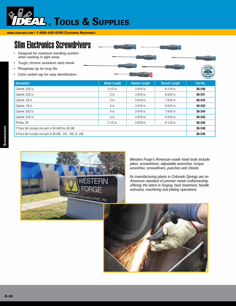
B-38
www.idealind.com • 1-800-435-0705 customer assistance
tools & supplies
sc
rew
dr
iver
s
Slim Electronics Screwdrivers• Designed for maximum handling comfort when working in tight areas
• Tough, chrome vanadium steel shank
• Phosphate tip for long life
• Color-coded cap for easy identification
Description Blade Length Handle Length Overall Length Part No.
Cabinet, 3/32 in. 2-1/2 in. 3-9/16 in. 6-1/16 in. 36-240
Cabinet, 3/32 in. 3 in. 3-9/16 in. 6-9/16 in. 36-241
Cabinet, 1/8 in. 4 in. 3-9/16 in. 7-9/16 in. 36-242
Cabinet, 1/8 in. 6 in. 3-9/16 in. 9-9/16 in. 36-243
Cabinet, 5/32 in. 4 in. 3-9/16 in. 7-9/16 in. 36-244
Cabinet, 5/32 in. 6 in. 3-9/16 in. 9-9/16 in. 36-245
Phillips, #0 2-1/2 in. 3-9/16 in. 6-1/16 in. 36-246
7-Piece Set includes one each of 36-240 thru 36-246 36-248
4-Piece Set includes one each of 36-240, -241, -242, & -246 36-249
Western Forge’s American-made hand tools include pliers, screwdrivers, adjustable wrenches, torque wrenches, screwdrivers, punches and chisels.
Its manufacturing plants in Colorado Springs are an American standard of premier metal craftsmanship, offering the latest in forging, heat treatment, handle extrusion, machining and plating operations.

Tools & supplies B-39
www.idealind.com • 1-800-435-0705 customer assistance
sc
rew
dr
iver B
iTs
Industrial Screwdriver Bits & Accessories
Power Bits
Insert Bits
• S2M tool steel, custom heat treated for strength and durability• All tips are manufactured to tight tolerances to ensure accurate fit and full fastener engagement• Insert bits have a retaining ring notch• Power bits have a power locking groove• 1/4 in. hex body• Fit most standard multi-bit screwdrivers
and
lasting performance.precision fit
Designed for
Combo Head™ Slotted Double Ended Phillips Square Torx®
Torx® is a registered trademark of Acument Intellectual Properties, LLC.
Made in U.S.A.
Power Locking Groove
1/4 in. Hex Body
All tips are manufactured to tight tolerances to
ensure accurate fit and full fastener engagement
Retaining Ring Notch
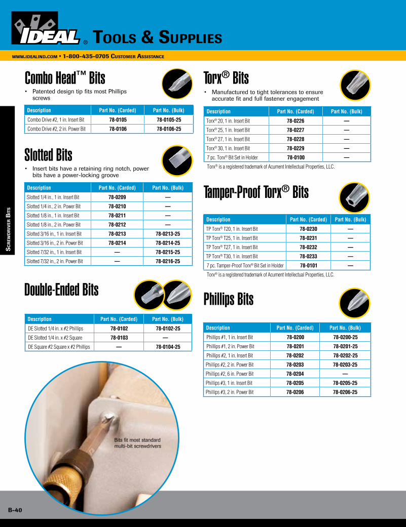
B-40
www.idealind.com • 1-800-435-0705 cusTomer assisTance
Tools & supplies
sc
rew
dr
iver
BiT
s
Combo Head™ Bits
Slotted Bits
Double-Ended Bits
Torx® Bits
Description Part No. (Carded) Part No. (Bulk)
Combo Drive #2, 1 in. Insert Bit 78-0105 78-0105-25
Combo Drive #2, 2 in. Power Bit 78-0106 78-0106-25
Description Part No. (Carded) Part No. (Bulk)
Slotted 1/4 in., 1 in. Insert Bit 78-0209 —
Slotted 1/4 in., 2 in. Power Bit 78-0210 —
Slotted 1/8 in., 1 in. Insert Bit 78-0211 —
Slotted 1/8 in., 2 in. Power Bit 78-0212 —
Slotted 3/16 in., 1 in. Insert Bit 78-0213 78-0213-25
Slotted 3/16 in., 2 in. Power Bit 78-0214 78-0214-25
Slotted 7/32 in., 1 in. Insert Bit — 78-0215-25
Slotted 7/32 in., 2 in. Power Bit — 78-0216-25
Description Part No. (Carded) Part No. (Bulk)
DE Slotted 1/4 in. x #2 Phillips 78-0102 78-0102-25
DE Slotted 1/4 in. x #2 Square 78-0103 ——
DE Square #2 Square x #2 Phillips — 78-0104-25
• Patented design tip fits most Phillips screws
• Insert bits have a retaining ring notch, power bits have a power-locking groove
Description Part No. (Carded) Part No. (Bulk)
Torx® 20, 1 in. Insert Bit 78-0226 —
Torx® 25, 1 in. Insert Bit 78-0227 —
Torx® 27, 1 in. Insert Bit 78-0228 —
Torx® 30, 1 in. Insert Bit 78-0229 —
7 pc. Torx® Bit Set in Holder 78-0100 —
Torx® is a registered trademark of Acument Intellectual Properties, LLC.
• Manufactured to tight tolerances to ensure accurate fit and full fastener engagement
Tamper-Proof Torx® Bits
Phillips BitsDescription Part No. (Carded) Part No. (Bulk)
Phillips #1, 1 in. Insert Bit 78-0200 78-0200-25
Phillips #1, 2 in. Power Bit 78-0201 78-0201-25
Phillips #2, 1 in. Insert Bit 78-0202 78-0202-25
Phillips #2, 2 in. Power Bit 78-0203 78-0203-25
Phillips #2, 6 in. Power Bit 78-0204 —
Phillips #3, 1 in. Insert Bit 78-0205 78-0205-25
Phillips #3, 2 in. Power Bit 78-0206 78-0206-25
Description Part No. (Carded) Part No. (Bulk)
TP Torx® T20, 1 in. Insert Bit 78-0230 —
TP Torx® T25, 1 in. Insert Bit 78-0231 —
TP Torx® T27, 1 in. Insert Bit 78-0232 —
TP Torx® T30, 1 in. Insert Bit 78-0233 —
7 pc. Tamper-Proof Torx® Bit Set in Holder 78-0101 —
Torx® is a registered trademark of Acument Intellectual Properties, LLC.
Bits fit most standard multi-bit screwdrivers
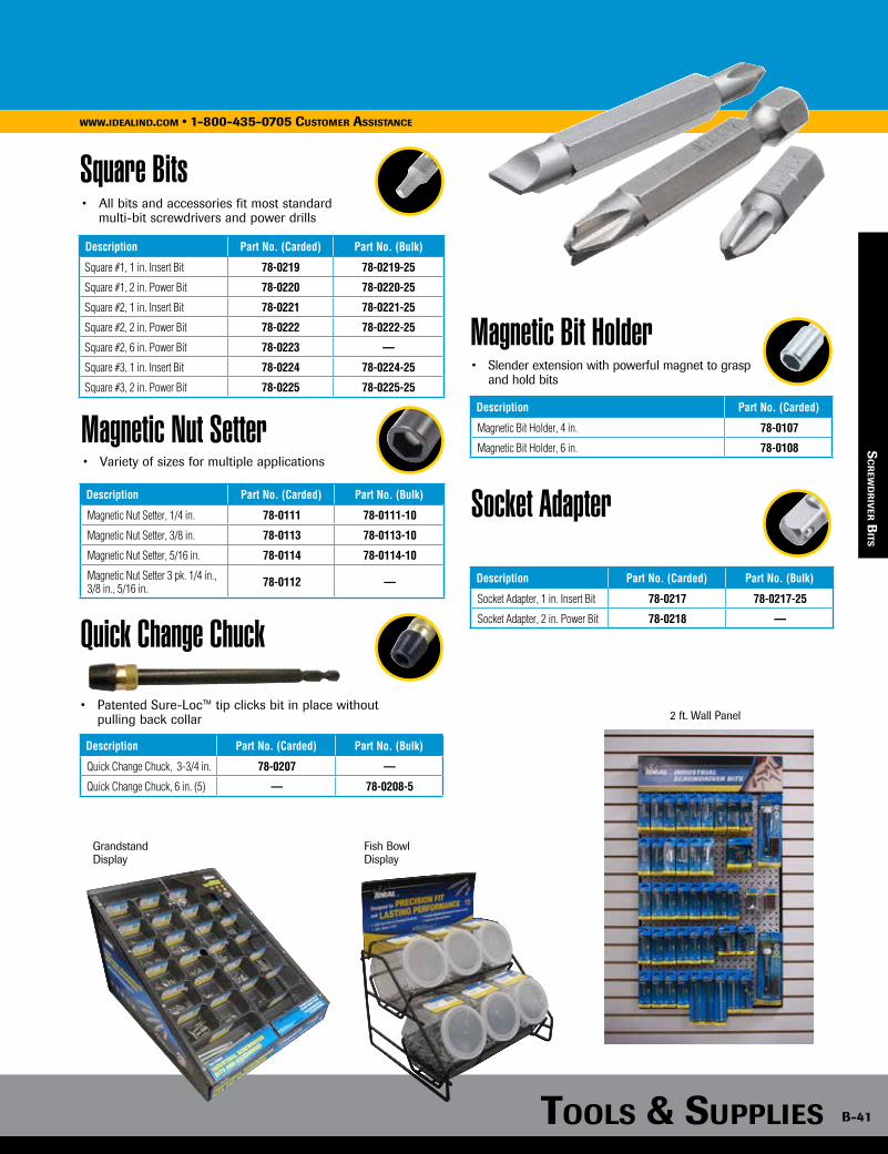
2 ft. Wall Panel
Fish BowlDisplay
Grandstand Display
Tools & supplies B-41
www.idealind.com • 1-800-435-0705 cusTomer assisTance
Square Bits
Description Part No. (Carded) Part No. (Bulk)
Square #1, 1 in. Insert Bit 78-0219 78-0219-25
Square #1, 2 in. Power Bit 78-0220 78-0220-25
Square #2, 1 in. Insert Bit 78-0221 78-0221-25
Square #2, 2 in. Power Bit 78-0222 78-0222-25
Square #2, 6 in. Power Bit 78-0223 —
Square #3, 1 in. Insert Bit 78-0224 78-0224-25
Square #3, 2 in. Power Bit 78-0225 78-0225-25
• All bits and accessories fit most standard multi-bit screwdrivers and power drills
sc
rew
dr
iver B
iTs
Quick Change Chuck
Magnetic Bit Holder
Socket Adapter
Description Part No. (Carded) Part No. (Bulk)
Quick Change Chuck, 3-3/4 in. 78-0207 —
Quick Change Chuck, 6 in. (5) — 78-0208-5
Description Part No. (Carded) Part No. (Bulk)
Socket Adapter, 1 in. Insert Bit 78-0217 78-0217-25
Socket Adapter, 2 in. Power Bit 78-0218 —
• Patented Sure-Loc™ tip clicks bit in place without pulling back collar
Description Part No. (Carded)
Magnetic Bit Holder, 4 in. 78-0107
Magnetic Bit Holder, 6 in. 78-0108
• Slender extension with powerful magnet to grasp and hold bits
Magnetic Nut Setter
Description Part No. (Carded) Part No. (Bulk)
Magnetic Nut Setter, 1/4 in. 78-0111 78-0111-10
Magnetic Nut Setter, 3/8 in. 78-0113 78-0113-10
Magnetic Nut Setter, 5/16 in. 78-0114 78-0114-10
Magnetic Nut Setter 3 pk. 1/4 in., 3/8 in., 5/16 in. 78-0112 —
• Variety of sizes for multiple applications
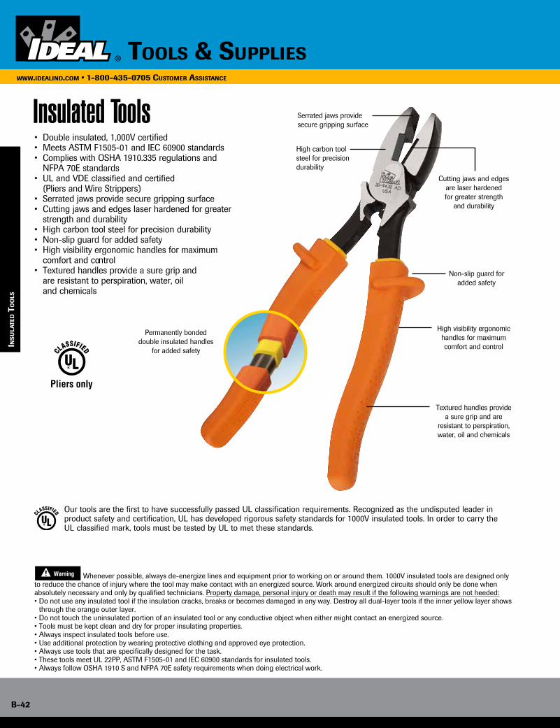
B-42
www.idealind.com • 1-800-435-0705 customer assistance
tools & supplies
ins
ula
Ted T
oo
ls
Insulated Tools• Double insulated, 1,000V certified• Meets ASTM F1505-01 and IEC 60900 standards• Complies with OSHA 1910.335 regulations and NFPA 70E standards• UL and VDE classified and certified (Pliers and Wire Strippers)• Serrated jaws provide secure gripping surface• Cutting jaws and edges laser hardened for greater strength and durability• High carbon tool steel for precision durability• Non-slip guard for added safety• High visibility ergonomic handles for maximum comfort and control• Textured handles provide a sure grip and are resistant to perspiration, water, oil and chemicals
Our tools are the first to have successfully passed UL classification requirements. Recognized as the undisputed leader in product safety and certification, UL has developed rigorous safety standards for 1000V insulated tools. In order to carry the UL classified mark, tools must be tested by UL to met these standards.
Pliers only
�
Whenever possible, always de-energize lines and equipment prior to working on or around them. 1000V insulated tools are designed only to reduce the chance of injury where the tool may make contact with an energized source. Work around energized circuits should only be done when absolutely necessary and only by qualified technicians. Property damage, personal injury or death may result if the following warnings are not heeded:• Do not use any insulated tool if the insulation cracks, breaks or becomes damaged in any way. Destroy all dual-layer tools if the inner yellow layer shows through the orange outer layer.• Do not touch the uninsulated portion of an insulated tool or any conductive object when either might contact an energized source.• Tools must be kept clean and dry for proper insulating properties.• Always inspect insulated tools before use.• Use additional protection by wearing protective clothing and approved eye protection.• Always use tools that are specifically designed for the task.• These tools meet UL 22PP, ASTM F1505-01 and IEC 60900 standards for insulated tools.• Always follow OSHA 1910 S and NFPA 70E safety requirements when doing electrical work.
Serrated jaws provide secure gripping surface
Permanently bondeddouble insulated handles
for added safety
High carbon tool steel for precision durability
Cutting jaws and edgesare laser hardenedfor greater strength
and durability
Non-slip guard for added safety
High visibility ergonomichandles for maximum comfort and control
Textured handles provide a sure grip and are
resistant to perspiration, water, oil and chemicals

Tools & supplies B-43
www.idealind.com • 1-800-435-0705 customer assistance
ins
ula
Ted sc
rew
dr
iver
s/nu
Tdr
iver
s
Insulated Screwdrivers & Nutdrivers
Cutting JawsInduction hardened cutting edgesfor precise cuts and long life.
Impact-ResistantDesigned for the most rugged jobsite conditions.
Safety Finger GuardReduces chance of accidental contactwith exposed metal tool parts.
IDEAL insulated screwdrivers and nutdrivers are VDE certified to 1000V AC. Each one is designed to meet ASTM F1505-01, EN, DIN and IEC 60 900 test standards.• Tempered blades are finished with black oxide and super hardened for maximum quality• Precision ground tips provide secure fit for less spin-out• Meets OSHA requirements for insulated tools (29 CFR 1910)
Tempered chrome vanadium tool steel blades are super hardened for maximum quality
Precision-groundtips provide secure fit for less spin-out
Molded-on insulationprovides permanent bonding
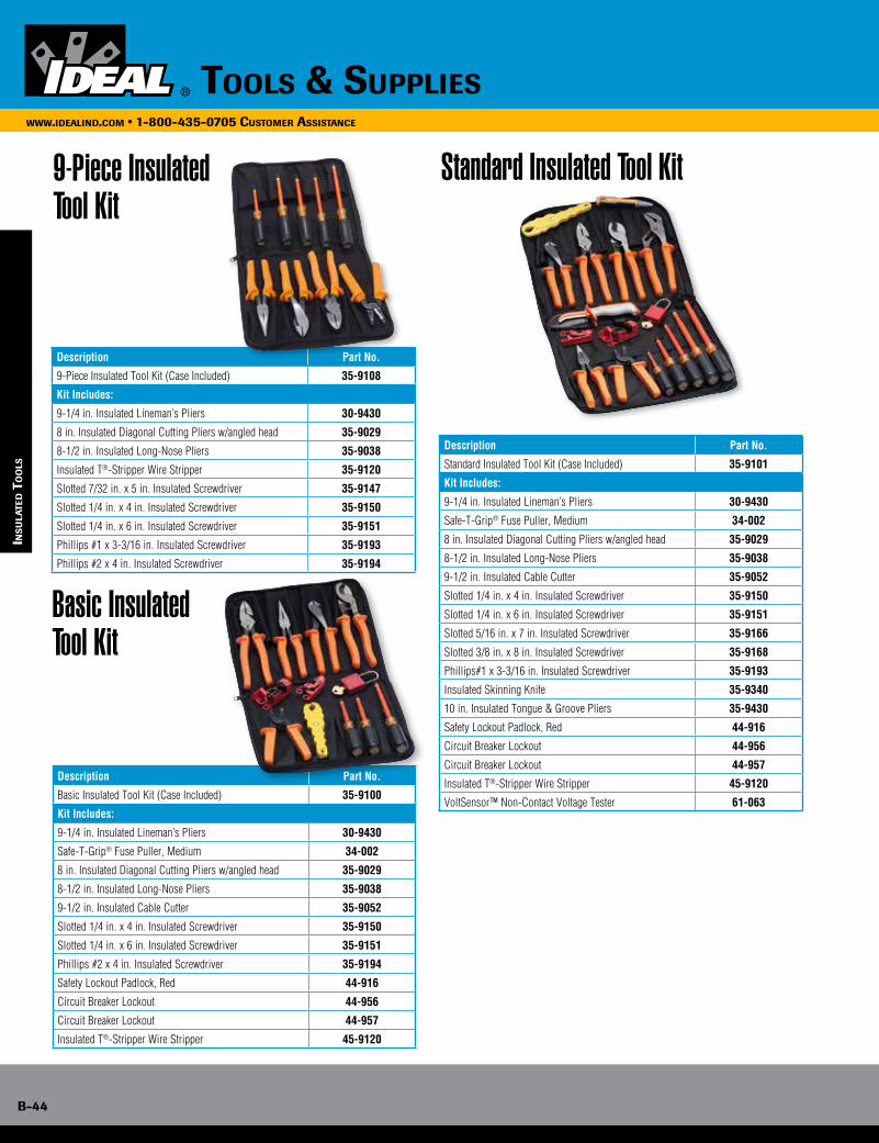
B-44
www.idealind.com • 1-800-435-0705 customer assistance
tools & supplies
ins
ula
Ted T
oo
ls
Basic Insulated Tool Kit
Standard Insulated Tool Kit
Description Part No.
Basic Insulated Tool Kit (Case Included) 35-9100
Kit Includes:
9-1/4 in. Insulated Lineman’s Pliers 30-9430
Safe-T-Grip® Fuse Puller, Medium 34-002
8 in. Insulated Diagonal Cutting Pliers w/angled head 35-9029
8-1/2 in. Insulated Long-Nose Pliers 35-9038
9-1/2 in. Insulated Cable Cutter 35-9052
Slotted 1/4 in. x 4 in. Insulated Screwdriver 35-9150
Slotted 1/4 in. x 6 in. Insulated Screwdriver 35-9151
Phillips #2 x 4 in. Insulated Screwdriver 35-9194
Safety Lockout Padlock, Red 44-916
Circuit Breaker Lockout 44-956
Circuit Breaker Lockout 44-957
Insulated T®-Stripper Wire Stripper 45-9120
Description Part No.
9-Piece Insulated Tool Kit (Case Included) 35-9108
Kit Includes:
9-1/4 in. Insulated Lineman’s Pliers 30-9430
8 in. Insulated Diagonal Cutting Pliers w/angled head 35-9029
8-1/2 in. Insulated Long-Nose Pliers 35-9038
Insulated T®-Stripper Wire Stripper 35-9120
Slotted 7/32 in. x 5 in. Insulated Screwdriver 35-9147
Slotted 1/4 in. x 4 in. Insulated Screwdriver 35-9150
Slotted 1/4 in. x 6 in. Insulated Screwdriver 35-9151
Phillips #1 x 3-3/16 in. Insulated Screwdriver 35-9193
Phillips #2 x 4 in. Insulated Screwdriver 35-9194
Description Part No.
Standard Insulated Tool Kit (Case Included) 35-9101
Kit Includes:
9-1/4 in. Insulated Lineman’s Pliers 30-9430
Safe-T-Grip® Fuse Puller, Medium 34-002
8 in. Insulated Diagonal Cutting Pliers w/angled head 35-9029
8-1/2 in. Insulated Long-Nose Pliers 35-9038
9-1/2 in. Insulated Cable Cutter 35-9052
Slotted 1/4 in. x 4 in. Insulated Screwdriver 35-9150
Slotted 1/4 in. x 6 in. Insulated Screwdriver 35-9151
Slotted 5/16 in. x 7 in. Insulated Screwdriver 35-9166
Slotted 3/8 in. x 8 in. Insulated Screwdriver 35-9168
Phillips#1 x 3-3/16 in. Insulated Screwdriver 35-9193
Insulated Skinning Knife 35-9340
10 in. Insulated Tongue & Groove Pliers 35-9430
Safety Lockout Padlock, Red 44-916
Circuit Breaker Lockout 44-956
Circuit Breaker Lockout 44-957
Insulated T®-Stripper Wire Stripper 45-9120
VoltSensor™ Non-Contact Voltage Tester 61-063
9-Piece Insulated Tool Kit
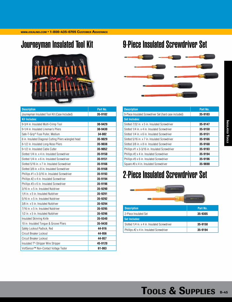
Tools & supplies B-45
www.idealind.com • 1-800-435-0705 customer assistance
ins
ula
Ted To
ols
Journeyman Insulated Tool Kit
Description Part No.
Journeyman Insulated Tool Kit (Case Included) 35-9102
Kit Includes:
9-3/4 in. Insulated Multi-Crimp Tool 30-9429
9-1/4 in. Insulated Lineman’s Pliers 30-9430
Safe-T-Grip® Fuse Puller, Medium 34-002
8 in. Insulated Diagonal Cutting Pliers w/angled head 35-9029
8-1/2 in. Insulated Long-Nose Pliers 35-9038
9-1/2 in. Insulated Cable Cutter 35-9052
Slotted 1/4 in. x 4 in. Insulated Screwdriver 35-9150
Slotted 1/4 in. x 6 in. Insulated Screwdriver 35-9151
Slotted 5/16 in. x 7 in. Insulated Screwdriver 35-9166
Slotted 3/8 in. x 8 in. Insulated Screwdriver 35-9168
Phillips #1 x 3-3/16 in. Insulated Screwdriver 35-9193
Phillips #2 x 4 in. Insulated Screwdriver 35-9194
Phillips #3 x 6 in. Insulated Screwdriver 35-9196
3/16 in. x 5 in. Insulated Nutdriver 35-9290
1/4 in. x 5 in. Insulated Nutdriver 35-9291
5/16 in. x 5 in. Insulated Nutdriver 35-9292
3/8 in. x 5 in. Insulated Nutdriver 35-9294
7/16 in. x 5 in. Insulated Nutdriver 35-9295
1/2 in. x 5 in. Insulated Nutdriver 35-9296
Insulated Skinning Knife 35-9340
10 in. Insulated Tongue & Groove Pliers 35-9430
Safety Lockout Padlock, Red 44-916
Circuit Breaker Lockout 44-956
Circuit Breaker Lockout 44-957
Insulated T®-Stripper Wire Stripper 45-9120
VoltSensor™ Non-Contact Voltage Tester 61-063
Description Part No.
9-Piece Insulated Screwdriver Set (hard case included) 35-9103
Set Includes:
Slotted 7/32 in. x 5 in. Insulated Screwdriver 35-9147
Slotted 1/4 in. x 4 in. Insulated Screwdriver 35-9150
Slotted 1/4 in. x 6 in. Insulated Screwdriver 35-9151
Slotted 5/16 in. x 7 in. Insulated Screwdriver 35-9166
Slotted 3/8 in. x 8 in. Insulated Screwdriver 35-9168
Phillips #1 x 3-3/16 in. Insulated Screwdriver 35-9193
Phillips #2 x 4 in. Insulated Screwdriver 35-9194
Phillips #3 x 6 in. Insulated Screwdriver 35-9196
Square #0 x 4 in. Insulated Screwdriver 35-9690
9-Piece Insulated Screwdriver Set
2-Piece Insulated Screwdriver Set
Description Part No.
2-Piece Insulated Set 35-9305
Set Includes:
Slotted 1/4 in. x 4 in. Insulated Screwdriver 35-9150
Phillips #2 x 4 in. Insulated Screwdriver 35-9194

B-46
www.idealind.com • 1-800-435-0705 customer assistance
tools & supplies
ins
ula
Ted T
oo
ls
7-Piece Insulated Nutdriver Set
Insulated Nutdrivers
Description Part No.
3/16 in. x 5 in. Insulated Nutdriver 35-9290
1/4 in. x 5 in. Insulated Nutdriver 35-9291
5/16 in. x 5 in. Insulated Nutdriver 35-9292
11/32 in. x 5 in. Insulated Nutdriver 35-9293
3/8 in. x 5 in. Insulated Nutdriver 35-9294
7/16 in. x 5 in. Insulated Nutdriver 35-9295
1/2 in. x 5 in. Insulated Nutdriver 35-9296
9/16 in. x 5 in. Insulated Nutdriver 35-9297
Description Part No.
7-Piece Insulated Nutdriver Set (hard case included) 35-9104
Set Includes:
3/16 in. x 5 in. Insulated Nutdriver 35-9290
1/4 in. x 5 in. Insulated Nutdriver 35-9291
5/16 in. x 5 in. Insulated Nutdriver 35-9292
3/8 in. x 5 in. Insulated Nutdriver 35-9294
7/16 in. x 5 in. Insulated Nutdriver 35-9295
1/2 in. x 5 in. Insulated Nutdriver 35-9296
9/16 in. x 5 in. Insulated Nutdriver 35-9297
Insulated Tool Kit Cases
Description Part No.
Soft Zipper Case for Basic Kit (35-9100 & 35-9108) 35-9350
Soft Zipper Case for Standard Kit (35-9101) 35-9351
Soft Zipper Case for Journeyman Kit (35-9102) 35-9352
Insulated Screwdrivers
Description Part No.
Slotted 7/32 in. x 5 in. Insulated Screwdriver 35-9147
Slotted 3/23 in. x 3 in. Insulated Screwdriver 35-9148
Slotted 1/8 in. x 4 in. Insulated Screwdriver 35-9149
Slotted 1/4 in. x 4 in. Insulated Screwdriver 35-9150
Slotted 1/4 in. x 6 in. Insulated Screwdriver 35-9151
Slotted 5/16 in. x 7 in. Insulated Screwdriver 35-9166
Slotted 3/8 in. x 8 in. Insulated Screwdriver 35-9168
Phillips #0 x 2-3/8 in. Insulated Screwdriver 35-9169
Phillips #1 x 3-1/8 in. Insulated Screwdriver 35-9170
Phillips #3 x 6 in. Insulated Screwdriver 35-9172
Phillips #1 x 3-3/16 in. Insulated Screwdriver 35-9193
Phillips #2 x 4 in. Insulated Screwdriver 35-9194
Phillips #3 x 6 in. Insulated Screwdriver 35-9196
Square #0 x 4 in. Insulated Screwdriver 35-9690
Square #1 x 6 in. Insulated Screwdriver 35-9691
Square #2 x 6 in. Insulated Screwdriver 35-9693
Square #3 x 6 in. Insulated Screwdriver 35-9695

Tools & supplies B-47
www.idealind.com • 1-800-435-0705 customer assistance
Insulated Multi-Crimp Tool
Insulated Lineman’s Pliers
Insulated Diagonal-Cutting Pliers
Description Part No.
9-3/4 in. Insulated Multi-Crimp Tool 30-9429
Description Part No.
8 in. Insulated Diagonal Cutting Pliers w/angled head 35-9029
Description Part No.
9-1/4 in. Insulated Lineman’s Pliers 30-9430
ins
ula
Ted To
ols
Insulated Long-Nose Pliers
Description Part No.
8-1/2 in. Insulated Long-Nose Pliers 35-9038
Insulated Tongue and Groove Pliers
Insulated T®-Stripper Wire Stripper
Description Part No.
10 in. Insulated Tongue and Groove Pliers 35-9430
Description Part No.
Insulated T®-Stripper Wire Stripper 45-9120
Insulated Skinning Knife
Description Part No.
Insulated Electrician’s Skinning Knife 35-9340
Insulated Cable Cutter
Description Part No.
9-1/2 in. Insulated Cable Cutter 35-9052
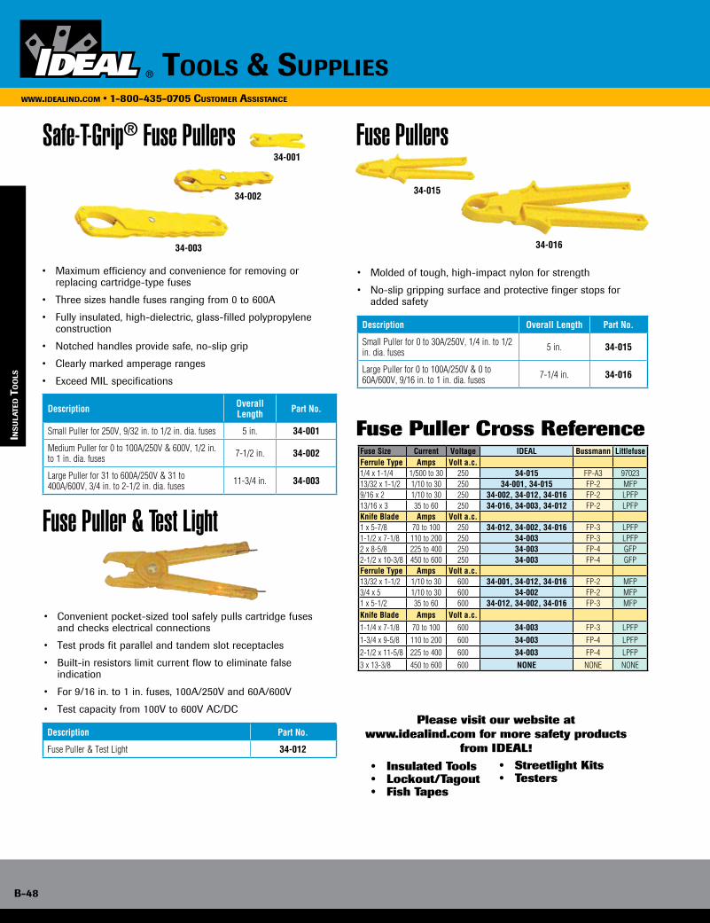
B-48
www.idealind.com • 1-800-435-0705 customer assistance
tools & supplies
Safe-T-Grip® Fuse Pullers
Fuse Puller & Test Light
Fuse Pullers
• Maximum efficiency and convenience for removing or replacing cartridge-type fuses
• Three sizes handle fuses ranging from 0 to 600A
• Fully insulated, high-dielectric, glass-filled polypropylene construction
• Notched handles provide safe, no-slip grip
• Clearly marked amperage ranges
• Exceed MIL specifications
Description Overall Length Part No.
Small Puller for 250V, 9/32 in. to 1/2 in. dia. fuses 5 in. 34-001
Medium Puller for 0 to 100A/250V & 600V, 1/2 in. to 1 in. dia. fuses 7-1/2 in. 34-002
Large Puller for 31 to 600A/250V & 31 to 400A/600V, 3/4 in. to 2-1/2 in. dia. fuses 11-3/4 in. 34-003
• Convenient pocket-sized tool safely pulls cartridge fuses and checks electrical connections
• Test prods fit parallel and tandem slot receptacles
• Built-in resistors limit current flow to eliminate false indication
• For 9/16 in. to 1 in. fuses, 100A/250V and 60A/600V
• Test capacity from 100V to 600V AC/DC
Description Part No.
Fuse Puller & Test Light 34-012
• Molded of tough, high-impact nylon for strength
• No-slip gripping surface and protective finger stops for added safety
Description Overall Length Part No.
Small Puller for 0 to 30A/250V, 1/4 in. to 1/2 in. dia. fuses 5 in. 34-015
Large Puller for 0 to 100A/250V & 0 to 60A/600V, 9/16 in. to 1 in. dia. fuses 7-1/4 in. 34-016
ins
ula
Ted T
oo
ls
34-003
34-002
34-001
34-015
34-016
Fuse Size Current Voltage IDEAL Bussmann LittlefuseFerrule Type Amps Volt a.c.1/4 x 1-1/4 1/500 to 30 250 34-015 FP-A3 9702313/32 x 1-1/2 1/10 to 30 250 34-001, 34-015 FP-2 MFP9/16 x 2 1/10 to 30 250 34-002, 34-012, 34-016 FP-2 LPFP13/16 x 3 35 to 60 250 34-016, 34-003, 34-012 FP-2 LPFPKnife Blade Amps Volt a.c.1 x 5-7/8 70 to 100 250 34-012, 34-002, 34-016 FP-3 LPFP1-1/2 x 7-1/8 110 to 200 250 34-003 FP-3 LPFP2 x 8-5/8 225 to 400 250 34-003 FP-4 GFP2-1/2 x 10-3/8 450 to 600 250 34-003 FP-4 GFPFerrule Type Amps Volt a.c.13/32 x 1-1/2 1/10 to 30 600 34-001, 34-012, 34-016 FP-2 MFP3/4 x 5 1/10 to 30 600 34-002 FP-2 MFP1 x 5-1/2 35 to 60 600 34-012, 34-002, 34-016 FP-3 MFPKnife Blade Amps Volt a.c.1-1/4 x 7-1/8 70 to 100 600 34-003 FP-3 LPFP1-3/4 x 9-5/8 110 to 200 600 34-003 FP-4 LPFP2-1/2 x 11-5/8 225 to 400 600 34-003 FP-4 LPFP3 x 13-3/8 450 to 600 600 NONE NONE NONE
Please visit our website atwww.idealind.com for more safety products
from IDEAL! • Insulated Tools • Lockout/Tagout • Fish Tapes
Fuse Puller Cross Reference
• Streetlight Kits • Testers

Tools & supplies B-49
www.idealind.com • 1-800-435-0705 customer assistance
To
ol c
ar
rier
s/po
uc
hes
Tool Carriers/Pouches
Premium Leather LineTop of the line tool carriers are handcrafted from top-grain cowhide and slow tanned in natural oils to enhance the leather’s inherent strength. Each bag is hand waxed for lasting protection against stains and moisture and is warranted for life. Available innatural or black leather.
Standard Leather LineLeather that stands up to the job like no other material, these tool carriers are constructed of top-grain, natural cowhide and tanned for added strength and durability. Color ages to a deep tan over the years.
Fabric LineDurable, lightweight, portable tool totes in rugged nylon polyester provide the perfect tool storage. Convenient pockets mean easy access; inner compartments keep tools organized and safe when not in use.
Fuse Puller Cross Reference

B-50
www.idealind.com • 1-800-435-0705 customer assistance
tools & supplies
Too
l c
ar
rie
rs/p
ou
ch
es
Tuff-Tote® Ultimate Tool Carriers
Tuff-Tote® Tool Carrier
Tuff-Tote® Tool Pouches
Ergo Tool Pouch
• 8 in. square tool carrier features 2 divided inside compartments with 6 screwdriver loops, 1 large center compartment, 4 outside pockets and 8 outside tool loops
• Exclusive leather-wrapped grab handle for carrying comfort
• Removable shoulder strap helps relieve lower back strain
• Unique stand-alone design keeps tools standing upright for easy identification and access
• Rust-resistant, plated-steel hardware and heavy, lock-stitched nylon thread for long-term durability
• Oil and moisture-resistant reinforced bottom
Description Part No.
Premium Leather Carrier w/shoulder strap 35-975
Premium Black Leather Carrier w/shoulder strap 35-975BLK
Standard Leather Carrier w/shoulder strap 35-325
• Convenient 6 in. x 8 in. tool carrier with 4 center screwdriver slots, 2 interior compartments, 2 divided outside pockets and 4 outside tool loops
• Exclusive leather grab handle for carrying comfort
• Removable shoulder strap helps relieve lower back strain
• Unique stand-alone design keeps tool standing upright for easy identification and access
• Rust-resistant, plated-steel hardware and heavy, lock-stitched nylon thread for long-term durability
• Oil and moisture-resistant reinforced bottom
• 8-pocket, belt-mounted pouch features large utility compartment with 2 dividers and 6 screwdriver loops, 7 outside pockets, release snaps and tape chain
• Exclusive leather grab handle for carrying comfort
• Removable shoulder strap helps relieve lower back strain
• Rust-resistant, plated-steel hardware and heavy, lock-stitched nylon thread for long-term durability
• Tunnel belt loop accommodates belts up to 2-1/4 in. wide
• Compact ergonomic design for versatility and superior comfort
• Large tool holding capacity
• Rust-resistant, plated-steel hardware and heavy, lock- stitched nylon thread for long- term durability
Description Part No.
Premium Leather Carrier w/shoulder strap 35-969
Description Part No.
Standard Natural Leather Ergo Tool Pouch 35-312
Description Part No.
Premium Leather Pouch w/shoulder strap 35-950
Premium Black Pouch w/shoulder strap 35-950BLK
Standard Leather Pouch w/shoulder strap 35-311
35-975 35-975BLK 35-325 35-950 35-31135-950BLK
Electrician’s Tool Pouch
Description Part No.
Standard Leather Electrician’s Tool Pouch 10-466
• Seven-pocket tool pouch
• Full length belt tunnel
• Chain tape lanyard
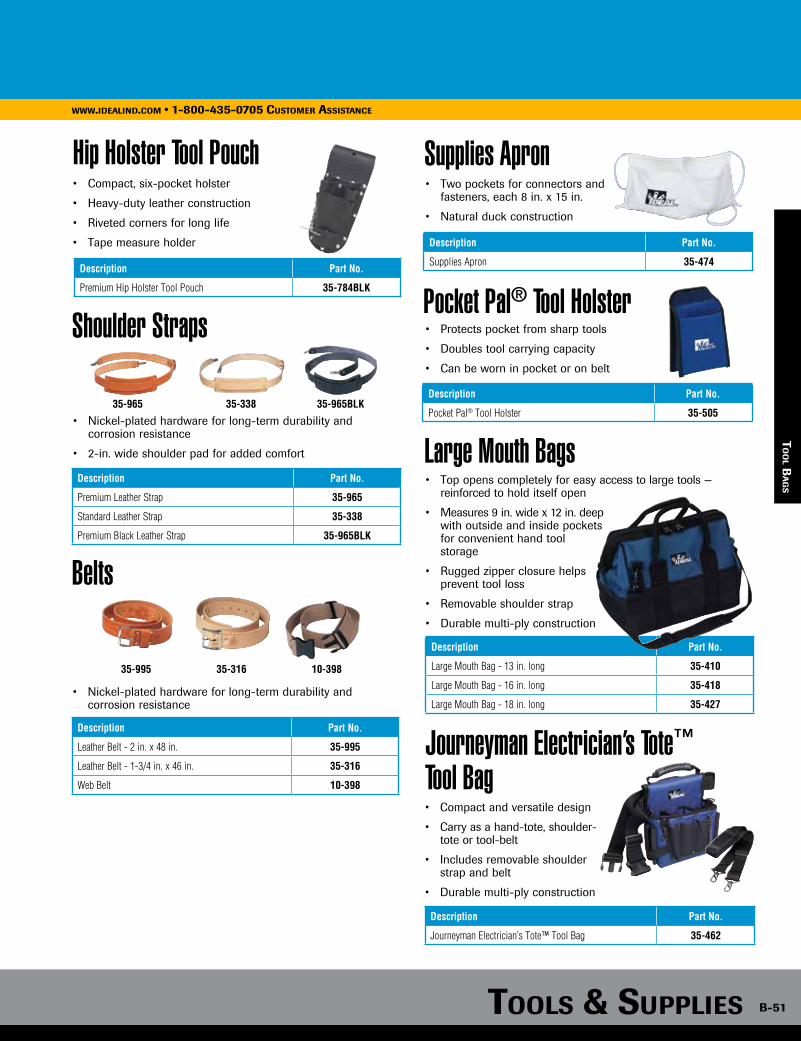
Tools & supplies B-51
www.idealind.com • 1-800-435-0705 customer assistance
Hip Holster Tool Pouch• Compact, six-pocket holster
• Heavy-duty leather construction
• Riveted corners for long life
• Tape measure holder
Description Part No.
Premium Hip Holster Tool Pouch 35-784BLK
To
ol B
ag
s
Shoulder Straps
• Nickel-plated hardware for long-term durability and corrosion resistance
• 2-in. wide shoulder pad for added comfort
Description Part No.
Premium Leather Strap 35-965
Standard Leather Strap 35-338
Premium Black Leather Strap 35-965BLK
35-965 35-338 35-965BLK
Belts
• Nickel-plated hardware for long-term durability and corrosion resistance
Description Part No.
Leather Belt - 2 in. x 48 in. 35-995
Leather Belt - 1-3/4 in. x 46 in. 35-316
Web Belt 10-398
35-995 35-316 10-398
Supplies Apron• Two pockets for connectors and
fasteners, each 8 in. x 15 in.
• Natural duck construction
Description Part No.
Supplies Apron 35-474
• Top opens completely for easy access to large tools — reinforced to hold itself open
• Measures 9 in. wide x 12 in. deep with outside and inside pockets for convenient hand tool storage
• Rugged zipper closure helps prevent tool loss
• Removable shoulder strap
• Durable multi-ply construction
Large Mouth Bags
Description Part No.
Large Mouth Bag - 13 in. long 35-410
Large Mouth Bag - 16 in. long 35-418
Large Mouth Bag - 18 in. long 35-427
Journeyman Electrician’s Tote™ Tool Bag• Compact and versatile design
• Carry as a hand-tote, shoulder-tote or tool-belt
• Includes removable shoulder strap and belt
• Durable multi-ply construction
Description Part No.
Journeyman Electrician’s Tote™ Tool Bag 35-462
Pocket Pal® Tool Holster• Protects pocket from sharp tools
• Doubles tool carrying capacity
• Can be worn in pocket or on belt
Description Part No.
Pocket Pal® Tool Holster 35-505

B-52
www.idealind.com • 1-800-435-0705 customer assistance
tools & supplies
Mechanic’s Tool Bag
Zipper Pouches
• Eight narrow inside pockets designed to hold small tools
• Two side pockets with closeable snaps for large tools or loose items
• Double inside liner and rigid bottom prevent bag distortion
• Durable nylon polyester construction
Description Part No.
Mechanic’s Tool Bag 35-535
• Durable, water resistant material
• Heavy duty, self-repairing zippers
Description Part No.
10-1/2 in. Zipper Pouch 35-402
12-1/2 in. Zipper Pouch 35-403
Divider Pouch™ Small Parts Bag• Designed to provide perfect small parts storage — keeps parts separate and organized
• Six internally divided 5-in. deep pockets
• Convenient drawstring protects contents from spillage
• Convenient handle loop
• Sized to stack in 5-gallon buckets
• Durable nylon polyester construction
Note: Wire connectors sold separately.
Description Part No.
Divider Pouch™ Small Parts Bag 35-655
Too
l B
ag
s/k
iTs
17-Piece Master Electrician’s Kitw/Tool Carrier
Description Part No.
17-Piece Master Electrician’s Kit 35-809
Kit Includes
9-1/2 in. Lineman’s Plier w/New England nose and crimping die 30-3430
8-1/2 in. Long-Nose Pliers w/cutter 35-3038
9-1/2 in. Tongue & Groove Pliers 35-3420
9-1/2 in. Cable Cutter 35-3052
Kinetic™ Reflex™ T®-Stripper Wire Stripper 45-915
7-in-1 Twist-a-Nut™ Screwdriver 35-908
Phillips #1 x 3 in. Cushioned-Grip Screwdriver 35-193
Phillips #2 x 4 in. Cushioned-Grip Screwdriver 35-194
3/16 in. x 6 in. Cushioned-Grip Slotted Cabinet Tip Screwdriver 35-186
1/4 in. x 4 in. Cushioned-Grip Slotted round shank Screwdriver 35-164
3/16 in. x 6 in. Cushioned-Grip Screw holding Slotted Screwdriver 35-406
Hawkbill Knife 35-286
Electrician’s Hammer 35-210
25’ Auto-Lock Tape Measure 35-242
Torpedo Level 35-205
Vol-Con® Voltage/Continuity Tester 61-076
Tuff-Tote® Premium Leather Tool Carrier 35-975
Master Electrician’s Tote™
• Spacious and durable design
• Organizes and displays tools for fast access
• Includes removable shoulder strap
• Durable multi-ply construction
Description Part No.
Master Electrician’s Tote™ 35-441

Tools & supplies B-53
www.idealind.com • 1-800-435-0705 customer assistance
ha
nd T
oo
l kiTs
16-Piece Master Electrician’s Kitw/Pouch
16-Piece Master Electrician’s Kit w/Large Mouth Bag
Description Part No.
16-Piece Master Electrician’s Kit 35-800
Kit Includes
9-1/4 in. Lineman’s Plier w/fish tape puller 30-430
8 in. Diagonal-Cutting Pliers w/angled head 35-029
8-1/2 in. Long-Nose Plier 35-038
9-1/2 in. Cable Cutter 35-052
3/16 in. x 6 in. Cushioned-Grip Screw holding Slotted Screwdriver 35-083
1/4 in. x 4 in. Cushioned-Grip Slotted round shank Screwdriver 35-164
#2 x 4 in. Cushioned-Grip Phillips Screwdriver 35-194
Electrician’s Hammer 35-210
25’ Auto-Lock Tape Measure 35-242
Electrician’s Knife 35-285
Standard Leather Pouch w/shoulder strap 35-311
10-1/2 in. Tongue and Groove Plier 35-430
7-in-1 Twist-a-Nut™ Screwdriver 35-908
T®-Stripper Wire Stripper 45-120
Vol-Con® Voltage/Continuity Tester 61-076
Replacement Battery 61-201
Description Part No.
16-Piece Master Electrician’s Kit 35-808
Kit Includes
Combo Crimp/Strip Tool 30-428
Pocket Fuse Puller 34-002
9-1/2 in. Lineman’s Plier w/New England nose, crimping die and fish tape puller 30-430
8-1/2 in. Long-Nose Pliers w/cutter 35-038
9-1/2 in. Cable Cutter 35-052
1/4 in. x 4 in. Cushioned-Grip Slotted round shank Screwdriver 35-164
3/16 in. x 6 in. Cushioned-Grip Slotted Cabinet Tip Screwdriver 35-186
#1 x 3 in. Cushioned-Grip Phillips Screwdriver 35-193
#2 x 4 in. Cushioned-Grip Phillips Screwdriver 35-194
Electrician’s Hammer 35-210
25’ Auto-Lock Tape Measure 35-242
Ergonomic Hacksaw 35-261
Hawkbill Knife 35-286
10-1/2 in. Tongue and Groove Plier 35-430
Reflex™ T®-5 T®-Stripper Wire Stripper 45-415
18 in. Large Mouth Bag 35-427

B-54
www.idealind.com • 1-800-435-0705 cusTomer assisTance
Tools & supplies
Description Part No.
13-Piece Journeyman Electrician’s Kit 35-790
Kit Includes
9-1/2 in. Lineman’s Plier w/New England nose and crimping die 30-3430
Fuse Puller, Medium 34-002
8-1/2 in. Long-Nose Pliers w/cutter 35-3038
1/4 in. x 4 in. Cushioned-Grip Slotted round shank Screwdriver 35-164
3/16 in. x 4 in. Cushioned-Grip Slotted Cabinet Tip Screwdriver 35-186
#1 x 3 in. Cushioned-Grip Phillips Screwdriver 35-193
#2 x 4 in. Cushioned-Grip Phillips Screwdriver 35-194
Torpedo Level 35-205
25’ Auto-Lock Tape Measure 35-242
Hawkbill Knife 35-286
9-1/2 in. Tongue & Groove Plier 35-3420
Kinetic™ Reflex™ T®-Stripper Wire Stripper 45-915
Journeyman Electrician’s Tote® 35-462
Description Part No.
12-Piece Journeyman Electrician’s Kit 35-5805
Kit Includes
Web Belt 10-398
Electrician’s Leather Tool Pouch 10-466
9-1/2 in. Lineman’s Plier w/New England nose, crimping die and fish tape puller 30-430
8 in. Diagonal-Cutting Pliers 35-028
8-1/2 in. Long-Nose Plier 35-038
1/4 in. x 4 in. Cushioned-Grip Slotted round shank Screwdriver 35-164
3/16 in. x 4 in. Cushioned-Grip Slotted Cabinet Tip Screwdriver 35-184
#1 x 3 in. Cushioned-Grip Phillips Screwdriver 35-193
#2 x 4 in. Cushioned-Grip Phillips Screwdriver 35-194
25’ Auto-Lock Tape Measure 35-242
8-1/2 in. Tongue & Groove Pliers 35-420
Premium T®-5 T®-Stripper Wire Stripper 45-120
13-Piece Journeyman Electrician’s Kitw/Electrician’s Tote
12-Piece Journeyman Electrician’s Kit w/Tool Pouch
ha
nd T
oo
l k
iTs

Tools & supplies B-55
www.idealind.com • 1-800-435-0705 cusTomer assisTance
Description Part No.
6-Piece Electrician’s Holster Kit 35-794
Kit Includes
9-1/4 in. Lineman’s Plier w/fish tape puller 30-430
25’ Auto-Lock Tape Measure 35-242
Utility Knife 35-300
Pocket Pal® Tool Holster 35-505
7-in-1 Twist-a-Nut™ Screwdriver 35-908
T®-5 T®-Stripper Wire Stripper 45-120
Description Part No.
5-Piece Electrician’s Holster Kit 35-5792
Kit Includes
9-1/4 in. Lineman’s Plier w/fish tape puller 30-430
3/16 in. x 6 in. Cushioned-Grip Slotted Cabinet Tip Screwdriver 35-186
#2 x 4 in. Cushioned-Grip Phillips Screwdriver 35-194
Pocket Pal® Tool Holster 35-505
Premium T®-5 T®-Stripper Wire Stripper 45-120
Description Part No.
4-Piece Electrician’s Holster Kit 35-5799
Kit Includes
9-1/2 in. Lineman’s Plier w/New England nose and crimping die 30-3430
Pocket Pal® Tool Holster 35-505
11-in-1 Screwdriver/Nutdriver 35-910
Premium T®-5 T®-Stripper Wire Stripper 45-120
6-Piece Electrician’s Holster Kit
5-Piece Electrician’s Holster Kit
4-Piece Electrician’s Holster Kit
ha
nd T
oo
l kiTs
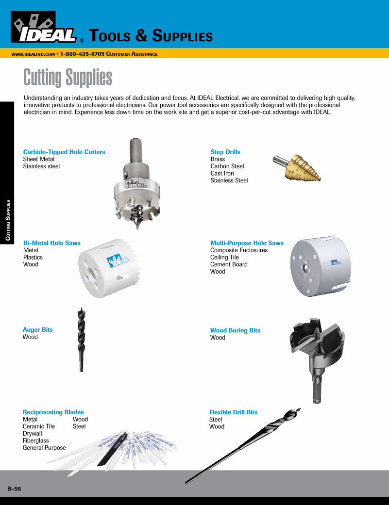
B-56
www.idealind.com • 1-800-435-0705 cusTomer assisTance
Tools & supplies
cu
TTin
g s
up
pli
es
Cutting SuppliesUnderstanding an industry takes years of dedication and focus. At IDEAL Electrical, we are committed to delivering high quality, innovative products to professional electricians. Our power tool accessories are specifically designed with the professional electrician in mind. Experience less down time on the work site and get a superior cost-per-cut advantage with IDEAL.
Bi-Metal Hole SawsMetalPlasticsWood
Multi-Purpose Hole SawsComposite EnclosuresCeiling TileCement BoardWood
Wood Boring BitsWood
Carbide-Tipped Hole CuttersSheet Metal Stainless steel
Step DrillsBrassCarbon SteelCast IronStainless Steel
Auger BitsWood
Flexible Drill BitsSteelWood
Reciprocating BladesMetalCeramic TileDrywallFiberglassGeneral Purpose
Wood Steel
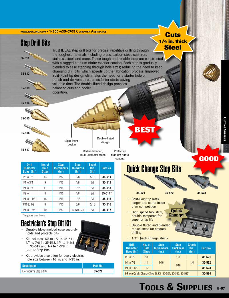
Tools & supplies B-57
www.idealind.com • 1-800-435-0705 cusTomer assisTance
35-515
35-517
35-511
35-512
35-513
35-514
35-516
Step Drill Bits
Electrician’s Step Bit Kit
Trust IDEAL step drill bits for precise, repetitive drilling through the toughest materials including brass, carbon steel, cast iron, stainless steel, and more. These tough and reliable tools are constructed with a rugged titanium nitrite exterior coating. Each step is gradually blended to ease stepping through hole sizes; reducing the need to keep changing drill bits, which speeds up the fabrication process. Improved Split-Point tip design eliminates the need for a starter hole or punch and delivers three times faster starts, saving valuable time. The double-fluted design provides balanced cuts and cooler operation.
Cuts1/4 in. thick
Steel
BESTSplit-Point
design
Radius-blended,multi-diameter steps
Protective titanium nitrite
coating
Double-fluted design
Drill Diameter
Sizes (In.)
No. of Hole Sizes
Step Increments
(In.)
Step Thickness
(In.)
Shank Dia. (In.)
Part No.
1/8 to 1/2 13 1/32 1/8 5/16 35-511
1/4 to 3/4 9 1/16 1/8 3/8 35-512
1/4 to 7/8 11 1/16 1/16 3/8 35-513
1/2 to 1 8 1/16 1/8 3/8 35-514*
1/4 to 1-1/8 16 1/16 1/16 3/8 35-515
3/16 to 1/2 6 1/16 3/8 5/16 35-516
1/4 to 1-3/8 10 1/32 1/16 to 1/4 3/8 35-517
*Requires pilot holes.
• Durable blow-molded case securely holds and protects bits
• Kit Includes: 1/8 to 1/2 in. 35-511, 1/4 to 7/8 in. 35-513, 1/4 to 1-1/8 in. 35-515 and 1/4 to 1-3/8 in. 35-517 Step Bits
• Kit provides a solution for every electrical hole size between 1⁄8 in. and 1-3⁄8 in.
Description Part No.
Electrician’s Step Bit Kit 35-520
35-521 35-522 35-523
QuickChange!
GOOD
Quick Change Step Bits
• Split-Point tip lasts longer and starts faster than competition
• High speed tool steel, double-tempered for superior tip life
• Double fluted and blended radius steps for smooth
drilling
• 1/4” Quick change shank
Drill Diameter Sizes (In.)
No. of Hole Sizes
Step Increments
(In.)
Step Thickness
(In.)
Shank Dia. (In.)
Part No.
1/8 to 1/2 13
1/16
1/8
1/4
35-521
1/4 to 7/8 111/16
35-522
1/4 to 1-1/8 16 35-523
3-Piece Quick-Change Step Bit Kit (35-521, 35-522, 35-523) 35-524
cu
TTing s
up
plies
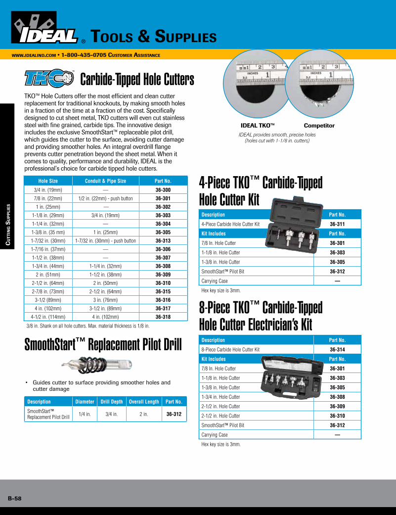
B-58
www.idealind.com • 1-800-435-0705 cusTomer assisTance
Tools & supplies
cu
TTin
g s
up
pli
es
Carbide-Tipped Hole Cutters
4-Piece TKO™ Carbide-Tipped Hole Cutter Kit
8-Piece TKO™ Carbide-Tipped Hole Cutter Electrician’s Kit
Hole Size Conduit & Pipe Size Part No.
3/4 in. (19mm) — 36-300
7/8 in. (22mm) 1/2 in. (22mm) - push button 36-301
1 in. (25mm) — 36-302
1-1/8 in. (29mm) 3/4 in. (19mm) 36-303
1-1/4 in. (32mm) — 36-304
1-3/8 in. (35 mm) 1 in. (25mm) 36-305
1-7/32 in. (30mm) 1-7/32 in. (30mm) - push button 36-313
1-7/16 in. (37mm) — 36-306
1-1/2 in. (38mm) — 36-307
1-3/4 in. (44mm) 1-1/4 in. (32mm) 36-308
2 in. (51mm) 1-1/2 in. (38mm) 36-309
2-1/2 in. (64mm) 2 in. (50mm) 36-310
2-7/8 in. (73mm) 2-1/2 in. (64mm) 36-315
3-1/2 (89mm) 3 in. (76mm) 36-316
4 in. (102mm) 3-1/2 in. (89mm) 36-317
4-1/2 in. (114mm) 4 in. (102mm) 36-318
3/8 in. Shank on all hole cutters. Max. material thickness is 1/8 in.
Description Part No.
4-Piece Carbide Hole Cutter Kit 36-311
Kit Includes Part No.
7/8 In. Hole Cutter 36-301
1-1/8 in. Hole Cutter 36-303
1-3/8 in. Hole Cutter 36-305
SmoothStart™ Pilot Bit 36-312
Carrying Case —
Hex key size is 3mm.
Description Part No.
8-Piece Carbide Hole Cutter Kit 36-314
Kit Includes Part No.
7/8 In. Hole Cutter 36-301
1-1/8 in. Hole Cutter 36-303
1-3/8 in. Hole Cutter 36-305
1-3/4 in. Hole Cutter 36-308
2-1/2 in. Hole Cutter 36-309
2-1/2 in. Hole Cutter 36-310
SmoothStart™ Pilot Bit 36-312
Carrying Case —
Hex key size is 3mm.
SmoothStart™ Replacement Pilot Drill
Description Diameter Drill Depth Overall Length Part No.
SmoothStart™ Replacement Pilot Drill 1/4 in. 3/4 in. 2 in. 36-312
• Guides cutter to surface providing smoother holes and cutter damage
TKO™ Hole Cutters offer the most efficient and clean cutter replacement for traditional knockouts, by making smooth holes in a fraction of the time at a fraction of the cost. Specifically designed to cut sheet metal, TKO cutters will even cut stainless steel with fine grained, carbide tips. The innovative design includes the exclusive SmoothStart™ replaceable pilot drill, which guides the cutter to the surface, avoiding cutter damage and providing smoother holes. An integral overdrill flange prevents cutter penetration beyond the sheet metal. When it comes to quality, performance and durability, IDEAL is the professional’s choice for carbide tipped hole cutters.
IDEAL provides smooth, precise holes (holes cut with 1-1/8 in. cutters)
IDEAL TKO™ Competitor

Carbide-Tipped Hole Cutters
Total time using the IDEAL TKO™
30 Seconds
Chuck Cutter
Total time using the competitors’ knockout tool
More than 6 Minutes
Drill hole & store
Slug removed, disassemble & store
06:20
Assemble knockout punch & stud pull
02:00
Ratchet
04:20
Drill Pilot Hole
00:30
Chuck Step Drill
00:1000:10
00:30
Tools & supplies B-59
www.idealind.com • 1-800-435-0705 cusTomer assisTance
Carbide-Tipped Hole Cutters
See how IDEAL TKO can save time...Low RPM recommended for longer life.
BESTChoiCE forLongEr LifE
Carbide tips cut up to 1/8 in. thick steel and outperforms HSS cutters and bi-metal hole saws in sheet steel
Integrated arbor provides smooth, accurate holes
Exclusive SmoothStart™ pilot drill guides cutter
Integrated overdrill flange prevents penetration beyond the sheet metal
Ejection spring effortlessly ejects slug
cu
TTing s
up
plies
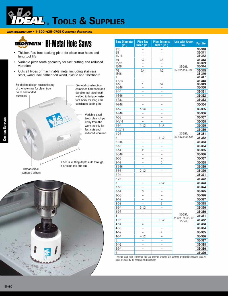
B-60
www.idealind.com • 1-800-435-0705 cusTomer assisTance
Tools & supplies
• Thicker, flex-free backing plate for clean true holes and long tool life
• Variable pitch tooth geometry for fast cutting and reduced vibration
• Cuts all types of machinable metal including stainless steel, wood, nail embedded wood, plastic and fiberboard
Saw Diameter (In.)
Pipe Tap Size* (In.)
Pipe Entrance Size* (In.)
Use with Arbor No. Part No.
9⁄165⁄811/16
–––
–––
35-391, 35-392 or 35-393
35-34035-34135-342
3⁄425/3213⁄16
1⁄2––
3⁄8––
35-34335-39935-344
7/815⁄161
3/4––
1/2––
35-34535-34635-347
1-1/161-1⁄891-3⁄16
–1–
–3⁄4–
35-34835-34935-350
1-1⁄4 – –
35-394, 35-536 or 35-537
35-3511-5⁄16 – – 35-3521-3/8 – 1 35-353
1-7⁄16 – – 35-354
1-1⁄2 1-1⁄4 – 35-3551-9⁄16 – – 35-3561-5⁄8 – – 35-3571-1/16 – – 35-3581-3⁄4 1-1⁄2 1-1⁄4 35-3591-13⁄16 – – 35-3601-7⁄8 – – 35-3612 – 1-1⁄2 35-3622-1⁄16 – – 35-3632-1⁄8 – – 35-3642-1⁄4 2 – 35-3652-5⁄16 – – 35-3662-3⁄8 – – 35-3672-1⁄2 – 2 35-3682-9⁄16 – – 35-3692-5⁄8 2-1⁄2 – 35-3702-3⁄4 – – 35-3712-7⁄8 – – 35-3723 – 2-1⁄2
35-394, 35-536, 35-537 or
35-538
35-3733-1⁄8 – – 35-3743-1⁄4 3 – 35-3753-3⁄8 – – 35-3763-1⁄2 – – 35-3773-5⁄8 – 3 35-3783-3⁄4 3-1⁄2 – 35-3793-7⁄8 – – 35-3804 – – 35-3814-1⁄8 – 3-1⁄2 35-3824-1⁄4 4 – 35-3834-3⁄8 – – 35-3844-1⁄2 – 4 35-3854-3⁄4 4-1⁄2 – 35-3865 – – 35-3875-1⁄2 – – 35-3885-3⁄4 – – 35-3896 – – 35-390*All pipe sizes listed in the Pipe Tap Size and Pipe Entrance Size columns are standard industry sizes. All pipes are sized by the nominal inside diameter.
Bi-Metal Hole Saws
cu
TTin
g s
up
pli
es
1-5/8 in. cutting depth cuts through 2’ x 4’s on the first cut
Threads fit all standard arbors
Bi-metal construction combines hardened and durable tool steel teeth welded to fatigue resis-tant body for long and consistent cutting life
Variable sized teeth clear chips away from the work quickly for fast cuts and reduced vibration
Solid plate design resists flexing of the hole saw for clean true holes and added durability
Description Part No.
12 in. Extension for 7/16 in. Arbors 35-396
Not for use with TKO™ Hole Cutters, Step Drills or Augers.
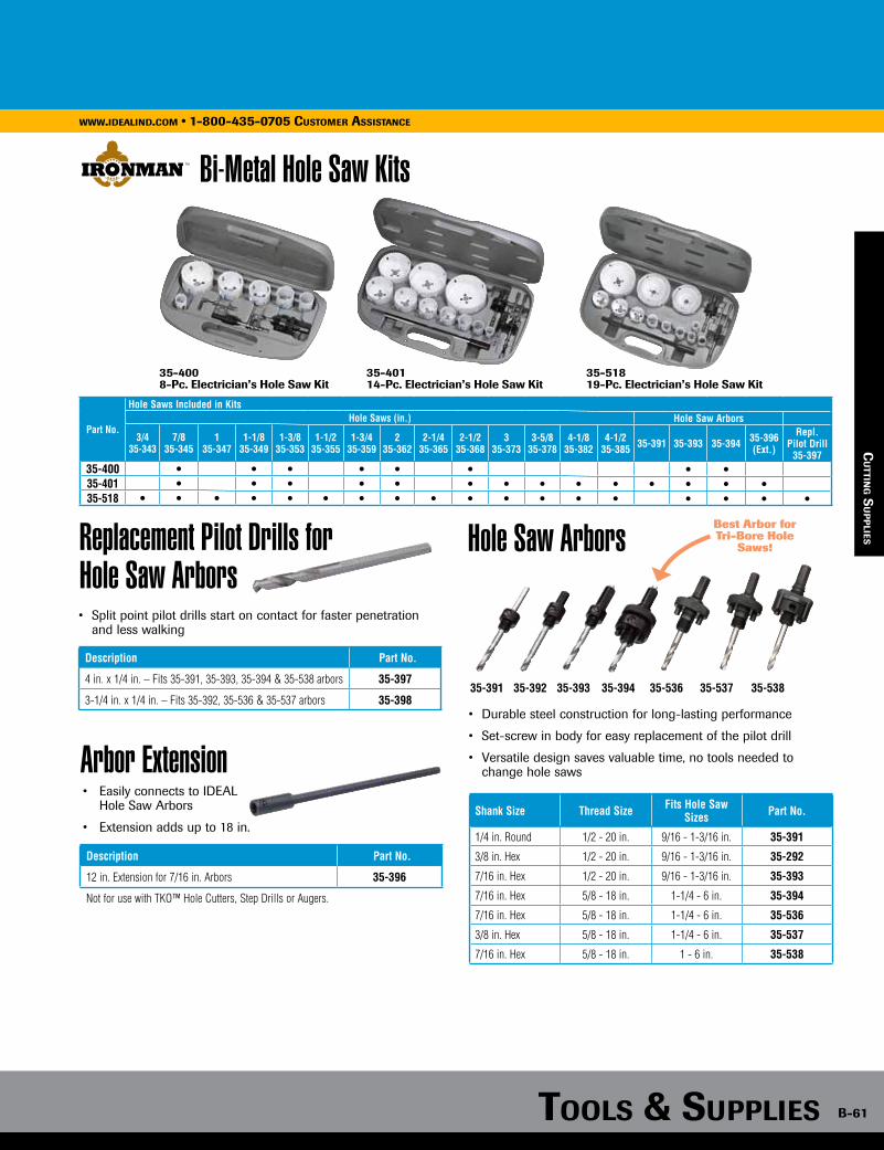
Bi-Metal Hole Saws
Tools & supplies B-61
www.idealind.com • 1-800-435-0705 cusTomer assisTance
Bi-Metal Hole Saw Kits
Replacement Pilot Drills for Hole Saw Arbors
Arbor Extension
Description Part No.
4 in. x 1/4 in. – Fits 35-391, 35-393, 35-394 & 35-538 arbors 35-397
3-1/4 in. x 1/4 in. – Fits 35-392, 35-536 & 35-537 arbors 35-398
• Easily connects to IDEAL Hole Saw Arbors
• Extension adds up to 18 in.
Description Part No.
12 in. Extension for 7/16 in. Arbors 35-396
Not for use with TKO™ Hole Cutters, Step Drills or Augers.
cu
TTing s
up
plies
Part No.
Hole Saws Included in KitsHole Saws (in.) Hole Saw Arbors
3/4 35-343
7/8 35-345
1 35-347
1-1/8 35-349
1-3/8 35-353
1-1/235-355
1-3/4 35-359
2 35-362
2-1/4 35-365
2-1/2 35-368
335-373
3-5/8 35-378
4-1/8 35-382
4-1/2 35-385 35-391 35-393 35-394 35-396
(Ext.)
Repl. Pilot Drill
35-39735-400 • • • • • • • •35-401 • • • • • • • • • • • • • •35-518 • • • • • • • • • • • • • • • • • •
35-4008-Pc. Electrician’s Hole Saw Kit
35-40114-Pc. Electrician’s Hole Saw Kit
35-51819-Pc. Electrician’s Hole Saw Kit
• Split point pilot drills start on contact for faster penetration and less walking
Hole Saw Arbors
• Durable steel construction for long-lasting performance
• Set-screw in body for easy replacement of the pilot drill
• Versatile design saves valuable time, no tools needed to change hole saws
35-391 35-392 35-393 35-394 35-536 35-537 35-538
Best Arbor for Tri-Bore Hole
Saws!
Shank Size Thread Size Fits Hole Saw Sizes Part No.
1/4 in. Round 1/2 - 20 in. 9/16 - 1-3/16 in. 35-391
3/8 in. Hex 1/2 - 20 in. 9/16 - 1-3/16 in. 35-292
7/16 in. Hex 1/2 - 20 in. 9/16 - 1-3/16 in. 35-393
7/16 in. Hex 5/8 - 18 in. 1-1/4 - 6 in. 35-394
7/16 in. Hex 5/8 - 18 in. 1-1/4 - 6 in. 35-536
3/8 in. Hex 5/8 - 18 in. 1-1/4 - 6 in. 35-537
7/16 in. Hex 5/8 - 18 in. 1 - 6 in. 35-538
cu
TTing s
up
plies

B-62
www.idealind.com • 1-800-435-0705 cusTomer assisTance
Tools & supplies
Spade & Carbide Pilot Bits for Tri-Bore™ Hole Saws
• Massive carbide tips designed to cut wood with nails, cement board, composite enclosures, ceiling tile and more!
• Faster than self-feed bits in wood and carbide grit in abrasive materials
Hole Size (in.)
Application Part No.
1-3/8 36-350
2-1/8 1-1/2” Pipe and lock installation 36-351
2-1/4 1-1/2” Pipe with couplings 36-352
2-9/16 2” Pipe 36-353
3 2” Pipe with couplings 36-354
3-3/8 36-355
3-5/8 3” Pipe 36-356
4 36-357
4-1/4 3” Pipe with couplings, 4" dryer vent 36-358
4-1/8 36-359
4-3/8 Capri®, Halo®, Marco, Mini Juno 36-360
4-5/8 4” pipe 36-361
5-3/8 Capri®, Juno®, Lightolier, Prescolite, Progress 36-362
6-1/4 6” Duct 36-363
6-3/8 Capri®, Halo® 36-364
6-5/8 Juno® and Progress 36-3656-7/8 Capri®, Lightolier, Lithonia, Prescolite, Progress 36-366
Hole Size (in.) Application Part No.
Spade Bit Wood boring 36-367*
Carbide Pilot Abrasive material boring 36-368*
*For use with Tri-Bore™ Hole Saw Arbors 35-393 & 35-394
• Deep-cup design on Tri-Bore™ Hole Saws require the use of a longer pilot bit.
• Tri-Bore™ pilot bits must be ordered separately.
• 35-393 for use with 1-3/8 in. Hole Saw (36-350)
• 35-394 for use with remaining sizes
cu
TTin
g s
up
pli
es
Multi-Purpose Hole Saw
Hole Saw Arbor
Shank Size Thread Size Shank Size Part No.
7/16 in. Hex 1/2 - 20 in. 9/16 - 1-3/16 in. 35-393*
7/16 in. Hex 5/8 - 18 in. 1/2 in. 35-394**Arbors include pilot bits for bi-metal hole saws. Tri-Bore™ pilot bits must be ordered separately.
Carbide Tip Pilot
Carbide teeth for woodwith nails, cement board, composite
enclosures and other abrasive materials. NOTE: Great for
adding holes to mostpre-cast polymer
concrete undergroundutility vaults.
Deep gullets for easy plug removal
Rugged construction for extra life
35-393 35-394
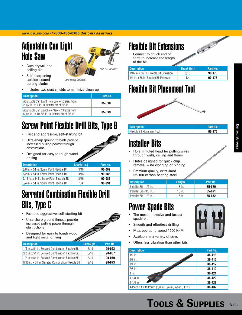
Flexible Bit Extensions
Tools & supplies B-63
www.idealind.com • 1-800-435-0705 cusTomer assisTance
Adjustable Can Light Hole Saw
Description Part No.
Adjustable Can Light Hole Saw – 10 sizes from 2-1/2 in. to 7 in. in increments of 3/8 in. 35-598
Adjustable Can Light Hole Saw – 13 sizes from 6-1/4 in. to 10-3/8 in. in increments of 3/8 in. 35-599
• Cuts drywall and ceiling tile
• Self-sharpening carbide-coated cutting blades
• Includes two dust shields to minimize clean up
Drill not included.
Dust shield included.
cu
TTing s
up
plies
Screw Point Flexible Drill Bits, Type B
Serrated Combination Flexible Drill Bits, Type C
• Fast and aggressive, self-starting bit
• Ultra-sharp ground threads provide increased pulling power through obstructions
• Designed for easy to tough wood drilling
Description Shank (in.) Part No.3/8 in. x 54 in. Screw Point Flexible Bit 3/16 90-0821/2 in. x 54 in. Screw Point Flexible Bit 3/16 90-0859/16 in. x 54 in. Screw Point Flexible Bit 3/16 90-0883/4 in. x 54 in. Screw Point Flexible Bit 1/4 90-091
• Fast and aggressive, self-starting bit
• Ultra-sharp ground threads provide increased pulling power through obstructions
• Designed for easy to tough wood and light metal drilling
Description Shank (in.) Part No.1/4 in. x 54 in. Serrated Combination Flexible Bit 3/16 90-0633/8 in. x 54 in. Serrated Combination Flexible Bit 3/16 90-0671/2 in. x 54 in. Serrated Combination Flexible Bit 3/16 90-0709/16 in. x 54 in. Serrated Combination Flexible Bit 3/16 90-073
Description Shank (in.) Part No.3/16 in. x 36 in. Flexible Bit Extension 3/16 90-1701/4 in. x 36 in. Flexible Bit Extension 1/4 90-173
• Connect to chuck end of shaft to increase the length of the bit
Flexible Bit Placement Tool
Description Part No.Flexible Bit Placement Tool 90-176
Installer Bits• Hole in fluted head for pulling wires
through walls, ceiling and floors
• Flutes designed for quick chip removal — no clogging or binding
• Premium quality, extra-hard 52-100 carbon bearing steel
• The most innovative and fastest spade bit
• Smooth and effortless drilling
• Max. operating speed 1500 RPM
• Available in a variety of sizes
• Offers less vibration than other bits
Description Length Part No.Installer Bit - 1/4 in. 18 in. 35-870Installer Bit - 3/8 in. 18 in. 35-871Installer Bit - 1/2 in. 18 in. 35-872
Power Spade Bits
Description Part No.1/2 in. 36-4135/8 in. 36-4153/4 in. 36-4177/8 in. 36-4191 in. 36-4211-1/8 in. 36-4221-1/4 in. 36-4234-Piece Kit with Pouch (5/8 in., 3/4 in., 7/8 in., 1 in.) 36-432
cu
TTing s
up
plies

B-64
www.idealind.com • 1-800-435-0705 cusTomer assisTance
Tools & supplies
• The most innovative and fastest spade bit
• Smooth and effortless drilling
• Max operating speed 1500 RPM
• Available in a variety of sizes
• Offers less vibration than other bits
• Twin cutting edges for superior cutting speed and ultra clean holes
• Precision ground teeth provide clean and balanced cuts for maximum control with wider cutting surface
• Robust replaceable lead screw with burr-free threads that feed the bit through the wood at a consistent rate
• Precision machined shaft for bit concentricity to eliminate wobble and deliver a truer hole
• Black oxide coated, heat treated and hardened for added durability
• Quick-change shank for fast, secure change out
Self Feed Wood Boring Bits
Description DiameterEntrance Size
for Pipe & EMT
Part No.
1 in. Self-Feed Wood Boring Bit 1 in. 1⁄2 in. 36-2501-1⁄8 in. Self-Feed Wood Boring Bit 1-1⁄8 in. — 36-2511-1⁄4 in. Self-Feed Wood Boring Bit 1-1⁄4 in. 3⁄4 in. 36-2521-3⁄8 in. Self-Feed Wood Boring Bit 1-3⁄8 in. 1 in. 36-2531-1⁄2 in. Self-Feed Wood Boring Bit 1-1⁄2 in. — 36-2541-3⁄4 in. Self-Feed Wood Boring Bit 1-3⁄4 in. 1-1⁄4 in. 36-2552 in. Self-Feed Wood Boring Bit 2 in. 1-1⁄2 in. 36-2562-1⁄8 in. Self-Feed Wood Boring Bit 2-1⁄8 in. — 36-257
2-1⁄4 in. Self-Feed Wood Boring Bit 2-1⁄4 in. — 36-2582-9⁄16 in. Self-Feed Wood Boring Bit 2-9⁄16 in. 2 in. 36-2593 in. Self-Feed Wood Boring Bit 3 in. 2-1⁄2 in. 36-2603-5⁄8 in. Self-Feed Wood Boring Bit 3-5⁄8 in. 3 in. 36-2614-5⁄8 in. Self-Feed Wood Boring Bit 4-5⁄8 in. 4 in. 36-262
™
™
™
cu
TTin
g s
up
pli
es
Replacement Lead Screws
Extension Bars
• Keeps self-feed bits running fast and true
• Easily replaced with hex wrench providing extended drill life and optimum cost-per-hole value
Description Qty. Part No.Small replacement lead screws, fits bit sizes 1 in. - 2-9/16 in. 3/pack 36-271
Small replacement lead screws, fits bit sizes 3 in. - 4-5/8 in. 3/pack 36-270
• Fits into hard-to-reach areas
• Compatible with IDEAL Auger Bits
Description Part No.5-1/2 in. Extension Bar (includes Allen wrench) 36-27318 in. Extension Bar (includes Allen wrench) 35-819
Wider precisionground teeth for maximum control
Robust replaceablelead screw with
burr-free threads
Precision machined shafteliminates wobble resulting
in true, accurate holes
Black oxide coated,heat treated and
hardened forimproved durability
Twin cutting edgesfor faster, more
balanced drilling andcleaner holes
Sharpening File • Keeps durable bits working like new
• High-grade sharpener hones dulled edges quickly and efficiently
Description Part No.Sharpening File 36-272

Tools & supplies B-65
www.idealind.com • 1-800-435-0705 cusTomer assisTance
Description Part No.
9-Piece BULZ-EYE™ Self-Feed Wood Boring Bit Kit 36-269
Kit Includes Part No.
1 in. Bit 36-250
1-1/8 in. Bit 36-251
1-1/4 in. Bit 36-252
1-3/8 in. Bit 36-253
1-1/2 in. Bit 36-254
1-3/4 in. Bit 36-255
2-1/8 in. Bit 36-257
2-9/16 in. Bit 36-259
5-1/2 in. Extension Bar 36-273
Carrying Case —
Description Part No.
6-Piece BULZ-EYE™ Self-Feed Wood Boring Bit Kit 36-266
Kit Includes Part No.
1 in. Bit 36-250
1-1/4 in. Bit 36-252
1-3/8 in. Bit 36-253
2 in. Bit 36-256
2-9/16 in. Bit 36-259
5-1/2 in. Extension Bar 36-273
Carrying Case —
cu
TTing s
up
plies
6-Piece BULZ-EYE™ Self Feed Wood Boring Bit Kit
9-Piece BULZ-EYE™ Self Feed Wood Boring Bit Kit
• For the professional needing to drill multiple hole sizes in any wood material
• For the professional needing to drill multiple hole sizes in any wood material
Mini™ Utility Bit Augers
Bit Length = 4-3/4”, Twist = 2-1/2”, Shank = 7/16” Hole Diameter Part No.
5/8 in. Mini™ Auger 5/8 in. 35-8623/4 in. Mini™ Auger 3/4 in. 35-8647/8 in. Mini™ Auger 7/8 in. 35-8661 in. Power Ship Auger 1 in. 35-868
• Designed to fit between wall studs when used with common drills
• Eliminates the need for expensive right angle drills
Auger Bit Extension• Dual locking screws
• Allen wrench included
• Compatible with Nailbiter™ and RESI-MASTER™ Ship Augers
Auger Bit Extensions, 18”; Six flats to fit drill chuck Description Part No.
Auger Bit Extension for 7/16 in. shank 35-819
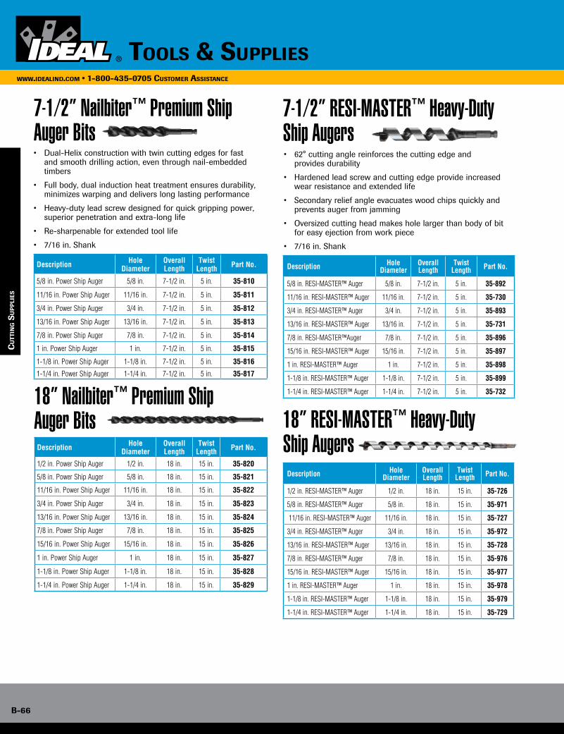
B-66
www.idealind.com • 1-800-435-0705 customer assistance
tools & supplies
7-1/2” Nailbiter™ Premium Ship Auger Bits
18” Nailbiter™ Premium Ship Auger Bits
• Dual-Helix construction with twin cutting edges for fast and smooth drilling action, even through nail-embedded timbers
• Full body, dual induction heat treatment ensures durability, minimizes warping and delivers long lasting performance
• Heavy-duty lead screw designed for quick gripping power, superior penetration and extra-long life
• Re-sharpenable for extended tool life
• 7/16 in. Shank
Description Hole Diameter
Overall Length
Twist Length Part No.
5/8 in. Power Ship Auger 5/8 in. 7-1/2 in. 5 in. 35-810
11/16 in. Power Ship Auger 11/16 in. 7-1/2 in. 5 in. 35-811
3/4 in. Power Ship Auger 3/4 in. 7-1/2 in. 5 in. 35-812
13/16 in. Power Ship Auger 13/16 in. 7-1/2 in. 5 in. 35-813
7/8 in. Power Ship Auger 7/8 in. 7-1/2 in. 5 in. 35-814
1 in. Power Ship Auger 1 in. 7-1/2 in. 5 in. 35-815
1-1/8 in. Power Ship Auger 1-1/8 in. 7-1/2 in. 5 in. 35-816
1-1/4 in. Power Ship Auger 1-1/4 in. 7-1/2 in. 5 in. 35-817
Description Hole Diameter
Overall Length
Twist Length Part No.
1/2 in. Power Ship Auger 1/2 in. 18 in. 15 in. 35-820
5/8 in. Power Ship Auger 5/8 in. 18 in. 15 in. 35-821
11/16 in. Power Ship Auger 11/16 in. 18 in. 15 in. 35-822
3/4 in. Power Ship Auger 3/4 in. 18 in. 15 in. 35-823
13/16 in. Power Ship Auger 13/16 in. 18 in. 15 in. 35-824
7/8 in. Power Ship Auger 7/8 in. 18 in. 15 in. 35-825
15/16 in. Power Ship Auger 15/16 in. 18 in. 15 in. 35-826
1 in. Power Ship Auger 1 in. 18 in. 15 in. 35-827
1-1/8 in. Power Ship Auger 1-1/8 in. 18 in. 15 in. 35-828
1-1/4 in. Power Ship Auger 1-1/4 in. 18 in. 15 in. 35-829
cu
TTin
g s
up
pli
es
7-1/2” RESI-MASTER™ Heavy-Duty Ship Augers
18” RESI-MASTER™ Heavy-Duty Ship Augers
• 62° cutting angle reinforces the cutting edge and provides durability
• Hardened lead screw and cutting edge provide increased wear resistance and extended life
• Secondary relief angle evacuates wood chips quickly and prevents auger from jamming
• Oversized cutting head makes hole larger than body of bit for easy ejection from work piece
• 7/16 in. Shank
Description Hole Diameter
Overall Length
Twist Length Part No.
5/8 in. RESI-MASTER™ Auger 5/8 in. 7-1/2 in. 5 in. 35-892
11/16 in. RESI-MASTER™ Auger 11/16 in. 7-1/2 in. 5 in. 35-730
3/4 in. RESI-MASTER™ Auger 3/4 in. 7-1/2 in. 5 in. 35-893
13/16 in. RESI-MASTER™ Auger 13/16 in. 7-1/2 in. 5 in. 35-731
7/8 in. RESI-MASTER™Auger 7/8 in. 7-1/2 in. 5 in. 35-896
15/16 in. RESI-MASTER™ Auger 15/16 in. 7-1/2 in. 5 in. 35-897
1 in. RESI-MASTER™ Auger 1 in. 7-1/2 in. 5 in. 35-898
1-1/8 in. RESI-MASTER™ Auger 1-1/8 in. 7-1/2 in. 5 in. 35-899
1-1/4 in. RESI-MASTER™ Auger 1-1/4 in. 7-1/2 in. 5 in. 35-732
Description Hole Diameter
Overall Length
Twist Length Part No.
1/2 in. RESI-MASTER™ Auger 1/2 in. 18 in. 15 in. 35-726
5/8 in. RESI-MASTER™ Auger 5/8 in. 18 in. 15 in. 35-971
11/16 in. RESI-MASTER™ Auger 11/16 in. 18 in. 15 in. 35-727
3/4 in. RESI-MASTER™ Auger 3/4 in. 18 in. 15 in. 35-972
13/16 in. RESI-MASTER™ Auger 13/16 in. 18 in. 15 in. 35-728
7/8 in. RESI-MASTER™ Auger 7/8 in. 18 in. 15 in. 35-976
15/16 in. RESI-MASTER™ Auger 15/16 in. 18 in. 15 in. 35-977
1 in. RESI-MASTER™ Auger 1 in. 18 in. 15 in. 35-978
1-1/8 in. RESI-MASTER™ Auger 1-1/8 in. 18 in. 15 in. 35-979
1-1/4 in. RESI-MASTER™ Auger 1-1/4 in. 18 in. 15 in. 35-729
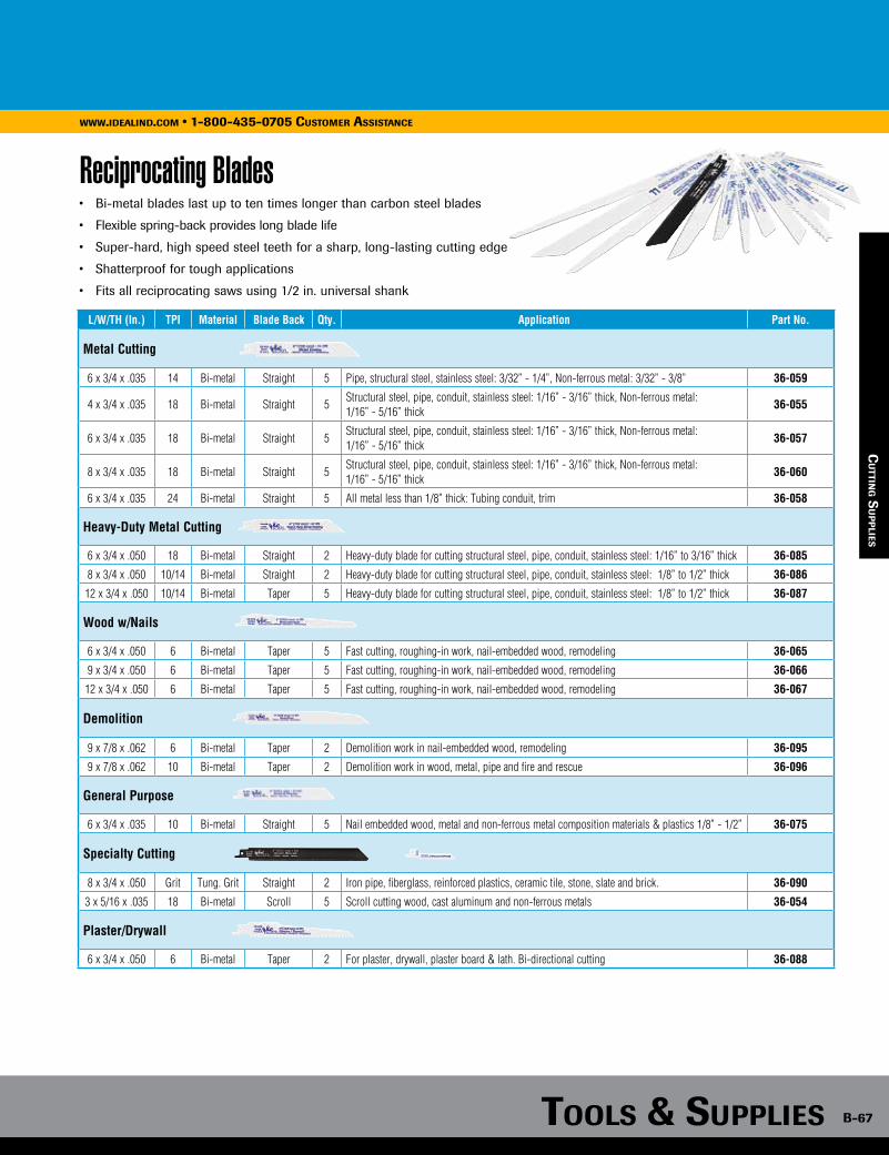
Tools & supplies B-67
www.idealind.com • 1-800-435-0705 customer assistance
cu
TTing s
up
plies
Reciprocating Blades• Bi-metal blades last up to ten times longer than carbon steel blades
• Flexible spring-back provides long blade life
• Super-hard, high speed steel teeth for a sharp, long-lasting cutting edge
• Shatterproof for tough applications
• Fits all reciprocating saws using 1/2 in. universal shank
L/W/TH (In.) TPI Material Blade Back Qty. Application Part No.
Metal Cutting
6 x 3/4 x .035 14 Bi-metal Straight 5 Pipe, structural steel, stainless steel: 3/32” - 1/4”, Non-ferrous metal: 3/32” - 3/8” 36-059
4 x 3/4 x .035 18 Bi-metal Straight 5Structural steel, pipe, conduit, stainless steel: 1/16” - 3/16” thick, Non-ferrous metal: 1/16” - 5/16” thick
36-055
6 x 3/4 x .035 18 Bi-metal Straight 5Structural steel, pipe, conduit, stainless steel: 1/16” - 3/16” thick, Non-ferrous metal: 1/16” - 5/16” thick
36-057
8 x 3/4 x .035 18 Bi-metal Straight 5Structural steel, pipe, conduit, stainless steel: 1/16” - 3/16” thick, Non-ferrous metal: 1/16” - 5/16” thick
36-060
6 x 3/4 x .035 24 Bi-metal Straight 5 All metal less than 1/8” thick: Tubing conduit, trim 36-058
Heavy-Duty Metal Cutting
6 x 3/4 x .050 18 Bi-metal Straight 2 Heavy-duty blade for cutting structural steel, pipe, conduit, stainless steel: 1/16” to 3/16” thick 36-085
8 x 3/4 x .050 10/14 Bi-metal Straight 2 Heavy-duty blade for cutting structural steel, pipe, conduit, stainless steel: 1/8” to 1/2” thick 36-086
12 x 3/4 x .050 10/14 Bi-metal Taper 5 Heavy-duty blade for cutting structural steel, pipe, conduit, stainless steel: 1/8” to 1/2” thick 36-087
Wood w/Nails
6 x 3/4 x .050 6 Bi-metal Taper 5 Fast cutting, roughing-in work, nail-embedded wood, remodeling 36-065
9 x 3/4 x .050 6 Bi-metal Taper 5 Fast cutting, roughing-in work, nail-embedded wood, remodeling 36-066
12 x 3/4 x .050 6 Bi-metal Taper 5 Fast cutting, roughing-in work, nail-embedded wood, remodeling 36-067
Demolition
9 x 7/8 x .062 6 Bi-metal Taper 2 Demolition work in nail-embedded wood, remodeling 36-095
9 x 7/8 x .062 10 Bi-metal Taper 2 Demolition work in wood, metal, pipe and fire and rescue 36-096
General Purpose
6 x 3/4 x .035 10 Bi-metal Straight 5 Nail embedded wood, metal and non-ferrous metal composition materials & plastics 1/8” - 1/2” 36-075
Specialty Cutting
8 x 3/4 x .050 Grit Tung. Grit Straight 2 Iron pipe, fiberglass, reinforced plastics, ceramic tile, stone, slate and brick. 36-090
3 x 5/16 x .035 18 Bi-metal Scroll 5 Scroll cutting wood, cast aluminum and non-ferrous metals 36-054
Plaster/Drywall
6 x 3/4 x .050 6 Bi-metal Taper 2 For plaster, drywall, plaster board & lath. Bi-directional cutting 36-088
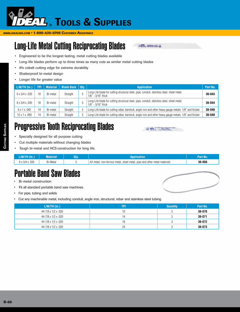
B-68
www.idealind.com • 1-800-435-0705 customer assistance
tools & supplies
B-68
www.idealind.com • 1-800-435-0705 cusTomer assisTance
Long-Life Metal Cutting Reciprocating Blades
Progressive Tooth Reciprocating Blades
Portable Band Saw Blades
• Engineered to be the longest lasting, metal cutting blades available
• Long-life blades perform up to three times as many cuts as similar metal cutting blades
• 8% cobalt cutting edge for extreme durability
• Shatterproof bi-metal design
• Longer life for greater value
L/W/TH (In.) TPI Material Blade Back Qty. Application Part No.
6 x 3/4 x .035 18 Bi-metal Straight 5 Long-Life blade for cutting structural steel, pipe, conduit, stainless steel, sheet metal: 1/6” - 3/16” thick 36-043
8 x 3/4 x .035 18 Bi-metal Straight 5 Long-Life blade for cutting structural steel, pipe, conduit, stainless steel, sheet metal: 1/6” - 3/16” thick 36-044
6 x 1 x .042 14 Bi-metal Straight 5 Long-Life blade for cutting rebar, barstock, angle iron and other heavy gauge metals: 1/8” and thicker 36-046
12 x 1 x .050 14 Bi-metal Straight 5 Long-Life blade for cutting rebar, barstock, angle iron and other heavy gauge metals: 1/8” and thicker 36-048
L/W/TH (In.) Material Qty. Application Part No.
6 x 3/4 x .035 Bi-Metal 5 All metal, non-ferrous metal, sheet metal, pipe and other metal materials 36-056
• Specially designed for all purpose cutting
• Cut multiple materials without changing blades
• Tough bi-metal and HCS construction for long life.
L/W/TH (In.) TPI Quantity Part No.
44-7/8 x 1/2 x .020 10 3 36-070
44-7/8 x 1/2 x .020 14 3 36-071
44-7/8 x 1/2 x .020 18 3 36-072
44-7/8 x 1/2 x .020 24 3 36-073
• Bi-metal construction
• Fit all standard portable band saw machines
• For pipe, tubing and solids
• Cut any machinable metal, including conduit, angle iron, structural, rebar and stainless steel tubing
cu
TTin
g s
up
pli
es
Tools & supplies

Tools & supplies B-69
www.idealind.com • 1-800-435-0705 cusTomer assisTance
Tools & supplies
www.idealind.com • 1-800-435-0705 cusTomer assisTance
Wire ManagementCable Ties• Tools• Identification Ties• Plenum, Powr-Tie™, Multi-Purpose• Miniature, Standard, Heavy Duty• Mounting Pads• Screw Mounting Bases
Supplies• Grommets• Bushings• Spacer Shims• Anchor Kits
Staples• Plastic Insulated• Carbon Steel
wir
e ma
na
gem
enT
Wire Markers• Booklets• Cards• Dispenser
Switches• Toggle• Rocker• Lever/Pull Chain• Push-Button• Rotary• Door• Indicator Lights

B-70
www.idealind.com • 1-800-435-0705 customer assistance
tools & supplies
Cable Tie Installation Tool
Identification Ties
• Consistent, positive tension
• Flush cut-off leaves no projections to damage nearby wires or components
• Lightweight economy model for smaller jobs
• Heavy-duty model features rugged construction with comfortable, cushioned grips
Description Part No.
Economy – use w/standard & heavy-duty ties 41-990
Heavy-Duty – use w/standard & heavy-duty ties 41-995
Replacement Cutter Blade L-9148
Replacement Cutter Bar K-5405
• Write-on surface
• Bundle and identify at the same time
Description Length Width Thickness Max. Bundle Tensile Strength
Pad Size (H X L) UL Type Plenum
Approval Qty./Bag Part No.
Natural Nylon 4.0 in./102mm .100 in./2.54mm .044 in./1.12mm 1/16 - 7/8 in. 18 lbs. 5/16 in. x 1 in.21 AH-2
100 IT1MID-C
Natural Nylon 7.8 in./200mm .181 in./4.59mm .055 in./1.40mm 1/16 - 1-7/8 in. 50 lbs. 1-1/8 in. x 1/2 in. 100 IT2SID-C
ca
Ble
Tie
s
IT - 2 - S - MH - C - 0
IT 2 S MH CC O
IT = IDEAL Powr-Tie™ Cable Ties
Size Tensile Strength Style Qty. Per Package Color
Approximate Bundle Diameter for ties
M = Miniature (18 lbs.)I = Intermediate (40 lbs.)S = Standard (50 lbs.)LH = Light-Heavy Duty (120 lbs.)H = Heavy Duty (175 lbs.)EH = Extra Heavy-Duty (250 lbs.)
_ = Standard TieMH = MountingID = IdentificationMB = Mounting BaseLPMB = Low Profile Mounting BaseMP = Mounting PadCCL = Cable Clamp
L = 50C = 100D = 500M = 1000
_ = Natural 0 = UV Black8 = Gray30 = Heat Stabilized Black35 = Maroon702 = Halar
Cable Tie Numbering System
B-70
Tools & supplieswww.idealind.com • 1-800-435-0705 cusTomer assisTance
IT1MID-C
IT2SID-C & IT4SID-C
1”
5/16”
1/2”
1-1/8”
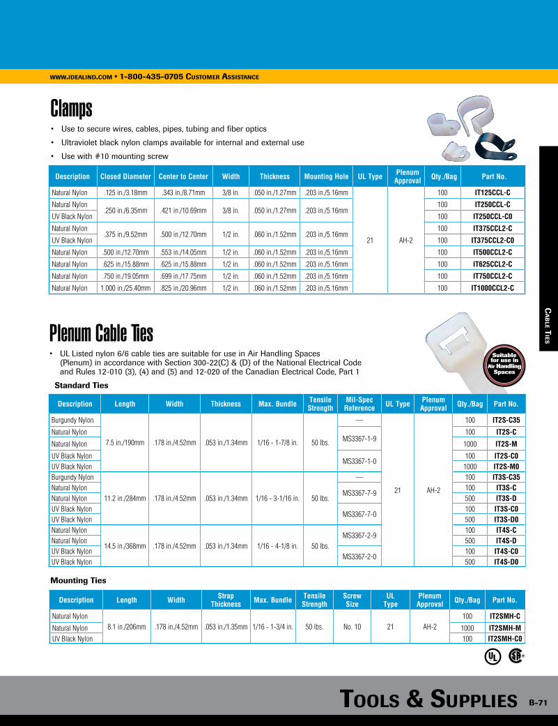
Tools & supplies B-71
www.idealind.com • 1-800-435-0705 customer assistance
Clamps
Description Closed Diameter Center to Center Width Thickness Mounting Hole UL Type Plenum Approval Qty./Bag Part No.
Natural Nylon .125 in./3.18mm .343 in./8.71mm 3/8 in. .050 in./1.27mm .203 in./5.16mm
21 AH-2
100 IT125CCL-C
Natural Nylon.250 in./6.35mm .421 in./10.69mm 3/8 in. .050 in./1.27mm .203 in./5.16mm
100 IT250CCL-C
UV Black Nylon 100 IT250CCL-C0
Natural Nylon.375 in./9.52mm .500 in./12.70mm 1/2 in. .060 in./1.52mm .203 in./5.16mm
100 IT375CCL2-C
UV Black Nylon 100 IT375CCL2-C0
Natural Nylon .500 in./12.70mm .553 in./14.05mm 1/2 in. .060 in./1.52mm .203 in./5.16mm 100 IT500CCL2-C
Natural Nylon .625 in./15.88mm .625 in./15.88mm 1/2 in. .060 in./1.52mm .203 in./5.16mm 100 IT625CCL2-C
Natural Nylon .750 in./19.05mm .699 in./17.75mm 1/2 in. .060 in./1.52mm .203 in./5.16mm 100 IT750CCL2-C
Natural Nylon 1.000 in./25.40mm .825 in./20.96mm 1/2 in. .060 in./1.52mm .203 in./5.16mm 100 IT1000CCL2-C
• Use to secure wires, cables, pipes, tubing and fiber optics
• Ultraviolet black nylon clamps available for internal and external use
• Use with #10 mounting screw
ca
Ble T
iesPlenum Cable Ties• UL Listed nylon 6/6 cable ties are suitable for use in Air Handling Spaces (Plenum) in accordance with Section 300-22(C) & (D) of the National Electrical Code
and Rules 12-010 (3), (4) and (5) and 12-020 of the Canadian Electrical Code, Part 1
Standard Ties
Description Length Width Thickness Max. Bundle Tensile Strength
Mil-Spec Reference UL Type Plenum
Approval Qty./Bag Part No.
Burgundy Nylon
7.5 in./190mm .178 in./4.52mm .053 in./1.34mm 1/16 - 1-7/8 in. 50 lbs.
—
21 AH-2
100 IT2S-C35
Natural NylonMS3367-1-9
100 IT2S-C
Natural Nylon 1000 IT2S-M
UV Black NylonMS3367-1-0
100 IT2S-C0UV Black Nylon 1000 IT2S-M0Burgundy Nylon
11.2 in./284mm .178 in./4.52mm .053 in./1.34mm 1/16 - 3-1/16 in. 50 lbs.
— 100 IT3S-C35Natural Nylon
MS3367-7-9100 IT3S-C
Natural Nylon 500 IT3S-DUV Black Nylon
MS3367-7-0100 IT3S-C0
UV Black Nylon 500 IT3S-D0Natural Nylon
14.5 in./368mm .178 in./4.52mm .053 in./1.34mm 1/16 - 4-1/8 in. 50 lbs.MS3367-2-9
100 IT4S-CNatural Nylon 500 IT4S-DUV Black Nylon
MS3367-2-0100 IT4S-C0
UV Black Nylon 500 IT4S-D0
Mounting Ties
Description Length Width Strap Thickness Max. Bundle Tensile
StrengthScrew Size
UL Type
Plenum Approval Qty./Bag Part No.
Natural Nylon8.1 in./206mm .178 in./4.52mm .053 in./1.35mm 1/16 - 1-3/4 in. 50 lbs. No. 10 21 AH-2
100 IT2SMH-C
Natural Nylon 1000 IT2SMH-MUV Black Nylon 100 IT2SMH-C0
B-71Tools & supplies
www.idealind.com • 1-800-435-0705 cusTomer assisTance
Suitable for use in
Air Handling Spaces
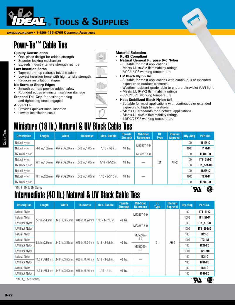
B-72
www.idealind.com • 1-800-435-0705 customer assistance
tools & supplies
Powr-Tie™ Cable TiesQuality Construction• One-piece design for added strength• Superior locking mechanism• Exceeds industry tensile strength ratingsLow Insertion Force• Tapered thin tip reduces initial friction• Lowest insertion force with high tensile strength• Reduces installation fatigueNo Burrs or Sharp Edges• Smooth corners provide added safety• Rounded edges eliminate insulation damageStepped Tail Grip for easier grabbing and tightening once engagedAngled Tail• Provides quicker initial insertion• Lowers installation costs
Material Selection• RoHS Compliant• Natural General Purpose 6/6 Nylon - Suitable for most applications - Meets UL 94V-2 flammability ratings - 85°C/185°F working temperature• UV Black Nylon 6/6 - Suitable for most applications with continuous or extended exposure to outdoor elements - Weather-resistant grade, able to endure ultraviolet (UV) light - Meets UL 94V-2 flammability ratings - 85°C/185°F working temperature• Heat Stabilized Black Nylon 6/6 - Suitable for most applications with continuous or extended
exposure to high temperatures - Meets UL standards for electrical applications - Meets UL 94V-2 flammability ratings - 125°C/257°F working temperature
Miniature (18 lb.) Natural & UV Black Cable TiesDescription Length Width Thickness Max. Bundle Tensile
StrengthMil-Spec Reference
UL Type
PlenumApproval Qty./Bag Part No.
Natural Nylon
4.0 in./102mm .094 in./2.39mm .042 in./1.06mm 1/16 - 7/8 in. 18 lbs.MS3367-4-9
21 AH-2
100 IT1M-C
Natural Nylon 1000 IT1M-M
UV Black Nylon MS3367-4-0 100 IT1M-C0
Natural Nylon6.1 in./154mm .094 in./2.39mm .042 in./1.06mm 1/16 - 3-1/2 in. 18 lbs. —
100 IT1_5M-C
UV Black Nylon 100 IT1_5M-C0
Natural Nylon
8.1 in./206mm .094 in./2.39mm .042 in./1.06mm 1/16 - 2-3/16 in. 18 lbs. —
100 IT2M-C
Natural Nylon 1000 IT2M-M
UV Black Nylon 100 IT2M-C0
*IM, 1_5M & 2M Series * *
Intermediate (40 lb.) Natural & UV Black Cable TiesDescription Length Width Thickness Max. Bundle Tensile
StrengthMil-Spec Reference
ULType
PlenumApproval Qty./Bag Part No.
Natural Nylon
5.7 in./145mm .140 in./3.56mm .049 in./1.24mm 1/16 - 1-7/16 in. 40 lbs.
MS3367-5-9
21 AH-2
100 IT1_5I-C
Natural Nylon 1000 IT1_5I-M
UV Black NylonMS3367-5-0
100 IT1_5I-C0
UV Black Nylon 1000 IT1_5I-M0
Natural Nylon
8.8 in./224mm .140 in./3.56mm .049 in./1.24mm 1/16 - 2-3/8 in. 40 lbs.
MS53367-5-9
100 IT2I-C
Natural Nylon 1000 IT2I-M
UV Black Nylon MS53367-5-0
100 IT2I-C0
UV Black Nylon 1000 IT2I-M0
Natural Nylon11.5 in./292mm .142 in./3.60mm .055 in./1.40mm 1/16 - 3-3/8 in. 40 lbs. —
100 IT3I-C
UV Black Nylon 100 IT3I-C0
Natural Nylon14.5 in./368mm .142 in./3.60mm .055 in./1.40mm 1/16 - 4 in. 40 lbs. —
100 IT4I-C
UV Black Nylon 100 IT4I-C0
*IM, 1_5 & 2I Series * *
ca
Ble
Tie
s
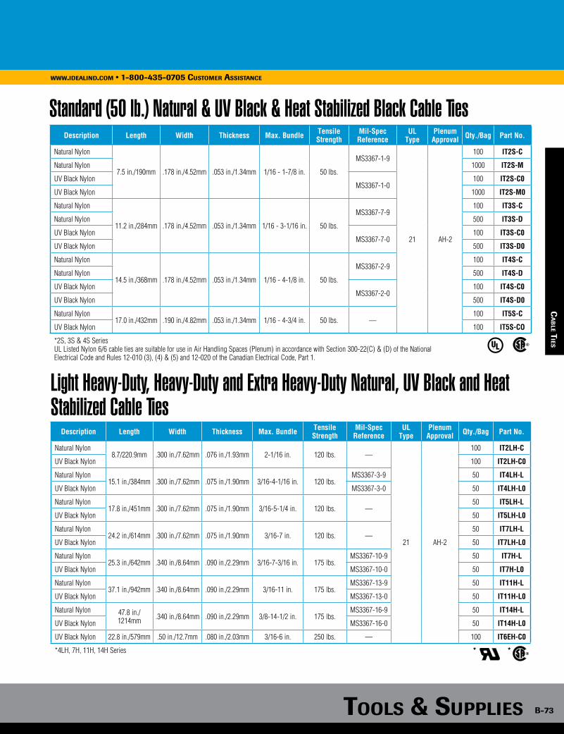
Tools & supplies B-73
www.idealind.com • 1-800-435-0705 customer assistance
Standard (50 lb.) Natural & UV Black & Heat Stabilized Black Cable TiesDescription Length Width Thickness Max. Bundle Tensile
StrengthMil-Spec Reference
ULType
PlenumApproval Qty./Bag Part No.
Natural Nylon
7.5 in./190mm .178 in./4.52mm .053 in./1.34mm 1/16 - 1-7/8 in. 50 lbs.
MS3367-1-9
21 AH-2
100 IT2S-C
Natural Nylon 1000 IT2S-M
UV Black NylonMS3367-1-0
100 IT2S-C0
UV Black Nylon 1000 IT2S-M0
Natural Nylon
11.2 in./284mm .178 in./4.52mm .053 in./1.34mm 1/16 - 3-1/16 in. 50 lbs.
MS3367-7-9100 IT3S-C
Natural Nylon 500 IT3S-D
UV Black NylonMS3367-7-0
100 IT3S-C0
UV Black Nylon 500 IT3S-D0
Natural Nylon
14.5 in./368mm .178 in./4.52mm .053 in./1.34mm 1/16 - 4-1/8 in. 50 lbs.
MS3367-2-9100 IT4S-C
Natural Nylon 500 IT4S-D
UV Black NylonMS3367-2-0
100 IT4S-C0
UV Black Nylon 500 IT4S-D0
Natural Nylon17.0 in./432mm .190 in./4.82mm .053 in./1.34mm 1/16 - 4-3/4 in. 50 lbs. —
100 IT5S-C
UV Black Nylon 100 IT5S-CO
*2S, 3S & 4S Series UL Listed Nylon 6/6 cable ties are suitable for use in Air Handling Spaces (Plenum) in accordance with Section 300-22(C) & (D) of the National Electrical Code and Rules 12-010 (3), (4) & (5) and 12-020 of the Canadian Electrical Code, Part 1.
Light Heavy-Duty, Heavy-Duty and Extra Heavy-Duty Natural, UV Black and Heat Stabilized Cable Ties
Description Length Width Thickness Max. Bundle Tensile Strength
Mil-Spec Reference
UL Type
Plenum Approval Qty./Bag Part No.
Natural Nylon 8.7/220.9mm .300 in./7.62mm .076 in./1.93mm 2-1/16 in. 120 lbs. —
21 AH-2
100 IT2LH-C
UV Black Nylon 100 IT2LH-C0
Natural Nylon 15.1 in./384mm .300 in./7.62mm .075 in./1.90mm 3/16-4-1/16 in. 120 lbs.
MS3367-3-9 50 IT4LH-L
UV Black Nylon MS3367-3-0 50 IT4LH-L0
Natural Nylon 17.8 in./451mm .300 in./7.62mm .075 in./1.90mm 3/16-5-1/4 in. 120 lbs. —
50 IT5LH-L
UV Black Nylon 50 IT5LH-L0
Natural Nylon 24.2 in./614mm .300 in./7.62mm .075 in./1.90mm 3/16-7 in. 120 lbs. —
50 IT7LH-L
UV Black Nylon 50 IT7LH-L0
Natural Nylon 25.3 in./642mm .340 in./8.64mm .090 in./2.29mm 3/16-7-3/16 in. 175 lbs.
MS3367-10-9 50 IT7H-L
UV Black Nylon MS3367-10-0 50 IT7H-L0
Natural Nylon 37.1 in./942mm .340 in./8.64mm .090 in./2.29mm 3/16-11 in. 175 lbs.
MS3367-13-9 50 IT11H-L
UV Black Nylon MS3367-13-0 50 IT11H-L0
Natural Nylon 47.8 in./1214mm .340 in./8.64mm .090 in./2.29mm 3/8-14-1/2 in. 175 lbs.
MS3367-16-9 50 IT14H-L
UV Black Nylon MS3367-16-0 50 IT14H-L0
UV Black Nylon 22.8 in./579mm .50 in./12.7mm .080 in./2.03mm 3/16-6 in. 250 lbs. — 100 IT6EH-C0
*4LH, 7H, 11H, 14H Series * *
ca
Ble T
ies
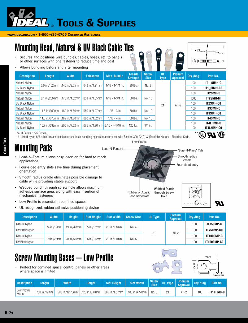
B-74
www.idealind.com • 1-800-435-0705 customer assistance
tools & supplies
ca
Ble
Tie
s
Mounting Head, Natural & UV Black Cable Ties• Secures and positions wire bundles, cables, hoses, etc. to panels
or other surfaces with one fastener to reduce time and cost
• Allows bundling before and after mounting
Description Length Width Thickness Max. Bundle Tensile Strength
Screw Size
ULType
PlenumApproval Qty./Bag Part No.
Natural Nylon6.0 in./152mm .140 in./3.55mm .048 in./1.21mm 1/16 - 1-1/4 in. 30 lbs. No. 8
21 AH-2
100 IT1_5IMH-C
UV Black Nylon 100 IT1_5IMH-C0
Natural Nylon 8.1 in./206mm .178 in./4.52mm .053 in./1.35mm 1/16 - 1-3/4 in. 50 lbs. No. 10
100 IT2SMH-C
Natural Nylon 1000 IT2SMH-MUV Black Nylon 100 IT2SMH-C0Natural Nylon
11.8 in./300mm .189 in./4.80mm .050 in./1.27mm 1/16 - 3 in. 50 lbs. No. 10100 IT3SMH-C
UV Black Nylon 100 IT3SMH-C0Natural Nylon 14.5 in./370mm .189 in./4.80mm .060 in./1.52mm 1/16 - 4 in. 50 lbs. No. 10 100 IT4SMH-CNatural Nylon
15.7 in./398mm .300 in./7.62mm .075 in./1.90mm 3/16 - 4-1/16 in. 120 lbs. 1/4 in.100 IT4LHMH-C
UV Black Nylon 100 IT4LHMH-C0
*4LH Series; **2S Series ** *UL Listed Nylon 6/6 cable ties are suitable for use in air handling spaces in accordance with Section 300-22(C) & (D) of the National Electrical Code.
Mounting Pads• Lead-N-Feature allows easy insertion for hard to reach
applications
• Four-sided entry slots save time during placement orientation
• Smooth radius cradle eliminates possible damage to cable while providing stable support
• Webbed punch through screw hole allows maximum adhesive surface area, along with easy insertion of mechanical fasteners
• Low Profile is essential in confined spaces
• UL recognized, rubber adhesive positioning device
Description Width Height Slot Height Slot Width Screw Size UL Type Plenum Approval Qty./Bag Part No.
Natural Nylon.74 in./19mm .19 in./4.8mm .05 in./1.2mm .20 in./5.1mm No. 4
21 AH-2
100 IT750MP-C
UV Black Nylon 100 IT750MP-C0
Natural Nylon.99 in./25mm .20 in./5.0mm .06 in./1.5mm .20 in./5.1mm No. 6
100 IT1000MP-C
UV Black Nylon 100 IT1000MP-C0
Screw Mounting Bases – Low Profile• Perfect for confined space, control panels or other areas
where space is limited
Description Length Width Height Slot Height Slot Width Screw Size UL Type Plenum
Approval Qty./Bag Part No.
Low Profile Mount .750 in./19mm .500 in./12.70mm .120 in./3.04mm .062 in./1.57mm .180 in./4.57mm No. 8 21 AH-2 100 IT1LPMB-C
Smooth radiuscradle
Low Profile
Lead-N-Feature
Four-sided entry
Rubber or Acrylic Base Adhesives
Webbed Punch through Screw
Hole
“Stay-N-Place” Tab
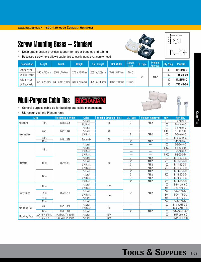
Tools & supplies B-75
www.idealind.com • 1-800-435-0705 customer assistance
ca
Ble T
ies
Screw Mounting Bases – Standard• Deep cradle design provides support for larger bundles and tubing
• Recessed screw hole allows cable ties to easily pass over screw head
Description Length Width Height Slot Height Slot Width Screw Size UL Type Plenum
Approval Qty./Bag Part No.
Natural Nylon.590 in./15mm .370 in./9.40mm .270 in./6.86mm .062 in./1.59mm .190 in./4.83mm No. 6
21 AH-2
100 IT1SMB-C
UV Black Nylon 100 IT1SMB-C0
Natural Nylon.870 in./22mm .640 in./16.26mm .380 in./9.65mm .125 in./3.18mm .300 in./7.62mm 1/4 in.
100 IT2SMB-C
UV Black Nylon 100 IT2SMB-C0
Multi-Purpose Cable Ties• General purpose cable tie for building and cable management
• UL recognized and Plenum rated
Size Thickness x Width Color Tensile Strength (lbs.) UL Type Plenum Approval Qty. Part No.
Miniature 4 in. .039 x .095Natural
18 21 AH-2100 B-4-18-9-C
UL Black 100 B-4-18-0-C
Intermediate6 in. .047 x .142
Natural40
— — 100 B-6-40-9-CNatural — — 1,000 B-6-40-9-M
UV Black 21 AH-2 100 B-6-40-0-C8 in.
.053 x .178 Burgundy 50— — 100 B-8-50-35-C
11 in. 21 AH-2 100 B-11-50-35-C
Standard
8 in.
.057 x .181
Natural
50
— — 100 B-8-50-9-CNatural — — 1,000 B-8-50-9-M
UV Black — — 100 B-8-50-0-CUV Black — — 1,000 B-8-50-0-M
11 in.
Natural 21 AH-2 100 B-11-50-9-CNatural 21 AH-2 500 B-11-50-9-D
UV Black 21 AH-2 100 B-11-50-0-CUV Black 21 AH-2 500 B-11-50-0-D
14 in.
Natural 21 AH-2 100 B-14-50-9-CNatural 21 AH-2 500 B-14-50-9-D
UV Black 21 AH-2 100 B-14-50-0-CUV Black 21 AH-2 500 B-14-50-0-D
Heavy-Duty
14 in.
.066 x .299
Natural120
21 AH-2
100 B-14-120-9-CUV Black 50 B-14-120-0-L
24 in. Natural
175
50 B-24-175-9-LUV Black 50 B-24-175-0-L
36 in. Natural 50 B-36-175-9-L48 in. Natural 50 B-48-175-9-L
Mounting Ties8 in. .057 x .189
Natural50
— — 100 B-8-50MT-9-CUV Black — — 100 B-8-50MT-0-C
14 in. .053 x .178 Natural 21 AH-2 100 B-14-50MT-9-C
Mounting Pads3/4 in. x 3/4 in. .142 Max. Tie Width Natural N/A — — 100 BMP-750-9-C
1 in. x 1 in. .189 Max Tie Width Natural N/A — — 100 BMP-1000-9-C
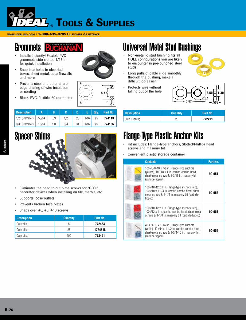
B-76
www.idealind.com • 1-800-435-0705 customer assistance
tools & supplies
su
pp
lies
Grommets
Spacer Shims
• Installs instantly! Flexible PVC grommets side slotted 1/16 in. for quick installation
• Snap into holes in electrical boxes, sheet metal, auto firewalls and more
• Prevents steel and other sharp edge chafing of wire insulation or cording
• Black, PVC, flexible, 60 durometer
Description A B C D E Qty. Part No.
1/2” Grommets 55/64 .69 1/2 .25 1/16 25 774113
3/4” Grommets 15/64 1.0 3/4 .31 1/16 25 774136
• Eliminates the need to cut plate screws for “GFCI” decorator devices when installing on tile, marble, etc.
• Supports loose outlets
• Prevents broken face plates
• Snaps over #6, #8, #10 screws
Description Quantity Part No.
Caterpillar 5 772453
Caterpillar 25 172451L
Caterpillar 500 772451
Universal Metal Stud Bushings
Flange-Type Plastic Anchor Kits
Description Quantity Part No.
Stud Bushing 25 772271
• Non-metallic stud bushing fits all HOLE configurations you are likely to encounter in pre-punched steel studs
• Long pulls of cable slide smoothly through the bushing, make a difficult job easier
• Protects wire without falling out of the hole
Contents Part No.
100 #6-8-10 x 7/8 in. Flange-type anchors (yellow), 100 #8 x 1 in. combo-combo-head, sheet-metal screws & 1-3/16 in. masonry bit (carbide-tipped)
90-051
100 #10-12 x 1 in. Flange-type anchors (red), 100 #10 x 1-1/4 in. combo-combo-head, sheet-metal screws & 1-1/4 in. masonry bit (carbide-tipped)
90-052
100 #10-12 x 1 in. Flange-type anchors (red), 100 #12 x 1 in. combo-combo-head, sheet-metal screws & 1-1/4 in. masonry bit (carbide-tipped)
90-053
40 #14-16 x 1-1/2 in. Flange-type anchors (white), 40 #14 x 1-1/2 in. combo-combo-head, sheet-metal screws & 1-5/4=16 in. masonry bit (carbide-tipped)
90-054
• Kit includes: Flange-type anchors, Slotted/Phillips head screws and masonry bit
• Convenient plastic storage container
A
A B C
ED
A 5.67
B
C
2.50 1.30
.505
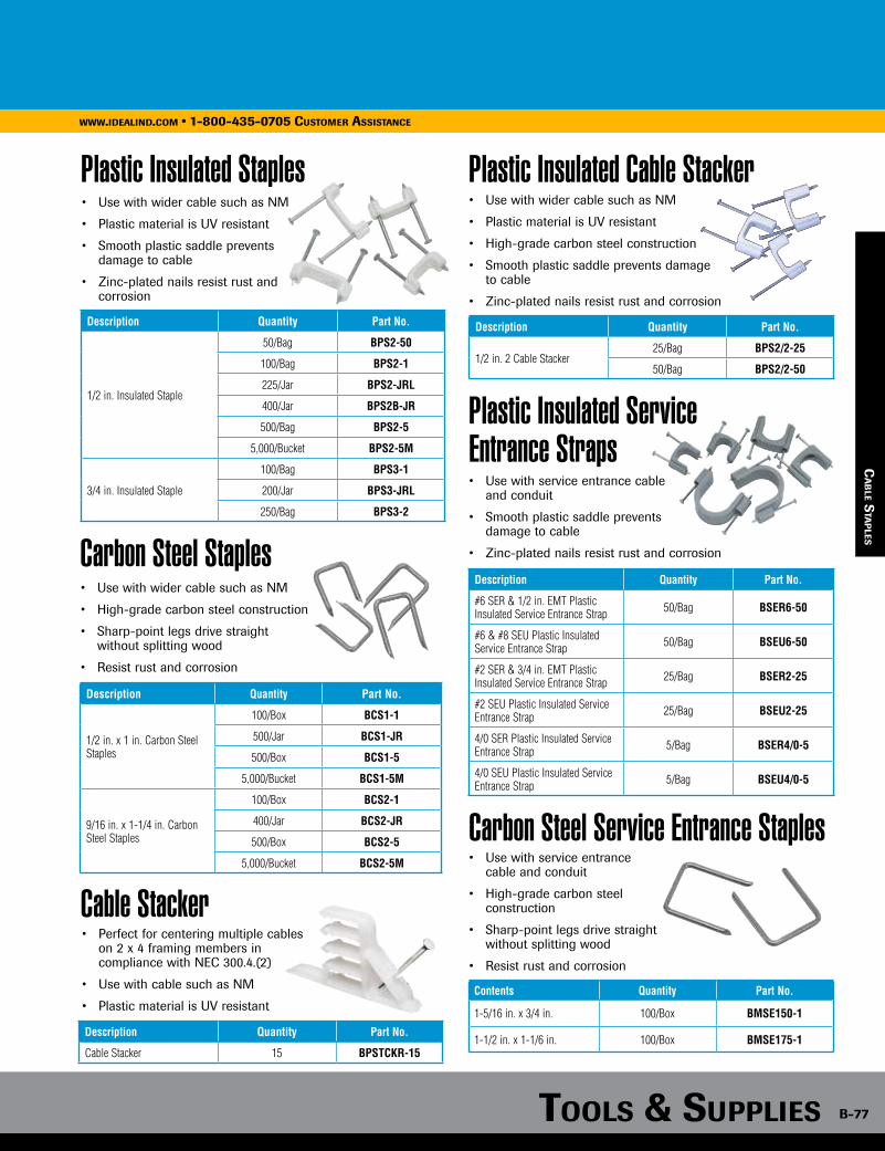
Tools & supplies B-77
www.idealind.com • 1-800-435-0705 customer assistance
ca
Ble s
Tap
les
Contents Quantity Part No.
1-5/16 in. x 3/4 in. 100/Box BMSE150-1
1-1/2 in. x 1-1/6 in. 100/Box BMSE175-1
Cable Stacker• Perfect for centering multiple cables on 2 x 4 framing members in
compliance with NEC 300.4.(2)
• Use with cable such as NM
• Plastic material is UV resistant
Description Quantity Part No.
Cable Stacker 15 BPSTCKR-15
Plastic Insulated Staples• Use with wider cable such as NM
• Plastic material is UV resistant
• Smooth plastic saddle prevents damage to cable
• Zinc-plated nails resist rust and corrosion
Description Quantity Part No.
1/2 in. Insulated Staple
50/Bag BPS2-50
100/Bag BPS2-1
225/Jar BPS2-JRL
400/Jar BPS2B-JR
500/Bag BPS2-5
5,000/Bucket BPS2-5M
3/4 in. Insulated Staple
100/Bag BPS3-1
200/Jar BPS3-JRL
250/Bag BPS3-2
Plastic Insulated Cable Stacker• Use with wider cable such as NM
• Plastic material is UV resistant
• High-grade carbon steel construction
• Smooth plastic saddle prevents damage to cable
• Zinc-plated nails resist rust and corrosion
Description Quantity Part No.
1/2 in. 2 Cable Stacker25/Bag BPS2/2-25
50/Bag BPS2/2-50
Carbon Steel Staples• Use with wider cable such as NM
• High-grade carbon steel construction
• Sharp-point legs drive straight without splitting wood
• Resist rust and corrosion
Description Quantity Part No.
1/2 in. x 1 in. Carbon Steel Staples
100/Box BCS1-1
500/Jar BCS1-JR
500/Box BCS1-5
5,000/Bucket BCS1-5M
9/16 in. x 1-1/4 in. Carbon Steel Staples
100/Box BCS2-1
400/Jar BCS2-JR
500/Box BCS2-5
5,000/Bucket BCS2-5M
Plastic Insulated Service Entrance Straps
Carbon Steel Service Entrance Staples
• Use with service entrance cable and conduit
• Smooth plastic saddle prevents damage to cable
• Zinc-plated nails resist rust and corrosion
• Use with service entrance cable and conduit
• High-grade carbon steel construction
• Sharp-point legs drive straight without splitting wood
• Resist rust and corrosion
Description Quantity Part No.
#6 SER & 1/2 in. EMT Plastic Insulated Service Entrance Strap 50/Bag BSER6-50
#6 & #8 SEU Plastic Insulated Service Entrance Strap 50/Bag BSEU6-50
#2 SER & 3/4 in. EMT Plastic Insulated Service Entrance Strap 25/Bag BSER2-25
#2 SEU Plastic Insulated Service Entrance Strap 25/Bag BSEU2-25
4/0 SER Plastic Insulated Service Entrance Strap 5/Bag BSER4/0-5
4/0 SEU Plastic Insulated Service Entrance Strap 5/Bag BSEU4/0-5
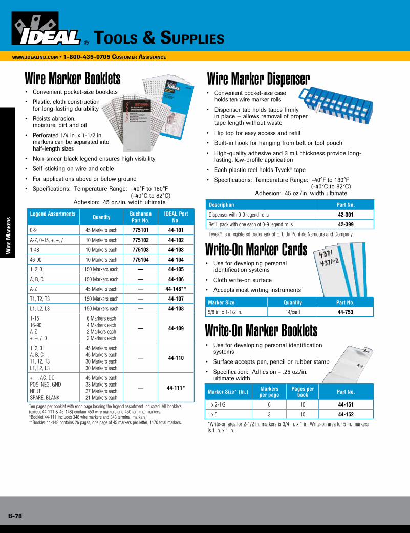
B-78
www.idealind.com • 1-800-435-0705 customer assistance
tools & supplies
wir
e m
ar
ker
s
Wire Marker Booklets• Convenient pocket-size booklets
• Plastic, cloth construction for long-lasting durability
• Resists abrasion, moisture, dirt and oil
• Perforated 1/4 in. x 1-1/2 in. markers can be separated into half-length sizes
• Non-smear black legend ensures high visibility
• Self-sticking on wire and cable
• For applications above or below ground
• Specifications: Temperature Range: -40°F to 180°F (-40°C to 82°C)
Adhesion: 45 oz./in. width ultimate
Legend Assortments Quantity Buchanan Part No.
IDEAL Part No.
0-9 45 Markers each 775101 44-101
A-Z, 0-15, +, –, / 10 Markers each 775102 44-102
1-48 10 Markers each 775103 44-103
46-90 10 Markers each 775104 44-104
1, 2, 3 150 Markers each — 44-105
A, B, C 150 Markers each — 44-106
A-Z 45 Markers each — 44-148**
T1, T2, T3 150 Markers each — 44-107
L1, L2, L3 150 Markers each — 44-108
1-1516-90A-Z+, –, /, 0
6 Markers each4 Markers each2 Markers each 2 Markers each
— 44-109
1, 2, 3A, B, CT1, T2, T3L1, L2, L3
45 Markers each45 Markers each30 Markers each30 Markers each
— 44-110
+, –, AC, DCPOS, NEG, GNDNEUTSPARE, BLANK
45 Markers each33 Markers each27 Markers each21 Markers each
— 44-111*
Ten pages per booklet with each page bearing the legend assortment indicated. All booklets (except 44-111 & 45-148) contain 450 wire markers and 450 terminal markers. *Booklet 44-111 includes 348 wire markers and 348 terminal markers. **Booklet 44-148 contains 26 pages, one page of 45 markers per letter, 1170 total markers.
Wire Marker Dispenser• Convenient pocket-size case holds ten wire marker rolls
• Dispenser tab holds tapes firmly in place — allows removal of proper tape length without waste
• Flip top for easy access and refill
• Built-in hook for hanging from belt or tool pouch
• High-quality adhesive and 3 mil. thickness provide long-lasting, low-profile application
• Each plastic reel holds Tyvek® tape
• Specifications: Temperature Range: -40°F to 180°F (-40°C to 82°C)
Adhesion: 45 oz./in. width ultimate
Description Part No.
Dispenser with 0-9 legend rolls 42-301
Refill pack with one each of 0-9 legend rolls 42-399
Tyvek® is a registered trademark of E. I. du Pont de Nemours and Company.
Write-On Marker Cards• Use for developing personal
identification systems
• Cloth write-on surface
• Accepts most writing instruments
Marker Size Quantity Part No.
5/8 in. x 1-1/2 in. 14/card 44-753
Write-On Marker Booklets• Use for developing personal identification
systems
• Surface accepts pen, pencil or rubber stamp
• Specification: Adhesion – .25 oz./in. ultimate width
Marker Size* (In.) Markers per page
Pages per book Part No.
1 x 2-1/2 6 10 44-151
1 x 5 3 10 44-152
*Write-on area for 2-1/2 in. markers is 3/4 in. x 1 in. Write-on area for 5 in. markers is 1 in. x 1 in.
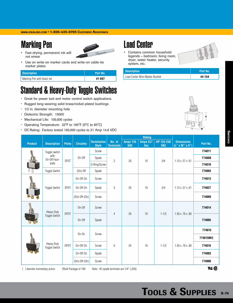
Tools & supplies B-79
www.idealind.com • 1-800-435-0705 customer assistance
sw
iTch
es
Standard & Heavy-Duty Toggle Switches• Great for power tool and motor control switch applications• Rugged long-wearing solid brass/nickel-plated bushings• 1/2 in. diameter mounting hole• Dielectric Strength: 1500V• Mechanical Life: 100,000 cycles• Operating Temperature: 32°F to 185°F (0°C to 85°C)• DC Rating: Factory tested 100,000 cycles to 21 Amp 14.8 VDC
H
WL
Rating
Product Description Poles Circuitry Termination Style
No. of Terminals
Amps 125 VAC
Amps 227 Vac
HP 125-250 VAC
Dimensions (L” x W” x H”) Part No.
Toggle switch with
On-Off Face-plate
SPSTOn-Off
Screw
2 20 10 3/4 1.13 x .57 x .61
774011
Spade 774008
O-Ring/Screw 774010
Toggle Switch (On)-Off Spade 774093
Toggle Switch SPDT
On-Off-On Screw
3 20 10 3/4 1.13 x .57 x .61
774013
On-Off-On Spade 774027
(On)-Off-(On) Screw 774009
Heavy-Duty Toggle Switch DPST
On-Off Screw
4 20 10 1-1/2 1.30 x .76 x .80
774014
On-Off Spade 774005
Heavy-Duty Toggle Switch DPDT
On-On Screw
6 20 10 1-1/2 1.30 x .76 x .80
774015
774015BK†
On-Off-On Screw 774016
On-Off-On Spade 774003
(On)-Off-(On) Screw 774000
( ) denotes momentary action †Bulk Package of 100 Note: All spade terminals are 1/4” (.250).
Marking Pen• Fast-drying, permanent ink will not smear
• Use on write-on marker cards and write-on cable-tie marker plates
Description Part No.
Marking Pen with black ink 41-697
Load Center• Contains common household legends — bedroom, living room, dryer, water heater, security system, etc.
Description Part No.
Load Center Wire Marker Booklet 44-154
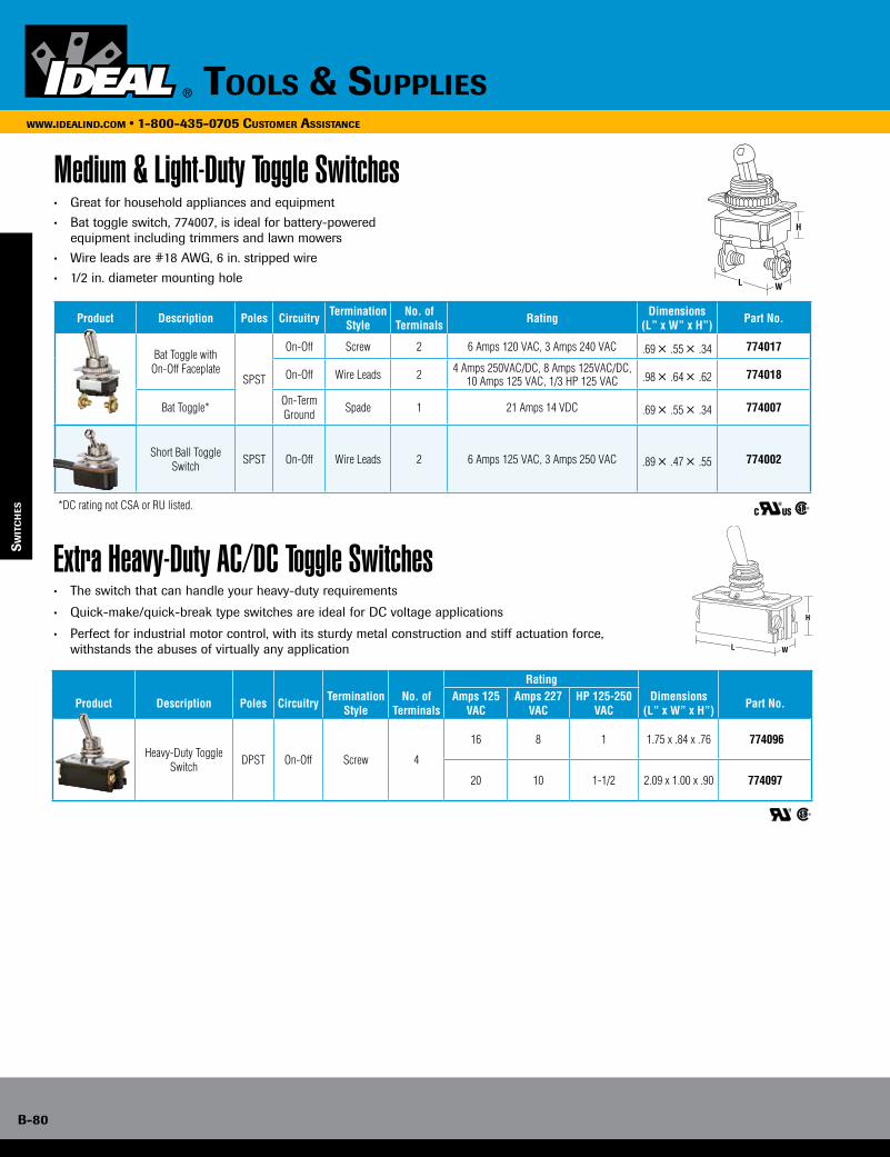
B-80
www.idealind.com • 1-800-435-0705 customer assistance
tools & supplies
Medium & Light-Duty Toggle Switches• Great for household appliances and equipment
• Bat toggle switch, 774007, is ideal for battery-powered equipment including trimmers and lawn mowers
• Wire leads are #18 AWG, 6 in. stripped wire
• 1/2 in. diameter mounting hole
sw
iTc
hes
Extra Heavy-Duty AC/DC Toggle Switches• The switch that can handle your heavy-duty requirements
• Quick-make/quick-break type switches are ideal for DC voltage applications
• Perfect for industrial motor control, with its sturdy metal construction and stiff actuation force, withstands the abuses of virtually any application
W
H
L
Product Description Poles Circuitry Termination Style
No. of Terminals Rating Dimensions
(L” x W” x H”) Part No.
Bat Toggle with On-Off Faceplate
SPST
On-Off Screw 2 6 Amps 120 VAC, 3 Amps 240 VAC .69 × .55 × .34 774017
On-Off Wire Leads 2 4 Amps 250VAC/DC, 8 Amps 125VAC/DC,10 Amps 125 VAC, 1/3 HP 125 VAC .98 × .64 × .62 774018
Bat Toggle* On-Term Ground Spade 1 21 Amps 14 VDC .69 × .55 × .34 774007
Short Ball Toggle Switch SPST On-Off Wire Leads 2 6 Amps 125 VAC, 3 Amps 250 VAC .89 × .47 × .55 774002
*DC rating not CSA or RU listed.
Rating
Product Description Poles Circuitry Termination Style
No. of Terminals
Amps 125 VAC
Amps 227 VAC
HP 125-250 VAC
Dimensions (L” x W” x H”) Part No.
Heavy-Duty Toggle Switch DPST On-Off Screw 4
16 8 1 1.75 x .84 x .76 774096
20 10 1-1/2 2.09 x 1.00 x .90 774097
C US
W
H
L
C US
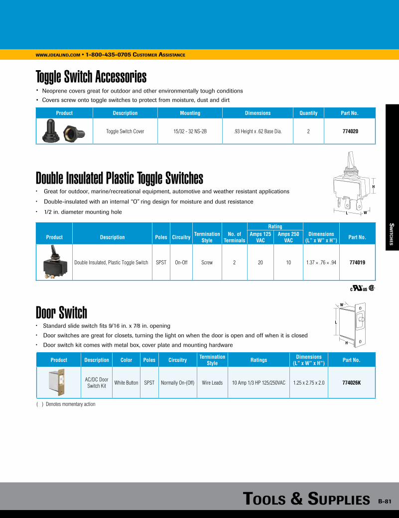
Tools & supplies B-81
www.idealind.com • 1-800-435-0705 customer assistance
Toggle Switch Accessories• Neoprene covers great for outdoor and other environmentally tough conditions
• Covers screw onto toggle switches to protect from moisture, dust and dirt
Product Description Mounting Dimensions Quantity Part No.
Toggle Switch Cover 15/32 - 32 NS-2B .93 Height x .62 Base Dia. 2 774020
sw
iTch
es
Double Insulated Plastic Toggle Switches• Great for outdoor, marine/recreational equipment, automotive and weather resistant applications
• Double-insulated with an internal “O” ring design for moisture and dust resistance
• 1/2 in. diameter mounting hole
Rating
Product Description Poles Circuitry Termination Style
No. of Terminals
Amps 125 VAC
Amps 250 VAC
Dimensions (L” x W” x H”) Part No.
Double Insulated, Plastic Toggle Switch SPST On-Off Screw 2 20 10 1.37 × .76 × .94 774019
W
H
L
C US
Door Switch• Standard slide switch fits 9/16 in. x 7⁄8 in. opening
• Door switches are great for closets, turning the light on when the door is open and off when it is closed
• Door switch kit comes with metal box, cover plate and mounting hardware
Product Description Color Poles Circuitry TerminationStyle Ratings Dimensions
(L” x W” x H”) Part No.
AC/DC Door Switch Kit White Button SPST Normally On-(Off) Wire Leads 10 Amp 1/3 HP 125/250VAC 1.25 x 2.75 x 2.0 774026K
L
H
W
( ) Denotes momentary action
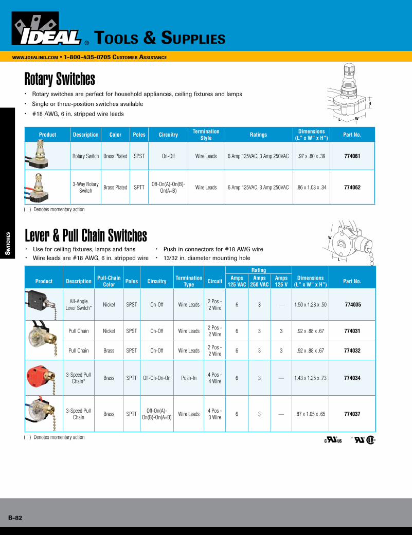
B-82
www.idealind.com • 1-800-435-0705 customer assistance
tools & supplies
W
L
Lever & Pull Chain Switches• Use for ceiling fixtures, lamps and fans• Wire leads are #18 AWG, 6 in. stripped wire
• Push in connectors for #18 AWG wire • 13/32 in. diameter mounting hole
sw
iTc
hes
C US *
Rating
Product Description Pull-Chain Color Poles Circuitry Termination
Type Circuit Amps 125 VAC
Amps 250 VAC
Amps125 V
Dimensions (L” x W” x H”) Part No.
All-Angle Lever Switch* Nickel SPST On-Off Wire Leads 2 Pos -
2 Wire 6 3 — 1.50 x 1.28 x .50 774035
Pull Chain Nickel SPST On-Off Wire Leads 2 Pos - 2 Wire 6 3 3 .92 x .88 x .67 774031
Pull Chain Brass SPST On-Off Wire Leads 2 Pos - 2 Wire 6 3 3 .92 x .88 x .67 774032
3-Speed Pull Chain* Brass SPTT Off-On-On-On Push-In 4 Pos -
4 WIre 6 3 — 1.43 x 1.25 x .73 774034
3-Speed Pull Chain Brass SPTT Off-On(A)-
On(B)-On(A+B) Wire Leads 4 Pos - 3 Wire 6 3 — .87 x 1.05 x .65 774037
sw
iTc
hes
Rotary Switches• Rotary switches are perfect for household appliances, ceiling fixtures and lamps
• Single or three-position switches available
• #18 AWG, 6 in. stripped wire leads
H
L W
Product Description Color Poles Circuitry TerminationStyle Ratings Dimensions
(L” x W” x H”) Part No.
Rotary Switch Brass Plated SPST On-Off Wire Leads 6 Amp 125VAC, 3 Amp 250VAC .97 x .80 x .39 774061
3-Way Rotary Switch Brass Plated SPTT Off-On(A)-On(B)-
On(A+B) Wire Leads 6 Amp 125VAC, 3 Amp 250VAC .86 x 1.03 x .34 774062
( ) Denotes momentary action
( ) Denotes momentary action
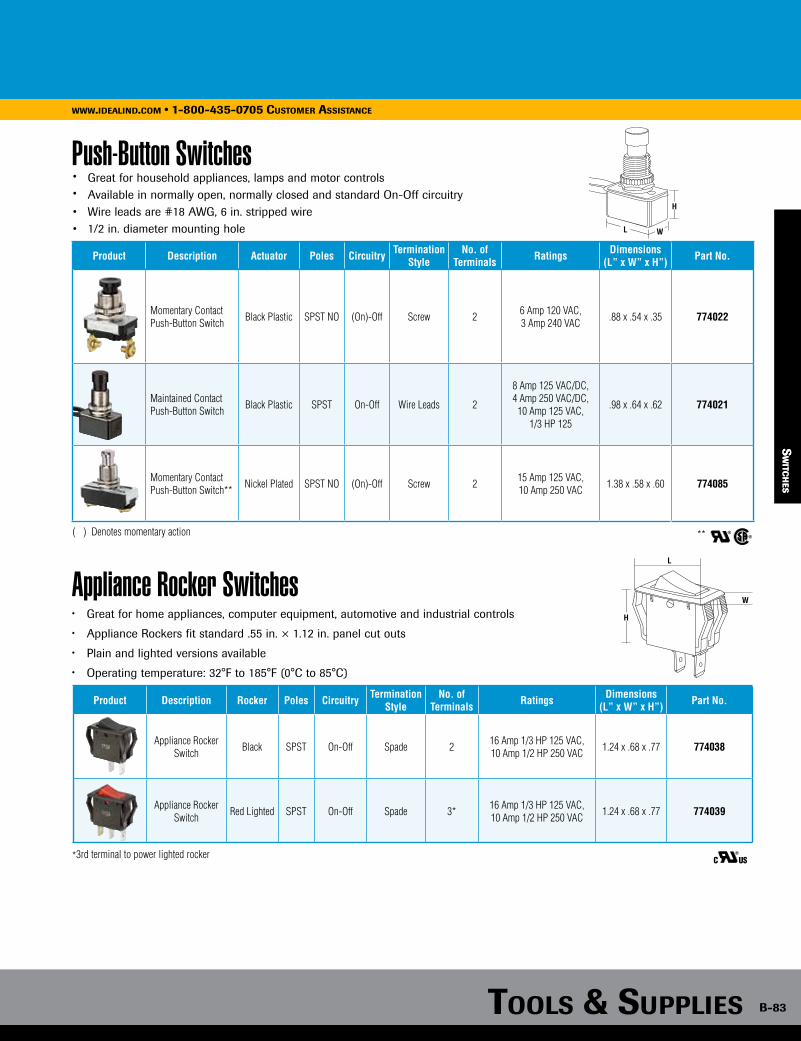
Tools & supplies B-83
www.idealind.com • 1-800-435-0705 customer assistance
Push-Button Switches• Great for household appliances, lamps and motor controls• Available in normally open, normally closed and standard On-Off circuitry• Wire leads are #18 AWG, 6 in. stripped wire• 1/2 in. diameter mounting hole
**
Product Description Actuator Poles Circuitry Termination Style
No. of Terminals Ratings Dimensions
(L” x W” x H”) Part No.
Momentary Contact Push-Button Switch Black Plastic SPST NO (On)-Off Screw 2 6 Amp 120 VAC,
3 Amp 240 VAC .88 x .54 x .35 774022
Maintained Contact Push-Button Switch Black Plastic SPST On-Off Wire Leads 2
8 Amp 125 VAC/DC,4 Amp 250 VAC/DC,
10 Amp 125 VAC,1/3 HP 125
.98 x .64 x .62 774021
Momentary Contact Push-Button Switch** Nickel Plated SPST NO (On)-Off Screw 2 15 Amp 125 VAC,
10 Amp 250 VAC 1.38 x .58 x .60 774085
H
L W
( ) Denotes momentary action
Appliance Rocker Switches• Great for home appliances, computer equipment, automotive and industrial controls
• Appliance Rockers fit standard .55 in. × 1.12 in. panel cut outs
• Plain and lighted versions available
• Operating temperature: 32°F to 185°F (0°C to 85°C)
sw
iTch
es
Product Description Rocker Poles Circuitry Termination Style
No. of Terminals Ratings Dimensions
(L” x W” x H”) Part No.
Appliance Rocker Switch Black SPST On-Off Spade 2 16 Amp 1/3 HP 125 VAC,
10 Amp 1/2 HP 250 VAC 1.24 x .68 x .77 774038
Appliance Rocker Switch Red Lighted SPST On-Off Spade 3* 16 Amp 1/3 HP 125 VAC,
10 Amp 1/2 HP 250 VAC 1.24 x .68 x .77 774039
H
W
L
C US*3rd terminal to power lighted rocker
sw
iTch
es
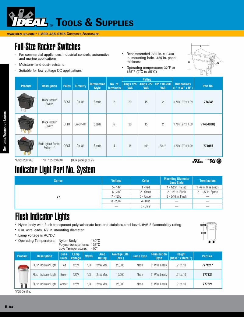
B-84
www.idealind.com • 1-800-435-0705 customer assistance
tools & supplies
Indicator Light Part No. System
Flush Indicator Lights• Nylon body with flush transparent polycarbonate lens and stainless steel bezel, 94V-2 flammability rating• 6 in. wire leads, 1/2 in. mounting diameter• Lamp voltage is AC/DC• Operating Temperature: Nylon Body: 140°C Polycarbonate lens: 135°C Low Temperature: -40°
Series Voltage Color Mounting Diameter Lens Style Terminators
77
5 - 14V 1 - Red 1 - 1/2 in. Raised 1 - 6 in. Wire Leads6 - 28V 2 - Green 2 - 1/2 in. Flush 2 - .187 in. Spade
7 - 125V 3 - Amber 3 - 5/16 in. Flush —8 - 250V 4 - Blue — —
— 5 - Clear — —
Base
Bezel
Product Description LensColor
Lamp Voltage Watts Amp
RatingAverage Life
(hrs.) Lamp Type Termination Style
Height(Base” x Bezel”) Part No.
Flush Indicator Light Red 125V 1/3 2mA Max. 25,000 Neon 6” Wire Leads .91 x .10 777121*
Flush Indicator Light Green 125V 1/3 2mA Max. 15,000 Neon 6” Wire Leads .91 x .10 777221
Flush Indicator Light Amber 125V 1/3 2mA Max. 25,000 Neon 6” Wire Leads .91 x .10 777321
sw
iTc
hes
/in
dic
aTo
r l
igh
Ts
Full-Size Rocker Switches• For commercial appliances, industrial controls, automotive
and marine applications
• Moisture- and dust-resistant
• Suitable for low-voltage DC applications
Rating
Product Description Poles Circuitry Termination Style
No. of Terminals
Amps 125 VAC
Amps 227 VAC
HP 110-250 VAC
Dimensions (L” x W” x H”) Part No.
Black Rocker Switch SPST On-Off Spade 2 20 15 2 1.70 x .97 x 1.09 774045
Black Rocker Switch DPDT On-Off-On Spade 6 20 15 2 1.70 x .97 x 1.09 774040BK†
Red Lighted Rocker Switch*** DPST On-Off Spade 4 15 10* 3/4** 1.70 x .97 x 1.09 774056
*Amps 250 VAC **HP 125-250VAC †Bulk package of 25
*VDE Certified
C US ***
H W
L
• Recommended .830 in. x 1.450 in. mounting hole, .125 in. panel thickness
• Operating temperature: 32°F to 185°F (0°C to 85°C)
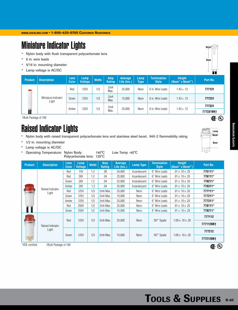
Tools & supplies B-85
www.idealind.com • 1-800-435-0705 customer assistance
Miniature Indicator Lights• Nylon body with flush transparent polycarbonate lens• 6 in. wire leads• 5/16 in. mounting diameter• Lamp voltage is AC/DC
Product Description Lens Color
Lamp Voltage Watts Amp
RatingAverage
Life (hrs.)Lamp Type
Termination Style
Height (Base” x Bezel”) Part No.
Miniature Indicator Light
Red 125V 1/3 2mA Max. 25,000 Neon 6 in. Wire Leads 1.43 × .13 777131
Green 125V 1/3 2mA Max. 15,000 Neon 6 in. Wire Leads 1.43 × .13 777231
Amber 125V 1/3 2mA Max. 25,000 Neon 6 in. Wire Leads 1.43 × .13
777331
777331BK†
†Bulk Package of 100
Base
Bezel
Raised Indicator Lights• Nylon body with raised transparent polycarbonate lens and stainless steel bezel, 94V-2 flammability rating
• 1/2 in. mounting diameter• Lamp voltage is AC/DC• Operating Temperature: Nylon Body: 140°C Low Temp -40°C Polycarbonate lens: 135°C
Base
Bezel
Lamp
*VDE certified †Bulk Package of 100
Product Description LensColor
Lamp Voltage Watts Amp
RatingAverage
Life (hrs.) Lamp Type Termination Style
Height(Base” x Bezel”) Part No.
Raised Indicator Light
Red 14V 1.2 .08 50,000 Incandescent 6” Wire Leads .91 x .10 x .20 775111*Red 28V 1.2 .04 25,000 Incandescent 6” Wire Leads .91 x .10 x .20 776111*
Green 28V 1.2 .04 25,000 Incandescent 6” Wire Leads .91 x .10 x .20 776211*Amber 28V 1.2 .04 25,000 Incandescent 6” Wire Leads .91 x .10 x .20 776311*
Red 125V 1/3 2mA Max. 25,000 Neon 6” Wire Leads .91 x .10 x .20 777111*Green 125V 1/3 2mA Max. 15,000 Neon 6” Wire Leads .91 x .10 x .20 777211*Amber 125V 1/3 2mA Max. 25,000 Neon 6” Wire Leads .91 x .10 x .20 777311*
Red 250V 1/2 2mA Max. 25,000 Neon 6” Wire Leads .91 x .10 x .20 778111*Green 250V 1/2 2mA Max. 15,000 Neon 6” Wire Leads .91 x .10 x .20 778211*
Raised IndicatorLight
Red 125V 1/3 2mA Max. 25,000 Neon .187” Spade 1.09 x .10 x .20777112
777112BK†
Green 125V 1/3 2mA Max. 15,000 Neon .187” Spade 1.09 x .10 x .20777212
777212BK†
ind
ica
Tor l
igh
Ts

B-86
www.idealind.com • 1-800-435-0705 customer assistance
tools & supplies
Heat Shrink & Splice Kits• Easy to install underground splice kits to help save time and money• Protects cable during storage with watertight seal provided by IDEAL End Caps
B-86
www.idealind.com • 1-800-435-0705 cusTomer assisTance
hea
T s
hr
ink
Tools & supplies
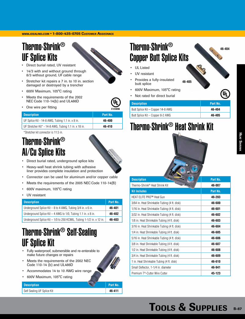
Tools & supplies B-87
www.idealind.com • 1-800-435-0705 customer assistance
Heat Shrink & Splice Kits
Tools & supplies B-87
www.idealind.com • 1-800-435-0705 cusTomer assisTance
Thermo-Shrink® UF Splice Kits
Thermo-Shrink® Copper Butt Splice Kits
Description Part No.
UF Splice Kit - 14-8 AWG, Tubing 1.1 in. x 8 in. 46-400
UF Stretcher Kit* - 14-8 AWG, Tubing 1.1 in. x 18 in. 46-410
*Stretcher kit connector is 11.5 in.
• Direct burial rated, UV resistant
• 14/3 with and without ground through 8/3 without ground, UF cable range
• Stretcher kit repairs a 7 in. to 10 in. section damaged or destroyed by a trencher
• 600V Maximum, 105°C rating
• Meets the requirements of the 2002 NEC Code 110-14(b) and UL486D
• One wire per fitting E123896
• UL Listed
• UV resistant
• Provides a fully-insulated butt splice
• 600V Maximum, 105°C rating
• Not rated for direct burial
Description Part No.
Butt Splice Kit – Copper 14-8 AWG 46-404
Butt Splice Kit – Copper 8-2 AWG 46-405
Thermo-Shrink® Al/Cu Splice Kits
Thermo-Shrink® Self-Sealing UF Splice Kit
• Direct burial rated, underground splice kits
• Heavy-wall heat shrink tubing with adhesive liner provides complete insulation and protection
• Connector can be used for aluminum and/or copper cable
• Meets the requirements of the 2005 NEC Code 110-14(B)
• 600V maximum, 105°C rating
• UV resistant
• Fully waterproof, submersible and re-enterable to make future changes or repairs
• Meets the requirements of the 2002 NEC Code 110-14 (b) and UL486D
• Accommodates 14 to 10 AWG wire range
• 600V Maximum, 105°C rating
Description Part No.
Underground Splice Kit – 8 to 4 AWG, Tubing 3/4 in. x 6 in. 46-401
Underground Splice Kit – 4 AWG to 1/0, Tubing 1.1 in. x 8 in. 46-402
Underground Splice Kit – 1/0 to 250 KCMIL, Tubing 1-1/2 in. x 12 in. 46-403
Description Part No.
Self Sealing UF Splice Kit 46-411
Description Part No.
Thermo-Shrink® Heat Shrink Kit 46-007
Kit Includes Part No.
HEAT ELITE PRO™ Heat Gun 46-203
3/64 in. Heat Shrinkable Tubing (4 ft. disk) 46-600
1/16 in. Heat Shrinkable Tubing (4 ft. disk) 46-601
3/32 in. Heat Shrinkable Tubing (4 ft. disk) 46-602
1/8 in. Heat Shrinkable Tubing (4 ft. disk) 46-603
3/16 in. Heat Shrinkable Tubing (4 ft. disk) 46-604
1/4 in. Heat Shrinkable Tubing (4 ft. disk) 46-605
5/16 in. Heat Shrinkable Tubing (4 ft. disk) 46-606
3/8 in. Heat Shrinkable Tubing (4 ft. disk) 46-607
1/2 in. Heat Shrinkable Tubing (4 ft. disk) 46-608
3/4 in. Heat Shrinkable Tubing (4 ft. disk) 46-609
1 in. Heat Shrinkable Tubing (4 ft. disk) 46-610
Small Deflector, 1-1/4 in. diameter 46-941
Premium T®-Cutter Wire Cutter 45-123
Thermo-Shrink® Heat Shrink Kit
46-405
46-404
hea
T sh
rin
k
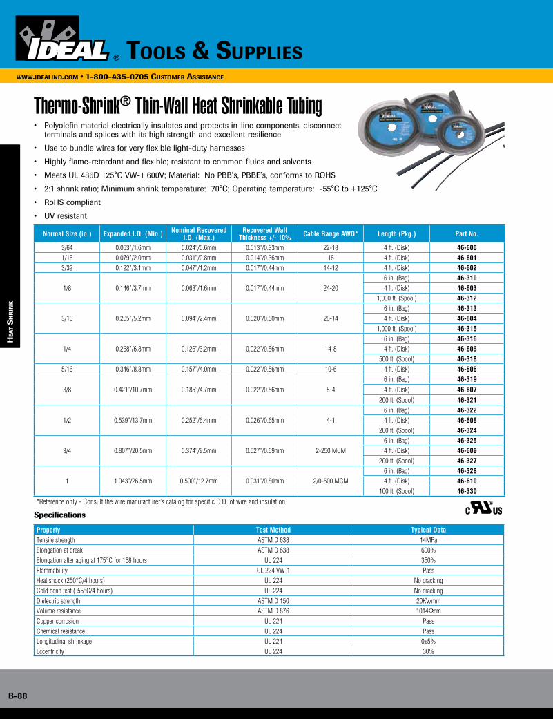
B-88
www.idealind.com • 1-800-435-0705 customer assistance
tools & supplies
hea
T s
hr
ink
Thermo-Shrink® Thin-Wall Heat Shrinkable Tubing• Polyolefin material electrically insulates and protects in-line components, disconnect terminals and splices with its high strength and excellent resilience
• Use to bundle wires for very flexible light-duty harnesses
• Highly flame-retardant and flexible; resistant to common fluids and solvents
• Meets UL 486D 125°C VW-1 600V; Material: No PBB’s, PBBE’s, conforms to ROHS
• 2:1 shrink ratio; Minimum shrink temperature: 70°C; Operating temperature: -55°C to +125°C
• RoHS compliant
• UV resistant
Specifications
Normal Size (in.) Expanded I.D. (Min.) Nominal Recovered I.D. (Max.)
Recovered Wall Thickness +/- 10% Cable Range AWG* Length (Pkg.) Part No.
3/64 0.063”/1.6mm 0.024”/0.6mm 0.013”/0.33mm 22-18 4 ft. (Disk) 46-6001/16 0.079”/2.0mm 0.031”/0.8mm 0.014”/0.36mm 16 4 ft. (Disk) 46-6013/32 0.122”/3.1mm 0.047”/1.2mm 0.017”/0.44mm 14-12 4 ft. (Disk) 46-602
1/8 0.146”/3.7mm 0.063”/1.6mm 0.017”/0.44mm 24-206 in. (Bag) 46-3104 ft. (Disk) 46-603
1,000 ft. (Spool) 46-312
3/16 0.205”/5.2mm 0.094”/2.4mm 0.020”/0.50mm 20-146 in. (Bag) 46-3134 ft. (Disk) 46-604
1,000 ft. (Spool) 46-315
1/4 0.268”/6.8mm 0.126”/3.2mm 0.022”/0.56mm 14-86 in. (Bag) 46-3164 ft. (Disk) 46-605
500 ft. (Spool) 46-3185/16 0.346”/8.8mm 0.157”/4.0mm 0.022”/0.56mm 10-6 4 ft. (Disk) 46-606
3/8 0.421”/10.7mm 0.185”/4.7mm 0.022”/0.56mm 8-46 in. (Bag) 46-3194 ft. (Disk) 46-607
200 ft. (Spool) 46-321
1/2 0.539”/13.7mm 0.252”/6.4mm 0.026”/0.65mm 4-16 in. (Bag) 46-3224 ft. (Disk) 46-608
200 ft. (Spool) 46-324
3/4 0.807”/20.5mm 0.374”/9.5mm 0.027”/0.69mm 2-250 MCM6 in. (Bag) 46-3254 ft. (Disk) 46-609
200 ft. (Spool) 46-327
1 1.043”/26.5mm 0.500”/12.7mm 0.031”/0.80mm 2/0-500 MCM6 in. (Bag) 46-3284 ft. (Disk) 46-610
100 ft. (Spool) 46-330*Reference only - Consult the wire manufacturer’s catalog for specific O.D. of wire and insulation.
Property Test Method Typical DataTensile strength ASTM D 638 14MPaElongation at break ASTM D 638 600%Elongation after aging at 175°C for 168 hours UL 224 350%Flammability UL 224 VW-1 PassHeat shock (250°C/4 hours) UL 224 No crackingCold bend test (-55°C/4 hours) UL 224 No crackingDielectric strength ASTM D 150 20KV/mmVolume resistance ASTM D 876 1014ΩcmCopper corrosion UL 224 PassChemical resistance UL 224 PassLongitudinal shrinkage UL 224 0±5%Eccentricity UL 224 30%
C US
B-88
Tools & supplieswww.idealind.com • 1-800-435-0705 cusTomer assisTance
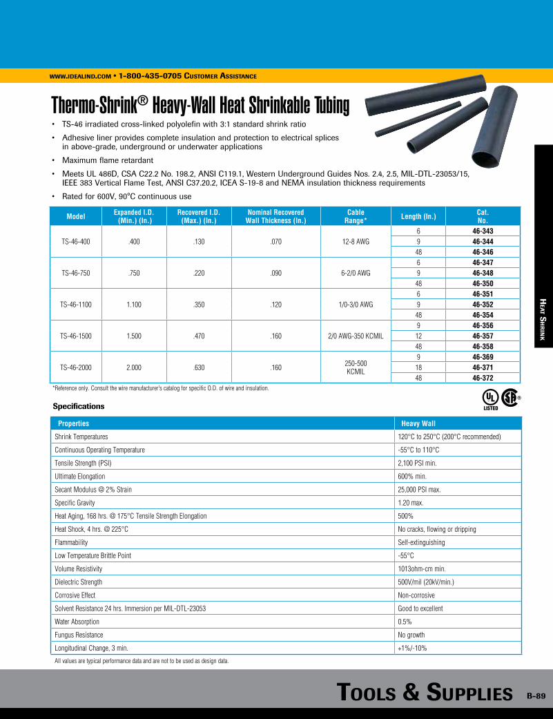
Tools & supplies B-89
www.idealind.com • 1-800-435-0705 customer assistance
hea
T sh
rin
k
B-89
www.idealind.com • 1-800-435-0705 cusTomer assisTance
Tools & supplies
Thermo-Shrink® Heavy-Wall Heat Shrinkable Tubing• TS-46 irradiated cross-linked polyolefin with 3:1 standard shrink ratio
• Adhesive liner provides complete insulation and protection to electrical splices in above-grade, underground or underwater applications
• Maximum flame retardant
• Meets UL 486D, CSA C22.2 No. 198.2, ANSI C119.1, Western Underground Guides Nos. 2.4, 2.5, MIL-DTL-23053/15, IEEE 383 Vertical Flame Test, ANSI C37.20.2, ICEA S-19-8 and NEMA insulation thickness requirements
• Rated for 600V, 90°C continuous use
Model Expanded l.D. (Min.) (In.)
Recovered I.D. (Max.) (In.)
Nominal RecoveredWall Thickness (In.)
CableRange* Length (In.) Cat.
No.
TS-46-400 .400 .130 .070 12-8 AWG6 46-3439 46-344
48 46-346
TS-46-750 .750 .220 .090 6-2/0 AWG6 46-3479 46-348
48 46-350
TS-46-1100 1.100 .350 .120 1/0-3/0 AWG6 46-3519 46-352
48 46-354
TS-46-1500 1.500 .470 .160 2/0 AWG-350 KCMIL9 46-35612 46-35748 46-358
TS-46-2000 2.000 .630 .160 250-500 KCMIL
9 46-36918 46-37148 46-372
*Reference only. Consult the wire manufacturer’s catalog for specific O.D. of wire and insulation.
LISTEDSpecifications
Properties Heavy Wall
Shrink Temperatures 120°C to 250°C (200°C recommended)
Continuous Operating Temperature -55°C to 110°C
Tensile Strength (PSI) 2,100 PSI min.
Ultimate Elongation 600% min.
Secant Modulus @ 2% Strain 25,000 PSI max.
Specific Gravity 1.20 max.
Heat Aging, 168 hrs. @ 175°C Tensile Strength Elongation 500%
Heat Shock, 4 hrs. @ 225°C No cracks, flowing or dripping
Flammability Self-extinguishing
Low Temperature Brittle Point -55°C
Volume Resistivity 1013ohm-cm min.
Dielectric Strength 500V/mil (20kV/min.)
Corrosive Effect Non-corrosive
Solvent Resistance 24 hrs. Immersion per MIL-DTL-23053 Good to excellent
Water Absorption 0.5%
Fungus Resistance No growth
Longitudinal Change, 3 min. +1%/-10%
All values are typical performance data and are not to be used as design data.
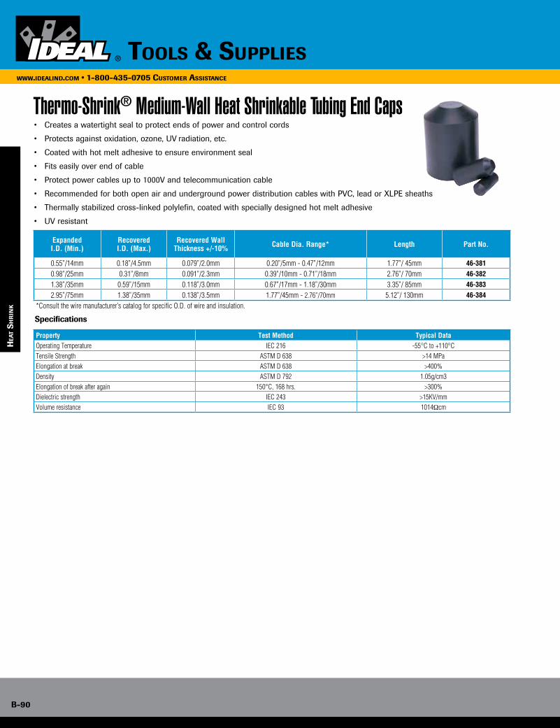
B-90
www.idealind.com • 1-800-435-0705 customer assistance
tools & supplies
hea
T s
hr
ink
Thermo-Shrink® Medium-Wall Heat Shrinkable Tubing End Caps
Expanded I.D. (Min.)
Recovered I.D. (Max.)
Recovered Wall Thickness +/-10% Cable Dia. Range* Length Part No.
0.55”/14mm 0.18”/4.5mm 0.079”/2.0mm 0.20”/5mm - 0.47”/12mm 1.77”/ 45mm 46-3810.98”/25mm 0.31”/8mm 0.091”/2.3mm 0.39”/10mm - 0.71”/18mm 2.76”/ 70mm 46-3821.38”/35mm 0.59”/15mm 0.118”/3.0mm 0.67”/17mm - 1.18”/30mm 3.35”/ 85mm 46-3832.95”/75mm 1.38”/35mm 0.138”/3.5mm 1.77”/45mm - 2.76”/70mm 5.12”/ 130mm 46-384
*Consult the wire manufacturer’s catalog for specific O.D. of wire and insulation.
• Creates a watertight seal to protect ends of power and control cords
• Protects against oxidation, ozone, UV radiation, etc.
• Coated with hot melt adhesive to ensure environment seal
• Fits easily over end of cable
• Protect power cables up to 1000V and telecommunication cable
• Recommended for both open air and underground power distribution cables with PVC, lead or XLPE sheaths
• Thermally stabilized cross-linked polylefin, coated with specially designed hot melt adhesive
• UV resistant
Property Test Method Typical DataOperating Temperature IEC 216 -55°C to +110°CTensile Strength ASTM D 638 >14 MPaElongation at break ASTM D 638 >400%Density ASTM D 792 1.05g/cm3Elongation of break after again 150°C, 168 hrs. >300%Dielectric strength IEC 243 >15KV/mmVolume resistance IEC 93 1014Ωcm
Specifications

Tools & supplies B-91
www.idealind.com • 1-800-435-0705 customer assistance
hea
T gu
ns
Heat Elite Heat Gun Kit
HEAT ELITE PRO™ Heat Gun Kit
• Temperature range: 660°-930°F
(300°-500°C)
• Two-step switch for heat and air flow adjustments
• Double-insulated power cord
• Ergonomic distribution of weight
• Comfortable non-slip handle for ease of use
• Temperature range: 180°F - 1020°F (80° - 550°C)
• Double-insulated power cord
• Ergonomic distribution of weight
• Comfortable non-slip handle for ease of use
• LCD display with memory functions
• Temperature and airflow adjustments
• Stand-by mode to minimize the energy consumption
• Ceramic heating element ensures long-term coil performance
Description Part No.
Heat Elite Heat Gun Kit, 1200 Watts 46-202
Kit Includes Part No.
Heat Elite Heat Gun, 1200 Watts 46-202
Small Deflector, 1-1/4 in. diameter 46-941
Wide-Slot Adapter 45-954
Description Part No.
HEAT ELITE PRO™ Heat Gun Kit, 1500 Watts 46-203
Kit Includes Part No.
HEAT ELITE PRO™ Heat Gun, 1500 Watts 46-203
Small Deflector 46-941
Reduction Adapter 46-950
Wide-Slot Adapter 46-954
Heat Elite Plus LCD Heat Gun Kit• Temperature range: 180° - 1200°F (80° - 650°C)
• Two-step switch for heat and air flow adjustments
• Double-insulated power cord
• Ergonomic distribution of weight
• Comfortable non-slip handle for ease of use
• Infinite temperature adjustment
Description Part No.
Heat Elite Plus LCD Heat Gun Kit, 1500 Watts 46-204
Kit Includes Part No.
Heat Elite Plus LSD Heat Gun, 1500 Watts 46-204
Small Deflector 46-941
Welding Adapter 46-952
Solder Reflector Adapter 46-953
Overlap Adapter 46-955
Pressure Roller 46-956
Heat Gun Accessories
46-941 46-950 46-954
46-952
46-956
46-95546-953
46-951
Description For Use With: Part No.
Small Deflector, 1-1/4 in. diameter 46-202, 46-203, 46-204 46-941
Reduction Adapter 46-203, 46-204 46-950
Glass Protection Adapter 46-202, 46-203, 46-204 46-951
Welding Adapter 46-203, 46-204 46-952
Solder Reflector Adapter 46-204 46-953
Wide-Slot Adapter 46-202, 46-203, 46-204 46-954
Overlap Adapter 46-203, 46-204 46-955
Pressure Roller 46-204 46-956

B-92
www.idealind.com • 1-800-435-0705 customer assistance
tools & supplies
loc
ko
uT/
Tag
ou
T
Lockout/Tagout
Your Safety is our #1 concern.A leader in personal safety for professional electricians, IDEAL Safety, Health and Environment products comply with ASTM requirements and OSHA regulations.
Every day we are protecting lives with the products we provide from 1000 volt insulated tools to Lockout/Tagout equipment, Clamp Meters, S-Class® Fish Tapes, specialty connectors and more!
IDEAL continuously works on methods and equipment that provide the maximum in performance to assure your safety and health while delivering better environment solutions that leave a small footprint.
Training...essential in keeping you safe whatever the job.The proper use of materials and tools can mean the difference to your personal safety and health. IDEAL provides state-of-the-art training to give you the best methods and utilization of this equipment through hands-on demonstrations, peer discussions and on-site applications.
Training consists of several proven methods• Lockout/Tagout Safety and Procedures• Arc Flash Safety and 1000V Insulated Tools• Test and Measurement Equipment and procedures
For more details on available training programs, contact your IDEAL sales representative.
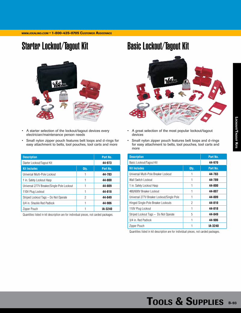
Tools & supplies B-93
www.idealind.com • 1-800-435-0705 customer assistance
lo
ck
ou
T/Ta
go
uT k
iTs
Starter Lockout/Tagout Kit
• A starter selection of the lockout/tagout devices every electrician/maintenance person needs
• Small nylon zipper pouch features belt loops and d-rings for easy attachment to belts, tool pouches, tool carts and more
Description Part No.
Starter Lockout/Tagout Kit 44-973
Kit Includes Qty. Part No.
Universal Multi-Pole Lockout 1 44-783
1 in. Safety Lockout Hasp 1 44-800
Universal 277V Breaker/Single-Pole Lockout 1 44-809
110V Plug Lockout 1 44-818
Striped Lockout Tags – Do Not Operate 2 44-849
3/4 in. Shackle Red Padlock 1 44-906
Zipper Pouch 1 IA-3240
Quantities listed in kit description are for individual pieces, not carded packages.
Basic Lockout/Tagout Kit
• A great selection of the most popular lockout/tagout devices
• Small nylon zipper pouch features belt loops and d-rings for easy attachment to belts, tool pouches, tool carts and more
Description Part No.
Basic Lockout/Tagout Kit 44-970
Kit Includes Qty. Part No.
Universal Multi-Pole Breaker Lockout 1 44-783
Wall Switch Lockout 1 44-789
1 in. Safety Lockout Hasp 1 44-800
480/600V Breaker Lockout 1 44-807
Universal 277V Breaker Lockout/Single Pole 1 44-809
Hinged Single-Pole Breaker Lockouts 2 44-810
110V Plug Lockout 1 44-818
Striped Lockout Tags – Do Not Operate 5 44-849
3/4 in. Red Padlock 1 44-906
Zipper Pouch 1 IA-3240
Quantities listed in kit description are for individual pieces, not carded packages.
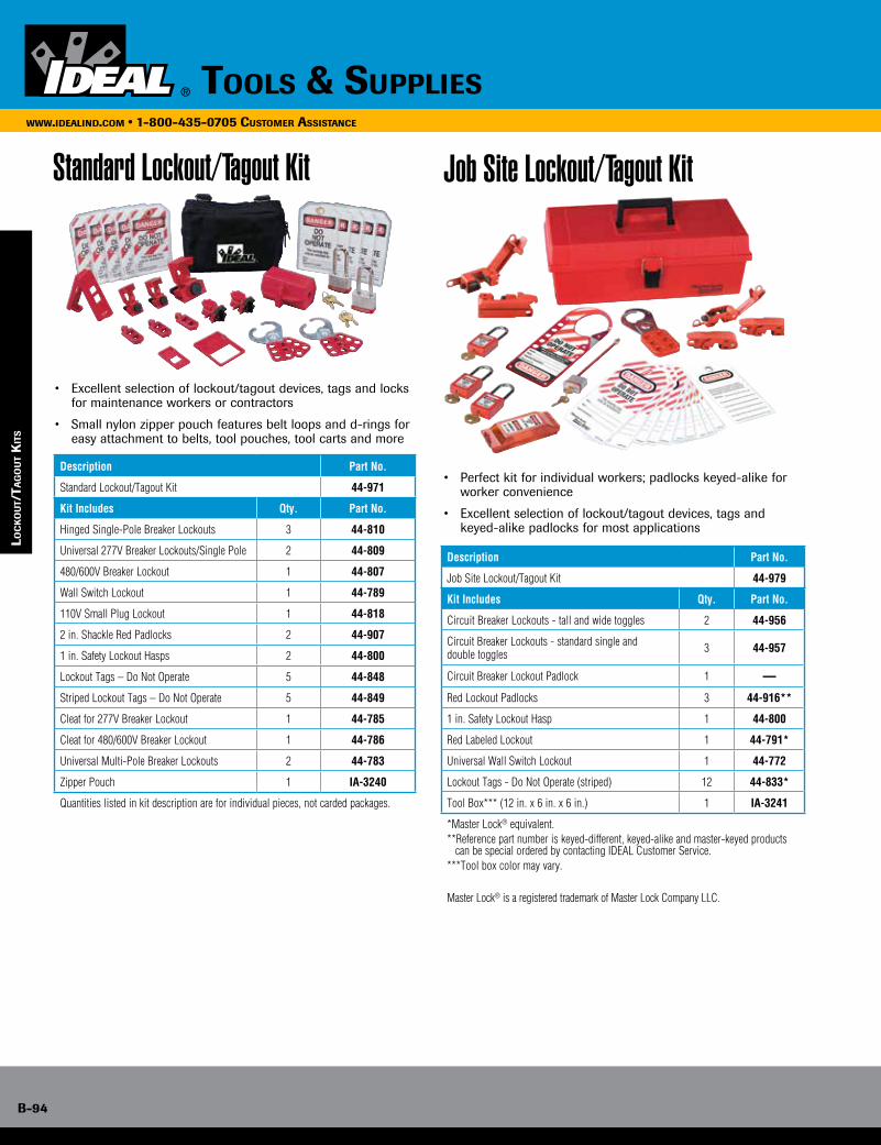
B-94
www.idealind.com • 1-800-435-0705 customer assistance
tools & supplies
loc
ko
uT/
Tag
ou
T k
iTs
Standard Lockout/Tagout Kit
• Excellent selection of lockout/tagout devices, tags and locks for maintenance workers or contractors
• Small nylon zipper pouch features belt loops and d-rings for easy attachment to belts, tool pouches, tool carts and more
Description Part No.
Standard Lockout/Tagout Kit 44-971
Kit Includes Qty. Part No.
Hinged Single-Pole Breaker Lockouts 3 44-810
Universal 277V Breaker Lockouts/Single Pole 2 44-809
480/600V Breaker Lockout 1 44-807
Wall Switch Lockout 1 44-789
110V Small Plug Lockout 1 44-818
2 in. Shackle Red Padlocks 2 44-907
1 in. Safety Lockout Hasps 2 44-800
Lockout Tags – Do Not Operate 5 44-848
Striped Lockout Tags – Do Not Operate 5 44-849
Cleat for 277V Breaker Lockout 1 44-785
Cleat for 480/600V Breaker Lockout 1 44-786
Universal Multi-Pole Breaker Lockouts 2 44-783
Zipper Pouch 1 IA-3240
Quantities listed in kit description are for individual pieces, not carded packages.
Job Site Lockout/Tagout Kit
• Perfect kit for individual workers; padlocks keyed-alike for worker convenience
• Excellent selection of lockout/tagout devices, tags and keyed-alike padlocks for most applications
Description Part No.
Job Site Lockout/Tagout Kit 44-979
Kit Includes Qty. Part No.
Circuit Breaker Lockouts - tall and wide toggles 2 44-956
Circuit Breaker Lockouts - standard single and double toggles 3 44-957
Circuit Breaker Lockout Padlock 1 —
Red Lockout Padlocks 3 44-916**
1 in. Safety Lockout Hasp 1 44-800
Red Labeled Lockout 1 44-791*
Universal Wall Switch Lockout 1 44-772
Lockout Tags - Do Not Operate (striped) 12 44-833*
Tool Box*** (12 in. x 6 in. x 6 in.) 1 IA-3241
*Master Lock® equivalent. **Reference part number is keyed-different, keyed-alike and master-keyed products
can be special ordered by contacting IDEAL Customer Service. ***Tool box color may vary.
Master Lock® is a registered trademark of Master Lock Company LLC.
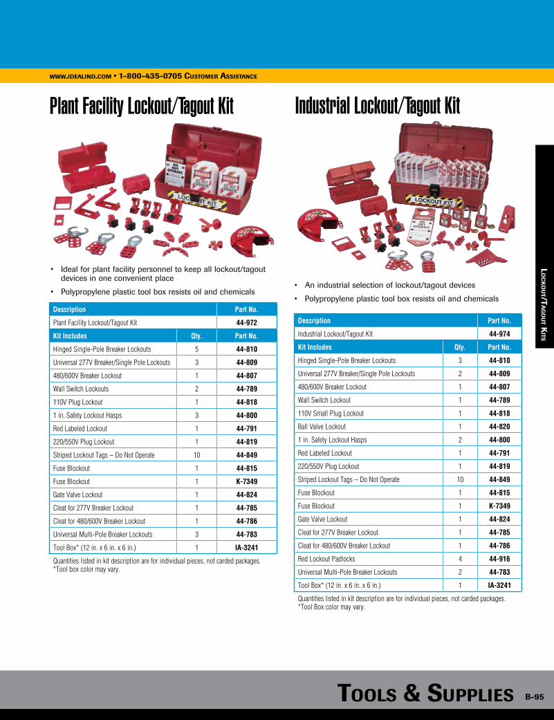
Tools & supplies B-95
www.idealind.com • 1-800-435-0705 customer assistance
lo
ck
ou
T/Ta
go
uT k
iTs
Plant Facility Lockout/Tagout Kit
• Ideal for plant facility personnel to keep all lockout/tagout devices in one convenient place
• Polypropylene plastic tool box resists oil and chemicals
Description Part No.
Plant Facility Lockout/Tagout Kit 44-972
Kit Includes Qty. Part No.
Hinged Single-Pole Breaker Lockouts 5 44-810
Universal 277V Breaker/Single Pole Lockouts 3 44-809
480/600V Breaker Lockout 1 44-807
Wall Switch Lockouts 2 44-789
110V Plug Lockout 1 44-818
1 in. Safety Lockout Hasps 3 44-800
Red Labeled Lockout 1 44-791
220/550V Plug Lockout 1 44-819
Striped Lockout Tags – Do Not Operate 10 44-849
Fuse Blockout 1 44-815
Fuse Blockout 1 K-7349
Gate Valve Lockout 1 44-824
Cleat for 277V Breaker Lockout 1 44-785
Cleat for 480/600V Breaker Lockout 1 44-786
Universal Multi-Pole Breaker Lockouts 3 44-783
Tool Box* (12 in. x 6 in. x 6 in.) 1 IA-3241
Quantities listed in kit description are for individual pieces, not carded packages. *Tool box color may vary.
Description Part No.
Industrial Lockout/Tagout Kit 44-974
Kit Includes Qty. Part No.
Hinged Single-Pole Breaker Lockouts 3 44-810
Universal 277V Breaker/Single Pole Lockouts 2 44-809
480/600V Breaker Lockout 1 44-807
Wall Switch Lockout 1 44-789
110V Small Plug Lockout 1 44-818
Ball Valve Lockout 1 44-820
1 in. Safety Lockout Hasps 2 44-800
Red Labeled Lockout 1 44-791
220/550V Plug Lockout 1 44-819
Striped Lockout Tags – Do Not Operate 10 44-849
Fuse Blockout 1 44-815
Fuse Blockout 1 K-7349
Gate Valve Lockout 1 44-824
Cleat for 277V Breaker Lockout 1 44-785
Cleat for 480/600V Breaker Lockout 1 44-786
Red Lockout Padlocks 4 44-916
Universal Multi-Pole Breaker Lockouts 2 44-783
Tool Box* (12 in. x 6 in. x 6 in.) 1 IA-3241
Quantities listed in kit description are for individual pieces, not carded packages. *Tool Box color may vary.
• An industrial selection of lockout/tagout devices
• Polypropylene plastic tool box resists oil and chemicals
Industrial Lockout/Tagout Kit
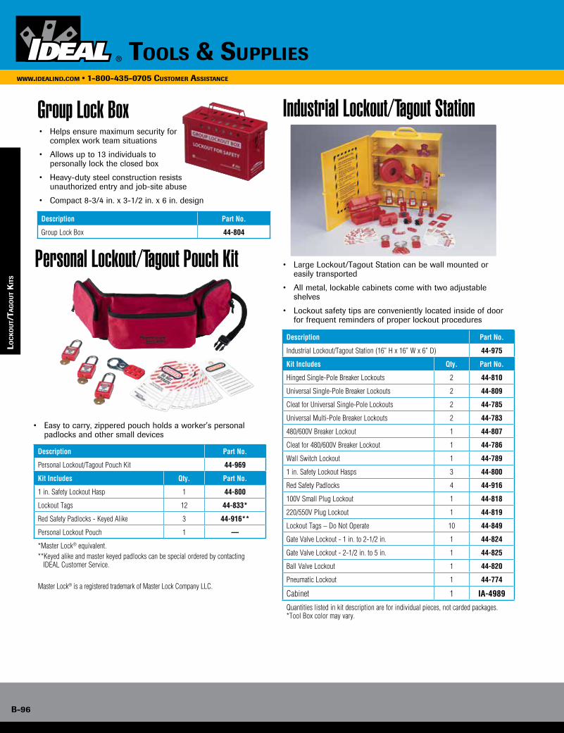
B-96
www.idealind.com • 1-800-435-0705 customer assistance
tools & supplies
Description Part No.
Industrial Lockout/Tagout Station (16” H x 16” W x 6” D) 44-975
Kit Includes Qty. Part No.
Hinged Single-Pole Breaker Lockouts 2 44-810
Universal Single-Pole Breaker Lockouts 2 44-809
Cleat for Universal Single-Pole Lockouts 2 44-785
Universal Multi-Pole Breaker Lockouts 2 44-783
480/600V Breaker Lockout 1 44-807
Cleat for 480/600V Breaker Lockout 1 44-786
Wall Switch Lockout 1 44-789
1 in. Safety Lockout Hasps 3 44-800
Red Safety Padlocks 4 44-916
100V Small Plug Lockout 1 44-818
220/550V Plug Lockout 1 44-819
Lockout Tags – Do Not Operate 10 44-849
Gate Valve Lockout - 1 in. to 2-1/2 in. 1 44-824
Gate Valve Lockout - 2-1/2 in. to 5 in. 1 44-825
Ball Valve Lockout 1 44-820
Pneumatic Lockout 1 44-774
Cabinet 1 IA-4989
Quantities listed in kit description are for individual pieces, not carded packages. *Tool Box color may vary.
Industrial Lockout/Tagout Station
• Large Lockout/Tagout Station can be wall mounted or easily transported
• All metal, lockable cabinets come with two adjustable shelves
• Lockout safety tips are conveniently located inside of door for frequent reminders of proper lockout procedures
Personal Lockout/Tagout Pouch Kit
• Easy to carry, zippered pouch holds a worker’s personal padlocks and other small devices
Group Lock Box• Helps ensure maximum security for complex work team situations
• Allows up to 13 individuals to personally lock the closed box
• Heavy-duty steel construction resists unauthorized entry and job-site abuse
• Compact 8-3/4 in. x 3-1/2 in. x 6 in. design
Description Part No.
Group Lock Box 44-804
Description Part No.
Personal Lockout/Tagout Pouch Kit 44-969
Kit Includes Qty. Part No.
1 in. Safety Lockout Hasp 1 44-800
Lockout Tags 12 44-833*
Red Safety Padlocks - Keyed Alike 3 44-916**
Personal Lockout Pouch 1 —
*Master Lock® equivalent. **Keyed alike and master keyed padlocks can be special ordered by contacting
IDEAL Customer Service.
Master Lock® is a registered trademark of Master Lock Company LLC.
loc
ko
uT/
Tag
ou
T k
iTs
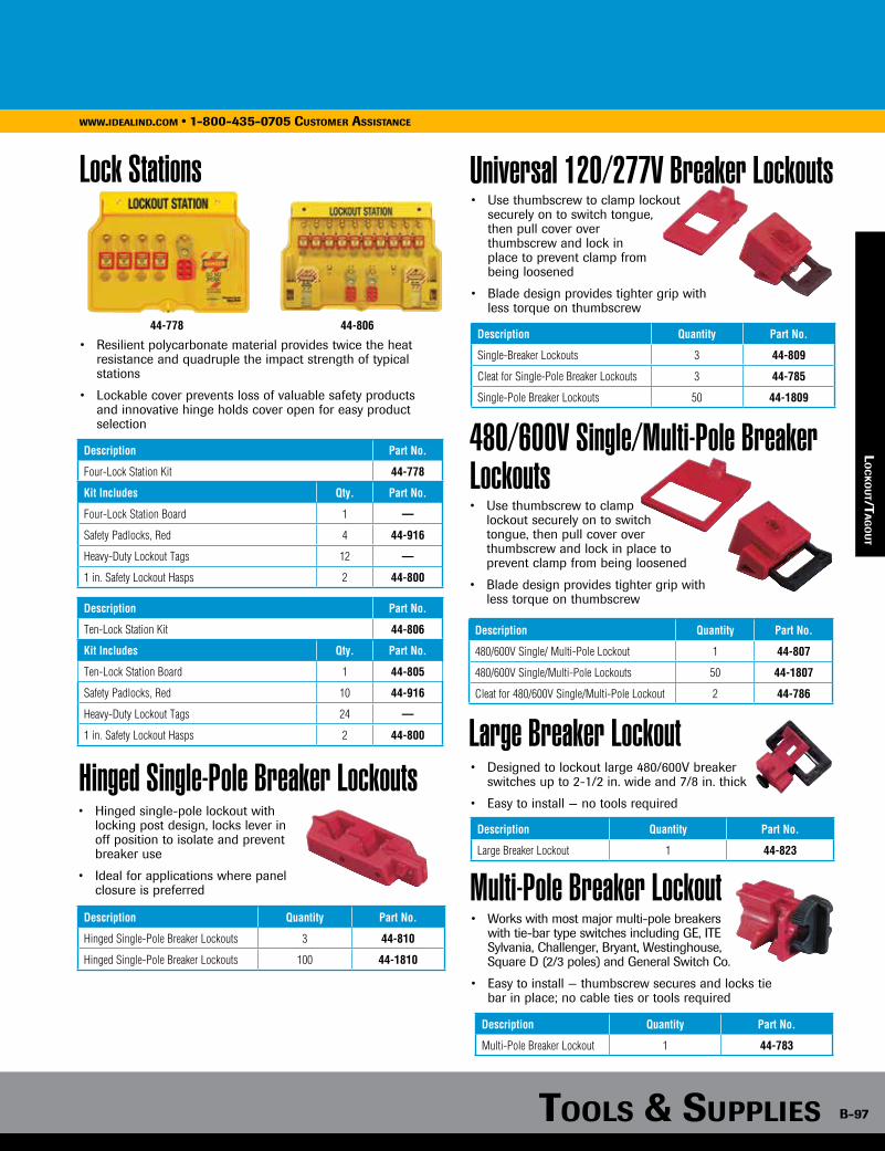
Tools & supplies B-97
www.idealind.com • 1-800-435-0705 customer assistance
Industrial Lockout/Tagout Station Lock Stations
• Resilient polycarbonate material provides twice the heat resistance and quadruple the impact strength of typical stations
• Lockable cover prevents loss of valuable safety products and innovative hinge holds cover open for easy product selection
Hinged Single-Pole Breaker Lockouts• Hinged single-pole lockout with
locking post design, locks lever in off position to isolate and prevent breaker use
• Ideal for applications where panel closure is preferred
Description Quantity Part No.
Hinged Single-Pole Breaker Lockouts 3 44-810
Hinged Single-Pole Breaker Lockouts 100 44-1810
Universal 120/277V Breaker Lockouts• Use thumbscrew to clamp lockout securely on to switch tongue, then pull cover over thumbscrew and lock in place to prevent clamp from being loosened
• Blade design provides tighter grip with less torque on thumbscrew
Description Quantity Part No.
Single-Breaker Lockouts 3 44-809
Cleat for Single-Pole Breaker Lockouts 3 44-785
Single-Pole Breaker Lockouts 50 44-1809
480/600V Single/Multi-Pole Breaker Lockouts• Use thumbscrew to clamp lockout securely on to switch tongue, then pull cover over thumbscrew and lock in place to prevent clamp from being loosened
• Blade design provides tighter grip with less torque on thumbscrew
Description Quantity Part No.
480/600V Single/ Multi-Pole Lockout 1 44-807
480/600V Single/Multi-Pole Lockouts 50 44-1807
Cleat for 480/600V Single/Multi-Pole Lockout 2 44-786
Large Breaker Lockout• Designed to lockout large 480/600V breaker
switches up to 2-1/2 in. wide and 7/8 in. thick
• Easy to install — no tools required
• Works with most major multi-pole breakers with tie-bar type switches including GE, ITE Sylvania, Challenger, Bryant, Westinghouse, Square D (2/3 poles) and General Switch Co.
• Easy to install — thumbscrew secures and locks tie bar in place; no cable ties or tools required
Description Quantity Part No.
Large Breaker Lockout 1 44-823
Multi-Pole Breaker Lockout
Description Quantity Part No.
Multi-Pole Breaker Lockout 1 44-783
44-778 44-806
Description Part No.
Four-Lock Station Kit 44-778
Kit Includes Qty. Part No.
Four-Lock Station Board 1 —
Safety Padlocks, Red 4 44-916
Heavy-Duty Lockout Tags 12 —
1 in. Safety Lockout Hasps 2 44-800
Description Part No.
Ten-Lock Station Kit 44-806
Kit Includes Qty. Part No.
Ten-Lock Station Board 1 44-805
Safety Padlocks, Red 10 44-916
Heavy-Duty Lockout Tags 24 —
1 in. Safety Lockout Hasps 2 44-800
lo
ck
ou
T/Ta
go
uT

B-98
www.idealind.com • 1-800-435-0705 customer assistance
tools & supplies
loc
ko
uT/
Tag
ou
T
Circuit Breaker Lockouts
• Attaches securely to breaker with simple thumb turn and clamping handle
• 44-956 is designed for breakers with wide or tall toggles
• 44-957 fits standard height and tie-bar toggles
• The narrow profile permits side-by-side breaker lockout
Description Part No.
Circuit Breaker Lockout 44-956
Circuit Breaker Lockout 44-957
Circuit Breaker Lockout System• Covers most 120V - 277V breakers
• Works on wide range of breakers, including single- and multi-pole configurations
• Makes use of unique lock rail system, providing the following benefits: - Allows panel door to be closed even when lockouts are in place - Accommodates multiple locks, facilitating group lockout activity without hasps - Keeps weight off the breakers, protecting delicate electrical
components from damage - Positions locks and tags outside the panel, making sure
lockout activity is clearly visible to anyone in the area
• Technical Information – Lockout devices constructed of high-impact Isoplast
polymers – Cables are 2 ft. in length – Lock rails made of durable isoplast polymers with acrylic
adhesive backing
• Snap-on – For use on Square D NQO and other breakers that have a hole in the switch tongue. Just align pins with hole and snap closed. Pins prevent switch from being thrown.
• Clamp-on – For use on breakers that do not have a hole in the switch tongue, including multiple breakers with tie bars. Turn thumb-screw to clamp lockout securely onto switch, then snap the cover closed to prevent thumb wheel from being loosened.
Description Quantity Part No.
Snap-on lockout for Square D NQO and other breakers with a hole in the switch tongue 1 44-768
Clamp-on lockout for breakers without hole in the switch tongue, including multi-pole breakers with tie bars
1 44-764
4 in. Lock Rail with seven lock loops 1 44-769
Oversized Circuit Breaker Lockout System• Unique Lockout system for over- sized 480/600V Circuit Breakers
• System can be permanently installed into an electrical panel putting all lockout items at the point
of need
• Easy installation of adhesive mounting rails – no tools required
• Pegs in mounting rails mate with holes in locking arms for security of arm when lock is in place
• Red arms lock off, green arms lock on
Description Quantity Part No.
Oversized Circuit Breaker System 1 44-822
44-957
44-764Clamp-on
44-768Snap-on
44-956
Plug Lockouts• Accommodates a variety of electrical plug and cord sizes to prevent accidental connection or disconnection
• Durable plastic body resists wear, chemicals and job-site abuse
• Accommodates cable ties or padlocks (with up to 3/8 in. shackles)
Description Size (in.) Part No.
Plug Lockouts - 100V 2 x 2 x 3-1/2 44-818
Plug Lockouts - 220/550V 3-1/4 x 3-1/4 x 7 44-819
44-819
Plug Lockouts• Plug lockout, 44-792 works with high and low voltage plugs up to 3 in. in diameter and 5-1/2 in. in length, up to 1-1/4 in. cord diameter
• Plug lockout, 44-973 works with 110V/220V plugs up to 1-3/4 in. in diameter and 2-1/2 in. in length, up to a 1/2 in. cord diameter
Description Part No.
Plug Lockout 44-792
Plug Lockout 44-793
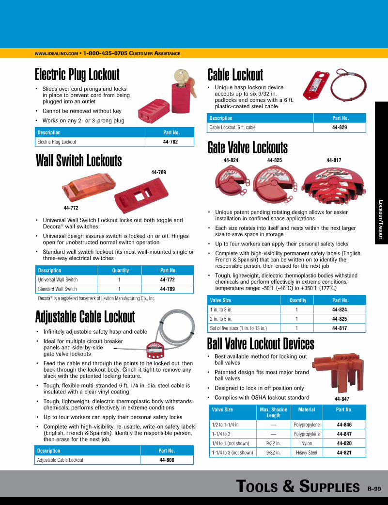
Tools & supplies B-99
www.idealind.com • 1-800-435-0705 customer assistance
Circuit Breaker Lockout System
Plug Lockouts
lo
ck
ou
T/Ta
go
uT
Electric Plug Lockout• Slides over cord prongs and locks
in place to prevent cord from being plugged into an outlet
• Cannot be removed without key
• Works on any 2- or 3-prong plug
Description Part No.
Electric Plug Lockout 44-782
Wall Switch Lockouts
• Universal Wall Switch Lockout locks out both toggle and Decora® wall switches
• Universal design assures switch is locked on or off. Hinges open for unobstructed normal switch operation
• Standard wall switch lockout fits most wall-mounted single or three-way electrical switches
Description Quantity Part No.
Universal Wall Switch 1 44-772
Standard Wall Switch 1 44-789
Decora® is a registered trademark of Leviton Manufacturing Co., Inc.
44-789
44-772
Adjustable Cable Lockout• Infinitely adjustable safety hasp and cable
• Ideal for multiple circuit breaker panels and side-by-side gate valve lockouts
• Feed the cable end through the points to be locked out, then back through the lockout body. Cinch it tight to remove any slack with the patented locking feature.
• Tough, flexible multi-stranded 6 ft. 1/4 in. dia. steel cable is insulated with a clear vinyl coating
• Tough, lightweight, dielectric thermoplastic body withstands chemicals; performs effectively in extreme conditions
• Up to four workers can apply their personal safety locks
• Complete with high-visibility, re-usable, write-on safety labels (English, French & Spanish). Identify the responsible person,
then erase for the next job.
Description Part No.
Adjustable Cable Lockout 44-808
Gate Valve Lockouts
Valve Size Quantity Part No.
1 in. to 3 in. 1 44-824
2 in. to 5 in. 1 44-825
Set of five sizes (1 in. to 13 in.) 1 44-817
• Unique patent pending rotating design allows for easier installation in confined space applications
• Each size rotates into itself and nests within the next larger size to save space in storage
• Up to four workers can apply their personal safety locks
• Complete with high-visibility permanent safety labels (English, French & Spanish) that can be written on to identify the responsible person, then erased for the next job
• Tough, lightweight, dielectric thermoplastic bodies withstand chemicals and perform effectively in extreme conditions, temperature range: -50°F (-46°C) to +350°F (177°C)
Cable Lockout
Description Part No.
Cable Lockout, 6 ft. cable 44-829
• Unique hasp lockout device accepts up to six 9/32 in. padlocks and comes with a 6 ft. plastic-coated steel cable
44-824 44-825 44-817
Ball Valve Lockout Devices• Best available method for locking out
ball valves
• Patented design fits most major brand ball valves
• Designed to lock in off position only
• Complies with OSHA lockout standard
Valve Size Max. Shackle Length
Material Part No.
1/2 to 1-1/4 in. — Polypropylene 44-846
1-1/4 to 3 — Polypropylene 44-847
1/4 to 1 (not shown) 9/32 in. Nylon 44-820
1-1/4 to 3 (not shown) 9/32 in. Heavy Steel 44-821
44-847
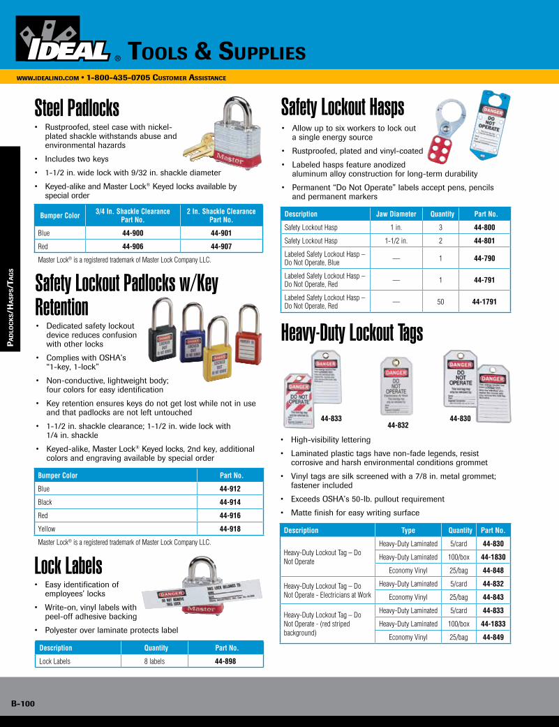
B-100
www.idealind.com • 1-800-435-0705 customer assistance
tools & supplies
pa
dlo
ck
s/h
as
ps/T
ag
s
44-83044-83344-832
Steel Padlocks
Safety Lockout Padlocks w/Key Retention
• Rustproofed, steel case with nickel-plated shackle withstands abuse and environmental hazards
• Includes two keys
• 1-1/2 in. wide lock with 9/32 in. shackle diameter
• Keyed-alike and Master Lock® Keyed locks available by special order
Bumper Color 3/4 In. Shackle ClearancePart No.
2 In. Shackle ClearancePart No.
Blue 44-900 44-901
Red 44-906 44-907
Master Lock® is a registered trademark of Master Lock Company LLC.
• Dedicated safety lockout device reduces confusion with other locks
• Complies with OSHA’s “1-key, 1-lock”
• Non-conductive, lightweight body; four colors for easy identification
• Key retention ensures keys do not get lost while not in use and that padlocks are not left untouched
• 1-1/2 in. shackle clearance; 1-1/2 in. wide lock with 1/4 in. shackle
• Keyed-alike, Master Lock® Keyed locks, 2nd key, additional colors and engraving available by special order
Bumper Color Part No.
Blue 44-912
Black 44-914
Red 44-916
Yellow 44-918
Master Lock® is a registered trademark of Master Lock Company LLC.
Lock Labels• Easy identification of employees’ locks
• Write-on, vinyl labels with peel-off adhesive backing
• Polyester over laminate protects label
Description Quantity Part No.
Lock Labels 8 labels 44-898
Safety Lockout Hasps
Heavy-Duty Lockout Tags
• Allow up to six workers to lock out a single energy source
• Rustproofed, plated and vinyl-coated
• Labeled hasps feature anodized aluminum alloy construction for long-term durability
• Permanent “Do Not Operate” labels accept pens, pencils and permanent markers
Description Jaw Diameter Quantity Part No.
Safety Lockout Hasp 1 in. 3 44-800
Safety Lockout Hasp 1-1/2 in. 2 44-801
Labeled Safety Lockout Hasp – Do Not Operate, Blue — 1 44-790
Labeled Safety Lockout Hasp – Do Not Operate, Red — 1 44-791
Labeled Safety Lockout Hasp – Do Not Operate, Red — 50 44-1791
• High-visibility lettering
• Laminated plastic tags have non-fade legends, resist corrosive and harsh environmental conditions grommet
• Vinyl tags are silk screened with a 7/8 in. metal grommet; fastener included
• Exceeds OSHA’s 50-lb. pullout requirement
• Matte finish for easy writing surface
Description Type Quantity Part No.
Heavy-Duty Lockout Tag – Do Not Operate
Heavy-Duty Laminated 5/card 44-830
Heavy-Duty Laminated 100/box 44-1830
Economy Vinyl 25/bag 44-848
Heavy-Duty Lockout Tag – Do Not Operate - Electricians at Work
Heavy-Duty Laminated 5/card 44-832
Economy Vinyl 25/bag 44-843
Heavy-Duty Lockout Tag – Do Not Operate - (red striped background)
Heavy-Duty Laminated 5/card 44-833
Heavy-Duty Laminated 100/box 44-1833
Economy Vinyl 25/bag 44-849
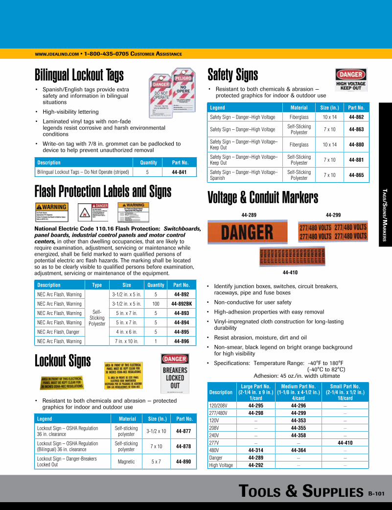
Tools & supplies B-101
www.idealind.com • 1-800-435-0705 customer assistance
Bumper Color 3/4 In. Shackle ClearancePart No.
2 In. Shackle ClearancePart No.
Blue 44-900 44-901
Red 44-906 44-907
Master Lock® is a registered trademark of Master Lock Company LLC.
Safety Lockout Hasps
Heavy-Duty Lockout Tags
Ta
gs/s
ign
s/ma
rk
ers
Bilingual Lockout Tags
Flash Protection Labels and Signs
Lockout Signs
Safety Signs• Spanish/English tags provide extra safety and information in bilingual situations
• High-visibility lettering
• Laminated vinyl tags with non-fade legends resist corrosive and harsh environmental
conditions
• Write-on tag with 7/8 in. grommet can be padlocked to device to help prevent unauthorized removal
Description Quantity Part No.
Bilingual Lockout Tags – Do Not Operate (striped) 5 44-841
National Electric Code 110.16 Flash Protection: Switchboards, panel boards, industrial control panels and motor control centers, in other than dwelling occupancies, that are likely to require examination, adjustment, servicing or maintenance while energized, shall be field marked to warn qualified persons of potential electric arc flash hazards. The marking shall be located so as to be clearly visible to qualified persons before examination, adjustment, servicing or maintenance of the equipment.
Description Type Size Quantity Part No.
NEC Arc Flash, Warning
Self-Sticking Polyester
3-1/2 in. x 5 in. 5 44-892
NEC Arc Flash, Warning 3-1/2 in. x 5 in. 100 44-892BK
NEC Arc Flash, Warning 5 in. x 7 in. 5 44-893
NEC Arc Flash, Warning 5 in. x 7 in. 5 44-894
NEC Arc Flash, Danger 4 in. x 6 in. 5 44-895
NEC Arc Flash, Warning 7 in. x 10 in. 1 44-896
Legend Material Size (In.) Part No.
Lockout Sign – OSHA Regulation 36 in. clearance
Self-sticking polyester 3-1/2 x 10 44-877
Lockout Sign – OSHA Regulation (Bilingual) 36 in. clearance
Self-sticking polyester 7 x 10 44-878
Lockout Sign – Danger-Breakers Locked Out Magnetic 5 x 7 44-890
• Resistant to both chemicals and abrasion — protected graphics for indoor and outdoor use
• Resistant to both chemicals & abrasion — protected graphics for indoor & outdoor use
Legend Material Size (In.) Part No.
Safety Sign – Danger–High Voltage Fiberglass 10 x 14 44-862
Safety Sign – Danger–High Voltage Self-Sticking Polyester 7 x 10 44-863
Safety Sign – Danger–High Voltage–Keep Out Fiberglass 10 x 14 44-880
Safety Sign – Danger–High Voltage–Keep Out
Self-Sticking Polyester 7 x 10 44-881
Safety Sign – Danger–High Voltage–Spanish
Self-Sticking Polyester 7 x 10 44-865
Voltage & Conduit Markers
• Identify junction boxes, switches, circuit breakers, raceways, pipe and fuse boxes
• Non-conductive for user safety
• High-adhesion properties with easy removal
• Vinyl-impregnated cloth construction for long-lasting durability
• Resist abrasion, moisture, dirt and oil
• Non-smear, black legend on bright orange background for high visibility
• Specifications: Temperature Range: -40°F to 180°F (-40°C to 82°C)
Adhesion: 45 oz./in. width ultimate
DescriptionLarge Part No.
(2-1/4 in. x 9 in.)1/card
Medium Part No.(1-1/8 in. x 4-1/2 in.)
4/card
Small Part No.(2-1/4 in. x 1/2 in.)
18/card120/208V 44-295 44-296 —
277/480V 44-298 44-299 —
120V — 44-353 —
208V — 44-355 —
240V — 44-358 —
277V — — 44-410480V 44-314 44-364 —
Danger 44-289 — —
High Voltage 44-292 — —
44-289 44-299
44-410
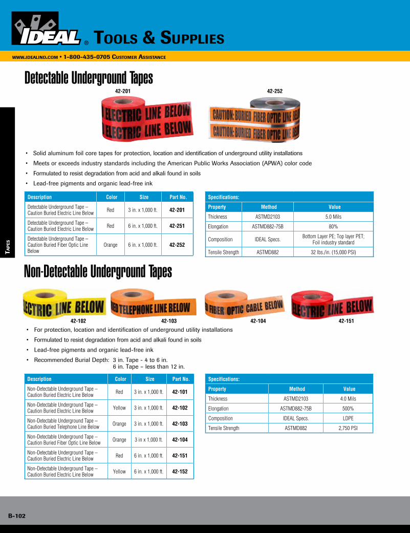
B-102
www.idealind.com • 1-800-435-0705 customer assistance
tools & supplies
Tap
es
Detectable Underground Tapes
• Solid aluminum foil core tapes for protection, location and identification of underground utility installations
• Meets or exceeds industry standards including the American Public Works Association (APWA) color code
• Formulated to resist degradation from acid and alkali found in soils
• Lead-free pigments and organic lead-free ink
Description Color Size Part No.
Detectable Underground Tape – Caution Buried Electric Line Below Red 3 in. x 1,000 ft. 42-201
Detectable Underground Tape – Caution Buried Electric Line Below Red 6 in. x 1,000 ft. 42-251
Detectable Underground Tape – Caution Buried Fiber Optic Line Below
Orange 6 in. x 1,000 ft. 42-252
Specifications:
Property Method Value
Thickness ASTMD2103 5.0 Mils
Elongation ASTMD882-75B 80%
Composition IDEAL Specs. Bottom Layer PE; Top layer PET;Foil industry standard
Tensile Strength ASTMD882 32 lbs./in. (15,000 PSI)
42-201 42-252
Non-Detectable Underground Tapes
• For protection, location and identification of underground utility installations
• Formulated to resist degradation from acid and alkali found in soils
• Lead-free pigments and organic lead-free ink
• Recommended Burial Depth: 3 in. Tape - 4 to 6 in. 6 in. Tape – less than 12 in.
Description Color Size Part No.
Non-Detectable Underground Tape – Caution Buried Electric Line Below Red 3 in. x 1,000 ft. 42-101
Non-Detectable Underground Tape – Caution Buried Electric Line Below Yellow 3 in. x 1,000 ft. 42-102
Non-Detectable Underground Tape – Caution Buried Telephone Line Below Orange 3 in. x 1,000 ft. 42-103
Non-Detectable Underground Tape – Caution Buried Fiber Optic Line Below Orange 3 in x 1,000 ft. 42-104
Non-Detectable Underground Tape – Caution Buried Electric Line Below Red 6 in. x 1,000 ft. 42-151
Non-Detectable Underground Tape – Caution Buried Electric Line Below Yellow 6 in. x 1,000 ft. 42-152
Specifications:
Property Method Value
Thickness ASTMD2103 4.0 Mils
Elongation ASTMD882-75B 500%
Composition IDEAL Specs. LDPE
Tensile Strength ASTMD882 2,750 PSI
42-102 42-103 42-104 42-151

Tools & supplies B-103
www.idealind.com • 1-800-435-0705 customer assistance
Ta
pes
Python™ Adjustable Locking CablePython™ Adjustable Locking Cable secures anything within its grasp. The only locking cable that is right length for your application. This patented product holds flexible steel cable tight at any position
• Infinite Locking Positions – Patented lock holds cable tight from 1 ft. (30cm) to 6 ft. (1.8m)
• Application Flexibility – Interchangeable cables
• Keyed Alike Convenience – Rekeyable cylinder
• Cut Resistance – 3/8 in. (10mm), 100% steel braided cable
• Weather Tough – Rust resistant aluminum lock body
• Scratch Resistant – Vinyl cable sleeve and lock body bumper
Other Applications: Bikes, lawn furniture, lawn mowers, job sites, canoes, boats, skis, snowboards, generators, pickup truck cargo, spare tire locks and much more.
Description Part No.
Master Lock® Python™ Kit with 6 ft. Cable-keyed different 44-990
Master Lock® Python™ Kit with 6 ft. Cable-keyed alike* 44-991
12 ft. (3.7m) x 3/8 in. (10mm) Cable for Python™ Lock* 44-992
*Special order through Customer Service.
Master Lock® is a registered trademark of Master Lock Company LLC.Python™ is a trademark of Master Lock Company LLC.
Barricade Tapes
Specifications:
Property Method Value
Elongation ASTMD882-75B > 400%
Composition IDEAL Specs. LDPE
Tensile Strength ASTMD882 2,350 PSI TD; 1,893 PSI MD
• High-visibility safety yellow or red polyethylene construction with bold black letters
• Meets OSHA specifications Section 1010.144 for marking physical hazards
Description Color Size Thickness Part No.
Barricade Tape – Caution Yellow 3 in. x 1,000 ft. 4.0 Mils 42-001
Barricade Tape – Caution Do Not Enter Yellow 3 in. x 1,000 ft. 4.0 Mils 42-002
Barricade Tape – Caution High Voltage Yellow 3 in. x 1,000 ft. 4.0 Mils 42-003
Barricade Tape – DangerHigh Voltage Red 3 in. x 1,000 ft. 4.0 Mils 42-051
Barricade Tape – Danger High Voltage Keep Out Red 3 in. x 1,000 ft. 4.0 Mils 42-052
Barricade Tape – Caution Do Not Enter Yellow 3 in. x 1,000 ft. 2.0 Mils 42-012
42-002 42-051 42-003
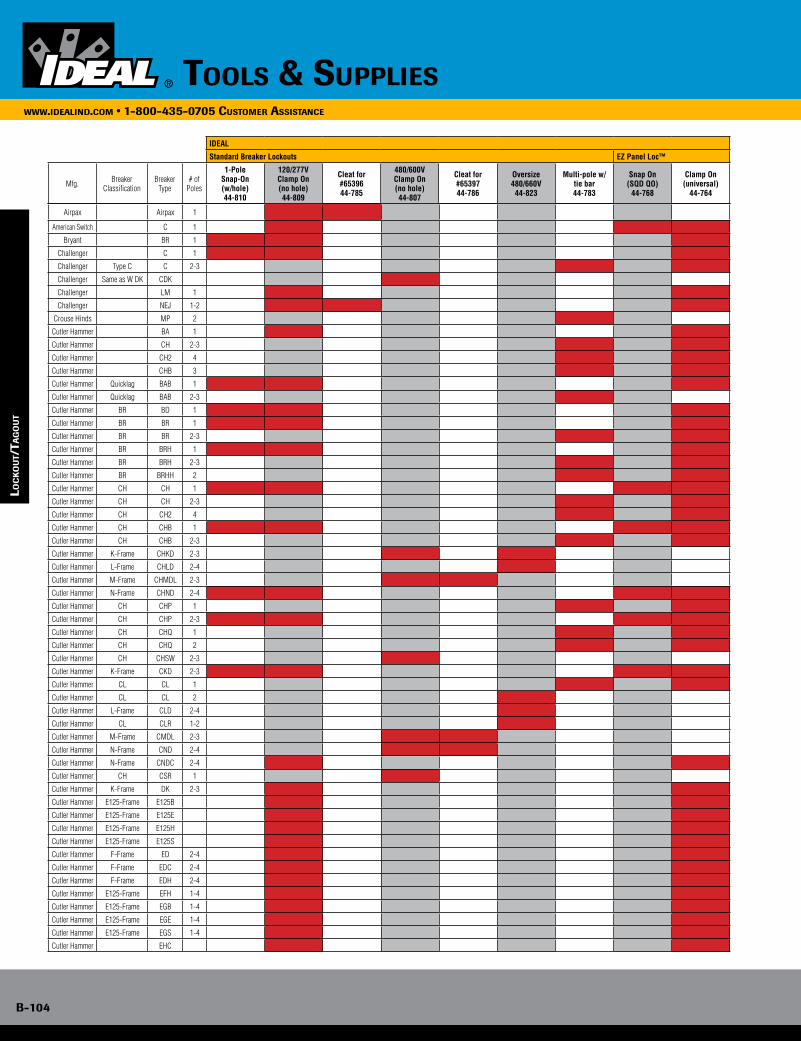
B-104
www.idealind.com • 1-800-435-0705 customer assistance
tools & supplies
Airpax Airpax 1
American Switch C 1
Bryant BR 1
Challenger C 1
Challenger Type C C 2-3
Challenger Same as W DK CDK
Challenger LM 1
Challenger NEJ 1-2
Crouse Hinds MP 2
Cutler Hammer BA 1
Cutler Hammer CH 2-3
Cutler Hammer CH2 4
Cutler Hammer CHB 3
Cutler Hammer Quicklag BAB 1
Cutler Hammer Quicklag BAB 2-3
Cutler Hammer BR BD 1
Cutler Hammer BR BR 1
Cutler Hammer BR BR 2-3
Cutler Hammer BR BRH 1
Cutler Hammer BR BRH 2-3
Cutler Hammer BR BRHH 2
Cutler Hammer CH CH 1
Cutler Hammer CH CH 2-3
Cutler Hammer CH CH2 4
Cutler Hammer CH CHB 1
Cutler Hammer CH CHB 2-3
Cutler Hammer K-Frame CHKD 2-3
Cutler Hammer L-Frame CHLD 2-4
Cutler Hammer M-Frame CHMDL 2-3
Cutler Hammer N-Frame CHND 2-4
Cutler Hammer CH CHP 1
Cutler Hammer CH CHP 2-3
Cutler Hammer CH CHQ 1
Cutler Hammer CH CHQ 2
Cutler Hammer CH CHSW 2-3
Cutler Hammer K-Frame CKD 2-3
Cutler Hammer CL CL 1
Cutler Hammer CL CL 2
Cutler Hammer L-Frame CLD 2-4
Cutler Hammer CL CLR 1-2
Cutler Hammer M-Frame CMDL 2-3
Cutler Hammer N-Frame CND 2-4
Cutler Hammer N-Frame CNDC 2-4
Cutler Hammer CH CSR 1
Cutler Hammer K-Frame DK 2-3
Cutler Hammer E125-Frame E125B
Cutler Hammer E125-Frame E125E
Cutler Hammer E125-Frame E125H
Cutler Hammer E125-Frame E125S
Cutler Hammer F-Frame ED 2-4
Cutler Hammer F-Frame EDC 2-4
Cutler Hammer F-Frame EDH 2-4
Cutler Hammer E125-Frame EFH 1-4
Cutler Hammer E125-Frame EGB 1-4
Cutler Hammer E125-Frame EGE 1-4
Cutler Hammer E125-Frame EGS 1-4
Cutler Hammer EHC
IDEAL
Standard Breaker Lockouts EZ Panel Loc™
Mfg. Breaker Classification
Breaker Type
# of Poles
1-PoleSnap-On(w/hole)44-810
120/277VClamp On(no hole)44-809
Cleat for #6539644-785
480/600VClamp On(no hole)44-807
Cleat for #6539744-786
Oversize480/660V
44-823
Multi-pole w/tie bar44-783
Snap On(SQD QO)
44-768
Clamp On(universal)
44-764
loc
ko
uT/
Tag
ou
T
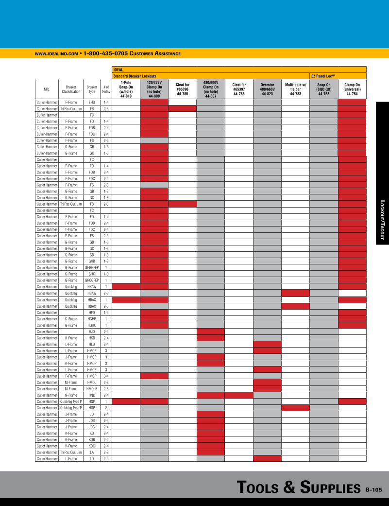
Tools & supplies B-105
www.idealind.com • 1-800-435-0705 customer assistance
IDEAL
Standard Breaker Lockouts EZ Panel Loc™
Mfg. Breaker Classification
Breaker Type
# of Poles
1-PoleSnap-On(w/hole)44-810
120/277VClamp On(no hole)44-809
Cleat for #6539644-785
480/600VClamp On(no hole)44-807
Cleat for #6539744-786
Oversize480/660V44-823
Multi-pole w/tie bar44-783
Snap On(SQD QO)
44-768
Clamp On(universal)
44-764
Cutler Hammer F-Frame EHD 1-4
Cutler Hammer Tri Pac Cur. Lim FB 2-3
Cutler Hammer FC
Cutler Hammer F-Frame FD 1-4
Cutler Hammer F-Frame FDB 2-4
Cutler-Hammer F-Frame FDC 2-4
Cutler-Hammer F-Frame FS 2-3
Cutler-Hammer G-Frame GB 1-3
Cutler-Hammer G-Frame GC 1-3
Cutler Hammer FC
Cutler Hammer F-Frame FD 1-4
Cutler Hammer F-Frame FDB 2-4
Cutler Hammer F-Frame FDC 2-4
Cutler Hammer F-Frame FS 2-3
Cutler Hammer G-Frame GB 1-3
Cutler Hammer G-Frame GC 1-3
Cutler Hammer Tri Pac Cur. Lim FB 2-3
Cutler Hammer FC
Cutler Hammer F-Frame FD 1-4
Cutler Hammer F-Frame FDB 2-4
Cutler Hammer F-Frame FDC 2-4
Cutler Hammer F-Frame FS 2-3
Cutler Hammer G-Frame GB 1-3
Cutler Hammer G-Frame GC 1-3
Cutler Hammer G-Frame GD 1-3
Cutler Hammer G-Frame GHB 1-3
Cutler Hammer G-Frame GHBGFEP 1
Cutler Hammer G-Frame GHC 1-3
Cutler Hammer G-Frame GHCGFEP 1
Cutler Hammer Quicklag HBAW 1
Cutler Hammer Quicklag HBAW 2-3
Cutler Hammer Quicklag HBAX 1
Cutler Hammer Quicklag HBAX 2-3
Cutler Hammer HFD 1-4
Cutler Hammer G-Frame HGHB 1
Cutler Hammer G-Frame HGHC 1
Cutler Hammer HJD 2-4
Cutler Hammer K-Frame HKD 2-4
Cutler Hammer L-Frame HLD 2-4
Cutler Hammer L-Frame HMCP 3
Cutler Hammer J-Frame HMCP 3
Cutler Hammer K-Frame HMCP 3
Cutler Hammer L-Frame HMCP 3
Cutler Hammer F-Frame HMCP 3-4
Cutler Hammer M-Frame HMDL 2-3
Cutler Hammer M-Frame HMDLB 2-3
Cutler Hammer N-Frame HND 2-4
Cutler Hammer Quicklag Type P HQP 1
Cutler Hammer Quicklag Type P HQP 2
Cutler Hammer J-Frame JD 2-4
Cutler Hammer J-Frame JDB 2-3
Cutler Hammer J-Frame JDC 2-4
Cutler Hammer K-Frame KD 2-4
Cutler Hammer K-Frame KDB 2-4
Cutler Hammer K-Frame KDC 2-4
Cutler Hammer Tri Pac Cur. Lim LA 2-3
Cutler Hammer L-Frame LD 2-4
lo
ck
ou
T/Ta
go
uT
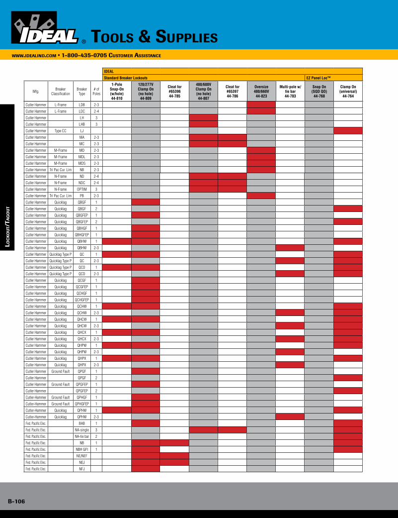
B-106
www.idealind.com • 1-800-435-0705 customer assistance
tools & supplies
IDEAL
Standard Breaker Lockouts EZ Panel Loc™
Mfg. Breaker Classification
Breaker Type
# of Poles
1-PoleSnap-On(w/hole)44-810
120/277VClamp On(no hole)44-809
Cleat for #6539644-785
480/600VClamp On(no hole)44-807
Cleat for #6539744-786
Oversize480/660V
44-823
Multi-pole w/tie bar44-783
Snap On(SQD QO)
44-768
Clamp On(universal)
44-764
lo
ck
ou
T/Ta
go
uT
Cutler Hammer L-Frame LDB 2-3
Cutler Hammer L-Frame LDC 2-4
Cutler Hammer LH 3
Cutler Hammer LHB 3
Cutler Hammer Type CC LJ
Cutler Hammer MA 2-3
Cutler Hammer MC 2-3
Cutler Hammer M-Frame MD 2-3
Cutler Hammer M-Frame MDL 2-3
Cutler Hammer M-Frame MDS 2-3
Cutler Hammer Tri Pac Cur. Lim NB 2-3
Cutler Hammer N-Frame ND 2-4
Cutler Hammer N-Frame NDC 2-4
Cutler Hammer N-Frame OPTIM 3
Cutler Hammer Tri Pac Cur. Lim PB 2-3
Cutler Hammer Quicklag QBGF 1
Cutler Hammer Quicklag QBGF 2
Cutler Hammer Quicklag QBGFEP 1
Cutler Hammer Quicklag QBGFEP 2
Cutler Hammer Quicklag QBHGF 1
Cutler Hammer Quicklag QBHGFEP 1
Cutler Hammer Quicklag QBHW 1
Cutler Hammer Quicklag QBHW 2-3
Cutler Hammer Quicklag Type P QC 1
Cutler Hammer Quicklag Type P QC 2-3
Cutler Hammer Quicklag Type P QCD 1
Cutler Hammer Quicklag Type P QCD 2-3
Cutler Hammer Quicklag QCGF 1
Cutler Hammer Quicklag QCGFEP 1
Cutler Hammer Quicklag QCHGF 1
Cutler Hammer Quicklag QCHGFEP 1
Cutler Hammer Quicklag QCHW 1
Cutler Hammer Quicklag QCHW 2-3
Cutler Hammer Quicklag QHCW 1
Cutler Hammer Quicklag QHCW 2-3
Cutler Hammer Quicklag QHCX 1
Cutler Hammer Quicklag QHCX 2-3
Cutler Hammer Quicklag QHPW 1
Cutler Hammer Quicklag QHPW 2-3
Cutler Hammer Quicklag QHPX 1
Cutler Hammer Quicklag QHPX 2-3
Cutler Hammer Ground Fault QPGF 1
Cutler Hammer QPGF 2
Cutler Hammer Ground Fault QPGFEP 1
Cutler Hammer QPGFEP 2
Cutler-Hammer Ground Fault QPHGF 1
Cutler-Hammer Ground Fault QPHGFEP 1
Cutler-Hammer Quicklag QPHW 1
Cutler-Hammer Quicklag QPHW 2-3
Fed. Pacific Elec. BAB 1
Fed. Pacific Elec. NA-single 3
Fed. Pacific Elec. NA-tie bar 2
Fed. Pacific Elec. NB 1
Fed. Pacific Elec. NBH GFI 1
Fed. Pacific Elec. NE/NEF
Fed. Pacific Elec. NEJ
Fed. Pacific Elec. NFJ
loc
ko
uT/
Tag
ou
T
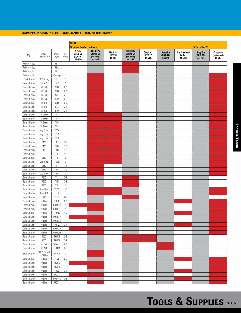
Tools & supplies B-107
www.idealind.com • 1-800-435-0705 customer assistance
IDEAL
Standard Breaker Lockouts EZ Panel Loc™
Mfg. Breaker Classification
Breaker Type
# of Poles
1-PoleSnap-On(w/hole)44-810
120/277VClamp On(no hole)44-809
Cleat for #6539644-785
480/600VClamp On(no hole)44-807
Cleat for #6539744-786
Oversize480/660V44-823
Multi-pole w/tie bar44-783
Snap On(SQD QO)
44-768
Clamp On(universal)
44-764
loc
ko
uT/
Tag
ou
T
Fed. Pacific Elec. NJJ
Fed. Pacific Elec. NJL
Fed. Pacific Elec. NM
Fed. Pacific Elec. NP-single 1
Frank Adams FA Quicklag P 1
General Electric Type C HQC 3
General Electric SE150 SED 2-3
General Electric SE150 SEH 2-3
General Electric SE150 SEL 2-3
General Electric SE150 SEP 2-3
General Electric SF250 SFH 2-3
General Electric SF250 SFL 2-3
General Electric SF250 SFP 2-3
General Electric Tri Break TB1
General Electric Tri Break TB4
General Electric Tri Break TB6
General Electric Tri Break TB8
General Electric Mag Break TBC4
General Electric Mag Break TBC6
General Electric Mag Break TBC8
General Electric E150 TE 1-3
General Electric E150 TEB 1-3
General Electric E150 TED 1-3
General Electric TEF 1-3
General Electric E150 TEL 3
General Electric Mag Break TEML 3
General Electric E150 TEY 1-3
General Electric E150 TF 1-3
General Electric Mag Break TFC 3
General Electric F225 TFJ 2-3
General Electric F225 TFK 2-3
General Electric F225 TFL 3
General Electric Like TED THED 1-3
General Electric Like TED THEF
General Electric F225 THFK 2-3
General Electric Q Line THHQB 2-3
General Electric Q Line THHQB-A 1
General Electric Q Line THHQB-S 1
General Electric Q Line THHQC 1-3
General Electric Q Line THHQC-A 1
General Electric Q Line THHQC-S 1
General Electric Q Line THHQL 2-3
General Electric Q Line THHQL-A 1
General Electric Q Line THHQL-S 1
General Electric J600 THJK4 2-3
General Electric J600 THJK6 2-3
General Electric K1200 THKM12 2-3
General Electric K1200 THKM8 2-3
General Electric THLC Current Limiting THLC1 3
General Electric Q Line THQB 2-3
General Electric Q Line THQB-A 1
General Electric Q Line THQB-S 1
General Electric Q Line THQC 2-3
General Electric Q Line THQC-A 1
General Electric Q Line THQC-AL 2-3
General Electric Q Line THQC-S 1
lo
ck
ou
T/Ta
go
uT
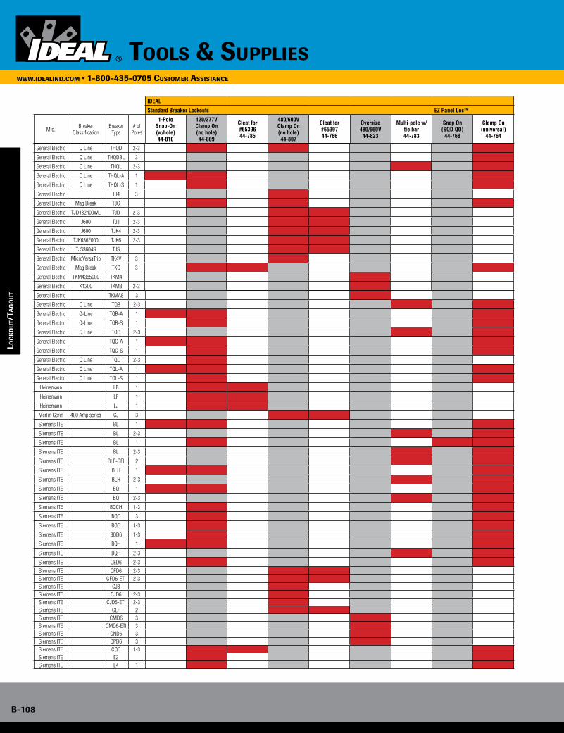
B-108
www.idealind.com • 1-800-435-0705 customer assistance
tools & supplies
IDEAL
Standard Breaker Lockouts EZ Panel Loc™
Mfg. Breaker Classification
Breaker Type
# of Poles
1-PoleSnap-On(w/hole)44-810
120/277VClamp On(no hole)44-809
Cleat for #6539644-785
480/600VClamp On(no hole)44-807
Cleat for #6539744-786
Oversize480/660V
44-823
Multi-pole w/tie bar44-783
Snap On(SQD QO)
44-768
Clamp On(universal)
44-764
lo
ck
ou
T/Ta
go
uT
General Electric Q Line THQD 2-3
General Electric Q Line THQDBL 3
General Electric Q Line THQL 2-3
General Electric Q Line THQL-A 1
General Electric Q Line THQL-S 1
General Electric TJ4 3
General Electric Mag Break TJC
General Electric TJD432400WL TJD 2-3
General Electric J600 TJJ 2-3
General Electric J600 TJK4 2-3
General Electric TJK636F000 TJK6 2-3
General Electric TJS3604S TJS
General Electric MicroVersaTrip TK4V 3
General Electric Mag Break TKC 3
General Electric TKM4365000 TKM4
General Electric K1200 TKM8 2-3
General Electric TKMA8 3
General Electric Q Line TQB 2-3
General Electric Q-Line TQB-A 1
General Electric Q-Line TQB-S 1
General Electric Q Line TQC 2-3
General Electric TQC-A 1
General Electric TQC-S 1
General Electric Q Line TQD 2-3
General Electric Q Line TQL-A 1
General Electric Q Line TQL-S 1
Heinemann LB 1
Heinemann LF 1
Heinemann LJ 1
Merlin Gerin 400 Amp series CJ 3
Siemens ITE BL 1
Siemens ITE BL 2-3
Siemens ITE BL 1
Siemens ITE BL 2-3
Siemens ITE BLF-GFI 2
Siemens ITE BLH 1
Siemens ITE BLH 2-3
Siemens ITE BQ 1
Siemens ITE BQ 2-3
Siemens ITE BQCH 1-3
Siemens ITE BQD 3
Siemens ITE BQD 1-3
Siemens ITE BQD6 1-3
Siemens ITE BQH 1
Siemens ITE BQH 2-3
Siemens ITE CED6 2-3Siemens ITE CFD6 2-3Siemens ITE CFD6-ETI 2-3Siemens ITE CJ3Siemens ITE CJD6 2-3Siemens ITE CJD6-ETI 2-3Siemens ITE CLF 2Siemens ITE CMD6 3Siemens ITE CMD6-ETI 3Siemens ITE CND6 3Siemens ITE CPD6 3Siemens ITE CQD 1-3Siemens ITE E2Siemens ITE E4 1
loc
ko
uT/
Tag
ou
T
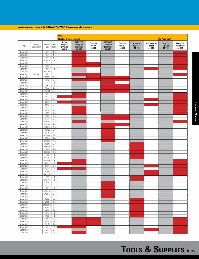
Tools & supplies B-109
www.idealind.com • 1-800-435-0705 customer assistance
IDEAL
Standard Breaker Lockouts EZ Panel Loc™
Mfg. Breaker Classification
Breaker Type
# of Poles
1-PoleSnap-On(w/hole)44-810
120/277VClamp On(no hole)44-809
Cleat for #6539644-785
480/600VClamp On(no hole)44-807
Cleat for #6539744-786
Oversize480/660V44-823
Multi-pole w/tie bar44-783
Snap On(SQD QO)
44-768
Clamp On(universal)
44-764
loc
ko
uT/
Tag
ou
T
Siemens ITE ED2 1-3Siemens ITE ED4 1-3Siemens ITE ED6 1-3Siemens ITE ED6-ETI 3Siemens ITE EE3Siemens ITE EH3Siemens ITE EQP 4Siemens ITE EQT QF Siemens ITE F-Frame ETSiemens ITE FD6A 2-3Siemens ITE FJ2-B 2-3Siemens ITE FJ3 2Siemens ITE FJ6 2Siemens ITE FXD6A 2-3Siemens ITE FXD6-ETI 2-3Siemens ITE GF 1Siemens ITE HBL 1Siemens ITE HBL 2-3 Siemens ITE HBQ 1Siemens ITE HBQ 2-3 Siemens ITE HE4Siemens ITE HED4 1-3Siemens ITE HED6 2-3Siemens ITE HFD6 2-3Siemens ITE HFXD6 2-3Siemens ITE HHED6 2-3Siemens ITE HHFD6 2-3Siemens ITE HHJD6 2-3Siemens ITE HHJXD6 2-3Siemens ITE HJD6 2-3Siemens ITE HJD6-A 2-3Siemens ITE HJXD6 2-3Siemens ITE HJXD6-A 2-3Siemens ITE HMD6 2-3Siemens ITE HMXD6 2-3Siemens ITE HND6 2-3Siemens ITE HNXD6 2-3Siemens ITE HPD6 3Siemens ITE HPXD6 3Siemens ITE HQJ2-H 3Siemens ITE HQP 1Siemens ITE HQP 2-3 Siemens ITE HQPP 1Siemens ITE HQPP 2-3 Siemens ITE HQPPH 2 Siemens ITE HRD6 3Siemens ITE HRXD6 3Siemens ITE JD6-A 2-3Siemens ITE JJ3Siemens ITE JL3 3Siemens ITE JXD2-A 2-3Siemens ITE JXD6-A 2-3Siemens ITE LL3Siemens ITE MD6 2-3Siemens ITE MXD6 2-3Siemens ITE MXD6-ETI 2-3Siemens ITE ND6 2-3Siemens ITE NXD6 2-3Siemens ITE PD6 3Siemens ITE PXD6 3Siemens ITE QJ2 2-3Siemens ITE QJ2-H 2-3Siemens ITE QJH2 2-3Siemens ITE QP 1Siemens ITE QP 2-3 Siemens ITE QP1 1
lo
ck
ou
T/Ta
go
uT
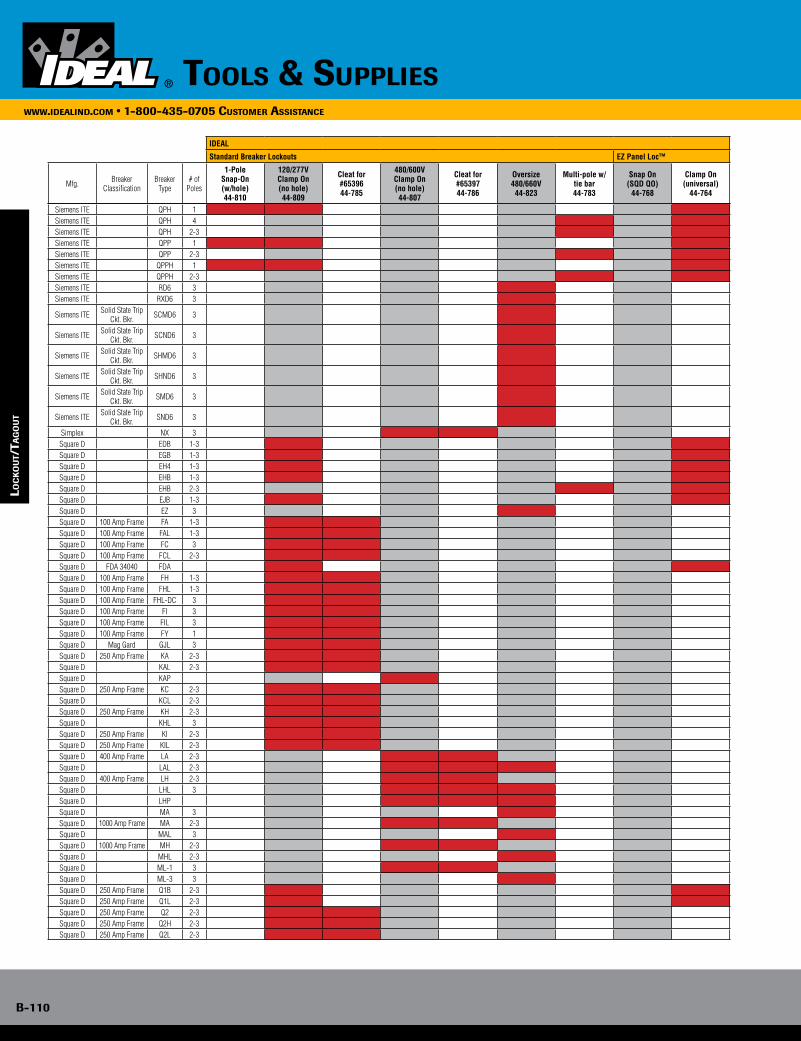
B-110
www.idealind.com • 1-800-435-0705 customer assistance
tools & supplies
IDEAL
Standard Breaker Lockouts EZ Panel Loc™
Mfg. Breaker Classification
Breaker Type
# of Poles
1-PoleSnap-On(w/hole)44-810
120/277VClamp On(no hole)44-809
Cleat for #6539644-785
480/600VClamp On(no hole)44-807
Cleat for #6539744-786
Oversize480/660V
44-823
Multi-pole w/tie bar44-783
Snap On(SQD QO)
44-768
Clamp On(universal)
44-764
lo
ck
ou
T/Ta
go
uT
Siemens ITE QPH 1Siemens ITE QPH 4Siemens ITE QPH 2-3 Siemens ITE QPP 1Siemens ITE QPP 2-3 Siemens ITE QPPH 1Siemens ITE QPPH 2-3 Siemens ITE RD6 3Siemens ITE RXD6 3
Siemens ITE Solid State Trip Ckt. Bkr. SCMD6 3
Siemens ITE Solid State Trip Ckt. Bkr. SCND6 3
Siemens ITE Solid State Trip Ckt. Bkr. SHMD6 3
Siemens ITE Solid State Trip Ckt. Bkr. SHND6 3
Siemens ITE Solid State Trip Ckt. Bkr. SMD6 3
Siemens ITE Solid State Trip Ckt. Bkr. SND6 3
Simplex NX 3Square D EDB 1-3Square D EGB 1-3Square D EH4 1-3Square D EHB 1-3Square D EHB 2-3Square D EJB 1-3Square D EZ 3Square D 100 Amp Frame FA 1-3Square D 100 Amp Frame FAL 1-3Square D 100 Amp Frame FC 3Square D 100 Amp Frame FCL 2-3Square D FDA 34040 FDASquare D 100 Amp Frame FH 1-3Square D 100 Amp Frame FHL 1-3Square D 100 Amp Frame FHL-DC 3Square D 100 Amp Frame FI 3Square D 100 Amp Frame FIL 3Square D 100 Amp Frame FY 1Square D Mag Gard GJL 3Square D 250 Amp Frame KA 2-3Square D KAL 2-3Square D KAPSquare D 250 Amp Frame KC 2-3Square D KCL 2-3Square D 250 Amp Frame KH 2-3Square D KHL 3Square D 250 Amp Frame KI 2-3Square D 250 Amp Frame KIL 2-3Square D 400 Amp Frame LA 2-3Square D LAL 2-3Square D 400 Amp Frame LH 2-3Square D LHL 3Square D LHPSquare D MA 3Square D 1000 Amp Frame MA 2-3Square D MAL 3Square D 1000 Amp Frame MH 2-3Square D MHL 2-3Square D ML-1 3Square D ML-3 3Square D 250 Amp Frame Q1B 2-3Square D 250 Amp Frame Q1L 2-3Square D 250 Amp Frame Q2 2-3Square D 250 Amp Frame Q2H 2-3Square D 250 Amp Frame Q2L 2-3
loc
ko
uT/
Tag
ou
T
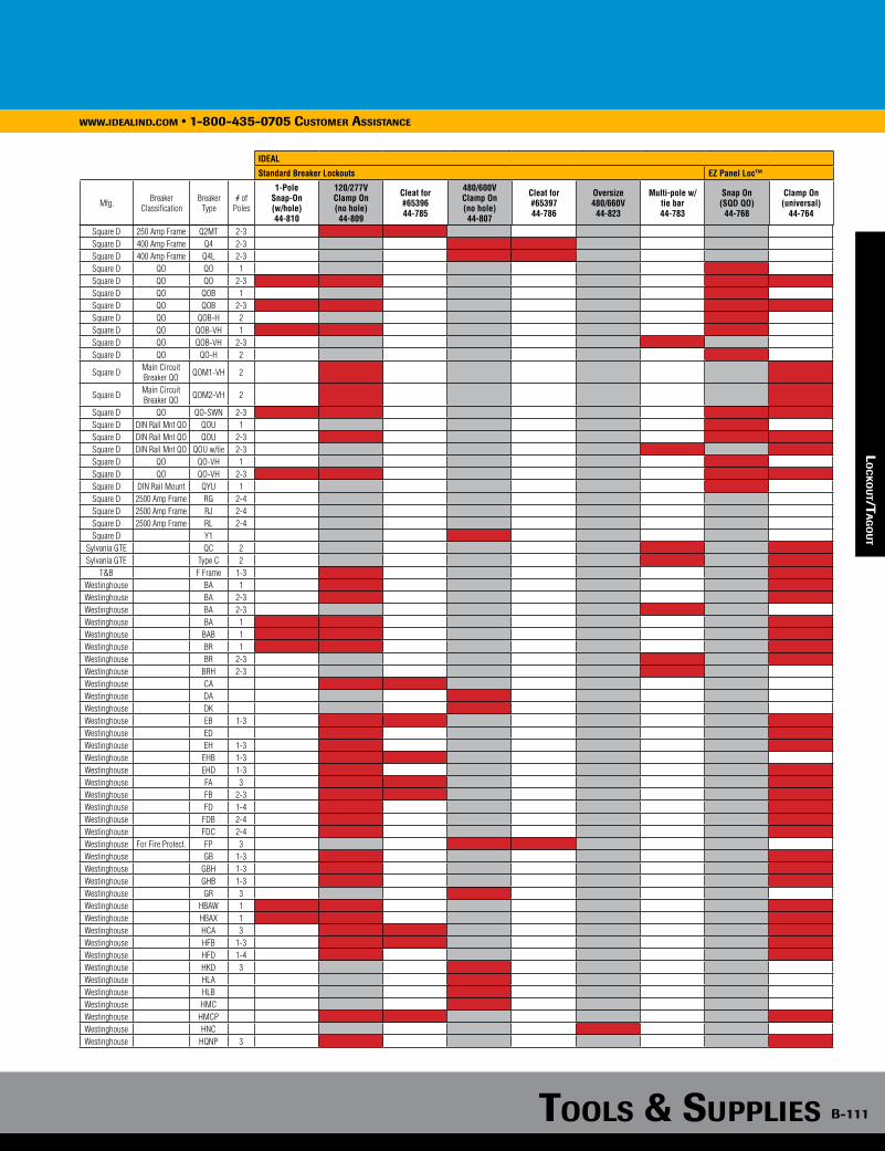
Tools & supplies B-111
www.idealind.com • 1-800-435-0705 customer assistance
IDEAL
Standard Breaker Lockouts EZ Panel Loc™
Mfg. Breaker Classification
Breaker Type
# of Poles
1-PoleSnap-On(w/hole)44-810
120/277VClamp On(no hole)44-809
Cleat for #6539644-785
480/600VClamp On(no hole)44-807
Cleat for #6539744-786
Oversize480/660V44-823
Multi-pole w/tie bar44-783
Snap On(SQD QO)
44-768
Clamp On(universal)
44-764
loc
ko
uT/
Tag
ou
T
Square D 250 Amp Frame Q2MT 2-3Square D 400 Amp Frame Q4 2-3Square D 400 Amp Frame Q4L 2-3Square D QO QO 1Square D QO QO 2-3Square D QO QOB 1Square D QO QOB 2-3Square D QO QOB-H 2Square D QO QOB-VH 1Square D QO QOB-VH 2-3Square D QO QO-H 2
Square D Main Circuit Breaker QO QOM1-VH 2
Square D Main Circuit Breaker QO QOM2-VH 2
Square D QO QO-SWN 2-3Square D DIN Rail Mnt QO QOU 1Square D DIN Rail Mnt QO QOU 2-3Square D DIN Rail Mnt QO QOU w/tie 2-3Square D QO QO-VH 1Square D QO QO-VH 2-3Square D DIN Rail Mount QYU 1Square D 2500 Amp Frame RG 2-4Square D 2500 Amp Frame RJ 2-4Square D 2500 Amp Frame RL 2-4Square D Y1
Sylvania GTE QC 2Sylvania GTE Type C 2
T&B F Frame 1-3Westinghouse BA 1Westinghouse BA 2-3Westinghouse BA 2-3Westinghouse BA 1Westinghouse BAB 1Westinghouse BR 1Westinghouse BR 2-3Westinghouse BRH 2-3Westinghouse CAWestinghouse DAWestinghouse DKWestinghouse EB 1-3Westinghouse ED Westinghouse EH 1-3Westinghouse EHB 1-3Westinghouse EHD 1-3Westinghouse FA 3Westinghouse FB 2-3Westinghouse FD 1-4Westinghouse FDB 2-4Westinghouse FDC 2-4Westinghouse For Fire Protect. FP 3Westinghouse GB 1-3Westinghouse GBH 1-3Westinghouse GHB 1-3Westinghouse GR 3Westinghouse HBAW 1Westinghouse HBAX 1Westinghouse HCA 3Westinghouse HFB 1-3Westinghouse HFD 1-4Westinghouse HKD 3Westinghouse HLAWestinghouse HLBWestinghouse HMC Westinghouse HMCPWestinghouse HNCWestinghouse HQNP 3
lo
ck
ou
T/Ta
go
uT
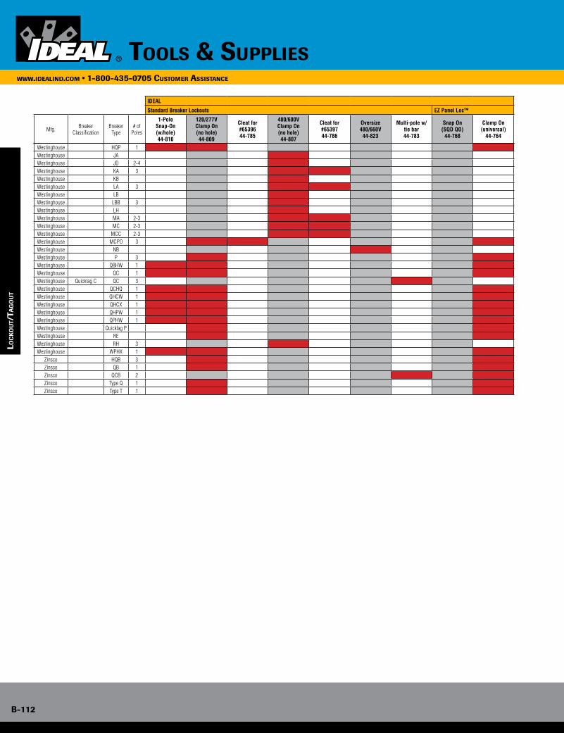
B-112
www.idealind.com • 1-800-435-0705 customer assistance
tools & supplies
IDEAL
Standard Breaker Lockouts EZ Panel Loc™
Mfg. Breaker Classification
Breaker Type
# of Poles
1-PoleSnap-On(w/hole)44-810
120/277VClamp On(no hole)44-809
Cleat for #6539644-785
480/600VClamp On(no hole)44-807
Cleat for #6539744-786
Oversize480/660V
44-823
Multi-pole w/tie bar44-783
Snap On(SQD QO)
44-768
Clamp On(universal)
44-764
lo
ck
ou
T/Ta
go
uT
Westinghouse HQP 1Westinghouse JAWestinghouse JD 2-4Westinghouse KA 3Westinghouse KBWestinghouse LA 3Westinghouse LBWestinghouse LBB 3Westinghouse LHWestinghouse MA 2-3Westinghouse MC 2-3Westinghouse MCC 2-3Westinghouse MCPO 3Westinghouse NBWestinghouse P 3Westinghouse QBHW 1Westinghouse QC 1Westinghouse Quicklag C QC 3Westinghouse QCHQ 1Westinghouse QHCW 1Westinghouse QHCX 1Westinghouse QHPW 1Westinghouse QPHW 1Westinghouse Quicklag PWestinghouse REWestinghouse RH 3Westinghouse WPHX 1
Zinsco HQB 3Zinsco QB 1Zinsco QCB 2Zinsco Type Q 1Zinsco Type T 1
loc
ko
uT/
Tag
ou
T

Tools & supplies B-113
www.idealind.com • 1-800-435-0705 customer assistance
Commutator MaintenanceHow to Select Resurfacer GradeSmall Motor and Pocket Resurfacers Grade code letters designate the following grade combinations:A Medium/Finish B Coarse/Finish D Finish/PolishH Medium/Polish
All Other Resurfacers Resurfacers for commutators and copper-alloy slip rings are made in four grades:C Coarse—fast cuttingM Medium—for general use, high mica, small ridges and burnsF Finish—for use after the three grades above, for periodic application and for removing small burns and ridges immediately after their appearanceP Polish—very fine grade (220 aggregate grain) for burnish finish
For all resurfacers, specify grade by adding the appropriate letter as a suffix to the catalog number. (Example: 80-475M for medium grade.)
How to Select Resurfacer SizeSize is always written length x width x thickness (working face area x depth of stone). For handle types, the handle is mounted parallel to the first dimension. Always use a resurfacer with the largest face possible (length x width). Thickness should be governed by clearance around commutator or ring.
Commutator Resurfacers The resurfacer should have a width of approximately 3/4 the length of the commutator bar and as long as will conveniently go between the brush riggings. For periodic application, three or four sizes are generally sufficient. After determining approximate dimensions, select nearest standard size and type.
Slip Ring Resurfacers When space permits, use a resurfacer about 1 in. wider than the face width of the ring. Length should be at least three times greater than the longest flat spot to bridge over and ensure a true ring.
co
mm
uTa
Tor m
ain
Ten
an
ce
co
mm
uTa
Tor m
ain
Tena
nc
e
• Different grades of stone on each end
• 10 in. handle
• For use on small fractional horsepower motors
Description Size (In.) Grades Part No.
Small Motor-Type Resurfacer 3/4 x 1/2 x 3/8 A, B, D 80-012*
*Add grade letter suffix to Part No. Please allow 4-5 weeks for delivery.
Small Motor-Type Resurfacer Tool-Type Resurfacers• For use in lathe-turning device
• Two resurfacers required for each grinder
Description Size (In.) Grades Part No.
Tool-Type Resurfacer 1 x 1-1/2 x 6-1/2 C, M, F 80-454*
Tool-Type Resurfacer 1 x 2 x 8 C, M, F 80-461*
Tool-Type Resurfacer 2 x 2 x 8 C, M, F 80-475*
*Add grade letter suffix to Part No. Please allow 4-5 weeks for delivery.
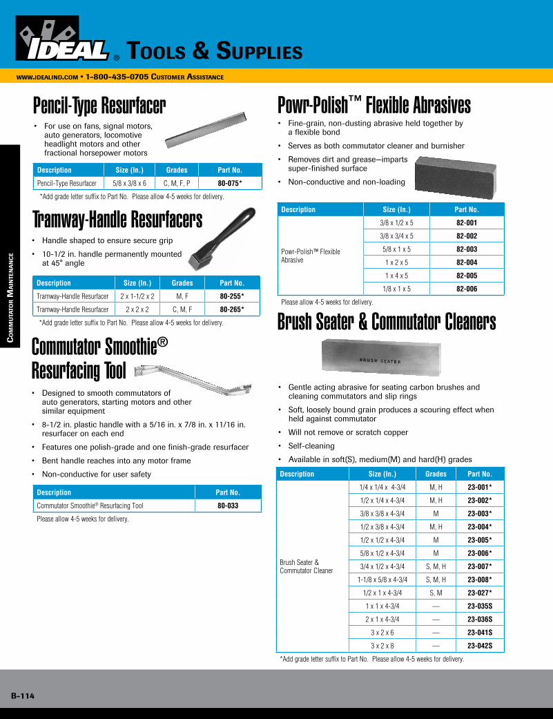
B-114
www.idealind.com • 1-800-435-0705 customer assistance
tools & supplies
Pencil-Type Resurfacer
Tramway-Handle Resurfacers• Handle shaped to ensure secure grip
• 10-1/2 in. handle permanently mounted at 45° angle
• For use on fans, signal motors, auto generators, locomotive headlight motors and other fractional horsepower motors
Description Size (In.) Grades Part No.
Pencil-Type Resurfacer 5/8 x 3/8 x 6 C, M, F, P 80-075*
*Add grade letter suffix to Part No. Please allow 4-5 weeks for delivery.
Description Size (In.) Grades Part No.
Tramway-Handle Resurfacer 2 x 1-1/2 x 2 M, F 80-255*
Tramway-Handle Resurfacer 2 x 2 x 2 C, M, F 80-265*
*Add grade letter suffix to Part No. Please allow 4-5 weeks for delivery.
Commutator Smoothie® Resurfacing Tool• Designed to smooth commutators of auto generators, starting motors and other similar equipment
• 8-1/2 in. plastic handle with a 5/16 in. x 7/8 in. x 11/16 in. resurfacer on each end
• Features one polish-grade and one finish-grade resurfacer
• Bent handle reaches into any motor frame
• Non-conductive for user safety
Description Part No.
Commutator Smoothie® Resurfacing Tool 80-033
Please allow 4-5 weeks for delivery.
• Fine-grain, non-dusting abrasive held together by a flexible bond
• Serves as both commutator cleaner and burnisher
• Removes dirt and grease—imparts super-finished surface
• Non-conductive and non-loading
Description Size (In.) Part No.
Powr-Polish™ Flexible Abrasive
3/8 x 1/2 x 5 82-001
3/8 x 3/4 x 5 82-002
5/8 x 1 x 5 82-003
1 x 2 x 5 82-004
1 x 4 x 5 82-005
1/8 x 1 x 5 82-006
Please allow 4-5 weeks for delivery.
Powr-Polish™ Flexible Abrasives
Brush Seater & Commutator Cleaners
• Gentle acting abrasive for seating carbon brushes and cleaning commutators and slip rings
• Soft, loosely bound grain produces a scouring effect when held against commutator
• Will not remove or scratch copper
• Self-cleaning
• Available in soft(S), medium(M) and hard(H) grades
Description Size (In.) Grades Part No.
Brush Seater & Commutator Cleaner
1/4 x 1/4 x 4-3/4 M, H 23-001*
1/2 x 1/4 x 4-3/4 M, H 23-002*
3/8 x 3/8 x 4-3/4 M 23-003*
1/2 x 3/8 x 4-3/4 M, H 23-004*
1/2 x 1/2 x 4-3/4 M 23-005*
5/8 x 1/2 x 4-3/4 M 23-006*
3/4 x 1/2 x 4-3/4 S, M, H 23-007*
1-1/8 x 5/8 x 4-3/4 S, M, H 23-008*
1/2 x 1 x 4-3/4 S, M 23-027*
1 x 1 x 4-3/4 — 23-035S
2 x 1 x 4-3/4 — 23-036S
3 x 2 x 6 — 23-041S
3 x 2 x 8 — 23-042S
*Add grade letter suffix to Part No. Please allow 4-5 weeks for delivery.
co
mm
uTa
Tor m
ain
Ten
an
ce
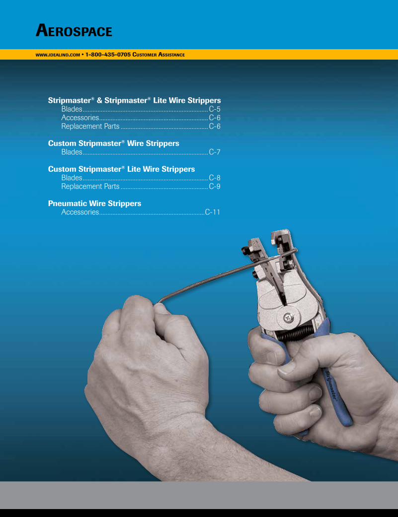
www.idealind.com • 1-800-435-0705 customer assistancewww.idealind.com • 1-800-435-0705 customer assistance
Stripmaster® & Stripmaster® Lite Wire Strippers Blades ............................................................................C-5 Accessories ..................................................................C-6 Replacement Parts .....................................................C-6
Custom Stripmaster® Wire Strippers Blades ............................................................................C-7
Custom Stripmaster® Lite Wire Strippers Blades ............................................................................C-8 Replacement Parts .....................................................C-9
Pneumatic Wire Strippers Accessories ................................................................C-11
aerospace

www.idealind.com • 1-800-435-0705 customer assistance
aerospace
c-2
precision wire processing
AerospaceEvery aspect of the aerospace industry demands precision and accuracy. That includes wire processing - our area of expertise at IDEAL. Working with both wire manufacturers and aerospace engineers, we develop unique blades with tight tolerances that strip wire accurately and dependably.
aerospacewww.idealind.com • 1-800-435-0705 customer assistance
c-2
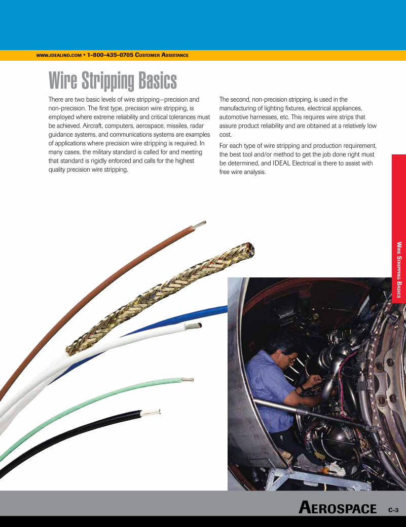
www.idealind.com • 1-800-435-0705 customer assistancewww.idealind.com • 1-800-435-0705 customer assistance
There are two basic levels of wire stripping—precision and non-precision. The first type, precision wire stripping, is employed where extreme reliability and critical tolerances must be achieved. Aircraft, computers, aerospace, missiles, radar guidance systems, and communications systems are examples of applications where precision wire stripping is required. In many cases, the military standard is called for and meeting that standard is rigidly enforced and calls for the highest quality precision wire stripping.
The second, non-precision stripping, is used in the manufacturing of lighting fixtures, electrical appliances, automotive harnesses, etc. This requires wire strips that assure product reliability and are obtained at a relatively low cost.
For each type of wire stripping and production requirement, the best tool and/or method to get the job done right must be determined, and IDEAL Electrical is there to assist with free wire analysis.
Wire Stripping Basics
wir
e str
ipp
ing B
as
ics
www.idealind.com • 1-800-435-0705 customer assistance
aerospace c-3

AerospAce
c-4
www.idealind.com • 1-800-435-0705 customer assistance
The versatile Stripmaster®/Stripmaster® Lite Wire Strippers are the standard of the industry. They incorporate a gripper that firmly holds the wire in a center-line position with the stripping hole. The lever action of the stripper offers a mechanical advantage that makes stripping easier. This aids in production applications and reduces operator fatigue. One squeeze strips the wireclean, up to a full 7/8 in. (22mm). The jaws are automatically held open to allow removal of the wire without damaging its end. This stripper virtually eliminates all nicking, cutting or fraying on non-precision wire.
Stripmaster® & Stripmaster® Lite Wire Strippers
Custom Stripmaster® Wire Strippers
Custom Stripmaster® Lite Wire Strippers
The Custom Stripmaster® Wire Stripper has set the industry standard in hand-held,precision wire stripping. It provides fast, accurate wire stripping with its one-step, squeeze-action stripping and unique precision blade design. This light-weight wire stripper, made from sturdy die-cast zinc, is designed for maximum mobility and high productivity in all types of non-precision and precision stripping applications. The Custom Stripmaster® Wire Stripper offers extra leverage with its spring-action mechanical design for reduced operator effort. It can be customized with your choice of gripper pads and blade sets to match your wire stripping requirements. The comfort grip handles are color-coded to identify the best tool for the application. Red handles are used for larger wire (10–14 AWG) and black handles are used for smaller wire (16–30 AWG). The blades and grippers installed in the tool are specific to the application. Optional short-stop latch and transparent wire stop increases tool versatility and insures consistent strip lengths.
The Custom Stripmaster® Lite Wire Stripper marks the beginning of a new era of light-weight, precision wire strippers designed specifically for improved operator comfort. It utilizes the same type of precision die-blade construction and features an optional short-stop latch and transparent wire stop. Built of sturdy die-cast zinc, this compact stripper weighs 50% less than its full-sized counterparts, and will impress you with both its ease of operation and durable performance.
str
ipm
as
ter
® w
ire
str
ipp
ers
aerospace
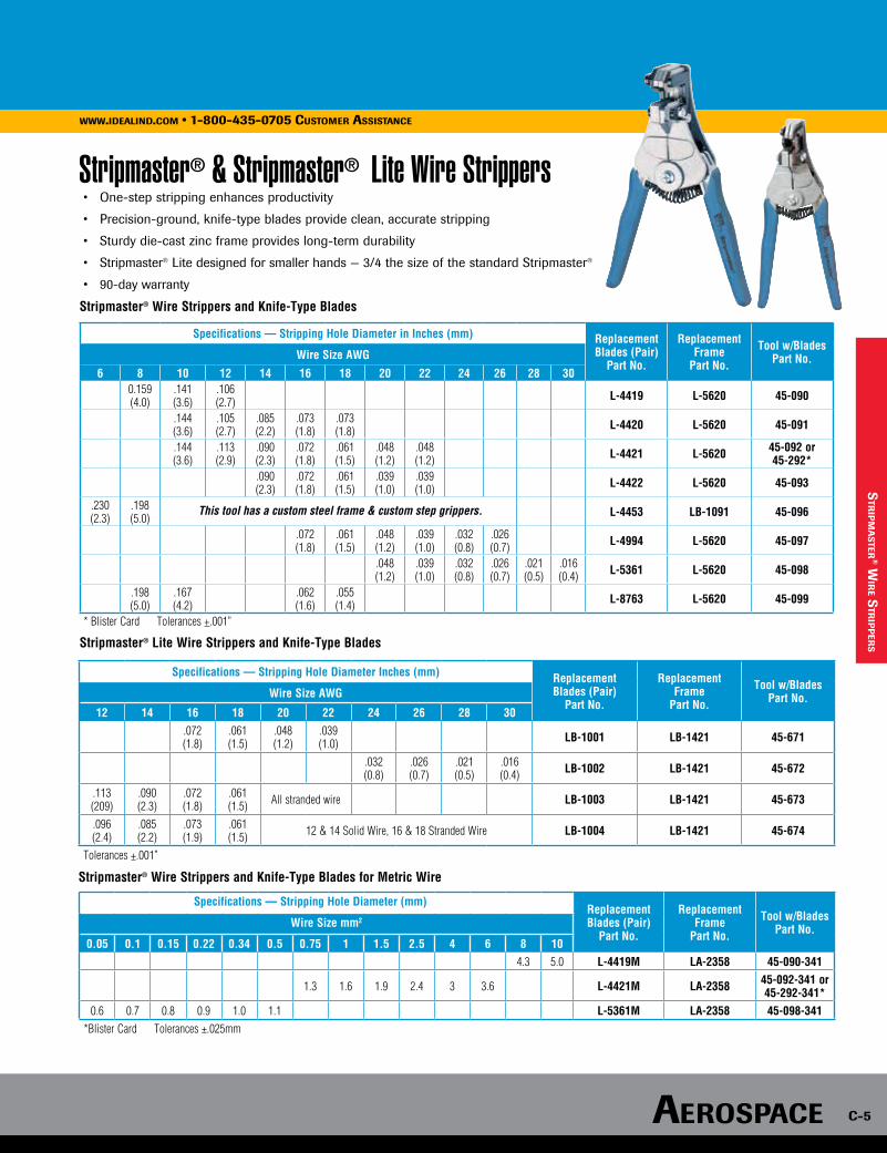
www.idealind.com • 1-800-435-0705 customer assistance
aerospace c-5
• One-step stripping enhances productivity
• Precision-ground, knife-type blades provide clean, accurate stripping
• Sturdy die-cast zinc frame provides long-term durability
• Stripmaster® Lite designed for smaller hands — 3/4 the size of the standard Stripmaster®
• 90-day warranty
Stripmaster® Wire Strippers and Knife-Type Blades
Specifications — Stripping Hole Diameter in Inches (mm) ReplacementBlades (Pair)
Part No.
ReplacementFrame
Part No.
Tool w/BladesPart No.Wire Size AWG
6 8 10 12 14 16 18 20 22 24 26 28 300.159 (4.0)
.141(3.6)
.106 (2.7) L-4419 L-5620 45-090
.144 (3.6)
.105 (2.7)
.085 (2.2)
.073 (1.8)
.073 (1.8) L-4420 L-5620 45-091
.144 (3.6)
.113 (2.9)
.090 (2.3)
.072 (1.8)
.061 (1.5)
.048 (1.2)
.048 (1.2) L-4421 L-5620 45-092 or
45-292*.090 (2.3)
.072 (1.8)
.061 (1.5)
.039 (1.0)
.039 (1.0) L-4422 L-5620 45-093
.230 (2.3)
.198 (5.0) L-4453 LB-1091 45-096
.072 (1.8)
.061 (1.5)
.048 (1.2)
.039 (1.0)
.032 (0.8)
.026 (0.7) L-4994 L-5620 45-097
.048 (1.2)
.039 (1.0)
.032 (0.8)
.026 (0.7)
.021 (0.5)
.016 (0.4) L-5361 L-5620 45-098
.198 (5.0)
.167 (4.2)
.062 (1.6)
.055 (1.4) L-8763 L-5620 45-099
* Blister Card Tolerances +.001”
Stripmaster® Lite Wire Strippers and Knife-Type Blades
Specifications — Stripping Hole Diameter Inches (mm) ReplacementBlades (Pair)
Part No.
Replacement Frame
Part No.
Tool w/BladesPart No.Wire Size AWG
12 14 16 18 20 22 24 26 28 30.072 (1.8)
.061 (1.5)
.048 (1.2)
.039 (1.0) LB-1001 LB-1421 45-671
.032 (0.8)
.026 (0.7)
.021 (0.5)
.016 (0.4) LB-1002 LB-1421 45-672
.113 (209)
.090 (2.3)
.072 (1.8)
.061 (1.5) All stranded wire LB-1003 LB-1421 45-673
.096 (2.4)
.085 (2.2)
.073 (1.9)
.061 (1.5) 12 & 14 Solid Wire, 16 & 18 Stranded Wire LB-1004 LB-1421 45-674
Tolerances +.001”
Stripmaster® & Stripmaster® Lite Wire Strippers
This tool has a custom steel frame & custom step grippers.
Specifications — Stripping Hole Diameter (mm)ReplacementBlades (Pair)
Part No.
ReplacementFrame
Part No.
Tool w/BladesPart No.Wire Size mm2
0.05 0.1 0.15 0.22 0.34 0.5 0.75 1 1.5 2.5 4 6 8 104.3 5.0 L-4419M LA-2358 45-090-341
1.3 1.6 1.9 2.4 3 3.6 L-4421M LA-2358 45-092-341 or 45-292-341*
0.6 0.7 0.8 0.9 1.0 1.1 L-5361M LA-2358 45-098-341 *Blister Card Tolerances ±.025mm
Stripmaster® Wire Strippers and Knife-Type Blades for Metric Wire
str
ipm
as
ter® w
ire s
trip
per
s
www.idealind.com • 1-800-435-0705 customer assistance
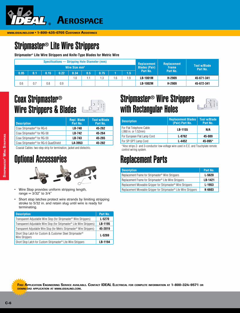
c-6
www.idealind.com • 1-800-435-0705 customer assistance
aerospace
Stripmaster® Lite Wire StrippersSpecifications — Stripping Hole Diameter (mm)
ReplacementBlades (Pair)
Part No.
ReplacementFrame
Part No.
Tool w/BladePart No.Wire Size mm2
0.05 0.1 0.15 0.22 0.34 0.5 0.75 1 1.51.0 1.1 1.3 1.6 1.9 LB-1001M H-2909 45-671-341
0.6 0.7 0.8 0.9 LB-1002M H-2909 45-672-341
Stripmaster® Lite Wire Strippers and Knife-Type Blades for Metric Wire
Coax Stripmaster® Wire Strippers & Blades
Stripmaster® Wire Strippers with Rectangular Holes
Optional Accessories
• Wire Stop provides uniform stripping length, range = 3/32” to 3/4”
• Short stop latches protect wire strands by limiting stripping stroke to 5/32 in. and retain slug until wire is ready for terminating.
Replacement Parts
Description Replacement Blades (Pair) Part No.
Tool w/BladePart No.
For Flat Telephone Cable (.060 in. or 1.52mm) LB-1155 N/A
For European Flat Lamp Cord L-8762 45-089For SP-SPT Lamp Cord L-4452 45-095**Also strips 2- and 3-conductor low-voltage wire used in E.E. and Touchplate remote control wiring system.
Specifications — Stripping Description
Repl. BladePart No.
Tool w/BladePart No.
Coax Stripmaster® for RG-6 LB-740 45-262Coax Stripmaster® for RG-58 LB-742 45-264Coax Stripmaster® for RG-59 LB-743 45-265Coax Stripmaster® for RG-6 QuadShield LA-3953 45-282Coaxial Cables: two-step strip for termination, jacket and dielectric.
Description Part No.Transparent Adjustable Wire Stop (for Stripmaster® Wire Strippers) L-5270Transparent Adjustable Wire Stop (for Stripmaster® Lite Wire Strippers) LB-1195Transparent Adjustable Wire Stop (for Metric Stripmaster® Wire Strippers) 45-2019Short Stop Latch for Custom & Customer Steel Stripmaster® Wire Strippers L-5269
Short Stop Latch for Custom Stripmaster® Lite Wire Strippers LB-1194
Description Part No.Replacement Frame for Stripmaster® Wire Strippers L-5620Replacement Frame for Stripmaster® Lite Wire Strippers LB-1421Replacement Moveable Gripper for Stripmaster® Wire Strippers L-1953Replacement Moveable Gripper for Stripmaster® Lite Wire Strippers K-6603
str
ipm
as
ter
® w
ire
str
ipp
ers
Free application engineering service availaBle. contact ideal electrical For complete inFormation at 1-800-324-9571 or download application at www.idealind.com.
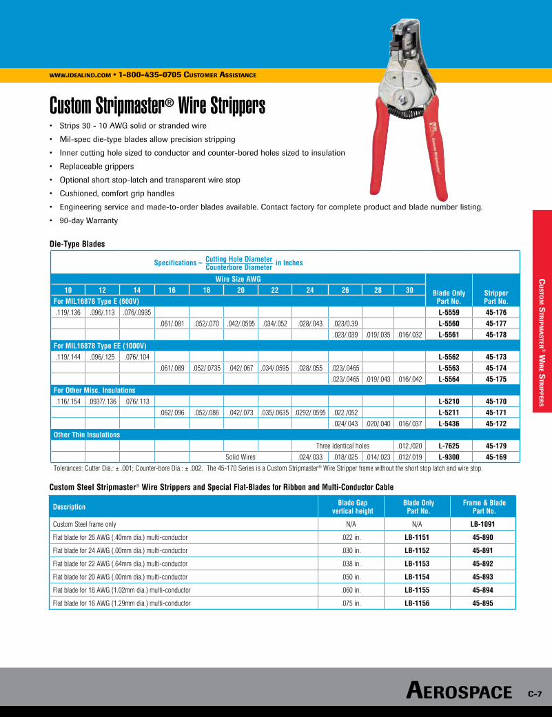
AerospAce c-7
www.idealind.com • 1-800-435-0705 customer assistance
Custom Stripmaster® Wire Strippers• Strips 30 - 10 AWG solid or stranded wire
• Mil-spec die-type blades allow precision stripping
• Inner cutting hole sized to conductor and counter-bored holes sized to insulation
• Replaceable grippers
• Optional short stop-latch and transparent wire stop
• Cushioned, comfort grip handles
• Engineering service and made-to-order blades available. Contact factory for complete product and blade number listing.
• 90-day Warranty
Die-Type Blades
cu
sto
m s
trip
ma
ster
® wir
e str
ipp
ers
Description Blade Gap vertical height
Blade Only Part No.
Frame & Blade Part No.
Custom Steel frame only N/A N/A LB-1091
Flat blade for 26 AWG (.40mm dia.) multi-conductor .022 in. LB-1151 45-890
Flat blade for 24 AWG (.00mm dia.) multi-conductor .030 in. LB-1152 45-891
Flat blade for 22 AWG (.64mm dia.) multi-conductor .038 in. LB-1153 45-892
Flat blade for 20 AWG (.00mm dia.) multi-conductor .050 in. LB-1154 45-893
Flat blade for 18 AWG (1.02mm dia.) multi-conductor .060 in. LB-1155 45-894
Flat blade for 16 AWG (1.29mm dia.) multi-conductor .075 in. LB-1156 45-895
Custom Steel Stripmaster® Wire Strippers and Special Flat-Blades for Ribbon and Multi-Conductor Cable
Wire Size AWG
Blade OnlyPart No.
StripperPart No.
10 12 14 16 18 20 22 24 26 28 30For MIL16878 Type E (600V).119/.136 .096/.113 .076/.0935 L-5559 45-176
.061/.081 .052/.070 .042/.0595 .034/.052 .028/.043 .023/0.39 L-5560 45-177.023/.039 .019/.035 .016/.032 L-5561 45-178
For MIL16878 Type EE (1000V).119/.144 .096/.125 .076/.104 L-5562 45-173
.061/.089 .052/.0735 .042/.067 .034/.0595 .028/.055 .023/.0465 L-5563 45-174 .023/.0465 .019/.043 .016/.042 L-5564 45-175
For Other Misc. Insulations.116/.154 .0937/.136 .076/.113 L-5210 45-170
.062/.096 .052/.086 .042/.073 .035/.0635 .0292/.0595 .022./052 L-5211 45-171.024/.043 .020/.040 .016/.037 L-5436 45-172
Other Thin InsulationsThree identical holes .012./020 L-7625 45-179
Solid Wires .024/.033 .018/.025 .014/.023 .012/.019 L-9300 45-169Tolerances: Cutter Dia.: ± .001; Counter-bore Dia.: ± .002. The 45-170 Series is a Custom Stripmaster® Wire Stripper frame without the short stop latch and wire stop.
Specifications – Cutting Hole Diameter in Inches Counterbore Diameter
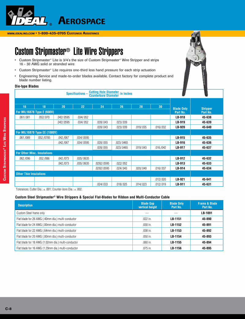
c-8
www.idealind.com • 1-800-435-0705 customer assistance
aerospace
Custom Stripmaster® Lite Wire Strippers
Custom Steel Stripmaster® Wire Strippers & Special Flat-Blades for Ribbon and Multi-Conductor Cable
• Custom Stripmaster® Lite is 3/4’s the size of Custom Stripmaster® Wire Stripper and strips 16 - 30 AWG solid or stranded wire
• Custom Stripmaster® Lite requires one-third less hand pressure for each strip actuation
• Engineering Service and made-to-order blades available. Contact factory for complete product and blade number listing.
Die-type Blades Specifications – Cutting Hole Diameter in Inches Counterbore Diameter
Blade OnlyPart No.
StripperPart No.
16 18 20 22 24 26 28 30
For MIL16878 Type E (600V)
.061/.081 .052/.070 .042/.0595 .034/.052 LB-918 45-638.042/.0595 .034/.052 .028/.043 .023/.039 LB-919 45-639
.028/.043 .023/.039 .019/.035 .016/.032 LB-920 45-640
For MIL16878 Type EE (1000V)
.061./089 .052./0785 .042./067 .034/.0595 LB-915 45-635.042./067 .034/.0595 .028/.055 .023/.0465 LB-916 45-636
.028/.055 .023/.0465 .019/.043 .016./042 LB-917 45-637
For Other Misc. Insulations
.062./096 .052./086 .042./073 .035/.0635 LB-912 45-632.042./073 .035/.0635 .0292/.0595 .022/.052 LB-913 45-633
.0292/.0595 .024/.043 .020/.040 .016/.037 LB-914 45-634
Other Thin Insulations
.012/.020 LB-921 45-641.024/.033 .018/.025 .014/.023 .012/.019 LB-911 45-631
Tolerances: Cutter Dia.: ± .001; Counter-bore Dia.: ± .002.
Description Blade Gap vertical height
Blade Only Part No.
Frame & Blade Part No.
Custom Steel frame only — — LB-1091
Flat blade for 26 AWG (.40mm dia.) multi-conductor .022 in. LB-1151 45-890
Flat blade for 24 AWG (.00mm dia.) multi-conductor .030 in. LB-1152 45-891
Flat blade for 22 AWG (.64mm dia.) multi-conductor .038 in. LB-1153 45-892
Flat blade for 20 AWG (.00mm dia.) multi-conductor .050 in. LB-1154 45-893
Flat blade for 18 AWG (1.02mm dia.) multi-conductor .060 in. LB-1155 45-894
Flat blade for 16 AWG (1.29mm dia.) multi-conductor .075 in. LB-1156 45-895
cu
sto
m s
trip
ma
ste
r® l
ite
wir
e s
trip
per
s
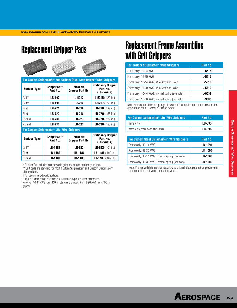
AerospAce c-9
www.idealind.com • 1-800-435-0705 customer assistance
Replacement Gripper Pads Replacement Frame Assemblies with Grit Grippers
For Custom Stripmaster® and Custom Steel Stripmaster® Wire Strippers
Surface Type Gripper Set* Part No.
Movable Gripper Part No.
Stationary Gripper Part No.
(Thickness)
Grit** LB-197 L-5212 L-5215 (.129 in.)
Grit** LB-198 L-5212 L-5217 (.156 in.)
File‡ LB-721 LB-718 LB-719 (.129 in.)
File‡ LB-722 LB-718 LB-720 (.156 in.)
Parallel LB-730 LB-727 LB-728 (.129 in.)
Parallel LB-731 LB-727 LB-729 (.156 in.)
For Custom Stripmaster® Lite Wire Strippers
Surface Type Gripper Set* Part No.
Movable Gripper Part No.
Stationary Gripper Part No.
(Thickness)
Grit** LB-1188 LB-882 LB-883 (.109 in.)
File‡ LB-1189 LB-1184 LB-1185 (.109 in.)
Parallel LB-1190 LB-1186 LB-1187 (.109 in.)
* Gripper Set includes one movable gripper and one stationary gripper. ** Grit pads are standard for most Custom Stripmaster® and Custom Stripmaster®
Lite products. ‡ For use on hard-to-grip surfaces. Gripper pad selection depends on insulation type and user preference. Note: For 10-14 AWG, use .129 in. stationary gripper. For 16-30 AWG, use .156 in. gripper.
For Custom Steel Stripmaster® Wire Strippers Part No.
Frame only, 10-14 AWG LB-1091
Frame only, 16-30 AWG LB-1092
Frame only, 10-14 AWG, internal spring (see note) LB-1090
Frame only, 16-30 AWG, internal spring (see note) LB-1089
Note: Frames with internal springs allow additional blade penetration pressure for difficult and multi-layered insulation types.
For Custom Stripmaster® Lite Wire Strippers Part No.
Frame only LB-895
Frame only, Wire Stop and Latch LB-896
For Custom Stripmaster® Wire Strippers Part No.
Frame only, 10-14 AWG L-5616
Frame only, 16-30 AWG L-5617
Frame only, 10-14 AWG, Wire Stop and Latch L-5618
Frame only, 16-30 AWG, Wire Stop and Latch L-5619
Frame only, 10-14 AWG, internal spring (see note) L-9039
Frame only, 16-30 AWG, internal spring (see note) L-9038
Note: Frames with internal springs allow additional blade penetration pressure for difficult and multi-layered insulation types.
cu
sto
m s
trip
ma
ster
® wir
e str
ipp
ers
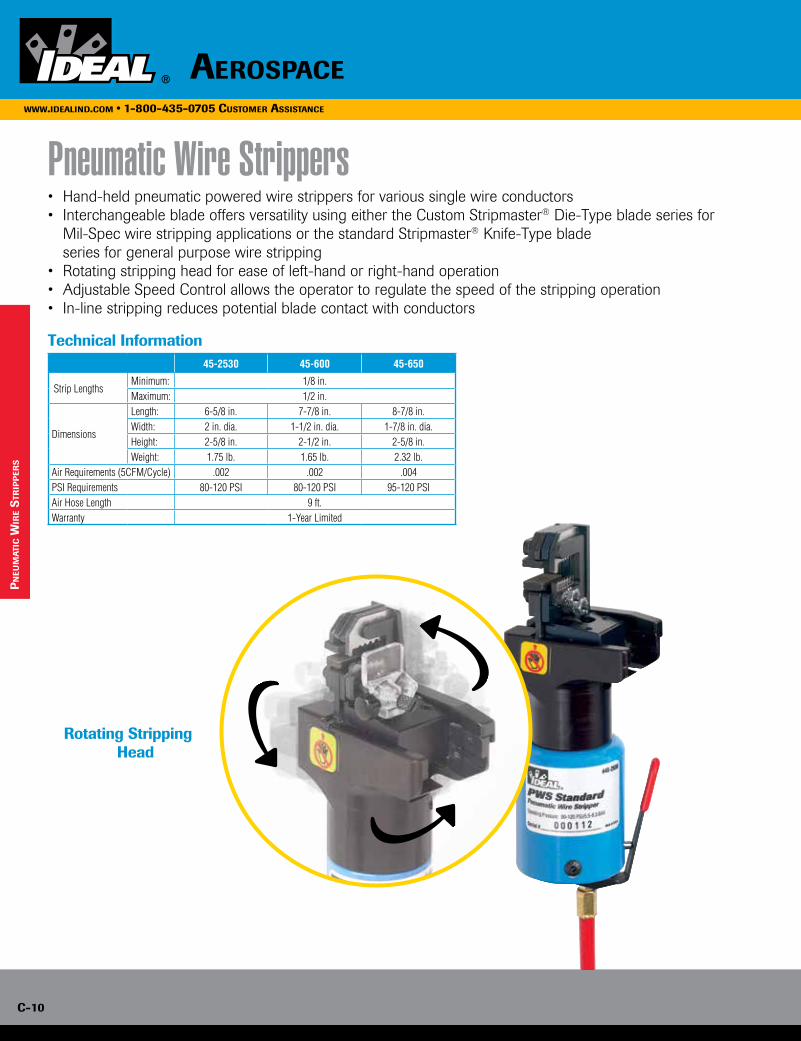
c-10
www.idealind.com • 1-800-435-0705 customer assistance
aerospace
• Hand-held pneumatic powered wire strippers for various single wire conductors• Interchangeable blade offers versatility using either the Custom Stripmaster® Die-Type blade series for
Mil-Spec wire stripping applications or the standard Stripmaster® Knife-Type blade series for general purpose wire stripping• Rotating stripping head for ease of left-hand or right-hand operation • Adjustable Speed Control allows the operator to regulate the speed of the stripping operation• In-line stripping reduces potential blade contact with conductors
Technical Information
Rotating Stripping Head
pn
eum
ati
c w
ire
str
ipp
ers
Pneumatic Wire Strippers
45-2530 45-600 45-650
Strip LengthsMinimum: 1/8 in. Maximum: 1/2 in.
Dimensions
Length: 6-5/8 in. 7-7/8 in. 8-7/8 in.Width: 2 in. dia. 1-1/2 in. dia. 1-7/8 in. dia.Height: 2-5/8 in. 2-1/2 in. 2-5/8 in.Weight: 1.75 lb. 1.65 lb. 2.32 lb.
Air Requirements (5CFM/Cycle) .002 .002 .004PSI Requirements 80-120 PSI 80-120 PSI 95-120 PSIAir Hose Length 9 ft.Warranty 1-Year Limited

AerospAce c-11
www.idealind.com • 1-800-435-0705 customer assistance
Standard Pneumatic Wire Stripper
Heavy-Duty Pneumatic Wire Stripper
Lite Pneumatic Wire Stripper
Pneumatic Wire Stripper Accessories
Description Part No.
Lite Pneumatic Wire Stripper 45-600
Description Part No.
Wire Stop (45-2530 & 45-650) L-5270
Wire Stop (45-600) LB-1195
Air Regulator (45-2530, 45-650 & 45-600) 45-906
Description Part No.
Heavy-Duty Pneumatic Wire Stripper 45-650
Description Part No.
Standard Pneumatic Wire Stripper 45-2530
pn
eum
atic w
ire s
trip
per
s
• Uses Custom Stripmaster® and standard Stripmaster® 16-30 AWG blades
• Blades sold separately
• Refer to specification charts for Stripmaster® and Custom Stripmaster®
blade selection
• For Mil-Spec blades not referenced in this catalog, refer to the Aerospace Catalog or take advantage of our free Applications Engineering service for wire evaluation
• Uses Custom Stripmaster® and standard Stripmaster® 10-30 AWG blades
• Blades sold separately
• Refer to specification charts for Stripmaster® and Custom Stripmaster® blade selection
• For Mil-Spec blades not referenced in this catalog, refer to the Aerospace Catalog or
take advantage of our free Applications Engineering service for wire evaluation
• Uses Custom Stripmaster® Lite and standard Stripmaster® Lite 16-30 AWG blades
• Blades sold separately
• Refer to specification charts for Stripmaster® Lite and Custom Stripmaster® Lite blade selection
• For Mil-Spec blades not referenced in this catalog, refer to the Aerospace Catalog or take advantage of our free Applications Engineering service for wire evaluation

c-12
www.idealind.com • 1-800-435-0705 customer assistance
aerospace
ap
pli
ca
tio
n e
ng
inee
rin
g s
erv
ice Please enclose at least five feet of your wire or cable and answer the
following questions to expedite a reply for your particular application.
1. Method Preference:
A. Hand Type
B. Production Strippers
1. 45-930 STP Stripping System
2. 45-950 Stripmaster® Model 950 Wire Stripper
2. Stripping Tolerance:
A. Precision
B. Non-Precision
3. Present Method:
4. Type of Insulation:
Whatever your particular wire or cable preparation challenge, we’re ready to assist you with practical solutions. Simply send us at least five feet of your wire or cable and complete the questionnaire below. Copy this form and mail to:
IDEAL INDUSTRIES, INC.Precision Tool LabAttn: Wire Stripping Applications Analysis1101 Park Avenue; Sycamore, Illinois 60178
We’ll quickly recommend a practical stripping or cutting solution designed to meet your needs. Remember, this is a free service that we’re eager to provide whenever you need it.
For immediate assistance, call our Industrial Support Line at 800-324-9571 or e-mail [email protected].
Wire Stripping Recommendations
5. Wire Gauge:
6. MIL-Spec:
7. Number of Strips per Day:
5. Remarks:
Customer Information
Please enclose business card or complete the following:
Name
Title
Company
Street
City State Zip
Phone Fax
Completion of this information is a request for recommended tools or equipment only and does not place the individual or the company inquiring under any obligation to purchase. This is a free service of IDEAL INDUSTRIES, INC., Sycamore, Illinois.
Coax CableTriaxial Cable
FREE Application Engineering Service

TesT & MeasureMenT D-1
www.iDealinD.coM • 1-800-435-0705 cusToMer assisTance
Circuit Tracers .............................................. D-4 Clamp Meters .............................................. D-7
Branch Circuit Analysis and Testing Circuit Analyzer ........................................ D-11 Circuit Breaker Finder ............................. D-12 Multimeters ............................................... D-13 Voltage Testers ......................................... D-14 Receptacle Testers .................................. D-14 Non-Contact Voltage Testers................ D-14
Specialty Testers Ground Resistance Meters ................... D-15 Insulation Testers ..................................... D-15 Light Meter ............................................... D-15 Phase & Rotation Testers ....................... D-15
Accessories Adapters .................................................... D-16 Thermocouples ........................................ D-16 Carrying Cases ......................................... D-17
www.iDealinD.coM • 1-800-435-0705 cusToMer assisTance
TesT & MeasureMenT
D-1

D-2
www.iDealinD.coM • 1-800-435-0705 cusToMer assisTance
D-2
IDEAL has been in the Electrical Test and Measurement Business for over 80 years. Throughout that time we have remained dedicated to providing the professional electrician with the tools and support required to safely and efficiently verify and analyze electrical systems and equipment. So, whether you are conducting routine measurements, testing installed devices, checking branch circuit integrity, locating breakers, tracing wires, or verifying grounding integrity, IDEAL has the tools to help you get the job done safely and efficiently.
www.iDealinD.coM • 1-800-435-0705 cusToMer assisTance
TesT & MeasureMenT

TesT & MeasureMenT D-3TesT & MeasureMenT D-3
SureTrace™ Circuit TracersIDEAL, a leader in Circuit Tracing technology, has released the latest generation of circuit tracers with refinements in performance, ease-of-use and safety.
Performance• Four defined ranges let you quickly select the proper sensitivity for your job• Easy-to-replace AA batteries
Ease-of-Use• Super-bright OLED display (61-957 and 61-959) indicates a numeric value between 0 and 99, providing a quick and easy way to determine received signal strength• Audible indication with variable tone assists in locating signal source• Peak detection provides instantaneous signal strength feedback• SureTrace™ Circuit Tracers feature the only rotating display in the industry. Regardless of the receiver orientation, the display automatically adjusts itself to a vertical position for easy reading.
Safety• Designed for durability and safety• CAT III 600V• High energy fuse
Features• Can be used on circuits 0-600V AC/DC• Identifies breakers and fuses • Pinpoints opens and shorts• Traces wires behind walls
CertainCircuit™After the correct breaker has been identified and tripped, the transmitter senses the loss of power and sends a different signal back to the receiver at the panel to give the user confidence that the right circuit has been de-energized.
Energized De-energized
Inductive Clamp
cir
cu
iT Tr
ac
ers
Traces on de-energized circuitsTraces behind wallsPinpoints Opens & Shorts
Exclusive Rotating Display
www.iDealinD.coM • 1-800-435-0705 cusToMer assisTance

D-4
TesT & MeasureMenTwww.idealind.coM • 1-800-435-0705 cusToMer assisTance
SureTrace™ Circuit Tracers• Receiver display rotates automatically for easy viewing
• Identifies breakers and fuses with CertainCircuit™ detection
• Pinpoints opens and shorts
• Traces wires
• “0-99” display of signal strength
• Audible indication intensifies in tone/pitch with signal strength
• Works on energized or de-energized circuits (0 - 600V AC/DC)
• Four sensitivity levels
• Peak reading bar graph
• 2-year warranty
Notes: • Circuit breaker identification is not possible using the inductive clamp. Connect directly to the H-N for breaker or fuse identification. • The inductive clamp is intended for use on de-energized closed loop circuits, low voltage conductors, or live circuits up to 120V AC
with less than 5 Amps of current flowing.• All instruction manuals are included and are available on-line.
600V
Description Part No.
Receiver with super-bright OLED Rotating Display (in 90° increments) – Kit includes Transmitter TR-955, Receiver RC-959, Lead Set TL-956, Inductive Clamp IC-958, Battery Pack BP-958 & Strap 61-565, Hard Carrying Case C-959, Batteries and Instruction Manual 61-959
Receiver with super-bright OLED Rotating Display (in 90° increments) – Kit includes Transmitter TR-955, Receiver RC-959, Lead Set TL-956, Hard Carrying Case C-957, Batteries and Instruction Manual 61-957
Receiver with Rotating LED Display (in 180° increments) – Kit includes Transmitter TR-955, Receiver RC-955, Lead Set TL-956, Hard Carrying Case C-955, Batteries and Instruction Manual 61-955
Kit Components 61-959 61-957 61-955
Transmitter TR-955 TR-955 TR-955
Receiver RC-959 RC-959 RC-955
Tracer Test Lead Set TL-956 TL-956 TL-956
Inductive Clamp IC-958 — —
Battery Pack & Strap (61-565) BP-958 — —
Hard Carrying Case C-959 C-957 C-955
Batteries • • •
Instruction Manual • • •
Battery Pack Strap 61-565 — —
cir
cu
iT T
ra
cer
s
61-959
61-955
61-957
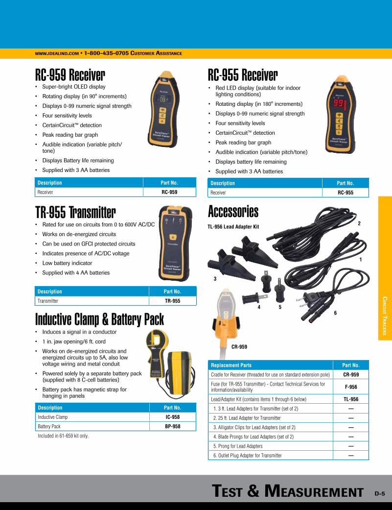
TesT & MeasureMenTTesT & MeasureMenT D-5
www.idealind.com • 1-800-435-0705 customer assistance
RC-955 Receiver
Accessories
RC-959 Receiver• Super-bright OLED display
• Rotating display (in 90° increments)
• Displays 0-99 numeric signal strength
• Four sensitivity levels
• CertainCircuit™ detection
• Peak reading bar graph
• Audible indication (variable pitch/tone)
• Displays Battery life remaining
• Supplied with 3 AA batteries
• Red LED display (suitable for indoor lighting conditions)
• Rotating display (in 180° increments)
• Displays 0-99 numeric signal strength
• Four sensitivity levels
• CertainCircuit™ detection
• Peak reading bar graph
• Audible indication (variable pitch/tone)
• Displays battery life remaining
• Supplied with 3 AA batteries
Description Part No.
Receiver RC-959
Description Part No.
Receiver RC-955
cir
cu
iT Tr
ac
ers
TR-955 Transmitter• Rated for use on circuits from 0 to 600V AC/DC
• Works on de-energized circuits
• Can be used on GFCI protected circuits
• Indicates presence of AC/DC voltage
• Low battery indicator
• Supplied with 4 AA batteries
Description Part No.
Transmitter TR-955
Inductive Clamp & Battery Pack• Induces a signal in a conductor
• 1 in. jaw opening/6 ft. cord
• Works on de-energized circuits and energized circuits up to 5A, also low voltage wiring and metal conduit
• Powered solely by a separate battery pack (supplied with 8 C-cell batteries)
• Battery pack has magnetic strap for hanging in panels
Description Part No.
Inductive Clamp IC-958
Battery Pack BP-958
Included in 61-659 kit only.
Replacement Parts Part No.
Cradle for Receiver (threaded for use on standard extension pole) CR-959
Fuse (for TR-955 Transmitter) - Contact Technical Services for information/availability F-956
Lead/Adapter Kit (contains items 1 through 6 below) TL-956
1. 3 ft. Lead Adapters for Transmitter (set of 2) —
2. 25 ft. Lead Adapter for Transmitter —
3. Alligator Clips for Lead Adapters (set of 2) —
4. Blade Prongs for Lead Adapters (set of 2) —
5. Prong for Lead Adapters —
6. Outlet Plug Adapter for Transmitter —
CR-959
3
56
1
2TL-956 Lead Adapter Kit
4

D-6
TesT & MeasureMenTwww.idealind.coM • 1-800-435-0705 cusToMer assisTance
TightSight™ Clamp Meters
cla
Mp M
eTer
s
Problem: Have you ever had to measure the circuit current in a confined, dimly lit and hard to reach location?
Solution: IDEAL TightSight™ Clamp Meter! This meter allows the user to safely and easily view current measurements with the exclusive second TightSight® display.
Safety• Patented TightSight™ display lets you easily view readings while keeping your head at a safe distance from the panel — no more need to twist the meter or risk pulling on an energized conductor• Easy-to-read backlit display with large numbers and icons so you can always see the correct reading• Selectable audible and visual alerts when potentially hazardous voltages are detected at the probe terminals• Electronic overload protection on all ranges• Supplied with test leads complying with UL 61010-031
Productivity• Read instantaneous values while clamped instead of holding the reading, unclamping, moving and then viewing• Hook tip for easier wire separation and tapered jaws for reaching into tight spaces• Help troubleshoot with min and max value readings over a period, i.e. nuisance tripping and power supply fluctuations• True RMS provides accurate readings of non-sinusoidal voltages and currents• Broad current range from 0 to 1000 amps (61-770 series) covers multiple applications• Large jaw diameter for cables up to 2” (51mm) in diameter (770 series only)
Value• Includes carrying case and test leads with alligator clips• Full AC/DC capabilities: the Tightsight™ is equally adaptable for both AC and DC current measurement requirements – such as solar, public transportation, and battery backup applications (Models 61-765 & 61-775)• Calibration services available• 2-year warranty
600V 1000VVisiT claMp-MeTer.coM for More inforMaTion.

TesT & MeasureMenTTesT & MeasureMenT D-7
www.idealind.com • 1-800-435-0705 customer assistance
cla
Mp M
eTers
TightSight™ 1000A Clamp Meters TightSight™ 660A Clamp Meters• TightSight™ second display
• Tapered jaws with hook tip
• True RMS current and voltage
• AC/DC Voltage
• Audible continuity
• High frequency rejection*
• Peak hold
• Max/min hold
• Data hold
• Selectable audible and visual alerts when potentially hazardous voltages are detected at the probe terminals
• Selectable auto power off
• Backlit display
• Low battery indicator
* Reads accurately on noisy electrical circuits.
• TightSight™ bottom display
• Tapered jaws with hook tip
• True RMS current and voltage
• AC/DC Voltage
• Audible continuity
• High frequency rejection*
• Peak hold
• Max/min hold
• Data hold
• Selectable audible and visual alerts when potentially hazardous voltages are detected at the probe terminals
• Selectable auto power off
• Backlit display
• Low battery indicator
* Reads accurately on noisy electrical circuits.
Description Part No.
1000A AC Clamp Meter 61-773
1000A AC/DC Clamp Meter 61-775
Includes: Carrying Case and Test Leads w/Alligator Clip.
Accessories Part No.
Test Leads w/Large Alligator Clips TL-770
Nylon Carrying Case (for 61-763 & 61-765) C-760
Nylon Carrying Case (for 61-773 & 61-775) C-770
Description Part No.
660A AC Clamp Meter 61-763
660A AC/DC Clamp Meter 61-765
Includes: Carrying Case and Test Leads w/Alligator Clip.
600V 1000V
Range & ResolutionAccuracy
Specifications 61-773 61-775 61-763 61-765
AC Current 0.0-999.9A 0.0-660.0A 2.0%
DC Current — 0.0-999.9A — 0.0-660.0A 2.0%
AC Voltage 0.0-750.0V 1.0%
DC Voltage 0.0-999.9V 1.0%
Resistance 0.0-999.9Ω 1.5%
Capacitance 0.0-999.9µF 5.0%
Continuity 0.0-999.9Ω Audible @ <30Ω
Frequency (clamp head or test leads) 20.0-400.0Hz 0.5%
Jaw Size 2” (51mm) 1.42” (36mm) —

D-8
TesT & MeasureMenTwww.idealind.coM • 1-800-435-0705 cusToMer assisTance
Clamp-Pro™ Clamp Meters 600 Amp (740 Series)
• Measures up to 600A AC
• Non-contact voltage indicator (70V-600VAC)
• Audible continuity
• Tapered jaws with hook tip
• Auto/manual ranging
• Data hold
• Auto power off
• Low battery indicator
Description Part No.
600A AC Clamp Meter 61-744
600A AC Clamp Meter w/TRMS 61-746
Includes: Carrying Case and Test Leads.
cla
Mp M
eTer
s
Specifications Range & Resolution Accuracy
AC Current 40.00/400.0/600A 1.7%
AC Voltage 400.0/600 V 1.2%
DC Voltage 400.0/600 V 0.5%
Resistance400.0/4.000k/ 40.00k
400.0k/4.000M/40.00M Ω 1.0%
Jaw opening is 1.25” (32mm).
Description Part No.
4-in-1 Test Tool w/TRMS, Backlight 61-704
Includes: Carrying Case and Silicone Test Leads.
1000V
4-in-1 Test Tool
• 200AAC current capability
• Non-contact voltage (40-600VAC)
• Visual, audible and tactile (shaker) indication of high AC/DC voltage at terminals
• Clean voltage indicator
• Max hold
• Audible continuity
• Low battery indication
• Integral lead storage
• Auto power off
• Ergonomic hourglass shape
• Compact clamp head
Specifications Range & Resolution Accuracy
AC Voltage 2000m/200.0/750 V 1.2%
DC Voltage 2000m/200.0/1000 V 0.5%
AC Current 200A 3.0%
Resistance 200.0/200.0k Ω 1.0%
Capacitance 200.0µ F 3.0%
Jaw opening is 1.3” (33mm).
600V
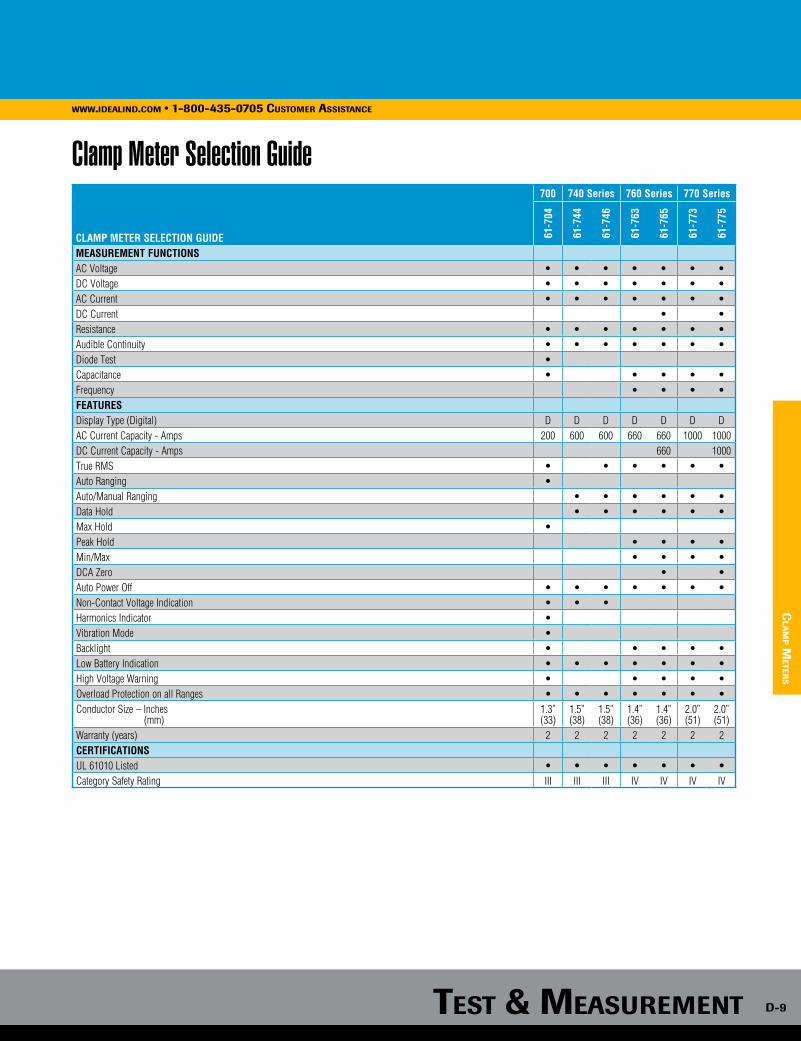
TesT & MeasureMenTTesT & MeasureMenT D-9
www.idealind.com • 1-800-435-0705 customer assistance
Clamp Meter Selection Guide
cla
Mp M
eTers
700 740 Series 760 Series 770 Series
CLAMP METER SELECTION GUIDE 61-7
04
61-7
44
61-7
46
61-7
63
61-7
65
61-7
73
61-7
75
MEASUREMENT FUNCTIONSAC Voltage • • • • • • •DC Voltage • • • • • • •AC Current • • • • • • •DC Current • •Resistance • • • • • • •Audible Continuity • • • • • • •Diode Test •Capacitance • • • • •Frequency • • • •FEATURESDisplay Type (Digital) D D D D D D DAC Current Capacity - Amps 200 600 600 660 660 1000 1000DC Current Capacity - Amps 660 1000True RMS • • • • • •Auto Ranging •Auto/Manual Ranging • • • • • •Data Hold • • • • • •Max Hold •Peak Hold • • • •Min/Max • • • •DCA Zero • •Auto Power Off • • • • • • •Non-Contact Voltage Indication • • •Harmonics Indicator •Vibration Mode •Backlight • • • • •Low Battery Indication • • • • • • •High Voltage Warning • • • • •Overload Protection on all Ranges • • • • • • •Conductor Size – Inches (mm)
1.3”(33)
1.5”(38)
1.5”(38)
1.4”(36)
1.4”(36)
2.0”(51)
2.0”(51)
Warranty (years) 2 2 2 2 2 2 2CERTIFICATIONSUL 61010 Listed • • • • • • •Category Safety Rating III III III IV IV IV IV
Specifications Range & Resolution Accuracy
AC Voltage 2000m/200.0/750 V 1.2%
DC Voltage 2000m/200.0/1000 V 0.5%
AC Current 200A 3.0%
Resistance 200.0/200.0k Ω 1.0%
Capacitance 200.0µ F 3.0%
Jaw opening is 1.3” (33mm).

D-10
TesT & MeasureMenTwww.idealind.coM • 1-800-435-0705 cusToMer assisTance
Br
an
ch c
irc
uiT
an
aly
sis
& T
esTi
ng
Branch Circuit Analysis and TestingProper wiring is crucial to ensure safety and performance of Branch circuits. From a safety perspective, shock hazards and fires are mainly due to poor installation or failure of protective devices, such as GFCIs. From a performance perspective, electrical equip-ment and high-tech devices are found everywhere in residential and commercial buildings. They require reliable power to operate and function properly and to ensure their longevity.
IDEAL has a long history of providing the professional electrician with the tools and knowledge required to safely and efficiently verify and analyze Branch Circuits. So, whether you are; conducting routine measurements, testing installed devices or the integrity of a Branch Circuit, locating a breaker, or tracing wires, IDEAL has the tools for the job.
www.iDealinD.coM • 1-800-435-0705 cusToMer assisTance
TesT & MeasureMenT

TesT & MeasureMenTTesT & MeasureMenT D-11
www.idealind.com • 1-800-435-0705 customer assistance
cir
cu
iT an
aly
zer
s
Have wiring issues ever required you to remove multiple outlet covers and pull outlets out of their boxes to look for a problem? Have you ever suspected that wiring integrity is the issue but your meter shows 120 volts and your receptacle tester indicates wiring is correct?
The SureTest® Circuit Analyzer from IDEAL is a comprehensive branch circuit analyzer that allows you to “look behind the walls” to find wiring problems, saving you time and money while letting you get the job done with safety and confidence.
SureTest Circuit Analyzer finds many of the toughest problems:
SureTest® Circuit Analyzer
300V
Description Part No.
SureTest® Circuit Analyzer 61-164
Includes: Carrying Case and Test Leads.
Accessories Part No.
Ground Continuity Adapter 61-175
Isolated Ground Adapter 61-176
Alligator Clip Adapter 61-183
1’ Extension Cord 61-182
Nylon Carrying Case 61-179
Specifications Range & Resolution AccuracyAC Voltage 85.0 - 265.0 VAC 1.0%Frequency 45.0 - 65.0 Hz 1.0%Impedance 0.00 - 3.00 Ω 5.0%Ground-Neutral Voltage 0.0 - 24.0 VAC 2.0%% Voltage Drop 12A, 15A, 20A load tests 0.1% - 50.0% 5.0%GFCI Test Current/Time 6.0 - 9.0 mA 0.0 - 6500 mS 2.0%
www.iDealinD.coM • 1-800-435-0705 cusToMer assisTance
Bootleg Grounds have been fooling inspectors for years when checking circuits for integrity. Receptacle (Plug) testers test for voltage and can’t identify this improper wiring condition. Bootleg grounds set up the potential for dangerous undetected fault conditions.
Solution: The SureTest® by IDEAL can’t be fooled, its advanced processing software gives it the capability to quickly identify bootleg grounds within 15 ft. of the outlet being tested.
Improper Installations can result in electrical fire hazards, personal shock hazards. and premature equipment failure.
Excessive voltage drop in a circuit can cause lights to flicker or burn dimly, heaters to heat poorly, and motors to run hotter than normal and burn out. It also causes overheating of components, often resulting in expensive damage or fire.
Solution: SureTest® measures the line voltage under simulated load conditions. Results are displayed for 12A, 15A, and 20A loads.
Solution: The SureTest® measures and displays individual Line Impedance giving the electrician/inspector valuable insight as to whether a particular conductor is the problem due perhaps to faulty splicing, overly long conductor runs, or undersized wire gauge.
Traditional receptacle test indicates circuit is good.
Improper solid wire connection.
Improper stranded wire connection.
Improperly torqued circuit breaker lugs.
IDEAL SureTest™ clearly identifies a fault with the ground.
• Measures voltage drop under load*
• Hot, neutral, and ground conductor impedances
• Estimates Load on Line (ELL) up to 15A
• Tests GFCIs and EPDs for proper operation
• Super-bright OLED display
• True RMS
• Identifies proper wiring in 3-wire receptacles
• Identifies false (bootleg) grounds
• Tests without disturbing sensitive loads
• Verifies isolated grounds (with 61-176 adapter)
• 2-year warranty
*12A, 15A, 20A load tests

D-12
TesT & MeasureMenTwww.idealind.coM • 1-800-435-0705 cusToMer assisTance
sp
ecia
lTy T
esTe
rs
Circuit Breaker Finder w/GFCI Receptacle Testing and Non-Contact Voltage SensingLocating breakers is often a two person job, one turning off breakers, the other waiting to see when a specific circuit is de-energized. It is frequently done by trial and error, or even by dangerously grounding a wire to the box to trip a breaker.
When locating breakers becomes needlessly time consuming and short cuts are taken, nobody wins. It was with this challenge in mind that IDEAL developed the Digital Circuit Breaker Finder.
The patented 61-534 Digital Circuit Breaker Finder from IDEAL makes locating breakers in AC circuits quick and easy. No need to interrupt the supply - simply plug the transmitter into an outlet, then two quick passes of the receiver over the breakers will reveal the associated breaker with clear audible and visual indicators. The 61-534 Digital Circuit Breaker Finder enables safer and more reliable working by taking the guesswork out of circuit identification.
The IDEAL 61-534 Circuit Breaker Finder provides three testers in one device. The receiver identifies breakers by detecting a signal applied to the branch circuit by the transmitter, and additionally incorporates a non-contact voltage sensing function. The transmitter also works as a GFCI receptacle tester, allowing you to verify AC is present in an outlet and to detect nearly all common improper wiring conditions. So you get the functionality of a circuit breaker finder, a non-contact voltage tester, and a GFCI receptacle tester in one versatile tool.
Features & SpecificationsTransmitter• Triple function - acts as a Signal Transmitter, Polarity Indicator and GFCI Receptacle Tester• Tests for correct wiring, open ground, reverse polarity, open hot, open neutral, hot on neutral, hot and ground reversed with open hot in 3 wire, AC circuits• 3-pin plug format allows direct connection to standard NEMA 5 15R receptacles• Power Supply: Line powered (115-250VAC)• Supply Frequency: 47-63Hz• Weight: 50g approx.• Pulse Amplitude: 18A approx. @ 120V• Pulse Rate: 4mS every 17ms (@ 60Hz)• Power Consumption: 200mW max. @ 120VAC
Description Part No.
Circuit Breaker Finder w/Digital Receiver & GFCI Circuit Tester 61-534
Split-Jaw™ Smart Meter• Measures 0.9-200AAC 1.3-750VAC 2.1-1000VDC 0.0-9999Ω
• Audible continuity
• Data hold
600V 1000V
Specifications Range & Resolution AccuracyAC Voltage 1.3 - 750 V 1.5%
DC Voltage 1.8 - 1000 V0.6 - 1000 V 1.0%
AC Current 0.6 - 200.0A 3.0%Resistance 0 - 2000 Ω 1.0%*Note: Jaw opening is 0.6 in. (16mm) - up to 1/0 copper cable.
Receiver• Dual function - acts as a Non-Contact Voltage Tester and Breaker Finder• Ergonomic Bent Tip Design w/ flat surface to support correct receiver orientation when scanning the panel• Visual and audible indicators• Low battery detect• Auto Power off (after 10 mins of no activity)• Power Supply: 9V Alkaline Battery• Weight: 85g (without battery)
System• Warranty: 2-years (limited)• Certification: UL 1436• Use Environment: Cat II 300V• Operating Temperature: 32 to 122°F (0 to 50°C)
• Integral lead storage
• Replaceable test leads
• Auto power off
• Low battery indication
• Test leads UL 61010-031 compliant
• 2-year warranty
Description Part No.
Split-Jaw™ Smart Meter 61-096
Includes: Test Leads.
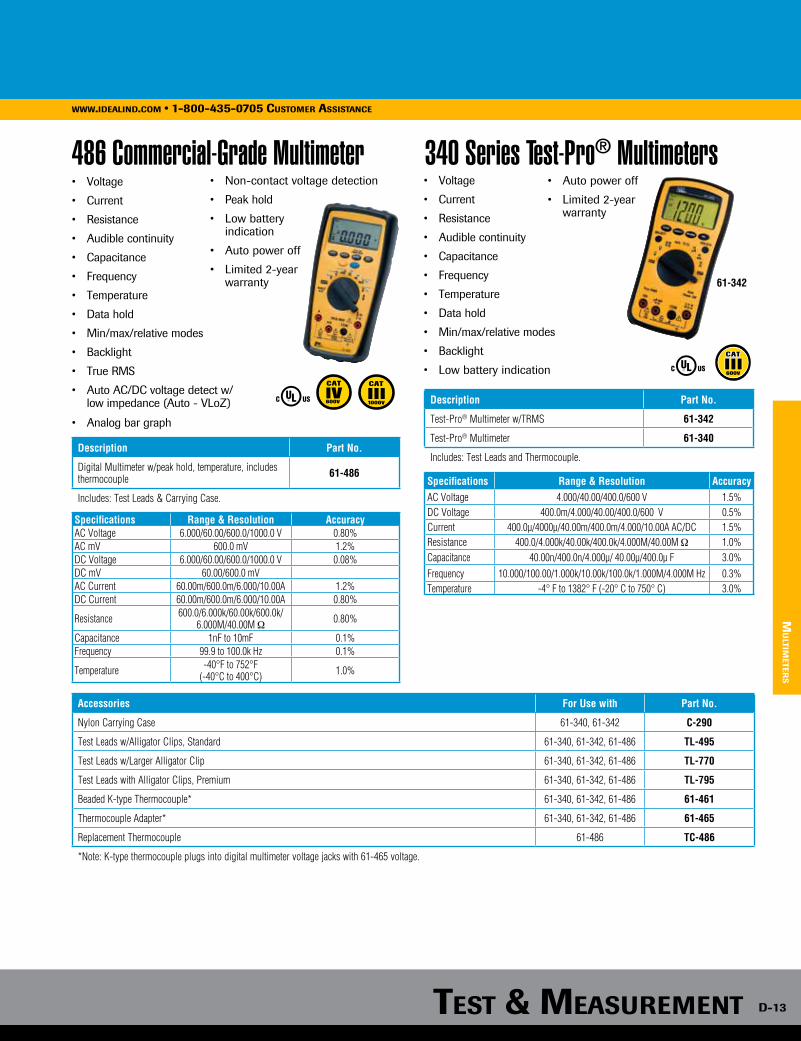
TesT & MeasureMenTTesT & MeasureMenT D-13
www.idealind.com • 1-800-435-0705 customer assistance
Mu
lTiMeTer
s
486 Commercial-Grade Multimeter• Voltage
• Current
• Resistance
• Audible continuity
• Capacitance
• Frequency
• Temperature
• Data hold
• Min/max/relative modes
• Backlight
• True RMS
• Auto AC/DC voltage detect w/low impedance (Auto - VLoZ)
• Analog bar graph
• Non-contact voltage detection
• Peak hold
• Low battery indication
• Auto power off
• Limited 2-year warranty
Description Part No.
Digital Multimeter w/peak hold, temperature, includes thermocouple 61-486
Includes: Test Leads & Carrying Case.
600V 1000V
Specifications Range & Resolution AccuracyAC Voltage 6.000/60.00/600.0/1000.0 V 0.80%AC mV 600.0 mV 1.2%DC Voltage 6.000/60.00/600.0/1000.0 V 0.08%DC mV 60.00/600.0 mVAC Current 60.00m/600.0m/6.000/10.00A 1.2%DC Current 60.00m/600.0m/6.000/10.00A 0.80%
Resistance 600.0/6.000k/60.00k/600.0k/6.000M/40.00M Ω 0.80%
Capacitance 1nF to 10mF 0.1% Frequency 99.9 to 100.0k Hz 0.1%
Temperature -40°F to 752°F(-40°C to 400°C) 1.0%
• Voltage
• Current
• Resistance
• Audible continuity
• Capacitance
• Frequency
• Temperature
• Data hold
• Min/max/relative modes
• Backlight
• Low battery indication
• Auto power off
• Limited 2-year warranty
340 Series Test-Pro® Multimeters
Description Part No.
Test-Pro® Multimeter w/TRMS 61-342
Test-Pro® Multimeter 61-340
Includes: Test Leads and Thermocouple.
Accessories For Use with Part No.
Nylon Carrying Case 61-340, 61-342 C-290
Test Leads w/Alligator Clips, Standard 61-340, 61-342, 61-486 TL-495
Test Leads w/Larger Alligator Clip 61-340, 61-342, 61-486 TL-770
Test Leads with Alligator Clips, Premium 61-340, 61-342, 61-486 TL-795
Beaded K-type Thermocouple* 61-340, 61-342, 61-486 61-461
Thermocouple Adapter* 61-340, 61-342, 61-486 61-465
Replacement Thermocouple 61-486 TC-486
*Note: K-type thermocouple plugs into digital multimeter voltage jacks with 61-465 voltage.
600V
Specifications Range & Resolution AccuracyAC Voltage 4.000/40.00/400.0/600 V 1.5%DC Voltage 400.0m/4.000/40.00/400.0/600 V 0.5%Current 400.0µ/4000µ/40.00m/400.0m/4.000/10.00A AC/DC 1.5%Resistance 400.0/4.000k/40.00k/400.0k/4.000M/40.00M Ω 1.0%Capacitance 40.00n/400.0n/4.000µ/ 40.00µ/400.0µ F 3.0%Frequency 10.000/100.00/1.000k/10.00k/100.0k/1.000M/4.000M Hz 0.3%Temperature -4° F to 1382° F (-20° C to 750° C) 3.0%
61-342

D-14
TesT & MeasureMenTwww.idealind.coM • 1-800-435-0705 cusToMer assisTance
Vol-Con® Elite Digital Voltage Tester
Description Part No.
Vol-Con® Elite Digital Voltage Tester w/vibration mode 61-092
Nylon Carrying Case C-90
Silicone Test Leads TL-102
Includes: Silicone Test Leads.
Solenoid Voltage Testers• Extremely rugged and reliable
• Vibrates when AC voltage is present
• Indicates AC/DC voltage level
• Replaceable leads with shielded probe tips (UL 61010-031 compliant)
• Bright, long-life LED’s and neon indicator lamp
• Dual voltage indication for backup safety
• 2-year warranty
Description Part No.
Vol-Con® Voltage/Continuity Tester, 5-600V AC/DC 61-076
Vol-Test® Voltage Tester, 100-600V AC/DC 61-065
Nylon Carrying Case C-90
Standard Test Leads (for use with 61-076 & 61-065) 61-070
Resistor Fused Leads (for use with 61-076 & 61-065) 61-072
Includes: Standard Test Leads.
600V
61-076
E-Z Check® Circuit Tester• Tests for correct wiring, open
ground, reverse polarity, open hot, open neutral, hot on neutral, hot and ground reversed with open hot in 3-wire, 120VAC circuits
• Simulates ground fault for testing GFCIs (61-051 only)
• No-slip ergonomic design maximizes comfort
• Premium neon lamps prevent false readings
• Tough, impact-resistant case
• 2-year warranty
Description Part No.
E-Z Check® Plus GFCI Circuit Tester 61-051
E-Z Check® Circuit Tester 61-035
• Tests for correct wiring in 3-wire receptacles
• For use on 120VAC circuits
• 1-year warranty
Description Part No.
GFCI Receptacle Tester 61-501
Receptacle Tester
VoltAware™ Non-Contact Voltage Tester
Description Part No.
VoltAware™ Non-Contact Voltage Tester 61-025
• Tests for voltage from 40-600VAC
• Audible and visual indication
• 1-year warranty
Description Part No.
Volt-Sensor™ Non-Contact Voltage Tester 61-063
600V
61-051
61-035sp
ecia
lTy T
esTe
rs
• Tests for AC Voltage from 24-600VAC and DC Voltage from 6-220VDC
• Visual and audible warning
• Audible continuity
• Non-contact voltage indication (40-600VAC)
• Low impedance to eliminate ghost voltages
• Low battery indicator
• Replaceable silicone test leads (UL 61010-031 compliant)
• Integral lead storage
• 2-year warranty 1000V
VoltSensor™ Non-Contact Voltage Tester
• Indicates presence of voltage from 40-1000VAC
• Visual indication of voltage; green LED shows unit is active, flashing red indicates live voltage
• Selectable audible indication of voltage
• Sleek, compact design
• Auto shut-off to conserve battery life after ten minutes
• Low battery detector and easy battery (2 AAA included) replacement
• 2-year warranty
600V
660V
1000V

TesT & MeasureMenTTesT & MeasureMenT D-15
www.idealind.com • 1-800-435-0705 customer assistance
sp
ecia
lTy Tes
Ters
Description Part No.
Insulation Meter w/PI, DAR, Remote Probe - Includes Test Lead and Carrying Case 61-797
Remote Probe Test Leads (61-797) TL-797RP
Insulation Tester - Includes Test Leads and Carrying Case 61-795
Test Leads w/Alligator Clips, Premium (for 61-795 & 61-797) TL-795
Test Leads w/Alligator Clips, Standard (for 61-795 & 61-797) TL-495
Insulation Testers• Checks new installations for damaged insulation
• Checks existing installations and motor windings for breakdowns in
insulation
• 2-year warranty600V
660V
1000V
Range & ResolutionSpecifications 61-797 61-795Test Voltage 50/100/250/500/1000 VDC 250/500/1000 VDCVoltage AC/DC 0.1-600.0 V 0.1-600.0 VContinuity — 0.01-20.0 ΩResistance — 0-200.0ΩInsulation Resistance Up to 20G Ω Up to 4000M ΩEarth-Bond Resistance 0.01 Ω to 40.00k Ω 0.01 Ω to 19.99 Ω
Range & Resolution Accuracy Range &
Resolution Accuracy
Specifications 61-920 61-796
Ground Resistance 0/120/1200 Ω 1.5% 20.00/200.0/2000 Ω 2.0%
Ground Leakage Current
100m/1000m/15/30 A 2.0% — —
Ground Resistance Meters• Auto ranging
• Auto power off
• Hard case included
• 2-year warranty
Description Part No.
Ground Resistance Clamp Meter 61-920
3-Pole Ground Resistance Tester (includes TL-796 lead set kit) 61-796
Earth Resistance Lead Set Kit (not shown) TL-796
300V
61-796 61-920
61-797
61-795
3-Phase/Motor Rotation Tester
3-Phase Sequence TesterDigital Light Meter• Responds to all visible light
sources
• Measures in four ranges up to 20,000 Foot Candles or 200,000 Lux
• +/- 3% basic accuracy
• Data hold mode
• Max reading mode
• Auto zero adjustment
• Low battery indication
• Auto power off
• Remote sensor with 59 in. (1.5m) cable
• 2-year warranty
Description Part No.
Digital Light Meter 61-686
Includes Carrying Case.Description Part No.
3-Phase/Motor Rotation Tester 61-521
Test Lead Set TL-521
Includes Carrying Case.
• Identifies three-phase sequence
• Indicates motor rotation
• Checks for open phases
• For use up to 600VAC
• 2-year warranty
600V
300V
1000V
• For use from 120 to 600VAC
• Color-coded insulators
• Shock resistant housing
• Easy to read
• 2-year warranty
Description Part No.
3-Phase Sequence Tester 61-520
Includes Carrying Case.
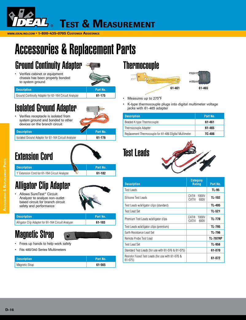
D-16
TesT & MeasureMenTwww.idealind.coM • 1-800-435-0705 cusToMer assisTance
ac
ces
so
rie
s &
rep
lac
eMen
T p
ar
Ts
Accessories & Replacement PartsGround Continuity Adapter
Isolated Ground Adapter
Extension Cord
Alligator Clip Adapter
• Verifies cabinet or equipment chassis has been properly bonded to system ground
• Verifies receptacle is isolated from system ground and bonded to other devices on the branch circuit
• Allows SureTest® Circuit Analyzer to analyze non-outlet based circuit for branch circuit safety and performance
Description Part No.
Ground Continuity Adapter for 61-164 Circuit Analyzer 61-175
Description Part No.
Isolated Ground Adapter for 61-164 Circuit Analyzer 61-176
Description Part No.
1’ Extension Cord for 61-164 Circuit Analyzer 61-182
Description Part No.
Alligator Clip Adapter for 61-164 Circuit Analyzer 61-183
Thermocouple
• Measures up to 275°F
• K-type thermocouple plugs into digital multimeter voltage jacks with 61-465 adapter
Description Part No.
Beaded K-type Thermocouple 61-461
Thermocouple Adapter 61-465
Replacement Thermocouple for 61-486 Digital Multimeter TC-486
• Frees up hands to help work safely
• Fits 480/340 Series Multimeters
Magnetic Strap
Description Part No.
Magnetic Strap 61-565
61-461 61-465
Test Leads
DescriptionCategory Rating Part No.
Test Leads TL-95
Silicone Test Leads CATIII 1000VCATIV 600V TL-102
Test Leads w/alligator clips (standard) TL-495
Test Lead Set TL-521
Premium Test Leads w/alligator clips CATIII 1000VCATIV 600V TL-770
Test Leads w/alligator clips (premium) TL-795
Earth Resistance Lead Set TL-796
Remote Probe Test Lead TL-797RP
Test Lead Set TL-956
Standard Test Leads (for use with 61-076 & 61-075) 61-070
Resistor Fused Test Leads (for use with 61-076 & 61-075) 61-072
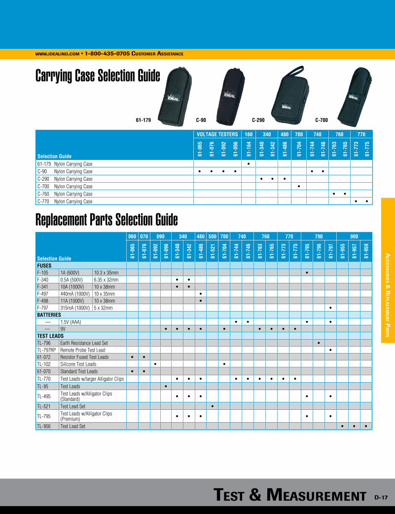
TesT & MeasureMenTTesT & MeasureMenT D-17
www.idealind.com • 1-800-435-0705 customer assistance
ac
ces
so
ries &
rep
lac
eMen
T pa
rTs
Selection Guide
VOLTAGE TESTERS 160 340 480 700 740 760 770
61-0
65
61-0
76
61-0
92
61-0
96
61-1
64
61-3
40
61-3
42
61-4
86
61-7
04
61-7
44
61-7
46
61-7
63
61-7
65
61-7
73
61-7
75
61-179 Nylon Carrying Case •C-90 Nylon Carrying Case • • • • • •C-290 Nylon Carrying Case • • •C-700 Nylon Carrying Case •C-760 Nylon Carrying Case • •C-770 Nylon Carrying Case • •
Replacement Parts Selection Guide
Carrying Case Selection Guide
Selection Guide
060 070 090 340 480 500 700 740 760 770 790 900
61-0
65
61-0
76
61-0
92
61-0
96
61-3
40
61-3
42
61-4
86
61-5
21
61-7
04
61-7
44
61-7
46
61-7
63
61-7
65
61-7
73
61-7
75
61-7
95
61-7
96
61-7
97
61-9
55
61-9
57
61-9
59
FUSESF-105 1A (600V) 10.3 x 35mm •F-340 0.5A (500V) 6.35 x 32mm • •F-341 10A (1000V) 10 x 38mm • •F-497 440mA (1000V) 10 x 35mm •F-498 11A (1000V) 10 x 38mm •F-797 315mA (1000V) 5 x 32mm •BATTERIES
— 1.5V (AAA) • • • •— 9V • • • • • • • • •
TEST LEADSTL-796 Earth Resistance Lead Set •TL-797RP Remote Probe Test Lead •61-072 Resistor Fused Test Leads • •TL-102 Silicone Test Leads • •61-070 Standard Test Leads • •TL-770 Test Leads w/larger Alligator Clips • • • • • • • • •TL-95 Test Leads •
TL-495 Test Leads w/Alligator Clips (Standard) • • • • •
TL-521 Test Lead Set •
TL-795 Test Leads w/Alligator Clips (Premium) • • • • •
TL-956 Test Lead Set • • •
C-90 C-290 C-70061-179
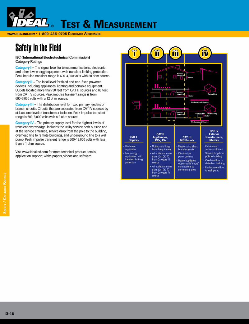
D-18
TesT & MeasureMenTwww.idealind.coM • 1-800-435-0705 cusToMer assisTance
Safety in the FieldIEC (International Electrotechnical Commission) Category Ratings
Category I – The signal level for telecommunications, electronic and other low-energy equipment with transient limiting protection. Peak impulse transient range is 600-4,000 volts with 30 ohm source.
Category II – The local level for fixed and non-fixed powered devices including appliances, lighting and portable equipment. Outlets located more than 30 feet from CAT III sources and 60 feet from CAT IV sources. Peak impulse transient range is from 600-6,000 volts with a 12 ohm source.
Category III – The distribution level for fixed primary feeders or branch circuits. Circuits that are separated from CAT IV sources by at least one level of transformer isolation. Peak impulse transient range is 600-8,000 volts with a 2 ohm source.
Category IV – The primary supply level for the highest levels of transient over voltage. Includes the utility service both outside and at the service entrance, service drop from the pole to the building, overhead line to remote buildings, and underground line to a well pump. Peak impulse transient range is 600-12,000 volts with less than a 1 ohm source.
Visit www.idealind.com for more technical product details, application support, white papers, videos and software.
CAT I Copiers
• Electronic equipment• Low energy equipment with transient limiting protection
CAT II Appliances, PCs, TVs
• Outlets and long branch equipment• All outlets at more than 10m (30 ft) from Category III source• All outlets at more than 20m (60 ft) from Category IV source
CAT III MC Panels
• Feeders and short branch circuits• Distribution panel devices• Heavy appliance outlets with “short” connections to service entrance
CAT IV Exterior Transformers, Meters
• Outside and service entrance• Service drop from pole to building• Overhead line to detached building• Underground line to well pump
ServiceEntrance
ServiceEntrance
Meter
Meter
MeterTransformer
Outbuilding
Underground Service
ServiceEntrance Outbuilding
Underground Service
sa
feTy
/ c
aTe
go
ry r
aTi
ng
s
www.idealind.com • 1-800-435-0705 customer assistance
Testers SignalTEK® II Transmission Testers ............. E-3 SecuriTEST® PRO CCTV/Security Tester ............................................................ E-3 VDV II Cable Verifiers ..................................... E-3 TraceTone® Tone Generator & Amplifier Probe Tester .............................. E-4 LinkMaster™ Tester ......................................... E-4
Compression Tools/Connectors OmniSeal™ Pro XL Compression Tool ........ E-5 LinearX® Pro Compression Tool ................... E-5 Compression Connectors ............................. E-6
Tools Crimpmaster™ Crimp Tool ............................. E-7 Punchdown Tool ............................................... E-9 Telephone Tools ................................................ E-9 Modular Plugs .................................................. E-10 Strippers ............................................................ E-11 Cutters/Scissors .............................................. E-12 Splitters .............................................................. E-13 Kits....................................................................... E-13 Fiber Optic ......................................................... E-16
www.idealind.com • 1-800-435-0705 customer assistance
datacomm

e-2e-2
Enhance existing technologies and provide a foundation for tomorrowIDEAL DataComm provides installation and testing solutions for twisted pair, coax and fiber based applications. Designed for the professional, IDEAL tools, testers and connectivity products offer an integrated approach to cut, strip, terminate and test a wide variety of low-voltage applications. Combined with our technical expertise, product training and customer support, this integrated approach ensures that your total cost of ownership is minimized.
datacommwww.idealind.com • 1-800-435-0705 customer assistance

datacomm e-3datacomm e-3
tes
ters
SignalTEK® II Ethernet Data Transmission Testers
Description Part No.
SignalTEK® CT Transmission Tester R156004
SignalTEK® NT Transmission Tester R156003
• If you install or maintain data cabling, SignalTEK® CT & SignalTEK® NT allow you to generate PDF test reports that prove installed links run at Gigabit Ethernet transmission rates.
• For installers, this means having a cost-effective way to demonstrate that the cabling was installed correctly and is capable of supporting Ethernet applications. By proving real world performance, SignalTEK® CT confirms a professional job - reducing the risk of call backs.
• SignalTEK® NT tests cable as well as active Ethernet networks by transmitting simulated web, VoIP, IP video and IP CCTV data through the LAN, stress-testing both the network equipment and the cable. SignalTEK® NT will also test fiber optic cable and connect to live fiber optic LANs with optional SFP (small form-factor pluggable) modules.
• SignalTEK® gives network installers and owners the assurance that installed cabling will support bandwidth hungry services like VoIP, IP CCTV and video streaming at full gigabit speeds without dropping data packets as required by the IEEE 802.3ab Ethernet standard.
SecuriTEST® PRO CCTV/Security Tester SecuriTEST® PRO is the most versatile all-in-one installation and troubleshooting tool for the CCTV professional. CCTV installers often need to carry a variety of testing tools to complete their work. SecuriTEST® PRO combines the most needed tools in one easy-to-carry package. Since all connections (video/communications/DMM) attach to a single unit, SecuriTEST® PRO eliminates the need to juggle several devices while on a ladder or lift, making working conditions safer and increasing productivity.
• IRE video level and sync tests
• Sound level test through integrated speaker and on screen level indicator
• High capacity lithium ion battery• Support for additional PTZ protocols• Carrying case included • Seven Essential CCTV Tools - Combines a CCTV video tester,
PTZ camera controller, Digital Multimeter, UTP cable tester, video test pattern generator, PTZ protocol analyzer and camera programmer in a single compact package.
• Save Time & Money - Test, aim, focus and program cameras when working alone. Save time by not having to walk back to the control center to verify functionality of each camera.
• Compact Design - Combines all the most needed security tools in a lightweight easy-to-carry unit. Sharp, bright 2.5 in.
(6.3 cm) color LCD screen with on-screen displays for PTZ control/diagnostics and DMM readouts.
• PTZ Protocol Analyzer - Compatible with 20+ PTZ protocols to test and program cameras in the field. Decodes and identifies output from PTZ console to aid in troubleshooting.
Description Part No.
SecuriTEST® PRO CCTV/Security Tester only 33-892
Replacement Lithium Polymer (LiPo) Battery 33-892-BP
www.idealind.com • 1-800-435-0705 customer assistance
VDV II Voice, Data and Video Cable Verifier The new VDV II Series are easy to use cable testers that check the integrity of copper cables commonly found in domestic, commercial or industrial voice, data or video installations, including telephone wiring, data network and video/security cabling.
• Accurate – Advanced TDR (Time Domain Reflectometry) measures cable length and provides distance to fault information (Pro model)
• Fast – Identifies wiring errors instantly and displays the results all on one screen (all models)
• Intelligent – Quickly determines which media service is running over cables, such as ISDN, PBX and PoE (Pro model)
Description Part No.
VDV II Cable Verifier includes: Tester, remote, battery and user’s guide R158000
VDV II Plus Cable Verifier includes: Tester, remote, battery, user’s guide, cables, adapters and carrying case R158002
VDV II Pro Cable Verifier includes: Tester, remote, battery, user’s guide, cables, adapters and carrying case R158003
RJ-45 Remote Units (12) - #1 - #12 158050
RJ-45 Identifiers (24) - #1 - #24 158051
Coax Remote Units (12) - #1 - #12 158053
Visit www.VdVii.com for more information on the VdV ii.

e-4
www.idealind.com • 1-800-435-0705 customer assistance
datacomm
tes
ter
s
Test-Tone-Trace Kit
VDV MultiMedia Cable Tester
• Kit includes the VDV (33-856), Amplifier Probe (62-164), carrying case and
accessories
• Tests and traces coax, twisted pair and telephone cables
All in one tester for installers working with voice, data and video applications.
• Voice — tests 2 or 3 pair, 6-position RJ-11/12 phone cables for wiremap/ continuity.
• Data — tests 8 position 8 contact CAT 3/5e/6/6a shielded and unshielded cable testing for wiremap/continuity to TIA 568A/B standards
• Video — tests coax cable for opens and shorts via F-connector interface
• Wiremap tests for opens, shorts, miswires, reversals and split pairs.
• LCD display with “PASS or ERROR” indicator displayed after each test
• Internal tone generator: Tone by pin/pair/entire cable with four different tones making fault isolation easier
• Main remote stores in base of tester
Description Part No.
Test-Tone-Trace Kit 33-866
Description Part No.
VDV MultiMedia Cable Tester 33-856
Replacement Remote IA-5516
PRO Amplifier Probe and Tone Generator Kit
TRACETone® Tone Generator & Amplifier Probe Tester • Economical solution for tracing copper low-voltage cabling
• Two selectable tone styles and adjustable volume control
• RJ-11 Alligator Clip, RJ-11 Cable Assembly included
Amplifier Probe
• Identifies and traces wire or cables within a group
• Adjustable volume knob
• Detects and audibly amplifies analog tone generation
• Compatible with analog tone generators
Tone Generator
• Emits three tone patterns
• F-Connector & RJ-11/12 interface for toning twisted pair and copper cables
• Includes alligator clips for toning de-energized copper cables
• Auto-off after three hours of non-use
Description Part No.
TRACETone® Tester 62-140
Description Part No.
Amplifier Probe & Tone Generator Kit - includes 62-164, 62-160, Lead Set, Cable Assembly 33-864
Amplifier Probe 62-164
Amplifier Probe Replacement Tip LA-4145
Tone Generator 62-160LinkMaster™ Tester
MiniTracker™ PRO Tester
LED based tester for wiremapping CAT 3/5e/6/6a twisted pair cabling.
• Wiremap for opens, shorts, reversal, miswire and split pair
• Tests by pair: 1/2, 3/6, 4/5, 7/8
• Tests shielded and unshielded RJ-45 cabling
• Debug feature cycles through errors one at a time
• Coax cable mapper and tracer with eight remotes
• LEDs identify remote number, opens and shorts
• Built in Tone Generator
• Includes carrying case with tester and remote storage
Description Part No.
LinkMaster™ Tester and Remote 62-200
Description Part No.
MiniTracker™ PRO Tester 62-1202

DataComm e-5
www.idealind.com • 1-800-435-0705 customer assistance
co
mp
res
sio
n to
ols/c
on
nec
tor
s
OmniSeal™ PRO XL Compression Tool
LinearX®3 Compression Tool
• Connects BNC, F-Type, RG11-F, RCA, 90°/Right Angle and Mini Coax compression connectors on coaxial cable
• Compresses ALL IDEAL compression connectors
• Fast and reliable solution to home theater, CATV, satellite systems and security applications
• Permanent connection so your connector never comes loose.
• Universal design with spin knob and adjustable post height works with most non-IDEAL compression connectors
Description Part No.
OmniSeal™ PRO XL Compression Tool 30-793
Description Part No.
LinearX®3 F/BNC/RCA Compression Tool (Adjustable) with four RTQ™ XR™ F-Connectors 33-632
• Compresses F/BNC/RCA connectors
• Adjustable post for different length/style connectors
• Linear stroke for consistent compression results & easy operation
• Durable & rugged zinc die-cast body with protective powder coated paint finish
• Includes four RTQ™ XR™ RG-6 Weatherproof F-Compression Connectors
INCLUDES4 WeatherProof™
Connectors
RTQ™ XR™ Reg/Tri/Quad & Plenum F-Connectors• Fits 60% regular, tri-shield and quad shield cables• Nickel-plated, brass-construction for superior corrosion resistance• Designed for use in satellite and cable TV installations• Weatherproof for indoor and outdoor use• Use 30-793 or LinearX® Compression Tools
RG-11 RTQ™ InSITE™ F-Connectors• Fits 60% regular and quad shield RG-11 cables• Plenum cable version also available• Use 30-793 Compression Tool for termination• Standard 1/4” x 1/4” cable prep. Use 45-111 Coax Stripper
InSITE™ BNC Connectors• Clear 360° window for confident cable insertions• Nickel-plated, brass-construction for superior corrosion resistance• Moisture-inhibiting design• Use 30-793 or 33-632 Compression Tool• 75 Ohm nominal impedance• Gold-plated pin contact area• Available in straight, 90° and plenum versions
OmniCONN™ F-Connectors• Non corrosive nickel plated brass body and polycarbonate bushing• Nylon adapter sleeve and o-ring provide double protection for a watertight seal• Free spinning hex nut for ease of installation onto all 7/16 ports• 75 ohm nominal impedance • Two-piece pre-assembled connectors
NJX™ Connectors• 75 ohm nominal impedance • Bandwidth up to 3 GHZ• Compatible with all IDEAL Compression Tools • Compact body size• RG-6 and RG-6 Quad versions
TLC™ Connectors• No compression tool required• 75 ohm nominal impedance • Bandwidth up to 3 GHZ• Compact body size• RG-6 and RG-6 Quad versions
Visit www.idealind.com for connector and tool compatibility.
Compression Connectors
Made in U.S.A. of U.S. and Global Components
Made in U.S.A. of U.S. and Global Components
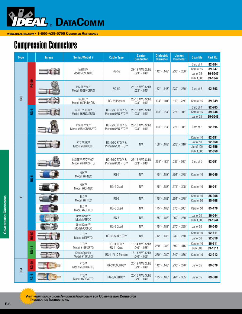
e-6
www.idealind.com • 1-800-435-0705 customer assistance
datacomm
Type Image Series/Model # Cable Type Center Conductor
Dielectric Diameter
Jacket Diameter Quantity Part No.
BNC
RG-5
9
InSITE™Model #59BNCIS RG-59 23-18 AWG Solid
.023” - .040” .142” - .148” .230” - .250”
Card of 4 92-704Card of 15 89-047Jar of 35 89-5047
Bulk 1,000 89-1047
InSITE™ 90° Model #59BNCRAIS RG-59 23-18 AWG Solid
.023” - .040” .142” - .148” .230” - .250” Card of 5 92-693
InSITE™Model #59PLBNCIS RG-59 Plenum 23-18 AWG Solid
.023” - .040” .134” - 140” .193” - 224” Card of 15 89-049
RG-6 InSITE™ RTQ™
Model #6BNCISRTQRG-6/6Q RTQ™ &
Plenum 6/6Q RTQ™23-18 AWG Solid
.023” - .040” .168” - 183” .226” - 305”Card of 4 92-705Card of 15 89-048Jar of 35 89-5048
InSITE™ 90°Model #6BNCRAISRTQ
RG-6/6Q RTQ™ & Plenum 6/6Q RTQ™
23-18 AWG Solid.023” - .040” .168” - 183” .226” - 305” Card of 5 92-695
F
RG-6
RTQ™ XR™Model #6FRTQXR
RG-6/6Q RTQ™ &Plenum 6/6Q RTQ™ N/A .168” - .183” .226” - .310”
Card of 10 92-651Jar of 50 92-650
Jar of 100 92-656Bulk 1,000 92-659
InSITE™ RTQ™ 90°Model #6FRAISRTQ
RG-6/6Q RTQ™ & Plenum 6/6Q RTQ™
23-18 AWG Solid.023” - .040” .168” - 183” .226” - 305” Card of 5 92-691
NJX™Model #6FNJX RG-6 N/A .175” - .183” .254” - .278” Card of 10 89-040
NJX™Model #6QFNJX RG-6 Quad N/A .175” - .183” .275” - .305” Card of 10 89-041
TLC™Model #6FTLC RG-6 N/A .175” - .183” .254” - .278”
Card of 10 85-068Card of 50 85-168
TLC™ Model #6QFTLC RG-6 Quad N/A .175” - .183” .275”- .305” Card of 50 85-178
OmniConn™Model #6FOC RG-6 N/A .175” - .183” .260” - .280”
Jar of 50 89-044Bulk 1,000 89-1544
OmniConn™Model #6QFOC RG-6 Quad N/A .175” - .183” .270” - .295” Jar of 50 89-045
RG-5
9 RTQ™Model #59FRTQ RG-59/59Q RTQ™ N/A .142” - .148” .230” - .270”
Card of 10 92-611
Jar of 50 92-610
RG-1
1
RTQ™Model #11FISRTQ
RG-11 RTQ™RG-11 Quad
18-14 AWG Solid.040” - .066” .280” - .285” .390” - .416”
Card of 10 89-211Bulk 500 89-1211
Cable SpecificModel #11PLFIS RG-11/11Q Plenum 18-14 AWG Solid
.040” - .066” .270” - .280” .340” - .356” Card of 10 92-212
RCA RG
-59 RTQ™
Model #59RCARTQ RG-59/59QRTQ™ 20-18 AWG Solid.029” - .040” .142” - .148” .230” - .270” Jar of 35 89-570
RG-6 RTQ™
Model #6RCARTQ RG-6/6Q RTQ™ 20-18 AWG Solid.029” - .040” .175” - .183” .267” - .305” Jar of 35 89-580
co
mp
res
sio
n c
on
nec
tor
s
Compression Connectors
Visit www.idealind.com/products/datacomm for compression connector installation instructions.
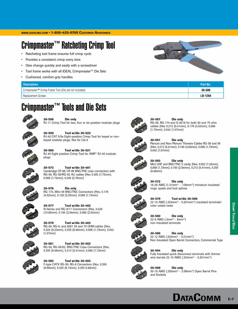
DataComm e-7
www.idealind.com • 1-800-435-0705 customer assistance
cr
imp t
oo
ls/dies
Crimpmaster™ Ratcheting Crimp Tool
Crimpmaster™ Tools and Die Sets
• Ratcheting tool frame ensures full crimp cycle
• Provides a consistent crimp every time
• Dies change quickly and easily with a screwdriver
• Tool frame works with all IDEAL Crimpmaster™ Die Sets
• Cushioned, comfort-grip handles
Description Part No.
Crimpmaster™ Crimp Frame Tool (Die set not included) 30-506
Replacement Screws LB-1284
30-556 Die onlyRJ-11 Crimp Tool for two, four or six-position modular plugs
30-559 Tool w/die 30-522RJ-45 CAT 5/5e Eight-position Crimp Tool for keyed or non-keyed modular plugs. Not for Cat 6
30-560 Tool w/die 30-521RJ-45 Eight-position Crimp Tool for AMP® RJ-45 modular plugs
30-573 Tool w/die 30-481Cambridge CP-88, CP-89 BNC/TNC coax connectors with RG-58, RG-59/RG-62 AU cables (Hex 0.305 (7.75mm), 0.068 (1.73mm), 0.228 (5.79mm)
30-576 Die onlyRG-174, Mini 59 BNC/TNC Connectors (Hex, 0.178 (4.52mm), 0.128 (3.25mm), 0.068 (1.73mm)
30-577 Tool w/die 30-482 N-Series and RG-8/11 Connectors (Hex, 0.429 (10.90mm), 0.100 (2.54mm), 0.080 (2.03mm)
30-578 Tool w/die 30-483RG-59, RG-6, and 8281 50 and 75 OHM cables (Hex, 0.324 (8.23mm), 0.255 (6.48mm), 0.068 (1.73mm), 0.042 (1.07mm)
30-581 Tool w/die 30-502RG-58, RG-59/62, BNC/TNC Coax Connectors (Hex, 0.255 (6.48mm), 0.213 (5.41mm), 0.068 (1.73mm)
30-582 Tool w/die 30-503F-type CATV RG-59, RG-6 Connectors (Hex, 0.350 (8.89mm), 0.320 (8.13mm), 0.255 6.48mm)
30-587 Die onlyRG-58, RG-174 and G-8218 for both 50 and 75 ohm cables (Hex 0.213 (5.41mm), 0.178 (4.52mm), 0.068 (1.73mm), 0.042 (1.07mm)
30-591 Die onlyPlenum and Non-Plenum Thinwire Cables RG-58 and 59 (Hex, 0.213 (5.41mm), 0.190 (4.83mm), 0.068 (1.73mm), 0.042 (1.07mm)
30-593 Die onlyMini UHF and BNC/TNC 5 cavity (Hex, 0.052 (1.32mm), 0.068 (1.73mm), 0.100 (2.54mm), 0.213 (5.41mm), 0.255 (6.48mm)
30-572 Die only16-26 AWG (1.31mm2 - .128mm2) miniature insulated rings, spade and butt splices
30-579 Tool w/die 30-50022-10 AWG (.324mm2 - 5.261mm2) insulated terminals/color coded nests
30-580 Die only22-8 AWG (.3mm2 - 8mm2) non-insulated terminals
30-586 Die only 22-12 AWG (.324mm2 - 3.31mm2) Non Insulated Open Barrel Connectors, Commercial Type
30-594 Die onlyFully Insulated quick disconnect terminals with thinner wire barrels 22-10 AWG (.324mm2 - 5.261mm2)
30-599 Die only 30-18 AWG (.205mm2 - 2.08mm2) Open Barrel Pins and Sockets

e-8
www.idealind.com • 1-800-435-0705 customer assistance
datacomm
co
nn
ecto
rs/t
oo
ls
Crimp-on F-ConnectorsNickel plated brass connectors designed for indoor coax terminations for video and other RF applications
• RG-59, RG-6, RG-6 Quad versions are available
• All versions require a hex crimp to secure cable to connector
• 1/4”x 1/4”cable prep for all models
• Crimp with 30-503 Crimpmaster™ Ratcheting Crimp tool
• Hex crimp sizes: RG-59 and RG-6, .320” cavity. RG-6 Quad, .350” cavity
Description Quantity Part No. Quantity Part No.
RG-6 F Crimp-on Coax Connector Card of 10 85-037 Card of 50 85-017
RG-6 F Quad Crimp Connector Card of 10 85-057 — —
RG-59 F Crimp-on Coax Connector Card of 10 85-036 — —
Twist-On F-Connectors• After cable is 1/4 in. x 1/4 in. stripped, simply twist on connector
• No termination tool required
• Available in two styles, RG-6 and RG-59
Description Quantity Part No.
F-Type RG-6 Twist-On ConnectorCard of 10 85-053
Card of 50 85-039
F-Type RG-59 Twist-On ConnectorCard of 4 84-018
Card of 10 85-035
Connector Installation and Removal Tool
• Patented design works on BNC and F connectors
• Works on compression and hex connectors
• Comfort grip handle aids in installing and removing connectors on coax cable
• F-post for aid in cable to connector assembly
Description Part No.
F & BNC Coax Connector Tool - 8 in. length 35-046
Coax Strip & Crimp Tool
• Precision, form-ground stripping holes remove outer jacket and insulation from RG-59 and RG-6 coaxial cable
• Durable blades cut copper-coated steel conductors
• Three crimping nests for crimping F-connectors and ring terminals
• Cushioned, comfort-grip handles
Description Part No.
Coax Strip & Crimp Tool 30-433
F-Type Adapters & Terminators • Nickel-plated brass construction
• For 75Ω applications
Description Quantity Part No.
3GHz F-Splice Adapter, high bandwidth, for standard and high definition applications, <0.25dB insertion loss, >25dB return loss
Card of 4 85-339
Card of 10 85-340
Female to RCA Male Adapter – converts female F-connectors to male RCA connectors
Card of 2 85-936
RCA Female-to-Female Adapter Card of 2 85-937
Coax Cable F-Terminators - for all open ports on coax wall plates and splitters
Card of 4 85-073
90° F-Adapter - F-female to F-male coax adapter Card of 2 85-070
BNC Female to BNC Female Adapter
Card of 2 85-075
Card of 10 92-817P

DataComm e-9
www.idealind.com • 1-800-435-0705 customer assistance
to
ols
Impact Punchdown Tool
Punchdown Tool Blades
• Insert and cut cable terminations effortlessly
• Adjustable high/low actuation setting accommodates termination requirements
• Turn-Lock™ Style blade holding design
• Impact-absorbing cushioned grip reduces operator stress for high volume installers
Description Part No.
Punchmaster™ II Punchdown Tool w/full 110 & 66 blades 35-485
Description Part No.
Probe Pic & Spudger 35-473
Removable Blades Part No.
110 Turn-Lock™ blade 35-495
66 Turn-Lock™ blade 35-497
110/66 combo blade w/cutting edges 35-407
Krone® blade 35-478
Bix® blade 35-479
Bix® is a registered trademark of Nortel. Krone® is a registered trademark of Krone, Inc.
Ratchet Telemaster™ Modular Plug Crimping Tool
Telemaster™ Modular Plug Crimping Tool
Data/Voice Crimp Tool Kit
Probe Pic & Spudger• Heavy-duty version of the 30-496 Telemaster™ tool requires less
user hand force
• Ratchet ensures full cycle crimping every time
• Crimps RJ-45 (8P8C) and RJ-11/12 (6P6C/6P4C) modular plugs
• Multi-function tool also cuts UTP/STP and strips CAT 5e/6 cable jacket and flat cable jackets
• Black oxide coated steel frame with cushioned handles for strength and comfort
Description Part No.
Ratchet Telemaster™ 30-696
Replacement Cut & Strip Blade Set LA-4102
• Crimps RJ-45 (8P8C) and RJ-11/12 (6P6C/6P4C) modular plugs
• Multi-function tool also cuts UTP/STP and strips round CAT 5e/6 cable jacket
• Black oxide coated steel frame with cushioned handles for strength and comfort
Description Replacement Blade
Kit Part No.
Tool Only Part No.
Telemaster™ Crimping Tool RJ-45 and RJ-11/12 LB-1747 33-700* 30-496
*Kit includes 10 each, RJ-45 8P8C, RJ-11 6P6C and RJ-11 6P4C modular plugs.
Description Part No.
Data/Voice Crimp Tool Kit includes ten RJ-11 (6P6C) and ten RJ-45 connectors 33-396
• Compact design is 2/3 the size of traditional crimp tools
• Crimps RJ-45 (8P8C) and RJ-11/12 (6P6C/6P4C) modular plugs
• One tool assembly process – cut, strip and crimp connectors on to CAT
3/5e/6 cables
• Black oxide coated steel core with spring loaded handle and locking feature
• For isolating conductors and removing terminated wires from voice and data IDC contacts
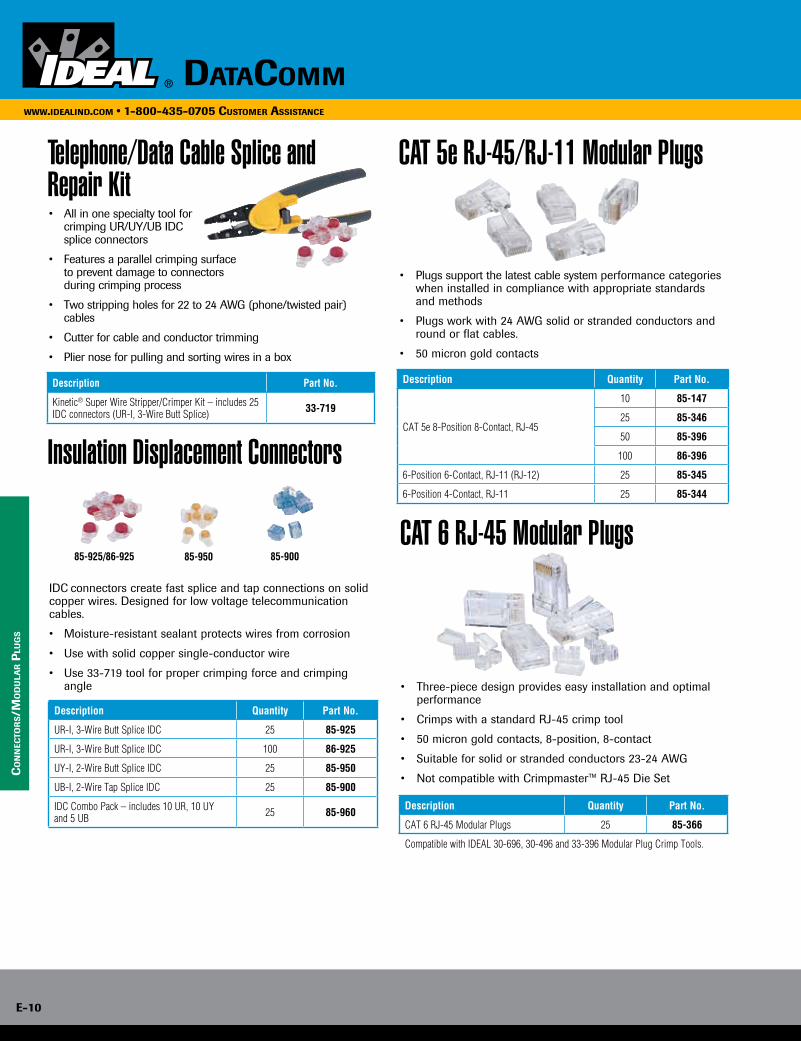
e-10
www.idealind.com • 1-800-435-0705 customer assistance
datacomm
co
nn
ecto
rs/m
od
ula
r p
lug
s
Telephone/Data Cable Splice and Repair Kit • All in one specialty tool for crimping UR/UY/UB IDC splice connectors
• Features a parallel crimping surface to prevent damage to connectors during crimping process
• Two stripping holes for 22 to 24 AWG (phone/twisted pair) cables
• Cutter for cable and conductor trimming
• Plier nose for pulling and sorting wires in a box
Description Part No.
Kinetic® Super Wire Stripper/Crimper Kit – includes 25 IDC connectors (UR-I, 3-Wire Butt Splice) 33-719
Insulation Displacement Connectors
IDC connectors create fast splice and tap connections on solid copper wires. Designed for low voltage telecommunication cables.
• Moisture-resistant sealant protects wires from corrosion
• Use with solid copper single-conductor wire
• Use 33-719 tool for proper crimping force and crimping angle
Description Quantity Part No.
UR-I, 3-Wire Butt Splice IDC 25 85-925
UR-I, 3-Wire Butt Splice IDC 100 86-925
UY-I, 2-Wire Butt Splice IDC 25 85-950
UB-I, 2-Wire Tap Splice IDC 25 85-900
IDC Combo Pack – includes 10 UR, 10 UY and 5 UB 25 85-960
85-90085-925/86-925 85-950
CAT 5e RJ-45/RJ-11 Modular Plugs
• Plugs support the latest cable system performance categories when installed in compliance with appropriate standards and methods
• Plugs work with 24 AWG solid or stranded conductors and round or flat cables.
• 50 micron gold contacts
Description Quantity Part No.
CAT 5e 8-Position 8-Contact, RJ-45
10 85-147
25 85-346
50 85-396
100 86-396
6-Position 6-Contact, RJ-11 (RJ-12) 25 85-345
6-Position 4-Contact, RJ-11 25 85-344
CAT 6 RJ-45 Modular Plugs
• Three-piece design provides easy installation and optimal performance
• Crimps with a standard RJ-45 crimp tool
• 50 micron gold contacts, 8-position, 8-contact
• Suitable for solid or stranded conductors 23-24 AWG
• Not compatible with Crimpmaster™ RJ-45 Die Set
Description Quantity Part No.
CAT 6 RJ-45 Modular Plugs 25 85-366
Compatible with IDEAL 30-696, 30-496 and 33-396 Modular Plug Crimp Tools.
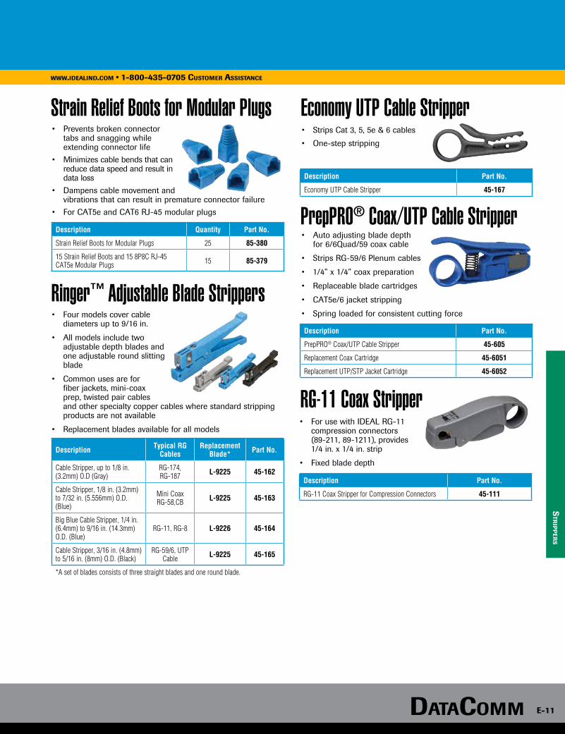
DataComm e-11
www.idealind.com • 1-800-435-0705 customer assistance
str
ipp
ers
Strain Relief Boots for Modular Plugs
Ringer™ Adjustable Blade Strippers
Economy UTP Cable Stripper • Prevents broken connector
tabs and snagging while extending connector life
• Minimizes cable bends that can reduce data speed and result in data loss
• Dampens cable movement and vibrations that can result in premature connector failure
• For CAT5e and CAT6 RJ-45 modular plugs
Description Quantity Part No.
Strain Relief Boots for Modular Plugs 25 85-380
15 Strain Relief Boots and 15 8P8C RJ-45 CAT5e Modular Plugs 15 85-379
• Four models cover cable diameters up to 9/16 in.
• All models include two adjustable depth blades and one adjustable round slitting blade
• Common uses are for fiber jackets, mini-coax prep, twisted pair cables and other specialty copper cables where standard stripping products are not available
• Replacement blades available for all models
Description Typical RG Cables
Replacement Blade* Part No.
Cable Stripper, up to 1/8 in. (3.2mm) O.D (Gray)
RG-174, RG-187 L-9225 45-162
Cable Stripper, 1/8 in. (3.2mm) to 7/32 in. (5.556mm) O.D. (Blue)
Mini Coax RG-58,CB L-9225 45-163
Big Blue Cable Stripper, 1/4 in. (6.4mm) to 9/16 in. (14.3mm) O.D. (Blue)
RG-11, RG-8 L-9226 45-164
Cable Stripper, 3/16 in. (4.8mm) to 5/16 in. (8mm) O.D. (Black)
RG-59/6, UTP Cable L-9225 45-165
*A set of blades consists of three straight blades and one round blade.
• Strips Cat 3, 5, 5e & 6 cables
• One-step stripping
Description Part No.
Economy UTP Cable Stripper 45-167
PrepPRO® Coax/UTP Cable Stripper • Auto adjusting blade depth for 6/6Quad/59 coax cable
• Strips RG-59/6 Plenum cables
• 1/4” x 1/4” coax preparation
• Replaceable blade cartridges
• CAT5e/6 jacket stripping
• Spring loaded for consistent cutting force
Description Part No.
PrepPRO® Coax/UTP Cable Stripper 45-605
Replacement Coax Cartridge 45-6051
Replacement UTP/STP Jacket Cartridge 45-6052
RG-11 Coax Stripper • For use with IDEAL RG-11
compression connectors (89-211, 89-1211), provides
1/4 in. x 1/4 in. strip
• Fixed blade depth
Description Part No.
RG-11 Coax Stripper for Compression Connectors 45-111
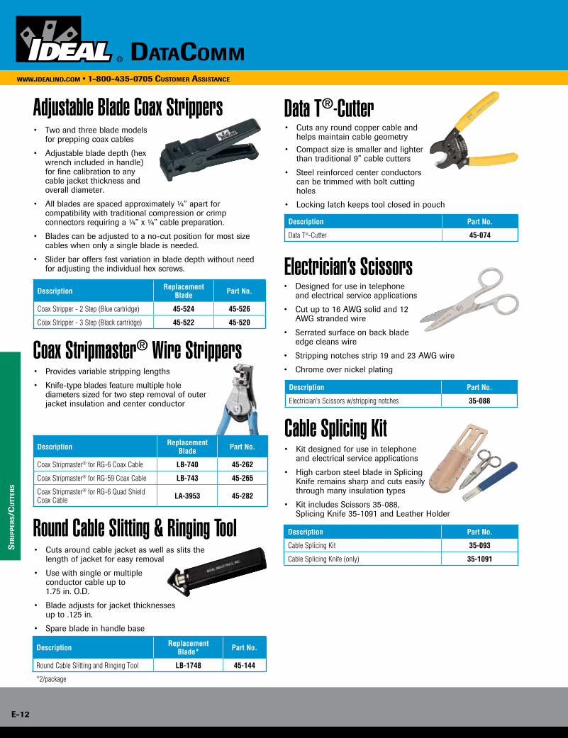
e-12
www.idealind.com • 1-800-435-0705 customer assistance
datacomm
str
ipp
ers/c
utt
ers
Adjustable Blade Coax Strippers
Coax Stripmaster® Wire Strippers
• Two and three blade models for prepping coax cables
• Adjustable blade depth (hex wrench included in handle) for fine calibration to any cable jacket thickness and overall diameter.
• All blades are spaced approximately ¼” apart for compatibility with traditional compression or crimp connectors requiring a ¼” x ¼” cable preparation.
• Blades can be adjusted to a no-cut position for most size cables when only a single blade is needed.
• Slider bar offers fast variation in blade depth without need for adjusting the individual hex screws.
Description Replacement Blade Part No.
Coax Stripper - 2 Step (Blue cartridge) 45-524 45-526
Coax Stripper - 3 Step (Black cartridge) 45-522 45-520
• Provides variable stripping lengths
• Knife-type blades feature multiple hole diameters sized for two step removal of outer jacket insulation and center conductor
Description Replacement Blade Part No.
Coax Stripmaster® for RG-6 Coax Cable LB-740 45-262
Coax Stripmaster® for RG-59 Coax Cable LB-743 45-265
Coax Stripmaster® for RG-6 Quad Shield Coax Cable LA-3953 45-282
Round Cable Slitting & Ringing Tool
Description Replacement Blade* Part No.
Round Cable Slitting and Ringing Tool LB-1748 45-144
*2/package
• Cuts around cable jacket as well as slits the length of jacket for easy removal
• Use with single or multiple conductor cable up to 1.75 in. O.D.
• Blade adjusts for jacket thicknesses up to .125 in.
• Spare blade in handle base
Data T®-Cutter
Description Part No.
Data T®-Cutter 45-074
• Cuts any round copper cable and helps maintain cable geometry
• Compact size is smaller and lighter than traditional 9” cable cutters
• Steel reinforced center conductors can be trimmed with bolt cutting holes
• Locking latch keeps tool closed in pouch
• Designed for use in telephone and electrical service applications
• Cut up to 16 AWG solid and 12 AWG stranded wire
• Serrated surface on back blade edge cleans wire
• Stripping notches strip 19 and 23 AWG wire
• Chrome over nickel plating
Description Part No.
Electrician’s Scissors w/stripping notches 35-088
Cable Splicing Kit • Kit designed for use in telephone
and electrical service applications
• High carbon steel blade in Splicing Knife remains sharp and cuts easily through many insulation types
• Kit includes Scissors 35-088, Splicing Knife 35-1091 and Leather Holder
Description Part No.
Cable Splicing Kit 35-093
Cable Splicing Knife (only) 35-1091
Electrician’s Scissors
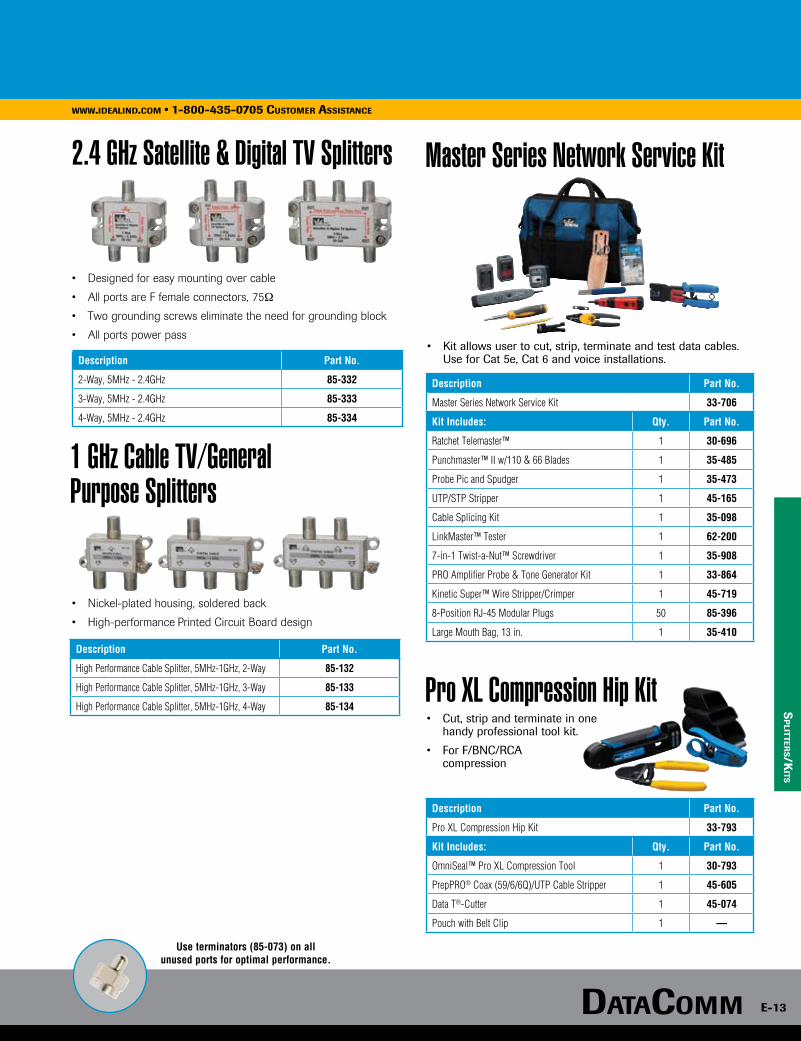
DataComm e-13
www.idealind.com • 1-800-435-0705 customer assistance
sp
litters/K
its
2.4 GHz Satellite & Digital TV Splitters
1 GHz Cable TV/General Purpose Splitters
• Designed for easy mounting over cable
• All ports are F female connectors, 75Ω
• Two grounding screws eliminate the need for grounding block
• All ports power pass
Description Part No.
2-Way, 5MHz - 2.4GHz 85-332
3-Way, 5MHz - 2.4GHz 85-333
4-Way, 5MHz - 2.4GHz 85-334
Description Part No.
Master Series Network Service Kit 33-706
Kit Includes: Qty. Part No.
Ratchet Telemaster™ 1 30-696
Punchmaster™ II w/110 & 66 Blades 1 35-485
Probe Pic and Spudger 1 35-473
UTP/STP Stripper 1 45-165
Cable Splicing Kit 1 35-098
LinkMaster™ Tester 1 62-200
7-in-1 Twist-a-Nut™ Screwdriver 1 35-908
PRO Amplifier Probe & Tone Generator Kit 1 33-864
Kinetic Super™ Wire Stripper/Crimper 1 45-719
8-Position RJ-45 Modular Plugs 50 85-396
Large Mouth Bag, 13 in. 1 35-410
Description Part No.
Pro XL Compression Hip Kit 33-793
Kit Includes: Qty. Part No.
OmniSeal™ Pro XL Compression Tool 1 30-793
PrepPRO® Coax (59/6/6Q)/UTP Cable Stripper 1 45-605
Data T®-Cutter 1 45-074
Pouch with Belt Clip 1 —
• Nickel-plated housing, soldered back
• High-performance Printed Circuit Board design
Description Part No.
High Performance Cable Splitter, 5MHz-1GHz, 2-Way 85-132
High Performance Cable Splitter, 5MHz-1GHz, 3-Way 85-133
High Performance Cable Splitter, 5MHz-1GHz, 4-Way 85-134
Master Series Network Service Kit
• Kit allows user to cut, strip, terminate and test data cables. Use for Cat 5e, Cat 6 and voice installations.
Pro XL Compression Hip Kit • Cut, strip and terminate in one
handy professional tool kit.
• For F/BNC/RCA compression
Use terminators (85-073) on all unused ports for optimal performance.
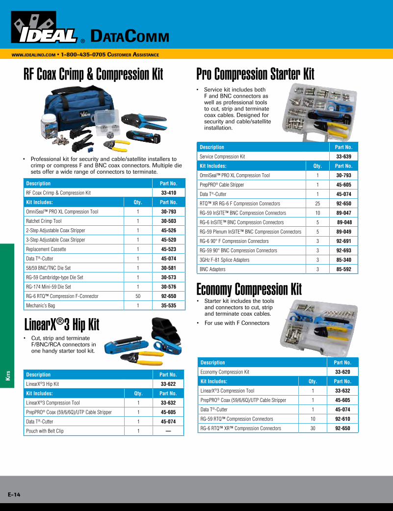
e-14
www.idealind.com • 1-800-435-0705 customer assistance
datacomm
Description Part No.
RF Coax Crimp & Compression Kit 33-410
Kit Includes: Qty. Part No.
OmniSeal™ PRO XL Compression Tool 1 30-793
Ratchet Crimp Tool 1 30-503
2-Step Adjustable Coax Stripper 1 45-526
3-Step Adjustable Coax Stripper 1 45-520
Replacement Cassette 1 45-523
Data T®-Cutter 1 45-074
58/59 BNC/TNC Die Set 1 30-581
RG-59 Cambridge-type Die Set 1 30-573
RG-174 Mini-59 Die Set 1 30-576
RG-6 RTQ™ Compression F-Connector 50 92-650
Mechanic’s Bag 1 35-535
Description Part No.
Service Compression Kit 33-639
Kit Includes: Qty. Part No.
OmniSeal™ PRO XL Compression Tool 1 30-793
PrepPRO® Cable Stripper 1 45-605
Data T®-Cutter 1 45-074
RTQ™ XR RG-6 F Compression Connectors 25 92-650
RG-59 InSITE™ BNC Compression Connectors 10 89-047
RG-6 InSITE™ BNC Compression Connectors 5 89-048
RG-59 Plenum InSITE™ BNC Compression Connectors 5 89-049
RG-6 90° F Compression Connectors 3 92-691
RG-59 90° BNC Compression Connectors 3 92-693
3GHz F-81 Splice Adapters 3 85-340
BNC Adapters 3 85-592
Description Part No.
LinearX®3 Hip Kit 33-622
Kit Includes: Qty. Part No.
LinearX®3 Compression Tool 1 33-632
PrepPRO® Coax (59/6/6Q)/UTP Cable Stripper 1 45-605
Data T®-Cutter 1 45-074
Pouch with Belt Clip 1 —
Kit
s
RF Coax Crimp & Compression Kit
• Professional kit for security and cable/satellite installers to crimp or compress F and BNC coax connectors. Multiple die sets offer a wide range of connectors to terminate.
LinearX®3 Hip Kit • Cut, strip and terminate F/BNC/RCA connectors in
one handy starter tool kit.
Pro Compression Starter Kit • Service kit includes both
F and BNC connectors as well as professional tools to cut, strip and terminate coax cables. Designed for security and cable/satellite installation.
Economy Compression Kit • Starter kit includes the tools
and connectors to cut, strip and terminate coax cables.
• For use with F Connectors
Description Part No.
Economy Compression Kit 33-620
Kit Includes: Qty. Part No.
LinearX®3 Compression Tool 1 33-632
PrepPRO® Coax (59/6/6Q)/UTP Cable Stripper 1 45-605
Data T®-Cutter 1 45-074
RG-59 RTQ™ Compression Connectors 10 92-610
RG-6 RTQ™ XR™ Compression Connectors 30 92-650

DataComm e-15
www.idealind.com • 1-800-435-0705 customer assistance
Kits
Technician’s Service Kit • Kit includes tools to install twisted pair
cable on blocks and data jacks.
RJ-45/11 Four, Six & Eight-Position Combination TelCom Termination Kit • TelCom Kit is designed for the
user who will terminate RJ-11 and RJ-45 twisted pair cables.
RJ-45 Termination Kit • Suited for the user who will cut
and terminate RJ-45 Modular Plugs.
Telemaster™ Crimp Kit
Description Part No.
Technician’s Service Kit 33-505
Kit Includes: Qty. Part No.
Electrician’s Scissors w/Stripping Notches 1 35-088
Probe Pic & Spudger 1 35-473
Punchmaster™ Punchdown Tool w/110 & 66 Blades 1 35-485
7-in-1 Twist-a-Nut™ Screwdriver/Nutdriver 1 35-908
UTP/STP Stripper 1 45-165
Nylon case 1 62-205
Description Part No.
TelCom Termination Kit 33-704
Description Qty. Part No.
Telemaster™ for RJ-11/RJ-45 Plugs 1 30-496
6P4C RJ-11 Modular Plugs 15 85-344
6P6C RJ-11 Modular Plugs 15 85-345
8P8C RJ-45 CAT 5e Modular Plugs 15 85-346
Description Part No.
RJ-45 Termination Kit 33-750
Description Qty. Part No.
Telemaster™ for RJ-11/RJ-45 Plugs 1 30-496
UTP/Coax Stripper 1 45-165
8-Position RJ-45 CAT5e Modular Plugs 50 85-346
Description Part No.
Telemaster™ Crimp Kit 33-700
Description Qty. Part No.
Telemaster™ for RJ-11 (1, 2, 3 pair) and RJ-45 Plugs 1 30-496
CAT 5e 8-Position, 8-Contact RJ-45 Modular Plugs 10 85-346
6-Position RJ-11 Modular Plugs 10 85-345
6-Position, 4-Contact RJ-11 Modular Plugs 10 85-344

e-16
www.idealind.com • 1-800-435-0705 customer assistance
datacomm
Kit
s/f
iber
op
tic
• Kit allows user to terminate modular plugs as well as data blocks or jacks.
PRO Network/Telco Installer Kit
Description Part No.
PRO Network/Telco Installer Kit 33-506
Description Qty. Part No.
Ratchet Telemaster™ 1 30-696
Punchmaster™ II 110 & 66 Blades 1 35-485
Probe Pic and Spudger 1 35-473
UTP/STP Stripper 1 45-165
Electrician’s Scissors w/Stripper Notches 1 35-088
8-Position RJ-45 Modular Plugs 50 85-396
Mechanic’s Bag 1 35-535
FiberMASTER™ Fiber Optic Test Kit
Visual Fault Finder
• Fiber Optic Power Meter & Light Source — Four wavelength power meter for multimode and single mode testing, and 850nm multimode LED light source.
• Calibration Function — Stores reference power level for quick dB loss measurements eliminating the need to manually calculate loss.
• Save Time and Money — Power meter features 2.5mm universal and FC adapters, light source includes ST®, SC and FC adapters to test the most common interfaces.
• Ready for FTTx — 1490nm measurement wavelength for use with nearly all single mode Fiber-To-The-Home applications.
• Designed for the Field — Unique “docking” light source and easy three-button operation make this the perfect fiber tester for use in the field.
Description Part No.
Power meter with 850NM fiber light source 33-928
Power meter with four wavelength MM/SM light source 33-931
Note: ST® is a registered trademark of AT&T.
Laser light source used to locate breaks, faulty splices and crimps
• 2.5mm Universal Adapter for all ST®, SC and FC connectors
• Useful over a distance of 5km (3 miles)
• Two AA batteries (included) provide over 30 hours of continuous use
• Slim, pocket-sized tool in rugged solid aluminum body
• Nylon carrying case with belt loop included
Description Part No.
Visual Fault Finder VFF5
Note: ST® is a registered trademark of AT&T.
Description Part No.
MiniLite-Strip™ Optical Fiber Stripper 45-352
• Small strip notch engineered and precision-ground to strip 900 micron or 250 micron buffer coatings from 125 micron fiber
• Larger round strip notch machined to remove the 3mm outer jacket
• Strip notches pre-set and locked, no field adjustment necessary
MiniLite-Strip™ Optical Fiber Stripper
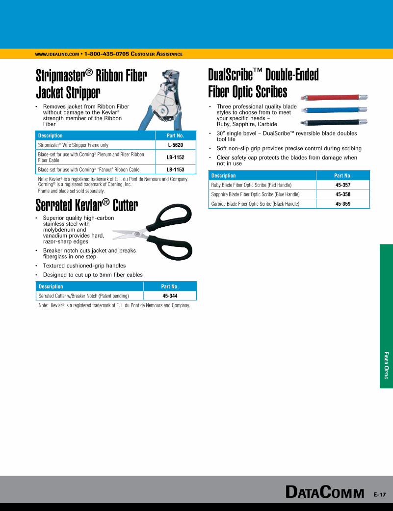
DataComm e-17
www.idealind.com • 1-800-435-0705 customer assistance
fib
er op
tic
Stripmaster® Ribbon Fiber Jacket Stripper
Serrated Kevlar® Cutter
• Removes jacket from Ribbon Fiber without damage to the Kevlar® strength member of the Ribbon
Fiber
Description Part No.
Stripmaster® Wire Stripper Frame only L-5620
Blade-set for use with Corning® Plenum and Riser Ribbon Fiber Cable LB-1152
Blade-set for use with Corning® “Fanout” Ribbon Cable LB-1153
Note: Kevlar® is a registered trademark of E. I. du Pont de Nemours and Company. Corning® is a registered trademark of Corning, Inc.Frame and blade set sold separately.
• Superior quality high-carbon stainless steel with molybdenum and vanadium provides hard, razor-sharp edges
• Breaker notch cuts jacket and breaks fiberglass in one step
• Textured cushioned-grip handles
• Designed to cut up to 3mm fiber cables
Description Part No.
Serrated Cutter w/Breaker Notch (Patent pending) 45-344
Note: Kevlar® is a registered trademark of E. I. du Pont de Nemours and Company.
DualScribe™ Double-Ended Fiber Optic Scribes • Three professional quality blade styles to choose from to meet your specific needs – Ruby, Sapphire, Carbide
• 30° single bevel – DualScribe™ reversible blade doubles tool life
• Soft non-slip grip provides precise control during scribing
• Clear safety cap protects the blades from damage when not in use
Description Part No.
Ruby Blade Fiber Optic Scribe (Red Handle) 45-357
Sapphire Blade Fiber Optic Scribe (Blue Handle) 45-358
Carbide Blade Fiber Optic Scribe (Black Handle) 45-359
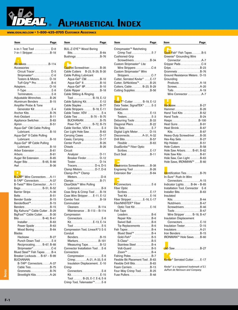
A C
D
E
F
G
H
I
JK
B
4-in-1 Test Tool . . . . . . . . . . . D-87-in-1 Stripper . . . . . . . . . . . . .B-18
Abrasives . . . . . . . . . . . . . . . .B-114Accessories Circuit Tracer . . . . . . . . . . . D-5 Stripmaster® . . . . . . . . . . . . .C-6 Testers & Meters . . . . . . . D-16 Tuff-Grip™ Pro . . . . . . . . . . .B-6Adapters . . . . . . . . . . . . . . . . . D-16 F-Type . . . . . . . . . . . . . . . . . . E-8 Terminators . . . . . . . . . . . . . . E-8Adjustable Wrenches . . . . . . .B-26Aluminum Benders . . . . . . . .B-15Amplifer Probe & Tone Generator Kit . . . . . . . . . . . . E-4Anchor Kits . . . . . . . . . . . . . . .B-76Anti-Oxidant . . . . . . . . . . . . . .B-11Appliance Switches . . . . . . . .B-83Apron . . . . . . . . . . . . . . . . . . . .B-51Aqua-Gel® CW Cable Pulling
Lubricant . . . . . . . . . . . . . . .B-10Aqua-Gel® II Cable Pulling
Lubricant . . . . . . . . . . . . . . .B-10Aqua-Gel® IIP Cable Pulling
Lubricant . . . . . . . . . . . . . . .B-10Arbor Extension . . . . . . . . . . .B-61Arbors . . . . . . . . . . . . . . . . . . . .B-61Auger Bit Extension . . . . . . . .B-65Auger Bits . . . . . . . . . . B-65, B-66Awl . . . . . . . . . . . . . . . . . . . . . .B-36
B-CAP® Wire Connectors . . .A-11B-TAP® Connectors . . . . . . . .A-37B-Twist™ Wire Connector . . .A-11Bags . . . . . . . . . . . . . . . B-51, B-52Barrier Strips . . . . . . . . . . . . . .A-36Belts . . . . . . . . . . . . . . . . . . . . .B-51Bender Guide . . . . . . . . . . . . .B-15BenderBoot™ . . . . . . . . . . . . . .B-15Benders . . . . . . . . . . . . . . . . . .B-15Big Kahuna™ Cable Cutter . .B-29BigFoot™ Cable Cutter . . . . . .B-30Bits . . . . . . . . . . . . . . . . B-40, B-41 Installer . . . . . . . . . . . . . . . .B-63 Power Spade . . . . . . . . . . .B-63 Wood Boring . . . . . . . . . . .B-64Blades Hacksaw . . . . . . . . . . . . . . .B-27 Punch Down Tool . . . . . . . . E-9 Reciprocating . . . . . B-67, B-68 Stripmaster® . . . . . . . . . . . . .C-6Blued Steel™ Fish Tapes . . . . .B-4Breaker Lockouts . . . B-97 – B-99BUCHANAN B-TAP® Connectors . . . . . .A-37 Cable Ties . . . . . . . . . . . . . .B-75 Grommets . . . . . . . . . . . . . .B-76 Streetlight Kits . . . . . . . . . .A-26
BUL-Z-EYE™ Wood Boring Bits . . . . . . . . . . . . . . . . . . . .B-64Bushings . . . . . . . . . . . . . . . . .B-76
Cabinet Screwdriver . . . . . . . .B-35Cable Cutters B-23, B-29, B-30Cable Pulling Lubricant Aqua-Gel® CW . . . . . . . . . .B-10 Aqua-Gel® II . . . . . . . . . . . .B-10 Aqua-Gel® IIP . . . . . . . . . . .B-10Cable Ripper . . . . . . . . . . . . . .B-18Cable Slitting & Ringing Tool . . . . . . . . . . . . . B-19, E-12Cable Splicing Kit . . . . . . . . . . E-12Cable Staples . . . . . . . . . . . . .B-77Cable Strippers . . . . . . B-18, E-11Cable Tester, VDV . . . . . . . . . . E-4Cable Ties . . . . . . . . . B-70 – B-75 BUCHANAN . . . . . . . . . . . .B-75 Powr-Tie™ . . . . . . . . B-72, B-73Cable Verifier, VDV II . . . . . . . . E-3Can Light Hole Saw . . . . . . . .B-63Carrying Cases . . . . . . . . . . . D-17Cases, Carrying . . . . . . . . . . . D-17Center Punch . . . . . . . . . . . . .B-26Chisels . . . . . . . . . . . . . . . . . . .B-26Circuit Analyzer . . . . . . . . . . . . . . D-11 Breaker Finder . . . . . . . . . D-12 Tester . . . . . . . . . . . . . . . . . D-14 Tracers . . . . . . . . . . . . . D-4, D-5Clamp Meters . . . . . . . . . D-7, D-8Clamp-Pro™ Clamp Meters . . . . . . . . . . . . . . . . D-8Clamps . . . . . . . . . . . . . . . . . . .B-71ClearGlide™ Wire Pulling
Lubricant . . . . . . . . . . . . . . . .B-9Coax Strip & Crimp Tool . . . .B-19Coax Wire Stripper . . . .E-11, E-12Combo Tool . . . . . . . . . . . . . . .B-19Commutator Cleaners . . . . . . . . . . . . . .B-114 Maintenance . . B-113 – B-114Compression Connectors . . . . . . . . . . . . . . E-6 Kit . . . . . . . . . . . . . . . .E-13, E-14 Tool . . . . . . . . . . . . . . . . . . . . E-5Compression Tool, LinearX®3 E-5Conduit Benders . . . . . . . . . . . . . . . .B-15 Markers . . . . . . . . . . . . . . .B-101 Measuring Tape . . . . . . . . .B-12Connector Installation Tool . . . E-8Connectors Compression . . . . . . . . . . . . E-6 Crimp . . . . . . . . A-21, A-33, E-8 Insulation Displacement . .E-10Crimp Connectors . . . . . . . . . . . . . . E-8 Kit . . . . . . . . . . . . . . . . . . . . .E-15 Tool . . . . . . B-25, E-7, E-8, E-9Crimp Tool, Telemaster™ . . . . . E-9
Crimpmaster™ Ratcheting Crimp Tool . . . . . . . . . . . . . . E-7Cushioned-Grip Screwdrivers . . . . . . . . . . . .B-34Custom Stripmaster® Lite Wire Strippers . . . . . . . . . . .C-8Custom Stripmaster® Wire
Strippers . . . . . . . . . . . . . . . .C-7Cutter, Serrated Kevlar® . . . . E-17Cutter, SirNickless™ . . . . . . . .B-25Cutters, Cable . . . . . . . B-23, B-29Cutting Supplies . . . . . . . . . . .B-56
Data T®-Cutter . . . . . . B-19, E-12Data Tester, SignalTEK® . . . . . E-3DataComm Kits . . . . . . . . . . . . . . . . . . . .E-13 Testers . . . . . . . . . . . . . . . . . . E-3Deburring Tools . . . . . . . . . . .B-33Diagonal Pliers . . . . . . . . . . . .B-22Die Sets . . . . . . . . . . . . . . . . . . . E-7Digital Light Meter . . . . . . . . D-15Disconnects . . . . . . . . . A-31, A-32Drill Bits . . . . . . . . . . . . . . . . . .B-57 Flexible . . . . . . . . . . . . . . . .B-63DualScribe™ Fiber Optic Scribes . . . . . . . . . . . . . . . . .E-17Duct Seal . . . . . . . . . . . . . . . . .B-11
Electronics Screwdrivers . . . .B-38Engraving Tool . . . . . . . . . . . .B-26Extension Bar . . . . . . . . . . . . .B-64
F-Connectors . . . . . . . . . . . . . . . E-8Fiber Optic Scribes . . . . . . . . . . . . . . . . .E-17 Test Kit . . . . . . . . . . . . . . . . E-16Fiber Stripper . . . . . . . . .E-16, E-17FiberMASTER™ Fiber Optic Test Kit . . . . . . . . . . . E-16Fish Tape Leaders . . . . . . . . . . . . . . . . .B-6 Repair Kits . . . . . . . . . . . . . .B-6 Swivel Ball . . . . . . . . . . . . . . .B-6 Tip Replacements . . . . . . . .B-6Fish Tapes . . . . . . . . . . . . . . . . .B-4 Blued Steel™ . . . . . . . . . . . .B-4 Gold-Fish® . . . . . . . . . . . . . .B-5 S-Class® . . . . . . . . . . . . . . . .B-5 Stainless Steel . . . . . . . . . . .B-4 Volt-Guard . . . . . . . . . . . . . .B-5 Zoom™ . . . . . . . . . . . . . . . . .B-4Fishing Poles . . . . . . . . . . . . . . .B-7Flexible Bit Placement Tool . .B-63Flexible Drill Bits . . . . . . . . . . .B-63Foam Carriers . . . . . . . . . . . . .B-13Four-Way Crimp Tool . . . . . . .B-25Fuse Pullers . . . . . . . . . . . . . . .B-48
Gold-Fish® Fish Tapes . . . . . . .B-5Greenie® Grounding Wire
Connector . . . . . . . . . . . . . . .A-7Gripper Pads . . . . . . . . . . . . . . .C-9Grips . . . . . . . . . . . . . . . . . . . . .B-23Grommets . . . . . . . . . . . . . . . .B-76Ground Resistance Meters . D-15Grounding Products . . . . . . . . . . . . . . .A-18 Screws . . . . . . . . . . . . . . . . .A-20 Tails . . . . . . . . . . . . . . . . . . .A-19 Wire Connector . . . . . . . . . .A-7
Hacksaw . . . . . . . . . . . . . . . . . .B-27Hammer . . . . . . . . . . . . . . . . . .B-26Hand Tool Kits . . . . . . . . . . . .B-52Hand Tools . . . . . . . . . . . . . . .B-24Hasps . . . . . . . . . . . . . . . . . . .B-100Heat Guns . . . . . . . . . . . . . . . .B-91Heat Shrink . . . . . . . . . . . . . . .B-87 Kits . . . . . . . . . . . . . . . . . . . .B-87Heavy-Duty Screwdriver . . . .B-35Hex-Key Sets . . . . . . . . . . . . . .B-27Hip Holster . . . . . . . . . . . . . . . .B-51Hole Cutters . . . . . . . . . . . . . .B-58Hole Saw Arbors . . . . . B-61, B-62Hole Saw Kits . . . . . . . . . . . . .B-61Hole Saw, Can Light . . . . . . .B-63Hole Saws, IRONMAN™ . . . .B-60
Identification Ties . . . . . . . . . .B-70In-Sure® Push-In Wire
Connectors . . . . . . . . . . . . .A-15Indicator Lights . . . . . B-84 – B-85Installation Tool, Connector E-8Installer Bits . . . . . . . . . . . . . . .B-63Insulated Kits . . . . . . . . . . . . . . . . . . . .B-44 Nutdrivers . . . . . . . . . . . . . .B-47 Screwdrivers . . . . . . . . . . . .B-46 Tools . . . . . . . . . . . . . . . . . .B-47 Wire Stripper . . . . . B-18, B-47Insulation Displacement
Connectors . . . . . . . . . . . . . E-10Insulation Tester . . . . . . . . . . D-15Insulators . . . . . . . . . . . . . . . . .A-21Iron Benders . . . . . . . . . . . . . .B-15IRONMAN™ Hole Saws . . . . .B-60
Jab Saw . . . . . . . . . . . . . . . . . .B-27
Kevlar® Serrated Cutter . . . . . E-17
Kevlar® is a registered trademark of E.I. duPont de Nemours and Company.
Item Page Item Page Item Page Item Page
AlphAbeticAl indexwww.ideAlind.com • 1-800-435-0705 customer AssistAnce
ind
ex
F-1
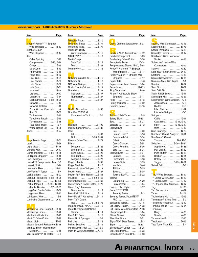
K
L
M
M
N
O
P
QR
S
S
T
Kinetic® Reflex™ T®-Stripper Wire Strippers . . . . . . . . . .B-17Kinetic® Super Wire Strippers . . . . . . . . . .B-17Kits Cable Splicing . . . . . . . . . . E-12 Compression . . . . . .E-13, E-14 Crimp . . . . . . . . . . . . . . . . . . E-15 DataComm . . . . . . . . . . . . . E-13 Fiber Optic . . . . . . . . . . . . . E-16 Hand Tool . . . . . . . . . . . . . .B-52 Heat Gun . . . . . . . . . . . . . . .B-91 Heat Shrink . . . . . . . . . . . . .B-87 Hole Cutter . . . . . . . . . . . . .B-58 Hole Saw . . . . . . . . . . . . . . .B-61 Insulated . . . . . . . . . . . . . . .B-44 Lighting . . . . . . . . . . . . . . . .A-17 LinearX®3 . . . . . . . . . . . . . E-14 Lockout/Tagout B-93 – B-96 Network . . . . . . . . . . . . . . . E-13 Network Installer . . . . . . . . E-16 Probe & Tone Generator E-4 Step Bit . . . . . . . . . . . . . . . .B-57 Technician’s . . . . . . . . . . . . E-15 Telephone Repair . . . . . . . E-10 Termination . . . . . . . . . . . . E-15 Test-Tone-Trace . . . . . . . . . E-4 Wood Boring Bit . . . . . . . .B-65Knife . . . . . . . . . . . . . . . . . . . . .B-27
Large Mouth Bags . . . . . . . . .B-51Level . . . . . . . . . . . . . . . . . . . . .B-26Light Meter . . . . . . . . . . . . . . D-15Lighting Kits . . . . . . . . . . . . . .A-17Lights, Indicator . . . . B-84 – B-85Lil’ Ripper Stripper™ . . . . . . . .B-18Line Packages . . . . . . . . . . . . .B-13LinearX®3 Compression Tool E-5LinearX®3 Kit . . . . . . . . . . . . . . E-14Lineman’s Pliers . . . . . . . . . . .B-22LinkMaster™ Tester . . . . . . . . . E-4Lock Stations . . . . . . . . . . . . . .B-97Lockout Tagout Kits B-93 – B-96Lockout Tags . . . . . . . . . . . . .B-100Lockout/Tagout . . . . B-93 – B-112Lockouts, Breaker B-97 – B-99Long-Arm Cable Cutter . . . . .B-30Long-Nose Pliers . . . . . . . . . .B-22Lubricants, Wire . . . . . . . . . . . .B-8Luminaire Disconnects . . . . .A-17
Measuring Tape, Conduit . . .B-12Measuring Tapes . . . . . . . . . .B-26Mechanical Indentor . . . . . . .B-25Merlin™ Cable Cutter . . . . . . .B-29Meter, Light . . . . . . . . . . . . . . D-15Meters, Ground Resistance D-15MiniLite-Strip™ Optical Fiber
Stripper . . . . . . . . . . . . . . . .E-16MiniTracker™ PRO Tester . . . . E-4
Modular Plugs . . . . . . . . . . . . . E-10Mounting Bases . . . . . . . . . . .B-74Mounting Pads . . . . . . . . . . . .B-74MudBug® Utility Wire Connector . . . . . . . . .A-10MULETAPE® . . . . . . . . . . . . . .B-12Multi-Crimp Strip Tool . . . . . . . . . . . . . . .B-19 Tool . . . . . . . . . . . . . . . . . . .B-23Multimeters . . . . . . . . . . . . . . D-13
Network Installer Kit . . . . . . . E-16Network Kit . . . . . . . . . . . . . . . E-13NM Wire Stripper . . . . . . . . . .B-18Noalox® Anti-Oxidant . . . . . .B-11Nutdrivers . . . . . . . . . . . . . . . .B-37 Insulated . . . . . . . . . . . . . . .B-47 Nutmaster® . . . . . . . . . . . . .B-37 Set . . . . . . . . . . . . . . . . . . . .B-37
Off-Set Screwdriver . . . . . . . .B-36OmniSeal™ PRO XL Compression Tool . . . . . . . . E-5
Padlocks . . . . . . . . . . . . . . . . .B-100Phillips Screwdriver . . . . . . . .B-35Pilot Bit . . . . . . . . . . . . . . . . . . . . .B-62 Drill . . . . . . . . . . . . . B-58, B-61Plenum Cable Ties . . . . . . . . .B-71Pliers Diagonal . . . . . . . . . . . . . . .B-22 Lineman’s . . . . . . . . . . . . .B-22 Long-Nose . . . . . . . . . . . . .B-22 Slip-Joint . . . . . . . . . . . . . . .B-23 Tongue & Groove . . . . . . .B-22Plug Lockouts . . . . . . . . . . . . .B-98Plugs, Modular . . . . . . . . . . . . E-10Pneumatic Wire Strippers . . .C-11Pocket Knife . . . . . . . . . . . . . .B-27Pocket Pal® Tool Holster . . . .B-51Pouches . . . . . . . . . . . . B-50, B-52Power Spade Bits . . . . . . . . . .B-63PowerBlade™ Cable Cutter . .B-29PowerPlug® Luminaire
Disconnects . . . . . . . . . . . .A-17Powr-Fish® Pull Line . . . . . . .B-12Powr-Polish™ Abrasives . . .B-114Powr-Tie™ Cable Ties . . . . . . . . . . . . . B-72, B-73Premise MULETAPE® . . . . . . .B-12PrepPRO® Coax/UTP Cable
Stripper . . . . . . . . . . . . . . . .E-11Pro-Pull™ Rope . . . . . . . . . . . .B-13Probe Pic & Spudger . . . . . . . . E-9Pull Line . . . . . . . . . . . . . . . . . .B-12Pulling Supplies . . . . . . . . . . .B-12Punch Down Tool . . . . . . . . . . . E-9Push-In Wire Connectors . . .A-15
Quick-Change Screwdriver . .B-37
Ratch-a-Nut™ Screwdriver . .B-32Ratchet Crimp Tool . . . . . . . .B-25Ratcheting Cable Cutter . . . .B-30Receptacle Tester . . . . . . . . . D-14Reciprocating Blades B-67, B-68Reflex™ Premium T®-Stripper
Wire Strippers . . . . . . . . . .B-17Reflex™ Super T®-Stripper Wire
Strippers . . . . . . . . . . . . . . .B-17Repair Kits . . . . . . . . . . . . . . . . .B-6Replacement Lead Screws . .B-64Resurfacer . . . . . . . . . . . . . . .B-113Ring Terminals . . . . . . . . . . . .A-30Ringer™ Adjustable Blade
Strippers . . . . . . . . . . . . . . . E-11Rope . . . . . . . . . . . . . . . . . . . . .B-13Rotary Switches . . . . . . . . . . .B-82Rotation Tester . . . . . . . . . . . D-15
S-Class® Fish Tapes . . . . . . . . .B-5Safety Signs . . . . . . . . . . . . . .B-101Saw . . . . . . . . . . . . . . . . . . . . . .B-27Scissors . . . . . . . . . . . . . . . . . . E-12Screwdriver Bits . . . . . . . . . . . . . . . . . . . .B-40 Combo Head™ . . . . . . . . .B-36
Cushioned-Grip . . . . . . . . .B-34 Offset . . . . . . . . . . . . . . . . . .B-36 Quick Change . . . . . . . . . .B-37
Quick-Rotating . . . . . . . . . .B-36 Sets . . . . . . . . . . . . . . . . . . .B-34Screwdrivers . . . . . . . . . . . . . .B-31 Cabinet . . . . . . . . . . . . . . . .B-35 Electronics . . . . . . . . . . . . .B-38 Heavy-Duty . . . . . . . . . . . . .B-35 Insulated . . . . . . . . . . . . . . .B-46 Phillips . . . . . . . . . . . . . . . . .B-35 Square . . . . . . . . . . . . . . . . .B-35 Twist-a-Nut™ . . . . . . . . . . .B-32Screws Grounding . . . . . . . . . . . . . .A-20 Replacement . . . . . . . . . . .B-64Scribes, Fiber Optic . . . . . . . . E-17SecuriTEST® PRO Security Tester . . . . . . . . . . . E-3Security Tester, SecuriTEST® PRO . . . . . . . . . . . . . . . . . . . . E-3Sequence Tester . . . . . . . . . . D-15Set Screw Holder . . . . . . . . . .A-33Set Screw Wire Connectors A-33Sharpening File . . . . . . . . . . . .B-64Shims, Spacer . . . . . . . . . . . . .B-76Shoulder Straps . . . . . . . . . . .B-51SignalTEK® Data Tester . . . . . . E-3Signs . . . . . . . . . . . . . . . . . . . .B-101SirNickless™ Cutter . . . . . . . .B-25Slip-Joint Pliers . . . . . . . . . . . .B-23SmoothStart™ Pilot Drill . . . . .B-58
Socket, Wire Connector . . . . .A-13Spacer Shims . . . . . . . . . . . . .B-76Spade Terminals . . . . . . . . . . .A-30Specialty Testers . . . . . . . . . . D-12SpinTwist® Wire Connector
Socket . . . . . . . . . . . . . . . . .A-13SpliceLine® In-line Wire
Connectors . . . . . . . . . . . . .A-15Splices . . . . . . . . . . . . . . . . . . .A-32Split-Jaw™ Smart Meter . . . D-17Splitters . . . . . . . . . . . . . . . . . . E-13Square Screwdriver . . . . . . . .B-35Stainless Steel Fish Tapes . . . .B-4Staples . . . . . . . . . . . . . . . . . . .B-77Step Bits . . . . . . . . . . . . . . . . . .B-57Step Drill Bits . . . . . . . . . . . . .B-57Strain Relief Boots . . . . . . . . . E-11Streetlight Kits . . . . . . . . . . . . .A-23Stripmaster® Wire Stripper . . .C-5 Accessories . . . . . . . . . . . . .C-6 Blades . . . . . . . . . . . . . . . . . .C-6 Fiber Stripper . . . . . . . . . . . E-17 Lite Wire Stripper . . . . . . . .C-5Strippers Cable . . . . . . . . . . . . . . . . . . E-11 Coax Wire . . . . . . . . .E-11, E-12 Fiber . . . . . . . . . . . . . .E-16, E-17 Wire . . . . . . . . . . . . . . . . . . .E-12Stud Bushings . . . . . . . . . . . . .B-76SureTest® Circuit Analyzer . D-11SureTrace™ Circuit Tracers . . . . . . . . . . . . . D-4, D-5Switches . . . . . . . . . . . B-79 – B-84 Appliance . . . . . . . . . . . . . .B-83 Pull Chain . . . . . . . . . . . . . .B-82 Push-Button . . . . . . . . . . . .B-83 Rocker . . . . . . . . . . . . . . . . .B-84 Rotary . . . . . . . . . . . . . . . . .B-82 Toggle . . . . . . . . . . B-79 – B-81Swivel Ball . . . . . . . . . . . . . . . . .B-6
T-90™ Wire Stripper . . . . . . . .B-17T®-Cutter Wire Cutter . . . . . .B-19T®-Cutter, Data . . . . . . . . . . . . E-12T®-Stripper Wire Strippers . .B-17Tags . . . . . . . . . . . . . . . . . . . .B-100Tap Connectors . . . . . . . . . . . .A-37Tapes . . . . . . . . . . . . . . . . . . .B-102Technician’s Kit . . . . . . . . . . . . E-15Telemaster™ Crimp Tool . . . . E-9Telephone Repair Kit . . . . . . . E-10Terminal Strips . . . . . . . . . . . .A-34Terminals Ring . . . . . . . . . . . . . . . . . . .A-30 Spade . . . . . . . . . . . . . . . . .A-30Termination Kit . . . . . . . . . . . . E-15Test Leads . . . . . . . . . . . . . . . D-16Test-Tone-Trace Kit . . . . . . . . . E-4
Item Page Item Page Item Page Item Page
www.ideAlind.com • 1-800-435-0705 customer AssistAnce
ind
ex
AlphAbeticAl index F-2
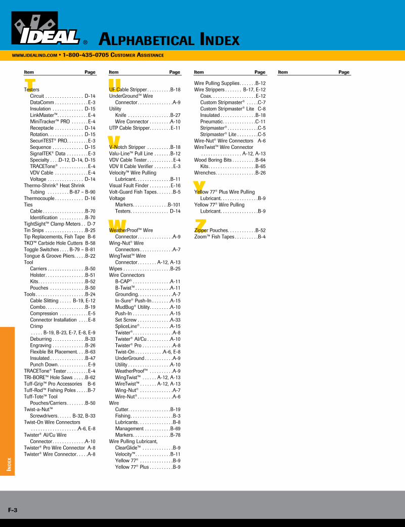
UT
V
W
Y
Z
Testers Circuit . . . . . . . . . . . . . . . . D-14 DataComm . . . . . . . . . . . . . . E-3 Insulation . . . . . . . . . . . . . D-15 LinkMaster™ . . . . . . . . . . . . . E-4 MiniTracker™ PRO . . . . . . . E-4 Receptacle . . . . . . . . . . . . D-14 Rotation . . . . . . . . . . . . . . . D-15 SecuriTEST® PRO . . . . . . . . . E-3 Sequence . . . . . . . . . . . . . D-15 SignalTEK® Data . . . . . . . . . E-3 Specialty . . . .D-12, D-14, D-15 TRACETone® . . . . . . . . . . . . E-4 VDV Cable . . . . . . . . . . . . . . E-4 Voltage . . . . . . . . . . . . . . . D-14Thermo-Shrink® Heat Shrink
Tubing . . . . . . . . . B-87 – B-90Thermocouple . . . . . . . . . . . . D-16Ties Cable . . . . . . . . . . . . . . . . . .B-70 Identification . . . . . . . . . . .B-70TightSight™ Clamp Meters . . D-7Tin Snips . . . . . . . . . . . . . . . . .B-25Tip Replacements, Fish Tape B-6TKO™ Carbide Hole Cutters B-58Toggle Switches . . . . B-79 – B-81Tongue & Groove Pliers . . . . .B-22Tool Carriers . . . . . . . . . . . . . . . .B-50 Holster . . . . . . . . . . . . . . . . .B-51 Kits . . . . . . . . . . . . . . . . . . . .B-52 Pouches . . . . . . . . . . . . . . .B-50Tools . . . . . . . . . . . . . . . . . . . . .B-24 Cable Slitting . . . . . B-19, E-12 Combo . . . . . . . . . . . . . . . . .B-19 Compression . . . . . . . . . . . . E-5 Connector Installation . . . . E-8 Crimp . . . . . B-19, B-23, E-7, E-8, E-9 Deburring . . . . . . . . . . . . . .B-33 Engraving . . . . . . . . . . . . . .B-26 Flexible Bit Placement . . . .B-63 Insulated . . . . . . . . . . . . . . .B-47 Punch Down . . . . . . . . . . . . . E-9TRACETone® Tester . . . . . . . . . E-4TRI-BORE™ Hole Saws . . . . .B-62Tuff-Grip™ Pro Accessories B-6Tuff-Rod™ Fishing Poles . . . . .B-7Tuff-Tote™ Tool Pouches/Carriers . . . . . . . .B-50Twist-a-Nut™ Screwdrivers . . . . . . B-32, B-33Twist-On Wire Connectors . . . . . . . . . . . . . . . . . . . .A-6, E-8Twister® Al/Cu Wire Connector . . . . . . . . . . . . . .A-10Twister® Pro Wire Connector A-8Twister® Wire Connector . . . . .A-8
UF Cable Stripper . . . . . . . . . .B-18UnderGround™ Wire Connector . . . . . . . . . . . . . . .A-9Utility Knife . . . . . . . . . . . . . . . . . .B-27 Wire Connector . . . . . . . . .A-10UTP Cable Stripper . . . . . . . . . E-11
V-Notch Stripper . . . . . . . . . .B-18Valu-Line™ Pull Line . . . . . . .B-12VDV Cable Tester . . . . . . . . . . . E-4VDV II Cable Verifier . . . . . . . . E-3Velocity™ Wire Pulling Lubricant . . . . . . . . . . . . . . .B-11Visual Fault Finder . . . . . . . . . E-16Volt-Guard Fish Tapes . . . . . . .B-5Voltage Markers . . . . . . . . . . . . . . .B-101 Testers . . . . . . . . . . . . . . . . D-14
WeatherProof™ Wire Connector . . . . . . . . . . . . . . .A-9Wing-Nut® Wire Connectors . . . . . . . . . . . . . .A-7WingTwist™ Wire Connector . . . . . . . . A-12, A-13Wipes . . . . . . . . . . . . . . . . . . . .B-25Wire Connectors B-CAP® . . . . . . . . . . . . . . . .A-11 B-Twist™ . . . . . . . . . . . . . . .A-11 Grounding . . . . . . . . . . . . . . .A-7 In-Sure® Push-In . . . . . . . .A-15 MudBug® Utility . . . . . . . . .A-10 Push-In . . . . . . . . . . . . . . . .A-15 Set Screw . . . . . . . . . . . . . .A-33 SpliceLine® . . . . . . . . . . . . .A-15 Twister® . . . . . . . . . . . . . . . . .A-8 Twister® Al/Cu . . . . . . . . . .A-10 Twister® Pro . . . . . . . . . . . . .A-8 Twist-On . . . . . . . . . . . .A-6, E-8 UnderGround . . . . . . . . . . . .A-9 Utility . . . . . . . . . . . . . . . . . .A-10 WeatherProof™ . . . . . . . . . .A-9 WingTwist™ . . . . . . A-12, A-13 WireTwist™ . . . . . . . A-12, A-13 Wing-Nut® . . . . . . . . . . . . . .A-7 Wire-Nut® . . . . . . . . . . . . . . .A-6Wire Cutter . . . . . . . . . . . . . . . . . .B-19 Fishing . . . . . . . . . . . . . . . . . .B-3 Lubricants . . . . . . . . . . . . . . .B-8 Management . . . . . . . . . . .B-69 Markers . . . . . . . . . . . . . . . .B-78Wire Pulling Lubricant, ClearGlide™ . . . . . . . . . . . . .B-9 Velocity™ . . . . . . . . . . . . . . .B-11 Yellow 77® . . . . . . . . . . . . . .B-9 Yellow 77® Plus . . . . . . . . . .B-9
Wire Pulling Supplies . . . . . . .B-12Wire Strippers . . . . . . . B-17, E-12 Coax . . . . . . . . . . . . . . . . . . .E-12 Custom Stripmaster® . . . . .C-7 Custom Stripmaster® Lite C-8 Insulated . . . . . . . . . . . . . . .B-18 Pneumatic . . . . . . . . . . . . . .C-11 Stripmaster® . . . . . . . . . . . . .C-5 Stripmaster® Lite . . . . . . . . .C-5Wire-Nut® Wire Connectors A-6WireTwist™ Wire Connector . . . . . . . . . . . . . . . . . A-12, A-13Wood Boring Bits . . . . . . . . . .B-64 Kits . . . . . . . . . . . . . . . . . . . .B-65Wrenches . . . . . . . . . . . . . . . . .B-26
Yellow 77® Plus Wire Pulling Lubricant . . . . . . . . . . . . . . . .B-9
Yellow 77® Wire Pulling Lubricant . . . . . . . . . . . . . . . .B-9
Zipper Pouches . . . . . . . . . . . .B-52Zoom™ Fish Tapes . . . . . . . . . .B-4
Item Page Item Page Item Page Item Page
AlphAbeticAl indexwww.ideAlind.com • 1-800-435-0705 customer AssistAnce
ind
ex
F-3
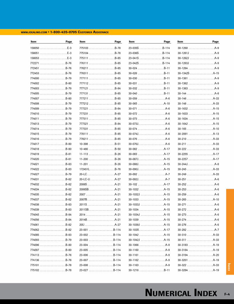
158050 . . . . . . . . . . . . . . . . . . . . E-3
158051 . . . . . . . . . . . . . . . . . . . . E-3
158053 . . . . . . . . . . . . . . . . . . . . E-3
772271 . . . . . . . . . . . . . . . . . . .B-76
772451 . . . . . . . . . . . . . . . . . . .B-76
772453 . . . . . . . . . . . . . . . . . . .B-76
774000 . . . . . . . . . . . . . . . . . . .B-79
774002 . . . . . . . . . . . . . . . . . . .B-80
774003 . . . . . . . . . . . . . . . . . . .B-79
774005 . . . . . . . . . . . . . . . . . . .B-79
774007 . . . . . . . . . . . . . . . . . . .B-80
774008 . . . . . . . . . . . . . . . . . . .B-79
774009 . . . . . . . . . . . . . . . . . . .B-79
774010 . . . . . . . . . . . . . . . . . . .B-79
774011 . . . . . . . . . . . . . . . . . . .B-79
774013 . . . . . . . . . . . . . . . . . . .B-79
774014 . . . . . . . . . . . . . . . . . . .B-79
774015 . . . . . . . . . . . . . . . . . . .B-79
774016 . . . . . . . . . . . . . . . . . . .B-79
774017 . . . . . . . . . . . . . . . . . . .B-80
774018 . . . . . . . . . . . . . . . . . . .B-80
774019 . . . . . . . . . . . . . . . . . . .B-81
774020 . . . . . . . . . . . . . . . . . . .B-81
774021 . . . . . . . . . . . . . . . . . . .B-83
774022 . . . . . . . . . . . . . . . . . . .B-83
774027 . . . . . . . . . . . . . . . . . . .B-79
774031 . . . . . . . . . . . . . . . . . . .B-82
774032 . . . . . . . . . . . . . . . . . . .B-82
774034 . . . . . . . . . . . . . . . . . . .B-82
774035 . . . . . . . . . . . . . . . . . . .B-82
774037 . . . . . . . . . . . . . . . . . . .B-82
774038 . . . . . . . . . . . . . . . . . . .B-83
774039 . . . . . . . . . . . . . . . . . . .B-83
774045 . . . . . . . . . . . . . . . . . . .B-84
774056 . . . . . . . . . . . . . . . . . . .B-84
774061 . . . . . . . . . . . . . . . . . . .B-82
774062 . . . . . . . . . . . . . . . . . . .B-82
774085 . . . . . . . . . . . . . . . . . . .B-83
774093 . . . . . . . . . . . . . . . . . . .B-79
774096 . . . . . . . . . . . . . . . . . . .B-80
774097 . . . . . . . . . . . . . . . . . . .B-80
774113 . . . . . . . . . . . . . . . . . . .B-76
774136 . . . . . . . . . . . . . . . . . . .B-76
775101 . . . . . . . . . . . . . . . . . . .B-78
775102 . . . . . . . . . . . . . . . . . . .B-78
775103 . . . . . . . . . . . . . . . . . . .B-78
775104 . . . . . . . . . . . . . . . . . . .B-78
775111 . . . . . . . . . . . . . . . . . . .B-85
776111 . . . . . . . . . . . . . . . . . . .B-85
776211 . . . . . . . . . . . . . . . . . . .B-85
776311 . . . . . . . . . . . . . . . . . . .B-85
777111 . . . . . . . . . . . . . . . . . . .B-85
777112 . . . . . . . . . . . . . . . . . . .B-85
777121 . . . . . . . . . . . . . . . . . . .B-84
777131 . . . . . . . . . . . . . . . . . . .B-85
777211 . . . . . . . . . . . . . . . . . . .B-85
777212 . . . . . . . . . . . . . . . . . . .B-85
777221 . . . . . . . . . . . . . . . . . . .B-84
777231 . . . . . . . . . . . . . . . . . . .B-85
777311 . . . . . . . . . . . . . . . . . . .B-85
777321 . . . . . . . . . . . . . . . . . . .B-84
777331 . . . . . . . . . . . . . . . . . . .B-85
778111 . . . . . . . . . . . . . . . . . . .B-85
778211 . . . . . . . . . . . . . . . . . . .B-85
10-398 . . . . . . . . . . . . . . . . . . .B-51
10-466 . . . . . . . . . . . . . . . . . . .B-50
11-113 . . . . . . . . . . . . . . . . . . .B-26
11-200 . . . . . . . . . . . . . . . . . . .B-26
11-201 . . . . . . . . . . . . . . . . . . .B-26
172451L . . . . . . . . . . . . . . . . . .B-76
20-LC . . . . . . . . . . . . . . . . . . . .A-27
20-LC-U . . . . . . . . . . . . . . . . . .A-27
2006S . . . . . . . . . . . . . . . . . . . .A-21
2006SB . . . . . . . . . . . . . . . . . . .A-21
2007 . . . . . . . . . . . . . . . . . . . . .A-21
2007B . . . . . . . . . . . . . . . . . . . .A-21
2011S . . . . . . . . . . . . . . . . . . . .A-21
2011SB . . . . . . . . . . . . . . . . . . .A-21
2014 . . . . . . . . . . . . . . . . . . . . .A-21
2014B . . . . . . . . . . . . . . . . . . . .A-21
20U . . . . . . . . . . . . . . . . . . . . . .A-27
23-001 . . . . . . . . . . . . . . . . . .B-114
23-002 . . . . . . . . . . . . . . . . . .B-114
23-003 . . . . . . . . . . . . . . . . . .B-114
23-004 . . . . . . . . . . . . . . . . . .B-114
23-005 . . . . . . . . . . . . . . . . . .B-114
23-006 . . . . . . . . . . . . . . . . . .B-114
23-007 . . . . . . . . . . . . . . . . . .B-114
23-008 . . . . . . . . . . . . . . . . . .B-114
23-027 . . . . . . . . . . . . . . . . . .B-114
23-035S . . . . . . . . . . . . . . . . .B-114
23-036S . . . . . . . . . . . . . . . . .B-114
23-041S . . . . . . . . . . . . . . . . .B-114
23-042S . . . . . . . . . . . . . . . . .B-114
30-024 . . . . . . . . . . . . . . . . . . .B-11
30-026 . . . . . . . . . . . . . . . . . . .B-11
30-030 . . . . . . . . . . . . . . . . . . .B-11
30-031 . . . . . . . . . . . . . . . . . . .B-11
30-032 . . . . . . . . . . . . . . . . . . .B-11
30-040 . . . . . . . . . . . . . . . . . . .B-11
30-059 . . . . . . . . . . . . . . . . . . . .A-6
30-065 . . . . . . . . . . . . . . . . . . .A-10
30-071 . . . . . . . . . . . . . . . . . . . .A-6
30-072 . . . . . . . . . . . . . . . . . . . .A-6
30-073 . . . . . . . . . . . . . . . . . . . .A-6
30-073J . . . . . . . . . . . . . . . . . . . .A-6
30-074 . . . . . . . . . . . . . . . . . . . .A-6
30-074J . . . . . . . . . . . . . . . . . . . .A-6
30-076 . . . . . . . . . . . . . . . . . . . .A-6
30-076J . . . . . . . . . . . . . . . . . . . .A-6
30-082 . . . . . . . . . . . . . . . . . . .A-17
30-083 . . . . . . . . . . . . . . . . . . .A-17
30-087J . . . . . . . . . . . . . . . . . . .A-15
30-088J . . . . . . . . . . . . . . . . . . .A-15
30-090J . . . . . . . . . . . . . . . . . . .A-15
30-092 . . . . . . . . . . . . . . . . . . . .A-7
30-092J . . . . . . . . . . . . . . . . . . . .A-7
30-102 . . . . . . . . . . . . . . . . . . .A-17
30-1032 . . . . . . . . . . . . . . . . . .A-15
30-1032J . . . . . . . . . . . . . . . . .A-15
30-1033 . . . . . . . . . . . . . . . . . .A-15
30-1033J . . . . . . . . . . . . . . . . .A-15
30-1034 . . . . . . . . . . . . . . . . . .A-15
30-1034J . . . . . . . . . . . . . . . . .A-15
30-1039 . . . . . . . . . . . . . . . . . .A-15
30-1039J . . . . . . . . . . . . . . . . .A-15
30-103X . . . . . . . . . . . . . . . . . .A-17
30-1042 . . . . . . . . . . . . . . . . . .A-15
30-1042J . . . . . . . . . . . . . . . . .A-15
30-1066 . . . . . . . . . . . . . . . . . . .A-9
30-1160 . . . . . . . . . . . . . . . . . . .A-9
30-1161 . . . . . . . . . . . . . . . . . . .A-9
30-1162 . . . . . . . . . . . . . . . . . . .A-9
30-1163 . . . . . . . . . . . . . . . . . . .A-9
30-1216 . . . . . . . . . . . . . . . . . .B-11
30-1260 . . . . . . . . . . . . . . . . . . .A-9
30-1261J . . . . . . . . . . . . . . . . . .A-9
30-1262J . . . . . . . . . . . . . . . . . .A-9
30-1263J . . . . . . . . . . . . . . . . . .A-9
30-1264 . . . . . . . . . . . . . . . . . . .A-9
30-1342S . . . . . . . . . . . . . . . . .A-15
30-1361 . . . . . . . . . . . . . . . . . . .A-9
30-1362 . . . . . . . . . . . . . . . . . . .A-9
30-1363 . . . . . . . . . . . . . . . . . . .A-9
30-144 . . . . . . . . . . . . . . . . . . . .A-8
30-146 . . . . . . . . . . . . . . . . . . .A-33
30-148 . . . . . . . . . . . . . . . . . . .A-33
30-1632 . . . . . . . . . . . . . . . . . .A-15
30-1633 . . . . . . . . . . . . . . . . . .A-15
30-1634 . . . . . . . . . . . . . . . . . .A-15
30-1642 . . . . . . . . . . . . . . . . . .A-15
30-165 . . . . . . . . . . . . . . . . . . .A-10
30-2091 . . . . . . . . . . . . . . . . . .A-13
30-210 . . . . . . . . . . . . . . . . . . .A-33
30-211 . . . . . . . . . . . . . . . . . . .A-33
30-222 . . . . . . . . . . . . . . . . . . .A-33
30-2255 . . . . . . . . . . . . . . . . . .A-17
30-2257 . . . . . . . . . . . . . . . . . .A-17
30-244J . . . . . . . . . . . . . . . . . . . .A-8
30-245 . . . . . . . . . . . . . . . . . . .A-33
30-249 . . . . . . . . . . . . . . . . . . .A-33
30-251 . . . . . . . . . . . . . . . . . . . .A-6
30-252 . . . . . . . . . . . . . . . . . . . .A-6
30-253 . . . . . . . . . . . . . . . . . . . .A-6
30-259 . . . . . . . . . . . . . . . . . . . .A-6
30-265 . . . . . . . . . . . . . . . . . . .A-10
30-271 . . . . . . . . . . . . . . . . . . . .A-6
30-272 . . . . . . . . . . . . . . . . . . . .A-6
30-273 . . . . . . . . . . . . . . . . . . . .A-6
30-274 . . . . . . . . . . . . . . . . . . . .A-6
30-276 . . . . . . . . . . . . . . . . . . . .A-6
30-292 . . . . . . . . . . . . . . . . . . . .A-7
30-310 . . . . . . . . . . . . . . . . . . .A-33
30-311 . . . . . . . . . . . . . . . . . . .A-33
30-3183 . . . . . . . . . . . . . . . . . .A-19
30-3184 . . . . . . . . . . . . . . . . . .A-19
30-3194 . . . . . . . . . . . . . . . . . .A-20
30-3201 . . . . . . . . . . . . . . . . . .A-19
30-322 . . . . . . . . . . . . . . . . . . .A-33
30-3284 . . . . . . . . . . . . . . . . . .A-19
Item Page Item Page Item Page Item Page
www.ideAlind.com • 1-800-435-0705 customer AssistAnce
ind
ex
numericAl index F-4
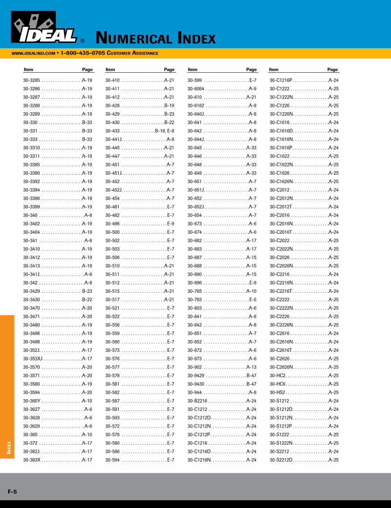
30-3285 . . . . . . . . . . . . . . . . . .A-19
30-3286 . . . . . . . . . . . . . . . . . .A-19
30-3287 . . . . . . . . . . . . . . . . . .A-19
30-3288 . . . . . . . . . . . . . . . . . .A-19
30-3289 . . . . . . . . . . . . . . . . . .A-19
30-330 . . . . . . . . . . . . . . . . . . .B-33
30-331 . . . . . . . . . . . . . . . . . . .B-33
30-333 . . . . . . . . . . . . . . . . . . .B-33
30-3310 . . . . . . . . . . . . . . . . . .A-19
30-3311 . . . . . . . . . . . . . . . . . .A-19
30-3385 . . . . . . . . . . . . . . . . . .A-19
30-3390 . . . . . . . . . . . . . . . . . .A-19
30-3392 . . . . . . . . . . . . . . . . . .A-19
30-3394 . . . . . . . . . . . . . . . . . .A-19
30-3396 . . . . . . . . . . . . . . . . . .A-19
30-3399 . . . . . . . . . . . . . . . . . .A-19
30-340 . . . . . . . . . . . . . . . . . . . .A-8
30-3402 . . . . . . . . . . . . . . . . . .A-19
30-3404 . . . . . . . . . . . . . . . . . .A-19
30-341 . . . . . . . . . . . . . . . . . . . .A-8
30-3410 . . . . . . . . . . . . . . . . . .A-19
30-3412 . . . . . . . . . . . . . . . . . .A-19
30-3413 . . . . . . . . . . . . . . . . . .A-19
30-341J . . . . . . . . . . . . . . . . . . . .A-8
30-342 . . . . . . . . . . . . . . . . . . . .A-8
30-3429 . . . . . . . . . . . . . . . . . .B-23
30-3430 . . . . . . . . . . . . . . . . . .B-22
30-3470 . . . . . . . . . . . . . . . . . .A-20
30-3471 . . . . . . . . . . . . . . . . . .A-20
30-3480 . . . . . . . . . . . . . . . . . .A-19
30-3496 . . . . . . . . . . . . . . . . . .A-19
30-3498 . . . . . . . . . . . . . . . . . .A-19
30-352J . . . . . . . . . . . . . . . . . . .A-17
30-353XJ . . . . . . . . . . . . . . . . .A-17
30-3570 . . . . . . . . . . . . . . . . . .A-20
30-3571 . . . . . . . . . . . . . . . . . .A-20
30-3580 . . . . . . . . . . . . . . . . . .A-19
30-3594 . . . . . . . . . . . . . . . . . .A-20
30-360Y . . . . . . . . . . . . . . . . . .A-10
30-3627 . . . . . . . . . . . . . . . . . . .A-6
30-3628 . . . . . . . . . . . . . . . . . . .A-6
30-3629 . . . . . . . . . . . . . . . . . . .A-6
30-365 . . . . . . . . . . . . . . . . . . .A-10
30-372 . . . . . . . . . . . . . . . . . . .A-17
30-382J . . . . . . . . . . . . . . . . . . .A-17
30-383X . . . . . . . . . . . . . . . . . .A-17
30-410 . . . . . . . . . . . . . . . . . . .A-21
30-411 . . . . . . . . . . . . . . . . . . .A-21
30-412 . . . . . . . . . . . . . . . . . . .A-21
30-428 . . . . . . . . . . . . . . . . . . .B-19
30-429 . . . . . . . . . . . . . . . . . . .B-23
30-430 . . . . . . . . . . . . . . . . . . .B-22
30-433 . . . . . . . . . . . . . . .B-19, E-8
30-441J . . . . . . . . . . . . . . . . . . . .A-8
30-445 . . . . . . . . . . . . . . . . . . .A-21
30-447 . . . . . . . . . . . . . . . . . . .A-21
30-451 . . . . . . . . . . . . . . . . . . . .A-7
30-451J . . . . . . . . . . . . . . . . . . . .A-7
30-452 . . . . . . . . . . . . . . . . . . . .A-7
30-452J . . . . . . . . . . . . . . . . . . . .A-7
30-454 . . . . . . . . . . . . . . . . . . . .A-7
30-481 . . . . . . . . . . . . . . . . . . . . E-7
30-482 . . . . . . . . . . . . . . . . . . . . E-7
30-496 . . . . . . . . . . . . . . . . . . . . E-9
30-500 . . . . . . . . . . . . . . . . . . . . E-7
30-502 . . . . . . . . . . . . . . . . . . . . E-7
30-503 . . . . . . . . . . . . . . . . . . . . E-7
30-506 . . . . . . . . . . . . . . . . . . . . E-7
30-510 . . . . . . . . . . . . . . . . . . .A-21
30-511 . . . . . . . . . . . . . . . . . . .A-21
30-512 . . . . . . . . . . . . . . . . . . .A-21
30-515 . . . . . . . . . . . . . . . . . . .A-21
30-517 . . . . . . . . . . . . . . . . . . .A-21
30-521 . . . . . . . . . . . . . . . . . . . . E-7
30-522 . . . . . . . . . . . . . . . . . . . . E-7
30-556 . . . . . . . . . . . . . . . . . . . . E-7
30-559 . . . . . . . . . . . . . . . . . . . . E-7
30-560 . . . . . . . . . . . . . . . . . . . . E-7
30-573 . . . . . . . . . . . . . . . . . . . . E-7
30-576 . . . . . . . . . . . . . . . . . . . . E-7
30-577 . . . . . . . . . . . . . . . . . . . . E-7
30-578 . . . . . . . . . . . . . . . . . . . . E-7
30-581 . . . . . . . . . . . . . . . . . . . . E-7
30-582 . . . . . . . . . . . . . . . . . . . . E-7
30-587 . . . . . . . . . . . . . . . . . . . . E-7
30-591 . . . . . . . . . . . . . . . . . . . . E-7
30-593 . . . . . . . . . . . . . . . . . . . . E-7
30-572 . . . . . . . . . . . . . . . . . . . . E-7
30-579 . . . . . . . . . . . . . . . . . . . . E-7
30-580 . . . . . . . . . . . . . . . . . . . . E-7
30-586 . . . . . . . . . . . . . . . . . . . . E-7
30-594 . . . . . . . . . . . . . . . . . . . . E-7
30-599 . . . . . . . . . . . . . . . . . . . . E-7
30-6064 . . . . . . . . . . . . . . . . . . .A-9
30-610 . . . . . . . . . . . . . . . . . . .A-21
30-6162 . . . . . . . . . . . . . . . . . . .A-9
30-640J . . . . . . . . . . . . . . . . . . . .A-8
30-641 . . . . . . . . . . . . . . . . . . . .A-8
30-642 . . . . . . . . . . . . . . . . . . . .A-8
30-644J . . . . . . . . . . . . . . . . . . . .A-8
30-645 . . . . . . . . . . . . . . . . . . .A-33
30-646 . . . . . . . . . . . . . . . . . . .A-33
30-648 . . . . . . . . . . . . . . . . . . .A-33
30-649 . . . . . . . . . . . . . . . . . . .A-33
30-651 . . . . . . . . . . . . . . . . . . . .A-7
30-651J . . . . . . . . . . . . . . . . . . . .A-7
30-652 . . . . . . . . . . . . . . . . . . . .A-7
30-652J . . . . . . . . . . . . . . . . . . . .A-7
30-654 . . . . . . . . . . . . . . . . . . . .A-7
30-673 . . . . . . . . . . . . . . . . . . . .A-6
30-674 . . . . . . . . . . . . . . . . . . . .A-6
30-682 . . . . . . . . . . . . . . . . . . .A-17
30-683 . . . . . . . . . . . . . . . . . . .A-17
30-687 . . . . . . . . . . . . . . . . . . .A-15
30-688 . . . . . . . . . . . . . . . . . . .A-15
30-690 . . . . . . . . . . . . . . . . . . .A-15
30-696 . . . . . . . . . . . . . . . . . . . . E-9
30-765 . . . . . . . . . . . . . . . . . . .A-10
30-793 . . . . . . . . . . . . . . . . . . . . E-5
30-803 . . . . . . . . . . . . . . . . . . . .A-6
30-841 . . . . . . . . . . . . . . . . . . . .A-8
30-842 . . . . . . . . . . . . . . . . . . . .A-8
30-851 . . . . . . . . . . . . . . . . . . . .A-7
30-852 . . . . . . . . . . . . . . . . . . . .A-7
30-872 . . . . . . . . . . . . . . . . . . . .A-6
30-873 . . . . . . . . . . . . . . . . . . . .A-6
30-902 . . . . . . . . . . . . . . . . . . .A-13
30-9429 . . . . . . . . . . . . . . . . . .B-47
30-9430 . . . . . . . . . . . . . . . . . .B-47
30-944 . . . . . . . . . . . . . . . . . . . .A-8
30-B2216 . . . . . . . . . . . . . . . . .A-24
30-C1212 . . . . . . . . . . . . . . . . .A-24
30-C1212D . . . . . . . . . . . . . . . .A-24
30-C1212N . . . . . . . . . . . . . . . .A-24
30-C1212P . . . . . . . . . . . . . . . .A-24
30-C1216 . . . . . . . . . . . . . . . . .A-24
30-C1216D . . . . . . . . . . . . . . . .A-24
30-C1216N . . . . . . . . . . . . . . . .A-24
30-C1216P . . . . . . . . . . . . . . . .A-24
30-C1222 . . . . . . . . . . . . . . . . .A-25
30-C1222N . . . . . . . . . . . . . . . .A-25
30-C1226 . . . . . . . . . . . . . . . . .A-25
30-C1226N . . . . . . . . . . . . . . . .A-25
30-C1616 . . . . . . . . . . . . . . . . .A-24
30-C1616D . . . . . . . . . . . . . . . .A-24
30-C1616N . . . . . . . . . . . . . . . .A-24
30-C1616P . . . . . . . . . . . . . . . .A-24
30-C1622 . . . . . . . . . . . . . . . . .A-25
30-C1622N . . . . . . . . . . . . . . . .A-25
30-C1626 . . . . . . . . . . . . . . . . .A-25
30-C1626N . . . . . . . . . . . . . . . .A-25
30-C2012 . . . . . . . . . . . . . . . . .A-24
30-C2012N . . . . . . . . . . . . . . . .A-24
30-C2012T . . . . . . . . . . . . . . . .A-24
30-C2016 . . . . . . . . . . . . . . . . .A-24
30-C2016N . . . . . . . . . . . . . . . .A-24
30-C2016T . . . . . . . . . . . . . . . .A-24
30-C2022 . . . . . . . . . . . . . . . . .A-25
30-C2022N . . . . . . . . . . . . . . . .A-25
30-C2026 . . . . . . . . . . . . . . . . .A-25
30-C2026N . . . . . . . . . . . . . . . .A-25
30-C2216 . . . . . . . . . . . . . . . . .A-24
30-C2216N . . . . . . . . . . . . . . . .A-24
30-C2216T . . . . . . . . . . . . . . . .A-24
30-C2222 . . . . . . . . . . . . . . . . .A-25
30-C2222N . . . . . . . . . . . . . . . .A-25
30-C2226 . . . . . . . . . . . . . . . . .A-25
30-C2226N . . . . . . . . . . . . . . . .A-25
30-C2616 . . . . . . . . . . . . . . . . .A-24
30-C2616N . . . . . . . . . . . . . . . .A-24
30-C2616T . . . . . . . . . . . . . . . .A-24
30-C2626 . . . . . . . . . . . . . . . . .A-25
30-C2626N . . . . . . . . . . . . . . . .A-25
30-HC2 . . . . . . . . . . . . . . . . . . .A-25
30-HC6 . . . . . . . . . . . . . . . . . . .A-25
30-HS2 . . . . . . . . . . . . . . . . . . .A-25
30-S1212 . . . . . . . . . . . . . . . . .A-24
30-S1212D . . . . . . . . . . . . . . . .A-24
30-S1212N . . . . . . . . . . . . . . . .A-24
30-S1212P . . . . . . . . . . . . . . . .A-24
30-S1222 . . . . . . . . . . . . . . . . .A-25
30-S1222N . . . . . . . . . . . . . . . .A-25
30-S2212 . . . . . . . . . . . . . . . . .A-24
30-S2212D . . . . . . . . . . . . . . . .A-25
Item Page Item Page Item Page Item Page
numericAl indexwww.ideAlind.com • 1-800-435-0705 customer AssistAnce
ind
ex
F-5
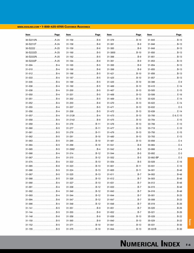
30-S2212N . . . . . . . . . . . . . . . .A-24
30-S2212T . . . . . . . . . . . . . . . .A-24
30-S2222 . . . . . . . . . . . . . . . . .A-25
30-S2222D . . . . . . . . . . . . . . . .A-25
30-S2222N . . . . . . . . . . . . . . . .A-25
30-S2222P . . . . . . . . . . . . . . . .A-25
31-004 . . . . . . . . . . . . . . . . . . . .B-4
31-010 . . . . . . . . . . . . . . . . . . . .B-4
31-012 . . . . . . . . . . . . . . . . . . . .B-4
31-033 . . . . . . . . . . . . . . . . . . . .B-4
31-035 . . . . . . . . . . . . . . . . . . . .B-4
31-036 . . . . . . . . . . . . . . . . . . . .B-4
31-038 . . . . . . . . . . . . . . . . . . . .B-4
31-050 . . . . . . . . . . . . . . . . . . . .B-4
31-051 . . . . . . . . . . . . . . . . . . . .B-4
31-052 . . . . . . . . . . . . . . . . . . . .B-4
31-055 . . . . . . . . . . . . . . . . . . . .B-4
31-056 . . . . . . . . . . . . . . . . . . . .B-4
31-057 . . . . . . . . . . . . . . . . . . . .B-4
31-058 . . . . . . . . . . . . . . . . . . . .B-4
31-059 . . . . . . . . . . . . . . . . . . . .B-4
31-060 . . . . . . . . . . . . . . . . . . . .B-5
31-061 . . . . . . . . . . . . . . . . . . . .B-5
31-062 . . . . . . . . . . . . . . . . . . . .B-5
31-063 . . . . . . . . . . . . . . . . . . . .B-5
31-064 . . . . . . . . . . . . . . . . . . . .B-5
31-065 . . . . . . . . . . . . . . . . . . . .B-5
31-066 . . . . . . . . . . . . . . . . . . . .B-4
31-067 . . . . . . . . . . . . . . . . . . . .B-4
31-074 . . . . . . . . . . . . . . . . . . . .B-4
31-085 . . . . . . . . . . . . . . . . . . . .B-6
31-086 . . . . . . . . . . . . . . . . . . . .B-5
31-087 . . . . . . . . . . . . . . . . . . . .B-5
31-088 . . . . . . . . . . . . . . . . . . . .B-5
31-090 . . . . . . . . . . . . . . . . . . . .B-4
31-091 . . . . . . . . . . . . . . . . . . . .B-4
31-092 . . . . . . . . . . . . . . . . . . . .B-4
31-093 . . . . . . . . . . . . . . . . . . . .B-4
31-094 . . . . . . . . . . . . . . . . . . . .B-6
31-096 . . . . . . . . . . . . . . . . . . . .B-4
31-141 . . . . . . . . . . . . . . . . . . . .B-5
31-144 . . . . . . . . . . . . . . . . . . . .B-5
31-148 . . . . . . . . . . . . . . . . . . . .B-6
31-150 . . . . . . . . . . . . . . . . . . . .B-5
31-152 . . . . . . . . . . . . . . . . . . . .B-5
31-155 . . . . . . . . . . . . . . . . . . . .B-5
31-156 . . . . . . . . . . . . . . . . . . . .B-6
31-158 . . . . . . . . . . . . . . . . . . . .B-6
31-159 . . . . . . . . . . . . . . . . . . . .B-6
31-160 . . . . . . . . . . . . . . . . . . . .B-5
31-162 . . . . . . . . . . . . . . . . . . . .B-5
31-164 . . . . . . . . . . . . . . . . . . . .B-6
31-165 . . . . . . . . . . . . . . . . . . . .B-5
31-166 . . . . . . . . . . . . . . . . . . . .B-6
31-186 . . . . . . . . . . . . . . . . . . . .B-5
31-187 . . . . . . . . . . . . . . . . . . . .B-5
31-189 . . . . . . . . . . . . . . . . . . . .B-5
31-190 . . . . . . . . . . . . . . . . . . . .B-5
31-200 . . . . . . . . . . . . . . . . . . . .B-5
31-201 . . . . . . . . . . . . . . . . . . . .B-5
31-202 . . . . . . . . . . . . . . . . . . . .B-5
31-203 . . . . . . . . . . . . . . . . . . . .B-6
31-207 . . . . . . . . . . . . . . . . . . . .B-5
31-208 . . . . . . . . . . . . . . . . . . . .B-5
31-2128 . . . . . . . . . . . . . . . . . . .B-4
31-2143 . . . . . . . . . . . . . . . . . . .B-9
31-276 . . . . . . . . . . . . . . . . . . .B-11
31-277 . . . . . . . . . . . . . . . . . . .B-11
31-278 . . . . . . . . . . . . . . . . . . .B-11
31-291 . . . . . . . . . . . . . . . . . . .B-10
31-295 . . . . . . . . . . . . . . . . . . .B-10
31-298 . . . . . . . . . . . . . . . . . . .B-10
31-2982 . . . . . . . . . . . . . . . . . . .B-4
31-314 . . . . . . . . . . . . . . . . . . .B-12
31-315 . . . . . . . . . . . . . . . . . . .B-12
31-322 . . . . . . . . . . . . . . . . . . .B-13
31-323 . . . . . . . . . . . . . . . . . . .B-13
31-324 . . . . . . . . . . . . . . . . . . .B-13
31-325 . . . . . . . . . . . . . . . . . . .B-13
31-326 . . . . . . . . . . . . . . . . . . .B-13
31-327 . . . . . . . . . . . . . . . . . . .B-13
31-338 . . . . . . . . . . . . . . . . . . .B-12
31-340 . . . . . . . . . . . . . . . . . . .B-12
31-344 . . . . . . . . . . . . . . . . . . .B-12
31-347 . . . . . . . . . . . . . . . . . . .B-12
31-348 . . . . . . . . . . . . . . . . . . .B-12
31-351 . . . . . . . . . . . . . . . . . . . .B-9
31-355 . . . . . . . . . . . . . . . . . . . .B-9
31-358 . . . . . . . . . . . . . . . . . . . .B-9
31-365 . . . . . . . . . . . . . . . . . . . .B-9
31-371 . . . . . . . . . . . . . . . . . . .B-10
31-375 . . . . . . . . . . . . . . . . . . .B-10
31-378 . . . . . . . . . . . . . . . . . . .B-10
31-381 . . . . . . . . . . . . . . . . . . . .B-9
31-385 . . . . . . . . . . . . . . . . . . . .B-9
31-3855 . . . . . . . . . . . . . . . . . .B-10
31-388 . . . . . . . . . . . . . . . . . . . .B-9
31-391 . . . . . . . . . . . . . . . . . . . .B-9
31-395 . . . . . . . . . . . . . . . . . . . .B-9
31-398 . . . . . . . . . . . . . . . . . . . .B-9
31-421 . . . . . . . . . . . . . . . . . . .B-10
31-425 . . . . . . . . . . . . . . . . . . .B-10
31-435 . . . . . . . . . . . . . . . . . . .B-10
31-466 . . . . . . . . . . . . . . . . . . .B-13
31-467 . . . . . . . . . . . . . . . . . . .B-13
31-468 . . . . . . . . . . . . . . . . . . .B-13
31-469 . . . . . . . . . . . . . . . . . . .B-13
31-470 . . . . . . . . . . . . . . . . . . .B-13
31-471 . . . . . . . . . . . . . . . . . . .B-13
31-472 . . . . . . . . . . . . . . . . . . .B-13
31-473 . . . . . . . . . . . . . . . . . . .B-13
31-475 . . . . . . . . . . . . . . . . . . .B-13
31-476 . . . . . . . . . . . . . . . . . . .B-13
31-477 . . . . . . . . . . . . . . . . . . .B-13
31-479 . . . . . . . . . . . . . . . . . . .B-13
31-480 . . . . . . . . . . . . . . . . . . .B-13
31-481 . . . . . . . . . . . . . . . . . . .B-13
31-541 . . . . . . . . . . . . . . . . . . . .B-6
31-542 . . . . . . . . . . . . . . . . . . . .B-5
31-544 . . . . . . . . . . . . . . . . . . . .B-5
31-552 . . . . . . . . . . . . . . . . . . . .B-5
31-554 . . . . . . . . . . . . . . . . . . . .B-5
31-601 . . . . . . . . . . . . . . . . . . .B-11
31-605 . . . . . . . . . . . . . . . . . . .B-11
31-611 . . . . . . . . . . . . . . . . . . . .B-7
31-612 . . . . . . . . . . . . . . . . . . . .B-7
31-631 . . . . . . . . . . . . . . . . . . . .B-7
31-633 . . . . . . . . . . . . . . . . . . . .B-7
31-643 . . . . . . . . . . . . . . . . . . . .B-7
31-644 . . . . . . . . . . . . . . . . . . . .B-7
31-647 . . . . . . . . . . . . . . . . . . . .B-7
31-648 . . . . . . . . . . . . . . . . . . . .B-7
31-651 . . . . . . . . . . . . . . . . . . . .B-7
31-652 . . . . . . . . . . . . . . . . . . . .B-7
31-839 . . . . . . . . . . . . . . . . . . .B-13
31-840 . . . . . . . . . . . . . . . . . . .B-13
31-841 . . . . . . . . . . . . . . . . . . .B-13
31-844 . . . . . . . . . . . . . . . . . . .B-13
31-845 . . . . . . . . . . . . . . . . . . .B-13
31-846 . . . . . . . . . . . . . . . . . . .B-13
31-849 . . . . . . . . . . . . . . . . . . .B-13
31-850 . . . . . . . . . . . . . . . . . . .B-13
31-851 . . . . . . . . . . . . . . . . . . .B-13
31-853 . . . . . . . . . . . . . . . . . . .B-13
31-854 . . . . . . . . . . . . . . . . . . .B-13
31-855 . . . . . . . . . . . . . . . . . . .B-13
31-856 . . . . . . . . . . . . . . . . . . .B-13
31-857 . . . . . . . . . . . . . . . . . . .B-13
33-396 . . . . . . . . . . . . . . . . . . . . E-9
33-410 . . . . . . . . . . . . . . . . . . . E-14
33-505 . . . . . . . . . . . . . . . . . . . E-15
33-506 . . . . . . . . . . . . . . . . . . . E-16
33-620 . . . . . . . . . . . . . . . . . . . E-14
33-622 . . . . . . . . . . . . . . . . . . . E-14
33-632 . . . . . . . . . . . . . . . . . . . . E-5
33-639 . . . . . . . . . . . . . . . . . . . E-14
33-700 . . . . . . . . . . . . . . .E-9, E-15
33-704 . . . . . . . . . . . . . . . . . . . E-15
33-706 . . . . . . . . . . . . . . . . . . . E-13
33-719 . . . . . . . . . . . . . . . . . . . E-10
33-750 . . . . . . . . . . . . . . . . . . . E-15
33-793 . . . . . . . . . . . . . . . . . . . E-13
33-856 . . . . . . . . . . . . . . . . . . . . E-4
33-864 . . . . . . . . . . . . . . . . . . . . E-4
33-866 . . . . . . . . . . . . . . . . . . . . E-4
33-892 . . . . . . . . . . . . . . . . . . . . E-3
33-892-BP . . . . . . . . . . . . . . . . . E-3
33-928 . . . . . . . . . . . . . . . . . . . E-16
33-931 . . . . . . . . . . . . . . . . . . . E-16
34-001 . . . . . . . . . . . . . . . . . . .B-48
34-002 . . . . . . . . . . . . . . . . . . .B-48
34-003 . . . . . . . . . . . . . . . . . . .B-48
34-012 . . . . . . . . . . . . . . . . . . .B-48
34-015 . . . . . . . . . . . . . . . . . . .B-48
34-016 . . . . . . . . . . . . . . . . . . .B-48
35-001 . . . . . . . . . . . . . . . . . . .B-25
35-008 . . . . . . . . . . . . . . . . . . .B-23
35-019 . . . . . . . . . . . . . . . . . . .B-26
35-020 . . . . . . . . . . . . . . . . . . .B-26
35-021 . . . . . . . . . . . . . . . . . . .B-26
35-028 . . . . . . . . . . . . . . . . . . .B-22
35-029 . . . . . . . . . . . . . . . . . . .B-22
35-031 . . . . . . . . . . . . . . . . . . .B-30
35-031B . . . . . . . . . . . . . . . . . .B-30
Item Page Item Page Item Page Item Page
www.ideAlind.com • 1-800-435-0705 customer AssistAnce
ind
ex
numericAl index F-6
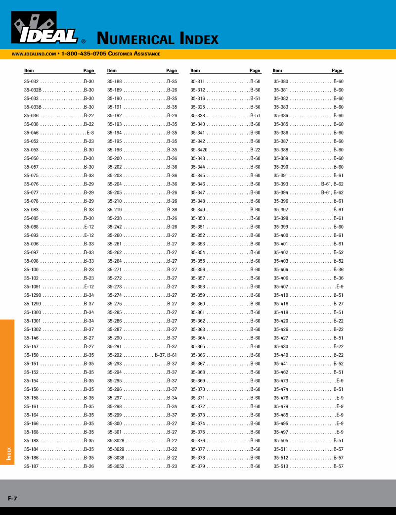
tw
ist-o
n wir
e co
nn
ecto
rs
35-032 . . . . . . . . . . . . . . . . . . .B-30
35-032B . . . . . . . . . . . . . . . . . .B-30
35-033 . . . . . . . . . . . . . . . . . . .B-30
35-033B . . . . . . . . . . . . . . . . . .B-30
35-036 . . . . . . . . . . . . . . . . . . .B-22
35-038 . . . . . . . . . . . . . . . . . . .B-22
35-046 . . . . . . . . . . . . . . . . . . . . E-8
35-052 . . . . . . . . . . . . . . . . . . .B-23
35-053 . . . . . . . . . . . . . . . . . . .B-30
35-056 . . . . . . . . . . . . . . . . . . .B-30
35-057 . . . . . . . . . . . . . . . . . . .B-30
35-075 . . . . . . . . . . . . . . . . . . .B-33
35-076 . . . . . . . . . . . . . . . . . . .B-29
35-077 . . . . . . . . . . . . . . . . . . .B-29
35-078 . . . . . . . . . . . . . . . . . . .B-29
35-083 . . . . . . . . . . . . . . . . . . .B-33
35-085 . . . . . . . . . . . . . . . . . . .B-30
35-088 . . . . . . . . . . . . . . . . . . . E-12
35-093 . . . . . . . . . . . . . . . . . . . E-12
35-096 . . . . . . . . . . . . . . . . . . .B-33
35-097 . . . . . . . . . . . . . . . . . .B-33
35-098 . . . . . . . . . . . . . . . . . . .B-33
35-100 . . . . . . . . . . . . . . . . . . .B-23
35-102 . . . . . . . . . . . . . . . . . . .B-23
35-1091 . . . . . . . . . . . . . . . . . . E-12
35-1298 . . . . . . . . . . . . . . . . . .B-34
35-1299 . . . . . . . . . . . . . . . . . .B-37
35-1300 . . . . . . . . . . . . . . . . . .B-34
35-1301 . . . . . . . . . . . . . . . . . .B-34
35-1302 . . . . . . . . . . . . . . . . . .B-37
35-146 . . . . . . . . . . . . . . . . . . .B-27
35-147 . . . . . . . . . . . . . . . . . . .B-27
35-150 . . . . . . . . . . . . . . . . . . .B-35
35-151 . . . . . . . . . . . . . . . . . . .B-35
35-152 . . . . . . . . . . . . . . . . . . .B-35
35-154 . . . . . . . . . . . . . . . . . . .B-35
35-156 . . . . . . . . . . . . . . . . . . .B-35
35-158 . . . . . . . . . . . . . . . . . . .B-35
35-161 . . . . . . . . . . . . . . . . . . .B-35
35-164 . . . . . . . . . . . . . . . . . . .B-35
35-166 . . . . . . . . . . . . . . . . . . .B-35
35-168 . . . . . . . . . . . . . . . . . . .B-35
35-183 . . . . . . . . . . . . . . . . . . .B-35
35-184 . . . . . . . . . . . . . . . . . . .B-35
35-186 . . . . . . . . . . . . . . . . . . .B-35
35-187 . . . . . . . . . . . . . . . . . . .B-26
35-188 . . . . . . . . . . . . . . . . . . .B-35
35-189 . . . . . . . . . . . . . . . . . . .B-26
35-190 . . . . . . . . . . . . . . . . . . .B-35
35-191 . . . . . . . . . . . . . . . . . . .B-35
35-192 . . . . . . . . . . . . . . . . . . .B-26
35-193 . . . . . . . . . . . . . . . . . . .B-35
35-194 . . . . . . . . . . . . . . . . . . .B-35
35-195 . . . . . . . . . . . . . . . . . . .B-35
35-196 . . . . . . . . . . . . . . . . . . .B-35
35-200 . . . . . . . . . . . . . . . . . . .B-36
35-202 . . . . . . . . . . . . . . . . . . .B-36
35-203 . . . . . . . . . . . . . . . . . . .B-36
35-204 . . . . . . . . . . . . . . . . . . .B-36
35-205 . . . . . . . . . . . . . . . . . . .B-26
35-210 . . . . . . . . . . . . . . . . . . .B-26
35-219 . . . . . . . . . . . . . . . . . . .B-36
35-238 . . . . . . . . . . . . . . . . . . .B-26
35-242 . . . . . . . . . . . . . . . . . . .B-26
35-260 . . . . . . . . . . . . . . . . . . .B-27
35-261 . . . . . . . . . . . . . . . . . . .B-27
35-262 . . . . . . . . . . . . . . . . . . .B-27
35-264 . . . . . . . . . . . . . . . . . . .B-27
35-271 . . . . . . . . . . . . . . . . . . .B-27
35-272 . . . . . . . . . . . . . . . . . . .B-27
35-273 . . . . . . . . . . . . . . . . . . .B-27
35-274 . . . . . . . . . . . . . . . . . . .B-27
35-275 . . . . . . . . . . . . . . . . . . .B-27
35-285 . . . . . . . . . . . . . . . . . . .B-27
35-286 . . . . . . . . . . . . . . . . . . .B-27
35-287 . . . . . . . . . . . . . . . . . . .B-27
35-290 . . . . . . . . . . . . . . . . . . .B-37
35-291 . . . . . . . . . . . . . . . . . . .B-37
35-292 . . . . . . . . . . . . . B-37, B-61
35-293 . . . . . . . . . . . . . . . . . . .B-37
35-294 . . . . . . . . . . . . . . . . . . .B-37
35-295 . . . . . . . . . . . . . . . . . . .B-37
35-296 . . . . . . . . . . . . . . . . . . .B-37
35-297 . . . . . . . . . . . . . . . . . . .B-34
35-298 . . . . . . . . . . . . . . . . . . .B-34
35-299 . . . . . . . . . . . . . . . . . . .B-37
35-300 . . . . . . . . . . . . . . . . . . .B-27
35-301 . . . . . . . . . . . . . . . . . . .B-27
35-3028 . . . . . . . . . . . . . . . . . .B-22
35-3029 . . . . . . . . . . . . . . . . . .B-22
35-3038 . . . . . . . . . . . . . . . . . .B-22
35-3052 . . . . . . . . . . . . . . . . . .B-23
35-311 . . . . . . . . . . . . . . . . . . .B-50
35-312 . . . . . . . . . . . . . . . . . . .B-50
35-316 . . . . . . . . . . . . . . . . . . .B-51
35-325 . . . . . . . . . . . . . . . . . . .B-50
35-338 . . . . . . . . . . . . . . . . . . .B-51
35-340 . . . . . . . . . . . . . . . . . . .B-60
35-341 . . . . . . . . . . . . . . . . . . .B-60
35-342 . . . . . . . . . . . . . . . . . . .B-60
35-3420 . . . . . . . . . . . . . . . . . .B-22
35-343 . . . . . . . . . . . . . . . . . . .B-60
35-344 . . . . . . . . . . . . . . . . . . .B-60
35-345 . . . . . . . . . . . . . . . . . . .B-60
35-346 . . . . . . . . . . . . . . . . . . .B-60
35-347 . . . . . . . . . . . . . . . . . . .B-60
35-348 . . . . . . . . . . . . . . . . . . .B-60
35-349 . . . . . . . . . . . . . . . . . . .B-60
35-350 . . . . . . . . . . . . . . . . . . .B-60
35-351 . . . . . . . . . . . . . . . . . . .B-60
35-352 . . . . . . . . . . . . . . . . . . .B-60
35-353 . . . . . . . . . . . . . . . . . . .B-60
35-354 . . . . . . . . . . . . . . . . . . .B-60
35-355 . . . . . . . . . . . . . . . . . . .B-60
35-356 . . . . . . . . . . . . . . . . . . .B-60
35-357 . . . . . . . . . . . . . . . . . . .B-60
35-358 . . . . . . . . . . . . . . . . . . .B-60
35-359 . . . . . . . . . . . . . . . . . . .B-60
35-360 . . . . . . . . . . . . . . . . . . .B-60
35-361 . . . . . . . . . . . . . . . . . . .B-60
35-362 . . . . . . . . . . . . . . . . . . .B-60
35-363 . . . . . . . . . . . . . . . . . . .B-60
35-364 . . . . . . . . . . . . . . . . . . .B-60
35-365 . . . . . . . . . . . . . . . . . . .B-60
35-366 . . . . . . . . . . . . . . . . . . .B-60
35-367 . . . . . . . . . . . . . . . . . . .B-60
35-368 . . . . . . . . . . . . . . . . . . .B-60
35-369 . . . . . . . . . . . . . . . . . . .B-60
35-370 . . . . . . . . . . . . . . . . . . .B-60
35-371 . . . . . . . . . . . . . . . . . . .B-60
35-372 . . . . . . . . . . . . . . . . . . .B-60
35-373 . . . . . . . . . . . . . . . . . . .B-60
35-374 . . . . . . . . . . . . . . . . . . .B-60
35-375 . . . . . . . . . . . . . . . . . . .B-60
35-376 . . . . . . . . . . . . . . . . . . .B-60
35-377 . . . . . . . . . . . . . . . . . . .B-60
35-378 . . . . . . . . . . . . . . . . . . .B-60
35-379 . . . . . . . . . . . . . . . . . . .B-60
35-380 . . . . . . . . . . . . . . . . . . .B-60
35-381 . . . . . . . . . . . . . . . . . . .B-60
35-382 . . . . . . . . . . . . . . . . . . .B-60
35-383 . . . . . . . . . . . . . . . . . . .B-60
35-384 . . . . . . . . . . . . . . . . . . .B-60
35-385 . . . . . . . . . . . . . . . . . . .B-60
35-386 . . . . . . . . . . . . . . . . . . .B-60
35-387 . . . . . . . . . . . . . . . . . . .B-60
35-388 . . . . . . . . . . . . . . . . . . .B-60
35-389 . . . . . . . . . . . . . . . . . . .B-60
35-390 . . . . . . . . . . . . . . . . . . .B-60
35-391 . . . . . . . . . . . . . . . . . . .B-61
35-393 . . . . . . . . . . . . . B-61, B-62
35-394 . . . . . . . . . . . . . B-61, B-62
35-396 . . . . . . . . . . . . . . . . . . .B-61
35-397 . . . . . . . . . . . . . . . . . . .B-61
35-398 . . . . . . . . . . . . . . . . . . .B-61
35-399 . . . . . . . . . . . . . . . . . . .B-60
35-400 . . . . . . . . . . . . . . . . . . .B-61
35-401 . . . . . . . . . . . . . . . . . . .B-61
35-402 . . . . . . . . . . . . . . . . . . .B-52
35-403 . . . . . . . . . . . . . . . . . . .B-52
35-404 . . . . . . . . . . . . . . . . . . .B-36
35-406 . . . . . . . . . . . . . . . . . . .B-36
35-407 . . . . . . . . . . . . . . . . . . . . E-9
35-410 . . . . . . . . . . . . . . . . . . .B-51
35-416 . . . . . . . . . . . . . . . . . . .B-27
35-418 . . . . . . . . . . . . . . . . . . .B-51
35-420 . . . . . . . . . . . . . . . . . . .B-22
35-426 . . . . . . . . . . . . . . . . . . .B-22
35-427 . . . . . . . . . . . . . . . . . .B-51
35-430 . . . . . . . . . . . . . . . . . . .B-22
35-440 . . . . . . . . . . . . . . . . . . .B-22
35-441 . . . . . . . . . . . . . . . . . . .B-52
35-462 . . . . . . . . . . . . . . . . . . .B-51
35-473 . . . . . . . . . . . . . . . . . . . . E-9
35-474 . . . . . . . . . . . . . . . . . . .B-51
35-478 . . . . . . . . . . . . . . . . . . . . E-9
35-479 . . . . . . . . . . . . . . . . . . . . E-9
35-485 . . . . . . . . . . . . . . . . . . . . E-9
35-495 . . . . . . . . . . . . . . . . . . . . E-9
35-497 . . . . . . . . . . . . . . . . . . . . E-9
35-505 . . . . . . . . . . . . . . . . . . .B-51
35-511 . . . . . . . . . . . . . . . . . . .B-57
35-512 . . . . . . . . . . . . . . . . . . .B-57
35-513 . . . . . . . . . . . . . . . . . . .B-57
Item Page Item Page Item Page Item Page
numericAl indexwww.ideAlind.com • 1-800-435-0705 customer AssistAnce
ind
ex
F-7

twis
t-o
n w
ire
co
nn
ecto
rs
35-514 . . . . . . . . . . . . . . . . . . .B-57
35-515 . . . . . . . . . . . . . . . . . . .B-57
35-516 . . . . . . . . . . . . . . . . . . .B-57
35-517 . . . . . . . . . . . . . . . . . . .B-57
35-518 . . . . . . . . . . . . . . . . . . .B-61
35-520 . . . . . . . . . . . . . . . . . . .B-57
35-521 . . . . . . . . . . . . . . . . . . .B-57
35-522 . . . . . . . . . . . . . . . . . . .B-57
35-523 . . . . . . . . . . . . . . . . . . .B-57
35-524 . . . . . . . . . . . . . . . . . . .B-57
35-535 . . . . . . . . . . . . . . . . . . .B-52
35-536 . . . . . . . . . . . . . . . . . . .B-61
35-537 . . . . . . . . . . . . . . . . . . .B-61
35-538 . . . . . . . . . . . . . . . . . . .B-61
35-5792 . . . . . . . . . . . . . . . . . .B-55
35-5799 . . . . . . . . . . . . . . . . . .B-55
35-5805 . . . . . . . . . . . . . . . . . .B-54
35-598 . . . . . . . . . . . . . . . . . . .B-63
35-599 . . . . . . . . . . . . . . . . . . .B-63
35-655 . . . . . . . . . . . . . . . . . . .B-52
35-688 . . . . . . . . . . . . . . . . . . .B-32
35-690 . . . . . . . . . . . . . . . . . . .B-35
35-691 . . . . . . . . . . . . . . . . . . .B-35
35-692 . . . . . . . . . . . . . . . . . . .B-35
35-693 . . . . . . . . . . . . . . . . . . .B-35
35-694 . . . . . . . . . . . . . . . . . . .B-35
35-695 . . . . . . . . . . . . . . . . . . .B-35
35-726 . . . . . . . . . . . . . . . . . . .B-66
35-727 . . . . . . . . . . . . . . . . . . .B-66
35-728 . . . . . . . . . . . . . . . . . . .B-66
35-729 . . . . . . . . . . . . . . . . . . .B-66
35-730 . . . . . . . . . . . . . . . . . . .B-66
35-731 . . . . . . . . . . . . . . . . . . .B-66
35-732 . . . . . . . . . . . . . . . . . . .B-66
35-781 . . . . . . . . . . . . . . . . . . .B-25
35-781-1 . . . . . . . . . . . . . . . . . .B-25
35-782 . . . . . . . . . . . . . . . . . . .B-25
35-784BLK . . . . . . . . . . . . . . . .B-51
35-790 . . . . . . . . . . . . . . . . . . .B-54
35-794 . . . . . . . . . . . . . . . . . . .B-55
35-800 . . . . . . . . . . . . . . . . . . .B-53
35-808 . . . . . . . . . . . . . . . . . . .B-53
35-809 . . . . . . . . . . . . . . . . . . .B-52
35-810 . . . . . . . . . . . . . . . . . . .B-66
35-811 . . . . . . . . . . . . . . . . . . .B-66
35-812 . . . . . . . . . . . . . . . . . . .B-66
35-813 . . . . . . . . . . . . . . . . . . .B-66
35-814 . . . . . . . . . . . . . . . . . . .B-66
35-815 . . . . . . . . . . . . . . . . . . .B-66
35-816 . . . . . . . . . . . . . . . . . . .B-66
35-817 . . . . . . . . . . . . . . . . . . .B-66
35-819 . . . . . . . . . . . . . B-64, B-65
35-820 . . . . . . . . . . . . . . . . . . .B-66
35-821 . . . . . . . . . . . . . . . . . . .B-66
35-822 . . . . . . . . . . . . . . . . . . .B-66
35-823 . . . . . . . . . . . . . . . . . . .B-66
35-824 . . . . . . . . . . . . . . . . . . .B-66
35-825 . . . . . . . . . . . . . . . . . . .B-66
35-826 . . . . . . . . . . . . . . . . . . .B-66
35-827 . . . . . . . . . . . . . . . . . . .B-66
35-828 . . . . . . . . . . . . . . . . . . .B-66
35-829 . . . . . . . . . . . . . . . . . . .B-66
35-862 . . . . . . . . . . . . . . . . . . .B-65
35-864 . . . . . . . . . . . . . . . . . . .B-65
35-866 . . . . . . . . . . . . . . . . . . .B-65
35-868 . . . . . . . . . . . . . . . . . . .B-65
35-870 . . . . . . . . . . . . . . . . . . .B-63
35-871 . . . . . . . . . . . . . . . . . . .B-63
35-872 . . . . . . . . . . . . . . . . . . .B-63
35-892 . . . . . . . . . . . . . . . . . . .B-66
35-893 . . . . . . . . . . . . . . . . . . .B-66
35-896 . . . . . . . . . . . . . . . . . . .B-66
35-897 . . . . . . . . . . . . . . . . . . .B-66
35-898 . . . . . . . . . . . . . . . . . . .B-66
35-899 . . . . . . . . . . . . . . . . . . .B-66
35-9029 . . . . . . . . . . . . . . . . . .B-47
35-9038 . . . . . . . . . . . . . . . . . .B-47
35-9052 . . . . . . . . . . . . . . . . . .B-47
35-908 . . . . . . . . . . . . . . . . . . .B-32
35-910 . . . . . . . . . . . . . . . . . . .B-33
35-9100 . . . . . . . . . . . . . . . . . .B-44
35-9101 . . . . . . . . . . . . . . . . . .B-44
35-9102 . . . . . . . . . . . . . . . . . .B-45
35-9103 . . . . . . . . . . . . . . . . . .B-45
35-9104 . . . . . . . . . . . . . . . . . .B-46
35-9108 . . . . . . . . . . . . . . . . . .B-44
35-911 . . . . . . . . . . . . . . . . . . .B-32
35-912 . . . . . . . . . . . . . . . . . . .B-32
35-913 . . . . . . . . . . . . . . . . . . .B-32
35-914 . . . . . . . . . . . . . . . . . . .B-32
35-915 . . . . . . . . . . . . . . . . . . .B-32
35-9147 . . . . . . . . . . . . . . . . . .B-46
35-9148 . . . . . . . . . . . . . . . . . .B-46
35-9149 . . . . . . . . . . . . . . . . . .B-46
35-915 . . . . . . . . . . . . . . . . . . .B-32
35-9150 . . . . . . . . . . . . . . . . . .B-46
35-9151 . . . . . . . . . . . . . . . . . .B-46
35-9166 . . . . . . . . . . . . . . . . . .B-46
35-9168 . . . . . . . . . . . . . . . . . .B-46
35-9169 . . . . . . . . . . . . . . . . . .B-46
35-9170 . . . . . . . . . . . . . . . . . .B-46
35-9172 . . . . . . . . . . . . . . . . . .B-46
35-9193 . . . . . . . . . . . . . . . . . .B-46
35-9194 . . . . . . . . . . . . . . . . . .B-46
35-9196 . . . . . . . . . . . . . . . . . .B-46
35-922 . . . . . . . . . . . . . . . . . . .B-32
35-923 . . . . . . . . . . . . . . . . . . .B-32
35-926 . . . . . . . . . . . . . . . . . . .B-33
35-927 . . . . . . . . . . . . . . . . . . .B-33
35-9290 . . . . . . . . . . . . . . . . . .B-46
35-9291 . . . . . . . . . . . . . . . . . .B-46
35-9292 . . . . . . . . . . . . . . . . . .B-46
35-9293 . . . . . . . . . . . . . . . . . .B-46
35-9294 . . . . . . . . . . . . . . . . . .B-46
35-9295 . . . . . . . . . . . . . . . . . .B-46
35-9296 . . . . . . . . . . . . . . . . . .B-46
35-9297 . . . . . . . . . . . . . . . . . .B-46
35-9305 . . . . . . . . . . . . . . . . . .B-45
35-932 . . . . . . . . . . . . . . . . . . .B-37
35-933 . . . . . . . . . . . . . . . . . . .B-37
35-933STD . . . . . . . . . . . . . . . .B-37
35-933TP . . . . . . . . . . . . . . . . .B-37
35-934 . . . . . . . . . . . . . . . . . . .B-37
35-9340 . . . . . . . . . . . . . . . . . .B-47
35-9350 . . . . . . . . . . . . . . . . . .B-46
35-9351 . . . . . . . . . . . . . . . . . .B-46
35-9352 . . . . . . . . . . . . . . . . . .B-46
35-940 . . . . . . . . . . . . . . . . . . .B-33
35-941 . . . . . . . . . . . . . . . . . . .B-33
35-942 . . . . . . . . . . . . . . . . . . .B-33
35-943 . . . . . . . . . . . . . . . . . . .B-33
35-9430 . . . . . . . . . . . . . . . . . .B-47
35-950 . . . . . . . . . . . . . . . . . . .B-50
35-950BLK . . . . . . . . . . . . . . . .B-50
35-965 . . . . . . . . . . . . . . . . . . .B-51
35-965BLK . . . . . . . . . . . . . . . .B-51
35-969 . . . . . . . . . . . . . . . . . . .B-50
35-9690 . . . . . . . . . . . . . . . . . .B-46
35-9691 . . . . . . . . . . . . . . . . . .B-46
35-9693 . . . . . . . . . . . . . . . . . .B-46
35-9695 . . . . . . . . . . . . . . . . . .B-46
35-971 . . . . . . . . . . . . . . . . . . .B-66
35-972 . . . . . . . . . . . . . . . . . . .B-66
35-975 . . . . . . . . . . . . . . . . . . .B-50
35-975BLK . . . . . . . . . . . . . . . .B-50
35-976 . . . . . . . . . . . . . . . . . . .B-66
35-977 . . . . . . . . . . . . . . . . . . .B-66
35-978 . . . . . . . . . . . . . . . . . . .B-66
35-979 . . . . . . . . . . . . . . . . . . .B-66
35-988 . . . . . . . . . . . . . . . . . . .B-32
35-995 . . . . . . . . . . . . . . . . . . .B-51
36-043 . . . . . . . . . . . . . . . . . . .B-68
36-044 . . . . . . . . . . . . . . . . . . .B-68
36-046 . . . . . . . . . . . . . . . . . . .B-68
36-048 . . . . . . . . . . . . . . . . . . .B-68
36-054 . . . . . . . . . . . . . . . . . . .B-67
36-055 . . . . . . . . . . . . . . . . . . .B-67
36-056 . . . . . . . . . . . . . . . . . . .B-68
36-057 . . . . . . . . . . . . . . . . . . .B-67
36-058 . . . . . . . . . . . . . . . . . . .B-67
36-059 . . . . . . . . . . . . . . . . . . .B-67
36-060 . . . . . . . . . . . . . . . . . . .B-67
36-065 . . . . . . . . . . . . . . . . . . .B-67
36-066 . . . . . . . . . . . . . . . . . . .B-67
36-067 . . . . . . . . . . . . . . . . . . .B-67
36-070 . . . . . . . . . . . . . . . . . . .B-68
36-071 . . . . . . . . . . . . . . . . . . .B-68
36-072 . . . . . . . . . . . . . . . . . . .B-68
36-073 . . . . . . . . . . . . . . . . . . .B-68
36-075 . . . . . . . . . . . . . . . . . . .B-67
36-085 . . . . . . . . . . . . . . . . . . .B-67
36-086 . . . . . . . . . . . . . . . . . . .B-67
36-087 . . . . . . . . . . . . . . . . . . .B-67
36-088 . . . . . . . . . . . . . . . . . . .B-67
36-090 . . . . . . . . . . . . . . . . . . .B-67
36-095 . . . . . . . . . . . . . . . . . . .B-67
36-096 . . . . . . . . . . . . . . . . . . .B-67
36-240 . . . . . . . . . . . . . . . . . . .B-38
36-241 . . . . . . . . . . . . . . . . . . .B-38
36-242 . . . . . . . . . . . . . . . . . . .B-38
36-243 . . . . . . . . . . . . . . . . . . .B-38
36-244 . . . . . . . . . . . . . . . . . . .B-38
36-245 . . . . . . . . . . . . . . . . . . .B-38
36-246 . . . . . . . . . . . . . . . . . . .B-38
Item Page Item Page Item Page Item Page
www.ideAlind.com • 1-800-435-0705 customer AssistAnce
ind
ex
numericAl index F-8
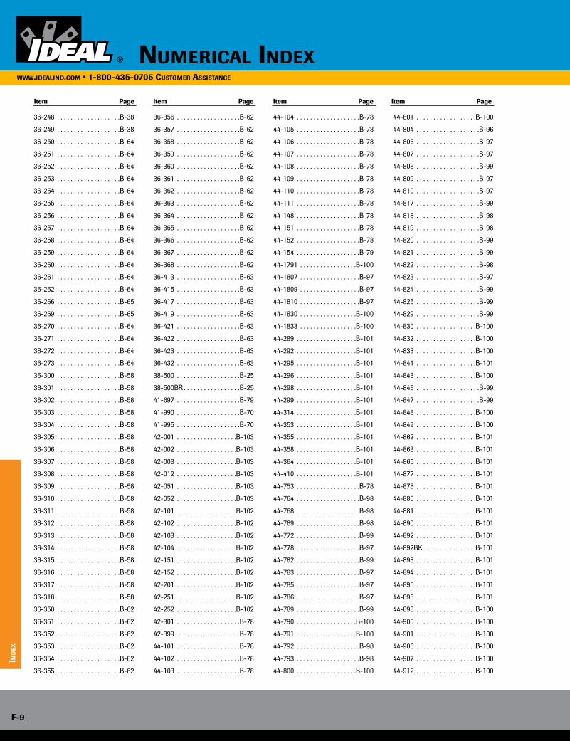
36-248 . . . . . . . . . . . . . . . . . . .B-38
36-249 . . . . . . . . . . . . . . . . . . .B-38
36-250 . . . . . . . . . . . . . . . . . . .B-64
36-251 . . . . . . . . . . . . . . . . . . .B-64
36-252 . . . . . . . . . . . . . . . . . . .B-64
36-253 . . . . . . . . . . . . . . . . . . .B-64
36-254 . . . . . . . . . . . . . . . . . . .B-64
36-255 . . . . . . . . . . . . . . . . . . .B-64
36-256 . . . . . . . . . . . . . . . . . . .B-64
36-257 . . . . . . . . . . . . . . . . . . .B-64
36-258 . . . . . . . . . . . . . . . . . . .B-64
36-259 . . . . . . . . . . . . . . . . . . .B-64
36-260 . . . . . . . . . . . . . . . . . . .B-64
36-261 . . . . . . . . . . . . . . . . . . .B-64
36-262 . . . . . . . . . . . . . . . . . . .B-64
36-266 . . . . . . . . . . . . . . . . . . .B-65
36-269 . . . . . . . . . . . . . . . . . . .B-65
36-270 . . . . . . . . . . . . . . . . . . .B-64
36-271 . . . . . . . . . . . . . . . . . . .B-64
36-272 . . . . . . . . . . . . . . . . . . .B-64
36-273 . . . . . . . . . . . . . . . . . . .B-64
36-300 . . . . . . . . . . . . . . . . . . .B-58
36-301 . . . . . . . . . . . . . . . . . . .B-58
36-302 . . . . . . . . . . . . . . . . . . .B-58
36-303 . . . . . . . . . . . . . . . . . . .B-58
36-304 . . . . . . . . . . . . . . . . . . .B-58
36-305 . . . . . . . . . . . . . . . . . . .B-58
36-306 . . . . . . . . . . . . . . . . . . .B-58
36-307 . . . . . . . . . . . . . . . . . . .B-58
36-308 . . . . . . . . . . . . . . . . . . .B-58
36-309 . . . . . . . . . . . . . . . . . . .B-58
36-310 . . . . . . . . . . . . . . . . . . .B-58
36-311 . . . . . . . . . . . . . . . . . . .B-58
36-312 . . . . . . . . . . . . . . . . . . .B-58
36-313 . . . . . . . . . . . . . . . . . . .B-58
36-314 . . . . . . . . . . . . . . . . . . .B-58
36-315 . . . . . . . . . . . . . . . . . . .B-58
36-316 . . . . . . . . . . . . . . . . . . .B-58
36-317 . . . . . . . . . . . . . . . . . . .B-58
36-318 . . . . . . . . . . . . . . . . . . .B-58
36-350 . . . . . . . . . . . . . . . . . . .B-62
36-351 . . . . . . . . . . . . . . . . . . .B-62
36-352 . . . . . . . . . . . . . . . . . . .B-62
36-353 . . . . . . . . . . . . . . . . . . .B-62
36-354 . . . . . . . . . . . . . . . . . . .B-62
36-355 . . . . . . . . . . . . . . . . . . .B-62
36-356 . . . . . . . . . . . . . . . . . . .B-62
36-357 . . . . . . . . . . . . . . . . . . .B-62
36-358 . . . . . . . . . . . . . . . . . . .B-62
36-359 . . . . . . . . . . . . . . . . . . .B-62
36-360 . . . . . . . . . . . . . . . . . . .B-62
36-361 . . . . . . . . . . . . . . . . . . .B-62
36-362 . . . . . . . . . . . . . . . . . . .B-62
36-363 . . . . . . . . . . . . . . . . . . .B-62
36-364 . . . . . . . . . . . . . . . . . . .B-62
36-365 . . . . . . . . . . . . . . . . . . .B-62
36-366 . . . . . . . . . . . . . . . . . . .B-62
36-367 . . . . . . . . . . . . . . . . . . .B-62
36-368 . . . . . . . . . . . . . . . . . . .B-62
36-413 . . . . . . . . . . . . . . . . . . .B-63
36-415 . . . . . . . . . . . . . . . . . . .B-63
36-417 . . . . . . . . . . . . . . . . . . .B-63
36-419 . . . . . . . . . . . . . . . . . . .B-63
36-421 . . . . . . . . . . . . . . . . . . .B-63
36-422 . . . . . . . . . . . . . . . . . . .B-63
36-423 . . . . . . . . . . . . . . . . . . .B-63
36-432 . . . . . . . . . . . . . . . . . . .B-63
38-500 . . . . . . . . . . . . . . . . . . .B-25
38-500BR . . . . . . . . . . . . . . . . .B-25
41-697 . . . . . . . . . . . . . . . . . . .B-79
41-990 . . . . . . . . . . . . . . . . . . .B-70
41-995 . . . . . . . . . . . . . . . . . . .B-70
42-001 . . . . . . . . . . . . . . . . . .B-103
42-002 . . . . . . . . . . . . . . . . . .B-103
42-003 . . . . . . . . . . . . . . . . . .B-103
42-012 . . . . . . . . . . . . . . . . . .B-103
42-051 . . . . . . . . . . . . . . . . . .B-103
42-052 . . . . . . . . . . . . . . . . . .B-103
42-101 . . . . . . . . . . . . . . . . . .B-102
42-102 . . . . . . . . . . . . . . . . . .B-102
42-103 . . . . . . . . . . . . . . . . . .B-102
42-104 . . . . . . . . . . . . . . . . . .B-102
42-151 . . . . . . . . . . . . . . . . . .B-102
42-152 . . . . . . . . . . . . . . . . . .B-102
42-201 . . . . . . . . . . . . . . . . . .B-102
42-251 . . . . . . . . . . . . . . . . . .B-102
42-252 . . . . . . . . . . . . . . . . . .B-102
42-301 . . . . . . . . . . . . . . . . . . .B-78
42-399 . . . . . . . . . . . . . . . . . . .B-78
44-101 . . . . . . . . . . . . . . . . . . .B-78
44-102 . . . . . . . . . . . . . . . . . . .B-78
44-103 . . . . . . . . . . . . . . . . . . .B-78
44-104 . . . . . . . . . . . . . . . . . . .B-78
44-105 . . . . . . . . . . . . . . . . . . .B-78
44-106 . . . . . . . . . . . . . . . . . . .B-78
44-107 . . . . . . . . . . . . . . . . . . .B-78
44-108 . . . . . . . . . . . . . . . . . . .B-78
44-109 . . . . . . . . . . . . . . . . . . .B-78
44-110 . . . . . . . . . . . . . . . . . . .B-78
44-111 . . . . . . . . . . . . . . . . . . .B-78
44-148 . . . . . . . . . . . . . . . . . . .B-78
44-151 . . . . . . . . . . . . . . . . . . .B-78
44-152 . . . . . . . . . . . . . . . . . . .B-78
44-154 . . . . . . . . . . . . . . . . . . .B-79
44-1791 . . . . . . . . . . . . . . . . .B-100
44-1807 . . . . . . . . . . . . . . . . . .B-97
44-1809 . . . . . . . . . . . . . . . . . .B-97
44-1810 . . . . . . . . . . . . . . . . . .B-97
44-1830 . . . . . . . . . . . . . . . . .B-100
44-1833 . . . . . . . . . . . . . . . . .B-100
44-289 . . . . . . . . . . . . . . . . . .B-101
44-292 . . . . . . . . . . . . . . . . . .B-101
44-295 . . . . . . . . . . . . . . . . . .B-101
44-296 . . . . . . . . . . . . . . . . . .B-101
44-298 . . . . . . . . . . . . . . . . . .B-101
44-299 . . . . . . . . . . . . . . . . . .B-101
44-314 . . . . . . . . . . . . . . . . . .B-101
44-353 . . . . . . . . . . . . . . . . . .B-101
44-355 . . . . . . . . . . . . . . . . . .B-101
44-358 . . . . . . . . . . . . . . . . . .B-101
44-364 . . . . . . . . . . . . . . . . . .B-101
44-410 . . . . . . . . . . . . . . . . . .B-101
44-753 . . . . . . . . . . . . . . . . . . .B-78
44-764 . . . . . . . . . . . . . . . . . . .B-98
44-768 . . . . . . . . . . . . . . . . . . .B-98
44-769 . . . . . . . . . . . . . . . . . . .B-98
44-772 . . . . . . . . . . . . . . . . . . .B-99
44-778 . . . . . . . . . . . . . . . . . . .B-97
44-782 . . . . . . . . . . . . . . . . . . .B-99
44-783 . . . . . . . . . . . . . . . . . . .B-97
44-785 . . . . . . . . . . . . . . . . . . .B-97
44-786 . . . . . . . . . . . . . . . . . . .B-97
44-789 . . . . . . . . . . . . . . . . . . .B-99
44-790 . . . . . . . . . . . . . . . . . .B-100
44-791 . . . . . . . . . . . . . . . . . .B-100
44-792 . . . . . . . . . . . . . . . . . . .B-98
44-793 . . . . . . . . . . . . . . . . . . .B-98
44-800 . . . . . . . . . . . . . . . . . .B-100
44-801 . . . . . . . . . . . . . . . . . .B-100
44-804 . . . . . . . . . . . . . . . . . . .B-96
44-806 . . . . . . . . . . . . . . . . . . .B-97
44-807 . . . . . . . . . . . . . . . . . . .B-97
44-808 . . . . . . . . . . . . . . . . . . .B-99
44-809 . . . . . . . . . . . . . . . . . . .B-97
44-810 . . . . . . . . . . . . . . . . . . .B-97
44-817 . . . . . . . . . . . . . . . . . . .B-99
44-818 . . . . . . . . . . . . . . . . . . .B-98
44-819 . . . . . . . . . . . . . . . . . . .B-98
44-820 . . . . . . . . . . . . . . . . . . .B-99
44-821 . . . . . . . . . . . . . . . . . . .B-99
44-822 . . . . . . . . . . . . . . . . . . .B-98
44-823 . . . . . . . . . . . . . . . . . . .B-97
44-824 . . . . . . . . . . . . . . . . . . .B-99
44-825 . . . . . . . . . . . . . . . . . . .B-99
44-829 . . . . . . . . . . . . . . . . . . .B-99
44-830 . . . . . . . . . . . . . . . . . .B-100
44-832 . . . . . . . . . . . . . . . . . .B-100
44-833 . . . . . . . . . . . . . . . . . .B-100
44-841 . . . . . . . . . . . . . . . . . .B-101
44-843 . . . . . . . . . . . . . . . . . .B-100
44-846 . . . . . . . . . . . . . . . . . . .B-99
44-847 . . . . . . . . . . . . . . . . . . .B-99
44-848 . . . . . . . . . . . . . . . . . .B-100
44-849 . . . . . . . . . . . . . . . . . .B-100
44-862 . . . . . . . . . . . . . . . . . .B-101
44-863 . . . . . . . . . . . . . . . . . .B-101
44-865 . . . . . . . . . . . . . . . . . .B-101
44-877 . . . . . . . . . . . . . . . . . .B-101
44-878 . . . . . . . . . . . . . . . . . .B-101
44-880 . . . . . . . . . . . . . . . . . .B-101
44-881 . . . . . . . . . . . . . . . . . .B-101
44-890 . . . . . . . . . . . . . . . . . .B-101
44-892 . . . . . . . . . . . . . . . . . .B-101
44-892BK . . . . . . . . . . . . . . . .B-101
44-893 . . . . . . . . . . . . . . . . . .B-101
44-894 . . . . . . . . . . . . . . . . . .B-101
44-895 . . . . . . . . . . . . . . . . . .B-101
44-896 . . . . . . . . . . . . . . . . . .B-101
44-898 . . . . . . . . . . . . . . . . . .B-100
44-900 . . . . . . . . . . . . . . . . . .B-100
44-901 . . . . . . . . . . . . . . . . . .B-100
44-906 . . . . . . . . . . . . . . . . . .B-100
44-907 . . . . . . . . . . . . . . . . . .B-100
44-912 . . . . . . . . . . . . . . . . . .B-100
Item Page Item Page Item Page Item Page
numericAl indexwww.ideAlind.com • 1-800-435-0705 customer AssistAnce
ind
ex
F-9
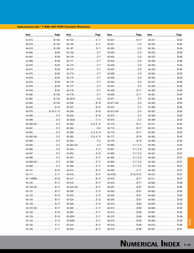
44-914 . . . . . . . . . . . . . . . . . .B-100
44-916 . . . . . . . . . . . . . . . . . .B-100
44-918 . . . . . . . . . . . . . . . . . .B-100
44-956 . . . . . . . . . . . . . . . . . . .B-98
44-957 . . . . . . . . . . . . . . . . . . .B-98
44-969 . . . . . . . . . . . . . . . . . . .B-96
44-970 . . . . . . . . . . . . . . . . . . .B-93
44-971 . . . . . . . . . . . . . . . . . . .B-94
44-972 . . . . . . . . . . . . . . . . . . .B-95
44-973 . . . . . . . . . . . . . . . . . . .B-93
44-974 . . . . . . . . . . . . . . . . . . .B-95
44-975 . . . . . . . . . . . . . . . . . . .B-96
44-979 . . . . . . . . . . . . . . . . . . .B-94
44-990 . . . . . . . . . . . . . . . . . .B-103
44-991 . . . . . . . . . . . . . . . . . .B-103
44-992 . . . . . . . . . . . . . . . . . .B-103
45-025 . . . . . . . . . . . . . . . . . . .B-18
45-074 . . . . . . . . . . . . . B-19, E-12
45-089 . . . . . . . . . . . . . . . . . . . .C-6
45-090 . . . . . . . . . . . . . . . . . . . .C-5
45-090-341 . . . . . . . . . . . . . . . .C-5
45-091 . . . . . . . . . . . . . . . . . . . .C-5
45-092 . . . . . . . . . . . . . . . . . . . .C-5
45-092-341 . . . . . . . . . . . . . . . .C-5
45-093 . . . . . . . . . . . . . . . . . . . .C-5
45-095 . . . . . . . . . . . . . . . . . . . .C-6
45-096 . . . . . . . . . . . . . . . . . . . .C-5
45-097 . . . . . . . . . . . . . . . . . . . .C-5
45-098 . . . . . . . . . . . . . . . . . . . .C-5
45-098-341 . . . . . . . . . . . . . . . .C-5
45-099 . . . . . . . . . . . . . . . . . . . .C-5
45-101 . . . . . . . . . . . . . . . . . . .B-18
45-111 . . . . . . . . . . . . . . . . . . . E-11
45-118SRS . . . . . . . . . . . . . . . .B-18
45-120 . . . . . . . . . . . . . . . . . . .B-17
45-120-341 . . . . . . . . . . . . . . .B-17
45-121 . . . . . . . . . . . . . . . . . . .B-17
45-123 . . . . . . . . . . . . . . . . . . .B-19
45-124 . . . . . . . . . . . . . . . . . . .B-17
45-125 . . . . . . . . . . . . . . . . . . .B-17
45-125-341 . . . . . . . . . . . . . . .B-17
45-128 . . . . . . . . . . . . . . . . . . .B-19
45-129 . . . . . . . . . . . . . . . . . . .B-19
45-144 . . . . . . . . . . . . . . . . . . . E-12
45-162 . . . . . . . . . . . . . . . . . . . E-11
45-163 . . . . . . . . . . . . . . . . . . . E-11
45-164 . . . . . . . . . . . . . . . . . . . E-11
45-165 . . . . . . . . . . . . . . . . . . . E-11
45-167 . . . . . . . . . . . . . . . . . . . E-11
45-169 . . . . . . . . . . . . . . . . . . . .C-7
45-170 . . . . . . . . . . . . . . . . . . . .C-7
45-171 . . . . . . . . . . . . . . . . . . . .C-7
45-172 . . . . . . . . . . . . . . . . . . . .C-7
45-173 . . . . . . . . . . . . . . . . . . . .C-7
45-174 . . . . . . . . . . . . . . . . . . . .C-7
45-175 . . . . . . . . . . . . . . . . . . . .C-7
45-176 . . . . . . . . . . . . . . . . . . . .C-7
45-177 . . . . . . . . . . . . . . . . . . . .C-7
45-178 . . . . . . . . . . . . . . . . . . . .C-7
45-179 . . . . . . . . . . . . . . . . . . . .C-7
45-2019 . . . . . . . . . . . . . . . . . . .C-6
45-235 . . . . . . . . . . . . . . . . . . .B-18
45-247 . . . . . . . . . . . . . . . . . . .B-18
45-248 . . . . . . . . . . . . . . . . . . .B-18
45-249 . . . . . . . . . . . . . . . . . . .B-18
45-2530 . . . . . . . . . . . . . . . . . .C-11
45-262 . . . . . . . . . . . . . . .C-6, E-12
45-264 . . . . . . . . . . . . . . . . . . . .C-6
45-265 . . . . . . . . . . . . . . .C-6, E-12
45-282 . . . . . . . . . . . . . . .C-6, E-12
45-292 . . . . . . . . . . . . . . . . . . . .C-5
45-292-341 . . . . . . . . . . . . . . . .C-5
45-344 . . . . . . . . . . . . . . . . . . . E-17
45-352 . . . . . . . . . . . . . . . . . . . E-16
45-357 . . . . . . . . . . . . . . . . . . . E-17
45-358 . . . . . . . . . . . . . . . . . . . E-17
45-359 . . . . . . . . . . . . . . . . . . . E-17
45-415 . . . . . . . . . . . . . . . . . . .B-17
45-416 . . . . . . . . . . . . . . . . . . .B-17
45-417 . . . . . . . . . . . . . . . . . . .B-17
45-418 . . . . . . . . . . . . . . . . . . .B-17
45-425-341 . . . . . . . . . . . . . . .B-17
45-520 . . . . . . . . . . . . . . . . . . . E-12
45-522 . . . . . . . . . . . . . . . . . . . E-12
45-524 . . . . . . . . . . . . . . . . . . . E-12
45-526 . . . . . . . . . . . . . . . . . . . E-12
45-600 . . . . . . . . . . . . . . . . . . .C-11
45-605 . . . . . . . . . . . . . . . . . . . E-11
45-6051 . . . . . . . . . . . . . . . . . . E-11
45-6052 . . . . . . . . . . . . . . . . . . E-11
45-615 . . . . . . . . . . . . . . . . . . .B-17
45-618 . . . . . . . . . . . . . . . . . . .B-17
45-621 . . . . . . . . . . . . . . . . . . .B-17
45-631 . . . . . . . . . . . . . . . . . . . .C-8
45-632 . . . . . . . . . . . . . . . . . . . .C-8
45-633 . . . . . . . . . . . . . . . . . . . .C-8
45-634 . . . . . . . . . . . . . . . . . . . .C-8
45-635 . . . . . . . . . . . . . . . . . . . .C-8
45-636 . . . . . . . . . . . . . . . . . . . .C-8
45-637 . . . . . . . . . . . . . . . . . . . .C-8
45-638 . . . . . . . . . . . . . . . . . . . .C-8
45-639 . . . . . . . . . . . . . . . . . . . .C-8
45-640 . . . . . . . . . . . . . . . . . . . .C-8
45-641 . . . . . . . . . . . . . . . . . . . .C-8
45-649 . . . . . . . . . . . . . . . . . . .B-17
45-650 . . . . . . . . . . . . . . . . . . .C-11
45-671 . . . . . . . . . . . . . . . . . . . .C-5
45-671-341 . . . . . . . . . . . . . . . .C-6
45-672 . . . . . . . . . . . . . . . . . . . .C-5
45-672-341 . . . . . . . . . . . . . . . .C-6
45-673 . . . . . . . . . . . . . . . . . . . .C-5
45-674 . . . . . . . . . . . . . . . . . . . .C-5
45-715 . . . . . . . . . . . . . . . . . . .B-17
45-716 . . . . . . . . . . . . . . . . . . .B-17
45-718 . . . . . . . . . . . . . . . . . . .B-17
45-777 . . . . . . . . . . . . . . . . . . .B-18
45-778 . . . . . . . . . . . . . . . . . . .B-19
45-890 . . . . . . . . . . . . . . . C-7, C-8
45-891 . . . . . . . . . . . . . . . C-7, C-8
45-892 . . . . . . . . . . . . . . . C-7, C-8
45-893 . . . . . . . . . . . . . . . C-7, C-8
45-894 . . . . . . . . . . . . . . . C-7, C-8
45-895 . . . . . . . . . . . . . . . C-7, C-8
45-906 . . . . . . . . . . . . . . . . . . .C-11
45-9120 . . . . . . . . . . . . B-18, B-47
45-915 . . . . . . . . . . . . . . . . . . .B-17
45-918 . . . . . . . . . . . . . . . . . . .B-17
46-007 . . . . . . . . . . . . . . . . . . .B-87
46-202 . . . . . . . . . . . . . . . . . . .B-91
46-203 . . . . . . . . . . . . . . . . . . .B-91
46-204 . . . . . . . . . . . . . . . . . . .B-91
46-310 . . . . . . . . . . . . . . . . . . .B-88
46-312 . . . . . . . . . . . . . . . . . . .B-88
46-313 . . . . . . . . . . . . . . . . . . .B-88
46-315 . . . . . . . . . . . . . . . . . . .B-88
46-316 . . . . . . . . . . . . . . . . . . .B-88
46-318 . . . . . . . . . . . . . . . . . . .B-88
46-319 . . . . . . . . . . . . . . . . . . .B-88
46-321 . . . . . . . . . . . . . . . . . . .B-88
46-322 . . . . . . . . . . . . . . . . . . .B-88
46-324 . . . . . . . . . . . . . . . . . . .B-88
46-325 . . . . . . . . . . . . . . . . . . .B-88
46-327 . . . . . . . . . . . . . . . . . . .B-88
46-328 . . . . . . . . . . . . . . . . . . .B-88
46-330 . . . . . . . . . . . . . . . . . . .B-88
46-343 . . . . . . . . . . . . . . . . . . .B-89
46-344 . . . . . . . . . . . . . . . . . . .B-89
46-346 . . . . . . . . . . . . . . . . . . .B-89
46-347 . . . . . . . . . . . . . . . . . . .B-89
46-348 . . . . . . . . . . . . . . . . . . .B-89
46-350 . . . . . . . . . . . . . . . . . . .B-89
46-351 . . . . . . . . . . . . . . . . . . .B-89
46-352 . . . . . . . . . . . . . . . . . . .B-89
46-354 . . . . . . . . . . . . . . . . . . .B-89
46-356 . . . . . . . . . . . . . . . . . . .B-89
46-357 . . . . . . . . . . . . . . . . . . .B-89
46-358 . . . . . . . . . . . . . . . . . . .B-89
46-369 . . . . . . . . . . . . . . . . . . .B-89
46-371 . . . . . . . . . . . . . . . . . . .B-89
46-372 . . . . . . . . . . . . . . . . . . .B-89
46-381 . . . . . . . . . . . . . . . . . . .B-90
46-382 . . . . . . . . . . . . . . . . . . .B-90
46-383 . . . . . . . . . . . . . . . . . . .B-90
46-384 . . . . . . . . . . . . . . . . . . .B-90
46-400 . . . . . . . . . . . . . . . . . . .B-87
46-401 . . . . . . . . . . . . . . . . . . .B-87
46-402 . . . . . . . . . . . . . . . . . . .B-87
46-403 . . . . . . . . . . . . . . . . . . .B-87
46-404 . . . . . . . . . . . . . . . . . . .B-87
46-405 . . . . . . . . . . . . . . . . . . .B-87
46-410 . . . . . . . . . . . . . . . . . . .B-87
46-411 . . . . . . . . . . . . . . . . . . .B-87
46-600 . . . . . . . . . . . . . . . . . . .B-88
46-601 . . . . . . . . . . . . . . . . . . .B-88
46-602 . . . . . . . . . . . . . . . . . . .B-88
46-603 . . . . . . . . . . . . . . . . . . .B-88
46-604 . . . . . . . . . . . . . . . . . . .B-88
46-605 . . . . . . . . . . . . . . . . . . .B-88
46-606 . . . . . . . . . . . . . . . . . . .B-88
46-607 . . . . . . . . . . . . . . . . . . .B-88
46-608 . . . . . . . . . . . . . . . . . . .B-88
46-609 . . . . . . . . . . . . . . . . . . .B-88
46-610 . . . . . . . . . . . . . . . . . . .B-88
46-941 . . . . . . . . . . . . . . . . . . .B-91
Item Page Item Page Item Page Item Page
www.ideAlind.com • 1-800-435-0705 customer AssistAnce
ind
ex
numericAl index F-10
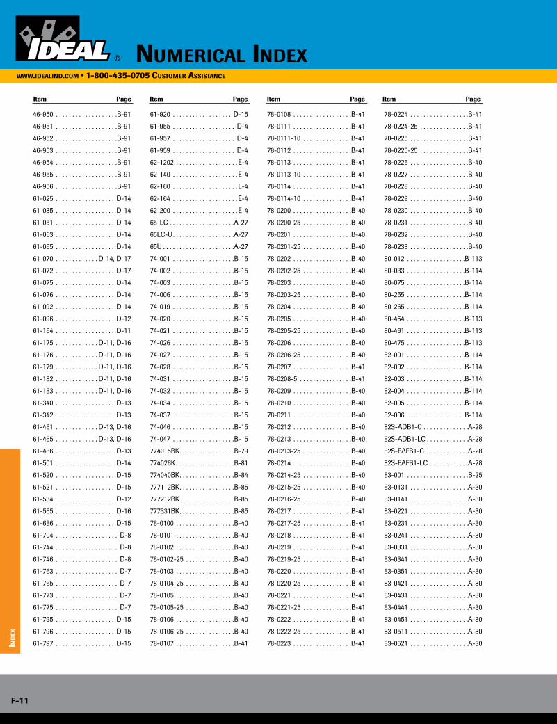
46-950 . . . . . . . . . . . . . . . . . . .B-91
46-951 . . . . . . . . . . . . . . . . . . .B-91
46-952 . . . . . . . . . . . . . . . . . . .B-91
46-953 . . . . . . . . . . . . . . . . . . .B-91
46-954 . . . . . . . . . . . . . . . . . . .B-91
46-955 . . . . . . . . . . . . . . . . . . .B-91
46-956 . . . . . . . . . . . . . . . . . . .B-91
61-025 . . . . . . . . . . . . . . . . . . D-14
61-035 . . . . . . . . . . . . . . . . . . D-14
61-051 . . . . . . . . . . . . . . . . . . D-14
61-063 . . . . . . . . . . . . . . . . . . D-14
61-065 . . . . . . . . . . . . . . . . . . D-14
61-070 . . . . . . . . . . . . . D-14, D-17
61-072 . . . . . . . . . . . . . . . . . . D-17
61-075 . . . . . . . . . . . . . . . . . . D-14
61-076 . . . . . . . . . . . . . . . . . . D-14
61-092 . . . . . . . . . . . . . . . . . . D-14
61-096 . . . . . . . . . . . . . . . . . . D-12
61-164 . . . . . . . . . . . . . . . . . . D-11
61-175 . . . . . . . . . . . . . D-11, D-16
61-176 . . . . . . . . . . . . . D-11, D-16
61-179 . . . . . . . . . . . . . D-11, D-16
61-182 . . . . . . . . . . . . . D-11, D-16
61-183 . . . . . . . . . . . . . D-11, D-16
61-340 . . . . . . . . . . . . . . . . . . D-13
61-342 . . . . . . . . . . . . . . . . . . D-13
61-461 . . . . . . . . . . . . . D-13, D-16
61-465 . . . . . . . . . . . . . D-13, D-16
61-486 . . . . . . . . . . . . . . . . . . D-13
61-501 . . . . . . . . . . . . . . . . . . D-14
61-520 . . . . . . . . . . . . . . . . . . D-15
61-521 . . . . . . . . . . . . . . . . . . D-15
61-534 . . . . . . . . . . . . . . . . . . D-12
61-565 . . . . . . . . . . . . . . . . . . D-16
61-686 . . . . . . . . . . . . . . . . . . D-15
61-704 . . . . . . . . . . . . . . . . . . . D-8
61-744 . . . . . . . . . . . . . . . . . . . D-8
61-746 . . . . . . . . . . . . . . . . . . . D-8
61-763 . . . . . . . . . . . . . . . . . . . D-7
61-765 . . . . . . . . . . . . . . . . . . . D-7
61-773 . . . . . . . . . . . . . . . . . . . D-7
61-775 . . . . . . . . . . . . . . . . . . . D-7
61-795 . . . . . . . . . . . . . . . . . . D-15
61-796 . . . . . . . . . . . . . . . . . . D-15
61-797 . . . . . . . . . . . . . . . . . . D-15
61-920 . . . . . . . . . . . . . . . . . . D-15
61-955 . . . . . . . . . . . . . . . . . . . D-4
61-957 . . . . . . . . . . . . . . . . . . . D-4
61-959 . . . . . . . . . . . . . . . . . . . D-4
62-1202 . . . . . . . . . . . . . . . . . . . E-4
62-140 . . . . . . . . . . . . . . . . . . . . E-4
62-160 . . . . . . . . . . . . . . . . . . . . E-4
62-164 . . . . . . . . . . . . . . . . . . . . E-4
62-200 . . . . . . . . . . . . . . . . . . . . E-4
65-LC . . . . . . . . . . . . . . . . . . . .A-27
65LC-U . . . . . . . . . . . . . . . . . . .A-27
65U . . . . . . . . . . . . . . . . . . . . . .A-27
74-001 . . . . . . . . . . . . . . . . . . .B-15
74-002 . . . . . . . . . . . . . . . . . . .B-15
74-003 . . . . . . . . . . . . . . . . . . .B-15
74-006 . . . . . . . . . . . . . . . . . . .B-15
74-019 . . . . . . . . . . . . . . . . . . .B-15
74-020 . . . . . . . . . . . . . . . . . . .B-15
74-021 . . . . . . . . . . . . . . . . . . .B-15
74-026 . . . . . . . . . . . . . . . . . . .B-15
74-027 . . . . . . . . . . . . . . . . . . .B-15
74-028 . . . . . . . . . . . . . . . . . . .B-15
74-031 . . . . . . . . . . . . . . . . . . .B-15
74-032 . . . . . . . . . . . . . . . . . . .B-15
74-034 . . . . . . . . . . . . . . . . . . .B-15
74-037 . . . . . . . . . . . . . . . . . . .B-15
74-046 . . . . . . . . . . . . . . . . . . .B-15
74-047 . . . . . . . . . . . . . . . . . . .B-15
774015BK . . . . . . . . . . . . . . . . .B-79
774026K . . . . . . . . . . . . . . . . . .B-81
774040BK . . . . . . . . . . . . . . . . .B-84
777112BK . . . . . . . . . . . . . . . . .B-85
777212BK . . . . . . . . . . . . . . . . .B-85
777331BK . . . . . . . . . . . . . . . . .B-85
78-0100 . . . . . . . . . . . . . . . . . .B-40
78-0101 . . . . . . . . . . . . . . . . . .B-40
78-0102 . . . . . . . . . . . . . . . . . .B-40
78-0102-25 . . . . . . . . . . . . . . .B-40
78-0103 . . . . . . . . . . . . . . . . . .B-40
78-0104-25 . . . . . . . . . . . . . . .B-40
78-0105 . . . . . . . . . . . . . . . . . .B-40
78-0105-25 . . . . . . . . . . . . . . .B-40
78-0106 . . . . . . . . . . . . . . . . . .B-40
78-0106-25 . . . . . . . . . . . . . . .B-40
78-0107 . . . . . . . . . . . . . . . . . .B-41
78-0108 . . . . . . . . . . . . . . . . . .B-41
78-0111 . . . . . . . . . . . . . . . . . .B-41
78-0111-10 . . . . . . . . . . . . . . .B-41
78-0112 . . . . . . . . . . . . . . . . . .B-41
78-0113 . . . . . . . . . . . . . . . . . .B-41
78-0113-10 . . . . . . . . . . . . . . .B-41
78-0114 . . . . . . . . . . . . . . . . . .B-41
78-0114-10 . . . . . . . . . . . . . . .B-41
78-0200 . . . . . . . . . . . . . . . . . .B-40
78-0200-25 . . . . . . . . . . . . . . .B-40
78-0201 . . . . . . . . . . . . . . . . . .B-40
78-0201-25 . . . . . . . . . . . . . . .B-40
78-0202 . . . . . . . . . . . . . . . . . .B-40
78-0202-25 . . . . . . . . . . . . . . .B-40
78-0203 . . . . . . . . . . . . . . . . . .B-40
78-0203-25 . . . . . . . . . . . . . . .B-40
78-0204 . . . . . . . . . . . . . . . . . .B-40
78-0205 . . . . . . . . . . . . . . . . . .B-40
78-0205-25 . . . . . . . . . . . . . . .B-40
78-0206 . . . . . . . . . . . . . . . . . .B-40
78-0206-25 . . . . . . . . . . . . . . .B-40
78-0207 . . . . . . . . . . . . . . . . . .B-41
78-0208-5 . . . . . . . . . . . . . . . .B-41
78-0209 . . . . . . . . . . . . . . . . . .B-40
78-0210 . . . . . . . . . . . . . . . . . .B-40
78-0211 . . . . . . . . . . . . . . . . . .B-40
78-0212 . . . . . . . . . . . . . . . . . .B-40
78-0213 . . . . . . . . . . . . . . . . . .B-40
78-0213-25 . . . . . . . . . . . . . . .B-40
78-0214 . . . . . . . . . . . . . . . . . .B-40
78-0214-25 . . . . . . . . . . . . . . .B-40
78-0215-25 . . . . . . . . . . . . . . .B-40
78-0216-25 . . . . . . . . . . . . . . .B-40
78-0217 . . . . . . . . . . . . . . . . . .B-41
78-0217-25 . . . . . . . . . . . . . . .B-41
78-0218 . . . . . . . . . . . . . . . . . .B-41
78-0219 . . . . . . . . . . . . . . . . . .B-41
78-0219-25 . . . . . . . . . . . . . . .B-41
78-0220 . . . . . . . . . . . . . . . . . .B-41
78-0220-25 . . . . . . . . . . . . . . .B-41
78-0221 . . . . . . . . . . . . . . . . . .B-41
78-0221-25 . . . . . . . . . . . . . . .B-41
78-0222 . . . . . . . . . . . . . . . . . .B-41
78-0222-25 . . . . . . . . . . . . . . .B-41
78-0223 . . . . . . . . . . . . . . . . . .B-41
78-0224 . . . . . . . . . . . . . . . . . .B-41
78-0224-25 . . . . . . . . . . . . . . .B-41
78-0225 . . . . . . . . . . . . . . . . . .B-41
78-0225-25 . . . . . . . . . . . . . . .B-41
78-0226 . . . . . . . . . . . . . . . . . .B-40
78-0227 . . . . . . . . . . . . . . . . . .B-40
78-0228 . . . . . . . . . . . . . . . . . .B-40
78-0229 . . . . . . . . . . . . . . . . . .B-40
78-0230 . . . . . . . . . . . . . . . . . .B-40
78-0231 . . . . . . . . . . . . . . . . . .B-40
78-0232 . . . . . . . . . . . . . . . . . .B-40
78-0233 . . . . . . . . . . . . . . . . . .B-40
80-012 . . . . . . . . . . . . . . . . . .B-113
80-033 . . . . . . . . . . . . . . . . . .B-114
80-075 . . . . . . . . . . . . . . . . . .B-114
80-255 . . . . . . . . . . . . . . . . . .B-114
80-265 . . . . . . . . . . . . . . . . . .B-114
80-454 . . . . . . . . . . . . . . . . . .B-113
80-461 . . . . . . . . . . . . . . . . . .B-113
80-475 . . . . . . . . . . . . . . . . . .B-113
82-001 . . . . . . . . . . . . . . . . . .B-114
82-002 . . . . . . . . . . . . . . . . . .B-114
82-003 . . . . . . . . . . . . . . . . . .B-114
82-004 . . . . . . . . . . . . . . . . . .B-114
82-005 . . . . . . . . . . . . . . . . . .B-114
82-006 . . . . . . . . . . . . . . . . . .B-114
82S-ADB1-C . . . . . . . . . . . . . .A-28
82S-ADB1-LC . . . . . . . . . . . . .A-28
82S-EAFB1-C . . . . . . . . . . . . .A-28
82S-EAFB1-LC . . . . . . . . . . . .A-28
83-001 . . . . . . . . . . . . . . . . . . .B-25
83-0131 . . . . . . . . . . . . . . . . . .A-30
83-0141 . . . . . . . . . . . . . . . . . .A-30
83-0221 . . . . . . . . . . . . . . . . . .A-30
83-0231 . . . . . . . . . . . . . . . . . .A-30
83-0241 . . . . . . . . . . . . . . . . . .A-30
83-0331 . . . . . . . . . . . . . . . . . .A-30
83-0341 . . . . . . . . . . . . . . . . . .A-30
83-0351 . . . . . . . . . . . . . . . . . .A-30
83-0421 . . . . . . . . . . . . . . . . . .A-30
83-0431 . . . . . . . . . . . . . . . . . .A-30
83-0441 . . . . . . . . . . . . . . . . . .A-30
83-0451 . . . . . . . . . . . . . . . . . .A-30
83-0511 . . . . . . . . . . . . . . . . . .A-30
83-0521 . . . . . . . . . . . . . . . . . .A-30
Item Page Item Page Item Page Item Page
numericAl indexwww.ideAlind.com • 1-800-435-0705 customer AssistAnce
ind
ex
F-11
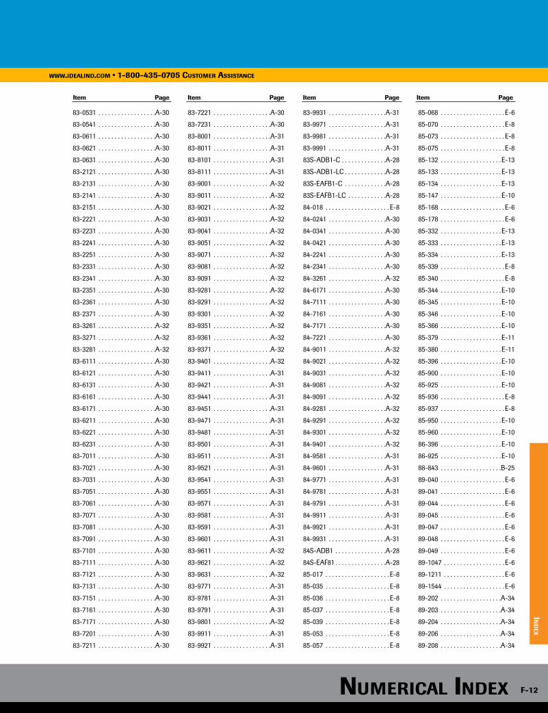
83-0531 . . . . . . . . . . . . . . . . . .A-30
83-0541 . . . . . . . . . . . . . . . . . .A-30
83-0611 . . . . . . . . . . . . . . . . . .A-30
83-0621 . . . . . . . . . . . . . . . . . .A-30
83-0631 . . . . . . . . . . . . . . . . . .A-30
83-2121 . . . . . . . . . . . . . . . . . .A-30
83-2131 . . . . . . . . . . . . . . . . . .A-30
83-2141 . . . . . . . . . . . . . . . . . .A-30
83-2151 . . . . . . . . . . . . . . . . . .A-30
83-2221 . . . . . . . . . . . . . . . . . .A-30
83-2231 . . . . . . . . . . . . . . . . . .A-30
83-2241 . . . . . . . . . . . . . . . . . .A-30
83-2251 . . . . . . . . . . . . . . . . . .A-30
83-2331 . . . . . . . . . . . . . . . . . .A-30
83-2341 . . . . . . . . . . . . . . . . . .A-30
83-2351 . . . . . . . . . . . . . . . . . .A-30
83-2361 . . . . . . . . . . . . . . . . . .A-30
83-2371 . . . . . . . . . . . . . . . . . .A-30
83-3261 . . . . . . . . . . . . . . . . . .A-32
83-3271 . . . . . . . . . . . . . . . . . .A-32
83-3281 . . . . . . . . . . . . . . . . . .A-32
83-6111 . . . . . . . . . . . . . . . . . .A-30
83-6121 . . . . . . . . . . . . . . . . . .A-30
83-6131 . . . . . . . . . . . . . . . . . .A-30
83-6161 . . . . . . . . . . . . . . . . . .A-30
83-6171 . . . . . . . . . . . . . . . . . .A-30
83-6211 . . . . . . . . . . . . . . . . . .A-30
83-6221 . . . . . . . . . . . . . . . . . .A-30
83-6231 . . . . . . . . . . . . . . . . . .A-30
83-7011 . . . . . . . . . . . . . . . . . .A-30
83-7021 . . . . . . . . . . . . . . . . . .A-30
83-7031 . . . . . . . . . . . . . . . . . .A-30
83-7051 . . . . . . . . . . . . . . . . . .A-30
83-7061 . . . . . . . . . . . . . . . . . .A-30
83-7071 . . . . . . . . . . . . . . . . . .A-30
83-7081 . . . . . . . . . . . . . . . . . .A-30
83-7091 . . . . . . . . . . . . . . . . . .A-30
83-7101 . . . . . . . . . . . . . . . . . .A-30
83-7111 . . . . . . . . . . . . . . . . . .A-30
83-7121 . . . . . . . . . . . . . . . . . .A-30
83-7131 . . . . . . . . . . . . . . . . . .A-30
83-7151 . . . . . . . . . . . . . . . . . .A-30
83-7161 . . . . . . . . . . . . . . . . . .A-30
83-7171 . . . . . . . . . . . . . . . . . .A-30
83-7201 . . . . . . . . . . . . . . . . . .A-30
83-7211 . . . . . . . . . . . . . . . . . .A-30
83-7221 . . . . . . . . . . . . . . . . . .A-30
83-7231 . . . . . . . . . . . . . . . . . .A-30
83-8001 . . . . . . . . . . . . . . . . . .A-31
83-8011 . . . . . . . . . . . . . . . . . .A-31
83-8101 . . . . . . . . . . . . . . . . . .A-31
83-8111 . . . . . . . . . . . . . . . . . .A-31
83-9001 . . . . . . . . . . . . . . . . . .A-32
83-9011 . . . . . . . . . . . . . . . . . .A-32
83-9021 . . . . . . . . . . . . . . . . . .A-32
83-9031 . . . . . . . . . . . . . . . . . .A-32
83-9041 . . . . . . . . . . . . . . . . . .A-32
83-9051 . . . . . . . . . . . . . . . . . .A-32
83-9071 . . . . . . . . . . . . . . . . . .A-32
83-9081 . . . . . . . . . . . . . . . . . .A-32
83-9091 . . . . . . . . . . . . . . . . . .A-32
83-9281 . . . . . . . . . . . . . . . . . .A-32
83-9291 . . . . . . . . . . . . . . . . . .A-32
83-9301 . . . . . . . . . . . . . . . . . .A-32
83-9351 . . . . . . . . . . . . . . . . . .A-32
83-9361 . . . . . . . . . . . . . . . . . .A-32
83-9371 . . . . . . . . . . . . . . . . . .A-32
83-9401 . . . . . . . . . . . . . . . . . .A-32
83-9411 . . . . . . . . . . . . . . . . . .A-31
83-9421 . . . . . . . . . . . . . . . . . .A-31
83-9441 . . . . . . . . . . . . . . . . . .A-31
83-9451 . . . . . . . . . . . . . . . . . .A-31
83-9471 . . . . . . . . . . . . . . . . . .A-31
83-9481 . . . . . . . . . . . . . . . . . .A-31
83-9501 . . . . . . . . . . . . . . . . . .A-31
83-9511 . . . . . . . . . . . . . . . . . .A-31
83-9521 . . . . . . . . . . . . . . . . . .A-31
83-9541 . . . . . . . . . . . . . . . . . .A-31
83-9551 . . . . . . . . . . . . . . . . . .A-31
83-9571 . . . . . . . . . . . . . . . . . .A-31
83-9581 . . . . . . . . . . . . . . . . . .A-31
83-9591 . . . . . . . . . . . . . . . . . .A-31
83-9601 . . . . . . . . . . . . . . . . . .A-31
83-9611 . . . . . . . . . . . . . . . . . .A-32
83-9621 . . . . . . . . . . . . . . . . . .A-32
83-9631 . . . . . . . . . . . . . . . . . .A-32
83-9771 . . . . . . . . . . . . . . . . . .A-31
83-9781 . . . . . . . . . . . . . . . . . .A-31
83-9791 . . . . . . . . . . . . . . . . . .A-31
83-9801 . . . . . . . . . . . . . . . . . .A-32
83-9911 . . . . . . . . . . . . . . . . . .A-31
83-9921 . . . . . . . . . . . . . . . . . .A-31
83-9931 . . . . . . . . . . . . . . . . . .A-31
83-9971 . . . . . . . . . . . . . . . . . .A-31
83-9981 . . . . . . . . . . . . . . . . . .A-31
83-9991 . . . . . . . . . . . . . . . . . .A-31
83S-ADB1-C . . . . . . . . . . . . . .A-28
83S-ADB1-LC . . . . . . . . . . . . .A-28
83S-EAFB1-C . . . . . . . . . . . . .A-28
83S-EAFB1-LC . . . . . . . . . . . .A-28
84-018 . . . . . . . . . . . . . . . . . . . . E-8
84-0241 . . . . . . . . . . . . . . . . . .A-30
84-0341 . . . . . . . . . . . . . . . . . .A-30
84-0421 . . . . . . . . . . . . . . . . . .A-30
84-2241 . . . . . . . . . . . . . . . . . .A-30
84-2341 . . . . . . . . . . . . . . . . . .A-30
84-3261 . . . . . . . . . . . . . . . . . .A-32
84-6171 . . . . . . . . . . . . . . . . . .A-30
84-7111 . . . . . . . . . . . . . . . . . .A-30
84-7161 . . . . . . . . . . . . . . . . . .A-30
84-7171 . . . . . . . . . . . . . . . . . .A-30
84-7221 . . . . . . . . . . . . . . . . . .A-30
84-9011 . . . . . . . . . . . . . . . . . .A-32
84-9021 . . . . . . . . . . . . . . . . . .A-32
84-9031 . . . . . . . . . . . . . . . . . .A-32
84-9081 . . . . . . . . . . . . . . . . . .A-32
84-9091 . . . . . . . . . . . . . . . . . .A-32
84-9281 . . . . . . . . . . . . . . . . . .A-32
84-9291 . . . . . . . . . . . . . . . . . .A-32
84-9301 . . . . . . . . . . . . . . . . . .A-32
84-9401 . . . . . . . . . . . . . . . . . .A-32
84-9581 . . . . . . . . . . . . . . . . . .A-31
84-9601 . . . . . . . . . . . . . . . . . .A-31
84-9771 . . . . . . . . . . . . . . . . . .A-31
84-9781 . . . . . . . . . . . . . . . . . .A-31
84-9791 . . . . . . . . . . . . . . . . . .A-31
84-9911 . . . . . . . . . . . . . . . . . .A-31
84-9921 . . . . . . . . . . . . . . . . . .A-31
84-9931 . . . . . . . . . . . . . . . . . .A-31
84S-ADB1 . . . . . . . . . . . . . . . .A-28
84S-EAF81 . . . . . . . . . . . . . . . .A-28
85-017 . . . . . . . . . . . . . . . . . . . . E-8
85-035 . . . . . . . . . . . . . . . . . . . . E-8
85-036 . . . . . . . . . . . . . . . . . . . . E-8
85-037 . . . . . . . . . . . . . . . . . . . . E-8
85-039 . . . . . . . . . . . . . . . . . . . . E-8
85-053 . . . . . . . . . . . . . . . . . . . . E-8
85-057 . . . . . . . . . . . . . . . . . . . . E-8
85-068 . . . . . . . . . . . . . . . . . . . . E-6
85-070 . . . . . . . . . . . . . . . . . . . . E-8
85-073 . . . . . . . . . . . . . . . . . . . . E-8
85-075 . . . . . . . . . . . . . . . . . . . . E-8
85-132 . . . . . . . . . . . . . . . . . . . E-13
85-133 . . . . . . . . . . . . . . . . . . . E-13
85-134 . . . . . . . . . . . . . . . . . . . E-13
85-147 . . . . . . . . . . . . . . . . . . . E-10
85-168 . . . . . . . . . . . . . . . . . . . . E-6
85-178 . . . . . . . . . . . . . . . . . . . . E-6
85-332 . . . . . . . . . . . . . . . . . . . E-13
85-333 . . . . . . . . . . . . . . . . . . . E-13
85-334 . . . . . . . . . . . . . . . . . . . E-13
85-339 . . . . . . . . . . . . . . . . . . . . E-8
85-340 . . . . . . . . . . . . . . . . . . . . E-8
85-344 . . . . . . . . . . . . . . . . . . . E-10
85-345 . . . . . . . . . . . . . . . . . . . E-10
85-346 . . . . . . . . . . . . . . . . . . . E-10
85-366 . . . . . . . . . . . . . . . . . . . E-10
85-379 . . . . . . . . . . . . . . . . . . . E-11
85-380 . . . . . . . . . . . . . . . . . . . E-11
85-396 . . . . . . . . . . . . . . . . . . . E-10
85-900 . . . . . . . . . . . . . . . . . . . E-10
85-925 . . . . . . . . . . . . . . . . . . . E-10
85-936 . . . . . . . . . . . . . . . . . . . . E-8
85-937 . . . . . . . . . . . . . . . . . . . . E-8
85-950 . . . . . . . . . . . . . . . . . . . E-10
85-960 . . . . . . . . . . . . . . . . . . . E-10
86-396 . . . . . . . . . . . . . . . . . . . E-10
86-925 . . . . . . . . . . . . . . . . . . . E-10
88-843 . . . . . . . . . . . . . . . . . . .B-25
89-040 . . . . . . . . . . . . . . . . . . . . E-6
89-041 . . . . . . . . . . . . . . . . . . . . E-6
89-044 . . . . . . . . . . . . . . . . . . . . E-6
89-045 . . . . . . . . . . . . . . . . . . . . E-6
89-047 . . . . . . . . . . . . . . . . . . . . E-6
89-048 . . . . . . . . . . . . . . . . . . . . E-6
89-049 . . . . . . . . . . . . . . . . . . . . E-6
89-1047 . . . . . . . . . . . . . . . . . . . E-6
89-1211 . . . . . . . . . . . . . . . . . . . E-6
89-1544 . . . . . . . . . . . . . . . . . . . E-6
89-202 . . . . . . . . . . . . . . . . . . .A-34
89-203 . . . . . . . . . . . . . . . . . . .A-34
89-204 . . . . . . . . . . . . . . . . . . .A-34
89-206 . . . . . . . . . . . . . . . . . . .A-34
89-208 . . . . . . . . . . . . . . . . . . .A-34
Item Page Item Page Item Page Item Page
www.ideAlind.com • 1-800-435-0705 customer AssistAnce
ind
ex
numericAl index F-12

89-210 . . . . . . . . . . . . . . . . . . .A-34
89-211 . . . . . . . . . . . . . . . . . . . . E-6
89-212 . . . . . . . . . . . . . . . . . . .A-34
89-224 . . . . . . . . . . . . . . . . . . .A-35
89-229 . . . . . . . . . . . . . . . . . . .A-35
89-230 . . . . . . . . . . . . . . . . . . .A-35
89-302 . . . . . . . . . . . . . . . . . . .A-34
89-304 . . . . . . . . . . . . . . . . . . .A-34
89-306 . . . . . . . . . . . . . . . . . . .A-34
89-308 . . . . . . . . . . . . . . . . . . .A-34
89-310 . . . . . . . . . . . . . . . . . . .A-34
89-312 . . . . . . . . . . . . . . . . . . .A-34
89-314 . . . . . . . . . . . . . . . . . . .A-35
89-317 . . . . . . . . . . . . . . . . . . .A-35
89-323 . . . . . . . . . . . . . . . . . . .A-35
89-324 . . . . . . . . . . . . . . . . . . .A-35
89-330 . . . . . . . . . . . . . . . . . . .A-35
89-402 . . . . . . . . . . . . . . . . . . .A-35
89-404 . . . . . . . . . . . . . . . . . . .A-35
89-406 . . . . . . . . . . . . . . . . . . .A-35
89-408 . . . . . . . . . . . . . . . . . . .A-35
89-410 . . . . . . . . . . . . . . . . . . .A-35
89-412 . . . . . . . . . . . . . . . . . . .A-35
89-414 . . . . . . . . . . . . . . . . . . .A-35
89-417 . . . . . . . . . . . . . . . . . . .A-35
89-423 . . . . . . . . . . . . . . . . . . .A-35
89-424 . . . . . . . . . . . . . . . . . . .A-35
89-430 . . . . . . . . . . . . . . . . . . .A-35
89-504 . . . . . . . . . . . . . . . . . . .A-35
89-5047 . . . . . . . . . . . . . . . . . . . E-6
89-5048 . . . . . . . . . . . . . . . . . . . E-6
89-505 . . . . . . . . . . . . . . . . . . .A-35
89-506 . . . . . . . . . . . . . . . . . . .A-35
89-507 . . . . . . . . . . . . . . . . . . .A-35
89-508 . . . . . . . . . . . . . . . . . . .A-35
89-509 . . . . . . . . . . . . . . . . . . .A-35
89-512 . . . . . . . . . . . . . . . . . . .A-35
89-513 . . . . . . . . . . . . . . . . . . .A-35
89-525 . . . . . . . . . . . . . . . . . . .A-35
89-570 . . . . . . . . . . . . . . . . . . . . E-6
89-580 . . . . . . . . . . . . . . . . . . . . E-6
89-608 . . . . . . . . . . . . . . . . . . .A-36
89-610 . . . . . . . . . . . . . . . . . . .A-36
89-612 . . . . . . . . . . . . . . . . . . .A-36
89-614 . . . . . . . . . . . . . . . . . .A-36
90-051 . . . . . . . . . . . . . . . . . . .B-76
90-052 . . . . . . . . . . . . . . . . . . .B-76
90-053 . . . . . . . . . . . . . . . . . . .B-76
90-054 . . . . . . . . . . . . . . . . . . .B-76
90-063 . . . . . . . . . . . . . . . . . . .B-63
90-067 . . . . . . . . . . . . . . . . . . .B-63
90-070 . . . . . . . . . . . . . . . . . . .B-63
90-073 . . . . . . . . . . . . . . . . . . .B-63
90-082 . . . . . . . . . . . . . . . . . . .B-63
90-085 . . . . . . . . . . . . . . . . . . .B-63
90-088 . . . . . . . . . . . . . . . . . . .B-63
90-091 . . . . . . . . . . . . . . . . . . .B-63
90-170 . . . . . . . . . . . . . . . . . . .B-63
90-173 . . . . . . . . . . . . . . . . . . .B-63
90-176 . . . . . . . . . . . . . . . . . . .B-63
92-212 . . . . . . . . . . . . . . . . . . . . E-6
92-610 . . . . . . . . . . . . . . . . . . . . E-6
92-611 . . . . . . . . . . . . . . . . . . . . E-6
92-650 . . . . . . . . . . . . . . . . . . . . E-6
92-651 . . . . . . . . . . . . . . . . . . . . E-6
92-656 . . . . . . . . . . . . . . . . . . . . E-6
92-659 . . . . . . . . . . . . . . . . . . . . E-6
92-691 . . . . . . . . . . . . . . . . . . . . E-6
92-693 . . . . . . . . . . . . . . . . . . . . E-6
92-695 . . . . . . . . . . . . . . . . . . . . E-6
92-704 . . . . . . . . . . . . . . . . . . . . E-6
92-705 . . . . . . . . . . . . . . . . . . . . E-6
92-817P . . . . . . . . . . . . . . . . . . . E-8
B-11-50-0-C . . . . . . . . . . . . . .B-75
B-11-50-0-D . . . . . . . . . . . . . .B-75
B-11-50-35-C . . . . . . . . . . . . .B-75
B-11-50-9-C . . . . . . . . . . . . . .B-75
B-11-50-9-D . . . . . . . . . . . . . .B-75
B-14-120-0-L . . . . . . . . . . . . .B-75
B-14-120-9-C . . . . . . . . . . . . .B-75
B-14-50-0-C . . . . . . . . . . . . . .B-75
B-14-50-0-D . . . . . . . . . . . . . .B-75
B-14-50-9-C . . . . . . . . . . . . . .B-75
B-14-50-9-D . . . . . . . . . . . . . .B-75
B-14-50MT-9-C . . . . . . . . . . .B-75
B-24-175-0-L . . . . . . . . . . . . .B-75
B-24-175-9-L . . . . . . . . . . . . .B-75
B-36-175-9-L . . . . . . . . . . . . .B-75
B-4-18-0-C . . . . . . . . . . . . . . .B-75
B-4-18-9-C . . . . . . . . . . . . . . .B-75
B-48-175-9-L . . . . . . . . . . . . .B-75
B-6-40-0-C . . . . . . . . . . . . . . .B-75
B-6-40-9-C . . . . . . . . . . . . . . .B-75
B-6-40-9-M . . . . . . . . . . . . . . .B-75
B-8-50-0-C . . . . . . . . . . . . . . .B-75
B-8-50-0-M . . . . . . . . . . . . . . .B-75
B-8-50-35-C . . . . . . . . . . . . . .B-75
B-8-50-9-C . . . . . . . . . . . . . . .B-75
B-8-50-9-M . . . . . . . . . . . . . . .B-75
B-8-50MT-0-C . . . . . . . . . . . .B-75
B-8-50MT-9-C . . . . . . . . . . . .B-75
B1-1 . . . . . . . . . . . . . . . . . . . . .A-11
B1-250JR . . . . . . . . . . . . . . . . .A-11
B1-500JR . . . . . . . . . . . . . . . . .A-11
B1-B . . . . . . . . . . . . . . . . . . . . .A-11
B2-1 . . . . . . . . . . . . . . . . . . . . .A-11
B2-350JR . . . . . . . . . . . . . . . . .A-11
B2-500JR . . . . . . . . . . . . . . . . .A-11
B2-B . . . . . . . . . . . . . . . . . . . . .A-11
B4-1 . . . . . . . . . . . . . . . . . . . . .A-11
B4-B . . . . . . . . . . . . . . . . . . . . .A-11
BCS1-1 . . . . . . . . . . . . . . . . . . .B-77
BCS1-5 . . . . . . . . . . . . . . . . . . .B-77
BCS1-5M . . . . . . . . . . . . . . . . .B-77
BCS1-JR . . . . . . . . . . . . . . . . . .B-77
BCS2-1 . . . . . . . . . . . . . . . . . . .B-77
BCS2-5 . . . . . . . . . . . . . . . . . . .B-77
BCS2-5M . . . . . . . . . . . . . . . . .B-77
BCS2-JR . . . . . . . . . . . . . . . . . .B-77
BGR-1 . . . . . . . . . . . . . . . . . . . .A-11
BGR-B . . . . . . . . . . . . . . . . . . .A-11
BMP-1000-9-C . . . . . . . . . . . .B-75
BMP-750-9-C . . . . . . . . . . . . .B-75
BMSE150-1 . . . . . . . . . . . . . . .B-77
BMSE175-1 . . . . . . . . . . . . . . .B-77
BP-958 . . . . . . . . . . . . . . . . . . . D-5
BPS2-1 . . . . . . . . . . . . . . . . . . .B-77
BPS2-5 . . . . . . . . . . . . . . . . . . .B-77
BPS2-50 . . . . . . . . . . . . . . . . . .B-77
BPS2-5M . . . . . . . . . . . . . . . . .B-77
BPS2-JRL . . . . . . . . . . . . . . . . .B-77
BPS2/2-25 . . . . . . . . . . . . . . . .B-77
BPS2/2-50 . . . . . . . . . . . . . . . .B-77
BPS2B-JR . . . . . . . . . . . . . . . . .B-77
BPS3-1 . . . . . . . . . . . . . . . . . . .B-77
BPS3-2 . . . . . . . . . . . . . . . . . . .B-77
BPS3-JRL . . . . . . . . . . . . . . . . .B-77
BPSTCKR-15 . . . . . . . . . . . . . .B-77
BSER2-25 . . . . . . . . . . . . . . . . .B-77
BSER4/0-5 . . . . . . . . . . . . . . . .B-77
BSER6-50 . . . . . . . . . . . . . . . . .B-77
BSEU2-25 . . . . . . . . . . . . . . . . .B-77
BSEU4/0-5 . . . . . . . . . . . . . . . .B-77
BSEU6-50 . . . . . . . . . . . . . . . . .B-77
BT2-1 . . . . . . . . . . . . . . . . . . . .A-11
BT2-500JR . . . . . . . . . . . . . . . .A-11
BT2-SK . . . . . . . . . . . . . . . . . . .A-11
BTC1/0-10 . . . . . . . . . . . . . . . .A-37
BTC2/0-14 . . . . . . . . . . . . . . . .A-37
BTC250-4 . . . . . . . . . . . . . . . . .A-37
BTC350-1/0 . . . . . . . . . . . . . . .A-37
BTC4/0-10 . . . . . . . . . . . . . . . .A-37
BTC4/0-2 . . . . . . . . . . . . . . . . .A-37
BTC4/0-6 . . . . . . . . . . . . . . . . .A-37
BTC500-1/0 . . . . . . . . . . . . . . .A-37
BTC500-14 . . . . . . . . . . . . . . . .A-37
BTC500-4 . . . . . . . . . . . . . . . . .A-37
BTC750-250 . . . . . . . . . . . . . . .A-37
C-24 . . . . . . . . . . . . . . . . . . . . .B-25
C-290 . . . . . . . . . . . . . . D-13, D-17
C-700 . . . . . . . . . . . . . . . . . . . D-17
C-760 . . . . . . . . . . . . . . . D-7, D-17
C-770 . . . . . . . . . . . . . . . D-7, D-17
C-90 . . . . . . . . . . . . . . . D-14, D-17
CR-959 . . . . . . . . . . . . . . . . . . . D-5
D65-LC . . . . . . . . . . . . . . . . . . .A-27
D65-LC-U . . . . . . . . . . . . . . . .A-27
D65PN-LC . . . . . . . . . . . . . . . .A-27
D65PN-LC-U . . . . . . . . . . . . . .A-27
D65PN-U . . . . . . . . . . . . . . . . .A-27
D65U . . . . . . . . . . . . . . . . . . . . .A-27
F-956 . . . . . . . . . . . . . . . . . . . . . D-5
H-2909 . . . . . . . . . . . . . . . . . . . .C-6
H-3400 . . . . . . . . . . . . . . . . . . .B-29
H-3507 . . . . . . . . . . . . . . . . . . .B-29
IA-5516 . . . . . . . . . . . . . . . . . . . . E-4
IC-958 . . . . . . . . . . . . . . . . . . . . D-5
IT1_5I-C . . . . . . . . . . . . . . . . . .B-72
IT1_5I-C0 . . . . . . . . . . . . . . . . .B-72
IT1_5I-M . . . . . . . . . . . . . . . . . .B-72
Item Page Item Page Item Page Item Page
numericAl indexwww.ideAlind.com • 1-800-435-0705 customer AssistAnce
ind
ex
F-13
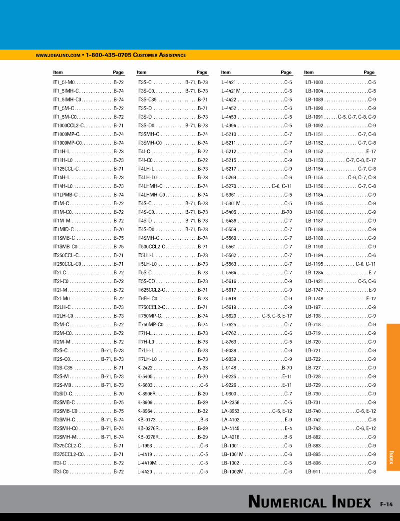
Item Page Item Page Item Page Item Page
IT1_5I-M0 . . . . . . . . . . . . . . . . .B-72
IT1_5IMH-C . . . . . . . . . . . . . . .B-74
IT1_5IMH-C0 . . . . . . . . . . . . . .B-74
IT1_5M-C . . . . . . . . . . . . . . . . .B-72
IT1_5M-C0 . . . . . . . . . . . . . . . .B-72
IT1000CCL2-C . . . . . . . . . . . . .B-71
IT1000MP-C . . . . . . . . . . . . . . .B-74
IT1000MP-C0 . . . . . . . . . . . . . .B-74
IT11H-L . . . . . . . . . . . . . . . . . .B-73
IT11H-L0 . . . . . . . . . . . . . . . . .B-73
IT125CCL-C . . . . . . . . . . . . . . .B-71
IT14H-L . . . . . . . . . . . . . . . . . .B-73
IT14H-L0 . . . . . . . . . . . . . . . . .B-73
IT1LPMB-C . . . . . . . . . . . . . . .B-74
IT1M-C . . . . . . . . . . . . . . . . . . .B-72
IT1M-C0 . . . . . . . . . . . . . . . . . .B-72
IT1M-M . . . . . . . . . . . . . . . . . .B-72
IT1MID-C . . . . . . . . . . . . . . . . .B-70
IT1SMB-C . . . . . . . . . . . . . . . .B-75
IT1SMB-C0 . . . . . . . . . . . . . . .B-75
IT250CCL-C . . . . . . . . . . . . . . .B-71
IT250CCL-C0 . . . . . . . . . . . . . .B-71
IT2I-C . . . . . . . . . . . . . . . . . . . .B-72
IT2I-C0 . . . . . . . . . . . . . . . . . . .B-72
IT2I-M . . . . . . . . . . . . . . . . . . . .B-72
IT2I-M0 . . . . . . . . . . . . . . . . . . .B-72
IT2LH-C . . . . . . . . . . . . . . . . . .B-73
IT2LH-C0 . . . . . . . . . . . . . . . . .B-73
IT2M-C . . . . . . . . . . . . . . . . . . .B-72
IT2M-C0 . . . . . . . . . . . . . . . . . .B-72
IT2M-M . . . . . . . . . . . . . . . . . .B-72
IT2S-C . . . . . . . . . . . . . . B-71, B-73
IT2S-C0 . . . . . . . . . . . . . B-71, B-73
IT2S-C35 . . . . . . . . . . . . . . . . .B-71
IT2S-M . . . . . . . . . . . . . B-71, B-73
IT2S-M0 . . . . . . . . . . . . B-71, B-73
IT2SID-C . . . . . . . . . . . . . . . . . .B-70
IT2SMB-C . . . . . . . . . . . . . . . .B-75
IT2SMB-C0 . . . . . . . . . . . . . . .B-75
IT2SMH-C . . . . . . . . . . B-71, B-74
IT2SMH-C0 . . . . . . . . . B-71, B-74
IT2SMH-M . . . . . . . . . . B-71, B-74
IT375CCL2-C . . . . . . . . . . . . . .B-71
IT375CCL2-C0 . . . . . . . . . . . . .B-71
IT3I-C . . . . . . . . . . . . . . . . . . . .B-72
IT3I-C0 . . . . . . . . . . . . . . . . . . .B-72
IT3S-C . . . . . . . . . . . . . B-71, B-73
IT3S-C0 . . . . . . . . . . . . . B-71, B-73
IT3S-C35 . . . . . . . . . . . . . . . . .B-71
IT3S-D . . . . . . . . . . . . . . . . . . .B-71
IT3S-D . . . . . . . . . . . . . . . . . . .B-73
IT3S-D0 . . . . . . . . . . . . B-71, B-73
IT3SMH-C . . . . . . . . . . . . . . . .B-74
IT3SMH-C0 . . . . . . . . . . . . . . .B-74
IT4I-C . . . . . . . . . . . . . . . . . . . .B-72
IT4I-C0 . . . . . . . . . . . . . . . . . . .B-72
IT4LH-L . . . . . . . . . . . . . . . . . .B-73
IT4LH-L0 . . . . . . . . . . . . . . . . .B-73
IT4LHMH-C . . . . . . . . . . . . . . .B-74
IT4LHMH-C0 . . . . . . . . . . . . . .B-74
IT4S-C . . . . . . . . . . . . . . B-71, B-73
IT4S-C0 . . . . . . . . . . . . . B-71, B-73
IT4S-D . . . . . . . . . . . . . B-71, B-73
IT4S-D0 . . . . . . . . . . . . B-71, B-73
IT4SMH-C . . . . . . . . . . . . . . . .B-74
IT500CCL2-C . . . . . . . . . . . . . .B-71
IT5LH-L . . . . . . . . . . . . . . . . . .B-73
IT5LH-L0 . . . . . . . . . . . . . . . . .B-73
IT5S-C . . . . . . . . . . . . . . . . . . . .B-73
IT5S-CO . . . . . . . . . . . . . . . . . .B-73
IT625CCL2-C . . . . . . . . . . . . . .B-71
IT6EH-C0 . . . . . . . . . . . . . . . . .B-73
IT750CCL2-C . . . . . . . . . . . . . .B-71
IT750MP-C . . . . . . . . . . . . . . . .B-74
IT750MP-C0 . . . . . . . . . . . . . . .B-74
IT7H-L . . . . . . . . . . . . . . . . . . . .B-73
IT7H-L0 . . . . . . . . . . . . . . . . . .B-73
IT7LH-L . . . . . . . . . . . . . . . . . .B-73
IT7LH-L0 . . . . . . . . . . . . . . . . .B-73
K-2422 . . . . . . . . . . . . . . . . . . .A-33
K-5405 . . . . . . . . . . . . . . . . . . .B-70
K-6603 . . . . . . . . . . . . . . . . . . . .C-6
K-8906R . . . . . . . . . . . . . . . . . .B-29
K-8909 . . . . . . . . . . . . . . . . . . .B-29
K-8964 . . . . . . . . . . . . . . . . . . .B-32
KB-0173 . . . . . . . . . . . . . . . . . . .B-6
KB-0276R . . . . . . . . . . . . . . . . .B-29
KB-0278R . . . . . . . . . . . . . . . . .B-29
L-1953 . . . . . . . . . . . . . . . . . . . .C-6
L-4419 . . . . . . . . . . . . . . . . . . . .C-5
L-4419M . . . . . . . . . . . . . . . . . . .C-5
L-4420 . . . . . . . . . . . . . . . . . . . .C-5
L-4421 . . . . . . . . . . . . . . . . . . . .C-5
L-4421M . . . . . . . . . . . . . . . . . . .C-5
L-4422 . . . . . . . . . . . . . . . . . . . .C-5
L-4452 . . . . . . . . . . . . . . . . . . . .C-6
L-4453 . . . . . . . . . . . . . . . . . . . .C-5
L-4994 . . . . . . . . . . . . . . . . . . . .C-5
L-5210 . . . . . . . . . . . . . . . . . . . .C-7
L-5211 . . . . . . . . . . . . . . . . . . . .C-7
L-5212 . . . . . . . . . . . . . . . . . . . .C-9
L-5215 . . . . . . . . . . . . . . . . . . . .C-9
L-5217 . . . . . . . . . . . . . . . . . . . .C-9
L-5269 . . . . . . . . . . . . . . . . . . . .C-6
L-5270 . . . . . . . . . . . . . . C-6, C-11
L-5361 . . . . . . . . . . . . . . . . . . . .C-5
L-5361M . . . . . . . . . . . . . . . . . . .C-5
L-5405 . . . . . . . . . . . . . . . . . . .B-70
L-5436 . . . . . . . . . . . . . . . . . . . .C-7
L-5559 . . . . . . . . . . . . . . . . . . . .C-7
L-5560 . . . . . . . . . . . . . . . . . . . .C-7
L-5561 . . . . . . . . . . . . . . . . . . . .C-7
L-5562 . . . . . . . . . . . . . . . . . . . .C-7
L-5563 . . . . . . . . . . . . . . . . . . . .C-7
L-5564 . . . . . . . . . . . . . . . . . . . .C-7
L-5616 . . . . . . . . . . . . . . . . . . . .C-9
L-5617 . . . . . . . . . . . . . . . . . . . .C-9
L-5618 . . . . . . . . . . . . . . . . . . . .C-9
L-5619 . . . . . . . . . . . . . . . . . . . .C-9
L-5620 . . . . . . . . . . C-5, C-6, E-17
L-7625 . . . . . . . . . . . . . . . . . . . .C-7
L-8762 . . . . . . . . . . . . . . . . . . . .C-6
L-8763 . . . . . . . . . . . . . . . . . . . .C-5
L-9038 . . . . . . . . . . . . . . . . . . . .C-9
L-9039 . . . . . . . . . . . . . . . . . . . .C-9
L-9148 . . . . . . . . . . . . . . . . . . .B-70
L-9225 . . . . . . . . . . . . . . . . . . . E-11
L-9226 . . . . . . . . . . . . . . . . . . . E-11
L-9300 . . . . . . . . . . . . . . . . . . . .C-7
LA-2358 . . . . . . . . . . . . . . . . . . .C-5
LA-3953 . . . . . . . . . . . . . .C-6, E-12
LA-4102 . . . . . . . . . . . . . . . . . . . E-9
LA-4145 . . . . . . . . . . . . . . . . . . . E-4
LA-4218 . . . . . . . . . . . . . . . . . . .B-6
LB-1001 . . . . . . . . . . . . . . . . . . .C-5
LB-1001M . . . . . . . . . . . . . . . . .C-6
LB-1002 . . . . . . . . . . . . . . . . . . .C-5
LB-1002M . . . . . . . . . . . . . . . . .C-6
LB-1003 . . . . . . . . . . . . . . . . . . .C-5
LB-1004 . . . . . . . . . . . . . . . . . . .C-5
LB-1089 . . . . . . . . . . . . . . . . . . .C-9
LB-1090 . . . . . . . . . . . . . . . . . . .C-9
LB-1091 . . . . . .C-5, C-7, C-8, C-9
LB-1092 . . . . . . . . . . . . . . . . . . .C-9
LB-1151 . . . . . . . . . . . . . . C-7, C-8
LB-1152 . . . . . . . . . . . . . . C-7, C-8
LB-1152 . . . . . . . . . . . . . . . . . . E-17
LB-1153 . . . . . . . . . C-7, C-8, E-17
LB-1154 . . . . . . . . . . . . . . C-7, C-8
LB-1155 . . . . . . . . . . C-6, C-7, C-8
LB-1156 . . . . . . . . . . . . . . C-7, C-8
LB-1184 . . . . . . . . . . . . . . . . . . .C-9
LB-1185 . . . . . . . . . . . . . . . . . . .C-9
LB-1186 . . . . . . . . . . . . . . . . . . .C-9
LB-1187 . . . . . . . . . . . . . . . . . . .C-9
LB-1188 . . . . . . . . . . . . . . . . . . .C-9
LB-1189 . . . . . . . . . . . . . . . . . . .C-9
LB-1190 . . . . . . . . . . . . . . . . . . .C-9
LB-1194 . . . . . . . . . . . . . . . . . . .C-6
LB-1195 . . . . . . . . . . . . . C-6, C-11
LB-1284 . . . . . . . . . . . . . . . . . . . E-7
LB-1421 . . . . . . . . . . . . . . C-5, C-6
LB-1747 . . . . . . . . . . . . . . . . . . . E-9
LB-1748 . . . . . . . . . . . . . . . . . . E-12
LB-197 . . . . . . . . . . . . . . . . . . . .C-9
LB-198 . . . . . . . . . . . . . . . . . . . .C-9
LB-718 . . . . . . . . . . . . . . . . . . . .C-9
LB-719 . . . . . . . . . . . . . . . . . . . .C-9
LB-720 . . . . . . . . . . . . . . . . . . . .C-9
LB-721 . . . . . . . . . . . . . . . . . . . .C-9
LB-722 . . . . . . . . . . . . . . . . . . . .C-9
LB-727 . . . . . . . . . . . . . . . . . . . .C-9
LB-728 . . . . . . . . . . . . . . . . . . . .C-9
LB-729 . . . . . . . . . . . . . . . . . . . .C-9
LB-730 . . . . . . . . . . . . . . . . . . . .C-9
LB-731 . . . . . . . . . . . . . . . . . . . .C-9
LB-740 . . . . . . . . . . . . . . .C-6, E-12
LB-742 . . . . . . . . . . . . . . . . . . . .C-6
LB-743 . . . . . . . . . . . . . . .C-6, E-12
LB-882 . . . . . . . . . . . . . . . . . . . .C-9
LB-883 . . . . . . . . . . . . . . . . . . . .C-9
LB-895 . . . . . . . . . . . . . . . . . . . .C-9
LB-896 . . . . . . . . . . . . . . . . . . . .C-9
LB-911 . . . . . . . . . . . . . . . . . . . .C-8
www.ideAlind.com • 1-800-435-0705 customer AssistAnce
ind
ex
numericAl index F-14
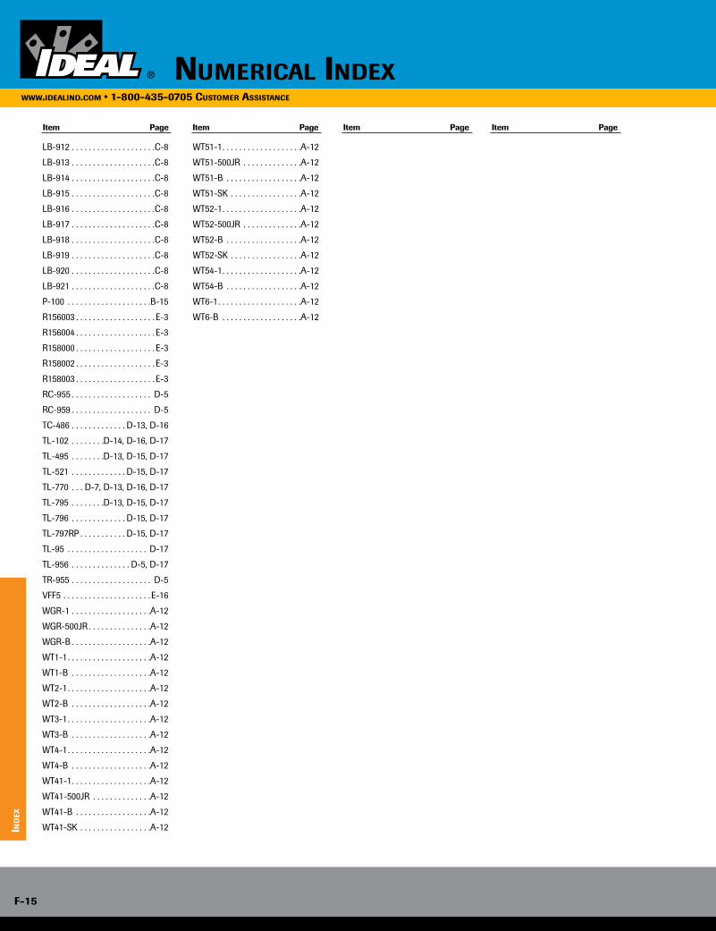
Item Page Item Page Item Page Item Page
LB-912 . . . . . . . . . . . . . . . . . . . .C-8
LB-913 . . . . . . . . . . . . . . . . . . . .C-8
LB-914 . . . . . . . . . . . . . . . . . . . .C-8
LB-915 . . . . . . . . . . . . . . . . . . . .C-8
LB-916 . . . . . . . . . . . . . . . . . . . .C-8
LB-917 . . . . . . . . . . . . . . . . . . . .C-8
LB-918 . . . . . . . . . . . . . . . . . . . .C-8
LB-919 . . . . . . . . . . . . . . . . . . . .C-8
LB-920 . . . . . . . . . . . . . . . . . . . .C-8
LB-921 . . . . . . . . . . . . . . . . . . . .C-8
P-100 . . . . . . . . . . . . . . . . . . . .B-15
R156003 . . . . . . . . . . . . . . . . . . . E-3
R156004 . . . . . . . . . . . . . . . . . . . E-3
R158000 . . . . . . . . . . . . . . . . . . . E-3
R158002 . . . . . . . . . . . . . . . . . . . E-3
R158003 . . . . . . . . . . . . . . . . . . . E-3
RC-955 . . . . . . . . . . . . . . . . . . . D-5
RC-959 . . . . . . . . . . . . . . . . . . . D-5
TC-486 . . . . . . . . . . . . . D-13, D-16
TL-102 . . . . . . . .D-14, D-16, D-17
TL-495 . . . . . . . .D-13, D-15, D-17
TL-521 . . . . . . . . . . . . . D-15, D-17
TL-770 . . . D-7, D-13, D-16, D-17
TL-795 . . . . . . . .D-13, D-15, D-17
TL-796 . . . . . . . . . . . . . D-15, D-17
TL-797RP . . . . . . . . . . . D-15, D-17
TL-95 . . . . . . . . . . . . . . . . . . . D-17
TL-956 . . . . . . . . . . . . . . D-5, D-17
TR-955 . . . . . . . . . . . . . . . . . . . D-5
VFF5 . . . . . . . . . . . . . . . . . . . . . E-16
WGR-1 . . . . . . . . . . . . . . . . . . .A-12
WGR-500JR . . . . . . . . . . . . . . .A-12
WGR-B . . . . . . . . . . . . . . . . . . .A-12
WT1-1 . . . . . . . . . . . . . . . . . . . .A-12
WT1-B . . . . . . . . . . . . . . . . . . .A-12
WT2-1 . . . . . . . . . . . . . . . . . . . .A-12
WT2-B . . . . . . . . . . . . . . . . . . .A-12
WT3-1 . . . . . . . . . . . . . . . . . . . .A-12
WT3-B . . . . . . . . . . . . . . . . . . .A-12
WT4-1 . . . . . . . . . . . . . . . . . . . .A-12
WT4-B . . . . . . . . . . . . . . . . . . .A-12
WT41-1 . . . . . . . . . . . . . . . . . . .A-12
WT41-500JR . . . . . . . . . . . . . .A-12
WT41-B . . . . . . . . . . . . . . . . . .A-12
WT41-SK . . . . . . . . . . . . . . . . .A-12
WT51-1 . . . . . . . . . . . . . . . . . . .A-12
WT51-500JR . . . . . . . . . . . . . .A-12
WT51-B . . . . . . . . . . . . . . . . . .A-12
WT51-SK . . . . . . . . . . . . . . . . .A-12
WT52-1 . . . . . . . . . . . . . . . . . . .A-12
WT52-500JR . . . . . . . . . . . . . .A-12
WT52-B . . . . . . . . . . . . . . . . . .A-12
WT52-SK . . . . . . . . . . . . . . . . .A-12
WT54-1 . . . . . . . . . . . . . . . . . . .A-12
WT54-B . . . . . . . . . . . . . . . . . .A-12
WT6-1 . . . . . . . . . . . . . . . . . . . .A-12
WT6-B . . . . . . . . . . . . . . . . . . .A-12
numericAl indexwww.ideAlind.com • 1-800-435-0705 customer AssistAnce
ind
ex
F-15
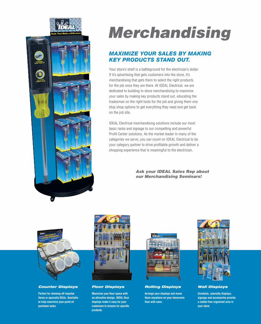
An American Original.AT HOME IN THE HEART OF AMERICA.
Entrepreneurial in spirit, grounded in the values of American ingenuity, IDEAL was founded on the basis that every product we make will exceed the value of the price paid for it. When it comes to creating value, IDEAL is an American original. Today, we exemplify those values in our vision, our mission and the future of our business. We are investing in the success and revitalization of American innovation and we are committed to manufacturing American Value In Every Tool We Make.
IDEAL IS WITH YOU EVERY STEP OF THE WAY.
We believe in innovative ideas for hardworking professionals — skilled tradesmen like electricians, contractors, mechanics, data communications pros and systems builders. These unsung problem solvers demand smart, tough, high-performance products that work right the first time. They also demand the innovations that keep them a step ahead of the challenges that drive the industries in which they work.
We innovate by listening. While most companies tell customers “Here’s what we’ve got,” we’re constantly asking, “What do you need?”
Wire Connectors
IDEAL is the leader in wire connectors. For wire termination, IDEAL is the industry standard.
Wire Pulling Lubricants
The environmentally safe lubes from IDEAL provide exceptional lubricity for rapid pulls.
Fish Tapes
IDEAL manufactures a variety of fish tapes for all applications, and our durable impact-resistant cases are the best in the market.
Conduit Benders
IDEAL benders are constructed of exceptionally durable materials and reinforced at stress points for long life.
Wire Strippers
Ergonomically designed in a variety of models for every application, IDEAL manufactures the finest wire strippers on the market.
MerchandisingMAXIMIZE YOUR SALES BY MAKING KEY PRODUCTS STAND OUT.
Your store’s shelf is a battleground for the electrician’s dollar. If it’s advertising that gets customers into the store, it’s merchandising that gets them to select the right products for the job once they are there. At IDEAL Electrical, we are dedicated to building in-store merchandising to maximize your sales by making key products stand out, educating the tradesman on the right tools for the job and giving them one stop shop options to get everything they need and get back on the job site.
IDEAL Electrical merchandising solutions include our most basic racks and signage to our compelling and powerful Profit Center solutions. As the market leader in many of the categories we serve, you can count on IDEAL Electrical to be your category partner to drive profitable growth and deliver a shopping experience that is meaningful to the electrician.
Counter Displays
Perfect for showing off impulse items or specialty SKUs. Available to help maximize your point-of- purchase sales.
Floor Displays
Maximize your floor space with an attractive design. IDEAL floor displays make it easy for your customers to browse for specific products.
Rolling Displays
Arrange your displays and move them anywhere on your showroom floor with ease.
Wall Displays
Gondolas, specialty displays, signage and accessories provide a clutter-free organized area in your store.
Ask your IDEAL Sales Rep about our Merchandising Seminars!

IDE
AL
EL
EC
TR
ICA
L P
RO
DU
CT
S F
UL
L-L
INE
CA
TA
LO
G
IDEAL INDUSTRIES, INC.1375 PARK AVENUE, SYCAMORE, IL 60178, USA
815-895-5181 • 800-435-0705 IN USA
INTERNATIONAL OFFICES:
AUSTRALIA / BRAZIL / CANADA / CHINA / FRANCE / GERMANY / INDIA / MEXICO / PUERTO RICO / UK
FOR COMPLETE SALES OFFICE CONTACT INFORMATION, V IS IT US AT:
WWW.IDEALIND.COM
P-070 2/16
FULL-LINE CATALOG
ELECTRICAL PRODUCTS
1 9 1 6 2 0 1 6