electrical installation condition report
TRANSCRIPT

This inspection and testing detailed in this report and accompanying schedules have been carried out in accordance with BS7671:2008 (IET Wiring Regulations) as amended
to
Where the overall assessment of the suitability of the installation for continued use above is stated as , recommend that any observations classified as
'Danger present' (code C1) or 'Potentially dangerous (code C2) are acted upon as a matter of urgency
Investigation without delay is recommended for observations identified as 'further investigation required'
Observation classified as 'Improvement recommended' (code C3) should be given due consideration.
Subject to the necessary remedial action being taken recommend that the installation is further inspected and tested by
, being the person(s) responsible for the inspection and testing of the electrical installation (as indicated by signatures below), particulars of
which are described above, having exercised reasonable skill and care when carrying out the inspection and testing, hereby declare that the
information in this report, including the observations and attached schedules, provides an accurate assessment of the condition of the electrical
installation taking into account the stated extent and limitations in section D of this report.
Extent of Electrical Installation covered by this report: Agreed limitations including the reasons (See regulation 634.2)
Operational Limitations including the reasons (See page No )
Agreed with name
Client:
Address:
Purpose of this report:
Date(s) on which Inspection:
and testing was carried out
General condition of the installations (In terms of electrical safety)
Overall assessment of the installation *An unsatisfactory assessment indicates that dangerous (code C1) and/or potentially dangerous (code
C2) conditions have been identified.
DomesticDescription of
premises:
Records held By:Record of
Installation available:
Date of previous
inspection:
Evidence of alterations
or additions:
Other:
IndustrialCommercial
Estimated age of wiring system:
yrs
yrs
If yes
estimated Age
Address:
Installation:
Trading Title
and address
Inspected and tested by:
Schedule(s) of inspection and Schedule(s) of test results are attached
Report authorised for issue by:
SignatureName Position Date
DatePosition SignatureName
The attached schedule(s) are part of this document and this report is valid only when they are attached to it.
It should be noted that cables concealed within trunking and conduits, under floors, in roof spaces, and generally within the fabric of the building or underground, have NOT
been inspected unless specifically agreed between the client and inspector prior to the inspection.
Branch No. (If Applicable)
Occupier:
I
NICEIC Enrolment Number
Copyright © Amtech Group Ltd 2012, FastTest Pro [17th Edition] v2012.0.2, PHS Compliance
NHS Highland
Glen Court
Raigmore Hospital
Inverness
Highland
No mains shutdown due to residents on site.
08/02/2013
Testing of all sub mains, lighting and power circuits, within the
--See Additional Page--
0
N/A
NHS Highland
N/A
N/A
UNSATISFACTORY
031362
NHS Highland
Finance Department
Assynt House
Beechwood Park
Inverness
Nigel Simpson
July 2011
PHS Compliance,
Compliance House,
Golborne Enterprise Park,
Kid Glove Road,
Warrington, WA3 3GR
Page 1 of 28
Unsatisfactory
N/A
N/A
000
David Warren
Essential information requested by the client in accordance
with the electricity at work regulations 1989.
Fixed Wire Tester
Not Known
My
22/02/2013
Glen Court
I
IV2 3UJ
30
08/02/2013
6
I
Bruce Barr
Regulation 621.2 - Only a percentage of the installation has been dismantled for inspection purposes. The correct connection of
--See Additional Page--
110008985 - Master
08/02/2018
N/A
Unable to access the sealed supply device characteristics. Ze
--See Additional Page--
12
Qualifying Manager
ELECTRICAL INSTALLATION
CONDITION REPORT
110008985 - Master
A. Details of the Client/Person Ordering the Report B. Reason for Producing this Report
C. Details of the Installation which is the Subject of this Report
D. Extent and Limitations Inspection and Testing
E. Summary of the Condition of the Installation
F. Recommendations
G. Declaration
H. Schedule(s)

One of the following codes, as appropriate, has been allocated to each of the observations made above to indicate to the person(s) responsible for the installation the
degree of urgency for remedial action.
C1 - Danger present. Risk of injury. Immediate remedial action required
C2 - Potentially dangerous - urgent remedial action required
C3 - Improvement recommended
Nominal
current rating
Type
BS(EN)
Supply protective deviceNature of Supply Parameters
2-Phase
(3 wire)
1-Phase
(2 wire)
a.c.
Number and Type of Live Conductors
IT
TT
TN-C
TN-C-S
TN-S
Earthing
Arrangements
3-Phase
(3 wire)
Short circuit
capacity
d.c.
3
Wire
Other
2
Wire
Other
Means of earthing
Distributor's
facility
Installation
earth electrode
Type (e.g. rod(s),
tape etc.)
Details of installation Earth Electrode (where applicable)
Resistance to
EarthΩ
Location
Method of
measurement
Earthing
Conductor
Main protective
bonding conductors
Material
Material
csa
csa
mm
mm
2
2
Connection and Continuity Verified
Connection and Continuity Verified
Bonding of Incoming Service
Water Gas Lightning Oil Steel Other Please State
Maximum Demand (Load)
Protective measure(s) against electric shock
Location
Type BS(EN)
Supply
Conductors
material
No of poles
Supply
Conductors
csa
Current
rating
Fuse/Device
rating or setting
Voltage
rating
A
A
V
if RCD main switch
mA
ms
ms
3-Phase
(4 wire)
Rated residual
operation current,
I n
Rated time delay
RCD Operating
time at, I n
Confirmation of supply polarity
Tick boxes and enter details as applicable
The following observations are madeNo remedial action is required.
Referring to the attached schedule(s) of Inspection and Test Results, and subject to the limitations specified at the Extent and Limitations of the Inspection and testing section.
Item No Code
Further
Investigation
RequiredObservations
kA
A
1-Phase
(3 wire)
mm2
(Note: (1) by enquiry, (2) by enquiry or
by measurement)
Number of
supplies
Ω(2)
ZeExternal loop
impedance
Prospective
fault currentlpf (2) kA
Hz(1)
fNominal
frequency
Nominal
VoltageU 0 V
VUNominal
Voltage
(1)
(1)230
80
0
N/A
N/A
N/A
N/A
200
N/A
10
200
N/A
N/A
Please see the additional sheet(s) at the end of the report.
Electrical Cupboard on Ground Floor
ADS
Copyright © Amtech Group Ltd 2012, FastTest Pro [17th Edition] v2012.0.2, PHS Compliance
N/A
3
N/ALIM
N/A
0
400
N/A
N/A
Copper
1
N/A
N/A
Page 2 of 28
88-2 Fuse HRC
Copper
N/A
N/A
N/A
5419 Isolator
50
400
N/A
N/A
0
N/A
gG
SWA
N/A
N/A
N/A
No
N/A
LIMSteel
110008985 - Master
N/A
N/A
N/A
N/A
1
0.24N/A
Amps
LIM
120
200
0.97
N/A
110008985 - Master
I. Supply Characteristics and Earthing Arrangements
J. Particulars of Installation Referred to in the Report
Main Protective Conductors
Main Switch / Switch-Fuse / Circuit-Breaker / RCD

Live
mm 22
Supply to
distribution
board is from
No of phases
TO BE COMPLETED IN EVERY CASE ONLY TO BE COMPLETED IF THE DISTRIBUTION BOARD IS NOT CONNECTED DIRECTLY TO THE ORIGIN
OF THE INSTALLATION
Overcurrent protective device for the distribution circuit
Associated RCD (if any)
BS(EN)
RCD No of
Poles
RCD Rating
A B C D E F G H O
PVC/PVC
cables
PVCcables
in
metallic
conduit
PVCcables
in
non-metallic
conduit
PVCcables
in
metallic
trunking
PVCcables
in
non-metallic
trunking
PVC/SWA
cables
XLPE/SWA
cables
Mineral insulated
cablesOther
Nominal Voltage
Type BS(EN) Rating
Max
per-
mitted
Zs
Circuit
number
and
phase
Circuit designationType of
wiring
Refe-
rence
method
No of
points
served
Circuit
conductors csa
cpc
mm
Max
per-
mitted
disc-
onnec-
tion
times
Overcurrent protective device RCD
Type
No
Rating
Short
circuit
capa-
city
Op.
currentBS(EN)
A
V
mA
Location of
Distribution
Board
Distribution
board
designation
A kA nI
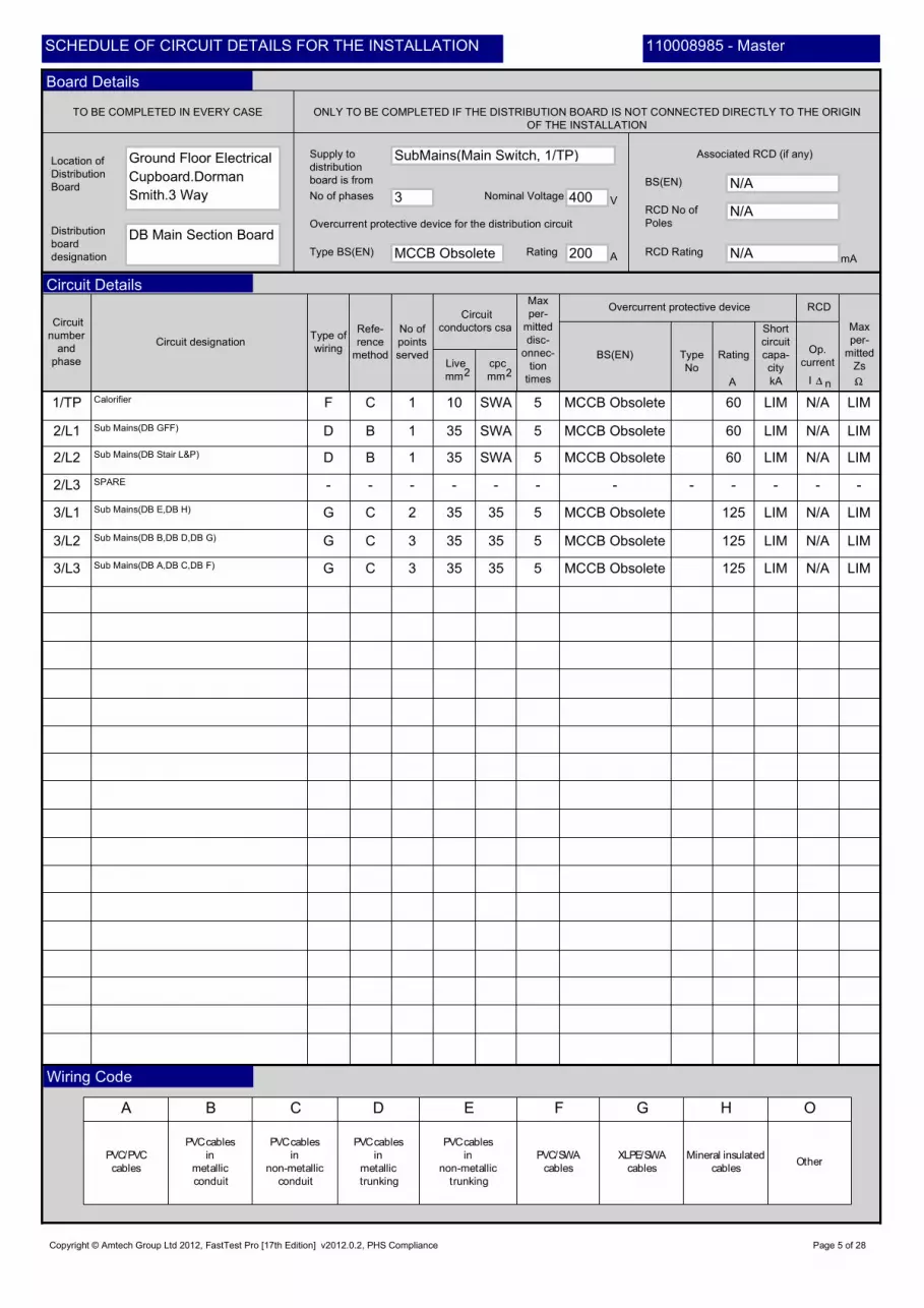
Ground Floor Electrical
Cupboard.Dorman
Smith.
N/A
N/A
LIM N/AMEC
H
N/A
N/A
Main Switch
120
Copyright © Amtech Group Ltd 2012, FastTest Pro [17th Edition] v2012.0.2, PHS Compliance Page 3 of 28
Sub Mains(DB Main Section Board) 1 MCCB Obsolete 200
N/A
B LIM1/TP D
N/A
5
N/A
110008985 - Master
N/A
110008985 - MasterSCHEDULE OF CIRCUIT DETAILS FOR THE INSTALLATION
Board Details
Circuit Details
Wiring Code

Rem
ark
s
se
eco
ntin
ua
tion
sh
ee
t
Maximum
measured
earth fault
loop
impedance
ONLY TO BE COMPLETED IF THE DISTRIBUTION BOARD IS NOT CONNECTED
DIRECTLY TO THE ORIGIN OF THE INSTALLATIONTEST INSTRUMENTS (SERIAL NUMBERS) USED
Circuit
number
and
phase
Circuit Impedances p
o
l
a
r
i
t
y
Live/
Neutral
Insulation resistance
Live/
Earth
At At
Te
st
butt
on
opera
tio
n
r1 (Line) rn (Neutral) r2 (cpc) (R1 + R2) (R2)
All circuits
(At least one
column
to be completed)Live/
Live
Earth/
Neutral
Date of
testing
Position
Name
Signature
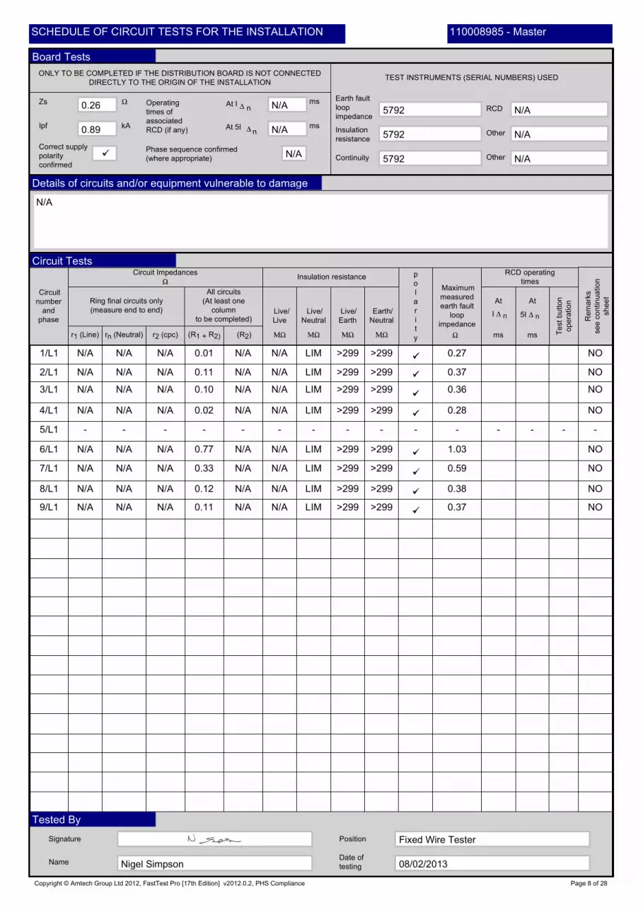
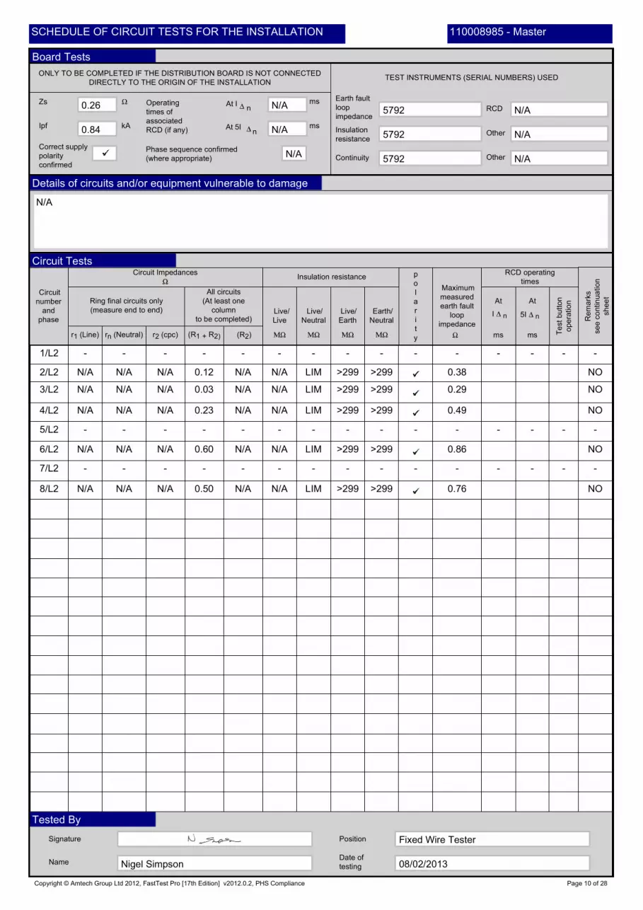
Ipf
Zs
kA
Operating
times of
associated
RCD (if any) At 5I
At In
ms
msn
Ring final circuits only
(measure end to end)
RCD operating
times
Phase sequence confirmed
(where appropriate)
Correct supply
polarity
confirmed
Insulation
resistanceOther
RCD
Earth fault
loop
impedance
Continuity Other
ms ms
I n 5I n
08/02/2013
Copyright © Amtech Group Ltd 2012, FastTest Pro [17th Edition] v2012.0.2, PHS Compliance
5792
N/A
Fixed Wire Tester
5792
N/A N/A
5792
N/A LIM NO
110008985 - Master
1/TP
Nigel Simpson
N/A
N/A
N/A
N/A
LIM
N/A
LIMLIM
N/A
Page 4 of 28
LIM
N/A
0.25
N/A
N/A
110008985 - MasterSCHEDULE OF CIRCUIT TESTS FOR THE INSTALLATION
Board Tests
Details of circuits and/or equipment vulnerable to damage
Circuit Tests
Tested By
Live
mm 22
Supply to
distribution
board is from
No of phases
TO BE COMPLETED IN EVERY CASE ONLY TO BE COMPLETED IF THE DISTRIBUTION BOARD IS NOT CONNECTED DIRECTLY TO THE ORIGIN
OF THE INSTALLATION
Overcurrent protective device for the distribution circuit
Associated RCD (if any)
BS(EN)
RCD No of
Poles
RCD Rating
A B C D E F G H O
PVC/PVC
cables
PVCcables
in
metallic
conduit
PVCcables
in
non-metallic
conduit
PVCcables
in
metallic
trunking
PVCcables
in
non-metallic
trunking
PVC/SWA
cables
XLPE/SWA
cables
Mineral insulated
cablesOther
Nominal Voltage
Type BS(EN) Rating
Max
per-
mitted
Zs
Circuit
number
and
phase
Circuit designationType of
wiring
Refe-
rence
method
No of
points
served
Circuit
conductors csa
cpc
mm
Max
per-
mitted
disc-
onnec-
tion
times
Overcurrent protective device RCD
Type
No
Rating
Short
circuit
capa-
city
Op.
currentBS(EN)
A
V
mA
Location of
Distribution
Board
Distribution
board
designation
A kA nI
60
-
Ground Floor Electrical
Cupboard.Dorman
Smith.3 Way
LIM
N/A
35
-
400
LIM
LIM
SPARE
N/A
125
5
N/A
MCCB Obsolete
SWA
LIM
-
Sub Mains(DB E,DB H)
-
LIM
-
5
5
N/A
35
60
3
3
200
Sub Mains(DB GFF)
C
DB Main Section Board
10
B
3
SWA
Copyright © Amtech Group Ltd 2012, FastTest Pro [17th Edition] v2012.0.2, PHS Compliance
MCCB Obsolete
2
MCCB Obsolete
-
2/L2
Page 5 of 28
35
5
3/L1
Calorifier
LIM
1
3/L2
35
MCCB Obsolete
-
Sub Mains(DB A,DB C,DB F)
-
35
5
D
MCCB Obsolete
-
60
N/A
1
SubMains(Main Switch, 1/TP)
3/L3
LIM
G 35
35
Sub Mains(DB B,DB D,DB G)
N/A
SWA
2/L3
G
C LIM
35
1/TP
LIMG
F
-
LIMC
125
D
N/A
B LIM
MCCB Obsolete
C
1
MCCB Obsolete
-
5
LIM
N/A
2/L1
-
110008985 - Master
125
Sub Mains(DB Stair L&P)
N/A
110008985 - MasterSCHEDULE OF CIRCUIT DETAILS FOR THE INSTALLATION
Board Details
Circuit Details
Wiring Code

Rem
ark
s
se
eco
ntin
ua
tion
sh
ee
t
Maximum
measured
earth fault
loop
impedance
ONLY TO BE COMPLETED IF THE DISTRIBUTION BOARD IS NOT CONNECTED
DIRECTLY TO THE ORIGIN OF THE INSTALLATIONTEST INSTRUMENTS (SERIAL NUMBERS) USED
Circuit
number
and
phase
Circuit Impedances p
o
l
a
r
i
t
y
Live/
Neutral
Insulation resistance
Live/
Earth
At At
Te
st
butt
on
opera
tio
n
r1 (Line) rn (Neutral) r2 (cpc) (R1 + R2) (R2)
All circuits
(At least one
column
to be completed)Live/
Live
Earth/
Neutral
Date of
testing
Position
Name
Signature
Ipf
Zs
kA
Operating
times of
associated
RCD (if any) At 5I
At In
ms
msn
Ring final circuits only
(measure end to end)
RCD operating
times
Phase sequence confirmed
(where appropriate)
Correct supply
polarity
confirmed
Insulation
resistanceOther
RCD
Earth fault
loop
impedance
Continuity Other
ms ms
I n 5I n
-
08/02/2013
N/A
N/AN/A
LIM
LIM
Copyright © Amtech Group Ltd 2012, FastTest Pro [17th Edition] v2012.0.2, PHS Compliance
5792
N/A
2/L3
N/A
-
Fixed Wire Tester
N/A 0.27
5792
N/A
3/L1
NO
N/A N/A
5792
-
NO
-
N/A
N/A
LIM
-
LIM
N/A
LIM
LIM
LIM
N/A
-
N/A
LIM
---
0.26LIM
3/L2 N/A
N/A
NO
110008985 - Master
LIMN/A
1/TP
Nigel Simpson
LIM
N/A
N/A
LIMN/A
NO
0.94
LIM
-
N/A
LIM2/L1
N/A
LIM
N/A
N/A
N/A
LIM
N/A
LIM
LIMN/A
0.25
LIM
-
0.26
N/A
0.26
LIM
Page 6 of 28
LIM
N/A
LIM
2/L2
NO
N/A
-
N/A
3/L3
0.31
--
0.27
N/A LIM
-
N/A
N/A
LIM
LIM
N/A
NO
110008985 - MasterSCHEDULE OF CIRCUIT TESTS FOR THE INSTALLATION
Board Tests
Details of circuits and/or equipment vulnerable to damage
Circuit Tests
Tested By

Live
mm 22
Supply to
distribution
board is from
No of phases
TO BE COMPLETED IN EVERY CASE ONLY TO BE COMPLETED IF THE DISTRIBUTION BOARD IS NOT CONNECTED DIRECTLY TO THE ORIGIN
OF THE INSTALLATION
Overcurrent protective device for the distribution circuit
Associated RCD (if any)
BS(EN)
RCD No of
Poles
RCD Rating
A B C D E F G H O
PVC/PVC
cables
PVCcables
in
metallic
conduit
PVCcables
in
non-metallic
conduit
PVCcables
in
metallic
trunking
PVCcables
in
non-metallic
trunking
PVC/SWA
cables
XLPE/SWA
cables
Mineral insulated
cablesOther
Nominal Voltage
Type BS(EN) Rating
Max
per-
mitted
Zs
Circuit
number
and
phase
Circuit designationType of
wiring
Refe-
rence
method
No of
points
served
Circuit
conductors csa
cpc
mm
Max
per-
mitted
disc-
onnec-
tion
times
Overcurrent protective device RCD
Type
No
Rating
Short
circuit
capa-
city
Op.
currentBS(EN)
A
V
mA
Location of
Distribution
Board
Distribution
board
designation
A kA nI
30
4
Ground Floor Electrical
Cupboard.Dorman
Smith.9 Way
2.30
N/A
1.5
3
7
400
2.30
3871 MCB
3
Sockets Hall,Store & DSR
C
N/A
MIC
C
-
N/A
30
0.4
3
N/A
3871 MCB
10
-
0.4
SPARE
30
-
N/A
0.4
3
0.4
2.5
N/A
0.77
-
30
1
5
60
Sockets Laundry
B
DB GFF
2.5
10
B
30
5
C
4 3
3871 MCB
Copyright © Amtech Group Ltd 2012, FastTest Pro [17th Edition] v2012.0.2, PHS Compliance
3871 MCB
-
3871 MCB
4
8/L1
3/L1
Page 7 of 28
-
0.4
3
5/L1
MIC
C
0.77
Cooker
0.77
Tumble Dryer
1
6/L1
3
1
1.5
3871 MCB
3871 MCB
Lights Hall,Gents WC,Laundry & Bell
3
1.5
-
B
3871 MCB
B
50
-
9
SubMains(DB Main Section Board,
7/L1
0.77
0.4
B 1.5
9/L1
4
Lights DSR,Ladies WC,Store & Common Room
N/A
4
4/L1
H
-
B 0.463
4
1/L1
H
3B
B
3
3B
10
B
N/A
0.4
B 3
MCCB Obsolete
-
3
-
4
Washing Machine
-
B
1
0.4
3
3
N/A
N/A
2/L1
0.77
110008985 - Master
10
Sockets Common Room
N/A
110008985 - MasterSCHEDULE OF CIRCUIT DETAILS FOR THE INSTALLATION
Board Details
Circuit Details
Wiring Code
Rem
ark
s
se
eco
ntin
ua
tion
sh
ee
t
Maximum
measured
earth fault
loop
impedance
ONLY TO BE COMPLETED IF THE DISTRIBUTION BOARD IS NOT CONNECTED
DIRECTLY TO THE ORIGIN OF THE INSTALLATIONTEST INSTRUMENTS (SERIAL NUMBERS) USED
Circuit
number
and
phase
Circuit Impedances p
o
l
a
r
i
t
y
Live/
Neutral
Insulation resistance
Live/
Earth
At At
Te
st
butt
on
opera
tio
n
r1 (Line) rn (Neutral) r2 (cpc) (R1 + R2) (R2)
All circuits
(At least one
column
to be completed)Live/
Live
Earth/
Neutral
Date of
testing
Position
Name
Signature
Ipf
Zs
kA
Operating
times of
associated
RCD (if any) At 5I
At In
ms
msn
Ring final circuits only
(measure end to end)
RCD operating
times
Phase sequence confirmed
(where appropriate)
Correct supply
polarity
confirmed
Insulation
resistanceOther
RCD
Earth fault
loop
impedance
Continuity Other
ms ms
I n 5I n
N/A
08/02/2013
9/L1
N/A
N/AN/A
-
>299
Copyright © Amtech Group Ltd 2012, FastTest Pro [17th Edition] v2012.0.2, PHS Compliance
5792
>299
N/A
4/L1
N/A
>299
Fixed Wire Tester
0.12
N/A 1.03
5792
N/A
N/A
5/L1
N/A
NO
N/A N/A
N/A
5792
>299
N/A
NO
N/A
N/A
N/A
LIM
NO
0.28
-
>299
N/A
0.33
>299
0.11
>299
-
N/A
N/A
N/A
N/A
N/A
NON/A
0.36>299
NO
6/L1 N/A
-
NO
110008985 - Master
--
N/A
1/L1
Nigel Simpson
-
N/A N/A
N/A
N/A
LIM
LIM
N/A
NO
>299
0.89
-
LIM
N/A
>299
N/A
2/L1
-
>299
N/A
N/A
N/A
LIM
0.38
>299
-
N/A
-
0.01
>299N/A
0.26
0.77
N/A
0.37
N/A
-
8/L1
0.10
Page 8 of 28
>299
-
>299
>299
3/L1
NO
N/A
N/A
N/A
0.37
7/L1
0.27
0.02
0.59
N/A 0.11
N/A
-
N/A
LIM
LIM
N/A
-
LIM
110008985 - MasterSCHEDULE OF CIRCUIT TESTS FOR THE INSTALLATION
Board Tests
Details of circuits and/or equipment vulnerable to damage
Circuit Tests
Tested By

Live
mm 22
Supply to
distribution
board is from
No of phases
TO BE COMPLETED IN EVERY CASE ONLY TO BE COMPLETED IF THE DISTRIBUTION BOARD IS NOT CONNECTED DIRECTLY TO THE ORIGIN
OF THE INSTALLATION
Overcurrent protective device for the distribution circuit
Associated RCD (if any)
BS(EN)
RCD No of
Poles
RCD Rating
A B C D E F G H O
PVC/PVC
cables
PVCcables
in
metallic
conduit
PVCcables
in
non-metallic
conduit
PVCcables
in
metallic
trunking
PVCcables
in
non-metallic
trunking
PVC/SWA
cables
XLPE/SWA
cables
Mineral insulated
cablesOther
Nominal Voltage
Type BS(EN) Rating
Max
per-
mitted
Zs
Circuit
number
and
phase
Circuit designationType of
wiring
Refe-
rence
method
No of
points
served
Circuit
conductors csa
cpc
mm
Max
per-
mitted
disc-
onnec-
tion
times
Overcurrent protective device RCD
Type
No
Rating
Short
circuit
capa-
city
Op.
currentBS(EN)
A
V
mA
Location of
Distribution
Board
Distribution
board
designation
A kA nI
30
1.5
Ground Floor Electrical
Cupboard.Dorman
Smith.8 Way
-
N/A
-
3
1
230
2.30
3871 MCB
-
Fire alarm panel
N/A
-
15
0.4
-
3871 MCB
-
-
0.4
SPARE
10
-
N/A
-
3
0.4
2.5
-
-
30
1
-
60
Sockets Tank Room
-
DB Stair L&P
-
B
2
B
MEC
H
3
Copyright © Amtech Group Ltd 2012, FastTest Pro [17th Edition] v2012.0.2, PHS Compliance
3871 MCB
-
3871 MCB
MEC
H
8/L2
3/L2
Page 9 of 28
-
0.4
5/L2
MEC
H
1.53
SPARE
0.77
-
6/L2
-
10
-
-
3871 MCB
SPARE
3
1.5
-
B
-
O
-
-
3
SubMains(DB Main Section Board,
7/L2
0.77
0.4
B MEC
H
4
Lights Tank Room
N/A
MEC
H
4/L2
-
- --
4
1/L2
B
--
-
3
3B
-
B
N/A
B 3
MCCB Obsolete
-
3
-
3
Lights Stairwell & Porch
-
C
-
3
3
N/A
N/A
2/L2
2.30
110008985 - Master
10
Sockets Stairwell
N/A
110008985 - MasterSCHEDULE OF CIRCUIT DETAILS FOR THE INSTALLATION
Board Details
Circuit Details
Wiring Code
Rem
ark
s
se
eco
ntin
ua
tion
sh
ee
t
Maximum
measured
earth fault
loop
impedance
ONLY TO BE COMPLETED IF THE DISTRIBUTION BOARD IS NOT CONNECTED
DIRECTLY TO THE ORIGIN OF THE INSTALLATIONTEST INSTRUMENTS (SERIAL NUMBERS) USED
Circuit
number
and
phase
Circuit Impedances p
o
l
a
r
i
t
y
Live/
Neutral
Insulation resistance
Live/
Earth
At At
Te
st
butt
on
opera
tio
n
r1 (Line) rn (Neutral) r2 (cpc) (R1 + R2) (R2)
All circuits
(At least one
column
to be completed)Live/
Live
Earth/
Neutral
Date of
testing
Position
Name
Signature
Ipf
Zs
kA
Operating
times of
associated
RCD (if any) At 5I
At In
ms
msn
Ring final circuits only
(measure end to end)
RCD operating
times
Phase sequence confirmed
(where appropriate)
Correct supply
polarity
confirmed
Insulation
resistanceOther
RCD
Earth fault
loop
impedance
Continuity Other
ms ms
I n 5I n
N/A
08/02/2013
N/A
N/AN/A
-
>299
Copyright © Amtech Group Ltd 2012, FastTest Pro [17th Edition] v2012.0.2, PHS Compliance
5792
>299
N/A
4/L2
N/A
>299
Fixed Wire Tester
0.50
N/A 0.86
5792
-
5/L2
N/A
NO
- -
5792
>299
N/A
NO
- -
N/A
N/A
--
NO
0.49
-
>299
- -
-
>299
>299
-
N/A
N/A
-
NON/A
0.29>299
6/L2 N/A
-
-
110008985 - Master
--
N/A
1/L2
Nigel Simpson
-
N/A N/A
-
N/A
LIMN/A
-
0.84
-
LIM
N/A
>2992/L2
-
-
-
N/A
-
-
0.76
-
-
N/A
-
-
--
0.26
0.60
N/A
0.38
N/A
-
8/L2
-
0.03
Page 10 of 28
-
-
>299
- -
3/L2
NO
-
N/A
N/A
N/A
7/L2
-
0.23
-
N/A 0.12
-
N/A
-
N/A
LIM
LIM
N/A
-
LIM
110008985 - MasterSCHEDULE OF CIRCUIT TESTS FOR THE INSTALLATION
Board Tests
Details of circuits and/or equipment vulnerable to damage
Circuit Tests
Tested By

Live
mm 22
Supply to
distribution
board is from
No of phases
TO BE COMPLETED IN EVERY CASE ONLY TO BE COMPLETED IF THE DISTRIBUTION BOARD IS NOT CONNECTED DIRECTLY TO THE ORIGIN
OF THE INSTALLATION
Overcurrent protective device for the distribution circuit
Associated RCD (if any)
BS(EN)
RCD No of
Poles
RCD Rating
A B C D E F G H O
PVC/PVC
cables
PVCcables
in
metallic
conduit
PVCcables
in
non-metallic
conduit
PVCcables
in
metallic
trunking
PVCcables
in
non-metallic
trunking
PVC/SWA
cables
XLPE/SWA
cables
Mineral insulated
cablesOther
Nominal Voltage
Type BS(EN) Rating
Max
per-
mitted
Zs
Circuit
number
and
phase
Circuit designationType of
wiring
Refe-
rence
method
No of
points
served
Circuit
conductors csa
cpc
mm
Max
per-
mitted
disc-
onnec-
tion
times
Overcurrent protective device RCD
Type
No
Rating
Short
circuit
capa-
city
Op.
currentBS(EN)
A
V
mA
Location of
Distribution
Board
Distribution
board
designation
A kA nI
-
6
-
Electrical Cupboard
Flat
A.
H 12
4
-
- -
30
-
-
-
B
-
230
-
60898 MCB
10
SPARE
B
-
4
-
30
-
32
-
10
N/A
20
- -
-
60898 MCB
-
10
-
SPARE
-
SPARE
-
-
-
-
-
B
-
0.4
2X4
-
-
2.30
-
4
-
-
1060898 MCB
11/L3
-
6
1
- -
-
125
Lights Bedroom 4,Hall,Kitchen,WC & Bathroom
-
DB A
4
-
-
-
10
B
20
-
B
-
1.5
-
B
60898 MCB
Copyright © Amtech Group Ltd 2012, FastTest Pro [17th Edition] v2012.0.2, PHS Compliance
60898 MCB
-
-
-
10/L3
-
8/L3
3/L3
Page 11 of 28
-
0.4
12/L3
-
B
5/L3
SPARE
5
-
2X4 1.44
Cooker
7.67
Sockets Kitchen
1
6/L3
-
-
-
12
-
60898 MCB
-
RCD Module (Split Board)
0.4
-
-
-
-
B
-
-
-
40
-
7
SubMains(DB Main Section Board,
7/L3
7.67
0.4
- -
9/L3
1.5
SPARE
2.30
N/A
1.5
4/L3
-
-
B
-
B 1.15B
Sockets Bedroom 4 and Hall
1.5
B
1/L3
B
-
-
-
B
-
--
-
-
B
N/A
0.4
B
13/L3 -
B
10
MCCB Obsolete
-
10
-
7
Sockets Bedrooms 1,2&3
-
-
-
5
0.4
B 30
-
10
30
61008 RCD
2/L3
-
110008985 - Master
-
Lights Bedrooms 1,2&3 and Hall Cupboard
2
SPARE
110008985 - MasterSCHEDULE OF CIRCUIT DETAILS FOR THE INSTALLATION
Board Details
Circuit Details
Wiring Code

Rem
ark
s
se
eco
ntin
ua
tion
sh
ee
t
Maximum
measured
earth fault
loop
impedance
ONLY TO BE COMPLETED IF THE DISTRIBUTION BOARD IS NOT CONNECTED
DIRECTLY TO THE ORIGIN OF THE INSTALLATIONTEST INSTRUMENTS (SERIAL NUMBERS) USED
Circuit
number
and
phase
Circuit Impedances p
o
l
a
r
i
t
y
Live/
Neutral
Insulation resistance
Live/
Earth
At At
Te
st
butt
on
opera
tio
n
r1 (Line) rn (Neutral) r2 (cpc) (R1 + R2) (R2)
All circuits
(At least one
column
to be completed)Live/
Live
Earth/
Neutral
Date of
testing
Position
Name
Signature
Ipf
Zs
kA
Operating
times of
associated
RCD (if any) At 5I
At In
ms
msn
Ring final circuits only
(measure end to end)
RCD operating
times
Phase sequence confirmed
(where appropriate)
Correct supply
polarity
confirmed
Insulation
resistanceOther
RCD
Earth fault
loop
impedance
Continuity Other
ms ms
I n 5I n
-
08/02/2013
32
-
9/L3
-
N/AN/A
>299
-
N/A
-
>299
-
Copyright © Amtech Group Ltd 2012, FastTest Pro [17th Edition] v2012.0.2, PHS Compliance
-
5792
>299
N/A
4/L3
N/A
-
Fixed Wire Tester
0.04
- -
5792
N/A
-
-
5/L3
N/A
-
N/A
-
N/A
N/A
5792
-
0.27
NO
-
-
N/A
-
-
32
0.27
N/A
-
0.31
-
NO
-
-
-
-
-
-
N/A
-
-
0.03
>299
-
-
10/L3
N/A
-
-
--
N/A
N/A
N/A
-
-
---
0.74>299
NO
6/L3
-
-
-
-
NO
-
110008985 - Master
115
-
11/L3
-
-
LIM
-
NO
N/A
N/A
-
1/L3
Nigel Simpson
-
-
0.25
32
-
N/A
-
N/A
5792
LIM
0.04
LIM
-
N/A
-
>299
-
-
0.85
-
-
-
-
-
N/A
N/A
>299
N/A
-
-
2/L3
-
>299
-
N/A
-
-
-
LIM
-
0.31
>299
-
-
-
N/A
-
0.05
13/L3
-
--
0.27
-
-
- -
-
0.86
N/A
-
-
8/L3
-
0.47
Page 12 of 28
-
-
-
>299
>299
3/L3
-
NO
-
>299
-
-
N/A
0.30
7/L3
0.32
--
- -
N/A
-
N/A 0.59
-
-
12/L3
115
-
N/A
-
LIM
-
N/A
-
-
115LIM
110008985 - MasterSCHEDULE OF CIRCUIT TESTS FOR THE INSTALLATION
Board Tests
Details of circuits and/or equipment vulnerable to damage
Circuit Tests
Tested By

Live
mm 22
Supply to
distribution
board is from
No of phases
TO BE COMPLETED IN EVERY CASE ONLY TO BE COMPLETED IF THE DISTRIBUTION BOARD IS NOT CONNECTED DIRECTLY TO THE ORIGIN
OF THE INSTALLATION
Overcurrent protective device for the distribution circuit
Associated RCD (if any)
BS(EN)
RCD No of
Poles
RCD Rating
A B C D E F G H O
PVC/PVC
cables
PVCcables
in
metallic
conduit
PVCcables
in
non-metallic
conduit
PVCcables
in
metallic
trunking
PVCcables
in
non-metallic
trunking
PVC/SWA
cables
XLPE/SWA
cables
Mineral insulated
cablesOther
Nominal Voltage
Type BS(EN) Rating
Max
per-
mitted
Zs
Circuit
number
and
phase
Circuit designationType of
wiring
Refe-
rence
method
No of
points
served
Circuit
conductors csa
cpc
mm
Max
per-
mitted
disc-
onnec-
tion
times
Overcurrent protective device RCD
Type
No
Rating
Short
circuit
capa-
city
Op.
currentBS(EN)
A
V
mA
Location of
Distribution
Board
Distribution
board
designation
A kA nI
-
6
-
Electrical Cupboard
Flat
B.
H 12
4
-
- -
30
-
-
-
B
-
230
-
60898 MCB
10
SPARE
B
-
4
-
30
-
32
-
10
N/A
20
- -
-
60898 MCB
-
10
-
SPARE
-
SPARE
-
-
-
-
-
B
-
0.4
2X4
-
-
2.30
-
4
-
-
1060898 MCB
11/L2
-
6
1
- -
-
125
Lights Bedroom 8,Hall,Kitchen,WC & Bathroom
-
DB B
4
-
-
-
10
B
20
-
B
-
2X1.
5
-
B
60898 MCB
Copyright © Amtech Group Ltd 2012, FastTest Pro [17th Edition] v2012.0.2, PHS Compliance
60898 MCB
-
-
-
10/L2
-
8/L2
3/L2
Page 13 of 28
-
0.4
12/L2
-
B
5/L2
SPARE
5
-
2X4 1.44
Cooker
7.67
Sockets Kitchen
1
6/L2
-
-
-
12
-
60898 MCB
-
RCD Module (Split Board)
0.4
-
-
-
-
B
-
-
-
40
-
7
SubMains(DB Main Section Board,
7/L2
7.67
0.4
- -
9/L2
2X1.
5
SPARE
2.30
N/A
1.5
4/L2
-
-
B
-
B 1.15B
Sockets Bedroom 8 and Hall
1.5
B
1/L2
B
-
-
-
B
-
--
-
-
B
N/A
0.4
B
13/L2 -
B
10
MCCB Obsolete
-
10
-
7
Sockets Bedrooms 5,6&7
-
-
-
5
0.4
B 30
-
10
30
61008 RCD
2/L2
-
110008985 - Master
-
Lights Bedrooms 5,6&7 , Hall Cupboard and
Doorbell
2
SPARE
110008985 - MasterSCHEDULE OF CIRCUIT DETAILS FOR THE INSTALLATION
Board Details
Circuit Details
Wiring Code

Rem
ark
s
se
eco
ntin
ua
tion
sh
ee
t
Maximum
measured
earth fault
loop
impedance
ONLY TO BE COMPLETED IF THE DISTRIBUTION BOARD IS NOT CONNECTED
DIRECTLY TO THE ORIGIN OF THE INSTALLATIONTEST INSTRUMENTS (SERIAL NUMBERS) USED
Circuit
number
and
phase
Circuit Impedances p
o
l
a
r
i
t
y
Live/
Neutral
Insulation resistance
Live/
Earth
At At
Te
st
butt
on
opera
tio
n
r1 (Line) rn (Neutral) r2 (cpc) (R1 + R2) (R2)
All circuits
(At least one
column
to be completed)Live/
Live
Earth/
Neutral
Date of
testing
Position
Name
Signature
Ipf
Zs
kA
Operating
times of
associated
RCD (if any) At 5I
At In
ms
msn
Ring final circuits only
(measure end to end)
RCD operating
times
Phase sequence confirmed
(where appropriate)
Correct supply
polarity
confirmed
Insulation
resistanceOther
RCD
Earth fault
loop
impedance
Continuity Other
ms ms
I n 5I n
-
08/02/2013
32
-
9/L2
-
N/AN/A
>299
-
N/A
-
>299
-
Copyright © Amtech Group Ltd 2012, FastTest Pro [17th Edition] v2012.0.2, PHS Compliance
-
5792
>299
N/A
4/L2
N/A
-
Fixed Wire Tester
0.04
- -
5792
N/A
-
-
5/L2
N/A
-
N/A
-
N/A
N/A
5792
-
0.28
NO
-
-
N/A
-
-
32
0.28
N/A
-
0.30
-
NO
-
-
-
-
-
-
N/A
-
-
0.01
>299
-
-
10/L2
N/A
-
-
--
N/A
N/A
N/A
-
-
---
0.73>299
NO
6/L2
-
-
-
-
NO
-
110008985 - Master
118
-
11/L2
-
-
LIM
-
NO
N/A
N/A
-
1/L2
Nigel Simpson
-
-
0.26
32
-
N/A
-
N/A
5792
LIM
0.03
LIM
-
N/A
-
>299
-
-
0.83
-
-
-
-
-
N/A
N/A
>299
N/A
-
-
2/L2
-
>299
-
N/A
-
-
-
LIM
-
0.31
>299
-
-
-
N/A
-
0.01
13/L2
-
--
0.27
-
-
- -
-
0.93
N/A
-
-
8/L2
-
0.46
Page 14 of 28
-
-
-
>299
>299
3/L2
-
NO
-
>299
-
-
N/A
0.28
7/L2
0.28
--
- -
N/A
-
N/A 0.66
-
-
12/L2
118
-
N/A
-
LIM
-
N/A
-
-
118LIM
110008985 - MasterSCHEDULE OF CIRCUIT TESTS FOR THE INSTALLATION
Board Tests
Details of circuits and/or equipment vulnerable to damage
Circuit Tests
Tested By

Live
mm 22
Supply to
distribution
board is from
No of phases
TO BE COMPLETED IN EVERY CASE ONLY TO BE COMPLETED IF THE DISTRIBUTION BOARD IS NOT CONNECTED DIRECTLY TO THE ORIGIN
OF THE INSTALLATION
Overcurrent protective device for the distribution circuit
Associated RCD (if any)
BS(EN)
RCD No of
Poles
RCD Rating
A B C D E F G H O
PVC/PVC
cables
PVCcables
in
metallic
conduit
PVCcables
in
non-metallic
conduit
PVCcables
in
metallic
trunking
PVCcables
in
non-metallic
trunking
PVC/SWA
cables
XLPE/SWA
cables
Mineral insulated
cablesOther
Nominal Voltage
Type BS(EN) Rating
Max
per-
mitted
Zs
Circuit
number
and
phase
Circuit designationType of
wiring
Refe-
rence
method
No of
points
served
Circuit
conductors csa
cpc
mm
Max
per-
mitted
disc-
onnec-
tion
times
Overcurrent protective device RCD
Type
No
Rating
Short
circuit
capa-
city
Op.
currentBS(EN)
A
V
mA
Location of
Distribution
Board
Distribution
board
designation
A kA nI
-
6
-
Electrical Cupboard
Flat
C.
H 12
4
-
- -
30
-
-
-
B
-
230
-
60898 MCB
10
SPARE
B
-
4
-
30
-
32
-
10
N/A
20
- -
-
60898 MCB
-
10
-
SPARE
-
SPARE
-
-
-
-
-
B
-
0.4
2X4
-
-
2.30
-
4
-
-
1060898 MCB
11/L3
-
6
1
- -
-
125
Lights Bedrooms 9,10&11 , Hall Cupboard and
Doorbell
-
DB C
4
-
-
-
10
B
20
-
B
-
1.5
-
B
60898 MCB
Copyright © Amtech Group Ltd 2012, FastTest Pro [17th Edition] v2012.0.2, PHS Compliance
60898 MCB
-
-
-
10/L3
-
8/L3
3/L3
Page 15 of 28
-
0.4
12/L3
-
B
5/L3
SPARE
5
-
2X4 1.44
Cooker
7.67
Sockets Bedroom 12 and Hall
1
6/L3
-
-
-
12
-
60898 MCB
-
RCD Module (Split Board)
0.4
-
-
-
-
B
-
-
-
40
-
7
SubMains(DB Main Section Board,
7/L3
7.67
0.4
- -
9/L3
1.5
SPARE
2.30
N/A
1.5
4/L3
-
-
B
-
B 1.15B
Sockets Kitchen
1.5
B
1/L3
B
-
-
-
B
-
--
-
-
B
N/A
0.4
B
13/L3 -
B
10
MCCB Obsolete
-
10
-
7
Sockets Bedrooms 9,10&11
-
-
-
5
0.4
B 30
-
10
30
61008 RCD
2/L3
-
110008985 - Master
-
Lights Bedroom 12,Hall,Kitchen,WC & Bathroom
2
SPARE
110008985 - MasterSCHEDULE OF CIRCUIT DETAILS FOR THE INSTALLATION
Board Details
Circuit Details
Wiring Code

Rem
ark
s
se
eco
ntin
ua
tion
sh
ee
t
Maximum
measured
earth fault
loop
impedance
ONLY TO BE COMPLETED IF THE DISTRIBUTION BOARD IS NOT CONNECTED
DIRECTLY TO THE ORIGIN OF THE INSTALLATIONTEST INSTRUMENTS (SERIAL NUMBERS) USED
Circuit
number
and
phase
Circuit Impedances p
o
l
a
r
i
t
y
Live/
Neutral
Insulation resistance
Live/
Earth
At At
Te
st
butt
on
opera
tio
n
r1 (Line) rn (Neutral) r2 (cpc) (R1 + R2) (R2)
All circuits
(At least one
column
to be completed)Live/
Live
Earth/
Neutral
Date of
testing
Position
Name
Signature
Ipf
Zs
kA
Operating
times of
associated
RCD (if any) At 5I
At In
ms
msn
Ring final circuits only
(measure end to end)
RCD operating
times
Phase sequence confirmed
(where appropriate)
Correct supply
polarity
confirmed
Insulation
resistanceOther
RCD
Earth fault
loop
impedance
Continuity Other
ms ms
I n 5I n
-
08/02/2013
32
-
9/L3
-
N/AN/A
>299
-
N/A
-
>299
-
Copyright © Amtech Group Ltd 2012, FastTest Pro [17th Edition] v2012.0.2, PHS Compliance
-
5792
>299
N/A
4/L3
N/A
-
Fixed Wire Tester
0.05
- -
5792
N/A
-
-
5/L3
N/A
-
N/A
-
N/A
N/A
5792
-
0.26
NO
-
-
N/A
-
-
32
0.26
N/A
-
0.36
-
NO
-
-
-
-
-
-
N/A
-
-
0.08
>299
-
-
10/L3
N/A
-
-
--
N/A
N/A
N/A
-
-
---
0.87>299
NO
6/L3
-
-
-
-
NO
-
110008985 - Master
138
-
11/L3
-
-
LIM
-
NO
N/A
N/A
-
1/L3
Nigel Simpson
-
-
0.24
32
-
N/A
-
N/A
5792
LIM
0.09
LIM
-
N/A
-
>299
-
-
0.85
-
-
-
-
-
N/A
N/A
>299
N/A
-
-
2/L3
-
>299
-
N/A
-
-
-
LIM
-
0.32
>299
-
-
-
N/A
-
0.02
13/L3
-
--
0.27
-
-
- -
-
0.71
N/A
-
-
8/L3
-
0.60
Page 16 of 28
-
-
-
>299
>299
3/L3
-
NO
-
>299
-
-
N/A
0.35
7/L3
0.29
--
- -
N/A
-
N/A 0.44
-
-
12/L3
138
-
N/A
-
LIM
-
N/A
-
-
138LIM
110008985 - MasterSCHEDULE OF CIRCUIT TESTS FOR THE INSTALLATION
Board Tests
Details of circuits and/or equipment vulnerable to damage
Circuit Tests
Tested By

Live
mm 22
Supply to
distribution
board is from
No of phases
TO BE COMPLETED IN EVERY CASE ONLY TO BE COMPLETED IF THE DISTRIBUTION BOARD IS NOT CONNECTED DIRECTLY TO THE ORIGIN
OF THE INSTALLATION
Overcurrent protective device for the distribution circuit
Associated RCD (if any)
BS(EN)
RCD No of
Poles
RCD Rating
A B C D E F G H O
PVC/PVC
cables
PVCcables
in
metallic
conduit
PVCcables
in
non-metallic
conduit
PVCcables
in
metallic
trunking
PVCcables
in
non-metallic
trunking
PVC/SWA
cables
XLPE/SWA
cables
Mineral insulated
cablesOther
Nominal Voltage
Type BS(EN) Rating
Max
per-
mitted
Zs
Circuit
number
and
phase
Circuit designationType of
wiring
Refe-
rence
method
No of
points
served
Circuit
conductors csa
cpc
mm
Max
per-
mitted
disc-
onnec-
tion
times
Overcurrent protective device RCD
Type
No
Rating
Short
circuit
capa-
city
Op.
currentBS(EN)
A
V
mA
Location of
Distribution
Board
Distribution
board
designation
A kA nI
-
6
-
Electrical Cupboard
Flat
D.
H 12
2X4
-
- -
30
-
-
-
B
-
230
-
60898 MCB
10
SPARE
B
-
4
-
30
-
20
-
10
N/A
32
- -
-
60898 MCB
-
10
-
SPARE
-
SPARE
-
-
-
-
-
B
-
0.4
4
-
-
2.30
-
2X4
-
-
1060898 MCB
11/L2
-
6
1
- -
-
125
Lights Bedrooms 13,14&15 , Hall Cupboard and
Doorbell
-
DB D
4
-
-
-
10
B
20
-
B
-
1.5
-
B
60898 MCB
Copyright © Amtech Group Ltd 2012, FastTest Pro [17th Edition] v2012.0.2, PHS Compliance
60898 MCB
-
-
-
10/L2
-
8/L2
3/L2
Page 17 of 28
-
0.4
12/L2
-
B
5/L2
SPARE
12
-
4 2.30
Cooker
7.67
Sockets Kitchen
1
6/L2
-
-
-
5
-
60898 MCB
-
RCD Module (Split Board)
0.4
-
-
-
-
B
-
-
-
40
-
7
SubMains(DB Main Section Board,
7/L2
7.67
0.4
- -
9/L2
1.5
SPARE
1.44
N/A
1.5
4/L2
-
-
B
-
B 1.15B
Sockets Bedrooms 13,14&15
1.5
B
1/L2
B
-
-
-
B
-
--
-
-
B
N/A
0.4
B
13/L2 -
B
10
MCCB Obsolete
-
10
-
7
Sockets Bedroom 16 and Hall
-
-
-
5
0.4
B 30
-
10
30
61008 RCD
2/L2
-
110008985 - Master
-
Lights Bedroom 16,Hall,Kitchen,WC & Bathroom
2
SPARE
110008985 - MasterSCHEDULE OF CIRCUIT DETAILS FOR THE INSTALLATION
Board Details
Circuit Details
Wiring Code

Rem
ark
s
se
eco
ntin
ua
tion
sh
ee
t
Maximum
measured
earth fault
loop
impedance
ONLY TO BE COMPLETED IF THE DISTRIBUTION BOARD IS NOT CONNECTED
DIRECTLY TO THE ORIGIN OF THE INSTALLATIONTEST INSTRUMENTS (SERIAL NUMBERS) USED
Circuit
number
and
phase
Circuit Impedances p
o
l
a
r
i
t
y
Live/
Neutral
Insulation resistance
Live/
Earth
At At
Te
st
butt
on
opera
tio
n
r1 (Line) rn (Neutral) r2 (cpc) (R1 + R2) (R2)
All circuits
(At least one
column
to be completed)Live/
Live
Earth/
Neutral
Date of
testing
Position
Name
Signature
Ipf
Zs
kA
Operating
times of
associated
RCD (if any) At 5I
At In
ms
msn
Ring final circuits only
(measure end to end)
RCD operating
times
Phase sequence confirmed
(where appropriate)
Correct supply
polarity
confirmed
Insulation
resistanceOther
RCD
Earth fault
loop
impedance
Continuity Other
ms ms
I n 5I n
-
08/02/2013
26
-
9/L2
-
N/AN/A
>299
-
N/A
-
>299
-
Copyright © Amtech Group Ltd 2012, FastTest Pro [17th Edition] v2012.0.2, PHS Compliance
-
5792
>299
N/A
4/L2
N/A
-
Fixed Wire Tester
0.08
- -
5792
N/A
-
-
5/L2
N/A
-
N/A
-
N/A
N/A
5792
-
N/A
NO
-
-
0.28
-
-
26
N/A
N/A
-
0.37
-
NO
-
-
-
-
-
-
N/A
-
-
0.09
>299
-
-
10/L2
N/A
-
-
--
N/A
N/A
N/A
-
-
---
0.86>299
NO
6/L2
-
-
-
-
NO
-
110008985 - Master
115
-
11/L2
-
-
LIM
-
NO
N/A
0.28
-
1/L2
Nigel Simpson
-
-
N/A
26
-
N/A
-
N/A
5792
LIM
0.10
LIM
-
N/A
-
>299
-
-
0.85
-
-
-
-
-
N/A
N/A
>299
N/A
-
-
2/L2
-
>299
-
N/A
-
-
-
LIM
-
0.35
>299
-
-
-
N/A
-
0.04
13/L2
-
--
0.27
-
-
- -
-
0.82
N/A
-
-
8/L2
-
0.59
Page 18 of 28
-
-
-
>299
>299
3/L2
-
NO
-
>299
-
-
N/A
0.36
7/L2
0.31
--
- -
0.27
-
N/A 0.55
-
-
12/L2
115
-
N/A
-
LIM
-
N/A
-
-
115LIM
110008985 - MasterSCHEDULE OF CIRCUIT TESTS FOR THE INSTALLATION
Board Tests
Details of circuits and/or equipment vulnerable to damage
Circuit Tests
Tested By
Live
mm 22
Supply to
distribution
board is from
No of phases
TO BE COMPLETED IN EVERY CASE ONLY TO BE COMPLETED IF THE DISTRIBUTION BOARD IS NOT CONNECTED DIRECTLY TO THE ORIGIN
OF THE INSTALLATION
Overcurrent protective device for the distribution circuit
Associated RCD (if any)
BS(EN)
RCD No of
Poles
RCD Rating
A B C D E F G H O
PVC/PVC
cables
PVCcables
in
metallic
conduit
PVCcables
in
non-metallic
conduit
PVCcables
in
metallic
trunking
PVCcables
in
non-metallic
trunking
PVC/SWA
cables
XLPE/SWA
cables
Mineral insulated
cablesOther
Nominal Voltage
Type BS(EN) Rating
Max
per-
mitted
Zs
Circuit
number
and
phase
Circuit designationType of
wiring
Refe-
rence
method
No of
points
served
Circuit
conductors csa
cpc
mm
Max
per-
mitted
disc-
onnec-
tion
times
Overcurrent protective device RCD
Type
No
Rating
Short
circuit
capa-
city
Op.
currentBS(EN)
A
V
mA
Location of
Distribution
Board
Distribution
board
designation
A kA nI
-
6
-
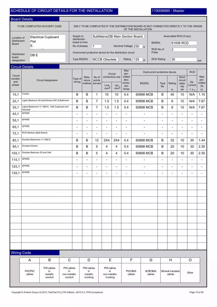
Electrical Cupboard
Flat
E.
H 12
4
-
- -
30
-
-
-
B
-
230
-
60898 MCB
10
SPARE
B
-
4
-
30
-
32
-
10
N/A
20
- -
-
60898 MCB
-
10
-
SPARE
-
SPARE
-
-
-
-
-
B
-
0.4
2X4
-
-
2.30
-
4
-
-
1060898 MCB
11/L1
-
6
1
- -
-
125
Lights Bedroom 20,Hall,Kitchen,WC & Bathroom
-
DB E
4
-
-
-
10
B
20
-
B
-
1.5
-
B
60898 MCB
Copyright © Amtech Group Ltd 2012, FastTest Pro [17th Edition] v2012.0.2, PHS Compliance
60898 MCB
-
-
-
10/L1
-
8/L1
3/L1
Page 19 of 28
-
0.4
12/L1
-
B
5/L1
SPARE
5
-
2X4 1.44
Cooker
7.67
Sockets Kitchen
1
6/L1
-
-
-
12
-
60898 MCB
-
RCD Module (Split Board)
0.4
-
-
-
-
B
-
-
-
40
-
7
SubMains(DB Main Section Board,
7/L1
7.67
0.4
- -
9/L1
1.5
SPARE
2.30
N/A
1.5
4/L1
-
-
B
-
B 1.15B
Sockets Bedroom 20 and Hall
1.5
B
1/L1
B
-
-
-
B
-
--
-
-
B
N/A
0.4
B
13/L1 -
B
10
MCCB Obsolete
-
10
-
7
Sockets Bedrooms 17,18&19
-
-
-
5
0.4
B 30
-
10
30
61008 RCD
2/L1
-
110008985 - Master
-
Lights Bedrooms 17,18&19 , Hall Cupboard and
Doorbell
2
SPARE
110008985 - MasterSCHEDULE OF CIRCUIT DETAILS FOR THE INSTALLATION
Board Details
Circuit Details
Wiring Code

Rem
ark
s
se
eco
ntin
ua
tion
sh
ee
t
Maximum
measured
earth fault
loop
impedance
ONLY TO BE COMPLETED IF THE DISTRIBUTION BOARD IS NOT CONNECTED
DIRECTLY TO THE ORIGIN OF THE INSTALLATIONTEST INSTRUMENTS (SERIAL NUMBERS) USED
Circuit
number
and
phase
Circuit Impedances p
o
l
a
r
i
t
y
Live/
Neutral
Insulation resistance
Live/
Earth
At At
Te
st
butt
on
opera
tio
n
r1 (Line) rn (Neutral) r2 (cpc) (R1 + R2) (R2)
All circuits
(At least one
column
to be completed)Live/
Live
Earth/
Neutral
Date of
testing
Position
Name
Signature
Ipf
Zs
kA
Operating
times of
associated
RCD (if any) At 5I
At In
ms
msn
Ring final circuits only
(measure end to end)
RCD operating
times
Phase sequence confirmed
(where appropriate)
Correct supply
polarity
confirmed
Insulation
resistanceOther
RCD
Earth fault
loop
impedance
Continuity Other
ms ms
I n 5I n
-
08/02/2013
32
-
9/L1
-
N/AN/A
>299
-
N/A
-
>299
-
Copyright © Amtech Group Ltd 2012, FastTest Pro [17th Edition] v2012.0.2, PHS Compliance
-
5792
>299
N/A
4/L1
N/A
-
Fixed Wire Tester
0.07
- -
5792
N/A
-
-
5/L1
N/A
-
N/A
-
N/A
N/A
5792
-
0.28
NO
-
-
N/A
-
-
32
0.26
N/A
-
0.30
-
NO
-
-
-
-
-
-
N/A
-
-
0.05
>299
-
-
10/L1
N/A
-
-
--
N/A
N/A
N/A
-
-
---
0.77>299
NO
6/L1
-
-
-
-
NO
-
110008985 - Master
118
-
11/L1
-
-
LIM
-
NO
N/A
N/A
-
1/L1
Nigel Simpson
-
-
0.29
32
-
N/A
-
N/A
5792
LIM
0.04
LIM
-
N/A
-
>299
-
-
0.88
-
-
-
-
-
N/A
N/A
>299
N/A
-
-
2/L1
-
>299
-
N/A
-
-
-
LIM
-
0.33
>299
-
-
-
N/A
-
0.01
13/L1
-
--
0.26
-
-
- -
-
0.94
N/A
-
-
8/L1
-
0.51
Page 20 of 28
-
-
-
>299
>299
3/L1
-
NO
-
>299
-
-
N/A
0.31
7/L1
0.27
--
- -
N/A
-
N/A 0.68
-
-
12/L1
118
-
N/A
-
LIM
-
N/A
-
-
118LIM
110008985 - MasterSCHEDULE OF CIRCUIT TESTS FOR THE INSTALLATION
Board Tests
Details of circuits and/or equipment vulnerable to damage
Circuit Tests
Tested By

Live
mm 22
Supply to
distribution
board is from
No of phases
TO BE COMPLETED IN EVERY CASE ONLY TO BE COMPLETED IF THE DISTRIBUTION BOARD IS NOT CONNECTED DIRECTLY TO THE ORIGIN
OF THE INSTALLATION
Overcurrent protective device for the distribution circuit
Associated RCD (if any)
BS(EN)
RCD No of
Poles
RCD Rating
A B C D E F G H O
PVC/PVC
cables
PVCcables
in
metallic
conduit
PVCcables
in
non-metallic
conduit
PVCcables
in
metallic
trunking
PVCcables
in
non-metallic
trunking
PVC/SWA
cables
XLPE/SWA
cables
Mineral insulated
cablesOther
Nominal Voltage
Type BS(EN) Rating
Max
per-
mitted
Zs
Circuit
number
and
phase
Circuit designationType of
wiring
Refe-
rence
method
No of
points
served
Circuit
conductors csa
cpc
mm
Max
per-
mitted
disc-
onnec-
tion
times
Overcurrent protective device RCD
Type
No
Rating
Short
circuit
capa-
city
Op.
currentBS(EN)
A
V
mA
Location of
Distribution
Board
Distribution
board
designation
A kA nI
-
6
-
Electrical Cupboard
Flat
F.
H 12
2X4
-
- -
30
-
-
-
B
-
230
-
60898 MCB
10
SPARE
B
-
4
-
30
-
20
-
10
N/A
32
- -
-
60898 MCB
-
10
-
SPARE
-
SPARE
-
-
-
-
-
B
-
0.4
4
-
-
2.30
-
2X4
-
-
1060898 MCB
11/L3
-
6
1
- -
-
125
Lights Bedrooms 21,22&23 , Hall Cupboard and
Doorbell
-
DB F
4
-
-
-
10
B
20
-
B
-
1.5
-
B
60898 MCB
Copyright © Amtech Group Ltd 2012, FastTest Pro [17th Edition] v2012.0.2, PHS Compliance
60898 MCB
-
-
-
10/L3
-
8/L3
3/L3
Page 21 of 28
-
0.4
12/L3
-
B
5/L3
SPARE
12
-
4 2.30
Cooker
7.67
Sockets Bedroom 24 and Hall
1
6/L3
-
-
-
5
-
60898 MCB
-
RCD Module (Split Board)
0.4
-
-
-
-
B
-
-
-
40
-
7
SubMains(DB Main Section Board,
7/L3
7.67
0.4
- -
9/L3
1.5
SPARE
1.44
N/A
1.5
4/L3
-
-
B
-
B 1.15B
Sockets Bedrooms 21,22&23
1.5
B
1/L3
B
-
-
-
B
-
--
-
-
B
N/A
0.4
B
13/L3 -
B
10
MCCB Obsolete
-
10
-
7
Sockets Kitchen
-
-
-
5
0.4
B 30
-
10
30
61008 RCD
2/L3
-
110008985 - Master
-
Lights Bedroom 24,Hall,Kitchen,WC & Bathroom
2
SPARE
110008985 - MasterSCHEDULE OF CIRCUIT DETAILS FOR THE INSTALLATION
Board Details
Circuit Details
Wiring Code
Rem
ark
s
se
eco
ntin
ua
tion
sh
ee
t
Maximum
measured
earth fault
loop
impedance
ONLY TO BE COMPLETED IF THE DISTRIBUTION BOARD IS NOT CONNECTED
DIRECTLY TO THE ORIGIN OF THE INSTALLATIONTEST INSTRUMENTS (SERIAL NUMBERS) USED
Circuit
number
and
phase
Circuit Impedances p
o
l
a
r
i
t
y
Live/
Neutral
Insulation resistance
Live/
Earth
At At
Te
st
butt
on
opera
tio
n
r1 (Line) rn (Neutral) r2 (cpc) (R1 + R2) (R2)
All circuits
(At least one
column
to be completed)Live/
Live
Earth/
Neutral
Date of
testing
Position
Name
Signature
Ipf
Zs
kA
Operating
times of
associated
RCD (if any) At 5I
At In
ms
msn
Ring final circuits only
(measure end to end)
RCD operating
times
Phase sequence confirmed
(where appropriate)
Correct supply
polarity
confirmed
Insulation
resistanceOther
RCD
Earth fault
loop
impedance
Continuity Other
ms ms
I n 5I n
-
08/02/2013
32
-
9/L3
-
N/AN/A
>299
-
N/A
-
>299
-
Copyright © Amtech Group Ltd 2012, FastTest Pro [17th Edition] v2012.0.2, PHS Compliance
-
5792
>299
N/A
4/L3
N/A
-
Fixed Wire Tester
0.03
- -
5792
N/A
-
-
5/L3
N/A
-
N/A
-
N/A
N/A
5792
-
N/A
NO
-
-
0.27
-
-
32
N/A
N/A
-
0.33
-
NO
-
-
-
-
-
-
N/A
-
-
0.09
>299
-
-
10/L3
N/A
-
-
--
N/A
N/A
N/A
-
-
---
0.84>299
NO
6/L3
-
-
-
-
NO
-
110008985 - Master
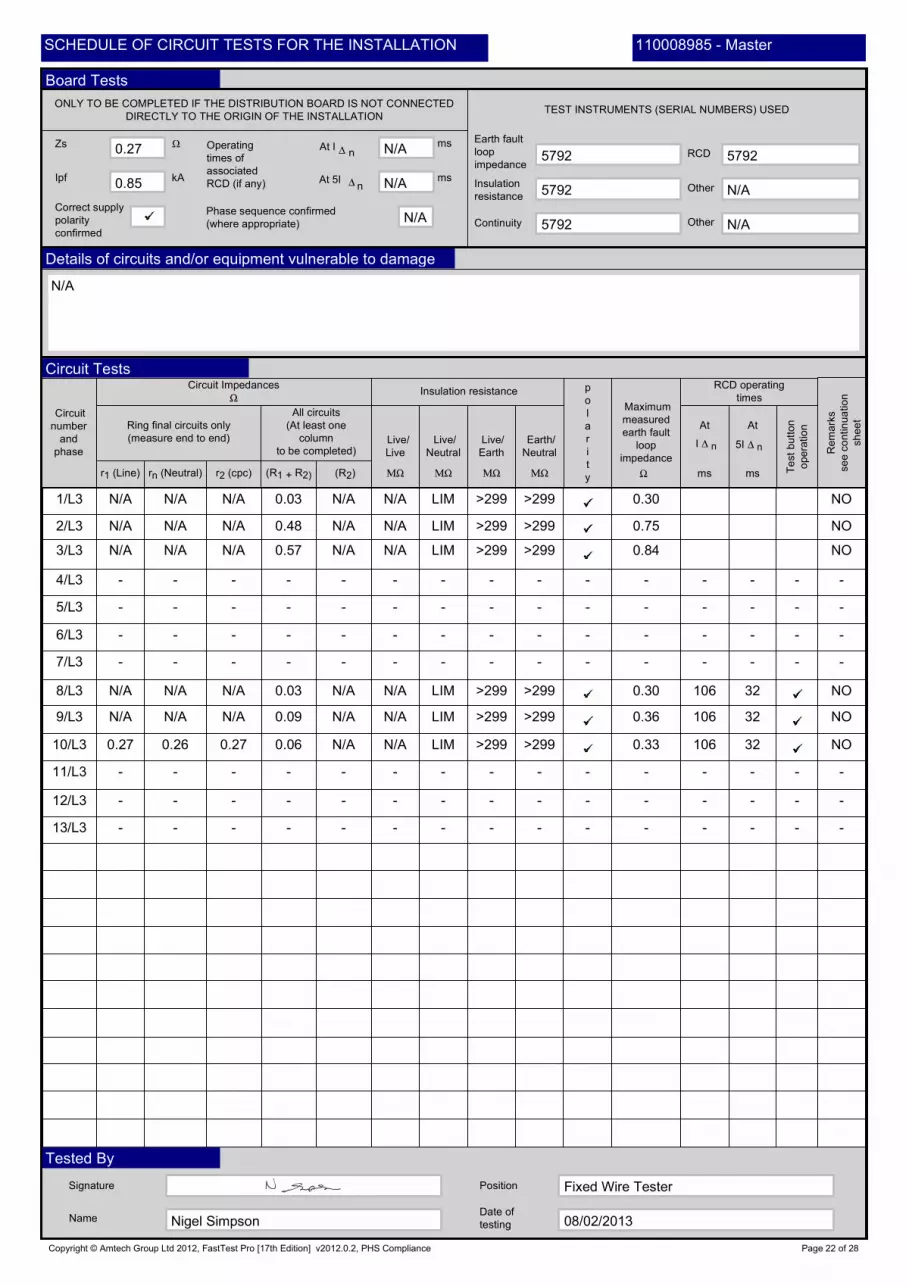
106
-
11/L3
-
-
LIM
-
NO
N/A
0.26
-
1/L3
Nigel Simpson
-
-
N/A
32
-
N/A
-
N/A
5792
LIM
0.06
LIM
-
N/A
-
>299
-
-
0.85
-
-
-
-
-
N/A
N/A
>299
N/A
-
-
2/L3
-
>299
-
N/A
-
-
-
LIM
-
0.30
>299
-
-
-
N/A
-
0.03
13/L3
-
--
0.27
-
-
- -
-
0.75
N/A
-
-
8/L3
-
0.57
Page 22 of 28
-
-
-
>299
>299
3/L3
-
NO
-
>299
-
-
N/A
0.36
7/L3
0.30
--
- -
0.27
-
N/A 0.48
-
-
12/L3
106
-
N/A
-
LIM
-
N/A
-
-
106LIM
110008985 - MasterSCHEDULE OF CIRCUIT TESTS FOR THE INSTALLATION
Board Tests
Details of circuits and/or equipment vulnerable to damage
Circuit Tests
Tested By
Live
mm 22
Supply to
distribution
board is from
No of phases
TO BE COMPLETED IN EVERY CASE ONLY TO BE COMPLETED IF THE DISTRIBUTION BOARD IS NOT CONNECTED DIRECTLY TO THE ORIGIN
OF THE INSTALLATION
Overcurrent protective device for the distribution circuit
Associated RCD (if any)
BS(EN)
RCD No of
Poles
RCD Rating
A B C D E F G H O
PVC/PVC
cables
PVCcables
in
metallic
conduit
PVCcables
in
non-metallic
conduit
PVCcables
in
metallic
trunking
PVCcables
in
non-metallic
trunking
PVC/SWA
cables
XLPE/SWA
cables
Mineral insulated
cablesOther
Nominal Voltage
Type BS(EN) Rating
Max
per-
mitted
Zs
Circuit
number
and
phase
Circuit designationType of
wiring
Refe-
rence
method
No of
points
served
Circuit
conductors csa
cpc
mm
Max
per-
mitted
disc-
onnec-
tion
times
Overcurrent protective device RCD
Type
No
Rating
Short
circuit
capa-
city
Op.
currentBS(EN)
A
V
mA
Location of
Distribution
Board
Distribution
board
designation
A kA nI
-
6
-
Electrical Cupboard
Flat
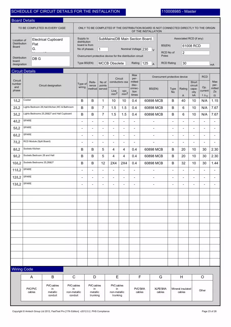
G.
H 12
2X4
-
- -
30
-
-
-
B
-
230
-
60898 MCB
10
SPARE
B
-
4
-
30
-
20
-
10
N/A
32
- -
-
60898 MCB
-
10
-
SPARE
-
SPARE
-
-
-
-
-
B
-
0.4
4
-
-
2.30
-
2X4
-
-
1060898 MCB
11/L2
-
6
1
- -
-
125
Lights Bedroom 28,Hall,Kitchen,WC & Bathroom
-
DB G
4
-
-
-
10
B
20
-
B
-
1.5
-
B
60898 MCB
Copyright © Amtech Group Ltd 2012, FastTest Pro [17th Edition] v2012.0.2, PHS Compliance
60898 MCB
-
-
-
10/L2
-
8/L2
3/L2
Page 23 of 28
-
0.4
12/L2
-
B
5/L2
SPARE
12
-
4 2.30
Cooker
7.67
Sockets Bedroom 28 and Hall
1
6/L2
-
-
-
5
-
60898 MCB
-
RCD Module (Split Board)
0.4
-
-
-
-
B
-
-
-
40
-
7
SubMains(DB Main Section Board,
7/L2
7.67
0.4
- -
9/L2
1.5
SPARE
1.44
N/A
1.5
4/L2
-
-
B
-
B 1.15B
Sockets Bedrooms 25,26&27
1.5
B
1/L2
B
-
-
-
B
-
--
-
-
B
N/A
0.4
B
13/L2 -
B
10
MCCB Obsolete
-
10
-
7
Sockets Kitchen
-
-
-
5
0.4
B 30
-
10
30
61008 RCD
2/L2
-
110008985 - Master
-
Lights Bedrooms 25,26&27 and Hall Cupboard
2
SPARE
110008985 - MasterSCHEDULE OF CIRCUIT DETAILS FOR THE INSTALLATION
Board Details
Circuit Details
Wiring Code

Rem
ark
s
se
eco
ntin
ua
tion
sh
ee
t
Maximum
measured
earth fault
loop
impedance
ONLY TO BE COMPLETED IF THE DISTRIBUTION BOARD IS NOT CONNECTED
DIRECTLY TO THE ORIGIN OF THE INSTALLATIONTEST INSTRUMENTS (SERIAL NUMBERS) USED
Circuit
number
and
phase
Circuit Impedances p
o
l
a
r
i
t
y
Live/
Neutral
Insulation resistance
Live/
Earth
At At
Te
st
butt
on
opera
tio
n
r1 (Line) rn (Neutral) r2 (cpc) (R1 + R2) (R2)
All circuits
(At least one
column
to be completed)Live/
Live
Earth/
Neutral
Date of
testing
Position
Name
Signature
Ipf
Zs
kA
Operating
times of
associated
RCD (if any) At 5I
At In
ms
msn
Ring final circuits only
(measure end to end)
RCD operating
times
Phase sequence confirmed
(where appropriate)
Correct supply
polarity
confirmed
Insulation
resistanceOther
RCD
Earth fault
loop
impedance
Continuity Other
ms ms
I n 5I n
-
08/02/2013
32
-
9/L2
-
N/AN/A
>299
-
N/A
-
>299
-
Copyright © Amtech Group Ltd 2012, FastTest Pro [17th Edition] v2012.0.2, PHS Compliance
-
5792
>299
N/A
4/L2
N/A
-
Fixed Wire Tester
0.03
- -
5792
N/A
-
-
5/L2
N/A
-
N/A
-
N/A
N/A
5792
-
N/A
NO
-
-
0.28
-
-
32
N/A
N/A
-
0.34
-
NO
-
-
-
-
-
-
N/A
-
-
0.02
>299
-
-
10/L2
N/A
-
-
--
N/A
N/A
N/A
-
-
---
0.71>299
NO
6/L2
-
-
-
-
NO
-
110008985 - Master
125
-
11/L2
-
-
LIM
-
NO
N/A
0.28
-
1/L2
Nigel Simpson
-
-
N/A
32
-
N/A
-
N/A
5792
LIM
0.07
LIM
-
N/A
-
>299
-
-
0.85
-
-
-
-
-
N/A
N/A
>299
N/A
-
-
2/L2
-
>299
-
N/A
-
-
-
LIM
-
0.30
>299
-
-
-
N/A
-
0.01
13/L2
-
--
0.27
-
-
- -
-
0.80
N/A
-
-
8/L2
-
0.44
Page 24 of 28
-
-
-
>299
>299
3/L2
-
NO
-
>299
-
-
N/A
0.29
7/L2
0.28
--
- -
0.27
-
N/A 0.53
-
-
12/L2
125
-
N/A
-
LIM
-
N/A
-
-
125LIM
110008985 - MasterSCHEDULE OF CIRCUIT TESTS FOR THE INSTALLATION
Board Tests
Details of circuits and/or equipment vulnerable to damage
Circuit Tests
Tested By

Live
mm 22
Supply to
distribution
board is from
No of phases
TO BE COMPLETED IN EVERY CASE ONLY TO BE COMPLETED IF THE DISTRIBUTION BOARD IS NOT CONNECTED DIRECTLY TO THE ORIGIN
OF THE INSTALLATION
Overcurrent protective device for the distribution circuit
Associated RCD (if any)
BS(EN)
RCD No of
Poles
RCD Rating
A B C D E F G H O
PVC/PVC
cables
PVCcables
in
metallic
conduit
PVCcables
in
non-metallic
conduit
PVCcables
in
metallic
trunking
PVCcables
in
non-metallic
trunking
PVC/SWA
cables
XLPE/SWA
cables
Mineral insulated
cablesOther
Nominal Voltage
Type BS(EN) Rating
Max
per-
mitted
Zs
Circuit
number
and
phase
Circuit designationType of
wiring
Refe-
rence
method
No of
points
served
Circuit
conductors csa
cpc
mm
Max
per-
mitted
disc-
onnec-
tion
times
Overcurrent protective device RCD
Type
No
Rating
Short
circuit
capa-
city
Op.
currentBS(EN)
A
V
mA
Location of
Distribution
Board
Distribution
board
designation
A kA nI
-
6
-
Electrical Cupboard
Flat
H.
H 12
2X4
-
- -
30
-
-
-
B
-
230
-
60898 MCB
10
SPARE
B
-
4
-
30
-
20
-
10
N/A
32
- -
-
60898 MCB
-
10
-
SPARE
-
SPARE
-
-
-
-
-
B
-
0.4
4
-
-
2.30
-
2X4
-
-
1060898 MCB
11/L1
-
6
1
- -
-
125
Lights Bedroom 32,Hall,Kitchen,WC & Bathroom
-
DB H
4
-
-
-
10
B
20
-
B
-
1.5
-
B
60898 MCB
Copyright © Amtech Group Ltd 2012, FastTest Pro [17th Edition] v2012.0.2, PHS Compliance
60898 MCB
-
-
-
10/L1
-
8/L1
3/L1
Page 25 of 28
-
0.4
12/L1
-
B
5/L1
SPARE
12
-
4 2.30
Cooker
7.67
Sockets Bedroom 32 and Hall
1
6/L1
-
-
-
5
-
60898 MCB
-
RCD Module (Split Board)
0.4
-
-
-
-
B
-
-
-
40
-
7
SubMains(DB Main Section Board,
7/L1
7.67
0.4
- -
9/L1
1.5
SPARE
1.44
N/A
1.5
4/L1
-
-
B
-
B 1.15B
Sockets Bedrooms 29,30&31
1.5
B
1/L1
B
-
-
-
B
-
--
-
-
B
N/A
0.4
B
13/L1 -
B
10
MCCB Obsolete
-
10
-
7
Sockets Kitchen
-
-
-
5
0.4
B 30
-
10
30
61008 RCD
2/L1
-
110008985 - Master
-
Lights Bedrooms 29,30&31 and Hall Cupboard
2
SPARE
110008985 - MasterSCHEDULE OF CIRCUIT DETAILS FOR THE INSTALLATION
Board Details
Circuit Details
Wiring Code
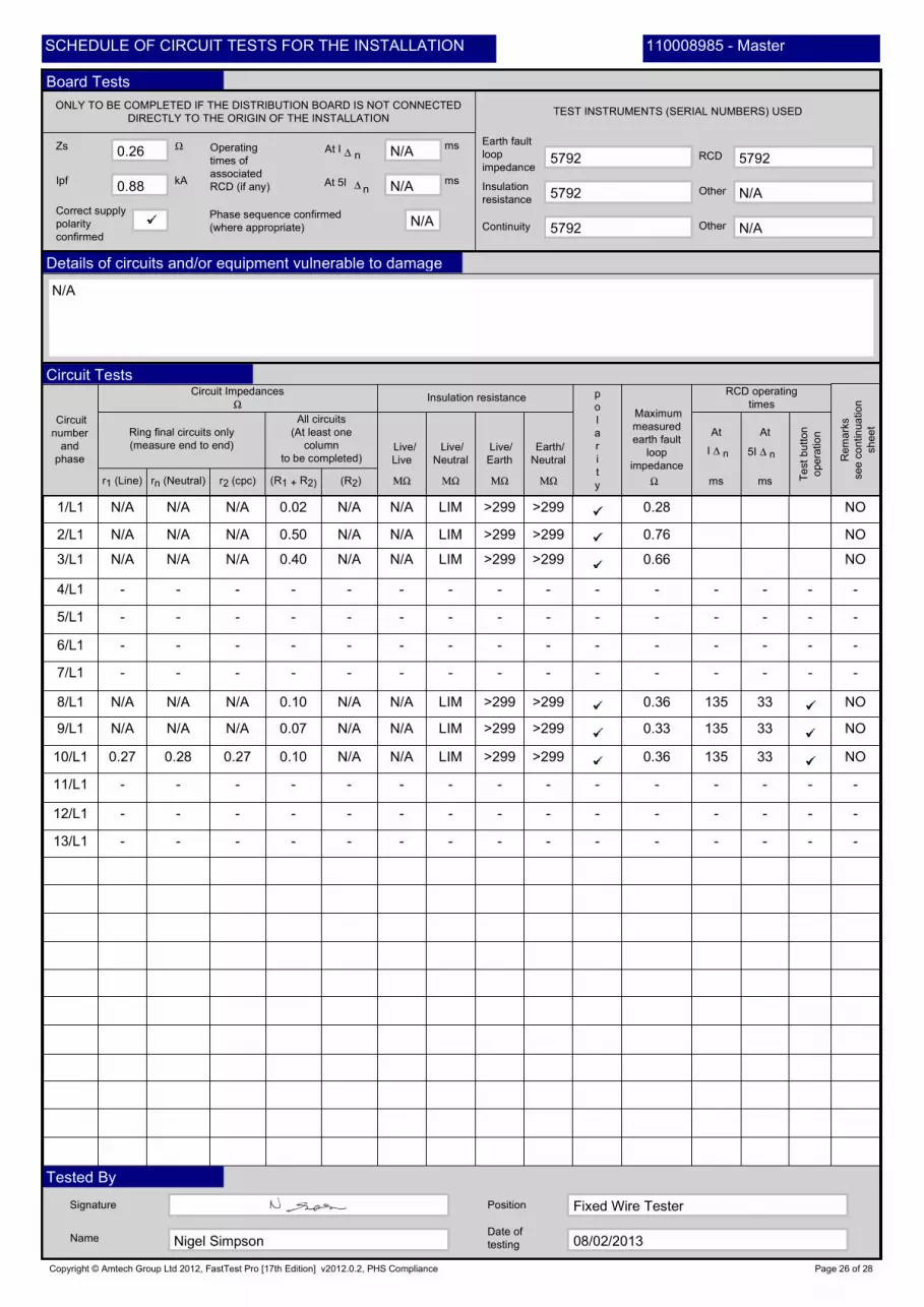
Rem
ark
s
se
eco
ntin
ua
tion
sh
ee
t
Maximum
measured
earth fault
loop
impedance
ONLY TO BE COMPLETED IF THE DISTRIBUTION BOARD IS NOT CONNECTED
DIRECTLY TO THE ORIGIN OF THE INSTALLATIONTEST INSTRUMENTS (SERIAL NUMBERS) USED
Circuit
number
and
phase
Circuit Impedances p
o
l
a
r
i
t
y
Live/
Neutral
Insulation resistance
Live/
Earth
At At
Te
st
butt
on
opera
tio
n
r1 (Line) rn (Neutral) r2 (cpc) (R1 + R2) (R2)
All circuits
(At least one
column
to be completed)Live/
Live
Earth/
Neutral
Date of
testing
Position
Name
Signature
Ipf
Zs
kA
Operating
times of
associated
RCD (if any) At 5I
At In
ms
msn
Ring final circuits only
(measure end to end)
RCD operating
times
Phase sequence confirmed
(where appropriate)
Correct supply
polarity
confirmed
Insulation
resistanceOther
RCD
Earth fault
loop
impedance
Continuity Other
ms ms
I n 5I n
-
08/02/2013
33
-
9/L1
-
N/AN/A
>299
-
N/A
-
>299
-
Copyright © Amtech Group Ltd 2012, FastTest Pro [17th Edition] v2012.0.2, PHS Compliance
-
5792
>299
N/A
4/L1
N/A
-
Fixed Wire Tester
0.10
- -
5792
N/A
-
-
5/L1
N/A
-
N/A
-
N/A
N/A
5792
-
N/A
NO
-
-
0.27
-
-
33
N/A
N/A
-
0.36
-
NO
-
-
-
-
-
-
N/A
-
-
0.07
>299
-
-
10/L1
N/A
-
-
--
N/A
N/A
N/A
-
-
---
0.66>299
NO
6/L1
-
-
-
-
NO
-
110008985 - Master
135
-
11/L1
-
-
LIM
-
NO
N/A
0.28
-
1/L1
Nigel Simpson
-
-
N/A
33
-
N/A
-
N/A
5792
LIM
0.10
LIM
-
N/A
-
>299
-
-
0.88
-
-
-
-
-
N/A
N/A
>299
N/A
-
-
2/L1
-
>299
-
N/A
-
-
-
LIM
-
0.36
>299
-
-
-
N/A
-
0.02
13/L1
-
--
0.26
-
-
- -
-
0.76
N/A
-
-
8/L1
-
0.40
Page 26 of 28
-
-
-
>299
>299
3/L1
-
NO
-
>299
-
-
N/A
0.33
7/L1
0.28
--
- -
0.27
-
N/A 0.50
-
-
12/L1
135
-
N/A
-
LIM
-
N/A
-
-
135LIM
110008985 - MasterSCHEDULE OF CIRCUIT TESTS FOR THE INSTALLATION
Board Tests
Details of circuits and/or equipment vulnerable to damage
Circuit Tests
Tested By
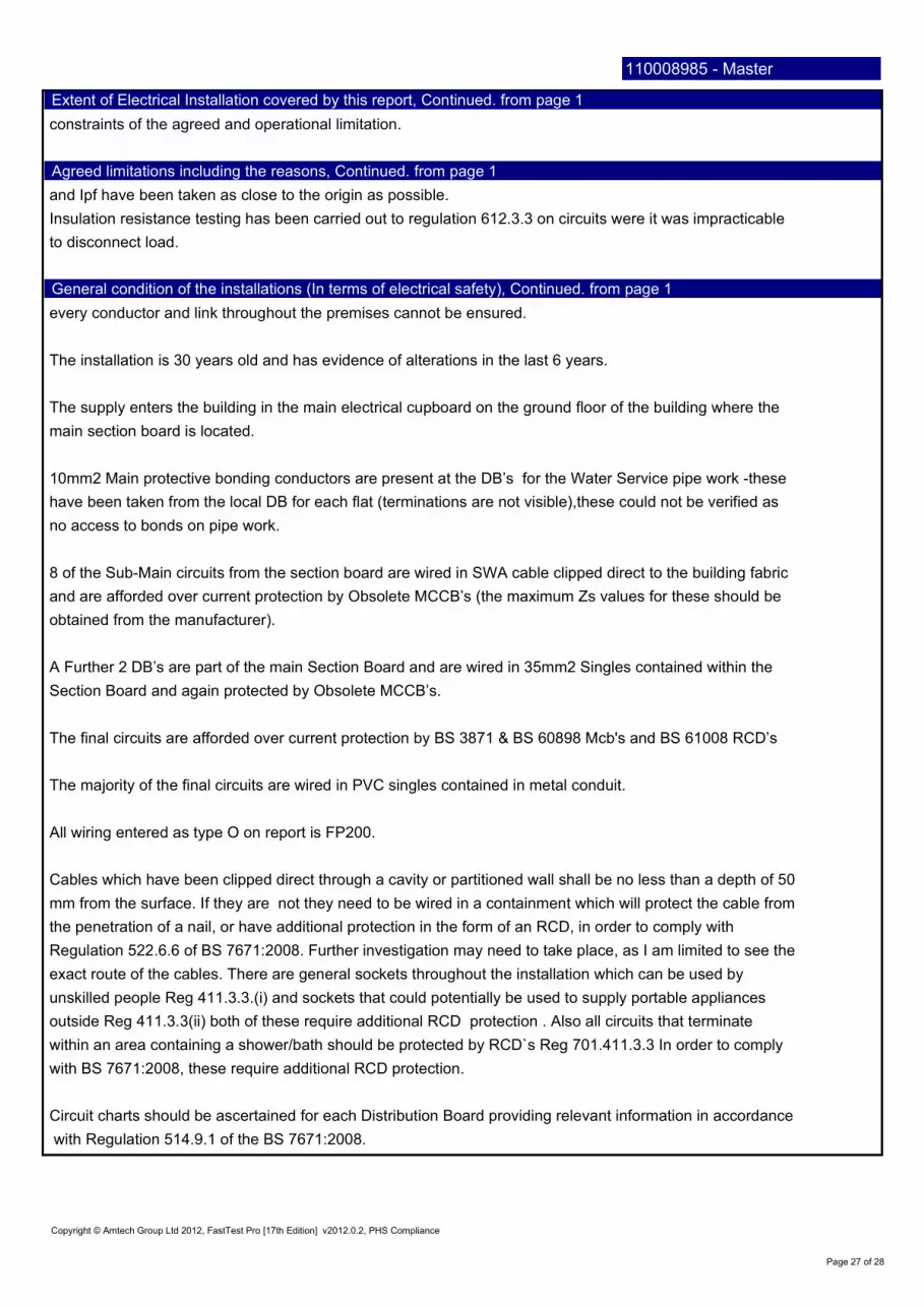
within an area containing a shower/bath should be protected by RCD`s Reg 701.411.3.3 In order to comply
A Further 2 DB’s are part of the main Section Board and are wired in 35mm2 Singles contained within the
no access to bonds on pipe work.
Page 27 of 28
main section board is located.
obtained from the manufacturer).
Section Board and again protected by Obsolete MCCB’s.
outside Reg 411.3.3(ii) both of these require additional RCD protection . Also all circuits that terminate
exact route of the cables. There are general sockets throughout the installation which can be used by
every conductor and link throughout the premises cannot be ensured.
8 of the Sub-Main circuits from the section board are wired in SWA cable clipped direct to the building fabric
constraints of the agreed and operational limitation.
Regulation 522.6.6 of BS 7671:2008. Further investigation may need to take place, as I am limited to see the
with Regulation 514.9.1 of the BS 7671:2008.
Copyright © Amtech Group Ltd 2012, FastTest Pro [17th Edition] v2012.0.2, PHS Compliance
mm from the surface. If they are not they need to be wired in a containment which will protect the cable from
All wiring entered as type O on report is FP200.
Circuit charts should be ascertained for each Distribution Board providing relevant information in accordance
to disconnect load.
and are afforded over current protection by Obsolete MCCB’s (the maximum Zs values for these should be
Cables which have been clipped direct through a cavity or partitioned wall shall be no less than a depth of 50
The installation is 30 years old and has evidence of alterations in the last 6 years.
the penetration of a nail, or have additional protection in the form of an RCD, in order to comply with
The majority of the final circuits are wired in PVC singles contained in metal conduit.
The final circuits are afforded over current protection by BS 3871 & BS 60898 Mcb's and BS 61008 RCD’s
unskilled people Reg 411.3.3.(i) and sockets that could potentially be used to supply portable appliances
and Ipf have been taken as close to the origin as possible.
10mm2 Main protective bonding conductors are present at the DB’s for the Water Service pipe work -these
with BS 7671:2008, these require additional RCD protection.
The supply enters the building in the main electrical cupboard on the ground floor of the building where the
Insulation resistance testing has been carried out to regulation 612.3.3 on circuits were it was impracticable
have been taken from the local DB for each flat (terminations are not visible),these could not be verified as
Extent of Electrical Installation covered by this report, Continued. from page 1
Agreed limitations including the reasons, Continued. from page 1
General condition of the installations (In terms of electrical safety), Continued. from page 1
110008985 - Master

11. Lhs - Left hand side.
5. RCD - residual current device.
Page 28 of 28
1. D.B.-distribution board.
9. C/w - comes with.
12. Csa - Cross sectional area.
the circuit protective conductors although this cannot always be ensured. On the distribution board
7. Cpc - Circuit protective conductor.
The installation is unsatisfactory. However in order for the installation to become satisfactory and up to date
2. Mcb - miniature circuit breaker.
radial circuits every effort has been made to carry out testing at the furthest point to check for continuity of
Copyright © Amtech Group Ltd 2012, FastTest Pro [17th Edition] v2012.0.2, PHS Compliance
possible .The polarity of all accessible socket outlets have been checked and on carrying out testing of
8. TP - Three phase.
13.FT – Firetuff (FP200)
board only. Circuits may have been jointed with a different cable type further along the circuit.
10. Rhs - Right hand side.
Due to the installation being in use at the time of the inspection and test items that were obstructed by
3. Skts - sockets.
with the present British Standards, I suggest that all defects on page 2 of this report be rectified.
6. SWA - Steel wire armour.
Abbreviations used:
schedules of circuit details cable types and sizes have been typed in as what is visible at the distribution
furniture, etc were not tested although a visual inspection on such items would have been carried out where
4. Lts - lights.
110008985 - Master
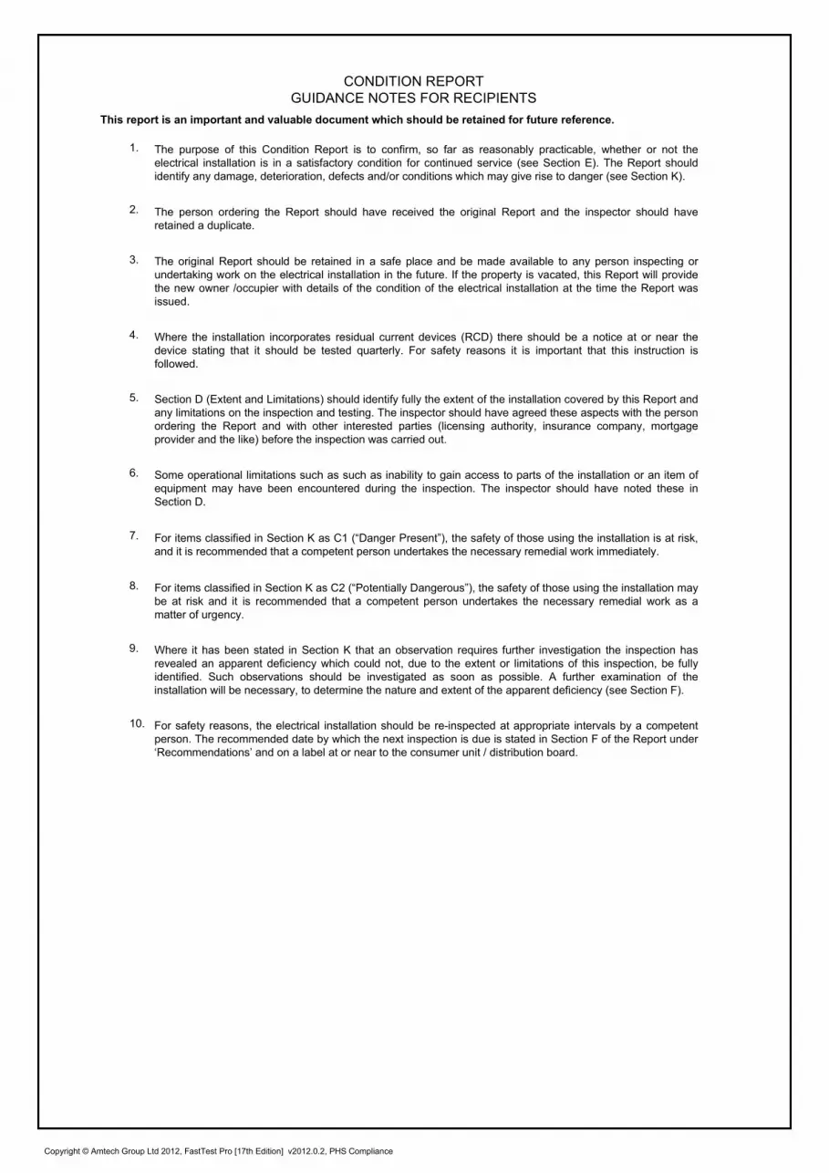
CONDITION REPORT
GUIDANCE NOTES FOR RECIPIENTS
The purpose of this Condition Report is to confirm, so far as reasonably practicable, whether or not the
electrical installation is in a satisfactory condition for continued service (see Section E). The Report should
identify any damage, deterioration, defects and/or conditions which may give rise to danger (see Section K).
This report is an important and valuable document which should be retained for future reference.
1.
The person ordering the Report should have received the original Report and the inspector should have
retained a duplicate.
2.
The original Report should be retained in a safe place and be made available to any person inspecting or
undertaking work on the electrical installation in the future. If the property is vacated, this Report will provide
the new owner /occupier with details of the condition of the electrical installation at the time the Report was
issued.
3.
Where the installation incorporates residual current devices (RCD) there should be a notice at or near the
device stating that it should be tested quarterly. For safety reasons it is important that this instruction is
followed.
4.
Section D (Extent and Limitations) should identify fully the extent of the installation covered by this Report and
any limitations on the inspection and testing. The inspector should have agreed these aspects with the person
ordering the Report and with other interested parties (licensing authority, insurance company, mortgage
provider and the like) before the inspection was carried out.
5.
Some operational limitations such as such as inability to gain access to parts of the installation or an item of
equipment may have been encountered during the inspection. The inspector should have noted these in
Section D.
6.
For items classified in Section K as C1 (“Danger Present”), the safety of those using the installation is at risk,
and it is recommended that a competent person undertakes the necessary remedial work immediately.
7.
For items classified in Section K as C2 (“Potentially Dangerous”), the safety of those using the installation may
be at risk and it is recommended that a competent person undertakes the necessary remedial work as a
matter of urgency.
8.
Where it has been stated in Section K that an observation requires further investigation the inspection has
revealed an apparent deficiency which could not, due to the extent or limitations of this inspection, be fully
identified. Such observations should be investigated as soon as possible. A further examination of the
installation will be necessary, to determine the nature and extent of the apparent deficiency (see Section F).
9.
For safety reasons, the electrical installation should be re-inspected at appropriate intervals by a competent
person. The recommended date by which the next inspection is due is stated in Section F of the Report under
‘Recommendations’ and on a label at or near to the consumer unit / distribution board.
10.
Copyright © Amtech Group Ltd 2012, FastTest Pro [17th Edition] v2012.0.2, PHS Compliance

Item Description
1.0 OutcomeFurther
investigation
√ No
√ No
√ No
√ No
√ No
N/V No
N/A No
3.0 OutcomeFurther
investigation
3.1
√ No
N/A No
√ No
√ No
√ No
C2 (see section K) No
N/V No
N/V No
3.2
N/A No
N/A No
3.3
N/A No
N/A No
Other Methods Details
Non-conducting location (418.1) N/A No
Earth-free local equipotential
bonding (418.2)N/A No
Electrical separation for the supply
to more than one item of current
using equipment (Sec 413; 418.3)
N/A No
Double insulation (Section 412) N/A No
Reinforced insulation (Section 412) N/A No
Use of obstacles (417.2) N/A No
Placing out of reach (417.3) N/A No
5.0 OutcomeFurther
investigation
√ No
√ No
√ No
N/V No
√ No
√ No
√ No
√ No
C3 (see section K) No
√ No
√ No
N/A No
√ No
√ No
√ No
√ No
Master:110008985
Further
investigationOutcome
Presence of adequate arrangements for other services, such as Microgenerators (551.6; 551.7)2.0
Earthing / Bonding Arrangements (411.3; Chap 54)
Provision of earthing / bonding labels at all appropriate locations (514.13.1)
Presence and condition of earth electrode connection where applicable (542.1.2.3)
Presence of distributor’s earthing arrangement (542.1.2.1; 542.1.2.2)3.1.1
3.1.2
Service cable condition1.1
1.6
1.5
1.4
1.3
1.2
Condition of Isolator (where present)
Condition of metering equipment
Condition of tails - Consumer
Condition of tails - Distributor
Condition of Service head
5.7
4.4
4.5
4.6
5.16
4.7
5.4
5.5
5.8
5.9
Presence of other required labelling (Section 514)
5.12 Presence of alternative supply warning notice at or near consumer unit / distribution board
(514.15)
Examination of protective device(s) and base(s); correct type and rating (no signs of
unacceptable thermal damage, arcing and overheating (421.1.3)
Single-pole protective devices in line conductor only (132.14.1; 530.3.2)
Protection against mechanical damage where cables enter consumer unit / distribution board
(522.8.1; 522.8.11)
5.13
5.14
5.15
Presence of RCD quarterly test notice at or near consumer unit / distribution board (514.12.2)
Presence of non-standard (mixed) cable colour warning notice at or near consumer unit /
distribution board (514.14)
Adequacy of working space / accessibility to consumer unit / distribution board (132.1.2; 513.1)
Accessibility and condition of all protective bonding connections (543.3.2)
Condition and accessibility of main protective bonding conductor connections (543.3.2; 544.1.2)
Confirmation of main protective bonding conductor sizes (544.1)
(Where any of the methods listed below are employed details should be provided)
CONSUMER UNITS / DISTRIBUTION BOARDS
Plugs, sockets-outlets and the like not interchangeable with those of other systems within the
premises (411.7.5)
Source supplying at least simple separation (411.7)
3.1.6
3.1.7
3.1.8
5.1
5.2
3.2.2
3.3.1
3.2.1
Security of fixing (416.2.3)
FELV
5.10
5.11
Reduced low voltage
3.3.2
Condition of enclosure(s) in terms of fire rating etc (526.5)
Enclosure not damaged/deteriorated so as to impair safety (621.2 (iii))
Presence of linked main switch (as required by 537.1.4)
Operation of main switch (functional check) (612.13.2)
Manual operation of circuit-breakers and RCDs to prove disconnection (612.13.2)
Correct identification of circuit details and protective devices (514.8.1; 514.9.1)
INSPECTION SCHEDULE FOR DISTRIBUTION BOARDS AND CIRCUITS
DISTRIBUTOR'S / SUPPLY INTAKE EQUIPMENT
AUTOMATIC DISCONNECTION OF SUPPLY
4.0
OTHER METHODS OF PROTECTION
3.1.3
3.1.4
3.1.5
Confirmation of earthing conductor size (542.3; 543.1.1)
Accessibility and condition of earthing conductor at MET (543.3.2)
Plugs, sockets-outlets and the like not interchangeable with those of other systems within the
premises (411.8.5)
Adequacy of source (411.8.4)
Condition of enclosure(s) in terms of IP rating etc (416.2)
4.1
4.2
4.3
5.3
5.6

Master:110008985
INSPECTION SCHEDULE FOR DISTRIBUTION BOARDS AND CIRCUITS
5.0 OutcomeFurther
investigation
√ No
√ No
√ No
√ No
√ No
√ No
C3 (see section K) No
√ No
6.0 OutcomeFurther
investigation
√ No
√ No
√ No
√ No
√ No
√ No
√ No
√ No
√ No
√ No
C2 (see section K) No
√ No
√ No
6.14
N/V No
√ No
C3 (see section K) No
6.15
C2 (see section K) No
C3 (see section K) No
6.16
√ No
√ No
√ No
√ No
N/V No
N/V No
√ No
√ No
√ No
C2 (see section K) No
√ No
7.0 OutcomeFurther
investigation
7.1
√ No
√ No
√ No
√ No
√ No
N/A No
Isolators (537.2)
Temperature rating of cable insulation (522.1.1; Table 52.1)
Clearly identified by position and / or durable marking (537.2.2.6)
7.1.1
Acceptable location - if local or remote from equipment in question (537.2.1.5)
Presence and condition of appropriate devices for isolation (537.2.2)
General condition of wiring systems.
Suitability of circuit accessories for external influences (512.2)
ISOLATION AND SWITCHING
Condition of circuit accessories (Section 416)
Capable of being secured in the OFF position (537.2.1.2)
7.1.2
Provision of additional protection by 30mAmp RCD
6.15.2 For all socket outlets of 20 Amp or less provided for use by ordinary people. (411.3.3 (i))
Adequacy of connection at point of entry to enclosure (gland, bush or similar) (522.8)
6.16.2
7.1.6
7.1.5
7.1.4
Warning label posted in situations where live parts cannot be isolated by the operation of a single
device (514.11.1; 537.2.1.3)
Correct operation verified (612.13.2)
6.23
Suitability of containment systems for continued use (including flexible conduit) (Section 522)
Non-sheathed cables protected by enclosure in conduit, ducting or trunking (521.10.1)
Cables segregated / separated from non-electrical services (528.3)
Band II cables segregated Separated from Band I cables (528.1)
Cable installation methods / practices with regard to the type and nature of installation and
external influences (Section 522)
Cables concealed under floors, above ceilings, in walls / partitions less than 50 mm from a surface, and in partitions containing
metal parts.6.14.1
6.15.1
6.18
Connections under undue strain (522.8)
6.7
6.14.2
Coordination between conductors and overload protective devices (433.1; 533.2.1)
6.10
6.11
6.8
6.9
Adequacy of cables for current-carrying capacity with regard for the type and nature of installation
(Section 523)
Examination of cables for signs of unacceptable thermal or mechanical damage / deterioration
(421.1; 522.6.1)
Adequacy of protective devices: type and rated current for fault protection (Section 434)
Provision of additional protection by 30mAmp RCD (522.6.101; 522.6.103)
6.20
6.17 Provision of fire barriers, sealing arrangements and protection against thermal effects (Section
Where reasonably likely to be used to supply mobile equipment outdoors. (411.3.3 (ii))
Incorporating earthed armour or sheath, or run within earthed wiring system. or otherwise
protected against mechanical damage by nails, screws and the like (see Section D. Extent and
limitations) (522.6.101; 522.6.103) or
Installed in prescribed zones (see Section D. Extent and limitations) (522.6.101) or
Where exposed to direct sunlight, cable of a suitable type (522.11.1)
6.22
The basic insulation of a conductor visible outside an enclosure. (526.2)
6.21
Presence and adequacy of circuit protective conductors (411.3.1.1; 543.1)
6.19
6.12
6.13
6.14.3
Termination of cables at enclosures
6.16.3 Connections of live conductors adequately enclosed. (416.1)
6.16.4
6.2
6.5
7.1.3
6.16.1
5.23
Condition of insulation of live parts (416.1)
Adequacy / security of barriers (416.2)
Identification of conductors (514.3.1)
5.24
5.20
5.21
6.1
5.22
5.17
5.18
5.19
CONSUMER UNITS / DISTRIBUTION BOARDS Continued.
6.4
6.6
6.3 Condition of insulation of live parts (416.1)
Cables correctly supported throughout their run (522.8.5)
Confirmation that integral test button / switch causes RCD(s) to trip when operated (functional
check) (612.13.1)
Presence of diagrams, charts or schedules at or near equipment, where required (514.9.1)
Correct identification of circuit protective devices (533.1)
Protection against electromagnetic effects where cables enter consumer unit / distribution board /
enclosures (521.5.1)
RCD(s) provided for fault protection – includes RCBOs (411.4.9; 411.5.2; 531.2)
RCD(s) provided for additional protection - includes RCBOs (411.3.3; 415.1)
MAIN DISTRIBUTION & FINAL CIRCUITS
Cables correctly terminated in enclosures (Section 526)

Master:110008985
INSPECTION SCHEDULE FOR DISTRIBUTION BOARDS AND CIRCUITS
7.0 OutcomeFurther
investigation
7.2
√ No
√ No
√ No
√ No
√ No
7.3
N/A No
N/A No
N/A No
N/A No
7.4
√ No
√ No
8.0 OutcomeFurther
investigation
C2 (see section K) No
√ No
√ No
√ No
C3 (see section K) No
8.6
N/A No
N/A No
N/A No
N/A No
9.0 OutcomeFurther
investigation
C3 (see section K) No
N/A No
N/A No
N/V No
√ No
√ No
√ No
√ No
10.0 OutcomeFurther
investigation
N/A No
N/A No
N/A No
N/A No
N/A No
N/A No
N/A No
N/A No
N/A No
N/A No
N/A No
N/A No
N/A No
N/A No
N/A No
7.4.1
Clearly identified by position and / or durable marking (537.4.2.7)
Correct operation Verified (537.4.2.6)
Readily accessible for operation where danger might occur (537.4.2.5)
Presence and condition of appropriate devices (537.4.1.1)
7.3.4
7.3.3
10.15
8.3
8.4
8.5
Floor and ceiling heating systems (753)
Temporary electrical installations for structures, amusement devices and booths at fairgrounds,
amusement parks and circuses. (740)
Operating and maintenance gangways (729)
Electrical installations in caravans and motor caravans (721)
Mobile or transportable units (717)
Solar photovoltaic (PV) power supply systems (712)
10.5
10.4
10.3
10.2
10.1
Construction and demolition site installations (704)
Emergency switching / stopping (537.4)
No signs of overheating to surrounding building fabric (559.5.1)
Correct operation verified (537.5.1.3; 537.5.2.2)
Presence and condition of appropriate devices (537.5.1.1)
8.6.4
8.6.3
8.6.2
Presence and condition of appropriate devices (537.3.1.1)
CURRENT-USING EQUIPMENT (PERMANENTLY CONNECTED)
7.2.5 Clearly identified by position and / or durable marking (537.2.2.6)
Correct operation verified (612.13.2)
Capable of being secured in the OFF position (537.3.2.3)
Condition of equipment in terms of IP rating etc (416.1)
Equipment dose not constitute a fire hazard (Section 421)
Enclosure not damaged deteriorated so as to impair safety (Section 416)
Suitability for the environment and external influences (512.2)
Installed to minimize build-up of heat by use of "fire rated" fittings. Insulation displacement box or
similar. Cable entry holes in ceiling above luminaries, sized or sealed so as to restrict the spread
of fire: (421.1.1)
Recessed luminaries (down lighters)
Correct type of lamps fitted (559.4.1)
Security of fixing (416.2.3)
7.4.2
8.6.1
8.2
ADDITIONAL INSPECTION FOR APPLICABLE SPECIAL LOCATIONS
Exhibitions, shows and stands (711)
Medical locations (710)
Marinas and similar locations (709)
Electrical installations in caravan . Camping parks and similar locations (708)
Conducting locations with restricted movement (706)
Agricultural and horticultural premises (705)
Rooms and cabins containing sauna heaters (703)
Swimming pools and other basins (702)
10.6
Where used as a protective measure, requirements for SELV or PELV met (701.414.4.5)
9.3 Shaver sockets comply with BS EN 61558-2-5 formally BS 3535 (701.512.3)
Low Voltage (e.g.230 volts) socket outlets at least 3m fromZone 1 (701.512.3)
No signs of overheating to conductors / terminations (526.1)
7.2.4
7.2.3
Acceptable location / Clearly identified by position and or durable marking (537.3.2.4)
10.8
10.7
9.4 Presence of supplementary bonding conductors, unless not required by BS 7671:2008
(701.415.2)9.5
LOCATION(S) CONTAINING A BATH OR SHOWER
8.1
7.2.1
9.6 Suitability of equipment for external influences for installed location in terms of IP rating
(701.512.2)9.7 Suitability of equipment for installation in a particular zone (701.512.3)
9.8 Suitability of current-using equipment for particular position within the location (701.55)
9.1 Additional protection for all low voltage (LV) circuits by RCD not exceeding 30mA (701.411.3.3)
9.2
10.14
10.13
10.12
10.11
10.10
10.9
7.3.2
7.3.1
Functional switching (537.5)
Switching off for mechanical maintenance (537.3)
7.2.2
ISOLATION AND SWITCHING Continued.

C1 - Danger present. Risk of injury. Immediate remedial action required
C2 - Potentially dangerous - urgent remedial action required
C3 - Improvement recommended
DB ReferenceMake & Model
(if applicable)Circuit Designation / Location Observation / Regulation Code
Further
Investigation
Required
1
All Cooker
control units
with socket
N/AAll Cooker control units with
socket
RCD protection shall be provided for socket outlets not exceeding 20
Amp intended for use by ordinary people. Reg 411.3.3 (i)C3 No
2 DB GFFDorman
SmithCircuits 2,3&4
RCD protection shall be provided for socket outlets not exceeding 20
Amp intended for use by ordinary people. Reg 411.3.3 (i)C3 No
3 DB GFFDorman
SmithCircuit 7 Laundry
No IP2X protection (>12mm hole) on the bottom surface of Light
Switch. Reg 416.1 & 416.2.1C2 No
4 DB GFFDorman
SmithCircuit 7 Hall Light
The diffuser is missing from the light fitting exposing live parts. Reg
559.10.5.2 & 416.1C2 No
5 DB Stair L&PDorman
SmithCircuit 4-Fire Alarm supply
Cables that are concealed within the wall not run in an earthed wiring
system and have no additional protection against nails; should be RCD
protected. Reg 522.6.101 - 522.6.103
C3 No
6 DB Stair L&PDorman
SmithCircuits 2&3
RCD protection shall be provided for socket outlets not exceeding 20
Amp intended for use by ordinary people. Reg 411.3.3 (i)C3 No
7 DB Stair L&PDorman
SmithCircuits 2&3
RCD protection shall be provided for socket outlets that could
potentially be used to supply portable appliances outside. Reg 411.3.3
(ii)
C2 No
8 DB Stair L&PDorman
SmithCircuit 6-Tank Room
The diffuser is missing from the light fitting exposing live parts. Reg
559.10.5.2 & 416.1C2 No
9 DB A HagerCircuit 2-Shaver Light Room
4
No IP4X protection (>1mm hole) on the top surface of Shaver Light.
Reg 416.2.2C2 No
10 DB A Hager Circuit 2-BathroomAll circuits that terminate within an area containing a shower/bath
should be protected by RCD`s Reg 701.411.3.3C3 No
11 DB B Hager Circuit 7-Sockets Room 7 Damaged Back Box.Surface Back Box Cracked . Reg 416.2 C2 No
0
Description Outcome
10
Section K: Observations
Ite
m N
o
Master:110008985
One of the following codes, as appropriate, has been allocated to each of the observations made above to indicate to the person(s) responsible for the
installation the degree of urgency for remedial action.
13

DB ReferenceMake & Model
(if applicable)Circuit Designation / Location Observation / Regulation Code
Further
Investigation
Required
Description Outcome
Ite
m N
o
Master:110008985
12 DB B Hager Circuit 3Multiple circuits in the over current protective device. Reg 314.4 &
521.8.2C3 No
13 DB B Hager Circuit 2No IP2X protection (>12mm hole) on the bottom surface of Light
Switch. Reg 416.2.1C2 No
14 DB B Hager Circuit 3No IP2X protection (>12mm hole) on the bottom surface of Light
Switch. Reg 416.2.1C2 No
15 DB B Hager Circuit 2-BathroomAll circuits that terminate within an area containing a shower/bath
should be protected by RCD`s Reg 701.411.3.3C3 No
16 DB C Hager Circuit 3-BathroomAll circuits that terminate within an area containing a shower/bath
should be protected by RCD`s Reg 701.411.3.3C3 No
17 DB D Hager Circuit 3-BathroomAll circuits that terminate within an area containing a shower/bath
should be protected by RCD`s Reg 701.411.3.3C3 No
18 DB E Hager Circuit 2-BathroomAll circuits that terminate within an area containing a shower/bath
should be protected by RCD`s Reg 701.411.3.3C3 No
19 DB F Hager Circuit 3-BathroomAll circuits that terminate within an area containing a shower/bath
should be protected by RCD`s Reg 701.411.3.3C3 No
20 DB G Hager Circuit 2-BathroomAll circuits that terminate within an area containing a shower/bath
should be protected by RCD`s Reg 701.411.3.3C3 No
21 DB H Hager Circuit 2-BathroomAll circuits that terminate within an area containing a shower/bath
should be protected by RCD`s Reg 701.411.3.3C3 No
22 All DB's N/A N/AUnable to locate and verify the Main Protective Bonding Conductor is
present at the main incoming Water service. Reg 411.3.1.2 & 544.1C2 No
23
DB-Main
Section
Board
Dorman
SmithCircuit 1/TP
Over rated over current protective device in relation to the current
carrying capacity of the connected cables. 10mm SWA/PVC/SWA on
60A MCCB. Reg 433.1.1
C2 No