eiger: a single-photon counting x-ray detector
TRANSCRIPT

This content has been downloaded from IOPscience. Please scroll down to see the full text.
Download details:
IP Address: 129.129.207.75
This content was downloaded on 04/06/2014 at 07:32
Please note that terms and conditions apply.
Eiger: a single-photon counting x-ray detector
View the table of contents for this issue, or go to the journal homepage for more
2014 JINST 9 C05032
(http://iopscience.iop.org/1748-0221/9/05/C05032)
Home Search Collections Journals About Contact us My IOPscience

2014 JINST 9 C05032
PUBLISHED BY IOP PUBLISHING FOR SISSA MEDIALAB
RECEIVED: December 13, 2013ACCEPTED: March 28, 2014
PUBLISHED: May 19, 2014
15th INTERNATIONAL WORKSHOP ON RADIATION IMAGING DETECTORS
23–27 JUNE 2013,PARIS, FRANCE
Eiger: a single-photon counting x-ray detector
I. Johnson,a,1 A. Bergamaschi,a H. Billich,a S. Cartier,a,b R. Dinapoli,a
D. Greiffenberg,a M. Guizar-Sicairos,a B. Henrich,a J. Jungmann,a D. Mezza,a
A. Mozzanica,a B. Schmitt,a X. Shia and G. Tintia,c
aPaul Scherrer Institut,CH-5232 Villigen PSI, Switzerland
bInstitut for Biomedical Engineering, University and ETH Zurich,CH-8092 Zurich, Switzerland
cEuropean Synchrotron Radiation Facility,F-38043 Grenoble Cedex, France
E-mail: [email protected]
ABSTRACT: Eiger is a single-photon counting x-ray pixel detector being developed at the PaulScherrer Institut (PSI) for applications at synchrotron light sources. It follows the widely utilizedand successful Pilatus detector. The main features of Eiger are a pixel size of 75× 75 µm2, highframe rate capability of 22 kHz and negligible dead time between frames of 4 µs. This article con-tains a detailed description of Eiger detector systems, from the 500 kpixel single-module detector tolarge-area multi-modules systems. The calibration and performance of the first 500 kpixel systemthat is in routine user operation are also presented. Furthermore, a method of calibrating the energyof single-photon counting detectors along the detector gain axis is introduced. This approach hasthe advantage that the detector settings can be optimized at all energies for count rate capabilities.Rate capabilities of the system are reported for energies between 6 and 16 keV.
KEYWORDS: Hybrid detectors; X-ray diffraction detectors; X-ray detectors
1Corresponding author.
c© 2014 IOP Publishing Ltd and Sissa Medialab srl doi:10.1088/1748-0221/9/05/C05032

2014 JINST 9 C05032
Contents
1 Introduction 1
2 Detector design 1
3 Module calibrations 4
4 Conclusion 6
1 Introduction
Detectors are key components in many applications at x-ray synchrotrons and free-electronlasers [1–6]. The unprecedented data quality and high dynamic range of detectors has drivenadvancements in many fields of research, especially in protein crystallography [7, 8], scanningsmall-angle x-ray scattering [9], coherent diffraction imaging [10, 11] and x-ray photon correlationspectroscopy [12, 13].
2 Detector design
Eiger [14] is a hybrid single-photon counting pixel detector. The basic building blocks are the pixe-lated silicon sensor, the complementary metal-oxide-semiconductor (CMOS) readout chip, and thereadout electronics. X-rays generate charge carriers in the fully depleted sensor which is typically320 µm thick and can stop x-rays of up to 25 keV with an efficiency of 25%. Indium bump bondselectrically connect the sensor pixels to individual cells in the readout chip. A single Eiger read-out chip houses 256× 256 readout cells on a 75 by 75 µm pitch, which matches the pitch on thesensor. Charge signals from the sensor are digitized in the readout cells with a processing chainthat consists of a gain-configurable preamplifier, a shaper, and a discriminator that increments acounter. The gain of the preamplifier is adjustable via an external voltage, Vr f , which controls theconductance of the feedback transistor. A pixel threshold level is the sum of a global threshold plusa pixel-specific offset that can be adjusted with 6 trimbit bits. The unit strength of the trimbits isalso adjustable via an external voltage. These trimbits are used to compensate for pixel-to-pixelvariations and level the response across the detector. Counter values directly translate into the inci-dent photon flux across the detector when pixel thresholds are precisely set at half of the incomingx-ray energy.
The dynamic range of the pixel counters is configurable with overflow logic to 4, 8 or 12 bits.A short dead time between frames is achieved with a parallel acquire-readout architecture that usescapacitors in the readout cells to locally buffer the counter values. Once the counter values from theexposure are transferred to the in-pixel capacitors and the counters have been reset, the succeedingexposure can start. In total, only about 4 µs are needed between frames. The data is transferred
– 1 –

2014 JINST 9 C05032
Figure 1. Eiger systems being developed at PSI. The 500 kpixel single module, 1.5 Mpixel three-modulesystem and the mechanical design of the planned 9 Mpixel detector, respectively from left to right.
column-wise from the pixels to the bottom periphery of the chip. At the bottom periphery the datais serialized and read out over 32 pads with a 100 MHz double data rate (DDR) frequency. Framerates of 22 kHz, 12 kHz and 8 kHz can be achieved when respectively 4, 8 or 12 bits are transferredto the readout electronics.
Eiger detector modules house eight readout chips (2 by 4) and have a sensitive area of38×77mm2. A sensor of a module contains the corresponding arrays of 256×256 pixels for eightreadout chips. Edge pixels along the border of two neighboring readout chips are twice as longto provide the needed mechanical space in a way that preserves the grid across the sensor. Linearinterpolation is used to distribute the intensity of these pixels into four virtual pixels. This resultsin a continuous detection surface. Larger detector systems are constructed by tiling modules.Currently, a 1.5 million and a 9 million pixel detector, the latter having an active area of 233 by238 mm2, are being developed for the coherent small-angle scattering cSAXS beamline at theSwiss Light Source, Villigen, Switzerland. Both of these detectors along with the 500k moduleare shown in figure 1. The combination of high frame rates and a large number of pixels leads tomaximum data rates of about 50 Gbit/s per module or approximately 900 Gbit/s on the 9 Mpixeldetector. On-board data processing, a parallel readout architecture, high-speed data transfer andonline compression are utilized to cope with the data deluge.
The readout electronics of a module are separated into top and bottom halves. One half con-trols the top row of four chips, while the other controls the bottom row. The timing of acquisitionacross all half-modules is synchronized down to 10 ns level via communication over a flat-bandcable that runs down the back of the detector. With this architecture, data processing and transfercan be carried out in a fully independent and parallel manner.
In-firmware data processing on the readout boards tackles the extreme data rates at the sourcein real time. Each module contains 8 GB of DDR2 memory that is used for both data buffering andimage accumulation. In 4-bit mode, more than 30 kframes can be stored directly in this memory.Larger systems also preserve the high frame rate capabilities of the chip, since both the storage vol-ume and bandwidth scale with detector size. Image summation is carried out on the detector to ex-tend the dynamic range of the 12-bit counters in the Eiger chip to 32 bits. Thus, the MHz count ratecapabilities of the chip can be extended from a few ms to minute-long exposures. Throughout the
– 2 –

2014 JINST 9 C05032
duration of an exposure, sub-images are acquired and summed with about a 400 Hz sub-exposurefrequency. Only the resulting summed image, or images of an exposure series, are transferred offthe detector. Rate corrections, that compensate for inefficiencies at high fluxes caused by pileup,are also applied in firmware to the sub-images. Applying the rate corrections to shorter sub-imagesis more precise and less sensitive to rate fluctuations during the acquisition [15].
Data is transferred from the detector to its destination over either multiple 1 GbE or 10 GbEconnections, one for each detector half module. The standard Ethernet option, i.e. the 1 GbE con-nection, is also compatible with slower 10 Mb or 100 Mb Ethernet networks. This has the advantagethat it is more portable and does not require specific hardware that supports 1 or 10 GbE. It is anideal solution for many systems that do not require a high (> 50 Hz) continuous frame rate. Mostapplications are not limited by this constraint, since higher frame rate exposure series can be ac-quired and buffered in the onboard memory for a finite time, 1.25 s at the highest data rates. UserDatagram Protocol (UDP) is used to transfer data from the half modules to the acquisition system.The data packets are assembled directly in the firmware with a pre-filled table of UDP headers.Reliable data transfer is achieved with a handshaking, request-based transfer. Packets lost on thenetwork or in overflowing port buffers on the receiving node are automatically requested again.
The widely used Hierarchical Data Format (HDF5) [16] has been chosen for Eiger. Imagetransfers over the 1 GbE connection are byte shuffled1 and level one deflate compressed [17]. Com-pression rates and factors not only depend on the algorithm and the quality of the compute node,but also on the data. High frame rate x-ray diffraction data from the practically noiseless Eigerdetector can typically be compressed at a rate of 50 MB/s and by a factor of more than 20x. Thiscompression rate is well suited for data transfer over 1 GbE.
A multiple 10 GbE data backend is currently under development for high-performance singlemodules, 1.5 Mpixel and 9 Mpixel Eiger systems. The goal is to reach continuous frame ratesof more than 100 Hz and potentially kHz. Data from the thirty-six 10 GbE connections of the9 Mpixel system will travel through a non-blocking switch to two 16 core servers each with two40 GbE connections. Hardware synchronization will be used to assure that oversubscription doesnot occur at any point on the network. Complete images will be steered to a single server, whereportions from the various modules and frames will be sent to different port numbers. On theservers, multiple processes can independently assemble the complete frames out of port-bufferorganized data, calculate the interpolated values of the border pixels and place the complete imagesinto a shared memory buffer. Other processes will then read the data from the shared memory,compress it and pass it on to a file writer.
In order to handle the data rates from large detector systems, DECTRIS [18] and PSI haveteamed up to support the development of pre-compressed chunk writing in the HDF5 library. Withpre-compressed chunk writing, multiple processes can independently compress complete imagesand pass them on as small chunks to the file writer process. Thus, the compression throughputscales with the number of cores. HDF5 has also recently introduced a mechanism that enablescustom filter plug-ins with which any compression algorithm can be used in conjunction with thelibrary. It has been found that the lossless data compression algorithm LZ4 is also a good candidatefor x-ray diffraction data. The algorithm can provide speeds of more than 500 MB/s and a typical
1When the data width is greater than 8 bits.
– 3 –

2014 JINST 9 C05032
compression factor of 70x. With these compression factors and rates, it is estimated that data ratesof at least 50 Gb/s can be converted in real time directly on the two servers to something easilydigested by the network and file server.
3 Module calibrations
Single-photon counting detectors have a few fundamental calibrations that need to be applied. Themodules need to be trimmed to minimize the threshold dispersion, an energy calibration is neededto convert the desired photon energy to gain and threshold settings, rate corrections are appliedto compensate for inefficiencies caused by pileup, and a flat field correction is used to flatten theresponse across the detector.
An iterative routine is used to tune the trimbits of Eiger, since the strength of the individualpixel bit is affected by voltage drops on the chip that depend on the trimbit values of all pixels.There are two common locations in which the response of the pixels are aligned: at the inflectionpoints of the s-curve (eq. (3.1)) with a source at the half-energy [19] or by normalizing the responseat the corresponding half-energy threshold. Ideally, the two approaches produce identical results.The former has the advantage that the sharp change, from not counting to counting at the inflectionpoint, is a clear edge to adjust on. While the latter, which in pratice requires higher statistics, hasthe convenience that any slight variations in efficiency across the detector are also trimmed away.
The latter approach has been applied for the results and calibrations in this paper. Off-axis scat-tering at about 7 m downstream from a glassy carbon target was used to create a uniform 6.2 keVsynchrotron illumination on the module. The trimbits of the pixels were varied until a uniformresponse across the detector was achieved. Some pixels at the border between the top-bottom halfmodules show an increased noise. The reason for this is currently not completely understood, how-ever it is under investigation and thought to be related to the fact that the top and bottom groundsmeet along this border. Otherwise, pixel-to-pixel differences were within the statistical fluctuationsand no systematic variations in the response across the detector were present.
In this paper the energy calibration has been performed along the gain axis, in contrast tothe conventional method of adjusting the comparator threshold [20]. The threshold level was keptconstant and the gain of the pre-amplifier was adjusted to modify the sensitivity to charge carriers.Choosing a low comparator threshold inherently optimizes the detector for count rate capabilities atall energies. Alternatively, selecting a higher threshold reduces the electronic noise2 at the expenseof rate capabilities. It is foreseen to have three detector settings: fast, standard and low-noise.The calibration for the fast detector setting is presented here. Monochromatic illuminations on thedetector at various photon energies were used for the calibration. Fluorescent targets between 4and 10 keV were chosen to have the corresponding calibration for full energies in the range from 8to 20 keV. In the future, K and Cl targets will also be added to the setup to extend the range at lowerenergies. The pixel-averaged response versus gain distributions at the various fluorescent energieswere characterized with s-curves (see figure 2),
f (x) =12
(a+bx)(
er f(
x− x0√2∗σ
)+1
)+ c+dx. (3.1)
2Electronic noise here corresponds to analogue noise in the signal processing chain of pixel cells in the readout chip,which is determined by the σ of the s-curve. Not to be confused with noisy pixels or noise in an image.
– 4 –

2014 JINST 9 C05032
Figure 2. Left: detector response versus Gain (Vrf) measurements for different fluorescent energies andcorresponding s-curve fits. Right: distribution of the inflection points of the s-curves versus x-ray energy, fitwith a second-order polynomial.
Where a is proportional to the flux of the primary energy, b parameterizes to first order thecharge sharing between pixels, x0 is the inflection point, σ is a measure of the electronic noise, andthe background in the distribution is linearly described by c and d. The locations of the inflectionpoints of the s-curves precisely correspond to the half-energy gains, Vrf values. The energy cal-ibration plot was created from these values, see figure 2. This distribution is parameterized by asecond order polynomial that converts photon energy to gain.
Inefficiencies at high rates are corrected for by mapping the measured flux of the pixels, that ishindered by pileup, to the theoretical incident flux. This is commonly known as the rate correction.The correction is not only a function of the incident flux but also depends on the gain setting and thetime structure of the source, i.e. the fill pattern at synchrotrons [21]. The following measurementswere made at the Swiss Light Source (SLS). The SLS primarily operates in a top-up mode with afill pattern that consists of a continuous train of 390 filled electron buckets spaced by 2 ns and onelarger cam shaft bunch that resides in a 180 ns gap. In the eyes of Eiger, this is a continuous sourceexcept for the one bunch and pause during the gap.
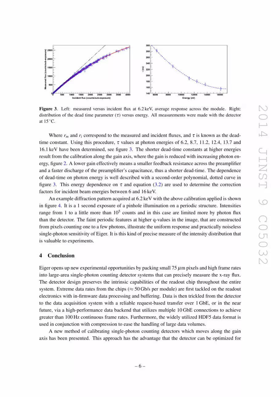
A foamy-carbon scatterer, approximately 7 m upstream from the detector, was used to spreadthe flux on the detector. By changing the undulator gap, 34 m upstream of the scatterer, the overallintensity on the detector could be altered without changing the intensity distribution on the detector.A high-flux image was recorded with a narrow-gap setting and the low flux with an open-gapsetting. Since only the undulator gap width was changed, the flux on the detector for the twoimages are ideally just direct scales of one another. The high-flux image suffered from coincidencelosses, while the low-flux image provided the incident flux on the detector after it was scaled tomatch the overall intensity. The inefficiency caused by pileup was extracted by correlating thepixel intensities in the high-flux image to those in the overall-intensity-corrected low-flux image,see figure 3. This fractional loss [22, 23] is well described by,
rm = rie−riτ . (3.2)
– 5 –
2014 JINST 9 C05032
Figure 3. Left: measured versus incident flux at 6.2 keV, average response across the module. Right:distribution of the dead time parameter (τ) versus energy. All measurements were made with the detectorat 15 ◦C.
Where rm and ri correspond to the measured and incident fluxes, and τ is known as the dead-time constant. Using this procedure, τ values at photon energies of 6.2, 8.7, 11.2, 12.4, 13.7 and16.1 keV have been determined, see figure 3. The shorter dead-time constants at higher energiesresult from the calibration along the gain axis, where the gain is reduced with increasing photon en-ergy, figure 2. A lower gain effectively means a smaller feedback resistance across the preamplifierand a faster discharge of the preamplifier’s capacitance, thus a shorter dead-time. The dependenceof dead-time on photon energy is well described with a second-order polynomial, dotted curve infigure 3. This energy dependence on τ and equation (3.2) are used to determine the correctionfactors for incident beam energies between 6 and 16 keV.
An example diffraction pattern acquired at 6.2 keV with the above calibration applied is shownin figure 4. It is a 1 second exposure of a pinhole illumination on a periodic structure. Intensitiesrange from 1 to a little more than 105 counts and in this case are limited more by photon fluxthan the detector. The faint periodic features at higher q-values in the image, that are constructedfrom pixels counting one to a few photons, illustrate the uniform response and practically noiselesssingle-photon sensitivity of Eiger. It is this kind of precise measure of the intensity distribution thatis valuable to experiments.
4 Conclusion
Eiger opens up new experimental opportunities by packing small 75 µm pixels and high frame ratesinto large-area single-photon counting detector systems that can precisely measure the x-ray flux.The detector design preserves the intrinsic capabilities of the readout chip throughout the entiresystem. Extreme data rates from the chips (≈ 50 Gb/s per module) are first tackled on the readoutelectronics with in-firmware data processing and buffering. Data is then trickled from the detectorto the data acquisition system with a reliable request-based transfer over 1 GbE, or in the nearfuture, via a high-performance data backend that utilizes multiple 10 GbE connections to achievegreater than 100 Hz continuous frame rates. Furthermore, the widely utilized HDF5 data format isused in conjunction with compression to ease the handling of large data volumes.
A new method of calibrating single-photon counting detectors which moves along the gainaxis has been presented. This approach has the advantage that the detector can be optimized for
– 6 –

2014 JINST 9 C05032
Figure 4. Diffraction pattern of a periodic structure behind a pinhole acquired with a 500 kpixel module.
count rate capabilities at all energies. It also has the potential to become a conventional methodfor calibrating single-photon counting detectors and has been used to calibrate the first 500 kpixelsystem that is in routine user operation at the cSAXS beamline. This detector has already been uti-lized in coherent diffractive imaging and ptychography experiments, and should soon see photonsfrom SAXS and time-resolved SAXS experiments.
We are working towards larger multi-module systems. A 1.5 Mpixel detector is in the testphase and 9 Mpixel is in the design stage. Furthermore, a 16 Mpixel detector is being developedin collaboration with DECTRIS Ltd. for the Protein Crystallography (PX) beamline and is cofi-nanced by CTI/KTI (Commission for Technology and Innovation) under project number 13454.1PFFLM-NM.
Acknowledgments
The authors would like to thank D. Maliakal, C. Ruder, L. Schadler, E. Schmid, A. Schreiber andG. Theidel for the technical support throughout the development and fabrication of Eiger detectors.Many thanks to A. Diaz and I. Rajkovic for the assistance during the experiments at cSAXS. Weare also grateful for the IT support that S. Ebner and T. Zamofing are providing in the design of thehigh performance readout system.
References
[1] B. Henrich et al., PILATUS: a single photon counting pixel detector for X-ray applications, Nucl.Instrum. Meth. A 607 (2009) 247.
[2] P. Denes et al., A fast, direct x-ray detection charge-coupled device, Rev. Sci. Instrum. 80 (2009)083302.
[3] P. Hart et al., The Cornell-SLAC Pixel Array Detector at LCLS, IEEE Nucl. Sci. Symp. Med. Imag.Conf. (NSS/MIC) 2012 (2012) 538, SLAC-PUB-15284.
[4] X. Llopart et al., Medipix2: a 64-k pixel readout chip with 55 µm square elements working in singlephoton counting mode, Nucl. Instrum. Meth. A 607 (2009) 247.
– 7 –
2014 JINST 9 C05032
[5] A. Bergamaschi et al., The MYTHEN detector for X-ray powder diffraction experiments at the SwissLight Source, IEEE Trans. Nucl. Sci. 49 (2002) 2279.
[6] L. Blanquart et al., XPAD, a new read-out pixel chip for X-ray counting, IEEE Nucl. Sci. Symp. Conf.Rec. 2 (2000) 92.
[7] R.J.C. Hilf and R. Dutzler, X-ray structure of a prokaryotic pentameric ligand-gated ion channel,Nature 452 (2008) 375.
[8] H.N. Chapman, et al., Femtosecond X-ray protein nanocrystallography, Nature 470 (2011) 73.
[9] O. Bunk et al., Multimodal x-ray scatter imaging, New J. Phys. 11 (2009) 123016.
[10] I. Johnson et al., Coherent diffractive imaging using phase front modifications, Phys. Rev. Lett. 100(2008) 155503.
[11] A. Menzel et al., Ptychographic Imaging at the Swiss Light Source, Synchrotron Rad. News 26 (2013)26.
[12] H. Kim et al., Surface Dynamics of Polymer Films, Phys. Rev. Lett. 90 (2003) 068302.
[13] I. Johnson et al., Capturing dynamics with Eiger, a fast-framing X-ray detector, J. Synchrotron Rad.19 (2012) 1001.
[14] R. Dinapoli et al., EIGER: Next generation single photon counting detector for X-ray applications,Nucl. Instrum. Meth. A 650 (2010) 79.
[15] I. Johnson, E. Schmid, D. Suter and G. Theidel, A method for correction of high rate inefficiencies ofa single photon counting detector system and single photon counting detector system, EuropeanPatent Application, PCT/EP2011/065321 (2011).
[16] The Hierarchical Data Format Group (HDF5), http://www.hdfgroup.org/HDF5.
[17] Performance evaluation report: gzip, bzip2 compression with and without shuffling algorithm,http://www.hdfgroup.org/HDF5/doc resource/H5Shuffle Perf.pdf.
[18] DECTRIS Ltd., https://www.dectris.com.
[19] P. Kraft et al., Characterization and Calibration of PILATUS Detectors, IEEE Trans. Nucl. Sci. 56(2009) 3.
[20] P. Kraft et al., Performance of single-photon-counting PILATUS detector modules, J. SynchrotronRad. 16 (2009) 368.
[21] B. A. Sobott et al., Success and failure of dead-time models as applied to hybrid pixel detectors inhigh-flux applications, J. Synchrotron Rad. 20, (2013) 347.
[22] A. Wyttenbach, Coincidence losses in activation analysis, J. Radioanal. Nucl. Chem. 8 (1971) 335.
[23] J. Bateman et al., The effect of beam time structure on counting detectors in SRS experiments, J.Synchrotron Rad. 7 (2000) 307.
– 8 –