ec_120_b.pdf - mauna loa helicopters
TRANSCRIPT
EC
B
TRANSPORT CANADA TYPE APPROVAL No H-102
REGISTRATION No SERIAL Nc
APPROVED BYLA DIRECTION GENERALE DEL'AVIATION CIVILE
BY
13 DEC. 1998DATE
THIS ROTORCRAFT FLIGHT MANUAL IS APPROVED FOR CANADIAN REGISTERED AIRCRAFT INACCORDANCE WITH THE CANADIAN AIRWORTHINESS MANUAL.THE TRANSPORT CANADA FLIGHT MANUAL CONSISTS OF ALL UNCODED AND CODED [Q]PAGES MARKED "DGAC APPROVED".
THIS DOCUMENT SHALL BE CARRIED IN AIRCRAFT AT ALL TIMES.
EUROCOPTER Direction Technique SupportA6roport international Marseille-Provence 13725 Marlgnane Cedex -France
@] TITLEDGAC APPROVEDORIGINAL ISSUE: JUNE 1997
8 euroco p ter FLIGHT MANUALEC120 B. LIST OF CONDITIONAL REVISIONS (CR)
EFFECTIVE PAGES
This manual assigned to the helicopter mentioned on the title page, contains thefollowing pink pages except those cancelled when the conditions are complied with.
,:.~Jt!tQ~';;i
If a nonnal revision (NR) modifies thc page 11l1.1l1ber for any infolmation concernedbclow, the reader will have to change the number of the pi Ilk pagc by hand, so
.that the infonnation remains in accordance with the paragraph concerned.
No PAGE DATE REMARKS / EFFECllVITY
.
.DGACAPPROVED AREVISION 3
FLIGHT MANUAL 11111111... 81EC120 B eurocopter
LIST OF INTERMED lATE TElVIPO RAR Y REVISIONS.(ITR) EFFECTIVE PAGES
The manual contains the following additional yellow pages.
No DATE No PAGE DATE
8)
8)
.)
B DGAC APPROVEDORIGINAL ISSUE
.
FLIGHT MANUALeurocoPter~]!!] ECI20 B
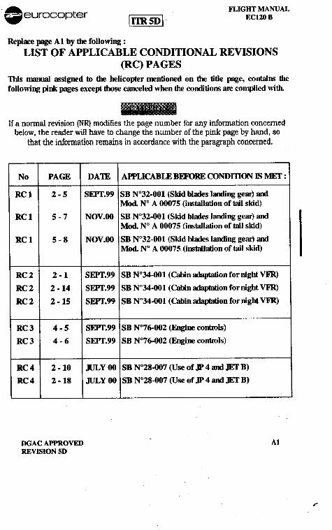
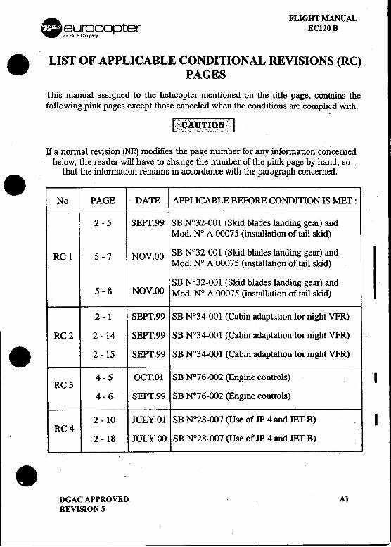
Reploce J..ge Al by die following :LIST OF APPLICABLE CONDmONAL REVISIONS
(RC) PAGESThis manual ~signed to die helicopter mentioned on die tide ~e, contains diefollowing pink ~es except those canceled when die conditions are complied with.
If a nonnal revision INR) modifies the page number for any infonnation concernedbelow, the reader will have to change the number of the pink page by hand, so
that the information remains in accordance with the paragraph concerned.
No PAGE DATE APPLICABLE BEFORE CONDmON IS MEr :
RC 1 2 -5 SEPf.99 SB N°32-001 (Skid blales landing gear) arxIMod. N° A 00075 (installation of tail skid)
RC 1 5 -7 NOV.OO SB N°32-001 (Skid blales landing gear) andMod. N° A 00075 (installation of tail skid)
RC 1 5 -8 NOV.OO SB N°32-001 (Skid blales landing gear) andMod. N° A 00075 (installation of tail skid)
RC 2 2 -1 SEPf.99 SB N°34-001 (Cabin adaptation for night VFR)
RC 2 2 -14 SEPf.99 SB N°34-001 (Cabin adaptation for night VFR)
RC 2 2 -15 SEPf.99 SB N°34-001 (Cabin adaptation for night VFR)
RC 3 4 -5 SEPf.99 SB N°76-002 (Engi1E controls)
RC 3 4 -6 SEPf.99 SB N°76-002 (EngilE conwls)
RC 4 2 -10 JULy 00 SB N°28-007 (Use of JP 4 arxIJEf B)
RC 4 2 -18 JULy 00 SB N°28-007 (Use of JP 4 arxIJEf B)
DGAC APPROVED AlREVISION 50
r
.I
It
. FLIGHT MANUALr- ~.};}[S?r:?°pter ECI20 B. LIST OF APPLICABLE CONDITIONAL REVISIONS (RC)
PAGES
This manual assigned to the helicopter mentioned on the title page, contains thefollowing pink pages except those canceled when the conditions are complied with,
11..""""" '1..ii~~CAUTION""""'C "',.""""
If a normal revision (NR) modifies the page number for any information concernedbelow, the reader will have to change the number of the pink page by hand, so
.that the. information remains in accordance with the paragraph concerned.
No PAGE DATE APPLICABLE BEFORE CONDmON IS MET:
2 -5 SEPT.99 SB N°32-001 (Skid blades landing gear) andMod. N° A 00075 (installation of tail skid)
RC 1 5 -7 NOV.OO SB N°32-001 (Skid blades landing gear) andMod. N° A 00075 (installation of tail skid)
SB N°32-001 (Skid blades landing gear) and! 5 -8 NOV.OO Mod. N° A 00075 (installation of tail skid)
2 -1 SEPT.99 SB N°34-001 (Cabin adaptation for night VFR)
RC 2 2 -14 SEPT.99 SB N°34-001 (Cabin adaptation for night VFR)
.2 -15 SEPT.99 SB N°34~OOI (Cabin adaptation for night VFR)
4 -5 OCT.OI SB N°76-OO2 (Engine controls) IRC3
4 -6 SEPT .99 SB N°76-002 (Engine controls)
2- 10 JULY 01 SB N°28-007 (Use of JP4 and JET B) IRC4
2 -18 JULY 00 SB N°28-007 (Use of JP 4 and JET B).-DGAC APPROVED AlREVISION 5
FLIGHT MANUAL A.EC120 B .~~rS?9opter
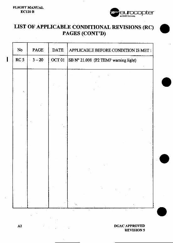
LIST OF APPLICABLE CONDITIONAL REVISIONS (RC) .PAGES (CONT'D)
No PAGE DATE APPLICABLE BEFORE CONDInON IS MET :
I RC 5 3 -20 OCTO~ SBN° 21.008 (p2 TEMP warning light)
.
.
.A2 DGAC APPROVED I
REVISION 5
. 8 'euroco p ter FLIGHT MANUALEC120B
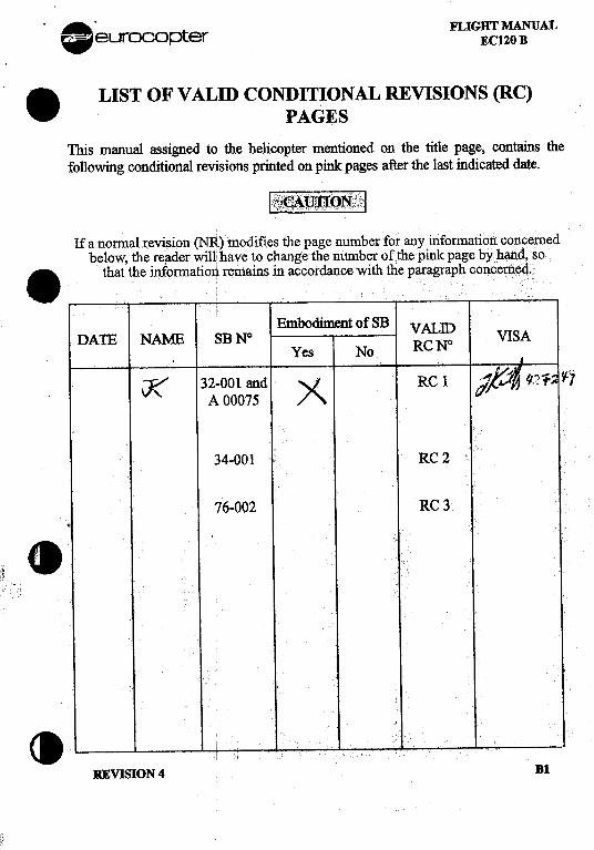
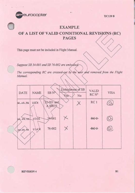
. LIST OF V ALm CONDITIONAL REVISIONS (RC)PAGES
This manual assigned to the helicopter mentioned on the title page, contains thefollowing conditional revisions printed on pink pages after the last indicated date.
Ifa normalrevision~R)modifies the page numberior any.informatiotlconcernedbelow,the re.ader WIll! have to change the number of the pmk page by hand,So. that the informatioti remains in accordance with the paragraph concem~.
DATE NAME SB N°Yes
iK 32-001 and V RC 1A 00075 A
34-001 RC 2
76-002 RC 3.<I
REVISION 4 Bl
. FliGHT MANUALeurocopter [!!BE] EC120 B
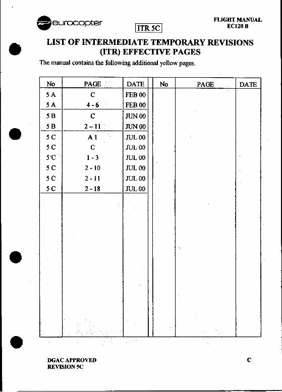
A. LIST OF INTERMEDIATE TEMPORARY REVISIONS..(ITR) EFFECTIVE PAGES
The manual contains the following additional yellow pages.
No PAGE DATE No PAGE DATE
5A C FEBOO
~ 4-6 FEBOO5B C JUNOO
8 ~ 2-11...~~5C Al JULOO
5C C JULOO
5'C 1 -3 JUL 00
5 C 2 -10 JUL 00
5C 2-11 JULOO
5 C 2 -18 JUL 00
8
eDGAC APPROVED CREVISION 5C
i
I
A FLIGHT MANUAL.eurocopter ~~ ECl20 B
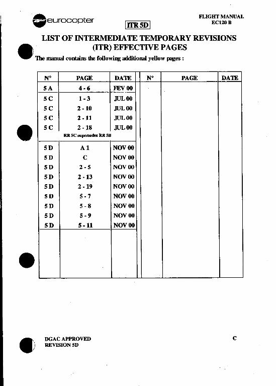
LIST OF INTERMEDIATE TEMPORARY REVISIONS. .(ITR) EFFECTIVE PAGES
The manual contaim die following OOditionai yellow ~es :
N° PAGE DAm N° PAGE DAm
SA 4.6 FEVOO
SC 1-3 JULOO
S C 2 -10 JUL 00
5 C 2 -11 JUL 00. SC 2-18 JULOORR sc supenedes RR SB
5D Al NOVOO
5D C NOVOO
5D 2-5 NOVOO
S D 2 -13 NOV 00
5 D 2 -19 NOV 00
5 D 5.7 NOV 00
5D 5-8 NOVOO
5D 5-9 NOVOO
5D S -11 NOVOO.. DGAC APPROVED C
! REVISION SD
. FLIGHT MANUALeurocOI=)ter EC120 B
.LIST OF INTERMEDIATE TEMPORARY REVISIONS(ITR) EFFECTIVE PAGES
The manual contains the following additional yellow pages.
No PAGE DAlE No PAGE DAlE.I .
...
. DGAC APPROVED CREVISION 4
I
..FLIGBTMANUAL 8 e roco p terEC120 B U
:LIST OF INTERMEDIATE TEMPORARY REVISIONS .(ITR) REQUIRING NO APPROVAL
The manual contains the following additional yellow pages.
No PAGE DATE No PAGE DATE
..' ..
...
.D REVISION 4 .
-
. FLIGHT MANUAL" eurocopter EC120B
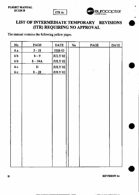
[~~J.LIST OF INTERMEDIATE TEMPORARY REVISIONS
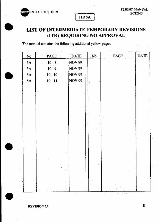
(ITR) REQUIRING NO APPROVAL
The manual contains the following additional yellow pages.
No PAGE DATE No PAGE DATE
5A 10-8 NOV99
5A 10-9 NOV99
-5A 10-10 NOV99
5A 10 -11 NOV 99
8
8REVISION SA D
FLIGHT MANUAL . ' I
EC120 B ~~J ~~opter.
LIST OF INTERMEDIATE TEMPORARY REVISIONS 8(ITR) REQUIRING NO APPROVAL
The manual contains the following yellow pages.
No PAGE DATE No PAGE DATE
6 a 5 -18 FEB 02
6b 8-9 JULY 02
6b 8-24A JULY 02
86c D JULY 02
6c 8-28 JULY 02
8
8D REVISION 6c
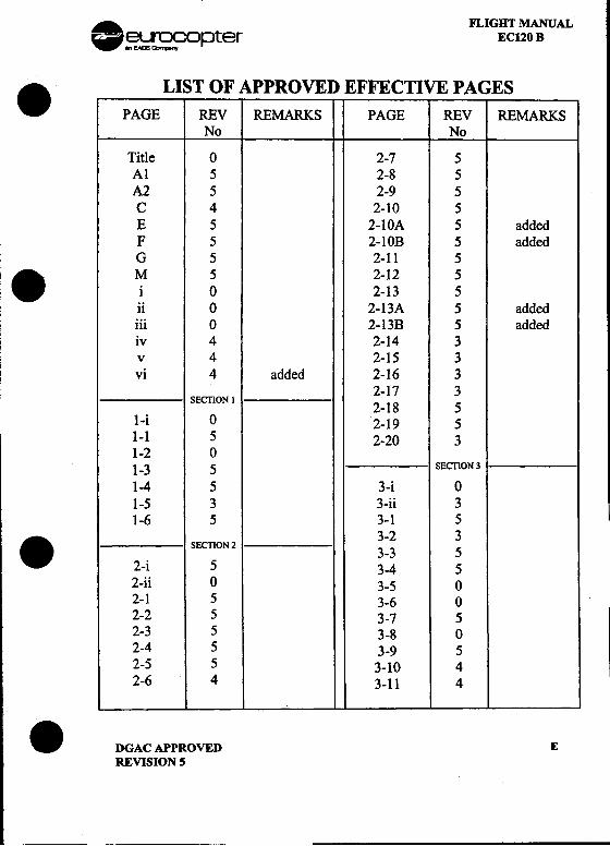
. FLIGHT MANUAL~~opter EC120 B. LIST OF APPROVED EFFECTIVE PAGESPAGE REV REMARKS PAGE REV REMARKS
No No
Title 0 2-7 5Al 5 2-8 5A2 5 2-9 5C 4 2-10 5E 5 2-IOA 5 addedF 5 2-IOB 5 addedG 5 2-11 5
. M 5 2-12 5i 0 2-13 5ii 0 2-13A 5 addediii 0 2-13B 5 addediv 4 2-14 3v 4 2-15 3vi 4 added 2-16 3
2-17 3SECTION 1 2-18 5
I-i 0 2-19 51-1 5 2-20 31-2 01-3 5 SEcnON3
1-4 5 3-i 01-5 3 3-ii 31-6 5 3-1 5
. 3-2 3
SEcnON2 3-3 5
2-i 5 3-4 52-ii 0 3-5 02-1 5 3-6 02-2 5 3-7 52-3 5 3-8 02-4 5 3-9 52-5 5 3-10 42-6 4 3-11 4
.DGAC APPROVED EREVISION 5
FLIGHT MANUAL .~C120 B ~~opter
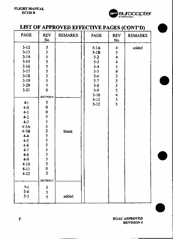
LIST OF APPROVED EFFECTIVE PAGES (CONT'D) .PAGE REV REMARKS PAGE REV REMARKS
No No
3-12 5 5-1A 4 added3-13 5 5-1B 53-14 5 5-2 43-15 5 5-3 43-16 5 5-4 53-17 5 5-5 43-18 5 5-6 3 .3-19 5 5-7 53-20 5 5-8 53-21 0 5-9 5
5-1 0 4SEcnON 45-11 5
4-i 5 5-12 54-ii 04-1 04-2 54-3 5
4-3A 54-3B 2 blank4-4 54-5 54-6 54-7 5 .4-8 54-9 54-10 54-11 04-12 5
SEcnON 5
5-i 55-ii 55-1 5 added..
F DGACAPPROVEDREVISION 5
. FLIGHT MANUAL~~o~)ter EC120 B
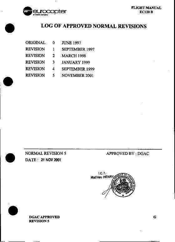
.LOG OF APPROVED NORMAL REVI:SIONS
ORIGINAL 0 JUNE 1997
REVISION 1 SEPTEMBER 1997
REVISION 2 MARCH 1998
REVISION 3 JANUARY 1999
REVISION 4 SEPTEMBER 1999
REVISION 5 NOVEMBER 2001.
. NORMAL REVISION 5 APPROVED BY : DGAC
DATE: 21 NOV 2001
I.Mathie
.DGAC APPROVED GREVISION 5
-
FLIGHT MANUAL AEC120 B .~~ opter
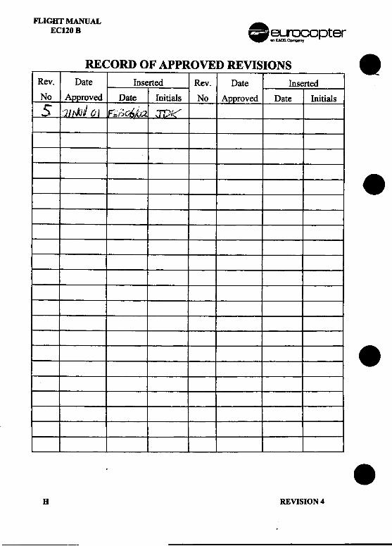
RECORD OF APPROVED REVISIONS .Rev. Date Inserted Rev. Date Inserted
No ~roved Date Initials No Approved Date Initials
5 :I'J,JjJ O~ F':.;r;~}.;:;' JT)/,-""
.
.
.H REVISION 4
--
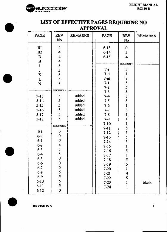
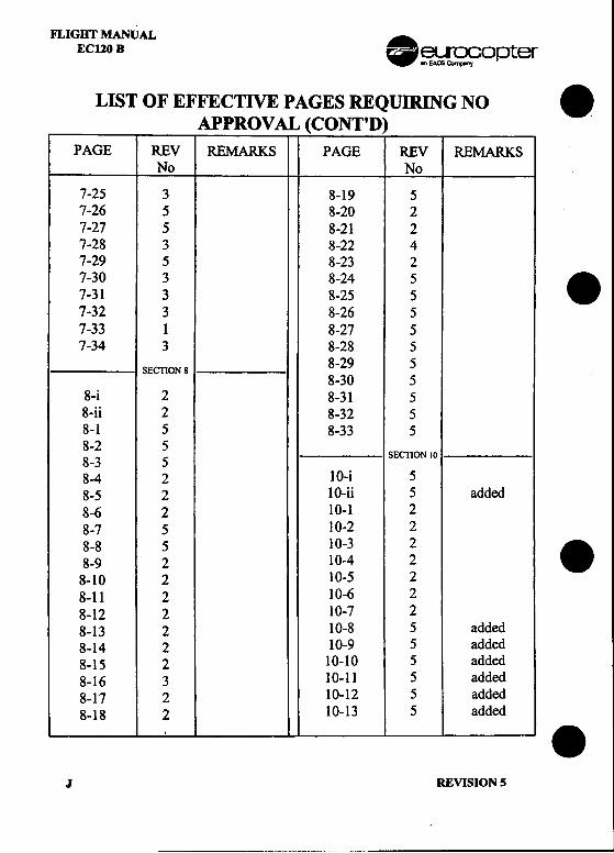
FLIGHT MANUAL.~~opter EC120 B. LIST OF EFFECTIVE PAGES REQUI~G NO
APPROV ALPAGE REV REMARKS PAGE REV REMARKS
No No
Bl 4 6-13 0B2 4 6-14 5D 4 6-15 4H 4 SEcnON 7I 5J 5 7-i 3K 5 7-ii 1
. L 4 7-iii 3N 5 7-1 5
7-2 5SEcnON5 7-3 5
5-13 5 added 7-4 35-14 5 added 7-5 35-15 5 added 7-6 15-16 5 added 7-7 35-17 5 added 7-8 15-18 5 added 7-9 1
7-10 1SEcnON6 7-11 5
6-i 0 7-12 56-ii 0 7-13 56-1 0 7-14 56-2 4 7-15 1
. 6-3 5 7-16 56-4 5 7-17 16-5 0 7-18 56-6 0 7-19 56-7 0 7-20 16-8 5 7-21 46-9 5 7-22 56-10 5 7-23 1 blank6-11 5 7-24 16-12 0
.REVISION 5 I
~
FLIGHT MANUALECI20 B .~~ opter
LIST OF EFFECTIVE PAGES REQUIRING NO .APPROVAL (CONT'D)
PAGE REV REMARKS PAGE REV REMARKSNo No
7-25 3 8-19 57-26 5 8-20 27-27 5 8-21 27-28 3 8-22 47-29 5 8-23 27-30 3 8-24 5 .7-31 3 8-25 57-32 3 8-26 57-33 1 8-27 57-34 3 8-28 5
SEcnON 8 8-29 58-30 5
8-i 2 8-31 58-ii 2 8-32 58-1 5 8-33 58-2 58-3 5 SEcnON 10
8-4 2 10-i 58-5 2 10-ii 5 added8-6 2 10-1 28-7 5 10-2 28-8 5 10-3 2
.8-9 2 10-4 28-10 2 10-5 28-11 2 10-6 28-12 2 10-7 28-13 2 10-8 5 added8-14 2 10-9 5 added8-15 2 10-10 5 added8-16 3 10-11 5 added8-17 2 10-12 5 added8-18 2 10-13 5 added..
J REVISION 5
. FLIGHT MANUAL~~~opter EC120 B
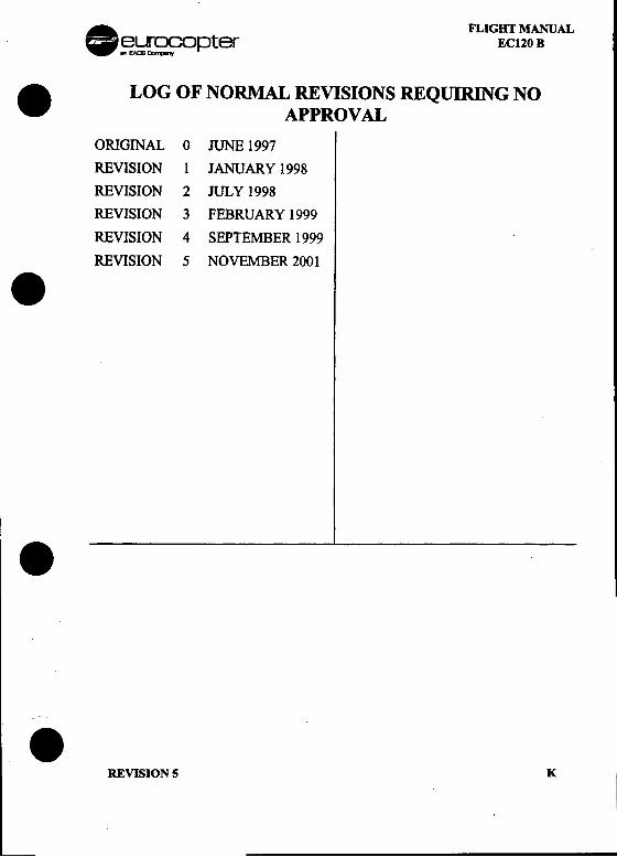
. LOG OF NORMAL REVISIONS REQUIRING NOAPPROVAL
ORIGINAL 0 JUNE 1997
REVISION 1 JANUARY 1998
REVISION 2 JULY 1998
REVISION 3 FEBRUARY 1999
REVISION 4 SEPTEMBER 1999
REVISION 5 NOVEMBER 2001.
.
.REVISION 5 K I
FLIGHT MANUAL .EC120 B ~~opter
RECORD OF REVISIONS REQUIRING NO APPROVAL .Rev. Date Inserted Rev. Date Inserted
No Date Initials No Date Initials
.
...
L REVISION 4
-~~ ---
. FLIGHT MANUAL~~opter EC120 B
.CUSTOMIZATIONA/C: EC 120B-S/N:
LIST OF ADDITIONAL APPROVED PAGES
PAGE REV REMARKS PAGE REV REMARKSN° N°.'.
.DGAC APPROVED MREVISION 5
'
FLIGHT MANUAL .ECl20 B ~~opter
CUSTOMIZATION .AIC : EC 120B -SIN :
LIST OF ADDITIONAL APPROVED PAGES
PAGE ~; REMARKS PAGE ~; REMARKS
.
.
.N REVISION 5
8 euroco p ter FLIGHT MANUALEC120 B
.MAIN TABLE OF CONTENTS
GENERAL
LIMITATIONS
.EMERGENCY PROCEDURES
NORMAL PROCEDURES
PERFORMANCE DATA(APPROVED PART I NON APPROVED PART)
WEIGHT AND BALANCE
SYSTEMS DESCRIPTION
HANDLING, SERVICING, MAINTENANCE
. FliGHT MANUAL SUPPLEMENTS(SPECIAL OPERAll0NS I OrnONAL EQUIPMENT)
OPERATIONAL TJPS
APPENDIX
.DGACAPPROVED iORIGINAL ISSUE
~
FLIGHT MANUAL AEC120B .eurocopter
ORGANIZATION OF THE MANUAL .')
1 GENERAL
To achieve the required degree of safety, this manual must be used inconjunction with the relevant regulations covering aircraft operation, such asaerial navigation laws in the operator's country. .It is essential for the crewto become familiar with the contents of this manual, special certificationrequirements and any information specific to customized configurations, andto check all revisions and related requirements. ...I
2 PAGE NUMBERING
The numbering of pages within each section consists of the section numberor designation, a dash and the consecutive number of the page beginningwith ".1"; e.g. for SECTION 3: 3-1, 3-2, etc.
Figures are likewise numbered consecutively by section, such as Fig. 3-1,Fig. 3-2, etc.
Exceptions:-The numbering of the TABLE OF CONTENTS pages preceding each
section in this manual consists of the section number, a dash and theconsecutive roman numeral (lower case) of the page, beginning with "i";e.g. for SECTION 3: 3-i, 3-ii, etc.
-The page numbers of the FLIGHT MANUAL SUPPLEMENTS (FMS) ~and APPENDICES consist of the section number, a dash, the number of ~ J
the SUPPLEMENT/APPENDIX, a dash and the consecutive number ofthe page; e.g. for FMS 9-17: 9-17-1, 9-17-2, etc.
-Figures within a FMS and APPENDIX are numbered consecutively, suchas Fig. 1, Fig. 2, etc.
The number of a blank page within a page block is printed on the precedingor following page by using dual page numbering; e.g. 3-9/(3-10 blank) or(3-9 blank)/3-10. .
ii DGAC APPROVEDORIGINAL ISSUE

8 euroco p ter FLIGHT MANUALECl20B
.If, at a later date, pages have to be added to the initial printing, the new pages.may carry the nmnber of the preceding page plus a letter suffIX; e.g. 2-6A, 2-
6B, etc.
3 FLIGHT MANUAL SUPPLEMENTS (FMS)
Information concerning optional equipment systems and operationalprocedures is covered by FMS.
. Each FMS is self-contained and corresponds in its general arrangement to thebasic FLIGHT MANUAL, but only additional information or different datawill be the subject of an FMS.
Each FMS, although complete in nature, shall therefore be used in conjunctionwith the basic FLIGHT MANUAL.
A LOG OF SUPPLEMENTS is provided in SUPPLEMENT 9.0 as an indexlisting the current supplements.
The manufacturer retains the right to convert optional equipment to standardequipment at any time as a product improvement program. FLM coverage ofthe converted optional equipment, however, will remain as an FMS inSECll0N 9 and also as an optional equipment item entry in theEQUIPMENT LIST.
4 REVISION SERVICE
This manual is kept up-to-date by normal revisions and intermediate temporary
.revisions.4.1 REVISIONS
Normal revisions are issued periodically. They are printed on white paper andincorporated into the manual in accordance with a "CHANGEINS1RUCll0NS" sheet which does not need to be inserted in the manual.Revisions are nmnbered consecutively beginning with the No. I.
.DGAC APPROVED ijiORIGINAL ISSUE
~
I.' '
FUGHT MANUAL .EC120 B eurocopter
4.2 INTERMEDIATE TEMPORARY REVISIONS (ITR) .I1Rs are provided to transmit information between revisions. They are printed
on yellow paper and are accompanied by an updated list of intermediatetemporary revision effective pages.The modified page is fIled in the manual facing the existing page which is tobe kept.
IIRs are identified by the number of the next normal revision and a lettersuffiX in normal alphabetical order. Several IIRs may be issued between twonormal revisions. All IJRs are canceled when the normal revision bearing thesame number is issued. If certain IIR provisions remain after the subsequentnoimal revision, they are confumed by a new I1R with another identification .code.
4.3 CONDITIONAL REVISIONS (RC)
The revised manual is issued on white pages and corresponds to the latestrecommended standard.
The conditional revisions, corresponding to the previous standard, are issuedon pink pages.
The list of pink pages corresponding to the modification aQQlicable to the.helicopter is given on white pages AI/A2 and/or 9-0-AI/9-0-A2.
This list of pink pages is subjected to approval and is updated byEUROCOPTER.
The list of ~ conditional revisions that must remain in the FLM because thecorresponding modification or SB has not been embodied to the aircraft, isgiven on pink pages B 1/B2 and/or 9-0-B 1/9-0-B2. This list of conditional .revisions is not subjected to approval and must be updated by the user.
The conditional revisions must not be removed from the FLM until themodification or SB has been embodied to the aircraft.
When the user embodies/removes a modification or SB, the correspondingpages of the conditional revision (pink pages) must be removedfrom/incorporated in FLM. The list of valid conditional revisions (pages Bl/B2and/or 9-0-B 1/9-0-B2) must be up-dated accordingly and validated by a visa.
iv DGAC APPROVED .REVISION 4I
-
.euroco~)ter FLIG:~t ~:VAL
.From the present revision onward, at the delivery of the aircraft, the list of the.valid modifications or SBs will be specified by EUROCOPTER on the pink
pages B 1/B2 and lor 9-0-B 1/9-0-B2, according to the configuration of theaircraft delivered. The valid conditional revisions are those validated by the
visas.
NOTEThe RC are unaffected by normal and intermediate temporary revisionsor by customization..
4.4 mENTIFYING REVISED MATERIAL
Changes (except as noted below) to the text and tables (including new materialon added pages) are indicated by a vertical line in the outer margin.
Change symbols will not be shown for:
-Introductory material.
-Blank space resulting from the deletion of text, or an illustration or a part ofan illustration, or table.
-Correction of minor inaccuracies, such as spelling, punctuation, relocationof material, etc., unless such correction changes the meaning of instructiveinformation and procedures.Changes to illustrations may be indicated by a miniature pointing hand. A
. vertical line next to changed text and call-outs on illustrations may be usedin lieu of a pointing hand. Shading and screening may be used for diagramsand schematics to highlight the area containing the changed information.Extensively changed presentations may be indicated by a screen b.otderaround the affected area.
.~ ~~- ~
.DGACAFFROVED v
REVISION 4
, .
FLIGHT MANUAL .EC120 B eurocopter
4.5 "ERRATUM" PROCEDURE .In the case of minor errors (typing errors, bad printing) likely to affect theWlderstanding of the text, the "ERRATUM" procedure is used to make quickcorrections between revisions.In this case, the pages affected by the procedure are re-issued completely andthe page number is Wlderlined for identification.These pages are summarized on an accompanying sheet which is not
i~entified.
5 CUSTOMIZA TION OF MANUAL (pRINTED ON .GREEN PAPER)
Special features of a particular aircraft may justify the incorporation, oncertain pages, of information differing from that of the basic manual andSupplements. These pages, printed on green paper, are filed in the manual overthe corresponding white pages.
The information contained in the green pages supersedes or supplements theinformation covered by the relevant white page. No white page is deleted.
.vi DGAC APPROVED .
REVISION 4
I
8 euroco p ter FLIGHT MANUALEC120 B
.SECTION 1
GENERALPage
1.1 TERMINOLOGY 1-11.2 MAIN AIRCRAFT DIMENSIONS 1 -21.3 DESCRIPTIVE DATA 1- 3
1.3.1 ENGINE 1- 3. 1.3.2 ROTOR 1 -3
1.3.3 TAn. ROTOR 1 -31.3.4 FUEL 1 -31.3.5 OIL 1 -3
1.4 SYMBOLS AND ABBREVIATIONS 1- 41.5 CONVERSION FACTORS 1 -6
1.5.1 METRIC UNITS TO ANGLO-SAXON UNITS 1 -61.5.2 ANGLO-SAXON UNITS TO METRIC UNITS .: 1 -6
LIST OF FIGURESPage
FIGURE 1-1: THREE-VIEW DRAWING 1-2..
DGAC APPROVED 1 -iORIGINAL ISSUE'--
. FLIGHT MANUAL~~r~n~Dpter EC120 B
.1.1 TERMINOLOGY.Unless otherwise specified in the text, altitudes are pressure-altitudes.
.Warnings, Cautions and Notes are used throughout this manual toemphasize important and critical instructions and are used as follows:
11811-AN OPERATING PROCEDURE, PRACTICE, ETC., WmCH,IF NOT CORRECTLY FOLLOWED, COULD RESULT INPERSONAL INJURY OR LOSS OF LIFE..
An operating procedure, practice, etc., which, if not strictlyobserved, could result in damage to, or destruction of equipment.
NOTEAn operating procedure, condition, etc., which is essential tohighlight.
USE OF PROCEDURAL WORDS
The concept of procedural word usage and intended meaning which has beenadhered to in preparing this manual is as follows:
."Shall" has been used only when application of a procedure is mandatory.
. ."Should" has been used only when application of a procedure isrecommended.
."May" and "need not" have been used only when application of aprocedure is optional.
."Will" has been used only to indicate future event or action, never toindicate a mandatory procedure.
~.DGACAPPROVED 1-1REVISION 5
,
I
FLIGHT MANUAL .EC120 B =. ~~rS:fopter
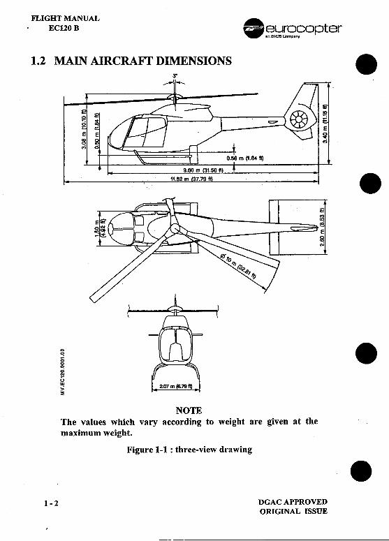
1.2 MAIN AIRCRAFT DIMENSIONS .3"
~
m (I.84ft) .
; .00;..uw,,;~
NOTEThe values which vary according to weight are given at themaximum weight.
Figure 1-1 : three-view drawing .1 -2 DGAC APPROVED
ORIGINAL ISSUE
,
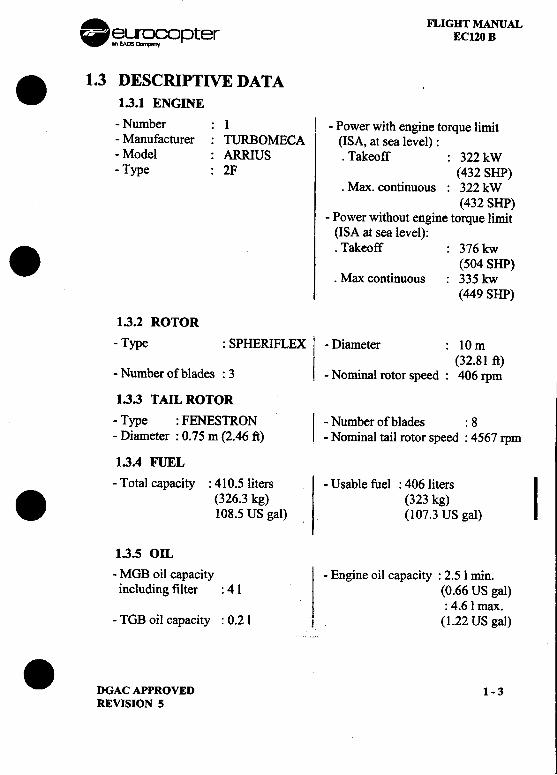
. FLIGHT MANUAL~~~opter EC120 B. 1.3 DESCRIPTIVE DATA1.3.1 ENGINE-Number : 1 I -Power with engine torque limit-Manufacturer: TURBOMECA (ISA, at sea level) :-Model : ARRIUS .Takeoff : 322 kW-Type : 2F (432 SHP)
.Max. continuous: 322 kW(432 SHP)
-Power without engine torque limit(ISA at sea level):
. .Takeoff : 376 kw(504 SHP)
.Max continuous: 335 kw
(449 SHP)
1.3.2 ROTOR
-Type : SPHERIFLEX I -Diameter : 10mI (32.81 ft)
-Number of blades : 3 .-Nominal rotor speed: 406 rpm
1.3.3 TAIL ROTOR
-Type: FENESTRON I -Number of blades : 8-Diameter: 0.75 m (2.46 ft) -Nominal tail rotor speed: 4567 rpm
1.3.4 FUEL-Total capacity: 410.5 liters -Usable fuel: 406 liters
I. (326.3 kg) (323 kg)
108.5 US gal) (107.3 US gal)
1.3.5 OIL-MOB oil capacity -Engine oil capacity: 2.5 1 min.including filter: 41 (0.66 US gal)
: 4.6 1 max.-TOB oil capacity: 0.21 1 (1.22 US gal)
.DGAC APPROVED 1- 3REVISION S
FLIGHT MANUAL .EC120 B ~~opter
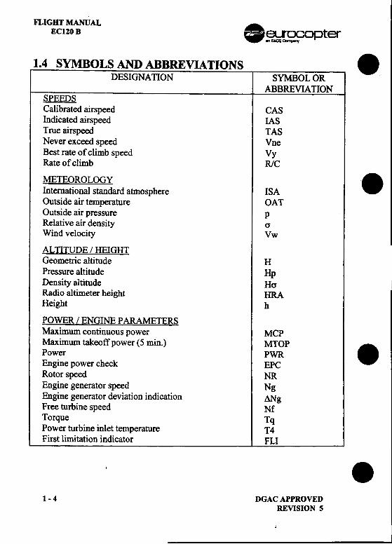
1.4 SYMBOLS AND ABBREVIATIONS .DESIGNATION SYMBOL OR
ABBREVIA nONSPEEDSCalibrated airspeed CASIndicated airspeed IASTrue airspeed TASNever exceed speed VneBest rate of climb speed VyRate of climb R/C
METEOROLOGY.International standard atmosphere ISA
Outside air temperature OATOutside air pressure pRelative air density crWind velocity Vw
ALTITUDE / HEIGHTGeometric altitude HPressure altitude HpDensity altitude Hcr iRadio altimeter height HRAHeight h
POWER / ENGINE PARAMETERSMaximum continuous power MCPMaximum takeoff power (5 min.) MTOP .Power PWREngine power check EPCRotor speed NREngine generator speed NgEngine generator deviation indication ANgFree turbine speed NfTorque TqPower turbine inlet temperature T4First limitation indicator FLI
..1-4 DGACAPPROVED
REVISION 5
.
II. FLIGHT MANUAL
eU"Ocopter EC120 B I~ EAlE ",",,"oy
. DESIGNATION .SYMBOL OR
ABBREVIATION
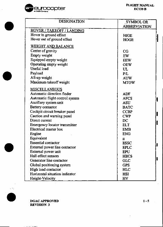
HOVER/TAKEOFF/LANDINGHover in ground effect HIGE IHover out of ground effect HOGE
WEIGHT AND BALANCECenter of gravity CGEmpty weight EWEquipped empty weight EEWOperating empty weight OEWUseful load UL. Payload P/LAll-up weight AUWMaximum takeoff weight MTOW
MISCELLANEOUSAutomatic direction finder ADFAutomatic flight control system AFCS IAncillary system unit ASUBattery contactor BA TCCockpit circuit breaker panel CCBP ICaution and warning panel CWPDirect current DC IEmergency locator transmitter EL TElectrical master box EMBEngine ENGEquivalent =Essential contactor ESSC I
. External power line contactor EPLCExternal power unit EPUHall effect sensors HECSGenerator line contactor GLC I
Global positioning system GPSHigh load contactor HLCHorizontal situation indicator HSIHeight-Velocity HV
.DGACAPPROVED 1-5REVISION 3
--
FLIGHT MANUALECI20 B .~~ opter
DESIONA TION SYMBOL OR .ABBREVIATION
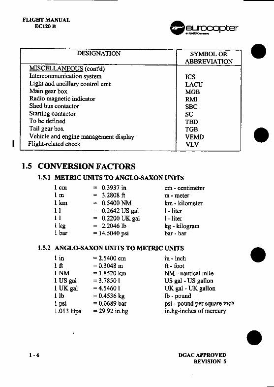
MISCELLANEOUS (cont'd)Intercommunication system ICSLight and ancillary control unit LACUMain gear box MOBRadio magnetic indicator RMIShed bus contactor SBCStarting contactor SCTo be defined TBDTail gear box TGB
.Vehicle and engine management display VEMDI Flight-related check VL V
1.5 CONVERSION FACTORS1.5.1 METRIC UNITS TO ANGLO-SAXON UNITS
1 cm = 0.3937 in cm -centimeter1 m = 3.2808 ft m -meter1 km = 0.5400 NM km -kilometer11 = 0.2642 US gal I -liter1 I = 0.2200 UK gal I -liter1 kg = 2.2046 Ib kg -kilogram1 bar = 14.5040 psi bar -bar
1.5.2 ANGLO-SAXON UNITS TO METRIC UNITS.1 in = 2.5400 cm in -inch
1 ft = 0.3048 m ft -foot1 NM = 1.8520 km NM -nautical mile1 US gal = 3.7850 I US gal -US gallon1 UK gal = 4.5460 I UK gal -UK gallonlIb = 0.4536 kg Ib -pound1 psi = 0.0689 bar psi -pound per square inch1.013 Hpa = 29.92 in.hg in.hg-inches of mercury .
1-6 DGACAPPROVEDREVISION 5
. FLIGHT :AL-leLrOcopter EC120 B.,EAOO(),n.-ny
I.SECTION 2
LIMITATIONS
Page
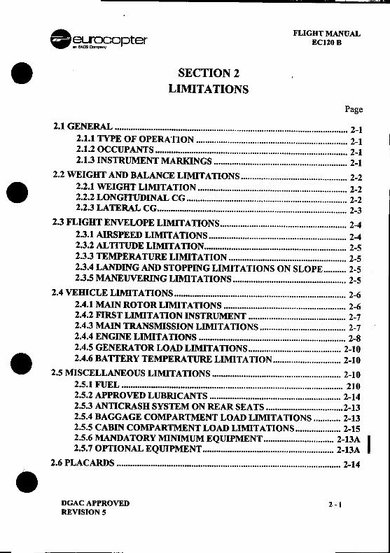
2.1 GENERAL 2-12.1.11YPE OF OPERATION , 2-12.1.2 OCCUPANTS 2-12.1.3 INSTRUMENT MARKINGS 2-1
2.2 WEIGHT AND BALANCE LIMITATIONS 2-2. 2.2.1 WEIGHT LIMITAnON 2-2
2.2.2 LONGITUDINAL CG 2-22.2.3 LATERAL CG 2-3
2.3 FLIGHT ENVELOPE LIMITATIONS 2-42.3.1 AIRSPEED LIMITATIONS 2-42.3.2 ALnTUDE LIMIT AnON , 2-52.3.3 TEMPERATURE LIMITAnON 2-52.3.4 LANDING AND STOPPING LIMITATIONS ON SLOPE 2-52.3.5 MANEUVERING LIMITATIONS 2-5
2.4 VEHICLE LIMITAnONS 2-62.4.1 MAIN ROTOR LIMITAnONS 2-62.4.2 FIRST LIMITA nON INSTRUMENT 2-72.4.3 MAIN TRANSMISSION LIMITATIONS 2-72.4.4 ENGINE LIMITATIONS 2-82.4.5 GENERATOR LOAD LIMIT A nONS 2-10
. .2.4.6 BATTERY TEMPERATURE LIMIT AnON 2-10
2.5 MISCELLANEOUS LIMITATIONS 2-102.5.1 FUEL 2102.5.2 APPROVED LUBRICANTS 2-142.5.3 ANnCRASH SYSTEM ON REAR SEATS 2-132.5.4 BAGGAGE COMPARTMENT LOAD LIMITATIONS 2-132.5.5 CABIN COMPARTMENT LOAD LIMITATIONS 2-152.5.6 MANDATORY MINIMUM EQUIPMENT 2-13A I2.5.7 OPTIONAL EQUIPMENT 2-13A
2.6 PLACARDS 2-14.DGAC APPROVED 2 -iREVISION 5
FLIGHT MANUALEC120 B .~~ opter
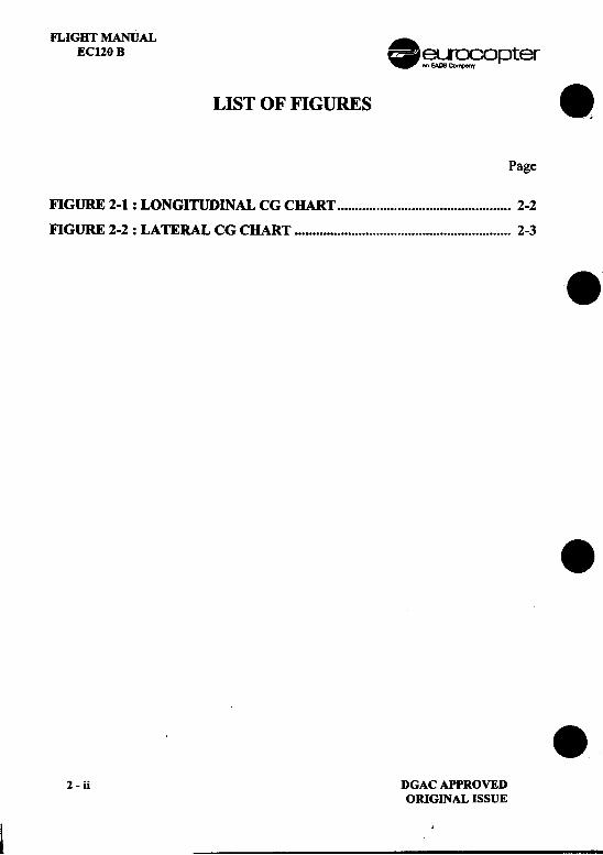
LIST OF FIGURES .Page
FIGURE 2-1 : LONGITUDINAL CG CHART 2-2
FIGURE 2-2 : LATERAL CG CHART 2-3 .
.
.2 -ii DGAC APPROVED
ORIGINAL ISSUE
~ ;
!
:.. FLIGHT MANUALr= eurocopter [E1J EC120 B ~
I :
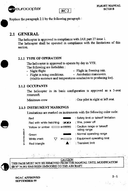
.Replace the paragraph 2.1 by the following paragraph: i
i
2.1 GENERAL .i1
The helicopter is approved in compliance with JAR part 27 issue 1. iThe helicopter shall be operated in compliance with the limitations of this I
.'Isection. j111i
2.1.1 TYPE OF OPERATION :.The helico~ter is appro.ved to operate by day in VFR. 1The folloWIng are forbIdden: .1-Night flight -Flight in freezing rain. I-Flight in icing conditio~s. -Aerobatics maneuvers.
(visible moisture and temperatures conducive to producing ice).
c
2.1.2 OCCUPANTS 'IiThe helicopter in its basic configuration is approved as a 5-seatrotorcraft. i'
Minimum crew : One pilot in right or left seat.
2.1.3 INSTRUMENT MARlaNGSLimitations are marked on instruments with the following color code:
Red -: Safety limit or takeoff limitation~ Red with white hatching ~ : Vne, power off~ Yellow or amber c==::J or~ : Caution range or takeoff
~ rating range'"m .~ Green -: Normal operating range~ White mark \7 orc=:Q : Equipment operating limitw~ Red triangle .& : Transient limit
! CAUTION~ 11nS PAGE MUST NOT B~ REMOVED FROM11ffi MANUAL UNTIL MODIFICATION~ SB~34.001 HAS BEEN EMBODIED TO 11ffi AIRCRAFT.
DGACAPPROVED 2-1
SEPTEMBER 99

. FLIGHT MANUAL~~[~,?opter EC120 B .
.2.1 GENERALThe helicopter is approved in compliance with JAR part 27 issue 1.The helicopter shall be operated in compliance with the limitations of thissection.
2.1.1 TYPE OF OPERATION
The helicopter is approved to operate:-by day in VFR.-by night in VFR, when the equipment required by operational
regulations are installed and serviceable.. The following are forbidden: I-Aerobatic maneuvers I
I-Flight in freezing rain.-Flight in icing conditions
(visible moisture and temperatures conducive to producing ice).
2.1.2 OCCUPANTS
-Minimum flight crew : One pilot in right or left seat.-Maximum number of seats : 5
I(including flight crew)
2.1.3 INSTRUMENT MARKINGS
Limitations are marked on instruments with the following color code:I:
.Red -: Safety limit or takeoff limitation,!.Ii Red with white hatching ~ : Vne, power offYellow or amber ~ or~ : Caution range or takeoff
~ rating range~ Green -: Normal operating range0
§ White mark V or ~ : Equipment operating limit
~ Red triangle ...: Transient limit
I .
!..DGAC APPROVED 2-1REVISION 5
FLIGHT MANUALEC120 B .~~r~c:?°pter
On the VEMD, related numerical value of parameters underlined:.-in yellow when the parameter is in caution or takeoff range,
-in red when at or above safety limit or maximum takeoff power.Moreover, to enforce safety, red underlining flashes.
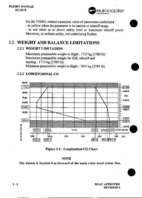
2.2 WEIGHT AND BALANCE LIMITATIONS
2.2.1 WEIGHT LIMITATION
Maximum permissible weight in flight: 1715 kg (3780 1b)Maximum permissible weight for JOE, takeoff andlanding: 1715 kg (3780 lb).Minimum permissible weight in flight: 1035 kg (2284Ib). .
2.2.2 LONGITUDINAL CG
~ ~~~ ~~~~~~~~~~~~~~~~~~~~~~~ ~~~~~~~~~~~~~~~~~~~j~~~ j~j~~~~~~~j~j~j~~~~~~~~ j~j~~~j~~~~jj~~j~j~~~j: :~j~j~jjj~~j~j~~j~j~~~j ~~~~j~j~j~~j~jj~~~~~j~~ ~j~~~~~~~~~~~~~~~:j~~: ~~~~~j~~~~~~~j~~~~.
1600
(kg)
1400
~1200
[IQm
..C!
g0
0
.;..~ (in),;~
Figure 2-1 : Longitudinal CG Chart
NOTE
The datum is located 4 m forward of the main rotor head center line. .2 -2 DGAC APPROVED
REVISION 5
~~~
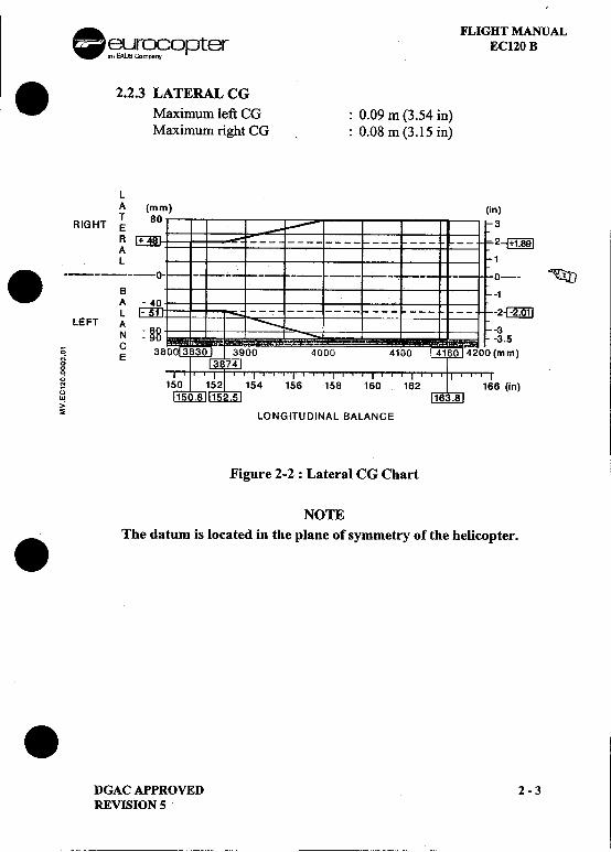
.A. FLIGHT MANUAL-~~[~n~opter EC120 B. 2.2.3 LATERAL CG
Maximum left CG : 0.09 m (3.54 in)Maximum right CG : 0.08 m (3.15 in)
LA .)
TRIGHT E
R ~AL.
;- 1-- ~AL 2-c::g;m]
LEFT A 3N 3.5
-C mm)~ E
0
g~ (in)0w,,:~ LONGITUDINAL BALANCE
Figure 2-2 : Lateral CG Chart
NOTEThe datum is located in the plane of symmetry of the helicopter..
.DGAC APPROVED 2 -3REVISION 5
FLIGHT MANUALECl20B
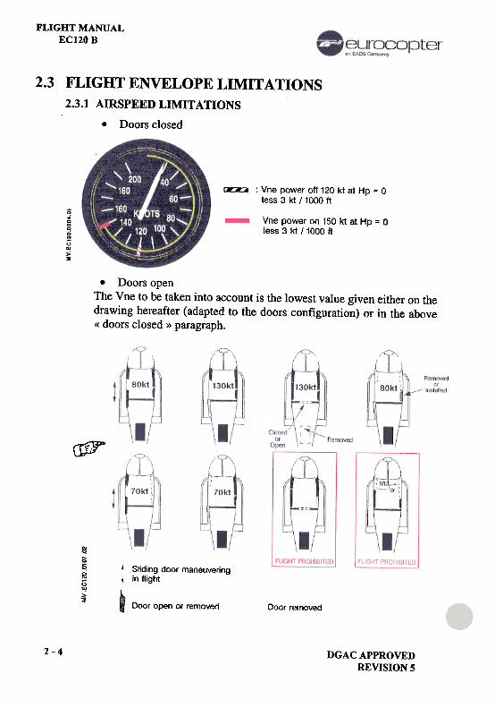
2.3 FLIGHT ENVELOPE LIMITATIONS
~ : Vne power off 120 kt at Hp = 0less 3 kt / 1000 ft
(;.;00~~(;w>'2
Vne power on 150 kt at Hp = 0less 3 kt /1000 ft
.Doors openThe Vne to be taken into account is the lowest value given either on thedrawing hereafter (adapted to the doors configuration) or in the above« doors closed » paragraph.
crf}r
~sc:0'"~~
Sliding door maneuveringin flight
I
Door open or removed Door removed
2-4 DGAC APPROVEDREVISION 5
2.3.1 AIRSPEED LIMITATIONS
.Doors closed
. ..RIGHT MANUALeurocopter ~lJ .EC120 Be
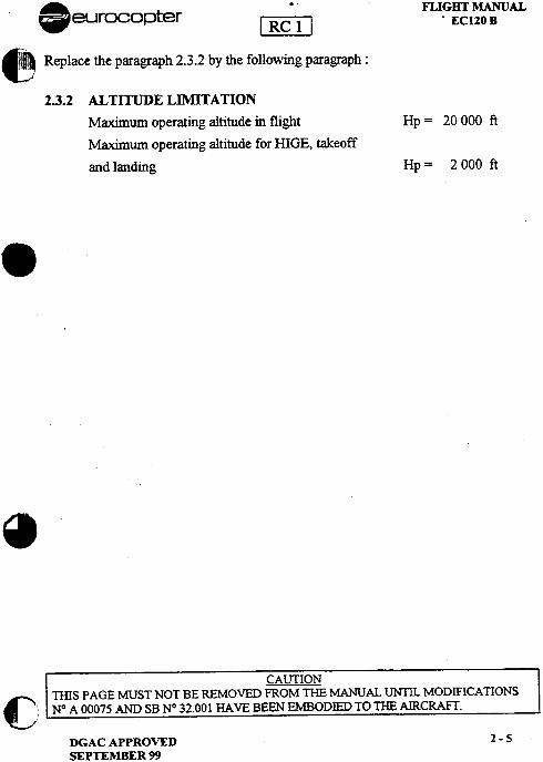
Replace the paragraph 2.3.2 by the following paragraph:
2.3.2 ALTITUDE LIMITATIONMaximum operating altitude in flight Hp = 20 000 ft
Maximum operating altitude for HIGE, takeoffand landing Hp = 2 000 ft.
ra
CAUTIONC rnIS PAGE MUST NOT BE REMOVED FROM THE MANUAL UN11L MODIFICATIONS) ~ A 00075 AND SB N° 32.001 HAVE BEEN EMBODIED TO THE AIRCRAFT.
DGACAPPROVED 2-5SEPTEMBER 99
..FLIGHT MANUALW ~~r~n~opter EC120 B
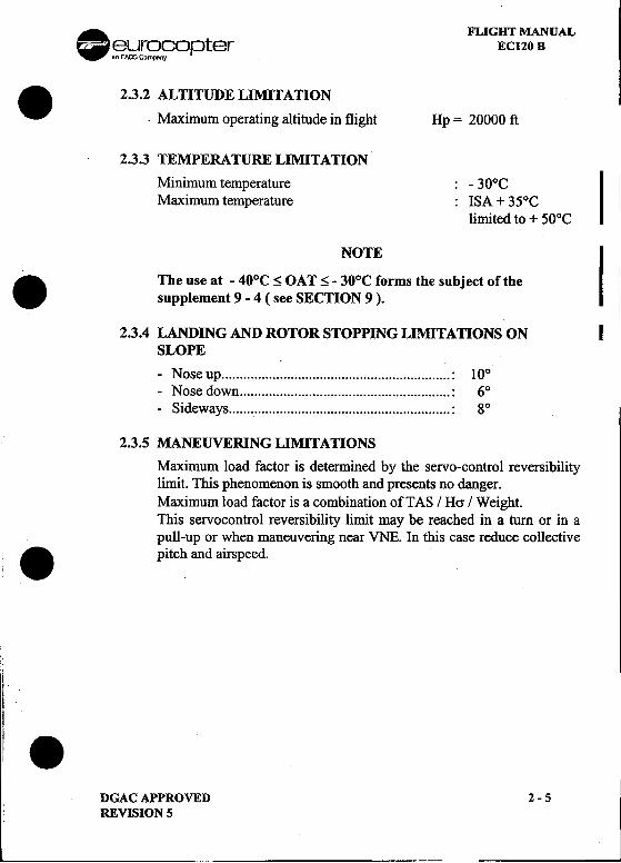
.2.3.2 ALTITUDE LIMITATION.Maximum operating altitude in flight Hp = 20000 ft
2.3.3 TEMPERATURE LIMITATION
Minimum temperature : -30°C I IMaximum temperature : ISA + 35°C i
limited to + 50°C
NOTEI. The use at -40°C ~ OAT ~ -30°C forms the subject of the i
supplement 9 -4 ( see SECTION 9 ). I
2.3.4 LANDING AND ROTOR STOPPING LIMITATIONS ON ISLOPE-Nose up : 10°-Nose down : 6°-Sideways : go
2.3.5 MANEUVERING LIMITAllONS
Maximum load factor is determined by the servo-control reversibilitylimit. This phenomenon is smooth and presents no danger;Maximum load factor is a combination ofTAS / Hcr / Weight.This servoconu'ol reversibility limit may be reached in a turn or in apull-up or when maneuvering near VNE. In this case reduce collectivei:
.pitch and airspeed.
it .
I.'.DGAC APPROVED ~ -5 REVISION 5
..
FLIGHT MANUALEC120B
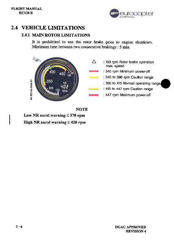
2.4 VEffiCLELIMITATIONS2.4.1 MAINROTORLIMITATIONS
It is prohibited to use the rotor brake prior to engine shutdown.Minimum time between two consecutive brakings : 5 min.
~ : 150 rpm Rotor brake operationmax. speed
: 340 rpm Minimum power-off
: 340 to 390 rpm Caution range
: 390 to 415 Normal operating range.
: 415 to 447 rpm Caution range
: 447 rpm Maximum power-off
~"'000..N
[;II!>~
NOTELow NR aural warning S 370 rpm
High NR aural warning;?: 420 rpm
2-6 DGAC APPROVEDREVISION 4
FLIGHT MANUALEC120 B
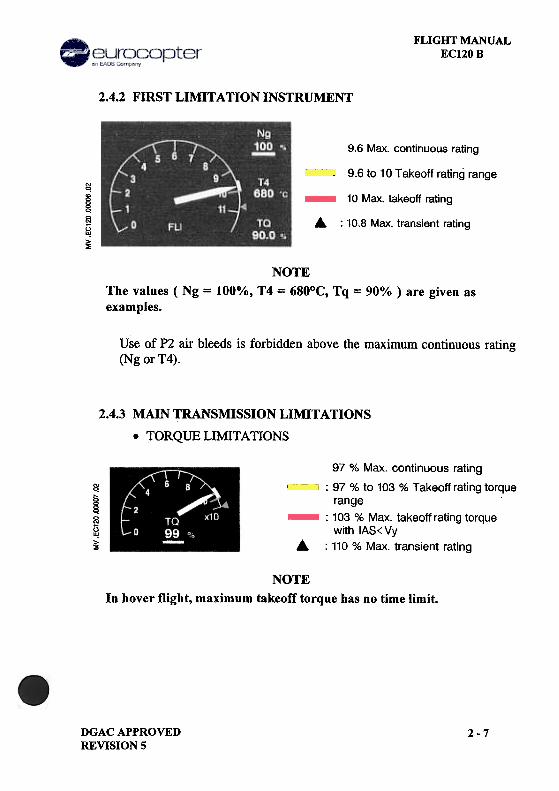
2.4.2 FIRST LIMITATION INSTRUMENT
9.6 Max. continuous rating
9.6 to 10 Takeoff rating range'"q
~q~~>~
10 Max. takeoff rating
...:
10.8 Max. transient rating
NOTEThe values ( Ng = 100%, T4 = 680°C, Tq = 90% ) are given as
examples.
Use of P2 air bleeds is forbidden above the maximum continuous rating(Ng or T4).
2.4.3 MAIN TRANSMISSION LIMITATIONS
.TORQUE LIMITATIONS
~§~~~~
..
97 % Max. continuous rating
: 97 % to 103 % Takeoff rating torque
range: 103 % Max. takeoff rating torque
with IAS<Vy
: 110 % Max. transient rating
NOTEIn hover flight, maximum takeoff torque has no time limit.
DGAC APPROVEDREVISION 5
2-7
FLIGHT MANUALEC1.20 B
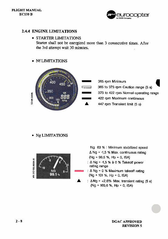
2.4.4 ENGINE LIMITATIONS
.STARTER LIMITATIONSStarter shall not be energized more than 3 consecutive times. Afterthe 3rd attempt wait 30 minutes.
.NfLIMITATIONS
-~--
365 rpm Minimum ,
365 to 373 rpm Caution range (5 s)
373 to 422 rpm Normal operating range
422 rpm Maximum continuous
447 rpm Transient limit (5 s)
.0000
0N
§
.Ng LIMITAllONS
~=00~0OJ
UUJ>~
A
Ng 63 % : Minimum stabilized speed6 Ng = -1,5 % Max. continuous rating
(Ng ; 99,5 %, Hp = 0, ISA)
: 6 Ng ,. -1,5 % a 0 % Takeoff power
rating range: 6 Ng = 0 % Maximum takeoff rating(Ng = 101 %, Hp = 0, ISA)
: 6 Ng = +2.6% Max. transient rating (5 s)(Ng = 103,6 %, Hp = 0, 'SA)
2-8 DGAC APPROVEDREVISION 5
FLIGHT MANUALEC120 B
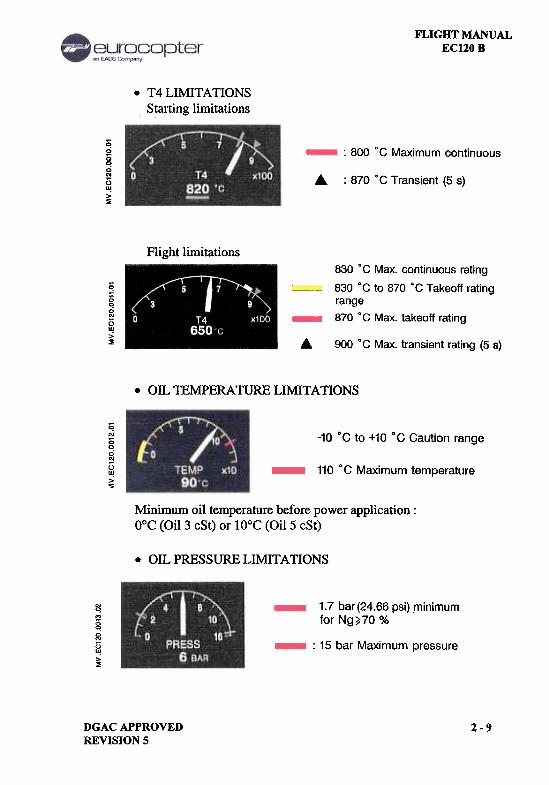
.T4LIMITATIONSStarting limitations
0.;00.;'"13"!>~
: 800 °C Maximum continuous
A. : 870 °C Transient (5 s)
Flight limitations
~1;'!0N
1)W
>~
830 D C Max. continuous rating
830 DC to 870 DC Takeoff rating
range870 DC Max. takeoff rating
6. 900 0 C Max. transient rating (5 s)
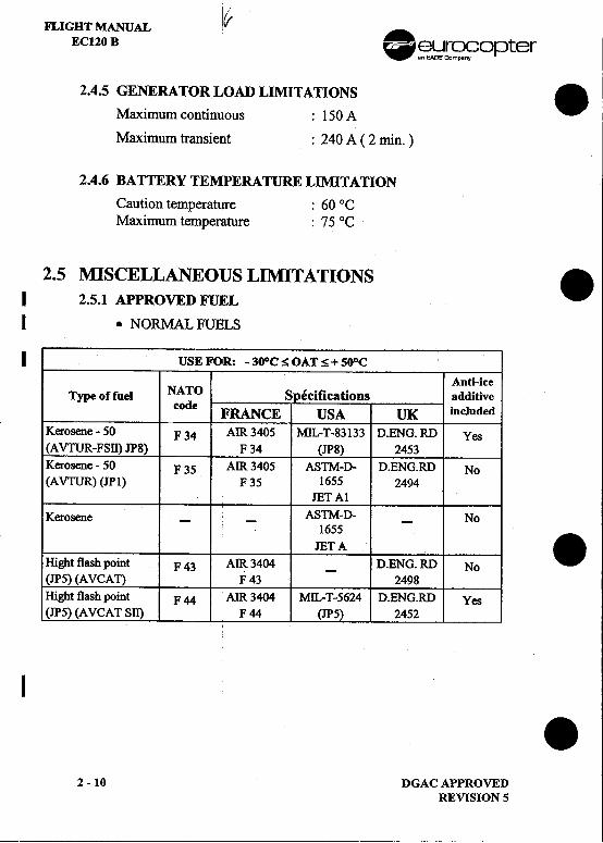
.OIL TEMPERATURE LIMITATIONS
~N
00
g5~>~
-10 DC to +10 DC Caution range
110 0 C Maximum temperature
Minimum oil temperature before power application:DOC (Oil 3 cSt) or 10°C (Oil 5 cSt)
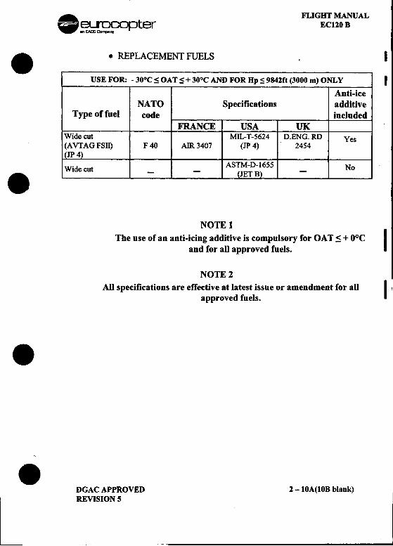
.OIL PRESSURE LIMITATIONS
1.7 bar (24.66 psi) minimumfor Ng~70 %
~'"
~0'"()II!
~: 15 bar Maximum pressure
DGAC APPROVEDREVISION 5
2-9
FLIGHT MANUAL I~EC120 B .~~~fopter
2.4.5 GENERATOR LOAD LIMITATIONS .Maximum continuous : 150 A
Maximum transient : 240 A ( 2 min. )
2.4.6 BATTERY TEMPERATURE LIMITATION
Caution temperature : 60 °C
Maximum temperature : 75 °C
2.5 MISCELLANEOUS LIMITATIONS .I 2.5.1 APPROVED FUELI .NORMAL FUELS
I USE FOR: -300C~OAT~+50oC
Anti-iceType of fuel NATO Specifications additive
code FRANCE USA UK included
Kerosene -50 F 34 AIR 3405 MIL-T-83133 D.ENG. RD Yes
(A VTUR-FSII) JP8) F 34 (JP8) 2453Kerosene -50 F 35 AIR 3405 ASTM-D- D.ENG.RD No(A VTUR) (IP1) F 35 1655 2494IETA1Kerosene --ASTM-D- -No
1655IETA .Hight flash point F 43 AIR 3404 -D.ENG. RD No
(JP5) (AVCAT) F43 2498Hight flash point F 44 AIR 3404 MIL-T-5624 D.ENG.RD Yes(IP5) (A VCA T SII) F 44 (IP5) 2452
I .2 -10 DGAC APPROVED
REVISION 5
. FLIGHT MANUAL~~opter EC120 B
..REPLACEMENT FUELS I
USE FOR: -30oC:$ OAT:$ + 30°C AND FOR Hp:$ 9842ft (3000 m) ONLY I
Anti-iceNATO Specifications additive
Type of fuel code includedFRANCE USA UK
Wide cut MIL-T-5624 D.ENG.RD Yes(A VTAG FSII) F 40 AIR 3407 (JP 4) 2454
I (JP 4)"d ASTM-D-1655 No.WI ecut --(JET B) -
NOTElThe use of an anti-icing additive is compulsory for OAT ~ + o°c
Iand for all approved fuels.
NOTE 2All specifications are effective at latest issue or amendment for all
Iapproved fuels.
.
.DGAC APPROVED 2 -10A(10B blank)REVISION 5 -I
FLIGHT MANUALEC120 B .~~ opter
.~-.
.
.
.2-10B DGACAPPROVED
REVISION 5
-
FLIGHT MANUALECl20B
.ADDITIVES
Anti-ice additive: If the fuel does not contain a freezing inhibitor andif the OAT is below or equal to DoC, the use of ananti-icing additive is compulsory. The additiveshall comply with French specification AIR 3652(equivalent to : MIL-I 27686, D-ENG-RD 2451,S748, PHILLIPS PFA/55 MB).
NOTEConcentration shall be between 0.10 % and 0.15 % by volume.
Anti-static additive: SHELL ASA 3, maximum concentration 0.0001% by volume.
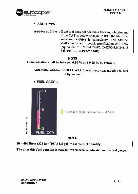
.FUEL GAUGE
0:.cq0'"(:;II!>~
NOTE10 = 4061itres (323 kg) (107.3 US gal) = usable fuel quantity.
The unusable fuel quantity is reached when zero is indicated on the fuel gauge.
DGACAPPROVEDREVISION 5
2-11
FLIGHT MANUALEC120 B .~~rs?f;?°pter
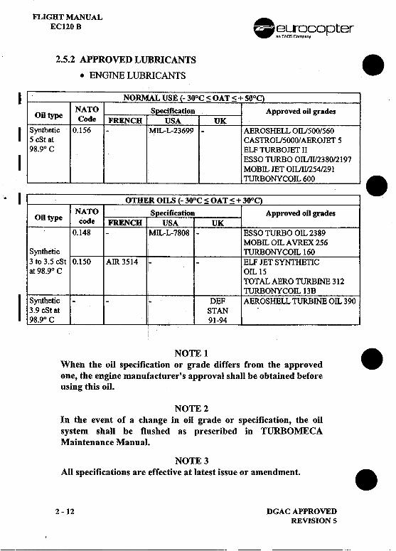
2.5.2 APPROVED LUBRICANTS ..ENGINE LUBRICANTS
I NO 30°C;SOAT;S+50°Con type NATO .on Approved oil grades
Code FRENCH UKI Synthetic 0.156 -MIL-L-23699 -AEROSHELL OIU500/560
5 cSt at CASTROU5000/ AEROJET 598.90 C ELF TURBOJET II
I ESSO TURBO OIL/II/2380/2197MOBIL JET O1L/II/254/291TURBONYCOIL 600 .
.I OTHER OILS -30°C S OAT;S + 300on ty NATO S ecification Approved oil grades
pe code FRENCH USA UK
0.148 -MIL-L-7808 -ESSOTURBO OIL 2389MOBIL OIL A VREX 256
Synthetic TURBONYCOIL 1603to3.5cSt 0.150 AIR 3514 --ELF JET SYNTHETICat 98.90 C OIL 15
TOTAL AER 0 TURBINE 312TURBONYCOIL 13BI Synthetic --!- DEF AEROSHELL TURBINE OIL 390
3.9 cSt at I STAN98.90 C 91-94
NOTE 1.When the oil specification or grade differs from the approved
one, the engine manufacturer's approval shall be obtained beforeusing this oil.
NOTE 2In the event of a change in oil grade or specification, the oilsystem shall be flushed as prescribed in TURBOMECAMaintenance Manual.
NOTE 3All specifications are effective at latest issue or amendment. .
2 -12 DGAC APPROVEDREVISION 5---
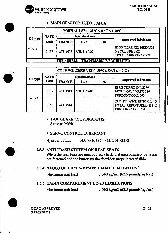
. FLIGHT MANUAL~~opter EC120 B. .MAIN GEARBOX LUBRICANTS
NORMAL USE ( -25°C S OAT s + 50oC )
NATO Specificationson type C d Approved lubricants0 e FRANCE USA UK
Mineral ESSO GEAR OIL MEDIUM0.155 Am 3525 MIL-L-6086 NYCOLUBE 3525
TOTAL AEROGEAR 823
THE (( SHELL » TRADEMARK IS PROHIBITED
COLD WEATHER USE (- 30oC S OAT S + OOC). Oil NATO Specificationstype Code FRANCE USA UK Approved lubricants
ESSO TURBO OIL 23890.148 AIR 3513 MIL-L-7808 MOBIL OILAVREX 256
TURBONYCOIL 160Synthetic
ELF JET SYNTHETIC OIL 150.150 Am 3514 TOTALAEROTURBlNE312
TURBONYCOIL 13B
.TAIL GEARBOX LUBRICANTSSame as MOB.
.SERVO CONTROL LUBRICANT
Hydraulic fluid NATO H 537 or MIL-H-83282. 2.5.3 ANllCRASH SYSTEM ON REAR SEATSIWhen the rear seats are unoccupied, check that unused safety belts are
not fastened and the button on the shoulder straps is not visible.
2.5.4 BAGGAGE COMPARTMENT LOAD LIMITAllONS
Maximum unit load : 300 kgim2 (62.5 pounds/sq feet)
2.5.5 CABIN COMPARTMENT LOAD LIMITATIONS
Maximum unit load : 300 kgim2 (62.5 pounds/sq feet)~
.DGAC APPROVED 2 -13REVISION S
FLIGHT MANUALEC120 B .~~ opter
2.5.6 MANDATORY MINIMUM EQUIPMENT .A minimum of two adequate radio / ICS audio headsets shall beonboard the helicopter, one worn by the pilot at the controls and one instand-by to monitor the audio warnings delivered through the ICSsystem.
2.5.7 OPTIONAL EQUIPMENTWhen optional equipment is installed, refer to supplements(SECTION 9) for additional limitations, procedures and performancedata. .
.
.2 -13A(13B blank) DGAC APPROVED
REVISION S
A FLIGHT MANUAL_~~opter EC120 B..
.
.DGAC APPROVED 2 -13BREVISION S
FLIGHT MANuAL .EC120 B ~~opter
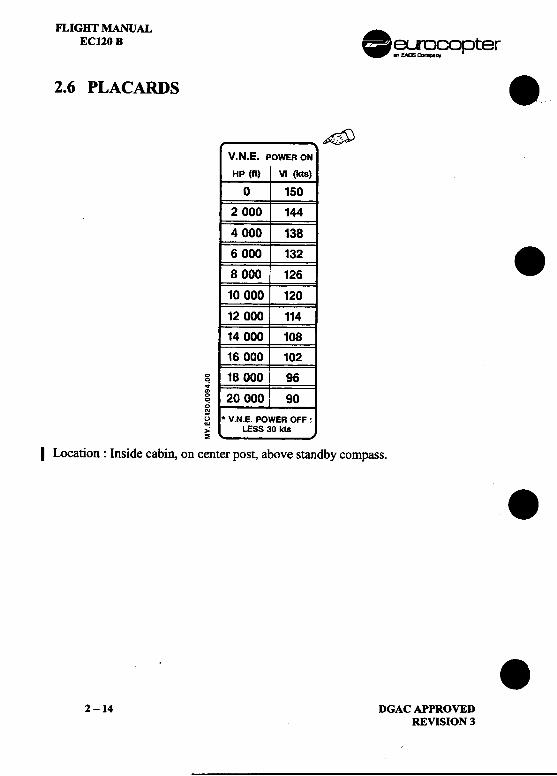
2.6 PLACARDS .~
V.N.E. POWER ON
HP (ft) Vi (kts)
0 150
2 000 1444 000 1386 000 132 .8 000 126
10 000 120
12 000 11414 000 10816000 102
g 18 000 96~~ 20 000 90cNU * V.N.E. POWER OFF:~ LESS 30 kts~
I Location: Inside cabin, on center post, above standby compass. ..
2 -14 DGAC APPROVEDREVISION 3
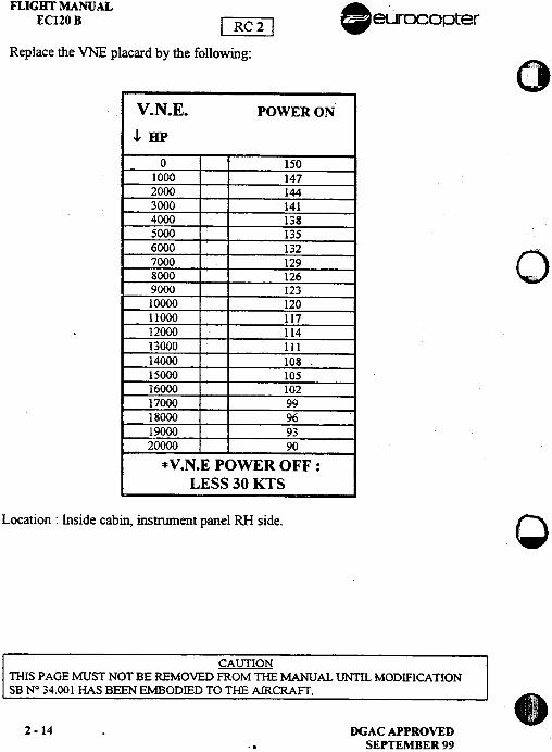
FLIGHT MANUAL .ECl20 B [~ eurocopter
Replace the VNE placard by the following: 0"',
V.N.E. POWER ON
.L.HP
0 150
1000 147
2000 144
3000 141
4000 138
5000 135
6000 132
07000 129
8000 126 "
9000 123
10000 120
11000 117
12000 114
13000 III
14000 108 .
15000 105
16000 102
17000 99
18000 96
19000 93
20000 90
*V.N.E POWER OFF:
LESS 30 KTS
Location: Inside cabin, instrument panel RH side. C
CAUTIONTHIS PAGE MUST NOT BE REMOVED FROM THE MANUAL UNTIL MODIFICATIONSB N° 34.00 1 HAS BEEN EMBODIED TO THE AIRCRAFT. .
2-14 DGACAPPROVED..SEPTEMBER 99
. ..FLIGHT MANUALeurocopter [~ .ECl20 B
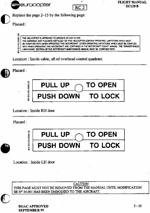
() Replace the page 2-15 by the following page:
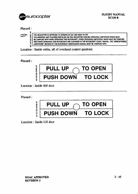
Placard:
00
~ n£ HEUCOPTER IS APPRa.'ED TO ~"TE BY DAY IN ~g 111E MARI<I~ AND PlACARDS ItSTAUED (J'/ ms HEUCOPTEFI C()'ITAIN OPERATlNG UMTTATlOOS WHlOi MUSTg BE ~8) W"TH ~ ~RAT1NG THIS ROTORCRAFT 0lHER ~ERATlNG UMTTATlONS 1'.l-l0i MUST BE COMPUED() ~ ~ OPERATING THS ROT{Yf:;RAFf ARE aJNTAlNED IN n£ ROTORCRAFT FUGHT MANUAL. 1HE "~NESS"! UMlTATlO'IS" SECTOj OF l}£ ROTORCRAFT MAI~ MANUAl t4JSr BE ~ ~>~
Location: Inside cabin, aft of overhead control quadrant
8::.c Placard:!!
; PULL UP TO OPEN0
g
~ PUSH DOWN TO LOCK~
Location: Inside RH door
Placard:
; PULL UP .TO OPEN0
g
.~ PUSH DOWN TO LOCK
Location: Inside LH door
CAlmONnns PAGE MUST NOT BE REMOVED FROM mE MANUAL UNTIL MODIFICATIONSB W 34.001 HAS BEEN EMBODIED TO THE AIRCRAFT.
~~
DGAC APPROVED 2 -15SEPTEMBER 99
FLIGHT MANUALECl20B
Placard:
Placard:
Location: Inside RH door
Placard:
g.;~0
gu~>5
Location: Inside LH door
2 -15DGAC APPROVEDREVISION 3
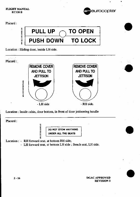
..FLIGHT MANUAL 8 euroco p terECl20B
Placard: .; PULL UP TO OPEN0
g
~ PUSH DOWN TO LOCK~
Location: Sliding door, inside LH side.
Placard :.
REMOVE COVER REMOVE COVER .AND PULL TO AND PULL TOJ E"T1l SON J ern soo
I ~'_illl_I' ~1_llil,r! 0 0
-LH side -RH side.
Location: Inside cabin, door bottom, in front of door jettisoning handle
Placard:00
! DO NOT STOW ANYTHING .u UNDER All THE SEATSw,.:~
Location: -RH forward seat, at bottom RH side;-LH forward seat, at bottom LH side; Bench seat, LH side.
2 -16 DGAC APPROVED .REVISION 3
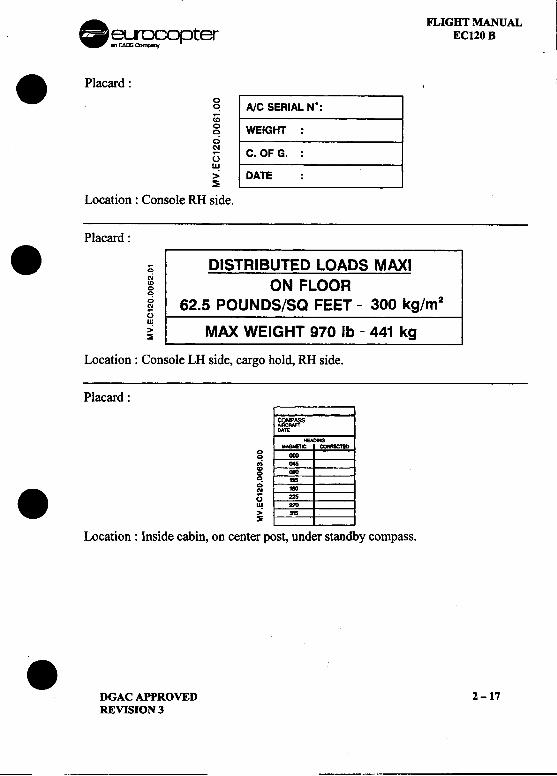
. FLIGHT MANUAL~~~opter EC120 8
.Placard: ~ A/C SERIAL N°:<0
~ WEIGHT:0Nu C. OF G. :w> DATE :~
Location: Console RH side.
Placard:
.~ DISTRIBUTED LOADS MAXI~ ON FLOOR0
~ 62.5 POUNDS/Sa FEET -300 kg/m20w
~ MAX WEIGHT 970 Ib -441 kg
Location: Console LH side, cargo hold, RH side.
Placard:
COOFASS-'DATE
OEADOGNAOIET1C~
g IN».; 0458 *". ...0. N ,~~ ~0W 210
> 315~
Location: Inside cabin, on center post, under standby compass.
.DGAC APPROVED 2-17REVISION 3
~ --,
FLIGHT MANUALEC120B .~~copter
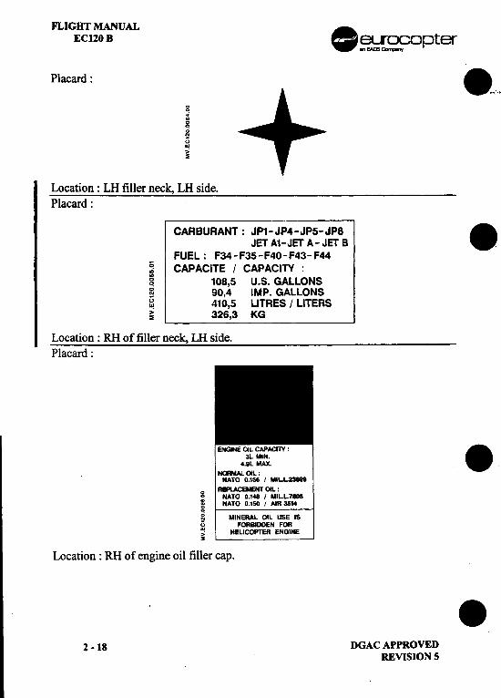
Placard: 8..,...
00
~guw,;~
Location: LH filler neck, LH side.Placard:
CARBURANT: JP1-JP4-JP5-JP8 .JET A1-JET A- JET B .FUEL: F34-F35-F40-F43-F44
~ CAPACITE I CAPACITY :~ 108,5 U.S. GALLONS~ 90,4 IMP. GALLONS~ 410,5 LlTRES I LITERS~ 326,3 KG
Location: RH of filler neck, LH side.Placard:
ENGNE OiL CAPACIlY :.3L MIN.
4.9L MAX.
~OIL:NATO 0.156 I MILL-
o REPlACEMENT OIL :..NATO 0.148 I MILL7808i NATO 0.150 I AIR 3S14
g MINERAL OIL USE ISu FORBIDDEN FOR~ HEUCOPTER ENGINE~
Location: RH of engine oil filler cap. .2 -18 DGAC APPROVED
REVISION S
..J
.FLIGHT MANUAL ~
EC120 B [~.eurocopter
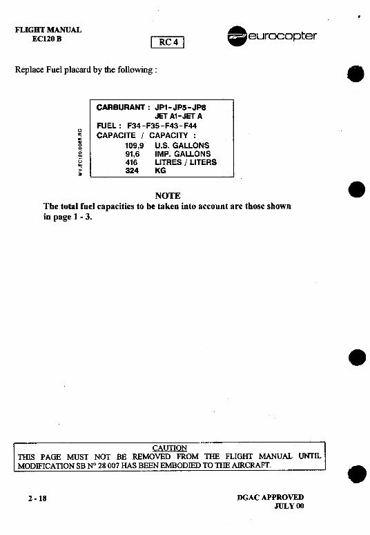
Replace Fuel placard by the following: 8
CARBURANT: JP1-JPS-JP8JET A1-JET A
FUEL: F34-F35-F43-F44u~ CAPACITE / CAPACITY :g 109,9 U.S. GALLONSg 91,6 IMP. GALLONS~ 416 LITRES / LITERS~ 324 KG
NOTE 8The total fuel capacities to be taken into account are those shownin page 1 -3.
8
CAUTIONTInS PAGE MUST NOT BE REMOVED FROM THE FLIGHT MANUAL UNTll.MODIFICATION SB N° 28 007 HAS BEEN EMBODIED TO THE AIRCRAFT. .
2 -18 DGAC APPROVEDJULY 00
. FLIGHT MANUAL~~opter EC120 B
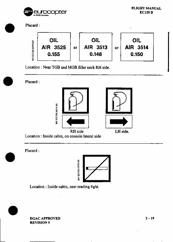
.Placard:
co OIL OIL OIL.;~ AIR 3525 or AIR 3513 or AIR 35140
§ 0.155 0.148 0.150>'~
Location: Near TGB and MGB filler neck RH side.
.Placard:
gQ) riJ00
! [E] [~JRH side LH side.
Location: Inside cabin, on console lateral side
Placard:
.g.;:;00N
0W>'~
Location: Inside cabin, near reading light.
.DGAC APPROVED 2 -19REVISION 5
---
FLIGHT MANUALEC120B
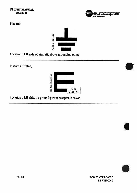
Placard:
00
oj~0.,;..uU!>~
Location: LH side of aircraft, above grounding point.
Placard (If fitted)
QC!......QC!QN
[)U!>~
Location: RH side, on ground power receptacle cover.
2-20 DGAC APPROVEDREVISION 3
FLIGHT MANUALEC120B
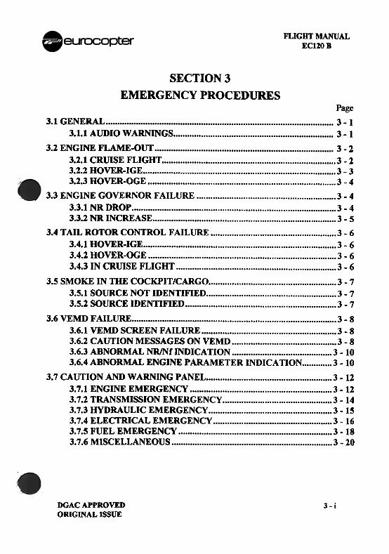
SECTION 3EMERGENCY PROCEDURES
Page3.1 GENERAL, 3 -1
3.1.1 AUDIO WARNINGS , 3 -1
3.2 ENGINE FLAME-OUT c 3 -2
3.2.1 CRUISE FLIGHT 3 -23.2.2 HOVER-IGE 3 -33.2.3 HOVER-OGE 3 -4
3.3 ENGINE GOVERNOR FAILURE 3 -43.3.1 NR DROP 3 -43.3.2 NR INCREASE 3 -5
3.4 TAIL ROTOR CONTROL FAILURE 3 -63.4.1 HOVER-IGE 3 -63.4.2 HOVER-OGE 3 -63.4.3 IN CRillSE FLIGHT 3 -6
3.5 SMOKE IN THE COCKPIT/CARGO 3 -73.5.1 SOURCE NOT IDENTIFIED 3 -73.5.2 SOURCE IDENTIFIED 3 -7
3.6 VEMD FAILURE 3 -83.6.1 VEMD SCREEN FAILURE 3 -83.6.2 CAUTION MESSAGES ON VEMD 3 -83.6.3 ABNORMAL NR/NfINDICATION 3 -103.6.4 ABNORMAL ENGINE PARAMETER INDICATION 3 -10
3.7 CAUTION AND WARNING P ANEL 3 -123.7.1 ENGINE EMERGENCY 3 -123.7.2 TRANSMISSION EMERGENCY 3 -143.7.3 HYDRAULIC EMERGENCY 3 -153.7.4 ELECTRICAL EMERGENCY 3 -163.7.5 FUEL EMERGENCY, 3 -183.7.6 MISCELLANEOUS 3 -20
DGAC APPROVEDORIGINAL ISSUE
3-i
..FLI G BT MANUAL .ECUO B eurocopter
3.8 VARIOUS FAILURES AND INCIDENTS NOT INDICATED ON page.THE CWP 3 -21
.
I
~J;AIi"
.3 -ii DGAC APPROVED
REVISION 3
~
. FLIGHT MANUAL
~~r~opter EC120 B
.3.1 GENERALEmergency procedures describe the actions that the pilot must take relative tothe various possible failures that can occur.Meanwhile, depending on the many variable external environment, such asthe type of terrain flown over, the pilot may have to adapt to the situationaccording to his experience.To help the pilot in his decision process, four recommendations are used :.LAND IMMEDIATELYSelf explanatory.
.LAND AS SOON AS POSSIBLE. Emergency conditions are urgent and require landing at the nearest landingsite at whicp a safe landing can be made.
.LAND AS SOON AS PRACTICABLEEmergency conditions are less urgent and in the pilot's judgement, he mayproceed to the nearest airfield where he can expect appropriate assistance.
.CONTINUE FLIGHTContinue flight as planned. Repair at the destination according to themaintenance manual.
NOTEImmediate actions that the pilot shall take are written in bold characters.
3.1.1 AUDIO WARNINGS
On the LACU, a pushbutton is used to activate the audio warning.When pressed in, the I HORN I light on the warning panel goes out.
NOTE.The pilot at the controls shall wear an adequate radio I ICS audio I I
headset to monitor the audio warnings delivered through the ICSsystem.
.GONGA gong is generated each time a red warning appears on the warningpanel.
.DGAC APPROVED 3 -1REVISION 5
FLIGHT MANUAL .EC120 B eurocopter
.CONTINUOUS TONE.Two continuous tone can be heard:
-When NR is b~low 370 rpm (310 Hz tone).-When maximum take-off limitations are exceeded for more than
1,5 seconds (285 Hz tone).1. Collective pitch REDUCE to maintain NR in green
I arc or power within limitations2. Engine parameters CHECK
.INTERMITTENT TONEI An intermittent tone (310 Hz) is heard when the NR is above
420 rpm..Collective pitch INCREASE to maintain NR in
green arc
Apply applicable procedure according to the situation.
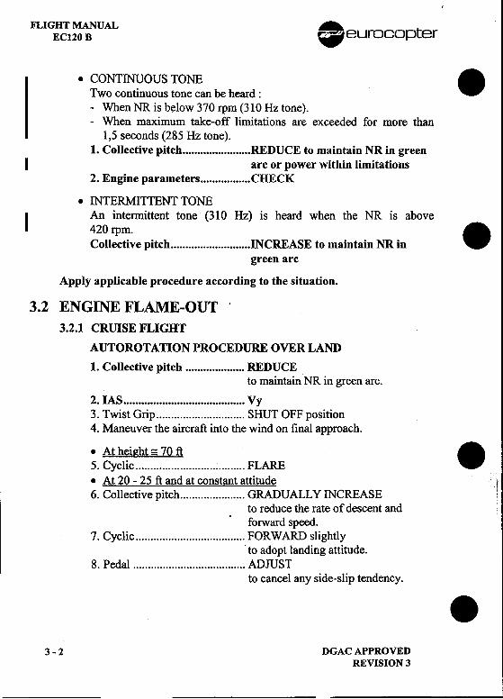
3.2 ENGINE FLAME-OUT'3.2.1 CRUISE FLIGHT
AUTOROTATION PROCEDURE OVER LAND
1. Collective pitch REDUCEto maintain NR in green arc.
2. IAS Vy3. Twist Grip SHUT OFF position4. Maneuver the aircraft into the wind on final approach.
;. ~~:l~~~~~.~.:.~..~ FLARE ..At 20 -25 ft and at constant attitude6. Collective pitch ,.. GRADUALLY INCREASE
to reduce the rate of descent andforward speed.
7. Cyclic FORWARD slightlyto adopt landing attitude.
8. Pedal ADJUSTto cancel any side-slip tendency. .
3 -2 DGAC APPROVED
REVISION 3
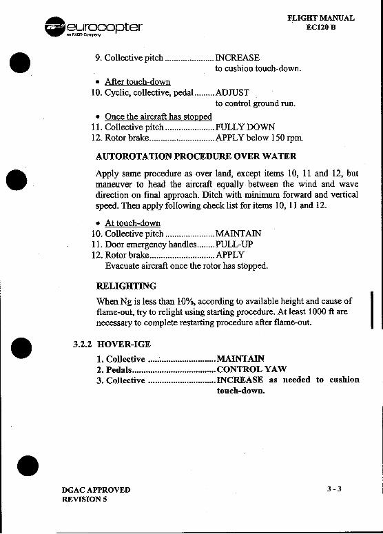
. FLIGHT MANUAL~~r~fopter EC120 B. 9. Collectivepitch INCRE.ASE
to cushion touch-down.
.Aftertouch-down10. Cyclic, collective, pedal ADJUST
to control ground run..Once the aircraft has stoQQ~d
11. Collective pitch ., FULLY DOWN12. Rotor brake APPL Y below 150 rpm.
AUTOROTATION PROCEDURE OVER WATER
. Apply same procedure as over land, except items 10, 11 and 12, butmaneuver to head the aircraft equally between the wind and wavedirection on final approach. Ditch with minimum forward and verticalspeed. Then apply following check list for items 10, 11 and 12.
.Attouch-downf 10. Collective pitch MAINTAIN
11. Door emergency handles PULL-UP12. Rotorbrake APPLY
Evacuate aircraft once the rotor has stopped.
RELIGHTING
When Ng is less than 10%, according to available height and cause ofIflame-out, try to relight using starting procedure. At least 1000 ft are
necessary to complete restarting procedure after flame-out.
.3.2.2 HOVER-IGE1. Collective MAINTAIN2. Pedals CONTROL YAW3. Collective INCREASE as needed to cushion
touch-down.
I
.DGACAPPROVED 3-3REVISION 5
FLIGHT MANUALECl20 B .~[~n~opter
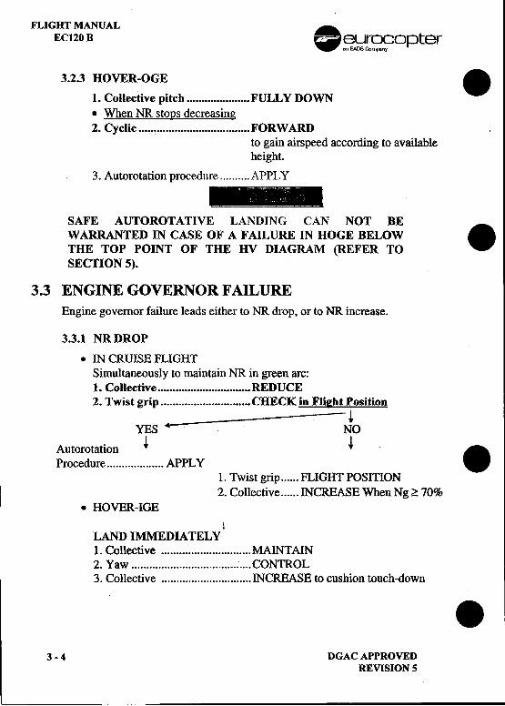
3.2.3 HOVER-OGE .
1. Collective pitch ~ FULLY DOWN.When NR stoQs decreasing2. Cyclic FORWARD
to gain airspeed according to availableheight.
3. Autorotation procedure APPL Y
, i
SAFE AUTOROTApVE LANDING CAN NOT BE.WARRANTED IN CAlSE OF A FAILURE IN HOGE BELOW
THE TOP POINT OF THE HV DIAGRAM (REFER TOSECTION 5).
3.3 ENGINE GOVERNOR FAILUREEngine governor failure leads either to NR drop, or to NR increase.
3.3.1 NR DROP
.IN CRUISE FLIGHTSimultaneously to maintain NR in green arc:1. Coliective REDUCE2. Twist grip CHECK in Flieht Position
---~YES .--,.-- NO
Autorotation ~ ~ .Procedure APPLY1. Twist grip FLIGHT POSITION2. Collective INCREASE When Ng?; 70%
.HOVER-IGE1
LAND Il\:IMEDI4TEL Y1. Collective MAINTAIN2. Yaw CONTROL3. Collective INCREASE to cushion touch-down .
3 -4 DGAC APPROVEDREVISION S
-
. FLIGHT MANUALeurocopter EC120 B
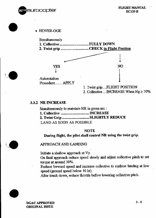
..HOVER-OGE
Simultaneously1. Collective FULLY DOWN2. Twist grip CHECK in Flil!ht Position
~ ~--~ 1
YES NO
(,-8 Autorotati~n jProcedure APPLY
1. Twist grip FLIGill POSmON2. Collective INCREASE When Ng ~ 70%
3.3.2 NR INCREASE
Simultaneously to maintain NR in green arc :1. Collective INCREASE2. Twist Grip SLIGIffL Y REDUCELAND AS SOON AS POSSllLE
NOTEDuring flight, the pilot shall control NR using the twist grip.
\,,8 APPROACH AND LANDING
Initiate a shallow approach at Vy.On final approach reduce speed slowly and adjust collective pitch to settorque at around 30%.Reduce forward speed and increase collective to cushion landing at lowspeed (ground speed below 10 kt).After touch down, reduce throttle before lowering collective pitch..
DGACAPPROVED 3-5ORIGINAL ISSUE
FLlGB-T MANUAL . tEC120 B eurocop er
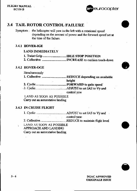
3.4 TAIL ROTOR-CONTROL FAILURE .Symptom: tlle helicopterwilryawtatlle Ieft with a rotational speed
depending on the amount of power-and the forward speed set atthe time of the failure.
3.4.1 HOVER-IGE !
LAND IMMEDIATELY1. Twist Grip :IBLE ST-oPPOSITION2. Collective INCREASE to cushion touch-down
3.4.2 HOVER-OGE .
Simultaneously1. Collective ~.~ REDUCEdependingonJl'V-3ilahle
.height2. Cyclic ~ F-oRW ARB to:gainspeed-3. Cyclic : AD.fUB~to-setIAS1(}Vy'and
control yawLAND AS SOON A,.I) POSSIBLE
Cany out an autorota6ve landing
3.4.3 IN CRUISE FLIGnT1. Cyclic ADJUSTto set IASto Vyand
i -contr,QI-Y3w
2. Collective L REDUCE to maintain flight level ...LAND AS SOON AS POSSIB.I"EAPPROACH AND LANDINGCarry out an autorotative randfug.
.3-6 DGACAPPROVED
ORIGINALEISSUE
. FLIGHT MANUAL-~.};Jr~n?Opter EC120 B
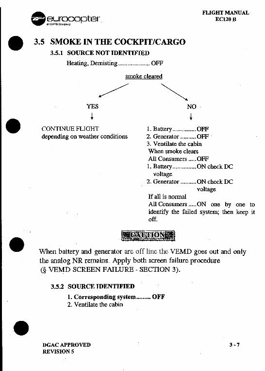
.3.5 SMOKE IN THE COCKPIT/CARGO3.5.1 SOURCE NOT IDENTIFIED
Heating, Demisting ,. OFF
smoke cleared
'*"//--/ ~YES NO
+ +
.CONTINUE FLIGHT 1. Battery , OFFdepending on weather conditions 2. Generator OFF
3. Ventilate the cabinWhen smoke clearsAll Consumers OFF1. Battery ON check DC
voltage2. Generator ON check DC
voltageIf all is normalAll Consumers ON one by one toidentify the failed system; then keep itoff.
"m.~!lm:rJ;'TmN81_~r~.\\7}1en batter)' and generato; are O~-fl:~1eth~ v'EMD goes out and only
the analog NR remaips. Apply both screen failure procedure(§ \/EMD SCREENiFAILURE -SECTION 3).
3.5.2 SOURCE IDENllFIED
1. Corresponding system OFF2. Ventilate the cabin.
DGACAPPROVED 3-7REVISION 5
FLIGHT MANUALEC120 B 0 ~~r~fopter
3.6 VEMD FAILURE .3.6.1 VEMD SCREEN FAILURE
.Failure of one screen
Failed Screen OFF.Read all information on the other screen.All information is available using the SCROLL pushbutton either onthe VEMD or on the collective pitch lever.
.Failure of both screens
Can be a single failure when battery and DC generator are in "OFF" .position (fire and smoke detection procedure).Set maximum power to establish level straight flight with the followinglaw:
IAS kt = 100 kt at sea level- (2 kt /1000 ft)
For landing canoy out a no hover landing.
3.6.2 CAUTION MESSAGES ON VEMD
When a parameter is off line, the parameter value is not displayed onthe VEMD upper screen and the parameter scale symbology isdisplayed in yellow. Caution messages are self explanatory and thepilot shall comply with the action requested. If no light is lit on thecaution and warning panel, no other action is required fI.om the pilot.
.LANE 1 (or 2,) FAILED---> PRESS-OFF 1 (or 2) : Self explanatory
..VEH PARAM OVER LIMIT: Vehicle parameter over limit
ENG PARAMi OVER LIMIT: Engine parameter over limit
These messages appear when a parameter usually displayed on thispage reaches a limitation, as the relevant (vehicle or engine) pages arenot displayed.-SCROLL : DEPRESS to reach the
relevant page and check theparameter. .
3-8 DGACAPPROVEDORIGINALEISSUE
. FLIGHT MANUAL£f!-~~fopter EC120 B
..CROSS TALKiFAILED---> PRESS pFF 2 : Self explanatory
.BRT CNTRL Fl.&\ILED : Brightness control hasI failed
.FU FAILED : One parameter (Ng, T4,---> CHEq P ARAM torque) is not consistent
-Parameterconsistancy : CHECKED-Relevant procedures in § ABNORMAL. ENGINE PARAMETER
INDICAllON (SECllON 3) : APPLY
.GENE PARAM bVERLIMIT : Generator parameter overlimit
BAT P ARAM OVER LIMIT: Battery parameter over limit
These messages appear when the relevant parameter is not displayed onthe vehicle page and when a limitation is reached.
r-~-L_~ LACUpushbutton : ACTUATE
.BAT. T : This message appearswhen battery temperatureis off line..
I1
.DGACAPPROVED 3-9REVISION 5
FLIGHT MANUAL .EC120 B ~'!;;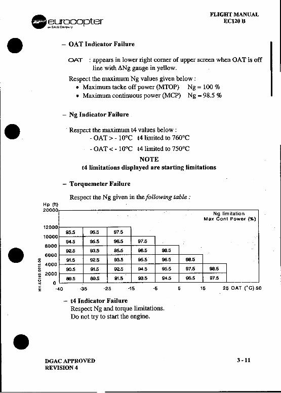
FLIGHT MANUAL.~rS?"~opter EC120 B
.-OAT Indicator Failure
OAT: appears in lower right comer of upper screen when OAT is offline with ANg gauge in yellow.
Respect the maximum Ng values given below:.Maximum tacke off power (MTOP) Ng = 100 %.Maximum continuous power (MCP) Ng = 98.5 %
-Ng Indicator Failure. Respect the maximum t4 values below:-OAT>-10°C t4limitedto760°C
-OAT < -100C t4limited to 750°C
NOTEt4 limitations displayed are starting limitations
-Torquemeter Failure
Respect the Ng given in the following table:Hp (ft)20000 I ... I .Ng limitation
I Max Cont Power (%)I
1200095.5 96.5 97.5
1000094.5 95.5 96.5 97.5
8000. 92.5 93.5 95.5 96.5 98.56000
g 91.5 92.5 93.5 95.5 96.5 98.5.; 4000 Ig 90.5 91.5 92.5 94.5 95.5 97.5 98.5g 2000 IU 89.5 89.5 91.5 93.5 94.5 96.5 97.5w 0 ~ -40 -35 -25 -15 -5 5 15 25 OAT ("C) 50
-t4 Indicator FailureRespect Ng and torque limitations.Do not try to start the engine..
DGAC APPROVED 3 -11REVISION 4
FLIGHT MANUALEC120 B
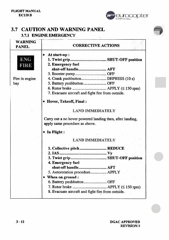
3.7 CAUTION AND WARNING PANEL3.7.1 ENGINE EMERGENCY
WARNINGPANEL CORRECTIVE ACTIONS
Fire in enginebay
.At start-up:1. Twist grip SHUT -OFF position2. Emergency fuel
shut-off handle AFT3. Booster pump OFF4. Crank pushbutton DEPRESS (10 s)5. Battery pushbutton OFF6. Rotor brake APPLY (~ 150 rpm)7. Evacuate aircraft and fight fire ft.om outside.
.Hover, Takeoff, Final:
LAND
IMMEDIATELY
Carry out a no hover powered landing then, after landing,apply same procedure as above.
In Flight:
LAND IMMEDIATELY
L Collective pitch """"""' ' REDUCE2. IAS Vy3. Twist grip SHUT-OFF position4. Emergency fuel
shut-off handle AFT5. Autorotation procedure APPLYWhen on ground:6. Battery pus~button OFF7. Rotor brake APPLY (~ 150 rpm)8. Evacuate aircraft and fight fire from outside.
3 -12 DGACAPPROVEDREVISION 5
FLIGHT MANUALEC120B
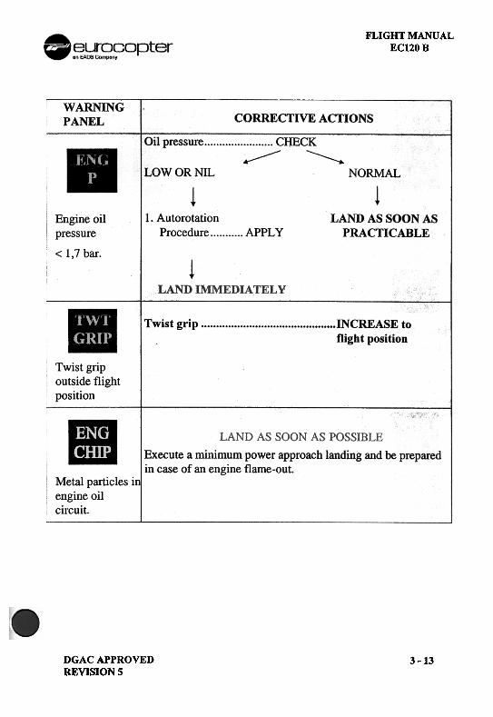
WARNINGPANEL CORRECTIVE ACTIONS
Oil pressure CHECK'
LOW OR NIL NORMAL
~
LAND AS SOON ASPRACTICABLE
Engine oilpressure< 1,7 bar.
AutorotationProcedure APPLY
LAND IMMEDIA TEL Y
Twist grip INCREASE toflight position
Twist gripoutside flightposition
LAND AS SOON AS POSSIBLE
Execute a minimum power approach landing and be preparedin case of an engine flame-out.
Metal particles i1engine oil
circuit.
DGAC APPROVEDREVISION 5
3 -13
FLIGHT MANUAL .EC120 B ~~r~n~opter
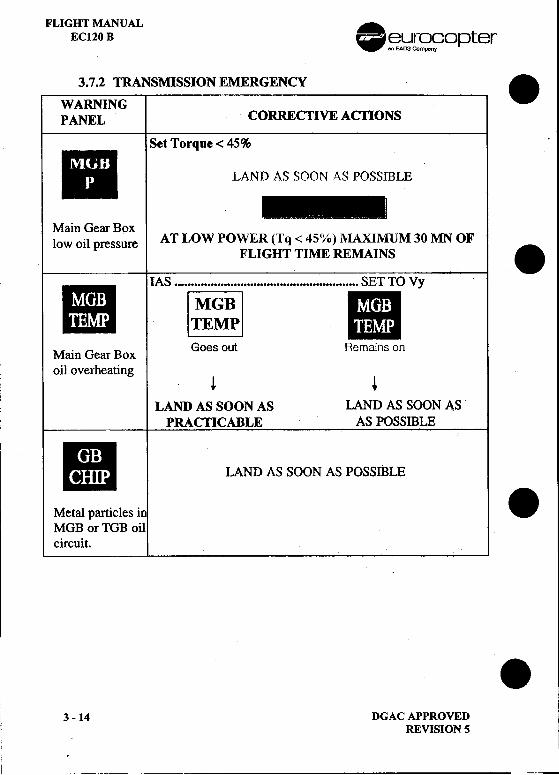
3.7.2 TRANSMISSION EMERGENCY .WARNINGPANEL CORRECTIVE ACTIONS
Set Torque < 45%
B LAND AS SOON AS POSSIBLE
---~Main Gear Boxlow oil pressure AT LOW POWER (Tq < 45%) lVlAXIMUM 30 MN OFFLIGHT TIME REMAINS .II !AS ...~ ii Vy .
M . G B Goes out Remains onam ear ox
oil overheating! +
LAND AS SOON AS LAND AS SOON ASPRACTICABLE AS POSSIBLE
II LAND AS SOON AS POSSIBLE
Metal particles in .MGB or TGB oilcircuit. I
.3 -14 DGAC APPROVED
REVISION 5
L --
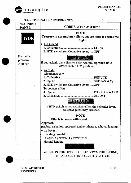
. FLIGHT MANUAL-~.};}[~opter EC120 B. 3.7.3 HYDRAULIC EMERGENCYWARNINGPANEL CORRECTIVE ACTIONS_ NOTE ..Pressure in accumulator allows enough time to secure the
flight..On ground:
1. Collective LOCK2. HYD switch (on Collective lever) OFF
Hydraulic.pressure ...< 20 bar If not locked, the collective pItch wIll pull up when HYD
switch is in "OFF" position..In flight:
Simultaneously1. Collective REDUCE
2. Cyclic SET IAS at Vy3. HYD switch (on Collective lever) OFF.To counter effort4. Cyclic PUSH FORWARD5. Collective ADJUST
If HYD switch is not switched off on the collective lever,collective pitch may increase.. NOTE Efforts increase with speed.
Approach:penOl'In a shallow approach and terminate to a hover landing..In hover:
Landing possible:LAND AS SOON AS POSSIBIJE
Nonnallanding.
=_=lJL-=-WHEN ON THE GROUND SHUT DOWN THE ENGINE,
.THEN LOCK THE COLLECTIVE PITCH.
DGAC APPROVED 3 -15REVISION 5
---
FLIGHT MANUAL .EC120 B ~~~n~opter
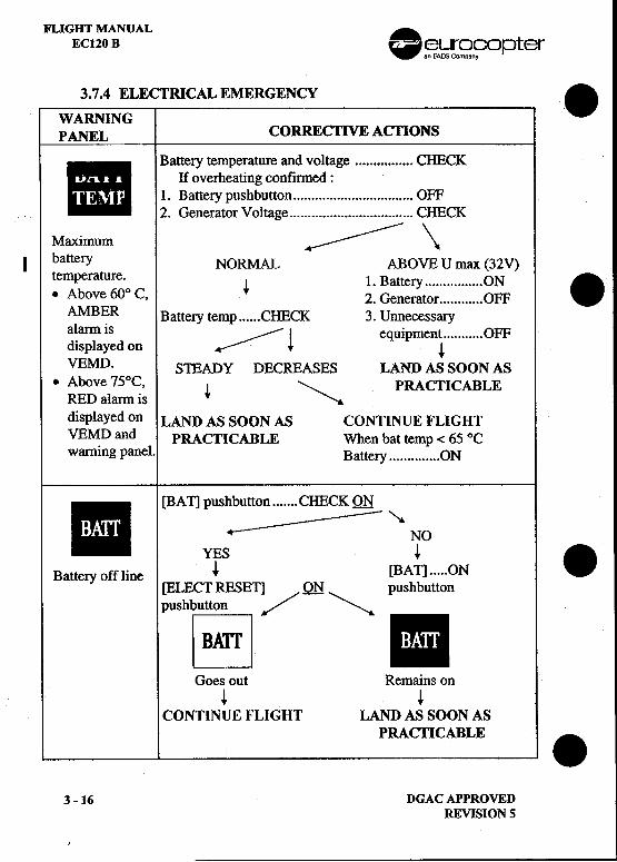
3.7.4 ELECTRICAL EMERGENCY .
WARNINGPANEL CORRECTIVE ACTIONS
_ Battery temperature and voltage CHECK .
If overheating confirmed:
..1. Battery pushbutton OFF2. Generator Voltage CHECK
Maximum ~-- \I battery NORMAL ABOVE U max (32V)
temperature. 1 B ON .~ .attery .Above 60° C,2 G t OFF.enera or AMBER Battery temp CHECK 3. Unnecessary
alarm is * --~~~--~ . t OFF.equlpmen displayed on +
VEMD. S1EADY DECREASES LAND AS SOON AS.Above 75°C, + "- PRACTICABLE
RED alarm is " displayed on LAND AS SOON AS CONTINUE FLIGHT
VEMD and PRACTICABLE When bat temp < 65 °Cwarning panel. Battery ON- [BAT] pushbutton CHECK Qt!
.~ NOYES +
.Battery off line + [BAT] ON[ELECT RESET] Qt! pushbuttonpushbutton '/ ~~ -
Goes out Remains on+ +
CONTINUE FLIGHT LAND AS SOON AS
i PRACTICABLE.
3 -16 DGAC APPROVEDREVISION 5
. FLIGHT MANUAL~~[S?fopter EC120 B
I
.WARNING I CORRECTIVE ACflONSPANEL I
I ,
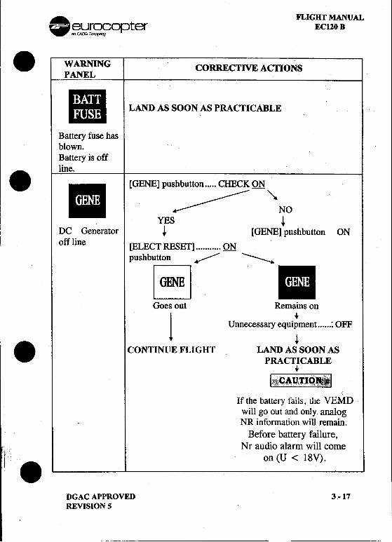
III LAND AS SOON AS PRACTICABLE ..
Battery fuse hasblown.Battery is off
line.
._II [GENE] pushbutton CHECK QN "'-Iii- "~ ~- NO
YES +
DC Generator + [GENE] pushbutton ON
off line S[ELECT RE ET] QNpushbutton ~ -
Goes out Remains on
1 Unnecessary equi~ment : OFF
+. CONTINUE }~LIGHT LAND AS SOON ASPRACTICABLE
+
1!~ "i CAUTIO .. "" ~ 1".. ."..C" .."'.",...,, "
,If the battery tails, the VEMD
will go out and only analog.NR information will remain.
Before battery failure,Nr audio alarm will come;, "if ". on (U < 18V).
DGACAPPROVED 3-17
REVISION 5
---
FLIGHT MANUALEC120 B .~~~n~opter
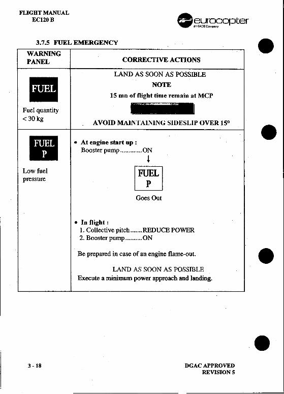
3.7.5 FUEL EMERGENCY .WARNINGPANEL CORREcrIVE ACTIONS
I LAND AS SOON AS POSSffiLE111- NOTE1_- 15 mn of flight time remain at MCP
Fuel quantity ___111-< 30 kg A vqm MAINTAINING SIDESLIP OVER 150 .
II .At engine start up :I Booster pump or
Low fuel IFuEilpressure L_~J
Goos Out
.In flight:1. Collective pitch REDUCE POWER2. Boosterpump ON
Be prepared in case of an engine flame-out. .
LAND AS SOON AS POSSIBLEExecute a minimum power approach and landing.
II
.3 -18 DGAC APPROVED
REVISION 5
. FLIGHT MANUAL~~~fopter EC120 B
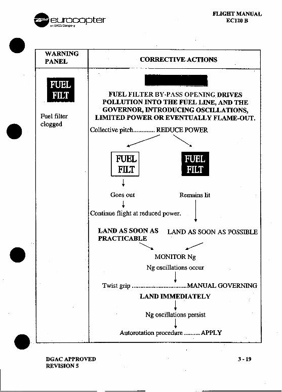
.WARNINGPANEL CORRECTIVEACfIONS
II FUEL FILT~~~~NGDRIVES~OLLUTION INTO THE FUEL LINE, AND THEqOVERNOR, INTRODUCING OSCILLATIONS,
Fuel filter LIl\IfITED POWER OR EVENTUALLY FLAME-OUT.. clogged Collective pitch REDUCE POWER
~ """
~ III~
Goes out Remains lit
Continue fli~ht at reduced power. 1
LAND AS SOON AS LAND AS SOON AS POSSffiLEPRACTICABLE
~ .MONITOR Ng
Ng oscillations occur
!Twist grip MANUAL GOVERNING
LAND IMMEDIA TEL Y
tNg oscillations persist
!.Autorotation procedure APPL Y
DGAC APPROVED 3 -19REVISION 5
---
FLIGHT MANUAL .EC120 B .El3.};}[~fopter
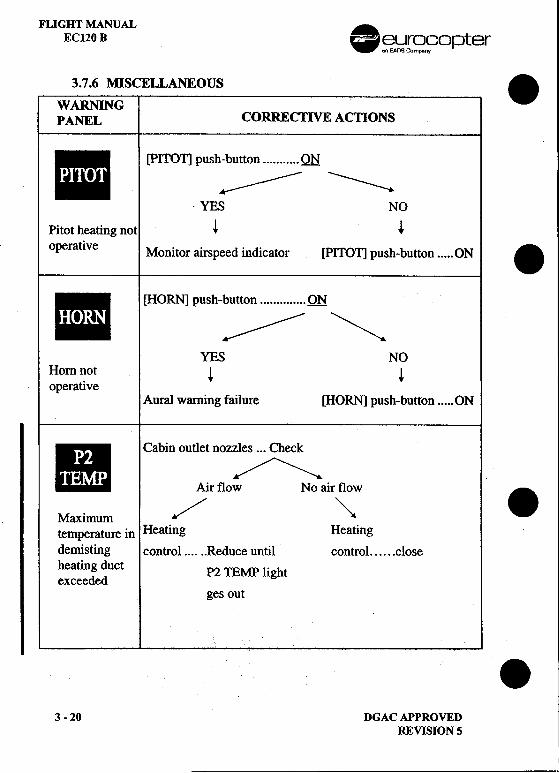
3.7.6 MISCELLANEOUS .WARNINGPANEL CORRECTIVE ACTIONS
-[pITOll PUSh~:::::~~~~=: QN .YES NO
Pitot heating not ~ ~operative Monitor airspeed indicator [PITOT] push-button ON .
-[HORN] PUSh-:::::::~ ~YES NO
Horn ~ot ~ ~operative
Aural warning failure [HORN] push-button ON
II Cabin outlet nozzles ...Check
.t ...,.-//"','--,..Air flow No air flow .Maximum /' ~temperature in Heating Heatingdemisting control ..Reduce until control .closeheating duct P2 TEMP Ii htexceeded g
ges out
.3 -20 DGAC APPROVED
REVISION 5
.
FLIGHT MANUAL AEC120 B [~~ .eurocopter
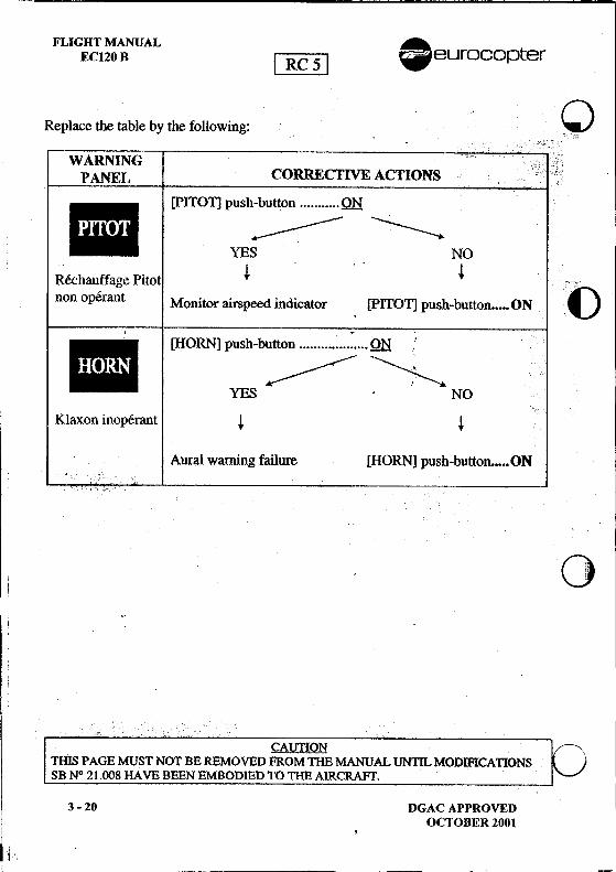
Replace the t~ble by the following: .Q., .ccc"c~
WARNING 1 :c;;PANEL CORRECTIVE ACTIONS c..'c',c!
C. [PITOT] push-button QN "
I ""-..;.,.--~
\~S NO
~Rechauffage PltOt ~ "c!
non operant Monitor airspeed indicator. [PITOT] push-button ON C
~ .. [HORN] push-button QN .'
""""""'~"""---" C
YES .NO
Klaxon inoperant ~ ~
Aural warning failure [HORN] push-button ON.;;
C C
.GJ
CAUTIONTHIS PAGE MUST NOT BE REMOVED FROM THE MANUALUNTn.. MODlFICA'nONSSB N° 21.008 HA VB BEEN EMBODIED TO THE AIRCRAFT'.
3 -20 DGAC APPROVED: OCTOBER 2001! .
~j
8 euroco p ter FLIGHT l\iIANUALECIZ6 B
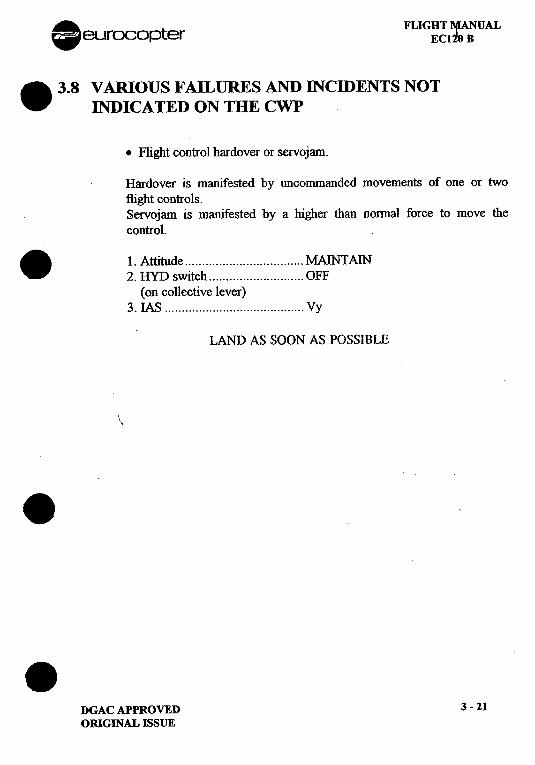
. 3.8 VARIOUS FAILURES AND INCmENTS NOTINDICATED ON THE CWP
.Flight control hardover or servojam.
Hardover is manifested by uncommanded movements of one or twoflight controls.Servojam is manifested by a higher than normal force to move thecontrol.
.1. Attitude MAINTAIN2. HYD switch OFF
(on collective lever)3. IAS Vy
I LAND AS SOON AS POSSIBLE
\
.
.DGAC APPROVED 3 -21
ORIGINAL ISSUE
~. FLIGHT MANUAL~~o~:Jter EC120 B
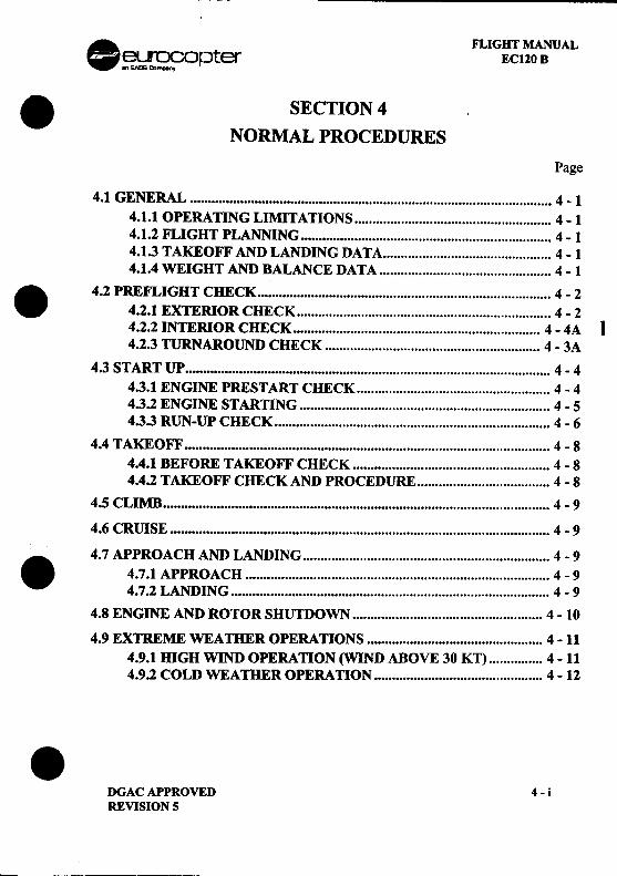
.SECTION 4NORMAL PROCEDURES
Page
4.1 GENERAL 4 -1
4.1.1 OPERATING LIMITATIONS 4 -14.1.2 FLIGHT PLANNING 4-14.1.3 TAKEOFF AND LANDING DATA 4 -14.1.4 WEIGHT AND BALANCE DATA 4 -1. 4.2 PREFLIGHT CHECK 4 -2
4.2.1 EXTERIOR CHECK 4 -24.2.2 INTERIOR CHECK 4 -4A I4.2.3 TURNAROUND CHECK 4 -3A
4.3 START UP 4 -4
4.3.1 ENGINE PREST ART CHECK 4 -44.3.2 ENGINE STARllNG 4 -54.3.3 RUN-UP CHECK 4 -6
4.4 TAKEOFF 4 -8
4.4.1 BEFORE TAKEOFF CHECK 4 -84.4.2 TAKEOFF CHECK AND PROCEDURE 4 -8
4.5 CLIMB 4 -9
4.6 CRUISE 4 -9
. 4.7 APPROACH AND LANDING 4 -9
4.7.1 APPROACH 4 -94.7.2 LANDING 4 -9
4.8 ENGINE AND ROTOR SHUTDOWN ...""'.' '.' " ' '.'.'.""'... 4 -10
4.9 EXTREME WEATHER OPERATIONS 4 -11
4.9.1 HIGH WIND OPERAllON (WIND ABOVE 30 KT) 4 -114.9.2 COLD WEAmER OPERAllON 4 -12
.DGAC APPROVED 4 -iREVISION 5'--
FLIGHT MANUAL .EC120 B ~~opter
LIST OF FIGURES .
Page
FIGURE 4-1 : SEQUENCE OF CHECKS 4 -2FIGURE 4-2 : TAKEOFF PROCEDURE 4 -8 .
.
.4-ii DGACAPPROVED
ORIGINAL ISSUE
-
. FLIGHT MANUAL~~opter ECl20 B. 4.1 GENERALThis section contains instructions and procedures for operating the helicopterfrom the planning stage, through actual flight conditions, to securing thehelicopter after landing.Normal and standard conditions are assumed in these procedures. Pertinentdata in other sections is referenced when applicable.The instructions and procedures contained herein are written for the purposeof standardization and are not applicable to all situations.
4.1.1 OPERA DNG LIMITATIONSFor minimum and maximum limits, refer to SECTION 2.
. Each time an operating limitation is exceeded, an appropriate entryshall be made in the logbook (helicopter, engine, etc.). The entry shallstate which limit was exceeded, the duration of time, the extreme valueattained, and any additional information essential in determining themaintenance action required.
4.1.2 FLIGHT PLANNINGEach flight should be planned adequately to ensure safe operations andto provide the pilot with the data to be used during flight.Flight planning must comply with helicopter limitations andperformances (Refer to SECTIONS 2, 5, 6 and 9).
4.1.3 TAKEOFF AND LANDING DATARefer to SECTION 2 -LIMITATIONS and
SECTION 5 -PERFORMANCE DATA.. 4.1.4 WEIGHT AND BALANCE DATAAscertain proper weight and balance of the helicopter as follows:-Consult SECTION 6 -WEIGHT AND BALANCE.-Ascertain weight of fuel, oil, payload, etc.-Compute takeoff and anticipated landing gross weights.-Check helicopter centre of gravity (CG) locations.-Check that the weight and CG limitations in SECTION 2 are not
exceeded.
.DGAC APPROVED 4-1ORIGINAL ISSUE
~~~ ~-- ~--~--~ -
FLIGHT MANUAL -EC120 B .~~ opter
4.2 PREFLIGHT CHECK .-Make sure that the Flight-Related Checks (VL V) after the last flight of the
previous day or before the first flight of the day have been performedeither by a pilot suitably trained to perform VL V and referring to presentFlight Manual (see SECTION 8) or by a qualified mechanic complyingwith the Aircraft Maintenance Manual.
-Check that the aircraft area is clean and unobstructed.-Carry out the following checks :
4.2.1 EXTERIOR CHECK .
~ 100
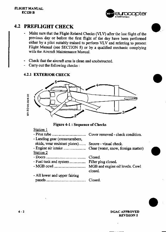
0>'"()U! 3>~
Figure 4-1: Sequence of ChecksStation I
-Pitot tube , Cover removed -check condition.-Landing gear (crossmembers,skids, wear resistant plates) Secure -visual check.
-Engine air intake Clear (water, snow, foreign matter) .Station 2-Doors Closed.-Fuel tank and system Filler plug closed.-MGB cowl MGB and engine oil levels. Cowl
closed.-All lower and upper fairingpanels Closed.
.4-2 DGACAPPROVED
REVISION 5
---
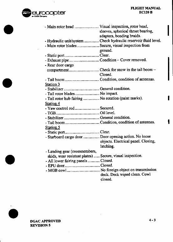
I . FLIGHT MANUAL~~opter EC120 B. -Main rotor head Visual inspection, ,rotor head,
Isleeves, spherical thrust bearing,adapters, bonding braids.
-Hydraulic unit/system Check hydraulic reservoir fluid level.-Main rotor blades Secure, visual inspection from
ground.-Static port Clear.-Exhaust pipe Condition -Cover removed.-Rear door cargo
compartment Check for snow in the tail boom-Closed.
-Tail boom , Condition, condition of antennas.Station 3-Stabilizer General condition.-Tail rotor blades No impact.-Tail rotor hub fairing No rotation (paint marks). IStation 4-Yaw control rod ., Secured.-TGB Oil level.-Stabilizer General condition.-Tail boom ' ' '.. Condition, condition of antennas. IStation 5-Static port Clear.-Starboard cargo door Door opening action. No loose
objects. Electrical panel. Closing,
latching.-Landing gear (crossmembers,
skids, wear resistant plates) Secure, visual inspection.-All lower fairing panels Closed.-EPU door Closed.-MGB cowL No foreign object on transmission
deck. Deck wiped clean. Cowlclosed.
.DGAC APPROVED 4 -3
REVISION 5
FLIGHT MANUALEC120 8 .~~O pter
4.2.2 INT~RIOR CHECK 8,-Cabm Clean.I -Blanking plate of pedal unit Installed (if single pilot
configuration).-Fire extinguisher Fitted and checked.-Breakers AII set.-Objects carried Stowed.
I -Freight Stowed.-Door jettison Checked, lockwired.
4.2.3 TURNAROUND CHECK
-Ov~ll aspect c~ndition, cleanliness. 8-Engme / MOB 011 level.-Main and tail rotor blades condition.(from ground)
-Loads secured.-All doors and cowlings locked.
NOTE!If the aircraft is to be parked some time between flights, temporarypicketing is recommended by fitting blanks, covers, and bladesocks. In this case, perform a complete exterior check.
I NOTE 2Perform a complete exterior check if the aircraft is to be parkedunder snow precipitations. 8
8
4 -3A (4 -38 blank) DGAC APPROVEDREVISION 5
. FLIGHT MANUAL
~r~n~opter EC120 BI-
-
-
-DGAC APPROVED 4 -3BREVISION 2
FLIGHT MANUAL .EC120 B ~~r~9opter
4.3 START UP .4.3.1 ENGINE PRESTART CHECK
-Seats and control pedals ""'."'" ADJUS1ED.-Seat belts FAS1ENED.
NOTE 1Copilot seat belts shall be fastened in all cases.
NOTA 2I When the rear seats are unoccupied, check that the unusedsafety .belts a~~ not fastened and the button on the shoulderstraps IS not vIsible. .I NOTE3.
Check that, when flying with doors opern there are no loose objectsin the cabin, and the belts of unoccupied rear seats are stowedbetween the backrest foam and the backrest.
1. Heating, demisting, airconditioner OFF.2. Rotor brake FORWARD.3. Fuel shut-off lever FORWARD. LOCKWIRED.4. Battery and Generator ON.5. Light test COMPLE1E.6. Engine fire test COMPLE1E.7. Warning panel remaininglights , CHECK
.With battery power Emi 11m ED.a'J~-llmm .l!j[C1:. ._"&"'CI:~I- amiilluminated
.With EPU power Same lights as above + 1m.illuminated
8. VEMD Engine page DISPLAYED.9. Control pedals Freedom of travel, then NEUTRAL.10.Collective pitch ., LOCKED.11. Twist grip SHUT OFF position.12.Hydraulic switch (both
collective levers) ON. .
4-4 DGACAPPROVEDREVISION 5
.
A FLIGHT MANUAL.~~c;opter ~lJ ECl20 B
t Replace the paragraph 4.3.2 by the following paragraph:
4.3.2 ENGINE STARTING1. Booster pump ON
I FUEL P I goes out
2. Anticollision light ON
.After 30 s3. Starter DEPRESSIt.
4. Twist grip GROUND IDLE position,NOTE
If remaining T4 is above 150°C wait until 100/0 Ng before
actuating twist grip.
5. Twist grip MONITOR T4
depending upon T4 rate of increase..When Ng = 50%
6. Starter : RELEASED
7. Twist grip FLIGHT POSITION
Maintain Tq < 40%
Check that [gEQ:[], I HYDR I and I MGB P I lights go out on the
warning panel.
..When NR ~ 350 rnrn.
Switch ON the aural warning and check that lli~J light goes
out on the warning panel.
.When Twist Grin is in flight nosition. ICheck that NR indication is in the lower part of the green arc and that
I TWf GRIP I light is out.
,
CAUTIONTHIS PAGE MUST NOT BE REMOVED FROM THE MANUAL UNTIL MODIFICATIONSB N° 76.002 HAS BEEN EMBODIED TO THE AIRCRAFT.
DGAC APPROVED 4 -5
OCTOBER 2001
. FLIGHT MANUAL~~opter EC120 B
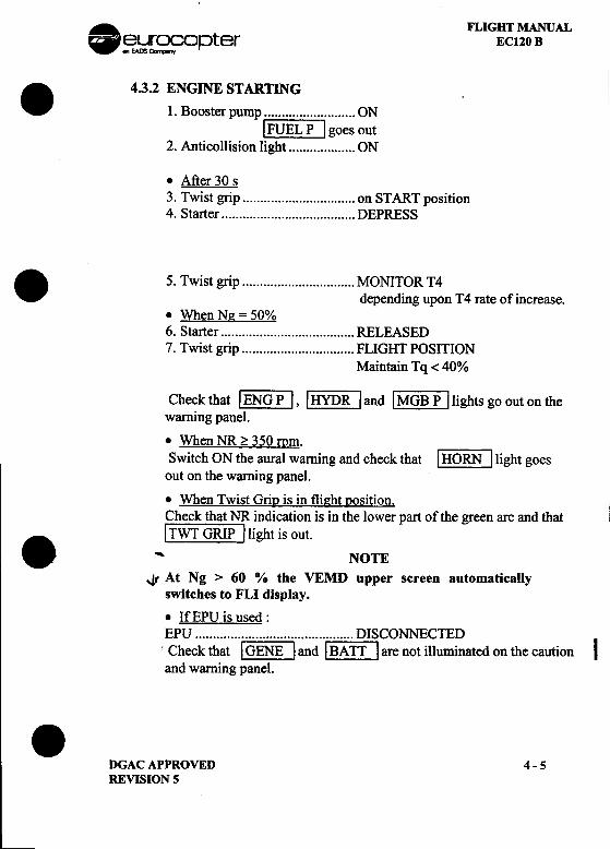
.4.3.2 ~:~:r :::~.~~ ONI FUEL P I goes out
2. Anticollision light ON
.After 30 s3. Twist grip "", ",..""", ,...,. on START position4. Starter DEPRESS. 5. Twist grip , MONITOR T4
depending upon T4 rate of increase..When Ne = 50%6. Starter RELEASED7. Twist grip FLIGHT POSITION
Maintain Tq < 40%
Check that ~:IJ, ~J and ~:RJ lights go out on thewarning panel..When NR ?: 350 mm.Switch ON the aural warning and check that [HQ:@] light goes
out on the warning panel.
.When Twist GriD is in flight 12osition.Check that NR indication is in the lower part of the green arc and that
. I TWT GRIP I light is out., NOTE
.Jf At Ng > 60 0/0 the VEMD upper screen automaticaUyswitches to FLI display.
.IfEPU is used:
on the caution Iand warning panel..
DGAC APPROVED 4 -5REVISION 5
FLIGHT MANUALECl20 B .~~ opter
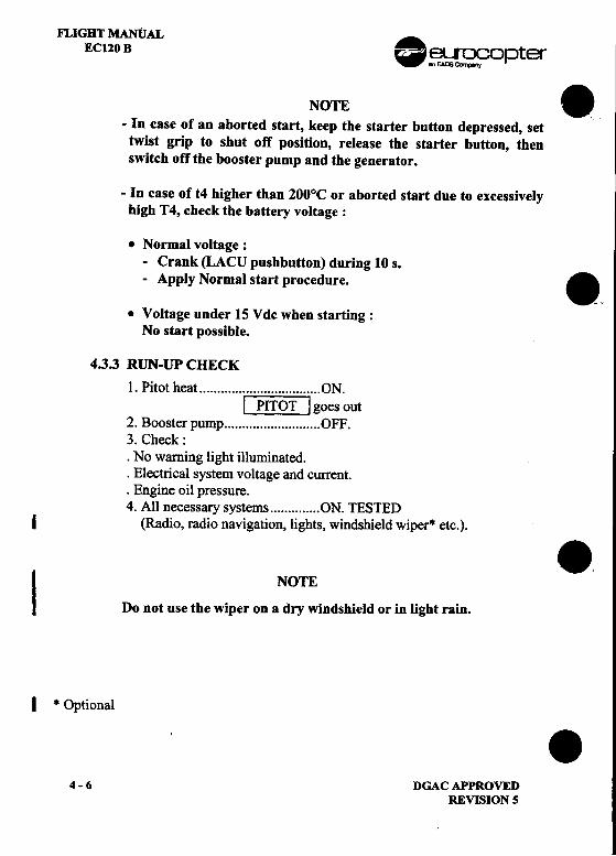
NOTE 8-In case of an aborted start, keep the starter button depressed, settwist grip to shut off position, release the starter button, thenswitch off the booster pump and the generator.
-In case of t4 higher than 200°C or aborted start due to excessivelyhigh T4, check the battery voltage:
.Normal voltage:-Crank (LACU pushbutton) during 10 s.-Apply Normal start procedure. .,
.Voltage under 15 Vdc when starting:No start possible.
4.3.3 RUN-UP CHECK
1. Pitot heat ON.I PITOT I goes out
2. Booster pump OFF.3. Check:.No warning light illuminated..Electrical system voltage and current..Engine oil pressure.4. All necessary systems ON. TESTED
I (Radio, radio navigation, lights, windshield wiper* etc.).
8.I NOTE
Do not use the wiper on a dry windshield or in light rain.
I * Optional
84-6 DGACAPPROVED
REVISION S
FUGHT MANUAL AEC120 B [~J .eurocopter
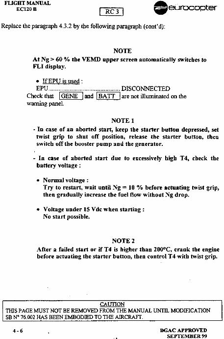
Replace the paragraph 4.3.2 by the following paragraph (cont'd):
NOTEAt Ng > 60 % the VEMD upper screen automatically switches toFLI display.
.IfEPU is used:EPU DISCONNECTED
Check that ~J and ~illJ are not illuminated on thewarning panel.
NOTE 1
-In case of an aborted start, keep the starter button depressed, settwist grip to shut off position, release the starter button, thenswitch off the booster pump and the generator.
-In case of aborted start due to excessively high T4, check thebattery voltage:
.Normal voltage:Try to restart, wait until Ng = 10 % before actuating twist grip,then gradually increase the fuel flow without Ng drop.
.Voltage under 15 V dc when starting:No start possible.
NOTE 2
After a failed start or if T4 is higher than 200°C, crank the enginebefore actuating the starter button, then control T4with twist grip.
CAU1l0NTHIS PAGE MUST NOT BE REMOVED FROM THE MANUAL UNTIL MODIFICA nONSB N° 76.002 HAS BEEN EMBODIED TO THE AIRCRAFf.
4-6 .DGACAPPROVED.SEPTEMBER 99
-. .FLIGHT MANUAL? ~~[S?C?opter EC120 B
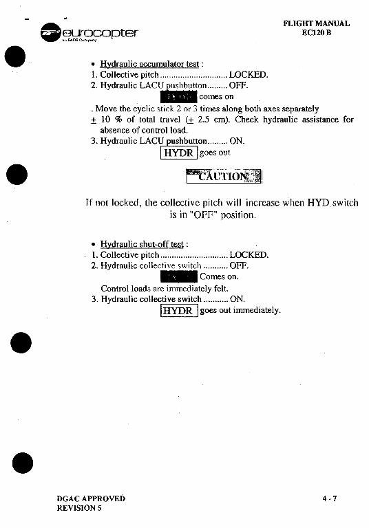
..Hydraulic accumulator test:1. Collective pitch LOCKED.2. Hydraulic LACU pushbutton OFF.
-comes on.Move the cyclic stick 2 or 3 times along both axes separately:t 10 % of total travel (:t 2.5 cm). Check hydraulic assistance for
absence of control load.3. Hydraulic LAC~ ~~~b~t~on ON.
I HYDR I goes out. -;-- 'Ci~\-"1110~1~: !
If not locked, the collective pitch will increase when HYD switchis in "OFF" position.
.Hydraulic shut-off test:.1. Collective pitch LOCKED.
2. Hydraulic collective switch OFF..~ Comes on.
Control loads are immediately felt.3. Hydraulic collective switch ON.
[gr~J goes out immediately...
DGAC APPROVED 4 -7REVISION 5
FLIGHT MANUALEC120 B .~~L~r;:op(er -
4.4 TAKEOFF .4.4.1 BEFORE TAKEOFF CHECK
1. Doors CLOSED.2. Collective, cyclic ti'iction locks AS REQUIRED.3. Landing light AS REQUIl"{ED4. Pressures and temperatures NORIvIAL RANGE.5. Warning pill1el Alllights OFF.6. Collective pitch UNLOCKED.
NOTEAdjust collective and cyclic friction locks so that friction
forces are felt by the pilot when moving tl1e flight controls. .
4.4.2 TAKEOFF CHECK AND PROCEDURE
Use of P2 air bleeds are tr)rbidden above themaximum continuous rating (Ng or T4)
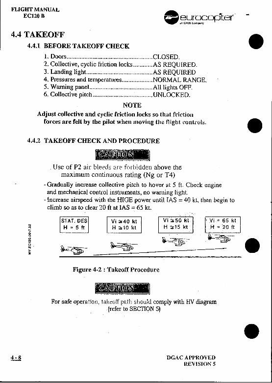
-Gradually increase collective pitch to hover at 5 ft. Check engineand mechanical control insu'uments, no will11ing light.
-Increase airspeed with the HIGE power until {AS = 40 kt, then begin toclimb so as to clear 20 ft at IAS = 65 kt.
.. rnTAT.OES []~~~JVi~40 kt~ H = 5 ft H '" 10 kt0; -
g ~-~- .~ ~~ -===:::~~~~~~;:::::::==:~~~:====
Figure 4-2 : Takeoff Procedure
1811mB.., ~-~-,---~ ~
For safe operation, tal(eoff path should comply With HV diagram! (refer to SECTION 5) .
~ DGAC API>ROVEDl{EVISION 5
A FLIGHT MANUAL-~r~fopter EC120 B
.4.5 CLIMBAbove 100 ft (30 m) select Maximum Continuous Power and optimumclimbing speed of (Vy) : IAS = 65 kt (120 km/h) -1 kt per 1000 ft.
4.6 CRillSEFast cruise is obtained by the first limitation reached corresponding to thebeginning of the FLI amber area:Corresponding mechanical limit Tq or Ng are pointed out with underlinednumerical value.. Economic cruise: set Tq to 10% less than MCP Tq.Reduce indicated airspeed in turbulence. I
4.7 APPROACH AND LANDING4.7.1 APPROACH
-Perform approach at a minimum rate of descent and at == Vy.-At approximately 100 ft, reduce airspeed down to HIGE at 5 ft..Approach check:1. Landing light AS REQUIRED.2. All parameters CHECK.
4.7.2 LANDING-In hover, gradually reduce collective pitch until touch-down, thenfully reduce collective pitch..
Use of P2 air bleeds are forbidden above themaximum continuous rating (Ng or T4)
..DGACAPPROVED 4-9REVISION 5
FLIGHT MANUALEC120 B .~~r~9opter
4.8 ENGINE AND ROTOR SHUTDOWN .1. Cyclic stick NEUTRAL2. Collective pitch .'.'...'.."".."'.'...'.." LOCK3. Pitot, Horn, Landing light OFF4. Twist grip '...'."."""""...'.."'."."" '. GROUND IDLE position
63 % ~ Ng ~ 68 %, wait 30 s. for temperature stabilization.5. Generator and all systems ".'...'."' OFF6. Twist grip """"."'.'."'.'.'.""".""'..."'. SHUT OFF position
Cancel the idle stop by briefly pressing the starter button..ForNR ~ 150 rpm7. Rotorbrake APPLY .8. Anticollision light OFF
.BEFORE LEAVING HELICOPTERI -VEMD ..,., ,.",.,.."",..".".."..,.,.,..,.." CHECK flight report page information.
-Ng and Nf cycles written in white characters and above O.-Switch off the battery.-Pitot, intake, exhaust covers, blade socks as required.
.
.4 -10 DGAC APPROVED
REVISION 5
, :'
. FLIGHT MANUAL~~opter EC120 B. 4.9 EXTREME WEATHER OPERATIONS4.9.1 mGH WIND OPERAllON (WIND ABOVE 30 ~
.Parking
-Park the helicopter head into the wind. Maintain rotor brake appliedwith one blade at 12 o'clock. Keep blade socks until start up.
-For wind above 50 kt the helicopter must be tied down.
.Start up
. -When the rotor begins to turn, push the cyclic stick slightly forwardand accelerate the engine as soon as possible until NR = 320 rpmwithin T 4 limitation.
-Then carry out the normal procedure.
NOTEStart up and shut down have been demonstrated up to 55 kt ofwind from all directions.
.
.DGACAPPROVED 4-11ORIGINAL ISSUE
FLIGHT MANUALEC120 B .~~oPter
4.9.2 COLDWEATllEROPERATION .,.NOTE
Use of 3 cSt synthetic oil is recommended for low temperatureoperation.
.Operation in Snow
-Clean the helicopter before takeoff; blades, rotor head, windshield...-Do not stay in HIGE with snow recirculation.
I -Replace the turnaround check by a complete exterior check. .
.
.4 -12 DGAC APPROVED
REVISION 5
FLIGHT MANUALEC120 B
SECTION 5
PERFORMANCE DATA(APPROVED PART I NON APPROVED PART)
Page
5.1 INTRODUCnON 5 -15.2 STARnNG AND STOPPING THE ROTOR ENVELOPE 5 -15.3 ENGINE CHECK PROCEDURE 5 -1
5.3.1 BEFORE TAKEOFF 5 -15.3.2 IN FLIGHT 5 -lA5.3.3 MANUAL ENGINE POWER CHECK 5 -IB
5.4 AIR DATA SYSTEM CALIBRAnON 5 -45.5 HEIGHT -VELOCITY DIAGRAM 5 -65.6 HOVER IN GROUND EFFECT 5 -85.7 HOVER OUT OF GROUND EFFECT 5 -95.8 CORRECTED WEIGHT 5 -105.9 RATE OF CLIMB 5 -115.10 GLWE DISTANCE IN AUTOROTATION 5 -125.11 NOISE LEVEL 5 -12
DGAC APPROVEDREVISION 5
S-i
FLIGHT MANUALEC120 B .~~ opter .
LIST OF FIGURES
Page
FIGURE 5 -la : ENGINE POWER CHECK 5 -2FIGURE 5 -Ib : ENGINE POWER CHECK 5 -3FIGURE 5 -2 : T4 CHECK 5 -4FIGURE 5 -3 : AIR DATA SYSTEM CALIBRATION 5 -5FIGURE 5 -4 : HEIGHT -VELOCITY DIAGRAM ..'.' ' 5 -7 .FIGURE 5 -5 : HOVER IN GROUND EFFECT 5 -8FIGURE 5 -6 : HOVER OUT OF GROUND EFFECT 5 -9FIGURE 5 -7 : CORRECTED WEIGHT 5 -10FIGURE 5 -8 : RATE OF CLIMB 5 -11FIGURE 5 -9 : TAS/CAS IN RECOMMENDED CRUISE 5 -13FIGURE 5 -10 : FUEL CONSUMPfION-ENDURANCE IN
RECOMMENDED CRUISE 5 -14FIGURE 5 -11: RANGE IN RECOMMENDED CRUISE 5 -15FIGURE 5 -12 : TAS/CAS IN FAST CRUISE 5 -16FIGURE 5 -13 : FUEL CONSUMPTION-RANGE IN FAST
CRUISE 5 -17FIGURE 5 -14 : ENDURANCE IN CRUISE AT MINIMUM HOURLY
FUEL CONSUMYfION 5 -18 ..
5-ii DGACAPPROVEDREVISION 5
FLIGHT MANUALEC120 B
5.1 INTRODUCTIONThe following perfonnance curves apply to the basic version of the aircraft.Refer to SECTION 9 when optional equipment is fitted.
NOTEValues obtained on VEMD PERFORMANCE and ENGINE POWERCHECK pages can be checked with the ENGINE POWER CHECK, T4CHECK, HOVER IN GROUND EFFECT, and HOVER OUT OFGROUND EFFECT curves.
For AUW over 1680 kg, the performances have to be checkedmanually with the figllres 5-5, 5-6 and 5-7.
Pilot shall limit the flight envelope and weight displayedoQVEMDPERFORMAN'CE pages to the relevant limitations of SECTION 2.
5.2 STARTING AND STOPPING THE ROTORENVELOPEMaximum wind velocity from any direction for starting and stopping the rotor is55kt
5.3 ENGINE CHECK PROCEDURE5.3.1 BEFORE TAKEOFF
In HIGE at Sft and before initiating forward flight, pull the collectivepitch lever slightly to ensure that the Ng can increase by at least 1 %.
DGAC APPROVEDREVISION 5
5-1
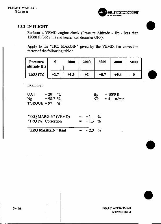
FLIGHT MANUALEC120 B .~~ef°pter
5.3.2 IN FLIGHT .Perform a VEMD engine check (Pressure Altitude -Hp -less than12000 ft (3657 m) and heater and demister OFF).
Apply to the "TRQ MARGIN" given by the VEMD, the correctionfactor of the following table:
Pressure 0 1000 2000 3000 4000 5000altitude (rt)
TRQ (0;0) +1.7 +1.3 +1 +0.7 +0.4 0 .
Example:
OAT = 20 °C Hp = 1000 ftNg =98.7 % NR =411 tr/minTORQUE = 97 %
"TRQ MARGIN" (VEMD) = + 1 %"TRQ (%) Correction = + 1.3 %
"TRQ MARGIN" Real = + 2.3 % .I .I
5-1A DGACAPPROVEDREVISION 4
,I i ~
FLIGHT MANUALECl20B
5.3.3 MANUAL ENGINE POWER CHECK
In stabilized level flight at the maximum Ng displayed, note thefollowing parameters: torque, Ng, NR, Hp, OAT and T4. Read thefigures ENGINE POWER CHECK and T4 CHECK in the directionindicated by the arrows. Engine power check is OK if point "P" islocated in the area marked "CORRECT". T4 check is OK if point "T"is located in the area marked "CORRECT".
DGAC APPROVEDREVISION 5
5-1B
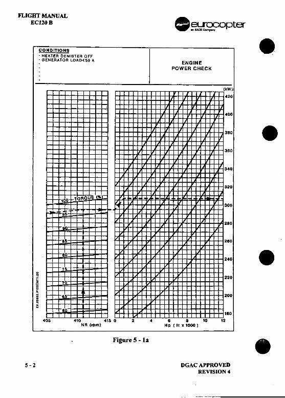
FLIGHT MANUALEC120 B .~~O pter
CONDITIONS .-HEATER DEMISTER OFF .--
-GENERATOR LOAD<SO A ENGINE
POWER CHECK
.
(kW)
420
00
380 .
380
40
20
00
80
80
240 .
g;: 220s"~0:
~ 200
~180
410 4150 8 8 10 12NR(rpm) Hp(ltxI000)
Figure 5 -la .
5-2 DGACAPPROVEDREVISION 4
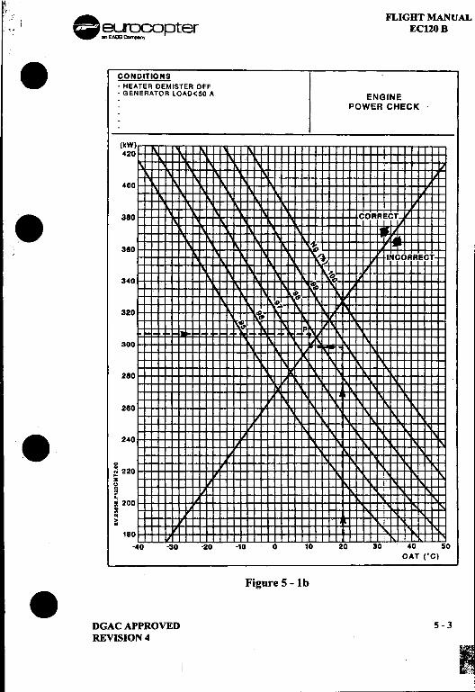
j;" '
!:: i ~ FLIGHT MANUALr.:] I ~~~ opter EC120 B. CONDITIONS '
-HEATER DEMISTER OFF: GENERATOR lOAD<SO A ENGINE
.POWER CHECK
(kW)420
400
.380 CORRE~1; 360 ~ ~
I\.~ INCORRECT~
340 ~ ~~
,p~iP~
320 ~,p~ P
300
280
260
'8 240
gN 220...S i" ,0 ...;~ 200 ~= ,~ i
180 -:-
-40 -30 -20 -10 0 10 20 30 40 50OAT rC)
Figure 5 -Ib
8DGACAPPROVED 5-3REVISION 4
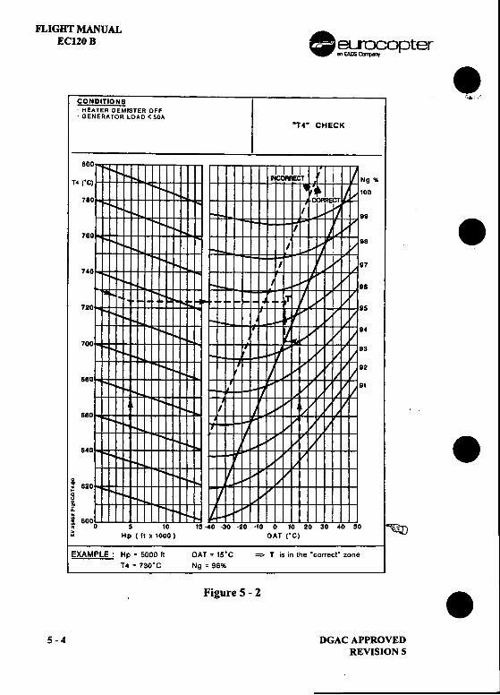
FLIGHT MANUALEC120 B .~~~opter .
CONDITIONS ',*.'
-HEATER OEMISTER OFF-GENERATOR LOAD < SOA
"T4" CHECK
,
800
T4 rC) 9 %
00780
9780 8.7
740
8
720 54
7003
2
8801
880
840 .! 8200
~oi= 800~ 0 10 0 10 20 30 40 50 ~
..Hp (It x 1000) OAT rC)
EXAMPLE: Hp' SOOO It OAT' IS.C => T is in the .correct" zoneT4 .730.C Ng = 96%
Figure 5-2 .5-4 DGACAPPROVED
REVISION 5
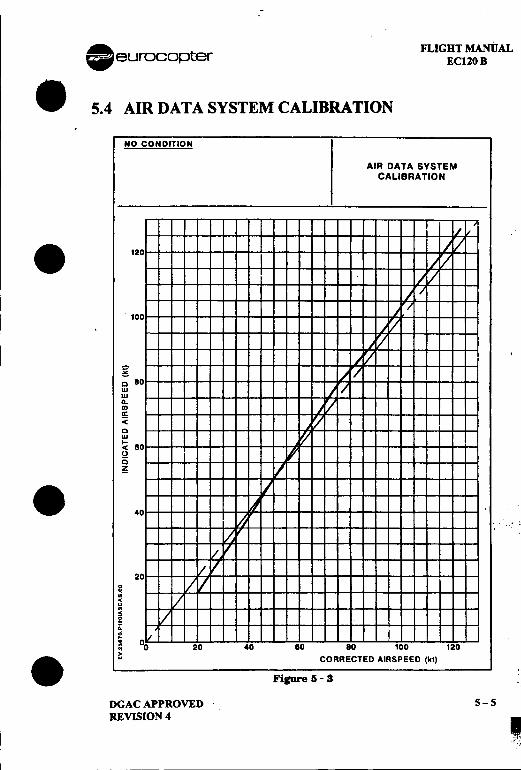
--~;iJ~
A FLIGHT MANUAL
.eurocopter ECl20 B
.5.4 AIRDATASYSTEMCALIBRATION
NO CONDITION
AIR DATA SYSTEMCALIBRATION
.120
100
~c 80UIUIG-O)or"< IcUI
'.< 80t)
[)~
.40
2000.;c"~~g= 20 40 80 80 100 120,.. ..CORRECTED AIRSPEED (kl)
Figure 5 -3
DGACAPPROVED 5-5REVISION 4
..FLIGHT MANUAL .EC120 B euroco~:)ter
5.5 HEIGHT -VELOCITY DIAGRAM .The avoidance zone is defmed by 4 points: A, B, C, D.
-Point A: low hover point
I Point A is at 6 ft (1.80 m) skid height at zero airspeed.
-Point B.
Point B is defmed by :.a variable height (18 ft $ height $ 24 ft) depending on the altitude and on
.the aircrafweight as determined by line (C),.a variable airspeed (50 kt $ !AS $ 60 kt) depending on the altitude and onthe aircraft weight as determined by line (C).
-Point C
Point C is defmed by :.a constant height of 50 ft (15 m),
..a variable airspeed (50 kt $ !AS $ 60 kt) depending on the altitude and onthe aircraft weight as determined by line (C).
-Point D
Point D is defmed by:.a variable height (500 ft $ height $ 800 ft) depending on the altitude and onthe aircrafweight as determined by line (D), ..a constant zero airspeed.
s -6 DGAC APPROVED .REVISION 3
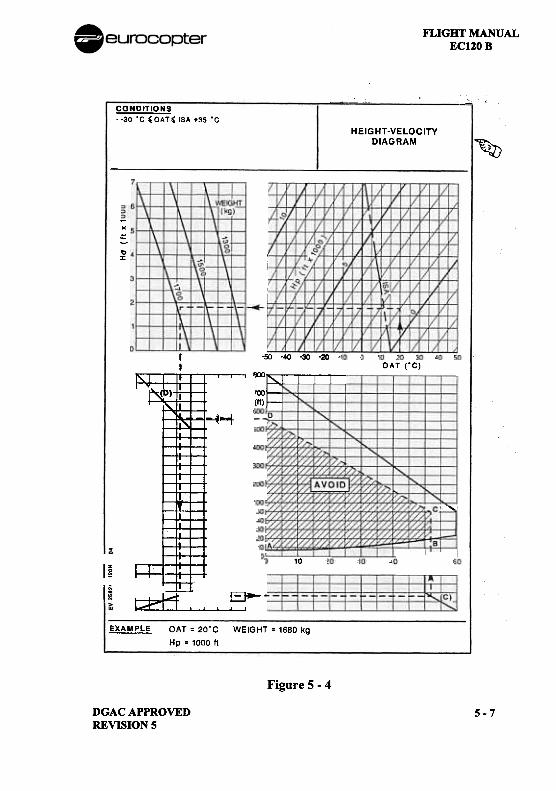
FLIGHT MANUALEC120 B
~--~ """CONDITIONS--30.C 'OAT, ISA +35.C
HEIGHT-VELOCITYDIAGRAM
~
-~
to:I:
-so -40 -30 -20 ~II IK)()~-"-T "--'
'00[II)
OAT rC)
~
' :"~
--i...,.~
~I
~~~~
'"
10
I~ I=P
I ~
EJ-
~H.""
EXAMPLE: OAT = 20'C WEIGHT = 1680 kg
Hp = 1000 It
Figure 5 -4
DGACAPPROVEDREVISION 5
5-7
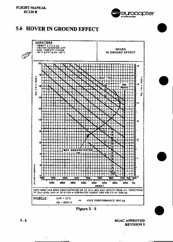
F1..IGBT MANUALEC120 B .~~O pter
5.6 HOVER IN GROUND EFFECT .CONDITIONS-HEIGHT 5 ft (1_5 m)-HEATER DEMISTER OFF
HOVER-MAX. TAKEOFF POWERc?" --30.C, OAT' ISA +3S"C IN GROUND EFFECT
-20
6
16-; OATI"C) -; .0 00 0~ ~
" 16 ~,; MAX 5 "= ~ WEIGHT E-I~-a- a-X :i! X
14 I~
"0 4
12
10 '0 3
.A
8 ~O""-
28 :.10
N
MAX. DEMONSTRATED4 HG .01 1 .~ 2
~~ So0, 0 ~ 1000 1100 1200 1300 1400 1500 1600 1700 (kg) 1600 0
~ ' I ., .I .I .I ' I .I .I .I ' I .I .I .I .I ' I .I ' I '
~ 2400 2600 2600 3000 3200 3400 3600 3800 (~)WEIGHT
SAFE WIND HAS BEEN DEMONSTRATED UP TO 35 kt AND MAX. WEIGHT FROM ALL DIRECTIONSAT SEA LEVEL AND AT 22 kI FOR A CORRECTED WEIGHT (SEE FIG.S7) OF 2200 kg.
EXAMPLE: OAT = 10.C= HIGE PERFORMANCE 1610 kg
Hp = 8500 It Figure 5 -5 .5-8 DGACAPPROVED
REVISION 5
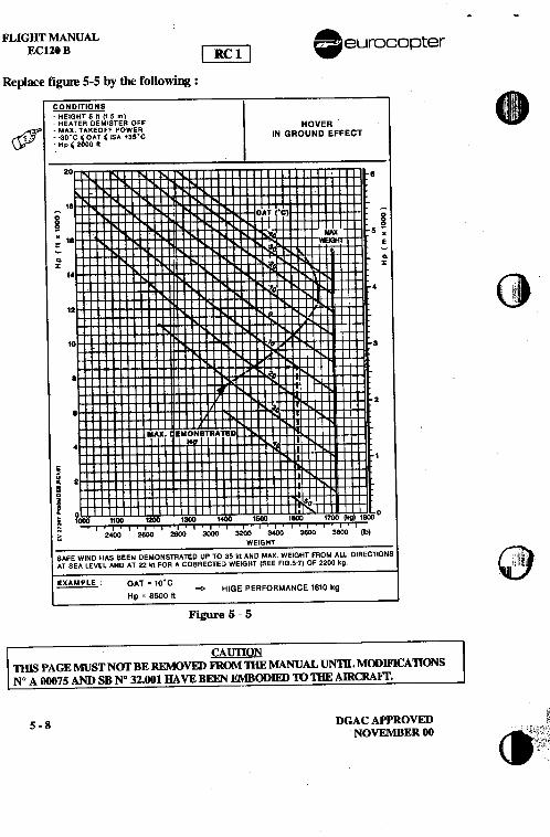
--FLIGHT MANUAL A
ECl20 B [~.. eurocopter
Replace figure 5-5 by the following :
CONDITIONS. ':
.HEIGHT 5 It (15 m) I ,
.HEATER DEMISTER OFFHOVER '
(jJ" .MAX, TAKEOFF POWER ~, .-30"C ,OAT' ISA +3S"C IN GROUND EFFECT
.Hp'20001t
20 8
18i ;~ ~.18 .= E--~ ~% %
14 (it . , ici i Ii'!
11 ,,'
10
.2.
MAX. EMONSTRATED4 H
1
~~ 2.~.g 80L 0~ 1000 1100 1200 '* 1400 1500 1800 1700 (1Ig) 1800 0
~ ::; I .-,'-. , ;-'-, ' ,ii, ' c_'.: '-'-- ,_.!_- '--~- '""~ 2400 2600 2SOO 3000 3200 3400 3600 3800 (lb)
WEIGHT-SAFE WIND HAS BEEN DEMONSTRATED UP TO 35 kt AND MAX. WEIGHT FROM ALL DIRECTIONSAT SEA LEVEL AND AT 22 kt FOR A COIjRECTED WEIGHT (SEE FIG 5-7) OF 2200 kg.
~: OAT " 10'C=0. HIGE PERFORMANCE 1610 kg
Hp : 8500 It
Figure 5 -5
CAUTIONnus PAGE MUST Nor BE REMOvm Ii1{OM mE MANUAL UN1n, MODIF1CAllONSN° A 00075 AND SB N° 32.001 HAVE BEEN EMBODIm> 10 mE AIRCRAFr.
5-8 DGACAPPROVEDNOVEMBER 00
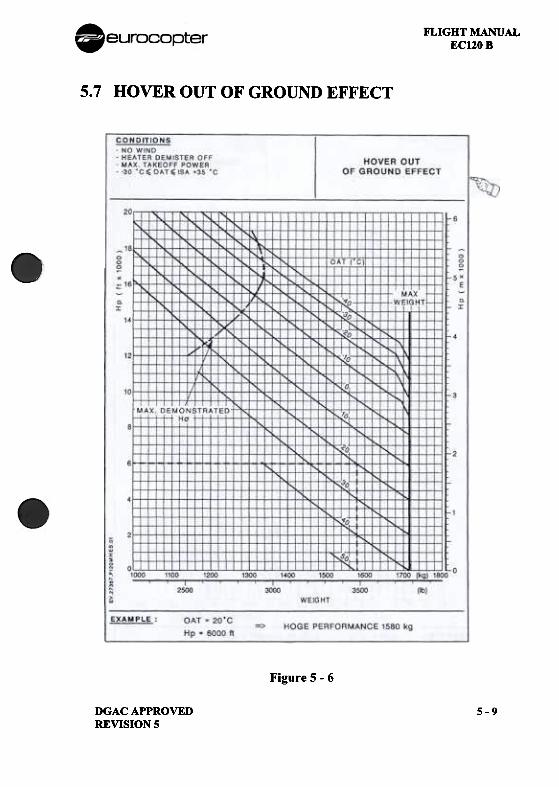
FLIGHT MANUALEC120 B
5.7 HOVER OUT OF GROUND EFFECT
Figure 5 -6
DGAC APPROVEDREVISION 5
5-9
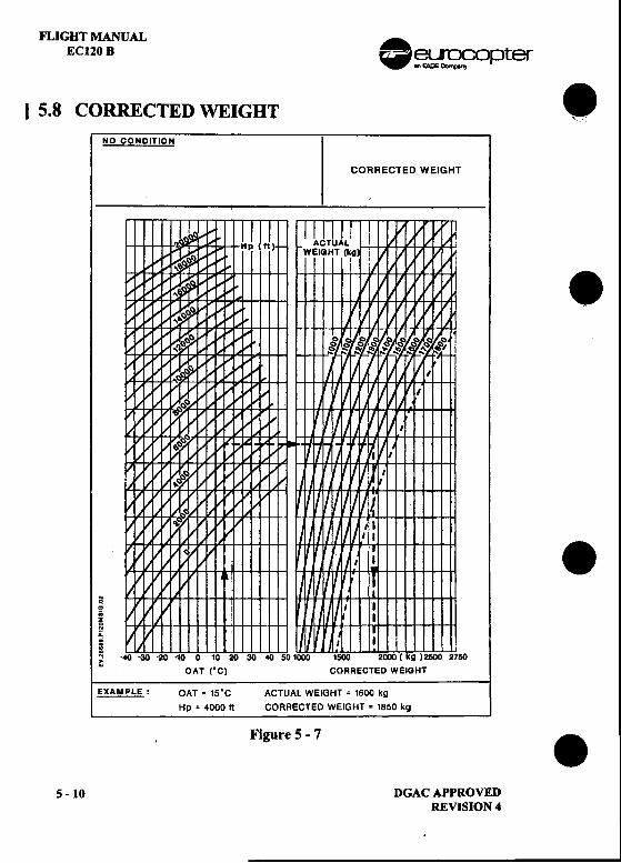
FLIGHT MANUALEC120 B .~~oPter
I 5.8 CORRECTED WEIGHT .NO CONOITION
CORRECTED WEIGHT
,
.I
.~
I.; I
i-Ii I I~ ---10 0 10 20 1500 2000 ( kg ) 2500 2750W OAT rC) CORRECTED WEIGHT
EXAMPLE: OAT = 15'C ACTUAL WEIGHT = 1600 kg
Hp .4000 It CORRECTED WEIGHT' 1850 kgFigure 5-7 .S -10 DGAC APPROVED
REVISION 4
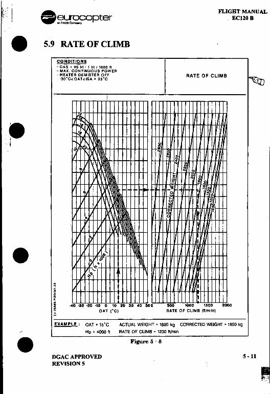
I .f FLIGHT MANUAL! O~~ ~pter EC120 B
.5.9 RATEOFCLIMB
CONDITIONS-CAS' 65 kl .1 kt 11000 It.MAX. CONTINUOUS POWER.HEATER DEMISTER OFF RATE OF CLIMB-.30.C~OAT~ISA + 35.C ~
.I c
CG(If
G C(If C..
II-Z~
aU
.~ I;~ I i.;: -4D -30 .20 -10 0 10 20 30 40 500 500 1000 1500 2000
~ OAT ("C) RATE OF CLIMB Iftlmln)~
EXAMPLE: OAT. 1S.C ACTUAL WEIGHT = 1600 kg CORRECTED WEIGHT = 1850 kg
..Hp = 4000 It RATE OF CLIMB = 1230 ft/min
.Figure 5 -8
DGAC APPROVED 5 -11REVISION 5
FLIGHT MANUAL .EC120 B ~~opter
5.10 GLmE DISTANCE IN AUTO ROTATION .The distance flown in autorotation is :
I 0.7 Nm (1300 m)/1000 ft at Vy and NR == 410 rpm
5.11 NOISE LEVELNoise characteristics defined by chapter 11 and appendix 4 of the ICAOannex 16 are as follows: .
Measurement Noise Level ICAO Noise Limits
Reference Point SEL dBA SEL dBA
Overflight 78.7 85.4(at Max. gross weight)
.
.S -12 DGAC APPROVED
REVISION S
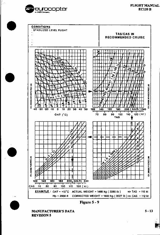
.A. n..IGBT MANUAL~~~ opter EC120 B. CONDITIONS
-STABILIZED LEVEL FLIGHT
TAS/CAS INRECOMMENDED CRUISE
.:8~ 'Ii. :: i '" '"
Q '"~'-
~i, ~ g
u .w ()c --~() ---()..()~ wg z~ ~.; .;~ ~..ftG ~ft ft>' >'w -40 -30 --1 180 200 ( km/h ) 240 w
, I ' I ' I ' I ' I I I '
OAT IC) 70 80 90 100 110 120 (kl)TAS t
.g gu u..wc c() U
~ >:..~ =N ~~ NN .>' >w w
1:u 1 ';U, ',QU, ,IQU, ,~UT'\,~'"f"',~.CAS 70 80 90 100 110 120 ( kl )
EXAMPLE: OAT = +15"C ACTUAL WEIGHT = 1488 kg (32BO Ib) = TAS = 115 kt
., Hp = 2000 It CORRECTED WEIGHT = 1600 kg ( 3527 Ib ) = CAS = 112 kt
.Figure 5 -9
MANUFACTURER'S DATA 5 -13REVISION S
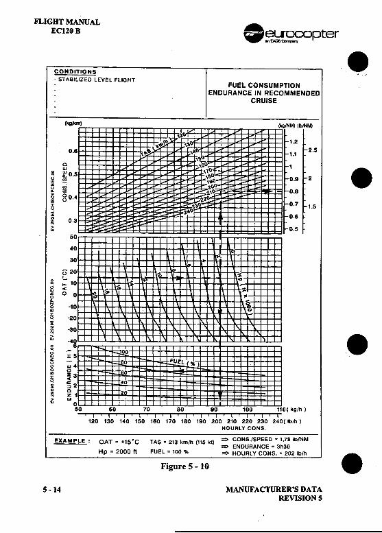
FLIGHT MANUALECI20 B .~~ opter
CONDITIONS -.STABILIZED LEVEL FLIGHT-FUEL CONSUMPTION: ENDURANCE IN RECOMMENDED-CRUISE
.(kg,1<m) (lcg1NM) (lblNM)
\2: I !, ~~\"> \~O ; : 1.2
0.8 :\"~ \~O I 1.1 2.5
: ~~O~: \6' 1
0 w \10.~ no 0.5 \SO. 2
'" !!? i ",90 0.9~ .,; , , 2.00~ z ..i i\O 0.8g g 0.4 I ZZO
~ 'l.~0 0.7 1.5
..Z~O~ 0.8~ 0.3 .,; ,
0w .5
50I
40to30 ...
.u 20 ..I $0 -I -0~ I- 10 ,... ~ ,-~ < ~ ~~ 0 0 ~ ~ ..
N. 00 -10 0..0% ...q -20;~ -30,; .: -49~ -I 100 Iw x 5 ,~ -.80 FUEL ( ~ )"w. ,0 ()' .~ z3 ' 60~ -< I~ ~2 40~ ;:,N 0
~ z 1> W ''" 0 I
50 60 70 80 90 100 110( kg/h).I .I ' I .I ' I ' I ' I ' I ' I ' I ' I ' I ' I
120 130 140 150 160 170 180 190 200 210 220 230 240{ Ib/h )HOURLY CONS
EXAMPLE: OAT ~ +1S.C TAS ~ 213 km/h (115 kt) => CONS./SPEED =1,78 Ib/NM=> ENDURANCE = 3h30
Hp = 2000 ft FUEL = 100 % ~ HOURLY CONS. = 202 Ib/h .Figure 5 -10
5-14 MANUFAcruRER'SDATAREVISION 5
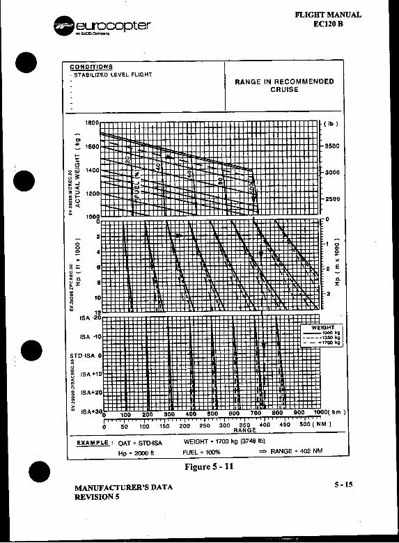
. FLIGHT MANUAL~~r;;apter EClZO B
.CONDITIONS-STABILIZED LEVEL FLIGHT
RANGE IN RECOMMENDEDCRUISE
1800 ( Ib )
c:. 1600 3500
~ 0 I,,'" ;-0. g UI 1400 ..00 ~ co I 3000
w-, 0~< G
~ =' 1200at-~ ~ 2500
,.:w 10000 0
-20 -
0 1 00 4 0-0X -
0 -8 X~:. 2 Ew~c. -":I: 8 c.~ :I:.;~ 10 3
,.:w
12ISA -20
WEIGHT
ISA -10 ,_1000kg. , 1350 kg ---1700 kg
STD-ISA 000
f;j -:~ ISA +10 '"...,;;i ISA+20
,.:w ISA+300 100 200 300 400 500 600 700 800 900 1000(km)
t' , , '~~:-, , ;~~; , ;i~" 20~ -,-, 2~~ i i 300 ' , 3~0 ' , ~OO ., ~~o ' .500 ( ~'M )
RANGE
EXAMPLE: OAT = STD-ISA WEIGHT = 1700 kg (3748lb)
Hp = 2000 It FUEL = 100% = RANGE = 402 NM
.Figure5-11MANUFACTURER'S DATA 5 -15
REVISION 5
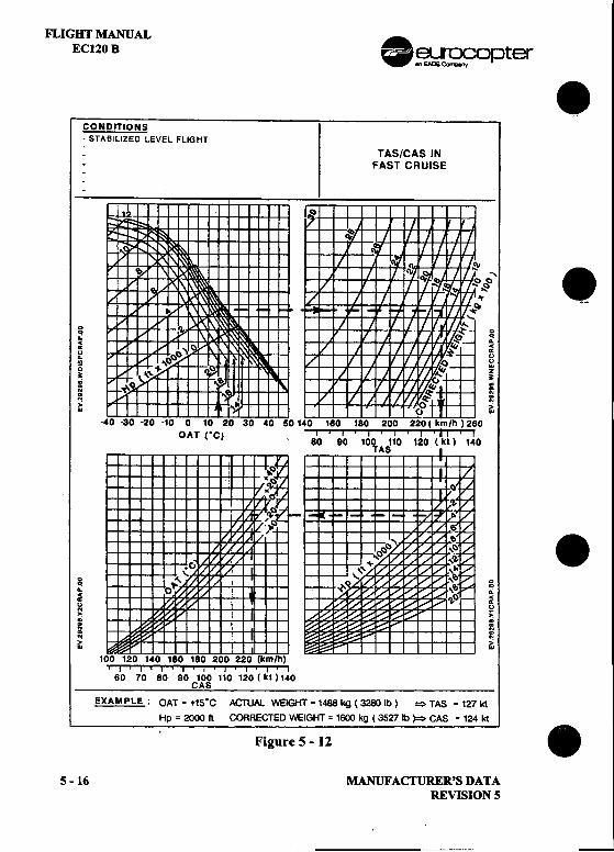
FLIGHT MANUAL .EC120 B ~~::opter .CONDITIONS-STABILIZED LEVEL FLIGHT
TAS/CAS INFAST CRUISE
$' .0 00 0.: .:c c~ ~" "
.."~ ..Q z~ ~
~
0 ~~ .-N ~~ .-" ,;~ ..
OAT ,CI 80 .9'0 .100 .110 ' 120(lk~) , 1~0
.0 00 0.: .:c ..~ ~" "N -> "oi :~ NN ~~ .-" ,;> ....
.I ' I .I .I .I .I .I ' I ' I
60 70 80 80 100 110 120 (kl)1.0CAS
EXAM PLE: OAT = +15"C ACTUAL WEIGHT = 1488 kg (3280 Ib) ~ TAS = 127 kt
Hp = 2000 It CORRECTED WEIGHT = 1EKJO kg ( 3527 Ib )=;> CAS = 124 ktFigure 5 -12 .5 -16 MANUFAcrURER'S DATA
REVISION 5
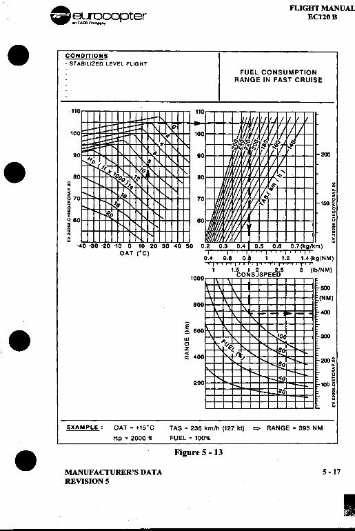
. i . eu"OCOpter FLIG~l~AL ~*~.,EAm""'.-ny. CONDITIONS
-STABILIZED LEVEL FLIGHT
FUEL CONSUMPTIONRANGE IN FAST CRUISE
110 110
100 10
90 9 200
. 80 80 00 0.: .:c c~ 70 7 ~~ 150 ~0 0~ .,: :q 80 8 q.....~>' >'w w
-4 ---)
OAT (OC) .0.4 0.8 0.8 1 1.2 1.4 (kg/NM)
'I"" I"" I"" I"" I'"1 1.5 I 2 2.5 3 (lb/NM)
100 CONS./SPEED
NM)80
E
.i6O <a: 40 200 g
.:cc"..
20 100 ~.;
~>'w
EXAMPLE: OAT = +15°C TAS = 236 km/h (127 k1) =:;> RANGE = 395 NM
Hp = 2000 ft FUEL = 100%
.Figure 5 -13
MANUFACTURER'S DATA 5-17REVISION 5
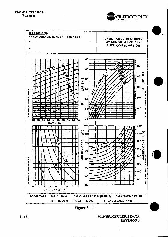
--
nIGHT MANUALEC120 B .~~opter
CONDITIONS 8..,-STABiliZED lEVEL FLIGHT TAS = 65 kl
ENDURANCE IN CRUISEAT MINIMUM HOURLYFUEL CONSUMPTION
40I
,,'\ 8045
~90- .=5 E~ ~
--,iID 100ID'C 5 <
g 0 00, 0
2% 2() ~~ 60 110 gN 20 0!Q --~() u" >: 65 120 :" "~ Q~ ~> >'" w
-40 -30 -20 '10 0 10 20 30 40 50 70
OAT ("C)100 220
:c- ~Q 90 200~~ .c-=-~ 8 180 ~0 00 0> 160> c-'7 -' .~ ~g- 140 g~ .
g x 6 x~, ~s ua 120 ~() NU 5 00 ..~ 100 ~u, G: 4 :
: 80 ~~ >> '""'023456783 "
ENDURANCE (h)
EXAMPLE: OAT = +15.c .ACTUAl. '/EGfr= 1488 kg (328J Ib) H().R.y~ = 1461b,t1
Hp = 2000 fI FUEL = 100% =:> ENDURANCE = 4h54
Figure 5 -14 .5 -18 MANUFACTURER'S DATA
REVISION 5
. FLIGHT MANUALeurocopter ECl20 B
.SECTION 6
WEIGHT AND BALANCEPage
6.1 GENERAL 6 -16.2 WEIGHT AND BALANCE 6-1
6.2.1 WEIGHT -STANDARD DEFINITIONS 6 -16.2.2 CENTER OF GRAVITY CONVENTIONAL TERMS 6 -2
. 6.3 WEIGffiNG 6 -36.4 LONGITUDINAL CG LOCATION 6 -3
6.4.1 CALCULATING CG 6 -36.4.2 LOADING DATA 6 -56.4.3 CG CHARTS 6 -9
6.5 LATERAL CG 6 -126.5.1 CREW AND .PASSENGERS 6 -126.5.2 DETERMINATION OF LATERAL CG LOCATION 6 -14
6.6 WEIGHT AND MOMENT OF EQUIPMENT ITEMS 6 -15
.
.MANUFACTURER'S DATA 6 -i
ORIGINAL ISSUE
FLIGHT MANUAL AEC120B .eurocopter .
LIST OF FIGURESPage
FIGURE 6 -1: BASIC DATUM PLANES 6 -2FIGURE 6 -2 : LONGITUDINAL LOCATION OF SEATS 6 -5FIGURE 6 -3: LONGITUDINAL LOCATION OF LOADS 6 -6FIGURE 6 -4: WNGITUDINAL LOCATION OF FUEL 6 -8FIGURE 6 -5 : CENTER OF GRAVITY 6 -10/6 -11FIGURE 6 -6 : LATERAL LOCATION OF SEATS ANDLOADS 6 -12 .
.
.6 -ii MANUFACTURER'S DATA
ORIGINAL ISSUE
FLIGHT MANUALEC120 B
6.1 GENERALThe purpose of this section is to provide data for use when evaluating aproposed loading configuration or calculating the weight and center of gravityof an aircraft in service.
6.2 WEIGHT AND BALANCE6.2.1 Weight -Standard Defmitions
.Empty Weight (EW)
This corresponds to the sum of the permanent assemblies and
equipment:
-The vehicle and its power plant.
-Equipment common to all missions.
-Lubricants and hydraulic fluids.
-Unusable fuel.
EW then, is constant for a given aircraft.
.Equipped Empty Weight (EEW)
This is the sum of :
-Empty weight (EW)
-Specific operational or mission equipment.
EEW varies according to the proposed mission.
.All-up Weight (AUW)
This is the sum of :
-Equipped empty weight (EEW)
-Crew
-Payload-Usable fuel
.Maximum Weight
Weight is limited on takeoff and landing. See limitations
(SECTION 2).
MANUFACTURER'S DATAORIGINAL ISSUE
6-1
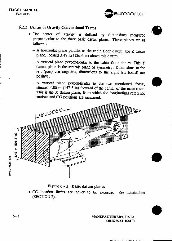
FLIGHT MANUAL Aeurocop terEC120 B .
6.2.2 Center of Gravity Conventional Terms .
.The center of gravity is defined by dimensions measuredperpendicular to the three basic datum planes. These planes are asfollows:
-A horizontal plane parallel to the cabin floor datum, the Z datumplane, located 3.47 m (136.6 in) above this datum.
-A vertical plane perpendicular to the cabin floor datum. This Ydatum plane is the aircraft plane of symmetry. Dimensions to theleft (port) are negative, dimensions to the right (starboard) arepositive.
.-A vertical plane perpendicular to the two mentioned above,situated 4.00 m (157.5 in) forward of the center of the main rotor.This is the X datum plane, from which the longitudinal referencestations and CG positions are measured.
:5'=cD
gE
~: .C! ..:--~0Q
g"w,,:~
Figure 6 -1 : Basic datum planes.CG location limits are never to be exceeded. See Limitations
(SECTION 2). .6-2 MANUFACTURER'S DATA
ORIGINAL ISSUE
FLIGHT MANUAL.~'};}[~9opter EC120 B. 'k,f~riC"T"Tffi'I'~~ ':~~~A~\i:J:; ~l'~ ,..," -'-'= =,
A CG location which is correct on takeoff may vary duringthe mission, due to the reduction in load and
therefore exceed acceptable limits.
-Longitudinal CG must be monitored more closely.
-Lateral CG need be considered only in very asymmetrical loadingconfigurations.
.6.3 WEIGmNGWeighing is the only reliable way of obtaining:
.Equipped empty weight (EEW).
.Aircraft center of gravity (CG) location.
The aircraft must be weighed:
.On leaving the works.
.Following any major modification.
6.4 LONGITUDINAL CG LOCATION6.4.1 Calculating CG
.Procedure. The distance from the aircraft center of gravity to the datum plane is
obtained using the formula:
Sum of moments ..S f . ht = CG In flIght order.um 0 weIg s
.MANUFACTURER'S DATA 6 -3REVISION 5
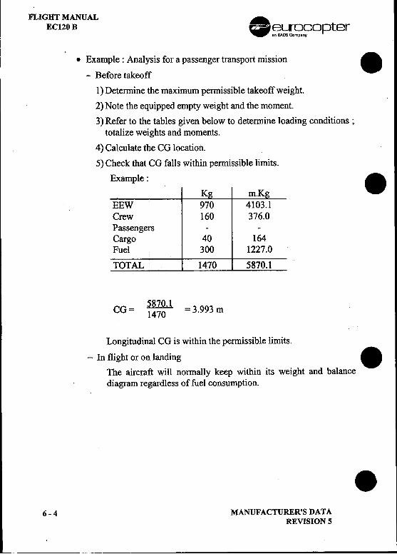
FLIGHT MANUAL .EC120 B ~~S?~opter
.Example: Analysis for a passenger transport mission .
-Before takeoff
1) Determine the maximum permissible takeoff weight.
2) Note the equipped empty weight and the moment.
3) Refer to the tables given below to determine loading conditions;totalize weights and moments.
4) Calculate the CG location.
5) Check that CG falls within permissible limits.
Example: .K m.K
EEW 970 4103.1Crew 160 376.0Passengers --Cargo 40 164Fuel 300 1227.0
TOTAL 1470 5870.1
CG= ~ =3.993m
Longitudinal CG is within the permissible limits.
-In flight or on landing .
The aircraft will normally keep within its weight and balancediagram regardless of fuel consumption.
.6-4 MANUFACTURER'S DATA
REVISION 5
-~--
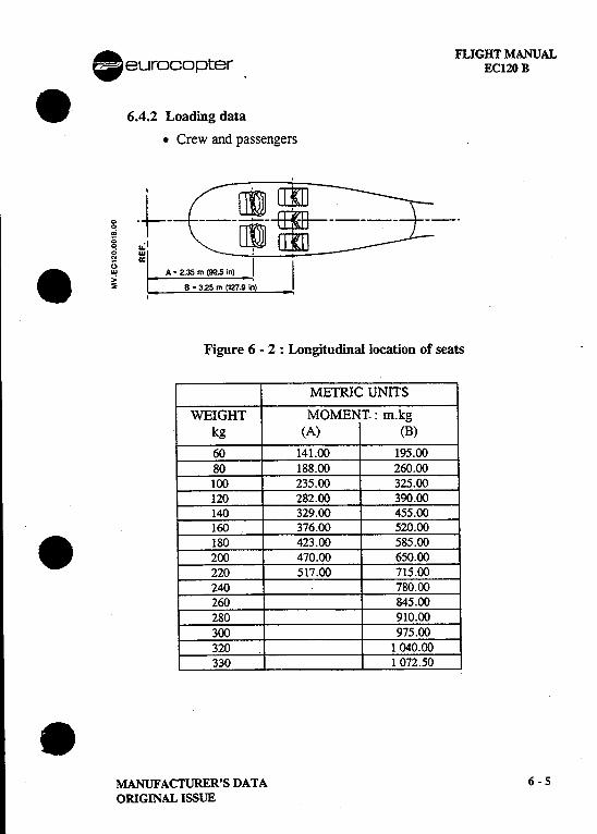
. FLIGHT MANUALeurocopter .EC120 B
.6.4.2 Loading data
.Crew and passengersI
i t-Cj~m::::=~ ~-.IL -\:==~~~~[~!J~J=~~=~==~=L=. ~ ~ I A .2.35 m (92:~-r-"'
1~ t "-~;,'~:s~:~~.;~) -!,
Figure 6 -2 : Longitudinal location of seats .
METRIC UNITS
WEIGHT MOMENT. : m.kgkg (A) (B)
60 141.00 195.0080 188.00 260.00100 235.00 325.00120 282.00 390.00140 329.00 455.00160 376.00 520.00
. 180 423.00 585.00200 470.00 650.00220 517.00 715.00240 780.00260 845.00280 910.00300 975.00320 1 040.00330 1 072.50
.MANUFACTURER'S DATA 6 -5
ORIGINAL ISSUE
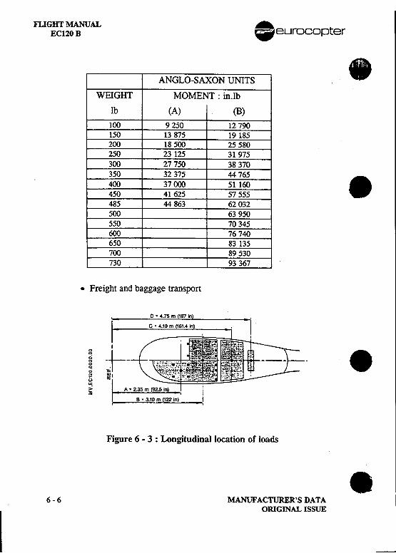
FLIGHT MANUAL .EC120 B eurocopter
ANGLO-SAXON UNITS .WEIGHT MOMENT: in.lb
lb (A) (B)
100 9250 12790150 13875 19185200 18 500 25 580250 23 125 31 975300 27750 38370350 32 375 44 765400 37 000 51 160 .450 41 625 57555485 44 863 62 032500 63 950550 70345600 76 740650 83 135700 89530730 93 367
.Freight and baggage transport
I ~ ~ .~.r5 m!'87i!!) -i
I .C .4.10 m (161.4 in), -j !
I
i -~- .0; ..:1N W
I-~.,..~ A .2.35 m (92.5 in)
i .B .3.10 m (122 in) -l
Figure 6 -3 : Longitudinal location of loads .6-6 MANUFACruRER'SDATA
ORIGINAL ISSUE
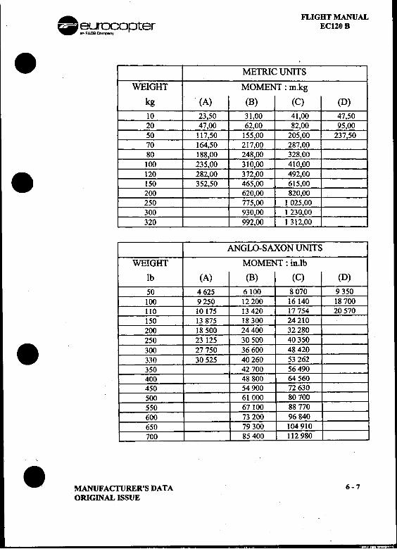
. FLIGHT MANUAL~~opter EC120 B
.METRIC UNI;S
WEIGHT MOMENT: m.kg
kg (A) (B) (C) (D)10 23,50 31,00 41,00 47,5020 47,00 62,00 82,00 95,0050 117,50 155,00 205,00 237,5070 164,50 217,00 287,0080 188.00 248,00 328,00100 235,00 310,00 410,00
. 120 282,00 372,00 492,00150 352,50 465,00 615,00200 620,00 820,00250 775,00 1 025,00300 930,00 1 230,00320 992,00 1 312,00
ANGLO-SAXON UNITS
WEIGHT MOMENT: in.lb
Ib (A) (B) (C) (D)
50 4625 6100 8070 9350100 9250 12200 16140 18700110 10175 13420 17754 20570150 13875 18300 24210200 18500 24400 32280250 23 125 30 500 40350
. 300 27 750 36 600 48 420330 30 525 40 260 53 262350 42 700 56490400 48 800 64 560450 54900 72630500 61000 80700550 67 100 88770600 73 200 96 840650 79300 104 910700 85400 112980
.MANUFACTURER'S DATA 6-7ORIGINAL ISSUE
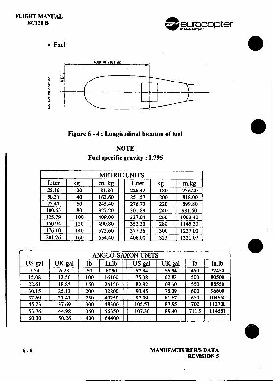
FLIGHT MANUALEC120 B .~~copter
.Fuel .4.09 m 161 in
0 ::-;1'" ~
'" I
! -t- > I
~
Figure 6 -4: Longitudinal location of fuel .
NOTEFuel specific gravity: 0.795
METRIC UNITSLiter k m. k Liter k25.16 20 81.80 226.42 180 .50.31 40 163.60 251.57 200 818.0075.47 60 245.40 276.73 220 899.80100.63 80 327.20 301.89 240 981.60125.79 100 409.00 327.04 260 1063.40150.94 120 490.80 352.20 280 1145.20176.10 140 572.60 377.36 300 1227.00201.26 160 654.40 406.00 323 1321.07 .
ANGLO-SAXON UNITSUS al UK al lb in.lb US al UK al lb in.lb
7.54 6.28 50 8050 67.84 56.54 450 7245015.08 12.56 100 16100 75.38 62.82 500 8050022.61 18.85 150 24150 82.92 69.10 550 8855030.15 25.13 200 32200 90.45 75.39 600 9660037.69 31.41 250 40250 97.99 81.67 650 10465045.23 37.69 300 48300 105.53 87.95 700 11270053.76 44.98 350 56350 107.30 89.40 711.5 11455160.30 50.26 400 64400 .
6-8 MANUFACTURER'S DATAREVISION 5
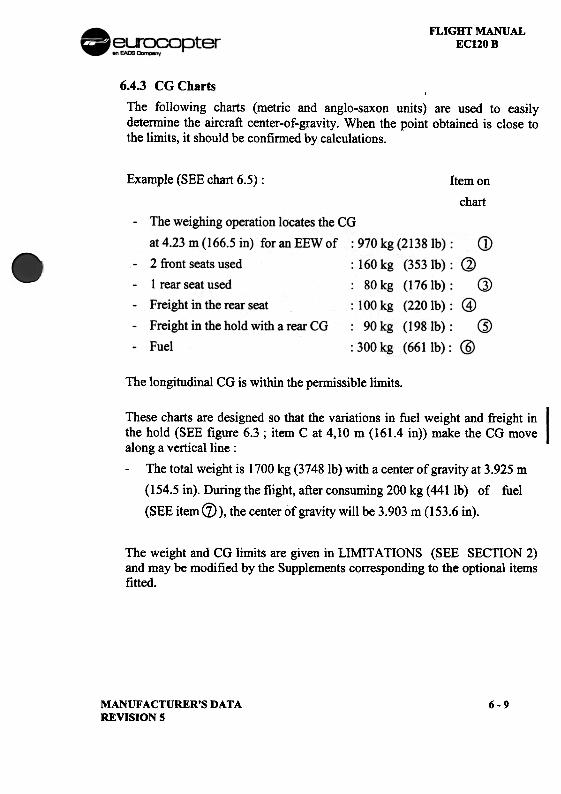
FLIGHT MANUALEC120 B
6.4.3 CG Charts
The following charts (metric and anglo-saxon units) are used to easilydetermine the aircraft center-of-gravity. When the point obtained is close tothe limits, it should be confirmed by calculations.
Example (SEE chart 6.5) : Item on
chart
The longitudinal CG is within the pennissible limits.
These charts are designed so that the variations in fuel weight and freight inthe hold (SEE figure 6.3 ; item C at 4,10 m (161.4 in)) make the CG movealong a vertical line :
-The total weight is 1700 kg (37481b) with a center of gravity at 3.925 m
(154.5 in). During the flight, after consuming 200 kg (4411b) of fuel
(SEE item (Z)), the center of gravity will be 3.903 m (153.6 in).
The weight and CG limits are given in LIMITATIONS (SEE SECTION 2)and may be modified by the Supplements corresponding to the optional itemsfitted.
MANUFACTURER'S DATAREVISION S
6-9
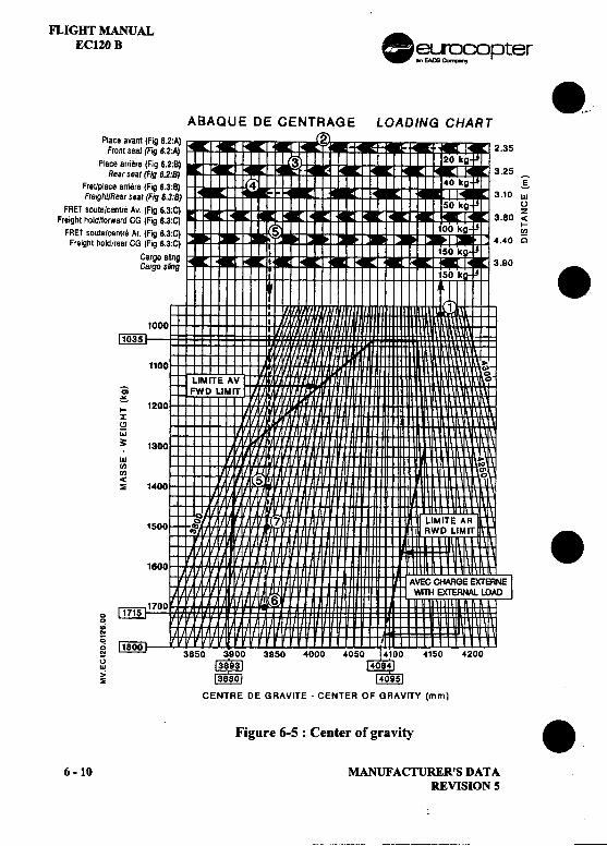
FLIGHT MANUALEC120 B .~ ~copter
8.ABAQUE DE CENT RAGE LOADING CHART"
Place avant (Fig 6.2:A) 2Front seat (Fig 6.2:A)
Place arrjere (Fig 6.2:8)Rear seat (Fig 6.2:8) ~
Fret/place aniere (Fig 6.38) gFreight/Reafseat(Fig6.3:8) 3.10 w
FRET saute/centre Av. (Fig 6.3:C) ~Freight hold/lorward CG (Fig 6.3:C) 3.80 -<
FRET saute/centre Ar. (Fig 6.3:C) 5 ~Fre~ht hold/rear CG (Fig 6.3:C) 4.40 0
Cargo slingCargo sUng I 3.90 .1000
1035
1100
LIMITE AVa FWD LIMIT~
;: 1200z
~w3: 1300
wCJ)
CJ)
~ 1400 5
15001600 .0 171517000
.;co
0,; 1800~ 38500w
>~
CENTRE DE GRAVITE -CENTER OF GRAVITY (mm)
Figure 6-5 : Center of gravity .6 -10 MANUFACI'URER'S DATA
REVISION 5
---~--
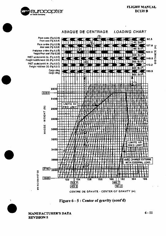
. FLIGHT MANUAL~~C?O~Jter ECl20 B
.ABAQUE DE CENTRAGE LOADING CHARTPlace avant (Fig 62:A) 2
Front seat (Fig 6.2:A)
Place alTiere (Fig 6.2:8)Rear seat (Fig 6.2:S) -c:
Fret/place arriere (Fig 6.3:8) '=-
Freight/Rear seat (Fig 6.3:S) ~FRET soule/centre Av. (Fig 6.3:C) Z
Freight holdlforward CG (Fig 6.3:C) ~
FRET soule/centre Ar. (Fig 6.3:C) 5 ~Frelghl hold/rear CG (Fig 6.3:C)
Cargo slingCargo sling I 153.5
.II
240
LIMITE AV
g FWD LIMIT
l-X(!J
W 280~wCJ)CJ) 3000(~
320
.3400 3600
00.:..(;g 164 166
()"!>s
CENTRE DE GRAVITE -CENTER OF GRAVITY (in)
, Figure 6 -5: Center of gravity (cont'd)
.MANUFACTURER'S DATA 6-11REVISION S
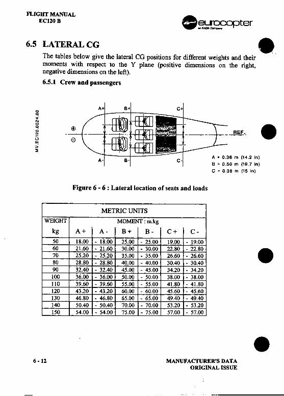
FLIGHT MANUAL .EC120 B ~~opter
6.5 LATERAL CG ..The tables below give the lateral CG positions for different weights and theirmoments with respect to the Y plane (positive dimensions on the right,negative dimensions on the left).
6.5.1 Crew and passengers
0~...'"
; -B-E.E .-.()II!>~
A = 0.36 m (14.2 in)A- --
B = 0.50 m (19.7 in)
C = 0.38 m (15 in)
Figure 6 -6 : Lateral location of seats and loads
METRIC UNITSWEIGHT MOMENT: m.kg
kg A+ A- B+ B- C+ C-
50 18.00 -18.00 25.00 -25.00 19.00 -19.00
60 21.60 -21.60 30.00 -30.00 22.80 -22.80 .70 25.20 -25.20 35.00 -35.00 26.60 -26.60
80 28.80 -28.80 40.00 -40.00 30.40 -30.40
90 32.40 -32.40 45.00 -45.00 34.20 -34.20
100 36.00 -36.00 50.00 -50.00 38.00 -38.00
110 39.60 -39.60 55.00 -55.00 41.80 -41.80
120 43.20 -43.20 60.00 -60.00 45.60 -45.60
130 46.80 -46.80 65.00 -65.00 49.40 -49.40
140 50.40 -50.40 70.00 -70.00 53.20 -53.20
150 54.00 -54.00 75.00 -75.00 57.00 -57.00 .6-12 MANUFACTURER'S DATA
ORIGINAL ISSUE
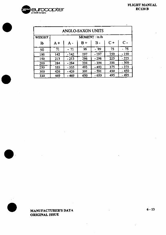
. FLIGHT MANUAL~~~opter ECI20 B
.ANGLO-SAXON UNITS .
WEIGHT MOMENT: in.lb
lb A+ A- B+ B- C+ C-
50 71 -71 99 -99 75 -75
100 142 -142 197 -197 150 -150150 213 -213 296 -296 225 -225200 284 -284 394 -394 300 -300250 355 -355 493 -493 375 -375300 426 .426 591 -591 450 -450
.330 469 -469 650 -650 495 -495
..MANUFACTURER'S DATA 6-13
ORIGINAL ISSUE
..,.. ..."
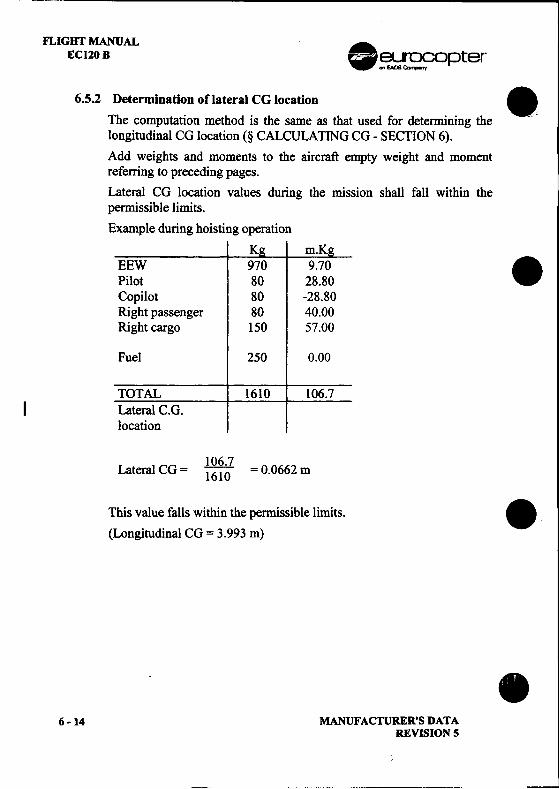
FLIGHT MANUALEC120B .~~opter
6.5.2 Determination of lateral CG location .The computation method is the same as that used for determining the --
longitudinal CG location (§ CALCULATING CG -SECTION 6).Add weights and moments to the aircraft empty weight and momentreferring to preceding pages.Lateral CG location values during the mission shall fall within thepermissible limits.
Example during hoisting operationK
EEW 970. .Pilot 80 28.80Copilot 80 -28.80Right passenger 80 40.00Right cargo 150 57.00
Fuel 250 0.00
TOTAL 1610 106.7I Lateral C.G.
location
106.7Lateral CG = 1610 = 0.0662 m
This value falls within the permissible limits. .(Longitudinal CG = 3.993 m)
.6-14 MANUFACTURER'S DATA
REVISION 5
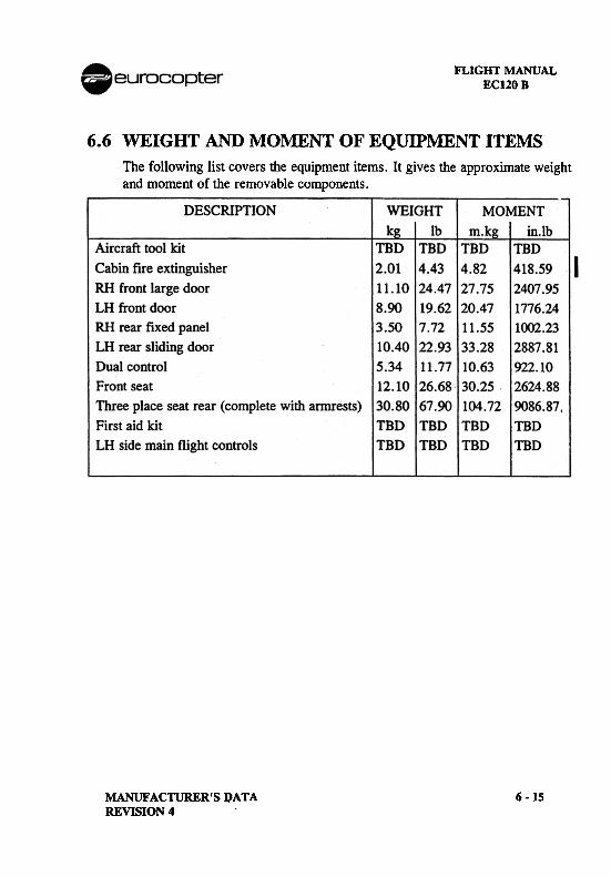
FLIGHT MANUALECl20B
6.6 WEIGHT AND MOMENT OF EQUIPMENT ITEMSThe following list covers the equipment items. It gives the approximate weightand moment of the removable components.
MANUFACTURER'S DATAREVISION 4
6 -15
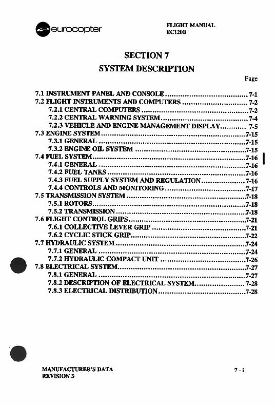
FLIGHT MANUALEC120B
SECTION 7
SYSTEM DESCRIPTIONPage
7.1 INSTRUMENT PANEL AND CONSOLE 7-17 .2li1..IGHT INSTRUMENTS AND COMPUTERS 7-2
7.2.1 CENTRAL COMPUTERS 7-27.2.2 CENTRAL WARNING SYSTEM 7-47.2.3 VEmCLE AND ENGINE MANAGEMENT DISPLAY 7-5
7.3 ENGINE SYSTEM '1-157.3.1 GENERAL '1-157.3.2 ENGINE OIL SYSTEM 7-15
7.4 FUEL SYSTEM 1-167.4.1 GENERAL 1-167.4.2 FUEL TANKS '1-167.4.3 FUEL SUPPLY SYSTEM AND REGULATION 7-167.4.4 CONTROLS AND MONITORlNG 7-17
7.5 TRANSMISSION SYSTEM 7-187.5.1 ROTORS 1-187.5.2 TRANSMISSION '-18
7.6li1..IGHT CONTROL GRIPS 7-217.6.1 COLLECTIVE LEVER GRIP 7-217.6.2 CYCLIC STICK GRIP 7-22
7.7 HYDRAULIC SYSTEM j-247.7.1 GENERAL 1-247.7.2 HYDRAULIC COMPACT UNIT 7-26
7.8 ELECTRICAL SYSTEM 7-277.8.1 GENERAL 1-277.8.2 DESCRIPTION OF ELECTRICAL SYSTEM 7-287.8.3 ELECTRICAL DISTRIBUTION 7-28
MANUFACTURER'S DATAREVISION 3
7-i
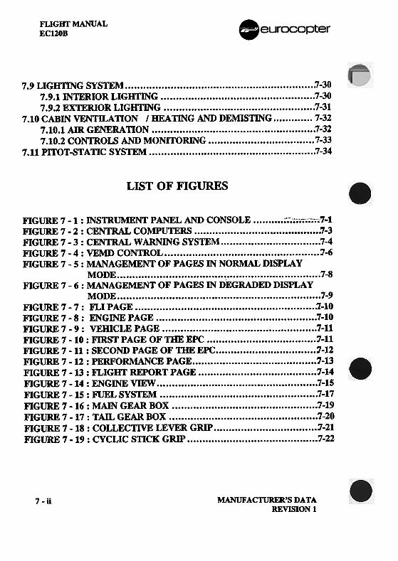
FLIGHT MANUALECl20B
7.9 LIGHTING SYSTEM 7-307.9.1 INTERIOR LIGIrrlNG 7-307.9.2 EXTERIOR LIGIrrlNG 7-31
7.10 CABIN VENTaAll0N I HEATING AND DEMIS11NG 7-327.10.1 AIR GENERA110N 7-327.10.2 CONTROl$ AND MONITORING 7-33
7.11 PITOT-STA11C SYSTEM 7-34
LIST OF FIGURES
FIGURE 7 -1 : INSTRUMENT PANEL AND CONSOLE ;-.-~;;~;~'~;,;.7-1FIGURE 7 -2 : CENTRAL COMPUTERS 7-3FIGURE 7 -3: CENTRAL WARNING SYS1EM 7-4FIGURE 7 -4: VEMD CONTROL j-6FIGURE 7 -5: MANAGEMENT OF PAGES IN NORMAL DISPLAY
MODE 7-8FIGURE 7 -6: MANAGEMENT OF PAGES IN DEGRADED DISPLAY
MODE 7-9FIGURE 7 -7: FLI PAGE 1-10FIGURE 7 -8: ENGINE PAGE 7-10FIGURE 7 -9: VElDCLE PAGE 7-11FIGURE 7 -10 : FIRST PAGE OF THE EPC j-l1FIGURE 7 -11 : SECOND PAGE OF mE EPC j-12FIGURE 7 -12 : PERFORMANCE PAGE 1-13FIGURE 7 -13 : FLIGHT REPORT PAGE 1-14FIGURE 7 -14 : ENGINE VIEW 7-15FIGURE 7 -15 : roEL SYSTEM 7-17F1GURE 7 -16 : MAIN GEAR BOX 1-19F1GURE 7 -17: TAIL GEAR BOX 7-20FIGURE 7 -18 : COLLECTIVE LEVER GRIP '1-21F1GURE 7 -19 : CYCLIC STICK GRIP 1-22
MANUFACTURER'S DATAREVISION 1
7-ii
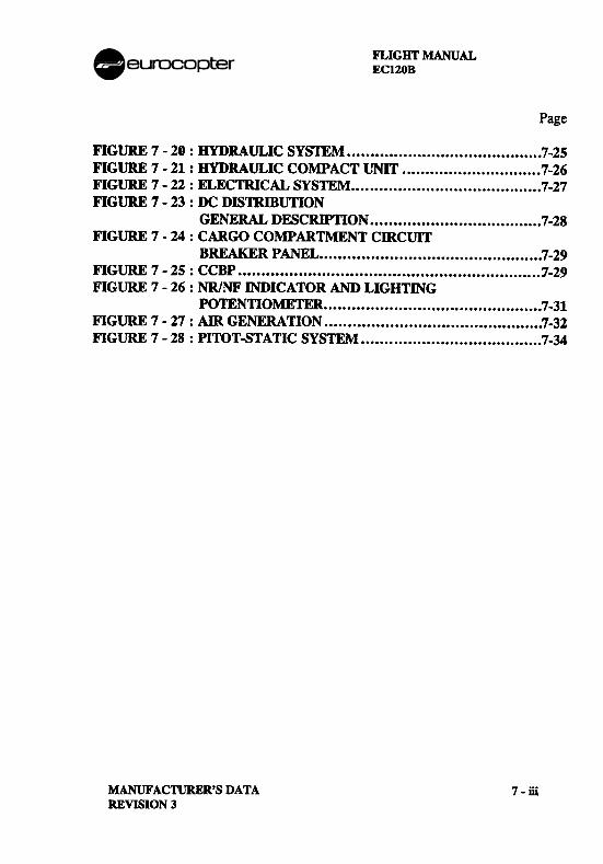
FLIGHT MANUALECl20B
Page
FIGURE 7 -20: HYDRAULIC SYSTEM 7-25FIGURE 7 -21: HYDRAULIC CO~ACT UNff 7-26FIGURE 7 -22: ELECTRICAL SYSTEM 7-27FIGURE 7 -23 : DC DISTRIBUTION
GENERAL D~CRlPnON 7-28FIGURE 7 -24 : CARGO COMPARTMENT CIRCUIT
BREAKER PANEL... 7-29FIGURE 7 -25: CCBP '1-29FIGURE 7 -26 : NR/NF INDICATOR AND LIGHTING
POTENTIOMETER 7-31FIGURE 7 -27 : AIR GENERATION 7-32FIGURE 7 -28 : PITOT-STATIC SYSTEM 7-34
MANUFACTURER'S DATAREVISION 3
7-ill

A FLIGHT MANUALW ~~r~o?°pter EC120B
.7.1 INSTRUMENTPANELANDCONSOLE
8
29
~___27
.~ 26115 .I 83 0
0 4 eGe ~
0(;;;\0[~~~~ ] Q \J
v EKJ [D22
1 -Gyro-compass 6 15 -CWPslaving unit. 16 -Airspeed indicator
2 -VCR indicator'3 -ELT control unit. 17 -NR/Nf indicator
4 -VEMD 18 -Clock chronometer'
5 -GPS .19 -Attitude indicator'6 -LACU 8 20 -Direct gyro-compass I HSI .
7 -ICS .9 21 -DME indicator'
. 8 .VCR -VHF I AM .22 -VCR I GPS switch'
9 .VHF I AM .10 23 -Vertical speed indicator''" 10 -TOR' 12 24 -Altimeter
~ 11 -CCBP 11 25 -Indicator light for swivelling~ 12 -Air conditioning' landing light'~ 13 -Servicing plug 26 -Indicator light for GPS .
(J"! 14 -Rotor phase 27 -Stand-by compass
~ reference plug 28 -Rotor brake
.OPTIONAL 13 14 29 -Fuel shut off cock
Figure 7- 1 : Instrument panel and console.MANUFACTURER'S DATA 7-1REVISION 5
FLIGHT MANUAL .EC120B .~~[~C?opter
7.2 FLIGHT INSTRUMENTS AND COMPUTERS .7.2.1 CENTRAL COMPUTERS
.GeneralThe central computers perform the ancillal"y service functions of thehelicopter. They include two subassemblies:
-the ancillary systems unit (ASU) (1),-the lighting and ancillary control unit (LACU) (2).
The ASU manages all the aural alarms, some visual warnings, and theprocessing of specific electrical signals.
The LACU includes all the electrical indicating and control .components of the main systems and lighting systems.
.CharacteristicsThe ASU and the LACU are both supplied with a dual 28 V DC powersupply, and are protected by circuit breakers.
.DescriptionThe ASU (1) performs the following functions:
-management of the II warning light,-generation of the aural max. and min. NR alarms,-management of aural "gong" alalms, due to red alarms and
maximum takeoff rating,-generation of the FLIGHT/GROUND signal for the VEMD,-time delay for maintaining the electro-magnetic pointer of the .twist grip after releasing the stalter button,
Em!-management of the IimI caution light,
.7-2 MANUFACTURER'S DATA
REVISION 5
---
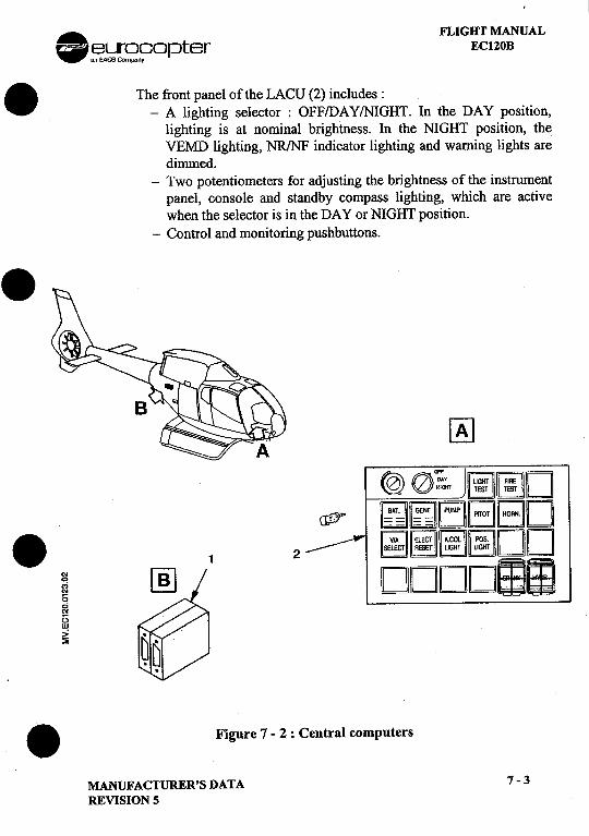
A. FLIGHT MANUAL-~~r9nC?opter ECl20B. The front panel of the LACU (2) includes:
-A lighting selector: OFF/DAY/NIGHT. In the DAY position,lighting is at nominal brightness. In the NIGHT position, theVEMD lighting, NR/NF indicator lighting and warning lights aredimmed.
-Two potentiometers for adjusting the brightness of the instrumentpanel, console and standby compass lighting, which are activewhen the selector is in the DAY or NIGHT position.
-Control and monitoring pushbuttons..~
@ a'F DAY LKJHT FUOE
<2) CO.'eiT ~I:[;]D
c1fJJ'" ~~~BIE]D. r;1 ~ ~ r;;;";1DD1 2 ~~~~
; DDDDEJci'"1:)w
>=~
.Figure 7 -2 : Central computers
MANUFACTURER'S DATA 7-3
REVISION 5
"",,,.,
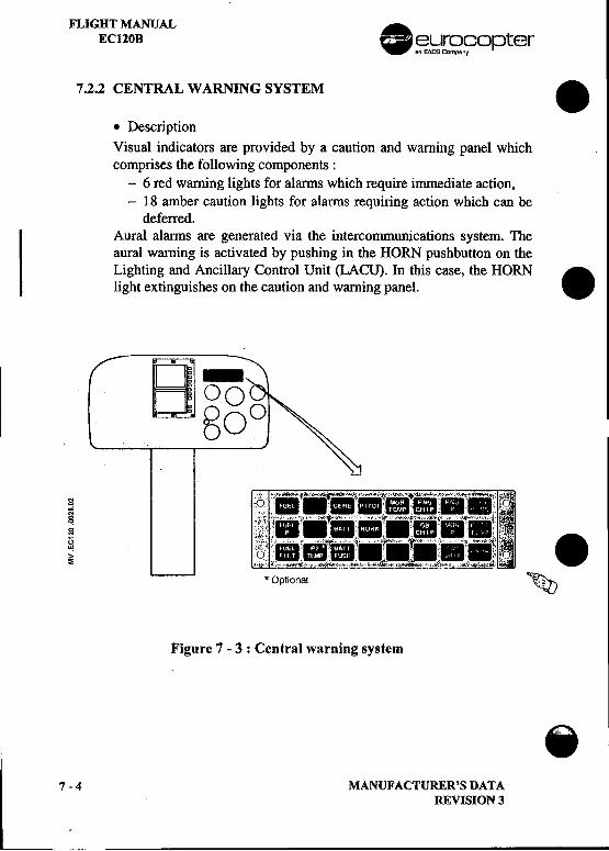
FLIGHT MANUAL .EC120B ~.};ir~fopter
7.2.2 CENTRAL WARNING SYSTEM .
.DescriptionVisual indicators are provided by a caution and warning panel whichcomprises the following components:
-6 red warning lights for alarms which require immediate action,-18 amber caution lights for alarms requiring action which can be
deferred.Aural alarms are generated via the intercommunications system. Theaural warning is activated by pushing in the HORN pushbutton on theLighting and Ancillary Control Unit (LACU). In this case, the HORN .light extinguishes on the caution and warning panel.
'" :' '.'.-"i.':t.."iii:8\; ;;~!Oi 1~~~ ...,' '".U t'::';'i ..;. .,;.; c4'-'"""'~O"wi'ilo:",,",i, .,,;..~,.~i; ."! ~~;'. :_'.. r.I!.. l. '. e
~ ,2:, ~i~,"""'~"..c;J.,..",:;;,;~""""",~".;"""""..c.Jr,,;,,,,_:.t~ c,* Optional ~
Figure 7 -3 : Central warning system
.7-4 MANUFACTURER'S DATA
REVISION 3
-
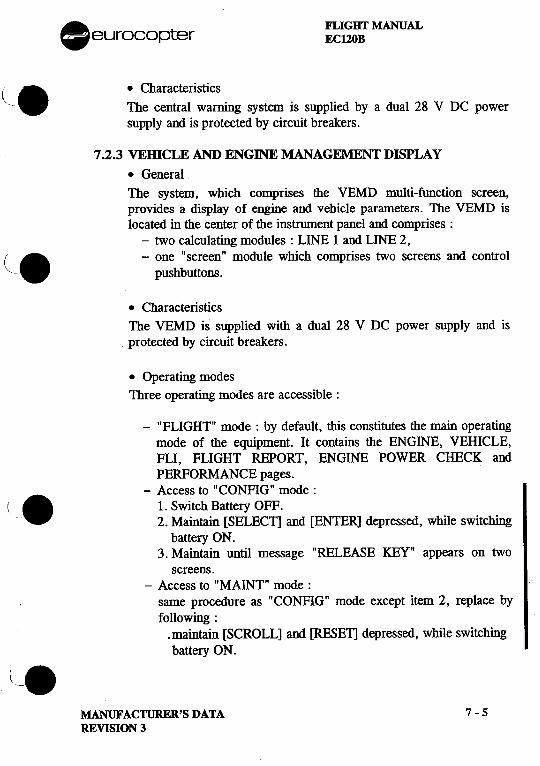
. FLIGHT MANUALeurocopter ECl20B
(. .Characteristics. ..I '- The central warnIng system IS supplIed by a dual 28 V DC power
supply and is protected by circuit breakers.
7.2.3 VEmCLE AND ENGINE MANAGEMENT DISPLAY
.GeneralThe system, which comprises the VEMD multi-function screen,provides a display of engine and vehicle parameters. The VEMD islocated in the center of the instrument panel and comprises:
-two calculating modules: LINE I and LINE 2,( . -one" screen" module which comprises two screens and control,~- pushbuttons.
.CharacteristicsThe VEMD is supplied with a dual 28 V DC power. supply and isprotected by circuit breakers.
.Operating modesThree operating modes are accessible:
-"FLIGHT" mode: by default, this constitutes the main operatingmode of the equipment. It contains the ENGINE, VEHICLE,FLI, FLIGHT REPORT, ENGINE POWER CHECK andPERFORMANCE pages.
-Access to "CONFIG" mode:(. 1. Switch Battery OFF.
2. Maintain [SELECll and [ENTER] depressed, while switchingbattery ON.
3. Maintain until message "RELEASE KEY" appears on twoscreens.
-Access to "MAINT" mode:same procedure as "CONFIG" mode except item 2, replace by
following:.maintain [SCROLL] and [RESE1] depressed, while switchingbattery ON.(.
MANUFACTURER'S DATA 7 -5
REVISION 3
"..
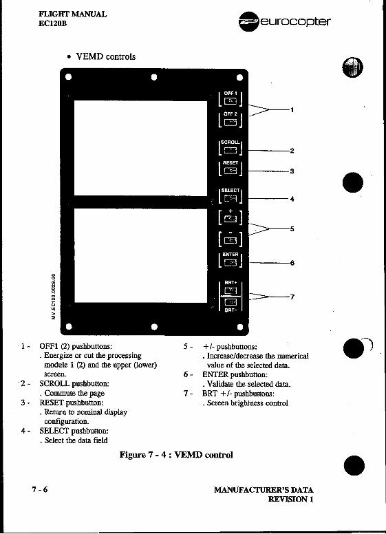
FLIGHT MANUAL .EC120B eurocopter
.VEMD controls .1
23 .4
5
6
00~N00
~ 7()~>~
1 -OFFl (2) pushbuttons: 5 -+/- pushbuttons: . -).Energize or cut the processing .Increase/decrease the numerical .
module 1 (2) and the upper (lower) value of the selected data.screen. 6 -ENTER pushbutton:
2 -SCROLL pushbutton: .Validate the selected data..Commute the page 7 -BRT +/- pushbuttons:
3 -RESET pushbutton: .Screen brightness control.Return to nominal display
configuration.4 -SELECT pushbutton:
.Select the data field
Figure 7 -4 : VEMD control .
7 -6 MANUFACTURER'S DATAREVISION 1
.
. FLIGHT MANUAL~ eurocopter ECl20B. .Operation
The VEMD is switched on when the "BAT' switch is set to "ON".
The eqlupment performs an initialization test which checks correctoperation of each of the two lines. During the test, the following messageis displayed:
"TEST IN PROGRESS"
If the test is faulty, the following is displayed:. " LANE 1 FAILED" or "LANE 2 FAILED""PRESS OFF 1 " "PRESS OFF2"
The line concerned can be cut by pressing the associated pushbutton(OFFI or OFF2). This validates the initialization tests and switches theremaining line to operating mode.
If tIle test is correct, tIle VEMD automatically goes to operating mode.
.FLIGHT mod.e
The flight mode is displayed by default, when no other mode is selected.The "SCROLL" pushbutton is used to scroll the pages as shown on the Ifollowing diagrams (Fig. 7.5 and Fig. 7.6). ..
.MANUFACTURER'S DATA 7 -7
REVISION 3
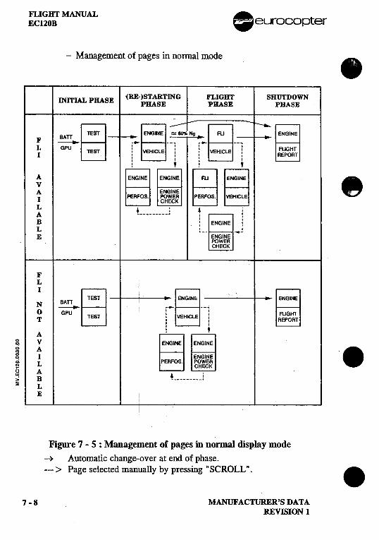
FLIGHT MANUAL .EC120B -eurocopter
-Management of pages in normal mode .
INITIAL PHASE '(RE-)STARTING FLIGHT SHUTDOWNPHASE PHASE PHASE
BATT~ST ~NGINE ~ -Ng ~F , ,
LI GPU TEST i VEHICLE i i VEHICLE i, I' I, I' I
! t; tA EJ 08 -~ E] BEl ~L 4; 4 :A , I :B I .
I I
L l_- iE
FL
; ~ ~EST ._~NGINE --;
0 'IGPU TEST : VEHICLE :T I I
II IA : t
~ V ~NGINE g A 8g I
g L PERfOS.
~ A 4 '> B ~~ L
E
Figure 7 -5 : Management of pages in normal display mode~ Automatic change-over at end of phase.---> Page selected manually by pressing "SCROLL". 8
7 -8 MANUFACTURER'S DATAREVISION 1
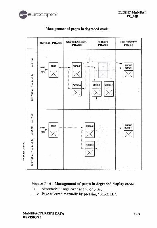
FLIGHT MANUALEC120B
Management of pages in degraded mode.
(RE-)STARTINGPHASE
FLIGHTPHASE
SHUTDOWNPHASE
INITIAL PHASE
FLI ..BATT-
GPU
-
.--~
AVAILABLE
...
.
FLI
N0T
AVAILABLE
BATT-GPU
~~
0'!;;00
~uw,,;~
Figure 7 -6 : Management of pages in degraded display mode~ Automatic change-over at end of phase.---> Page selected manually by pressing "SCROLL".
MANUFACTURER'S DATAREVISION 1
7-9
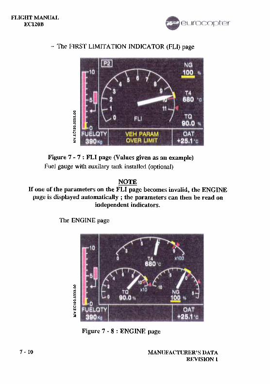
l"LIGHT MANUALECl20B
-The FIRST LIMITATION INDICA TOR (FLI) page
0~'"g~0'"()w>':z
Figure 7 -7 : FLI page (Values given as an example)Fuel gauge with auxilary tank installed (optional)
NOTEIf one of the parameters on the FLI page becomes invalid, the ENGINE
page is displayed automatically; the parameters can then be read onindependent indicators.
The ENGINE page
00
~0.,.;..;:;w>2
Figure 7 -8 : ENGINE page
7 -10 MANtrFACTURI~R'S DATAIU~VISION 1
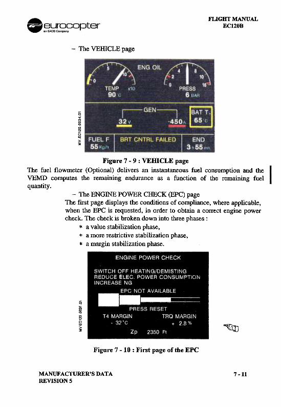
FLIGHT MANUALEC120B
-The VEffiCLE page
C'i...cC!c..1)"!>~
Figure 7 -9 : VEHICLE page
The fuel flowmeter (Optional) delivers an instantaneous fuel consumption and theVEMD computes the remaining endurance as a function of the remaining fuelquantity.
-The ENGINE POWER CHECK (EPC) pageThe first page displays the conditions of compliance, where applicable,when the EPC is requested, in order to obtain a correct engine powercheck. The check is broken down into three phases:
* a value stabilization phase,* a more restrictive stabilization phase,* a margin stabilization phase.
~~~()w>~ ~
Figure 7 -10: First page of the EPC
MANUFACTURER'S DATAREVISION 5
7-11
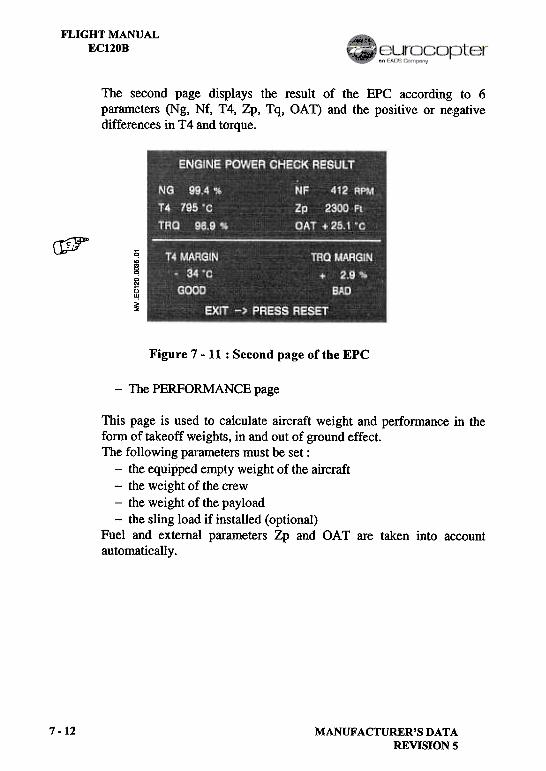
FLIGHT MANUALECl20B
The second page displays the result of the EPC according to 6parameters (Ng, Nf, T4, Zp, Tq, OAT) and the positive or negativedifferences in T4 and torque.
~ Ci'D
§~1:;~~
Figure 7 -11 : Second page of the EPC
-The PERFORMANCE page
This page is used to calculate aircraft weight and perfonnance in thefonD of takeoff weights, in and out of ground effect.The following parameters must be set:
-the equipped empty weight of the aircraft-the weight of the crew-the weight of the payload-the sling load if installed (optional)
Fuel and external parameters Zp and OAT are taken into accountautomatically.
7-12 MANUFACTURER'S DATAREVISION 5
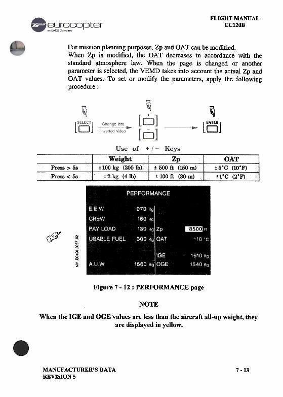
FLIGHT MANUALEC120B
For mission planning purposes, Zp and OAT can be modified.When Zp is modified, the OAT decreases in accordance with thestandard atmosphere law. When the page is changed or anotherparameter is selected, the VEMD takes into account the actual Zp andOAT values. To set or modify the parameters, apply the followingprocedure:
~oj
Weight:!: 100 kg (200 Ib)
:!:2kg (41b)
OAT:!: SoC (10°F)
:!: 1°C (2°F)
Press> 5s
Press < 5s
Zp:t 500 ft (150 m)
:t 100 ft (30 m)
~r
~§~~~
Figure 7 -12 : PERFORMANCE page
NOTE
When the IGE and OGE values are less than the aircraft all-up weight, theyare displayed in yellow.
MANUFACTURER'S DATAREVISION 5
7 -13
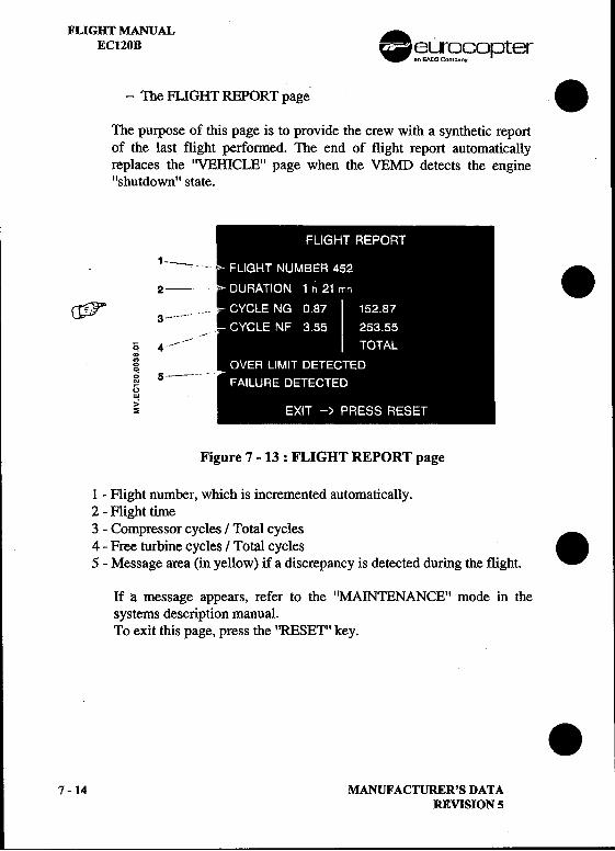
FLIGHT MANUAL .EC120B ~ ~.};}r~.~opter
-The FLIGHT REPORT page .
The purpose of this page is to provide the crew with a synthetic reportof the last flight performed. The end of flight report automaticallyreplaces the "VEillCLE" page when the VEMD detects the engine"shutdown" state.
1 2 -~--~ .
~ 3 ~-- -~,
& 4 -~--~.,00.; 5 -~-~~~N
()W
>'s
Figure 7 -13 : FLIGHT REPORT page
I -Flight number, which is incremented automatically.2 -Flight time3 -Compressor cycles / Total cycles4 -Free turbine cycles / Total cycles .5 -Message area (in yellow) if a discrepancy is detected during the flight.
If a message appears, refer to the "MAINTENANCE" mode in thesystems description manual.To exit this page, press the "RESET" key.
.7 -14 MANUFACTURER'S DATA
REVISION 5
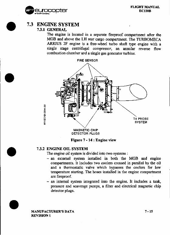
. FLIGHT MANUAL~~opter ECl20B
. 7.3 ENGINE SYSTEM7.3.1 GENERAL
The engine is located in a separate fireproof compartment after theMGB and above the LH rear cargo compartment. The TURBOMECAARRIUS 2F engine is a free-wheel turbo shaft type engine with asingle stage centrifugal compressor, an annular reverse flowcombustion chamber and a single gas generator turbine.
FIRE SENSOR.0q..00
.;'"~ "" T4 PROBE~ """ SYSTEM
MAGNETIC CHIPDETECTOR PLUGS
Figure 7 -14 : Engine view. 7.3.2 ENGINE OIL SYSTEMThe engine oil system is divided into two systems:-an external system installed in both the MGB and engine
compartments. It includes two coolers crossed in parallel by the oiland a thermostatic valve which bypasses the coolers for lowtemperature starting. The hoses installed in the engine compartmentare fireproof.
-an internal system integrated into the engine. It includes a tank,pressure and scavenge pumps, a filter and electrical magnetic chipdetector plugs..
MANUFACTURER'S DATA 7 -15REVISION 1
FLIGHT MANUAL .EC120B ~~opter
7.4 FUEL SYSTEM ..7.4.1 GENERAL "..
The fuel system comprises two tanks with crashworthy elastomerbladders, a supply system, refueling equipment and a monitoringsystem. The connections are anti-crash treated.
7.4.2 FUEL TANKSThe upper tank is located above the cargo compartment and feeds thelower tank by gravity. The lower tank is located below the cargocompartment floor. The engine is supplied from this tank.Both t~ are equipped with a mounting plate and a fuel level
.transUlltter.As soon as the upper tank is dried, the indicated fuel quantity is .'
approximately 145 kg (180 1- 48 US gal). According to the fuel flow,this value reaches 120 kg (150 1 -40 US gal) due to the fuel linesbetween the two tanks after about 15 minutes flight.The lower tank also includes a starting pump, a quick fuel drain valveand a decanting sump with a sediment drain valve. A venting device onthe RH side and a filler on the LH side are fitted to the upper tank.
7.4.3 FUEL SUPPLY SYSTEM AND REGULATIONThe fuel is sucked up through the filter by the high pressure pump.The fuel flow is regulated in the metering valve according to the powerrequired in normal flight mode. The principle is to govern a constantN f regardless of the power required from the engine, by controlling N g:For starting, the twist grip opens the metering valve, regulators supplythe fuel necessary for lighting up Ng = 15 % under starter generator
.effect. The twist grip is then moved forward to its flight position.The fuel is then distributed to the injectors.
.7 -16 MANUFACTURER'S DATA
REVISION 5
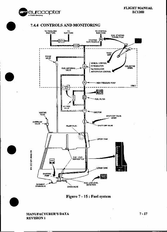
A FLIGHT MANUAL-§3~r~r;?°pter EC120B
.7.4.4 CONTROLS AND MONITORINGTO FAVOURED TO TO STARTING
INJECTORS INJECTORS INJECTORSENG. STARTING
STARllNG .ELECTROVALVE
r--- ~~IS~- ---,.:;..~'.-1I GRIP~'" I , PURGE , II VAlVE II "'" II MANUAl CONTROl I: t NI REGULATOR COlLECTIVE :I FUEL METERING _-r !Ng REGULATOR LEVER I
VALVEI ANllCiPATOR CONTROl I. ' II II II II [~ II ~ -HIGH PRESSURE PUMP I
~ [ F~TtZ ~ ~~~~FI~ "
-~""'" FUEL FILTER
SHurr'OFF VALVE,...-~-- LEVEROVER
VA ---:::AU.ER PLUG ~ SHUTT-OFF VALVE
"'"!
.~ ..00
.;..(jW>~
\8/
'" FUEL LOW LEVELSEDIMENT '" DETECTIONDRAINVALVE DRAI!'! VALVE
.Figure 7 ~ 15 : Fuel system
MANUFACTURER'S DATA 7-17REVISION 1
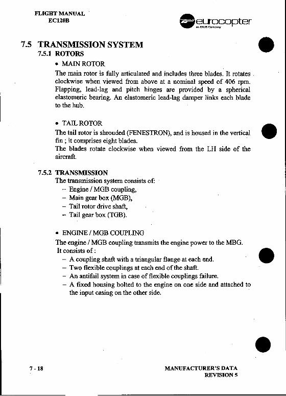
FLIGHT MANUALECI20B .~~~9opter
7.5 TRANSMISSION SYSTEM .7.5.1 ROTORS
.MAIN ROTORThe main rotor is fully articulated and includes three blades. It rotates.clockwise when viewed from above at a nominal speed of 406 rpm.Flapping, lead-lag and pitch hinges are provided by a sphericalelastomeric bearing. An elastomeric lead-lag damper links each bladeto the hub.
.TAIL ROTORThe tail rotor is shrouded (FENESTRON), and is housed in the vertical.fin ; it comprises eight blades.The blades rotate clockwise when viewed from the LH side of theaircraft.
7.5.2 TRANSMISSIONThe transmission system consists of:
-Engine / MGB coupling,-Main gear box (MGB),-Tail rotor drive shaft,-Tail gear box (TGB).
.ENGINE / MGB COUPLINGThe engine / MGB coupling transmits the engine power to the MBG.It consists of:
.-A coupling shaft with a triangular flange at each end.-Two flexible couplings at each end of the shaft.-An antifail system in case of flexible couplings failure.-A fixed housing bolted to the engine on one side and attached to
the input casing on the other side.
.7 -18 MANUFACTURER'S DATA
REVISION 5
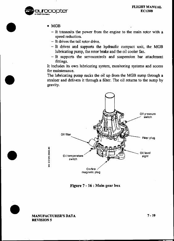
. FLIGHT MANUAL~~opter EC120B
..MGB -It transmits the power from the engine to the main rotor with aspeed reduction.
-It drives the tail rotor drive.-It drives and supports the hydraulic compact unit, the MGB
lubricating pump, the rotor brake and the oil cooler fan.-It supports the servocontrols and suspension bar attachment
fittings.It includes its own lubricating system, monitoring systems and accessfor maintenance.
. The lubricating pump sucks the oil up from the MGB sump through astrai?er and delivers it through a filter. The oil returns to the sump bygravIty.
Oil pressureswitch
Oil filterFiller plug
00. ~ /" ~oillevel6 Oil temperature sight~ switch
~ On-line /magnetic plug
Figure 7 -16 : Main gear box
.MANUFACTURER'S DATA 7 -19REVISION 5
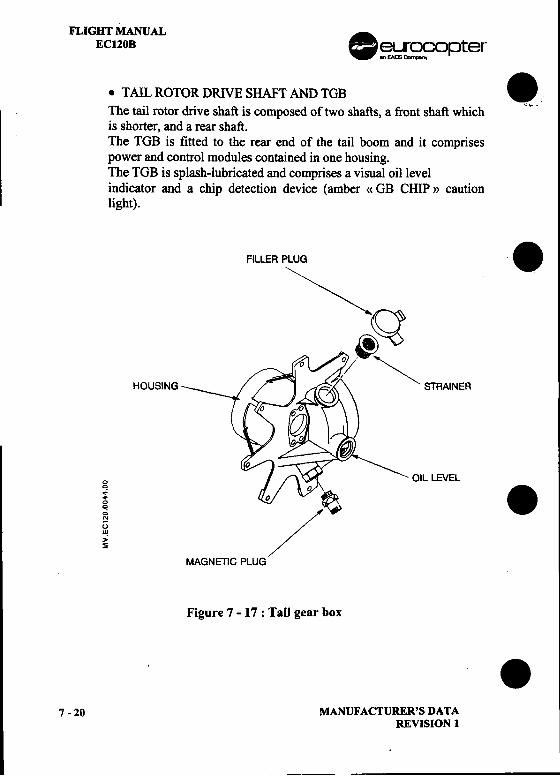
FLIGHT MANUALEC120B .~~opter
.TAIL ROTOR DRIVE SHAFT AND TGB ."The tail rotor drive shaft is composed of two shafts, a front shaft which "..
is shorter, and a rear shaft.The TGB is fitted to the rear end of the tail boom and it comprisespower and control modules contained in one housing.The TGB is splash-lubricated and comprises a visual oil levelindicator and a chip detection device (amber «GB CHIP» cautionlight).
FILLER PLUG .~
.Q
HOUSING STRAINER
0 OIL LEVEL! / .MAGNETIC PLUG
Figure 7 -17: Tail gear box
.7.20 MANUFACTURER'S DATA
REVISION 1
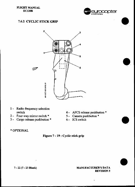
FLIGHT MANUALEC120B .~~ opter
7.6.2 CYCLICSnCKGRIP .2
1 .~
0~00..()w,,;~
I -Radio frequency selectionswitch 4 -AFCS release pushbutton *
2 -Four-way mirror switch * 5 -Camera pushbutton * .3 -Cargo release pushbutton * 6 -ICS switch
* OPTIONAL
Figure 7 -19 : Cyclic stick grip
.7 -22 (7 -23 Blank) MANUFACTURER'S DATA
REVISION 5
. FLIGHT MANUALeurocopter ECUOB.
.
.
.MANUFACTURER'S DATA 7 -23
REVISION 1
,,~"~.
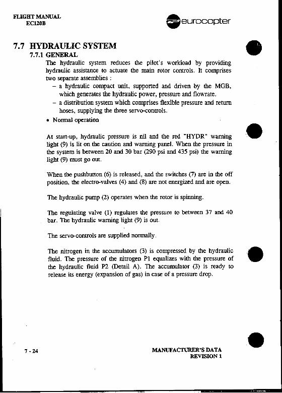
FLIGHT MANUAL .EC120B eurocopter
7.7 HYDRAULIC SYSTEM .7.7.1 GENERALThe hydraulic system reduces the pilot's workload by providinghydraulic assistance to actuate the main rotor controls. It comprisestwo separate assemblies:
-a hydraulic compact unit, supported and driven by the MGB,which generates the hydraulic power, pressure and flowrate.
-a distribution system which comprises flexible pressure and returnhoses, supplying the three servo-controls.
.Normal operation
At stan-up, hydraulic pressure is nil and the red "HYDR" warning '.light (9) is lit on the caution and warning panel. When the pressure inthe system is betWeen 20 and 30 bar (290 psi and 435 psi) the warninglight (9) must go out.
When the pushbutton (6) is released, and the switches (7) are in the offposition, the electro-valves (4) and (8) are not energized and are open.
The hydraulic pump (2) operates when the rotor is spinning.
The regulating valve (1) regulates the pressure to between 37 and 40bar. The hydraulic warning light (9) is out.
The servo-controls are supplied normally.
The nitrogen in the accumulators (3) is compressed by the hYdraUlic.fluid. The pressure of the nitrogen PI equalizes with the pressure of
the hydraulic fluid P2 (Detail A). The accumulator (3) is ready torelease its energy (expansion of gas) in case of a pressure drop.
.7 -24 MANUFACTURER'S DATA
REVISION 1
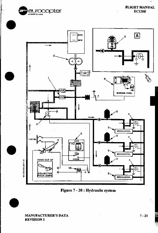
i. . . FLIGHT MANUALt ~~[~9opter ECI20B.
HMAX ~LdUIN--
t
.~
!--
. i HYDR CUT:-l J
0 ~J oIJ~ OLLECTIVE ~
~ ITCH GRIP
Figure 7 -20 : Hydraulic system.MANUFACTURER'S DATA 7-25REVISION 3
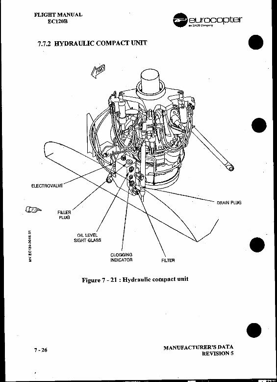
FLIGHT MANUALECl20B .~~[~C?opter
7.7.2 HYDRAULIC COMPACT UNIT .
<'P
.ELECT
~ UG
1;.;I .,,;~ INDICATOR FILTER
Figure 7 -21 : Hydraulic compact unit
.7 -26 MANUFACTURER'S DATA
REVISION 5
..
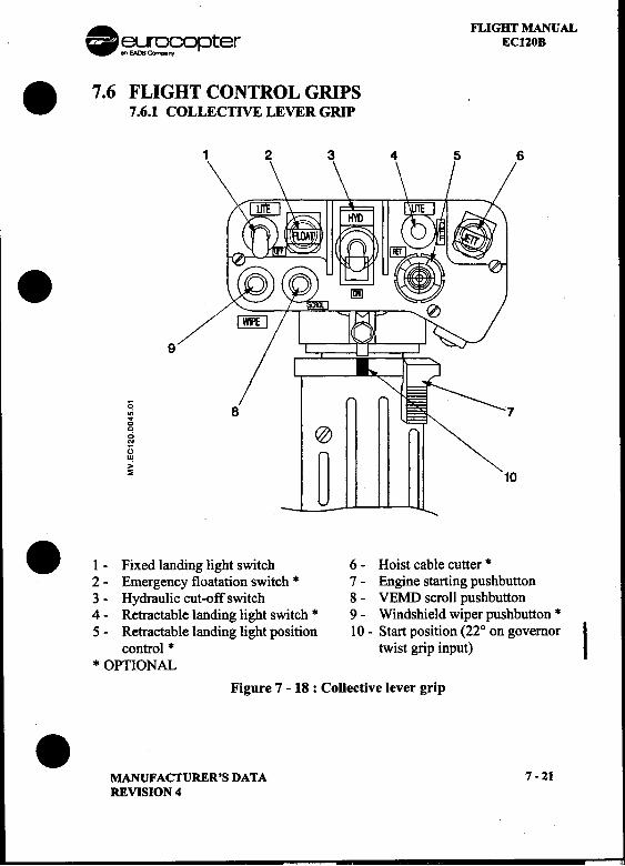
. FLIGHT MANUAL~~opter ECl20B
. 7.6 FLIGHT CONTROL GRIPS7.6.1 COLLECnVE LEVER GRIP
1 2 3 4 5 6
.9
0.;.~ @u~ ~ 10
.1 -Fixed landing light switch 6 -Hoist cable cutter *2 -Emergency floatation switch * 7 -Engine starting pushbutton3 -Hydraulic cut-off switch 8 -VEMD scroll pushbutton4 -Retractable landing light switch * 9 -Windshield wiper pushbutton *
5 -Retractable landing light position 10 -Start position (220 on governorIcontrol * twist grip input)
* OPTIONAL
Figure 7 -18 : CoUective lever grip.MANUFACTURER'S DATA 7-21REVISION 4
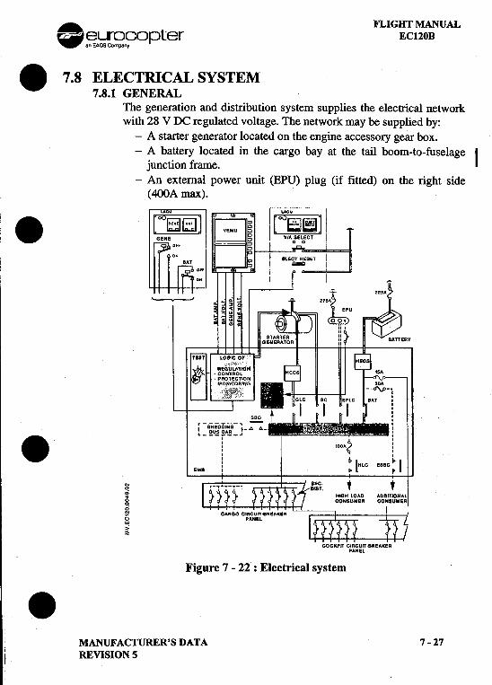
. FLIGHT MANUAL.El3.!;;}r~n?Opter EC120B
.7.8 ELECTRICAL SYSTEM7.8.1 GENERAL
The generation and distribution system supplies the electrical networkwith 28 V DC regulated voltage. The network may be supplied by:
-A starter generator located on the engine accessory gear box.-A battery located in the cargo bay at the tail boom-to-fuselage
ljunction frame.-An external power unit (EPU) plug (if fitted) on the right side
(400A max)." u r-LACii '
.[~~ ~
RV
.-.~-1~ t 1
,-SHEOOI"0-1-.6 6- :susaAR ,. L ' I
i 'OOA? i: t. 1: IHLC ESSC ~ IEMa I .~
~ , ,.;
gg~,,;~
COCKPIT CIRCUIT.aREAKERPAHEl
Figure 7 -21 : Electrical system.MANUFACTURER'S DATA 7-27
l REVISION 5
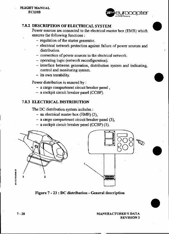
FLIGHT MANUALEC120B .~~r~,?opter
7.8.2 DESCRIPTION OF ELECTRICAL SYSTEM .Power sources are connected to the electrical master box (EMB) whichensures the following functions:
-regulation of the starter generator.-electrical network protection against failure of power sources and
distribution.-connection of power sources to the electrical network.-operating logic (network reconfiguration).-interface between generation, distribution system and indicating,
control and monitoring system.-its own testability. .
Power distribution is ensured by :-a cargo compartment circuit breaker panel,-a cockpit circuit breaker panel (CCBP).
7.8.3 ELECTRICAL DISTRIBUnON
The DC distribution system includes:-an electrical master box (EMB) (2),I -a cargo compartment circuit breaker panel (3),-a cockpit circuit breaker panel (CCBP) (1).
Dc:::::::::JD oog ~80 .
1
8
~~ 3 213w"~
Figure 7 -23: DC distribution -General description .7 -28 MANUFACTURER'S DATA
REVISION 3
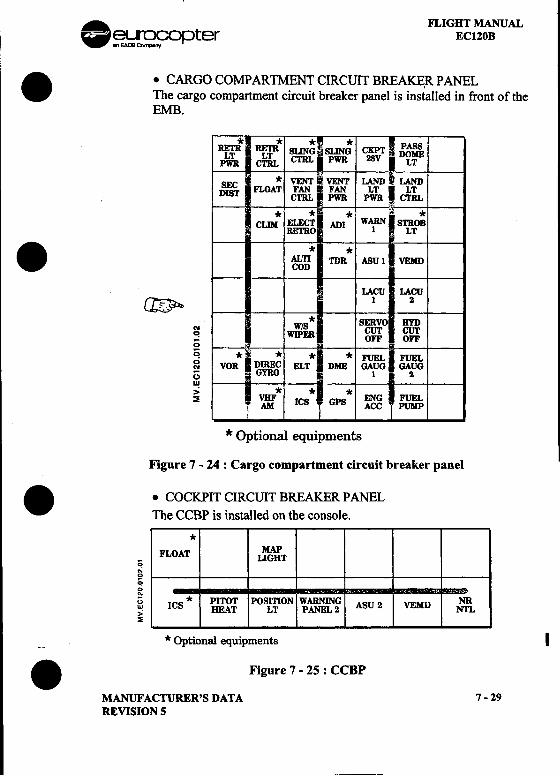
. FLIGHT MANUAL~~opter EC120B. .CARGO COMPARTMENT CIRCUIT BREAKER PANEL
The cargo compartment circuit breaker panel is installed in front of theEMB.
* * * *RF:rR RETR SLING SLING CKPr PASS
LT LT CTRL PWR 28V DOMEPWR CTRL LT
S *VENTIVENTLANDLANDD~ FWAT FAN I FAN LT I LT CTRL ij PWR PWR CTRL
I * *= * *CUM ELECT' ADI WARN STROB
RETRO 1 LT. * *t'o'R TOR ASUl VEMD
LACU LACU~ 1 2*
(\I W/S ~O ~~ WIPER OFF OFF0~ * -0; * * *FUELFUEL~ VOR DGYRQIREC ELT DME GAUG GAUG;:; 1 2w -
> * * *~ VBF ICS GPS ENG FUEL
AM ACC PUMP
* Optional equipments
Figure 7 -24 : Cargo compartment circuit breaker panel
..COCKPIT CIRCUIT BREAKER PANELThe CCBP is installed on the console.
*MAP
-FLOAT LIGHT0oj0
~0;
~ ICS * PITOT POsmON WARNING ASU 2 VEMD NR~ HEAT LT PANEL 2 NfLs
--* Optional equipments I
.Figure 7 -25 : CCBP
MANUFACTURER'S DATA 7-29REVISION 5
---
FLIGm MANUALEC120B .~~ opter
7.9 LIGHTING SYSTEM .7.9.1 INTERIOR LIGOllNG 'c
.GENERAL
Interior lighting is provided by :
-a spot light located on the overhead panel, for normal instrumentpanel lighting.
-two map lights on the overhead panel, which are supplied directlyby the battery, for instrument panel and console emergency.lighting.
'e,--integral lighting of console instruments (including standby
compass).I -LCD displays on VEMD and NR/Nfindicator.-CWP integral lighting.-a dome light for the passengers.-an intemallight for the stand-by compass.
.CONTROLS
Except for the map lights, the interior lighting is controlled by theI OFF/DA YINlGHT switch, the general lighting potentiometers on the
LACU, and the NR/NF lighting potentiometer:
-OFF: the spot light and console instrument lighting are off; the.LCD displays and CWP lights are at nominal brightness.
-DAY: the spot light and console instrument lighting are on ; theLCD displays and CWP lights are at nominal brightness.
-NIGHT: the spot light and console instrument lighting are on ;the LCD displays and CWP lights are dimmed. .
7 -30 MANUFACTURER'S DATAREVISION 3
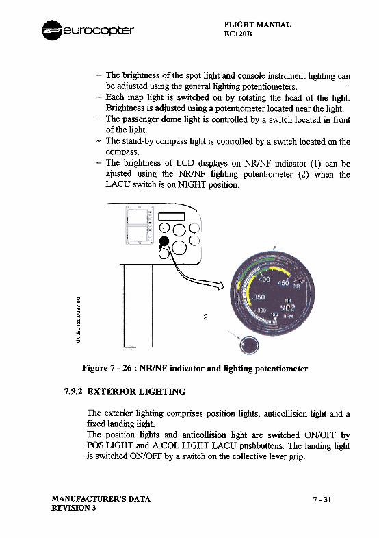
FLIGHT MANUALEC120B.eurocopter
-The brightness of the spot light and console instrument lighting canbe adjusted using the general lighting potentiometers.
-Each map light is switched on by rotating the head of the light.Brightness is adjusted using a potentiometer located near the light.
-The passenger dome light is controlled by a switch located in frontof the light.
-The stand-by compass light is controlled by a switch located on thecompass.
-The brightness of LCD displays on NR/NF indicator (1) can beajusted using the NR/NF lighting potentiometer (2) when theLACU switch is on NIGHT position.
~I I
°OL~00
..:~0q0OJ
UI'!:>~
2
Figure 7 -26 : NR/NF indicator and lighting potentiometer
7.9.2 EXTERIOR LIGHTING
The exterior lighting comprises position lights, anticollision light and afixed landing light.The position ligllts and anticollision light are switched ON/OFF byPOS.LIGHT and A.COL LIGHT LACU pushbuttons. The landing lightis switched ON/OFF by a switch on the collective lever grip.
MANUFACTURER'S DATAREVISION 3
7-31
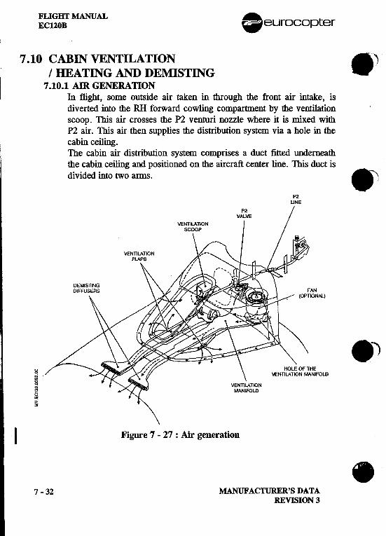
FLIGHT MANUAL .EC120B eurocopter
7.10 CABIN VENTll-ATION 8 J/ IlEA TING AND DEMISTINGI
7.10.1 AIR GENERAll0NIn flight, some outside air taken in through the front air intake, isdiverted into the RH forward cowling compartment by the ventilationscoop. This air crosses the P2 venturi nozzle where it is mixed withP2 air. This air then supplies the distribution system via a hole in thecabin ceiling.The cabin air distribution system comprises a duct fitted underneaththe cabin ceiling and positioned on the aircraft center line. This duct isdivided into two arms. 81
P2UNE
P2VALVE
ANIONAL)
.c HEi IFOLDciOJ13w>"~
I Figure 7 -27 : Ajr generation .7 -32 MANUFACTURER'S DATA
REVISION 3
FLIGHT MANUALECl20B
7.10.2 CONTROI$ AND MONrrORING.VENTILATION CONTROL
The ventilation is controlled by adjusting louvres:-Open/closed.-Air flow adjustment.
.HEATING AND DEMISTING CONTROL
The waml air temperature setting is perfomled by the P2 gate valvecontrol knob located on the cabin ceiling.The louvres have to be closed for demisting operation..MONITORING
The crew is infonned that the P2 gate valve is in the open position bya P2 flag on the VEMD upper screen.
MANUFACTURER'S DATAREVISION 1
7-33
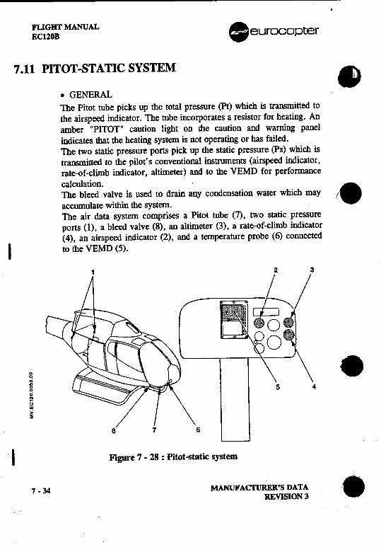
FLI G BT MANUAL .ECUOB eurocopter
7.11 PITOT-STATIC SYSTEM ..GENERALThe Pitot tube picks up the total pressure (Pt) which is transmitted tothe airspeed indicator. The tube incorporates a resistor for heating. Anamber "PITOT" caution light on the caution and warning panelindicates that the heating system is not operating or has failed.The two static pressure ports pick up the static pressure (ps) which istransmjtted to the pilot's conventional instruments (airspeed indicator.rate-of-climb indicator, altimeter) and to the VEMD for performancecalculation.
.The bleed valve is used to drain any condensation water which mayaccumulate within the system. '.
The air data system comprises a Pi tot tube (7), two static pressureports (1), a bleed valve (8), an altimeter (3), a rate-of-climb indicator(4), an airspeed indicator (2), and a temperature probe (6) connected
I to the VEMD (5).
2 3
g, ...~0cco13III,.:~
8 7 6
I Figure 7 -28 : Pitot-static system
7 -34 MANUFACTURER'S DATA '.-
REVISION 3
FLIGHT MANUALECUOB
SECTION 8
HANDLING -SERVICING -MAINTENANCE
Page
8.1 GROUND HANDLING 8-18.1.1 EQUWMENT REQUIRED 8-18.1.2 HANDLING 8-1
8.2 SERVICING INSTRUCnONS 8-38.2.1 FUELS 8-38.2.2 FUEL ADDITIVES 8-38.2.3 LUBRICANTS 8-48.2.4 HYDRAULIC FLUIDS .."'..'.'. 8-58.2.5 REFUELLING 8-5
8.3 TEST SCHEDULE 8-88.3.1 GENERAL "'." 8-88.3.2 TEST SHEETS 8-9
8.4 DAn.Y OPERATING CHECKS 8-258.4.1 INSPECnON ASSOCIATED WITH THE FLIGHTS OF THE
DAY 8-258.4.2 OPERAnON OF OPTIONAL INSTALLAnONS 8-328.4.3 COMMISSIONING IN COLD WEATHER CONDmONS 8-33
MANUFACTURER'S DATAREVISION 2
8-i
F1.JGBT MANUAL .EC120 B eurocopter
LIST OF FIGURES .Page
FIGURE 8-1 : TOWING AND MANUAL POsmONING DEVICE 8-2FIGURE 8-2 : FllLER PLUG AND ELECTRO-STAnC
CONNECTOR LOCAnON 8-5FIGURE 8-3 : SEQUENCE OF CHECKS 8-27
'8
.
.8 -ii MANUFAC'nJRER'S DATA
REVISION 2
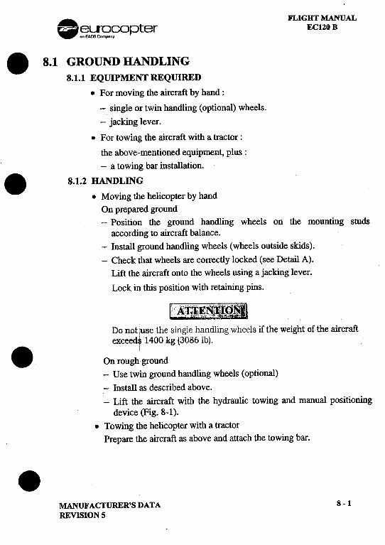
. FLIGHT MANUAL~~~fopter ECl20 B
.8.1 GROUND HANDLING8.1.1 EQUIPMENT REQUIRED
.For moving the aircraft by hand:
-single or twin handling (optional) wheels.
-jacking lever.
.For towing the aircraft with a tractor:
the above-mentioned equipment, plus:-a towing bar installation.
.8.1.2 HANDLING.Moving the helicopter by hand
On prepared ground-Position the ground handling wheels on the mounting studs
according to aircraft balance.-Install ground handling wheels (wheels outside skids).-Check that wheels are correctly locked (see Detail A).
Lift the aircraft onto the wheels using a jacking lever.
Lock in this position with retaining pins.
Do not luBe the single handling wheels if the weight of the aircraftexceed. 1400 kg (3086 It).
.On rOUgh'. ground-Use twin ground handling wheels (optional)
-Install as described above.-Lift the aircraft with the hydraulic towing and manual positioning
device (Fig. 8-1)..Towing the helicopter with a tractor
Prepare the aircraft as above and attach the towing bar..MANUFACTURER'S DATA 8-1REVISION 5
'"""
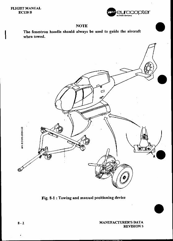
FLIGHT MANUAL .EC120 B ~e1Ir~C?opter
NOTE.I The fenestron handle should always be used to guide the aircraft
when towed.
00
.,:"'00
.;'"()U!>~
Fig. 8-1 : Towing and manual positioning device .8 -2 MANUFACTURER'S DATA
REVISION 5
.
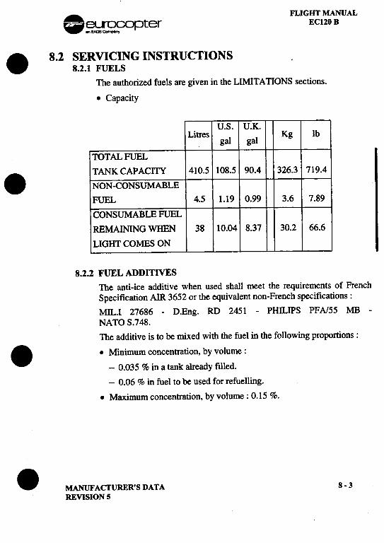
. FLIGHT MANUAL~~opter EC120 B. 8.2 SERVICING INSTRUCTIONS .
8.2.1 FUELSThe authorized fuels are given in the LIMITATIONS sections.
.Capacity
U.S. U.K.Litres al Kg lb
g gal
TOTAL FUEL. TANK CAPACITY 410.5 108.5 90.4 326.3 719.4
NON-CONSUMABLEFUEL 4.5 1.19 0.99 3.6 7.89
CONSUMABLE FUELREMAINING WHEN 38 10.04 8.37 30.2 66.6
LIGHT COMES ON
8.2.2 FUEL ADDITIVESThe anti-ice additive when used shall meet the requirements of FrenchSpecification AIR 3652 or the equivalent non-French specifications:MIL.I 27686 -D.Eng. RD 2451 -PHILIPS PFAJ55 MB -
NATO S.748.The additive is to be mixed with the fuel in the following proportions:
..Minimum concentration. by volume:
-0.035 % in a tank already filled.
-0.06 % in fuel to be used for refuelling.
.Maximum concentration, by volume: 0.15 %.
.MANUFACTURER'S DATA 8-3REVISION S
FLIGHT MANUAL .EC120 B ~~opter
If there exists any doubt as to the concentration of additive in the contents .of a fuel tank, the fuel is to be drained from the tank and replaced by fuel..containing a known proportion of additive within the afore-mentionedlimits unless it is possible to measure the concentration using adifferential refractometer.
Instructions pennitting the correct concentration of additive to beobtained are given by the vendor.
8.2.3 LUBRICANTS
..Engine Oil SystemLubricants and Commercial Descriptions
-Authorized lubricants : Refer to the LIMITATIONSsection.
-Commercial descriptions: Refer to the TURBOMECApublications.
CapacityEngine oil tank and system capacity: 4.6litres (1.21 U.S. gal)
.Transmission ComponentsLubricants
The authorized lubricants are given in the LIMITATIONS section.
Capacity .Main gearbox (system included) : 41itres (1.05 U.S. gal)Tail gearbox (system included) : 0.22 litre (0.05 U.S. gal)
.8-4 MANUFACTURER'S DATA
REVISION 2
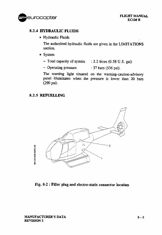
FLIGHT MANUALEC120B
8.2.4 HYDRAULIC FLUIDS
.Hydraulic Fluids
The authorized hydraulic fluids are given in the LIMITATIONSsection.
.System
-Total capacity of system: 2.2 litres (0.58 U.S. gal)
-Operating pressure : 37 bars (536 psi).
The warning light situated on the warning-caution-advisorypanel illuminates when the pressure is lower than 20 bars(290 psi).
8.2.5 REFUELLING
00
.,;~0.;N
1)II!>~
Fig. 8-2 : Filler plug and electro-static connector location
MANUFACTURER'S DATAREVISION 2
8-5
FLIGHT MANUAL AEC120 B .eurocopter
.Normal refuelling .
-Place the helicopter on a level surface.
-Connect the bowser earthing cable to the electro-static balanceconnector (1) on the helicopter.
-Check the quantity of fuel remaining in the tanks on VEMD fuelindicator.
-Observe the following safety precautions: .0 Ensure that the aircraft electrical power supply is switched off.
0 Place a fire extinguisher near the work area.
0 Strictly prohibit smoking in the security area.
0 Prohibit the use of any means of lighting not confoIming to therules of safety .
0 Ensure, during refuelling (or de fuelling), that the bowser (orthe de fuelling unit) is connected to the aircraft by the electro-static balance connectors (1).
0 Strictly prohibit draining of fuel tanks, whether partial or total,inside a hangar or shop.
-Fill the tanks, monitoring the quantity of fuel delivered on thebowser flowmeter.
-Position and lock the filler plug (2). .
-Disconnect the bowser earthing connector from the aircraftelectro-static balance connector.
-Check that the difference in the aircraft fuel gauge readingscorresponds to the quantity of fuel delivered and determine thecorresponding weight. .
8 -6 MANUFACfURER'S DATAREVISION 2
. FLIGHT MANUAL~.!i[~n?Opter EC120 B
..Refuelling with rotors spining.
WARNING!~"
REFUELLING WITH ROTORS SPINING SHALL BE, PERFORMED qNL Y AFTER PRIOR AGREEMENT IS GIVENI BY THECOMP~TENT AUTHORITY IN COMPLIANCE WITHI OPERATIONAI1 REGULATIONS.
-Strictly comply with the instructions defined below.
.-Head aircraft into forward wind sector:t. 450 if wind above 10 kt.
-Lock the collective pitch lever in full low pitch position.
-Check m~i~_r~o~_i~- ~t nominal speed with twist grip in flightposition (I TWT GRIP I light "off").
-Limit refuelling at 95% in order to prevent any fuel spillage.
-The pilot must always have someone in view who can signal to themechanic to stop refuelling.
.i
.MANUFACTURER'S DATA 8 -7
REVISION 5
FLIGHT MANUAL .EC120 B -~[~fopter
8.3 TEST SCHEDULE .8.3.1 GENERAL
The test sheets are intended to sum up the checks to be canied out inflight or on the ground, with rotors turning either after replacement ofmain components, or after an extensive operation, or further to periodicinspections.The test sheets are in the form of reproductible sheets which can directlybe filled in by the crew.
I_~K~ .Since these checks do notfonn part of nonnalhelicopter
operation, they shall be carried out only by qualified
personnel under the operator's responsability.
..
.8-8 MANUFACTURER'S DATA
REVISION 5
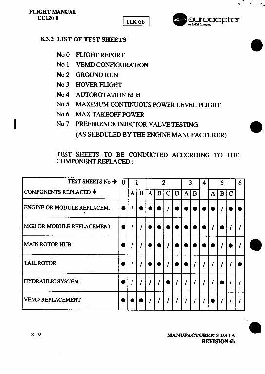
,.".
FLIGHT MANUAL .ECl20 B [~~ ~~copter
8.3.2 LIST OF TEST SHEETS 8
No 0 FLIGHT REPORT
No 1 VEMDCONFIGURAllON
No 2 GROUND RUN
No 3 HOVER FLIGHT
No4 AUTOROTAllON65kt
No 5 MAXIMUM CONTINuOUS POWER LEVEL FLIGHT
No 6 MAX TAKEOFF POWER
I No 7 PREFERENCE INJECTOR VALVE TESllNG 8
(AS SHEDULED BY THE ENGINE MANUFACTURER)
TEST SHEETS TO BE CONDUCTED ACCORDING TO THECOMPONENT REPLACED :
TESTSHEEfSNo~ 0 1 2 3 4 5 6COMPONENTS REPLACED ." A B ABC DAB ABC
ENGINE OR MODULE REPLACEM. .I ...I I ..
MGB OR MODULE REPLACEMENT. I I I .I I
MAIN ROTOR HUB .I I ..I I .I 8
TAll.. ROTOR .I I ..I ..I I I I I .
HYDRAULIC SYSTEM .I I I I .I I I I I .I I
VEMD REPLACEMENT ...I I I I I I I .I I I
88-9 MANUFACTURER'S DATAREVISION 6b
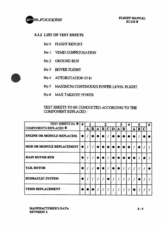
FLIGHT MANUALEC120B
8.3.2 LIST OF TEST SHEETS
No 0 FLIGIn REPORT
No 1 VEMD CONFIGURAllON
No 2 GROUND RUN
No 3 HOVER FLIGHT
No4 AUTOROTAnON 65 kt
NoS MAXIMUM CONTINUOUS POWER LEVEL FLIGHr
No 6 MAX TAKEOFF POWER
TEST SHEETS TO BE CONDUCTED ACCORDING TO THECOMPONENT REPLACED :
MANUFACI'URER'S DATAREVISION 2
8-9
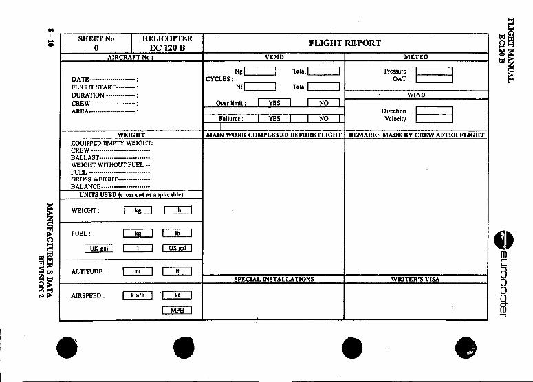
FLIG
HT
MA
NU
AL
Oeurocc>
pter
EC
l2OB
I-§8
'! ~~=
Om
rn~
~
~
=
=
~I-
Z
U
=~
-~
~
~
>-
I-
~
"I- =
?;o =
-
=<
.g.-
~
~
~o
~:§
=
~--"
<A
, a>
~
f-c '"
~
2
0 <
.~
~
~ ~
~
=
~D
O-r-
~~
0
0 ~
-z z
~...J
~..-~
'"
-~
Z--~
0
0~
=
~
-
~
~
~
!<
--=
~=
~
~D
D~
~~
i
--~
~
.
0 ~
u u~A
..Z
.-~
~
-z
.5 ~
0
.'"
..-=
~
'" -::...
(:j ~
~
Z
~
0 -
u <
f:) ~
~=
:§
B-B
~=
BB
-~A
, .~
=
~
-~
~o~
.~
u ,'E
.
~u
I~~
.o ~
~
BB
BG
~-=
x::::::~
=
Z
I-c:
:~:
: : -=
-
I- x-!!
(:j 1
! !
6.x .x
-=
~
c.. ",.,
..(:j ,
.::J '
., ~
~
-~,,','
'"'~' ',.'"
~
, ,
, .,
'- ,
., =
: :
: ::
~::
I- :
: :
..
u 1
II!! ~
~
!
I::J !
! 1
I::
~
:~:::
a.::O:I-:=
=
-' ~
.,
, ~
'
'i=
' x
' 0_'
~:
::: "
:: :
: --
z <
,
~
' ,
, (:j
" ,
c .'"
~..
'- !~
zl! !I;:I-::.
(:jc..
t""" ,~
, .c,
(:j ..
~c
:"'9::: (:j:!;;I-:~
U~
I-
~
C
(:j~
:1-1-':
A,'<
x:",z-x ..::J
~
(:j
~
(:j~<
~<
~
~~
c~"'
o<
Z
(;, ~
~
~
-I-,",~(:j(:j
::J(:j~-(:j~
:' -
~~
=
~
<~
::J~~
~
~<
~::J~
<
~
~
~.C
r.;CU
<
(:jU~
~r.;(;,~
~
<
"!;
8 -10
MA
NU
FA
CT
UR
ER
'S
DA
TA
RE
VIS
ION
2
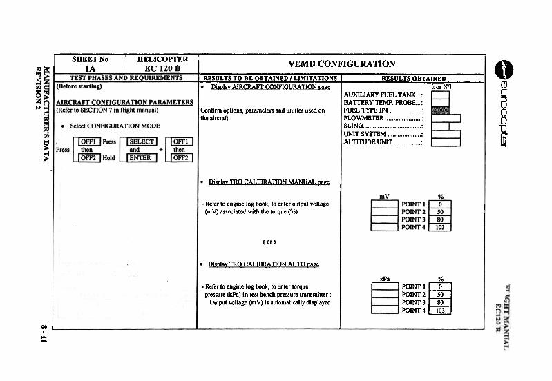
t::=
z101 ...
~::.
~
0, 0, ° .j.j.1.10
~aj
::::
~
~~
!! I i
~
..1 °
:::!oo
~
=
~~
~.r:
1~~
f: >
~IIJ~
j~
1IJ
~
~~
~~
d~~
~
g~~
o~~
~C
<
I%I~
~U
)~..~z;0UQ~~>~~~§~=cz1-.<~
-~=fIJ O
eun:JCopter
c0~=.2.~-ac=on:;U~'"~0'='" .°'ac -c ~'2 '=-Q
"u:
IS~
~~
IIJ +
8 ~-~
i~~
~
"0,~
:J
-'"'
..0-~
:I:
~~-~~
-0-508-;;'".~
~
DA
TA
~
"00s~=co.=
~a~~ 0
,,~-"c
~"
0-a
~-a-";;""'.=.8;
00.-a
~
";'3c-.~
.~5 ga
:g
~$:
~.s,
~~~
.,~u
~[
~Im
-N""'"
~~
~~
2222
;,;'8" ...=
~
'E~
~:a
g e
...
c--S~
e
B-=
-=~
., ~C
eOv
a. 0:;
O.=
~-"
c.~.§~
,S'
"£50
= "
-;;.- ..=
~s
.~
~-
c~~
~e&
-a-~
e8":a.
8 -11
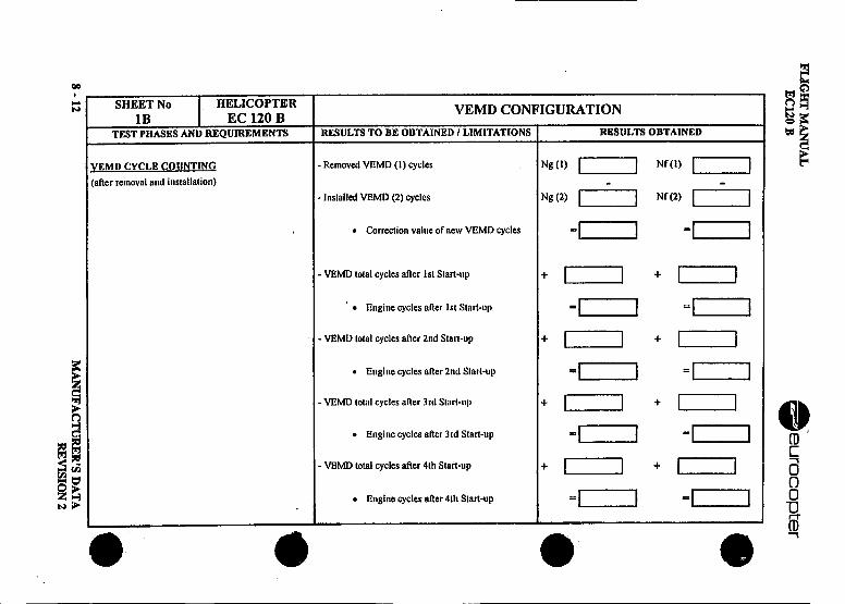
FU
GH
T M
AN
UA
L A
-E
C120 B
-eurocopter
~ ~
'~n
00000000 .
<
~
;;: ;;:
=
z z
+
+
+
+0C
/O
I i ~.~
0 ~ 0 ~
0 ~ 0 ~
0 .
~z C
/O0
Z
'"
0 .!!
U
!: fi.
Q
~
A
Co
go C
o C
o~
-~
=
.:r
:r~
~
I%
J ,::
i ~
~
->
'" C
o -C
o =
C
o =
~
~
Co
-=
C/O
-'"
=.-::
"'- -C
/O.
--.v."'-c
~
~
~
5 -g'::"E
'::-=0=
=
~
M
S
...~
...0
on -C
/O
-C/O
-C
/O
-~
()
"0 ()
() ()
-'" ()
~
<=
0=
<
=
"E
<=
-=
<
=<
():J
=
-=
N
=
M
co... =
~
u '"
~
w
'" -'"
-'" w
on->
- >
.>
() ()
U
() U
()
() ()
-u u
<=
-<
=
-<=
-<
=
-0
=:
~
6 O
J fi.
=
fi. '"
fi. ~
~
~
~
~
-E
:J ()
:J ()
:J ()
:J ()
=~
() -0=
-0=
-0=
-0=
~-~
--~
.-~
.-~
.-
0-u
OQ
u
OQ
u
co u
co~
0 0=
=
C
C
~
I%J
U
~
I%J
~
IIj ~
I%
J -IIj
CI2
>
"0 "0
"0 ~
~
~
~
S
~
~
~.
~
~
~
~
~
~
~
~
~
~~
..
~=
~
.
~oz
ON
~U
""~~
U~
~~
~=
0'~
r.; 'C
'f-'-
=
~-g
~~
.$ Z
-
-..C
I2 -~
c ~
~
-=Z
CI2
¥"O<
~
C
Eoo=
=
~~
~-~
u~
~
~
>-
0::
CI2
u C
VJ
~
=2
.~
:;
~ ~
8 -12 M
AN
UF
AC
TU
RE
R'S
D
AT
AR
EV
ISIO
N 2
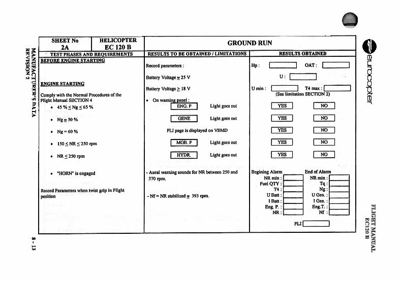
=z~<~
N=C
/)
~=
I
~=OM
U'
~U
~~
= Geurocopter
~on-cVI
~VI
~on....
--
\TA
~ ~
~
~
r;1 r;1 ~
r;1 r;1~
~
~~
6 I.J
I.J I:J I.J
I.Ji'-
<
~=
0
i'-cn0
=0cn
.=
z i ~ :; ~
I ~ ~
~ ~
~;J
..~
...§
Q
~
~z;J
cnz92 -~
""
"0
"
0 0
0
c ~
'8
'8 A
'8
'8;
co co~
co
co~
.E
.E~
.E.E
-co co;>
co
co-;:3
;:3 =
;:3
;:3Q
0
~
"3z
""-..~
~~
~~
~=
»'."'.~
~"'.ei
0 u
0 Z
.-a1
~
..~
~
= z
~
~
0=
B
III
AI
~
0 ~
~
~
o.,~~
=
-i'-
E
oS
oS.:=
.oJ
cn c
~~
~
~
~
~
., "E
e:-
e:- =
~
§ ~
~
0
c.: a1 a1 .
~0'"RI
on:z.
Ee-oon'"
~
VI
~
~II
VI
00 0
Z
~..
ee-o..,NV
I
~
illlJ!~
;i".i~~
~~
~-oZ
o-~
~~
"0C'"0~c~.8~.s.:gc~~"E~ e
-=
eo"0~
.....,
E
~.~
~~
~~
~~
<~
O'
--cw
c ..
.2 ~
.~~-1~5"'~~.
~ii;.5Co
"C00on
.~="~5uee..'" ="0
0-";0~
"~
..:8. ~..,0-..,al
]~~II...Z.
8-13
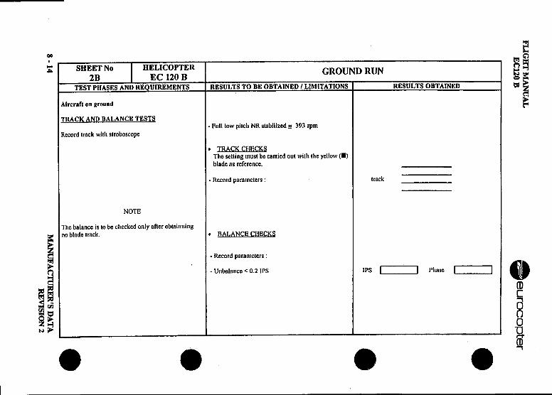
n.I G BT
MA
NU
AL
.E
Cl20 B
eurocopter
~
~
8
~~
~=
.E
-o
~
'"~~
.. '"z
=
~
~
e~
-g:
8Q
-
z~ '"
~o
z' 0
-~
-~
Ci-
.9--<
-
i- ~
~
E
.'J-C
o -
.oJ c
-M
.~C
\ 0-
~
M
-~
II
g-"i
~~
~
o~
=::
t:I
.Q
=
0 S
u
00 .0
'"
~
~;.8
0 ~
~
::-
=
~
~8
=.!!
.!! M
:z "
" "
.0
-E1!
=
E
0i-
~
..~..
=
v'"
os. =
1! :;
:; "
i- 0=
~
Co
Q,
g.oJ
~
~c:
~
~
=..-u~
~
='"
-u~
8 u
.Q~
"3
.c~"
" =
=
'" i-.Q
~
~
~
' .
~
.._8
'" =
fjol = i-
o-f--
Z
=~
=
~
.:
OM
~
su-~
.Q
~u~
~
fjolr.l=.
~
'5=
~
'"
.?:--~
=
=
i-" ~
0
-~
~
go i-"3
z u
~
0 -"
-<
z.2. z
~'"
<
0 .c
~
uQ
~
~
.oJ
~
uZ
"'=
<.c
.Q<
6
=
-0f-- -=
..~
°i
;: .
fjol-~
co .--"
fjolMi-
c ~
~
8~
='"
0 =
c:'
~
-=
~
:. =
urIJ
i- f
U
"E
"'""i8
u <
0
.Q-
..~
u u.Q
:<
...~
e=g
8 -14 M
AN
UF
AC
TU
RE
R'S
D
AT
AR
EV
ISIO
N 2
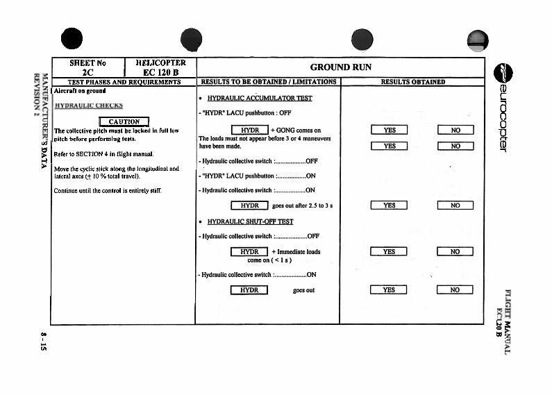
.~~~0~~~=
~Q
'"
Z[01-=
'" =<
=""U
=E
~N
Q,"
~
1-==
",=
00 [01~I-
ft:=<
..eurocopter
~~
R~~
]
=
0;;=
c
~
'6 ~
-.=
;~
"C
1.~
b "
c c
" ~
-0
-'"
z~
--=--=
0_-e
"" c
--.c>
"-"-
.c -co
~!-
.Q"
~
~=
.-
c -
I;: 00;;
0<
=c
c --=
~E
a --cog
c.cl;
~
~~
8
~o
z -=
0 "
--'f0
~o
.cQ
", -u-
-"Q
, f-o
;: +
, :=
>U
u""-' -"E
~
(IJ ~
:1 g
",2 (/)
"" "
="
0 .cco
=~
.Q
---C'"
." co
--.c
->'"
-"'"
~
0" c
.c- "
""" ~
!- C
r::
~
.-u
SD
AT
A
~ ~
~ ~Qr.1
~=0~;J'"~z~~QZ
-rc--~
~
f.0
~
.:: '
;"-~
0
...c=
-t on
C
~~
~
~
~
~
0;]
~
g5
5 :::
u :
u :
on8'"
:::e: :;;
:8~
:::"
: ,-
: C
D11,
00 :::
E
foo :
'g~
i11,
Z..,
::: 0
: 5
on :
0 o!!
:::.. :
5 -:
0 0
: ,:
: 8
: -V
:
C
+
~
"c" ""
"+
~
,:0.0
'=0'=
'=
-'=-
~,,-
'"~"~
-'"~
~
~ [
'! ~
'!
c.: '!
c.: ~ i
c.:
g, ~
~
,~g,,~
~
,~
~
8 ,~
e
::J C
o; ~
::J
~
~
~
&:
U
'0;'0 =
U
=
=
=
<
==
0
<8
88
oJ 55"
oJ
: g
: ,g
<,~
.g
c.: '0-
-c.: -c.:
--~
~1.
§~
§~
§ §
-u '0
'0 '0
'0u>
>
, >
. >
. >
.:
.=
=
:1:::1: :I:
:I:foo c,
, ..
--
~ ~
MJ':',
_20B8 -15
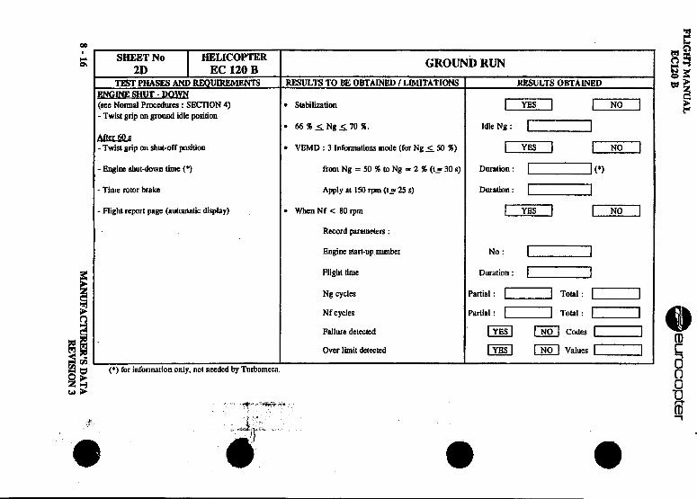
FLIG
HT
MA
NU
AL
.E
C120 B
eurocopter
Q~
~
£ ~
~
~~
~
.
I~~
~~
~~
~
~~
~~
~~
Q
0 ..0
~~
z .~
.~
0 .~
-~
" ..
z"..
..>-
>-
IS
~
~
~
-;; -;;
=
-Q
Q0
~
~Q
::
.~
[I)
~
'";0'0
~
~
~=
~
~
II
t-' ~
vi
;::,..~
~
Z
N
~,
"."-.g."
, N
..
~..Z
I
U
'8 0
_I o.
.c~"C
-~
..jI~
~
~
c.;
...~p.
.00 a~
jI~
=
~'=
"'S1;e~
.!. ~
"C0
0~~
"_Q."3""~
u.~
r- ..,-
...~~
u,,"C
~
vi ~
Z
.0
"C
8 .~
~
u
" !
0 c:
.., .=
~
-a:
~
8 'O
il ~
~
~
.a t
p. oz
e ~
v U
~
~"
a".~
I00
-=
<
...~
~
Il. Z
Z
It.
0~
:=
v
0 Z
;J:s~~
5
:;, ~
:g
~
~~
;
~
J~
§
,,;,.1~
~ ~
-e
: :;.)~
E: = Z
~
t..".:-~.
ON I
i.U
~
~
~
,~
~
...
~U
"""
U
'
~~
~
8 i
]=
!g
t:~
=
'6 .:
1=
~
~.g.g
~-Q
~'" "
00;8.
:;- ~
~
Z
00 IS ~
~
-=
'<
~o-
1:" =
0
~
'? o~
$
S;;;
~,'B
1
S
~
~
~
.i'<
~~
. 'O
! 0
~
~
=~
Q~
=A
.8 g
'i ~
~
~
~ Ni
:~ 10~
i'~
~
~
~
0:
.~
0 --8 ~
.g
w..
Z~
U
-~
..-I
c: ..."
~
~
0=
,- ~
PA
l- I-
I- ~
8-16 ~
,
"" M
AN
UF
Acr~
'SD
AT
A
.
RE
VIS
ION
3
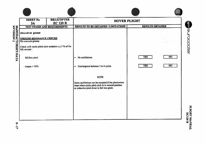
~~=
.~=
,O
NU
-""U~
~==z~~
<~f')
=rI)
=~z~=0~;;)fI)
~~=c-~r..~
fI)
r-1 z
;>
S0
i-=
~~:3-=~~~=0~=0i-fI)
~;;)fI)
~
2
u.c.::0~V\+1c.8S';<u~".~.c~'s.
.c".-"
u .~
~..
~=
i .£
.; ~
-
..~
-~
8 .a
iI-
o;a--
UR
ER
'S D
AT
A
~ ~
~.g~'u~0:z;
~ ~~~'"II~g. ~u~...oS..,cII~2-"uC~~c0U.
~z
..c c
UE0..:1
0.-C
w
]8-g,-u"'".c=
U-=
.~~
"g,C ~].50c..!1 =8~
;a"'.:1
C..w
'-.D
..:~c£~"
g,-w
u":c.-
u0 u.::
.:: ;.,
g,..u..=
c>".c-~
~~
"wo
Eg,u
0 0
~m
1;;o
FLIG
HT
~E
C120 B
8 -17
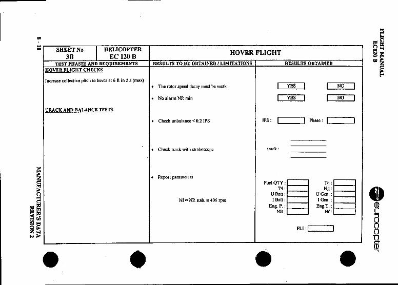
FLIG
HT
MA
NU
AL
.E
Cl20 B
eurocopter
~ ~
~ ~
~
~."'"
==
.:
0 ~
C/J
[!III!] ..
j~~
~'"~
2
'- >
~=
=c;~
""," .-=
=
z
==
...Q
'alal..r..
..E
u ::>
-~.
"" C
/J -~
-~
~
...J -
~,
C(; '"
~
z>
9
0 "'"
==
~~ -=
=~
"
e--0-
.~
-0
Q.8
" 0
'-I C
o'"Z
0;
C/J
0 111
-: ~
u
<
=
-~
.ci~
-N
0
=.->
. ..0
-=
=
0
e ~
0 3-
v 0;
~
~'-I
"C.:
" .:
~
Z=
"5
E
g .:
"OJ
D~
=
~
E
...
0 ~
z
=
z"'"
g ~
t;
C/J
0 =
~
..C
o"'"
-0 t;
...; ~
..J ..-u
u 0
,,=
" "
Co
;J .:0':
.: "
~
"'" z
u u
~
=
';;: -
.~
~
~=
~
.s~
=2:
..O
M
'-I N
U-~
.5
""U~
-=
,.J =
-0
C/J
~~
~
~
"'"=
~
~
~
~'"
~
"'"-Q
~':
'-I2:U
.9 U
<'-I
.: 2:
:: u
<'"
U
.: ,
0 '-I
Co
-z
"'t" <
< -.2:
=&
-=::c"
v Q
~r"IA
o~.£
2:~
"'"'"
-0 <
=
~~
~
~
00 ..'-1
~
U.
>
~
<
0 u
~
=
.5 "'"
8 -18 M
AN
UF
AC
TU
RE
R'S
D
AT
AR
EV
ISIO
N 2
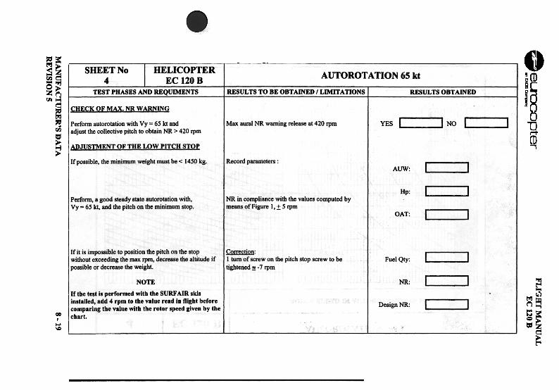
.~~
~apter
MA
NU
FA
~
-"
RE
VIS
ION
5
eZ~~
~=
IrI)
I
~~=
t=OM
U~
~U
I~
~ ; ~Ir)IeZ0-~~i~
~~~;;)~ -fI)ze~~oJ-=[oJ
~-<~~[oJ=0~rI}~oJ;JrI}
~ QroJ
on"'"
e~
0
0. 0
VI
~~
'"
V...=
=
""""
U
.0~
~
..-"
~z
;: ~
~
VI .s
~
.E~
-Os
0on
II .0 .-
>,0
~
~:..
>.9
roJ e
5-=
==
~
=
.~ g
..ez
Co
r.. .-
.§" 0
.s>
<
.=
.~
..e<
S
g Z
"
~
e=
roJ -5
r..o
*8 E
.£
"u ~
:£!
~
~-5
~
~u
c- ..0
roJ ~
~
Q
Co
==
u,,",
<
:::u_=
-- ..
~~~ffJ>
-ee-oN".~"~.£!!~.~~~]~~
-:TU
RE
R'S
DA
TA
~;;I"E0~ ~~
~c.~
-s" ~.~
~c
e.g
§~
.--ce .-0 e~
~B d
~
0~
.c>.B
." .-~
c.B
"~-S
"""0 c
~..
~:!i
~:2
~
II"
>.
~>
:t;-"0£=~0".,"=~]
c-eo~
'".~
+1
" .
,,-.~
~-to)0..-c'"0'-"
0" .,.-;~
e ~E
.:t:0
.."':
...'--.-Q
...
" "'.0
"0 ..
~
~.c=
Q,.~
~
:c
~0-
~..-
~~
~
"
"="0
~.:;
-<.5
~=o
~~
"Oi-
~
.'-oJ: ~
..
"" ~
'-~.,;: "
=Q
Q,"O
.=
'-
" d. ~
':;":15. E
- .=>
,s=
e-.~
0 .::~
.=.g ~
~
Z
~
-.~.,;: e "
"0 Q
~
8.".:; ~
e~o.:;~
~
Q,..
-..~
""->.£.5
~
t ~
1!g ::g,s
~ ""0
0".. -.=
Q,"
0 ~
"0 .-" "
".. '-
"- "
.-~:c
..-Co
1:.!!!0'0
~5e.
-.:;~
-~-.=
0 ...=
-
= ~
'='-
~ .~
-'" ...
~
.'6g~e~~.c2"6."-55 e~
e-"t--
"" ..'5
1~
111
,-"" ."
-0 "
u c:
" e
"c " :=O
~oo
u -'" ;;,5]
~~
L_1 MA
NU
AL
EC
120 B
~~z;,";;"0
8-19
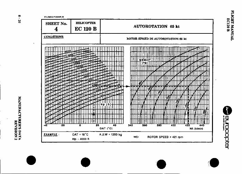
FLIG
HT
MA
NU
AL
EC
120 B
.~
~
opter
.91-=
0-...c.g: O
gSt
~~z-0
~
O§"
~IC
E
=
a.~
Zo
"OgeJ
~0
OIl
to ...0",
=
~
z g
, ~
~
0=
W.
0 0
Q.
~
~
~JJ:
cn~
-<
~
.
~
~
I-0
~
I- 0
...~
Z-
~
~~
ro1
"0 0
0,-,
r--r--I-.~
~-111-
..E
o- ~
~
~
=
fi~
!
~=
...
01~
0 0
...~-=
0'
:-::.
' ~
~
Q.
0- .
C
:)=
=
.7' ~
o <
~~
.u~.
Q~
coo
~
~
0~
0
..0 ,,'"
=
r~"
I- "
-=
~
<a.
~.~
~
I o~
=8 ~
.,.--9Q
--'"
0Z
--0 o~
. O
IlIi
Z
'~
~
0
..
~
~~
.. ~
O~
E:
A.
..Q
~:
z c
;; rn
P;
0 )(
w
~
or w.
8 -20 M
AN
UF
AC
TU
RE
R'S
D
AT
AR
EV
ISIO
N 2
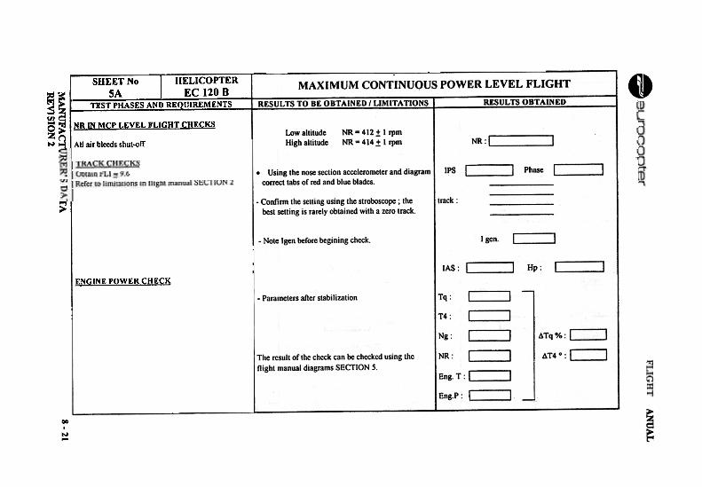
-
=~
-'"'"'-~~
~
Q
9z
...-<
~
'" ...~
c ~
roJ
'i'Z
'" ;..
--<
~
~
'"'<=
...~
~Il)A
o A
o ~~
'"
U
IS=
~
~
:is
(IJ '"
:!: °a
~
=z
-<
MA
NU
FA
CT
lR
EV
] SIO
N 2
~
Q~
[oJ
t-' ~
--<~
I-
~
=
~
~~
~
>
~~
'"
~
~~~~0Q
.,00~
'"
0 7;
~
9z
~-l-E
- -Z
~
0 .J
U
~~
'Z
:~
<
~
;-0>(
[oJ-0( =~
~~~'"[oJ=
E E
e-e-+
1 +1;;
."~~".g
I~".c~
..3~ ~~
~u]a.
~'"~~~
E~co ,
.~
,,~00
-:: ..00
..~=
u
0..o.~~
0
""
U
Nii
~ ..
E..
.&.=
2 .g 2 .:
".. -3:
--~8.0
""'3U
U
-::c..~
co'-
c:D
=is
51 00 'o;.g
-=
~u
->-
u '.
CD
-"'00
="
It e
"=:;
0'- ii:;'
=
0 ~
.-,,~
"co
.=.0
'=c
-is -.-
CD
- =
==
u
c"._"
I:: '"
~
t: =
-::J
0 0
~u
u.c.
--fA
0c~..:~uC
Dc"c"00".0".2.8c!!!"0z
~0-
X~'"~
~u(oJ= ~
DD
DD
~~
.;,:
..., oil
oilO
'~~
c.:cc~
~:Z
:ZU
JUJ
=g~:c~:;~~:;~..:;Q.
DO~
0
0 ..
~
~-d
"~on=:g"3 .
~'"
Vz
,go.85c
UI
'"tnv
"'~
E
v '"
" ~.=
on
v '"
" -.=
-0':-;;0
=-c
~ 5
" -~
.c
" on
.c .-
1-1::
8-21
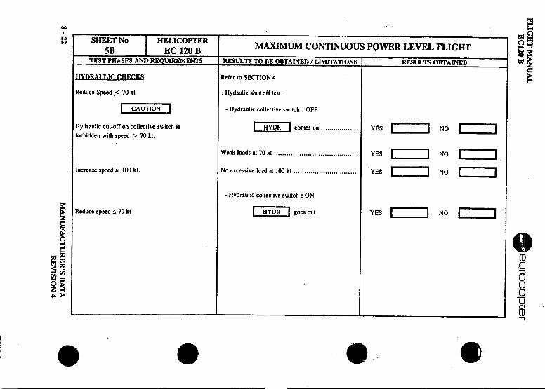
FLIG
HT
MA
NU
AL
.E
Cl20 B
eurocO
I:Jter
~~
0 D
O
0 .
~
~
oz000
~
=
Z
Z
Z~
0
~i
0 D
O
0~0
gJ gJgJ
gJ=
-- >
- >
->-
>-
~
'" ::
.0
Z
..
;J ~
1
1z
-<
..-!-
::E
o- -::
Z
~
::0
~
'"" 5:
--'""
: Z
=
U~
0
~:
00~
~..e:
..~
.c o.
.cO
"": ,,"
-<
.:~
.-.: !-
~
;.¥ ~
=
~
.a ~
-0 ';~
A:
;~
"A:
'Q"
" .-C
. .~
0
~r.)Z
:;~>
- ...:;
~~""'=
00=:C
a
-g =
=~
0~-8
...00.,:;!-~
=
--"U
.c"
""""'W
~:=
~
>
:=
"'" ,,=
"0.-
=~
'"
:=..
..~
..:;J
0 =
~
0"
~
",:~~
;
~
>,
~~
>,-
.." =
=
" =
. ~
0
.A
: ...Z
~~~
~tor.)
.O
N~
,,- ~
--r.) .-
:3U=
"5
~~
~~
.i =
~
Z
~
=
0" ..:
-.~.¥
~e
~
5]~
.~
~~
-<
"5 1\
...'"
.¥ U
"
Q
~
a c"O
8
...
z ~
~
... ~
8. -:
~c...
..w
vi 0
~
..VI
r-~..
U"O
.:..c
"0~
II)~5-"
~.:
8 -g
~!-
&
,,~
Q.
"'"
:;.- "
c ~
Q
.r.)
." v,
:=
" "
~C
IJ "'"
-" =
"0 ~
"
"'" .."0
.."e
~
" =
s: ~
~
~
] ~
8 -22 M
AN
UF
AC
TU
RE
R'S
D
AT
A .
RE
VIS
ION
4
E:
~Io~
I~
u ~
~
~
~-c0
~
g
~u~
~
~III..
~rIJ
e ~
s =
~
~--<s
~
~
~~
~
~~~ '"
0 Z
~
8~
~
§ ::u
~i !~i
Q~
FLIG
HT
MA
NU
AL
EC
120 B
8 -23
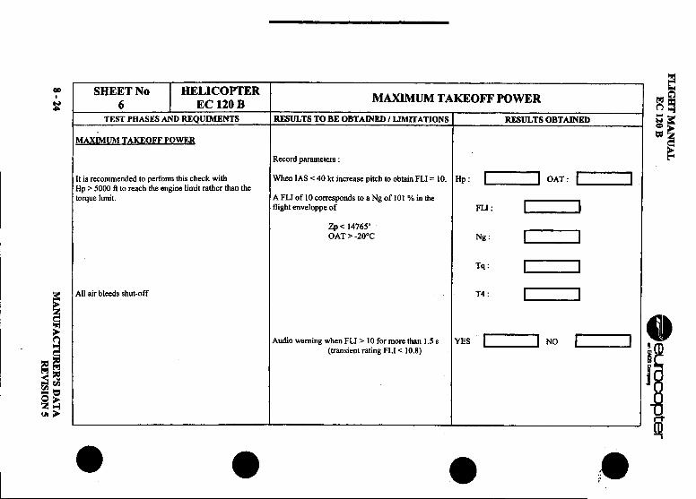
FLIG
HT
MA
NU
AL
.E
C 120 B
~~
apter
o~
n n
~
u ~
;.;, ;;',;,:
u0
~
z ""
~
.~
;,;, ~
~:c
>-
-<
'" .
p..z ~
~
~
~
II -11
"!~
""
:J ~
-
;J1:<
~
.5
S
~
~
.5 ~
-50
-~
~
;; ~
-;;>
<
~
~
;: ~
:J-<
Q
-0
'"~~
iol
.c .,.
.g.,.~
2:
.~
Z
u 0.5
~
~
~
;"0 -~
<
"0 'C
o ,,'"
~
., -r-.'"
-~
~
..,.'
:Jc=
~
"O
-" !!
0 ...~
&
v ~
5 ~
~
~
~
~"O
rfto
~e,
g ~
~ v
~g;o"
~~
0
.-r;
; '"
-u E
5 ..;"
~
"O~
~
~
~
5 :J;c
~i
~
~
~.s'
~
~.
~
.st::r;
sO
NZ
.s-5
u~
iol .~
I;
:3U~
~
~r_' ~
0'
.c .~-
~=
uS
=iol
~;:
~
:S8
-~
~
E .~
~
.g"'"
,. "
"iol
-,,-"C
0
~;
Z
~
~
B-fi
~p..
~
<::g~
]
r_' IC
""
"" C
B
~-'"
~
".;: ~
~
iol ~
S
0 .~
-g
=""
~S
oS
" °0.-:iS
.'10
, u-
'#.. " '" "
'".."
~
.;.~
~
go
=~
.=
:cB
<
8 -24 M
AN
UF
AcruR
ER
'S
DA
TA
RE
VIS
ION
S
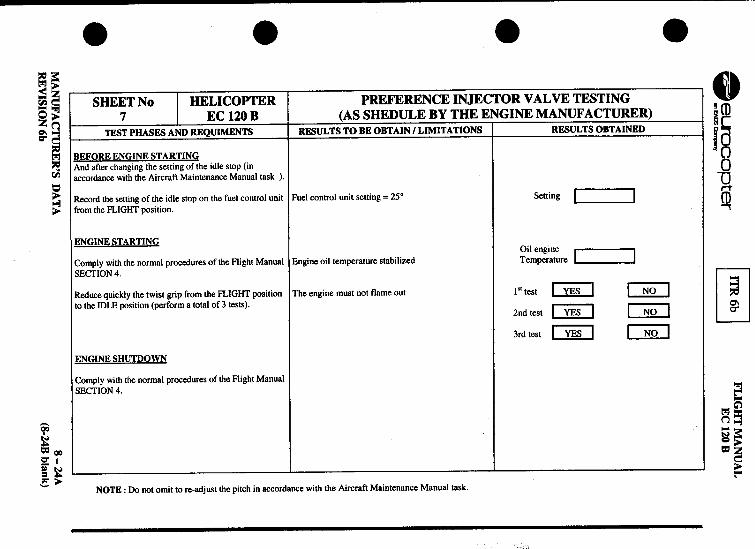
.' .'
..r~
~l
FLIG
HT
MAN
UA
L~
~copter
I...'~u
I E
Cl20B
8-.Q
Q~
~~
~
LJlJlJz~
-<
n n
~II
~
~ ~
~~
<~
~
~
~
~
~
~8
~~
§~
!:g';:
;"~
--N
..,
,
o~Eo-z
~r8lfIJ
...,r8lZz=
o ...
-too. ~
.,
<
=r8l>
-,", .:;
U=
i S
Zr8l:3
~~
~-]
8'""'
Z
N
-=r8l~
- 0
._" =
~Q
-<
~
] 0
=
r8lr8l ~
II
g ~
~
~=
o ~
~
'"
.;=
..~~
'S
5
~
~~
=
~
~
g 0;
~o
-,,- ~
'"' 'c
c. ~
.~
-fIJ "
ee
-0:~
-"
...0 -"
"~
)j
:: =
.c
..., =
0'-
--0
,,~
,s~
u
="
.-~
Q
';",
~~
=
.c "
~
~
E--
g
.'"~
.';:
=
"E8
-="
0 "
0~
~
"
=.=
=
u
E'"
-"'.- '"
u::.
e ~
~
~
:
=
fIJ =
'" c
-c. -.-
-~
.-" 0
.c!i:
..c.c
-~=
u
00 ~
00
0-.~
'" .-.!3.-
~"
-"" ~
-.-
U~
~
.9"" g
~
~
~
c.~
""...
,,~
" "
-u~
.£u" ,s~
"',s ,s
"r~.,""
-o=.c
...'" ...
'" -0
,,0 0
~r8l
g --~
~
5
~,s
"3 ~
:§.
=
~
\.:1,:.- c.
5 g.9,;
=Q
~
~~
~
~
.:=S
~
!!
-Z
t .:
-=
.£ g.§"
...g .9
-<
-0: ~ ~
:9 C
6-"'.g
6- .-
fIJ,",.,~".9
-~"
z- e
~
~"
.-,s .';:
~
"' e.-c.
:>e=
0
Q
~
.c-O:
.,Z
~~
... -
Z~
~-"'o
=
0'" 0
Zoo~
oc.
~
0 "0
Q0
==
-OO
E--
..." .c .-=
Eo-
~
S
';'.c .:
:I: ~
~
;,.~
E
-- ~
8
r8l r--
'"' z;
.';: ~
0
..: -~
8.
~
-..r8l
~
r.1.c~"-
'"',s... u
:I: ,s...
r.18
=
'"' r.1 ~
~
£ r;:
~.~
z
'g.~
~.~
z
~~
~
~~
"E£
~
-s:.9 ,,8
~~
.9 z
~~
~!]
~ 8~
!~
~!~
MA
NU
FA
CT
UR
ER
'S
DA
TA
8-24A
RE
VIS
ION
6b (8-24B
blank)
. FLIGHT MANUAL~~~opter EC120 B
.8.4 DAILY OPERATING CHECKS
The FLIGHT -RELATED and INSPECTION CHECKS (VL V) to beperformed after the last flight of the previous day and before the first flight ofthe day and the EXTERIOR CHECKS before each flight must be performed,either by a suitably trained pilot referring to present Flight Manual or by aqualified mechanic complying with the Aircraft Maintenance Manual
(MMA).In the course of daily inspections, if any doubt or defect is noted, the pilot
. must report to the maintenance supervisor for the action to be taken. Thedefect acceptance criteria for defects on the items checked during the dailyinspections are listed in the Aircraft Maintenance Manual.
If as a result of a daily inspection, a detailed inspection or a maintenanceoperation is required in order to make the aircraft flight worthy, this must beperformed under the responsibility of a qualified aircraft maintenancespecialist, and must be recorded in the aircraft documents.
8.3.3 INSPECnON ASSOCIATED WIm TIlE FLIGIffS OF TIlEIDAY: FLIGIff-RELATED CHECKS (VLV)
.GENERALThis inspection is to be performed once at the end of a day of flyingor before a new day of flying.
The inspection associated with the flights of the day is intended tomaintain the aircraft in a flight worthy condition for a new day of. flying. It consists in performing a visual or tactile inspection of thecondition of a component, or an assembly, without the use of specialtechniques or tooling, in order to detect any defects which could be
detrimental to its correct operation
.MANUFACTURER'S DATA 8-25REVISION 5
FLIGHT MANUAL .EC120 B ~~opter
NOTE I e. "-;Pay particular attention to those operations identified by an asterisk (*).
NOTE 2I In the event that the FLIGHT-RELATED CHECKS are performed bythe pilot immediately before a new day of flying, it replaces theEXTERIOR CHECK to be performed prior to each flight.
NOTE 3 .After a grounding lasting in excess of one week:
-Perform an inspection associated with the flights of the day beforeresuming flying.
-Wipe the servo piston rods with a cloth impregnated with hydraulicoperating fluid before moving the flight controls.
e
e8 -26 MANUFACTURER'S DATA
REVISION 5
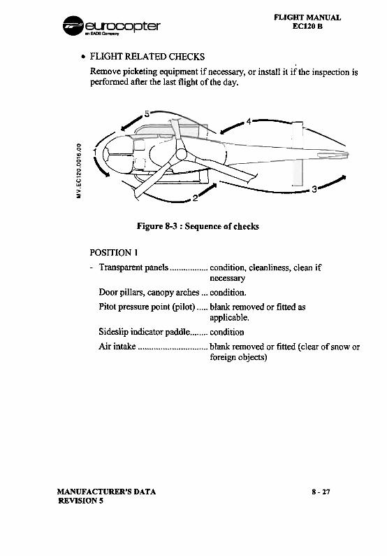
FLIGHT MANUALEC120 B
.FLIGHT RELATED CHECKS
Remove picketing equipment if necessary, or install it if the inspection isperformed after the last flight of the day.
IIIII':-~ I' ~400
cO;;0;0
~u"!>~
1
.3
Figure 8-3 : Sequence of checks
POSITION I
-Transparent panels condition, cleanliness, clean ifnecessary
Door pillars, canopy arches ...condition.
Pitot pressure point (pilot) blank removed or fitted asapplicable.
Sideslip indicator paddle condition
Air intake .., blank removed or fitted (clear of snow orforeign objects)
MANUFACTURER'S DATAREVISION S
8-27
FLIGHT MANUALEC120 B .~~ opter
POSITION 2 ..-Cabin access doors condition, attachment points,
locking.-Static pressure port blanking removed or installed (as
applicable).-Landing gear condition.-LH side engine-MGB
cowling opening, condition of lockingdevices.I -MGB : : o~llevel. ...
-HydraulIc compact UnIt 011 level, attachment poInts, pIpes,clogging indicator retracted.
-Servos.!!llQ hydraulic
system attachment points, absence of
leaks, pipes.-MGB suspension bars condition, attachment points.
ENGINE AND ENGINE BAYI -Plenum chamber condition, attachment points.
-Engine and accessories general condition, absence of leaks,cleanliness, pipes.
-Engine casing condition around bossings.I -Oil filter pre-cl~gg~ng.indicator retracted.
.-Fuel filter cloggmg IndIcator retracted.-Engine oillevel.I -Oil system absence of leaks.-Engine controls co?dition, absence of interference
poInts.-Engine mounts condition, attachment points.-Cowling upper acess panel closed and locked. .
8-28 MANUFACTURER'S DATAREVISION 5
. FLIGHT MANUAL~~~pter ECl20 B
.-Transmission ~ enginedeck condition, cleanliness, absence
of leaks.-Ports and drains in
transmission deck , unobstructed.-Exhaust pipe condition, blanking cover removed
or installed.-LH engine-MGB cowling closed and locked.-MAIN ROTOR HUB attachment points, general condition. of all components.-Laminated spherical thrust
bearings (elastomeric part) condition, absence of cracks.-Bonding braids , condition.-Reciprocal ring contact
surfaces condition, greased.-Blade droop restrainers condition.
-Frequency adaptater(elastomeric part) , condition of elastomer.
-Frequency adaptater ball ends.. condition, attachment point.-Pitch change rods condition, absence of end play.
-Swashplate condition.
-Rotating and stationaryscissors condition.
. -Swashplate guide condition.An .. b . d ,' h t 't I -tI-Vl ration system con Itlon, attac men porn s.
-Dome condition, attachment points.-MAIN ROTOR BLADES attachment points, general condition,
check forde-bonding at the leadingedge, impact damage or erosion.
-Cargo bay opened.-Battery condition, attachment points.-Cargo bay Check for snow in the tail boom -
IClosed.
.MANUFACTURER'S DATA 8 -29
REVISION S
FLIGHT MANUAL .EC120 B ~~opter
POSITION 3 .-Horizontal stabiliser, fin,
rotor tunnel, tail skid condition, attachment points,condition of navigation lights.
-TRH, hub body and fairing condition, absence of impact orcracks, no rotation of fairing, paintmarks, clearance between blade tipsand rotor tunnel.
-Tail rotor blades, visiblepart condition, absence of scores, erosion.
.Check for abnormal gap at the blades.-Tail boom condition, condition of antennas. .
POSITION 4-TGB oillevel.
-Stator condition.
-Tail rotor blades condition.
-Horizontal stabiliser, fin,rotor tunnel, tail skid condition, attachment points,
condition of navigation lights.
-Tail boom condition, condition of antennas. ..
8-30 MANUFACTURER'S DATAREVISION 5
. FLIGHT MANUAL~~opter EC120 8. POSITION 5
-Static pressure point :blank removed or installed (asapplicable).
-RH cargo bay door ,. opening, attachment points, condition.
-Electrical master boxcircuit-breakers engaged.
-RH cargo bay door , closing, locking.-Ground powe.plug
access panel closed.-RH engine-MGB cowling opening, condition of locking systems.
.-Fan and cooling radiator condition, cleanliness, absence of Ileaks.
-Engine air intake andtransmission deck cleanliness, absence of foreign
Ibodies.
-Servos ~ hydraulicsystem a~chment points, absence of leaks,
IpIpes.
-RH engine-MGB cowling closing, correct locking.-Landing gear condition.-Lower central cowling , closed.-MAIN ROTOR BLADES attachment points, general condition,
absence of bonding separation on theleading edge, absence of impact. damage or erosion.
-Cabin access door , condition, attachment, locking.CABIN INTERIOR-Seats condition, attachment points.
-Cabin general cleanliness.
.MANUFACTURER'S DATA 8 -31
REVISION 5
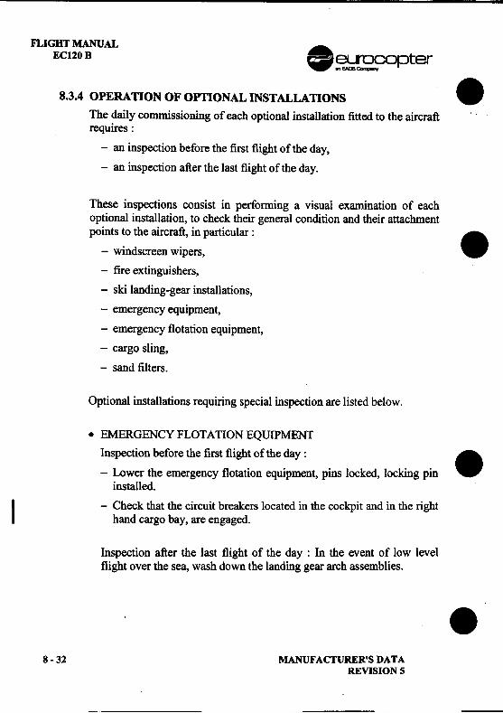
FLIGHT MANUALEC120 B .~~ opter
8.3.4 OPERATION OF OPflONAL INSTALLATIONS .The daily commissioning of each optional installation fitted to the aircraftrequires:
-an inspection before the first flight of the day,
-an inspection after the last flight of the day.
These inspections consist in perfonning a visual examination of eachoptional installation, to check their general condition and their attachmentpoints to the aircraft, in particular :
.-windscreen wipers,
-fire extinguishers,
-ski landing-gear installations,
-emergency equipment,
-emergency flotation equipment,
-cargo sling,-sand filters.
Optional installations requiring special inspection are listed below.
.EMERGENCY FLOTATION EQUIPMENT
Inspection before the first flight of the day :
.-Lower the emergency flotation equipment, pins locked, locking pininstalled.
I -Check that the circuit breakers located in the cockpit and in the righthand cargo bay, are engaged.
Inspection after the last flight of the day : In the event of low levelflight over the sea, wash down the landing gear arch assemblies. .
8-32 MANUFACTURER'S DATAREVISION 5
-
FLIGHT MANUALEC120B
.AGRICULTURAL SPRAYING INSTALLATION
This optional installation requires the presence of qualified personnelto perform the daily commissioning inspections.
.CARGO SLING
-After the last flight of the day, lightly grease (G354) the end of the loadhook at the bolt attachment point.
8.3.5 COMMISSIONING IN COLD WEATHER CONDmONS
NOTEUse of 3 cSt synthetic oil is recommended for low temperatureoperation.
.OPERATION IN SNOW
-Clean the helicopter before takeoff; blades, rotor head, windshield...
-Do not stay in HIGE with snow recirculation.
-Replace the turnaround check by a complete exterior check
MANUFACTURER'S DATAREVISION 5
8-33
.eurocopter
.FLIGHT MANUAL
EC 120 B
SUPPLEMENT.LIST OF SUPPLEMENTS AND OPTIONALS
INCOMPATIBILITY OF UTILIZATION
EFFECT ON PERFO~CE DATA
. IMPORTANT NOTE
THE INFORMATION CONTAINED HEREIN SUPPLEMENTS OR SUPERSEDES THE INFORMATIONGIVEN IN THE BASIC FLIGHT MANUAL AND/OR SUPPLEMENTS LISTED IN SECTION 9 -0 .
THE EFFECTIVITY OF THE SUPPLEMENT AT THE LATEST REVISION IS SPECIFIED ON THELIST OF EFFECTIVE PAGES.
THIS SUPPLEMENT SHALL BE CARRIED IN AIRCRAFT AT ALL TIMES.
-:::;:;g~:::===~ EUROCOPTER Direction Technique Support(:fg3J7--~ Aeroporl international Marseille-Provence 13725 Marignane Cedex -France.
DGAC APPROVED 9 -0 -TITLEREVISION 2 : NOVEMBER 1998
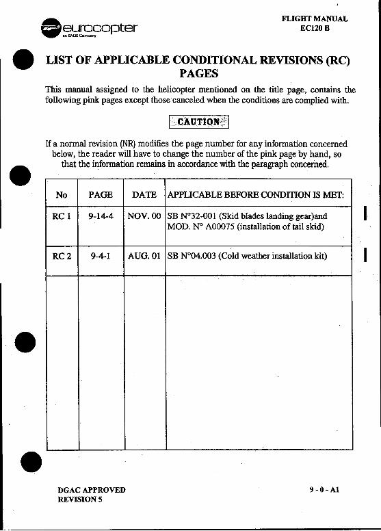
A FLIGHT MANUAL-~.};Jr~n?Opter EC120 B
.LIST OF APPLICABLE CONDITIONAL REVISIONS (RC)PAGES
This manual assigned to the helicopter mentioned on the title page, contains thefollowing pink pages except those canceled when the conditions are complied with.
[.C AUTION ,i,,1 , ";"'1
If a normal revision (NR) modifies the page number for any information concernedbelow,the reader will have to change the number of the pink page by hand, so
.that the information r9mains in accordance with the paragraph concerned.
No PAGE DATE APPLICABLE BEFORE CONDmON IS MET:
RC 1 9-14-4 NOY.OO SB N°32-001 (Skid blades landing gear)and IMOD. N° AOOO75 (installation of tail skid)
RC 2 9-4-.1 AUG. 01 SB N°O4.003 (Cold weather installation kit) I
..-I
DGACAPPROVED 9-0-AlREVISION 5
FLIGHT MANUAL .A.EC120 B -~.!;}~9opter
LIST OF APPLICABLE CONDITIONAL REVISIONS (RC) .PAGES (CONT'D)
No PAGE DATE APPLICABLE BEFORE CONDITION IS MET:
.
.
.9 -0 -A2 DGAC APPROVED
REVISION 3
. FLIGHT MANUALeurocopter EC120 B
. LIST OF CONDITIONAL REVISIONS (CR)EFFECTIVE PAGES
This manual assigned to the helicopter mentioned on the title page, contains thefollowing pink pages except those canceled when the conditions are complied with.
;G~~QN
If a nonnal revision (NR) modifies the page number for any infonnation concernedbelow, the reader will have to change the numbcroft11c pink page by hand, so
.that the information remains in accordance with the paragraph concerned.
No PAGE DAm REMARKS / EFFECllvrrv
.
.DGACAPPROVED 9-0-AORIGINAL ISSUE
FLIGHT MANUAL ...eurocopterEC120 B W
LIST OF INTERMED lATE TEMPO RAR Y .REVISIONS (ITR) EFFECTIVE PAGES
The manual contains the following additional yellow pages.
No PAGE DATE No PAGE DATE
.
.I
i! .
9-0-B DGACAPPROVEDORIGINAL ISSUE
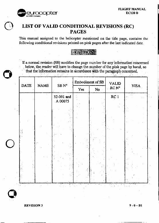
. FLIGHT MANUAL-~~~n~opter EC120 B
Q) LIST OF VALID CONDITIONAL ~VISIONS (RC)PAGES
This manual assigned to the helicopter mentioned on the title page, contains thefollowing conditional revisions printed on pink pages after the last indicated date.
Ifa nonnal revision (N~)modifies the page number for any infonnationconcemedb~low !th~readerWi11i~aveto ch~ge the p~~ber of thepipkpage by hand, so0 that. theitifQnnation~fuaih.s fuaccotdanceWith theparagraphconremed.
,. 'c .
Embodiment of SB VALIDDATE NAME SB N° o VISAYes No RCN
32-001 and RC 1A 00075
0
0REVISION 3 9 -0 -81
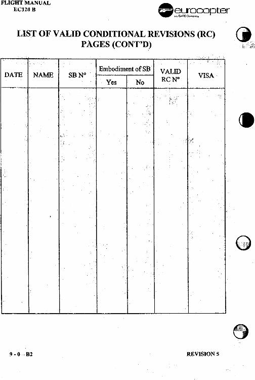
FLIGHT MANUAL .EC120 B -~~~~opter
LIST OF VALID CONDITIONAL REVISIONS (llC) ()PAGES (CONT'D) ~,::fi\'~
Embodiment of SBDATE NAME SB
Yes No
..
~
~\J9 -0 -B2 REVISION 5
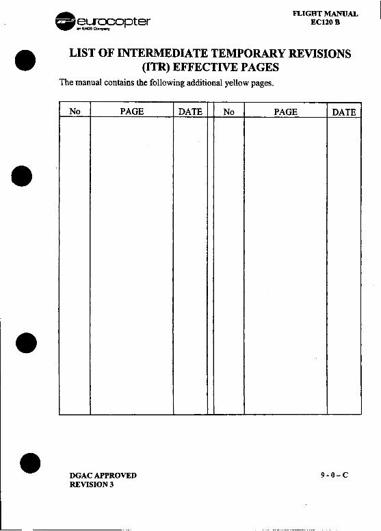
.-.FLIGHT MANUAL~ ~~~opter EC120 B
. LIST OF INTERMEDIATE TEMPORARY REVISIONS(ITR) EFFECTIVE PAGES
The manual contains the following additional yellow pages.
No PAGE DATE No PAGE DATE
.
..DGAC APPROVED 9 -0 -C
REVISION 3
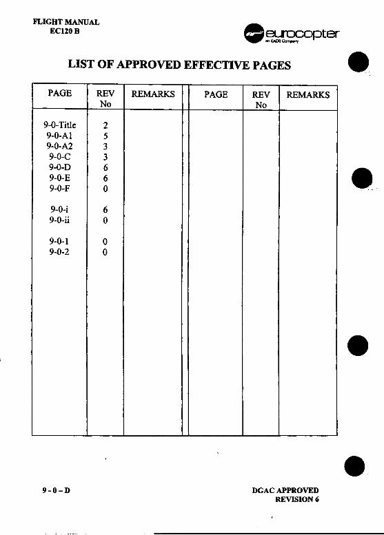
FLIGHT MANUAL .EC120 B ~~opter
LIST OF APPROVED EFFECTIVE PAGES .
PAGE REV REMARKS PAGE REV REMARKSNo No
9-0- Title 29-0-A1 59-0-A2 39-0-C 39-0-D 6
.9-0-E 69-0-F 0 .
9-0-i 69-0-ii 0
9-0-1 09-0-2 0
...
9-0-D DGACAPPROVEDREVISION 6
.
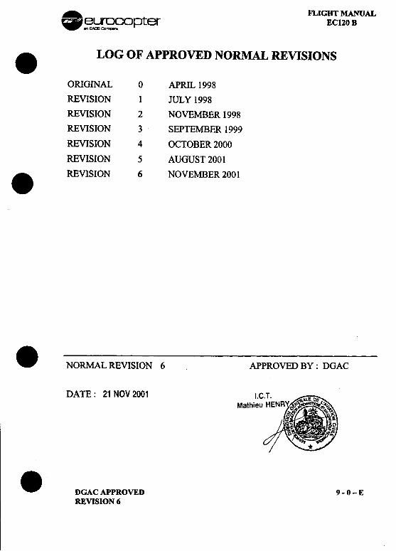
. FLIGHT MANUAL~~~opter EC120 B
.LOG OF APPROVED NORMAL REVISIONS I
ORIGINAL 0 APRIL 1998
REVISION 1 JULY 1998
REVISION 2 NOVEMBER 1998
REVISION 3 SEPTEMBER 1999
REVISION 4 OCTOBER 2000
REVISION 5 AUGUST 2001
.REVISION 6 NOVEMBER 2001
.NORMAL REVISION 6 APPROVED BY: DGAC
DATE: 21 NOV 2001 I.Mathie
.DGACAPPROVED 9-0-EREVISION 6
RIGHT MANUALEC120 B .~~ opter
CUSTOMIZATION .AlC: EC 120- SIN: '""-
SECTION PAGE ISSUE SECTION PAGE ISSUE
TillS AIRCRAFT DOES NOT OFFER ANY PARTICULAR FEATURESREQUIRING THE CUSTOMIZATION ON THE FLIGHT MANUAL ON
GREEN PAGES ...
.
.9-0-F DGACAPPROVED
ORIGINAL ISSUE
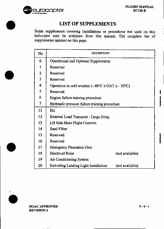
. FLIGHT MANUAL~~opter EC120 B
.LIST OF SUPPLEMENTSSome supplements covering installations or procedures not used on thishelicopter may be withdraw from this manual. The complete list ofsupplements appears on this page.
No DESCRIPTION
0 Operational and Optional Supplements
I Reserved. 2 Reserved
I3 Reserved
4 Operation in cold weather (- 40°C ~ OAT ~ -30°C)
5 Reserved I
6 Engine failure training procedure
I7 Hydraulic pressure failure training procedure
11 Ski
12 External Load Transport: Cargo Sling
13 LH Side Main Flight Controls
14 Sand Filter
15 Reserved
I16 Reserved
.17 Emergency Floatation Gear
18 Electrical Hoist (not available)
19 Air Conditioning System
20 Swiveling Landing Light Installation (not available)
,i.
DGAC APPROVED 9 -0 -iREVISION 6
--
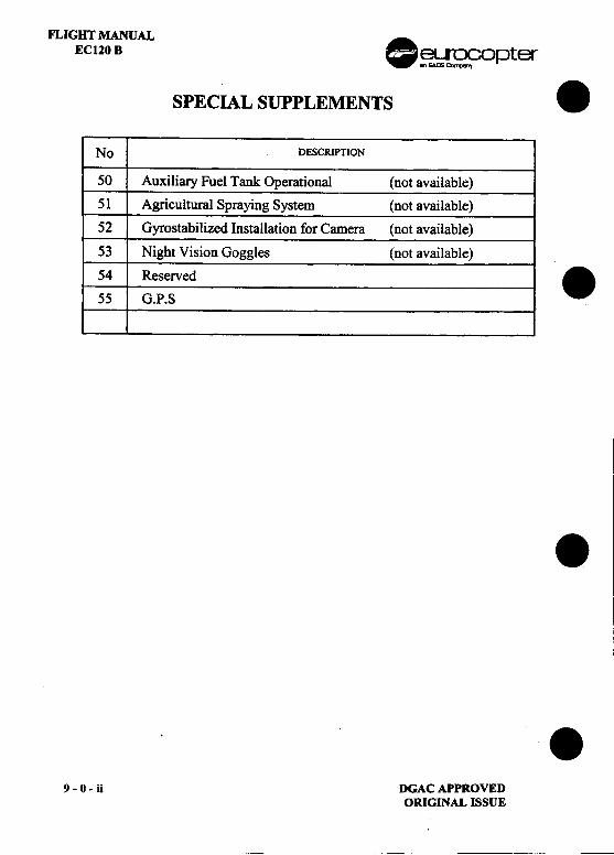
F1..IGHT MANUALEC120B .~~oPter
SPECIAL SUPPLEMENTS .No DESCRIPTION
50 Auxiliary Fuel Tank Operational (not available)51 Agricultural Spraying System (not available)52 Gyrostabilized Installation for Camera (not available)53 Night Vision Goggles (not available)54 Reserved .55 G.P.S
.
.9-0-ii DGACAPPROVED
ORIGINAL ISSUE
--
I,. FLIGHT MANUAL I~~opter EC120 B I. 1 INCOMPATIBILITY OF UTILIZATION BETWEENOPTIONAL EQUIPMENT ITEMS
(none).
..DGACAPPROVED 9-0-1
ORIGINAL ISSUE
FLIGHT MANUAL .EC120 B ~~opter
2 INFLUENCE OF OPTIONAL EQUIPMENT ON ..PERFORMANCE DATA
(none) .
.
.9-0-2 DGACAPPROVED
ORIGINAL ISSUE
Arctic Sunwest Charters LH Bubble W;ndmvYellowknife, NWT ECI20 B
IJ~ot.orcraft FM Supplcmcnt No: 682 I
Eurocopter EC120 B
Rotorcraft Flight Manual Supplement No: 682 Issue 1
For
In~tallation of Lf'ft Hand Bt.bble Window
on
C-GRTN 1058C-GRTA 1076
This supplement mU8t be attached to the DGAC Approved Rotorcraft Flight MantIa!, .with the insta11ation ofLH Bubble window in accordance with Outback AviationDrawing No: 1480 Issue I, or later DOTIDAR approved revision, per p-LSnO1.- 10.
The information contained herein super8edes and supplements the information of the basicRotorcraft Flight Manual: compliance with SECTION 1 -Limitations -is mandatory.For limitations. procedure~ and performance information not contained in thi~ ~upplement.consult the basic Rotorcraft Flight Manual
DOT Approved: : :'",,;':4H W WongAircraft Certification EngineerPacific Region
Dated:
Page I of 4
Arctic Sunwest Charters I~H Bubble Windo\vYellowknife, NWT EC I 20 B!
Rotorcraft FM Supplement No: 682
IJog of Amendments
Installation of LH Bubble Window
Issue Date Signature Effective DOT appro,'alNo: Inserted Pages by/Date
1 23.Tan 2001 1\11
DOT Approved:Dated:
Page 7 of 4
...III.Arctic Sunwest Charters LH Bubf11e WindowYellowknife, NWT ECI)f) R
Rotorcraft FM Supplement No: 682
SECTION 1 -GENERAL
The Eurocopter EC 120 B rotorcraft may be fitted with a bubble window in the left handcrew door for vertical reference operations The bubble window is approx 14 inches deepand replaces the original window
Page 1 of 4
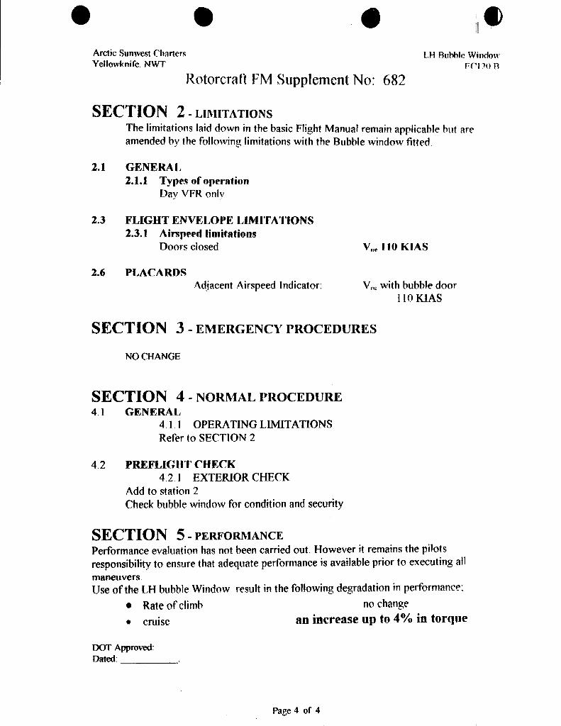
...ileArctic Sunwest Charters LH Aul'*lle W1ndo\\'Yellowknife. NWT FCIJ:() A
Rotorcraft FM Supplement No: 682
SECTION 2 -LIMITATIONSThe limitations laid down in the basic Flight Manual remain applicable but areamended by the following limitations with the Bubble window fitted
2.1 GENERAL2.1.1 Types ofoperfttion
Day VFR only
2.3 FLIGHT ENVEIJOPE LIMITATIONS2.3.1 Airspeed limitfttions
Doors closed V"" 1.0 KIAS
2.6 PLACARDSAdjacent Airspeed Indicator: V"" with bubble door
110 KIAS
SECTION 3-EMERGENCYPROCEDURES
NO CHANGE
SECTION 4 -NOI{MAL }:tROCEDURE4.1 GENERAL
41 1 OPERATING LIMITATIONSRefer to SECTION 2
4.2 PREFLIGHT CHECK4.21 EXTERIOR CHECK
Add to station 2Check bubble window for condition and security
SECTION 5 -PERFOMIANCEPerformance evaluation has not been carried out. However it remains the pilotsresponsibility to ensure that adequate performance is available prior to executing all
maneuver..;.Use of the LH bubble Window result in the following degradation in performance:
.Rate of climb no changt'
.cruise an increase up to 4% in torque
DOT Approved:Dated: ,
IiI
Page 4 of 4 I
I ---",".." L~."...
.~~ opter
.FLIGHT MANUAL
EC 120 B
SUPPLEMENT.OPERATION
IN COLD WEATHER(- 40°C ~ OAT<-300C)
IMPORTANT NOTE
. THE INFORMATION CONTAINED HEREiN SUPPLEMENTS OR SUPERSEDES THE INFORMATIONGIVEN IN THE BASIC FLIGHT MANUAL AND/OR FLIGHT MANUAL SUPPLEMENTS LISTED INSUPPLEMENT 9-0.
THE EFFECTIVITY OF THE SUPPLEMENT AT THE LATEST REVISION is SPECIFIED ON THELIST OF EFFECTIVE PAGES.
THIS SUPPLEMENT MUST BE INCLUDED IN THE FLIGHT MANUAL WHEN THE
EQUIPMENT MENTIONED ABOVE IS INSTALLED ON THE AIRCRAFT.
~:::;~S::::~~ EUROCOPTER Direction Technique Support(~~::f!/> ~ Aeroport international Marseille-Provence 13725 Marignane Cedex -France.
DGAC APPROVED 9 -4 -TITLEORIGINAL ISSUE: AUGUST 2001
-
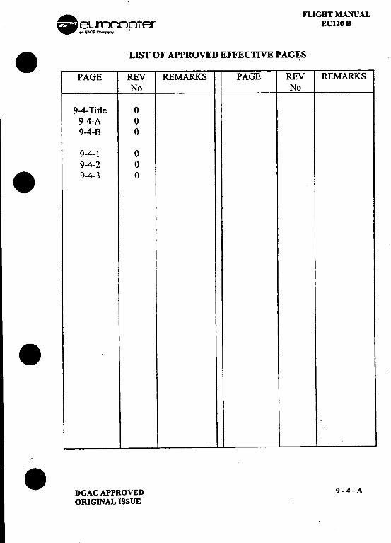
. FLIGHT MANUAL~~opter EC120 B
.LIST OF APPROVED EFFECTIVE PAG~S
PAGE REV REMARKS PAGE REV REMARKSNo No
9-4- Title 09-4-A 09-4-B 0
9-4-1 09-4-2 0
.9-4-3 0
..'. DGACAPPROVED 9-4-A
ORIGINAL ISSUE
"",."""",,
FLIGHT MANUALEC120 B
LOG OF APPROVED NORMAL REVISIONS
ORIGINAL ISSUE 0 AUGUST 2001
ORIGINAL ISSUE APPROVEDBY:DGAC
DATE: 03 AOUT 2001
9-4-8 DGAC APPROVEDORIGINAL ISSUE
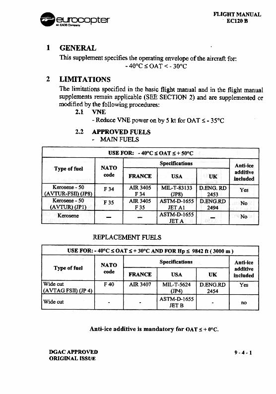
FLIGHT MANUALEC120B
1
GENERALThis supplement specifies the operating envelope of the aircraft for:
-40°C ~ OAT < -30°C
2 LIMITATIONSThe limitations specified in the basic flight manual and in the flight manualsupplements remain applicable (SEE SECTION 2) and are supplemented ormodified by the following procedures:
2.1 VNE-Reduce VNE power on by 5 kt for OAT ~ -35°C
2.2 APPROVED FUELS-MAIN FUELS
REPLACEMENT FUELS
USE FOR: -40oC S OATS + 30°C AND FOR Hp S 9842 ft ( 3000 m ).
Specifications Anti-iceadditiveincluded
NATOcode
Type of fuelFRANCE
AIR 3407
USA UK
Wide cutJ(A VT AG FSn) JJ~)
F40 MIL-T-5624(JP4)
D.ENG.RD2454
Yes
ASTM-D-1655JETB
Wide cut no
Anti-ice
additive is mandatory for OAT S + o°c.
DGAC APPROVEDORIGINAL ISSUE
9-4-1
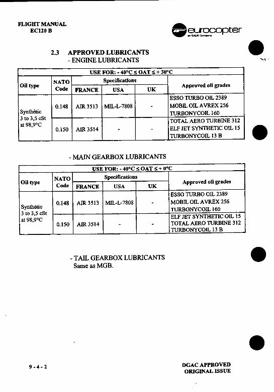
I
FLIGHr MANUAL
EC120 B .~~opter
2.3 APPROVED LUBRICANTS .-ENGINE LUBRICANTS "-..
USE FOR: -40°C:S OAT:S + 30°C
.NATO Specifications
Oil type Code FRANCE USA UK Approved oil grades
ESSO TURBO OIL 2389
0.148 AIR 3513 MIL-L-7808 .MOBIL OIL AVREX 256
Synthetic TURBONYCOIL 160
3 to 3,5 cStat 98,9°C TOTAL AERO TURBINE 312
0.150 AIR 3514 --ELF JET SYNTHETIC OIL 15 .TURBONYCOIL 13 B
-MAIN GEARBOX LUBRICANTS
USE FOR: -40oC:S OAT:S + DoC
NATO Specifications
Oil type Code K Approved oil grades
FRANCE USA UESSO TURBO OIL 2389
S th ,. 0.148 AIR 3513 MIL-L-7808 -MOBIL OIL AVREX 256
yn etlc3 to 3 5 cSt TURBONYCOIL 160
at 98,9°C ELF JET SYNTHETIC OIL 15
0.150 AIR 3514 --TOTAL AERO TURBINE 312
TURBONYCOIL 13 B
-TAIL GEARBOX LUBRICANTS .Same as MGB.
, .
9-4-2 DGACAPPROVED
ORIGINAL ISSUE
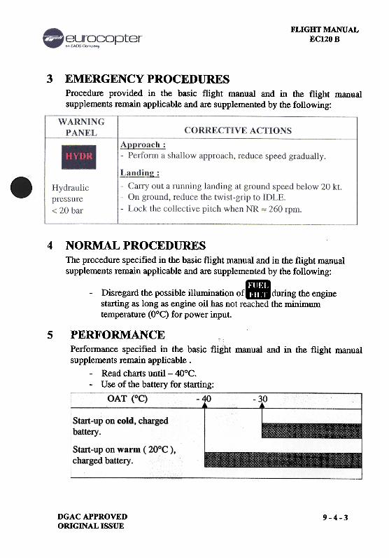
FLIGHT MANUALEC120 B
3 EMERGENCY PROCEDURESProcedure provided in the basic flight manual and in the flight manualsupplements remain applicable and are supplemented by the following:
4 NORMAL PROCEDURESThe procedure specified in the basic flight manual and in the flight manualsupplements l-emain applicable and are supplemented by the following:
-Disregm"d the possible illumination Of. during the enginestarting as long as engine oil has not reached the minimumtemperature (O°C) for power input.
5 PERFORMANCE c,Performance specified in the basic fli~ht manual and in the flight manualsupplements remain applicable.
-Read charts until -4O°C.-Use of the battery for starting:
OAT (OC) -';\0 -3,0
Start-up on cold, chargedbattery .
Start-up on warm ( 20°C ),charged battery.
DGACAPPROVEDORIGINAL ISSUE
9-4-3
.~~ opter.FLIGHT MANUAL
EC 120 B
.SUPPLEMENT
ENGINE FAILURE
TRAINING PROCEDURE
. IMPORTANT NOTE
THE INFORMATION CONTAINED HEREIN SUPPLEMENTS OR SUPERSEDES THE INFORMATIONGIVEN IN THE BASIC FLIGHT MANUAL AND/OR FLIGHT MANUAL SUPPLEMENTS LISTED IN
SUPPLEMENT 9-0.
THE EFFECTIVITY OF THE SUPPLEMENT AT THE LATEST REVISION IS SPECIFIED ON THE
LIST OF EFFECTIVE PAGES.
THIS SUPPLEMENT MUST BE INCLUDED IN THE FLIGHT MANUAL WHEN THE
EQUIPMENT MENTIONED ABOVE IS INSTALLED ON THE AIRCRAFT.
-:;~3~~~ EUROCOPTER Direction Technique Support(l~(..1---~ Aeroport international Marseille-Provence 13725 Marignane Cedex -France
.DGAC APPROVED 9 -6 -llTLEORIGINAL ISSUE: NOVEMBER 2001
. FLIGHT MANUAL~~opter EC120 B
.LIST OF APPROVED EFFECTIVE PAGES
PAGE REV REMARKS PAGE REV REMARKSNo No
9-6- Title 09-6-A 09-6-B 0
9-6-1 0.9-6-2 0
.'.
. DGACAPPROVED 9-6-AORIGINAL ISSUE
FLIGHT MANUALEC120 B .~~ opter
LOG OF APPROVED NORMAL REVISIONS .
ORIGINAL 0 NOVEMBER 2001
.
ORIGINAL ISSUE APPROVED BY : DGAC .DATE: 21 NOV 2001 I.
Mathieu
.9-6-B DGACAPPROVED
ORIGINAL ISSUE
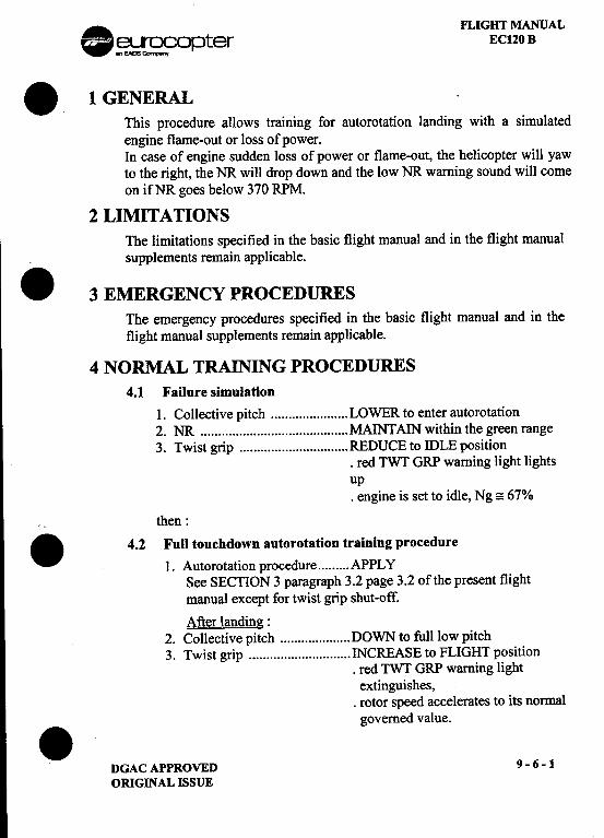
. FLIGHT MANUAL~~opter EC120 B
.1 GENERALThis procedure allows training for autorotation landing with a simulatedengine flame-out or loss of power.In case of engine sudden loss of power or flame-out, the helicopter will yawto the right, the NR will drop down and the low NR warning sound will comeon ifNR goes below 370 RPM.
2 LIMITATIONSThe limitations specified in the basic flight manual and in the flight manualsupplements remain applicable.
.3 EMERGENCY PROCEDURESThe emergency procedures specified in the basic flight manual and in theflight manual supplements remain applicable.
4 NORMAL TRAINING PROCEDURES4.1 Failure simulation
1. Collective pitch LOWER to enter autorotation2. NR MAINTAIN within the green range3. Twist grip REDUCE to IDLE position
.red TWT GRP warning light lightsup.engine is set to idle, Ng =: 67%
then:
.4.2 Fun touchdown auto rotation training procedure
1. Autorotation procedure APPLYSee SECTION 3 paragraph 3.2 page 3.2 of the present flightmanual except for twist grip shut-off.
After landing:2. Collective pitch DOWN to full low pitch3. Twist grip INCREASE to FLIGHT position
.red TWT GRP warning lightextinguishes,
.rotor speed accelerates to its normalgoverned value..
DGACAPPROVED 9-6-1ORIGINAL ISSUE
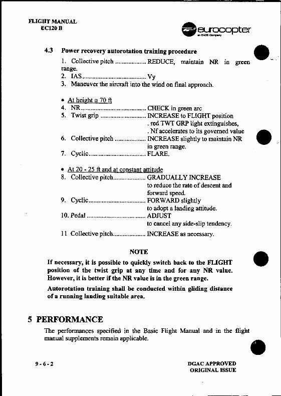
FLIGHT MANUALEC120 B .~~O pter
4.3 Power rec~ve~ autorotation training proced~re ...,~1. Collective pitch REDUCE, maIntaIn NR m green -
range.2. IAS Vy3. Maneuver the aircraft into the wind on final approach.
.At height == 70 ft4. NR CHECK in green arc5. Twist grip ..".".'.'.""""" INCREASE to FLIGHT position
.red TWT GRP light extinguishes,
.Nf accelerates to its governed value.6. Collective pitch ~CREASE slightly to maintain NR .'
m green range.7. Cyclic FLARE.
.At 20 -25 ft and at constant attitude8. Collective pitch GRADUALLY INCREASE
to reduce the rate of descent andforward speed.
9. Cyclic FORWARD slightlyto adopt a landing attitude.
10. Pedal ADJUSTto cancel any side-slip tendency.
11 Collective pitch INCREASE as necessary.
NOTE.If necessary, it is possible to quickly switch back to the FLIGHT
position of the twist grip at any time and for any NR value.However, it is better if the NR value is in the green range.
Autorotation training shall be conducted within gliding distanceof a running landing suitable area.
5 PERFORMANCEThe performances specified in the Basic Flight Manual and in the flightmanual supplements remain applicable. .
9-6-2 DGACAPPROVEDORIGINAL ISSUE
.~~ opt~r
.FLIGHT MANUAL'
EC 120 B
SUPPLEMENT.HYDRAULIC PRESSURE FAILURE
TRAINING PROCEDURE
IMPORTANT NOTE
. THE INFORMATION CONTAINED HEREIN SUPPLEMENTS OR SUPERSEDES THE INFORMATIONGIVEN IN THE BASIC FLIGHT MANUAL AND/OR FLIGHT MANUAL SUPPLEMENTS LISTED INSUPPLEMENT 9-0.
THE EFFECTIVITY OF THE SUPPLEMENT AT THE LATEST REVISION IS SPECIFIED ON THELIST OF EFFECTIVE PAGES.
THIS SUPPLEMENT MUST BE INCLUDED IN THE FLIGHT MANUAL WHEN THEEQUIPMENT MENTIONED ABOVE IS INSTALLED ON THE AIRCRAFT.
-:;;;5~~~ EUROCOPTER Direction Technique Support(l:;gS1/.) ~ Aeropon international Marseille-Provence 13725 Marignane Cedex -France
8GAC APPROVED 9 -7 -TITLEORIGINAL ISSUE: NOVEMBER 2001
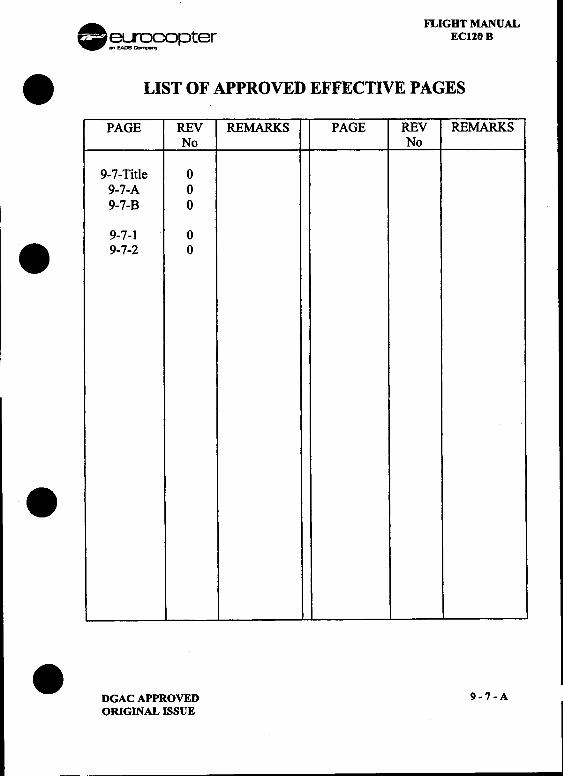
. FLIGHT MANUAL~~opter ECl20 B
.LIST OF APPROVED EFFECTIVE PAGES
PAGE REV REMARKS PAGE REV REMARKSNo No
9-7- Title 09-7-A 09-7-B 0
9-7-1 0.9-7-2 0
.
. DGACAPPROVED 9-7-A-oRi;;;;'AL -'Ssm I
FLIGHT MANUALEC120 B .~ ~opter
LOG OF APPROVED NORMAL REVISIONS ~.
ORIGINAL 0 NOVEMBER 2001
8,
ORIGINAL ISSUE APPROVED BY : DGAC
DATE: 21 NOV 2001 I. 8Mathie
89-7-B DGACAPPROVED
ORIGINAL ISSUE
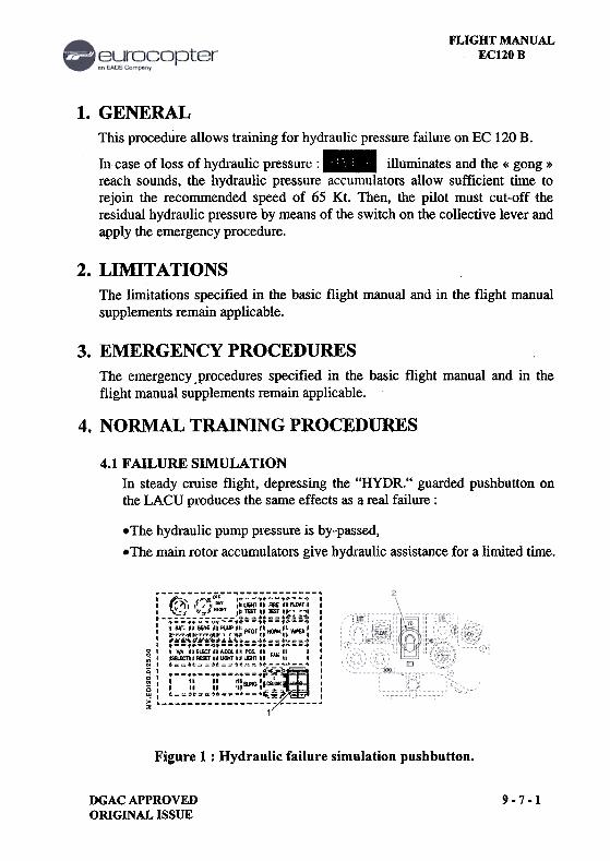
FLIGHT MANUALEC120 B
1. GENERALThis procedure allows training for hydraulic pressure failure on EC 120 B.
10. case of loss of hydraulic pressure: 11- illuminates and the « gong »reach sounds, the hydraulic pressure accumulators allow sufficient time torejoin the recommended speed of 65 Kt. Then, the pilot must cut-off theresidual hydraulic pressure by means of the switch on the collective lever andapply the emergency procedure.
2. LIMITATIONSThe limitations specified in the basic flight manual and in the flight manualsupplements remain applicable.
3. EMERGENCY PROCEDURESThe emergency .procedures specified in the basic flight manual and in theflight manual supplements remain applicable.
4. NORMAL TRAINING PROCEDURES
4.1 FAILURE SIMULATIONIn steady cruise flight, depressing the "HYDR." guarded pushbutton onthe LACU produces the same effects as a real failure:
-The hydraulic pump pressure is by-passed,-The main rotor accumulatol"S give hydraulic assistance for a limited time.
~--~--,- -;; ~,--~:==:.~~~;: :;- ~I ';-'1,1,',,'" ,b",",," FIlE "RDA'iI I, v-. ":*"'" 1'-11-0"; :.., I~o.._~..t~_.. I,.0_'.-_'.--'.--', I, "".""""'UI""",O"', "" ' I
Wr~,,'Wr~"'" "" '1 '0 0I "K t..~" = o.. I1 .s_,.s =..==..-=.,,--, .g"V/A"E""""'OOL""""'",,'" .,.;1 ilSELECTII-"",",,"UGlnll '" ",N I .=~..~ ~..=~..=_..~~. ,~ I " ,,-=..==.;;~..~ -I I0 I .
N, b " ii' "",,"'I~ I
~ t_~:::~___8_~~.:::~::::~~~~ J1
Figure 1 : Hydraulic failure simulation pushbutton.
DGACAPPROVEDORIGINAL ISSUE
9-7-1
FLIGHT MANUAL .EC120 B ~~fopter
4.2 TRAINING PROCEDURE .
1. LACU "HYDR." guarded pushbutton (1) ...DEPRESS.
1111- Comes on + "GONG" sounds.
2. Hydraulic failure procedure , APPLY.
See FLM SECTION 3 (§ 3.7.3).
When HYD switch (2) on collective lever is in OFF Dosition :3. LACU "HYDR." pushbutton RESET.
When on !!round. or at anv moment to restore hvdraulic assistance: .
4. HYD switch (on collective lever) ON.
[!!~!] goes out.
'%;;C4;UTIQ~i\itt
If the llYDI~. gu~lrded push button on the LACU is not resejno hydraulic assistance can be restored.
5. PERFORMANCEThe performance given in the Basic Flight Manual and in the flight manualsupplements remain applicable. .
.9-7-2 DGACAPPROVED
ORIGINAL ISSUE
.eurocopter
.FLIGHT MANUAL
EC 120 B
SUPPLEMENT.EXTERNAL LOAD TRANSPORT
" CARGO SLING "
IMPORTANT NOTE
. THE INFORMATION CONTAINED HEREIN SUPPLEMENTS OR SUPERSEDES THE INFORMATIONGIVEN IN THE BASIC FLIGHT MANUAL AND/OR FLIGHT MANUAL SUPPLEMENTS LISTED IN
SUPPLEMENT 9-0.
THE EFFECTIVITY OF THE SUPPLEMENT AT THE LATEST REVISION IS SPECIFIED ON THE
LIST OF EFFECTIVE PAGES.
THIS SUPPLEMENT MUST BE INCLUDED IN THE FLIGHT MANUAL WHEN THE
EQUIPMENT MENTIONED ABOVE IS INSTALLED ON THE AIRCRAFT.
-:;~§~==:~ EUROCOPTER Direction Technique Support(~~J--.)-~ Aeroport international Marseille-Provence 13725 Marignane Cedex -France.
DGAC APPROVED 9 -12 -TITLEREVISION 1 : JANUARY 1999
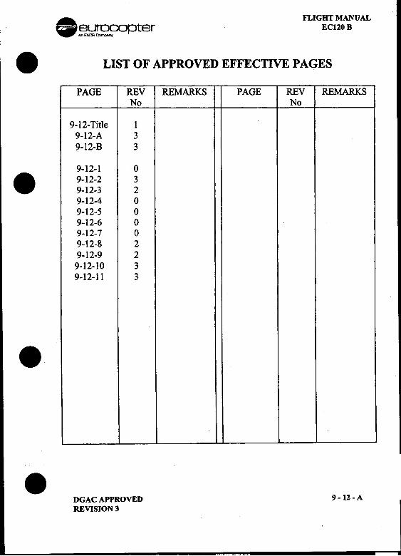
. FLIGHT MANUAL~~~pter EC120 B
.LIST OF APPROVED EFFECTIVE PAGES
PAGE REV REMARKS PAGE REV REMARKSNo No
9-12-Title 19-12-A 39-12-B 3
9-12-1 0. 9-12-2 3
9-12-3 29-12-4 09-12-5 09-12-6 09-12-7 09-12-8 29-12-9 29-12-10 39-12-11 3
.
.DGAC APPROVED 9 -12 -A
REVISION 3
FLIGHT MANUALEC120B .~~opter
LOG OF APPROVED NORMAL REVISIONS 81
ORIGINAL 0 JULY 1998
REVISION 1 JANUARY 1999
REVISION 2 SEPTEMBER 1999
REVISION 3 NOVEMBER 2001 .
NORMAL REVISION 3 APPROVED BY : DGAC .DATE: 21 NOV 2001 I.
Mathieu
.9 -12 -B DGAC APPROVED
REVISION 3
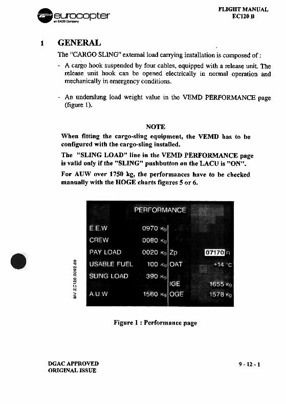
FLIGHT MANUALEC120 B
1 GENERALThe "CARGO SLING'! extemalload carrying installation is composed of:
-A cargo hook suspended by four cables, equipped with a release unit. Therelease unit hook can be opened electrically in normal operation andmechanically in emergency conditions.
-An underslung load weight value in the VEMD PERFORMANCE page(figure 1).
NOTEWhen fitting the cargo-sling equipment, the VEMD has to beconfigured with the cargo-sling installed.
The "SLING LOAD" line in the VEMD PERFORMANCE pageis valid only if the "SLING" pushbutton on the LACU is "ON".
For AUW over 1750 kg, the performances have to be checkedmanually with the DOGE charts figures 5 or 6.
00<-iQ)000'"0U!>~
Figure 1 : Performance page
DGAC APPROVEDORIGINAL ISSUE
9-12-1
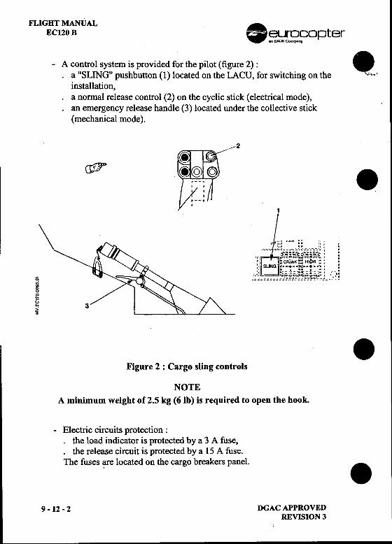
FLIGHT MANUALEC120 B .~ ~copter
-A control system is provided for the pilot (figure 2) : .a "SLING" pushbutton (1) located on the LACU, for switching on the ',I.,,'
installation,a normal release control (2) on the cyclic stick (electrical mode),
.an emergency release handle (3) located under the collective stick(mechanical mode).
2(ffir .1
.." ,." .." " 0r",o ". '" ." .." , .., ''0' ~ --', ~i-i~;t3i-i-~t : !
" .CR.\NK.' HY;,n ., ,': SUNG ~..~"~~"".;=;: :' ,
0 :;~~= =====;~,~t1ic~~f:~~tj- _::?!.;.,8gUw'"~ .
Figure 2 : Cargo sling controls
NOTEA minimum weight of2.S kg (6Ib) is required to open the hook.
-Electric circuits protection:.the load indicator is protected by a 3 A fuse,.the release circuit is protected by a 15 A fuse.The fuses ~re located on the cargo breakers panel. .
9 -12 -2 DGAC APPROVEDREVISION 3
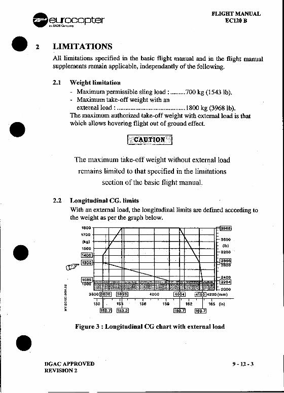
A FLIGHT MANUAL..fi3~r~fopter EC120 B
.2 LIMITATIONSAll limitations specified in the basic flight manual and in the flight manualsupplements remain applicable, independantly of the following.
2.1 Weight limitation-Maximum permissible sling load: 700 kg (1543 lb).-Maximum take-off weight with an
external load: 1800 kg (3968Ib).The maximum authorized take-off weight with external load is that
.which allows hOVering,,~ig~to~tof!~round effect.
"'CAUTION "v";'" i
The maximum take-off weight without external load
remains limited to that specified in the limitations
section of the basic flight manual.
2.2 Longitudinal CG. limitsWith an external load, the longitudinal limits are defmed according tothe weight as per the graph below.
1800
1700.(rJJ)'"
..0
..00
g~.:~
Figure 3 : Longitudinal CG chart with external load.DGACAPPROVED , -11-3 19_12_3REVISION 2
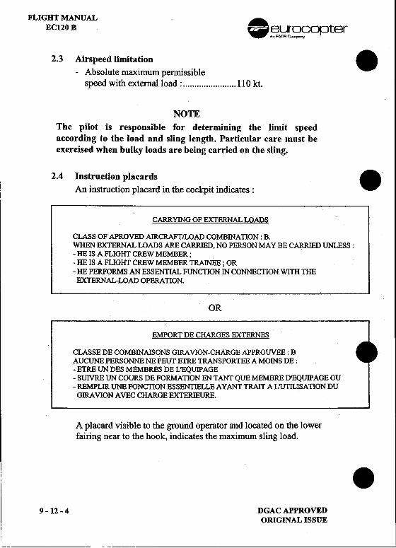
FLIGHT MANUALEC120 B ..fi3~S?C?opter
2.3 Airspeed limitation .-Absolute maximum pelmissible
speed with external load : 110 kt.
NOTEThe pilot is responsible for determining the limit speedaccording to the load and sling length. Particular care must beexercised when bulky loads are beiug carried on the sling.
2.4 Instruction placards .An instruction placard in the cockpit indicates :
CARRYING OF EXTERNAL LOADS
CLASS OF APROVED AIRCRAFf/LOAD COMBINAllON : B.WHEN EXTERNAL LOADS ARE CARRIED, NO PERSON MAY BE C~ UNLESS:-HE IS A FLIGHr CREW MEMBER;-HE IS A FLIGHT CREW MEMBER TRAINEE; OR-HE PERFORMS AN ESSENTIAL FUNCTION IN CONNECTION WITH nIE
EXTERNAL-LOAD OPERAllON.
OR
EMPORT DE CHARGES EXTERNES
CLASSE DE COMBINAISONS GIRA VION-CHARGE APPROUVEE : BAUCUNE PERSONNE NE PEUT ETRE TRANSPORTEE A MOINS DE ;-ETRE UN DES MEMBRES DE L 'EQUIPAGE-SUIVRE UN COURS DE FORMAllON EN TANT QUE MEMBRE D'EQUIPAGE OU-REMPLIR UNE FONCllON ESSENTIELLE A Y ANT TRAIT A L'1:JnLISATION DUGIRA VION AVEC CHARGE EXTERIEURE.
A placard visible to the ground operator and located on the lowerfairing near to the hook, indicates the maximum sling load. .
9 -12 -4 DGAC APPROVEDORIGINAL ISSUE
II
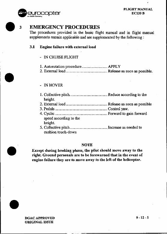
. FLIGHT MANUAL~~r~o?opter EC120 B
.3 EMERGENCY~R<?CED~~ ..The procedures provIded In the basIC flIght manual and In flIght manualsupplements remain applicable and are supplemented by the following:
3.1 Engine failure with external load
-IN CRUISE FLIGHT
1. Autorotation procedure APPLY2. External load Release as soon as possible..-IN HOVER
1. Collective pitch. Reduce according to theheight.
2. External load Release as soon as possible3. Pedals """""""""""""""""""""""""'" Control yaw.4. Cyclic Forward to gain forward
speed according to theheight.
5.. Collective pitch Increase as needed tocushion touch-down
NOTE. Except during hooking phase, the pilot should move away to theright. Ground personals are to be forewarned that in the event ofengine failure they are to move away to the left of the helicopter.
.DGAC APPROVED 9 -12 -5
ORIGINAL ISSUE
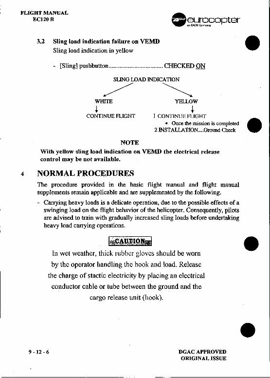
FLIGHT MANUAL .EC120 B ~r~9opter
3.2 Sling load indication failure on VEMD .Sling load indication in yellow
-[Sling] pushbutton CHECKED Qtl
SLING LOAD INDICATION""/""""'~.--/ , ,," WmTE YEu.oW
+ +CONTINUE FLIGHT 1 CONTINLIE FLIGHT
.Once the mission is completed.2 INST ALLA TION Ground Check
NOTEWith yellow sling load indication on VEMD the electrical releasecontrol may be not available.
4 NORMAL PROCEDURESThe procedure provided in the basic flight manual and flight manualsupplements remain applicable and are supplemented by the following.-Carrying heavy loads is a delicate operation, due to the possible effects of a
swinging load on the flight behavior of the helicopter. Consequently, pilotsare advised to train with gradually increased sling loads before undertakingheavy load carrying operations. .!i§~Jl~Jg;!
In wet weather, thick rubber gloves should be worn
by the operator handling the hook and load. Release
the charge of stactic electricity by placing an electrical
conductor cable or tube between the ground and the
car~o release unit (hook). .9 -12 -6 DGAC APPROVED
ORIGINAL ISSUE
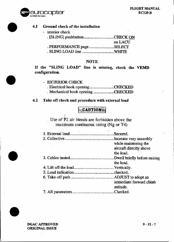
I. FLIGHT MANUAL-eurocopter EC120 B
on EAr5 Compony I
.4.1 Ground check of the installation-interior check
.[SLING] pushbutton CHECK QNon LACU
.PERFORMANCE page SELECf.SLING LOAD line WHIlE
NOTEIf the "SLING LOAD" line is missing, check the VEMDconfiguration.
.-EX1ERIOR CHECK.Electrical hook opening CHECKED.Mechanical hook opening CHECKED
4.2 Take off check and procedure with external load
y
i:i"CAUTION'~"\;",CY",~~y,,,'i~
i
Use ofP2 air bleeds are forbidden above themaximum continuous rating (Ng or T4)
I. Extemalload Secured.2. Collective Increase very smoothly
while maintening theaircraft directly above
. the load.3. Cables tanted Dwell briefly before raising
the load.4. Lift off the load Vertically.5. Load .indication checked6. Take-off path ADJUST to adopt an
inunediate forward climbattitude.
7. All pat.arneters Checked..DGACAPPROVED 9-12-7ORIGINAL ISSUE
FLIGHT MANUAL .EC120 B c ~~rS>!?Opter
4.3 Manoeuvres .All control movements should be made very gently, with very gradualacceleration and deceleration, and only slightly banked turns.
4.4 Approach and landing with external load.
"CAUTIONc" ';'\ ,.."" c;,,'"
Use of iP2 ai~ ble~ds are for?idden above the .maximum contInUOUS rating (Ng or 14)
-Perform approach at minimum rate of descent.-Establish zero translational ground speed sufficiently hight to ensure
that the load is not dragged along the ground.-Then descent vertically until the load is on the ground.-Release the load.-Load released CHECKED
NOTE.If the load is not released, actuate the emergency release handle
5 PERFORMANCE
The performance given in the Basic Flight Manual and in flight manual .I supplements remain applicable and are supplemented as following:
The performance curves for weights in excess of 1715 kg (3780 lb) areplotted in dotted line on the following performance charts.
.9 -12 -8 DGAC APPROVED
REVISION 2
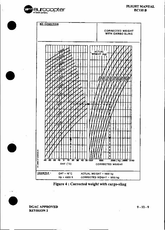
. FLIGHT MANUAL~~opter EC120 B. NO CONDITION
CORRECTED WEIGHTWITH CARGO-SLING
.
.II
I. 0~i5 ---1500 2000 ( kg)2500 2750
i OAT rC) CORRECTED WEIGHT~
EXAMPLE: OAT = 15'C ACTUAL WEIGHT = 1600 kg
Hp = 4000 It CORRECTED WEIGHT = 1850 kg
Figure 4 : Corrected weight with cargo-sling.DGAC APPROVED 9 -12 -9REVISION 2
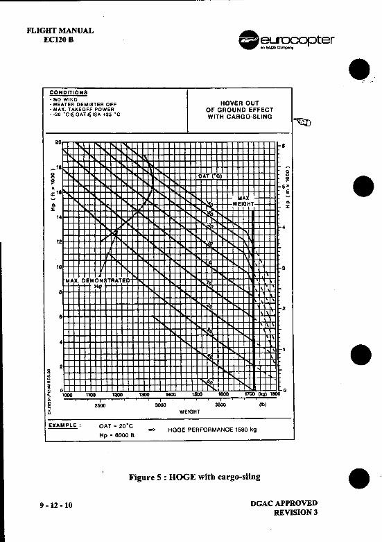
FLIGHT MANUAL .EC120 B ~~opter
8.,- .
CONDITIONS.NO WIND.HEATER DEMISTER OFF HOVER OUT.MAX TAKEOFF POWER OF GROUND EFFECT.-30 .c, OAT ~ ISA -35 'C WITH CARGO-SLING
~20 8
18 --0
g OAT ( C) ~ 8-;; 5~-18 E:. MAX -~ ~ WEIGHT- :X OJ
14 0"!'..
:.-" 4"!'..
12 "D
10 3
MAX. DEMONSTRATEO 10Ha \
8 ,
\
:'-0 2"to. \
8 I
I \
, ;to
-r..4 I
I \ I 8#0"" \
S 2
.;~ ,sO2~ 0 "'" 00; 1000 1100 1200 1300 1400 ISOO ~ 1700 (kg) 1800G ., I ' , ., I ., ., .
~ 2500 3000 3SOO (Ib)..:. WEIGHT
EXAMPLE: OAT = 20'C-HOGE PERFORMANCE 1580 kg
Hp = 6000 It
, Figure 5 : DOGE with cargo-sling 8
9 -12 -10 DGAC APPROVEDREVISION 3
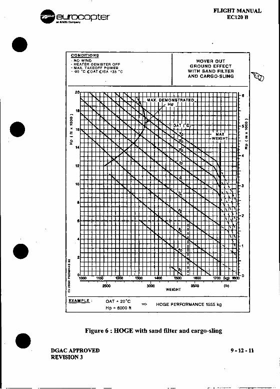
. FLIGHT MANUAL~~opter EC120 B.
CONDITIONS-NO WIND HOVER OUT-HEATER DEMISTER OFF GROUND EFFECT-MAX. TAKEOFF POWER--30 'C~OAT~ISA +35'C WITH SAND FILTER ~
AND CARGO-SLING ~
208
18
0 -0. 0 0
~ 50
" 18 ~:: MAX"-WEIGHT E~ -% ~
14 %
4
12
10 3
~
8
28 \
"
4
.S 2 1
..~~s0 0~ 1000 1100 1200 1300 1400 1500 1800 1700 (kg) 1800 0; ..I ..., I ' , ..I ~ 2500 3000 3500 (lb)
~ WEIGHT
EXAMPLE: OAT = 20.C=> HOGE PERFORMANCE 1555 kg
Hp = 6000 It
Figure 6 : DOGE with sand filter and cargo-sling.DGAC APPROVED 9 -12 -11REVISION 3
"
EC
SUPPLEMENT
LH SIDE MAIN FLIGHT CONTROLS
THIS SUPPLEMENT MUST BE INCLUDED IN THE FLIGHT MANUAL WHEN THEEQUIPMENT MENTIONED ABOVE IS INSTALLED ON THE AIRCRAFT.
EUROCOPTER Direction Technique SupportA'roport international Marseille-Provence 13725 Marignane Codex -France
9-13-TITLEDGAC APPROVEDORIGINAL ISSUE: NOVEMBER 1998
FLIGHT MANUAL
EC120 B
LIST OF APPROVED EFFECTIVE PAGES
REMARKSPAGE REVNo
REVNo
REMARKSPAGE
000
9-13-Title9-13-A9-13-8
00
9-13-19-13-2
9-13-ADGAC APPROVEDORIGINAL ISSUE
FLIGHf MANUAL 8 eurocoJJterEC120B
LOG OF APPROVED NORMAL REVISIONS
ORIGINAL 0 NOVEMBER 1998 .
.ORIGINAL ISSUE APPROVED BY : DGAC
-~.~:.:,-" E t.,DATE: 27 tDI. 1. ..v."r , -.-1:.
I'Exploitation .9 -13 -B DGAt APPROVED
ORIGINAL ISSUE i8
, .'.
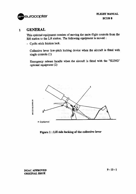
FLIGHT MANUAL
EC120B
1
GENERALThis optional equipment consists of moving the main flight controls from theRH station to the LH station. The following equipment is moved :
-Cyclic stick friction lock.
Collective lever low-pitch locking device when the aircraft is fitted with
single controls (1)
Emergency release handle when the aircraft is fitted with the "SLING"
optional equipment (2)
00:g.;..()"!>~
* Optional
Figure 1 : LH side locking of the coUective lever
9-13-1DGAC APPROVEDORIGINAL ISSUE
FLlGHI'MANUAL Aeurocol:JterECI20 B -2 LIMITATIONS
The limitations specified in the basic flight manual and in the flight manual 8
supplements remain applicable.
3 EMERGENCY PROCEDURESThe emergency procedures specified in the basic flight manual and in the
flight manual supplements remain applicable.
4 NORMAL PROCEDURESThe normal procedures specified in the basic flight manual and in the flightmanual supplements remain applicable and are supplemented by thefollowing procedures: '
8-When dual controls are titted :
Interior checks
.RH side collective lever low-pitch locking device .Installed
.LH side collective lever low-pitch locking device .Removed
-When LH side single controls are fitted :
Interior checks
.RH side pedals protective device Installed
.Cyclic and collective pitch control covers lnstalled.LH side collective lever low-pitch locking device Installed
5 PERFORMANCEThe performances specified in the Basic Flight Manual and in the flight 8
manual supplements remain applicable.
9 -13 -2 DGAC APPROVEDI ORIGINAL ISSUE 8 '
I!
.euracapter
.FLIGHT MANUAL
EC 120 B
SUPPLEMENT.SAND FILTER
AEROFLO
IMPORTANT NOTE
. THE INFORMATION CONTAINED HEREIN SUPPLEMENTS OR SUPERSEDES THE INFORMATIONGIVEN IN THE BASIC FLIGHT MANUAL AND/OR FLIGHT MANUAL SUPPLEMENTS LISTED IN
SUPPLEMENT 9-0.THE EFFECTIVITY OF THE SUPPLEMENT AT THE LATEST REVISION IS SPECIFIED ON THE
THIS SUPPLEMENT MUST BE INCLUDED IN THE FLIGHT MANUAL WHEN THE
EQUIPMENT MENTIONED ABOVE IS INSTAllED ON THE AIRCRAFT-
-:~:::s:=~~ EURO CO PTER Direction Technique Support(~::g:3J//-~ Aeroport international Marseille-Provence 13725 Marignane Cede. -France
.DGAC APPROVED 9 -14 -TITLEREVISION 1 : JANUARY 1999
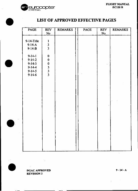
. FLIGHT MANUAL~~~opter EC120 B
.LIST OF APPROVED EFFECTIVE PAGES
PAGE REV REMARKS PAGE REV REMARKSNo No
9-14-Title 19-14-A 39-14-B 3
9-14-1 0. 9-14-2 0
9-14-3 09-14-4 39-14-5 39-14-6 3
..DGAC APPROVED 9 -14 -A
REVISION 3
--
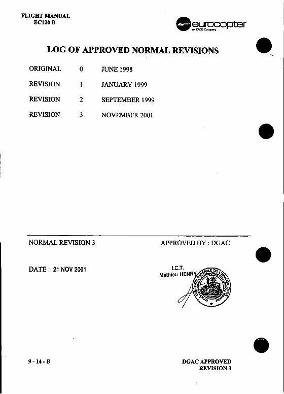
FLIGHT MANUAL .EC120 B ~~opter
LOG OF APPROVED NORMAL REVISIONS _.
ORIGINAL 0 JUNE 1998
REVISION 1 JANUARY 1999
REVISION 2 SEPTEMBER 1999
REVISION 3 NOVEMBER 2001 .
NORMAL REVISION 3 APPROVED BY : DGAC .DATE: 21 NOV 2001 I.
Mathie
.9 -14 -B DGAC APPROVED
REVISION 3
. FLIGHT MANUALf!!'~r~C?opter EC120 B
.1 GENERALThe sand filter installation is intended to protect the engine from sandingestion, during hovering flight or when flying in sand-laden atmosphere.
It operates permanently whenever it is fitted on the aircraft.
The installation consists essentially of :
.-A structural sand filter support fitted in front of the engine air intake,-A rectangular filtering panel fitted on structural support,-A pressurised air (P2) supply system.
In operation, the ambient air passes through the VORTEX tubes of thefiltering panel. The sand is centrifuged and is ejected out towards the rear ofthe aircraft, through a duct which is flushed by the P2 air system.
2 LIMITATIONSThe limitations provided in the basic flight manual and flight manualsupplements remain applicable and are supplemented by :
.I CAUTION I
The flight is forbidden if the filtering panel is not
fitted on his Sllpport.
.DGAC APPROVED 9- 14 -1ORIGINAL ISSUE
---
FLIGHT MANUAL .EC120 B ~~99opter
3 EMERGENCY PROCEDURES .The overall emergency procedures provided in the basic flight manual andflight manual supplements remain applicable.
4 NORMAL PROCEDURESThe normal procedures provided in the basic flight manual and flight manualsupplements, remain applicable and are supplemented by :
-Exterior checks: .MaB cowl (starboard side) OPENEDRectangular filtering panel fitted, clear of snow or iceMaB cowL CLOSED
.Flight in Sand-laden Atmosphere:Switch off the heating-demisting system.
S PERFORMANCEThe performance given in the basic flight manual and in flight manual
I supplements remain applicable and are supplemented by graphs hereafter.
NOTE .VEMD engine power check and hovering performances are .automatically modified if the sand filter is fitted.
.9 -14 -2 DGAC APPROVED
ORIGINAL ISSUE
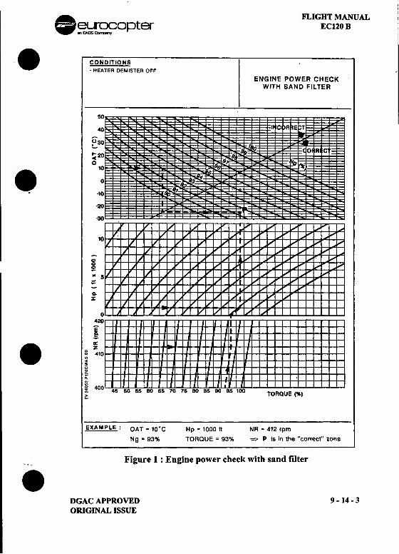
. FLIGHT MANUAL~~opter EC120 B
.CONDITIONS .HEATER DEMISTER OFF
ENGINE POWER CHECKWITH SAND FILTER
50
40 T
Eao ~"'20 Q~ 9. 10 0 ~
.-10
-20
1
00
5!K
0-:r
0420
E,g;
.~~10~.;~ 40~ TORQUE (%)
EXAMPLE: OAT. 10.C Hp = 1000 It NR = 412 rpm
Ng = 93% TORQUE = 93% => P is in the "correct" zone
'. Figure 1 : Engine power check with sand filter.DGAC APPROVED 9 -14 -3
ORIGINAL ISSUE
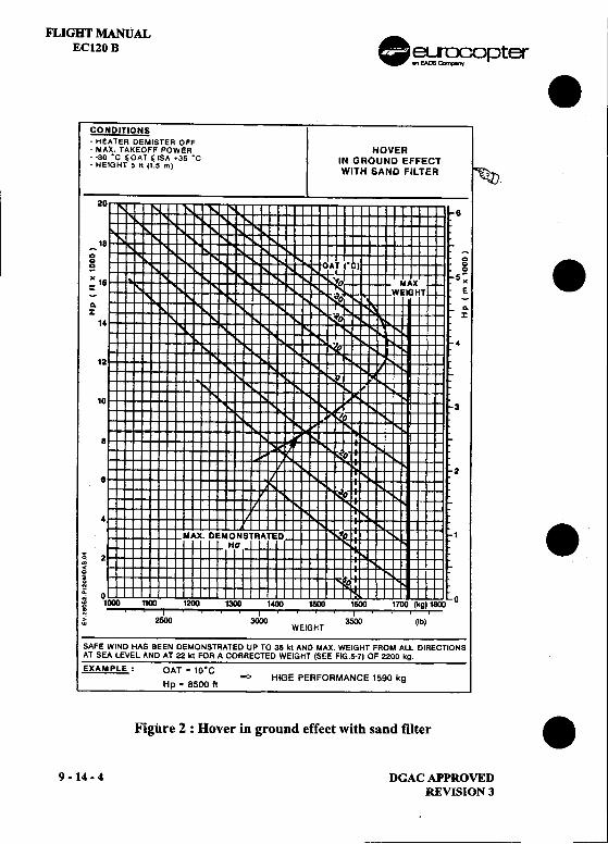
FLIGHT MANUALEC120 B .~~O pter .
CONDITIONS
-HEATER DEMISTER OFF-MAX. TAKEOFF POWER HOVER--30 'c 'OAT' ISA +35 'c IN GROUND EFFECT-HEIGHT 5 It (15 m) WITH SAND FILTER .~
.20
6
_18 -0 0 .0 0 0 0
~ 5-
"16 MAX"~ WEIGHT ~A A..
14
12
10
8
26
4
MAX. DEMONSTRATED 1 .Ha~ 2~i 0;; 0 0~ 1CXM1 1100 1200 1300 1400 1500 1600 1700 (kg) 1600
~ I ..I J ,. 2500 3O(X) 3500(Ib )W WEIGHT
SAFE WIND HAS BEEN DEMONSTRATED UP TO 35 kt AND MAX. WEIGHT FROM ALL DIRECTIONSAT SEA LEVEL AND AT 22 kt FOR A CORRECTED WEIGHT (SEE FIG.5-7) OF 2200 kg.
EXAMPLE: OAT = 10'C=> HIGE PERFORMANCE 1590 kg
Hp = 8500 It
Figure 2 : Hover in ground effect with sand filter .
9 -14 -4 DGAC APPROVED
REVISION 3
~--
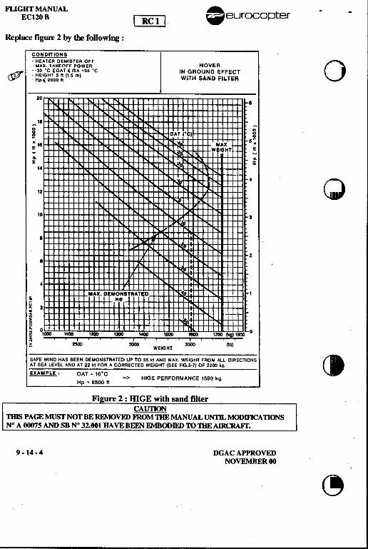
FLIGHT MANUAL A ~ -ECI20 B [~.eurocopter
Replace figure 2 by die following :
COIIDITIONS-HEATER DEMISTER OFF 0-MAX TAKEOFF POWER HOVER
& --30 .C 'OAT' 'SA +35 .C IN GROUND EFFECT~ : ~;~~;og ~ (15 m) WITH SAND FILTER
20I
II-~0 0g OA 'CI g~ II MAX s~= -WEIGHT E-VD-~ ~
~% ~ %14 I.
4 f\ it)12 "-' \1
10 3.I
I
4
MAX. DEMONITRATEDq HaU; 2
~~ 0 .~ 1000 11~ 1100 '* ,~ 1600 1«10 1700 (kg) 1800 0~ ., ,',.. I ' , , -," 2600 3000 3500 (lb)W WEIGHT
SAFE WIND HAS BEEN DEMONSTRATED UP TO 35 kI AND MAX WEIGHT FROM ALL DIRECTIONS CIAT SEA LEVEL AND AT 22 kI FOR A CORRECTED WEIGHT (SEE FIG.5-7) OF 2200 kg
EXAMPLE: OAT = 10'C=> HIGE PERFORMANCE 1590 kg
Hp .8500 II
Fi re 2 : ffiGE with sand filterCAUnON
nus PAGE MUST NOT BE REMOVED FROM mE MANUAL UN1n, MODmCA nONSN° A 00075 AND SB N° 32.001 HAVE BEEN EMBODIED 'TO DIE AIRCRAFf.
9. 14 .4 DGAC APPROVEDNOVEMBER 00
~
il,,:,llij
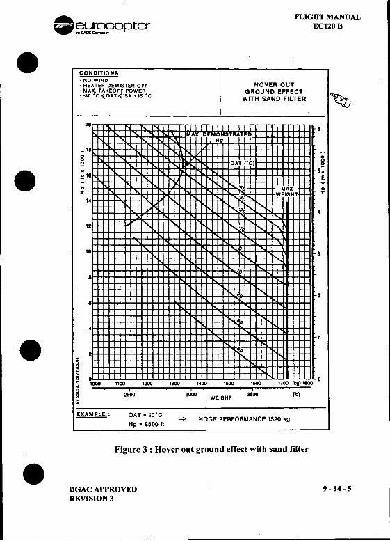
. FLIGHT MANUAL~~o~)ter EC120 B
.CONDITIONS-NO WIND-HEATER DEMISTER OFF HOVER OUT-MAX. TAKEOFF POWER GROUND EFFECT--30 .C ~OAT 'ISA +35 .C WITH SAND FILTER ~
20
_18 -0 00 0
5! 5!. x x:. 18 .:a- a-X ~
14
4
12
10 3
8
28
4
1
.32.;~x2
gooa; 1000 1100 1200 1300 1400 1500 1600 1700 (kg) 1800:: ..I ., ., I ' ...I~ 2500 3000 WEIGHT 3500 (1b)
EXAMPLE: OAT = 10.C= HOGE PERFORMANCE 1520 kg
Hp .8500 It
Figure 3 : Hover out ground effect with sand filter.DGACAPPROVED 9-14-5 I
REVISION 3 I

FLIGHT MANl.:tALEC120 B .~~ opter
CONDITIONS .-CAS = 65 kt -1 kt /1000 It ..'
-MAX. CONTINUOUS POWER RATE OF CLIMB-HEATER DEMISTER OFF
(Jfr --30.C~OAT~ISA+35.C WITH SAND FILTER
!
I !
.I 10 .ct!J"" :
.~.;<~
~ I !oi' '
~ -40 -30 -20 -10 0 10 20 30 40 500 2000~ OAT rC) RATE OF CLIMB 1ft/minIEXAMPLE: OAT = 15'C ACTUAL WEIGHT = 1600 kg
Hp = 4000 It CORRECTED WEIGHT = 1850 kgRATE OF CLIMB = 1180 fl/min
Figure 4 : Rate of climb with saud filter .9-14-6 DGACAPPROVED
REVISION 3
--'--
EC
EMERGENCY FLOATATION GEAR
AERAZUR
THIS SUPPLEMENT MUST BE INCLUDED IN THE FLIGHT MANUAL WHEN THEEQUIPMENT MENTIONED ABOVE IS INSTALLED ON THE AIRCRAFT.
-~_.~=:=,
EUROCOPTER Direction Technique SupportAeroport inlernationel Marseille-Provence 13725 Marignane Cedex -France
DGAC APPROVEDORIGINAL ISSUE: JULY 1998
9 -17 -TITLE
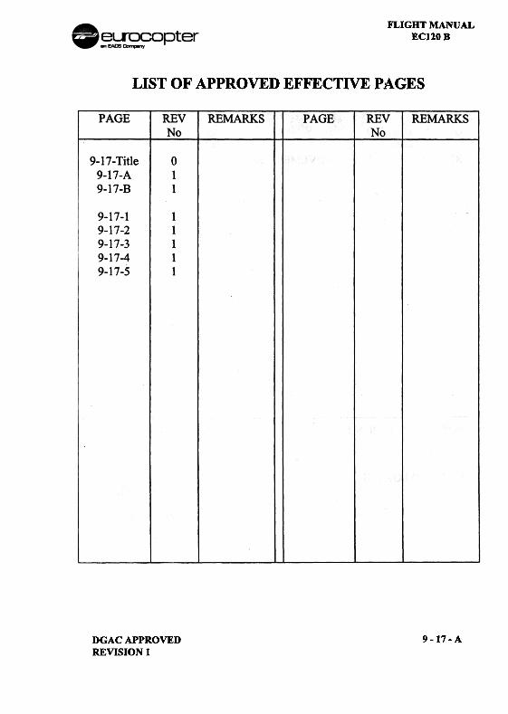
FLIGHT MANUALEC120 B
LIST OF APPROVED EFFECTIVE PAGES
PAGE REVNo
REMARKS PAGE REVNo
REMARKS
9-17- Title9-17-A9-17-B
0
9-1'9-1'9-1'9-1'9-1'
9-17-ADGAC APPROVEDREVISION 1
7-17-27-3
7-47-5
FLIGHT MANUALEC120 B
LOG OF APPROVED NORMAL REVISIONS
ORIGINAL 0 JULY 1998
REVISION 1 NOVEMBER 2001
NORMAL REVISION 1 APPROVEDBY:DGAC
DATE: 21 NOV 2001
9-17-8 DGACAPPROVEDREVISION 1
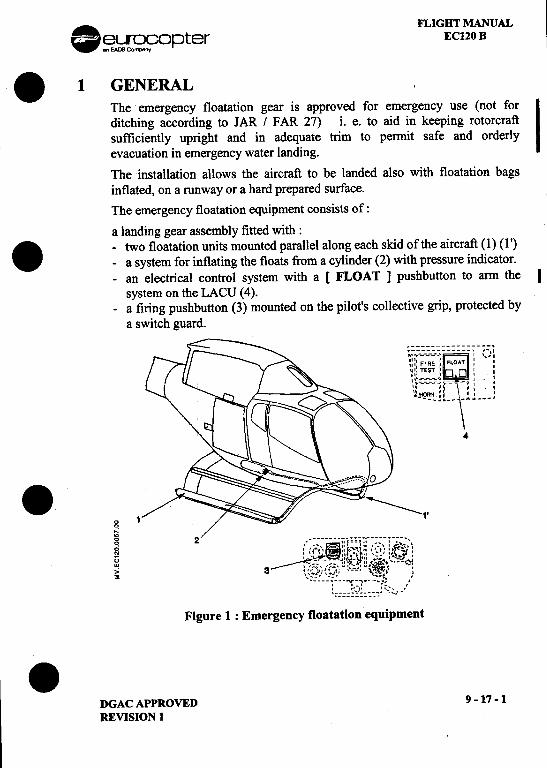
. FLIGHT MANUAL~~9Dpter EC120 B
.1 GENERALThe emergency floatation gear is approved for emergency use (not for
Iditching according to JAR / FAR 27) i. e. to aid in keeping rotorcraft
sufficiently upright and in adequate trim to permit safe and orderly
evacuation in emergency water landing.
The installation allows the aircraft to be landed also with floatation bags
inflated, on a runway or a hard prepared surface.
The emergency floatation equipment consists of :
a landing gear assembly fitted with:. -two floatation units mounted parallel along each skid of the aircraft (1) (1')
-a system for inflating the floats from a cylinder (2) with pressure indicator.
-an electrical control system with a [ FLOAT] pushbutton to arm the I
system on the LACU (4).
-a firing pushbutton (3) mounted on the pilot's collective grip, protected by
a switch guard.
~~.::-.::_:_::;.~:~ :::::~-:_): ~::I FIRE " FLOAT: I
~:: TEST :: 0: :
,~:=:=:=:;o:~,~ ~": :". " ., , , ..
"'~"' , " '",~...",
--_"_-\A~___'4
.l'g 1
"g " ~ (__, ~::f==1::,_,:"-:' & ::;1' "r"'-'-t".,-,;..~~:u ~- -;:,,':u.:: '.-;;. :~. .w '!;~." --""t~" .~. '---,~i,,; 3 :(';-;,'.(';":"'-~'---,,~-,,¥~ '
~ '::::'-~"!:~-~-~.--:'!' !, '-' '. ,
, ")' ',-'",:::::~:~:""." ",,-
Figure 1 : Emergency floatation equipment
.DGACAPPROVED 9-17-1
REVISION 1
~ ~
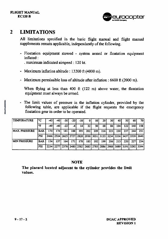
FLIGHT MANUALEC120 B
2 LIMITATIONSAll limitations specified in the basic flight manual and flight manualsupplements remain applicable, independantly of the following.
-Floatation equipment stowed -system anned or floatation equipmentinflated:.maximum indicated airspeed: 120 kt.
-Maximum inflation altitude: 13200 ft (4000 m).
-Maximum permissible loss of altitude after inflation: 6600 ft (2000 m).
When flying at less than 400 ft (122 m) above water, the floatationequipment must always be anned.
-The limit values of pressure in the inflation cylinder, provided by thefollowing table, are applicable if the flight requests the emergencyfloatation gear in order to be operated.
TEMPERATURE -451 -401 -301 -20' -101 10--"50
I~--30311
1921
27851
20
2886
301 401 50
3191
60
3292
70
158
251
3640,
234,~
OF
-491 -401 -22 14
2582
32
2683
861 1041
MAX. PRESSURE I BAR I 1701 1741 1811 1881 2231 2301
PSI 124661252412625127271 323413336
MIN PRESSURE
BAR
PSI
2061 2131
298813089!
NOTEThe placard located adjacent to the cylinder provides the limitvalues.
9-17-2 DGACAPPROVEDREVISION I
FLIGHT MANUALEC120B
3 EMERGENCY PROCEDURESThe procedures provided in the basic flight manual and in the flight manualsupplements remain applicable and are supplemented by the following:
-INFLAllONPROCEDURE
In the event of engine failure or other urgent requirement to ditch, checkthe rotor speed then apply the following procedure:
.[ FLOAT] pushbutton '." PRESSED IN, two lights on.
.Floatation equipment cartridge FIRED (recommended firing IAS :
below 80 kt -148 km/hP).
NOTE
A deceleration with a pitch down movement can occur when firing thefloatation equipment at a speed greater than 80 kt (148 km/h).
AUTORA TION PROCEDURE OVER WATER WImEMERGENCY FLOATATION GEAR
1. Collective pitch REDUCEto maintain NR in green arc.
2.IAS , Vy.
.If relighting impossible or after tail rotor failure.3. Twist Grip SHUT OFF position.4. Maneuver to head the aircraft equally between the wind and wave direction
on final approach.
.At height ;: 70 ft5. Cyclic Flare.
.At 20-25 ft at constant attitude6. Collective pitch """..."""""""'. GRADUALLY INCREASE
to reduce the rate of descent andforward speed.
DGACAPPROVEDREVISION 1
9-17-3
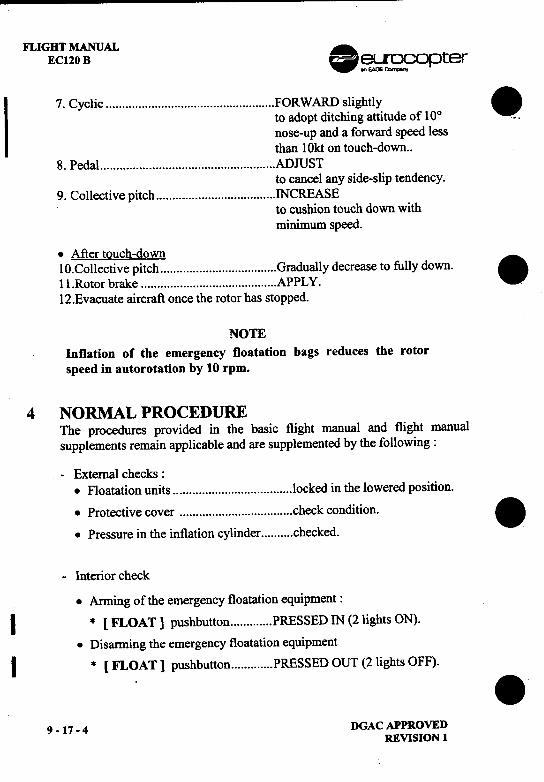
FLIGHT MANUAL .ECI20 B ~~opter
I 7. Cyclic FORWARD slightly .to adopt ditching attitude of 100 ...nose-up and a forward speed lessthan 10kt on touch-down..
8. Pedal ADJUSTto cancel any side-slip tendency.
9. Collective pitch INCREASEto cushion touch down withminimum speed.
.Aftertouch-down10.Collective pitch Gradually decrease to fully down.
.Il.Rotor brake APPL Y.l2.Evacuate aircraft once the rotor has stopped.
NOTEInflation of the emergency floatation bags reduces the rotorspeed in autorotation by 10 rpm.
4 NORMAL PROCEDUREThe procedures provided in the basic flight manual and flight manualsupplements remain applicable and are supplemented by the following:
-External checks :.Floatation units locked in the lowered position.
.Protective cover check condition. .
.Pressure in the inflation cylinder checked.
-Interior check
.Arming of the emergency floatation equipment:I * [FLOAT] pushbutton PRESSED IN (2 lights ON).
.Disarming the emergency floatation equipmentI * [FLOAT] pushbutton PRESSED OUT (2 lights OFF). .
9 -17 -4 DGAC APPROVEDREVISION 1
~ FLIGHT MANUAL~~~ opter ECl20 B
.5 PERFORMANCEWhen the floatation equipment is stowed, only the climb performanceprovided in section 5 is affected:
-the rate of climb must be reduced by 11 %.
.
.
. DGAC APPROVED 9 -17 -5
REVISION 1
---
.eurocopter
.FLIG HT MAN UAL
EC 120 B
SUPPLEMENT.AIR CONDITIONING SYSTEM
IMPORTANT NOTE
. THE INFORMATION CONTAINED HEREIN SUPPLEMENTS OR SUPERSEDES THE INFORMATIONGIVEN IN THE BASIC FLIGHT MANUAL AND/OR FLIGHT MANUAL SUPPLEMENTS LISTED INSUPPLEMENT 9-0.
THE EFFECTIVITY OF THE SUPPLEMENT AT THE LATEST REVISION IS SPECIFIED ON THELIST OF EFFECTIVE PAGES.
THIS SUPPLEMENT MUST BE INCLUDED IN THE FLIGHT MANUAL WHEN THE
EQUIPMENT MENTIONED ABOVE IS INSTALLED ON THE AIRCRAFT.
-::;:~3~=:~ EUROCOPTER Direction Technique Support(~~fT~~ Aeroport international Marseille-Provence 13725 Marignane Cedex -France
.DGAC APPROVED 9 -19 -TITLEORIGINAL ISSUE: NOVEMBER 1998
--- --
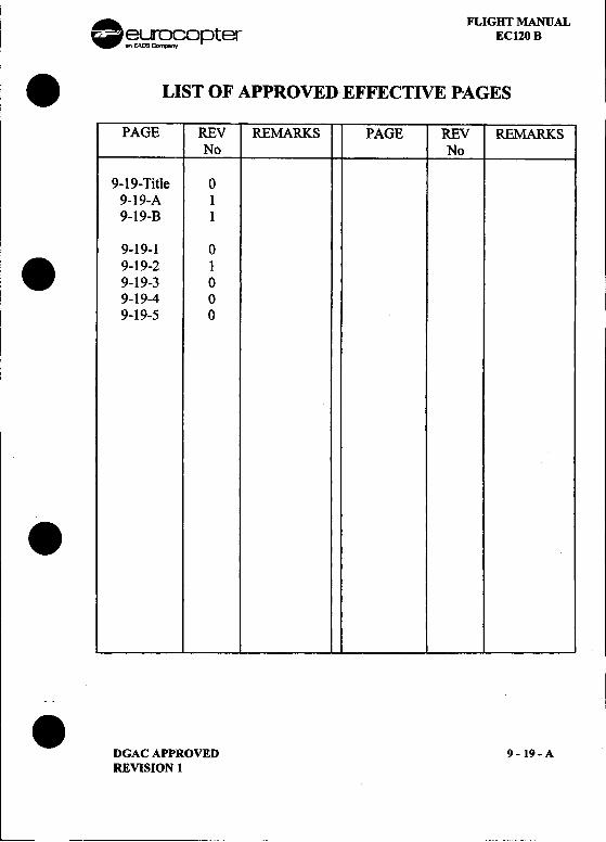
. FLIGHT MANUAL
~~C?Dpter ECI20 B
.LIST OF APPROVED EFFECTIVE PAGES
PAGE REV REMARKS PAGE REV REMARKSNo No
9-19-Title 09-19-A 19-19-B 1
9-19-1 0. 9-19-2 1
9-19-} 09-19-4 09-19-5 0
.
.DGAC APPROVED 9 -19 -AREVISION 1
---
FLIGHT MANUAL .EC120 B ~~opter
LOG OF APPROVED NORMAL REVISIONS .
ORIGINAL 0 NOVEMBER 1998
REVISION 1 NOVEMBER 2001
.
NORMAL REVISION 1 APPROVED BY : DGAC .
DATE: 21 NOV 2001 I.Mathie
.9 -19 -B DGAC APPROVED
REVISION 1
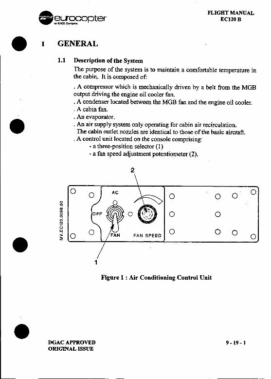
. FLIGHT MANUAL~~opter EC120 B
.1 GENERAL1.1 Description of the System
The purpose of the system is to maintain a comfortable temperature inthe cabin. It is composed of:
.A compressor which is mechanically driven by a belt from the MGBoutput driving the engine oil cooler fan..A condenser located between the MGB fan and the engine oil cooler..A cabin fan..An evaporator.. .An air supply system only operating for cabin air recirculation.The cabin outlet nozzles are identical to those of the basic aircraft.
.A control unit located on the console comprising:-a three-position selector (1)-a fan speed adjustment potentiometer (2).
2
0 0 00~co~ 0 00
.,;'"()
~O 0 000
.~1
Figure 1 : Air Conditioning Control Unit
.DGAC APPROVED 9 -19-1ORIGINAL ISSUE
FLIGHT MANUAL AEC120B w~~opter
.An electrical supply and monitoring system. The cabin fan is switched .on automatically when the heating system is on. A "P2 TEMP"amber light on the warning panel indicates that the maximumtemperature has been reached in the cabin ventilation duct.
1.2 Air productionWith the air conditioning option, cold and hot air production uses aninternal air recirculation system. The air is no longer taken in from theoutside, it is taken from the interior of the cabin at the rear RH side ofthe distribution duct. This air flows through the fan and then theevaporator where it is cooled, finally flowing through the P2 diffuser
.where it can be mixed with the hot air. This air then flows through thecabin roof to reach the cabin distribution duct. The air distribution inthe cabin has not changed with regard to the basic version.
2 LIMITATIONS
The limitations provided in the basic flight manual and flight manualsupplements remain applicable and are supplemented by the followinglimitations:
I
.
.9 -19 -2 DGAC APPROVED
REVISION 1
~ --
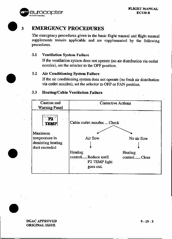
FLIGHT MANUAL.~~9opter ECI20 B
.3 EMERGENCY PROCEDURESThe emergency procedures given in the basic flight manual and flight manualsupplements remain applicable and are supplemented by the followingprocedures.
3.1 Ventilation System FailureIf the ventilation system does not operate (no air distribution via outletnozzles), set the selector to the OFF position.
3.2 Air Conditioning System Failure.If the air conditioning system does not operate (no fresh air distribution
via outlet nozzles), set the selector to OFF or FAN position.
3.3 Heating/Cabin Ventilation Failure
Caution and Corrective ActionsWarnin Panel
Cabin outlet nozzles ...Check
Maximum ///""""""""""""'-" temperature in Air flow No air flow
demisting heating I ~duct exceeded t. Heating Heating
conti"ol Reduce until conti"ol CloseP2 TEMP lightgoes out.II!
.DGACAPPROVED 9 -19 -3ORIGINAL ISSUE
--
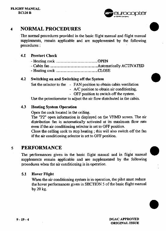
FLIGHT MANUALECI20 B .~~rS?£?Opter
4 NORMAL PROCEDURES .
The normal procedures provided in the basic flight manual and flight manualsupplements, remain applicable and are supplemented by the followingprocedures:
4.1 Prestart Check-Heating cock OPEN-Cabin fan Automatically ACTN ATED-Heating cock CLOSE
4.2 Switching on and Switching off the System .Set the selector to the -FAN position to obtain cabin ventilation
-AlC position to obtain air conditioning.-OFF position to switch off the system.
Use the potentiometer to adjust the air flow distributed in the cabin.
4.3 Heating System OperationOpen the cock located in the ceiling.The "P2" open information is displayed on the VEMD screen. The airdistribution fan is automatically activated at its maximum flow rateeven if the air conditioning selector is set to OFF position.Close the ceiling cock to stop heating; this will also switch off the fanif the air conditioning selector is set to OFF position.
PERFORMANCE.The performances given in the basic flight manual and in flight manual
supplements remain applicable and are supplemented by the followingprocedures when the air conditioning is in operation.
5.1 Hover FlightWhen the air conditioning system is in operation, the pilot must reducethe hover performances given in SECTION 5 of the basic flight manualby 20 kg. .
9 -19 -4 DGAC APPROVEDORIGINAL ISSUE
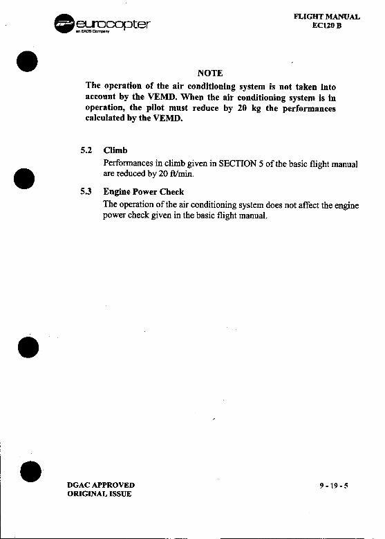
. FLIGHT MANUAL~~fOrJter EC120 B
.NOTEThe operation of the air conditioning system is not taken intoaccount by the VEMD. When the air conditioning system is inoperation, the pilot must reduce by 20 kg the performancescalculated by the VEMD.
5.2 ClimbPerfonnances in climb given in SECnON 5 of the basic flight manual
.are reduced by 20 ftJmin.
5.3 Engine Power CheckThe operation of the air conditioning system does not affect the enginepower check given in the basic flight manual.
..DGACAPPROVED 9-19-5
ORIGINAL ISSUE
--~
I
.eurocopter.FLIG HT MAN UAL
EC 120 B
.SUPPLEMENT
GPSTRIMBLE TNL 1000 DC
IMPORTANT NOTE
. THE INFORMATION CONTAINED HEREIN SUPPLEMENTS OR SUPERSEDES THE INFORMATIONGIVEN IN THE BASIC FUGHT MANUAl AND/OR APPLICABLE FLIGHT MANUAL SUPPLEMENTS.
THE EFFECTIVITY OF THE SUPPLEMENT AT THE LATEST REVISION IS SPECIFIED ON THELIST OF EFFECTIVE PAGES.
THIS SUPPLEMENT MUST BE INCLUDED IN THE FLIGHT MANUAL WHEN THE
EQUIPMENT MENTIONED ABOVE IS INSTALLED ON THE AIRCRAFT.
-:::;~§~=~~ EUROCOPTER Direction Technique Support(:t~SJ/)---~ Aeroport inlern~lional Marseille-Provence 13725 Marignane Cedex -France.DGAC APPROVED 9 -55 -TITLEORIGINAL ISSUE: APRIL 1998
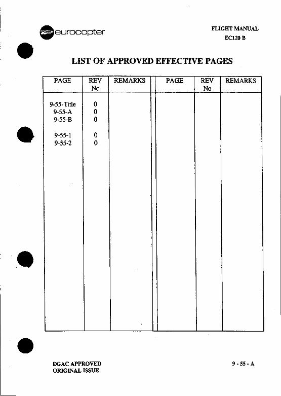
A eurocopter FLIGIrr MANUAL.ECl20B
.LIST OF APPROVED EFFECTIVE PAGES
PAGE REV REMARKS PAGE REV REMARKSNo No
9-55- Title 09-55-A 09-55-B 0
.9-55-1 09-55-2 0
.8
.DGAC APPROVED 9 -SS -AORIGINAL ISSUE
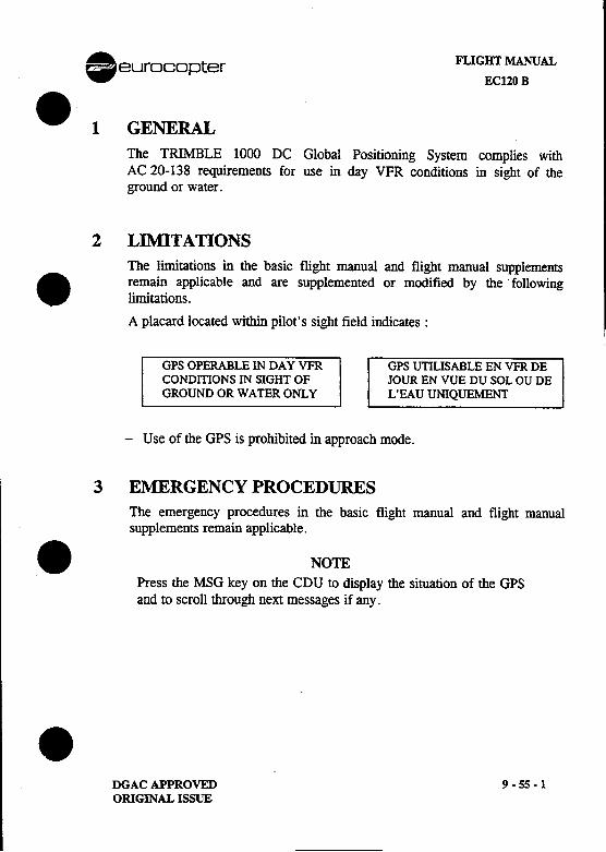
. FLIGHT MANUAL eurocopterECl20 B
.1 GENERALThe TRIMBLE 1000 DC Global Positioning System complies withAC 20-138 requirements for use in day VFR conditions in sight of theground or water.
2 LIMITATIONSThe limitations in the basic flight manual and flight manual supplements
. remain applicable and are supplemented or modified by the' followinglimitations.
A placard located within pilot's sight field indicates:
GPS OPERABLE IN DAY VFR GPS UnUSABLE EN VFR DECONDITIONS IN SIGHT OF JOUR EN VUE DU SOL OU DEGROUND OR WATER ONLY L'EAUUNIQUEMENT
-Use of the GPS is prohibited in approach mode.
3 EMERGENCY PROCEDURESThe emergency procedures in the basic flight manual and flight manualsupplements remain applicable.
.NOTEPress the MSG key on the CDU to display the situation of the GPSand to scroll through next messages if any.
.DGAC APPROVED 9 -55-1ORIGINAL ISSUE
FLIGHT MANUAL .eurocopterECl20 B
LOG OF APPROVED NORMAL REVISIONS .
ORIGINAL 0 APRIL 1998
.ORIGINAL ISSUE APPROVED BY : DGAC
DATE: -1 AVi. 1998
~,,~~~ ...r~
::?,::'I;;;~\~C'" cc
~ ~:.;:)~~. REVAULT*
9 -55 -B DGAC APPROVED.ORIGINAL ISSUE
FLIGHT MANUAL .eurocopterECl20 B
4 NORMAL PROCEDURE .The normal procedures in the basic flight manual and flight manualsupplements in use remain applicable, and are supplemented by thefollowing normal procedures:
4.1 BEFORE STARTING-The PILOT GUIDE operating manual (reference: 80455-0612)
must be up-to-date and kept on-board the aircraft.-The crew must check the validity and accuracy of the data base (28
day validity) relative to the official documentation.-Before the start of navigation, check that all the data is valid by .
reading the messages on the CDU.
NOTEDuring the « en route» phase, the integrity of the position supplied bythe GPS is not ensured. Consequently it is the responsibility of thecrew to check the accuracy of the position every 15 minutes usingeither conventional VFR method or other navigation equipment if
: available.
Transmissions from the helicopter, via transmitters KX165 andKY196 can lead to momentary losses of GPS reception at thefollowing frequencies:121.150 MHz, 121.175 Mhz, 121.250 Mhz, 131.275 MHz.
Navigation calculation becomes nominal 2 to 3 seconds after the end.of transmission.
5 STATUTORY PERFORMANCEThe statutory performance in the basic flight manual and flight manualsupplements remains applicable.
.9 -55 -2 DGAC APPROVED
ORIGINAL ISSUE
.eurocopter 1
.FLIG HT MAN UAL
EC 120 B
SUPPLEMENT.GPS
TNL 2000 APPROACH PLUS
IMPORTANT NOTE
. THE INFORMATION CONTAINED HEREIN SUPPLEMENTS OR SUPERSEDES THE INFORMATIONGIVEN IN THE BASIC FLIGHT MANUAL AND/OR FLIGHT MANUAL SUPPLEMENTS LISTED IN
SUPPLEMENT 9-0.THE EFFECTIVITY OF THE SUPPLEMENT AT THE LATEST REVISION IS SPECIFIED ON THE
LIST OF EFFECTIVE PAGES.
THIS SUPPLEMENT MUST BE INCLUDED IN THE FLIGHT MANUAL WHEN THE
EQUIPMENT MENTIONED ABOVE IS INSTALLED ON THE AIRCRAFT.
-:;~S:=~ EUROCOPTER Direction Technique Support(~~J..-?-~ A6roport intemetional Marseille-Provence t3725 Marignana Cade. .France.L
DGAC APPROVED 9 -55B -TITLE
ORIGINAL ISSUE: JUNE 1999
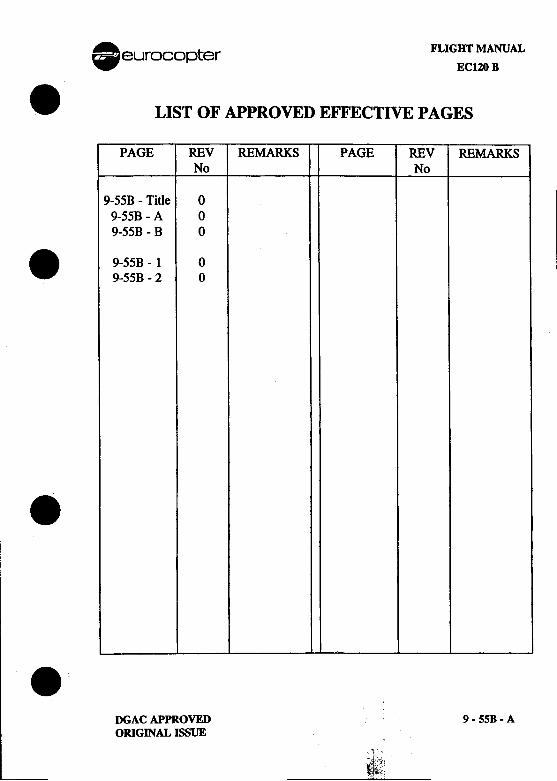
.A eurocopter FLIGHT MANUAL-EC120B
.LIST OF APPROVED EFFECTIVE PAGES
PAGE REV REMARKS PAGE REV REMARKSNo No
9-55B -Title 09-55B -A 0
9-55B -B 0
. 9-55B -1 09-55B -2 0
...
;
iDGAC APPROVED t 9 -55B -A
ORIGINAL ISSUE ;
'c Jt.
~,t:",1~~.I
FLIGHT MANUAL .EC120 B eurocopter
LOG OF APPROVED NORMAL REVISIONS .
ORIGINAL 0 JUNE 1999
.ORIGINAL ISSUE APPROVED BY : DGAC
DA1E: 02 JUl. ~ IC8IA."!\!.Ii,,;,AvU!5 de T~',
~ .,", '
.9 -55B -B DGAC APPROVED
ORIGINAL ISSUE
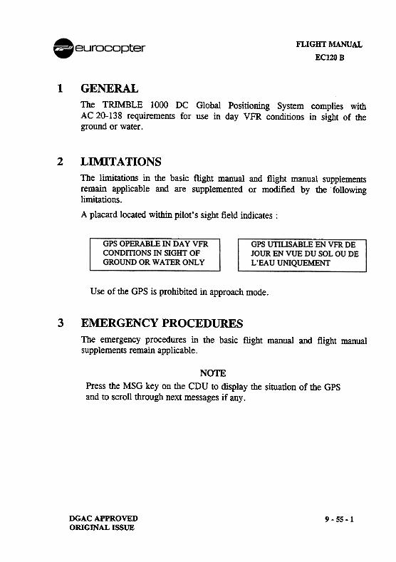
FLIGHT MANUAL
ECl20 B
1 GENERALThe TRIMBLE 1000 DC Global Positioning System complies withAC 20-138 requirements for use in day VFR conditions in sight of theground or water.
2 LIl\flTATIONSThe limitations in the basic flight manual and flight manual supplementsremain applicable and are supplemented or modified by the. following
limitations.
A placard located within pilot's sight field indicates:
GPS OPERABLE IN DAY VFRCONDITIONS IN SIGHT OFGROUND OR WATER ONLY
GPS UTIUSABLE EN VFR DEJOUR EN VUE DU SOL OU DEL'EAU UNIQUEMENT
Use of the GPS is prohibited in approach mode.
3 EMERGENCY PROCEDURESThe emergency procedures in the basic flight manual and flight manualsupplements remain applicable.
NOTEPress the MSG key on the CDU to display the situation of the GPSand to scroll through next messages if any.
DGAC APPROVEDORIGINAL ISSUE
9-55-1
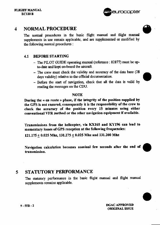
FLIGHT MANUAL .ECl20 B eurocopter
4 NORMAL PROCEDURE .The nonnal procedures in the basic flight manual and flight manualsupplements in use remain applicable, and are supplemented or modified bythe following normal procedures:
4.1 BEFORE STARTING-The Pll..OT GUillE operating manual (reference: 82877) must be up-
to-date and kept on-board the aircraft.-The crew must check the validity and accuracy of the data base (28
days validity) relative to the official docwnentation. .-Before the start of navigation, check that all the data is valid by
reading the messages on the CDU.
NOTEDuring the «en route» phase, if the integrity of the position supplied bythe GPS is not ensured, consequently it is the responsibility of the crew tocheck the accuracy of the position every 15 minutes using eitherconventional VFR method or the other navigation equipment if available.
Transmissions from the helicopter, via KX165 and KY196 can lead tomomentary losses of GPS reception at the following frequencies:
121.175 :!: 0.025 Mhz, 131.275 :!: 0.025 Mhz and 131.200 Mhz
Navigation calculation becomes nominal few seconds after the end of
.transmission.
S STATUTORY PERFORMANCEThe statutory performance in the basic flight manual and flight manualsupplements remains applicable. .
9 -55B -2 DGAC APPROVEDORIGINAL ISSUE
. FLIGHT MANUAL~~~opter EC120 B
.SECTION 10
OPERATIONAL TIPSPage
10.1 RECOMMENDATIONS FOR CARGO SLINGOPERATIONS 10-110.1.1 PERSONNEL TRAINING 1 0-110.1.2 MANDATORY PRE-OPERATIONAL CHECKS 10-110.1.3 AIRBORNE LOADS 10-2
.10.1.4 IN-FLIGHT PRECAUTIONS 10-3
10.2 EMERGENCY LOCATOR TRANSMITTER(JOLLIET JE-2 NG) 10-410.2.1 GENERAL 10-410.2.2 DESCRIPTION-OPERA TION 1 0-410.2.3 TESTING 10-510.2.4 OPERATING PROCEDURE 10-6
10.3 EMERGENCY LOCATOR TRANSMITTER(EL T-406) 10-810.3.1 GENERAL 1 0-810.3.2 DESCRIPTION-OPERATION " 10-810.3.3 TESTING " 10-9
.0.310-10ELEVATION AND AZIMUTH 10-1210.4.1 GENERAL 10-1210.4.2 DESCRIPTION 1 0-1210.4.3 TESTING 10-1310.4.4 PROTECTION OF THE CIRCUITS 10-14
.MANUFACTURER'S DATA lO-iREVISION 5
FLIGHT MANUAL ..ECl20 B v~2~ opter .LIST OF FIGURES .
PageFIGURE 10-1 : REMOTE CONTROL SWITCH AND
EMERGENCY LOCATOR JE-2 NG I0-5
FIGURE 10-2: REMOTE CONTROL SWITCH ANDEMERGENCY LOCATOR 96-406 10-9
FIGURE 10-3: ADDITIONAL LANDING LIGHT, CONTROLLABLEIN ELEVATION AND AZIMUTH 10-12 .
.
.10 -ii MANUFACTURER'S DATA
REVISION 5
. . FLIGHT MANUALeurocopter ECl20 B
.10.1 RECOMMENDATIONS FOR CARGO SLINGOPERATIONS10.1.1 Personnel Training
Cargo sling operations may only be conducted by pilots who alreadyhave considerable experience with this type of aircraft.
No pilot should perform solo external load flights without first havingaccomplished such operations in the company of an instructor.
.Mechanics on ground duty must be fully informed by the pilot beforeeach new operation, in particular as regards:-their position on the ground considering the proposed flight path ;-the direction in which to move away;-the hook-up operation;-hand signals to be used or radio instructions ;
-protective equipment: helmets, gloves, glasses (if applicable) ;-the number of round trips between replenishments ;-the manner of retrieving slings and nets.
10.1.2 Mandatory pre-operational checks
-Helicopter ConditionIn addition to the normal pre-flight checks of the helicopter, therelease unit must be carefully inspected and the mechanismchecked for correct release operation.. -Condition of Sling EquipmentThe nets, straps and slings must be examined thoroughly. Anyworn or frayed components are to be discarded.The cables, strops and shackles must be capable of carrying threetimes the maximum anticipated load.
-Preparation of LoadsMake sure that all participants are well aware of the weight of theloads.Ensure that the method of suspension is understood..
MANUFACTURER'S DATA 10 -1REVISION 2
FLIGHT MANUAL .EC120 B eurocopterI
-Condition of Loading and Unloading Areas .Remove or tie down all that might be displaced by the rotordownwash.
-Total Weight of Helicopter with LoadDefine maximum acceptable load compatible with terrainconfiguration and atmospheric conditions. The maximum all upweight of the aircraft is that at which O.G.E. hover can be heldover the higher of the take-off or landing platforms.
10.1.3 Airborne loads
Heavy loads, such as bags of cement or drums of kerosen, which are.carried in a net, present no particular problem.
Special precautions must be taken in the case of bulky loads, whichhave a tendency to oscillate and even to "float" during transport onthe sling.Permeability to air can have a stabilizing effect on a bulky load: forexample, a teleferic car should be carried with both its doors open.
Never carry an airfoil alone: there is a great risk of the airfoil flyingup into the tail rotor.
If several cables are used to sling the load, they must be long enoughto form an angle of less than 450 between cables at the point ofsuspension under the helicopter; experience shows that oscillation ofthe load is thus less likely to occur.
On the other hand, if the load is slung on a single sling cable, it is .preferable that a fairly short cable be used as there is then less risk ofthe load swinging, and it is easier to judge the height of the loadduring approach.
For the retrieval of crashed helicopters it is generally possible to usea lifting ring on the rotor shaft.
.10 -2 MANUFACTURER'S DATA
REVISION 2
. FLIGHT MANUALeurocopter EC120 B
8, Airplanes are carried using straps passing under the fuselage orunder the wings. The cables must be attached in such a way that theairplane is in a slightly nose-down attitude when the helicopter is inthe hover.
10.1.4 In-flight precautionsAfter hooking on the load the ground mechanic is to check theposition of the sling cables then move away. The pilot must thenmake sure that the mechanic has moved clear and then be advised by
.signs that he may lift off the load.
Power must be applied slowly enough to allow the helicopter tocentre itself above the load.
A vertical take-off must be made, avoiding dragging the load alongthe ground or striking any obstacle.
Carefully avoid flying over houses, vehicles and persons.
If the load starts to swing, slowly reduce speed or make a gentle leftturn.
Approach must be made head into the wind with gradual reduction inairspeed, and transition into hover high enough above the ground toeliminate the risk of dragging the load.
. Set the load down, then reduce collective pitch sufficiently to slackenthe cables before opening the release unit hook; this also allows thepilot to ensure that the load is deposited. If the cables are longenough, move sideways a little before opening the hook, to preventthe ring and tackle from falling onto the freight.
Even after the mechanic has signalled that the load is released, moveaway as if it were not; this is an advisable precaution againstpossible misinterpretation of signals.
.Never flyaway with an empty net or an unbal1asted sling.
MANUFACTURER'S DATA 10 -3REVISION 2
FLIGHT MANUAL .ECl20 B eurocopter
10.2 EMERGENCY LOCATOR TRANSMITTER .(JOLLIET JE-2 NG)
10.2.1 General
The JOLLIET JE-2 NG emergency locator transmits radio beaconsignals simultaneously on the international distress frequencies(121.5 Mhz and 243.0 Mhz) to aid helicopter search and rescueoperations.
The unit operates automatically in the event of crash impactexceeding 5 g along the accelerometer axis.
.It may be operated manually by means of a MANU-OFF-AUTOswitch (3) on the transmitter front panel, or by means of aMANU-AUTO (2) remote control switch, on "MANU" position.
10.2.2 Description-Operation
-Components & location
.A transmitter, located on the RH side in the cargo hold: aplacard (4) indicates its location and its use in the cockpit (1).
.An external antenna (6) permits signal transmission whenoperated on board.
.A cockpit remote control switch. .
.A flexible antenna (5) on the transmitter can be used inMANUAL operation outside the helicopter.
.10 -4 MANUFACTURER'S DATA
REVISION 2
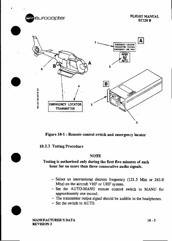
.. FLIGHT MANUAL
eurOCOI=)ter EC120 B.1 ~- f~~~~~E!OGENCY LOCATOR
1RANSAIm!I AVIATON ,E!ERGENCV use O"LV!
rTlA /~
2
.\ 4I0 0
\ I
~ /~ \ Iu~ EMERGENCY LOCATOR 5~ TRANSMITTER
3
Figure 10-1: Remote control switch and emergency locator
10.2.3 Testing Procedure. NOTETesting is authorized only during the first five minutes of each
hour for no more than three consecutive audio signals.
-Select an international distress frequency (121.5 Mhz or 243.0Mhz) on the aircraft VHF or UHF system.
-Set the AUTO-MANU remote control switch to MANU forapproximately one second.
-The transmitter outPut signal should be audible in the headphones.-Set the switch to AUTO..
MANUFACTURER'S DATA 10 -5REVISION 2
FLIGHT MANUAL AEC120 B .eurocopter
10.2.4 Operating Procedure .
-Pre-Flight Checks.In cockpit: check that remote control switch is set to AUTO..On transmitter: check that MANU-OFF-AUTO switch is set to
AUTO.
-Post-Flight CheckAfter landing, set the VHF communications receiver to 121.5 Mhzto ensure that the emergency locator transmitter has notaccidentally been switched on. .
-Automatic OperationThe transmitter is actuated automatically in the event of an impactof at least 5 g (assuming the MANU-AUTO switch is set toAUTO).
NOTEThe impact detector (accelerometer) may be reset by means of the
switch control on the transmitter front panel on "OFF/RST'f position(2 a 3 s.). The reset stops the transmitter output signals if the unit is
operating.
-Manual Operation .The unit may be actuated manually by setting the control switch to"MANU".
.10 -6 MANUFAC11JRER'S DATA
REVISION 2
A. FLIGHT MANUAL~~~ opter EC120 B. -Portable Operation ,
The transmitter may be used for self-contained operation on theground as follows:.Remove the transmitter from its mounting bracket..Select an unobstructed area..Extend the built-in whip antenna..Place the unit upright with the antenna on top..Switch on the transmitter by setting the MANU-OFF-AUTO
switch to "MANU".. -Complete cut-offSet the transmitter switch to OFF/RST.
..MANUFACTURER'S DATA 10-7
REVISION 2
---
FLIGHT MANUAL AECI20 B .~~ opter
10.3 EMERGENCY LOCATOR TRANSMITTER .(ELT 96 -406) ,
10.3.1 GENERAL
The EL T 96- 406 radio beacon is an emergency transmitter which is usedto locate the helicopter in an emergency. It transmits simultaneously onthe international frequencies (121.5 -243 -406 MHz).
The transmitter starts operating automatically in case of impact or in caseof breakage of the electric cable loom A-B between the remote control .switch and the emergency locator.
It may be switched on manually via the switch located on the top face ofthe transmitter or via the remote control switch located on the instrument
panel.
10.3.2 DESCRIPnON OPERAllON
-Components & location:
.A transmitter (4) attached to the structure inside the rear RH cargohold.
.An external label indicating transmitter location (5).
.An (AUTO -MANU) control switch located on the instrumentI panel on the left hand side (2).
.An (AUTO TEST/RESET) pushbutton located next to the controlswitch (1).
.A amber (XMIT ALERT) indicator light located on the instrument .I panel on the right hand side (3).
.A 3 Amp circuit breaker on CCBP.
.An external antenna (6) .
.10 -8 MANUFACTURER'S DATAI
REVISION 5
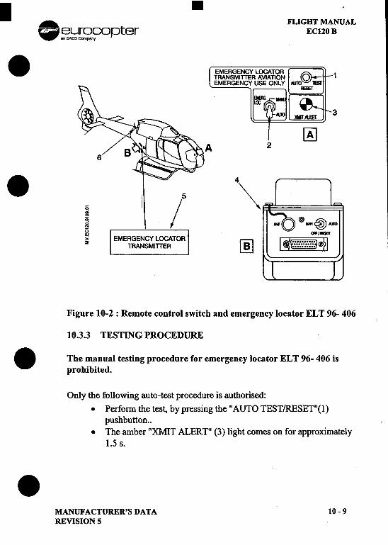
. 1111111. FLIGHT MANUAL~urS?n~opter ECl20 B
.EMERGENCY 1RANSMITTERMERGENCY
3
~A 2
.5 4\.~ / ~~~G~ EMERGENCY LOCATOR rDl~ TRANSMITTER ~
Figure 10-2: Remote control switch and emergency locator ELT 96- 406
10.3.3 TESTING PROCEDURE
.The manual testing procedure for emergency locator EL T 96- 406 isprohibited.
Only the following auto-test procedure is authorised:.Perform the test, by pressing the "AUTO TEST/RESET"(I)
pushbutton...The amber "XMIT ALERT" (3) light comes on for approximately
1.5 s..MANUFACTURER'S DATA 10-9REVISION 5
FLIGHT MANUAL .EC120 B c ~.};j[~r;opterI
10.3.4 OPERATING PROCEDURE .-Pre-flight check:I Check the following under the instrument panel:
.The remote control switch is set to "AUTO".
If the switch is set to"AUTO" and the connector is unplugged,
the transmitter will operate.
-Check the following on the transmitter: ..The connector is plugged in..The switch is set to "AUTO".
NOTEIf the indicator light flashes, it indicates that the batteries are faulty orthe transmitter is inoperative.
-Post-flight check:
After landing, check for untimely transmitter operation ( the amber"XMIT ALERT" light should be extinguished ). .
-Automatic operation:
The transmitter will begin operating automatically in case of impactif the remote control switch is set to the "AUTO" position. Theamber "XMIT ALERT" light comes on during transmitter operation.
.10 -10 MANUFACTURER'S DATA
REVISION 5
.
. FLIGHT MANUAL~~f?Opter EC120 B. Resetting the impact detector:
.Control switch set to "AUTO"..Press the "AUTO TEST/RESET" pushbutton..The transmitter should cease operating.
NOTEIf the transmitter continues transmitting, perform the operation again. If,after several attempts, the transmitter remains in operation, set the switchon its top face to "OFF".In the event of untimely activation, advise the local authorities and give theaircraft caD sign.
.-Manual operation
The transmitter will begin operating when the remote control switchis set to "MANU".The amber "XMIT ALERT" light comes on during transmitteroperation.
-Portable operation:
This transmitter may be used on the ground, as follows:.Set the switch to "OFF"..Remove the transmitter from its support..Work in a clear space..Hold the transmitter in the vertical position with the antenna
upwards...Set the switch to "MAN/RESET" to begin transmission
z;.MANUFACTURER'S DATA , 10-11
REVISION S
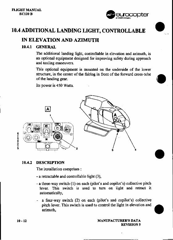
FLIGHT MANUALEC120 B .~~opter
10.4 ADDITIONAL LANDING LIGHT, CONTROLLABLE ',.,
IN ELEVATION AND AZIMUTH10.4.1 GENERAL
The additional landing light, controllable in elevation and azimuth, isan optional equipment designed for improving safety during approachand taxiing maneuvers.
This optional equipment is mounted on the underside of the lowerstructure, in the center of the fairing in front of the forward cross-tube
.of the landing gear.
Its power is 450 Watts.
~1
:/~:i~!;~]i:i~i1)-i~~~f'~;!- :-:6-~~~~":," ", """'" £,'-'" " '~"'., , , " " ""'-~.' "'r ~-~I'" ..,:?', , .., -'".. ",." ..'" " ~f '
i l.~j~~~~~:~:~~.", ":::,-~~)w ':;~'. "">' : ,. "!I : '.-', ,.2 , /' ':'. '-' 2._., {-} ,._. ~ 3 4 .
10.4.2 DESCRIYl'ION
The installation comprises:
-a retractable and controllable light (3),
-a three-way switch (1) on each (pilot's and copilot's) collective pitchlever. This switch is used to turn on light and retract itautomatically,
-a four-way switch (2) on each (pilot's and copilot's) collectivepit~h lever. This switch is used to control the light in elevation and.azimuth,
10 -12 MANUFACTURER'S DATAREVISION 5
. FLIGHT MANUAL~~opter ECl20 B
.-a blue "LAND LT" indicator light (4) on the instrument panel,which shows that the landing light is illuminated.
10.4.3 OPERATION
The landing light is turned on and off by means of the three-wayswitch (ON-OFF-RETRACT) on the collective pitch lever:
-In the "ON" position of the switch, the landing light is turned on Iand the "LAND TL" indicator light is illuminated.
.-In the center "OFF" position of the switch, the landing light isturned off and the "LAND L Y' indicator is out.
-The spring-loaded "RETRACT" position of the switch must beused to turn off and retract the landing light automatically. In thisway, the landing light will always be turned off in the retractedposition.
The extension and orientation of the landing light are controlled bymeans of the four-way switch.
10.4.4 PROTECnON OF THE CIRCmTS
The circuits are protected by means of:
-a 3 Amp fuse for the control circuits,
.-a 20 Amp fuse for the lighting circuit.
The fuses are located on the side panel of the cargo compartment
.MANUFACTURER'S DATA 10 -13REVISION 5
-
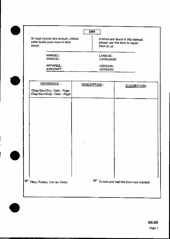
.I ERR I
Si vous trouvez des erreurs, utilisez If errors are found in this manual,
cette feuille pour nous Ie faire please use this fonn to reportsavoir. them to us.
MANUEL: LANGUE:MANUAL: LANGUAGE:
APPAREIL: VERSION:AIRCRAFT: VERSION:
..REFERENCE: DESCRIPTION: SUGGESTION:
Chap/Sect/Sui -Date -PageChap/Sect/Subj -Date -Page
8\I
I::u" Pliez, Postez, Voir au Verso I::u" To fold and mail the fonn see overleaf
.99.99Page 1

r:D'" Cacheter avec un ruban adhesif r:D'" Seal here with adhesive tape
Pour: From : Nom -Compagnie -Name -Compagny-
Adresse Adress
=:~~':.I.' ....j Timbre j
~ ~~ j
EUROCOPTER
Direction Technique SupportDocumentation techniqueAeroport International Marseille-Provence13725 MARIGNANE Cedex. France
.99.99Page 2
MANUELIMANUAL: APPAREILJAIRCRAFT:.,""I[ '" '!"" LANGUEIlANGUAGE: VERSION/VERSION: !
ATTENTION: r
LA VAUDITE DE CE MANUEL EST FONCTION DE SA QUALITE D'ORIGINE ET DE LADISCIPLINE APPORTEE A SA TENUE A JOUR.-L 'IMPRIMEUR EST DESIGNE AU VERSO-LA RESPONSABILITE DE MISE A JOUR DOlT ETRE ENREGISTREE CI-APRES.
IMPORTANT NOTE:
THE PRACTICAL VALUE OF THIS MANUAL DEPENDS UPON ITS ORIGINAL QUALITY AND ITSBEING CORRECTL Y UPDATED
-THE PRINTER'S NAME SPECIFIED OVERLEAF. -THE NAME OF THE PERSON RESPONSIBLE FOR KEEPING THE MANUAL UP- TO-DA TE MUST.BE RECORDED HEREAFTER.
INCORPORATION INCORPORATIONREVISION INSERTED REVISION INSERTED
N' Date Date Par (NOM) Visa N' Date Date Par (NOM) VisaNo By (NAME) Signature No By (NAME) Signature
Z 31~
I8 '
LISTE DES REVISIONS I RECORD OF REVISIONS
.99.99
Page 3
MANUEUMANUAL: APPAREIUAIRCRAFT:
I
LANGUE/LANGUAGE: VERSION/VERSION: .
L'impression de ce document, a la I This document at the revision specifiedrevision signaJee page precedente, a on the previous page, has been printedete realisee avec tous les soins de : with great care by :
Imprimeur: TORRESPONDANCEPrinter: 59, bd de la Republique
13100. AlX EN PROVENCETel.: 04.42.27.06.86 -Fax. : 04.42.27.53.08E-Mail: [email protected]
Date: JUILLET 1998
Si vous trouvez des erreurs, utilisez I If errors are foud in this ManUal.La feuille « ERR» pour nous Ie faire please use the « ERR» fom7 to report them
savoir. to us.
Pour toute reclamation s'adresser a : EUROCOPTERAll comments should be adressed to : Direction Technique Support
Documentation techniqueAeroport International Marseille.Provence13725 MARIGNANE Cedex -France
Tel. : (33) (0) 44285 96 75Fax : (33) (0) 44285 94 80
Les textes et fi9ures contenus dans ce No part of the text or illustrationsdocument ne peuvent etre reproduits contained in this document may besans accord ecrit de Ia Societe reproduced without the writtenEUROCOPTER. approval of the companyToute reproduction doit porter mention EUROCOPTER.de I'accord et de I'autorite a I'origine de Such approval and approvingcelIe autorisation authority shall be mentioned on all
:~prOductiOns. .
....
..99.99
Page 4
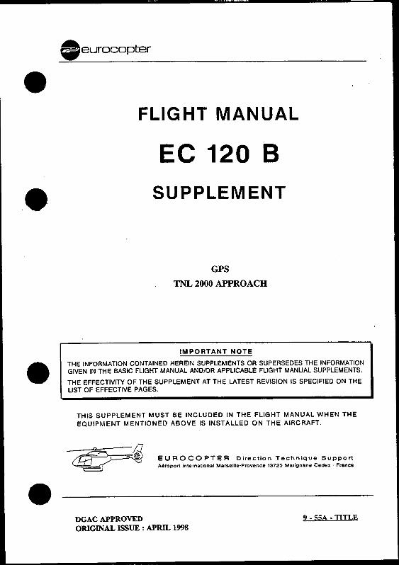
.eurocopter.FLIG HT MAN UAL
EC 120 B
.SUPPLEMENT
GPS
TNL 2000 APPROACH
IMPORTANT NOTE
. THE INFORMATION CONTAINED HEREIN SUPPLEMENTS OR SUPERSEDES THE INFORMATIONGIVEN IN THE BASIC FLIGHT MANUAL AND/OR APPLICABLE FLIGHT MANUAL SUPPLEMENTS.
THE EFFECTIVITY OF THE SUPPLEMENT AT THE LATEST REVISION IS SPECIFIED ON THE
LIST OF EFFECTIVE PAGES.
THIS SUPPLEMENT MUST BE INCLUDED IN THE FLIGHT MANUAL WHEN THE
EQUIPMENT MENTIONED ABOVE IS INSTALLED ON THE AIRCRAFT.
~~72 ~~:~~}=~~~ L-h ' -~ EUROCOPTER Direction TeChnique Support
~ Aeroport international Marseille-Provence 13725 Marignane Cedex -France.DGAC APPROVED 9 -55A -TITLE
ORIGINAL ISSUE: APRll.. 1998
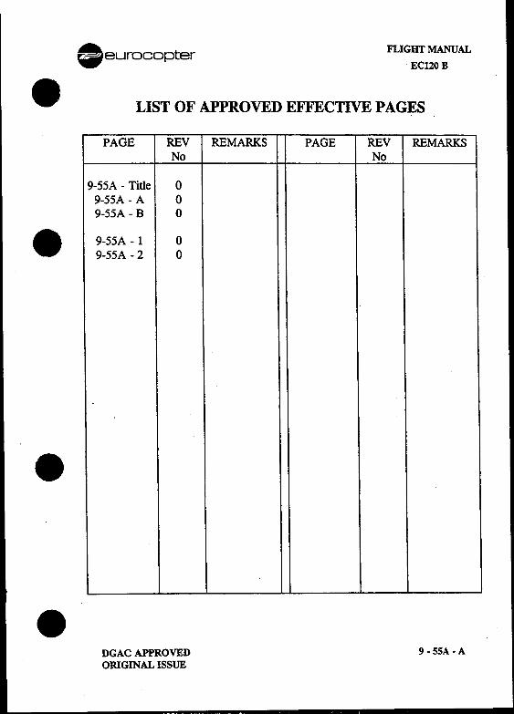
. eurocopter FLIGHT MANUALEC120 B
.LIST OF APPROVED EFFECTIVE PAGES
PAGE REV REMARKS PAGE REV REMARKSNo No
9-55A -Title 09-55A -A 09-55A -B 0
. 9-55A -1 09-55A -2 0
.
.DGAC APPROVED 9 -55A -A
ORIGINAL ISSUE
FLI G lIT MANUAL .eul~ocopterEC120B
LOG OF APPROVED NORMAL REVISIONS .
ORIGINAL 0 APRIL 1998
.ORIGINAL ISSUE APPROVED BY : DGAC
DATE: -1 AVR. !198
.4 ~~~i~""'- .,.';:..'""-'" "',~ -"
~~' ;~o~.urc"o~=esC~ -i 'd T-..",,- 0' '--.:: ,no..-'u a..8- .
I""" -.."~:5 "
"S$ .,
\ ~~B~E~'~~~~~~~CIre REVAULT
9 .55 A .B DGAC APPROVED .ORIGINAL ISSUE
l. eurocopter FLIGHT MANUAL
ECl20B
.I GENERALThe Global Positioning System 1RIMBLE 2000 APPROACH complies withAC 20-138 requirements for use in day VFR conditions in sight of the groundor water.
2 LIMITATIONSThe limitations in the basic flight manual and flight manual supplements
. remain applicable and are supplemented or modified by the followinglimitations.
-A placard located within pilot's sight field indicates:
GPS OPERABLE IN DAY VFR GPS UTILISABLE EN VFR DECONDITIONS IN SIGHf OF JOUR EN VUE DU SOL OU DEGROUND OR WATER ONI.. Y L'EAU UNIQUEMENT
-Use of the GPS is prohibited in approach mode.
3 EMERGENCY PROCEDURESThe emergency procedures in the basic flight manual and flight manualsupplements remain applicable.
.NOTEPress the MSG key on the CDU to display the situation of theGPS and to scroll through next messages if any.
.DGAC APPROVED 9 -55A-lORIGINAL ISSUE
~
FLIGHT MANUAL .eurocoJ:>terEC120 B
4 NORMAL PROCEDURE.The nonnal procedures in the basic flight manual and flight manual .
supplements in use remain applicable, and are supplemented or modified bythe following nonnal procedures :
4.1 BEFORE STARTING
-The PILOT GUIDE operating manual (reference: 81449) must be up-to-date and kept on-board the aircraft.
..;:. -The crew must check the validity and accuracy of the data base (28.." days validity) relative to the official documentation.
-Before the start of navigation, check that all the data is valid by .reading the messages on the CDU.
NOTEDuring the « en route » phase, the integrity of the position suppliedby the GPS is not ensured. Consequently it is the responsibility ofthe crew to check the accuracy of the position every 15 minutesusing either conventional VFR method or the other navigationequipment if available.
Transmissions from the helicopter, via KY196 can lead tomomentary losses of GPS reception at the following frequencies:
121.175::!: 0.25 MHz and 131.275::!: 0.25 MHz.
Navigation calculation becomes nominal 2 to 3 seconds after theend of transmission. .
5 STATUTORY PERFORMANCEThe statutory perfonnance in the basic flight manual and flight manualsupplements remains applicable.
9 -55A -2 DGAC APPROVED .ORIGINAL ISSUE
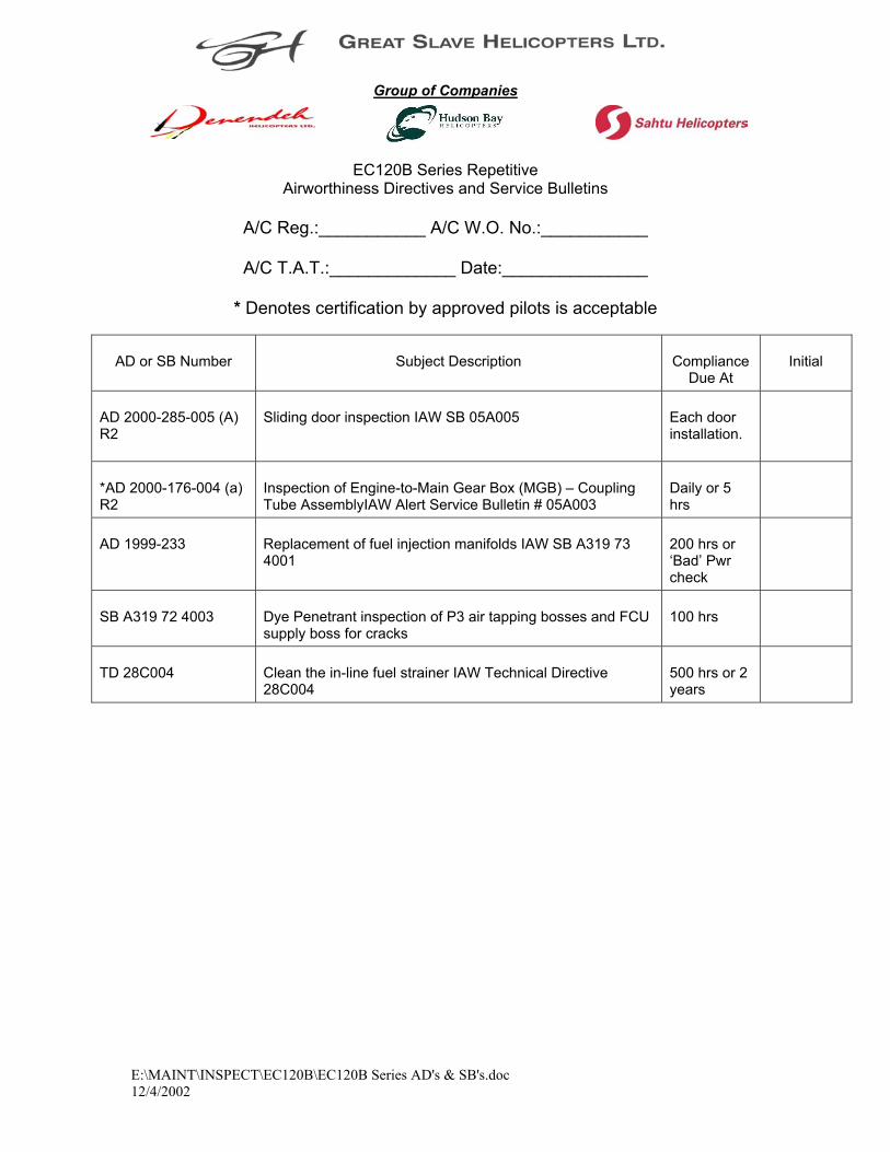
Group of Companies
EC120B Series Repetitive Airworthiness Directives and Service Bulletins
A/C Reg.:___________ A/C W.O. No.:___________
A/C T.A.T.:_____________ Date:_______________
* Denotes certification by approved pilots is acceptable
E:\MAINT\INSPECT\EC120B\EC120B Series AD's & SB's.doc 12/4/2002
AD or SB Number Subject Description Compliance Due At
Initial
AD 2000-285-005 (A) R2
Sliding door inspection IAW SB 05A005 Each door installation.
*AD 2000-176-004 (a) R2
Inspection of Engine-to-Main Gear Box (MGB) – Coupling Tube AssemblyIAW Alert Service Bulletin # 05A003
Daily or 5 hrs
AD 1999-233 Replacement of fuel injection manifolds IAW SB A319 73 4001
200 hrs or ‘Bad’ Pwr check
SB A319 72 4003 Dye Penetrant inspection of P3 air tapping bosses and FCU supply boss for cracks
100 hrs
TD 28C004 Clean the in-line fuel strainer IAW Technical Directive 28C004
500 hrs or 2 years