dynamic application development in symbian os - lutpub
TRANSCRIPT

Lappeenranta University of Technology
Department of Information Technology
Master’s Thesis
Dynamic application development in Symbian OS
The subject has been approved by the council of the Department of Information
Technology on March 12, 2003
Supervisors: Professor Heikki Kälviäinen and M.Sc. Samuli Forsman
Instructor: M.Sc. Kimmo Hoikka
Lappeenranta, March 23, 2004
Timo Rouvinen
Ruskonlahdenkatu 10 A 10
FIN - 53850 Lappeenranta
Finland
+358 40 709 2527
ii
ABSTRACT
Lappeenranta University of Technology
Department of Information Technology
Timo Rouvinen
Dynamic application development in Symbian OS
Master’s Thesis
2004
79 pages, 29 figures and 10 tables
Supervisors: Professor Heikki Kälviäinen and M.Sc. Samuli Forsman
Keywords: Symbian, mobile, application, user interface, XML
This thesis studies ways to develop Symbian OS applications more efficiently. The work
introduces the Symbian OS and considers the challenges and restraints when developing
applications to it. Also, already available methods are considered based on the goal of the
thesis. The work includes a representation of a project where an XML-based application
implementation was created.
Symbian application development follows the same patterns time after time. Since
Symbian OS is an open platform there are lots of application developers doing the same
things. Finding a more effective way to create applications would potentially save a lot of
resources. At the moment conventional programming methods seems to be the most
popular way to implement the applications. However there are already emerging
solutions available to make development more efficient, which proves the need for more
efficient development. The implemented project runs a Symbian application from an
XML definition. When using XML definition as a program language it changes the
software development in many aspects. However the changes must be positive and they
must not harm the software quality or usability.

iii
TIIVISTELMÄ
Lappeenrannan teknillinen yliopisto
Tietotekniikan osasto
Timo Rouvinen
Dynaaminen sovelluskehitys Symbian-käyttöjärjestelmässä
Diplomityö
2004
79 sivua, 29 kuvaa ja 10 taulukkoa
Tarkastaja: Professori Heikki Kälviäinen ja DI Samuli Forsman
Hakusanat: Symbian, mobiili, sovellus, käyttöliittymä, XML
Keywords: Symbian, mobile, application, user interface, XML
Diplomityössä tutkitaan, kuinka Symbian-sovelluskehitystä voitaisiin tehostaa. Työssä
esitellään Symbian-käyttöjärjestelmä, sekä pohditaan haasteita ja rajoitteita joita
Symbian sovelluskehityksessä kohdataan. Myöskin jo olemassa olevia kehitystapoja
pohditaan työn tavoitteen kannalta.
Symbian-sovelluskehityksessä tehdään toistuvasti samoja asioita. Koska Symbian on
avoin käyttöjärjestelmä, sovelluskehittäjiä on paljon. Tehokkaamman kehitystavan
löytäminen säästäisi paljon resursseja. Tällä hetkellä perinteiset ohjelmointitavat
näyttävät olevan suosituin tapa kehittää sovelluksia. Kuitenkin on jo olemassa useita
ratkaisuja, jotka pyrkivät tehostamaan sovelluskehitystä, mikä todistaa tarpeen kehittää
tehokkuutta. Työssä toteutettu systeemi ajaa Symbian sovelluksia XML-määrityksen
pohjalta. Kun käytetään XML-määritystä C++-koodin sijasta, sovelluskehitys muuttuu.
Näiden muutosten täytyy kuitenkin olla myönteisiä, eivätkä ne saa haitata ohjelmiston
laatua tai käytettävyyttä.
iv
PREFACE
About four years ago, after studying a couple of years in Lappeenranta University of
Technology, I applied for a job at Digia. The job interview was the first time I held an
EPOC (now known as Symbian) device. The device was Psion’s personal digital
assistant with gray-tone display and no communication capabilities. The performance
and resources of the device were quite close to the computers in the mid 80’s, when I got
my first computer, Commodore-64. The progress in the mobile world is fast, and the
devices now are very different from those of four years ago. A lot has happened in these
four years in many aspects.
I would like to thank Digia for allowing me to do this thesis in the middle of the busy
projects. Thanks go also to all the great workmates at Digia who have shared their
knowledge with me. The instructor of this thesis was Kimmo Hoikka who gave me
valuable advices during the project, thanks Kimmo! Also big thanks go to supervisors
Heikki Kälviäinen and Samuli Forsman who gave a lot of good comments and advices to
the work.
Finally, the biggest thanks go to my parents who have always supported me in my
studies.

1
CONTENTS
1. INTRODUCTION ...................................................................................................5
1.1. Background information ............................................................................................. 5 1.2. Objectives ................................................................................................................... 5 1.3. Structure of the work .................................................................................................. 6
2. SYMBIAN OS APPLICATION DEVELOPMENT.............................................7
2.1. Symbian OS ................................................................................................................ 7 2.2. Reference designs and device types............................................................................ 9
2.2.1. Series 60................................................................................................................... 10 2.2.2. Series 90................................................................................................................... 11 2.2.3. UIQ .......................................................................................................................... 11
2.3. Software development platforms .............................................................................. 12 2.3.1. Nokia Series 60 Platform ......................................................................................... 12 2.3.2. Nokia Series 90 Platform ......................................................................................... 15
2.4. Common mobile application development demands................................................ 17 2.4.1. Mobile device limitations......................................................................................... 17 2.4.2. Compatibility issues................................................................................................. 19
3. SYMBIAN OS APPLICATION FRAMEWORK ..............................................21
3.1. User interface architecture ........................................................................................ 21 3.2. Uikon application classes.......................................................................................... 22 3.3. Basic application classes........................................................................................... 24 3.4. Avkon application classes......................................................................................... 25
4. APPLICATION DEVELOPMENT DEMANDS................................................26
4.1. An application for multiple platforms....................................................................... 26 4.2. Application development and the software lifecycle................................................ 28
5. USER INTERFACE PROGRAMMING METHODS.......................................31
5.1. Introduction to UI creation ....................................................................................... 31 5.2. UI creation tools for Symbian OS............................................................................. 34
5.2.1. Trigenix.................................................................................................................... 34 5.2.2. AppForge MobileVB ............................................................................................... 35 5.2.3. Cybelius Maestro ..................................................................................................... 37 5.2.4. MetaCase MetaEdit+ ............................................................................................... 37 5.2.5. Prosa Mobile Developer........................................................................................... 39 5.2.6. Peroon S2S............................................................................................................... 39
5.3. Evaluation of the methods ........................................................................................ 40
6. DYNAMIC APPLICATION DEVELOPMENT SYSTEM: DRUID ...............43

2
6.1. Concept ..................................................................................................................... 43 6.2. The Model-View-Controller design pattern.............................................................. 43 6.3. User interface requirements ...................................................................................... 44 6.4. Engine and model requirements ............................................................................... 48 6.5. Dynamic application environment............................................................................ 50
6.5.1. Files and tools .......................................................................................................... 50 6.5.2. Definition language and parsing .............................................................................. 53 6.5.3. Software architecture ............................................................................................... 58 6.5.4. Events and interfaces ............................................................................................... 60 6.5.5. Application engines and models .............................................................................. 62 6.5.6. Localization.............................................................................................................. 64
6.6. Results....................................................................................................................... 66 6.7. Further development ................................................................................................. 69
6.7.1. Speed optimization................................................................................................... 69 6.7.2. Extending the support .............................................................................................. 70 6.7.3. Graphic XML generation ......................................................................................... 70 6.7.4. Affects to the software lifecycle .............................................................................. 70
7. CONCLUSIONS....................................................................................................72
REFERENCES................................................................................................................73

3
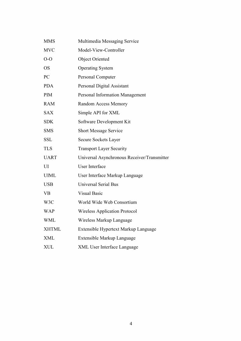
ABBREVIATIONS
2G, 2.5G, 3G Mobile Communication Generations
ABI Application Binary Interface
AIF Application Information File
API Application Program Interface
BC Binary Compatibility
CASE Computer Aided Software Engineering
CLDC Connected Limited Device Configuration
CONE Control Environment
CSS Cascading Style Sheet
DFRD Device Family Reference Design
DLL Dynamic Link Library
DMA Direct Memory Access
Druid, DUI Dynamic Rapid User Interface Development
DSWP Digia Software Process
GPRS General Packet Radio Services
GSM Global System for Mobile communication
GT Generic Technology
GUI Graphic User Interface
HTML Hypertext Markup Language
HTTP Hypertext Transfer Protocol
IDE Integrated Development Environment
IrDA Infrared Data Association
JFC Java Foundation Classes
LAF Look And Feel
MFC Microsoft Foundation Classes
MIDP Mobile Information Device Profile
MIME Multi-Purpose Internet Mail Extensions
4
MMS Multimedia Messaging Service
MVC Model-View-Controller
O-O Object Oriented
OS Operating System
PC Personal Computer
PDA Personal Digital Assistant
PIM Personal Information Management
RAM Random Access Memory
SAX Simple API for XML
SDK Software Development Kit
SMS Short Message Service
SSL Secure Sockets Layer
TLS Transport Layer Security
UART Universal Asynchronous Receiver/Transmitter
UI User Interface
UIML User Interface Markup Language
USB Universal Serial Bus
VB Visual Basic
W3C World Wide Web Consortium
WAP Wireless Application Protocol
WML Wireless Markup Language
XHTML Extensible Hypertext Markup Language
XML Extensible Markup Language
XUL XML User Interface Language
5
1. Introduction
1.1. Background information
The Symbian operating system is becoming an industry standard operating system for
smartphones. As an open platform it allows anyone to create applications to be used in
mobile devices. The application, and especially user interface (UI) implementation in the
Symbian operating system (OS) usually follows the same patterns which makes it
worthwhile to study alternative methods for the application development.
In fluctuating mobile phone world the software development time is crucial so that the
devices can meet the demands of the mass market in time. Also the competition between
device manufacturers leads to increasing demands in both features and software quality.
There are already few tools and techniques available for creating applications without
starting from scratch. Since it has been noticed that creating user interfaces to the
Symbian OS using C++ can take quite a lot of resources, it is reasonable to study if the
application creation process can be made lighter.
1.2. Objectives
The objective of this thesis is to study how to make the Symbian OS application
development more effective throughout the software lifecycle. However reducing the
application development and testing resources should not reduce the software usability or
reliability.
6
1.3. Structure of the work
The Symbian platforms and mobile application development challenges are overviewed
in Chapter 2. Chapter 3 describes the Symbian application framework and presents the
application structure. Chapter 4 describes the application development problem domain.
Chapter 5 considers different UI creation methods and represents solutions that are
already on the market. Chapter 6 presents a dynamic application creation concept which
was the project related to this thesis. Chapter 7 considers the results of the project and
draws conclusions of the whole study.
7
2. Symbian OS application development
2.1. Symbian OS
“Symbian OS is the open, standard operating system licensed by the world’s leading
mobile phone manufacturers. It is designed for the specific requirements of data-enabled
2G (Mobile phone generation), 2.5G and 3G mobile phones. The Symbian OS includes a
robust multi-tasking kernel, integrated telephony support, communications protocols,
data management, advanced graphics support, a low-level graphical user interface
framework, and a variety of application engines.” [1]
The Symbian OS was formerly called EPOC. The name EPOC in particular has a long
history so it can still be found in old documentations. Psion was the originator of the
original EPOC platform. They believed the world is entering “a new epoch of personal
convenience” by adding wireless communication to PDAs (Personal Digital Assistant).
The term “Symbian platform” is used in many cases of the software built on top of
Symbian OS.
The reason why mobile phones require a different operating system is that there are
characteristics that require special attention from the OS. Compared with the PC
(Personal Computer) world there are big differences in the available resources. Mobile
phones are small but still packed with features. There is a limited amount of memory and
processor capacity available. Also the power consumption must be optimized, as there is
limited amount of battery resources available. The most remarkable difference compared
to PCs is that usually there is no mass storage media integrated into the device.
Since mobile phones are also used instead of paper diaries and agendas users expect them
to be as reliable as the old method they used. Rebooting should not be an option to
recover in mobile phones, and user data should never be lost.
8
Different manufacturers require very different kind of mobile phones. The Symbian OS
allows its licensees to modify the user interface part to suit each one’s needs. Mobile
phones are highly connected, both with other mobile devices and with bigger server side
systems with built-in communication hardware such as GSM (Global System for Mobile
communication), GPRS (General Packet Radio Services), Bluetooth, IrDA (Infrared Data
Association), USB (Universal Serial Bus) and middleware protocols such as MMS
(Multimedia Messaging Service), HTTP (Hypertext Transfer Protocol) and SyncML. [2]
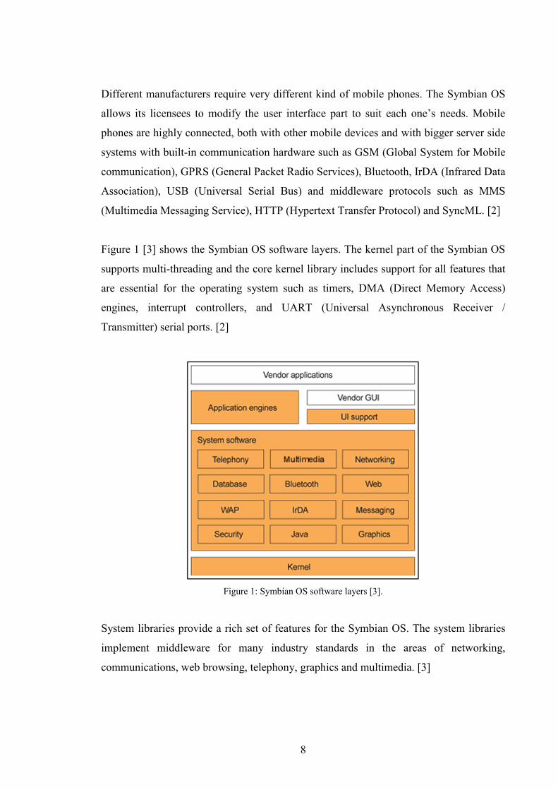
Figure 1 [3] shows the Symbian OS software layers. The kernel part of the Symbian OS
supports multi-threading and the core kernel library includes support for all features that
are essential for the operating system such as timers, DMA (Direct Memory Access)
engines, interrupt controllers, and UART (Universal Asynchronous Receiver /
Transmitter) serial ports. [2]
Figure 1: Symbian OS software layers [3].
System libraries provide a rich set of features for the Symbian OS. The system libraries
implement middleware for many industry standards in the areas of networking,
communications, web browsing, telephony, graphics and multimedia. [3]
9
A Symbian platform usually contains applications such as calendar, phonebook, note,
pinboard, and so on. The application engines for these are separated from user interface
part so that every Symbian device using these application engines can share data between
each other. The separation of the application engines also makes it possible to reuse the
same engines in different platforms since they should not be depending on any platform
specific features.
Personal information management (PIM) applications are highly connected with each
other. For example Series 60 phones are very contact-oriented. An example of this is an
incoming call to a Series 60 phone. When a call arrives, a contact matching the caller’s
number is searched and information (e.g. name and image) is shown if it is available in
contact database. The contacts also contain various types of data for different
applications. A contact may for example contain pictures, and location and presence
information.
The up-most layers of the platform are the user interface parts. Symbian provides the
base UI support including entities such as application architecture (AppArc) and control
environment library (CONE). User libraries for different device family reference designs
(DFRD) are built on top of the CONE and AppArc. That makes possible for every
Symbian licensee to create the user interface to suit the look and feel (LAF) and usability
requirements. [3]
2.2. Reference designs and device types
Reference designs define the form factor of a device. Mobile devices come in many
different sizes and forms and therefore have different kinds of displays and keyboard and
other input methods such as a touch screen pen. [4]
Formerly Symbian shipped full UI implementations for three types of devices. Now
Symbian ships the core part of the UI and a reference implementation called the
TechView. TechView is a communicator type reference implementation, but it is not
meant for any particular device and it is mostly used for reference application
10
development and testing purposes. Basically anyone can implement their own UI layers
on top of Symbian’s UI core. The next chapters represent the three most common UI
implementations.
2.2.1. Series 60
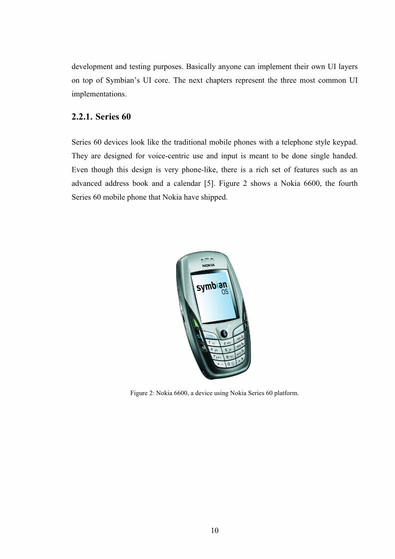
Series 60 devices look like the traditional mobile phones with a telephone style keypad.
They are designed for voice-centric use and input is meant to be done single handed.
Even though this design is very phone-like, there is a rich set of features such as an
advanced address book and a calendar [5]. Figure 2 shows a Nokia 6600, the fourth
Series 60 mobile phone that Nokia have shipped.
Figure 2: Nokia 6600, a device using Nokia Series 60 platform.
11
2.2.2. Series 90
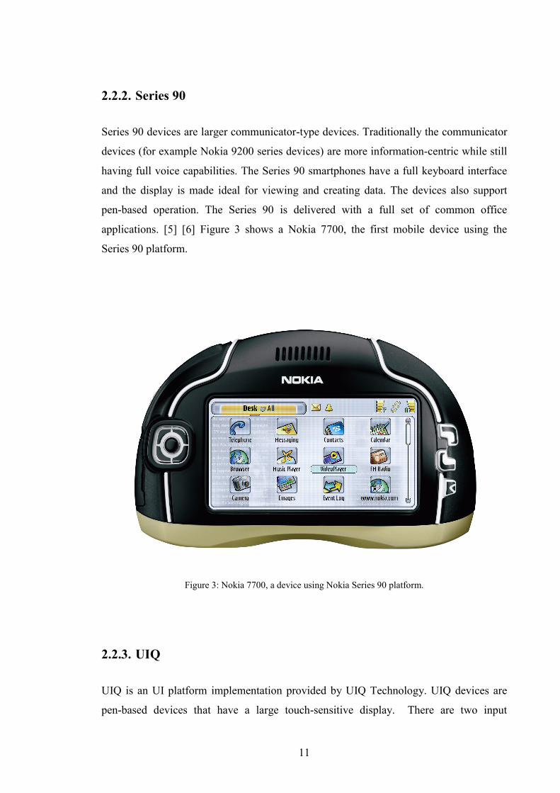
Series 90 devices are larger communicator-type devices. Traditionally the communicator
devices (for example Nokia 9200 series devices) are more information-centric while still
having full voice capabilities. The Series 90 smartphones have a full keyboard interface
and the display is made ideal for viewing and creating data. The devices also support
pen-based operation. The Series 90 is delivered with a full set of common office
applications. [5] [6] Figure 3 shows a Nokia 7700, the first mobile device using the
Series 90 platform.
Figure 3: Nokia 7700, a device using Nokia Series 90 platform.
2.2.3. UIQ
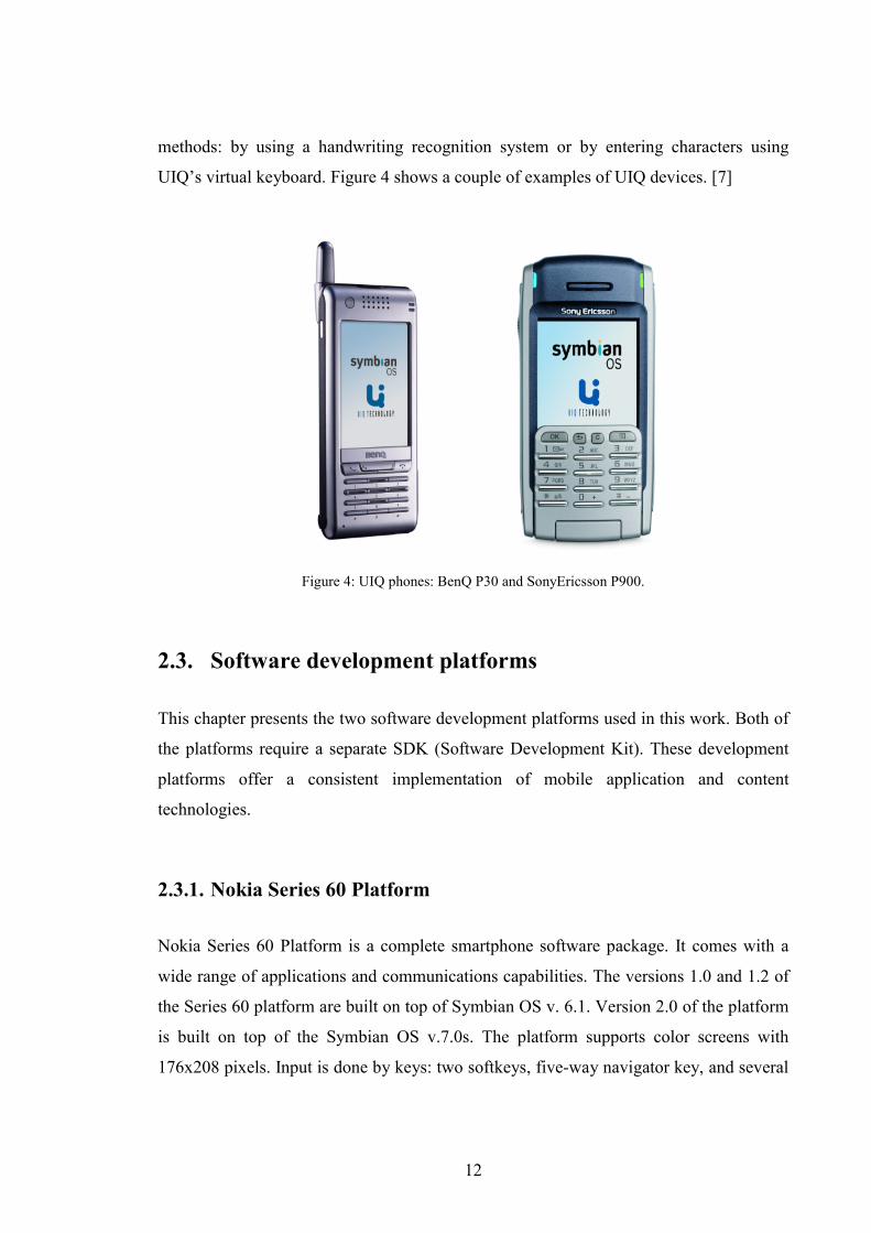
UIQ is an UI platform implementation provided by UIQ Technology. UIQ devices are
pen-based devices that have a large touch-sensitive display. There are two input
12
methods: by using a handwriting recognition system or by entering characters using
UIQ’s virtual keyboard. Figure 4 shows a couple of examples of UIQ devices. [7]
Figure 4: UIQ phones: BenQ P30 and SonyEricsson P900.
2.3. Software development platforms
This chapter presents the two software development platforms used in this work. Both of
the platforms require a separate SDK (Software Development Kit). These development
platforms offer a consistent implementation of mobile application and content
technologies.
2.3.1. Nokia Series 60 Platform
Nokia Series 60 Platform is a complete smartphone software package. It comes with a
wide range of applications and communications capabilities. The versions 1.0 and 1.2 of
the Series 60 platform are built on top of Symbian OS v. 6.1. Version 2.0 of the platform
is built on top of the Symbian OS v.7.0s. The platform supports color screens with
176x208 pixels. Input is done by keys: two softkeys, five-way navigator key, and several

13
dedicated keys. The user interface is designed for one-hand operation. [9] The SDK has
an emulator (Figure 5) for development and testing purposes.
Figure 5: The Series 60 emulator.
The Series 60 platform includes a variety of advanced applications. These application
groups are presented in the following list [9]:
• SyncML synchronization. Series 60 implements SyncML data synchronization
over HTTP, Bluetooth and IrDA. Synchronization of contact (vCard) and
calendar (vCalendar) data are also supported.
• PIM suite includes such applications as Calendar, Phonebook, Photoalbum, and
To-Do list. They all can be synchronized with other PC-based PIM applications.
• Telephony applications include advanced phone features, speed dialing, call logs
and message indications, and a framework support for voice dialing.
14
• Application installation and management systems include an installation engine
that allows the user to add and remove Symbian OS applications to the device.
Java MIDP (Mobile Information Device Profile) applications are also supported.
• Browsing and downloading applications include a WAP (Wireless Application
Protocol) browser that conforms to the WAP 1.2.1 standard. The Series 60
platform supports messaging-based downloads for small items. MIME (Multi-
Purpose Internet Mail Extensions) content type handling is also supported. All
supported types are accessible through WAP, PC connectivity, MMS and e-mail.
• Messaging applications include MMS, SMS (Short Message Service), e-mail and
Nokia Smart Messaging.
The development with the Series 60 SDK can be done by using Java (MIDP). Java MIDP
is built on the Java 2 Micro Edition (J2ME) core platform using the CLDC (Connected
Limited Device Configuration). They have a reduced set of APIs (Application Program
Interface) to suit small devices like mobile phones. Series 60 SDK for Java MIDP
includes an emulator that can be easily integrated with Borland JBuilder and Sun ONE
Studio. [9]
Concerning the project presented in 6, the Java MIDP would be a very suitable choice for
the portable application development. However the CLDC assumes that the set of JNI’s
native functions must be closed for security reasons, which means that the MIDP’s set of
functionality cannot be expanded dynamically. This leads to the fact that an application
developed using Java MIDP would be limited to a set of UI components offered by the
MIDP.
Development in Series 60 SDK for Symbian OS is done with C++ and it gives the
developer access to all of the Symbian OS 6.1 public APIs and the Series 60 libraries as
well as Series 60 application engines, such as the Phonebook and the Photoalbum. The
used IDE (Integrated Development Environment) is Microsoft Visual C++ 6.0. [9]
15
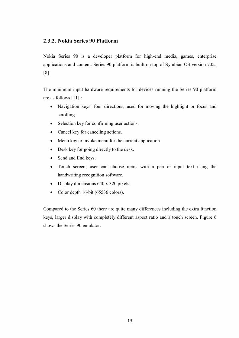
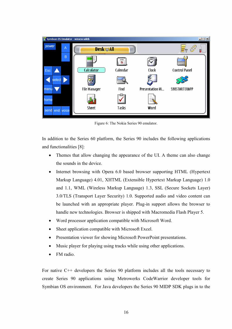
2.3.2. Nokia Series 90 Platform
Nokia Series 90 is a developer platform for high-end media, games, enterprise
applications and content. Series 90 platform is built on top of Symbian OS version 7.0s.
[8]
The minimum input hardware requirements for devices running the Series 90 platform
are as follows [11] :
• Navigation keys: four directions, used for moving the highlight or focus and
scrolling.
• Selection key for confirming user actions.
• Cancel key for canceling actions.
• Menu key to invoke menu for the current application.
• Desk key for going directly to the desk.
• Send and End keys.
• Touch screen; user can choose items with a pen or input text using the
handwriting recognition software.
• Display dimensions 640 x 320 pixels.
• Color depth 16-bit (65536 colors).
Compared to the Series 60 there are quite many differences including the extra function
keys, larger display with completely different aspect ratio and a touch screen. Figure 6
shows the Series 90 emulator.
16
Figure 6: The Nokia Series 90 emulator.
In addition to the Series 60 platform, the Series 90 includes the following applications
and functionalities [8]:
• Themes that allow changing the appearance of the UI. A theme can also change
the sounds in the device.
• Internet browsing with Opera 6.0 based browser supporting HTML (Hypertext
Markup Language) 4.01, XHTML (Extensible Hypertext Markup Language) 1.0
and 1.1, WML (Wireless Markup Language) 1.3, SSL (Secure Sockets Layer)
3.0/TLS (Transport Layer Security) 1.0. Supported audio and video content can
be launched with an appropriate player. Plug-in support allows the browser to
handle new technologies. Browser is shipped with Macromedia Flash Player 5.
• Word processor application compatible with Microsoft Word.
• Sheet application compatible with Microsoft Excel.
• Presentation viewer for showing Microsoft PowerPoint presentations.
• Music player for playing using tracks while using other applications.
• FM radio.
For native C++ developers the Series 90 platform includes all the tools necessary to
create Series 90 applications using Metrowerks CodeWarrior developer tools for
Symbian OS environment. For Java developers the Series 90 MIDP SDK plugs in to the
17
Nokia Developer Suite for J2ME. The Nokia Series 90 SDK package includes the same
basic parts that are included in the Series 60 platform. [8]
2.4. Common mobile application development demands
Smartphones are small and mobile devices. Mobile application developers face several
additional challenges that PC application developers do not need to care about.
2.4.1. Mobile device limitations
The following set of mobile device limitations is based on Symbian’s document “Why is
a different operating system needed?” [2] .
Always available and usable
Mobile devices are usually always carried along so users expect them to be available for
use at all times. The device must be responsive in all situations and it should not get
booted often. Actually a mobile device should never be powered down at all since it must
be always able to raise alarms or handle incoming calls. Also it is extremely important
that a call can be made in an emergency situation.
Battery energy limitations
Since the mobile phone should always be on, a lot of attention must be paid to energy
consumption. The whole operating system must be designed to be efficient on this part
too, but also application developers must remember the energy consumption. Always
when the processor processes something, it consumes power. Therefore for example
timers that run all time when the application is on should be avoided since they consume
a lot of power continuously.

18
Low processing power
There should always be enough processor time available so that the phone responds
rapidly to user input. Mobile devices do not have so much processing resources because
of the limited size and the limited amount of battery energy. Applications should not
consume too much processing resources, otherwise the phone’s responsiveness
decreases. This means that time consuming tasks must be implemented so that the phone
remains usable.
Small amount of memory
When programming PC applications there are huge amount of device resources available
compared to the mobile environment. A PC can have hundreds of megabytes of memory
when a mobile phone has few megabytes. While a device contains a rich set of features
the only way to pack every feature to the small amount of memory is comprehensive
code reuse.
Connectivity
As the mobile device is usually moving all the time, the connections cannot be assumed
to be available always. All the connection protocols and applications that use
connectivity must be designed so that everything works even if the connection is lost.
Connections are lost quite often when traveling in remote areas or places that block the
network signals. Mobile applications must manipulate the data locally in the device until
the connections are restored, which adds extra complexity to applications.
Product diversity
Since mobile phones are manufactured for the mass market the manufacturers are
continuously competing on how appealing their phones are to the customer.
Customization of the phones has proven to be very popular; mobile phone users use
money to make their phone look and sound different than the other phones. User
interfaces can be customized too to take the customization even further. This means that
19
the user interfaces are evolving all the time. Different input methods are used and the size
of the screens changes. Also different look and feels are implemented by each
manufacturer. Platforms may support application “skin” features that make the UI look
different. One application can be needed in many different kinds of phones and platforms
meaning that applications must be designed so that a minimum amount of work is needed
to convert the UI to another platform and device.
Fast evolving markets
As mentioned above the competition between manufacturers is going on all the time.
Manufacturers compete on how fast they can introduce the next phone with new features,
and the one who makes it first usually has an advantage over the competitors.
Applications must sometimes be developed on incomplete platforms meaning that the
platform that the application developers are using is changing. Still the software should
be reliable and ready when the manufacturer needs the phone on the market.
2.4.2. Compatibility issues
Once a software component has been developed for some Symbian OS platform it is
important that the software also works on the future platform versions. There are so
many variants and versions of the platform that binary compatibility (BC) must be
maintained. It would cause too much effort for the clients of a software component to fix
and deliver new version of the software each time a component they use changes.
The BC means that an old software component can be replaced with a new version so
that the clients of the component can use the software component without rebuilding. If
the old and new software components are binary compatible with each other they
implement the same application binary interface (ABI). Usually it is enough that the BC
is maintained backwards so that the old component can be replaced with a new one.
The main way to control the binary compatibility changes is the application
programming interfaces (API). The API defines the methods of a software component

20
and it should remain unchanged in order to maintain compatibility with the client
components. API freezes are done to ensure that the API stays the same.
Subtypes of the binary compatibility are source compatibility (SC) and link compatibility
(LC). A source compatibility change happens when a component’s source level interface,
the header file, has changed. This kind of change can be easily found by examining the
header file. If the header has changed, just compile the code against the new interface. It
is also possible that the public header files are removed from a component. This causes
the component’s SC to break while still maintaining the BC.
A link level change happens when component’s exported interface has changed. Link
level interfaces are defined by the published import library. The need for re-linking can
be seen by inspecting the component’s exported functions. If the exported functions have
changed the client component needs to be linked again against the changed component.
The sources need not to be compiled again at this case. Even if BC and SC are
maintained it is possible that the new software component is not compatible logically.
API defines the methods but it does not know exactly what the methods do. Changing the
implementation behind an API may break the logical compatibility meaning that the user
of the component expects the methods to behave differently than they really do.
A related compatibility issue to the previously mentioned ones is data compatibility. Data
is stored always based on some defined structure. If the structure has changed it may
cause a data compatibility break; the client software cannot read the data in the latest
platform. Data compatibility does not usually affect the software functionality but it
makes the old documents and user data obsolete. [10]
These compatibility issues must be taken into account when developing applications and
their architecture. Application developers must be aware of possible compatibility issues
in the underlying platform or OS level APIs. Different OS versions and platforms may
have incompatible APIs.
21
3. Symbian OS application framework
This chapter represents the Symbian OS user interface architecture and shows how
applications are constructed in different platforms.
3.1. User interface architecture
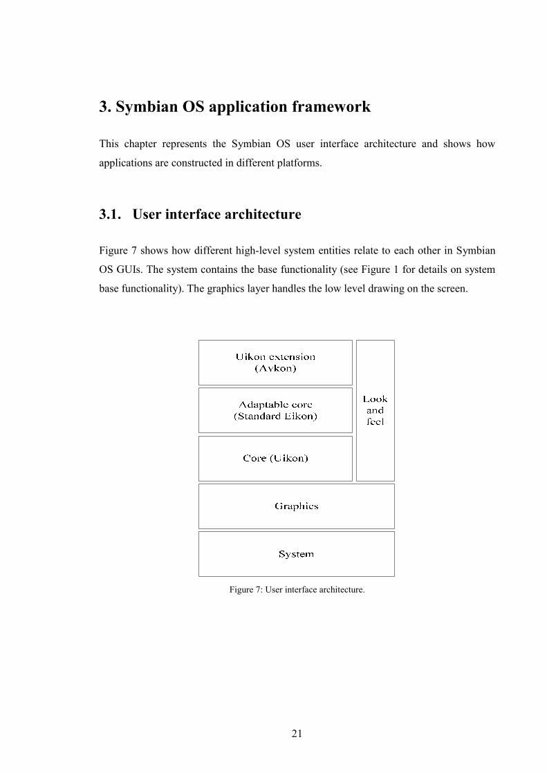
Figure 7 shows how different high-level system entities relate to each other in Symbian
OS GUIs. The system contains the base functionality (see Figure 1 for details on system
base functionality). The graphics layer handles the low level drawing on the screen.
Figure 7: User interface architecture.

22
The core user interface layer (Uikon) provides UI services that are common to all
Symbian OS devices. The Uikon application framework extends to two sub-frameworks:
• Application architecture framework (AppArc) that handles the application start-
up provides the basic framework for all Symbian OS applications (see Chapter
3.3).
• UI control framework (Control Environment (CONE)) provides drawing and
input handling to screen controls. The control framework provides base classes
for UI components (e.g. listbox). It also provides fundamental controls such as
images, menus, labels, and scroll bars that can be used directly from Uikon. [12]
The adaptable core (Standard Eikon) is implemented by the provider of the UI style. At
the moment Nokia provides two platforms, the Series 60 (Avkon) and the Series 90
(Ckon) that both implement different look and feel. Together with the Uikon extension
(Avkon or Ckon) and provider implemented adaptable Eikon core, a platform gets the
device specific look and feel. The base parts of the Symbian OS that do not change
between different UI platforms are called the Symbian GT (Generic Technology). In
some cases the phrase “native Symbian” can be used also. [5]
3.2. Uikon application classes
Figure 8 shows how the application classes are derived in a Uikon application. The
“Application” package items are the parts that are implemented by the developer. The
lower parts come from the platform.

23
Uikon
AppArc Cone
Application
CMyDocument CMyAppUiCMyApplication
CEikApplication CEikDocument CEikAppUi
CApaApplication CApaDocument CCoeAppUi
Figure 8: Application class derivation from Uikon.
The application architecture framework (AppArc) defines the basic functionality for the
application and document classes. Uikon’s application and document classes derive from
the AppArc classes. Uikon application’s classes are derived from the corresponding
CEik classes. CEikApplication class contains two functions that must be
implemented in the application:
• AppDllUid() returns the application library’s UID (unique identifier for
application).
• CreateDocumentL() creates the application’s document (CMyDocument).
CEikDocument defines one method that must be implemented by the application:
CreateAppUiL() creates application’s AppUi class (CMyAppUi). CEikAppUi does
not require any methods to be derived by the application but usually some of the methods
presented in Table 1 [10] are implemented. The table shows what kind of events can
occur through the CCoeAppUi class.
24
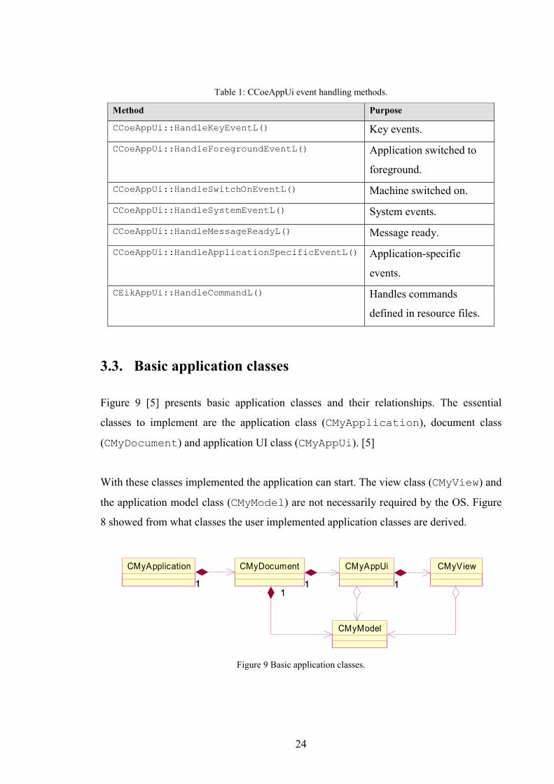
Table 1: CCoeAppUi event handling methods.
Method Purpose
CCoeAppUi::HandleKeyEventL() Key events.
CCoeAppUi::HandleForegroundEventL() Application switched to
foreground.
CCoeAppUi::HandleSwitchOnEventL() Machine switched on.
CCoeAppUi::HandleSystemEventL() System events.
CCoeAppUi::HandleMessageReadyL() Message ready.
CCoeAppUi::HandleApplicationSpecificEventL() Application-specific
events.
CEikAppUi::HandleCommandL() Handles commands
defined in resource files.
3.3. Basic application classes
Figure 9 [5] presents basic application classes and their relationships. The essential
classes to implement are the application class (CMyApplication), document class
(CMyDocument) and application UI class (CMyAppUi). [5]
With these classes implemented the application can start. The view class (CMyView) and
the application model class (CMyModel) are not necessarily required by the OS. Figure
8 showed from what classes the user implemented application classes are derived.
CMyViewCMyApplication CMyAppUi
11
CMyDocument
11 11
CMyModel
11
Figure 9 Basic application classes.

25
The Symbian application framework starts to build the application by calling the method
NewApplication() that is exported from the application class, in this case the
CMyApplication. Then the application class’ method CreateDocumentL is
called, and the document class is instantiated and returned to the application framework.
The document class, CMyDocument, implements the method CreateAppUiL that
creates the CMyAppUi object. The AppUi class builds up the application specific views
and other objects that are needed.
3.4. Avkon application classes
Figure 10 shows how application classes are derived from Avkon classes. The Avkon is a
Uikon extension layer used by the Series 60 platform. By overriding methods from
Uikon, Avkon changes some default functionalities to suit the purposes of the Series 60.
[5]
Figure 10: Application class derivation from Avkon.

26
4. Application development demands
This chapter clarifies the problems when creating applications for Symbian OS
platforms.
4.1. An application for multiple platforms
The Symbian OS has already proved to be an efficient operating system for smartphones
of today. There are many manufacturers and they all require a different kind of look and
feel for the phones. The number of platforms that are built on top of Symbian OS generic
libraries is increasing. Every platform requires a bit different implementation for the
applications and this increases the work amount needed for the user interface
development.
At the moment a lot of work is done when converting applications for example from the
Series 60 platform to the Series 90 platform. The user interface library parts are different
between platforms so applications need to change all UI specific parts to match the new
platform.
27
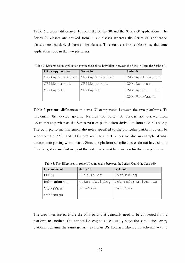
Table 2 presents differences between the Series 90 and the Series 60 applications. The
Series 90 classes are derived from CEik classes whereas the Series 60 application
classes must be derived from CAkn classes. This makes it impossible to use the same
application code in the two platforms.
Table 2: Differences in application architecture class derivations between the Series 90 and the Series 60.
Uikon AppArc class Series 90 Series 60
CEikApplication CEikApplication CAknApplication
CEikDocument CEikDocument CAknDocument
CEikAppUi CEikAppUi CAknAppUi or
CAknViewAppUi
Table 3 presents differences in some UI components between the two platforms. To
implement the device specific features the Series 60 dialogs are derived from
CAknDialog whereas the Series 90 uses plain Uikon derivation from CEikDialog.
The both platforms implement the notes specified to the particular platform as can be
seen from the CCkn and CAkn prefixes. These differences are also an example of what
the concrete porting work means. Since the platform specific classes do not have similar
interfaces, it means that many of the code parts must be rewritten for the new platform.
Table 3: The differences in some UI components between the Series 90 and the Series 60.
UI component Series 90 Series 60
Dialog CEikDialog CAknDialog
Information note CCknInfoDialog CAknInformationNote
View (View
architecture)
MCoeView CAknView
The user interface parts are the only parts that generally need to be converted from a
platform to another. The application engine code usually stays the same since every
platform contains the same generic Symbian OS libraries. Having an efficient way to

28
convert applications between different platforms saves a lot of developing and testing
time.
4.2. Application development and the software lifecycle
Creating software to mobile devices sets high demands for the software quality.
Simultaneously the product lifecycles and the development lifecycles are short. This
contradictory situation needs a software process specifically developed for the mobile
business. Quality is the main aspect and it must be observed in all entities related to the
software project. Digia Software Process (DSWP) quality concept includes a special
quality attention paid to the working methods and the resources.
DSWP is an incremental and iterative software process model (Figure 11). A software
process consists of two main elements: planning and construction. The iterative approach
means that the activities belonging to a phase are repeated inside a short time frame to
achieve the quality. [13]
Figure 11: Digia Software Process overview. [13]
29
The documentation is the key artifact in a software project. The quality of the documents
is a significant part of the whole software quality. This thesis concentrates mainly on the
software construction part and considers how it will change if alternative application
creation methods are used.
The documents related to the software construction at the iterative planning stage are
requirement specification, functionality and user interface specification (FUI), and
software architecture specification.
The FUI specification is derived from the requirement specification and from user needs
analysis conducted as a usability study. The FUI specification is a very important
document for the UI developer since it directly specifies how UI should look like and
how it should react to the user actions. In order to create a good UI specification,
usability of the application needs to be observed carefully. [13]
Even though requirement specifications and FUI specifications are done with care the
implemented application may not satisfy the needs of the end users. It is difficult to take
the role of an end-user and imagine using the application before there is no real user
interface to use. Therefore it is important that applications can be created efficiently and
so that change management does not take too much resources.
Conventional software construction includes design, implementation, and testing phases.
These phases are iterated until the software meets its functional and quality requirements.
Considering the application creation method presented in Chapter 6 the construction part
would change a lot since the amount of program code would be significantly lower. Also
the need for software design is reduced since there is no software design for the
application because of the fact that the application is defined in the XML (Extensible
Markup Language) definition. Also the testing and maintenance methods are affected
since testing and maintaining an XML definition is quite less demanding than doing the
same things for the C++ code. If an application can be created rapidly it eases also the
work of the usability specialists since they get the real output of their work in shorter
time than with the conventional methods.
30
Software product’s lifecycle starts from the requirement specification phase and ends to
maintenance. According to [14] 67% of software’s lifecycle costs are maintenance costs.
8% is spent on requirements and definition. The construction phase including design,
implementation, integration, and testing takes 26% of costs.
This work studies the methods to improve the software creation efficiency. Efficient
dynamic implementation methods could improve the efficiency of several parts of the
software process.

31
5. User interface programming methods
This chapter introduces different types of methods to create user interfaces. Also a
review of current market offering is presented by introducing Symbian OS UI creation
tools from different companies.
5.1. Introduction to UI creation
According to [15] programming languages can be grouped into two general categories:
imperative and declarative. Imperative languages require the programmer to explicitly
define how to perform each task. Declarative languages require the programmer only to
specify what tasks to perform. [15]
Before the web age most user interfaces were written in imperative language with a
graphical toolkit such as C++ and MFC (Microsoft Foundation Classes). The internet
with HTML showed that the user interfaces could be created without using any of the
imperative languages. The learning curve to develop a graphical user interface became
significantly lower.
Defining user interfaces with a declarative language provides several advantages over
using an imperative one. Declarative languages are usually easier to learn. Due to the
success of HTML people are used to the XML-like syntax. The syntax is mostly text-
based so it is readable by humans and machines.
Imperative languages such as Java or C++ compile the structure and behavior into a
binary encoding that is executed in a runtime environment on the user platform.
Declarative languages are not compiled into a binary format, instead different kind of
renderers are used to interpret the language.

32
With declarative languages it is easier to separate the interface, application logic and the
application engines from each other. User interface designers are not usually experts on
application programming so it is convenient to have an easy way to define an UI.
Meanwhile the C++ experts can concentrate on building the engine that provides the
model for the UI. [15]
Table 4 [15] shows user interface programming methods from the first low-level methods
to the higher level methods.
Table 4: User interface programming methods.
UI programming method Description
Low-level programming
(Assembly language)
The first method to create user interfaces. Code is
written with assembly language.
+ The assembly language is very fast to execute.
- Porting assembly requires complete redesign of the
software since each platform has its own machine
instruction set.
High-level programming
(C++, VB (Visual Basic)
, Java)
High-level languages such as C++, VB or Java are used
with the published platform APIs and toolkits to create
the UI.
+ Powerful, giving the programmer a lot of control over
the details.
+ Encapsulates the low-level programming.
- Requires significant programming experience.
Toolkit programming
(Microsoft Foundation
Classes (MFC), Motif
toolkit used in X-
Windows, Java
Foundation Classes
(JFC) )
Toolkit programming uses Object Oriented (O-O)
techniques to raise the level of abstraction when
building UIs. Programmers use high-level “widgets”
(different UI components; buttons etc.) to build up the
application.
+ Hides the low level details.
+ Development time is reduced.

33
UI programming method Description
- Many toolkits trying to solve different problems
(portability, ease of use, looks, features) that leads to
the fact that programmers must support different
toolkits for different platforms.
Visual Programming
(Computer Aided
Software Engineering
(CASE) tools)
Programmer uses a GUI (Graphic User Interface)
toolkit to create the application. Widgets are drag-and-
dropped to the design. Events are specified by writing
code with some high-level language.
+ Faster than toolkit programming.
+ Easy to learn.
- Not suitable for complex systems with customized
needs because a lot of functionality is defined in the
widgets.
Markup languages
(HTML, XML and their
derivatives)
Originally invented for describing and preserving data.
Now these languages are used also the describe UIs.
+ High level of abstraction that allows portability.
+ Human readable.
+ Can be generated by using visual builders.
+ Easy to learn.
+ Does not require compilation.
- Needs run-time interpreters.
- Can be slow to execute.

34
5.2. UI creation tools for Symbian OS
5.2.1. Trigenix
Trigenix is a 3G LAB’s UI solution for mobile devices. Trigenix aims to fulfill the
following needs in the mobile handset market [16]:
• Attractive and customizable user interfaces.
• Low manufacturing cost, including the software development.
• Increased mobile operator revenue from handset customization.
• UI personalization changes including all look and feel of the UI.
• Promotion and advertising via a mobile handset.
Figure 12 [16] presents the Trigenix handset architecture. The Trigenix engine operates
above the OS level and communicates with device’s other components called Actors in
the figure. Examples of Actors are battery controllers, keypad input handlers, contact
databases, and calendars.
Figure 12: Trigenix handset architecture.
35
The renderer displays the content to the handset’s screen. The rendering can be done by
using an existing HTML or WML browsers or the Trigenix renderer. Agent is a software
component that handles the engine’s connection to the mobile network. Transformer is
an XSL (Extensible Stylesheet Language) processor. The engine passes the XML data
from Actors to Transformer. Transformer converts the XML data into a format that can
be displayed by the supported renderers. [16]
This solution builds a complete UI framework on top of Symbian OS. It does not use any
existing platforms such as the Series 60 or the Series 90 to implement the user interface.
It gives a lot of freedom to create GUIs since there are no restrictions from the platform.
The whole application can be defined with an XML-based language which should make
the application creation easy. This can be a suitable solution for many developers but it
cannot be used to implement the look and feel of the existing platforms.
5.2.2. AppForge MobileVB
AppForge’s MobileVB is an extension to Microsoft Visual Basic (VB). Developing
applications to mobile devices is done the same way as any other VB application. The
MobileVB includes many of the same functions as the VB.
The user interface is created by assigning controls such as text boxes and command
buttons, on a form. Then the properties are set to the controls by specifying values for
such parameters as color and size. Finally the VB code is added to the controls to make
the application work. The MobileVB introduces Ingots that are ActiveX controls that are
used to build the interface. The Ingots map to the user interface components. Table 5 [18]
shows examples of MobileVB Ingots. [17] [18]

36
Table 5: AppForge Ingots.
Ingot Purpose
AFAlarm Launches application and fires events at
specified times.
AFButton A command button that registers user clicks.
AFCheckBox Prompts for true/false selection of an item.
AFClientSocket Provides for socket-based communication.
AFComboBox Combines features of the text box and list box.
AFFormScroller Used to scroll a form that is larger than the
screen size of the device it is played on.
AFGraphic Displays an image on the form.
The MobileVB application development can be done in the normal Visual Basic IDE.
The application can also be executed on the IDE. For running the application on the
target device an AppForge’s OS extension must be installed to the target device.
Currently the MobileVB supports Palm OS, Pocket PC and Symbian (Sony Ericsson
P800, Nokia Communicator series, and the Series 60) with a certain set of features. [17]
[18]
The development is done with Visual Basic and the VB implementation is interpreted to
create target device binary. Visual Basic is a much simpler language than C++ so the
learning curve in this case is lower than with conventional programming methods. The
set of Ingots and their platform specific implementation determines the possible UI
components that can be implemented with the MobileVB. The quality of software
created with MobileVB depends on the implementation behind the Ingots. If there are
errors in the Ingot platform specific implementation they are also in the produced
application.
37
5.2.3. Cybelius Maestro
Cybelius Maestro is an integrated product simulation, development, and testing
environment. The Maestro tool has been developed in cooperation with Nokia Mobile
Phones and VTT Electronics. The simulation tools include a GUI tool that is used for
software modeling, simulation, development, and testing. The Maestro tool architecture
supports plug-ins that can be used to execute customized tasks.
Code can be generated from the simulation models. The current code generation supports
Java platforms, but is expandable for C/C++ target platforms by using Native Component
Toolkit. Maestro simulations can be executed on Cybelius Maestro hosts, web browsers
or on other platforms or devices. [19]
Even if the IDE is usable and efficient it is up to the code generation how efficient the
tool is when considering application development costs. Furthermore the system does not
yet support other than Java platforms. To increase the effectiveness of the system there
should be a possibility to create a model from already existing code.
5.2.4. MetaCase MetaEdit+
MetaEdit+ is a CASE tool from MetaCase Consulting. The metaCASE architecture
behind the MetaEdit+ products is divided into two separate tools. Method Workbench is
the tool for method development. It stores the methods as metamodels. The MetaEdit+
reads the metamodels and provides CASE functionality for modeling with the previously
defined metamodels.
After the system has been modeled with the CASE tool, code can be generated based on
the metamodels defined with the Method Workbench tool. The aim is to define the
methods once with the Method Workbench tool and then re-use them with the CASE
tool. This way every developer does not need to know the implementation details which
cuts down costs.
38
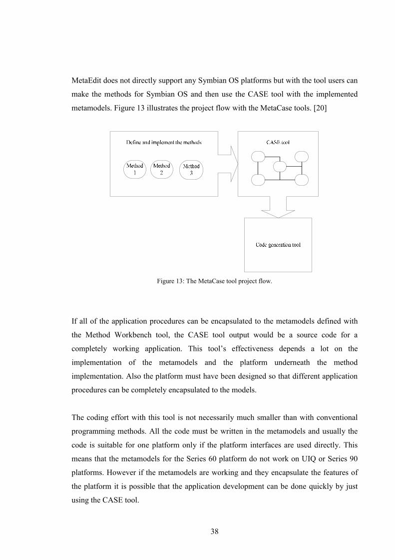
MetaEdit does not directly support any Symbian OS platforms but with the tool users can
make the methods for Symbian OS and then use the CASE tool with the implemented
metamodels. Figure 13 illustrates the project flow with the MetaCase tools. [20]
Figure 13: The MetaCase tool project flow.
If all of the application procedures can be encapsulated to the metamodels defined with
the Method Workbench tool, the CASE tool output would be a source code for a
completely working application. This tool’s effectiveness depends a lot on the
implementation of the metamodels and the platform underneath the method
implementation. Also the platform must have been designed so that different application
procedures can be completely encapsulated to the models.
The coding effort with this tool is not necessarily much smaller than with conventional
programming methods. All the code must be written in the metamodels and usually the
code is suitable for one platform only if the platform interfaces are used directly. This
means that the metamodels for the Series 60 platform do not work on UIQ or Series 90
platforms. However if the metamodels are working and they encapsulate the features of
the platform it is possible that the application development can be done quickly by just
using the CASE tool.

39
5.2.5. Prosa Mobile Developer
Prosa Mobile Developer tool environment is meant for C++ and Java 2 based mobile
application development. It supports the Series 60 platform. The tool can generate C++
and Java 2 code from the UML models to be executed in the mobile device.
The tool supports reverse engineering so that developers can make a UML model of the
already existing code. The Prosa Mobile Developer tool keeps the UML model and the
code up-to-date by automatically synchronizing the code and the model.
The tool also offers an UML simulator that makes it possible to simulate the modeled
application. When running the application the UML simulator shows the execution and
the states in the diagrams in real time. The Mobile Developer tool also offers real time
documentation with interfaces to several documentation applications and web
documentations. [21]
Prosa Mobile Developer is a toolkit that uses code generation to provide the executable
code. The UML modeling is a well-known and a general way to describe software. The
benefits the tool provides are the benefits offered by the UML definition and the
graphical toolkit with reverse engineering functionality. Application creation does not
necessarily become any faster since the developer needs to adapt to use the toolkit
instead of just writing the code directly. For larger-scale applications the importance of
modeling increases significantly and then these kinds of tools can increase the efficiency.
Now the tool supports only the Series 60 platform. If the developer needs to create the
same application for the UIQ or for the Series 90, the benefits of the tool cannot be used
in full-scale.
5.2.6. Peroon S2S
S2S is an application-porting platform that enables application developers to write
applications to the Series 60 platform and simultaneously deploy binaries to Series 60-
and UIQ-based appliances. [22]
40
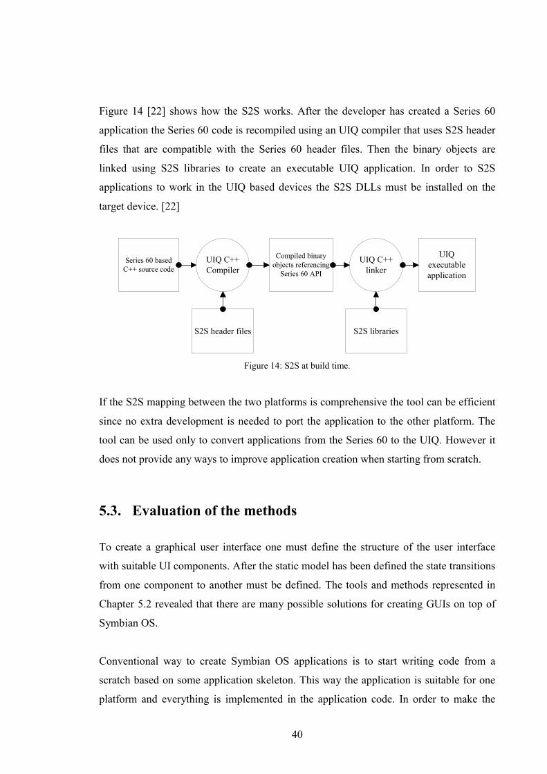
Figure 14 [22] shows how the S2S works. After the developer has created a Series 60
application the Series 60 code is recompiled using an UIQ compiler that uses S2S header
files that are compatible with the Series 60 header files. Then the binary objects are
linked using S2S libraries to create an executable UIQ application. In order to S2S
applications to work in the UIQ based devices the S2S DLLs must be installed on the
target device. [22]
Series 60 basedC++ source code
UIQ C++Compiler
S2S header files
Compiled binaryobjects referencing
Series 60 API
UIQ C++linker
S2S libraries
UIQexecutableapplication
Figure 14: S2S at build time.
If the S2S mapping between the two platforms is comprehensive the tool can be efficient
since no extra development is needed to port the application to the other platform. The
tool can be used only to convert applications from the Series 60 to the UIQ. However it
does not provide any ways to improve application creation when starting from scratch.
5.3. Evaluation of the methods
To create a graphical user interface one must define the structure of the user interface
with suitable UI components. After the static model has been defined the state transitions
from one component to another must be defined. The tools and methods represented in
Chapter 5.2 revealed that there are many possible solutions for creating GUIs on top of
Symbian OS.
Conventional way to create Symbian OS applications is to start writing code from a
scratch based on some application skeleton. This way the application is suitable for one
platform and everything is implemented in the application code. In order to make the

41
same application to work on a different platform the code must be altered to support
another platform and it usually means a lot of work.
To get rid of the application porting problem UI abstraction layers can be created as
described in Peroon S2S solution in Chapter 5.2.6. The challenge with the additional
layers is that how well the differences between platforms can be mapped to each other,
and how to keep such a layer up to date with the changes in the underlying platforms.
Actually the mapping of functionality from a platform to another is the fundamental
challenge when creating GUIs using methods other than the conventional way. The plain
porting solution does not offer any improvements in efficiency when creating the
application for the first time.
Different kind of IDEs or CASE tools can be used to define the user interface and its
functionality. A toolkit can use direct code generation to some specific platform or a tool
can have controls that are mapped to Symbian platform’s components. The possible
problem with the code generation approach is that if the generated code contains errors,
the errors are copied to every implementation that uses the generator. The run-time
interpretation is much more suitable solution in this case since the error can be fixed by
just changing the engine that interprets the UI definition. The clients do not need to
generate their application code again or perform any compilation.
With the run-time interpretation approach the target devices usually need some kind of
external libraries to interpret applications created with the toolkit. This usually involves
some overhead processing and memory usage. However this approach is quite different
compared to the code generation since the application definition does not contain any
conventional program code. If the overhead processing can be minimized the run-time
approach seems appealing since it changes the application creation phase significantly.
Also, if the definition is for example XML-based, the developers do not necessarily need
any expensive IDEs to create an application. All that is needed is the engine that
interprets the definition.
Although the dynamic application creation methods may increase the efficiency there are
costs that must be paid for speeding up the development. UI abstraction layers usually

42
mean some compromises on functionality. Everything cannot be mapped from a platform
to another. If external DLLs or engines are needed to run the application it means that
extra ROM memory is used and probably also extra computation compared to a
conventional application. These possible drawbacks of a dynamic creation method must
be minimized in order to achieve a usable method for creating graphical user interfaces
efficiently.
43
6. Dynamic application development system: Druid
This chapter presents a solution to create applications more efficiently. The
implementation combines some of the methods presented in Chapter 5. The system is
referenced in this chapter as the “Dynamic Rapid User Interface Development (Druid)
system” and the engine part of the system is referenced as the “Druid engine”. Also the
shorter abbreviation “DUI” is used when referencing to Druid system’s objects.
6.1. Concept
The idea of the dynamic user interface system emerged from the several projects where it
was noticed that application development consumes a lot of time and same type of things
were done repeatedly. As Chapter 5 revealed, there are already several tools and concepts
available for making the application development more efficient.
The Druid concept aims to be easy to use. Also a target is to create applications rapidly
with minimum C++ coding effort. To develop Druid applications a developer needs the
Druid package with the engine and the tools, and a Symbian OS platform such as the
Series 90 which is available for the public. The UI part is implemented with XML. C++
coding skills and a compiler is needed for implementing the application engines.
The basic idea is to have an XML-based definition of the user interface. The definition
defines the static structure and the behavior of the GUI. An engine interprets the
definition and uses the platform underneath accordingly.
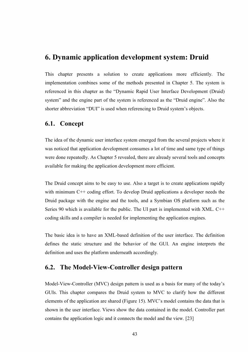
6.2. The Model-View-Controller design pattern
Model-View-Controller (MVC) design pattern is used as a basis for many of the today’s
GUIs. This chapter compares the Druid system to MVC to clarify how the different
elements of the application are shared (Figure 15). MVC’s model contains the data that is
shown in the user interface. Views show the data contained in the model. Controller part
contains the application logic and it connects the model and the view. [23]
44
Figure 15: MVC and the DUI system.
The models and views are separated clearly in the MVC design pattern. In practice the
parts are not separated so clearly in Symbian OS applications. Views and the controlling
logic are usually tied together since the views are an integral part of an application.
Considering the Druid system some of the high level application logic lies in the
application definition file. The detailed application logic comes from the platform’s UI
components. The model consists of application engines and containers that hold the
information. The view of the MVC pattern can be mapped to the UI components that are
executed from the target platform.
6.3. User interface requirements
The Symbian OS user interfaces consist of different types of UI blocks that together
build up the interface. In order to use all the functionality of the platform every UI
component class should be supported by the XML definition and the Druid engine.
However with supporting the most common set of components it is possible to create
usable applications. The most common UI building blocks are presented next.

45
View components
Figure 16 and Figure 17 show the views and their layout components from the Series 90
and Series 60 platforms. As the Series 90 has a much bigger display there is more room
for different components. Basically the same type of components can be found from the
Series 60, but they use much less space and are more limited than the ones in Series 90.
[11]
Figure 16: Series 90 view.
Figure 17: Series 60 view.
46
Considering the implementation, some of the components can be implemented with the
same source code to both platforms, but there are details that need platform specific
implementation. In these views the biggest difference is that the Series 90 has a toolbar
component whereas the Series 60 has the navipane. A navipane can contain “tabs” that
are used for view changing in applications. These types of differences must be
considered when designing the dynamic UI system.
Dialogs
Dialogs and the way they work are quite well-known for the Windows users. Generally
the dialogs have the same functionality in the Symbian OS applications as in other GUIs.
They are used for getting feedback from the user. Query dialogs get simple answers from
the user on how the program should proceed. Different kind of settings dialogs are used
for adjusting application behavior. A dialog has a clear input and output after the user has
finished with the dialog. [6]
A remarkable characteristic of the dialogs is that they interrupt all other operations on the
current view while displayed. This emphasizes the input/output aspect on the dialogs; the
dialog is not complete until the user has closed it. This fact is an important issue
considering the implementation of dialogs. [11]
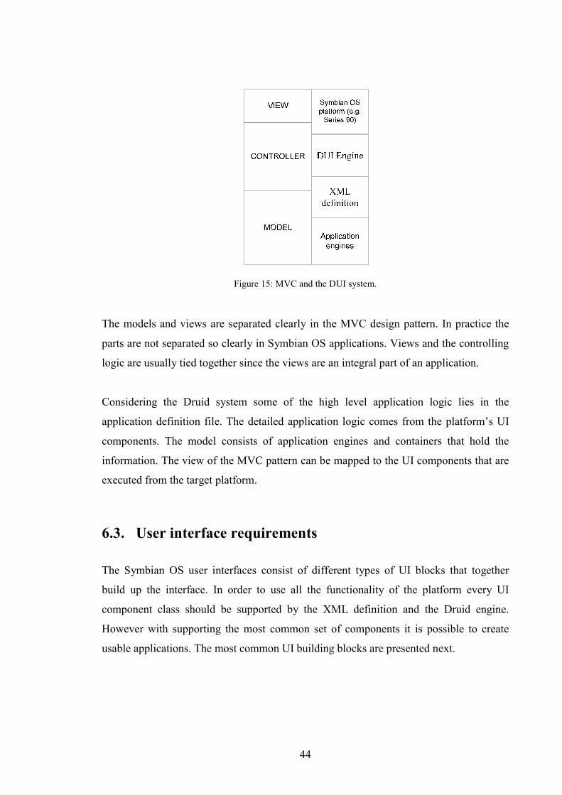
Figure 18 shows settings dialogs. As can be seen from the Series 90 example the
background of the dialog is dimmed indicating that the dialog is the object in control. It
is the only control getting the user input at the moment. As the Series 60 has much
smaller display the dialog is set to use the whole main pane area. This is common to the
Series 60 dialogs. Also can be noted that the command button area is used for the dialog
buttons in the Series 60 whereas in the Series 90 the dialog has own command buttons
and the command button bar can still be seen on the right.

47
Figure 18: Series 90 settings dialog (left) and a Series 60 settings dialog (right).
The Symbian platforms make it possible to create a lot of different kinds of dialogs. They
are an essential part of the user interface since a big part of the user input is done with the
dialogs. Dialogs can contain lists and different types of editors; basically any kind
controls can be implemented inside a dialog. The platforms offer a set of ready-made
dialogs for the most common purposes. Table 6 lists some of the dialogs offered by the
Series 60 platform.
Table 6: Some dialogs offered by the Series 60 platform.
Dialog interface class Description
CAknProgressDialog Note showing progress of a time
consuming action.
CAknMarkableListDialog Dialog containing a list control where
user can mark items as a selection.
CAknTimeQueryDialog Dialog where time can be entered in a
relevant format.
CAknConfirmationNote Note asking user yes/no- type of
confirmation from the user.
48
Queries and notes are a subtype of dialogs. They share the same basic functionality that
they are the topmost control when activated. The queries are used to get data from the
user and notes are used for giving information to the user. Error cases are usually notified
with a simple note describing the situation.
6.4. Engine and model requirements
User interface components are not much of use if they do not contain any information.
Usually applications use application engines to retrieve the data to be shown in the UI.
The application engines and the data structures in the application form the data model of
the UI. The application engines are usually implemented as dynamic link libraries (DLL).
If an engine is well designed it can be used in different Symbian OS platforms without
any modifications to the source code. And furthermore if the used platforms are binary
compatible the application engine can be used in the platforms without any
modifications.
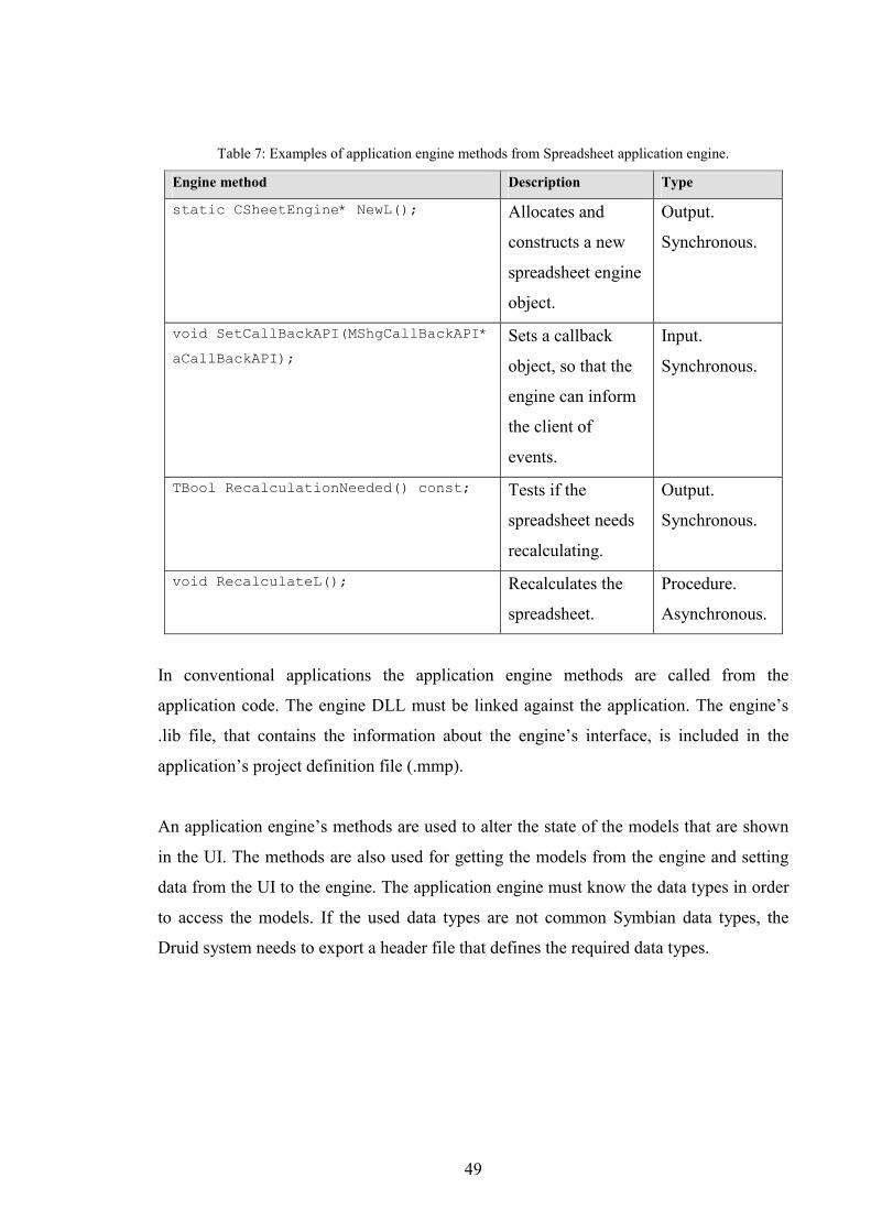
Table 7 [10] lists a few methods from the Spreadsheet application engine. An application
engine method can have input and output. If the data processing takes a long time it
might be necessary to make the method asynchronous meaning that when the method is
called the code execution continues on the client side while the engine runs the method.
In this case a notification is needed to the client when the operation is finished. These
kinds of features are usually implemented with callback methods that the engine calls,
and the client implements. Synchronous methods are simpler for the client since there is
no need to implement any callback interfaces. Also the application’s state is easier to
maintain with synchronous engine calls since there is only the state before the call and
the state after the call. With asynchronous methods the completion of the method may
happen during different application states.
49
Table 7: Examples of application engine methods from Spreadsheet application engine.
Engine method Description Type
static CSheetEngine* NewL(); Allocates and
constructs a new
spreadsheet engine
object.
Output.
Synchronous.
void SetCallBackAPI(MShgCallBackAPI*
aCallBackAPI);
Sets a callback
object, so that the
engine can inform
the client of
events.
Input.
Synchronous.
TBool RecalculationNeeded() const; Tests if the
spreadsheet needs
recalculating.
Output.
Synchronous.
void RecalculateL(); Recalculates the
spreadsheet.
Procedure.
Asynchronous.
In conventional applications the application engine methods are called from the
application code. The engine DLL must be linked against the application. The engine’s
.lib file, that contains the information about the engine’s interface, is included in the
application’s project definition file (.mmp).
An application engine’s methods are used to alter the state of the models that are shown
in the UI. The methods are also used for getting the models from the engine and setting
data from the UI to the engine. The application engine must know the data types in order
to access the models. If the used data types are not common Symbian data types, the
Druid system needs to export a header file that defines the required data types.
50
6.5. Dynamic application environment
This chapter describes the implementation of the Druid system. The purpose of the Druid
project was to find out the ways to create Symbian application more efficiently. Based on
the other solutions on the market an approach with XML and an interpreter engine was
chosen. The XML definition was chosen since it does not require conventional
programming language expertise and it can be generated by any text editor. If the
application UI can be defined by just writing XML it is obvious that the development
time is shortened significantly. The challenge is that can all the features of the platform
be used with the method and what are the costs in system resources when running an
application with an interpreter engine.
The goal of the project was to define and implement the XML interpreter engine and add
a support for a limited set of UI components so that a demo application could be
executed using the system.
6.5.1. Files and tools
In order to understand the whole concept it is important to know how the application is
built with the environment. The upper part of Figure 19 shows the files and entities that
are needed in development time. The lower part presents the run-time files and the
arrows show what development time files are needed to produce the run-time files.
A Druid application consists from the developer point-of-view of the starter application,
the XML definition, AIF related files, and localization files. Also the application engine
is implemented by the developer.
The XML definition contains information that is needed also by the external modules
such as the application engines. This information needs to be gathered from the XML file
to a definition structure that can be used in the source code of the external
implementation. Also the localization strings must be gathered from the XML file so that
the localization can be implemented. Localization is covered in more detail in Chapter
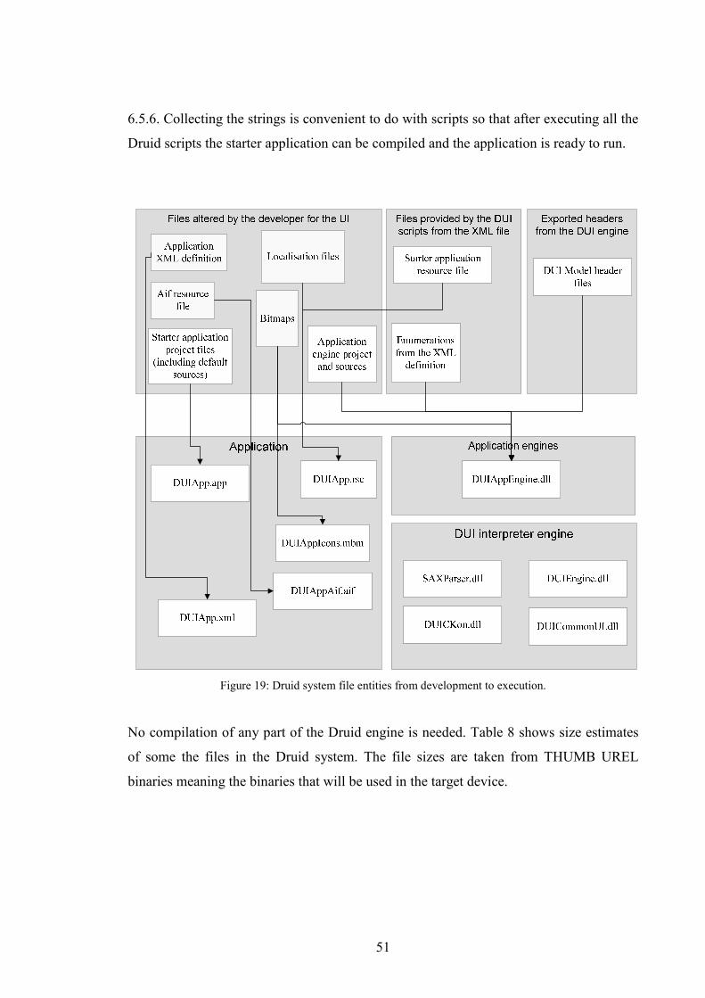
51
6.5.6. Collecting the strings is convenient to do with scripts so that after executing all the
Druid scripts the starter application can be compiled and the application is ready to run.
Figure 19: Druid system file entities from development to execution.
No compilation of any part of the Druid engine is needed. Table 8 shows size estimates
of some the files in the Druid system. The file sizes are taken from THUMB UREL
binaries meaning the binaries that will be used in the target device.

52
Table 8: Druid file size estimates (THUMB UREL).
File Current size and an estimate
Starter application
(DUIApp.app)
3.75 kB (4kB)
Application resource
(DUIApp.rsc)
0,3 kB (depends on the amount of localization
strings, 1-2 kB)
XML definition file
(DUIApp.xml)
6,3 kB (depends directly of application
complexity, 10-20 kB)
DUI Engine library
DUIEngine.dll
14,1 kB (15 kB)
Platform plug-in library
DUICKon.dll
4,5 kB (depends on the amount of CKon
components supported, 10-20 kB)
Common UI library
DUICommonUI.dll
15,5 kB ( now supporting a minor portion of
the UI functionality, with more support 20-40
kB)
Digia SAX parser
SAXParser.dll
12 kB
The size of a single application could be something from 10 to 20 kB with the XML
definition taking the biggest part of the ROM consumption. The XML file is a text file so
compressing it would save a lot of space. With ZIP compression the 6,3 kB definition file
was compressed to 1,26 kB. To use the compressed definition it should be decompressed
before parsing, which means a lot of processing. As a comparison a Series 90 example
application with one view and few notes, takes 6,2 kilobytes of ROM. Bigger
applications can consume a lot more of ROM space making a Druid application
competitive against the conventional applications in terms of ROM size.
The size of the Druid system files are around 60-100 kB (estimated) meaning that using
the system for a single application does not make sense if thinking about the ROM
consumption.
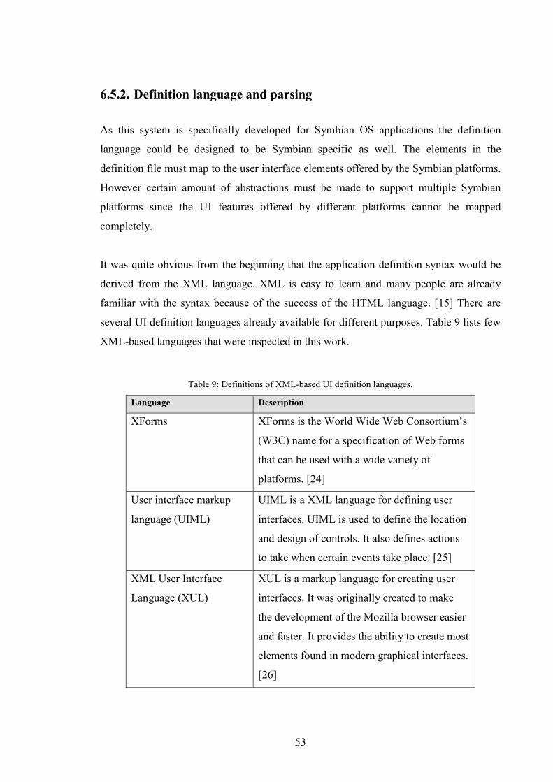
53
6.5.2. Definition language and parsing
As this system is specifically developed for Symbian OS applications the definition
language could be designed to be Symbian specific as well. The elements in the
definition file must map to the user interface elements offered by the Symbian platforms.
However certain amount of abstractions must be made to support multiple Symbian
platforms since the UI features offered by different platforms cannot be mapped
completely.
It was quite obvious from the beginning that the application definition syntax would be
derived from the XML language. XML is easy to learn and many people are already
familiar with the syntax because of the success of the HTML language. [15] There are
several UI definition languages already available for different purposes. Table 9 lists few
XML-based languages that were inspected in this work.
Table 9: Definitions of XML-based UI definition languages.
Language Description
XForms XForms is the World Wide Web Consortium’s
(W3C) name for a specification of Web forms
that can be used with a wide variety of
platforms. [24]
User interface markup
language (UIML)
UIML is a XML language for defining user
interfaces. UIML is used to define the location
and design of controls. It also defines actions
to take when certain events take place. [25]
XML User Interface
Language (XUL)
XUL is a markup language for creating user
interfaces. It was originally created to make
the development of the Mozilla browser easier
and faster. It provides the ability to create most
elements found in modern graphical interfaces.
[26]
54
XForms Model is a device independent XML form definition that can be used with a
variety of standard or proprietary interfaces such as the Extensible Hypertext Markup
Language (XHTML) or the Wireless Markup Language (WML). The XForms provides
also an XForms User Interface that is a set of visual controls that are targeted replacing
the XHTML form controls. An important concept in XForms is that forms collect data
which is expressed as XML instance data. The XForms Model describes the structure of
the instance data. The XForms Submit Protocol defines how XForms send and receive
data. [27]
When designing the UIML2 the following guiding principles were used [15]:
• The language must not embed any assumptions about a particular device,
platform, or UI metaphor.
• Number of features and language complexity must be balanced.
• Use existing standards when possible.
• Allow efficient implementation of the language.
The content of an interface is not embedded in the UIML definition. The content is
retrieved from external sources (e.g. files, databases, and directories). The UIML is a
user interface definition which contains references that will be populated with content
when the document is rendered to a particular device. The language also defines the
interactions between a person and a computer. It is not restricted to use any certain type
of GUI or interface hardware. UIML style sheets are used to map the UI definition to the
interface building blocks of a certain platform and a device.
XUL is an XML-based markup language that can be used to create applications without
special tools. XUL can be used any place where one might use a web application. When
you need to be able to get resources from the network and require a richer user interface.
Cascading style sheets (CSS) are used to define the appearance and JavaScript is used for
defining the behavior. The XUL offers access to programming interface for reading and
writing to remote content over network, calling web services, and reading local files. The
XUL also offers a set of user interface widgets for creating menus, toolbars, tabbed
55
panels and hierarchical trees, and other UI components. The UI elements offered by the
XUL language are designed to look and feel just like the ones on the user’s native
platform. The UI widgets also support localization and have support for accessibility
using OS level accessibility interfaces.
A XUL application can be either opened directly from a remote Web site or they can be
downloaded and installed the target platform. XUL can also be used to create standalone
applications that embed the Gecko engine. [26] The Gecko engine is Netscape’s open-
source browser layout engine that can be embedded across multiple platforms and
devices. [28]
All these definition languages strive for easy UI creation and portability to different
platforms. As the XForms and XUL are more web-oriented the UIML markets itself as
an all-around solution that can be used on any platform and any device. The near future
will show that will these languages provide enough benefits in practice.
The definition language developed in the Druid system describes the UI components and
the interactions. Figure 20 shows a definition of a view. The defined view has two
command buttons (cbaItem) and two options menu items (optMenuItem). All UI
elements that are used to do interactions need to have the behavior defined. Every
object’s behavior is defined inside the “<behavior>” element. The behavior element
consists of rules. The rules have a condition that defines to which event a rule maps. A
rule also contains actions that are carried out when the defined condition is met.
The view also has “<controls>” element that contains a listbox. Inside the control
there is a “<model>” definition that tells that the listbox’s data comes from external
engine with an id “Enum_FirstAppEngine” and from the method
“Enum_GetListBoxModel”. More information of application engines can be found
from the Chapter 6.5.5.
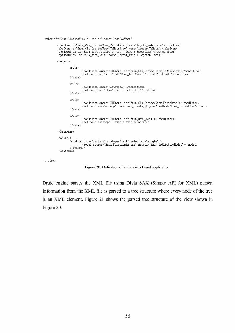
56
Figure 20: Definition of a view in a Druid application.
Druid engine parses the XML file using Digia SAX (Simple API for XML) parser.
Information from the XML file is parsed to a tree structure where every node of the tree
is an XML element. Figure 21 shows the parsed tree structure of the view shown in
Figure 20.
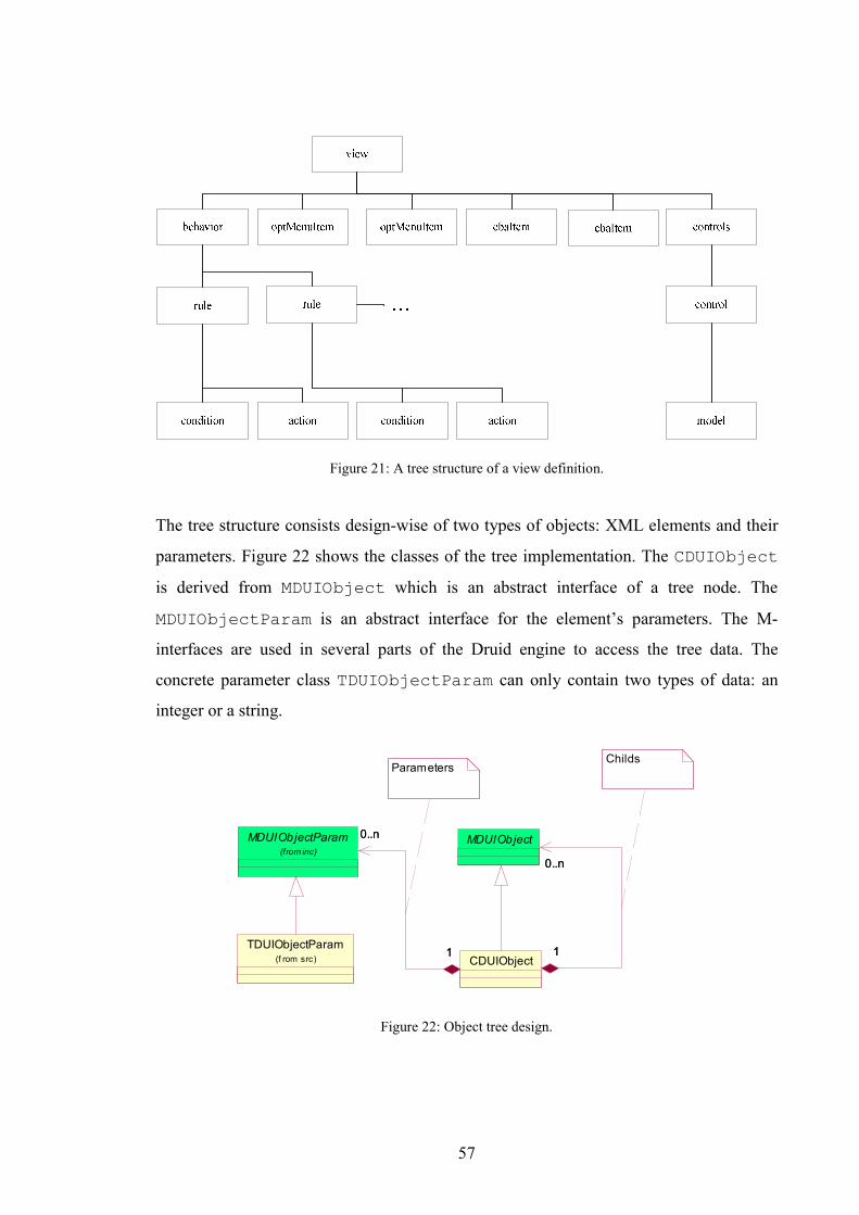
57
Figure 21: A tree structure of a view definition.
The tree structure consists design-wise of two types of objects: XML elements and their
parameters. Figure 22 shows the classes of the tree implementation. The CDUIObject
is derived from MDUIObject which is an abstract interface of a tree node. The
MDUIObjectParam is an abstract interface for the element’s parameters. The M-
interfaces are used in several parts of the Druid engine to access the tree data. The
concrete parameter class TDUIObjectParam can only contain two types of data: an
integer or a string.
CDUIObjectTDUIObjectParam
(f rom src)
MDUIObjectParam(from inc)
0..n
1
0..n
1
MDUIObject
0..n
1
0..n
1
ChildsParameters
Figure 22: Object tree design.
58
The parsed tree plays an important role in the whole system. It contains all the data that is
needed to run the application. Whatever happens in UI the tree gets searched and it
should be done as efficiently as possible since slow tree searching means that UI will
slow down and the usability suffers. To prevent excessive tree searching, declaration of
local and global elements should be considered. For example, if a view should show a
note that is only used in that particular view, the note can be defined inside the view’s
definition. This way the search can be done just on the view object instead of the whole
tree. Defining a global element is done the tree’s top level. If the number of global
elements gets large, searching them will take more time.
Also the size of the tree is an important matter since it must be kept in the memory while
running the application. As it is known that mobile device does not necessarily have
much memory the tree size should be optimized. Every element and parameter takes
some memory so the size optimization is done by reducing the size of an object and the
parameters. The tree’s size depends directly from the size of the XML definition.
Therefore the definition should be optimized also so that there are no unnecessary
elements or parameters.
6.5.3. Software architecture
After analyzing the problem domain a logical structure of the system can be created.
Logical structure encapsulates the functionalities into logical groups, packages that can
be developed further into real component architecture. [13]
As it has been noticed in several projects the basis for many UI related mobile phone
software architectures is the MVC design pattern. There are always the model, views,
and the controller. How these logical entities are shared between the modules and classes
are the decisions that developers need to make when designing the architecture. More
than anything else the given requirements are the most important starting point when
sketching the architecture.

59
The requirements in this case were that the Druid engine should work without changes on
several Symbian platforms. So the Druid engine’s components that are the Common UI
and Druid Engine (Figure 23) must depend only on the interfaces that are common to all
platforms.
Figure 23 presents the software modules for two different platforms: the Series 60 and
the Series 90. Symbian applications run as a process in the Symbian OS. Therefore the
Druid system’s execution context is naturally the application process. The other Druid
system libraries do not have an execution context.
Series 60 PlatformSeries 90 platform
Dru id engine
Plug-in appl ication engines
Starter appl ications
Plug-in platform libraries
S90StarterApp
<<APP>>
S60StarterApp
<<APP>><<DLL>>DUIComm onUI
DUIEngine<<DLL>>
DUICkon<<DLL>>
DUIAvkon<<DLL>>
Eikon core
SAXParser<<DLL>>
Figure 23: Component diagram of the Druid system.

60
The task of the starter applications is to start the application process and initiate the
build-up of the application framework. Every Druid application has an own starter
application so that the platform can handle the Druid applications the same way it
handles the other applications.
The Druid system’s core consists of two components: Druid Common UI and Druid
Engine. The Common UI contains UI implementations that are common to all platforms.
The most important task of the Common UI is to map the objects from the tree structure
to a real platform implementation. The Common UI also loads the plug-in platform
libraries that are used for executing platform specific UI components. The Druid engine
does the parsing and provides the methods to access the tree. It also handles the
connection to the application engines.
The platform plug-in libraries contain the platform specific UI component
implementations. They are used always when the required UI functionality is platform
specific. For example the Series 60 and the Series 90 platforms do not have many
common parts when considering the UI. The Common UI loads the correct platform
plug-in depending on the used Symbian platform. The platform libraries are plug-in type
which means that the Common UI does not need to statically link to any single platform.
The application engines are also plug-in libraries. They are defined in the XML
definition, the loading of the libraries is done by the Druid engine in the application
startup.
6.5.4. Events and interfaces
When a user uses a GUI events are generated. For example a press of a button or
choosing a menu item causes event that executes an UI object. The Druid system is
event-based; the behavior for different events is defined in the application XML
definition. In the Druid system the events can be generated by the engine and the user
generated events come from the platform. For example the Druid system starts by
sending “appStarted” event to the engine. It usually launches the first view where the
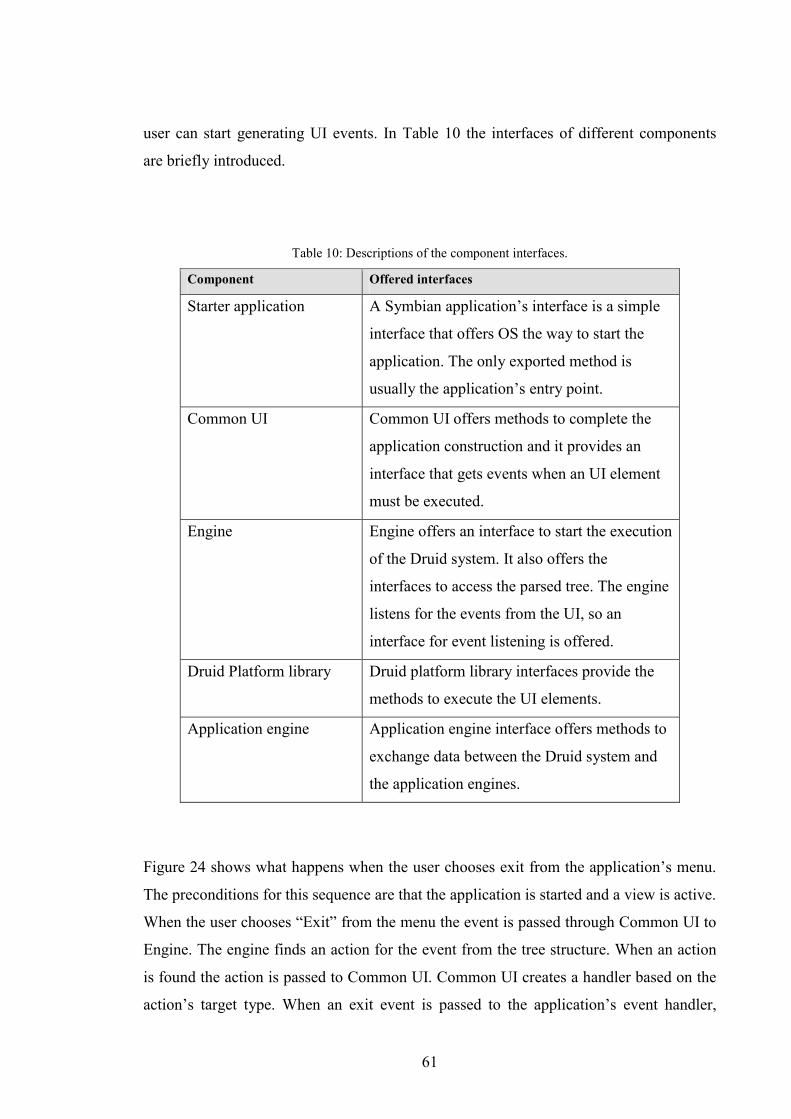
61
user can start generating UI events. In Table 10 the interfaces of different components
are briefly introduced.
Table 10: Descriptions of the component interfaces.
Component Offered interfaces
Starter application A Symbian application’s interface is a simple
interface that offers OS the way to start the
application. The only exported method is
usually the application’s entry point.
Common UI Common UI offers methods to complete the
application construction and it provides an
interface that gets events when an UI element
must be executed.
Engine Engine offers an interface to start the execution
of the Druid system. It also offers the
interfaces to access the parsed tree. The engine
listens for the events from the UI, so an
interface for event listening is offered.
Druid Platform library Druid platform library interfaces provide the
methods to execute the UI elements.
Application engine Application engine interface offers methods to
exchange data between the Druid system and
the application engines.
Figure 24 shows what happens when the user chooses exit from the application’s menu.
The preconditions for this sequence are that the application is started and a view is active.
When the user chooses “Exit” from the menu the event is passed through Common UI to
Engine. The engine finds an action for the event from the tree structure. When an action
is found the action is passed to Common UI. Common UI creates a handler based on the
action’s target type. When an exit event is passed to the application’s event handler,
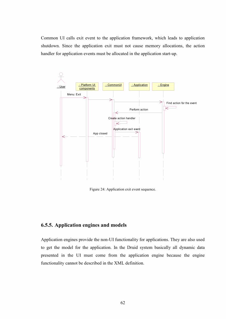
62
Common UI calls exit event to the application framework, which leads to application
shutdown. Since the application exit must not cause memory allocations, the action
handler for application events must be allocated in the application start-up.
: Application : Engine : CommonUI : Platform UI components : User
Menu: Exit
Find action for the event
Perform action
Create action handler
Application exit eventApp closed
Figure 24: Application exit event sequence.
6.5.5. Application engines and models
Application engines provide the non-UI functionality for applications. They are also used
to get the model for the application. In the Druid system basically all dynamic data
presented in the UI must come from the application engine because the engine
functionality cannot be described in the XML definition.
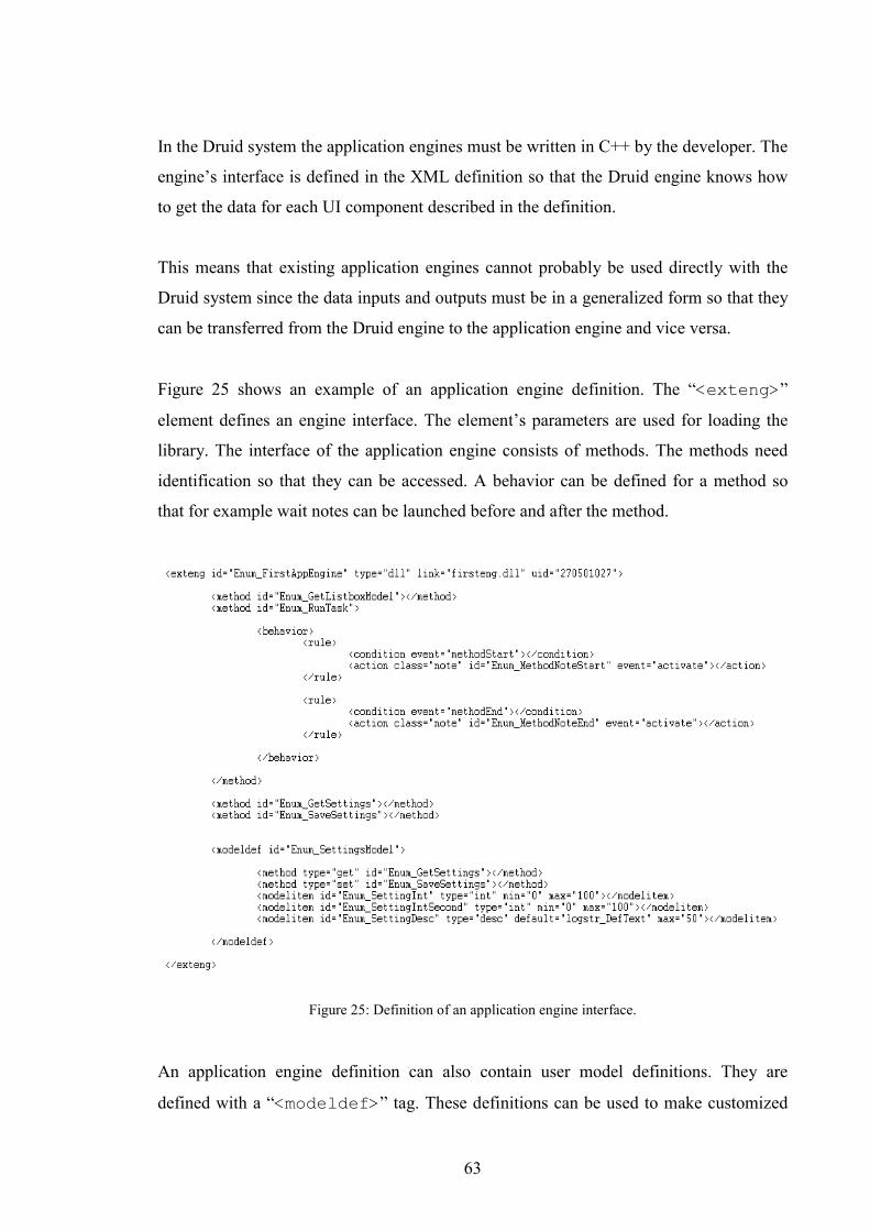
63
In the Druid system the application engines must be written in C++ by the developer. The
engine’s interface is defined in the XML definition so that the Druid engine knows how
to get the data for each UI component described in the definition.
This means that existing application engines cannot probably be used directly with the
Druid system since the data inputs and outputs must be in a generalized form so that they
can be transferred from the Druid engine to the application engine and vice versa.
Figure 25 shows an example of an application engine definition. The “<exteng>”
element defines an engine interface. The element’s parameters are used for loading the
library. The interface of the application engine consists of methods. The methods need
identification so that they can be accessed. A behavior can be defined for a method so
that for example wait notes can be launched before and after the method.
Figure 25: Definition of an application engine interface.
An application engine definition can also contain user model definitions. They are
defined with a “<modeldef>” tag. These definitions can be used to make customized
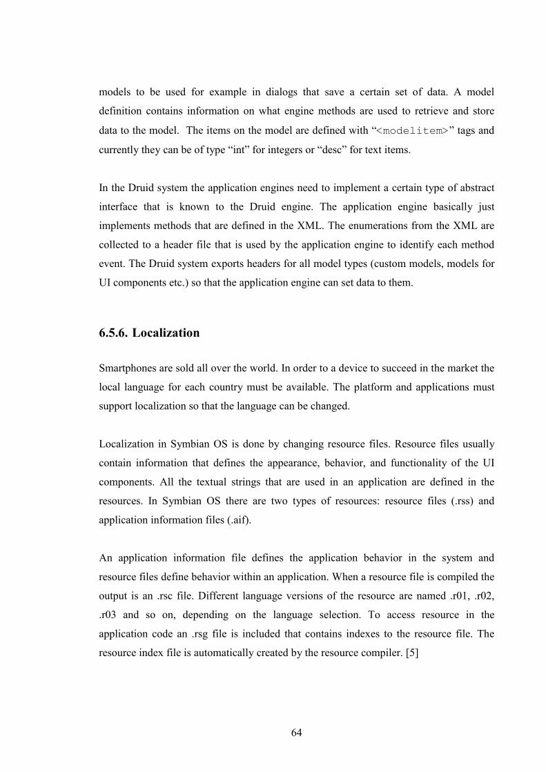
64
models to be used for example in dialogs that save a certain set of data. A model
definition contains information on what engine methods are used to retrieve and store
data to the model. The items on the model are defined with “<modelitem>” tags and
currently they can be of type “int” for integers or “desc” for text items.
In the Druid system the application engines need to implement a certain type of abstract
interface that is known to the Druid engine. The application engine basically just
implements methods that are defined in the XML. The enumerations from the XML are
collected to a header file that is used by the application engine to identify each method
event. The Druid system exports headers for all model types (custom models, models for
UI components etc.) so that the application engine can set data to them.
6.5.6. Localization
Smartphones are sold all over the world. In order to a device to succeed in the market the
local language for each country must be available. The platform and applications must
support localization so that the language can be changed.
Localization in Symbian OS is done by changing resource files. Resource files usually
contain information that defines the appearance, behavior, and functionality of the UI
components. All the textual strings that are used in an application are defined in the
resources. In Symbian OS there are two types of resources: resource files (.rss) and
application information files (.aif).
An application information file defines the application behavior in the system and
resource files define behavior within an application. When a resource file is compiled the
output is an .rsc file. Different language versions of the resource are named .r01, .r02,
.r03 and so on, depending on the language selection. To access resource in the
application code an .rsg file is included that contains indexes to the resource file. The
resource index file is automatically created by the resource compiler. [5]
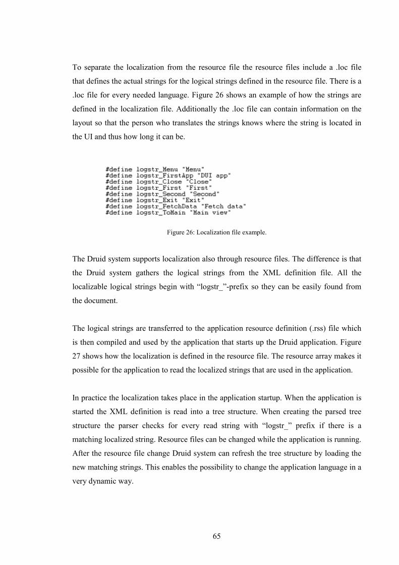
65
To separate the localization from the resource file the resource files include a .loc file
that defines the actual strings for the logical strings defined in the resource file. There is a
.loc file for every needed language. Figure 26 shows an example of how the strings are
defined in the localization file. Additionally the .loc file can contain information on the
layout so that the person who translates the strings knows where the string is located in
the UI and thus how long it can be.
Figure 26: Localization file example.
The Druid system supports localization also through resource files. The difference is that
the Druid system gathers the logical strings from the XML definition file. All the
localizable logical strings begin with “logstr_”-prefix so they can be easily found from
the document.
The logical strings are transferred to the application resource definition (.rss) file which
is then compiled and used by the application that starts up the Druid application. Figure
27 shows how the localization is defined in the resource file. The resource array makes it
possible for the application to read the localized strings that are used in the application.
In practice the localization takes place in the application startup. When the application is
started the XML definition is read into a tree structure. When creating the parsed tree
structure the parser checks for every read string with “logstr_” prefix if there is a
matching localized string. Resource files can be changed while the application is running.
After the resource file change Druid system can refresh the tree structure by loading the
new matching strings. This enables the possibility to change the application language in a
very dynamic way.
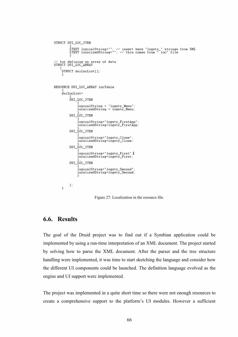
66
Figure 27: Localization in the resource file.
6.6. Results
The goal of the Druid project was to find out if a Symbian application could be
implemented by using a run-time interpretation of an XML document. The project started
by solving how to parse the XML document. After the parser and the tree structure
handling were implemented, it was time to start sketching the language and consider how
the different UI components could be launched. The definition language evolved as the
engine and UI support were implemented.
The project was implemented in a quite short time so there were not enough resources to
create a comprehensive support to the platform’s UI modules. However a sufficient
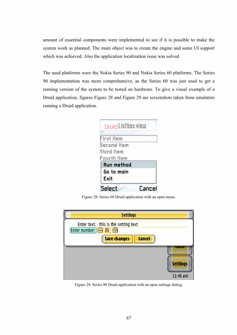
67
amount of essential components were implemented to see if it is possible to make the
system work as planned. The main object was to create the engine and some UI support
which was achieved. Also the application localization issue was solved.
The used platforms were the Nokia Series 90 and Nokia Series 60 platforms. The Series
90 implementation was more comprehensive, as the Series 60 was just used to get a
running version of the system to be tested on hardware. To give a visual example of a
Druid application, figures Figure 28 and Figure 29 are screenshots taken from emulators
running a Druid application.
Figure 28: Series 60 Druid application with an open menu.
Figure 29: Series 90 Druid application with an open settings dialog.

68
During the project there were two main concerns about the system:
• Usability: Processing the parsed tree structure involves quite a lot of loops to
search the items which might slow down the UI. Mobile application must be very
responsive so this is a problem that must be solved in order to make the system
really usable. The start-up of the application takes time since the whole XML
document must be parsed to the tree structure. A slow application start-up is an
unwanted thing for usability; a Druid application must be competitive against the
other applications in this matter as well. Also it is unknown how the system
would handle large applications. The bigger the definition, the more processing is
needed.
• Creating a comprehensive platform support means a lot of work. Also the
language definition still needs to be expanded to support more components. The
system should be able to implement the same features as the application created
with the conventional methods.
After installing the system on a Nokia 6600 phone (Figure 2), it was revealed that the
application start-up was quite fast, at least with the quite small test XML. There was
approximately 0.5 second delay compared to other small applications on the device.
However the delay rises directly compared to the size of the XML, so the parsing delay
may raise an issue.
Using the application was a positive surprise since there was no visible delay when
executing actions from the UI components. Searching the tree did not slow down the
application notably, which was good news for the system since the tree search can be
even further optimized by optimizing the XML definition and the tree search procedures.
So with these results running the application should not be a problem when thinking
about usability.
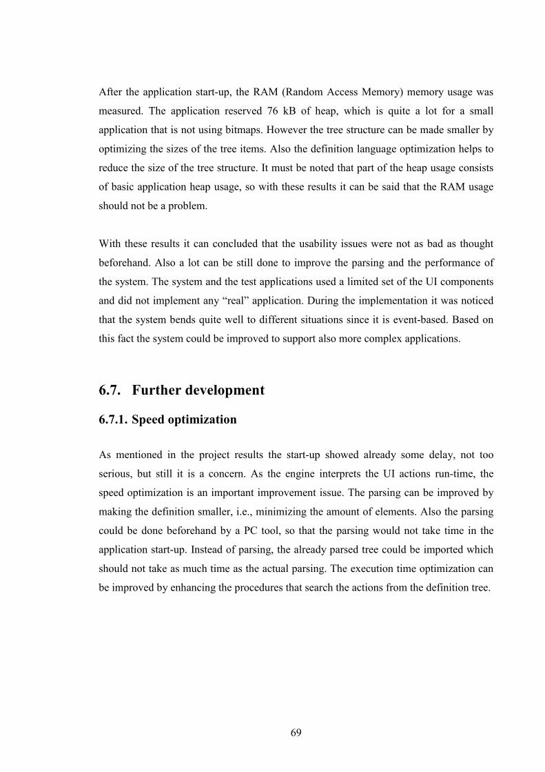
69
After the application start-up, the RAM (Random Access Memory) memory usage was
measured. The application reserved 76 kB of heap, which is quite a lot for a small
application that is not using bitmaps. However the tree structure can be made smaller by
optimizing the sizes of the tree items. Also the definition language optimization helps to
reduce the size of the tree structure. It must be noted that part of the heap usage consists
of basic application heap usage, so with these results it can be said that the RAM usage
should not be a problem.
With these results it can concluded that the usability issues were not as bad as thought
beforehand. Also a lot can be still done to improve the parsing and the performance of
the system. The system and the test applications used a limited set of the UI components
and did not implement any “real” application. During the implementation it was noticed
that the system bends quite well to different situations since it is event-based. Based on
this fact the system could be improved to support also more complex applications.
6.7. Further development
6.7.1. Speed optimization
As mentioned in the project results the start-up showed already some delay, not too
serious, but still it is a concern. As the engine interprets the UI actions run-time, the
speed optimization is an important improvement issue. The parsing can be improved by
making the definition smaller, i.e., minimizing the amount of elements. Also the parsing
could be done beforehand by a PC tool, so that the parsing would not take time in the
application start-up. Instead of parsing, the already parsed tree could be imported which
should not take as much time as the actual parsing. The execution time optimization can
be improved by enhancing the procedures that search the actions from the definition tree.

70
6.7.2. Extending the support
To be interesting for the developers, the system should be able to achieve the same
functionality as the normal applications while still offering much faster and easier
development.
The implemented system supports only minor part of all possible UI and platform
functionality. The estimations of making a complete system must be based on the
implemented project. First of all, the system needs very specific requirements of what
features must be supported and what can be left out. Extending the UI support is quite
straightforward task based on the current implementation since using the UI components
follows the same pattern.
An application must be compatible also with the device, meaning that it must respond
correctly to system events such as phone shutdown (forced exit) and an incoming call
(application goes to background). As the Druid system is event based, it is quite flexible
to add support for new events. For example now the system support user events such as
menu and buttons presses. Other events, even from the system, can be implemented the
same way.
6.7.3. Graphic XML generation
As the application is defined in XML in the Druid system, it allows many possibilities
considering the implementation. There are already many tools available that output
XML. Even though writing XML is much easier and faster than writing for example
C++, the development can be still developed further. The UI components could be
defined using a CASE-type tool that would also allow definition of all Druid entities such
as the behavior. If the tool could output working Druid definitions the development
would be even more easy and efficient.
6.7.4. Affects to the software lifecycle
Assuming that the system would be used in the projects, it would affect many of the
software engineering phases. Even though the requirement specification phase (see
71
DSWP/Chapter 4.2) is a very early phase in the software construction, the high-level
technical specification phase is affected by the use of the Druid system. The architectural
choices must be made so that the solution is suitable for the Druid system.
The most affected part of the software process lifecycle is the software construction
phase. The amount of software design is smaller since there is no application design.
Also the Druid system’s application engine framework sets some pre-defined design
characteristics for the engine’s design. There is no other program code for an application
UI than the XML definition. This decreases the amount of all tasks related to
implementation and code quality assurance. Also one of the main benefits is that early
prototyping of applications becomes easier since the application UI can be built rapidly.
The user interface prototyping with a real application is valuable feedback for usability
specialists. While the construction phase is faster, the functionality testing for the UI
must be as comprehensive as before to ensure that the XML definition is correct.
Assuming that the system would speed up the construction phase, it would allow faster
implementation of the project since the time to complete an iterative construction
increment would be smaller, thus leading to reduced costs.

72
7. Conclusions
The purpose of this thesis was to find an alternative, more effective way to create
applications for the Symbian OS. The work introduced the Symbian OS and presented
different aspects of mobile application development. Symbian OS user interfaces come in
many different forms and finding an effective way to produce applications to multiple
platforms is not a simple task. The practical part of the work was the Druid project that
presented a solution that executed a Symbian OS application based on an XML
definition.
There is a lot of competition in the mobile device markets at the moment. New features
are introduced to the devices in fast pace. In order to succeed in the market the device
must be appealing and the quality must be good. The software must be developed rapidly
to beat the competitors. This requires a lot from the software construction teams. There is
evidently a need for tools that shorten the software construction cycles and improve the
quality.
Most of the application development is still done with conventional methods by writing
software with imperative languages such as Java and C++. There are already many
toolkits and alternative application creation methods available, but none of them have
really beaten the conventional methods. The program code gives the developer full
control over the program, on the other hand it also requires a lot of effort to produce and
maintain the code.
To successfully compete with the old software creation methods the new method must be
more effective, and the learning curve must be low to achieve the interest of the
developers. Also the software created by the new method must be competitive against the
old software. If these goals are achieved it is still not certain that the new system will
succeed, since the actual decisions are made by people who need to believe that the new
method really increases the efficiency.
73
References
[1] Symbian, Ltd.: Symbian OS Version 7.0s functional description, Revision 2.1, 2003,
[Internet], available: http://www.symbian.com/technology/symbos-v7s-det.html
[referenced 10.3.2004]
[2] Symbian, Ltd.: Why is a different operating system needed? Revision 2.4, 2003,
[Internet], available: http://www.symbian.com/technology/why-diff-os.html,
[referenced 10.03.2004]
[3] Symbian, Ltd.: Creating Symbian OS Phones, Revision 1.1, 2002, [Internet],
available: http://www.symbian.com/technology/create-symb-OS-phones.html
[referenced 10.03.2004]
[4] Symbian, Ltd.: Symbian's Reference Designs for Wireless Information Devices,
2000, [Internet], available: http://www.symbian.com/events/devexpo00/pres-
usa00/DFRDsDavidWood_transcript/usdevcon_dw.htm [referenced 10.03.2004]
[5] Digia, Inc.: Programming for the Series 60 platform and Symbian OS, John Wiley
and Sons Ltd., 2002
[6] Richard Harrison: Symbian OS C++ for Mobile Phones, John Wiley & Sons Ltd.,
2003.
[7] UIQ Technology: UIQ 2.0 Product Description, 2002, [Internet],
available:http://uiq.velocitytech.net/UIQ%202.0%20Product%20Description%20RE
V%202.8.pdf [referenced 06.03.2004]
[8] Nokia: Developer Platform 2.0 for Series 90: Introductory White Paper, 2003,
[Internet], available: www.forum.nokia.com [referenced 06.03.2004]
[9] Nokia: Series 60 Platform Introductory White Paper v.1.0, 2002, [Internet], available:
www.forum.nokia.com [referenced 06.03.2004]
[10] Symbian, Ltd.: Symbian OS v.7.0 Developer Library, 2002, [Internet], available:
http://www.symbian.com/developer/techlib/v70docs/sdl_v7.0/doc_source/index.html
[referenced 10.03.2004]
[11] Nokia: Nokia Series 90 UI Style Guide v.1.0, 2003, [Internet], available:
www.forum.nokia.com [referenced 06.03.2004]
[12] Symbian: Uikon overview, [Internet], available:

74
http://www.symbian.com/developer/techlib/v70docs/sdl_v7.0/doc_source/devguides/cpp/
applicationframework/uikonoverview.guide.html [referenced 06.03.2004]
[13] Digia: Digia Software Process, 2004, [Confidential] available: Digia Intranet
[14] Ilkka Haikala, Jukka Märijärvi: Ohjelmistotuotanto, Suomen Atk-kustannus, 1998.
[15] Constantinos Phanouriou: UIML: A Device-Independent User Interface Markup
Language, 2000.
[16] Trigenix, Ltd.: Managing the Mobile Interface, 2004, [Internet], available
(registration needed): www.trigenix.com/products/mobileinterface.pdf
[17] AppForge, Inc.: AppForge MobileVB Tutorial, 2003, [Internet], available:
http://www.appforge.com/dev/users-guide/AppForge-Tutorial.pdf [referenced
06.04.2004]
[18] AppForge, Inc.: AppForge MobileVB Manual v.4.0.0, 2004, [Internet], available:
http://www.appforge.com/dev/users-guide/AppForge-Manual.pdf [referenced
06.03.2004]
[19] Cybelius Software: Cybelius Software Website, [Internet], available:
www.cybelius.fi [referenced 06.03.2004]
[20] MetaCase: Metacase Website, [Internet], available: www.metacase.com [referenced
06.03.2004]
[21] Insoft, Oy: Prosa UML 2004 Mobile Developer tuotekuvaus, [Internet], available:
http://www.prosa.fi/fin/pr2MobiDev.htm [referenced 06.03.2004]
[22] Peroon, Ltd.: Peroon S2S white paper v.3.0, 2003, [Internet], available:
http://www.peroon.co.il/WP/S2S_White_Paper_v3_0r_a.pdf [referenced 06.03.2004]
[23] Gamma E., Helm R., Johnson R., Vlissides J.: Design patterns: Elements of
Reusable Object-Oriented Software. Addison Wesley Longman Inc., 2000.
[24] World Wide Web Consortium: XForms - The Next Generation of Web Forms,
[Internet], available: http://www.w3.org/MarkUp/Forms/ [referenced 19.02.2004]
[25] UIML Intro, [Internet], available: http://www.uiml.org/intro/index.htm [referenced
19.02.2004]
[26] XUL Tutorial, [Internet], available: http://www.xulplanet.com/tutorials/xultu/
[referenced 19.02.2004]
[27] Harmonia, Inc.: White Paper: UIML Vision, [Internet], available:
http://www.harmonia.com/resources/papers/whitepapers/UIMLVisionWhitePaperV5
.pdf [referenced 19.02.2004]
75
[28] Netscape: Netscape Gecko Technologies: Enabling the Next-Generation Internet,
[Internet], available: http://wp.netscape.com/browsers/gecko/whitepaper.pdf
[referenced 22.02.2004]