ductility of composite beams under negative bending: an equivalence index for reinforcing steel...
TRANSCRIPT

Journal of Constructional Steel Research 57 (2001) 185–202www.elsevier.com/locate/jcsr
Ductility of composite beams under negativebending: an equivalence index for reinforcing
steel classification
Giovanni Fabbrocino, Gaetano Manfredi*, Edoardo CosenzaUniversita di Napoli Federico II, Facolta` di Ingegneria, Dipartimento di Analisi e Progettazione
Strutturale, Via Claudio, 21, 80125 Napoli, Italy
Received 15 March 1999; received in revised form 4 January 2000; accepted 18 February 2000
Abstract
Reinforcing steel actually available on the European market is generally characterised by agood strength, but also by reduced ductility; on the other hand European codes concerningconcrete and composite structures point out the importance of using reinforcing steel withsufficient ductility.
In this paper, the influence of the properties of reinforcing steel on the rotational capacityof composite beams under negative bending is theoretically analysed using a refined model,validated with experimental tests. An equivalence criterion for the classification of reinforcingsteel is also introduced. Plastic rotation that can be sustained by composite beams at failureis assumed as the main parameter to define the equivalent structural performance. To this end,the results of a wide parametric analysis are discussed.
The comparison with similar analyses made for concrete structures shows that one classi-fication for reinforcing steel seems to be not reliable for both types of structures. 2001Elsevier Science Ltd. All rights reserved.
Keywords:Composite beams; Ductility; Rotation capacity; Partial interaction; Negative bending
1. Introduction
The use of simply supported steel–concrete composite beams allows exploitationof the two components, as the concrete slab is mainly in compression and the steelprofile is subjected to tensile stresses.
* Corresponding author. Tel.:+39-081-768-3488; fax:+39-081-768-3491.E-mail address:[email protected] (G. Manfredi).
0143-974X/01/$ - see front matter 2001 Elsevier Science Ltd. All rights reserved.PII: S0143 -974X(00)00008-0

186 G. Fabbrocino et al. / Journal of Constructional Steel Research 57 (2001) 185–202
Nevertheless, continuous structural schemes are largely used in building andbridge construction due to many advantages. In fact, for a given cross section, conti-nuity at internal support provides the reduction of the internal forces and deflections,while the structural dimensions can be optimised if the internal forces and limits fordeflections are the same.
The evaluation of the internal forces at the ultimate limit state in continuous beamsrequires specific procedures, able to take account of the actual redistribution capacityof composite beams, which is however strictly related to a reliable assessment ofrotation capacity [1–3].
Eurocode 4 [4] allows performance of an elastic analysis with a limited degreeof redistribution, which depends on the type of analysis (cracked or uncracked) andon the classification of steel profile, but is not related to specific requirements forsteel reinforcement and allowable plastic rotations that depend on complex phenom-ena of interaction.
Nevertheless experimental results on composite structural systems [5–7] showclearly that the collapse of composite members under negative bending is often dueto the fracture of reinforcing bars.
Therefore, mechanical properties of reinforcement can influence the structuralresponse of composite beams, on the analogy with the reinforced concrete structures[8], which are affected by a relevant reduction of rotation capacity when reinforce-ment with low ductility is used. Advanced codes concerning concrete structures[9,10] provide a classification of reinforcing steel according to ductility that is definedas a function of two parameters: the ultimate straineu and the strain hardeningratio ft/fy.
The theoretical assessment of rotation capacity of composite beams is a very diffi-cult task and many models, characterised by different levels of accuracy, can bedeveloped [11]. However, a reliable estimation of the influence of rebar ductility onrotation capacity requires refined approaches, able to take account of the non-linearinteraction phenomena.
An advanced model and a specific numerical procedure of a solution have beenpreviously developed [12,13] and validated with specific experimental tests [14].
It takes account not only of the deformability of the shear connection [15], butalso of the bond interaction between steel rebars and concrete in tension.
In the present paper, some results of a numerical analysis are discussed in orderto point out the influence of the design criteria and of properties of materials on therotation capacity of continuous composite beams. In particular, the influence of themain parameters representing the mechanical behaviour of reinforcing steel and ofshear connection is analysed.
In fact, due to lack of knowledge of the influence of concrete related factors onthe overall structural performances of composite systems, code recommendationsdeveloped for concrete structures are extended to steel–concrete composite structures,as shown by Eurocode 4.
A steel index for an improved assessment of reinforcing steel requirements ensur-ing a sufficient rotation capacity is introduced on the analogy with reinforced con-crete structures [16]. A rational criterion for classification of reinforcing steel is then

187G. Fabbrocino et al. / Journal of Constructional Steel Research 57 (2001) 185–202
proposed assuming that the rotation capacity is the key parameter to defining equival-ent structural performances.
The attention is focussed on the influence of rebar ductility, thus the depedenceof plastic rotation capacity on the ultimate strain,eu, and the strain hardening ratio,ft/fy, of the reinforcement is explicitly expressed, while other mechanical and geo-metrical parameters are included in a global coefficient.
Consequently, two different reinforcing steel rebars used in a given compositebeam can be addressed as “equivalent”, if and only if they provide the samerotation capacity.
The results clearly point out the differences between the requirements forreinforced concrete and composite flexural members.
2. The structural model
The analysis of the steel–concrete composite beams under negative bending isperformed using a monodimensional approach, that takes account of the main mech-anical phenomena at the ultimate limit state [13].
The cross section of the beam is characterised by a slip at the rebar–concreteinterface,s1, and another at the slab-profile interface,s2, Fig. 1. A linear pattern ofstrains is applied to each component of the cross section.
It is also assumed that the curvature and the rotation is the same for each compo-nent (concrete slab and steel profile), therefore the uplift between the slab and theprofile is neglected [17].
The cracking of the slab is in a final steady state, so that all the transient phenom-ena related to the crack propagations are fully developed. The assumption of stabil-ised cracking does not influence the behaviour of the beam at the ultimate limit state.
Thus the slab is characterised by cracks, placed at a given distance depending onthe geometry of the slab and the mechanical properties and diameter of the reinforc-ing bars [9,10]. The distance between cracks is evaluated according to code rec-ommendations for concrete structures, since specific formulations for compositebeams are not available. However, the influence of crack distance on the rotationcapacity is hardly relevant.
It is then assumed that concrete between two subsequent cracks is able to beartensile stresses and the reinforcing bars can slip with respect to the surroundingconcrete. For concrete in tension, the stress–strain relationship suggested by ModelCode 90 has been used; a more refined approach is not needed since the crack propa-gation is not investigated.
The slippage at the concrete-reinforcement interface is the key feature of the pro-posed model that allows a refined local analysis of bond interaction and makesreliable the numerical simulation of the yielding spreading of reinforcement and theinfluence of its main mechanical parameters. This result is achieved introducing anexplicit constitutive relationship for bond.
Only strains of concrete in compression and reinforcing steel in tension are relatedby a linear pattern, so that the displacements of rebars and concrete in tension canbe different.

188 G. Fabbrocino et al. / Journal of Constructional Steel Research 57 (2001) 185–202
Fig. 1. The structural model of composite beams under negative bending.
As a result, the two slips governing the interaction phenomena (bond and shearconnection) are given by the following kinematic equations:
s1(z)5wsc(z)2wct(z) (1a)
s2(z)5wups (z)2wlow
c (z) (1b)
where: wsc(z) is the displacement of the reinforcement;wct(z) is the displacementcorresponding to the effective area of concrete in tension,Aeff. It takes into accountthe non-uniform normal stress distribution by bond forces into the concrete crosssection [9,10] and depends on the reinforcement arrangement as well as on the exter-nal forces and the shape of the cross section.wup
s (z) is the longitudinal displacementof the upper fibre of the steel profile andwlow
c (z) is the longitudinal displacement ofthe lower fibre of the concrete slab.
The following six parameters of deformation:es, ec, s1, s2, esc and ect can beaddressed as unknown of the problem, wherees(z) is the strain of the centroid fibreof the steel profile;ec(z) is the strain of the centroid fibre of the concrete slab;esc(z)is the strain of the steel rebars andect(z) is the strain of the concrete in tension.Therefore six equations are required; two of them are kinematic and four are equa-
189G. Fabbrocino et al. / Journal of Constructional Steel Research 57 (2001) 185–202
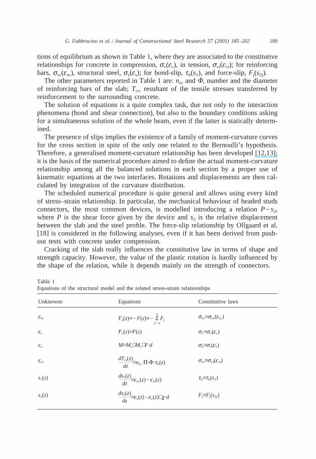
tions of equilibrium as shown in Table 1, where they are associated to the constitutiverelationships for concrete in compression,sc(ec), in tension,sct(ect); for reinforcingbars,ssc(esc), structural steel,ss(es); for bond-slip,tb(s1), and force-slip,Fj(s2j).
The other parameters reported in Table 1 are:nsc andF, number and the diameterof reinforcing bars of the slab;Tct, resultant of the tensile stresses transferred byreinforcement to the surrounding concrete.
The solution of equations is a quite complex task, due not only to the interactionphenomena (bond and shear connection), but also to the boundary conditions askingfor a simultaneous solution of the whole beam, even if the latter is statically determ-ined.
The presence of slips implies the existence of a family of moment-curvature curvesfor the cross section in spite of the only one related to the Bernoulli’s hypothesis.Therefore, a generalised moment-curvature relationship has been developed [12,13];it is the basis of the numerical procedure aimed to define the actual moment-curvaturerelationship among all the balanced solutions in each section by a proper use ofkinematic equations at the two interfaces. Rotations and displacements are then cal-culated by integration of the curvature distribution.
The scheduled numerical procedure is quite general and allows using every kindof stress–strain relationship. In particular, the mechanical behaviour of headed studsconnectors, the most common devices, is modelled introducing a relationP2s2,whereP is the shear force given by the device ands2 is the relative displacementbetween the slab and the steel profile. The force-slip relationship by Ollgaard et al.[18] is considered in the following analyses, even if it has been derived from push-out tests with concrete under compression.
Cracking of the slab really influences the constitutive law in terms of shape andstrength capacity. However, the value of the plastic rotation is hardly influenced bythe shape of the relation, while it depends mainly on the strength of connectors.
Table 1Equations of the structural model and the related stress-strain relationships
Unknowns Equations Constitutive laws
esc ssc=ssc(esc)Fs(z)=2F(z)=2 Sn
j51Fj
ec Fc(z)=F(z) sc=sc(ec)
es M=Ms+Mc+F·d ss=ss(es)
ect sct=sct(ect)dTct(z)dz
=nsc·P·F·tb(z)
s1(z) tb=tb(s1)ds1(z)dz
=esc(z)2ect(z)
s2(z) Fj=Fj(s2j)ds2(z)dz
=es(z)2ec(z)+c·d

190 G. Fabbrocino et al. / Journal of Constructional Steel Research 57 (2001) 185–202
As a consequence, the results of the parametric analysis can be properly usedconsidering appropriate values of the strength of the connecting device.
Shear connectors are considered in their actual position, and their action is a con-centrated axial load depending on the value of the slip at the slab-profile interface.Their main mechanical properties can be summarised using a simple parameter,N/Nf.It is given by the ratio between the number of shear connectors provided in thebeam,N, and the number of shear connectors strictly needed to ensure the full shearconnection,Nf. It is worth noting that Eurocode 4 restricts partial shear connectionin hogging moment regions of continuous composite beams.
The relationship between slip and bond stress is very complex and is characterisedby different phenomena involving chemical and mechanical interactions that dependon the value of the load level. An analytical constitutive model [19] taking accountof the main mechanical and geometrical parameters, i.e. concrete grade and rebardiameter, has been considered.
It also depends on the presence of cracks in tensile or flexural reinforced concretemembers. In fact, the bond-slip relation is weaker near the cracks as the concrete isnot sufficiently confined and the resisting bond mechanisms cannot fully develop.This effect provides a degradation of the bond behaviour near the cracks (debonding),so the bond-slip relationship depends also on the parameterx/F, that is the ratiobetween the distancex from the crack, and the diameterF of the bar.
3. Rotation capacity and properties of reinforcing steel
The influence of the main mechanical properties of steel reinforcement is analysedusing the above structural model of composite beams under negative bending.
Early numerical results [20] showed that the greater the ductility of the reinforcingsteel the higher is the plastic rotation developed by composite members. Neverthe-less, the above results were due to the combined effect of the ultimate strain and ofthe strain-hardening ratio.
A suitable numerical investigation has been performed to identify the influenceof each parameter on the plastic rotation capacity.
The structural scheme shown in Fig. 2(a) is considered; it can fit the behaviourof continuous composite beams in the intermediate support regions.
The structural steel is modelled using a typical stress–strain relationship directlyderived from tests on steel specimens under tension; the yielding stress is 315 MPa;the ultimate strength is 414 MPa and the ultimate strain is about 25%. The concretegrade is equal to 30 MPa.
The relative depth of the steel section and of the slab is assumed as a constantvalue, in order to reduce the range of the parametric field and is representative oftypical composite beams for buildings, as shown in Fig. 2(b).
Furthermore, buckling phenomena are not taken into account, since it is assumedthat steel has the same mechanical response to both compressive and tensile stresses.Thus the results apply to compact sections, in the sense that the full plastic momentcan be developed and a relevant rotation capacity is ensured [4].

191G. Fabbrocino et al. / Journal of Constructional Steel Research 57 (2001) 185–202
Fig. 2. The structural scheme and the cross section of the beam.
The cross section of the steel component, Fig. 2(b), fulfils both for the flangesand the web, the width over thickness limit ratios provided by Eurocode 4 for theso-called Class 1 sections.
Specific experimental tests [21] and the related numerical simulations [14] showthat the model is able to fit the real mechanical response of composite beams undernegative bending, even if loss of load bearing capacity is observed for “compact”sections. However, local buckling affects very localised parts of the steel beam, theinteraction force and slips at the slab-profile interface are generally increasing evenfor high strain levels and the loss of load is due to the reduced load bearing capacityof the steel profile.
Therefore, the following results can be considered as general, because the attentionis focussed on the concrete slab and its components.
The sample beams are characterised by a value of the geometrical percentageof reinforcementr equal to 0.45%, obtained using five barsF 10 mm, and 0.9%,corresponding to ten barsF 10 mm.
The distance between cracks is assumed equal to 100 mm. The ultimate straineu, the strain hardening ratioft/fy and the degree of interactionN/Nf are the mainexamined parameters.
Table 2 summarises the parametric field; it is worth noting that the strain hardeningratio is affected by a stronger variation with respect to the ultimate strain, as shownby the difference (ft/fy21), which influences directly the rotation capacity [16].
The level of interactionN/Nf is a key aspect of the analysis, since local distributionof strain is dependent on the strength and arrangement of shear connectors.

192 G. Fabbrocino et al. / Journal of Constructional Steel Research 57 (2001) 185–202
Table 2The parametric field
eu 4%÷14%ft/fy 1.05÷1.45(ft/fy21) 0.05÷0.45N/Nf 0.30÷2.50
Common procedures used in design practice change the level of interactionadjusting the spacing of connectors, since generally the diameter and the strength ofthe devices are given. As a result, the distribution of local strains in the slab isstrongly influenced.
In order to completely avoid any interference in the statistical analysis, in thepresent study, the spacing is given and the interaction level is scaled changing onlythe strength of connectors.
Ultimate stress of reinforcement is equal to 635 MPa, and the yielding stress isdependent upon the value of the strain hardening ratio.
The contribution of the interaction phenomena can be recognised referring to theplots arranged in Fig. 3. Relative rotations between the end of the beam at collapse,qu, and at yielding,qy, are used to define the plastic rotation capacityqpl=qu2qy.
The results refer to steel rebars with a strain hardening ratio equal to 1.25 and tobeams with a global slenderness, given by the ratio between the span and the totaldepth of the beam, equal to 6. The structural scheme is shown in Fig. 2(a).
The plots provide the rotation capacityqpl (diagram a), the end slip of the beamat the slab-profile interface (diagram b) and the maximum strain of reinforcing steel(diagram c).
It is worth noting that:
O when partial shear connection is provided (N/Nf,1) the rotation capacity is gov-erned by the slip at the slab-profile interface; in fact the strain of the reinforcementis very low, while the slip increases;
O the maximum level of ductility is reached whenN/Nf<1; in this range both theslip at the slab-profile interface and the strain of reinforcement are near the peakvalue, thus give the maximum contribution to the plastic rotation;
O as the level of interaction increases (N/Nf.1), the slip due to shear connectorsbecomes negligible, so the plastic rotation is basically due to the ductility ofreinforcement. In this field, the slip at the slab-profile interface is very low andis not dependent on the ductility of reinforcement; conversely the contribution ofthe ultimate strain is maximum and constant.
The values of calculated plastic rotations are high, as the structural slenderness ishigh as well and the local buckling phenomena in structural steel is not taken intoaccount.
In Fig. 4 the plastic rotations are plotted depending on the level of interaction andon the strain-hardening ratio; they are evaluated for a given value of the ultimate

193G. Fabbrocino et al. / Journal of Constructional Steel Research 57 (2001) 185–202
Fig. 3. Development of the rotational capacity. Beam parameters: slendernessL/H=6, percentage ofreinforcementr=0.45%, concentrated load; strain hardening ratio of reinforcementft/fy=1.25.

194 G. Fabbrocino et al. / Journal of Constructional Steel Research 57 (2001) 185–202
Fig. 4. Rotation capacity and strain hardening ratio,L/H=6, r=0.45%,eu=8%.
strain (8%). It is easy to recognise that the increase of plastic rotation as the ultimatestrain changes between 4% and 12% is much greater than the increase related to thestrain-hardening ratio changing from 1.05 to 1.45, taking also into consideration therange of variation of each parameter.
Therefore, it can be stated that in composite beams the strain-hardening ratio ofreinforcement is not relevant, in opposition to the results obtained for reinforcedconcrete beams [16]. In fact, the yielding spreading is basically due to the arrange-ment of shear connectors, rather than to the hardening of rebars.
In the field of partial shear interaction, the reinforcing steel is characterised bylow values of strain, thus the effect of slip between slab and profile is predominantand the rotation capacity depends on the slip capacity of shear connectors [22].
However, in the field of full shear connection, the curves show an asymptotictrend, so that it can be stated that the plastic rotation is not influenced by the slipof shear connectors beyond a level of interaction equal to 1.5. This value has alsoan interesting practical meaning, since it represents the actual level of interactionthat is generally ensured by Eurocode 4 design procedures at an ultimate limit statewhen the design interaction level, considering the partial safety factors, is about 1.
The reliability of the above results, even if the slenderness of the beam, type ofloading (concentrated or distributed) and the percentage of reinforcement change hasbeen also checked [12,22].
4. A ductility index for cold-worked reinforcing steel
Advanced design procedures are allowed by the most recent Codes and generallythe structural analysis is performed at the ultimate limit state.
As a result, the capacity of redistribution of members becomes a basic requirementfor design, so that specific rules are developed to ensure satisfactory levels of duc-tility.

195G. Fabbrocino et al. / Journal of Constructional Steel Research 57 (2001) 185–202
Codes for concrete structures emphasise the importance of using steel with attestedductility. Therefore, minimum values of the “uniform” failure straineu and of thestrain hardening ratioft/fy are provided.
However, sometimes the above limits may impose to reject steel complying withonly one of them, but definitely satisfying the other, even if the physics of the prob-lem suggests that the last occurrence could compensate the other.
Therefore, the definition of a criterion of equivalence between different steel barsseems to be useful. In particular, the “equivalent steel” can be addressed as the steelgiving the same structural performances as the one which the codes refer to, evenif it is affected by ultimate strain or the strain hardening ratio is lower than thevalues provided by Codes.
Such a criterion is based on the plastic rotation capacity of beams, on the analogywith similar analyses made for concrete structures [16]. The aim of the present analy-sis is to check the reliability of Eurocode 4 provisions concerning reinforcing steelthat are based on the classification developed for concrete structures given in Euroc-ode 2 (Table 3).
To this end the rotational capacity is supposed to only depend on the steel proper-ties without taking into account other parameters affecting the problem; the assump-tion is not rigorously correct, but is suitable when reinforcing steel properties rep-resent the key issue in the structural performance.
The definition of an equivalence index for reinforcement used in composite beamsis based on the numerical results of the above extensive parametric analysis. Theattention is focussed on beams with full shear connection, since in the field of partialshear connection the ratioN/Nf seems to be more relevant than the reinforcingsteel properties.
In particular,N/Nf=1.5 is assumed as a reference value, since an asymptotic trendis clearly shown by curves of rotation capacity for higher values of the interactiondegree.
The results of the statistical analysis are rearranged in Fig. 5 that shows a set ofcurves of the plastic rotationqpl, with the strain hardening ratioft/fy varying between1.05 and 1.45, the maximum elongationeu ranges between 4% and 10% and theglobal slenderness is between 3 and 15.
The results are very regular, as all the curves tend to zero for low values of theultimate plastic elongation, independently on the strain-hardening ratio; thereforethey can be successfully described by a single analytical expression [16]:
qpl5A·(eu2ey)a·Sftfy
21Db (2)
Table 3Reinforcing steel according to Eurocode 2 provisions
N.D. Steel H.D. Steel
eu,k $2.5% $5%(ft/fy)k $1.05 $1.08

196 G. Fabbrocino et al. / Journal of Constructional Steel Research 57 (2001) 185–202
Fig. 5. Results of the parametric analysis.
It is worth noting that the analysis is not aimed to develop a stand alone formulafor the assessment of plastic rotation capacity, since, as demonstrated for concretestructures [8], the large number of involved parameters does not allow a reliableapproach. Conversely, the objective is only to point out and evaluate the influenceof the reinforcing steel properties on the rotation capacity.
Eq. (2) can be simplified, as the strain at yieldingey is by far lower than theultimate straineu, and therefore can be neglected obtaining:
qpl5A·eau·Sftfy
21Db (3)
The three parameters can be evaluated processing the results of the parametric analy-sis following the least mean square method.
In summary the rotation capacity is proportional to the parameterp, dependingonly on the properties of the reinforcing steel:
p5eau·Sftfy
21Db (4)
The parameterp, given by Eq. (4), is the ductility index, which can be used to definethe criterion of equivalence between different reinforcing steels.
It depends only on the steel properties and allows the definition of the “equivalentsteel” assuming that the parameterp is constant; in other words, reinforcing steels

197G. Fabbrocino et al. / Journal of Constructional Steel Research 57 (2001) 185–202
characterised by couples (eu, ft/fy), providing there are the same values ofp, aredefined as “equivalent”.
This is also an index of the overall ductility of the element, as two elementsprovided by different types of reinforcing steel produce plastic rotations proportionalto the parameterp.
On the other hand, the parameterA is related to other structural properties, suchas the slenderness of the beam, the load pattern and the type and arrangement ofrestraints.
Some results of the statistical analysis are summarised in Table 4. The values ofthe two parametersa andb are affected by a low variation, depending on the valueof the slenderness. In any case, the value of the mean square error is very low;therefore, the data can be used to evaluate the rotation capacity of elements affectedby different slenderness.
In Fig. 6, the two classes of reinforcing steel provided by Eurocode 2 are con-sidered; the curves show the equivalence criterion based on the parametera andb,depending on the geometrical slenderness.
The three curves are not scattered; so that the parameterp is practically inde-pendent on the geometrical slenderness. The reduced scatter between the curves con-firms the reliability of the method.
It is also possible to perform a simultaneous statistical analysis of the data givenby the ratioqpl/A. Typical results of such a statistical analysis are summarised inTable 5.
The results are not scattered again and show a low variation depending on thereinforcement ratior. It is also clearly shown that the major influence of the ultimatestrain eu is almost linear (a<1), and conversely the very low influence of strainhardening ratioft/fy (b<0).
In view of a practical application of the above results, the variation of theexponents depending on the reinforcement ratio can be neglected and a statisticalanalysis of all data processed according to the parametric field given in Table 1 canbe developed obtaining only one couple of the coefficientsa andb.
The criterion of equivalence derived from the whole parametric field shows agreater mean error that is certainly acceptable for technical purposes.
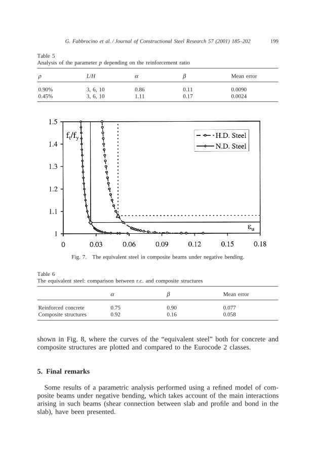
In Fig. 7, the couples of values (eu2ft/fy) providing the same plastic rotationsobtained using the N.D. Steel and H.D. Steel given in Eurocode 2 are plotted. Thecurves define the “equivalent steel” for composite beams under negative bending.
Table 4Statistical analysis - Influence of the slenderness (r=0.9%)
L/H A a b Mean error
3 0.89 0.80 0.10 0.000056 1.99 0.93 0.12 0.0004010 2.45 0.81 0.13 0.00013

198 G. Fabbrocino et al. / Journal of Constructional Steel Research 57 (2001) 185–202
Fig. 6. Statistical analysis — Influence of the slenderness.
Table 6 shows the parameters representing the criterion of equivalence forreinforced concrete and for composite structures with the corresponding mean error.
The scatter between the values,a and b, calculated for both concrete structuresand composite structures, points out that the mechanisms governing the developmentof plastic rotations are different.
A common classification for reinforcing steel seems to be unsatisfactory, as also
199G. Fabbrocino et al. / Journal of Constructional Steel Research 57 (2001) 185–202
Table 5Analysis of the parameterp depending on the reinforcement ratio
r L/H a b Mean error
0.90% 3, 6, 10 0.86 0.11 0.00900.45% 3, 6, 10 1.11 0.17 0.0024
Fig. 7. The equivalent steel in composite beams under negative bending.
Table 6The equivalent steel: comparison between r.c. and composite structures
a b Mean error
Reinforced concrete 0.75 0.90 0.077Composite structures 0.92 0.16 0.058
shown in Fig. 8, where the curves of the “equivalent steel” both for concrete andcomposite structures are plotted and compared to the Eurocode 2 classes.
5. Final remarks
Some results of a parametric analysis performed using a refined model of com-posite beams under negative bending, which takes account of the main interactionsarising in such beams (shear connection between slab and profile and bond in theslab), have been presented.

200 G. Fabbrocino et al. / Journal of Constructional Steel Research 57 (2001) 185–202
Fig. 8. The equivalent steel: comparison between r.c. and composite structures.
The ductility of reinforcement has a relevant role in the development of therotation capacity of composite beams. The ultimate strain is the most importantmechanical parameter of reinforcement, mainly in the field of full shear connection,as the yielding spreading is governed by the arrangement of shear connectors, inopposition to reinforced concrete structures.
Conversely, when the beam is designed in the field of partial shear connection,

201G. Fabbrocino et al. / Journal of Constructional Steel Research 57 (2001) 185–202
the main contribution to rotation capacity is due to the slip at the slab-profile interfaceand depends on the slip capacity of shear connectors, as a result the influence ofreinforcing steel is negligible. The above remarks are substantially independent onthe type of loading (concentrated or distributed load), on the global slenderness ofthe beam and on the value of the percentage of reinforcement.
Mechanical properties of reinforcing steel cannot be judged in absolute terms, butaccording to structural requirements. Thus, a more effective ductility index has beenintroduced to fully describe the ductility performances of steel as reinforcement inthe composite structures. The allowable plastic rotationqpl can be a reliable indexof the steel ductility, when the failure depends on the reinforcing steel fracture.
The parametric analysis shows that the extension to composite structures of thereinforcing steel classification developed for concrete structures can be unsatisfac-tory. Further analyses, mainly experimental, are needed to confirm the above resultsand give appropriate provisions in the Codes.
References
[1] Kemp AR, Dekker NW. Available rotation capacity in steel and composite beams. The Struct Eng1991;69(5):88–97.
[2] Kemp AR, Dekker NW, Trinchero P. Differences in inelastic properties of steel and compositebeams. J Constr Steel Res 1995;34:187–206.
[3] Nethercot DA, Li TQ, Choo B. Required rotations and moment redistribution for composite framesand continuous beams. J Constr Steel Res 1995;35:121–63.
[4] Eurocode 4. Common unified rules for composite steel and concrete structures, ENV 1994-1-1, 1992.[5] Aribert JM, Lachal A. Experimental investigation of composite connection and global interpretation.
COST C1. In: Colson A, editor. Proceedings of the First State of Art Workshop, 1992.[6] Xiao Y, Anderson D. Review of research in the United Kingdom on composite semi-rigid joints.
Proceedings of the Second State of Art Report, COST C1, Prague, 1994.[7] Bode H, Kronenberger HJ, Michaeli W. Composite joints — further experimental results. Proceed-
ings of the International Conference Composite Construction, Conventional and Innovative, IABSEInnsbruck, 1997. p. 433–8.
[8] CEB, Bulletin d’Information no 242. Ductility of reinforced concrete structures. Synthesis Reportand Individual Contributions, 1998.
[9] CEB, Bulletin d’Information no 213/214, Model Code 90, 1993.[10] Eurocode 2. Common unified rules for concrete structures, ENV 1992-1-1, 1991.[11] Leon RT, Viest IM. Theories of incomplete interaction in composite beams. Proceedings of Engineer-
ing Foundation, Composite Construction in Steel and Concrete III, ASCE, 1996. p. 858–70.[12] Fabbrocino G. Modelling and experimental behaviour of continuous steel-concrete composite beams.
PhD thesis in Structural Engineering, University of Naples Federico II, 1998 (in Italian).[13] Manfredi G, Fabbrocino G, Cosenza E. Modelling of composite beams under negative bending.
ASCE J Engng Mech 1999;125(6):654–62.[14] Fabbrocino G, Manfredi G, Cosenza E, Pecce M. Non-linear behaviour of composite beams under
negative bending: an experimental-theoretical comparison. Proc. of EUROSTEEL 99, 2nd EuropeanConference on Steel Structures, Prague, May, 1999. Web page: http://cihla.fsv.cvut.cz/~eurostee/028/028.htm
[15] Fabbrocino G, Manfredi G, Cosenza E. Non-linear analysis of composite beams under positivebending. Computer and Struct 1999;70:77–89.
[16] Cosenza E, Greco C, Manfredi G. The concept of equivalent steel. CEB Bulletin d’Information1993;218:163–84.

202 G. Fabbrocino et al. / Journal of Constructional Steel Research 57 (2001) 185–202
[17] Johnson RP, Molenstra N. Partial shear connection in composite beams in building. ProceedingsInstitute of Civil Engineers, part 2, vol. 91, 1991.
[18] Ollgaard JG, Slutter RG, Fisher JW. Shear strength of stud connectors in lightweight and normalweight concrete. AISC Engineering Journal, 1971.
[19] Ciampi V, Eligehausen R, Popov EP, Bertero VV. Analytical model for concrete anchorage ofreinforcing bars under generalised excitations. UCB/EERC 82-23, University of California, Berke-ley, 1982.
[20] Cosenza E, Fabbrocino G, Manfredi G. The influence of rebar ductility on the rotational capacityof composite beams. Proceedings of SDSS ’97, Nagoya, July, 1997.
[21] Fabbrocino G, Pecce M. Non-linear behaviour of composite beams under negative bending: experi-mental results. Italian Workshop on Composite Structures III, Ancona (Italy), 1998 (in Italian).
[22] Fabbrocino G, Manfredi G, Cosenza E. Rotation capacity of steel concrete composite beams: influ-ence of the properties of reinforcing steel. Costruzioni Metalliche, no 6, 1998.