dual-rate non-linear high order holds for visual servoing applications
TRANSCRIPT
Dual-rate Non-linear High Order Holds forVisual Servoing Applications.
J.Ernesto Solanes?, Leopoldo Armesto, Josep Tornero, P. Munoz-Benavent,and Vicent Girbes
Intitute of Design and Manufacturing,Universitat Politecnica de Valencia, Cami de Vera s/n, 46022, Valencia, Spain
{jesolanes,larmesto,jtornero,pmunyoz,vgirbes}@idf.upv.es
http://www.institutoidf.com
Abstract. This paper introduces a novel concept of dual-rate non-linearhigh order holds, based on artificial neuronal networks, in order to im-prove control, robustness and stability margin of non-linear processes.The main idea is that artificial networks provide accurate inter-samplingdata estimation in dual-rate systems, allowing controlling the processat the fastest possible rate. In addition to this, the paper compares theperformance with other approaches taking into account the ideal butnon-feasible closed loop at high frequency. For that purpose, the paperconsiders metrics such as mean square error and settling time to measurethe overall performance. The proposed dual-rate non-linear holds havebeen tested in both, simulation and real processes, and particularly, in anindustrial robot within an image-based visual servoing application. Thenew approach improves with respect to the conventional single-rate be-havior and showing higher stability margin than conventional dual-rateholds.
Keywords: Visual servoing, non-linear control, machine learning
1 Introduction
In sampled-data systems, the sampling time of sensors and actuators has also agreat influence over the maximum system speed and overall performance. In con-ventional control theory, the sampling time is the same for all elements and usu-ally the slowest element determines the overall sampling frequency. In robotics,one of the most demanding computational resources are vision systems and theycommonly determine the control sampling rate, especially in visual servoing ap-plications. Thus, the complexity of processing tasks may introduce latency andslow sampling periods that can significantly affect to the task itself. In order to
? This work was supported by VALi+d Program (Generalitat Valenciana), FPIProgram (Spanish Ministry), DIVISAMOS Project (Spanish Ministry), PROME-TEO Program (Conselleria d’Educacio, Generalitat Valenciana) and MAGV Project(PAID-05-10 Program from VIDI UPV)
2 J. Ernesto Solanes
overcome this problem, multi-rate approaches [1], [2], can be used instead, wherethe aim is to reproduce, as ideal behavior, the high-frequency response.
During the three last decades, special attention has been paid to dual-ratesampled-data systems, and it is possible to find many contributions dealing withmodeling and control of multi-rate systems [3]. However, just few of them arerelated to control of non-linear systems with non-linear controllers [1] and [4].
This paper presents novels dual-rate non-linear high order holds (DR-NLHOH),where inputs of the process are updated at every frame-period T , meanwhile out-puts are updated at a base-period T , where T = NT , being N ∈ Z+, [5]. It isinteresting to remark its aim is to generate an inter-sampling signal at higherfrequency by including the knowledge of the closed loop system behavior. In thissense, conventional dual-rate high order holds (DR-HOHs) [6] do not take suchinformation into account, frequently failing in predicting the estimation of thesignal.
The paper also introduces a methodology for training such dual-rate non-linear holds based on artificial neural networks (ANN) with synthetic data. Thekey idea is to provide a sequence of values of the signal to be estimated, obtainedfrom a closed loop simulated environment at base period, T . From collected data,inputs of the ANN are considered to be T time-spaced, while target outputs areconsidered to be T time-spaced. As a consequence, outputs of DR-NLHOH are,indeed, a lifted signal [7], which means that they are packed into a single signalwhose elements must be distributed over time every base period.
In order to test the new concept of non-linear holds, an image-based robotvisual servoing application has been considered. For that purpose, a real platformformed by an industrial robot with 6 DOF and a web-cam located at end-effectorof the robot are modeled using kinematic and dynamic components.
In the paper, we also show that the new approach reduces over 50% of theconvergence time in positioning and object following tasks, and significantlydecreases the mean square error (MSE) with respect to the traditional single-rateapproach working at T . In addition the new non-linear holds increases robustnessand stability margin.
2 Dual-rate holds.
In [6], a methodology for designing DR-HOHs was proposed based on primitivefunction such as polynomial extrapolation, approximation functions (Bezier) andeven non-polynomial functions (exponential, sinusoidal, etc.). The main idea be-hind this approach is that a signal is reconstructed from a discrete sequence ofinput values {e(tk), . . . , e(tk−l)} to internally generate a continuous-time func-tion to extrapolate inputs. The continuous-time function (f) can be sampledat any desired period, usually the base period (T ), accommodating the outputof the hold eh(t) to the required frequency. The “continuized” signal can be
DR-NLHOH for Visual Servoing applications. 3
obtained from:
eh(t)=
n∑l=0
fn,l(t, tk)·e(tk−l) (1)
where n denotes the hold order, tk = kT and k denotes the sampling instant atlow frequency:
eh(tk + i·T )=
n∑l=0
fn,l(i·T )·e(tk−l) (2)
where i = 0, 1, . . . , N − 1. The term “high order” refers to the fact that thehold takes into account, not just current input e(tk) (zero order), but also pastinputs
{e(tk−1), . . . , e(tk−l)
}(first order, second order and so on). We would
like to remark that the notation for discrete sequence of input/output valuesuses double indexing, corresponding to indexes for frame and base periods, thatis, eh(k, i)= eh(kT + iT ).Therefore, using such notation, the dual-rate holds canbe expressed as:
eh(k, i)=
n∑l=0
f∗n,l(i)·e(k − l, 0) (3)
with f∗n,l(i)= fn,l(iT ).The zero order case (n = 0) is known as DR-ZOH, the first order case (n = 1)
is known as DR-FOH, while the second order case (n = 2) is known as DR-SOH.Other second order “coined” cases are DR-SOBH and DR-SOTH which useBezier and Taylor approximation series, see [6] for details.
In this paper, we introduce a more general and non-linear formulation:
eh(k, i)= Fi(t, tk, e(tk), . . . , e(tk−n)) (4)
where Fi is a non-linear function-valued vector F, which represents the mappingbetween low-frequency sampled signals and inter-sampling instants. In this sense,the hold predicts inter-sampling signal values based on a set of previously knowninputs sampled at low-sampling frequency, but its input is not necessarily affine.
Let us assume F : I→ I as the set of non-linear functions mapping betweenthe high-frequency discrete sequence I(k) =
{e(k, 0), . . . , e(k,N − 1)
}and the
low-frequency signals I(k) ={e(k − n, 0), . . . , e(k − 1, 0), e(k, 0)
}. This will im-
ply to find the mapping between I(k) and I(k). Due to I(k) includes future-timeinstants and inter-sampling values, which are not accessible in real-time pro-cesses, we denote Ih(k) =
{eh(k, 0), . . . , eh(k,N − 1)
}as the hold-estimated
mapping. Thus, our aim is to find the appropriate mapping such Ih ≈ I forevery time instant tk = kT and input vector I, with I =
{I(k)
}, Ih =
{Ih(k)
}.
As mentioned therein before, the packed vector Ih must be unpacked usingthe inverse lifting operator, to produce the hold “continuized” output signal
4 J. Ernesto Solanes
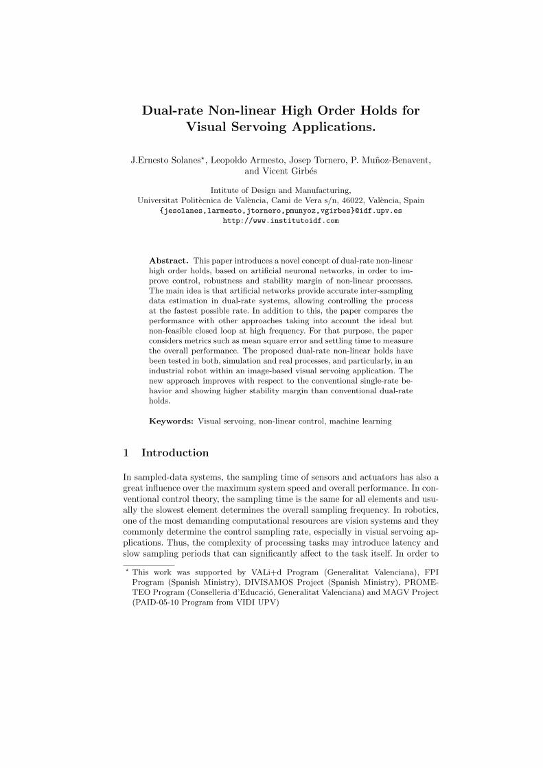
Fig. 1. Dual-rate non-linear high order hold based on artificial networks.
eh(t):
eh(t)=
N−1∑i=0
δi(t, tk)·eh(k, i) (5)
where δi(t, tk) =
{1 if iT ≤ t− tk < (i+ 1)
0 otherwise.
Unfortunately, it is hard to obtain general mathematical models that canapproximate real complex systems. In this sense, in the paper we propose theuse of machine learning techniques in order to obtain an approximate of functionF. Taking into account the nature of our problem, supervised machine learningmethods, such artificial neural networks have shown to be the most adequatemethods as shown therein after. In this sense, based on a closed-loop simulations,we can collect entries for a data-set containing combinations of I and I, where Iis the used input and I as target in order to train the network. Fig. 1 shows theblock diagram structure of the proposed dual-rate ANN hold.
3 Training DR-NLHOHs for visual servoing tasks.
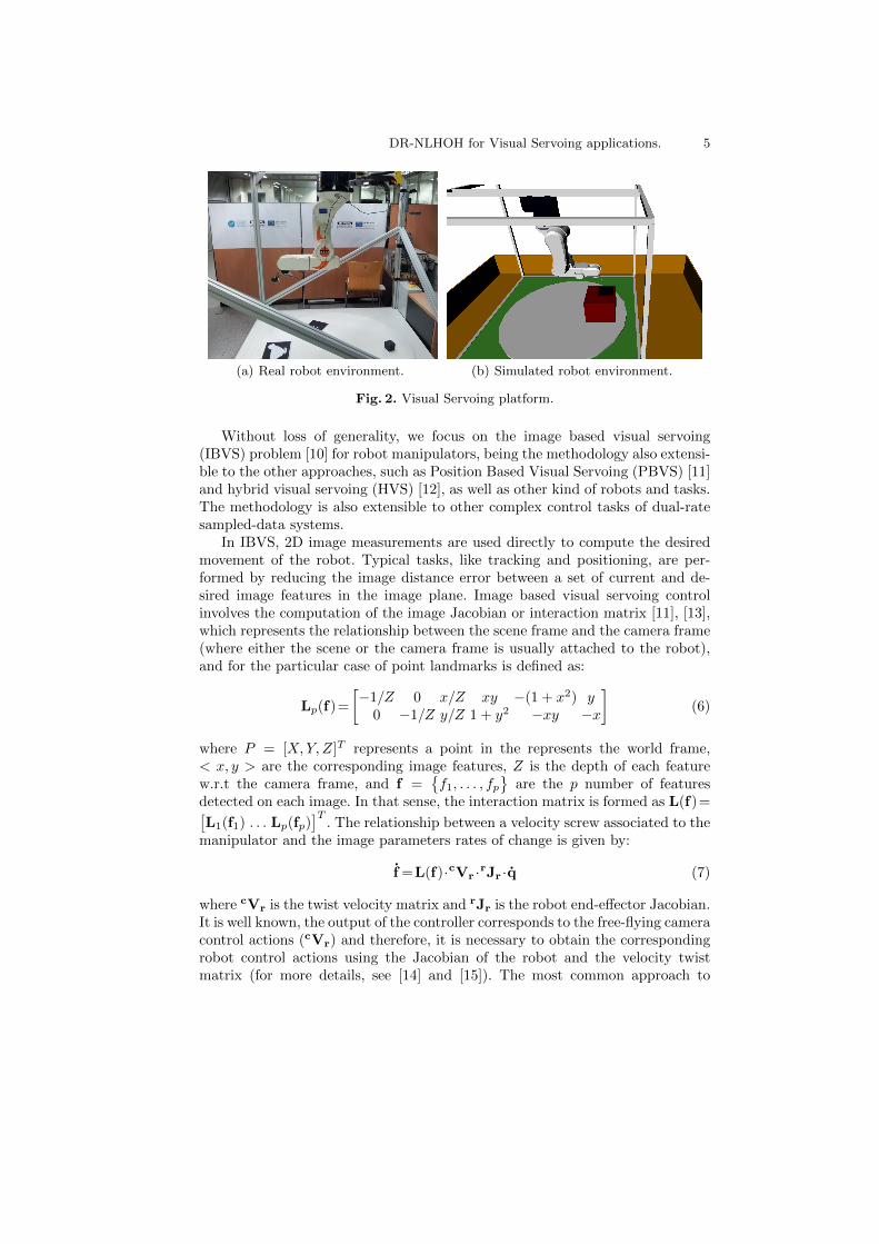
In this section, we introduce a methodology for training DR-NLHOHs for robotvisual servoing tasks. The training results shown in this paper have been val-idated on an industrial robot Kuka KR5 sixx R650 (see Fig. 2(a)) based onrealistic simulations of this robot using OpenRAVE [8] and ViSP [9] libraries(see Fig. 2(b)). As a consequence, the DR-NLHOH will be trained taking intoaccount all complex robot and camera non-linearities and dynamics from syn-thetic data.
DR-NLHOH for Visual Servoing applications. 5
(a) Real robot environment. (b) Simulated robot environment.
Fig. 2. Visual Servoing platform.
Without loss of generality, we focus on the image based visual servoing(IBVS) problem [10] for robot manipulators, being the methodology also extensi-ble to the other approaches, such as Position Based Visual Servoing (PBVS) [11]and hybrid visual servoing (HVS) [12], as well as other kind of robots and tasks.The methodology is also extensible to other complex control tasks of dual-ratesampled-data systems.
In IBVS, 2D image measurements are used directly to compute the desiredmovement of the robot. Typical tasks, like tracking and positioning, are per-formed by reducing the image distance error between a set of current and de-sired image features in the image plane. Image based visual servoing controlinvolves the computation of the image Jacobian or interaction matrix [11], [13],which represents the relationship between the scene frame and the camera frame(where either the scene or the camera frame is usually attached to the robot),and for the particular case of point landmarks is defined as:
Lp(f)=
[−1/Z 0 x/Z xy −(1 + x2) y
0 −1/Z y/Z 1 + y2 −xy −x
](6)
where P = [X,Y, Z]T represents a point in the represents the world frame,< x, y > are the corresponding image features, Z is the depth of each featurew.r.t the camera frame, and f =
{f1, . . . , fp
}are the p number of features
detected on each image. In that sense, the interaction matrix is formed as L(f)=[L1(f1) . . . Lp(fp)
]T. The relationship between a velocity screw associated to the
manipulator and the image parameters rates of change is given by:
f =L(f)·cVr ·rJr ·q (7)
where cVr is the twist velocity matrix and rJr is the robot end-effector Jacobian.It is well known, the output of the controller corresponds to the free-flying cameracontrol actions (cVr) and therefore, it is necessary to obtain the correspondingrobot control actions using the Jacobian of the robot and the velocity twistmatrix (for more details, see [14] and [15]). The most common approach to
6 J. Ernesto Solanes
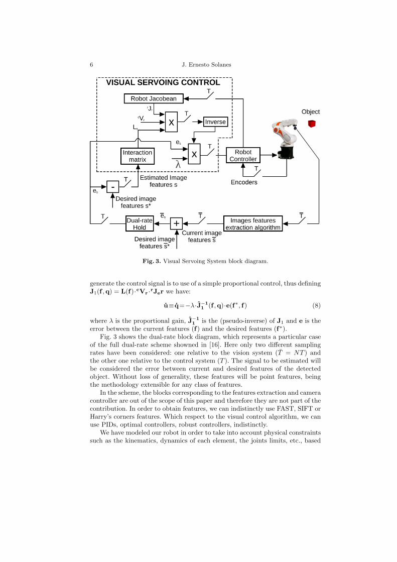
Fig. 3. Visual Servoing System block diagram.
generate the control signal is to use of a simple proportional control, thus definingJ1(f ,q) = L(f)·cVr ·rJer we have:
u≡ q=−λ·J−11 (f ,q)·e(f∗, f) (8)
where λ is the proportional gain, J−11 is the (pseudo-inverse) of J1 and e is the
error between the current features (f) and the desired features (f∗).Fig. 3 shows the dual-rate block diagram, which represents a particular case
of the full dual-rate scheme showned in [16]. Here only two different samplingrates have been considered: one relative to the vision system (T = NT ) andthe other one relative to the control system (T ). The signal to be estimated willbe considered the error between current and desired features of the detectedobject. Without loss of generality, these features will be point features, beingthe methodology extensible for any class of features.
In the scheme, the blocks corresponding to the features extraction and cameracontroller are out of the scope of this paper and therefore they are not part of thecontribution. In order to obtain features, we can indistinctly use FAST, SIFT orHarry’s corners features. Which respect to the visual control algorithm, we canuse PIDs, optimal controllers, robust controllers, indistinctly.
We have modeled our robot in order to take into account physical constraintssuch as the kinematics, dynamics of each element, the joints limits, etc., based
DR-NLHOH for Visual Servoing applications. 7
0.08 0.1 0.12 0.14 0.16 0.18 0.2
0.026
0.028
0.03
0.032
0.034
0.036
0.038
0.04
Time (s)
Err
or
(m) e(k,0)
e(k−1,0)
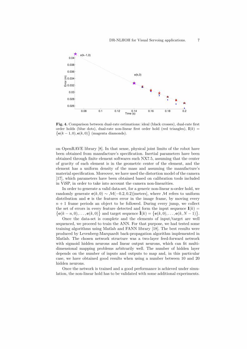
Fig. 4. Comparison between dual-rate estimations: ideal (black crosses), dual-rate firstorder holds (blue dots), dual-rate non-linear first order hold (red triangles), I(k) ={e(k − 1, 0), e(k, 0)
}(magenta diamonds).
on OpenRAVE library [8]. In that sense, physical joint limits of the robot havebeen obtained from manufacture’s specification. Inertial parameters have beenobtained through finite element softwares such NX7.5, assuming that the centerof gravity of each element is in the geometric center of the element, and theelement has a uniform density of the mass and assuming the manufacture’smaterial specification. Moreover, we have used the distortion model of the camera[17], which parameters have been obtained based on calibration tools includedin ViSP, in order to take into account the camera non-linearities.
In order to generate a valid data-set, for a generic non-linear n-order hold, werandomly generate e(k, 0) ∼ M(−0.2, 0.2)[meters], where M refers to uniformdistribution and e is the features error in the image frame, by moving everyn + 1 frame periods an object to be followed. During every jump, we collectthe set of errors in every feature detected and form the input sequence I(k) ={e(k − n, 0), . . . , e(k, 0)
}and target sequence I(k) =
{e(k, 0), . . . , e(k,N − 1)
}.
Once the data-set is complete and the elements of input/target are wellsequenced, we proceed to train the ANN. For that purpose, we had tested sometraining algorithms using Matlab and FANN library [18]. The best results wereproduced by Levenberg-Marquardt back-propagation algorithm implemented inMatlab. The chosen network structure was a two-layer feed-forward networkwith sigmoid hidden neurons and linear output neurons, which can fit multi-dimensional mapping problems arbitrarily well. The number of hidden layerdepends on the number of inputs and outputs to map and, in this particularcase, we have obtained good results when using a number between 10 and 20hidden neurons.
Once the network is trained and a good performance is achieved under simu-lation, the non-linear hold has to be validated with some additional experiments.
8 J. Ernesto Solanes
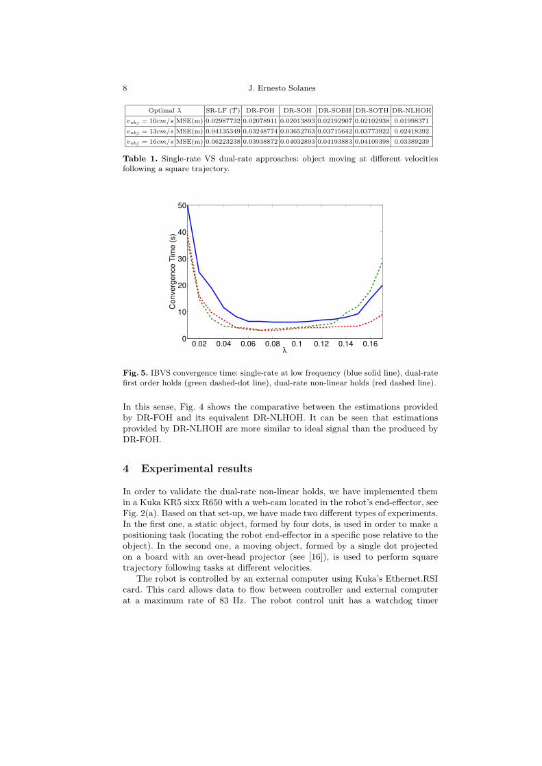
Optimal λ SR-LF (T ) DR-FOH DR-SOH DR-SOBH DR-SOTH DR-NLHOH
vobj = 10cm/s MSE(m) 0.02987732 0.02078911 0.02013893 0.02192907 0.02102938 0.01998371
vobj = 13cm/s MSE(m) 0.04135349 0.03248774 0.03652763 0.03715642 0.03773922 0.02418392
vobj = 16cm/s MSE(m) 0.06223238 0.03938872 0.04032893 0.04193883 0.04109398 0.03389239
Table 1. Single-rate VS dual-rate approaches: object moving at different velocitiesfollowing a square trajectory.
0.02 0.04 0.06 0.08 0.1 0.12 0.14 0.160
10
20
30
40
50
λ
Converg
ence T
ime (
s)
Fig. 5. IBVS convergence time: single-rate at low frequency (blue solid line), dual-ratefirst order holds (green dashed-dot line), dual-rate non-linear holds (red dashed line).
In this sense, Fig. 4 shows the comparative between the estimations providedby DR-FOH and its equivalent DR-NLHOH. It can be seen that estimationsprovided by DR-NLHOH are more similar to ideal signal than the produced byDR-FOH.
4 Experimental results
In order to validate the dual-rate non-linear holds, we have implemented themin a Kuka KR5 sixx R650 with a web-cam located in the robot’s end-effector, seeFig. 2(a). Based on that set-up, we have made two different types of experiments.In the first one, a static object, formed by four dots, is used in order to make apositioning task (locating the robot end-effector in a specific pose relative to theobject). In the second one, a moving object, formed by a single dot projectedon a board with an over-head projector (see [16]), is used to perform squaretrajectory following tasks at different velocities.
The robot is controlled by an external computer using Kuka’s Ethernet.RSIcard. This card allows data to flow between controller and external computerat a maximum rate of 83 Hz. The robot control unit has a watchdog timer
DR-NLHOH for Visual Servoing applications. 9
(a) t=0s. (b) t=4s. (c) t=7s. (converged)
(d) t=0s. (e) t=4s. (converged) (f) t=7s. (converged)
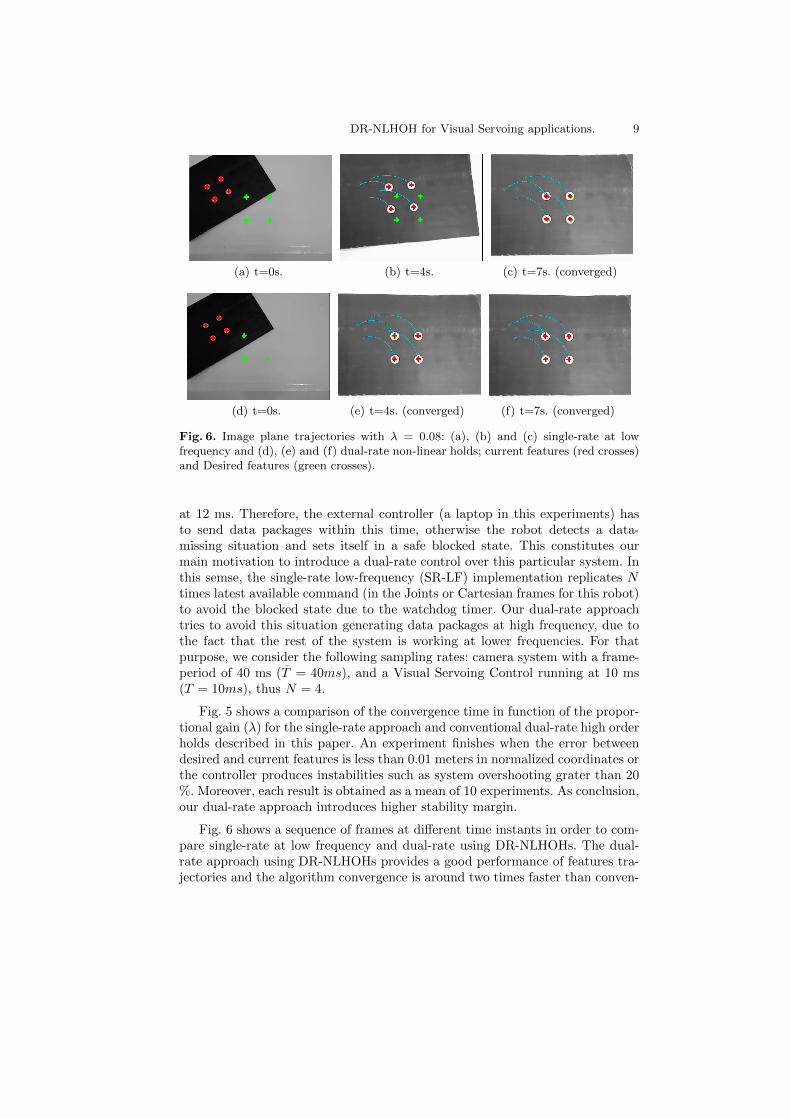
Fig. 6. Image plane trajectories with λ = 0.08: (a), (b) and (c) single-rate at lowfrequency and (d), (e) and (f) dual-rate non-linear holds; current features (red crosses)and Desired features (green crosses).
at 12 ms. Therefore, the external controller (a laptop in this experiments) hasto send data packages within this time, otherwise the robot detects a data-missing situation and sets itself in a safe blocked state. This constitutes ourmain motivation to introduce a dual-rate control over this particular system. Inthis semse, the single-rate low-frequency (SR-LF) implementation replicates Ntimes latest available command (in the Joints or Cartesian frames for this robot)to avoid the blocked state due to the watchdog timer. Our dual-rate approachtries to avoid this situation generating data packages at high frequency, due tothe fact that the rest of the system is working at lower frequencies. For thatpurpose, we consider the following sampling rates: camera system with a frame-period of 40 ms (T = 40ms), and a Visual Servoing Control running at 10 ms(T = 10ms), thus N = 4.
Fig. 5 shows a comparison of the convergence time in function of the propor-tional gain (λ) for the single-rate approach and conventional dual-rate high orderholds described in this paper. An experiment finishes when the error betweendesired and current features is less than 0.01 meters in normalized coordinates orthe controller produces instabilities such as system overshooting grater than 20%. Moreover, each result is obtained as a mean of 10 experiments. As conclusion,our dual-rate approach introduces higher stability margin.
Fig. 6 shows a sequence of frames at different time instants in order to com-pare single-rate at low frequency and dual-rate using DR-NLHOHs. The dual-rate approach using DR-NLHOHs provides a good performance of features tra-jectories and the algorithm convergence is around two times faster than conven-
10 J. Ernesto Solanes
10 15 20
−0.04
−0.02
0
0.02
0.04
Time (s)
e2(x
,y)
(m)
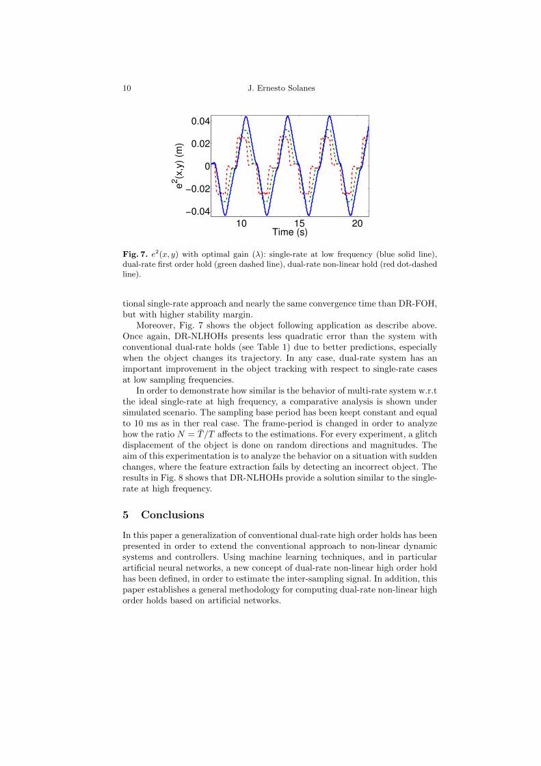
Fig. 7. e2(x, y) with optimal gain (λ): single-rate at low frequency (blue solid line),dual-rate first order hold (green dashed line), dual-rate non-linear hold (red dot-dashedline).
tional single-rate approach and nearly the same convergence time than DR-FOH,but with higher stability margin.
Moreover, Fig. 7 shows the object following application as describe above.Once again, DR-NLHOHs presents less quadratic error than the system withconventional dual-rate holds (see Table 1) due to better predictions, especiallywhen the object changes its trajectory. In any case, dual-rate system has animportant improvement in the object tracking with respect to single-rate casesat low sampling frequencies.
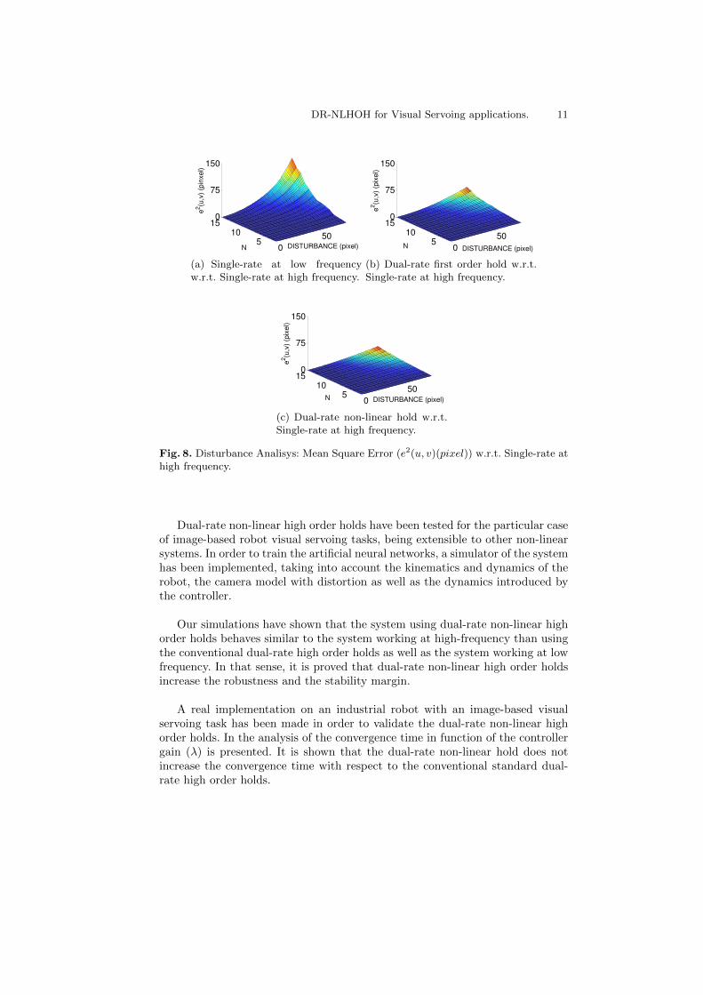
In order to demonstrate how similar is the behavior of multi-rate system w.r.tthe ideal single-rate at high frequency, a comparative analysis is shown undersimulated scenario. The sampling base period has been keept constant and equalto 10 ms as in ther real case. The frame-period is changed in order to analyzehow the ratio N = T /T affects to the estimations. For every experiment, a glitchdisplacement of the object is done on random directions and magnitudes. Theaim of this experimentation is to analyze the behavior on a situation with suddenchanges, where the feature extraction fails by detecting an incorrect object. Theresults in Fig. 8 shows that DR-NLHOHs provide a solution similar to the single-rate at high frequency.
5 Conclusions
In this paper a generalization of conventional dual-rate high order holds has beenpresented in order to extend the conventional approach to non-linear dynamicsystems and controllers. Using machine learning techniques, and in particularartificial neural networks, a new concept of dual-rate non-linear high order holdhas been defined, in order to estimate the inter-sampling signal. In addition, thispaper establishes a general methodology for computing dual-rate non-linear highorder holds based on artificial networks.
DR-NLHOH for Visual Servoing applications. 11
0
505
1015
0
75
150
DISTURBANCE (pixel)N
e2(u
,v)
(pin
xel)
(a) Single-rate at low frequencyw.r.t. Single-rate at high frequency.
0
505
1015
0
75
150
DISTURBANCE (pixel)N
e2(u
,v)
(pix
el)
(b) Dual-rate first order hold w.r.t.Single-rate at high frequency.
0
505
1015
0
75
150
DISTURBANCE (pixel)N
e2(u
,v)
(pix
el)
(c) Dual-rate non-linear hold w.r.t.Single-rate at high frequency.
Fig. 8. Disturbance Analisys: Mean Square Error (e2(u, v)(pixel)) w.r.t. Single-rate athigh frequency.
Dual-rate non-linear high order holds have been tested for the particular caseof image-based robot visual servoing tasks, being extensible to other non-linearsystems. In order to train the artificial neural networks, a simulator of the systemhas been implemented, taking into account the kinematics and dynamics of therobot, the camera model with distortion as well as the dynamics introduced bythe controller.
Our simulations have shown that the system using dual-rate non-linear highorder holds behaves similar to the system working at high-frequency than usingthe conventional dual-rate high order holds as well as the system working at lowfrequency. In that sense, it is proved that dual-rate non-linear high order holdsincrease the robustness and the stability margin.
A real implementation on an industrial robot with an image-based visualservoing task has been made in order to validate the dual-rate non-linear highorder holds. In the analysis of the convergence time in function of the controllergain (λ) is presented. It is shown that the dual-rate non-linear hold does notincrease the convergence time with respect to the conventional standard dual-rate high order holds.
12 J. Ernesto Solanes
References
1. H. J. Chang, P. J. Kim, D. S. Song, and J. Y. Choi, “Optical image stabilizingsystem using multirate fuzzy pid controller for mobile device camera,” ConsumerElectronics, IEEE Transactions on, vol. 55, no. 2, pp. 303 –311, may 2009.
2. D. Anderson, “Multirate and nonlinear controllers for low-cost laser tracking sys-tems,” in 17th IFAC Symposium on Automatic Control in Aerospace, 2007.
3. J. Tornero and M. Tomizuka, “Modeling, analysis and design tools for dual-ratesystems,” in American Control Conf., 2002, pp. 4116–4121.
4. J. Ahrens, X. Tan, and H. Khalil, “Multirate sampled-data output feedback controlwith application to smart material actuated systems,” Automatic Control, IEEETransactions on, vol. 54, no. 11, pp. 2518 –2529, nov. 2009.
5. L. Armesto, G. Ippoliti, S. Longhi, and J. Tornero, “Probabilistic self-localizationand mapping - an asynchronous multirate approach,” Robotics Automation Maga-zine, IEEE, vol. 15, no. 2, pp. 77 –88, june 2008.
6. L. Armesto and J. Tornero, “Dual-rate high order holds based on primitive func-tions,” in American Control Conf., 2003, pp. 1140–1145.
7. D. Huang and J.-X. Xu, “Discrete-time adaptive control for nonlinear systems withperiodic parameters: A lifting approach,” Asian Journal of Control, 2011.
8. R. Diankov and J. Kuffner, “OpenRAVE: A planning architecture for autonomousrobotics,” Robotics Institue, Carnegie Mellon University, Tech. Rep., Jul. 2008.
9. E. Marchand, F. Spindler, and F. Chaumette, “Visp for visual servoing: a genericsoftware platform with a wide class of robot control skills,” IEEE Robotics andAutomation Magazine, vol. 12, no. 4, pp. 40–52, December 2005.
10. P. Martinet, J. Gallice, and D. Khadraoui, “Vision based control law using 3dvisual features,” in Committees, Econometrica, 1996, pp. 497–502.
11. S. Hutchinson, G. Hager, and P. Corke, “A tutorial on visual servo control,”Robotics and Automation, IEEE Transactions on, pp. 651 –670, oct 1996.
12. F. Chaumette and E. Malis, “2 1/2 d visual servoing: a possible solution to improveimage-based and position-based visual servoings,” in Robotics and Automation,2000. Proceedings. ICRA ’00. IEEE International Conference on, vol. 1, 2000, pp.630 –635 vol.1.
13. F. Chaumette and S. Hutchinson, “Visual servo control, part ii: Advanced ap-proaches,” IEEE Robotics and Automation Magazine, vol. 14, no. 1, pp. 109–118,March 2007.
14. P. Corke, Robotics, Vision and Control : Fundamental algorithms in MATLAB,ser. Springer Tracts in Advanced Robotics. Germany: Springer, August 2011.
15. Chaumette and S. Hutchinson, “Visual servo control, part i: Basic approaches,”IEEE Robotics and Automation Magazine, vol. 13, pp. 82–90, 2006.
16. J. E. Solanes, J. Tornero, L. Armesto, and V. Girbes, “Multi-rate visual servoingbased on dual-rate high order holds,” in Proceedings of the 12th Annual conferenceon Towards autonomous robotic systems, ser. TAROS 2011, 2011, p. 195 206.
17. P. Puget and T. Skordas, “An optimal solution for mobile camera calibration.”in ECCV, ser. Lecture Notes in Computer Science, O. D. Faugeras, Ed., vol. 427.Springer, 1990, pp. 187–198.
18. S. Nissen, “Implementation of a fast artificial neural network library (fann),” De-partment of Computer Science University of Copenhagen (DIKU), Tech. Rep.,2003, http://fann.sf.net.