download this - civil engineering journal
TRANSCRIPT
Available online at www.CivileJournal.org
Civil Engineering Journal
Vol. 5, No. 4, April, 2019
881
Comparative Study on Two Storey Car Showroom Using Pre-engineered
Building (PEB) Concept Based on British Standards and Euro Code
Balamuralikrishnan R. a*, Ibrahim Shabbir Mohammedali b
a Asst. professor, Department of BNE, College of Engineering, National University of Science and Technology, Muscat, PO Box:2322,
CPO Seeb 111, Sultanate of Oman.
b Department of Civil and Structural Engineering, Annamalai University, Pin:608001,Tamilnadu, India.
Received 25 December 2018; Accepted 28 March 2019
Abstract
Majority of steel structures are used for low-rise single storey buildings mainly for industrial purpose. Steel structures are
preferred for industrial buildings due to its higher strength to weight ratio as compare to RCC structures and steel structures
also gives more free internal space by allowing long clear span between columns. Pre-engineered building (PEB) is a
modern age concept of utilizing structural steel and optimizing the design by ensuring the economical integrity of the
structure. The structural members are designed and fabricated in the factory under controlled environment to produce
optimum sections by varying the thickness of the sections along the length of the member as per the bending moment
requirement. The aim of the research paper is to analyses and design a PEB car showroom of two storey (G+1) using
STAAD Pro in accordance to British standards (BS 5950-1:2000) and Euro codes (EC3 EN-1993-1) with wind and seismic
analysis. In order to achieve the above aim of the project, two models of the car showroom were created namely British
Standard (BS) model and Euro code (EC) model using STAAD Pro. The member property for BS model is assigned with
tapered frame sections while the EC model is assigned with universal standard section frames. The load cases were assigned
to the models for analysis include dead load, live load, wind load and seismic load. Wind load and seismic load being the
critical dynamic loads that will be analyzed for the stability of the structure against lateral forces. The results from the
analysis and design of the two models were within the allowable limits for ultimate and serviceability limit state since the
internal stresses in all the members satisfies the unity check ratio requirements for both design codes. The dynamic analysis
results suggest that EC model has higher resistance to seismic loading as compare to BS model since the maximum
displacement with time in X-direction for EC model is 8.83 mm and for BS model is 10.5 mm. The total weight of the
structure for BS model is 1125.431 kN and for EC model is 1214.315 kN, which makes EC model 7.9% heavier than BS
model. Moreover, the total weight of all the portal frames for BS model is 457.26 kN and for EC model is 574.725 kN,
which makes tapered frame sections to utilize and reduce the amount of steel by 25.7%. Therefore, BS model proved to be
an economical model when compared to Euro code.
Keywords: Pre-engineered Buildings (PEB); STAAD Pro; Industrial Structures; Dynamic Loading; Tapered Sections.
1. Introduction
1.1. Pre-engineered Building Design
Steel has been used as a construction material for a very long time. The famous Eiffel tower is one among the oldest
steel structure made in 1889 and it has been a symbolic landmark for Paris and it has stood for over 129 years. Despite
the fact, steel buildings are not known for high rise structures but instead majority of steel structures are low rise with
* Corresponding author: [email protected]
http://dx.doi.org/10.28991/cej-2019-03091296
This is an open access article under the CC-BY license (https://creativecommons.org/licenses/by/4.0/).
© Authors retain all copyrights.
Civil Engineering Journal Vol. 5, No. 4, April, 2019
882
single storey mainly used for industrial purposes. Pre-engineered building (PEB) is a modern concept of utilizing steel
structures and optimizing the design by ensuring the economical integrity of the structure [1]. Oman is a well-developed
country and its economy mainly depended on exporting petroleum products, but as the country is facing economic crisis
due to depletion of crude oil reserve, the country tends to divert its economical vision toward boosting the business
sector. This only means that more industries and factories are required to manufacture local products and to export them
in order to stabilize the economy of the country. This encourages construction of Pre-engineered building in the country
for both small and large scale industries.
Pre-engineered building concept is getting famous rapidly not only in Oman but all around the world due to the
increasing demand of Industrial oriented building that requires long clear span with column free space which can provide
easy access and mobility within the building. In addition to that, the PEB concept gives economical structural sections
by reducing excess steel usage and optimizing the required steel as per the bending moment requirement which has a
major advantage over the traditional steel structures where unnecessary wastage of steel is done resulting in increase of
material cost and making the construction uneconomical. Pre-engineered building (PEB) offers a lot of advantages over
conventional steel building (CSB) construction. In the Some of the main advantages that are offered by PEB, which are
reduction in time, reduced cost of construction, light weight foundation, easy, future expansion flexibility, ability for
long span column free space, single source responsibility, higher resistance to earthquake. The materials used in
conventional steel building consume more cost, so to overcome this “PEB structures” are needed to reduce the cost of
the project. In order to reduce the self-weight of conventional steel buildings PEB can be used. Generally PEB can
reduce up to 35% of self-weight when compared to conventional steel buildings.
Steel structures are preferred for industrial buildings due to higher strength to weight ratio than RCC structures. Pre-
engineered building (PEB) is steel structure in which the structural members and components are fully designed and
fabricated in the factory and transported to the site in knock down condition. Normally it requires 6 to 8 weeks for the
fabrication process and delivery of all the structural components to the site. The PEB concept utilizes the amount of steel
required and produces the most optimum sections based on the bending moment requirement. Hence, the section depth
varies throughout the length following the bending moment diagram [2]. In order to achieve the above member
configuration, thin steel plates are tapered and combined to give the I-section desired. Since all the design and fabrication
is done at the factory under controlled environment, the components are of high quality and precision. PEB design
concept offer greater advantage over conventional steel structures (CSB) with roof truss configuration for low rise single
storey structures. PEB also fulfils the need and demand of long span column free area by eliminating or minimizing
interior columns and walls which is the utmost requirement of almost all industrial buildings. Moreover PEB is much
economical in terms of cost and time of construction, which is a major advantage over CSB concept. The advancement
in technology has introduced computerized software that makes analysis and designing of PEB structures very simple
and easy.
STAAD Pro is an advanced structural analysis and design software which is the most popular software used all over
the world for analysing and designing of different types of structures. It supports almost all the designing codes, and can
design concrete, steel and timber structures. It provides user friendly interface and visualization of 3D structural model
of the building. It is one of the easiest software available for modeling, analyzing and designing of different types of
structures. PEB is significantly advantageous over Conventional Steel Building (CSB) structure since it offers less cost
and time of construction, it has the ability to span long distance giving column free span, easy flexibility for future
expansion, low maintenance cost, single source responsibility and also has higher resistance to moisture, fire, adverse
weather condition and earthquake which makes it more durable and safe.
The results obtained the authors concluded that the 3D PEB model weights 43.77 tons and the CSB model weights
74.08 tons i.e. PEB weights 35% lesser than CSB as per IS 800-2007 [3]. The only disadvantage of PEB structure is that
they have poor thermal and fire resistance and vulnerable towards corrosion [4]. PEB structures can be easily designed
by using advanced softwares like STAAD Pro by following simple procedures and by using different country building
codes. It was also concluded that PEB are more advantageous over CSB in terms of cost effectiveness, quality control,
simplicity in erection and speed of construction [5].
The deflection of the two structures was studied under dynamic loading from the results obtained and it was
concluded by the author that the PEB model with bracing provides more stability against seismic loading and the
deflection of the structure is less when compared to the PEB structure without bracing, therefore PEB offers higher
earthquake resistance when braced. PEB frame were more stable under wind loading as compared to CSB frame.
Moreover, the weight of PEB frame was 27% lesser as compared to the weight of CSB frame [6]. PEB structure over
conventional steel structures in details by considering the cost, time and material requirements [7]. The design aspects
of Indian standard are higher as compared to the American standards and mentioned the main criteria as listed below
which has caused the weight of the structure to be more when designed using IS 800-2007 as compared to MBMA/AISC
design code [8]. The deflection of the PEB frames are more as compared to the conventional structure making the
structure more flexible and withstand seismic loading [9].
Civil Engineering Journal Vol. 5, No. 4, April, 2019
883
The existence of pre-cast concrete industry are numerous, successfully executed construction project, its uses not
disputed and it’s the proof that the manufacturing and production technology is practical and cost effective. The growing
requirements of architectural design at building construction raise progress of stable and constant development of the
industries as this is a new technology [10].The adoptability of PEB in the place of Conventional Steel Building (CSB)
design concept resulted in many advantages, including economy and easier fabrication [11]. Presently, large column
free area is the utmost requirement for any type of industry and with the advent of computer software’s it is now easily
possible. With the improvement in technology, computer software’s have contributed immensely to the enhancement of
quality of life through new researches [12]. "Pre-engineered steel buildings" are those that are totally invented within
the industrial plant once planning, shipped to site} in CKD (completely knocked down) condition; and all parts are
assembled and erected at a site with nut-bolts, thereby reducing the time of completion. Pre–engineered means that,
typically speaking, is any a part of a structure that's factory-made first off to its arrival on the building site [13]. Cold
formed steel section over hot rolled section as purlin is almost lighter than 32 % [14]. PEB structures are lighter
structures. As PEB is 30 % lighter than CSB structures [15]. PEB steel frames are not only the most economical solution
due to lesser weight of construction but also have shown better performance compared to CSB frames [16].
3. Experimental Investigations
3.1. Detailed Methodology
Carry out intense research on PEB structures and understand the design concepts by carrying out sufficient literature
reviewing. Collect Journals, and other research related materials that can aid in literature review. Prepare the model on
STAAD Pro and carry out the analysis and design of the PEB structure by applying dead load, live load, wind load and
seismic load conditions in accordance to both British Standard (BS 5950-1:2000) [17] and Eurocodes (EC3 EN-1993-
1) [18] and interpret and compare the output results.
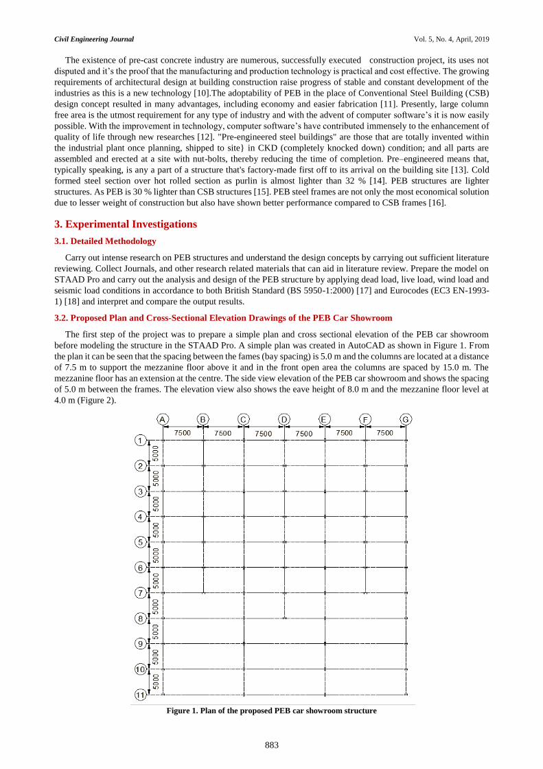
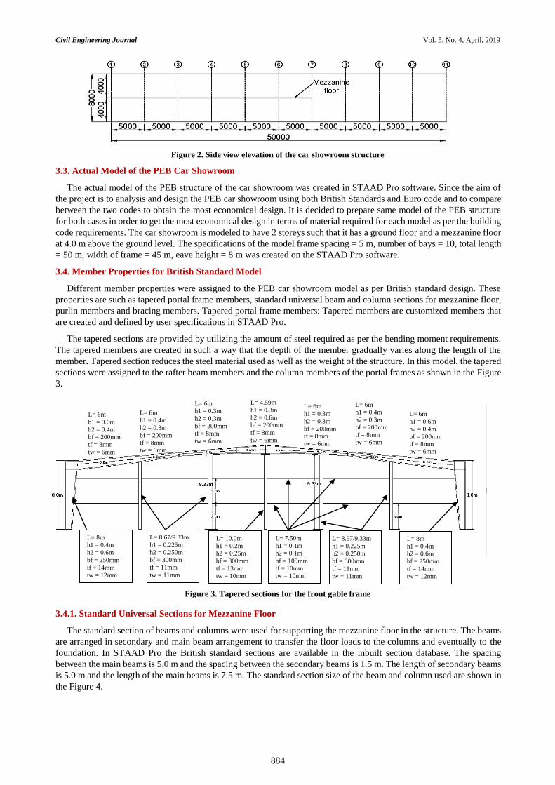
3.2. Proposed Plan and Cross-Sectional Elevation Drawings of the PEB Car Showroom
The first step of the project was to prepare a simple plan and cross sectional elevation of the PEB car showroom
before modeling the structure in the STAAD Pro. A simple plan was created in AutoCAD as shown in Figure 1. From
the plan it can be seen that the spacing between the fames (bay spacing) is 5.0 m and the columns are located at a distance
of 7.5 m to support the mezzanine floor above it and in the front open area the columns are spaced by 15.0 m. The
mezzanine floor has an extension at the centre. The side view elevation of the PEB car showroom and shows the spacing
of 5.0 m between the frames. The elevation view also shows the eave height of 8.0 m and the mezzanine floor level at
4.0 m (Figure 2).
Figure 1. Plan of the proposed PEB car showroom structure
Civil Engineering Journal Vol. 5, No. 4, April, 2019
884
Figure 2. Side view elevation of the car showroom structure
3.3. Actual Model of the PEB Car Showroom
The actual model of the PEB structure of the car showroom was created in STAAD Pro software. Since the aim of
the project is to analysis and design the PEB car showroom using both British Standards and Euro code and to compare
between the two codes to obtain the most economical design. It is decided to prepare same model of the PEB structure
for both cases in order to get the most economical design in terms of material required for each model as per the building
code requirements. The car showroom is modeled to have 2 storeys such that it has a ground floor and a mezzanine floor
at 4.0 m above the ground level. The specifications of the model frame spacing = 5 m, number of bays = 10, total length
= 50 m, width of frame = 45 m, eave height = 8 m was created on the STAAD Pro software.
3.4. Member Properties for British Standard Model
Different member properties were assigned to the PEB car showroom model as per British standard design. These
properties are such as tapered portal frame members, standard universal beam and column sections for mezzanine floor,
purlin members and bracing members. Tapered portal frame members: Tapered members are customized members that
are created and defined by user specifications in STAAD Pro.
The tapered sections are provided by utilizing the amount of steel required as per the bending moment requirements.
The tapered members are created in such a way that the depth of the member gradually varies along the length of the
member. Tapered section reduces the steel material used as well as the weight of the structure. In this model, the tapered
sections were assigned to the rafter beam members and the column members of the portal frames as shown in the Figure
3.
Figure 3. Tapered sections for the front gable frame
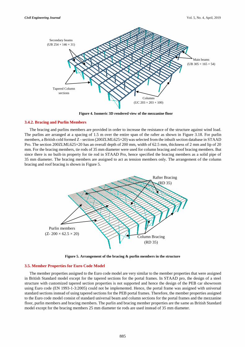
3.4.1. Standard Universal Sections for Mezzanine Floor
The standard section of beams and columns were used for supporting the mezzanine floor in the structure. The beams
are arranged in secondary and main beam arrangement to transfer the floor loads to the columns and eventually to the
foundation. In STAAD Pro the British standard sections are available in the inbuilt section database. The spacing
between the main beams is 5.0 m and the spacing between the secondary beams is 1.5 m. The length of secondary beams
is 5.0 m and the length of the main beams is 7.5 m. The standard section size of the beam and column used are shown in
the Figure 4.
L= 6m
h1 = 0.6m
h2 = 0.4m
bf = 200mm
tf = 8mm
tw = 6mm
L= 6m
h1 = 0.6m
h2 = 0.4m
bf = 200mm
tf = 8mm
tw = 6mm
L= 6m
h1 = 0.4m
h2 = 0.3m
bf = 200mm
tf = 8mm
tw = 6mm
L= 6m
h1 = 0.4m
h2 = 0.3m
bf = 200mm
tf = 8mm
tw = 6mm
L= 6m
h1 = 0.3m
h2 = 0.3m
bf = 200mm
tf = 8mm
tw = 6mm
L= 6m
h1 = 0.3m
h2 = 0.3m
bf = 200mm
tf = 8mm
tw = 6mm
L= 4.59m
h1 = 0.3m
h2 = 0.6m
bf = 200mm
tf = 8mm
tw = 6mm
L= 8m
h1 = 0.4m
h2 = 0.6m
bf = 250mm
tf = 14mm
tw = 12mm
L= 8m
h1 = 0.4m
h2 = 0.6m
bf = 250mm
tf = 14mm
tw = 12mm
L= 8.67/9.33m
h1 = 0.225m
h2 = 0.250m
bf = 300mm
tf = 11mm
tw = 11mm
L= 8.67/9.33m
h1 = 0.225m
h2 = 0.250m
bf = 300mm
tf = 11mm
tw = 11mm
L= 10.0m
h1 = 0.2m
h2 = 0.25m
bf = 300mm
tf = 13mm
tw = 10mm
L= 7.50m
h1 = 0.1m
h2 = 0.1m
bf = 100mm
tf = 10mm
tw = 10mm
Civil Engineering Journal Vol. 5, No. 4, April, 2019
885
Figure 4. Isomeric 3D rendered view of the mezzanine floor
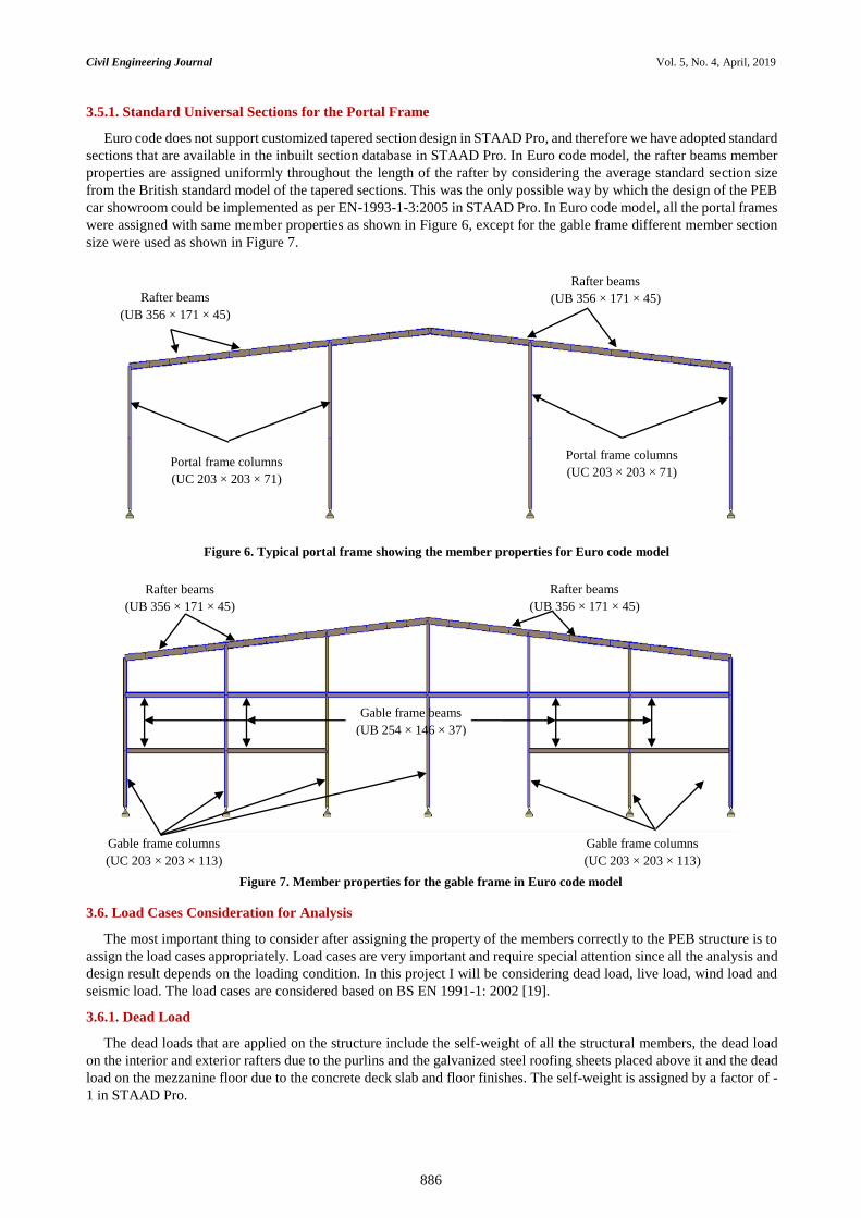
3.4.2. Bracing and Purlin Members
The bracing and purlins members are provided in order to increase the resistance of the structure against wind load.
The purlins are arranged at a spacing of 1.5 m over the entire span of the rafter as shown in Figure 3.18. For purlin
members, a British cold formed Z - section (200ZLML625×20) was selected from the inbuilt section database in STAAD
Pro. The section 200ZLML625×20 has an overall depth of 200 mm, width of 62.5 mm, thickness of 2 mm and lip of 20
mm. For the bracing members, tie rods of 35 mm diameter were used for column bracing and roof bracing members. But
since there is no built-in property for tie rod in STAAD Pro, hence specified the bracing members as a solid pipe of
35 mm diameter. The bracing members are assigned to act as tension members only. The arrangement of the column
bracing and roof bracing is shown in Figure 5.
Figure 5. Arrangement of the bracing & purlin members in the structure
3.5. Member Properties for Euro Code Model
The member properties assigned to the Euro code model are very similar to the member properties that were assigned
in British Standard model except for the tapered sections for the portal frames. In STAAD pro, the design of a steel
structure with customized tapered section properties is not supported and hence the design of the PEB car showroom
using Euro code (EN 1993-1-3:2005) could not be implemented. Hence, the portal frame was assigned with universal
standard sections instead of using tapered sections for the PEB portal frames. Therefore, the member properties assigned
to the Euro code model consist of standard universal beam and column sections for the portal frames and the mezzanine
floor, purlin members and bracing members. The purlin and bracing member properties are the same as British Standard
model except for the bracing members 25 mm diameter tie rods are used instead of 35 mm diameter.
Main beams
(UB 305 × 165 × 54)
Secondary beams
(UB 254 × 146 × 31)
Columns
(UC 203 × 203 × 100)
Tapered Column
sections
Rafter Bracing
(RD 35)
Column Bracing
(RD 35)
Purlin members
(Z- 200 × 62.5 × 20)
Civil Engineering Journal Vol. 5, No. 4, April, 2019
886
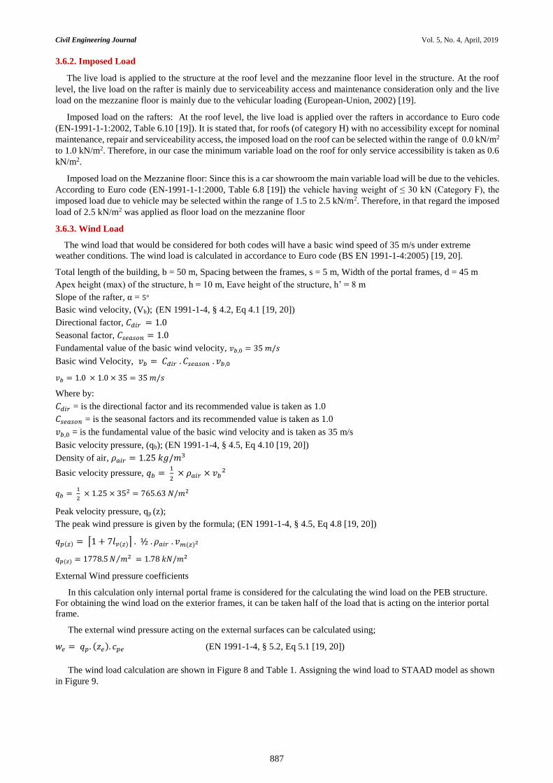
3.5.1. Standard Universal Sections for the Portal Frame
Euro code does not support customized tapered section design in STAAD Pro, and therefore we have adopted standard
sections that are available in the inbuilt section database in STAAD Pro. In Euro code model, the rafter beams member
properties are assigned uniformly throughout the length of the rafter by considering the average standard section size
from the British standard model of the tapered sections. This was the only possible way by which the design of the PEB
car showroom could be implemented as per EN-1993-1-3:2005 in STAAD Pro. In Euro code model, all the portal frames
were assigned with same member properties as shown in Figure 6, except for the gable frame different member section
size were used as shown in Figure 7.
Figure 6. Typical portal frame showing the member properties for Euro code model
Figure 7. Member properties for the gable frame in Euro code model
3.6. Load Cases Consideration for Analysis
The most important thing to consider after assigning the property of the members correctly to the PEB structure is to
assign the load cases appropriately. Load cases are very important and require special attention since all the analysis and
design result depends on the loading condition. In this project I will be considering dead load, live load, wind load and
seismic load. The load cases are considered based on BS EN 1991-1: 2002 [19].
3.6.1. Dead Load
The dead loads that are applied on the structure include the self-weight of all the structural members, the dead load
on the interior and exterior rafters due to the purlins and the galvanized steel roofing sheets placed above it and the dead
load on the mezzanine floor due to the concrete deck slab and floor finishes. The self-weight is assigned by a factor of -
1 in STAAD Pro.
Rafter beams
(UB 356 × 171 × 45)
Rafter beams
(UB 356 × 171 × 45)
Portal frame columns
(UC 203 × 203 × 71)
Portal frame columns
(UC 203 × 203 × 71)
Rafter beams
(UB 356 × 171 × 45)
Rafter beams
(UB 356 × 171 × 45)
Gable frame columns
(UC 203 × 203 × 113)
Gable frame columns
(UC 203 × 203 × 113)
Gable frame beams
(UB 254 × 146 × 37)
Civil Engineering Journal Vol. 5, No. 4, April, 2019
887
3.6.2. Imposed Load
The live load is applied to the structure at the roof level and the mezzanine floor level in the structure. At the roof
level, the live load on the rafter is mainly due to serviceability access and maintenance consideration only and the live
load on the mezzanine floor is mainly due to the vehicular loading (European-Union, 2002) [19].
Imposed load on the rafters: At the roof level, the live load is applied over the rafters in accordance to Euro code
(EN-1991-1-1:2002, Table 6.10 [19]). It is stated that, for roofs (of category H) with no accessibility except for nominal
maintenance, repair and serviceability access, the imposed load on the roof can be selected within the range of 0.0 kN/m2
to 1.0 kN/m2. Therefore, in our case the minimum variable load on the roof for only service accessibility is taken as 0.6
kN/m2.
Imposed load on the Mezzanine floor: Since this is a car showroom the main variable load will be due to the vehicles.
According to Euro code (EN-1991-1-1:2000, Table 6.8 [19]) the vehicle having weight of ≤ 30 kN (Category F), the
imposed load due to vehicle may be selected within the range of 1.5 to 2.5 kN/m2. Therefore, in that regard the imposed
load of 2.5 kN/m2 was applied as floor load on the mezzanine floor
3.6.3. Wind Load
The wind load that would be considered for both codes will have a basic wind speed of 35 m/s under extreme
weather conditions. The wind load is calculated in accordance to Euro code (BS EN 1991-1-4:2005) [19, 20].
Total length of the building, b = 50 m, Spacing between the frames, s = 5 m, Width of the portal frames, d = 45 m
Apex height (max) of the structure, h = 10 m, Eave height of the structure, h’ = 8 m
Slope of the rafter, α = 5°
Basic wind velocity, (Vb); (EN 1991-1-4, § 4.2, Eq 4.1 [19, 20])
Directional factor, 𝐶𝑑𝑖𝑟 = 1.0
Seasonal factor, 𝐶𝑠𝑒𝑎𝑠𝑜𝑛 = 1.0
Fundamental value of the basic wind velocity, 𝑣𝑏,0 = 35 𝑚/𝑠
Basic wind Velocity, 𝑣𝑏 = 𝐶𝑑𝑖𝑟 . 𝐶𝑠𝑒𝑎𝑠𝑜𝑛 . 𝑣𝑏,0
𝑣𝑏 = 1.0 × 1.0 × 35 = 35 𝑚/𝑠
Where by:
𝐶𝑑𝑖𝑟 = is the directional factor and its recommended value is taken as 1.0
𝐶𝑠𝑒𝑎𝑠𝑜𝑛 = is the seasonal factors and its recommended value is taken as 1.0
𝑣𝑏,0 = is the fundamental value of the basic wind velocity and is taken as 35 m/s
Basic velocity pressure, (qb); (EN 1991-1-4, § 4.5, Eq 4.10 [19, 20])
Density of air, 𝜌𝑎𝑖𝑟 = 1.25 𝑘𝑔/𝑚3
Basic velocity pressure, 𝑞𝑏 = 1
2 × 𝜌𝑎𝑖𝑟 × 𝑣𝑏
2
𝑞𝑏 = 1
2 × 1.25 × 352 = 765.63 𝑁/𝑚2
Peak velocity pressure, qp (z);
The peak wind pressure is given by the formula; (EN 1991-1-4, § 4.5, Eq 4.8 [19, 20])
𝑞𝑝(𝑧) = ⌈1 + 7𝑙𝑣(𝑧)⌉ . ½ . 𝜌𝑎𝑖𝑟 . 𝑣𝑚(𝑧)2
𝑞𝑝(𝑧) = 1778.5 𝑁 𝑚2⁄ = 1.78 𝑘𝑁/𝑚2
External Wind pressure coefficients
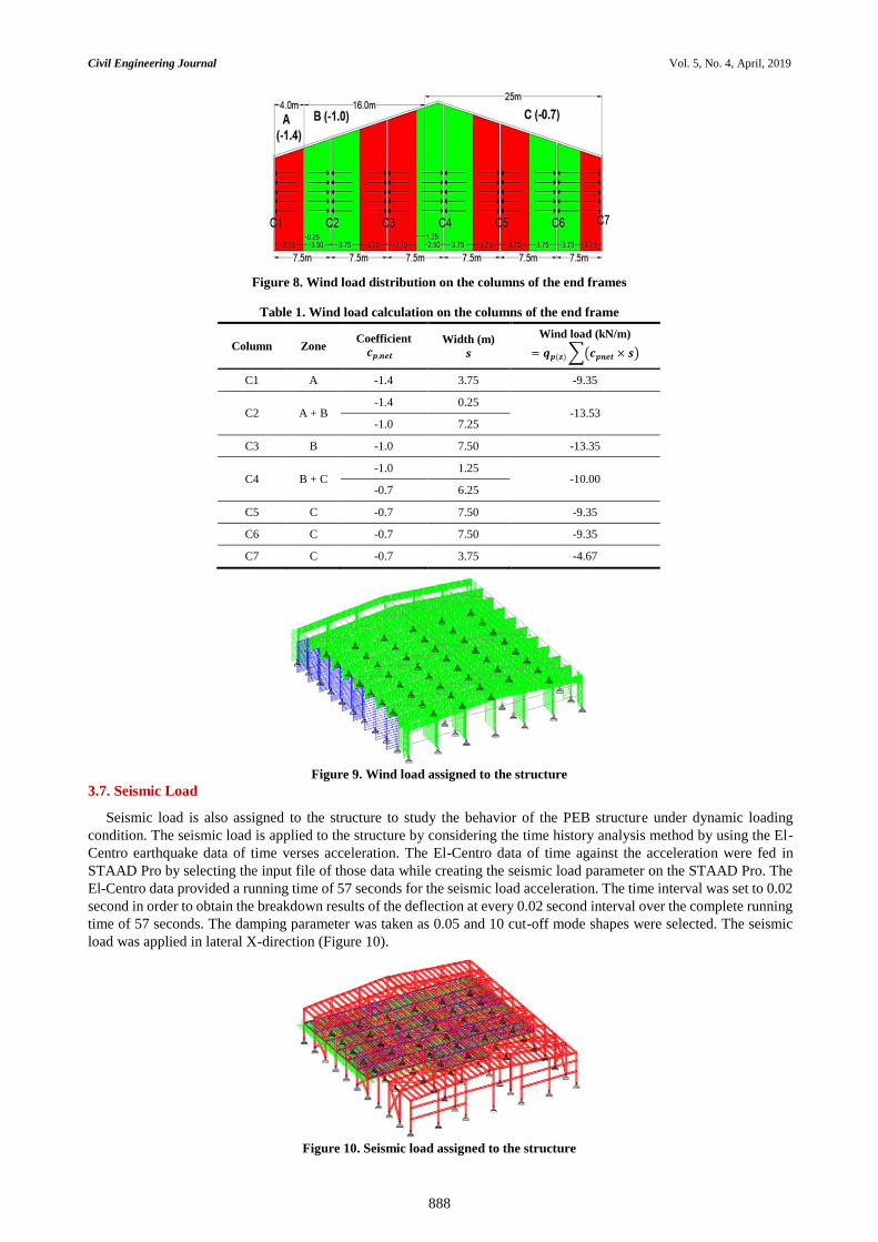
In this calculation only internal portal frame is considered for the calculating the wind load on the PEB structure.
For obtaining the wind load on the exterior frames, it can be taken half of the load that is acting on the interior portal
frame.
The external wind pressure acting on the external surfaces can be calculated using;
𝑤𝑒 = 𝑞𝑝. (𝑧𝑒). 𝑐𝑝𝑒 (EN 1991-1-4, § 5.2, Eq 5.1 [19, 20])
The wind load calculation are shown in Figure 8 and Table 1. Assigning the wind load to STAAD model as shown
in Figure 9.
Civil Engineering Journal Vol. 5, No. 4, April, 2019
888
Figure 8. Wind load distribution on the columns of the end frames
Table 1. Wind load calculation on the columns of the end frame
Figure 9. Wind load assigned to the structure
3.7. Seismic Load
Seismic load is also assigned to the structure to study the behavior of the PEB structure under dynamic loading
condition. The seismic load is applied to the structure by considering the time history analysis method by using the El-
Centro earthquake data of time verses acceleration. The El-Centro data of time against the acceleration were fed in
STAAD Pro by selecting the input file of those data while creating the seismic load parameter on the STAAD Pro. The
El-Centro data provided a running time of 57 seconds for the seismic load acceleration. The time interval was set to 0.02
second in order to obtain the breakdown results of the deflection at every 0.02 second interval over the complete running
time of 57 seconds. The damping parameter was taken as 0.05 and 10 cut-off mode shapes were selected. The seismic
load was applied in lateral X-direction (Figure 10).
Figure 10. Seismic load assigned to the structure
Column Zone Coefficient
𝒄𝒑,𝒏𝒆𝒕 Width (m)
𝒔
Wind load (kN/m)
= 𝒒𝒑(𝒛) ∑(𝒄𝒑𝒏𝒆𝒕 × 𝒔)
C1 A -1.4 3.75 -9.35
C2 A + B -1.4 0.25
-13.53 -1.0 7.25
C3 B -1.0 7.50 -13.35
C4 B + C -1.0 1.25
-10.00 -0.7 6.25
C5 C -0.7 7.50 -9.35
C6 C -0.7 7.50 -9.35
C7 C -0.7 3.75 -4.67
Civil Engineering Journal Vol. 5, No. 4, April, 2019
889
3.8. Load Combinations
After assigning the above four load cases to the structure, different load combinations were created in order to
apply the safety factor for the structure. Below are the load combination in accordance to British standard and Euro
code.
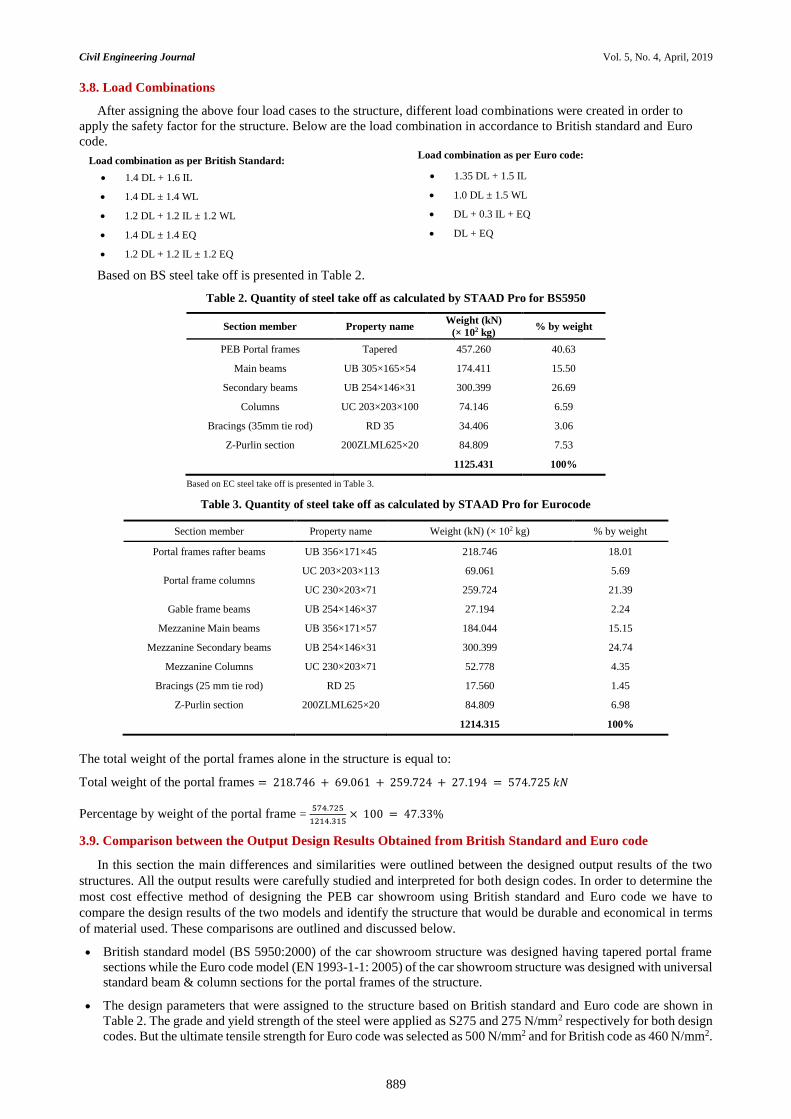
Based on BS steel take off is presented in Table 2.
Table 2. Quantity of steel take off as calculated by STAAD Pro for BS5950
Section member Property name Weight (kN)
(× 102 kg) % by weight
PEB Portal frames Tapered 457.260 40.63
Main beams UB 305×165×54 174.411 15.50
Secondary beams UB 254×146×31 300.399 26.69
Columns UC 203×203×100 74.146 6.59
Bracings (35mm tie rod) RD 35 34.406 3.06
Z-Purlin section 200ZLML625×20 84.809 7.53
1125.431 100%
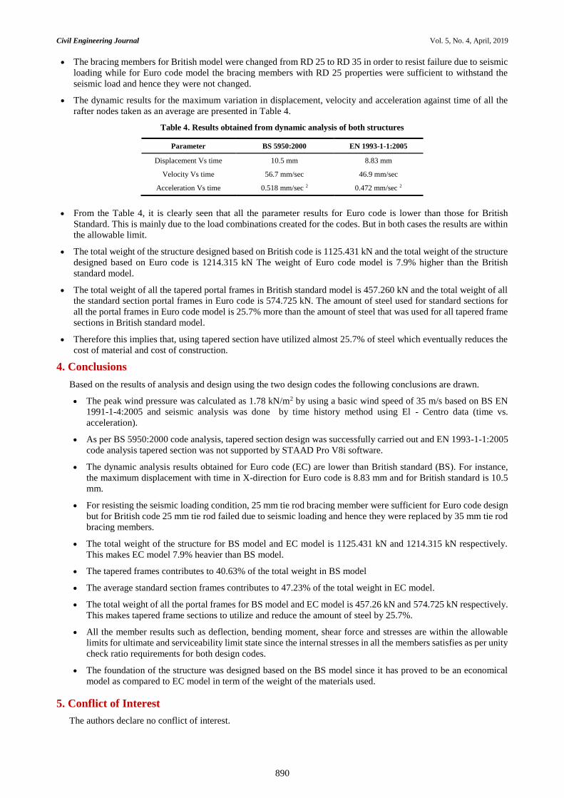
Based on EC steel take off is presented in Table 3.
Table 3. Quantity of steel take off as calculated by STAAD Pro for Eurocode
Section member Property name Weight (kN) (× 102 kg) % by weight
Portal frames rafter beams UB 356×171×45 218.746 18.01
Portal frame columns UC 203×203×113 69.061 5.69
UC 230×203×71 259.724 21.39
Gable frame beams UB 254×146×37 27.194 2.24
Mezzanine Main beams UB 356×171×57 184.044 15.15
Mezzanine Secondary beams UB 254×146×31 300.399 24.74
Mezzanine Columns UC 230×203×71 52.778 4.35
Bracings (25 mm tie rod) RD 25 17.560 1.45
Z-Purlin section 200ZLML625×20 84.809 6.98
1214.315 100%
The total weight of the portal frames alone in the structure is equal to:
Total weight of the portal frames = 218.746 + 69.061 + 259.724 + 27.194 = 574.725 𝑘𝑁
Percentage by weight of the portal frame = 574.725
1214.315 × 100 = 47.33%
3.9. Comparison between the Output Design Results Obtained from British Standard and Euro code
In this section the main differences and similarities were outlined between the designed output results of the two
structures. All the output results were carefully studied and interpreted for both design codes. In order to determine the
most cost effective method of designing the PEB car showroom using British standard and Euro code we have to
compare the design results of the two models and identify the structure that would be durable and economical in terms
of material used. These comparisons are outlined and discussed below.
British standard model (BS 5950:2000) of the car showroom structure was designed having tapered portal frame
sections while the Euro code model (EN 1993-1-1: 2005) of the car showroom structure was designed with universal
standard beam & column sections for the portal frames of the structure.
The design parameters that were assigned to the structure based on British standard and Euro code are shown in
Table 2. The grade and yield strength of the steel were applied as S275 and 275 N/mm2 respectively for both design
codes. But the ultimate tensile strength for Euro code was selected as 500 N/mm2 and for British code as 460 N/mm2.
Load combination as per Euro code:
1.35 DL + 1.5 IL
1.0 DL ± 1.5 WL
DL + 0.3 IL + EQ
DL + EQ
Load combination as per British Standard:
1.4 DL + 1.6 IL
1.4 DL ± 1.4 WL
1.2 DL + 1.2 IL ± 1.2 WL
1.4 DL ± 1.4 EQ
1.2 DL + 1.2 IL ± 1.2 EQ
Civil Engineering Journal Vol. 5, No. 4, April, 2019
890
The bracing members for British model were changed from RD 25 to RD 35 in order to resist failure due to seismic
loading while for Euro code model the bracing members with RD 25 properties were sufficient to withstand the
seismic load and hence they were not changed.
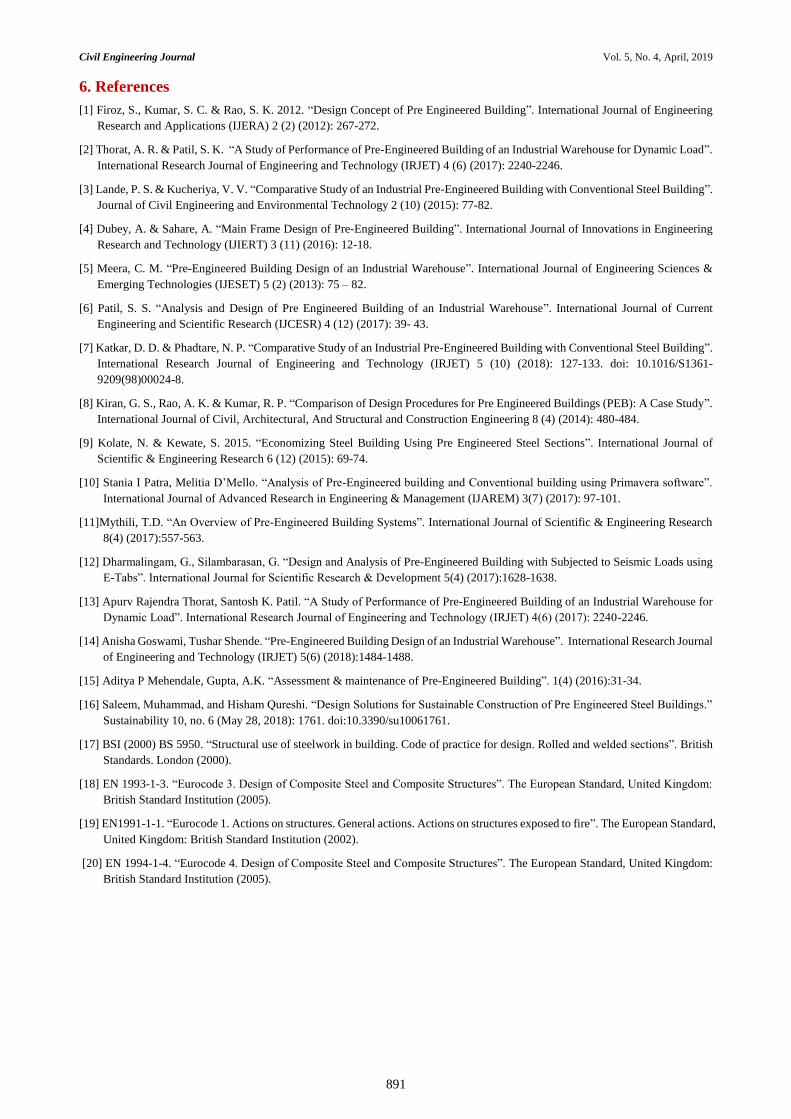
The dynamic results for the maximum variation in displacement, velocity and acceleration against time of all the
rafter nodes taken as an average are presented in Table 4.
Table 4. Results obtained from dynamic analysis of both structures
Parameter BS 5950:2000 EN 1993-1-1:2005
Displacement Vs time 10.5 mm 8.83 mm
Velocity Vs time 56.7 mm/sec 46.9 mm/sec
Acceleration Vs time 0.518 mm/sec 2 0.472 mm/sec 2
From the Table 4, it is clearly seen that all the parameter results for Euro code is lower than those for British
Standard. This is mainly due to the load combinations created for the codes. But in both cases the results are within
the allowable limit.
The total weight of the structure designed based on British code is 1125.431 kN and the total weight of the structure
designed based on Euro code is 1214.315 kN The weight of Euro code model is 7.9% higher than the British
standard model.
The total weight of all the tapered portal frames in British standard model is 457.260 kN and the total weight of all
the standard section portal frames in Euro code is 574.725 kN. The amount of steel used for standard sections for
all the portal frames in Euro code model is 25.7% more than the amount of steel that was used for all tapered frame
sections in British standard model.
Therefore this implies that, using tapered section have utilized almost 25.7% of steel which eventually reduces the
cost of material and cost of construction.
4. Conclusions
Based on the results of analysis and design using the two design codes the following conclusions are drawn.
The peak wind pressure was calculated as 1.78 kN/m2 by using a basic wind speed of 35 m/s based on BS EN
1991-1-4:2005 and seismic analysis was done by time history method using El - Centro data (time vs.
acceleration).
As per BS 5950:2000 code analysis, tapered section design was successfully carried out and EN 1993-1-1:2005
code analysis tapered section was not supported by STAAD Pro V8i software.
The dynamic analysis results obtained for Euro code (EC) are lower than British standard (BS). For instance,
the maximum displacement with time in X-direction for Euro code is 8.83 mm and for British standard is 10.5
mm.
For resisting the seismic loading condition, 25 mm tie rod bracing member were sufficient for Euro code design
but for British code 25 mm tie rod failed due to seismic loading and hence they were replaced by 35 mm tie rod
bracing members.
The total weight of the structure for BS model and EC model is 1125.431 kN and 1214.315 kN respectively.
This makes EC model 7.9% heavier than BS model.
The tapered frames contributes to 40.63% of the total weight in BS model
The average standard section frames contributes to 47.23% of the total weight in EC model.
The total weight of all the portal frames for BS model and EC model is 457.26 kN and 574.725 kN respectively.
This makes tapered frame sections to utilize and reduce the amount of steel by 25.7%.
All the member results such as deflection, bending moment, shear force and stresses are within the allowable
limits for ultimate and serviceability limit state since the internal stresses in all the members satisfies as per unity
check ratio requirements for both design codes.
The foundation of the structure was designed based on the BS model since it has proved to be an economical
model as compared to EC model in term of the weight of the materials used.
5. Conflict of Interest
The authors declare no conflict of interest.
Civil Engineering Journal Vol. 5, No. 4, April, 2019
891
6. References
[1] Firoz, S., Kumar, S. C. & Rao, S. K. 2012. “Design Concept of Pre Engineered Building”. International Journal of Engineering
Research and Applications (IJERA) 2 (2) (2012): 267-272.
[2] Thorat, A. R. & Patil, S. K. “A Study of Performance of Pre-Engineered Building of an Industrial Warehouse for Dynamic Load”.
International Research Journal of Engineering and Technology (IRJET) 4 (6) (2017): 2240-2246.
[3] Lande, P. S. & Kucheriya, V. V. “Comparative Study of an Industrial Pre-Engineered Building with Conventional Steel Building”.
Journal of Civil Engineering and Environmental Technology 2 (10) (2015): 77-82.
[4] Dubey, A. & Sahare, A. “Main Frame Design of Pre-Engineered Building”. International Journal of Innovations in Engineering
Research and Technology (IJIERT) 3 (11) (2016): 12-18.
[5] Meera, C. M. “Pre-Engineered Building Design of an Industrial Warehouse”. International Journal of Engineering Sciences &
Emerging Technologies (IJESET) 5 (2) (2013): 75 – 82.
[6] Patil, S. S. “Analysis and Design of Pre Engineered Building of an Industrial Warehouse”. International Journal of Current
Engineering and Scientific Research (IJCESR) 4 (12) (2017): 39- 43.
[7] Katkar, D. D. & Phadtare, N. P. “Comparative Study of an Industrial Pre-Engineered Building with Conventional Steel Building”.
International Research Journal of Engineering and Technology (IRJET) 5 (10) (2018): 127-133. doi: 10.1016/S1361-
9209(98)00024-8.
[8] Kiran, G. S., Rao, A. K. & Kumar, R. P. “Comparison of Design Procedures for Pre Engineered Buildings (PEB): A Case Study”.
International Journal of Civil, Architectural, And Structural and Construction Engineering 8 (4) (2014): 480-484.
[9] Kolate, N. & Kewate, S. 2015. “Economizing Steel Building Using Pre Engineered Steel Sections”. International Journal of
Scientific & Engineering Research 6 (12) (2015): 69-74.
[10] Stania I Patra, Melitia D’Mello. “Analysis of Pre-Engineered building and Conventional building using Primavera software”.
International Journal of Advanced Research in Engineering & Management (IJAREM) 3(7) (2017): 97-101.
[11]Mythili, T.D. “An Overview of Pre-Engineered Building Systems”. International Journal of Scientific & Engineering Research
8(4) (2017):557-563.
[12] Dharmalingam, G., Silambarasan, G. “Design and Analysis of Pre-Engineered Building with Subjected to Seismic Loads using
E-Tabs”. International Journal for Scientific Research & Development 5(4) (2017):1628-1638.
[13] Apurv Rajendra Thorat, Santosh K. Patil. “A Study of Performance of Pre-Engineered Building of an Industrial Warehouse for
Dynamic Load”. International Research Journal of Engineering and Technology (IRJET) 4(6) (2017): 2240-2246.
[14] Anisha Goswami, Tushar Shende. “Pre-Engineered Building Design of an Industrial Warehouse”. International Research Journal
of Engineering and Technology (IRJET) 5(6) (2018):1484-1488.
[15] Aditya P Mehendale, Gupta, A.K. “Assessment & maintenance of Pre-Engineered Building”. 1(4) (2016):31-34.
[16] Saleem, Muhammad, and Hisham Qureshi. “Design Solutions for Sustainable Construction of Pre Engineered Steel Buildings.”
Sustainability 10, no. 6 (May 28, 2018): 1761. doi:10.3390/su10061761.
[17] BSI (2000) BS 5950. “Structural use of steelwork in building. Code of practice for design. Rolled and welded sections”. British
Standards. London (2000).
[18] EN 1993-1-3. “Eurocode 3. Design of Composite Steel and Composite Structures”. The European Standard, United Kingdom:
British Standard Institution (2005).
[19] EN1991-1-1. “Eurocode 1. Actions on structures. General actions. Actions on structures exposed to fire”. The European Standard,
United Kingdom: British Standard Institution (2002).
[20] EN 1994-1-4. “Eurocode 4. Design of Composite Steel and Composite Structures”. The European Standard, United Kingdom:
British Standard Institution (2005).