down with noise practical control systems for combatting audible noise show up in aerospace, general...
TRANSCRIPT

Down with
Practical control systems for combatting audible noise show up in aerospace, general aviation, and military roles
ANNOYING NOISE IN THE passenger cabins of propeller aircraft, the rumble in air-conditioning systems, and the sounds disrupting headset communication are being reduced these days by active noise control, thanks to advances in digital sig- nal processing. The technique relies on the principle of de- structive interference between two sound fields; one field is generated by the original or primary sound source, the other by a secondary sound source set up to interfere with, and can- cel, that unwanted primary sound. The primary source may be an engine and the secondary source, a loudspeaker with an electronically controlled output.
Destructive interference is at its most efficient when the two sound fields can be accurately aligned in space over an acoustic wavelength. It works best on low-frequency sounds, whose acoustic wavelendhs are large conmared to the zone
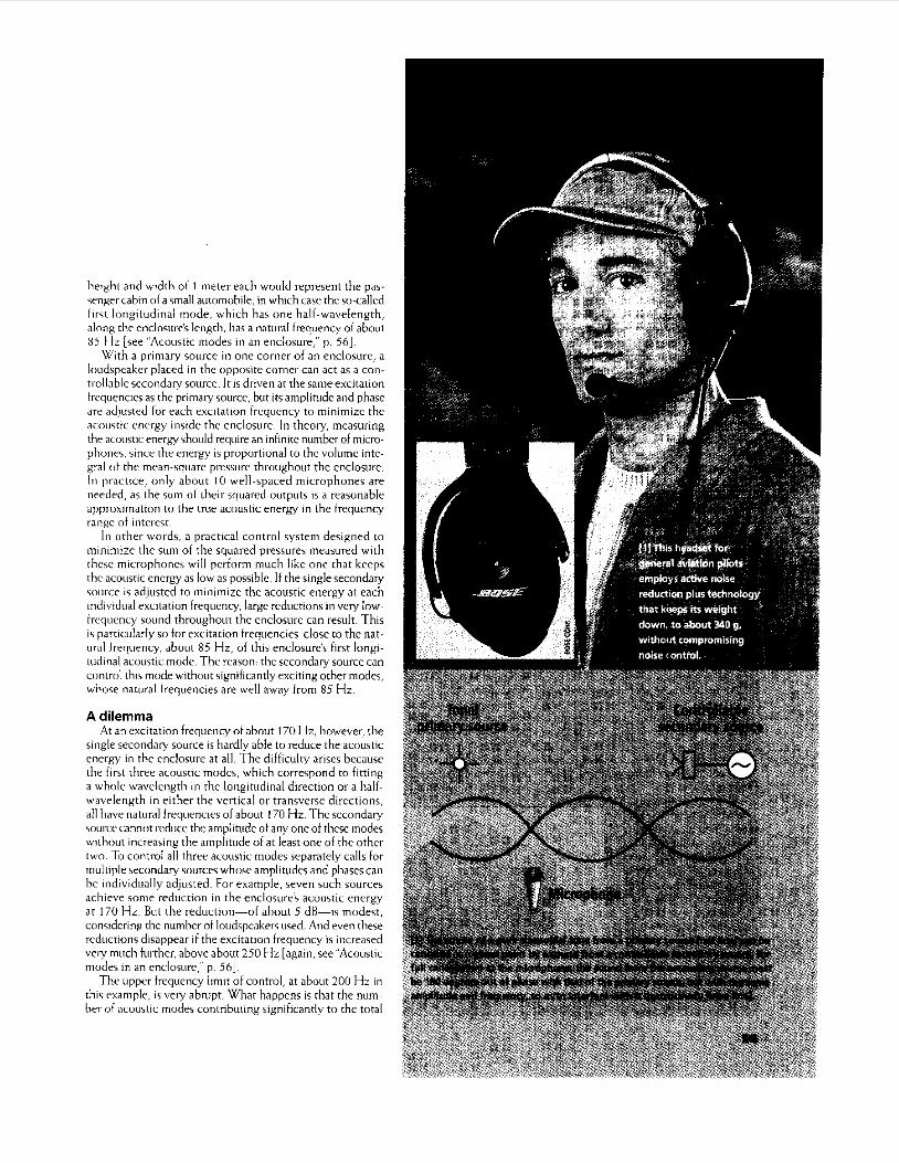
aircraft is a widespread example. Further, earphones with built- in active noise control are available for general aviation pilots [Fig. 11. Future developments, such as control of the noise inside cars, will require an understanding of both the physi- cal principles of sound cancellation and the technology of producing a reliable, robust control system at a reasonable cost.
Scientific principles What are the physical mechanisms of active noise control?
Consider a pressure waveform as sensed by a microphone positioned so that its output is influenced by both a pri- mary source of sound and a controllable secondary source- a loudspeaker. For simplicity, the primary source may be assumed to be tonal, so that its pressum waveform at the micro- phone is sinusoidal [red line in Fig. 21. The amplitude and
in which the noise is c&elled. Fn conirast, traditional passive techniques, which employ heavy barriers to block the transmission of sound and acoustic materials to absorb sound energy, are more effective at higher frequencies, when the acoustic wavelength is large compared to the thickness of an absorber. But a sound wave with a frequency of 100 Hz, typical of engine noise, has a wavelength of 3.4 meters or so in air under normal conditions. Many low-frequency acoustic noise problems are therefore difficult to control pas- sively, yet may be amenable to active control. The active approach can thus complement the traditional passive con- trol methods.
Recent developments with inexpensive and powerful dig- ita1 signal-processing (DSP) chips have brought active con- trol techniques within the realm of practicality. At present, they show up most often in aerospace applications, where the weight and space requirements of passive techniques often preclude their use in controlling low-frequency sound. n e active control of propeller noise in the passenger cabins of
phase of the secondary source is driven by a sine wave generator at the same frequency as the primary source but with the phase shifted by 180 degrees [blue line in Fig. 21. If both sourxes are on at the same time, their acoustic
pressures cancel, since sound propagation is very nearly a lin- ear process at all but the highest sound-pressure levels (up to about 140 dB), and the principle of superposition applies- sound waveforms are additive. How much active sound con- trol at a single microphone position like this influences the sound field at other points in space depends upon the sepa- ration between the sources and upon the acoustic environ- ment, for example, whether the pressure wave propagates freely in air or is enclosed within a confined space.
The sound field in an enclosure, whether a room or an auto- motive or aircraft passenger cabin, is typically created by stand- ing, rather than propagating, waves, and depends on the super- position of a number of acoustic modes. A mode is chamterized by the number of wavelengths that fits along one dimension of the enclosure. An enclosure of length of about 2 meters and
S~F'HEN J. ELLIOTT University of
Southampton
54 001 8-9235/99/$10.0081999 IEEE IEEE SPECTRUM JUNE 1999
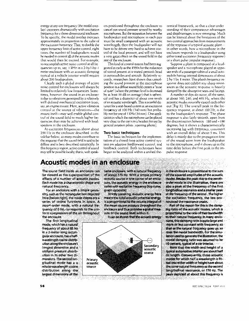
height and width 01 1 mr t r r rach would rrprrsrnt thr pas- senger cahin 01 a small autimobilc, in which cai r the wcal l rd fir51 longitudinal mnde. which has one hall-wavelength, along the enclosure'r length. has a natural frequency ni ahout 8 5 I I L [see "Acoustic modes in an encInsuic,"p. 561.
With a primary source in oiie corner of an enclosure. a loudspeaker placed in the opposite corner can act as a coil- trollablcsccondarysourcc. I t i s drivenat the sameexcitation trcqiiencics as thc primary sourcc, hut i ts amplitude and phase arc adjusred tor each excitation frcqucncy to minimizc the acoustic rncrgy insidc the enclosure. In thcory. mcasuring thc acoustic rncrgy should require an inhnitc nunibcr of micro- phone, sincr thr cncrgy i s proportional to thc volumc intc- gral uf thr mean-iquarr pre,surr throughout the enclosurc. In practxe. m l y about I O well-spaced micruphunes are iieedrd, as the sum d thwr squared uritputr IS a rrasunablc approximation to the tme acowtic enerm in thc trcqurncy range of nteresr.
111 other words. a practical control system designed IO
niinimizc the sum of the squared pressurer mearured with rhcsc microphoncs wil l perform much like one that keeps thc acoustic cncrgy as low as possible. If the single secondary soilice IS adjiistcd to minimizc thc acoustic energy a t each individual cxcitation frequency, largc rcductions in very low^ trrqorncy w i n d throughout thc enclosurc can result. This i s particularly so tor excitation trequencics closc to thc nat- ural trrqucncy, about 85 Hz, ot this cnclosure's first longi- tudinal acoustic mudr. Tht. reason: the secondary sourcc can ciintnil thir mode without signiticantly cxcitmg other modes, whoce natural lrequencies are wr l l away from 85 H z
A dilemma At an excitation frequency of shout 170 H z . however. the
single secondaly source i s hardly able to reduce the acnustic cncrgy in thc cnclosurc a t all. The difficulty arises because the first three acoustic modcs. which correspond to fitting a whole wavelength in thc longitudinal direction or a half^ wavclrngth in either the vcrtical or transverse directions, a l l havr natiiral frequencies of about I70 Hz. Thc sccondary sourcr cannvt rcducc the ampllhlde of any onc of thcsc modes without increasing the amplitude of a t least onc of rhc othcr two. To c o n t d al l thrcc acoustic modes separately calls for multiple iecondary suurces whusc amplitudes and phases can he individually adjusted. For cxample, swrn such sources achieve snnie reduction ~n the enclosurr'b acwstic enrrgy ar 170 HL. But the reduction-of ahnut 5 dK--l.; modest, considering the nuinher of loudspeakem used. And even these rcductions disappear if the excitation frequency i s increaied very much hirrhcr. abovc about 250 Hr [again, see"Acoustir modes in an cnclosurc," p. 561.
The upper trequency limit of control, at about 2OU Hz in this rxample. is very abnipr. W h a t happens is rhar the iiuni~ hcr of acvuitic modrs contributing significanrlv to the total
energy at any one hequency (the modal over- lap1 increases dramatically with excitation frequency for a three-dimensional enclosure. To be specitic, the modal overlap increasrs approximately in proportion to the cuhr of theevcitatjon frequency Thus, to doublr the upper frequency limit of activc control, right times the number of loudspeakers would bt. needed to control all of the acuiisnc modec that would then hc cxcited. For example, to accomplish active noisr control at all f r e~ quencies up to, say, I kHz in a 2-hyl-hy-l meter enclosure with an acwstic damping typical of a vehicle intrrior would require about 200 loudspeakcn.
Clearly such a gluhal strategy of activc noise control for rnclosures will always bc liniitcd to relatively low frequencies. some^ times, howcvrr, the sound in an enclosiirr is due to vibrations generated by a relatively well~drtined mechanical excitation trom, say. a n cngine mount. Herc, active vibration contrul at the source of vibrations-the mount itcelf-may well enable global c m - t r d ol the sound ficld to much higher fre- quencies than (may bc achieved with loud- ipeakerr in the enclosure.
At excitation frequencies above about 210 H r in thc encloswr dercrihed i n the sidebar below,, so manymdec contribute ro the response that the round tield is said to bc diffuse and is best described statistically. In this kqucncy region, active control of sound may still hr pusrible locally, thar is, with sprak-
er5 positioned throughout the enclosurr to cancel out sound pressurc sensed by nearby mrmphones. But the separation between the loudspeaker and microphone ~n each pair must he small compared with a n acnwtic wavelength; then the loudspeaker will not have to be driven very hard to achieve con- trol of the local pressure. and will not have a very grcat effect on the sound field in the rest of the enclusure.
This kind of control system had becn s u g gestcd as early as the I9505 for the reduction of sound present at a seated person's head in automubiles and aircraft. Relatively re- cently, researchers have shown that cancel- ing the sound pressure at the microphone positivn in a diffuse sound field creates a "zone oi quiet" (where the pressurc lwel is decreased by at least 10 dB on average) that is spheri- cal and has a diamcter of about one-tenth of an acoustic wavelength. This is a useful dis- tance for a seat-based system at an excitation freqwncy of 100 Hz (340mm) hut proha- hlynotforoneot 1 kHz(34mm). Oneappli- cation in which thr microphone can be placed vety close to the car is in a headset for use by gcncral aviation pilots [opening photo].
Two basic techniques The basic techniques for the implemen-
tation o( a closed-loop activc control sys- tem are adaptive feedforward cuntrul, and teedhack control. Both techniques have hegun to be analyzed within a unified the-
oretical framework. so that a clear under^ standing of thcir comparative advantages and disadvantages IS now emerging. Much can he learned ahout the limitations of thc two control appruaches fmm measurements of the response ol a typical acoustic plant- in other words, how a microphone in the enclosurr respond? tn a loudspeakcr using either tonal excitation (frequency rcsponsr! or a short puke (impulse response].
Suppose a plant is composed ot B loud- sprakrr and a niicrophonc placed at uppo- site ends of a passenger cabin of a small auto- mobile having internal dimensions ut about 2 hy 1 by I meter. This plant:, irequency re- rponre does riot cxhibit any sharp r e m - ances as the acoustic response IS heavily damped by thc absorptive seats and facings.
A numbcr of dips dn occur, all the same, at about Ih0,240. and 460 H r , wherc the acoustic modes naturally cancel each other out [Fig 31. The overal l peak i n the f r e ~ quency rerpome, at about 100 Hz, IS dur to thr loudspeakeis response The phair response 1s alio fairly smooth. apart trom the discontinuitiec between -1 80 and + 180 degrees; but it shows a characteristically increasing lag with frcquency, consistent with an overall dclay of about 5 mi. This delay i 5 mainly duc to the prupagauon time nf the sound wave from the loudspeaker to the microphonr, and $1 shows up i n the time dclay beiurr thr first peak in thc i m ~ pulsc responic
The impulse response i s also very well damped, decaying to almost zero after about 70 ms. Because i t does not last vely long, i t i s efficiently modeled by finite ~mpiilse response (FIR) filters in active noise control applications. This i s in cnntrast to thc inti- nite impulse response (IIR) models that are more commnn in describing the vibration rcrponsr of StNctUres. Such StNCtUreS as a panel in an aircraft may well be very lightly damped, and they exhihit plant responses o la relatively low nrder, because their modal overlap generally increaser only linearly with frequency.
Uncertainty, as well The plant response in active noise con-
trol applications i s not only subject to delay and damping, but also influenced by a large amount of what control engineers wnuld call uncertainty. The mnvemrnt ut passengers within, say, the cabin ofavehiclecancause variations of 3 dB in amplitude and 45 degrees in phase.
In manycnntrol systems, plant response changes of this nature can be measured hy injecting a test signal into the plant and iden- tifying the plant's response. But suppose the changes in the plant response occur within less than a second, as happens with the mnvement of vasseneers and in many other
I I 110
105
m 100
s, P i 95 U
I
._ L
3 4 90
50 100 150 200 250 300 350 400
Frequency, HZ
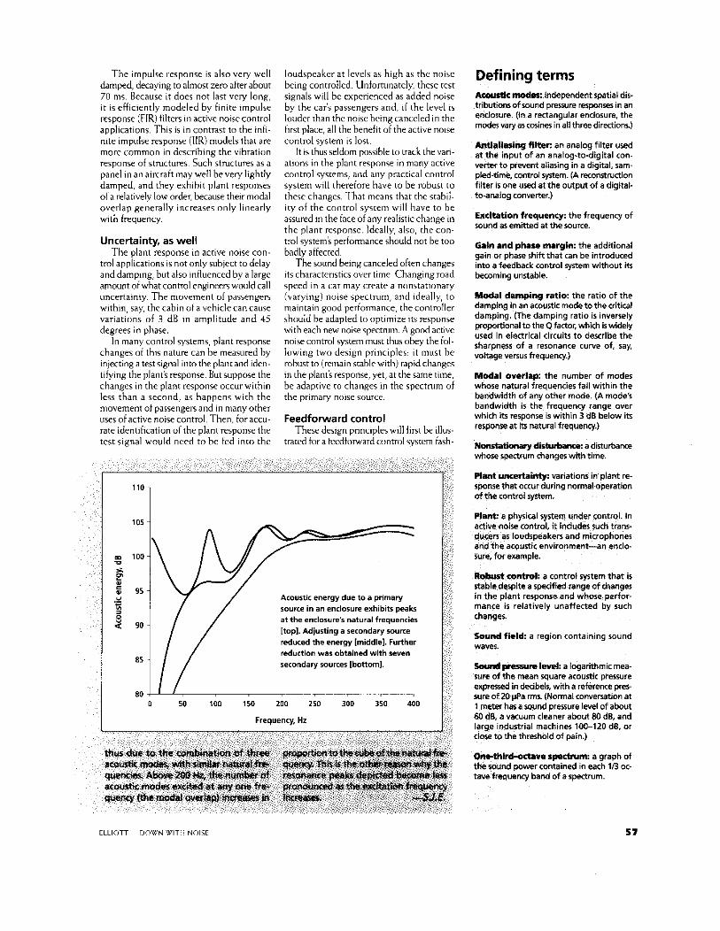
Acoustic energy due to a primary source in an enclo~ure exhibits peaks a t the enrlorure's natural frequencies [top]. Adjusting a secondary soume reduced the energy Imiddle]. Further reduction war obtained with seven secondary sources Ibonoml.
Defining terms Awustk modes: independent spatial dis- tributionrof m n d prewre mpmei in an enclosure. (In a rectangular enclosure. the moder vary arcwiner inall threedirectiom)
Adaliasing filtw: an analog filter used at the input of an analog-to-digital con- vsrter to prevent aliasing in a digital, sam- pled-time, control system. (A reconstruction filter is one U& at the output of a digkal- to-analog converter.)
Excitation frequency: the frequency of sound as emitted at the lource.
Galn and phase margin: the additional gain or phase shift that can be introduced into a feedback control system without i ts becoming unstable.
Modal damping ratio: the ratio of the damping in an acoustic mode tothe critical damping. (The damping ratio is inversely proportionaltotheQfactor,wh& iswidely used in electrical circuits to describe the sharpness of a resonance curve of, ray. voltage versus frequenq.)
Modal overlap: the number of modes whose natural frequencies fall within the bandwidth of any other mode. (A mode's bandwidth i s the frequency range over which i t s response is within 3 dB below its rerponre at itr natural frequency.)
N o n s W b w y d i s i u r b m m a disturbance whore spearurn changes wlth time.
Plant uncertainty: variations in plant re spoose that occur during normal operation of the control syjtem.
Plant: a physical system under control. In active noise contrd. it incledes such trans- dwr! as loudspeakers and microphones and the acoustic environment-an enclo- sure. for example.
Robust control; a control rystam that i s stataMe despite a specified range of changes in the plant responra and whose perfor- mance i s relatively unaffected by such changes.
Sound field a region containing sound waves.
Sounil possum l e d a logarithmic mea- sure of the mean square acoustic pressure expressed in decibds, with a reference p m sure of 20 pQPa rm. (Normal conversation at 1 meter hasa sound pressure level of about €4 dB, a vacuum cleaner about Bo dB, and larw industrial machines 100-120 de, or close to the threshold of pain.)
Ow-thM-odava SpctNm: a graph of the lound power contained in each 1B oc-
uency band of a spectrum.
CLLlOTT- DOU'N WIT11 NOIS[ 57
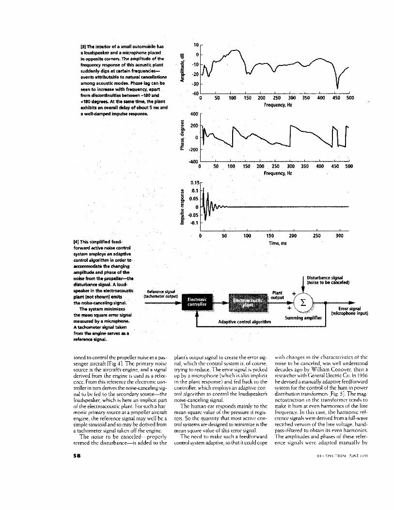
131 The interior of a andl automobile has a loudspeaket and a microphone placed in opp.=site corners. The ampliNde of the f w q m y response of this acoustic plant suddenly dips at certain fmquencie-s- events amibutebla to natural cancellations among acoustic modmi. Phase lag can be Men to increase with freqmncy, apan fmm dixontinumes !aawe+n -180 and +180 dogmas. At the m e time, the plant exhibits an overall delay of about 5 ms and a well-dampad impulse rerpome.
10 r
f.
4 -30 - -40
o sa 100 150 200 250 300 350 400 450 500 Frequency. L
I41 This simplified feed- torward active mise control system employs an adeptiws wntrol a@rithm in order Io x m m & t e the changing amplihKk and phase d the noise from the pmpcllerthe disturbance slgnal. A loud. spmker in the ektnroacourtic plant {not shown1 emu the noirbcancding S!qnal.
The synem minimizer the mean squere wmr si& measured by 0 ntnmphone. A tachometer M a l taken from the engine serves as a refewesignal.
0 50 100 150 200 250 300 350 400 450 5MI Freqwnq, Hz
0 50 180 150 200 250 300 Time, ms
Adautive control alaorithm
ioned to control thc propeller noise in a pas- senger aircraft [Fig 41. The primary noise source i s the aircrait's engine, and a signal derived from the engine i s used as a refer- ence. From this reference thc rlrctruniccon- troller in him derives the noise-cancelingsix-
planri output signal to crratr the error rig- nal, which the control system is. of course, trying to reduce The error signal i s picked up by a microphone (which i < alsn Implicit in the plant response) and fed hack to the controller. which emplnyq an adaptive con-
nal to br tcd to the secondary source-& loudspeaker, which is here an implicit part of the electroacoustic plant. For such a ha r~ monic primary source as a propeller aircraft engine, the reference signal may wcll be a simple sinusoid and so may bc dcrivcd from a tachometer signal taken off the engine.
The noise to be canceled-properly rermed thc disturbance-is added to the
5 8
t iol algorithm to control the loudspeakei-s noise~canceling signal.
The human ear responds mainly to the mean squarc value of the pressure it regis^ ters. So the quantity that most active con- trol systems are designed to minimize is the mean square value of this error signal.
The need tu make such a feedlorward control system adaptive, so that i t could cope
wi lh change5 in the characteristics of the noise to he canceled, was well understood decades ago by William Conover. then a researcher with General Electsic Co. In 1956 he devised a manually adaptive feedfoward system for the control of the hum in powcr distribution rransformcrs [Fig 51. The mag^
netostriction in the transformrr tcnds to make it hum at even harmonics ut thr linr fxqurnry. In this case, thc harmonic rel- rrence signals werr denved from a full-wave rectified version o i the line voltage, hand- pacs-iiltered to ohrain it5 even harmonics, The amplitudes and phases of these refer- ence signals were adapted manually by
IFFF SPF< TRUM IllhF , ,141
loudspeaker a I
Adapted from Noise Control Magazine
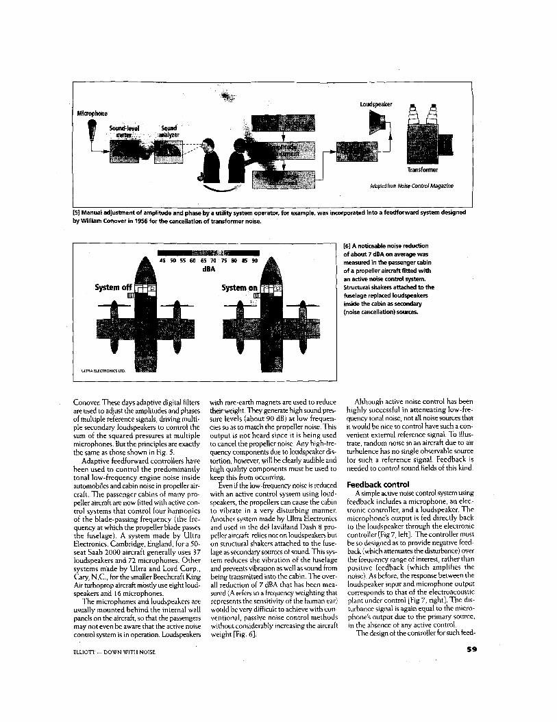
[SI Manual adjustment of amplitude and phase by a utility system operator, for example, was incorporated into a feedforwad system designed by William Conover in 1956 for the cancellation of transformer noise.
ULTRA ELECTRONICS LTD
Conover. These days adaptive digital filters are used to adjust the amplitudes and phases of multiple reference signals, driving multi- ple secondary loudspeakers to control the sum of the squared pressures at multiple microphones. But the principles are exactly the same as those shown in Fig. 5.
Adaptive feedfonvard controllers have been used to control the predominantly tonal low-frequency engine noise inside automobiles and cabin noise in propeller air- craft. The passenger cabins of many pro- peller aircraft are now fitted with active con- trol systems that control four harmonics of the blade-passing frequency (the fre- quency at which the propeller blade passes the fuselage). A system made by Ultra Electronics, Cambridge, England, for a 50- seat Saab 2000 aircraft generally uses 37 loudspeakers and 72 microphones. Other systems made by Ultra and Lord Corp., Cary, N.C., for the smaller Beechcraft King Air turboprop aircraft mostly use eight loud- speakers and 16 microphones.
The microphones and loudspeakers are usually mounted behind the internal wall panels on the aircraft, so that the passengers may not even be aware that the active noise control system is in operation. Loudspeakers
[6] A noticeable noise reduction of about 7 dBA on average was measured in the passenger cabin of a propeller aircraft fitted with an active noise control system. Structural shakers attached to the fuselage replaced loudspeakers inside the cabin as secondary (noise cancellation) sources.
with rare-earth magnets are used to reduce their weight. They generate high sound pres- sure levels (about 90 dB) at low frequen- cies so as to match the propeller noise. This output is not heard since it is being used to cancel the propeller noise. Any high-fre- quency components due to loudspeaker dis- tortion, however, will be clearly audible and high quality components must be used to keep this from occurring.
Even if the low-frequency noise is reduced with an active control system using loud- speakers, the propellers can cause the cabin to vibrate in a very disturbing manner. Another system made by Ultra Electronics and used in the deHavilland Dash 8 pro- peller aircraft relies not on loudspeakers but on structural shakers attached to the fuse- lage as secondary sources of sound. This sys- tem reduces the vibration of the fuselage and prevents vibration as well as sound from being transmitted into the cabin. The over- all reduction of 7 dBA that has been mea- sured (A refers to a frequency weighting that represents the sensitivity of the human ear) would be very difficult to achieve with con- ventional, passive noise control methods without considerably increasing the aircraft weight [Fig. 61.
Although active noise control has been highly successful in attenuating low-fre- quency tonal noise, not all noise sources that it would be nice to control have such a con- venient external reference signal. To illus- trate, random noise in an aircraft due to air turbulence has no single observable source for such a reference signal. Feedback is needed to control sound fields of this kind.
Feedback control A simple active noise control system using
feedback includes a microphone, an elec- tronic controller, and a loudspeaker. The microphone's output is fed directly back to the loudspeaker through the electronic controller [Fig 7, left]. The controller must be so designed as to provide negative feed- back (which attenuates the disturbance) over the frequency range of interest, rather than positive feedback (which amplifies the noise). As before, the response between the loudspeaker input and microphone output corresponds to that of the electroacoustic plant under control [Fig 7, right]. The dis- turbance signal is again equal to the micro- phone's output due to the primary source, in the absence of any active control.
The design of the controller for such feed-
5 9 ELLIOTT - DOWN WITH NOISE
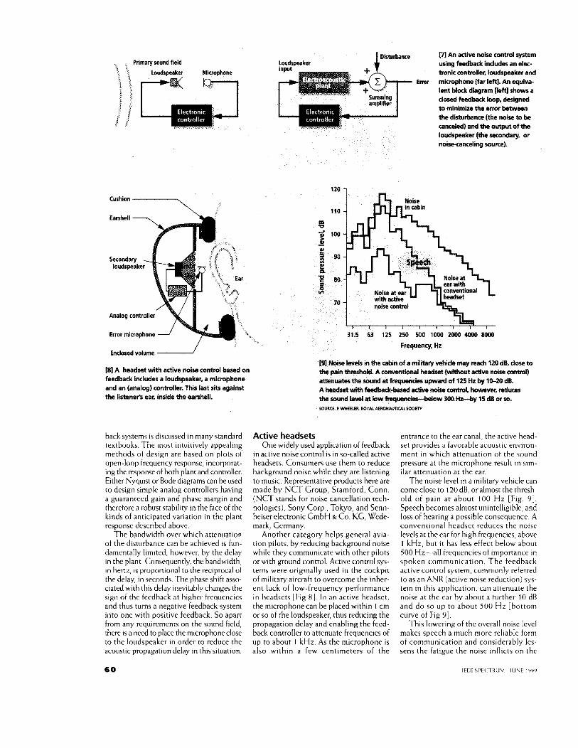
PI An aaive noise control system using feadback includes an el-- tmnic controller. budspeaker and rnkmphone [far left]. An equivb Imt !hck dkgram lleftl show a dosed feedback loop, dalgnad m minimize the efmf bstwwn the disturbance (the noise m be cancdod) and the o w of the lwdspeaker (the -ndary. or noksancding mum).
Lwdwaker
E m
Entlmed volume
(81 A headset with active noise cmtml based on feedback includes a loudspeaker. a micmphone and an (analog) wntmller. This last sits agalwt tha listaner% ear, inside the earshall.
hackryrtcmr is dircursrd in many standard trxtbuuks. Thr muit intuitively appcalmg methc,ds o1 deqign are hased o n plots oI open-lool> frequency response, incnrpnrat- ing the recponce of both plant and mimoller. Either Nyquist or Bode diagrains can he used to design simple analog controllers having a guaranrccd gain and phasc margin and thcrcforc a robust stability in thc facc of rhc kinds of anticipated variation in thc plant response dcscnbcd ahovc.
The bandwidth over which attenuation u t th r dirturbancc can he achirvcd 1s tun-
120 1 n in &in K
- 315 63 125 250 500 1000 2ooD .(MI0 8ooo
Active headsets One widely uacd application uf krdhack
in aclive noisecontrol is in so-calledactive headsets. Concumers use them to reduce hackground noise while they are listening to nusic. Representative products here are made by NCT Group, Stamford. Conn. (NCT stands for noise cancellation rech- nologics), Sony Corp.. Tokyo, and Senn- hciscr clcctronic CmbH g Co. KG, Wcde- mark, Germany.
Another category helps general av ia~ tion d o t s . bv rrducinn backnround noise
rnt~ance to the car canal, thr activr h r a d ~ sct p r u d e , P tavorahlr acowtic rnvirun- ment in which attenuation ot the ruund prersure at the miicrophnnr ~ e w l t ~n <I",-
ilar attenuatim a t the ear. The noise level 111 a inilitary vehicle can
comeclose to 120dB. oralmost the thresb old of pain a t ahour 100 Hz [Fig 91. Speech bccomcs almost uninrelligiblc, and loss of hearing a possiblc conscqucncc A convcnrional hcadrcr rcduccs rhc noisc levels at the ear for high frequencics, ahow I kHz. but i t has less ciirct brlow about

headset wearer. Headsets of this kind for military use are made by Racal Acoustics Ltd., Harrow, United Kingdom; Lectret Precision Ltd., in Singapore; and Bose Corp., Framingham, Mass.
The feedback controllers for active head- sets are generally analog devices. Designed to reduce delay in the controller, they em- ploy classical technique-sing a Bode plot, for example-to shape the open-loop char- acteristics. This is possible because the plant uncertainty, being due mainly to movement of the headset on the head, can in this case be quantified, and the spectrum of the dis- turbance is known and stationary inside such a military vehicle.
The need for a more analytic design pro- cedure has led to an alternative interpreta- tion of the feedback controller. This approach may also pave the way toward making active control systems using feed- back about as adaptive to changes in the dis- turbance spectrum, as the feedfoxward con- trollers discussed above.
O n e scheme is known as internal model control (IMC) to the process con- trol community, where it has been most widely developed. In this arrangement, an estimate of the disturbance is used to drive a control filter that feeds the sec- ondary source and so completes the feed- back loop. Not only does the IMC archi- tecture afford a very useful insight into the performance limitations of an active feedback controller, but it also provides a method of designing optimal controllers for a given environment.
The IMC controller has one potential dis- advantage, however. To provide the flexi- bility needed to implement an accurate inter-
nal plant model and an optimal control fil-
ter, digital filters based on digital signal-pro- cessing (DSP) systems must generally be used. The drawbacks are that the sampling process associated with such filters intro- duces an a& delay into the feedback loop.
necessary to prevent high-frequency aliased components of the low-frequency distur- bance fmm being annoyingly broadcast from the loudspeaker.
Since the total loop delay is increased, the control bandwidth is inevitably reduced
the DSP Combined ana- log and d~gital systems could be used to over- come these problems.
What lies ahead As the performance of DSP devices
increases and their prices fall, the prospect of controlling noise by using active con- trol will continue to be an attractive one. It is not hue, however, that with ever-increas- ing DSP power, active control will solve all noise problems. Recall that there are fun- damental physical limitations on most active noise control systems, which make them impractical above a few hundred hertz
Remember, too, that the control of tonal noise is much simpler than the control of random noise. Many low-frequency tonal noise problems are everyday irritants and in principle many are amenable to active con- trol. One of the problems at the moment is the cost of the complete system, which
includes not only that of the DSP device but also that of the secondary loudspeakers, microphones, and associated interfaces.
An application whose cost matters to man- ufacturers a great deal is the active control of noise in cars. Notwithstanding many suc- cessful demonstrations of such systems for both low-frequency engine and road noise, fully active control systems are currently fit- ted to very few production vehicles. The key to future development here may be inte- gration. Loudspeakers and associated ampli- fiers, and maybe even the DSP requirements of an active noise control system, could be shared with the vehicles’ audio systems. Microphones are also now being fitted into vehicles, for hands-free telephone dialing, for example, and once again these could be shared with an active control system.
In the longer term, more attention will be paid to the control of random noise using feedback systems. Current work is focused on whether a system like the pilot‘s active headset could be implemented as an active headrest arrangement for passengers in com- mercial aircraft.
Future emphasis will also fall on increas- ing the upper frequency range of control, particularly in applications such as the con- trol of engine and gearbox noise in com- mercial airliners and helicopters. Probably the most feasible approach here will be to concentrate on actively controlling the vibra- tion of these components as near the source of noise as possible. The ultimate aim would be to actively control the source mechanism itself. Research is being conducted in this area for gearbox and aeroengine noise con- trol, but the commercial realization of such systems is probably many years away. +
To probe further
The signal-processing algorithms alluded to in the article are reviewed in greater detail in “Active Noise Control,” by this article‘s author and P. A. Nelson, which appeared in the October 1993 issue of / €E€ Signal Pro- cessing Magazine.
Feedback control approaches are review- ed in the December 1995 /€€€ Control Systems Magazine in “Active Control of Sound and Vibration,” by C. R. Fuller and A. H. von Flotow.
Several textbooks have been written about the physical aspects of active noise and vibra- tion control, including Active Control of Sound by P. A. Nelson and S. J. Elliott (Academic Press, San Diego, Calif., 1992) and Active Controlof Vibration by C. R. Fuller, 5. J. Elliott, and P. A. Nelson (Academic Press, 1996).
S. M. Kuo and D. R. Morgan describe the algo-
rithms and digital signal-processing imple- mentation of many active control systems in their book Active Noise ControlSystems (John Wiley & Sons, New York, 1996). The same top- ics are discussed in the comprehensive text Active Control of Noise and Vibration by C. H. Hansen and S. D. Snyder (E. FN. Spon, 1997).
An account of the synthesis of signal process- ing and automatic control using state space methods is provided by R. L. Clark, W. R. Saunders, and G. P. Gibbs in Adaptive Struc- tures, Dynamics and Control (John Wiley & Sons, 1998). A more complete synthesis using the approaches outlined in this article is pro- vided by the present author in the book Signal Processing forActive Control, to be published by Academic Press in 1999.
World Wide Web addresses of companies that are relevant to the article are: ultraquiet. codnvs, bombardier.com, lordcorp.com, bose. com, racal-acoustics.co.uk, nct-active.com, and swiftnet.com.sg/iectret.
Further information about research in active noise control may also be found on the Web at isvr.soton.ac.uk/active/, vaLme.vt.edu, and mecheng.adelaide.edu.au.
A list of other Internet resources is provided at hh.se/staff/wolfgang/orpheus/anclinks.
About the author
Stephen J. Elliott is a professor at the Institute of Sound and Vibration Research at the Uni- versity of Southampton, in Britain. With a background in both physics and electronics, he has worked on numerous projects in active noise and vibration control over the past 15 years, including early practical demonstra- tions in automobiles, propeller aircraft, and helicopters. His e-mail address is sjeaisvr. soton.ac.uk.
Spectrum editor: Gadi Kaplan
ELLIOTT - DOWN WITH NOISE 61