dodge challenger 2015-present.pdf - mopar repair connect
TRANSCRIPT

31 - COLLISION INFORMATION . . . . . . . . . . . .2
LA - 1
31 - Collision Information
Warning . . . . . . . . . . . . . . . . . . . . . . . . . . . . . . . . .3
SAFETY NOTICE . . . . . . . . . . . . . . . . . . . . . . . . .4USE OF HEAT DURING REPAIR . . . . . . . . . . . .5
Position Statements . . . . . . . . . . . . . . . . . . . . . .5
AUTHENTIC MOPART GLASS REPLACE-MENT . . . . . . . . . . . . . . . . . . . . . . . . . . . . . . . . .6
RECONDITIONED WHEEL USAGE . . . . . . . . . .7REPLACEMENT SEAT COVERS AND SEATCOVER REPAIRS. . . . . . . . . . . . . . . . . . . . . . . .8
SALVAGED AIR BAGS OR OTHER SALVAGEDRESTRAINT SYSTEM COMPONENTUASAGE . . . . . . . . . . . . . . . . . . . . . . . . . . . . . . .9
SCAN TOOL SUPPORT BEFORE and AFTERCOLLISION REPAIR . . . . . . . . . . . . . . . . . . . .10
REPAIR PARTS USED FOR STRUCTURALREPAIRS . . . . . . . . . . . . . . . . . . . . . . . . . . . . . .11
USE OF AFTERMARKET PARTS . . . . . . . . . . .12USE OF HEAT DURING REPAIR . . . . . . . . . . .13USE OF SALVAGE/RECYCLED PARTS. . . . . .14
Standard Procedure . . . . . . . . . . . . . . . . . . . . .14
SERVICE AFTER A SUPPLEMENTALRESTRAINT SYSTEM DEPLOYMENT . . . . . .15
POST COLLISION SEAT BELT INSPECTION .18POST COLLISION SCAN TOOL INSPEC-TION . . . . . . . . . . . . . . . . . . . . . . . . . . . . . . . . .19
RECALIBRATION OF SENSORS AND MOD-
ULES. . . . . . . . . . . . . . . . . . . . . . . . . . . . . . . . .21
BASECOAT/CLEARCOAT FINISH. . . . . . . . . . .22
FINESSE SANDING, BUFFING, AND POLISH-
ING . . . . . . . . . . . . . . . . . . . . . . . . . . . . . . . . . .23
PAINT TOUCH-UP . . . . . . . . . . . . . . . . . . . . . . .24
NET, FORM AND PIERCE REPAIR . . . . . . . . .25POLYURETHANE FOAM REMOVAL . . . . . . . .26NON-STRUCTURAL SHEET METAL REPAIR .29WELDING AND WELD BONDING. . . . . . . . . . .39SECTIONING PROCEDURES. . . . . . . . . . . . . .51CORROSION PROTECTION. . . . . . . . . . . . . . .76
Technical Specifications . . . . . . . . . . . . . . . . .77
VEHICLE IDENTIFICATION NUMBER . . . . . . .78STANDARDIZED STEEL IDENTIFICATION . . .84BODY OPENING DIMENSIONS . . . . . . . . . . . .92FRAME DIMENSIONS . . . . . . . . . . . . . . . . . . . .95GAP AND FLUSH DIMENSIONS . . . . . . . . . . .98PAINT CODES . . . . . . . . . . . . . . . . . . . . . . . . .102VEHICLE CERTIFICATION LABEL . . . . . . . . .107
Locations. . . . . . . . . . . . . . . . . . . . . . . . . . . . . .107
SEALERS AND SOUND DEADENERS . . . . .108SOUND DEADENER LOCATIONS . . . . . . . . .109STRUCTURAL ADHESIVE, FLEXIBLE ADHE-SIVES AND SEAM SEALER LOCATIONS . .128
- 2 31 - Collision Information LA
Warning
LA 31 - Collision Information - 3
SAFETY NOTICE
CAUTION: All service and rebuilding instructions contained herein are applicable to, and for the
convenience of, the automotive trade only. All test and repair procedures on components or
assemblies in non-automotive applications should be repaired in accordance with instructions
supplied by the manufacturer of the total product.
Proper service and repair is important to the safe, reliable operation of all motor vehicles. The
service produces recommended and described in this publication were developed for
professional service personnel, and are effective methods for performing vehicle repair.
Following these procedures will help ensure efficient economical vehicle performance and
service reliability. Some service procedures require the use of special tools designed for
specific procedures. These special tools should be used as recommended throughout this
publication.
Special attention should be exercised when working with spring-or tension-loaded fasteners
and devices such as E-Clips, Circlips, Snap rings, etc., since careless removal may cause
personal injury. Always wear safety goggles when working on vehicles or vehicle components.
It is important to note that this publication contains various Cautions and Warnings. These
should be read carefully in order to minimize risk of personal injury or the possibility that
improper service methods may damage the vehicle or render it unsafe. It is important to note
that these Cautions and Warnings cover only the situations and procedures FCA US LLC has
encountered and recommended. FCA US LLC cannot possibly know, evaluate, and advise
the service trade of all conceivable ways in which service may be performed, or of the possible
hazards of each. Consequently, FCA US LLC has not undertaken any such broad service
review. Accordingly, anyone uses a service procedure or tool that is not recommended in this
publication must be certain that neither personal safety, nor vehicle safety, will be
jeopardized by the service methods they select.
- 4 31 - Collision Information LA
USE OF HEAT DURING REPAIR
WARNING: FCA US LLC engineering’s position on the use of heat during collision repair is as follows:
• Any body panel or frame component damaged which is to be repaired and reused, must be
repaired using the “cold straightening” method. No heat may be used during the straightening
process.
• During rough straightening prior to panel replacement, damaged panels or frame components may
be heated to assist in body/frame realignment. The application of heat must be constrained to the
parts which will be replaced and not allowed to affect any other components.
This “no heat” recommendation is due to the extensive use of high strength and advanced high strength
steels in FCA US LLC products. High-strength materials can be substantially and negatively affected
from heat input which will not be obviously known to the repairer or consumer.
Ignoring these recommendations may lead to serious compromises in the ability to protect occupants in a
future collision event, reduce the engineered qualities and attributes, or decrease the durability and
reliability of the vehicle.
This statement supersedes any previously released information by the FCA US LLC.
Failure to follow these instructions may result in serious or fatal injury.
Position Statements
LA 31 - Collision Information - 5
AUTHENTIC MOPART GLASS REPLACEMENT
FCA US LLC Position
Only Authentic MoparT Glass is designed, engineered, manufactured and tested to the FCA US LLC internal and
government-mandated standards and are the only parts equivalent to the originally installed parts.
FCA US LLC does not approve of or recognize glass replacement procedures where Authentic MoparT Parts are not
used for Chrysler,T DodgeT, JeepT, RAMT, and FIATT brand vehicle’s. Any repairs performed not using Mopar
replacement glass, and not following published repair guidelines and procedures, may expose current or future
vehicle owners and occupants to unnecessary risk.
FCA’s vehicle’s systems and components are engineered, tested and manufactured to help protect vehicle
occupants. They are engineered based upon both government mandated and internal corporate requirements
relative to Durability, Noise Vibration Harshness (NVH) and Vehicle Safety.
Authentic MoparT Glass Characteristics Include and are not Limited to:
• Glass coatings that provide UV protection and in cabin heat reduction. Aftermarket variants often may not be
equipped with reflective technology. This technology optimizes air-conditioning performance and can improve
fuel economy.
The attached moldings have been validated with exposure testing, including UV, chemical, temperature, tear,
and abrasion resistance.
• Glass may be equipped with enhanced acoustic dampening technologies integrated into the glass assembly.
Aftermarket glass may not be equipped with this variant, which may result in increased wind, road, and engine
noise in your vehicle’s cabin.
• Works with various advanced driver safety system electrical components, including cameras, rain sensors,
antennae, and heating elements. Aftermarket glass may not support the function of complex electrical
components and could interfere with your vehicle’s electronic systems, resulting in unintended functions or
disabling the system function.
• If your vehicle’s windshield is equipped with a forward facing camera (typically integrated in the rearview mirror
assembly), the camera must be recalibrated after the windshield has been installed.
• Glass components are also often a part of the vehicle’s structural assembly. Using Mopar authored removal
and replacement procedures, including the use of advanced adhesives specific to each model, helps ensure
that the vehicle is as design.
Aftermarket glass manufactures may represent their products as Original Equipment Equivalent, or OEE. No
supplier is authorized to utilize FCA tooling, test equipment, or Intellectual Property in the development or
production of aftermarket glass. Aftermarket windshields and moldings are often made with materials that
do not adhere to FCA US LLC performance standards.
Release Date: November 20, 2019
©2019 FCA US LLC. All Rights Reserved. Chrysler, Dodge, Jeep, Ram, Mopar and SRT are registered trademarks
of FCA US LLC. FIAT is a registered trademark of Fiat Group Marketing & Corporate Communication S.p.A., used
under license by FCA US LLC.
- 6 31 - Collision Information LA
RECONDITIONED WHEEL USAGE
FCA US LLC Position
FCA US LLC does not recommend that customers use “reconditioned” wheels (wheels that have been damaged
and repaired) because they can result in a sudden catastrophic wheel failure which could cause loss of control and
result in injury or death.
For clarification:
• Cosmetic refinishing for the purpose of repairing a superficial flaw is an acceptable procedure providing it is
limited to paint or clear coat only, the wheel is not modified in any way, and there is no exposure to paint
curing heat over 93 degrees Celsius (200 degrees Fahrenheit).
• Damaged wheels are those which have been bent, broken, cracked or sustained some other physical damage
which may have compromised the wheel structure.
• Repaired indicates that the wheel has been modified through bending, welding, heating, straightening, or
material removal to rectify damage.
• Re-plating of chrome plated wheels, or chrome plating of original equipment painted or polished wheels is not
an acceptable procedure as this may alter mechanical properties and affect fatigue life. Additionally, FCA US
LLC Global Warranty Administration does not allow refinishing of wheels under warranty.
This statement supersedes any previously released information by FCA US LLC.
Release Date: August 11, 2010
For more information, log on to www.MoparRepairConnection.com.
©2015 FCA US LLC. All Rights Reserved. Chrysler, Dodge, Jeep, Ram, Mopar and SRT are registered trademarks
of FCA US LLC. FIAT is a registered trademark of Fiat Group Marketing & Corporate Communication S.p.A., used
under license by FCA US LLC.
LA 31 - Collision Information - 7
REPLACEMENT SEAT COVERS AND SEAT COVER REPAIRS
FCA US LLC Position
FCA US LLC vehicles, systems and components are engineered, tested and manufactured to help protect vehicle
occupants based upon government mandated and internal corporate requirements relative to durability, noise
vibration & harshness, occupant protection and vehicle safety.
Supplemental Seat-Mounted Side Air Bags provide enhanced protection to help protect an occupant during a side
impact. When the seat-mounted side air bag deploys, it opens the seam between the front and side of the seat’s
trim cover. Modifications to the seat system, including the seat cover, may change the way the air bag deploys,
which could adversely affect the performance of the Supplemental Seat-Mounted Side Air Bag causing serious
injury.
“Modifications” include:
• Any change to the seat back cover such as material, thread, stitch design and alterations or misplacement of
the features which guide the deploying air bag into position.
• Any non-approved seat-cover replacements.
Only Authentic MoparT Repair Parts, and approved MoparT accessories such as KatzkinT Leather seat covers, are
designed, engineered, manufactured and tested to the FCA US LLC internal and government mandated standards.
The use of parts not specifically designed and tested by FCA US LLC may compromise the integral balance
between these safety systems.
FCA US LLC only approves of repairs or modifications to the supplemental seat-mounted side air bag system,
including the seat system or seat cover, where Authentic Mopar Repair Parts or Mopar Accessories are used for
Chrysler, JeepT Dodge and Ram vehicles. Any unapproved repairs or modifications performed not using Mopar
parts, or not following FCA US LLC approved published repair guidelines and procedures, may increase the risk of
injury to current or future vehicle owners and occupants.
This statement supersedes any previously released information by FCA US LLC.
Release Date: June 21, 2011
For more information, log on to www.MoparRepairConnection.com.
©2015 FCA US LLC. All Rights Reserved. Chrysler, Dodge, Jeep, Ram, Mopar and SRT are registered trademarks
of FCA US LLC. FIAT is a registered trademark of Fiat Group Marketing & Corporate Communication S.p.A., used
under license by FCA US LLC.
- 8 31 - Collision Information LA
SALVAGED AIR BAGS OR OTHER SALVAGED RESTRAINT SYSTEM COMPONENTUASAGE
FCA US LLC Position
FCA US LLC does not support the use of any Supplemental Restraint System (SRS) component, seatbelt
component, or any other occupant protection component which has been removed from a vehicle previously
damaged, flooded, burned, scrapped or removed from use for any other reason – commonly referred to as “salvage
parts”.
Restraint system components are engineered, tested and manufactured to protect vehicle occupants based upon
both government mandated and internal corporate requirements relative to vehicle safety and occupant protection.
New MoparT replacement parts are required to be equivalent to the originally installed parts and are tested to
ensure these requirements are met. While some salvage parts may visually appear equivalent, there can be
dramatic differences in the design and functional characteristics which could have a negative effect on the vehicle
occupants in a future collision event. These specific design and functional characteristics can only be determined
through destructive testing.
Salvage components may have been affected by:
• Crash impact loads
• Incorrect, improper or inadequate disassembly and removal procedures
• Weathering or environmental exposure outside of that expected during normal use
• Flooding
• Smoke or heat damage
• Abuse
Additionally, salvage components are not traceable should a component recall be required in the future.
It is in the best interest of the current or future vehicle owner and/or occupants that repairs to the SRS, seatbelt and
occupant protection system are made using new original equipment parts. Anything less than this may expose
operators and occupants too unnecessary risk.
This statement supersedes any previously released information by FCA US LLC. Release Date: August 11, 2010
For more information, log on to www.MoparRepairConnection.com.
©2015 FCA US LLC. All Rights Reserved. Chrysler, Dodge, Jeep, Ram, Mopar and SRT are registered trademarks
of FCA US LLC. FIAT is a registered trademark of Fiat Group Marketing & Corporate Communication S.p.A., used
under license by FCA US LLC.
LA 31 - Collision Information - 9
SCAN TOOL SUPPORT BEFORE and AFTER COLLISION REPAIR
This position statement supersedes any previously released “Scan Tool Position Statement” prior to
September 25, 2019. Any previous version should be removed from your files. All revisions are highlighted
with **asterisks**and include updated websites and note.
FCA US LLC vehicles, systems and components are engineered, tested and manufactured to help protect vehicle
occupants. They are engineered based upon both government mandated and internal corporate requirements
relative to durability, Noise Vibration and Harshness (NVH) and vehicle safety. Use of the Mopar *wiTECH vehicle
diagnostic tester (“Mopar Scan Tool”) is an important part of FCA vehicle service and maintenance. This tool
contains software that aftermarket tools may not contain and can assess whether any FCA’s vehicle’s safety and
security systems contain active or stored Diagnostic Trouble Codes (DTCs).
Safety and security related systems such as Anti-lock Brake System (ABS), Supplemental Restraint Systems (SRS)
- air bags, Occupant Restraint Controller (ORC), seat belts, active head restraints, forward facing camera and
radar, blind spot monitoring, and other automated electronic driver assistance systems MUST be tested for fault
codes (DTCs) that could possibly be active (current) or stored following a collision. Use of the Mopar *wiTECH
vehicle diagnostic tester (scan tool) is necessary beforeand afterafter collision repair.
ANYof the following conditions could trigger DTCs prior to or during collision repairs which could result in improper
vehicle performance:
• Vehicle is involved in an accident or collision, even though the damage may appear minor.
• Vehicle has been in an accident with or without air bag deployment.
• Voltage loss, including battery disconnects and Hybrid battery disabling.
• Significant vehicle disassembly including, but not limited to, bumpers, door handles, headlamps and mirrors.
• Interior trim repair or removal.
• Glass removal and replacement operations.
Any repairs performed without using Mopar parts, and not following published repair guidelines and procedures may
expose current or future vehicle owners and occupants to unnecessary risk.
If faults were stored in the DTC memory for any safety or security system, then these systems MUST be serviced
according to the repair procedures in Service Information. After performing repairs, re-check the system to
determine if any active or stored DTCs remain; if so, take appropriate service action to ensure proper function.
SRS AIR BAG SQUIB STATUS
Multistage air bags with multiple initiators (squibs) MUSTbe checked to determine that all squibs were used during
the deployment event. The Driver Air Bag (DAB) and Passenger Air Bag (PAB), are deployed by electrical signals
generated by the Occupant Restraint Controller (ORC) through the driver or passenger squib circuits (up to 3) to the
initiators in the air bag inflators. Typically, all initiators are exhausted and all potentially hazardous chemicals are
burned during an air bag deployment event.
However, it is possible for only one initiator to be exhausted; therefore, you MUSTalways confirm that all initiators
have been cycled, in order to minimize the risk of improper handling or disposal of potentially live pyrotechnic or
hazardous materials. This procedure should be performed using the Mopar wiTECH diagnostic scan tool to
verify the status of all air bag squibs, prior to removing deployed air bags from the vehicle for disposal.
Reference Websites
• **Service Information can be obtained at https://www.techauthority.com
• Mopar wiTECH scan tools can be purchased from https://aftermarket.witechtools.com.**
©2019 FCA US LLC. All Rights Reserved. Chrysler, Dodge, Jeep, Ram, Mopar and SRT are registered trademarks
of FCA US LLC. FIAT is a registered trademark of FCA Group Marketing S.p.A., used under license by FCA US
LLC.
- 10 31 - Collision Information LA
REPAIR PARTS USED FOR STRUCTURAL REPAIRS
This position statement supersedes any previously released “Structural Repair Parts Usage” position
statements prior to November 20, 2019. Any previous version should be removed from your files. This is a
complete revision and no asterisks have been added to highlight revisions.
FCA US LLC Position
FCA US LLC vehicles, systems and components are engineered, tested and manufactured to protect vehicle
occupants based upon both government mandated and internal corporate requirements relative to durability, Noise/
Vibration/Harshness (NVH), occupant protection and vehicle safety.
The overall structural integrity of the vehicle is dependent on its inherent design specifications. Sheet metal and
glass are critical elements in the design of specific crush zones that allow the energy of a collision to be absorbed in
a predictable way and maximize the effectiveness of the restraint system to protect the occupants. The use of parts
not specifically designed and tested by FCA US LLC may compromise the integral balance between these safety
systems.
Only Authentic MoparT Repair Parts and glass are designed, engineered, manufactured and tested to the FCA US
LLC internal and government mandated standards and are the only ones equivalent to the originally installed parts.
FCA US LLC does not approve of or recognize structural repair procedures where Authentic Mopar Parts are not
used for Chrysler, Dodge, JeepT and Ram vehicles. Any repairs performed not using Mopar parts, and not following
published repair guidelines and procedures, may expose current or future vehicle owners and occupants to
unnecessary risk.
When restoring a collision damaged vehicle to pre-loss condition, consideration must be given to the following:
• All structural distortion has been identified and corrected using appropriate structural straightening equipment
(“frame rack”) and a three-dimensional measuring system.
• All damaged panels have been repaired or replaced.
• All replaced panels provide the as-built structural equivalence and corrosion protection of the original panels.
• Unless partial replacement procedures are documented in a FCA US LLC publication, structural panels must
be installed in their entirety – partial replacement or “sectioning” of panels may compromise vehicle structure.
• FCA US LLC strictly prohibits the collision repair process of “clipping”, the general practice of clipping would
include the sectioning of multiple vehicles at the a-pillar, floor, rocker panel and other locations which contain
advanced high strength steel reinforcements. These panels must be replaced at the factory seams when
applicable. Risk of improper repair is significant and is not a supported practice.
• FCA US LLC does not support the use or re-use of any structural component which has been removed from a
vehicle previously damaged, flooded, burned, scrapped or removed from use for any other reason - commonly
referred to as “salvage parts”.
• While some salvage parts may “appear” equivalent, there can be dramatic differences in the design and
functional characteristics which cannot be determined by a visual inspection and which could have a negative
effect on the vehicle occupants in a future collision event.
• Salvage components may have been affected by crash impact loads, incorrect, improper or inadequate
disassembly and removal procedures, weathering or environmental exposure outside of that expected during
normal use.
• Salvage components are not traceable should a component recall be required in the future.
This statement supersedes any previously released information by FCA US LLC. Release Date: August 11, 2010
For more information, log on to https://www.MoparRepairConnection.com.
FCA US LLC vehicle lease agreements specify that ONLY Genuine FCA US LLC replacement parts be
utilized for collision repairs to the vehicle.
©2019 FCA US LLC. All Rights Reserved. Chrysler, Dodge, Jeep, Ram, Mopar and SRT are registered trademarks
of FCA US LLC. FIAT is a registered trademark of Fiat Group Marketing & Corporate Communication S.p.A., used
under license by FCA US LLC.
LA 31 - Collision Information - 11
USE OF AFTERMARKET PARTS
FCA US LLC Position
The original parts used on all FCA US LLC vehicles are designed and built to provide optimum fit, function, safety,
and structural integrity. These parts are carefully designed to act as a safety system and are rigorously impact
tested to ensure optimal performance. Because of this, FCA US LLC does NOT approve of the use of recycled,
salvaged, aftermarket, or reconditioned parts. Aftermarket parts may not be built to FCA US LLC’s exact design and
can therefore affect the performance of important structural and safety features of the vehicle. The best way to
ensure replacement parts meet the safety, performance, and quality standards set by FCA US LLC is to purchase
Original Equipment parts through an authorized FCA US LLC dealer.
In the event collision repairs are necessary, all repairs should be performed by a trained technician and follow
vehicle specific repair procedures available at https://www.techauthority.com. Failure to follow proper procedures or
deviation from Original Equipment parts could result in compromising performance of impact safety systems.
FCA US LLC vehicle lease agreements specify ONLY Genuine FCA US LLC replacement parts be utilized for
collision repairs to the vehicle.
Release Date: November 20, 2019
©2019 FCA US LLC. All Rights Reserved. Chrysler, Dodge, Jeep, Ram, Mopar and SRT are registered trademarks
of FCA US LLC. FIAT is a registered trademark of Fiat Group Marketing & Corporate Communication S.p.A., used
under license by FCA US LLC.
- 12 31 - Collision Information LA
USE OF HEAT DURING REPAIR
FCA US LLC Position
FCA US LLC Service Engineering’s position on the use of heat during collision repair is as follows:
• Any damaged body panel or frame component, which is to be repaired, must be repaired using the “cold
straightening” method. No heat may be used during the straightening process.
• During rough straightening prior to replacement, damaged panels or frame components may be heated to
assist in body/frame realignment. This application of heat, if absolutely necessary, must be constrained to
the parts which will be replaced and not allowed to affect any other components.
This “no heat” recommendation is due to the extensive use of high-strength and advanced high-strength steels in
FCA US LLC vehicles. High-strength materials can be substantially and negatively affected from heat input which
will not be obviously known to the repairer or consumer. Additionally, application of heat will alter or destroy material
coatings utilized for corrosion protection and which may not be restorable.
Ignoring these recommendations may lead to serious compromises in the ability to protect occupants in a future
collision event, reduce the engineered qualities and attributes, or decrease the durability and reliability of the
vehicle.
This statement supersedes any previously released information by FCA US LLC.
Release Date: August 11, 2010
For more information, log on to www.MoparRepairConnection.com.
©2015 FCA US LLC. All Rights Reserved. Chrysler, Dodge, Jeep, Ram, Mopar and SRT are registered trademarks
of FCA US LLC. FIAT is a registered trademark of Fiat Group Marketing & Corporate Communication S.p.A., used
under license by FCA US LLC.
LA 31 - Collision Information - 13
USE OF SALVAGE/RECYCLED PARTS
FCA US LLC Position
Many factors can influence the integrity and quality of salvage parts including but not limited to weather, previous
damage, improper removal and transfer of parts. Because of this, FCA US LLC does NOT approve the use of
salvage or recycled parts in the event that collision repairs are necessary.
FCA US LLC air bag and restraint systems are carefully designed and engineered to protect the safety of all
passengers. Using salvage restraint systems could affect the timing and performance of these safety systems. FCA
US LLC only approves the use of new airbag systems and components installed using original FCA repair
procedures.
Using salvage parts can lead to the following events:
• Compromised crush zones caused by previous repairs.
• Additional installation time due to variations in fit and finish.
• Exposure to adverse elements and conditions that have not been considered by FCA US LLC.
• Require additional repair time based on variations in storage and delivery practices.
Release Date: November 20, 2019
FCA US’ limited warranties only apply to genuine FCA original equipment parts. FCA US LLC is not
responsible for any costs associated with part failure caused by the use of any parts other than FCA US
genuine replacement parts.
©2019 FCA US LLC. All Rights Reserved. Chrysler, Dodge, Jeep, Ram, Mopar and SRT are registered trademarks
of FCA US LLC. FIAT is a registered trademark of Fiat Group Marketing & Corporate Communication S.p.A., used
under license by FCA US LLC.
Standard Procedure
- 14 31 - Collision Information LA
SERVICE AFTER A SUPPLEMENTAL RESTRAINT SYSTEM DEPLOYMENT
Any vehicle which is to be returned to use following a Supplemental Restraint System (SRS) component deployment
must have the deployed restraints replaced. In addition, the following guidelines MUST be observed.
• Following ANY major vehicle impact damage in the vicinity of an impact sensor or the ORC - It is
critical that the mounting surfaces and mounting brackets for the Occupant Restraint Controller (ORC),
front impact sensors and side impact sensors located within the Proximity of the impact damage be closely
inspected and restored to their original conditions. Because the ORC and each impact sensor are used by the
SRS to monitor or confirm the direction and severity of a vehicle impact, improper orientation or insecure
fastening of these components may cause airbags not to deploy when required, or to deploy when not
required.
• Following ANY airbag deployment event - The Lower Anchors and Tethers for Children (LATCH) provisions,
the upper tether anchors (if equipped) and all interior trim panels must also be inspected.
• If an active head restraint is deployed - An inertia-based Active Head Restraint (AHR) unit that is
undamaged following a deployment automatically resets itself. These units are designed with the intention of
reuse.
• If the driver airbag is deployed - If the Driver AirBag (DAB) has been deployed, the DAB, the clockspring,
the steering wheel, the steering column assembly including the intermediate shaft and coupler, both front seat
belt retractor and tensioner assemblies, and all other seat belt retractors and buckles in use must be
replaced. The front impact sensors must be inspected.
• If the passenger airbag is deployed - If the Passenger AirBag (PAB) has been deployed, the PAB, the
instrument panel and the PAB wire harness or connector must be replaced.
• If a seat airbag is deployed - If a Seat AirBag (SAB) has been deployed, the SAB, the SAB jumper wire
harness, the thermoplastic SAB chute, the seat back frame, the seat back foam, the seat back trim cover
and the side impact sensors on the same side of the vehicle as the deployed airbag must be replaced. Both
front seat belt retractor and tensioner assemblies, and all other seat belt retractors and buckles in use must be
replaced.
• If a seat belt tensioner is deployed - The seat belt tensioners are deployed in conjunction with the front
airbags, but can also be deployed with a SAB or side curtain airbags (also known as Side AirBag Inflatable
Curtains/SABIC). All seat belt tensioners must be replaced if any airbag in the vehicle has been deployed.
• If a side curtain airbag is deployed - If a side curtain airbag (SABIC) has been deployed, the SABIC, the
upper A and C-pillar trim, the upper quarter trim and the side impact sensors on the same side of the vehicle
as the deployed airbag must be replaced. The headliner, both front seat belt retractor and tensioner
assemblies, and all other seat belt retractors and buckles in use must be replaced. For vehicles with an
optional sunroof, the sunroof and the sunroof drain tubes and hoses must be inspected.
The components identified with the deployed SRS components in the preceding list are not intended for reuse and
will be damaged or weakened as a result of an airbag deployment, which may or may not be obvious during a
visual inspection. All other vehicle components should be closely inspected following any SRS component
deployment, but are to be replaced only as required by the extent of the visible damage incurred.
SQUIB CIRCUIT DAMAGE
In addition to the preceding guidelines, be aware that the heat created by the initiator during an airbag or tensioner
deployment will cause collateral damage to the connected wiring (squib circuits) and connector insulators. There are
two methods by which an airbag or seat belt tensioner may be connected to the vehicle electrical system. The first
method involves a short pigtail harness and connector insulator that are integral to the airbag or tensioner unit
and are replaced as a unit with the service replacement airbag or seat belt tensioner. This connection method
typically requires no additional wiring repair following a deployment.
However, the second connection method involves a wire harness takeout and connector insulator that are
connected directly to the airbag or tensioner initiator or squib. These direct-connect type take outs and connector
insulators MUST be repaired following an airbag or seat belt tensioner deployment using the approved
Supplemental Restraint System Wiring Repairs procedure (Refer to 10 - Restraints - Standard Procedure).
AIRBAG SQUIB STATUS
Multistage airbags with multiple initiators (squibs) must be checked to determine that all squibs were used during
the deployment event. The Driver AirBag (DAB) and Passenger AirBag (PAB) in this vehicle are deployed by
electrical signals generated by the Occupant Restraint Controller (ORC) through the driver or passenger squib 1 and
squib 2 circuits to the two initiators in the airbag inflators. Typically, both initiators are used and all potentially
LA 31 - Collision Information - 15
hazardous chemicals are burned during an airbag deployment event. However, it is possible for only one initiator to
be used; therefore, it is always necessary to confirm that both initiators have been used in order to avoid the
improper handling or disposal of potentially live pyrotechnic or hazardous materials. The following procedure should
be performed using a diagnostic scan tool to verify the status of both airbag squibs before either deployed airbag
is removed from the vehicle for disposal.
CAUTION: Deployed front airbags have initiators (squibs) in the airbag inflator may or may not have live
pyrotechnic material within the inflator. Do not dispose of these airbags unless you are certain
of complete deployment. Refer to the Hazardous Substance Control System for information
regarding the potentially hazardous properties of the subject component and the proper safe
handling procedures. Then dispose of all non-deployed and deployed airbags and seat belt
tensioners in a manner consistent with state, provincial, local and federal regulations.
1. Be certain that the diagnostic scan tool contains the latest version of the proper diagnostic software. Connect
the scan tool to the 16-way Data Link Connector (DLC). The DLC is located on the driver side lower edge of
the instrument panel, outboard of the steering column.
2. Transition the status of the ignition switch to On.
3. Using the scan tool, read and record the active (current) Diagnostic Trouble Code (DTC) data.
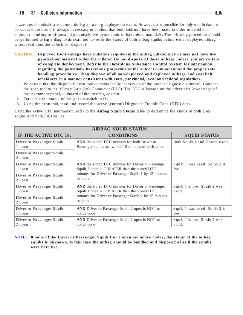
Using the active DTC information, refer to the Airbag Squib Status table to determine the status of both DAB
squibs and both PAB squibs.
AIRBAG SQUIB STATUS
IF THE ACTIVE DTC IS: CONDITIONS SQUIB STATUS
Driver or Passenger Squib
1 open
AND the stored DTC minutes for both Driver or
Passenger squibs are within 15 minutes of each other
Both Squib 1 and 2 were used.
Driver or Passenger Squib
2 open
Driver or Passenger Squib
1 open
AND the stored DTC minutes for Driver or Passenger
Squib 2 open is GREATER than the stored DTC
minutes for Driver or Passenger Squib 1 by 15 minutes
or more
Squib 1 was used; Squib 2 is
live.
Driver or Passenger Squib
2 open
Driver or Passenger Squib
1 open
AND the stored DTC minutes for Driver or Passenger
Squib 1 open is GREATER than the stored DTC
minutes for Driver or Passenger Squib 2 by 15 minutes
or more
Squib 1 is live; Squib 2 was
used.
Driver or Passenger Squib
2 open
Driver or Passenger Squib
1 open
AND Driver or Passenger Squib 2 open is NOT an
active code
Squib 1 was used; Squib 2 is
live.
Driver or Passenger Squib
2 open
AND Driver or Passenger Squib 1 open is NOT an
active code
Squib 1 is live; Squib 2 was
used.
NOTE: If none of the Driver or Passenger Squib 1 or 2 open are active codes, the status of the airbag
squibs is unknown. In this case the airbag should be handled and disposed of as if the squibs
were both live.
- 16 31 - Collision Information LA
CLEANUP PROCEDURE
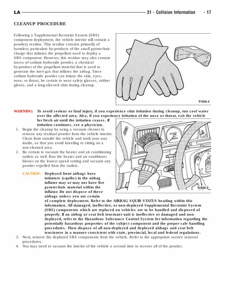
Following a Supplemental Restraint System (SRS)
component deployment, the vehicle interior will contain a
powdery residue. This residue consists primarily of
harmless particulate by-products of the small pyrotechnic
charge that initiates the propellant used to deploy a
SRS component. However, this residue may also contain
traces of sodium hydroxide powder, a chemical
by-product of the propellant material that is used to
generate the inert gas that inflates the airbag. Since
sodium hydroxide powder can irritate the skin, eyes,
nose, or throat, be certain to wear safety glasses, rubber
gloves, and a long-sleeved shirt during cleanup.
WARNING: To avoid serious or fatal injury, if you experience skin irritation during cleanup, run cool water
over the affected area. Also, if you experience irritation of the nose or throat, exit the vehicle
for fresh air until the irritation ceases. If
irritation continues, see a physician.
1. Begin the cleanup by using a vacuum cleaner to
remove any residual powder from the vehicle interior.
Clean from outside the vehicle and work your way
inside, so that you avoid kneeling or sitting on a
non-cleaned area.
2. Be certain to vacuum the heater and air conditioning
outlets as well. Run the heater and air conditioner
blower on the lowest speed setting and vacuum any
powder expelled from the outlets.
CAUTION: Deployed front airbags have
initiators (squibs) in the airbag
inflator may or may not have live
pyrotechnic material within the
inflator. Do not dispose of these
airbags unless you are certain
of complete deployment. Refer to the AIRBAG SQUIB STATUS heading within this
information. All damaged, ineffective, or non-deployed Supplemental Restraint System
(SRS) components which are replaced on vehicles are to be handled and disposed of
properly. If an airbag or seat belt tensioner unit is ineffective or damaged and non-
deployed, refer to the Hazardous Substance Control System for information regarding the
potentially hazardous properties of the subject component and the proper safe handling
procedures. Then dispose of all non-deployed and deployed airbags and seat belt
tensioners in a manner consistent with state, provincial, local and federal regulations.
3. Next, remove the deployed SRS components from the vehicle. Refer to the appropriate service removal
procedures.
4. You may need to vacuum the interior of the vehicle a second time to recover all of the powder.
LA 31 - Collision Information - 17
POST COLLISION SEAT BELT INSPECTION
Following any collision inspect the seat belts for proper function and operation prior to returning the vehicle to the
customer.
If the collision event was severe enough to activate any of the Supplemental Restraint System (SRS) components
refer to (Refer to 31 - Collision Information/Standard Procedure/Standard Procedure/Service After Supplemental
Restraint Deployment) to determine if there are any mandatory replacement of seat belt components.
NOTE: The following inspections, where applicable, are for the driver and all passenger positions,
including the Lower Anchors and Tethers for Children (LATCH) restraint systems.
• Inspect the seat belt, for fraying, cuts, fading and torn or loose stitching. If any of these condition exist replace
the seat belt.
• Inspect all of the seat belt buckles for proper latching and releasing operation. If it does not function properly,
replace the seat belt buckle.
• Inspect the seat belt retractor by slowly extending the seat belt fully. It should extend smoothly without binding
or locking. If it does not function properly, replace the seat belt.
• Inspect the seat belt retractor by latching the seat belt and then pulling the belt quickly. The seat belt should
lock. If it does not function properly, replace the seat belt.
• Inspect the seat belt shoulder turning loop to be certain it rotates freely without binding. If it does not travel
freely, replace the seat belt.
• Inspect the seat belt turning loop height adjuster. It should move freely and lock firmly into the different height
positions. If it does not function properly, replace the seat belt turning loop height adjuster.
NOTE: If any of the seat belt components have physical damage or are doubtful of proper operation,
replace the component.
- 18 31 - Collision Information LA
POST COLLISION SCAN TOOL INSPECTION
Before any repair decisions are made, access to FCA US LLC service information is required. Diagnostic Trouble
Codes (DTCs) do not identify which part needs to be replaced, rather DTCs are a piece of the diagnostic
process that will lead a trained and qualified technician to the correct test to accurately diagnose the damage. Be
certain of proper battery support when scanning.
Collision damage pre-scan before repairs- All vehicles that are in a collision need to have a diagnostic scan done
at the beginning of the repair process, preferably during the estimating process, to determine damaged systems
that may not be obvious. If proper battery support is not possible due to collision damage the scan should be
performed during the repair process as soon as the battery can support the system and operate safely. After the
repair process is completed the vehicle will need to be scanned again to be certain the systems involved are
functioning properly. A Malfunction Indicator Light (MIL) may not illuminate for a particular system yet a DTC may be
present, active or stored, compromising the proper function of the system. Identifying system faults will significantly
reduce unexpected repairs at or near the end of the repair process. It will reduce the need for additional charges
and benefit the vehicle being delivered without delay. The use of the Mopar scan tool wiTECH™ will be necessary
to access DTC’s. and to perform many of the programming and initialization of modules. If the wiTECH™ scan
tool is not available it can be obtained through an FCA US dealership service center or through a company such as
Collision Diagnostics Services that can remotely use the wiTECH™ scan tool in conjunction with their patented
asTech™ device. DTC identification is only part of the repair process as it will most likely be necessary to access
the service and diagnostic information to understand proper operation, wiring and diagnosis and testing of the
system and DTC.
The vehicle will also need to have a diagnostic scan done upon the completion of repairs to determine that all
systems are functioning properly and if any of the systems are in need of repair, reprogramming or initialization.
Pre-Scan Process
1. Conduct a customer consultation.
a. Gain customer authorization to scan the vehicle and to share the data with the appropriate parties involved
(sublet technician, insurer, repair facility personnel).
2. Check for Malfunction Indicator Lamps (MILs) and/or information display messages.
a. The 12-volt electrical system must be enabled to identify any MILs.
b. Not all systems will illuminate MILs, even if there is damage to that system.
3. Document any MILs and/or information display messages.
4. Identify Driver Assistance Systems (DAS) which the vehicle is equipped with. These systems include but are
not limited to Adaptive Cruise Control (ACC), Forward Collision Warning (FCW), Lane Sensing.
5. Document the DAS the vehicle is equipped with.
6. Document potential damage to DAS component(s), DAS mounting location(s), damage that may affect DAS ,
or parts that will need to be removed and installed near DAS.
7. Identify any calibration, initialization and aiming requirements for DAS parts, including required calibration,
initialization and aiming requirements following removal and installation.
a. FCA US LLC service information as found on TechCONNECT
b. Mopar TECH AUTHORITY
c. RTS - OEM Calibration Requirements Search (https://rts.i-car.com/oem-calibration-requirements-search.html
8. Identify enable and disable switches.
a. The system may require enablement/disablement for calibration procedure.
b. If the system is turned off, it may not be able to be calibrated.
c. Systems that can be enabled or disabled should be documented, so that the system can be set to the
customer’s preferences.
9. Perform the pre-scan.
a. A pre-scan is not possible if the 12-volt electrical system and vehicle communication networks are disabled
or cannot be maintained throughout the scan.
b. If the pre-scan is not possible due to vehicle damage, it should be done as soon as the repair progress
allows it to be done safely.
10. Document DTCs and other data.
a. Does not include black box info, speed of accident/accident recreation.
b. Include pending, current and past DTCs.
11. Access the service information to identify system(s) affected by DTCs.
a. Access the FCA vehicle specific service and diagnostic information.
b. Check FCA vehicle specific information for service bulletins and recalls information that relate to DTCs.
12. Determine likely related and unrelated DTCs.
a. Key cycles/time stamps/freeze frame data.
LA 31 - Collision Information - 19
Post Repair Calibrations and Post Scan Process
1. Perform all required calibration/initialization/aiming steps, following the FCA service information procedures.
a. Some systems will require the vehicle to be driven to perform calibration/initialization/aiming within the
require driving parameters.
b. Some systems will not detect issues within the system until the vehicle is driven within the required
parameters.
c. Some systems will require special tools and/or aiming equipment for calibration/initialization/aiming
equipment
d. Some systems will require both.
2. Perform post-scan.
3. If related DTC’s return, access the diagnostic information to troubleshoot the cause of the error.
- 20 31 - Collision Information LA
RECALIBRATION OF SENSORS AND MODULES
During the collision repair process, depending on the type and location of the damage, sensors and modules of
electronic systems that are removed and/or replaced. These system sensors, modules and motors may require
recalibration, relearning, initialization or verification testing.
These systems and components may include but are not limited to-
• Occupant restraint systems such as- air bags, seat belt tensioners. impact sensors and Occupant Restraint
Controller (ORC)
• Vehicle safety systems such as- Lane Departure Warning (LDW), Adaptive Cruise Control (ACC), Anti-lock
Brake System (ABS) and park assist
• Vehicle options such as- power liftgate, power roof systems, power windows and power seat systems.
• Vehicle standard functions such as- Body Control Module (BCM), Powertrain Control Module (PCM) and door
module
Access to the service information will be necessary to perform the procedures. The service information can be found
on techCONNECT™ and techAUTHORITY™.
The procedures may require one or a combination of-
The procedures may require one or a combination of-
• wiTECH™ scan tool
• Specialty tools or equipment (for example; Forward Facing Camera (FFC)
• Established driving parameters
• Operation of the component’s switches
If the wiTECH™ scan tool is not available it can be obtained through an FCA US dealership service center or
through a company such as Collision Diagnostics Services that can remotely use the wiTECH™ scan tool in
conjunction with their patented asTech™ device.
LA 31 - Collision Information - 21
BASECOAT/CLEARCOAT FINISH
CAUTION: Do not use abrasive chemicals, abrasive compounds or harsh alkaline based cleaning solvents
on the painted surfaces of a vehicle. Failure to follow this caution can result in damage to
vehicle finish.
The original equipment paint finish is a multi step process that involves multi step cleaning, applying electro
deposition primer (E-coat), anti-chip primer, basecoat, and clearcoat steps.
On most vehicles a two-part paint application (basecoat/clearcoat) is used. The vehicle’s “color” paint that is applied
over primer is called basecoat. A clearcoat paint is then applied to protect the basecoat from ultraviolet light and
provides a durable high-gloss finish.
- 22 31 - Collision Information LA
FINESSE SANDING, BUFFING, AND POLISHING
CAUTION: Do not remove more than 0.5 mils of clearcoat finish when sanding, hand buffing or polishing.
Basecoat paint must retain clearcoat for durability.
CAUTION: If the finish has been finesse sanded in the past, it cannot be repeated. Failure to follow this
caution can result in damage to vehicle finish.
NOTE: Finesse sanding should only be performed by a trained automotive paint technician.
Minor acid etching, orange peel, or smudging in a clearcoat or single-stage finish can be reduced with light finesse
sanding, hand buffing and polishing. Use a Paint Thickness Gauge #PR-ETG-2X or equivalent to determine
clearcoat or single-stage paint thickness before and after the repair.
LA 31 - Collision Information - 23
PAINT TOUCH-UP
If the painted metal surface of a vehicle becomes scratched or chipped to metal, it should be touched-up as soon as
possible to avoid corrosion.
WARNING: Use an OSHA approved respirator and safety glasses when spraying paint or solvents. Failure
to follow this warning may result in possible personal injury or death.
When repairing painted metal surfaces, for best results, use MOPART Scratch Filler/Primer, Touch-Up Paints and
Clear Top Coat.
1. Scrape any loose paint and corrosion from inside the scratch or chip.
WARNING: Avoid prolonged skin contact with petroleum or alcohol–based cleaning solvents. Failure
to follow this warning can result in possible personal injury or death.
NOTE: Skin contact with petroleum or alchohol-based cleaning solvents can be avoided by wearing
nitrile gloves.
2. Clean affected area with MOPART Tar/Road Oil Remover or equivalent, and allow to dry.
3. Fill the inside of the scratch or chip with a coat of filler/primer. Do not overlap primer onto good surface finish.
The applicator brush should be wet enough to puddle-fill the scratch or chip without running. Do not stroke
brush applicator on body surface. Allow the filler/primer to dry hard.
4. Cover the filler/primer with color touch-up paint. Do not overlap touch-up color onto the original color coat
around the scratch or chip. Butt the new color to the original color, if possible. Do not stroke applicator brush
on body surface. Allow touch-up paint to dry hard.
5. On vehicles with clearcoat, apply clear top coat to touch-up paint with the same technique as described in step
4. Allow clear top coat to dry hard. If desired, the clearcoat can be lightly finesse sanded (1500 grit) and
polished with rubbing compound.
- 24 31 - Collision Information LA
NET, FORM AND PIERCE REPAIR
CAUTION: Failure to follow these recommendations could result in damage or failure to the part and the
related parts.
Net, form and pierce is a manufacturing process which takes place during the original build of the vehicle. The
original part will have a beveled platform that will decrease toward the fastener location mounting hole. Replacement
parts in these areas may not include bevel (form) or fastener hole (pierce) and will need to be adapted for proper
fit and finish.
The primary locations which may utilize net, form and pierce are:
• Fender reinforcement (at front end module mount)
• Fender tower mounts
• Hood hinge (lower half)
• Rear body header (liftgate hinge mounts)
• Strut tower (at upper control arm mount)
NOTE: Shock tower is net, pierce only.
NOTE: The thickness of shims is not to exceed the original thickness of the factory bevel. If more shims
are needed damage is still present and must be repaired properly.
If the replacement part did not come with a fastener hole, one of equal size and location will have to be drilled.
Body shims should be used in the fender reinforcement to front end module. The hood hinge area, fender tower
mounts, and rear body header will utilize washers as spacers where a specific spacer does not exist. The
shims and spacers should be sealed between each other and to the stationary surface. Care should be taken when
smoothing sealer around washers to give an undetectable repair. Refinish the repair area per the paint
manufacturer’s recommendations for corrosion resistance and appearance purposes.
LA 31 - Collision Information - 25
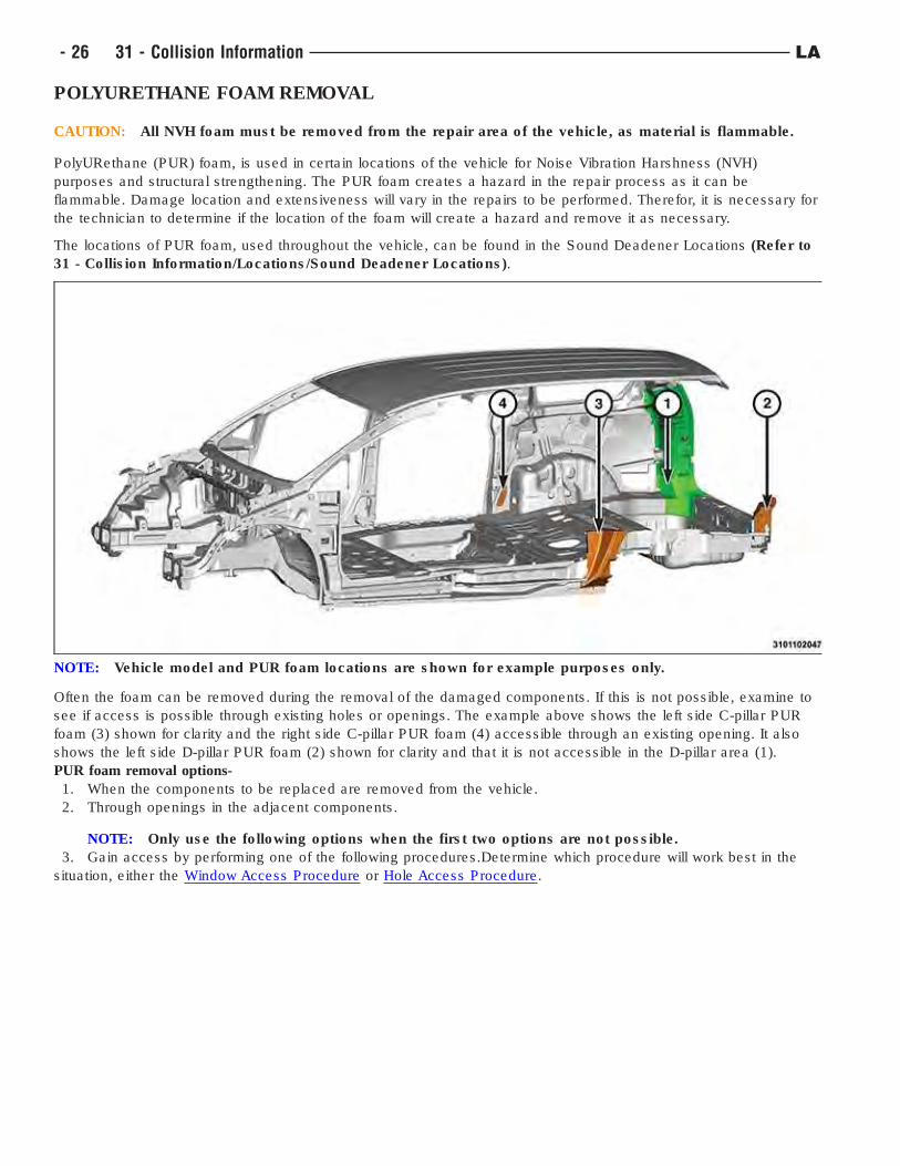
POLYURETHANE FOAM REMOVAL
CAUTION: All NVH foam must be removed from the repair area of the vehicle, as material is flammable.
PolyURethane (PUR) foam, is used in certain locations of the vehicle for Noise Vibration Harshness (NVH)
purposes and structural strengthening. The PUR foam creates a hazard in the repair process as it can be
flammable. Damage location and extensiveness will vary in the repairs to be performed. Therefor, it is necessary for
the technician to determine if the location of the foam will create a hazard and remove it as necessary.
The locations of PUR foam, used throughout the vehicle, can be found in the Sound Deadener Locations (Refer to
31 - Collision Information/Locations/Sound Deadener Locations).
Often the foam can be removed during the removal of the damaged components. If this is not possible, examine to
see if access is possible through existing holes or openings. The example above shows the left side C-pillar PUR
foam (3) shown for clarity and the right side C-pillar PUR foam (4) accessible through an existing opening. It also
shows the left side D-pillar PUR foam (2) shown for clarity and that it is not accessible in the D-pillar area (1).
PUR foam removal options-
1. When the components to be replaced are removed from the vehicle.
2. Through openings in the adjacent components.
NOTE: Only use the following options when the first two options are not possible.
3. Gain access by performing one of the following procedures.Determine which procedure will work best in the
situation, either the Window Access Procedure or Hole Access Procedure.
NOTE: Vehicle model and PUR foam locations are shown for example purposes only.
- 26 31 - Collision Information LA
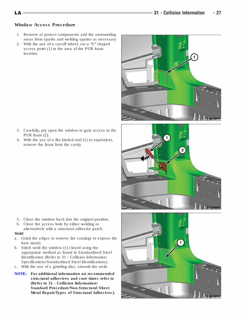
Window Access Procedure
1. Remove or protect components and the surrounding
areas from sparks and welding spatter as necessary
2. With the use of a cut-off wheel, cut a “U” shaped
access point (1) in the area of the PUR foam
location.
3. Carefully, pry open the window to gain access to the
PUR foam (2).
4. With the use of a flat bladed tool (1) or equivalent,
remove the foam from the cavity.
5. Close the window back into the original position.
6. Close the access hole by either welding or
alternatively with a structural adhesive patch.
Weld
a. Grind the edges to remove the coatings to expose the
bare metal.
b. Stitch weld the window (1) closed using the
appropriate method as found in Standardized Steel
Identification (Refer to 31 - Collision Information/
Specifications/Standardized Steel Identifications).
c. With the use of a grinding disc, smooth the weld.
NOTE: For additional information on recommended
structural adhesives and cure times refer to
(Refer to 31 - Collision Information/
Standard Procedure/Non-Structural Sheet
Metal Repair/Types of Structural Adhesives).
LA 31 - Collision Information - 27
Structural Adhesive
a. Create a metal patch 25 mm (1 in) larger than the opening.
b. Grind 13 mm (0.5 in) of the outer edge of the patch and the opening to expose bare metal.
c. Apply structural adhesive to the bare metal on the patch.
d. Position the patch to the opening and clamp into place.
e. Remove any squeeze-out adhesive and allow to cure per recommendations.
7. Refinish as necessary.
8. Apply inner panel corrosion inhibiting materials (Mopar Cavity Wax part #68042970AA, or equivalent).
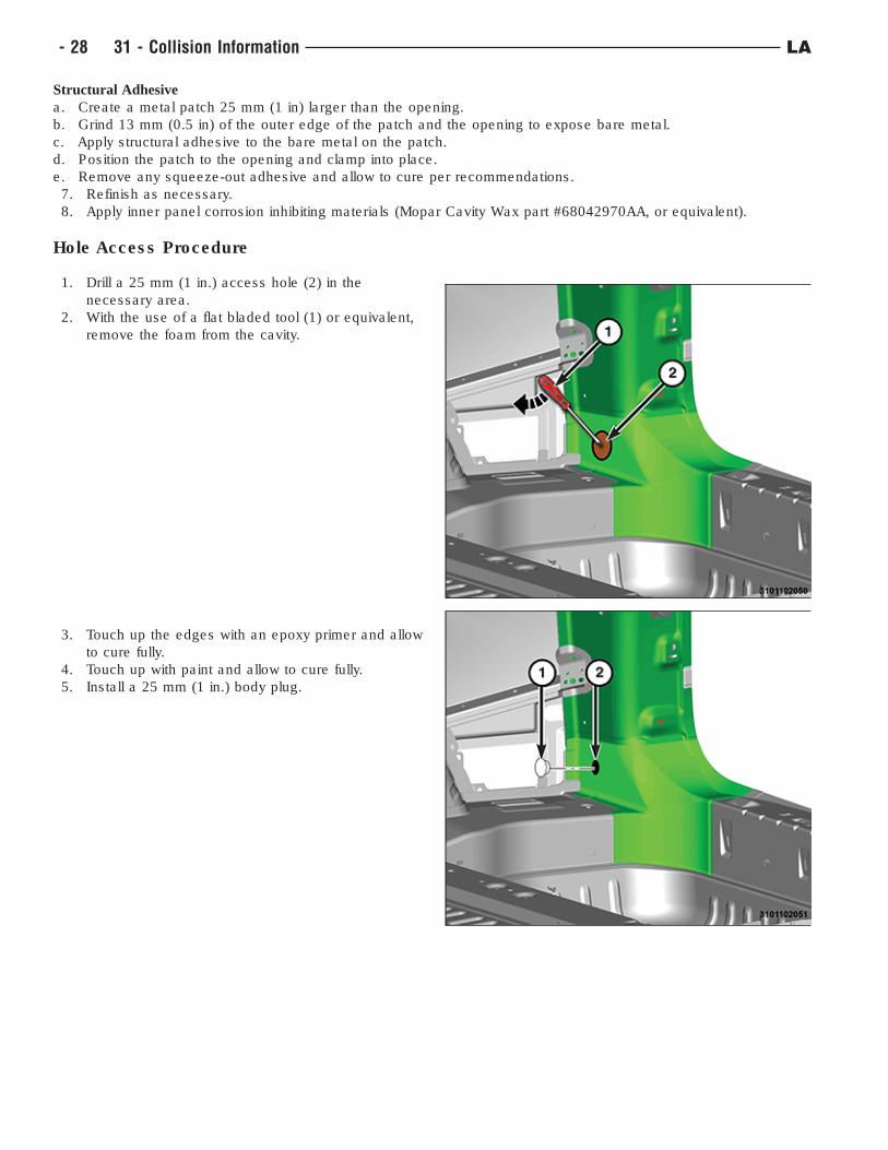
Hole Access Procedure
1. Drill a 25 mm (1 in.) access hole (2) in the
necessary area.
2. With the use of a flat bladed tool (1) or equivalent,
remove the foam from the cavity.
3. Touch up the edges with an epoxy primer and allow
to cure fully.
4. Touch up with paint and allow to cure fully.
5. Install a 25 mm (1 in.) body plug.
- 28 31 - Collision Information LA
NON-STRUCTURAL SHEET METAL REPAIR
Safety Notice
CAUTION: All Service and rebuilding instructions contained herein are applicable to, and for the
convenience of, the automotive repair industry only.
Proper service and repair is important to the safe, reliable operation of all motor vehicles. The service procedures
recommended and described in this publication were developed for professional service personnel, and are effective
methods for performing vehicle repair. Following these procedures will help ensure efficient and economical vehicle
performance and service reliability. Some service procedures require the use of special tools designed for specific
procedures. These special tools should be used as recommended throughout this publication.
It is important to note this publication contains various Cautions and Warnings. These should be read carefully in
order to minimize risk of personal injury or the possibility that improper service may damage the vehicle or render
it unsafe. It is important to note that these cautions and warnings cover only the situations and procedures FCA US
LLC has encountered and recommended. FCA US LLC cannot possibly know, evaluate, and advise the service
trade of all conceivable ways in which service may be performed, or the possible hazards of each. Consequently,
FCA US LLC has not undertaken any broad service review. Accordingly, anyone that uses a service procedure
or tool that is not recommended in this publication must be certain that neither personal safety, nor vehicle safety
will be jeopardized by the service methods they select.
Safety Precautions
WARNING: Always wear an approved respirator, as well as skin and eye protection per adhesive
manufacturer recommendations as stated in the product Safety Data Sheets (SDS).
WARNING: Failure to follow these instructions may result in possible serious or fatal injury
Adhesives:
• Safety Data Sheets (SDS) must be available and understood before adhesives are handled.
• All personnel should be instructed on the proper procedures to prevent skin contact with solvents, curing
agents, and uncured base adhesives, which could cause allergic reactions or sensitization.
Types of Structural Adhesives
Overview: There are three basic chemistries used in the collision repair industry. The types of adhesives used
include Acrylic, Epoxy and Urethane. To achieve optimal results, it is best to use the chemistry that bonds best to
the substrate being repaired, is easiest to use and offers the most permanent, non-detectable repair at the most
economical repair cost. All three chemistries have their strengths and weaknesses.
NOTE: Structural adhesives that meet FCA US LLC’s approved replacement materials specifications
include - LORD Fusor 2098, LORD Fusor 112B and 3M 08116
Adhesive Types:
• Acrylic Adhesives - Bond all types of bare metals and are excellent for cross bonding aluminum to steel.
They have good Noise Vibration Harshness (NVH) properties and offer anti-corrosion properties, so primers
must be removed in the bond area. Most acrylics have a fast room temperature cure and respond well to force
curing. They are stable with regards to temperature and moisture during cure. However, both of these can
effect shelf life. Acrylics are the most forgiving of the three chemistries with regards to mix ratio accuracy.
• Epoxy Adhesives - Bond well to ridged and semi-ridged plastics, steel and aluminum and are generally easy
to sand and feather edge. Some may be too ridged for flexible substrates and they often require primers on
bare metal applications. Epoxies can be heat cured to increase strength and accelerate the curing process.
They have a long and stable shelf life. Always purge the air out of the cartridges and use mix nozzles.
• Urethane Adhesive - Typically flexible and bond well to plastics. However, they usually require primers on
metal surfaces to protect against corrosion. Urethanes have good seam sealing and NVH qualities and are
frequently the optimal choice for seam sealers. They are sensitive to moisture during cure, packaging and
storage. Single component urethanes usually have a much shorter shelf life than two component urethanes.
Mix ratios are critical for urethanes. In most cases it cannot vary more than ± 5%. Therefore, hand mixing
is not recommended. Urethanes are the most unforgiving of the three chemistries with regards to mix
ratio accuracy.
LA 31 - Collision Information - 29
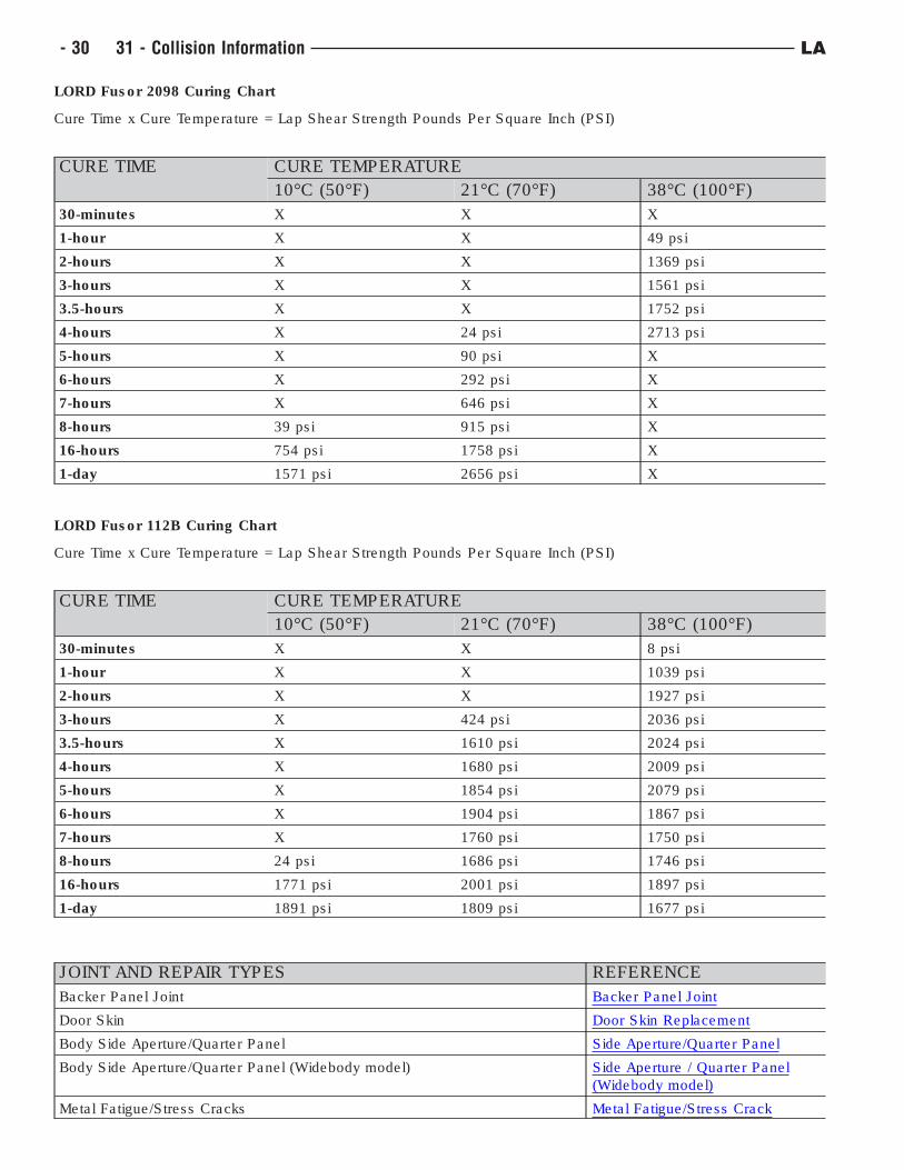
LORD Fusor 2098 Curing Chart
Cure Time x Cure Temperature = Lap Shear Strength Pounds Per Square Inch (PSI)
CURE TIME CURE TEMPERATURE
10°C (50°F) 21°C (70°F) 38°C (100°F)
30-minutes X X X
1-hour X X 49 psi
2-hours X X 1369 psi
3-hours X X 1561 psi
3.5-hours X X 1752 psi
4-hours X 24 psi 2713 psi
5-hours X 90 psi X
6-hours X 292 psi X
7-hours X 646 psi X
8-hours 39 psi 915 psi X
16-hours 754 psi 1758 psi X
1-day 1571 psi 2656 psi X
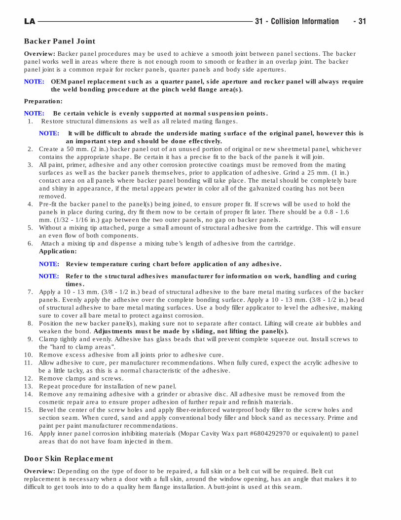
LORD Fusor 112B Curing Chart
Cure Time x Cure Temperature = Lap Shear Strength Pounds Per Square Inch (PSI)
CURE TIME CURE TEMPERATURE
10°C (50°F) 21°C (70°F) 38°C (100°F)
30-minutes X X 8 psi
1-hour X X 1039 psi
2-hours X X 1927 psi
3-hours X 424 psi 2036 psi
3.5-hours X 1610 psi 2024 psi
4-hours X 1680 psi 2009 psi
5-hours X 1854 psi 2079 psi
6-hours X 1904 psi 1867 psi
7-hours X 1760 psi 1750 psi
8-hours 24 psi 1686 psi 1746 psi
16-hours 1771 psi 2001 psi 1897 psi
1-day 1891 psi 1809 psi 1677 psi
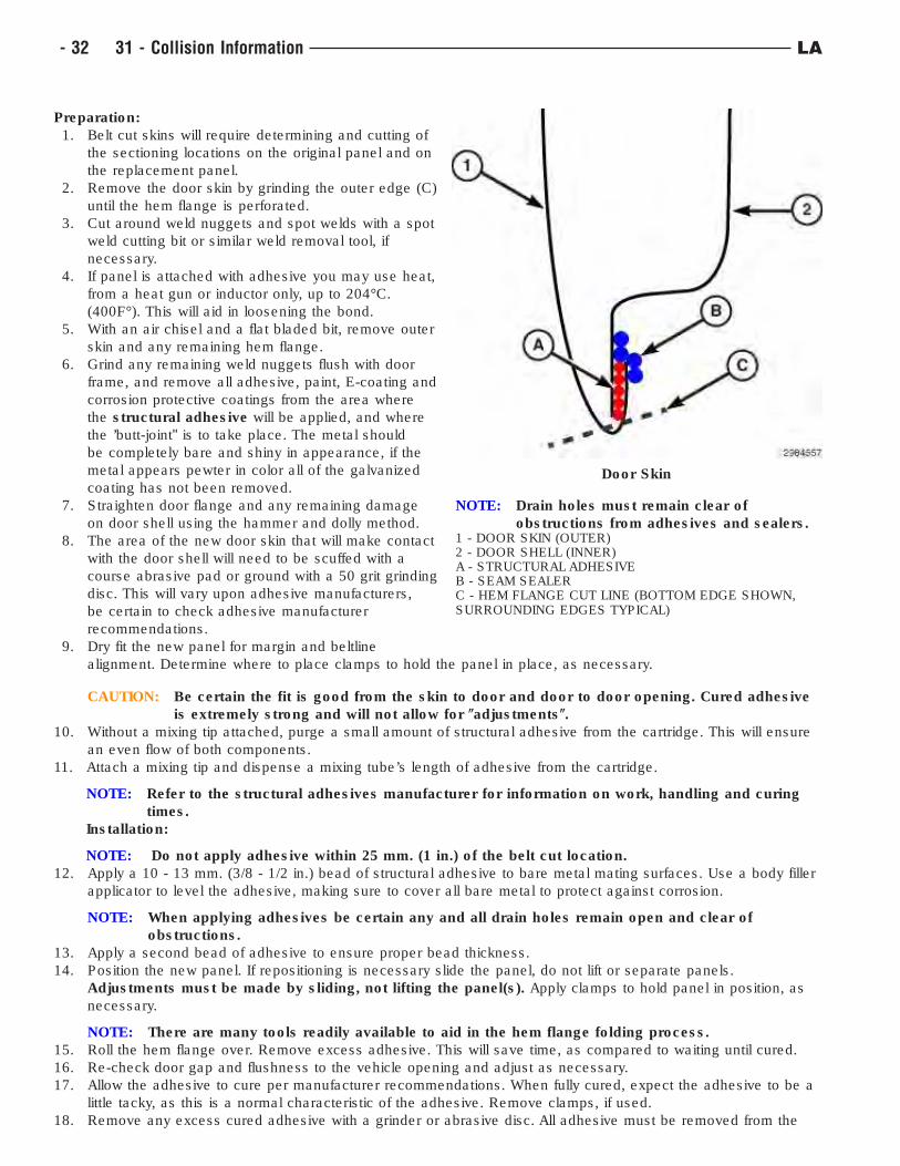
JOINT AND REPAIR TYPES REFERENCE
Backer Panel Joint Backer Panel Joint
Door Skin Door Skin Replacement
Body Side Aperture/Quarter Panel Side Aperture/Quarter Panel
Body Side Aperture/Quarter Panel (Widebody model) Side Aperture / Quarter Panel
(Widebody model)
Metal Fatigue/Stress Cracks Metal Fatigue/Stress Crack
- 30 31 - Collision Information LA
Backer Panel Joint
Overview: Backer panel procedures may be used to achieve a smooth joint between panel sections. The backer
panel works well in areas where there is not enough room to smooth or feather in an overlap joint. The backer
panel joint is a common repair for rocker panels, quarter panels and body side apertures.
NOTE: OEM panel replacement such as a quarter panel, side aperture and rocker panel will always require
the weld bonding procedure at the pinch weld flange area(s).
Preparation:
NOTE: Be certain vehicle is evenly supported at normal suspension points.
1. Restore structural dimensions as well as all related mating flanges.
NOTE: It will be difficult to abrade the underside mating surface of the original panel, however this is
an important step and should be done effectively.
2. Create a 50 mm. (2 in.) backer panel out of an unused portion of original or new sheetmetal panel, whichever
contains the appropriate shape. Be certain it has a precise fit to the back of the panels it will join.
3. All paint, primer, adhesive and any other corrosion protective coatings must be removed from the mating
surfaces as well as the backer panels themselves, prior to application of adhesive. Grind a 25 mm. (1 in.)
contact area on all panels where backer panel bonding will take place. The metal should be completely bare
and shiny in appearance, if the metal appears pewter in color all of the galvanized coating has not been
removed.
4. Pre-fit the backer panel to the panel(s) being joined, to ensure proper fit. If screws will be used to hold the
panels in place during curing, dry fit them now to be certain of proper fit later. There should be a 0.8 - 1.6
mm. (1/32 - 1/16 in.) gap between the two outer panels, no gap on backer panels.
5. Without a mixing tip attached, purge a small amount of structural adhesive from the cartridge. This will ensure
an even flow of both components.
6. Attach a mixing tip and dispense a mixing tube’s length of adhesive from the cartridge.
Application:
NOTE: Review temperature curing chart before application of any adhesive.
NOTE: Refer to the structural adhesives manufacturer for information on work, handling and curing
times.
7. Apply a 10 - 13 mm. (3/8 - 1/2 in.) bead of structural adhesive to the bare metal mating surfaces of the backer
panels. Evenly apply the adhesive over the complete bonding surface. Apply a 10 - 13 mm. (3/8 - 1/2 in.) bead
of structural adhesive to bare metal mating surfaces. Use a body filler applicator to level the adhesive, making
sure to cover all bare metal to protect against corrosion.
8. Position the new backer panel(s), making sure not to separate after contact. Lifting will create air bubbles and
weaken the bond. Adjustments must be made by sliding, not lifting the panel(s).
9. Clamp tightly and evenly. Adhesive has glass beads that will prevent complete squeeze out. Install screws to
the "hard to clamp areas".
10. Remove excess adhesive from all joints prior to adhesive cure.
11. Allow adhesive to cure, per manufacturer recommendations. When fully cured, expect the acrylic adhesive to
be a little tacky, as this is a normal characteristic of the adhesive.
12. Remove clamps and screws.
13. Repeat procedure for installation of new panel.
14. Remove any remaining adhesive with a grinder or abrasive disc. All adhesive must be removed from the
cosmetic repair area to ensure proper adhesion of further repair and refinish materials.
15. Bevel the center of the screw holes and apply fiber-reinforced waterproof body filler to the screw holes and
section seam. When cured, sand and apply conventional body filler and block sand as necessary. Prime and
paint per paint manufacturer recommendations.
16. Apply inner panel corrosion inhibiting materials (Mopar Cavity Wax part #6804292970 or equivalent) to panel
areas that do not have foam injected in them.
Door Skin Replacement
Overview: Depending on the type of door to be repaired, a full skin or a belt cut will be required. Belt cut
replacement is necessary when a door with a full skin, around the window opening, has an angle that makes it to
difficult to get tools into to do a quality hem flange installation. A butt-joint is used at this seam.
LA 31 - Collision Information - 31
Preparation:
1. Belt cut skins will require determining and cutting of
the sectioning locations on the original panel and on
the replacement panel.
2. Remove the door skin by grinding the outer edge (C)
until the hem flange is perforated.
3. Cut around weld nuggets and spot welds with a spot
weld cutting bit or similar weld removal tool, if
necessary.
4. If panel is attached with adhesive you may use heat,
from a heat gun or inductor only, up to 204°C.
(400F°). This will aid in loosening the bond.
5. With an air chisel and a flat bladed bit, remove outer
skin and any remaining hem flange.
6. Grind any remaining weld nuggets flush with door
frame, and remove all adhesive, paint, E-coating and
corrosion protective coatings from the area where
the structural adhesive will be applied, and where
the ’butt-joint" is to take place. The metal should
be completely bare and shiny in appearance, if the
metal appears pewter in color all of the galvanized
coating has not been removed.
7. Straighten door flange and any remaining damage
on door shell using the hammer and dolly method.
8. The area of the new door skin that will make contact
with the door shell will need to be scuffed with a
course abrasive pad or ground with a 50 grit grinding
disc. This will vary upon adhesive manufacturers,
be certain to check adhesive manufacturer
recommendations.
9. Dry fit the new panel for margin and beltline
alignment. Determine where to place clamps to hold the panel in place, as necessary.
CAUTION: Be certain the fit is good from the skin to door and door to door opening. Cured adhesive
is extremely strong and will not allow for (adjustments(.
10. Without a mixing tip attached, purge a small amount of structural adhesive from the cartridge. This will ensure
an even flow of both components.
11. Attach a mixing tip and dispense a mixing tube’s length of adhesive from the cartridge.
NOTE: Refer to the structural adhesives manufacturer for information on work, handling and curing
times.
Installation:
NOTE: Do not apply adhesive within 25 mm. (1 in.) of the belt cut location.
12. Apply a 10 - 13 mm. (3/8 - 1/2 in.) bead of structural adhesive to bare metal mating surfaces. Use a body filler
applicator to level the adhesive, making sure to cover all bare metal to protect against corrosion.
NOTE: When applying adhesives be certain any and all drain holes remain open and clear of
obstructions.
13. Apply a second bead of adhesive to ensure proper bead thickness.
14. Position the new panel. If repositioning is necessary slide the panel, do not lift or separate panels.
Adjustments must be made by sliding, not lifting the panel(s). Apply clamps to hold panel in position, as
necessary.
NOTE: There are many tools readily available to aid in the hem flange folding process.
15. Roll the hem flange over. Remove excess adhesive. This will save time, as compared to waiting until cured.
16. Re-check door gap and flushness to the vehicle opening and adjust as necessary.
17. Allow the adhesive to cure per manufacturer recommendations. When fully cured, expect the adhesive to be a
little tacky, as this is a normal characteristic of the adhesive. Remove clamps, if used.
18. Remove any excess cured adhesive with a grinder or abrasive disc. All adhesive must be removed from the
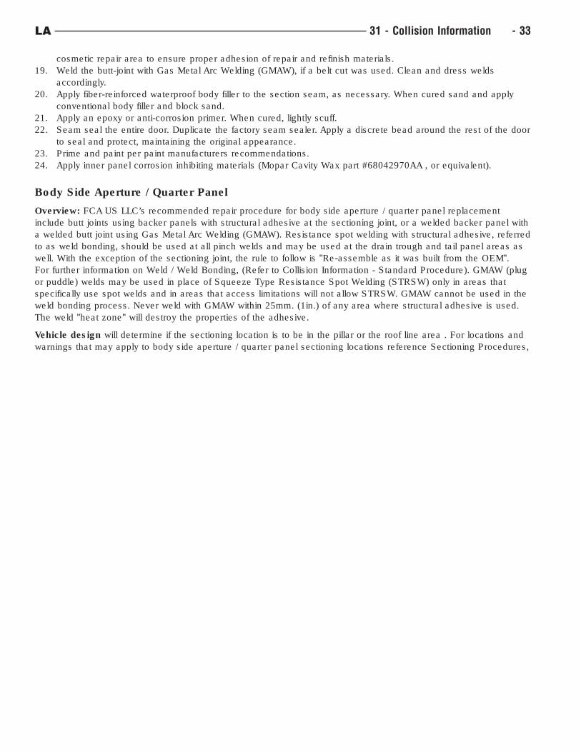
Door Skin
NOTE: Drain holes must remain clear of
obstructions from adhesives and sealers.1 - DOOR SKIN (OUTER)2 - DOOR SHELL (INNER)A - STRUCTURAL ADHESIVEB - SEAM SEALERC - HEM FLANGE CUT LINE (BOTTOM EDGE SHOWN,SURROUNDING EDGES TYPICAL)
- 32 31 - Collision Information LA
cosmetic repair area to ensure proper adhesion of repair and refinish materials.
19. Weld the butt-joint with Gas Metal Arc Welding (GMAW), if a belt cut was used. Clean and dress welds
accordingly.
20. Apply fiber-reinforced waterproof body filler to the section seam, as necessary. When cured sand and apply
conventional body filler and block sand.
21. Apply an epoxy or anti-corrosion primer. When cured, lightly scuff.
22. Seam seal the entire door. Duplicate the factory seam sealer. Apply a discrete bead around the rest of the door
to seal and protect, maintaining the original appearance.
23. Prime and paint per paint manufacturers recommendations.
24. Apply inner panel corrosion inhibiting materials (Mopar Cavity Wax part #68042970AA , or equivalent).
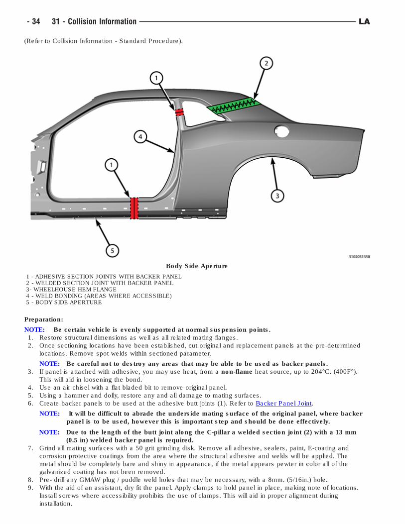
Body Side Aperture / Quarter Panel
Overview: FCA US LLC’s recommended repair procedure for body side aperture / quarter panel replacement
include butt joints using backer panels with structural adhesive at the sectioning joint, or a welded backer panel with
a welded butt joint using Gas Metal Arc Welding (GMAW). Resistance spot welding with structural adhesive, referred
to as weld bonding, should be used at all pinch welds and may be used at the drain trough and tail panel areas as
well. With the exception of the sectioning joint, the rule to follow is "Re-assemble as it was built from the OEM".
For further information on Weld / Weld Bonding, (Refer to Collision Information - Standard Procedure). GMAW (plug
or puddle) welds may be used in place of Squeeze Type Resistance Spot Welding (STRSW) only in areas that
specifically use spot welds and in areas that access limitations will not allow STRSW. GMAW cannot be used in the
weld bonding process. Never weld with GMAW within 25mm. (1in.) of any area where structural adhesive is used.
The weld "heat zone" will destroy the properties of the adhesive.
Vehicle design will determine if the sectioning location is to be in the pillar or the roof line area . For locations and
warnings that may apply to body side aperture / quarter panel sectioning locations reference Sectioning Procedures,
LA 31 - Collision Information - 33
(Refer to Collision Information - Standard Procedure).
Preparation:
NOTE: Be certain vehicle is evenly supported at normal suspension points.
1. Restore structural dimensions as well as all related mating flanges.
2. Once sectioning locations have been established, cut original and replacement panels at the pre-determined
locations. Remove spot welds within sectioned parameter.
NOTE: Be careful not to destroy any areas that may be able to be used as backer panels.
3. If panel is attached with adhesive, you may use heat, from a non-flame heat source, up to 204°C. (400F°).
This will aid in loosening the bond.
4. Use an air chisel with a flat bladed bit to remove original panel.
5. Using a hammer and dolly, restore any and all damage to mating surfaces.
6. Create backer panels to be used at the adhesive butt joints (1). Refer to Backer Panel Joint.
NOTE: It will be difficult to abrade the underside mating surface of the original panel, where backer
panel is to be used, however this is important step and should be done effectively.
NOTE: Due to the length of the butt joint along the C-pillar a welded section joint (2) with a 13 mm
(0.5 in) welded backer panel is required.
7. Grind all mating surfaces with a 50 grit grinding disk. Remove all adhesive, sealers, paint, E-coating and
corrosion protective coatings from the area where the structural adhesive and welds will be applied. The
metal should be completely bare and shiny in appearance, if the metal appears pewter in color all of the
galvanized coating has not been removed.
8. Pre- drill any GMAW plug / puddle weld holes that may be necessary, with a 8mm. (5/16in.) hole.
9. With the aid of an assistant, dry fit the panel. Apply clamps to hold panel in place, making note of locations.
Install screws where accessibility prohibits the use of clamps. This will aid in proper alignment during
installation.
Body Side Aperture
1 - ADHESIVE SECTION JOINTS WITH BACKER PANEL2 - WELDED SECTION JOINT WITH BACKER PANEL3- WHEELHOUSE HEM FLANGE4 - WELD BONDING (AREAS WHERE ACCESSIBLE)5 - BODY SIDE APERTURE
- 34 31 - Collision Information LA
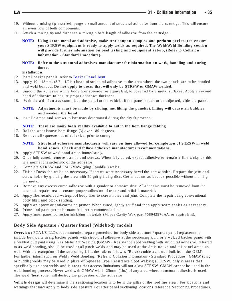
10. Without a mixing tip installed, purge a small amount of structural adhesive from the cartridge. This will ensure
an even flow of both components.
11. Attach a mixing tip and dispense a mixing tube’s length of adhesive from the cartridge.
NOTE: Using scrap metal and adhesive, make test coupon samples and perform peel test to ensure
your STRSW equipment is ready to apply welds as required. The Weld/Weld Bonding section
will provide further information on peel testing and equipment set-up, (Refer to Collision
Information - Standard Procedure).
NOTE: Refer to the structural adhesives manufacturer for information on work, handling and curing
times.
Installation:
12. Install backer panels, refer to Backer Panel Joint.
13. Apply 10 - 13mm. (3/8 - 1/2in.) bead of structural adhesive to the area where the two panels are to be bonded
and weld bonded. Do not apply to areas that will only be STRSW or GMAW welded.
14. Smooth the adhesive with a body filler spreader or equivalent, to cover all bare metal surfaces. Apply a second
bead of adhesive to ensure proper adhesive thickness.
15. With the aid of an assistant place the panel to the vehicle. If the panel needs to be adjusted, slide the panel.
NOTE: Adjustments must be made by sliding, not lifting the panel(s). Lifting will cause air bubbles
and weaken the bond.
16. Install clamps and screws to locations determined during the dry fit process.
NOTE: There are many tools readily available to aid in the hem flange folding
17. Roll the wheelhouse hem flange (3) over 180 degrees.
18. Remove all squeeze out of adhesive, prior to curing.
NOTE: Structural adhesive manufacturers will vary on time allowed for completion of STRSW in weld
bond zones. Check and follow adhesive manufacturer recommendations.
19. Apply STRSW to weld bond areas immediately.
20. Once fully cured, remove clamps and screws. When fully cured, expect adhesive to remain a little tacky, as this
is a normal characteristic of the adhesive.
21. Complete STRSW and / or GMAW (plug / puddle ) welds.
22. Finish / Dress the welds as necessary. If screws were necessary bevel the screw holes. Prepare the joint and
screw holes by grinding the area with 50 grit grinding disc. Get in seams as best as possible without thinning
the metal.
23. Remove any excess cured adhesive with a grinder or abrasive disc. All adhesive must be removed from the
cosmetic repair area to ensure proper adhesion of repair and refinish materials.
24. Apply fiber-reinforced waterproof body filler to screw holes and joint. Complete the repair using conventional
body filler, and block sanding.
25. Apply an epoxy or anti-corrosion primer. When cured, lightly scuff and then apply seam sealer as necessary.
26. Prime and paint per paint manufacturer recommendations.
27. Apply inner panel corrosion inhibiting materials (Mopar Cavity Wax part #68042970AA, or equivalent).
Body Side Aperture / Quarter Panel (Widebody model)
Overview: FCA US LLC’s recommended repair procedure for body side aperture / quarter panel replacement
include butt joints using backer panels with structural adhesive at the sectioning joint, or a welded backer panel with
a welded butt joint using Gas Metal Arc Welding (GMAW). Resistance spot welding with structural adhesive, referred
to as weld bonding, should be used at all pinch welds and may be used at the drain trough and tail panel areas as
well. With the exception of the sectioning joint, the rule to follow is "Re-assemble as it was built from the OEM".
For further information on Weld / Weld Bonding, (Refer to Collision Information - Standard Procedure). GMAW (plug
or puddle) welds may be used in place of Squeeze Type Resistance Spot Welding (STRSW) only in areas that
specifically use spot welds and in areas that access limitations will not allow STRSW. GMAW cannot be used in the
weld bonding process. Never weld with GMAW within 25mm. (1in.) of any area where structural adhesive is used.
The weld "heat zone" will destroy the properties of the adhesive.
Vehicle design will determine if the sectioning location is to be in the pillar or the roof line area . For locations and
warnings that may apply to body side aperture / quarter panel sectioning locations reference Sectioning Procedures,
LA 31 - Collision Information - 35
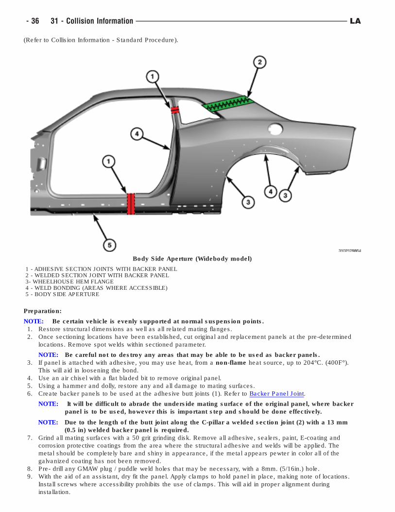
(Refer to Collision Information - Standard Procedure).
Preparation:
NOTE: Be certain vehicle is evenly supported at normal suspension points.
1. Restore structural dimensions as well as all related mating flanges.
2. Once sectioning locations have been established, cut original and replacement panels at the pre-determined
locations. Remove spot welds within sectioned parameter.
NOTE: Be careful not to destroy any areas that may be able to be used as backer panels.
3. If panel is attached with adhesive, you may use heat, from a non-flame heat source, up to 204°C. (400F°).
This will aid in loosening the bond.
4. Use an air chisel with a flat bladed bit to remove original panel.
5. Using a hammer and dolly, restore any and all damage to mating surfaces.
6. Create backer panels to be used at the adhesive butt joints (1). Refer to Backer Panel Joint.
NOTE: It will be difficult to abrade the underside mating surface of the original panel, where backer
panel is to be used, however this is important step and should be done effectively.
NOTE: Due to the length of the butt joint along the C-pillar a welded section joint (2) with a 13 mm
(0.5 in) welded backer panel is required.
7. Grind all mating surfaces with a 50 grit grinding disk. Remove all adhesive, sealers, paint, E-coating and
corrosion protective coatings from the area where the structural adhesive and welds will be applied. The
metal should be completely bare and shiny in appearance, if the metal appears pewter in color all of the
galvanized coating has not been removed.
8. Pre- drill any GMAW plug / puddle weld holes that may be necessary, with a 8mm. (5/16in.) hole.
9. With the aid of an assistant, dry fit the panel. Apply clamps to hold panel in place, making note of locations.
Install screws where accessibility prohibits the use of clamps. This will aid in proper alignment during
installation.
Body Side Aperture (Widebody model)
1 - ADHESIVE SECTION JOINTS WITH BACKER PANEL2 - WELDED SECTION JOINT WITH BACKER PANEL3- WHEELHOUSE HEM FLANGE4 - WELD BONDING (AREAS WHERE ACCESSIBLE)5 - BODY SIDE APERTURE
- 36 31 - Collision Information LA
10. Without a mixing tip installed, purge a small amount of structural adhesive from the cartridge. This will ensure
an even flow of both components.
11. Attach a mixing tip and dispense a mixing tube’s length of adhesive from the cartridge.
NOTE: Using scrap metal and adhesive, make test coupon samples and perform peel test to ensure
your STRSW equipment is ready to apply welds as required. The Weld/Weld Bonding section
will provide further information on peel testing and equipment set-up, (Refer to Collision
Information - Standard Procedure).
NOTE: Refer to the structural adhesives manufacturer for information on work, handling and curing
times.
Installation:
12. Install backer panels, refer to Backer Panel Joint.
13. Apply 10 - 13mm. (3/8 - 1/2in.) bead of structural adhesive to the area where the two panels are to be bonded
and weld bonded. Do not apply to areas that will only be STRSW or GMAW welded.
14. Smooth the adhesive with a body filler spreader or equivalent, to cover all bare metal surfaces. Apply a second
bead of adhesive to ensure proper adhesive thickness.
15. With the aid of an assistant place the panel to the vehicle. If the panel needs to be adjusted, slide the panel.
NOTE: Adjustments must be made by sliding, not lifting the panel(s). Lifting will cause air bubbles
and weaken the bond.
16. Install clamps and screws to locations determined during the dry fit process.
NOTE: There are many tools readily available to aid in the hem flange folding
17. Roll the wheelhouse hem flange (3) over 180 degrees.
18. Remove all squeeze out of adhesive, prior to curing.
NOTE: Structural adhesive manufacturers will vary on time allowed for completion of STRSW in weld
bond zones. Check and follow adhesive manufacturer recommendations.
19. Apply STRSW to weld bond areas immediately.
20. Once fully cured, remove clamps and screws. When fully cured, expect adhesive to remain a little tacky, as this
is a normal characteristic of the adhesive.
21. Complete STRSW and / or GMAW (plug / puddle ) welds.
22. Finish / Dress the welds as necessary. If screws were necessary bevel the screw holes. Prepare the joint and
screw holes by grinding the area with 50 grit grinding disc. Get in seams as best as possible without thinning
the metal.
23. Remove any excess cured adhesive with a grinder or abrasive disc. All adhesive must be removed from the
cosmetic repair area to ensure proper adhesion of repair and refinish materials.
24. Apply fiber-reinforced waterproof body filler to screw holes and joint. Complete the repair using conventional
body filler, and block sanding.
25. Apply an epoxy or anti-corrosion primer. When cured, lightly scuff and then apply seam sealer as necessary.
26. Prime and paint per paint manufacturer recommendations.
27. Apply inner panel corrosion inhibiting materials (Mopar Cavity Wax part #68042970AA, or equivalent).
Metal Fatigue/Stress Crack
Overview: On rare occasions you may encounter metal fatigue, also referred to as stress cracks. This will appear
as a crack starting at an edge and trailing away. Follow these steps for a proper repair:
1. Locate the trailing end of the crack and drill a 3 mm. (1/8 in.) hole at the very point at which it stops. This is
referred to as "Stop Drilling".
2. Remove all contaminants and coatings including primer, paint and anti-corrosion, from the repair area. Surface
should be clean and shiny (if pewter in color then anti-corrosion has not been removed).
3. Identify the type of metal to be welded and the recommended welding process for that metal as found in
Standardized Steel Identification (Refer to 31 - Collision Information/Specifications/Standardized Steel
Identification).
4. Stitch weld the seam/crack closed using the recommended welding process and in accordance with the
welding guidelines as found in Weld/Weld Bonding (Refer to 31 - Collision Information/Standard Procedure/
Welding and Weld Bonding).
5. Dress the welds as necessary. Careful not to thin the base metal.
6. Depending on the location and visibility of the repair surface refinishing will vary from body filler, finishing and
painting to simply applying an epoxy or anticorrosion primer and rubberized undercoating, Mopar part
#05093417AA or equivalent.
LA 31 - Collision Information - 37
7. Apply inner panel corrosion inhibiting materials (Mopar Cavity Wax part #68042970AA or equivalent).
- 38 31 - Collision Information LA
WELDING AND WELD BONDING
Safety Notice
CAUTION: All Service and rebuilding instructions contained herein are applicable to, and for the
convenience of, the automotive repair industry only
The service procedures recommended and described in this publication were developed for professional service
personnel, and are effective methods for performing vehicle repair.
It is important to note this publication contains various Cautions and Warnings. These should be read carefully in
order to minimize risk of personal injury or the possibility that improper service may damage the vehicle or render
it unsafe. FCA US LLC cannot possibly know, evaluate and advise the service trade of all conceivable ways in
which service may be performed, or the possible hazards of each. Consequently, FCA US LLC has not undertaken
any broad service review. Accordingly, anyone that uses a service procedure or tool that is not recommended in this
publication must be certain that neither personal safety, nor vehicle safety will be jeopardized by the service
methods they select.
Safety Precautions
WARNING:
• When Welding or working with Adhesives always wear safety goggles and gloves to prevent contact
with chemicals and to prevent weld spatter, sparks, and sharp metal from causing bodily injury.
• Wear an approved respirator while welding and during the application of adhesives to prevent
inhalation of harmful vapors.
• Always remove NVH (Noise Vibration and Harshness) foam from welding repair area, as material
is flammable.
WARNING: Failure to follow these instructions may result in possible serious or fatal injury
Welding
• Comply with all federal, state and local regulations to avoid any injuries due to shock, fires, fumes, sparks and
liquids.
• All flammable materials or liquid should be stored in tightly sealed and labeled containers, and used only in
well ventilated areas.
• No spark producing equipment should be permitted in any area where flammable materials are being handled
or stored.
Adhesives:
• Safety Data Sheets (SDS) must be available and understood before adhesives are handled.
• All personnel should be instructed on the proper procedures to prevent skin contact with solvents, curing
agents, and uncured base adhesives, which could cause allergic reactions or sensitization.
Introduction
The purpose of this document is to clearly explain the welding options available to the collision repair technician and
how to determine that welding repairs are made properly. The primary types of welding covered in this section are
Squeeze Type Resistant Spot Welding (STRSW), Gas Metal Arc Welding (GMAW), Metal Inert Gas (MIG)
Brazing and Weld Bonding (a combination of STRSW and structural adhesive). Proper training and weld testing are
required to ensure that a safe, high quality, vehicle repair is made.
INDEX REFERENCE
Panel Removal Panel Removal
Key Points of a Welding Repair Key Points of a Welding Repair
Requirements of a Welding Repair Requirements of a Welding Repair
Modified Lap Joint Modified Lap Joint
Types of Welding (STRSW, GMAW and Weld Bonding) Types of Welding
Weld Processes (STRSW, GMAW and Weld Bonding) Weld Processes
Minimum Weld Nugget Requirement Chart Minimum Weld Nugget Chart
LA 31 - Collision Information - 39
INDEX REFERENCE
Training and Qualification Training and Qualification
Panel Removal
WARNING: Always Wear Safety Goggles, Work Gloves, Hearing Protection and a Dust Mask when
removing welded panels this way. Failure to follow these instructions could result in serious or
fatal injury.
When removing panels and components for replacement, care must be taken not to damage the underlying
component. On welded and "Weld Bonded" panels spot welds must be removed using a spot weld cutting type tool,
or equivalent. On panels that are adhesive bonded or weld bonded it is acceptable to use heat up to 204°C.
(400°F.), from a Non-Open Flame heat source such as a heat gun. This will loosen the bond, so less damage is
inflicted to the mating surface. After panel is removed, any remaining weld nugget should be ground smooth. Cut-off
wheels should not be used, as there is potential to remove material from the base material which would weaken
the final repair. Place an air hammer with a flat bladed chisel bit (or equivalent) in between panels and remove the
panel. Care should be taken as to not damage mating flanges and the surrounding components.
Key Points of a Welding Repair• Poor fit up will adversely affect weld quality and may result in a weld failure due to excessive metal stretching
around the nugget.
• Clamps/Clecos should be used to bring parts together and hold them in position.
• Clamps/Clecos should be insulated when using STRSW to control weld current shunting (This can be
accomplished with specialized clamps or by placing a insulating material such as cardboard between the
clamp jaws and the panels.)
• Number, size and location of welds should closely duplicate the original assembly. Do not place the new spot
weld directly on the original spot weld location. Placement of a new weld over an original weld location may
lead to metal fatigue or poor weld quality.
• Surface of the steel parts should be clean and free of scale, rust, paint, cured adhesives/sealers and any other
contaminants that could adversely affect the quality of the weld joint. This includes the removal of any E-coat
applied to the service part within 25 mm. (1 in.) of any welds.
• Proper corrosion protection must be installed when repairs are complete, (Refer to 31 - Collision Information/
Standard Procedure/Corrosion Protection).
• If the joint originally had adhesive, all E-coat must be removed where the adhesive is to be reapplied.
• "Weld-thru" primers are not recommended anywhere.
• Do not remove base material from the base panel when releasing welds.
NOTE: FCA US LLC recommends the same quantity of welds as the original panel, but placement of the
new weld should NOT be put directly on the original spot weld location. Placement of a new weld
over an original weld location may lead to metal fatigue or poor weld quality.
Requirements of a Welding Repair
The number one requirement of any welding repair is to restore the vehicle to its OEM condition. Materials and
technologies should duplicate original OEM conditions as much as possible. To meet this requirement, the
technician must ensure the following:
• Panel layering (shingling) is the same as original
• Part fit up is correct
• Equivalent sealers and/or adhesives are utilized
• Welds are replaced in the same size, quantity and location
• "Weld-thru" primers are NOT recommended
• Structural adhesives and sealers must be replaced where they were located
A significant amount of structural adhesive is used at the OEM to improve joint strength. It may be difficult to
determine if the material between the panels is an adhesive or a sealer, and for this reason, the following guideline
should be used: If in doubt, use a two-component, corrosion inhibiting, structural adhesive. GMAW welding
is not recommended within 25 mm. (1 in.) of the adhesive as it creates heat that will destroy the adhesive. STRSW
on the other hand, can weld through the adhesive and will not destroy its properties.
NOTE: Structural adhesives that meet FCA US LLC materials recommendations for adhesive strength and
corrosion protection qualities include Lord Fusor #2098, Lord Fusor #112B and 3M #08116.
- 40 31 - Collision Information LA
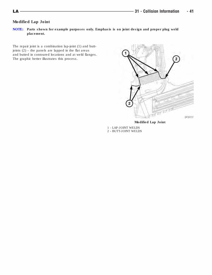
Modified Lap Joint
NOTE: Parts shown for example purposes only. Emphasis is on joint design and proper plug weld
placement.
The repair joint is a combination lap-joint (1) and butt-
joints (2) – the panels are lapped in the flat areas
and butted in contoured locations and at weld flanges.
The graphic better illustrates this process.
Modified Lap Joint
1 - LAP-JOINT WELDS2 - BUTT-JOINT WELDS
LA 31 - Collision Information - 41
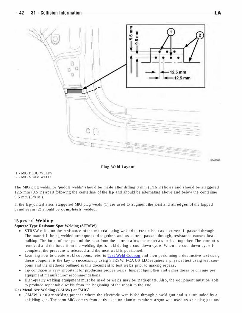
The MIG plug welds, or "puddle welds" should be made after drilling 8 mm (5/16 in) holes and should be staggered
12.5 mm (0.5 in) apart following the centerline of the lap and should be alternating above and below the centerline
9.5 mm (3/8 in.).
In the lap-jointed area, staggered MIG plug welds (1) are used to augment the joint and all edges of the lapped
panel seam (2) should be completely welded.
Types of WeldingSqueeze Type Resistant Spot Welding (STRSW)
• STRSW relies on the resistance of the material being welded to create heat as a current is passed through.
The materials being welded are squeezed together, and as current passes through, resistance causes heat
buildup. The force of the tips and the heat from the current allow the materials to fuse together. The current is
removed and the force from the welding tips is held during a cool down cycle. When the cool down cycle is
complete, the pressure is released and the next weld is positioned.
• Learning how to create weld coupons, refer to Test Weld Coupon and then performing a destructive test using
these coupons, is the key to successfully using STRSW. FCA US LLC requires a physical test using test cou-
pons and the methods outlined in this document to test welds prior to making repairs.
• Tip condition is very important for producing proper welds. Inspect tips often and either dress or change per
equipment manufacturer recommendations.
• High-quality welding equipment must be used or welds may be inadequate. Also, the equipment must be able
to produce repeatable welds from the beginning of the repair to the end.
Gas Metal Arc Welding (GMAW) or (MIG(
• GMAW is an arc welding process where the electrode wire is fed through a weld gun and is surrounded by a
shielding gas. The term MIG comes from early uses on aluminum where argon was used as shielding gas and
Plug Weld Layout
1 - MIG PLUG WELDS2 - MIG SEAM WELD
- 42 31 - Collision Information LA
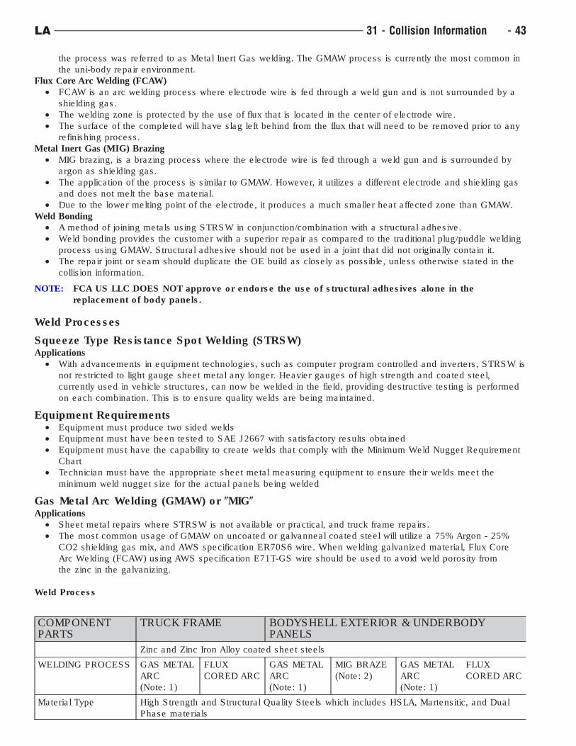
the process was referred to as Metal Inert Gas welding. The GMAW process is currently the most common in
the uni-body repair environment.
Flux Core Arc Welding (FCAW)
• FCAW is an arc welding process where electrode wire is fed through a weld gun and is not surrounded by a
shielding gas.
• The welding zone is protected by the use of flux that is located in the center of electrode wire.
• The surface of the completed will have slag left behind from the flux that will need to be removed prior to any
refinishing process.
Metal Inert Gas (MIG) Brazing
• MIG brazing, is a brazing process where the electrode wire is fed through a weld gun and is surrounded by
argon as shielding gas.
• The application of the process is similar to GMAW. However, it utilizes a different electrode and shielding gas
and does not melt the base material.
• Due to the lower melting point of the electrode, it produces a much smaller heat affected zone than GMAW.
Weld Bonding
• A method of joining metals using STRSW in conjunction/combination with a structural adhesive.
• Weld bonding provides the customer with a superior repair as compared to the traditional plug/puddle welding
process using GMAW. Structural adhesive should not be used in a joint that did not originally contain it.
• The repair joint or seam should duplicate the OE build as closely as possible, unless otherwise stated in the
collision information.
NOTE: FCA US LLC DOES NOT approve or endorse the use of structural adhesives alone in the
replacement of body panels.
Weld Processes
Squeeze Type Resistance Spot Welding (STRSW)Applications
• With advancements in equipment technologies, such as computer program controlled and inverters, STRSW is
not restricted to light gauge sheet metal any longer. Heavier gauges of high strength and coated steel,
currently used in vehicle structures, can now be welded in the field, providing destructive testing is performed
on each combination. This is to ensure quality welds are being maintained.
Equipment Requirements• Equipment must produce two sided welds
• Equipment must have been tested to SAE J2667 with satisfactory results obtained
• Equipment must have the capability to create welds that comply with the Minimum Weld Nugget Requirement
Chart
• Technician must have the appropriate sheet metal measuring equipment to ensure their welds meet the
minimum weld nugget size for the actual panels being welded
Gas Metal Arc Welding (GMAW) or (MIG(
Applications
• Sheet metal repairs where STRSW is not available or practical, and truck frame repairs.
• The most common usage of GMAW on uncoated or galvanneal coated steel will utilize a 75% Argon - 25%
CO2 shielding gas mix, and AWS specification ER70S6 wire. When welding galvanized material, Flux Core
Arc Welding (FCAW) using AWS specification E71T-GS wire should be used to avoid weld porosity from
the zinc in the galvanizing.
Weld Process
COMPONENTPARTS
TRUCK FRAME BODYSHELL EXTERIOR & UNDERBODYPANELS
Zinc and Zinc Iron Alloy coated sheet steels
WELDING PROCESS GAS METAL
ARC
(Note: 1)
FLUX
CORED ARC
GAS METAL
ARC
(Note: 1)
MIG BRAZE
(Note: 2)
GAS METAL
ARC
(Note: 1)
FLUX
CORED ARC
Material Type High Strength and Structural Quality Steels which includes HSLA, Martensitic, and Dual
Phase materials
LA 31 - Collision Information - 43
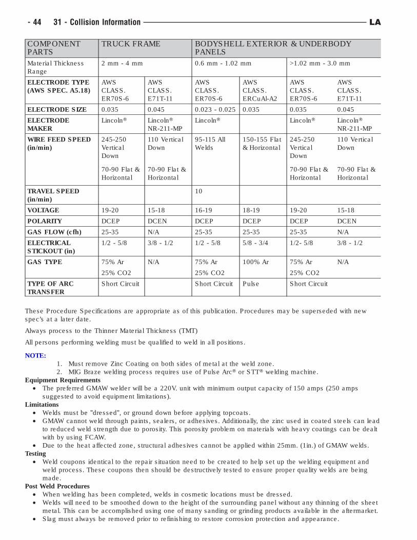
COMPONENTPARTS
TRUCK FRAME BODYSHELL EXTERIOR & UNDERBODYPANELS
Material Thickness
Range
2 mm - 4 mm 0.6 mm - 1.02 mm >1.02 mm - 3.0 mm
ELECTRODE TYPE
(AWS SPEC. A5.18)
AWS
CLASS.
ER70S-6
AWS
CLASS.
E71T-11
AWS
CLASS.
ER70S-6
AWS
CLASS.
ERCuAl-A2
AWS
CLASS.
ER70S-6
AWS
CLASS.
E71T-11
ELECTRODE SIZE 0.035 0.045 0.023 - 0.025 0.035 0.035 0.045
ELECTRODE
MAKER
LincolnT LincolnT
NR-211-MP
LincolnT LincolnT LincolnT
NR-211-MP
WIRE FEED SPEED
(in/min)
245-250
Vertical
Down
110 Vertical
Down
95-115 All
Welds
150-155 Flat
& Horizontal
245-250
Vertical
Down
110 Vertical
Down
70-90 Flat &
Horizontal
70-90 Flat &
Horizontal
70-90 Flat &
Horizontal
70-90 Flat &
Horizontal
TRAVEL SPEED
(in/min)
10
VOLTAGE 19-20 15-18 16-19 18-19 19-20 15-18
POLARITY DCEP DCEN DCEP DCEP DCEP DCEN
GAS FLOW (cfh) 25-35 N/A 25-35 25-35 25-35 N/A
ELECTRICAL
STICKOUT (in)
1/2 - 5/8 3/8 - 1/2 1/2 - 5/8 5/8 - 3/4 1/2- 5/8 3/8 - 1/2
GAS TYPE 75% Ar N/A 75% Ar 100% Ar 75% Ar N/A
25% CO2 25% CO2 25% CO2
TYPE OF ARC
TRANSFER
Short Circuit Short Circuit Pulse Short Circuit
These Procedure Specifications are appropriate as of this publication. Procedures may be superseded with new
spec’s at a later date.
Always process to the Thinner Material Thickness (TMT)
All persons performing welding must be qualified to weld in all positions.
NOTE:
1. Must remove Zinc Coating on both sides of metal at the weld zone.
2. MIG Braze welding process requires use of Pulse ArcT or STTT welding machine.
Equipment Requirements
• The preferred GMAW welder will be a 220V. unit with minimum output capacity of 150 amps (250 amps
suggested to avoid equipment limitations).
Limitations
• Welds must be "dressed", or ground down before applying topcoats.
• GMAW cannot weld through paints, sealers, or adhesives. Additionally, the zinc used in coated steels can lead
to reduced weld strength due to porosity. This porosity problem on materials with heavy coatings can be dealt
with by using FCAW.
• Due to the heat affected zone, structural adhesives cannot be applied within 25mm. (1in.) of GMAW welds.
Testing
• Weld coupons identical to the repair situation need to be created to help set up the welding equipment and
weld process. These coupons then should be destructively tested to ensure proper quality welds are being
made.
Post Weld Procedures
• When welding has been completed, welds in cosmetic locations must be dressed.
• Welds will need to be smoothed down to the height of the surrounding panel without any thinning of the sheet
metal. This can be accomplished using one of many sanding or grinding products available in the aftermarket.
• Slag must always be removed prior to refinishing to restore corrosion protection and appearance.
- 44 31 - Collision Information LA
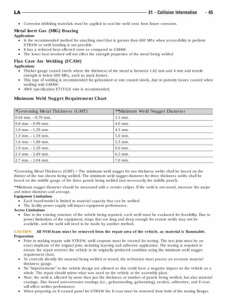
• Corrosion inhibiting materials must be applied to seal the weld zone from future corrosion.
Metal Inert Gas (MIG) BrazingApplications
• Is the recommended method for attaching steel that is greater than 600 MPa when accessibility to perform
STRSW or weld bonding is not possible.
• It has a reduced heat affected zone as compared to GMAW.
• The lower heat involved will not affect the strength properties of the metal being welded
Flux Core Arc Welding (FCAW)Applications
• Thicker gauge coated steels where the thickness of the metal is between 1.02 mm and 4 mm and tensile
strength is below 600 MPa, such as truck frames.
• This type of welding is recommended for galvanized or zinc coated steels, due to porosity issues caused when
welding with GMAW.
• AWS specification E71T-GS wire is recommended.
Minimum Weld Nugget Requirement Chart
*Governing Metal Thickness (GMT) **Minimum Weld Nugget Diameter
0.64 mm. - 0.79 mm. 3.5 mm.
0.8 mm. - 0.99 mm. 4.0 mm.
1.0 mm. - 1.29 mm. 4.5 mm.
1.3 mm. - 1.59 mm. 5.0 mm.
1.6 mm. - 1.89 mm. 5.5 mm.
1.9 mm. - 2.29 mm. 6.0 mm.
2.3 mm. - 2.69 mm. 6.5 mm.
2.7 mm. - 3.04 mm. 7.0 mm.
*Governing Metal Thickness (GMT) = The minimum weld nugget for two thickness welds shall be based on the
thinner of the two sheets being welded. The minimum weld nugget diameter for three thickness welds shall be
based on the middle gauge of the three panels being welded (not necessarily the middle panel).
**Minimum nugget diameter should be measured with a vernier caliper. If the weld is not round, measure the major
and minor diameter and average.
Equipment Limitations
• Each brand/model is limited to material capacity that can be welded.
• The facility power supply will impact equipment performance.
Access Limitations
• Due to the existing structure of the vehicle being repaired, each weld must be evaluated for feasibility. Due to
power limitations of the equipment, tongs that are long and deep enough for certain welds may not be
available, and the weld will need to be made by another method.
CAUTION: All NVH foam must be removed from the repair area of the vehicle, as material is flammable.
Preparation
• Prior to making repairs with STRSW, weld coupons must be created for testing. The test joint must be an
exact duplicate of the original joint, including layering and adhesive application. The testing is required to
ensure the repair restores the vehicle to its originally produced condition using the minimum weld nugget
requirement chart.
• To correctly identify the material being welded or tested, the technician must posses an accurate material
thickness gauge.
• No "improvements" to the vehicle design are allowed as this could have a negative impact on the vehicle as a
whole. The repair should mirror what was used on the vehicle at the assembly plant.
• Note, the weld is affected by more than just the thickness or number of panels being welded, but also material
coatings. Zinc based anti-corrosion coatings (i.e., galvannealing, galvanizing), sealers, adhesives, and E-coat
will affect welder performance.
• When preparing an E-coated panel for STRSW the E-coat must be removed from both of the mating flanges
LA 31 - Collision Information - 45
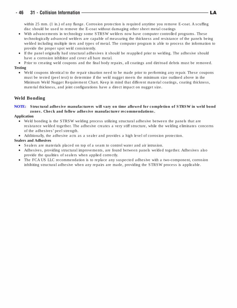
within 25 mm. (1 in.) of any flange. Corrosion protection is required anytime you remove E-coat. A scuffing
disc should be used to remove the E-coat without damaging other sheet metal coatings
• With advancements in technology some STRSW welders now have computer controlled programs. These
technologically advanced welders are capable of measuring the thickness and resistance of the panels being
welded including multiple tiers and types of metal. The computer program is able to process the information to
provide the proper spot weld consistently.
• If the panel originally had structural adhesives it should be reapplied prior to welding. The adhesive should
have a corrosion inhibitor and cover all bare metal.
• Prior to creating weld coupons and the final body repairs, all coatings and dirt/road debris must be removed.
Testing
• Weld coupons identical to the repair situation need to be made prior to performing any repair. These coupons
must be tested (peel test) to determine if the weld nugget meets the minimum size outlined above in the
Minimum Weld Nugget Requirement Chart. Keep in mind that different material coatings, coating thickness,
material thickness, and joint configurations have a direct impact on nugget size.
Weld Bonding
NOTE: Structural adhesive manufacturers will vary on time allowed for completion of STRSW in weld bond
zones. Check and follow adhesive manufacturer recommendations.
Application
• Weld bonding is the STRSW welding process utilizing structural adhesive between the panels that are
resistance welded together. The adhesive creates a very stiff structure, while the welding eliminates concerns
of the adhesives’ peel strength.
• Additionally, the adhesive acts as a sealer and provides a high level of corrosion protection.
Sealers and Adhesives
• Sealers are materials placed on top of a seam to control water and air intrusion.
• Adhesives, providing structural improvements, are found between panels welded together. Adhesives also
provide the qualities of sealers when applied correctly.
• The FCA US LLC recommendation is to replace any suspected adhesive with a two-component, corrosion
inhibiting structural adhesive when any repairs are made, providing the STRSW process is applicable.
- 46 31 - Collision Information LA
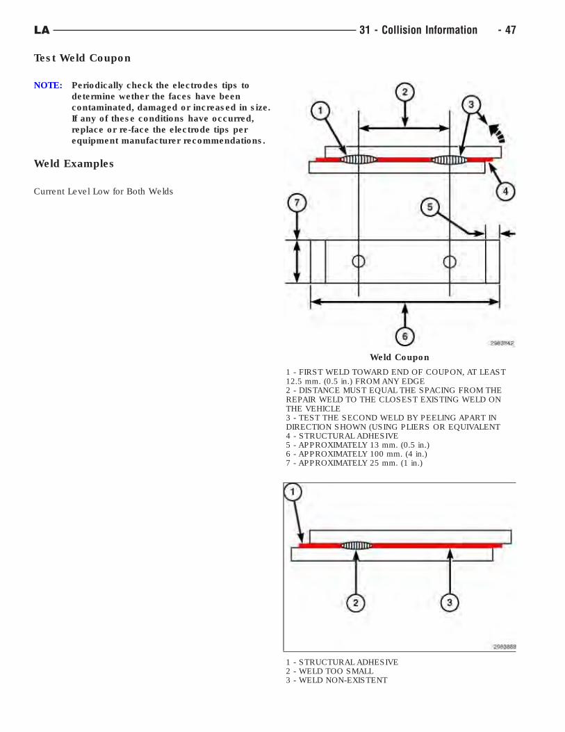
Test Weld Coupon
NOTE: Periodically check the electrodes tips to
determine wether the faces have been
contaminated, damaged or increased in size.
If any of these conditions have occurred,
replace or re-face the electrode tips per
equipment manufacturer recommendations.
Weld Examples
Current Level Low for Both Welds
Weld Coupon
1 - FIRST WELD TOWARD END OF COUPON, AT LEAST12.5 mm. (0.5 in.) FROM ANY EDGE2 - DISTANCE MUST EQUAL THE SPACING FROM THEREPAIR WELD TO THE CLOSEST EXISTING WELD ONTHE VEHICLE3 - TEST THE SECOND WELD BY PEELING APART INDIRECTION SHOWN (USING PLIERS OR EQUIVALENT4 - STRUCTURAL ADHESIVE5 - APPROXIMATELY 13 mm. (0.5 in.)6 - APPROXIMATELY 100 mm. (4 in.)7 - APPROXIMATELY 25 mm. (1 in.)
1 - STRUCTURAL ADHESIVE2 - WELD TOO SMALL3 - WELD NON-EXISTENT
LA 31 - Collision Information - 47
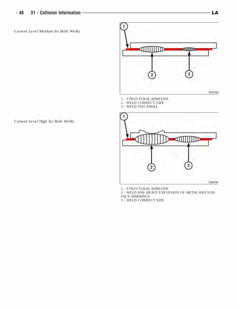
Current Level Medium for Both Welds
Current Level High for Both Welds
1 - STRUCTURAL ADHESIVE2 - WELD CORRECT SIZE3 - WELD TOO SMALL
1 - STRUCTURAL ADHESIVE2 - WELD HAS HEAVY EXPULSION OF METAL AND SUR-FACE MARKINGS3 - WELD CORRECT SIZE
- 48 31 - Collision Information LA
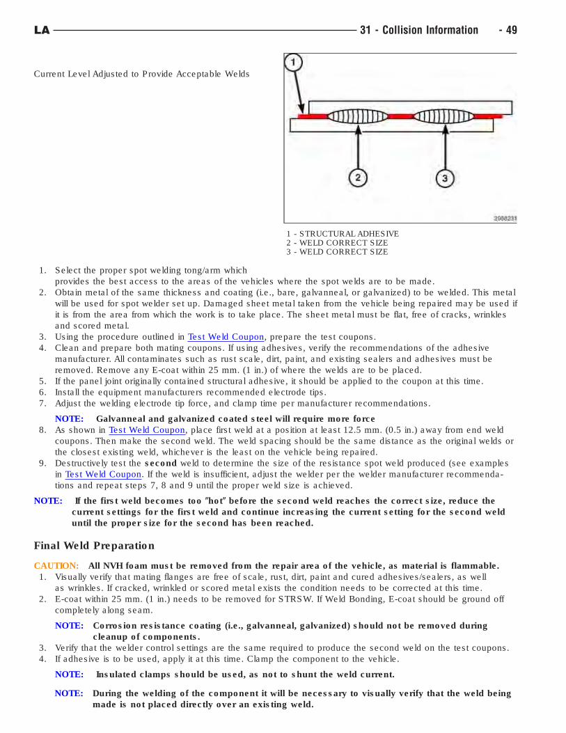
Current Level Adjusted to Provide Acceptable Welds
1. Select the proper spot welding tong/arm which
provides the best access to the areas of the vehicles where the spot welds are to be made.
2. Obtain metal of the same thickness and coating (i.e., bare, galvanneal, or galvanized) to be welded. This metal
will be used for spot welder set up. Damaged sheet metal taken from the vehicle being repaired may be used if
it is from the area from which the work is to take place. The sheet metal must be flat, free of cracks, wrinkles
and scored metal.
3. Using the procedure outlined in Test Weld Coupon, prepare the test coupons.
4. Clean and prepare both mating coupons. If using adhesives, verify the recommendations of the adhesive
manufacturer. All contaminates such as rust scale, dirt, paint, and existing sealers and adhesives must be
removed. Remove any E-coat within 25 mm. (1 in.) of where the welds are to be placed.
5. If the panel joint originally contained structural adhesive, it should be applied to the coupon at this time.
6. Install the equipment manufacturers recommended electrode tips.
7. Adjust the welding electrode tip force, and clamp time per manufacturer recommendations.
NOTE: Galvanneal and galvanized coated steel will require more force
8. As shown in Test Weld Coupon, place first weld at a position at least 12.5 mm. (0.5 in.) away from end weld
coupons. Then make the second weld. The weld spacing should be the same distance as the original welds or
the closest existing weld, whichever is the least on the vehicle being repaired.
9. Destructively test the second weld to determine the size of the resistance spot weld produced (see examples
in Test Weld Coupon. If the weld is insufficient, adjust the welder per the welder manufacturer recommenda-
tions and repeat steps 7, 8 and 9 until the proper weld size is achieved.
NOTE: If the first weld becomes too (hot( before the second weld reaches the correct size, reduce the
current settings for the first weld and continue increasing the current setting for the second weld
until the proper size for the second has been reached.
Final Weld Preparation
CAUTION: All NVH foam must be removed from the repair area of the vehicle, as material is flammable.
1. Visually verify that mating flanges are free of scale, rust, dirt, paint and cured adhesives/sealers, as well
as wrinkles. If cracked, wrinkled or scored metal exists the condition needs to be corrected at this time.
2. E-coat within 25 mm. (1 in.) needs to be removed for STRSW. If Weld Bonding, E-coat should be ground off
completely along seam.
NOTE: Corrosion resistance coating (i.e., galvanneal, galvanized) should not be removed during
cleanup of components.
3. Verify that the welder control settings are the same required to produce the second weld on the test coupons.
4. If adhesive is to be used, apply it at this time. Clamp the component to the vehicle.
NOTE: Insulated clamps should be used, as not to shunt the weld current.
NOTE: During the welding of the component it will be necessary to visually verify that the weld being
made is not placed directly over an existing weld.
1 - STRUCTURAL ADHESIVE2 - WELD CORRECT SIZE3 - WELD CORRECT SIZE
LA 31 - Collision Information - 49
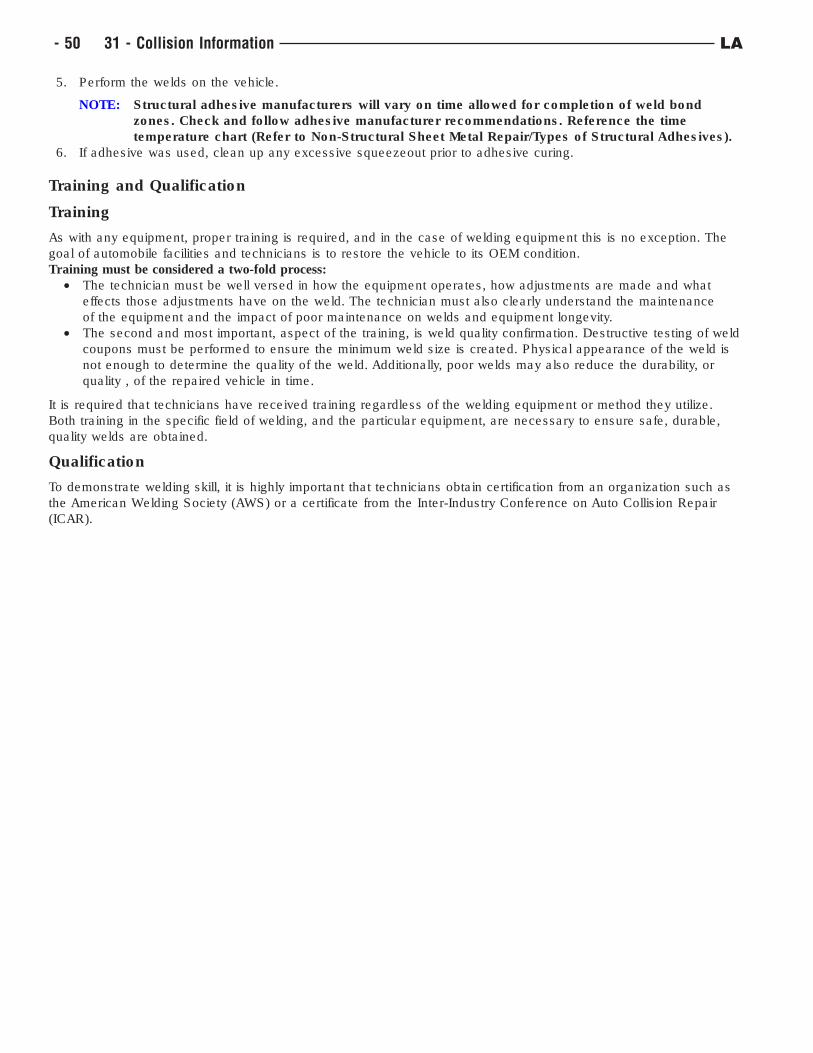
5. Perform the welds on the vehicle.
NOTE: Structural adhesive manufacturers will vary on time allowed for completion of weld bond
zones. Check and follow adhesive manufacturer recommendations. Reference the time
temperature chart (Refer to Non-Structural Sheet Metal Repair/Types of Structural Adhesives).
6. If adhesive was used, clean up any excessive squeezeout prior to adhesive curing.
Training and Qualification
Training
As with any equipment, proper training is required, and in the case of welding equipment this is no exception. The
goal of automobile facilities and technicians is to restore the vehicle to its OEM condition.
Training must be considered a two-fold process:
• The technician must be well versed in how the equipment operates, how adjustments are made and what
effects those adjustments have on the weld. The technician must also clearly understand the maintenance
of the equipment and the impact of poor maintenance on welds and equipment longevity.
• The second and most important, aspect of the training, is weld quality confirmation. Destructive testing of weld
coupons must be performed to ensure the minimum weld size is created. Physical appearance of the weld is
not enough to determine the quality of the weld. Additionally, poor welds may also reduce the durability, or
quality , of the repaired vehicle in time.
It is required that technicians have received training regardless of the welding equipment or method they utilize.
Both training in the specific field of welding, and the particular equipment, are necessary to ensure safe, durable,
quality welds are obtained.
Qualification
To demonstrate welding skill, it is highly important that technicians obtain certification from an organization such as
the American Welding Society (AWS) or a certificate from the Inter-Industry Conference on Auto Collision Repair
(ICAR).
- 50 31 - Collision Information LA
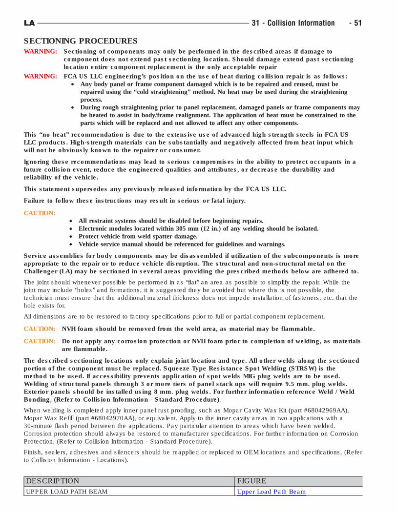
SECTIONING PROCEDURESWARNING: Sectioning of components may only be performed in the described areas if damage to
component does not extend past sectioning location. Should damage extend past sectioning
location entire component replacement is the only acceptable repair
WARNING: FCA US LLC engineering’s position on the use of heat during collision repair is as follows:
• Any body panel or frame component damaged which is to be repaired and reused, must be
repaired using the “cold straightening” method. No heat may be used during the straightening
process.
• During rough straightening prior to panel replacement, damaged panels or frame components may
be heated to assist in body/frame realignment. The application of heat must be constrained to the
parts which will be replaced and not allowed to affect any other components.
This “no heat” recommendation is due to the extensive use of advanced high strength steels in FCA US
LLC products. High-strength materials can be substantially and negatively affected from heat input which
will not be obviously known to the repairer or consumer.
Ignoring these recommendations may lead to serious compromises in the ability to protect occupants in a
future collision event, reduce the engineered qualities and attributes, or decrease the durability and
reliability of the vehicle.
This statement supersedes any previously released information by the FCA US LLC.
Failure to follow these instructions may result in serious or fatal injury.
CAUTION:
• All restraint systems should be disabled before beginning repairs.
• Electronic modules located within 305 mm (12 in.) of any welding should be isolated.
• Protect vehicle from weld spatter damage.
• Vehicle service manual should be referenced for guidelines and warnings.
Service assemblies for body components may be disassembled if utilization of the subcomponents is more
appropriate to the repair or to reduce vehicle disruption. The structural and non-structural metal on the
Challenger (LA) may be sectioned in several areas providing the prescribed methods below are adhered to.
The joint should whenever possible be performed in as “flat” an area as possible to simplify the repair. While the
joint may include “holes” and formations, it is suggested they be avoided but where this is not possible, the
technician must ensure that the additional material thickness does not impede installation of fasteners, etc. that the
hole exists for.
All dimensions are to be restored to factory specifications prior to full or partial component replacement.
CAUTION: NVH foam should be removed from the weld area, as material may be flammable.
CAUTION: Do not apply any corrosion protection or NVH foam prior to completion of welding, as materials
are flammable.
The described sectioning locations only explain joint location and type. All other welds along the sectioned
portion of the component must be replaced. Squeeze Type Resistance Spot Welding (STRSW) is the
method to be used. If accessibility prevents application of spot welds MIG plug welds are to be used.
Welding of structural panels through 3 or more tiers of panel stack ups will require 9.5 mm. plug welds.
Exterior panels should be installed using 8 mm. plug welds. For further information reference Weld / Weld
Bonding, (Refer to Collision Information - Standard Procedure).
When welding is completed apply inner panel rust proofing, such as Mopar Cavity Wax Kit (part #68042969AA),
Mopar Wax Refill (part #68042970AA), or equivalent. Apply to the inner cavity areas in two applications with a
30-minute flash period between the applications. Pay particular attention to areas which have been welded.
Corrosion protection should always be restored to manufacturer specifications. For further information on Corrosion
Protection, (Refer to Collision Information - Standard Procedure).
Finish, sealers, adhesives and silencers should be reapplied or replaced to OEM locations and specifications, (Refer
to Collision Information - Locations).
DESCRIPTION FIGURE
UPPER LOAD PATH BEAM Upper Load Path Beam
LA 31 - Collision Information - 51
DESCRIPTION FIGURE
LOWER FRONT RAIL ASSEMBLY Front Rail Assembly
OUTER BODY SIDE APERTURE Outer Body Side Aperture
INNER BODY SIDE COMPONENT DO NOT SECTION Inner Body Side Components-Do Not
Section
A-PILLAR AND ROOF RAIL COMPOSITE INSERTS Composite Inserts
INNER BODY SIDE ASSEMBLY Inner Body Side Assembly
INNER BODY SIDE REINFORCEMENT Inner Body Side Reinforcement
SILL PANEL AND SILL REINFORCEMENT Sill Panel and Sill Reinforcement Section-
ing
REAR RAIL (Right and Left) Rear Rail
Upper Load Path Beam1. Verify that structural dimensions have been restored to vehicle specifications.
2. Remove all components necessary to access the upper load path beam.
NOTE: Sectioning of the outer load path beam is recommended due to the use of net, form and pierce
in the hood hinge area.
NOTE: Should full replacement of outer load path beam be necessary, hood hinge mount area will
require hammer and dolly method to re-create.
3. On the existing (original) outer load path beam (2), measure 400 mm (15.75 in) from the rear edge shown
forward, and scribe top edge.
4. With the use of a "square", scribe the center section. With a straight edge, scribe the upper and lower flange.
This will be the cut line (3).
- 52 31 - Collision Information LA
5. Cut through the outer load path beam using a reciprocating saw or similar tool, while being careful not to cut
the inner load path beam.
6. Release all the spot welds forward of the cut line.
7. Remove front section with an air chisel equipped with a flat blade bit and discard the front section (1).
8. On the existing (original) inner load path beam (2), measure 500 mm (19.5 in) from the rear edge shown
forward, and scribe top edge.
9. With the use of a "square", placed to the rear of beam cut line (3), scribe the upper load path beam upper and
lower flanges. With a straight edge, scribe the center section of original inner load path beam.
10. Cut through the beam using a reciprocating saw or similar tool, while being careful not to cut into the
wheelhouse.
11. Release all the spot welds forward of the cut line (3).
12. Remove front section of the upper load path beam (1) with an air chisel equipped flat bladed bit. Discard the
front section.
LA 31 - Collision Information - 53
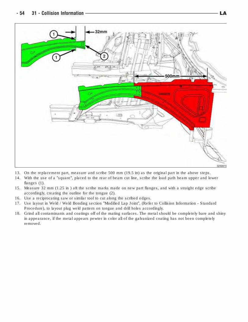
13. On the replacement part, measure and scribe 500 mm (19.5 in) as the original part in the above steps.
14. With the use of a "square", placed to the rear of beam cut line, scribe the load path beam upper and lower
flanges (1).
15. Measure 32 mm (1.25 in ) aft the scribe marks made on new part flanges, and with a straight edge scribe
accordingly, creating the outline for the tongue (2).
16. Use a reciprocating saw or similar tool to cut along the scribed edges.
17. Use layout in Weld / Weld Bonding section "Modified Lap Joint", (Refer to Collision Information - Standard
Procedure), to layout plug weld pattern on tongue and drill holes accordingly.
18. Grind all contaminants and coatings off of the mating surfaces. The metal should be completely bare and shiny
in appearance, if the metal appears pewter in color all of the galvanized coating has not been completely
removed.
- 54 31 - Collision Information LA
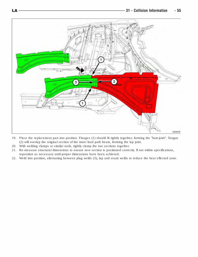
19. Place the replacement part into position. Flanges (1) should fit tightly together, forming the "butt-joint". Tongue
(2) will overlap the original section of the inner load path beam, forming the lap joint.
20. With welding clamps or similar tools, tightly clamp the two sections together.
21. Re-measure structural dimensions to ensure new section is positioned correctly. If not within specifications,
reposition as necessary until proper dimensions have been achieved.
22. Weld into position, alternating between plug welds (3), lap and seam welds to reduce the heat effected zone.
LA 31 - Collision Information - 55
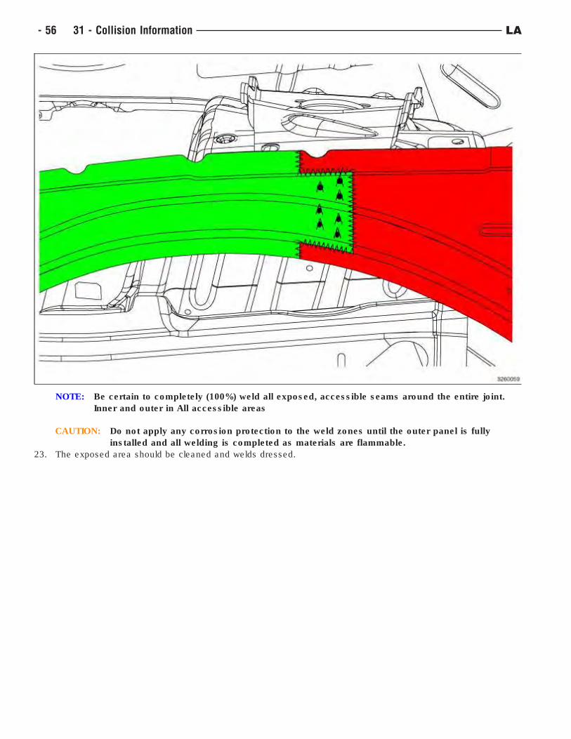
NOTE: Be certain to completely (100%) weld all exposed, accessible seams around the entire joint.
Inner and outer in All accessible areas
CAUTION: Do not apply any corrosion protection to the weld zones until the outer panel is fully
installed and all welding is completed as materials are flammable.
23. The exposed area should be cleaned and welds dressed.
- 56 31 - Collision Information LA
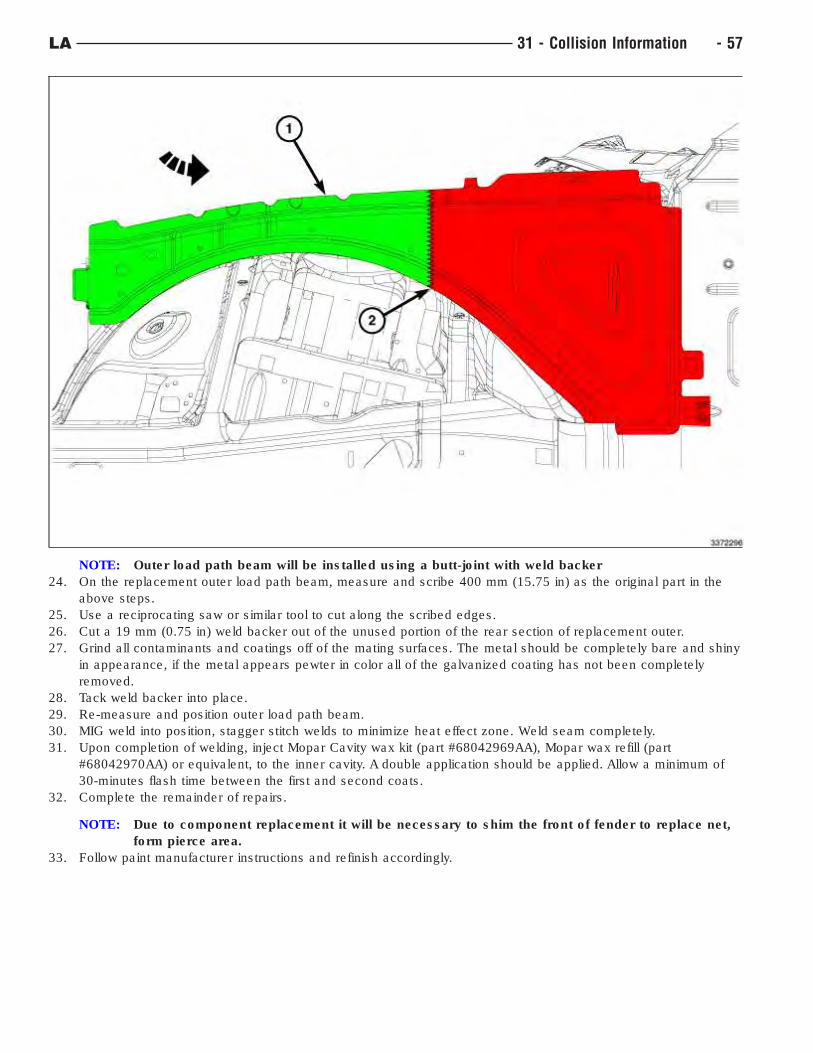
NOTE: Outer load path beam will be installed using a butt-joint with weld backer
24. On the replacement outer load path beam, measure and scribe 400 mm (15.75 in) as the original part in the
above steps.
25. Use a reciprocating saw or similar tool to cut along the scribed edges.
26. Cut a 19 mm (0.75 in) weld backer out of the unused portion of the rear section of replacement outer.
27. Grind all contaminants and coatings off of the mating surfaces. The metal should be completely bare and shiny
in appearance, if the metal appears pewter in color all of the galvanized coating has not been completely
removed.
28. Tack weld backer into place.
29. Re-measure and position outer load path beam.
30. MIG weld into position, stagger stitch welds to minimize heat effect zone. Weld seam completely.
31. Upon completion of welding, inject Mopar Cavity wax kit (part #68042969AA), Mopar wax refill (part
#68042970AA) or equivalent, to the inner cavity. A double application should be applied. Allow a minimum of
30-minutes flash time between the first and second coats.
32. Complete the remainder of repairs.
NOTE: Due to component replacement it will be necessary to shim the front of fender to replace net,
form pierce area.
33. Follow paint manufacturer instructions and refinish accordingly.
LA 31 - Collision Information - 57
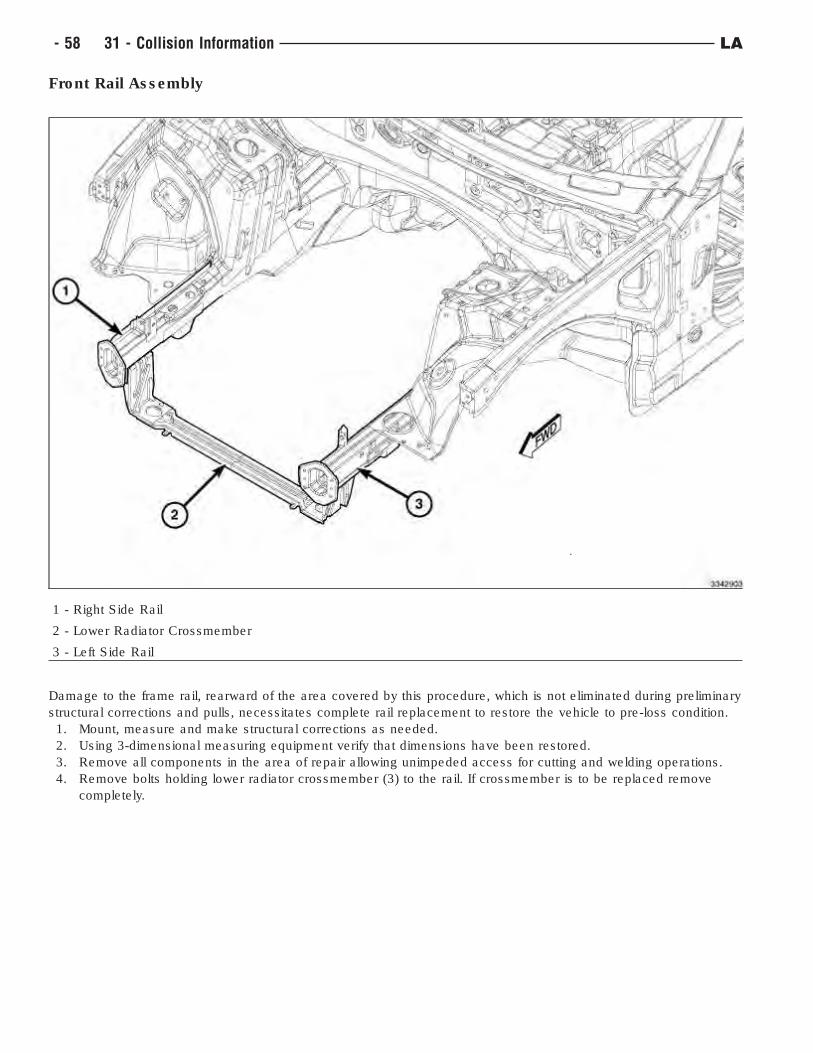
Front Rail Assembly
1 - Right Side Rail
2 - Lower Radiator Crossmember
3 - Left Side Rail
Damage to the frame rail, rearward of the area covered by this procedure, which is not eliminated during preliminary
structural corrections and pulls, necessitates complete rail replacement to restore the vehicle to pre-loss condition.
1. Mount, measure and make structural corrections as needed.
2. Using 3-dimensional measuring equipment verify that dimensions have been restored.
3. Remove all components in the area of repair allowing unimpeded access for cutting and welding operations.
4. Remove bolts holding lower radiator crossmember (3) to the rail. If crossmember is to be replaced remove
completely.
- 58 31 - Collision Information LA
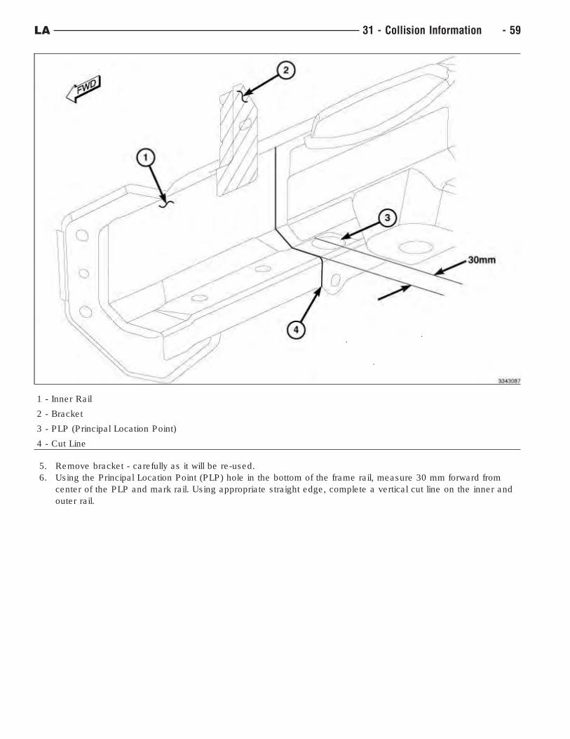
1 - Inner Rail
2 - Bracket
3 - PLP (Principal Location Point)
4 - Cut Line
5. Remove bracket - carefully as it will be re-used.
6. Using the Principal Location Point (PLP) hole in the bottom of the frame rail, measure 30 mm forward from
center of the PLP and mark rail. Using appropriate straight edge, complete a vertical cut line on the inner and
outer rail.
LA 31 - Collision Information - 59
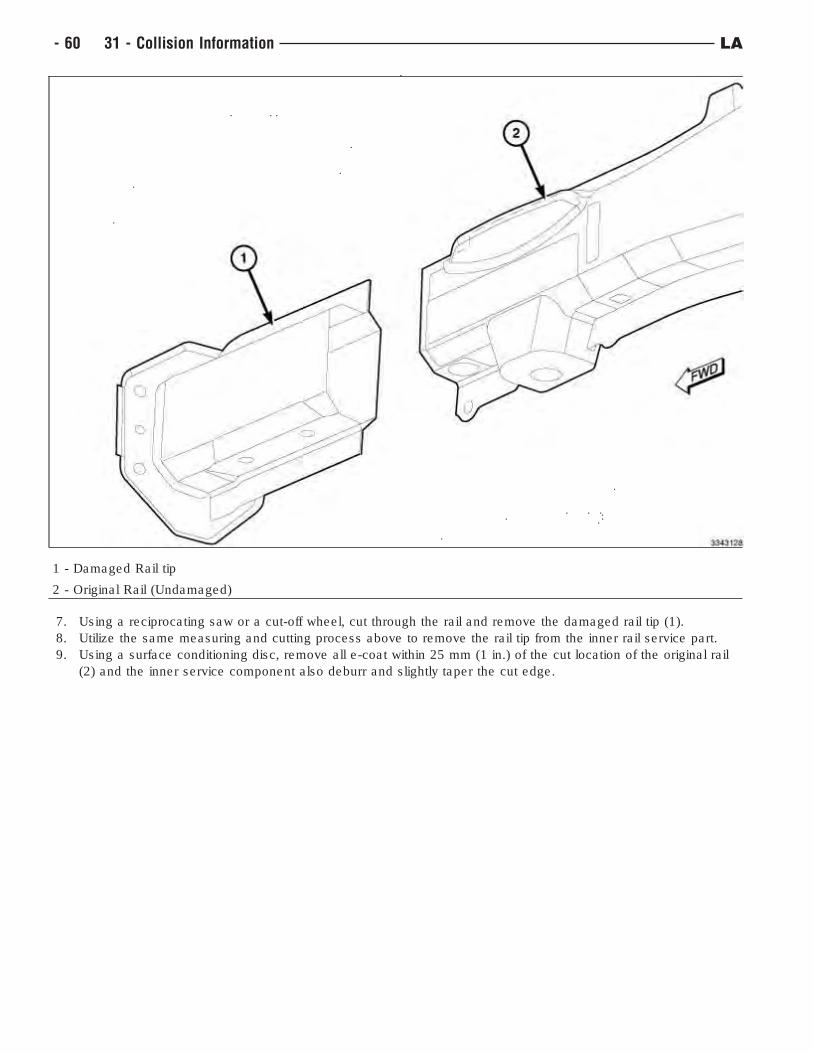
1 - Damaged Rail tip
2 - Original Rail (Undamaged)
7. Using a reciprocating saw or a cut-off wheel, cut through the rail and remove the damaged rail tip (1).
8. Utilize the same measuring and cutting process above to remove the rail tip from the inner rail service part.
9. Using a surface conditioning disc, remove all e-coat within 25 mm (1 in.) of the cut location of the original rail
(2) and the inner service component also deburr and slightly taper the cut edge.
- 60 31 - Collision Information LA
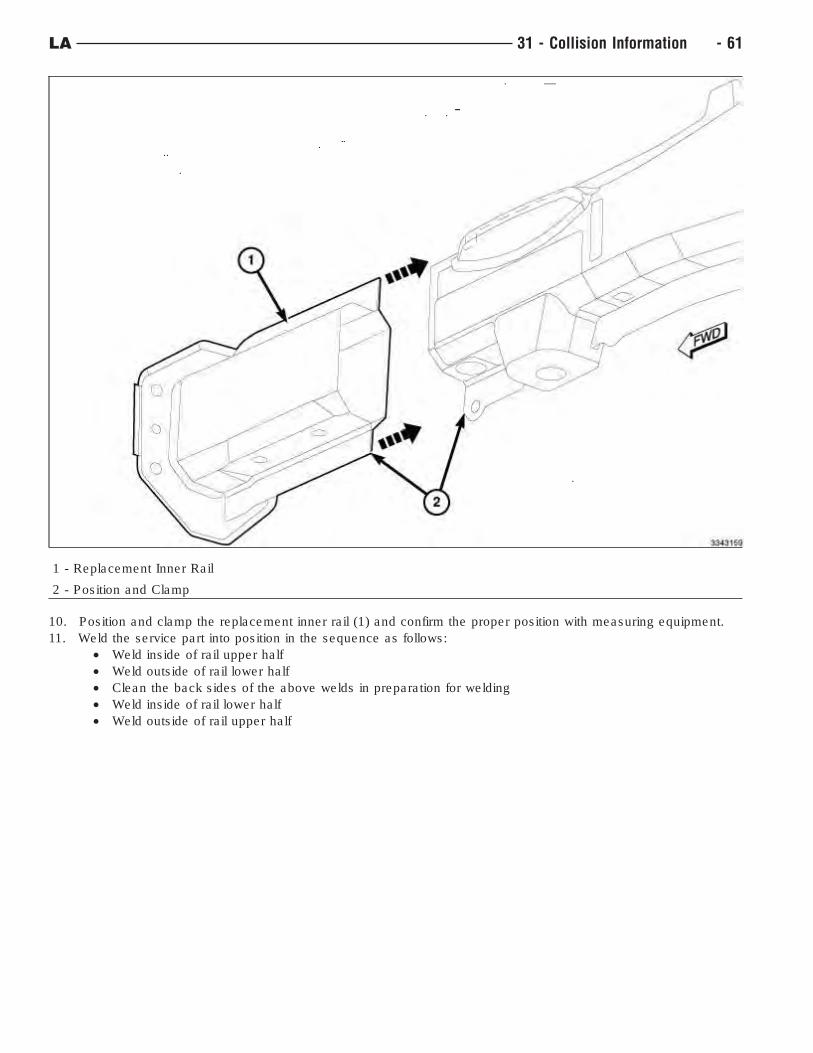
1 - Replacement Inner Rail
2 - Position and Clamp
10. Position and clamp the replacement inner rail (1) and confirm the proper position with measuring equipment.
11. Weld the service part into position in the sequence as follows:
• Weld inside of rail upper half
• Weld outside of rail lower half
• Clean the back sides of the above welds in preparation for welding
• Weld inside of rail lower half
• Weld outside of rail upper half
LA 31 - Collision Information - 61
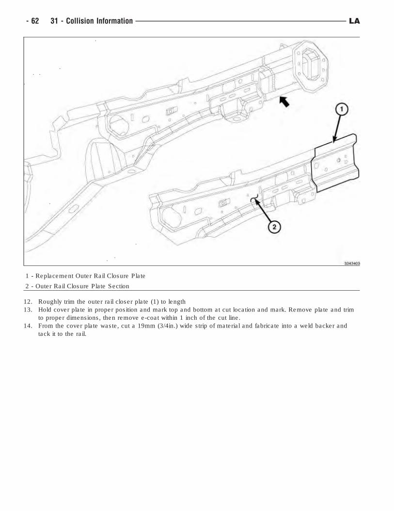
1 - Replacement Outer Rail Closure Plate
2 - Outer Rail Closure Plate Section
12. Roughly trim the outer rail closer plate (1) to length
13. Hold cover plate in proper position and mark top and bottom at cut location and mark. Remove plate and trim
to proper dimensions, then remove e-coat within 1 inch of the cut line.
14. From the cover plate waste, cut a 19mm (3/4in.) wide strip of material and fabricate into a weld backer and
tack it to the rail.
- 62 31 - Collision Information LA
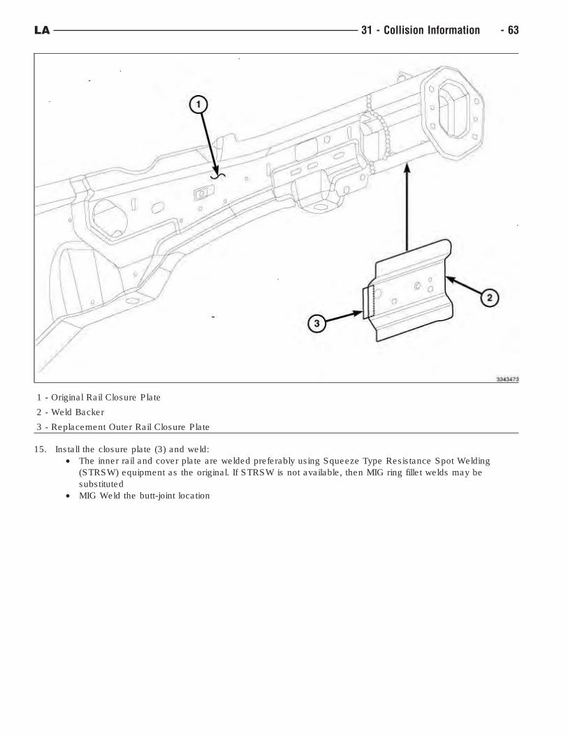
1 - Original Rail Closure Plate
2 - Weld Backer
3 - Replacement Outer Rail Closure Plate
15. Install the closure plate (3) and weld:
• The inner rail and cover plate are welded preferably using Squeeze Type Resistance Spot Welding
(STRSW) equipment as the original. If STRSW is not available, then MIG ring fillet welds may be
substituted
• MIG Weld the butt-joint location
LA 31 - Collision Information - 63
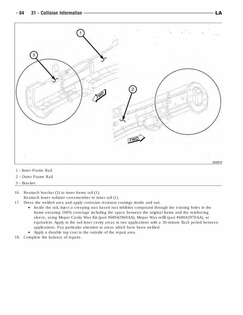
1 - Inner Frame Rail
2 - Outer Frame Rail
3 - Bracket
16. Reattach bracket (3) to inner frame rail (1).
Reattach lower radiator crossmember to inner rail (1).
17. Dress the welded area and apply corrosion resistant coatings inside and out:
• Inside the rail, inject a creeping wax based rust inhibitor compound through the existing holes in the
frame ensuring 100% coverage including the space between the original frame and the reinforcing
sleeve, using Mopar Cavity Wax Kit (part #68042969AA), Mopar Wax refill (part #68042970AA), or
equivalent. Apply to the rail inner cavity areas in two applications with a 30-minute flash period between
applications. Pay particular attention to areas which have been welded.
• Apply a durable top coat to the outside of the repair area.
18. Complete the balance of repairs.
- 64 31 - Collision Information LA
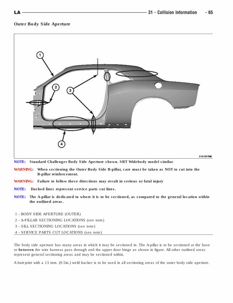
Outer Body Side Aperture
WARNING: When sectioning the Outer Body Side B-pillar, care must be taken as NOT to cut into the
B-pillar reinforcement.
WARNING: Failure to follow these directions may result in serious or fatal injury
NOTE: Dashed lines represent service parts cut lines.
NOTE: The A-pillar is dedicated to where it is to be sectioned, as compared to the general location within
the outlined areas.
1 - BODY SIDE APERTURE (OUTER)
2 - A-PILLAR SECTIONING LOCATIONS (see note)
3 - SILL SECTIONING LOCATIONS (see note)
4 - SERVICE PARTS CUT LOCATIONS (see note)
The body side aperture has many areas in which it may be sectioned in. The A-pillar is to be sectioned at the base
or between the wire harness pass through and the upper door hinge as shown in figure. All other outlined areas
represent general sectioning areas and may be sectioned within.
A butt-joint with a 13 mm. (0.5in.) weld backer is to be used in all sectioning areas of the outer body side aperture.
NOTE: Standard Challenger Body Side Aperture shown. SRT Widebody model similar.
LA 31 - Collision Information - 65
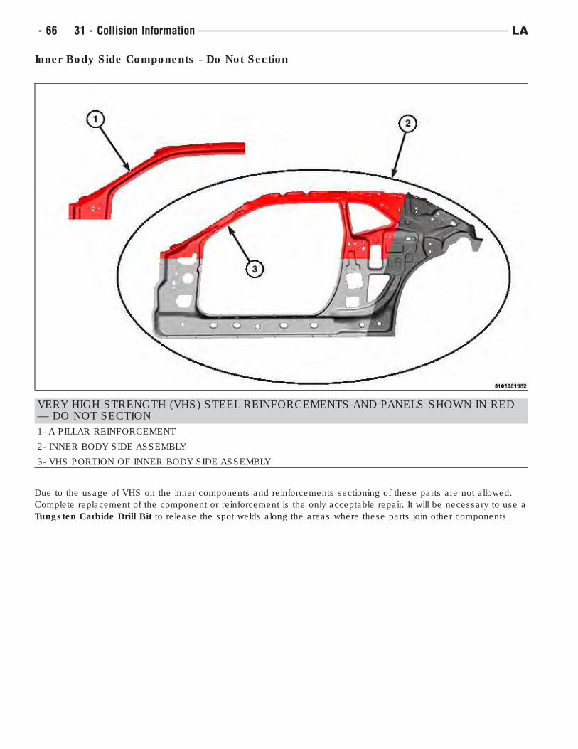
Inner Body Side Components - Do Not Section
VERY HIGH STRENGTH (VHS) STEEL REINFORCEMENTS AND PANELS SHOWN IN RED— DO NOT SECTION
1- A-PILLAR REINFORCEMENT
2- INNER BODY SIDE ASSEMBLY
3- VHS PORTION OF INNER BODY SIDE ASSEMBLY
Due to the usage of VHS on the inner components and reinforcements sectioning of these parts are not allowed.
Complete replacement of the component or reinforcement is the only acceptable repair. It will be necessary to use a
Tungsten Carbide Drill Bit to release the spot welds along the areas where these parts join other components.
- 66 31 - Collision Information LA
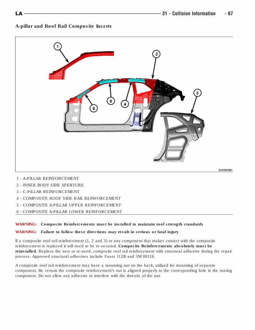
A-pillar and Roof Rail Composite Inserts
1 - A-PILLAR REINFORCEMENT
2 - INNER BODY SIDE APERTURE
3 - C-PILLAR REINFORCEMENT
4 - COMPOSITE ROOF SIDE RAIL REINFORCEMENT
5 - COMPOSITE A-PILLAR UPPER REINFORCEMENT
6 - COMPOSITE A-PILLAR LOWER REINFORCEMENT
WARNING: Composite Reinforcements must be installed to maintain roof strength standards
WARNING: Failure to follow these directions may result in serious or fatal injury
If a composite roof rail reinforcement (1, 2 and 3) or any component that makes contact with the composite
reinforcement is replaced it will need to be re-secured. Composite Reinforcements absolutely must be
reinstalled. Replace the new or re-used, composite roof rail reinforcement with structural adhesive during the repair
process. Approved structural adhesives include Fusor 112B and 3M 08116.
A composite roof rail reinforcement may have a mounting nut on the back, utilized for mounting of separate
component. Be certain the composite reinforcement’s nut is aligned properly to the corresponding hole in the mating
component. Do not allow any adhesive to interfere with the threads of the nut.
LA 31 - Collision Information - 67
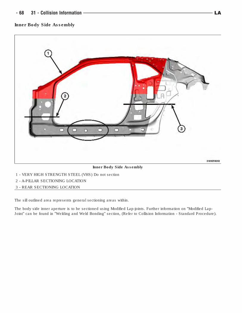
Inner Body Side Assembly
1 - VERY HIGH STRENGTH STEEL (VHS) Do not section
2 - A-PILLAR SECTIONING LOCATION
3 - REAR SECTIONING LOCATION
The sill outlined area represents general sectioning areas within.
The body side inner aperture is to be sectioned using Modified Lap-joints. Further information on "Modified Lap-
Joint" can be found in "Welding and Weld Bonding" section, (Refer to Collision Information - Standard Procedure).
Inner Body Side Assembly
- 68 31 - Collision Information LA
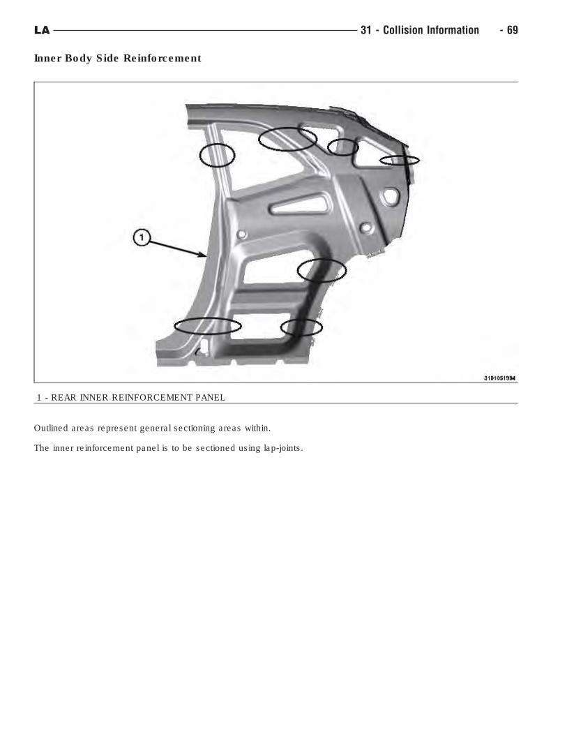
Inner Body Side Reinforcement
1 - REAR INNER REINFORCEMENT PANEL
Outlined areas represent general sectioning areas within.
The inner reinforcement panel is to be sectioned using lap-joints.
LA 31 - Collision Information - 69
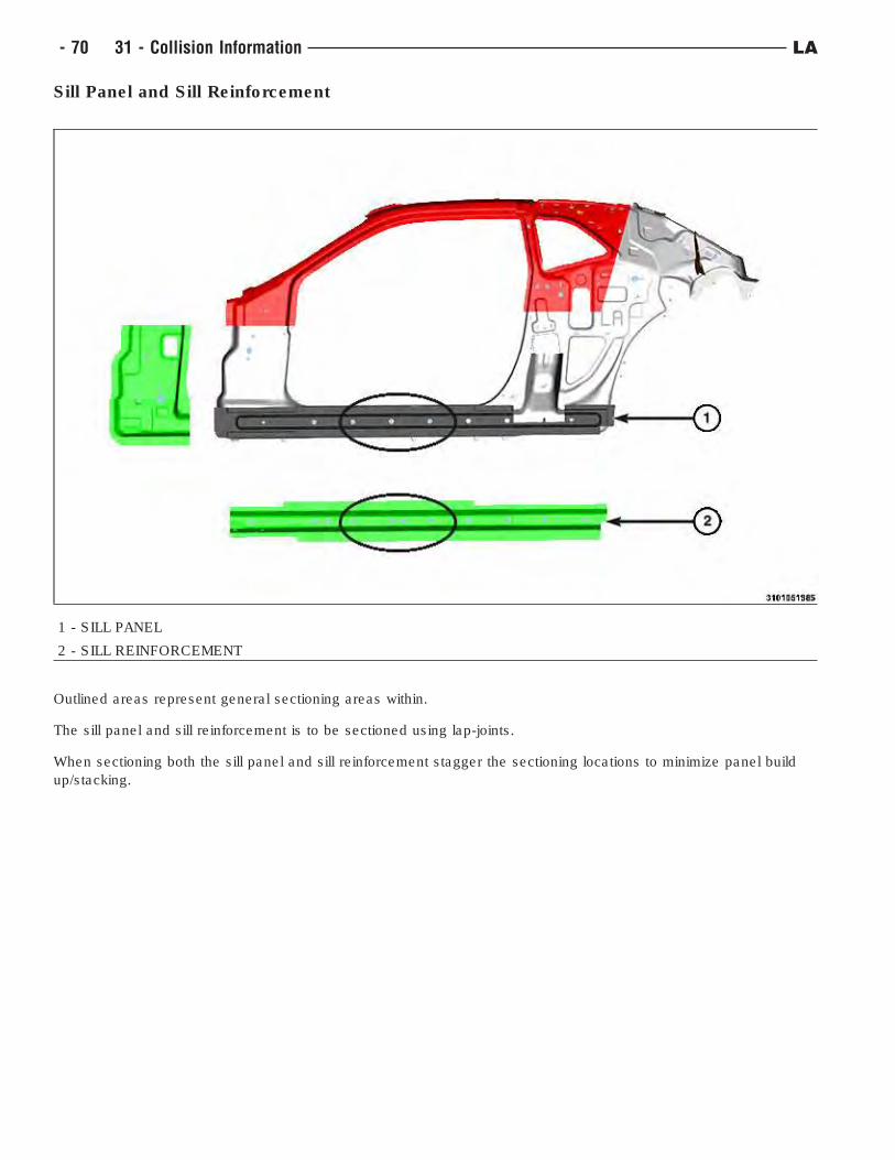
Sill Panel and Sill Reinforcement
1 - SILL PANEL
2 - SILL REINFORCEMENT
Outlined areas represent general sectioning areas within.
The sill panel and sill reinforcement is to be sectioned using lap-joints.
When sectioning both the sill panel and sill reinforcement stagger the sectioning locations to minimize panel build
up/stacking.
- 70 31 - Collision Information LA
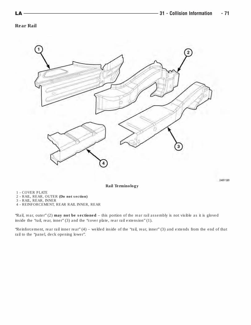
Rear Rail
“Rail, rear, outer” (2) may not be sectioned – this portion of the rear rail assembly is not visible as it is gloved
inside the “rail, rear, inner” (3) and the “cover plate, rear rail extension” (1).
“Reinforcement, rear rail inner rear” (4) – welded inside of the “rail, rear, inner” (3) and extends from the end of that
rail to the “panel, deck opening lower”.
Rail Terminology
1 - COVER PLATE2 - RAIL, REAR, OUTER (Do not section)3 - RAIL, REAR, INNER4 - REINFORCEMENT, REAR RAIL INNER, REAR
LA 31 - Collision Information - 71
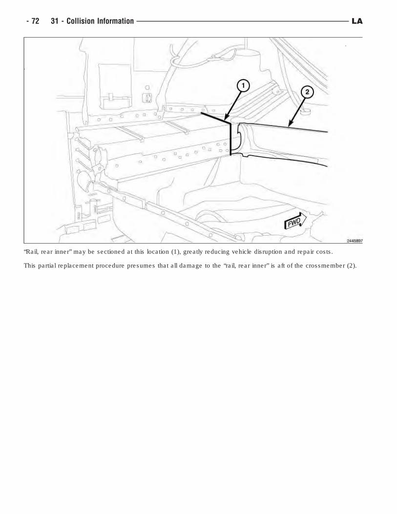
“Rail, rear inner” may be sectioned at this location (1), greatly reducing vehicle disruption and repair costs.
This partial replacement procedure presumes that all damage to the “rail, rear inner” is aft of the crossmember (2).
- 72 31 - Collision Information LA
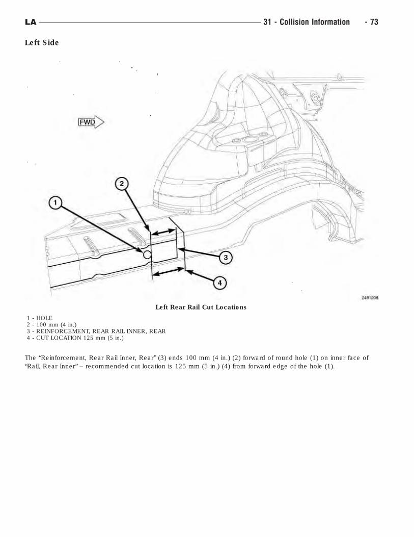
Left Side
The “Reinforcement, Rear Rail Inner, Rear” (3) ends 100 mm (4 in.) (2) forward of round hole (1) on inner face of
“Rail, Rear Inner” – recommended cut location is 125 mm (5 in.) (4) from forward edge of the hole (1).
Left Rear Rail Cut Locations
1 - HOLE2 - 100 mm (4 in.)3 - REINFORCEMENT, REAR RAIL INNER, REAR4 - CUT LOCATION 125 mm (5 in.)
LA 31 - Collision Information - 73
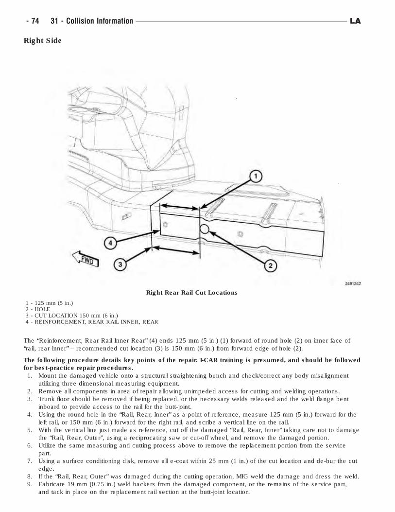
Right Side
The “Reinforcement, Rear Rail Inner Rear” (4) ends 125 mm (5 in.) (1) forward of round hole (2) on inner face of
“rail, rear inner” – recommended cut location (3) is 150 mm (6 in.) from forward edge of hole (2).
The following procedure details key points of the repair. I-CAR training is presumed, and should be followed
for best-practice repair procedures.
1. Mount the damaged vehicle onto a structural straightening bench and check/correct any body misalignment
utilizing three dimensional measuring equipment.
2. Remove all components in area of repair allowing unimpeded access for cutting and welding operations.
3. Trunk floor should be removed if being replaced, or the necessary welds released and the weld flange bent
inboard to provide access to the rail for the butt-joint.
4. Using the round hole in the “Rail, Rear, Inner” as a point of reference, measure 125 mm (5 in.) forward for the
left rail, or 150 mm (6 in.) forward for the right rail, and scribe a vertical line on the rail.
5. With the vertical line just made as reference, cut off the damaged “Rail, Rear, Inner” taking care not to damage
the “Rail, Rear, Outer”, using a reciprocating saw or cut-off wheel, and remove the damaged portion.
6. Utilize the same measuring and cutting process above to remove the replacement portion from the service
part.
7. Using a surface conditioning disk, remove all e-coat within 25 mm (1 in.) of the cut location and de-bur the cut
edge.
8. If the “Rail, Rear, Outer” was damaged during the cutting operation, MIG weld the damage and dress the weld.
9. Fabricate 19 mm (0.75 in.) weld backers from the damaged component, or the remains of the service part,
and tack in place on the replacement rail section at the butt-joint location.
Right Rear Rail Cut Locations
1 - 125 mm (5 in.)2 - HOLE3 - CUT LOCATION 150 mm (6 in.)4 - REINFORCEMENT, REAR RAIL INNER, REAR
- 74 31 - Collision Information LA
10. Position and clamp the replacement rail and confirm proper position with measuring equipment.
11. Weld the service part in position using a skip-stitch process.
12. Complete remaining repairs in the damaged area.
13. Clean and dress all welded areas.
14. Apply epoxy primer to the exterior of the rail at the repair location.
15. Apply quality body sealer to all areas previously sealed to duplicate the original appearance. Note that
additional sealer may be applied to better protect the exterior exposed seams from road spray.
16. Refinish all exposed surfaces in trunk and on underbody using quality refinish materials.
17. Apply inner panel rust proofing, such as Mopar Cavity Wax Kit (part #68042969AA) Mopar Wax Refill (part
#68042970AA), or equivalent. Apply to the inner cavity areas in two applications, with a 30-minute flash period
between the applications. Pay particular attention to areas which have been welded.
18. Reassemble vehicle and complete repairs.
Butt joint should be metal finished without thinning the base rail material or weldment. This is a cosmetic finishing
process to disguise the repair and should have the surface coating (paint) duplicated as well.
LA 31 - Collision Information - 75
CORROSION PROTECTION
Corrosion Protection Restoration
"Corrosion protection" encompasses all the materials and coatings which protect a vehicle from corrosion and
include:
• Coated steels
• E-coat primer on the complete body
• Body sealing to eliminate water and air intrusion where panels join
• Structural adhesives in some joints
• Chip resistant primer applications on the entire body
• Paint application
• Underbody corrosion protection
• Inner panel corrosion protection added to repair areas
Corrosion protection must be restored during a repair anytime it may have been compromised. All areas that have
been subjected to structural pulls, clamping, straightening, welding, or any other any other operation that may
have imparted damage to the corrosion protection system will need to be addressed.
In the repair process corrosion protection is addressed in three phases: pre-refinish, refinish and post-refinish.
Pre-refinish
In the pre-finish phase, structural adhesives, seam sealers and other applied coatings are installed. Sheet metal
seams are sealed to prevent water intrusion into the "dry" areas of the vehicle, such as passenger
compartment, and also to prevent intrusions of contaminates, such as water and road salt, into seams causing
corrosion. Lap joints, hem flanges, and any panel mating locations need to be addressed during the repair and
treated to duplicate the original vehicle build.
All bare metal should be epoxy primed prior to applying seam sealer, following the refinish material provider’s
instructions for doing so, unless the manufacture of the sealer specifically states otherwise.
When working around pinch weld flanges, seam sealer should be installed to duplicate the original appearance and
function. If it is unclear whether the original sealing material between the flanges is strictly a sealer or structural
adhesive, always default to a structural adhesive such as LORD Fusor 2098, LORD Fusor 112B, or 3M 08116. For
additional information related to weld-bonding and welding around adhesives and sealers, (Refer to 31 - Collision
Information - Standard Procedure).
Roof and closure panels will require the use of anti-flutter foam. Where inner panel supports meet external panels,
the proper replacement materials in these areas are Mopar part No. 04864015AB, or equivalent, or LORD Fusor
121, or 3M 4274 Noise Vibration Harshness (NVH) Dampening Material.
Any disturbed or removed NVH foam needs to be replaced. Use Mopar part No. 05142864AA, LORD Fusor 130, or
3M 8463.
All hem flanges on closure panels should be sealed whether sealer is apparent or not. This includes those disturbed
during the repair, and those on new replacement panels. Either duplicate the existing bead in shape or size, or
where one is not obvious, seal the hem flange in a discrete fashion. Hem flanges should be sealed using Mopar
part No.04318026, LORD Fusor 129, or 3M 08308.
Lap joints, such as in floor pans, should be sealed to duplicate the sealer visible, but also addressed on any exterior
surface by sealing the lap wether visible or not.
NOTE: FCA US LLC does not recommend the use of any type of (weld-thru( primer during repairs. Weld-
bonding with corrosion protecting adhesives or sealers, along with final application of inner panel
corrosion protection is the proper method.
Refinish
All painted surfaces should be coated using a FCA US LLC approved refinish material. The refinish process
includes application of undercoats, primers (filler & sealer), basecoats and clearcoat. These approved materials
have been tested to the same material standards as the production materials.
Post-refinish
All new panels, and repair areas, must have inner panel corrosion protection applied after the painting operation is
complete, but before all the trim is reinstalled. Mopar Cavity Wax #68042970AA, or 3M Cavity Wax Plus
- 76 31 - Collision Information LA
#08852 should be applied to all interior cavities, weld flanges, hem flanges as well as any are affected by the repair
especially where any type of welding was performed. Inner panel corrosion protection should be applied using
"pressure pot" equipment with wands which provide 360-degree material coverage for closed cavities, and
directional spray wands for visible coverage (Mopar kit #04271235). Additionally, the corrosion protecting material
must be applied in two coats with a minimum 30-minute flash time between applications.
Wheel wells and underbody panels which have been involved in the repair process should also have a final
undercoating applied. Use Mopar #05093417AA, or equivalent, and apply with "pressure pot" style application
equipment.
Following this arrangement, choice of materials, and proper application, the repaired vehicle should be as well
protected against corrosion as it was prior to the repair.
Technical Specifications
LA 31 - Collision Information - 77
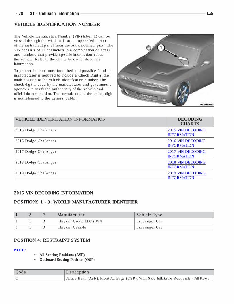
VEHICLE IDENTIFICATION NUMBER
The Vehicle Identification Number (VIN) label (1) can be
viewed through the windshield at the upper left corner
of the instrument panel, near the left windshield pillar. The
VIN consists of 17 characters in a combination of letters
and numbers that provide specific information about
the vehicle. Refer to the charts below for decoding
information.
To protect the consumer from theft and possible fraud the
manufacturer is required to include a Check Digit at the
ninth position of the vehicle identification number. The
check digit is used by the manufacturer and government
agencies to verify the authenticity of the vehicle and
official documentation. The formula to use the check digit
is not released to the general public.
VEHICLE IDENTIFICATION INFORMATION DECODINGCHARTS
2015 Dodge Challenger 2015 VIN DECODING
INFORMATION
2016 Dodge Challenger 2016 VIN DECODING
INFORMATION
2017 Dodge Challenger 2017 VIN DECODING
INFORMATION
2018 Dodge Challenger 2018 VIN DECODING
INFORMATION
2019 Dodge Challenger 2019 VIN DECODING
INFORMATION
2015 VIN DECODING INFORMATION
POSITIONS 1 - 3: WORLD MANUFACTURER IDENTIFIER
1 2 3 Manufacturer Vehicle Type
1 C 3 Chrysler Group LLC (USA) Passenger Car
2 C 3 Chrysler Canada Passenger Car
POSITION 4: RESTRAINT SYSTEM
NOTE:
• All Seating Positions (ASP)
• Outboard Seating Position (OSP)
Code Description
C Active Belts (ASP), Front Air Bags (OSP), With Side Inflatable Restraints - All Rows
- 78 31 - Collision Information LA
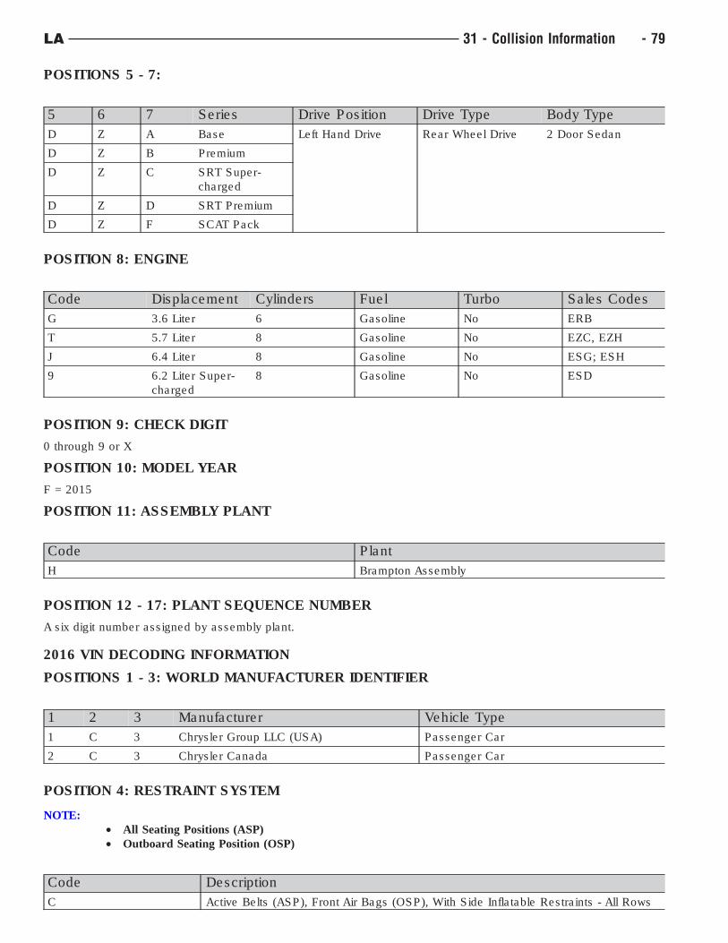
POSITIONS 5 - 7:
5 6 7 Series Drive Position Drive Type Body Type
D Z A Base Left Hand Drive Rear Wheel Drive 2 Door Sedan
D Z B Premium
D Z C SRT Super-
charged
D Z D SRT Premium
D Z F SCAT Pack
POSITION 8: ENGINE
Code Displacement Cylinders Fuel Turbo Sales Codes
G 3.6 Liter 6 Gasoline No ERB
T 5.7 Liter 8 Gasoline No EZC, EZH
J 6.4 Liter 8 Gasoline No ESG; ESH
9 6.2 Liter Super-
charged
8 Gasoline No ESD
POSITION 9: CHECK DIGIT
0 through 9 or X
POSITION 10: MODEL YEAR
F = 2015
POSITION 11: ASSEMBLY PLANT
Code Plant
H Brampton Assembly
POSITION 12 - 17: PLANT SEQUENCE NUMBER
A six digit number assigned by assembly plant.
2016 VIN DECODING INFORMATION
POSITIONS 1 - 3: WORLD MANUFACTURER IDENTIFIER
1 2 3 Manufacturer Vehicle Type
1 C 3 Chrysler Group LLC (USA) Passenger Car
2 C 3 Chrysler Canada Passenger Car
POSITION 4: RESTRAINT SYSTEM
NOTE:
• All Seating Positions (ASP)
• Outboard Seating Position (OSP)
Code Description
C Active Belts (ASP), Front Air Bags (OSP), With Side Inflatable Restraints - All Rows
LA 31 - Collision Information - 79
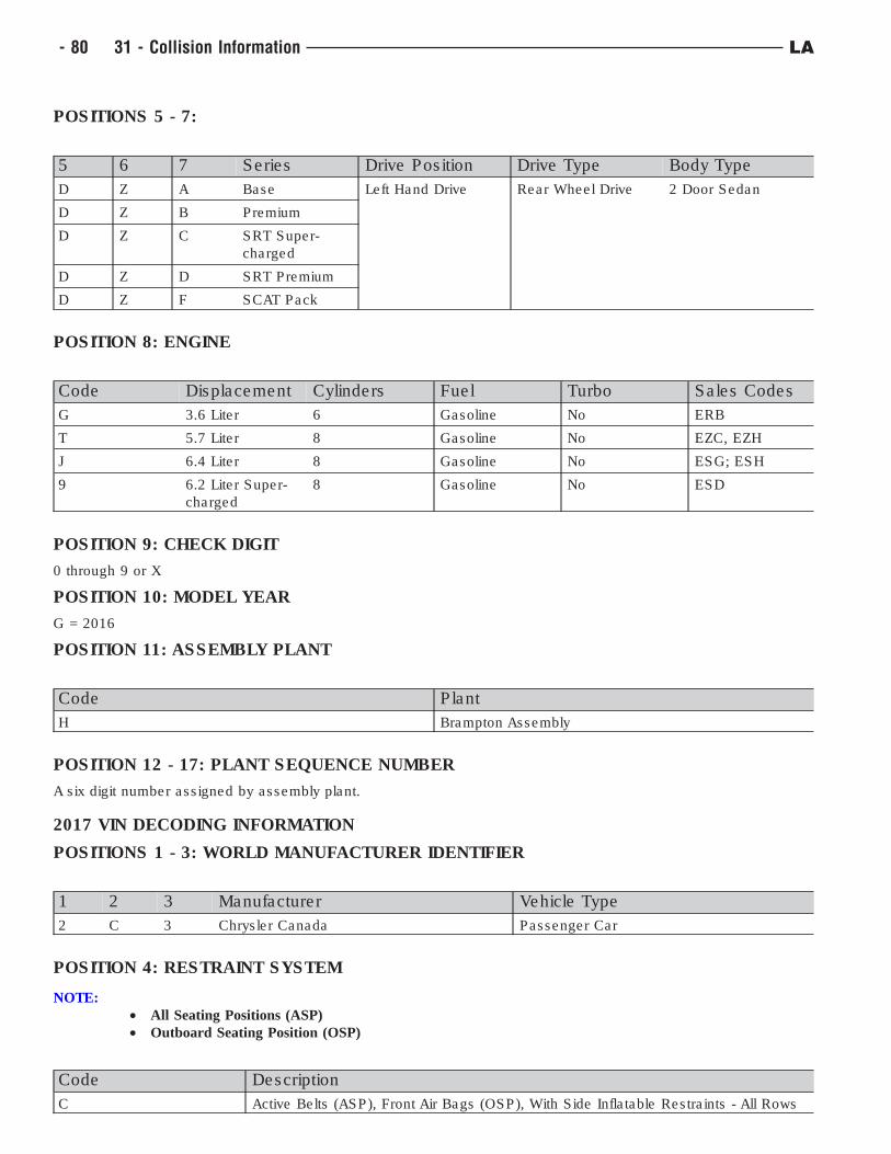
POSITIONS 5 - 7:
5 6 7 Series Drive Position Drive Type Body Type
D Z A Base Left Hand Drive Rear Wheel Drive 2 Door Sedan
D Z B Premium
D Z C SRT Super-
charged
D Z D SRT Premium
D Z F SCAT Pack
POSITION 8: ENGINE
Code Displacement Cylinders Fuel Turbo Sales Codes
G 3.6 Liter 6 Gasoline No ERB
T 5.7 Liter 8 Gasoline No EZC, EZH
J 6.4 Liter 8 Gasoline No ESG; ESH
9 6.2 Liter Super-
charged
8 Gasoline No ESD
POSITION 9: CHECK DIGIT
0 through 9 or X
POSITION 10: MODEL YEAR
G = 2016
POSITION 11: ASSEMBLY PLANT
Code Plant
H Brampton Assembly
POSITION 12 - 17: PLANT SEQUENCE NUMBER
A six digit number assigned by assembly plant.
2017 VIN DECODING INFORMATION
POSITIONS 1 - 3: WORLD MANUFACTURER IDENTIFIER
1 2 3 Manufacturer Vehicle Type
2 C 3 Chrysler Canada Passenger Car
POSITION 4: RESTRAINT SYSTEM
NOTE:
• All Seating Positions (ASP)
• Outboard Seating Position (OSP)
Code Description
C Active Belts (ASP), Front Air Bags (OSP), With Side Inflatable Restraints - All Rows
- 80 31 - Collision Information LA
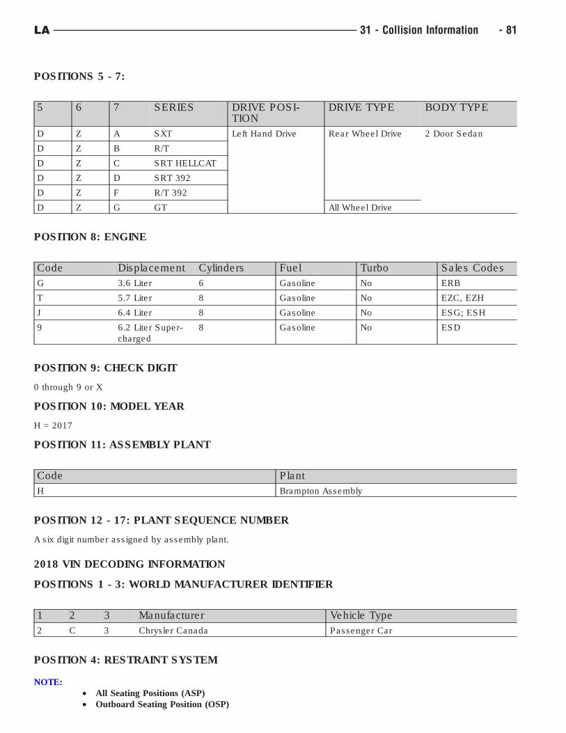
POSITIONS 5 - 7:
5 6 7 SERIES DRIVE POSI-TION
DRIVE TYPE BODY TYPE
D Z A SXT Left Hand Drive Rear Wheel Drive 2 Door Sedan
D Z B R/T
D Z C SRT HELLCAT
D Z D SRT 392
D Z F R/T 392
D Z G GT All Wheel Drive
POSITION 8: ENGINE
Code Displacement Cylinders Fuel Turbo Sales Codes
G 3.6 Liter 6 Gasoline No ERB
T 5.7 Liter 8 Gasoline No EZC, EZH
J 6.4 Liter 8 Gasoline No ESG; ESH
9 6.2 Liter Super-
charged
8 Gasoline No ESD
POSITION 9: CHECK DIGIT
0 through 9 or X
POSITION 10: MODEL YEAR
H = 2017
POSITION 11: ASSEMBLY PLANT
Code Plant
H Brampton Assembly
POSITION 12 - 17: PLANT SEQUENCE NUMBER
A six digit number assigned by assembly plant.
2018 VIN DECODING INFORMATION
POSITIONS 1 - 3: WORLD MANUFACTURER IDENTIFIER
1 2 3 Manufacturer Vehicle Type
2 C 3 Chrysler Canada Passenger Car
POSITION 4: RESTRAINT SYSTEM
NOTE:
• All Seating Positions (ASP)
• Outboard Seating Position (OSP)
LA 31 - Collision Information - 81
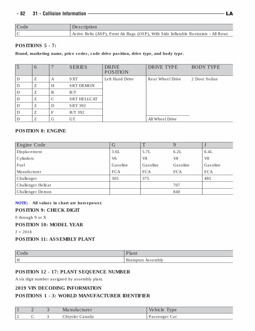
Code Description
C Active Belts (ASP), Front Air Bags (OSP), With Side Inflatable Restraints - All Rows
POSITIONS 5 - 7:
Brand, marketing name, price series, code drive position, drive type, and body type.
5 6 7 SERIES DRIVEPOSITION
DRIVE TYPE BODY TYPE
D Z A SXT Left Hand Drive Rear Wheel Drive 2 Door Sedan
D Z H SRT DEMON
D Z B R/T
D Z C SRT HELLCAT
D Z D SRT 392
D Z F R/T 392
D Z G GT All Wheel Drive
POSITION 8: ENGINE
Engine Code G T 9 J
Displacement 3.6L 5.7L 6.2L 6.4L
Cylinders V6 V8 V8 V8
Fuel Gasoline Gasoline Gasoline Gasoline
Manufacturer FCA FCA FCA FCA
Challenger 305 375 485
Challenger Hellcat 707
Challenger Demon 840
NOTE: All values in chart are horsepower.
POSITION 9: CHECK DIGIT
0 through 9 or X
POSITION 10: MODEL YEAR
J = 2018
POSITION 11: ASSEMBLY PLANT
Code Plant
H Brampton Assembly
POSITION 12 - 17: PLANT SEQUENCE NUMBER
A six digit number assigned by assembly plant.
2019 VIN DECODING INFORMATION
POSITIONS 1 - 3: WORLD MANUFACTURER IDENTIFIER
1 2 3 Manufacturer Vehicle Type
2 C 3 Chrysler Canada Passenger Car
- 82 31 - Collision Information LA
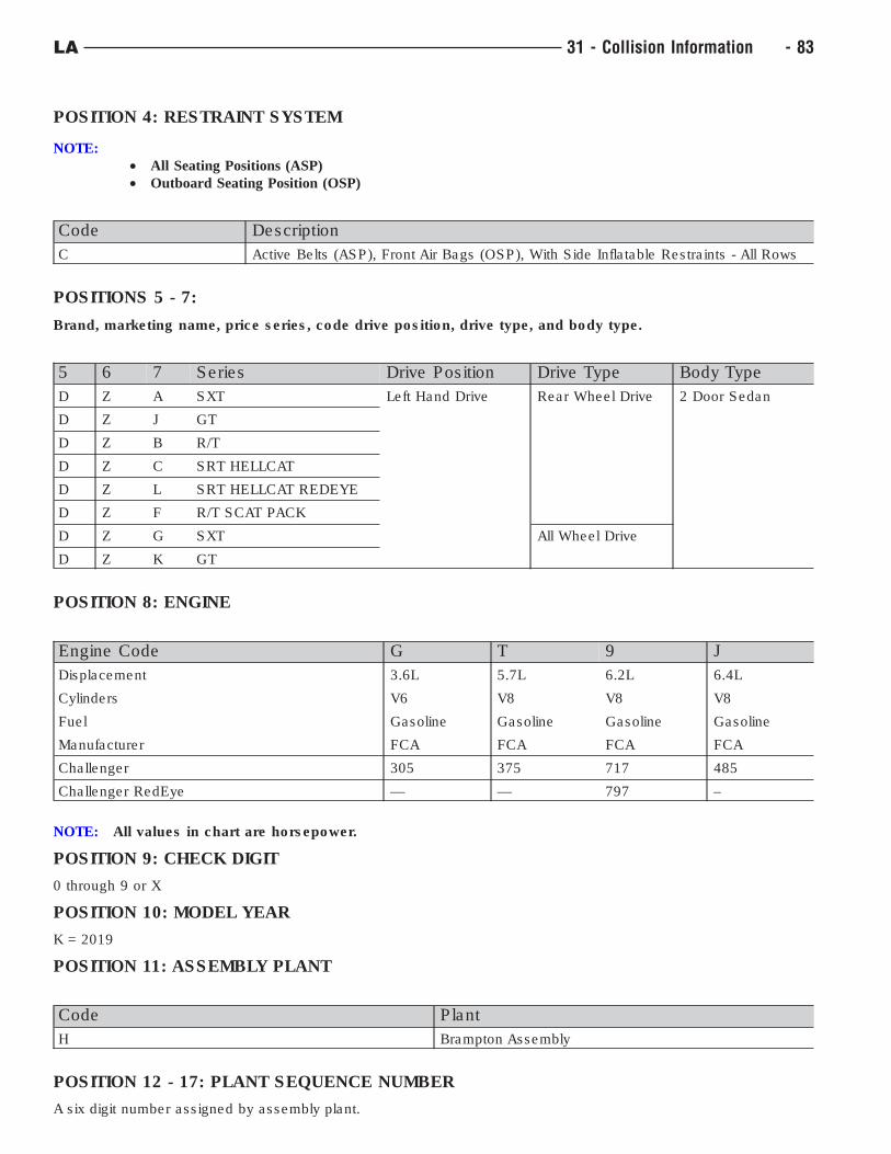
POSITION 4: RESTRAINT SYSTEM
NOTE:
• All Seating Positions (ASP)
• Outboard Seating Position (OSP)
Code Description
C Active Belts (ASP), Front Air Bags (OSP), With Side Inflatable Restraints - All Rows
POSITIONS 5 - 7:
Brand, marketing name, price series, code drive position, drive type, and body type.
5 6 7 Series Drive Position Drive Type Body Type
D Z A SXT Left Hand Drive Rear Wheel Drive 2 Door Sedan
D Z J GT
D Z B R/T
D Z C SRT HELLCAT
D Z L SRT HELLCAT REDEYE
D Z F R/T SCAT PACK
D Z G SXT All Wheel Drive
D Z K GT
POSITION 8: ENGINE
Engine Code G T 9 J
Displacement 3.6L 5.7L 6.2L 6.4L
Cylinders V6 V8 V8 V8
Fuel Gasoline Gasoline Gasoline Gasoline
Manufacturer FCA FCA FCA FCA
Challenger 305 375 717 485
Challenger RedEye — — 797 –
NOTE: All values in chart are horsepower.
POSITION 9: CHECK DIGIT
0 through 9 or X
POSITION 10: MODEL YEAR
K = 2019
POSITION 11: ASSEMBLY PLANT
Code Plant
H Brampton Assembly
POSITION 12 - 17: PLANT SEQUENCE NUMBER
A six digit number assigned by assembly plant.
LA 31 - Collision Information - 83
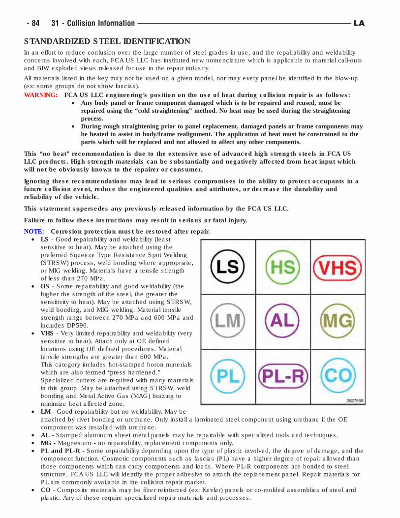
STANDARDIZED STEEL IDENTIFICATION
In an effort to reduce confusion over the large number of steel grades in use, and the repairability and weldability
concerns involved with each, FCA US LLC has instituted new nomenclature which is applicable to material call-outs
and BIW exploded views released for use in the repair industry.
All materials listed in the key may not be used on a given model, nor may every panel be identified in the blow-up
(ex: some groups do not show fascias).
WARNING: FCA US LLC engineering’s position on the use of heat during collision repair is as follows:
• Any body panel or frame component damaged which is to be repaired and reused, must be
repaired using the “cold straightening” method. No heat may be used during the straightening
process.
• During rough straightening prior to panel replacement, damaged panels or frame components may
be heated to assist in body/frame realignment. The application of heat must be constrained to the
parts which will be replaced and not allowed to affect any other components.
This “no heat” recommendation is due to the extensive use of advanced high strength steels in FCA US
LLC products. High-strength materials can be substantially and negatively affected from heat input which
will not be obviously known to the repairer or consumer.
Ignoring these recommendations may lead to serious compromises in the ability to protect occupants in a
future collision event, reduce the engineered qualities and attributes, or decrease the durability and
reliability of the vehicle.
This statement supersedes any previously released information by the FCA US LLC.
Failure to follow these instructions may result in serious or fatal injury.
NOTE: Corrosion protection must be restored after repair.
• LS - Good repairability and weldability (least
sensitive to heat). May be attached using the
preferred Squeeze Type Resistance Spot Welding
(STRSW) process, weld bonding where appropriate,
or MIG welding. Materials have a tensile strength
of less than 270 MPa.
• HS - Some repairability and good weldability (the
higher the strength of the steel, the greater the
sensitivity to heat). May be attached using STRSW,
weld bonding, and MIG welding. Material tensile
strength range between 270 MPa and 600 MPa and
includes DP590.
• VHS - Very limited repairability and weldability (very
sensitive to heat). Attach only at OE defined
locations using OE defined procedures. Material
tensile strengths are greater than 600 MPa.
This category includes hot-stamped boron materials
which are also termed “press hardened.”
Specialized cutters are required with many materials
in this group. May be attached using STRSW, weld
bonding and Metal Active Gas (MAG) brazing to
minimize heat affected zone.
• LM - Good repairability but no weldability. May be
attached by rivet bonding or urethane. Only install a laminated steel component using urethane if the OE
component was installed with urethane.
• AL - Stamped aluminum sheet metal panels may be repairable with specialized tools and techniques.
• MG - Magnesium - no repairability, replacement components only.
• PL and PL-R - Some repairability depending upon the type of plastic involved, the degree of damage, and the
component function. Cosmetic components such as fascias (PL) have a higher degree of repair allowed than
those components which can carry components and loads. Where PL-R components are bonded to steel
structure, FCA US LLC will identify the proper adhesive to attach the replacement panel. Repair materials for
PL are commonly available in the collision repair market.
• CO - Composite materials may be fiber reinforced (ex: Kevlar) panels or co-molded assemblies of steel and
plastic. Any of these require specialized repair materials and processes.
- 84 31 - Collision Information LA
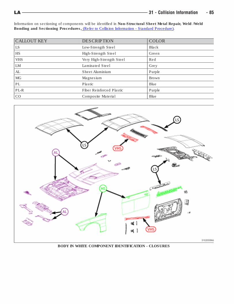
Information on sectioning of components will be identified in Non-Structural Sheet Metal Repair, Weld /Weld
Bonding and Sectioning Procedures, (Refer to Collision Information - Standard Procedure).
CALLOUT KEY DESCRIPTION COLOR
LS Low-Strength Steel Black
HS High-Strength Steel Green
VHS Very High-Strength Steel Red
LM Laminated Steel Grey
AL Sheet Aluminium Purple
MG Magnesium Brown
PL Plastic Blue
PL-R Fiber Reinforced Plastic Purple
CO Composite Material Blue
BODY IN WHITE COMPONENT IDENTIFICATION - CLOSURES
LA 31 - Collision Information - 85
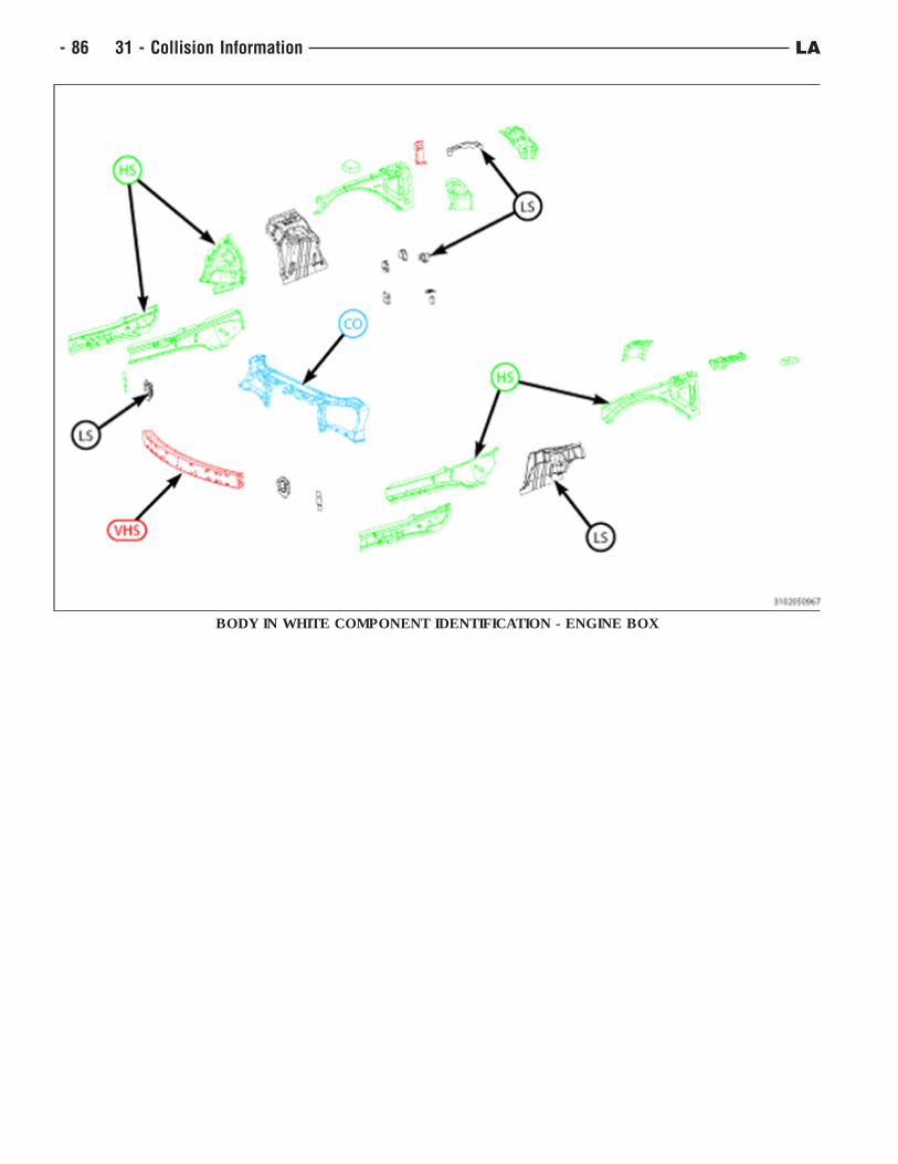
BODY IN WHITE COMPONENT IDENTIFICATION - ENGINE BOX
- 86 31 - Collision Information LA
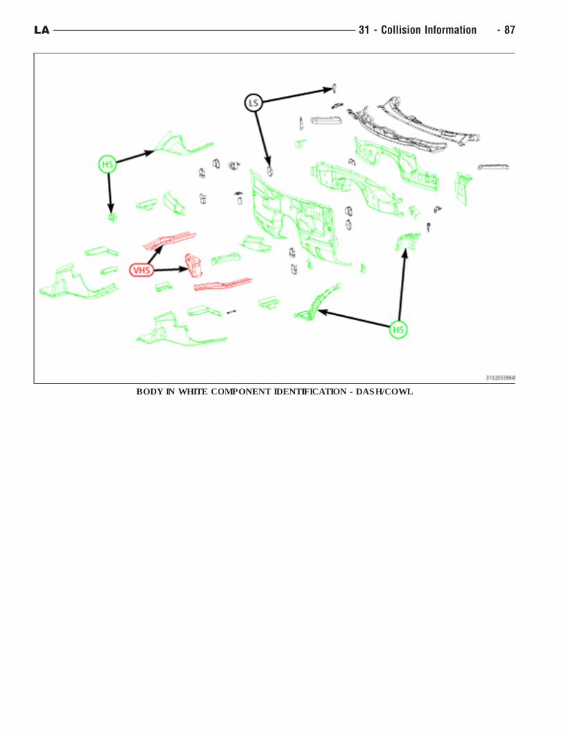
BODY IN WHITE COMPONENT IDENTIFICATION - DASH/COWL
LA 31 - Collision Information - 87
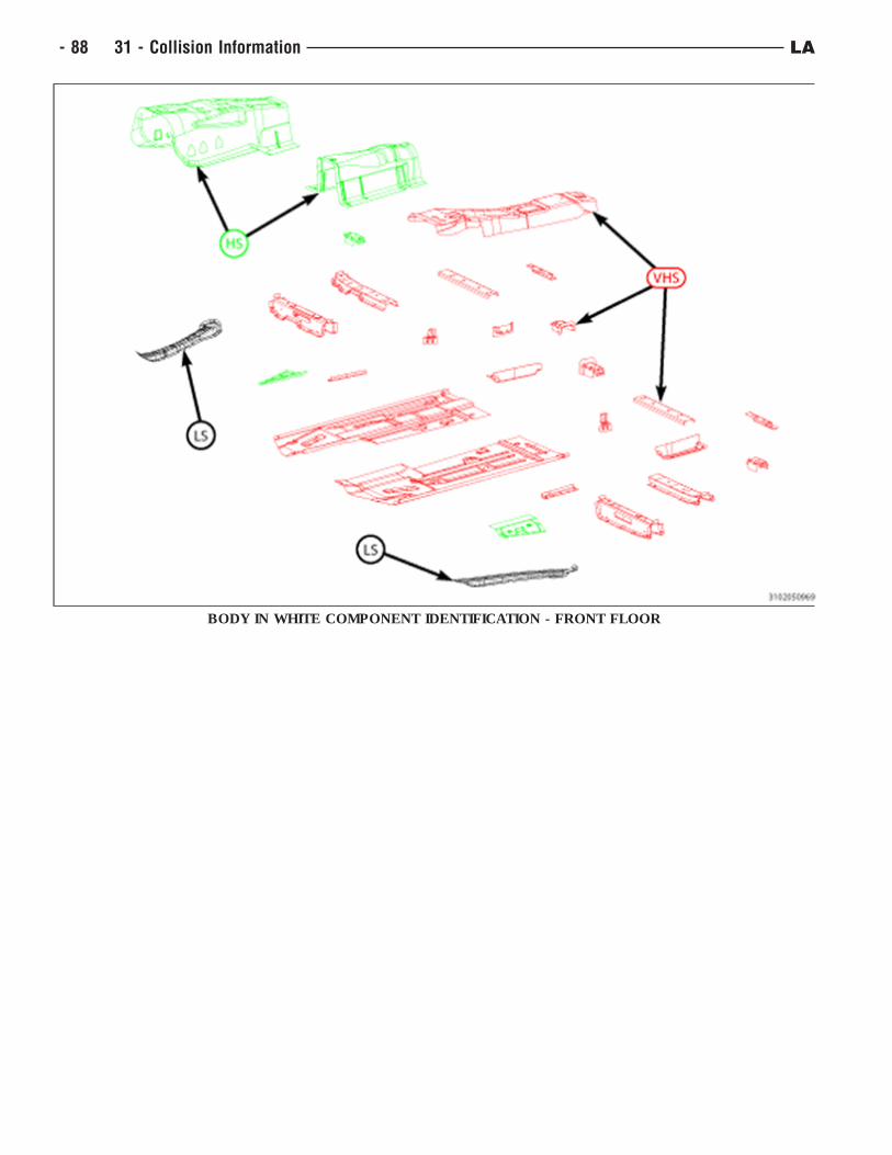
BODY IN WHITE COMPONENT IDENTIFICATION - FRONT FLOOR
- 88 31 - Collision Information LA
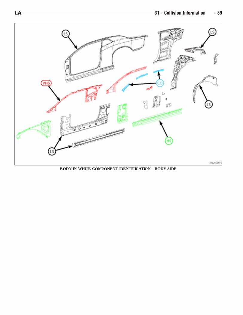
BODY IN WHITE COMPONENT IDENTIFICATION - BODY SIDE
LA 31 - Collision Information - 89
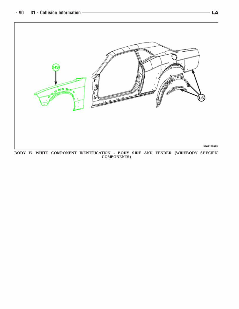
BODY IN WHITE COMPONENT IDENTIFICATION - BODY SIDE AND FENDER (WIDEBODY SPECIFICCOMPONENTS)
- 90 31 - Collision Information LA
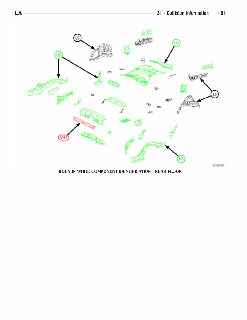
BODY IN WHITE COMPONENT IDENTIFICATION - REAR FLOOR
LA 31 - Collision Information - 91
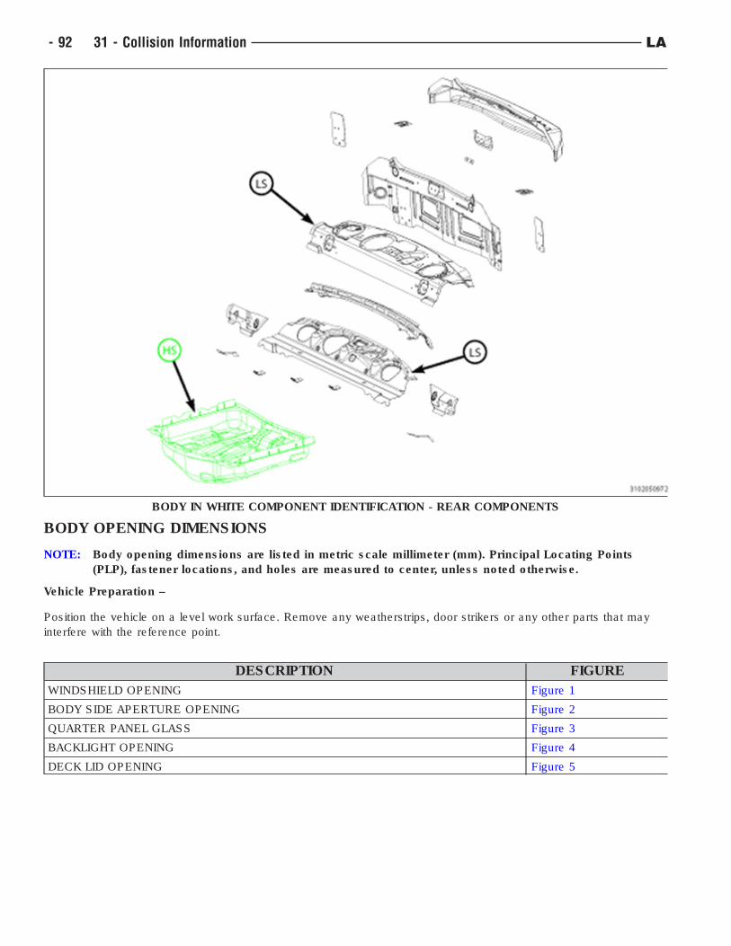
BODY OPENING DIMENSIONS
NOTE: Body opening dimensions are listed in metric scale millimeter (mm). Principal Locating Points
(PLP), fastener locations, and holes are measured to center, unless noted otherwise.
Vehicle Preparation –
Position the vehicle on a level work surface. Remove any weatherstrips, door strikers or any other parts that may
interfere with the reference point.
DESCRIPTION FIGURE
WINDSHIELD OPENING Figure 1
BODY SIDE APERTURE OPENING Figure 2
QUARTER PANEL GLASS Figure 3
BACKLIGHT OPENING Figure 4
DECK LID OPENING Figure 5
BODY IN WHITE COMPONENT IDENTIFICATION - REAR COMPONENTS
- 92 31 - Collision Information LA
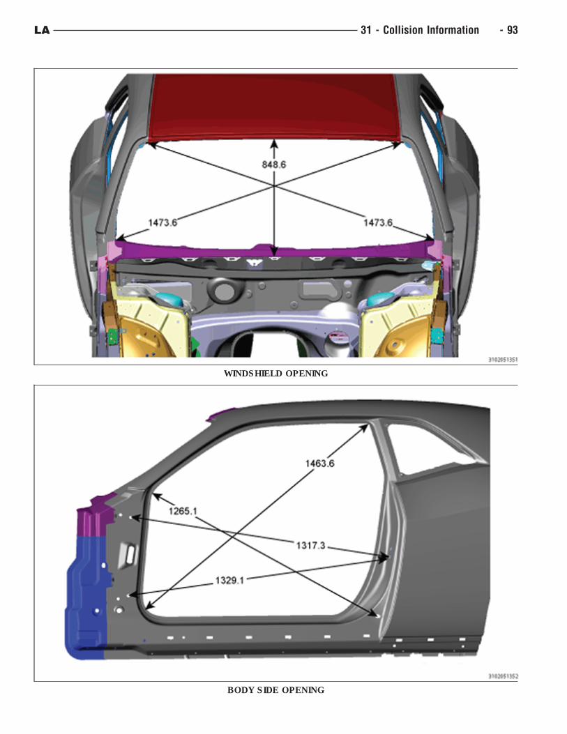
WINDSHIELD OPENING
BODY SIDE OPENING
LA 31 - Collision Information - 93
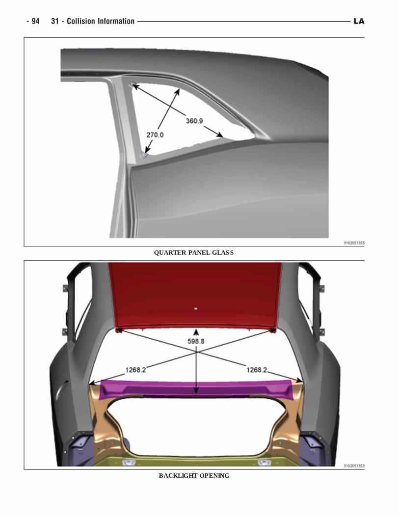
QUARTER PANEL GLASS
BACKLIGHT OPENING
- 94 31 - Collision Information LA
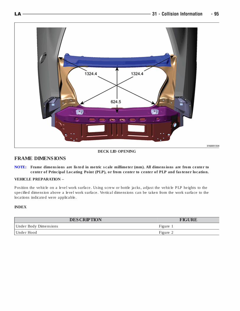
FRAME DIMENSIONS
NOTE: Frame dimensions are listed in metric scale millimeter (mm). All dimensions are from center to
center of Principal Locating Point (PLP), or from center to center of PLP and fastener location.
VEHICLE PREPARATION –
Position the vehicle on a level work surface. Using screw or bottle jacks, adjust the vehicle PLP heights to the
specified dimension above a level work surface. Vertical dimensions can be taken from the work surface to the
locations indicated were applicable.
INDEX
DESCRIPTION FIGURE
Under Body Dimensions Figure 1
Under Hood Figure 2
DECK LID OPENING
LA 31 - Collision Information - 95
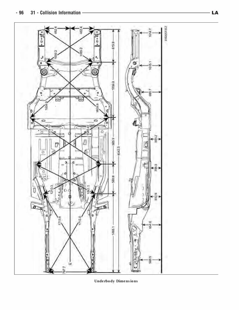
Underbody Dimensions
- 96 31 - Collision Information LA
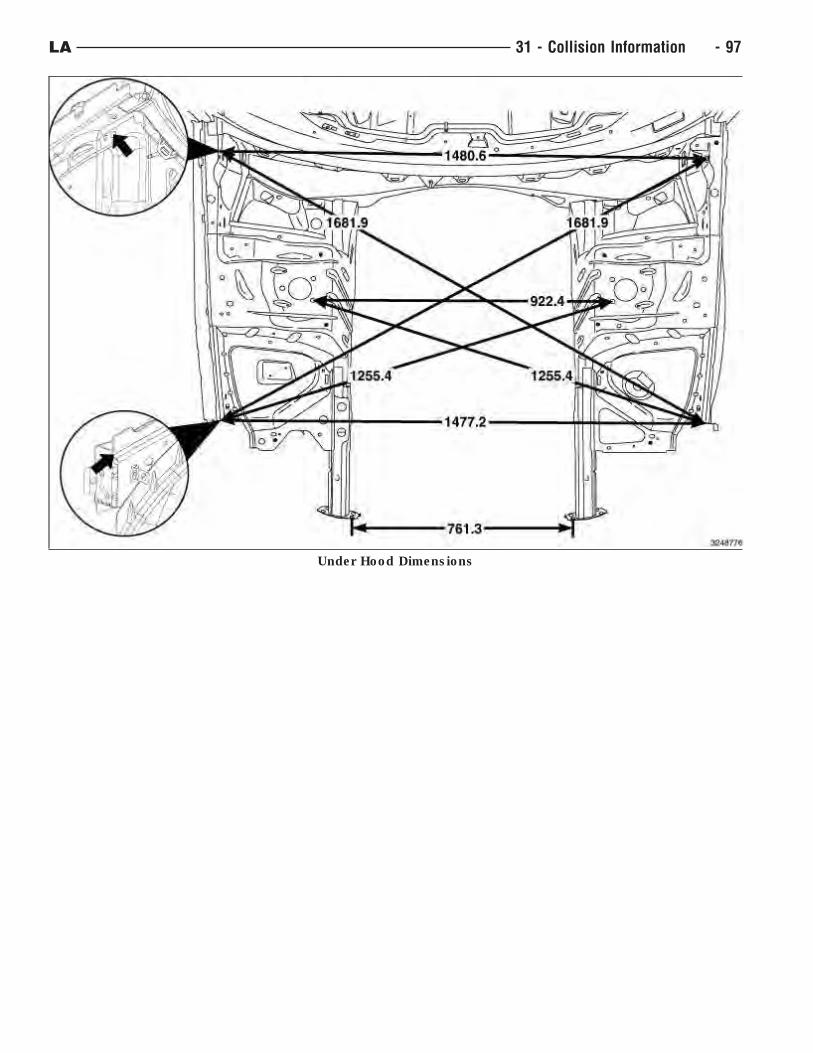
Under Hood Dimensions
LA 31 - Collision Information - 97
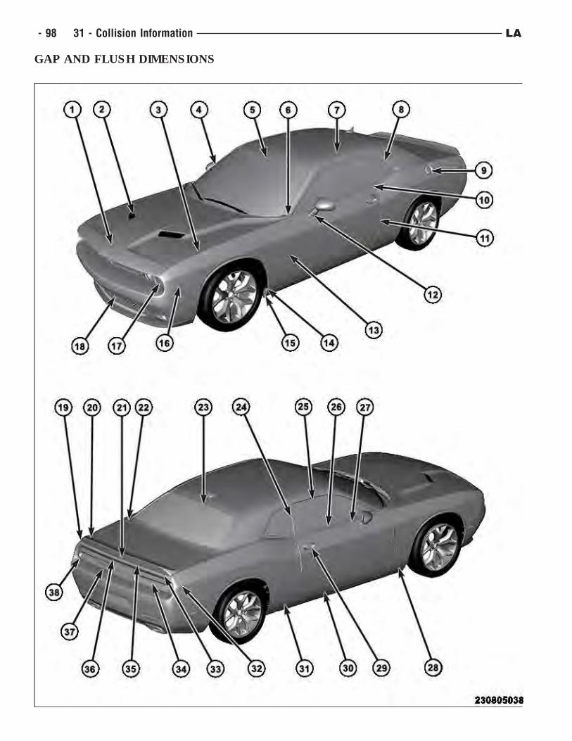
GAP AND FLUSH DIMENSIONS
- 98 31 - Collision Information LA
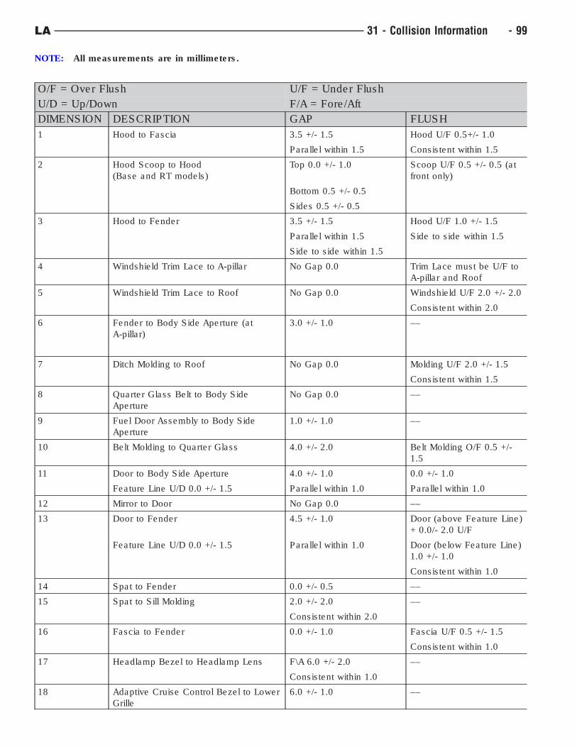
NOTE: All measurements are in millimeters.
O/F = Over Flush U/F = Under Flush
U/D = Up/Down F/A = Fore/Aft
DIMENSION DESCRIPTION GAP FLUSH
1 Hood to Fascia 3.5 +/- 1.5 Hood U/F 0.5+/- 1.0
Parallel within 1.5 Consistent within 1.5
2 Hood Scoop to Hood
(Base and RT models)
Top 0.0 +/- 1.0 Scoop U/F 0.5 +/- 0.5 (at
front only)
Bottom 0.5 +/- 0.5
Sides 0.5 +/- 0.5
3 Hood to Fender 3.5 +/- 1.5 Hood U/F 1.0 +/- 1.5
Parallel within 1.5 Side to side within 1.5
Side to side within 1.5
4 Windshield Trim Lace to A-pillar No Gap 0.0 Trim Lace must be U/F to
A-pillar and Roof
5 Windshield Trim Lace to Roof No Gap 0.0 Windshield U/F 2.0 +/- 2.0
Consistent within 2.0
6 Fender to Body Side Aperture (at
A-pillar)
3.0 +/- 1.0 ––
7 Ditch Molding to Roof No Gap 0.0 Molding U/F 2.0 +/- 1.5
Consistent within 1.5
8 Quarter Glass Belt to Body Side
Aperture
No Gap 0.0 ––
9 Fuel Door Assembly to Body Side
Aperture
1.0 +/- 1.0 ––
10 Belt Molding to Quarter Glass 4.0 +/- 2.0 Belt Molding O/F 0.5 +/-
1.5
11 Door to Body Side Aperture 4.0 +/- 1.0 0.0 +/- 1.0
Feature Line U/D 0.0 +/- 1.5 Parallel within 1.0 Parallel within 1.0
12 Mirror to Door No Gap 0.0 ––
13 Door to Fender 4.5 +/- 1.0 Door (above Feature Line)
+ 0.0/- 2.0 U/F
Feature Line U/D 0.0 +/- 1.5 Parallel within 1.0 Door (below Feature Line)
1.0 +/- 1.0
Consistent within 1.0
14 Spat to Fender 0.0 +/- 0.5 ––
15 Spat to Sill Molding 2.0 +/- 2.0 ––
Consistent within 2.0
16 Fascia to Fender 0.0 +/- 1.0 Fascia U/F 0.5 +/- 1.5
Consistent within 1.0
17 Headlamp Bezel to Headlamp Lens F\A 6.0 +/- 2.0 ––
Consistent within 1.0
18 Adaptive Cruise Control Bezel to Lower
Grille
6.0 +/- 1.0 ––
LA 31 - Collision Information - 99
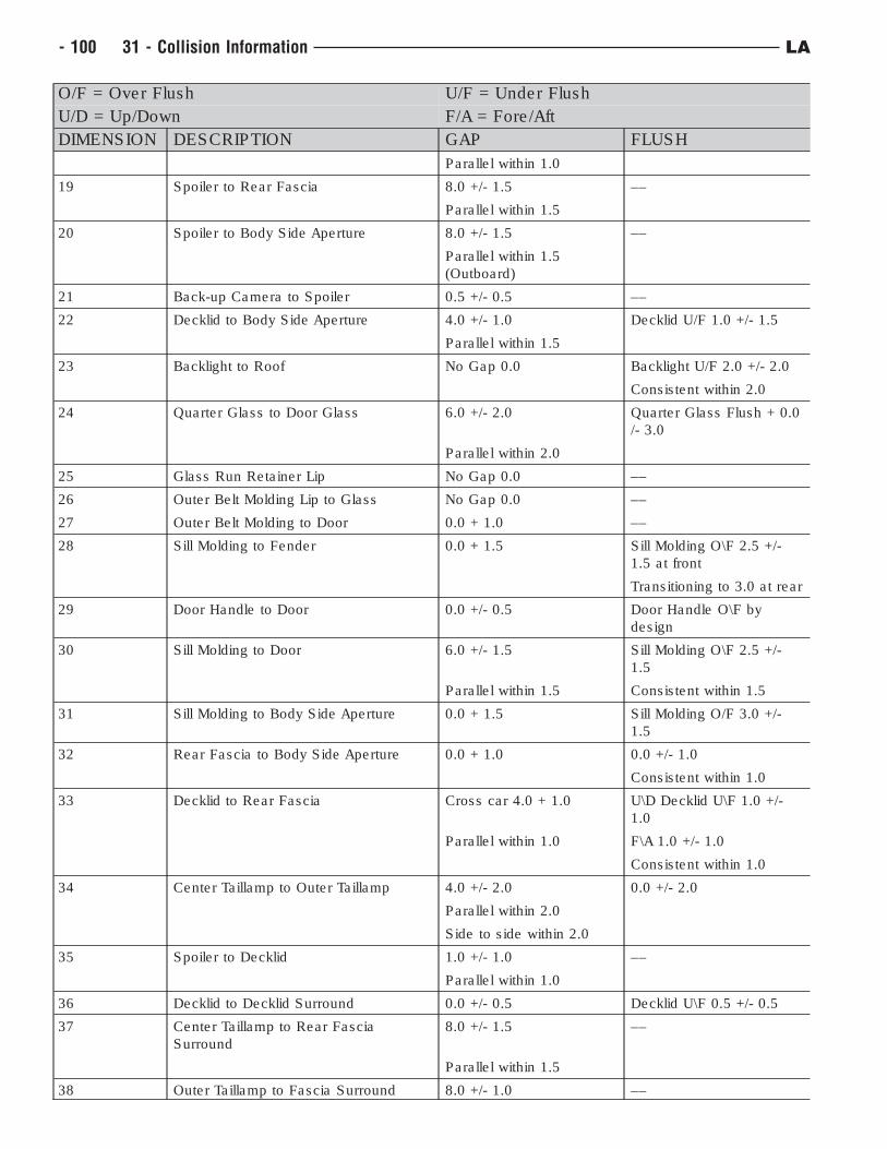
O/F = Over Flush U/F = Under Flush
U/D = Up/Down F/A = Fore/Aft
DIMENSION DESCRIPTION GAP FLUSH
Parallel within 1.0
19 Spoiler to Rear Fascia 8.0 +/- 1.5 ––
Parallel within 1.5
20 Spoiler to Body Side Aperture 8.0 +/- 1.5 ––
Parallel within 1.5
(Outboard)
21 Back-up Camera to Spoiler 0.5 +/- 0.5 ––
22 Decklid to Body Side Aperture 4.0 +/- 1.0 Decklid U/F 1.0 +/- 1.5
Parallel within 1.5
23 Backlight to Roof No Gap 0.0 Backlight U/F 2.0 +/- 2.0
Consistent within 2.0
24 Quarter Glass to Door Glass 6.0 +/- 2.0 Quarter Glass Flush + 0.0
/- 3.0
Parallel within 2.0
25 Glass Run Retainer Lip No Gap 0.0 ––
26 Outer Belt Molding Lip to Glass No Gap 0.0 ––
27 Outer Belt Molding to Door 0.0 + 1.0 ––
28 Sill Molding to Fender 0.0 + 1.5 Sill Molding O\F 2.5 +/-
1.5 at front
Transitioning to 3.0 at rear
29 Door Handle to Door 0.0 +/- 0.5 Door Handle O\F by
design
30 Sill Molding to Door 6.0 +/- 1.5 Sill Molding O\F 2.5 +/-
1.5
Parallel within 1.5 Consistent within 1.5
31 Sill Molding to Body Side Aperture 0.0 + 1.5 Sill Molding O/F 3.0 +/-
1.5
32 Rear Fascia to Body Side Aperture 0.0 + 1.0 0.0 +/- 1.0
Consistent within 1.0
33 Decklid to Rear Fascia Cross car 4.0 + 1.0 U\D Decklid U\F 1.0 +/-
1.0
Parallel within 1.0 F\A 1.0 +/- 1.0
Consistent within 1.0
34 Center Taillamp to Outer Taillamp 4.0 +/- 2.0 0.0 +/- 2.0
Parallel within 2.0
Side to side within 2.0
35 Spoiler to Decklid 1.0 +/- 1.0 ––
Parallel within 1.0
36 Decklid to Decklid Surround 0.0 +/- 0.5 Decklid U\F 0.5 +/- 0.5
37 Center Taillamp to Rear Fascia
Surround
8.0 +/- 1.5 ––
Parallel within 1.5
38 Outer Taillamp to Fascia Surround 8.0 +/- 1.0 ––
- 100 31 - Collision Information LA
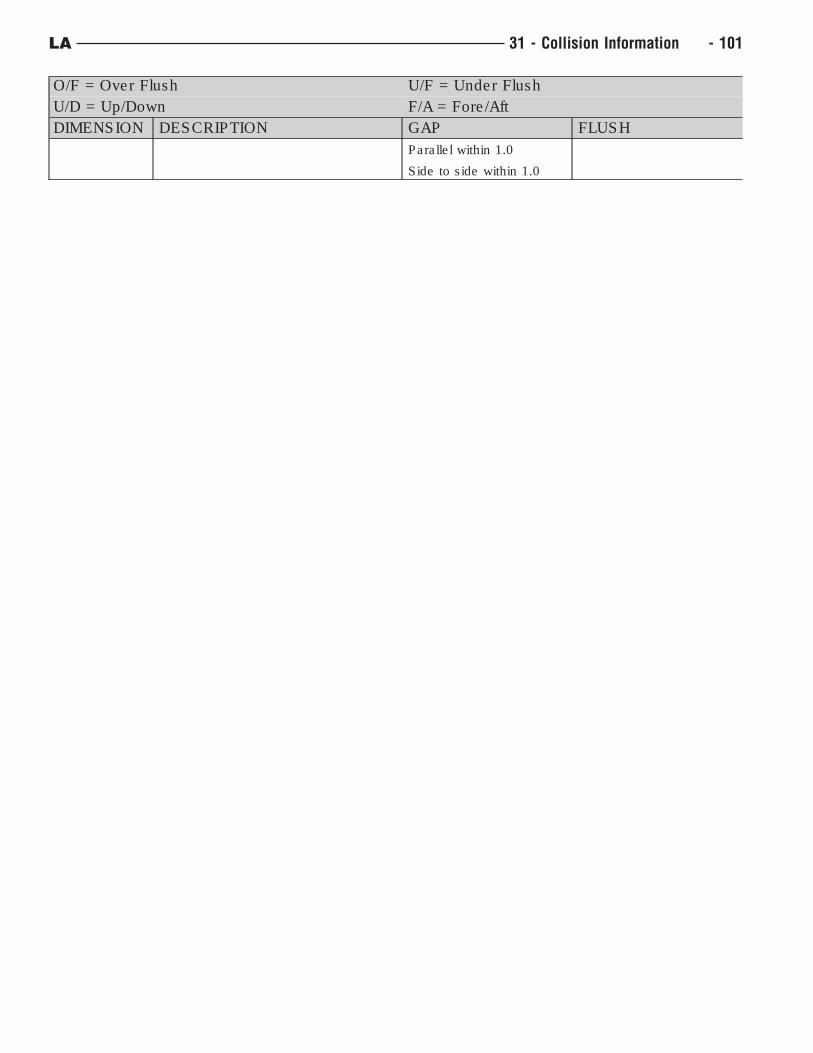
O/F = Over Flush U/F = Under Flush
U/D = Up/Down F/A = Fore/Aft
DIMENSION DESCRIPTION GAP FLUSH
Parallel within 1.0
Side to side within 1.0
LA 31 - Collision Information - 101
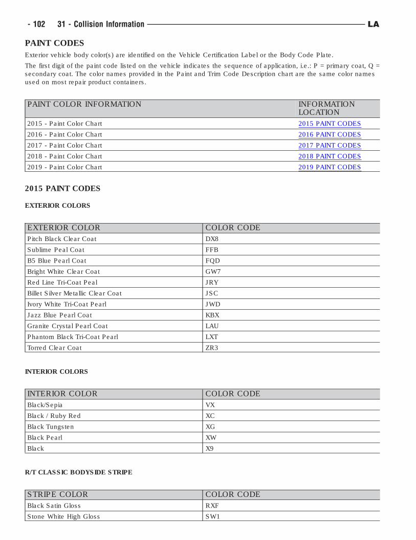
PAINT CODES
Exterior vehicle body color(s) are identified on the Vehicle Certification Label or the Body Code Plate.
The first digit of the paint code listed on the vehicle indicates the sequence of application, i.e.: P = primary coat, Q =
secondary coat. The color names provided in the Paint and Trim Code Description chart are the same color names
used on most repair product containers.
PAINT COLOR INFORMATION INFORMATIONLOCATION
2015 - Paint Color Chart 2015 PAINT CODES
2016 - Paint Color Chart 2016 PAINT CODES
2017 - Paint Color Chart 2017 PAINT CODES
2018 - Paint Color Chart 2018 PAINT CODES
2019 - Paint Color Chart 2019 PAINT CODES
2015 PAINT CODES
EXTERIOR COLORS
EXTERIOR COLOR COLOR CODE
Pitch Black Clear Coat DX8
Sublime Peal Coat FFB
B5 Blue Pearl Coat FQD
Bright White Clear Coat GW7
Red Line Tri-Coat Peal JRY
Billet Silver Metallic Clear Coat JSC
Ivory White Tri-Coat Pearl JWD
Jazz Blue Pearl Coat KBX
Granite Crystal Pearl Coat LAU
Phantom Black Tri-Coat Pearl LXT
Torred Clear Coat ZR3
INTERIOR COLORS
INTERIOR COLOR COLOR CODE
Black/Sepia VX
Black / Ruby Red XC
Black Tungsten XG
Black Pearl XW
Black X9
R/T CLASSIC BODYSIDE STRIPE
STRIPE COLOR COLOR CODE
Black Satin Gloss RXF
Stone White High Gloss SW1
- 102 31 - Collision Information LA
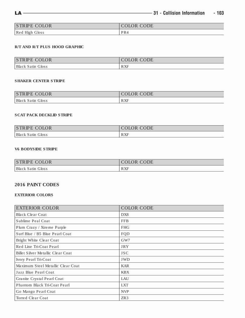
STRIPE COLOR COLOR CODE
Red High Gloss PR4
R/T AND R/T PLUS HOOD GRAPHIC
STRIPE COLOR COLOR CODE
Black Satin Gloss RXF
SHAKER CENTER STRIPE
STRIPE COLOR COLOR CODE
Black Satin Gloss RXF
SCAT PACK DECKLID STRIPE
STRIPE COLOR COLOR CODE
Black Satin Gloss RXF
V6 BODYSIDE STRIPE
STRIPE COLOR COLOR CODE
Black Satin Gloss RXF
2016 PAINT CODES
EXTERIOR COLORS
EXTERIOR COLOR COLOR CODE
Black Clear Coat DX8
Sublime Peal Coat FFB
Plum Crazy / Xtreme Purple FHG
Surf Blue / B5 Blue Pearl Coat FQD
Bright White Clear Coat GW7
Red Line Tri-Coat Pearl JRY
Billet Silver Metallic Clear Coat JSC
Ivory Pearl Tri-Coat JWD
Maximum Steel Metallic Clear Coat KAR
Jazz Blue Pearl Coat KBX
Granite Crystal Pearl Coat LAU
Phantom Black Tri-Coat Pearl LXT
Go Mango Pearl Coat NVP
Torred Clear Coat ZR3
LA 31 - Collision Information - 103
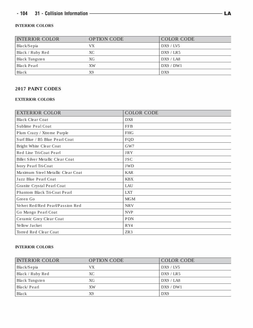
INTERIOR COLORS
INTERIOR COLOR OPTION CODE COLOR CODE
Black/Sepia VX DX9 / LV5
Black / Ruby Red XC DX9 / LR5
Black Tungsten XG DX9 / LA8
Black Pearl XW DX9 / DW1
Black X9 DX9
2017 PAINT CODES
EXTERIOR COLORS
EXTERIOR COLOR COLOR CODE
Black Clear Coat DX8
Sublime Peal Coat FFB
Plum Crazy / Xtreme Purple FHG
Surf Blue / B5 Blue Pearl Coat FQD
Bright White Clear Coat GW7
Red Line Tri-Coat Pearl JRY
Billet Silver Metallic Clear Coat JSC
Ivory Pearl Tri-Coat JWD
Maximum Steel Metallic Clear Coat KAR
Jazz Blue Pearl Coat KBX
Granite Crystal Pearl Coat LAU
Phantom Black Tri-Coat Pearl LXT
Green Go MGM
Velvet Red/Red Pearl/Passion Red NRV
Go Mango Pearl Coat NVP
Ceramic Grey Clear Coat PDN
Yellow Jacket RY4
Torred Red Clear Coat ZR3
INTERIOR COLORS
INTERIOR COLOR OPTION CODE COLOR CODE
Black/Sepia VX DX9 / LV5
Black / Ruby Red XC DX9 / LR5
Black Tungsten XG DX9 / LA8
Black/ Pearl XW DX9 / DW1
Black X9 DX9
- 104 31 - Collision Information LA
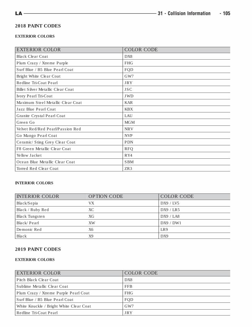
2018 PAINT CODES
EXTERIOR COLORS
EXTERIOR COLOR COLOR CODE
Black Clear Coat DX8
Plum Crazy / Xtreme Purple FHG
Surf Blue / B5 Blue Pearl Coat FQD
Bright White Clear Coat GW7
Redline Tri-Coat Pearl JRY
Billet Silver Metallic Clear Coat JSC
Ivory Pearl Tri-Coat JWD
Maximum Steel Metallic Clear Coat KAR
Jazz Blue Pearl Coat KBX
Granite Crystal Pearl Coat LAU
Green Go MGM
Velvet Red/Red Pearl/Passion Red NRV
Go Mango Pearl Coat NVP
Ceramic/ Sting Grey Clear Coat PDN
F8 Green Metallic Clear Coat RFQ
Yellow Jacket RY4
Ocean Blue Metallic Clear Coat SBM
Torred Red Clear Coat ZR3
INTERIOR COLORS
INTERIOR COLOR OPTION CODE COLOR CODE
Black/Sepia VX DX9 / LV5
Black / Ruby Red XC DX9 / LR5
Black Tungsten XG DX9 / LA8
Black/ Pearl XW DX9 / DW1
Demonic Red X6 LR9
Black X9 DX9
2019 PAINT CODES
EXTERIOR COLORS
EXTERIOR COLOR COLOR CODE
Pitch Black Clear Coat DX8
Sublime Metallic Clear Coat FFB
Plum Crazy / Xtreme Purple Pearl Coat FHG
Surf Blue / B5 Blue Pearl Coat FQD
White Knuckle / Bright White Clear Coat GW7
Redline Tri-Coat Pearl JRY
LA 31 - Collision Information - 105
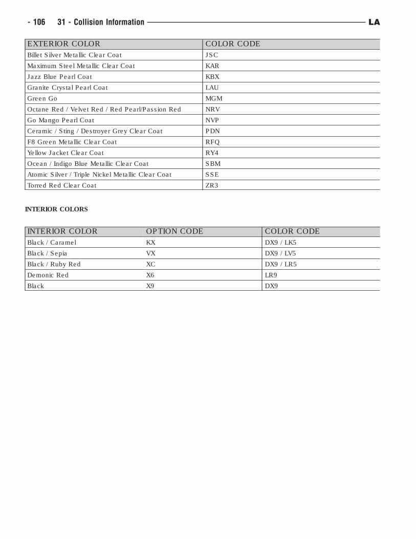
EXTERIOR COLOR COLOR CODE
Billet Silver Metallic Clear Coat JSC
Maximum Steel Metallic Clear Coat KAR
Jazz Blue Pearl Coat KBX
Granite Crystal Pearl Coat LAU
Green Go MGM
Octane Red / Velvet Red / Red Pearl/Passion Red NRV
Go Mango Pearl Coat NVP
Ceramic / Sting / Destroyer Grey Clear Coat PDN
F8 Green Metallic Clear Coat RFQ
Yellow Jacket Clear Coat RY4
Ocean / Indigo Blue Metallic Clear Coat SBM
Atomic Silver / Triple Nickel Metallic Clear Coat SSE
Torred Red Clear Coat ZR3
INTERIOR COLORS
INTERIOR COLOR OPTION CODE COLOR CODE
Black / Caramel KX DX9 / LK5
Black / Sepia VX DX9 / LV5
Black / Ruby Red XC DX9 / LR5
Demonic Red X6 LR9
Black X9 DX9
- 106 31 - Collision Information LA
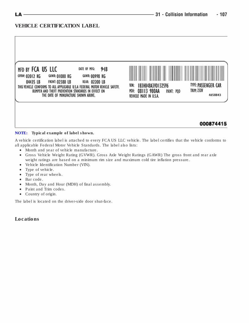
VEHICLE CERTIFICATION LABEL
NOTE: Typical example of label shown.
A vehicle certification label is attached to every FCA US LLC vehicle. The label certifies that the vehicle conforms to
all applicable Federal Motor Vehicle Standards. The label also lists:
• Month and year of vehicle manufacture.
• Gross Vehicle Weight Rating (GVWR). Gross Axle Weight Ratings (GAWR) The gross front and rear axle
weight ratings are based on a minimum rim size and maximum cold tire inflation pressure.
• Vehicle Identification Number (VIN).
• Type of vehicle.
• Type of rear wheels.
• Bar code.
• Month, Day and Hour (MDH) of final assembly.
• Paint and Trim codes.
• Country of origin.
The label is located on the driver-side door shut-face.
Locations
LA 31 - Collision Information - 107
SEALERS AND SOUND DEADENERSTerminology
• Work Time : The length of time a sealer can continue to be applied or tooled effectively.
• Set Time : Time when there is no longer product transfer.
• Handling Time : The time when a part can be safely transported and sealer can no longer be tooled or
repositioned.
• Full Cure Time : Time when a sealer has reached full strength.
• Paintable Time : Established time when refinish materials can safely be applied to a sealer.
Sealers
• Brushable : Single component sealer applied with a brush.
• Flowable : Sealer with low viscosity and self-leveling characteristics.
• Pumpable : A two component or one component sealer that seals interior and exterior joints and voids.
• Resistance Weld-through : Sealer / adhesive that can be used in conjunction with resistance spot welding.
• Sealer Tape : Preformed sealer.
• Sprayable : Sealer applied with a pneumatic dispenser to duplicate original textured appearance.
• Thumb Grade : Heavy bodied sealer for sealing large gaps and filling voids. Should remain soft and pliable.
Sound Deadeners
• Non-Structural Flexible Acoustical : Flexible foam with sealing and sound deadening properties.
• Non-Structural Ridged Acoustical : Ridged foam with sealing and sound deadening properties.
• Mastic Pads : Sound deadener pad that is preformed to fit a specific area.
Identifying Sealers
• Several types of sealers and sound deadeners are used during assembly. Therefore, specific applications may
not be identified in this publication. General applications and the various types of products for repair will be
featured to identify and replace OEM sealers and sound deadeners.
Helpful Sealer Tips
• Check shelf life or expiration date prior to beginning sealer applications.
• Be sure "work time" is appropriate for sealer application.
• Temperature, humidity and thickness of sealer will affect the work, set and paintable times.
• Test fit replacement panels prior to installation to be certain of a tight fit and proper seal.
• Equalize 2K Products according to adhesive manufacturer’s recommendations.
• Always follow manufacturer’s recommendations for storage, usage and application to achieve best
performance of the product.
- 108 31 - Collision Information LA
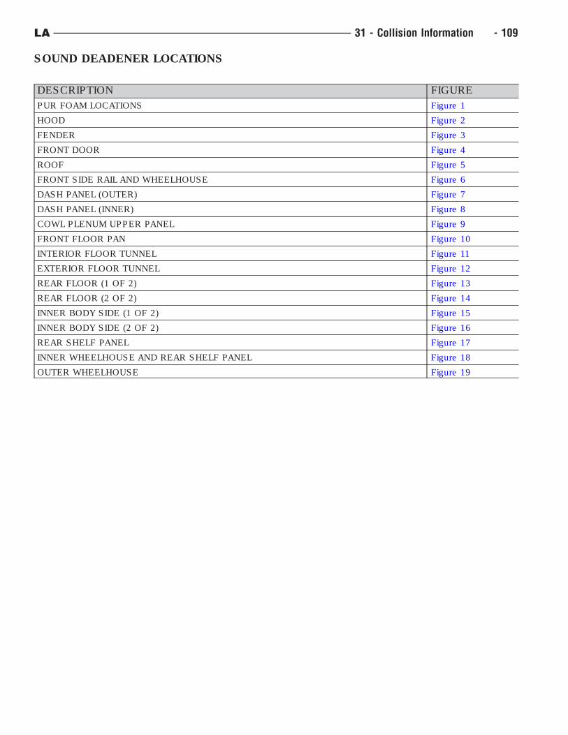
SOUND DEADENER LOCATIONS
DESCRIPTION FIGURE
PUR FOAM LOCATIONS Figure 1
HOOD Figure 2
FENDER Figure 3
FRONT DOOR Figure 4
ROOF Figure 5
FRONT SIDE RAIL AND WHEELHOUSE Figure 6
DASH PANEL (OUTER) Figure 7
DASH PANEL (INNER) Figure 8
COWL PLENUM UPPER PANEL Figure 9
FRONT FLOOR PAN Figure 10
INTERIOR FLOOR TUNNEL Figure 11
EXTERIOR FLOOR TUNNEL Figure 12
REAR FLOOR (1 OF 2) Figure 13
REAR FLOOR (2 OF 2) Figure 14
INNER BODY SIDE (1 OF 2) Figure 15
INNER BODY SIDE (2 OF 2) Figure 16
REAR SHELF PANEL Figure 17
INNER WHEELHOUSE AND REAR SHELF PANEL Figure 18
OUTER WHEELHOUSE Figure 19
LA 31 - Collision Information - 109
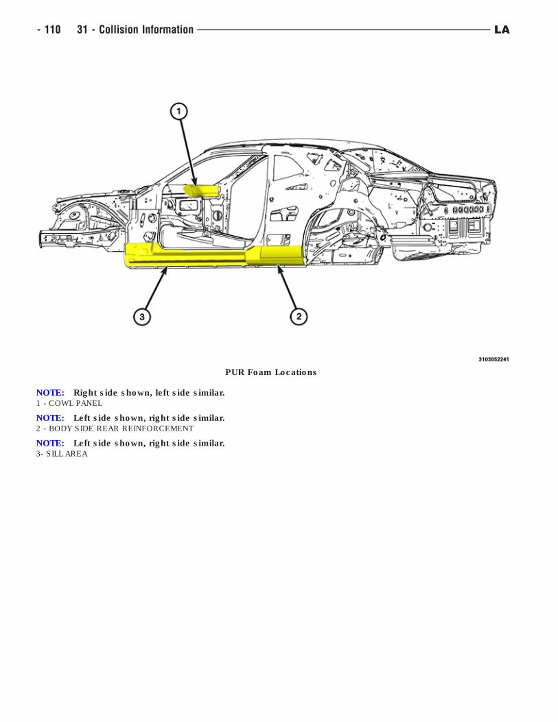
PUR Foam Locations
NOTE: Right side shown, left side similar.1 - COWL PANEL
NOTE: Left side shown, right side similar.2 - BODY SIDE REAR REINFORCEMENT
NOTE: Left side shown, right side similar.3- SILL AREA
- 110 31 - Collision Information LA
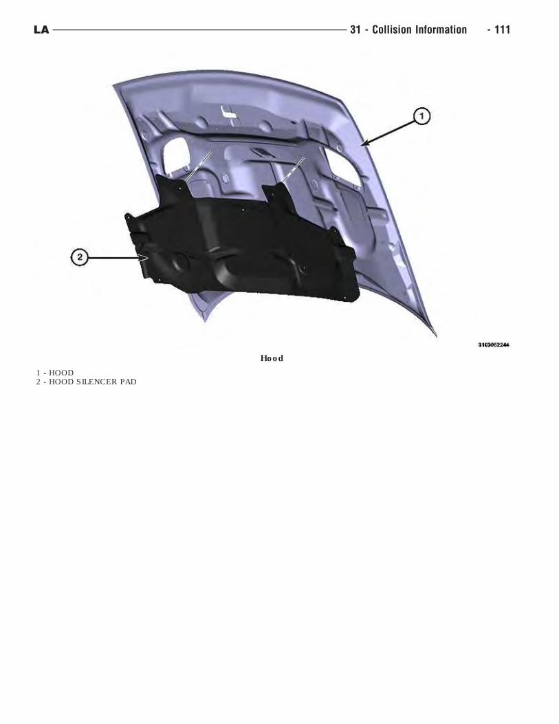
Hood
1 - HOOD2 - HOOD SILENCER PAD
LA 31 - Collision Information - 111
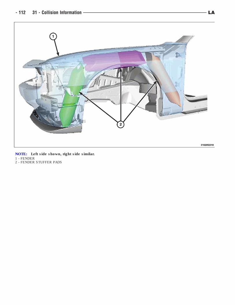
NOTE: Left side shown, right side similar.1 - FENDER2 - FENDER STUFFER PADS
- 112 31 - Collision Information LA
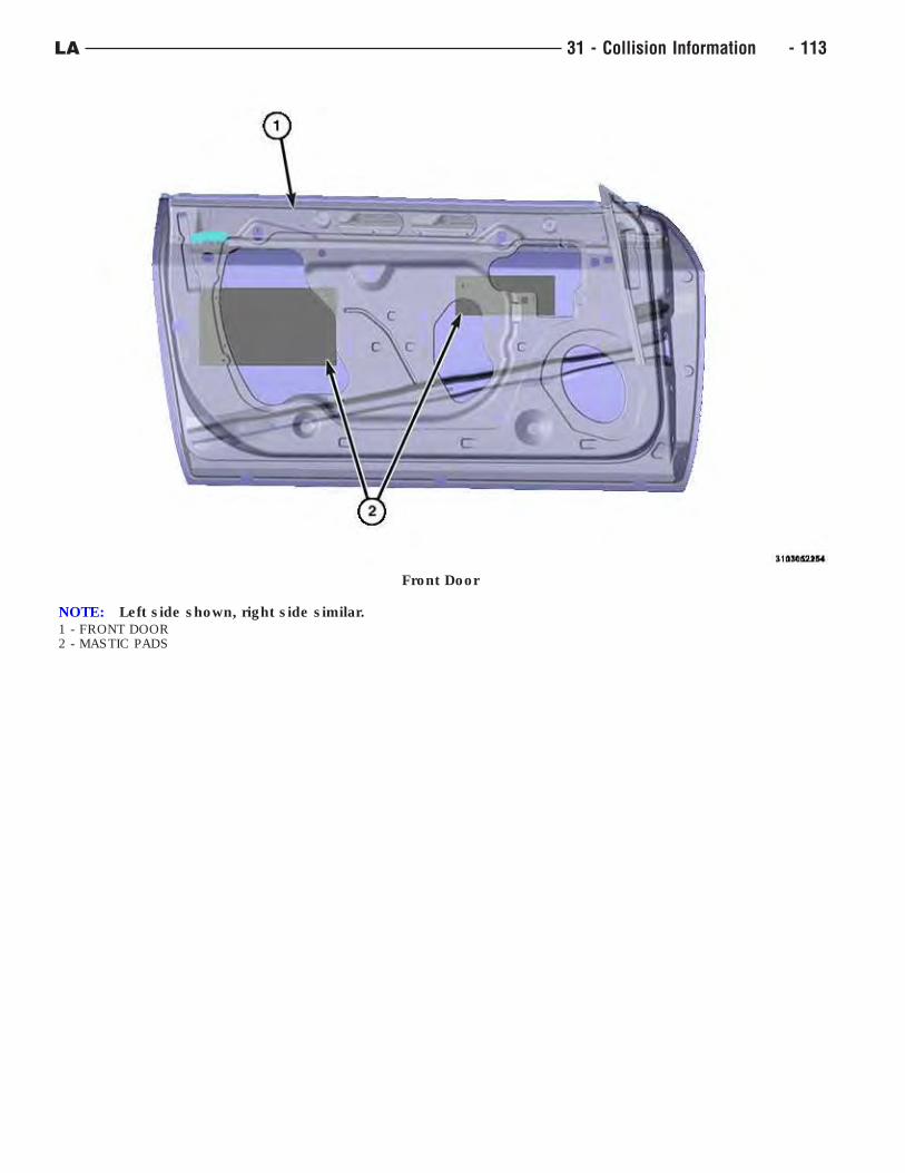
Front Door
NOTE: Left side shown, right side similar.1 - FRONT DOOR2 - MASTIC PADS
LA 31 - Collision Information - 113
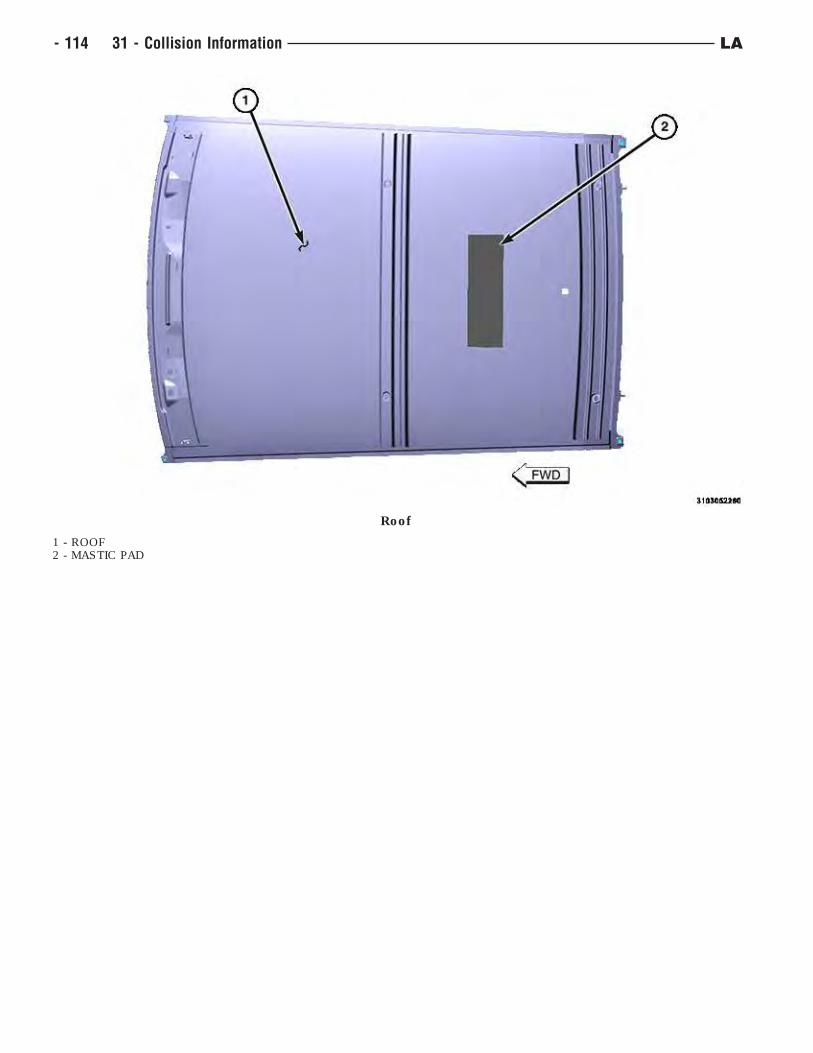
Roof
1 - ROOF2 - MASTIC PAD
- 114 31 - Collision Information LA
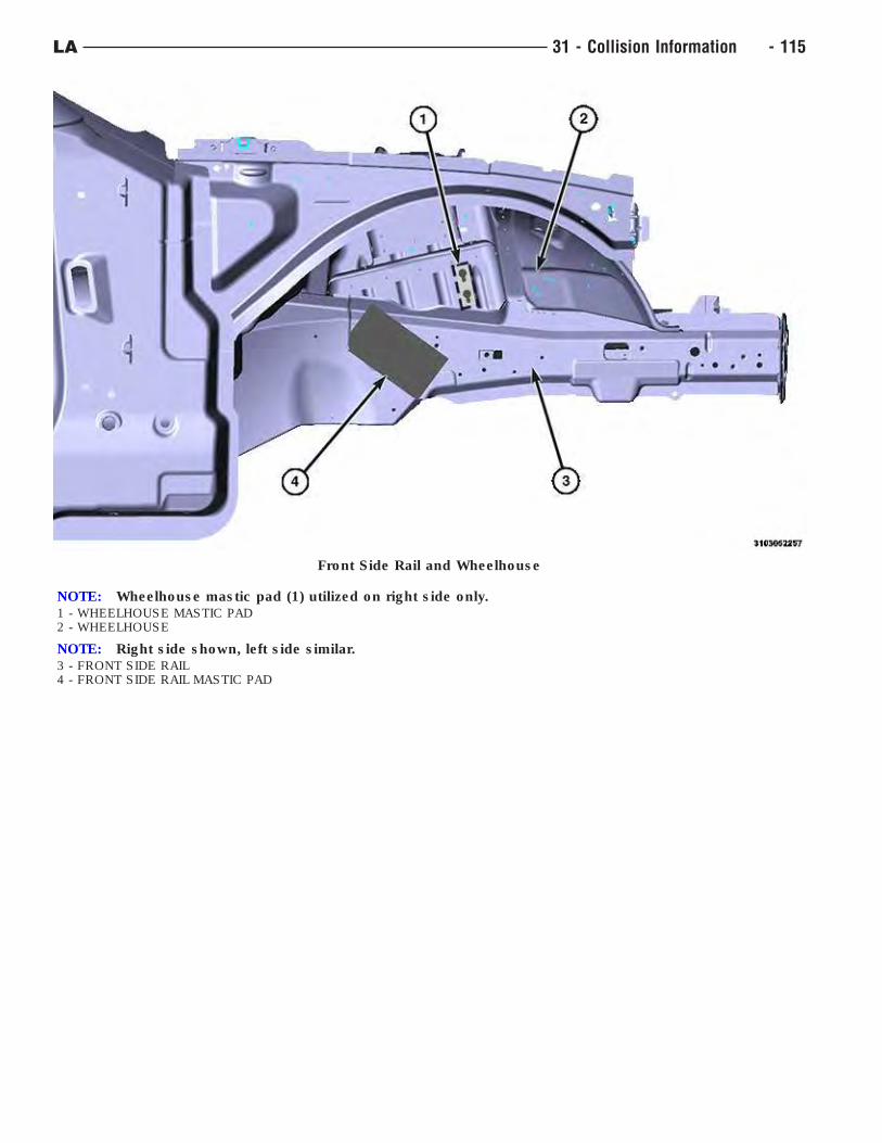
Front Side Rail and Wheelhouse
NOTE: Wheelhouse mastic pad (1) utilized on right side only.1 - WHEELHOUSE MASTIC PAD2 - WHEELHOUSE
NOTE: Right side shown, left side similar.3 - FRONT SIDE RAIL4 - FRONT SIDE RAIL MASTIC PAD
LA 31 - Collision Information - 115
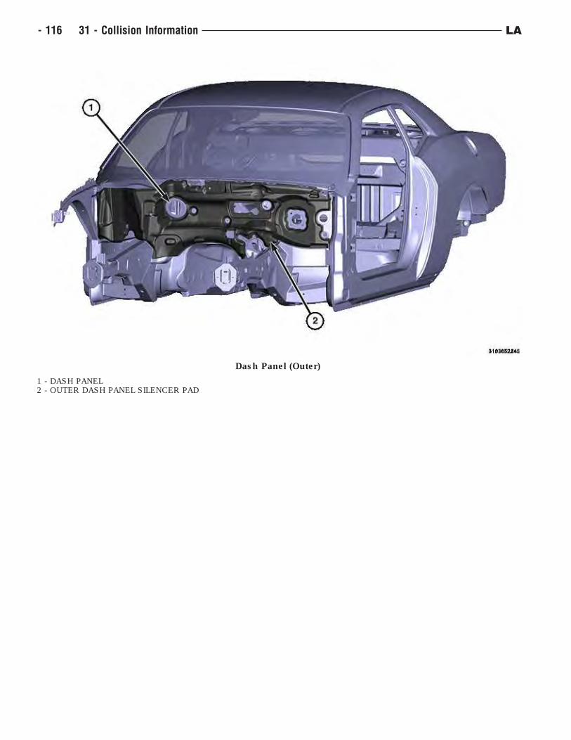
Dash Panel (Outer)
1 - DASH PANEL2 - OUTER DASH PANEL SILENCER PAD
- 116 31 - Collision Information LA
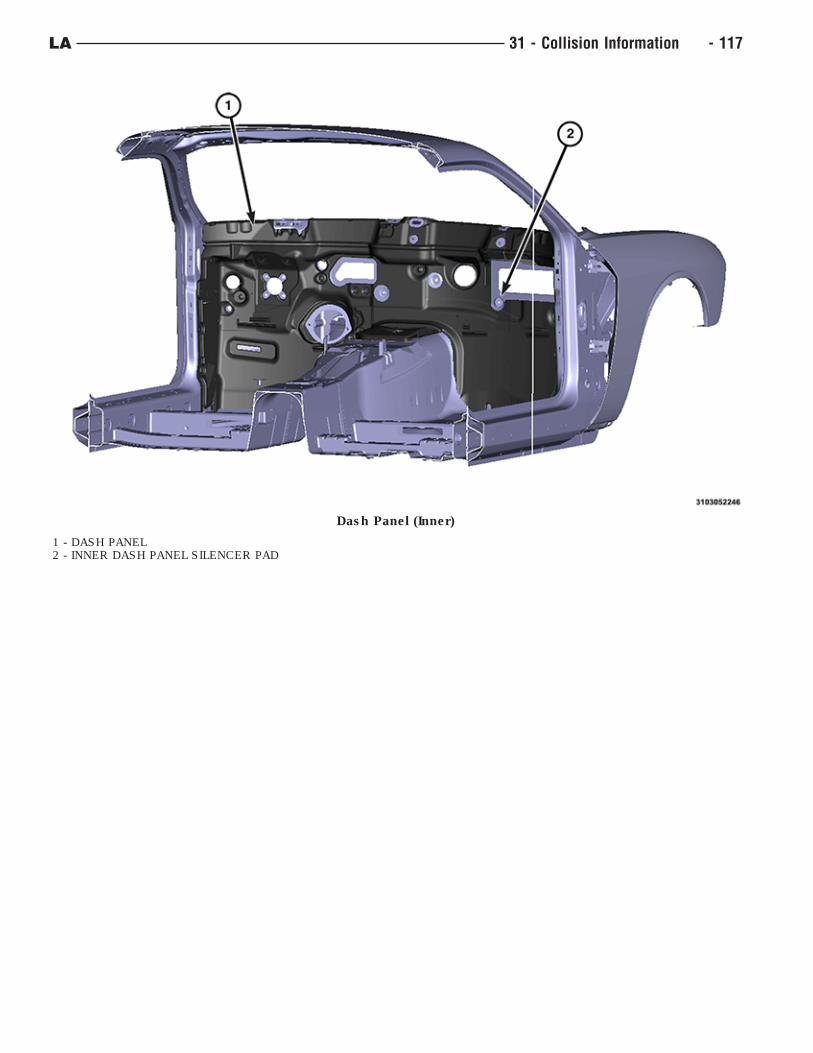
Dash Panel (Inner)
1 - DASH PANEL2 - INNER DASH PANEL SILENCER PAD
LA 31 - Collision Information - 117
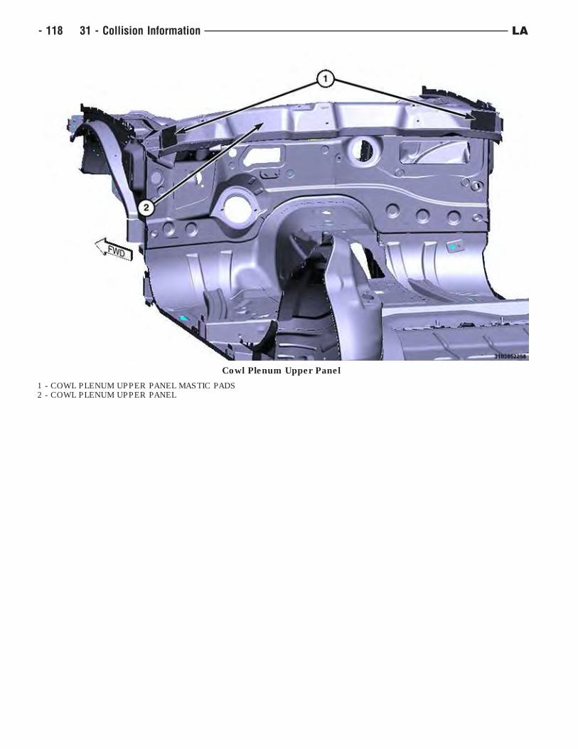
Cowl Plenum Upper Panel
1 - COWL PLENUM UPPER PANEL MASTIC PADS2 - COWL PLENUM UPPER PANEL
- 118 31 - Collision Information LA
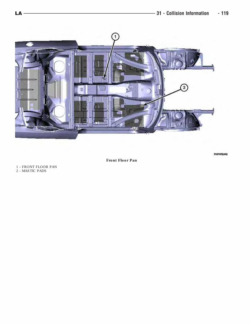
Front Floor Pan
1 - FRONT FLOOR PAN2 - MASTIC PADS
LA 31 - Collision Information - 119
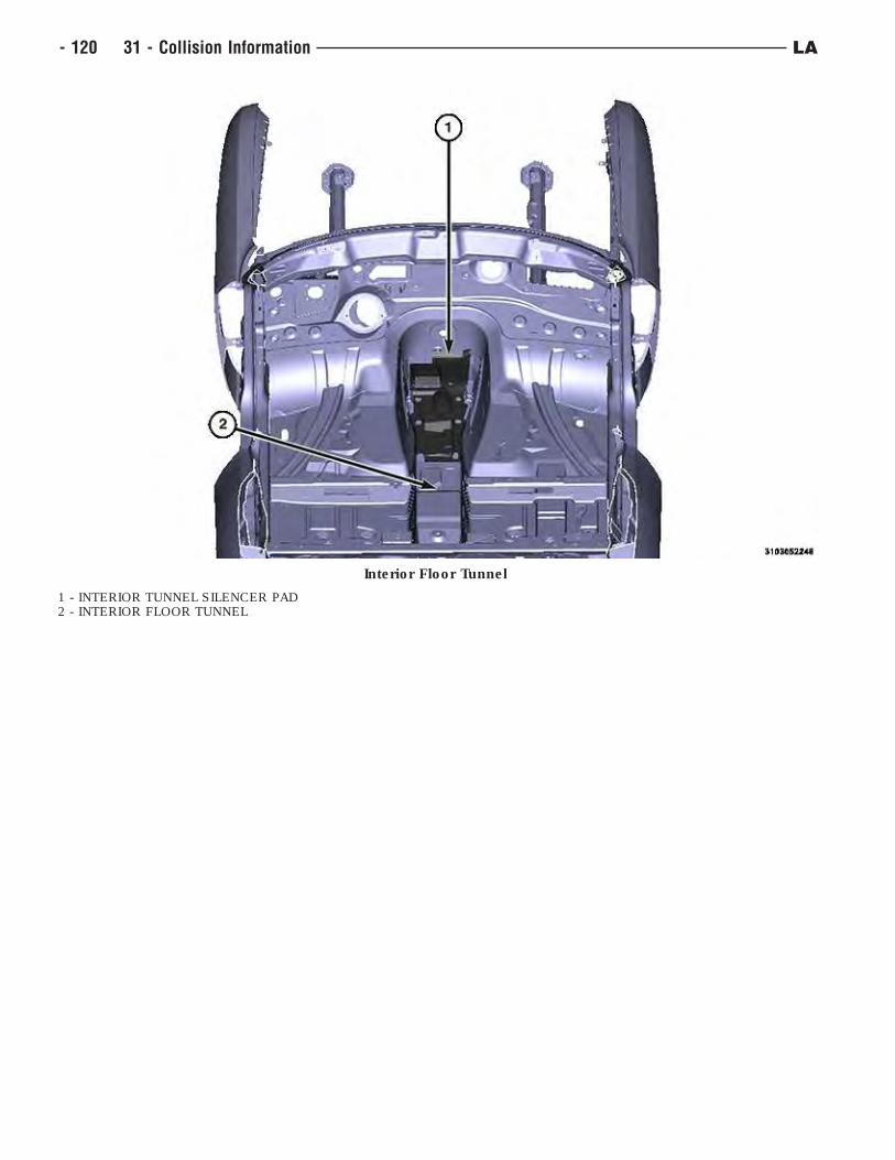
Interior Floor Tunnel
1 - INTERIOR TUNNEL SILENCER PAD2 - INTERIOR FLOOR TUNNEL
- 120 31 - Collision Information LA
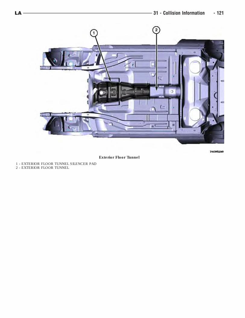
Exterior Floor Tunnel
1 - EXTERIOR FLOOR TUNNEL SILENCER PAD2 - EXTERIOR FLOOR TUNNEL
LA 31 - Collision Information - 121

Rear Floor Pan (1 of 2)
1 - REAR FLOOR SILENCER PAD2 - REAR FLOOR
- 122 31 - Collision Information LA
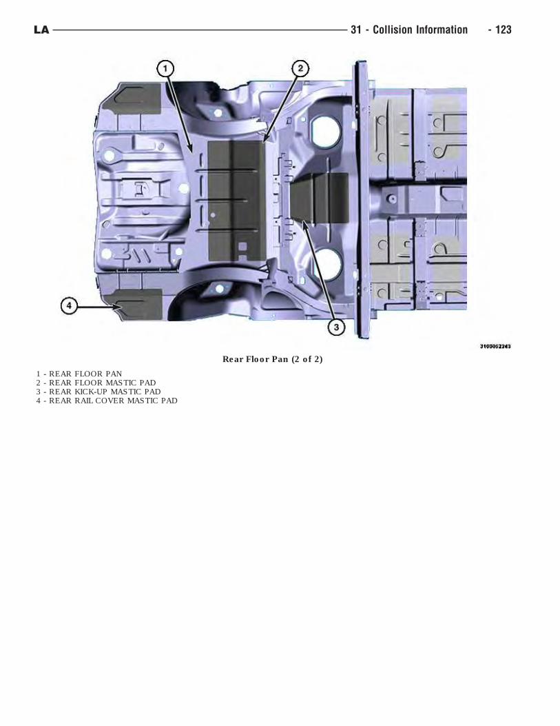
Rear Floor Pan (2 of 2)
1 - REAR FLOOR PAN2 - REAR FLOOR MASTIC PAD3 - REAR KICK-UP MASTIC PAD4 - REAR RAIL COVER MASTIC PAD
LA 31 - Collision Information - 123
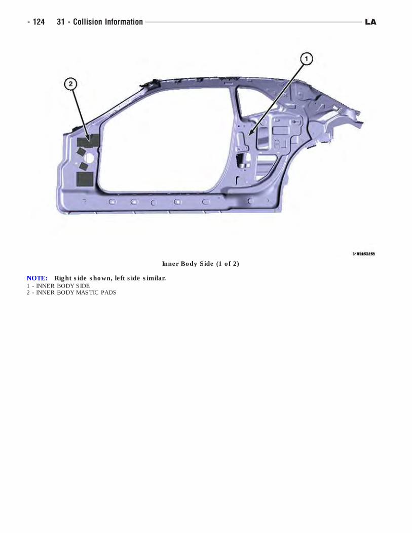
Inner Body Side (1 of 2)
NOTE: Right side shown, left side similar.1 - INNER BODY SIDE2 - INNER BODY MASTIC PADS
- 124 31 - Collision Information LA
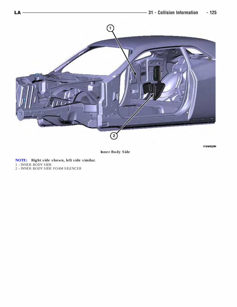
Inner Body Side
NOTE: Right side shown, left side similar.1 - INNER BODY SIDE2 - INNER BODY SIDE FOAM SILENCER
LA 31 - Collision Information - 125
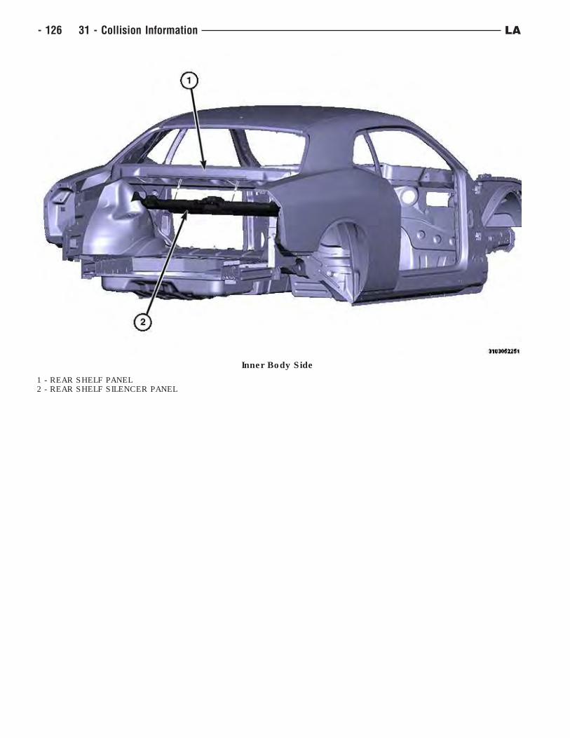
Inner Body Side
1 - REAR SHELF PANEL2 - REAR SHELF SILENCER PANEL
- 126 31 - Collision Information LA
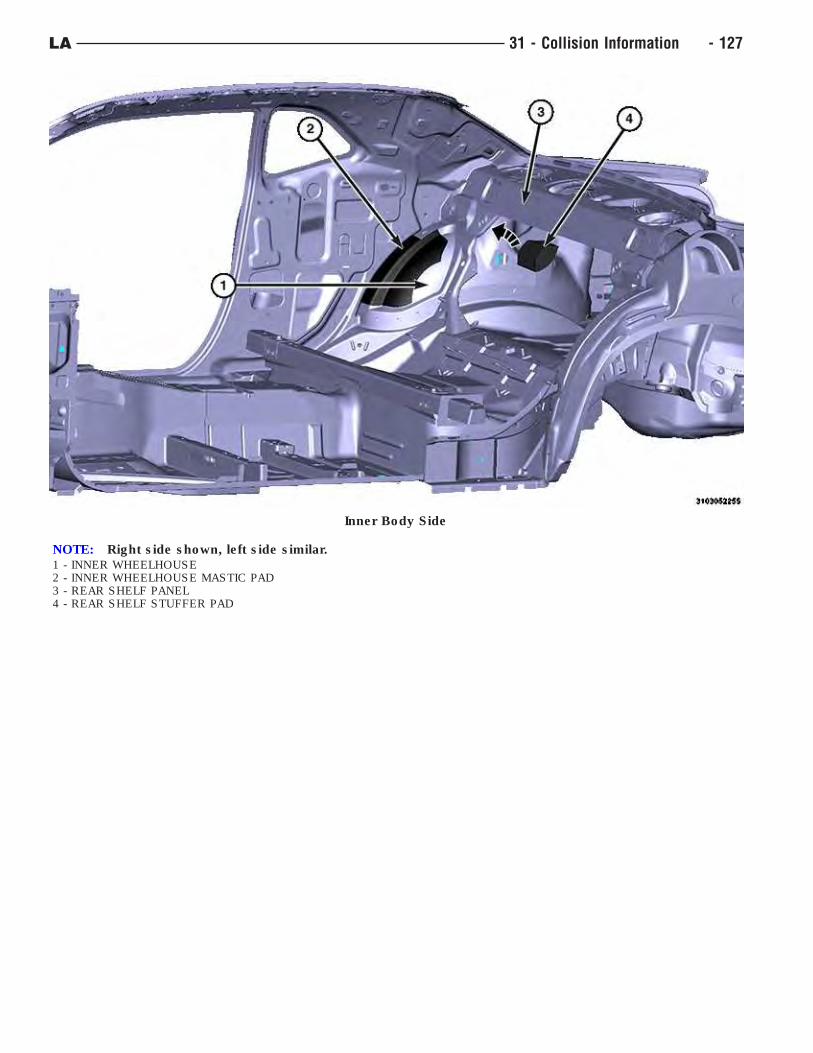
Inner Body Side
NOTE: Right side shown, left side similar.1 - INNER WHEELHOUSE2 - INNER WHEELHOUSE MASTIC PAD3 - REAR SHELF PANEL4 - REAR SHELF STUFFER PAD
LA 31 - Collision Information - 127
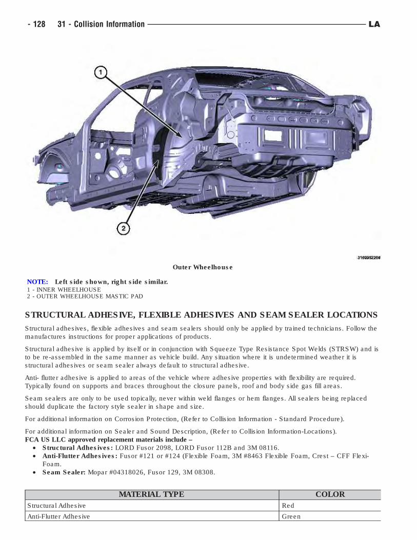
STRUCTURAL ADHESIVE, FLEXIBLE ADHESIVES AND SEAM SEALER LOCATIONS
Structural adhesives, flexible adhesives and seam sealers should only be applied by trained technicians. Follow the
manufactures instructions for proper applications of products.
Structural adhesive is applied by itself or in conjunction with Squeeze Type Resistance Spot Welds (STRSW) and is
to be re-assembled in the same manner as vehicle build. Any situation where it is undetermined weather it is
structural adhesives or seam sealer always default to structural adhesive.
Anti- flutter adhesive is applied to areas of the vehicle where adhesive properties with flexibility are required.
Typically found on supports and braces throughout the closure panels, roof and body side gas fill areas.
Seam sealers are only to be used topically, never within weld flanges or hem flanges. All sealers being replaced
should duplicate the factory style sealer in shape and size.
For additional information on Corrosion Protection, (Refer to Collision Information - Standard Procedure).
For additional information on Sealer and Sound Description, (Refer to Collision Information-Locations).
FCA US LLC approved replacement materials include –
• Structural Adhesives: LORD Fusor 2098, LORD Fusor 112B and 3M 08116.
• Anti-Flutter Adhesives: Fusor #121 or #124 (Flexible Foam, 3M #8463 Flexible Foam, Crest – CFF Flexi-
Foam.
• Seam Sealer: Mopar #04318026, Fusor 129, 3M 08308.
MATERIAL TYPE COLOR
Structural Adhesive Red
Anti-Flutter Adhesive Green
Outer Wheelhouse
NOTE: Left side shown, right side similar.1 - INNER WHEELHOUSE2 - OUTER WHEELHOUSE MASTIC PAD
- 128 31 - Collision Information LA
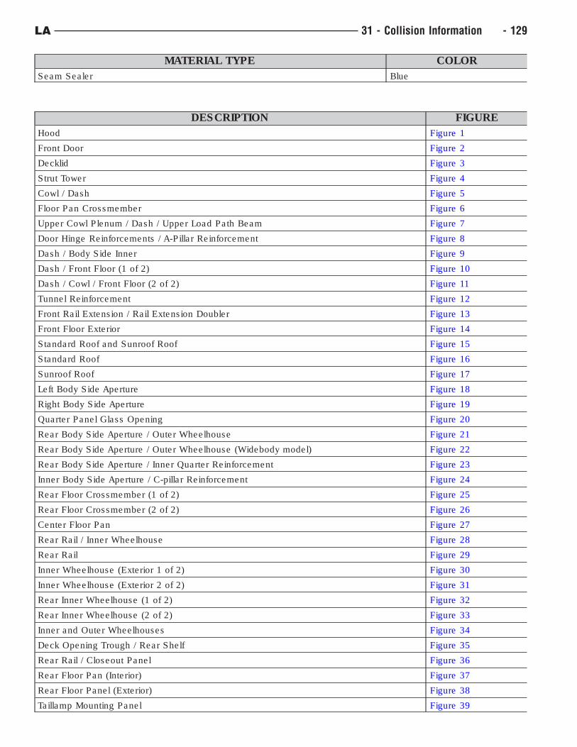
MATERIAL TYPE COLOR
Seam Sealer Blue
DESCRIPTION FIGURE
Hood Figure 1
Front Door Figure 2
Decklid Figure 3
Strut Tower Figure 4
Cowl / Dash Figure 5
Floor Pan Crossmember Figure 6
Upper Cowl Plenum / Dash / Upper Load Path Beam Figure 7
Door Hinge Reinforcements / A-Pillar Reinforcement Figure 8
Dash / Body Side Inner Figure 9
Dash / Front Floor (1 of 2) Figure 10
Dash / Cowl / Front Floor (2 of 2) Figure 11
Tunnel Reinforcement Figure 12
Front Rail Extension / Rail Extension Doubler Figure 13
Front Floor Exterior Figure 14
Standard Roof and Sunroof Roof Figure 15
Standard Roof Figure 16
Sunroof Roof Figure 17
Left Body Side Aperture Figure 18
Right Body Side Aperture Figure 19
Quarter Panel Glass Opening Figure 20
Rear Body Side Aperture / Outer Wheelhouse Figure 21
Rear Body Side Aperture / Outer Wheelhouse (Widebody model) Figure 22
Rear Body Side Aperture / Inner Quarter Reinforcement Figure 23
Inner Body Side Aperture / C-pillar Reinforcement Figure 24
Rear Floor Crossmember (1 of 2) Figure 25
Rear Floor Crossmember (2 of 2) Figure 26
Center Floor Pan Figure 27
Rear Rail / Inner Wheelhouse Figure 28
Rear Rail Figure 29
Inner Wheelhouse (Exterior 1 of 2) Figure 30
Inner Wheelhouse (Exterior 2 of 2) Figure 31
Rear Inner Wheelhouse (1 of 2) Figure 32
Rear Inner Wheelhouse (2 of 2) Figure 33
Inner and Outer Wheelhouses Figure 34
Deck Opening Trough / Rear Shelf Figure 35
Rear Rail / Closeout Panel Figure 36
Rear Floor Pan (Interior) Figure 37
Rear Floor Panel (Exterior) Figure 38
Taillamp Mounting Panel Figure 39
LA 31 - Collision Information - 129
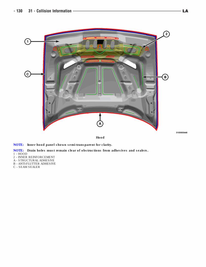
Hood
NOTE: Inner hood panel shown semi-transparent for clarity.
NOTE: Drain holes must remain clear of obstructions from adhesives and sealers.1 - HOOD2 - INNER REINFORCEMENTA - STRUCTURAL ADHESIVEB - ANTI-FLUTTER ADHESIVEC - SEAM SEALER
- 130 31 - Collision Information LA
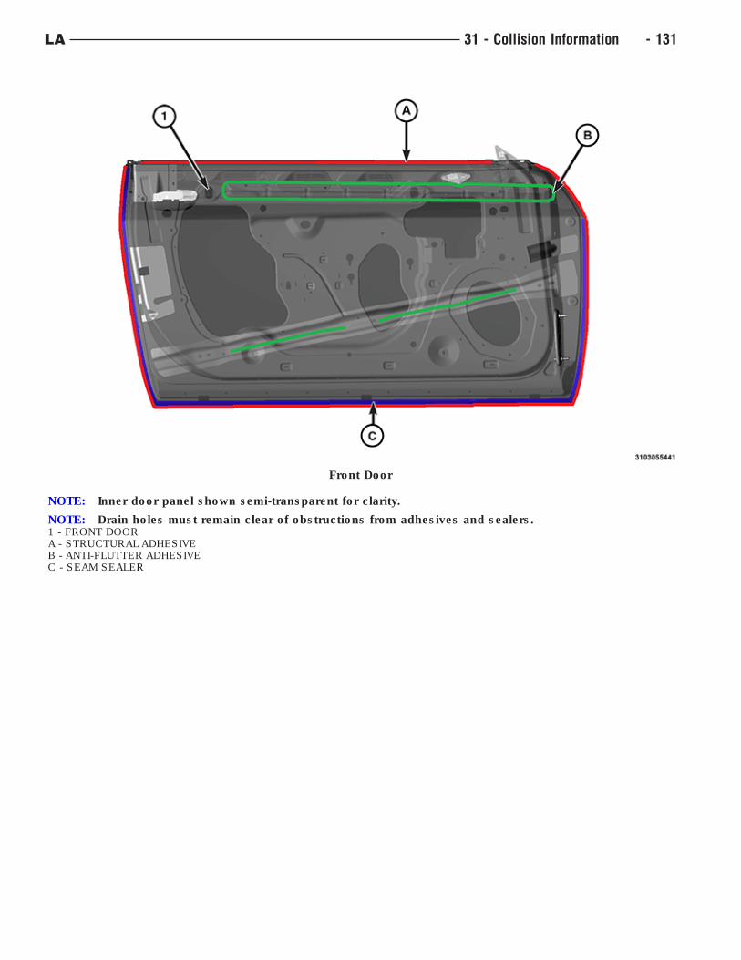
Front Door
NOTE: Inner door panel shown semi-transparent for clarity.
NOTE: Drain holes must remain clear of obstructions from adhesives and sealers.1 - FRONT DOORA - STRUCTURAL ADHESIVEB - ANTI-FLUTTER ADHESIVEC - SEAM SEALER
LA 31 - Collision Information - 131
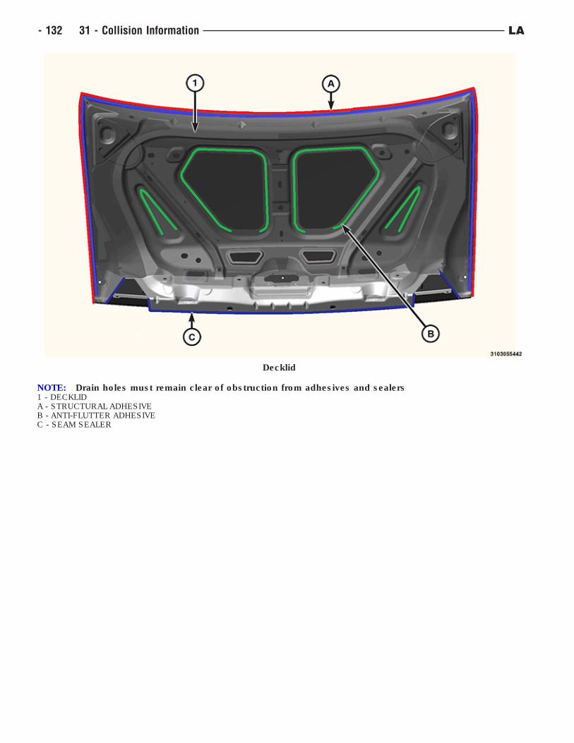
Decklid
NOTE: Drain holes must remain clear of obstruction from adhesives and sealers1 - DECKLIDA - STRUCTURAL ADHESIVEB - ANTI-FLUTTER ADHESIVEC - SEAM SEALER
- 132 31 - Collision Information LA
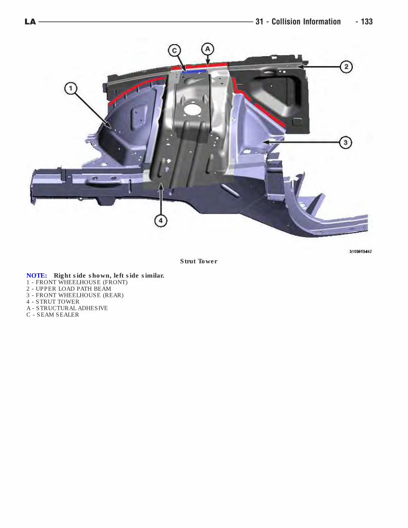
Strut Tower
NOTE: Right side shown, left side similar.1 - FRONT WHEELHOUSE (FRONT)2 - UPPER LOAD PATH BEAM3 - FRONT WHEELHOUSE (REAR)4 - STRUT TOWERA - STRUCTURAL ADHESIVEC - SEAM SEALER
LA 31 - Collision Information - 133
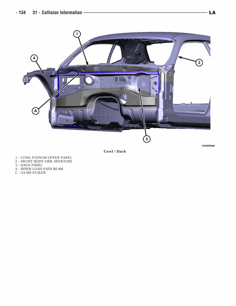
Cowl / Dash
1 - COWL PLENUM UPPER PANEL2 - FRONT BODY SIDE APERTURE3 - DASH PANEL4 - INNER LOAD PATH BEAMC - SEAM SEALER
- 134 31 - Collision Information LA
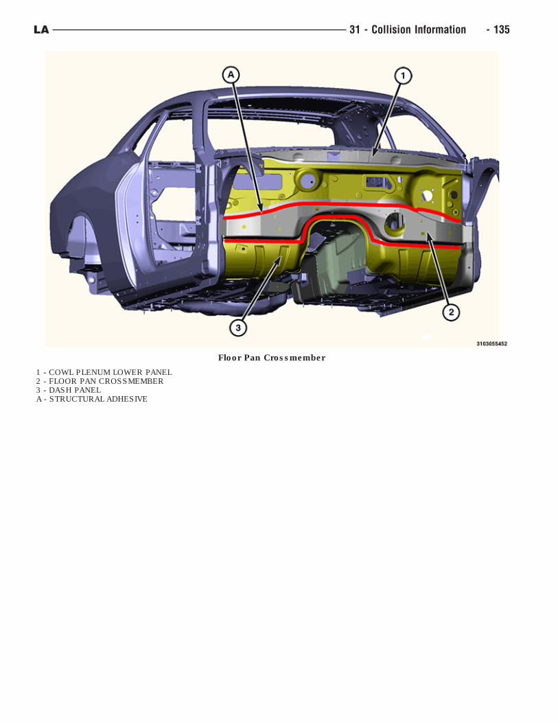
Floor Pan Crossmember
1 - COWL PLENUM LOWER PANEL2 - FLOOR PAN CROSSMEMBER3 - DASH PANELA - STRUCTURAL ADHESIVE
LA 31 - Collision Information - 135
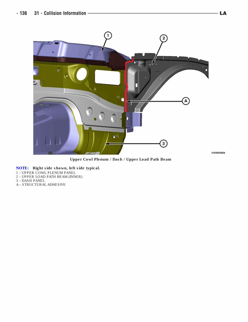
Upper Cowl Plenum / Dash / Upper Load Path Beam
NOTE: Right side shown, left side typical.1 - UPPER COWL PLENUM PANEL2 - UPPER LOAD PATH BEAM (INNER)3 - DASH PANELA - STRUCTURAL ADHESIVE
- 136 31 - Collision Information LA
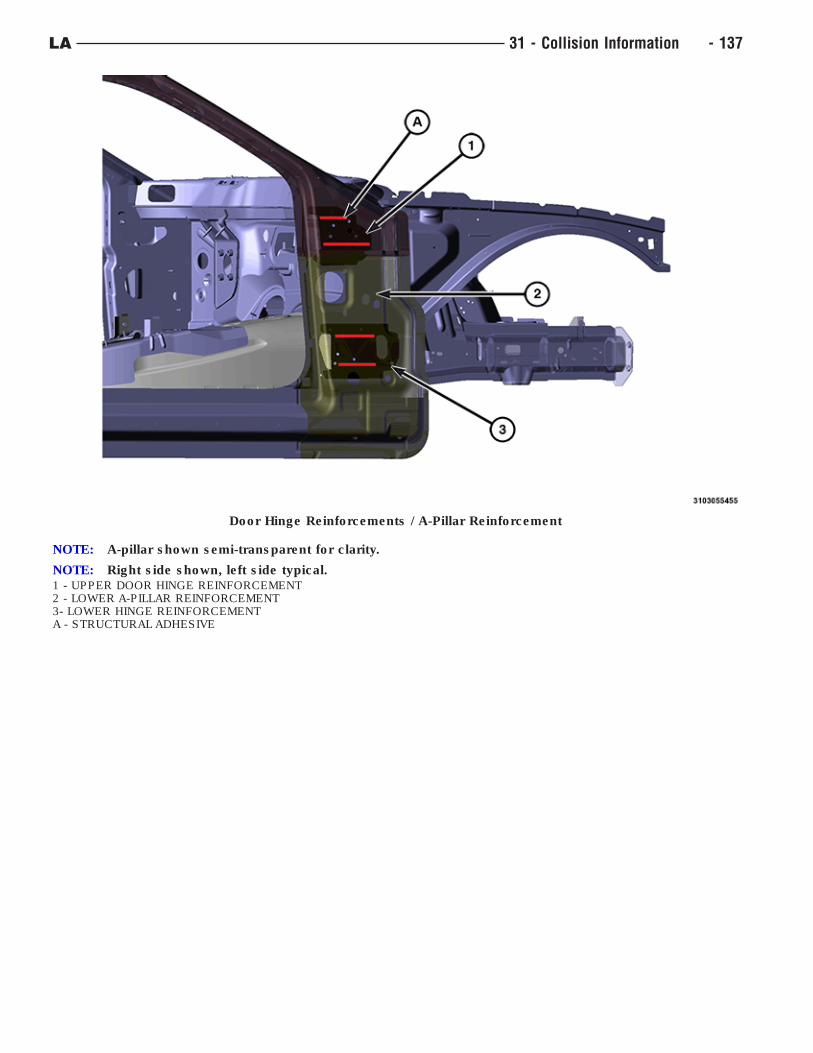
Door Hinge Reinforcements / A-Pillar Reinforcement
NOTE: A-pillar shown semi-transparent for clarity.
NOTE: Right side shown, left side typical.1 - UPPER DOOR HINGE REINFORCEMENT2 - LOWER A-PILLAR REINFORCEMENT3- LOWER HINGE REINFORCEMENTA - STRUCTURAL ADHESIVE
LA 31 - Collision Information - 137
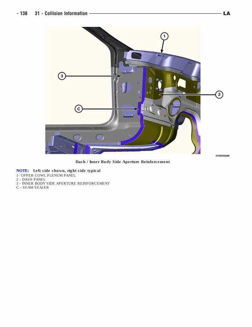
Dash / Inner Body Side Aperture Reinforcement
NOTE: Left side shown, right side typical1- UPPER COWL PLENUM PANEL2 - DASH PANEL3 - INNER BODY SIDE APERTURE REINFORCEMENTC - SEAM SEALER
- 138 31 - Collision Information LA
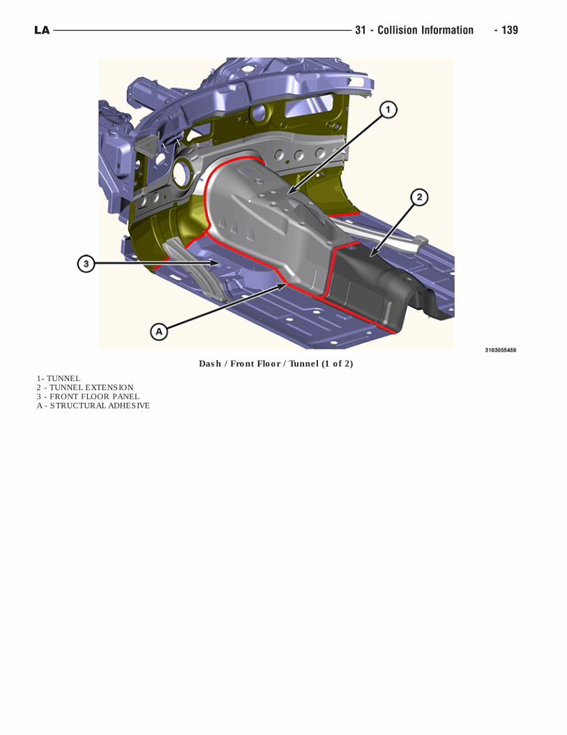
Dash / Front Floor / Tunnel (1 of 2)
1- TUNNEL2 - TUNNEL EXTENSION3 - FRONT FLOOR PANELA - STRUCTURAL ADHESIVE
LA 31 - Collision Information - 139
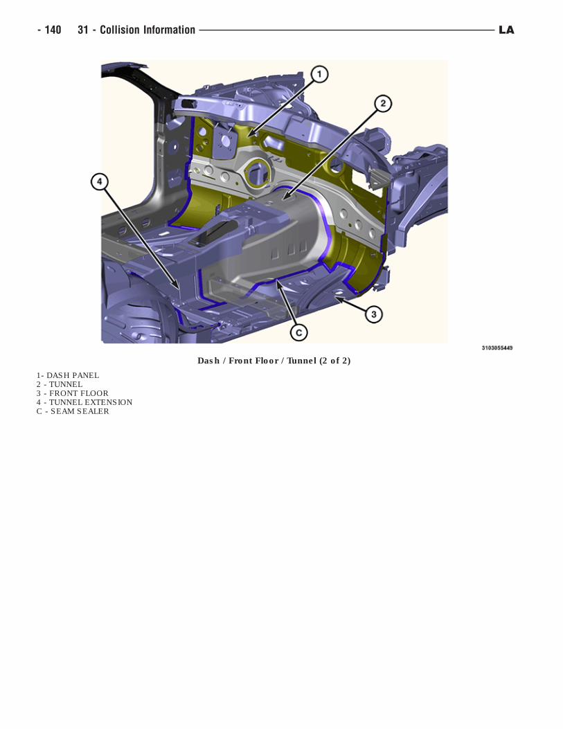
Dash / Front Floor / Tunnel (2 of 2)
1- DASH PANEL2 - TUNNEL3 - FRONT FLOOR4 - TUNNEL EXTENSIONC - SEAM SEALER
- 140 31 - Collision Information LA
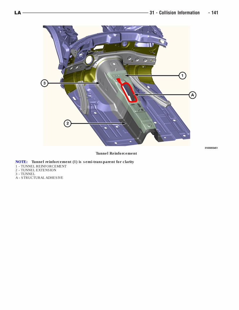
Tunnel Reinforcement
NOTE: Tunnel reinforcement (1) is semi-transparent for clarity1 - TUNNEL REINFORCEMENT2 - TUNNEL EXTENSION3 - TUNNELA - STRUCTURAL ADHESIVE
LA 31 - Collision Information - 141
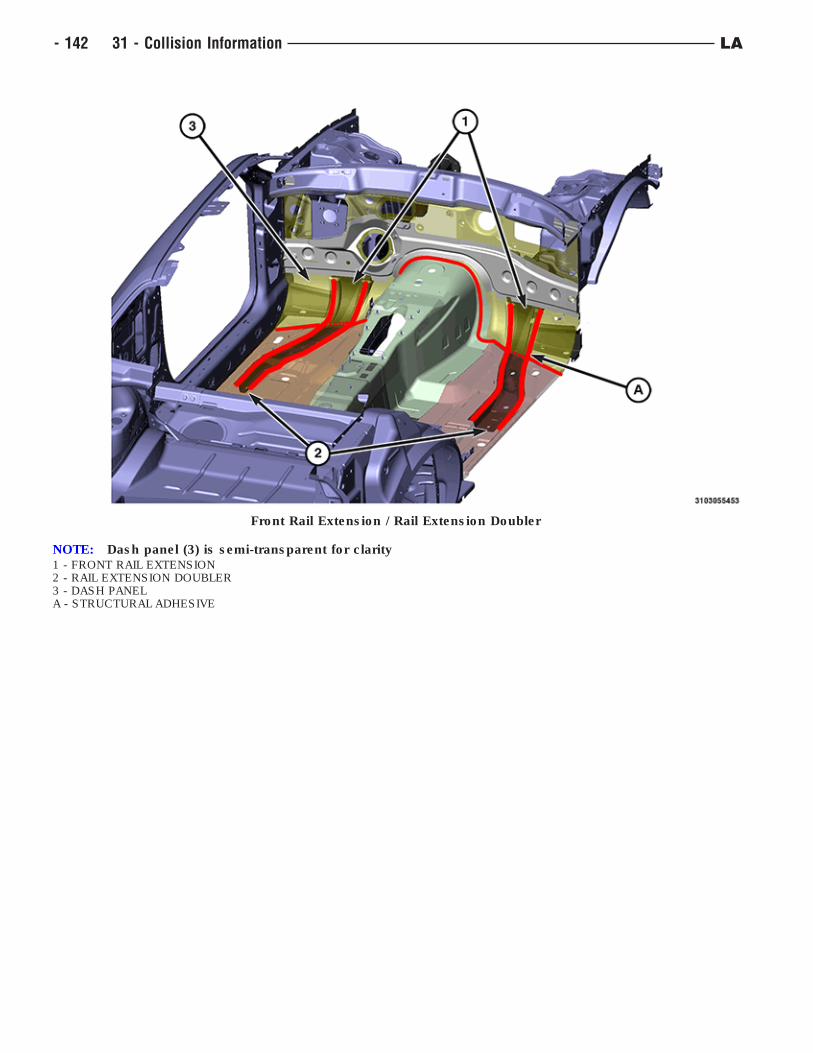
Front Rail Extension / Rail Extension Doubler
NOTE: Dash panel (3) is semi-transparent for clarity1 - FRONT RAIL EXTENSION2 - RAIL EXTENSION DOUBLER3 - DASH PANELA - STRUCTURAL ADHESIVE
- 142 31 - Collision Information LA
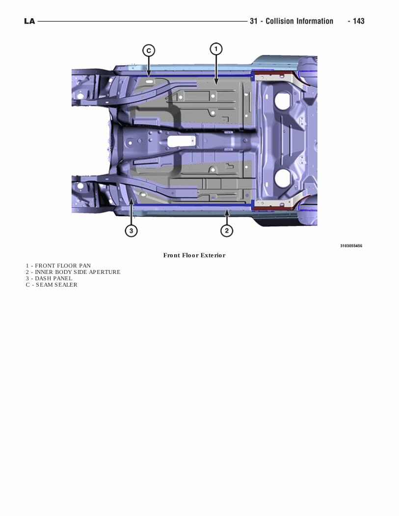
Front Floor Exterior
1 - FRONT FLOOR PAN2 - INNER BODY SIDE APERTURE3 - DASH PANELC - SEAM SEALER
LA 31 - Collision Information - 143
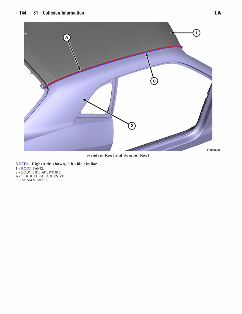
Standard Roof and Sunroof Roof
NOTE: Right side shown, left side similar.1 - ROOF PANEL2 - BODY SIDE APERTUREA - STRUCTURAL ADHESIVEC - SEAM SEALER
- 144 31 - Collision Information LA
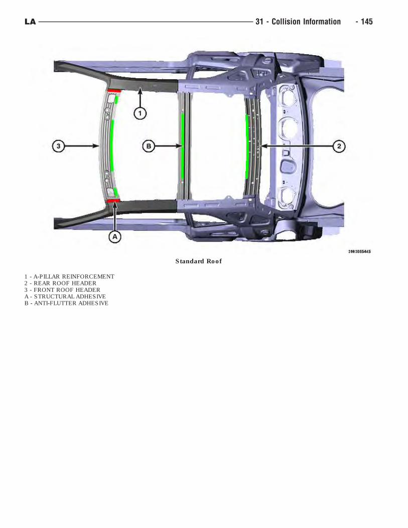
Standard Roof
1 - A-PILLAR REINFORCEMENT2 - REAR ROOF HEADER3 - FRONT ROOF HEADERA - STRUCTURAL ADHESIVEB - ANTI-FLUTTER ADHESIVE
LA 31 - Collision Information - 145
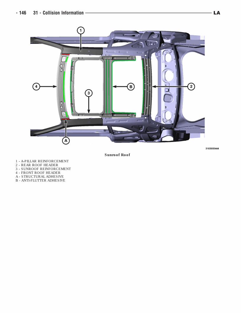
Sunroof Roof
1 - A-PILLAR REINFORCEMENT2 - REAR ROOF HEADER3 - SUNROOF REINFORCEMENT4 - FRONT ROOF HEADERA - STRUCTURAL ADHESIVEB - ANTI-FLUTTER ADHESIVE
- 146 31 - Collision Information LA
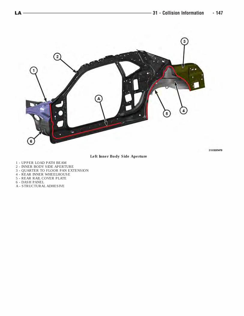
Left Inner Body Side Aperture
1 - UPPER LOAD PATH BEAM2 - INNER BODY SIDE APERTURE3 - QUARTER TO FLOOR PAN EXTENSION4 - REAR INNER WHEELHOUSE5 - REAR RAIL COVER PLATE6 - DASH PANELA - STRUCTURAL ADHESIVE
LA 31 - Collision Information - 147
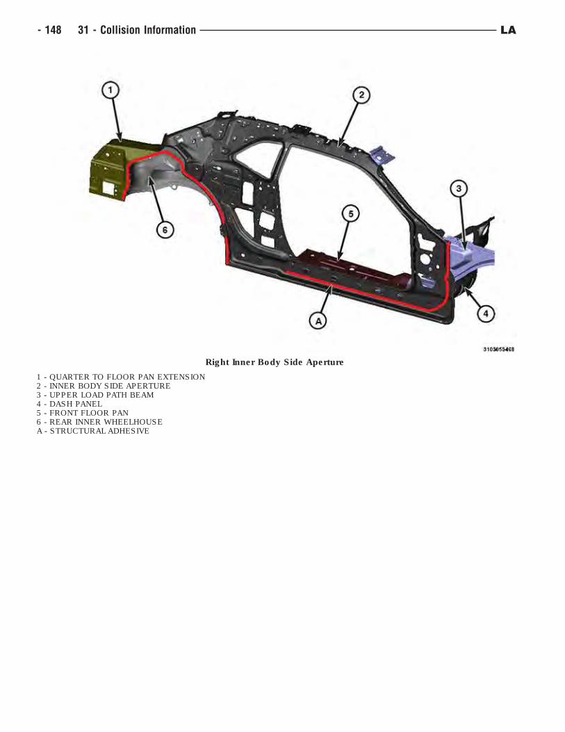
Right Inner Body Side Aperture
1 - QUARTER TO FLOOR PAN EXTENSION2 - INNER BODY SIDE APERTURE3 - UPPER LOAD PATH BEAM4 - DASH PANEL5 - FRONT FLOOR PAN6 - REAR INNER WHEELHOUSEA - STRUCTURAL ADHESIVE
- 148 31 - Collision Information LA
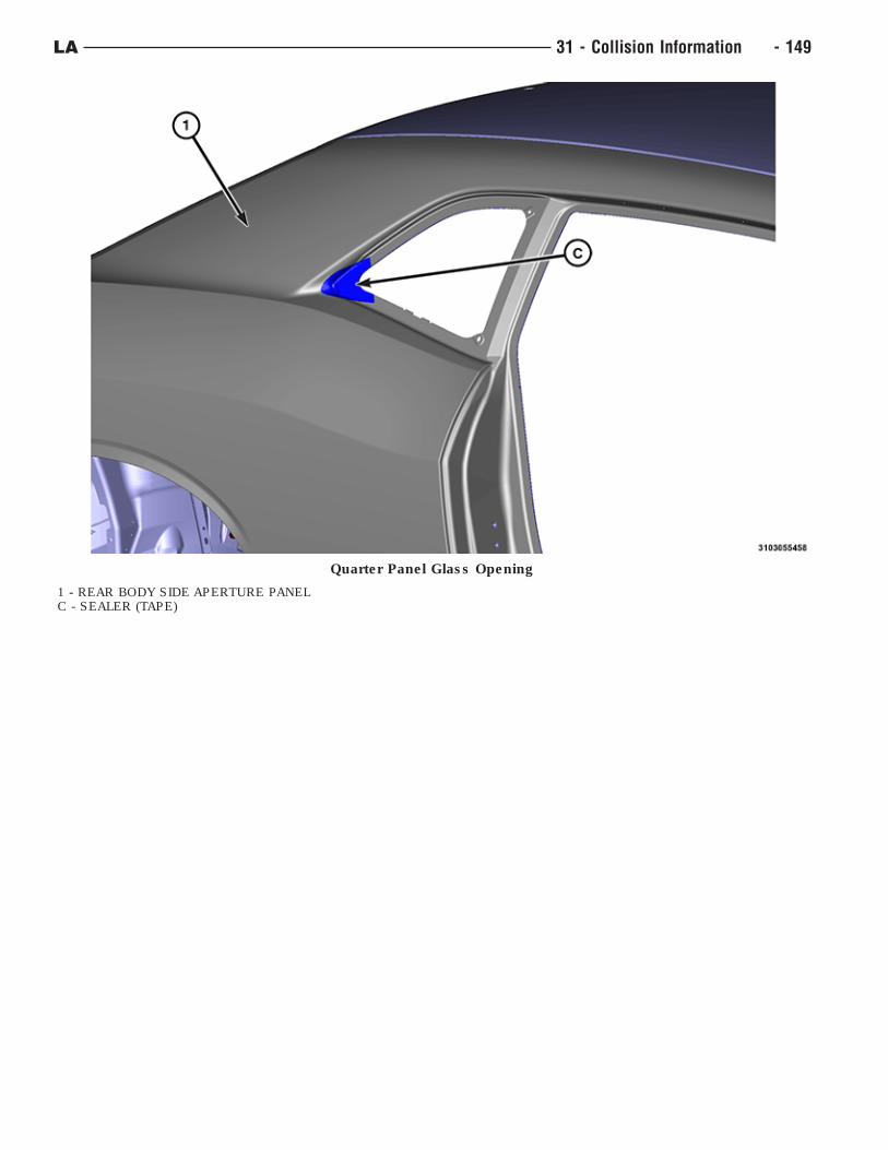
Quarter Panel Glass Opening
1 - REAR BODY SIDE APERTURE PANELC - SEALER (TAPE)
LA 31 - Collision Information - 149
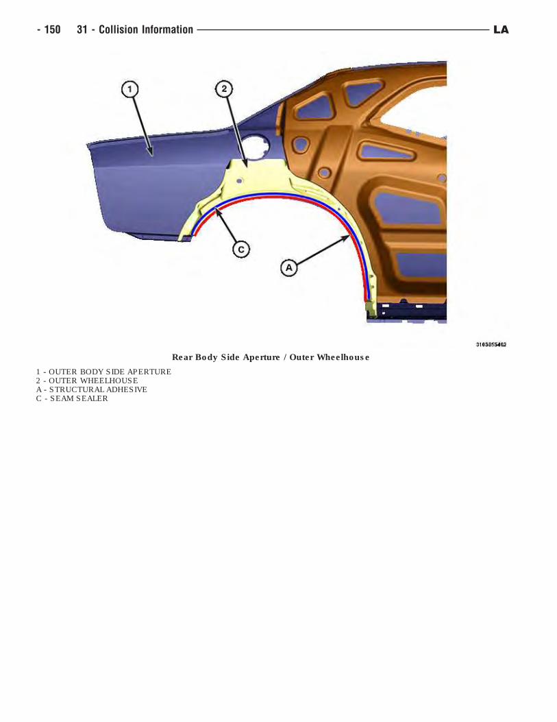
Rear Body Side Aperture / Outer Wheelhouse
1 - OUTER BODY SIDE APERTURE2 - OUTER WHEELHOUSEA - STRUCTURAL ADHESIVEC - SEAM SEALER
- 150 31 - Collision Information LA
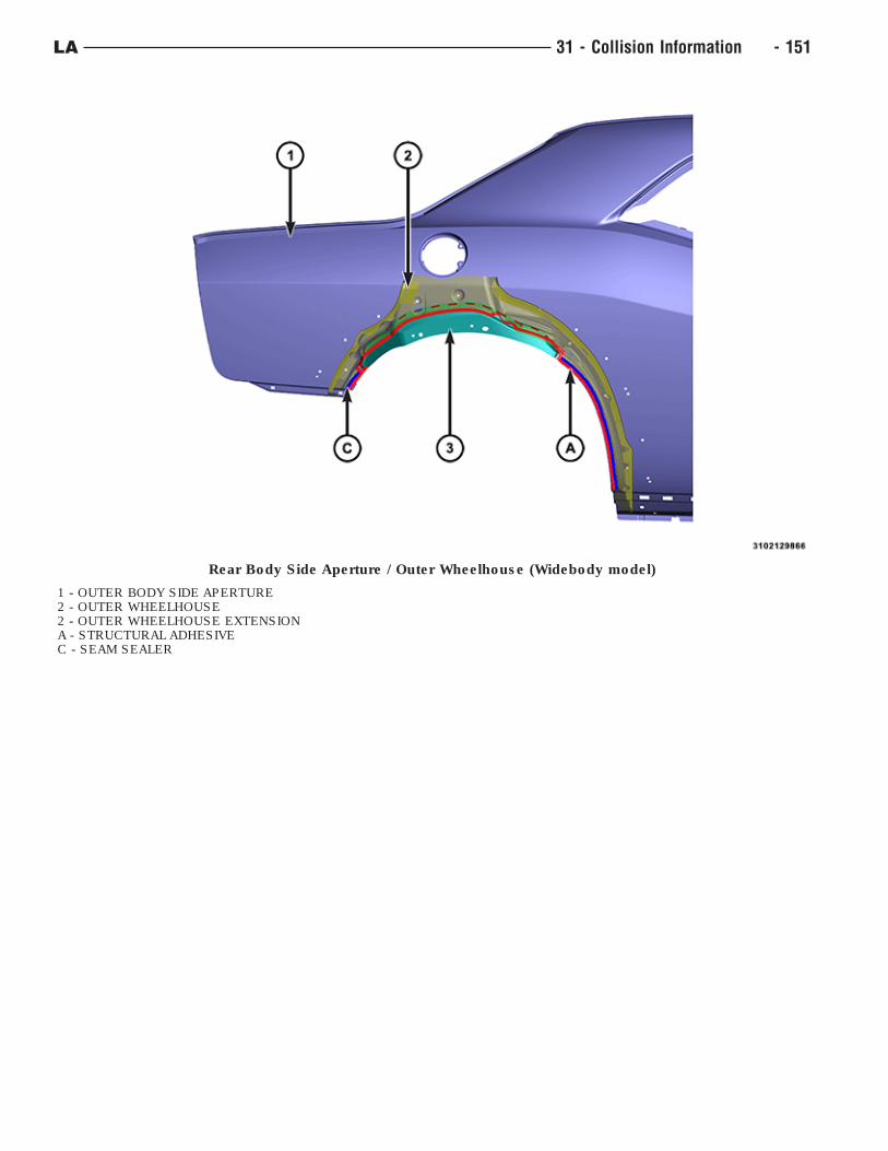
Rear Body Side Aperture / Outer Wheelhouse (Widebody model)
1 - OUTER BODY SIDE APERTURE2 - OUTER WHEELHOUSE2 - OUTER WHEELHOUSE EXTENSIONA - STRUCTURAL ADHESIVEC - SEAM SEALER
LA 31 - Collision Information - 151
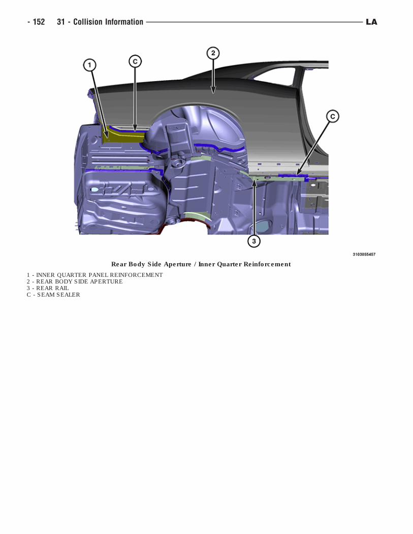
Rear Body Side Aperture / Inner Quarter Reinforcement
1 - INNER QUARTER PANEL REINFORCEMENT2 - REAR BODY SIDE APERTURE3 - REAR RAILC - SEAM SEALER
- 152 31 - Collision Information LA
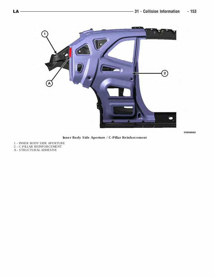
Inner Body Side Aperture / C-Pillar Reinforcement
1 - INNER BODY SIDE APERTURE2 - C-PILLAR REINFORCEMENTA - STRUCTURAL ADHESIVE
LA 31 - Collision Information - 153
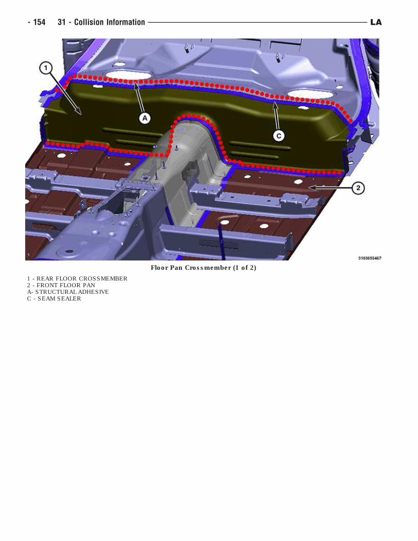
Floor Pan Crossmember (1 of 2)
1 - REAR FLOOR CROSSMEMBER2 - FRONT FLOOR PANA- STRUCTURAL ADHESIVEC - SEAM SEALER
- 154 31 - Collision Information LA
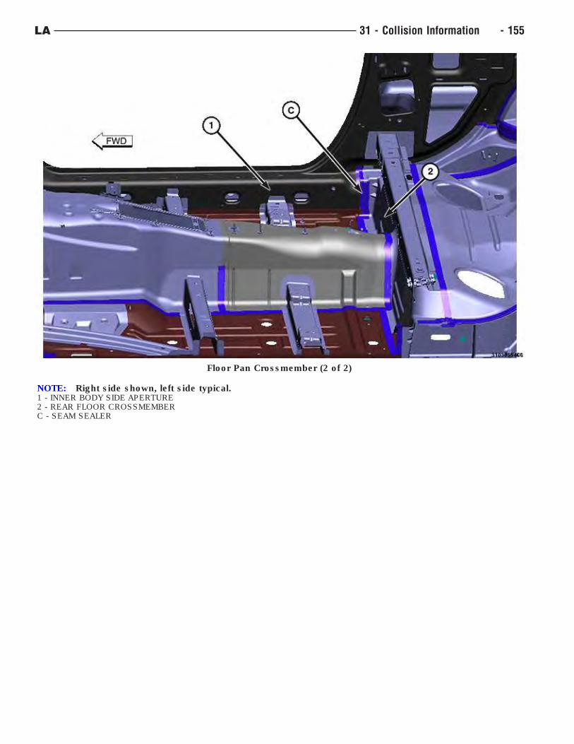
Floor Pan Crossmember (2 of 2)
NOTE: Right side shown, left side typical.1 - INNER BODY SIDE APERTURE2 - REAR FLOOR CROSSMEMBERC - SEAM SEALER
LA 31 - Collision Information - 155
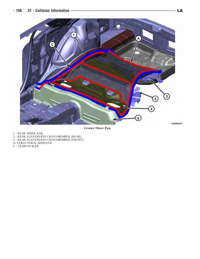
Center Floor Pan
1 - REAR INNER RAIL2 - REAR SUSPENSION CROSSMEMBER (REAR)3 - REAR SUSPENSION CROSSMEMBER (FRONT)A- STRUCTURAL ADHESIVEC - SEAM SEALER
- 156 31 - Collision Information LA
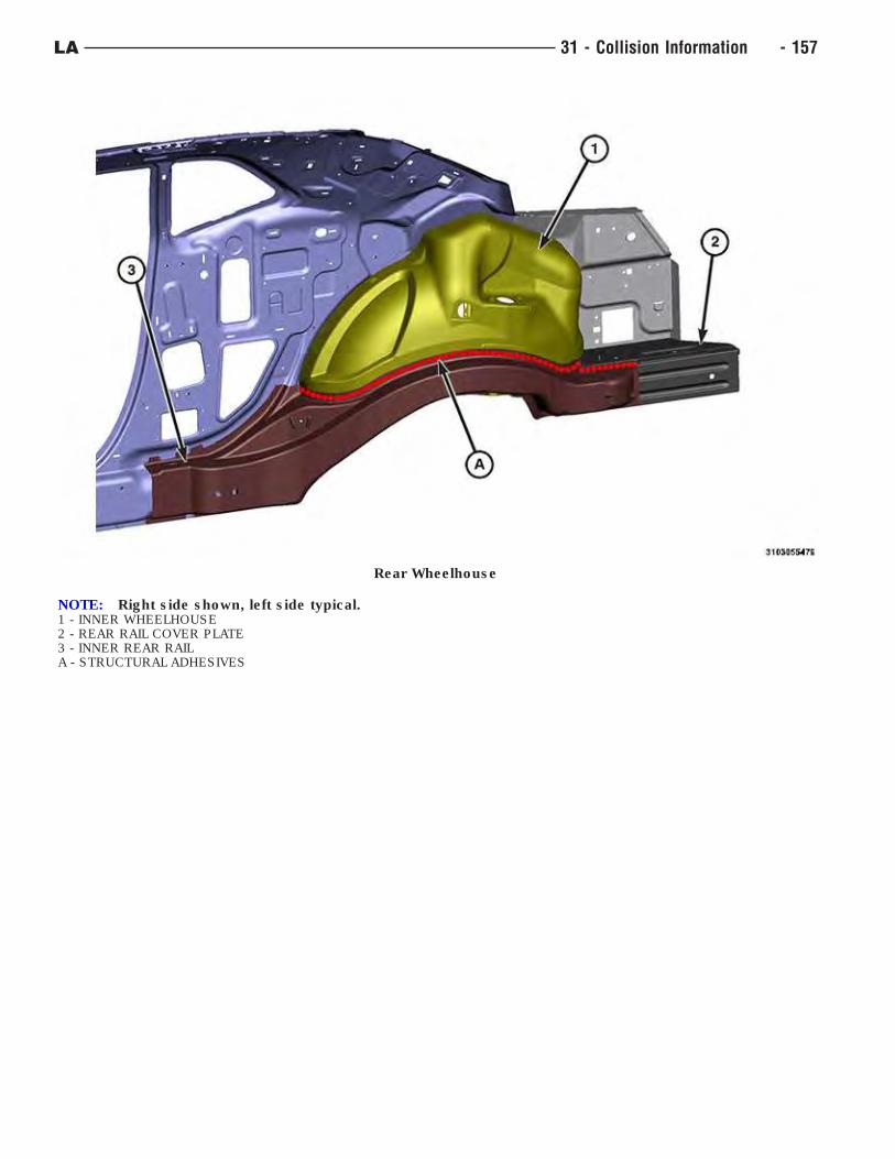
Rear Wheelhouse
NOTE: Right side shown, left side typical.1 - INNER WHEELHOUSE2 - REAR RAIL COVER PLATE3 - INNER REAR RAILA - STRUCTURAL ADHESIVES
LA 31 - Collision Information - 157
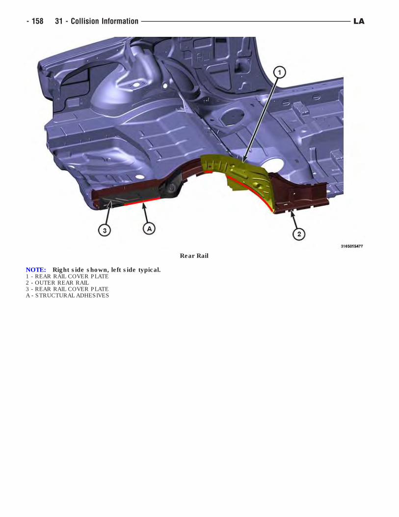
Rear Rail
NOTE: Right side shown, left side typical.1 - REAR RAIL COVER PLATE2 - OUTER REAR RAIL3 - REAR RAIL COVER PLATEA - STRUCTURAL ADHESIVES
- 158 31 - Collision Information LA
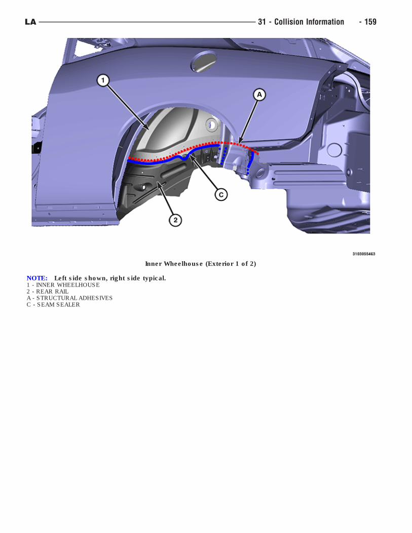
Inner Wheelhouse (Exterior 1 of 2)
NOTE: Left side shown, right side typical.1 - INNER WHEELHOUSE2 - REAR RAILA - STRUCTURAL ADHESIVESC - SEAM SEALER
LA 31 - Collision Information - 159
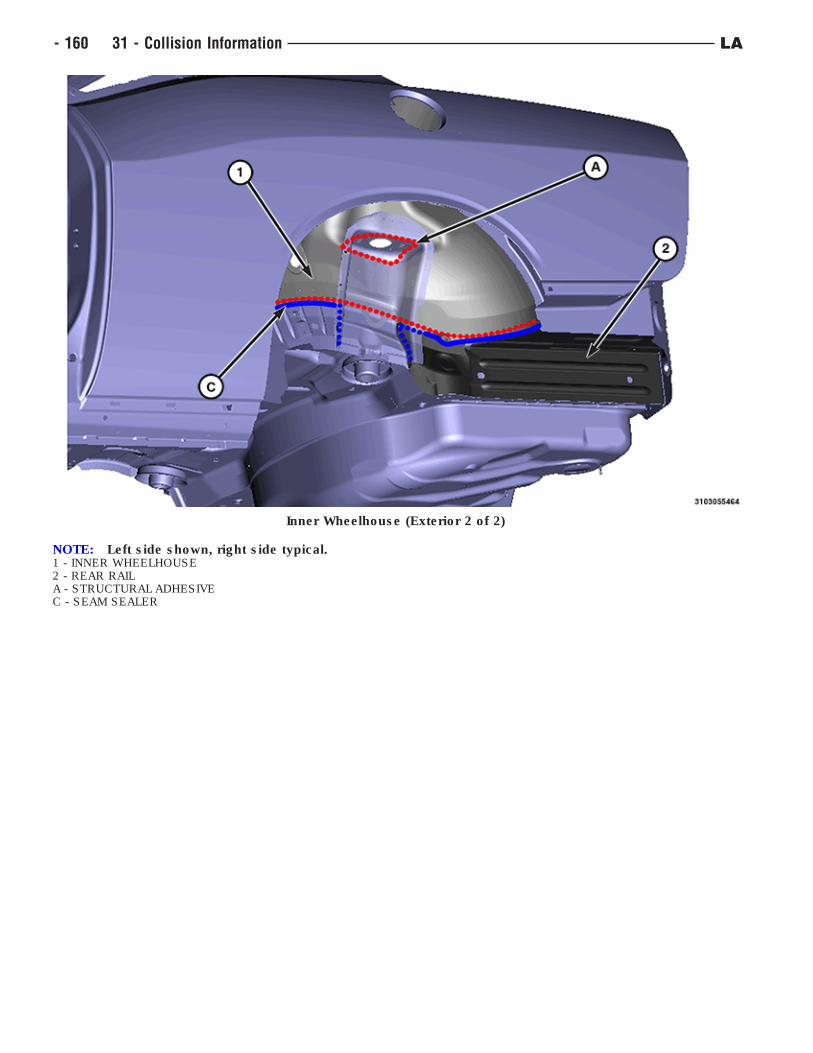
Inner Wheelhouse (Exterior 2 of 2)
NOTE: Left side shown, right side typical.1 - INNER WHEELHOUSE2 - REAR RAILA - STRUCTURAL ADHESIVEC - SEAM SEALER
- 160 31 - Collision Information LA
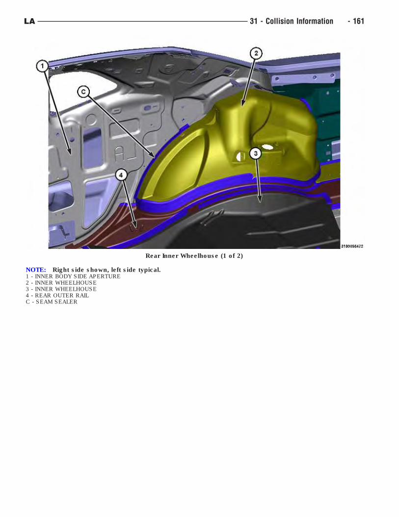
Rear Inner Wheelhouse (1 of 2)
NOTE: Right side shown, left side typical.1 - INNER BODY SIDE APERTURE2 - INNER WHEELHOUSE3 - INNER WHEELHOUSE4 - REAR OUTER RAILC - SEAM SEALER
LA 31 - Collision Information - 161
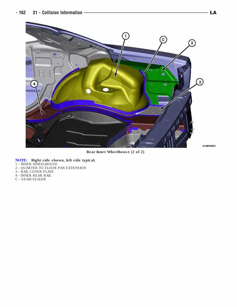
Rear Inner Wheelhouse (2 of 2)
NOTE: Right side shown, left side typical.1 - INNER WHEELHOUSE2 - QUARTER TO FLOOR PAN EXTENSION3 - RAIL COVER PLATE4 - INNER REAR RAILC - SEAM SEALER
- 162 31 - Collision Information LA
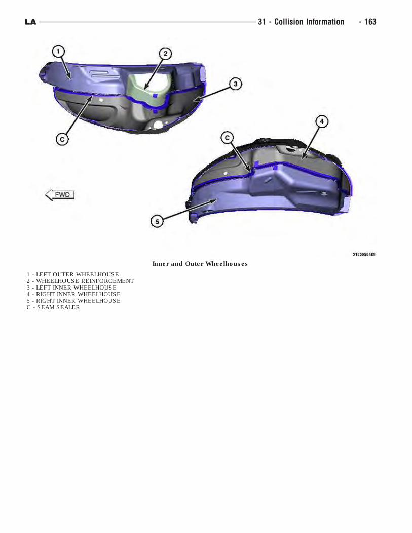
Inner and Outer Wheelhouses
1 - LEFT OUTER WHEELHOUSE2 - WHEELHOUSE REINFORCEMENT3 - LEFT INNER WHEELHOUSE4 - RIGHT INNER WHEELHOUSE5 - RIGHT INNER WHEELHOUSEC - SEAM SEALER
LA 31 - Collision Information - 163
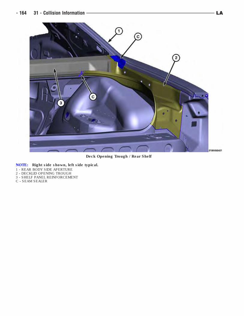
Deck Opening Trough / Rear Shelf
NOTE: Right side shown, left side typical.1 - REAR BODY SIDE APERTURE2 - DECKLID OPENING TROUGH3 - SHELF PANEL REINFORCEMENTC - SEAM SEALER
- 164 31 - Collision Information LA
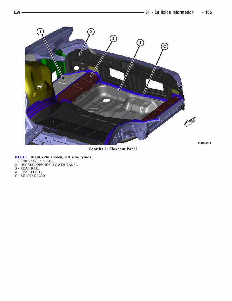
Rear Rail / Closeout Panel
NOTE: Right side shown, left side typical.1 - RAIL COVER PLATE2 - DECKLID OPENING LOWER PANEL3 - REAR RAIL4 - REAR FLOORC - SEAM SEALER
LA 31 - Collision Information - 165
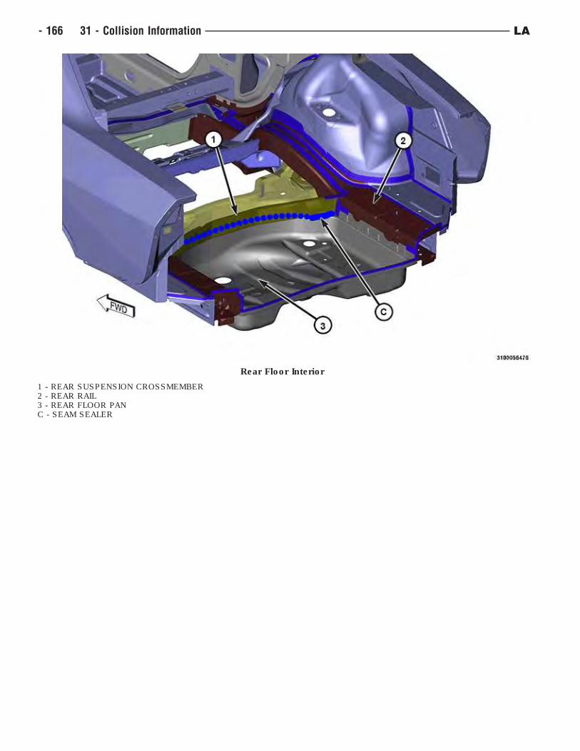
Rear Floor Interior
1 - REAR SUSPENSION CROSSMEMBER2 - REAR RAIL3 - REAR FLOOR PANC - SEAM SEALER
- 166 31 - Collision Information LA
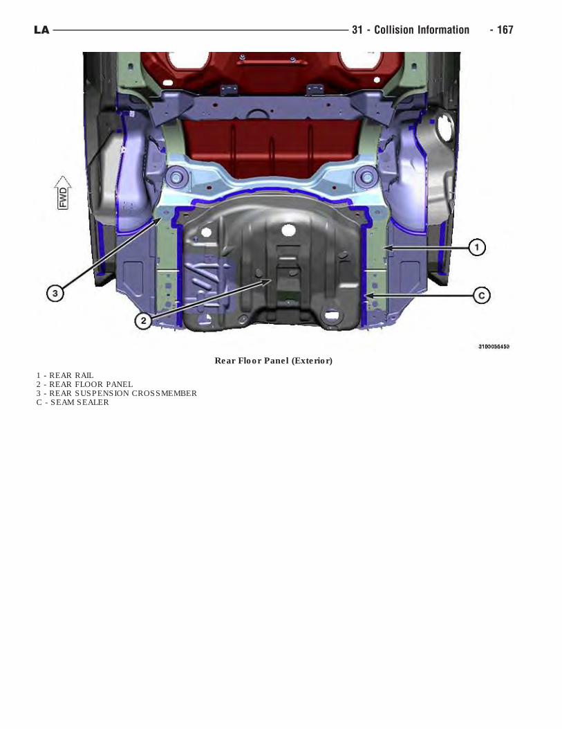
Rear Floor Panel (Exterior)
1 - REAR RAIL2 - REAR FLOOR PANEL3 - REAR SUSPENSION CROSSMEMBERC - SEAM SEALER
LA 31 - Collision Information - 167
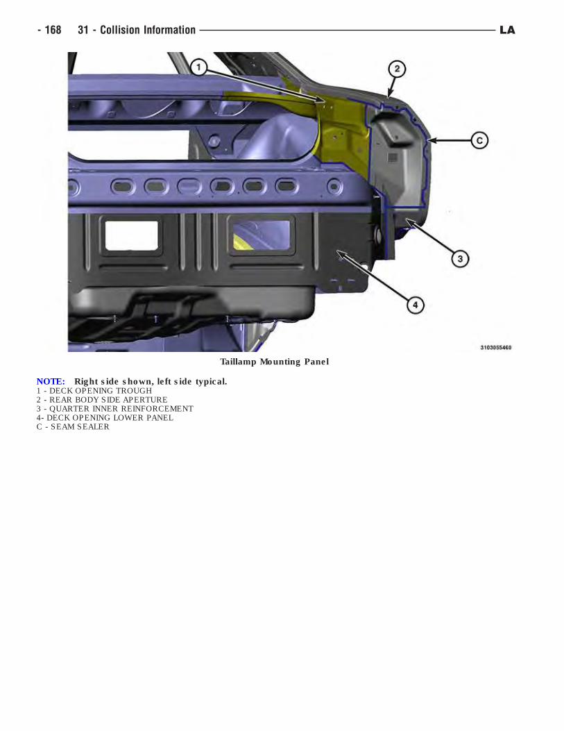
Taillamp Mounting Panel
NOTE: Right side shown, left side typical.1 - DECK OPENING TROUGH2 - REAR BODY SIDE APERTURE3 - QUARTER INNER REINFORCEMENT4- DECK OPENING LOWER PANELC - SEAM SEALER
- 168 31 - Collision Information LA