dl05 micro plc user manual - automationdirect
TRANSCRIPT
DL05 Micro PLC User Manual
Manual Number: D0-USER-M

~ WARNING ~Thank you for purchasing automation equipment from AutomationDirect.com®, doing business as, AutomationDirect. We want your new automation equipment to operate safely. Anyone who installs or uses this equipment should read this publication (and any other relevant publications) before installing or operating the equipment.
To minimize the risk of potential safety problems, you should follow all applicable local and national codes that regulate the installation and operation of your equipment. These codes vary from area to area and usually change with time. It is your responsibility to determine which codes should be followed, and to verify that the equipment, installation, and operation is in compliance with the latest revision of these codes.
At a minimum, you should follow all applicable sections of the National Fire Code, National Electrical Code, and the codes of the National Electrical Manufacturer’s Association (NEMA). There may be local regulatory or government offices that can also help determine which codes and standards are necessary for safe installation and operation.
Equipment damage or serious injury to personnel can result from the failure to follow all applicable codes and standards. We do not guarantee the products described in this publication are suitable for your particular application, nor do we assume any responsibility for your product design, installation, or operation.
Our products are not fault-tolerant and are not designed, manufactured or intended for use or resale as on-line control equipment in hazardous environments requiring fail-safe performance, such as in the operation of nuclear facilities, aircraft navigation or communication systems, air traffic control, direct life support machines, or weapons systems, in which the failure of the product could lead directly to death, personal injury, or severe physical or environmental damage (“High Risk Activities”). AutomationDirect specifically disclaims any expressed or implied warranty of fitness for High Risk Activities.
For additional warranty and safety information, see the Terms and Conditions section of our catalog. If you have any questions concerning the installation or operation of this equipment, or if you need additional information, please call us at 770-844-4200.
This publication is based on information that was available at the time it was printed. At AutomationDirect we constantly strive to improve our products and services, so we reserve the right to make changes to the products and/or publications at any time without notice and without any obligation. This publication may also discuss features that may not be available in certain revisions of the product.
TrademarksThis publication may contain references to products produced and/or offered by other companies. The product and company names may be trademarked and are the sole property of their respective owners. AutomationDirect disclaims any proprietary interest in the marks and names of others.
Copyright 2018, AutomationDirect.com Incorporated All Rights Reserved
No part of this manual shall be copied, reproduced, or transmitted in any way without the prior, written consent of AutomationDirect.com Incorporated. AutomationDirect retains the exclusive rights to all information included in this document.
~ ADVERTENCIA ~Gracias por comprar equipo de automatización de Automationdirect.com®. Deseamos que su nuevo equipo de automatización opere de manera segura. Cualquier persona que instale o use este equipo debe leer esta publicación (y cualquier otra publicación pertinente) antes de instalar u operar el equipo.
Para reducir al mínimo el riesgo debido a problemas de seguridad, debe seguir todos los códigos de seguridad locales o nacionales aplicables que regulan la instalación y operación de su equipo. Estos códigos varian de área en área y usualmente cambian con el tiempo. Es su responsabilidad determinar cuales códigos deben ser seguidos y verificar que el equipo, instalación y operación estén en cumplimiento con la revisión mas reciente de estos códigos.
Como mínimo, debe seguir las secciones aplicables del Código Nacional de Incendio, Código Nacional Eléctrico, y los códigos de (NEMA) la Asociación Nacional de Fabricantes Eléctricos de USA. Puede haber oficinas de normas locales o del gobierno que pueden ayudar a determinar cuales códigos y normas son necesarios para una instalación y operación segura.
Si no se siguen todos los códigos y normas aplicables, puede resultar en daños al equipo o lesiones serias a personas. No garantizamos los productos descritos en esta publicación para ser adecuados para su aplicación en particular, ni asumimos ninguna responsabilidad por el diseño de su producto, la instalación u operación.
Nuestros productos no son tolerantes a fallas y no han sido diseñados, fabricados o intencionados para uso o reventa como equipo de control en línea en ambientes peligrosos que requieren una ejecución sin fallas, tales como operación en instalaciones nucleares, sistemas de navegación aérea, o de comunicación, control de tráfico aéreo, máquinas de soporte de vida o sistemas de armamentos en las cuales la falla del producto puede resultar directamente en muerte, heridas personales, o daños físicos o ambientales severos (“Actividades de Alto Riesgo”). Automationdirect.com específicamente rechaza cualquier garantía ya sea expresada o implicada para actividades de alto riesgo. Para información adicional acerca de garantía e información de seguridad, vea la sección de Términos y Condiciones de nuestro catálogo. Si tiene alguna pregunta sobre instalación u operación de este equipo, o si necesita información adicional, por favor llámenos al número 770-844-4200 en Estados Unidos. Esta publicación está basada en la información disponible al momento de impresión. En Automationdirect.com nos esforzamos constantemente para mejorar nuestros productos y servicios, así que nos reservamos el derecho de hacer cambios al producto y/o a las publicaciones en cualquier momento sin notificación y sin ninguna obligación. Esta publicación también puede discutir características que no estén disponibles en ciertas revisiones del producto.
Marcas RegistradasEsta publicación puede contener referencias a productos producidos y/u ofrecidos por otras compañías. Los nombres de las compañías y productos pueden tener marcas registradas y son propiedad única de sus respectivos dueños. Automationdirect.com, renuncia cualquier interés propietario en las marcas y nombres de otros.
PROPIEDAD LITERARIA 2018, AUTOMATIONDIRECT.COM® INCORPORATEDTodos los derechos reservados
No se permite copiar, reproducir, o transmitir de ninguna forma ninguna parte de este manual sin previo consentimiento por escrito de Automationdirect.com® Incorprated. Automationdirect.com retiene los derechos exclusivos a toda la información incluida en este documento. Los usuarios de este equipo pueden copiar este documento solamente para instalar, configurar y mantener el equipo correspondiente. También las instituciones de enseñanza pueden usar este manual para propósitos educativos.
~ AVERTISSEMENT ~Nous vous remercions d’avoir acheté l’équipement d’automatisation de Automationdirect.comMC, en faisant des affaires comme, AutomationDirect. Nous tenons à ce que votre nouvel équipement d’automatisation fonctionne en toute sécurité. Toute personne qui installe ou utilise cet équipement doit lire la présente publication (et toutes les autres publications pertinentes) avant de l’installer ou de l’utiliser.
Afin de réduire au minimum le risque d’éventuels problèmes de sécurité, vous devez respecter tous les codes locaux et nationaux applicables régissant l’installation et le fonctionnement de votre équipement. Ces codes diffèrent d’une région à l’autre et, habituellement, évoluent au fil du temps. Il vous incombe de déterminer les codes à respecter et de vous assurer que l’équipement, l’installation et le fonctionnement sont conformes aux exigences de la version la plus récente de ces codes.
Vous devez, à tout le moins, respecter toutes les sections applicables du Code national de prévention des incendies, du Code national de l’électricité et des codes de la National Electrical Manufacturer’s Association (NEMA). Des organismes de réglementation ou des services gouvernementaux locaux peuvent également vous aider à déterminer les codes ainsi que les normes à respecter pour assurer une installation et un fonctionnement sûrs.
L’omission de respecter la totalité des codes et des normes applicables peut entraîner des dommages à l’équipement ou causer de graves blessures au personnel. Nous ne garantissons pas que les produits décrits dans cette publication conviennent à votre application particulière et nous n’assumons aucune responsabilité à l’égard de la conception, de l’installation ou du fonctionnement de votre produit.
Nos produits ne sont pas insensibles aux défaillances et ne sont ni conçus ni fabriqués pour l’utilisation ou la revente en tant qu’équipement de commande en ligne dans des environnements dangereux nécessitant une sécurité absolue, par exemple, l’exploitation d’installations nucléaires, les systèmes de navigation aérienne ou de communication, le contrôle de la circulation aérienne, les équipements de survie ou les systèmes d’armes, pour lesquels la défaillance du produit peut provoquer la mort, des blessures corporelles ou de graves dommages matériels ou environnementaux («activités à risque élevé»). La société AutomationDirect nie toute garantie expresse ou implicite d’aptitude à l’emploi en ce qui a trait aux activités à risque élevé.
Pour des renseignements additionnels touchant la garantie et la sécurité, veuillez consulter la section Modalités et conditions de notre documentation. Si vous avez des questions au sujet de l’installation ou du fonctionnement de cet équipement, ou encore si vous avez besoin de renseignements supplémentaires, n’hésitez pas à nous téléphoner au 770-844-4200.
Cette publication s’appuie sur l’information qui était disponible au moment de l’impression. À la société AutomationDirect, nous nous efforçons constamment d’améliorer nos produits et services. C’est pourquoi nous nous réservons le droit d’apporter des modifications aux produits ou aux publications en tout temps, sans préavis ni quelque obligation que ce soit. La présente publication peut aussi porter sur des caractéristiques susceptibles de ne pas être offertes dans certaines versions révisées du produit.
Marques de commerceLa présente publication peut contenir des références à des produits fabriqués ou offerts par d’autres entreprises. Les désignations des produits et des entreprises peuvent être des marques de commerce et appartiennent exclusivement à leurs propriétaires respectifs. AutomationDirect nie tout intérêt dans les autres marques et désignations.
Copyright 2018, Automationdirect.com IncorporatedTous droits réservés
Nulle partie de ce manuel ne doit être copiée, reproduite ou transmise de quelque façon que ce soit sans le consentement préalable écrit de la société Automationdirect.com Incorporated. AutomationDirect conserve les droits exclusifs à l’égard de tous les renseignements contenus dans le présent document.
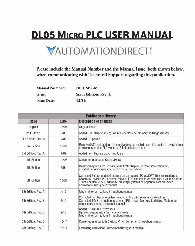
Please include the Manual Number and the Manual Issue, both shown below, when communicating with Technical Support regarding this publication.
Manual Number: D0-USER-M
Issue: Sixth Edition, Rev. E
Issue Date: 12/18
DL05 Micro PLc USER MANUAL
Publication HistoryIssue Date Description of Changes
Original 12/98 Original issue
2nd Edition 2/00 Added PID chapter,analog module chapter and memory cartridge chapter
2nd Edition, Rev. A 7/00 Added DC power
3rd Edition 11/01 Removed MC and analog module chapters, corrected drum instruction, several minor corrections, added PLC weights, EU directive additions
3rd Edition, Rev. A 7/02 Added new discrete option modules
4th Edition 11/02 Converted manual to QuarkXPress
5th Edition 6/04 Removed option module data, added MC chapter, updated instruction set, inserted memory appendix, made minor corrections
6th Edition 12/08Corrected E-stop, updated instruction set, added DirectSOFT IBox instructions to Chapter 5, revised PID chapter, moved HSIO chapter to Appendices, divided Chapter 4 into Chapters 3 & 4, added Numbering Systems to Appendix section, made corrections throughout manual
6th Edition, Rev. A 4/10 Made minor corrections throughout manual.
6th Edition, Rev. B 8/11Corrected number of registers needed in the print message instruction. Corrected TIME instruction: changed CPU to read Memory Cartridge. Made other minor corrections throughout manual.
6th Edition, Rev. C 2/13Added H0-CTRIO2 references Updated suppression for inductive loads Made minor corrections throughout manual.
6th Edition, Rev. D 10/17 Converted manual to InDesign, Minor Correction throughout manual
6th Edition, Rev. E 12/18 Formating and Minor Corrections throughout manual
Table of ConTenTs
Chapter 1: Getting StartedIntroduction ............................................................................................................... 1-2
Conventions Used ...................................................................................................... 1-3
DL05 Micro PLC Components ................................................................................... 1-4
I/O Selection Quick Chart ......................................................................................... 1-5
Quick Start for PLC Checkout and Programming..................................................... 1-6
Steps to Designing a Successful System ................................................................. 1-10
Questions and Answers about DL05 Micro PLCs .................................................... 1-12
Chapter 2 - Installation, Wiring, and SpecificationsSafety Guidelines ....................................................................................................... 2-2
Orientation to DL05 Front Panel .............................................................................. 2-5
Mounting Guidelines ................................................................................................. 2-7
Wiring Guidelines .................................................................................................... 2-11
System Wiring Strategies ........................................................................................ 2-14
Wiring Diagrams and Specifications ....................................................................... 2-31
Glossary of Specification Terms .............................................................................. 2-47
Chapter 3 - CPU Specifications and OperationIntroduction ............................................................................................................... 3-2
CPU Specifications ..................................................................................................... 3-3
CPU Hardware Setup ................................................................................................. 3-4
CPU Operation ......................................................................................................... 3-11
I/O Response Time .................................................................................................. 3-15
DL05 Micro PLC User Manual, 6th Edition, Rev. E ii
Table of Contents
CPU Scan Time Considerations ............................................................................... 3-18
Memory Map ........................................................................................................... 3-22
DL05 System V-memory .......................................................................................... 3-26
DL05 Aliases ............................................................................................................. 3-29
X Input Bit Map ....................................................................................................... 3-30
Y Output Bit Map .................................................................................................... 3-30
Control Relay Bit Map ............................................................................................. 3-31
Stage Control/Status Bit Map ................................................................................. 3-32
Timer Status Bit Map ............................................................................................... 3-32
Counter Status Bit Map ........................................................................................... 3-33
Chapter 4 - Configuration and ConnectionsIn this Chapter .......................................................................................................... 4-1
DL05 System Design Strategies ................................................................................ 4-2
Network Configuration and Connections ................................................................. 4-4
Network Slave Operation .......................................................................................... 4-8
Network Master Operation ..................................................................................... 4-14
Chapter 5 - Standard RLL and Intelligent Box InstructionsIntroduction ............................................................................................................... 5-2
Using Boolean Instructions ....................................................................................... 5-4
Boolean Instructions .................................................................................................. 5-9
Comparative Boolean .............................................................................................. 5-25
Immediate Instructions ........................................................................................... 5-31
Timer, Counter and Shift Register Instructions ...................................................... 5-35
Accumulator/Stack Load and Output Data Instructions ........................................ 5-48
Logical Instructions (Accumulator) ......................................................................... 5-60
Math Instructions .................................................................................................... 5-68
Bit Operation Instructions ....................................................................................... 5-82
Number Conversion Instructions (Accumulator) .................................................... 5-87
DL05 Micro PLC User Manual, 6th Edition, Rev. E iii
Table of Contents
Table Instructions .................................................................................................... 5-96
CPU Control Instructions ......................................................................................... 5-99
Program Control Instructions ............................................................................... 5-101
Interrupt Instructions ............................................................................................ 5-108
Message Instructions ............................................................................................. 5-111
Intelligent I/O Instructions .................................................................................... 5-118
Network Instructions ............................................................................................. 5-120
Intelligent Box (IBox) Instructions ........................................................................ 5-124
Chapter 6 - Drum Instruction ProgrammingDL05 Drum Introduction ........................................................................................... 6-2
Step Transitions ......................................................................................................... 6-4
Overview of Drum Operation ................................................................................... 6-8
Drum Control Techniques ....................................................................................... 6-10
Drum Instruction ..................................................................................................... 6-12
Event Drum (EDRUM) Instruction ........................................................................... 6-14
Chapter 7 - RLLPlus Stage ProgrammingIntroduction to Stage Programming ........................................................................ 7-2
Learning to Draw State Transition Diagrams ........................................................... 7-3
Using the Stage Jump Instruction for State Transitions .......................................... 7-7
Stage Program Example: Toggle On/Off Lamp Controller ...................................... 7-8
Four Steps to Writing a Stage Program ................................................................... 7-9
Stage Program Example: A Garage Door Opener .................................................. 7-10
Stage Program Design Considerations ................................................................... 7-15
Parallel Processing Concepts ................................................................................... 7-19
RLLPlus Stage Instructions .................................................................................... 7-21
Questions and Answers about Stage Programming .............................................. 7-25
DL05 Micro PLC User Manual, 6th Edition, Rev. E iv
Table of Contents
Chapter 8 - PID Loop OperationDL05 PID Control ....................................................................................................... 8-2
Introduction to PID Control ...................................................................................... 8-4
Introducing DL05 PID Control .................................................................................. 8-6
PID Loop Operation ................................................................................................... 8-9
Ten Steps to Successful Process Control................................................................. 8-16
PID Loop Setup ........................................................................................................ 8-18
PID Loop Tuning ...................................................................................................... 8-40
Using Other PID Features ........................................................................................ 8-53
Ramp/Soak Generator ............................................................................................. 8-58
DirectSOFT Ramp/Soak Example ............................................................................ 8-63
Cascade Control ....................................................................................................... 8-65
Time-Proportioning Control .................................................................................... 8-68
Feedforward Control ............................................................................................... 8-70
PID Example Program ............................................................................................. 8-72
Troubleshooting Tips............................................................................................... 8-75
Glossary of PID Loop Terminology ......................................................................... 8-77
Bibliography ........................................................................................................... 8-79
Chapter 9 - Maintenance and TroubleshootingHardware System Maintenance ................................................................................ 9-2
Diagnostics ................................................................................................................. 9-2
CPU Indicators ........................................................................................................... 9-6
Communications Problems ....................................................................................... 9-7
I/O Point Troubleshooting ........................................................................................ 9-8
Noise Troubleshooting ............................................................................................ 9-10
Machine Startup and Program Troubleshooting ................................................... 9-11
DL05 Micro PLC User Manual, 6th Edition, Rev. E v
Table of Contents
Chapter 10 - Memory Cartridge/Real Time Clock (DL05 Only)General Information about the D0–01MC .............................................................. 10-2
Setting the Write Enable/Disable Jumper .............................................................. 10-3
Plugging-in the Memory Cartridge ........................................................................ 10-4
Software and Firmware Requirements ................................................................... 10-5
Naming the Memory Cartridge .............................................................................. 10-6
Setting the Time and Date ...................................................................................... 10-7
Memory Transfers .................................................................................................... 10-8
LED Indicator Lights ................................................................................................ 10-9
Password Protected Programs ................................................................................ 10-9
Memory Map and Forwarding Range ................................................................... 10-10
Battery Back-up During AC Power Loss ................................................................ 10-11
Specifications and Agency Approvals ................................................................... 10-12
Clock/Calendar Instructions .................................................................................. 10-13
Error Codes ............................................................................................................ 10-18
Appendix A - Auxiliary FunctionsIntroduction ............................................................................................................... A-2
AUX 2* — RLL Operations ......................................................................................... A-4
AUX 3* — V-memory Operations .............................................................................. A-4
AUX 4* — I/O Configuration ..................................................................................... A-5
AUX 5* — CPU Configuration ................................................................................... A-5
AUX 6* — Handheld Programmer Configuration .................................................... A-8
AUX 7* — EEPROM Operations ................................................................................. A-8
AUX 8* — Password Operations ............................................................................... A-9
Appendix B - DL05 Error Codes
DL05 Micro PLC User Manual, 6th Edition, Rev. E vi
Table of Contents
Appendix C - Instruction Execution TimesIntroduction ............................................................................................................... C-2
Instruction Execution Times ...................................................................................... C-3
Appendix D - Special RelaysDL05 PLC Special Relays ............................................................................................D-2
Appendix E - High-Speed Input and Pulse Output FeaturesIntroduction ................................................................................................................E-2
Choosing the HSIO Operating Mode .........................................................................E-4
Mode 10: High-Speed Counter ..................................................................................E-6
Mode 20: Quadrature Counter ................................................................................E-18
Mode 30: Pulse Output ............................................................................................E-24
Trapezoidal Profile Operation ..................................................................................E-31
Registration Profile Operation .................................................................................E-34
Velocity Profile Operation ........................................................................................E-42
Mode 40: High-Speed Interrupts .............................................................................E-47
Mode 50: Pulse Catch Input .....................................................................................E-52
Mode 60: Discrete Inputs with Filter .......................................................................E-55
Appendix F - PLC MemoryDL05 PLC Memory ......................................................................................................F-2
Appendix G - ASCII TableASCII Table .................................................................................................................G-2
Appendix H - Product WeightsProduct Weight Table ...............................................................................................H-2
DL05 Micro PLC User Manual, 6th Edition, Rev. E vii
Table of Contents
Appendix I - Numbering SystemsIntroduction ................................................................................................................ I-2
Binary Numbering System ......................................................................................... I-2
Hexadecimal Numbering System ............................................................................... I-3
Octal Numbering System ........................................................................................... I-4
Binary Coded Decimal (BCD) Numbering System .................................................... I-5
Real (Floating Point) Numbering System .................................................................. I-5
BCD/Binary/Decimal/Hex/Octal - What is the Difference? .............................................................................................. I-6
Data Type Mismatch................................................................................................... I-7
Signed vs. Unsigned Integers ..................................................................................... I-8
AutomationDirect.com Products and Data Types ..................................................... I-9
Appendix J - European Union Directives (CE)European Union (EU) Directives ................................................................................ J-2
Basic EMC Installation Guidelines .............................................................................. J-5
Appendix K - Introduction to Serial CommunicationsIntroduction to Serial Communications .................................................................... K-2
GettinG Started 111ChapterChapterChapter
In This Chapter...Introduction ............................................................................................................... 1-2
Conventions Used ...................................................................................................... 1-3
DL05 Micro PLC Components ................................................................................... 1-4
I/O Selection Quick Chart ......................................................................................... 1-5
Quick Start for PLC Checkout and Programming..................................................... 1-6
Steps to Designing a Successful System ................................................................. 1-10
Questions and Answers about DL05 Micro PLCs .................................................... 1-12
DL05 Micro PLC User Manual, 6th Edition, Rev. E1-2
Chapter 1: Getting Started
IntroductionThe Purpose of this Manual
Thank you for purchasing a DL05 Micro PLC. This manual shows you how to install, program, and maintain all the Micro PLCs in the DL05 family. It also helps you understand how to interface them to other devices in a control system. This manual contains important information for personnel who will install DL05 PLCs, and for the PLC programmer. If you understand PLC systems our manuals will provide all the information you need to get and keep your system up and running.
Where to BeginIf you already understand the DL05 Micro PLC please read Chapter 2, “Installation, Wiring, and Specifications”, and proceed on to other chapters as needed. Be sure to keep this manual handy for reference when you run into questions. If you are a new DL05 customer, we suggest you read this manual completely so you can understand the wide variety of features in the DL05 family of products. We believe you will be pleasantly surprised with how much you can accomplish with AutomationDirect products.
Supplemental ManualsThe D0–OPTIONS–M manual will be most helpful to select and use any of the optional modules that are available for the DL05 PLC which includes the analog I/O modules. If you have purchased operator interfaces or DirectSOFT programming software you will need to supplement this manual with the manuals that are written for these products.
Technical SupportWe realize that even though we strive to be the best, we may have arranged our information in such a way you cannot find what you are looking for. First, check these resources for help in locating the information:
• Table of Contents – chapter and section listing of contents, in the front of this manual
• Appendices – reference material for key topics, near the end of this manual
You can also check our online resources for the latest product support information:
• Internet – the address of our website is: http://www.automationdirect.com
If you still need assistance, please call us at 770–844–4200. Our technical support team will be available to work with you in answering your questions. They are available Monday through Friday from 9:00 A.M. to 6:00 P.M. Eastern Standard Time.
DL05 Micro PLC User Manual, 6th Edition, Rev. E 1-3
Chapter 1: Getting Started
Conventions Used
Getting Started CHAPTER
1In This Chapter...
.................................................................1-2
...........................................................................1-4Specifications
General Information
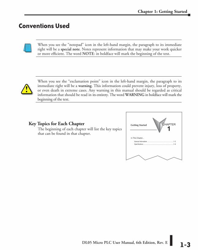
Key Topics for Each ChapterThe beginning of each chapter will list the key topics that can be found in that chapter.
When you see the “notepad” icon in the left-hand margin, the paragraph to its immediate right will be a special note. Notes represent information that may make your work quicker or more efficient. The word NOTE: in boldface will mark the beginning of the text.
When you see the “exclamation point” icon in the left-hand margin, the paragraph to its immediate right will be a warning. This information could prevent injury, loss of property, or even death in extreme cases. Any warning in this manual should be regarded as critical information that should be read in its entirety. The word WARNING in boldface will mark the beginning of the text.
DL05 Micro PLC User Manual, 6th Edition, Rev. E1-4
Chapter 1: Getting Started
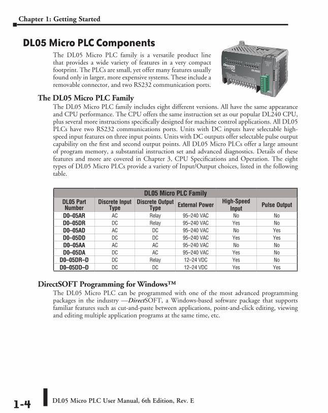
DL05 Micro PLC ComponentsThe DL05 Micro PLC family is a versatile product line that provides a wide variety of features in a very compact footprint. The PLCs are small, yet offer many features usually found only in larger, more expensive systems. These include a removable connector, and two RS232 communication ports.
The DL05 Micro PLC FamilyThe DL05 Micro PLC family includes eight different versions. All have the same appearance and CPU performance. The CPU offers the same instruction set as our popular DL240 CPU, plus several more instructions specifically designed for machine control applications. All DL05 PLCs have two RS232 communications ports. Units with DC inputs have selectable high-speed input features on three input points. Units with DC outputs offer selectable pulse output capability on the first and second output points. All DL05 Micro PLCs offer a large amount of program memory, a substantial instruction set and advanced diagnostics. Details of these features and more are covered in Chapter 3, CPU Specifications and Operation. The eight types of DL05 Micro PLCs provide a variety of Input/Output choices, listed in the following table.
DirectSOFT Programming for Windows™The DL05 Micro PLC can be programmed with one of the most advanced programming packages in the industry ––DirectSOFT, a Windows-based software package that supports familiar features such as cut-and-paste between applications, point-and-click editing, viewing and editing multiple application programs at the same time, etc.
DL05 Micro PLC FamilyDL05 Part Number
Discrete Input Type
Discrete Output Type External Power High-Speed
Input Pulse Output
D0–05AR AC Relay 95–240 VAC No NoD0–05DR DC Relay 95–240 VAC Yes NoD0–05AD AC DC 95–240 VAC No YesD0–05DD DC DC 95–240 VAC Yes YesD0–05AA AC AC 95–240 VAC No NoD0–05DA DC AC 95–240 VAC Yes No
D0–05DR–D DC Relay 12–24 VDC Yes NoD0–05DD–D DC DC 12–24 VDC Yes Yes
PWR
RUN
CPU
TX1
RX1
TX2
RX2
DL05 Micro PLC User Manual, 6th Edition, Rev. E 1-5
Chapter 1: Getting Started
DirectSOFT universally supports the DirectLOGIC CPU families. This means you can use the full version of DirectSOFT to program DL05, DL06, DL105, DL205, DL305, DL405 CPUs. The DirectSOFT Programming Software User Manual discusses the programming language in depth. DirectSOFT version 2.4 or later is needed to program the DL05.
Handheld ProgrammerAll DL05 Micro PLCs have built-in programming ports for use with the handheld programmer (D2–HPP), the same programmer is used with the DL06 and DL205 families. The handheld programmer can be used to create, modify and debug your application program. A separate manual discusses the handheld programmer. The D2–HPP requires firmware version 1.09 or later to program the DL05.
NOTE: Not all program instructions are available to use with the HHP, such as the DRUM instruction. Use DirectSOFT for these instructions.
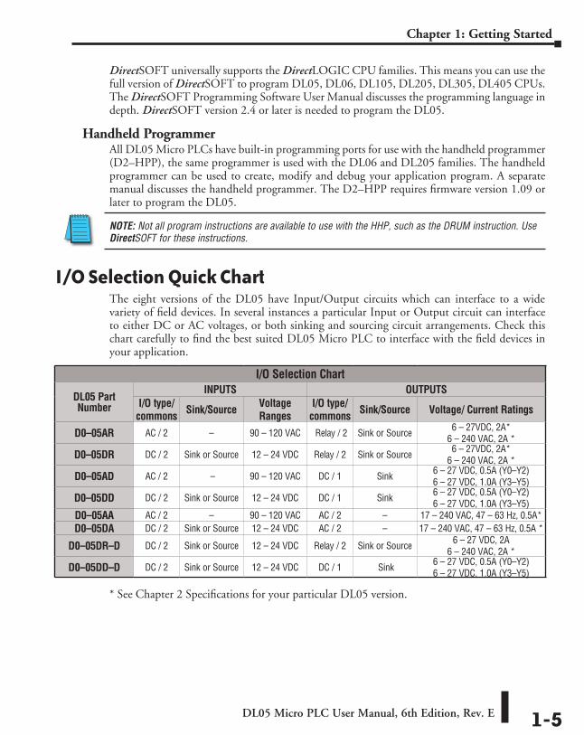
I/O Selection Quick ChartThe eight versions of the DL05 have Input/Output circuits which can interface to a wide variety of field devices. In several instances a particular Input or Output circuit can interface to either DC or AC voltages, or both sinking and sourcing circuit arrangements. Check this chart carefully to find the best suited DL05 Micro PLC to interface with the field devices in your application.
* See Chapter 2 Specifications for your particular DL05 version.
I/O Selection Chart
DL05 Part Number
INPUTS OUTPUTSI/O type/
commons Sink/Source Voltage Ranges
I/O type/commons Sink/Source Voltage/ Current Ratings
D0–05AR AC / 2 – 90 – 120 VAC Relay / 2 Sink or Source 6 – 27VDC, 2A* 6 – 240 VAC, 2A *
D0–05DR DC / 2 Sink or Source 12 – 24 VDC Relay / 2 Sink or Source 6 – 27VDC, 2A* 6 – 240 VAC, 2A *
D0–05AD AC / 2 – 90 – 120 VAC DC / 1 Sink 6 – 27 VDC, 0.5A (Y0–Y2) 6 – 27 VDC, 1.0A (Y3–Y5)
D0–05DD DC / 2 Sink or Source 12 – 24 VDC DC / 1 Sink 6 – 27 VDC, 0.5A (Y0–Y2) 6 – 27 VDC, 1.0A (Y3–Y5)
D0–05AA AC / 2 – 90 – 120 VAC AC / 2 – 17 – 240 VAC, 47 – 63 Hz, 0.5A*D0–05DA DC / 2 Sink or Source 12 – 24 VDC AC / 2 – 17 – 240 VAC, 47 – 63 Hz, 0.5A *
D0–05DR–D DC / 2 Sink or Source 12 – 24 VDC Relay / 2 Sink or Source 6 – 27 VDC, 2A 6 – 240 VAC, 2A *
D0–05DD–D DC / 2 Sink or Source 12 – 24 VDC DC / 1 Sink 6 – 27 VDC, 0.5A (Y0–Y2) 6 – 27 VDC, 1.0A (Y3–Y5)
DL05 Micro PLC User Manual, 6th Edition, Rev. E1-6
Chapter 1: Getting Started
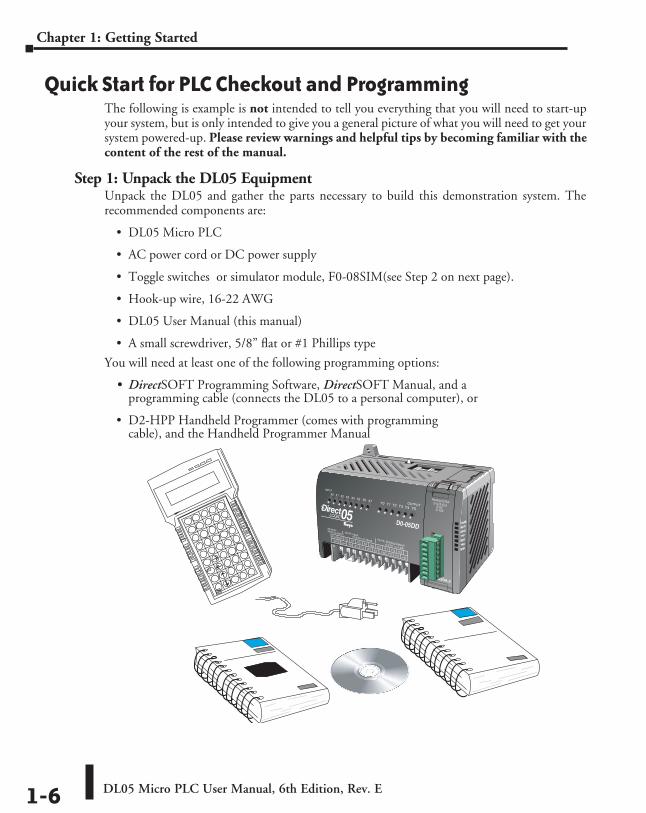
Quick Start for PLC Checkout and ProgrammingThe following is example is not intended to tell you everything that you will need to start-up your system, but is only intended to give you a general picture of what you will need to get your system powered-up. Please review warnings and helpful tips by becoming familiar with the content of the rest of the manual.
Step 1: Unpack the DL05 EquipmentUnpack the DL05 and gather the parts necessary to build this demonstration system. The recommended components are:
• DL05 Micro PLC
• AC power cord or DC power supply
• Toggle switches or simulator module, F0-08SIM(see Step 2 on next page).
• Hook-up wire, 16-22 AWG
• DL05 User Manual (this manual)
• A small screwdriver, 5/8” flat or #1 Phillips type
You will need at least one of the following programming options:
• DirectSOFT Programming Software, DirectSOFT Manual, and a programming cable (connects the DL05 to a personal computer), or
• D2-HPP Handheld Programmer (comes with programming cable), and the Handheld Programmer Manual
PWR
RUN
CPU
TX1
RX1
TX2
RX2
DL05 Micro PLC User Manual, 6th Edition, Rev. E 1-7
Chapter 1: Getting Started
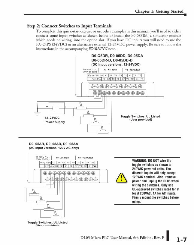
Step 2: Connect Switches to Input TerminalsTo complete this quick-start exercise or use other examples in this manual, you’ll need to either connect some input switches as shown below or install the F0-08SIM, a simulator module which needs no wiring, into the option slot. If you have DC inputs you will need to use the FA–24PS (24VDC) or an alternative external 12-24VDC power supply. Be sure to follow the instructions in the accompanying WARNING note.
D0-O5DR, D0-05DD, D0-05DAD0-05DR-D, D0-05DD-D(DC input versions, 12-24VDC)
+–
12–24VDCPower Supply
Toggle Switches, UL Listed(User provided)
X0 - X7: Input Y0 - Y5: Output
C3
Y0 - Y5: OutputX0 - X7: Input
D0–05AR, D0–05AD, D0–05AA(AC input versions, 120V AC only)
Toggle Switches, UL Listed(User provided)
WARNING: DO NOT wire the toggle switches as shown to 240VAC-powered units. The discrete inputs will only accept 120VAC nominal. Also, remove power and unplug the DL05 when wiring the switches. Only use UL-approved switches rated for at least 250VAC, 1A for AC inputs. Firmly mount the switches before using.
DL05 Micro PLC User Manual, 6th Edition, Rev. E1-8
Chapter 1: Getting Started
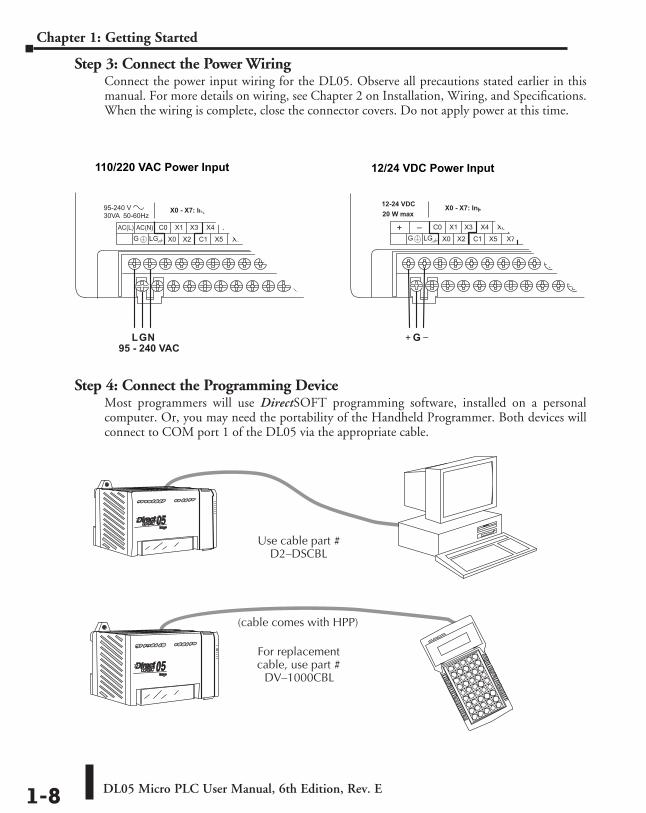
Step 3: Connect the Power WiringConnect the power input wiring for the DL05. Observe all precautions stated earlier in this manual. For more details on wiring, see Chapter 2 on Installation, Wiring, and Specifications. When the wiring is complete, close the connector covers. Do not apply power at this time.
Step 4: Connect the Programming DeviceMost programmers will use DirectSOFT programming software, installed on a personal computer. Or, you may need the portability of the Handheld Programmer. Both devices will connect to COM port 1 of the DL05 via the appropriate cable.
C3
Y0 - Y5: OutputX0 - X7: Input
110/220 VAC Power Input
LGN95 - 240 VAC
12/24 VDC Power Input
12-24 VDC20 W max
X0 - X7: Input Y0 - Y5: Output
G
Use cable part #D2–DSCBL
For replacementcable, use part #
DV–1000CBL
(cable comes with HPP)
DL05 Micro PLC User Manual, 6th Edition, Rev. E 1-9
Chapter 1: Getting Started
Step 5: Switch on the System PowerApply power to the system and ensure the PWR indicator on the DL05 is on. If not, remove power from the system and check all wiring and refer to the troubleshooting section in Chapter 9 for assistance.
Step 6: Initialize Scratchpad MemoryIt’s a good precaution to always clear the system memory (scratchpad memory) on a new DL05. There are two ways to clear the system memory:
• In DirectSOFT, select the PLC menu, then Setup, then Initialize Scratchpad. For additional information, see the DirectSOFT Manual.
• For the Handheld Programmer, use the AUX key and execute AUX 54.
See the Handheld Programmer Manual for additional information.
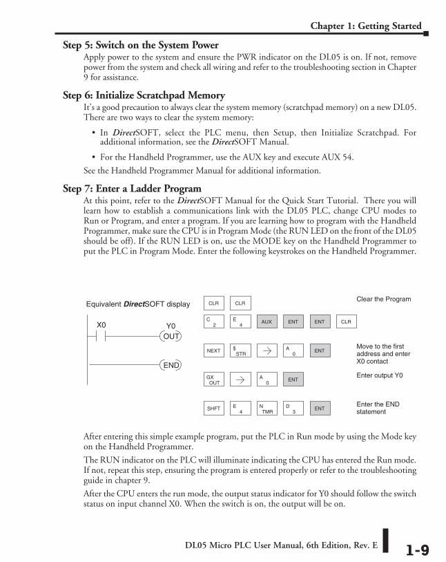
Step 7: Enter a Ladder ProgramAt this point, refer to the DirectSOFT Manual for the Quick Start Tutorial. There you will learn how to establish a communications link with the DL05 PLC, change CPU modes to Run or Program, and enter a program. If you are learning how to program with the Handheld Programmer, make sure the CPU is in Program Mode (the RUN LED on the front of the DL05 should be off). If the RUN LED is on, use the MODE key on the Handheld Programmer to put the PLC in Program Mode. Enter the following keystrokes on the Handheld Programmer.
After entering this simple example program, put the PLC in Run mode by using the Mode key on the Handheld Programmer.
The RUN indicator on the PLC will illuminate indicating the CPU has entered the Run mode. If not, repeat this step, ensuring the program is entered properly or refer to the troubleshooting guide in chapter 9.
After the CPU enters the run mode, the output status indicator for Y0 should follow the switch status on input channel X0. When the switch is on, the output will be on.
ENT CLR
3D
TMRN
4ESHFT
CLR CLR
2C
4E AUX ENT
NEXTSTR
$0
A ENT
OUTGX
0A ENT
ENT
Clear the Program
Move to the firstaddress and enterX0 contact
Enter output Y0
Enter the ENDstatement
END
X0
OUTY0
Equivalent DirectSOFT display
DL05 Micro PLC User Manual, 6th Edition, Rev. E1-10
Chapter 1: Getting Started
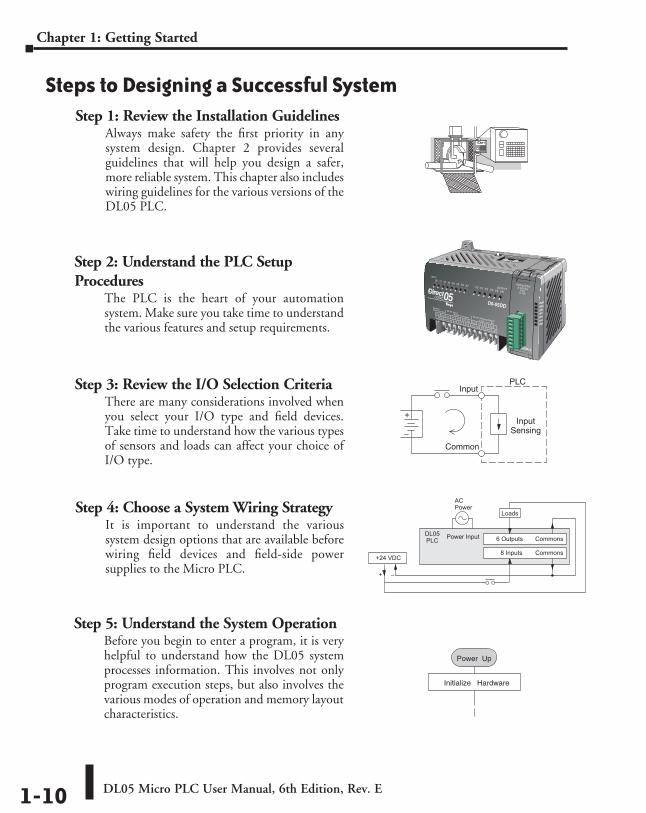
Steps to Designing a Successful SystemStep 1: Review the Installation Guidelines
Always make safety the first priority in any system design. Chapter 2 provides several guidelines that will help you design a safer, more reliable system. This chapter also includes wiring guidelines for the various versions of the DL05 PLC.
PWR
RUN
CPU
TX1
RX1
TX2
RX2
+
–
InputSensing
PLCInput
Common
8 Inputs Commons
Commons6 OutputsPower InputPLCDL05
+ –
Loads
+24 VDC
ACPower
Power Up
Initialize Hardware
Step 5: Understand the System OperationBefore you begin to enter a program, it is very helpful to understand how the DL05 system processes information. This involves not only program execution steps, but also involves the various modes of operation and memory layout characteristics.
Step 4: Choose a System Wiring StrategyIt is important to understand the various system design options that are available before wiring field devices and field-side power supplies to the Micro PLC.
Step 2: Understand the PLC Setup Procedures
The PLC is the heart of your automation system. Make sure you take time to understand the various features and setup requirements.
Step 3: Review the I/O Selection CriteriaThere are many considerations involved when you select your I/O type and field devices. Take time to understand how the various types of sensors and loads can affect your choice of I/O type.
DL05 Micro PLC User Manual, 6th Edition, Rev. E 1-11
Chapter 1: Getting Started
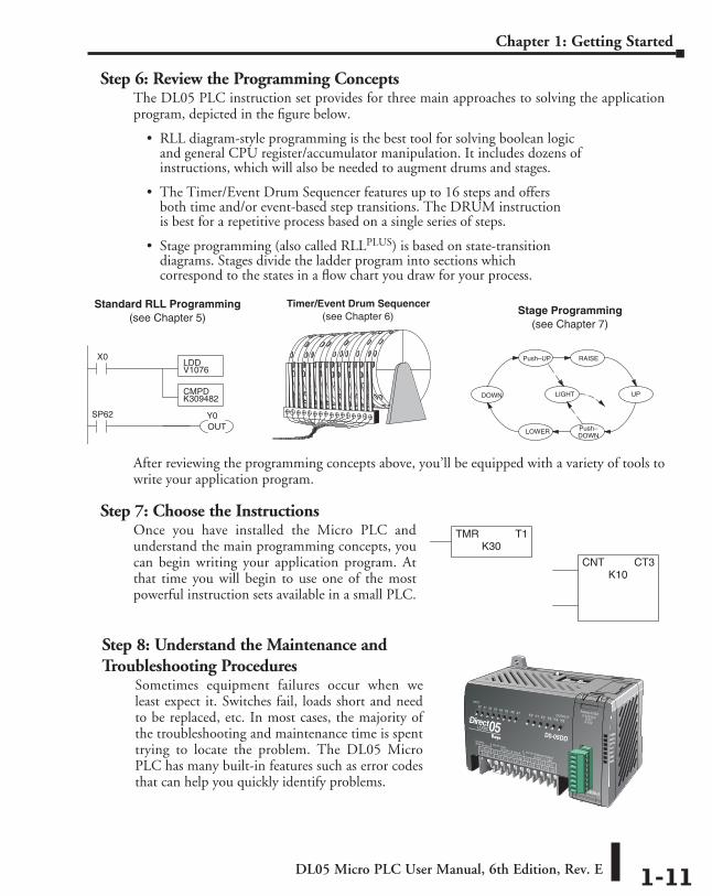
Step 6: Review the Programming ConceptsThe DL05 PLC instruction set provides for three main approaches to solving the application program, depicted in the figure below.
• RLL diagram-style programming is the best tool for solving boolean logic and general CPU register/accumulator manipulation. It includes dozens of instructions, which will also be needed to augment drums and stages.
• The Timer/Event Drum Sequencer features up to 16 steps and offers both time and/or event-based step transitions. The DRUM instruction is best for a repetitive process based on a single series of steps.
• Stage programming (also called RLLplus) is based on state-transition diagrams. Stages divide the ladder program into sections which correspond to the states in a flow chart you draw for your process.
After reviewing the programming concepts above, you’ll be equipped with a variety of tools to write your application program.
PWR
RUN
CPU
TX1
RX1
TX2
RX2
TMR T1K30
CNT CT3K10
Standard RLL Programming(see Chapter 5)
X0LDDV1076
CMPDK309482
SP62OUTY0
Timer/Event Drum Sequencer(see Chapter 6)
Push–DOWN
Push–UP
UPDOWN
LOWER
RAISE
LIGHT
Stage Programming(see Chapter 7)
Step 8: Understand the Maintenance and Troubleshooting Procedures
Sometimes equipment failures occur when we least expect it. Switches fail, loads short and need to be replaced, etc. In most cases, the majority of the troubleshooting and maintenance time is spent trying to locate the problem. The DL05 Micro PLC has many built-in features such as error codes that can help you quickly identify problems.
Step 7: Choose the InstructionsOnce you have installed the Micro PLC and understand the main programming concepts, you can begin writing your application program. At that time you will begin to use one of the most powerful instruction sets available in a small PLC.
DL05 Micro PLC User Manual, 6th Edition, Rev. E1-12
Chapter 1: Getting Started
Questions and Answers about DL05 Micro PLCsQ. What is the instruction set like?
A. The instruction set is very close to our popular DL240 CPU. However, there are significant additions, such as the drum instruction, networking, PID control and High-Speed I/O capabilities.
Q. Do I have to buy the full DirectSOFT programming package to program the DL05?
A. No, DirectSOFT programming software is available for programming DirectLOGIC PLCs for no additional charge; however this FREE version will only allow 100 maximum words to be programmed. Go to AutomationDirect.com for more information.
Q. Is the DL05 expandable?A. No, the DL05 series are stand-alone PLCs with one slot for the installation of an available
option module. They do not have expansion bases, such as our DL205 system which has expansion bases, yet are very compact and affordable.
Q. Does the DL05 have motion control capability?A. Yes. The units with DC I/O have selectable high-speed input features on three inputs. There
is also an optional High-Speed Counter I/O module available with special utility software. Either can accept pulse-type input signals for high-speed counting or timing applications and provide high-speed pulse-type output signals for stepper/servo motor control, monitoring, alarm or other discrete control functions. Three types of motion profiles are available, which are explained in Chapter 3.
Q. Are the ladder programs stored in a removable EEPROM?A. The DL05 contains a non-removable FLASH memory for program storage, which may be
written and erased thousands of times. You may transfer programs to/from the DL05 using DirectSOFT on a PC, or the HPP (which does support a removable EEPROM). There is an optional CMOS RAM memory cartridge (MC) available (See Chapter 10).
Q. Does the DL05 contain fuses for its outputs?A. There are no output circuit fuses. Therefore, we recommend fusing each channel, or fusing
each common. See Chapter 2 for I/O wiring guidelines.
Q. Is the DL05 Micro PLC UL approved?A. The Micro PLC has met the requirements of UL (Underwriters’ Laboratories, Inc.), and
CUL (Canadian Underwriters’ Laboratories, Inc.).
Q. Does the DL05 Micro PLC comply with European Union (EU) Directives?A. The Micro PLC has met the requirements of the European Union Directives (CE).
DL05 Micro PLC User Manual, 6th Edition, Rev. E 1-13
Chapter 1: Getting Started
Q. Which devices can I connect to the communication ports of the DL05?A. Port 1: The port is RS-232, fixed at 9600 baud, and uses the proprietary K-sequence
protocol. The DL05 can also connect to Modbus RTU and DirectNET networks as a slave device through port 1. The port communicates with the following devices:
• DirectSOFT (running on a personal computer)
• D2-HPP handheld programmer
• Other devices which communicate via K-sequence protocol should work with the DL05 Micro PLC. Contact the vendor for details.
A. Port 2: The port is RS232, with selective baud rates (300-38,400bps), address and parity. It also supports the proprietary K-sequence protocol as well as DirectNET and Modbus RTU and non-sequence/print protocols.
Q. Can the DL05 accept 5VDC inputs?A. No, 5 volts is lower than the DC input ON threshold. However, many TTL logic circuits
can drive the inputs if they are wired as open collector (sinking) inputs. See Chapter 2 for I/O wiring guidelines.
InstallatIon, WIrIng, and specIfIcatIons 222
ChapterChapterChapter
In This Chapter...Safety Guidelines ....................................................................................................... 2-2
Orientation to DL05 Front Panel .............................................................................. 2-5
Mounting Guidelines ................................................................................................. 2-7
Wiring Guidelines .................................................................................................... 2-11
System Wiring Strategies ........................................................................................ 2-14
Wiring Diagrams and Specifications ....................................................................... 2-31
Glossary of Specification Terms .............................................................................. 2-47
DL05 Micro PLC User Manual, 6th Edition, Rev. E2-2
Chapter 2: Installation, Wiring, and Specifications
Safety GuidelinesNOTE: Products with CE marks perform their required functions safely and adhere to relevant standards as specified by CE directives provided they are used according to their intended purpose and that the instructions in this manual are adhered to. The protection provided by the equipment may be impaired if this equipment is used in a manner not specified in this manual. A listing of our international affiliates is available on our Web site: http://www.automationdirect.com
WARNING: Providing a safe operating environment for personnel and equipment is your responsibility and should be your primary goal during system planning and installation. Automation systems can fail and may result in situations that can cause serious injury to personnel or damage to equipment. Do not rely on the automation system alone to provide a safe operating environment. You should use external electromechanical devices, such as relays or limit switches, that are independent of the PLC application to provide protection for any part of the system that may cause personal injury or damage. Every automation application is different, so there may be special requirements for your particular application. Make sure you follow all national, state, and local government requirements for the proper installation and use of your equipment.
Plan for SafetyThe best way to provide a safe operating environment is to make personnel and equipment safety part of the planning process. You should examine every aspect of the system to determine which areas are critical to operator or machine safety. If you are not familiar with PLC system installation practices, or your company does not have established installation guidelines, you should obtain additional information from the following sources.
• NEMA — The National Electrical Manufacturers Association, located in Washington, D.C., publishes many different documents that discuss standards for industrial control systems. You can order these publications directly from NEMA. Some of these include:
• ICS 1, General Standards for Industrial Control and Systems ICS 3, Industrial Systems ICS 6, Enclosures for Industrial Control Systems
• NEC — The National Electrical Code provides regulations concerning the installation and use of various types of electrical equipment. Copies of the NEC Handbook can often be obtained from your local electrical equipment distributor or your local library.
• Local and State Agencies — many local governments and state governments have additional requirements above and beyond those described in the NEC Handbook. Check with your local Electrical Inspector or Fire Marshall office for information.
DL05 Micro PLC User Manual, 6th Edition, Rev. E 2-3
Chapter 2: Installation, Wiring, and Specifications
Three Levels of ProtectionThe publications mentioned provide many ideas and requirements for system safety. At a minimum, you should follow these regulations. Also, you should use the following techniques, which provide three levels of system control.
• Emergency stop switch for disconnecting system power
• Mechanical disconnect for output module power
• Orderly system shutdown sequence in the PLC control program
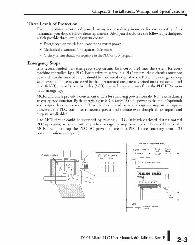
Emergency StopsIt is recommended that emergency stop circuits be incorporated into the system for every machine controlled by a PLC. For maximum safety in a PLC system, these circuits must not be wired into the controller, but should be hardwired external to the PLC. The emergency stop switches should be easily accessed by the operator and are generally wired into a master control relay (MCR) or a safety control relay (SCR) that will remove power from the PLC I/O system in an emergency.
MCRs and SCRs provide a convenient means for removing power from the I/O system during an emergency situation. By de-energizing an MCR (or SCR) coil, power to the input (optional) and output devices is removed. This event occurs when any emergency stop switch opens. However, the PLC continues to receive power and operate even though all its inputs and outputs are disabled.
The MCR circuit could be extended by placing a PLC fault relay (closed during normal PLC operation) in series with any other emergency stop conditions. This would cause the MCR circuit to drop the PLC I/O power in case of a PLC failure (memory error, I/O communications error, etc.).
SawArbor
E STOP
Emergency Stop
Power On
Use E-Stop and Master Relay
Guard Master Link Relay
?
Guard Line Switch
MCR
MCR
L1 to Output Commons
L1 to Input Commons(optional)
DL05 Micro PLC User Manual, 6th Edition, Rev. E2-4
Chapter 2: Installation, Wiring, and Specifications
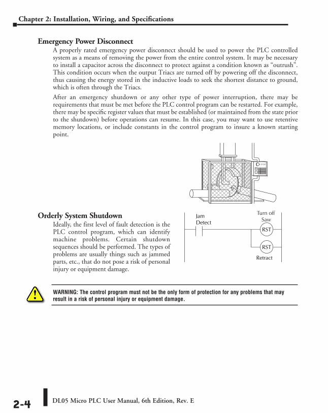
Emergency Power DisconnectA properly rated emergency power disconnect should be used to power the PLC controlled system as a means of removing the power from the entire control system. It may be necessary to install a capacitor across the disconnect to protect against a condition known as “outrush”. This condition occurs when the output Triacs are turned off by powering off the disconnect, thus causing the energy stored in the inductive loads to seek the shortest distance to ground, which is often through the Triacs.
After an emergency shutdown or any other type of power interruption, there may be requirements that must be met before the PLC control program can be restarted. For example, there may be specific register values that must be established (or maintained from the state prior to the shutdown) before operations can resume. In this case, you may want to use retentive memory locations, or include constants in the control program to insure a known starting point.
Orderly System ShutdownIdeally, the first level of fault detection is the PLC control program, which can identify machine problems. Certain shutdown sequences should be performed. The types of problems are usually things such as jammed parts, etc., that do not pose a risk of personal injury or equipment damage.
WARNING: The control program must not be the only form of protection for any problems that may result in a risk of personal injury or equipment damage.
JamDetect
RST
RST
RetractArm
Turn off Saw
DL05 Micro PLC User Manual, 6th Edition, Rev. E 2-5
Chapter 2: Installation, Wiring, and Specifications
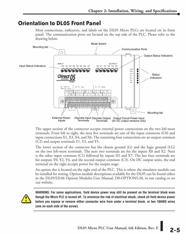
Orientation to DL05 Front PanelMost connections, indicators, and labels on the DL05 Micro PLCs are located on its front panel. The communication ports are located on the top side of the PLC. Please refer to the drawing below.
The upper section of the connector accepts external power connections on the two left-most terminals. From left to right, the next five terminals are one of the input commons (C0) and input connections X1, X3, X4, and X6. The remaining four connections are an output common (C2) and output terminals Y1, Y3, and Y5.
The lower section of the connector has the chassis ground (G) and the logic ground (LG) on the two left-most terminals. The next two terminals are for the inputs X0 and X2. Next is the other input common (C1) followed by inputs X5 and X7. The last four terminals are for outputs Y0, Y2, Y4, and the second output common (C3). On DC output units, the end terminal on the right accepts power for the output stage.
An option slot is located on the right end of the PLC. This is where the simulator module can be installed for testing. Option module descriptions available for the DL05 can be found either in the DL05/DL06 Options Modules User Manual, D0-OPTIONS-M, in our catalog or on our website.
WARNING: For some applications, field device power may still be present on the terminal block even though the Micro PLC is turned off. To minimize the risk of electrical shock, check all field device power before you expose or remove either connector wire from under a terminal block, or two 18AWG wires (one on each side of the screw).
Output Status Indicators
Input Status Indicators
Mounting tabCommunication Ports
Discrete Input Discrete Output External Power
StatusIndicators
Mode Switch
Mounting tab
Inputs Terminals TerminalsOutput Circuit Power Input
(for DC output versions only)
DL05 Micro PLC User Manual, 6th Edition, Rev. E2-6
Chapter 2: Installation, Wiring, and Specifications
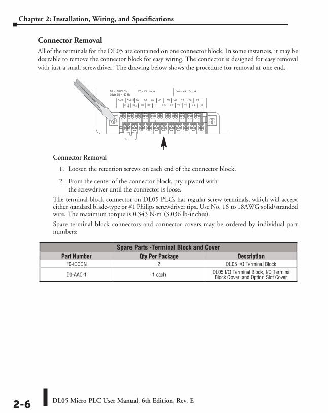
Connector RemovalAll of the terminals for the DL05 are contained on one connector block. In some instances, it may be desirable to remove the connector block for easy wiring. The connector is designed for easy removal with just a small screwdriver. The drawing below shows the procedure for removal at one end.
Connector Removal
1. Loosen the retention screws on each end of the connector block.
2. From the center of the connector block, pry upward with the screwdriver until the connector is loose.
The terminal block connector on DL05 PLCs has regular screw terminals, which will accept either standard blade-type or #1 Philips screwdriver tips. Use No. 16 to 18AWG solid/stranded wire. The maximum torque is 0.343 N·m (3.036 lb-inches).
Spare terminal block connectors and connector covers may be ordered by individual part numbers:
Spare Parts -Terminal Block and CoverPart Number Qty Per Package Description
F0-IOCON 2 DL05 I/O Terminal Block
D0-AAC-1 1 each DL05 I/O Terminal Block, I/O Terminal Block Cover, and Option Slot Cover
DL05 Micro PLC User Manual, 6th Edition, Rev. E 2-7
Chapter 2: Installation, Wiring, and Specifications
Mounting GuidelinesIn addition to the panel layout guidelines, other specifications can affect the definition and installation of a PLC system. Always consider the following:
• Environmental Specifications
• Power Requirements
• Agency Approvals
• Enclosure Selection and Component Dimensions
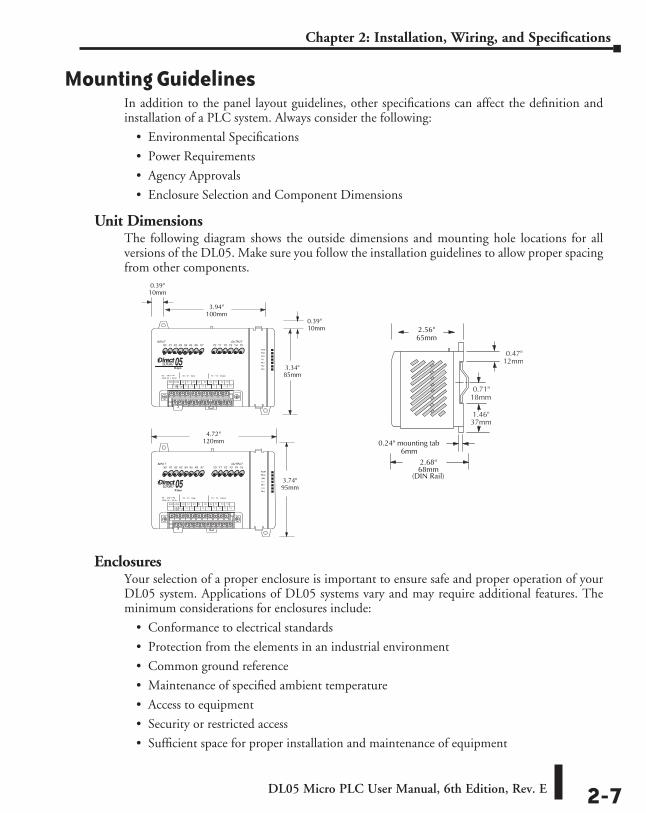
Unit DimensionsThe following diagram shows the outside dimensions and mounting hole locations for all versions of the DL05. Make sure you follow the installation guidelines to allow proper spacing from other components.
EnclosuresYour selection of a proper enclosure is important to ensure safe and proper operation of your DL05 system. Applications of DL05 systems vary and may require additional features. The minimum considerations for enclosures include:
• Conformance to electrical standards
• Protection from the elements in an industrial environment
• Common ground reference
• Maintenance of specified ambient temperature
• Access to equipment
• Security or restricted access
• Sufficient space for proper installation and maintenance of equipment
3.94"100mm
3.34"85mm
0.39"10mm
0.39"10mm
4.72"120mm
3.74"95mm
2.56"65mm
2.68"68mm
(DIN Rail)
0.24" mounting tab6mm
1.46"37mm
18mm0.71"
12mm0.47"
DL05 Micro PLC User Manual, 6th Edition, Rev. E2-8
Chapter 2: Installation, Wiring, and Specifications
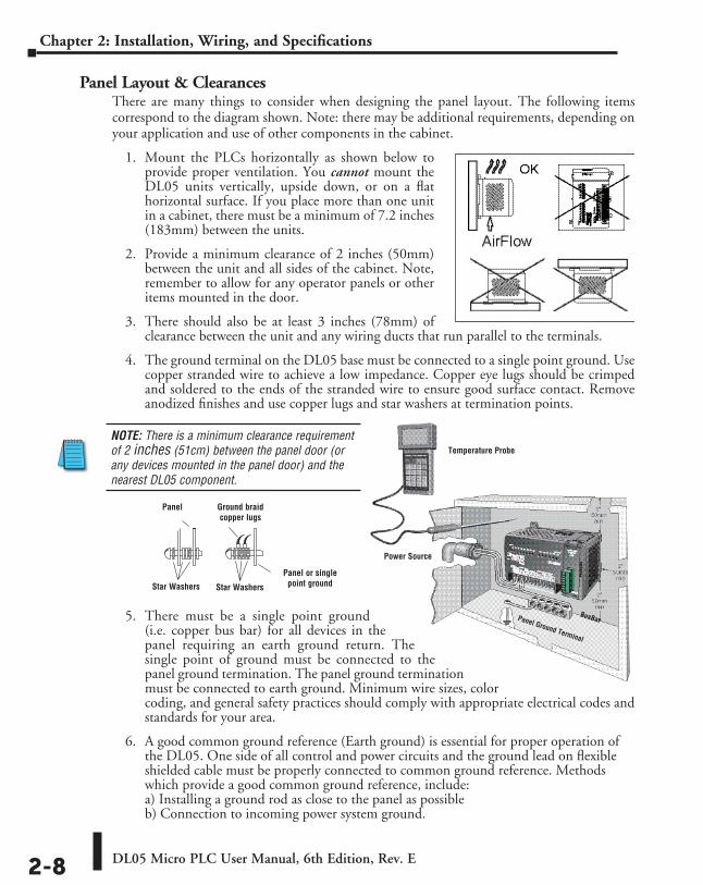
Panel Layout & ClearancesThere are many things to consider when designing the panel layout. The following items correspond to the diagram shown. Note: there may be additional requirements, depending on your application and use of other components in the cabinet.
1. Mount the PLCs horizontally as shown below to provide proper ventilation. You cannot mount the DL05 units vertically, upside down, or on a flat horizontal surface. If you place more than one unit in a cabinet, there must be a minimum of 7.2 inches (183mm) between the units.
2. Provide a minimum clearance of 2 inches (50mm) between the unit and all sides of the cabinet. Note, remember to allow for any operator panels or other items mounted in the door.
3. There should also be at least 3 inches (78mm) of clearance between the unit and any wiring ducts that run parallel to the terminals.
4. The ground terminal on the DL05 base must be connected to a single point ground. Use copper stranded wire to achieve a low impedance. Copper eye lugs should be crimped and soldered to the ends of the stranded wire to ensure good surface contact. Remove anodized finishes and use copper lugs and star washers at termination points.
5. There must be a single point ground (i.e. copper bus bar) for all devices in the panel requiring an earth ground return. The single point of ground must be connected to the panel ground termination. The panel ground termination must be connected to earth ground. Minimum wire sizes, color coding, and general safety practices should comply with appropriate electrical codes and standards for your area.
6. A good common ground reference (Earth ground) is essential for proper operation of the DL05. One side of all control and power circuits and the ground lead on flexible shielded cable must be properly connected to common ground reference. Methods which provide a good common ground reference, include: a) Installing a ground rod as close to the panel as possible b) Connection to incoming power system ground.
NOTE: There is a minimum clearance requirement of 2 inches (51cm) between the panel door (or any devices mounted in the panel door) and the nearest DL05 component.
Panel Ground braid copper lugs
Panel or single point groundStar WashersStar Washers
Panel Ground Terminal
Power Source
Temperature Probe
BusBar
DL05 Micro PLC User Manual, 6th Edition, Rev. E 2-9
Chapter 2: Installation, Wiring, and Specifications
7. Evaluate any installations where the ambient temperature may approach the lower or upper limits of the specifications. If you suspect the ambient temperature will not be within the operating specification for the DL05 system, measures such as installing a cooling/heating source must be taken to get the ambient temperature within the range of specifications.
8. The DL05 systems are designed to be powered by 95-240 VAC or 12–24 VDC normally available throughout an industrial environment. Electrical power in some areas where the PLCs are installed is not always stable and storms can cause power surges. Due to this, powerline filters are recommended for protecting the DL05 PLCs from power surges and EMI/RFI noise. The Automation Powerline Filter, for use with 120VAC and 240VAC, 1–5 Amps (part number APF120N05), is an excellent choice, however, you can use a filter of your choice. These units install easily between the power source and the PLC.
CAUTION: Always refer to the appropriate manual to determine the requisite mounting dimensions and how to properly setup and use the specific modules in your system.
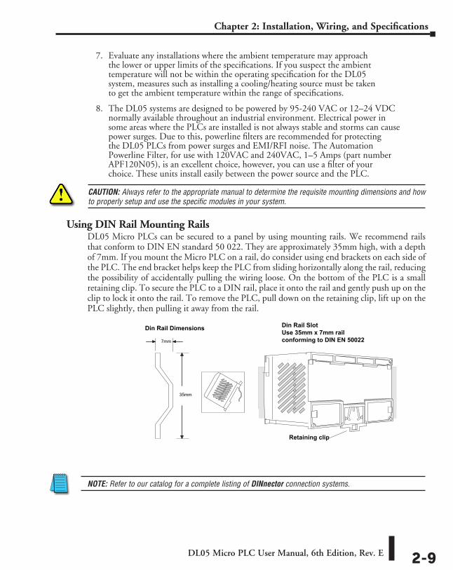
Using DIN Rail Mounting RailsDL05 Micro PLCs can be secured to a panel by using mounting rails. We recommend rails that conform to DIN EN standard 50 022. They are approximately 35mm high, with a depth of 7mm. If you mount the Micro PLC on a rail, do consider using end brackets on each side of the PLC. The end bracket helps keep the PLC from sliding horizontally along the rail, reducing the possibility of accidentally pulling the wiring loose. On the bottom of the PLC is a small retaining clip. To secure the PLC to a DIN rail, place it onto the rail and gently push up on the clip to lock it onto the rail. To remove the PLC, pull down on the retaining clip, lift up on the PLC slightly, then pulling it away from the rail.
NOTE: Refer to our catalog for a complete listing of DINnector connection systems.
35mm
7mm
Retaining clip
Din Rail Dimensions
Din Rail SlotUse 35mm x 7mm railconforming to DIN EN 50022
DL05 Micro PLC User Manual, 6th Edition, Rev. E2-10
Chapter 2: Installation, Wiring, and Specifications
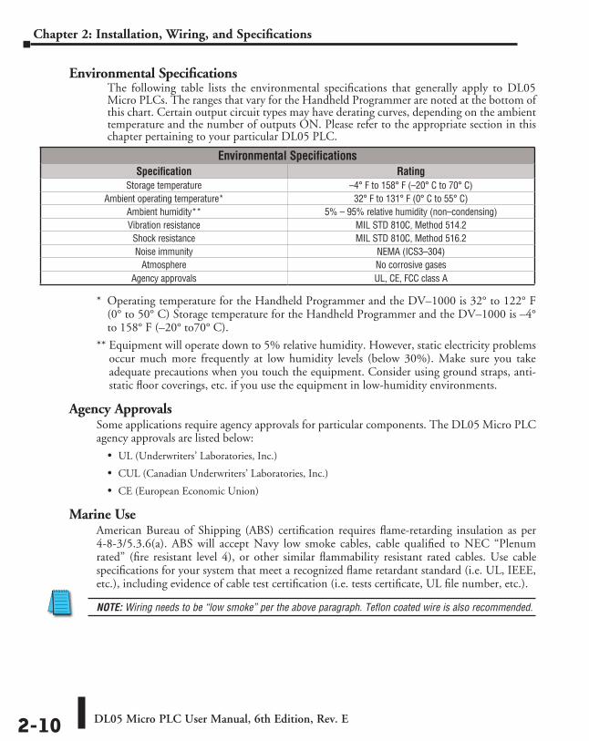
Environmental SpecificationsThe following table lists the environmental specifications that generally apply to DL05 Micro PLCs. The ranges that vary for the Handheld Programmer are noted at the bottom of this chart. Certain output circuit types may have derating curves, depending on the ambient temperature and the number of outputs ON. Please refer to the appropriate section in this chapter pertaining to your particular DL05 PLC.
* Operating temperature for the Handheld Programmer and the DV–1000 is 32° to 122° F (0° to 50° C) Storage temperature for the Handheld Programmer and the DV–1000 is –4° to 158° F (–20° to70° C).
** Equipment will operate down to 5% relative humidity. However, static electricity problems occur much more frequently at low humidity levels (below 30%). Make sure you take adequate precautions when you touch the equipment. Consider using ground straps, anti-static floor coverings, etc. if you use the equipment in low-humidity environments.
Agency ApprovalsSome applications require agency approvals for particular components. The DL05 Micro PLC agency approvals are listed below:
• UL (Underwriters’ Laboratories, Inc.)
• CUL (Canadian Underwriters’ Laboratories, Inc.)
• CE (European Economic Union)
Marine UseAmerican Bureau of Shipping (ABS) certification requires flame-retarding insulation as per 4-8-3/5.3.6(a). ABS will accept Navy low smoke cables, cable qualified to NEC “Plenum rated” (fire resistant level 4), or other similar flammability resistant rated cables. Use cable specifications for your system that meet a recognized flame retardant standard (i.e. UL, IEEE, etc.), including evidence of cable test certification (i.e. tests certificate, UL file number, etc.).
NOTE: Wiring needs to be “low smoke” per the above paragraph. Teflon coated wire is also recommended.
Environmental SpecificationsSpecification Rating
Storage temperature –4° F to 158° F (–20° C to 70° C)Ambient operating temperature* 32° F to 131° F (0° C to 55° C)
Ambient humidity** 5% – 95% relative humidity (non–condensing)Vibration resistance MIL STD 810C, Method 514.2
Shock resistance MIL STD 810C, Method 516.2Noise immunity NEMA (ICS3–304)
Atmosphere No corrosive gasesAgency approvals UL, CE, FCC class A
DL05 Micro PLC User Manual, 6th Edition, Rev. E 2-11
Chapter 2: Installation, Wiring, and Specifications
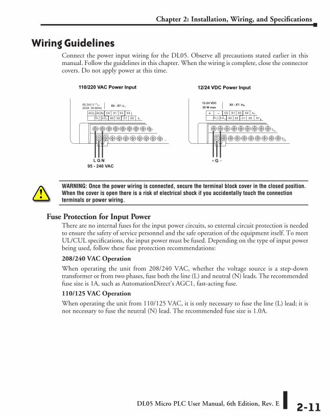
Wiring GuidelinesConnect the power input wiring for the DL05. Observe all precautions stated earlier in this manual. Follow the guidelines in this chapter. When the wiring is complete, close the connector covers. Do not apply power at this time.
WARNING: Once the power wiring is connected, secure the terminal block cover in the closed position. When the cover is open there is a risk of electrical shock if you accidentally touch the connection terminals or power wiring.
Fuse Protection for Input PowerThere are no internal fuses for the input power circuits, so external circuit protection is needed to ensure the safety of service personnel and the safe operation of the equipment itself. To meet UL/CUL specifications, the input power must be fused. Depending on the type of input power being used, follow these fuse protection recommendations:
208/240 VAC Operation
When operating the unit from 208/240 VAC, whether the voltage source is a step-down transformer or from two phases, fuse both the line (L) and neutral (N) leads. The recommended fuse size is 1A, such as AutomationDirect’s AGC1, fast-acting fuse.
110/125 VAC Operation
When operating the unit from 110/125 VAC, it is only necessary to fuse the line (L) lead; it is not necessary to fuse the neutral (N) lead. The recommended fuse size is 1.0A.
C3
Y0 - Y5: OutputX0 - X7: Input
110/220 VAC Power Input
L G N95 - 240 VAC
12/24 VDC Power Input
12-24 VDC20 W max
X0 - X7: Input Y0 - Y5: Output
G
DL05 Micro PLC User Manual, 6th Edition, Rev. E2-12
Chapter 2: Installation, Wiring, and Specifications
12/24 VDC Operation
When operating at these lower DC voltages, wire gauge size is just as important as proper fusing techniques. Using large conductors minimizes the voltage drop in the conductor. Each DL05 input power terminal can accommodate one 16AWG wire or two 18AWG wires. A DC failure can maintain an arc for much longer time and distance than AC failures. Typically, the main bus is fused at a higher level than the branch device, which in this case is the DL05. The recommended fuse size for the branch circuit to the DL05 is 1A, such as AutomationDirect’s AGC1, fast-acting fuse.
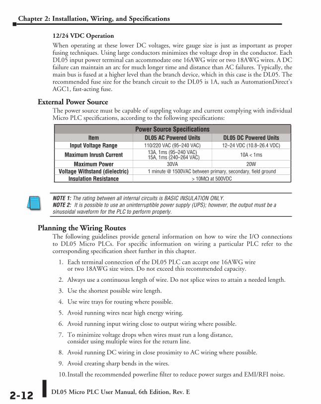
External Power SourceThe power source must be capable of suppling voltage and current complying with individual Micro PLC specifications, according to the following specifications:
NOTE 1: The rating between all internal circuits is BASIC INSULATION ONLY. NOTE 2: It is possible to use an uninterruptible power supply (UPS); however, the output must be a sinusoidal waveform for the PLC to perform properly.
Planning the Wiring RoutesThe following guidelines provide general information on how to wire the I/O connections to DL05 Micro PLCs. For specific information on wiring a particular PLC refer to the corresponding specification sheet further in this chapter.
1. Each terminal connection of the DL05 PLC can accept one 16AWG wire or two 18AWG size wires. Do not exceed this recommended capacity.
2. Always use a continuous length of wire. Do not splice wires to attain a needed length.
3. Use the shortest possible wire length.
4. Use wire trays for routing where possible.
5. Avoid running wires near high energy wiring.
6. Avoid running input wiring close to output wiring where possible.
7. To minimize voltage drops when wires must run a long distance, consider using multiple wires for the return line.
8. Avoid running DC wiring in close proximity to AC wiring where possible.
9. Avoid creating sharp bends in the wires.
10. Install the recommended powerline filter to reduce power surges and EMI/RFI noise.
Power Source SpecificationsItem DL05 AC Powered Units DL05 DC Powered Units
Input Voltage Range 110/220 VAC (95–240 VAC) 12–24 VDC (10.8–26.4 VDC)
Maximum Inrush Current 13A, 1ms (95–240 VAC) 15A, 1ms (240–264 VAC) 10A < 1ms
Maximum Power 30VA 20WVoltage Withstand (dielectric) 1 minute @ 1500VAC between primary, secondary, field ground
Insulation Resistance > 10Mq at 500VDC
DL05 Micro PLC User Manual, 6th Edition, Rev. E 2-13
Chapter 2: Installation, Wiring, and Specifications
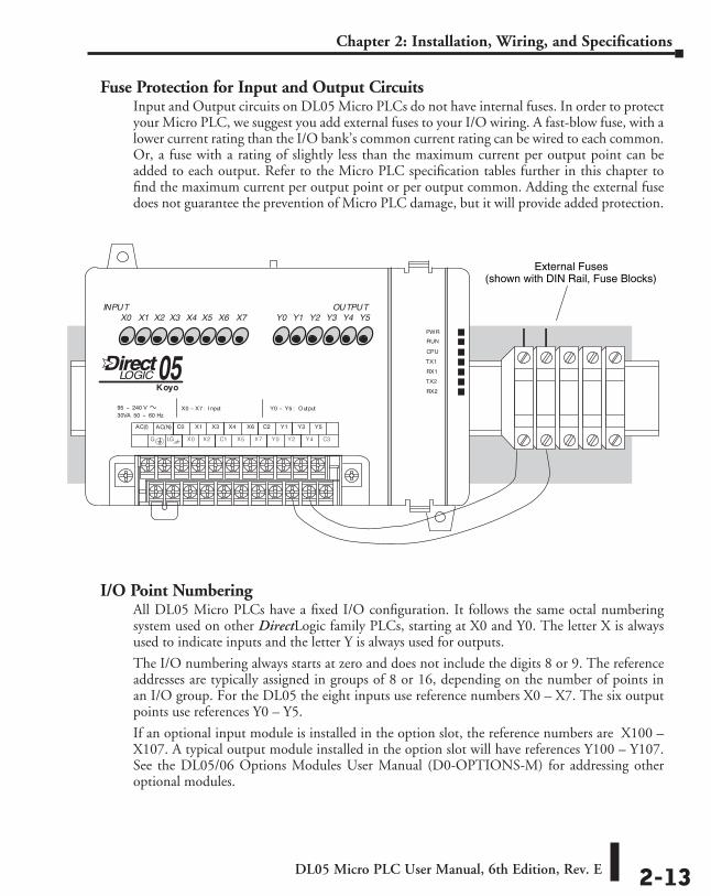
Fuse Protection for Input and Output CircuitsInput and Output circuits on DL05 Micro PLCs do not have internal fuses. In order to protect your Micro PLC, we suggest you add external fuses to your I/O wiring. A fast-blow fuse, with a lower current rating than the I/O bank’s common current rating can be wired to each common. Or, a fuse with a rating of slightly less than the maximum current per output point can be added to each output. Refer to the Micro PLC specification tables further in this chapter to find the maximum current per output point or per output common. Adding the external fuse does not guarantee the prevention of Micro PLC damage, but it will provide added protection.
I/O Point NumberingAll DL05 Micro PLCs have a fixed I/O configuration. It follows the same octal numbering system used on other DirectLogic family PLCs, starting at X0 and Y0. The letter X is always used to indicate inputs and the letter Y is always used for outputs.
The I/O numbering always starts at zero and does not include the digits 8 or 9. The reference addresses are typically assigned in groups of 8 or 16, depending on the number of points in an I/O group. For the DL05 the eight inputs use reference numbers X0 – X7. The six output points use references Y0 – Y5.
If an optional input module is installed in the option slot, the reference numbers are X100 – X107. A typical output module installed in the option slot will have references Y100 – Y107. See the DL05/06 Options Modules User Manual (D0-OPTIONS-M) for addressing other optional modules.
External Fuses(shown with DIN Rail, Fuse Blocks)
DL05 Micro PLC User Manual, 6th Edition, Rev. E2-14
Chapter 2: Installation, Wiring, and Specifications
System Wiring StrategiesThe DL05 Micro PLC is very flexible and will work in many different wiring configurations. By studying this section before actual installation, you can probably find the best wiring strategy for your application. This will help to lower system cost, wiring errors, and avoid safety problems.
PLC Isolation BoundariesPLC circuitry is divided into three main regions separated by isolation boundaries, shown in the drawing below. Electrical isolation provides safety, so that a fault in one area does not damage another. A powerline filter will provide isolation between the power source and the power supply. A transformer in the power supply provides magnetic isolation between the primary and secondary sides. Opto-couplers provide optical isolation in Input and Output circuits. This isolates logic circuitry from the field side, where factory machinery connects. Note that the discrete inputs are isolated from the discrete outputs, because each is isolated from the logic side. Isolation boundaries protect the operator interface (and the operator) from power input faults or field wiring faults. When wiring a PLC, it is extremely important to avoid making external connections which connect to the logic side of the PLC circuits.
The next figure shows the internal layout of DL05 PLCs, as viewed from the front panel.
Output CircuitInput Circuit
CPU2 Comm. Ports
Main PowerSupply
8 discrete inputs
Commons Commons6 discrete outputsPower Input
PLCDL05
Filter
To programming deviceor operator interface
CPU
Input Circuit Main
PowerSupply
Discrete inputsPower input
OutputCircuit
Primary Side Secondary,orLogic side
Field Side
PLC
Programming Device or Operator Interface
IsolationBoundary
IsolationBoundary
Filter
Discrete outputs
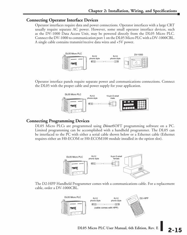
DL05 Micro PLC User Manual, 6th Edition, Rev. E 2-15
Chapter 2: Installation, Wiring, and Specifications
Connecting Operator Interface DevicesOperator interfaces require data and power connections. Operator interfaces with a large CRT usually require separate AC power. However, some small operator interface devices, such as the DV-1000 Data Access Unit, may be powered directly from the DL05 Micro PLC. Connect the DV-1000 to communication port 1 on the DL05 Micro PLC with a DV-1000CBL. A single cable contains transmit/receive data wires and +5V power.
Operator interface panels require separate power and communications connections. Connect the DL05 with the proper cable and power supply for your application.
Connecting Programming DevicesDL05 Micro PLCs are programmed using DirectSOFT programming software on a PC. Limited programming can be accomplished with a handheld programmer. The DL05 can be interfaced to the PC with either a serial cable shown below or a Ethernet cable (Ethernet requires either an H0-ECOM or H0-ECOM100 module installed in the option slot).
The D2-HPP Handheld Programmer comes with a communications cable. For a replacement cable, order a DV-1000CBL.
DL05 Micro PLC DV-1000RJ12
phone styleRJ12
phone style
DL05 Micro PLC15-pin D-shell
maleRJ12
phone style
9-pin D-shellfemale
RJ12phone style
DL05 Micro PLC
RJ12phone style
RJ12phone style
(cable comes with HPP)
DL05 Micro PLC D2–HPP
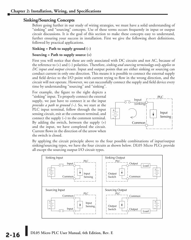
DL05 Micro PLC User Manual, 6th Edition, Rev. E2-16
Chapter 2: Installation, Wiring, and Specifications
Sinking/Sourcing ConceptsBefore going further in our study of wiring strategies, we must have a solid understanding of “sinking” and “sourcing” concepts. Use of these terms occurs frequently in input or output circuit discussions. It is the goal of this section to make these concepts easy to understand, further ensuring your success in installation. First we give the following short definitions, followed by practical applications.
Sinking = Path to supply ground (–)
Sourcing = Path to supply source (+)
First you will notice that these are only associated with DC circuits and not AC, because of the reference to (+) and (–) polarities. Therefore, sinking and sourcing terminology only applies to DC input and output circuits. Input and output points that are either sinking or sourcing can conduct current in only one direction. This means it is possible to connect the external supply and field device to the I/O point with current trying to flow in the wrong direction, and the circuit will not operate. However, we can successfully connect the supply and field device every time by understanding “sourcing” and “sinking”.
For example, the figure to the right depicts a “sinking” input. To properly connect the external supply, we just have to connect it so the input provides a path to ground (–). So, we start at the PLC input terminal, follow through the input sensing circuit, exit at the common terminal, and connect the supply (–) to the common terminal. By adding the switch, between the supply (+) and the input, we have completed the circuit. Current flows in the direction of the arrow when the switch is closed.
By applying the circuit principle above to the four possible combinations of input/output sinking/sourcing types, we have the four circuits as shown below. DL05 Micro PLCs provide all except the sourcing output I/O circuit types.
+
–
InputSensing
PLC
Common
Input(sinking)
+
–
Input Sensing
Load
Sinking Input Sinking Output
Sourcing Input Sourcing Output
PLCInput
Common
+
–
OutputSwitch
PLCOutput
Common
+
–
Input Sensing
Load
PLC
Input
Common
+
–
OutputSwitch
PLC
Output
Common
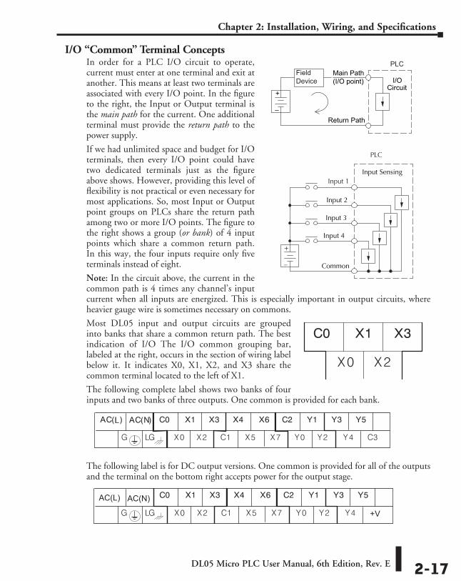
DL05 Micro PLC User Manual, 6th Edition, Rev. E 2-17
Chapter 2: Installation, Wiring, and Specifications
I/O “Common” Terminal ConceptsIn order for a PLC I/O circuit to operate, current must enter at one terminal and exit at another. This means at least two terminals are associated with every I/O point. In the figure to the right, the Input or Output terminal is the main path for the current. One additional terminal must provide the return path to the power supply.
If we had unlimited space and budget for I/O terminals, then every I/O point could have two dedicated terminals just as the figure above shows. However, providing this level of flexibility is not practical or even necessary for most applications. So, most Input or Output point groups on PLCs share the return path among two or more I/O points. The figure to the right shows a group (or bank) of 4 input points which share a common return path. In this way, the four inputs require only five terminals instead of eight.
Note: In the circuit above, the current in the common path is 4 times any channel’s input current when all inputs are energized. This is especially important in output circuits, where heavier gauge wire is sometimes necessary on commons.
Most DL05 input and output circuits are grouped into banks that share a common return path. The best indication of I/O The I/O common grouping bar, labeled at the right, occurs in the section of wiring label below it. It indicates X0, X1, X2, and X3 share the common terminal located to the left of X1.
The following complete label shows two banks of four inputs and two banks of three outputs. One common is provided for each bank.
The following label is for DC output versions. One common is provided for all of the outputs and the terminal on the bottom right accepts power for the output stage.
+
–
I/OCircuit
Return Path
Main Path(I/O point)
FieldDevice
PLC
+
–
Input Sensing
Input 4
Common
Input 3
Input 2
PLC
Input 1
AC(L) AC(N)
+V
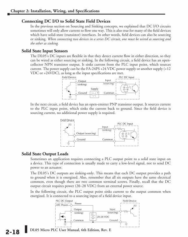
DL05 Micro PLC User Manual, 6th Edition, Rev. E2-18
Chapter 2: Installation, Wiring, and Specifications
Connecting DC I/O to Solid State Field DevicesIn the previous section on Sourcing and Sinking concepts, we explained that DC I/O circuits sometimes will only allow current to flow one way. This is also true for many of the field devices which have solid-state (transistor) interfaces. In other words, field devices can also be sourcing or sinking. When connecting two devices in a series DC circuit, one must be wired as sourcing and the other as sinking.
Solid State Input SensorsThe DL05’s DC inputs are flexible in that they detect current flow in either direction, so they can be wired as either sourcing or sinking. In the following circuit, a field device has an open-collector NPN transistor output. It sinks current from the PLC input point, which sources current. The power supply can be the FA-24PS +24 VDC power supply or another supply (+12 VDC or +24VDC), as long as the input specifications are met.
In the next circuit, a field device has an open-emitter PNP transistor output. It sources current to the PLC input point, which sinks the current back to ground. Since the field device is sourcing current, no additional power supply is required.
Solid State Output LoadsSometimes an application requires connecting a PLC output point to a solid state input on a device. This type of connection is usually made to carry a low-level signal, not to send DC power to an actuator.
The DL05’s DC outputs are sinking-only. This means that each DC output provides a path to ground when it is energized. Also, remember that all six outputs have the same electrical common, even though there are two common terminal screws. Finally, recall that the DC output circuit requires power (20–28 VDC) from an external power source.
In the following circuit, the PLC output point sinks current to the output common when energized. It is connected to a sourcing input of a field device input.
Field Device
+–
PLC DC Input
Output
Ground
Common
Supply
(sinking)
Input(sourcing)
Field DevicePLC DC Input
Output (sourcing)
Ground Common
=>
Input(sinking)
Field Device
Output
Common
=>
PLC DC Output
+DC Power
+
–
(sourcing) (sinking)
Power
20-28 VDC
Input
Ground
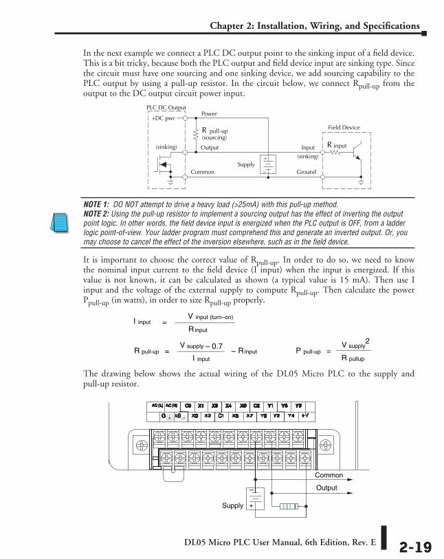
DL05 Micro PLC User Manual, 6th Edition, Rev. E 2-19
Chapter 2: Installation, Wiring, and Specifications
In the next example we connect a PLC DC output point to the sinking input of a field device. This is a bit tricky, because both the PLC output and field device input are sinking type. Since the circuit must have one sourcing and one sinking device, we add sourcing capability to the PLC output by using a pull-up resistor. In the circuit below, we connect Rpull-up from the output to the DC output circuit power input.
NOTE 1: DO NOT attempt to drive a heavy load (>25mA) with this pull-up method. NOTE 2: Using the pull-up resistor to implement a sourcing output has the effect of inverting the output point logic. In other words, the field device input is energized when the PLC output is OFF, from a ladder logic point-of-view. Your ladder program must comprehend this and generate an inverted output. Or, you may choose to cancel the effect of the inversion elsewhere, such as in the field device.
It is important to choose the correct value of Rpull-up. In order to do so, we need to know the nominal input current to the field device (I input) when the input is energized. If this value is not known, it can be calculated as shown (a typical value is 15 mA). Then use I input and the voltage of the external supply to compute Rpull-up. Then calculate the power Ppull-up (in watts), in order to size Rpull-up properly.
The drawing below shows the actual wiring of the DL05 Micro PLC to the supply and pull-up resistor.
Field Device
Output
Ground
Input
Common
PLC DC Output
+DC pwr
+
–
(sourcing)
(sinking)
Power
(sinking)
pull-up
Supply
R
inputR
pull-upR inputR=supplyV – 0.7
–inputI
inputI =input (turn–on)V
inputR
pull-upP =supplyV 2
pullupR
+
– Output
Common
Supply
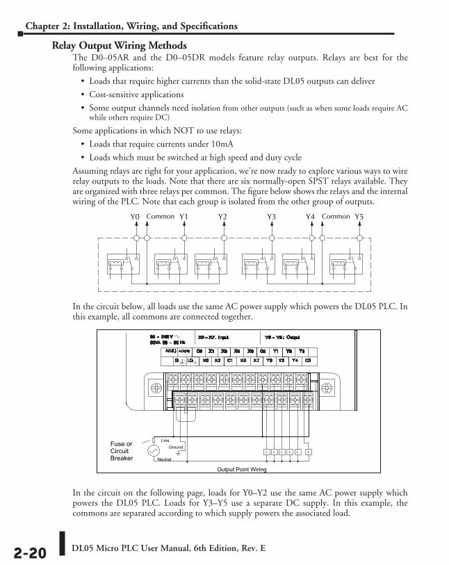
DL05 Micro PLC User Manual, 6th Edition, Rev. E2-20
Chapter 2: Installation, Wiring, and Specifications
Relay Output Wiring MethodsThe D0–05AR and the D0–05DR models feature relay outputs. Relays are best for the following applications:
• Loads that require higher currents than the solid-state DL05 outputs can deliver
• Cost-sensitive applications
• Some output channels need isolation from other outputs (such as when some loads require AC while others require DC)
Some applications in which NOT to use relays:
• Loads that require currents under 10mA
• Loads which must be switched at high speed and duty cycle
Assuming relays are right for your application, we’re now ready to explore various ways to wire relay outputs to the loads. Note that there are six normally-open SPST relays available. They are organized with three relays per common. The figure below shows the relays and the internal wiring of the PLC. Note that each group is isolated from the other group of outputs.
In the circuit below, all loads use the same AC power supply which powers the DL05 PLC. In this example, all commons are connected together.
In the circuit on the following page, loads for Y0–Y2 use the same AC power supply which powers the DL05 PLC. Loads for Y3–Y5 use a separate DC supply. In this example, the commons are separated according to which supply powers the associated load.
Y0 Common Y1 Y2 Y3 Y4 Common Y5
Output Point Wiring
Ground
Neutral
LineFuse orCircuitBreaker
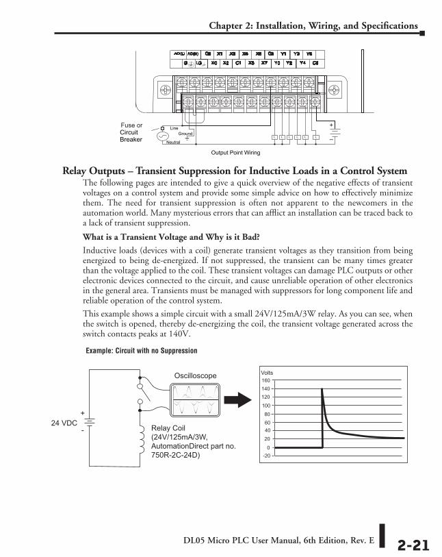
DL05 Micro PLC User Manual, 6th Edition, Rev. E 2-21
Chapter 2: Installation, Wiring, and Specifications
Relay Outputs – Transient Suppression for Inductive Loads in a Control SystemThe following pages are intended to give a quick overview of the negative effects of transient voltages on a control system and provide some simple advice on how to effectively minimize them. The need for transient suppression is often not apparent to the newcomers in the automation world. Many mysterious errors that can afflict an installation can be traced back to a lack of transient suppression.
What is a Transient Voltage and Why is it Bad?
Inductive loads (devices with a coil) generate transient voltages as they transition from being energized to being de-energized. If not suppressed, the transient can be many times greater than the voltage applied to the coil. These transient voltages can damage PLC outputs or other electronic devices connected to the circuit, and cause unreliable operation of other electronics in the general area. Transients must be managed with suppressors for long component life and reliable operation of the control system.
This example shows a simple circuit with a small 24V/125mA/3W relay. As you can see, when the switch is opened, thereby de-energizing the coil, the transient voltage generated across the switch contacts peaks at 140V.
Output Point Wiring
Ground
Neutral
LineFuse orCircuitBreaker
+
–
Oscilloscope
Relay Coil(24V/125mA/3W, AutomationDirect part no.750R-2C-24D)
24 VDC+
-
160140120
100
40
20
-20
Volts
80
60
0
Example: Circuit with no Suppression
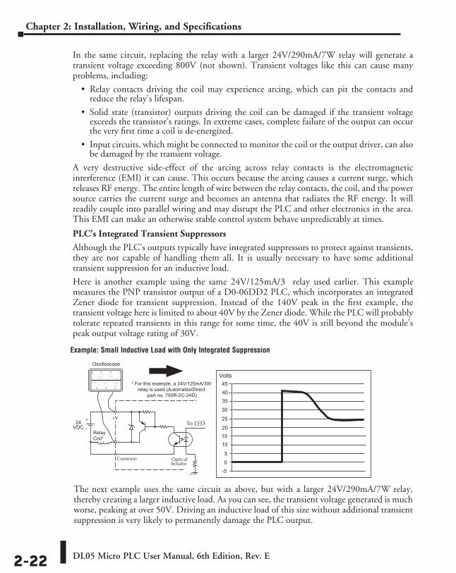
DL05 Micro PLC User Manual, 6th Edition, Rev. E2-22
Chapter 2: Installation, Wiring, and Specifications
In the same circuit, replacing the relay with a larger 24V/290mA/7W relay will generate a transient voltage exceeding 800V (not shown). Transient voltages like this can cause many problems, including:
• Relay contacts driving the coil may experience arcing, which can pit the contacts and reduce the relay’s lifespan.
• Solid state (transistor) outputs driving the coil can be damaged if the transient voltage exceeds the transistor’s ratings. In extreme cases, complete failure of the output can occur the very first time a coil is de-energized.
• Input circuits, which might be connected to monitor the coil or the output driver, can also be damaged by the transient voltage.
A very destructive side-effect of the arcing across relay contacts is the electromagnetic interference (EMI) it can cause. This occurs because the arcing causes a current surge, which releases RF energy. The entire length of wire between the relay contacts, the coil, and the power source carries the current surge and becomes an antenna that radiates the RF energy. It will readily couple into parallel wiring and may disrupt the PLC and other electronics in the area. This EMI can make an otherwise stable control system behave unpredictably at times.
PLC’s Integrated Transient Suppressors
Although the PLC’s outputs typically have integrated suppressors to protect against transients, they are not capable of handling them all. It is usually necessary to have some additional transient suppression for an inductive load.
Here is another example using the same 24V/125mA/3 relay used earlier. This example measures the PNP transistor output of a D0-06DD2 PLC, which incorporates an integrated Zener diode for transient suppression. Instead of the 140V peak in the first example, the transient voltage here is limited to about 40V by the Zener diode. While the PLC will probably tolerate repeated transients in this range for some time, the 40V is still beyond the module’s peak output voltage rating of 30V.
Example: Small Inductive Load with Only Integrated Suppression
The next example uses the same circuit as above, but with a larger 24V/290mA/7W relay, thereby creating a larger inductive load. As you can see, the transient voltage generated is much worse, peaking at over 50V. Driving an inductive load of this size without additional transient suppression is very likely to permanently damage the PLC output.
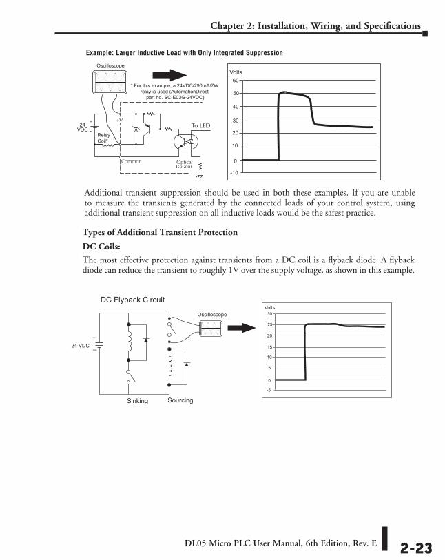
DL05 Micro PLC User Manual, 6th Edition, Rev. E 2-23
Chapter 2: Installation, Wiring, and Specifications
Example: Larger Inductive Load with Only Integrated Suppression
Additional transient suppression should be used in both these examples. If you are unable to measure the transients generated by the connected loads of your control system, using additional transient suppression on all inductive loads would be the safest practice.
Types of Additional Transient Protection
DC Coils:
The most effective protection against transients from a DC coil is a flyback diode. A flyback diode can reduce the transient to roughly 1V over the supply voltage, as shown in this example.
Oscilloscope
24 VDC
DC Flyback Circuit
Sinking Sourcing
+_
30
25
20
15
10
5
0
-5
Volts
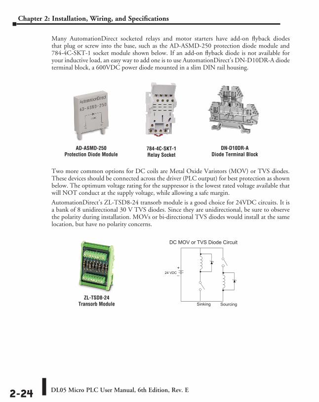
DL05 Micro PLC User Manual, 6th Edition, Rev. E2-24
Chapter 2: Installation, Wiring, and Specifications
Many AutomationDirect socketed relays and motor starters have add-on flyback diodes that plug or screw into the base, such as the AD-ASMD-250 protection diode module and 784-4C-SKT-1 socket module shown below. If an add-on flyback diode is not available for your inductive load, an easy way to add one is to use AutomationDirect’s DN-D10DR-A diode terminal block, a 600VDC power diode mounted in a slim DIN rail housing.
Two more common options for DC coils are Metal Oxide Varistors (MOV) or TVS diodes. These devices should be connected across the driver (PLC output) for best protection as shown below. The optimum voltage rating for the suppressor is the lowest rated voltage available that will NOT conduct at the supply voltage, while allowing a safe margin.
AutomationDirect’s ZL-TSD8-24 transorb module is a good choice for 24VDC circuits. It is a bank of 8 unidirectional 30 V TVS diodes. Since they are unidirectional, be sure to observe the polarity during installation. MOVs or bi-directional TVS diodes would install at the same location, but have no polarity concerns.
DN-D10DR-ADiode Terminal Block
AD-ASMD-250Protection Diode Module
784-4C-SKT-1 Relay Socket
ZL-TSD8-24 Transorb Module
24 VDC
DC MOV or TVS Diode Circuit
Sinking Sourcing
+_
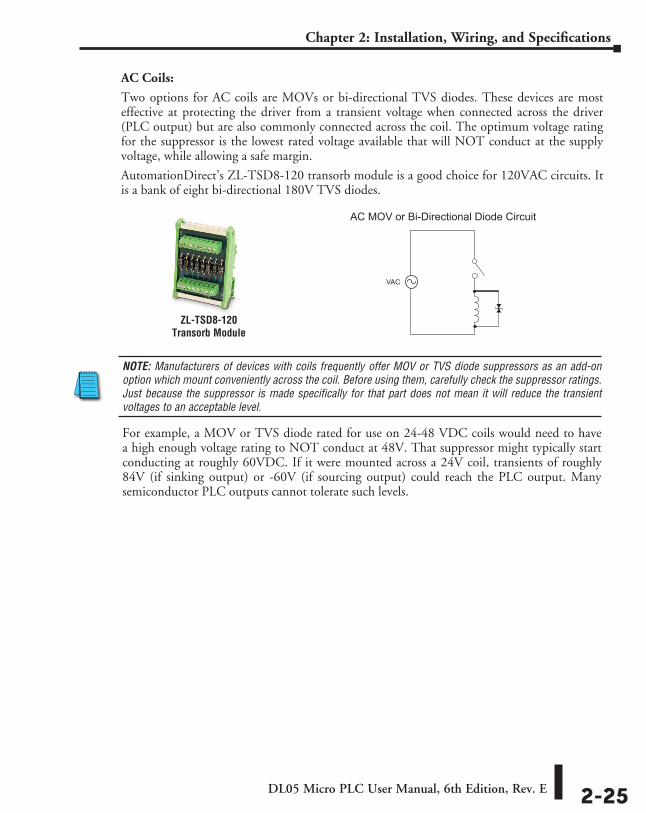
DL05 Micro PLC User Manual, 6th Edition, Rev. E 2-25
Chapter 2: Installation, Wiring, and Specifications
AC Coils:
Two options for AC coils are MOVs or bi-directional TVS diodes. These devices are most effective at protecting the driver from a transient voltage when connected across the driver (PLC output) but are also commonly connected across the coil. The optimum voltage rating for the suppressor is the lowest rated voltage available that will NOT conduct at the supply voltage, while allowing a safe margin.
AutomationDirect’s ZL-TSD8-120 transorb module is a good choice for 120VAC circuits. It is a bank of eight bi-directional 180V TVS diodes.
ZL-TSD8-120Transorb Module
NOTE: Manufacturers of devices with coils frequently offer MOV or TVS diode suppressors as an add-on option which mount conveniently across the coil. Before using them, carefully check the suppressor ratings. Just because the suppressor is made specifically for that part does not mean it will reduce the transient voltages to an acceptable level.
For example, a MOV or TVS diode rated for use on 24-48 VDC coils would need to have a high enough voltage rating to NOT conduct at 48V. That suppressor might typically start conducting at roughly 60VDC. If it were mounted across a 24V coil, transients of roughly 84V (if sinking output) or -60V (if sourcing output) could reach the PLC output. Many semiconductor PLC outputs cannot tolerate such levels.
VAC
AC MOV or Bi-Directional Diode Circuit
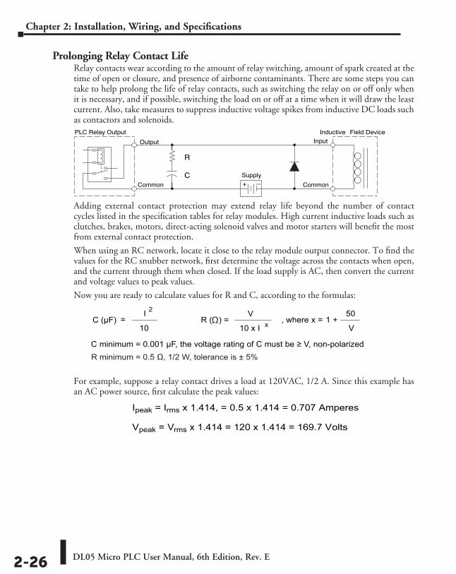
DL05 Micro PLC User Manual, 6th Edition, Rev. E2-26
Chapter 2: Installation, Wiring, and Specifications
Prolonging Relay Contact LifeRelay contacts wear according to the amount of relay switching, amount of spark created at the time of open or closure, and presence of airborne contaminants. There are some steps you can take to help prolong the life of relay contacts, such as switching the relay on or off only when it is necessary, and if possible, switching the load on or off at a time when it will draw the least current. Also, take measures to suppress inductive voltage spikes from inductive DC loads such as contactors and solenoids.
Adding external contact protection may extend relay life beyond the number of contact cycles listed in the specification tables for relay modules. High current inductive loads such as clutches, brakes, motors, direct-acting solenoid valves and motor starters will benefit the most from external contact protection.
When using an RC network, locate it close to the relay module output connector. To find the values for the RC snubber network, first determine the voltage across the contacts when open, and the current through them when closed. If the load supply is AC, then convert the current and voltage values to peak values.
Now you are ready to calculate values for R and C, according to the formulas:
For example, suppose a relay contact drives a load at 120VAC, 1/2 A. Since this example has an AC power source, first calculate the peak values:
Inductive Field Device
+ –
PLC Relay Output
Output
Common
Input
Common
Supply
R
C
R ( ) =C (µF) =10
I 2 V
10 x I x, where x =
50
V1 +
C minimum = 0.001 µF, the voltage rating of C must be ≥ V, non-polarized
Ω
R minimum = 0.5 Ω, 1/2 W, tolerance is ± 5%
Ipeak = Irms x 1.414, = 0.5 x 1.414 = 0.707 Amperes
Vpeak = Vrms x 1.414 = 120 x 1.414 = 169.7 Volts
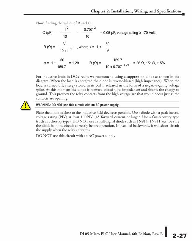
DL05 Micro PLC User Manual, 6th Edition, Rev. E 2-27
Chapter 2: Installation, Wiring, and Specifications
Now, finding the values of R and C,:
For inductive loads in DC circuits we recommend using a suppression diode as shown in the diagram. When the load is energized the diode is reverse-biased (high impedance). When the load is turned off, energy stored in its coil is released in the form of a negative-going voltage spike. At this moment the diode is forward-biased (low impedance) and shunts the energy to ground. This protects the relay contacts from the high voltage arc that would occur just as the contacts are opening.
WARNING: DO NOT use this circuit with an AC power supply.
Place the diode as close to the inductive field device as possible. Use a diode with a peak inverse voltage rating (PIV) at least 100PIV, 3A forward current or larger. Use a fast-recovery type (such as Schottky type). DO NOT use a small-signal diode such as 1N914, 1N941, etc. Be sure the diode is in the circuit correctly before operation. If installed backwards, it will short-circuit the supply when the relay energizes.
DO NOT use this circuit with an AC power supply.
R (Ω) =
10
I 2
V
10 x I x, where x =
50
V1 +
=10
0.707 2
= 0.05 µF, voltage rating ≥ 170 Volts
x =50
169.71 + = 1.29 R (Ω) =
169.7
10 x 0.707 1.29= 26 Ω, 1/2 W, ± 5%
C (µF) =
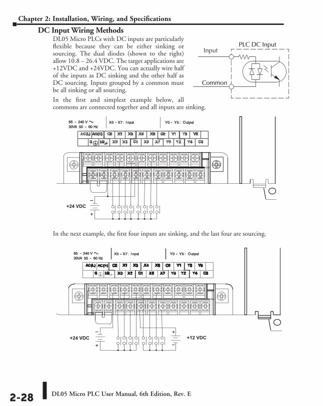
DL05 Micro PLC User Manual, 6th Edition, Rev. E2-28
Chapter 2: Installation, Wiring, and Specifications
DC Input Wiring MethodsDL05 Micro PLCs with DC inputs are particularly flexible because they can be either sinking or sourcing. The dual diodes (shown to the right) allow 10.8 – 26.4 VDC. The target applications are +12VDC and +24VDC. You can actually wire half of the inputs as DC sinking and the other half as DC sourcing. Inputs grouped by a common must be all sinking or all sourcing.
In the first and simplest example below, all commons are connected together and all inputs are sinking.
In the next example, the first four inputs are sinking, and the last four are sourcing.
PLC DC Input
Common
Input
+
–+24 VDC
+
– +
–+24 VDC +12 VDC
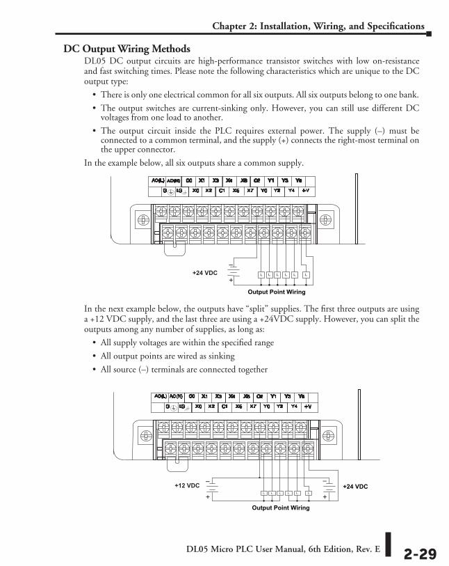
DL05 Micro PLC User Manual, 6th Edition, Rev. E 2-29
Chapter 2: Installation, Wiring, and Specifications
DC Output Wiring MethodsDL05 DC output circuits are high-performance transistor switches with low on-resistance and fast switching times. Please note the following characteristics which are unique to the DC output type:
• There is only one electrical common for all six outputs. All six outputs belong to one bank.
• The output switches are current-sinking only. However, you can still use different DC voltages from one load to another.
• The output circuit inside the PLC requires external power. The supply (–) must be connected to a common terminal, and the supply (+) connects the right-most terminal on the upper connector.
In the example below, all six outputs share a common supply.
In the next example below, the outputs have “split” supplies. The first three outputs are using a +12 VDC supply, and the last three are using a +24VDC supply. However, you can split the outputs among any number of supplies, as long as:
• All supply voltages are within the specified range
• All output points are wired as sinking
• All source (–) terminals are connected together
Output Point Wiring
+
–+24 VDC
+
–
+
–+24 VDC
Output Point Wiring
+12 VDC
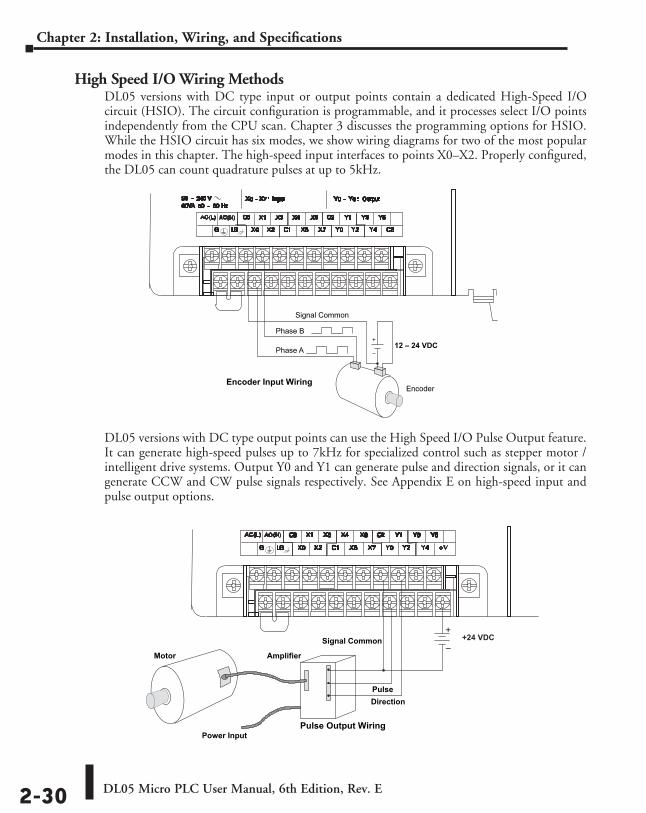
DL05 Micro PLC User Manual, 6th Edition, Rev. E2-30
Chapter 2: Installation, Wiring, and Specifications
High Speed I/O Wiring MethodsDL05 versions with DC type input or output points contain a dedicated High-Speed I/O circuit (HSIO). The circuit configuration is programmable, and it processes select I/O points independently from the CPU scan. Chapter 3 discusses the programming options for HSIO. While the HSIO circuit has six modes, we show wiring diagrams for two of the most popular modes in this chapter. The high-speed input interfaces to points X0–X2. Properly configured, the DL05 can count quadrature pulses at up to 5kHz.
DL05 versions with DC type output points can use the High Speed I/O Pulse Output feature. It can generate high-speed pulses up to 7kHz for specialized control such as stepper motor / intelligent drive systems. Output Y0 and Y1 can generate pulse and direction signals, or it can generate CCW and CW pulse signals respectively. See Appendix E on high-speed input and pulse output options.
Encoder Input Wiring
+
–12 – 24 VDCPhase A
Phase B
Encoder
Signal Common
Signal Common
Motor Amplifier
Pulse Output WiringPower Input
PulseDirection
+
–+24 VDC
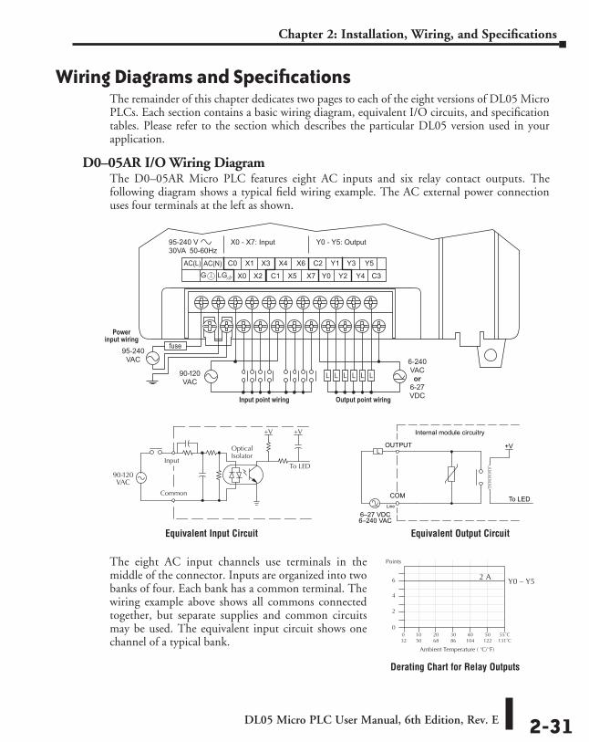
DL05 Micro PLC User Manual, 6th Edition, Rev. E 2-31
Chapter 2: Installation, Wiring, and Specifications
Wiring Diagrams and SpecificationsThe remainder of this chapter dedicates two pages to each of the eight versions of DL05 Micro PLCs. Each section contains a basic wiring diagram, equivalent I/O circuits, and specification tables. Please refer to the section which describes the particular DL05 version used in your application.
D0–05AR I/O Wiring DiagramThe D0–05AR Micro PLC features eight AC inputs and six relay contact outputs. The following diagram shows a typical field wiring example. The AC external power connection uses four terminals at the left as shown.
90-120VAC
6-240VACor
6-27VDC
95-240VAC
Powerinput wiring
Input point wiring Output point wiring
Equivalent Input Circuit
Derating Chart for Relay Outputs
COM
OUTPUT
To LED
Internal module circuitry
6–240 VAC
L
6–27 VDCLine
+V
Equivalent Output Circuit
The eight AC input channels use terminals in the middle of the connector. Inputs are organized into two banks of four. Each bank has a common terminal. The wiring example above shows all commons connected together, but separate supplies and common circuits may be used. The equivalent input circuit shows one channel of a typical bank.
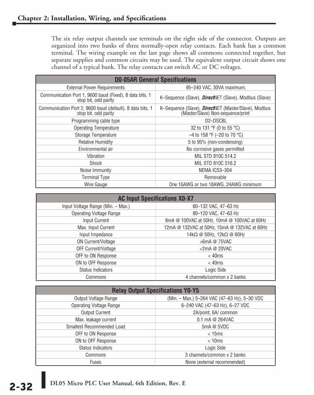
DL05 Micro PLC User Manual, 6th Edition, Rev. E2-32
Chapter 2: Installation, Wiring, and Specifications
The six relay output channels use terminals on the right side of the connector. Outputs are organized into two banks of three normally-open relay contacts. Each bank has a common terminal. The wiring example on the last page shows all commons connected together, but separate supplies and common circuits may be used. The equivalent output circuit shows one channel of a typical bank. The relay contacts can switch AC or DC voltages.
D0-05AR General SpecificationsExternal Power Requirements 95–240 VAC, 30VA maximum,
Communication Port 1, 9600 baud (Fixed), 8 data bits, 1 stop bit, odd parity K–Sequence (Slave), DirectNET (Slave), Modbus (Slave)
Communication Port 2, 9600 baud (default), 8 data bits, 1 stop bit, odd parity
K–Sequence (Slave), DirectNET (Master/Slave), Modbus (Master/Slave) Non-sequence/print
Programming cable type D2–DSCBL Operating Temperature 32 to 131 °F (0 to 55 °C)Storage Temperature –4 to 158 °F (–20 to 70 °C)
Relative Humidity 5 to 95% (non-condensing)Environmental air No corrosive gases permitted
Vibration MIL STD 810C 514.2Shock MIL STD 810C 516.2
Noise Immunity NEMA ICS3–304Terminal Type RemovableWire Gauge One 16AWG or two 18AWG, 24AWG minimum
AC Input Specifications X0-X7Input Voltage Range (Min. – Max.) 80–132 VAC, 47–63 Hz
Operating Voltage Range 90–120 VAC, 47–63 HzInput Current 8mA @ 100VAC at 50Hz, 10mA @ 100VAC at 60Hz
Max. Input Current 12mA @ 132VAC at 50Hz, 15mA @ 132VAC at 60HzInput Impedance 14kq @ 50Hz, 12kq @ 60Hz
ON Current/Voltage >6mA @ 75VACOFF Current/Voltage <2mA @ 20VACOFF to ON Response < 40msON to OFF Response < 40ms
Status Indicators Logic SideCommons 4 channels/common x 2 banks
Relay Output Specifications Y0-Y5Output Voltage Range (Min. – Max.) 5–264 VAC (47–63 Hz), 5–30 VDC
Operating Voltage Range 6–240 VAC (47–63 Hz), 6–27 VDCOutput Current 2A/point, 6A/ common
Max. leakage current 0.1 mA @ 264VACSmallest Recommended Load 5mA @ 5VDC
OFF to ON Response < 15msON to OFF Response < 10ms
Status Indicators Logic SideCommons 3 channels/common x 2 banks
Fuses None (external recommended)
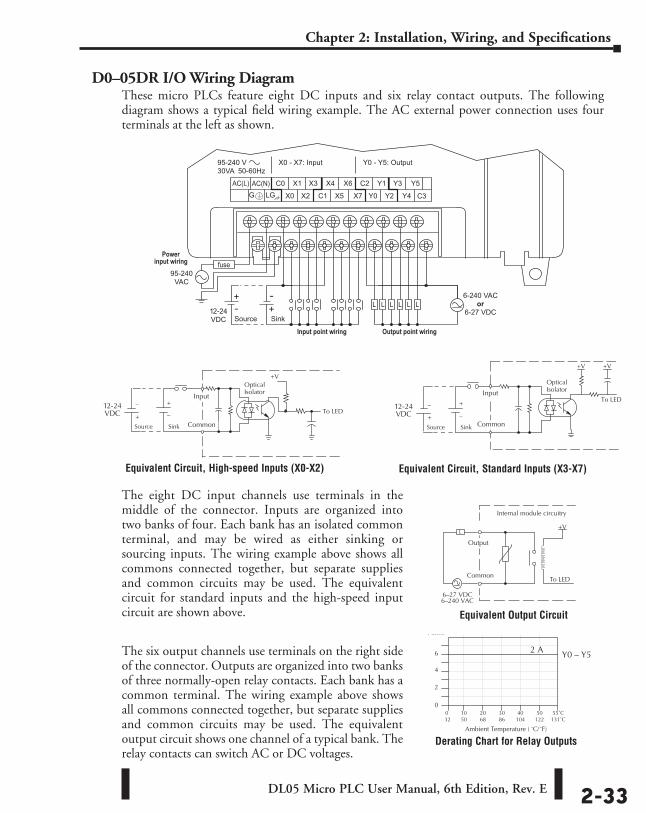
DL05 Micro PLC User Manual, 6th Edition, Rev. E 2-33
Chapter 2: Installation, Wiring, and Specifications
D0–05DR I/O Wiring DiagramThese micro PLCs feature eight DC inputs and six relay contact outputs. The following diagram shows a typical field wiring example. The AC external power connection uses four terminals at the left as shown.
The eight DC input channels use terminals in the middle of the connector. Inputs are organized into two banks of four. Each bank has an isolated common terminal, and may be wired as either sinking or sourcing inputs. The wiring example above shows all commons connected together, but separate supplies and common circuits may be used. The equivalent circuit for standard inputs and the high-speed input circuit are shown above.
The six output channels use terminals on the right side of the connector. Outputs are organized into two banks of three normally-open relay contacts. Each bank has a common terminal. The wiring example above shows all commons connected together, but separate supplies and common circuits may be used. The equivalent output circuit shows one channel of a typical bank. The relay contacts can switch AC or DC voltages.
C3
Powerinput wiring
Input point wiring Output point wiring
12-24VDC SinkSource
6-240 VACor
6-27 VDC
95-240VAC
Equivalent Circuit, Standard Inputs (X3-X7)Equivalent Circuit, High-speed Inputs (X0-X2)
Derating Chart for Relay Outputs
Equivalent Output Circuit
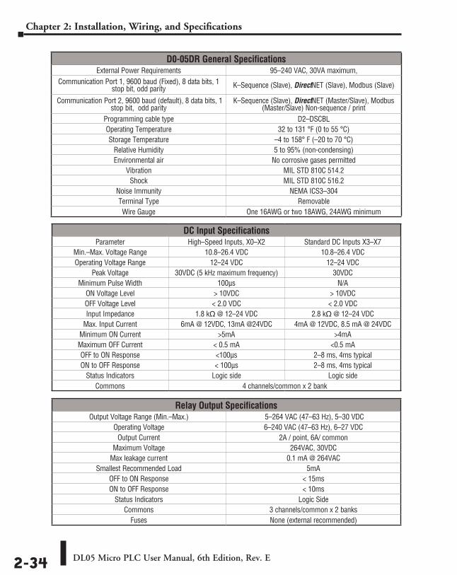
DL05 Micro PLC User Manual, 6th Edition, Rev. E2-34
Chapter 2: Installation, Wiring, and Specifications
D0-05DR General SpecificationsExternal Power Requirements 95–240 VAC, 30VA maximum,
Communication Port 1, 9600 baud (Fixed), 8 data bits, 1 stop bit, odd parity K–Sequence (Slave), DirectNET (Slave), Modbus (Slave)
Communication Port 2, 9600 baud (default), 8 data bits, 1 stop bit, odd parity
K–Sequence (Slave), DirectNET (Master/Slave), Modbus (Master/Slave) Non-sequence / print
Programming cable type D2–DSCBLOperating Temperature 32 to 131 °F (0 to 55 °C)Storage Temperature –4 to 158° F (–20 to 70 °C)
Relative Humidity 5 to 95% (non-condensing)Environmental air No corrosive gases permitted
Vibration MIL STD 810C 514.2Shock MIL STD 810C 516.2
Noise Immunity NEMA ICS3–304Terminal Type RemovableWire Gauge One 16AWG or two 18AWG, 24AWG minimum
DC Input SpecificationsParameter High–Speed Inputs, X0–X2 Standard DC Inputs X3–X7
Min.–Max. Voltage Range 10.8–26.4 VDC 10.8–26.4 VDCOperating Voltage Range 12–24 VDC 12–24 VDC
Peak Voltage 30VDC (5 kHz maximum frequency) 30VDCMinimum Pulse Width 100µs N/A
ON Voltage Level > 10VDC > 10VDCOFF Voltage Level < 2.0 VDC < 2.0 VDCInput Impedance 1.8 kq @ 12–24 VDC 2.8 kq @ 12–24 VDC
Max. Input Current 6mA @ 12VDC, 13mA @24VDC 4mA @ 12VDC, 8.5 mA @ 24VDCMinimum ON Current >5mA >4mAMaximum OFF Current < 0.5 mA <0.5 mAOFF to ON Response <100µs 2–8 ms, 4ms typicalON to OFF Response < 100µs 2–8 ms, 4ms typical
Status Indicators Logic side Logic sideCommons 4 channels/common x 2 bank
Relay Output SpecificationsOutput Voltage Range (Min.–Max.) 5–264 VAC (47–63 Hz), 5–30 VDC
Operating Voltage 6–240 VAC (47–63 Hz), 6–27 VDCOutput Current 2A / point, 6A/ common
Maximum Voltage 264VAC, 30VDCMax leakage current 0.1 mA @ 264VAC
Smallest Recommended Load 5mAOFF to ON Response < 15msON to OFF Response < 10ms
Status Indicators Logic SideCommons 3 channels/common x 2 banks
Fuses None (external recommended)
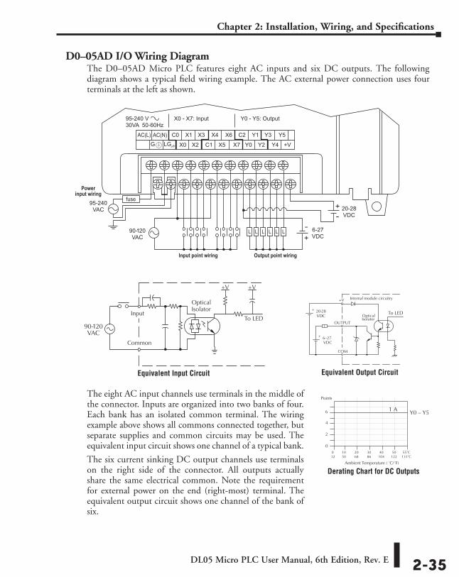
DL05 Micro PLC User Manual, 6th Edition, Rev. E 2-35
Chapter 2: Installation, Wiring, and Specifications
D0–05AD I/O Wiring DiagramThe D0–05AD Micro PLC features eight AC inputs and six DC outputs. The following diagram shows a typical field wiring example. The AC external power connection uses four terminals at the left as shown.
The eight AC input channels use terminals in the middle of the connector. Inputs are organized into two banks of four. Each bank has an isolated common terminal. The wiring example above shows all commons connected together, but separate supplies and common circuits may be used. The equivalent input circuit shows one channel of a typical bank.
The six current sinking DC output channels use terminals on the right side of the connector. All outputs actually share the same electrical common. Note the requirement for external power on the end (right-most) terminal. The equivalent output circuit shows one channel of the bank of six.
90-120VAC
6-27VDC
20-28VDC
95-240VAC
Powerinput wiring
Input point wiring Output point wiring
Equivalent Input Circuit Equivalent Output Circuit
Derating Chart for DC Outputs
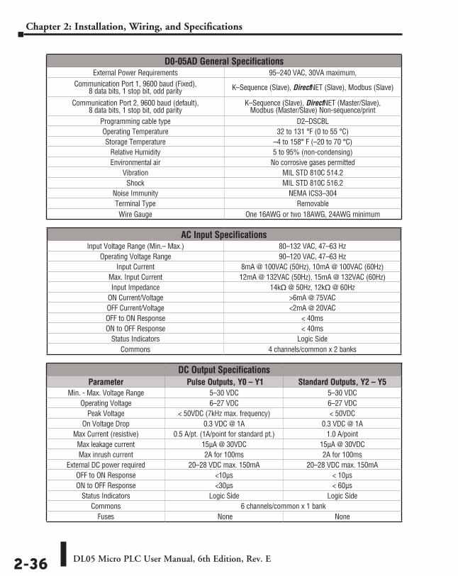
DL05 Micro PLC User Manual, 6th Edition, Rev. E2-36
Chapter 2: Installation, Wiring, and Specifications
D0-05AD General SpecificationsExternal Power Requirements 95–240 VAC, 30VA maximum,
Communication Port 1, 9600 baud (Fixed), 8 data bits, 1 stop bit, odd parity K–Sequence (Slave), DirectNET (Slave), Modbus (Slave)
Communication Port 2, 9600 baud (default), 8 data bits, 1 stop bit, odd parity
K–Sequence (Slave), DirectNET (Master/Slave), Modbus (Master/Slave) Non-sequence/print
Programming cable type D2–DSCBLOperating Temperature 32 to 131 °F (0 to 55 °C)Storage Temperature –4 to 158° F (–20 to 70 °C)
Relative Humidity 5 to 95% (non-condensing)Environmental air No corrosive gases permitted
Vibration MIL STD 810C 514.2Shock MIL STD 810C 516.2
Noise Immunity NEMA ICS3–304Terminal Type RemovableWire Gauge One 16AWG or two 18AWG, 24AWG minimum
AC Input SpecificationsInput Voltage Range (Min.– Max.) 80–132 VAC, 47–63 Hz
Operating Voltage Range 90–120 VAC, 47–63 HzInput Current 8mA @ 100VAC (50Hz), 10mA @ 100VAC (60Hz)
Max. Input Current 12mA @ 132VAC (50Hz), 15mA @ 132VAC (60Hz)Input Impedance 14kq @ 50Hz, 12kq @ 60Hz
ON Current/Voltage >6mA @ 75VACOFF Current/Voltage <2mA @ 20VACOFF to ON Response < 40msON to OFF Response < 40ms
Status Indicators Logic SideCommons 4 channels/common x 2 banks
DC Output SpecificationsParameter Pulse Outputs, Y0 – Y1 Standard Outputs, Y2 – Y5
Min. - Max. Voltage Range 5–30 VDC 5–30 VDCOperating Voltage 6–27 VDC 6–27 VDC
Peak Voltage < 50VDC (7kHz max. frequency) < 50VDCOn Voltage Drop 0.3 VDC @ 1A 0.3 VDC @ 1A
Max Current (resistive) 0.5 A/pt. (1A/point for standard pt.) 1.0 A/pointMax leakage current 15µA @ 30VDC 15µA @ 30VDCMax inrush current 2A for 100ms 2A for 100ms
External DC power required 20–28 VDC max. 150mA 20–28 VDC max. 150mAOFF to ON Response <10µs < 10µsON to OFF Response <30µs < 60µs
Status Indicators Logic Side Logic SideCommons 6 channels/common x 1 bank
Fuses None None
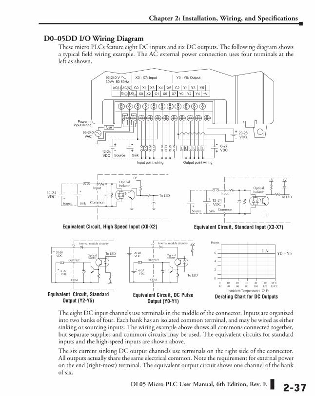
DL05 Micro PLC User Manual, 6th Edition, Rev. E 2-37
Chapter 2: Installation, Wiring, and Specifications
D0–05DD I/O Wiring DiagramThese micro PLCs feature eight DC inputs and six DC outputs. The following diagram shows a typical field wiring example. The AC external power connection uses four terminals at the left as shown.
The eight DC input channels use terminals in the middle of the connector. Inputs are organized into two banks of four. Each bank has an isolated common terminal, and may be wired as either sinking or sourcing inputs. The wiring example above shows all commons connected together, but separate supplies and common circuits may be used. The equivalent circuits for standard inputs and the high-speed inputs are shown above.
The six current sinking DC output channels use terminals on the right side of the connector. All outputs actually share the same electrical common. Note the requirement for external power on the end (right-most) terminal. The equivalent output circuit shows one channel of the bank of six.
Powerinput wiring
Input point wiring Output point wiring
6-27VDC
20-28VDC
12-24VDC SinkSource
95-240VAC
Equivalent Circuit, DC Pulse Output (Y0-Y1)
Equivalent Circuit, Standard Output (Y2-Y5)
Equivalent Circuit, Standard Input (X3-X7)Equivalent Circuit, High Speed Input (X0-X2)
Derating Chart for DC Outputs
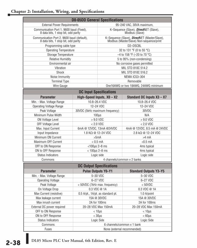
DL05 Micro PLC User Manual, 6th Edition, Rev. E2-38
Chapter 2: Installation, Wiring, and Specifications
D0-05DD General SpecificationsExternal Power Requirements 95–240 VAC, 30VA maximum,
Communication Port 1, 9600 baud (Fixed), 8 data bits, 1 stop bit, odd parity
K–Sequence (Slave), DirectNET (Slave), Modbus (Slave)
Communication Port 2, 9600 baud (default), 8 data bits, 1 stop bit, odd parity
K–Sequence (Slave), DirectNET (Master/Slave), Modbus (Master/Slave) Non-sequence/print
Programming cable type D2–DSCBLOperating Temperature 32 to 131 °F (0 to 55 °C)Storage Temperature –4 to 158 °F (–20 to 70 °C)
Relative Humidity 5 to 95% (non-condensing)Environmental air No corrosive gases permitted
Vibration MIL STD 810C 514.2Shock MIL STD 810C 516.2
Noise Immunity NEMA ICS3–304Terminal Type RemovableWire Gauge One16AWG or two 18AWG, 24AWG minimum
DC Input SpecificationsParameter High–Speed Inputs, X0 – X2 Standard DC Inputs X3 – X7
Min. - Max. Voltage Range 10.8–26.4 VDC 10.8–26.4 VDCOperating Voltage Range 12–24 VDC 12–24 VDC
Peak Voltage 30VDC (5kHz maximum frequency) 30VDCMinimum Pulse Width 100µs N/A
ON Voltage Level > 9.0 VDC > 9.0 VDCOFF Voltage Level < 2.0 VDC < 2.0 VDCMax. Input Current 6mA @ 12VDC, 13mA @24VDC 4mA @ 12VDC, 8.5 mA @ 24VDCInput Impedance 1.8 Kq @ 12–24 VDC 2.8 kq @ 12–24 VDC
Minimum ON Current >5mA >4 mAMaximum OFF Current < 0.5 mA <0.5 mAOFF to ON Response <100µs 2–8 ms 4ms typicalON to OFF Response < 100µs 2–8 ms 4ms typical
Status Indicators Logic side Logic sideCommons 4 channels/common x 2 banks
DC Output SpecificationsParameter Pulse Outputs Y0–Y1 Standard Outputs Y3–Y5
Min. - Max. Voltage Range 5–30 VDC 5–30 VDCOperating Voltage 6–27 VDC 6–27 VDC
Peak Voltage < 50VDC (7kHz max. frequency) < 50VDCOn Voltage Drop 0.3 VDC @ 1A 0.3 VDC @ 1A
Max Current (resistive) 0.5 A/pt., 1A/pt. as standard pt. 1.0 A/pointMax leakage current 15A @ 30VDC 15A @ 30VDCMax inrush current 2A for 100ms 2A for 100ms
External DC power required 20–28 VDC Max 150mA 20–28 VDC Max 150mAOFF to ON Response < 10µs < 10µsON to OFF Response < 30µs < 60µs
Status Indicators Logic Side Logic SideCommons 6 channels/common x 1 bank
Fuses None (external recommended)
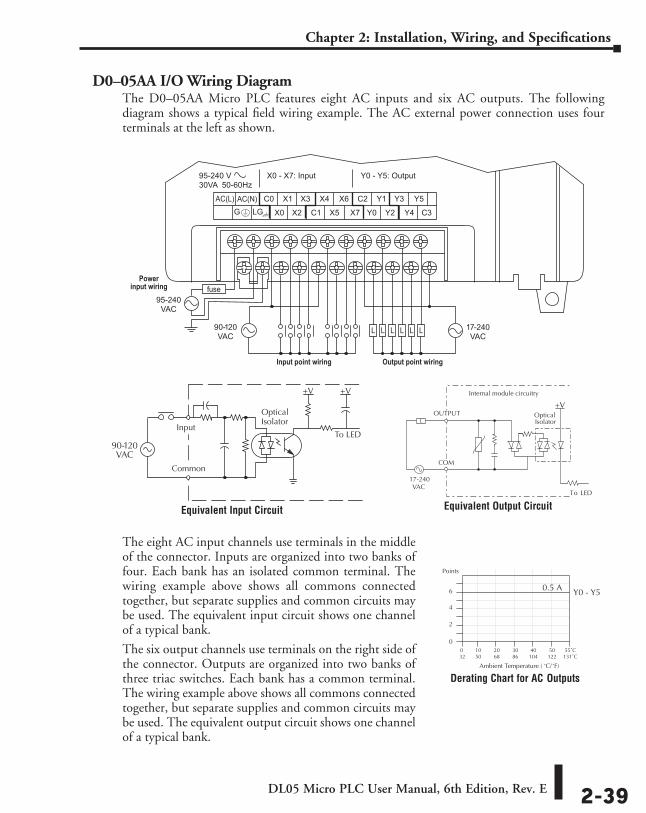
DL05 Micro PLC User Manual, 6th Edition, Rev. E 2-39
Chapter 2: Installation, Wiring, and Specifications
D0–05AA I/O Wiring DiagramThe D0–05AA Micro PLC features eight AC inputs and six AC outputs. The following diagram shows a typical field wiring example. The AC external power connection uses four terminals at the left as shown.
The eight AC input channels use terminals in the middle of the connector. Inputs are organized into two banks of four. Each bank has an isolated common terminal. The wiring example above shows all commons connected together, but separate supplies and common circuits may be used. The equivalent input circuit shows one channel of a typical bank.
The six output channels use terminals on the right side of the connector. Outputs are organized into two banks of three triac switches. Each bank has a common terminal. The wiring example above shows all commons connected together, but separate supplies and common circuits may be used. The equivalent output circuit shows one channel of a typical bank.
90-120VAC
95-240VAC
17-240VAC
Powerinput wiring
Input point wiring Output point wiring
Equivalent Input Circuit Equivalent Output Circuit
Derating Chart for AC Outputs
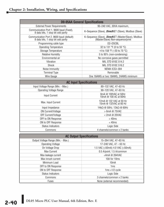
DL05 Micro PLC User Manual, 6th Edition, Rev. E2-40
Chapter 2: Installation, Wiring, and Specifications
D0-05AA General SpecificationsExternal Power Requirements 95–240 VAC, 30VA maximum,
Communication Port 1, 9600 baud (Fixed), 8 data bits, 1 stop bit odd parity K–Sequence (Slave), DirectNET (Slave), Modbus (Slave)
Communication Port 2, 9600 baud (default) 8 data bits, 1 stop bit odd parity
K–Sequence (Slave), DirectNET (Master/Slave), Modbus (Master/Slave) Non-sequence/print
Programming cable type D2–DSCBLOperating Temperature 32 to 131 °F (0 to 55 °C)Storage Temperature –4 to 158 °F (–20 to 70 °C)
Relative Humidity 5 to 95% (non-condensing)Environmental air No corrosive gases permitted
Vibration MIL STD 810C 514.2Shock MIL STD 810C 516.2
Noise Immunity NEMA ICS3–304Terminal Type RemovableWire Gauge One 16AWG or two 18AWG, 24AWG minimum
AC Input SpecificationsInput Voltage Range (Min. - Max.) 80–132 VAC, 47–63 Hz
Operating Voltage Range 90–120 VAC, 47–63 Hz
Input Current 8mA @ 100VAC at 50Hz 10mA @ 100 AC at 60Hz
Max. Input Current 12mA @ 132 VAC at 50 Hz 15mA @ 132VAC at 60 Hz
Input Impedance 14kq @ 50Hz, 12kq @ 60HzON Current/Voltage > 6mA @ 75VACOFF Current/Voltage < 2mA @ 20VACOFF to ON Response < 40msON to OFF Response < 40ms
Status Indicators Logic SideCommons 4 channels/common x 2 banks
AC Output SpecificationsOutput Voltage Range (Min. - Max.) 15–264 VAC, 47–63 Hz
Operating Voltage 17–240 VAC, 47 – 63 HzOn Voltage Drop 1.5 VAC (>50mA) 4.0 VAC (<50mA)
Max Current 0.5 A/point, 1.5 A/commonMax leakage current <4mA @ 264VACMax inrush current 10A for 10ms
Minimum Load 10mAOFF to ON Response 1msON to OFF Response 1ms +1/2 cycle
Status Indicators Logic SideCommons 3 channels/common x 2 banks
Fuses None (external recommended)
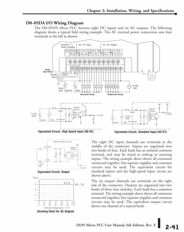
DL05 Micro PLC User Manual, 6th Edition, Rev. E 2-41
Chapter 2: Installation, Wiring, and Specifications
D0–05DA I/O Wiring DiagramThe D0–05DA Micro PLC features eight DC inputs and six AC outputs. The following diagram shows a typical field wiring example. The AC external power connection uses four terminals at the left as shown.
The eight DC input channels use terminals in the middle of the connector. Inputs are organized into two banks of four. Each bank has an isolated common terminal, and may be wired as sinking or sourcing inputs. The wiring example above shows all commons connected together, but separate supplies and common circuits may be used. The equivalent circuit for standard inputs and the high-speed input circuit are shown above.
The six output channels use terminals on the right side of the connector. Outputs are organized into two banks of three triac switches. Each bank has a common terminal. The wiring example above shows all commons connected together, but separate supplies and common circuits may be used. The equivalent output circuit shows one channel of a typical bank.
17-240VAC12-24
VDC SinkSource
Powerinput wiring
Input point wiring Output point wiring
95-240VAC
Equivalent Circuit, High Speed Input (X0-X2)
Equivalent Circuit, Output
Equivalent Circuit, Standard Input (X3-X7)
Derating Chart for AC Outputs
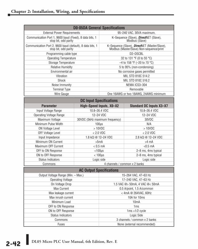
DL05 Micro PLC User Manual, 6th Edition, Rev. E2-42
Chapter 2: Installation, Wiring, and Specifications
D0-05DA General SpecificationsExternal Power Requirements 95–240 VAC, 30VA maximum,
Communication Port 1, 9600 baud (Fixed), 8 data bits, 1 stop bit, odd parity
K–Sequence (Slave), DirectNET (Slave), Modbus (Slave)
Communication Port 2, 9600 baud (default), 8 data bits, 1 stop bit, odd parity
K–Sequence (Slave), DirectNET (Master/Slave), Modbus (Master/Slave) Non-sequence/print
Programming cable type D2–DSCBLOperating Temperature 32 to 131 °F (0 to 55 °C)Storage Temperature –4 to 158 °F (–20 to 70 °C)
Relative Humidity 5 to 95% (non-condensing)Environmental air No corrosive gases permitted
Vibration MIL STD 810C 514.2Shock MIL STD 810C 516.2
Noise Immunity NEMA ICS3–304Terminal Type RemovableWire Gauge One 16AWG or two 18AWG, 24AWG minimum
DC Input SpecificationsParameter High–Speed Inputs, X0–X2 Standard DC Inputs X3–X7
Input Voltage Range 10.8–26.4 VDC 10.8–26.4 VDCOperating Voltage Range 12–24 VDC 12–24 VDC
Maximum Voltage 30VDC (5kHz maximum frequency) 30VDCMinimum Pulse Width 100µs N/A
ON Voltage Level > 10VDC > 10VDCOFF Voltage Level < 2.0 VDC < 2.0 VDCInput Impedance 1.8 kq @ 12–24 VDC 2.8 kq @ 12–24 VDC
Minimum ON Current >5mA >4 mAMaximum OFF Current < 0.5 mA <0.5 mAOFF to ON Response <100µs 2–8 ms, 4ms typicalON to OFF Response < 100µs 2–8 ms, 4ms typical
Status Indicators Logic side Logic sideCommons 4 channels / common x 2 banks
AC Output SpecificationsOutput Voltage Range (Min. – Max.) 15–264 VAC, 47–63 Hz
Operating Voltage 17–240 VAC, 47–63 HzOn Voltage Drop 1.5 VAC @> 50mA, 4 VAC @< 50mA
Max Current 0.5 A/point, 1.5 A/commonMax leakage current < 4mA @ 264VAC, 60HzMax inrush current 10A for 10ms
Minimum Load 10mAOFF to ON Response 1msON to OFF Response 1ms +1/2 cycle
Status Indicators Logic SideCommons 3 channels / common x 2 banks
Fuses None (external recommended)
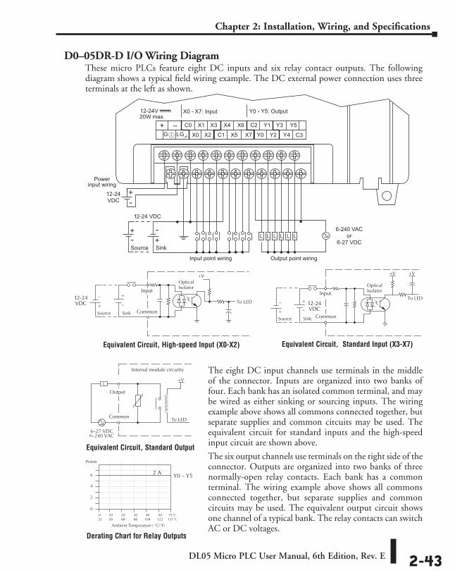
DL05 Micro PLC User Manual, 6th Edition, Rev. E 2-43
Chapter 2: Installation, Wiring, and Specifications
D0–05DR-D I/O Wiring DiagramThese micro PLCs feature eight DC inputs and six relay contact outputs. The following diagram shows a typical field wiring example. The DC external power connection uses three terminals at the left as shown.
The eight DC input channels use terminals in the middle of the connector. Inputs are organized into two banks of four. Each bank has an isolated common terminal, and may be wired as either sinking or sourcing inputs. The wiring example above shows all commons connected together, but separate supplies and common circuits may be used. The equivalent circuit for standard inputs and the high-speed input circuit are shown above.
The six output channels use terminals on the right side of the connector. Outputs are organized into two banks of three normally-open relay contacts. Each bank has a common terminal. The wiring example above shows all commons connected together, but separate supplies and common circuits may be used. The equivalent output circuit shows one channel of a typical bank. The relay contacts can switch AC or DC voltages.
12-24V20W max.
X0 - X7: Input Y0 - Y5: Output
C3
Powerinput wiring
Input point wiring Output point wiring
6-240 VACor
6-27 VDC
12-24 VDC
SinkSource
12-24VDC
Derating Chart for Relay Outputs
Equivalent Circuit, High-speed Input (X0-X2) Equivalent Circuit, Standard Input (X3-X7)
Equivalent Circuit, Standard Output
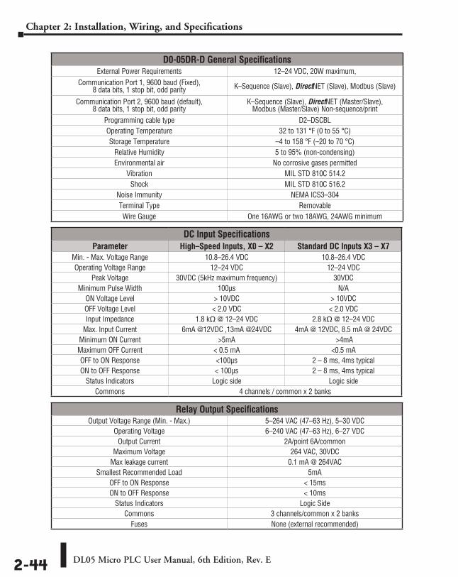
DL05 Micro PLC User Manual, 6th Edition, Rev. E2-44
Chapter 2: Installation, Wiring, and Specifications
D0-05DR-D General SpecificationsExternal Power Requirements 12–24 VDC, 20W maximum,
Communication Port 1, 9600 baud (Fixed), 8 data bits, 1 stop bit, odd parity K–Sequence (Slave), DirectNET (Slave), Modbus (Slave)
Communication Port 2, 9600 baud (default), 8 data bits, 1 stop bit, odd parity
K–Sequence (Slave), DirectNET (Master/Slave), Modbus (Master/Slave) Non-sequence/print
Programming cable type D2–DSCBLOperating Temperature 32 to 131 °F (0 to 55 °C)Storage Temperature –4 to 158 °F (–20 to 70 °C)
Relative Humidity 5 to 95% (non-condensing)Environmental air No corrosive gases permitted
Vibration MIL STD 810C 514.2Shock MIL STD 810C 516.2
Noise Immunity NEMA ICS3–304Terminal Type RemovableWire Gauge One 16AWG or two 18AWG, 24AWG minimum
DC Input SpecificationsParameter High–Speed Inputs, X0 – X2 Standard DC Inputs X3 – X7
Min. - Max. Voltage Range 10.8–26.4 VDC 10.8–26.4 VDCOperating Voltage Range 12–24 VDC 12–24 VDC
Peak Voltage 30VDC (5kHz maximum frequency) 30VDCMinimum Pulse Width 100µs N/A
ON Voltage Level > 10VDC > 10VDCOFF Voltage Level < 2.0 VDC < 2.0 VDCInput Impedance 1.8 kq @ 12–24 VDC 2.8 kq @ 12–24 VDC
Max. Input Current 6mA @12VDC ,13mA @24VDC 4mA @ 12VDC, 8.5 mA @ 24VDCMinimum ON Current >5mA >4mAMaximum OFF Current < 0.5 mA <0.5 mAOFF to ON Response <100µs 2 – 8 ms, 4ms typicalON to OFF Response < 100µs 2 – 8 ms, 4ms typical
Status Indicators Logic side Logic sideCommons 4 channels / common x 2 banks
Relay Output SpecificationsOutput Voltage Range (Min. - Max.) 5–264 VAC (47–63 Hz), 5–30 VDC
Operating Voltage 6–240 VAC (47–63 Hz), 6–27 VDCOutput Current 2A/point 6A/common
Maximum Voltage 264 VAC, 30VDCMax leakage current 0.1 mA @ 264VAC
Smallest Recommended Load 5mAOFF to ON Response < 15msON to OFF Response < 10ms
Status Indicators Logic SideCommons 3 channels/common x 2 banks
Fuses None (external recommended)
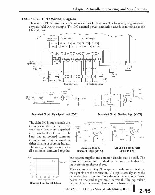
DL05 Micro PLC User Manual, 6th Edition, Rev. E 2-45
Chapter 2: Installation, Wiring, and Specifications
D0–05DD–D I/O Wiring DiagramThese micro PLCs feature eight DC inputs and six DC outputs. The following diagram shows a typical field wiring example. The DC external power connection uses four terminals at the left as shown.
The eight DC input channels use terminals in the middle of the connector. Inputs are organized into two banks of four. Each bank has an isolated common terminal, and may be wired as either sinking or sourcing inputs. The wiring example above shows all commons connected together,
but separate supplies and common circuits may be used. The equivalent circuit for standard inputs and the high-speed input circuit are shown above.
The six current sinking DC output channels use terminals on the right side of the connector. All outputs actually share the same electrical common. Note the requirement for external power on the end (right-most) terminal. The equivalent output circuit shows one channel of the bank of six.
12-24V20W max.
X0 - X7: Input Y0 - Y5: Output
Powerinput wiring
Input point wiring Output point wiring
6-27VDC
20-28VDC
12-24VDC
12-24VDC SinkSource
Equivalent Circuit, High Speed Input (X0-X2) Equivalent Circuit, Standard Input (X3-X7)
Equivalent Circuit, Standard Output (Y2-Y5)
Equivalent Circuit, Pulse Output (Y0-Y1)
Derating Chart for DC Outputs
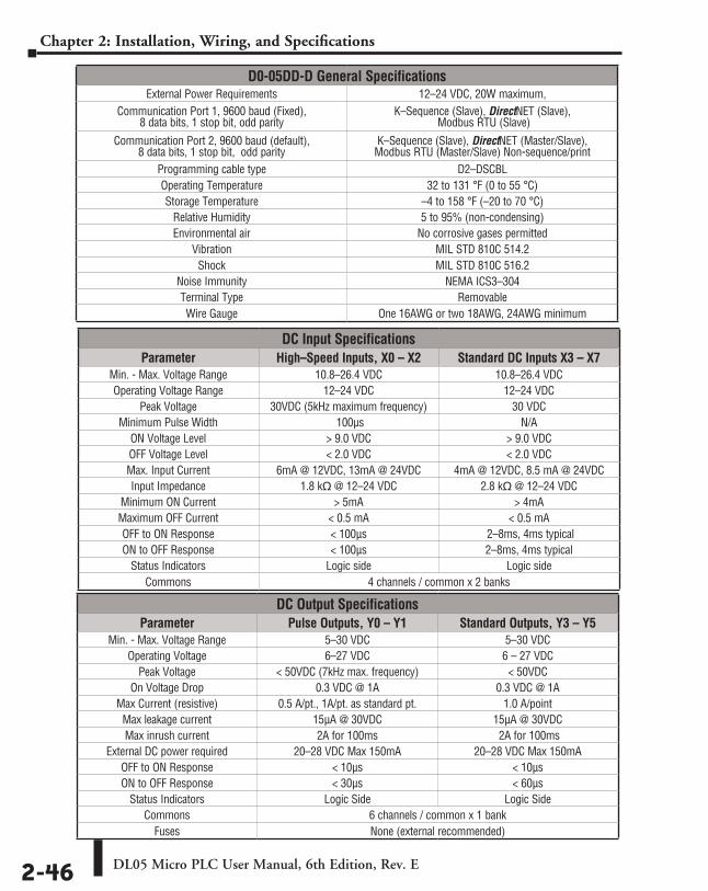
DL05 Micro PLC User Manual, 6th Edition, Rev. E2-46
Chapter 2: Installation, Wiring, and Specifications
D0-05DD-D General SpecificationsExternal Power Requirements 12–24 VDC, 20W maximum,
Communication Port 1, 9600 baud (Fixed), 8 data bits, 1 stop bit, odd parity
K–Sequence (Slave), DirectNET (Slave), Modbus RTU (Slave)
Communication Port 2, 9600 baud (default), 8 data bits, 1 stop bit, odd parity
K–Sequence (Slave), DirectNET (Master/Slave), Modbus RTU (Master/Slave) Non-sequence/print
Programming cable type D2–DSCBLOperating Temperature 32 to 131 °F (0 to 55 °C)Storage Temperature –4 to 158 °F (–20 to 70 °C)
Relative Humidity 5 to 95% (non-condensing)Environmental air No corrosive gases permitted
Vibration MIL STD 810C 514.2Shock MIL STD 810C 516.2
Noise Immunity NEMA ICS3–304Terminal Type RemovableWire Gauge One 16AWG or two 18AWG, 24AWG minimum
DC Input SpecificationsParameter High–Speed Inputs, X0 – X2 Standard DC Inputs X3 – X7
Min. - Max. Voltage Range 10.8–26.4 VDC 10.8–26.4 VDCOperating Voltage Range 12–24 VDC 12–24 VDC
Peak Voltage 30VDC (5kHz maximum frequency) 30 VDCMinimum Pulse Width 100µs N/A
ON Voltage Level > 9.0 VDC > 9.0 VDCOFF Voltage Level < 2.0 VDC < 2.0 VDCMax. Input Current 6mA @ 12VDC, 13mA @ 24VDC 4mA @ 12VDC, 8.5 mA @ 24VDCInput Impedance 1.8 kq @ 12–24 VDC 2.8 kq @ 12–24 VDC
Minimum ON Current > 5mA > 4mAMaximum OFF Current < 0.5 mA < 0.5 mAOFF to ON Response < 100µs 2–8ms, 4ms typicalON to OFF Response < 100µs 2–8ms, 4ms typical
Status Indicators Logic side Logic sideCommons 4 channels / common x 2 banks
DC Output SpecificationsParameter Pulse Outputs, Y0 – Y1 Standard Outputs, Y3 – Y5
Min. - Max. Voltage Range 5–30 VDC 5–30 VDCOperating Voltage 6–27 VDC 6 – 27 VDC
Peak Voltage < 50VDC (7kHz max. frequency) < 50VDCOn Voltage Drop 0.3 VDC @ 1A 0.3 VDC @ 1A
Max Current (resistive) 0.5 A/pt., 1A/pt. as standard pt. 1.0 A/pointMax leakage current 15µA @ 30VDC 15µA @ 30VDCMax inrush current 2A for 100ms 2A for 100ms
External DC power required 20–28 VDC Max 150mA 20–28 VDC Max 150mAOFF to ON Response < 10µs < 10µsON to OFF Response < 30µs < 60µs
Status Indicators Logic Side Logic SideCommons 6 channels / common x 1 bank
Fuses None (external recommended)
DL05 Micro PLC User Manual, 6th Edition, Rev. E 2-47
Chapter 2: Installation, Wiring, and Specifications
Glossary of Specification TermsDiscrete Input
One of eight input connections to the PLC which converts an electrical signal from a field device to a binary status (off or on), which is read by the internal CPU each PLC scan.
Discrete OutputOne of six output connections from the PLC which converts an internal ladder program result (0 or 1) to turn On or Off an output switching device. This enables the program to turn on and off large field loads.
I/O CommonA connection in the input or output terminals which is shared by multiple I/O circuits. It usually is in the return path to the power supply of the I/O circuit.
Input Voltage RangeThe operating voltage range of the input circuit.
Maximum VoltageMaximum voltage allowed for the input circuit.
ON Voltage LevelThe minimum voltage level at which the input point will turn ON.
OFF Voltage LevelThe maximum voltage level at which the input point will turn OFF.
Input ImpedanceInput impedance can be used to calculate input current for a particular operating voltage.
Input CurrentTypical operating current for an active (ON) input.
Minimum ON CurrentThe minimum current for the input circuit to operate reliably in the ON state.
Maximum OFF CurrentThe maximum current for the input circuit to operate reliably in the OFF state.
OFF to ON ResponseThe time the module requires to process an OFF to ON state transition.
ON to OFF ResponseThe time the module requires to process an ON to OFF state transition.
Status IndicatorsThe LEDs that indicate the ON/OFF status of an input or output point. All LEDs on DL05 Micro PLCs are electrically located on the logic side of the input or output circuit.
333ChapterChapterChapter
CPU SPeCifiCationS and oPeration
In This Chapter...Introduction ............................................................................................................... 3-2
CPU Specifications ..................................................................................................... 3-3
CPU Hardware Setup ................................................................................................. 3-4
CPU Operation ......................................................................................................... 3-11
I/O Response Time .................................................................................................. 3-15
CPU Scan Time Considerations ............................................................................... 3-18
Memory Map ........................................................................................................... 3-22
DL05 System V-memory .......................................................................................... 3-26
DL05 Aliases ............................................................................................................. 3-29
X Input Bit Map ....................................................................................................... 3-30
Y Output Bit Map .................................................................................................... 3-30
Control Relay Bit Map ............................................................................................. 3-31
Stage Control/Status Bit Map ................................................................................. 3-32
Timer Status Bit Map ............................................................................................... 3-32
Counter Status Bit Map ........................................................................................... 3-33
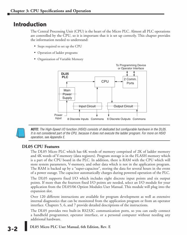
DL05 Micro PLC User Manual, 6th Edition, Rev. E3-2
Chapter 3: CPU Specifications and Operation
IntroductionThe Central Processing Unit (CPU) is the heart of the Micro PLC. Almost all PLC operations are controlled by the CPU, so it is important that it is set up correctly. This chapter provides the information needed to understand:
• Steps required to set up the CPU
• Operation of ladder programs
• Organization of Variable Memory
NOTE: The High-Speed I/O function (HSIO) consists of dedicated but configurable hardware in the DL05. It is not considered part of the CPU, because it does not execute the ladder program. For more on HSIO operation, see Appendix E.
DL05 CPU FeaturesThe DL05 Micro PLC which has 6K words of memory comprised of 2K of ladder memory and 4K words of V-memory (data registers). Program storage is in the FLASH memory which is a part of the CPU board in the PLC. In addition, there is RAM with the CPU which will store system parameters, V-memory, and other data which is not in the application program. The RAM is backed up by a “super-capacitor”, storing the data for several hours in the event of a power outage. The capacitor automatically charges during powered operation of the PLC.
The DL05 supports fixed I/O which includes eight discrete input points and six output points. If more than the fourteen fixed I/O points are needed, select an I/O module for your application from the DL05/06 Option Modules User Manual. This module will plug into the expansion slot.
Over 120 different instructions are available for program development as well as extensive internal diagnostics that can be monitored from the application program or from an operator interface. Chapters 5, 6, and 7 provide detailed descriptions of the instructions.
The DL05 provides two built-in RS232C communication ports, so you can easily connect a handheld programmer, operator interface, or a personal computer without needing any additional hardware.
Output CircuitInput Circuit
CPU2 Comm.
Ports
MainPowerSupply
To Programming Deviceor Operator Interface
8 Discrete Inputs Commons Commons6 Discrete OutputsPowerInput
PLCDL05
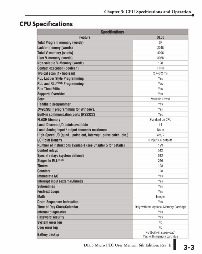
DL05 Micro PLC User Manual, 6th Edition, Rev. E 3-3
Chapter 3: CPU Specifications and Operation
CPU SpecificationsSpecifications
Feature DL05Total Program memory (words) 6K
Ladder memory (words) 2048
Total V-memory (words) 4096
User V-memory (words) 3968
Non-volatile V-Memory (words) 128
Contact execution (boolean) 2.0 us
Typical scan (1k boolean) 2.7–3.2 ms
RLL Ladder Style Programming Yes
RLL and RLLPLUS Programming Yes
Run Time Edits Yes
Supports Overrides Yes
Scan Variable / fixed
Handheld programmer Yes
DirectSOFT programming for Windows. Yes
Built-in communication ports (RS232C) Yes
FLASH Memory Standard on CPU
Local Discrete I/O points available 14
Local Analog input / output channels maximum None
High-Speed I/O (quad., pulse out, interrupt, pulse catch, etc.) Yes, 2
I/O Point Density 8 inputs, 6 outputs
Number of instructions available (see Chapter 5 for details) 129
Control relays 512
Special relays (system defined) 512
Stages in RLLPLUS 256
Timers 128
Counters 128
Immediate I/O Yes
Interrupt input (external/timed) Yes
Subroutines Yes
For/Next Loops Yes
Math Integer
Drum Sequencer Instruction Yes
Time of Day Clock/Calendar Only with the optional Memory Cartridge
Internal diagnostics Yes
Password security Yes
System error log No
User error log No
Battery backup No (built–in super–cap) Yes, with memory cartridge
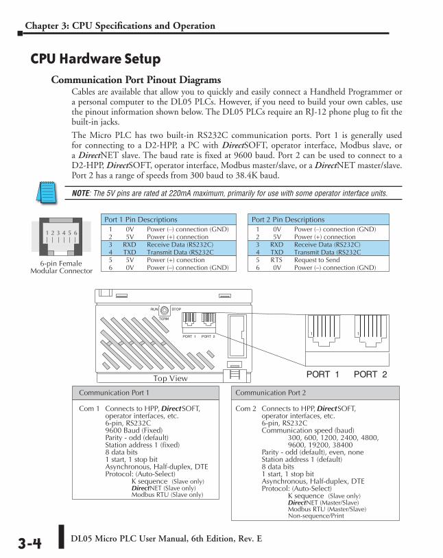
DL05 Micro PLC User Manual, 6th Edition, Rev. E3-4
Chapter 3: CPU Specifications and Operation
CPU Hardware SetupCommunication Port Pinout Diagrams
Cables are available that allow you to quickly and easily connect a Handheld Programmer or a personal computer to the DL05 PLCs. However, if you need to build your own cables, use the pinout information shown below. The DL05 PLCs require an RJ-12 phone plug to fit the built-in jacks.
The Micro PLC has two built-in RS232C communication ports. Port 1 is generally used for connecting to a D2-HPP, a PC with DirectSOFT, operator interface, Modbus slave, or a DirectNET slave. The baud rate is fixed at 9600 baud. Port 2 can be used to connect to a D2-HPP, DirectSOFT, operator interface, Modbus master/slave, or a DirectNET master/slave. Port 2 has a range of speeds from 300 baud to 38.4K baud.
NOTE: The 5V pins are rated at 220mA maximum, primarily for use with some operator interface units.
Port 1 Pin Descriptions1 0V Power (–) connection (GND)2 5V Power (+) connection3 RXD Receive Data (RS232C)4 TXD Transmit Data (RS232C5 5V Power (+) conection6 0V Power (–) connection (GND)6-pin Female
Modular Connector
Port 2 Pin Descriptions1 0V Power (–) connection (GND)2 5V Power (+) connection3 RXD Receive Data (RS232C)4 TXD Transmit Data (RS232C5 RTS Request to Send6 0V Power (–) connection (GND)
1 2 3 4 5 6
Top View
1 1
Communication Port 1
Com 1 Connects to HPP, DirectSOFT,operator interfaces, etc.6-pin, RS232C9600 Baud (Fixed)Parity - odd (default)Station address 1 (fixed)8 data bits1 start, 1 stop bitAsynchronous, Half-duplex, DTEProtocol: (Auto-Select)
K sequence (Slave only)DirectNET (Slave only)Modbus RTU (Slave only)
Communication Port 2
Com 2 Connects to HPP, DirectSOFT,operator interfaces, etc.6-pin, RS232CCommunication speed (baud)
300, 600, 1200, 2400, 4800,9600, 19200, 38400
Parity - odd (default), even, noneStation address 1 (default)8 data bits1 start, 1 stop bitAsynchronous, Half-duplex, DTEProtocol: (Auto-Select)
K sequence (Slave only)DirectNET (Master/Slave)Modbus RTU (Master/Slave)Non-sequence/Print
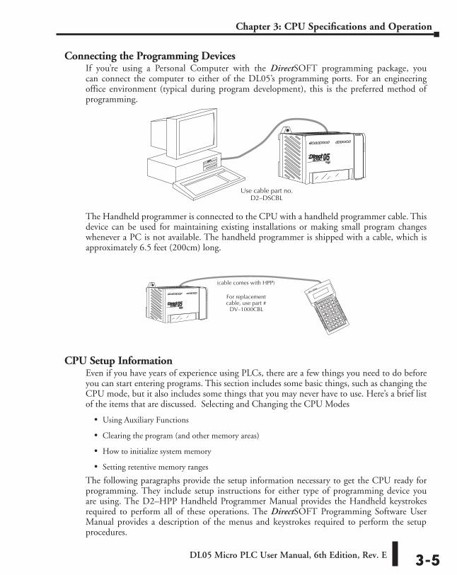
DL05 Micro PLC User Manual, 6th Edition, Rev. E 3-5
Chapter 3: CPU Specifications and Operation
Connecting the Programming DevicesIf you’re using a Personal Computer with the DirectSOFT programming package, you can connect the computer to either of the DL05’s programming ports. For an engineering office environment (typical during program development), this is the preferred method of programming.
The Handheld programmer is connected to the CPU with a handheld programmer cable. This device can be used for maintaining existing installations or making small program changes whenever a PC is not available. The handheld programmer is shipped with a cable, which is approximately 6.5 feet (200cm) long.
CPU Setup InformationEven if you have years of experience using PLCs, there are a few things you need to do before you can start entering programs. This section includes some basic things, such as changing the CPU mode, but it also includes some things that you may never have to use. Here’s a brief list of the items that are discussed. Selecting and Changing the CPU Modes
• Using Auxiliary Functions
• Clearing the program (and other memory areas)
• How to initialize system memory
• Setting retentive memory ranges
The following paragraphs provide the setup information necessary to get the CPU ready for programming. They include setup instructions for either type of programming device you are using. The D2–HPP Handheld Programmer Manual provides the Handheld keystrokes required to perform all of these operations. The DirectSOFT Programming Software User Manual provides a description of the menus and keystrokes required to perform the setup procedures.
For replacementcable, use part #
DV–1000CBL
(cable comes with HPP)
Use cable part no.D2–DSCBL
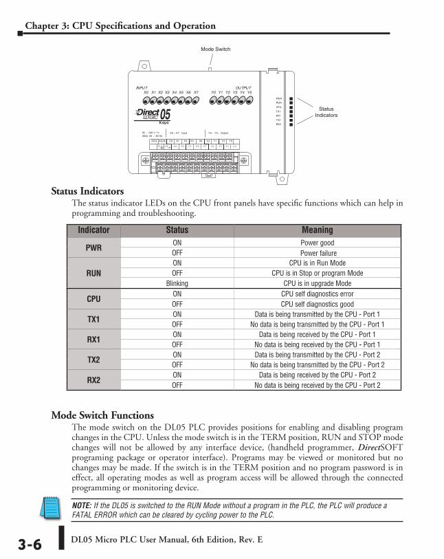
DL05 Micro PLC User Manual, 6th Edition, Rev. E3-6
Chapter 3: CPU Specifications and Operation
Status IndicatorsThe status indicator LEDs on the CPU front panels have specific functions which can help in programming and troubleshooting.
Mode Switch FunctionsThe mode switch on the DL05 PLC provides positions for enabling and disabling program changes in the CPU. Unless the mode switch is in the TERM position, RUN and STOP mode changes will not be allowed by any interface device, (handheld programmer, DirectSOFT programing package or operator interface). Programs may be viewed or monitored but no changes may be made. If the switch is in the TERM position and no program password is in effect, all operating modes as well as program access will be allowed through the connected programming or monitoring device.
NOTE: If the DL05 is switched to the RUN Mode without a program in the PLC, the PLC will produce a FATAL ERROR which can be cleared by cycling power to the PLC.
StatusIndicators
Mode Switch
Indicator Status Meaning
PWR ON Power goodOFF Power failure
RUN ON CPU is in Run ModeOFF CPU is in Stop or program Mode
Blinking CPU is in upgrade Mode
CPU ON CPU self diagnostics errorOFF CPU self diagnostics good
TX1 ON Data is being transmitted by the CPU - Port 1OFF No data is being transmitted by the CPU - Port 1
RX1 ON Data is being received by the CPU - Port 1OFF No data is being received by the CPU - Port 1
TX2 ON Data is being transmitted by the CPU - Port 2OFF No data is being transmitted by the CPU - Port 2
RX2 ON Data is being received by the CPU - Port 2OFF No data is being received by the CPU - Port 2
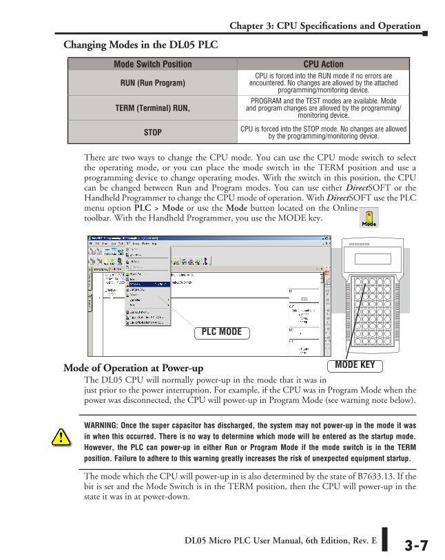
DL05 Micro PLC User Manual, 6th Edition, Rev. E 3-7
Chapter 3: CPU Specifications and Operation
Changing Modes in the DL05 PLC
There are two ways to change the CPU mode. You can use the CPU mode switch to select the operating mode, or you can place the mode switch in the TERM position and use a programming device to change operating modes. With the switch in this position, the CPU can be changed between Run and Program modes. You can use either DirectSOFT or the Handheld Programmer to change the CPU mode of operation. With DirectSOFT use the PLC menu option PLC > Mode or use the Mode button located on the Online toolbar. With the Handheld Programmer, you use the MODE key.
Mode of Operation at Power-upThe DL05 CPU will normally power-up in the mode that it was in just prior to the power interruption. For example, if the CPU was in Program Mode when the power was disconnected, the CPU will power-up in Program Mode (see warning note below).
WARNING: Once the super capacitor has discharged, the system may not power-up in the mode it was in when this occurred. There is no way to determine which mode will be entered as the startup mode. However, the PLC can power-up in either Run or Program Mode if the mode switch is in the TERM position. Failure to adhere to this warning greatly increases the risk of unexpected equipment startup.
The mode which the CPU will power-up in is also determined by the state of B7633.13. If the bit is set and the Mode Switch is in the TERM position, then the CPU will power-up in the state it was in at power-down.
Mode Switch Position CPU Action
RUN (Run Program) CPU is forced into the RUN mode if no errors are
encountered. No changes are allowed by the attached programming/monitoring device.
TERM (Terminal) RUN, PROGRAM and the TEST modes are available. Mode
and program changes are allowed by the programming/monitoring device.
STOP CPU is forced into the STOP mode. No changes are allowed by the programming/monitoring device.
PLC MODE
MODE KEY
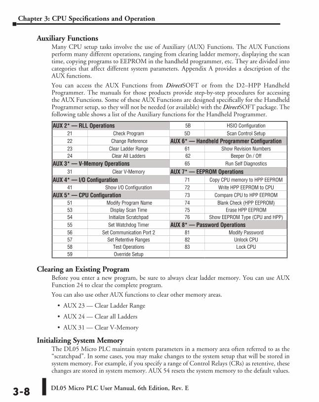
DL05 Micro PLC User Manual, 6th Edition, Rev. E3-8
Chapter 3: CPU Specifications and Operation
Auxiliary FunctionsMany CPU setup tasks involve the use of Auxiliary (AUX) Functions. The AUX Functions perform many different operations, ranging from clearing ladder memory, displaying the scan time, copying programs to EEPROM in the handheld programmer, etc. They are divided into categories that affect different system parameters. Appendix A provides a description of the AUX functions.
You can access the AUX Functions from DirectSOFT or from the D2–HPP Handheld Programmer. The manuals for those products provide step-by-step procedures for accessing the AUX Functions. Some of these AUX Functions are designed specifically for the Handheld Programmer setup, so they will not be needed (or available) with the DirectSOFT package. The following table shows a list of the Auxiliary functions for the Handheld Programmer.
Clearing an Existing ProgramBefore you enter a new program, be sure to always clear ladder memory. You can use AUX Function 24 to clear the complete program.
You can also use other AUX functions to clear other memory areas.
• AUX 23 — Clear Ladder Range
• AUX 24 — Clear all Ladders
• AUX 31 — Clear V-Memory
Initializing System MemoryThe DL05 Micro PLC maintain system parameters in a memory area often referred to as the “scratchpad”. In some cases, you may make changes to the system setup that will be stored in system memory. For example, if you specify a range of Control Relays (CRs) as retentive, these changes are stored in system memory. AUX 54 resets the system memory to the default values.
AUX 2* — RLL Operations 5B HSIO Configuration21 Check Program 5D Scan Control Setup22 Change Reference AUX 6* — Handheld Programmer Configuration23 Clear Ladder Range 61 Show Revision Numbers24 Clear All Ladders 62 Beeper On / Off
AUX 3* — V-Memory Operations 65 Run Self Diagnostics31 Clear V-Memory AUX 7* — EEPROM Operations
AUX 4* — I/O Configuration 71 Copy CPU memory to HPP EEPROM41 Show I/O Configuration 72 Write HPP EEPROM to CPU
AUX 5* — CPU Configuration 73 Compare CPU to HPP EEPROM51 Modify Program Name 74 Blank Check (HPP EEPROM)53 Display Scan Time 75 Erase HPP EEPROM54 Initialize Scratchpad 76 Show EEPROM Type (CPU and HPP)55 Set Watchdog Timer AUX 8* — Password Operations56 Set Communication Port 2 81 Modify Password57 Set Retentive Ranges 82 Unlock CPU58 Test Operations 83 Lock CPU59 Override Setup
DL05 Micro PLC User Manual, 6th Edition, Rev. E 3-9
Chapter 3: CPU Specifications and Operation
WARNING: You may never have to use this feature unless you want to clear any setup information that is stored in system memory. Usually, you’ll only need to initialize the system memory if you are changing programs and the old program required a special system setup. You can usually load in new programs without ever initializing system memory. Remember, this AUX function will reset all system memory. If you have set special parameters such as retentive ranges, etc. they will be erased when AUX 54 is used. Make sure you that you have considered all ramifications of this operation before you select it.
Setting Retentive Memory RangesThe DL05 PLCs provide certain ranges of retentive memory by default. The default ranges are suitable for many applications, but you can change them if your application requires additional retentive ranges or no retentive ranges at all. Appendix F has more information pertaining to the different types of memory. The default settings are:
You can use AUX 57 to set the retentive ranges. Appendix A contains detailed information about auxiliary functions. You can also set the retentive ranges by using Setup in DirectSOFT, PLC > Setup > Retentive Ranges.
WARNING: The DL05 PLCs do not have battery back-up (unless the memory cartridge, D0–01MC, is installed) The super capacitor will retain the values in the event of a power loss, but only for a short period of time, depending on conditions.
Memory Area DL05Default Range Available Range
Control Relays C400 – C777 C0 – C777
V-memory V1400 – V7777 V0 – V7777
Timers None by default T0 – T177
Counters CT0 – CT177 CT0 – CT177
Stages None by default S0 – S377
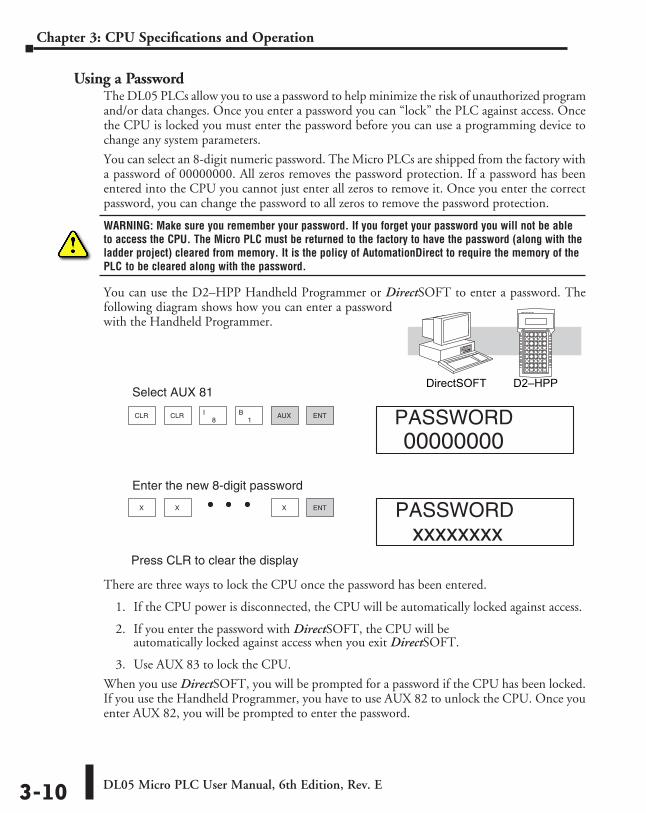
DL05 Micro PLC User Manual, 6th Edition, Rev. E3-10
Chapter 3: CPU Specifications and Operation
Using a PasswordThe DL05 PLCs allow you to use a password to help minimize the risk of unauthorized program and/or data changes. Once you enter a password you can “lock” the PLC against access. Once the CPU is locked you must enter the password before you can use a programming device to change any system parameters.
You can select an 8-digit numeric password. The Micro PLCs are shipped from the factory with a password of 00000000. All zeros removes the password protection. If a password has been entered into the CPU you cannot just enter all zeros to remove it. Once you enter the correct password, you can change the password to all zeros to remove the password protection.
WARNING: Make sure you remember your password. If you forget your password you will not be able to access the CPU. The Micro PLC must be returned to the factory to have the password (along with the ladder project) cleared from memory. It is the policy of AutomationDirect to require the memory of the PLC to be cleared along with the password.
You can use the D2–HPP Handheld Programmer or DirectSOFT to enter a password. The following diagram shows how you can enter a password with the Handheld Programmer.
There are three ways to lock the CPU once the password has been entered.
1. If the CPU power is disconnected, the CPU will be automatically locked against access.
2. If you enter the password with DirectSOFT, the CPU will be automatically locked against access when you exit DirectSOFT.
3. Use AUX 83 to lock the CPU.
When you use DirectSOFT, you will be prompted for a password if the CPU has been locked. If you use the Handheld Programmer, you have to use AUX 82 to unlock the CPU. Once you enter AUX 82, you will be prompted to enter the password.
CLR CLR AUX8
I1
B ENT
X X ENTX
Select AUX 81
Enter the new 8-digit password
Press CLR to clear the display
PASSWORD
PASSWORD
00000000
xxxxxxxx
D2–HPPDirectSOFT
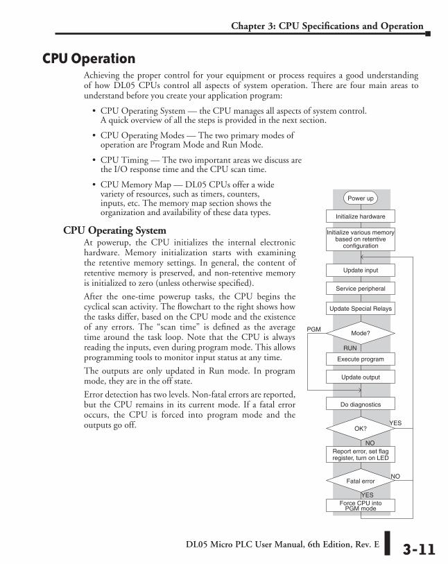
DL05 Micro PLC User Manual, 6th Edition, Rev. E 3-11
Chapter 3: CPU Specifications and Operation
CPU OperationAchieving the proper control for your equipment or process requires a good understanding of how DL05 CPUs control all aspects of system operation. There are four main areas to understand before you create your application program:
• CPU Operating System — the CPU manages all aspects of system control. A quick overview of all the steps is provided in the next section.
• CPU Operating Modes — The two primary modes of operation are Program Mode and Run Mode.
• CPU Timing — The two important areas we discuss are the I/O response time and the CPU scan time.
• CPU Memory Map — DL05 CPUs offer a wide variety of resources, such as timers, counters, inputs, etc. The memory map section shows the organization and availability of these data types.
CPU Operating SystemAt powerup, the CPU initializes the internal electronic hardware. Memory initialization starts with examining the retentive memory settings. In general, the content of retentive memory is preserved, and non-retentive memory is initialized to zero (unless otherwise specified).
After the one-time powerup tasks, the CPU begins the cyclical scan activity. The flowchart to the right shows how the tasks differ, based on the CPU mode and the existence of any errors. The “scan time” is defined as the average time around the task loop. Note that the CPU is always reading the inputs, even during program mode. This allows programming tools to monitor input status at any time.
The outputs are only updated in Run mode. In program mode, they are in the off state.
Error detection has two levels. Non-fatal errors are reported, but the CPU remains in its current mode. If a fatal error occurs, the CPU is forced into program mode and the outputs go off.
YES
Power up
Initialize hardware
Initialize various memorybased on retentive
configuration
Update input
Service peripheral
PGMMode?
RUN
Execute program
Update output
Do diagnostics
NO
NOFatal error
Force CPU intoPGM mode
OK?
Report error, set flagregister, turn on LED
YES
Update Special Relays
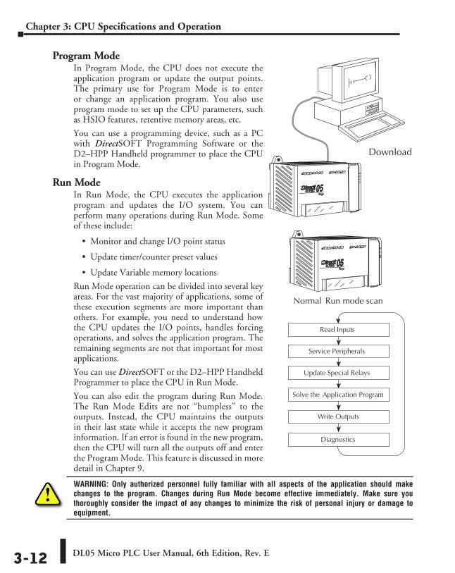
DL05 Micro PLC User Manual, 6th Edition, Rev. E3-12
Chapter 3: CPU Specifications and Operation
Program ModeIn Program Mode, the CPU does not execute the application program or update the output points. The primary use for Program Mode is to enter or change an application program. You also use program mode to set up the CPU parameters, such as HSIO features, retentive memory areas, etc.
You can use a programming device, such as a PC with DirectSOFT Programming Software or the D2–HPP Handheld programmer to place the CPU in Program Mode.
Run ModeIn Run Mode, the CPU executes the application program and updates the I/O system. You can perform many operations during Run Mode. Some of these include:
• Monitor and change I/O point status
• Update timer/counter preset values
• Update Variable memory locations
Run Mode operation can be divided into several key areas. For the vast majority of applications, some of these execution segments are more important than others. For example, you need to understand how the CPU updates the I/O points, handles forcing operations, and solves the application program. The remaining segments are not that important for most applications.
You can use DirectSOFT or the D2–HPP Handheld Programmer to place the CPU in Run Mode.
You can also edit the program during Run Mode. The Run Mode Edits are not “bumpless” to the outputs. Instead, the CPU maintains the outputs in their last state while it accepts the new program information. If an error is found in the new program, then the CPU will turn all the outputs off and enter the Program Mode. This feature is discussed in more detail in Chapter 9.
WARNING: Only authorized personnel fully familiar with all aspects of the application should make changes to the program. Changes during Run Mode become effective immediately. Make sure you thoroughly consider the impact of any changes to minimize the risk of personal injury or damage to equipment.
Download
Read Inputs
Solve the Application Program
Write Outputs
Diagnostics
Update Special Relays
Service Peripherals
Normal Run mode scan
DL05 Micro PLC User Manual, 6th Edition, Rev. E 3-13
Chapter 3: CPU Specifications and Operation
Read InputsThe CPU reads the status of all inputs, then stores it in the image register. Input image register locations are designated with an X followed by a memory location. Image register data is used by the CPU when it solves the application program.
Of course, an input may change after the CPU has just read the inputs. Generally, the CPU scan time is measured in milliseconds. If you have an application that cannot wait until the next I/O update, you can use Immediate Instructions. These do not use the status of the input image register to solve the application program. The Immediate instructions immediately read the input status directly from the I/O modules. However, this lengthens the program scan since the CPU has to read the I/O point status again. A complete list of the Immediate instructions is included in Chapter 5.
Service Peripherals and Force I/OAfter the CPU reads the inputs from the input modules, it reads any attached peripheral devices. This is primarily a communications service for any attached devices. For example, it would read a programming device to see if any input, output, or other memory type status needs to be modified. There are two basic types of forcing available with the DL05 CPUs.
• Forcing from a peripheral – not a permanent force, good only for one scan
• Bit Override – holds the I/O point (or other bit) in the current state. Valid bits are X, Y, C, T, CT, and S. (These memory types are discussed in more detail later in this chapter).
Regular Forcing — This type of forcing can temporarily change the status of a discrete bit. For example, you may want to force an input on, even though it is really off. This allows you to change the point status that was stored in the image register. This value will be valid until the image register location is written to during the next scan. This is primarily useful during testing situations when you need to force a bit on to trigger another event.
Bit Override — Bit override can be enabled on a point-by-point basis by using AUX 59 from the Handheld Programmer or, by using the Data View option within DirectSOFT. Bit override basically disables any changes to the discrete point by the CPU. For example, if you enable bit override for X1, and X1 is off at the time, then the CPU will not change the state of X1. This means that even if X1 comes on, the CPU will not acknowledge the change. So, if you used X1 in the program, it would always be evaluated as “off” in this case. Of course, if X1 was on when the bit override was enabled, then X1 would always be evaluated as “on”.
There is an advantage available when you use the bit override feature. The regular forcing is not disabled because the bit override is enabled. For example, if you enabled the Bit Override for Y0 and it was off at the time, then the CPU would not change the state of Y0. However, you can still use a programming device to change the status. Now, if you use the programming device to force Y0 on, it will remain on and the CPU will not change the state of Y0. If you then force Y0 off, the CPU will maintain Y0 as off. The CPU will never update the point with the results from the application program or from the I/O update until the bit override is removed. The following diagram shows a brief overview of the bit override feature. Notice the CPU does not update the Image Register when bit override is enabled.
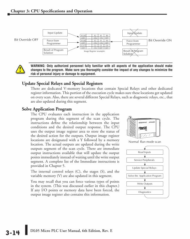
DL05 Micro PLC User Manual, 6th Edition, Rev. E3-14
Chapter 3: CPU Specifications and Operation
WARNING: Only authorized personnel fully familiar with all aspects of the application should make changes to the program. Make sure you thoroughly consider the impact of any changes to minimize the risk of personal injury or damage to equipment.
Update Special Relays and Special RegistersThere are dedicated V-memory locations that contain Special Relays and other dedicated register information. This portion of the execution cycle makes sure these locations get updated on every scan. Also, there are several different Special Relays, such as diagnostic relays, etc., that are also updated during this segment.
Solve Application ProgramThe CPU evaluates each instruction in the application program during this segment of the scan cycle. The instructions define the relationship between the input conditions and the desired output response. The CPU uses the output image register area to store the status of the desired action for the outputs. Output image register locations are designated with a Y followed by a memory location. The actual outputs are updated during the write outputs segment of the scan cycle. There are immediate output instructions available that will update the output points immediately instead of waiting until the write output segment. A complete list of the Immediate instructions is provided in Chapter 5.
The internal control relays (C), the stages (S), and the variable memory (V) are also updated in this segment.
You may recall that you can force various types of points in the system. (This was discussed earlier in this chapter.) If any I/O points or memory data have been forced, the output image register also contains this information.
Input Update
Result of ProgramSolution
OFF
Image Register (example)
Y1Y2...Y128ONON...OFF
C0C1C2...C377OFFOFFON...OFF
Y0OFF
X1X2...X128ONON...OFF
X0
Bit Override OFF Force fromProgrammer
Input Update
Result of ProgramSolution
Bit Override ONForce fromProgrammer
Download
Read Inputs
Solve the Application Program
Write Outputs
Diagnostics
Update Special Relays
Service Peripherals
Normal Run mode scan
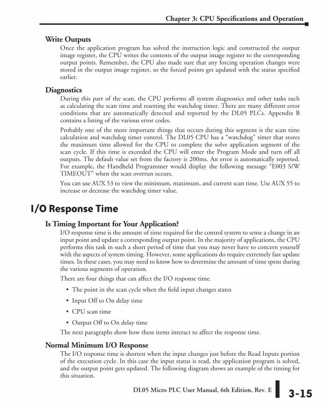
DL05 Micro PLC User Manual, 6th Edition, Rev. E 3-15
Chapter 3: CPU Specifications and Operation
Write OutputsOnce the application program has solved the instruction logic and constructed the output image register, the CPU writes the contents of the output image register to the corresponding output points. Remember, the CPU also made sure that any forcing operation changes were stored in the output image register, so the forced points get updated with the status specified earlier.
DiagnosticsDuring this part of the scan, the CPU performs all system diagnostics and other tasks such as calculating the scan time and resetting the watchdog timer. There are many different error conditions that are automatically detected and reported by the DL05 PLCs. Appendix B contains a listing of the various error codes.
Probably one of the more important things that occurs during this segment is the scan time calculation and watchdog timer control. The DL05 CPU has a “watchdog” timer that stores the maximum time allowed for the CPU to complete the solve application segment of the scan cycle. If this time is exceeded the CPU will enter the Program Mode and turn off all outputs. The default value set from the factory is 200ms. An error is automatically reported. For example, the Handheld Programmer would display the following message “E003 S/W TIMEOUT” when the scan overrun occurs.
You can use AUX 53 to view the minimum, maximum, and current scan time. Use AUX 55 to increase or decrease the watchdog timer value.
I/O Response TimeIs Timing Important for Your Application?
I/O response time is the amount of time required for the control system to sense a change in an input point and update a corresponding output point. In the majority of applications, the CPU performs this task in such a short period of time that you may never have to concern yourself with the aspects of system timing. However, some applications do require extremely fast update times. In these cases, you may need to know how to determine the amount of time spent during the various segments of operation.
There are four things that can affect the I/O response time.
• The point in the scan cycle when the field input changes states
• Input Off to On delay time
• CPU scan time
• Output Off to On delay time
The next paragraphs show how these items interact to affect the response time.
Normal Minimum I/O ResponseThe I/O response time is shortest when the input changes just before the Read Inputs portion of the execution cycle. In this case the input status is read, the application program is solved, and the output point gets updated. The following diagram shows an example of the timing for this situation.
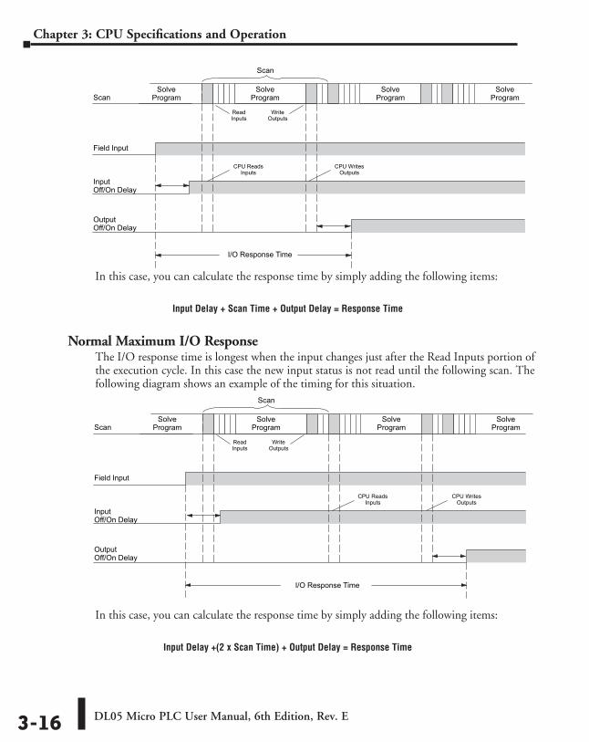
DL05 Micro PLC User Manual, 6th Edition, Rev. E3-16
Chapter 3: CPU Specifications and Operation
In this case, you can calculate the response time by simply adding the following items:
Input Delay + Scan Time + Output Delay = Response Time
Normal Maximum I/O ResponseThe I/O response time is longest when the input changes just after the Read Inputs portion of the execution cycle. In this case the new input status is not read until the following scan. The following diagram shows an example of the timing for this situation.
In this case, you can calculate the response time by simply adding the following items:
Input Delay +(2 x Scan Time) + Output Delay = Response Time
SolveProgram
ReadInputs
WriteOutputs
SolveProgramScan
SolveProgram
Field Input
Input Off/On Delay
CPU ReadsInputs
OutputOff/On Delay
I/O Response Time
Scan
SolveProgram
CPU WritesOutputs
SolveProgram
ReadInputs
WriteOutputs
SolveProgramScan
SolveProgram
Field Input
InputOff/On Delay
CPU ReadsInputs
OutputOff/On Delay
I/O Response Time
Scan
SolveProgram
CPU WritesOutputs
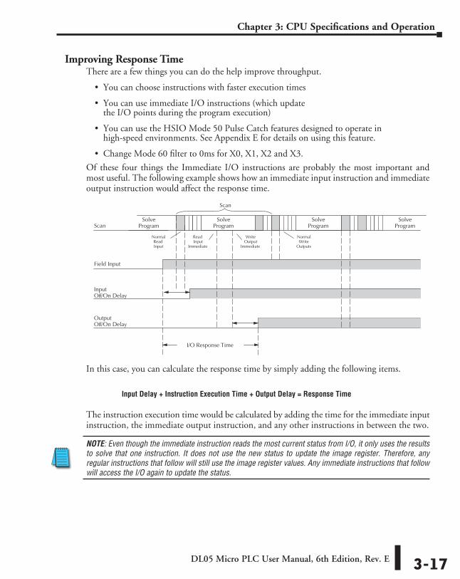
DL05 Micro PLC User Manual, 6th Edition, Rev. E 3-17
Chapter 3: CPU Specifications and Operation
Improving Response TimeThere are a few things you can do the help improve throughput.
• You can choose instructions with faster execution times
• You can use immediate I/O instructions (which update the I/O points during the program execution)
• You can use the HSIO Mode 50 Pulse Catch features designed to operate in high-speed environments. See Appendix E for details on using this feature.
• Change Mode 60 filter to 0ms for X0, X1, X2 and X3.
Of these four things the Immediate I/O instructions are probably the most important and most useful. The following example shows how an immediate input instruction and immediate output instruction would affect the response time.
In this case, you can calculate the response time by simply adding the following items.
Input Delay + Instruction Execution Time + Output Delay = Response Time
The instruction execution time would be calculated by adding the time for the immediate input instruction, the immediate output instruction, and any other instructions in between the two.
NOTE: Even though the immediate instruction reads the most current status from I/O, it only uses the results to solve that one instruction. It does not use the new status to update the image register. Therefore, any regular instructions that follow will still use the image register values. Any immediate instructions that follow will access the I/O again to update the status.
SolveProgram
ReadInput
Immediate
NormalWrite
Outputs
SolveProgramScan
SolveProgram
Field Input
InputOff/On Delay
OutputOff/On Delay
I/O Response Time
Scan
SolveProgram
NormalReadInput
WriteOutput
Immediate
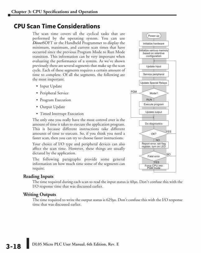
DL05 Micro PLC User Manual, 6th Edition, Rev. E3-18
Chapter 3: CPU Specifications and Operation
CPU Scan Time ConsiderationsThe scan time covers all the cyclical tasks that are performed by the operating system. You can use DirectSOFT or the Handheld Programmer to display the minimum, maximum, and current scan times that have occurred since the previous Program Mode to Run Mode transition. This information can be very important when evaluating the performance of a system. As we’ve shown previously there are several segments that make up the scan cycle. Each of these segments requires a certain amount of time to complete. Of all the segments, the following are the most important.
• Input Update
• Peripheral Service
• Program Execution
• Output Update
• Timed Interrupt Execution
The only one you really have the most control over is the amount of time it takes to execute the application program. This is because different instructions take different amounts of time to execute. So, if you think you need a faster scan, then you can try to choose faster instructions.
Your choice of I/O type and peripheral devices can also affect the scan time. However, these things are usually dictated by the application.
The following paragraphs provide some general information on how much time some of the segments can require.
Reading InputsThe time required during each scan to read the input status is 40µs. Don’t confuse this with the I/O response time that was discussed earlier.
Writing OutputsThe time required to write the output status is 629µs. Don’t confuse this with the I/O response time that was discussed earlier.
YES
Power up
Initialize hardware
Initialize various memorybased on retentive
configuration
Update input
Service peripheral
PGMMode?
RUN
Execute program
Update output
Do diagnostics
NO
NOFatal error
Force CPU intoPGM mode
OK?
Report error, set flagregister, turn on LED
YES
Update Special Relays
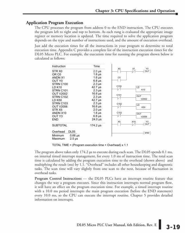
DL05 Micro PLC User Manual, 6th Edition, Rev. E 3-19
Chapter 3: CPU Specifications and Operation
Application Program ExecutionThe CPU processes the program from address 0 to the END instruction. The CPU executes the program left to right and top to bottom. As each rung is evaluated the appropriate image register or memory location is updated. The time required to solve the application program depends on the type and number of instructions used, and the amount of execution overhead.
Just add the execution times for all the instructions in your program to determine to total execution time. Appendix C provides a complete list of the instruction execution times for the DL05 Micro PLC. For example, the execution time for running the program shown below is calculated as follows:
The program above takes only 174.2 µs to execute during each scan. The DL05 spends 0.1 ms, on internal timed interrupt management, for every 1.0 ms of instruction time. The total scan time is calculated by adding the program execution time to the overhead (shown above) and multiplying the result (ms) by 1.1. “Overhead” includes all other housekeeping and diagnostic tasks. The scan time will vary slightly from one scan to the next, because of fluctuation in overhead tasks.
Program Control Instructions — the DL05 PLCs have an interrupt routine feature that changes the way a program executes. Since this instruction interrupts normal program flow, it will have an effect on the program execution time. For example, a timed interrupt routine with a 10.0 ms period interrupts the main program execution (before the END statement) every 10.0 ms, so the CPU can execute the interrupt routine. Chapter 5 provides detailed information on interrupts.
X0 X1 Y0OUT
C0
C100 LDK10
C101 OUTV2002
C102 LDK50
C103 OUTV2006
X5 X10 Y3OUT
END
Instruction Time
STR X0OR C0 1.6 µsANDN X1 1.6 µsOUT Y0 6.8 µsSTRN C100 2.3 µsLD K10 42.7 µsSTRN C101 2.3 µsOUT V2002 16.6 µsSTRN C102 2.3 µsLD K50 42.7 µsSTRN C103 2.3 µsOUT V2006 16.6 µsSTR X5 2.0 µsANDN X10 1.6 µsOUT Y3 6.8 µsEND 24.0 µs
SUBTOTAL 174.2 µs
Overhead DL05Minimum 0.66 µsMaximum 2.5 µs
TOTAL TIME = (Program execution time + Overhead) x 1.1
2.0 µs
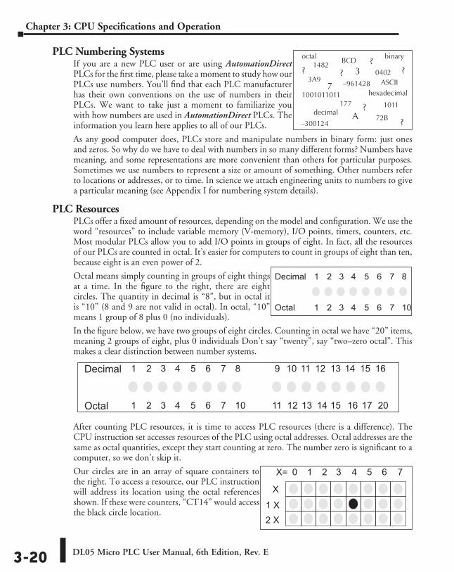
DL05 Micro PLC User Manual, 6th Edition, Rev. E3-20
Chapter 3: CPU Specifications and Operation
PLC Numbering SystemsIf you are a new PLC user or are using AutomationDirect PLCs for the first time, please take a moment to study how our PLCs use numbers. You’ll find that each PLC manufacturer has their own conventions on the use of numbers in their PLCs. We want to take just a moment to familiarize you with how numbers are used in AutomationDirect PLCs. The information you learn here applies to all of our PLCs.
As any good computer does, PLCs store and manipulate numbers in binary form: just ones and zeros. So why do we have to deal with numbers in so many different forms? Numbers have meaning, and some representations are more convenient than others for particular purposes. Sometimes we use numbers to represent a size or amount of something. Other numbers refer to locations or addresses, or to time. In science we attach engineering units to numbers to give a particular meaning (see Appendix I for numbering system details).
PLC ResourcesPLCs offer a fixed amount of resources, depending on the model and configuration. We use the word “resources” to include variable memory (V-memory), I/O points, timers, counters, etc. Most modular PLCs allow you to add I/O points in groups of eight. In fact, all the resources of our PLCs are counted in octal. It’s easier for computers to count in groups of eight than ten, because eight is an even power of 2.
Octal means simply counting in groups of eight things at a time. In the figure to the right, there are eight circles. The quantity in decimal is “8”, but in octal it is “10” (8 and 9 are not valid in octal). In octal, “10” means 1 group of 8 plus 0 (no individuals).
In the figure below, we have two groups of eight circles. Counting in octal we have “20” items, meaning 2 groups of eight, plus 0 individuals Don’t say “twenty”, say “two–zero octal”. This makes a clear distinction between number systems.
After counting PLC resources, it is time to access PLC resources (there is a difference). The CPU instruction set accesses resources of the PLC using octal addresses. Octal addresses are the same as octal quantities, except they start counting at zero. The number zero is significant to a computer, so we don’t skip it.
Our circles are in an array of square containers to the right. To access a resource, our PLC instruction will address its location using the octal references shown. If these were counters, “CT14” would access the black circle location.
14820402
10010110117
33A9
? ??
?BCD
binary
decimal
octal
hexadecimalASCII
1011
–961428
177 ?
–300124A 72B ?
0 1 2 3 4 5 6 7
2 X
1 X
X
X=
Decimal 1 2 3 4 5 6 7 8
Octal 1 2 3 4 5 6 7 10
9 10 11 12 13 14 15 16
11 12 13 14 15 16 17 20
Decimal 1 2 3 4 5 6 7 8
Octal 1 2 3 4 5 6 7 10
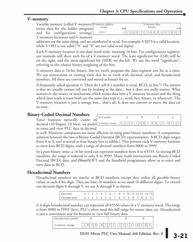
DL05 Micro PLC User Manual, 6th Edition, Rev. E 3-21
Chapter 3: CPU Specifications and Operation
V–memoryVariable memory (called V-memory) stores data for the ladder program and for configuration settings. V-memory locations and V-memory addresses are the same thing, and are numbered in octal. For example, V2073 is a valid location, while V1983 is not valid (“9” and “8” are not valid octal digits).
Each V-memory location is one data word wide, meaning 16 bits. For configuration registers, our manuals will show each bit of a V-memory word. The least significant bit (LSB) will be on the right, and the most significant bit (MSB) on the left. We use the word “significant”, referring to the relative binary weighting of the bits.
V-memory data is 16-bit binary, but we rarely program the data registers one bit at a time. We use instructions or viewing tools that let us work with decimal, octal, and hexadecimal numbers. All these are converted and stored as binary for us.
A frequently-asked question is “How do I tell if a number is octal, BCD, or hex”? The answer is that we usually cannot tell just by looking at the data... but it does not really matter. What matters is: the source or mechanism which writes data into a V-memory location and the thing which later reads it must both use the same data type (i.e., octal, hex, binary, or whatever). The V-memory location is just a storage box... that’s all. It does not convert or move the data on its own.
Binary-Coded Decimal NumbersSince humans naturally count in decimal (10 fingers, 10 toes), we prefer to enter and view PLC data in decimal as well. However, computers are more efficient in using pure binary numbers. A compromise solution between the two is Binary-Coded Decimal (BCD) representation. A BCD digit ranges from 0 to 9, and is stored as four binary bits (a nibble). This permits each V-memory location to store four BCD digits, with a range of decimal numbers from 0000 to 9999.
In a pure binary sense, a 16-bit word can represent numbers from 0 to 65535. In storing BCD numbers, the range is reduced to only 0 to 9999. Many math instructions use Binary-Coded Decimal (BCD) data, and DirectSOFT and the handheld programmer allow us to enter and view data in BCD.
Hexadecimal NumbersHexadecimal numbers are similar to BCD numbers, except they utilize all possible binary values in each 4-bit digit. They are base-16 numbers so we need 16 different digits. To extend our decimal digits 0 through 9, we use A through F as shown.
A 4-digit hexadecimal number can represent all 65536 values in a V-memory word. The range is from 0000 to FFFF (hex). PLC’s often need this full range for sensor data, etc. Hexadecimal is just a convenient way for humans to view full binary data.
1 0 1 0 0 1 1 1 1 1 1 1 0 1 0 0
A 7 F 4
V-memory storage
Hexadecimal number
0 1 0 0 1 1 1 0 0 0 1 0 1 0 0 1
MSB LSB
V-memory data(binary)
V-memory address(octal)
V2017
0 1 0 0 1 0 0 1 0 0 1 1 0 1 1 0
4 9 3 6
V-memory storage
BCD number
8 9 10 11 12 13 14 150 1 2 3 4 5 6 78 9 A B C D E F0 1 2 3 4 5 6 7
DecimalHexadecimal
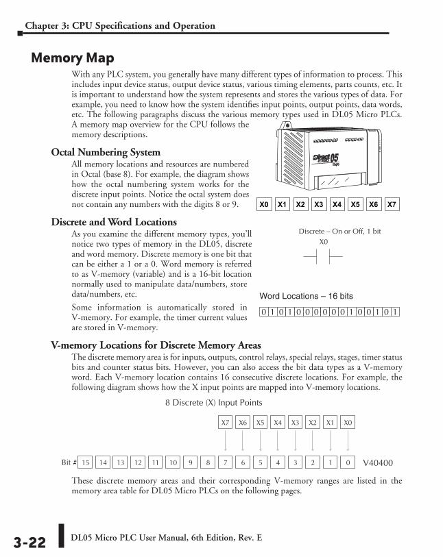
DL05 Micro PLC User Manual, 6th Edition, Rev. E3-22
Chapter 3: CPU Specifications and Operation
Memory MapWith any PLC system, you generally have many different types of information to process. This includes input device status, output device status, various timing elements, parts counts, etc. It is important to understand how the system represents and stores the various types of data. For example, you need to know how the system identifies input points, output points, data words, etc. The following paragraphs discuss the various memory types used in DL05 Micro PLCs. A memory map overview for the CPU follows the memory descriptions.
Octal Numbering SystemAll memory locations and resources are numbered in Octal (base 8). For example, the diagram shows how the octal numbering system works for the discrete input points. Notice the octal system does not contain any numbers with the digits 8 or 9.
Discrete and Word LocationsAs you examine the different memory types, you’ll notice two types of memory in the DL05, discrete and word memory. Discrete memory is one bit that can be either a 1 or a 0. Word memory is referred to as V-memory (variable) and is a 16-bit location normally used to manipulate data/numbers, store data/numbers, etc.
Some information is automatically stored in V-memory. For example, the timer current values are stored in V-memory.
V-memory Locations for Discrete Memory AreasThe discrete memory area is for inputs, outputs, control relays, special relays, stages, timer status bits and counter status bits. However, you can also access the bit data types as a V-memory word. Each V-memory location contains 16 consecutive discrete locations. For example, the following diagram shows how the X input points are mapped into V-memory locations.
These discrete memory areas and their corresponding V-memory ranges are listed in the memory area table for DL05 Micro PLCs on the following pages.
X0 X1 X2 X3 X4 X5 X6 X7
X0Discrete – On or Off, 1 bit
0 11 0 1 0 0 0 0 0 0 1 0 0 1 0
Word Locations – 16 bits
X0X1X2X3X4X5X6X7
0123456789101112131415 V40400Bit #
8 Discrete (X) Input Points
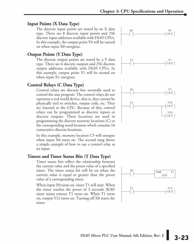
DL05 Micro PLC User Manual, 6th Edition, Rev. E 3-23
Chapter 3: CPU Specifications and Operation
Input Points (X Data Type)The discrete input points are noted by an X data type. There are 8 discrete input points and 256 discrete input addresses available with DL05 CPUs. In this example, the output point Y0 will be turned on when input X0 energizes.
Output Points (Y Data Type)The discrete output points are noted by a Y data type. There are 6 discrete outputs and 256 discrete output addresses available with DL05 CPUs. In this example, output point Y1 will be turned on when input X1 energizes.
Control Relays (C Data Type)Control relays are discrete bits normally used to control the user program. The control relays do not represent a real world device, that is, they cannot be physically tied to switches, output coils, etc. They are internal to the CPU. Because of this, control relays can be programmed as discrete inputs or discrete outputs. These locations are used in programming the discrete memory locations (C) or the corresponding word location which contains 16 consecutive discrete locations.
In this example, memory location C5 will energize when input X6 turns on. The second rung shows a simple example of how to use a control relay as an input.
Timers and Timer Status Bits (T Data Type)Timer status bits reflect the relationship between the current value and the preset value of a specified timer. The timer status bit will be on when the current value is equal or greater than the preset value of a corresponding timer.
When input X0 turns on, timer T1 will start. When the timer reaches the preset of 3 seconds (K30) timer status contact T1 turns on. When T1 turns on, output Y12 turns on. Turning off X0 resets the timer.
Y0OUT
X0
Y1OUT
X1
C5OUT
X6
Y10OUT
C5
Y20OUT
Y12OUT
T1
TMR T1K30
X0
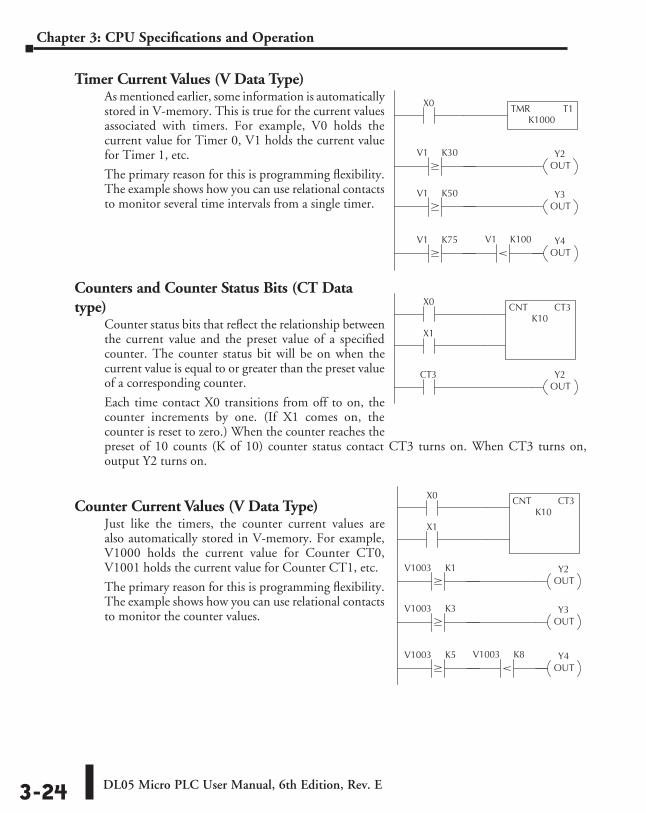
DL05 Micro PLC User Manual, 6th Edition, Rev. E3-24
Chapter 3: CPU Specifications and Operation
Timer Current Values (V Data Type)As mentioned earlier, some information is automatically stored in V-memory. This is true for the current values associated with timers. For example, V0 holds the current value for Timer 0, V1 holds the current value for Timer 1, etc.
The primary reason for this is programming flexibility. The example shows how you can use relational contacts to monitor several time intervals from a single timer.
Counters and Counter Status Bits (CT Data type)
Counter status bits that reflect the relationship between the current value and the preset value of a specified counter. The counter status bit will be on when the current value is equal to or greater than the preset value of a corresponding counter.
Each time contact X0 transitions from off to on, the counter increments by one. (If X1 comes on, the counter is reset to zero.) When the counter reaches the preset of 10 counts (K of 10) counter status contact CT3 turns on. When CT3 turns on, output Y2 turns on.
Counter Current Values (V Data Type)Just like the timers, the counter current values are also automatically stored in V-memory. For example, V1000 holds the current value for Counter CT0, V1001 holds the current value for Counter CT1, etc.
The primary reason for this is programming flexibility. The example shows how you can use relational contacts to monitor the counter values.
V1 K100
TMR T1K1000
X0
V1 K30 Y2OUT
V1 K50 Y3OUT
V1 K75 Y4OUT
Y2OUT
CT3
X0 CNT CT3K10
X1
V1003 K8
V1003 K1 Y2OUT
V1003 K3 Y3OUT
V1003 K5 Y4OUT
X0 CNT CT3K10
X1
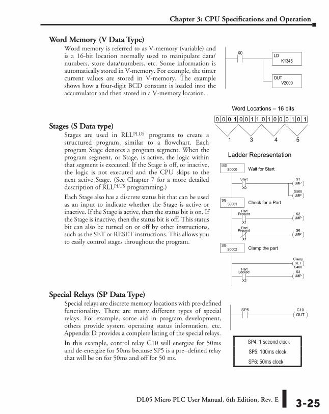
DL05 Micro PLC User Manual, 6th Edition, Rev. E 3-25
Chapter 3: CPU Specifications and Operation
Word Memory (V Data Type)Word memory is referred to as V-memory (variable) and is a 16-bit location normally used to manipulate data/numbers, store data/numbers, etc. Some information is automatically stored in V-memory. For example, the timer current values are stored in V-memory. The example shows how a four-digit BCD constant is loaded into the accumulator and then stored in a V-memory location.
Stages (S Data type)Stages are used in RLLPLUS programs to create a structured program, similar to a flowchart. Each program Stage denotes a program segment. When the program segment, or Stage, is active, the logic within that segment is executed. If the Stage is off, or inactive, the logic is not executed and the CPU skips to the next active Stage. (See Chapter 7 for a more detailed description of RLLplus programming.)
Each Stage also has a discrete status bit that can be used as an input to indicate whether the Stage is active or inactive. If the Stage is active, then the status bit is on. If the Stage is inactive, then the status bit is off. This status bit can also be turned on or off by other instructions, such as the SET or RESET instructions. This allows you to easily control stages throughout the program.
Special Relays (SP Data Type)Special relays are discrete memory locations with pre-defined functionality. There are many different types of special relays. For example, some aid in program development, others provide system operating status information, etc. Appendix D provides a complete listing of the special relays.
In this example, control relay C10 will energize for 50ms and de-energize for 50ms because SP5 is a pre–defined relay that will be on for 50ms and off for 50 ms.
X0 LDK1345
OUTV2000
0 10 0 1 0 0 1 1 0 1 0 0 0 1 0
Word Locations – 16 bits
1 3 4 5
Ladder RepresentationISG
S0000
Start S1JMP
SGS0001
Present S2JMP
Part
X1
X0
S6JMP
PresentPart
X1
SGS0002
ClampSET
S3JMP
LockedPart
X2
S400
Wait for Start
Check for a Part
Clamp the part
S500JMP
SP4: 1 second clock
SP5: 100ms clock
SP6: 50ms clock
C10OUT
SP5
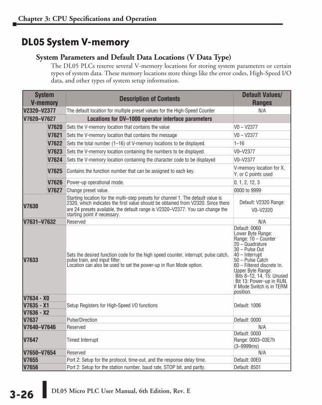
DL05 Micro PLC User Manual, 6th Edition, Rev. E3-26
Chapter 3: CPU Specifications and Operation
DL05 System V-memorySystem Parameters and Default Data Locations (V Data Type)
The DL05 PLCs reserve several V-memory locations for storing system parameters or certain types of system data. These memory locations store things like the error codes, High-Speed I/O data, and other types of system setup information.
System V-memory Description of Contents Default Values/
RangesV2320–V2377 The default location for multiple preset values for the High-Speed Counter N/A
V7620–V7627 Locations for DV–1000 operator interface parameters V7620 Sets the V-memory location that contains the value V0 – V2377
V7621 Sets the V-memory location that contains the message V0 – V2377
V7622 Sets the total number (1–16) of V-memory locations to be displayed. 1–16
V7623 Sets the V-memory location containing the numbers to be displayed. V0–V2377
V7624 Sets the V-memory location containing the character code to be displayed V0–V2377
V7625 Contains the function number that can be assigned to each key. V-memory location for X, Y, or C points used
V7626 Power-up operational mode. 0, 1, 2, 12, 3
V7627 Change preset value. 0000 to 9999
V7630 Starting location for the multi–step presets for channel 1. The default value is 2320, which indicates the first value should be obtained from V2320. Since there are 24 presets available, the default range is V2320–V2377. You can change the starting point if necessary.
Default: V2320 Range: V0–V2320
V7631–V7632 Reserved N/A
V7633 Sets the desired function code for the high speed counter, interrupt, pulse catch, pulse train, and input filter. Location can also be used to set the power-up in Run Mode option.
Default: 0060 Lower Byte Range: Range: 10 – Counter 20 – Quadrature 30 – Pulse Out 40 – Interrupt 50 – Pulse Catch 60 – Filtered discrete In. Upper Byte Range: Bits 8–12, 14, 15: Unused Bit 13: Power–up in RUN, if Mode Switch is in TERM position.
V7634 - X0 Setup Registers for High-Speed I/O functions Default: 1006V7635 - X1
V7636 - X2 V7637 Pulse/Direction Default: 0000V7640–V7646 Reserved N/A
V7647 Timed Interrupt Default: 0000 Range: 0003–03E7h (3–9999ms)
V7650–V7654 Reserved N/AV7655 Port 2: Setup for the protocol, time-out, and the response delay time. Default: 00E0V7656 Port 2: Setup for the station number, baud rate, STOP bit, and parity. Default: 8501
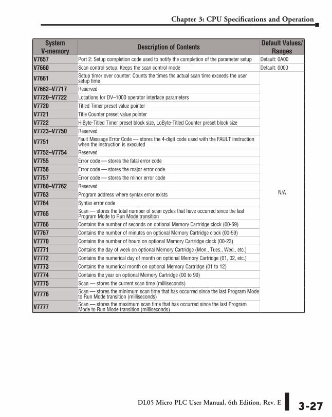
DL05 Micro PLC User Manual, 6th Edition, Rev. E 3-27
Chapter 3: CPU Specifications and Operation
System V-memory Description of Contents Default Values/
RangesV7657 Port 2: Setup completion code used to notify the completion of the parameter setup Default: 0A00
V7660 Scan control setup: Keeps the scan control mode Default: 0000
V7661 Setup timer over counter: Counts the times the actual scan time exceeds the user setup time
N/A
V7662–V7717 Reserved
V7720–V7722 Locations for DV–1000 operator interface parameters
V7720 Titled Timer preset value pointer
V7721 Title Counter preset value pointer
V7722 HiByte-Titled Timer preset block size, LoByte-Titled Counter preset block size
V7723–V7750 Reserved
V7751 Fault Message Error Code — stores the 4-digit code used with the FAULT instruction when the instruction is executed
V7752–V7754 Reserved
V7755 Error code — stores the fatal error code
V7756 Error code — stores the major error code
V7757 Error code — stores the minor error code
V7760–V7762 Reserved
V7763 Program address where syntax error exists
V7764 Syntax error code
V7765 Scan — stores the total number of scan cycles that have occurred since the last Program Mode to Run Mode transition
V7766 Contains the number of seconds on optional Memory Cartridge clock (00-59)
V7767 Contains the number of minutes on optional Memory Cartridge clock (00-59)
V7770 Contains the number of hours on optional Memory Cartridge clock (00-23)
V7771 Contains the day of week on optional Memory Cartridge (Mon., Tues., Wed., etc.)
V7772 Contains the numerical day of month on optional Memory Cartridge (01, 02, etc.)
V7773 Contains the numerical month on optional Memory Cartridge (01 to 12)
V7774 Contains the year on optional Memory Cartridge (00 to 99)
V7775 Scan — stores the current scan time (milliseconds)
V7776 Scan — stores the minimum scan time that has occurred since the last Program Mode to Run Mode transition (milliseconds)
V7777 Scan — stores the maximum scan time that has occurred since the last Program Mode to Run Mode transition (milliseconds)
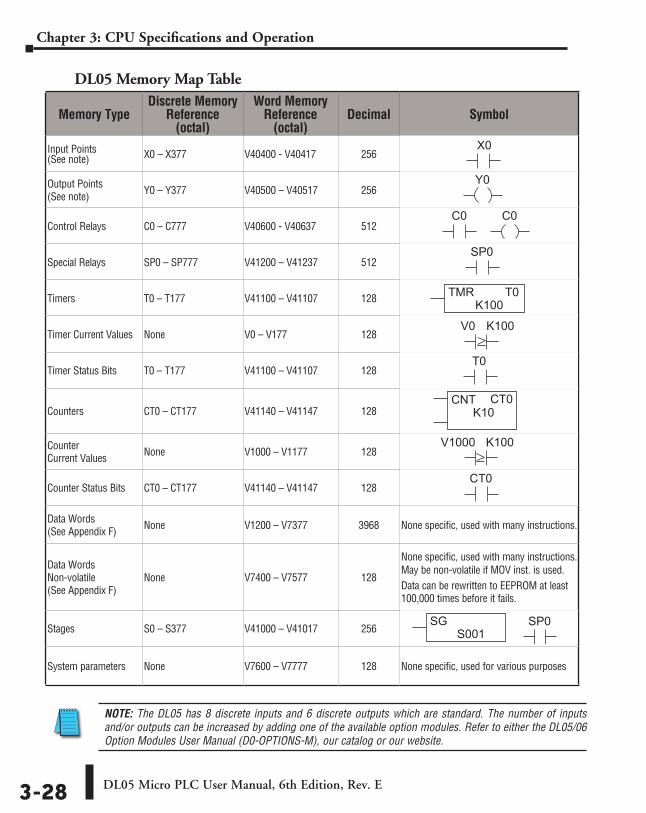
DL05 Micro PLC User Manual, 6th Edition, Rev. E3-28
Chapter 3: CPU Specifications and Operation
DL05 Memory Map Table
NOTE: The DL05 has 8 discrete inputs and 6 discrete outputs which are standard. The number of inputs and/or outputs can be increased by adding one of the available option modules. Refer to either the DL05/06 Option Modules User Manual (D0-OPTIONS-M), our catalog or our website.
Memory TypeDiscrete Memory
Reference (octal)
Word Memory Reference
(octal)Decimal Symbol
Input Points (See note) X0 – X377 V40400 - V40417 256
X0
Output Points (See note) Y0 – Y377 V40500 – V40517 256
Y0
Control Relays C0 – C777 V40600 - V40637 512C0C0
Special Relays SP0 – SP777 V41200 – V41237 512SP0
Timers T0 – T177 V41100 – V41107 128 TMRK100
T0
Timer Current Values None V0 – V177 128V0 K100
Timer Status Bits T0 – T177 V41100 – V41107 128T0
Counters CT0 – CT177 V41140 – V41147 128CNT
K10CT0
Counter Current Values None V1000 – V1177 128
V1000 K100
Counter Status Bits CT0 – CT177 V41140 – V41147 128CT0
Data Words (See Appendix F) None V1200 – V7377 3968 None specific, used with many instructions.
Data Words Non-volatile (See Appendix F)
None V7400 – V7577 128
None specific, used with many instructions. May be non-volatile if MOV inst. is used.Data can be rewritten to EEPROM at least 100,000 times before it fails.
Stages S0 – S377 V41000 – V41017 256SP0SG
S001
System parameters None V7600 – V7777 128 None specific, used for various purposes
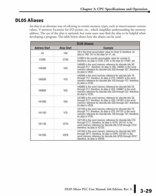
DL05 Micro PLC User Manual, 6th Edition, Rev. E 3-29
Chapter 3: CPU Specifications and Operation
DL05 AliasesAn alias is an alternate way of referring to certain memory types, such as timer/counter current values, V-memory locations for I/O points, etc., which simplifies understanding the memory address. The use of the alias is optional, but some users may find the alias to be helpful when developing a program. The table below shows how the aliases can be used.
DL05 AliasesAddress Start Alias Start Example
V0 TA0 V0 is the timer accumulator value for timer 0; therefore, its alias is TA0. TA1 is the alias for V1, etc.
V1000 CTA0 V1000 is the counter accumulator value for counter 0; therefore, its alias is CTA0. CTA1 is the alias for V1001, etc.
V40400 VX0V40400 is the word memory reference for discrete bits X0 through X17; therefore, its alias is VX0. V40401 is the word memory reference for discrete bits X20 through X37; therefore, its alias is VX20.
V40500 VY0V40500 is the word memory reference for discrete bits Y0 through Y17; therefore, its alias is VY0. V40501 is the word memory reference for discrete bits Y20 through Y37; therefore, its alias is VY20.
V40600 VC0V40600 is the word memory reference for discrete bits C0 through C17; therefore, its alias is VC0. V40601 is the word memory reference for discrete bits C20 through C37; therefore, its alias is VC20.
V41000 VS0V41000 is the word memory reference for discrete bits S0 through S17; therefore, its alias is VS0. V41001 is the word memory reference for discrete bits S20 through S37; therefore, its alias is VS20.
V41100 VT0V41100 is the word memory reference for discrete bits T0 through T17; therefore, its alias is VT0. V41101 is the word memory reference for discrete bits T20 through T37; therefore, its alias is VT20.
V41140 VCT0V41140 is the word memory reference for discrete bits CT0 through CT17; therefore, its alias is VCT0. V41141 is the word memory reference for discrete bits CT20 through CT37; therefore, its alias is VCT20.
V41200 VSP0V41200 is the word memory reference for discrete bits SP0 through SP17; therefore, its alias is VSP0. V41201 is the word memory reference for discrete bits SP20 through SP37; therefore, its alias is VSP20.
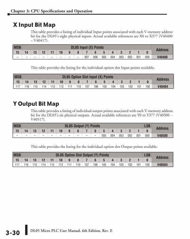
DL05 Micro PLC User Manual, 6th Edition, Rev. E3-30
Chapter 3: CPU Specifications and Operation
X Input Bit MapThis table provides a listing of individual Input points associated with each V-memory address bit for the DL05’s eight physical inputs. Actual available references are X0 to X377 (V40400 – V40417).
This table provides the listing for the individual option slot Input points available.
Y Output Bit MapThis table provides a listing of individual output points associated with each V-memory address bit for the DL05’s six physical outputs. Actual available references are Y0 to Y377 (V40500 – V40517).
This table provides the listing for the individual option slot Output points available.
MSB DL05 Output (Y) Points LSB Address15 14 13 12 11 10 9 8 7 6 5 4 3 2 1 0– – – – – – – – – – 005 004 003 002 001 000 V40500
MSB DL05 Input (X) Points Address15 14 13 12 11 10 9 8 7 6 5 4 3 2 1 0– – – – – – – – 007 006 005 004 003 002 001 000 V40400
MSB DL05 Option Slot Input (X) Points Address15 14 13 12 11 10 9 8 7 6 5 4 3 2 1 0117 116 115 114 113 112 111 110 107 106 105 104 103 102 101 100 V40404
MSB DL05 Option Slot Output (Y) Points LSB Address15 14 13 12 11 10 9 8 7 6 5 4 3 2 1 0117 116 115 114 113 112 111 110 107 106 105 104 103 102 101 100 V40504
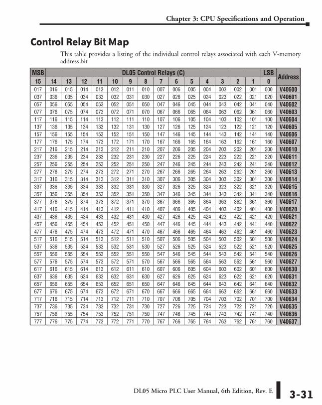
DL05 Micro PLC User Manual, 6th Edition, Rev. E 3-31
Chapter 3: CPU Specifications and Operation
Control Relay Bit MapThis table provides a listing of the individual control relays associated with each V-memory address bit
MSB DL05 Control Relays (C) LSBAddress
15 14 13 12 11 10 9 8 7 6 5 4 3 2 1 0017 016 015 014 013 012 011 010 007 006 005 004 003 002 001 000 V40600037 036 035 034 033 032 031 030 027 026 025 024 023 022 021 020 V40601057 056 055 054 053 052 051 050 047 046 045 044 043 042 041 040 V40602077 076 075 074 073 072 071 070 067 066 065 064 063 062 061 060 V40603117 116 115 114 113 112 111 110 107 106 105 104 103 102 101 100 V40604137 136 135 134 133 132 131 130 127 126 125 124 123 122 121 120 V40605157 156 155 154 153 152 151 150 147 146 145 144 143 142 141 140 V40606177 176 175 174 173 172 171 170 167 166 165 164 163 162 161 160 V40607217 216 215 214 213 212 211 210 207 206 205 204 203 202 201 200 V40610237 236 235 234 233 232 231 230 227 226 225 224 223 222 221 220 V40611257 256 255 254 253 252 251 250 247 246 245 244 243 242 241 240 V40612277 276 275 274 273 272 271 270 267 266 265 264 263 262 261 260 V40613317 316 315 314 313 312 311 310 307 306 305 304 303 302 301 300 V40614337 336 335 334 333 332 331 330 327 326 325 324 323 322 321 320 V40615357 356 355 354 353 352 351 350 347 346 345 344 343 342 341 340 V40616377 376 375 374 373 372 371 370 367 366 365 364 363 362 361 360 V40617417 416 415 414 413 412 411 410 407 406 405 404 403 402 401 400 V40620437 436 435 434 433 432 431 430 427 426 425 424 423 422 421 420 V40621457 456 455 454 453 452 451 450 447 446 445 444 443 442 441 440 V40622477 476 475 474 473 472 471 470 467 466 465 464 463 462 461 460 V40623517 516 515 514 513 512 511 510 507 506 505 504 503 502 501 500 V40624537 536 535 534 533 532 531 530 527 526 525 524 523 522 521 520 V40625557 556 555 554 553 552 551 550 547 546 545 544 543 542 541 540 V40626577 576 575 574 573 572 571 570 567 566 565 564 563 562 561 560 V40627617 616 615 614 613 612 611 610 607 606 605 604 603 602 601 600 V40630637 636 635 634 633 632 631 630 627 626 625 624 623 622 621 620 V40631657 656 655 654 653 652 651 650 647 646 645 644 643 642 641 640 V40632677 676 675 674 673 672 671 670 667 666 665 664 663 662 661 660 V40633717 716 715 714 713 712 711 710 707 706 705 704 703 702 701 700 V40634737 736 735 734 733 732 731 730 727 726 725 724 723 722 721 720 V40635757 756 755 754 753 752 751 750 747 746 745 744 743 742 741 740 V40636777 776 775 774 773 772 771 770 767 766 765 764 763 762 761 760 V40637
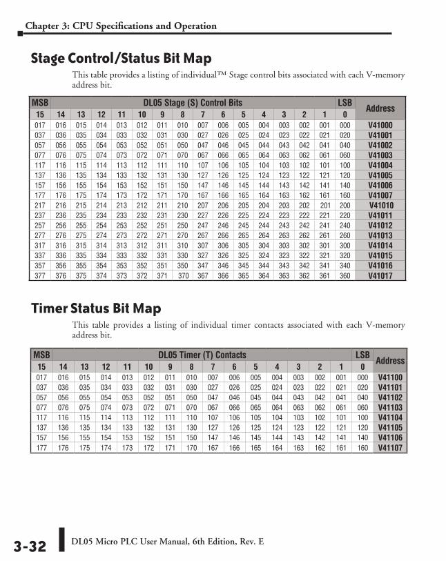
DL05 Micro PLC User Manual, 6th Edition, Rev. E3-32
Chapter 3: CPU Specifications and Operation
Stage Control/Status Bit MapThis table provides a listing of individual™ Stage control bits associated with each V-memory address bit.
Timer Status Bit MapThis table provides a listing of individual timer contacts associated with each V-memory address bit.
MSB DL05 Timer (T) Contacts LSB Address15 14 13 12 11 10 9 8 7 6 5 4 3 2 1 0017 016 015 014 013 012 011 010 007 006 005 004 003 002 001 000 V41100037 036 035 034 033 032 031 030 027 026 025 024 023 022 021 020 V41101057 056 055 054 053 052 051 050 047 046 045 044 043 042 041 040 V41102077 076 075 074 073 072 071 070 067 066 065 064 063 062 061 060 V41103117 116 115 114 113 112 111 110 107 106 105 104 103 102 101 100 V41104137 136 135 134 133 132 131 130 127 126 125 124 123 122 121 120 V41105157 156 155 154 153 152 151 150 147 146 145 144 143 142 141 140 V41106177 176 175 174 173 172 171 170 167 166 165 164 163 162 161 160 V41107
MSB DL05 Stage (S) Control Bits LSB Address15 14 13 12 11 10 9 8 7 6 5 4 3 2 1 0017 016 015 014 013 012 011 010 007 006 005 004 003 002 001 000 V41000037 036 035 034 033 032 031 030 027 026 025 024 023 022 021 020 V41001057 056 055 054 053 052 051 050 047 046 045 044 043 042 041 040 V41002077 076 075 074 073 072 071 070 067 066 065 064 063 062 061 060 V41003117 116 115 114 113 112 111 110 107 106 105 104 103 102 101 100 V41004137 136 135 134 133 132 131 130 127 126 125 124 123 122 121 120 V41005157 156 155 154 153 152 151 150 147 146 145 144 143 142 141 140 V41006177 176 175 174 173 172 171 170 167 166 165 164 163 162 161 160 V41007217 216 215 214 213 212 211 210 207 206 205 204 203 202 201 200 V41010237 236 235 234 233 232 231 230 227 226 225 224 223 222 221 220 V41011257 256 255 254 253 252 251 250 247 246 245 244 243 242 241 240 V41012277 276 275 274 273 272 271 270 267 266 265 264 263 262 261 260 V41013317 316 315 314 313 312 311 310 307 306 305 304 303 302 301 300 V41014337 336 335 334 333 332 331 330 327 326 325 324 323 322 321 320 V41015357 356 355 354 353 352 351 350 347 346 345 344 343 342 341 340 V41016377 376 375 374 373 372 371 370 367 366 365 364 363 362 361 360 V41017
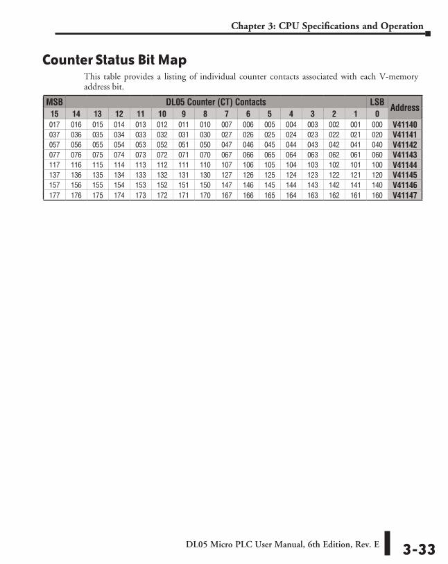
DL05 Micro PLC User Manual, 6th Edition, Rev. E 3-33
Chapter 3: CPU Specifications and Operation
Counter Status Bit MapThis table provides a listing of individual counter contacts associated with each V-memory address bit.
MSB DL05 Counter (CT) Contacts LSB Address15 14 13 12 11 10 9 8 7 6 5 4 3 2 1 0017 016 015 014 013 012 011 010 007 006 005 004 003 002 001 000 V41140037 036 035 034 033 032 031 030 027 026 025 024 023 022 021 020 V41141057 056 055 054 053 052 051 050 047 046 045 044 043 042 041 040 V41142077 076 075 074 073 072 071 070 067 066 065 064 063 062 061 060 V41143117 116 115 114 113 112 111 110 107 106 105 104 103 102 101 100 V41144137 136 135 134 133 132 131 130 127 126 125 124 123 122 121 120 V41145157 156 155 154 153 152 151 150 147 146 145 144 143 142 141 140 V41146177 176 175 174 173 172 171 170 167 166 165 164 163 162 161 160 V41147
Configuration and ConneCtions 444
ChapterChapterChapter
In This Chapter...In this Chapter ........................................................................................................... 4-1
DL05 System Design Strategies ................................................................................ 4-2
Network Configuration and Connections ................................................................. 4-4
Network Slave Operation .......................................................................................... 4-8
Network Master Operation ..................................................................................... 4-14
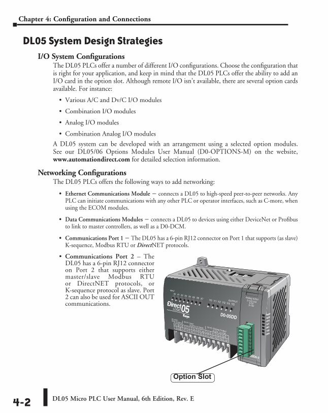
DL05 Micro PLC User Manual, 6th Edition, Rev. E4-2
Chapter 4: Configuration and Connections
DL05 System Design StrategiesI/O System Configurations
The DL05 PLCs offer a number of different I/O configurations. Choose the configuration that is right for your application, and keep in mind that the DL05 PLCs offer the ability to add an I/O card in the option slot. Although remote I/O isn’t available, there are several option cards available. For instance:
• Various A/C and Dv/C I/O modules
• Combination I/O modules
• Analog I/O modules
• Combination Analog I/O modules
A DL05 system can be developed with an arrangement using a selected option modules. See our DL05/06 Options Modules User Manual (D0-OPTIONS-M) on the website, www.automationdirect.com for detailed selection information.
Networking ConfigurationsThe DL05 PLCs offers the following ways to add networking:
• Ethernet Communications Module s connects a DL05 to high-speed peer-to-peer networks. Any PLC can initiate communications with any other PLC or operator interfaces, such as C-more, when using the ECOM modules.
• Data Communications Modules s connects a DL05 to devices using either DeviceNet or Profibus to link to master controllers, as well as a D0-DCM.
• Communications Port 1 s The DL05 has a 6-pin RJ12 connector on Port 1 that supports (as slave) K-sequence, Modbus RTU or DirectNET protocols.
• Communications Port 2 – The DL05 has a 6-pin RJ12 connector on Port 2 that supports either master/slave Modbus RTU or DirectNET protocols, or K-sequence protocol as slave. Port 2 can also be used for ASCII OUT communications.
PWR
RUN
CPU
TX1
RX1
TX2
RX2
Option Slot
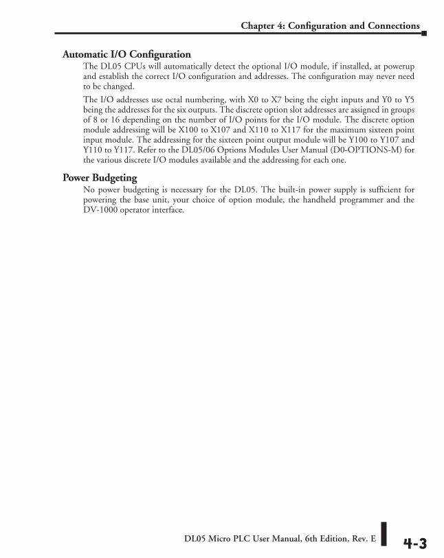
DL05 Micro PLC User Manual, 6th Edition, Rev. E 4-3
Chapter 4: Configuration and Connections
Automatic I/O ConfigurationThe DL05 CPUs will automatically detect the optional I/O module, if installed, at powerup and establish the correct I/O configuration and addresses. The configuration may never need to be changed.
The I/O addresses use octal numbering, with X0 to X7 being the eight inputs and Y0 to Y5 being the addresses for the six outputs. The discrete option slot addresses are assigned in groups of 8 or 16 depending on the number of I/O points for the I/O module. The discrete option module addressing will be X100 to X107 and X110 to X117 for the maximum sixteen point input module. The addressing for the sixteen point output module will be Y100 to Y107 and Y110 to Y117. Refer to the DL05/06 Options Modules User Manual (D0-OPTIONS-M) for the various discrete I/O modules available and the addressing for each one.
Power BudgetingNo power budgeting is necessary for the DL05. The built-in power supply is sufficient for powering the base unit, your choice of option module, the handheld programmer and the DV-1000 operator interface.
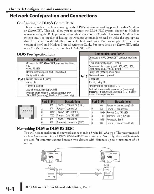
DL05 Micro PLC User Manual, 6th Edition, Rev. E4-4
Chapter 4: Configuration and Connections
Network Configuration and ConnectionsConfiguring the DL05’s Comm Ports
This section describes how to configure the CPU’s built-in networking ports for either Modbus or DirectNET. This will allow you to connect the DL05 PLC system directly to Modbus networks using the RTU protocol, or to other devices on a DirectNET network. Modbus host systems must be capable of issuing the Modbus commands to read or write the appropriate data. For details on the Modbus protocol, check with your Modbus supplier for the latest version of the Gould Modbus Protocol reference Guide. For more details on DirectNET, order our DirectNET manual, part number DA–DNET–M.
DL05 Port Specifications
Networking DL05 to DL05 RS-232CYou will need to make sure the network connection is a 3-wire RS–232 type. The recommended cable is AutomationDirect L19772 (Belden 8102) or equivalent. Normally, the RS–232 signals are used for communications between two devices with distances up to a maximum of 15 meters.
Port 2 Pin Descriptions1 0V Power (–) connection (GND)2 5V Power (+) connection3 RXD Receive Data (RS232C)4 TXD Transmit Data (RS232C5 RTS Request to Send6 0V Power (–) connection (GND)
1 2 3 4 5 6
Port 1 Pin Descriptions1 0V Power (–) connection (GND)2 5V Power (+) connection3 RXD Receive Data (RS232C)4 TXD Transmit Data (RS232C5 5V Power (+) connection6 0V Power (–) connection (GND)
Communications Port 1
Port 1
Connects to HPP, DirectSOFT, operator interfaces, etc.6-pin, RS232CCommunication speed: 9600 Baud (fixed)Parity: odd (fixed)Station Address: 1 (fixed)8 data bits1 start, 1 stop bitAsynchronous, half-duplex, DTEProtocol (auto-select): K-sequence (slave only), DirectNET (slave only), Modbus RTU (slave only)
Communications Port 2
Port 2
Connects to HPP, DirectSOFT, operator interfaces, etc.6-pin, multifunction port, RS232CCommunication speed (baud): 300, 600, 1200, 2400, 4800, 9600, 19200, 38400Parity: odd (default), even, noneStation Address: 1 (default)8 data bits1 start, 1 stop bitAsynchronous, half-duplex, DTEProtocol (auto-select): K-sequence (slave only), DirectNET (master/slave), Modbus RTU (master/slave), non-sequence/print
DL05PORT 2
DL05PORT 1 or 2
1 0V 0V 1
TXD 4RXD 33 RXD
4 TXD
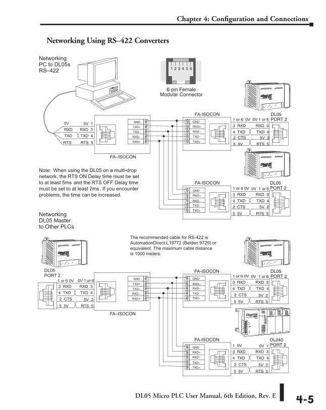
DL05 Micro PLC User Manual, 6th Edition, Rev. E 4-5
Chapter 4: Configuration and Connections
Networking Using RS–422 Converters
CP
U S
pecifications
4 TXD
Networking PC to DL05s RS–422
GND TXD+
RXD– RXD+
TXD–
6-pin FemaleModular Connector
1 2 3 4 5 6
DL05PORT 21 or 6 0V 0V 1 or 6
TXD 4
RXD 33 RXDGND
RXD+
TXD–
FA-ISOCON
F A–ISOCON
0V 0V 1
TXD 4 RXD 3 RXD
TXD
R TS 5 RT S
1 or 6 0V 0V 1 or 6
TXD 4
RXD 33 RXD
4 TXD
FA-ISOCON
TXD+
RXD–
GND
RXD+
TXD–
TXD+
RXD–
DL05PORT 2
Networking DL05 Master to Other PLCs
GND TXD+
RXD– RXD+
TXD–
DL05PORT 21 or 6 0V 0V 1 or 6
TXD 4
RXD 33 RXD
4 TXD
GND
RXD+
TXD–
FA-ISOCON
F A–ISOCON
1 or 6 0V 0V 1 or 6
TXD 4 RXD 3 3 RXD
4 TXD
5V 2 2 CTS
1 0V 0V 1
TXD 4
RXD 33 RXD
4 TXD
FA-ISOCON
TXD+
RXD–
GND
RXD+
TXD–
TXD+
RXD–
DL240PORT 2
DL05 PORT 2
Note: When using the DL05 on a multi-drop network, the R TS ON Delay time must be set to at least 5ms and the R TS OFF Delay time must be set to at least 2ms . If you encounter problems, the time can be increased.
2 CTS 5V 2
5 5V
2 CTS
RTS 5
5V 2
5 5V RTS 5
5 5V R TS 5
5V 22 CTS
5 5V RTS 5
5V 22 CTS
5 5V RTS 5
The recommended cable for RS-422 is AutomationDirect L19772 (Belden 9729) orequivalent. The maximum cable distance is 1000 meters.
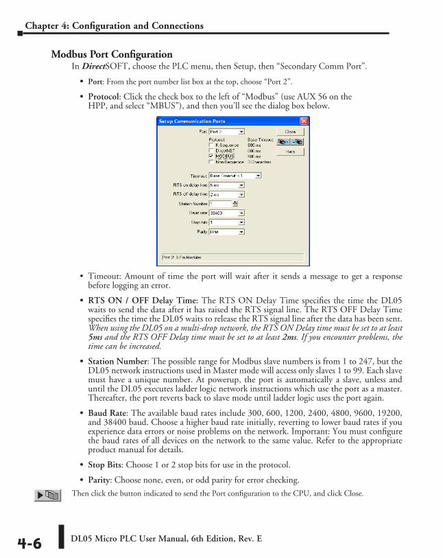
DL05 Micro PLC User Manual, 6th Edition, Rev. E4-6
Chapter 4: Configuration and Connections
Modbus Port ConfigurationIn DirectSOFT, choose the PLC menu, then Setup, then “Secondary Comm Port”.
• Port: From the port number list box at the top, choose “Port 2”.
• Protocol: Click the check box to the left of “Modbus” (use AUX 56 on the HPP, and select “MBUS”), and then you’ll see the dialog box below.
• Timeout: Amount of time the port will wait after it sends a message to get a response before logging an error.
• RTS ON / OFF Delay Time: The RTS ON Delay Time specifies the time the DL05 waits to send the data after it has raised the RTS signal line. The RTS OFF Delay Time specifies the time the DL05 waits to release the RTS signal line after the data has been sent. When using the DL05 on a multi-drop network, the RTS ON Delay time must be set to at least 5ms and the RTS OFF Delay time must be set to at least 2ms. If you encounter problems, the time can be increased.
• Station Number: The possible range for Modbus slave numbers is from 1 to 247, but the DL05 network instructions used in Master mode will access only slaves 1 to 99. Each slave must have a unique number. At powerup, the port is automatically a slave, unless and until the DL05 executes ladder logic network instructions which use the port as a master. Thereafter, the port reverts back to slave mode until ladder logic uses the port again.
• Baud Rate: The available baud rates include 300, 600, 1200, 2400, 4800, 9600, 19200, and 38400 baud. Choose a higher baud rate initially, reverting to lower baud rates if you experience data errors or noise problems on the network. Important: You must configure the baud rates of all devices on the network to the same value. Refer to the appropriate product manual for details.
• Stop Bits: Choose 1 or 2 stop bits for use in the protocol.
• Parity: Choose none, even, or odd parity for error checking.
Then click the button indicated to send the Port configuration to the CPU, and click Close.
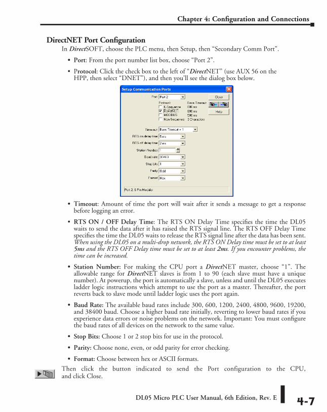
DL05 Micro PLC User Manual, 6th Edition, Rev. E 4-7
Chapter 4: Configuration and Connections
DirectNET Port ConfigurationIn DirectSOFT, choose the PLC menu, then Setup, then “Secondary Comm Port”.
• Port: From the port number list box, choose “Port 2”.
• Protocol: Click the check box to the left of “DirectNET” (use AUX 56 on the HPP, then select “DNET”), and then you’ll see the dialog box below.
• Timeout: Amount of time the port will wait after it sends a message to get a response before logging an error.
• RTS ON / OFF Delay Time: The RTS ON Delay Time specifies the time the DL05 waits to send the data after it has raised the RTS signal line. The RTS OFF Delay Time specifies the time the DL05 waits to release the RTS signal line after the data has been sent. When using the DL05 on a multi-drop network, the RTS ON Delay time must be set to at least 5ms and the RTS OFF Delay time must be set to at least 2ms. If you encounter problems, the time can be increased.
• Station Number: For making the CPU port a DirectNET master, choose “1”. The allowable range for DirectNET slaves is from 1 to 90 (each slave must have a unique number). At powerup, the port is automatically a slave, unless and until the DL05 executes ladder logic instructions which attempt to use the port as a master. Thereafter, the port reverts back to slave mode until ladder logic uses the port again.
• Baud Rate: The available baud rates include 300, 600, 1200, 2400, 4800, 9600, 19200, and 38400 baud. Choose a higher baud rate initially, reverting to lower baud rates if you experience data errors or noise problems on the network. Important: You must configure the baud rates of all devices on the network to the same value.
• Stop Bits: Choose 1 or 2 stop bits for use in the protocol.
• Parity: Choose none, even, or odd parity for error checking.
• Format: Choose between hex or ASCII formats.
Then click the button indicated to send the Port configuration to the CPU, and click Close.
DL05 Micro PLC User Manual, 6th Edition, Rev. E4-8
Chapter 4: Configuration and Connections
Network Slave OperationThis section describes how other devices on a network can communicate with a CPU port that you have configured as a DirectNETslave or Modbus slave (DL05). A Modbus host must use the Modbus RTU protocol to communicate with the DL05 as a slave. The host software must send a Modbus function code and Modbus address to specify a PLC memory location the DL05 comprehends. The DirectNET host uses normal I/O addresses to access applicable DL05 CPU and system. No CPU ladder logic is required to support either Modbus slave or DirectNET slave operation.
Modbus Function Codes SupportedThe Modbus function code determines whether the access is a read or a write, and whether to access a single data point or a group of them. The DL05 supports the Modbus function codes described below.
Determining the Modbus AddressThere are typically two ways that most host software conventions allow you to specify a PLC memory location. These are:
• By specifying the Modbus data type and address
• By specifying a Modbus address only
NOTE: For information about the Modbus protocol see the Group Schneider website at: www.schneiderautomation.com. At the main menu, select Support/Services, Modbus, Modbus Technical Manuals, PI-MBUS-300 Modbus Protocol Reference Guide or search for PIMBUS300. For more information about the DirectNET protocol, order our DirectNET User Manual, DA-DNET-M, or download the manual free from our website: www.automationdirect.com. Select Manuals\Docs\onlineusermanuals\misc.\DA-DNET-M
MODBUS Function Code Function DL05 Data Types Available01 Read a group of coils Y, CR, T, CT02 Read a group of inputs X, SP05 Set / Reset a single coil Y, CR, T, CT15 Set / Reset a group of coils Y, CR, T, CT
03, 04 Read a value from one or more registers V06 Write a value into a single register V16 Write a value into a group of registers V
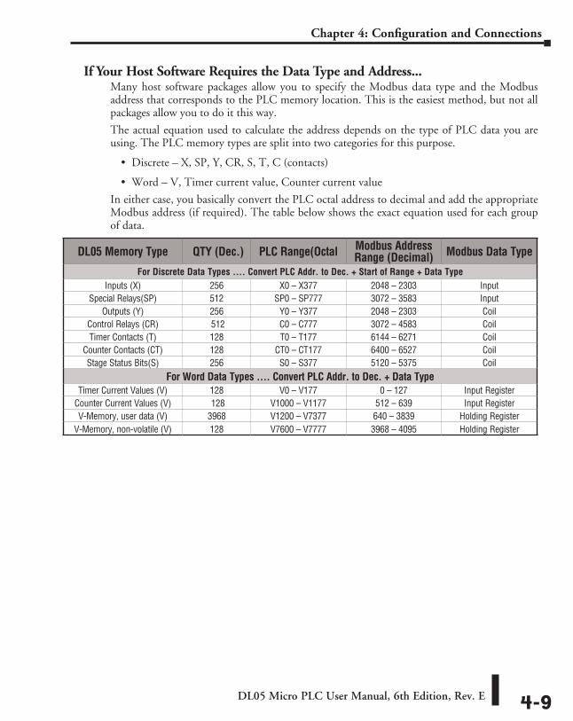
DL05 Micro PLC User Manual, 6th Edition, Rev. E 4-9
Chapter 4: Configuration and Connections
If Your Host Software Requires the Data Type and Address...Many host software packages allow you to specify the Modbus data type and the Modbus address that corresponds to the PLC memory location. This is the easiest method, but not all packages allow you to do it this way.
The actual equation used to calculate the address depends on the type of PLC data you are using. The PLC memory types are split into two categories for this purpose.
• Discrete – X, SP, Y, CR, S, T, C (contacts)
• Word – V, Timer current value, Counter current value
In either case, you basically convert the PLC octal address to decimal and add the appropriate Modbus address (if required). The table below shows the exact equation used for each group of data.
DL05 Memory Type QTY (Dec.) PLC Range(Octal Modbus Address Range (Decimal) Modbus Data Type
For Discrete Data Types .... Convert PLC Addr. to Dec. + Start of Range + Data TypeInputs (X) 256 X0 – X377 2048 – 2303 Input
Special Relays(SP) 512 SP0 – SP777 3072 – 3583 InputOutputs (Y) 256 Y0 – Y377 2048 – 2303 Coil
Control Relays (CR) 512 C0 – C777 3072 – 4583 CoilTimer Contacts (T) 128 T0 – T177 6144 – 6271 Coil
Counter Contacts (CT) 128 CT0 – CT177 6400 – 6527 CoilStage Status Bits(S) 256 S0 – S377 5120 – 5375 Coil
For Word Data Types .... Convert PLC Addr. to Dec. + Data TypeTimer Current Values (V) 128 V0 – V177 0 – 127 Input Register
Counter Current Values (V) 128 V1000 – V1177 512 – 639 Input RegisterV-Memory, user data (V) 3968 V1200 – V7377 640 – 3839 Holding Register
V-Memory, non-volatile (V) 128 V7600 – V7777 3968 – 4095 Holding Register
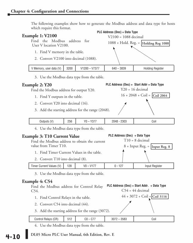
DL05 Micro PLC User Manual, 6th Edition, Rev. E4-10
Chapter 4: Configuration and Connections
The following examples show how to generate the Modbus address and data type for hosts which require this format.
Example 1: V2100Find the Modbus address for User V location V2100.
1. Find V memory in the table.
2. Convert V2100 into decimal (1088).
3. Use the Modbus data type from the table.
Example 2: Y20Find the Modbus address for output Y20.
1. Find Y outputs in the table.
2. Convert Y20 into decimal (16).
3. Add the starting address for the range (2048).
4. Use the Modbus data type from the table.
Example 3: T10 Current ValueFind the Modbus address to obtain the current value from Timer T10.
1. Find Timer Current Values in the table.
2. Convert T10 into decimal (8).
3. Use the Modbus data type from the table.
Example 4: C54Find the Modbus address for Control Relay C54.
1. Find Control Relays in the table.
2. Convert C54 into decimal (44).
3. Add the starting address for the range (3072).
4. Use the Modbus data type from the table.
V Memory, user data (V) 3200 V1200 – V7377 640 – 3839 Holding Register
Control Relays (CR) 512 C0 – C77 3072 – 3583 Coil
Outputs (V) 256 Y0 – Y377 2048 - 2303 Coil
Timer Current Values (V) 128 V0 – V177 0 - 127 Input Register
PLC Address (Dec) + Data Type
V2100 = 1088 decimal
1088 + Hold. Reg. =
PLC Address (Dec) + Start Addr + Data Type
Y20 = 16 decimal
16 + 2048 + Coil =
PLC Address (Dec) + Data Type
T10 = 8 decimal
8 + Input Reg. =
PLC Address (Dec) + Start Addr. + Data Type
C54 = 44 decimal
44 + 3072 + Coil =
Holding Reg 1088
Coil 2064
Input Reg. 8
Coil 3116
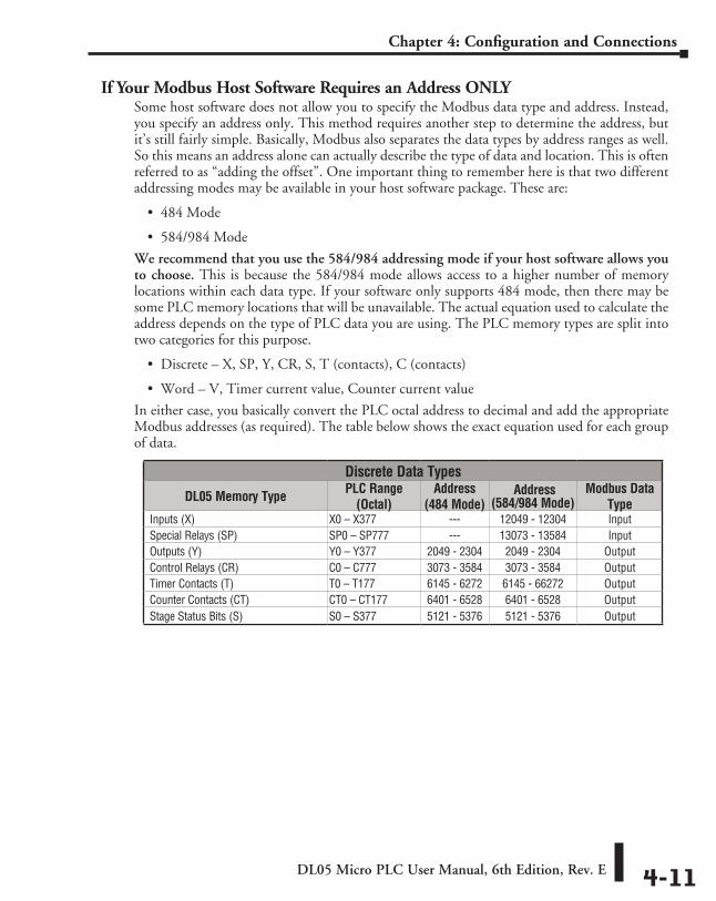
DL05 Micro PLC User Manual, 6th Edition, Rev. E 4-11
Chapter 4: Configuration and Connections
If Your Modbus Host Software Requires an Address ONLYSome host software does not allow you to specify the Modbus data type and address. Instead, you specify an address only. This method requires another step to determine the address, but it’s still fairly simple. Basically, Modbus also separates the data types by address ranges as well. So this means an address alone can actually describe the type of data and location. This is often referred to as “adding the offset”. One important thing to remember here is that two different addressing modes may be available in your host software package. These are:
• 484 Mode
• 584/984 Mode
We recommend that you use the 584/984 addressing mode if your host software allows you to choose. This is because the 584/984 mode allows access to a higher number of memory locations within each data type. If your software only supports 484 mode, then there may be some PLC memory locations that will be unavailable. The actual equation used to calculate the address depends on the type of PLC data you are using. The PLC memory types are split into two categories for this purpose.
• Discrete – X, SP, Y, CR, S, T (contacts), C (contacts)
• Word – V, Timer current value, Counter current value
In either case, you basically convert the PLC octal address to decimal and add the appropriate Modbus addresses (as required). The table below shows the exact equation used for each group of data.
Discrete Data Types
DL05 Memory Type PLC Range (Octal)
Address (484 Mode)
Address (584/984 Mode)
Modbus Data Type
Inputs (X) X0 – X377 --- 12049 - 12304 InputSpecial Relays (SP) SP0 – SP777 --- 13073 - 13584 InputOutputs (Y) Y0 – Y377 2049 - 2304 2049 - 2304 OutputControl Relays (CR) C0 – C777 3073 - 3584 3073 - 3584 OutputTimer Contacts (T) T0 – T177 6145 - 6272 6145 - 66272 OutputCounter Contacts (CT) CT0 – CT177 6401 - 6528 6401 - 6528 OutputStage Status Bits (S) S0 – S377 5121 - 5376 5121 - 5376 Output
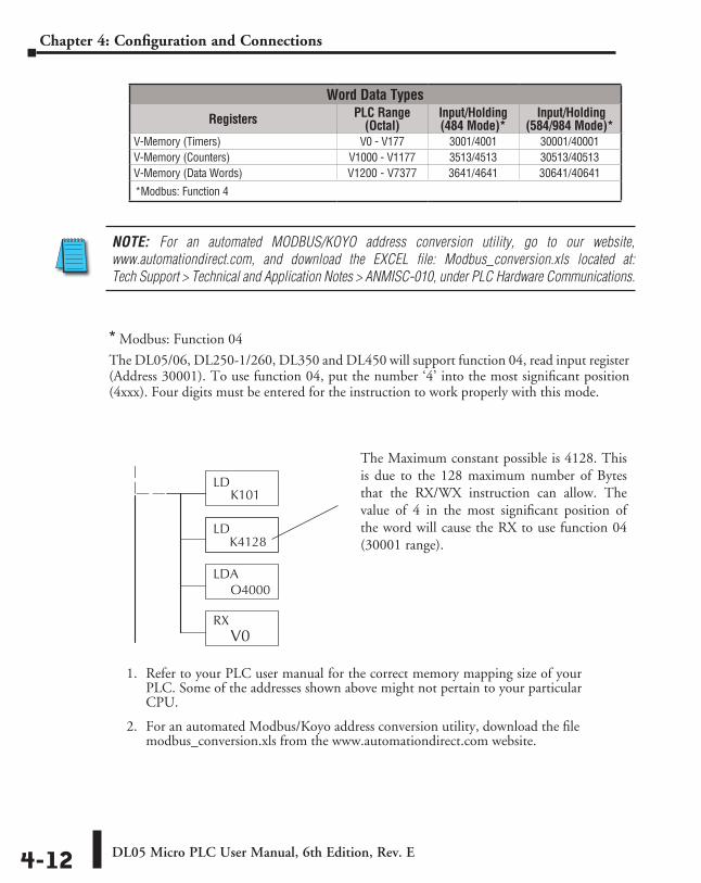
DL05 Micro PLC User Manual, 6th Edition, Rev. E4-12
Chapter 4: Configuration and Connections
NOTE: For an automated MODBUS/KOYO address conversion utility, go to our website, www.automationdirect.com, and download the EXCEL file: Modbus_conversion.xls located at: Tech Support > Technical and Application Notes > ANMISC-010, under PLC Hardware Communications.
Word Data Types
Registers PLC Range (Octal)
Input/Holding (484 Mode)*
Input/Holding (584/984 Mode)*
V-Memory (Timers) V0 - V177 3001/4001 30001/40001 V-Memory (Counters) V1000 - V1177 3513/4513 30513/40513 V-Memory (Data Words) V1200 - V7377 3641/4641 30641/40641
*Modbus: Function 4
1. Refer to your PLC user manual for the correct memory mapping size of your PLC. Some of the addresses shown above might not pertain to your particular CPU.
2. For an automated Modbus/Koyo address conversion utility, download the file modbus_conversion.xls from the www.automationdirect.com website.
* Modbus: Function 04
The DL05/06, DL250-1/260, DL350 and DL450 will support function 04, read input register (Address 30001). To use function 04, put the number ‘4’ into the most significant position (4xxx). Four digits must be entered for the instruction to work properly with this mode.
The Maximum constant possible is 4128. This is due to the 128 maximum number of Bytes that the RX/WX instruction can allow. The value of 4 in the most significant position of the word will cause the RX to use function 04 (30001 range).
LDK101
LDK4128
LDAO4000
RX V0
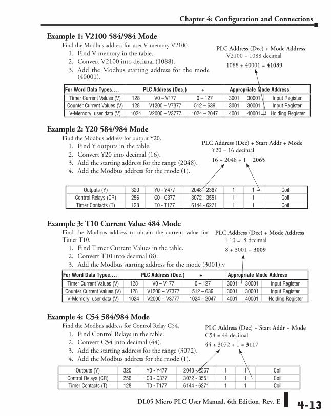
DL05 Micro PLC User Manual, 6th Edition, Rev. E 4-13
Chapter 4: Configuration and Connections
Example 1: V2100 584/984 ModeFind the Modbus address for user V-memory V2100.
1. Find V memory in the table.2. Convert V2100 into decimal (1088).3. Add the Modbus starting address for the mode
(40001).
Example 2: Y20 584/984 ModeFind the Modbus address for output Y20.
1. Find Y outputs in the table. 2. Convert Y20 into decimal (16).3. Add the starting address for the range (2048).4. Add the Modbus address for the mode (1).
Example 3: T10 Current Value 484 ModeFind the Modbus address to obtain the current value for Timer T10.
1. Find Timer Current Values in the table.2. Convert T10 into decimal (8).3. Add the Modbus starting address for the mode (3001).v
Example 4: C54 584/984 ModeFind the Modbus address for Control Relay C54.
1. Find Control Relays in the table.2. Convert C54 into decimal (44).3. Add the starting address for the range (3072).4. Add the Modbus address for the mode (1).
PLC Address (Dec) + Mode Address V2100 = 1088 decimal
1088 + 40001 = 41089
PLC Address (Dec) + Mode Address T10 = 8 decimal
8 + 3001 = 3009
PLC Address (Dec) + Start Addr + ModeC54 = 44 decimal
44 + 3072 + 1 = 3117
PLC Address (Dec) + Start Addr + Mode Y20 = 16 decimal
16 + 2048 + 1 = 2065
For Word Data Types.... PLC Address (Dec.) + Appropriate Mode Address
Timer Current Values (V) 128 V0 – V177 0 – 127 3001 30001 Input RegisterCounter Current Values (V) 128 V1200 – V7377 512 – 639 3001 30001 Input RegisterV-Memory, user data (V) 1024 V2000 – V3777 1024 – 2047 4001 40001 Holding Register
Outputs (Y) 320 Y0 - Y477 2048 - 2367 1 1 Coil Control Relays (CR) 256 C0 - C377 3072 - 3551 1 1 Coil Timer Contacts (T) 128 T0 - T177 6144 - 6271 1 1 Coil
Outputs (Y) 320 Y0 - Y477 2048 - 2367 1 1 Coil Control Relays (CR) 256 C0 - C377 3072 - 3551 1 1 Coil Timer Contacts (T) 128 T0 - T177 6144 - 6271 1 1 Coil
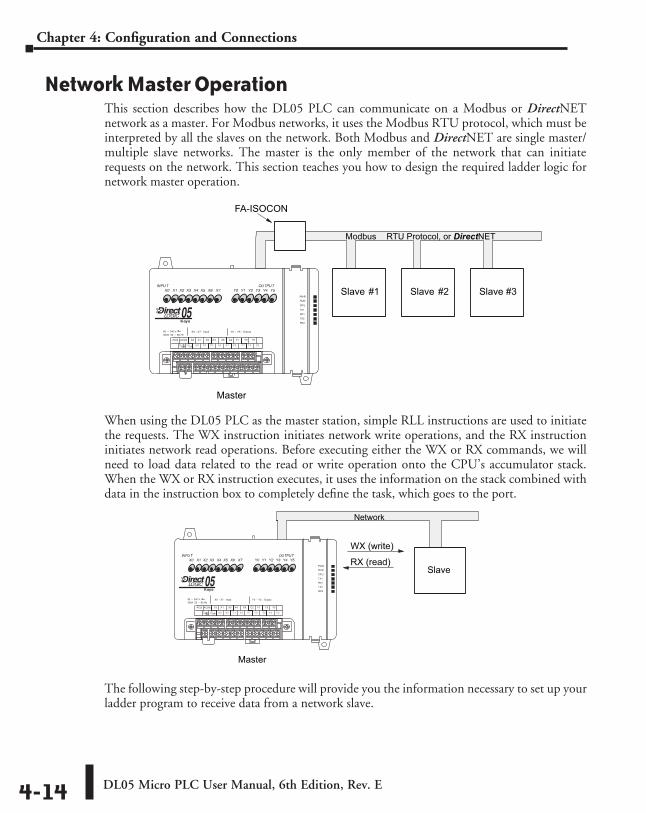
DL05 Micro PLC User Manual, 6th Edition, Rev. E4-14
Chapter 4: Configuration and Connections
Network Master OperationThis section describes how the DL05 PLC can communicate on a Modbus or DirectNET network as a master. For Modbus networks, it uses the Modbus RTU protocol, which must be interpreted by all the slaves on the network. Both Modbus and DirectNET are single master/multiple slave networks. The master is the only member of the network that can initiate requests on the network. This section teaches you how to design the required ladder logic for network master operation.
When using the DL05 PLC as the master station, simple RLL instructions are used to initiate the requests. The WX instruction initiates network write operations, and the RX instruction initiates network read operations. Before executing either the WX or RX commands, we will need to load data related to the read or write operation onto the CPU’s accumulator stack. When the WX or RX instruction executes, it uses the information on the stack combined with data in the instruction box to completely define the task, which goes to the port.
The following step-by-step procedure will provide you the information necessary to set up your ladder program to receive data from a network slave.
Slave #1 Slave #3
Master
Modbus RTU Protocol, or DirectNET
Slave #2
FA-ISOCON
Slave
Master
WX (write)
RX (read)
Network
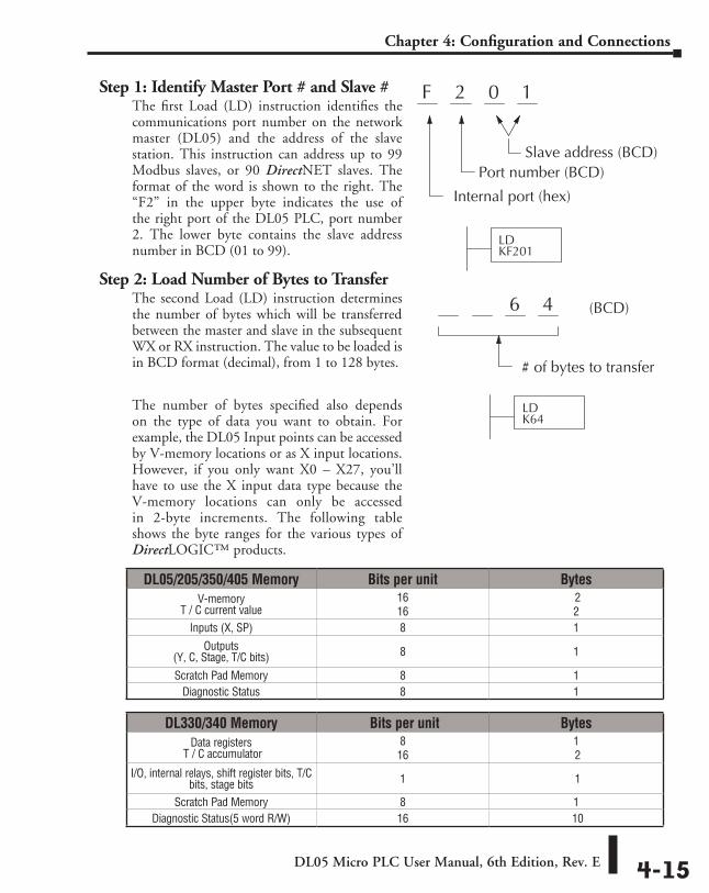
DL05 Micro PLC User Manual, 6th Edition, Rev. E 4-15
Chapter 4: Configuration and Connections
Step 1: Identify Master Port # and Slave #The first Load (LD) instruction identifies the communications port number on the network master (DL05) and the address of the slave station. This instruction can address up to 99 Modbus slaves, or 90 DirectNET slaves. The format of the word is shown to the right. The “F2” in the upper byte indicates the use of the right port of the DL05 PLC, port number 2. The lower byte contains the slave address number in BCD (01 to 99).
Step 2: Load Number of Bytes to TransferThe second Load (LD) instruction determines the number of bytes which will be transferred between the master and slave in the subsequent WX or RX instruction. The value to be loaded is in BCD format (decimal), from 1 to 128 bytes.
The number of bytes specified also depends on the type of data you want to obtain. For example, the DL05 Input points can be accessed by V-memory locations or as X input locations. However, if you only want X0 – X27, you’ll have to use the X input data type because the V-memory locations can only be accessed in 2-byte increments. The following table shows the byte ranges for the various types of DirectLOGIC™ products.
DL05/205/350/405 Memory Bits per unit BytesV-memory
T / C current value16 16
2 2
Inputs (X, SP) 8 1
Outputs (Y, C, Stage, T/C bits) 8 1
Scratch Pad Memory 8 1Diagnostic Status 8 1
DL330/340 Memory Bits per unit BytesData registers
T / C accumulator8 16
1 2
I/O, internal relays, shift register bits, T/C bits, stage bits 1 1
Scratch Pad Memory 8 1Diagnostic Status(5 word R/W) 16 10
2 0 1F
Internal port (hex)
Port number (BCD)Slave address (BCD)
LDKF201
6 4 (BCD)
# of bytes to transfer
LDK64
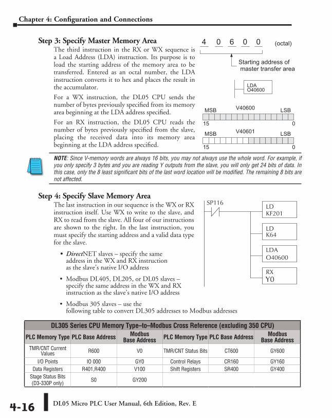
DL05 Micro PLC User Manual, 6th Edition, Rev. E4-16
Chapter 4: Configuration and Connections
Step 3: Specify Master Memory AreaThe third instruction in the RX or WX sequence is a Load Address (LDA) instruction. Its purpose is to load the starting address of the memory area to be transferred. Entered as an octal number, the LDA instruction converts it to hex and places the result in the accumulator.
For a WX instruction, the DL05 CPU sends the number of bytes previously specified from its memory area beginning at the LDA address specified.
For an RX instruction, the DL05 CPU reads the number of bytes previously specified from the slave, placing the received data into its memory area beginning at the LDA address specified.
NOTE: Since V-memory words are always 16 bits, you may not always use the whole word. For example, if you only specify 3 bytes and you are reading Y outputs from the slave, you will only get 24 bits of data. In this case, only the 8 least significant bits of the last word location will be modified. The remaining 8 bits are not affected.
Step 4: Specify Slave Memory AreaThe last instruction in our sequence is the WX or RX instruction itself. Use WX to write to the slave, and RX to read from the slave. All four of our instructions are shown to the right. In the last instruction, you must specify the starting address and a valid data type for the slave.
• DirectNET slaves – specify the same address in the WX and RX instruction as the slave’s native I/O address
• Modbus DL405, DL205, or DL05 slaves – specify the same address in the WX and RX instruction as the slave’s native I/O address
• Modbus 305 slaves – use the following table to convert DL305 addresses to Modbus addresses
6 0 00 (octal)
LDAO40600
4
Starting address of master transfer area
V40600MSB LSB
015
V40601MSB LSB
015
DL305 Series CPU Memory Type–to–Modbus Cross Reference (excluding 350 CPU)
PLC Memory Type PLC Base Address Modbus Base Address PLC Memory Type PLC Base Address Modbus
Base AddressTMR/CNT Current
Values R600 V0 TMR/CNT Status Bits CT600 GY600
I/O Points IO 000 GY0 Control Relays CR160 GY160Data Registers R401,R400 V100 Shift Registers SR400 GY400
Stage Status Bits (D3-330P only) S0 GY200
LDKF201
LDK64
LDAO40600
RX
SP116
Y0
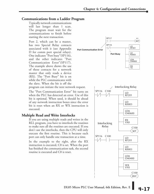
DL05 Micro PLC User Manual, 6th Edition, Rev. E 4-17
Chapter 4: Configuration and Connections
Communications from a Ladder ProgramTypically network communications will last longer than 1 scan. The program must wait for the communications to finish before starting the next transaction.
Port 2, which can be a master, has two Special Relay contacts associated with it (see Appendix D for comm port special relays). One indicates “Port busy”(SP116), and the other indicates ”Port Communication Error”(SP117). The example above shows the use of these contacts for a network master that only reads a device (RX). The “Port Busy” bit is on while the PLC communicates with the slave. When the bit is off the program can initiate the next network request.
The “Port Communication Error” bit turns on when the PLC has detected an error. Use of this bit is optional. When used, it should be ahead of any network instruction boxes since the error bit is reset when an RX or WX instruction is executed.
Multiple Read and Write InterlocksIf you are using multiple reads and writes in the RLL program, you have to interlock the routines to make sure all the routines are executed. If you don’t use the interlocks, then the CPU will only execute the first routine. This is because each port can only handle one transaction at a time.
In the example to the right, after the RX instruction is executed, C0 is set. When the port has finished the communication task, the second routine is executed and C0 is reset.
Port Communication Error
LDKF201
LDK0003
LDAO40600
RXY0
SP116
Port Busy
SP117
SETY1
Interlocking Relay
LDKF201
LDK0003
LDAO40600
RXVX0
SP116
SETC100
C100
LDKF201
LDK0003
LDAO40400
WXVY0
SP116
RSTC100
C100
InterlockingRelay
Standard rLL and InteLLIgent Box InStructIonS 555
ChapterChapterChapter
In This Chapter...Introduction ............................................................................................................... 5-2
Using Boolean Instructions ....................................................................................... 5-4
Boolean Instructions .................................................................................................. 5-9
Comparative Boolean .............................................................................................. 5-25
Immediate Instructions ........................................................................................... 5-31
Timer, Counter and Shift Register Instructions ...................................................... 5-35
Accumulator/Stack Load and Output Data Instructions ........................................ 5-48
Logical Instructions (Accumulator) ......................................................................... 5-60
Math Instructions .................................................................................................... 5-68
Bit Operation Instructions ....................................................................................... 5-82
Number Conversion Instructions (Accumulator) .................................................... 5-87
Table Instructions .................................................................................................... 5-96
CPU Control Instructions ......................................................................................... 5-99
Program Control Instructions ............................................................................... 5-101
Interrupt Instructions ............................................................................................ 5-108
Message Instructions ............................................................................................. 5-111
Intelligent I/O Instructions .................................................................................... 5-118
Network Instructions ............................................................................................. 5-120
Intelligent Box (IBox) Instructions ........................................................................ 5-124
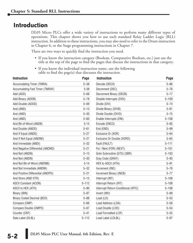
DL05 Micro PLC User Manual, 6th Edition, Rev. E5-2
Chapter 5: Standard RLL Instructions
IntroductionDL05 Micro PLCs offer a wide variety of instructions to perform many different types of operations. This chapter shows you how to use each standard Relay Ladder Logic (RLL) instruction. In addition to these instructions, you may also need to refer to the Drum instruction in Chapter 6, or the Stage programming instructions in Chapter 7.
There are two ways to quickly find the instruction you need.
• If you know the instruction category (Boolean, Comparative Boolean, etc.) just use the title at the top of the page to find the pages that discuss the instructions in that category.
• If you know the individual instruction name, use the following table to find the page(s) that discusses the instruction.
Accumulating Timer (TMRA) 5–38
Accumulating Fast Timer (TMRAF) 5-38
Add (ADD) 5–68
Add Binary (ADDB) 5–78
Add Double (ADDD) 5–69
And (AND) 5–13
And (AND) 5–30
And (AND) 5–60
And Bit-of-Word (ANDB) 5-14
And Double (ANDD) 5–61
And If Equal (ANDE) 5–27
And If Not Equal (ANDNE) 5–27
And Immediate (ANDI) 5–32
And Negative Differential (ANDND) 5–21
And Not (ANDN) 5–13
And Not (ANDN) 5–30
And Not Bit-of-Word (ANDNB) 5-14
And Not Immediate (ANDNI) 5–32
And Positive Differential (ANDPD) 5–21
And Store (AND STR) 5–15
ASCII Constant (ACON) 5–112
ASCII to HEX (ATH) 5–90
Binary (BIN) 5–87
Binary Coded Decimal (BCD) 5–88
Compare (CMP) 5–66
Compare Double (CMPD) 5–67
Counter (CNT) 5–41
Data Label (DLBL) 5–112
Decode (DECO) 5–86
Decrement (DEC) 5–76
Decrement Binary (DECB) 5–77
Disable Interrupts (DISI) 5–109
Divide (DIV) 5–74
Divide Binary (DIVB) 5–81
Divide Double (DIVD) 5–75
Enable Interrupts (ENI) 5–108
Encode (ENCO) 5–85
End (END) 5–99
Exclusive Or (XOR) 5–64
Exclusive Or Double (XORD) 5–65
Fault (FAULT) 5–111
For / Next (FOR) (NEXT) 5–101
Goto Subroutine (GTS) (SBR) 5–103
Gray Code (GRAY) 5–93
HEX to ASCII (HTA) 5–91
Increment (INC) 5–76
Increment Binary (INCB) 5–77
Interrupt (INT) 5–108
Interrupt Return (IRT) 5–108
Interrupt Return Conditional (IRTC) 5–108
Invert (INV) 5–89
Load (LD) 5–53
Load Address (LDA) 5–56
Load Double (LDD) 5–54
Load Formatted (LDF) 5–55
Load Label (LDLBL) 5–97
Instruction Page Instruction Page
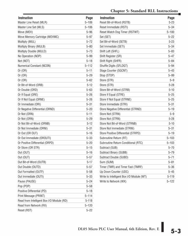
DL05 Micro PLC User Manual, 6th Edition, Rev. E 5-3
Chapter 5: Standard RLL Instructions
Master Line Reset (MLR) 5–106
Master Line Set (MLS) 5–106
Move (MOV) 5–96
Move Memory Cartridge (MOVMC) 5–97
Multiply (MUL) 5–72
Multiply Binary (MULB) 5–80
Multiply Double (MULD) 5–73
No Operation (NOP) 5–99
Not (NOT) 5–18
Numerical Constant (NCON) 5–112
Or (OR) 5–11
Or (OR) 5–29
Or (OR) 5–62
Or Bit-of-Word (ORB) 5-12
Or Double (ORD) 5–63
Or If Equal (ORE) 5–26
Or If Not Equal (ORNE) 5–26
Or Immediate (ORI) 5–31
Or Negative Differential (ORND) 5–20
Or Not (ORN) 5–11
Or Not (ORN) 5–29
Or Not Bit-of-Word (ORNB) 5-12
Or Not Immediate (ORNI) 5–31
Or Out (OR OUT) 5–16
Or Out Immediate (OROUTI) 5–33
Or Positive Differential (ORPD) 5–20
Or Store (OR STR) 5–15
Out (OUT) 5–16
Out (OUT) 5–57
Out Bit-of-Word (OUTB) 5-17
Out Double (OUTD) 5–57
Out Formatted (OUTF) 5–58
Out Immediate (OUTI) 5–33
Pause (PAUSE) 5–24
Pop (POP) 5–58
Positive Differential (PD) 5–18
Print Message (PRINT) 5–114
Read from Intelligent Box I/O Module (RD) 5-118
Read from Network (RX) 5–120
Reset (RST) 5–22
Reset Bit-of-Word (RSTB) 5-23
Reset Immediate (RSTI) 5–34
Reset Watch Dog Timer (RSTWT) 5–100
Set (SET) 5–22
Set Bit-of-Word (SETB) 5-23
Set Immediate (SETI) 5–34
Shift Left (SHFL) 5–83
Shift Register (SR) 5–47
Shift Right (SHFR) 5–84
Shuffle Digits (SFLDGT) 5–94
Stage Counter (SGCNT) 5–43
Stop (STOP) 5–99
Store (STR) 5–9
Store (STR) 5-28
Store Bit-of-Word (STRB) 5-10
Store If Equal (STRE) 5–25
Store If Not Equal (STRNE) 5–25
Store Immediate (STRI) 5–31
Store Negative Differential (STRND) 5–19
Store Not (STRN) 5–9
Store Not (STRN) 5-28
Store Not Bit-of-Word (STRNB) 5-10
Store Not Immediate (STRNI) 5–31
Store Positive Differential (STRPD) 5–19
Subroutine Return (RT) 5–103
Subroutine Return Conditional (RTC) 5–103
Subtract (SUB) 5–70
Subtract Binary (SUBB) 5–79
Subtract Double (SUBD) 5–71
Sum (SUM) 5–81
Timer (TMR) and Timer Fast (TMRF) 5–36
Up Down Counter (UDC) 5–45
Write to Intelligent Box I/O Module (WT) 5-119
Write to Network (WX) 5–122
Instruction Page Instruction Page
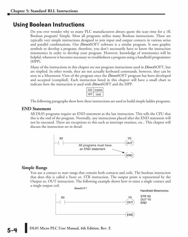
DL05 Micro PLC User Manual, 6th Edition, Rev. E5-4
Chapter 5: Standard RLL Instructions
Using Boolean InstructionsDo you ever wonder why so many PLC manufacturers always quote the scan time for a 1K Boolean program? Simple. Most all programs utilize many Boolean instructions. These are typically very simple instructions designed to join input and output contacts in various series and parallel combinations. Our DirectSOFT software is a similar program. It uses graphic symbols to develop a program; therefore, you don’t necessarily have to know the instruction mnemonics in order to develop your program. However, knowledge of mnemonics will be helpful, whenever it becomes necessary to troubleshoot a program using a handheld programmer (HPP).
Many of the instructions in this chapter are not program instructions used in DirectSOFT, but are implied. In other words, they are not actually keyboard commands, however, they can be seen in a Mnemonic View of the program once the DirectSOFT program has been developed and accepted (compiled). Each instruction listed in this chapter will have a small chart to indicate how the instruction is used with DirectSOFT and the HPP.
The following paragraphs show how these instructions are used to build simple ladder programs.
END StatementAll DL05 programs require an END statement as the last instruction. This tells the CPU that this is the end of the program. Normally, any instructions placed after the END statement will not be executed. There are exceptions to this such as interrupt routines, etc.. This chapter will discuss the instruction set in detail.
Simple RungsYou use a contact to start rungs that contain both contacts and coils. The boolean instruction that does this is called a Store or, STR instruction. The output point is represented by the Output or, OUT instruction. The following example shows how to enter a single contact and a single output coil.
OUTY0X0
END
All programs must have an END statement
DS5 Implied
HPP Used
OUTY0X0
END
DirectSOFT Example Handheld Mnemonics
STR X0OUT Y0END
DirectSOFT
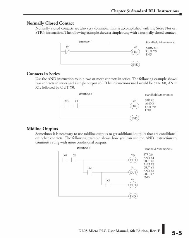
DL05 Micro PLC User Manual, 6th Edition, Rev. E 5-5
Chapter 5: Standard RLL Instructions
Normally Closed ContactNormally closed contacts are also very common. This is accomplished with the Store Not or, STRN instruction. The following example shows a simple rung with a normally closed contact.
Contacts in SeriesUse the AND instruction to join two or more contacts in series. The following example shows two contacts in series and a single output coil. The instructions used would be STR X0, AND X1, followed by OUT Y0.
Midline OutputsSometimes it is necessary to use midline outputs to get additional outputs that are conditional on other contacts. The following example shows how you can use the AND instruction to continue a rung with more conditional outputs.
OUT
Y0X0
END
X1
Direct SOFT32 Example Handheld Mnemonics
STR X0AND X1OUT Y0AND X2OUT Y1AND X3OUT Y2END
X2
OUT
Y1
X3
OUT
Y2
OUT
Y0X0
END
X1
Direct SOFT32 Example Handheld Mnemonics
STR X0AND X1OUT Y0END
OUT
Y0X0
END
Direct SOFT32 Example Handheld Mnemonics
STRN X0OUT Y0END
DirectSOFT
DirectSOFT
DirectSOFT
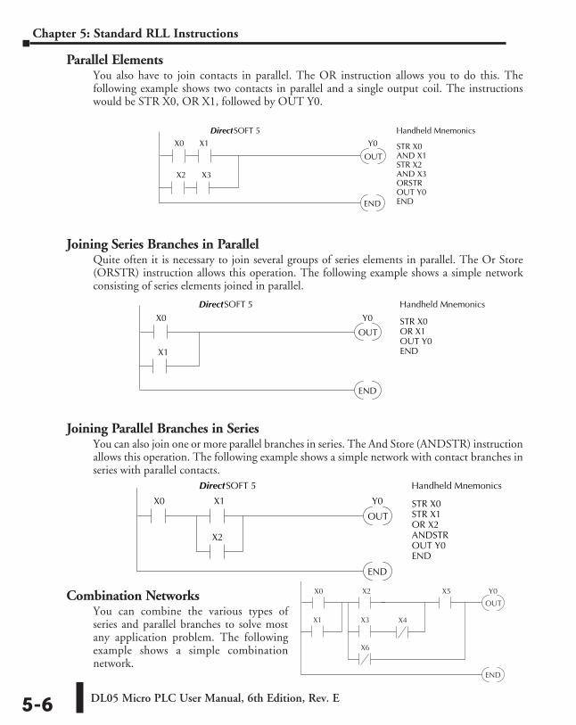
DL05 Micro PLC User Manual, 6th Edition, Rev. E5-6
Chapter 5: Standard RLL Instructions
Parallel ElementsYou also have to join contacts in parallel. The OR instruction allows you to do this. The following example shows two contacts in parallel and a single output coil. The instructions would be STR X0, OR X1, followed by OUT Y0.
Joining Series Branches in ParallelQuite often it is necessary to join several groups of series elements in parallel. The Or Store (ORSTR) instruction allows this operation. The following example shows a simple network consisting of series elements joined in parallel.
Joining Parallel Branches in SeriesYou can also join one or more parallel branches in series. The And Store (ANDSTR) instruction allows this operation. The following example shows a simple network with contact branches in series with parallel contacts.
Combination NetworksYou can combine the various types of series and parallel branches to solve most any application problem. The following example shows a simple combination network.
OUT
Y0X0
END
X2
X3X1 X4
X5
X6
OUT
Y0X0
END
X1
X2
DirectSOFT 5 Handheld Mnemonics
STR X0STR X1OR X2ANDSTROUT Y0END
OUT
Y0X0
END
X2
X1
X3
DirectSOFT 5 Handheld Mnemonics
STR X0AND X1STR X2AND X3ORSTROUT Y0END
OUT
Y0X0
END
X1
DirectSOFT 5 Handheld Mnemonics
STR X0OR X1OUT Y0END
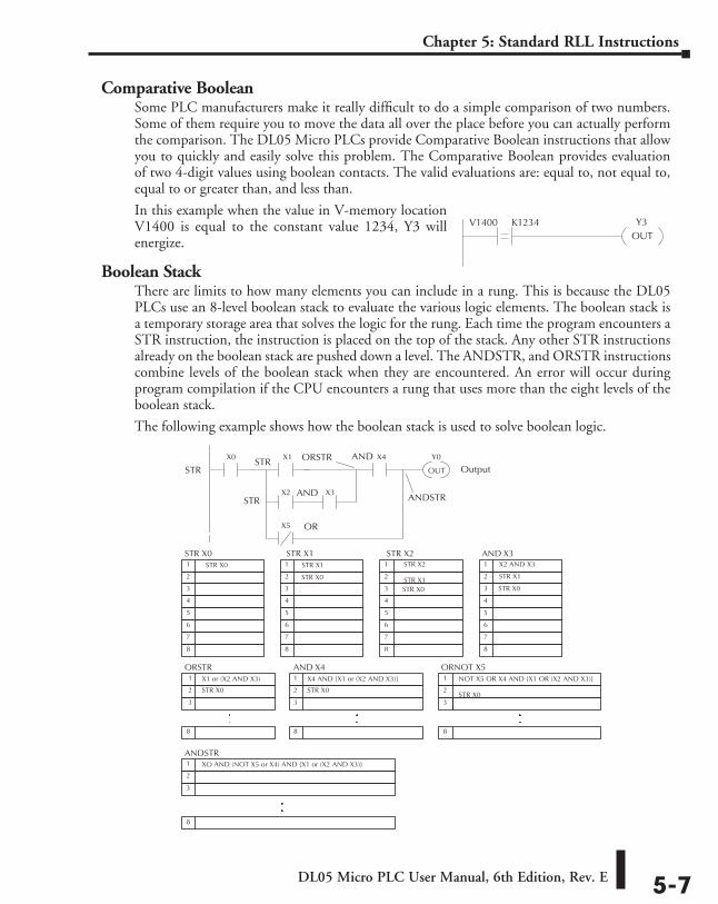
DL05 Micro PLC User Manual, 6th Edition, Rev. E 5-7
Chapter 5: Standard RLL Instructions
Comparative BooleanSome PLC manufacturers make it really difficult to do a simple comparison of two numbers. Some of them require you to move the data all over the place before you can actually perform the comparison. The DL05 Micro PLCs provide Comparative Boolean instructions that allow you to quickly and easily solve this problem. The Comparative Boolean provides evaluation of two 4-digit values using boolean contacts. The valid evaluations are: equal to, not equal to, equal to or greater than, and less than.
In this example when the value in V-memory location V1400 is equal to the constant value 1234, Y3 will energize.
Boolean StackThere are limits to how many elements you can include in a rung. This is because the DL05 PLCs use an 8-level boolean stack to evaluate the various logic elements. The boolean stack is a temporary storage area that solves the logic for the rung. Each time the program encounters a STR instruction, the instruction is placed on the top of the stack. Any other STR instructions already on the boolean stack are pushed down a level. The ANDSTR, and ORSTR instructions combine levels of the boolean stack when they are encountered. An error will occur during program compilation if the CPU encounters a rung that uses more than the eight levels of the boolean stack.
The following example shows how the boolean stack is used to solve boolean logic.
Y3OUT
V1400 K1234
X1 or (X2 AND X3)
STR X0 STR X1 STR X21 STR X0
2
3
4
5
6
7
8
1 STR X1
2 STR X0
3
4
5
6
7
8
1 STR X2 STR X1 2
3 STR X0
4
5
6
7
8
AND X31 X2 AND X3
2 STR X1
3 STR X0
4
5
6
7
8
ORSTR 1
2 STR X0
3
8
OUT
Y0X0 X1
X2 X3
X4
X5
STR
OR
AND
ORSTR
ANDSTR
OutputSTR
STR
AND
X4 AND X1 or (X2 AND X3)
AND X41
2 STR X0
3
8
NOT X5 OR X4 AND X1 OR (X2 AND X3) STR X0
ORNOT X51
2 3
8
ANDSTR XO AND (NOT X5 or X4) AND X1 or (X2 AND X3)
1
2
3
8
.
. . .
. .
.
.
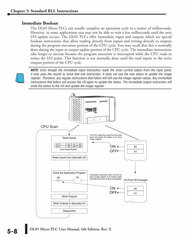
DL05 Micro PLC User Manual, 6th Edition, Rev. E5-8
Chapter 5: Standard RLL Instructions
Immediate BooleanThe DL05 Micro PLCs can usually complete an operation cycle in a matter of milliseconds. However, in some applications you may not be able to wait a few milliseconds until the next I/O update occurs. The DL05 PLCs offer Immediate input and outputs which are special boolean instructions that allow reading directly from inputs and writing directly to outputs during the program execution portion of the CPU cycle. You may recall that this is normally done during the input or output update portion of the CPU cycle. The immediate instructions take longer to execute because the program execution is interrupted while the CPU reads or writes the I/O point. This function is not normally done until the read inputs or the write outputs portion of the CPU cycle.
NOTE: Even though the immediate input instruction reads the most current status from the input point, it only uses the results to solve that one instruction. It does not use the new status to update the image register. Therefore, any regular instructions that follow will still use the image register values. Any immediate instructions that follow will access the I/O again to update the status. The immediate output instruction will write the status to the I/O and update the image register.
X1
Read Inputs
Diagnostics
Input Image Register
The CPU reads the inputs from the localbase and stores the status in an inputimage register.
X0 Y0
X0X1X2...X11OFFOFFON...OFF
Solve the Application Program
Read Inputs from Specialty I/O
Write Outputs
Write Outputs to Specialty I/O
X0
X1OFF
Immediate instruction does not use theinput image register, but instead readsthe status from the module immediately. I/O Point X0 Changes
ON
ONOFF
CPU Scan
I
X0
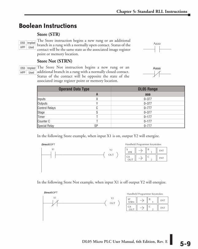
DL05 Micro PLC User Manual, 6th Edition, Rev. E 5-9
Chapter 5: Standard RLL Instructions
Boolean InstructionsStore (STR)The Store instruction begins a new rung or an additional branch in a rung with a normally open contact. Status of the contact will be the same state as the associated image register point or memory location.
Store Not (STRN)The Store Not instruction begins a new rung or an additional branch in a rung with a normally closed contact. Status of the contact will be opposite the state of the associated image register point or memory location.
In the following Store example, when input X1 is on, output Y2 will energize.
In the following Store Not example, when input X1 is off output Y2 will energize.
Aaaa
Aaaa
Operand Data Type DL05 Range ⸠⸠⸠⸠⸠⸠⸠⸠⸠⸠⸠⸠⸠⸠⸠⸠⸠⸠⸠⸠⸠⸠⸠⸠⸠⸠⸠⸠⸠⸠⸠⸠⸠⸠⸠⸠⸠⸠⸠⸠⸠⸠⸠⸠⸠⸠⸠⸠⸠⸠⸠⸠⸠⸠⸠⸠⸠⸠⸠⸠⸠⸠⸠⸠⸠⸠⸠⸠⸠⸠⸠⸠⸠A aaaInputs ⸠⸠⸠⸠⸠⸠⸠⸠⸠⸠⸠⸠⸠⸠⸠⸠⸠⸠⸠⸠⸠⸠⸠⸠⸠⸠⸠⸠⸠⸠⸠⸠⸠⸠⸠⸠⸠⸠⸠⸠⸠⸠⸠⸠⸠⸠⸠⸠⸠⸠⸠⸠⸠⸠⸠⸠⸠⸠⸠⸠⸠⸠⸠⸠⸠⸠X 0–377Outputs ⸠⸠⸠⸠⸠⸠⸠⸠⸠⸠⸠⸠⸠⸠⸠⸠⸠⸠⸠⸠⸠⸠⸠⸠⸠⸠⸠⸠⸠⸠⸠⸠⸠⸠⸠⸠⸠⸠⸠⸠⸠⸠⸠⸠⸠⸠⸠⸠⸠⸠⸠⸠⸠⸠⸠⸠⸠⸠⸠⸠⸠⸠⸠⸠Y 0–377Control Relays ⸠⸠⸠⸠⸠⸠⸠⸠⸠⸠⸠⸠⸠⸠⸠⸠⸠⸠⸠⸠⸠⸠⸠⸠⸠⸠⸠⸠⸠⸠⸠⸠⸠⸠⸠⸠⸠⸠⸠⸠⸠⸠⸠⸠⸠⸠⸠⸠⸠⸠⸠⸠C 0–777Stage ⸠⸠⸠⸠⸠⸠⸠⸠⸠⸠⸠⸠⸠⸠⸠⸠⸠⸠⸠⸠⸠⸠⸠⸠⸠⸠⸠⸠⸠⸠⸠⸠⸠⸠⸠⸠⸠⸠⸠⸠⸠⸠⸠⸠⸠⸠⸠⸠⸠⸠⸠⸠⸠⸠⸠⸠⸠⸠⸠⸠⸠⸠⸠⸠⸠⸠S 0–377Timer ⸠⸠⸠⸠⸠⸠⸠⸠⸠⸠⸠⸠⸠⸠⸠⸠⸠⸠⸠⸠⸠⸠⸠⸠⸠⸠⸠⸠⸠⸠⸠⸠⸠⸠⸠⸠⸠⸠⸠⸠⸠⸠⸠⸠⸠⸠⸠⸠⸠⸠⸠⸠⸠⸠⸠⸠⸠⸠⸠⸠⸠⸠⸠⸠⸠⸠ T 0–177Counter C ⸠⸠⸠⸠⸠⸠⸠⸠⸠⸠⸠⸠⸠⸠⸠⸠⸠⸠⸠⸠⸠⸠⸠⸠⸠⸠⸠⸠⸠⸠⸠⸠⸠⸠⸠⸠⸠⸠⸠⸠⸠⸠⸠⸠⸠⸠⸠⸠⸠⸠⸠⸠⸠⸠⸠⸠⸠⸠⸠⸠ T 0–177Special Relay ⸠⸠⸠⸠⸠⸠⸠⸠⸠⸠⸠⸠⸠⸠⸠⸠⸠⸠⸠⸠⸠⸠⸠⸠⸠⸠⸠⸠⸠⸠⸠⸠⸠⸠⸠⸠⸠⸠⸠⸠⸠⸠⸠⸠⸠⸠⸠⸠⸠⸠⸠⸠⸠SP 0–777
STR$
1B ENT
OUTGX
2C ENT
Handheld Programmer KeystrokesDirect SOFT32
Y2
OUT
X1
STRNSP
1B ENT
OUTGX
2C ENT
Y2
OUT
X1
Handheld Programmer KeystrokesDirect SOFT32
DS5 Implied
HPP Used
DS5 Implied
HPP Used
DirectSOFT
DirectSOFT
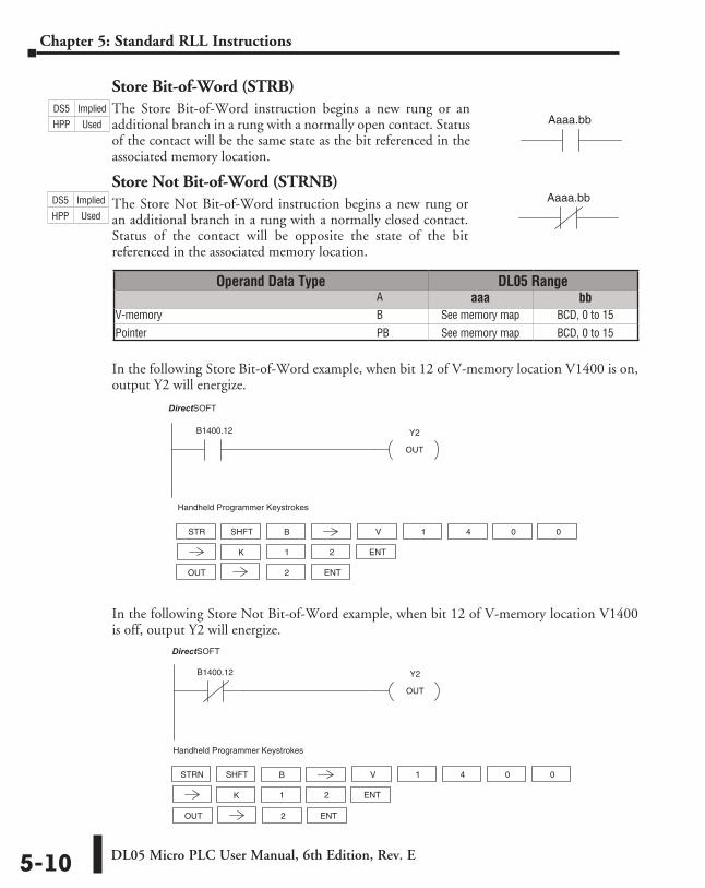
DL05 Micro PLC User Manual, 6th Edition, Rev. E5-10
Chapter 5: Standard RLL Instructions
Store Bit-of-Word (STRB)The Store Bit-of-Word instruction begins a new rung or an additional branch in a rung with a normally open contact. Status of the contact will be the same state as the bit referenced in the associated memory location.
Store Not Bit-of-Word (STRNB)The Store Not Bit-of-Word instruction begins a new rung or an additional branch in a rung with a normally closed contact. Status of the contact will be opposite the state of the bit referenced in the associated memory location.
In the following Store Bit-of-Word example, when bit 12 of V-memory location V1400 is on, output Y2 will energize.
In the following Store Not Bit-of-Word example, when bit 12 of V-memory location V1400 is off, output Y2 will energize.
Aaaa.bb
Aaaa.bb
Operand Data Type DL05 Range ⸠⸠⸠⸠⸠⸠⸠⸠⸠⸠⸠⸠⸠⸠⸠⸠⸠⸠⸠⸠⸠⸠⸠⸠⸠⸠⸠⸠⸠⸠⸠⸠⸠⸠⸠⸠⸠⸠⸠⸠⸠⸠⸠⸠⸠⸠⸠⸠⸠⸠⸠⸠⸠⸠⸠⸠⸠⸠⸠⸠⸠⸠⸠⸠⸠⸠⸠⸠⸠⸠⸠⸠⸠⸠⸠ A aaa bbV-memory ⸠⸠⸠⸠⸠⸠⸠⸠⸠⸠⸠⸠⸠⸠⸠⸠⸠⸠⸠⸠⸠⸠⸠⸠⸠⸠⸠⸠⸠⸠⸠⸠⸠⸠⸠⸠⸠⸠⸠⸠⸠⸠⸠⸠⸠⸠⸠⸠⸠⸠⸠⸠⸠⸠⸠⸠⸠⸠⸠⸠ B See memory map BCD, 0 to 15
Pointer ⸠⸠⸠⸠⸠⸠⸠⸠⸠⸠⸠⸠⸠⸠⸠⸠⸠⸠⸠⸠⸠⸠⸠⸠⸠⸠⸠⸠⸠⸠⸠⸠⸠⸠⸠⸠⸠⸠⸠⸠⸠⸠⸠⸠⸠⸠⸠⸠⸠⸠⸠⸠⸠⸠⸠⸠⸠⸠⸠⸠⸠⸠⸠⸠⸠⸠ PB See memory map BCD, 0 to 15
Handheld Programmer Keystrokes
DirectSOFT32
Y2
OUT
B1400.12
STR V 1
OUT 2
SHFT 4 0 0
1 2 ENT
ENT
K
B
Y2
OUT
B1400.12
DirectSOFT32
OUT 2 ENT
Handheld Programmer Keystrokes
STRN V 1SHFT 4 0 0
1 2 ENTK
B
DS5 Implied
HPP Used
DS5 Implied
HPP Used
DirectSOFT
DirectSOFT
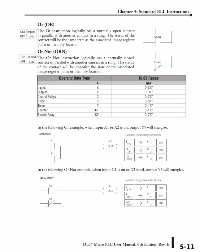
DL05 Micro PLC User Manual, 6th Edition, Rev. E 5-11
Chapter 5: Standard RLL Instructions
Or (OR)The Or instruction logically ors a normally open contact in parallel with another contact in a rung. The status of the contact will be the same state as the associated image register point or memory location.
Or Not (ORN)The Or Not instruction logically ors a normally closed contact in parallel with another contact in a rung. The status of the contact will be opposite the state of the associated image register point or memory location.
In the following Or example, when input X1 or X2 is on, output Y5 will energize.
In the following Or Not example, when input X1 is on or X2 is off, output Y5 will energize.
Aaaa
Aaaa
Operand Data Type DL05 Range ⸠⸠⸠⸠⸠⸠⸠⸠⸠⸠⸠⸠⸠⸠⸠⸠⸠⸠⸠⸠⸠⸠⸠⸠⸠⸠⸠⸠⸠⸠⸠⸠⸠⸠⸠⸠⸠⸠⸠⸠⸠⸠⸠⸠⸠⸠⸠⸠⸠⸠⸠⸠⸠⸠⸠⸠⸠⸠⸠⸠⸠⸠⸠⸠⸠⸠⸠⸠⸠⸠⸠⸠⸠A aaaInputs ⸠⸠⸠⸠⸠⸠⸠⸠⸠⸠⸠⸠⸠⸠⸠⸠⸠⸠⸠⸠⸠⸠⸠⸠⸠⸠⸠⸠⸠⸠⸠⸠⸠⸠⸠⸠⸠⸠⸠⸠⸠⸠⸠⸠⸠⸠⸠⸠⸠⸠⸠⸠⸠⸠⸠⸠⸠⸠⸠⸠⸠⸠⸠⸠⸠X 0–377Outputs ⸠⸠⸠⸠⸠⸠⸠⸠⸠⸠⸠⸠⸠⸠⸠⸠⸠⸠⸠⸠⸠⸠⸠⸠⸠⸠⸠⸠⸠⸠⸠⸠⸠⸠⸠⸠⸠⸠⸠⸠⸠⸠⸠⸠⸠⸠⸠⸠⸠⸠⸠⸠⸠⸠⸠⸠⸠⸠⸠⸠⸠⸠⸠Y 0–377Control Relays ⸠⸠⸠⸠⸠⸠⸠⸠⸠⸠⸠⸠⸠⸠⸠⸠⸠⸠⸠⸠⸠⸠⸠⸠⸠⸠⸠⸠⸠⸠⸠⸠⸠⸠⸠⸠⸠⸠⸠⸠⸠⸠⸠⸠⸠⸠⸠⸠⸠⸠⸠⸠C 0–777Stage ⸠⸠⸠⸠⸠⸠⸠⸠⸠⸠⸠⸠⸠⸠⸠⸠⸠⸠⸠⸠⸠⸠⸠⸠⸠⸠⸠⸠⸠⸠⸠⸠⸠⸠⸠⸠⸠⸠⸠⸠⸠⸠⸠⸠⸠⸠⸠⸠⸠⸠⸠⸠⸠⸠⸠⸠⸠⸠⸠⸠⸠⸠⸠⸠⸠⸠S 0–377Timer ⸠⸠⸠⸠⸠⸠⸠⸠⸠⸠⸠⸠⸠⸠⸠⸠⸠⸠⸠⸠⸠⸠⸠⸠⸠⸠⸠⸠⸠⸠⸠⸠⸠⸠⸠⸠⸠⸠⸠⸠⸠⸠⸠⸠⸠⸠⸠⸠⸠⸠⸠⸠⸠⸠⸠⸠⸠⸠⸠⸠⸠⸠⸠⸠⸠⸠ T 0–177Counter ⸠⸠⸠⸠⸠⸠⸠⸠⸠⸠⸠⸠⸠⸠⸠⸠⸠⸠⸠⸠⸠⸠⸠⸠⸠⸠⸠⸠⸠⸠⸠⸠⸠⸠⸠⸠⸠⸠⸠⸠⸠⸠⸠⸠⸠⸠⸠⸠⸠⸠⸠⸠⸠⸠⸠⸠⸠⸠⸠⸠⸠CT 0–177Special Relay ⸠⸠⸠⸠⸠⸠⸠⸠⸠⸠⸠⸠⸠⸠⸠⸠⸠⸠⸠⸠⸠⸠⸠⸠⸠⸠⸠⸠⸠⸠⸠⸠⸠⸠⸠⸠⸠⸠⸠⸠⸠⸠⸠⸠⸠⸠⸠⸠⸠⸠⸠⸠SP 0–777
STR$
1B ENT
ORQ
2C ENT
OUTGX
5F ENT
Y5
OUT
X1
X2
Handheld Programmer KeystrokesDirect SOFT32
STR$
1B ENT
2C ENT
OUTGX
5F ENT
ORNR
X1 Y5
OUT
X2
Handheld Programmer KeystrokesDirect SOFT32
DS5 Implied
HPP Used
DS5 Implied
HPP Used
DirectSOFT
DirectSOFT
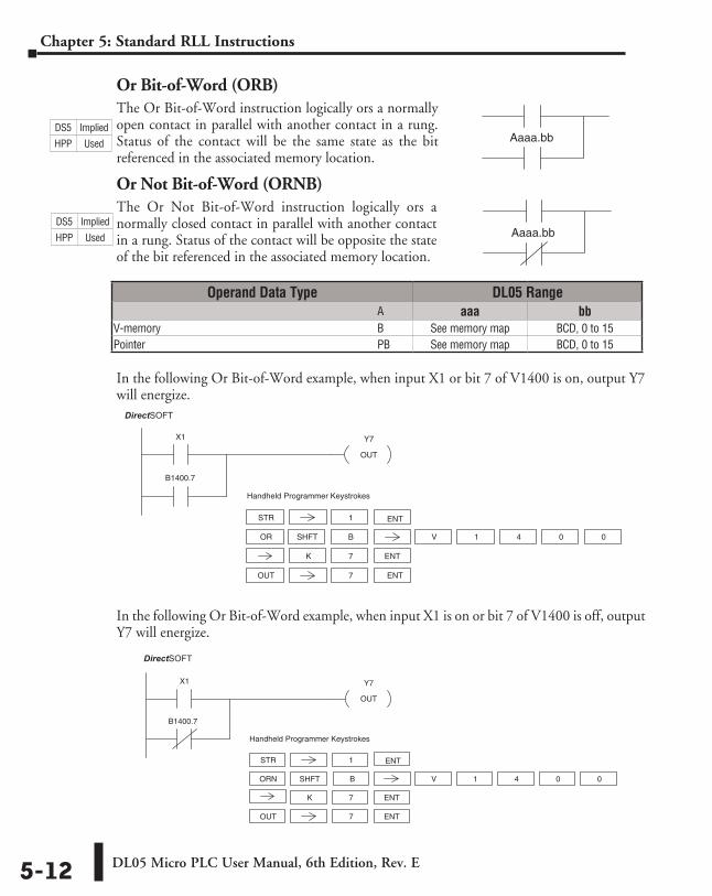
DL05 Micro PLC User Manual, 6th Edition, Rev. E5-12
Chapter 5: Standard RLL Instructions
Or Bit-of-Word (ORB)The Or Bit-of-Word instruction logically ors a normally open contact in parallel with another contact in a rung. Status of the contact will be the same state as the bit referenced in the associated memory location.
Or Not Bit-of-Word (ORNB)The Or Not Bit-of-Word instruction logically ors a normally closed contact in parallel with another contact in a rung. Status of the contact will be opposite the state of the bit referenced in the associated memory location.
In the following Or Bit-of-Word example, when input X1 or bit 7 of V1400 is on, output Y7 will energize.
In the following Or Bit-of-Word example, when input X1 is on or bit 7 of V1400 is off, output Y7 will energize.
Aaaa.bb
Aaaa.bb
Y7
OUT
X1
STR 1
Handheld Programmer Keystrokes
DirectSOFT32
ORN V 1
OUT 7
4 0 0
7
B1400.7
ENT
ENT
ENT
K
SHFT B
Operand Data Type DL05 Range ⸠⸠⸠⸠⸠⸠⸠⸠⸠⸠⸠⸠⸠⸠⸠⸠⸠⸠⸠⸠⸠⸠⸠⸠⸠⸠⸠⸠⸠⸠⸠⸠⸠⸠⸠⸠⸠⸠⸠⸠⸠⸠⸠⸠⸠⸠⸠⸠⸠⸠⸠⸠⸠⸠⸠⸠⸠⸠⸠⸠⸠⸠⸠⸠⸠⸠⸠⸠⸠⸠⸠⸠⸠⸠⸠ A aaa bbV-memory ⸠⸠⸠⸠⸠⸠⸠⸠⸠⸠⸠⸠⸠⸠⸠⸠⸠⸠⸠⸠⸠⸠⸠⸠⸠⸠⸠⸠⸠⸠⸠⸠⸠⸠⸠⸠⸠⸠⸠⸠⸠⸠⸠⸠⸠⸠⸠⸠⸠⸠⸠⸠⸠⸠⸠⸠⸠⸠⸠⸠⸠ B See memory map BCD, 0 to 15Pointer ⸠⸠⸠⸠⸠⸠⸠⸠⸠⸠⸠⸠⸠⸠⸠⸠⸠⸠⸠⸠⸠⸠⸠⸠⸠⸠⸠⸠⸠⸠⸠⸠⸠⸠⸠⸠⸠⸠⸠⸠⸠⸠⸠⸠⸠⸠⸠⸠⸠⸠⸠⸠⸠⸠⸠⸠⸠⸠⸠⸠⸠⸠⸠⸠⸠⸠⸠ PB See memory map BCD, 0 to 15
DS5 Implied
HPP Used
DS5 Implied
HPP Used
DirectSOFT
Y7
OUT
X1
B1400.7
STR 1
Handheld Programmer Keystrokes
DirectSOFT32
OR V 1
OUT 7
SHFT 4 0 0
7
ENT
ENT
ENT
K
B
DirectSOFT
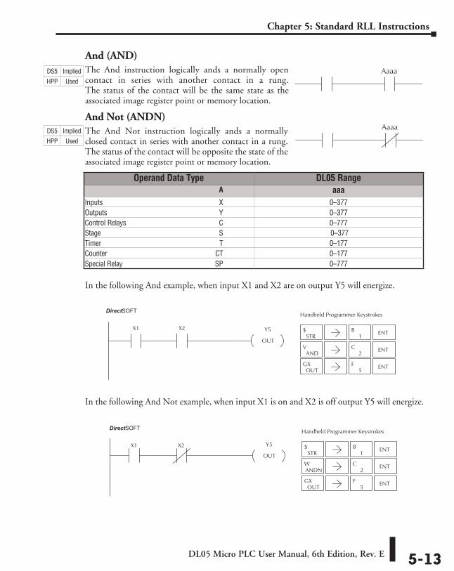
DL05 Micro PLC User Manual, 6th Edition, Rev. E 5-13
Chapter 5: Standard RLL Instructions
And (AND)The And instruction logically ands a normally open contact in series with another contact in a rung. The status of the contact will be the same state as the associated image register point or memory location.
And Not (ANDN)The And Not instruction logically ands a normally closed contact in series with another contact in a rung. The status of the contact will be opposite the state of the associated image register point or memory location.
In the following And example, when input X1 and X2 are on output Y5 will energize.
In the following And Not example, when input X1 is on and X2 is off output Y5 will energize.
Aaaa
Aaaa
Operand Data Type DL05 Range ⸠⸠⸠⸠⸠⸠⸠⸠⸠⸠⸠⸠⸠⸠⸠⸠⸠⸠⸠⸠⸠⸠⸠⸠⸠⸠⸠⸠⸠⸠⸠⸠⸠⸠⸠⸠⸠⸠⸠⸠⸠⸠⸠⸠⸠⸠⸠⸠⸠⸠⸠⸠⸠⸠⸠⸠⸠⸠⸠⸠⸠⸠⸠⸠⸠⸠⸠⸠⸠⸠⸠⸠⸠A aaaInputs ⸠⸠⸠⸠⸠⸠⸠⸠⸠⸠⸠⸠⸠⸠⸠⸠⸠⸠⸠⸠⸠⸠⸠⸠⸠⸠⸠⸠⸠⸠⸠⸠⸠⸠⸠⸠⸠⸠⸠⸠⸠⸠⸠⸠⸠⸠⸠⸠⸠⸠⸠⸠⸠⸠⸠⸠⸠⸠⸠⸠⸠⸠⸠⸠⸠X 0–377Outputs ⸠⸠⸠⸠⸠⸠⸠⸠⸠⸠⸠⸠⸠⸠⸠⸠⸠⸠⸠⸠⸠⸠⸠⸠⸠⸠⸠⸠⸠⸠⸠⸠⸠⸠⸠⸠⸠⸠⸠⸠⸠⸠⸠⸠⸠⸠⸠⸠⸠⸠⸠⸠⸠⸠⸠⸠⸠⸠⸠⸠⸠⸠⸠Y 0–377Control Relays ⸠⸠⸠⸠⸠⸠⸠⸠⸠⸠⸠⸠⸠⸠⸠⸠⸠⸠⸠⸠⸠⸠⸠⸠⸠⸠⸠⸠⸠⸠⸠⸠⸠⸠⸠⸠⸠⸠⸠⸠⸠⸠⸠⸠⸠⸠⸠⸠⸠⸠⸠⸠C 0–777Stage ⸠⸠⸠⸠⸠⸠⸠⸠⸠⸠⸠⸠⸠⸠⸠⸠⸠⸠⸠⸠⸠⸠⸠⸠⸠⸠⸠⸠⸠⸠⸠⸠⸠⸠⸠⸠⸠⸠⸠⸠⸠⸠⸠⸠⸠⸠⸠⸠⸠⸠⸠⸠⸠⸠⸠⸠⸠⸠⸠⸠⸠⸠⸠⸠⸠⸠S 0–377Timer ⸠⸠⸠⸠⸠⸠⸠⸠⸠⸠⸠⸠⸠⸠⸠⸠⸠⸠⸠⸠⸠⸠⸠⸠⸠⸠⸠⸠⸠⸠⸠⸠⸠⸠⸠⸠⸠⸠⸠⸠⸠⸠⸠⸠⸠⸠⸠⸠⸠⸠⸠⸠⸠⸠⸠⸠⸠⸠⸠⸠⸠⸠⸠⸠⸠⸠ T 0–177Counter ⸠⸠⸠⸠⸠⸠⸠⸠⸠⸠⸠⸠⸠⸠⸠⸠⸠⸠⸠⸠⸠⸠⸠⸠⸠⸠⸠⸠⸠⸠⸠⸠⸠⸠⸠⸠⸠⸠⸠⸠⸠⸠⸠⸠⸠⸠⸠⸠⸠⸠⸠⸠⸠⸠⸠⸠⸠⸠⸠⸠⸠CT 0–177Special Relay ⸠⸠⸠⸠⸠⸠⸠⸠⸠⸠⸠⸠⸠⸠⸠⸠⸠⸠⸠⸠⸠⸠⸠⸠⸠⸠⸠⸠⸠⸠⸠⸠⸠⸠⸠⸠⸠⸠⸠⸠⸠⸠⸠⸠⸠⸠⸠⸠⸠⸠⸠⸠SP 0–777
STR$
1B ENT
2C ENT
OUTGX
5F ENT
ANDV
Y5
OUT
X1 X2
Handheld Programmer KeystrokesDirect SOFT32
ANDNW
STR$
1B ENT
2C ENT
OUTGX
5F ENT
X1 Y5
OUT
X2
Handheld Programmer KeystrokesDirect SOFT32
DS5 Implied
HPP Used
DS5 Implied
HPP Used
DirectSOFT
DirectSOFT
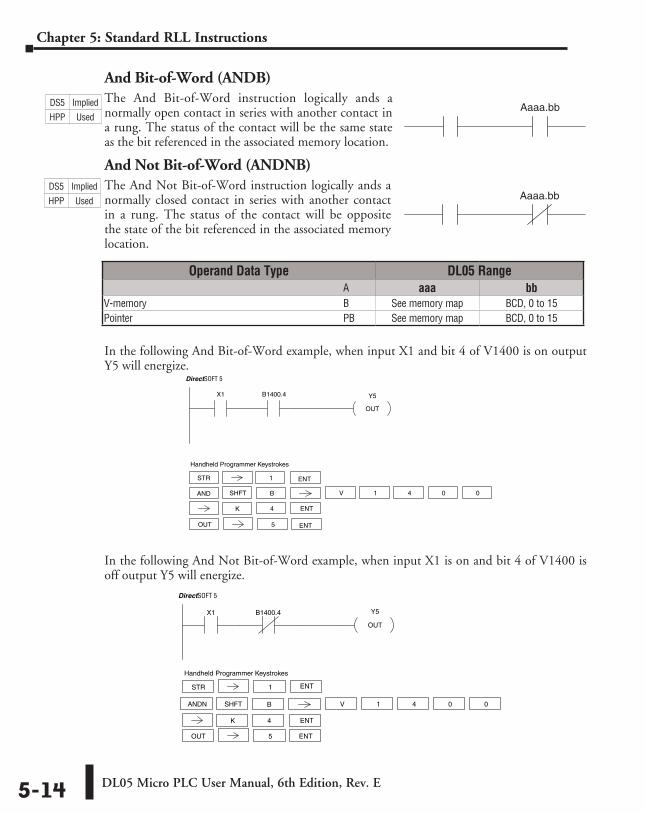
DL05 Micro PLC User Manual, 6th Edition, Rev. E5-14
Chapter 5: Standard RLL Instructions
And Bit-of-Word (ANDB)The And Bit-of-Word instruction logically ands a normally open contact in series with another contact in a rung. The status of the contact will be the same state as the bit referenced in the associated memory location.
And Not Bit-of-Word (ANDNB)The And Not Bit-of-Word instruction logically ands a normally closed contact in series with another contact in a rung. The status of the contact will be opposite the state of the bit referenced in the associated memory location.
In the following And Bit-of-Word example, when input X1 and bit 4 of V1400 is on output Y5 will energize.
In the following And Not Bit-of-Word example, when input X1 is on and bit 4 of V1400 is off output Y5 will energize.
Aaaa.bb
Aaaa.bb
Operand Data Type DL05 Range ⸠⸠⸠⸠⸠⸠⸠⸠⸠⸠⸠⸠⸠⸠⸠⸠⸠⸠⸠⸠⸠⸠⸠⸠⸠⸠⸠⸠⸠⸠⸠⸠⸠⸠⸠⸠⸠⸠⸠⸠⸠⸠⸠⸠⸠⸠⸠⸠⸠⸠⸠⸠⸠⸠⸠⸠⸠⸠⸠⸠⸠⸠⸠⸠⸠⸠⸠⸠⸠⸠⸠⸠⸠⸠⸠ A aaa bbV-memory ⸠⸠⸠⸠⸠⸠⸠⸠⸠⸠⸠⸠⸠⸠⸠⸠⸠⸠⸠⸠⸠⸠⸠⸠⸠⸠⸠⸠⸠⸠⸠⸠⸠⸠⸠⸠⸠⸠⸠⸠⸠⸠⸠⸠⸠⸠⸠⸠⸠⸠⸠⸠⸠⸠⸠⸠⸠⸠⸠⸠⸠ B See memory map BCD, 0 to 15Pointer ⸠⸠⸠⸠⸠⸠⸠⸠⸠⸠⸠⸠⸠⸠⸠⸠⸠⸠⸠⸠⸠⸠⸠⸠⸠⸠⸠⸠⸠⸠⸠⸠⸠⸠⸠⸠⸠⸠⸠⸠⸠⸠⸠⸠⸠⸠⸠⸠⸠⸠⸠⸠⸠⸠⸠⸠⸠⸠⸠⸠⸠⸠⸠⸠⸠⸠⸠ PB See memory map BCD, 0 to 15
Y5
OUT
X1 B1400.4
DirectSOFT 5
OUT 5 ENT
Handheld Programmer Keystrokes
V 1SHFT 4 0 0
4 ENTK
B
STR 1 ENT
AND
X1 Y5
OUT
B1400.4
DirectSOFT 5
STR 1
Handheld Programmer Keystrokes
OUT 5
ANDN V 1SHFT 4 0 0
4 ENTK
B
ENT
ENT
DS5 Implied
HPP Used
DS5 Implied
HPP Used
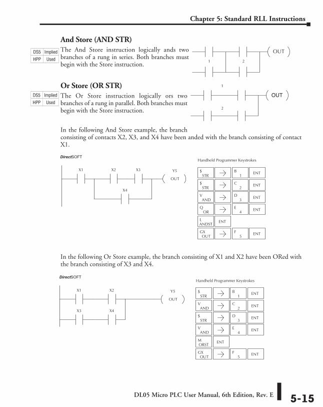
DL05 Micro PLC User Manual, 6th Edition, Rev. E 5-15
Chapter 5: Standard RLL Instructions
And Store (AND STR)The And Store instruction logically ands two branches of a rung in series. Both branches must begin with the Store instruction.
Or Store (OR STR)The Or Store instruction logically ors two branches of a rung in parallel. Both branches must begin with the Store instruction.
In the following And Store example, the branch consisting of contacts X2, X3, and X4 have been anded with the branch consisting of contact X1.
In the following Or Store example, the branch consisting of X1 and X2 have been ORed with the branch consisting of X3 and X4.
OUT
1 2
OUT
1
2
STR$
1B ENT
STR$ ENT
2C
ANDV ENT
3D
ORQ ENT
4E
ANDSTL ENT
OUTGX
5F ENT
Y5
OUT
X1 X2
X4
X3
Handheld Programmer KeystrokesDirect SOFT32
STR$
1B ENT
STR$ ENT
ANDV ENT
OUTGX
5F ENT
2C
3D
ANDV ENT
4E
ORSTM ENT
Y5
OUT
X1 X2
X3 X4
Handheld Programmer KeystrokesDirect SOFT32
DS5 Implied
HPP Used
DS5 Implied
HPP Used
DirectSOFT
DirectSOFT
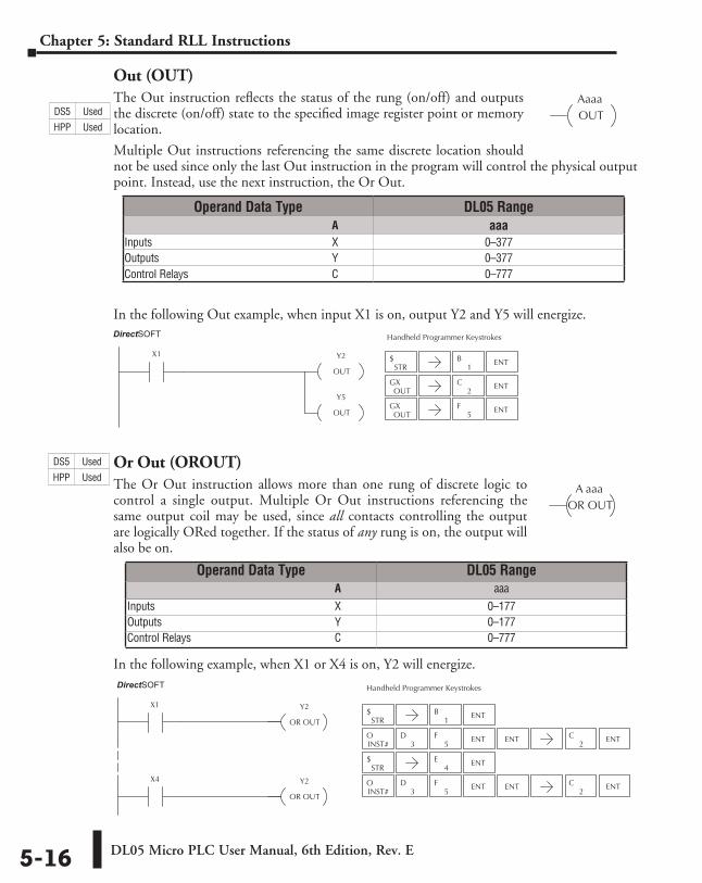
DL05 Micro PLC User Manual, 6th Edition, Rev. E5-16
Chapter 5: Standard RLL Instructions
Out (OUT)The Out instruction reflects the status of the rung (on/off) and outputs the discrete (on/off) state to the specified image register point or memory location.
Multiple Out instructions referencing the same discrete location should not be used since only the last Out instruction in the program will control the physical output point. Instead, use the next instruction, the Or Out.
In the following Out example, when input X1 is on, output Y2 and Y5 will energize.
Or Out (OROUT)The Or Out instruction allows more than one rung of discrete logic to control a single output. Multiple Or Out instructions referencing the same output coil may be used, since all contacts controlling the output are logically ORed together. If the status of any rung is on, the output will also be on.
In the following example, when X1 or X4 is on, Y2 will energize.
AaaaOUT
STR$
1B ENT
STR$ ENT
4E
Y2
OR OUT
X1
Y2
OR OUT
X4
Handheld Programmer KeystrokesDirect SOFT32
INST#O
5F
3D ENT ENT
2C ENT
2C ENT
INST#O
5F
3D ENT ENT
A aaaOR OUT
Operand Data Type DL05 Range ⸠⸠⸠⸠⸠⸠⸠⸠⸠⸠⸠⸠⸠⸠⸠⸠⸠⸠⸠⸠⸠⸠⸠⸠⸠⸠⸠⸠⸠⸠⸠⸠⸠⸠⸠⸠⸠⸠⸠⸠⸠⸠⸠⸠⸠⸠⸠⸠⸠⸠⸠⸠⸠⸠⸠⸠⸠⸠⸠⸠⸠⸠⸠⸠⸠⸠⸠⸠⸠⸠⸠⸠⸠A aaaInputs ⸠⸠⸠⸠⸠⸠⸠⸠⸠⸠⸠⸠⸠⸠⸠⸠⸠⸠⸠⸠⸠⸠⸠⸠⸠⸠⸠⸠⸠⸠⸠⸠⸠⸠⸠⸠⸠⸠⸠⸠⸠⸠⸠⸠⸠⸠⸠⸠⸠⸠⸠⸠⸠⸠⸠⸠⸠⸠⸠⸠⸠⸠⸠⸠⸠X 0–377Outputs ⸠⸠⸠⸠⸠⸠⸠⸠⸠⸠⸠⸠⸠⸠⸠⸠⸠⸠⸠⸠⸠⸠⸠⸠⸠⸠⸠⸠⸠⸠⸠⸠⸠⸠⸠⸠⸠⸠⸠⸠⸠⸠⸠⸠⸠⸠⸠⸠⸠⸠⸠⸠⸠⸠⸠⸠⸠⸠⸠⸠⸠⸠⸠Y 0–377Control Relays ⸠⸠⸠⸠⸠⸠⸠⸠⸠⸠⸠⸠⸠⸠⸠⸠⸠⸠⸠⸠⸠⸠⸠⸠⸠⸠⸠⸠⸠⸠⸠⸠⸠⸠⸠⸠⸠⸠⸠⸠⸠⸠⸠⸠⸠⸠⸠⸠⸠⸠⸠⸠C 0–777
Operand Data Type DL05 Range ⸠⸠⸠⸠⸠⸠⸠⸠⸠⸠⸠⸠⸠⸠⸠⸠⸠⸠⸠⸠⸠⸠⸠⸠⸠⸠⸠⸠⸠⸠⸠⸠⸠⸠⸠⸠⸠⸠⸠⸠⸠⸠⸠⸠⸠⸠⸠⸠⸠⸠⸠⸠⸠⸠⸠⸠⸠⸠⸠⸠⸠⸠⸠⸠⸠⸠⸠⸠⸠⸠⸠⸠⸠A aaaInputs ⸠⸠⸠⸠⸠⸠⸠⸠⸠⸠⸠⸠⸠⸠⸠⸠⸠⸠⸠⸠⸠⸠⸠⸠⸠⸠⸠⸠⸠⸠⸠⸠⸠⸠⸠⸠⸠⸠⸠⸠⸠⸠⸠⸠⸠⸠⸠⸠⸠⸠⸠⸠⸠⸠⸠⸠⸠⸠⸠⸠⸠⸠⸠⸠⸠X 0–177Outputs ⸠⸠⸠⸠⸠⸠⸠⸠⸠⸠⸠⸠⸠⸠⸠⸠⸠⸠⸠⸠⸠⸠⸠⸠⸠⸠⸠⸠⸠⸠⸠⸠⸠⸠⸠⸠⸠⸠⸠⸠⸠⸠⸠⸠⸠⸠⸠⸠⸠⸠⸠⸠⸠⸠⸠⸠⸠⸠⸠⸠⸠⸠⸠Y 0–177Control Relays ⸠⸠⸠⸠⸠⸠⸠⸠⸠⸠⸠⸠⸠⸠⸠⸠⸠⸠⸠⸠⸠⸠⸠⸠⸠⸠⸠⸠⸠⸠⸠⸠⸠⸠⸠⸠⸠⸠⸠⸠⸠⸠⸠⸠⸠⸠⸠⸠⸠⸠⸠⸠C 0–777
DS5 Used
HPP Used
DirectSOFT
STR$
1B ENT
OUTGX
2C ENT
OUTGX ENT
5F
Y2
OUT
X1
Y5
OUT
Handheld Programmer KeystrokesDirect SOFT32DirectSOFT
DS5 Used
HPP Used
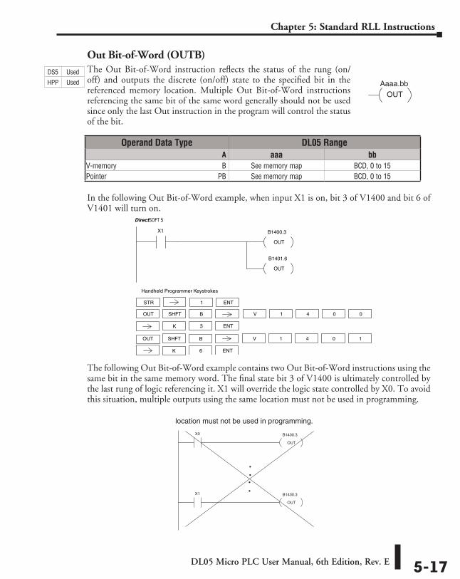
DL05 Micro PLC User Manual, 6th Edition, Rev. E 5-17
Chapter 5: Standard RLL Instructions
Out Bit-of-Word (OUTB)The Out Bit-of-Word instruction reflects the status of the rung (on/off) and outputs the discrete (on/off) state to the specified bit in the referenced memory location. Multiple Out Bit-of-Word instructions referencing the same bit of the same word generally should not be used since only the last Out instruction in the program will control the status of the bit.
In the following Out Bit-of-Word example, when input X1 is on, bit 3 of V1400 and bit 6 of V1401 will turn on.
The following Out Bit-of-Word example contains two Out Bit-of-Word instructions using the same bit in the same memory word. The final state bit 3 of V1400 is ultimately controlled by the last rung of logic referencing it. X1 will override the logic state controlled by X0. To avoid this situation, multiple outputs using the same location must not be used in programming.
Aaaa.bbOUT
B1400.3
OUT
X1
B1401.6
OUT
DirectSOFT 5
STR 1
Handheld Programmer Keystrokes
OUT V 1SHFT 4 0 0
3 ENTK
B
ENT
OUT V 1SHFT 4 0 1
6 ENTK
B
location must not be used in programming.
B1400.3
OUT
X0
B1400.3
OUT
X1
DS5 Used
HPP Used
Operand Data Type DL05 Range ⸠⸠⸠⸠⸠⸠⸠⸠⸠⸠⸠⸠⸠⸠⸠⸠⸠⸠⸠⸠⸠⸠⸠⸠⸠⸠⸠⸠⸠⸠⸠⸠⸠⸠⸠⸠⸠⸠⸠⸠⸠⸠⸠⸠⸠⸠⸠⸠⸠⸠⸠⸠⸠⸠⸠⸠⸠⸠⸠⸠⸠⸠⸠⸠⸠⸠⸠⸠⸠⸠⸠⸠⸠A aaa bbV-memory ⸠⸠⸠⸠⸠⸠⸠⸠⸠⸠⸠⸠⸠⸠⸠⸠⸠⸠⸠⸠⸠⸠⸠⸠⸠⸠⸠⸠⸠⸠⸠⸠⸠⸠⸠⸠⸠⸠⸠⸠⸠⸠⸠⸠⸠⸠⸠⸠⸠⸠⸠⸠⸠⸠⸠⸠⸠⸠B See memory map BCD, 0 to 15Pointer ⸠⸠⸠⸠⸠⸠⸠⸠⸠⸠⸠⸠⸠⸠⸠⸠⸠⸠⸠⸠⸠⸠⸠⸠⸠⸠⸠⸠⸠⸠⸠⸠⸠⸠⸠⸠⸠⸠⸠⸠⸠⸠⸠⸠⸠⸠⸠⸠⸠⸠⸠⸠⸠⸠⸠⸠⸠⸠⸠⸠⸠⸠PB See memory map BCD, 0 to 15
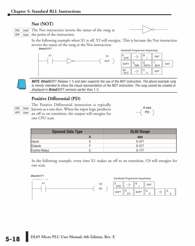
DL05 Micro PLC User Manual, 6th Edition, Rev. E5-18
Chapter 5: Standard RLL Instructions
Not (NOT)The Not instruction inverts the status of the rung at the point of the instruction.
In the following example when X1 is off, Y2 will energize. This is because the Not instruction inverts the status of the rung at the Not instruction.
NOTE: DirectSOFT Release 1.1i and later supports the use of the NOT instruction. The above example rung is merely intended to show the visual representation of the NOT instruction. The rung cannot be created or displayed in DirectSOFT versions earlier than 1.1i.
Positive Differential (PD)The Positive Differential instruction is typically known as a one shot. When the input logic produces an off to on transition, the output will energize for one CPU scan.
In the following example, every time X1 makes an off to on transition, C0 will energize for one scan.
Y2
OUT
X1
Handheld Programmer KeystrokesDirectSOFT32
STR$
1B ENT
SHFTTMR
NINST#O
MLRT ENT
OUTGX
2C ENT
A aaaPD
Operand Data Type DL05 Range ⸠⸠⸠⸠⸠⸠⸠⸠⸠⸠⸠⸠⸠⸠⸠⸠⸠⸠⸠⸠⸠⸠⸠⸠⸠⸠⸠⸠⸠⸠⸠⸠⸠⸠⸠⸠⸠⸠⸠⸠⸠⸠⸠⸠⸠⸠⸠⸠⸠⸠⸠⸠⸠⸠⸠⸠⸠⸠⸠⸠⸠⸠⸠⸠⸠⸠⸠⸠⸠⸠⸠⸠⸠A aaaInputs ⸠⸠⸠⸠⸠⸠⸠⸠⸠⸠⸠⸠⸠⸠⸠⸠⸠⸠⸠⸠⸠⸠⸠⸠⸠⸠⸠⸠⸠⸠⸠⸠⸠⸠⸠⸠⸠⸠⸠⸠⸠⸠⸠⸠⸠⸠⸠⸠⸠⸠⸠⸠⸠⸠⸠⸠⸠⸠⸠⸠⸠⸠⸠⸠⸠ X 0–377Outputs ⸠⸠⸠⸠⸠⸠⸠⸠⸠⸠⸠⸠⸠⸠⸠⸠⸠⸠⸠⸠⸠⸠⸠⸠⸠⸠⸠⸠⸠⸠⸠⸠⸠⸠⸠⸠⸠⸠⸠⸠⸠⸠⸠⸠⸠⸠⸠⸠⸠⸠⸠⸠⸠⸠⸠⸠⸠⸠⸠⸠⸠⸠⸠Y 0–377Control Relays ⸠⸠⸠⸠⸠⸠⸠⸠⸠⸠⸠⸠⸠⸠⸠⸠⸠⸠⸠⸠⸠⸠⸠⸠⸠⸠⸠⸠⸠⸠⸠⸠⸠⸠⸠⸠⸠⸠⸠⸠⸠⸠⸠⸠⸠⸠⸠⸠⸠⸠⸠⸠C 0–777
STR$
1B ENT
SHFTCV
P3
DSHFT0
A ENT
C0
PD
X1
Handheld Programmer KeystrokesDirectSOFT32
DS5 Used
HPP Used
DS5 Used
HPP Used
DirectSOFT
DirectSOFT
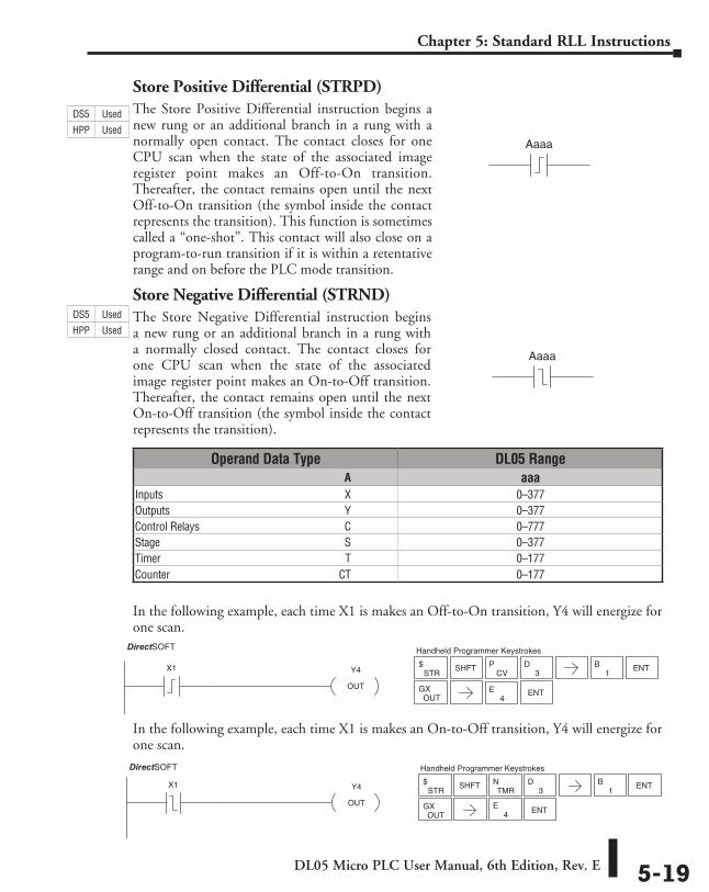
DL05 Micro PLC User Manual, 6th Edition, Rev. E 5-19
Chapter 5: Standard RLL Instructions
Store Positive Differential (STRPD)The Store Positive Differential instruction begins a new rung or an additional branch in a rung with a normally open contact. The contact closes for one CPU scan when the state of the associated image register point makes an Off-to-On transition. Thereafter, the contact remains open until the next Off-to-On transition (the symbol inside the contact represents the transition). This function is sometimes called a “one-shot”. This contact will also close on a program-to-run transition if it is within a retentative range and on before the PLC mode transition.
Store Negative Differential (STRND)The Store Negative Differential instruction begins a new rung or an additional branch in a rung with a normally closed contact. The contact closes for one CPU scan when the state of the associated image register point makes an On-to-Off transition. Thereafter, the contact remains open until the next On-to-Off transition (the symbol inside the contact represents the transition).
In the following example, each time X1 is makes an Off-to-On transition, Y4 will energize for one scan.
In the following example, each time X1 is makes an On-to-Off transition, Y4 will energize for one scan.
Aaaa
Aaaa
Operand Data Type DL05 Range ⸠⸠⸠⸠⸠⸠⸠⸠⸠⸠⸠⸠⸠⸠⸠⸠⸠⸠⸠⸠⸠⸠⸠⸠⸠⸠⸠⸠⸠⸠⸠⸠⸠⸠⸠⸠⸠⸠⸠⸠⸠⸠⸠⸠⸠⸠⸠⸠⸠⸠⸠⸠⸠⸠⸠⸠⸠⸠⸠⸠⸠⸠⸠⸠⸠⸠⸠⸠⸠⸠⸠⸠⸠A aaaInputs ⸠⸠⸠⸠⸠⸠⸠⸠⸠⸠⸠⸠⸠⸠⸠⸠⸠⸠⸠⸠⸠⸠⸠⸠⸠⸠⸠⸠⸠⸠⸠⸠⸠⸠⸠⸠⸠⸠⸠⸠⸠⸠⸠⸠⸠⸠⸠⸠⸠⸠⸠⸠⸠⸠⸠⸠⸠⸠⸠⸠⸠⸠⸠⸠⸠X 0–377Outputs ⸠⸠⸠⸠⸠⸠⸠⸠⸠⸠⸠⸠⸠⸠⸠⸠⸠⸠⸠⸠⸠⸠⸠⸠⸠⸠⸠⸠⸠⸠⸠⸠⸠⸠⸠⸠⸠⸠⸠⸠⸠⸠⸠⸠⸠⸠⸠⸠⸠⸠⸠⸠⸠⸠⸠⸠⸠⸠⸠⸠⸠⸠⸠Y 0–377Control Relays ⸠⸠⸠⸠⸠⸠⸠⸠⸠⸠⸠⸠⸠⸠⸠⸠⸠⸠⸠⸠⸠⸠⸠⸠⸠⸠⸠⸠⸠⸠⸠⸠⸠⸠⸠⸠⸠⸠⸠⸠⸠⸠⸠⸠⸠⸠⸠⸠⸠⸠⸠⸠C 0–777Stage ⸠⸠⸠⸠⸠⸠⸠⸠⸠⸠⸠⸠⸠⸠⸠⸠⸠⸠⸠⸠⸠⸠⸠⸠⸠⸠⸠⸠⸠⸠⸠⸠⸠⸠⸠⸠⸠⸠⸠⸠⸠⸠⸠⸠⸠⸠⸠⸠⸠⸠⸠⸠⸠⸠⸠⸠⸠⸠⸠⸠⸠⸠⸠⸠⸠⸠S 0–377Timer ⸠⸠⸠⸠⸠⸠⸠⸠⸠⸠⸠⸠⸠⸠⸠⸠⸠⸠⸠⸠⸠⸠⸠⸠⸠⸠⸠⸠⸠⸠⸠⸠⸠⸠⸠⸠⸠⸠⸠⸠⸠⸠⸠⸠⸠⸠⸠⸠⸠⸠⸠⸠⸠⸠⸠⸠⸠⸠⸠⸠⸠⸠⸠⸠⸠⸠ T 0–177Counter ⸠⸠⸠⸠⸠⸠⸠⸠⸠⸠⸠⸠⸠⸠⸠⸠⸠⸠⸠⸠⸠⸠⸠⸠⸠⸠⸠⸠⸠⸠⸠⸠⸠⸠⸠⸠⸠⸠⸠⸠⸠⸠⸠⸠⸠⸠⸠⸠⸠⸠⸠⸠⸠⸠⸠⸠⸠⸠⸠⸠⸠CT 0–177
Y4
OUT
DirectSOFT32
X1STR
$CV
P
ENTOUT
GX
3DSHFT
1B ENT
Handheld Programmer Keystrokes
4E
Y4
OUT
DirectSOFT32
X1STR
$TMR
N
ENTOUT
GX
3DSHFT
1B ENT
Handheld Programmer Keystrokes
4E
DS5 Used
HPP Used
DS5 Used
HPP Used
DirectSOFT
DirectSOFT
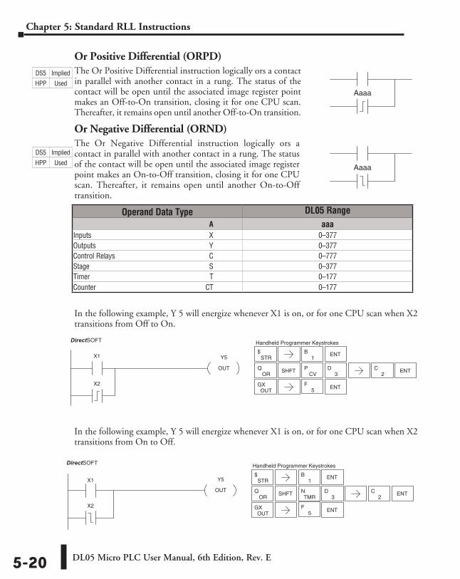
DL05 Micro PLC User Manual, 6th Edition, Rev. E5-20
Chapter 5: Standard RLL Instructions
Or Positive Differential (ORPD)The Or Positive Differential instruction logically ors a contact in parallel with another contact in a rung. The status of the contact will be open until the associated image register point makes an Off-to-On transition, closing it for one CPU scan. Thereafter, it remains open until another Off-to-On transition.
Or Negative Differential (ORND)The Or Negative Differential instruction logically ors a contact in parallel with another contact in a rung. The status of the contact will be open until the associated image register point makes an On-to-Off transition, closing it for one CPU scan. Thereafter, it remains open until another On-to-Off transition.
In the following example, Y 5 will energize whenever X1 is on, or for one CPU scan when X2 transitions from Off to On.
In the following example, Y 5 will energize whenever X1 is on, or for one CPU scan when X2 transitions from On to Off.
Aaaa
Aaaa
Operand Data Type DL05 Range ⸠⸠⸠⸠⸠⸠⸠⸠⸠⸠⸠⸠⸠⸠⸠⸠⸠⸠⸠⸠⸠⸠⸠⸠⸠⸠⸠⸠⸠⸠⸠⸠⸠⸠⸠⸠⸠⸠⸠⸠⸠⸠⸠⸠⸠⸠⸠⸠⸠⸠⸠⸠⸠⸠⸠⸠⸠⸠⸠⸠⸠⸠⸠⸠⸠⸠⸠⸠⸠⸠⸠⸠⸠A aaaInputs ⸠⸠⸠⸠⸠⸠⸠⸠⸠⸠⸠⸠⸠⸠⸠⸠⸠⸠⸠⸠⸠⸠⸠⸠⸠⸠⸠⸠⸠⸠⸠⸠⸠⸠⸠⸠⸠⸠⸠⸠⸠⸠⸠⸠⸠⸠⸠⸠⸠⸠⸠⸠⸠⸠⸠⸠⸠⸠⸠⸠⸠⸠⸠⸠⸠X 0–377Outputs ⸠⸠⸠⸠⸠⸠⸠⸠⸠⸠⸠⸠⸠⸠⸠⸠⸠⸠⸠⸠⸠⸠⸠⸠⸠⸠⸠⸠⸠⸠⸠⸠⸠⸠⸠⸠⸠⸠⸠⸠⸠⸠⸠⸠⸠⸠⸠⸠⸠⸠⸠⸠⸠⸠⸠⸠⸠⸠⸠⸠⸠⸠⸠Y 0–377Control Relays ⸠⸠⸠⸠⸠⸠⸠⸠⸠⸠⸠⸠⸠⸠⸠⸠⸠⸠⸠⸠⸠⸠⸠⸠⸠⸠⸠⸠⸠⸠⸠⸠⸠⸠⸠⸠⸠⸠⸠⸠⸠⸠⸠⸠⸠⸠⸠⸠⸠⸠⸠⸠C 0–777Stage ⸠⸠⸠⸠⸠⸠⸠⸠⸠⸠⸠⸠⸠⸠⸠⸠⸠⸠⸠⸠⸠⸠⸠⸠⸠⸠⸠⸠⸠⸠⸠⸠⸠⸠⸠⸠⸠⸠⸠⸠⸠⸠⸠⸠⸠⸠⸠⸠⸠⸠⸠⸠⸠⸠⸠⸠⸠⸠⸠⸠⸠⸠⸠⸠⸠⸠S 0–377Timer ⸠⸠⸠⸠⸠⸠⸠⸠⸠⸠⸠⸠⸠⸠⸠⸠⸠⸠⸠⸠⸠⸠⸠⸠⸠⸠⸠⸠⸠⸠⸠⸠⸠⸠⸠⸠⸠⸠⸠⸠⸠⸠⸠⸠⸠⸠⸠⸠⸠⸠⸠⸠⸠⸠⸠⸠⸠⸠⸠⸠⸠⸠⸠⸠⸠⸠ T 0–177Counter ⸠⸠⸠⸠⸠⸠⸠⸠⸠⸠⸠⸠⸠⸠⸠⸠⸠⸠⸠⸠⸠⸠⸠⸠⸠⸠⸠⸠⸠⸠⸠⸠⸠⸠⸠⸠⸠⸠⸠⸠⸠⸠⸠⸠⸠⸠⸠⸠⸠⸠⸠⸠⸠⸠⸠⸠⸠⸠⸠⸠⸠CT 0–177
Y5
OUT
X1
DirectSOFT32
X2
STR$
CVP
ENTOUT
GX
3DSHFT
1B ENT
Handheld Programmer Keystrokes
5F
ORQ
2C ENT
X1 Y5
OUT
DirectSOFT32
X2
STR$
TMRN
ENTOUT
GX
3DSHFT
1B ENT
Handheld Programmer Keystrokes
5F
ORQ
2C ENT
DS5 Implied
HPP Used
DS5 Implied
HPP Used
DirectSOFT
DirectSOFT
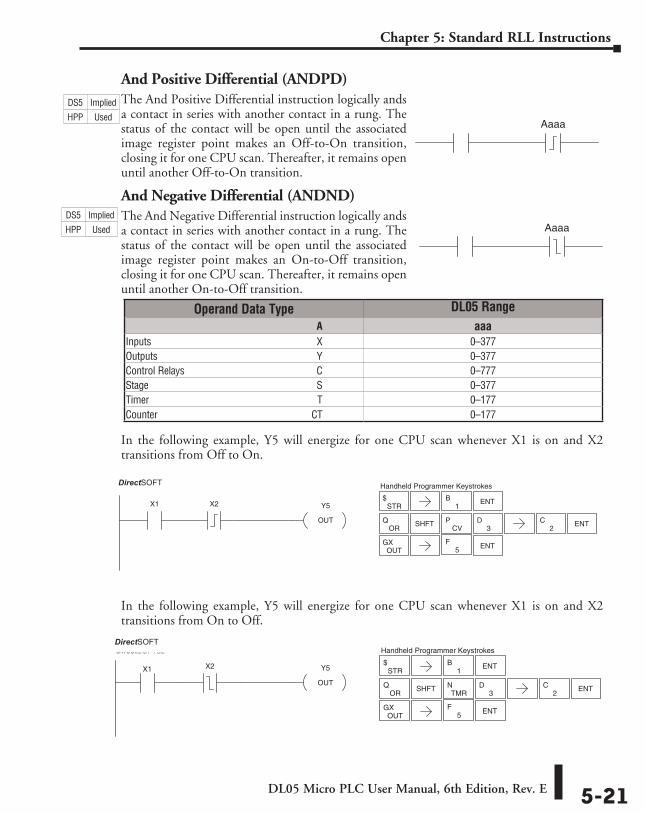
DL05 Micro PLC User Manual, 6th Edition, Rev. E 5-21
Chapter 5: Standard RLL Instructions
And Positive Differential (ANDPD)The And Positive Differential instruction logically ands a contact in series with another contact in a rung. The status of the contact will be open until the associated image register point makes an Off-to-On transition, closing it for one CPU scan. Thereafter, it remains open until another Off-to-On transition.
And Negative Differential (ANDND)The And Negative Differential instruction logically ands a contact in series with another contact in a rung. The status of the contact will be open until the associated image register point makes an On-to-Off transition, closing it for one CPU scan. Thereafter, it remains open until another On-to-Off transition.
In the following example, Y5 will energize for one CPU scan whenever X1 is on and X2 transitions from Off to On.
In the following example, Y5 will energize for one CPU scan whenever X1 is on and X2 transitions from On to Off.
Operand Data Type DL05 Range ⸠⸠⸠⸠⸠⸠⸠⸠⸠⸠⸠⸠⸠⸠⸠⸠⸠⸠⸠⸠⸠⸠⸠⸠⸠⸠⸠⸠⸠⸠⸠⸠⸠⸠⸠⸠⸠⸠⸠⸠⸠⸠⸠⸠⸠⸠⸠⸠⸠⸠⸠⸠⸠⸠⸠⸠⸠⸠⸠⸠⸠⸠⸠⸠⸠⸠⸠⸠⸠⸠⸠⸠⸠A aaaInputs ⸠⸠⸠⸠⸠⸠⸠⸠⸠⸠⸠⸠⸠⸠⸠⸠⸠⸠⸠⸠⸠⸠⸠⸠⸠⸠⸠⸠⸠⸠⸠⸠⸠⸠⸠⸠⸠⸠⸠⸠⸠⸠⸠⸠⸠⸠⸠⸠⸠⸠⸠⸠⸠⸠⸠⸠⸠⸠⸠⸠⸠⸠⸠⸠⸠X 0–377Outputs ⸠⸠⸠⸠⸠⸠⸠⸠⸠⸠⸠⸠⸠⸠⸠⸠⸠⸠⸠⸠⸠⸠⸠⸠⸠⸠⸠⸠⸠⸠⸠⸠⸠⸠⸠⸠⸠⸠⸠⸠⸠⸠⸠⸠⸠⸠⸠⸠⸠⸠⸠⸠⸠⸠⸠⸠⸠⸠⸠⸠⸠⸠⸠Y 0–377Control Relays ⸠⸠⸠⸠⸠⸠⸠⸠⸠⸠⸠⸠⸠⸠⸠⸠⸠⸠⸠⸠⸠⸠⸠⸠⸠⸠⸠⸠⸠⸠⸠⸠⸠⸠⸠⸠⸠⸠⸠⸠⸠⸠⸠⸠⸠⸠⸠⸠⸠⸠⸠⸠C 0–777Stage ⸠⸠⸠⸠⸠⸠⸠⸠⸠⸠⸠⸠⸠⸠⸠⸠⸠⸠⸠⸠⸠⸠⸠⸠⸠⸠⸠⸠⸠⸠⸠⸠⸠⸠⸠⸠⸠⸠⸠⸠⸠⸠⸠⸠⸠⸠⸠⸠⸠⸠⸠⸠⸠⸠⸠⸠⸠⸠⸠⸠⸠⸠⸠⸠⸠⸠S 0–377Timer ⸠⸠⸠⸠⸠⸠⸠⸠⸠⸠⸠⸠⸠⸠⸠⸠⸠⸠⸠⸠⸠⸠⸠⸠⸠⸠⸠⸠⸠⸠⸠⸠⸠⸠⸠⸠⸠⸠⸠⸠⸠⸠⸠⸠⸠⸠⸠⸠⸠⸠⸠⸠⸠⸠⸠⸠⸠⸠⸠⸠⸠⸠⸠⸠⸠⸠ T 0–177Counter ⸠⸠⸠⸠⸠⸠⸠⸠⸠⸠⸠⸠⸠⸠⸠⸠⸠⸠⸠⸠⸠⸠⸠⸠⸠⸠⸠⸠⸠⸠⸠⸠⸠⸠⸠⸠⸠⸠⸠⸠⸠⸠⸠⸠⸠⸠⸠⸠⸠⸠⸠⸠⸠⸠⸠⸠⸠⸠⸠⸠⸠CT 0–177
Aaaa
Aaaa
Y5
OUT
X1
DirectSOFT32
X2 STR$
CVP
ENTOUT
GX
3DSHFT
1B ENT
Handheld Programmer Keystrokes
5F
ORQ
2C ENT
X1 Y5
OUT
DirectSOFT32
X2STR
$
TMRN
ENTOUT
GX
3DSHFT
1B ENT
Handheld Programmer Keystrokes
5F
ORQ
2C ENT
DS5 Implied
HPP Used
DS5 Implied
HPP Used
DirectSOFT
DirectSOFT
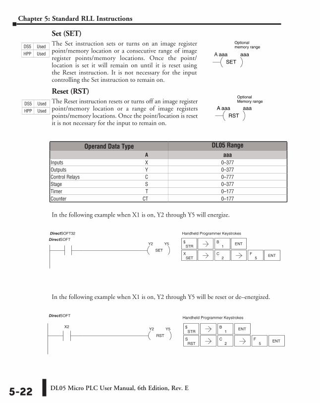
DL05 Micro PLC User Manual, 6th Edition, Rev. E5-22
Chapter 5: Standard RLL Instructions
Set (SET)The Set instruction sets or turns on an image register point/memory location or a consecutive range of image register points/memory locations. Once the point/location is set it will remain on until it is reset using the Reset instruction. It is not necessary for the input controlling the Set instruction to remain on.
Reset (RST)The Reset instruction resets or turns off an image register point/memory location or a range of image registers points/memory locations. Once the point/location is reset it is not necessary for the input to remain on.
In the following example when X1 is on, Y2 through Y5 will energize.
In the following example when X1 is on, Y2 through Y5 will be reset or de–energized.
SET
X1 Y2 Y5
Handheld Programmer KeystrokesDirectSOFT32
STR$
1B ENT
SETX ENT
2C
5F
STR$
1B ENT
RSTS
2C
RST
X2 Y2 Y5
Handheld Programmer KeystrokesDirectSOFT32
ENT5
F
A aaaSET
aaa
Optional memory range
A aaaRST
aaa
Optional Memory range.
Operand Data Type DL05 Range ⸠⸠⸠⸠⸠⸠⸠⸠⸠⸠⸠⸠⸠⸠⸠⸠⸠⸠⸠⸠⸠⸠⸠⸠⸠⸠⸠⸠⸠⸠⸠⸠⸠⸠⸠⸠⸠⸠⸠⸠⸠⸠⸠⸠⸠⸠⸠⸠⸠⸠⸠⸠⸠⸠⸠⸠⸠⸠⸠⸠⸠⸠⸠⸠⸠⸠⸠⸠⸠⸠⸠⸠⸠A aaaInputs ⸠⸠⸠⸠⸠⸠⸠⸠⸠⸠⸠⸠⸠⸠⸠⸠⸠⸠⸠⸠⸠⸠⸠⸠⸠⸠⸠⸠⸠⸠⸠⸠⸠⸠⸠⸠⸠⸠⸠⸠⸠⸠⸠⸠⸠⸠⸠⸠⸠⸠⸠⸠⸠⸠⸠⸠⸠⸠⸠⸠⸠⸠⸠⸠⸠X 0–377Outputs ⸠⸠⸠⸠⸠⸠⸠⸠⸠⸠⸠⸠⸠⸠⸠⸠⸠⸠⸠⸠⸠⸠⸠⸠⸠⸠⸠⸠⸠⸠⸠⸠⸠⸠⸠⸠⸠⸠⸠⸠⸠⸠⸠⸠⸠⸠⸠⸠⸠⸠⸠⸠⸠⸠⸠⸠⸠⸠⸠⸠⸠⸠⸠Y 0–377Control Relays ⸠⸠⸠⸠⸠⸠⸠⸠⸠⸠⸠⸠⸠⸠⸠⸠⸠⸠⸠⸠⸠⸠⸠⸠⸠⸠⸠⸠⸠⸠⸠⸠⸠⸠⸠⸠⸠⸠⸠⸠⸠⸠⸠⸠⸠⸠⸠⸠⸠⸠⸠⸠C 0–777Stage ⸠⸠⸠⸠⸠⸠⸠⸠⸠⸠⸠⸠⸠⸠⸠⸠⸠⸠⸠⸠⸠⸠⸠⸠⸠⸠⸠⸠⸠⸠⸠⸠⸠⸠⸠⸠⸠⸠⸠⸠⸠⸠⸠⸠⸠⸠⸠⸠⸠⸠⸠⸠⸠⸠⸠⸠⸠⸠⸠⸠⸠⸠⸠⸠⸠⸠S 0–377Timer ⸠⸠⸠⸠⸠⸠⸠⸠⸠⸠⸠⸠⸠⸠⸠⸠⸠⸠⸠⸠⸠⸠⸠⸠⸠⸠⸠⸠⸠⸠⸠⸠⸠⸠⸠⸠⸠⸠⸠⸠⸠⸠⸠⸠⸠⸠⸠⸠⸠⸠⸠⸠⸠⸠⸠⸠⸠⸠⸠⸠⸠⸠⸠⸠⸠⸠ T 0–177Counter ⸠⸠⸠⸠⸠⸠⸠⸠⸠⸠⸠⸠⸠⸠⸠⸠⸠⸠⸠⸠⸠⸠⸠⸠⸠⸠⸠⸠⸠⸠⸠⸠⸠⸠⸠⸠⸠⸠⸠⸠⸠⸠⸠⸠⸠⸠⸠⸠⸠⸠⸠⸠⸠⸠⸠⸠⸠⸠⸠⸠⸠CT 0–177
DS5 Used
HPP Used
DS5 Used
HPP Used
DirectSOFT
DirectSOFT
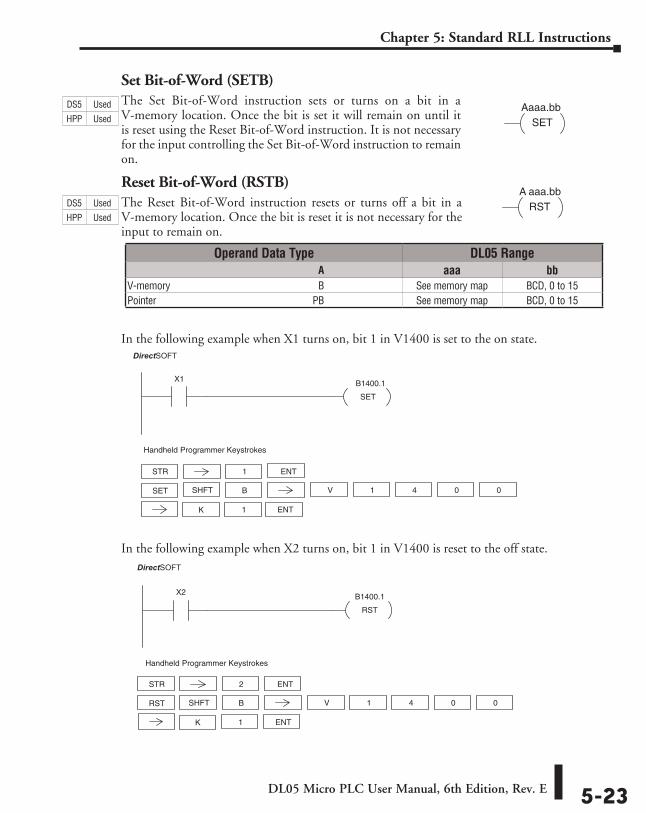
DL05 Micro PLC User Manual, 6th Edition, Rev. E 5-23
Chapter 5: Standard RLL Instructions
Set Bit-of-Word (SETB)The Set Bit-of-Word instruction sets or turns on a bit in a V-memory location. Once the bit is set it will remain on until it is reset using the Reset Bit-of-Word instruction. It is not necessary for the input controlling the Set Bit-of-Word instruction to remain on.
Reset Bit-of-Word (RSTB)The Reset Bit-of-Word instruction resets or turns off a bit in a V-memory location. Once the bit is reset it is not necessary for the input to remain on.
In the following example when X1 turns on, bit 1 in V1400 is set to the on state.
In the following example when X2 turns on, bit 1 in V1400 is reset to the off state.
Aaaa.bbSET
A aaa.bbRST
SET
X1 B1400.1
DirectSOFT32
STR 1
Handheld Programmer Keystrokes
SET V 1SHFT 4 0 0
1 ENTK
B
ENT
RST
X2 B1400.1
DirectSOFT32
Handheld Programmer Keystrokes
STR 2
RST V 1SHFT 4 0 0
1 ENTK
B
ENT
Operand Data Type DL05 Range ⸠⸠⸠⸠⸠⸠⸠⸠⸠⸠⸠⸠⸠⸠⸠⸠⸠⸠⸠⸠⸠⸠⸠⸠⸠⸠⸠⸠⸠⸠⸠⸠⸠⸠⸠⸠⸠⸠⸠⸠⸠⸠⸠⸠⸠⸠⸠⸠⸠⸠⸠⸠⸠⸠⸠⸠⸠⸠⸠⸠⸠⸠⸠⸠⸠⸠⸠⸠⸠⸠⸠⸠⸠A aaa bbV-memory ⸠⸠⸠⸠⸠⸠⸠⸠⸠⸠⸠⸠⸠⸠⸠⸠⸠⸠⸠⸠⸠⸠⸠⸠⸠⸠⸠⸠⸠⸠⸠⸠⸠⸠⸠⸠⸠⸠⸠⸠⸠⸠⸠⸠⸠⸠⸠⸠⸠⸠⸠⸠⸠⸠⸠⸠⸠⸠B See memory map BCD, 0 to 15Pointer ⸠⸠⸠⸠⸠⸠⸠⸠⸠⸠⸠⸠⸠⸠⸠⸠⸠⸠⸠⸠⸠⸠⸠⸠⸠⸠⸠⸠⸠⸠⸠⸠⸠⸠⸠⸠⸠⸠⸠⸠⸠⸠⸠⸠⸠⸠⸠⸠⸠⸠⸠⸠⸠⸠⸠⸠⸠⸠⸠⸠⸠⸠PB See memory map BCD, 0 to 15
DS5 Used
HPP Used
DS5 Used
HPP Used
DirectSOFT
DirectSOFT
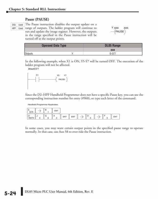
DL05 Micro PLC User Manual, 6th Edition, Rev. E5-24
Chapter 5: Standard RLL Instructions
Pause (PAUSE)The Pause instruction disables the output update on a range of outputs. The ladder program will continue to run and update the image register. However, the outputs in the range specified in the Pause instruction will be turned off at the output points.
In the following example, when X1 is ON, Y5-Y7 will be turned OFF. The execution of the ladder program will not be affected.
Since the D2–HPP Handheld Programmer does not have a specific Pause key, you can use the corresponding instruction number for entry (#960), or type each letter of the command.
In some cases, you may want certain output points in the specified pause range to operate normally. In that case, use Aux 58 to over-ride the Pause instruction.
aaaaaaY
PAUSE
Operand Data Type DL05 Rangeaaa
Outputs ⸠⸠⸠⸠⸠⸠⸠⸠⸠⸠⸠⸠⸠⸠⸠⸠⸠⸠⸠⸠⸠⸠⸠⸠⸠⸠⸠⸠⸠⸠⸠⸠⸠⸠⸠⸠⸠⸠⸠⸠⸠⸠⸠⸠⸠⸠⸠⸠⸠⸠⸠⸠⸠⸠⸠⸠⸠⸠⸠⸠⸠⸠⸠Y 0–377
DirectSOFT32
PAUSE
X1 Y5 Y7
STR$
1B ENT
Handheld Programmer Keystrokes
5F ENT
INST#O
9J
6G
0A ENT ENT
3D
DS5 Used
HPP Used
DirectSOFT
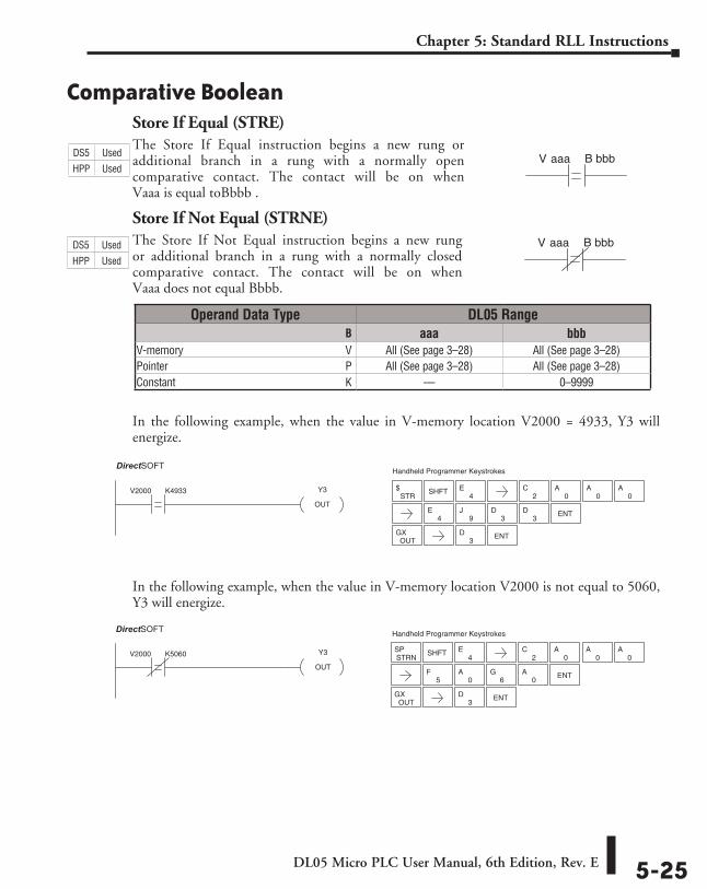
DL05 Micro PLC User Manual, 6th Edition, Rev. E 5-25
Chapter 5: Standard RLL Instructions
Comparative BooleanStore If Equal (STRE)The Store If Equal instruction begins a new rung or additional branch in a rung with a normally open comparative contact. The contact will be on when Vaaa is equal toBbbb .
Store If Not Equal (STRNE)The Store If Not Equal instruction begins a new rung or additional branch in a rung with a normally closed comparative contact. The contact will be on when Vaaa does not equal Bbbb.
In the following example, when the value in V-memory location V2000 = 4933, Y3 will energize.
In the following example, when the value in V-memory location V2000 is not equal to 5060, Y3 will energize.
V aaa B bbb
V aaa B bbb
Operand Data Type DL05 Range ⸠⸠⸠⸠⸠⸠⸠⸠⸠⸠⸠⸠⸠⸠⸠⸠⸠⸠⸠⸠⸠⸠⸠⸠⸠⸠⸠⸠⸠⸠⸠⸠⸠⸠⸠⸠⸠⸠⸠⸠⸠⸠⸠⸠⸠⸠⸠⸠⸠⸠⸠⸠⸠⸠⸠⸠⸠⸠⸠⸠⸠⸠⸠⸠⸠⸠⸠⸠⸠⸠⸠⸠⸠B aaa bbbV-memory ⸠⸠⸠⸠⸠⸠⸠⸠⸠⸠⸠⸠⸠⸠⸠⸠⸠⸠⸠⸠⸠⸠⸠⸠⸠⸠⸠⸠⸠⸠⸠⸠⸠⸠⸠⸠⸠⸠⸠⸠⸠⸠⸠⸠⸠⸠⸠⸠⸠⸠⸠⸠⸠⸠⸠⸠⸠⸠V All (See page 3–28) All (See page 3–28)Pointer ⸠⸠⸠⸠⸠⸠⸠⸠⸠⸠⸠⸠⸠⸠⸠⸠⸠⸠⸠⸠⸠⸠⸠⸠⸠⸠⸠⸠⸠⸠⸠⸠⸠⸠⸠⸠⸠⸠⸠⸠⸠⸠⸠⸠⸠⸠⸠⸠⸠⸠⸠⸠⸠⸠⸠⸠⸠⸠⸠⸠⸠⸠⸠⸠P All (See page 3–28) All (See page 3–28)Constant ⸠⸠⸠⸠⸠⸠⸠⸠⸠⸠⸠⸠⸠⸠⸠⸠⸠⸠⸠⸠⸠⸠⸠⸠⸠⸠⸠⸠⸠⸠⸠⸠⸠⸠⸠⸠⸠⸠⸠⸠⸠⸠⸠⸠⸠⸠⸠⸠⸠⸠⸠⸠⸠⸠⸠⸠⸠⸠⸠⸠⸠K –– 0–9999
V2000 K4933 Y3
OUT
DirectSOFT32 Handheld Programmer Keystrokes
STR$ SHFT
4E
2C
0A
0A
0A
4E
9J
3D
3D ENT
OUTGX ENT
3D
Y3
OUT
V2000 K5060
DirectSOFT32 Handheld Programmer Keystrokes
SHFT
OUTGX ENT
3D
4E
2C
0A
0A
0A
STRNSP
5F
0A ENT
6G
0A
DS5 Used
HPP Used
DS5 Used
HPP Used
DirectSOFT
DirectSOFT
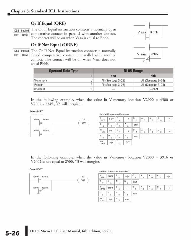
DL05 Micro PLC User Manual, 6th Edition, Rev. E5-26
Chapter 5: Standard RLL Instructions
Or If Equal (ORE)The Or If Equal instruction connects a normally open comparative contact in parallel with another contact. The contact will be on when Vaaa is equal to Bbbb.
Or If Not Equal (ORNE)The Or If Not Equal instruction connects a normally closed comparative contact in parallel with another contact. The contact will be on when Vaaa does not equal Bbbb.
In the following example, when the value in V-memory location V2000 = 4500 or V2002 = 2345 , Y3 will energize.
In the following example, when the value in V-memory location V2000 = 3916 or V2002 is not equal to 2500, Y3 will energize.
Operand Data Type DL05 Range ⸠⸠⸠⸠⸠⸠⸠⸠⸠⸠⸠⸠⸠⸠⸠⸠⸠⸠⸠⸠⸠⸠⸠⸠⸠⸠⸠⸠⸠⸠⸠⸠⸠⸠⸠⸠⸠⸠⸠⸠⸠⸠⸠⸠⸠⸠⸠⸠⸠⸠⸠⸠⸠⸠⸠⸠⸠⸠⸠⸠⸠⸠⸠⸠⸠⸠⸠⸠⸠⸠⸠⸠⸠B aaa bbbV-memory ⸠⸠⸠⸠⸠⸠⸠⸠⸠⸠⸠⸠⸠⸠⸠⸠⸠⸠⸠⸠⸠⸠⸠⸠⸠⸠⸠⸠⸠⸠⸠⸠⸠⸠⸠⸠⸠⸠⸠⸠⸠⸠⸠⸠⸠⸠⸠⸠⸠⸠⸠⸠⸠⸠⸠⸠⸠⸠V All (See page 3–28) All (See page 3–28)Pointer ⸠⸠⸠⸠⸠⸠⸠⸠⸠⸠⸠⸠⸠⸠⸠⸠⸠⸠⸠⸠⸠⸠⸠⸠⸠⸠⸠⸠⸠⸠⸠⸠⸠⸠⸠⸠⸠⸠⸠⸠⸠⸠⸠⸠⸠⸠⸠⸠⸠⸠⸠⸠⸠⸠⸠⸠⸠⸠⸠⸠⸠⸠⸠⸠P All (See page 3–28) All (See page 3–28)Constant ⸠⸠⸠⸠⸠⸠⸠⸠⸠⸠⸠⸠⸠⸠⸠⸠⸠⸠⸠⸠⸠⸠⸠⸠⸠⸠⸠⸠⸠⸠⸠⸠⸠⸠⸠⸠⸠⸠⸠⸠⸠⸠⸠⸠⸠⸠⸠⸠⸠⸠⸠⸠⸠⸠⸠⸠⸠⸠⸠⸠⸠K –– 0–9999
V aaa B bbb
V aaa B bbbDS5 Implied
HPP Used
DS5 Implied
HPP Used
2C
5F ENT
0A
0A
3D
9J ENT
1B
6G
4E
Y3
OUT
V2000 K3916
V2002 K2500
DirectSOFT32 Handheld Programmer Keystrokes
STR$ SHFT
2C
0A
0A
0A
ORNR SHFT
4E
2C
0A
0A
2C
OUTGX ENT
3D
DirectSOFT
2C
3D
4E
5F ENT
4E
5F ENT
0A
0A
Y3
OUT
V2002 K2345
V2000 K4500
DirectSOFT32 Handheld Programmer Keystrokes
SHFT4
E2
C0
A0
A0
ASTR
$
ORQ SHFT
4E
2C
0A
0A
2C
OUTGX ENT
3D
DirectSOFT
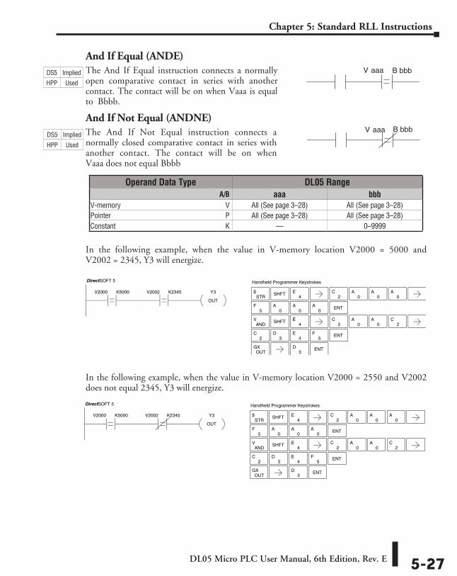
DL05 Micro PLC User Manual, 6th Edition, Rev. E 5-27
Chapter 5: Standard RLL Instructions
And If Equal (ANDE)The And If Equal instruction connects a normally open comparative contact in series with another contact. The contact will be on when Vaaa is equal to Bbbb.
And If Not Equal (ANDNE)The And If Not Equal instruction connects a normally closed comparative contact in series with another contact. The contact will be on when Vaaa does not equal Bbbb
In the following example, when the value in V-memory location V2000 = 5000 and V2002 = 2345, Y3 will energize.
In the following example, when the value in V-memory location V2000 = 2550 and V2002 does not equal 2345, Y3 will energize.
V aaa B bbb
V aaa B bbb
2C
3D
4E
5F ENT
5F
0A ENT
0A
0A
2C
STR$ SHFT
4E
0A
0A
0A
ANDV SHFT
4EE
2C
0A
0A
2C
OUTGX ENT
3D
Y3
OUT
V2002 K2345V2000 K5000
DirectSOFT 5 Handheld Programmer Keystrokes
2C
3D
4E
5F ENT
5F
0A ENT
0A
0A
2C
STR$ SHFT
4E
0A
0A
0A
ANDV SHFT
4E
2C
0A
0A
2C
OUTGX ENT
3D
Y3
OUT
V2002 K2345V2000 K5000
DirectSOFT 5 Handheld Programmer Keystrokes
Operand Data Type DL05 Range ⸠⸠⸠⸠⸠⸠⸠⸠⸠⸠⸠⸠⸠⸠⸠⸠⸠⸠⸠⸠⸠⸠⸠⸠⸠⸠⸠⸠⸠⸠⸠⸠⸠⸠⸠⸠⸠⸠⸠⸠⸠⸠⸠⸠⸠⸠⸠⸠⸠⸠⸠⸠⸠⸠⸠⸠⸠⸠⸠⸠⸠⸠⸠⸠⸠⸠⸠⸠⸠ A/B aaa bbbV-memory ⸠⸠⸠⸠⸠⸠⸠⸠⸠⸠⸠⸠⸠⸠⸠⸠⸠⸠⸠⸠⸠⸠⸠⸠⸠⸠⸠⸠⸠⸠⸠⸠⸠⸠⸠⸠⸠⸠⸠⸠⸠⸠⸠⸠⸠⸠⸠⸠⸠⸠⸠⸠⸠⸠⸠⸠⸠⸠V All (See page 3–28) All (See page 3–28)Pointer ⸠⸠⸠⸠⸠⸠⸠⸠⸠⸠⸠⸠⸠⸠⸠⸠⸠⸠⸠⸠⸠⸠⸠⸠⸠⸠⸠⸠⸠⸠⸠⸠⸠⸠⸠⸠⸠⸠⸠⸠⸠⸠⸠⸠⸠⸠⸠⸠⸠⸠⸠⸠⸠⸠⸠⸠⸠⸠⸠⸠⸠⸠⸠⸠P All (See page 3–28) All (See page 3–28)Constant ⸠⸠⸠⸠⸠⸠⸠⸠⸠⸠⸠⸠⸠⸠⸠⸠⸠⸠⸠⸠⸠⸠⸠⸠⸠⸠⸠⸠⸠⸠⸠⸠⸠⸠⸠⸠⸠⸠⸠⸠⸠⸠⸠⸠⸠⸠⸠⸠⸠⸠⸠⸠⸠⸠⸠⸠⸠⸠⸠⸠⸠K –– 0–9999
DS5 Implied
HPP Used
DS5 Implied
HPP Used
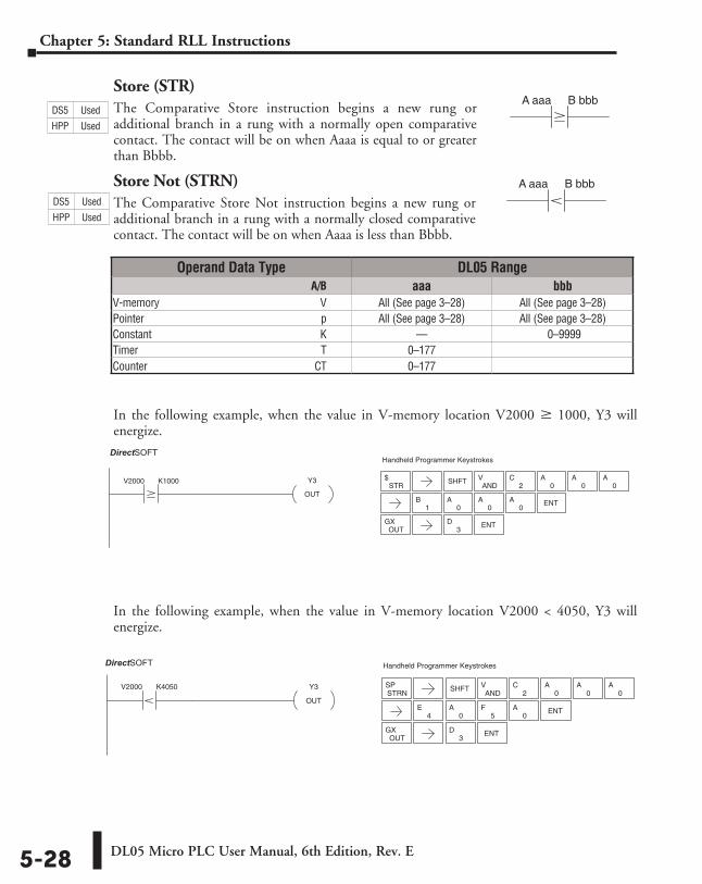
DL05 Micro PLC User Manual, 6th Edition, Rev. E5-28
Chapter 5: Standard RLL Instructions
Store (STR)The Comparative Store instruction begins a new rung or additional branch in a rung with a normally open comparative contact. The contact will be on when Aaaa is equal to or greater than Bbbb.
Store Not (STRN)The Comparative Store Not instruction begins a new rung or additional branch in a rung with a normally closed comparative contact. The contact will be on when Aaaa is less than Bbbb.
In the following example, when the value in V-memory location V2000 M 1000, Y3 will energize.
In the following example, when the value in V-memory location V2000 < 4050, Y3 will energize.
A aaa B bbb
A aaa B bbb
Operand Data Type DL05 Range ⸠⸠⸠⸠⸠⸠⸠⸠⸠⸠⸠⸠⸠⸠⸠⸠⸠⸠⸠⸠⸠⸠⸠⸠⸠⸠⸠⸠⸠⸠⸠⸠⸠⸠⸠⸠⸠⸠⸠⸠⸠⸠⸠⸠⸠⸠⸠⸠⸠⸠⸠⸠⸠⸠⸠⸠⸠⸠⸠⸠⸠⸠⸠⸠⸠⸠⸠⸠⸠ A/B aaa bbbV-memory ⸠⸠⸠⸠⸠⸠⸠⸠⸠⸠⸠⸠⸠⸠⸠⸠⸠⸠⸠⸠⸠⸠⸠⸠⸠⸠⸠⸠⸠⸠⸠⸠⸠⸠⸠⸠⸠⸠⸠⸠⸠⸠⸠⸠⸠⸠⸠⸠⸠⸠⸠⸠⸠⸠⸠⸠⸠⸠V All (See page 3–28) All (See page 3–28)Pointer ⸠⸠⸠⸠⸠⸠⸠⸠⸠⸠⸠⸠⸠⸠⸠⸠⸠⸠⸠⸠⸠⸠⸠⸠⸠⸠⸠⸠⸠⸠⸠⸠⸠⸠⸠⸠⸠⸠⸠⸠⸠⸠⸠⸠⸠⸠⸠⸠⸠⸠⸠⸠⸠⸠⸠⸠⸠⸠⸠⸠⸠⸠⸠⸠⸠ p All (See page 3–28) All (See page 3–28)Constant ⸠⸠⸠⸠⸠⸠⸠⸠⸠⸠⸠⸠⸠⸠⸠⸠⸠⸠⸠⸠⸠⸠⸠⸠⸠⸠⸠⸠⸠⸠⸠⸠⸠⸠⸠⸠⸠⸠⸠⸠⸠⸠⸠⸠⸠⸠⸠⸠⸠⸠⸠⸠⸠⸠⸠⸠⸠⸠⸠⸠⸠K –– 0–9999Timer ⸠⸠⸠⸠⸠⸠⸠⸠⸠⸠⸠⸠⸠⸠⸠⸠⸠⸠⸠⸠⸠⸠⸠⸠⸠⸠⸠⸠⸠⸠⸠⸠⸠⸠⸠⸠⸠⸠⸠⸠⸠⸠⸠⸠⸠⸠⸠⸠⸠⸠⸠⸠⸠⸠⸠⸠⸠⸠⸠⸠⸠⸠⸠⸠⸠⸠ T 0–177Counter ⸠⸠⸠⸠⸠⸠⸠⸠⸠⸠⸠⸠⸠⸠⸠⸠⸠⸠⸠⸠⸠⸠⸠⸠⸠⸠⸠⸠⸠⸠⸠⸠⸠⸠⸠⸠⸠⸠⸠⸠⸠⸠⸠⸠⸠⸠⸠⸠⸠⸠⸠⸠⸠⸠⸠⸠⸠⸠⸠⸠⸠CT 0–177
ENT3
D
Y3
OUT
V2000 K1000
DirectSOFT32 Handheld Programmer Keystrokes
STR$
ENT
OUTGX
SHFTAND
V2
C0
A0
A0
A
1B
0A
0A
0A
ENT3
D
0A ENT
0A
4E
5F
Y3
OUT
V2000 K4050
DirectSOFT32 Handheld Programmer Keystrokes
OUTGX
STRNSP SHFT
ANDV
2C
0A
0A
0A
DS5 Used
HPP Used
DS5 Used
HPP Used
DirectSOFT
DirectSOFT
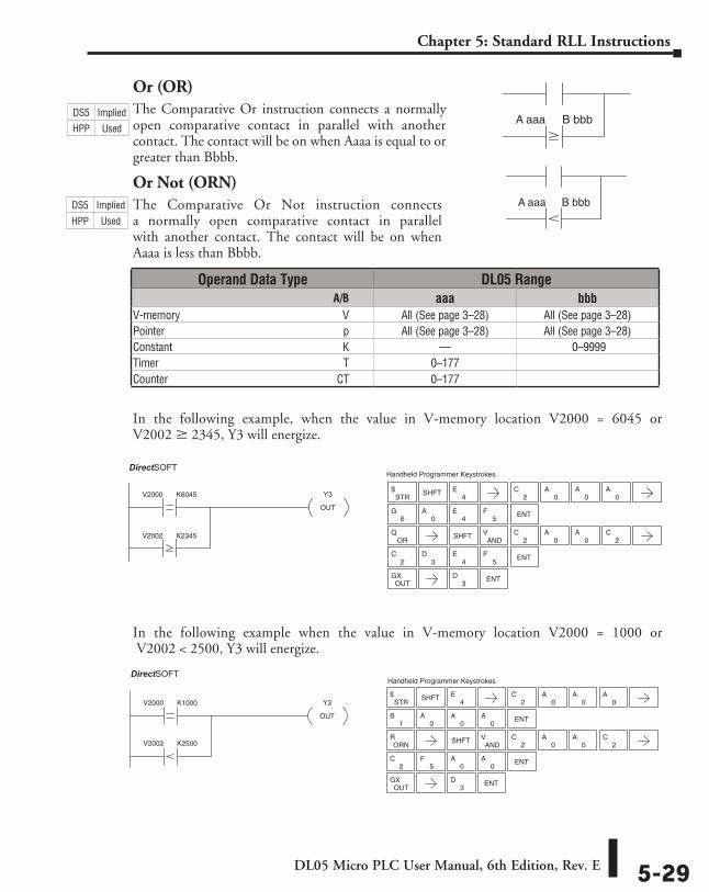
DL05 Micro PLC User Manual, 6th Edition, Rev. E 5-29
Chapter 5: Standard RLL Instructions
Or (OR)The Comparative Or instruction connects a normally open comparative contact in parallel with another contact. The contact will be on when Aaaa is equal to or greater than Bbbb.
Or Not (ORN)The Comparative Or Not instruction connects a normally open comparative contact in parallel with another contact. The contact will be on when Aaaa is less than Bbbb.
In the following example, when the value in V-memory location V2000 = 6045 or V2002 M 2345, Y3 will energize.
In the following example when the value in V-memory location V2000 = 1000 or V2002 < 2500, Y3 will energize.
A aaa B bbb
A aaa B bbb
2C
3D
4E
5F ENT
6G
0A
Y3
OUT
V2000 K6045
V2002 K2345
DirectSOFT32 Handheld Programmer Keystrokes
SHFT4
E2
C0
A0
A0
A
ENT
STR$
ORQ
OUTGX ENT
3D
4E
5F
SHFTAND
V2
C0
A0
A2
C
ENT3
D
2C
5F ENT
0A
0A
ENT1
B0
A0
A0
A
4E
Y3
OUT
V2000 K1000
V2002 K2500
DirectSOFT32 Handheld Programmer Keystrokes
STR$ SHFT
2C
0A
0A
0A
ORNR
OUTGX
SHFTAND
V2
C0
A0
A2
C
Operand Data Type DL05 Range ⸠⸠⸠⸠⸠⸠⸠⸠⸠⸠⸠⸠⸠⸠⸠⸠⸠⸠⸠⸠⸠⸠⸠⸠⸠⸠⸠⸠⸠⸠⸠⸠⸠⸠⸠⸠⸠⸠⸠⸠⸠⸠⸠⸠⸠⸠⸠⸠⸠⸠⸠⸠⸠⸠⸠⸠⸠⸠⸠⸠⸠⸠⸠⸠⸠⸠⸠⸠⸠ A/B aaa bbbV-memory ⸠⸠⸠⸠⸠⸠⸠⸠⸠⸠⸠⸠⸠⸠⸠⸠⸠⸠⸠⸠⸠⸠⸠⸠⸠⸠⸠⸠⸠⸠⸠⸠⸠⸠⸠⸠⸠⸠⸠⸠⸠⸠⸠⸠⸠⸠⸠⸠⸠⸠⸠⸠⸠⸠⸠⸠⸠⸠V All (See page 3–28) All (See page 3–28)Pointer ⸠⸠⸠⸠⸠⸠⸠⸠⸠⸠⸠⸠⸠⸠⸠⸠⸠⸠⸠⸠⸠⸠⸠⸠⸠⸠⸠⸠⸠⸠⸠⸠⸠⸠⸠⸠⸠⸠⸠⸠⸠⸠⸠⸠⸠⸠⸠⸠⸠⸠⸠⸠⸠⸠⸠⸠⸠⸠⸠⸠⸠⸠⸠⸠⸠ p All (See page 3–28) All (See page 3–28)Constant ⸠⸠⸠⸠⸠⸠⸠⸠⸠⸠⸠⸠⸠⸠⸠⸠⸠⸠⸠⸠⸠⸠⸠⸠⸠⸠⸠⸠⸠⸠⸠⸠⸠⸠⸠⸠⸠⸠⸠⸠⸠⸠⸠⸠⸠⸠⸠⸠⸠⸠⸠⸠⸠⸠⸠⸠⸠⸠⸠⸠⸠K –– 0–9999Timer ⸠⸠⸠⸠⸠⸠⸠⸠⸠⸠⸠⸠⸠⸠⸠⸠⸠⸠⸠⸠⸠⸠⸠⸠⸠⸠⸠⸠⸠⸠⸠⸠⸠⸠⸠⸠⸠⸠⸠⸠⸠⸠⸠⸠⸠⸠⸠⸠⸠⸠⸠⸠⸠⸠⸠⸠⸠⸠⸠⸠⸠⸠⸠⸠⸠⸠ T 0–177Counter ⸠⸠⸠⸠⸠⸠⸠⸠⸠⸠⸠⸠⸠⸠⸠⸠⸠⸠⸠⸠⸠⸠⸠⸠⸠⸠⸠⸠⸠⸠⸠⸠⸠⸠⸠⸠⸠⸠⸠⸠⸠⸠⸠⸠⸠⸠⸠⸠⸠⸠⸠⸠⸠⸠⸠⸠⸠⸠⸠⸠⸠CT 0–177
DS5 Implied
HPP Used
DS5 Implied
HPP Used
DirectSOFT
DirectSOFT
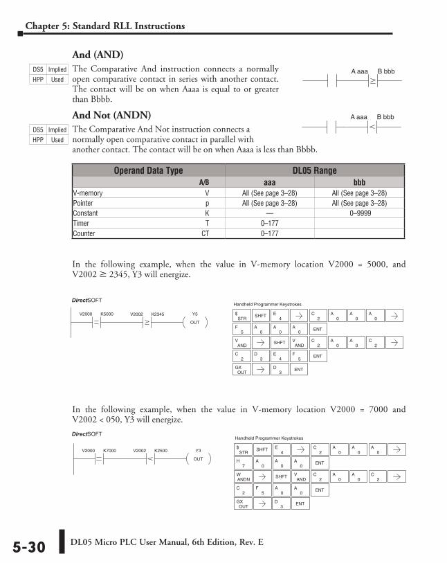
DL05 Micro PLC User Manual, 6th Edition, Rev. E5-30
Chapter 5: Standard RLL Instructions
And (AND)The Comparative And instruction connects a normally open comparative contact in series with another contact. The contact will be on when Aaaa is equal to or greater than Bbbb.
And Not (ANDN)The Comparative And Not instruction connects a normally open comparative contact in parallel with another contact. The contact will be on when Aaaa is less than Bbbb.
In the following example, when the value in V-memory location V2000 = 5000, and V2002 M 2345, Y3 will energize.
In the following example, when the value in V-memory location V2000 = 7000 and V2002 < 050, Y3 will energize.
A aaa B bbb
A aaa B bbb
ENT3
D
2C
3D
4E
5F ENT
ENT0
A0
A5
F0
A
2CY3
OUT
V2000 K5000 V2002 K2345
DirectSOFT32 Handheld Programmer Keystrokes
STR$ SHFT
4E
0A
0A
0A
ANDV
OUTGX
SHFTAND
V2
C0
A0
A2
C
2C
5F ENT
0A
0A
7H ENT
0A
0A
0A
2C
Y3
OUT
V2000 K7000 V2002 K2500
DirectSOFT32 Handheld Programmer Keystrokes
STR$ SHFT
4E
2C
0A
0A
0A
ANDNW
OUTGX ENT
3D
SHFTAND
V2
C0
A0
A
Operand Data Type DL05 Range ⸠⸠⸠⸠⸠⸠⸠⸠⸠⸠⸠⸠⸠⸠⸠⸠⸠⸠⸠⸠⸠⸠⸠⸠⸠⸠⸠⸠⸠⸠⸠⸠⸠⸠⸠⸠⸠⸠⸠⸠⸠⸠⸠⸠⸠⸠⸠⸠⸠⸠⸠⸠⸠⸠⸠⸠⸠⸠⸠⸠⸠⸠⸠⸠⸠⸠⸠⸠⸠ A/B aaa bbbV-memory ⸠⸠⸠⸠⸠⸠⸠⸠⸠⸠⸠⸠⸠⸠⸠⸠⸠⸠⸠⸠⸠⸠⸠⸠⸠⸠⸠⸠⸠⸠⸠⸠⸠⸠⸠⸠⸠⸠⸠⸠⸠⸠⸠⸠⸠⸠⸠⸠⸠⸠⸠⸠⸠⸠⸠⸠⸠⸠V All (See page 3–28) All (See page 3–28)Pointer ⸠⸠⸠⸠⸠⸠⸠⸠⸠⸠⸠⸠⸠⸠⸠⸠⸠⸠⸠⸠⸠⸠⸠⸠⸠⸠⸠⸠⸠⸠⸠⸠⸠⸠⸠⸠⸠⸠⸠⸠⸠⸠⸠⸠⸠⸠⸠⸠⸠⸠⸠⸠⸠⸠⸠⸠⸠⸠⸠⸠⸠⸠⸠⸠⸠ p All (See page 3–28) All (See page 3–28)Constant ⸠⸠⸠⸠⸠⸠⸠⸠⸠⸠⸠⸠⸠⸠⸠⸠⸠⸠⸠⸠⸠⸠⸠⸠⸠⸠⸠⸠⸠⸠⸠⸠⸠⸠⸠⸠⸠⸠⸠⸠⸠⸠⸠⸠⸠⸠⸠⸠⸠⸠⸠⸠⸠⸠⸠⸠⸠⸠⸠⸠⸠K –– 0–9999Timer ⸠⸠⸠⸠⸠⸠⸠⸠⸠⸠⸠⸠⸠⸠⸠⸠⸠⸠⸠⸠⸠⸠⸠⸠⸠⸠⸠⸠⸠⸠⸠⸠⸠⸠⸠⸠⸠⸠⸠⸠⸠⸠⸠⸠⸠⸠⸠⸠⸠⸠⸠⸠⸠⸠⸠⸠⸠⸠⸠⸠⸠⸠⸠⸠⸠⸠ T 0–177Counter ⸠⸠⸠⸠⸠⸠⸠⸠⸠⸠⸠⸠⸠⸠⸠⸠⸠⸠⸠⸠⸠⸠⸠⸠⸠⸠⸠⸠⸠⸠⸠⸠⸠⸠⸠⸠⸠⸠⸠⸠⸠⸠⸠⸠⸠⸠⸠⸠⸠⸠⸠⸠⸠⸠⸠⸠⸠⸠⸠⸠⸠CT 0–177
DS5 Implied
HPP Used
DS5 Implied
HPP Used
DirectSOFT
DirectSOFT
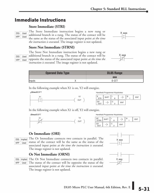
DL05 Micro PLC User Manual, 6th Edition, Rev. E 5-31
Chapter 5: Standard RLL Instructions
Immediate InstructionsStore Immediate (STRI)The Store Immediate instruction begins a new rung or additional branch in a rung. The status of the contact will be the same as the status of the associated input point at the time the instruction is executed. The image register is not updated.
Store Not Immediate (STRNI)The Store Not Immediate instruction begins a new rung or additional branch in a rung. The status of the contact will be opposite the status of the associated input point at the time the instruction is executed. The image register is not updated.
In the following example when X1 is on, Y2 will energize.
In the following example when X1 is off, Y2 will energize.
Or Immediate (ORI)The Or Immediate connects two contacts in parallel. The status of the contact will be the same as the status of the associated input point at the time the instruction is executed. The image register is not updated.
Or Not Immediate (ORNI)The Or Not Immediate connects two contacts in parallel. The status of the contact will be opposite the status of the associated input point at the time the instruction is executed. The image register is not updated.
aaaX
aaaX
ENT2
C
1B ENTX1 Y2
OUT
Handheld Programmer KeystrokesDirectSOFT32
STR$ SHFT
8I
OUTGX
ENT2
C
1B ENT
X1 Y2
OUT
Handheld Programmer KeystrokesDirectSOFT32
STRNSP SHFT
8I
OUTGX
aaaX
aaaX
Operand Data Type DL05 Rangeaaa
Inputs ⸠⸠⸠⸠⸠⸠⸠⸠⸠⸠⸠⸠⸠⸠⸠⸠⸠⸠⸠⸠⸠⸠⸠⸠⸠⸠⸠⸠⸠⸠⸠⸠⸠⸠⸠⸠⸠⸠⸠⸠⸠⸠⸠⸠⸠⸠⸠⸠⸠⸠⸠⸠⸠⸠⸠⸠⸠⸠⸠⸠⸠⸠⸠⸠⸠X 0–377
DS5 Used
HPP Used
DS5 Used
HPP Used
DS5 Implied
HPP Used
DS5 Implied
HPP Used
DirectSOFT
DirectSOFT
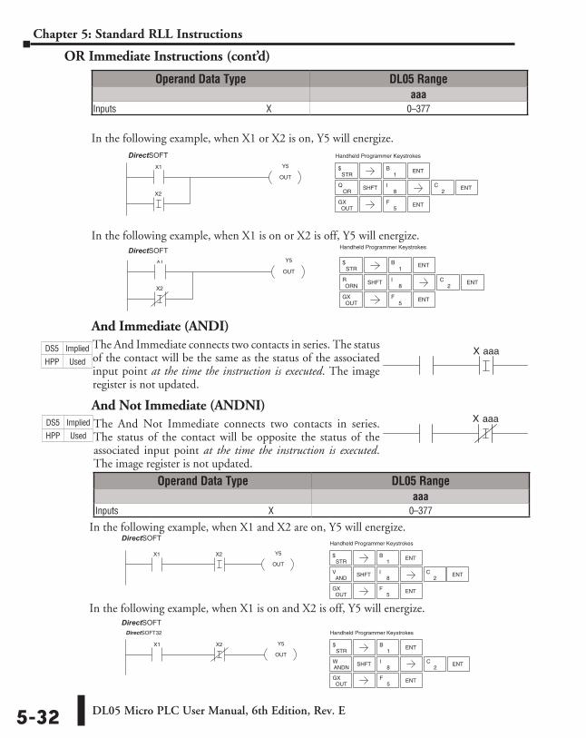
DL05 Micro PLC User Manual, 6th Edition, Rev. E5-32
Chapter 5: Standard RLL Instructions
OR Immediate Instructions (cont’d)
In the following example, when X1 or X2 is on, Y5 will energize.
In the following example, when X1 is on or X2 is off, Y5 will energize.
And Immediate (ANDI)The And Immediate connects two contacts in series. The status of the contact will be the same as the status of the associated input point at the time the instruction is executed. The image register is not updated.
And Not Immediate (ANDNI)The And Not Immediate connects two contacts in series. The status of the contact will be opposite the status of the associated input point at the time the instruction is executed. The image register is not updated.
1B ENT
ENT2
C
ENT5
F
X1
X2
Y5
OUT
Handheld Programmer KeystrokesDirectSOFT32
STR$
ORQ SHFT
8I
OUTGX
ENT5
F
ENT2
C
1B ENT
X1
X2
Y5
OUT
Handheld Programmer KeystrokesDirectSOFT32
STR$
SHFT8
IORN
R
OUTGX
aaaX
aaaX
OUTGX
X1 X2 Y5
OUT
Handheld Programmer KeystrokesDirectSOFT32
STR$
1B ENT
ANDV SHFT
8I ENT
2C
ENT5
F
X1 X2 Y5
OUT
Handheld Programmer KeystrokesDirectSOFT32
STR$
ANDNW SHFT
8I
OUTGX
1B ENT
ENT2
C
ENT5
F
Operand Data Type DL05 Rangeaaa
Inputs ⸠⸠⸠⸠⸠⸠⸠⸠⸠⸠⸠⸠⸠⸠⸠⸠⸠⸠⸠⸠⸠⸠⸠⸠⸠⸠⸠⸠⸠⸠⸠⸠⸠⸠⸠⸠⸠⸠⸠⸠⸠⸠⸠⸠⸠⸠⸠⸠⸠⸠⸠⸠⸠⸠⸠⸠⸠⸠⸠⸠⸠⸠⸠⸠⸠X 0–377
Operand Data Type DL05 Rangeaaa
Inputs ⸠⸠⸠⸠⸠⸠⸠⸠⸠⸠⸠⸠⸠⸠⸠⸠⸠⸠⸠⸠⸠⸠⸠⸠⸠⸠⸠⸠⸠⸠⸠⸠⸠⸠⸠⸠⸠⸠⸠⸠⸠⸠⸠⸠⸠⸠⸠⸠⸠⸠⸠⸠⸠⸠⸠⸠⸠⸠⸠⸠⸠⸠⸠⸠⸠X 0–377
In the following example, when X1 is on and X2 is off, Y5 will energize.
In the following example, when X1 and X2 are on, Y5 will energize.
DS5 Implied
HPP Used
DS5 Implied
HPP Used
DirectSOFT
DirectSOFT
DirectSOFT
DirectSOFT
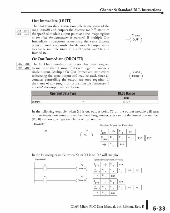
DL05 Micro PLC User Manual, 6th Edition, Rev. E 5-33
Chapter 5: Standard RLL Instructions
Out Immediate (OUTI)The Out Immediate instruction reflects the status of the rung (on/off) and outputs the discrete (on/off) status to the specified module output point and the image register at the time the instruction is executed. If multiple Out Immediate instructions referencing the same discrete point are used it is possible for the module output status to change multiple times in a CPU scan. See Or Out Immediate.
Or Out Immediate (OROUTI)The Or Out Immediate instruction has been designed to use more than 1 rung of discrete logic to control a single output. Multiple Or Out Immediate instructions referencing the same output coil may be used, since all contacts controlling the output are ored together. If the status of any rung is on at the time the instruction is executed, the output will also be on.
In the following example, when X1 is on, output point Y2 on the output module will turn on. For instruction entry on the Handheld Programmer, you can use the instruction number (#350) as shown, or type each letter of the command.
In the following example, when X1 or X4 is on, Y2 will energize.
Y aaa
OUTI
OROUTI
Y aaa
1B ENTX1 Y2
OUTI
DirectSOFT32 Handheld Programmer Keystrokes
STR$
INST#O
5F
3D
0A ENT ENT
2C ENT
STR$
X1
X4
Y2
OR OUTI
Y2
OR OUTI
DirectSOFT32 Handheld Programmer Keystrokes
STR$
1B ENT
ENT4
E
INST#O
5F
3D
0A ENT ENT
2C ENT
INST#O
5F
3D
0A ENT ENT
2C ENT
Operand Data Type DL05 Rangeaaa
Outputs ⸠⸠⸠⸠⸠⸠⸠⸠⸠⸠⸠⸠⸠⸠⸠⸠⸠⸠⸠⸠⸠⸠⸠⸠⸠⸠⸠⸠⸠⸠⸠⸠⸠⸠⸠⸠⸠⸠⸠⸠⸠⸠⸠⸠⸠⸠⸠⸠⸠⸠⸠⸠⸠⸠⸠⸠⸠⸠⸠⸠⸠⸠⸠Y 0–377
DS5 Used
HPP Used
DS5 Used
HPP Used
DirectSOFT
DirectSOFT
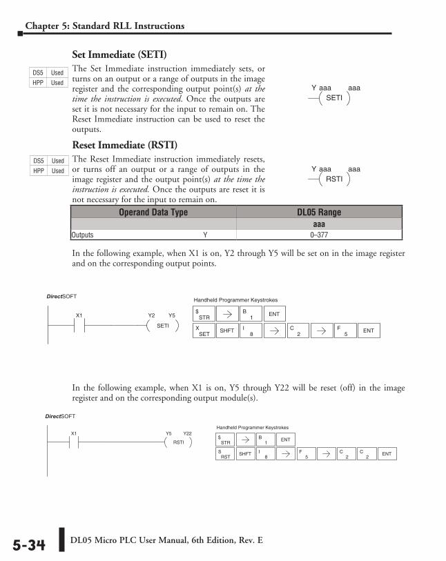
DL05 Micro PLC User Manual, 6th Edition, Rev. E5-34
Chapter 5: Standard RLL Instructions
Set Immediate (SETI)The Set Immediate instruction immediately sets, or turns on an output or a range of outputs in the image register and the corresponding output point(s) at the time the instruction is executed. Once the outputs are set it is not necessary for the input to remain on. The Reset Immediate instruction can be used to reset the outputs.
Reset Immediate (RSTI)The Reset Immediate instruction immediately resets, or turns off an output or a range of outputs in the image register and the output point(s) at the time the instruction is executed. Once the outputs are reset it is not necessary for the input to remain on.
In the following example, when X1 is on, Y2 through Y5 will be set on in the image register and on the corresponding output points.
In the following example, when X1 is on, Y5 through Y22 will be reset (off) in the image register and on the corresponding output module(s).
aaaY aaaSETI
aaaY aaaRSTI
1B ENTX1 Y2
SETI
Y5
DirectSOFT32 Handheld Programmer Keystrokes
STR$
SETX SHFT
8I ENT
2C
5F
1B ENT
X1 Y5
RSTI
Y22
DirectSOFT32
Handheld Programmer Keystrokes
STR$
SHFT8
I5
F2
C2
C ENTRST
S
Operand Data Type DL05 Rangeaaa
Outputs ⸠⸠⸠⸠⸠⸠⸠⸠⸠⸠⸠⸠⸠⸠⸠⸠⸠⸠⸠⸠⸠⸠⸠⸠⸠⸠⸠⸠⸠⸠⸠⸠⸠⸠⸠⸠⸠⸠⸠⸠⸠⸠⸠⸠⸠⸠⸠⸠⸠⸠⸠⸠⸠⸠⸠⸠⸠⸠⸠⸠⸠⸠⸠Y 0–377
DS5 Used
HPP Used
DS5 Used
HPP Used
DirectSOFT
DirectSOFT
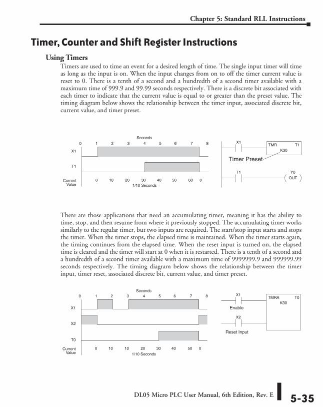
DL05 Micro PLC User Manual, 6th Edition, Rev. E 5-35
Chapter 5: Standard RLL Instructions
Timer, Counter and Shift Register InstructionsUsing Timers
Timers are used to time an event for a desired length of time. The single input timer will time as long as the input is on. When the input changes from on to off the timer current value is reset to 0. There is a tenth of a second and a hundredth of a second timer available with a maximum time of 999.9 and 99.99 seconds respectively. There is a discrete bit associated with each timer to indicate that the current value is equal to or greater than the preset value. The timing diagram below shows the relationship between the timer input, associated discrete bit, current value, and timer preset.
There are those applications that need an accumulating timer, meaning it has the ability to time, stop, and then resume from where it previously stopped. The accumulating timer works similarly to the regular timer, but two inputs are required. The start/stop input starts and stops the timer. When the timer stops, the elapsed time is maintained. When the timer starts again, the timing continues from the elapsed time. When the reset input is turned on, the elapsed time is cleared and the timer will start at 0 when it is restarted. There is a tenth of a second and a hundredth of a second timer available with a maximum time of 9999999.9 and 999999.99 seconds respectively. The timing diagram below shows the relationship between the timer input, timer reset, associated discrete bit, current value, and timer preset.
X1
X1
T0
1 2 3 4 5 6 7 80
0 10 10 20 30 40 50 0CurrentValue
TMRA T0K30
X2
X2
Reset Input
Enable
Seconds
1/10 Seconds
TMR T1K30
X1
X1
T1
1 2 3 4 5 6 7 80
0 10 20 30 40 50 60 0CurrentValue
T1 Y0OUT
Seconds
1/10 Seconds
Timer Preset
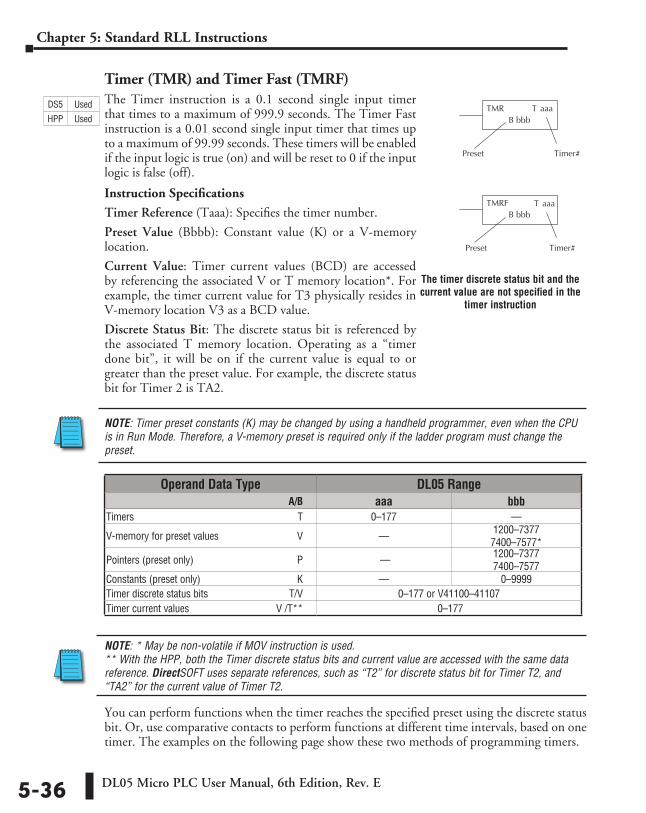
DL05 Micro PLC User Manual, 6th Edition, Rev. E5-36
Chapter 5: Standard RLL Instructions
Timer (TMR) and Timer Fast (TMRF)The Timer instruction is a 0.1 second single input timer that times to a maximum of 999.9 seconds. The Timer Fast instruction is a 0.01 second single input timer that times up to a maximum of 99.99 seconds. These timers will be enabled if the input logic is true (on) and will be reset to 0 if the input logic is false (off).
Instruction Specifications
Timer Reference (Taaa): Specifies the timer number.
Preset Value (Bbbb): Constant value (K) or a V-memory location.
Current Value: Timer current values (BCD) are accessed by referencing the associated V or T memory location*. For example, the timer current value for T3 physically resides in V-memory location V3 as a BCD value.
Discrete Status Bit: The discrete status bit is referenced by the associated T memory location. Operating as a “timer done bit”, it will be on if the current value is equal to or greater than the preset value. For example, the discrete status bit for Timer 2 is TA2.
NOTE: Timer preset constants (K) may be changed by using a handheld programmer, even when the CPU is in Run Mode. Therefore, a V-memory preset is required only if the ladder program must change the preset.
NOTE: * May be non-volatile if MOV instruction is used. ** With the HPP, both the Timer discrete status bits and current value are accessed with the same data reference. DirectSOFT uses separate references, such as “T2” for discrete status bit for Timer T2, and “TA2” for the current value of Timer T2.
You can perform functions when the timer reaches the specified preset using the discrete status bit. Or, use comparative contacts to perform functions at different time intervals, based on one timer. The examples on the following page show these two methods of programming timers.
T aaa
aaaTTMRB bbb
Preset Timer #
TMRFB bbb
Preset Timer #
Operand Data Type DL05 Range ⸠⸠⸠⸠⸠⸠⸠⸠⸠⸠⸠⸠⸠⸠⸠⸠⸠⸠⸠⸠⸠⸠⸠⸠⸠⸠⸠⸠⸠⸠⸠⸠⸠⸠⸠⸠⸠⸠⸠⸠⸠⸠⸠⸠⸠⸠⸠⸠⸠⸠⸠⸠⸠⸠⸠⸠⸠⸠⸠⸠⸠⸠⸠⸠⸠⸠⸠⸠⸠ A/B aaa bbbTimers ⸠⸠⸠⸠⸠⸠⸠⸠⸠⸠⸠⸠⸠⸠⸠⸠⸠⸠⸠⸠⸠⸠⸠⸠⸠⸠⸠⸠⸠⸠⸠⸠⸠⸠⸠⸠⸠⸠⸠⸠⸠⸠⸠⸠⸠⸠⸠⸠⸠⸠⸠⸠⸠⸠⸠⸠⸠⸠⸠⸠⸠⸠⸠⸠ T 0–177 ––
V-memory for preset values ⸠⸠⸠⸠⸠⸠⸠⸠⸠⸠⸠⸠⸠⸠⸠⸠⸠⸠⸠⸠⸠⸠⸠⸠⸠⸠⸠⸠⸠⸠V –– 1200–7377 7400–7577*
Pointers (preset only) ⸠⸠⸠⸠⸠⸠⸠⸠⸠⸠⸠⸠⸠⸠⸠⸠⸠⸠⸠⸠⸠⸠⸠⸠⸠⸠⸠⸠⸠⸠⸠⸠⸠⸠⸠⸠⸠⸠⸠⸠P –– 1200–7377 7400–7577
Constants (preset only) ⸠⸠⸠⸠⸠⸠⸠⸠⸠⸠⸠⸠⸠⸠⸠⸠⸠⸠⸠⸠⸠⸠⸠⸠⸠⸠⸠⸠⸠⸠⸠⸠⸠⸠⸠⸠⸠K –– 0–9999Timer discrete status bits ⸠⸠⸠⸠⸠⸠⸠⸠⸠⸠⸠⸠⸠⸠⸠⸠⸠⸠⸠⸠⸠⸠⸠⸠⸠⸠⸠⸠⸠⸠⸠T/V 0–177 or V41100–41107Timer current values ⸠⸠⸠⸠⸠⸠⸠⸠⸠⸠⸠⸠⸠⸠⸠⸠⸠⸠⸠⸠⸠⸠⸠⸠⸠⸠⸠⸠⸠⸠⸠⸠⸠ V /T** 0–177
The timer discrete status bit and the current value are not specified in the
timer instruction
DS5 Used
HPP Used
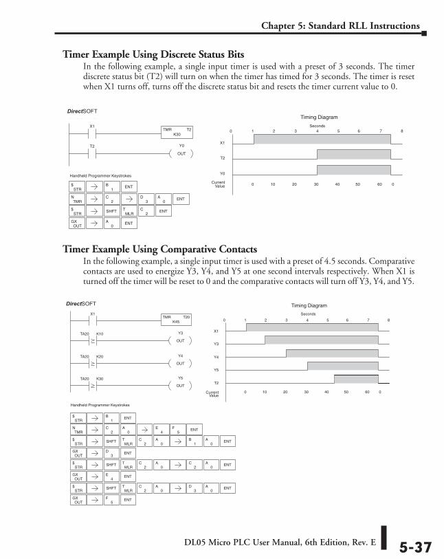
DL05 Micro PLC User Manual, 6th Edition, Rev. E 5-37
Chapter 5: Standard RLL Instructions
Timer Example Using Discrete Status BitsIn the following example, a single input timer is used with a preset of 3 seconds. The timer discrete status bit (T2) will turn on when the timer has timed for 3 seconds. The timer is reset when X1 turns off, turns off the discrete status bit and resets the timer current value to 0.
Timer Example Using Comparative ContactsIn the following example, a single input timer is used with a preset of 4.5 seconds. Comparative contacts are used to energize Y3, Y4, and Y5 at one second intervals respectively. When X1 is turned off the timer will be reset to 0 and the comparative contacts will turn off Y3, Y4, and Y5.
STR$
TMRN
2C
STR$ SHFT
MLRT
2C ENT
OUTGX
Handheld Programmer Keystrokes
X1TMR T2
K30
T2 Y0
OUT
X1
T2
1 2 3 4 5 6 7 80
0 10 20 30 40 50 60 0CurrentValue
Y0
Timing DiagramDirect SOFT32
Seconds
1B ENT
3D
0A ENT
ENT0
A
1B ENT
Handheld Programmer Keystrokes
X1TMR T20
K45
TA20 K10
TA20 K20
TA20 K30
Y4
OUT
Y3
OUT
Y5
OUT
X1
Y3
1 2 3 4 5 6 7 80
0 10 20 30 40 50 60 0CurrentValue
Y4
Timing Diagram
Y5
T2
Direct SOFT32
Seconds
STR$
TMRN
2C ENT
0A
4E
5F
STR$ SHFT
MLRT
2C
0A
1B ENT
OUTGX ENT
3D
STR$ SHFT
MLRT
2C
0A ENT
OUTGX ENT
2C
4E
STR$ SHFT
MLRT
2C
0A ENT
OUTGX ENT
3D
5F
0A
0A
0A
DirectSOFT
DirectSOFT
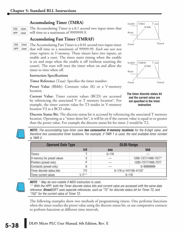
DL05 Micro PLC User Manual, 6th Edition, Rev. E5-38
Chapter 5: Standard RLL Instructions
Accumulating Timer (TMRA)The Accumulating Timer is a 0.1 second two input timer that will time to a maximum of 9999999.9.
Accumulating Fast Timer (TMRAF)The Accumulating Fast Timer is a 0.01 second two-input timer that will time to a maximum of 99999.99. Each one uses two timer registers in V-memory. These timers have two inputs, an enable and a reset. The timer starts timing when the enable is on and stops when the enable is off (without resetting the count). The reset will reset the timer when on and allow the timer to time when off.
Instruction Specifications
Timer Reference (Taaa): Specifies the timer number.
Preset Value (Bbbb): Constant value (K) or a V-memory location.
Current Value: Timer current values (BCD) are accessed by referencing the associated V or T memory location*. For example, the timer current value for T3 resides in V-memory location V3 as a BCD value.
Discrete Status Bit: The discrete status bit is accessed by referencing the associated T memory location. Operating as a “timer done bit”, it will be on if the current value is equal to or greater than the preset value. For example the discrete status bit for timer 2 would be T2.
NOTE: The accumulating type timer uses two consecutive V-memory locations for the 8-digit value, and therefore two consecutive timer locations. For example, if TMR 1 is used, the next available timer number is TMR 3.
NOTE: * May be non-volatile if MOV instruction is used. ** With the HPP, both the Timer discrete status bits and current value are accessed with the same data reference. DirectSOFT uses separate references, such as “T2” for discrete status bit for Timer T2, and “TA2” for the current value of Timer T2.
The following examples show two methods of programming timers. One performs functions when the timer reaches the preset value using the discrete status bit, or use comparative contacts to perform functions at different time intervals.
T aaa
T aaaTMRAB bbb
Enable
Reset
Preset Timer #
TMRAFB bbb
Enable
Reset
Preset Timer #
Operand Data Type DL05 Range ⸠⸠⸠⸠⸠⸠⸠⸠⸠⸠⸠⸠⸠⸠⸠⸠⸠⸠⸠⸠⸠⸠⸠⸠⸠⸠⸠⸠⸠⸠⸠⸠⸠⸠⸠⸠⸠⸠⸠⸠⸠⸠⸠⸠⸠⸠⸠⸠⸠⸠⸠⸠⸠⸠⸠⸠⸠⸠⸠⸠⸠⸠⸠⸠⸠⸠⸠⸠⸠ A/B aaa bbbTimers ⸠⸠⸠⸠⸠⸠⸠⸠⸠⸠⸠⸠⸠⸠⸠⸠⸠⸠⸠⸠⸠⸠⸠⸠⸠⸠⸠⸠⸠⸠⸠⸠⸠⸠⸠⸠⸠⸠⸠⸠⸠⸠⸠⸠⸠⸠⸠⸠⸠⸠⸠⸠⸠⸠⸠⸠⸠⸠⸠⸠⸠⸠⸠⸠ T 0–176 ––V-memory for preset values ⸠⸠⸠⸠⸠⸠⸠⸠⸠⸠⸠⸠⸠⸠⸠⸠⸠⸠⸠⸠⸠⸠⸠⸠⸠⸠⸠⸠⸠⸠V –– 1200–7377/7400–7577*Pointers (preset only) ⸠⸠⸠⸠⸠⸠⸠⸠⸠⸠⸠⸠⸠⸠⸠⸠⸠⸠⸠⸠⸠⸠⸠⸠⸠⸠⸠⸠⸠⸠⸠⸠⸠⸠⸠⸠⸠⸠⸠⸠P –– 1200–7377/7400–7577Constants (preset only) ⸠⸠⸠⸠⸠⸠⸠⸠⸠⸠⸠⸠⸠⸠⸠⸠⸠⸠⸠⸠⸠⸠⸠⸠⸠⸠⸠⸠⸠⸠⸠⸠⸠⸠⸠⸠⸠K –– 0–99999999Timer discrete status bits ⸠⸠⸠⸠⸠⸠⸠⸠⸠⸠⸠⸠⸠⸠⸠⸠⸠⸠⸠⸠⸠⸠⸠⸠⸠⸠⸠⸠⸠⸠⸠T/V 0–176 or V41100–41107Timer current values ⸠⸠⸠⸠⸠⸠⸠⸠⸠⸠⸠⸠⸠⸠⸠⸠⸠⸠⸠⸠⸠⸠⸠⸠⸠⸠⸠⸠⸠⸠⸠⸠⸠ V /T** 0–176
The timer discrete status bit and the current value are not specified in the timer
instruction
DS5 Used
HPP Used
DS5 Used
HPP Used
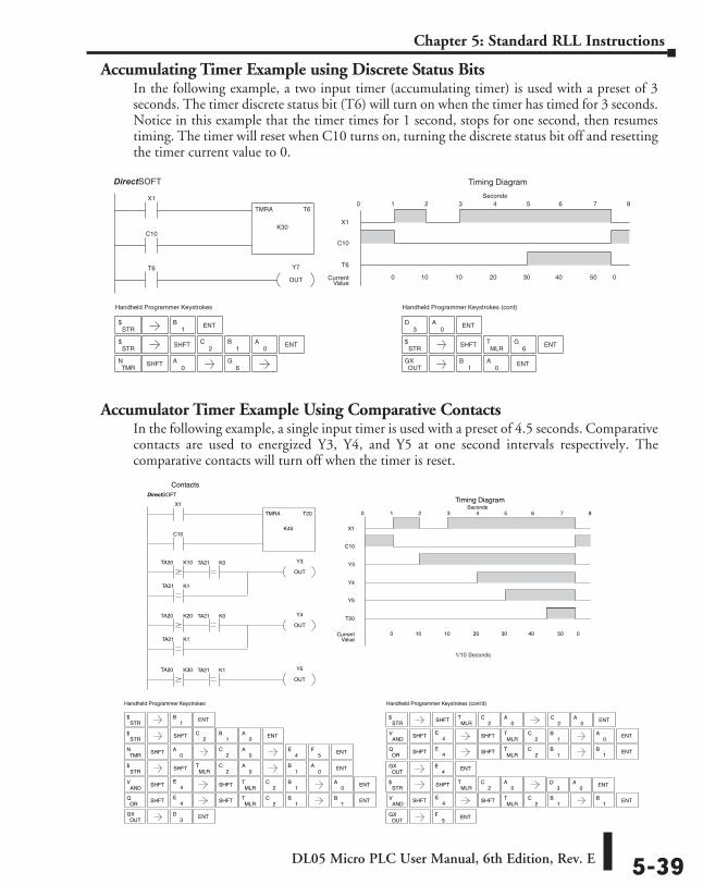
DL05 Micro PLC User Manual, 6th Edition, Rev. E 5-39
Chapter 5: Standard RLL Instructions
Accumulating Timer Example using Discrete Status BitsIn the following example, a two input timer (accumulating timer) is used with a preset of 3 seconds. The timer discrete status bit (T6) will turn on when the timer has timed for 3 seconds. Notice in this example that the timer times for 1 second, stops for one second, then resumes timing. The timer will reset when C10 turns on, turning the discrete status bit off and resetting the timer current value to 0.
Accumulator Timer Example Using Comparative ContactsIn the following example, a single input timer is used with a preset of 4.5 seconds. Comparative contacts are used to energized Y3, Y4, and Y5 at one second intervals respectively. The comparative contacts will turn off when the timer is reset.
Handheld Programmer Keystrokes
X1
T6
TMRA T6
K30C10
Y7
OUT
X1
C10
1 2 3 4 5 6 7 80
0 10 10 20 30 40 50 0CurrentValue
T6
Timing DiagramDirect SOFT32
Seconds
Handheld Programmer Keystrokes (cont)
STR$
STR$ SHFT ENT
2C
1B
0A
TMRN SHFT
0A
3D
0A ENT
STR$ SHFT
MLRT ENT
OUTGX ENT
0A
6G
1B
1B ENT
6G
Handheld Programmer Keystrokes
TA20 K10
TA21 K1
TA20 K20
Y3
OUT
Y4
OUT
X1
TMRA T20
K45C10
X1
C10
1 2 3 4 5 6 7 80
0 10 10 20 30 40 50 0CurrentValue
Timing Diagram
Y3
Y4
Y5
T20
DirectSOFT
Handheld Programmer Keystrokes (cont’d)
Seconds
ANDV SHFT4
EMLR
T
OUTGX ENT
1B
4E
STR$ SHFT
MLRT
2C
0A
OUTGX ENT
5F
STR$
1B ENT
ENT4
E5
F
STR$ SHFT
MLRT
2C
0A
1B ENT
OUTGX ENT
3D
STR$ SHFT ENT
2C
1B
0A
2C
0A
TMRN SHFT
0A
0A
0A
Contacts
TA21 K1
TA20 K30 Y5
OUT
TA21 K0
TA21 K0
TA21 K1
ORQ SHFT4
EMLR
T1
B1
B
ENT
ENT
SHFT
SHFT
2C
2C
STR$ SHFT
MLRT
2C
0A
ANDV SHFT4
EMLR
T1
B0
A
ORQ SHFT4
EMLR
T1
B1
B
ENT
ENT
SHFT
SHFT
2C
2C
ENT2
C0
A
ENT3
D0
A
ANDV SHFT4
EMLR
T1
B1
B ENTSHFT2
C
DirectSOFT
1/10 Seconds
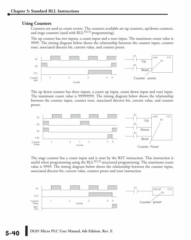
DL05 Micro PLC User Manual, 6th Edition, Rev. E5-40
Chapter 5: Standard RLL Instructions
Using CountersCounters are used to count events. The counters available are up counters, up/down counters, and stage counters (used with RLLPLUS programming).
The up counter has two inputs, a count input and a reset input. The maximum count value is 9999. The timing diagram below shows the relationship between the counter input, counter reset, associated discrete bit, current value, and counter preset.
The up down counter has three inputs, a count up input, count down input and reset input. The maximum count value is 99999999. The timing diagram below shows the relationship between the counter input, counter reset, associated discrete bit, current value, and counter preset.
The stage counter has a count input and is reset by the RST instruction. This instruction is useful when programming using the RLLPLUS structured programming. The maximum count value is 9999. The timing diagram below shows the relationship between the counter input, associated discrete bit, current value, counter preset and reset instruction.
X1X1
CT1
1 2 3 4 0Currentalue
CNT CT1K3
X2X2
Counter preset
Up
Reset
Counts
X1X1
CT2
1 2 3 4 0CurrentValue
SGCNT CT2K3
RSTCT2
Counts Counter preset
X1X1
CT2
1 2 1 2 3 0CurrentValue
X2X2
UDC CT2K3
X3X3
Counter Preset
Up
Down
Reset
Counts
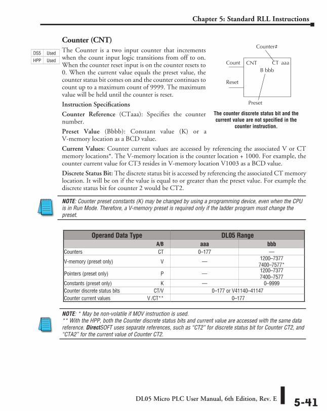
DL05 Micro PLC User Manual, 6th Edition, Rev. E 5-41
Chapter 5: Standard RLL Instructions
Counter (CNT)The Counter is a two input counter that increments when the count input logic transitions from off to on. When the counter reset input is on the counter resets to 0. When the current value equals the preset value, the counter status bit comes on and the counter continues to count up to a maximum count of 9999. The maximum value will be held until the counter is reset.
Instruction Specifications
Counter Reference (CTaaa): Specifies the counter number.
Preset Value (Bbbb): Constant value (K) or a V-memory location as a BCD value.
Current Values: Counter current values are accessed by referencing the associated V or CT memory locations*. The V-memory location is the counter location + 1000. For example, the counter current value for CT3 resides in V-memory location V1003 as a BCD value.
Discrete Status Bit: The discrete status bit is accessed by referencing the associated CT memory location. It will be on if the value is equal to or greater than the preset value. For example the discrete status bit for counter 2 would be CT2.
NOTE: Counter preset constants (K) may be changed by using a programming device, even when the CPU is in Run Mode. Therefore, a V-memory preset is required only if the ladder program must change the preset.
NOTE: * May be non-volatile if MOV instruction is used. ** With the HPP, both the Counter discrete status bits and current value are accessed with the same data reference. DirectSOFT uses separate references, such as “CT2” for discrete status bit for Counter CT2, and “CTA2” for the current value of Counter CT2.
CT aaaCNTB bbb
Count
Reset
Counter #
Preset
Operand Data Type DL05 Range ⸠⸠⸠⸠⸠⸠⸠⸠⸠⸠⸠⸠⸠⸠⸠⸠⸠⸠⸠⸠⸠⸠⸠⸠⸠⸠⸠⸠⸠⸠⸠⸠⸠⸠⸠⸠⸠⸠⸠⸠⸠⸠⸠⸠⸠⸠⸠⸠⸠⸠⸠⸠⸠⸠⸠⸠⸠⸠⸠⸠⸠⸠⸠⸠⸠⸠⸠⸠⸠ A/B aaa bbbCounters ⸠⸠⸠⸠⸠⸠⸠⸠⸠⸠⸠⸠⸠⸠⸠⸠⸠⸠⸠⸠⸠⸠⸠⸠⸠⸠⸠⸠⸠⸠⸠⸠⸠⸠⸠⸠⸠⸠⸠⸠⸠⸠⸠⸠⸠⸠⸠⸠⸠⸠⸠⸠⸠⸠⸠⸠⸠⸠⸠CT 0–177 ––
V-memory (preset only) ⸠⸠⸠⸠⸠⸠⸠⸠⸠⸠⸠⸠⸠⸠⸠⸠⸠⸠⸠⸠⸠⸠⸠⸠⸠⸠⸠⸠⸠⸠⸠⸠⸠⸠⸠⸠V –– 1200–7377 7400–7577*
Pointers (preset only) ⸠⸠⸠⸠⸠⸠⸠⸠⸠⸠⸠⸠⸠⸠⸠⸠⸠⸠⸠⸠⸠⸠⸠⸠⸠⸠⸠⸠⸠⸠⸠⸠⸠⸠⸠⸠⸠⸠⸠⸠P –– 1200–7377 7400–7577
Constants (preset only) ⸠⸠⸠⸠⸠⸠⸠⸠⸠⸠⸠⸠⸠⸠⸠⸠⸠⸠⸠⸠⸠⸠⸠⸠⸠⸠⸠⸠⸠⸠⸠⸠⸠⸠⸠⸠⸠K –– 0–9999Counter discrete status bits ⸠⸠⸠⸠⸠⸠⸠⸠⸠⸠⸠⸠⸠⸠⸠⸠⸠⸠⸠⸠⸠⸠⸠⸠⸠ CT/V 0–177 or V41140–41147Counter current values ⸠⸠⸠⸠⸠⸠⸠⸠⸠⸠⸠⸠⸠⸠⸠⸠⸠⸠⸠⸠⸠⸠⸠⸠⸠⸠⸠V /CT** 0–177
The counter discrete status bit and the current value are not specified in the
counter instruction.
DS5 Used
HPP Used
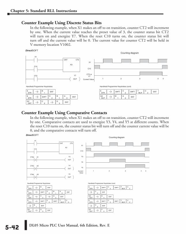
DL05 Micro PLC User Manual, 6th Edition, Rev. E5-42
Chapter 5: Standard RLL Instructions
Counter Example Using Discrete Status BitsIn the following example, when X1 makes an off to on transition, counter CT2 will increment by one. When the current value reaches the preset value of 3, the counter status bit CT2 will turn on and energize Y7. When the reset C10 turns on, the counter status bit will turn off and the current value will be 0. The current value for counter CT2 will be held in V-memory location V1002.
Counter Example Using Comparative ContactsIn the following example, when X1 makes an off to on transition, counter CT2 will increment by one. Comparative contacts are used to energize Y3, Y4, and Y5 at different counts. When the reset C10 turns on, the counter status bit will turn off and the counter current value will be 0, and the comparative contacts will turn off.
2C
Handheld Programmer Keystrokes
CT2
X1
CNT CT2
K3C10
Y7
OUT
X1
CT2 or Y7
1 2 3 4 0Current Value
C10
Counting diagramDirectSOFT32
STR$
1B ENT
3D ENT
STR$ SHFT ENT
2C
1B
0A
CNTGY
STR$ SHFT ENT
OUTGX ENT
0A
1B
2C
MLRT
2C
Handheld Programmer Keystrokes (cont)
SHFT
Handheld Programmer Keystrokes
X1
CNT CT2
K3C10
X1
Y3
1 2 3 4 0CurrentValue
C10
Counting diagram
CTA2 K1
CTA2 K2
CTA2 K3
Y4
OUT
Y3
OUT
Y5
OUT
Y4
Y5
DirectSOFT32
Handheld Programmer Keystrokes (cont)
STR$ SHFT
ENT
OUTGX ENT
2C
4E
STR$ SHFT
2C
ENT
OUTGX ENT
3D
5F
STR$
1B ENT
2C
STR$ SHFT
1B ENT
OUTGX ENT
3D
STR$ SHFT ENT
2C
1B
0A
CNTGY ENT
3D
MLRT
2C
2C
MLRT
2C
2C
MLRT
2CSHFT
SHFT
SHFT
DirectSOFT
DirectSOFT
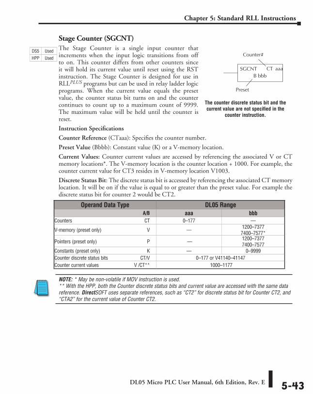
DL05 Micro PLC User Manual, 6th Edition, Rev. E 5-43
Chapter 5: Standard RLL Instructions
Stage Counter (SGCNT)The Stage Counter is a single input counter that increments when the input logic transitions from off to on. This counter differs from other counters since it will hold its current value until reset using the RST instruction. The Stage Counter is designed for use in RLLPLUS programs but can be used in relay ladder logic programs. When the current value equals the preset value, the counter status bit turns on and the counter continues to count up to a maximum count of 9999. The maximum value will be held until the counter is reset.
Instruction Specifications
Counter Reference (CTaaa): Specifies the counter number.
Preset Value (Bbbb): Constant value (K) or a V-memory location.
Current Values: Counter current values are accessed by referencing the associated V or CT memory locations*. The V-memory location is the counter location + 1000. For example, the counter current value for CT3 resides in V-memory location V1003.
Discrete Status Bit: The discrete status bit is accessed by referencing the associated CT memory location. It will be on if the value is equal to or greater than the preset value. For example the discrete status bit for counter 2 would be CT2.
NOTE: * May be non-volatile if MOV instruction is used. ** With the HPP, both the Counter discrete status bits and current value are accessed with the same data reference. DirectSOFT uses separate references, such as “CT2” for discrete status bit for Counter CT2, and “CTA2” for the current value of Counter CT2.
CT aaaSGCNTB bbb
Preset
Counter #
Operand Data Type DL05 Range ⸠⸠⸠⸠⸠⸠⸠⸠⸠⸠⸠⸠⸠⸠⸠⸠⸠⸠⸠⸠⸠⸠⸠⸠⸠⸠⸠⸠⸠⸠⸠⸠⸠⸠⸠⸠⸠⸠⸠⸠⸠⸠⸠⸠⸠⸠⸠⸠⸠⸠⸠⸠⸠⸠⸠⸠⸠⸠⸠⸠⸠⸠⸠⸠⸠⸠⸠⸠⸠ A/B aaa bbbCounters ⸠⸠⸠⸠⸠⸠⸠⸠⸠⸠⸠⸠⸠⸠⸠⸠⸠⸠⸠⸠⸠⸠⸠⸠⸠⸠⸠⸠⸠⸠⸠⸠⸠⸠⸠⸠⸠⸠⸠⸠⸠⸠⸠⸠⸠⸠⸠⸠⸠⸠⸠⸠⸠⸠⸠⸠⸠⸠⸠CT 0–177 ––
V-memory (preset only) ⸠⸠⸠⸠⸠⸠⸠⸠⸠⸠⸠⸠⸠⸠⸠⸠⸠⸠⸠⸠⸠⸠⸠⸠⸠⸠⸠⸠⸠⸠⸠⸠⸠⸠⸠⸠V –– 1200–7377 7400–7577*
Pointers (preset only) ⸠⸠⸠⸠⸠⸠⸠⸠⸠⸠⸠⸠⸠⸠⸠⸠⸠⸠⸠⸠⸠⸠⸠⸠⸠⸠⸠⸠⸠⸠⸠⸠⸠⸠⸠⸠⸠⸠⸠⸠P –– 1200–7377 7400–7577
Constants (preset only) ⸠⸠⸠⸠⸠⸠⸠⸠⸠⸠⸠⸠⸠⸠⸠⸠⸠⸠⸠⸠⸠⸠⸠⸠⸠⸠⸠⸠⸠⸠⸠⸠⸠⸠⸠⸠⸠K –– 0–9999Counter discrete status bits ⸠⸠⸠⸠⸠⸠⸠⸠⸠⸠⸠⸠⸠⸠⸠⸠⸠⸠⸠⸠⸠⸠⸠⸠⸠ CT/V 0–177 or V41140–41147Counter current values ⸠⸠⸠⸠⸠⸠⸠⸠⸠⸠⸠⸠⸠⸠⸠⸠⸠⸠⸠⸠⸠⸠⸠⸠⸠⸠⸠V /CT** 1000–1177
The counter discrete status bit and the current value are not specified in the
counter instruction.
DS5 Used
HPP Used
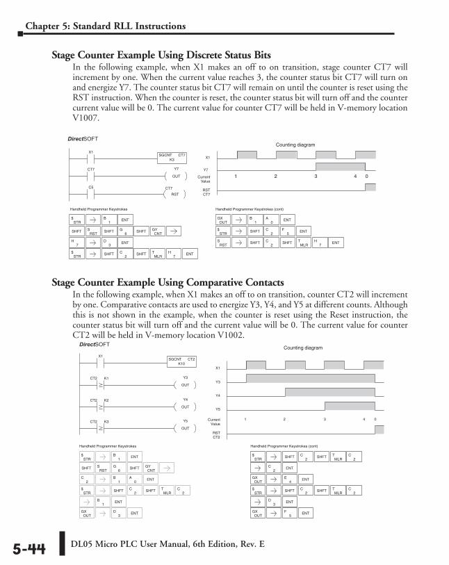
DL05 Micro PLC User Manual, 6th Edition, Rev. E5-44
Chapter 5: Standard RLL Instructions
Stage Counter Example Using Discrete Status BitsIn the following example, when X1 makes an off to on transition, stage counter CT7 will increment by one. When the current value reaches 3, the counter status bit CT7 will turn on and energize Y7. The counter status bit CT7 will remain on until the counter is reset using the RST instruction. When the counter is reset, the counter status bit will turn off and the counter current value will be 0. The current value for counter CT7 will be held in V-memory location V1007.
Stage Counter Example Using Comparative ContactsIn the following example, when X1 makes an off to on transition, counter CT2 will increment by one. Comparative contacts are used to energize Y3, Y4, and Y5 at different counts. Although this is not shown in the example, when the counter is reset using the Reset instruction, the counter status bit will turn off and the current value will be 0. The current value for counter CT2 will be held in V-memory location V1002.
3D
7H
Handheld Programmer Keystrokes
X1
C5 CT7
SGCNT CT7K3
RST
X1
Y7
1 2 3 4 0CurrentValue
RSTCT7
CT7 Y7
OUT
Counting diagramDirectSOFT32
STR$
1B ENT
CNTGY
STR$ SHFT ENT
OUTGX ENT
0A
1B
2C
MLRT
7H
STR$ SHFT ENT
2C
5F
RSTS SHFT
2C
7H ENT
SHFTRST
S6
G SHFT
ENT
Handheld Programmer Keystrokes (cont)
SHFT
SHFT
SHFTMLR
T
Handheld Programmer Keystrokes
X1
X1
Y3
1 2 3 4 0Current Value
Counting diagram
CT2 K1
CT2 K2
CT2 K3
Y4
OUT
Y3
OUT
Y5
OUT
Y4
Y5
SGCNT CT2K10
DirectSOFT32
Handheld Programmer Keystrokes (cont)
STR$
1B ENT
CNTGYSHFT
RSTS
6G SHFT
ENT2
C1
B0
A
STR$ SHFT
1B ENT
OUTGX ENT
3D
MLRT
2C
2C
STR$ SHFT
ENT
OUTGX ENT
2C
4E
STR$ SHFT
2C
ENT
OUTGX ENT
3D
5F
MLRT
2C
2C
MLRT
2CSHFT
SHFT
SHFT
RST CT2
DirectSOFT
DirectSOFT
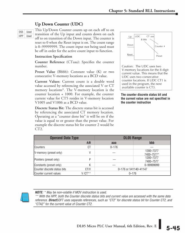
DL05 Micro PLC User Manual, 6th Edition, Rev. E 5-45
Chapter 5: Standard RLL Instructions
Up Down Counter (UDC)This Up/Down Counter counts up on each off to on transition of the Up input and counts down on each off to on transition of the Down input. The counter is reset to 0 when the Reset input is on. The count range is 0–99999999. The count input not being used must be off in order for the active count input to function.
Instruction Specification
Counter Reference (CTaaa): Specifies the counter number.
Preset Value (Bbbb): Constant value (K) or two consecutive V-memory locations as a BCD value.
Current Values: Current count is a double word value accessed by referencing the associated V or CT memory locations*. The V-memory location is the counter location + 1000. For example, the counter current value for CT5 resides in V-memory location V1005 and V1006 as a BCD value.
Discrete Status Bit: The discrete status bit is accessed by referencing the associated CT memory location. Operating as a “counter done bit” it will be on if the value is equal to or greater than the preset value. For example the discrete status bit for counter 2 would be CT2.
NOTE: * May be non-volatile if MOV instruction is used. ** With the HPP, both the Counter discrete status bits and current value are accessed with the same data reference. DirectSOFT uses separate references, such as “CT2” for discrete status bit for Counter CT2, and “CTA2” for the current value of Counter CT2.
CT aaaUDCB bbb
Up
Down
Reset
Caution: The UDC uses two V-memory locations for the 8 digitcurrent value. This means that theUDC uses two consecutivecounter locations. If UDC CT1 isused in the program, the nextavailable counter is CT3.
Preset
Counter #
Operand Data Type DL05 Range ⸠⸠⸠⸠⸠⸠⸠⸠⸠⸠⸠⸠⸠⸠⸠⸠⸠⸠⸠⸠⸠⸠⸠⸠⸠⸠⸠⸠⸠⸠⸠⸠⸠⸠⸠⸠⸠⸠⸠⸠⸠⸠⸠⸠⸠⸠⸠⸠⸠⸠⸠⸠⸠⸠⸠⸠⸠⸠⸠⸠⸠⸠⸠⸠⸠⸠⸠⸠⸠ A/B aaa bbbCounters ⸠⸠⸠⸠⸠⸠⸠⸠⸠⸠⸠⸠⸠⸠⸠⸠⸠⸠⸠⸠⸠⸠⸠⸠⸠⸠⸠⸠⸠⸠⸠⸠⸠⸠⸠⸠⸠⸠⸠⸠⸠⸠⸠⸠⸠⸠⸠⸠⸠⸠⸠⸠⸠⸠⸠⸠⸠⸠⸠CT 0–176 ––
V-memory (preset only) ⸠⸠⸠⸠⸠⸠⸠⸠⸠⸠⸠⸠⸠⸠⸠⸠⸠⸠⸠⸠⸠⸠⸠⸠⸠⸠⸠⸠⸠⸠⸠⸠⸠⸠⸠⸠V –– 1200–7377 7400–7577*
Pointers (preset only) ⸠⸠⸠⸠⸠⸠⸠⸠⸠⸠⸠⸠⸠⸠⸠⸠⸠⸠⸠⸠⸠⸠⸠⸠⸠⸠⸠⸠⸠⸠⸠⸠⸠⸠⸠⸠⸠⸠⸠⸠P –– 1200–7377 7400–7577
Constants (preset only) ⸠⸠⸠⸠⸠⸠⸠⸠⸠⸠⸠⸠⸠⸠⸠⸠⸠⸠⸠⸠⸠⸠⸠⸠⸠⸠⸠⸠⸠⸠⸠⸠⸠⸠⸠⸠⸠K –– 0–99999999Counter discrete status bits ⸠⸠⸠⸠⸠⸠⸠⸠⸠⸠⸠⸠⸠⸠⸠⸠⸠⸠⸠⸠⸠⸠⸠⸠⸠ CT/V 0–176 or V41140–41147Counter current values ⸠⸠⸠⸠⸠⸠⸠⸠⸠⸠⸠⸠⸠⸠⸠⸠⸠⸠⸠⸠⸠⸠⸠⸠⸠⸠⸠V /CT** 0–176
The counter discrete status bit and the current value are not specified in the counter instruction
DS5 Used
HPP Used
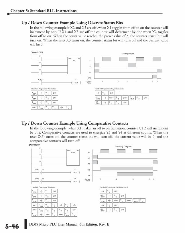
DL05 Micro PLC User Manual, 6th Edition, Rev. E5-46
Chapter 5: Standard RLL Instructions
Up / Down Counter Example Using Discrete Status BitsIn the following example if X2 and X3 are off ,when X1 toggles from off to on the counter will increment by one. If X1 and X3 are off the counter will decrement by one when X2 toggles from off to on. When the count value reaches the preset value of 3, the counter status bit will turn on. When the reset X3 turns on, the counter status bit will turn off and the current value will be 0.
Up / Down Counter Example Using Comparative ContactsIn the following example, when X1 makes an off to on transition, counter CT2 will increment by one. Comparative contacts are used to energize Y3 and Y4 at different counts. When the reset (X3) turns on, the counter status bit will turn off, the current value will be 0, and the comparative contacts will turn off.
3D ENT
Handheld Programmer Keystrokes
X1
UDC CT2K3
X2
X3
CT2 Y7
OUT
X1
CT2
1 2 1 2 3 0CurrentValue
X2
X3
Counting DiagramDirectSOFT32
Handheld Programmer Keystrokes (cont)
STR$
1B ENT
STR$
2C
STR$
3D
SHFTISG
U3
D2
C2
C
ENT
ENTSTR
$ SHFT ENT
OUTGX ENT
0A
1B
2C
MLRT
2CSHFT
ANDV
Handheld Programmer Keystrokes
X1
UDC CT2V2000
X2
X3
X1
X2
X3
Counting Diagram
CTA2 K1
CTA2 K2 Y4
OUT
Y3
OUT
Y3
1 2 3 4 0CurrentValue
Y4
DirectSOFT32
Handheld Programmer Keystrokes (cont)
STR$
1B ENT
STR$
2C
STR$
3D
SHFTISG
U3
D2
C2
C
ENT
ENT
SHFT ENT2
C0
A0
A0
A
STR$ SHFT
1B ENT
OUTGX ENT
3D
MLRT
2C
2C
STR$ SHFT
ENT
OUTGX ENT
MLRT
2C
2C
2C
4E
SHFT
SHFT
DirectSOFT
DirectSOFT
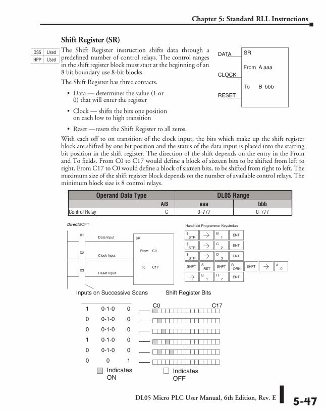
DL05 Micro PLC User Manual, 6th Edition, Rev. E 5-47
Chapter 5: Standard RLL Instructions
Shift Register (SR)The Shift Register instruction shifts data through a predefined number of control relays. The control ranges in the shift register block must start at the beginning of an 8 bit boundary use 8-bit blocks.
The Shift Register has three contacts.
• Data — determines the value (1 or 0) that will enter the register
• Clock — shifts the bits one position on each low to high transition
• Reset —resets the Shift Register to all zeros.
With each off to on transition of the clock input, the bits which make up the shift register block are shifted by one bit position and the status of the data input is placed into the starting bit position in the shift register. The direction of the shift depends on the entry in the From and To fields. From C0 to C17 would define a block of sixteen bits to be shifted from left to right. From C17 to C0 would define a block of sixteen bits, to be shifted from right to left. The maximum size of the shift register block depends on the number of available control relays. The minimum block size is 8 control relays.
SR
aaaFrom A
bbbTo B
DATA
CLOCK
RESET
Data Input
Clock Input
Reset Input
Shift Register Bits
C0 C17
1 0-1-0 0
0 0-1-0 0
0 0-1-0 0
1 0-1-0 0
0 0-1-0 0
0 0 1
Inputs on Successive Scans
X1
X2
SR
C0From
C17X3
To
Handheld Programmer KeystrokesDirect SOFT32
STR$
1B ENT
STR$
2C
STR$
3D
SHFT
ENT
ENT
RSTS
ORNR SHFT
0A
1B
7H ENT
SHFT
Indicates ON
IndicatesOFF
Operand Data Type DL05 Range ⸠⸠⸠⸠⸠⸠⸠⸠⸠⸠⸠⸠⸠⸠⸠⸠⸠⸠⸠⸠⸠⸠⸠⸠⸠⸠⸠⸠⸠⸠⸠⸠⸠⸠⸠⸠⸠⸠⸠⸠⸠⸠⸠⸠⸠⸠⸠⸠⸠⸠⸠⸠⸠⸠⸠⸠⸠⸠⸠⸠⸠⸠⸠⸠⸠⸠⸠⸠⸠ A/B aaa bbbControl Relay ⸠⸠⸠⸠⸠⸠⸠⸠⸠⸠⸠⸠⸠⸠⸠⸠⸠⸠⸠⸠⸠⸠⸠⸠⸠⸠⸠⸠⸠⸠⸠⸠⸠⸠⸠⸠⸠⸠⸠⸠⸠⸠⸠⸠⸠⸠⸠⸠⸠⸠⸠⸠⸠C 0–777 0–777
DS5 Used
HPP Used
DirectSOFT
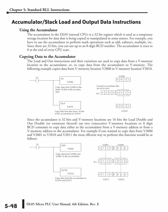
DL05 Micro PLC User Manual, 6th Edition, Rev. E5-48
Chapter 5: Standard RLL Instructions
Accumulator/Stack Load and Output Data InstructionsUsing the Accumulator
The accumulator in the DL05 internal CPUs is a 32 bit register which is used as a temporary storage location for data that is being copied or manipulated in some manor. For example, you have to use the accumulator to perform math operations such as add, subtract, multiply, etc. Since there are 32 bits, you can use up to an 8-digit BCD number. The accumulator is reset to 0 at the end of every CPU scan.
Copying Data to the AccumulatorThe Load and Out instructions and their variations are used to copy data from a V-memory location to the accumulator, or, to copy data from the accumulator to V-memory. The following example copies data from V-memory location V2000 to V-memory location V2010.
Since the accumulator is 32 bits and V-memory locations are 16 bits the Load Double and Out Double (or variations thereof) use two consecutive V-memory locations or 8 digit BCD constants to copy data either to the accumulator from a V-memory address or from a V-memory address to the accumulator. For example if you wanted to copy data from V2000 and V2001 to V2010 and V2011 the most efficient way to perform this function would be as follows:
LD
V2000
X1
Copy data from V2000 to thelower 16 bits of the accumu-lator
Copy data from the lower 16 bitsof the accumulator to V2010
OUT
V2010
V2010
Acc.
8 9 3 5
8 9 3 5
0 0 0 0 8 9 3 5 8 9 3 5
Unused accumulator bitsare set to zero
V2000
LDD
V2000
Copy data from V2000 andV2001 to the accumulator
Copy data from the accumulator toV2010 and V2011
OUTD
V2010
V2010
Acc.
V2000
6 7 3 9 5 0 2 6 5 0 2 6
X1 V2001
6 7 3 9 5 0 2 6
V2011
6 7 3 9 5 0 2 6
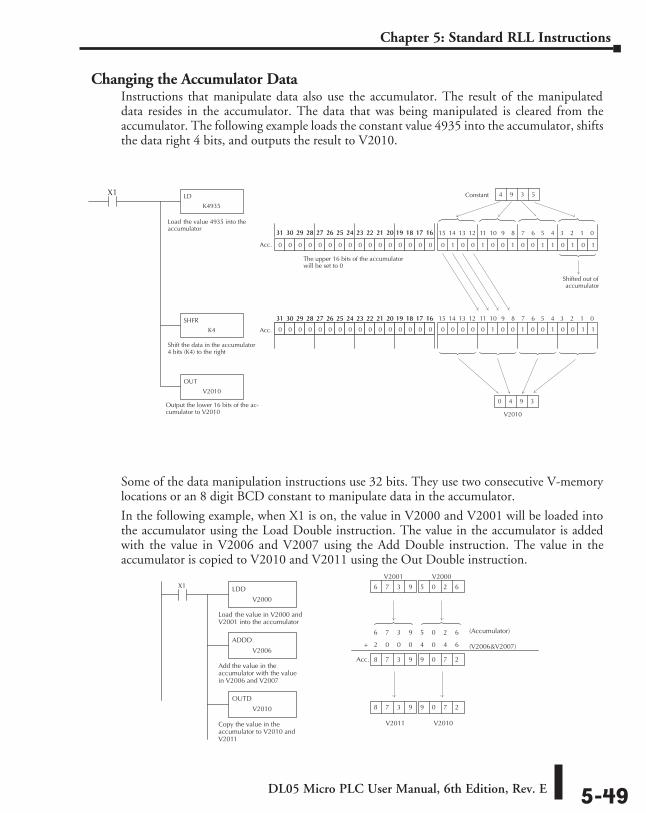
DL05 Micro PLC User Manual, 6th Edition, Rev. E 5-49
Chapter 5: Standard RLL Instructions
Changing the Accumulator DataInstructions that manipulate data also use the accumulator. The result of the manipulated data resides in the accumulator. The data that was being manipulated is cleared from the accumulator. The following example loads the constant value 4935 into the accumulator, shifts the data right 4 bits, and outputs the result to V2010.
Some of the data manipulation instructions use 32 bits. They use two consecutive V-memory locations or an 8 digit BCD constant to manipulate data in the accumulator.
In the following example, when X1 is on, the value in V2000 and V2001 will be loaded into the accumulator using the Load Double instruction. The value in the accumulator is added with the value in V2006 and V2007 using the Add Double instruction. The value in the accumulator is copied to V2010 and V2011 using the Out Double instruction.
LD
K4935
X1
Load the value 4935 into theaccumulator
Shift the data in the accumulator4 bits (K4) to the right
Output the lower 16 bits of the ac-cumulator to V2010
0 1 0 0 1 0 0 1 0 0 1 1 0 1 0 1
Constant
V2010
0 0 0 0 0 1 0 0 1 0 0 1 0 0 1 10 0 0 0 0 1 0 0 0 0 0 0 0 0 0 0
15 14 13 12 11 10 9 8 7 6 5 4 3 2 1 031 30 29 28 27 26 25 24 23 22 21 20 19 18 17 16
Shifted out ofaccumulator
0 4 9 3
4 9 3 5
SHFR
K4
OUT
V2010
0 0 0 0 0 0 0 0 0 0 0 0 0 0 0 0
31 30 29 28 27 26 25 24 23 22 21 20 19 18 17 16
0 0 0 0 0 0 0 0 0 0 0 0 0 0 0 0
The upper 16 bits of the accumulatorwill be set to 0
15 14 13 12 11 10 9 8 7 6 5 4 3 2 1 031 30 29 28 27 26 25 24 23 22 21 20 19 18 17 1631 30 29 28 27 26 25 24 23 22 21 20 19 18 17 16
Acc.
Acc.
6 7 3 9 5 0 2 6
LDD
V2000
X1
Load the value in V2000 andV2001 into the accumulator
ADDD
V2006
Add the value in theaccumulator with the valuein V2006 and V2007
OUTD
V2010
Copy the value in theaccumulator to V2010 andV2011
V2010
V2000
V2001
6 7 3 9 5 0 2 6
V2011
8 7 3 9 9 0 7 2
(Accumulator)
(V2006 & V2007) 2 0 0 0 4 0 4 6 +
8 7 3 9 9 0 7 2 Acc.
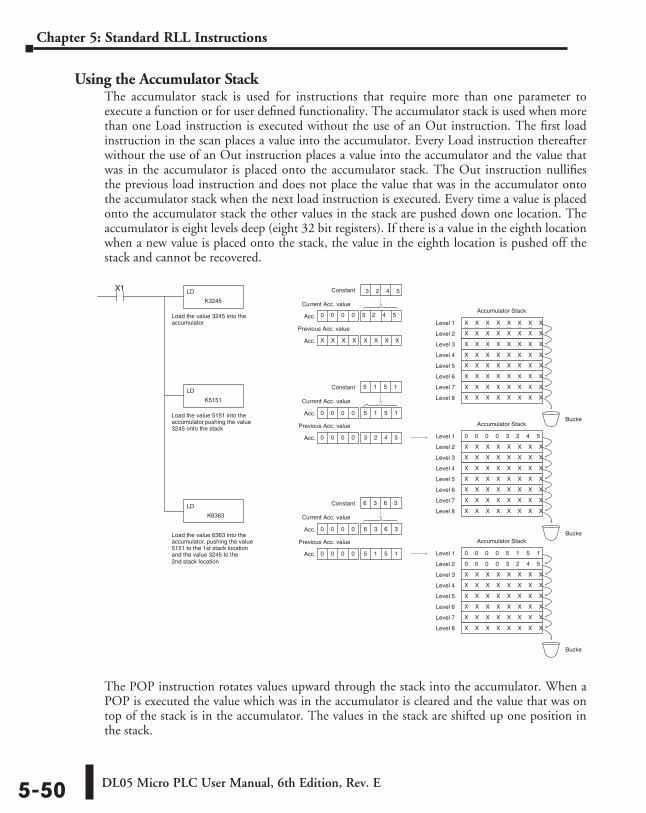
DL05 Micro PLC User Manual, 6th Edition, Rev. E5-50
Chapter 5: Standard RLL Instructions
Using the Accumulator StackThe accumulator stack is used for instructions that require more than one parameter to execute a function or for user defined functionality. The accumulator stack is used when more than one Load instruction is executed without the use of an Out instruction. The first load instruction in the scan places a value into the accumulator. Every Load instruction thereafter without the use of an Out instruction places a value into the accumulator and the value that was in the accumulator is placed onto the accumulator stack. The Out instruction nullifies the previous load instruction and does not place the value that was in the accumulator onto the accumulator stack when the next load instruction is executed. Every time a value is placed onto the accumulator stack the other values in the stack are pushed down one location. The accumulator is eight levels deep (eight 32 bit registers). If there is a value in the eighth location when a new value is placed onto the stack, the value in the eighth location is pushed off the stack and cannot be recovered.
The POP instruction rotates values upward through the stack into the accumulator. When a POP is executed the value which was in the accumulator is cleared and the value that was on top of the stack is in the accumulator. The values in the stack are shifted up one position in the stack.
Acc.Load the value 3245 into the accumulator
Load the value 5151 into the accumulator, pushing the value 3245 onto the stack
Load the value 6363 into the accumulator, pushing the value 5151 to the 1st stack location and the value 3245 to the 2nd stack location
LD
K3245
X1
LD
K5151
LD
K6363
Constant
Acc. X X X X X X X X X
Current Acc. value
Previous Acc. valueX X X X X X X XX X X X X X XX X X X X X X
Level 1
X X X X X X X X Level 2
X X X X X X X X Level 3
X X X X X X X X Level 4
X X X X X X X X Level 5
X X X X X X X X Level 6
X X X X X X X X Level 7
X X X X X X X X Level 8
Accumulator Stack
0 0 0 0 3 2 4 5 Level 1
X X X X X X X X Level 2
X X X X X X X X Level 3
X X X X X X X X Level 4
X X X X X X X X Level 5
X X X X X X X X Level 6
X X X X X X X X Level 7
X X X X X X X X Level 8
Accumulator Stack
Acc.
Constant 5 1 5 1
0 0 0 0 5 5 1 5 1
Acc. 0 0 0 0 3 2 4 5 3 2 4 5
Current Acc. value
Previous Acc. value
0 0 0 0 5 1 5 1
0 0 0 0
Level 1
0 0 0 0 3 2 4 5 Level 2
X X X X X X X X Level 3
X X X X X X X X Level 4
X X X X X X X X Level 5
X X X X X X X X Level 6
X X X X X X X X Level 7
X X X X X X X X Level 8
Accumulator Stack
Acc.
Constant 6 3 6 3
0 0 0 0 6 3 6 3 6 3 6 3
Acc. 0 0 0 0 5 5 1 5 1
Current Acc. value
Previous Acc. value
Bucket
Bucket
Bucket
3 2 4 5
0 0 0 0 3 2 4 5
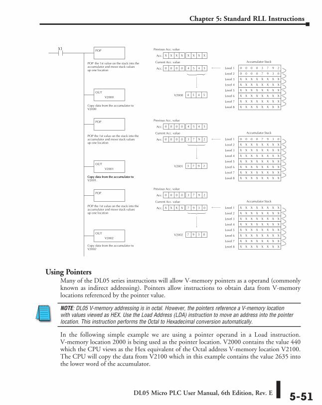
DL05 Micro PLC User Manual, 6th Edition, Rev. E 5-51
Chapter 5: Standard RLL Instructions
Using PointersMany of the DL05 series instructions will allow V-memory pointers as a operand (commonly known as indirect addressing). Pointers allow instructions to obtain data from V-memory locations referenced by the pointer value.
NOTE: DL05 V-memory addressing is in octal. However, the pointers reference a V-memory location with values viewed as HEX. Use the Load Address (LDA) instruction to move an address into the pointer location. This instruction performs the Octal to Hexadecimal conversion automatically.
In the following simple example we are using a pointer operand in a Load instruction. V-memory location 2000 is being used as the pointer location. V2000 contains the value 440 which the CPU views as the Hex equivalent of the Octal address V-memory location V2100. The CPU will copy the data from V2100 which in this example contains the value 2635 into the lower word of the accumulator.
Acc.
POP the 1st value on the stack into theaccumulator and move stack valuesup one location
POPX1
POP
POP
V2000 4 5 4 5
X X X X X X X X X X X
Acc. 0 0 0 0 4 5 4 5 4 5
Previous Acc. value
Current Acc. value
0 0 0 0 3 7 9 2 Level 1
0 0 0 0 7 9 3 0 Level 2
X X X X X X X X
Level 3
X X X X X X X X Level 4
X X X X X X X X Level 5
X X X X X X X X Level 6
X X X X X X X X Level 7
X X X X X X X X Level 8
Accumulator Stack
0 0 0 0 7 9 3 0 Level 1
X X X X X X X X Level 2
X X X X X X X X Level 3
X X X X X X X X Level 4
X X X X X X X X Level 5
X X X X X X X X Level 6
X X X X X X X X Level 7
X X X X X X X X Level 8
Accumulator Stack
X X X X X X X X Level 1
X X X X X X X X Level 2
X X X X X X X X Level 3
X X X X X X X X Level 4
X X X X X X X X Level 5
X X X X X X X X Level 6
X X X X X X X X Level 7
X X X X X X X X Level 8
Accumulator Stack
POP the 1st value on the stack into theaccumulator and move stack valuesup one location
POP the 1st value on the stack into theaccumulator and move stack valuesup one location
OUT
V2000
OUT
V2001
Acc.
V2001 3 7 9 2
0 0 0 0 4 5 4 5 4 5 4 5
Acc. 0 0 0 0 3 7 9 2 3 7 9 2
Previous Acc. value
Current Acc. value
Acc.
V2002 7 9 3 0
0 0 0 0 3 4 6 0 3 7 9 2
Acc. X X X X 7 9 3 0 7 9 3 0
Previous Acc. value
Current Acc. value
OUT
V2002
Copy data from the accumulator toV2000
Copy data from the accumulator toV2001.Copy data from the accumulator to
Copy data from the accumulator toV2002
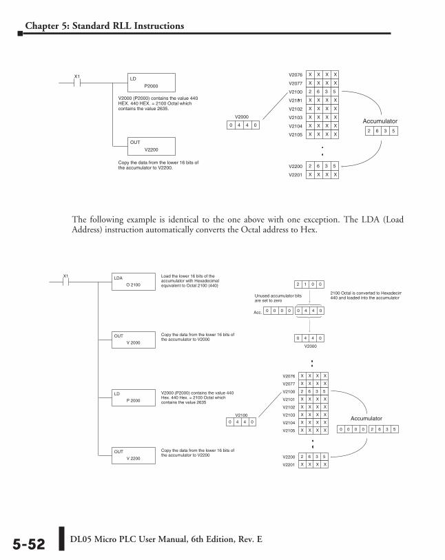
DL05 Micro PLC User Manual, 6th Edition, Rev. E5-52
Chapter 5: Standard RLL Instructions
The following example is identical to the one above with one exception. The LDA (Load Address) instruction automatically converts the Octal address to Hex.
V2000 (P2000) contains the value 440HEX. 440 HEX. = 2100 Octal whichcontains the value 2635.
LD
P2000
X1
OUT
V2200
Copy the data from the lower 16 bits ofthe accumulator to V2200.
0 4 4 0
V2076 X X X X
V2077 X X X X
V2100 2 6 3 5
V2101 X X X X
V2102 X X X X
V2103 X X X X
V2104 X X X X
V2105 X X X X
V2200 2 6 3 5
V2201 X X X X
2 6 3 5
AccumulatorV2000
V2000 (P2000) contains the value 440Hex. 440 Hex. = 2100 Octal whichcontains the value 2635
LDA
O 2100
X1
OUT
V 2000
Copy the data from the lower 16 bits ofthe accumulator to V2000
V2100
0 4 4 0
V2076 X X X X
V2077 X X X X
V2100 2 6 3 5
V2101 X X X X
V2102 X X X X
V2103 X X X X
V2104 X X X X
V2105 X X X X
V2200 2 6 3 5
V2201 X X X X
LD
P 2000
OUT
V 2200
Copy the data from the lower 16 bits ofthe accumulator to V2200
Load the lower 16 bits of theaccumulator with Hexadecimalequivalent to Octal 2100 (440)
V2000
Acc.
2 1 0 0
0 4 4 0
0 0 0 0 0 4 4 0 0 4 4 0
2100 Octal is converted to Hexadecimal440 and loaded into the accumulator
Accumulator
0 0 0 0 2 6 3 5 2 6 3 5
Unused accumulator bitsare set to zero
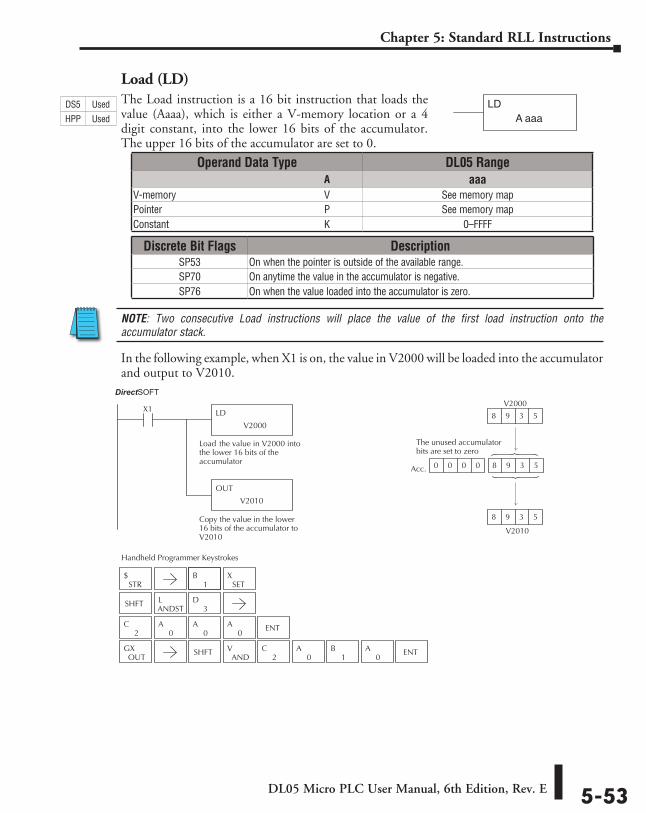
DL05 Micro PLC User Manual, 6th Edition, Rev. E 5-53
Chapter 5: Standard RLL Instructions
Load (LD)The Load instruction is a 16 bit instruction that loads the value (Aaaa), which is either a V-memory location or a 4 digit constant, into the lower 16 bits of the accumulator. The upper 16 bits of the accumulator are set to 0.
NOTE: Two consecutive Load instructions will place the value of the first load instruction onto the accumulator stack.
In the following example, when X1 is on, the value in V2000 will be loaded into the accumulator and output to V2010.
LDA aaa
Operand Data Type DL05 Range ⸠⸠⸠⸠⸠⸠⸠⸠⸠⸠⸠⸠⸠⸠⸠⸠⸠⸠⸠⸠⸠⸠⸠⸠⸠⸠⸠⸠⸠⸠⸠⸠⸠⸠⸠⸠⸠⸠⸠⸠⸠⸠⸠⸠⸠⸠⸠⸠⸠⸠⸠⸠⸠⸠⸠⸠⸠⸠⸠⸠⸠⸠⸠⸠⸠⸠⸠⸠⸠⸠⸠⸠⸠A aaaV-memory ⸠⸠⸠⸠⸠⸠⸠⸠⸠⸠⸠⸠⸠⸠⸠⸠⸠⸠⸠⸠⸠⸠⸠⸠⸠⸠⸠⸠⸠⸠⸠⸠⸠⸠⸠⸠⸠⸠⸠⸠⸠⸠⸠⸠⸠⸠⸠⸠⸠⸠⸠⸠⸠⸠⸠⸠⸠⸠V See memory mapPointer ⸠⸠⸠⸠⸠⸠⸠⸠⸠⸠⸠⸠⸠⸠⸠⸠⸠⸠⸠⸠⸠⸠⸠⸠⸠⸠⸠⸠⸠⸠⸠⸠⸠⸠⸠⸠⸠⸠⸠⸠⸠⸠⸠⸠⸠⸠⸠⸠⸠⸠⸠⸠⸠⸠⸠⸠⸠⸠⸠⸠⸠⸠⸠⸠P See memory mapConstant ⸠⸠⸠⸠⸠⸠⸠⸠⸠⸠⸠⸠⸠⸠⸠⸠⸠⸠⸠⸠⸠⸠⸠⸠⸠⸠⸠⸠⸠⸠⸠⸠⸠⸠⸠⸠⸠⸠⸠⸠⸠⸠⸠⸠⸠⸠⸠⸠⸠⸠⸠⸠⸠⸠⸠⸠⸠⸠⸠⸠⸠K 0–FFFF
Discrete Bit Flags DescriptionSP53 On when the pointer is outside of the available range.SP70 On anytime the value in the accumulator is negative.SP76 On when the value loaded into the accumulator is zero.
DS5 Used
HPP Used
LD
V2000
X1
Load the value in V2000 intothe lower 16 bits of theaccumulator
OUT
V2010
Copy the value in the lower16 bits of the accumulator toV2010
V2010
Acc.
V2000
8 9 3 5
8 9 3 5
0 0 0 0 8 9 3 5 8 9 3 5
Direct SOFT32
The unused accumulatorbits are set to zero
1B
2C
0A
0A
0A ENT
Handheld Programmer Keystrokes
STR$
SETX
SHFTANDSTL
3D
OUTGX SHFT
ANDV
2C
0A
1B
0A ENT
DirectSOFT
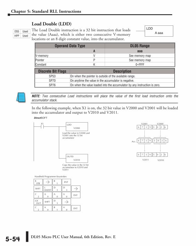
DL05 Micro PLC User Manual, 6th Edition, Rev. E5-54
Chapter 5: Standard RLL Instructions
Load Double (LDD)The Load Double instruction is a 32 bit instruction that loads the value (Aaaa), which is either two consecutive V-memory locations or an 8 digit constant value, into the accumulator.
NOTE: Two consecutive Load instructions will place the value of the first load instruction onto the accumulator stack.
In the following example, when X1 is on, the 32 bit value in V2000 and V2001 will be loaded into the accumulator and output to V2010 and V2011.
Operand Data Type DL05 Range ⸠⸠⸠⸠⸠⸠⸠⸠⸠⸠⸠⸠⸠⸠⸠⸠⸠⸠⸠⸠⸠⸠⸠⸠⸠⸠⸠⸠⸠⸠⸠⸠⸠⸠⸠⸠⸠⸠⸠⸠⸠⸠⸠⸠⸠⸠⸠⸠⸠⸠⸠⸠⸠⸠⸠⸠⸠⸠⸠⸠⸠⸠⸠⸠⸠⸠⸠⸠⸠⸠⸠⸠⸠A aaaV-memory ⸠⸠⸠⸠⸠⸠⸠⸠⸠⸠⸠⸠⸠⸠⸠⸠⸠⸠⸠⸠⸠⸠⸠⸠⸠⸠⸠⸠⸠⸠⸠⸠⸠⸠⸠⸠⸠⸠⸠⸠⸠⸠⸠⸠⸠⸠⸠⸠⸠⸠⸠⸠⸠⸠⸠⸠⸠⸠V See memory mapPointer ⸠⸠⸠⸠⸠⸠⸠⸠⸠⸠⸠⸠⸠⸠⸠⸠⸠⸠⸠⸠⸠⸠⸠⸠⸠⸠⸠⸠⸠⸠⸠⸠⸠⸠⸠⸠⸠⸠⸠⸠⸠⸠⸠⸠⸠⸠⸠⸠⸠⸠⸠⸠⸠⸠⸠⸠⸠⸠⸠⸠⸠⸠⸠⸠P See memory mapConstant ⸠⸠⸠⸠⸠⸠⸠⸠⸠⸠⸠⸠⸠⸠⸠⸠⸠⸠⸠⸠⸠⸠⸠⸠⸠⸠⸠⸠⸠⸠⸠⸠⸠⸠⸠⸠⸠⸠⸠⸠⸠⸠⸠⸠⸠⸠⸠⸠⸠⸠⸠⸠⸠⸠⸠⸠⸠⸠⸠⸠⸠K 0–FFFF
Discrete Bit Flags DescriptionSP53 On when the pointer is outside of the available range.SP70 On anytime the value in the accumulator is negative.SP76 On when the value loaded into the accumulator by any instruction is zero.
LDDA aaa
1B ENT
2C
0A
0A
0A ENT
2C
0A
1B
0A ENT
Handheld Programmer Keystrokes
Direct SOFT32
LDD
V2000
X1
Load the value in V2000 andV2001 into the 32 bitaccumulator
OUTD
V2010
Copy the value in the 32 bitaccumulator to V2010 andV2011
V2010
Acc.
V2000
6 7 3 9 6 0 2 6 5 0 2 6
V2001
6 7 3 9 5 0 2 6
V2011
6 7 3 9 5 0 2 6
STR$
SHFTANDSTL
3D
3D
OUTGX SHFT
3D
DS5 Used
HPP Used
DirectSOFT
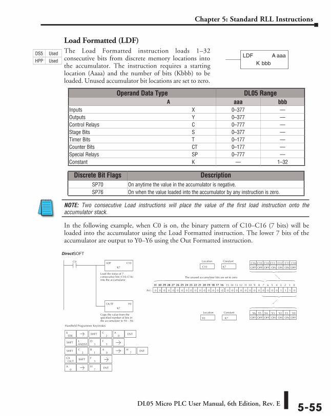
DL05 Micro PLC User Manual, 6th Edition, Rev. E 5-55
Chapter 5: Standard RLL Instructions
Load Formatted (LDF)The Load Formatted instruction loads 1–32 consecutive bits from discrete memory locations into the accumulator. The instruction requires a starting location (Aaaa) and the number of bits (Kbbb) to be loaded. Unused accumulator bit locations are set to zero.
NOTE: Two consecutive Load instructions will place the value of the first load instruction onto the accumulator stack.
In the following example, when C0 is on, the binary pattern of C10–C16 (7 bits) will be loaded into the accumulator using the Load Formatted instruction. The lower 7 bits of the accumulator are output to Y0–Y6 using the Out Formatted instruction.
bbbKLDF A aaa
Operand Data Type DL05 Range ⸠⸠⸠⸠⸠⸠⸠⸠⸠⸠⸠⸠⸠⸠⸠⸠⸠⸠⸠⸠⸠⸠⸠⸠⸠⸠⸠⸠⸠⸠⸠⸠⸠⸠⸠⸠⸠⸠⸠⸠⸠⸠⸠⸠⸠⸠⸠⸠⸠⸠⸠⸠⸠⸠⸠⸠⸠⸠⸠⸠⸠⸠⸠⸠⸠⸠⸠⸠⸠⸠⸠⸠⸠A aaa bbbInputs ⸠⸠⸠⸠⸠⸠⸠⸠⸠⸠⸠⸠⸠⸠⸠⸠⸠⸠⸠⸠⸠⸠⸠⸠⸠⸠⸠⸠⸠⸠⸠⸠⸠⸠⸠⸠⸠⸠⸠⸠⸠⸠⸠⸠⸠⸠⸠⸠⸠⸠⸠⸠⸠⸠⸠⸠⸠⸠⸠⸠⸠⸠⸠⸠⸠⸠⸠ X 0–377 ––Outputs ⸠⸠⸠⸠⸠⸠⸠⸠⸠⸠⸠⸠⸠⸠⸠⸠⸠⸠⸠⸠⸠⸠⸠⸠⸠⸠⸠⸠⸠⸠⸠⸠⸠⸠⸠⸠⸠⸠⸠⸠⸠⸠⸠⸠⸠⸠⸠⸠⸠⸠⸠⸠⸠⸠⸠⸠⸠⸠⸠⸠⸠⸠⸠⸠⸠ Y 0–377 ––Control Relays ⸠⸠⸠⸠⸠⸠⸠⸠⸠⸠⸠⸠⸠⸠⸠⸠⸠⸠⸠⸠⸠⸠⸠⸠⸠⸠⸠⸠⸠⸠⸠⸠⸠⸠⸠⸠⸠⸠⸠⸠⸠⸠⸠⸠⸠⸠⸠⸠⸠⸠⸠⸠⸠⸠⸠ C 0–777 ––Stage Bits ⸠⸠⸠⸠⸠⸠⸠⸠⸠⸠⸠⸠⸠⸠⸠⸠⸠⸠⸠⸠⸠⸠⸠⸠⸠⸠⸠⸠⸠⸠⸠⸠⸠⸠⸠⸠⸠⸠⸠⸠⸠⸠⸠⸠⸠⸠⸠⸠⸠⸠⸠⸠⸠⸠⸠⸠⸠⸠⸠⸠⸠ S 0–377 ––Timer Bits ⸠⸠⸠⸠⸠⸠⸠⸠⸠⸠⸠⸠⸠⸠⸠⸠⸠⸠⸠⸠⸠⸠⸠⸠⸠⸠⸠⸠⸠⸠⸠⸠⸠⸠⸠⸠⸠⸠⸠⸠⸠⸠⸠⸠⸠⸠⸠⸠⸠⸠⸠⸠⸠⸠⸠⸠⸠⸠⸠⸠⸠ T 0–177 ––Counter Bits ⸠⸠⸠⸠⸠⸠⸠⸠⸠⸠⸠⸠⸠⸠⸠⸠⸠⸠⸠⸠⸠⸠⸠⸠⸠⸠⸠⸠⸠⸠⸠⸠⸠⸠⸠⸠⸠⸠⸠⸠⸠⸠⸠⸠⸠⸠⸠⸠⸠⸠⸠⸠⸠⸠⸠⸠⸠ CT 0–177 ––Special Relays ⸠⸠⸠⸠⸠⸠⸠⸠⸠⸠⸠⸠⸠⸠⸠⸠⸠⸠⸠⸠⸠⸠⸠⸠⸠⸠⸠⸠⸠⸠⸠⸠⸠⸠⸠⸠⸠⸠⸠⸠⸠⸠⸠⸠⸠⸠⸠⸠⸠⸠⸠⸠⸠⸠ SP 0–777 ––Constant ⸠⸠⸠⸠⸠⸠⸠⸠⸠⸠⸠⸠⸠⸠⸠⸠⸠⸠⸠⸠⸠⸠⸠⸠⸠⸠⸠⸠⸠⸠⸠⸠⸠⸠⸠⸠⸠⸠⸠⸠⸠⸠⸠⸠⸠⸠⸠⸠⸠⸠⸠⸠⸠⸠⸠⸠⸠⸠⸠⸠⸠⸠⸠ K –– 1–32
Discrete Bit Flags DescriptionSP70 On anytime the value in the accumulator is negative.SP76 On when the value loaded into the accumulator by any instruction is zero.
0A
7H ENT
Handheld Programmer Keystrokes
LDF C10
K7
C0
Load the status of 7consecutive bits (C10–C16)into the accumulator
OUTF Y0
K7
Copy the value from thespecified number of bits inthe accumulator to Y0 – Y6
K7 C10
Location Constant
0 0 0 0 0 0 0 0 0 0 0 0 1 1 1 00 0 0 0 0 0 0 0 0 0 0 0 0 0 0 0
15 14 13 12 11 10 9 8 7 6 5 4 3 2 1 031 30 29 28 27 26 25 24 23 22 21 20 19 18 17 1631 30 29 28 27 26 25 24 23 22 21 20 19 18 17 16
Acc.
K7Y0
Location Constant
C16 C15 C14 C13 C12 C11 C10
OFFONONONOFFOFFOFF
Y6 Y5 Y4 Y3 Y2 Y1 Y0
OFFONONONOFFOFFOFF
The unused accumulator bits are set to zero
Direct SOFT32
STR$ SHFT ENT
2C
0A
SHFTANDSTL
3D
5F
SHFT2
C1
B0
A7
H ENT
OUTGX SHFT
5F
DS5 Used
HPP Used
DirectSOFT
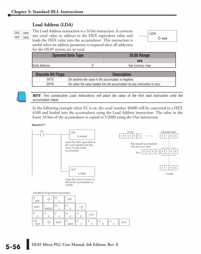
DL05 Micro PLC User Manual, 6th Edition, Rev. E5-56
Chapter 5: Standard RLL Instructions
Load Address (LDA)The Load Address instruction is a 16 bit instruction. It converts any octal value or address to the HEX equivalent value and loads the HEX value into the accumulator. This instruction is useful when an address parameter is required since all addresses for the DL05 system are in octal.
NOTE: Two consecutive Load instructions will place the value of the first load instruction onto the accumulator stack.
In the following example when X1 is on, the octal number 40400 will be converted to a HEX 4100 and loaded into the accumulator using the Load Address instruction. The value in the lower 16 bits of the accumulator is copied to V2000 using the Out instruction.
Discrete Bit Flags DescriptionSP70 On anytime the value in the accumulator is negative.SP76 On when the value loaded into the accumulator by any instruction is zero.
O aaaLDA
Operand Data Type DL05 Rangeaaa
Octal Address ⸠⸠⸠⸠⸠⸠⸠⸠⸠⸠⸠⸠⸠⸠⸠⸠⸠⸠⸠⸠⸠⸠⸠⸠⸠⸠⸠⸠⸠⸠⸠⸠⸠⸠⸠⸠⸠⸠⸠⸠⸠⸠⸠⸠⸠⸠⸠⸠⸠⸠⸠⸠⸠O See memory map
1B ENT
4E
0A
4E
0A
0A ENT
Handheld Programmer Keystrokes
Direct SOFT32
LDA
O 40400
X1
Load The HEX equivalent tothe octal number into thelower 16 bits of theaccumulator
OUT
V2000
Copy the value in lower 16bits of the accumulator toV2000
V2000
Acc.
Hexadecimal
4 1 0 0
4 1 0 0
0 0 0 0 4 1 0 0
Octal
4 0 4 0 0
The unused accumulator bits are set to zero
STR$
SHFTANDSTL
3D
0A
OUTGX SHFT
ANDV
2C
0A
0A ENT
0A
DS5 Used
HPP Used
DirectSOFT
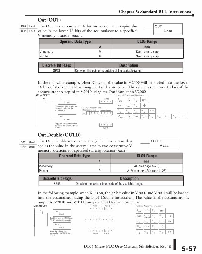
DL05 Micro PLC User Manual, 6th Edition, Rev. E 5-57
Chapter 5: Standard RLL Instructions
Out (OUT)The Out instruction is a 16 bit instruction that copies the value in the lower 16 bits of the accumulator to a specified V-memory location (Aaaa).
In the following example, when X1 is on, the value in V2000 will be loaded into the lower 16 bits of the accumulator using the Load instruction. The value in the lower 16 bits of the accumulator are copied to V2010 using the Out instruction.V2000
Out Double (OUTD)The Out Double instruction is a 32 bit instruction that copies the value in the accumulator to two consecutive V memory locations at a specified starting location (Aaaa).
In the following example, when X1 is on, the 32 bit value in V2000 and V2001 will be loaded into the accumulator using the Load Double instruction. The value in the accumulator is output to V2010 and V2011 using the Out Double instruction.
OUTA aaa
Operand Data Type DL05 Range ⸠⸠⸠⸠⸠⸠⸠⸠⸠⸠⸠⸠⸠⸠⸠⸠⸠⸠⸠⸠⸠⸠⸠⸠⸠⸠⸠⸠⸠⸠⸠⸠⸠⸠⸠⸠⸠⸠⸠⸠⸠⸠⸠⸠⸠⸠⸠⸠⸠⸠⸠⸠⸠⸠⸠⸠⸠⸠⸠⸠⸠⸠⸠⸠⸠⸠⸠⸠⸠⸠⸠⸠⸠A aaaV-memory ⸠⸠⸠⸠⸠⸠⸠⸠⸠⸠⸠⸠⸠⸠⸠⸠⸠⸠⸠⸠⸠⸠⸠⸠⸠⸠⸠⸠⸠⸠⸠⸠⸠⸠⸠⸠⸠⸠⸠⸠⸠⸠⸠⸠⸠⸠⸠⸠⸠⸠⸠⸠⸠⸠⸠⸠⸠⸠V See memory mapPointer ⸠⸠⸠⸠⸠⸠⸠⸠⸠⸠⸠⸠⸠⸠⸠⸠⸠⸠⸠⸠⸠⸠⸠⸠⸠⸠⸠⸠⸠⸠⸠⸠⸠⸠⸠⸠⸠⸠⸠⸠⸠⸠⸠⸠⸠⸠⸠⸠⸠⸠⸠⸠⸠⸠⸠⸠⸠⸠⸠⸠⸠⸠⸠⸠P See memory map
Operand Data Type DL05 Range ⸠⸠⸠⸠⸠⸠⸠⸠⸠⸠⸠⸠⸠⸠⸠⸠⸠⸠⸠⸠⸠⸠⸠⸠⸠⸠⸠⸠⸠⸠⸠⸠⸠⸠⸠⸠⸠⸠⸠⸠⸠⸠⸠⸠⸠⸠⸠⸠⸠⸠⸠⸠⸠⸠⸠⸠⸠⸠⸠⸠⸠⸠⸠⸠⸠⸠⸠⸠⸠⸠⸠⸠⸠A aaaV-memory ⸠⸠⸠⸠⸠⸠⸠⸠⸠⸠⸠⸠⸠⸠⸠⸠⸠⸠⸠⸠⸠⸠⸠⸠⸠⸠⸠⸠⸠⸠⸠⸠⸠⸠⸠⸠⸠⸠⸠⸠⸠⸠⸠⸠⸠⸠⸠⸠⸠⸠⸠⸠⸠⸠⸠⸠⸠⸠V All (See page 4–28)Pointer ⸠⸠⸠⸠⸠⸠⸠⸠⸠⸠⸠⸠⸠⸠⸠⸠⸠⸠⸠⸠⸠⸠⸠⸠⸠⸠⸠⸠⸠⸠⸠⸠⸠⸠⸠⸠⸠⸠⸠⸠⸠⸠⸠⸠⸠⸠⸠⸠⸠⸠⸠⸠⸠⸠⸠⸠⸠⸠⸠⸠⸠⸠⸠⸠P All V-memory (See page 4–28)
Discrete Bit Flags DescriptionSP53 On when the pointer is outside of the available range.
Discrete Bit Flags DescriptionSP53 On when the pointer is outside of the available range.
2C
0A
0A
0A ENT
1B ENT
Handheld Programmer Keystrokes
LD
V2000
X1
Load the value in V2000 intothe lower 16 bits of theaccumulator
OUT
V2010
Copy the value in the lower16 bits of the accumulator toV2010 V2010
Acc.
V2000
8 9 3 5
8 9 3 5
0 0 0 0 8 9 3 5 8 9 3 5
Direct SOFT32
The unused accumulator bits are set to zero
STR$
SHFTANDSTL
3D
OUTGX SHFT
ANDV
2C
0A
1B
0A ENT
OUTDA aaa
2C
0A
0A
0A ENT
2C
0A
1B
0A ENT
1B ENT
Handheld Programmer Keystrokes
V2010
Acc.
V2000
6 7 3 9 5 0 2 6 5 0 2 6
V2001
6 7 3 9 5 0 2 6
V2011
6 7 3 9 5 0 2 6
Load the value in V2000 andV2001 into the accumulator
LDD
OUTD
Copy the value in theaccumulator to V2010 andV2011
V2000
X1
V2010
Direct SOFT32
STR$
SHFTANDSTL
3D
3D
OUTGX SHFT
3D
DS5 Used
HPP Used
DS5 Used
HPP Used
DirectSOFT
DirectSOFT
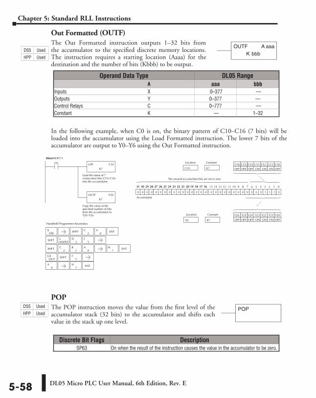
DL05 Micro PLC User Manual, 6th Edition, Rev. E5-58
Chapter 5: Standard RLL Instructions
Out Formatted (OUTF)The Out Formatted instruction outputs 1–32 bits from the accumulator to the specified discrete memory locations. The instruction requires a starting location (Aaaa) for the destination and the number of bits (Kbbb) to be output.
In the following example, when C0 is on, the binary pattern of C10–C16 (7 bits) will be loaded into the accumulator using the Load Formatted instruction. The lower 7 bits of the accumulator are output to Y0–Y6 using the Out Formatted instruction.
POPThe POP instruction moves the value from the first level of the accumulator stack (32 bits) to the accumulator and shifts each value in the stack up one level.
Discrete Bit Flags DescriptionSP63 On when the result of the instruction causes the value in the accumulator to be zero.
bbbKOUTF A aaa
Operand Data Type DL05 Range ⸠⸠⸠⸠⸠⸠⸠⸠⸠⸠⸠⸠⸠⸠⸠⸠⸠⸠⸠⸠⸠⸠⸠⸠⸠⸠⸠⸠⸠⸠⸠⸠⸠⸠⸠⸠⸠⸠⸠⸠⸠⸠⸠⸠⸠⸠⸠⸠⸠⸠⸠⸠⸠⸠⸠⸠⸠⸠⸠⸠⸠⸠⸠⸠⸠⸠⸠⸠⸠⸠⸠⸠⸠A aaa bbbInputs ⸠⸠⸠⸠⸠⸠⸠⸠⸠⸠⸠⸠⸠⸠⸠⸠⸠⸠⸠⸠⸠⸠⸠⸠⸠⸠⸠⸠⸠⸠⸠⸠⸠⸠⸠⸠⸠⸠⸠⸠⸠⸠⸠⸠⸠⸠⸠⸠⸠⸠⸠⸠⸠⸠⸠⸠⸠⸠⸠⸠⸠⸠⸠⸠⸠X 0–377 ––Outputs ⸠⸠⸠⸠⸠⸠⸠⸠⸠⸠⸠⸠⸠⸠⸠⸠⸠⸠⸠⸠⸠⸠⸠⸠⸠⸠⸠⸠⸠⸠⸠⸠⸠⸠⸠⸠⸠⸠⸠⸠⸠⸠⸠⸠⸠⸠⸠⸠⸠⸠⸠⸠⸠⸠⸠⸠⸠⸠⸠⸠⸠⸠⸠Y 0–377 ––Control Relays ⸠⸠⸠⸠⸠⸠⸠⸠⸠⸠⸠⸠⸠⸠⸠⸠⸠⸠⸠⸠⸠⸠⸠⸠⸠⸠⸠⸠⸠⸠⸠⸠⸠⸠⸠⸠⸠⸠⸠⸠⸠⸠⸠⸠⸠⸠⸠⸠⸠⸠⸠⸠C 0–777 ––Constant ⸠⸠⸠⸠⸠⸠⸠⸠⸠⸠⸠⸠⸠⸠⸠⸠⸠⸠⸠⸠⸠⸠⸠⸠⸠⸠⸠⸠⸠⸠⸠⸠⸠⸠⸠⸠⸠⸠⸠⸠⸠⸠⸠⸠⸠⸠⸠⸠⸠⸠⸠⸠⸠⸠⸠⸠⸠⸠⸠⸠⸠K –– 1–32
0A
7H ENT
Handheld Programmer Keystrokes
LDF C10
K7
C0
Load the status of 7consecutive bits (C10–C16)into the accumulator
OUTF Y20
K7
Copy the value of thespecified number of bitsfrom the accumulator toY20–Y26
K7C10
Location Constant
0 0 0 0 0 0 0 0 0 0 0 0 1 1 1 00 0 0 0 0 0 0 0 0 0 0 0 0 0 0 0
15 14 13 12 11 10 9 8 7 6 5 4 3 2 1 031 30 29 28 27 26 25 24 23 22 21 20 19 18 17 1631 30 29 28 27 26 25 24 23 22 21 20 19 18 17 16
K7Y0
Location Constant
C16 C15 C14 C13 C12 C11 C10
OFFONONONOFFOFF OFF
Y21 Y20 Y23 Y22 Y26 Y25 Y24
OFFONONONOFFOFFOFF
The unused accumulator bits are set to zero
Accumulator
DirectSOFT 5
STR$ SHFT ENT
2C
0A
SHFTANDSTL
3D
5F
SHFT2
C1
B0
A7
H ENT
OUTGX SHFT
5F
POPDS5 Used
HPP Used
DS5 Used
HPP Used
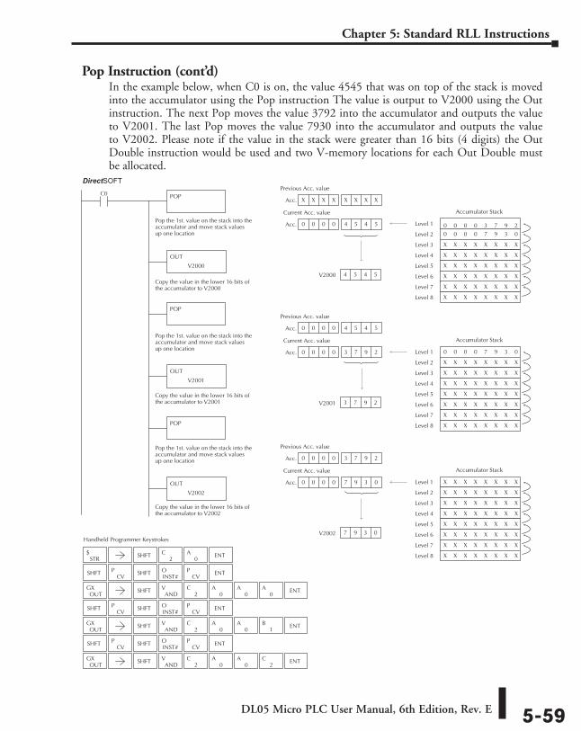
DL05 Micro PLC User Manual, 6th Edition, Rev. E 5-59
Chapter 5: Standard RLL Instructions
Pop Instruction (cont’d)In the example below, when C0 is on, the value 4545 that was on top of the stack is moved into the accumulator using the Pop instruction The value is output to V2000 using the Out instruction. The next Pop moves the value 3792 into the accumulator and outputs the value to V2001. The last Pop moves the value 7930 into the accumulator and outputs the value to V2002. Please note if the value in the stack were greater than 16 bits (4 digits) the Out Double instruction would be used and two V-memory locations for each Out Double must be allocated.
Handheld Programmer Keystrokes
Acc.
Pop the 1st. value on the stack into theaccumulator and move stack valuesup one location
POPC0
POP
POP
V2000 4 5 4 5
X X X X X X X X X X X X
Acc. 0 0 0 0 4 5 4 5 4 5 4 5
Previous Acc. value
Current Acc. value
0 0 0 0 3 7 9 2 0 0
Level 1
0 0 0 0 7 9 3 0 Level 2
X X X X X X X X Level 3
X X X X X X X X Level 4
X X X X X X X X Level 5
X X X X X X X X Level 6
X X X X X X X X Level 7
X X X X X X X X Level 8
Accumulator Stack
0 0 0 0 7 9 3 0 Level 1
X X X X X X X X Level 2
X X X X X X X X Level 3
X X X X X X X X Level 4
X X X X X X X X Level 5
X X X X X X X X Level 6
X X X X X X X X Level 7
X X X X X X X X Level 8
Accumulator Stack
X X X X X X X X Level 1
X X X X X X X X Level 2
X X X X X X X X Level 3
X X X X X X X X Level 4
X X X X X X X X Level 5
X X X X X X X X Level 6
X X X X X X X X Level 7
X X X X X X X X Level 8
Accumulator Stack
Pop the 1st. value on the stack into theaccumulator and move stack valuesup one location
Pop the 1st. value on the stack into theaccumulator and move stack valuesup one location
OUT
V2000
OUT
V2001
Acc.
V2001 3 7 9 2
0 0 0 0 4 5 4 5 4 5 4 5
Acc. 0 0 0 0 3 7 9 2
Previous Acc. value
Current Acc. value
Acc.
V2002 7 9 3 0
0 0 0 0 3 7 9 2
Acc. 0 0 0 0 7 9 3 0
Previous Acc. value
Current Acc. value
OUT
V2002
Copy the value in the lower 16 bits ofthe accumulator to V2000
Copy the value in the lower 16 bits ofthe accumulator to V2001
Copy the value in the lower 16 bits ofthe accumulator to V2002
Direct SOFT32
STR$ SHFT
2C
0A ENT
SHFTCV
PINST#O
CVP ENT
OUTGX SHFT
ANDV
2C
0A
0A ENT
0A
SHFTCV
PINST#O
CVP ENT
OUTGX SHFT
ANDV
2C
0A ENT
0A
1B
SHFTCV
PINST#O
CVP ENT
OUTGX SHFT
ANDV
2C
0A ENT
0A
2C
SHFT
SHFT
SHFT
DirectSOFT
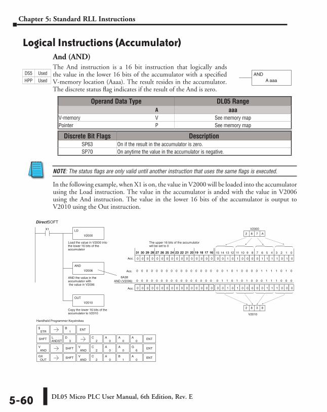
DL05 Micro PLC User Manual, 6th Edition, Rev. E5-60
Chapter 5: Standard RLL Instructions
Logical Instructions (Accumulator)And (AND)The And instruction is a 16 bit instruction that logically ands the value in the lower 16 bits of the accumulator with a specified V-memory location (Aaaa). The result resides in the accumulator. The discrete status flag indicates if the result of the And is zero.
NOTE: The status flags are only valid until another instruction that uses the same flags is executed.
In the following example, when X1 is on, the value in V2000 will be loaded into the accumulator using the Load instruction. The value in the accumulator is anded with the value in V2006 using the And instruction. The value in the lower 16 bits of the accumulator is output to V2010 using the Out instruction.
ANDA aaa
AND (V2006)
Handheld Programmer Keystrokes
LD
V2000
X1
Load the value in V2000 intothe lower 16 bits of theaccumulator
AND
V2006
AND the value in theaccumulator with the value in V2006
OUT
V2010
Copy the lower 16 bits of theaccumulator to V2010
0 0 1 0 1 0 0 0 0 1 1 1 1 0 1 0
0 0 1 0 1 0 0 0 0 0 1 1 1 0 0 00 0 0 0 0 1 0 0 0 0 0 0 0 0 0 0
V2000
2 8 7 A
0 0 0 0 0 0 0 0 0 0 0 0 0 0 0 0
0 0 0 0 0 0 0 0 0 0 0 0 0 0 0 0
The upper 16 bits of the accumulatorwill be set to 0
15 14 13 12 11 10 9 8 7 6 5 4 3 2 1 031 30 29 28 27 26 25 24 23 22 21 20 19 18 17 1631 30 29 28 27 26 25 24 23 22 21 20 19 18 17 16
Acc.
Acc.
0 0 1 0 1 0 0 0 0 1 1 1 1 0 1 00 0 0 0 0 0 0 0 0 0 0 0 0 0 0 0Acc.
0 1 1 0 1 0 1 0 0 0 1 1 1 0 0 00 0 0 0 0 0 0 0 0 0 0 0 0 0 0 06A38
V2010
2 8 3 8
Direct SOFT32
STR$
SHFTANDSTL
3D
SHFTAND
V2
C0
A0
A ENT6
G
OUTGX SHFT
ANDV
2C
0A
1B
0A ENT
ANDV
1B ENT
2C
0A
0A
0A ENT
Operand Data Type DL05 Range ⸠⸠⸠⸠⸠⸠⸠⸠⸠⸠⸠⸠⸠⸠⸠⸠⸠⸠⸠⸠⸠⸠⸠⸠⸠⸠⸠⸠⸠⸠⸠⸠⸠⸠⸠⸠⸠⸠⸠⸠⸠⸠⸠⸠⸠⸠⸠⸠⸠⸠⸠⸠⸠⸠⸠⸠⸠⸠⸠⸠⸠⸠⸠⸠⸠⸠⸠⸠⸠⸠⸠⸠⸠A aaaV-memory ⸠⸠⸠⸠⸠⸠⸠⸠⸠⸠⸠⸠⸠⸠⸠⸠⸠⸠⸠⸠⸠⸠⸠⸠⸠⸠⸠⸠⸠⸠⸠⸠⸠⸠⸠⸠⸠⸠⸠⸠⸠⸠⸠⸠⸠⸠⸠⸠⸠⸠⸠⸠⸠⸠⸠⸠⸠⸠V See memory mapPointer ⸠⸠⸠⸠⸠⸠⸠⸠⸠⸠⸠⸠⸠⸠⸠⸠⸠⸠⸠⸠⸠⸠⸠⸠⸠⸠⸠⸠⸠⸠⸠⸠⸠⸠⸠⸠⸠⸠⸠⸠⸠⸠⸠⸠⸠⸠⸠⸠⸠⸠⸠⸠⸠⸠⸠⸠⸠⸠⸠⸠⸠⸠⸠⸠P See memory map
Discrete Bit Flags DescriptionSP63 On if the result in the accumulator is zero.SP70 On anytime the value in the accumulator is negative.
DS5 Used
HPP Used
DirectSOFT
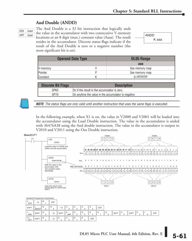
DL05 Micro PLC User Manual, 6th Edition, Rev. E 5-61
Chapter 5: Standard RLL Instructions
And Double (ANDD)The And Double is a 32 bit instruction that logically ands the value in the accumulator with two consecutive V-memory locations or an 8 digit (max.) constant value (Aaaa). The result resides in the accumulator. Discrete status flags indicate if the result of the And Double is zero or a negative number (the most significant bit is on).
In the following example, when X1 is on, the value in V2000 and V2001 will be loaded into the accumulator using the Load Double instruction. The value in the accumulator is anded with 36476A38 using the And double instruction. The value in the accumulator is output to V2010 and V2011 using the Out Double instruction.
K aaaANDD
AND 36476A38
Handheld Programmer Keystrokes
LDD
V2000
X1
Load the value in V2000 andV2001 into the accumulator
ANDD
K36476A38
AND the value in theaccumulator with the constant value36476A38
OUTD
V2010
Copy the value in theaccumulator to V2010 andV2011
0 0 1 0 1 0 0 0 0 1 1 1 1 0 1 0
0 0 1 0 1 0 0 0 0 0 1 1 1 0 0 00 0 0 0 0 1 0 0 0 0 0 0 0 0 0 0
2 8 7 A
0 0 0 1 0 1 0 0 0 1 0 0 0 1 1 0
0 1 0 1 0 1 0 0 0 1 1 1 1 1 1 0
15 14 13 12 11 10 9 8 7 6 5 4 3 2 1 031 30 29 28 27 26 25 24 23 22 21 20 19 18 17 1631 30 29 28 27 26 25 24 23 22 21 20 19 18 17 16
Acc.
Acc.
Acc.
V2010
2 8 3 8
5 4 7 E
V2011
1 4 4 6
0 1 0 1 0 1 0 0 0 1 1 1 1 1 1 0 0 0 1 0 1 0 0 0 0 1 1 1 1 0 1 0
0 1 1 0 1 0 1 0 0 0 1 1 1 0 0 00 0 1 1 0 1 1 0 0 1 0 0 0 1 1 1
Direct SOFT32
STR$
SHFTANDSTL
3D
SHFT
OUTGX
3D
SHFT3
D
ANDV SHFT
3D
8I
3DSHFTSHFT
JMPK
0A
3D
6G
4E
7H
6G ENT
1B ENT
2C
0A
1B
0A ENT
2C
0A
0A ENT
0A
V2000 V2000
Operand Data Type DL05 Rangeaaa
V-memory ⸠⸠⸠⸠⸠⸠⸠⸠⸠⸠⸠⸠⸠⸠⸠⸠⸠⸠⸠⸠⸠⸠⸠⸠⸠⸠⸠⸠⸠⸠⸠⸠⸠⸠⸠⸠⸠⸠⸠⸠⸠⸠⸠⸠⸠⸠⸠⸠⸠⸠⸠⸠⸠⸠⸠⸠⸠⸠V See memory mapPointer ⸠⸠⸠⸠⸠⸠⸠⸠⸠⸠⸠⸠⸠⸠⸠⸠⸠⸠⸠⸠⸠⸠⸠⸠⸠⸠⸠⸠⸠⸠⸠⸠⸠⸠⸠⸠⸠⸠⸠⸠⸠⸠⸠⸠⸠⸠⸠⸠⸠⸠⸠⸠⸠⸠⸠⸠⸠⸠⸠⸠⸠⸠⸠⸠P See memory mapConstant ⸠⸠⸠⸠⸠⸠⸠⸠⸠⸠⸠⸠⸠⸠⸠⸠⸠⸠⸠⸠⸠⸠⸠⸠⸠⸠⸠⸠⸠⸠⸠⸠⸠⸠⸠⸠⸠⸠⸠⸠⸠⸠⸠⸠⸠⸠⸠⸠⸠⸠⸠⸠⸠⸠⸠⸠⸠⸠⸠⸠⸠K 0–FFFFFFFF
Discrete Bit Flags DescriptionSP63 On if the result in the accumulator is zero.SP70 On anytime the value in the accumulator is negative
DS5 Used
HPP Used
DirectSOFT
NOTE: The status flags are only valid until another instruction that uses the same flags is executed.
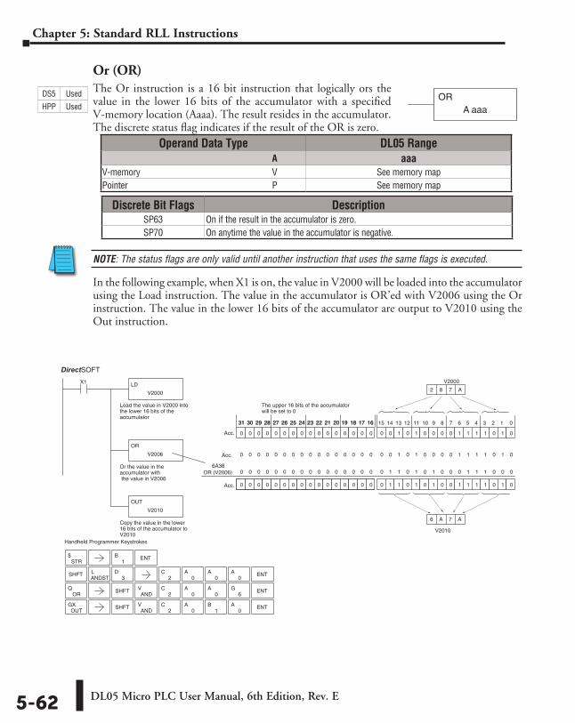
DL05 Micro PLC User Manual, 6th Edition, Rev. E5-62
Chapter 5: Standard RLL Instructions
Or (OR)The Or instruction is a 16 bit instruction that logically ors the value in the lower 16 bits of the accumulator with a specified V-memory location (Aaaa). The result resides in the accumulator. The discrete status flag indicates if the result of the OR is zero.
NOTE: The status flags are only valid until another instruction that uses the same flags is executed.
In the following example, when X1 is on, the value in V2000 will be loaded into the accumulator using the Load instruction. The value in the accumulator is OR’ed with V2006 using the Or instruction. The value in the lower 16 bits of the accumulator are output to V2010 using the Out instruction.
ORA aaa
3D
OR (V2006)
Handheld Programmer Keystrokes
LD
V2000
X1
Load the value in V2000 intothe lower 16 bits of theaccumulator
OR
V2006
Or the value in theaccumulator with the value in V2006
OUT
V2010
Copy the value in the lower16 bits of the accumulator toV2010
0 0 1 0 1 0 0 0 0 1 1 1 1 0 1 0
0 1 1 0 1 0 1 0 0 1 1 1 1 0 1 00 0 0 0 0 1 0 0 0 0 0 0 0 0 0 0
V2000
2 8 7 A
0 0 0 0 0 0 0 0 0 0 0 0 0 0 0 0
0 0 0 0 0 0 0 0 0 0 0 0 0 0 0 0
The upper 16 bits of the accumulatorwill be set to 0
15 14 13 12 11 10 9 8 7 6 5 4 3 2 131 30 29 28 27 26 25 24 23 22 21 20 19 18 17 1631 30 29 28 27 26 25 24 23 22 21 20 19 18 17 16
Acc.
Acc.
0 0 1 0 1 0 0 0 0 1 1 1 1 0 1 00 0 0 0 0 0 0 0 0 0 0 0 0 0 0 0Acc.
0 1 1 0 1 0 1 0 0 0 1 1 1 0 0 00 0 0 0 0 0 0 0 0 0 0 0 0 0 0 06A38
V2010
6 A 7 A
Direct SOFT32
STR$
1B ENT
SHFTANDSTL
2C
0A
0A
0A ENT
SHFTAND
V2
C0
A0
A ENT6
G
OUTGX SHFT
ANDV
2C
0A
1B
0A ENT
ORQ
0
Operand Data Type DL05 Range ⸠⸠⸠⸠⸠⸠⸠⸠⸠⸠⸠⸠⸠⸠⸠⸠⸠⸠⸠⸠⸠⸠⸠⸠⸠⸠⸠⸠⸠⸠⸠⸠⸠⸠⸠⸠⸠⸠⸠⸠⸠⸠⸠⸠⸠⸠⸠⸠⸠⸠⸠⸠⸠⸠⸠⸠⸠⸠⸠⸠⸠⸠⸠⸠⸠⸠⸠⸠⸠⸠⸠⸠⸠A aaaV-memory ⸠⸠⸠⸠⸠⸠⸠⸠⸠⸠⸠⸠⸠⸠⸠⸠⸠⸠⸠⸠⸠⸠⸠⸠⸠⸠⸠⸠⸠⸠⸠⸠⸠⸠⸠⸠⸠⸠⸠⸠⸠⸠⸠⸠⸠⸠⸠⸠⸠⸠⸠⸠⸠⸠⸠⸠⸠⸠V See memory mapPointer ⸠⸠⸠⸠⸠⸠⸠⸠⸠⸠⸠⸠⸠⸠⸠⸠⸠⸠⸠⸠⸠⸠⸠⸠⸠⸠⸠⸠⸠⸠⸠⸠⸠⸠⸠⸠⸠⸠⸠⸠⸠⸠⸠⸠⸠⸠⸠⸠⸠⸠⸠⸠⸠⸠⸠⸠⸠⸠⸠⸠⸠⸠⸠⸠P See memory map
Discrete Bit Flags DescriptionSP63 On if the result in the accumulator is zero.SP70 On anytime the value in the accumulator is negative.
DS5 Used
HPP Used
DirectSOFT
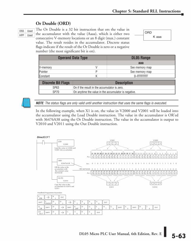
DL05 Micro PLC User Manual, 6th Edition, Rev. E 5-63
Chapter 5: Standard RLL Instructions
Or Double (ORD)The Or Double is a 32 bit instruction that ors the value in the accumulator with the value (Aaaa), which is either two consecutive V-memory locations or an 8 digit (max.) constant value. The result resides in the accumulator. Discrete status flags indicate if the result of the Or Double is zero or a negative number (the most significant bit is on).
NOTE: The status flags are only valid until another instruction that uses the same flags is executed.
In the following example, when X1 is on, the value in V2000 and V2001 will be loaded into the accumulator using the Load Double instruction. The value in the accumulator is OR’ed with 36476A38 using the Or Double instruction. The value in the accumulator is output to V2010 and V2011 using the Out Double instruction.
K aaaORD
JMPK
OR 36476A38
Handheld Programmer Keystrokes
LDD
V2000
X1
Load the value in V2000 andV2001 into accumulator
ORD
K36476A38
OR the value in theaccumulator with the constant value36476A38
OUTD
V2010
Copy the value in theaccumulator to V2010 andV2011
0 0 1 0 1 0 0 0 0 1 1 1 1 0 1 0
0 1 1 0 1 0 1 0 0 1 1 1 1 0 1 00 0 0 0 0 1 0 0 0 0 0 0 0 0 0 0
2 8 7 A
0 1 1 1 0 1 1 0 0 1 1 1 1 1 1 1
0 1 0 1 0 1 0 0 0 1 1 1 1 1 1 0
15 14 13 12 11 10 9 8 7 6 5 4 3 2 1 031 30 29 28 27 26 25 24 23 22 21 20 19 18 17 1631 30 29 28 27 26 25 24 23 22 21 20 19 18 17 16
Acc.
Acc.
Acc.
V2010
6 A 7 A
5 4 7 E
V2011
7 6 7 F
0 1 0 1 0 1 0 0 0 1 1 1 1 1 1 0 0 0 1 0 1 0 0 0 0 1 1 1 1 0 1 0
Direct SOFT32
0 1 1 0 1 0 1 0 0 0 1 1 1 0 0 00 0 1 1 0 1 1 0 0 1 0 0 0 1 1 1
STR$
SHFTANDSTL
3D
SHFT
OUTGX
3D
SHFT3
D
SHFT3
DOR
Q8
I3
DSHFTSHFT0
A3
D6
G4
E7
H6
G ENT
1B ENT
2C
0A
0A
0A ENT
2C
0A
1B
0A ENT
V2000V2001
Operand Data Type DL05 Rangeaaa
V-memory ⸠⸠⸠⸠⸠⸠⸠⸠⸠⸠⸠⸠⸠⸠⸠⸠⸠⸠⸠⸠⸠⸠⸠⸠⸠⸠⸠⸠⸠⸠⸠⸠⸠⸠⸠⸠⸠⸠⸠⸠⸠⸠⸠⸠⸠⸠⸠⸠⸠⸠⸠⸠⸠⸠⸠⸠⸠⸠V See memory mapPointer ⸠⸠⸠⸠⸠⸠⸠⸠⸠⸠⸠⸠⸠⸠⸠⸠⸠⸠⸠⸠⸠⸠⸠⸠⸠⸠⸠⸠⸠⸠⸠⸠⸠⸠⸠⸠⸠⸠⸠⸠⸠⸠⸠⸠⸠⸠⸠⸠⸠⸠⸠⸠⸠⸠⸠⸠⸠⸠⸠⸠⸠⸠⸠⸠P See memory mapConstant ⸠⸠⸠⸠⸠⸠⸠⸠⸠⸠⸠⸠⸠⸠⸠⸠⸠⸠⸠⸠⸠⸠⸠⸠⸠⸠⸠⸠⸠⸠⸠⸠⸠⸠⸠⸠⸠⸠⸠⸠⸠⸠⸠⸠⸠⸠⸠⸠⸠⸠⸠⸠⸠⸠⸠⸠⸠⸠⸠⸠⸠K 0–FFFFFFFF
Discrete Bit Flags DescriptionSP63 On if the result in the accumulator is zero.SP70 On anytime the value in the accumulator is negative.
DS5 Used
HPP Used
DirectSOFT
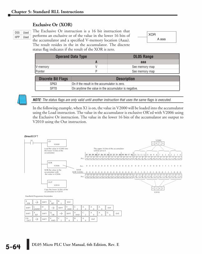
DL05 Micro PLC User Manual, 6th Edition, Rev. E5-64
Chapter 5: Standard RLL Instructions
Exclusive Or (XOR)The Exclusive Or instruction is a 16 bit instruction that performs an exclusive or of the value in the lower 16 bits of the accumulator and a specified V-memory location (Aaaa). The result resides in the in the accumulator. The discrete status flag indicates if the result of the XOR is zero.
NOTE: The status flags are only valid until another instruction that uses the same flags is executed.
In the following example, when X1 is on, the value in V2000 will be loaded into the accumulator using the Load instruction. The value in the accumulator is exclusive OR’ed with V2006 using the Exclusive Or instruction. The value in the lower 16 bits of the accumulator are output to V2010 using the Out instruction.
XORA aaa
XOR (V2006)
Handheld Programmer Keystrokes
LD
V2000
X1
Load the value in V2000 intothe lower 16 bits of theaccumulator
XOR
V2006
XOR the value in theaccumulator with the value in V2006
OUT
V2010
Copy the lower 16 bits of theaccumulator to V2010
0 0 1 0 1 0 0 0 0 1 1 1 1 0 1 0
0 1 0 0 0 0 1 0 0 1 0 0 0 0 1 00 0 0 0 0 1 0 0 0 0 0 0 0 0 0 0
V2000
2 8 7 A
0 0 0 0 0 0 0 0 0 0 0 0 0 0 0 0
0 0 0 0 0 0 0 0 0 0 0 0 0 0 0 0
The upper 16 bits of the accumulatorwill be set to 0
15 14 13 12 11 10 9 8 7 6 5 4 3 2 1 031 30 29 28 27 26 25 24 23 22 21 20 19 18 17 1631 30 29 28 27 26 25 24 23 22 21 20 19 18 17 16
Acc.
Acc.
0 0 1 0 1 0 0 0 0 1 1 1 1 0 1 00 0 0 0 0 0 0 0 0 0 0 0 0 0 0 0Acc.
6A38
V2010
4 2 4 2
Direct SOFT32
0 1 1 0 1 0 1 0 0 0 1 1 1 0 0 00 0 0 0 0 0 0 0 0 0 0 0 0 0 0 0
STR$ SHFT
SETX
1B ENT
SHFTANDSTL
3D SHFT
ANDV
2C
0A
0A
0A ENT
SHFTAND
V2
C0
A0
A ENT6
G
OUTGX SHFT
ANDV
2C
0A
1B
0A ENT
ORQSHFT SHFT
SETX
Operand Data Type DL05 Range ⸠⸠⸠⸠⸠⸠⸠⸠⸠⸠⸠⸠⸠⸠⸠⸠⸠⸠⸠⸠⸠⸠⸠⸠⸠⸠⸠⸠⸠⸠⸠⸠⸠⸠⸠⸠⸠⸠⸠⸠⸠⸠⸠⸠⸠⸠⸠⸠⸠⸠⸠⸠⸠⸠⸠⸠⸠⸠⸠⸠⸠⸠⸠⸠⸠⸠⸠⸠⸠⸠⸠⸠⸠A aaaV-memory ⸠⸠⸠⸠⸠⸠⸠⸠⸠⸠⸠⸠⸠⸠⸠⸠⸠⸠⸠⸠⸠⸠⸠⸠⸠⸠⸠⸠⸠⸠⸠⸠⸠⸠⸠⸠⸠⸠⸠⸠⸠⸠⸠⸠⸠⸠⸠⸠⸠⸠⸠⸠⸠⸠⸠⸠⸠⸠V See memory mapPointer ⸠⸠⸠⸠⸠⸠⸠⸠⸠⸠⸠⸠⸠⸠⸠⸠⸠⸠⸠⸠⸠⸠⸠⸠⸠⸠⸠⸠⸠⸠⸠⸠⸠⸠⸠⸠⸠⸠⸠⸠⸠⸠⸠⸠⸠⸠⸠⸠⸠⸠⸠⸠⸠⸠⸠⸠⸠⸠⸠⸠⸠⸠⸠⸠P See memory map
DS5 Used
HPP Used
Discrete Bit Flags DescriptionSP63 On if the result in the accumulator is zero.SP70 On anytime the value in the accumulator is negative.
DirectSOFT
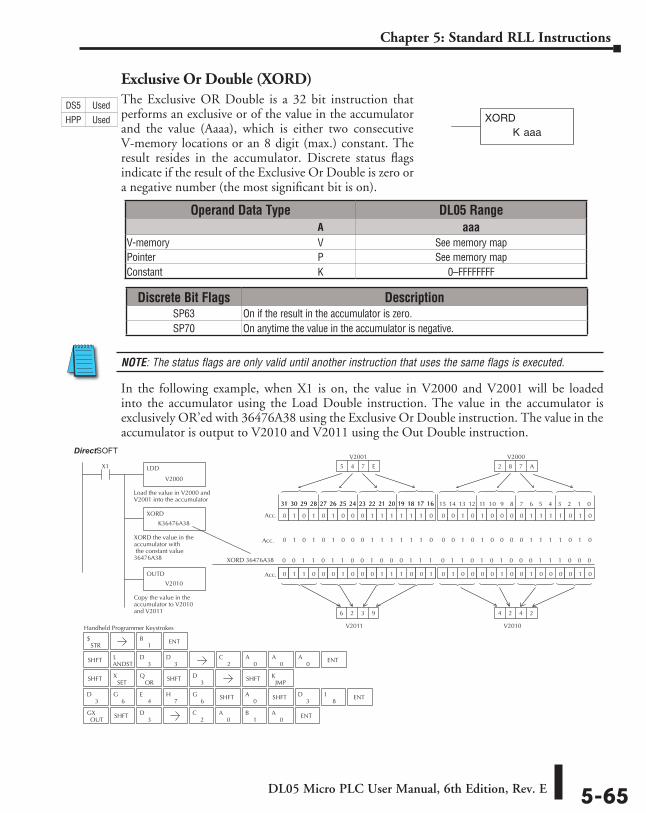
DL05 Micro PLC User Manual, 6th Edition, Rev. E 5-65
Chapter 5: Standard RLL Instructions
Exclusive Or Double (XORD)The Exclusive OR Double is a 32 bit instruction that performs an exclusive or of the value in the accumulator and the value (Aaaa), which is either two consecutive V-memory locations or an 8 digit (max.) constant. The result resides in the accumulator. Discrete status flags indicate if the result of the Exclusive Or Double is zero or a negative number (the most significant bit is on).
NOTE: The status flags are only valid until another instruction that uses the same flags is executed.
In the following example, when X1 is on, the value in V2000 and V2001 will be loaded into the accumulator using the Load Double instruction. The value in the accumulator is exclusively OR’ed with 36476A38 using the Exclusive Or Double instruction. The value in the accumulator is output to V2010 and V2011 using the Out Double instruction.
K aaaXORD
JMPKSHFTSHFT
3D
ORQ
XORD 36476A38
Handheld Programmer Keystrokes
LDD
V2000
X1
Load the value in V2000 andV2001 into the accumulator
XORD
K36476A38
XORD the value in theaccumulator with the constant value36476A38
OUTD
V2010
Copy the value in theaccumulator to V2010and V2011
0 0 1 0 1 0 0 0 0 1 1 1 1 0 1 0
0 1 0 0 0 0 1 0 0 1 0 0 0 0 1 00 0 0 0 0 1 0 0 0 0 0 0 0 0 0 0
V2000
2 8 7 A
0 1 1 0 0 0 1 0 0 0 1 1 1 0 0 1
0 1 0 1 0 1 0 0 0 1 1 1 1 1 1 0
15 14 13 12 11 10 9 8 7 6 5 4 3 2 1 031 30 29 28 27 26 25 24 23 22 21 20 19 18 17 1631 30 29 28 27 26 25 24 23 22 21 20 19 18 17 16
Acc.
Acc.
Acc.
V2010
4 2 4 2
V2001
5 4 7 E
V2011
6 2 3 9
0 1 0 1 0 1 0 0 0 1 1 1 1 1 1 0 0 0 1 0 1 0 0 0 0 1 1 1 1 0 1 0
Direct SOFT32
0 1 1 0 1 0 1 0 0 0 1 1 1 0 0 00 0 1 1 0 1 1 0 0 1 0 0 0 1 1 1
STR$
SHFTANDSTL
3D
3D
SHFTSET
X
OUTGX SHFT
3D
3D
6G
4E
8I
3DSHFTSHFT
0A
7H
6G ENT
1B ENT
2C
0A
0A
0A ENT
2C
0A
1B
0A ENT
Operand Data Type DL05 Range ⸠⸠⸠⸠⸠⸠⸠⸠⸠⸠⸠⸠⸠⸠⸠⸠⸠⸠⸠⸠⸠⸠⸠⸠⸠⸠⸠⸠⸠⸠⸠⸠⸠⸠⸠⸠⸠⸠⸠⸠⸠⸠⸠⸠⸠⸠⸠⸠⸠⸠⸠⸠⸠⸠⸠⸠⸠⸠⸠⸠⸠⸠⸠⸠⸠⸠⸠⸠⸠⸠⸠⸠⸠A aaaV-memory ⸠⸠⸠⸠⸠⸠⸠⸠⸠⸠⸠⸠⸠⸠⸠⸠⸠⸠⸠⸠⸠⸠⸠⸠⸠⸠⸠⸠⸠⸠⸠⸠⸠⸠⸠⸠⸠⸠⸠⸠⸠⸠⸠⸠⸠⸠⸠⸠⸠⸠⸠⸠⸠⸠⸠⸠⸠⸠V See memory mapPointer ⸠⸠⸠⸠⸠⸠⸠⸠⸠⸠⸠⸠⸠⸠⸠⸠⸠⸠⸠⸠⸠⸠⸠⸠⸠⸠⸠⸠⸠⸠⸠⸠⸠⸠⸠⸠⸠⸠⸠⸠⸠⸠⸠⸠⸠⸠⸠⸠⸠⸠⸠⸠⸠⸠⸠⸠⸠⸠⸠⸠⸠⸠⸠⸠P See memory mapConstant ⸠⸠⸠⸠⸠⸠⸠⸠⸠⸠⸠⸠⸠⸠⸠⸠⸠⸠⸠⸠⸠⸠⸠⸠⸠⸠⸠⸠⸠⸠⸠⸠⸠⸠⸠⸠⸠⸠⸠⸠⸠⸠⸠⸠⸠⸠⸠⸠⸠⸠⸠⸠⸠⸠⸠⸠⸠⸠⸠⸠⸠K 0–FFFFFFFF
DS5 Used
HPP Used
Discrete Bit Flags DescriptionSP63 On if the result in the accumulator is zero.SP70 On anytime the value in the accumulator is negative.
DirectSOFT
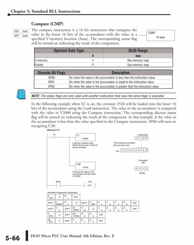
DL05 Micro PLC User Manual, 6th Edition, Rev. E5-66
Chapter 5: Standard RLL Instructions
Compare (CMP)The compare instruction is a 16 bit instruction that compares the value in the lower 16 bits of the accumulator with the value in a specified V-memory location (Aaaa). The corresponding status flag will be turned on indicating the result of the comparison.
NOTE: The status flags are only valid until another instruction that uses the same flags is executed.
In the following example when X1 is on, the constant 4526 will be loaded into the lower 16 bits of the accumulator using the Load instruction. The value in the accumulator is compared with the value in V2000 using the Compare instruction. The corresponding discrete status flag will be turned on indicating the result of the comparison. In this example, if the value in the accumulator is less than the value specified in the Compare instruction, SP60 will turn on energizing C30.
CMPA aaa
Discrete Bit Flags DescriptionSP60 On when the value in the accumulator is less than the instruction value.SP61 On when the value in the accumulator is equal to the instruction value.SP62 On when the value in the accumulator is greater than the instruction value.
Handheld Programmer Keystrokes
V2000
Acc.
CONSTANT4 5 2 6 ? ?
8 9 4 5
0 0 0 0 4 5 2 64 5 2 6 ? ?
LD
Compare the value in theaccumulator with the valuein V2000
Load the constant value4526 into the lower 16 bits ofthe accumulator
K4526
CMP
X1
V2000
Compared with
SP60 C30
DirectSOFT32
The unused accumulatorbits are set to zero
STR$
SHFT ANDSTL
3D SHFT JMP
K4
E5
F2
C6
G ENT
SHFT 2C
ORSTM
CVP
STR$ SHFT ENTSTRN
SP6
G0
A
OUTGX SHFT 2
C3
D0
A ENT
1B ENT
2C
0A
0A
0A ENTSHFT
OUT
Operand Data Type DL05 Range ⸠⸠⸠⸠⸠⸠⸠⸠⸠⸠⸠⸠⸠⸠⸠⸠⸠⸠⸠⸠⸠⸠⸠⸠⸠⸠⸠⸠⸠⸠⸠⸠⸠⸠⸠⸠⸠⸠⸠⸠⸠⸠⸠⸠⸠⸠⸠⸠⸠⸠⸠⸠⸠⸠⸠⸠⸠⸠⸠⸠⸠⸠⸠⸠⸠⸠⸠⸠⸠⸠⸠⸠⸠A aaaV-memory ⸠⸠⸠⸠⸠⸠⸠⸠⸠⸠⸠⸠⸠⸠⸠⸠⸠⸠⸠⸠⸠⸠⸠⸠⸠⸠⸠⸠⸠⸠⸠⸠⸠⸠⸠⸠⸠⸠⸠⸠⸠⸠⸠⸠⸠⸠⸠⸠⸠⸠⸠⸠⸠⸠⸠⸠⸠⸠V See memory mapPointer ⸠⸠⸠⸠⸠⸠⸠⸠⸠⸠⸠⸠⸠⸠⸠⸠⸠⸠⸠⸠⸠⸠⸠⸠⸠⸠⸠⸠⸠⸠⸠⸠⸠⸠⸠⸠⸠⸠⸠⸠⸠⸠⸠⸠⸠⸠⸠⸠⸠⸠⸠⸠⸠⸠⸠⸠⸠⸠⸠⸠⸠⸠⸠⸠P See memory map
DS5 Used
HPP Used
DirectSOFT
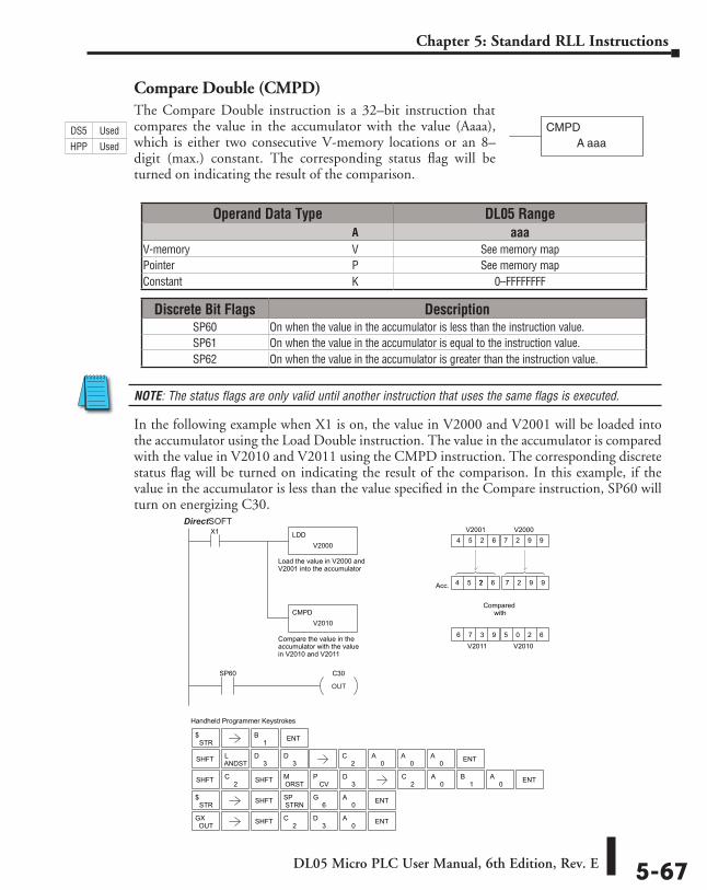
DL05 Micro PLC User Manual, 6th Edition, Rev. E 5-67
Chapter 5: Standard RLL Instructions
Compare Double (CMPD)The Compare Double instruction is a 32–bit instruction that compares the value in the accumulator with the value (Aaaa), which is either two consecutive V-memory locations or an 8–digit (max.) constant. The corresponding status flag will be turned on indicating the result of the comparison.
NOTE: The status flags are only valid until another instruction that uses the same flags is executed.
In the following example when X1 is on, the value in V2000 and V2001 will be loaded into the accumulator using the Load Double instruction. The value in the accumulator is compared with the value in V2010 and V2011 using the CMPD instruction. The corresponding discrete status flag will be turned on indicating the result of the comparison. In this example, if the value in the accumulator is less than the value specified in the Compare instruction, SP60 will turn on energizing C30.
CMPDA aaa
Handheld Programmer Keystrokes
LDD
Compare the value in theaccumulator with the valuein V2010 and V2011
Load the value in V2000 andV2001 into the accumulator
V2000
CMPD
X1
V2010
Compared with
SP60 C30
V2010
Acc.
V2000
4 5 2 6 7 7 ? 7 2 9 9
V20014 5 2 6 7 2 9 9
V20116 7 3 9 5 0 2 6
DirectSOFT32
STR$
SHFT ANDSTL
3D
SHFT 2C
ORSTM
CVP
STR$ SHFT ENTSTRN
SP6
G0
A
OUTGX SHFT 2
C3
D0
A ENT
3D
3D
1B ENT
ENT
2C
0A
0A ENT
2C
0A
0A
0A
1BSHFT
OUT
Operand Data Type DL05 Range ⸠⸠⸠⸠⸠⸠⸠⸠⸠⸠⸠⸠⸠⸠⸠⸠⸠⸠⸠⸠⸠⸠⸠⸠⸠⸠⸠⸠⸠⸠⸠⸠⸠⸠⸠⸠⸠⸠⸠⸠⸠⸠⸠⸠⸠⸠⸠⸠⸠⸠⸠⸠⸠⸠⸠⸠⸠⸠⸠⸠⸠⸠⸠⸠⸠⸠⸠⸠⸠⸠⸠⸠⸠A aaaV-memory ⸠⸠⸠⸠⸠⸠⸠⸠⸠⸠⸠⸠⸠⸠⸠⸠⸠⸠⸠⸠⸠⸠⸠⸠⸠⸠⸠⸠⸠⸠⸠⸠⸠⸠⸠⸠⸠⸠⸠⸠⸠⸠⸠⸠⸠⸠⸠⸠⸠⸠⸠⸠⸠⸠⸠⸠⸠⸠V See memory mapPointer ⸠⸠⸠⸠⸠⸠⸠⸠⸠⸠⸠⸠⸠⸠⸠⸠⸠⸠⸠⸠⸠⸠⸠⸠⸠⸠⸠⸠⸠⸠⸠⸠⸠⸠⸠⸠⸠⸠⸠⸠⸠⸠⸠⸠⸠⸠⸠⸠⸠⸠⸠⸠⸠⸠⸠⸠⸠⸠⸠⸠⸠⸠⸠⸠P See memory mapConstant ⸠⸠⸠⸠⸠⸠⸠⸠⸠⸠⸠⸠⸠⸠⸠⸠⸠⸠⸠⸠⸠⸠⸠⸠⸠⸠⸠⸠⸠⸠⸠⸠⸠⸠⸠⸠⸠⸠⸠⸠⸠⸠⸠⸠⸠⸠⸠⸠⸠⸠⸠⸠⸠⸠⸠⸠⸠⸠⸠⸠⸠K 0–FFFFFFFF
Discrete Bit Flags DescriptionSP60 On when the value in the accumulator is less than the instruction value.SP61 On when the value in the accumulator is equal to the instruction value.SP62 On when the value in the accumulator is greater than the instruction value.
DS5 Used
HPP Used
DirectSOFT
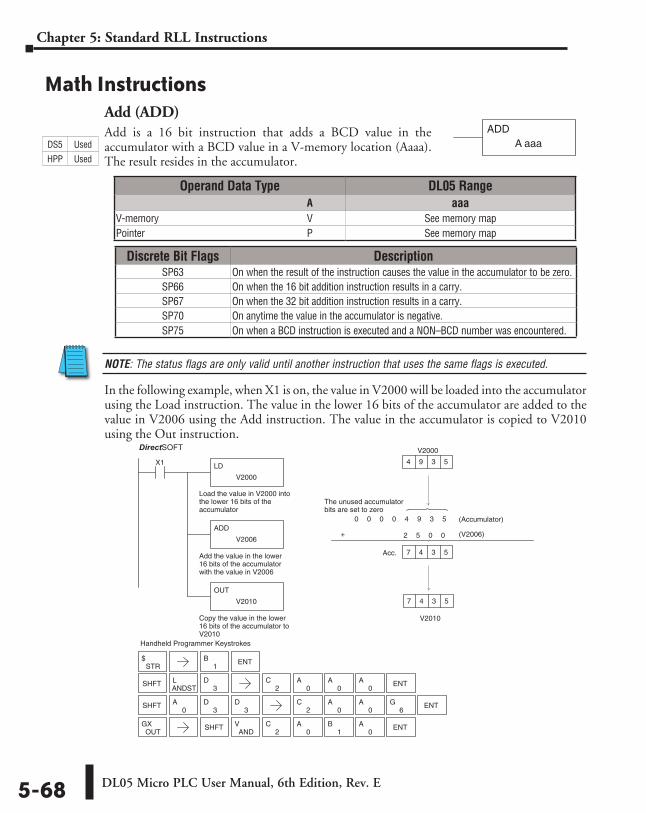
DL05 Micro PLC User Manual, 6th Edition, Rev. E5-68
Chapter 5: Standard RLL Instructions
Math InstructionsAdd (ADD)Add is a 16 bit instruction that adds a BCD value in the accumulator with a BCD value in a V-memory location (Aaaa). The result resides in the accumulator.
NOTE: The status flags are only valid until another instruction that uses the same flags is executed.
In the following example, when X1 is on, the value in V2000 will be loaded into the accumulator using the Load instruction. The value in the lower 16 bits of the accumulator are added to the value in V2006 using the Add instruction. The value in the accumulator is copied to V2010 using the Out instruction.
ADDA aaa
Discrete Bit Flags DescriptionSP63 On when the result of the instruction causes the value in the accumulator to be zero.SP66 On when the 16 bit addition instruction results in a carry.SP67 On when the 32 bit addition instruction results in a carry.SP70 On anytime the value in the accumulator is negative.SP75 On when a BCD instruction is executed and a NON–BCD number was encountered.
Direct SOFT32
Handheld Programmer Keystrokes
LD
V2000
X1
Load the value in V2000 intothe lower 16 bits of theaccumulator
ADD
V2006
Add the value in the lower16 bits of the accumulatorwith the value in V2006
OUT
V2010
Copy the value in the lower16 bits of the accumulator toV2010
V2010
V2000
4 9 3 5
7 4 3 5
0 0 0 0 4 9 3 5
+ 2 5 0 0
Acc. 7 4 3 5
(V2006)
(Accumulator)
The unused accumulatorbits are set to zero
SHFTANDSTL
3D
STR$
SHFT0
A3
D3
D
OUTGX SHFT
ANDV
2C
0A
1B
0A ENT
1B ENT
2C
0A
0A
0A ENT
2C
0A
0A ENT
6G
Operand Data Type DL05 Range ⸠⸠⸠⸠⸠⸠⸠⸠⸠⸠⸠⸠⸠⸠⸠⸠⸠⸠⸠⸠⸠⸠⸠⸠⸠⸠⸠⸠⸠⸠⸠⸠⸠⸠⸠⸠⸠⸠⸠⸠⸠⸠⸠⸠⸠⸠⸠⸠⸠⸠⸠⸠⸠⸠⸠⸠⸠⸠⸠⸠⸠⸠⸠⸠⸠⸠⸠⸠⸠⸠⸠⸠⸠A aaaV-memory ⸠⸠⸠⸠⸠⸠⸠⸠⸠⸠⸠⸠⸠⸠⸠⸠⸠⸠⸠⸠⸠⸠⸠⸠⸠⸠⸠⸠⸠⸠⸠⸠⸠⸠⸠⸠⸠⸠⸠⸠⸠⸠⸠⸠⸠⸠⸠⸠⸠⸠⸠⸠⸠⸠⸠⸠⸠⸠V See memory mapPointer ⸠⸠⸠⸠⸠⸠⸠⸠⸠⸠⸠⸠⸠⸠⸠⸠⸠⸠⸠⸠⸠⸠⸠⸠⸠⸠⸠⸠⸠⸠⸠⸠⸠⸠⸠⸠⸠⸠⸠⸠⸠⸠⸠⸠⸠⸠⸠⸠⸠⸠⸠⸠⸠⸠⸠⸠⸠⸠⸠⸠⸠⸠⸠⸠P See memory map
DS5 Used
HPP Used
DirectSOFT
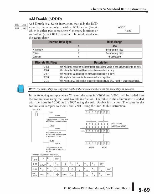
DL05 Micro PLC User Manual, 6th Edition, Rev. E 5-69
Chapter 5: Standard RLL Instructions
Add Double (ADDD)Add Double is a 32 bit instruction that adds the BCD value in the accumulator with a BCD value (Aaaa), which is either two consecutive V-memory locations or an 8–digit (max.) BCD constant. The result resides in the accumulator.
NOTE: The status flags are only valid until another instruction that uses the same flags is executed.
In the following example, when X1 is on, the value in V2000 and V2001 will be loaded into the accumulator using the Load Double instruction. The value in the accumulator is added with the value in V2006 and V2007 using the Add Double instruction. The value in the accumulator is copied to V2010 and V2011 using the Out Double instruction.
ADDDA aaa
6 7 3 9 5 0 2 6
Direct SOFT
Handheld Programmer Keystrokes
LDD
V2000
X1
Load the value in V2000 andV2001 into the accumulator
ADDD
V2006
Add the value in theaccumulator with the valuein V2006 and V2007
OUTD
V2010
Copy the value in theaccumulator to V2010 andV2011
V2010
V2000
V2001
6 7 3 9 5 0 2 6
V2011
8 7 3 9 9 0 7 2
(Accumulator)
2 0 0 0 4 0 4 6 +
8 7 3 9 9 0 7 2 Acc.
STR$
1B
SHFT0
A3
D3
D
SHFTANDSTL
3D
3D
3D
OUTGX SHFT
3D
ANDV
2C
0A
1B
0A ENTSHFT
ENT
2C
0A
0A ENT
6G
2C
0A
0A
0A ENT
(V2006 and V2007)
Discrete Bit Flags DescriptionSP63 On when the result of the instruction causes the value in the accumulator to be zero.SP66 On when the 16 bit addition instruction results in a carry.SP67 On when the 32 bit addition instruction results in a carry.SP70 On anytime the value in the accumulator is negative.SP75 On when a BCD instruction is executed and a NON–BCD number was encountered.
Operand Data Type DL05 Range ⸠⸠⸠⸠⸠⸠⸠⸠⸠⸠⸠⸠⸠⸠⸠⸠⸠⸠⸠⸠⸠⸠⸠⸠⸠⸠⸠⸠⸠⸠⸠⸠⸠⸠⸠⸠⸠⸠⸠⸠⸠⸠⸠⸠⸠⸠⸠⸠⸠⸠⸠⸠⸠⸠⸠⸠⸠⸠⸠⸠⸠⸠⸠⸠⸠⸠⸠⸠⸠⸠⸠⸠⸠A aaaV-memory ⸠⸠⸠⸠⸠⸠⸠⸠⸠⸠⸠⸠⸠⸠⸠⸠⸠⸠⸠⸠⸠⸠⸠⸠⸠⸠⸠⸠⸠⸠⸠⸠⸠⸠⸠⸠⸠⸠⸠⸠⸠⸠⸠⸠⸠⸠⸠⸠⸠⸠⸠⸠⸠⸠⸠⸠⸠⸠V See memory mapPointer ⸠⸠⸠⸠⸠⸠⸠⸠⸠⸠⸠⸠⸠⸠⸠⸠⸠⸠⸠⸠⸠⸠⸠⸠⸠⸠⸠⸠⸠⸠⸠⸠⸠⸠⸠⸠⸠⸠⸠⸠⸠⸠⸠⸠⸠⸠⸠⸠⸠⸠⸠⸠⸠⸠⸠⸠⸠⸠⸠⸠⸠⸠⸠⸠P See memory mapConstant ⸠⸠⸠⸠⸠⸠⸠⸠⸠⸠⸠⸠⸠⸠⸠⸠⸠⸠⸠⸠⸠⸠⸠⸠⸠⸠⸠⸠⸠⸠⸠⸠⸠⸠⸠⸠⸠⸠⸠⸠⸠⸠⸠⸠⸠⸠⸠⸠⸠⸠⸠⸠⸠⸠⸠⸠⸠⸠⸠⸠⸠K 0–99999999
DS5 Used
HPP Used
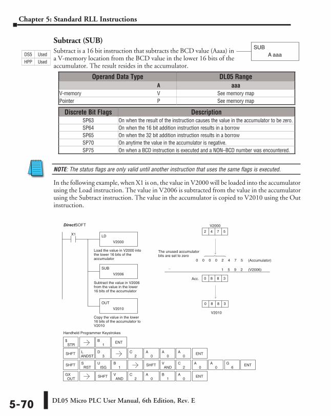
DL05 Micro PLC User Manual, 6th Edition, Rev. E5-70
Chapter 5: Standard RLL Instructions
Subtract (SUB)Subtract is a 16 bit instruction that subtracts the BCD value (Aaaa) in a V-memory location from the BCD value in the lower 16 bits of the accumulator. The result resides in the accumulator.
NOTE: The status flags are only valid until another instruction that uses the same flags is executed.
In the following example, when X1 is on, the value in V2000 will be loaded into the accumulator using the Load instruction. The value in V2006 is subtracted from the value in the accumulator using the Subtract instruction. The value in the accumulator is copied to V2010 using the Out instruction.
SUBA aaa
Direct SOFT32
Handheld Programmer Keystrokes
LD
V2000
X1
Load the value in V2000 intothe lower 16 bits of theaccumulator
SUB
V2006
Subtract the value in V2006from the value in the lower16 bits of the accumulator
OUT
V2010
Copy the value in the lower16 bits of the accumulator toV2010
V2010
2
0
0
_
V2000
4 7 5
8 8 3
0 0 0 0 2 4 7 5
1 5 9 2
Acc. 8 8 3
The unused accumulatorbits are set to zero
SHFTANDSTL
3D
STR$
SHFT SHFTAND
V2
C0
A0
A ENT6
G
OUTGX SHFT
ANDV
2C
0A
1B
0A ENT
RSTS
ISGU
1B
1B ENT
2C
0A
0A
0A ENT
(V2006)
(Accumulator)
Operand Data Type DL05 Range ⸠⸠⸠⸠⸠⸠⸠⸠⸠⸠⸠⸠⸠⸠⸠⸠⸠⸠⸠⸠⸠⸠⸠⸠⸠⸠⸠⸠⸠⸠⸠⸠⸠⸠⸠⸠⸠⸠⸠⸠⸠⸠⸠⸠⸠⸠⸠⸠⸠⸠⸠⸠⸠⸠⸠⸠⸠⸠⸠⸠⸠⸠⸠⸠⸠⸠⸠⸠⸠⸠⸠⸠⸠A aaaV-memory ⸠⸠⸠⸠⸠⸠⸠⸠⸠⸠⸠⸠⸠⸠⸠⸠⸠⸠⸠⸠⸠⸠⸠⸠⸠⸠⸠⸠⸠⸠⸠⸠⸠⸠⸠⸠⸠⸠⸠⸠⸠⸠⸠⸠⸠⸠⸠⸠⸠⸠⸠⸠⸠⸠⸠⸠⸠⸠V See memory mapPointer ⸠⸠⸠⸠⸠⸠⸠⸠⸠⸠⸠⸠⸠⸠⸠⸠⸠⸠⸠⸠⸠⸠⸠⸠⸠⸠⸠⸠⸠⸠⸠⸠⸠⸠⸠⸠⸠⸠⸠⸠⸠⸠⸠⸠⸠⸠⸠⸠⸠⸠⸠⸠⸠⸠⸠⸠⸠⸠⸠⸠⸠⸠⸠⸠P See memory map
Discrete Bit Flags DescriptionSP63 On when the result of the instruction causes the value in the accumulator to be zero.SP64 On when the 16 bit addition instruction results in a borrowSP65 On when the 32 bit addition instruction results in a borrowSP70 On anytime the value in the accumulator is negative.SP75 On when a BCD instruction is executed and a NON–BCD number was encountered.
DS5 Used
HPP Used
DirectSOFT
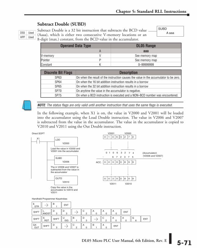
DL05 Micro PLC User Manual, 6th Edition, Rev. E 5-71
Chapter 5: Standard RLL Instructions
Subtract Double (SUBD)Subtract Double is a 32 bit instruction that subtracts the BCD value (Aaaa), which is either two consecutive V-memory locations or an 8-digit (max.) constant, from the BCD value in the accumulator.
NOTE: The status flags are only valid until another instruction that uses the same flags is executed.
In the following example, when X1 is on, the value in V2000 and V2001 will be loaded into the accumulator using the Load Double instruction. The value in V2006 and V2007 is subtracted from the value in the accumulator. The value in the accumulator is copied to V2010 and V2011 using the Out Double instruction.
SUBDA aaa
Discrete Bit Flags DescriptionSP63 On when the result of the instruction causes the value in the accumulator to be zero.SP64 On when the 16 bit addition instruction results in a borrowSP65 On when the 32 bit addition instruction results in a borrowSP70 On anytime the value in the accumulator is negative.SP75 On when a BCD instruction is executed and a NON–BCD number was encountered.
Operand Data Type DL05 Range ⸠⸠⸠⸠⸠⸠⸠⸠⸠⸠⸠⸠⸠⸠⸠⸠⸠⸠⸠⸠⸠⸠⸠⸠⸠⸠⸠⸠⸠⸠⸠⸠⸠⸠⸠⸠⸠⸠⸠⸠⸠⸠⸠⸠⸠⸠⸠⸠⸠⸠⸠⸠⸠⸠⸠⸠⸠⸠⸠⸠⸠⸠⸠⸠⸠⸠⸠⸠⸠⸠⸠⸠⸠A aaaV-memory ⸠⸠⸠⸠⸠⸠⸠⸠⸠⸠⸠⸠⸠⸠⸠⸠⸠⸠⸠⸠⸠⸠⸠⸠⸠⸠⸠⸠⸠⸠⸠⸠⸠⸠⸠⸠⸠⸠⸠⸠⸠⸠⸠⸠⸠⸠⸠⸠⸠⸠⸠⸠⸠⸠⸠⸠⸠⸠V See memory mapPointer ⸠⸠⸠⸠⸠⸠⸠⸠⸠⸠⸠⸠⸠⸠⸠⸠⸠⸠⸠⸠⸠⸠⸠⸠⸠⸠⸠⸠⸠⸠⸠⸠⸠⸠⸠⸠⸠⸠⸠⸠⸠⸠⸠⸠⸠⸠⸠⸠⸠⸠⸠⸠⸠⸠⸠⸠⸠⸠⸠⸠⸠⸠⸠⸠P See memory mapConstant ⸠⸠⸠⸠⸠⸠⸠⸠⸠⸠⸠⸠⸠⸠⸠⸠⸠⸠⸠⸠⸠⸠⸠⸠⸠⸠⸠⸠⸠⸠⸠⸠⸠⸠⸠⸠⸠⸠⸠⸠⸠⸠⸠⸠⸠⸠⸠⸠⸠⸠⸠⸠⸠⸠⸠⸠⸠⸠⸠⸠⸠K 0–99999999
Direct SOFT
Handheld Programmer Keystrokes
LDD
V2000
X1
Load the value in V2000 andV2001 into the accumulator
SUBD
V2006
The in V2006 and V2007 issubtracted from the value inthe accumulator
OUTD
V2010
Copy the value in theaccumulator to V2010 andV2011
0 0 3 9 0 8 9 9
0 1 0 6 3 2 7 4
0 1 0 6 3 2 7 4 (Accumulator)
V2010
V2000
V2001
V2011
0 0 3 9 0 8 9 9
6 7 2 3 7 5
ACC.
STR$
SHFT
SHFTANDSTL
3D
3D
3D
OUTGX SHFT
3D
RSTS
ISGU
1B
1B ENT
2C
0A
0A ENT
6G
2C
0A
0A
0A ENT
2C
0A
1B
0A ENT
SHFT
_ (V2006 and V2007)
DS5 Used
HPP Used
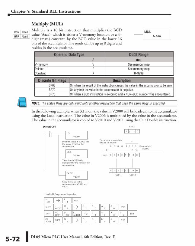
DL05 Micro PLC User Manual, 6th Edition, Rev. E5-72
Chapter 5: Standard RLL Instructions
Multiply (MUL)Multiply is a 16 bit instruction that multiplies the BCD value (Aaaa), which is either a V-memory location or a 4–digit (max.) constant, by the BCD value in the lower 16 bits of the accumulator The result can be up to 8 digits and resides in the accumulator.
NOTE: The status flags are only valid until another instruction that uses the same flags is executed.
In the following example, when X1 is on, the value in V2000 will be loaded into the accumulator using the Load instruction. The value in V2006 is multiplied by the value in the accumulator. The value in the accumulator is copied to V2010 and V2011 using the Out Double instruction.
MULA aaa
Direct SOFT32
Handheld Programmer Keystrokes
LD
V2000
X1
Load the value in V2000 intothe lower 16 bits of theaccumulator
MUL
V2006
The value in V2006 ismultiplied by the value in theaccumulator
OUTD
V2010
Copy the value in theaccumulator to V2010 andV2011
0 0 0 2 5 0 0 0
0
X
0 0 0 0 1 0 0 0
V2010
1
V2000 0
0 0 0 2 5 0 0 0
2 5
The unused accumulatorbits are set to zero
Acc.
STR$
SHFTANDSTL
3D
SHFTORSTM
ISGU
ANDSTL
OUTGX SHFT
3D
1B ENT
2C
0A
0A
0A ENT
2C
0A
0A ENT
6G
2C
0A
1B
0A ENT
0
V2011
(Accumulator) (V2006)
Operand Data Type DL05 Range ⸠⸠⸠⸠⸠⸠⸠⸠⸠⸠⸠⸠⸠⸠⸠⸠⸠⸠⸠⸠⸠⸠⸠⸠⸠⸠⸠⸠⸠⸠⸠⸠⸠⸠⸠⸠⸠⸠⸠⸠⸠⸠⸠⸠⸠⸠⸠⸠⸠⸠⸠⸠⸠⸠⸠⸠⸠⸠⸠⸠⸠⸠⸠⸠⸠⸠⸠⸠⸠⸠⸠⸠⸠A aaaV-memory ⸠⸠⸠⸠⸠⸠⸠⸠⸠⸠⸠⸠⸠⸠⸠⸠⸠⸠⸠⸠⸠⸠⸠⸠⸠⸠⸠⸠⸠⸠⸠⸠⸠⸠⸠⸠⸠⸠⸠⸠⸠⸠⸠⸠⸠⸠⸠⸠⸠⸠⸠⸠⸠⸠⸠⸠⸠⸠V See memory mapPointer ⸠⸠⸠⸠⸠⸠⸠⸠⸠⸠⸠⸠⸠⸠⸠⸠⸠⸠⸠⸠⸠⸠⸠⸠⸠⸠⸠⸠⸠⸠⸠⸠⸠⸠⸠⸠⸠⸠⸠⸠⸠⸠⸠⸠⸠⸠⸠⸠⸠⸠⸠⸠⸠⸠⸠⸠⸠⸠⸠⸠⸠⸠⸠⸠P See memory mapConstant ⸠⸠⸠⸠⸠⸠⸠⸠⸠⸠⸠⸠⸠⸠⸠⸠⸠⸠⸠⸠⸠⸠⸠⸠⸠⸠⸠⸠⸠⸠⸠⸠⸠⸠⸠⸠⸠⸠⸠⸠⸠⸠⸠⸠⸠⸠⸠⸠⸠⸠⸠⸠⸠⸠⸠⸠⸠⸠⸠⸠⸠K 0–9999
Discrete Bit Flags DescriptionSP63 On when the result of the instruction causes the value in the accumulator to be zero.SP70 On anytime the value in the accumulator is negative.SP75 On when a BCD instruction is executed and a NON–BCD number was encountered.
DS5 Used
HPP Used
DirectSOFT
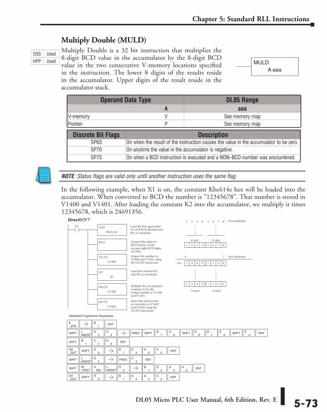
DL05 Micro PLC User Manual, 6th Edition, Rev. E 5-73
Chapter 5: Standard RLL Instructions
Multiply Double (MULD)Multiply Double is a 32 bit instruction that multiplies the 8-digit BCD value in the accumulator by the 8-digit BCD value in the two consecutive V-memory locations specified in the instruction. The lower 8 digits of the results reside in the accumulator. Upper digits of the result reside in the accumulator stack.
NOTE: Status flags are valid only until another instruction uses the same flag.
In the following example, when X1 is on, the constant Kbc614e hex will be loaded into the accumulator. When converted to BCD the number is ”12345678”. That number is stored in V1400 and V1401. After loading the constant K2 into the accumulator, we multiply it times 12345678, which is 24691356.
MULDA aaa
Direct SOFT32 Display
LDD
Kbc614e
X1 Load the hex equivalentof 12345678 decimal intothe accumulator.
BCD Convert the value toBCD format. It willoccupy eight BCD digits(32 bits).
OUTD
V1400
Output the number toV1400 and V1401 usingthe OUTD instruction. 3 5 62 4 6 9
6 7 8
(Accumulator)
1 2 3 4 5 6 7 8
1
(Accumulator)
V1402
1
5
V1400
3 5 6
V1403
2 4 6 9
2
Acc.
LD
K2
Load the constant K2into the accumulator.
MULD
V1400
Multiply the accumulatorcontents (2) by the8-digit number in V1400and V1401.
OUTD
V1402
Move the result in theaccumulator to V1402and V1403 using theOUTD instruction.
2 3 41
V1401
X
Handheld Programmer Keystrokes
STR$
SHFTANDSTL
3D
SHFTORSTM
ISGU
ANDSTL
OUTGX SHFT
3D
1B ENT
6G
1B
4E ENT
ENT
ENT
3D PREV SHFT
1B
2C SHFT SHFT
4E
SHFT1
B2
C3
D
OUTGX SHFT
3D
1B
4E
0A ENT
0A
ENT
SHFTANDSTL
3D PREV ENT
2C
3D
1B
4E
0A
0A
1B
4E
0A
2C
Operand Data Type DL05 Range ⸠⸠⸠⸠⸠⸠⸠⸠⸠⸠⸠⸠⸠⸠⸠⸠⸠⸠⸠⸠⸠⸠⸠⸠⸠⸠⸠⸠⸠⸠⸠⸠⸠⸠⸠⸠⸠⸠⸠⸠⸠⸠⸠⸠⸠⸠⸠⸠⸠⸠⸠⸠⸠⸠⸠⸠⸠⸠⸠⸠⸠⸠⸠⸠⸠⸠⸠⸠⸠⸠⸠⸠⸠A aaaV-memory ⸠⸠⸠⸠⸠⸠⸠⸠⸠⸠⸠⸠⸠⸠⸠⸠⸠⸠⸠⸠⸠⸠⸠⸠⸠⸠⸠⸠⸠⸠⸠⸠⸠⸠⸠⸠⸠⸠⸠⸠⸠⸠⸠⸠⸠⸠⸠⸠⸠⸠⸠⸠⸠⸠⸠⸠⸠⸠V See memory mapPointer ⸠⸠⸠⸠⸠⸠⸠⸠⸠⸠⸠⸠⸠⸠⸠⸠⸠⸠⸠⸠⸠⸠⸠⸠⸠⸠⸠⸠⸠⸠⸠⸠⸠⸠⸠⸠⸠⸠⸠⸠⸠⸠⸠⸠⸠⸠⸠⸠⸠⸠⸠⸠⸠⸠⸠⸠⸠⸠⸠⸠⸠⸠⸠⸠P See memory map
Discrete Bit Flags DescriptionSP63 On when the result of the instruction causes the value in the accumulator to be zero.SP70 On anytime the value in the accumulator is negative.SP75 On when a BCD instruction is executed and a NON–BCD number was encountered.
DS5 Used
HPP Used
DirectSOFT
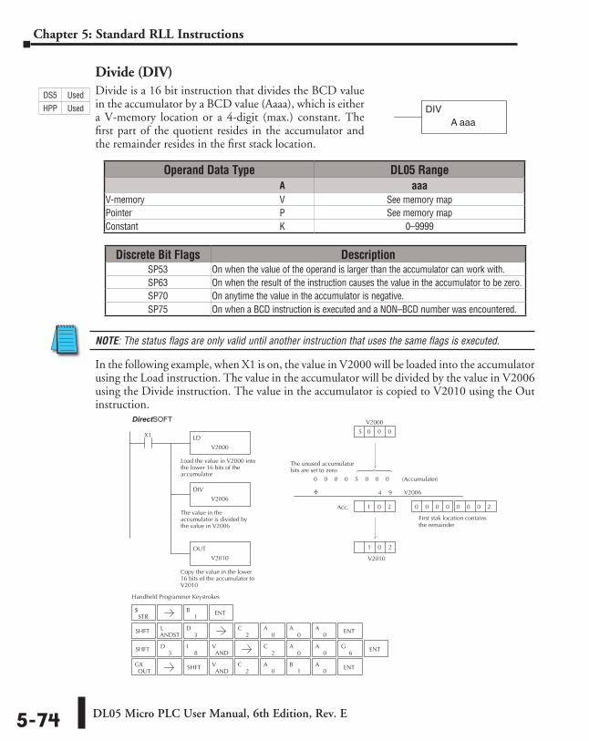
DL05 Micro PLC User Manual, 6th Edition, Rev. E5-74
Chapter 5: Standard RLL Instructions
Divide (DIV)Divide is a 16 bit instruction that divides the BCD value in the accumulator by a BCD value (Aaaa), which is either a V-memory location or a 4-digit (max.) constant. The first part of the quotient resides in the accumulator and the remainder resides in the first stack location.
NOTE: The status flags are only valid until another instruction that uses the same flags is executed.
In the following example, when X1 is on, the value in V2000 will be loaded into the accumulator using the Load instruction. The value in the accumulator will be divided by the value in V2006 using the Divide instruction. The value in the accumulator is copied to V2010 using the Out instruction.
DIVA aaa
Discrete Bit Flags DescriptionSP53 On when the value of the operand is larger than the accumulator can work with.SP63 On when the result of the instruction causes the value in the accumulator to be zero.SP70 On anytime the value in the accumulator is negative.SP75 On when a BCD instruction is executed and a NON–BCD number was encountered.
Direct SOFT32
Handheld Programmer Keystrokes
LD
V2000
X1
Load the value in V2000 intothe lower 16 bits of theaccumulator
DIV
V2006
The value in theaccumulator is divided bythe value in V2006
OUT
V2010
Copy the value in the lower16 bits of the accumulator toV2010
V2010
0
5
V2000
0 0 0
0 0 0 5 0 0 0
4 9
Acc. 1 0 2
The unused accumulatorbits are set to zero
0 0 0 0 0 0 0 2
First stak location contains the remainder
STR$
SHFTANDSTL
3D
SHFT3
D8
IAND
V
OUTGX SHFT
ANDV
2C
0A
1B
0A ENT
1B ENT
2C
0A
0A
0A ENT
2C
0A
0A ENT
6G
(Accumulater)
V2006÷
1 20
Operand Data Type DL05 Range ⸠⸠⸠⸠⸠⸠⸠⸠⸠⸠⸠⸠⸠⸠⸠⸠⸠⸠⸠⸠⸠⸠⸠⸠⸠⸠⸠⸠⸠⸠⸠⸠⸠⸠⸠⸠⸠⸠⸠⸠⸠⸠⸠⸠⸠⸠⸠⸠⸠⸠⸠⸠⸠⸠⸠⸠⸠⸠⸠⸠⸠⸠⸠⸠⸠⸠⸠⸠⸠⸠⸠⸠⸠A aaaV-memory ⸠⸠⸠⸠⸠⸠⸠⸠⸠⸠⸠⸠⸠⸠⸠⸠⸠⸠⸠⸠⸠⸠⸠⸠⸠⸠⸠⸠⸠⸠⸠⸠⸠⸠⸠⸠⸠⸠⸠⸠⸠⸠⸠⸠⸠⸠⸠⸠⸠⸠⸠⸠⸠⸠⸠⸠⸠⸠V See memory mapPointer ⸠⸠⸠⸠⸠⸠⸠⸠⸠⸠⸠⸠⸠⸠⸠⸠⸠⸠⸠⸠⸠⸠⸠⸠⸠⸠⸠⸠⸠⸠⸠⸠⸠⸠⸠⸠⸠⸠⸠⸠⸠⸠⸠⸠⸠⸠⸠⸠⸠⸠⸠⸠⸠⸠⸠⸠⸠⸠⸠⸠⸠⸠⸠⸠P See memory mapConstant ⸠⸠⸠⸠⸠⸠⸠⸠⸠⸠⸠⸠⸠⸠⸠⸠⸠⸠⸠⸠⸠⸠⸠⸠⸠⸠⸠⸠⸠⸠⸠⸠⸠⸠⸠⸠⸠⸠⸠⸠⸠⸠⸠⸠⸠⸠⸠⸠⸠⸠⸠⸠⸠⸠⸠⸠⸠⸠⸠⸠⸠K 0–9999
DS5 Used
HPP Used
DirectSOFT
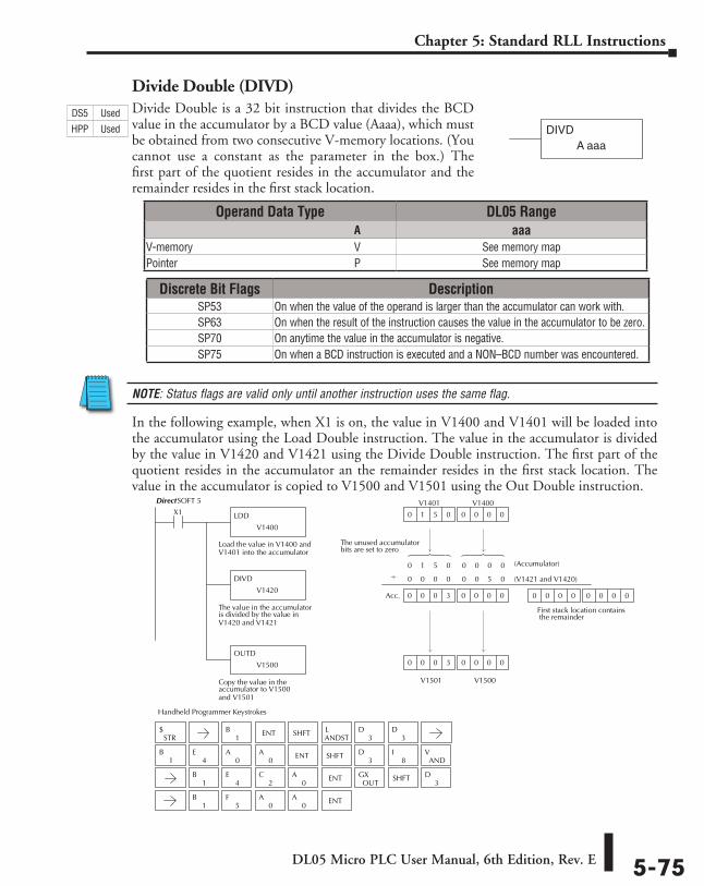
DL05 Micro PLC User Manual, 6th Edition, Rev. E 5-75
Chapter 5: Standard RLL Instructions
Divide Double (DIVD)Divide Double is a 32 bit instruction that divides the BCD value in the accumulator by a BCD value (Aaaa), which must be obtained from two consecutive V-memory locations. (You cannot use a constant as the parameter in the box.) The first part of the quotient resides in the accumulator and the remainder resides in the first stack location.
NOTE: Status flags are valid only until another instruction uses the same flag.
In the following example, when X1 is on, the value in V1400 and V1401 will be loaded into the accumulator using the Load Double instruction. The value in the accumulator is divided by the value in V1420 and V1421 using the Divide Double instruction. The first part of the quotient resides in the accumulator an the remainder resides in the first stack location. The value in the accumulator is copied to V1500 and V1501 using the Out Double instruction.
DIVDA aaa
DirectSOFT 5
Handheld Programmer Keystrokes
LDD
V1400
X1
Load the value in V1400 andV1401 into the accumulator
DIVD
V1420
The value in the accumulatoris divided by the value inV1420 and V1421
OUTD
V1500
Copy the value in theaccumulator to V1500and V1501
0 0 00 0 0 3
0 0 00 1 5 0
0 (Accumulator)
(V1421 and V1420)
0
0
1 5 0 0 0 0 0
0
V1500
V1400
0
0 0 0
V1401
V1501
0 0 0 3
0 0 0 0 0 5 0
0 0 00 0 0 0 0
First stack location contains the remainder
The unused accumulatorbits are set to zero
Acc.
SHFT
SHFT
SHFT
1B ENT
ANDSTL
3D
STR$
3D
ENT
ENT3
D
3D
1B
4E
0A
0A
8I
ANDV
1B
5F
0A
0A
OUTGX
1B
4E
0A
2C ENT
Operand Data Type DL05 Range ⸠⸠⸠⸠⸠⸠⸠⸠⸠⸠⸠⸠⸠⸠⸠⸠⸠⸠⸠⸠⸠⸠⸠⸠⸠⸠⸠⸠⸠⸠⸠⸠⸠⸠⸠⸠⸠⸠⸠⸠⸠⸠⸠⸠⸠⸠⸠⸠⸠⸠⸠⸠⸠⸠⸠⸠⸠⸠⸠⸠⸠⸠⸠⸠⸠⸠⸠⸠⸠⸠⸠⸠⸠A aaaV-memory ⸠⸠⸠⸠⸠⸠⸠⸠⸠⸠⸠⸠⸠⸠⸠⸠⸠⸠⸠⸠⸠⸠⸠⸠⸠⸠⸠⸠⸠⸠⸠⸠⸠⸠⸠⸠⸠⸠⸠⸠⸠⸠⸠⸠⸠⸠⸠⸠⸠⸠⸠⸠⸠⸠⸠⸠⸠⸠V See memory mapPointer ⸠⸠⸠⸠⸠⸠⸠⸠⸠⸠⸠⸠⸠⸠⸠⸠⸠⸠⸠⸠⸠⸠⸠⸠⸠⸠⸠⸠⸠⸠⸠⸠⸠⸠⸠⸠⸠⸠⸠⸠⸠⸠⸠⸠⸠⸠⸠⸠⸠⸠⸠⸠⸠⸠⸠⸠⸠⸠⸠⸠⸠⸠⸠⸠P See memory map
Discrete Bit Flags DescriptionSP53 On when the value of the operand is larger than the accumulator can work with.SP63 On when the result of the instruction causes the value in the accumulator to be zero.SP70 On anytime the value in the accumulator is negative.SP75 On when a BCD instruction is executed and a NON–BCD number was encountered.
DS5 Used
HPP Used
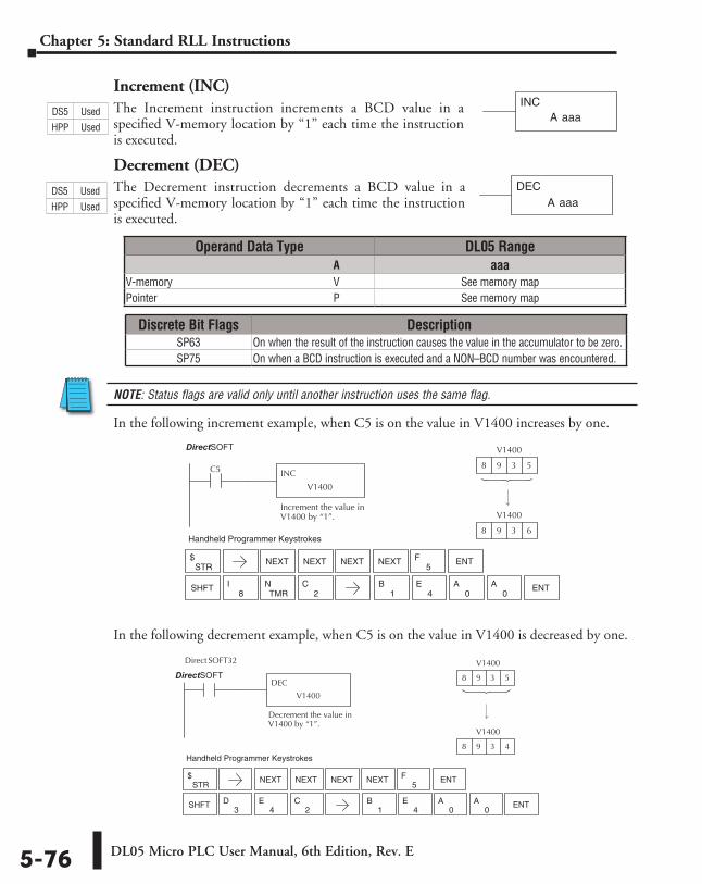
DL05 Micro PLC User Manual, 6th Edition, Rev. E5-76
Chapter 5: Standard RLL Instructions
Increment (INC)The Increment instruction increments a BCD value in a specified V-memory location by “1” each time the instruction is executed.
Decrement (DEC)The Decrement instruction decrements a BCD value in a specified V-memory location by “1” each time the instruction is executed.
NOTE: Status flags are valid only until another instruction uses the same flag.
In the following increment example, when C5 is on the value in V1400 increases by one.
In the following decrement example, when C5 is on the value in V1400 is decreased by one.
A aaaINC
A aaaDEC
Direct SOFT32
C5 INC
V1400
Increment the value inV1400 by “1”.
V1400
8 9 3 5
V1400
8 9 3 6Handheld Programmer Keystrokes
STR$
5F ENT
8I ENT
NEXT NEXT NEXT NEXT
SHFTTMR
N1
B4
E0
A0
A2
C
Operand Data Type DL05 Range ⸠⸠⸠⸠⸠⸠⸠⸠⸠⸠⸠⸠⸠⸠⸠⸠⸠⸠⸠⸠⸠⸠⸠⸠⸠⸠⸠⸠⸠⸠⸠⸠⸠⸠⸠⸠⸠⸠⸠⸠⸠⸠⸠⸠⸠⸠⸠⸠⸠⸠⸠⸠⸠⸠⸠⸠⸠⸠⸠⸠⸠⸠⸠⸠⸠⸠⸠⸠⸠⸠⸠⸠⸠A aaaV-memory ⸠⸠⸠⸠⸠⸠⸠⸠⸠⸠⸠⸠⸠⸠⸠⸠⸠⸠⸠⸠⸠⸠⸠⸠⸠⸠⸠⸠⸠⸠⸠⸠⸠⸠⸠⸠⸠⸠⸠⸠⸠⸠⸠⸠⸠⸠⸠⸠⸠⸠⸠⸠⸠⸠⸠⸠⸠⸠V See memory mapPointer ⸠⸠⸠⸠⸠⸠⸠⸠⸠⸠⸠⸠⸠⸠⸠⸠⸠⸠⸠⸠⸠⸠⸠⸠⸠⸠⸠⸠⸠⸠⸠⸠⸠⸠⸠⸠⸠⸠⸠⸠⸠⸠⸠⸠⸠⸠⸠⸠⸠⸠⸠⸠⸠⸠⸠⸠⸠⸠⸠⸠⸠⸠⸠⸠P See memory map
Discrete Bit Flags DescriptionSP63 On when the result of the instruction causes the value in the accumulator to be zero.SP75 On when a BCD instruction is executed and a NON–BCD number was encountered.
Direct SOFT32
C5 DEC
V1400
Decrement the value inV1400 by “1”.
V1400
8 9 3 5
V1400
8 9 3 4Handheld Programmer Keystrokes
STR$
5F ENT
3D ENT
NEXT NEXT NEXT NEXT
SHFT4
E1
B4
E0
A0
A2
C
DS5 Used
HPP Used
DS5 Used
HPP Used
DirectSOFT
DirectSOFT
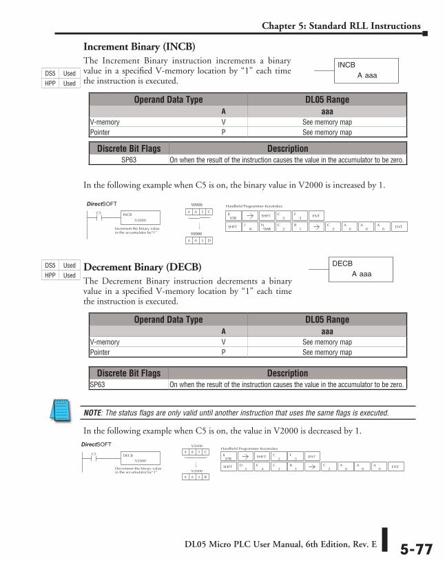
DL05 Micro PLC User Manual, 6th Edition, Rev. E 5-77
Chapter 5: Standard RLL Instructions
Increment Binary (INCB)The Increment Binary instruction increments a binary value in a specified V-memory location by “1” each time the instruction is executed.
In the following example when C5 is on, the binary value in V2000 is increased by 1.
Decrement Binary (DECB)The Decrement Binary instruction decrements a binary value in a specified V-memory location by “1” each time the instruction is executed.
NOTE: The status flags are only valid until another instruction that uses the same flags is executed.
In the following example when C5 is on, the value in V2000 is decreased by 1.
A aaaINCB
Handheld Programmer KeystrokesDirect SOFT32
C5 INCB
V2000
Increment the binary valuein the accumulator by“1”
4 A 3 C
4 A 3 D
STR$
2C
5FSHFT ENT
SHFT8
ITMR
N2
C1
B2
C0
A0
A0
A ENT
V2000
V2000
Handheld Programmer KeystrokesDirect SOFT32
C5 DECB
V2000
Decrement the binary valuein the accumulator by“1”
V2000
4 A 3 C
V2000
4 A 3 B
STR$
2C
5FSHFT ENT
SHFT2
C3
D4
E1
B2
C0
A0
A0
A ENT
Operand Data Type DL05 Range ⸠⸠⸠⸠⸠⸠⸠⸠⸠⸠⸠⸠⸠⸠⸠⸠⸠⸠⸠⸠⸠⸠⸠⸠⸠⸠⸠⸠⸠⸠⸠⸠⸠⸠⸠⸠⸠⸠⸠⸠⸠⸠⸠⸠⸠⸠⸠⸠⸠⸠⸠⸠⸠⸠⸠⸠⸠⸠⸠⸠⸠⸠⸠⸠⸠⸠⸠⸠⸠⸠⸠⸠⸠A aaaV-memory ⸠⸠⸠⸠⸠⸠⸠⸠⸠⸠⸠⸠⸠⸠⸠⸠⸠⸠⸠⸠⸠⸠⸠⸠⸠⸠⸠⸠⸠⸠⸠⸠⸠⸠⸠⸠⸠⸠⸠⸠⸠⸠⸠⸠⸠⸠⸠⸠⸠⸠⸠⸠⸠⸠⸠⸠⸠⸠V See memory mapPointer ⸠⸠⸠⸠⸠⸠⸠⸠⸠⸠⸠⸠⸠⸠⸠⸠⸠⸠⸠⸠⸠⸠⸠⸠⸠⸠⸠⸠⸠⸠⸠⸠⸠⸠⸠⸠⸠⸠⸠⸠⸠⸠⸠⸠⸠⸠⸠⸠⸠⸠⸠⸠⸠⸠⸠⸠⸠⸠⸠⸠⸠⸠⸠⸠P See memory map
Operand Data Type DL05 Range ⸠⸠⸠⸠⸠⸠⸠⸠⸠⸠⸠⸠⸠⸠⸠⸠⸠⸠⸠⸠⸠⸠⸠⸠⸠⸠⸠⸠⸠⸠⸠⸠⸠⸠⸠⸠⸠⸠⸠⸠⸠⸠⸠⸠⸠⸠⸠⸠⸠⸠⸠⸠⸠⸠⸠⸠⸠⸠⸠⸠⸠⸠⸠⸠⸠⸠⸠⸠⸠⸠⸠⸠⸠A aaaV-memory ⸠⸠⸠⸠⸠⸠⸠⸠⸠⸠⸠⸠⸠⸠⸠⸠⸠⸠⸠⸠⸠⸠⸠⸠⸠⸠⸠⸠⸠⸠⸠⸠⸠⸠⸠⸠⸠⸠⸠⸠⸠⸠⸠⸠⸠⸠⸠⸠⸠⸠⸠⸠⸠⸠⸠⸠⸠⸠V See memory mapPointer ⸠⸠⸠⸠⸠⸠⸠⸠⸠⸠⸠⸠⸠⸠⸠⸠⸠⸠⸠⸠⸠⸠⸠⸠⸠⸠⸠⸠⸠⸠⸠⸠⸠⸠⸠⸠⸠⸠⸠⸠⸠⸠⸠⸠⸠⸠⸠⸠⸠⸠⸠⸠⸠⸠⸠⸠⸠⸠⸠⸠⸠⸠⸠⸠P See memory map
Discrete Bit Flags DescriptionSP63 On when the result of the instruction causes the value in the accumulator to be zero.
Discrete Bit Flags DescriptionSP63 On when the result of the instruction causes the value in the accumulator to be zero.
A aaaDECB
DS5 Used
HPP Used
DS5 Used
HPP Used
DirectSOFT
DirectSOFT
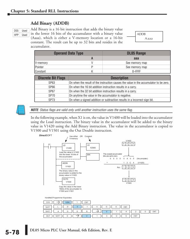
DL05 Micro PLC User Manual, 6th Edition, Rev. E5-78
Chapter 5: Standard RLL Instructions
Add Binary (ADDB)Add Binary is a 16 bit instruction that adds the binary value in the lower 16 bits of the accumulator with a binary value (Aaaa), which is either a V-memory location or a 16-bit constant. The result can be up to 32 bits and resides in the accumulator.
NOTE: Status flags are valid only until another instruction uses the same flag.
In the following example, when X1 is on, the value in V1400 will be loaded into the accumulator using the Load instruction. The binary value in the accumulator will be added to the binary value in V1420 using the Add Binary instruction. The value in the accumulator is copied to V1500 and V1501 using the Out Double instruction.
ADDBA aaa
Discrete Bit Flags DescriptionSP63 On when the result of the instruction causes the value in the accumulator to be zero.SP66 On when the 16 bit addition instruction results in a carry.SP67 On when the 32 bit addition instruction results in a carry.SP70 On anytime the value in the accumulator is negative.SP73 On when a signed addition or subtraction results in a incorrect sign bit.
HandheldProgrammer Keystrokes
LDX1
+ 1
1
(Accumulator)00
1
0 A 0 5
C C 9
0 0 0 A 0 5
2 C 4
Acc. C C 9
STR X(IN) 1
D V 1 4 0 0
OUT V 1 5 0 0
V 1 4 0A 2SHFT B
The unused accumulatorbits are set to zero
SHFT D
ENT
SHFT L ENT
D D ENT
ENT
Load the value in V1400into the lower 16 bits ofthe accumulator
LD
BIN
ADDB
OUTDV1500
K2565
Use either OR ConstantV-memory
V1420
V1400
(V1420)
V1500
V1400
The binary value in theaccumulator is added to thebinary value in V1420
Copy the value in the lower16bits of the accumulator toV1500 and V1501
DirectSOFT 5
Operand Data Type DL05 Range ⸠⸠⸠⸠⸠⸠⸠⸠⸠⸠⸠⸠⸠⸠⸠⸠⸠⸠⸠⸠⸠⸠⸠⸠⸠⸠⸠⸠⸠⸠⸠⸠⸠⸠⸠⸠⸠⸠⸠⸠⸠⸠⸠⸠⸠⸠⸠⸠⸠⸠⸠⸠⸠⸠⸠⸠⸠⸠⸠⸠⸠⸠⸠⸠⸠⸠⸠⸠⸠⸠⸠⸠⸠A aaaV-memory ⸠⸠⸠⸠⸠⸠⸠⸠⸠⸠⸠⸠⸠⸠⸠⸠⸠⸠⸠⸠⸠⸠⸠⸠⸠⸠⸠⸠⸠⸠⸠⸠⸠⸠⸠⸠⸠⸠⸠⸠⸠⸠⸠⸠⸠⸠⸠⸠⸠⸠⸠⸠⸠⸠⸠⸠⸠⸠V See memory mapPointer ⸠⸠⸠⸠⸠⸠⸠⸠⸠⸠⸠⸠⸠⸠⸠⸠⸠⸠⸠⸠⸠⸠⸠⸠⸠⸠⸠⸠⸠⸠⸠⸠⸠⸠⸠⸠⸠⸠⸠⸠⸠⸠⸠⸠⸠⸠⸠⸠⸠⸠⸠⸠⸠⸠⸠⸠⸠⸠⸠⸠⸠⸠⸠⸠P See memory mapConstant ⸠⸠⸠⸠⸠⸠⸠⸠⸠⸠⸠⸠⸠⸠⸠⸠⸠⸠⸠⸠⸠⸠⸠⸠⸠⸠⸠⸠⸠⸠⸠⸠⸠⸠⸠⸠⸠⸠⸠⸠⸠⸠⸠⸠⸠⸠⸠⸠⸠⸠⸠⸠⸠⸠⸠⸠⸠⸠⸠⸠⸠K 0–FFFF
DS5 Used
HPP Used
DirectSOFT
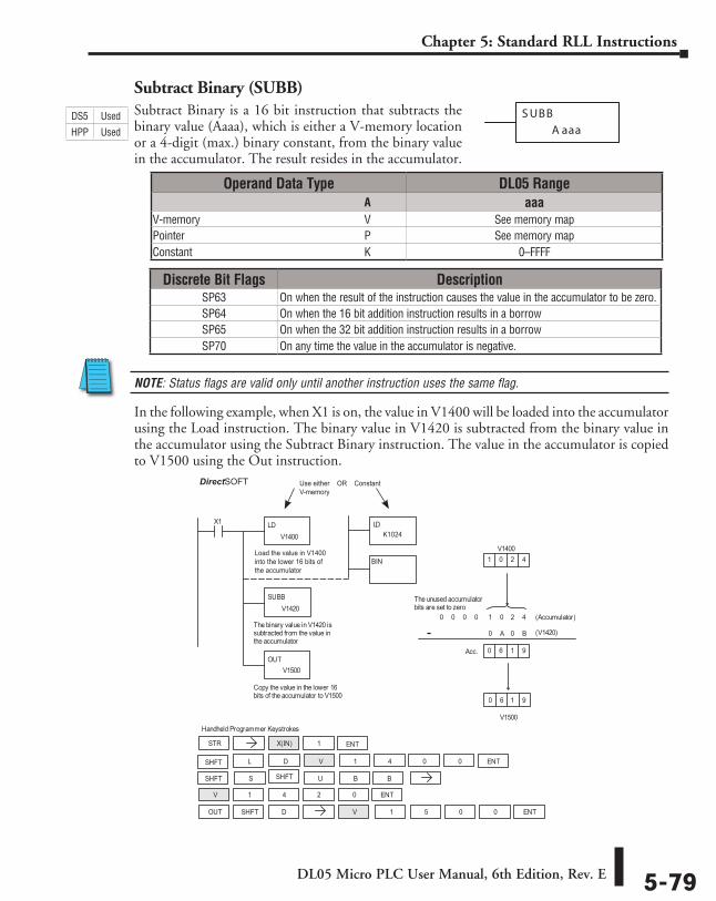
DL05 Micro PLC User Manual, 6th Edition, Rev. E 5-79
Chapter 5: Standard RLL Instructions
Subtract Binary (SUBB)Subtract Binary is a 16 bit instruction that subtracts the binary value (Aaaa), which is either a V-memory location or a 4-digit (max.) binary constant, from the binary value in the accumulator. The result resides in the accumulator.
NOTE: Status flags are valid only until another instruction uses the same flag.
In the following example, when X1 is on, the value in V1400 will be loaded into the accumulator using the Load instruction. The binary value in V1420 is subtracted from the binary value in the accumulator using the Subtract Binary instruction. The value in the accumulator is copied to V1500 using the Out instruction.
S UBB
A aaa
DirectSOFT32 Display
Handheld Programmer Keystrokes
LDV1400
X1
SUBBV1420
The binary value in V1420 issubtracted from the value inthe accumulator
OUTV1500
Copy the value in the lower 16bits of the accumulator to V1500
V1500
(V1420)
0
1 (Accumulator)
0
1
0
0
V14000 2 4
6 1 9
0 0 0 0 2 4
A 0 B
Acc. 6 1 9
The unused accumulatorbits are set to zero
STR X(IN) 1
D V 1 4 0 0
OUT V 1 5 0 0
V 1 4 0
S
2
SHFT B
SHFT D
ENT
SHFT L ENT
U B
ENT
ENT
SHFT
Use either OR ConstantV-memory
LD
BIN
K1024
Load the value in V1400into the lower 16 bits ofthe accumulator
-
Operand Data Type DL05 Range ⸠⸠⸠⸠⸠⸠⸠⸠⸠⸠⸠⸠⸠⸠⸠⸠⸠⸠⸠⸠⸠⸠⸠⸠⸠⸠⸠⸠⸠⸠⸠⸠⸠⸠⸠⸠⸠⸠⸠⸠⸠⸠⸠⸠⸠⸠⸠⸠⸠⸠⸠⸠⸠⸠⸠⸠⸠⸠⸠⸠⸠⸠⸠⸠⸠⸠⸠⸠⸠⸠⸠⸠⸠A aaaV-memory ⸠⸠⸠⸠⸠⸠⸠⸠⸠⸠⸠⸠⸠⸠⸠⸠⸠⸠⸠⸠⸠⸠⸠⸠⸠⸠⸠⸠⸠⸠⸠⸠⸠⸠⸠⸠⸠⸠⸠⸠⸠⸠⸠⸠⸠⸠⸠⸠⸠⸠⸠⸠⸠⸠⸠⸠⸠⸠V See memory mapPointer ⸠⸠⸠⸠⸠⸠⸠⸠⸠⸠⸠⸠⸠⸠⸠⸠⸠⸠⸠⸠⸠⸠⸠⸠⸠⸠⸠⸠⸠⸠⸠⸠⸠⸠⸠⸠⸠⸠⸠⸠⸠⸠⸠⸠⸠⸠⸠⸠⸠⸠⸠⸠⸠⸠⸠⸠⸠⸠⸠⸠⸠⸠⸠⸠P See memory mapConstant ⸠⸠⸠⸠⸠⸠⸠⸠⸠⸠⸠⸠⸠⸠⸠⸠⸠⸠⸠⸠⸠⸠⸠⸠⸠⸠⸠⸠⸠⸠⸠⸠⸠⸠⸠⸠⸠⸠⸠⸠⸠⸠⸠⸠⸠⸠⸠⸠⸠⸠⸠⸠⸠⸠⸠⸠⸠⸠⸠⸠⸠K 0–FFFF
Discrete Bit Flags DescriptionSP63 On when the result of the instruction causes the value in the accumulator to be zero.SP64 On when the 16 bit addition instruction results in a borrowSP65 On when the 32 bit addition instruction results in a borrowSP70 On any time the value in the accumulator is negative.
DS5 Used
HPP Used
DirectSOFT
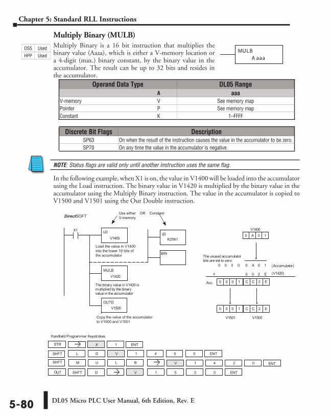
DL05 Micro PLC User Manual, 6th Edition, Rev. E5-80
Chapter 5: Standard RLL Instructions
Multiply Binary (MULB)Multiply Binary is a 16 bit instruction that multiplies the binary value (Aaaa), which is either a V-memory location or a 4-digit (max.) binary constant, by the binary value in the accumulator. The result can be up to 32 bits and resides in the accumulator.
NOTE: Status flags are valid only until another instruction uses the same flag.
In the following example, when X1 is on, the value in V1400 will be loaded into the accumulator using the Load instruction. The binary value in V1420 is multiplied by the binary value in the accumulator using the Multiply Binary instruction. The value in the accumulator is copied to V1500 and V1501 using the Out Double instruction.
MULBA aaa
DirectSOFT32 Display
Handheld Programmer Keystrokes
LDV1400
X1
MULBV1420
The binary value in V1420 ismultiplied by the binaryvalue in the accumulator
OUTDV1500
0 (Accumulator)
0
0
0
(V1420)
V1400A 0 1
0 0 0 A 0 1
0 2 E
The unused accumulatorbits are set to zero
2 E0 0 0 1 C
C
C
V1500
C 2 E
V1501
0 0 0 1
Acc.
STR X 1
D V 1 4 0 0
OUT V 1 5 0 0
V 1 4 0M 2SHFT B
SHFT D
ENT
SHFT L ENT
U L ENT
ENT
Copy the value of the accumulatorto V1500 and V1501
Use either OR ConstantV-memory
LD
BIN
K2561
Load the value in V1400into the lower 16 bits ofthe accumulator
x
Operand Data Type DL05 Range ⸠⸠⸠⸠⸠⸠⸠⸠⸠⸠⸠⸠⸠⸠⸠⸠⸠⸠⸠⸠⸠⸠⸠⸠⸠⸠⸠⸠⸠⸠⸠⸠⸠⸠⸠⸠⸠⸠⸠⸠⸠⸠⸠⸠⸠⸠⸠⸠⸠⸠⸠⸠⸠⸠⸠⸠⸠⸠⸠⸠⸠⸠⸠⸠⸠⸠⸠⸠⸠⸠⸠⸠⸠A aaaV-memory ⸠⸠⸠⸠⸠⸠⸠⸠⸠⸠⸠⸠⸠⸠⸠⸠⸠⸠⸠⸠⸠⸠⸠⸠⸠⸠⸠⸠⸠⸠⸠⸠⸠⸠⸠⸠⸠⸠⸠⸠⸠⸠⸠⸠⸠⸠⸠⸠⸠⸠⸠⸠⸠⸠⸠⸠⸠⸠V See memory mapPointer ⸠⸠⸠⸠⸠⸠⸠⸠⸠⸠⸠⸠⸠⸠⸠⸠⸠⸠⸠⸠⸠⸠⸠⸠⸠⸠⸠⸠⸠⸠⸠⸠⸠⸠⸠⸠⸠⸠⸠⸠⸠⸠⸠⸠⸠⸠⸠⸠⸠⸠⸠⸠⸠⸠⸠⸠⸠⸠⸠⸠⸠⸠⸠⸠P See memory mapConstant ⸠⸠⸠⸠⸠⸠⸠⸠⸠⸠⸠⸠⸠⸠⸠⸠⸠⸠⸠⸠⸠⸠⸠⸠⸠⸠⸠⸠⸠⸠⸠⸠⸠⸠⸠⸠⸠⸠⸠⸠⸠⸠⸠⸠⸠⸠⸠⸠⸠⸠⸠⸠⸠⸠⸠⸠⸠⸠⸠⸠⸠K 1–FFFF
Discrete Bit Flags DescriptionSP63 On when the result of the instruction causes the value in the accumulator to be zero.SP70 On any time the value in the accumulator is negative.
DS5 Used
HPP Used
DirectSOFT
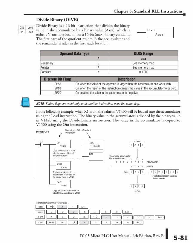
DL05 Micro PLC User Manual, 6th Edition, Rev. E 5-81
Chapter 5: Standard RLL Instructions
Divide Binary (DIVB)Divide Binary is a 16 bit instruction that divides the binary value in the accumulator by a binary value (Aaaa), which is either a V-memory location or a 16-bit (max.) binary constant. The first part of the quotient resides in the accumulator and the remainder resides in the first stack location.
NOTE: Status flags are valid only until another instruction uses the same flag.
In the following example, when X1 is on, the value in V1400 will be loaded into the accumulator using the Load instruction. The binary value in the accumulator is divided by the binary value in V1420 using the Divide Binary instruction. The value in the accumulator is copied to V1500 using the Out instruction.
DIVB
A aaa
DirectSOFT32 Display
Handheld Programmer Keystrokes
LDV1400
X1
DIVBV1420
The binary value in thaccumulator is divided bythe binary value in V1420
OUTV1500
Copy the value in the lower 16bits of the accumulator to V1500
V1500
0 (Accumulator)F
0
0
F
(V1420)
0
V1400A 0 1
3 2 0
0 0 0 A 0 1
0 5 0
Acc. 3 2 0
The unused accumulatorbits are set to zero
0 0 00 0 0 0 0
First stack location containsthe remainder
STR X 1
D V 1 4 0 0
OUT V 1 5 0 0
V 1 4 0D 2SHFT B
SHFT D
ENT
SHFT L ENT
I V ENT
ENT
_..
Use either OR ConstantV-memory
LDD
BIN
K64001
Load the value in V1400into the lower 16 bits ofthe accumulator
Operand Data Type DL05 Range ⸠⸠⸠⸠⸠⸠⸠⸠⸠⸠⸠⸠⸠⸠⸠⸠⸠⸠⸠⸠⸠⸠⸠⸠⸠⸠⸠⸠⸠⸠⸠⸠⸠⸠⸠⸠⸠⸠⸠⸠⸠⸠⸠⸠⸠⸠⸠⸠⸠⸠⸠⸠⸠⸠⸠⸠⸠⸠⸠⸠⸠⸠⸠⸠⸠⸠⸠⸠⸠⸠⸠⸠⸠A aaaV-memory ⸠⸠⸠⸠⸠⸠⸠⸠⸠⸠⸠⸠⸠⸠⸠⸠⸠⸠⸠⸠⸠⸠⸠⸠⸠⸠⸠⸠⸠⸠⸠⸠⸠⸠⸠⸠⸠⸠⸠⸠⸠⸠⸠⸠⸠⸠⸠⸠⸠⸠⸠⸠⸠⸠⸠⸠⸠⸠V See memory mapPointer ⸠⸠⸠⸠⸠⸠⸠⸠⸠⸠⸠⸠⸠⸠⸠⸠⸠⸠⸠⸠⸠⸠⸠⸠⸠⸠⸠⸠⸠⸠⸠⸠⸠⸠⸠⸠⸠⸠⸠⸠⸠⸠⸠⸠⸠⸠⸠⸠⸠⸠⸠⸠⸠⸠⸠⸠⸠⸠⸠⸠⸠⸠⸠⸠P See memory mapConstant ⸠⸠⸠⸠⸠⸠⸠⸠⸠⸠⸠⸠⸠⸠⸠⸠⸠⸠⸠⸠⸠⸠⸠⸠⸠⸠⸠⸠⸠⸠⸠⸠⸠⸠⸠⸠⸠⸠⸠⸠⸠⸠⸠⸠⸠⸠⸠⸠⸠⸠⸠⸠⸠⸠⸠⸠⸠⸠⸠⸠⸠K 0–FFFF
Discrete Bit Flags DescriptionSP53 On when the value of the operand is larger than the accumulator can work with.SP63 On when the result of the instruction causes the value in the accumulator to be zero.SP70 On anytime the value in the accumulator is negative.
DS5 Used
HPP Used
DirectSOFT
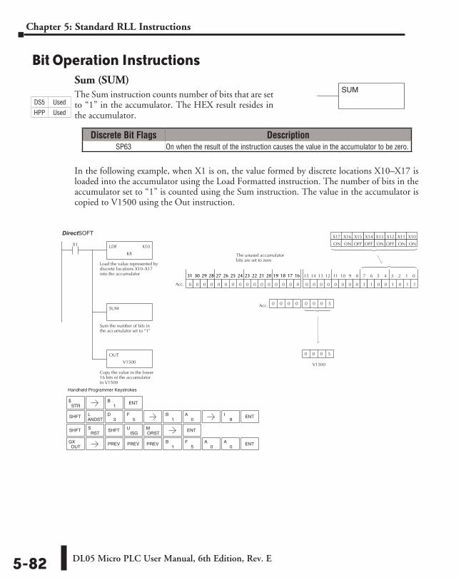
DL05 Micro PLC User Manual, 6th Edition, Rev. E5-82
Chapter 5: Standard RLL Instructions
Bit Operation InstructionsSum (SUM)The Sum instruction counts number of bits that are set to “1” in the accumulator. The HEX result resides in the accumulator.
In the following example, when X1 is on, the value formed by discrete locations X10–X17 is loaded into the accumulator using the Load Formatted instruction. The number of bits in the accumulator set to “1” is counted using the Sum instruction. The value in the accumulator is copied to V1500 using the Out instruction.
SUM
Direct SOFT32 Display
LDF X10
K8
X1
Load the value represented bydiscrete locations X10–X17into the accumulator
SUM
Sum the number of bits inthe accumulator set to “1”
OUT
V1500
Copy the value in the lower16 bits of the accumulatorto V1500
X10X11X12X13
ONONOFFON
X14X15X16X17
OFFOFFONON
0 0 0 0 0 0 0 0 1 1 0 0 1 0 1 10 0 0 0 0 0 0 0 0 0 0 0 0 0 0 0
15 14 13 12 11 10 9 8 7 6 5 4 3 2 1 031 30 29 28 27 26 25 24 23 22 21 20 19 18 17 1631 30 29 28 27 26 25 24 23 22 21 20 19 18 17 16
Acc.
V1500
Acc.
0 0 0 5
0 0 0 0 0 0 0 5
The unused accumulatorbits are set to zero
STR$ ENT
SHFTANDSTL
3D
5F
SHFTRST
SISG
UORSTM ENT
1B
1B
0A
8I ENT
SHFT
OUTGX PREV
1B
5F
0A
0A ENTPREV PREV
Handheld Programmer Keystrokes
Discrete Bit Flags DescriptionSP63 On when the result of the instruction causes the value in the accumulator to be zero.
DS5 Used
HPP Used
DirectSOFT
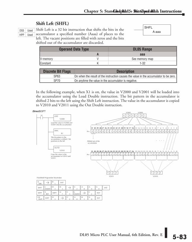
DL05 Micro PLC User Manual, 6th Edition, Rev. E 5-83
Chapter 5: Standard RLL Instructions
Shift Left (SHFL)Shift Left is a 32 bit instruction that shifts the bits in the accumulator a specified number (Aaaa) of places to the left. The vacant positions are filled with zeros and the bits shifted out of the accumulator are discarded.
In the following example, when X1 is on, the value in V2000 and V2001 will be loaded into the accumulator using the Load Double instruction. The bit pattern in the accumulator is shifted 2 bits to the left using the Shift Left instruction. The value in the accumulator is copied to V2010 and V2011 using the Out Double instruction.
Chapter 5: Standard RLL - Bit Operation Instructions
2C ENT
Handheld Programmer Keystrokes
Direct SOFT32
LDD
V2000
X1
Load the value in V2000 andV2001 into the accumulator
SHFL
K2
The bit pattern in theaccumulator is shifted 2 bitpositions to the left
OUTD
V2010
Copy the value in theaccumulator to V2010 andV2011
0 0 1 1 0 0 0 1 0 0 0 0 0 0 0 1
V2010
1 1 0 0 0 1 0 0 0 0 0 0 0 1 0 00 0 0 0 0 1 0 0 0 0 0 0 0 0 0 0
15 14 13 12 11 10 9 8 7 6 5 4 3 2 1 031 30 29 28 27 26 25 24 23 22 21 20 19 18 17 16
C 4 0 4
. . . .
1 0 0 1 1 1 0 0 0 0 0 1 0 1 0 0
31 30 29 28 27 26 25 24 23 22 21 20 19 18 17 16
0 1 1 0 0 1 1 1 0 0 0 0 0 1 0 1
15 14 13 12 11 10 9 8 7 6 5 4 3 2 1 031 30 29 28 27 26 25 24 23 22 21 20 19 18 17 1631 30 29 28 27 26 25 24 23 22 21 20 19 18 17 16
Acc.
Acc.
V2011
9 C 1 4
6 7 0 5 3 3 1 0 3 1 0 1
Shifted out of the accumulator
V2000V2001
STR$
SHFTANDSTL
3D
3D
SHFTRST
S7
H5
FANDSTL
OUTGX SHFT
3D
1B ENT
2C
0A
0A
0A ENT
2C
0A
1B
0A ENT
SHFT
Operand Data Type DL05 Range ⸠⸠⸠⸠⸠⸠⸠⸠⸠⸠⸠⸠⸠⸠⸠⸠⸠⸠⸠⸠⸠⸠⸠⸠⸠⸠⸠⸠⸠⸠⸠⸠⸠⸠⸠⸠⸠⸠⸠⸠⸠⸠⸠⸠⸠⸠⸠⸠⸠⸠⸠⸠⸠⸠⸠⸠⸠⸠⸠⸠⸠⸠⸠⸠⸠⸠⸠⸠⸠⸠⸠⸠⸠A aaaV-memory ⸠⸠⸠⸠⸠⸠⸠⸠⸠⸠⸠⸠⸠⸠⸠⸠⸠⸠⸠⸠⸠⸠⸠⸠⸠⸠⸠⸠⸠⸠⸠⸠⸠⸠⸠⸠⸠⸠⸠⸠⸠⸠⸠⸠⸠⸠⸠⸠⸠⸠⸠⸠⸠⸠⸠⸠⸠⸠V See memory mapConstant ⸠⸠⸠⸠⸠⸠⸠⸠⸠⸠⸠⸠⸠⸠⸠⸠⸠⸠⸠⸠⸠⸠⸠⸠⸠⸠⸠⸠⸠⸠⸠⸠⸠⸠⸠⸠⸠⸠⸠⸠⸠⸠⸠⸠⸠⸠⸠⸠⸠⸠⸠⸠⸠⸠⸠⸠⸠⸠⸠⸠⸠K 1-32
Discrete Bit Flags DescriptionSP63 On when the result of the instruction causes the value in the accumulator to be zero.SP70 On anytime the value in the accumulator is negative.
SHFLA aaaDS5 Used
HPP Used
DirectSOFT
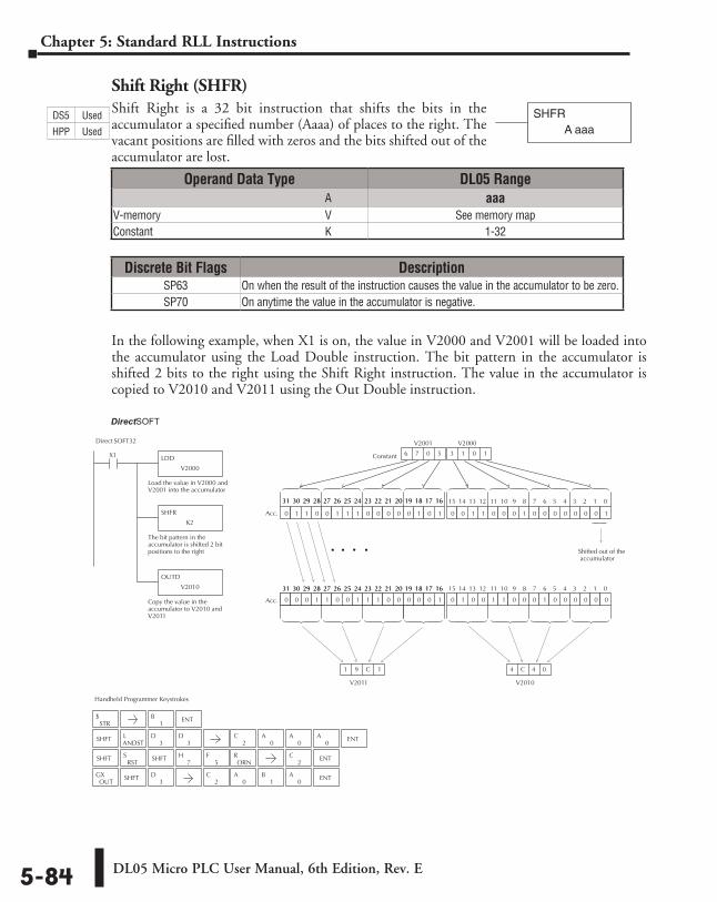
DL05 Micro PLC User Manual, 6th Edition, Rev. E5-84
Chapter 5: Standard RLL Instructions
Shift Right (SHFR)Shift Right is a 32 bit instruction that shifts the bits in the accumulator a specified number (Aaaa) of places to the right. The vacant positions are filled with zeros and the bits shifted out of the accumulator are lost.
In the following example, when X1 is on, the value in V2000 and V2001 will be loaded into the accumulator using the Load Double instruction. The bit pattern in the accumulator is shifted 2 bits to the right using the Shift Right instruction. The value in the accumulator is copied to V2010 and V2011 using the Out Double instruction.
SHFRA aaa
Handheld Programmer Keystrokes
Direct SOFT32
LDD
V2000
X1
Load the value in V2000 andV2001 into the accumulator
SHFR
K2
The bit pattern in theaccumulator is shifted 2 bitpositions to the right
OUTD
V2010
Copy the value in theaccumulator to V2010 andV2011
0 0 1 1 0 0 0 1 0 0 0 0 0 0 0 1
V2010
0 1 0 0 1 1 0 0 0 1 0 0 0 0 0 00 0 0 0 0 1 0 0 0 0 0 0 0 0 0 0
15 14 13 12 11 10 9 8 7 6 5 4 3 2 1 031 30 29 28 27 26 25 24 23 22 21 20 19 18 17 16
4 C 4 0
. . .
0 0 0 1 1 0 0 1 1 1 0 0 0 0 0 1
31 30 29 28 27 26 25 24 23 22 21 20 19 18 17 16
0 1 1 0 0 1 1 1 0 0 0 0 0 1 0 1
15 14 13 12 11 10 9 8 7 6 5 4 3 2 1 031 30 29 28 27 26 25 24 23 22 21 20 19 18 17 1631 30 29 28 27 26 25 24 23 22 21 20 19 18 17 16
Acc.
Acc.
V2011
1 9 C 1
Constant 6 7 0 5 3 1 0 1 3 1 0 1
Shifted out of the accumulator
V2001 V2000
STR$
SHFTANDSTL
3D
3D
SHFTRST
S7
H5
F2
C ENT
OUTGX SHFT
3D
ORNRSHFT
1B ENT
2C
0A
0A
0A ENT
2C
0A
1B
0A ENT
.
Operand Data Type DL05 Range ⸠⸠⸠⸠⸠⸠⸠⸠⸠⸠⸠⸠⸠⸠⸠⸠⸠⸠⸠⸠⸠⸠⸠⸠⸠⸠⸠⸠⸠⸠⸠⸠⸠⸠⸠⸠⸠⸠⸠⸠⸠⸠⸠⸠⸠⸠⸠⸠⸠⸠⸠⸠⸠⸠⸠⸠⸠⸠⸠⸠⸠⸠⸠⸠⸠⸠⸠⸠⸠⸠⸠⸠⸠A aaaV-memory ⸠⸠⸠⸠⸠⸠⸠⸠⸠⸠⸠⸠⸠⸠⸠⸠⸠⸠⸠⸠⸠⸠⸠⸠⸠⸠⸠⸠⸠⸠⸠⸠⸠⸠⸠⸠⸠⸠⸠⸠⸠⸠⸠⸠⸠⸠⸠⸠⸠⸠⸠⸠⸠⸠⸠⸠⸠⸠V See memory mapConstant ⸠⸠⸠⸠⸠⸠⸠⸠⸠⸠⸠⸠⸠⸠⸠⸠⸠⸠⸠⸠⸠⸠⸠⸠⸠⸠⸠⸠⸠⸠⸠⸠⸠⸠⸠⸠⸠⸠⸠⸠⸠⸠⸠⸠⸠⸠⸠⸠⸠⸠⸠⸠⸠⸠⸠⸠⸠⸠⸠⸠⸠K 1-32
Discrete Bit Flags DescriptionSP63 On when the result of the instruction causes the value in the accumulator to be zero.SP70 On anytime the value in the accumulator is negative.
DS5 Used
HPP Used
DirectSOFT
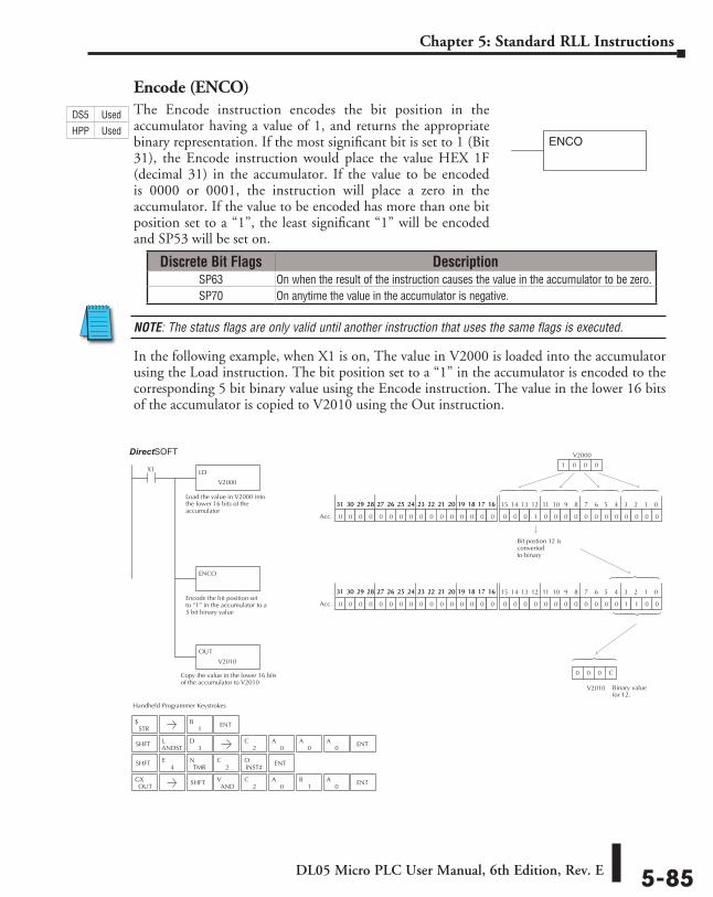
DL05 Micro PLC User Manual, 6th Edition, Rev. E 5-85
Chapter 5: Standard RLL Instructions
Encode (ENCO)The Encode instruction encodes the bit position in the accumulator having a value of 1, and returns the appropriate binary representation. If the most significant bit is set to 1 (Bit 31), the Encode instruction would place the value HEX 1F (decimal 31) in the accumulator. If the value to be encoded is 0000 or 0001, the instruction will place a zero in the accumulator. If the value to be encoded has more than one bit position set to a “1”, the least significant “1” will be encoded and SP53 will be set on.
NOTE: The status flags are only valid until another instruction that uses the same flags is executed.
In the following example, when X1 is on, The value in V2000 is loaded into the accumulator using the Load instruction. The bit position set to a “1” in the accumulator is encoded to the corresponding 5 bit binary value using the Encode instruction. The value in the lower 16 bits of the accumulator is copied to V2010 using the Out instruction.
ENCO
Handheld Programmer Keystrokes
Direct SOFT32
LD
V2000
X1
Load the value in V2000 intothe lower 16 bits of theaccumulator
ENCO
Encode the bit position setto “1” in the accumulator to a5 bit binary value
0 0 0 1 0 0 0 0 0 0 0 0 0 0 0 00 0 0 0 0 0 0 0 0 0 0 0 0 0 0 0
15 14 13 12 11 10 9 8 7 6 5 4 3 2 1 031 30 29 28 27 26 25 24 23 22 21 20 19 18 17 1631 30 29 28 27 26 25 24 23 22 21 20 19 18 17 16
Acc.
0 0 0 0 0 0 0 0 0 0 0 0 1 1 0 00 0 0 0 0 0 0 0 0 0 0 0 0 0 0 0
15 14 13 12 11 10 9 8 7 6 5 4 3 2 1 031 30 29 28 27 26 25 24 23 22 21 20 19 18 17 1631 30 29 28 27 26 25 24 23 22 21 20 19 18 17 16
Acc.
V2000
1 0 0 0
Bit postion 12 isconverted to binary
Copy the value in the lower 16 bitsof the accumulator to V2010
OUT
V2010
V2010
0 0 0 C
Binary valuefor 12.
STR$
1B ENT
SHFT
OUTGX SHFT
ANDV
2C
0A
1B
0A ENT
4E
TMRN
2C
INST#O ENT
SHFTANDSTL
3D
2C
0A
0A
0A ENT
Discrete Bit Flags DescriptionSP63 On when the result of the instruction causes the value in the accumulator to be zero.SP70 On anytime the value in the accumulator is negative.
DS5 Used
HPP Used
DirectSOFT
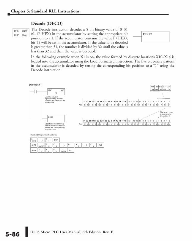
DL05 Micro PLC User Manual, 6th Edition, Rev. E5-86
Chapter 5: Standard RLL Instructions
Decode (DECO)The Decode instruction decodes a 5 bit binary value of 0–31 (0–1F HEX) in the accumulator by setting the appropriate bit position to a 1. If the accumulator contains the value F (HEX), bit 15 will be set in the accumulator. If the value to be decoded is greater than 31, the number is divided by 32 until the value is less than 32 and then the value is decoded.
In the following example when X1 is on, the value formed by discrete locations X10–X14 is loaded into the accumulator using the Load Formatted instruction. The five bit binary pattern in the accumulator is decoded by setting the corresponding bit position to a “1” using the Decode instruction.
Handheld Programmer Keystrokes
Direct SOFT32
LDF X10
K5
X1
Load the value inrepresented by discretelocations X10–X14 into theaccumulator
DECO
Decode the five bit binarypattern in the accumulatorand set the correspondingbit position to a “1”
X10 X11 X13 X12
ON ON OFF
X14
OFF ON
0 0 0 0 0 0 0 0 0 0 0 0 1 0 1 10 0 0 0 0 0 0 0 0 0 0 0 0 0 0 0
15 14 13 12 11 10 9 8 7 6 5 4 3 2 1 031 30 29 28 27 26 25 24 23 22 21 20 19 18 17 1631 30 29 28 27 26 25 24 23 22 21 20 19 18 17 16
Acc.
0 0 0 0 1 0 0 0 0 0 0 0 0 0 0 00 0 0 0 0 0 0 0 0 0 0 0 0 0 0 0
15 14 13 12 11 10 9 8 7 6 5 4 3 2 1 031 30 29 28 27 26 25 24 23 22 21 20 19 18 17 1631 30 29 28 27 26 25 24 23 22 21 20 19 18 17 16
Acc.
The binary vlaue is converted tobit position 11.
STR$ ENT
SHFTANDSTL
3D
5F
1B
1B
0A ENT
5F
SHFT2
CINST#O ENT
3D
4E
DECODS5 Used
HPP Used
DirectSOFT
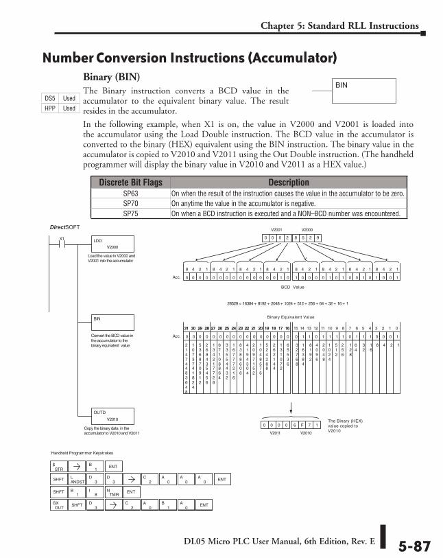
DL05 Micro PLC User Manual, 6th Edition, Rev. E 5-87
Chapter 5: Standard RLL Instructions
Number Conversion Instructions (Accumulator)Binary (BIN)The Binary instruction converts a BCD value in the accumulator to the equivalent binary value. The result resides in the accumulator.
In the following example, when X1 is on, the value in V2000 and V2001 is loaded into the accumulator using the Load Double instruction. The BCD value in the accumulator is converted to the binary (HEX) equivalent using the BIN instruction. The binary value in the accumulator is copied to V2010 and V2011 using the Out Double instruction. (The handheld programmer will display the binary value in V2010 and V2011 as a HEX value.)
BIN
Standard
RLL
Instructions
STR$
0A
OUTGX SHFT
3D
2C
0A
1B ENT
0 0 0 0 6 F 7 1
V2010V2011
Handheld Programmer Keystrokes
DirectSOFT32
LDD
V2000
X1
BIN
1 0 0 0 0 1 0 1 0 0 1 0 1 0 0 10 0 0 0 0 0 0 0 0 0 0 0 0 0 1 0
8 4 2 1 8 4 2 1 8 4 2 1 8 4 2 18 4 2 1 8 4 2 1 8 4 2 1 8 4 2 1
Acc.
0 0 0 2 8 5 2 9
V2000V2001
0 1 1 0 1 1 1 1 0 1 1 1 0 0 0 10 0 0 0 0 0 0 0 0 0 0 0 0 0 0 0
15 14 13 12 11 10 9 8 7 6 5 4 3 2 1 031 30 29 28 27 26 25 24 23 22 21 20 19 18 17 1631 30 29 28 27 26 25 24 23 22 21 20 19 18 17 16
Acc.
124816
32
64
128
256
512
1024
2048
4096
8192
16384
32768
65536
131072
262144
524288
1048576
2097152
4194304
8388608
16777216
33554432
67108864
134217728
268435456
536870912
1073741824
21474483648
OUTD
V2010
28529 = 16384 + 8192 + 2048 + 1024 + 512 + 256 + 64 + 32 + 16 + 1
1B ENT
SHFTANDSTL
3D
3D
2C
0A
0A
0A ENT
SHFT1
B8
ITMR
N ENT
Copy the binary data in theaccumulator to V2010 and V2011
Convert the BCD value in the accumulator to the binary equivalent value
Load the value in V2000 andV2001 into the accumulator
BCD Value
Binary Equivalent Value
The Binary (HEX)value copied toV2010
Discrete Bit Flags DescriptionSP63 On when the result of the instruction causes the value in the accumulator to be zero.SP70 On anytime the value in the accumulator is negative.SP75 On when a BCD instruction is executed and a NON–BCD number was encountered.
DS5 Used
HPP Used
DirectSOFT
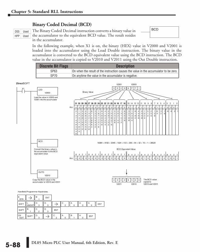
DL05 Micro PLC User Manual, 6th Edition, Rev. E5-88
Chapter 5: Standard RLL Instructions
Binary Coded Decimal (BCD)The Binary Coded Decimal instruction converts a binary value in the accumulator to the equivalent BCD value. The result resides in the accumulator.
In the following example, when X1 is on, the binary (HEX) value in V2000 and V2001 is loaded into the accumulator using the Load Double instruction. The binary value in the accumulator is converted to the BCD equivalent value using the BCD instruction. The BCD value in the accumulator is copied to V2010 and V2011 using the Out Double instruction.
BCD
3D
Handheld Programmer Keystrokes
DirectSOFT32
LDD
V2000
X1
Load the value in V2000 andV2001 into the accumulator
BCD
Convert the binary value inthe accumulator to the BCDequivalent value
0 1 1 0 1 1 1 1 0 1 1 1 0 0 0 10 0 0 0 0 0 0 0 0 0 0 0 0 0 0 0
15 14 13 12 11 10 9 8 7 6 5 4 3 2 1 031 30 29 28 27 26 25 24 23 22 21 20 19 18 17 1631 30 29 28 27 26 25 24 23 22 21 20 19 18 17 16
Acc.
0 0 0 0 6 F 7 1
V2000V2001
BCD Equivalent Value
Binary Value
1 0 0 0 0 1 0 1 0 0 1 0 1 0 0 10 0 0 0 0 0 0 0 0 0 0 0 0 0 1 0Acc.
124816
32
64
128
256
512
1024
2048
4096
8192
16384
32768
65536
131072
262144
524288
1048576
2097152
4194304
8388608
16777216
33554432
67108864
134217728
268435456
536870912
1073741824
21474483648
Copy the BCD value in theaccumulator to V2010 and V2011
OUTD
V2010
The BCD valuecopied toV2010 and V2011
0 0 0 2 8 5 2 9
V2010V2011
8 4 2 1 8 4 2 1 8 4 2 1 8 4 2 18 4 2 1 8 4 2 1 8 4 2 1 8 4 2 1
16384 + 8192 + 2048 + 1024 + 512 + 256 + 64 + 32 + 16 + 1 = 28529
STR$
1B ENT
SHFTANDSTL
3D
3D
2C
0A
0A
0A ENT
SHFT1
B ENT
OUTGX SHFT
2C
0A
1B
0A ENT
2C
3D
Discrete Bit Flags DescriptionSP63 On when the result of the instruction causes the value in the accumulator to be zero.SP70 On anytime the value in the accumulator is negative.
DS5 Used
HPP Used
DirectSOFT
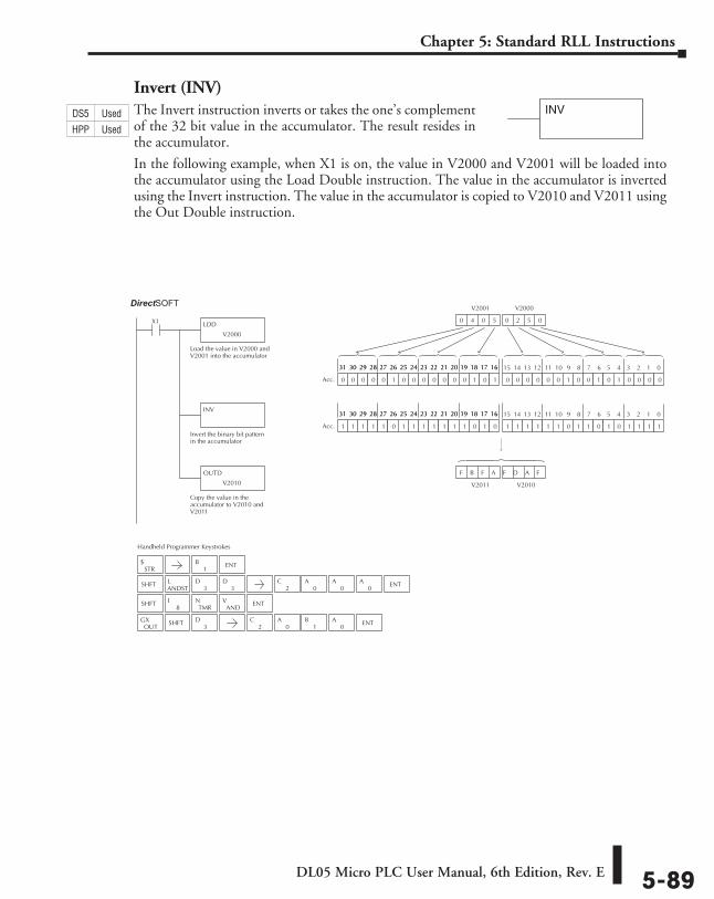
DL05 Micro PLC User Manual, 6th Edition, Rev. E 5-89
Chapter 5: Standard RLL Instructions
Invert (INV)The Invert instruction inverts or takes the one’s complement of the 32 bit value in the accumulator. The result resides in the accumulator.
In the following example, when X1 is on, the value in V2000 and V2001 will be loaded into the accumulator using the Load Double instruction. The value in the accumulator is inverted using the Invert instruction. The value in the accumulator is copied to V2010 and V2011 using the Out Double instruction.
INV
Handheld Programmer Keystrokes
Direct SOFT32
LDD
V2000
X1
Load the value in V2000 andV2001 into the accumulator
INV
Invert the binary bit patternin the accumulator
OUTD
V2010
Copy the value in theaccumulator to V2010 andV2011
0 0 0 0 0 0 1 0 0 1 0 1 0 0 0 00 0 0 0 0 1 0 0 0 0 0 0 0 1 0 1
15 14 13 12 11 10 9 8 7 6 5 4 3 2 1 031 30 29 28 27 26 25 24 23 22 21 20 19 18 17 1631 30 29 28 27 26 25 24 23 22 21 20 19 18 17 16
Acc.
0 4 0 5 0 2 5 0 0 2 5 0
V2000 V2001
V2010 V2011
1 1 1 1 1 1 0 1 1 0 1 0 1 1 1 11 1 1 1 1 0 1 1 1 1 1 1 1 0 1 0
15 14 13 12 11 10 9 8 7 6 5 4 3 2 1 031 30 29 28 27 26 25 24 23 22 21 20 19 18 17 1631 30 29 28 27 26 25 24 23 22 21 20 19 18 17 16
Acc.
F B F A F D A F
STR$
SHFTANDSTL
3D
3D
SHFT ENT
OUTGX SHFT
3D
8I
TMRN
ANDV
1B ENT
2C
0A
0A
0A ENT
2C
0A
1B
0A ENT
DS5 Used
HPP Used
DirectSOFT
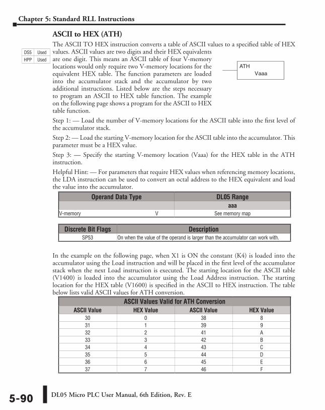
DL05 Micro PLC User Manual, 6th Edition, Rev. E5-90
Chapter 5: Standard RLL Instructions
ASCII to HEX (ATH)The ASCII TO HEX instruction converts a table of ASCII values to a specified table of HEX values. ASCII values are two digits and their HEX equivalents are one digit. This means an ASCII table of four V-memory locations would only require two V-memory locations for the equivalent HEX table. The function parameters are loaded into the accumulator stack and the accumulator by two additional instructions. Listed below are the steps necessary to program an ASCII to HEX table function. The example on the following page shows a program for the ASCII to HEX table function.
Step 1: — Load the number of V-memory locations for the ASCII table into the first level of the accumulator stack.
Step 2: — Load the starting V-memory location for the ASCII table into the accumulator. This parameter must be a HEX value.
Step 3: — Specify the starting V-memory location (Vaaa) for the HEX table in the ATH instruction.
Helpful Hint: — For parameters that require HEX values when referencing memory locations, the LDA instruction can be used to convert an octal address to the HEX equivalent and load the value into the accumulator.
In the example on the following page, when X1 is ON the constant (K4) is loaded into the accumulator using the Load instruction and will be placed in the first level of the accumulator stack when the next Load instruction is executed. The starting location for the ASCII table (V1400) is loaded into the accumulator using the Load Address instruction. The starting location for the HEX table (V1600) is specified in the ASCII to HEX instruction. The table below lists valid ASCII values for ATH conversion.
aaaATH
V
Operand Data Type DL05 Rangeaaa
V-memory ⸠⸠⸠⸠⸠⸠⸠⸠⸠⸠⸠⸠⸠⸠⸠⸠⸠⸠⸠⸠⸠⸠⸠⸠⸠⸠⸠⸠⸠⸠⸠⸠⸠⸠⸠⸠⸠⸠⸠⸠⸠⸠⸠⸠⸠⸠⸠⸠⸠⸠⸠⸠⸠⸠⸠⸠⸠⸠V See memory map
Discrete Bit Flags DescriptionSP53 On when the value of the operand is larger than the accumulator can work with.
ASCII Values Valid for ATH ConversionASCII Value HEX Value ASCII Value HEX Value
30 0 38 831 1 39 932 2 41 A33 3 42 B34 4 43 C35 5 44 D36 6 45 E37 7 46 F
DS5 Used
HPP Used
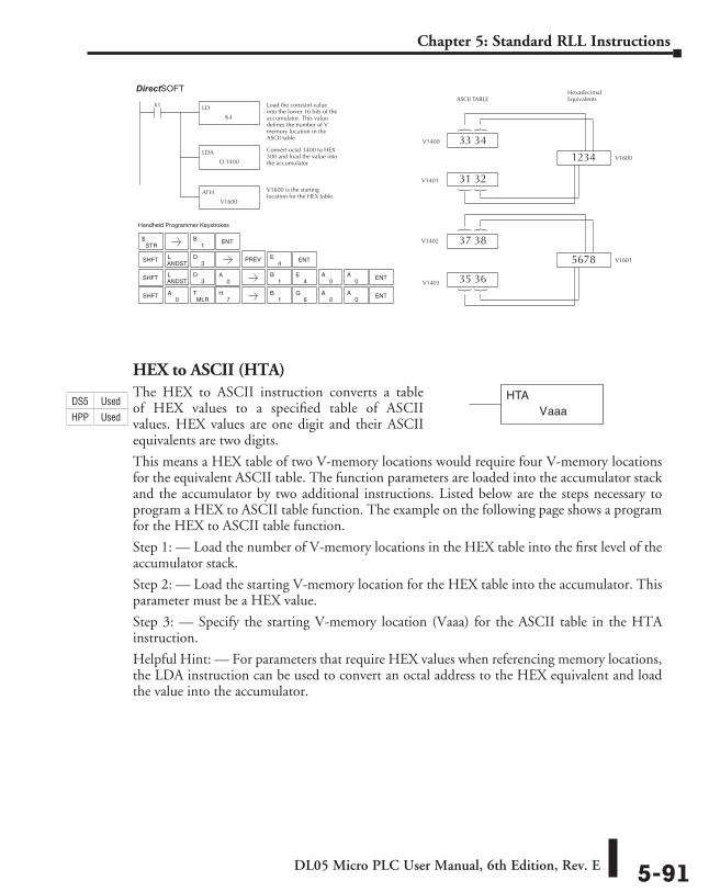
DL05 Micro PLC User Manual, 6th Edition, Rev. E 5-91
Chapter 5: Standard RLL Instructions
HEX to ASCII (HTA)The HEX to ASCII instruction converts a table of HEX values to a specified table of ASCII values. HEX values are one digit and their ASCII equivalents are two digits.
This means a HEX table of two V-memory locations would require four V-memory locations for the equivalent ASCII table. The function parameters are loaded into the accumulator stack and the accumulator by two additional instructions. Listed below are the steps necessary to program a HEX to ASCII table function. The example on the following page shows a program for the HEX to ASCII table function.
Step 1: — Load the number of V-memory locations in the HEX table into the first level of the accumulator stack.
Step 2: — Load the starting V-memory location for the HEX table into the accumulator. This parameter must be a HEX value.
Step 3: — Specify the starting V-memory location (Vaaa) for the ASCII table in the HTA instruction.
Helpful Hint: — For parameters that require HEX values when referencing memory locations, the LDA instruction can be used to convert an octal address to the HEX equivalent and load the value into the accumulator.
Direct SOFT32
LD
K4
X1 Load the constant valueinto the lower 16 bits of theaccumulator. This valuedefines the number of Vmemory location in theASCII table
LDA
O 1400
Convert octal 1400 to HEX300 and load the value intothe accumulator
ATH
V1600
V1600 is the startinglocation for the HEX table
ASCII TABLEHexadecimal Equivalents
1234
33 34V1400
5678
31 32V1401
37 38V1402
35 36V1403
V1600
V1601
STR$
SHFTANDSTL
3D
7H
SHFT
MLRTSHFT
1B ENT
ENT
4E
0A
0A
ENT
1B
6G
0A
0A
Handheld Programmer Keystrokes
PREV
ANDSTL
3D ENT
1B
4E
0A
0A
aaaVHTADS5 Used
HPP Used
DirectSOFT
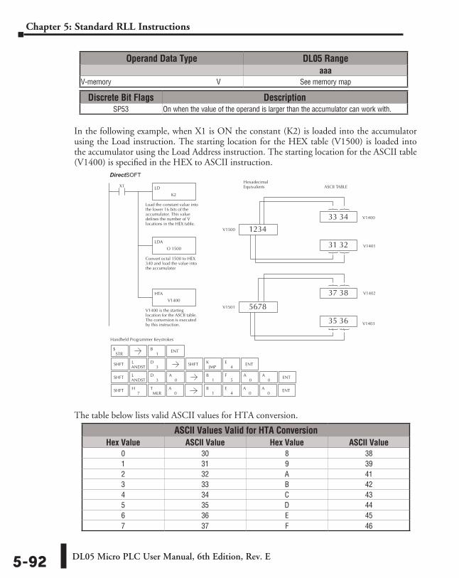
DL05 Micro PLC User Manual, 6th Edition, Rev. E5-92
Chapter 5: Standard RLL Instructions
In the following example, when X1 is ON the constant (K2) is loaded into the accumulator using the Load instruction. The starting location for the HEX table (V1500) is loaded into the accumulator using the Load Address instruction. The starting location for the ASCII table (V1400) is specified in the HEX to ASCII instruction.
The table below lists valid ASCII values for HTA conversion.
Direct SOFT32
Handheld Programmer Keystrokes
LD
K2
X1
Load the constant value intothe lower 16 bits of theaccumulator. This valuedefines the number of Vlocations in the HEX table.
LDA
O 1500
Convert octal 1500 to HEX340 and load the value intothe accumulator
HTA
V1400
V1400 is the startinglocation for the ASCII table.The conversion is executedby this instruction.
ASCII TABLEHexadecimal Equivalents
1234
33 34 V1400
5678
31 32 V1401
37 38 V1402
35 36 V1403
V1500
V1501
STR$
SHFTANDSTL
3D SHFT
JMPK
4E ENT
SHFTANDSTL
3D
0A
0A
0A ENT
SHFT
1B ENT
0A
0A ENT
1B
5F
0A
MLRT
7H
1B
4E
ASCII Values Valid for HTA ConversionHex Value ASCII Value Hex Value ASCII Value
0 30 8 381 31 9 392 32 A 413 33 B 424 34 C 435 35 D 446 36 E 457 37 F 46
Operand Data Type DL05 Rangeaaa
V-memory ⸠⸠⸠⸠⸠⸠⸠⸠⸠⸠⸠⸠⸠⸠⸠⸠⸠⸠⸠⸠⸠⸠⸠⸠⸠⸠⸠⸠⸠⸠⸠⸠⸠⸠⸠⸠⸠⸠⸠⸠⸠⸠⸠⸠⸠⸠⸠⸠⸠⸠⸠⸠⸠⸠⸠⸠⸠⸠V See memory map
Discrete Bit Flags DescriptionSP53 On when the value of the operand is larger than the accumulator can work with.
DirectSOFT
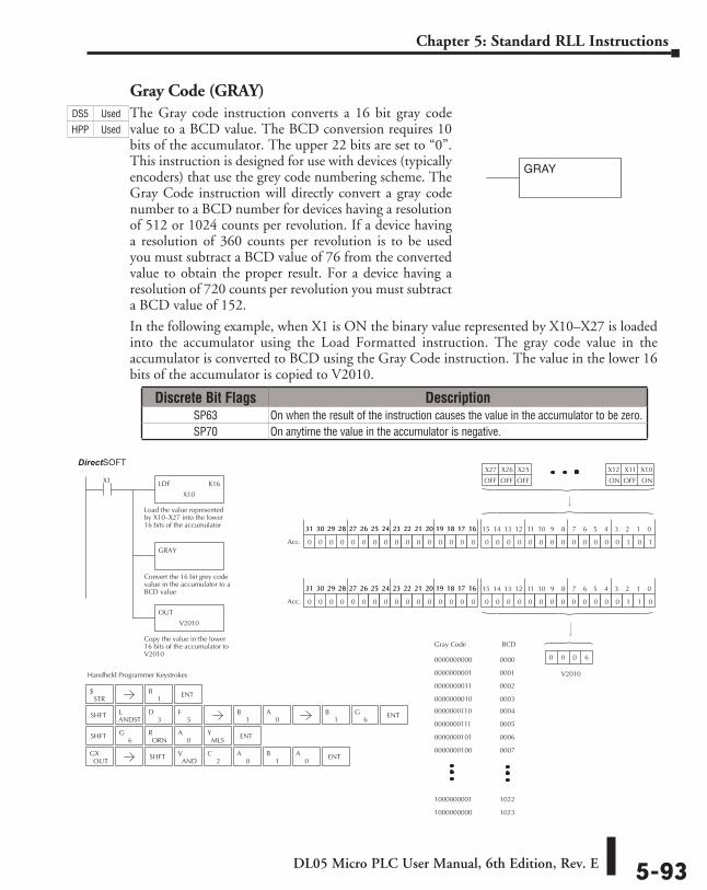
DL05 Micro PLC User Manual, 6th Edition, Rev. E 5-93
Chapter 5: Standard RLL Instructions
Gray Code (GRAY)The Gray code instruction converts a 16 bit gray code value to a BCD value. The BCD conversion requires 10 bits of the accumulator. The upper 22 bits are set to “0”. This instruction is designed for use with devices (typically encoders) that use the grey code numbering scheme. The Gray Code instruction will directly convert a gray code number to a BCD number for devices having a resolution of 512 or 1024 counts per revolution. If a device having a resolution of 360 counts per revolution is to be used you must subtract a BCD value of 76 from the converted value to obtain the proper result. For a device having a resolution of 720 counts per revolution you must subtract a BCD value of 152.
In the following example, when X1 is ON the binary value represented by X10–X27 is loaded into the accumulator using the Load Formatted instruction. The gray code value in the accumulator is converted to BCD using the Gray Code instruction. The value in the lower 16 bits of the accumulator is copied to V2010.
GRAY
Handheld Programmer Keystrokes
Direct SOFT32
LDF K16
X10
X1
Load the value representedby X10–X27 into the lower16 bits of the accumulator
GRAY
Convert the 16 bit grey codevalue in the accumulator to aBCD value
OUT
V2010
Copy the value in the lower16 bits of the accumulator toV2010
0000000000
Gray Code BCD
0000000001
0000000011
0000000010
0000000110
0000000111
0000000101
0000000100
1000000001
1000000000
0000
0001
0002
0003
0004
0005
0006
0007
1022
1023
X10X11X12
ONOFFON
0 0 0 0 0 0 0 0 0 0 0 0 0 1 0 10 0 0 0 0 0 0 0 0 0 0 0 0 0 0 0
15 14 13 12 11 10 9 8 7 6 5 4 3 2 1 031 30 29 28 27 26 25 24 23 22 21 20 19 18 17 1631 30 29 28 27 26 25 24 23 22 21 20 19 18 17 16
Acc.
0 0 0 0 0 0 0 0 0 0 0 0 0 1 1 00 0 0 0 0 0 0 0 0 0 0 0 0 0 0 0
15 14 13 12 11 10 9 8 7 6 5 4 3 2 1 031 30 29 28 27 26 25 24 23 22 21 20 19 18 17 1631 30 29 28 27 26 25 24 23 22 21 20 19 18 17 16
Acc.
X25X26X27
OFFOFFOFF
V2010
0 0 0 6
STR$
SHFTANDSTL
3D
5F
SHFT6
GORN
R0
AMLS
Y ENT
OUTGX SHFT
ANDV
2C
0A
1B
0A ENT
ENT1
B
1B
0A ENT
1B
6G
Discrete Bit Flags DescriptionSP63 On when the result of the instruction causes the value in the accumulator to be zero.SP70 On anytime the value in the accumulator is negative.
DS5 Used
HPP Used
DirectSOFT
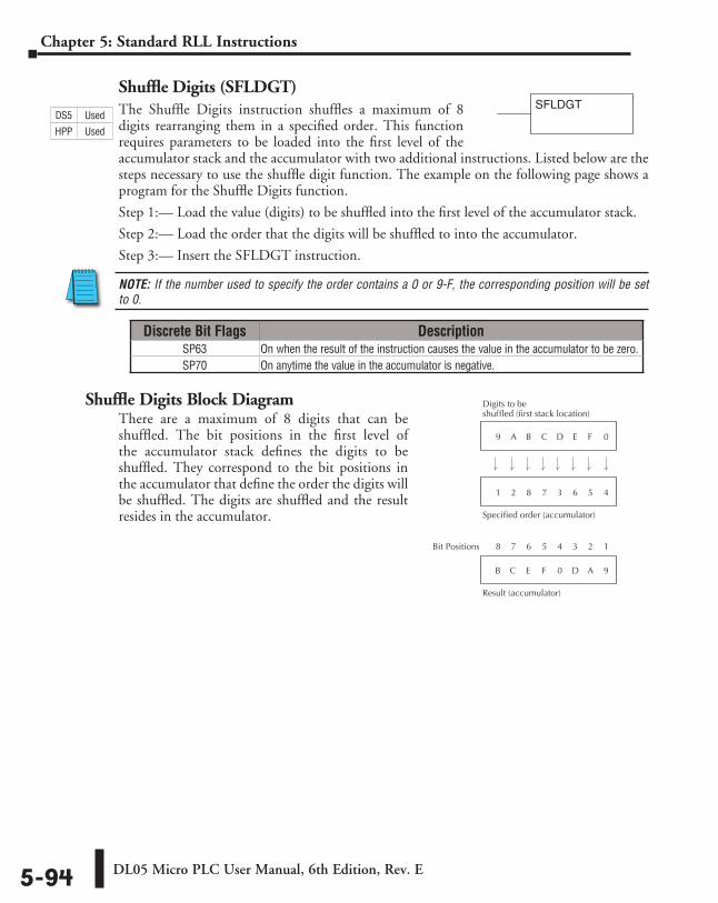
DL05 Micro PLC User Manual, 6th Edition, Rev. E5-94
Chapter 5: Standard RLL Instructions
Shuffle Digits (SFLDGT)The Shuffle Digits instruction shuffles a maximum of 8 digits rearranging them in a specified order. This function requires parameters to be loaded into the first level of the accumulator stack and the accumulator with two additional instructions. Listed below are the steps necessary to use the shuffle digit function. The example on the following page shows a program for the Shuffle Digits function.
Step 1:— Load the value (digits) to be shuffled into the first level of the accumulator stack.
Step 2:— Load the order that the digits will be shuffled to into the accumulator.
Step 3:— Insert the SFLDGT instruction.
NOTE: If the number used to specify the order contains a 0 or 9-F, the corresponding position will be set to 0.
Shuffle Digits Block DiagramThere are a maximum of 8 digits that can be shuffled. The bit positions in the first level of the accumulator stack defines the digits to be shuffled. They correspond to the bit positions in the accumulator that define the order the digits will be shuffled. The digits are shuffled and the result resides in the accumulator.
Digits to beshuffled (first stack location)
Specified order (accumulator)
D E F 09 A B C
3 6 5 41 2 8 7
Result (accumulator)
0 D A 9B C E F
4 3 2 18 7 6 5Bit Positions
Discrete Bit Flags DescriptionSP63 On when the result of the instruction causes the value in the accumulator to be zero.SP70 On anytime the value in the accumulator is negative.
SFLDGTDS5 Used
HPP Used
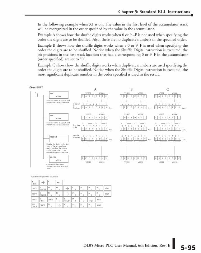
DL05 Micro PLC User Manual, 6th Edition, Rev. E 5-95
Chapter 5: Standard RLL Instructions
In the following example when X1 is on, The value in the first level of the accumulator stack will be reorganized in the order specified by the value in the accumulator.
Example A shows how the shuffle digits works when 0 or 9 –F is not used when specifying the order the digits are to be shuffled. Also, there are no duplicate numbers in the specified order.
Example B shows how the shuffle digits works when a 0 or 9–F is used when specifying the order the digits are to be shuffled. Notice when the Shuffle Digits instruction is executed, the bit positions in the first stack location that had a corresponding 0 or 9–F in the accumulator (order specified) are set to “0”.
Example C shows how the shuffle digits works when duplicate numbers are used specifying the order the digits are to be shuffled. Notice when the Shuffle Digits instruction is executed, the most significant duplicate number in the order specified is used in the result.
D E F 09 A B C
Handheld Programmer Keystrokes
Direct SOFT32
LDD
V2000
X1
Load the value in V2000 andV2001 into the accumulator
LDD
V2006
Load the value in V2006 andV2007 into the accumulator
OUTD
V2010
Copy the value in theaccumulator to V2010 andV2011
SFLDGT
Shuf fle the digits in the firstlevel of the accumulatorstack based on the patternin the accumulator. Theresult is in the accumulator .
V2010
Acc.
0 D A 9
9 A B C D E F 0
V2011
B C E F
Acc.
3 6 5 4
1 2 8 7 3 6 5 4
1 2 8 7
Acc.B C E F 0 D A 9
V2000V2001
V2006V2007
C B A 90 F E D
V2010
Acc.
E D A 9
0 F E D C B A 9
V2011
0 0 0 0
Acc.
0 0 2 1
0 0 4 3 0 0 2 1
0 0 4 3
Acc.0 0 0 0 E D A 9
V2000V2001
V2006V2007
D E F 09 A B C
V2010
Acc.
9 A B C
9 A B C D E F 0
V2011
0 0 0 0
Acc.
4 3 2 1
4 3 2 1 4 3 2 1
4 3 2 1
Acc.0 0 0 0 9 A B C
V2000V2001
V2006V2007
A B C
Original bitPositions
4 3 2 18 7 6 5 4 3 2 18 7 6 5 4 3 2 18 7 6 5
Specifiedorder
4 3 2 18 7 6 5 4 3 2 18 7 6 5 4 3 2 18 7 6 5
New bitPositions
4 3 2 18 7 6 5 4 3 2 18 7 6 5 4 3 2 18 7 6 5
STR$
SHFTANDSTL
3D
3D
SHFTANDSTL
3D
3D
SHFTRST
S5
FANDSTL
3D
6G
MLRT ENT
OUTGX SHFT
3D
1B ENT
2C
0A
0A
0A ENT
2C
0A
0A ENT
6G
2C
0A
1B
0A ENT
SHFT
DirectSOFT
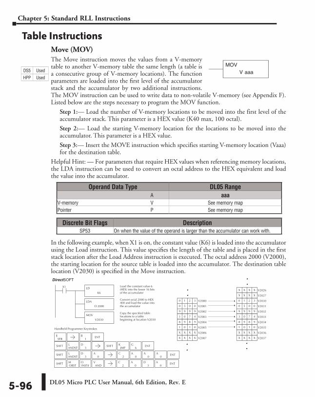
DL05 Micro PLC User Manual, 6th Edition, Rev. E5-96
Chapter 5: Standard RLL Instructions
Table InstructionsMove (MOV)The Move instruction moves the values from a V-memory table to another V-memory table the same length (a table is a consecutive group of V-memory locations). The function parameters are loaded into the first level of the accumulator stack and the accumulator by two additional instructions. The MOV instruction can be used to write data to non-volatile V-memory (see Appendix F). Listed below are the steps necessary to program the MOV function.
Step 1:— Load the number of V-memory locations to be moved into the first level of the accumulator stack. This parameter is a HEX value (K40 max, 100 octal).
Step 2:— Load the starting V-memory location for the locations to be moved into the accumulator. This parameter is a HEX value.
Step 3:— Insert the MOVE instruction which specifies starting V-memory location (Vaaa) for the destination table.
Helpful Hint: — For parameters that require HEX values when referencing memory locations, the LDA instruction can be used to convert an octal address to the HEX equivalent and load the value into the accumulator.
In the following example, when X1 is on, the constant value (K6) is loaded into the accumulator using the Load instruction. This value specifies the length of the table and is placed in the first stack location after the Load Address instruction is executed. The octal address 2000 (V2000), the starting location for the source table is loaded into the accumulator. The destination table location (V2030) is specified in the Move instruction.
V aaaMOV
Direct SOFT32
LD
K6
X1 Load the constant value 6(HEX) into the lower 16 bitsof the accumulator
LDA
O 2000
Convert octal 2000 to HEX400 and load the value intothe accumulator
MOV
V2030
Copy the specified tablelocations to a tablebeginning at location V2030
V20300 1 2 3
V20310 5 0 0
V20329 9 9 9
V20333 0 7 4
V20348 9 8 9
V20351 0 1 0
V2036X X X X
V2037X X X X
V2026X X X X
V2027X X X X
V20000 1 2 3
V20010 5 0 0
V20029 9 9 9
V20033 0 7 4
V20048 9 8 9
V20051 0 1 0
V2006X X X X
V2007X X X X
Handheld Programmer Keystrokes
STR$
SHFTANDSTL
3D SHFT
JMPK
6G ENT
SHFTANDSTL
3D
0A
2C
0A
0A
0A ENT
SHFTORSTM
INST#O
1B ENT
2C
0A
0A ENT
3D
ANDV
Discrete Bit Flags DescriptionSP53 On when the value of the operand is larger than the accumulator can work with.
Operand Data Type DL05 Range ⸠⸠⸠⸠⸠⸠⸠⸠⸠⸠⸠⸠⸠⸠⸠⸠⸠⸠⸠⸠⸠⸠⸠⸠⸠⸠⸠⸠⸠⸠⸠⸠⸠⸠⸠⸠⸠⸠⸠⸠⸠⸠⸠⸠⸠⸠⸠⸠⸠⸠⸠⸠⸠⸠⸠⸠⸠⸠⸠⸠⸠⸠⸠⸠⸠⸠⸠⸠⸠⸠⸠⸠⸠A aaaV-memory ⸠⸠⸠⸠⸠⸠⸠⸠⸠⸠⸠⸠⸠⸠⸠⸠⸠⸠⸠⸠⸠⸠⸠⸠⸠⸠⸠⸠⸠⸠⸠⸠⸠⸠⸠⸠⸠⸠⸠⸠⸠⸠⸠⸠⸠⸠⸠⸠⸠⸠⸠⸠⸠⸠⸠⸠⸠⸠V See memory mapPointer ⸠⸠⸠⸠⸠⸠⸠⸠⸠⸠⸠⸠⸠⸠⸠⸠⸠⸠⸠⸠⸠⸠⸠⸠⸠⸠⸠⸠⸠⸠⸠⸠⸠⸠⸠⸠⸠⸠⸠⸠⸠⸠⸠⸠⸠⸠⸠⸠⸠⸠⸠⸠⸠⸠⸠⸠⸠⸠⸠⸠⸠⸠⸠⸠P See memory map
DS5 Used
HPP Used
DirectSOFT
DL05 Micro PLC User Manual, 6th Edition, Rev. E 5-97
Chapter 5: Standard RLL Instructions
Move Memory Cartridge (MOVMC) and
Load Label (LDLBL)The Move Memory Cartridge and the Load Label instructions are used to copy data from program ladder memory to V-memory. The Load Label instruction is used with the MOVMC instruction when copying data from program ladder memory to V-memory.
To copy data from the program ladder memory to V-memory, the function parameters are loaded into the first two levels of the accumulator stack and the accumulator by two additional instructions. Listed below are the steps necessary to program the Move Memory Cartridge and Load Label functions.
Step 1:— Load the number of words to be copied into the second level of the accumulator stack.
Step 2:— Load the offset for the data label area in ladder memory and the beginning of the V-memory block into the first level of the stack.
Step 3:— Load the source data label (LDLBL Kaaa) into the accumulator when copying data from ladder memory to V-memory. This is the source location of the value.
Step 4:— Insert the MOVMC instruction which specifies destination in V-memory (Vaaa). This is the copy destination.
V aaaMOVMC
LDLBLaaaK
Operand Data Type DL05 Range ⸠⸠⸠⸠⸠⸠⸠⸠⸠⸠⸠⸠⸠⸠⸠⸠⸠⸠⸠⸠⸠⸠⸠⸠⸠⸠⸠⸠⸠⸠⸠⸠⸠⸠⸠⸠⸠⸠⸠⸠⸠⸠⸠⸠⸠⸠⸠⸠⸠⸠⸠⸠⸠⸠⸠⸠⸠⸠⸠⸠⸠⸠⸠⸠⸠⸠⸠⸠⸠⸠⸠⸠⸠A aaaV-memory ⸠⸠⸠⸠⸠⸠⸠⸠⸠⸠⸠⸠⸠⸠⸠⸠⸠⸠⸠⸠⸠⸠⸠⸠⸠⸠⸠⸠⸠⸠⸠⸠⸠⸠⸠⸠⸠⸠⸠⸠⸠⸠⸠⸠⸠⸠⸠⸠⸠⸠⸠⸠⸠⸠⸠⸠⸠⸠V See memory map
DS5 Used
HPP Used
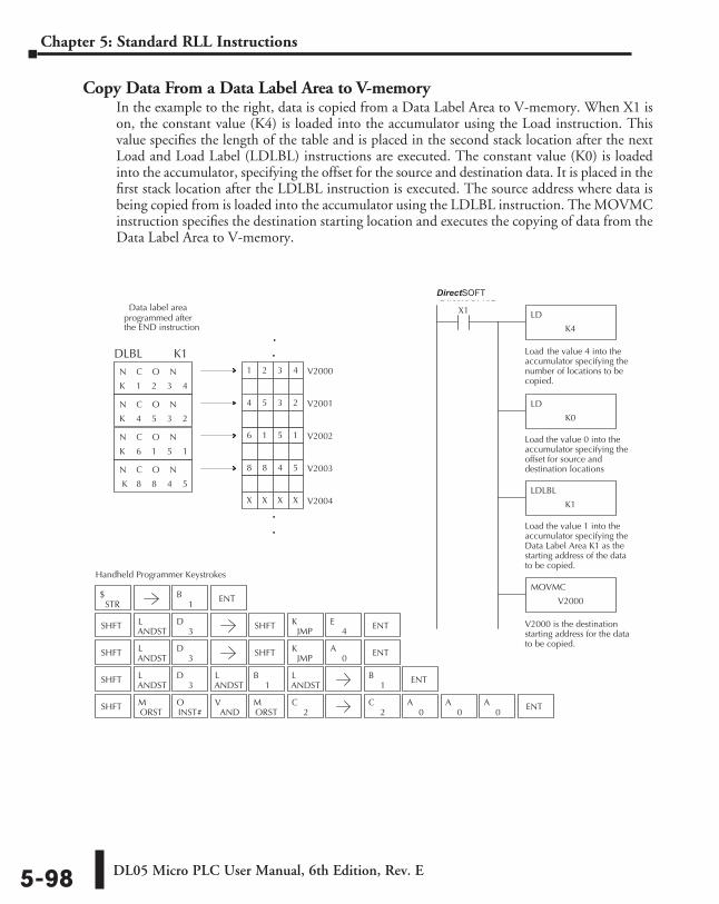
DL05 Micro PLC User Manual, 6th Edition, Rev. E5-98
Chapter 5: Standard RLL Instructions
Copy Data From a Data Label Area to V-memoryIn the example to the right, data is copied from a Data Label Area to V-memory. When X1 is on, the constant value (K4) is loaded into the accumulator using the Load instruction. This value specifies the length of the table and is placed in the second stack location after the next Load and Load Label (LDLBL) instructions are executed. The constant value (K0) is loaded into the accumulator, specifying the offset for the source and destination data. It is placed in the first stack location after the LDLBL instruction is executed. The source address where data is being copied from is loaded into the accumulator using the LDLBL instruction. The MOVMC instruction specifies the destination starting location and executes the copying of data from the Data Label Area to V-memory.
Direct SOFT32
LD
K4
X1
Load the value 4 into theaccumulator specifying thenumber of locations to becopied.
LD
K0
Load the value 0 into theaccumulator specifying theoffset for source anddestination locations
LDLBL
K1
Load the value 1 into theaccumulator specifying theData Label Area K1 as thestarting address of the datato be copied.
MOVMC
V2000
V2000 is the destinationstarting address for the datato be copied.
1 2 3 4
4 5 3 2
6 1 5 1
8 8 4 5
K
N C O N
K
N C O N
K
N C O N
K
N C O N
V20014 5 3 2
V20026 1 5 1
V20038 8 4 5
V2004X X X X
.
.
.
.V20001 2 3 4
Data label areaprogrammed after
the END instruction
DLBL
Handheld Programmer Keystrokes
STR$
SHFTANDSTL
3D SHFT
JMPK ENT
SHFTANDSTL
3D
ANDSTL
1B
ANDSTL
SHFTORSTM
ANDV
INST#O
ORSTM
2C
1B ENT
ENT1
B
2C
0A
0A
0A ENT
SHFTANDSTL
3D SHFT
JMPK
0A ENT
4E
K1
DirectSOFT
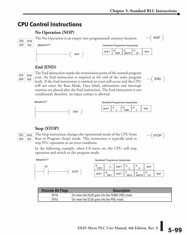
DL05 Micro PLC User Manual, 6th Edition, Rev. E 5-99
Chapter 5: Standard RLL Instructions
CPU Control InstructionsNo Operation (NOP)The No Operation is an empty (not programmed) memory location.
End (END)The End instruction marks the termination point of the normal program scan. An End instruction is required at the end of the main program body. If the End instruction is omitted an error will occur and the CPU will not enter the Run Mode. Data labels, subroutines and interrupt routines are placed after the End instruction. The End instruction is not conditional; therefore, no input contact is allowed.
Stop (STOP)The Stop instruction changes the operational mode of the CPU from Run to Program (Stop) mode. This instruction is typically used to stop PLC operation in an error condition.
In the following example, when C0 turns on, the CPU will stop operation and switch to the program mode.
NOP
END
DirectSOFT32 Handheld Programmer Keystrokes
ENDSHFT 4
ETMR
N3
D ENT
STOP
DirectSOFT32 Handheld Programmer Keystrokes
STOP
C0STR
$ SHFT ENT2C
0A
SHFT RSTS
MLRT
INST#O
CVP ENTSHFT
Discrete Bit Flags DescriptionSP16 On when the DL05 goes into the TERM_PRG mode.SP53 On when the DL05 goes into the PRG mode.
DirectSOFT32 Handheld Programmer Keystrokes
NOPSHFT TMR
NINST#O
CVP ENT
DS5 Used
HPP N/A
DS5 Used
HPP N/A
DS5 Used
HPP N/A DirectSOFT
DirectSOFT
DirectSOFT
DL05 Micro PLC User Manual, 6th Edition, Rev. E5-100
Chapter 5: Standard RLL Instructions
Reset Watch Dog Timer (RSTWT)The Reset Watch Dog Timer instruction resets the CPU scan timer. The default setting for the watch dog timer is 200ms. Scan times very seldom exceed 200ms, but it is possible. For/next loops, subroutines, interrupt routines, and table instructions can be programmed such that the scan becomes longer than 200ms. When instructions are used in a manner that could exceed the watch dog timer setting, this instruction can be used to reset the timer.
A software timeout error (E003) will occur and the CPU will enter the program mode if the scan time exceeds the watch dog timer setting. Placement of the RSTWT instruction in the program is very important. The instruction has to be executed before the scan time exceeds the watch dog timer’s setting.
If the scan time is consistently longer than the watch dog timer’s setting, the timeout value may be permanently increased from the default value of 200ms by AUX 55 on the HPP or the appropriate auxiliary function in your programming package. This eliminates the need for the RSTWT instruction.
In the following example the CPU scan timer will be reset to 0 when the RSTWT instruction is executed. See the For/Next instruction for a detailed example.
RSTWT
Direct SOFT 32 Handheld Programmer Keystrokes
RSTWT
SHFTORN
RRST
SMLR
TANDNW
MLRT ENT
DS5 Used
HPP N/A
DirectSOFT
DL05 Micro PLC User Manual, 6th Edition, Rev. E 5-101
Chapter 5: Standard RLL Instructions
Program Control InstructionsFor / Next (FOR) (NEXT)The For and Next instructions are used to execute a section of ladder logic between the For and Next instruction a specified numbers of times. When the For instruction is enabled, the program will loop the specified number of times. If the For instruction is not energized the section of ladder logic between the For and Next instructions is not executed.
For / Next instructions cannot be nested. The normal I/O update and CPU housekeeping is suspended while executing the For / Next loop. The program scan can increase significantly, depending on the amount of times the logic between the For and Next instruction is executed. With the exception of immediate I/O instructions, I/O will not be updated until the program execution is completed for that scan. Depending on the length of time required to complete the program execution, it may be necessary to reset the watch dog timer inside of the For / Next loop using the RSTWT instruction.
A aaaFOR
NEXT
Operand Data Type DL05 Range ⸠⸠⸠⸠⸠⸠⸠⸠⸠⸠⸠⸠⸠⸠⸠⸠⸠⸠⸠⸠⸠⸠⸠⸠⸠⸠⸠⸠⸠⸠⸠⸠⸠⸠⸠⸠⸠⸠⸠⸠⸠⸠⸠⸠⸠⸠⸠⸠⸠⸠⸠⸠⸠⸠⸠⸠⸠⸠⸠⸠⸠⸠⸠⸠⸠⸠⸠⸠⸠⸠⸠⸠⸠A aaaV-memory ⸠⸠⸠⸠⸠⸠⸠⸠⸠⸠⸠⸠⸠⸠⸠⸠⸠⸠⸠⸠⸠⸠⸠⸠⸠⸠⸠⸠⸠⸠⸠⸠⸠⸠⸠⸠⸠⸠⸠⸠⸠⸠⸠⸠⸠⸠⸠⸠⸠⸠⸠⸠⸠⸠⸠⸠⸠⸠V See memory mapConstant ⸠⸠⸠⸠⸠⸠⸠⸠⸠⸠⸠⸠⸠⸠⸠⸠⸠⸠⸠⸠⸠⸠⸠⸠⸠⸠⸠⸠⸠⸠⸠⸠⸠⸠⸠⸠⸠⸠⸠⸠⸠⸠⸠⸠⸠⸠⸠⸠⸠⸠⸠⸠⸠⸠⸠⸠⸠⸠⸠⸠⸠K 1-9999
DS5 Used
HPP Used
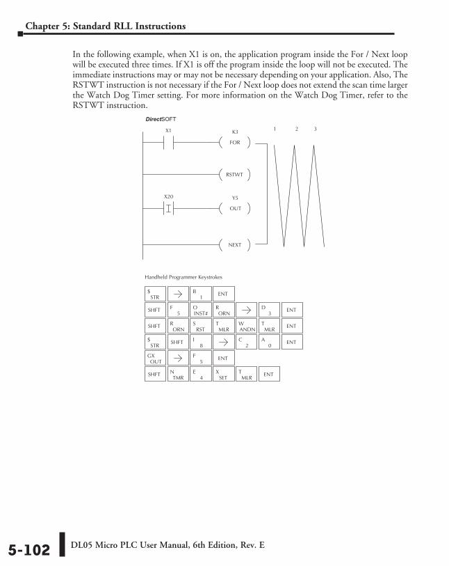
DL05 Micro PLC User Manual, 6th Edition, Rev. E5-102
Chapter 5: Standard RLL Instructions
In the following example, when X1 is on, the application program inside the For / Next loop will be executed three times. If X1 is off the program inside the loop will not be executed. The immediate instructions may or may not be necessary depending on your application. Also, The RSTWT instruction is not necessary if the For / Next loop does not extend the scan time larger the Watch Dog Timer setting. For more information on the Watch Dog Timer, refer to the RSTWT instruction.
X1Direct SOFT32
Handheld Programmer Keystrokes
K3
FOR
RSTWT
X20 Y5
OUT
NEXT
1 2 3
STR$
SHFT5
FINST#O
ORNR
SHFTORN
RRST
SMLR
TANDNW
MLRT ENT
STR$ SHFT
8I
2C
0A ENT
OUTGX
SHFTTMR
N4
ESET
XMLR
T ENT
1B ENT
3D ENT
5F ENT
DirectSOFT
DL05 Micro PLC User Manual, 6th Edition, Rev. E 5-103
Chapter 5: Standard RLL Instructions
Goto Subroutine (GTS) (SBR)The Goto Subroutine instruction allows a section of ladder logic to be placed outside the main body of the program execute only when needed. There can be a maximum of 64 GTS instructions and 64 SBR instructions used in a program. The GTS instructions can be nested up to 8 levels. An error E412 will occur if the maximum limits are exceeded. Typically this will be used in an application where a block of program logic may be slow to execute and is not required to execute every scan. The subroutine label and all associated logic is placed after the End statement in the program. When the subroutine is called from the main program, the CPU will execute the subroutine (SBR) with the same constant number (K) as the GTS instruction which called the subroutine.
By placing code in a subroutine it is only scanned and executed when needed since it resides after the End instruction. Code which is not scanned does not impact the overall scan time of the program.
Subroutine Return (RT)When a Subroutine Return is executed in the subroutine the CPU will return to the point in the main body of the program from which it was called. The Subroutine Return is used as termination of the subroutine which must be the last instruction in the subroutine and is a stand alone instruction (no input contact on the rung).
Subroutine Return Conditional (RTC)The Subroutine Return Conditional instruction is a optional instruction used with a input contact to implement a conditional return from the subroutine. The Subroutine Return (RT) is still required for termination of the Subroutine.
K aaa
GTS
K aaaSBR
RT
RTC
Operand Data Type DL05 Range ⸠⸠⸠⸠⸠⸠⸠⸠⸠⸠⸠⸠⸠⸠⸠⸠⸠⸠⸠⸠⸠⸠⸠⸠⸠⸠⸠⸠⸠⸠⸠⸠⸠⸠⸠⸠⸠⸠⸠⸠⸠⸠⸠⸠⸠⸠⸠⸠⸠⸠⸠⸠⸠⸠⸠⸠⸠⸠⸠⸠⸠⸠⸠⸠⸠⸠⸠⸠⸠⸠⸠⸠⸠A aaaConstant ⸠⸠⸠⸠⸠⸠⸠⸠⸠⸠⸠⸠⸠⸠⸠⸠⸠⸠⸠⸠⸠⸠⸠⸠⸠⸠⸠⸠⸠⸠⸠⸠⸠⸠⸠⸠⸠⸠⸠⸠⸠⸠⸠⸠⸠⸠⸠⸠⸠⸠⸠⸠⸠⸠⸠⸠⸠⸠⸠⸠⸠K 1-FFFF
DS5 Used
HPP Used
DS5 Used
HPP Used
DS5 Used
HPP Used
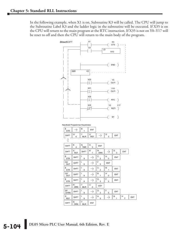
DL05 Micro PLC User Manual, 6th Edition, Rev. E5-104
Chapter 5: Standard RLL Instructions
In the following example, when X1 is on, Subroutine K3 will be called. The CPU will jump to the Subroutine Label K3 and the ladder logic in the subroutine will be executed. If X35 is on the CPU will return to the main program at the RTC instruction. If X35 is not on Y0–Y17 will be reset to off and then the CPU will return to the main body of the program.
Direct SOFT32 Display
Handheld Programmer Keystrokes
SBR K3
X1 K3GTS
END
Y5OUTI
X20
Y10OUTI
X21
X35
RTCX35
RSTIY0 Y17
RT
K10LD
C0
STR$
SHFT 6G
MLRT
RSTS
SHFT RSTS
1B
ORNR
STR$ SHFT 8
I2
C0
A ENT
OUTGX
STR$
SHFT 8I
3D ENT5
F
OUTGX
SHFT ORNR
MLRT ENT
SHFT 4E
TMRN
3D ENT
1B ENT
3D ENT
3D ENT
5F ENT
ENT1B
0A
SHFT
??
SHFT 8I
SHFT 8I
2C
STR$ SHFT 8
I2
C ENT1B
STRNSP
RSTS SHFT 8
I0
A1
B7
H ENT
SHFT 8I
3D ENT5
F
SHFT ORNR
MLRT ENT
DirectSOFT
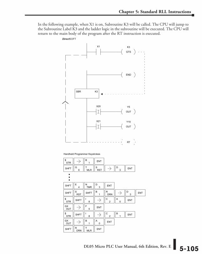
DL05 Micro PLC User Manual, 6th Edition, Rev. E 5-105
Chapter 5: Standard RLL Instructions
In the following example, when X1 is on, Subroutine K3 will be called. The CPU will jump to the Subroutine Label K3 and the ladder logic in the subroutine will be executed. The CPU will return to the main body of the program after the RT instruction is executed.
Direct SOFT
Handheld Programmer Keystrokes
SBR K3
X1 K3
GTS
END
Y5
OUT
X20
Y10
OUT
X21
RT
STR$
SHFT 6G
MLRT
RSTS
SHFT RSTS
1B
ORNR
STR$ SHFT 8
I2
C0
A ENT
OUTGX
STR$ SHFT 8
I2
C ENT1B
OUTGX
SHFT ORNR
MLRT ENT
SHFT 4E
TMRN
3D ENT
1B ENT
3D ENT
3D ENT
5F ENT
ENT1B
0A
SHFT
32
DirectSOFT
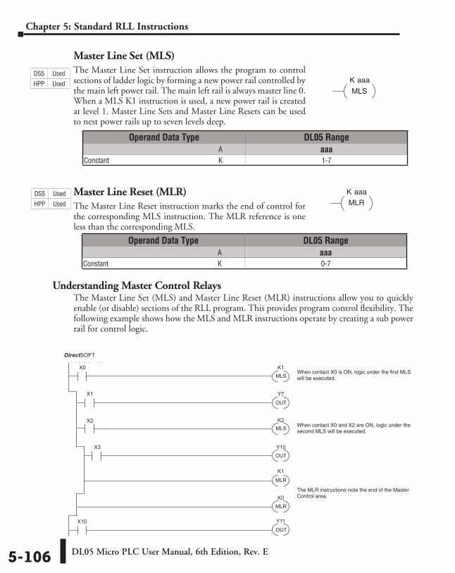
DL05 Micro PLC User Manual, 6th Edition, Rev. E5-106
Chapter 5: Standard RLL Instructions
Master Line Set (MLS)The Master Line Set instruction allows the program to control sections of ladder logic by forming a new power rail controlled by the main left power rail. The main left rail is always master line 0. When a MLS K1 instruction is used, a new power rail is created at level 1. Master Line Sets and Master Line Resets can be used to nest power rails up to seven levels deep.
Master Line Reset (MLR)The Master Line Reset instruction marks the end of control for the corresponding MLS instruction. The MLR reference is one less than the corresponding MLS.
Understanding Master Control RelaysThe Master Line Set (MLS) and Master Line Reset (MLR) instructions allow you to quickly enable (or disable) sections of the RLL program. This provides program control flexibility. The following example shows how the MLS and MLR instructions operate by creating a sub power rail for control logic.
K aaa
MLS
K aaa
MLR
X0
X1
X2
OUTY7
X3
MLS
X10
K1
K2
K0
K1
MLS
OUT
MLR
MLR
OUT
Y10
Y11
Direct SOFT32
When contact X0 is ON, logic under the first MLSwill be executed.
When contact X0 and X2 are ON, logic under the second MLS will be executed.
The MLR instructions note the end of the MasterControl area.
Operand Data Type DL05 Range ⸠⸠⸠⸠⸠⸠⸠⸠⸠⸠⸠⸠⸠⸠⸠⸠⸠⸠⸠⸠⸠⸠⸠⸠⸠⸠⸠⸠⸠⸠⸠⸠⸠⸠⸠⸠⸠⸠⸠⸠⸠⸠⸠⸠⸠⸠⸠⸠⸠⸠⸠⸠⸠⸠⸠⸠⸠⸠⸠⸠⸠⸠⸠⸠⸠⸠⸠⸠⸠⸠⸠⸠⸠A aaaConstant ⸠⸠⸠⸠⸠⸠⸠⸠⸠⸠⸠⸠⸠⸠⸠⸠⸠⸠⸠⸠⸠⸠⸠⸠⸠⸠⸠⸠⸠⸠⸠⸠⸠⸠⸠⸠⸠⸠⸠⸠⸠⸠⸠⸠⸠⸠⸠⸠⸠⸠⸠⸠⸠⸠⸠⸠⸠⸠⸠⸠⸠K 0-7
Operand Data Type DL05 Range ⸠⸠⸠⸠⸠⸠⸠⸠⸠⸠⸠⸠⸠⸠⸠⸠⸠⸠⸠⸠⸠⸠⸠⸠⸠⸠⸠⸠⸠⸠⸠⸠⸠⸠⸠⸠⸠⸠⸠⸠⸠⸠⸠⸠⸠⸠⸠⸠⸠⸠⸠⸠⸠⸠⸠⸠⸠⸠⸠⸠⸠⸠⸠⸠⸠⸠⸠⸠⸠⸠⸠⸠⸠A aaaConstant ⸠⸠⸠⸠⸠⸠⸠⸠⸠⸠⸠⸠⸠⸠⸠⸠⸠⸠⸠⸠⸠⸠⸠⸠⸠⸠⸠⸠⸠⸠⸠⸠⸠⸠⸠⸠⸠⸠⸠⸠⸠⸠⸠⸠⸠⸠⸠⸠⸠⸠⸠⸠⸠⸠⸠⸠⸠⸠⸠⸠⸠K 1-7
DS5 Used
HPP Used
DS5 Used
HPP Used
DirectSOFT
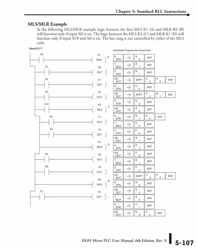
DL05 Micro PLC User Manual, 6th Edition, Rev. E 5-107
Chapter 5: Standard RLL Instructions
MLS/MLR ExampleIn the following MLS/MLR example logic between the first MLS K1 (A) and MLR K0 (B) will function only if input X0 is on. The logic between the MLS K2 (C) and MLR K1 (D) will function only if input X10 and X0 is on. The last rung is not controlled by either of the MLS coils.
K1
MLS
X0
C0
OUT
X1
C1
OUT
X2
Y0
OUT
X3
K2
MLS
X10
Y1
OUT
X5
Y2
OUT
X4
K1
MLR
C2
OUT
X5
Y3
OUT
X6
K0
MLR
Y4
OUT
X7
DirectSOFT32 Handheld Programmer Keystrokes
STR$ ENT
0A
MLSY
1B ENT
STR$
1B ENT
OUTGX SHFT ENT
2C
0A
STR$ ENT
2C
OUTGX SHFT ENT
2C
1B
STR$ ENT
3D
OUTGX ENT
0A
STR$ ENT
0A
1B
MLSY ENT
2C
STR$ ENT
5F
OUTGX ENT
1B
STR$ ENT
OUTGX ENT
4E
2C
MLRT
1B ENT
STR$ ENT
5F
OUTGX SHFT ENT
2C
2C
STR$ ENT
OUTGX ENT
6G
3D
MLRT ENT
0A
STR$ ENT
OUTGX
4E
7H
ENT2
C
A
C
D
B
DirectSOFT
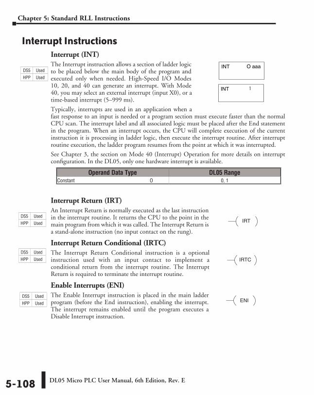
DL05 Micro PLC User Manual, 6th Edition, Rev. E5-108
Chapter 5: Standard RLL Instructions
Interrupt InstructionsInterrupt (INT)The Interrupt instruction allows a section of ladder logic to be placed below the main body of the program and executed only when needed. High-Speed I/O Modes 10, 20, and 40 can generate an interrupt. With Mode 40, you may select an external interrupt (input X0), or a time-based interrupt (5–999 ms).
Typically, interrupts are used in an application when a fast response to an input is needed or a program section must execute faster than the normal CPU scan. The interrupt label and all associated logic must be placed after the End statement in the program. When an interrupt occurs, the CPU will complete execution of the current instruction it is processing in ladder logic, then execute the interrupt routine. After interrupt routine execution, the ladder program resumes from the point at which it was interrupted.
See Chapter 3, the section on Mode 40 (Interrupt) Operation for more details on interrupt configuration. In the DL05, only one hardware interrupt is available.
Interrupt Return (IRT)An Interrupt Return is normally executed as the last instruction in the interrupt routine. It returns the CPU to the point in the main program from which it was called. The Interrupt Return is a stand-alone instruction (no input contact on the rung).
Interrupt Return Conditional (IRTC)The Interrupt Return Conditional instruction is a optional instruction used with an input contact to implement a conditional return from the interrupt routine. The Interrupt Return is required to terminate the interrupt routine.
Enable Interrupts (ENI)The Enable Interrupt instruction is placed in the main ladder program (before the End instruction), enabling the interrupt. The interrupt remains enabled until the program executes a Disable Interrupt instruction.
O aaaINT
INT
1
IRT
IRTC
ENI
Operand Data Type DL05 RangeConstant ⸠⸠⸠⸠⸠⸠⸠⸠⸠⸠⸠⸠⸠⸠⸠⸠⸠⸠⸠⸠⸠⸠⸠⸠⸠⸠⸠⸠⸠⸠⸠⸠⸠⸠⸠⸠⸠⸠⸠⸠⸠⸠⸠⸠⸠⸠⸠⸠⸠⸠⸠⸠⸠⸠⸠⸠⸠⸠⸠⸠⸠O 0, 1
DS5 Used
HPP Used
DS5 Used
HPP Used
DS5 Used
HPP Used
DS5 Used
HPP Used
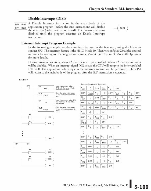
DL05 Micro PLC User Manual, 6th Edition, Rev. E 5-109
Chapter 5: Standard RLL Instructions
Disable Interrupts (DISI)A Disable Interrupt instruction in the main body of the application program (before the End instruction) will disable the interrupt (either external or timed). The interrupt remains disabled until the program executes an Enable Interrupt instruction.
External Interrupt Program ExampleIn the following example, we do some initialization on the first scan, using the first-scan contact SP0. The interrupt feature is the HSIO Mode 40. Then we configure X0 as the external interrupt by writing to its configuration register, V7634. See Chapter 3, Mode 40 Operation for more details.
During program execution, when X2 is on the interrupt is enabled. When X2 is off the interrupt will be disabled. When an interrupt signal (X0) occurs the CPU will jump to the interrupt label INT O 0. The application ladder logic in the interrupt routine will be performed. The CPU will return to the main body of the program after the IRT instruction is executed.
DISI
O 0
X2ENI
DISIX2
END
Y5SETI
X1
Y7SETI
X3
IRT
Handheld Programmer Keystrokes
8I
ORNR
MLRT
STR$ SHFT 8
I1
B ENT
SHFT 8I
5F ENT
STR$ SHFT 8
I3
D ENT
SHFT 8I ENT7
H
SHFT 4E
TMRN
3D ENT
STR$ ENT2
C
SHFT 4E
TMRN
8I ENT
STRNSP ENT2
C
SHFT 8I
TMRN
MLRT
0A ENT
SHFT ENT
SHFT ENT3D
8I
RSTS
8I
SETX
SETX
LDK40
SP0 Load the constant value(K40) into the lower 16 bitsof the accumulator
OUTV7633
Copy the value in the lower16 bits of the accumulator toV7633
LDK4
Load the constant value (K4)into the lower 16 bits of theaccumulator
OUTV7634
Copy the value in the lower16 bits of the accumulator toV7634
STR$
SHFT ANDSTL
3D SHFT
OUTGX SHFT AND
V ENT
JMPK ENT
7H
6G
3D
4E
SHFT ANDSTL
3D SHFT 0
A
OUTGX SHFT AND
V ENT
JMPK
4E ENT
7H
6G
3D
3D
4E
SHFT ENTSTRNSP
0A
INT
DirectSOFT
DS5 Used
HPP Used
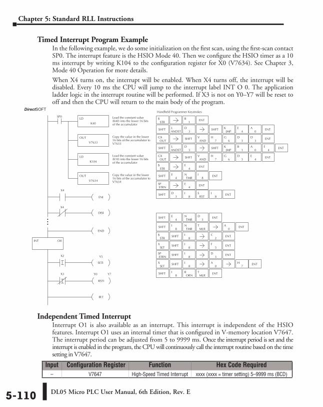
DL05 Micro PLC User Manual, 6th Edition, Rev. E5-110
Chapter 5: Standard RLL Instructions
Timed Interrupt Program ExampleIn the following example, we do some initialization on the first scan, using the first-scan contact SP0. The interrupt feature is the HSIO Mode 40. Then we configure the HSIO timer as a 10 ms interrupt by writing K104 to the configuration register for X0 (V7634). See Chapter 3, Mode 40 Operation for more details.
When X4 turns on, the interrupt will be enabled. When X4 turns off, the interrupt will be disabled. Every 10 ms the CPU will jump to the interrupt label INT O 0. The application ladder logic in the interrupt routine will be performed. If X3 is not on Y0–Y7 will be reset to off and then the CPU will return to the main body of the program.
Independent Timed InterruptInterrupt O1 is also available as an interrupt. This interrupt is independent of the HSIO features. Interrupt O1 uses an internal timer that is configured in V-memory location V7647. The interrupt period can be adjusted from 5 to 9999 ms. Once the interrupt period is set and the interrupt is enabled in the program, the CPU will continuously call the interrupt routine based on the time setting in V7647.
Direct SOFT32
INT O0
X4
ENI
DISI
X4
END
Y5
SETI
X2
X3
RSTI
Y0 Y7
IRT
Handheld Programmer Keystrokes
LD
K40
SP0 Load the constant value(K40) into the lower 16 bitsof the accumulator
OUT
V7633
Copy the value in the lower16 bits of the accumulator toV7633
STR$
SHFTANDSTL
3D SHFT
0A
OUTGX SHFT
ANDV ENT
JMPK
1B ENT
7H
6G
3D
4E
STR$
SHFT4
ETMR
N8
I ENT
STRNSP
SHFT ENT3
D8
IRST
S8
I
8I
ORNR
MLRT
STR$ SHFT
8I
2C ENT
SHFT8
I5
F ENT
SHFT8
I ENT
SHFT8
I ENT0
A
SHFT4
ETMR
N3
D ENT
SHFT8
ITMR
NMLR
T ENT
SHFT ENT
0A
1B ENT
ENT
ENT
4E
4E
7H
3D
SETX
SETX
STRNSP
LD
K104
Load the constant value(K10) into the lower 16 bitsof the accumulator
OUT
V7634
Copy the value in the lower16 bits of the accumulator toV7634
SHFTANDSTL
3D SHFT
0A
OUTGX SHFT
ANDV ENT
JMPK
4E ENT
7H
6G
3D
3D
4E
Input Configuration Register Function Hex Code Required– V7647 High-Speed Timed Interrupt xxxx (xxxx = timer setting) 5–9999 ms (BCD)
DirectSOFT
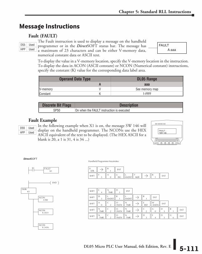
DL05 Micro PLC User Manual, 6th Edition, Rev. E 5-111
Chapter 5: Standard RLL Instructions
Message InstructionsFault (FAULT)
The Fault instruction is used to display a message on the handheld programmer or in the DirectSOFT status bar. The message has a maximum of 23 characters and can be either V-memory data, numerical constant data or ASCII text.
To display the value in a V-memory location, specify the V-memory location in the instruction. To display the data in ACON (ASCII constant) or NCON (Numerical constant) instructions, specify the constant (K) value for the corresponding data label area.
Fault ExampleIn the following example when X1 is on, the message SW 146 will display on the handheld programmer. The NCONs use the HEX ASCII equivalent of the text to be displayed. (The HEX ASCII for a blank is 20, a 1 is 31, 4 is 34 ...)
FAULTA aaa
Direct SOFT32
DLBLK1
END
FAULTK1
X1
ACON A SW
NCONK 2031
NCONK 3436
Handheld Programmer Keystrokes
STR$
SHFT4
ETMR
N3
D ENT
SHFT3
DANDSTL
1B
ANDSTL
1B ENT
SHFT0
A2
CINST#O
TMRN
SHFTTMR
N2
CINST#O
TMRN
SHFTTMR
N2
CINST#O
TMRN
1B ENT
ENT
ENT3
D3
D4
E6
G
ENT3
D2
C0
A1
B
RSTS
ANDNW
SHFTISG
UMLR
TANDSTL
5F
0A
1B ENT
FAULT :*SW 146
Operand Data Type DL05 Range ⸠⸠⸠⸠⸠⸠⸠⸠⸠⸠⸠⸠⸠⸠⸠⸠⸠⸠⸠⸠⸠⸠⸠⸠⸠⸠⸠⸠⸠⸠⸠⸠⸠⸠⸠⸠⸠⸠⸠⸠⸠⸠⸠⸠⸠⸠⸠⸠⸠⸠⸠⸠⸠⸠⸠⸠⸠⸠⸠⸠⸠⸠⸠⸠⸠⸠⸠⸠⸠⸠⸠⸠⸠A aaaV-memory ⸠⸠⸠⸠⸠⸠⸠⸠⸠⸠⸠⸠⸠⸠⸠⸠⸠⸠⸠⸠⸠⸠⸠⸠⸠⸠⸠⸠⸠⸠⸠⸠⸠⸠⸠⸠⸠⸠⸠⸠⸠⸠⸠⸠⸠⸠⸠⸠⸠⸠⸠⸠⸠⸠⸠⸠⸠⸠V See memory mapConstant ⸠⸠⸠⸠⸠⸠⸠⸠⸠⸠⸠⸠⸠⸠⸠⸠⸠⸠⸠⸠⸠⸠⸠⸠⸠⸠⸠⸠⸠⸠⸠⸠⸠⸠⸠⸠⸠⸠⸠⸠⸠⸠⸠⸠⸠⸠⸠⸠⸠⸠⸠⸠⸠⸠⸠⸠⸠⸠⸠⸠⸠K 1-FFFF
Discrete Bit Flags DescriptionSP50 On when the FAULT instruction is executed
DS5 Used
HPP Used
DS5 Used
HPP Used
DirectSOFT
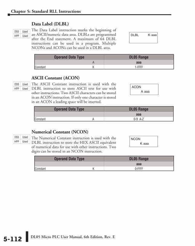
DL05 Micro PLC User Manual, 6th Edition, Rev. E5-112
Chapter 5: Standard RLL Instructions
Data Label (DLBL)The Data Label instruction marks the beginning of an ASCII/numeric data area. DLBLs are programmed after the End statement. A maximum of 64 DLBL instructions can be used in a program. Multiple NCONs and ACONs can be used in a DLBL area.
ASCII Constant (ACON)The ASCII Constant instruction is used with the DLBL instruction to store ASCII text for use with other instructions. Two ASCII characters can be stored in an ACON instruction. If only one character is stored in an ACON a leading space will be inserted.
Numerical Constant (NCON)The Numerical Constant instruction is used with the DLBL instruction to store the HEX ASCII equivalent of numerical data for use with other instructions. Two digits can be stored in an NCON instruction.
K aaaDLBL
A aaaACON
K aaaNCON
Operand Data Type DL05 Range ⸠⸠⸠⸠⸠⸠⸠⸠⸠⸠⸠⸠⸠⸠⸠⸠⸠⸠⸠⸠⸠⸠⸠⸠⸠⸠⸠⸠⸠⸠⸠⸠⸠⸠⸠⸠⸠⸠⸠⸠⸠⸠⸠⸠⸠⸠⸠⸠⸠⸠⸠⸠⸠⸠⸠⸠⸠⸠⸠⸠⸠⸠⸠⸠⸠⸠⸠⸠⸠⸠⸠⸠⸠A aaaConstant ⸠⸠⸠⸠⸠⸠⸠⸠⸠⸠⸠⸠⸠⸠⸠⸠⸠⸠⸠⸠⸠⸠⸠⸠⸠⸠⸠⸠⸠⸠⸠⸠⸠⸠⸠⸠⸠⸠⸠⸠⸠⸠⸠⸠⸠⸠⸠⸠⸠⸠⸠⸠⸠⸠⸠⸠⸠⸠⸠⸠⸠K 1-FFFF
Operand Data Type DL05 Rangeaaa
Constant ⸠⸠⸠⸠⸠⸠⸠⸠⸠⸠⸠⸠⸠⸠⸠⸠⸠⸠⸠⸠⸠⸠⸠⸠⸠⸠⸠⸠⸠⸠⸠⸠⸠⸠⸠⸠⸠⸠⸠⸠⸠⸠⸠⸠⸠⸠⸠⸠⸠⸠⸠⸠⸠⸠⸠⸠⸠⸠⸠⸠⸠A 0-9 A-Z
Operand Data Type DL05 Rangeaaa
Constant ⸠⸠⸠⸠⸠⸠⸠⸠⸠⸠⸠⸠⸠⸠⸠⸠⸠⸠⸠⸠⸠⸠⸠⸠⸠⸠⸠⸠⸠⸠⸠⸠⸠⸠⸠⸠⸠⸠⸠⸠⸠⸠⸠⸠⸠⸠⸠⸠⸠⸠⸠⸠⸠⸠⸠⸠⸠⸠⸠⸠⸠K 0-FFFF
DS5 Used
HPP Used
DS5 Used
HPP Used
DS5 Used
HPP Used
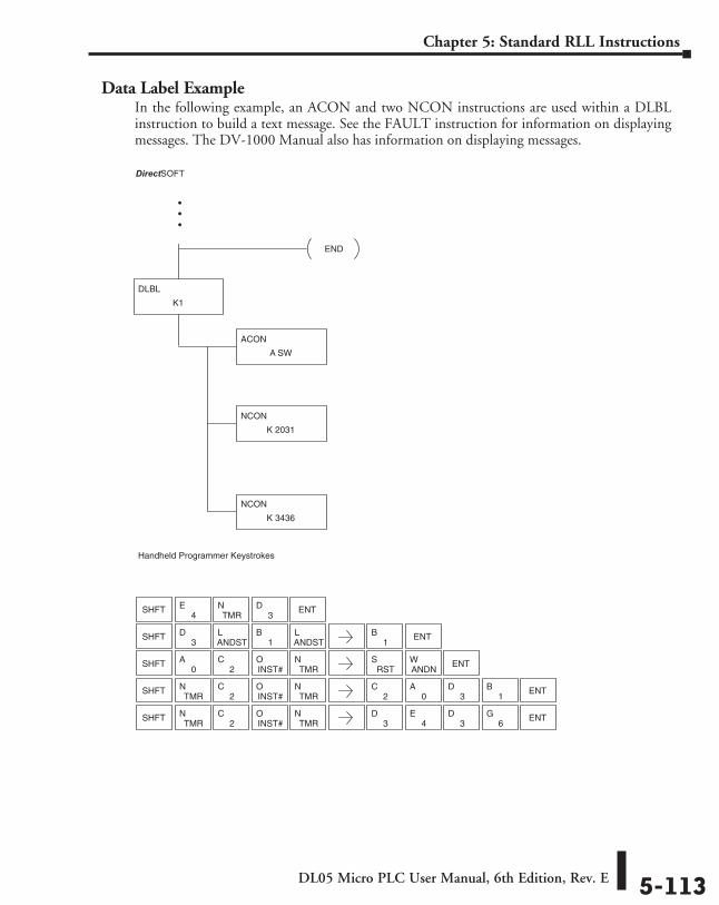
DL05 Micro PLC User Manual, 6th Edition, Rev. E 5-113
Chapter 5: Standard RLL Instructions
Data Label ExampleIn the following example, an ACON and two NCON instructions are used within a DLBL instruction to build a text message. See the FAULT instruction for information on displaying messages. The DV-1000 Manual also has information on displaying messages.
Direct SOFT32
Handheld Programmer Keystrokes
DLBL
K1
END
ACON
A SW
NCON
K 2031
NCON
K 3436
SHFT4
ETMR
N3
D ENT
SHFT3
DANDSTL
1B
ANDSTL
1B ENT
SHFT0
A2
CINST#O
TMRN
SHFTTMR
N2
CINST#O
TMRN
SHFTTMR
N2
CINST#O
TMRN
ENT3
D3
D4
E6
G
ENT3
D2
C0
A1
B
ENTRST
SANDNW
DirectSOFT
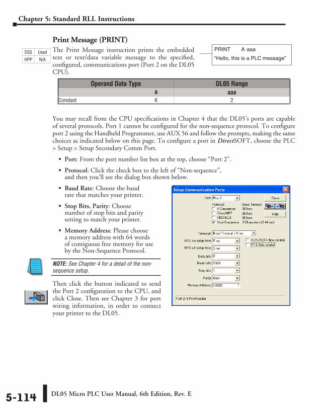
DL05 Micro PLC User Manual, 6th Edition, Rev. E5-114
Chapter 5: Standard RLL Instructions
Print Message (PRINT)The Print Message instruction prints the embedded text or text/data variable message to the specified, configured, communications port (Port 2 on the DL05 CPU).
You may recall from the CPU specifications in Chapter 4 that the DL05’s ports are capable of several protocols. Port 1 cannot be configured for the non-sequence protocol. To configure port 2 using the Handheld Programmer, use AUX 56 and follow the prompts, making the same choices as indicated below on this page. To configure a port in DirectSOFT, choose the PLC > Setup > Setup Secondary Comm Port.
• Port: From the port number list box at the top, choose “Port 2”.
• Protocol: Click the check box to the left of “Non-sequence”, and then you’ll see the dialog box shown below.
• Baud Rate: Choose the baud rate that matches your printer.
• Stop Bits, Parity: Choose number of stop bits and parity setting to match your printer.
• Memory Address: Please choose a memory address with 64 words of contiguous free memory for use by the Non-Sequence Protocol.
NOTE: See Chapter 4 for a detail of the non-sequence setup.
Then click the button indicated to send the Port 2 configuration to the CPU, and click Close. Then see Chapter 3 for port wiring information, in order to connect your printer to the DL05.
PRINT A aaa
“Hello, this is a PLC message”
Operand Data Type DL05 Range ⸠⸠⸠⸠⸠⸠⸠⸠⸠⸠⸠⸠⸠⸠⸠⸠⸠⸠⸠⸠⸠⸠⸠⸠⸠⸠⸠⸠⸠⸠⸠⸠⸠⸠⸠⸠⸠⸠⸠⸠⸠⸠⸠⸠⸠⸠⸠⸠⸠⸠⸠⸠⸠⸠⸠⸠⸠⸠⸠⸠⸠⸠⸠⸠⸠⸠⸠⸠⸠⸠⸠⸠⸠A aaaConstant ⸠⸠⸠⸠⸠⸠⸠⸠⸠⸠⸠⸠⸠⸠⸠⸠⸠⸠⸠⸠⸠⸠⸠⸠⸠⸠⸠⸠⸠⸠⸠⸠⸠⸠⸠⸠⸠⸠⸠⸠⸠⸠⸠⸠⸠⸠⸠⸠⸠⸠⸠⸠⸠⸠⸠⸠⸠⸠⸠⸠⸠K 2
DS5 Used
HPP N/A
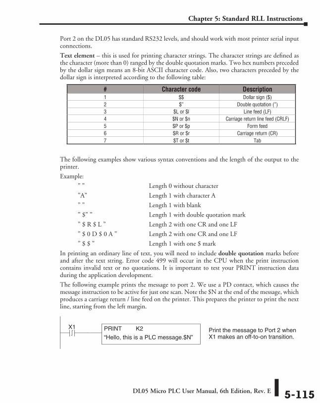
DL05 Micro PLC User Manual, 6th Edition, Rev. E 5-115
Chapter 5: Standard RLL Instructions
Port 2 on the DL05 has standard RS232 levels, and should work with most printer serial input connections.
Text element – this is used for printing character strings. The character strings are defined as the character (more than 0) ranged by the double quotation marks. Two hex numbers preceded by the dollar sign means an 8-bit ASCII character code. Also, two characters preceded by the dollar sign is interpreted according to the following table:
The following examples show various syntax conventions and the length of the output to the printer.
Example:
” ” Length 0 without character
”A” Length 1 with character A
” ” Length 1 with blank
” $” ” Length 1 with double quotation mark
” $ R $ L ” Length 2 with one CR and one LF
” $ 0 D $ 0 A ” Length 2 with one CR and one LF
” $ $ ” Length 1 with one $ mark
In printing an ordinary line of text, you will need to include double quotation marks before and after the text string. Error code 499 will occur in the CPU when the print instruction contains invalid text or no quotations. It is important to test your PRINT instruction data during the application development.
The following example prints the message to port 2. We use a PD contact, which causes the message instruction to be active for just one scan. Note the $N at the end of the message, which produces a carriage return / line feed on the printer. This prepares the printer to print the next line, starting from the left margin.
# Character code Description1 $$ Dollar sign ($)2 $” Double quotation (”)3 $L or $l Line feed (LF)4 $N or $n Carriage return line feed (CRLF)5 $P or $p Form feed6 $R or $r Carriage return (CR)7 $T or $t Tab
X1 Print the message to Port 2 whenX1 makes an off-to-on transition.
PRINT K2
“Hello, this is a PLC message.$N”
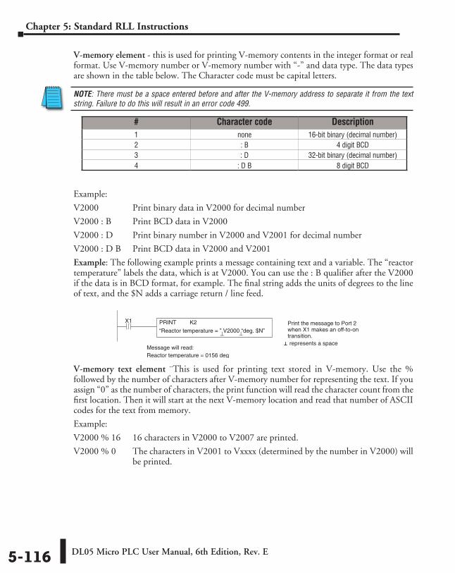
DL05 Micro PLC User Manual, 6th Edition, Rev. E5-116
Chapter 5: Standard RLL Instructions
V-memory element - this is used for printing V-memory contents in the integer format or real format. Use V-memory number or V-memory number with “-” and data type. The data types are shown in the table below. The Character code must be capital letters.
NOTE: There must be a space entered before and after the V-memory address to separate it from the text string. Failure to do this will result in an error code 499.
Example:
V2000 Print binary data in V2000 for decimal number
V2000 : B Print BCD data in V2000
V2000 : D Print binary number in V2000 and V2001 for decimal number
V2000 : D B Print BCD data in V2000 and V2001
Example: The following example prints a message containing text and a variable. The “reactor temperature” labels the data, which is at V2000. You can use the : B qualifier after the V2000 if the data is in BCD format, for example. The final string adds the units of degrees to the line of text, and the $N adds a carriage return / line feed.
V-memory text element ¨This is used for printing text stored in V-memory. Use the % followed by the number of characters after V-memory number for representing the text. If you assign “0” as the number of characters, the print function will read the character count from the first location. Then it will start at the next V-memory location and read that number of ASCII codes for the text from memory.
Example:
V2000 % 16 16 characters in V2000 to V2007 are printed.
V2000 % 0 The characters in V2001 to Vxxxx (determined by the number in V2000) will be printed.
# Character code Description1 none 16-bit binary (decimal number)2 : B 4 digit BCD3 : D 32-bit binary (decimal number)4 : D B 8 digit BCD
X1 Print the message to Port 2when X1 makes an off-to-ontransition.
PRINT K2
“Reactor temperature = ” V2000 “deg. $N”⊥ ⊥
Message will read:Reactor temperature = 0156 deg
⊥ represents a space
DL05 Micro PLC User Manual, 6th Edition, Rev. E 5-117
Chapter 5: Standard RLL Instructions
Bit element – this is used for printing the state of the designated bit in V-memory or a relay bit. The bit element can be assigned by the designating point (.) and bit number preceded by the V-memory number or relay number. The output type is described as shown in the table below.
Example:
V2000.15 Prints the status of bit 15 in V2000, in 1/0 format
C100 Prints the status of C100 in 1/0 format
C100 : BOOL Prints the status of C100 in TRUE/FALSE format
C100 : ON/OFF Prints the status of C00 in ON/OFF format
V2000.15 : BOOL Prints the status of bit 15 in V2000 in TRUE/FALSE format
The maximum numbers of characters you can print is 128. The number of characters for each element is listed in the table below:
The handheld programmer’s mnemonic is “PRINT,” followed by the DEF field.
Special relay flags SP116 and SP117 indicate the status of the DL05 CPU ports (busy, or communications error). See the appendix on special relays for a description.
NOTE: You must use the appropriate special relay in conjunction with the PRINT command to ensure the ladder program does not try to PRINT to a port that is still busy from a previous PRINT or WX or RX instruction.
# Data format Description1 none Print 1 for an ON state, and 0 for an
OFF state
2 : BOOL Print “TRUE” for an ON state, and “FALSE” for an OFF state
3 : ONOFF Print “ON” for an ON state, and “OFF” for an OFF state
Element Type Maximum CharactersText, 1 character 1
16 bit binary 632 bit binary 114 digit BCD 48 digit BCD 8
Floating point (real number) 12Floating point (real with exponent) 12
V-memory/text 2Bit (1/0 format) 1
Bit (TRUE/FALSE format) 5Bit (ON/OFF format) 3
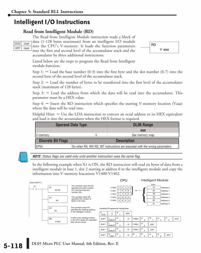
DL05 Micro PLC User Manual, 6th Edition, Rev. E5-118
Chapter 5: Standard RLL Instructions
Intelligent I/O InstructionsRead from Intelligent Module (RD)
The Read from Intelligent Module instruction reads a block of data (1-128 bytes maximum) from an intelligent I/O module into the CPU’s V-memory. It loads the function parameters into the first and second level of the accumulator stack and the accumulator by three additional instructions.
Listed below are the steps to program the Read from Intelligent module function.
Step 1: S Load the base number (0-3) into the first byte and the slot number (0-7) into the second byte of the second level of the accumulator stack.
Step 2: S Load the number of bytes to be transferred into the first level of the accumulator stack (maximum of 128 bytes).
Step 3: S Load the address from which the data will be read into the accumulator. This parameter must be a HEX value.
Step 4: S Insert the RD instruction which specifies the starting V-memory location (Vaaa) where the data will be read into.
Helpful Hint: S Use the LDA instruction to convert an octal address to its HEX equivalent and load it into the accumulator when the HEX format is required.
NOTE: Status flags are valid only until another instruction uses the same flag.
In the following example when X1 is ON, the RD instruction will read six bytes of data from a intelligent module in base 1, slot 2 starting at address 0 in the intelligent module and copy the information into V-memory loacations V1400-V1402.
DS32 Used
HPP Used V aaaRD
Direct SOFT 5
Handheld Programmer Keystrokes
LDK0102
X1 The constant value K0102specifies the base number(01) and the base slot number (02).
LDK6
The constant value K6specifies the number ofbytes to be read.
LDK0
RDV1400
V1400 is the starting locationin the CPU where the specifieddata will be stored.
Address 2
Address 3
1 9
Address 4
0
Address 5
Address 0
Address 1
3 4
7
V1402
6
V1403
V1404
V1400
V1401
STR$
SHFT ANDSTL
3D PREV
SHFT ANDSTL
3D
6G ENT
SHFT ORNR
1B ENT
0A ENT
4E
0A
0A ENT
SHFT ANDSTL
3D PREV 0
A0
A ENT2C
CPU
The constant value K0specifies the starting addressin the intelligent module.
1 2
8 5
0
X X X X
X X X X
12
56
34
78
90
01
1
B
PREV
1B
Intelligent Module
Data
3D
Operand Data Type DL06 Rangeaaa
V-memory ⸠⸠⸠⸠⸠⸠⸠⸠⸠⸠⸠⸠⸠⸠⸠⸠⸠⸠⸠⸠⸠⸠⸠⸠⸠⸠⸠⸠⸠⸠⸠⸠⸠⸠⸠⸠⸠⸠⸠⸠⸠⸠⸠⸠⸠⸠⸠⸠⸠⸠⸠⸠⸠⸠⸠⸠⸠⸠V See memory map
Discrete Bit Flags DescriptionSP54 On when RX, WX RD, WT instructions are executed with the wrong parameters.
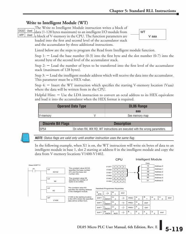
DL05 Micro PLC User Manual, 6th Edition, Rev. E 5-119
Chapter 5: Standard RLL Instructions
Write to Intelligent Module (WT)The Write to Intelligent Module instruction writes a block of data (1-128 bytes maximum) to an intelligent I/O module from a block of V-memory in the CPU. The function parameters are loaded into the first and second level of the accumulator stack and the accumulator by three additional instructions.
Listed below are the steps to program the Read from Intelligent module function.
Step 1: S Load the base number (0-3) into the first byte and the slot number (0-7) into the second byte of the second level of the accumulator stack.
Step 2: S Load the number of bytes to be transferred into the first level of the accumulator stack (maximum of 128 bytes).
Step 3: S Load the intelligent module address which will receive the data into the accumulator. This parameter must be a HEX value.
Step 4: S Insert the WT instruction which specifies the starting V-memory location (Vaaa) where the data will be written from in the CPU.
Helpful Hint: S Use the LDA instruction to convert an octal address to its HEX equivalent and load it into the accumulator when the HEX format is required.
NOTE: Status flags are valid only until another instruction uses the same flag.
In the following example, when X1 is on, the WT instruction will write six bytes of data to an intelligent module in base 1, slot 2 starting at address 0 in the intelligent module and copy the data from V-memory locations V1400-V1402.
V aaaWTDS32 Used
HPP Used
Direct SOFT 5
Handheld Programmer Keystrokes
LDK0102
X1 The constant value K0102specifies the base number(01) and the base slot number (02).
LDK6
The constant value K6specifies the number ofbytes to be written.
LDK0
WTV1400
V1400 is the starting locationin the CPU where the specifieddata will be written from.
Address 2
Address 31 9Address 4
0
Address 5
Address 0
Address 13 4
7
V1402
6
V1403
V1404
V1400
V1401
STR$
SHFT ANDSTL
3D PREV
SHFT ANDSTL
3D
6G ENT
SHFT ANDNW
1B ENT
0A ENT
4E
0A
0A ENT
SHFT ANDSTL
3D PREV 0
A0
A ENT2C
CPU
The constant value K0specifies the starting addressin the intelligent module.
1 2
8 5
0
X X X X
X X X X
12
56
34
78
90
01
1
B
PREV
1B
Intelligent ModuleData
MLRT
V1377 X X X X
Operand Data Type DL06 Rangeaaa
V-memory ⸠⸠⸠⸠⸠⸠⸠⸠⸠⸠⸠⸠⸠⸠⸠⸠⸠⸠⸠⸠⸠⸠⸠⸠⸠⸠⸠⸠⸠⸠⸠⸠⸠⸠⸠⸠⸠⸠⸠⸠⸠⸠⸠⸠⸠⸠⸠⸠⸠⸠⸠⸠⸠⸠⸠⸠⸠⸠V See memory map
Discrete Bit Flags DescriptionSP54 On when RX, WX RD, WT instructions are executed with the wrong parameters.
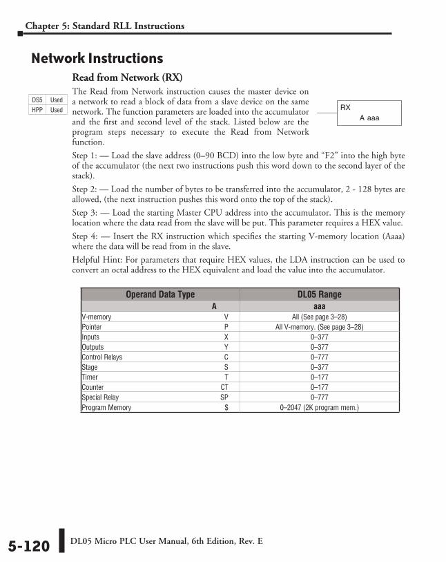
DL05 Micro PLC User Manual, 6th Edition, Rev. E5-120
Chapter 5: Standard RLL Instructions
Network InstructionsRead from Network (RX)The Read from Network instruction causes the master device on a network to read a block of data from a slave device on the same network. The function parameters are loaded into the accumulator and the first and second level of the stack. Listed below are the program steps necessary to execute the Read from Network function.
Step 1: — Load the slave address (0–90 BCD) into the low byte and “F2” into the high byte of the accumulator (the next two instructions push this word down to the second layer of the stack).
Step 2: — Load the number of bytes to be transferred into the accumulator, 2 - 128 bytes are allowed, (the next instruction pushes this word onto the top of the stack).
Step 3: — Load the starting Master CPU address into the accumulator. This is the memory location where the data read from the slave will be put. This parameter requires a HEX value.
Step 4: — Insert the RX instruction which specifies the starting V-memory location (Aaaa) where the data will be read from in the slave.
Helpful Hint: For parameters that require HEX values, the LDA instruction can be used to convert an octal address to the HEX equivalent and load the value into the accumulator.
A aaaRX
Operand Data Type DL05 Range A aaaV-memory ⸠⸠⸠⸠⸠⸠⸠⸠⸠⸠⸠⸠⸠⸠⸠⸠⸠⸠⸠⸠⸠⸠⸠⸠⸠⸠⸠⸠⸠⸠⸠⸠⸠⸠⸠⸠⸠⸠⸠⸠⸠⸠⸠⸠⸠⸠⸠⸠⸠⸠⸠⸠⸠⸠⸠⸠⸠⸠⸠⸠⸠⸠⸠⸠ V All (See page 3–28)Pointer ⸠⸠⸠⸠⸠⸠⸠⸠⸠⸠⸠⸠⸠⸠⸠⸠⸠⸠⸠⸠⸠⸠⸠⸠⸠⸠⸠⸠⸠⸠⸠⸠⸠⸠⸠⸠⸠⸠⸠⸠⸠⸠⸠⸠⸠⸠⸠⸠⸠⸠⸠⸠⸠⸠⸠⸠⸠⸠⸠⸠⸠⸠⸠⸠⸠⸠⸠⸠⸠⸠ P All V-memory. (See page 3–28)Inputs ⸠⸠⸠⸠⸠⸠⸠⸠⸠⸠⸠⸠⸠⸠⸠⸠⸠⸠⸠⸠⸠⸠⸠⸠⸠⸠⸠⸠⸠⸠⸠⸠⸠⸠⸠⸠⸠⸠⸠⸠⸠⸠⸠⸠⸠⸠⸠⸠⸠⸠⸠⸠⸠⸠⸠⸠⸠⸠⸠⸠⸠⸠⸠⸠⸠⸠⸠⸠⸠⸠⸠ X 0–377Outputs ⸠⸠⸠⸠⸠⸠⸠⸠⸠⸠⸠⸠⸠⸠⸠⸠⸠⸠⸠⸠⸠⸠⸠⸠⸠⸠⸠⸠⸠⸠⸠⸠⸠⸠⸠⸠⸠⸠⸠⸠⸠⸠⸠⸠⸠⸠⸠⸠⸠⸠⸠⸠⸠⸠⸠⸠⸠⸠⸠⸠⸠⸠⸠⸠⸠⸠⸠⸠⸠ Y 0–377Control Relays ⸠⸠⸠⸠⸠⸠⸠⸠⸠⸠⸠⸠⸠⸠⸠⸠⸠⸠⸠⸠⸠⸠⸠⸠⸠⸠⸠⸠⸠⸠⸠⸠⸠⸠⸠⸠⸠⸠⸠⸠⸠⸠⸠⸠⸠⸠⸠⸠⸠⸠⸠⸠⸠⸠⸠⸠⸠⸠ C 0–777Stage ⸠⸠⸠⸠⸠⸠⸠⸠⸠⸠⸠⸠⸠⸠⸠⸠⸠⸠⸠⸠⸠⸠⸠⸠⸠⸠⸠⸠⸠⸠⸠⸠⸠⸠⸠⸠⸠⸠⸠⸠⸠⸠⸠⸠⸠⸠⸠⸠⸠⸠⸠⸠⸠⸠⸠⸠⸠⸠⸠⸠⸠⸠⸠⸠⸠⸠⸠⸠⸠⸠⸠⸠ S 0–377Timer ⸠⸠⸠⸠⸠⸠⸠⸠⸠⸠⸠⸠⸠⸠⸠⸠⸠⸠⸠⸠⸠⸠⸠⸠⸠⸠⸠⸠⸠⸠⸠⸠⸠⸠⸠⸠⸠⸠⸠⸠⸠⸠⸠⸠⸠⸠⸠⸠⸠⸠⸠⸠⸠⸠⸠⸠⸠⸠⸠⸠⸠⸠⸠⸠⸠⸠⸠⸠⸠⸠⸠⸠ T 0–177Counter ⸠⸠⸠⸠⸠⸠⸠⸠⸠⸠⸠⸠⸠⸠⸠⸠⸠⸠⸠⸠⸠⸠⸠⸠⸠⸠⸠⸠⸠⸠⸠⸠⸠⸠⸠⸠⸠⸠⸠⸠⸠⸠⸠⸠⸠⸠⸠⸠⸠⸠⸠⸠⸠⸠⸠⸠⸠⸠⸠⸠⸠⸠⸠⸠⸠⸠⸠CT 0–177Special Relay ⸠⸠⸠⸠⸠⸠⸠⸠⸠⸠⸠⸠⸠⸠⸠⸠⸠⸠⸠⸠⸠⸠⸠⸠⸠⸠⸠⸠⸠⸠⸠⸠⸠⸠⸠⸠⸠⸠⸠⸠⸠⸠⸠⸠⸠⸠⸠⸠⸠⸠⸠⸠⸠⸠⸠⸠⸠⸠SP 0–777Program Memory ⸠⸠⸠⸠⸠⸠⸠⸠⸠⸠⸠⸠⸠⸠⸠⸠⸠⸠⸠⸠⸠⸠⸠⸠⸠⸠⸠⸠⸠⸠⸠⸠⸠⸠⸠⸠⸠⸠⸠⸠⸠⸠⸠⸠⸠⸠⸠⸠⸠⸠⸠⸠ $ 0–2047 (2K program mem.)
DS5 Used
HPP Used
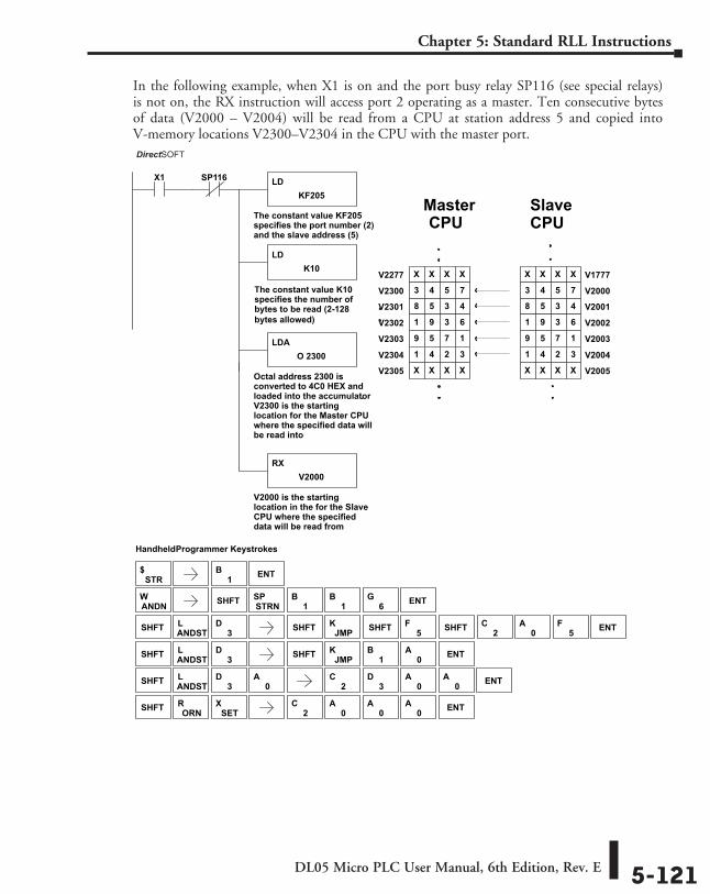
DL05 Micro PLC User Manual, 6th Edition, Rev. E 5-121
Chapter 5: Standard RLL Instructions
In the following example, when X1 is on and the port busy relay SP116 (see special relays) is not on, the RX instruction will access port 2 operating as a master. Ten consecutive bytes of data (V2000 – V2004) will be read from a CPU at station address 5 and copied into V-memory locations V2300–V2304 in the CPU with the master port.
DirectSOFT
Handheld Programmer Keystrokes
LDKF205
X1
The constant value KF205specifies the port number (2)and the slave address (5)
LDK10
The constant value K10specifies the number ofbytes to be read (2-128 bytes allowed)
LDAO 2300
Octal address 2300 isconverted to 4C0 HEX andloaded into the accumulator.V2300 is the startinglocation for the Master CPUwhere the specified data willbe read into
RXV2000
V2000 is the startinglocation in the for the SlaveCPU where the specifieddata will be read from
V20018 5 3 4
V20021 9 3 6
V20039 5 7 1
V20041 4 2 3
V1777X X X X
V20003 4 5 7
Master
SP116
V2005X X X X
V2301 8 5 3 4
V2302 1 9 3 6
V2303 9 5 7 1
V2304 1 4 2 3
V2277 X X X X
V2300 3 4 5 7
V2305 X X X X
SlaveCPU
STR$
SHFT ANDSTL
3D SHFT JMP
K
SHFT ANDSTL
3D
ANDNW SHFT STRN
SP1
B1
B6
G ENT
1B
0A ENT
0A
SHFT ORNR
SETX
1B ENT
2C
3D
0A
0A ENT
2C
0A
0A
0A ENT
SHFT ANDSTL
3D SHFT JMP
K0
A ENT2C
5FSHFT SHFT5
F
CPU
DirectSOFT
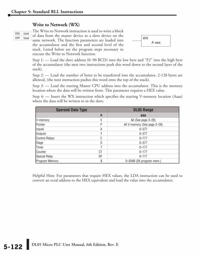
DL05 Micro PLC User Manual, 6th Edition, Rev. E5-122
Chapter 5: Standard RLL Instructions
Write to Network (WX)The Write to Network instruction is used to write a block of data from the master device to a slave device on the same network. The function parameters are loaded into the accumulator and the first and second level of the stack. Listed below are the program steps necessary to execute the Write to Network function.
Step 1: — Load the slave address (0–90 BCD) into the low byte and “F2” into the high byte of the accumulator (the next two instructions push this word down to the second layer of the stack).
Step 2: — Load the number of bytes to be transferred into the accumulator, 2-128 bytes are allowed, (the next instruction pushes this word onto the top of the stack).
Step 3: — Load the starting Master CPU address into the accumulator. This is the memory location where the data will be written from. This parameter requires a HEX value.
Step 4: — Insert the WX instruction which specifies the starting V-memory location (Aaaa) where the data will be written to in the slave.
Helpful Hint: For parameters that require HEX values, the LDA instruction can be used to convert an octal address to the HEX equivalent and load the value into the accumulator.
A aaaWX
Operand Data Type DL05 Range ⸠⸠⸠⸠⸠⸠⸠⸠⸠⸠⸠⸠⸠⸠⸠⸠⸠⸠⸠⸠⸠⸠⸠⸠⸠⸠⸠⸠⸠⸠⸠⸠⸠⸠⸠⸠⸠⸠⸠⸠⸠⸠⸠⸠⸠⸠⸠⸠⸠⸠⸠⸠⸠⸠⸠⸠⸠⸠⸠⸠⸠⸠⸠⸠⸠⸠⸠⸠⸠⸠⸠⸠⸠⸠⸠⸠⸠⸠⸠ A aaaV-memory ⸠⸠⸠⸠⸠⸠⸠⸠⸠⸠⸠⸠⸠⸠⸠⸠⸠⸠⸠⸠⸠⸠⸠⸠⸠⸠⸠⸠⸠⸠⸠⸠⸠⸠⸠⸠⸠⸠⸠⸠⸠⸠⸠⸠⸠⸠⸠⸠⸠⸠⸠⸠⸠⸠⸠⸠⸠⸠⸠⸠⸠⸠⸠⸠ V All (See page 3–28)Pointer ⸠⸠⸠⸠⸠⸠⸠⸠⸠⸠⸠⸠⸠⸠⸠⸠⸠⸠⸠⸠⸠⸠⸠⸠⸠⸠⸠⸠⸠⸠⸠⸠⸠⸠⸠⸠⸠⸠⸠⸠⸠⸠⸠⸠⸠⸠⸠⸠⸠⸠⸠⸠⸠⸠⸠⸠⸠⸠⸠⸠⸠⸠⸠⸠⸠⸠⸠⸠⸠⸠ P All V-memory (See page 3–28)Inputs ⸠⸠⸠⸠⸠⸠⸠⸠⸠⸠⸠⸠⸠⸠⸠⸠⸠⸠⸠⸠⸠⸠⸠⸠⸠⸠⸠⸠⸠⸠⸠⸠⸠⸠⸠⸠⸠⸠⸠⸠⸠⸠⸠⸠⸠⸠⸠⸠⸠⸠⸠⸠⸠⸠⸠⸠⸠⸠⸠⸠⸠⸠⸠⸠⸠⸠⸠⸠⸠⸠⸠ X 0–377Outputs ⸠⸠⸠⸠⸠⸠⸠⸠⸠⸠⸠⸠⸠⸠⸠⸠⸠⸠⸠⸠⸠⸠⸠⸠⸠⸠⸠⸠⸠⸠⸠⸠⸠⸠⸠⸠⸠⸠⸠⸠⸠⸠⸠⸠⸠⸠⸠⸠⸠⸠⸠⸠⸠⸠⸠⸠⸠⸠⸠⸠⸠⸠⸠⸠⸠⸠⸠⸠⸠ Y 0–377Control Relays ⸠⸠⸠⸠⸠⸠⸠⸠⸠⸠⸠⸠⸠⸠⸠⸠⸠⸠⸠⸠⸠⸠⸠⸠⸠⸠⸠⸠⸠⸠⸠⸠⸠⸠⸠⸠⸠⸠⸠⸠⸠⸠⸠⸠⸠⸠⸠⸠⸠⸠⸠⸠⸠⸠⸠⸠⸠⸠ C 0–777Stage ⸠⸠⸠⸠⸠⸠⸠⸠⸠⸠⸠⸠⸠⸠⸠⸠⸠⸠⸠⸠⸠⸠⸠⸠⸠⸠⸠⸠⸠⸠⸠⸠⸠⸠⸠⸠⸠⸠⸠⸠⸠⸠⸠⸠⸠⸠⸠⸠⸠⸠⸠⸠⸠⸠⸠⸠⸠⸠⸠⸠⸠⸠⸠⸠⸠⸠⸠⸠⸠⸠⸠⸠ S 0–377Timer ⸠⸠⸠⸠⸠⸠⸠⸠⸠⸠⸠⸠⸠⸠⸠⸠⸠⸠⸠⸠⸠⸠⸠⸠⸠⸠⸠⸠⸠⸠⸠⸠⸠⸠⸠⸠⸠⸠⸠⸠⸠⸠⸠⸠⸠⸠⸠⸠⸠⸠⸠⸠⸠⸠⸠⸠⸠⸠⸠⸠⸠⸠⸠⸠⸠⸠⸠⸠⸠⸠⸠⸠ T 0–177Counter ⸠⸠⸠⸠⸠⸠⸠⸠⸠⸠⸠⸠⸠⸠⸠⸠⸠⸠⸠⸠⸠⸠⸠⸠⸠⸠⸠⸠⸠⸠⸠⸠⸠⸠⸠⸠⸠⸠⸠⸠⸠⸠⸠⸠⸠⸠⸠⸠⸠⸠⸠⸠⸠⸠⸠⸠⸠⸠⸠⸠⸠⸠⸠⸠⸠⸠⸠CT 0–177Special Relay ⸠⸠⸠⸠⸠⸠⸠⸠⸠⸠⸠⸠⸠⸠⸠⸠⸠⸠⸠⸠⸠⸠⸠⸠⸠⸠⸠⸠⸠⸠⸠⸠⸠⸠⸠⸠⸠⸠⸠⸠⸠⸠⸠⸠⸠⸠⸠⸠⸠⸠⸠⸠⸠⸠⸠⸠⸠⸠SP 0–777Program Memory ⸠⸠⸠⸠⸠⸠⸠⸠⸠⸠⸠⸠⸠⸠⸠⸠⸠⸠⸠⸠⸠⸠⸠⸠⸠⸠⸠⸠⸠⸠⸠⸠⸠⸠⸠⸠⸠⸠⸠⸠⸠⸠⸠⸠⸠⸠⸠⸠⸠⸠⸠⸠ $ 0–2048 (2K program mem.)
DS5 Used
HPP Used
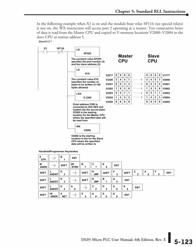
DL05 Micro PLC User Manual, 6th Edition, Rev. E 5-123
Chapter 5: Standard RLL Instructions
In the following example when X1 is on and the module busy relay SP116 (see special relays) is not on, the WX instruction will access port 2 operating as a master. Ten consecutive bytes of data is read from the Master CPU and copied to V-memory locations V2000–V2004 in the slave CPU at station address 5.
DirectSOFT
Handheld Programmer Keystrokes
LDKF205
X1
The constant value KF205specifies the port number (2)and the slave address (5)
LDK10
The constant value K10specifies the number ofbytes to be written (2-128bytes allowed)
LDAO 2300
WXV2000
V2000 is the startinglocation in the for the SlaveCPU where the specifieddata will be written to
V20018 5 3 4
V20021 9 3 6
V20039 5 7 1
V20041 4 2 3
V1777X X X X
V20003 4 5 7
MasterCPU
SP116
V2005X X X X
V2301 8 5 3 4
V2302 1 9 3 6
V2303 9 5 7 1
V2304 1 4 2 3
V2277 X X X X
V2300 3 4 5 7
V2305 X X X X
SlaveCPU
Octal address 2300 isconverted to 4C0 HEX andloaded into the accumulator
.
V2300 is the startinglocation for the Master CPUwhere the specified data willbe read from.
STR$
SHFT ANDSTL
3D SHFT JMP
K
SHFT ANDSTL
3D
ANDNW SHFT STRN
SP1
B1
C6
E ENT
1B
0A ENT
SHFT
0A
5F
2C
3D
0A
0A ENT
SHFT
SHFT
2C
0A
0A
0A ENTSET
XANDNW
SHFT ANDSTL
3D SHFT JMP
K0
A ENT2C
5F
1B ENT
DirectSOFT
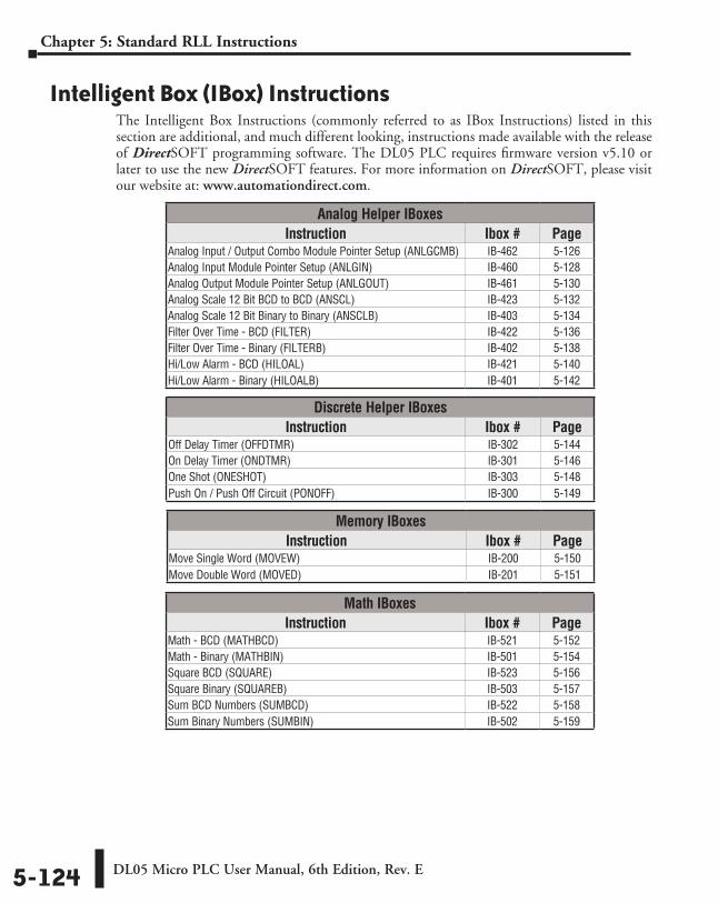
DL05 Micro PLC User Manual, 6th Edition, Rev. E5-124
Chapter 5: Standard RLL Instructions
Intelligent Box (IBox) InstructionsThe Intelligent Box Instructions (commonly referred to as IBox Instructions) listed in this section are additional, and much different looking, instructions made available with the release of DirectSOFT programming software. The DL05 PLC requires firmware version v5.10 or later to use the new DirectSOFT features. For more information on DirectSOFT, please visit our website at: www.automationdirect.com.
Analog Helper IBoxesInstruction Ibox # Page
Analog Input / Output Combo Module Pointer Setup (ANLGCMB) IB-462 5-126Analog Input Module Pointer Setup (ANLGIN) IB-460 5-128Analog Output Module Pointer Setup (ANLGOUT) IB-461 5-130Analog Scale 12 Bit BCD to BCD (ANSCL) IB-423 5-132Analog Scale 12 Bit Binary to Binary (ANSCLB) IB-403 5-134Filter Over Time - BCD (FILTER) IB-422 5-136Filter Over Time - Binary (FILTERB) IB-402 5-138Hi/Low Alarm - BCD (HILOAL) IB-421 5-140Hi/Low Alarm - Binary (HILOALB) IB-401 5-142
Discrete Helper IBoxesInstruction Ibox # Page
Off Delay Timer (OFFDTMR) IB-302 5-144On Delay Timer (ONDTMR) IB-301 5-146One Shot (ONESHOT) IB-303 5-148Push On / Push Off Circuit (PONOFF) IB-300 5-149
Memory IBoxesInstruction Ibox # Page
Move Single Word (MOVEW) IB-200 5-150Move Double Word (MOVED) IB-201 5-151
Math IBoxesInstruction Ibox # Page
Math - BCD (MATHBCD) IB-521 5-152Math - Binary (MATHBIN) IB-501 5-154Square BCD (SQUARE) IB-523 5-156Square Binary (SQUAREB) IB-503 5-157Sum BCD Numbers (SUMBCD) IB-522 5-158Sum Binary Numbers (SUMBIN) IB-502 5-159
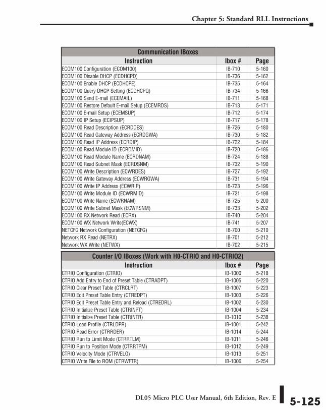
DL05 Micro PLC User Manual, 6th Edition, Rev. E 5-125
Chapter 5: Standard RLL Instructions
Communication IBoxesInstruction Ibox # Page
ECOM100 Configuration (ECOM100) IB-710 5-160ECOM100 Disable DHCP (ECDHCPD) IB-736 5-162ECOM100 Enable DHCP (ECDHCPE) IB-735 5-164ECOM100 Query DHCP Setting (ECDHCPQ) IB-734 5-166ECOM100 Send E-mail (ECEMAIL) IB-711 5-168ECOM100 Restore Default E-mail Setup (ECEMRDS) IB-713 5-171ECOM100 E-mail Setup (ECEMSUP) IB-712 5-174ECOM100 IP Setup (ECIPSUP) IB-717 5-178ECOM100 Read Description (ECRDDES) IB-726 5-180ECOM100 Read Gateway Address (ECRDGWA) IB-730 5-182ECOM100 Read IP Address (ECRDIP) IB-722 5-184ECOM100 Read Module ID (ECRDMID) IB-720 5-186ECOM100 Read Module Name (ECRDNAM) IB-724 5-188ECOM100 Read Subnet Mask (ECRDSNM) IB-732 5-190ECOM100 Write Description (ECWRDES) IB-727 5-192ECOM100 Write Gateway Address (ECWRGWA) IB-731 5-194ECOM100 Write IP Address (ECWRIP) IB-723 5-196ECOM100 Write Module ID (ECWRMID) IB-721 5-198ECOM100 Write Name (ECWRNAM) IB-725 5-200ECOM100 Write Subnet Mask (ECWRSNM) IB-733 5-202ECOM100 RX Network Read (ECRX) IB-740 5-204ECOM100 WX Network Write(ECWX) IB-741 5-207NETCFG Network Configuration (NETCFG) IB-700 5-210Network RX Read (NETRX) IB-701 5-212Network WX Write (NETWX) IB-702 5-215
Counter I/O IBoxes (Work with H0-CTRIO and H0-CTRIO2)Instruction Ibox # Page
CTRIO Configuration (CTRIO) IB-1000 5-218CTRIO Add Entry to End of Preset Table (CTRADPT) IB-1005 5-220CTRIO Clear Preset Table (CTRCLRT) IB-1007 5-223CTRIO Edit Preset Table Entry (CTREDPT) IB-1003 5-226CTRIO Edit Preset Table Entry and Reload (CTREDRL) IB-1002 5-230CTRIO Initialize Preset Table (CTRINPT) IB-1004 5-234CTRIO Initialize Preset Table (CTRINTR) IB-1010 5-238CTRIO Load Profile (CTRLDPR) IB-1001 5-242CTRIO Read Error (CTRRDER) IB-1014 5-244CTRIO Run to Limit Mode (CTRRTLM) IB-1011 5-246CTRIO Run to Position Mode (CTRRTPM) IB-1012 5-249CTRIO Velocity Mode (CTRVELO) IB-1013 5-251CTRIO Write File to ROM (CTRWFTR) IB-1006 5-254
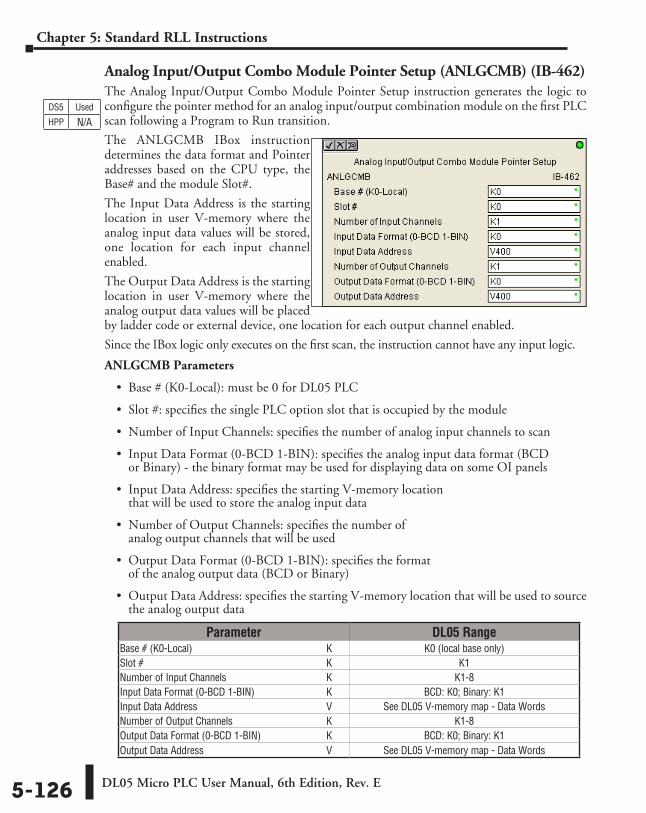
DL05 Micro PLC User Manual, 6th Edition, Rev. E5-126
Chapter 5: Standard RLL Instructions
Analog Input/Output Combo Module Pointer Setup (ANLGCMB) (IB-462)The Analog Input/Output Combo Module Pointer Setup instruction generates the logic to configure the pointer method for an analog input/output combination module on the first PLC scan following a Program to Run transition.
The ANLGCMB IBox instruction determines the data format and Pointer addresses based on the CPU type, the Base# and the module Slot#.
The Input Data Address is the starting location in user V-memory where the analog input data values will be stored, one location for each input channel enabled.
The Output Data Address is the starting location in user V-memory where the analog output data values will be placed by ladder code or external device, one location for each output channel enabled.
Since the IBox logic only executes on the first scan, the instruction cannot have any input logic.
ANLGCMB Parameters
• Base # (K0-Local): must be 0 for DL05 PLC
• Slot #: specifies the single PLC option slot that is occupied by the module
• Number of Input Channels: specifies the number of analog input channels to scan
• Input Data Format (0-BCD 1-BIN): specifies the analog input data format (BCD or Binary) - the binary format may be used for displaying data on some OI panels
• Input Data Address: specifies the starting V-memory location that will be used to store the analog input data
• Number of Output Channels: specifies the number of analog output channels that will be used
• Output Data Format (0-BCD 1-BIN): specifies the format of the analog output data (BCD or Binary)
• Output Data Address: specifies the starting V-memory location that will be used to source the analog output data
DS5 Used
HPP N/A
Parameter DL05 RangeBase # (K0-Local) ⸠⸠⸠⸠⸠⸠⸠⸠⸠⸠⸠⸠⸠⸠⸠⸠⸠⸠⸠⸠⸠⸠⸠⸠⸠⸠⸠⸠⸠⸠⸠⸠⸠⸠⸠⸠⸠⸠⸠⸠⸠⸠⸠⸠⸠⸠⸠⸠⸠⸠⸠⸠ K K0 (local base only)Slot # ⸠⸠⸠⸠⸠⸠⸠⸠⸠⸠⸠⸠⸠⸠⸠⸠⸠⸠⸠⸠⸠⸠⸠⸠⸠⸠⸠⸠⸠⸠⸠⸠⸠⸠⸠⸠⸠⸠⸠⸠⸠⸠⸠⸠⸠⸠⸠⸠⸠⸠⸠⸠⸠⸠⸠⸠⸠⸠⸠⸠⸠⸠⸠⸠⸠⸠⸠⸠⸠⸠⸠⸠ K K1Number of Input Channels ⸠⸠⸠⸠⸠⸠⸠⸠⸠⸠⸠⸠⸠⸠⸠⸠⸠⸠⸠⸠⸠⸠⸠⸠⸠⸠⸠⸠⸠⸠⸠⸠⸠⸠⸠⸠⸠⸠ K K1-8Input Data Format (0-BCD 1-BIN) ⸠⸠⸠⸠⸠⸠⸠⸠⸠⸠⸠⸠⸠⸠⸠⸠⸠⸠⸠⸠⸠⸠⸠⸠⸠⸠⸠⸠ K BCD: K0; Binary: K1Input Data Address ⸠⸠⸠⸠⸠⸠⸠⸠⸠⸠⸠⸠⸠⸠⸠⸠⸠⸠⸠⸠⸠⸠⸠⸠⸠⸠⸠⸠⸠⸠⸠⸠⸠⸠⸠⸠⸠⸠⸠⸠⸠⸠⸠⸠⸠⸠⸠⸠⸠⸠ V See DL05 V-memory map - Data WordsNumber of Output Channels ⸠⸠⸠⸠⸠⸠⸠⸠⸠⸠⸠⸠⸠⸠⸠⸠⸠⸠⸠⸠⸠⸠⸠⸠⸠⸠⸠⸠⸠⸠⸠⸠⸠⸠⸠⸠ K K1-8Output Data Format (0-BCD 1-BIN) ⸠⸠⸠⸠⸠⸠⸠⸠⸠⸠⸠⸠⸠⸠⸠⸠⸠⸠⸠⸠⸠⸠⸠⸠ K BCD: K0; Binary: K1 Output Data Address ⸠⸠⸠⸠⸠⸠⸠⸠⸠⸠⸠⸠⸠⸠⸠⸠⸠⸠⸠⸠⸠⸠⸠⸠⸠⸠⸠⸠⸠⸠⸠⸠⸠⸠⸠⸠⸠⸠⸠⸠⸠⸠⸠⸠⸠⸠⸠⸠ V See DL05 V-memory map - Data Words
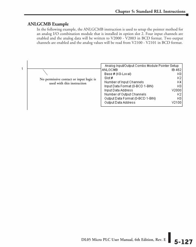
DL05 Micro PLC User Manual, 6th Edition, Rev. E 5-127
Chapter 5: Standard RLL Instructions
ANLGCMB ExampleIn the following example, the ANLGCMB instruction is used to setup the pointer method for an analog I/O combination module that is installed in option slot 2. Four input channels are enabled and the analog data will be written to V2000 - V2003 in BCD format. Two output channels are enabled and the analog values will be read from V2100 - V2101 in BCD format.
No permissive contact or input logic is used with this instruction
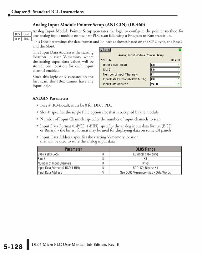
DL05 Micro PLC User Manual, 6th Edition, Rev. E5-128
Chapter 5: Standard RLL Instructions
Analog Input Module Pointer Setup (ANLGIN) (IB-460)Analog Input Module Pointer Setup generates the logic to configure the pointer method for one analog input module on the first PLC scan following a Program to Run transition.
This IBox determines the data format and Pointer addresses based on the CPU type, the Base#, and the Slot#.
The Input Data Address is the starting location in user V-memory where the analog input data values will be stored, one location for each input channel enabled.
Since this logic only executes on the first scan, this IBox cannot have any input logic.
ANLGIN Parameters
• Base # (K0-Local): must be 0 for DL05 PLC
• Slot #: specifies the single PLC option slot that is occupied by the module
• Number of Input Channels: specifies the number of input channels to scan
• Input Data Format (0-BCD 1-BIN): specifies the analog input data format (BCD or Binary) - the binary format may be used for displaying data on some OI panels
• Input Data Address: specifies the starting V-memory location that will be used to store the analog input data
DS5 Used
HPP N/A
Parameter DL05 RangeBase # (K0-Local) ⸠⸠⸠⸠⸠⸠⸠⸠⸠⸠⸠⸠⸠⸠⸠⸠⸠⸠⸠⸠⸠⸠⸠⸠⸠⸠⸠⸠⸠⸠⸠⸠⸠⸠⸠⸠⸠⸠⸠⸠⸠⸠⸠⸠⸠⸠⸠⸠⸠⸠⸠⸠ K K0 (local base only)Slot # ⸠⸠⸠⸠⸠⸠⸠⸠⸠⸠⸠⸠⸠⸠⸠⸠⸠⸠⸠⸠⸠⸠⸠⸠⸠⸠⸠⸠⸠⸠⸠⸠⸠⸠⸠⸠⸠⸠⸠⸠⸠⸠⸠⸠⸠⸠⸠⸠⸠⸠⸠⸠⸠⸠⸠⸠⸠⸠⸠⸠⸠⸠⸠⸠⸠⸠⸠⸠⸠⸠⸠⸠ K K1Number of Input Channels ⸠⸠⸠⸠⸠⸠⸠⸠⸠⸠⸠⸠⸠⸠⸠⸠⸠⸠⸠⸠⸠⸠⸠⸠⸠⸠⸠⸠⸠⸠⸠⸠⸠⸠⸠⸠⸠⸠ K K1-8Input Data Format (0-BCD 1-BIN) ⸠⸠⸠⸠⸠⸠⸠⸠⸠⸠⸠⸠⸠⸠⸠⸠⸠⸠⸠⸠⸠⸠⸠⸠⸠⸠⸠⸠ K BCD: K0; Binary: K1Input Data Address ⸠⸠⸠⸠⸠⸠⸠⸠⸠⸠⸠⸠⸠⸠⸠⸠⸠⸠⸠⸠⸠⸠⸠⸠⸠⸠⸠⸠⸠⸠⸠⸠⸠⸠⸠⸠⸠⸠⸠⸠⸠⸠⸠⸠⸠⸠⸠⸠⸠⸠ V See DL05 V-memory map - Data Words
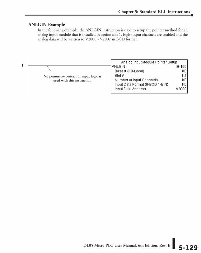
DL05 Micro PLC User Manual, 6th Edition, Rev. E 5-129
Chapter 5: Standard RLL Instructions
ANLGIN ExampleIn the following example, the ANLGIN instruction is used to setup the pointer method for an analog input module that is installed in option slot 1. Eight input channels are enabled and the analog data will be written to V2000 - V2007 in BCD format.
No permissive contact or input logic is used with this instruction
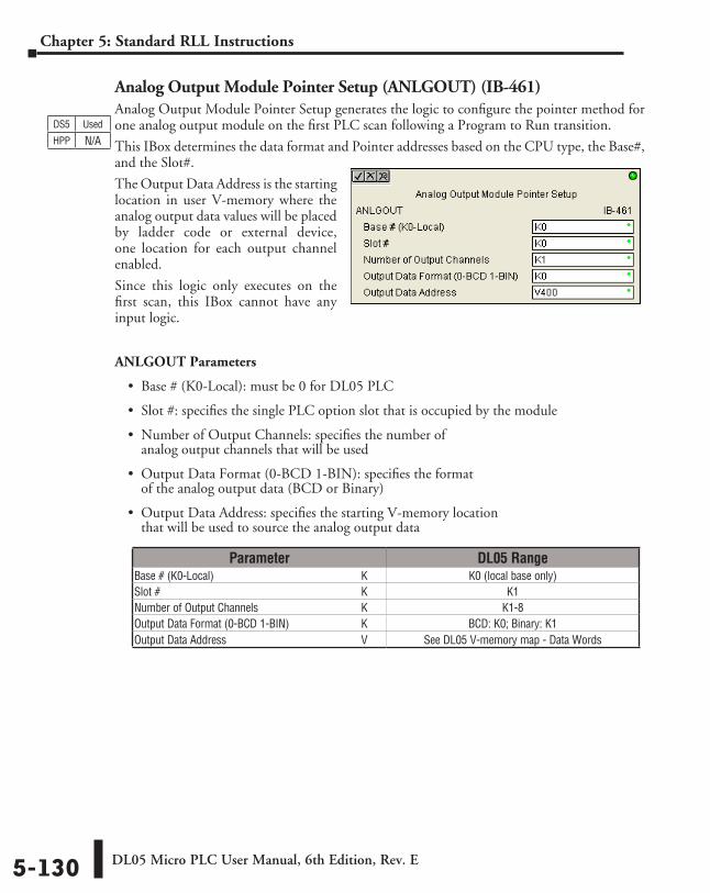
DL05 Micro PLC User Manual, 6th Edition, Rev. E5-130
Chapter 5: Standard RLL Instructions
Analog Output Module Pointer Setup (ANLGOUT) (IB-461)Analog Output Module Pointer Setup generates the logic to configure the pointer method for one analog output module on the first PLC scan following a Program to Run transition.
This IBox determines the data format and Pointer addresses based on the CPU type, the Base#, and the Slot#.
The Output Data Address is the starting location in user V-memory where the analog output data values will be placed by ladder code or external device, one location for each output channel enabled.
Since this logic only executes on the first scan, this IBox cannot have any input logic.
ANLGOUT Parameters
• Base # (K0-Local): must be 0 for DL05 PLC
• Slot #: specifies the single PLC option slot that is occupied by the module
• Number of Output Channels: specifies the number of analog output channels that will be used
• Output Data Format (0-BCD 1-BIN): specifies the format of the analog output data (BCD or Binary)
• Output Data Address: specifies the starting V-memory location that will be used to source the analog output data
DS5 Used
HPP N/A
Parameter DL05 RangeBase # (K0-Local) ⸠⸠⸠⸠⸠⸠⸠⸠⸠⸠⸠⸠⸠⸠⸠⸠⸠⸠⸠⸠⸠⸠⸠⸠⸠⸠⸠⸠⸠⸠⸠⸠⸠⸠⸠⸠⸠⸠⸠⸠⸠⸠⸠⸠⸠⸠⸠⸠⸠⸠⸠⸠ K K0 (local base only)Slot # ⸠⸠⸠⸠⸠⸠⸠⸠⸠⸠⸠⸠⸠⸠⸠⸠⸠⸠⸠⸠⸠⸠⸠⸠⸠⸠⸠⸠⸠⸠⸠⸠⸠⸠⸠⸠⸠⸠⸠⸠⸠⸠⸠⸠⸠⸠⸠⸠⸠⸠⸠⸠⸠⸠⸠⸠⸠⸠⸠⸠⸠⸠⸠⸠⸠⸠⸠⸠⸠⸠⸠⸠ K K1Number of Output Channels ⸠⸠⸠⸠⸠⸠⸠⸠⸠⸠⸠⸠⸠⸠⸠⸠⸠⸠⸠⸠⸠⸠⸠⸠⸠⸠⸠⸠⸠⸠⸠⸠⸠⸠⸠⸠ K K1-8Output Data Format (0-BCD 1-BIN) ⸠⸠⸠⸠⸠⸠⸠⸠⸠⸠⸠⸠⸠⸠⸠⸠⸠⸠⸠⸠⸠⸠⸠⸠⸠ K BCD: K0; Binary: K1 Output Data Address ⸠⸠⸠⸠⸠⸠⸠⸠⸠⸠⸠⸠⸠⸠⸠⸠⸠⸠⸠⸠⸠⸠⸠⸠⸠⸠⸠⸠⸠⸠⸠⸠⸠⸠⸠⸠⸠⸠⸠⸠⸠⸠⸠⸠⸠⸠⸠⸠ V See DL05 V-memory map - Data Words
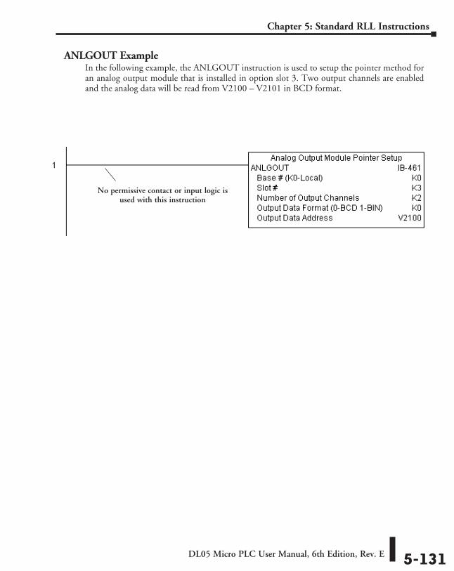
DL05 Micro PLC User Manual, 6th Edition, Rev. E 5-131
Chapter 5: Standard RLL Instructions
ANLGOUT ExampleIn the following example, the ANLGOUT instruction is used to setup the pointer method for an analog output module that is installed in option slot 3. Two output channels are enabled and the analog data will be read from V2100 – V2101 in BCD format.
No permissive contact or input logic is used with this instruction
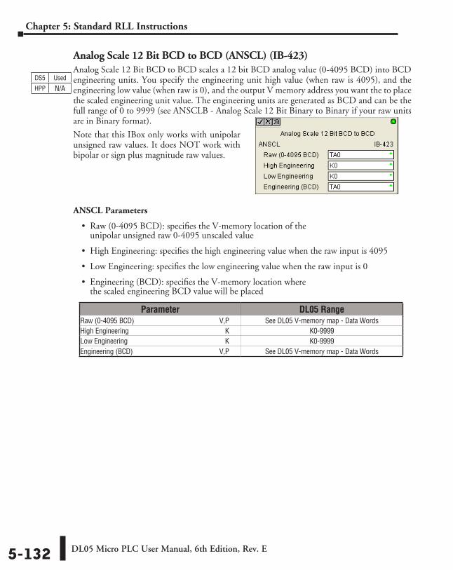
DL05 Micro PLC User Manual, 6th Edition, Rev. E5-132
Chapter 5: Standard RLL Instructions
Analog Scale 12 Bit BCD to BCD (ANSCL) (IB-423)Analog Scale 12 Bit BCD to BCD scales a 12 bit BCD analog value (0-4095 BCD) into BCD engineering units. You specify the engineering unit high value (when raw is 4095), and the engineering low value (when raw is 0), and the output V memory address you want the to place the scaled engineering unit value. The engineering units are generated as BCD and can be the full range of 0 to 9999 (see ANSCLB - Analog Scale 12 Bit Binary to Binary if your raw units are in Binary format).
Note that this IBox only works with unipolar unsigned raw values. It does NOT work with bipolar or sign plus magnitude raw values.
ANSCL Parameters
• Raw (0-4095 BCD): specifies the V-memory location of the unipolar unsigned raw 0-4095 unscaled value
• High Engineering: specifies the high engineering value when the raw input is 4095
• Low Engineering: specifies the low engineering value when the raw input is 0
• Engineering (BCD): specifies the V-memory location where the scaled engineering BCD value will be placed
DS5 Used
HPP N/A
Parameter DL05 RangeRaw (0-4095 BCD) ⸠⸠⸠⸠⸠⸠⸠⸠⸠⸠⸠⸠⸠⸠⸠⸠⸠⸠⸠⸠⸠⸠⸠⸠⸠⸠⸠⸠⸠⸠⸠⸠⸠⸠⸠⸠⸠⸠⸠⸠⸠⸠⸠⸠⸠⸠⸠V,P See DL05 V-memory map - Data WordsHigh Engineering ⸠⸠⸠⸠⸠⸠⸠⸠⸠⸠⸠⸠⸠⸠⸠⸠⸠⸠⸠⸠⸠⸠⸠⸠⸠⸠⸠⸠⸠⸠⸠⸠⸠⸠⸠⸠⸠⸠⸠⸠⸠⸠⸠⸠⸠⸠⸠⸠⸠⸠⸠⸠⸠ K K0-9999Low Engineering ⸠⸠⸠⸠⸠⸠⸠⸠⸠⸠⸠⸠⸠⸠⸠⸠⸠⸠⸠⸠⸠⸠⸠⸠⸠⸠⸠⸠⸠⸠⸠⸠⸠⸠⸠⸠⸠⸠⸠⸠⸠⸠⸠⸠⸠⸠⸠⸠⸠⸠⸠⸠⸠⸠ K K0-9999Engineering (BCD) ⸠⸠⸠⸠⸠⸠⸠⸠⸠⸠⸠⸠⸠⸠⸠⸠⸠⸠⸠⸠⸠⸠⸠⸠⸠⸠⸠⸠⸠⸠⸠⸠⸠⸠⸠⸠⸠⸠⸠⸠⸠⸠⸠⸠⸠⸠⸠⸠⸠V,P See DL05 V-memory map - Data Words
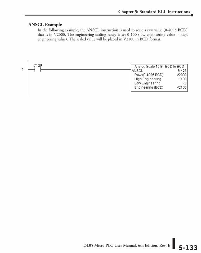
DL05 Micro PLC User Manual, 6th Edition, Rev. E 5-133
Chapter 5: Standard RLL Instructions
ANSCL ExampleIn the following example, the ANSCL instruction is used to scale a raw value (0-4095 BCD) that is in V2000. The engineering scaling range is set 0-100 (low engineering value - high engineering value). The scaled value will be placed in V2100 in BCD format.
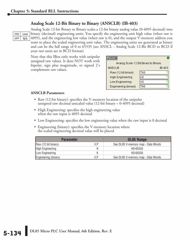
DL05 Micro PLC User Manual, 6th Edition, Rev. E5-134
Chapter 5: Standard RLL Instructions
Analog Scale 12-Bit Binary to Binary (ANSCLB) (IB-403)Analog Scale 12-bit Binary to Binary scales a 12-bit binary analog value (0-4095 decimal) into binary (decimal) engineering units. You specify the engineering unit high value (when raw is 4095), and the engineering low value (when raw is 0), and the output V-memory address you want to place the scaled engineering unit value. The engineering units are generated as binary and can be the full range of 0 to 65535 (see ANSCL - Analog Scale 12-Bit BCD to BCD if your raw units are in BCD format).
Note that this IBox only works with unipolar unsigned raw values. It does NOT work with bipolar, sign plus magnitude, or signed 2’s complement raw values.
ANSCLB Parameters
• Raw (12-bit binary): specifies the V-memory location of the unipolar unsigned raw decimal unscaled value (12-bit binary = 0-4095 decimal)
• High Engineering: specifies the high engineering value when the raw input is 4095 decimal
• Low Engineering: specifies the low engineering value when the raw input is 0 decimal
• Engineering (binary): specifies the V-memory location where the scaled engineering decimal value will be placed
Parameter DL05 RangeRaw (12 bit binary) ⸠⸠⸠⸠⸠⸠⸠⸠⸠⸠⸠⸠⸠⸠⸠⸠⸠⸠⸠⸠⸠⸠⸠⸠⸠⸠⸠⸠⸠⸠⸠⸠⸠⸠⸠⸠⸠⸠⸠⸠⸠⸠⸠⸠⸠⸠⸠V,P See DL05 V-memory map - Data WordsHigh Engineering ⸠⸠⸠⸠⸠⸠⸠⸠⸠⸠⸠⸠⸠⸠⸠⸠⸠⸠⸠⸠⸠⸠⸠⸠⸠⸠⸠⸠⸠⸠⸠⸠⸠⸠⸠⸠⸠⸠⸠⸠⸠⸠⸠⸠⸠⸠⸠⸠⸠⸠⸠⸠⸠ K K0-65535Low Engineering ⸠⸠⸠⸠⸠⸠⸠⸠⸠⸠⸠⸠⸠⸠⸠⸠⸠⸠⸠⸠⸠⸠⸠⸠⸠⸠⸠⸠⸠⸠⸠⸠⸠⸠⸠⸠⸠⸠⸠⸠⸠⸠⸠⸠⸠⸠⸠⸠⸠⸠⸠⸠⸠⸠ K K0-65535Engineering (binary) ⸠⸠⸠⸠⸠⸠⸠⸠⸠⸠⸠⸠⸠⸠⸠⸠⸠⸠⸠⸠⸠⸠⸠⸠⸠⸠⸠⸠⸠⸠⸠⸠⸠⸠⸠⸠⸠⸠⸠⸠⸠⸠⸠⸠⸠⸠V,P See DL05 V-memory map - Data Words
DS5 Used
HPP N/A
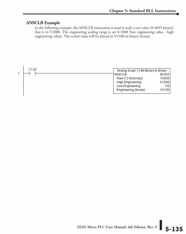
DL05 Micro PLC User Manual, 6th Edition, Rev. E 5-135
Chapter 5: Standard RLL Instructions
ANSCLB ExampleIn the following example, the ANSCLB instruction is used to scale a raw value (0-4095 binary) that is in V2000. The engineering scaling range is set 0-1000 (low engineering value - high engineering value). The scaled value will be placed in V2100 in binary format.
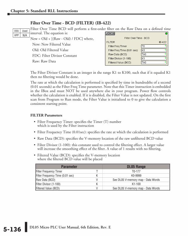
DL05 Micro PLC User Manual, 6th Edition, Rev. E5-136
Chapter 5: Standard RLL Instructions
Filter Over Time - BCD (FILTER) (IB-422)Filter Over Time BCD will perform a first-order filter on the Raw Data on a defined time interval. The equation is:
New = Old + [(Raw - Old) / FDC] where,
New: New Filtered Value
Old: Old Filtered Value
FDC: Filter Divisor Constant
Raw: Raw Data
The Filter Divisor Constant is an integer in the range K1 to K100, such that if it equaled K1 then no filtering would be done.
The rate at which the calculation is performed is specified by time in hundredths of a second (0.01 seconds) as the Filter Freq Time parameter. Note that this Timer instruction is embedded in the IBox and must NOT be used anywhere else in your program. Power flow controls whether the calculation is enabled. If it is disabled, the Filter Value is not updated. On the first scan from Program to Run mode, the Filter Value is initialized to 0 to give the calculation a consistent starting point.
FILTER Parameters
• Filter Frequency Timer: specifies the Timer (T) number which is used by the Filter instruction
• Filter Frequency Time (0.01sec): specifies the rate at which the calculation is performed
• Raw Data (BCD): specifies the V-memory location of the raw unfiltered BCD value
• Filter Divisor (1-100): this constant used to control the filtering effect. A larger value will increase the smoothing effect of the filter. A value of 1 results with no filtering.
• Filtered Value (BCD): specifies the V-memory location where the filtered BCD value will be placed
DS5 Used
HPP N/A
Parameter DL05 RangeFilter Frequency Timer ⸠⸠⸠⸠⸠⸠⸠⸠⸠⸠⸠⸠⸠⸠⸠⸠⸠⸠⸠⸠⸠⸠⸠⸠⸠⸠⸠⸠⸠⸠⸠⸠⸠⸠⸠⸠⸠⸠⸠⸠⸠⸠⸠⸠ T T0-177Filter Frequency Time (0.01 sec) ⸠⸠⸠⸠⸠⸠⸠⸠⸠⸠⸠⸠⸠⸠⸠⸠⸠⸠⸠⸠⸠⸠⸠⸠⸠⸠⸠⸠⸠ K K0-9999Raw Data (BCD) ⸠⸠⸠⸠⸠⸠⸠⸠⸠⸠⸠⸠⸠⸠⸠⸠⸠⸠⸠⸠⸠⸠⸠⸠⸠⸠⸠⸠⸠⸠⸠⸠⸠⸠⸠⸠⸠⸠⸠⸠⸠⸠⸠⸠⸠⸠⸠⸠⸠⸠⸠⸠⸠⸠⸠ V See DL05 V-memory map - Data WordsFilter Divisor (1-100) ⸠⸠⸠⸠⸠⸠⸠⸠⸠⸠⸠⸠⸠⸠⸠⸠⸠⸠⸠⸠⸠⸠⸠⸠⸠⸠⸠⸠⸠⸠⸠⸠⸠⸠⸠⸠⸠⸠⸠⸠⸠⸠⸠⸠⸠⸠⸠⸠ K K1-100Filtered Value (BCD) ⸠⸠⸠⸠⸠⸠⸠⸠⸠⸠⸠⸠⸠⸠⸠⸠⸠⸠⸠⸠⸠⸠⸠⸠⸠⸠⸠⸠⸠⸠⸠⸠⸠⸠⸠⸠⸠⸠⸠⸠⸠⸠⸠⸠⸠⸠⸠⸠⸠ V See DL05 V-memory map - Data Words
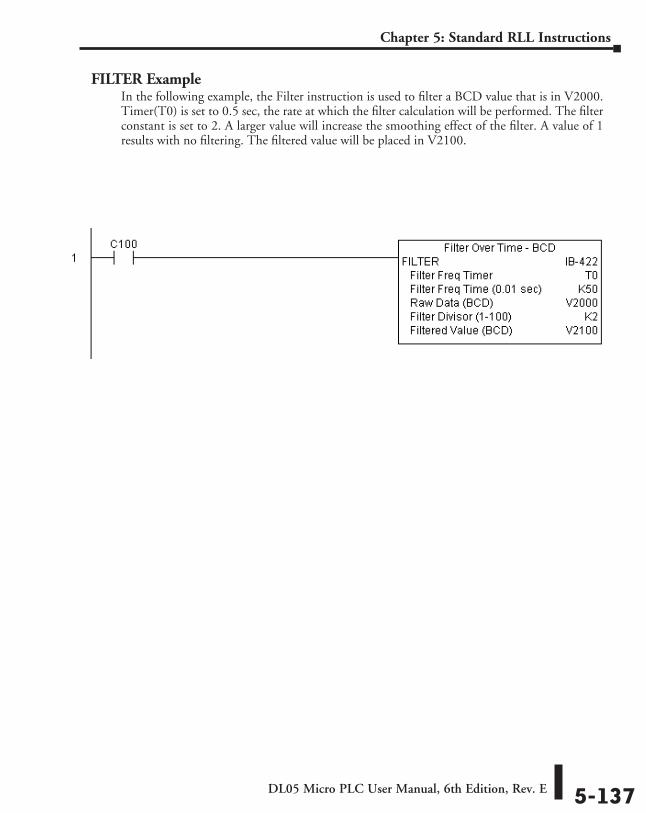
DL05 Micro PLC User Manual, 6th Edition, Rev. E 5-137
Chapter 5: Standard RLL Instructions
FILTER ExampleIn the following example, the Filter instruction is used to filter a BCD value that is in V2000. Timer(T0) is set to 0.5 sec, the rate at which the filter calculation will be performed. The filter constant is set to 2. A larger value will increase the smoothing effect of the filter. A value of 1 results with no filtering. The filtered value will be placed in V2100.
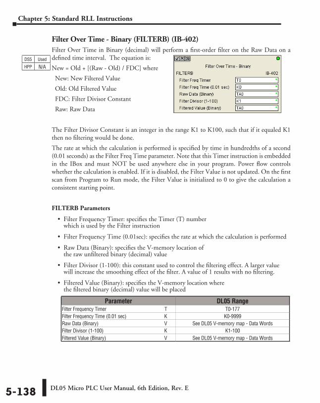
DL05 Micro PLC User Manual, 6th Edition, Rev. E5-138
Chapter 5: Standard RLL Instructions
Filter Over Time - Binary (FILTERB) (IB-402)Filter Over Time in Binary (decimal) will perform a first-order filter on the Raw Data on a defined time interval. The equation is:
New = Old + [(Raw - Old) / FDC] where
New: New Filtered Value
Old: Old Filtered Value
FDC: Filter Divisor Constant
Raw: Raw Data
The Filter Divisor Constant is an integer in the range K1 to K100, such that if it equaled K1 then no filtering would be done.
The rate at which the calculation is performed is specified by time in hundredths of a second (0.01 seconds) as the Filter Freq Time parameter. Note that this Timer instruction is embedded in the IBox and must NOT be used anywhere else in your program. Power flow controls whether the calculation is enabled. If it is disabled, the Filter Value is not updated. On the first scan from Program to Run mode, the Filter Value is initialized to 0 to give the calculation a consistent starting point.
FILTERB Parameters
• Filter Frequency Timer: specifies the Timer (T) number which is used by the Filter instruction
• Filter Frequency Time (0.01sec): specifies the rate at which the calculation is performed
• Raw Data (Binary): specifies the V-memory location of the raw unfiltered binary (decimal) value
• Filter Divisor (1-100): this constant used to control the filtering effect. A larger value will increase the smoothing effect of the filter. A value of 1 results with no filtering.
• Filtered Value (Binary): specifies the V-memory location where the filtered binary (decimal) value will be placed
DS5 Used
HPP N/A
Parameter DL05 RangeFilter Frequency Timer ⸠⸠⸠⸠⸠⸠⸠⸠⸠⸠⸠⸠⸠⸠⸠⸠⸠⸠⸠⸠⸠⸠⸠⸠⸠⸠⸠⸠⸠⸠⸠⸠⸠⸠⸠⸠⸠⸠⸠⸠⸠⸠⸠⸠ T T0-177Filter Frequency Time (0.01 sec) ⸠⸠⸠⸠⸠⸠⸠⸠⸠⸠⸠⸠⸠⸠⸠⸠⸠⸠⸠⸠⸠⸠⸠⸠⸠⸠⸠⸠⸠ K K0-9999Raw Data (Binary) ⸠⸠⸠⸠⸠⸠⸠⸠⸠⸠⸠⸠⸠⸠⸠⸠⸠⸠⸠⸠⸠⸠⸠⸠⸠⸠⸠⸠⸠⸠⸠⸠⸠⸠⸠⸠⸠⸠⸠⸠⸠⸠⸠⸠⸠⸠⸠⸠⸠⸠⸠⸠ V See DL05 V-memory map - Data WordsFilter Divisor (1-100) ⸠⸠⸠⸠⸠⸠⸠⸠⸠⸠⸠⸠⸠⸠⸠⸠⸠⸠⸠⸠⸠⸠⸠⸠⸠⸠⸠⸠⸠⸠⸠⸠⸠⸠⸠⸠⸠⸠⸠⸠⸠⸠⸠⸠⸠⸠⸠⸠ K K1-100Filtered Value (Binary) ⸠⸠⸠⸠⸠⸠⸠⸠⸠⸠⸠⸠⸠⸠⸠⸠⸠⸠⸠⸠⸠⸠⸠⸠⸠⸠⸠⸠⸠⸠⸠⸠⸠⸠⸠⸠⸠⸠⸠⸠⸠⸠⸠⸠⸠ V See DL05 V-memory map - Data Words
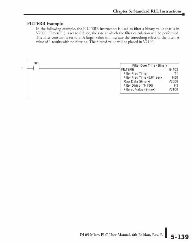
DL05 Micro PLC User Manual, 6th Edition, Rev. E 5-139
Chapter 5: Standard RLL Instructions
FILTERB ExampleIn the following example, the FILTERB instruction is used to filter a binary value that is in V2000. Timer(T1) is set to 0.5 sec, the rate at which the filter calculation will be performed. The filter constant is set to 3. A larger value will increase the smoothing effect of the filter. A value of 1 results with no filtering. The filtered value will be placed in V2100.
SP1
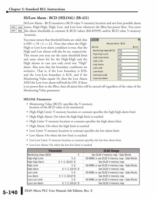
DL05 Micro PLC User Manual, 6th Edition, Rev. E5-140
Chapter 5: Standard RLL Instructions
Hi/Low Alarm - BCD (HILOAL) (IB-421)Hi/Low Alarm - BCD monitors a BCD value V-memory location and sets four possible alarm states, High-High, High, Low, and Low-Low whenever the IBox has power flow. You enter the alarm thresholds as constant K BCD values (K0-K9999) and/or BCD value V-memory locations.
You must ensure that threshold limits are valid, that is HH >= H > L >= LL. Note that when the High-High or Low-Low alarm condition is true, that the High and Low alarms will also be set, respectively. This means you may use the same threshold limit and same alarm bit for the High-High and the High alarms in case you only need one “High” alarm. Also note that the boundary conditions are inclusive. That is, if the Low boundary is K50, and the Low-Low boundary is K10, and if the Monitoring Value equals 10, then the Low Alarm AND the Low-Low alarm will both be ON. If there is no power flow to the IBox, then all alarm bits will be turned off regardless of the value of the Monitoring Value parameter.
HILOAL Parameters
• Monitoring Value (BCD): specifies the V-memory location of the BCD value to be monitored
• High-High Limit: V-memory location or constant specifies the high-high alarm limit
• High-High Alarm: On when the high-high limit is reached
• High Limit: V-memory location or constant specifies the high alarm limit
• High Alarm: On when the high limit is reached
• Low Limit: V-memory location or constant specifies the low alarm limit
• Low Alarm: On when the low limit is reached
• Low-Low Limit: V-memory location or constant specifies the low-low alarm limit
• Low-Low Alarm: On when the low-low limit is reached
DS5 Used
HPP N/A
Parameter DL05 RangeMonitoring Value (BCD) ⸠⸠⸠⸠⸠⸠⸠⸠⸠⸠⸠⸠⸠⸠⸠⸠⸠⸠⸠⸠⸠⸠⸠⸠⸠⸠⸠⸠⸠⸠⸠⸠⸠⸠⸠⸠⸠⸠⸠⸠⸠ V See DL05 V-memory map - Data WordsHigh-High Limit ⸠⸠⸠⸠⸠⸠⸠⸠⸠⸠⸠⸠⸠⸠⸠⸠⸠⸠⸠⸠⸠⸠⸠⸠⸠⸠⸠⸠⸠⸠⸠⸠⸠⸠⸠⸠⸠⸠⸠⸠⸠⸠⸠⸠⸠ V, K K0-9999; or see DL05 V-memory map - Data Words High-High Alarm ⸠⸠⸠⸠⸠⸠⸠⸠⸠⸠⸠⸠⸠⸠⸠⸠⸠⸠⸠⸠⸠ X, Y, C, GX,GY, B See DL05 V-memory mapHigh Limit ⸠⸠⸠⸠⸠⸠⸠⸠⸠⸠⸠⸠⸠⸠⸠⸠⸠⸠⸠⸠⸠⸠⸠⸠⸠⸠⸠⸠⸠⸠⸠⸠⸠⸠⸠⸠⸠⸠⸠⸠⸠⸠⸠⸠⸠⸠⸠⸠⸠⸠⸠⸠⸠⸠ V, K K0-9999; or see DL05 V-memory map - Data WordsHigh Alarm ⸠⸠⸠⸠⸠⸠⸠⸠⸠⸠⸠⸠⸠⸠⸠⸠⸠⸠⸠⸠⸠⸠⸠⸠⸠⸠⸠⸠⸠⸠⸠⸠⸠⸠⸠⸠⸠ X, Y, C, GX,GY, B See DL05 V-memory mapLow Limit ⸠⸠⸠⸠⸠⸠⸠⸠⸠⸠⸠⸠⸠⸠⸠⸠⸠⸠⸠⸠⸠⸠⸠⸠⸠⸠⸠⸠⸠⸠⸠⸠⸠⸠⸠⸠⸠⸠⸠⸠⸠⸠⸠⸠⸠⸠⸠⸠⸠⸠⸠⸠⸠⸠ V, K K0-9999; or see DL05 V-memory map - Data Words Low Alarm ⸠⸠⸠⸠⸠⸠⸠⸠⸠⸠⸠⸠⸠⸠⸠⸠⸠⸠⸠⸠⸠⸠⸠⸠⸠⸠⸠⸠⸠⸠⸠⸠ X, Y, C, GX,GY,B See DL05 V-memory mapLow-Low Limit ⸠⸠⸠⸠⸠⸠⸠⸠⸠⸠⸠⸠⸠⸠⸠⸠⸠⸠⸠⸠⸠⸠⸠⸠⸠⸠⸠⸠⸠⸠⸠⸠⸠⸠⸠⸠⸠⸠⸠⸠⸠⸠⸠⸠⸠⸠ V, K K0-9999; or see DL05 V-memory map - Data WordsLow-Low Alarm⸠⸠⸠⸠⸠⸠⸠⸠⸠⸠⸠⸠⸠⸠⸠⸠⸠⸠⸠⸠⸠⸠⸠⸠⸠⸠⸠⸠⸠⸠⸠X, Y, C, GX,GY, B See DL05 V-memory map
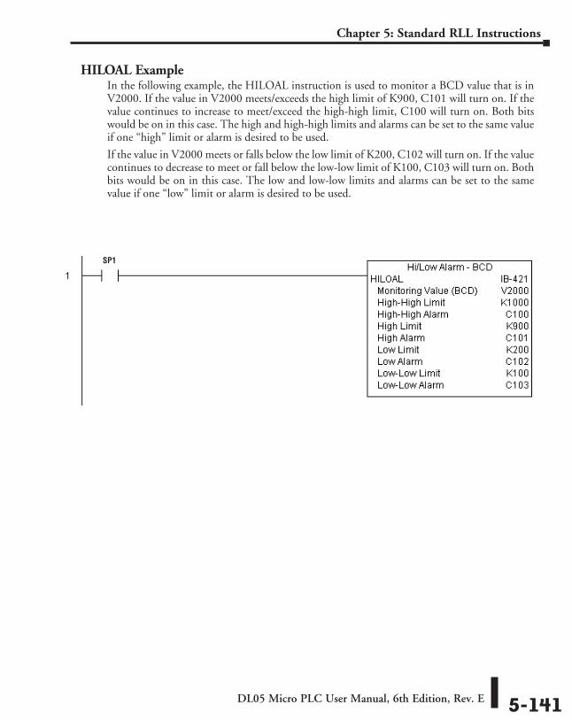
DL05 Micro PLC User Manual, 6th Edition, Rev. E 5-141
Chapter 5: Standard RLL Instructions
HILOAL ExampleIn the following example, the HILOAL instruction is used to monitor a BCD value that is in V2000. If the value in V2000 meets/exceeds the high limit of K900, C101 will turn on. If the value continues to increase to meet/exceed the high-high limit, C100 will turn on. Both bits would be on in this case. The high and high-high limits and alarms can be set to the same value if one “high” limit or alarm is desired to be used.
If the value in V2000 meets or falls below the low limit of K200, C102 will turn on. If the value continues to decrease to meet or fall below the low-low limit of K100, C103 will turn on. Both bits would be on in this case. The low and low-low limits and alarms can be set to the same value if one “low” limit or alarm is desired to be used.
SP1
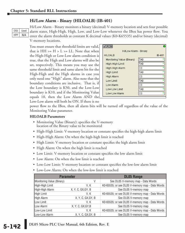
DL05 Micro PLC User Manual, 6th Edition, Rev. E5-142
Chapter 5: Standard RLL Instructions
Hi/Low Alarm - Binary (HILOALB) (IB-401)Hi/Low Alarm - Binary monitors a binary (decimal) V-memory location and sets four possible alarm states, High-High, High, Low, and Low-Low whenever the IBox has power flow. You enter the alarm thresholds as constant K decimal values (K0-K65535) and/or binary (decimal) V-memory locations.
You must ensure that threshold limits are valid, that is HH >= H > L >= LL. Note that when the High-High or Low-Low alarm condition is true, that the High and Low alarms will also be set, respectively. This means you may use the same threshold limit and same alarm bit for the High-High and the High alarms in case you only need one “High” alarm. Also note that the boundary conditions are inclusive. That is, if the Low boundary is K50, and the Low-Low boundary is K10, and if the Monitoring Value equals 10, then the Low Alarm AND the Low-Low alarm will both be ON. If there is no power flow to the IBox, then all alarm bits will be turned off regardless of the value of the Monitoring Value parameter.
HILOALB Parameters
• Monitoring Value (Binary): specifies the V-memory location of the Binary value to be monitored
• High-High Limit: V-memory location or constant specifies the high-high alarm limit
• High-High Alarm: On when the high-high limit is reached
• High Limit: V-memory location or constant specifies the high alarm limit
• High Alarm: On when the high limit is reached
• Low Limit: V-memory location or constant specifies the low alarm limit
• Low Alarm: On when the low limit is reached
• Low-Low Limit: V-memory location or constant specifies the low-low alarm limit
• Low-Low Alarm: On when the low-low limit is reached
Parameter DL05 RangeMonitoring Value (Binary) ⸠⸠⸠⸠⸠⸠⸠⸠⸠⸠⸠⸠⸠⸠⸠⸠⸠⸠⸠⸠⸠⸠⸠⸠⸠⸠⸠⸠⸠⸠⸠⸠⸠⸠⸠⸠⸠⸠ V See DL05 V-memory map - Data WordsHigh-High Limit ⸠⸠⸠⸠⸠⸠⸠⸠⸠⸠⸠⸠⸠⸠⸠⸠⸠⸠⸠⸠⸠⸠⸠⸠⸠⸠⸠⸠⸠⸠⸠⸠⸠⸠⸠⸠⸠⸠⸠⸠⸠⸠⸠⸠⸠ V, K K0-65535; or see DL05 V-memory map - Data Words High-High Alarm ⸠⸠⸠⸠⸠⸠⸠⸠⸠⸠⸠⸠⸠⸠⸠⸠⸠⸠⸠⸠⸠ X, Y, C, GX,GY, B See DL05 V-memory mapHigh Limit ⸠⸠⸠⸠⸠⸠⸠⸠⸠⸠⸠⸠⸠⸠⸠⸠⸠⸠⸠⸠⸠⸠⸠⸠⸠⸠⸠⸠⸠⸠⸠⸠⸠⸠⸠⸠⸠⸠⸠⸠⸠⸠⸠⸠⸠⸠⸠⸠⸠⸠⸠⸠⸠⸠ V, K K0-65535; or see DL05 V-memory map - Data WordsHigh Alarm ⸠⸠⸠⸠⸠⸠⸠⸠⸠⸠⸠⸠⸠⸠⸠⸠⸠⸠⸠⸠⸠⸠⸠⸠⸠⸠⸠⸠⸠⸠⸠⸠⸠⸠⸠⸠⸠ X, Y, C, GX,GY, B See DL05 V-memory mapLow Limit ⸠⸠⸠⸠⸠⸠⸠⸠⸠⸠⸠⸠⸠⸠⸠⸠⸠⸠⸠⸠⸠⸠⸠⸠⸠⸠⸠⸠⸠⸠⸠⸠⸠⸠⸠⸠⸠⸠⸠⸠⸠⸠⸠⸠⸠⸠⸠⸠⸠⸠⸠⸠⸠⸠ V, K K0-65535; or see DL05 V-memory map - Data Words Low Alarm ⸠⸠⸠⸠⸠⸠⸠⸠⸠⸠⸠⸠⸠⸠⸠⸠⸠⸠⸠⸠⸠⸠⸠⸠⸠⸠⸠⸠⸠⸠⸠⸠ X, Y, C, GX,GY,B See DL05 V-memory mapLow-Low Limit ⸠⸠⸠⸠⸠⸠⸠⸠⸠⸠⸠⸠⸠⸠⸠⸠⸠⸠⸠⸠⸠⸠⸠⸠⸠⸠⸠⸠⸠⸠⸠⸠⸠⸠⸠⸠⸠⸠⸠⸠⸠⸠⸠⸠⸠⸠ V, K K0-65535; or see DL05 V-memory map - Data WordsLow-Low Alarm⸠⸠⸠⸠⸠⸠⸠⸠⸠⸠⸠⸠⸠⸠⸠⸠⸠⸠⸠⸠⸠⸠⸠⸠⸠⸠⸠⸠⸠⸠⸠X, Y, C, GX,GY, B See DL05 V-memory map
DS5 Used
HPP N/A
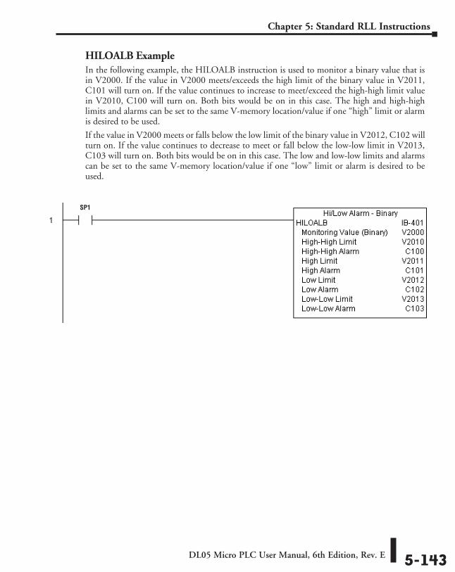
DL05 Micro PLC User Manual, 6th Edition, Rev. E 5-143
Chapter 5: Standard RLL Instructions
HILOALB ExampleIn the following example, the HILOALB instruction is used to monitor a binary value that is in V2000. If the value in V2000 meets/exceeds the high limit of the binary value in V2011, C101 will turn on. If the value continues to increase to meet/exceed the high-high limit value in V2010, C100 will turn on. Both bits would be on in this case. The high and high-high limits and alarms can be set to the same V-memory location/value if one “high” limit or alarm is desired to be used.
If the value in V2000 meets or falls below the low limit of the binary value in V2012, C102 will turn on. If the value continues to decrease to meet or fall below the low-low limit in V2013, C103 will turn on. Both bits would be on in this case. The low and low-low limits and alarms can be set to the same V-memory location/value if one “low” limit or alarm is desired to be used.
SP1
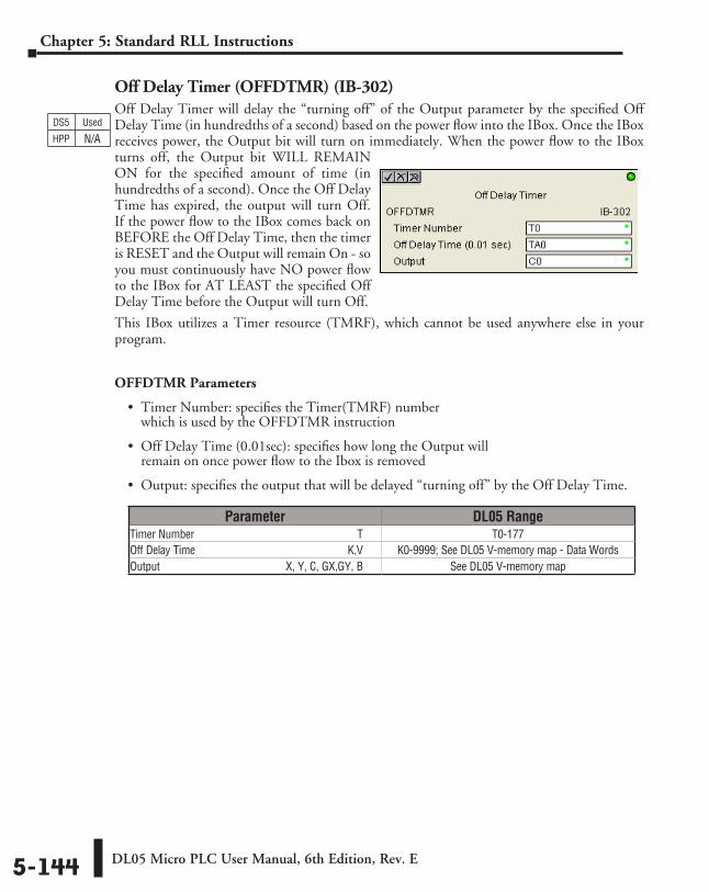
DL05 Micro PLC User Manual, 6th Edition, Rev. E5-144
Chapter 5: Standard RLL Instructions
Off Delay Timer (OFFDTMR) (IB-302)Off Delay Timer will delay the “turning off” of the Output parameter by the specified Off Delay Time (in hundredths of a second) based on the power flow into the IBox. Once the IBox receives power, the Output bit will turn on immediately. When the power flow to the IBox turns off, the Output bit WILL REMAIN ON for the specified amount of time (in hundredths of a second). Once the Off Delay Time has expired, the output will turn Off. If the power flow to the IBox comes back on BEFORE the Off Delay Time, then the timer is RESET and the Output will remain On - so you must continuously have NO power flow to the IBox for AT LEAST the specified Off Delay Time before the Output will turn Off.
This IBox utilizes a Timer resource (TMRF), which cannot be used anywhere else in your program.
OFFDTMR Parameters
• Timer Number: specifies the Timer(TMRF) number which is used by the OFFDTMR instruction
• Off Delay Time (0.01sec): specifies how long the Output will remain on once power flow to the Ibox is removed
• Output: specifies the output that will be delayed “turning off” by the Off Delay Time.
Parameter DL05 RangeTimer Number ⸠⸠⸠⸠⸠⸠⸠⸠⸠⸠⸠⸠⸠⸠⸠⸠⸠⸠⸠⸠⸠⸠⸠⸠⸠⸠⸠⸠⸠⸠⸠⸠⸠⸠⸠⸠⸠⸠⸠⸠⸠⸠⸠⸠⸠⸠⸠⸠⸠⸠⸠⸠⸠⸠⸠⸠⸠ T T0-177Off Delay Time ⸠⸠⸠⸠⸠⸠⸠⸠⸠⸠⸠⸠⸠⸠⸠⸠⸠⸠⸠⸠⸠⸠⸠⸠⸠⸠⸠⸠⸠⸠⸠⸠⸠⸠⸠⸠⸠⸠⸠⸠⸠⸠⸠⸠⸠⸠⸠⸠⸠⸠⸠⸠⸠⸠K,V K0-9999; See DL05 V-memory map - Data WordsOutput⸠⸠⸠⸠⸠⸠⸠⸠⸠⸠⸠⸠⸠⸠⸠⸠⸠⸠⸠⸠⸠⸠⸠⸠⸠⸠⸠⸠⸠⸠⸠⸠⸠⸠⸠⸠⸠⸠⸠⸠⸠⸠⸠⸠⸠⸠X, Y, C, GX,GY, B See DL05 V-memory map
DS5 Used
HPP N/A
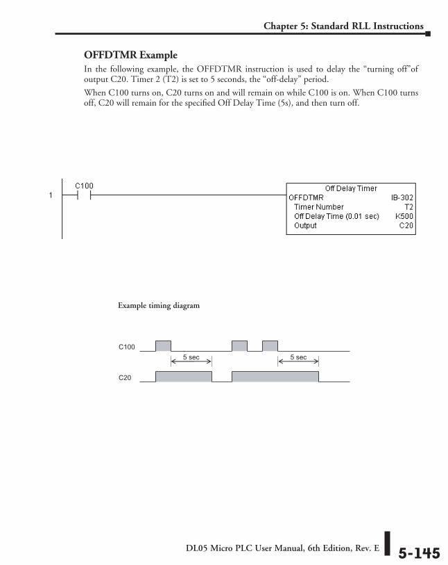
DL05 Micro PLC User Manual, 6th Edition, Rev. E 5-145
Chapter 5: Standard RLL Instructions
OFFDTMR ExampleIn the following example, the OFFDTMR instruction is used to delay the “turning off”of output C20. Timer 2 (T2) is set to 5 seconds, the “off-delay” period.
When C100 turns on, C20 turns on and will remain on while C100 is on. When C100 turns off, C20 will remain for the specified Off Delay Time (5s), and then turn off.
C100
C20
5 sec 5 sec
Example timing diagram
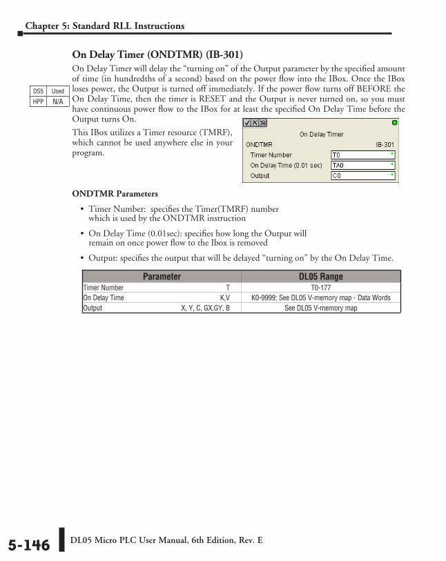
DL05 Micro PLC User Manual, 6th Edition, Rev. E5-146
Chapter 5: Standard RLL Instructions
On Delay Timer (ONDTMR) (IB-301)On Delay Timer will delay the “turning on” of the Output parameter by the specified amount of time (in hundredths of a second) based on the power flow into the IBox. Once the IBox loses power, the Output is turned off immediately. If the power flow turns off BEFORE the On Delay Time, then the timer is RESET and the Output is never turned on, so you must have continuous power flow to the IBox for at least the specified On Delay Time before the Output turns On.
This IBox utilizes a Timer resource (TMRF), which cannot be used anywhere else in your program.
ONDTMR Parameters
• Timer Number: specifies the Timer(TMRF) number which is used by the ONDTMR instruction
• On Delay Time (0.01sec): specifies how long the Output will remain on once power flow to the Ibox is removed
• Output: specifies the output that will be delayed “turning on” by the On Delay Time.
Parameter DL05 RangeTimer Number ⸠⸠⸠⸠⸠⸠⸠⸠⸠⸠⸠⸠⸠⸠⸠⸠⸠⸠⸠⸠⸠⸠⸠⸠⸠⸠⸠⸠⸠⸠⸠⸠⸠⸠⸠⸠⸠⸠⸠⸠⸠⸠⸠⸠⸠⸠⸠⸠⸠⸠⸠⸠⸠⸠⸠⸠⸠ T T0-177On Delay Time ⸠⸠⸠⸠⸠⸠⸠⸠⸠⸠⸠⸠⸠⸠⸠⸠⸠⸠⸠⸠⸠⸠⸠⸠⸠⸠⸠⸠⸠⸠⸠⸠⸠⸠⸠⸠⸠⸠⸠⸠⸠⸠⸠⸠⸠⸠⸠⸠⸠⸠⸠⸠⸠⸠⸠K,V K0-9999; See DL05 V-memory map - Data WordsOutput⸠⸠⸠⸠⸠⸠⸠⸠⸠⸠⸠⸠⸠⸠⸠⸠⸠⸠⸠⸠⸠⸠⸠⸠⸠⸠⸠⸠⸠⸠⸠⸠⸠⸠⸠⸠⸠⸠⸠⸠⸠⸠⸠⸠⸠⸠X, Y, C, GX,GY, B See DL05 V-memory map
DS5 Used
HPP N/A
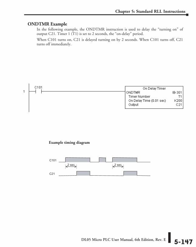
DL05 Micro PLC User Manual, 6th Edition, Rev. E 5-147
Chapter 5: Standard RLL Instructions
ONDTMR ExampleIn the following example, the ONDTMR instruction is used to delay the “turning on” of output C21. Timer 1 (T1) is set to 2 seconds, the “on-delay” period.
When C101 turns on, C21 is delayed turning on by 2 seconds. When C101 turns off, C21 turns off immediately.
C101
C21
2 sec 2 sec
Example timing diagram
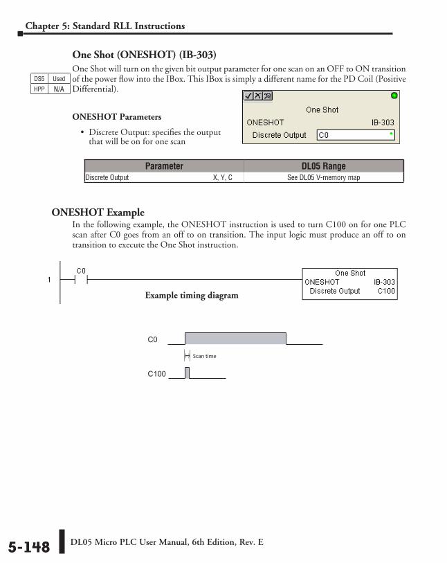
DL05 Micro PLC User Manual, 6th Edition, Rev. E5-148
Chapter 5: Standard RLL Instructions
One Shot (ONESHOT) (IB-303)One Shot will turn on the given bit output parameter for one scan on an OFF to ON transition of the power flow into the IBox. This IBox is simply a different name for the PD Coil (Positive Differential).
ONESHOT Parameters
• Discrete Output: specifies the output that will be on for one scan
ONESHOT ExampleIn the following example, the ONESHOT instruction is used to turn C100 on for one PLC scan after C0 goes from an off to on transition. The input logic must produce an off to on transition to execute the One Shot instruction.
Parameter DL05 RangeDiscrete Output ⸠⸠⸠⸠⸠⸠⸠⸠⸠⸠⸠⸠⸠⸠⸠⸠⸠⸠⸠⸠⸠⸠⸠⸠⸠⸠⸠⸠⸠⸠⸠⸠⸠⸠⸠⸠⸠⸠⸠⸠⸠⸠⸠⸠⸠⸠⸠⸠ X, Y, C See DL05 V-memory map
DS5 Used
HPP N/A
C0
C100
Scan time
Example timing diagram
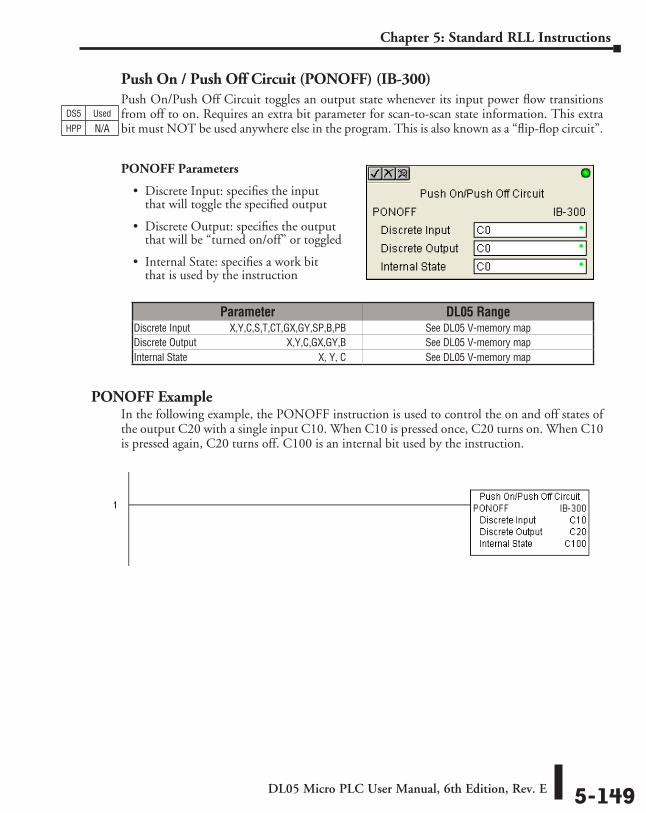
DL05 Micro PLC User Manual, 6th Edition, Rev. E 5-149
Chapter 5: Standard RLL Instructions
Push On / Push Off Circuit (PONOFF) (IB-300)Push On/Push Off Circuit toggles an output state whenever its input power flow transitions from off to on. Requires an extra bit parameter for scan-to-scan state information. This extra bit must NOT be used anywhere else in the program. This is also known as a “flip-flop circuit”.
PONOFF Parameters
• Discrete Input: specifies the input that will toggle the specified output
• Discrete Output: specifies the output that will be “turned on/off” or toggled
• Internal State: specifies a work bit that is used by the instruction
PONOFF ExampleIn the following example, the PONOFF instruction is used to control the on and off states of the output C20 with a single input C10. When C10 is pressed once, C20 turns on. When C10 is pressed again, C20 turns off. C100 is an internal bit used by the instruction.
Parameter DL05 RangeDiscrete Input ⸠⸠⸠⸠⸠⸠⸠⸠⸠⸠⸠⸠ X,Y,C,S,T,CT,GX,GY,SP,B,PB See DL05 V-memory map Discrete Output ⸠⸠⸠⸠⸠⸠⸠⸠⸠⸠⸠⸠⸠⸠⸠⸠⸠⸠⸠⸠⸠⸠⸠⸠⸠⸠⸠⸠⸠⸠⸠⸠⸠⸠ X,Y,C,GX,GY,B See DL05 V-memory mapInternal State ⸠⸠⸠⸠⸠⸠⸠⸠⸠⸠⸠⸠⸠⸠⸠⸠⸠⸠⸠⸠⸠⸠⸠⸠⸠⸠⸠⸠⸠⸠⸠⸠⸠⸠⸠⸠⸠⸠⸠⸠⸠⸠⸠⸠⸠⸠⸠⸠⸠⸠⸠⸠ X, Y, C See DL05 V-memory map
DS5 Used
HPP N/A
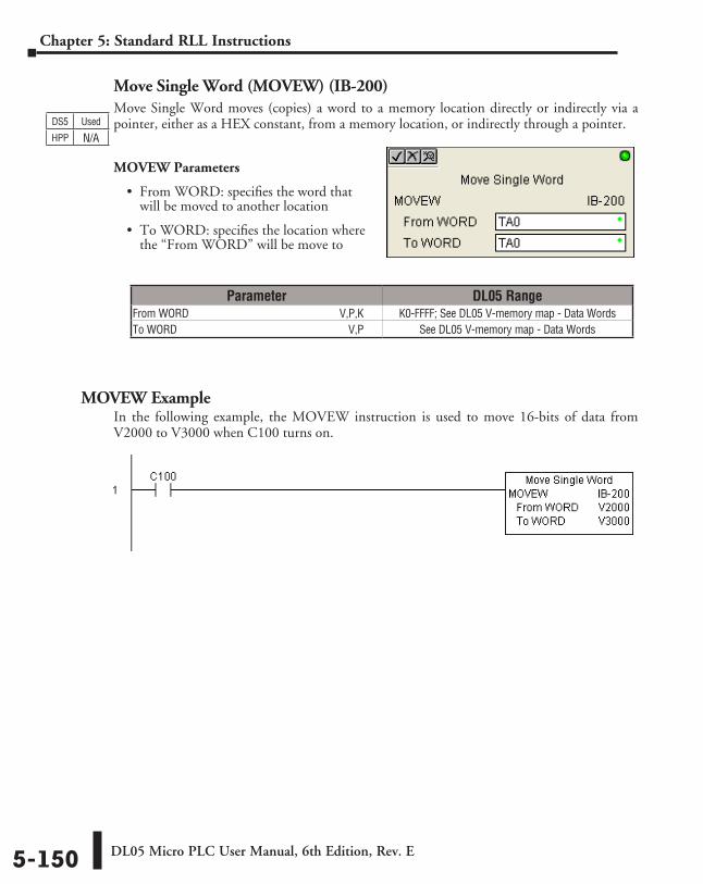
DL05 Micro PLC User Manual, 6th Edition, Rev. E5-150
Chapter 5: Standard RLL Instructions
Move Single Word (MOVEW) (IB-200)Move Single Word moves (copies) a word to a memory location directly or indirectly via a pointer, either as a HEX constant, from a memory location, or indirectly through a pointer.
MOVEW Parameters
• From WORD: specifies the word that will be moved to another location
• To WORD: specifies the location where the “From WORD” will be move to
MOVEW ExampleIn the following example, the MOVEW instruction is used to move 16-bits of data from V2000 to V3000 when C100 turns on.
Parameter DL05 RangeFrom WORD ⸠⸠⸠⸠⸠⸠⸠⸠⸠⸠⸠⸠⸠⸠⸠⸠⸠⸠⸠⸠⸠⸠⸠⸠⸠⸠⸠⸠⸠⸠⸠⸠⸠⸠⸠⸠⸠⸠⸠⸠⸠⸠⸠⸠⸠⸠⸠⸠⸠⸠⸠⸠⸠⸠V,P,K K0-FFFF; See DL05 V-memory map - Data WordsTo WORD ⸠⸠⸠⸠⸠⸠⸠⸠⸠⸠⸠⸠⸠⸠⸠⸠⸠⸠⸠⸠⸠⸠⸠⸠⸠⸠⸠⸠⸠⸠⸠⸠⸠⸠⸠⸠⸠⸠⸠⸠⸠⸠⸠⸠⸠⸠⸠⸠⸠⸠⸠⸠⸠⸠⸠⸠⸠⸠⸠⸠⸠⸠⸠V,P See DL05 V-memory map - Data Words
DS5 Used
HPP N/A
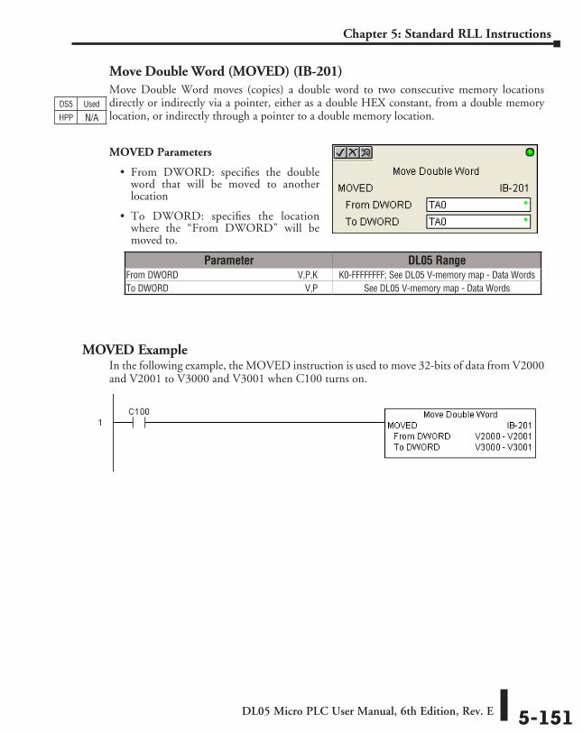
DL05 Micro PLC User Manual, 6th Edition, Rev. E 5-151
Chapter 5: Standard RLL Instructions
Move Double Word (MOVED) (IB-201)Move Double Word moves (copies) a double word to two consecutive memory locations directly or indirectly via a pointer, either as a double HEX constant, from a double memory location, or indirectly through a pointer to a double memory location.
MOVED Parameters
• From DWORD: specifies the double word that will be moved to another location
• To DWORD: specifies the location where the “From DWORD” will be moved to.
MOVED ExampleIn the following example, the MOVED instruction is used to move 32-bits of data from V2000 and V2001 to V3000 and V3001 when C100 turns on.
Parameter DL05 RangeFrom DWORD ⸠⸠⸠⸠⸠⸠⸠⸠⸠⸠⸠⸠⸠⸠⸠⸠⸠⸠⸠⸠⸠⸠⸠⸠⸠⸠⸠⸠⸠⸠⸠⸠⸠⸠⸠⸠⸠⸠⸠⸠⸠⸠⸠⸠⸠⸠⸠⸠⸠⸠⸠V,P,K K0-FFFFFFFF; See DL05 V-memory map - Data WordsTo DWORD ⸠⸠⸠⸠⸠⸠⸠⸠⸠⸠⸠⸠⸠⸠⸠⸠⸠⸠⸠⸠⸠⸠⸠⸠⸠⸠⸠⸠⸠⸠⸠⸠⸠⸠⸠⸠⸠⸠⸠⸠⸠⸠⸠⸠⸠⸠⸠⸠⸠⸠⸠⸠⸠⸠⸠⸠⸠⸠⸠⸠⸠V,P See DL05 V-memory map - Data Words
DS5 Used
HPP N/A
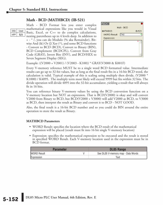
DL05 Micro PLC User Manual, 6th Edition, Rev. E5-152
Chapter 5: Standard RLL Instructions
Math - BCD (MATHBCD) (IB-521)Math - BCD Format lets you enter complex mathematical expressions like you would in Visual Basic, Excel, or C++ to do complex calculations, nesting parentheses up to 4 levels deep. In addition to + - * /, you can do Modulo (% aka Remainder), Bit-wise And (&) Or (|) Xor (^), and some BCD functions - Convert to BCD (BCD), Convert to Binary (BIN), BCD Complement (BCDCPL), Convert from Gray Code (GRAY), Invert Bits (INV), and BCD/HEX to Seven Segment Display (SEG).
Example: ((V2000 + V2001) / (V2003 - K100)) * GRAY(V3000 & K001F)
Every V-memory reference MUST be to a single word BCD formatted value. Intermediate results can go up to 32-bit values, but as long as the final result fits in a 16-bit BCD word, the calculation is valid. Typical example of this is scaling using multiply then divide, (V2000 * K1000) / K4095. The multiply term most likely will exceed 9999 but fits within 32 bits. The divide operation will divide 4095 into the 32-bit accumulator, yielding a result that will always fit in 16 bits.
You can reference binary V-memory values by using the BCD conversion function on a V-memory location but NOT an expression. That is BCD(V2000) is okay and will convert V2000 from Binary to BCD, but BCD(V2000 + V3000) will add V2000 as BCD, to V3000 as BCD, then interpret the result as Binary and convert it to BCD - NOT GOOD.
Also, the final result is a 16-bit BCD number and so you could do BIN around the entire operation to store the result as Binary.
MATHBCD Parameters
• WORD Result: specifies the location where the BCD result of the mathematical expression will be placed (result must fit into 16 bit single V-memory location)
• Expression: specifies the mathematical expression to be executed and the result is stored in specified WORD Result. Each V-memory location used in the expression must be in BCD format.
Parameter DL05 RangeWORD Result ⸠⸠⸠⸠⸠⸠⸠⸠⸠⸠⸠⸠⸠⸠⸠⸠⸠⸠⸠⸠⸠⸠⸠⸠⸠⸠⸠⸠⸠⸠⸠⸠⸠⸠⸠⸠⸠⸠⸠⸠⸠⸠⸠⸠⸠⸠⸠⸠⸠⸠⸠⸠⸠⸠⸠⸠⸠⸠ V See DL05 V-memory map - Data WordsExpression ⸠⸠⸠⸠⸠⸠⸠⸠⸠⸠⸠⸠⸠⸠⸠⸠⸠⸠⸠⸠⸠⸠⸠⸠⸠⸠⸠⸠⸠⸠⸠⸠⸠⸠⸠⸠⸠⸠⸠⸠⸠⸠⸠⸠⸠⸠⸠⸠⸠⸠⸠⸠⸠⸠⸠⸠⸠⸠⸠⸠⸠⸠⸠⸠⸠⸠⸠⸠ Text
DS5 Used
HPP N/A
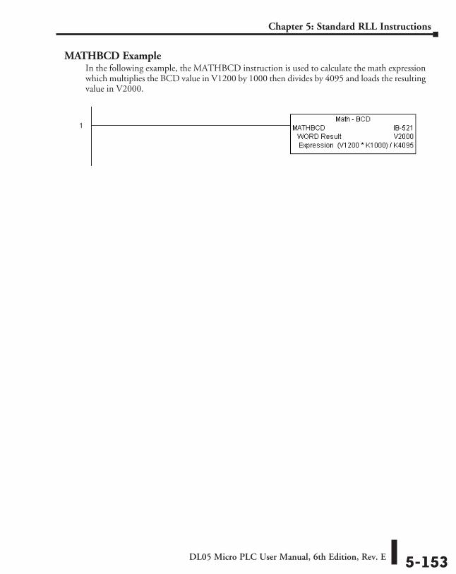
DL05 Micro PLC User Manual, 6th Edition, Rev. E 5-153
Chapter 5: Standard RLL Instructions
MATHBCD ExampleIn the following example, the MATHBCD instruction is used to calculate the math expression which multiplies the BCD value in V1200 by 1000 then divides by 4095 and loads the resulting value in V2000.
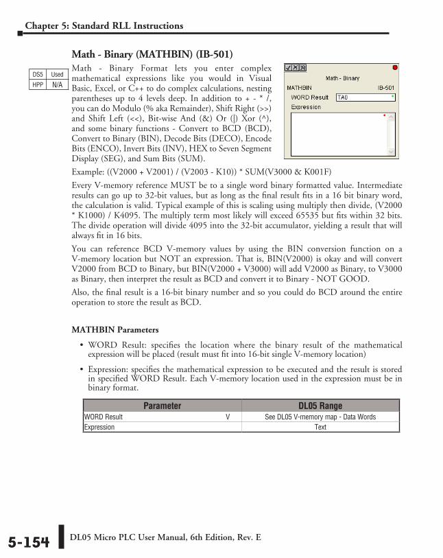
DL05 Micro PLC User Manual, 6th Edition, Rev. E5-154
Chapter 5: Standard RLL Instructions
Math - Binary (MATHBIN) (IB-501)Math - Binary Format lets you enter complex mathematical expressions like you would in Visual Basic, Excel, or C++ to do complex calculations, nesting parentheses up to 4 levels deep. In addition to + - * /, you can do Modulo (% aka Remainder), Shift Right (>>) and Shift Left (<<), Bit-wise And (&) Or (|) Xor (^), and some binary functions - Convert to BCD (BCD), Convert to Binary (BIN), Decode Bits (DECO), Encode Bits (ENCO), Invert Bits (INV), HEX to Seven Segment Display (SEG), and Sum Bits (SUM).
Example: ((V2000 + V2001) / (V2003 - K10)) * SUM(V3000 & K001F)
Every V-memory reference MUST be to a single word binary formatted value. Intermediate results can go up to 32-bit values, but as long as the final result fits in a 16 bit binary word, the calculation is valid. Typical example of this is scaling using multiply then divide, (V2000 * K1000) / K4095. The multiply term most likely will exceed 65535 but fits within 32 bits. The divide operation will divide 4095 into the 32-bit accumulator, yielding a result that will always fit in 16 bits.
You can reference BCD V-memory values by using the BIN conversion function on a V-memory location but NOT an expression. That is, BIN(V2000) is okay and will convert V2000 from BCD to Binary, but BIN(V2000 + V3000) will add V2000 as Binary, to V3000 as Binary, then interpret the result as BCD and convert it to Binary - NOT GOOD.
Also, the final result is a 16-bit binary number and so you could do BCD around the entire operation to store the result as BCD.
MATHBIN Parameters
• WORD Result: specifies the location where the binary result of the mathematical expression will be placed (result must fit into 16-bit single V-memory location)
• Expression: specifies the mathematical expression to be executed and the result is stored in specified WORD Result. Each V-memory location used in the expression must be in binary format.
Parameter DL05 RangeWORD Result ⸠⸠⸠⸠⸠⸠⸠⸠⸠⸠⸠⸠⸠⸠⸠⸠⸠⸠⸠⸠⸠⸠⸠⸠⸠⸠⸠⸠⸠⸠⸠⸠⸠⸠⸠⸠⸠⸠⸠⸠⸠⸠⸠⸠⸠⸠⸠⸠⸠⸠⸠⸠⸠⸠⸠⸠⸠⸠ V See DL05 V-memory map - Data WordsExpression ⸠⸠⸠⸠⸠⸠⸠⸠⸠⸠⸠⸠⸠⸠⸠⸠⸠⸠⸠⸠⸠⸠⸠⸠⸠⸠⸠⸠⸠⸠⸠⸠⸠⸠⸠⸠⸠⸠⸠⸠⸠⸠⸠⸠⸠⸠⸠⸠⸠⸠⸠⸠⸠⸠⸠⸠⸠⸠⸠⸠⸠⸠⸠⸠⸠⸠⸠⸠ Text
DS5 Used
HPP N/A
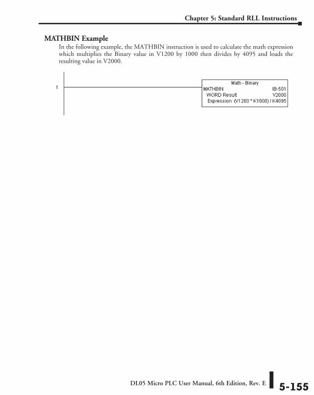
DL05 Micro PLC User Manual, 6th Edition, Rev. E 5-155
Chapter 5: Standard RLL Instructions
MATHBIN ExampleIn the following example, the MATHBIN instruction is used to calculate the math expression which multiplies the Binary value in V1200 by 1000 then divides by 4095 and loads the resulting value in V2000.
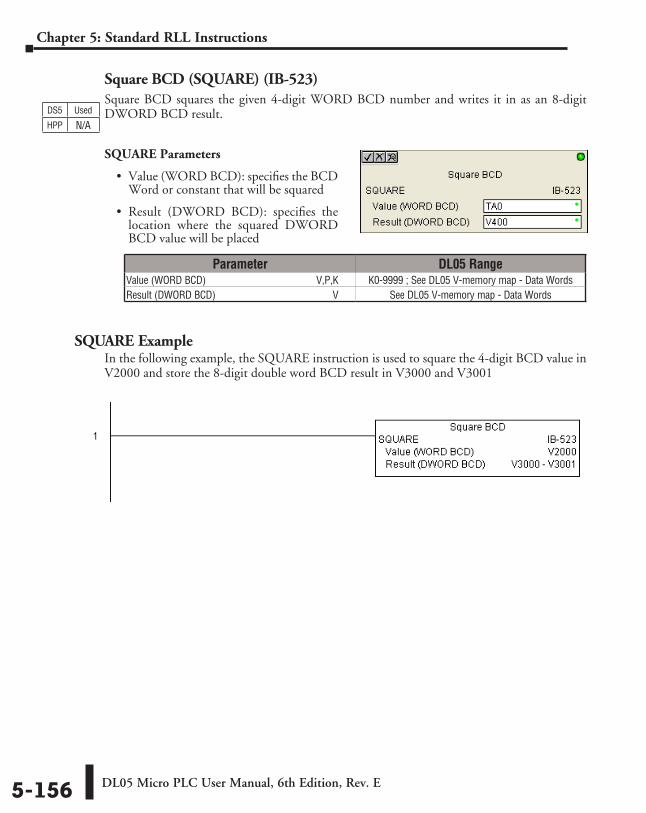
DL05 Micro PLC User Manual, 6th Edition, Rev. E5-156
Chapter 5: Standard RLL Instructions
Square BCD (SQUARE) (IB-523)Square BCD squares the given 4-digit WORD BCD number and writes it in as an 8-digit DWORD BCD result.
SQUARE Parameters
• Value (WORD BCD): specifies the BCD Word or constant that will be squared
• Result (DWORD BCD): specifies the location where the squared DWORD BCD value will be placed
SQUARE ExampleIn the following example, the SQUARE instruction is used to square the 4-digit BCD value in V2000 and store the 8-digit double word BCD result in V3000 and V3001
Parameter DL05 RangeValue (WORD BCD) ⸠⸠⸠⸠⸠⸠⸠⸠⸠⸠⸠⸠⸠⸠⸠⸠⸠⸠⸠⸠⸠⸠⸠⸠⸠⸠⸠⸠⸠⸠⸠⸠⸠⸠⸠⸠⸠⸠⸠⸠⸠⸠V,P,K K0-9999 ; See DL05 V-memory map - Data WordsResult (DWORD BCD) ⸠⸠⸠⸠⸠⸠⸠⸠⸠⸠⸠⸠⸠⸠⸠⸠⸠⸠⸠⸠⸠⸠⸠⸠⸠⸠⸠⸠⸠⸠⸠⸠⸠⸠⸠⸠⸠⸠⸠⸠⸠⸠⸠⸠⸠⸠ V See DL05 V-memory map - Data Words
DS5 Used
HPP N/A
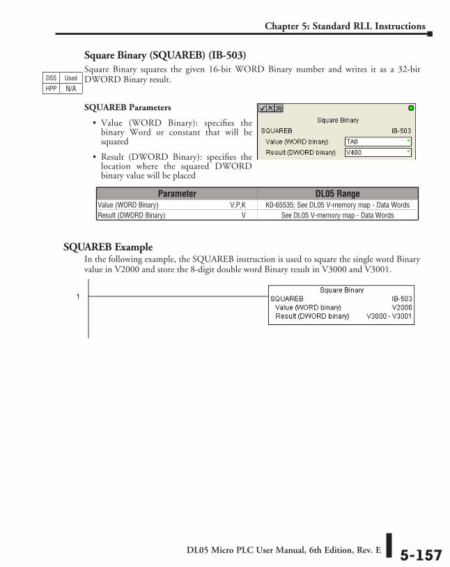
DL05 Micro PLC User Manual, 6th Edition, Rev. E 5-157
Chapter 5: Standard RLL Instructions
Square Binary (SQUAREB) (IB-503)Square Binary squares the given 16-bit WORD Binary number and writes it as a 32-bit DWORD Binary result.
SQUAREB Parameters
• Value (WORD Binary): specifies the binary Word or constant that will be squared
• Result (DWORD Binary): specifies the location where the squared DWORD binary value will be placed
SQUAREB ExampleIn the following example, the SQUAREB instruction is used to square the single word Binary value in V2000 and store the 8-digit double word Binary result in V3000 and V3001.
Parameter DL05 RangeValue (WORD Binary) ⸠⸠⸠⸠⸠⸠⸠⸠⸠⸠⸠⸠⸠⸠⸠⸠⸠⸠⸠⸠⸠⸠⸠⸠⸠⸠⸠⸠⸠⸠⸠⸠⸠⸠⸠⸠⸠⸠⸠V,P,K K0-65535; See DL05 V-memory map - Data WordsResult (DWORD Binary) ⸠⸠⸠⸠⸠⸠⸠⸠⸠⸠⸠⸠⸠⸠⸠⸠⸠⸠⸠⸠⸠⸠⸠⸠⸠⸠⸠⸠⸠⸠⸠⸠⸠⸠⸠⸠⸠⸠⸠⸠⸠⸠⸠ V See DL05 V-memory map - Data Words
DS5 Used
HPP N/A
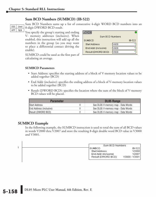
DL05 Micro PLC User Manual, 6th Edition, Rev. E5-158
Chapter 5: Standard RLL Instructions
Sum BCD Numbers (SUMBCD) (IB-522)Sum BCD Numbers sums up a list of consecutive 4-digit WORD BCD numbers into an 8-digit DWORD BCD result.
You specify the group’s starting and ending V- memory addresses (inclusive). When enabled, this instruction will add up all the numbers in the group (so you may want to place a differential contact driving the enable).
SUMBCD could be used as the first part of calculating an average.
SUMBCD Parameters
• Start Address: specifies the starting address of a block of V-memory location values to be added together (BCD)
• End Addr (inclusive): specifies the ending address of a block of V-memory location values to be added together (BCD)
• Result (DWORD BCD): specifies the location where the sum of the block of V-memory BCD values will be placed.
SUMBCD ExampleIn the following example, the SUMBCD instruction is used to total the sum of all BCD values in words V2000 thru V2007 and store the resulting 8-digit double word BCD value in V3000 and V3001.
Parameter DL05 RangeStart Address ⸠⸠⸠⸠⸠⸠⸠⸠⸠⸠⸠⸠⸠⸠⸠⸠⸠⸠⸠⸠⸠⸠⸠⸠⸠⸠⸠⸠⸠⸠⸠⸠⸠⸠⸠⸠⸠⸠⸠⸠⸠⸠⸠⸠⸠⸠⸠⸠⸠⸠⸠⸠⸠⸠⸠⸠⸠⸠ V See DL05 V-memory map - Data WordsEnd Address (inclusive) ⸠⸠⸠⸠⸠⸠⸠⸠⸠⸠⸠⸠⸠⸠⸠⸠⸠⸠⸠⸠⸠⸠⸠⸠⸠⸠⸠⸠⸠⸠⸠⸠⸠⸠⸠⸠⸠⸠⸠⸠⸠⸠ V See DL05 V-memory map - Data WordsResult (DWORD BCD) ⸠⸠⸠⸠⸠⸠⸠⸠⸠⸠⸠⸠⸠⸠⸠⸠⸠⸠⸠⸠⸠⸠⸠⸠⸠⸠⸠⸠⸠⸠⸠⸠⸠⸠⸠⸠⸠⸠⸠⸠⸠⸠⸠⸠⸠⸠ V See DL05 V-memory map - Data Words
DS5 Used
HPP N/A
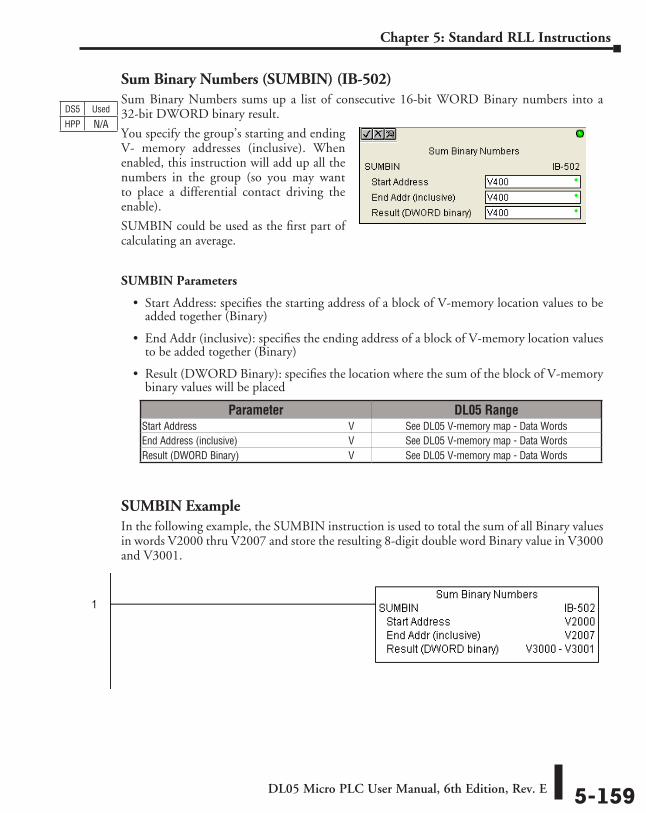
DL05 Micro PLC User Manual, 6th Edition, Rev. E 5-159
Chapter 5: Standard RLL Instructions
Sum Binary Numbers (SUMBIN) (IB-502)Sum Binary Numbers sums up a list of consecutive 16-bit WORD Binary numbers into a 32-bit DWORD binary result.
You specify the group’s starting and ending V- memory addresses (inclusive). When enabled, this instruction will add up all the numbers in the group (so you may want to place a differential contact driving the enable).
SUMBIN could be used as the first part of calculating an average.
SUMBIN Parameters
• Start Address: specifies the starting address of a block of V-memory location values to be added together (Binary)
• End Addr (inclusive): specifies the ending address of a block of V-memory location values to be added together (Binary)
• Result (DWORD Binary): specifies the location where the sum of the block of V-memory binary values will be placed
SUMBIN ExampleIn the following example, the SUMBIN instruction is used to total the sum of all Binary values in words V2000 thru V2007 and store the resulting 8-digit double word Binary value in V3000 and V3001.
Parameter DL05 RangeStart Address ⸠⸠⸠⸠⸠⸠⸠⸠⸠⸠⸠⸠⸠⸠⸠⸠⸠⸠⸠⸠⸠⸠⸠⸠⸠⸠⸠⸠⸠⸠⸠⸠⸠⸠⸠⸠⸠⸠⸠⸠⸠⸠⸠⸠⸠⸠⸠⸠⸠⸠⸠⸠⸠⸠⸠⸠⸠⸠ V See DL05 V-memory map - Data WordsEnd Address (inclusive) ⸠⸠⸠⸠⸠⸠⸠⸠⸠⸠⸠⸠⸠⸠⸠⸠⸠⸠⸠⸠⸠⸠⸠⸠⸠⸠⸠⸠⸠⸠⸠⸠⸠⸠⸠⸠⸠⸠⸠⸠⸠⸠ V See DL05 V-memory map - Data WordsResult (DWORD Binary) ⸠⸠⸠⸠⸠⸠⸠⸠⸠⸠⸠⸠⸠⸠⸠⸠⸠⸠⸠⸠⸠⸠⸠⸠⸠⸠⸠⸠⸠⸠⸠⸠⸠⸠⸠⸠⸠⸠⸠⸠⸠⸠⸠ V See DL05 V-memory map - Data Words
DS5 Used
HPP N/A
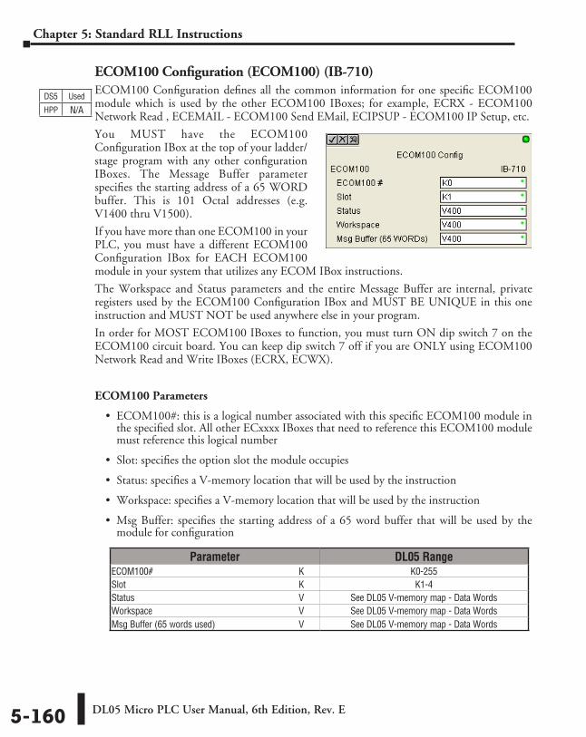
DL05 Micro PLC User Manual, 6th Edition, Rev. E5-160
Chapter 5: Standard RLL Instructions
ECOM100 Configuration (ECOM100) (IB-710)ECOM100 Configuration defines all the common information for one specific ECOM100 module which is used by the other ECOM100 IBoxes; for example, ECRX - ECOM100 Network Read , ECEMAIL - ECOM100 Send EMail, ECIPSUP - ECOM100 IP Setup, etc.
You MUST have the ECOM100 Configuration IBox at the top of your ladder/stage program with any other configuration IBoxes. The Message Buffer parameter specifies the starting address of a 65 WORD buffer. This is 101 Octal addresses (e.g. V1400 thru V1500).
If you have more than one ECOM100 in your PLC, you must have a different ECOM100 Configuration IBox for EACH ECOM100 module in your system that utilizes any ECOM IBox instructions.
The Workspace and Status parameters and the entire Message Buffer are internal, private registers used by the ECOM100 Configuration IBox and MUST BE UNIQUE in this one instruction and MUST NOT be used anywhere else in your program.
In order for MOST ECOM100 IBoxes to function, you must turn ON dip switch 7 on the ECOM100 circuit board. You can keep dip switch 7 off if you are ONLY using ECOM100 Network Read and Write IBoxes (ECRX, ECWX).
ECOM100 Parameters
• ECOM100#: this is a logical number associated with this specific ECOM100 module in the specified slot. All other ECxxxx IBoxes that need to reference this ECOM100 module must reference this logical number
• Slot: specifies the option slot the module occupies
• Status: specifies a V-memory location that will be used by the instruction
• Workspace: specifies a V-memory location that will be used by the instruction
• Msg Buffer: specifies the starting address of a 65 word buffer that will be used by the module for configuration
DS5 Used
HPP N/A
Parameter DL05 RangeECOM100# ⸠⸠⸠⸠⸠⸠⸠⸠⸠⸠⸠⸠⸠⸠⸠⸠⸠⸠⸠⸠⸠⸠⸠⸠⸠⸠⸠⸠⸠⸠⸠⸠⸠⸠⸠⸠⸠⸠⸠⸠⸠⸠⸠⸠⸠⸠⸠⸠⸠⸠⸠⸠⸠⸠⸠⸠⸠⸠⸠⸠⸠⸠ K K0-255Slot ⸠⸠⸠⸠⸠⸠⸠⸠⸠⸠⸠⸠⸠⸠⸠⸠⸠⸠⸠⸠⸠⸠⸠⸠⸠⸠⸠⸠⸠⸠⸠⸠⸠⸠⸠⸠⸠⸠⸠⸠⸠⸠⸠⸠⸠⸠⸠⸠⸠⸠⸠⸠⸠⸠⸠⸠⸠⸠⸠⸠⸠⸠⸠⸠⸠⸠⸠⸠⸠⸠⸠⸠⸠⸠ K K1-4Status ⸠⸠⸠⸠⸠⸠⸠⸠⸠⸠⸠⸠⸠⸠⸠⸠⸠⸠⸠⸠⸠⸠⸠⸠⸠⸠⸠⸠⸠⸠⸠⸠⸠⸠⸠⸠⸠⸠⸠⸠⸠⸠⸠⸠⸠⸠⸠⸠⸠⸠⸠⸠⸠⸠⸠⸠⸠⸠⸠⸠⸠⸠⸠⸠⸠⸠⸠⸠⸠⸠ V See DL05 V-memory map - Data WordsWorkspace ⸠⸠⸠⸠⸠⸠⸠⸠⸠⸠⸠⸠⸠⸠⸠⸠⸠⸠⸠⸠⸠⸠⸠⸠⸠⸠⸠⸠⸠⸠⸠⸠⸠⸠⸠⸠⸠⸠⸠⸠⸠⸠⸠⸠⸠⸠⸠⸠⸠⸠⸠⸠⸠⸠⸠⸠⸠⸠⸠⸠⸠⸠ V See DL05 V-memory map - Data WordsMsg Buffer (65 words used) ⸠⸠⸠⸠⸠⸠⸠⸠⸠⸠⸠⸠⸠⸠⸠⸠⸠⸠⸠⸠⸠⸠⸠⸠⸠⸠⸠⸠⸠⸠⸠⸠⸠⸠⸠⸠ V See DL05 V-memory map - Data Words
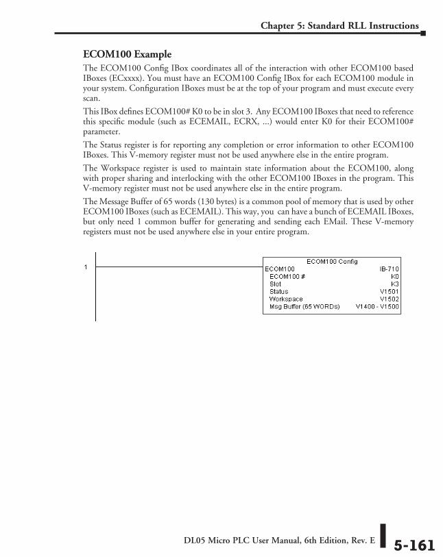
DL05 Micro PLC User Manual, 6th Edition, Rev. E 5-161
Chapter 5: Standard RLL Instructions
ECOM100 ExampleThe ECOM100 Config IBox coordinates all of the interaction with other ECOM100 based IBoxes (ECxxxx). You must have an ECOM100 Config IBox for each ECOM100 module in your system. Configuration IBoxes must be at the top of your program and must execute every scan.
This IBox defines ECOM100# K0 to be in slot 3. Any ECOM100 IBoxes that need to reference this specific module (such as ECEMAIL, ECRX, ...) would enter K0 for their ECOM100# parameter.
The Status register is for reporting any completion or error information to other ECOM100 IBoxes. This V-memory register must not be used anywhere else in the entire program.
The Workspace register is used to maintain state information about the ECOM100, along with proper sharing and interlocking with the other ECOM100 IBoxes in the program. This V-memory register must not be used anywhere else in the entire program.
The Message Buffer of 65 words (130 bytes) is a common pool of memory that is used by other ECOM100 IBoxes (such as ECEMAIL). This way, you can have a bunch of ECEMAIL IBoxes, but only need 1 common buffer for generating and sending each EMail. These V-memory registers must not be used anywhere else in your entire program.
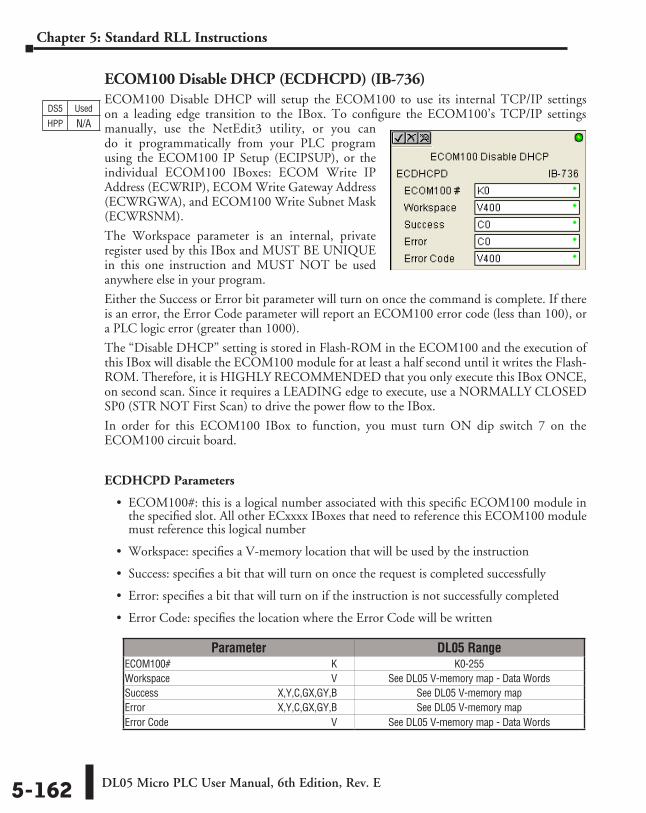
DL05 Micro PLC User Manual, 6th Edition, Rev. E5-162
Chapter 5: Standard RLL Instructions
ECOM100 Disable DHCP (ECDHCPD) (IB-736)ECOM100 Disable DHCP will setup the ECOM100 to use its internal TCP/IP settings on a leading edge transition to the IBox. To configure the ECOM100’s TCP/IP settings manually, use the NetEdit3 utility, or you can do it programmatically from your PLC program using the ECOM100 IP Setup (ECIPSUP), or the individual ECOM100 IBoxes: ECOM Write IP Address (ECWRIP), ECOM Write Gateway Address (ECWRGWA), and ECOM100 Write Subnet Mask (ECWRSNM).
The Workspace parameter is an internal, private register used by this IBox and MUST BE UNIQUE in this one instruction and MUST NOT be used anywhere else in your program.
Either the Success or Error bit parameter will turn on once the command is complete. If there is an error, the Error Code parameter will report an ECOM100 error code (less than 100), or a PLC logic error (greater than 1000).
The “Disable DHCP” setting is stored in Flash-ROM in the ECOM100 and the execution of this IBox will disable the ECOM100 module for at least a half second until it writes the Flash-ROM. Therefore, it is HIGHLY RECOMMENDED that you only execute this IBox ONCE, on second scan. Since it requires a LEADING edge to execute, use a NORMALLY CLOSED SP0 (STR NOT First Scan) to drive the power flow to the IBox.
In order for this ECOM100 IBox to function, you must turn ON dip switch 7 on the ECOM100 circuit board.
ECDHCPD Parameters
• ECOM100#: this is a logical number associated with this specific ECOM100 module in the specified slot. All other ECxxxx IBoxes that need to reference this ECOM100 module must reference this logical number
• Workspace: specifies a V-memory location that will be used by the instruction
• Success: specifies a bit that will turn on once the request is completed successfully
• Error: specifies a bit that will turn on if the instruction is not successfully completed
• Error Code: specifies the location where the Error Code will be written
Parameter DL05 RangeECOM100# ⸠⸠⸠⸠⸠⸠⸠⸠⸠⸠⸠⸠⸠⸠⸠⸠⸠⸠⸠⸠⸠⸠⸠⸠⸠⸠⸠⸠⸠⸠⸠⸠⸠⸠⸠⸠⸠⸠⸠⸠⸠⸠⸠⸠⸠⸠⸠⸠⸠⸠⸠⸠⸠⸠⸠⸠⸠⸠⸠⸠⸠⸠ K K0-255Workspace ⸠⸠⸠⸠⸠⸠⸠⸠⸠⸠⸠⸠⸠⸠⸠⸠⸠⸠⸠⸠⸠⸠⸠⸠⸠⸠⸠⸠⸠⸠⸠⸠⸠⸠⸠⸠⸠⸠⸠⸠⸠⸠⸠⸠⸠⸠⸠⸠⸠⸠⸠⸠⸠⸠⸠⸠⸠⸠⸠⸠⸠⸠ V See DL05 V-memory map - Data WordsSuccess ⸠⸠⸠⸠⸠⸠⸠⸠⸠⸠⸠⸠⸠⸠⸠⸠⸠⸠⸠⸠⸠⸠⸠⸠⸠⸠⸠⸠⸠⸠⸠⸠⸠⸠⸠⸠⸠⸠⸠⸠⸠⸠⸠⸠⸠ X,Y,C,GX,GY,B See DL05 V-memory mapError ⸠⸠⸠⸠⸠⸠⸠⸠⸠⸠⸠⸠⸠⸠⸠⸠⸠⸠⸠⸠⸠⸠⸠⸠⸠⸠⸠⸠⸠⸠⸠⸠⸠⸠⸠⸠⸠⸠⸠⸠⸠⸠⸠⸠⸠⸠⸠⸠⸠⸠ X,Y,C,GX,GY,B See DL05 V-memory mapError Code ⸠⸠⸠⸠⸠⸠⸠⸠⸠⸠⸠⸠⸠⸠⸠⸠⸠⸠⸠⸠⸠⸠⸠⸠⸠⸠⸠⸠⸠⸠⸠⸠⸠⸠⸠⸠⸠⸠⸠⸠⸠⸠⸠⸠⸠⸠⸠⸠⸠⸠⸠⸠⸠⸠⸠⸠⸠⸠⸠⸠⸠⸠⸠⸠⸠ V See DL05 V-memory map - Data Words
DS5 Used
HPP N/A
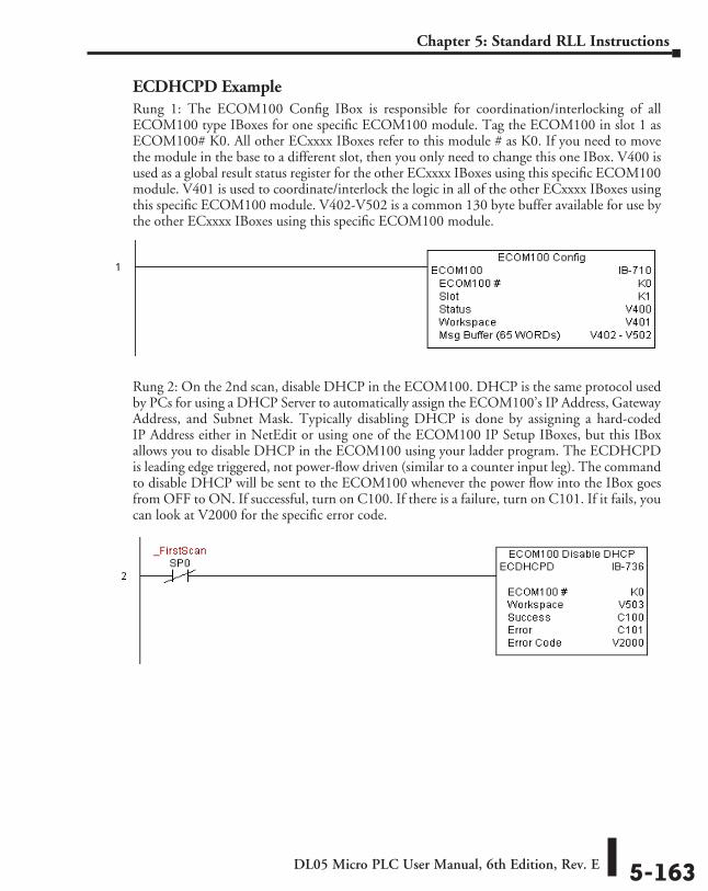
DL05 Micro PLC User Manual, 6th Edition, Rev. E 5-163
Chapter 5: Standard RLL Instructions
ECDHCPD ExampleRung 1: The ECOM100 Config IBox is responsible for coordination/interlocking of all ECOM100 type IBoxes for one specific ECOM100 module. Tag the ECOM100 in slot 1 as ECOM100# K0. All other ECxxxx IBoxes refer to this module # as K0. If you need to move the module in the base to a different slot, then you only need to change this one IBox. V400 is used as a global result status register for the other ECxxxx IBoxes using this specific ECOM100 module. V401 is used to coordinate/interlock the logic in all of the other ECxxxx IBoxes using this specific ECOM100 module. V402-V502 is a common 130 byte buffer available for use by the other ECxxxx IBoxes using this specific ECOM100 module.
Rung 2: On the 2nd scan, disable DHCP in the ECOM100. DHCP is the same protocol used by PCs for using a DHCP Server to automatically assign the ECOM100’s IP Address, Gateway Address, and Subnet Mask. Typically disabling DHCP is done by assigning a hard-coded IP Address either in NetEdit or using one of the ECOM100 IP Setup IBoxes, but this IBox allows you to disable DHCP in the ECOM100 using your ladder program. The ECDHCPD is leading edge triggered, not power-flow driven (similar to a counter input leg). The command to disable DHCP will be sent to the ECOM100 whenever the power flow into the IBox goes from OFF to ON. If successful, turn on C100. If there is a failure, turn on C101. If it fails, you can look at V2000 for the specific error code.
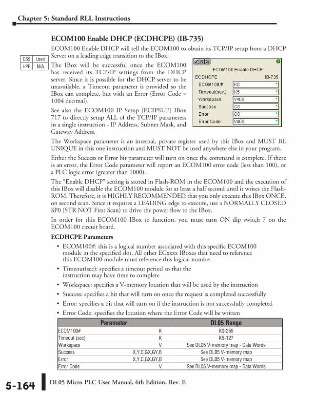
DL05 Micro PLC User Manual, 6th Edition, Rev. E5-164
Chapter 5: Standard RLL Instructions
ECOM100 Enable DHCP (ECDHCPE) (IB-735)ECOM100 Enable DHCP will tell the ECOM100 to obtain its TCP/IP setup from a DHCP Server on a leading edge transition to the IBox.
The IBox will be successful once the ECOM100 has received its TCP/IP settings from the DHCP server. Since it is possible for the DHCP server to be unavailable, a Timeout parameter is provided so the IBox can complete, but with an Error (Error Code = 1004 decimal).
See also the ECOM100 IP Setup (ECIPSUP) IBox 717 to directly setup ALL of the TCP/IP parameters in a single instruction - IP Address, Subnet Mask, and Gateway Address.
The Workspace parameter is an internal, private register used by this IBox and MUST BE UNIQUE in this one instruction and MUST NOT be used anywhere else in your program.
Either the Success or Error bit parameter will turn on once the command is complete. If there is an error, the Error Code parameter will report an ECOM100 error code (less than 100), or a PLC logic error (greater than 1000).
The “Enable DHCP” setting is stored in Flash-ROM in the ECOM100 and the execution of this IBox will disable the ECOM100 module for at least a half second until it writes the Flash-ROM. Therefore, it is HIGHLY RECOMMENDED that you only execute this IBox ONCE, on second scan. Since it requires a LEADING edge to execute, use a NORMALLY CLOSED SP0 (STR NOT First Scan) to drive the power flow to the IBox.
In order for this ECOM100 IBox to function, you must turn ON dip switch 7 on the ECOM100 circuit board.
ECDHCPE Parameters
• ECOM100#: this is a logical number associated with this specific ECOM100 module in the specified slot. All other ECxxxx IBoxes that need to reference this ECOM100 module must reference this logical number
• Timeout(sec): specifies a timeout period so that the instruction may have time to complete
• Workspace: specifies a V-memory location that will be used by the instruction
• Success: specifies a bit that will turn on once the request is completed successfully
• Error: specifies a bit that will turn on if the instruction is not successfully completed
• Error Code: specifies the location where the Error Code will be written
Parameter DL05 RangeECOM100# ⸠⸠⸠⸠⸠⸠⸠⸠⸠⸠⸠⸠⸠⸠⸠⸠⸠⸠⸠⸠⸠⸠⸠⸠⸠⸠⸠⸠⸠⸠⸠⸠⸠⸠⸠⸠⸠⸠⸠⸠⸠⸠⸠⸠⸠⸠⸠⸠⸠⸠⸠⸠⸠⸠⸠⸠⸠⸠⸠⸠⸠⸠ K K0-255Timeout (sec) ⸠⸠⸠⸠⸠⸠⸠⸠⸠⸠⸠⸠⸠⸠⸠⸠⸠⸠⸠⸠⸠⸠⸠⸠⸠⸠⸠⸠⸠⸠⸠⸠⸠⸠⸠⸠⸠⸠⸠⸠⸠⸠⸠⸠⸠⸠⸠⸠⸠⸠⸠⸠⸠⸠⸠⸠⸠⸠ K K5-127Workspace ⸠⸠⸠⸠⸠⸠⸠⸠⸠⸠⸠⸠⸠⸠⸠⸠⸠⸠⸠⸠⸠⸠⸠⸠⸠⸠⸠⸠⸠⸠⸠⸠⸠⸠⸠⸠⸠⸠⸠⸠⸠⸠⸠⸠⸠⸠⸠⸠⸠⸠⸠⸠⸠⸠⸠⸠⸠⸠⸠⸠⸠⸠ V See DL05 V-memory map - Data WordsSuccess ⸠⸠⸠⸠⸠⸠⸠⸠⸠⸠⸠⸠⸠⸠⸠⸠⸠⸠⸠⸠⸠⸠⸠⸠⸠⸠⸠⸠⸠⸠⸠⸠⸠⸠⸠⸠⸠⸠⸠⸠⸠⸠⸠⸠⸠ X,Y,C,GX,GY,B See DL05 V-memory mapError ⸠⸠⸠⸠⸠⸠⸠⸠⸠⸠⸠⸠⸠⸠⸠⸠⸠⸠⸠⸠⸠⸠⸠⸠⸠⸠⸠⸠⸠⸠⸠⸠⸠⸠⸠⸠⸠⸠⸠⸠⸠⸠⸠⸠⸠⸠⸠⸠⸠⸠ X,Y,C,GX,GY,B See DL05 V-memory mapError Code ⸠⸠⸠⸠⸠⸠⸠⸠⸠⸠⸠⸠⸠⸠⸠⸠⸠⸠⸠⸠⸠⸠⸠⸠⸠⸠⸠⸠⸠⸠⸠⸠⸠⸠⸠⸠⸠⸠⸠⸠⸠⸠⸠⸠⸠⸠⸠⸠⸠⸠⸠⸠⸠⸠⸠⸠⸠⸠⸠⸠⸠⸠⸠⸠⸠ V See DL05 V-memory map - Data Words
DS5 Used
HPP N/A
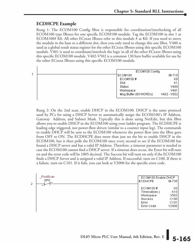
DL05 Micro PLC User Manual, 6th Edition, Rev. E 5-165
Chapter 5: Standard RLL Instructions
ECDHCPE ExampleRung 1: The ECOM100 Config IBox is responsible for coordination/interlocking of all ECOM100 type IBoxes for one specific ECOM100 module. Tag the ECOM100 in slot 1 as ECOM100# K0. All other ECxxxx IBoxes refer to this module # as K0. If you need to move the module in the base to a different slot, then you only need to change this one IBox. V400 is used as a global result status register for the other ECxxxx IBoxes using this specific ECOM100 module. V401 is used to coordinate/interlock the logic in all of the other ECxxxx IBoxes using this specific ECOM100 module. V402-V502 is a common 130 byte buffer available for use by the other ECxxxx IBoxes using this specific ECOM100 module.
Rung 2: On the 2nd scan, enable DHCP in the ECOM100. DHCP is the same protocol used by PCs for using a DHCP Server to automatically assign the ECOM100’s IP Address, Gateway Address, and Subnet Mask. Typically this is done using NetEdit, but this IBox allows you to enable DHCP in the ECOM100 using your ladder program. The ECDHCPE is leading edge triggered, not power-flow driven (similar to a counter input leg). The commands to enable DHCP will be sent to the ECOM100 whenever the power flow into the IBox goes from OFF to ON. The ECDHCPE does more than just set the bit to enable DHCP in the ECOM100, but it then polls the ECOM100 once every second to see if the ECOM100 has found a DHCP server and has a valid IP Address. Therefore, a timeout parameter is needed in case the ECOM100 cannot find a DHCP server. If a timeout does occur, the Error bit will turn on and the error code will be 1005 decimal. The Success bit will turn on only if the ECOM100 finds a DHCP Server and is assigned a valid IP Address. If successful, turn on C100. If there is a failure, turn on C101. If it fails, you can look at V2000 for the specific error code.
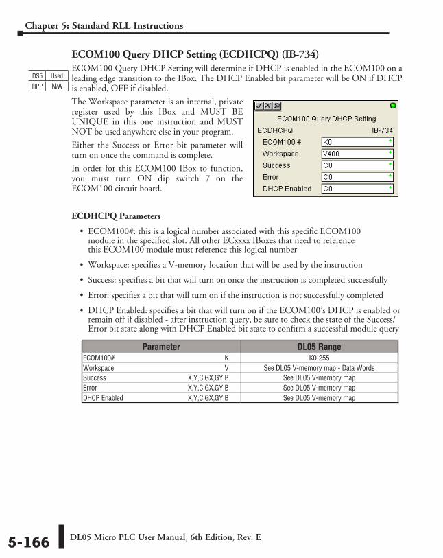
DL05 Micro PLC User Manual, 6th Edition, Rev. E5-166
Chapter 5: Standard RLL Instructions
ECOM100 Query DHCP Setting (ECDHCPQ) (IB-734)ECOM100 Query DHCP Setting will determine if DHCP is enabled in the ECOM100 on a leading edge transition to the IBox. The DHCP Enabled bit parameter will be ON if DHCP is enabled, OFF if disabled.
The Workspace parameter is an internal, private register used by this IBox and MUST BE UNIQUE in this one instruction and MUST NOT be used anywhere else in your program.
Either the Success or Error bit parameter will turn on once the command is complete.
In order for this ECOM100 IBox to function, you must turn ON dip switch 7 on the ECOM100 circuit board.
ECDHCPQ Parameters
• ECOM100#: this is a logical number associated with this specific ECOM100 module in the specified slot. All other ECxxxx IBoxes that need to reference this ECOM100 module must reference this logical number
• Workspace: specifies a V-memory location that will be used by the instruction
• Success: specifies a bit that will turn on once the instruction is completed successfully
• Error: specifies a bit that will turn on if the instruction is not successfully completed
• DHCP Enabled: specifies a bit that will turn on if the ECOM100’s DHCP is enabled or remain off if disabled - after instruction query, be sure to check the state of the Success/Error bit state along with DHCP Enabled bit state to confirm a successful module query
Parameter DL05 RangeECOM100# ⸠⸠⸠⸠⸠⸠⸠⸠⸠⸠⸠⸠⸠⸠⸠⸠⸠⸠⸠⸠⸠⸠⸠⸠⸠⸠⸠⸠⸠⸠⸠⸠⸠⸠⸠⸠⸠⸠⸠⸠⸠⸠⸠⸠⸠⸠⸠⸠⸠⸠⸠⸠⸠⸠⸠⸠⸠⸠⸠⸠⸠⸠ K K0-255Workspace ⸠⸠⸠⸠⸠⸠⸠⸠⸠⸠⸠⸠⸠⸠⸠⸠⸠⸠⸠⸠⸠⸠⸠⸠⸠⸠⸠⸠⸠⸠⸠⸠⸠⸠⸠⸠⸠⸠⸠⸠⸠⸠⸠⸠⸠⸠⸠⸠⸠⸠⸠⸠⸠⸠⸠⸠⸠⸠⸠⸠⸠⸠ V See DL05 V-memory map - Data WordsSuccess ⸠⸠⸠⸠⸠⸠⸠⸠⸠⸠⸠⸠⸠⸠⸠⸠⸠⸠⸠⸠⸠⸠⸠⸠⸠⸠⸠⸠⸠⸠⸠⸠⸠⸠⸠⸠⸠⸠⸠⸠⸠⸠⸠⸠⸠ X,Y,C,GX,GY,B See DL05 V-memory mapError ⸠⸠⸠⸠⸠⸠⸠⸠⸠⸠⸠⸠⸠⸠⸠⸠⸠⸠⸠⸠⸠⸠⸠⸠⸠⸠⸠⸠⸠⸠⸠⸠⸠⸠⸠⸠⸠⸠⸠⸠⸠⸠⸠⸠⸠⸠⸠⸠⸠⸠ X,Y,C,GX,GY,B See DL05 V-memory mapDHCP Enabled ⸠⸠⸠⸠⸠⸠⸠⸠⸠⸠⸠⸠⸠⸠⸠⸠⸠⸠⸠⸠⸠⸠⸠⸠⸠⸠⸠⸠⸠⸠⸠⸠⸠⸠⸠⸠⸠ X,Y,C,GX,GY,B See DL05 V-memory map
DS5 Used
HPP N/A
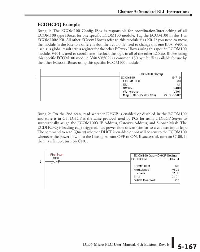
DL05 Micro PLC User Manual, 6th Edition, Rev. E 5-167
Chapter 5: Standard RLL Instructions
ECDHCPQ ExampleRung 1: The ECOM100 Config IBox is responsible for coordination/interlocking of all ECOM100 type IBoxes for one specific ECOM100 module. Tag the ECOM100 in slot 1 as ECOM100# K0. All other ECxxxx IBoxes refer to this module # as K0. If you need to move the module in the base to a different slot, then you only need to change this one IBox. V400 is used as a global result status register for the other ECxxxx IBoxes using this specific ECOM100 module. V401 is used to coordinate/interlock the logic in all of the other ECxxxx IBoxes using this specific ECOM100 module. V402-V502 is a common 130 byte buffer available for use by the other ECxxxx IBoxes using this specific ECOM100 module.
Rung 2: On the 2nd scan, read whether DHCP is enabled or disabled in the ECOM100 and store it in C5. DHCP is the same protocol used by PCs for using a DHCP Server to automatically assign the ECOM100’s IP Address, Gateway Address, and Subnet Mask. The ECDHCPQ is leading edge triggered, not power-flow driven (similar to a counter input leg). The command to read (Query) whether DHCP is enabled or not will be sent to the ECOM100 whenever the power flow into the IBox goes from OFF to ON. If successful, turn on C100. If there is a failure, turn on C101.
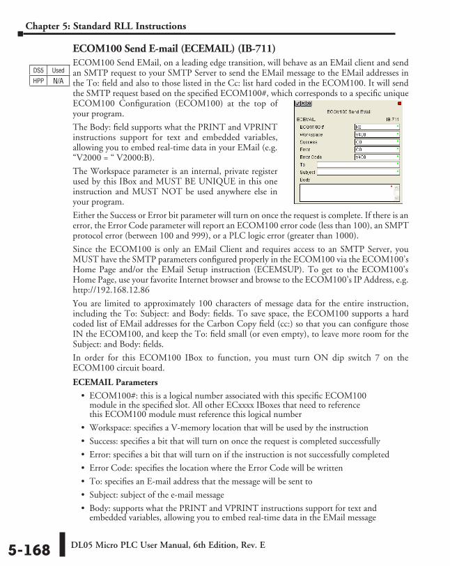
DL05 Micro PLC User Manual, 6th Edition, Rev. E5-168
Chapter 5: Standard RLL Instructions
ECOM100 Send E-mail (ECEMAIL) (IB-711)ECOM100 Send EMail, on a leading edge transition, will behave as an EMail client and send an SMTP request to your SMTP Server to send the EMail message to the EMail addresses in the To: field and also to those listed in the Cc: list hard coded in the ECOM100. It will send the SMTP request based on the specified ECOM100#, which corresponds to a specific unique ECOM100 Configuration (ECOM100) at the top of your program.
The Body: field supports what the PRINT and VPRINT instructions support for text and embedded variables, allowing you to embed real-time data in your EMail (e.g. “V2000 = “ V2000:B).
The Workspace parameter is an internal, private register used by this IBox and MUST BE UNIQUE in this one instruction and MUST NOT be used anywhere else in your program.
Either the Success or Error bit parameter will turn on once the request is complete. If there is an error, the Error Code parameter will report an ECOM100 error code (less than 100), an SMPT protocol error (between 100 and 999), or a PLC logic error (greater than 1000).
Since the ECOM100 is only an EMail Client and requires access to an SMTP Server, you MUST have the SMTP parameters configured properly in the ECOM100 via the ECOM100’s Home Page and/or the EMail Setup instruction (ECEMSUP). To get to the ECOM100’s Home Page, use your favorite Internet browser and browse to the ECOM100’s IP Address, e.g. http://192.168.12.86
You are limited to approximately 100 characters of message data for the entire instruction, including the To: Subject: and Body: fields. To save space, the ECOM100 supports a hard coded list of EMail addresses for the Carbon Copy field (cc:) so that you can configure those IN the ECOM100, and keep the To: field small (or even empty), to leave more room for the Subject: and Body: fields.
In order for this ECOM100 IBox to function, you must turn ON dip switch 7 on the ECOM100 circuit board.
ECEMAIL Parameters
• ECOM100#: this is a logical number associated with this specific ECOM100 module in the specified slot. All other ECxxxx IBoxes that need to reference this ECOM100 module must reference this logical number
• Workspace: specifies a V-memory location that will be used by the instruction
• Success: specifies a bit that will turn on once the request is completed successfully
• Error: specifies a bit that will turn on if the instruction is not successfully completed
• Error Code: specifies the location where the Error Code will be written
• To: specifies an E-mail address that the message will be sent to
• Subject: subject of the e-mail message
• Body: supports what the PRINT and VPRINT instructions support for text and embedded variables, allowing you to embed real-time data in the EMail message
DS5 Used
HPP N/A
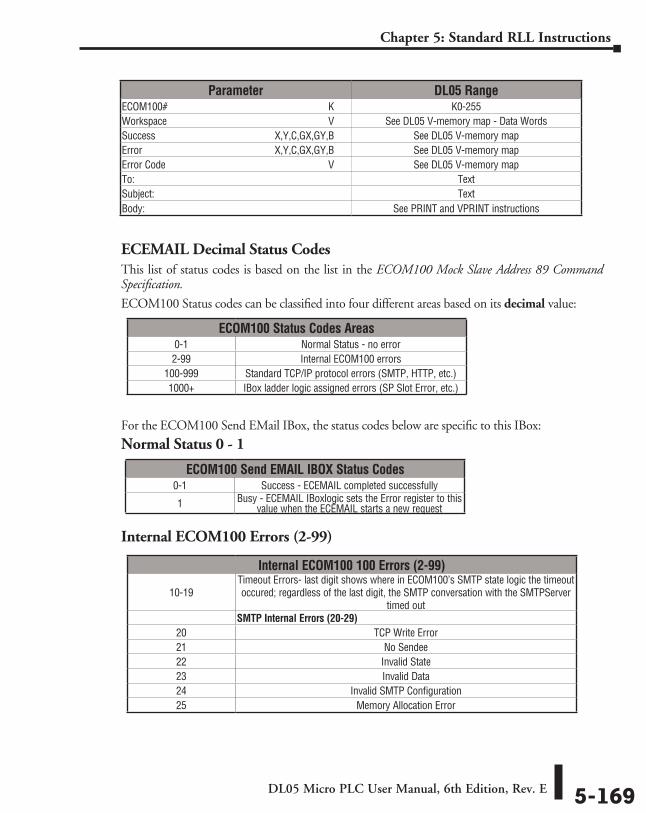
DL05 Micro PLC User Manual, 6th Edition, Rev. E 5-169
Chapter 5: Standard RLL Instructions
ECEMAIL Decimal Status CodesThis list of status codes is based on the list in the ECOM100 Mock Slave Address 89 Command Specification.
ECOM100 Status codes can be classified into four different areas based on its decimal value:
For the ECOM100 Send EMail IBox, the status codes below are specific to this IBox:
Normal Status 0 - 1
Internal ECOM100 Errors (2-99)
Parameter DL05 RangeECOM100# ⸠⸠⸠⸠⸠⸠⸠⸠⸠⸠⸠⸠⸠⸠⸠⸠⸠⸠⸠⸠⸠⸠⸠⸠⸠⸠⸠⸠⸠⸠⸠⸠⸠⸠⸠⸠⸠⸠⸠⸠⸠⸠⸠⸠⸠⸠⸠⸠⸠⸠⸠⸠⸠⸠⸠⸠⸠⸠⸠⸠⸠⸠ K K0-255Workspace ⸠⸠⸠⸠⸠⸠⸠⸠⸠⸠⸠⸠⸠⸠⸠⸠⸠⸠⸠⸠⸠⸠⸠⸠⸠⸠⸠⸠⸠⸠⸠⸠⸠⸠⸠⸠⸠⸠⸠⸠⸠⸠⸠⸠⸠⸠⸠⸠⸠⸠⸠⸠⸠⸠⸠⸠⸠⸠⸠⸠⸠⸠ V See DL05 V-memory map - Data WordsSuccess ⸠⸠⸠⸠⸠⸠⸠⸠⸠⸠⸠⸠⸠⸠⸠⸠⸠⸠⸠⸠⸠⸠⸠⸠⸠⸠⸠⸠⸠⸠⸠⸠⸠⸠⸠⸠⸠⸠⸠⸠⸠⸠⸠⸠⸠ X,Y,C,GX,GY,B See DL05 V-memory mapError ⸠⸠⸠⸠⸠⸠⸠⸠⸠⸠⸠⸠⸠⸠⸠⸠⸠⸠⸠⸠⸠⸠⸠⸠⸠⸠⸠⸠⸠⸠⸠⸠⸠⸠⸠⸠⸠⸠⸠⸠⸠⸠⸠⸠⸠⸠⸠⸠⸠⸠ X,Y,C,GX,GY,B See DL05 V-memory mapError Code ⸠⸠⸠⸠⸠⸠⸠⸠⸠⸠⸠⸠⸠⸠⸠⸠⸠⸠⸠⸠⸠⸠⸠⸠⸠⸠⸠⸠⸠⸠⸠⸠⸠⸠⸠⸠⸠⸠⸠⸠⸠⸠⸠⸠⸠⸠⸠⸠⸠⸠⸠⸠⸠⸠⸠⸠⸠⸠⸠⸠⸠⸠⸠⸠⸠ V See DL05 V-memory mapTo: ⸠⸠⸠⸠⸠⸠⸠⸠⸠⸠⸠⸠⸠⸠⸠⸠⸠⸠⸠⸠⸠⸠⸠⸠⸠⸠⸠⸠⸠⸠⸠⸠⸠⸠⸠⸠⸠⸠⸠⸠⸠⸠⸠⸠⸠⸠⸠⸠⸠⸠⸠⸠⸠⸠⸠⸠⸠⸠⸠⸠⸠⸠⸠⸠⸠⸠⸠⸠⸠⸠⸠⸠⸠⸠⸠⸠⸠⸠⸠⸠ TextSubject: ⸠⸠⸠⸠⸠⸠⸠⸠⸠⸠⸠⸠⸠⸠⸠⸠⸠⸠⸠⸠⸠⸠⸠⸠⸠⸠⸠⸠⸠⸠⸠⸠⸠⸠⸠⸠⸠⸠⸠⸠⸠⸠⸠⸠⸠⸠⸠⸠⸠⸠⸠⸠⸠⸠⸠⸠⸠⸠⸠⸠⸠⸠⸠⸠⸠⸠⸠⸠⸠⸠⸠⸠ TextBody: ⸠⸠⸠⸠⸠⸠⸠⸠⸠⸠⸠⸠⸠⸠⸠⸠⸠⸠⸠⸠⸠⸠⸠⸠⸠⸠⸠⸠⸠⸠⸠⸠⸠⸠⸠⸠⸠⸠⸠⸠⸠⸠⸠⸠⸠⸠⸠⸠⸠⸠⸠⸠⸠⸠⸠⸠⸠⸠⸠⸠⸠⸠⸠⸠⸠⸠⸠⸠⸠⸠⸠⸠⸠⸠⸠⸠ See PRINT and VPRINT instructions
ECOM100 Status Codes Areas0-1 Normal Status - no error2-99 Internal ECOM100 errors
100-999 Standard TCP/IP protocol errors (SMTP, HTTP, etc.)1000+ IBox ladder logic assigned errors (SP Slot Error, etc.)
ECOM100 Send EMAIL IBOX Status Codes0-1 Success - ECEMAIL completed successfully
1 Busy - ECEMAIL IBoxlogic sets the Error register to this value when the ECEMAIL starts a new request
Internal ECOM100 100 Errors (2-99)
10-19Timeout Errors- last digit shows where in ECOM100’s SMTP state logic the timeout occured; regardless of the last digit, the SMTP conversation with the SMTPServer
timed outSMTP Internal Errors (20-29)
20 TCP Write Error21 No Sendee22 Invalid State23 Invalid Data24 Invalid SMTP Configuration25 Memory Allocation Error
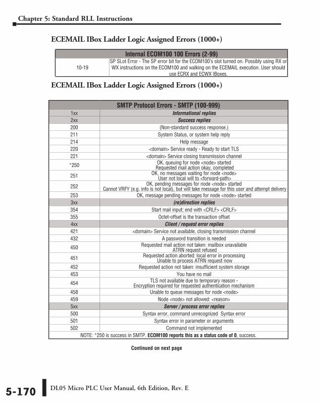
DL05 Micro PLC User Manual, 6th Edition, Rev. E5-170
Chapter 5: Standard RLL Instructions
ECEMAIL IBox Ladder Logic Assigned Errors (1000+)
ECEMAIL IBox Ladder Logic Assigned Errors (1000+)
SMTP Protocol Errors - SMTP (100-999)1xx Informational replies2xx Success replies200 (Non-standard success response.) 211 System Status, or system help reply214 Help message220 <domain> Service ready - Ready to start TLS221 <domain> Service closing transmission channel
*250 OK, queuing for node <node> started Requested mail action okay, completed
251 OK, no messages waiting for node <node> User not local will to <forward-path>
252 OK, pending messages for node <node> started Cannot VRFY (e.g. info is not local), but will take message for this user and attempt delivery
253 OK, message pending messages for node <node> started3xx (re)direction replies354 Start mail input; end with <CRLF> <CRLF>355 Octet-offset is the transaction offset4xx Client / request error replies421 <domain> Service not available, closing transmission channel432 A password transition is needed
450 Requested mail action not taken: mailbox unavailable ATRN request refused
451 Requested action aborted: local error in processing Unable to process ATRN request now
452 Requested action not taken: insufficient system storage453 You have no mail
454 TLS not available due to temporary reason - Encryption required for requested authentication mechanism
458 Unable to queue messages for node <node>459 Node <node> not allowed: <reason>5xx Server / process error replies500 Syntax error, command unrecognized Syntax error501 Syntax error in parameter or arguments502 Command not implemented
NOTE: *250 is success in SMTP. ECOM100 reports this as a status code of 0, success.
Continued on next page
Internal ECOM100 100 Errors (2-99)
10-19SP SLot Error - The SP error bit for the ECOM100’s slot turned on. Possibly using RX or WX instructions on the ECOM100 and walking on the ECEMAIL execution. User should
use ECRX and ECWX IBoxes.
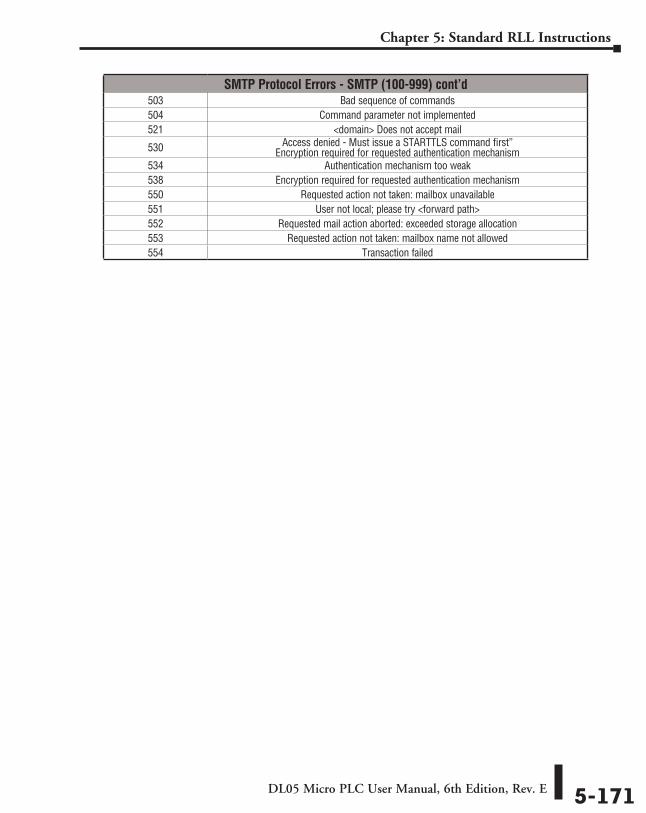
DL05 Micro PLC User Manual, 6th Edition, Rev. E 5-171
Chapter 5: Standard RLL Instructions
SMTP Protocol Errors - SMTP (100-999) cont’d503 Bad sequence of commands504 Command parameter not implemented521 <domain> Does not accept mail
530 Access denied - Must issue a STARTTLS command first” Encryption required for requested authentication mechanism
534 Authentication mechanism too weak538 Encryption required for requested authentication mechanism550 Requested action not taken: mailbox unavailable551 User not local; please try <forward path>552 Requested mail action aborted: exceeded storage allocation553 Requested action not taken: mailbox name not allowed554 Transaction failed
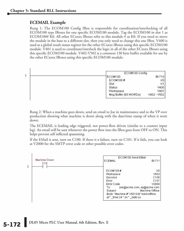
DL05 Micro PLC User Manual, 6th Edition, Rev. E5-172
Chapter 5: Standard RLL Instructions
Rung 2: When a machine goes down, send an email to Joe in maintenance and to the VP over production showing what machine is down along with the date/time stamp of when it went down.
The ECEMAIL is leading edge triggered, not power-flow driven (similar to a counter input leg). An email will be sent whenever the power flow into the IBox goes from OFF to ON. This helps prevent self inflicted spamming.
If the EMail is sent, turn on C100. If there is a failure, turn on C101. If it fails, you can look at V2000 for the SMTP error code or other possible error codes.
ECEMAIL ExampleRung 1: The ECOM100 Config IBox is responsible for coordination/interlocking of all ECOM100 type IBoxes for one specific ECOM100 module. Tag the ECOM100 in slot 1 as ECOM100# K0. All other ECxxxx IBoxes refer to this module # as K0. If you need to move the module in the base to a different slot, then you only need to change this one IBox. V400 is used as a global result status register for the other ECxxxx IBoxes using this specific ECOM100 module. V401 is used to coordinate/interlock the logic in all of the other ECxxxx IBoxes using this specific ECOM100 module. V402-V502 is a common 130 byte buffer available for use by the other ECxxxx IBoxes using this specific ECOM100 module.
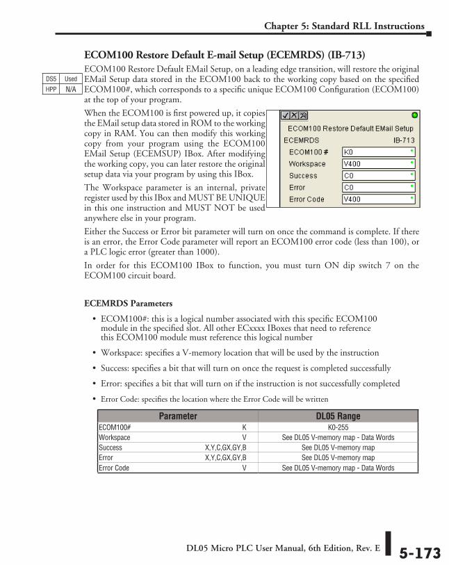
DL05 Micro PLC User Manual, 6th Edition, Rev. E 5-173
Chapter 5: Standard RLL Instructions
ECOM100 Restore Default E-mail Setup (ECEMRDS) (IB-713)ECOM100 Restore Default EMail Setup, on a leading edge transition, will restore the original EMail Setup data stored in the ECOM100 back to the working copy based on the specified ECOM100#, which corresponds to a specific unique ECOM100 Configuration (ECOM100) at the top of your program.
When the ECOM100 is first powered up, it copies the EMail setup data stored in ROM to the working copy in RAM. You can then modify this working copy from your program using the ECOM100 EMail Setup (ECEMSUP) IBox. After modifying the working copy, you can later restore the original setup data via your program by using this IBox.
The Workspace parameter is an internal, private register used by this IBox and MUST BE UNIQUE in this one instruction and MUST NOT be used anywhere else in your program.
Either the Success or Error bit parameter will turn on once the command is complete. If there is an error, the Error Code parameter will report an ECOM100 error code (less than 100), or a PLC logic error (greater than 1000).
In order for this ECOM100 IBox to function, you must turn ON dip switch 7 on the ECOM100 circuit board.
ECEMRDS Parameters
• ECOM100#: this is a logical number associated with this specific ECOM100 module in the specified slot. All other ECxxxx IBoxes that need to reference this ECOM100 module must reference this logical number
• Workspace: specifies a V-memory location that will be used by the instruction
• Success: specifies a bit that will turn on once the request is completed successfully
• Error: specifies a bit that will turn on if the instruction is not successfully completed
• Error Code: specifies the location where the Error Code will be written
DS5 Used
HPP N/A
Parameter DL05 RangeECOM100# ⸠⸠⸠⸠⸠⸠⸠⸠⸠⸠⸠⸠⸠⸠⸠⸠⸠⸠⸠⸠⸠⸠⸠⸠⸠⸠⸠⸠⸠⸠⸠⸠⸠⸠⸠⸠⸠⸠⸠⸠⸠⸠⸠⸠⸠⸠⸠⸠⸠⸠⸠⸠⸠⸠⸠⸠⸠⸠⸠⸠⸠⸠ K K0-255Workspace ⸠⸠⸠⸠⸠⸠⸠⸠⸠⸠⸠⸠⸠⸠⸠⸠⸠⸠⸠⸠⸠⸠⸠⸠⸠⸠⸠⸠⸠⸠⸠⸠⸠⸠⸠⸠⸠⸠⸠⸠⸠⸠⸠⸠⸠⸠⸠⸠⸠⸠⸠⸠⸠⸠⸠⸠⸠⸠⸠⸠⸠⸠ V See DL05 V-memory map - Data WordsSuccess ⸠⸠⸠⸠⸠⸠⸠⸠⸠⸠⸠⸠⸠⸠⸠⸠⸠⸠⸠⸠⸠⸠⸠⸠⸠⸠⸠⸠⸠⸠⸠⸠⸠⸠⸠⸠⸠⸠⸠⸠⸠⸠⸠⸠⸠ X,Y,C,GX,GY,B See DL05 V-memory mapError ⸠⸠⸠⸠⸠⸠⸠⸠⸠⸠⸠⸠⸠⸠⸠⸠⸠⸠⸠⸠⸠⸠⸠⸠⸠⸠⸠⸠⸠⸠⸠⸠⸠⸠⸠⸠⸠⸠⸠⸠⸠⸠⸠⸠⸠⸠⸠⸠⸠⸠ X,Y,C,GX,GY,B See DL05 V-memory mapError Code ⸠⸠⸠⸠⸠⸠⸠⸠⸠⸠⸠⸠⸠⸠⸠⸠⸠⸠⸠⸠⸠⸠⸠⸠⸠⸠⸠⸠⸠⸠⸠⸠⸠⸠⸠⸠⸠⸠⸠⸠⸠⸠⸠⸠⸠⸠⸠⸠⸠⸠⸠⸠⸠⸠⸠⸠⸠⸠⸠⸠⸠⸠⸠⸠⸠ V See DL05 V-memory map - Data Words
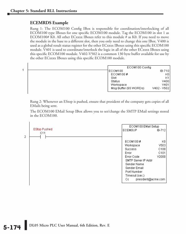
DL05 Micro PLC User Manual, 6th Edition, Rev. E5-174
Chapter 5: Standard RLL Instructions
ECEMRDS ExampleRung 1: The ECOM100 Config IBox is responsible for coordination/interlocking of all ECOM100 type IBoxes for one specific ECOM100 module. Tag the ECOM100 in slot 1 as ECOM100# K0. All other ECxxxx IBoxes refer to this module # as K0. If you need to move the module in the base to a different slot, then you only need to change this one IBox. V400 is used as a global result status register for the other ECxxxx IBoxes using this specific ECOM100 module. V401 is used to coordinate/interlock the logic in all of the other ECxxxx IBoxes using this specific ECOM100 module. V402-V502 is a common 130 byte buffer available for use by the other ECxxxx IBoxes using this specific ECOM100 module.
Rung 2: Whenever an EStop is pushed, ensure that president of the company gets copies of all EMails being sent.
The ECOM100 EMail Setup IBox allows you to set/change the SMTP EMail settings stored in the ECOM100.
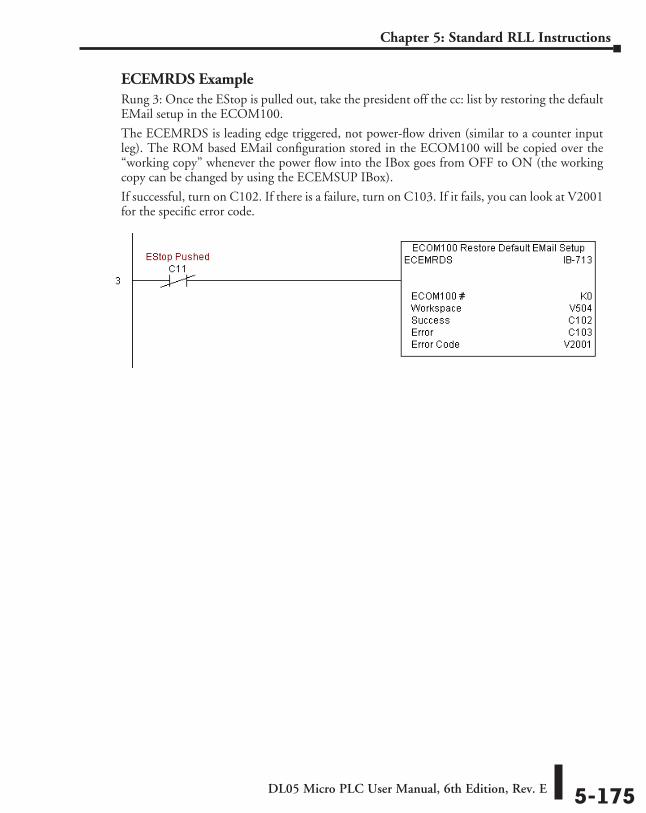
DL05 Micro PLC User Manual, 6th Edition, Rev. E 5-175
Chapter 5: Standard RLL Instructions
ECEMRDS ExampleRung 3: Once the EStop is pulled out, take the president off the cc: list by restoring the default EMail setup in the ECOM100.
The ECEMRDS is leading edge triggered, not power-flow driven (similar to a counter input leg). The ROM based EMail configuration stored in the ECOM100 will be copied over the “working copy” whenever the power flow into the IBox goes from OFF to ON (the working copy can be changed by using the ECEMSUP IBox).
If successful, turn on C102. If there is a failure, turn on C103. If it fails, you can look at V2001 for the specific error code.
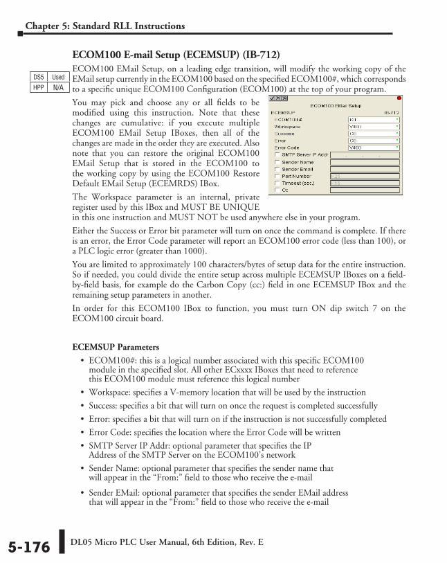
DL05 Micro PLC User Manual, 6th Edition, Rev. E5-176
Chapter 5: Standard RLL Instructions
ECOM100 E-mail Setup (ECEMSUP) (IB-712)ECOM100 EMail Setup, on a leading edge transition, will modify the working copy of the EMail setup currently in the ECOM100 based on the specified ECOM100#, which corresponds to a specific unique ECOM100 Configuration (ECOM100) at the top of your program.
You may pick and choose any or all fields to be modified using this instruction. Note that these changes are cumulative: if you execute multiple ECOM100 EMail Setup IBoxes, then all of the changes are made in the order they are executed. Also note that you can restore the original ECOM100 EMail Setup that is stored in the ECOM100 to the working copy by using the ECOM100 Restore Default EMail Setup (ECEMRDS) IBox.
The Workspace parameter is an internal, private register used by this IBox and MUST BE UNIQUE in this one instruction and MUST NOT be used anywhere else in your program.
Either the Success or Error bit parameter will turn on once the command is complete. If there is an error, the Error Code parameter will report an ECOM100 error code (less than 100), or a PLC logic error (greater than 1000).
You are limited to approximately 100 characters/bytes of setup data for the entire instruction. So if needed, you could divide the entire setup across multiple ECEMSUP IBoxes on a field-by-field basis, for example do the Carbon Copy (cc:) field in one ECEMSUP IBox and the remaining setup parameters in another.
In order for this ECOM100 IBox to function, you must turn ON dip switch 7 on the ECOM100 circuit board.
ECEMSUP Parameters
• ECOM100#: this is a logical number associated with this specific ECOM100 module in the specified slot. All other ECxxxx IBoxes that need to reference this ECOM100 module must reference this logical number
• Workspace: specifies a V-memory location that will be used by the instruction
• Success: specifies a bit that will turn on once the request is completed successfully
• Error: specifies a bit that will turn on if the instruction is not successfully completed
• Error Code: specifies the location where the Error Code will be written
• SMTP Server IP Addr: optional parameter that specifies the IP Address of the SMTP Server on the ECOM100’s network
• Sender Name: optional parameter that specifies the sender name that will appear in the “From:” field to those who receive the e-mail
• Sender EMail: optional parameter that specifies the sender EMail address that will appear in the “From:” field to those who receive the e-mail
DS5 Used
HPP N/A
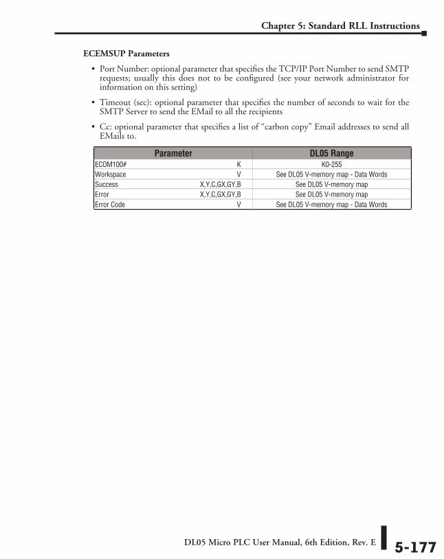
DL05 Micro PLC User Manual, 6th Edition, Rev. E 5-177
Chapter 5: Standard RLL Instructions
ECEMSUP Parameters
• Port Number: optional parameter that specifies the TCP/IP Port Number to send SMTP requests; usually this does not to be configured (see your network administrator for information on this setting)
• Timeout (sec): optional parameter that specifies the number of seconds to wait for the SMTP Server to send the EMail to all the recipients
• Cc: optional parameter that specifies a list of “carbon copy” Email addresses to send all EMails to.
Parameter DL05 RangeECOM100# ⸠⸠⸠⸠⸠⸠⸠⸠⸠⸠⸠⸠⸠⸠⸠⸠⸠⸠⸠⸠⸠⸠⸠⸠⸠⸠⸠⸠⸠⸠⸠⸠⸠⸠⸠⸠⸠⸠⸠⸠⸠⸠⸠⸠⸠⸠⸠⸠⸠⸠⸠⸠⸠⸠⸠⸠⸠⸠⸠⸠⸠⸠ K K0-255Workspace ⸠⸠⸠⸠⸠⸠⸠⸠⸠⸠⸠⸠⸠⸠⸠⸠⸠⸠⸠⸠⸠⸠⸠⸠⸠⸠⸠⸠⸠⸠⸠⸠⸠⸠⸠⸠⸠⸠⸠⸠⸠⸠⸠⸠⸠⸠⸠⸠⸠⸠⸠⸠⸠⸠⸠⸠⸠⸠⸠⸠⸠⸠ V See DL05 V-memory map - Data WordsSuccess ⸠⸠⸠⸠⸠⸠⸠⸠⸠⸠⸠⸠⸠⸠⸠⸠⸠⸠⸠⸠⸠⸠⸠⸠⸠⸠⸠⸠⸠⸠⸠⸠⸠⸠⸠⸠⸠⸠⸠⸠⸠⸠⸠⸠⸠ X,Y,C,GX,GY,B See DL05 V-memory mapError ⸠⸠⸠⸠⸠⸠⸠⸠⸠⸠⸠⸠⸠⸠⸠⸠⸠⸠⸠⸠⸠⸠⸠⸠⸠⸠⸠⸠⸠⸠⸠⸠⸠⸠⸠⸠⸠⸠⸠⸠⸠⸠⸠⸠⸠⸠⸠⸠⸠⸠ X,Y,C,GX,GY,B See DL05 V-memory mapError Code ⸠⸠⸠⸠⸠⸠⸠⸠⸠⸠⸠⸠⸠⸠⸠⸠⸠⸠⸠⸠⸠⸠⸠⸠⸠⸠⸠⸠⸠⸠⸠⸠⸠⸠⸠⸠⸠⸠⸠⸠⸠⸠⸠⸠⸠⸠⸠⸠⸠⸠⸠⸠⸠⸠⸠⸠⸠⸠⸠⸠⸠⸠⸠⸠⸠ V See DL05 V-memory map - Data Words
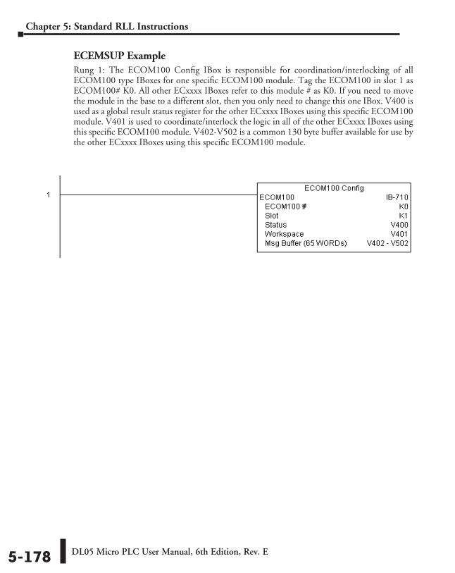
DL05 Micro PLC User Manual, 6th Edition, Rev. E5-178
Chapter 5: Standard RLL Instructions
ECEMSUP ExampleRung 1: The ECOM100 Config IBox is responsible for coordination/interlocking of all ECOM100 type IBoxes for one specific ECOM100 module. Tag the ECOM100 in slot 1 as ECOM100# K0. All other ECxxxx IBoxes refer to this module # as K0. If you need to move the module in the base to a different slot, then you only need to change this one IBox. V400 is used as a global result status register for the other ECxxxx IBoxes using this specific ECOM100 module. V401 is used to coordinate/interlock the logic in all of the other ECxxxx IBoxes using this specific ECOM100 module. V402-V502 is a common 130 byte buffer available for use by the other ECxxxx IBoxes using this specific ECOM100 module.
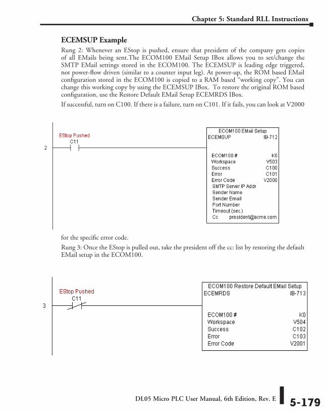
DL05 Micro PLC User Manual, 6th Edition, Rev. E 5-179
Chapter 5: Standard RLL Instructions
ECEMSUP ExampleRung 2: Whenever an EStop is pushed, ensure that president of the company gets copies of all EMails being sent.The ECOM100 EMail Setup IBox allows you to set/change the SMTP EMail settings stored in the ECOM100. The ECEMSUP is leading edge triggered, not power-flow driven (similar to a counter input leg). At power-up, the ROM based EMail configuration stored in the ECOM100 is copied to a RAM based “working copy”. You can change this working copy by using the ECEMSUP IBox. To restore the original ROM based configuration, use the Restore Default EMail Setup ECEMRDS IBox.
If successful, turn on C100. If there is a failure, turn on C101. If it fails, you can look at V2000
for the specific error code.
Rung 3: Once the EStop is pulled out, take the president off the cc: list by restoring the default EMail setup in the ECOM100.
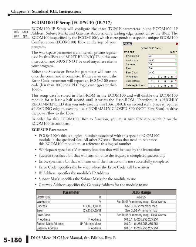
DL05 Micro PLC User Manual, 6th Edition, Rev. E5-180
Chapter 5: Standard RLL Instructions
ECOM100 IP Setup (ECIPSUP) (IB-717)ECOM100 IP Setup will configure the three TCP/IP parameters in the ECOM100: IP Address, Subnet Mask, and Gateway Address, on a leading edge transition to the IBox. The ECOM100 is specified by the ECOM100#, which corresponds to a specific unique ECOM100 Configuration (ECOM100) IBox at the top of your program.
The Workspace parameter is an internal, private register used by this IBox and MUST BE UNIQUE in this one instruction and MUST NOT be used anywhere else in your program.
Either the Success or Error bit parameter will turn on once the command is complete. If there is an error, the Error Code parameter will report an ECOM100 error code (less than 100), or a PLC logic error (greater than 1000).
This setup data is stored in Flash-ROM in the ECOM100 and will disable the ECOM100 module for at least a half second until it writes the Flash-ROM. Therefore, it is HIGHLY RECOMMENDED that you only execute this IBox ONCE on second scan. Since it requires a LEADING edge to execute, use a NORMALLY CLOSED SP0 (NOT First Scan) to drive the power flow to the IBox.
In order for this ECOM100 IBox to function, you must turn ON dip switch 7 on the ECOM100 circuit board.
ECIPSUP Parameters
• ECOM100#: this is a logical number associated with this specific ECOM100 module in the specified slot. All other ECxxxx IBoxes that need to reference this ECOM100 module must reference this logical number
• Workspace: specifies a V-memory location that will be used by the instruction
• Success: specifies a bit that will turn on once the request is completed successfully
• Error: specifies a bit that will turn on if the instruction is not successfully completed
• Error Code: specifies the location where the Error Code will be written
• IP Address: specifies the module’s IP Address
• Subnet Mask: specifies the Subnet Mask for the module to use
• Gateway Address: specifies the Gateway Address for the module to use
DS5 Used
HPP N/A
Parameter DL05 RangeECOM100# ⸠⸠⸠⸠⸠⸠⸠⸠⸠⸠⸠⸠⸠⸠⸠⸠⸠⸠⸠⸠⸠⸠⸠⸠⸠⸠⸠⸠⸠⸠⸠⸠⸠⸠⸠⸠⸠⸠⸠⸠⸠⸠⸠⸠⸠⸠⸠⸠⸠⸠⸠⸠⸠⸠⸠⸠⸠⸠⸠⸠⸠⸠ K K0-255Workspace ⸠⸠⸠⸠⸠⸠⸠⸠⸠⸠⸠⸠⸠⸠⸠⸠⸠⸠⸠⸠⸠⸠⸠⸠⸠⸠⸠⸠⸠⸠⸠⸠⸠⸠⸠⸠⸠⸠⸠⸠⸠⸠⸠⸠⸠⸠⸠⸠⸠⸠⸠⸠⸠⸠⸠⸠⸠⸠⸠⸠⸠⸠ V See DL05 V-memory map - Data WordsSuccess ⸠⸠⸠⸠⸠⸠⸠⸠⸠⸠⸠⸠⸠⸠⸠⸠⸠⸠⸠⸠⸠⸠⸠⸠⸠⸠⸠⸠⸠⸠⸠⸠⸠⸠⸠⸠⸠⸠⸠⸠⸠⸠⸠⸠⸠ X,Y,C,GX,GY,B See DL05 V-memory mapError ⸠⸠⸠⸠⸠⸠⸠⸠⸠⸠⸠⸠⸠⸠⸠⸠⸠⸠⸠⸠⸠⸠⸠⸠⸠⸠⸠⸠⸠⸠⸠⸠⸠⸠⸠⸠⸠⸠⸠⸠⸠⸠⸠⸠⸠⸠⸠⸠⸠⸠ X,Y,C,GX,GY,B See DL05 V-memory mapError Code ⸠⸠⸠⸠⸠⸠⸠⸠⸠⸠⸠⸠⸠⸠⸠⸠⸠⸠⸠⸠⸠⸠⸠⸠⸠⸠⸠⸠⸠⸠⸠⸠⸠⸠⸠⸠⸠⸠⸠⸠⸠⸠⸠⸠⸠⸠⸠⸠⸠⸠⸠⸠⸠⸠⸠⸠⸠⸠⸠⸠⸠⸠⸠⸠⸠ V See DL05 V-memory map - Data WordsIP Address ⸠⸠⸠⸠⸠⸠⸠⸠⸠⸠⸠⸠⸠⸠⸠⸠⸠⸠⸠⸠⸠⸠⸠⸠⸠⸠⸠⸠⸠⸠⸠⸠⸠⸠⸠⸠⸠⸠⸠⸠⸠⸠⸠⸠⸠⸠⸠⸠⸠⸠IP Address 0.0.0.1. to 255.255.255.254Subnet Mask Address ⸠⸠⸠⸠⸠⸠⸠⸠⸠⸠⸠⸠⸠⸠⸠⸠⸠⸠⸠⸠⸠⸠IP Address Mask 0.0.0.1. to 255.255.255.254Gateway Address ⸠⸠⸠⸠⸠⸠⸠⸠⸠⸠⸠⸠⸠⸠⸠⸠⸠⸠⸠⸠⸠⸠⸠⸠⸠⸠⸠⸠⸠⸠⸠⸠⸠⸠⸠⸠⸠⸠⸠IP Address 0.0.0.1. to 255.255.255.254
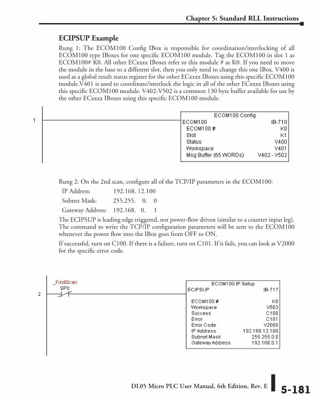
DL05 Micro PLC User Manual, 6th Edition, Rev. E 5-181
Chapter 5: Standard RLL Instructions
ECIPSUP ExampleRung 1: The ECOM100 Config IBox is responsible for coordination/interlocking of all ECOM100 type IBoxes for one specific ECOM100 module. Tag the ECOM100 in slot 1 as ECOM100# K0. All other ECxxxx IBoxes refer to this module # as K0. If you need to move the module in the base to a different slot, then you only need to change this one IBox. V400 is used as a global result status register for the other ECxxxx IBoxes using this specific ECOM100 module.V401 is used to coordinate/interlock the logic in all of the other ECxxxx IBoxes using this specific ECOM100 module. V402-V502 is a common 130 byte buffer available for use by the other ECxxxx IBoxes using this specific ECOM100 module.
Rung 2: On the 2nd scan, configure all of the TCP/IP parameters in the ECOM100:
IP Address: 192.168. 12.100
Subnet Mask: 255.255. 0. 0
Gateway Address: 192.168. 0. 1
The ECIPSUP is leading edge triggered, not power-flow driven (similar to a counter input leg). The command to write the TCP/IP configuration parameters will be sent to the ECOM100 whenever the power flow into the IBox goes from OFF to ON.
If successful, turn on C100. If there is a failure, turn on C101. If it fails, you can look at V2000 for the specific error code.
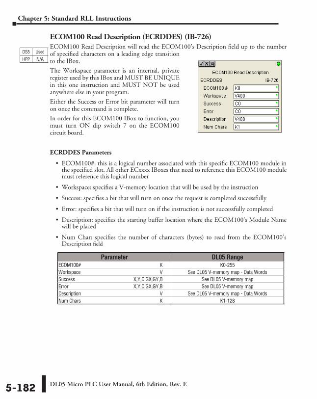
DL05 Micro PLC User Manual, 6th Edition, Rev. E5-182
Chapter 5: Standard RLL Instructions
ECOM100 Read Description (ECRDDES) (IB-726)ECOM100 Read Description will read the ECOM100’s Description field up to the number of specified characters on a leading edge transition to the IBox.
The Workspace parameter is an internal, private register used by this IBox and MUST BE UNIQUE in this one instruction and MUST NOT be used anywhere else in your program.
Either the Success or Error bit parameter will turn on once the command is complete.
In order for this ECOM100 IBox to function, you must turn ON dip switch 7 on the ECOM100 circuit board.
ECRDDES Parameters
• ECOM100#: this is a logical number associated with this specific ECOM100 module in the specified slot. All other ECxxxx IBoxes that need to reference this ECOM100 module must reference this logical number
• Workspace: specifies a V-memory location that will be used by the instruction
• Success: specifies a bit that will turn on once the request is completed successfully
• Error: specifies a bit that will turn on if the instruction is not successfully completed
• Description: specifies the starting buffer location where the ECOM100’s Module Name will be placed
• Num Char: specifies the number of characters (bytes) to read from the ECOM100’s Description field
DS5 Used
HPP N/A
Parameter DL05 RangeECOM100# ⸠⸠⸠⸠⸠⸠⸠⸠⸠⸠⸠⸠⸠⸠⸠⸠⸠⸠⸠⸠⸠⸠⸠⸠⸠⸠⸠⸠⸠⸠⸠⸠⸠⸠⸠⸠⸠⸠⸠⸠⸠⸠⸠⸠⸠⸠⸠⸠⸠⸠⸠⸠⸠⸠⸠⸠⸠⸠⸠⸠⸠⸠ K K0-255Workspace ⸠⸠⸠⸠⸠⸠⸠⸠⸠⸠⸠⸠⸠⸠⸠⸠⸠⸠⸠⸠⸠⸠⸠⸠⸠⸠⸠⸠⸠⸠⸠⸠⸠⸠⸠⸠⸠⸠⸠⸠⸠⸠⸠⸠⸠⸠⸠⸠⸠⸠⸠⸠⸠⸠⸠⸠⸠⸠⸠⸠⸠⸠ V See DL05 V-memory map - Data WordsSuccess ⸠⸠⸠⸠⸠⸠⸠⸠⸠⸠⸠⸠⸠⸠⸠⸠⸠⸠⸠⸠⸠⸠⸠⸠⸠⸠⸠⸠⸠⸠⸠⸠⸠⸠⸠⸠⸠⸠⸠⸠⸠⸠⸠⸠⸠ X,Y,C,GX,GY,B See DL05 V-memory mapError ⸠⸠⸠⸠⸠⸠⸠⸠⸠⸠⸠⸠⸠⸠⸠⸠⸠⸠⸠⸠⸠⸠⸠⸠⸠⸠⸠⸠⸠⸠⸠⸠⸠⸠⸠⸠⸠⸠⸠⸠⸠⸠⸠⸠⸠⸠⸠⸠⸠⸠ X,Y,C,GX,GY,B See DL05 V-memory mapDescription ⸠⸠⸠⸠⸠⸠⸠⸠⸠⸠⸠⸠⸠⸠⸠⸠⸠⸠⸠⸠⸠⸠⸠⸠⸠⸠⸠⸠⸠⸠⸠⸠⸠⸠⸠⸠⸠⸠⸠⸠⸠⸠⸠⸠⸠⸠⸠⸠⸠⸠⸠⸠⸠⸠⸠⸠⸠⸠⸠⸠⸠⸠ V See DL05 V-memory map - Data WordsNum Chars ⸠⸠⸠⸠⸠⸠⸠⸠⸠⸠⸠⸠⸠⸠⸠⸠⸠⸠⸠⸠⸠⸠⸠⸠⸠⸠⸠⸠⸠⸠⸠⸠⸠⸠⸠⸠⸠⸠⸠⸠⸠⸠⸠⸠⸠⸠⸠⸠⸠⸠⸠⸠⸠⸠⸠⸠⸠⸠⸠⸠⸠⸠⸠⸠ K K1-128
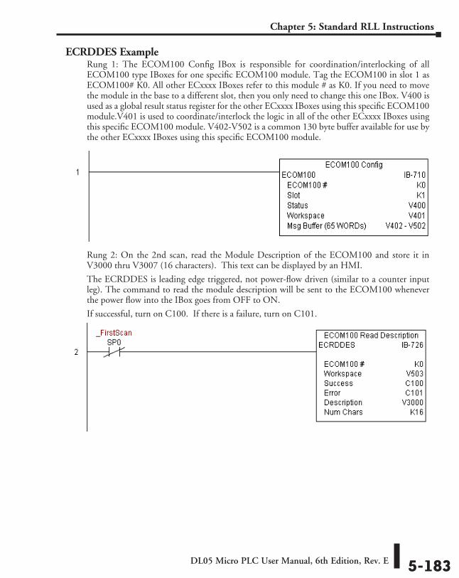
DL05 Micro PLC User Manual, 6th Edition, Rev. E 5-183
Chapter 5: Standard RLL Instructions
ECRDDES ExampleRung 1: The ECOM100 Config IBox is responsible for coordination/interlocking of all ECOM100 type IBoxes for one specific ECOM100 module. Tag the ECOM100 in slot 1 as ECOM100# K0. All other ECxxxx IBoxes refer to this module # as K0. If you need to move the module in the base to a different slot, then you only need to change this one IBox. V400 is used as a global result status register for the other ECxxxx IBoxes using this specific ECOM100 module.V401 is used to coordinate/interlock the logic in all of the other ECxxxx IBoxes using this specific ECOM100 module. V402-V502 is a common 130 byte buffer available for use by the other ECxxxx IBoxes using this specific ECOM100 module.
Rung 2: On the 2nd scan, read the Module Description of the ECOM100 and store it in V3000 thru V3007 (16 characters). This text can be displayed by an HMI.
The ECRDDES is leading edge triggered, not power-flow driven (similar to a counter input leg). The command to read the module description will be sent to the ECOM100 whenever the power flow into the IBox goes from OFF to ON.
If successful, turn on C100. If there is a failure, turn on C101.
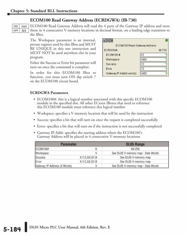
DL05 Micro PLC User Manual, 6th Edition, Rev. E5-184
Chapter 5: Standard RLL Instructions
ECOM100 Read Gateway Address (ECRDGWA) (IB-730)ECOM100 Read Gateway Address will read the 4 parts of the Gateway IP address and store them in 4 consecutive V-memory locations in decimal format, on a leading edge transition to the IBox.
The Workspace parameter is an internal, private register used by this IBox and MUST BE UNIQUE in this one instruction and MUST NOT be used anywhere else in your program.
Either the Success or Error bit parameter will turn on once the command is complete.
In order for this ECOM100 IBox to function, you must turn ON dip switch 7 on the ECOM100 circuit board.
ECRDGWA Parameters
• ECOM100#: this is a logical number associated with this specific ECOM100 module in the specified slot. All other ECxxxx IBoxes that need to reference this ECOM100 module must reference this logical number
• Workspace: specifies a V-memory location that will be used by the instruction
• Success: specifies a bit that will turn on once the request is completed successfully
• Error: specifies a bit that will turn on if the instruction is not successfully completed
• Gateway IP Addr: specifies the starting address where the ECOM100’s Gateway Address will be placed in 4 consecutive V-memory locations
DS5 Used
HPP N/A
Parameter DL05 RangeECOM100# ⸠⸠⸠⸠⸠⸠⸠⸠⸠⸠⸠⸠⸠⸠⸠⸠⸠⸠⸠⸠⸠⸠⸠⸠⸠⸠⸠⸠⸠⸠⸠⸠⸠⸠⸠⸠⸠⸠⸠⸠⸠⸠⸠⸠⸠⸠⸠⸠⸠⸠⸠⸠⸠⸠⸠⸠⸠⸠⸠⸠⸠⸠ K K0-255Workspace ⸠⸠⸠⸠⸠⸠⸠⸠⸠⸠⸠⸠⸠⸠⸠⸠⸠⸠⸠⸠⸠⸠⸠⸠⸠⸠⸠⸠⸠⸠⸠⸠⸠⸠⸠⸠⸠⸠⸠⸠⸠⸠⸠⸠⸠⸠⸠⸠⸠⸠⸠⸠⸠⸠⸠⸠⸠⸠⸠⸠⸠⸠ V See DL05 V-memory map - Data WordsSuccess ⸠⸠⸠⸠⸠⸠⸠⸠⸠⸠⸠⸠⸠⸠⸠⸠⸠⸠⸠⸠⸠⸠⸠⸠⸠⸠⸠⸠⸠⸠⸠⸠⸠⸠⸠⸠⸠⸠⸠⸠⸠⸠⸠⸠⸠ X,Y,C,GX,GY,B See DL05 V-memory mapError ⸠⸠⸠⸠⸠⸠⸠⸠⸠⸠⸠⸠⸠⸠⸠⸠⸠⸠⸠⸠⸠⸠⸠⸠⸠⸠⸠⸠⸠⸠⸠⸠⸠⸠⸠⸠⸠⸠⸠⸠⸠⸠⸠⸠⸠⸠⸠⸠⸠⸠ X,Y,C,GX,GY,B See DL05 V-memory mapGateway IP Address (4 Words) ⸠⸠⸠⸠⸠⸠⸠⸠⸠⸠⸠⸠⸠⸠⸠⸠⸠⸠⸠⸠⸠⸠⸠⸠⸠⸠⸠⸠⸠⸠⸠⸠ V See DL05 V-memory map - Data Words
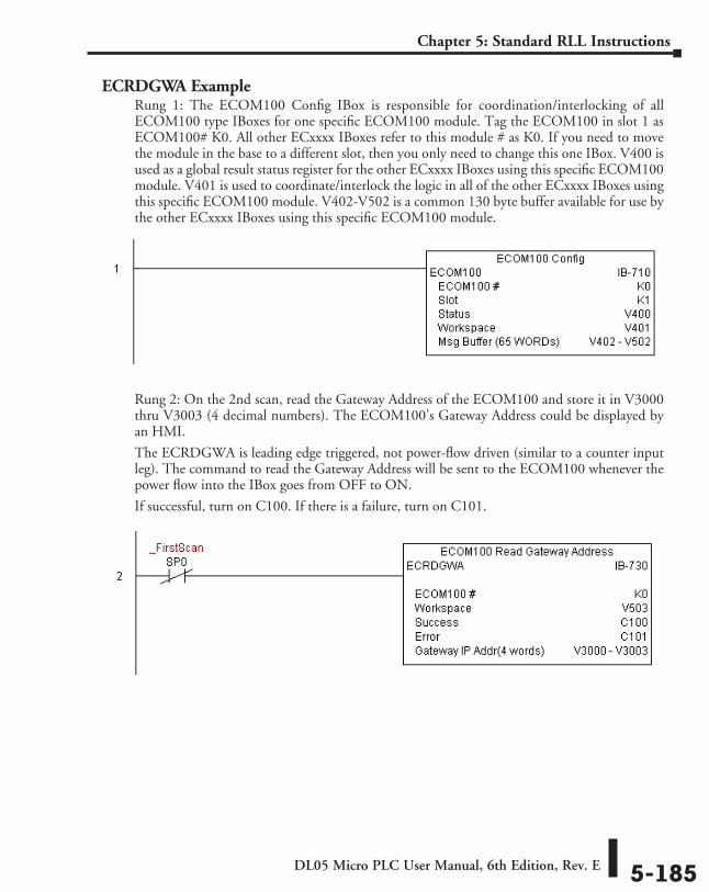
DL05 Micro PLC User Manual, 6th Edition, Rev. E 5-185
Chapter 5: Standard RLL Instructions
ECRDGWA ExampleRung 1: The ECOM100 Config IBox is responsible for coordination/interlocking of all ECOM100 type IBoxes for one specific ECOM100 module. Tag the ECOM100 in slot 1 as ECOM100# K0. All other ECxxxx IBoxes refer to this module # as K0. If you need to move the module in the base to a different slot, then you only need to change this one IBox. V400 is used as a global result status register for the other ECxxxx IBoxes using this specific ECOM100 module. V401 is used to coordinate/interlock the logic in all of the other ECxxxx IBoxes using this specific ECOM100 module. V402-V502 is a common 130 byte buffer available for use by the other ECxxxx IBoxes using this specific ECOM100 module.
Rung 2: On the 2nd scan, read the Gateway Address of the ECOM100 and store it in V3000 thru V3003 (4 decimal numbers). The ECOM100’s Gateway Address could be displayed by an HMI.
The ECRDGWA is leading edge triggered, not power-flow driven (similar to a counter input leg). The command to read the Gateway Address will be sent to the ECOM100 whenever the power flow into the IBox goes from OFF to ON.
If successful, turn on C100. If there is a failure, turn on C101.
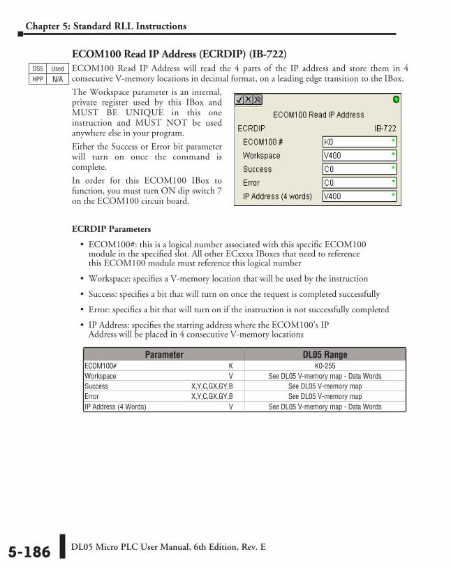
DL05 Micro PLC User Manual, 6th Edition, Rev. E5-186
Chapter 5: Standard RLL Instructions
ECOM100 Read IP Address (ECRDIP) (IB-722)ECOM100 Read IP Address will read the 4 parts of the IP address and store them in 4 consecutive V-memory locations in decimal format, on a leading edge transition to the IBox.
The Workspace parameter is an internal, private register used by this IBox and MUST BE UNIQUE in this one instruction and MUST NOT be used anywhere else in your program.
Either the Success or Error bit parameter will turn on once the command is complete.
In order for this ECOM100 IBox to function, you must turn ON dip switch 7 on the ECOM100 circuit board.
ECRDIP Parameters
• ECOM100#: this is a logical number associated with this specific ECOM100 module in the specified slot. All other ECxxxx IBoxes that need to reference this ECOM100 module must reference this logical number
• Workspace: specifies a V-memory location that will be used by the instruction
• Success: specifies a bit that will turn on once the request is completed successfully
• Error: specifies a bit that will turn on if the instruction is not successfully completed
• IP Address: specifies the starting address where the ECOM100’s IP Address will be placed in 4 consecutive V-memory locations
DS5 Used
HPP N/A
Parameter DL05 RangeECOM100# ⸠⸠⸠⸠⸠⸠⸠⸠⸠⸠⸠⸠⸠⸠⸠⸠⸠⸠⸠⸠⸠⸠⸠⸠⸠⸠⸠⸠⸠⸠⸠⸠⸠⸠⸠⸠⸠⸠⸠⸠⸠⸠⸠⸠⸠⸠⸠⸠⸠⸠⸠⸠⸠⸠⸠⸠⸠⸠⸠⸠⸠⸠ K K0-255Workspace ⸠⸠⸠⸠⸠⸠⸠⸠⸠⸠⸠⸠⸠⸠⸠⸠⸠⸠⸠⸠⸠⸠⸠⸠⸠⸠⸠⸠⸠⸠⸠⸠⸠⸠⸠⸠⸠⸠⸠⸠⸠⸠⸠⸠⸠⸠⸠⸠⸠⸠⸠⸠⸠⸠⸠⸠⸠⸠⸠⸠⸠⸠ V See DL05 V-memory map - Data WordsSuccess ⸠⸠⸠⸠⸠⸠⸠⸠⸠⸠⸠⸠⸠⸠⸠⸠⸠⸠⸠⸠⸠⸠⸠⸠⸠⸠⸠⸠⸠⸠⸠⸠⸠⸠⸠⸠⸠⸠⸠⸠⸠⸠⸠⸠⸠ X,Y,C,GX,GY,B See DL05 V-memory mapError ⸠⸠⸠⸠⸠⸠⸠⸠⸠⸠⸠⸠⸠⸠⸠⸠⸠⸠⸠⸠⸠⸠⸠⸠⸠⸠⸠⸠⸠⸠⸠⸠⸠⸠⸠⸠⸠⸠⸠⸠⸠⸠⸠⸠⸠⸠⸠⸠⸠⸠ X,Y,C,GX,GY,B See DL05 V-memory mapIP Address (4 Words) ⸠⸠⸠⸠⸠⸠⸠⸠⸠⸠⸠⸠⸠⸠⸠⸠⸠⸠⸠⸠⸠⸠⸠⸠⸠⸠⸠⸠⸠⸠⸠⸠⸠⸠⸠⸠⸠⸠⸠⸠⸠⸠⸠⸠⸠⸠⸠ V See DL05 V-memory map - Data Words
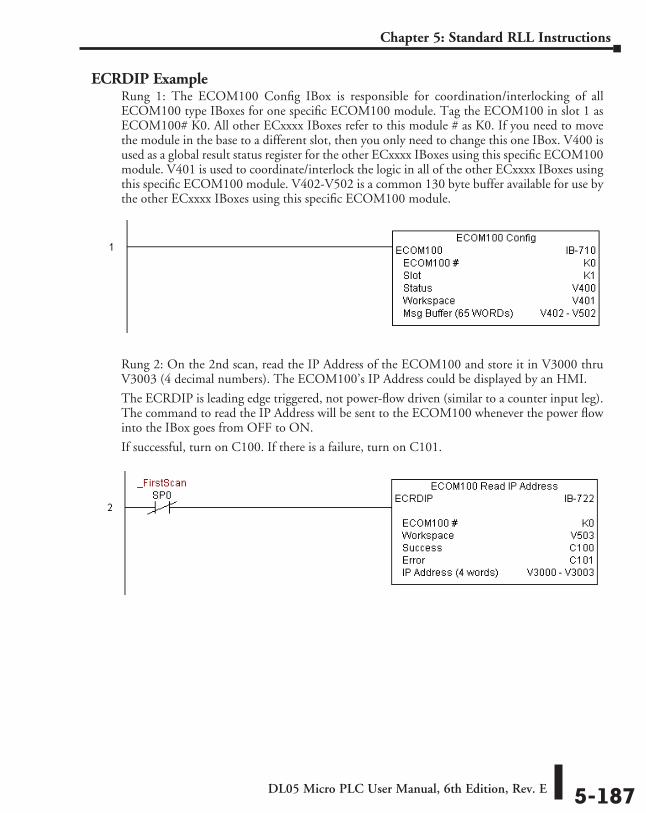
DL05 Micro PLC User Manual, 6th Edition, Rev. E 5-187
Chapter 5: Standard RLL Instructions
ECRDIP ExampleRung 1: The ECOM100 Config IBox is responsible for coordination/interlocking of all ECOM100 type IBoxes for one specific ECOM100 module. Tag the ECOM100 in slot 1 as ECOM100# K0. All other ECxxxx IBoxes refer to this module # as K0. If you need to move the module in the base to a different slot, then you only need to change this one IBox. V400 is used as a global result status register for the other ECxxxx IBoxes using this specific ECOM100 module. V401 is used to coordinate/interlock the logic in all of the other ECxxxx IBoxes using this specific ECOM100 module. V402-V502 is a common 130 byte buffer available for use by the other ECxxxx IBoxes using this specific ECOM100 module.
Rung 2: On the 2nd scan, read the IP Address of the ECOM100 and store it in V3000 thru V3003 (4 decimal numbers). The ECOM100’s IP Address could be displayed by an HMI.
The ECRDIP is leading edge triggered, not power-flow driven (similar to a counter input leg). The command to read the IP Address will be sent to the ECOM100 whenever the power flow into the IBox goes from OFF to ON.
If successful, turn on C100. If there is a failure, turn on C101.
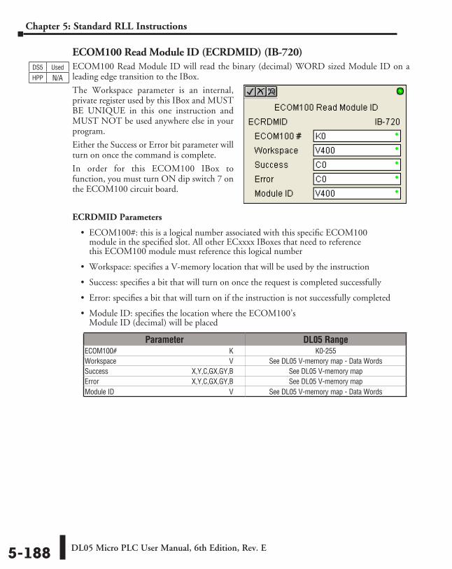
DL05 Micro PLC User Manual, 6th Edition, Rev. E5-188
Chapter 5: Standard RLL Instructions
ECOM100 Read Module ID (ECRDMID) (IB-720)ECOM100 Read Module ID will read the binary (decimal) WORD sized Module ID on a leading edge transition to the IBox.
The Workspace parameter is an internal, private register used by this IBox and MUST BE UNIQUE in this one instruction and MUST NOT be used anywhere else in your program.
Either the Success or Error bit parameter will turn on once the command is complete.
In order for this ECOM100 IBox to function, you must turn ON dip switch 7 on the ECOM100 circuit board.
ECRDMID Parameters
• ECOM100#: this is a logical number associated with this specific ECOM100 module in the specified slot. All other ECxxxx IBoxes that need to reference this ECOM100 module must reference this logical number
• Workspace: specifies a V-memory location that will be used by the instruction
• Success: specifies a bit that will turn on once the request is completed successfully
• Error: specifies a bit that will turn on if the instruction is not successfully completed
• Module ID: specifies the location where the ECOM100’s Module ID (decimal) will be placed
DS5 Used
HPP N/A
Parameter DL05 RangeECOM100# ⸠⸠⸠⸠⸠⸠⸠⸠⸠⸠⸠⸠⸠⸠⸠⸠⸠⸠⸠⸠⸠⸠⸠⸠⸠⸠⸠⸠⸠⸠⸠⸠⸠⸠⸠⸠⸠⸠⸠⸠⸠⸠⸠⸠⸠⸠⸠⸠⸠⸠⸠⸠⸠⸠⸠⸠⸠⸠⸠⸠⸠⸠ K K0-255Workspace ⸠⸠⸠⸠⸠⸠⸠⸠⸠⸠⸠⸠⸠⸠⸠⸠⸠⸠⸠⸠⸠⸠⸠⸠⸠⸠⸠⸠⸠⸠⸠⸠⸠⸠⸠⸠⸠⸠⸠⸠⸠⸠⸠⸠⸠⸠⸠⸠⸠⸠⸠⸠⸠⸠⸠⸠⸠⸠⸠⸠⸠⸠ V See DL05 V-memory map - Data WordsSuccess ⸠⸠⸠⸠⸠⸠⸠⸠⸠⸠⸠⸠⸠⸠⸠⸠⸠⸠⸠⸠⸠⸠⸠⸠⸠⸠⸠⸠⸠⸠⸠⸠⸠⸠⸠⸠⸠⸠⸠⸠⸠⸠⸠⸠⸠ X,Y,C,GX,GY,B See DL05 V-memory mapError ⸠⸠⸠⸠⸠⸠⸠⸠⸠⸠⸠⸠⸠⸠⸠⸠⸠⸠⸠⸠⸠⸠⸠⸠⸠⸠⸠⸠⸠⸠⸠⸠⸠⸠⸠⸠⸠⸠⸠⸠⸠⸠⸠⸠⸠⸠⸠⸠⸠⸠ X,Y,C,GX,GY,B See DL05 V-memory mapModule ID⸠⸠⸠⸠⸠⸠⸠⸠⸠⸠⸠⸠⸠⸠⸠⸠⸠⸠⸠⸠⸠⸠⸠⸠⸠⸠⸠⸠⸠⸠⸠⸠⸠⸠⸠⸠⸠⸠⸠⸠⸠⸠⸠⸠⸠⸠⸠⸠⸠⸠⸠⸠⸠⸠⸠⸠⸠⸠⸠⸠⸠⸠⸠⸠⸠⸠ V See DL05 V-memory map - Data Words
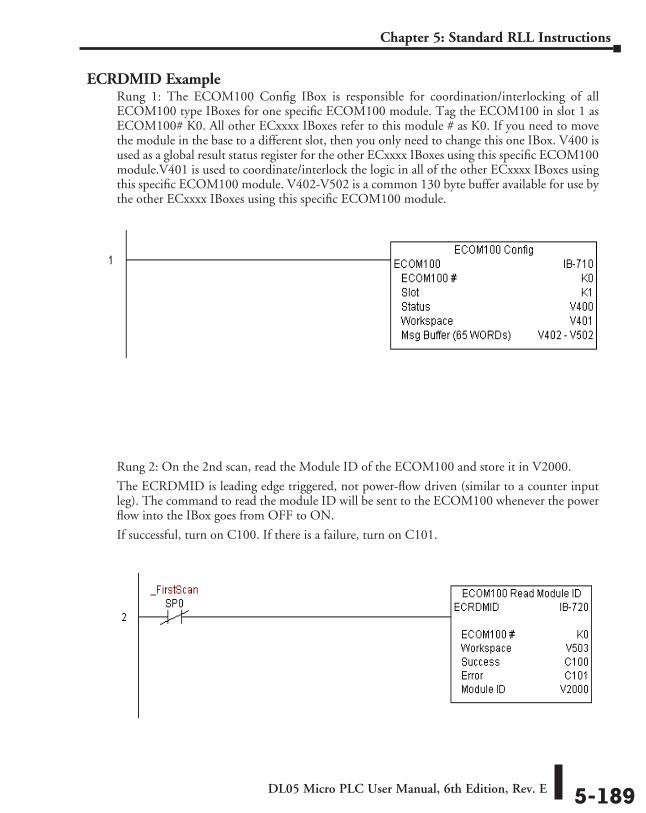
DL05 Micro PLC User Manual, 6th Edition, Rev. E 5-189
Chapter 5: Standard RLL Instructions
ECRDMID ExampleRung 1: The ECOM100 Config IBox is responsible for coordination/interlocking of all ECOM100 type IBoxes for one specific ECOM100 module. Tag the ECOM100 in slot 1 as ECOM100# K0. All other ECxxxx IBoxes refer to this module # as K0. If you need to move the module in the base to a different slot, then you only need to change this one IBox. V400 is used as a global result status register for the other ECxxxx IBoxes using this specific ECOM100 module.V401 is used to coordinate/interlock the logic in all of the other ECxxxx IBoxes using this specific ECOM100 module. V402-V502 is a common 130 byte buffer available for use by the other ECxxxx IBoxes using this specific ECOM100 module.
Rung 2: On the 2nd scan, read the Module ID of the ECOM100 and store it in V2000.
The ECRDMID is leading edge triggered, not power-flow driven (similar to a counter input leg). The command to read the module ID will be sent to the ECOM100 whenever the power flow into the IBox goes from OFF to ON.
If successful, turn on C100. If there is a failure, turn on C101.
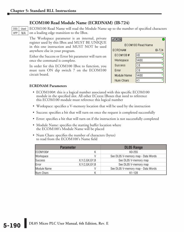
DL05 Micro PLC User Manual, 6th Edition, Rev. E5-190
Chapter 5: Standard RLL Instructions
ECOM100 Read Module Name (ECRDNAM) (IB-724)ECOM100 Read Name will read the Module Name up to the number of specified characters on a leading edge transition to the IBox.
The Workspace parameter is an internal, private register used by this IBox and MUST BE UNIQUE in this one instruction and MUST NOT be used anywhere else in your program.
Either the Success or Error bit parameter will turn on once the command is complete.
In order for this ECOM100 IBox to function, you must turn ON dip switch 7 on the ECOM100 circuit board.
ECRDNAM Parameters
• ECOM100#: this is a logical number associated with this specific ECOM100 module in the specified slot. All other ECxxxx IBoxes that need to reference this ECOM100 module must reference this logical number
• Workspace: specifies a V-memory location that will be used by the instruction
• Success: specifies a bit that will turn on once the request is completed successfully
• Error: specifies a bit that will turn on if the instruction is not successfully completed
• Module Name: specifies the starting buffer location where the ECOM100’s Module Name will be placed
• Num Chars: specifies the number of characters (bytes) to read from the ECOM100’s Name field
DS5 Used
HPP N/A
Parameter DL05 RangeECOM100# ⸠⸠⸠⸠⸠⸠⸠⸠⸠⸠⸠⸠⸠⸠⸠⸠⸠⸠⸠⸠⸠⸠⸠⸠⸠⸠⸠⸠⸠⸠⸠⸠⸠⸠⸠⸠⸠⸠⸠⸠⸠⸠⸠⸠⸠⸠⸠⸠⸠⸠⸠⸠⸠⸠⸠⸠⸠⸠⸠⸠⸠⸠ K K0-255Workspace ⸠⸠⸠⸠⸠⸠⸠⸠⸠⸠⸠⸠⸠⸠⸠⸠⸠⸠⸠⸠⸠⸠⸠⸠⸠⸠⸠⸠⸠⸠⸠⸠⸠⸠⸠⸠⸠⸠⸠⸠⸠⸠⸠⸠⸠⸠⸠⸠⸠⸠⸠⸠⸠⸠⸠⸠⸠⸠⸠⸠⸠⸠ V See DL05 V-memory map - Data WordsSuccess ⸠⸠⸠⸠⸠⸠⸠⸠⸠⸠⸠⸠⸠⸠⸠⸠⸠⸠⸠⸠⸠⸠⸠⸠⸠⸠⸠⸠⸠⸠⸠⸠⸠⸠⸠⸠⸠⸠⸠⸠⸠⸠⸠⸠⸠ X,Y,C,GX,GY,B See DL05 V-memory mapError ⸠⸠⸠⸠⸠⸠⸠⸠⸠⸠⸠⸠⸠⸠⸠⸠⸠⸠⸠⸠⸠⸠⸠⸠⸠⸠⸠⸠⸠⸠⸠⸠⸠⸠⸠⸠⸠⸠⸠⸠⸠⸠⸠⸠⸠⸠⸠⸠⸠⸠ X,Y,C,GX,GY,B See DL05 V-memory mapModule Name ⸠⸠⸠⸠⸠⸠⸠⸠⸠⸠⸠⸠⸠⸠⸠⸠⸠⸠⸠⸠⸠⸠⸠⸠⸠⸠⸠⸠⸠⸠⸠⸠⸠⸠⸠⸠⸠⸠⸠⸠⸠⸠⸠⸠⸠⸠⸠⸠⸠⸠⸠⸠⸠⸠⸠⸠⸠⸠ V See DL05 V-memory map - Data WordsNum Chars ⸠⸠⸠⸠⸠⸠⸠⸠⸠⸠⸠⸠⸠⸠⸠⸠⸠⸠⸠⸠⸠⸠⸠⸠⸠⸠⸠⸠⸠⸠⸠⸠⸠⸠⸠⸠⸠⸠⸠⸠⸠⸠⸠⸠⸠⸠⸠⸠⸠⸠⸠⸠⸠⸠⸠⸠⸠⸠⸠⸠⸠⸠⸠⸠ K K1-128
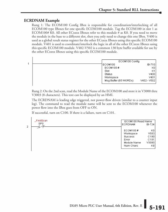
DL05 Micro PLC User Manual, 6th Edition, Rev. E 5-191
Chapter 5: Standard RLL Instructions
ECRDNAM ExampleRung 1: The ECOM100 Config IBox is responsible for coordination/interlocking of all ECOM100 type IBoxes for one specific ECOM100 module. Tag the ECOM100 in slot 1 as ECOM100# K0. All other ECxxxx IBoxes refer to this module # as K0. If you need to move the module in the base to a different slot, then you only need to change this one IBox. V400 is used as a global result status register for the other ECxxxx IBoxes using this specific ECOM100 module. V401 is used to coordinate/interlock the logic in all of the other ECxxxx IBoxes using this specific ECOM100 module. V402-V502 is a common 130 byte buffer available for use by the other ECxxxx IBoxes using this specific ECOM100 module.
Rung 2: On the 2nd scan, read the Module Name of the ECOM100 and store it in V3000 thru V3003 (8 characters). This text can be displayed by an HMI.
The ECRDNAM is leading edge triggered, not power-flow driven (similar to a counter input leg). The command to read the module name will be sent to the ECOM100 whenever the power flow into the IBox goes from OFF to ON.
If successful, turn on C100. If there is a failure, turn on C101.
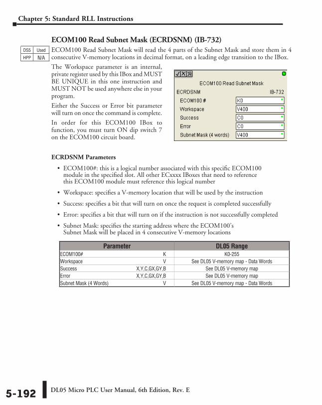
DL05 Micro PLC User Manual, 6th Edition, Rev. E5-192
Chapter 5: Standard RLL Instructions
ECOM100 Read Subnet Mask (ECRDSNM) (IB-732)ECOM100 Read Subnet Mask will read the 4 parts of the Subnet Mask and store them in 4 consecutive V-memory locations in decimal format, on a leading edge transition to the IBox.
The Workspace parameter is an internal, private register used by this IBox and MUST BE UNIQUE in this one instruction and MUST NOT be used anywhere else in your program.
Either the Success or Error bit parameter will turn on once the command is complete.
In order for this ECOM100 IBox to function, you must turn ON dip switch 7 on the ECOM100 circuit board.
ECRDSNM Parameters
• ECOM100#: this is a logical number associated with this specific ECOM100 module in the specified slot. All other ECxxxx IBoxes that need to reference this ECOM100 module must reference this logical number
• Workspace: specifies a V-memory location that will be used by the instruction
• Success: specifies a bit that will turn on once the request is completed successfully
• Error: specifies a bit that will turn on if the instruction is not successfully completed
• Subnet Mask: specifies the starting address where the ECOM100’s Subnet Mask will be placed in 4 consecutive V-memory locations
DS5 Used
HPP N/A
Parameter DL05 RangeECOM100# ⸠⸠⸠⸠⸠⸠⸠⸠⸠⸠⸠⸠⸠⸠⸠⸠⸠⸠⸠⸠⸠⸠⸠⸠⸠⸠⸠⸠⸠⸠⸠⸠⸠⸠⸠⸠⸠⸠⸠⸠⸠⸠⸠⸠⸠⸠⸠⸠⸠⸠⸠⸠⸠⸠⸠⸠⸠⸠⸠⸠⸠⸠ K K0-255Workspace ⸠⸠⸠⸠⸠⸠⸠⸠⸠⸠⸠⸠⸠⸠⸠⸠⸠⸠⸠⸠⸠⸠⸠⸠⸠⸠⸠⸠⸠⸠⸠⸠⸠⸠⸠⸠⸠⸠⸠⸠⸠⸠⸠⸠⸠⸠⸠⸠⸠⸠⸠⸠⸠⸠⸠⸠⸠⸠⸠⸠⸠⸠ V See DL05 V-memory map - Data WordsSuccess ⸠⸠⸠⸠⸠⸠⸠⸠⸠⸠⸠⸠⸠⸠⸠⸠⸠⸠⸠⸠⸠⸠⸠⸠⸠⸠⸠⸠⸠⸠⸠⸠⸠⸠⸠⸠⸠⸠⸠⸠⸠⸠⸠⸠⸠ X,Y,C,GX,GY,B See DL05 V-memory mapError ⸠⸠⸠⸠⸠⸠⸠⸠⸠⸠⸠⸠⸠⸠⸠⸠⸠⸠⸠⸠⸠⸠⸠⸠⸠⸠⸠⸠⸠⸠⸠⸠⸠⸠⸠⸠⸠⸠⸠⸠⸠⸠⸠⸠⸠⸠⸠⸠⸠⸠ X,Y,C,GX,GY,B See DL05 V-memory mapSubnet Mask (4 Words) ⸠⸠⸠⸠⸠⸠⸠⸠⸠⸠⸠⸠⸠⸠⸠⸠⸠⸠⸠⸠⸠⸠⸠⸠⸠⸠⸠⸠⸠⸠⸠⸠⸠⸠⸠⸠⸠⸠⸠⸠⸠⸠⸠ V See DL05 V-memory map - Data Words
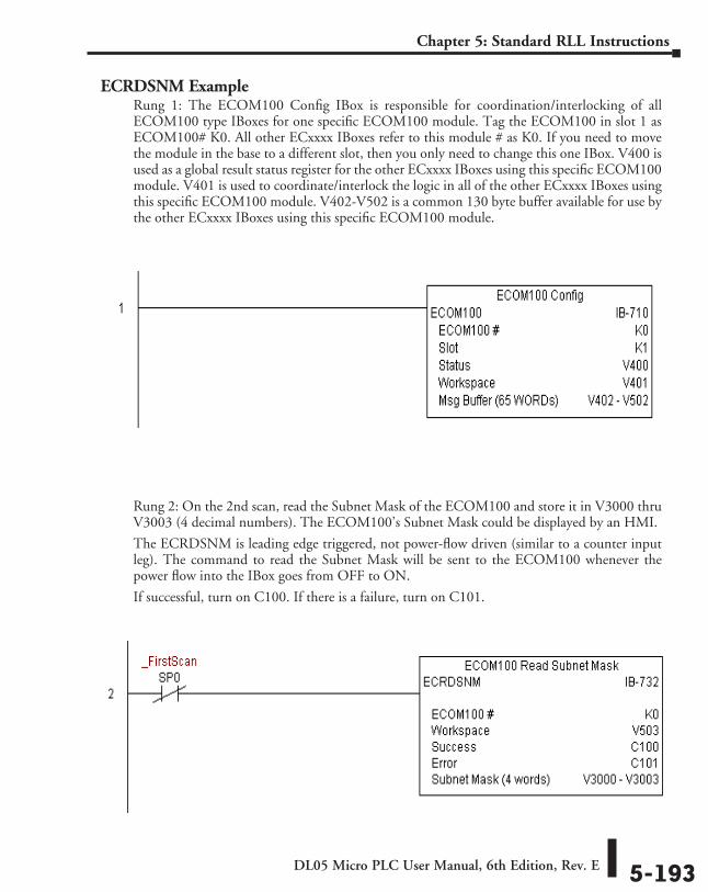
DL05 Micro PLC User Manual, 6th Edition, Rev. E 5-193
Chapter 5: Standard RLL Instructions
ECRDSNM ExampleRung 1: The ECOM100 Config IBox is responsible for coordination/interlocking of all ECOM100 type IBoxes for one specific ECOM100 module. Tag the ECOM100 in slot 1 as ECOM100# K0. All other ECxxxx IBoxes refer to this module # as K0. If you need to move the module in the base to a different slot, then you only need to change this one IBox. V400 is used as a global result status register for the other ECxxxx IBoxes using this specific ECOM100 module. V401 is used to coordinate/interlock the logic in all of the other ECxxxx IBoxes using this specific ECOM100 module. V402-V502 is a common 130 byte buffer available for use by the other ECxxxx IBoxes using this specific ECOM100 module.
Rung 2: On the 2nd scan, read the Subnet Mask of the ECOM100 and store it in V3000 thru V3003 (4 decimal numbers). The ECOM100’s Subnet Mask could be displayed by an HMI.
The ECRDSNM is leading edge triggered, not power-flow driven (similar to a counter input leg). The command to read the Subnet Mask will be sent to the ECOM100 whenever the power flow into the IBox goes from OFF to ON.
If successful, turn on C100. If there is a failure, turn on C101.
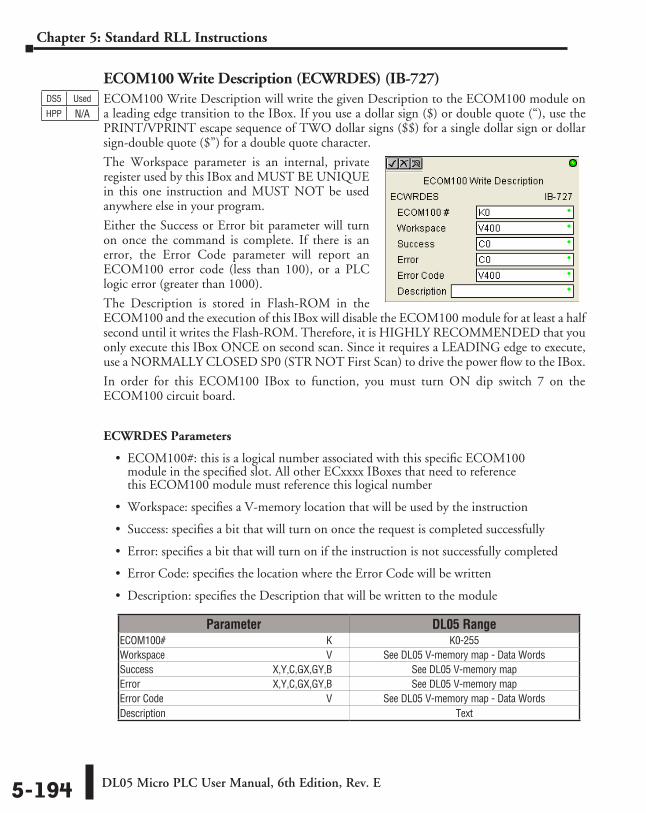
DL05 Micro PLC User Manual, 6th Edition, Rev. E5-194
Chapter 5: Standard RLL Instructions
ECOM100 Write Description (ECWRDES) (IB-727)ECOM100 Write Description will write the given Description to the ECOM100 module on a leading edge transition to the IBox. If you use a dollar sign ($) or double quote (“), use the PRINT/VPRINT escape sequence of TWO dollar signs ($$) for a single dollar sign or dollar sign-double quote ($”) for a double quote character.
The Workspace parameter is an internal, private register used by this IBox and MUST BE UNIQUE in this one instruction and MUST NOT be used anywhere else in your program.
Either the Success or Error bit parameter will turn on once the command is complete. If there is an error, the Error Code parameter will report an ECOM100 error code (less than 100), or a PLC logic error (greater than 1000).
The Description is stored in Flash-ROM in the ECOM100 and the execution of this IBox will disable the ECOM100 module for at least a half second until it writes the Flash-ROM. Therefore, it is HIGHLY RECOMMENDED that you only execute this IBox ONCE on second scan. Since it requires a LEADING edge to execute, use a NORMALLY CLOSED SP0 (STR NOT First Scan) to drive the power flow to the IBox.
In order for this ECOM100 IBox to function, you must turn ON dip switch 7 on the ECOM100 circuit board.
ECWRDES Parameters
• ECOM100#: this is a logical number associated with this specific ECOM100 module in the specified slot. All other ECxxxx IBoxes that need to reference this ECOM100 module must reference this logical number
• Workspace: specifies a V-memory location that will be used by the instruction
• Success: specifies a bit that will turn on once the request is completed successfully
• Error: specifies a bit that will turn on if the instruction is not successfully completed
• Error Code: specifies the location where the Error Code will be written
• Description: specifies the Description that will be written to the module
DS5 Used
HPP N/A
Parameter DL05 RangeECOM100# ⸠⸠⸠⸠⸠⸠⸠⸠⸠⸠⸠⸠⸠⸠⸠⸠⸠⸠⸠⸠⸠⸠⸠⸠⸠⸠⸠⸠⸠⸠⸠⸠⸠⸠⸠⸠⸠⸠⸠⸠⸠⸠⸠⸠⸠⸠⸠⸠⸠⸠⸠⸠⸠⸠⸠⸠⸠⸠⸠⸠⸠⸠ K K0-255Workspace ⸠⸠⸠⸠⸠⸠⸠⸠⸠⸠⸠⸠⸠⸠⸠⸠⸠⸠⸠⸠⸠⸠⸠⸠⸠⸠⸠⸠⸠⸠⸠⸠⸠⸠⸠⸠⸠⸠⸠⸠⸠⸠⸠⸠⸠⸠⸠⸠⸠⸠⸠⸠⸠⸠⸠⸠⸠⸠⸠⸠⸠⸠ V See DL05 V-memory map - Data WordsSuccess ⸠⸠⸠⸠⸠⸠⸠⸠⸠⸠⸠⸠⸠⸠⸠⸠⸠⸠⸠⸠⸠⸠⸠⸠⸠⸠⸠⸠⸠⸠⸠⸠⸠⸠⸠⸠⸠⸠⸠⸠⸠⸠⸠⸠⸠ X,Y,C,GX,GY,B See DL05 V-memory mapError ⸠⸠⸠⸠⸠⸠⸠⸠⸠⸠⸠⸠⸠⸠⸠⸠⸠⸠⸠⸠⸠⸠⸠⸠⸠⸠⸠⸠⸠⸠⸠⸠⸠⸠⸠⸠⸠⸠⸠⸠⸠⸠⸠⸠⸠⸠⸠⸠⸠⸠ X,Y,C,GX,GY,B See DL05 V-memory mapError Code ⸠⸠⸠⸠⸠⸠⸠⸠⸠⸠⸠⸠⸠⸠⸠⸠⸠⸠⸠⸠⸠⸠⸠⸠⸠⸠⸠⸠⸠⸠⸠⸠⸠⸠⸠⸠⸠⸠⸠⸠⸠⸠⸠⸠⸠⸠⸠⸠⸠⸠⸠⸠⸠⸠⸠⸠⸠⸠⸠⸠⸠⸠⸠ V See DL05 V-memory map - Data WordsDescription ⸠⸠⸠⸠⸠⸠⸠⸠⸠⸠⸠⸠⸠⸠⸠⸠⸠⸠⸠⸠⸠⸠⸠⸠⸠⸠⸠⸠⸠⸠⸠⸠⸠⸠⸠⸠⸠⸠⸠⸠⸠⸠⸠⸠⸠⸠⸠⸠⸠⸠⸠⸠⸠⸠⸠⸠⸠⸠⸠⸠⸠⸠⸠⸠⸠ Text
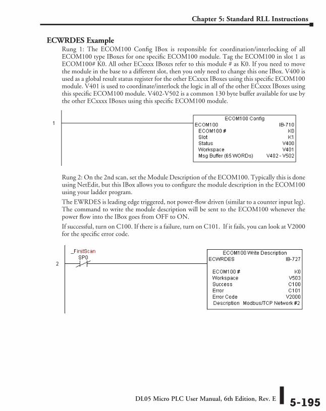
DL05 Micro PLC User Manual, 6th Edition, Rev. E 5-195
Chapter 5: Standard RLL Instructions
ECWRDES ExampleRung 1: The ECOM100 Config IBox is responsible for coordination/interlocking of all ECOM100 type IBoxes for one specific ECOM100 module. Tag the ECOM100 in slot 1 as ECOM100# K0. All other ECxxxx IBoxes refer to this module # as K0. If you need to move the module in the base to a different slot, then you only need to change this one IBox. V400 is used as a global result status register for the other ECxxxx IBoxes using this specific ECOM100 module. V401 is used to coordinate/interlock the logic in all of the other ECxxxx IBoxes using this specific ECOM100 module. V402-V502 is a common 130 byte buffer available for use by the other ECxxxx IBoxes using this specific ECOM100 module.
Rung 2: On the 2nd scan, set the Module Description of the ECOM100. Typically this is done using NetEdit, but this IBox allows you to configure the module description in the ECOM100 using your ladder program.
The EWRDES is leading edge triggered, not power-flow driven (similar to a counter input leg). The command to write the module description will be sent to the ECOM100 whenever the power flow into the IBox goes from OFF to ON.
If successful, turn on C100. If there is a failure, turn on C101. If it fails, you can look at V2000 for the specific error code.
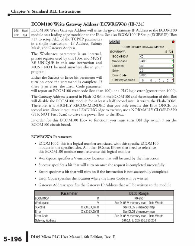
DL05 Micro PLC User Manual, 6th Edition, Rev. E5-196
Chapter 5: Standard RLL Instructions
ECOM100 Write Gateway Address (ECWRGWA) (IB-731)ECOM100 Write Gateway Address will write the given Gateway IP Address to the ECOM100 module on a leading edge transition to the IBox. See also ECOM100 IP Setup (ECIPSUP) IBox 717 to setup ALL of the TCP/IP parameters in a single instruction - IP Address, Subnet Mask, and Gateway Address.
The Workspace parameter is an internal, private register used by this IBox and MUST BE UNIQUE in this one instruction and MUST NOT be used anywhere else in your program.
Either the Success or Error bit parameter will turn on once the command is complete. If there is an error, the Error Code parameter will report an ECOM100 error code (less than 100), or a PLC logic error (greater than 1000).
The Gateway Address is stored in Flash-ROM in the ECOM100 and the execution of this IBox will disable the ECOM100 module for at least a half second until it writes the Flash-ROM. Therefore, it is HIGHLY RECOMMENDED that you only execute this IBox ONCE, on second scan. Since it requires a LEADING edge to execute, use a NORMALLY CLOSED SP0 (STR NOT First Scan) to drive the power flow to the IBox.
In order for this ECOM100 IBox to function, you must turn ON dip switch 7 on the ECOM100 circuit board.
ECWRGWA Parameters
• ECOM100#: this is a logical number associated with this specific ECOM100 module in the specified slot. All other ECxxxx IBoxes that need to reference this ECOM100 module must reference this logical number
• Workspace: specifies a V-memory location that will be used by the instruction
• Success: specifies a bit that will turn on once the request is completed successfully
• Error: specifies a bit that will turn on if the instruction is not successfully completed
• Error Code: specifies the location where the Error Code will be written
• Gateway Address: specifies the Gateway IP Address that will be written to the module
DS5 Used
HPP N/A
Parameter DL05 RangeECOM100# ⸠⸠⸠⸠⸠⸠⸠⸠⸠⸠⸠⸠⸠⸠⸠⸠⸠⸠⸠⸠⸠⸠⸠⸠⸠⸠⸠⸠⸠⸠⸠⸠⸠⸠⸠⸠⸠⸠⸠⸠⸠⸠⸠⸠⸠⸠⸠⸠⸠⸠⸠⸠⸠⸠⸠⸠⸠⸠⸠⸠⸠⸠ K K0-255Workspace ⸠⸠⸠⸠⸠⸠⸠⸠⸠⸠⸠⸠⸠⸠⸠⸠⸠⸠⸠⸠⸠⸠⸠⸠⸠⸠⸠⸠⸠⸠⸠⸠⸠⸠⸠⸠⸠⸠⸠⸠⸠⸠⸠⸠⸠⸠⸠⸠⸠⸠⸠⸠⸠⸠⸠⸠⸠⸠⸠⸠⸠⸠ V See DL05 V-memory map - Data WordsSuccess ⸠⸠⸠⸠⸠⸠⸠⸠⸠⸠⸠⸠⸠⸠⸠⸠⸠⸠⸠⸠⸠⸠⸠⸠⸠⸠⸠⸠⸠⸠⸠⸠⸠⸠⸠⸠⸠⸠⸠⸠⸠⸠⸠⸠⸠ X,Y,C,GX,GY,B See DL05 V-memory mapError ⸠⸠⸠⸠⸠⸠⸠⸠⸠⸠⸠⸠⸠⸠⸠⸠⸠⸠⸠⸠⸠⸠⸠⸠⸠⸠⸠⸠⸠⸠⸠⸠⸠⸠⸠⸠⸠⸠⸠⸠⸠⸠⸠⸠⸠⸠⸠⸠⸠⸠ X,Y,C,GX,GY,B See DL05 V-memory mapError Code ⸠⸠⸠⸠⸠⸠⸠⸠⸠⸠⸠⸠⸠⸠⸠⸠⸠⸠⸠⸠⸠⸠⸠⸠⸠⸠⸠⸠⸠⸠⸠⸠⸠⸠⸠⸠⸠⸠⸠⸠⸠⸠⸠⸠⸠⸠⸠⸠⸠⸠⸠⸠⸠⸠⸠⸠⸠⸠⸠⸠⸠⸠⸠ V See DL05 V-memory map - Data WordsGateway Address ⸠⸠⸠⸠⸠⸠⸠⸠⸠⸠⸠⸠⸠⸠⸠⸠⸠⸠⸠⸠⸠⸠⸠⸠⸠⸠⸠⸠⸠⸠⸠⸠⸠⸠⸠⸠⸠⸠⸠⸠⸠⸠⸠⸠⸠⸠⸠⸠⸠⸠⸠⸠⸠⸠⸠ 0.0.0.1. to 255.255.255.254
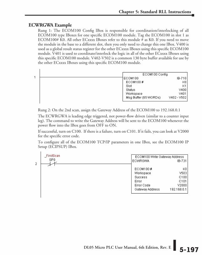
DL05 Micro PLC User Manual, 6th Edition, Rev. E 5-197
Chapter 5: Standard RLL Instructions
ECWRGWA ExampleRung 1: The ECOM100 Config IBox is responsible for coordination/interlocking of all ECOM100 type IBoxes for one specific ECOM100 module. Tag the ECOM100 in slot 1 as ECOM100# K0. All other ECxxxx IBoxes refer to this module # as K0. If you need to move the module in the base to a different slot, then you only need to change this one IBox. V400 is used as a global result status register for the other ECxxxx IBoxes using this specific ECOM100 module. V401 is used to coordinate/interlock the logic in all of the other ECxxxx IBoxes using this specific ECOM100 module. V402-V502 is a common 130 byte buffer available for use by the other ECxxxx IBoxes using this specific ECOM100 module.
Rung 2: On the 2nd scan, assign the Gateway Address of the ECOM100 to 192.168.0.1
The ECWRGWA is leading edge triggered, not power-flow driven (similar to a counter input leg). The command to write the Gateway Address will be sent to the ECOM100 whenever the power flow into the IBox goes from OFF to ON.
If successful, turn on C100. If there is a failure, turn on C101. If it fails, you can look at V2000 for the specific error code.
To configure all of the ECOM100 TCP/IP parameters in one IBox, see the ECOM100 IP Setup (ECIPSUP) IBox.
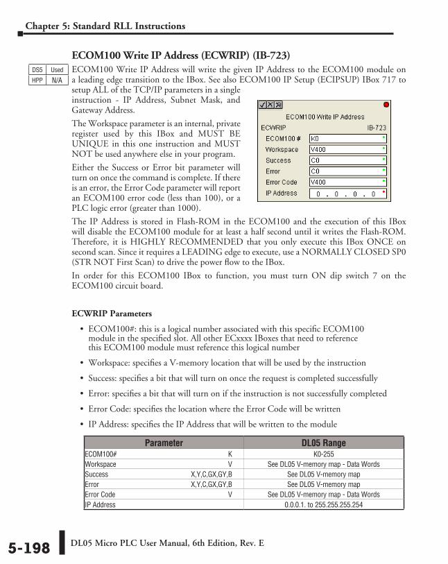
DL05 Micro PLC User Manual, 6th Edition, Rev. E5-198
Chapter 5: Standard RLL Instructions
ECOM100 Write IP Address (ECWRIP) (IB-723)ECOM100 Write IP Address will write the given IP Address to the ECOM100 module on a leading edge transition to the IBox. See also ECOM100 IP Setup (ECIPSUP) IBox 717 to setup ALL of the TCP/IP parameters in a single instruction - IP Address, Subnet Mask, and Gateway Address.
The Workspace parameter is an internal, private register used by this IBox and MUST BE UNIQUE in this one instruction and MUST NOT be used anywhere else in your program.
Either the Success or Error bit parameter will turn on once the command is complete. If there is an error, the Error Code parameter will report an ECOM100 error code (less than 100), or a PLC logic error (greater than 1000).
The IP Address is stored in Flash-ROM in the ECOM100 and the execution of this IBox will disable the ECOM100 module for at least a half second until it writes the Flash-ROM. Therefore, it is HIGHLY RECOMMENDED that you only execute this IBox ONCE on second scan. Since it requires a LEADING edge to execute, use a NORMALLY CLOSED SP0 (STR NOT First Scan) to drive the power flow to the IBox.
In order for this ECOM100 IBox to function, you must turn ON dip switch 7 on the ECOM100 circuit board.
ECWRIP Parameters
• ECOM100#: this is a logical number associated with this specific ECOM100 module in the specified slot. All other ECxxxx IBoxes that need to reference this ECOM100 module must reference this logical number
• Workspace: specifies a V-memory location that will be used by the instruction
• Success: specifies a bit that will turn on once the request is completed successfully
• Error: specifies a bit that will turn on if the instruction is not successfully completed
• Error Code: specifies the location where the Error Code will be written
• IP Address: specifies the IP Address that will be written to the module
DS5 Used
HPP N/A
Parameter DL05 RangeECOM100# ⸠⸠⸠⸠⸠⸠⸠⸠⸠⸠⸠⸠⸠⸠⸠⸠⸠⸠⸠⸠⸠⸠⸠⸠⸠⸠⸠⸠⸠⸠⸠⸠⸠⸠⸠⸠⸠⸠⸠⸠⸠⸠⸠⸠⸠⸠⸠⸠⸠⸠⸠⸠⸠⸠⸠⸠⸠⸠⸠⸠⸠⸠ K K0-255Workspace ⸠⸠⸠⸠⸠⸠⸠⸠⸠⸠⸠⸠⸠⸠⸠⸠⸠⸠⸠⸠⸠⸠⸠⸠⸠⸠⸠⸠⸠⸠⸠⸠⸠⸠⸠⸠⸠⸠⸠⸠⸠⸠⸠⸠⸠⸠⸠⸠⸠⸠⸠⸠⸠⸠⸠⸠⸠⸠⸠⸠⸠⸠ V See DL05 V-memory map - Data WordsSuccess ⸠⸠⸠⸠⸠⸠⸠⸠⸠⸠⸠⸠⸠⸠⸠⸠⸠⸠⸠⸠⸠⸠⸠⸠⸠⸠⸠⸠⸠⸠⸠⸠⸠⸠⸠⸠⸠⸠⸠⸠⸠⸠⸠⸠⸠ X,Y,C,GX,GY,B See DL05 V-memory mapError ⸠⸠⸠⸠⸠⸠⸠⸠⸠⸠⸠⸠⸠⸠⸠⸠⸠⸠⸠⸠⸠⸠⸠⸠⸠⸠⸠⸠⸠⸠⸠⸠⸠⸠⸠⸠⸠⸠⸠⸠⸠⸠⸠⸠⸠⸠⸠⸠⸠⸠ X,Y,C,GX,GY,B See DL05 V-memory mapError Code ⸠⸠⸠⸠⸠⸠⸠⸠⸠⸠⸠⸠⸠⸠⸠⸠⸠⸠⸠⸠⸠⸠⸠⸠⸠⸠⸠⸠⸠⸠⸠⸠⸠⸠⸠⸠⸠⸠⸠⸠⸠⸠⸠⸠⸠⸠⸠⸠⸠⸠⸠⸠⸠⸠⸠⸠⸠⸠⸠⸠⸠⸠⸠ V See DL05 V-memory map - Data WordsIP Address ⸠⸠⸠⸠⸠⸠⸠⸠⸠⸠⸠⸠⸠⸠⸠⸠⸠⸠⸠⸠⸠⸠⸠⸠⸠⸠⸠⸠⸠⸠⸠⸠⸠⸠⸠⸠⸠⸠⸠⸠⸠⸠⸠⸠⸠⸠⸠⸠⸠⸠⸠⸠⸠⸠⸠⸠⸠⸠⸠⸠⸠⸠⸠⸠⸠ 0.0.0.1. to 255.255.255.254
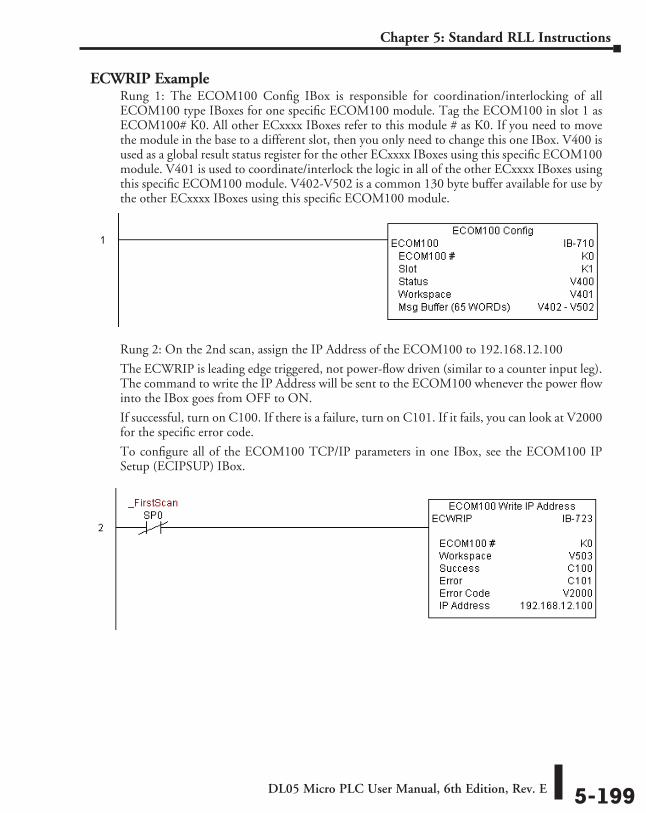
DL05 Micro PLC User Manual, 6th Edition, Rev. E 5-199
Chapter 5: Standard RLL Instructions
ECWRIP ExampleRung 1: The ECOM100 Config IBox is responsible for coordination/interlocking of all ECOM100 type IBoxes for one specific ECOM100 module. Tag the ECOM100 in slot 1 as ECOM100# K0. All other ECxxxx IBoxes refer to this module # as K0. If you need to move the module in the base to a different slot, then you only need to change this one IBox. V400 is used as a global result status register for the other ECxxxx IBoxes using this specific ECOM100 module. V401 is used to coordinate/interlock the logic in all of the other ECxxxx IBoxes using this specific ECOM100 module. V402-V502 is a common 130 byte buffer available for use by the other ECxxxx IBoxes using this specific ECOM100 module.
Rung 2: On the 2nd scan, assign the IP Address of the ECOM100 to 192.168.12.100
The ECWRIP is leading edge triggered, not power-flow driven (similar to a counter input leg). The command to write the IP Address will be sent to the ECOM100 whenever the power flow into the IBox goes from OFF to ON.
If successful, turn on C100. If there is a failure, turn on C101. If it fails, you can look at V2000 for the specific error code.
To configure all of the ECOM100 TCP/IP parameters in one IBox, see the ECOM100 IP Setup (ECIPSUP) IBox.
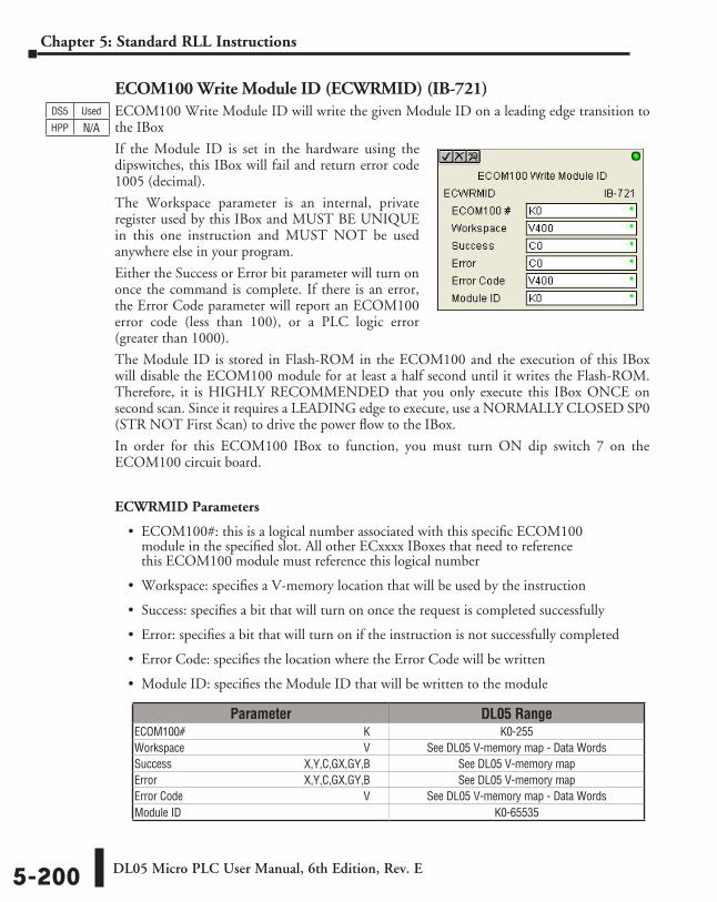
DL05 Micro PLC User Manual, 6th Edition, Rev. E5-200
Chapter 5: Standard RLL Instructions
ECOM100 Write Module ID (ECWRMID) (IB-721)ECOM100 Write Module ID will write the given Module ID on a leading edge transition to the IBox
If the Module ID is set in the hardware using the dipswitches, this IBox will fail and return error code 1005 (decimal).
The Workspace parameter is an internal, private register used by this IBox and MUST BE UNIQUE in this one instruction and MUST NOT be used anywhere else in your program.
Either the Success or Error bit parameter will turn on once the command is complete. If there is an error, the Error Code parameter will report an ECOM100 error code (less than 100), or a PLC logic error (greater than 1000).
The Module ID is stored in Flash-ROM in the ECOM100 and the execution of this IBox will disable the ECOM100 module for at least a half second until it writes the Flash-ROM. Therefore, it is HIGHLY RECOMMENDED that you only execute this IBox ONCE on second scan. Since it requires a LEADING edge to execute, use a NORMALLY CLOSED SP0 (STR NOT First Scan) to drive the power flow to the IBox.
In order for this ECOM100 IBox to function, you must turn ON dip switch 7 on the ECOM100 circuit board.
ECWRMID Parameters
• ECOM100#: this is a logical number associated with this specific ECOM100 module in the specified slot. All other ECxxxx IBoxes that need to reference this ECOM100 module must reference this logical number
• Workspace: specifies a V-memory location that will be used by the instruction
• Success: specifies a bit that will turn on once the request is completed successfully
• Error: specifies a bit that will turn on if the instruction is not successfully completed
• Error Code: specifies the location where the Error Code will be written
• Module ID: specifies the Module ID that will be written to the module
DS5 Used
HPP N/A
Parameter DL05 RangeECOM100# ⸠⸠⸠⸠⸠⸠⸠⸠⸠⸠⸠⸠⸠⸠⸠⸠⸠⸠⸠⸠⸠⸠⸠⸠⸠⸠⸠⸠⸠⸠⸠⸠⸠⸠⸠⸠⸠⸠⸠⸠⸠⸠⸠⸠⸠⸠⸠⸠⸠⸠⸠⸠⸠⸠⸠⸠⸠⸠⸠⸠⸠⸠ K K0-255Workspace ⸠⸠⸠⸠⸠⸠⸠⸠⸠⸠⸠⸠⸠⸠⸠⸠⸠⸠⸠⸠⸠⸠⸠⸠⸠⸠⸠⸠⸠⸠⸠⸠⸠⸠⸠⸠⸠⸠⸠⸠⸠⸠⸠⸠⸠⸠⸠⸠⸠⸠⸠⸠⸠⸠⸠⸠⸠⸠⸠⸠⸠⸠ V See DL05 V-memory map - Data WordsSuccess ⸠⸠⸠⸠⸠⸠⸠⸠⸠⸠⸠⸠⸠⸠⸠⸠⸠⸠⸠⸠⸠⸠⸠⸠⸠⸠⸠⸠⸠⸠⸠⸠⸠⸠⸠⸠⸠⸠⸠⸠⸠⸠⸠⸠⸠ X,Y,C,GX,GY,B See DL05 V-memory mapError ⸠⸠⸠⸠⸠⸠⸠⸠⸠⸠⸠⸠⸠⸠⸠⸠⸠⸠⸠⸠⸠⸠⸠⸠⸠⸠⸠⸠⸠⸠⸠⸠⸠⸠⸠⸠⸠⸠⸠⸠⸠⸠⸠⸠⸠⸠⸠⸠⸠⸠ X,Y,C,GX,GY,B See DL05 V-memory mapError Code ⸠⸠⸠⸠⸠⸠⸠⸠⸠⸠⸠⸠⸠⸠⸠⸠⸠⸠⸠⸠⸠⸠⸠⸠⸠⸠⸠⸠⸠⸠⸠⸠⸠⸠⸠⸠⸠⸠⸠⸠⸠⸠⸠⸠⸠⸠⸠⸠⸠⸠⸠⸠⸠⸠⸠⸠⸠⸠⸠⸠⸠⸠⸠ V See DL05 V-memory map - Data WordsModule ID ⸠⸠⸠⸠⸠⸠⸠⸠⸠⸠⸠⸠⸠⸠⸠⸠⸠⸠⸠⸠⸠⸠⸠⸠⸠⸠⸠⸠⸠⸠⸠⸠⸠⸠⸠⸠⸠⸠⸠⸠⸠⸠⸠⸠⸠⸠⸠⸠⸠⸠⸠⸠⸠⸠⸠⸠⸠⸠⸠⸠⸠⸠⸠⸠⸠⸠ K0-65535
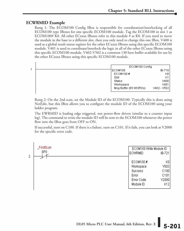
DL05 Micro PLC User Manual, 6th Edition, Rev. E 5-201
Chapter 5: Standard RLL Instructions
ECWRMID ExampleRung 1: The ECOM100 Config IBox is responsible for coordination/interlocking of all ECOM100 type IBoxes for one specific ECOM100 module. Tag the ECOM100 in slot 1 as ECOM100# K0. All other ECxxxx IBoxes refer to this module # as K0. If you need to move the module in the base to a different slot, then you only need to change this one IBox. V400 is used as a global result status register for the other ECxxxx IBoxes using this specific ECOM100 module. V401 is used to coordinate/interlock the logic in all of the other ECxxxx IBoxes using this specific ECOM100 module. V402-V502 is a common 130 byte buffer available for use by the other ECxxxx IBoxes using this specific ECOM100 module.
Rung 2: On the 2nd scan, set the Module ID of the ECOM100. Typically this is done using NetEdit, but this IBox allows you to configure the module ID of the ECOM100 using your ladder program.
The EWRMID is leading edge triggered, not power-flow driven (similar to a counter input leg). The command to write the module ID will be sent to the ECOM100 whenever the power flow into the IBox goes from OFF to ON.
If successful, turn on C100. If there is a failure, turn on C101. If it fails, you can look at V2000 for the specific error code.
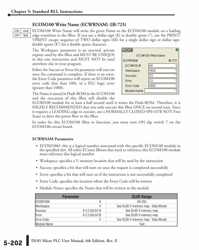
DL05 Micro PLC User Manual, 6th Edition, Rev. E5-202
Chapter 5: Standard RLL Instructions
ECOM100 Write Name (ECWRNAM) (IB-725)ECOM100 Write Name will write the given Name to the ECOM100 module on a leading edge transition to the IBox. If you use a dollar sign ($) or double quote (“), use the PRINT/VPRINT escape sequence of TWO dollar signs ($$) for a single dollar sign or dollar sign-double quote ($”) for a double quote character.
The Workspace parameter is an internal, private register used by this IBox and MUST BE UNIQUE in this one instruction and MUST NOT be used anywhere else in your program.
Either the Success or Error bit parameter will turn on once the command is complete. If there is an error, the Error Code parameter will report an ECOM100 error code (less than 100), or a PLC logic error (greater than 1000).
The Name is stored in Flash-ROM in the ECOM100 and the execution of this IBox will disable the ECOM100 module for at least a half second until it writes the Flash-ROM. Therefore, it is HIGHLY RECOMMENDED that you only execute this IBox ONCE on second scan. Since it requires a LEADING edge to execute, use a NORMALLY CLOSED SP0 (STR NOT First Scan) to drive the power flow to the IBox.
In order for this ECOM100 IBox to function, you must turn ON dip switch 7 on the ECOM100 circuit board.
ECWRNAM Parameters
• ECOM100#: this is a logical number associated with this specific ECOM100 module in the specified slot. All other ECxxxx IBoxes that need to reference this ECOM100 module must reference this logical number
• Workspace: specifies a V-memory location that will be used by the instruction
• Success: specifies a bit that will turn on once the request is completed successfully
• Error: specifies a bit that will turn on if the instruction is not successfully completed
• Error Code: specifies the location where the Error Code will be written
• Module Name: specifies the Name that will be written to the module
DS5 Used
HPP N/A
Parameter DL05 RangeECOM100# ⸠⸠⸠⸠⸠⸠⸠⸠⸠⸠⸠⸠⸠⸠⸠⸠⸠⸠⸠⸠⸠⸠⸠⸠⸠⸠⸠⸠⸠⸠⸠⸠⸠⸠⸠⸠⸠⸠⸠⸠⸠⸠⸠⸠⸠⸠⸠⸠⸠⸠⸠⸠⸠⸠⸠⸠⸠⸠⸠⸠⸠⸠ K K0-255Workspace ⸠⸠⸠⸠⸠⸠⸠⸠⸠⸠⸠⸠⸠⸠⸠⸠⸠⸠⸠⸠⸠⸠⸠⸠⸠⸠⸠⸠⸠⸠⸠⸠⸠⸠⸠⸠⸠⸠⸠⸠⸠⸠⸠⸠⸠⸠⸠⸠⸠⸠⸠⸠⸠⸠⸠⸠⸠⸠⸠⸠⸠⸠ V See DL05 V-memory map - Data WordsSuccess ⸠⸠⸠⸠⸠⸠⸠⸠⸠⸠⸠⸠⸠⸠⸠⸠⸠⸠⸠⸠⸠⸠⸠⸠⸠⸠⸠⸠⸠⸠⸠⸠⸠⸠⸠⸠⸠⸠⸠⸠⸠⸠⸠⸠⸠ X,Y,C,GX,GY,B See DL05 V-memory mapError ⸠⸠⸠⸠⸠⸠⸠⸠⸠⸠⸠⸠⸠⸠⸠⸠⸠⸠⸠⸠⸠⸠⸠⸠⸠⸠⸠⸠⸠⸠⸠⸠⸠⸠⸠⸠⸠⸠⸠⸠⸠⸠⸠⸠⸠⸠⸠⸠⸠⸠ X,Y,C,GX,GY,B See DL05 V-memory mapError Code ⸠⸠⸠⸠⸠⸠⸠⸠⸠⸠⸠⸠⸠⸠⸠⸠⸠⸠⸠⸠⸠⸠⸠⸠⸠⸠⸠⸠⸠⸠⸠⸠⸠⸠⸠⸠⸠⸠⸠⸠⸠⸠⸠⸠⸠⸠⸠⸠⸠⸠⸠⸠⸠⸠⸠⸠⸠⸠⸠⸠⸠⸠⸠ V See DL05 V-memory map - Data WordsModule Name ⸠⸠⸠⸠⸠⸠⸠⸠⸠⸠⸠⸠⸠⸠⸠⸠⸠⸠⸠⸠⸠⸠⸠⸠⸠⸠⸠⸠⸠⸠⸠⸠⸠⸠⸠⸠⸠⸠⸠⸠⸠⸠⸠⸠⸠⸠⸠⸠⸠⸠⸠⸠⸠⸠⸠⸠⸠⸠⸠⸠⸠ Text
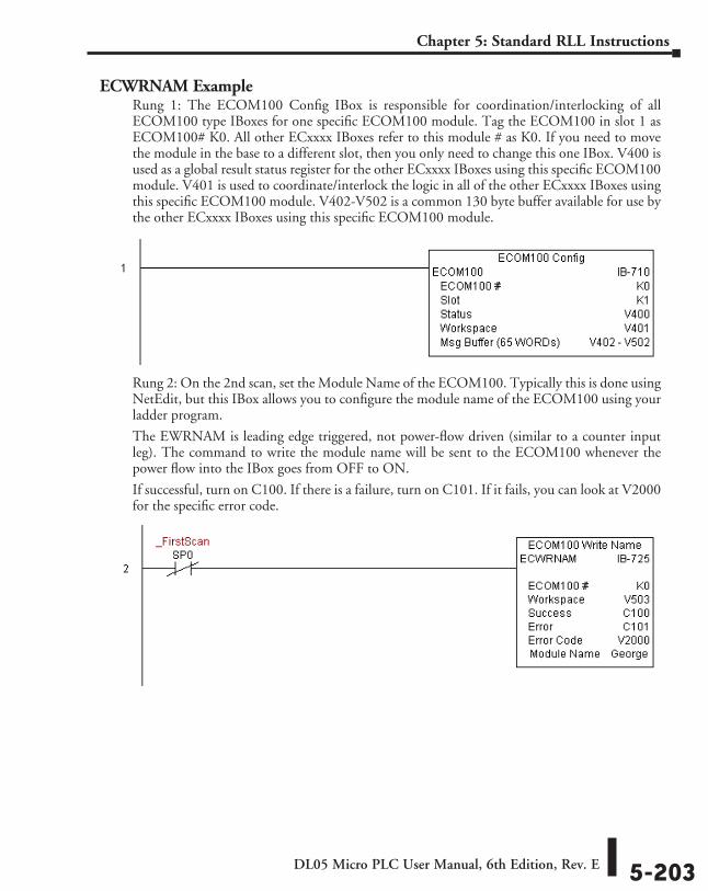
DL05 Micro PLC User Manual, 6th Edition, Rev. E 5-203
Chapter 5: Standard RLL Instructions
ECWRNAM ExampleRung 1: The ECOM100 Config IBox is responsible for coordination/interlocking of all ECOM100 type IBoxes for one specific ECOM100 module. Tag the ECOM100 in slot 1 as ECOM100# K0. All other ECxxxx IBoxes refer to this module # as K0. If you need to move the module in the base to a different slot, then you only need to change this one IBox. V400 is used as a global result status register for the other ECxxxx IBoxes using this specific ECOM100 module. V401 is used to coordinate/interlock the logic in all of the other ECxxxx IBoxes using this specific ECOM100 module. V402-V502 is a common 130 byte buffer available for use by the other ECxxxx IBoxes using this specific ECOM100 module.
Rung 2: On the 2nd scan, set the Module Name of the ECOM100. Typically this is done using NetEdit, but this IBox allows you to configure the module name of the ECOM100 using your ladder program.
The EWRNAM is leading edge triggered, not power-flow driven (similar to a counter input leg). The command to write the module name will be sent to the ECOM100 whenever the power flow into the IBox goes from OFF to ON.
If successful, turn on C100. If there is a failure, turn on C101. If it fails, you can look at V2000 for the specific error code.
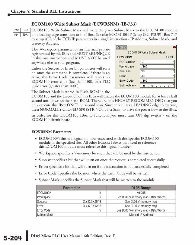
DL05 Micro PLC User Manual, 6th Edition, Rev. E5-204
Chapter 5: Standard RLL Instructions
ECOM100 Write Subnet Mask (ECWRSNM) (IB-733)ECOM100 Write Subnet Mask will write the given Subnet Mask to the ECOM100 module on a leading edge transition to the IBox. See also ECOM100 IP Setup (ECIPSUP) IBox 717 to setup ALL of the TCP/IP parameters in a single instruction - IP Address, Subnet Mask, and Gateway Address.
The Workspace parameter is an internal, private register used by this IBox and MUST BE UNIQUE in this one instruction and MUST NOT be used anywhere else in your program.
Either the Success or Error bit parameter will turn on once the command is complete. If there is an error, the Error Code parameter will report an ECOM100 error code (less than 100), or a PLC logic error (greater than 1000).
The Subnet Mask is stored in Flash-ROM in the ECOM100 and the execution of this IBox will disable the ECOM100 module for at least a half second until it writes the Flash-ROM. Therefore, it is HIGHLY RECOMMENDED that you only execute this IBox ONCE on second scan. Since it requires a LEADING edge to execute, use a NORMALLY CLOSED SP0 (STR NOT First Scan) to drive the power flow to the IBox.
In order for this ECOM100 IBox to function, you must turn ON dip switch 7 on the ECOM100 circuit board.
ECWRSNM Parameters
• ECOM100#: this is a logical number associated with this specific ECOM100 module in the specified slot. All other ECxxxx IBoxes that need to reference this ECOM100 module must reference this logical number
• Workspace: specifies a V-memory location that will be used by the instruction
• Success: specifies a bit that will turn on once the request is completed successfully
• Error: specifies a bit that will turn on if the instruction is not successfully completed
• Error Code: specifies the location where the Error Code will be written
• Subnet Mask: specifies the Subnet Mask that will be written to the module
DS5 Used
HPP N/A
Parameter DL05 RangeECOM100# ⸠⸠⸠⸠⸠⸠⸠⸠⸠⸠⸠⸠⸠⸠⸠⸠⸠⸠⸠⸠⸠⸠⸠⸠⸠⸠⸠⸠⸠⸠⸠⸠⸠⸠⸠⸠⸠⸠⸠⸠⸠⸠⸠⸠⸠⸠⸠⸠⸠⸠⸠⸠⸠⸠⸠⸠⸠⸠⸠⸠⸠⸠ K K0-255Workspace ⸠⸠⸠⸠⸠⸠⸠⸠⸠⸠⸠⸠⸠⸠⸠⸠⸠⸠⸠⸠⸠⸠⸠⸠⸠⸠⸠⸠⸠⸠⸠⸠⸠⸠⸠⸠⸠⸠⸠⸠⸠⸠⸠⸠⸠⸠⸠⸠⸠⸠⸠⸠⸠⸠⸠⸠⸠⸠⸠⸠⸠⸠ V See DL05 V-memory map - Data WordsSuccess ⸠⸠⸠⸠⸠⸠⸠⸠⸠⸠⸠⸠⸠⸠⸠⸠⸠⸠⸠⸠⸠⸠⸠⸠⸠⸠⸠⸠⸠⸠⸠⸠⸠⸠⸠⸠⸠⸠⸠⸠⸠⸠⸠⸠⸠ X,Y,C,GX,GY,B See DL05 V-memory mapError ⸠⸠⸠⸠⸠⸠⸠⸠⸠⸠⸠⸠⸠⸠⸠⸠⸠⸠⸠⸠⸠⸠⸠⸠⸠⸠⸠⸠⸠⸠⸠⸠⸠⸠⸠⸠⸠⸠⸠⸠⸠⸠⸠⸠⸠⸠⸠⸠⸠⸠ X,Y,C,GX,GY,B See DL05 V-memory mapError Code ⸠⸠⸠⸠⸠⸠⸠⸠⸠⸠⸠⸠⸠⸠⸠⸠⸠⸠⸠⸠⸠⸠⸠⸠⸠⸠⸠⸠⸠⸠⸠⸠⸠⸠⸠⸠⸠⸠⸠⸠⸠⸠⸠⸠⸠⸠⸠⸠⸠⸠⸠⸠⸠⸠⸠⸠⸠⸠⸠⸠⸠⸠⸠ V See DL05 V-memory map - Data WordsSubnet Mask ⸠⸠⸠⸠⸠⸠⸠⸠⸠⸠⸠⸠⸠⸠⸠⸠⸠⸠⸠⸠⸠⸠⸠⸠⸠⸠⸠⸠⸠⸠⸠⸠⸠⸠⸠⸠⸠⸠⸠⸠⸠⸠⸠⸠⸠⸠⸠⸠⸠⸠⸠⸠⸠⸠⸠⸠⸠⸠⸠⸠⸠⸠ Masked IP Address
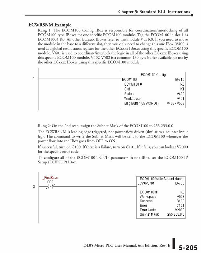
DL05 Micro PLC User Manual, 6th Edition, Rev. E 5-205
Chapter 5: Standard RLL Instructions
ECWRSNM ExampleRung 1: The ECOM100 Config IBox is responsible for coordination/interlocking of all ECOM100 type IBoxes for one specific ECOM100 module. Tag the ECOM100 in slot 1 as ECOM100# K0. All other ECxxxx IBoxes refer to this module # as K0. If you need to move the module in the base to a different slot, then you only need to change this one IBox. V400 is used as a global result status register for the other ECxxxx IBoxes using this specific ECOM100 module. V401 is used to coordinate/interlock the logic in all of the other ECxxxx IBoxes using this specific ECOM100 module. V402-V502 is a common 130 byte buffer available for use by the other ECxxxx IBoxes using this specific ECOM100 module.
Rung 2: On the 2nd scan, assign the Subnet Mask of the ECOM100 to 255.255.0.0
The ECWRSNM is leading edge triggered, not power-flow driven (similar to a counter input leg). The command to write the Subnet Mask will be sent to the ECOM100 whenever the power flow into the IBox goes from OFF to ON.
If successful, turn on C100. If there is a failure, turn on C101. If it fails, you can look at V2000 for the specific error code.
To configure all of the ECOM100 TCP/IP parameters in one IBox, see the ECOM100 IP Setup (ECIPSUP) IBox.
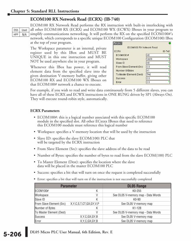
DL05 Micro PLC User Manual, 6th Edition, Rev. E5-206
Chapter 5: Standard RLL Instructions
ECOM100 RX Network Read (ECRX) (IB-740)ECOM100 RX Network Read performs the RX instruction with built-in interlocking with all other ECOM100 RX (ECRX) and ECOM100 WX (ECWX) IBoxes in your program to simplify communications networking. It will perform the RX on the specified ECOM100#’s network, which corresponds to a specific unique ECOM100 Configuration (ECOM100) IBox at the top of your program.
The Workspace parameter is an internal, private register used by this IBox and MUST BE UNIQUE in this one instruction and MUST NOT be used anywhere else in your program.
Whenever this IBox has power, it will read element data from the specified slave into the given destination V-memory buffer, giving other ECOM100 RX and ECOM100 WX IBoxes on that ECOM100# network a chance to execute.
For example, if you wish to read and write data continuously from 5 different slaves, you can have all of these ECRX and ECWX instructions in ONE RUNG driven by SP1 (Always On). They will execute round-robin style, automatically.
ECRX Parameters
• ECOM100#: this is a logical number associated with this specific ECOM100 module in the specified slot. All other ECxxxx IBoxes that need to reference this ECOM100 module must reference this logical number
• Workspace: specifies a V-memory location that will be used by the instruction
• Slave ID: specifies the slave ECOM(100) PLC that will be targeted by the ECRX instruction
• From Slave Element (Src): specifies the slave address of the data to be read
• Number of Bytes: specifies the number of bytes to read from the slave ECOM(100) PLC
• To Master Element (Dest): specifies the location where the slave data will be placed in the master ECOM100 PLC
• Success: specifies a bit that will turn on once the request is completed successfully
• Error: specifies a bit that will turn on if the instruction is not successfully completed
DS5 Used
HPP N/A
Parameter DL05 RangeECOM100# ⸠⸠⸠⸠⸠⸠⸠⸠⸠⸠⸠⸠⸠⸠⸠⸠⸠⸠⸠⸠⸠⸠⸠⸠⸠⸠⸠⸠⸠⸠⸠⸠⸠⸠⸠⸠⸠⸠⸠⸠⸠⸠⸠⸠⸠⸠⸠⸠⸠⸠⸠⸠⸠⸠⸠⸠⸠⸠⸠⸠⸠⸠ K K0-255Workspace ⸠⸠⸠⸠⸠⸠⸠⸠⸠⸠⸠⸠⸠⸠⸠⸠⸠⸠⸠⸠⸠⸠⸠⸠⸠⸠⸠⸠⸠⸠⸠⸠⸠⸠⸠⸠⸠⸠⸠⸠⸠⸠⸠⸠⸠⸠⸠⸠⸠⸠⸠⸠⸠⸠⸠⸠⸠⸠⸠⸠⸠⸠ V See DL05 V-memory map - Data WordsSlave ID ⸠⸠⸠⸠⸠⸠⸠⸠⸠⸠⸠⸠⸠⸠⸠⸠⸠⸠⸠⸠⸠⸠⸠⸠⸠⸠⸠⸠⸠⸠⸠⸠⸠⸠⸠⸠⸠⸠⸠⸠⸠⸠⸠⸠⸠⸠⸠⸠⸠⸠⸠⸠⸠⸠⸠⸠⸠⸠⸠⸠⸠⸠⸠⸠⸠⸠⸠ K K0-90From Slave Element (Src) ⸠⸠⸠ X,Y,C,S,T,CT,GX,GY,V,P See DL05 V-memory mapNumber of Bytes ⸠⸠⸠⸠⸠⸠⸠⸠⸠⸠⸠⸠⸠⸠⸠⸠⸠⸠⸠⸠⸠⸠⸠⸠⸠⸠⸠⸠⸠⸠⸠⸠⸠⸠⸠⸠⸠⸠⸠⸠⸠⸠⸠⸠⸠⸠⸠⸠⸠⸠⸠⸠⸠ K K1-128To Master Element (Dest) ⸠⸠⸠⸠⸠⸠⸠⸠⸠⸠⸠⸠⸠⸠⸠⸠⸠⸠⸠⸠⸠⸠⸠⸠⸠⸠⸠⸠⸠⸠⸠⸠⸠⸠⸠⸠⸠⸠ V See DL05 V-memory map - Data WordsSuccess ⸠⸠⸠⸠⸠⸠⸠⸠⸠⸠⸠⸠⸠⸠⸠⸠⸠⸠⸠⸠⸠⸠⸠⸠⸠⸠⸠⸠⸠⸠⸠⸠⸠⸠⸠⸠⸠⸠⸠⸠⸠⸠⸠⸠⸠ X,Y,C,GX,GY,B See DL05 V-memory mapError ⸠⸠⸠⸠⸠⸠⸠⸠⸠⸠⸠⸠⸠⸠⸠⸠⸠⸠⸠⸠⸠⸠⸠⸠⸠⸠⸠⸠⸠⸠⸠⸠⸠⸠⸠⸠⸠⸠⸠⸠⸠⸠⸠⸠⸠⸠⸠⸠⸠⸠ X,Y,C,GX,GY,B See DL05 V-memory map
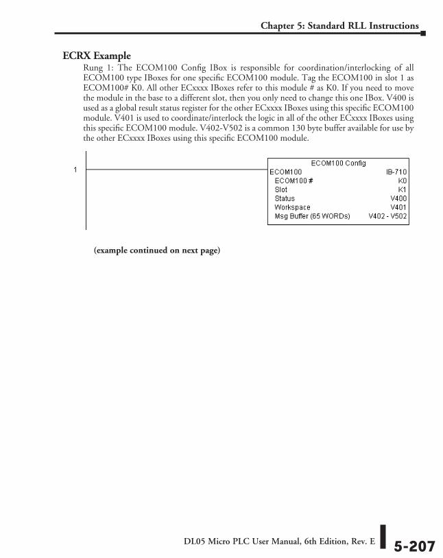
DL05 Micro PLC User Manual, 6th Edition, Rev. E 5-207
Chapter 5: Standard RLL Instructions
ECRX ExampleRung 1: The ECOM100 Config IBox is responsible for coordination/interlocking of all ECOM100 type IBoxes for one specific ECOM100 module. Tag the ECOM100 in slot 1 as ECOM100# K0. All other ECxxxx IBoxes refer to this module # as K0. If you need to move the module in the base to a different slot, then you only need to change this one IBox. V400 is used as a global result status register for the other ECxxxx IBoxes using this specific ECOM100 module. V401 is used to coordinate/interlock the logic in all of the other ECxxxx IBoxes using this specific ECOM100 module. V402-V502 is a common 130 byte buffer available for use by the other ECxxxx IBoxes using this specific ECOM100 module.
(example continued on next page)
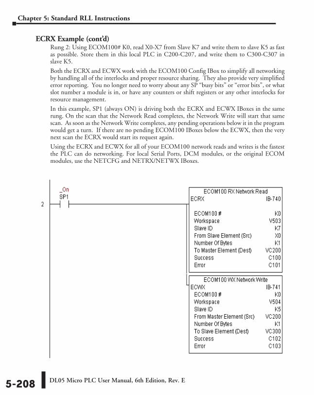
DL05 Micro PLC User Manual, 6th Edition, Rev. E5-208
Chapter 5: Standard RLL Instructions
ECRX Example (cont’d)Rung 2: Using ECOM100# K0, read X0-X7 from Slave K7 and write them to slave K5 as fast as possible. Store them in this local PLC in C200-C207, and write them to C300-C307 in slave K5.
Both the ECRX and ECWX work with the ECOM100 Config IBox to simplify all networking by handling all of the interlocks and proper resource sharing. They also provide very simplified error reporting. You no longer need to worry about any SP “busy bits” or “error bits”, or what slot number a module is in, or have any counters or shift registers or any other interlocks for resource management.
In this example, SP1 (always ON) is driving both the ECRX and ECWX IBoxes in the same rung. On the scan that the Network Read completes, the Network Write will start that same scan. As soon as the Network Write completes, any pending operations below it in the program would get a turn. If there are no pending ECOM100 IBoxes below the ECWX, then the very next scan the ECRX would start its request again.
Using the ECRX and ECWX for all of your ECOM100 network reads and writes is the fastest the PLC can do networking. For local Serial Ports, DCM modules, or the original ECOM modules, use the NETCFG and NETRX/NETWX IBoxes.
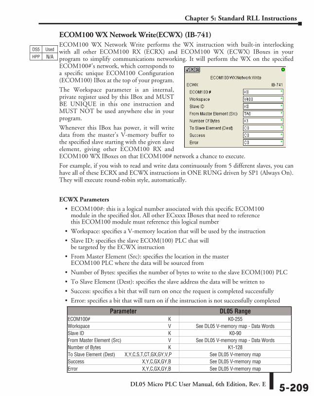
DL05 Micro PLC User Manual, 6th Edition, Rev. E 5-209
Chapter 5: Standard RLL Instructions
ECOM100 WX Network Write(ECWX) (IB-741)ECOM100 WX Network Write performs the WX instruction with built-in interlocking with all other ECOM100 RX (ECRX) and ECOM100 WX (ECWX) IBoxes in your program to simplify communications networking. It will perform the WX on the specified ECOM100#’s network, which corresponds to a specific unique ECOM100 Configuration (ECOM100) IBox at the top of your program.
The Workspace parameter is an internal, private register used by this IBox and MUST BE UNIQUE in this one instruction and MUST NOT be used anywhere else in your program.
Whenever this IBox has power, it will write data from the master’s V-memory buffer to the specified slave starting with the given slave element, giving other ECOM100 RX and ECOM100 WX IBoxes on that ECOM100# network a chance to execute.
For example, if you wish to read and write data continuously from 5 different slaves, you can have all of these ECRX and ECWX instructions in ONE RUNG driven by SP1 (Always On). They will execute round-robin style, automatically.
ECWX Parameters
• ECOM100#: this is a logical number associated with this specific ECOM100 module in the specified slot. All other ECxxxx IBoxes that need to reference this ECOM100 module must reference this logical number
• Workspace: specifies a V-memory location that will be used by the instruction
• Slave ID: specifies the slave ECOM(100) PLC that will be targeted by the ECWX instruction
• From Master Element (Src): specifies the location in the master ECOM100 PLC where the data will be sourced from
• Number of Bytes: specifies the number of bytes to write to the slave ECOM(100) PLC
• To Slave Element (Dest): specifies the slave address the data will be written to
• Success: specifies a bit that will turn on once the request is completed successfully
• Error: specifies a bit that will turn on if the instruction is not successfully completed
DS5 Used
HPP N/A
Parameter DL05 RangeECOM100# ⸠⸠⸠⸠⸠⸠⸠⸠⸠⸠⸠⸠⸠⸠⸠⸠⸠⸠⸠⸠⸠⸠⸠⸠⸠⸠⸠⸠⸠⸠⸠⸠⸠⸠⸠⸠⸠⸠⸠⸠⸠⸠⸠⸠⸠⸠⸠⸠⸠⸠⸠⸠⸠⸠⸠⸠⸠⸠⸠⸠⸠⸠ K K0-255Workspace ⸠⸠⸠⸠⸠⸠⸠⸠⸠⸠⸠⸠⸠⸠⸠⸠⸠⸠⸠⸠⸠⸠⸠⸠⸠⸠⸠⸠⸠⸠⸠⸠⸠⸠⸠⸠⸠⸠⸠⸠⸠⸠⸠⸠⸠⸠⸠⸠⸠⸠⸠⸠⸠⸠⸠⸠⸠⸠⸠⸠⸠⸠ V See DL05 V-memory map - Data WordsSlave ID ⸠⸠⸠⸠⸠⸠⸠⸠⸠⸠⸠⸠⸠⸠⸠⸠⸠⸠⸠⸠⸠⸠⸠⸠⸠⸠⸠⸠⸠⸠⸠⸠⸠⸠⸠⸠⸠⸠⸠⸠⸠⸠⸠⸠⸠⸠⸠⸠⸠⸠⸠⸠⸠⸠⸠⸠⸠⸠⸠⸠⸠⸠⸠⸠⸠⸠⸠ K K0-90From Master Element (Src) ⸠⸠⸠⸠⸠⸠⸠⸠⸠⸠⸠⸠⸠⸠⸠⸠⸠⸠⸠⸠⸠⸠⸠⸠⸠⸠⸠⸠⸠⸠⸠⸠⸠⸠⸠⸠ V See DL05 V-memory map - Data WordsNumber of Bytes ⸠⸠⸠⸠⸠⸠⸠⸠⸠⸠⸠⸠⸠⸠⸠⸠⸠⸠⸠⸠⸠⸠⸠⸠⸠⸠⸠⸠⸠⸠⸠⸠⸠⸠⸠⸠⸠⸠⸠⸠⸠⸠⸠⸠⸠⸠⸠⸠⸠⸠⸠⸠⸠ K K1-128To Slave Element (Dest) ⸠⸠⸠⸠⸠X,Y,C,S,T,CT,GX,GY,V,P See DL05 V-memory mapSuccess ⸠⸠⸠⸠⸠⸠⸠⸠⸠⸠⸠⸠⸠⸠⸠⸠⸠⸠⸠⸠⸠⸠⸠⸠⸠⸠⸠⸠⸠⸠⸠⸠⸠⸠⸠⸠⸠⸠⸠⸠⸠⸠⸠⸠⸠ X,Y,C,GX,GY,B See DL05 V-memory mapError ⸠⸠⸠⸠⸠⸠⸠⸠⸠⸠⸠⸠⸠⸠⸠⸠⸠⸠⸠⸠⸠⸠⸠⸠⸠⸠⸠⸠⸠⸠⸠⸠⸠⸠⸠⸠⸠⸠⸠⸠⸠⸠⸠⸠⸠⸠⸠⸠⸠⸠ X,Y,C,GX,GY,B See DL05 V-memory map
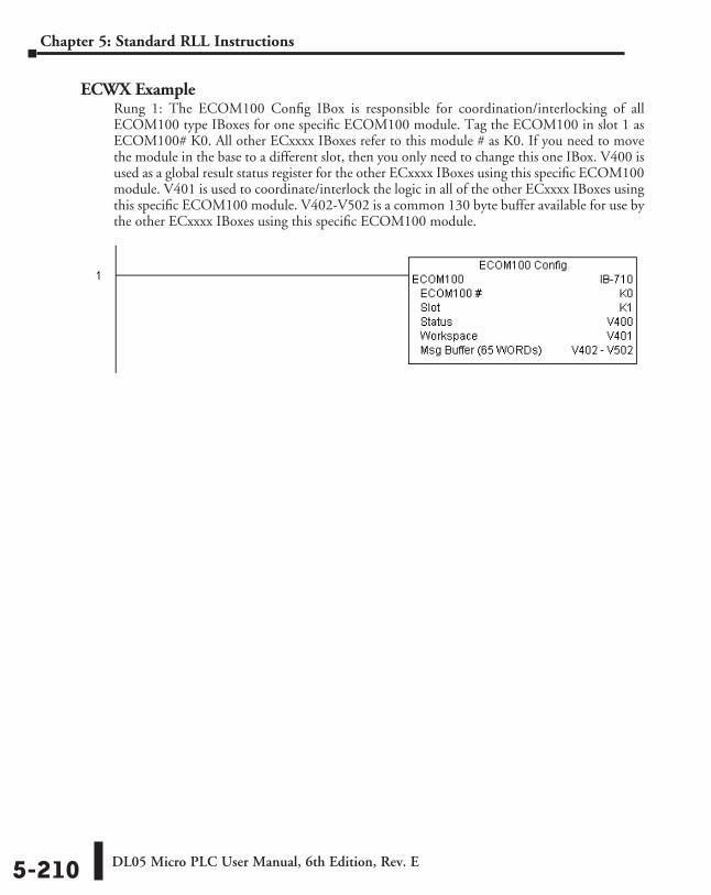
DL05 Micro PLC User Manual, 6th Edition, Rev. E5-210
Chapter 5: Standard RLL Instructions
ECWX ExampleRung 1: The ECOM100 Config IBox is responsible for coordination/interlocking of all ECOM100 type IBoxes for one specific ECOM100 module. Tag the ECOM100 in slot 1 as ECOM100# K0. All other ECxxxx IBoxes refer to this module # as K0. If you need to move the module in the base to a different slot, then you only need to change this one IBox. V400 is used as a global result status register for the other ECxxxx IBoxes using this specific ECOM100 module. V401 is used to coordinate/interlock the logic in all of the other ECxxxx IBoxes using this specific ECOM100 module. V402-V502 is a common 130 byte buffer available for use by the other ECxxxx IBoxes using this specific ECOM100 module.
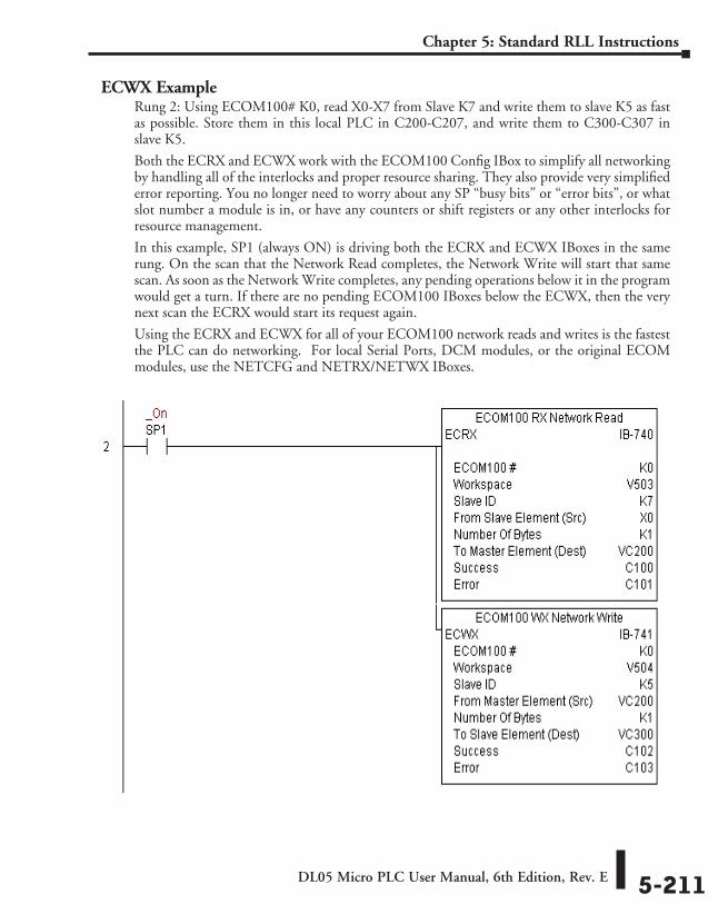
DL05 Micro PLC User Manual, 6th Edition, Rev. E 5-211
Chapter 5: Standard RLL Instructions
ECWX ExampleRung 2: Using ECOM100# K0, read X0-X7 from Slave K7 and write them to slave K5 as fast as possible. Store them in this local PLC in C200-C207, and write them to C300-C307 in slave K5.
Both the ECRX and ECWX work with the ECOM100 Config IBox to simplify all networking by handling all of the interlocks and proper resource sharing. They also provide very simplified error reporting. You no longer need to worry about any SP “busy bits” or “error bits”, or what slot number a module is in, or have any counters or shift registers or any other interlocks for resource management.
In this example, SP1 (always ON) is driving both the ECRX and ECWX IBoxes in the same rung. On the scan that the Network Read completes, the Network Write will start that same scan. As soon as the Network Write completes, any pending operations below it in the program would get a turn. If there are no pending ECOM100 IBoxes below the ECWX, then the very next scan the ECRX would start its request again.
Using the ECRX and ECWX for all of your ECOM100 network reads and writes is the fastest the PLC can do networking. For local Serial Ports, DCM modules, or the original ECOM modules, use the NETCFG and NETRX/NETWX IBoxes.
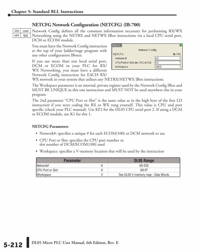
DL05 Micro PLC User Manual, 6th Edition, Rev. E5-212
Chapter 5: Standard RLL Instructions
NETCFG Network Configuration (NETCFG) (IB-700)Network Config defines all the common information necessary for performing RX/WX Networking using the NETRX and NETWX IBox instructions via a local CPU serial port, DCM or ECOM module.
You must have the Network Config instruction at the top of your ladder/stage program with any other configuration IBoxes.
If you use more than one local serial port, DCM or ECOM in your PLC for RX/WX Networking, you must have a different Network Config instruction for EACH RX/WX network in your system that utilizes any NETRX/NETWX IBox instructions.
The Workspace parameter is an internal, private register used by the Network Config IBox and MUST BE UNIQUE in this one instruction and MUST NOT be used anywhere else in your program.
The 2nd parameter “CPU Port or Slot” is the same value as in the high byte of the first LD instruction if you were coding the RX or WX rung yourself. This value is CPU and port specific (check your PLC manual). Use KF2 for the DL05 CPU serial port 2. If using a DCM or ECOM module, use K1 for slot 1.
NETCFG Parameters
• Network#: specifies a unique # for each ECOM(100) or DCM network to use
• CPU Port or Slot: specifies the CPU port number or slot number of DCM/ECOM(100) used
• Workspace: specifies a V-memory location that will be used by the instruction
DS5 Used
HPP N/A
Parameter DL05 RangeNetwork# ⸠⸠⸠⸠⸠⸠⸠⸠⸠⸠⸠⸠⸠⸠⸠⸠⸠⸠⸠⸠⸠⸠⸠⸠⸠⸠⸠⸠⸠⸠⸠⸠⸠⸠⸠⸠⸠⸠⸠⸠⸠⸠⸠⸠⸠⸠⸠⸠⸠⸠⸠⸠⸠⸠⸠⸠⸠⸠⸠⸠⸠⸠⸠⸠⸠ K K0-255CPU Port or Slot ⸠⸠⸠⸠⸠⸠⸠⸠⸠⸠⸠⸠⸠⸠⸠⸠⸠⸠⸠⸠⸠⸠⸠⸠⸠⸠⸠⸠⸠⸠⸠⸠⸠⸠⸠⸠⸠⸠⸠⸠⸠⸠⸠⸠⸠⸠⸠⸠⸠⸠⸠⸠⸠ K K0-FFWorkspace ⸠⸠⸠⸠⸠⸠⸠⸠⸠⸠⸠⸠⸠⸠⸠⸠⸠⸠⸠⸠⸠⸠⸠⸠⸠⸠⸠⸠⸠⸠⸠⸠⸠⸠⸠⸠⸠⸠⸠⸠⸠⸠⸠⸠⸠⸠⸠⸠⸠⸠⸠⸠⸠⸠⸠⸠⸠⸠⸠⸠⸠⸠ V See DL05 V-memory map - Data Words
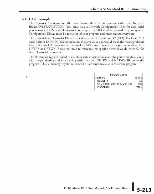
DL05 Micro PLC User Manual, 6th Edition, Rev. E 5-213
Chapter 5: Standard RLL Instructions
NETCFG ExampleThe Network Configuration IBox coordinates all of the interaction with other Network IBoxes (NETRX/NETWX). You must have a Network Configuration IBox for each serial port network, DCM module network, or original ECOM module network in your system. Configuration IBoxes must be at the top of your program and must execute every scan.
This IBox defines Network# K0 to be for the local CPU serial port #2 (KF2). For local CPU serial ports or DCM/ECOM modules, use the same value you would use in the most significant byte of the first LD instruction in a normal RX/WX rung to reference the port or module. Any NETRX or NETWX IBoxes that need to reference this specific network would enter K0 for their Network# parameter.
The Workspace register is used to maintain state information about the port or module, along with proper sharing and interlocking with the other NETRX and NETWX IBoxes in the program. This V-memory register must not be used anywhere else in the entire program.
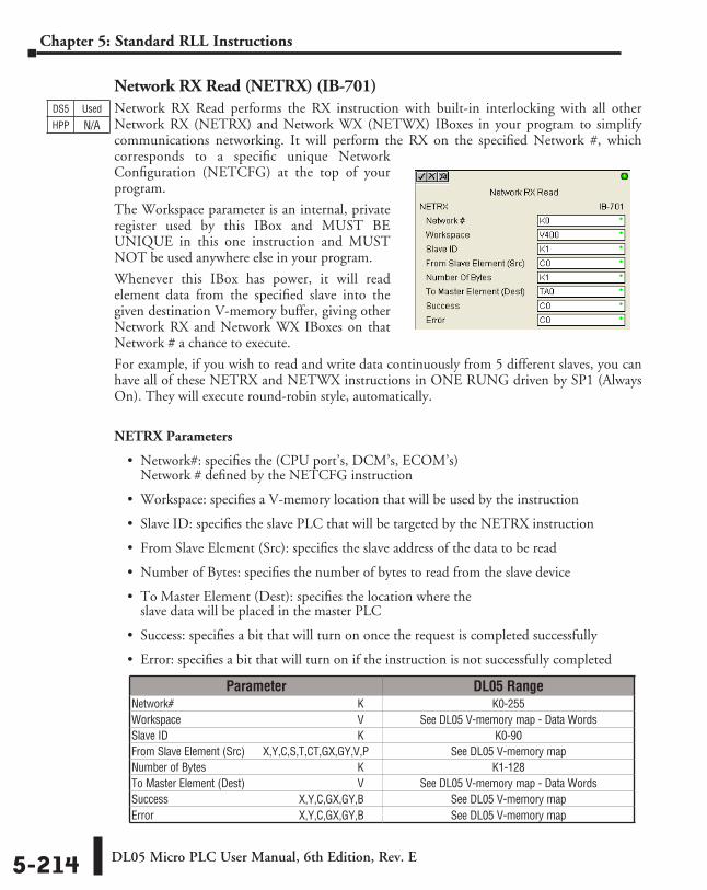
DL05 Micro PLC User Manual, 6th Edition, Rev. E5-214
Chapter 5: Standard RLL Instructions
Network RX Read (NETRX) (IB-701)Network RX Read performs the RX instruction with built-in interlocking with all other Network RX (NETRX) and Network WX (NETWX) IBoxes in your program to simplify communications networking. It will perform the RX on the specified Network #, which corresponds to a specific unique Network Configuration (NETCFG) at the top of your program.
The Workspace parameter is an internal, private register used by this IBox and MUST BE UNIQUE in this one instruction and MUST NOT be used anywhere else in your program.
Whenever this IBox has power, it will read element data from the specified slave into the given destination V-memory buffer, giving other Network RX and Network WX IBoxes on that Network # a chance to execute.
For example, if you wish to read and write data continuously from 5 different slaves, you can have all of these NETRX and NETWX instructions in ONE RUNG driven by SP1 (Always On). They will execute round-robin style, automatically.
NETRX Parameters
• Network#: specifies the (CPU port’s, DCM’s, ECOM’s) Network # defined by the NETCFG instruction
• Workspace: specifies a V-memory location that will be used by the instruction
• Slave ID: specifies the slave PLC that will be targeted by the NETRX instruction
• From Slave Element (Src): specifies the slave address of the data to be read
• Number of Bytes: specifies the number of bytes to read from the slave device
• To Master Element (Dest): specifies the location where the slave data will be placed in the master PLC
• Success: specifies a bit that will turn on once the request is completed successfully
• Error: specifies a bit that will turn on if the instruction is not successfully completed
DS5 Used
HPP N/A
Parameter DL05 RangeNetwork# ⸠⸠⸠⸠⸠⸠⸠⸠⸠⸠⸠⸠⸠⸠⸠⸠⸠⸠⸠⸠⸠⸠⸠⸠⸠⸠⸠⸠⸠⸠⸠⸠⸠⸠⸠⸠⸠⸠⸠⸠⸠⸠⸠⸠⸠⸠⸠⸠⸠⸠⸠⸠⸠⸠⸠⸠⸠⸠⸠⸠⸠⸠⸠⸠⸠ K K0-255Workspace ⸠⸠⸠⸠⸠⸠⸠⸠⸠⸠⸠⸠⸠⸠⸠⸠⸠⸠⸠⸠⸠⸠⸠⸠⸠⸠⸠⸠⸠⸠⸠⸠⸠⸠⸠⸠⸠⸠⸠⸠⸠⸠⸠⸠⸠⸠⸠⸠⸠⸠⸠⸠⸠⸠⸠⸠⸠⸠⸠⸠⸠⸠ V See DL05 V-memory map - Data WordsSlave ID ⸠⸠⸠⸠⸠⸠⸠⸠⸠⸠⸠⸠⸠⸠⸠⸠⸠⸠⸠⸠⸠⸠⸠⸠⸠⸠⸠⸠⸠⸠⸠⸠⸠⸠⸠⸠⸠⸠⸠⸠⸠⸠⸠⸠⸠⸠⸠⸠⸠⸠⸠⸠⸠⸠⸠⸠⸠⸠⸠⸠⸠⸠⸠⸠⸠⸠⸠ K K0-90From Slave Element (Src) ⸠⸠⸠ X,Y,C,S,T,CT,GX,GY,V,P See DL05 V-memory mapNumber of Bytes ⸠⸠⸠⸠⸠⸠⸠⸠⸠⸠⸠⸠⸠⸠⸠⸠⸠⸠⸠⸠⸠⸠⸠⸠⸠⸠⸠⸠⸠⸠⸠⸠⸠⸠⸠⸠⸠⸠⸠⸠⸠⸠⸠⸠⸠⸠⸠⸠⸠⸠⸠⸠⸠ K K1-128To Master Element (Dest) ⸠⸠⸠⸠⸠⸠⸠⸠⸠⸠⸠⸠⸠⸠⸠⸠⸠⸠⸠⸠⸠⸠⸠⸠⸠⸠⸠⸠⸠⸠⸠⸠⸠⸠⸠⸠⸠⸠ V See DL05 V-memory map - Data WordsSuccess ⸠⸠⸠⸠⸠⸠⸠⸠⸠⸠⸠⸠⸠⸠⸠⸠⸠⸠⸠⸠⸠⸠⸠⸠⸠⸠⸠⸠⸠⸠⸠⸠⸠⸠⸠⸠⸠⸠⸠⸠⸠⸠⸠⸠⸠ X,Y,C,GX,GY,B See DL05 V-memory mapError ⸠⸠⸠⸠⸠⸠⸠⸠⸠⸠⸠⸠⸠⸠⸠⸠⸠⸠⸠⸠⸠⸠⸠⸠⸠⸠⸠⸠⸠⸠⸠⸠⸠⸠⸠⸠⸠⸠⸠⸠⸠⸠⸠⸠⸠⸠⸠⸠⸠⸠ X,Y,C,GX,GY,B See DL05 V-memory map
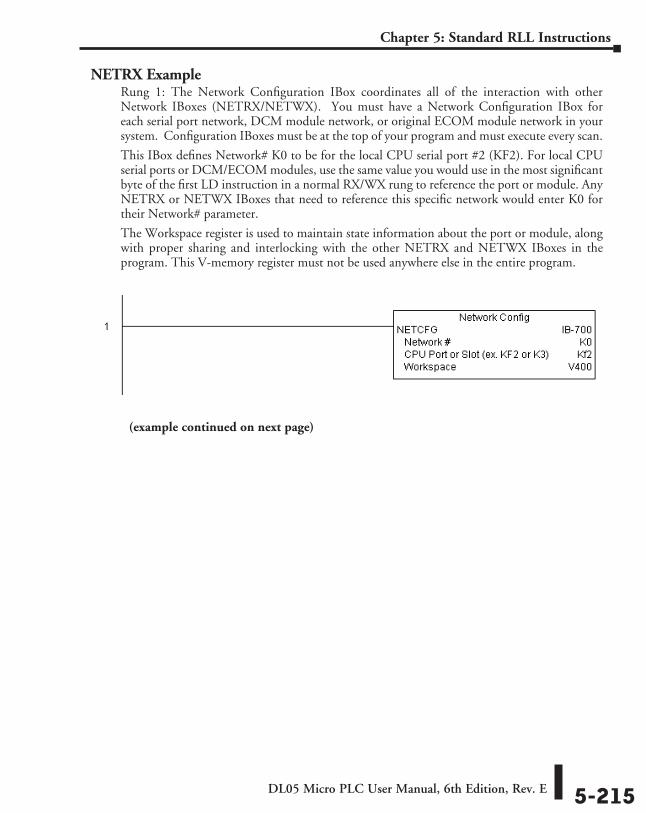
DL05 Micro PLC User Manual, 6th Edition, Rev. E 5-215
Chapter 5: Standard RLL Instructions
NETRX ExampleRung 1: The Network Configuration IBox coordinates all of the interaction with other Network IBoxes (NETRX/NETWX). You must have a Network Configuration IBox for each serial port network, DCM module network, or original ECOM module network in your system. Configuration IBoxes must be at the top of your program and must execute every scan.
This IBox defines Network# K0 to be for the local CPU serial port #2 (KF2). For local CPU serial ports or DCM/ECOM modules, use the same value you would use in the most significant byte of the first LD instruction in a normal RX/WX rung to reference the port or module. Any NETRX or NETWX IBoxes that need to reference this specific network would enter K0 for their Network# parameter.
The Workspace register is used to maintain state information about the port or module, along with proper sharing and interlocking with the other NETRX and NETWX IBoxes in the program. This V-memory register must not be used anywhere else in the entire program.
(example continued on next page)
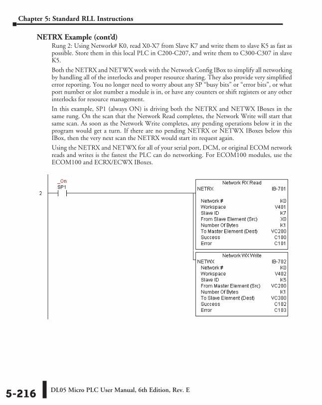
DL05 Micro PLC User Manual, 6th Edition, Rev. E5-216
Chapter 5: Standard RLL Instructions
NETRX Example (cont’d)Rung 2: Using Network# K0, read X0-X7 from Slave K7 and write them to slave K5 as fast as possible. Store them in this local PLC in C200-C207, and write them to C300-C307 in slave K5.
Both the NETRX and NETWX work with the Network Config IBox to simplify all networking by handling all of the interlocks and proper resource sharing. They also provide very simplified error reporting. You no longer need to worry about any SP “busy bits” or “error bits”, or what port number or slot number a module is in, or have any counters or shift registers or any other interlocks for resource management.
In this example, SP1 (always ON) is driving both the NETRX and NETWX IBoxes in the same rung. On the scan that the Network Read completes, the Network Write will start that same scan. As soon as the Network Write completes, any pending operations below it in the program would get a turn. If there are no pending NETRX or NETWX IBoxes below this IBox, then the very next scan the NETRX would start its request again.
Using the NETRX and NETWX for all of your serial port, DCM, or original ECOM network reads and writes is the fastest the PLC can do networking. For ECOM100 modules, use the ECOM100 and ECRX/ECWX IBoxes.
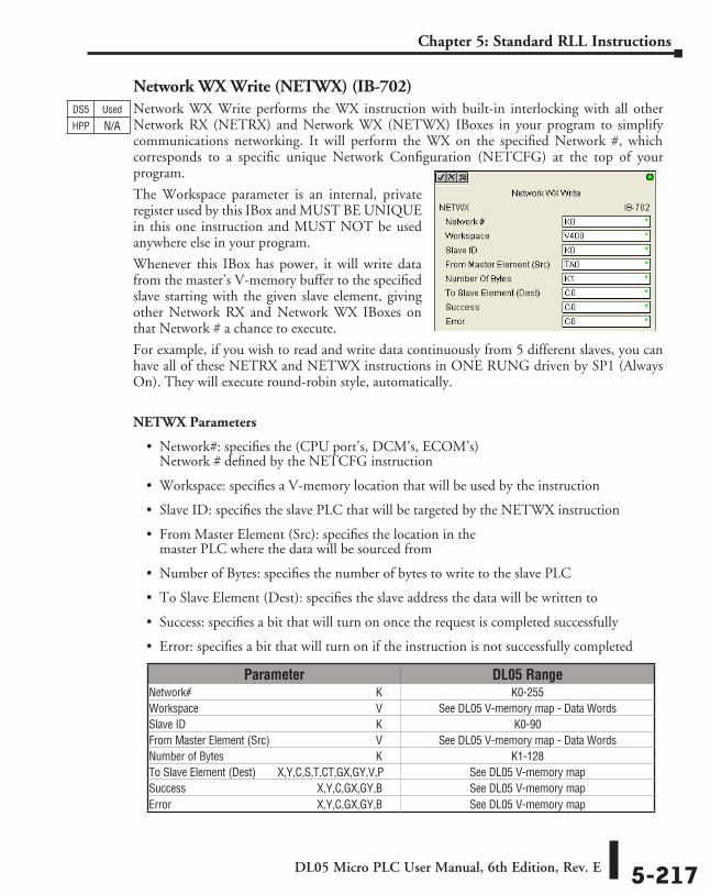
DL05 Micro PLC User Manual, 6th Edition, Rev. E 5-217
Chapter 5: Standard RLL Instructions
Network WX Write (NETWX) (IB-702)Network WX Write performs the WX instruction with built-in interlocking with all other Network RX (NETRX) and Network WX (NETWX) IBoxes in your program to simplify communications networking. It will perform the WX on the specified Network #, which corresponds to a specific unique Network Configuration (NETCFG) at the top of your program.
The Workspace parameter is an internal, private register used by this IBox and MUST BE UNIQUE in this one instruction and MUST NOT be used anywhere else in your program.
Whenever this IBox has power, it will write data from the master’s V-memory buffer to the specified slave starting with the given slave element, giving other Network RX and Network WX IBoxes on that Network # a chance to execute.
For example, if you wish to read and write data continuously from 5 different slaves, you can have all of these NETRX and NETWX instructions in ONE RUNG driven by SP1 (Always On). They will execute round-robin style, automatically.
NETWX Parameters
• Network#: specifies the (CPU port’s, DCM’s, ECOM’s) Network # defined by the NETCFG instruction
• Workspace: specifies a V-memory location that will be used by the instruction
• Slave ID: specifies the slave PLC that will be targeted by the NETWX instruction
• From Master Element (Src): specifies the location in the master PLC where the data will be sourced from
• Number of Bytes: specifies the number of bytes to write to the slave PLC
• To Slave Element (Dest): specifies the slave address the data will be written to
• Success: specifies a bit that will turn on once the request is completed successfully
• Error: specifies a bit that will turn on if the instruction is not successfully completed
DS5 Used
HPP N/A
Parameter DL05 RangeNetwork# ⸠⸠⸠⸠⸠⸠⸠⸠⸠⸠⸠⸠⸠⸠⸠⸠⸠⸠⸠⸠⸠⸠⸠⸠⸠⸠⸠⸠⸠⸠⸠⸠⸠⸠⸠⸠⸠⸠⸠⸠⸠⸠⸠⸠⸠⸠⸠⸠⸠⸠⸠⸠⸠⸠⸠⸠⸠⸠⸠⸠⸠⸠⸠⸠⸠ K K0-255Workspace ⸠⸠⸠⸠⸠⸠⸠⸠⸠⸠⸠⸠⸠⸠⸠⸠⸠⸠⸠⸠⸠⸠⸠⸠⸠⸠⸠⸠⸠⸠⸠⸠⸠⸠⸠⸠⸠⸠⸠⸠⸠⸠⸠⸠⸠⸠⸠⸠⸠⸠⸠⸠⸠⸠⸠⸠⸠⸠⸠⸠⸠⸠ V See DL05 V-memory map - Data WordsSlave ID ⸠⸠⸠⸠⸠⸠⸠⸠⸠⸠⸠⸠⸠⸠⸠⸠⸠⸠⸠⸠⸠⸠⸠⸠⸠⸠⸠⸠⸠⸠⸠⸠⸠⸠⸠⸠⸠⸠⸠⸠⸠⸠⸠⸠⸠⸠⸠⸠⸠⸠⸠⸠⸠⸠⸠⸠⸠⸠⸠⸠⸠⸠⸠⸠⸠⸠⸠ K K0-90From Master Element (Src) ⸠⸠⸠⸠⸠⸠⸠⸠⸠⸠⸠⸠⸠⸠⸠⸠⸠⸠⸠⸠⸠⸠⸠⸠⸠⸠⸠⸠⸠⸠⸠⸠⸠⸠⸠⸠ V See DL05 V-memory map - Data WordsNumber of Bytes ⸠⸠⸠⸠⸠⸠⸠⸠⸠⸠⸠⸠⸠⸠⸠⸠⸠⸠⸠⸠⸠⸠⸠⸠⸠⸠⸠⸠⸠⸠⸠⸠⸠⸠⸠⸠⸠⸠⸠⸠⸠⸠⸠⸠⸠⸠⸠⸠⸠⸠⸠⸠⸠ K K1-128To Slave Element (Dest) ⸠⸠⸠⸠⸠X,Y,C,S,T,CT,GX,GY,V,P See DL05 V-memory mapSuccess ⸠⸠⸠⸠⸠⸠⸠⸠⸠⸠⸠⸠⸠⸠⸠⸠⸠⸠⸠⸠⸠⸠⸠⸠⸠⸠⸠⸠⸠⸠⸠⸠⸠⸠⸠⸠⸠⸠⸠⸠⸠⸠⸠⸠⸠ X,Y,C,GX,GY,B See DL05 V-memory mapError ⸠⸠⸠⸠⸠⸠⸠⸠⸠⸠⸠⸠⸠⸠⸠⸠⸠⸠⸠⸠⸠⸠⸠⸠⸠⸠⸠⸠⸠⸠⸠⸠⸠⸠⸠⸠⸠⸠⸠⸠⸠⸠⸠⸠⸠⸠⸠⸠⸠⸠ X,Y,C,GX,GY,B See DL05 V-memory map
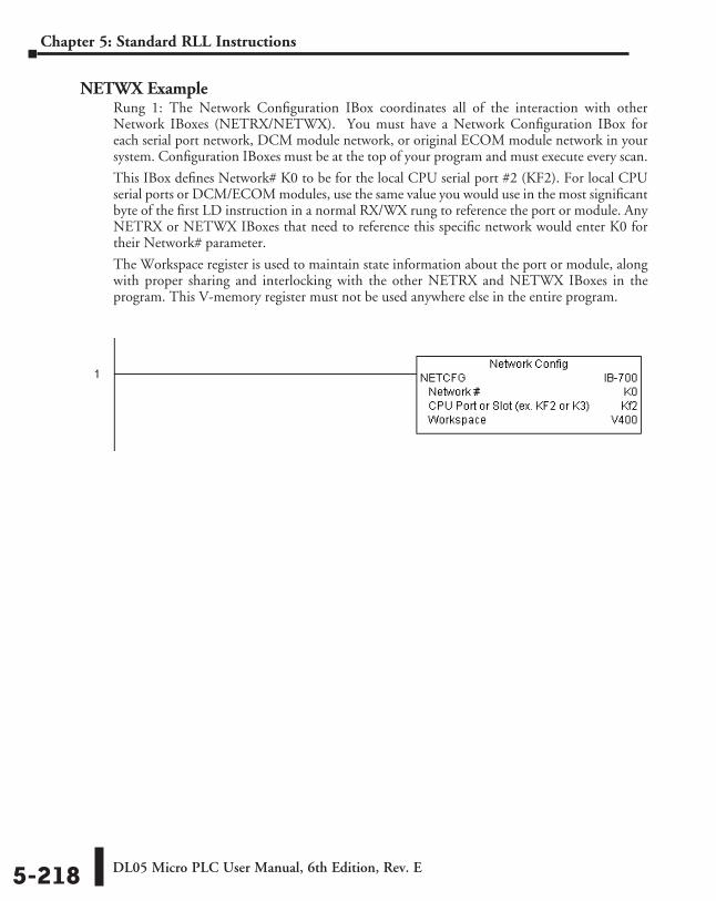
DL05 Micro PLC User Manual, 6th Edition, Rev. E5-218
Chapter 5: Standard RLL Instructions
NETWX ExampleRung 1: The Network Configuration IBox coordinates all of the interaction with other Network IBoxes (NETRX/NETWX). You must have a Network Configuration IBox for each serial port network, DCM module network, or original ECOM module network in your system. Configuration IBoxes must be at the top of your program and must execute every scan.
This IBox defines Network# K0 to be for the local CPU serial port #2 (KF2). For local CPU serial ports or DCM/ECOM modules, use the same value you would use in the most significant byte of the first LD instruction in a normal RX/WX rung to reference the port or module. Any NETRX or NETWX IBoxes that need to reference this specific network would enter K0 for their Network# parameter.
The Workspace register is used to maintain state information about the port or module, along with proper sharing and interlocking with the other NETRX and NETWX IBoxes in the program. This V-memory register must not be used anywhere else in the entire program.
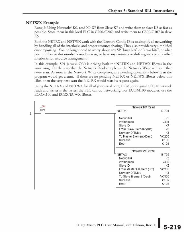
DL05 Micro PLC User Manual, 6th Edition, Rev. E 5-219
Chapter 5: Standard RLL Instructions
NETWX ExampleRung 2: Using Network# K0, read X0-X7 from Slave K7 and write them to slave K5 as fast as possible. Store them in this local PLC in C200-C207, and write them to C300-C307 in slave K5.
Both the NETRX and NETWX work with the Network Config IBox to simplify all networking by handling all of the interlocks and proper resource sharing. They also provide very simplified error reporting. You no longer need to worry about any SP “busy bits” or “error bits”, or what port number or slot number a module is in, or have any counters or shift registers or any other interlocks for resource management.
In this example, SP1 (always ON) is driving both the NETRX and NETWX IBoxes in the same rung. On the scan that the Network Read completes, the Network Write will start that same scan. As soon as the Network Write completes, any pending operations below it in the program would get a turn. If there are no pending NETRX or NETWX IBoxes below this IBox, then the very next scan the NETRX would start its request again.
Using the NETRX and NETWX for all of your serial port, DCM, or original ECOM network reads and writes is the fastest the PLC can do networking. For ECOM100 modules, use the ECOM100 and ECRX/ECWX IBoxes.
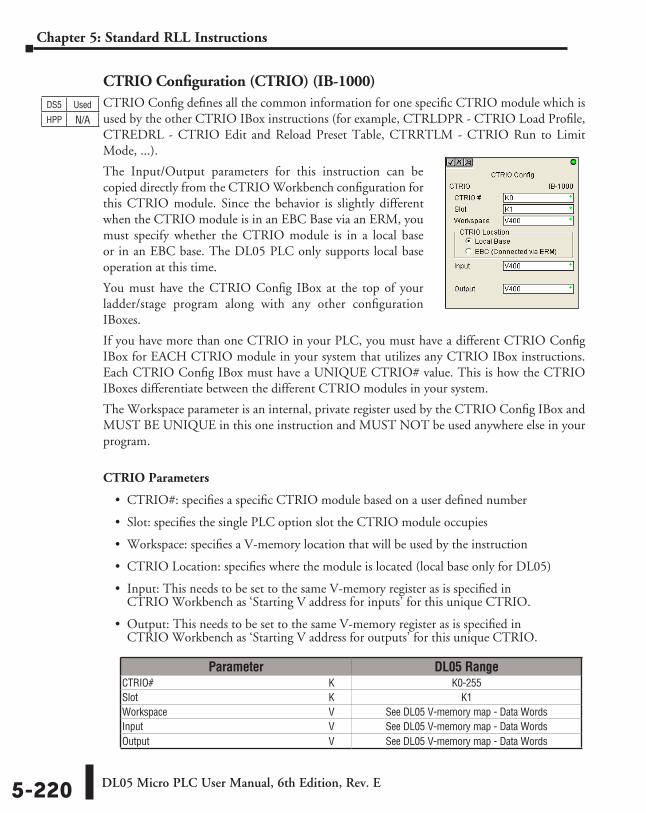
DL05 Micro PLC User Manual, 6th Edition, Rev. E5-220
Chapter 5: Standard RLL Instructions
CTRIO Configuration (CTRIO) (IB-1000)CTRIO Config defines all the common information for one specific CTRIO module which is used by the other CTRIO IBox instructions (for example, CTRLDPR - CTRIO Load Profile, CTREDRL - CTRIO Edit and Reload Preset Table, CTRRTLM - CTRIO Run to Limit Mode, ...).
The Input/Output parameters for this instruction can be copied directly from the CTRIO Workbench configuration for this CTRIO module. Since the behavior is slightly different when the CTRIO module is in an EBC Base via an ERM, you must specify whether the CTRIO module is in a local base or in an EBC base. The DL05 PLC only supports local base operation at this time.
You must have the CTRIO Config IBox at the top of your ladder/stage program along with any other configuration IBoxes.
If you have more than one CTRIO in your PLC, you must have a different CTRIO Config IBox for EACH CTRIO module in your system that utilizes any CTRIO IBox instructions. Each CTRIO Config IBox must have a UNIQUE CTRIO# value. This is how the CTRIO IBoxes differentiate between the different CTRIO modules in your system.
The Workspace parameter is an internal, private register used by the CTRIO Config IBox and MUST BE UNIQUE in this one instruction and MUST NOT be used anywhere else in your program.
CTRIO Parameters
• CTRIO#: specifies a specific CTRIO module based on a user defined number
• Slot: specifies the single PLC option slot the CTRIO module occupies
• Workspace: specifies a V-memory location that will be used by the instruction
• CTRIO Location: specifies where the module is located (local base only for DL05)
• Input: This needs to be set to the same V-memory register as is specified in CTRIO Workbench as ‘Starting V address for inputs’ for this unique CTRIO.
• Output: This needs to be set to the same V-memory register as is specified in CTRIO Workbench as ‘Starting V address for outputs’ for this unique CTRIO.
DS5 Used
HPP N/A
Parameter DL05 RangeCTRIO# ⸠⸠⸠⸠⸠⸠⸠⸠⸠⸠⸠⸠⸠⸠⸠⸠⸠⸠⸠⸠⸠⸠⸠⸠⸠⸠⸠⸠⸠⸠⸠⸠⸠⸠⸠⸠⸠⸠⸠⸠⸠⸠⸠⸠⸠⸠⸠⸠⸠⸠⸠⸠⸠⸠⸠⸠⸠⸠⸠⸠⸠⸠⸠⸠⸠⸠⸠⸠ K K0-255Slot ⸠⸠⸠⸠⸠⸠⸠⸠⸠⸠⸠⸠⸠⸠⸠⸠⸠⸠⸠⸠⸠⸠⸠⸠⸠⸠⸠⸠⸠⸠⸠⸠⸠⸠⸠⸠⸠⸠⸠⸠⸠⸠⸠⸠⸠⸠⸠⸠⸠⸠⸠⸠⸠⸠⸠⸠⸠⸠⸠⸠⸠⸠⸠⸠⸠⸠⸠⸠⸠⸠⸠⸠⸠⸠ K K1Workspace ⸠⸠⸠⸠⸠⸠⸠⸠⸠⸠⸠⸠⸠⸠⸠⸠⸠⸠⸠⸠⸠⸠⸠⸠⸠⸠⸠⸠⸠⸠⸠⸠⸠⸠⸠⸠⸠⸠⸠⸠⸠⸠⸠⸠⸠⸠⸠⸠⸠⸠⸠⸠⸠⸠⸠⸠⸠⸠⸠⸠⸠⸠ V See DL05 V-memory map - Data WordsInput ⸠⸠⸠⸠⸠⸠⸠⸠⸠⸠⸠⸠⸠⸠⸠⸠⸠⸠⸠⸠⸠⸠⸠⸠⸠⸠⸠⸠⸠⸠⸠⸠⸠⸠⸠⸠⸠⸠⸠⸠⸠⸠⸠⸠⸠⸠⸠⸠⸠⸠⸠⸠⸠⸠⸠⸠⸠⸠⸠⸠⸠⸠⸠⸠⸠⸠⸠⸠⸠⸠⸠⸠ V See DL05 V-memory map - Data WordsOutput ⸠⸠⸠⸠⸠⸠⸠⸠⸠⸠⸠⸠⸠⸠⸠⸠⸠⸠⸠⸠⸠⸠⸠⸠⸠⸠⸠⸠⸠⸠⸠⸠⸠⸠⸠⸠⸠⸠⸠⸠⸠⸠⸠⸠⸠⸠⸠⸠⸠⸠⸠⸠⸠⸠⸠⸠⸠⸠⸠⸠⸠⸠⸠⸠⸠⸠⸠⸠⸠ V See DL05 V-memory map - Data Words
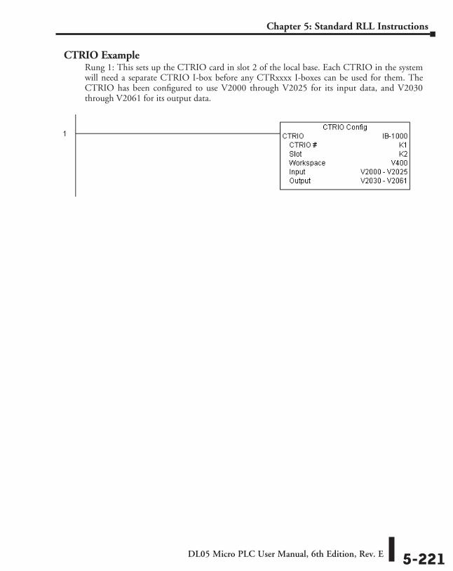
DL05 Micro PLC User Manual, 6th Edition, Rev. E 5-221
Chapter 5: Standard RLL Instructions
CTRIO ExampleRung 1: This sets up the CTRIO card in slot 2 of the local base. Each CTRIO in the system will need a separate CTRIO I-box before any CTRxxxx I-boxes can be used for them. The CTRIO has been configured to use V2000 through V2025 for its input data, and V2030 through V2061 for its output data.
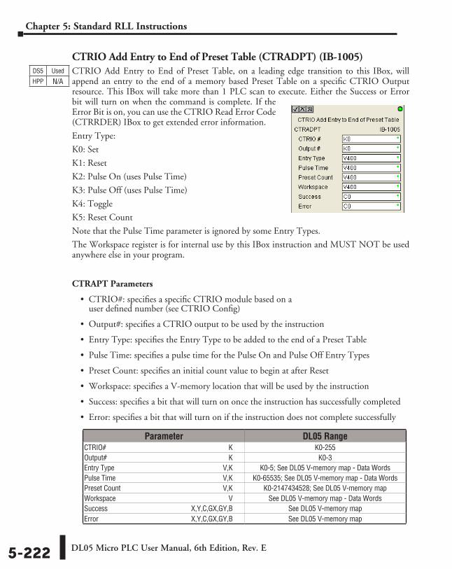
DL05 Micro PLC User Manual, 6th Edition, Rev. E5-222
Chapter 5: Standard RLL Instructions
CTRIO Add Entry to End of Preset Table (CTRADPT) (IB-1005)CTRIO Add Entry to End of Preset Table, on a leading edge transition to this IBox, will append an entry to the end of a memory based Preset Table on a specific CTRIO Output resource. This IBox will take more than 1 PLC scan to execute. Either the Success or Error bit will turn on when the command is complete. If the Error Bit is on, you can use the CTRIO Read Error Code (CTRRDER) IBox to get extended error information.
Entry Type:
K0: Set
K1: Reset
K2: Pulse On (uses Pulse Time)
K3: Pulse Off (uses Pulse Time)
K4: Toggle
K5: Reset Count
Note that the Pulse Time parameter is ignored by some Entry Types.
The Workspace register is for internal use by this IBox instruction and MUST NOT be used anywhere else in your program.
CTRAPT Parameters
• CTRIO#: specifies a specific CTRIO module based on a user defined number (see CTRIO Config)
• Output#: specifies a CTRIO output to be used by the instruction
• Entry Type: specifies the Entry Type to be added to the end of a Preset Table
• Pulse Time: specifies a pulse time for the Pulse On and Pulse Off Entry Types
• Preset Count: specifies an initial count value to begin at after Reset
• Workspace: specifies a V-memory location that will be used by the instruction
• Success: specifies a bit that will turn on once the instruction has successfully completed
• Error: specifies a bit that will turn on if the instruction does not complete successfully
DS5 Used
HPP N/A
Parameter DL05 RangeCTRIO# ⸠⸠⸠⸠⸠⸠⸠⸠⸠⸠⸠⸠⸠⸠⸠⸠⸠⸠⸠⸠⸠⸠⸠⸠⸠⸠⸠⸠⸠⸠⸠⸠⸠⸠⸠⸠⸠⸠⸠⸠⸠⸠⸠⸠⸠⸠⸠⸠⸠⸠⸠⸠⸠⸠⸠⸠⸠⸠⸠⸠⸠⸠⸠⸠⸠⸠⸠⸠ K K0-255Output# ⸠⸠⸠⸠⸠⸠⸠⸠⸠⸠⸠⸠⸠⸠⸠⸠⸠⸠⸠⸠⸠⸠⸠⸠⸠⸠⸠⸠⸠⸠⸠⸠⸠⸠⸠⸠⸠⸠⸠⸠⸠⸠⸠⸠⸠⸠⸠⸠⸠⸠⸠⸠⸠⸠⸠⸠⸠⸠⸠⸠⸠⸠⸠⸠⸠⸠⸠ K K0-3Entry Type ⸠⸠⸠⸠⸠⸠⸠⸠⸠⸠⸠⸠⸠⸠⸠⸠⸠⸠⸠⸠⸠⸠⸠⸠⸠⸠⸠⸠⸠⸠⸠⸠⸠⸠⸠⸠⸠⸠⸠⸠⸠⸠⸠⸠⸠⸠⸠⸠⸠⸠⸠⸠⸠⸠⸠⸠⸠⸠⸠⸠V,K K0-5; See DL05 V-memory map - Data WordsPulse Time ⸠⸠⸠⸠⸠⸠⸠⸠⸠⸠⸠⸠⸠⸠⸠⸠⸠⸠⸠⸠⸠⸠⸠⸠⸠⸠⸠⸠⸠⸠⸠⸠⸠⸠⸠⸠⸠⸠⸠⸠⸠⸠⸠⸠⸠⸠⸠⸠⸠⸠⸠⸠⸠⸠⸠⸠⸠⸠⸠V,K K0-65535; See DL05 V-memory map - Data WordsPreset Count ⸠⸠⸠⸠⸠⸠⸠⸠⸠⸠⸠⸠⸠⸠⸠⸠⸠⸠⸠⸠⸠⸠⸠⸠⸠⸠⸠⸠⸠⸠⸠⸠⸠⸠⸠⸠⸠⸠⸠⸠⸠⸠⸠⸠⸠⸠⸠⸠⸠⸠⸠⸠⸠⸠⸠⸠V,K K0-2147434528; See DL05 V-memory mapWorkspace ⸠⸠⸠⸠⸠⸠⸠⸠⸠⸠⸠⸠⸠⸠⸠⸠⸠⸠⸠⸠⸠⸠⸠⸠⸠⸠⸠⸠⸠⸠⸠⸠⸠⸠⸠⸠⸠⸠⸠⸠⸠⸠⸠⸠⸠⸠⸠⸠⸠⸠⸠⸠⸠⸠⸠⸠⸠⸠⸠⸠⸠⸠ V See DL05 V-memory map - Data WordsSuccess ⸠⸠⸠⸠⸠⸠⸠⸠⸠⸠⸠⸠⸠⸠⸠⸠⸠⸠⸠⸠⸠⸠⸠⸠⸠⸠⸠⸠⸠⸠⸠⸠⸠⸠⸠⸠⸠⸠⸠⸠⸠⸠⸠⸠⸠ X,Y,C,GX,GY,B See DL05 V-memory mapError ⸠⸠⸠⸠⸠⸠⸠⸠⸠⸠⸠⸠⸠⸠⸠⸠⸠⸠⸠⸠⸠⸠⸠⸠⸠⸠⸠⸠⸠⸠⸠⸠⸠⸠⸠⸠⸠⸠⸠⸠⸠⸠⸠⸠⸠⸠⸠⸠⸠⸠ X,Y,C,GX,GY,B See DL05 V-memory map
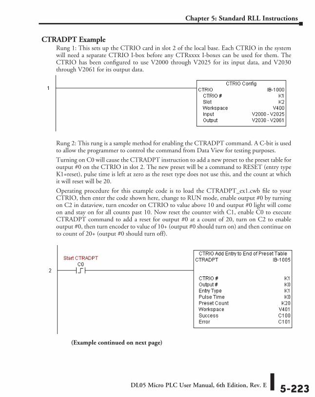
DL05 Micro PLC User Manual, 6th Edition, Rev. E 5-223
Chapter 5: Standard RLL Instructions
CTRADPT ExampleRung 1: This sets up the CTRIO card in slot 2 of the local base. Each CTRIO in the system will need a separate CTRIO I-box before any CTRxxxx I-boxes can be used for them. The CTRIO has been configured to use V2000 through V2025 for its input data, and V2030 through V2061 for its output data.
Rung 2: This rung is a sample method for enabling the CTRADPT command. A C-bit is used to allow the programmer to control the command from Data View for testing purposes.
Turning on C0 will cause the CTRADPT instruction to add a new preset to the preset table for output #0 on the CTRIO in slot 2. The new preset will be a command to RESET (entry type K1=reset), pulse time is left at zero as the reset type does not use this, and the count at which it will reset will be 20.
Operating procedure for this example code is to load the CTRADPT_ex1.cwb file to your CTRIO, then enter the code shown here, change to RUN mode, enable output #0 by turning on C2 in dataview, turn encoder on CTRIO to value above 10 and output #0 light will come on and stay on for all counts past 10. Now reset the counter with C1, enable C0 to execute CTRADPT command to add a reset for output #0 at a count of 20, turn on C2 to enable output #0, then turn encoder to value of 10+ (output #0 should turn on) and then continue on to count of 20+ (output #0 should turn off).
(Example continued on next page)
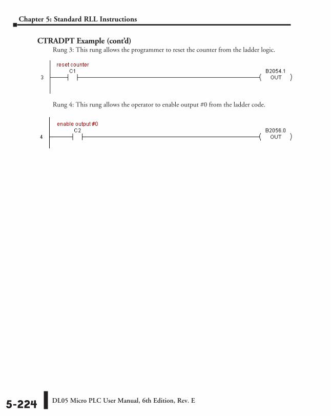
DL05 Micro PLC User Manual, 6th Edition, Rev. E5-224
Chapter 5: Standard RLL Instructions
CTRADPT Example (cont’d)Rung 3: This rung allows the programmer to reset the counter from the ladder logic.
Rung 4: This rung allows the operator to enable output #0 from the ladder code.
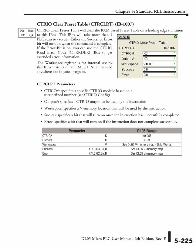
DL05 Micro PLC User Manual, 6th Edition, Rev. E 5-225
Chapter 5: Standard RLL Instructions
CTRIO Clear Preset Table (CTRCLRT) (IB-1007)CTRIO Clear Preset Table will clear the RAM based Preset Table on a leading edge transition to this IBox. This IBox will take more than 1 PLC scan to execute. Either the Success or Error bit will turn on when the command is complete. If the Error Bit is on, you can use the CTRIO Read Error Code (CTRRDER) IBox to get extended error information.
The Workspace register is for internal use by this IBox instruction and MUST NOT be used anywhere else in your program.
CTRCLRT Parameters
• CTRIO#: specifies a specific CTRIO module based on a user defined number (see CTRIO Config)
• Output#: specifies a CTRIO output to be used by the instruction
• Workspace: specifies a V-memory location that will be used by the instruction
• Success: specifies a bit that will turn on once the instruction has successfully completed
• Error: specifies a bit that will turn on if the instruction does not complete successfully
DS5 Used
HPP N/A
Parameter DL05 RangeCTRIO# ⸠⸠⸠⸠⸠⸠⸠⸠⸠⸠⸠⸠⸠⸠⸠⸠⸠⸠⸠⸠⸠⸠⸠⸠⸠⸠⸠⸠⸠⸠⸠⸠⸠⸠⸠⸠⸠⸠⸠⸠⸠⸠⸠⸠⸠⸠⸠⸠⸠⸠⸠⸠⸠⸠⸠⸠⸠⸠⸠⸠⸠⸠⸠⸠⸠⸠⸠⸠ K K0-255Output# ⸠⸠⸠⸠⸠⸠⸠⸠⸠⸠⸠⸠⸠⸠⸠⸠⸠⸠⸠⸠⸠⸠⸠⸠⸠⸠⸠⸠⸠⸠⸠⸠⸠⸠⸠⸠⸠⸠⸠⸠⸠⸠⸠⸠⸠⸠⸠⸠⸠⸠⸠⸠⸠⸠⸠⸠⸠⸠⸠⸠⸠⸠⸠⸠⸠⸠⸠ K K0-3Workspace ⸠⸠⸠⸠⸠⸠⸠⸠⸠⸠⸠⸠⸠⸠⸠⸠⸠⸠⸠⸠⸠⸠⸠⸠⸠⸠⸠⸠⸠⸠⸠⸠⸠⸠⸠⸠⸠⸠⸠⸠⸠⸠⸠⸠⸠⸠⸠⸠⸠⸠⸠⸠⸠⸠⸠⸠⸠⸠⸠⸠⸠⸠ V See DL05 V-memory map - Data WordsSuccess ⸠⸠⸠⸠⸠⸠⸠⸠⸠⸠⸠⸠⸠⸠⸠⸠⸠⸠⸠⸠⸠⸠⸠⸠⸠⸠⸠⸠⸠⸠⸠⸠⸠⸠⸠⸠⸠⸠⸠⸠⸠⸠⸠⸠⸠ X,Y,C,GX,GY,B See DL05 V-memory mapError ⸠⸠⸠⸠⸠⸠⸠⸠⸠⸠⸠⸠⸠⸠⸠⸠⸠⸠⸠⸠⸠⸠⸠⸠⸠⸠⸠⸠⸠⸠⸠⸠⸠⸠⸠⸠⸠⸠⸠⸠⸠⸠⸠⸠⸠⸠⸠⸠⸠⸠ X,Y,C,GX,GY,B See DL05 V-memory map
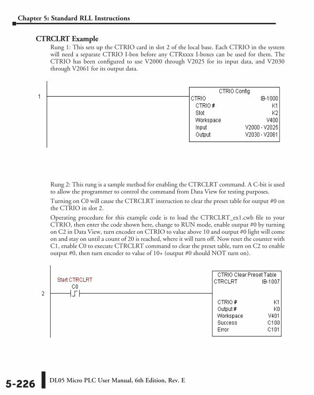
DL05 Micro PLC User Manual, 6th Edition, Rev. E5-226
Chapter 5: Standard RLL Instructions
CTRCLRT ExampleRung 1: This sets up the CTRIO card in slot 2 of the local base. Each CTRIO in the system will need a separate CTRIO I-box before any CTRxxxx I-boxes can be used for them. The CTRIO has been configured to use V2000 through V2025 for its input data, and V2030 through V2061 for its output data.
Rung 2: This rung is a sample method for enabling the CTRCLRT command. A C-bit is used to allow the programmer to control the command from Data View for testing purposes.
Turning on C0 will cause the CTRCLRT instruction to clear the preset table for output #0 on the CTRIO in slot 2.
Operating procedure for this example code is to load the CTRCLRT_ex1.cwb file to your CTRIO, then enter the code shown here, change to RUN mode, enable output #0 by turning on C2 in Data View, turn encoder on CTRIO to value above 10 and output #0 light will come on and stay on until a count of 20 is reached, where it will turn off. Now reset the counter with C1, enable C0 to execute CTRCLRT command to clear the preset table, turn on C2 to enable output #0, then turn encoder to value of 10+ (output #0 should NOT turn on).
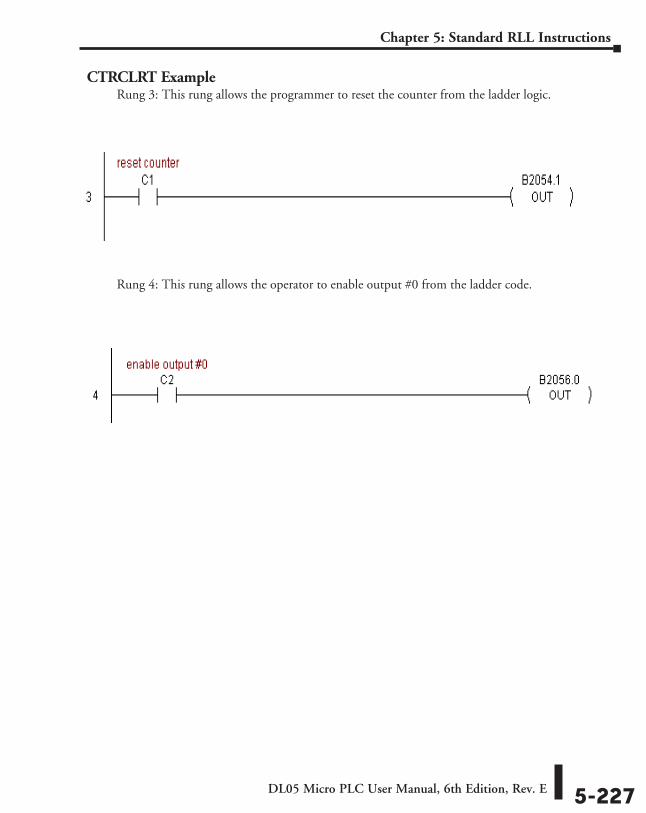
DL05 Micro PLC User Manual, 6th Edition, Rev. E 5-227
Chapter 5: Standard RLL Instructions
CTRCLRT ExampleRung 3: This rung allows the programmer to reset the counter from the ladder logic.
Rung 4: This rung allows the operator to enable output #0 from the ladder code.
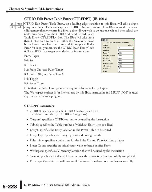
DL05 Micro PLC User Manual, 6th Edition, Rev. E5-228
Chapter 5: Standard RLL Instructions
CTRIO Edit Preset Table Entry (CTREDPT) (IB-1003)CTRIO Edit Preset Table Entry, on a leading edge transition to this IBox, will edit a single entry in a Preset Table on a specific CTRIO Output resource. This IBox is good if you are editing more than one entry in a file at a time. If you wish to do just one edit and then reload the table immediately, see the CTRIO Edit and Reload Preset Table Entry (CTREDRL) IBox. This IBox will take more than 1 PLC scan to execute. Either the Success or Error bit will turn on when the command is complete. If the Error Bit is on, you can use the CTRIO Read Error Code (CTRRDER) IBox to get extended error information.
Entry Type:
K0: Set
K1: Reset
K2: Pulse On (uses Pulse Time)
K3: Pulse Off (uses Pulse Time)
K4: Toggle
K5: Reset Count
Note that the Pulse Time parameter is ignored by some Entry Types.
The Workspace register is for internal use by this IBox instruction and MUST NOT be used anywhere else in your program.
CTREDPT Parameters
• CTRIO#: specifies a specific CTRIO module based on a user defined number (see CTRIO Config Ibox)
• Output#: specifies a CTRIO output to be used by the instruction
• Table#: specifies the Table number of which an Entry is to be edited
• Entry#: specifies the Entry location in the Preset Table to be edited
• Entry Type: specifies the Entry Type to add during the edit
• Pulse Time: specifies a pulse time for the Pulse On and Pulse Off Entry Types
• Preset Count: specifies an initial count value to begin at after Reset
• Workspace: specifies a V-memory location that will be used by the instruction
• Success: specifies a bit that will turn on once the instruction has successfully completed
• Error: specifies a bit that will turn on if the instruction does not complete successfully
DS5 Used
HPP N/A
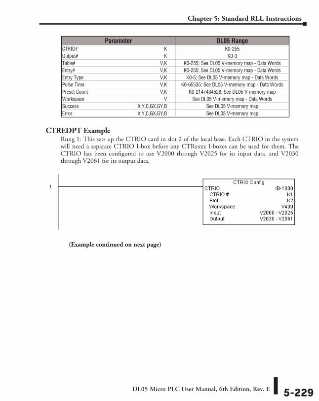
DL05 Micro PLC User Manual, 6th Edition, Rev. E 5-229
Chapter 5: Standard RLL Instructions
CTREDPT ExampleRung 1: This sets up the CTRIO card in slot 2 of the local base. Each CTRIO in the system will need a separate CTRIO I-box before any CTRxxxx I-boxes can be used for them. The CTRIO has been configured to use V2000 through V2025 for its input data, and V2030 through V2061 for its output data.
(Example continued on next page)
Parameter DL05 RangeCTRIO# ⸠⸠⸠⸠⸠⸠⸠⸠⸠⸠⸠⸠⸠⸠⸠⸠⸠⸠⸠⸠⸠⸠⸠⸠⸠⸠⸠⸠⸠⸠⸠⸠⸠⸠⸠⸠⸠⸠⸠⸠⸠⸠⸠⸠⸠⸠⸠⸠⸠⸠⸠⸠⸠⸠⸠⸠⸠⸠⸠⸠⸠⸠⸠⸠⸠⸠⸠⸠ K K0-255Output# ⸠⸠⸠⸠⸠⸠⸠⸠⸠⸠⸠⸠⸠⸠⸠⸠⸠⸠⸠⸠⸠⸠⸠⸠⸠⸠⸠⸠⸠⸠⸠⸠⸠⸠⸠⸠⸠⸠⸠⸠⸠⸠⸠⸠⸠⸠⸠⸠⸠⸠⸠⸠⸠⸠⸠⸠⸠⸠⸠⸠⸠⸠⸠⸠⸠⸠⸠ K K0-3Table# ⸠⸠⸠⸠⸠⸠⸠⸠⸠⸠⸠⸠⸠⸠⸠⸠⸠⸠⸠⸠⸠⸠⸠⸠⸠⸠⸠⸠⸠⸠⸠⸠⸠⸠⸠⸠⸠⸠⸠⸠⸠⸠⸠⸠⸠⸠⸠⸠⸠⸠⸠⸠⸠⸠⸠⸠⸠⸠⸠⸠⸠⸠⸠⸠⸠⸠⸠V,K K0-255; See DL05 V-memory map - Data WordsEntry# ⸠⸠⸠⸠⸠⸠⸠⸠⸠⸠⸠⸠⸠⸠⸠⸠⸠⸠⸠⸠⸠⸠⸠⸠⸠⸠⸠⸠⸠⸠⸠⸠⸠⸠⸠⸠⸠⸠⸠⸠⸠⸠⸠⸠⸠⸠⸠⸠⸠⸠⸠⸠⸠⸠⸠⸠⸠⸠⸠⸠⸠⸠⸠⸠⸠⸠⸠V,K K0-255; See DL05 V-memory map - Data WordsEntry Type ⸠⸠⸠⸠⸠⸠⸠⸠⸠⸠⸠⸠⸠⸠⸠⸠⸠⸠⸠⸠⸠⸠⸠⸠⸠⸠⸠⸠⸠⸠⸠⸠⸠⸠⸠⸠⸠⸠⸠⸠⸠⸠⸠⸠⸠⸠⸠⸠⸠⸠⸠⸠⸠⸠⸠⸠⸠⸠⸠⸠V,K K0-5; See DL05 V-memory map - Data WordsPulse Time ⸠⸠⸠⸠⸠⸠⸠⸠⸠⸠⸠⸠⸠⸠⸠⸠⸠⸠⸠⸠⸠⸠⸠⸠⸠⸠⸠⸠⸠⸠⸠⸠⸠⸠⸠⸠⸠⸠⸠⸠⸠⸠⸠⸠⸠⸠⸠⸠⸠⸠⸠⸠⸠⸠⸠⸠⸠⸠⸠V,K K0-65535; See DL05 V-memory map - Data WordsPreset Count ⸠⸠⸠⸠⸠⸠⸠⸠⸠⸠⸠⸠⸠⸠⸠⸠⸠⸠⸠⸠⸠⸠⸠⸠⸠⸠⸠⸠⸠⸠⸠⸠⸠⸠⸠⸠⸠⸠⸠⸠⸠⸠⸠⸠⸠⸠⸠⸠⸠⸠⸠⸠⸠⸠⸠⸠V,K K0-2147434528; See DL05 V-memory mapWorkspace ⸠⸠⸠⸠⸠⸠⸠⸠⸠⸠⸠⸠⸠⸠⸠⸠⸠⸠⸠⸠⸠⸠⸠⸠⸠⸠⸠⸠⸠⸠⸠⸠⸠⸠⸠⸠⸠⸠⸠⸠⸠⸠⸠⸠⸠⸠⸠⸠⸠⸠⸠⸠⸠⸠⸠⸠⸠⸠⸠⸠⸠⸠ V See DL05 V-memory map - Data WordsSuccess ⸠⸠⸠⸠⸠⸠⸠⸠⸠⸠⸠⸠⸠⸠⸠⸠⸠⸠⸠⸠⸠⸠⸠⸠⸠⸠⸠⸠⸠⸠⸠⸠⸠⸠⸠⸠⸠⸠⸠⸠⸠⸠⸠⸠⸠ X,Y,C,GX,GY,B See DL05 V-memory mapError ⸠⸠⸠⸠⸠⸠⸠⸠⸠⸠⸠⸠⸠⸠⸠⸠⸠⸠⸠⸠⸠⸠⸠⸠⸠⸠⸠⸠⸠⸠⸠⸠⸠⸠⸠⸠⸠⸠⸠⸠⸠⸠⸠⸠⸠⸠⸠⸠⸠⸠ X,Y,C,GX,GY,B See DL05 V-memory map
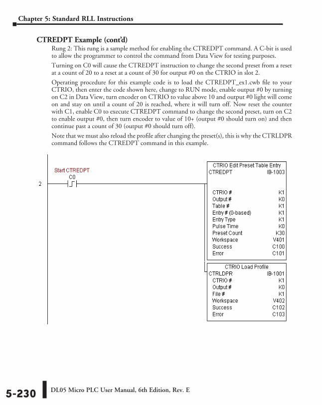
DL05 Micro PLC User Manual, 6th Edition, Rev. E5-230
Chapter 5: Standard RLL Instructions
CTREDPT Example (cont’d)Rung 2: This rung is a sample method for enabling the CTREDPT command. A C-bit is used to allow the programmer to control the command from Data View for testing purposes.
Turning on C0 will cause the CTREDPT instruction to change the second preset from a reset at a count of 20 to a reset at a count of 30 for output #0 on the CTRIO in slot 2.
Operating procedure for this example code is to load the CTREDPT_ex1.cwb file to your CTRIO, then enter the code shown here, change to RUN mode, enable output #0 by turning on C2 in Data View, turn encoder on CTRIO to value above 10 and output #0 light will come on and stay on until a count of 20 is reached, where it will turn off. Now reset the counter with C1, enable C0 to execute CTREDPT command to change the second preset, turn on C2 to enable output #0, then turn encoder to value of 10+ (output #0 should turn on) and then continue past a count of 30 (output #0 should turn off).
Note that we must also reload the profile after changing the preset(s), this is why the CTRLDPR command follows the CTREDPT command in this example.
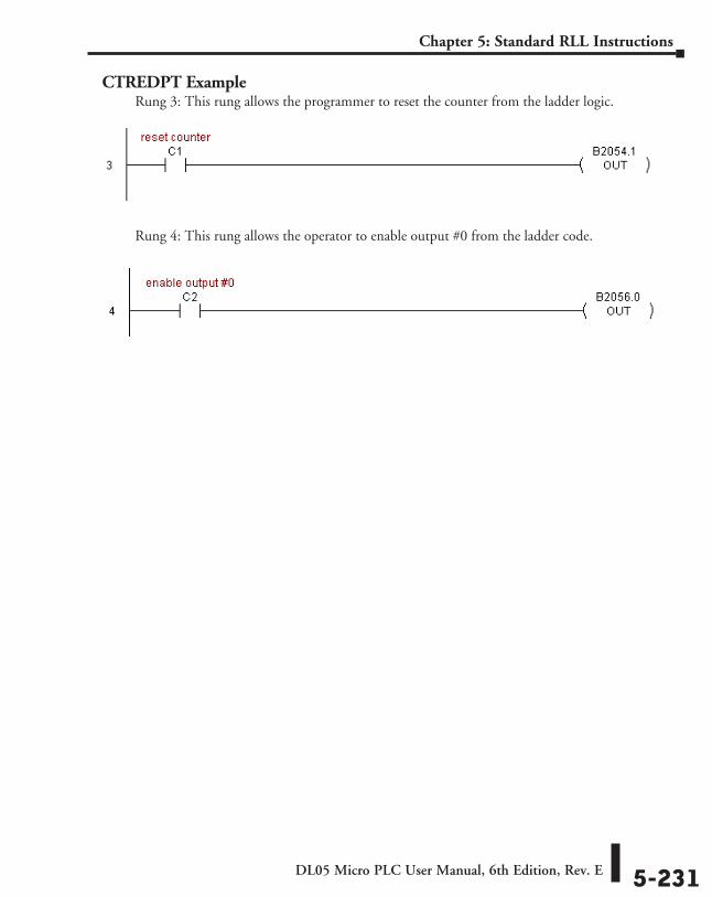
DL05 Micro PLC User Manual, 6th Edition, Rev. E 5-231
Chapter 5: Standard RLL Instructions
CTREDPT ExampleRung 3: This rung allows the programmer to reset the counter from the ladder logic.
Rung 4: This rung allows the operator to enable output #0 from the ladder code.
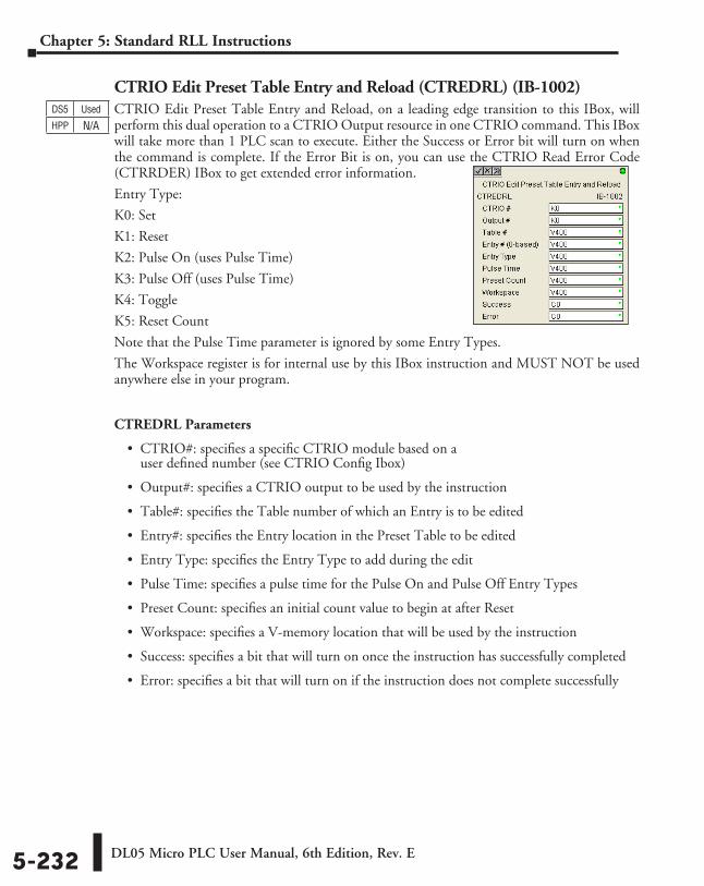
DL05 Micro PLC User Manual, 6th Edition, Rev. E5-232
Chapter 5: Standard RLL Instructions
CTRIO Edit Preset Table Entry and Reload (CTREDRL) (IB-1002)CTRIO Edit Preset Table Entry and Reload, on a leading edge transition to this IBox, will perform this dual operation to a CTRIO Output resource in one CTRIO command. This IBox will take more than 1 PLC scan to execute. Either the Success or Error bit will turn on when the command is complete. If the Error Bit is on, you can use the CTRIO Read Error Code (CTRRDER) IBox to get extended error information.
Entry Type:
K0: Set
K1: Reset
K2: Pulse On (uses Pulse Time)
K3: Pulse Off (uses Pulse Time)
K4: Toggle
K5: Reset Count
Note that the Pulse Time parameter is ignored by some Entry Types.
The Workspace register is for internal use by this IBox instruction and MUST NOT be used anywhere else in your program.
CTREDRL Parameters
• CTRIO#: specifies a specific CTRIO module based on a user defined number (see CTRIO Config Ibox)
• Output#: specifies a CTRIO output to be used by the instruction
• Table#: specifies the Table number of which an Entry is to be edited
• Entry#: specifies the Entry location in the Preset Table to be edited
• Entry Type: specifies the Entry Type to add during the edit
• Pulse Time: specifies a pulse time for the Pulse On and Pulse Off Entry Types
• Preset Count: specifies an initial count value to begin at after Reset
• Workspace: specifies a V-memory location that will be used by the instruction
• Success: specifies a bit that will turn on once the instruction has successfully completed
• Error: specifies a bit that will turn on if the instruction does not complete successfully
DS5 Used
HPP N/A
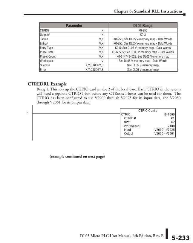
DL05 Micro PLC User Manual, 6th Edition, Rev. E 5-233
Chapter 5: Standard RLL Instructions
CTREDRL ExampleRung 1: This sets up the CTRIO card in slot 2 of the local base. Each CTRIO in the system will need a separate CTRIO I-box before any CTRxxxx I-boxes can be used for them. The CTRIO has been configured to use V2000 through V2025 for its input data, and V2030 through V2061 for its output data.
Parameter DL05 RangeCTRIO# ⸠⸠⸠⸠⸠⸠⸠⸠⸠⸠⸠⸠⸠⸠⸠⸠⸠⸠⸠⸠⸠⸠⸠⸠⸠⸠⸠⸠⸠⸠⸠⸠⸠⸠⸠⸠⸠⸠⸠⸠⸠⸠⸠⸠⸠⸠⸠⸠⸠⸠⸠⸠⸠⸠⸠⸠⸠⸠⸠⸠⸠⸠⸠⸠⸠⸠⸠⸠ K K0-255Output# ⸠⸠⸠⸠⸠⸠⸠⸠⸠⸠⸠⸠⸠⸠⸠⸠⸠⸠⸠⸠⸠⸠⸠⸠⸠⸠⸠⸠⸠⸠⸠⸠⸠⸠⸠⸠⸠⸠⸠⸠⸠⸠⸠⸠⸠⸠⸠⸠⸠⸠⸠⸠⸠⸠⸠⸠⸠⸠⸠⸠⸠⸠⸠⸠⸠⸠⸠ K K0-3Table# ⸠⸠⸠⸠⸠⸠⸠⸠⸠⸠⸠⸠⸠⸠⸠⸠⸠⸠⸠⸠⸠⸠⸠⸠⸠⸠⸠⸠⸠⸠⸠⸠⸠⸠⸠⸠⸠⸠⸠⸠⸠⸠⸠⸠⸠⸠⸠⸠⸠⸠⸠⸠⸠⸠⸠⸠⸠⸠⸠⸠⸠⸠⸠⸠⸠⸠⸠V,K K0-255; See DL05 V-memory map - Data WordsEntry# ⸠⸠⸠⸠⸠⸠⸠⸠⸠⸠⸠⸠⸠⸠⸠⸠⸠⸠⸠⸠⸠⸠⸠⸠⸠⸠⸠⸠⸠⸠⸠⸠⸠⸠⸠⸠⸠⸠⸠⸠⸠⸠⸠⸠⸠⸠⸠⸠⸠⸠⸠⸠⸠⸠⸠⸠⸠⸠⸠⸠⸠⸠⸠⸠⸠⸠⸠V,K K0-255; See DL05 V-memory map - Data WordsEntry Type ⸠⸠⸠⸠⸠⸠⸠⸠⸠⸠⸠⸠⸠⸠⸠⸠⸠⸠⸠⸠⸠⸠⸠⸠⸠⸠⸠⸠⸠⸠⸠⸠⸠⸠⸠⸠⸠⸠⸠⸠⸠⸠⸠⸠⸠⸠⸠⸠⸠⸠⸠⸠⸠⸠⸠⸠⸠⸠⸠⸠V,K K0-5; See DL05 V-memory map - Data WordsPulse Time ⸠⸠⸠⸠⸠⸠⸠⸠⸠⸠⸠⸠⸠⸠⸠⸠⸠⸠⸠⸠⸠⸠⸠⸠⸠⸠⸠⸠⸠⸠⸠⸠⸠⸠⸠⸠⸠⸠⸠⸠⸠⸠⸠⸠⸠⸠⸠⸠⸠⸠⸠⸠⸠⸠⸠⸠⸠⸠⸠V,K K0-65535; See DL05 V-memory map - Data WordsPreset Count ⸠⸠⸠⸠⸠⸠⸠⸠⸠⸠⸠⸠⸠⸠⸠⸠⸠⸠⸠⸠⸠⸠⸠⸠⸠⸠⸠⸠⸠⸠⸠⸠⸠⸠⸠⸠⸠⸠⸠⸠⸠⸠⸠⸠⸠⸠⸠⸠⸠⸠⸠⸠⸠⸠⸠⸠V,K K0-2147434528; See DL05 V-memory mapWorkspace ⸠⸠⸠⸠⸠⸠⸠⸠⸠⸠⸠⸠⸠⸠⸠⸠⸠⸠⸠⸠⸠⸠⸠⸠⸠⸠⸠⸠⸠⸠⸠⸠⸠⸠⸠⸠⸠⸠⸠⸠⸠⸠⸠⸠⸠⸠⸠⸠⸠⸠⸠⸠⸠⸠⸠⸠⸠⸠⸠⸠⸠⸠ V See DL05 V-memory map - Data WordsSuccess ⸠⸠⸠⸠⸠⸠⸠⸠⸠⸠⸠⸠⸠⸠⸠⸠⸠⸠⸠⸠⸠⸠⸠⸠⸠⸠⸠⸠⸠⸠⸠⸠⸠⸠⸠⸠⸠⸠⸠⸠⸠⸠⸠⸠⸠ X,Y,C,GX,GY,B See DL05 V-memory mapError ⸠⸠⸠⸠⸠⸠⸠⸠⸠⸠⸠⸠⸠⸠⸠⸠⸠⸠⸠⸠⸠⸠⸠⸠⸠⸠⸠⸠⸠⸠⸠⸠⸠⸠⸠⸠⸠⸠⸠⸠⸠⸠⸠⸠⸠⸠⸠⸠⸠⸠ X,Y,C,GX,GY,B See DL05 V-memory map
(example continued on next page)
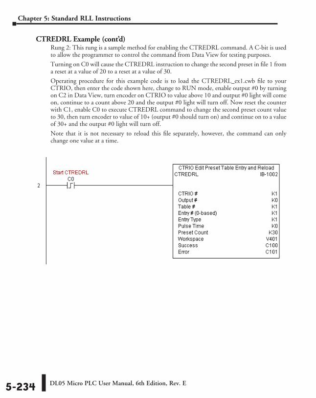
DL05 Micro PLC User Manual, 6th Edition, Rev. E5-234
Chapter 5: Standard RLL Instructions
CTREDRL Example (cont’d)Rung 2: This rung is a sample method for enabling the CTREDRL command. A C-bit is used to allow the programmer to control the command from Data View for testing purposes.
Turning on C0 will cause the CTREDRL instruction to change the second preset in file 1 from a reset at a value of 20 to a reset at a value of 30.
Operating procedure for this example code is to load the CTREDRL_ex1.cwb file to your CTRIO, then enter the code shown here, change to RUN mode, enable output #0 by turning on C2 in Data View, turn encoder on CTRIO to value above 10 and output #0 light will come on, continue to a count above 20 and the output #0 light will turn off. Now reset the counter with C1, enable C0 to execute CTREDRL command to change the second preset count value to 30, then turn encoder to value of 10+ (output #0 should turn on) and continue on to a value of 30+ and the output #0 light will turn off.
Note that it is not necessary to reload this file separately, however, the command can only change one value at a time.
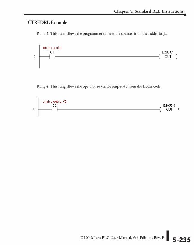
DL05 Micro PLC User Manual, 6th Edition, Rev. E 5-235
Chapter 5: Standard RLL Instructions
CTREDRL Example
Rung 3: This rung allows the programmer to reset the counter from the ladder logic.
Rung 4: This rung allows the operator to enable output #0 from the ladder code.
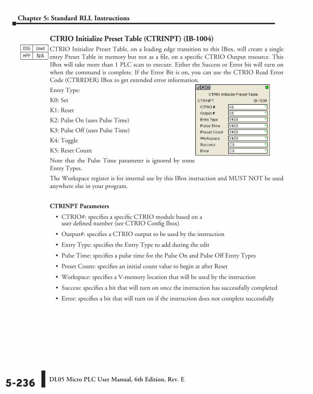
DL05 Micro PLC User Manual, 6th Edition, Rev. E5-236
Chapter 5: Standard RLL Instructions
CTRIO Initialize Preset Table (CTRINPT) (IB-1004)CTRIO Initialize Preset Table, on a leading edge transition to this IBox, will create a single entry Preset Table in memory but not as a file, on a specific CTRIO Output resource. This IBox will take more than 1 PLC scan to execute. Either the Success or Error bit will turn on when the command is complete. If the Error Bit is on, you can use the CTRIO Read Error Code (CTRRDER) IBox to get extended error information.
Entry Type:
K0: Set
K1: Reset
K2: Pulse On (uses Pulse Time)
K3: Pulse Off (uses Pulse Time)
K4: Toggle
K5: Reset Count
Note that the Pulse Time parameter is ignored by some Entry Types.
The Workspace register is for internal use by this IBox instruction and MUST NOT be used anywhere else in your program.
CTRINPT Parameters
• CTRIO#: specifies a specific CTRIO module based on a user defined number (see CTRIO Config Ibox)
• Output#: specifies a CTRIO output to be used by the instruction
• Entry Type: specifies the Entry Type to add during the edit
• Pulse Time: specifies a pulse time for the Pulse On and Pulse Off Entry Types
• Preset Count: specifies an initial count value to begin at after Reset
• Workspace: specifies a V-memory location that will be used by the instruction
• Success: specifies a bit that will turn on once the instruction has successfully completed
• Error: specifies a bit that will turn on if the instruction does not complete successfully
DS5 Used
HPP N/A
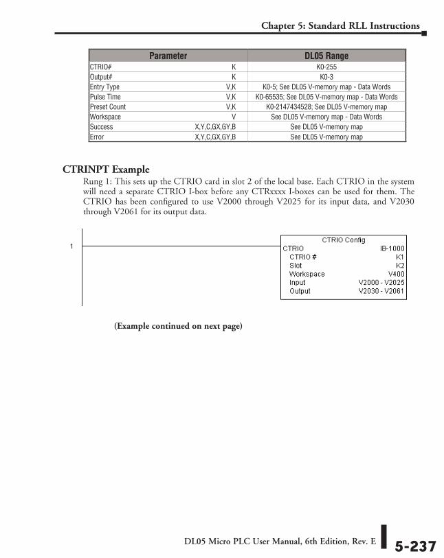
DL05 Micro PLC User Manual, 6th Edition, Rev. E 5-237
Chapter 5: Standard RLL Instructions
CTRINPT ExampleRung 1: This sets up the CTRIO card in slot 2 of the local base. Each CTRIO in the system will need a separate CTRIO I-box before any CTRxxxx I-boxes can be used for them. The CTRIO has been configured to use V2000 through V2025 for its input data, and V2030 through V2061 for its output data.
Parameter DL05 RangeCTRIO# ⸠⸠⸠⸠⸠⸠⸠⸠⸠⸠⸠⸠⸠⸠⸠⸠⸠⸠⸠⸠⸠⸠⸠⸠⸠⸠⸠⸠⸠⸠⸠⸠⸠⸠⸠⸠⸠⸠⸠⸠⸠⸠⸠⸠⸠⸠⸠⸠⸠⸠⸠⸠⸠⸠⸠⸠⸠⸠⸠⸠⸠⸠⸠⸠⸠⸠⸠⸠ K K0-255Output# ⸠⸠⸠⸠⸠⸠⸠⸠⸠⸠⸠⸠⸠⸠⸠⸠⸠⸠⸠⸠⸠⸠⸠⸠⸠⸠⸠⸠⸠⸠⸠⸠⸠⸠⸠⸠⸠⸠⸠⸠⸠⸠⸠⸠⸠⸠⸠⸠⸠⸠⸠⸠⸠⸠⸠⸠⸠⸠⸠⸠⸠⸠⸠⸠⸠⸠⸠ K K0-3Entry Type ⸠⸠⸠⸠⸠⸠⸠⸠⸠⸠⸠⸠⸠⸠⸠⸠⸠⸠⸠⸠⸠⸠⸠⸠⸠⸠⸠⸠⸠⸠⸠⸠⸠⸠⸠⸠⸠⸠⸠⸠⸠⸠⸠⸠⸠⸠⸠⸠⸠⸠⸠⸠⸠⸠⸠⸠⸠⸠⸠⸠V,K K0-5; See DL05 V-memory map - Data WordsPulse Time ⸠⸠⸠⸠⸠⸠⸠⸠⸠⸠⸠⸠⸠⸠⸠⸠⸠⸠⸠⸠⸠⸠⸠⸠⸠⸠⸠⸠⸠⸠⸠⸠⸠⸠⸠⸠⸠⸠⸠⸠⸠⸠⸠⸠⸠⸠⸠⸠⸠⸠⸠⸠⸠⸠⸠⸠⸠⸠⸠V,K K0-65535; See DL05 V-memory map - Data WordsPreset Count ⸠⸠⸠⸠⸠⸠⸠⸠⸠⸠⸠⸠⸠⸠⸠⸠⸠⸠⸠⸠⸠⸠⸠⸠⸠⸠⸠⸠⸠⸠⸠⸠⸠⸠⸠⸠⸠⸠⸠⸠⸠⸠⸠⸠⸠⸠⸠⸠⸠⸠⸠⸠⸠⸠⸠⸠V,K K0-2147434528; See DL05 V-memory mapWorkspace ⸠⸠⸠⸠⸠⸠⸠⸠⸠⸠⸠⸠⸠⸠⸠⸠⸠⸠⸠⸠⸠⸠⸠⸠⸠⸠⸠⸠⸠⸠⸠⸠⸠⸠⸠⸠⸠⸠⸠⸠⸠⸠⸠⸠⸠⸠⸠⸠⸠⸠⸠⸠⸠⸠⸠⸠⸠⸠⸠⸠⸠⸠ V See DL05 V-memory map - Data WordsSuccess ⸠⸠⸠⸠⸠⸠⸠⸠⸠⸠⸠⸠⸠⸠⸠⸠⸠⸠⸠⸠⸠⸠⸠⸠⸠⸠⸠⸠⸠⸠⸠⸠⸠⸠⸠⸠⸠⸠⸠⸠⸠⸠⸠⸠⸠ X,Y,C,GX,GY,B See DL05 V-memory mapError ⸠⸠⸠⸠⸠⸠⸠⸠⸠⸠⸠⸠⸠⸠⸠⸠⸠⸠⸠⸠⸠⸠⸠⸠⸠⸠⸠⸠⸠⸠⸠⸠⸠⸠⸠⸠⸠⸠⸠⸠⸠⸠⸠⸠⸠⸠⸠⸠⸠⸠ X,Y,C,GX,GY,B See DL05 V-memory map
(Example continued on next page)
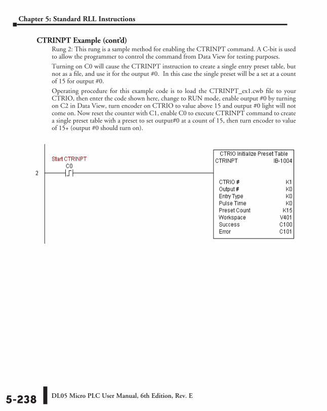
DL05 Micro PLC User Manual, 6th Edition, Rev. E5-238
Chapter 5: Standard RLL Instructions
CTRINPT Example (cont’d)Rung 2: This rung is a sample method for enabling the CTRINPT command. A C-bit is used to allow the programmer to control the command from Data View for testing purposes.
Turning on C0 will cause the CTRINPT instruction to create a single entry preset table, but not as a file, and use it for the output #0. In this case the single preset will be a set at a count of 15 for output #0.
Operating procedure for this example code is to load the CTRINPT_ex1.cwb file to your CTRIO, then enter the code shown here, change to RUN mode, enable output #0 by turning on C2 in Data View, turn encoder on CTRIO to value above 15 and output #0 light will not come on. Now reset the counter with C1, enable C0 to execute CTRINPT command to create a single preset table with a preset to set output#0 at a count of 15, then turn encoder to value of 15+ (output #0 should turn on).
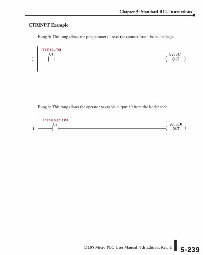
DL05 Micro PLC User Manual, 6th Edition, Rev. E 5-239
Chapter 5: Standard RLL Instructions
CTRINPT Example
Rung 3: This rung allows the programmer to reset the counter from the ladder logic.
Rung 4: This rung allows the operator to enable output #0 from the ladder code.
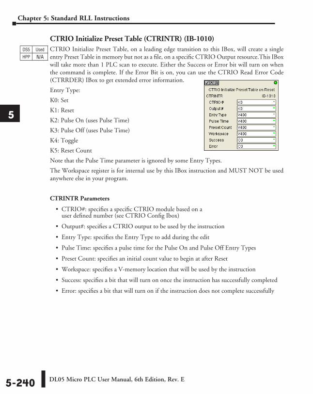
DL05 Micro PLC User Manual, 6th Edition, Rev. E5-240
Chapter 5: Standard RLL Instructions
1
2
3
4
5
6
7
8
9
10
11
12
13
14
A
B
c
D
CTRIO Initialize Preset Table (CTRINTR) (IB-1010)CTRIO Initialize Preset Table, on a leading edge transition to this IBox, will create a single entry Preset Table in memory but not as a file, on a specific CTRIO Output resource.This IBox will take more than 1 PLC scan to execute. Either the Success or Error bit will turn on when the command is complete. If the Error Bit is on, you can use the CTRIO Read Error Code (CTRRDER) IBox to get extended error information.
Entry Type:
K0: Set
K1: Reset
K2: Pulse On (uses Pulse Time)
K3: Pulse Off (uses Pulse Time)
K4: Toggle
K5: Reset Count
Note that the Pulse Time parameter is ignored by some Entry Types.
The Workspace register is for internal use by this IBox instruction and MUST NOT be used anywhere else in your program.
CTRINTR Parameters
• CTRIO#: specifies a specific CTRIO module based on a user defined number (see CTRIO Config Ibox)
• Output#: specifies a CTRIO output to be used by the instruction
• Entry Type: specifies the Entry Type to add during the edit
• Pulse Time: specifies a pulse time for the Pulse On and Pulse Off Entry Types
• Preset Count: specifies an initial count value to begin at after Reset
• Workspace: specifies a V-memory location that will be used by the instruction
• Success: specifies a bit that will turn on once the instruction has successfully completed
• Error: specifies a bit that will turn on if the instruction does not complete successfully
DS5 Used
HPP N/A
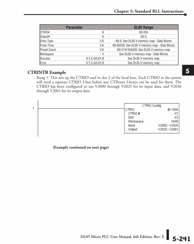
DL05 Micro PLC User Manual, 6th Edition, Rev. E 5-241
Chapter 5: Standard RLL Instructions
1
2
3
4
5
6
7
8
9
10
11
12
13
14
A
B
c
D
CTRINTR ExampleRung 1: This sets up the CTRIO card in slot 2 of the local base. Each CTRIO in the system will need a separate CTRIO I-box before any CTRxxxx I-boxes can be used for them. The CTRIO has been configured to use V2000 through V2025 for its input data, and V2030 through V2061 for its output data.
Parameter DL05 RangeCTRIO# ⸠⸠⸠⸠⸠⸠⸠⸠⸠⸠⸠⸠⸠⸠⸠⸠⸠⸠⸠⸠⸠⸠⸠⸠⸠⸠⸠⸠⸠⸠⸠⸠⸠⸠⸠⸠⸠⸠⸠⸠⸠⸠⸠⸠⸠⸠⸠⸠⸠⸠⸠⸠⸠⸠⸠⸠⸠⸠⸠⸠⸠⸠⸠⸠⸠⸠⸠⸠ K K0-255Output# ⸠⸠⸠⸠⸠⸠⸠⸠⸠⸠⸠⸠⸠⸠⸠⸠⸠⸠⸠⸠⸠⸠⸠⸠⸠⸠⸠⸠⸠⸠⸠⸠⸠⸠⸠⸠⸠⸠⸠⸠⸠⸠⸠⸠⸠⸠⸠⸠⸠⸠⸠⸠⸠⸠⸠⸠⸠⸠⸠⸠⸠⸠⸠⸠⸠⸠⸠ K K0-3Entry Type ⸠⸠⸠⸠⸠⸠⸠⸠⸠⸠⸠⸠⸠⸠⸠⸠⸠⸠⸠⸠⸠⸠⸠⸠⸠⸠⸠⸠⸠⸠⸠⸠⸠⸠⸠⸠⸠⸠⸠⸠⸠⸠⸠⸠⸠⸠⸠⸠⸠⸠⸠⸠⸠⸠⸠⸠⸠⸠⸠⸠V,K K0-5; See DL05 V-memory map - Data WordsPulse Time ⸠⸠⸠⸠⸠⸠⸠⸠⸠⸠⸠⸠⸠⸠⸠⸠⸠⸠⸠⸠⸠⸠⸠⸠⸠⸠⸠⸠⸠⸠⸠⸠⸠⸠⸠⸠⸠⸠⸠⸠⸠⸠⸠⸠⸠⸠⸠⸠⸠⸠⸠⸠⸠⸠⸠⸠⸠⸠⸠V,K K0-65535; See DL05 V-memory map - Data WordsPreset Count ⸠⸠⸠⸠⸠⸠⸠⸠⸠⸠⸠⸠⸠⸠⸠⸠⸠⸠⸠⸠⸠⸠⸠⸠⸠⸠⸠⸠⸠⸠⸠⸠⸠⸠⸠⸠⸠⸠⸠⸠⸠⸠⸠⸠⸠⸠⸠⸠⸠⸠⸠⸠⸠⸠⸠⸠V,K K0-2147434528; See DL05 V-memory mapWorkspace ⸠⸠⸠⸠⸠⸠⸠⸠⸠⸠⸠⸠⸠⸠⸠⸠⸠⸠⸠⸠⸠⸠⸠⸠⸠⸠⸠⸠⸠⸠⸠⸠⸠⸠⸠⸠⸠⸠⸠⸠⸠⸠⸠⸠⸠⸠⸠⸠⸠⸠⸠⸠⸠⸠⸠⸠⸠⸠⸠⸠⸠⸠ V See DL05 V-memory map - Data WordsSuccess ⸠⸠⸠⸠⸠⸠⸠⸠⸠⸠⸠⸠⸠⸠⸠⸠⸠⸠⸠⸠⸠⸠⸠⸠⸠⸠⸠⸠⸠⸠⸠⸠⸠⸠⸠⸠⸠⸠⸠⸠⸠⸠⸠⸠⸠ X,Y,C,GX,GY,B See DL05 V-memory mapError ⸠⸠⸠⸠⸠⸠⸠⸠⸠⸠⸠⸠⸠⸠⸠⸠⸠⸠⸠⸠⸠⸠⸠⸠⸠⸠⸠⸠⸠⸠⸠⸠⸠⸠⸠⸠⸠⸠⸠⸠⸠⸠⸠⸠⸠⸠⸠⸠⸠⸠ X,Y,C,GX,GY,B See DL05 V-memory map
(Example continued on next page)
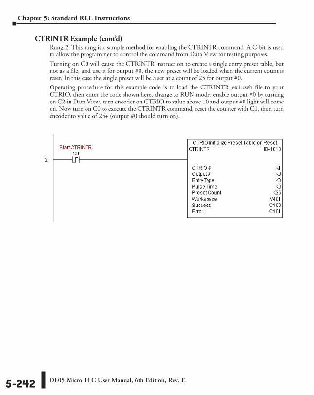
DL05 Micro PLC User Manual, 6th Edition, Rev. E5-242
Chapter 5: Standard RLL Instructions
CTRINTR Example (cont’d)Rung 2: This rung is a sample method for enabling the CTRINTR command. A C-bit is used to allow the programmer to control the command from Data View for testing purposes.
Turning on C0 will cause the CTRINTR instruction to create a single entry preset table, but not as a file, and use it for output #0, the new preset will be loaded when the current count is reset. In this case the single preset will be a set at a count of 25 for output #0.
Operating procedure for this example code is to load the CTRINTR_ex1.cwb file to your CTRIO, then enter the code shown here, change to RUN mode, enable output #0 by turning on C2 in Data View, turn encoder on CTRIO to value above 10 and output #0 light will come on. Now turn on C0 to execute the CTRINTR command, reset the counter with C1, then turn encoder to value of 25+ (output #0 should turn on).
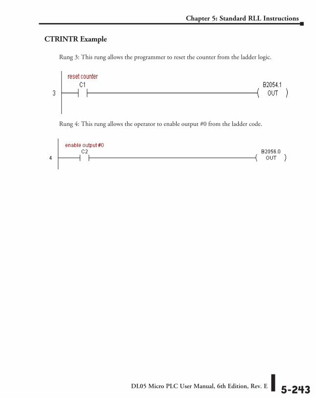
DL05 Micro PLC User Manual, 6th Edition, Rev. E 5-243
Chapter 5: Standard RLL Instructions
CTRINTR Example
Rung 3: This rung allows the programmer to reset the counter from the ladder logic.
Rung 4: This rung allows the operator to enable output #0 from the ladder code.
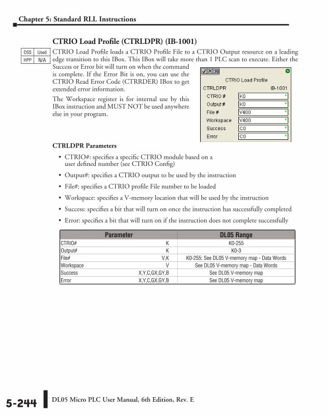
DL05 Micro PLC User Manual, 6th Edition, Rev. E5-244
Chapter 5: Standard RLL Instructions
CTRIO Load Profile (CTRLDPR) (IB-1001)CTRIO Load Profile loads a CTRIO Profile File to a CTRIO Output resource on a leading edge transition to this IBox. This IBox will take more than 1 PLC scan to execute. Either the Success or Error bit will turn on when the command is complete. If the Error Bit is on, you can use the CTRIO Read Error Code (CTRRDER) IBox to get extended error information.
The Workspace register is for internal use by this IBox instruction and MUST NOT be used anywhere else in your program.
CTRLDPR Parameters
• CTRIO#: specifies a specific CTRIO module based on a user defined number (see CTRIO Config)
• Output#: specifies a CTRIO output to be used by the instruction
• File#: specifies a CTRIO profile File number to be loaded
• Workspace: specifies a V-memory location that will be used by the instruction
• Success: specifies a bit that will turn on once the instruction has successfully completed
• Error: specifies a bit that will turn on if the instruction does not complete successfully
DS5 Used
HPP N/A
Parameter DL05 RangeCTRIO# ⸠⸠⸠⸠⸠⸠⸠⸠⸠⸠⸠⸠⸠⸠⸠⸠⸠⸠⸠⸠⸠⸠⸠⸠⸠⸠⸠⸠⸠⸠⸠⸠⸠⸠⸠⸠⸠⸠⸠⸠⸠⸠⸠⸠⸠⸠⸠⸠⸠⸠⸠⸠⸠⸠⸠⸠⸠⸠⸠⸠⸠⸠⸠⸠⸠⸠⸠⸠ K K0-255Output# ⸠⸠⸠⸠⸠⸠⸠⸠⸠⸠⸠⸠⸠⸠⸠⸠⸠⸠⸠⸠⸠⸠⸠⸠⸠⸠⸠⸠⸠⸠⸠⸠⸠⸠⸠⸠⸠⸠⸠⸠⸠⸠⸠⸠⸠⸠⸠⸠⸠⸠⸠⸠⸠⸠⸠⸠⸠⸠⸠⸠⸠⸠⸠⸠⸠⸠⸠ K K0-3File# ⸠⸠⸠⸠⸠⸠⸠⸠⸠⸠⸠⸠⸠⸠⸠⸠⸠⸠⸠⸠⸠⸠⸠⸠⸠⸠⸠⸠⸠⸠⸠⸠⸠⸠⸠⸠⸠⸠⸠⸠⸠⸠⸠⸠⸠⸠⸠⸠⸠⸠⸠⸠⸠⸠⸠⸠⸠⸠⸠⸠⸠⸠⸠⸠⸠⸠⸠⸠⸠⸠V,K K0-255; See DL05 V-memory map - Data WordsWorkspace ⸠⸠⸠⸠⸠⸠⸠⸠⸠⸠⸠⸠⸠⸠⸠⸠⸠⸠⸠⸠⸠⸠⸠⸠⸠⸠⸠⸠⸠⸠⸠⸠⸠⸠⸠⸠⸠⸠⸠⸠⸠⸠⸠⸠⸠⸠⸠⸠⸠⸠⸠⸠⸠⸠⸠⸠⸠⸠⸠⸠⸠⸠ V See DL05 V-memory map - Data WordsSuccess ⸠⸠⸠⸠⸠⸠⸠⸠⸠⸠⸠⸠⸠⸠⸠⸠⸠⸠⸠⸠⸠⸠⸠⸠⸠⸠⸠⸠⸠⸠⸠⸠⸠⸠⸠⸠⸠⸠⸠⸠⸠⸠⸠⸠⸠ X,Y,C,GX,GY,B See DL05 V-memory mapError ⸠⸠⸠⸠⸠⸠⸠⸠⸠⸠⸠⸠⸠⸠⸠⸠⸠⸠⸠⸠⸠⸠⸠⸠⸠⸠⸠⸠⸠⸠⸠⸠⸠⸠⸠⸠⸠⸠⸠⸠⸠⸠⸠⸠⸠⸠⸠⸠⸠⸠ X,Y,C,GX,GY,B See DL05 V-memory map
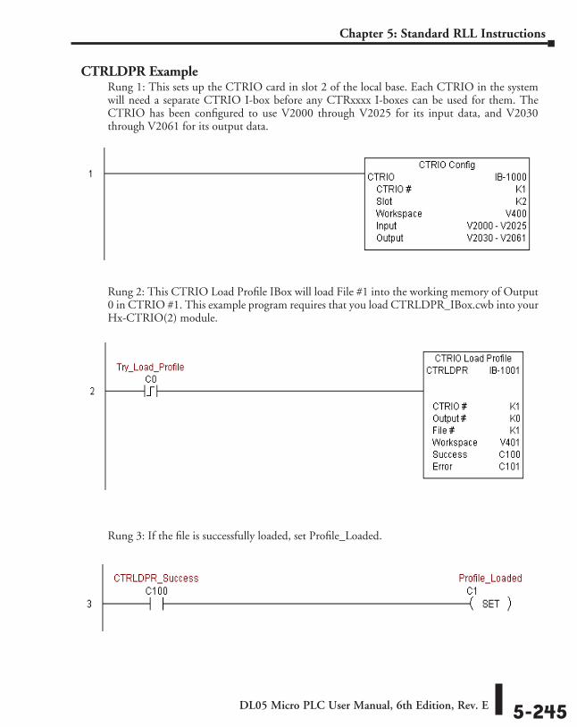
DL05 Micro PLC User Manual, 6th Edition, Rev. E 5-245
Chapter 5: Standard RLL Instructions
CTRLDPR ExampleRung 1: This sets up the CTRIO card in slot 2 of the local base. Each CTRIO in the system will need a separate CTRIO I-box before any CTRxxxx I-boxes can be used for them. The CTRIO has been configured to use V2000 through V2025 for its input data, and V2030 through V2061 for its output data.
Rung 2: This CTRIO Load Profile IBox will load File #1 into the working memory of Output 0 in CTRIO #1. This example program requires that you load CTRLDPR_IBox.cwb into your Hx-CTRIO(2) module.
Rung 3: If the file is successfully loaded, set Profile_Loaded.
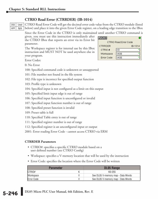
DL05 Micro PLC User Manual, 6th Edition, Rev. E5-246
Chapter 5: Standard RLL Instructions
CTRIO Read Error (CTRRDER) (IB-1014)CTRIO Read Error Code will get the decimal error code value from the CTRIO module (listed below) and place it into the given Error Code register, on a leading edge transition to the IBox
Since the Error Code in the CTRIO is only maintained until another CTRIO command is given, you must use this instruction immediately after the CTRIO IBox that reports an error via its Error bit parameter.
The Workspace register is for internal use by this IBox instruction and MUST NOT be used anywhere else in your program.
Error Codes:
0: No Error
100: Specified command code is unknown or unsupported
101: File number not found in the file system
102: File type is incorrect for specified output function
103: Profile type is unknown
104: Specified input is not configured as a limit on this output
105: Specified limit input edge is out of range
106: Specified input function is unconfigured or invalid
107: Specified input function number is out of range
108: Specified preset function is invalid
109: Preset table is full
110: Specified Table entry is out of range
111: Specified register number is out of range
112: Specified register is an unconfigured input or output
2001: Error reading Error Code - cannot access CTRIO via ERM
CTRRDER Parameters
• CTRIO#: specifies a specific CTRIO module based on a user defined number (see CTRIO Config)
• Workspace: specifies a V-memory location that will be used by the instruction
• Error Code: specifies the location where the Error Code will be written
DS5 Used
HPP N/A
Parameter DL05 RangeCTRIO# ⸠⸠⸠⸠⸠⸠⸠⸠⸠⸠⸠⸠⸠⸠⸠⸠⸠⸠⸠⸠⸠⸠⸠⸠⸠⸠⸠⸠⸠⸠⸠⸠⸠⸠⸠⸠⸠⸠⸠⸠⸠⸠⸠⸠⸠⸠⸠⸠⸠⸠⸠⸠⸠⸠⸠⸠⸠⸠⸠⸠⸠⸠⸠⸠⸠⸠⸠⸠ K K0-255Workspace ⸠⸠⸠⸠⸠⸠⸠⸠⸠⸠⸠⸠⸠⸠⸠⸠⸠⸠⸠⸠⸠⸠⸠⸠⸠⸠⸠⸠⸠⸠⸠⸠⸠⸠⸠⸠⸠⸠⸠⸠⸠⸠⸠⸠⸠⸠⸠⸠⸠⸠⸠⸠⸠⸠⸠⸠⸠⸠⸠⸠⸠⸠ V See DL05 V-memory map - Data WordsError Code ⸠⸠⸠⸠⸠⸠⸠⸠⸠⸠⸠⸠⸠⸠⸠⸠⸠⸠⸠⸠⸠⸠⸠⸠⸠⸠⸠⸠⸠⸠⸠⸠⸠⸠⸠⸠⸠⸠⸠⸠⸠⸠⸠⸠⸠⸠⸠⸠⸠⸠⸠⸠⸠⸠⸠⸠⸠⸠⸠⸠⸠⸠⸠ V See DL05 V-memory map - Data Words

DL05 Micro PLC User Manual, 6th Edition, Rev. E 5-247
Chapter 5: Standard RLL Instructions
CTRRDER ExampleRung 1: This sets up the CTRIO card in slot 2 of the local base. Each CTRIO in the system will need a separate CTRIO I-box before any CTRxxxx I-boxes can be used for them. The CTRIO has been configured to use V2000 through V2025 for its input data, and V2030 through V2061 for its output data.
Rung 2: This CTRIO Read Error Code IBox will read the Extended Error information from CTRIO #1. This example program requires that you load CTRRDER_IBox.cwb into your Hx-CTRIO(2) module.
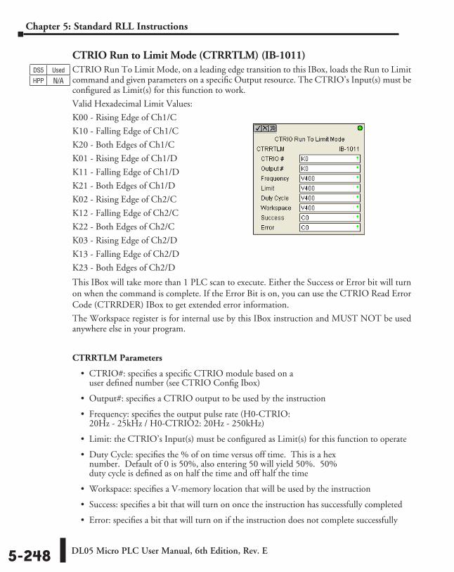
DL05 Micro PLC User Manual, 6th Edition, Rev. E5-248
Chapter 5: Standard RLL Instructions
CTRIO Run to Limit Mode (CTRRTLM) (IB-1011)CTRIO Run To Limit Mode, on a leading edge transition to this IBox, loads the Run to Limit command and given parameters on a specific Output resource. The CTRIO’s Input(s) must be configured as Limit(s) for this function to work.
Valid Hexadecimal Limit Values:
K00 - Rising Edge of Ch1/C
K10 - Falling Edge of Ch1/C
K20 - Both Edges of Ch1/C
K01 - Rising Edge of Ch1/D
K11 - Falling Edge of Ch1/D
K21 - Both Edges of Ch1/D
K02 - Rising Edge of Ch2/C
K12 - Falling Edge of Ch2/C
K22 - Both Edges of Ch2/C
K03 - Rising Edge of Ch2/D
K13 - Falling Edge of Ch2/D
K23 - Both Edges of Ch2/D
This IBox will take more than 1 PLC scan to execute. Either the Success or Error bit will turn on when the command is complete. If the Error Bit is on, you can use the CTRIO Read Error Code (CTRRDER) IBox to get extended error information.
The Workspace register is for internal use by this IBox instruction and MUST NOT be used anywhere else in your program.
CTRRTLM Parameters
• CTRIO#: specifies a specific CTRIO module based on a user defined number (see CTRIO Config Ibox)
• Output#: specifies a CTRIO output to be used by the instruction
• Frequency: specifies the output pulse rate (H0-CTRIO: 20Hz - 25kHz / H0-CTRIO2: 20Hz - 250kHz)
• Limit: the CTRIO’s Input(s) must be configured as Limit(s) for this function to operate
• Duty Cycle: specifies the % of on time versus off time. This is a hex number. Default of 0 is 50%, also entering 50 will yield 50%. 50% duty cycle is defined as on half the time and off half the time
• Workspace: specifies a V-memory location that will be used by the instruction
• Success: specifies a bit that will turn on once the instruction has successfully completed
• Error: specifies a bit that will turn on if the instruction does not complete successfully
DS5 Used
HPP N/A
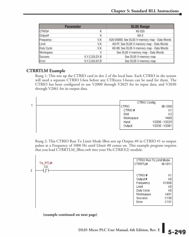
DL05 Micro PLC User Manual, 6th Edition, Rev. E 5-249
Chapter 5: Standard RLL Instructions
CTRRTLM ExampleRung 1: This sets up the CTRIO card in slot 2 of the local base. Each CTRIO in the system will need a separate CTRIO I-box before any CTRxxxx I-boxes can be used for them. The CTRIO has been configured to use V2000 through V2025 for its input data, and V2030 through V2061 for its output data.
Rung 2: This CTRIO Run To Limit Mode IBox sets up Output #0 in CTRIO #1 to output pulses at a Frequency of 1000 Hz until Llimit #0 comes on. This example program requires that you load CTRRTLM_IBox.cwb into your Hx-CTRIO(2) module.
Parameter DL05 RangeCTRIO# ⸠⸠⸠⸠⸠⸠⸠⸠⸠⸠⸠⸠⸠⸠⸠⸠⸠⸠⸠⸠⸠⸠⸠⸠⸠⸠⸠⸠⸠⸠⸠⸠⸠⸠⸠⸠⸠⸠⸠⸠⸠⸠⸠⸠⸠⸠⸠⸠⸠⸠⸠⸠⸠⸠⸠⸠⸠⸠⸠⸠⸠⸠⸠⸠⸠⸠⸠⸠ K K0-255Output# ⸠⸠⸠⸠⸠⸠⸠⸠⸠⸠⸠⸠⸠⸠⸠⸠⸠⸠⸠⸠⸠⸠⸠⸠⸠⸠⸠⸠⸠⸠⸠⸠⸠⸠⸠⸠⸠⸠⸠⸠⸠⸠⸠⸠⸠⸠⸠⸠⸠⸠⸠⸠⸠⸠⸠⸠⸠⸠⸠⸠⸠⸠⸠⸠⸠⸠⸠ K K0-3Frequency ⸠⸠⸠⸠⸠⸠⸠⸠⸠⸠⸠⸠⸠⸠⸠⸠⸠⸠⸠⸠⸠⸠⸠⸠⸠⸠⸠⸠⸠⸠⸠⸠⸠⸠⸠⸠⸠⸠⸠⸠⸠⸠⸠⸠⸠⸠⸠⸠⸠⸠⸠⸠⸠⸠⸠⸠⸠⸠⸠⸠⸠V,K K20-20000; See DL05 V-memory map - Data WordsLimit ⸠⸠⸠⸠⸠⸠⸠⸠⸠⸠⸠⸠⸠⸠⸠⸠⸠⸠⸠⸠⸠⸠⸠⸠⸠⸠⸠⸠⸠⸠⸠⸠⸠⸠⸠⸠⸠⸠⸠⸠⸠⸠⸠⸠⸠⸠⸠⸠⸠⸠⸠⸠⸠⸠⸠⸠⸠⸠⸠⸠⸠⸠⸠⸠⸠⸠⸠⸠⸠V,K K0-FF; See DL05 V-memory map - Data WordsDuty Cycle ⸠⸠⸠⸠⸠⸠⸠⸠⸠⸠⸠⸠⸠⸠⸠⸠⸠⸠⸠⸠⸠⸠⸠⸠⸠⸠⸠⸠⸠⸠⸠⸠⸠⸠⸠⸠⸠⸠⸠⸠⸠⸠⸠⸠⸠⸠⸠⸠⸠⸠⸠⸠⸠⸠⸠⸠⸠⸠⸠⸠V,K K0-99; See DL05 V-memory map - Data WordsWorkspace ⸠⸠⸠⸠⸠⸠⸠⸠⸠⸠⸠⸠⸠⸠⸠⸠⸠⸠⸠⸠⸠⸠⸠⸠⸠⸠⸠⸠⸠⸠⸠⸠⸠⸠⸠⸠⸠⸠⸠⸠⸠⸠⸠⸠⸠⸠⸠⸠⸠⸠⸠⸠⸠⸠⸠⸠⸠⸠⸠⸠⸠⸠ V See DL05 V-memory map - Data WordsSuccess ⸠⸠⸠⸠⸠⸠⸠⸠⸠⸠⸠⸠⸠⸠⸠⸠⸠⸠⸠⸠⸠⸠⸠⸠⸠⸠⸠⸠⸠⸠⸠⸠⸠⸠⸠⸠⸠⸠⸠⸠⸠⸠⸠⸠⸠ X,Y,C,GX,GY,B See DL05 V-memory mapError ⸠⸠⸠⸠⸠⸠⸠⸠⸠⸠⸠⸠⸠⸠⸠⸠⸠⸠⸠⸠⸠⸠⸠⸠⸠⸠⸠⸠⸠⸠⸠⸠⸠⸠⸠⸠⸠⸠⸠⸠⸠⸠⸠⸠⸠⸠⸠⸠⸠⸠ X,Y,C,GX,GY,B See DL05 V-memory map
(example continued on next page)
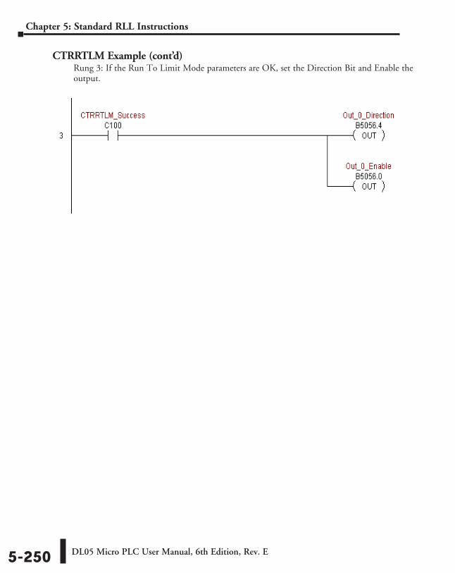
DL05 Micro PLC User Manual, 6th Edition, Rev. E5-250
Chapter 5: Standard RLL Instructions
CTRRTLM Example (cont’d)Rung 3: If the Run To Limit Mode parameters are OK, set the Direction Bit and Enable the output.
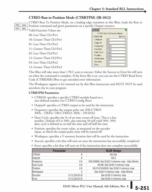
DL05 Micro PLC User Manual, 6th Edition, Rev. E 5-251
Chapter 5: Standard RLL Instructions
CTRIO Run to Position Mode (CTRRTPM) (IB-1012)CTRIO Run To Position Mode, on a leading edge transition to this IBox, loads the Run to Position command and given parameters on a specific Output resource.
Valid Function Values are:
00: Less Than Ch1/Fn1
10: Greater Than Ch1/Fn1
01: Less Than Ch1/Fn2
11: Greater Than Ch1/Fn2
02: Less Than Ch2/Fn1
12: Greater Than Ch2/Fn1
03: Less Than Ch2/Fn2
13: Greater Than Ch2/Fn2
This IBox will take more than 1 PLC scan to execute. Either the Success or Error bit will turn on when the command is complete. If the Error Bit is on, you can use the CTRIO Read Error Code (CTRRDER) IBox to get extended error information.
The Workspace register is for internal use by this IBox instruction and MUST NOT be used anywhere else in your program.
CTRRTPM Parameters
• CTRIO#: specifies a specific CTRIO module based on a user defined number (see CTRIO Config Ibox)
• Output#: specifies a CTRIO output to be used by the instruction
• Frequency: specifies the output pulse rate (H0-CTRIO: 20Hz - 25KHz / H0-CTRIO2: 20Hz - 250 KHz)
• Duty Cycle: specifies the % of on time versus off time. This is a hex number. Default of 0 is 50%, also entering 50 will yield 50%. 50% duty cycle is defined as on half the time and off half the time
• Position: specifies the count value, as measured on the encoder input, at which the output pulse train will be turned off
• Workspace: specifies a V-memory location that will be used by the instruction
• Success: specifies a bit that will turn on once the instruction has successfully completed
• Error: specifies a bit that will turn on if the instruction does not complete successfully
DS5 Used
HPP N/A
Parameter DL05 RangeCTRIO# ⸠⸠⸠⸠⸠⸠⸠⸠⸠⸠⸠⸠⸠⸠⸠⸠⸠⸠⸠⸠⸠⸠⸠⸠⸠⸠⸠⸠⸠⸠⸠⸠⸠⸠⸠⸠⸠⸠⸠⸠⸠⸠⸠⸠⸠⸠⸠⸠⸠⸠⸠⸠⸠⸠⸠⸠⸠⸠⸠⸠⸠⸠⸠⸠⸠⸠⸠⸠ K K0-255Output# ⸠⸠⸠⸠⸠⸠⸠⸠⸠⸠⸠⸠⸠⸠⸠⸠⸠⸠⸠⸠⸠⸠⸠⸠⸠⸠⸠⸠⸠⸠⸠⸠⸠⸠⸠⸠⸠⸠⸠⸠⸠⸠⸠⸠⸠⸠⸠⸠⸠⸠⸠⸠⸠⸠⸠⸠⸠⸠⸠⸠⸠⸠⸠⸠⸠⸠⸠ K K0-3Frequency ⸠⸠⸠⸠⸠⸠⸠⸠⸠⸠⸠⸠⸠⸠⸠⸠⸠⸠⸠⸠⸠⸠⸠⸠⸠⸠⸠⸠⸠⸠⸠⸠⸠⸠⸠⸠⸠⸠⸠⸠⸠⸠⸠⸠⸠⸠⸠⸠⸠⸠⸠⸠⸠⸠⸠⸠⸠⸠⸠⸠⸠V,K K20-20000; See DL05 V-memory map - Data WordsDuty Cycle ⸠⸠⸠⸠⸠⸠⸠⸠⸠⸠⸠⸠⸠⸠⸠⸠⸠⸠⸠⸠⸠⸠⸠⸠⸠⸠⸠⸠⸠⸠⸠⸠⸠⸠⸠⸠⸠⸠⸠⸠⸠⸠⸠⸠⸠⸠⸠⸠⸠⸠⸠⸠⸠⸠⸠⸠⸠⸠⸠⸠V,K K0-99; See DL05 V-memory mapPosition ⸠⸠⸠⸠⸠⸠⸠⸠⸠⸠⸠⸠⸠⸠⸠⸠⸠⸠⸠⸠⸠⸠⸠⸠⸠⸠⸠⸠⸠⸠⸠⸠⸠⸠⸠⸠⸠⸠⸠⸠⸠⸠⸠⸠⸠⸠⸠⸠⸠⸠⸠⸠⸠⸠⸠⸠⸠⸠⸠⸠⸠⸠⸠⸠V,K K0-2147434528; See DL05 V-memory mapWorkspace ⸠⸠⸠⸠⸠⸠⸠⸠⸠⸠⸠⸠⸠⸠⸠⸠⸠⸠⸠⸠⸠⸠⸠⸠⸠⸠⸠⸠⸠⸠⸠⸠⸠⸠⸠⸠⸠⸠⸠⸠⸠⸠⸠⸠⸠⸠⸠⸠⸠⸠⸠⸠⸠⸠⸠⸠⸠⸠⸠⸠⸠⸠ V See DL05 V-memory map - Data WordsSuccess ⸠⸠⸠⸠⸠⸠⸠⸠⸠⸠⸠⸠⸠⸠⸠⸠⸠⸠⸠⸠⸠⸠⸠⸠⸠⸠⸠⸠⸠⸠⸠⸠⸠⸠⸠⸠⸠⸠⸠⸠⸠⸠⸠⸠⸠ X,Y,C,GX,GY,B See DL05 V-memory mapError ⸠⸠⸠⸠⸠⸠⸠⸠⸠⸠⸠⸠⸠⸠⸠⸠⸠⸠⸠⸠⸠⸠⸠⸠⸠⸠⸠⸠⸠⸠⸠⸠⸠⸠⸠⸠⸠⸠⸠⸠⸠⸠⸠⸠⸠⸠⸠⸠⸠⸠ X,Y,C,GX,GY,B See DL05 V-memory map
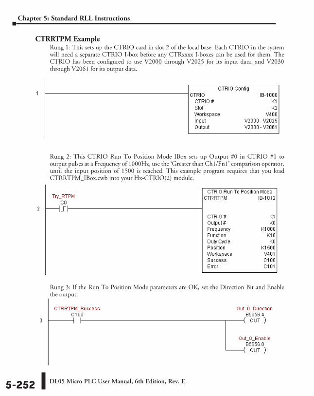
DL05 Micro PLC User Manual, 6th Edition, Rev. E5-252
Chapter 5: Standard RLL Instructions
CTRRTPM ExampleRung 1: This sets up the CTRIO card in slot 2 of the local base. Each CTRIO in the system will need a separate CTRIO I-box before any CTRxxxx I-boxes can be used for them. The CTRIO has been configured to use V2000 through V2025 for its input data, and V2030 through V2061 for its output data.
Rung 2: This CTRIO Run To Position Mode IBox sets up Output #0 in CTRIO #1 to output pulses at a Frequency of 1000Hz, use the ‘Greater than Ch1/Fn1’ comparison operator, until the input position of 1500 is reached. This example program requires that you load CTRRTPM_IBox.cwb into your Hx-CTRIO(2) module.
Rung 3: If the Run To Position Mode parameters are OK, set the Direction Bit and Enable the output.
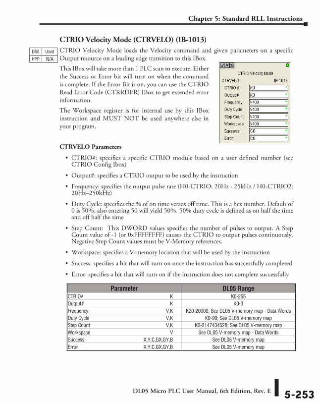
DL05 Micro PLC User Manual, 6th Edition, Rev. E 5-253
Chapter 5: Standard RLL Instructions
CTRIO Velocity Mode (CTRVELO) (IB-1013)CTRIO Velocity Mode loads the Velocity command and given parameters on a specific Output resource on a leading edge transition to this IBox.
This IBox will take more than 1 PLC scan to execute. Either the Success or Error bit will turn on when the command is complete. If the Error Bit is on, you can use the CTRIO Read Error Code (CTRRDER) IBox to get extended error information.
The Workspace register is for internal use by this IBox instruction and MUST NOT be used anywhere else in your program.
CTRVELO Parameters
• CTRIO#: specifies a specific CTRIO module based on a user defined number (see CTRIO Config Ibox)
• Output#: specifies a CTRIO output to be used by the instruction
• Frequency: specifies the output pulse rate (H0-CTRIO: 20Hz - 25kHz / H0-CTRIO2: 20Hz–250kHz)
• Duty Cycle: specifies the % of on time versus off time. This is a hex number. Default of 0 is 50%, also entering 50 will yield 50%. 50% duty cycle is defined as on half the time and off half the time
• Step Count: This DWORD values specifies the number of pulses to output. A Step Count value of -1 (or 0xFFFFFFFF) causes the CTRIO to output pulses continuously. Negative Step Count values must be V-Memory references.
• Workspace: specifies a V-memory location that will be used by the instruction
• Success: specifies a bit that will turn on once the instruction has successfully completed
• Error: specifies a bit that will turn on if the instruction does not complete successfully
DS5 Used
HPP N/A
Parameter DL05 RangeCTRIO# ⸠⸠⸠⸠⸠⸠⸠⸠⸠⸠⸠⸠⸠⸠⸠⸠⸠⸠⸠⸠⸠⸠⸠⸠⸠⸠⸠⸠⸠⸠⸠⸠⸠⸠⸠⸠⸠⸠⸠⸠⸠⸠⸠⸠⸠⸠⸠⸠⸠⸠⸠⸠⸠⸠⸠⸠⸠⸠⸠⸠⸠⸠⸠⸠⸠⸠⸠⸠ K K0-255Output# ⸠⸠⸠⸠⸠⸠⸠⸠⸠⸠⸠⸠⸠⸠⸠⸠⸠⸠⸠⸠⸠⸠⸠⸠⸠⸠⸠⸠⸠⸠⸠⸠⸠⸠⸠⸠⸠⸠⸠⸠⸠⸠⸠⸠⸠⸠⸠⸠⸠⸠⸠⸠⸠⸠⸠⸠⸠⸠⸠⸠⸠⸠⸠⸠⸠⸠⸠ K K0-3Frequency ⸠⸠⸠⸠⸠⸠⸠⸠⸠⸠⸠⸠⸠⸠⸠⸠⸠⸠⸠⸠⸠⸠⸠⸠⸠⸠⸠⸠⸠⸠⸠⸠⸠⸠⸠⸠⸠⸠⸠⸠⸠⸠⸠⸠⸠⸠⸠⸠⸠⸠⸠⸠⸠⸠⸠⸠⸠⸠⸠⸠⸠V,K K20-20000; See DL05 V-memory map - Data WordsDuty Cycle ⸠⸠⸠⸠⸠⸠⸠⸠⸠⸠⸠⸠⸠⸠⸠⸠⸠⸠⸠⸠⸠⸠⸠⸠⸠⸠⸠⸠⸠⸠⸠⸠⸠⸠⸠⸠⸠⸠⸠⸠⸠⸠⸠⸠⸠⸠⸠⸠⸠⸠⸠⸠⸠⸠⸠⸠⸠⸠⸠⸠V,K K0-99; See DL05 V-memory mapStep Count ⸠⸠⸠⸠⸠⸠⸠⸠⸠⸠⸠⸠⸠⸠⸠⸠⸠⸠⸠⸠⸠⸠⸠⸠⸠⸠⸠⸠⸠⸠⸠⸠⸠⸠⸠⸠⸠⸠⸠⸠⸠⸠⸠⸠⸠⸠⸠⸠⸠⸠⸠⸠⸠⸠⸠⸠⸠⸠⸠V,K K0-2147434528; See DL05 V-memory mapWorkspace ⸠⸠⸠⸠⸠⸠⸠⸠⸠⸠⸠⸠⸠⸠⸠⸠⸠⸠⸠⸠⸠⸠⸠⸠⸠⸠⸠⸠⸠⸠⸠⸠⸠⸠⸠⸠⸠⸠⸠⸠⸠⸠⸠⸠⸠⸠⸠⸠⸠⸠⸠⸠⸠⸠⸠⸠⸠⸠⸠⸠⸠⸠ V See DL05 V-memory map - Data WordsSuccess ⸠⸠⸠⸠⸠⸠⸠⸠⸠⸠⸠⸠⸠⸠⸠⸠⸠⸠⸠⸠⸠⸠⸠⸠⸠⸠⸠⸠⸠⸠⸠⸠⸠⸠⸠⸠⸠⸠⸠⸠⸠⸠⸠⸠⸠ X,Y,C,GX,GY,B See DL05 V-memory mapError ⸠⸠⸠⸠⸠⸠⸠⸠⸠⸠⸠⸠⸠⸠⸠⸠⸠⸠⸠⸠⸠⸠⸠⸠⸠⸠⸠⸠⸠⸠⸠⸠⸠⸠⸠⸠⸠⸠⸠⸠⸠⸠⸠⸠⸠⸠⸠⸠⸠⸠ X,Y,C,GX,GY,B See DL05 V-memory map
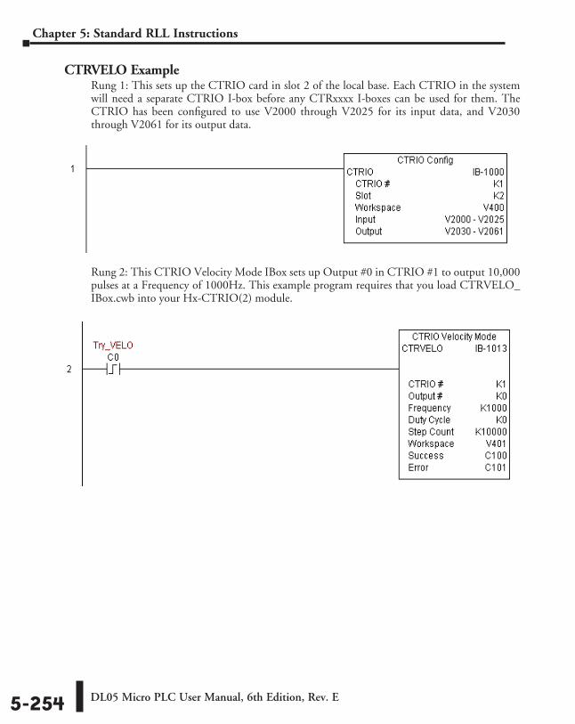
DL05 Micro PLC User Manual, 6th Edition, Rev. E5-254
Chapter 5: Standard RLL Instructions
CTRVELO ExampleRung 1: This sets up the CTRIO card in slot 2 of the local base. Each CTRIO in the system will need a separate CTRIO I-box before any CTRxxxx I-boxes can be used for them. The CTRIO has been configured to use V2000 through V2025 for its input data, and V2030 through V2061 for its output data.
Rung 2: This CTRIO Velocity Mode IBox sets up Output #0 in CTRIO #1 to output 10,000 pulses at a Frequency of 1000Hz. This example program requires that you load CTRVELO_IBox.cwb into your Hx-CTRIO(2) module.
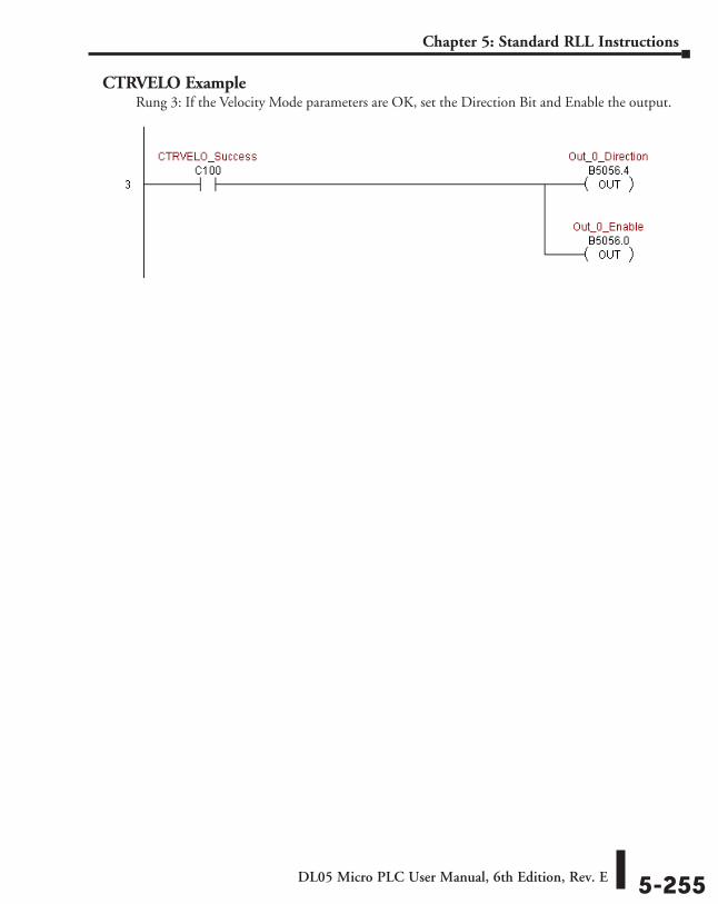
DL05 Micro PLC User Manual, 6th Edition, Rev. E 5-255
Chapter 5: Standard RLL Instructions
CTRVELO ExampleRung 3: If the Velocity Mode parameters are OK, set the Direction Bit and Enable the output.
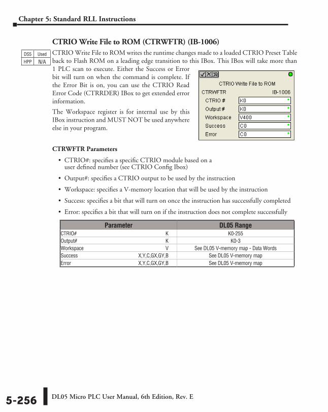
DL05 Micro PLC User Manual, 6th Edition, Rev. E5-256
Chapter 5: Standard RLL Instructions
CTRIO Write File to ROM (CTRWFTR) (IB-1006)CTRIO Write File to ROM writes the runtime changes made to a loaded CTRIO Preset Table back to Flash ROM on a leading edge transition to this IBox. This IBox will take more than 1 PLC scan to execute. Either the Success or Error bit will turn on when the command is complete. If the Error Bit is on, you can use the CTRIO Read Error Code (CTRRDER) IBox to get extended error information.
The Workspace register is for internal use by this IBox instruction and MUST NOT be used anywhere else in your program.
CTRWFTR Parameters
• CTRIO#: specifies a specific CTRIO module based on a user defined number (see CTRIO Config Ibox)
• Output#: specifies a CTRIO output to be used by the instruction
• Workspace: specifies a V-memory location that will be used by the instruction
• Success: specifies a bit that will turn on once the instruction has successfully completed
• Error: specifies a bit that will turn on if the instruction does not complete successfully
DS5 Used
HPP N/A
Parameter DL05 RangeCTRIO# ⸠⸠⸠⸠⸠⸠⸠⸠⸠⸠⸠⸠⸠⸠⸠⸠⸠⸠⸠⸠⸠⸠⸠⸠⸠⸠⸠⸠⸠⸠⸠⸠⸠⸠⸠⸠⸠⸠⸠⸠⸠⸠⸠⸠⸠⸠⸠⸠⸠⸠⸠⸠⸠⸠⸠⸠⸠⸠⸠⸠⸠⸠⸠⸠⸠⸠⸠⸠ K K0-255Output# ⸠⸠⸠⸠⸠⸠⸠⸠⸠⸠⸠⸠⸠⸠⸠⸠⸠⸠⸠⸠⸠⸠⸠⸠⸠⸠⸠⸠⸠⸠⸠⸠⸠⸠⸠⸠⸠⸠⸠⸠⸠⸠⸠⸠⸠⸠⸠⸠⸠⸠⸠⸠⸠⸠⸠⸠⸠⸠⸠⸠⸠⸠⸠⸠⸠⸠⸠ K K0-3Workspace ⸠⸠⸠⸠⸠⸠⸠⸠⸠⸠⸠⸠⸠⸠⸠⸠⸠⸠⸠⸠⸠⸠⸠⸠⸠⸠⸠⸠⸠⸠⸠⸠⸠⸠⸠⸠⸠⸠⸠⸠⸠⸠⸠⸠⸠⸠⸠⸠⸠⸠⸠⸠⸠⸠⸠⸠⸠⸠⸠⸠⸠⸠ V See DL05 V-memory map - Data WordsSuccess ⸠⸠⸠⸠⸠⸠⸠⸠⸠⸠⸠⸠⸠⸠⸠⸠⸠⸠⸠⸠⸠⸠⸠⸠⸠⸠⸠⸠⸠⸠⸠⸠⸠⸠⸠⸠⸠⸠⸠⸠⸠⸠⸠⸠⸠ X,Y,C,GX,GY,B See DL05 V-memory mapError ⸠⸠⸠⸠⸠⸠⸠⸠⸠⸠⸠⸠⸠⸠⸠⸠⸠⸠⸠⸠⸠⸠⸠⸠⸠⸠⸠⸠⸠⸠⸠⸠⸠⸠⸠⸠⸠⸠⸠⸠⸠⸠⸠⸠⸠⸠⸠⸠⸠⸠ X,Y,C,GX,GY,B See DL05 V-memory map
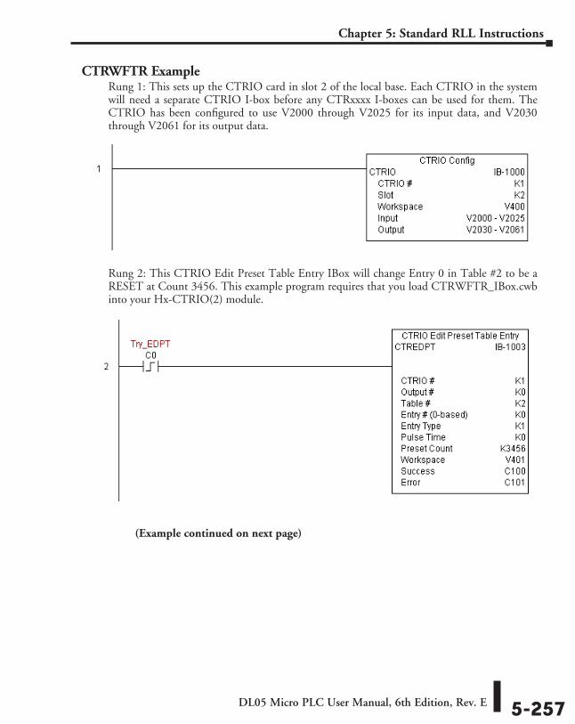
DL05 Micro PLC User Manual, 6th Edition, Rev. E 5-257
Chapter 5: Standard RLL Instructions
CTRWFTR ExampleRung 1: This sets up the CTRIO card in slot 2 of the local base. Each CTRIO in the system will need a separate CTRIO I-box before any CTRxxxx I-boxes can be used for them. The CTRIO has been configured to use V2000 through V2025 for its input data, and V2030 through V2061 for its output data.
Rung 2: This CTRIO Edit Preset Table Entry IBox will change Entry 0 in Table #2 to be a RESET at Count 3456. This example program requires that you load CTRWFTR_IBox.cwb into your Hx-CTRIO(2) module.
(Example continued on next page)
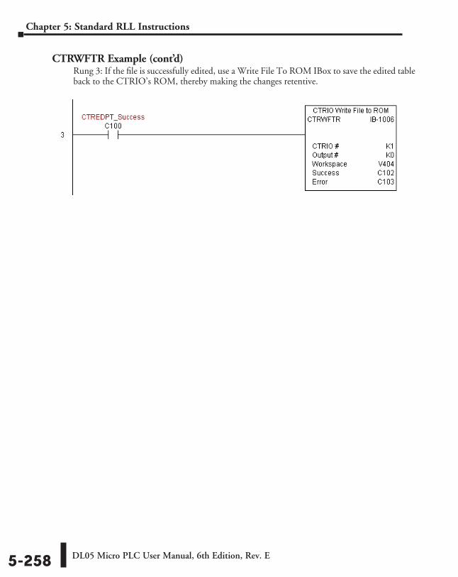
DL05 Micro PLC User Manual, 6th Edition, Rev. E5-258
Chapter 5: Standard RLL Instructions
CTRWFTR Example (cont’d)Rung 3: If the file is successfully edited, use a Write File To ROM IBox to save the edited table back to the CTRIO’s ROM, thereby making the changes retentive.
Drum InstructIon ProgrammIng 666
ChapterChapterChapter
In This Chapter...DL05 Drum Introduction ........................................................................................... 6-2
Step Transitions ......................................................................................................... 6-4
Overview of Drum Operation ................................................................................... 6-8
Drum Control Techniques ....................................................................................... 6-10
Drum Instruction ..................................................................................................... 6-12
Event Drum (EDRUM) Instruction ........................................................................... 6-14
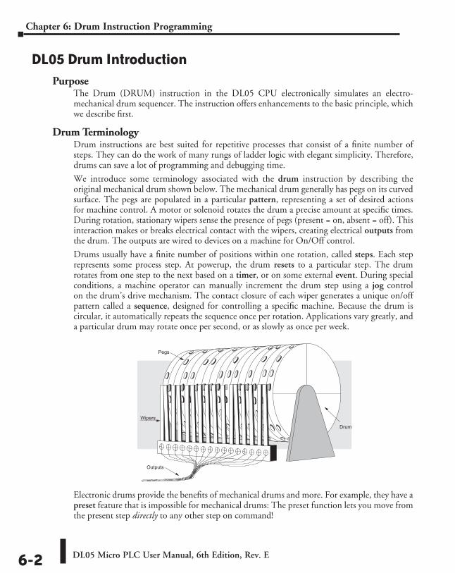
DL05 Micro PLC User Manual, 6th Edition, Rev. E6-2
Chapter 6: Drum Instruction Programming
DL05 Drum IntroductionPurpose
The Drum (DRUM) instruction in the DL05 CPU electronically simulates an electro-mechanical drum sequencer. The instruction offers enhancements to the basic principle, which we describe first.
Drum TerminologyDrum instructions are best suited for repetitive processes that consist of a finite number of steps. They can do the work of many rungs of ladder logic with elegant simplicity. Therefore, drums can save a lot of programming and debugging time.
We introduce some terminology associated with the drum instruction by describing the original mechanical drum shown below. The mechanical drum generally has pegs on its curved surface. The pegs are populated in a particular pattern, representing a set of desired actions for machine control. A motor or solenoid rotates the drum a precise amount at specific times. During rotation, stationary wipers sense the presence of pegs (present = on, absent = off). This interaction makes or breaks electrical contact with the wipers, creating electrical outputs from the drum. The outputs are wired to devices on a machine for On/Off control.
Drums usually have a finite number of positions within one rotation, called steps. Each step represents some process step. At powerup, the drum resets to a particular step. The drum rotates from one step to the next based on a timer, or on some external event. During special conditions, a machine operator can manually increment the drum step using a jog control on the drum’s drive mechanism. The contact closure of each wiper generates a unique on/off pattern called a sequence, designed for controlling a specific machine. Because the drum is circular, it automatically repeats the sequence once per rotation. Applications vary greatly, and a particular drum may rotate once per second, or as slowly as once per week.
Electronic drums provide the benefits of mechanical drums and more. For example, they have a preset feature that is impossible for mechanical drums: The preset function lets you move from the present step directly to any other step on command!
Drum
Outputs
Wipers
Pegs
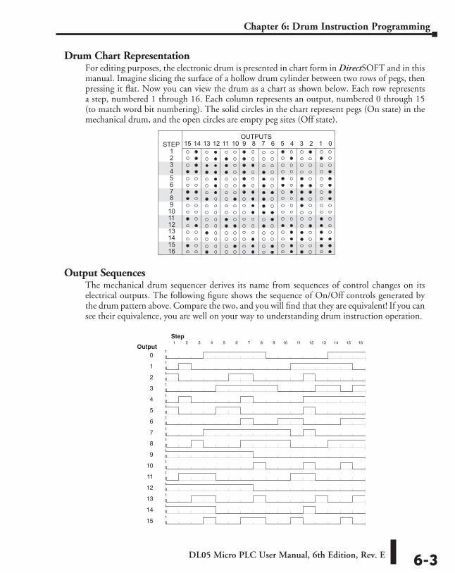
DL05 Micro PLC User Manual, 6th Edition, Rev. E 6-3
Chapter 6: Drum Instruction Programming
Drum Chart RepresentationFor editing purposes, the electronic drum is presented in chart form in DirectSOFT and in this manual. Imagine slicing the surface of a hollow drum cylinder between two rows of pegs, then pressing it flat. Now you can view the drum as a chart as shown below. Each row represents a step, numbered 1 through 16. Each column represents an output, numbered 0 through 15 (to match word bit numbering). The solid circles in the chart represent pegs (On state) in the mechanical drum, and the open circles are empty peg sites (Off state).
Output SequencesThe mechanical drum sequencer derives its name from sequences of control changes on its electrical outputs. The following figure shows the sequence of On/Off controls generated by the drum pattern above. Compare the two, and you will find that they are equivalent! If you can see their equivalence, you are well on your way to understanding drum instruction operation.
1STEP
2 3 4 5 6 7 8 910111213141516
1 2 3 4 5 6 7 8 9101112131415 0OUTPUTS
0 01
1 01
2 01
3 01
4 01
5 01
6 01
7 01
8 01
9 01
10 01
11 01
12 01
13 01
14 01
15 01
Output1 2 3 4 5 6 7 8 9 10 11 12 13 14 15 16
Step
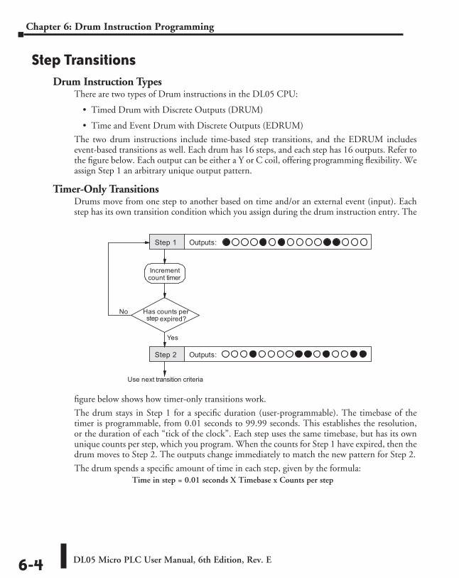
DL05 Micro PLC User Manual, 6th Edition, Rev. E6-4
Chapter 6: Drum Instruction Programming
Step TransitionsDrum Instruction Types
There are two types of Drum instructions in the DL05 CPU:
• Timed Drum with Discrete Outputs (DRUM)
• Time and Event Drum with Discrete Outputs (EDRUM)
The two drum instructions include time-based step transitions, and the EDRUM includes event-based transitions as well. Each drum has 16 steps, and each step has 16 outputs. Refer to the figure below. Each output can be either a Y or C coil, offering programming flexibility. We assign Step 1 an arbitrary unique output pattern.
Timer-Only TransitionsDrums move from one step to another based on time and/or an external event (input). Each step has its own transition condition which you assign during the drum instruction entry. The
figure below shows how timer-only transitions work.
The drum stays in Step 1 for a specific duration (user-programmable). The timebase of the timer is programmable, from 0.01 seconds to 99.99 seconds. This establishes the resolution, or the duration of each “tick of the clock”. Each step uses the same timebase, but has its own unique counts per step, which you program. When the counts for Step 1 have expired, then the drum moves to Step 2. The outputs change immediately to match the new pattern for Step 2.
The drum spends a specific amount of time in each step, given by the formula:Time in step = 0.01 seconds X Timebase x Counts per step
Step 1 Outputs:
Step 2 Outputs:
Has counts perexpired?
No
Yes
Incrementcount timer
Use next transition criteria
step
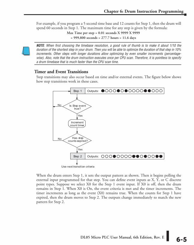
DL05 Micro PLC User Manual, 6th Edition, Rev. E 6-5
Chapter 6: Drum Instruction Programming
For example, if you program a 5 second time base and 12 counts for Step 1, then the drum will spend 60 seconds in Step 1. The maximum time for any step is given by the formula:
Max Time per step = 0.01 seconds X 9999 X 9999= 999,800 seconds = 277.7 hours = 11.6 days
NOTE: When first choosing the timebase resolution, a good rule of thumb is to make it about 1/10 the duration of the shortest step in your drum. Then you will be able to optimize the duration of that step in 10% increments. Other steps with longer durations allow optimizing by even smaller increments (percentage-wise). Also, note that the drum instruction executes once per CPU scan. Therefore, it is pointless to specify a drum timebase that is much faster than the CPU scan time.
Timer and Event TransitionsStep transitions may also occur based on time and/or external events. The figure below shows how step transitions work in these cases.
When the drum enters Step 1, it sets the output pattern as shown. Then it begins polling the external input programmed for that step. You can define event inputs as X, Y, or C discrete point types. Suppose we select X0 for the Step 1 event input. If X0 is off, then the drum remains in Step 1. When X0 is On, the event criteria is met and the timer increments. The timer increments as long as the event (X0) remains true. When the counts for Step 1 have expired, then the drum moves to Step 2. The outputs change immediately to match the new pattern for Step 2.
Is Step eventtrue?
Step 1 Outputs:
Step 2 Outputs:
No
Yes
Incrementcount timer
Has stepcounts expired?
No
Yes
Use next transit ion criteria
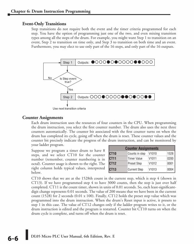
DL05 Micro PLC User Manual, 6th Edition, Rev. E6-6
Chapter 6: Drum Instruction Programming
Event-Only TransitionsStep transitions do not require both the event and the timer criteria programmed for each step. You have the option of programming just one of the two, and even mixing transition types among all the steps of the drum. For example, you might want Step 1 to transition on an event, Step 2 to transition on time only, and Step 3 to transition on both time and an event. Furthermore, you may elect to use only part of the 16 steps, and only part of the 16 outputs.
Counter AssignmentsEach drum instruction uses the resources of four counters in the CPU. When programming the drum instruction, you select the first counter number. The drum also uses the next three counters automatically. The counter bit associated with the first counter turns on when the drum has completed its cycle, going off when the drum is reset. These counter values and the counter bit precisely indicate the progress of the drum instruction, and can be monitored by your ladder program.
Suppose we program a timer drum to have 8 steps, and we select CT10 for the counter number (remember, counter numbering is in octal). Counter usage is shown to the right. The right column holds typical values, interpreted below.
CT10 shows that we are at the 1528th count in the current step, which is step 4 (shown in CT13). If we have programmed step 4 to have 3000 counts, then the step is just over half completed. CT11 is the count timer, shown in units of 0.01 seconds. So, each least-significant-digit change represents 0.01 seconds. The value of 200 means that we have been in the current count (1528) for 2 seconds (0.01 x 100). Finally, CT12 holds the preset step value which was programmed into the drum instruction. When the drum’s Reset input is active, it presets to step 1 in this case. The value of CT12 changes only if the ladder program writes to it, or the drum instruction is edited and the program is restarted. Counter bit CT10 turns on when the drum cycle is complete, and turns off when the drum is reset.
Counter Assignments CT10 Counts in step V1010 1528
CT11 Timer Value V1011 0200
CT12 Preset Step V1012 0001
CT13 Current Step V1013 0004
Is Step eventtrue?
Step 1 Outputs:
Step 2 Outputs:
No
Yes
Use next transition criteria
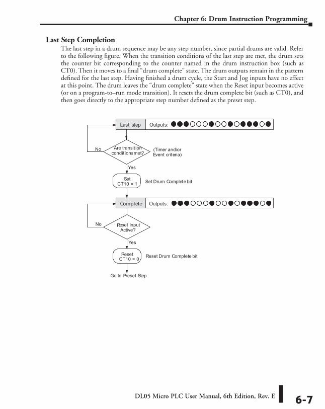
DL05 Micro PLC User Manual, 6th Edition, Rev. E 6-7
Chapter 6: Drum Instruction Programming
Last Step CompletionThe last step in a drum sequence may be any step number, since partial drums are valid. Refer to the following figure. When the transition conditions of the last step are met, the drum sets the counter bit corresponding to the counter named in the drum instruction box (such as CT0). Then it moves to a final “drum complete” state. The drum outputs remain in the pattern defined for the last step. Having finished a drum cycle, the Start and Jog inputs have no effect at this point. The drum leaves the “drum complete” state when the Reset input becomes active (or on a program-to–run mode transition). It resets the drum complete bit (such as CT0), and then goes directly to the appropriate step number defined as the preset step.
Are transit ionconditions met?
Last step Outputs:
Complete Outputs:
No
Yes
Go to Preset Step
SetCT10 = 1
Reset InputActive?
No
Yes
Reset
(Timer and/orEvent criteria)
Set Drum Complete bit
Reset Drum Complete bitCT10 = 0
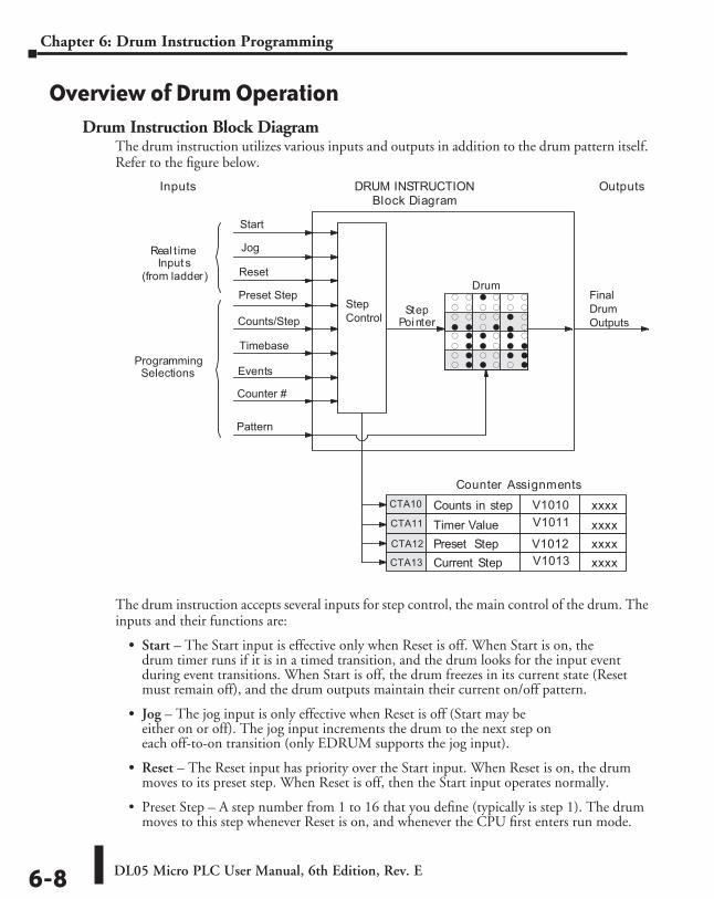
DL05 Micro PLC User Manual, 6th Edition, Rev. E6-8
Chapter 6: Drum Instruction Programming
Overview of Drum OperationDrum Instruction Block Diagram
The drum instruction utilizes various inputs and outputs in addition to the drum pattern itself. Refer to the figure below.
The drum instruction accepts several inputs for step control, the main control of the drum. The inputs and their functions are:
• Start – The Start input is effective only when Reset is off. When Start is on, the drum timer runs if it is in a timed transition, and the drum looks for the input event during event transitions. When Start is off, the drum freezes in its current state (Reset must remain off), and the drum outputs maintain their current on/off pattern.
• Jog – The jog input is only effective when Reset is off (Start may be either on or off). The jog input increments the drum to the next step on each off-to-on transition (only EDRUM supports the jog input).
• Reset – The Reset input has priority over the Start input. When Reset is on, the drum moves to its preset step. When Reset is off, then the Start input operates normally.
• Preset Step – A step number from 1 to 16 that you define (typically is step 1). The drum moves to this step whenever Reset is on, and whenever the CPU first enters run mode.
f f F f f ff f f f f ff f f f F fF F f F F ff F F f F ff F F f F Ff F f f F Ff F F f f F
StepPointer
Drum
DRUM INSTRUCTIONBlock Diagram
Inputs Outputs
Counts in step xxxx
Timer Value xxxx
Preset Step xxxx
Current Step xxxx
Counter Assignments
Events
Real timeInput s
(from ladder)
ProgrammingSelections
Start
Jog
Reset
Preset Step
Counts/Step
Timebase
Counter #
Pattern
Step
Control
Final
Drum
Outputs
CTA10
CTA11
CTA12
CTA13
V1010
V1011
V1012
V1013
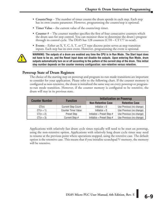
DL05 Micro PLC User Manual, 6th Edition, Rev. E 6-9
Chapter 6: Drum Instruction Programming
• Counts/Step – The number of timer counts the drum spends in each step. Each step has its own counts parameter. However, programming the counts/step is optional.
• Timer Value – the current value of the counts/step timer.
• Counter # – The counter number specifies the first of four consecutive counters which the drum uses for step control. You can monitor these to determine the drum’s progress through its control cycle. The DL05 has 128 counters (CT0 – CT177 in octal).
• Events – Either an X, Y, C, S, T, or CT type discrete point serves as step transition inputs. Each step has its own event. However, programming the event is optional.
WARNING: The outputs of a drum are enabled any time the CPU is in Run Mode. The Start Input does not have to be on, and the Reset input does not disable the outputs. Upon entering Run Mode, drum outputs automatically turn on or off according to the pattern of the current step of the drum. This initial step number depends on the counter memory configuration: non-retentive versus retentive.
Powerup State of Drum RegistersThe choice of the starting step on powerup and program-to-run mode transitions are important to consider for your application. Please refer to the following chart. If the counter memory is configured as non-retentive, the drum is initialized the same way on every powerup or program-to-run mode transition. However, if the counter memory is configured to be retentive, the drum will stay in its previous state.
Applications with relatively fast drum cycle times typically will need to be reset on powerup, using the non-retentive option. Applications with relatively long drum cycle times may need to resume at the previous point where operations stopped, using the retentive case. The default option is the retentive case. This means that if you initialize scratchpad V-memory, the memory will be retentive.
Counter Number Function Initialization on PowerupNon-Retentive Case Retentive Case
CT(n) Current Step Count Initialize = 0 Use Previous (no change)CT(n + 1) Counter Timer Value Initialize = 0 Use Previous (no change)CT(n + 2) Preset Step Initialize = Preset Step # Use Previous (no change)CT(n + 3) Current Step # Initialize = Preset Step # Use Previous (no change)
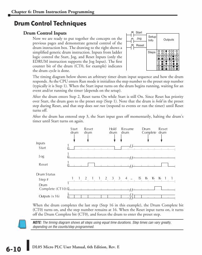
DL05 Micro PLC User Manual, 6th Edition, Rev. E6-10
Chapter 6: Drum Instruction Programming
Drum Control TechniquesDrum Control Inputs
Now we are ready to put together the concepts on the previous pages and demonstrate general control of the drum instruction box. The drawing to the right shows a simplified generic drum instruction. Inputs from ladder logic control the Start, Jog, and Reset Inputs (only the EDRUM instruction supports the Jog Input). The first counter bit of the drum (CT0, for example) indicates the drum cycle is done.
The timing diagram below shows an arbitrary timer drum input sequence and how the drum responds. As the CPU enters Run mode it initializes the step number to the preset step number (typically it is Step 1). When the Start input turns on the drum begins running, waiting for an event and/or running the timer (depends on the setup).
After the drum enters Step 2, Reset turns On while Start is still On. Since Reset has priority over Start, the drum goes to the preset step (Step 1). Note that the drum is held in the preset step during Reset, and that step does not run (respond to events or run the timer) until Reset turns off.
After the drum has entered step 3, the Start input goes off momentarily, halting the drum’s timer until Start turns on again.
When the drum completes the last step (Step 16 in this example), the Drum Complete bit (CT0) turns on, and the step number remains at 16. When the Reset input turns on, it turns off the Drum Complete bit (CT0), and forces the drum to enter the preset step.
NOTE: The timing diagram shows all steps using equal time durations. Step times can vary greatly, depending on the counts/step programmed.
f f f f F fF F f F F f
f f F FF f
X0
X1
X2
X0
X1
X2
Start
Jog
Reset
SetupInfo Outputs
Steps
Start 01
J og 01
Step #
Drum0
1
Inputs
1 1 2 1 1 2 3 3 4 ... 15 16 16 16 1 1Drum Status
S tartdrum
Resetdrum
Holddrum
Resumedrum
DrumComplete
Resetdrum
01
Outputs (x 16)
Reset 01
Complete (CT10)
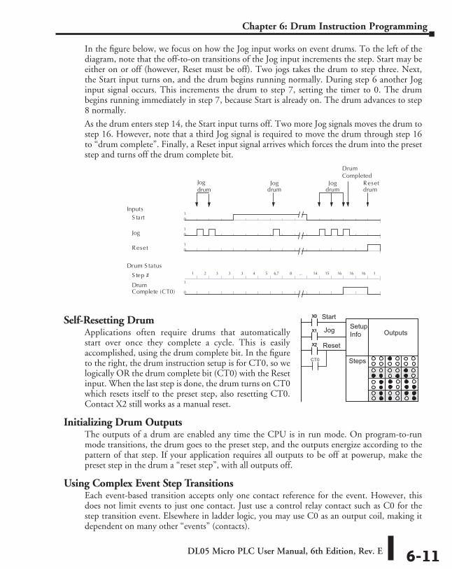
DL05 Micro PLC User Manual, 6th Edition, Rev. E 6-11
Chapter 6: Drum Instruction Programming
In the figure below, we focus on how the Jog input works on event drums. To the left of the diagram, note that the off-to-on transitions of the Jog input increments the step. Start may be either on or off (however, Reset must be off). Two jogs takes the drum to step three. Next, the Start input turns on, and the drum begins running normally. During step 6 another Jog input signal occurs. This increments the drum to step 7, setting the timer to 0. The drum begins running immediately in step 7, because Start is already on. The drum advances to step 8 normally.
As the drum enters step 14, the Start input turns off. Two more Jog signals moves the drum to step 16. However, note that a third Jog signal is required to move the drum through step 16 to “drum complete”. Finally, a Reset input signal arrives which forces the drum into the preset step and turns off the drum complete bit.
Self-Resetting DrumApplications often require drums that automatically start over once they complete a cycle. This is easily accomplished, using the drum complete bit. In the figure to the right, the drum instruction setup is for CT0, so we logically OR the drum complete bit (CT0) with the Reset input. When the last step is done, the drum turns on CT0 which resets itself to the preset step, also resetting CT0. Contact X2 still works as a manual reset.
Initializing Drum OutputsThe outputs of a drum are enabled any time the CPU is in run mode. On program-to-run mode transitions, the drum goes to the preset step, and the outputs energize according to the pattern of that step. If your application requires all outputs to be off at powerup, make the preset step in the drum a “reset step”, with all outputs off.
Using Complex Event Step TransitionsEach event-based transition accepts only one contact reference for the event. However, this does not limit events to just one contact. Just use a control relay contact such as C0 for the step transition event. Elsewhere in ladder logic, you may use C0 as an output coil, making it dependent on many other “events” (contacts).
S tart 01
Reset 01
S tep #
DrumComplete (CT0) 0
1
Inputs
1 2 3 3 3 4 5 6,7 8 ... 14 15 16 16 16 1
Drum S tatus
Resetdrum
Jog drum
01
Outputs (x 16)
Jog 01
Jogdrum
Jogdrum
DrumCompleted
f f f f F fF F f F F f
f f F FF f
X0
X1
X2
X0
X1
X2
Start
Jog
Reset
SetupInfo Outputs
StepsCT0
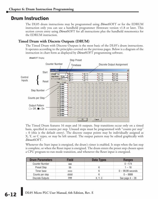
DL05 Micro PLC User Manual, 6th Edition, Rev. E6-12
Chapter 6: Drum Instruction Programming
Drum InstructionThe DL05 drum instructions may be programmed using DirectSOFT or for the EDRUM instruction only you can use a handheld programmer (firmware version v1.8 or later. This section covers entry using DirectSOFT for all instructions plus the handheld mnemonics for the EDRUM instruction.
Timed Drum with Discrete Outputs (DRUM)The Timed Drum with Discrete Outputs is the most basic of the DL05’s drum instructions. It operates according to the principles covered on the previous pages. Below is a diagram of the instruction in chart form as displayed by DirectSOFT programming software.
The Timed Drum features 16 steps and 16 outputs. Step transitions occur only on a timed basis, specified in counts per step. Unused steps must be programmed with “counts per step” = 0 (this is the default entry). The discrete output points may be individually assigned as X, Y, or C types, or may be left unused. The output pattern may be edited graphically with DirectSOFT.
Whenever the Start input is energized, the drum’s timer is enabled. It stops when the last step is complete, or when the Reset input is energized. The drum enters the preset step chosen upon a CPU program-to-run mode transition, and whenever the Reset input is energized.
Drum Parameters Field Data Types RangesCounter Number aaa 0 --174
Preset Step bb K 1 -- 16Timer base cccc K 0 -- 99.99 seconds
Counts per step dddd K 0 -- 9999Discrete Outputs Fffff X, Y, C See page 4 -- 28
Step Number
Start
Reset
Counts per Step
Output Pattern l= Off, L= On
Counter NumberStep Preset
Timebase Discrete Output Assignment
ControlInputs
DirectSOFT Display
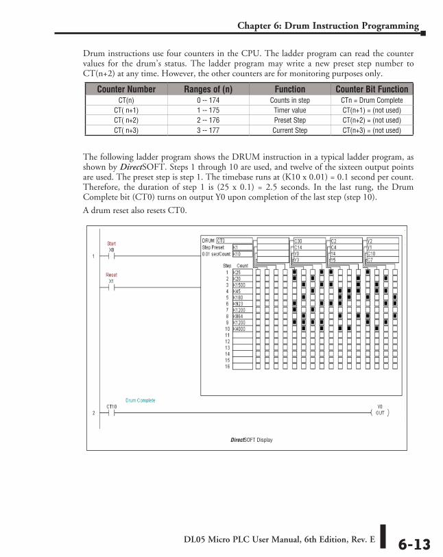
DL05 Micro PLC User Manual, 6th Edition, Rev. E 6-13
Chapter 6: Drum Instruction Programming
Drum instructions use four counters in the CPU. The ladder program can read the counter values for the drum’s status. The ladder program may write a new preset step number to CT(n+2) at any time. However, the other counters are for monitoring purposes only.
The following ladder program shows the DRUM instruction in a typical ladder program, as shown by DirectSOFT. Steps 1 through 10 are used, and twelve of the sixteen output points are used. The preset step is step 1. The timebase runs at (K10 x 0.01) = 0.1 second per count. Therefore, the duration of step 1 is (25 x 0.1) = 2.5 seconds. In the last rung, the Drum Complete bit (CT0) turns on output Y0 upon completion of the last step (step 10).
A drum reset also resets CT0.
Counter Number Ranges of (n) Function Counter Bit FunctionCT(n) 0 -- 174 Counts in step CTn = Drum Complete
CT( n+1) 1 -- 175 Timer value CT(n+1) = (not used)CT( n+2) 2 -- 176 Preset Step CT(n+2) = (not used)CT( n+3) 3 -- 177 Current Step CT(n+3) = (not used)
DirectSOFT Display
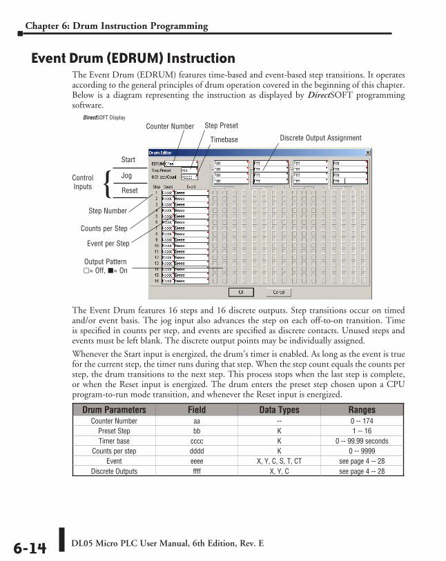
DL05 Micro PLC User Manual, 6th Edition, Rev. E6-14
Chapter 6: Drum Instruction Programming
Event Drum (EDRUM) InstructionThe Event Drum (EDRUM) features time-based and event-based step transitions. It operates according to the general principles of drum operation covered in the beginning of this chapter. Below is a diagram representing the instruction as displayed by DirectSOFT programming software.
The Event Drum features 16 steps and 16 discrete outputs. Step transitions occur on timed and/or event basis. The jog input also advances the step on each off-to-on transition. Time is specified in counts per step, and events are specified as discrete contacts. Unused steps and events must be left blank. The discrete output points may be individually assigned.
Whenever the Start input is energized, the drum’s timer is enabled. As long as the event is true for the current step, the timer runs during that step. When the step count equals the counts per step, the drum transitions to the next step. This process stops when the last step is complete, or when the Reset input is energized. The drum enters the preset step chosen upon a CPU program-to-run mode transition, and whenever the Reset input is energized.
Drum Parameters Field Data Types RangesCounter Number aa -- 0 -- 174
Preset Step bb K 1 -- 16Timer base cccc K 0 -- 99.99 seconds
Counts per step dddd K 0 -- 9999Event eeee X, Y, C, S, T, CT see page 4 -- 28
Discrete Outputs ffff X, Y, C see page 4 -- 28
DirectSOFT Display
Step Number
Start
Jog
Counts per Step
Output Pattern l= Off, L= On
Counter Number Step Preset
Timebase Discrete Output Assignment
ControlInputs Reset
Event per Step
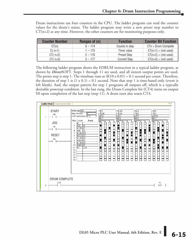
DL05 Micro PLC User Manual, 6th Edition, Rev. E 6-15
Chapter 6: Drum Instruction Programming
Drum instructions use four counters in the CPU. The ladder program can read the counter values for the drum’s status. The ladder program may write a new preset step number to CT(n+2) at any time. However, the other counters are for monitoring purposes only.
The following ladder program shows the EDRUM instruction in a typical ladder program, as shown by DirectSOFT. Steps 1 through 11 are used, and all sixteen output points are used. The preset step is step 1. The timebase runs at (K10 x 0.01) = 0.1 second per count. Therefore, the duration of step 1 is (1 x 0.1) = 0.1 second. Note that step 1 is time-based only (event is left blank). And, the output pattern for step 1 programs all outputs off, which is a typically desirable powerup condition. In the last rung, the Drum Complete bit (CT4) turns on output Y0 upon completion of the last step (step 11). A drum reset also resets CT4.
Counter Number Ranges of (n) Function Counter Bit FunctionCT(n) 0 -- 174 Counts in step CTn = Drum Complete
C( n+1) 1 -- 175 Timer value CT(n+1) = (not used)CT( n+2) 2 -- 176 Preset Step CT(n+2) = (not used)CT( n+3) 3 -- 177 Current Step CT(n+3) = (not used)
START
JOG
RESET
DRUM COMPLETE
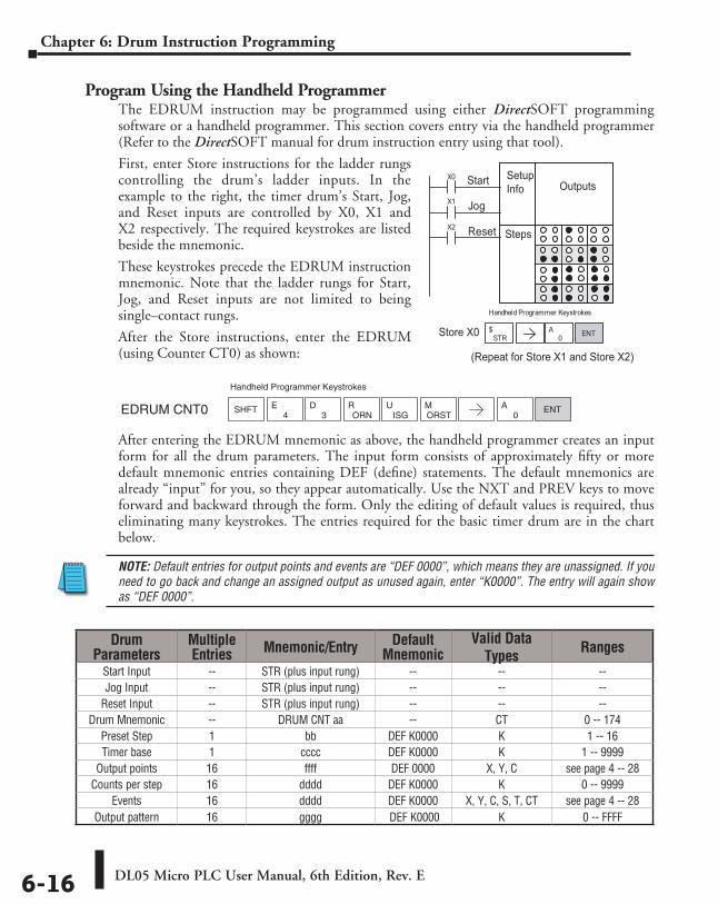
DL05 Micro PLC User Manual, 6th Edition, Rev. E6-16
Chapter 6: Drum Instruction Programming
Program Using the Handheld ProgrammerThe EDRUM instruction may be programmed using either DirectSOFT programming software or a handheld programmer. This section covers entry via the handheld programmer (Refer to the DirectSOFT manual for drum instruction entry using that tool).
First, enter Store instructions for the ladder rungs controlling the drum’s ladder inputs. In the example to the right, the timer drum’s Start, Jog, and Reset inputs are controlled by X0, X1 and X2 respectively. The required keystrokes are listed beside the mnemonic.
These keystrokes precede the EDRUM instruction mnemonic. Note that the ladder rungs for Start, Jog, and Reset inputs are not limited to being single–contact rungs.
After the Store instructions, enter the EDRUM (using Counter CT0) as shown:
After entering the EDRUM mnemonic as above, the handheld programmer creates an input form for all the drum parameters. The input form consists of approximately fifty or more default mnemonic entries containing DEF (define) statements. The default mnemonics are already “input” for you, so they appear automatically. Use the NXT and PREV keys to move forward and backward through the form. Only the editing of default values is required, thus eliminating many keystrokes. The entries required for the basic timer drum are in the chart below.
NOTE: Default entries for output points and events are “DEF 0000”, which means they are unassigned. If you need to go back and change an assigned output as unused again, enter “K0000”. The entry will again show as “DEF 0000”.
X0
X1 Jog
Handheld Programmer Keystrokes
X2 Reset
STR$
0A ENT
Start
Store X0
(Repeat for Store X1 and Store X2)
f f f f F fF F f F F f
f f F FF f
SetupInfo Outputs
Steps
Drum Parameters
Multiple Entries Mnemonic/Entry Default
MnemonicValid Data
Types Ranges
Start Input -- STR (plus input rung) -- -- --Jog Input -- STR (plus input rung) -- -- --
Reset Input -- STR (plus input rung) -- -- --Drum Mnemonic -- DRUM CNT aa -- CT 0 -- 174
Preset Step 1 bb DEF K0000 K 1 -- 16Timer base 1 cccc DEF K0000 K 1 -- 9999
Output points 16 ffff DEF 0000 X, Y, C see page 4 -- 28Counts per step 16 dddd DEF K0000 K 0 -- 9999
Events 16 dddd DEF K0000 X, Y, C, S, T, CT see page 4 -- 28Output pattern 16 gggg DEF K0000 K 0 -- FFFF
Handheld Programmer Keystrokes
EDRUM CNT0 SHFT4
E3
DORN
RISG
UORSTM
0A ENT
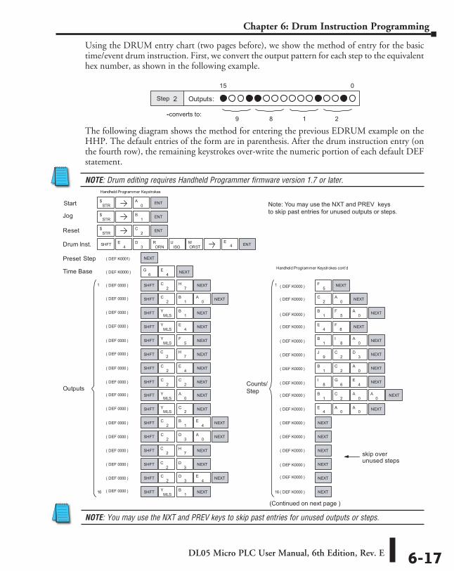
DL05 Micro PLC User Manual, 6th Edition, Rev. E 6-17
Chapter 6: Drum Instruction Programming
Using the DRUM entry chart (two pages before), we show the method of entry for the basic time/event drum instruction. First, we convert the output pattern for each step to the equivalent hex number, as shown in the following example.
The following diagram shows the method for entering the previous EDRUM example on the HHP. The default entries of the form are in parenthesis. After the drum instruction entry (on the fourth row), the remaining keystrokes over-write the numeric portion of each default DEF statement.
NOTE: Drum editing requires Handheld Programmer firmware version 1.7 or later.
NOTE: You may use the NXT and PREV keys to skip past entries for unused outputs or steps.
2 Outputs:
015
9 8 1 2--converts to:
Step
Handheld Programmer Keystrokes
( DEF K0001)
Reset
Drum Inst.
( DEF 0000 )
( DEF 0000 )
( DEF 0000 )
( DEF K0000 )
Preset
Time Base
( DEF 0000 )
( DEF 0000 )
( DEF 0000 )
( DEF 0000 )
( DEF 0000 )
( DEF 0000 )
( DEF 0000 )
( DEF 0000 )
( DEF 0000 )
( DEF 0000 )
( DEF 0000 )
( DEF 0000 )
( DEF 0000 )
Outputs
( DEF K0000 )
( DEF K0000 )
( DEF K0000 )
( DEF K0000 )
( DEF K0000 )
( DEF K0000 )
( DEF K0000 )
( DEF K0000 )
( DEF K0000 )
( DEF K0000 )
( DEF K0000 )
( DEF K0000 )
( DEF K0000 )
( DEF K0000 )
( DEF K0000 )
( DEF K0000 )
skip overunused steps
Jog
STR$
0A
STR$
1B
STR$
2C
SHFT 4E
3D
ORNR
ISGU
ORSTM ENT
4E
6G
NEXT
NEXT
ENT
ENT
ENT
SHFT2
C7
H NEXT
SHFT 2C
0A NEXT1
B
SHFT MLSY
1B NEXT
SHFT MLSY NEXT4
E
SHFT MLSY
5F NEXT
SHFT NEXT
SHFT 2C
4E NEXT
SHFT 2C
2C NEXT
SHFTMLS
Y NEXT0
A
SHFT MLSY NEXT2
C
SHFT 2C
1B
4E NEXT
SHFT 2C NEXT3
D0
A
SHFT NEXT
SHFT NEXT
SHFT 2C
3D
4E NEXT
SHFT MLSY
1B NEXT
1
16
1
16
5F NEXT
2C
0A NEXT
1B
5F
0A NEXT
4E
8F NEXT
1B
8I
0A NEXT
9J
2C
3D NEXT
1B
0A NEXT2
C
8I
6G
4E NEXT
1B
2C
0A
0A NEXT
4E
0A
0A NEXT
NEXT
NEXT
NEXT
NEXT
NEXT
NEXT
Handheld Programmer Keystrokes cont’d
Start
Step
Counts/Step
Note: You may use the NXT and PREV keysto skip past entries for unused outputs or steps.
(Continued on next page )
E4
2C
7H
2C
7H
2C
3D
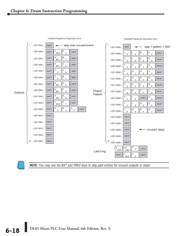
DL05 Micro PLC User Manual, 6th Edition, Rev. E6-18
Chapter 6: Drum Instruction Programming
NOTE: You may use the NXT and PREV keys to skip past entries for unused outputs or steps.
Handheld Programmer Keystrokes cont’d
unused
( DEF 0000 )
( DEF 0000 )
( DEF 0000 )
( DEF 0000 )
( DEF 0000 )
( DEF 0000 )
( DEF 0000 )
( DEF 0000 )
( DEF 0000 )
( DEF 0000 )
( DEF 0000 )
skip over unused event( DEF K0000 )
( DEF K0000 )
( DEF K0000 )
( DEF K0000 )
( DEF K0000 )
( DEF K0000 )
( DEF K0000 )
( DEF K0000 )
( DEF K0000 )
( DEF K0000 )
( DEF K0000 )
( DEF K0000 )
( DEF K0000 )
( DEF K0000 )
( DEF K0000 )
( DEF K0000 )
Last rung
6G
1
16
NEXT
SHFT MLSY
4E NEXT
SHFT SETX
1B NEXT
SHFT SETX
2C NEXT
SHFT 2C
0A NEXT
SHFT 2C NEXT1
B
SHFT SETX NEXT0
A
SHFT SETX NEXT5
F
SHFTSET
X3
D NEXT
SHFT MLSY
7H NEXT
SHFT 2C
2C
0A NEXT
NEXT
NEXT
NEXT
NEXT
NEXT
NEXT
9J
8I
1B NEXT2
C
2C
8I
9J
4E NEXT
( DEF 0000 )
( DEF 0000 )
( DEF 0000 )
( DEF 0000 )
( DEF 0000 )
4E
4E
7H NEXT
5F
1B
6G
9J NEXT
9J
3D
4E
3D NEXT
4E
4E
8I
6G NEXT
9J
4E
5F NEXT9
J
3D
8I SHFT 0
A NEXT
5F
8I
6G
4E NEXT
8I
4E
4E
7H NEXT
NEXT
NEXT
NEXT
NEXT
NEXT
1
16
Handheld Programmer Keystrokes cont’d
STR$
CNTGY NEXT
SHFTMLS
Y0
A NEXT
Outputs OutputPattern
step 1 pattern = 0000
steps
NOTE: You may use the NXT and PREV keysto skip past entries for unused outputs or stops.
E4
RLLPLUS Stage PRogRamming 777
ChapterChapterChapter
In This Chapter...Introduction to Stage Programming ........................................................................ 7-2
Learning to Draw State Transition Diagrams ........................................................... 7-3
Using the Stage Jump Instruction for State Transitions ........................................... 7-7
Stage Program Example: Toggle On/Off Lamp Controller ...................................... 7-8
Four Steps to Writing a Stage Program ................................................................... 7-9
Stage Program Example: A Garage Door Opener .................................................. 7-10
Stage Program Design Considerations ................................................................... 7-15
Parallel Processing Concepts ................................................................................... 7-19
RLLPLUS (Stage) Instructions .................................................................................... 7-21
Questions and Answers about Stage Programming .............................................. 7-25
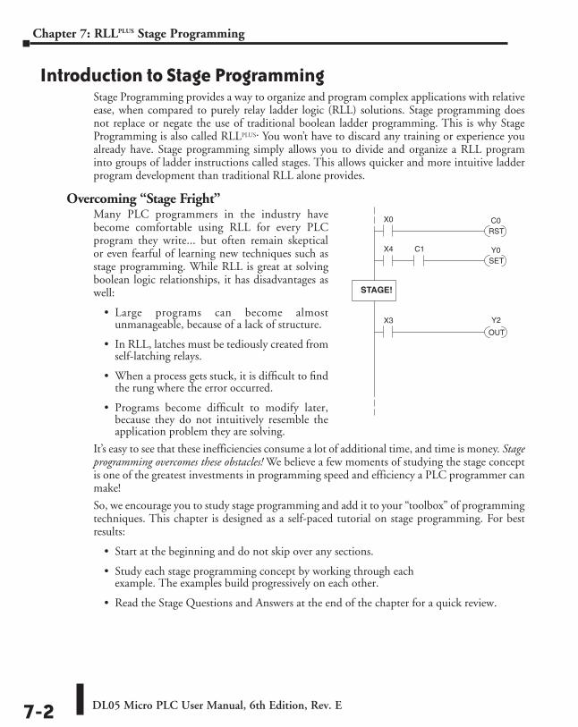
DL05 Micro PLC User Manual, 6th Edition, Rev. E7-2
Chapter 7: RLLPLUS Stage Programming
Introduction to Stage ProgrammingStage Programming provides a way to organize and program complex applications with relative ease, when compared to purely relay ladder logic (RLL) solutions. Stage programming does not replace or negate the use of traditional boolean ladder programming. This is why Stage Programming is also called RLLplus. You won’t have to discard any training or experience you already have. Stage programming simply allows you to divide and organize a RLL program into groups of ladder instructions called stages. This allows quicker and more intuitive ladder program development than traditional RLL alone provides.
Overcoming “Stage Fright”Many PLC programmers in the industry have become comfortable using RLL for every PLC program they write... but often remain skeptical or even fearful of learning new techniques such as stage programming. While RLL is great at solving boolean logic relationships, it has disadvantages as well:
• Large programs can become almost unmanageable, because of a lack of structure.
• In RLL, latches must be tediously created from self-latching relays.
• When a process gets stuck, it is difficult to find the rung where the error occurred.
• Programs become difficult to modify later, because they do not intuitively resemble the application problem they are solving.
It’s easy to see that these inefficiencies consume a lot of additional time, and time is money. Stage programming overcomes these obstacles! We believe a few moments of studying the stage concept is one of the greatest investments in programming speed and efficiency a PLC programmer can make!
So, we encourage you to study stage programming and add it to your “toolbox” of programming techniques. This chapter is designed as a self-paced tutorial on stage programming. For best results:
• Start at the beginning and do not skip over any sections.
• Study each stage programming concept by working through each example. The examples build progressively on each other.
• Read the Stage Questions and Answers at the end of the chapter for a quick review.
STAGE!
Y2X3
OUT
X0
RSTC0
X4
SETY0C1
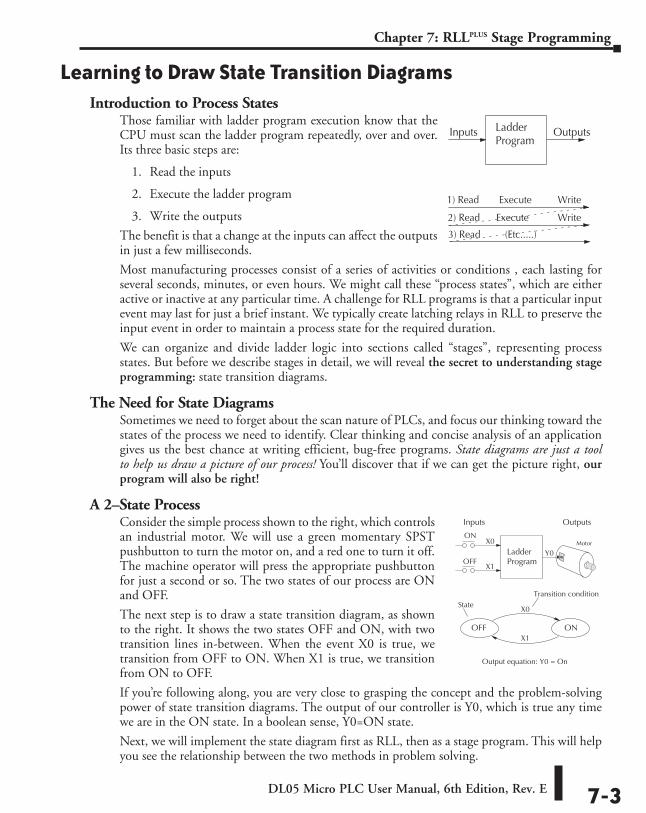
DL05 Micro PLC User Manual, 6th Edition, Rev. E 7-3
Chapter 7: RLLPLUS Stage Programming
Learning to Draw State Transition DiagramsIntroduction to Process States
Those familiar with ladder program execution know that the CPU must scan the ladder program repeatedly, over and over. Its three basic steps are:
1. Read the inputs
2. Execute the ladder program
3. Write the outputs
The benefit is that a change at the inputs can affect the outputs in just a few milliseconds.
Most manufacturing processes consist of a series of activities or conditions , each lasting for several seconds, minutes, or even hours. We might call these “process states”, which are either active or inactive at any particular time. A challenge for RLL programs is that a particular input event may last for just a brief instant. We typically create latching relays in RLL to preserve the input event in order to maintain a process state for the required duration.
We can organize and divide ladder logic into sections called “stages”, representing process states. But before we describe stages in detail, we will reveal the secret to understanding stage programming: state transition diagrams.
The Need for State DiagramsSometimes we need to forget about the scan nature of PLCs, and focus our thinking toward the states of the process we need to identify. Clear thinking and concise analysis of an application gives us the best chance at writing efficient, bug-free programs. State diagrams are just a tool to help us draw a picture of our process! You’ll discover that if we can get the picture right, our program will also be right!
A 2–State ProcessConsider the simple process shown to the right, which controls an industrial motor. We will use a green momentary SPST pushbutton to turn the motor on, and a red one to turn it off. The machine operator will press the appropriate pushbutton for just a second or so. The two states of our process are ON and OFF.
The next step is to draw a state transition diagram, as shown to the right. It shows the two states OFF and ON, with two transition lines in-between. When the event X0 is true, we transition from OFF to ON. When X1 is true, we transition from ON to OFF.
If you’re following along, you are very close to grasping the concept and the problem-solving power of state transition diagrams. The output of our controller is Y0, which is true any time we are in the ON state. In a boolean sense, Y0=ON state.
Next, we will implement the state diagram first as RLL, then as a stage program. This will help you see the relationship between the two methods in problem solving.
Ladder Program
Inputs Outputs
1) Read Execute Write
Execute Write
(Etc.....)
2) Read
3) Read
LadderProgram
Inputs Outputs
OFF
MotorX0
X1
Y0
OFF ON
X0
X1
Output equation: Y0 = On
State Transition condition
ON
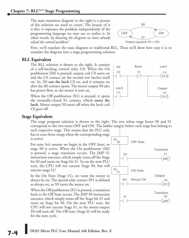
DL05 Micro PLC User Manual, 6th Edition, Rev. E7-4
Chapter 7: RLLPLUS Stage Programming
The state transition diagram to the right is a picture of the solution we need to create. The beauty of it is this: it expresses the problem independently of the programming language we may use to realize it. In other words, by drawing the diagram we have already solved the control problem!
First, we’ll translate the state diagram to traditional RLL. Then we’ll show how easy it is to translate the diagram into a stage programming solution.
RLL EquivalentThe RLL solution is shown to the right. It consists of a self-latching control relay, C0. When the On pushbutton (X0) is pressed, output coil C0 turns on and the C0 contact on the second row latches itself on. So, X0 sets the latch C0 on, and it remains on after the X0 contact opens. The motor output Y0 also has power flow, so the motor is now on.
When the Off pushbutton (X1) is pressed, it opens the normally-closed X1 contact, which resets the latch. Motor output Y0 turns off when the latch coil C0 goes off.
Stage EquivalentThe stage program solution is shown to the right. The two inline stage boxes S0 and S1 correspond to the two states OFF and ON. The ladder rung(s) below each stage box belong to each respective stage. This means that the PLC only has to scan those rungs when the corresponding stage is active!
For now, let’s assume we begin in the OFF State, so stage S0 is active. When the On pushbutton (X0) is pressed, a stage transition occurs. The JMP S1 instruction executes, which simply turns off the Stage bit S0 and turns on Stage bit S1. So on the next PLC scan, the CPU will not execute Stage S0, but will execute stage S1!
In the On State (Stage S1), we want the motor to always be on. The special relay contact SP1 is defined as always on, so Y0 turns the motor on.
When the Off pushbutton (X1) is pressed, a transition back to the Off State occurs. The JMP S0 instruction executes, which simply turns off the Stage bit S1 and turns on Stage bit S0. On the next PLC scan, the CPU will not execute Stage S1, so the motor output Y0 will turn off. The Off state (Stage 0) will be ready for the next cycle.
OFF ONX1
X0
Output equation Y0 = ON
X1X0
OUTC0
OUTY0C0
Set Reset Latch
OutputLatch
S1X0
JMP
SGS0
S0X1
JMP
SGS1
OUTY0
OFF State
ON State
Output
Transition
Transition
SP1 Always On
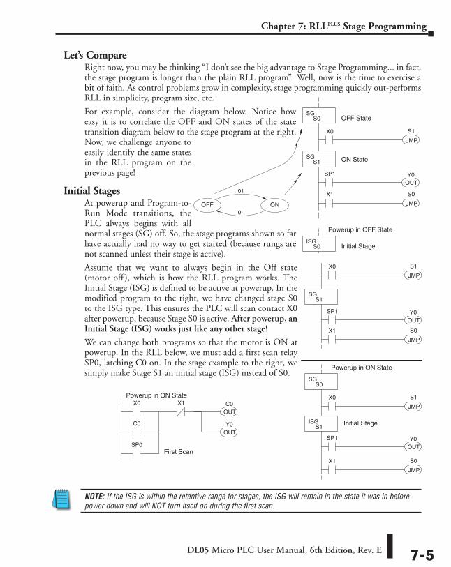
DL05 Micro PLC User Manual, 6th Edition, Rev. E 7-5
Chapter 7: RLLPLUS Stage Programming
Let’s CompareRight now, you may be thinking “I don’t see the big advantage to Stage Programming... in fact, the stage program is longer than the plain RLL program”. Well, now is the time to exercise a bit of faith. As control problems grow in complexity, stage programming quickly out-performs RLL in simplicity, program size, etc.
For example, consider the diagram below. Notice how easy it is to correlate the OFF and ON states of the state transition diagram below to the stage program at the right. Now, we challenge anyone to easily identify the same states in the RLL program on the previous page!
Initial StagesAt powerup and Program-to-Run Mode transitions, the PLC always begins with all normal stages (SG) off. So, the stage programs shown so far have actually had no way to get started (because rungs are not scanned unless their stage is active).
Assume that we want to always begin in the Off state (motor off ), which is how the RLL program works. The Initial Stage (ISG) is defined to be active at powerup. In the modified program to the right, we have changed stage S0 to the ISG type. This ensures the PLC will scan contact X0 after powerup, because Stage S0 is active. After powerup, an Initial Stage (ISG) works just like any other stage!
We can change both programs so that the motor is ON at powerup. In the RLL below, we must add a first scan relay SP0, latching C0 on. In the stage example to the right, we simply make Stage S1 an initial stage (ISG) instead of S0.
NOTE: If the ISG is within the retentive range for stages, the ISG will remain in the state it was in before power down and will NOT turn itself on during the first scan.
.
S1X0
JMP
SGS0
S0X1
JMP
SGS1
OUTY0
OFF State
ON State
SP1
OFF ON
01
0-
,
S1X0
JMP
ISGS0
S0X1
JMP
SGS1
OUTY0
Initial Stage
SP1
S1X0
JMP
SGS0
S0X1
JMP
ISGS1
OUTY0
Initial Stage
SP1
X1X0
OUTC0
OUTY0C0
First ScanSP0
Powerup in OFF State
Powerup in ON State
Powerup in ON State
.
S1X0
JMP
SGS0
S0X1
JMP
SGS1
OUTY0
OFF State
ON State
SP1
OFF ON
01
0-
,
S1X0
JMP
ISGS0
S0X1
JMP
SGS1
OUTY0
Initial Stage
SP1
S1X0
JMP
SGS0
S0X1
JMP
ISGS1
OUTY0
Initial Stage
SP1
X1X0
OUTC0
OUTY0C0
First ScanSP0
Powerup in OFF State
Powerup in ON State
Powerup in ON State
.
S1X0
JMP
SGS0
S0X1
JMP
SGS1
OUTY0
OFF State
ON State
SP1
OFF ON
01
0-
,
S1X0
JMP
ISGS0
S0X1
JMP
SGS1
OUTY0
Initial Stage
SP1
S1X0
JMP
SGS0
S0X1
JMP
ISGS1
OUTY0
Initial Stage
SP1
X1X0
OUTC0
OUTY0C0
First ScanSP0
Powerup in OFF State
Powerup in ON State
Powerup in ON State
.
S1X0
JMP
SGS0
S0X1
JMP
SGS1
OUTY0
OFF State
ON State
SP1
OFF ON
01
0-
,
S1X0
JMP
ISGS0
S0X1
JMP
SGS1
OUTY0
Initial Stage
SP1
S1X0
JMP
SGS0
S0X1
JMP
ISGS1
OUTY0
Initial Stage
SP1
X1X0
OUTC0
OUTY0C0
First ScanSP0
Powerup in OFF State
Powerup in ON State
Powerup in ON State
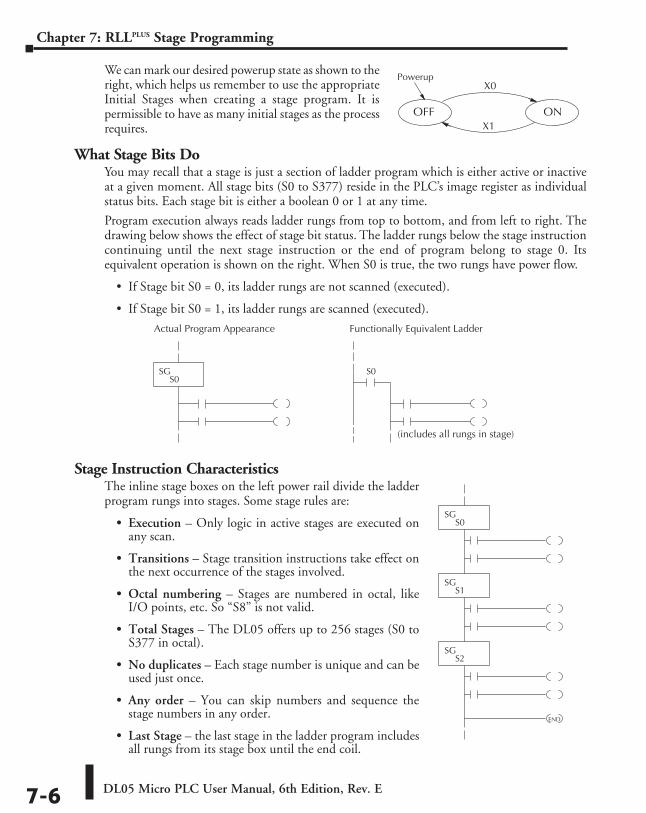
DL05 Micro PLC User Manual, 6th Edition, Rev. E7-6
Chapter 7: RLLPLUS Stage Programming
We can mark our desired powerup state as shown to the right, which helps us remember to use the appropriate Initial Stages when creating a stage program. It is permissible to have as many initial stages as the process requires.
What Stage Bits DoYou may recall that a stage is just a section of ladder program which is either active or inactive at a given moment. All stage bits (S0 to S377) reside in the PLC’s image register as individual status bits. Each stage bit is either a boolean 0 or 1 at any time.
Program execution always reads ladder rungs from top to bottom, and from left to right. The drawing below shows the effect of stage bit status. The ladder rungs below the stage instruction continuing until the next stage instruction or the end of program belong to stage 0. Its equivalent operation is shown on the right. When S0 is true, the two rungs have power flow.
• If Stage bit S0 = 0, its ladder rungs are not scanned (executed).
• If Stage bit S0 = 1, its ladder rungs are scanned (executed).
Stage Instruction CharacteristicsThe inline stage boxes on the left power rail divide the ladder program rungs into stages. Some stage rules are:
• Execution – Only logic in active stages are executed on any scan.
• Transitions – Stage transition instructions take effect on the next occurrence of the stages involved.
• Octal numbering – Stages are numbered in octal, like I/O points, etc. So “S8” is not valid.
• Total Stages – The DL05 offers up to 256 stages (S0 to S377 in octal).
• No duplicates – Each stage number is unique and can be used just once.
• Any order – You can skip numbers and sequence the stage numbers in any order.
• Last Stage – the last stage in the ladder program includes all rungs from its stage box until the end coil.
OFF ONX1
PowerupX0
SGS0
Actual Program Appearance Functionally Equivalent Ladder
S0
(includes all rungs in stage)
SG
S0
SGS1
SGS2
END
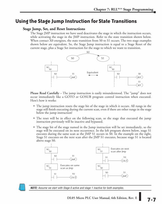
DL05 Micro PLC User Manual, 6th Edition, Rev. E 7-7
Chapter 7: RLLPLUS Stage Programming
Using the Stage Jump Instruction for State TransitionsStage Jump, Set, and Reset Instructions
The Stage JMP instruction we have used deactivates the stage in which the instruction occurs, while activating the stage in the JMP instruction. Refer to the state transition shown below. When contact X0 energizes, the state transition from S0 to S1 occurs. The two stage examples shown below are equivalent. So, the Stage Jump instruction is equal to a Stage Reset of the current stage, plus a Stage Set instruction for the stage to which we want to transition.
Please Read Carefully – The jump instruction is easily misunderstood. The “jump” does not occur immediately like a GOTO or GOSUB program control instruction when executed. Here’s how it works:
• The jump instruction resets the stage bit of the stage in which it occurs. All rungs in the stage still finish executing during the current scan, even if there are other rungs in the stage below the jump instruction!
• The reset will be in effect on the following scan, so the stage that executed the jump instruction previously will be inactive and bypassed.
• The stage bit of the stage named in the Jump instruction will be set immediately, so the stage will be executed on its next occurrence. In the left program shown below, stage S1 executes during the same scan as the JMP S1 occurs in S0. In the example on the right, Stage S1 executes on the next scan after the JMP S1 executes, because stage S1 is located above stage S0.
NOTE: Assume we start with Stage 0 active and stage 1 inactive for both examples.
S1X0
JMP
SGS0
Equivalent S0X0
RST
SGS0
S1
SET
S0 S1
X0
S1X0
JMP
SGS0
Y0S1
OUT
SGS1
S1X0
JMP
SGS0
Y0S1
OUT
SGS1
Executes on samescan as Jmp
Executes on nextscan after Jmp
Note: Assume we start with Stage 0 active and stage 1 inactive for both examples.
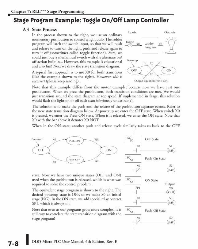
DL05 Micro PLC User Manual, 6th Edition, Rev. E7-8
Chapter 7: RLLPLUS Stage Programming
Stage Program Example: Toggle On/Off Lamp ControllerA 4–State Process
In the process shown to the right, we use an ordinary momentary pushbutton to control a light bulb. The ladder program will latch the switch input, so that we will push and release to turn on the light, push and release again to turn it off (sometimes called toggle function). Sure, we could just buy a mechanical switch with the alternate on/off action built in... However, this example is educational and also fun! Next we draw the state transition diagram.
A typical first approach is to use X0 for both transitions (like the example shown to the right). However, this is incorrect (please keep reading).
Note that this example differs from the motor example, because now we have just one pushbutton. When we press the pushbutton, both transition conditions are met. We would just transition around the state diagram at top speed. If implemented in Stage, this solution would flash the light on or off each scan (obviously undesirable)!
The solution is to make the push and the release of the pushbutton separate events. Refer to the new state transition diagram below. At powerup we enter the OFF state. When switch X0 is pressed, we enter the Press-ON state. When it is released, we enter the ON state. Note that X0 with the bar above it denotes X0 NOT.
When in the ON state, another push and release cycle similarly takes us back to the OFF
state. Now we have two unique states (OFF and ON) used when the pushbutton is released, which is what was required to solve the control problem.
The equivalent stage program is shown to the right. The desired powerup state is OFF, so we make S0 an initial stage (ISG). In the ON state, we add special relay contact SP1, which is always on.
Note that even as our programs grow more complex, it is still easy to correlate the state transition diagram with the stage program!
LadderProgram
Inputs Outputs
Toggle X0 Y0
OFF ON
X0
X0
Output equation: Y0 = ON
Powerup
S1X0
JMP
ISGS0
S2
JMP
SGS1
OUTY0
OFF State
SP1
S3X0
JMP
SGS2
SGS3
X0
S0
JMP
X0
Push–On State
ON State
Push–Off State
Output
X0 Push–ON
ON
Push–OFF
OFF
Powerup X0
X0X0
DL05 Micro PLC User Manual, 6th Edition, Rev. E 7-9
Chapter 7: RLLPLUS Stage Programming
Four Steps to Writing a Stage ProgramBy now, you’ve probably noticed that we follow the same steps to solve each example problem. The steps will probably come to you automatically if you work through all the examples in this chapter. It’s helpful to have a checklist to guide us through the problem solving. The following steps summarize the stage program design procedure:
1. Write a Word Description of the application.Describe all functions of the process in your own words. Start by listing what happens first, then next, etc. If you find there are too many things happening at once, try dividing the problem into more than one process. Remember, you can still have the processes communicate with each other to coordinate their overall activity.
2. Draw the Block Diagram.Inputs represent all the information the process needs for decisions, and outputs connect to all devices controlled by the process.
• Make lists of inputs and outputs for the process.
• Assign I/O point numbers (X and Y) to physical inputs and outputs.
3. Draw the State Transition Diagram.The state transition diagram describes the central function of the block diagram, reading inputs and generating outputs.
• Identify and name the states of the process.
• Identify the event(s) required for each transition between states.
• Ensure the process has a way to re-start itself, or is cyclical.
• Choose the powerup state for your process.
• Write the output equations.
4. Write the Stage Program.Translate the state transition diagram into a stage program.
• Make each state a stage. Remember to number stages in octal. Up to 256 total stages are available in the DL05, numbered 0 to 377 in octal.
• Put transition logic inside the stage which originates each transition (the stage each arrow points away from).
• Use an initial stage (ISG) for any states that must be active at powerup.
• Place the outputs or actions in the appropriate stages.
You’ll notice that Steps 1 through 3 just prepare us to write the stage program in Step 4. However, the program virtually writes itself because of the preparation beforehand. Soon you’ll be able to start with a word description of an application and create a stage program in one easy session!
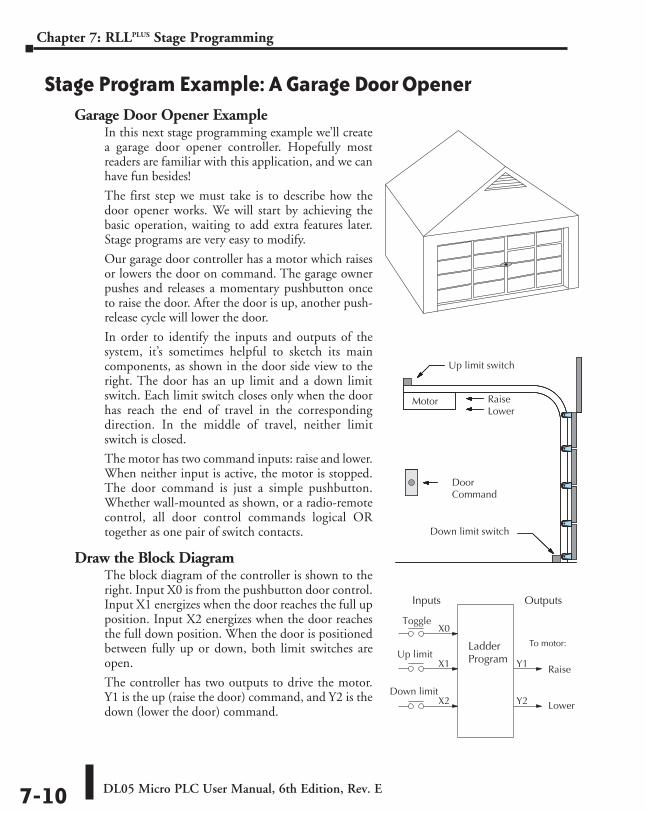
DL05 Micro PLC User Manual, 6th Edition, Rev. E7-10
Chapter 7: RLLPLUS Stage Programming
Stage Program Example: A Garage Door OpenerGarage Door Opener Example
In this next stage programming example we’ll create a garage door opener controller. Hopefully most readers are familiar with this application, and we can have fun besides!
The first step we must take is to describe how the door opener works. We will start by achieving the basic operation, waiting to add extra features later. Stage programs are very easy to modify.
Our garage door controller has a motor which raises or lowers the door on command. The garage owner pushes and releases a momentary pushbutton once to raise the door. After the door is up, another push-release cycle will lower the door.
In order to identify the inputs and outputs of the system, it’s sometimes helpful to sketch its main components, as shown in the door side view to the right. The door has an up limit and a down limit switch. Each limit switch closes only when the door has reach the end of travel in the corresponding direction. In the middle of travel, neither limit switch is closed.
The motor has two command inputs: raise and lower. When neither input is active, the motor is stopped. The door command is just a simple pushbutton. Whether wall-mounted as shown, or a radio-remote control, all door control commands logical OR together as one pair of switch contacts.
Draw the Block DiagramThe block diagram of the controller is shown to the right. Input X0 is from the pushbutton door control. Input X1 energizes when the door reaches the full up position. Input X2 energizes when the door reaches the full down position. When the door is positioned between fully up or down, both limit switches are open.
The controller has two outputs to drive the motor. Y1 is the up (raise the door) command, and Y2 is the down (lower the door) command.
Down limit switch
RaiseLower
DoorCommand
Up limit switch
Motor
LadderProgram
Inputs Outputs
Toggle X0
Y1
To motor:
Raise
Y2 Lower
Up limit X1
Down limit X2
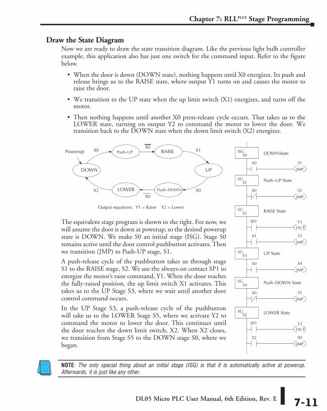
DL05 Micro PLC User Manual, 6th Edition, Rev. E 7-11
Chapter 7: RLLPLUS Stage Programming
Draw the State DiagramNow we are ready to draw the state transition diagram. Like the previous light bulb controller example, this application also has just one switch for the command input. Refer to the figure below.
• When the door is down (DOWN state), nothing happens until X0 energizes. Its push and release brings us to the RAISE state, where output Y1 turns on and causes the motor to raise the door.
• We transition to the UP state when the up limit switch (X1) energizes, and turns off the motor.
• Then nothing happens until another X0 press-release cycle occurs. That takes us to the LOWER state, turning on output Y2 to command the motor to lower the door. We transition back to the DOWN state when the down limit switch (X2) energizes.
The equivalent stage program is shown to the right. For now, we will assume the door is down at powerup, so the desired powerup state is DOWN. We make S0 an initial stage (ISG). Stage S0 remains active until the door control pushbutton activates. Then we transition (JMP) to Push-UP stage, S1.
A push-release cycle of the pushbutton takes us through stage S1 to the RAISE stage, S2. We use the always-on contact SP1 to energize the motor’s raise command, Y1. When the door reaches the fully-raised position, the up limit switch X1 activates. This takes us to the UP Stage S3, where we wait until another door control command occurs.
In the UP Stage S3, a push-release cycle of the pushbutton will take us to the LOWER Stage S5, where we activate Y2 to command the motor to lower the door. This continues until the door reaches the down limit switch, X2. When X2 closes, we transition from Stage S5 to the DOWN stage S0, where we began.
NOTE: The only special thing about an initial stage (ISG) is that it is automatically active at powerup. Afterwards, it is just like any other.
X0 Push–UP
UP
Push–DOWN
DOWN
X0LOWER
RAISEX0
X1
X0X2
Output equations: Y1 = Raise Y2 = Lower
Powerup
S1X0
JMP
ISGS0
S2
JMP
SGS1
OUTY1
DOWN State
SP1
S3X1
JMP
SGS2
SGS3
X0
S4
JMP
X0
Push–UP State
RAISE State
UP State
S5
JMP
SGS4
X0
Push–DOWN State
OUTY2SP1
S0X2
JMP
SGS5 LOWER State
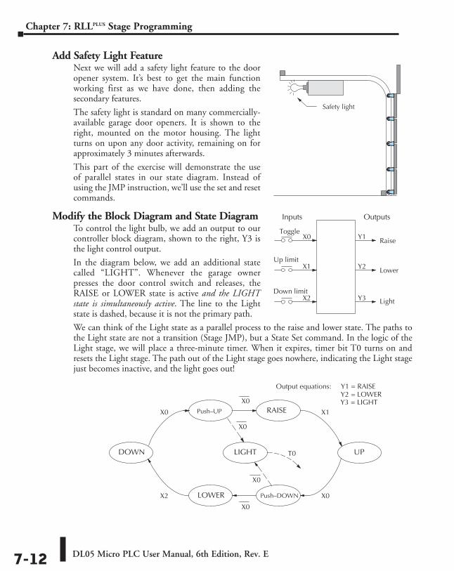
DL05 Micro PLC User Manual, 6th Edition, Rev. E7-12
Chapter 7: RLLPLUS Stage Programming
Add Safety Light FeatureNext we will add a safety light feature to the door opener system. It’s best to get the main function working first as we have done, then adding the secondary features.
The safety light is standard on many commercially-available garage door openers. It is shown to the right, mounted on the motor housing. The light turns on upon any door activity, remaining on for approximately 3 minutes afterwards.
This part of the exercise will demonstrate the use of parallel states in our state diagram. Instead of using the JMP instruction, we’ll use the set and reset commands.
Modify the Block Diagram and State DiagramTo control the light bulb, we add an output to our controller block diagram, shown to the right, Y3 is the light control output.
In the diagram below, we add an additional state called “LIGHT”. Whenever the garage owner presses the door control switch and releases, the RAISE or LOWER state is active and the LIGHT state is simultaneously active. The line to the Light state is dashed, because it is not the primary path.
We can think of the Light state as a parallel process to the raise and lower state. The paths to the Light state are not a transition (Stage JMP), but a State Set command. In the logic of the Light stage, we will place a three-minute timer. When it expires, timer bit T0 turns on and resets the Light stage. The path out of the Light stage goes nowhere, indicating the Light stage just becomes inactive, and the light goes out!
Safety light
Inputs Outputs
ToggleX0 Y1 Raise
Y2 Lower
Up limit X1
Down limit X2 Y3 Light
X0 Push–UP
UP
Push–DOWN
DOWN
X0LOWER
RAISEX0
X1
X0
X2
Output equations: Y2 = LOWERY1 = RAISE
LIGHT
Y3 = LIGHT
X0
X0
T0
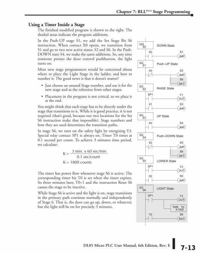
DL05 Micro PLC User Manual, 6th Edition, Rev. E 7-13
Chapter 7: RLLPLUS Stage Programming
Using a Timer Inside a StageThe finished modified program is shown to the right. The shaded areas indicate the program additions.
In the Push-UP stage S1, we add the Set Stage Bit S6 instruction. When contact X0 opens, we transition from S1 and go to two new active states: S2 and S6. In the Push-DOWN state S4, we make the same additions. So, any time someone presses the door control pushbutton, the light turns on.
Most new stage programmers would be concerned about where to place the Light Stage in the ladder, and how to number it. The good news is that it doesn’t matter!
• Just choose an unused Stage number, and use it for the new stage and as the reference from other stages.
• Placement in the program is not critical, so we place it at the end.
You might think that each stage has to be directly under the stage that transitions to it. While it is good practice, it is not required (that’s good, because our two locations for the Set S6 instruction make that impossible). Stage numbers and how they are used determines the transition paths.
In stage S6, we turn on the safety light by energizing Y3. Special relay contact SP1 is always on. Timer T0 times at 0.1 second per count. To achieve 3 minutes time period, we calculate:
The timer has power flow whenever stage S6 is active. The corresponding timer bit T0 is set when the timer expires. So three minutes later, T0=1 and the instruction Reset S6 causes the stage to be inactive.
While Stage S6 is active and the light is on, stage transitions in the primary path continue normally and independently of Stage 6. That is, the door can go up, down, or whatever, but the light will be on for precisely 3 minutes.
S1X0
JMP
ISGS0
S2
JMP
SGS1
OUT
Y1
DOWN State
SP1
S3X1
JMP
SGS2
SGS3
X0
S4
JMP
X0
Push–UP State
RAISE State
UP State
S5
JMP
SGS4
X0
Push–DOWN State
OUT
Y2SP1
S0X2
JMP
SGS5 LOWER State
OUT
Y3SP1
S6T0
RST
SGS6
LIGHT State
TMRK1800
T0
S6
SET
S6
SET
3 min. x 60 sec/min
0.1 sec/count K =
K = 1800 counts
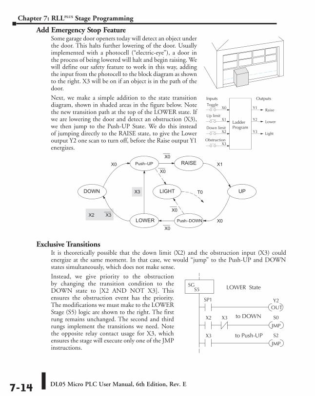
DL05 Micro PLC User Manual, 6th Edition, Rev. E7-14
Chapter 7: RLLPLUS Stage Programming
Add Emergency Stop FeatureSome garage door openers today will detect an object under the door. This halts further lowering of the door. Usually implemented with a photocell (“electric-eye”), a door in the process of being lowered will halt and begin raising. We will define our safety feature to work in this way, adding the input from the photocell to the block diagram as shown to the right. X3 will be on if an object is in the path of the door.
Next, we make a simple addition to the state transition diagram, shown in shaded areas in the figure below. Note the new transition path at the top of the LOWER state. If we are lowering the door and detect an obstruction (X3), we then jump to the Push-UP State. We do this instead of jumping directly to the RAISE state, to give the Lower output Y2 one scan to turn off, before the Raise output Y1 energizes.
Exclusive TransitionsIt is theoretically possible that the down limit (X2) and the obstruction input (X3) could energize at the same moment. In that case, we would “jump” to the Push-UP and DOWN states simultaneously, which does not make sense.
Instead, we give priority to the obstruction by changing the transition condition to the DOWN state to [X2 AND NOT X3]. This ensures the obstruction event has the priority. The modifications we must make to the LOWER Stage (S5) logic are shown to the right. The first rung remains unchanged. The second and third rungs implement the transitions we need. Note the opposite relay contact usage for X3, which ensures the stage will execute only one of the JMP instructions.
Ladder Program
Inputs Outputs Toggle
X0 Y1 Raise
Y2 Lower
Up limit X1
Down limit X2 Y3 Light
Obstruction X3
X0 Push–UP
UP
Push–DOWN
DOWN
X0LOWER
RAISE
X0
X1
X0
X2
LIGHT
X0
X0
T0X3
X3
OUTY2SP1
S0X2
JMP
SGS5 LOWER State
X3
S2X3
JMP
to Push-UP
to DOWN
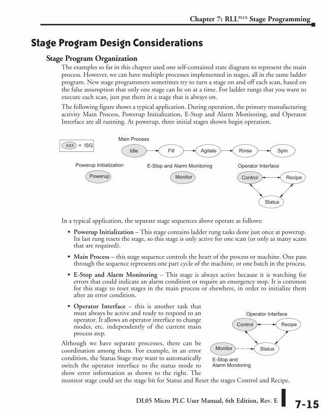
DL05 Micro PLC User Manual, 6th Edition, Rev. E 7-15
Chapter 7: RLLPLUS Stage Programming
Stage Program Design ConsiderationsStage Program Organization
The examples so far in this chapter used one self-contained state diagram to represent the main process. However, we can have multiple processes implemented in stages, all in the same ladder program. New stage programmers sometimes try to turn a stage on and off each scan, based on the false assumption that only one stage can be on at a time. For ladder rungs that you want to execute each scan, just put them in a stage that is always on.
The following figure shows a typical application. During operation, the primary manufacturing activity Main Process, Powerup Initialization, E-Stop and Alarm Monitoring, and Operator Interface are all running. At powerup, three initial stages shown begin operation.
In a typical application, the separate stage sequences above operate as follows:
• Powerup Initialization – This stage contains ladder rung tasks done just once at powerup. Its last rung resets the stage, so this stage is only active for one scan (or only as many scans that are required).
• Main Process – this stage sequence controls the heart of the process or machine. One pass through the sequence represents one part cycle of the machine, or one batch in the process.
• E-Stop and Alarm Monitoring – This stage is always active because it is watching for errors that could indicate an alarm condition or require an emergency stop. It is common for this stage to reset stages in the main process or elsewhere, in order to initialize them after an error condition.
• Operator Interface – this is another task that must always be active and ready to respond to an operator. It allows an operator interface to change modes, etc. independently of the current main process step.
Although we have separate processes, there can be coordination among them. For example, in an error condition, the Status Stage may want to automatically switch the operator interface to the status mode to show error information as shown to the right. The monitor stage could set the stage bit for Status and Reset the stages Control and Recipe.
Agitate
Monitor
Idle Fill Rinse Spin
E-Stop and Alarm Monitoring
Main Process
Operator Interface
Control Recipe
Status
XXX = ISG
Powerup
Powerup Initialization
Monitor
E-Stop andAlarm Monitoring
Operator Interface
Control Recipe
Status
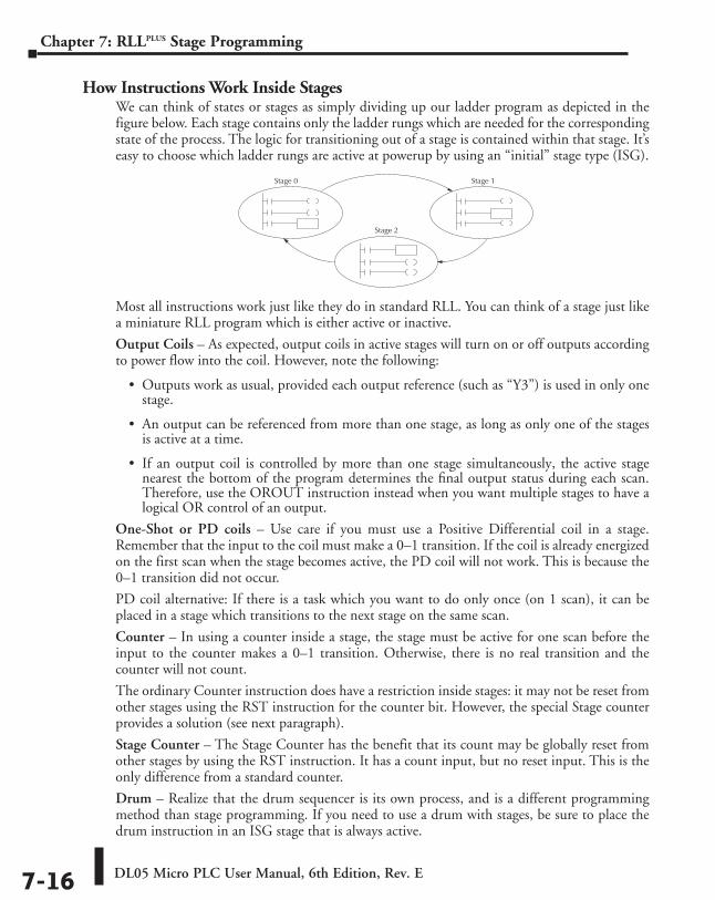
DL05 Micro PLC User Manual, 6th Edition, Rev. E7-16
Chapter 7: RLLPLUS Stage Programming
How Instructions Work Inside StagesWe can think of states or stages as simply dividing up our ladder program as depicted in the figure below. Each stage contains only the ladder rungs which are needed for the corresponding state of the process. The logic for transitioning out of a stage is contained within that stage. It’s easy to choose which ladder rungs are active at powerup by using an “initial” stage type (ISG).
Most all instructions work just like they do in standard RLL. You can think of a stage just like a miniature RLL program which is either active or inactive.
Output Coils – As expected, output coils in active stages will turn on or off outputs according to power flow into the coil. However, note the following:
• Outputs work as usual, provided each output reference (such as “Y3”) is used in only one stage.
• An output can be referenced from more than one stage, as long as only one of the stages is active at a time.
• If an output coil is controlled by more than one stage simultaneously, the active stage nearest the bottom of the program determines the final output status during each scan. Therefore, use the OROUT instruction instead when you want multiple stages to have a logical OR control of an output.
One-Shot or PD coils – Use care if you must use a Positive Differential coil in a stage. Remember that the input to the coil must make a 0–1 transition. If the coil is already energized on the first scan when the stage becomes active, the PD coil will not work. This is because the 0–1 transition did not occur.
PD coil alternative: If there is a task which you want to do only once (on 1 scan), it can be placed in a stage which transitions to the next stage on the same scan.
Counter – In using a counter inside a stage, the stage must be active for one scan before the input to the counter makes a 0–1 transition. Otherwise, there is no real transition and the counter will not count.
The ordinary Counter instruction does have a restriction inside stages: it may not be reset from other stages using the RST instruction for the counter bit. However, the special Stage counter provides a solution (see next paragraph).
Stage Counter – The Stage Counter has the benefit that its count may be globally reset from other stages by using the RST instruction. It has a count input, but no reset input. This is the only difference from a standard counter.
Drum – Realize that the drum sequencer is its own process, and is a different programming method than stage programming. If you need to use a drum with stages, be sure to place the drum instruction in an ISG stage that is always active.
Stage 0 Stage 1
Stage 2
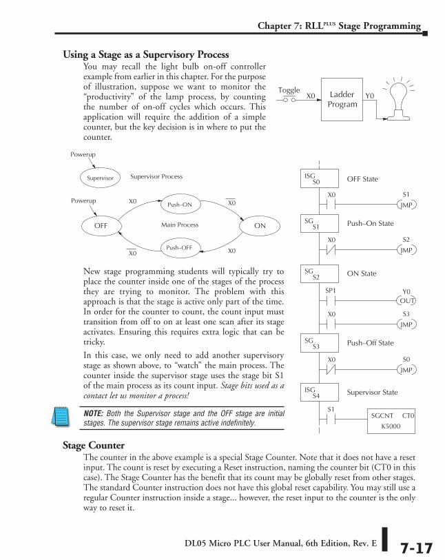
DL05 Micro PLC User Manual, 6th Edition, Rev. E 7-17
Chapter 7: RLLPLUS Stage Programming
Using a Stage as a Supervisory ProcessYou may recall the light bulb on-off controller example from earlier in this chapter. For the purpose of illustration, suppose we want to monitor the “productivity” of the lamp process, by counting the number of on-off cycles which occurs. This application will require the addition of a simple counter, but the key decision is in where to put the counter.
New stage programming students will typically try to place the counter inside one of the stages of the process they are trying to monitor. The problem with this approach is that the stage is active only part of the time. In order for the counter to count, the count input must transition from off to on at least one scan after its stage activates. Ensuring this requires extra logic that can be tricky.
In this case, we only need to add another supervisory stage as shown above, to “watch” the main process. The counter inside the supervisor stage uses the stage bit S1 of the main process as its count input. Stage bits used as a contact let us monitor a process!
NOTE: Both the Supervisor stage and the OFF stage are initial stages. The supervisor stage remains active indefinitely.
Stage CounterThe counter in the above example is a special Stage Counter. Note that it does not have a reset input. The count is reset by executing a Reset instruction, naming the counter bit (CT0 in this case). The Stage Counter has the benefit that its count may be globally reset from other stages. The standard Counter instruction does not have this global reset capability. You may still use a regular Counter instruction inside a stage... however, the reset input to the counter is the only way to reset it.
LadderProgram
Toggle X0 Y0
S1X0
JMP
ISGS0
S2
JMP
SGS1
OUTY0
OFF State
SP1
S3X0
JMP
SGS2
SGS3
X0
S0
JMP
X0
Push–On State
ON State
Push–Off State
SGCNT
K5000
CT0
ISGS4
S1
Supervisor State
X0 Push–ON
ON
Push–OFF
OFF
X0
X0X0
Supervisor
Main Process
Supervisor Process
Powerup
Powerup
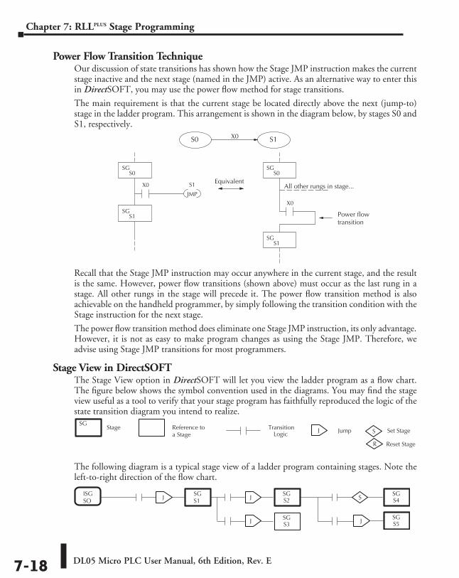
DL05 Micro PLC User Manual, 6th Edition, Rev. E7-18
Chapter 7: RLLPLUS Stage Programming
Power Flow Transition TechniqueOur discussion of state transitions has shown how the Stage JMP instruction makes the current stage inactive and the next stage (named in the JMP) active. As an alternative way to enter this in DirectSOFT, you may use the power flow method for stage transitions.
The main requirement is that the current stage be located directly above the next (jump-to) stage in the ladder program. This arrangement is shown in the diagram below, by stages S0 and S1, respectively.
Recall that the Stage JMP instruction may occur anywhere in the current stage, and the result is the same. However, power flow transitions (shown above) must occur as the last rung in a stage. All other rungs in the stage will precede it. The power flow transition method is also achievable on the handheld programmer, by simply following the transition condition with the Stage instruction for the next stage.
The power flow transition method does eliminate one Stage JMP instruction, its only advantage. However, it is not as easy to make program changes as using the Stage JMP. Therefore, we advise using Stage JMP transitions for most programmers.
Stage View in DirectSOFTThe Stage View option in DirectSOFT will let you view the ladder program as a flow chart. The figure below shows the symbol convention used in the diagrams. You may find the stage view useful as a tool to verify that your stage program has faithfully reproduced the logic of the state transition diagram you intend to realize.
The following diagram is a typical stage view of a ladder program containing stages. Note the left-to-right direction of the flow chart.
S1X0
JMP
SGS0
Equivalent
X0
SGS0
S0 S1X0
SGS1
SGS1
All other rungs in stage... Power flow
transition
Stage Reference to a Stage
J Jump S Set Stage
R Reset Stage
Transition Logic
SG
ISGSO
SGS1
SGS2
SGS3
SGS4
SGS5
J J
J
S
J
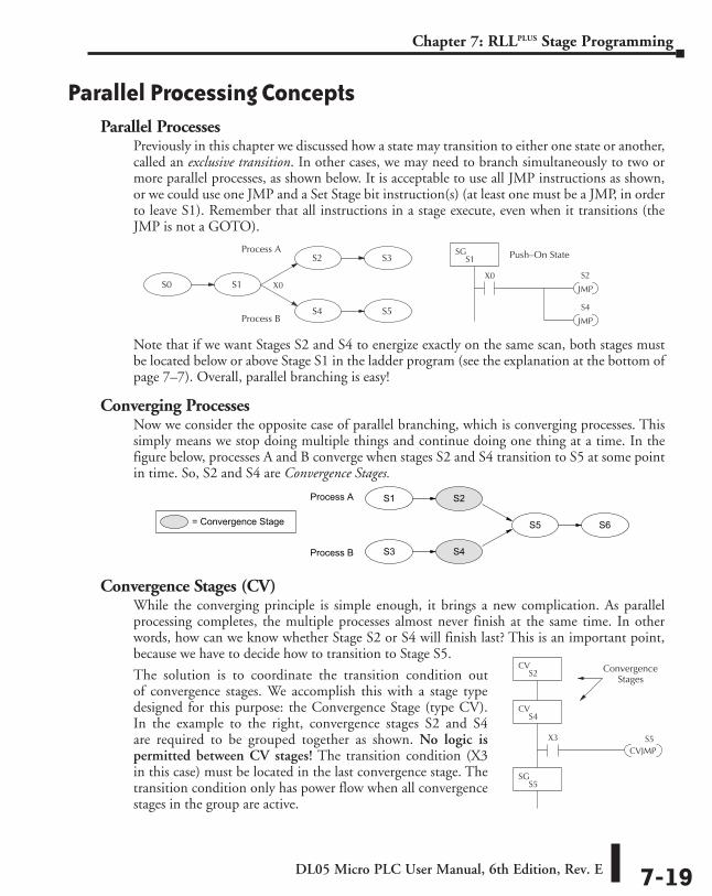
DL05 Micro PLC User Manual, 6th Edition, Rev. E 7-19
Chapter 7: RLLPLUS Stage Programming
Parallel Processing ConceptsParallel Processes
Previously in this chapter we discussed how a state may transition to either one state or another, called an exclusive transition. In other cases, we may need to branch simultaneously to two or more parallel processes, as shown below. It is acceptable to use all JMP instructions as shown, or we could use one JMP and a Set Stage bit instruction(s) (at least one must be a JMP, in order to leave S1). Remember that all instructions in a stage execute, even when it transitions (the JMP is not a GOTO).
Note that if we want Stages S2 and S4 to energize exactly on the same scan, both stages must be located below or above Stage S1 in the ladder program (see the explanation at the bottom of page 7–7). Overall, parallel branching is easy!
Converging ProcessesNow we consider the opposite case of parallel branching, which is converging processes. This simply means we stop doing multiple things and continue doing one thing at a time. In the figure below, processes A and B converge when stages S2 and S4 transition to S5 at some point in time. So, S2 and S4 are Convergence Stages.
Convergence Stages (CV)While the converging principle is simple enough, it brings a new complication. As parallel processing completes, the multiple processes almost never finish at the same time. In other words, how can we know whether Stage S2 or S4 will finish last? This is an important point, because we have to decide how to transition to Stage S5.
The solution is to coordinate the transition condition out of convergence stages. We accomplish this with a stage type designed for this purpose: the Convergence Stage (type CV). In the example to the right, convergence stages S2 and S4 are required to be grouped together as shown. No logic is permitted between CV stages! The transition condition (X3 in this case) must be located in the last convergence stage. The transition condition only has power flow when all convergence stages in the group are active.
S1S0
S2
S4
S3
S5
S2
JMP
SGS1
X0
Push–On State
S4
JMP
X0
Process A
Process B
S5
S1
S3
S2
S4
S6= Convergence Stage
Process A
Process B
CVJMPS5X3
CVS2
CVS4
ConvergenceStages
SGS5
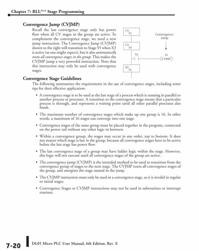
DL05 Micro PLC User Manual, 6th Edition, Rev. E7-20
Chapter 7: RLLPLUS Stage Programming
Convergence Jump (CVJMP)Recall the last convergence stage only has power flow when all CV stages in the group are active. To complement the convergence stage, we need a new jump instruction. The Convergence Jump (CVJMP) shown to the right will transition to Stage S5 when X3 is active (as one might expect), but it also automatically resets all convergence stages in the group. This makes the CVJMP jump a very powerful instruction. Note that this instruction may only be used with convergence stages.
Convergence Stage GuidelinesThe following summarizes the requirements in the use of convergence stages, including some tips for their effective application:
• A convergence stage is to be used as the last stage of a process which is running in parallel to another process or processes. A transition to the convergence stage means that a particular process is through, and represents a waiting point until all other parallel processes also finish.
• The maximum number of convergence stages which make up one group is 16. In other words, a maximum of 16 stages can converge into one stage.
• Convergence stages of the same group must be placed together in the program, connected on the power rail without any other logic in between.
• Within a convergence group, the stages may occur in any order, top to bottom. It does not matter which stage is last in the group, because all convergence stages have to be active before the last stage has power flow.
• The last convergence stage of a group may have ladder logic within the stage. However, this logic will not execute until all convergence stages of the group are active.
• The convergence jump (CVJMP) is the intended method to be used to transition from the convergence group of stages to the next stage. The CVJMP resets all convergence stages of the group, and energizes the stage named in the jump.
• The CVJMP instruction must only be used in a convergence stage, as it is invalid in regular or initial stages.
• Convergence Stages or CVJMP instructions may not be used in subroutines or interrupt routines.
CVJMPS5X3
CVS2
CVS4
ConvergenceJump
SGS5
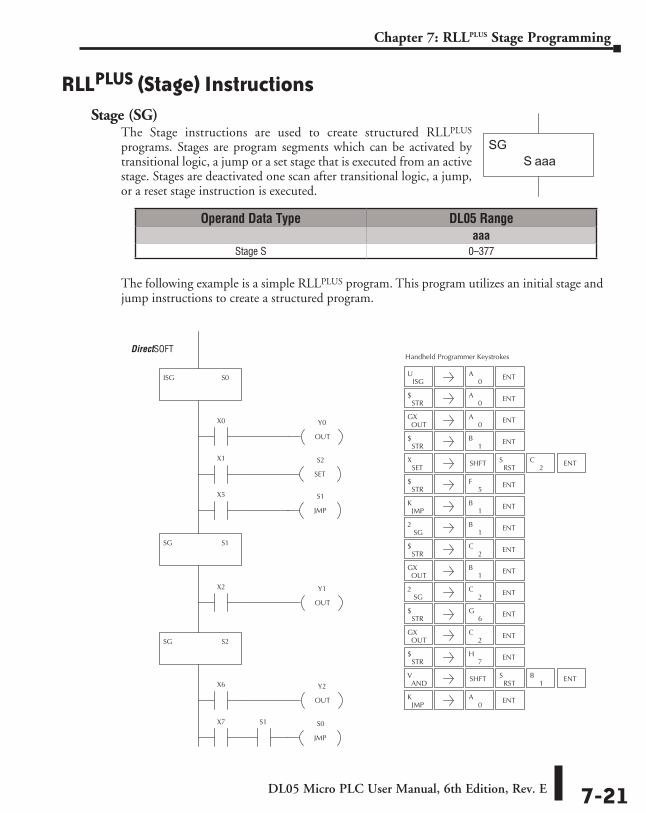
DL05 Micro PLC User Manual, 6th Edition, Rev. E 7-21
Chapter 7: RLLPLUS Stage Programming
RLLPLUS (Stage) InstructionsStage (SG)
The Stage instructions are used to create structured RLLPLUS programs. Stages are program segments which can be activated by transitional logic, a jump or a set stage that is executed from an active stage. Stages are deactivated one scan after transitional logic, a jump, or a reset stage instruction is executed.
The following example is a simple RLLPLUS program. This program utilizes an initial stage and jump instructions to create a structured program.
aaaS
SG
Operand Data Type DL05 Rangeaaa
Stage S 0–377
X0
ISG S0
Y0
OUT
X1 S2
SET
SG S1
X5
X2 Y1
OUT
SG S2
X6 Y2
OUT
X7 S0
JMP
S1
JMP
S1
Direct SOFT32 Handheld Programmer Keystrokes
ISGU
0A ENT
STR$
OUTGX
STR$
SETX SHFT
RSTS
2C ENT
STR$
JMPK
1B ENT
SG2
1B ENT
STR$
OUTGX
SG2 ENT
STR$
OUTGX
2C
STR$
ANDV SHFT
RSTS
1B ENT
JMPK ENT
0A
ENT0
A
1B ENT
ENT5
F
ENT2
C
ENT1
B
ENT
ENT
6G
2C
ENT7
H
0A ENT
DirectSOFT
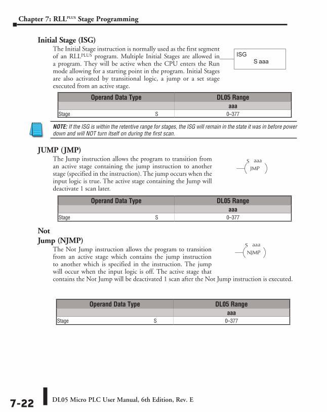
DL05 Micro PLC User Manual, 6th Edition, Rev. E7-22
Chapter 7: RLLPLUS Stage Programming
Initial Stage (ISG)The Initial Stage instruction is normally used as the first segment of an RLLPLUS program. Multiple Initial Stages are allowed in a program. They will be active when the CPU enters the Run mode allowing for a starting point in the program. Initial Stages are also activated by transitional logic, a jump or a set stage executed from an active stage.
NOTE: If the ISG is within the retentive range for stages, the ISG will remain in the state it was in before power down and will NOT turn itself on during the first scan.
JUMP (JMP)The Jump instruction allows the program to transition from an active stage containing the jump instruction to another stage (specified in the instruction). The jump occurs when the input logic is true. The active stage containing the Jump will deactivate 1 scan later.
Not Jump (NJMP)
The Not Jump instruction allows the program to transition from an active stage which contains the jump instruction to another which is specified in the instruction. The jump will occur when the input logic is off. The active stage that contains the Not Jump will be deactivated 1 scan after the Not Jump instruction is executed.
aaaSISG
Operand Data Type DL05 Rangeaaa
Stage ⸠⸠⸠⸠⸠⸠⸠⸠⸠⸠⸠⸠⸠⸠⸠⸠⸠⸠⸠⸠⸠⸠⸠⸠⸠⸠⸠⸠⸠⸠⸠⸠⸠⸠⸠⸠⸠⸠⸠⸠⸠⸠⸠⸠⸠⸠⸠⸠⸠⸠⸠⸠⸠⸠⸠⸠⸠⸠⸠⸠⸠⸠⸠⸠⸠⸠⸠S 0–377
Operand Data Type DL05 Rangeaaa
Stage ⸠⸠⸠⸠⸠⸠⸠⸠⸠⸠⸠⸠⸠⸠⸠⸠⸠⸠⸠⸠⸠⸠⸠⸠⸠⸠⸠⸠⸠⸠⸠⸠⸠⸠⸠⸠⸠⸠⸠⸠⸠⸠⸠⸠⸠⸠⸠⸠⸠⸠⸠⸠⸠⸠⸠⸠⸠⸠⸠⸠⸠⸠⸠⸠⸠⸠⸠S 0–377
Operand Data Type DL05 Rangeaaa
Stage ⸠⸠⸠⸠⸠⸠⸠⸠⸠⸠⸠⸠⸠⸠⸠⸠⸠⸠⸠⸠⸠⸠⸠⸠⸠⸠⸠⸠⸠⸠⸠⸠⸠⸠⸠⸠⸠⸠⸠⸠⸠⸠⸠⸠⸠⸠⸠⸠⸠⸠⸠⸠⸠⸠⸠⸠⸠⸠⸠⸠⸠⸠⸠⸠⸠⸠⸠S 0–377
aaaSJMP
aaaSNJMP
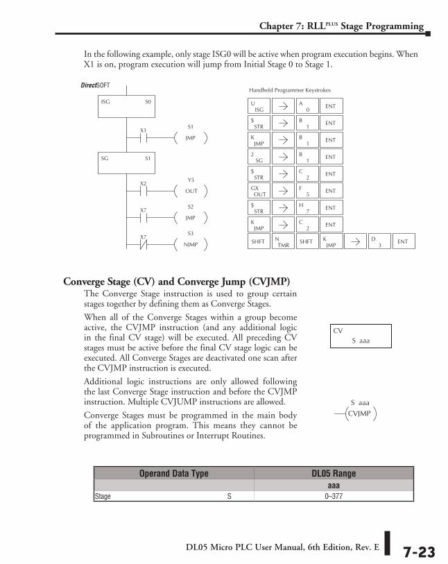
DL05 Micro PLC User Manual, 6th Edition, Rev. E 7-23
Chapter 7: RLLPLUS Stage Programming
In the following example, only stage ISG0 will be active when program execution begins. When X1 is on, program execution will jump from Initial Stage 0 to Stage 1.
Converge Stage (CV) and Converge Jump (CVJMP)The Converge Stage instruction is used to group certain stages together by defining them as Converge Stages.
When all of the Converge Stages within a group become active, the CVJMP instruction (and any additional logic in the final CV stage) will be executed. All preceding CV stages must be active before the final CV stage logic can be executed. All Converge Stages are deactivated one scan after the CVJMP instruction is executed.
Additional logic instructions are only allowed following the last Converge Stage instruction and before the CVJMP instruction. Multiple CVJUMP instructions are allowed.
Converge Stages must be programmed in the main body of the application program. This means they cannot be programmed in Subroutines or Interrupt Routines.
Operand Data Type DL05 Rangeaaa
Stage ⸠⸠⸠⸠⸠⸠⸠⸠⸠⸠⸠⸠⸠⸠⸠⸠⸠⸠⸠⸠⸠⸠⸠⸠⸠⸠⸠⸠⸠⸠⸠⸠⸠⸠⸠⸠⸠⸠⸠⸠⸠⸠⸠⸠⸠⸠⸠⸠⸠⸠⸠⸠⸠⸠⸠⸠⸠⸠⸠⸠⸠⸠⸠⸠⸠⸠⸠S 0–377
Direct SOFT32 Handheld Programmer Keystrokes
ISG S0
X1S1
JMP
SG S1
X2Y5
OUT
X7S2
JMP
S3
NJMP
ISGU
0A ENT
STR$
JMPK
1B ENT
SG2
1B ENT
STR$
OUTGX
STR$
JMPK ENT
2C
SHFTTMR
N SHFTJMP
K ENT3
D
ENT1
B
ENT2
C
5F ENT
ENT7
H
X7
S aaaCV
S aaaCVJMP
DirectSOFT
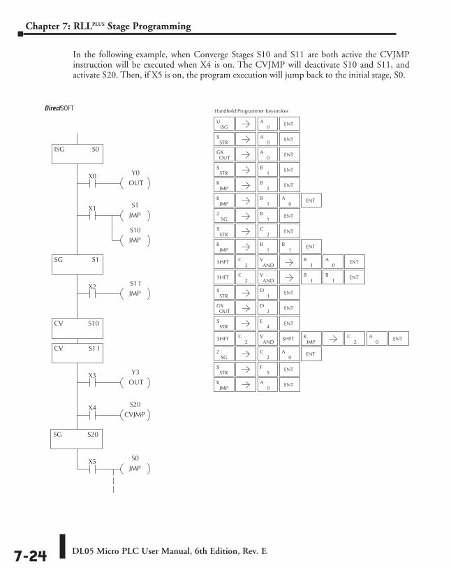
DL05 Micro PLC User Manual, 6th Edition, Rev. E7-24
Chapter 7: RLLPLUS Stage Programming
In the following example, when Converge Stages S10 and S11 are both active the CVJMP instruction will be executed when X4 is on. The CVJMP will deactivate S10 and S11, and activate S20. Then, if X5 is on, the program execution will jump back to the initial stage, S0.
Direct SOFT32
ISG S0
CV S11
X3 Y3
OUT
X4 S20
CVJMP
SG S20
X0 Y0
OUT
X1 S1
JMP
S10
JMP
SG S1
X2 S11
JMP
Handheld Programmer Keystrokes
CV S10
X5 S0
JMP
ISGU
0A ENT
STR$
JMPK
1B ENT
SG2
1B ENT
STR$
OUTGX
JMPK ENT
SHFT
JMPK
ENT
3D
ENT
1B
ENT2
C
ENT
ENT
0A
OUTGX ENT
0A
STR$ ENT
JMPK
1B ENT
0A
1B
1B
2C
ANDV
1B
0A
SHFT ENT2
CAND
V1
B1
B
STR$ ENT
3D
4E
STR$ ENT
SHFT ENT2
CAND
V0
ASHFTJMP
K
SG2 ENT
2C
0A
2C
5F
STR$ ENT
0A
DirectSOFT
DL05 Micro PLC User Manual, 6th Edition, Rev. E 7-25
Chapter 7: RLLPLUS Stage Programming
Questions and Answers about Stage ProgrammingWe include the following commonly-asked questions about Stage Programming as an aid to new students. All question topics are covered in more detail in this chapter.
Q. What does stage programming do that I can’t do with regular RLL programs?A. Stages allow you to identify all the states of your process before you begin programming. This
approach is more organized, because you divide up a ladder program into sections. As stages, these program sections are active only when they are actually needed by the process. Most processes can be organized into a sequence of stages, connected by event-based transitions.
Q. What are Stage Bits?A. A stage bit is just a single bit in the CPU’s image register, representing the active/inactive
status of the stage in real time. For example, the bit for Stage 0 is referenced as “S0”. If S0 = 0, then the ladder rungs in Stage 0 are bypassed (not executed) on each CPU scan. If S0 = 1, then the ladder rungs in Stage 0 are executed on each CPU scan. Stage bits, when used as contacts, allow one part of your program to monitor another part by detecting stage active/inactive status.
Q. How does a stage become active?A. There are three ways:
• If the Stage is an initial stage (ISG), it is automatically active at powerup.
• Another stage can execute a Stage JMP instruction naming this stage, which makes it active upon its next occurrence in the program.
• A program rung can execute a Set Stage Bit instruction (such as Set S0).
Q. How does a stage become inactive?A. There are three ways:
• Standard Stages (SG) are automatically inactive at powerup.
• A stage can execute a Stage JMP instruction, resetting its Stage Bit to 0.
• Any rung in the program can execute a Reset Stage Bit instruction (such as Reset S0).
Q. What about the power flow technique of stage transitions?A. The power flow method of connecting adjacent stages (directly above or below in the
program) actually is the same as the Stage Jump instruction executed in the stage above, naming the stage below. Power flow transitions are more difficult to edit in DirectSOFT, we list them separately from two preceding questions.
Q. Can I have a stage which is active for only one scan?A. Yes, but this is not the intended use for a stage. Instead, just make a ladder rung active for 1
scan by including a stage Jump instruction at the bottom of the rung. Then the ladder will execute on the last scan before its stage jumps to a new one.
DL05 Micro PLC User Manual, 6th Edition, Rev. E7-26
Chapter 7: RLLPLUS Stage Programming
Q. Isn’t a Stage JMP just like a regular GOTO instruction used in software?A. No, it is very different. A GOTO instruction sends the program execution immediately
to the code location named by the GOTO. A Stage JMP simply resets the Stage Bit of the current stage, while setting the Stage Bit of the stage named in the JMP instruction. Stage bits are 0 or 1, determining the inactive/active status of the corresponding stages. A stage JMP has the following results:
• When the JMP is executed, the remainder of the current stage’s rungs are executed, even if they reside past(under) the JMP instruction. On the following scan, that stage is not executed, because it is inactive.
• The Stage named in the Stage JMP instruction will be executed upon its next occurrence. If located past (under) the current stage, it will be executed on the same scan. If located before (above) the current stage, it will be executed on the following scan.
Q. How can I know when to use stage JMP, versus a Set Stage Bit or Reset Stage Bit?
A. These instructions are used according to the state diagram topology you have derived:
• Use a Stage JMP instruction for a state transition... moving from one state to another.
• Use a Set Stage Bit instruction when the current state is spawning a new parallel state or stage sequence, or when a supervisory state is starting a state sequence under its command.
• Use a Reset Bit instruction when the current state is the last state in a sequence and its task is complete, or when a supervisory state is ending a state sequence under its command.
Q. What is an initial stage, and when do I use it?A. An initial stage (ISG) is automatically active at powerup. Afterwards, it works just like any
other stage. You can have multiple initial stages, if required. Use an initial stage for ladder that must always be active, or as a starting point.
Q. Can I have place program ladder rungs outside of the stages, so they are always on?
A. It is possible, but it’s not good software design practice. Place ladder that must always be active in an initial stage, and do not reset that stage or use a Stage JMP instruction inside it. It can start other stage sequences at the proper time by setting the appropriate Stage Bit(s).
Q. Can I have more than one active stage at a time?A. Yes, and this is a normal occurrence for many programs. However, it is important to organize
your application into separate processes, each made up of stages. And a good process design will be mostly sequential, with only one stage on at a time. However, all the processes in the program may be active simultaneously.
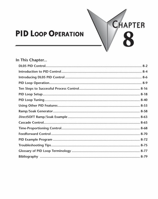
PID LooP oPeratIon 888ChapterChapterChapter
In This Chapter...DL05 PID Control ....................................................................................................... 8-2
Introduction to PID Control ...................................................................................... 8-4
Introducing DL05 PID Control .................................................................................. 8-6
PID Loop Operation ................................................................................................... 8-9
Ten Steps to Successful Process Control ................................................................. 8-16
PID Loop Setup ........................................................................................................ 8-18
PID Loop Tuning ...................................................................................................... 8-40
Using Other PID Features ........................................................................................ 8-53
Ramp/Soak Generator ............................................................................................. 8-58
DirectSOFT Ramp/Soak Example ............................................................................. 8-63
Cascade Control ....................................................................................................... 8-65
Time-Proportioning Control .................................................................................... 8-68
Feedforward Control ............................................................................................... 8-70
PID Example Program ............................................................................................. 8-72
Troubleshooting Tips ............................................................................................... 8-75
Glossary of PID Loop Terminology ......................................................................... 8-77
Bibliography ........................................................................................................... 8-79
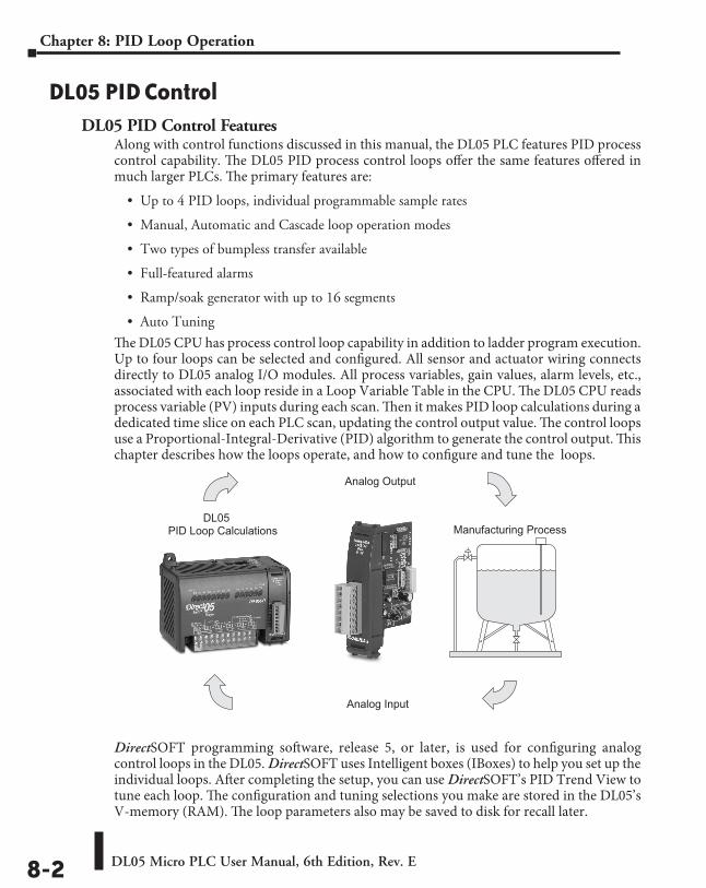
DL05 Micro PLC User Manual, 6th Edition, Rev. E8-2
Chapter 8: PID Loop Operation
DL05 PID ControlDL05 PID Control Features
Along with control functions discussed in this manual, the DL05 PLC features PID process control capability. The DL05 PID process control loops offer the same features offered in much larger PLCs. The primary features are:
• Up to 4 PID loops, individual programmable sample rates
• Manual, Automatic and Cascade loop operation modes
• Two types of bumpless transfer available
• Full-featured alarms
• Ramp/soak generator with up to 16 segments
• Auto Tuning
The DL05 CPU has process control loop capability in addition to ladder program execution. Up to four loops can be selected and configured. All sensor and actuator wiring connects directly to DL05 analog I/O modules. All process variables, gain values, alarm levels, etc., associated with each loop reside in a Loop Variable Table in the CPU. The DL05 CPU reads process variable (PV) inputs during each scan. Then it makes PID loop calculations during a dedicated time slice on each PLC scan, updating the control output value. The control loops use a Proportional-Integral-Derivative (PID) algorithm to generate the control output. This chapter describes how the loops operate, and how to configure and tune the loops.
DirectSOFT programming software, release 5, or later, is used for configuring analog control loops in the DL05. DirectSOFT uses Intelligent boxes (IBoxes) to help you set up the individual loops. After completing the setup, you can use DirectSOFT’s PID Trend View to tune each loop. The configuration and tuning selections you make are stored in the DL05’s V-memory (RAM). The loop parameters also may be saved to disk for recall later.
DL05Manufacturing ProcessPID Loop Calculations
Analog Output
Analog Input
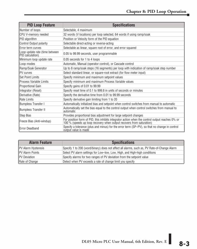
DL05 Micro PLC User Manual, 6th Edition, Rev. E 8-3
Chapter 8: PID Loop Operation
PID Loop Feature SpecificationsNumber of loops Selectable, 4 maximumCPU V-memory needed 32 words (V locations) per loop selected, 64 words if using ramp/soakPID algorithm Position or Velocity form of the PID equationControl Output polarity Selectable direct-acting or reverse-actingError term curves Selectable as linear, square root of error, and error squaredLoop update rate (time between PID calculation) 0.05 to 99.99 seconds, user programmable
Minimum loop update rate 0.05 seconds for 1 to 4 loopsLoop modes Automatic, Manual (operator control), or Cascade controlRamp/Soak Generator Up to 8 ramp/soak steps (16 segments) per loop with indication of ramp/soak step numberPV curves Select standard linear, or square-root extract (for flow meter input)Set Point Limits Specify minimum and maximum setpoint valuesProcess Variable Limits Specify minimum and maximum Process Variable valuesProportional Gain Specify gains of 0.01 to 99.99Integrator (Reset) Specify reset time of 0.1 to 999.8 in units of seconds or minutesDerivative (Rate) Specify the derivative time from 0.01 to 99.99 secondsRate Limits Specify derivative gain limiting from 1 to 20Bumpless Transfer I Automatically initialized bias and setpoint when control switches from manual to automatic
Bumpless Transfer II Automatically set the bias equal to the control output when control switches from manual to automatic
Step Bias Provides proportional bias adjustment for large setpoint changes
Freeze Bias (Anti-windup) For position form of PID, this inhibits integrator action when the control output reaches 0% or 100 % (speeds up loop recovery when output recovers from saturation)
Error Deadband Specify a tolerance (plus and minus) for the error term (SP–PV), so that no change in control output value is made
Alarm Feature SpecificationsPV Alarm Hysteresis Specify 1 to 200 (word/binary) does not affect all alarms, such as, PV Rate-of-Change AlarmPV Alarm Points Select PV alarm settings for Low–low, Low, High, and High-high conditionsPV Deviation Specify alarms for two ranges of PV deviation from the setpoint valueRate of Change Detect when PV exceeds a rate of change limit you specify
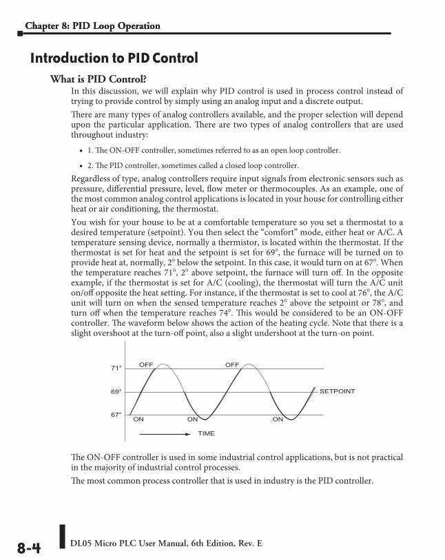
DL05 Micro PLC User Manual, 6th Edition, Rev. E8-4
Chapter 8: PID Loop OperationChapter 8: PID Loop Operation
Introduction to PID ControlWhat is PID Control?
In this discussion, we will explain why PID control is used in process control instead of trying to provide control by simply using an analog input and a discrete output.There are many types of analog controllers available, and the proper selection will depend upon the particular application. There are two types of analog controllers that are used throughout industry:
• 1. The ON-OFF controller, sometimes referred to as an open loop controller.
• 2. The PID controller, sometimes called a closed loop controller.Regardless of type, analog controllers require input signals from electronic sensors such as pressure, differential pressure, level, flow meter or thermocouples. As an example, one of the most common analog control applications is located in your house for controlling either heat or air conditioning, the thermostat. You wish for your house to be at a comfortable temperature so you set a thermostat to a desired temperature (setpoint). You then select the “comfort” mode, either heat or A/C. A temperature sensing device, normally a thermistor, is located within the thermostat. If the thermostat is set for heat and the setpoint is set for 69!, the furnace will be turned on to provide heat at, normally, 2! below the setpoint. In this case, it would turn on at 67!. When the temperature reaches 71!, 2! above setpoint, the furnace will turn off. In the opposite example, if the thermostat is set for A/C (cooling), the thermostat will turn the A/C unit on/off opposite the heat setting. For instance, if the thermostat is set to cool at 76!, the A/C unit will turn on when the sensed temperature reaches 2! above the setpoint or 78!, and turn off when the temperature reaches 74!. This would be considered to be an ON-OFF controller. The waveform below shows the action of the heating cycle. Note that there is a slight overshoot at the turn-off point, also a slight undershoot at the turn-on point.
The ON-OFF controller is used in some industrial control applications, but is not practical in the majority of industrial control processes.The most common process controller that is used in industry is the PID controller.
69°
71°
67°
SETPOINT
TIME
OFF
ON ONON
OFF
DL05 Micro PLC User Manual, 6th Edition, Rev. E 8-5
Chapter 8: PID Loop Operation
The PID controller controls a continuous feedback loop that keeps the process output (control variable) flowing normally by taking corrective action whenever there is a deviation from the desired value (setpoint) of the process variable (PV) such as, rate of flow, temperature, voltage, etc. An “error” occurs when an operator manually changes the setpoint or when an event (valve opened, closed, etc.) or a disturbance (cold water, wind, etc.) changes the load, thus causing a change in the process variable.The PID controller receives signals from sensors and computes corrective action to the actuator from a computation based on the error (Proportional), the sum of all previous errors (Integral) and the rate of change of the error (Derivative).We can look at the PID controller in more simple terms. Take the cruise control on an automobile as an example. Let’s say that we are cruising on an interstate highway in a car equipped with cruise control. The driver decides to engage the cruise control by turning it ON, then he manually brings the car to the desired cruising speed, say 70 miles per hour. Once the cruise speed is reached, the SET button is pushed fixing the speed at 70 mph, the setpoint. Now, the car is cruising at a steady 70 mph until it comes to a hill to go up. As the car goes up the hill, it tends to slow down. The speed sensor senses this and causes the throttle to increase the fuel to the engine. The vehicle speeds up to maintain 70 mph without jerking the car and it reaches the top at the set speed. When the car levels out after reaching the top of the hill it will speed up. The speed sensor senses this and signals the throttle to provide less fuel to the engine, thus, the engine slows down allowing the car to maintain the 70mph speed. How does this application apply to PID control? Lets look at the function of P, I and D terms:
• Proportional - is commonly referred to as Proportional Gain. The proportional term is the corrective action which is proportional to the error, that is, the change of the manipulated variable is equal to the proportional gain multiplied by the error (the activating signal). In mathematical terms:
Proportional action = proportional gain X error Error = Setpoint (SP) - Process Variable (PV)
• Applying this to the cruise control, the speed was set at 70 mph which is the Setpoint. The speed sensor senses the actual speed of the car and sends this signal to the cruise controller as the Process Variable (PV). When the car is on a level highway, the speed is maintained at 70 mph, thus, no error since the error would be SP - PV = 0. When the car goes up the hill, the speed sensor detected a slow down of the car, SP-PV = error. The proportional gain would cause the output of the speed controller to bring the car back to the setpoint of 70 mph. This would be the Controlled Output.
• Integral - this term is often referred to as Reset action. It provides additional compensation to the control output, which causes a change in proportion to the value of the error over a period of time. In other words, the reset term is the integral sum of the error values over a period of time.
• Derivative - this term is referred to as rate. The Rate action adds compensation to the control output, which causes a change in proportion to the rate of change of error. Its job is to anticipate the probable growth of the error and generate a contribution to the output in advance.
Chapter 8: PID Loop Operation
DL05 Micro PLC User Manual, 6th Edition, Rev. E8-6
Chapter 8: PID Loop Operation
Introducing DL05 PID ControlThe DL05 is capable of controlling a process variable such as those already mentioned. As previously mentioned, the control of a variable, such as temperature, at a given level (setpoint) as long as there are no disturbances (cold water) in the process.The DL05 PLC has the ability to directly accept signals from electronic sensors, such as thermocouples, pressure, VFDs, etc. These signals may be used in mathematically derived control systems.In addition, the DL05 has built-in PID control algorithms that can be implemented. The basic function of PID closed loop process control is to maintain certain process characteristics at desired setpoints. As a rule, the process deviates from the desired setpoint reference as a result of load material changes and interaction with other processes. During this control, the actual condition of the process characteristics (liquid level, temperature, motor control, etc.) is measured as a process variable (PV) and compared with the target setpoint (SP). When deviations occur, an error is generated by the difference between the process variable (actual value) and the setpoint (desired value). Once an error is detected, the function of the control loop is to modify the control output in order to force the error to zero. The DL05 PID control provides feedback loops using the PID algorithm. The control output is computed from the measured process variable as follows:Let:
• Kc = proportional gain
• Ti = Reset or integral time
• Td = Derivative time or rate
• SP = Setpoint
• PV(t) = Process Variable at time “t”
• e(t) = SP-PV(t) = PV deviation from setpoint at time “t” or PV error.
Then:
• M(t) = Control output at time “t”
M(t) = Kc [ e(t) + 1/Ti *0
t e(x) dx + Td d/dt e(t) ] + Mo
The analog input module receives the process variable in analog form along with an operator entered setpoint; the CPU computes the error. The error is used in the algorithm computation to provide corrective action at the control output. The function of the control action is based on an output control, which is proportional to the instantaneous error value. The integral control action (reset action) provides additional compensation to the control output, which causes a change in proportion to the value of the change of error over a period of time. The derivative control action (rate change) adds compensation to the control output, which causes a change in proportion to the rate of change of error. These three modes are used to provide the desired control action in Proportional (P), Proportional-Integral (PI), or Proportional-Integral-Derivative (PID) control fashion.
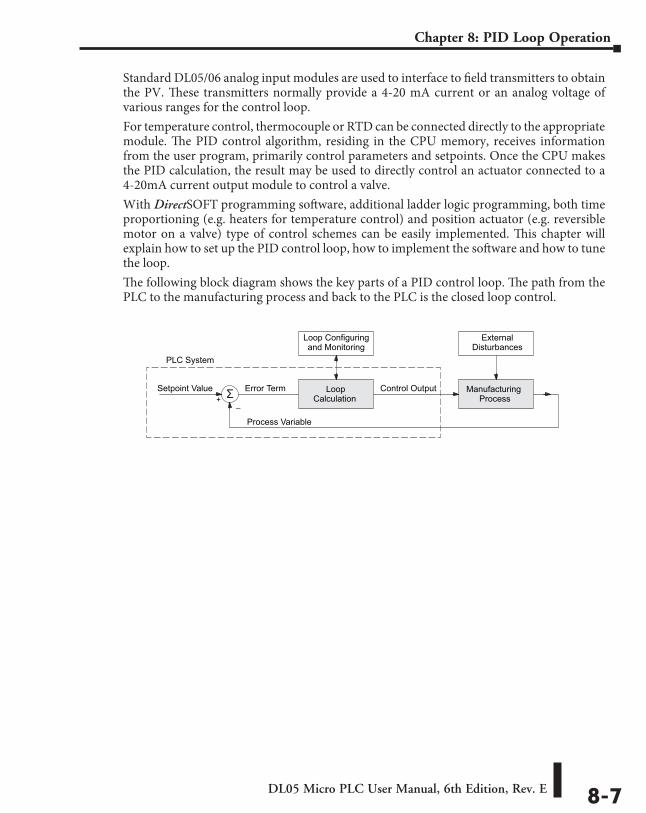
DL05 Micro PLC User Manual, 6th Edition, Rev. E 8-7
Chapter 8: PID Loop Operation
Standard DL05/06 analog input modules are used to interface to field transmitters to obtain the PV. These transmitters normally provide a 4-20 mA current or an analog voltage of various ranges for the control loop.For temperature control, thermocouple or RTD can be connected directly to the appropriate module. The PID control algorithm, residing in the CPU memory, receives information from the user program, primarily control parameters and setpoints. Once the CPU makes the PID calculation, the result may be used to directly control an actuator connected to a 4-20mA current output module to control a valve.With DirectSOFT programming software, additional ladder logic programming, both time proportioning (e.g. heaters for temperature control) and position actuator (e.g. reversible motor on a valve) type of control schemes can be easily implemented. This chapter will explain how to set up the PID control loop, how to implement the software and how to tune the loop.The following block diagram shows the key parts of a PID control loop. The path from the PLC to the manufacturing process and back to the PLC is the closed loop control.
Process Variable
LoopCalculation
ManufacturingProcess
Setpoint Value
Loop Configuringand Monitoring
Control Output
ExternalDisturbances
Error Term+
–
PLC System
Σ
DL05 Micro PLC User Manual, 6th Edition, Rev. E8-8
Chapter 8: PID Loop Operation
Process Control DefinitionsManufacturing Process – the set of actions that adds value to raw materials. The process can involve physical changes and/or chemical changes to the material. The changes render the material more useful for a particular purpose, ultimately used in a final product.Process Variable – The controlled variable part of the process that you wish to control. It may be temperature, pressure, level, flow, composition, density, the ratio of two streams, etc. Also known as the actual value.Setpoint – This is the target for the process variable. When all conditions of the process are correct, the process variable will equal the setpoint.Control Output – The result of the loop calculation, which becomes a command for the process (such as the heater level in an oven). This is sometimes referred to as control variable.Error Term – The algebraic difference between the process variable and the setpoint. This is the control loop error, and is equal to zero when the process variable is equal to the setpoint (desired) value. A well-behaved control loop is able to maintain a small error term magnitude.Manipulated Variable – This is what is used to effect the controlled variable. For example, the fuel used in a furnace might be manipulated in order to control the temperature.Disturbance – Something in the system that changes such that corrective action is required. For instance, when controlling a flow and the upstream pressure drops, the control valve must open wider in order to keep flow constant. The drop in upstream pressure is the disturbance.Final Control Element – This is the physical device used to control the manipulated variable. Valves are probably the most widely used final control element.Lag Time – The time it takes for the process to respond to a change in manipulated variable. This is also known as the capacitance of the system. When you’re in the shower and you turn up the hot water a little, the time it takes before the water gets hot is the lag time.Dead Time – The time it takes for a change in the process to be recognized. Composition analyzers and quality control are usually sources of significant dead time.Loop Configuring – Operator-initiated selections which set up and optimize the performance of a control loop. The loop calculation function uses the configuration parameters in real time to adjust gains, offsets, etc.Loop Monitoring – The function which allows an operator to observe the status and performance of a control loop. This is used in conjunction with the loop configuring to optimize the performance of a loop (minimize the error term).
DL05 Micro PLC User Manual, 6th Edition, Rev. E 8-9
Chapter 8: PID Loop Operation
PID Loop OperationThe Proportional–Integral–Derivative (PID) algorithm is widely used in process control. The PID method of control adapts well to electronic solutions, whether implemented in analog or digital (CPU) components. The DL05 CPU implements the PID equations digitally by solving the basic equations in software. I/O modules serve only to convert electronic signals into digital form (or vice versa).The DL05 uses two types of PID controls: “position” and “velocity”. These terms usually refer to motion control situations, but here we use them in a different sense:
• PID Position Algorithm – The control output is calculated so it responds to the displacement (position) of the PV from the SP (error term).
• PID Velocity Algorithm – The control output is calculated to represent the rate of change (velocity) for the PV to become equal to the SP.
Position Form of the PID EquationReferring to the control output equation on page 8-6, the DL05 CPU approximates the output M(t) using a discrete position form of the PID equation.
• Let:
Ts = Sample rate Kc = Proportional gain Ki = Kc * (Ts/Ti) = Coefficient of integral term Kr = Kc * (Td/Ts) = Coefficient of derivative term Ti = Reset or integral time Td = Derivative time or rate SP = Setpoint PVn = Process variable at nth sample en = SP – PVn = Error at nth sample Mo = Value to which the controller output has been initialized
• Then:
Mn = Control output at nth sample
Mn = Kc * en + Ki (n
i=1 ei + Kr (en - en-1) + Mo
This form of the PID equation is referred to as the position form since the actual actuator position is computed. The velocity form of the PID equation computes the change in actuator position. The CPU modifies the standard equation slightly to use the derivative of the process variable instead of the error as follows:
Mn = Kc * en + Ki (n
i=1 ei + Kr (PVn - PVn-1) + Mo
These two forms are equivalent unless the setpoint is changed. In the original equation, a large step change in the setpoint will cause a correspondingly large change in the error resulting in a bump to the process due to derivative action. This bump is not present in the second form of the equation.
DL05 Micro PLC User Manual, 6th Edition, Rev. E8-10
Chapter 8: PID Loop Operation
Step Bias Proportional to Step Change in SPThis feature reduces oscillation caused by a step change in setpoint when the adjusting bias feature is used.
Mx = Mx * SPn / SPn-1 “if the loop is direct acting”Mx = Mx * SPn-1 / SPn “if the loop is reverse acting”
Mxn = 0 “if Mx < 0” Mxn = Mx “if 0 < Mx < 1” Mxn = 1 “if M > 1”
Eliminating Proportional, Integral or Derivative ActionIt is not always necessary to run a full three mode PID control loop. Most loops require only the PI terms or just the P term. Parts of the PID equation may be eliminated by choosing appropriate values for the gain (Kc), reset (Ti) and rate (Td) yielding a P, PI, PD, I and even an ID and a D loop.Eliminating Integral Action The effect of integral action on the output may be
eliminated by setting Ti = 9999 or 0000. When this is done, the user may then manually control the bias term (Mx) to eliminate any steady-state offset.
Eliminating Derivative Action The effect of derivative action on the output may be eliminated by setting Td = 0 (most loops do not require a D parameter; it may make the loop unstable).
Eliminating Proportional Action Although rarely done, the effect of proportional term on the output may be eliminated by setting Kc = 0. Since Kc is also normally a multiplier of the integral coefficient (Ki) and the derivative coefficient (Kr), the CPU makes the computation of these values conditional on the value of Kc as follows:
Ki = Kc * (Ts / Ti) “if Kc Þ 0” Ki = Ts / Ti “if Kc = 0 (I or ID only)” Kr = Kc * (Td / Ts) “if Kc Þ 0” Kr = Td / Ts “if Kc = 0 (ID or D only)”
Velocity Form of the PID EquationThe standard position form of the PID equation computes the actual actuator position. An alternative form of the PID equation computes the change in actuator position. This form of the equation is referred to as the velocity PID equation and is obtained by subtracting the equation at time “n” from the equation at time “n-1”.The velocity equation is given by:
DMn = M - Mn-1DMn = Kc * (en - en-1) + Ki * (PVn - 2 * PVn-1 + PVn-2)
DL05 Micro PLC User Manual, 6th Edition, Rev. E 8-11
Chapter 8: PID Loop Operation
The DL05 also combines the integral sum and the initial output into a single term called the bias (Mx). This results in the following set of equations:
Mxo = MoMx = Ki * en + Mxn-1Mn = Kc * en - Kr(PVn-PVn-1) + Mxn
The DL05 by default will keep the normalized output M in the range of 0.0 to 1.0. This is done by clamping M to the nearer of 0.0 or 1.0 whenever the calculated output falls outside this range. The DL05 also allows you to specify the minimum and maximum output limit values (within the range 0 to 4095 in binary if using 12 bit unipolar).
NOTE: The equations and algorithms , or parts of, in this chapter are only for references. Analysis of these equations can be found in most good text books about process control.
Reset Windup ProtectionReset windup can occur if reset action (integral term) is specified and the computation of the bias term Mx is:
Mx = Ki * en + Mxn-1
For example, assume the output is controlling a valve and the PV remains at some value greater than the setpoint. The negative error (en) will cause the bias term (Mx) to constantly decrease until the output M goes to 0 closing the valve. However, since the error term is still negative, the bias will continue to decrease becoming ever more negative. When the PV finally does come back down below the SP, the valve will stay closed until the error is positive for long enough to cause the bias to become positive again. This will cause the process variable to undershoot.One way to solve the problem is to simply clamp the normalized bias between 0.0 and 1.0. The DL05 CPU does this. However, if this is the only thing that is done, then the output will not move off 0.0 (thus opening the valve) until the PV has become less than the SP. This will also cause the process variable to undershoot.The DL05 CPU is programmed to solve the overshoot problem by either freezing the bias term, or by adjusting the bias term.
DL05 Micro PLC User Manual, 6th Edition, Rev. E8-12
Chapter 8: PID Loop Operation
Freeze BiasIf the “Freeze Bias” option is selected when setting up the PID loop (discussed later) then the CPU simply stops changing the bias (Mx) whenever the computed normalized output (M) goes outside the interval 0.0 to 1.0.
Mx = Ki * en + Mxn-1
M = Kc * en - Kr(PVn - PVn-1) + Mx
Mn = 0 “if M < 0” Mn = M “if 0 < M < 1” Mn = 1 “if M > 1”
Mxn = Mx “if 0 < M < 1” Mxn = Mxn-1 “otherwise”
Thus in this example, the bias will probably not go all the way to zero so that, when the PV does begin to come down, the loop will begin to open the valve sooner than it would have if the bias had been allowed to go all the way to zero. This action has the effect of reducing the amount of overshoot.
Adjusting the BiasThe normal action of the CPU is to adjust the bias term when the output goes out of range as shown below.
Mx = Ki * en + Mxn-1M = Kc * en - Kr(PVn - PVn-1) + Mx
Mn = 0 “if M < 0” Mn = M “if 0 < M < 1” Mn = 1 “if M > 1”
Mxn = Mx “if 0 < M < 1” Mxn = Mn - Kc * en - Kr(PVn - PVn-1) “otherwise”
By adjusting the bias, the valve will begin to open as soon as the PV begins to come down. If the loop is properly tuned, overshoot can be eliminated entirely. If the output went out of range due to a setpoint change, then the loop probably will oscillate because we must wait for the bias term to stabilize again.The choice of whether to use the default loop action or to freeze the bias is dependent on the application. If large, step changes to the setpoint are anticipated, then it is probably better to select the freeze bias option (see page 8-34).
DL05 Micro PLC User Manual, 6th Edition, Rev. E 8-13
Chapter 8: PID Loop Operation
Bumpless TransferThe DL05 loop controller provides for bumpless mode changes. A bumpless transfer from manual mode to automatic mode is achieved by preventing the control output from changing immediately after the mode change.When a loop is switched from Manual mode to Automatic mode, the setpoint and Bias are initialized as follows:
• Position PID Algorithm Velocity PID Algorithm
SP = PV SP = PVMx = M (Control Output)
The bumpless transfer feature of the DL05 is available in two types: Bumpless I and Bumpless II (see page 8-26). The transfer type is selected when the loop is set up.
Loop AlarmsThe DL05 allows the user to specify alarm conditions that are to be monitored for each loop. Alarm conditions are reported to the CPU by setting up the alarms in DirectSOFT programming software using the PID setup alarm dialog when the loop is setup. The alarm features for each loop are:
• PV Limit – Specify up to four PV alarm points. High-High PV rises above the programmed High-High Alarm Limit.
High PV rises above the programmed High Alarm Limit. Low PV fails below the Low Alarm Limit. Low-Low PV fails below the Low-Low Limit.
• PV Deviation Alarm – Specify an alarm for High and Low PV deviation from the setpoint (Yellow Deviation). An alarm for High-High and Low-Low PV deviation from the setpoint (Orange Deviation) may also be specified. When the PV is further from the setpoint than the programmed Yellow or Orange Deviation Limit the corresponding alarm bit is activated.
• Rat e of Change – This alarm is set when the PV changes faster than a specified rate-of-change limit.
• PV Alarm Hysteresis – The PV Limit Alarms and PV Deviation Alarms are programmed using threshold values. When the absolute value or deviation exceeds the threshold, the alarm status becomes true. Real-world PV signals have some noise on them, which can cause some fluctuation in the PV value in the CPU. As the PV value crosses an alarm threshold, its fluctuations will cause the alarm to be intermittent and annoy process operators. The solution is to use the PV Alarm Hysteresis feature.
DL05 Micro PLC User Manual, 6th Edition, Rev. E8-14
Chapter 8: PID Loop Operation
Loop Operating ModesThe DL05 loop controller operates in one of two modes, either Manual or Automatic.Manual
In manual mode, the control output is determined by the operator, not the loop controller. While in manual mode, the loop controller will still monitor all of the alarms including High-High, High, Low, Low-Low, Yellow deviation, Orange deviation and Rate-of-Change.Automatic
In automatic mode, the loop controller computes the control output based on the programmed parameters stored in V-memory. All alarms are monitored while in automatic.Cascade
Cascade mode is an option with the DL05 PLC and is used in special control applications. If the cascade feature is used, the loop will operate as it would if in automatic mode except for the fact that a cascaded loop has a setpoint which is the control output from another loop.
Special Loop CalculationsReverse Acting Loop
Although the PID algorithm is used in a direct, or forward, acting loop controller, there are times when a reverse acting control output is needed. The DL05 loop controller allows a loop to operate as reverse acting. With a reverse acting loop, the output is driven in the opposite direction of the error. For example, if SP > PV, then a reverse acting controller will decrease the output to increase the PV.
Mx = -Ki * en + Mxn-1M = -Kc * en + Kr(PVn-PVn-1) + Mxn
Square Root of the Process Variable
Square root is selected whenever the PV is from a device such as an orifice meter which requires this calculation.Error Squared Control
Whenever error squared control is selected, the error is calculated as:en = (SP - PVn) * ABS(SP - PVn)
A loop using the error squared is less responsive than a loop using just the error, however, it will respond faster with a large error. The smaller the error, the less responsive the loop. Error squared control would typically be used in a PH control application.
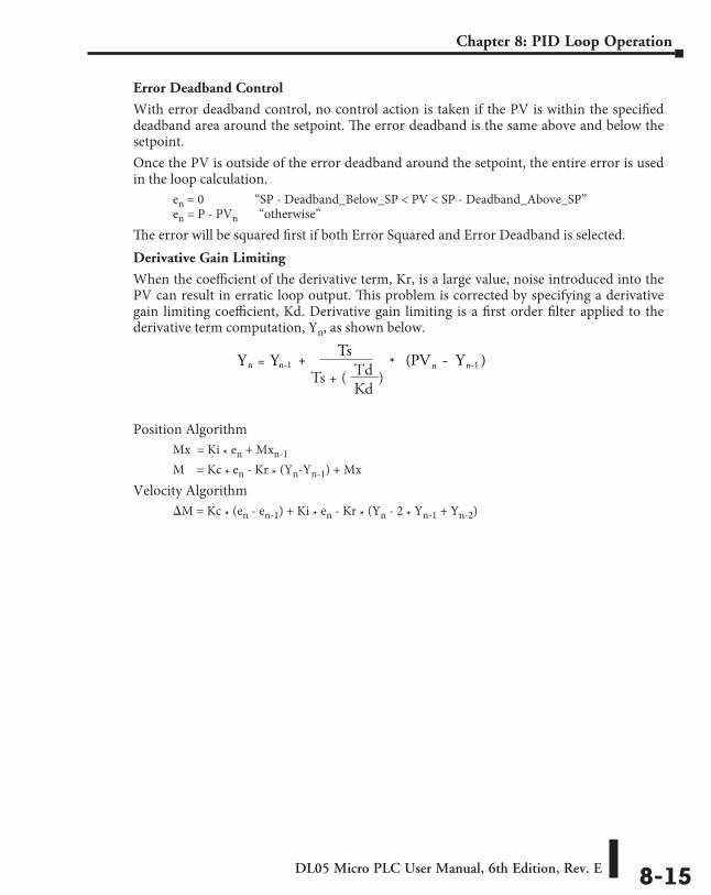
DL05 Micro PLC User Manual, 6th Edition, Rev. E 8-15
Chapter 8: PID Loop Operation
Error Deadband Control
With error deadband control, no control action is taken if the PV is within the specified deadband area around the setpoint. The error deadband is the same above and below the setpoint.Once the PV is outside of the error deadband around the setpoint, the entire error is used in the loop calculation.
en = 0 “SP - Deadband_Below_SP < PV < SP - Deadband_Above_SP” en = P - PVn “otherwise”
The error will be squared first if both Error Squared and Error Deadband is selected.Derivative Gain Limiting
When the coefficient of the derivative term, Kr, is a large value, noise introduced into the PV can result in erratic loop output. This problem is corrected by specifying a derivative gain limiting coefficient, Kd. Derivative gain limiting is a first order filter applied to the derivative term computation, Yn, as shown below.
Position AlgorithmMx = Ki * en + Mxn-1M = Kc * en - Kr * (Yn-Yn-1) + Mx
Velocity AlgorithmDM = Kc * (en - en-1) + Ki * en - Kr * (Yn - 2 * Yn-1 + Yn-2)
Yn = Yn-1 * +Ts
(PV - Y )n n-1
Ts + ( )TdKd
DL05 Micro PLC User Manual, 6th Edition, Rev. E8-16
Chapter 8: PID Loop Operation
Ten Steps to Successful Process ControlControllers such as the DL05 PLC provide sophisticated process control features. Automated control systems can be difficult to debug, because a given symptom can have many possible causes. We recommend a careful, step-by-step approach to bringing new control loops online:
Step 1: Know the RecipeThe most important knowledge is – how to produce your product. This knowledge is the foundation for designing an effective control system. A good process recipe will do the following:
• Identify all relevant Process Variables, such as temperature, pressure, or flow rates, etc. which need precise control.
• Plot the desired Setpoint values for each process variables for the duration of one process cycle.
Step 2: Plan Loop Control StrategyThis simply means choosing the method the machine will use to maintain control over the Process Variables to follow their Setpoints. This involves many issues and trade-offs, such as energy efficiency, equipment costs, ability to service the machine during production, and more. You must also determine how to generate the Setpoint value during the process, and whether a machine operator can change the SP.
Step 3: Size and Scale Loop ComponentsAssuming the control strategy is sound, it is still crucial to properly size the actuator and properly scale the sensors.
• Choose an actuator (heater, pump. etc.) which matches the size of the load. An oversized actuator will have an overwhelming effect on your process after a SP change. However, an undersized actuator will allow the PV to lag or drift away from the SP after a SP change or process disturbance.
• Choose a PV sensor which matches the range of interest (and control) for our process. Decide the resolution of control you need for the PV (such as within 2!C), and make sure the sensor input value provides the loop with at least 5 times that resolution (at LSB level). However, an over-sensitive sensor can cause control oscillations, etc. The DL05 provides 12-bit and 15-bit unipolar and bipolar data format options, and a 16–bit unipolar option. This selection affects SP, PV, Control Output and Integrator sum.
Step 4: Select I/O ModulesAfter deciding the number of loops, PV variables to measure, and SP values, you can choose the appropriate I/O module. Refer to the figure on the next page. In many cases, you will be able to share input or output modules, or use a analog I/O combination module, among several control loops. The example shown sends the PV and Control Output signals for two loops through the same set of modules.AutomationDirect offers DL05 analog input modules with 4 channels per module that accept 0–20 mA or 4–20 mA signals. Also, analog input and output combination modules are now available. Thermocouple and RTD modules can also be used to maintain temperatures to a 10th of a degree. Refer to the sales catalog for further information on these modules, or find the modules on our website, www.automationdirect.com.
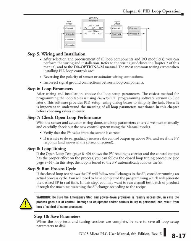
DL05 Micro PLC User Manual, 6th Edition, Rev. E 8-17
Chapter 8: PID Loop Operation
Step 5: Wiring and Installation• After selection and procurement of all loop components and I/O module(s), you can
perform the wiring and installation. Refer to the wiring guidelines in Chapter 2 of this manual, and to the D0–OPTIONS–M manual. The most common wiring errors when installing PID loop controls are:
• Reversing the polarity of sensor or actuator wiring connections.• Incorrect signal ground connections between loop components.
Step 6: Loop ParametersAfter wiring and installation, choose the loop setup parameters. The easiest method for programming the loop tables is using DirectSOFT programming software version (5.0 or later). This software provides PID Setup using dialog boxes to simplify the task. Note: It is important to understand the meaning of all loop parameters mentioned in this chapter before choosing values to enter.
Step 7: Check Open Loop PerformanceWith the sensor and actuator wiring done, and loop parameters entered, we must manually and carefully check out the new control system using the Manual mode).
• Verify that the PV value from the sensor is correct.
• If it is safe to do so, gradually increase the control output up above 0%, and see if the PV responds (and moves in the correct direction!).
Step 8: Loop TuningIf the Open Loop Test (page 8–40) shows the PV reading is correct and the control output has the proper effect on the process; you can follow the closed loop tuning procedure (see page 8–46). In this step, the loop is tuned so the PV automatically follows the SP.
Step 9: Run Process CycleIf the closed loop test shows the PV will follow small changes in the SP, consider running an actual process cycle. You will need to have completed the programming which will generate the desired SP in real time. In this step, you may want to run a small test batch of product through the machine, watching the SP change according to the recipe.
WARNING: Be sure the Emergency Stop and power-down provision is readily accessible, in case the process goes out of control. Damage to equipment and/or serious injury to personnel can result from loss of control of some processes.
Step 10: Save ParametersWhen the loop tests and tuning sessions are complete, be sure to save all loop setup parameters to disk.
Loop 1 DataSP
V-memory DigitalOutput
DL05 CPU
InputModule
Channel 1 Process 1
Process 2
PV OUT
Channel 2Loop 2 Data
SPPV OUT
Channel 3
Channel 4
Channel 1
Channel 2
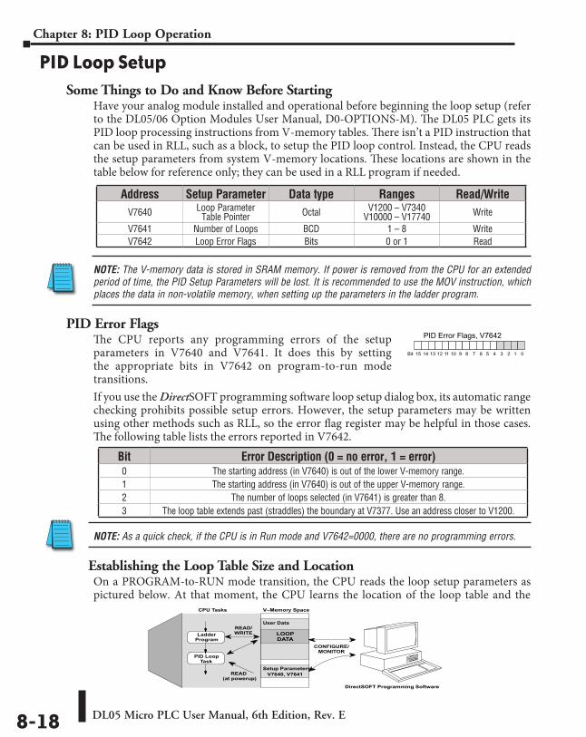
DL05 Micro PLC User Manual, 6th Edition, Rev. E8-18
Chapter 8: PID Loop Operation
PID Loop SetupSome Things to Do and Know Before Starting
Have your analog module installed and operational before beginning the loop setup (refer to the DL05/06 Option Modules User Manual, D0-OPTIONS-M). The DL05 PLC gets its PID loop processing instructions from V-memory tables. There isn’t a PID instruction that can be used in RLL, such as a block, to setup the PID loop control. Instead, the CPU reads the setup parameters from system V-memory locations. These locations are shown in the table below for reference only; they can be used in a RLL program if needed.
NOTE: The V-memory data is stored in SRAM memory. If power is removed from the CPU for an extended period of time, the PID Setup Parameters will be lost. It is recommended to use the MOV instruction, which places the data in non-volatile memory, when setting up the parameters in the ladder program.
PID Error FlagsThe CPU reports any programming errors of the setup parameters in V7640 and V7641. It does this by setting the appropriate bits in V7642 on program-to-run mode transitions.If you use the DirectSOFT programming software loop setup dialog box, its automatic range checking prohibits possible setup errors. However, the setup parameters may be written using other methods such as RLL, so the error flag register may be helpful in those cases. The following table lists the errors reported in V7642.
NOTE: As a quick check, if the CPU is in Run mode and V7642=0000, there are no programming errors.
Establishing the Loop Table Size and LocationOn a PROGRAM-to-RUN mode transition, the CPU reads the loop setup parameters as pictured below. At that moment, the CPU learns the location of the loop table and the
Address Setup Parameter Data type Ranges Read/WriteV7640 Loop Parameter
Table Pointer Octal V1200 – V7340 V10000 – V17740 Write
V7641 Number of Loops BCD 1 – 8 WriteV7642 Loop Error Flags Bits 0 or 1 Read
READ(at powerup)
CONFIGURE/MONITOR
V–Memory Space
User Data
Setup Parameters
LOOPDATA
CPU Tasks
READ/WRITELadder
Program
PID LoopTask
DirectSOFT Programming Software
V7640, V7641
Bit Error Description (0 = no error, 1 = error)0 The starting address (in V7640) is out of the lower V-memory range.1 The starting address (in V7640) is out of the upper V-memory range.2 The number of loops selected (in V7641) is greater than 8.3 The loop table extends past (straddles) the boundary at V7377. Use an address closer to V1200.
PID Error Flags, V7642
013456789101112131415 2Bit
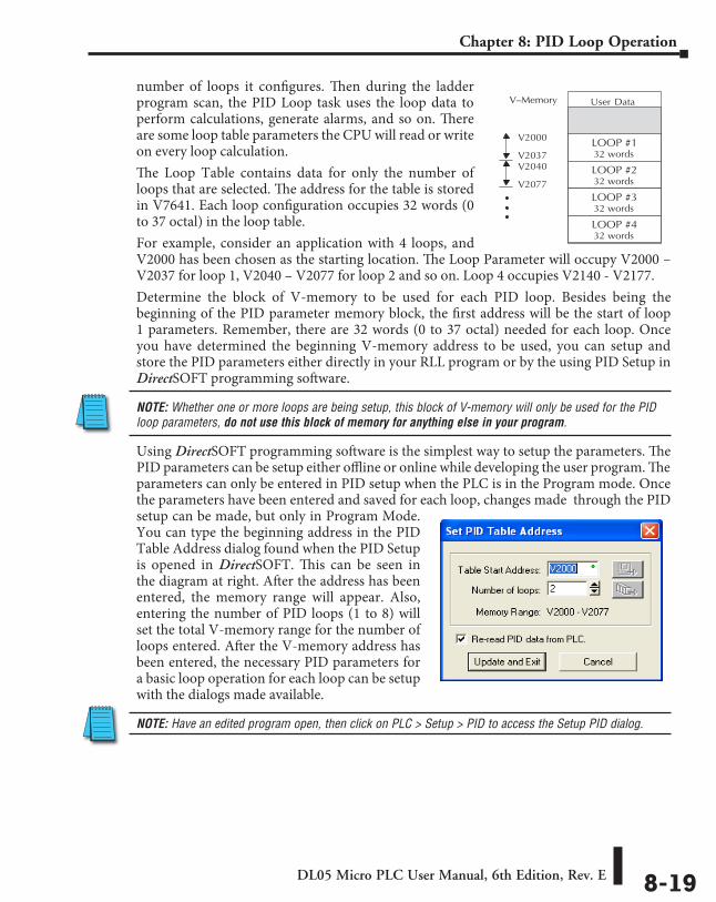
DL05 Micro PLC User Manual, 6th Edition, Rev. E 8-19
Chapter 8: PID Loop Operation
number of loops it configures. Then during the ladder program scan, the PID Loop task uses the loop data to perform calculations, generate alarms, and so on. There are some loop table parameters the CPU will read or write on every loop calculation.The Loop Table contains data for only the number of loops that are selected. The address for the table is stored in V7641. Each loop configuration occupies 32 words (0 to 37 octal) in the loop table.For example, consider an application with 4 loops, and V2000 has been chosen as the starting location. The Loop Parameter will occupy V2000 – V2037 for loop 1, V2040 – V2077 for loop 2 and so on. Loop 4 occupies V2140 - V2177.Determine the block of V-memory to be used for each PID loop. Besides being the beginning of the PID parameter memory block, the first address will be the start of loop 1 parameters. Remember, there are 32 words (0 to 37 octal) needed for each loop. Once you have determined the beginning V-memory address to be used, you can setup and store the PID parameters either directly in your RLL program or by the using PID Setup in DirectSOFT programming software.
NOTE: Whether one or more loops are being setup, this block of V-memory will only be used for the PID loop parameters, do not use this block of memory for anything else in your program.
Using DirectSOFT programming software is the simplest way to setup the parameters. The PID parameters can be setup either offline or online while developing the user program. The parameters can only be entered in PID setup when the PLC is in the Program mode. Once the parameters have been entered and saved for each loop, changes made through the PID setup can be made, but only in Program Mode. You can type the beginning address in the PID Table Address dialog found when the PID Setup is opened in DirectSOFT. This can be seen in the diagram at right. After the address has been entered, the memory range will appear. Also, entering the number of PID loops (1 to 8) will set the total V-memory range for the number of loops entered. After the V-memory address has been entered, the necessary PID parameters for a basic loop operation for each loop can be setup with the dialogs made available.
NOTE: Have an edited program open, then click on PLC > Setup > PID to access the Setup PID dialog.
V–Memory User Data
LOOP #1V2000
32 words
LOOP #232 words
LOOP #332 words
LOOP #432 words
V2037V2040
V2077
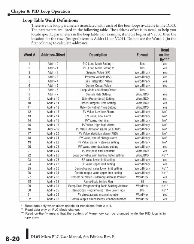
DL05 Micro PLC User Manual, 6th Edition, Rev. E8-20
Chapter 8: PID Loop Operation
Loop Table Word DefinitionsThese are the loop parameters associated with each of the four loops available in the DL05. The parameters are listed in the following table. The address offset is in octal, to help you locate specific parameters in the loop table. For example, if a table begins at V2000, then the location for the reset (integral) term is Addr+11, or V2011. Do not use the Word # (in the first column) to calculate addresses.
Word # Address+Offset Description FormatRead
on-the- fly***
1 Addr + 0 PID Loop Mode Setting 1 Bits Yes2 Addr + 1 PID Loop Mode Setting 2 Bits Yes3 Addr + 2 Setpoint Value (SP) Word/Binary Yes4 Addr + 3 Process Variable (PV) Word/Binary Yes5 Addr + 4 Bias (Integrator) Value Word/Binary Yes6 Addr + 5 Control Output Value Word/Binary Yes7 Addr + 6 Loop Mode and Alarm Status Bits –8 Addr + 7 Sample Rate Setting Word/BCD Yes9 Addr + 10 Gain (Proportional) Setting Word/BCD Yes10 Addr + 11 Reset (Integral) Time Setting Word/BCD Yes11 Addr + 12 Rate (Derivative) Time Setting Word/BCD Yes12 Addr + 13 PV Value, Low-low Alarm Word/Binary No*13 Addr + 14 PV Value, Low Alarm Word/Binary No*14 Addr + 15 PV Value, High Alarm Word/Binary No*15 Addr + 16 PV Value, High-high Alarm Word/Binary No*16 Addr + 17 PV Value, deviation alarm (YELLOW) Word/Binary No*17 Addr + 20 PV Value, deviation alarm (RED) Word/Binary No*18 Addr + 21 PV Value, rate-of-change alarm Word/Binary No*19 Addr + 22 PV Value, alarm hysteresis setting Word/Binary No*20 Addr + 23 PV Value, error deadband setting Word/Binary Yes21 Addr + 24 PV low-pass filter constant Word/BCD Yes22 Addr + 25 Loop derivative gain limiting factor setting Word/BCD No**23 Addr + 26 SP value lower limit setting Word/Binary Yes24 Addr + 27 SP value upper limit setting Word/Binary Yes25 Addr + 30 Control output value lower limit setting Word/Binary No**26 Addr + 31 Control output value upper limit setting Word/Binary No**27 Addr + 32 Remote SP Value V-Memory Address Pointer Word/Hex Yes28 Addr + 33 Ramp/Soak Setting Flag Bit Yes29 Addr + 34 Ramp/Soak Programming Table Starting Address Word/Hex No**30 Addr + 35 Ramp/Soak Programming Table Error Flags Bits No**31 Addr + 36 PV direct access, channel number Word/Hex Yes32 Addr + 37 Control output direct access, channel number Word/Hex Yes
* Read data only when alarm enable bit transitions from 0 to 1.** Read data only on PLC Mode change.*** Read on-the-fly means that the content of V-memory can be changed while the PID loop is in
operation.
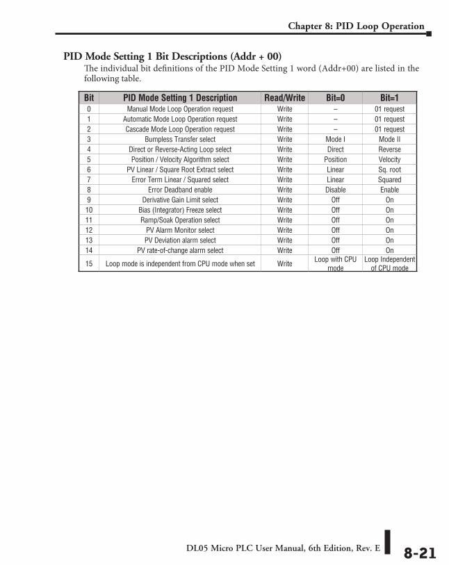
DL05 Micro PLC User Manual, 6th Edition, Rev. E 8-21
Chapter 8: PID Loop Operation
PID Mode Setting 1 Bit Descriptions (Addr + 00)The individual bit definitions of the PID Mode Setting 1 word (Addr+00) are listed in the following table.
Bit PID Mode Setting 1 Description Read/Write Bit=0 Bit=10 Manual Mode Loop Operation request Write – 01 request1 Automatic Mode Loop Operation request Write – 01 request2 Cascade Mode Loop Operation request Write – 01 request3 Bumpless Transfer select Write Mode I Mode II4 Direct or Reverse-Acting Loop select Write Direct Reverse5 Position / Velocity Algorithm select Write Position Velocity6 PV Linear / Square Root Extract select Write Linear Sq. root7 Error Term Linear / Squared select Write Linear Squared8 Error Deadband enable Write Disable Enable9 Derivative Gain Limit select Write Off On10 Bias (Integrator) Freeze select Write Off On11 Ramp/Soak Operation select Write Off On12 PV Alarm Monitor select Write Off On13 PV Deviation alarm select Write Off On14 PV rate-of-change alarm select Write Off On
15 Loop mode is independent from CPU mode when set Write Loop with CPU mode
Loop Independent of CPU mode
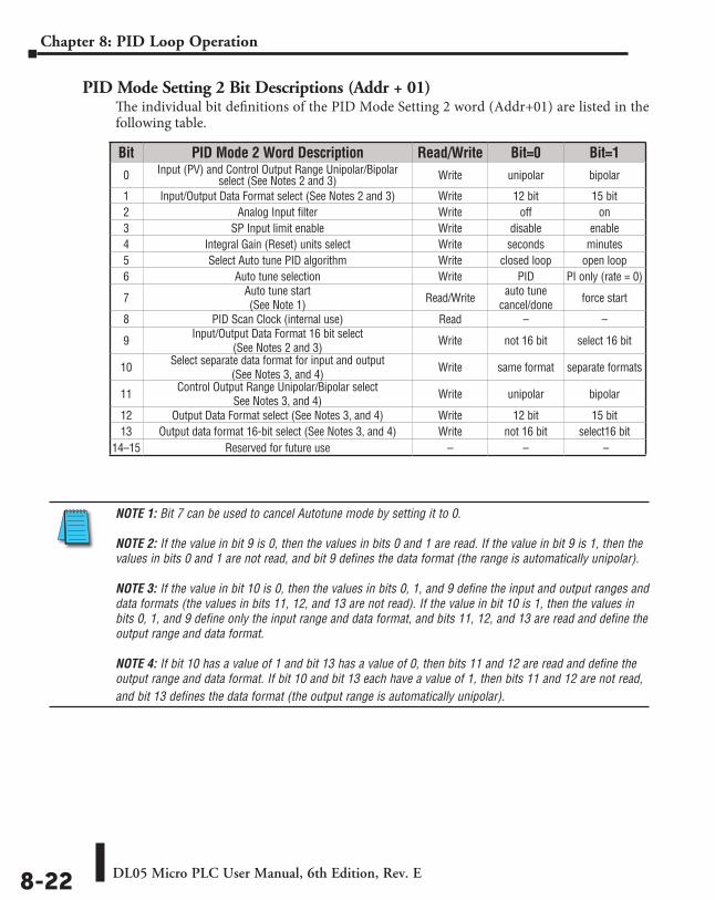
DL05 Micro PLC User Manual, 6th Edition, Rev. E8-22
Chapter 8: PID Loop Operation
PID Mode Setting 2 Bit Descriptions (Addr + 01)The individual bit definitions of the PID Mode Setting 2 word (Addr+01) are listed in the following table.
NOTE 1: Bit 7 can be used to cancel Autotune mode by setting it to 0. NOTE 2: If the value in bit 9 is 0, then the values in bits 0 and 1 are read. If the value in bit 9 is 1, then the values in bits 0 and 1 are not read, and bit 9 defines the data format (the range is automatically unipolar). NOTE 3: If the value in bit 10 is 0, then the values in bits 0, 1, and 9 define the input and output ranges and data formats (the values in bits 11, 12, and 13 are not read). If the value in bit 10 is 1, then the values in bits 0, 1, and 9 define only the input range and data format, and bits 11, 12, and 13 are read and define the output range and data format. NOTE 4: If bit 10 has a value of 1 and bit 13 has a value of 0, then bits 11 and 12 are read and define the output range and data format. If bit 10 and bit 13 each have a value of 1, then bits 11 and 12 are not read, and bit 13 defines the data format (the output range is automatically unipolar).
Bit PID Mode 2 Word Description Read/Write Bit=0 Bit=10 Input (PV) and Control Output Range Unipolar/Bipolar
select (See Notes 2 and 3) Write unipolar bipolar
1 Input/Output Data Format select (See Notes 2 and 3) Write 12 bit 15 bit2 Analog Input filter Write off on3 SP Input limit enable Write disable enable4 Integral Gain (Reset) units select Write seconds minutes5 Select Auto tune PID algorithm Write closed loop open loop6 Auto tune selection Write PID PI only (rate = 0)
7 Auto tune start (See Note 1) Read/Write auto tune
cancel/done force start
8 PID Scan Clock (internal use) Read – –
9 Input/Output Data Format 16 bit select (See Notes 2 and 3) Write not 16 bit select 16 bit
10 Select separate data format for input and output (See Notes 3, and 4) Write same format separate formats
11 Control Output Range Unipolar/Bipolar select See Notes 3, and 4) Write unipolar bipolar
12 Output Data Format select (See Notes 3, and 4) Write 12 bit 15 bit13 Output data format 16-bit select (See Notes 3, and 4) Write not 16 bit select16 bit
14–15 Reserved for future use – – –
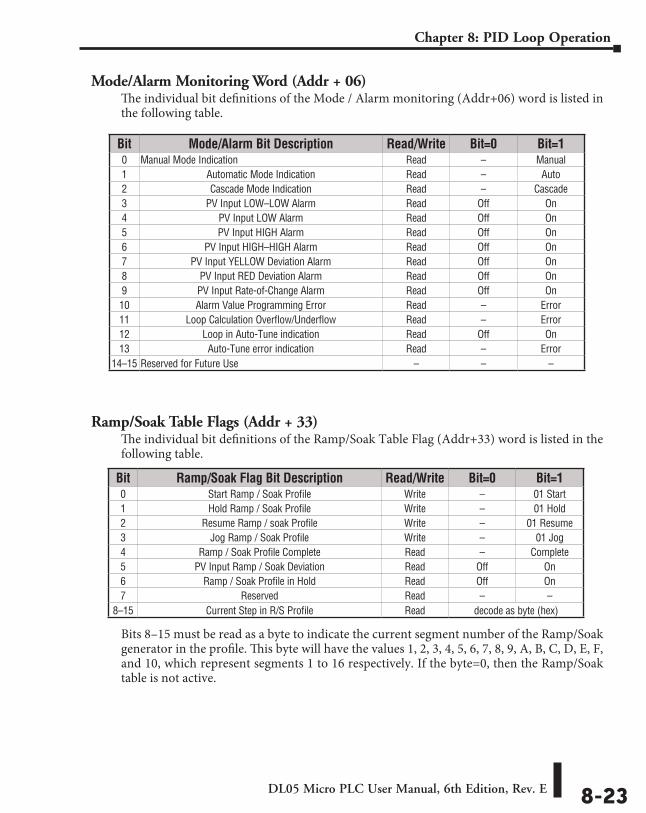
DL05 Micro PLC User Manual, 6th Edition, Rev. E 8-23
Chapter 8: PID Loop Operation
Mode/Alarm Monitoring Word (Addr + 06)The individual bit definitions of the Mode / Alarm monitoring (Addr+06) word is listed in the following table.
Ramp/Soak Table Flags (Addr + 33)The individual bit definitions of the Ramp/Soak Table Flag (Addr+33) word is listed in the following table.
Bits 8–15 must be read as a byte to indicate the current segment number of the Ramp/Soak generator in the profile. This byte will have the values 1, 2, 3, 4, 5, 6, 7, 8, 9, A, B, C, D, E, F, and 10, which represent segments 1 to 16 respectively. If the byte=0, then the Ramp/Soak table is not active.
Bit Mode/Alarm Bit Description Read/Write Bit=0 Bit=10 Manual Mode Indication Read – Manual1 Automatic Mode Indication Read – Auto2 Cascade Mode Indication Read – Cascade3 PV Input LOW–LOW Alarm Read Off On4 PV Input LOW Alarm Read Off On5 PV Input HIGH Alarm Read Off On6 PV Input HIGH–HIGH Alarm Read Off On7 PV Input YELLOW Deviation Alarm Read Off On8 PV Input RED Deviation Alarm Read Off On9 PV Input Rate-of-Change Alarm Read Off On10 Alarm Value Programming Error Read – Error11 Loop Calculation Overflow/Underflow Read – Error12 Loop in Auto-Tune indication Read Off On13 Auto-Tune error indication Read – Error
14–15 Reserved for Future Use – – –
Bit Ramp/Soak Flag Bit Description Read/Write Bit=0 Bit=10 Start Ramp / Soak Profile Write – 01 Start1 Hold Ramp / Soak Profile Write – 01 Hold2 Resume Ramp / soak Profile Write – 01 Resume3 Jog Ramp / Soak Profile Write – 01 Jog4 Ramp / Soak Profile Complete Read – Complete5 PV Input Ramp / Soak Deviation Read Off On6 Ramp / Soak Profile in Hold Read Off On7 Reserved Read – –
8–15 Current Step in R/S Profile Read decode as byte (hex)
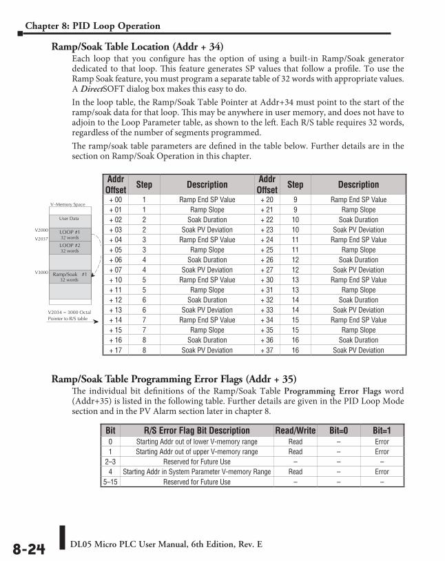
DL05 Micro PLC User Manual, 6th Edition, Rev. E8-24
Chapter 8: PID Loop Operation
Ramp/Soak Table Location (Addr + 34)Each loop that you configure has the option of using a built-in Ramp/Soak generator dedicated to that loop. This feature generates SP values that follow a profile. To use the Ramp Soak feature, you must program a separate table of 32 words with appropriate values. A DirectSOFT dialog box makes this easy to do.In the loop table, the Ramp/Soak Table Pointer at Addr+34 must point to the start of the ramp/soak data for that loop. This may be anywhere in user memory, and does not have to adjoin to the Loop Parameter table, as shown to the left. Each R/S table requires 32 words, regardless of the number of segments programmed.The ramp/soak table parameters are defined in the table below. Further details are in the section on Ramp/Soak Operation in this chapter.
Ramp/Soak Table Programming Error Flags (Addr + 35)The individual bit definitions of the Ramp/Soak Table Programming Error Flags word (Addr+35) is listed in the following table. Further details are given in the PID Loop Mode section and in the PV Alarm section later in chapter 8.
Addr Offset Step Description Addr
Offset Step Description
+ 00 1 Ramp End SP Value + 20 9 Ramp End SP Value+ 01 1 Ramp Slope + 21 9 Ramp Slope+ 02 2 Soak Duration + 22 10 Soak Duration+ 03 2 Soak PV Deviation + 23 10 Soak PV Deviation+ 04 3 Ramp End SP Value + 24 11 Ramp End SP Value+ 05 3 Ramp Slope + 25 11 Ramp Slope+ 06 4 Soak Duration + 26 12 Soak Duration+ 07 4 Soak PV Deviation + 27 12 Soak PV Deviation+ 10 5 Ramp End SP Value + 30 13 Ramp End SP Value+ 11 5 Ramp Slope + 31 13 Ramp Slope+ 12 6 Soak Duration + 32 14 Soak Duration+ 13 6 Soak PV Deviation + 33 14 Soak PV Deviation+ 14 7 Ramp End SP Value + 34 15 Ramp End SP Value+ 15 7 Ramp Slope + 35 15 Ramp Slope+ 16 8 Soak Duration + 36 16 Soak Duration+ 17 8 Soak PV Deviation + 37 16 Soak PV Deviation
V–Memory Space
User Data
LOOP #1V2000
32 words
LOOP #232 words
V2037
Ramp/Soak #132 words
V3000
V2034 = 3000 OctalPointer to R/S table
Bit R/S Error Flag Bit Description Read/Write Bit=0 Bit=10 Starting Addr out of lower V-memory range Read – Error1 Starting Addr out of upper V-memory range Read – Error
2–3 Reserved for Future Use – – –4 Starting Addr in System Parameter V-memory Range Read – Error
5–15 Reserved for Future Use – – –
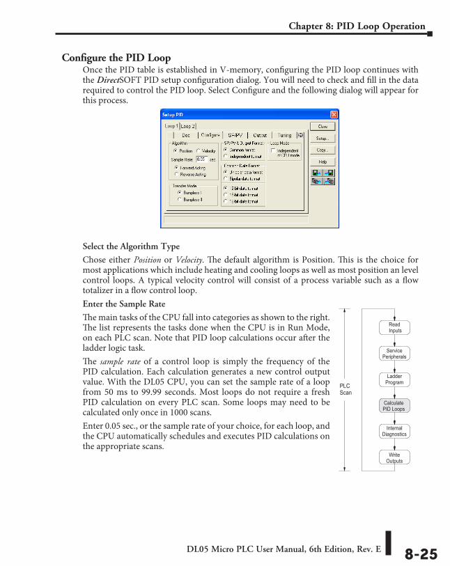
DL05 Micro PLC User Manual, 6th Edition, Rev. E 8-25
Chapter 8: PID Loop Operation
Configure the PID LoopOnce the PID table is established in V-memory, configuring the PID loop continues with the DirectSOFT PID setup configuration dialog. You will need to check and fill in the data required to control the PID loop. Select Configure and the following dialog will appear for this process.
Select the Algorithm Type
Chose either Position or Velocity. The default algorithm is Position. This is the choice for most applications which include heating and cooling loops as well as most position an level control loops. A typical velocity control will consist of a process variable such as a flow totalizer in a flow control loop.Enter the Sample Rate
The main tasks of the CPU fall into categories as shown to the right. The list represents the tasks done when the CPU is in Run Mode, on each PLC scan. Note that PID loop calculations occur after the ladder logic task.The sample rate of a control loop is simply the frequency of the PID calculation. Each calculation generates a new control output value. With the DL05 CPU, you can set the sample rate of a loop from 50 ms to 99.99 seconds. Most loops do not require a fresh PID calculation on every PLC scan. Some loops may need to be calculated only once in 1000 scans.Enter 0.05 sec., or the sample rate of your choice, for each loop, and the CPU automatically schedules and executes PID calculations on the appropriate scans.
ReadInputs
ServicePeripherals
LadderProgram
CalculatePID Loops
InternalDiagnostics
WriteOutputs
PLCScan
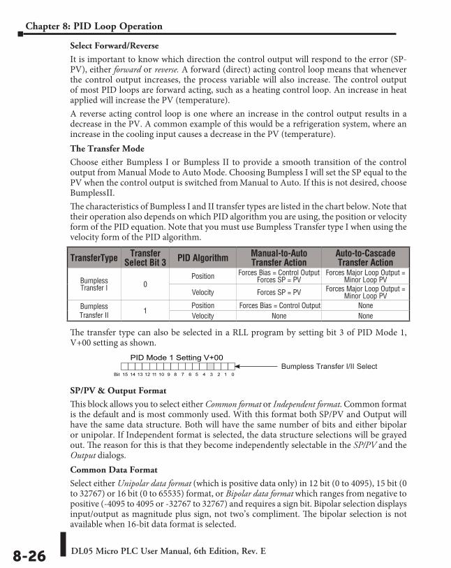
DL05 Micro PLC User Manual, 6th Edition, Rev. E8-26
Chapter 8: PID Loop Operation
Select Forward/Reverse
It is important to know which direction the control output will respond to the error (SP-PV), either forward or reverse. A forward (direct) acting control loop means that whenever the control output increases, the process variable will also increase. The control output of most PID loops are forward acting, such as a heating control loop. An increase in heat applied will increase the PV (temperature).A reverse acting control loop is one where an increase in the control output results in a decrease in the PV. A common example of this would be a refrigeration system, where an increase in the cooling input causes a decrease in the PV (temperature).The Transfer Mode
Choose either Bumpless I or Bumpless II to provide a smooth transition of the control output from Manual Mode to Auto Mode. Choosing Bumpless I will set the SP equal to the PV when the control output is switched from Manual to Auto. If this is not desired, choose Bumpless II.The characteristics of Bumpless I and II transfer types are listed in the chart below. Note that their operation also depends on which PID algorithm you are using, the position or velocity form of the PID equation. Note that you must use Bumpless Transfer type I when using the velocity form of the PID algorithm.
The transfer type can also be selected in a RLL program by setting bit 3 of PID Mode 1, V+00 setting as shown.
SP/PV & Output Format
This block allows you to select either Common format or Independent format. Common format is the default and is most commonly used. With this format both SP/PV and Output will have the same data structure. Both will have the same number of bits and either bipolar or unipolar. If Independent format is selected, the data structure selections will be grayed out. The reason for this is that they become independently selectable in the SP/PV and the Output dialogs.Common Data Format
Select either Unipolar data format (which is positive data only) in 12 bit (0 to 4095), 15 bit (0 to 32767) or 16 bit (0 to 65535) format, or Bipolar data format which ranges from negative to positive (-4095 to 4095 or -32767 to 32767) and requires a sign bit. Bipolar selection displays input/output as magnitude plus sign, not two’s compliment. The bipolar selection is not available when 16-bit data format is selected.
TransferType Transfer Select Bit 3 PID Algorithm Manual-to-Auto
Transfer Action Auto-to-Cascade Transfer Action
Bumpless Transfer I 0
Position Forces Bias = Control Output Forces SP = PV
Forces Major Loop Output = Minor Loop PV
Velocity Forces SP = PV Forces Major Loop Output = Minor Loop PV
Bumpless Transfer II 1
Position Forces Bias = Control Output NoneVelocity None None
PID Mode 1 Setting V+00
013456789101112131415 2BitBumpless Transfer I/II Select
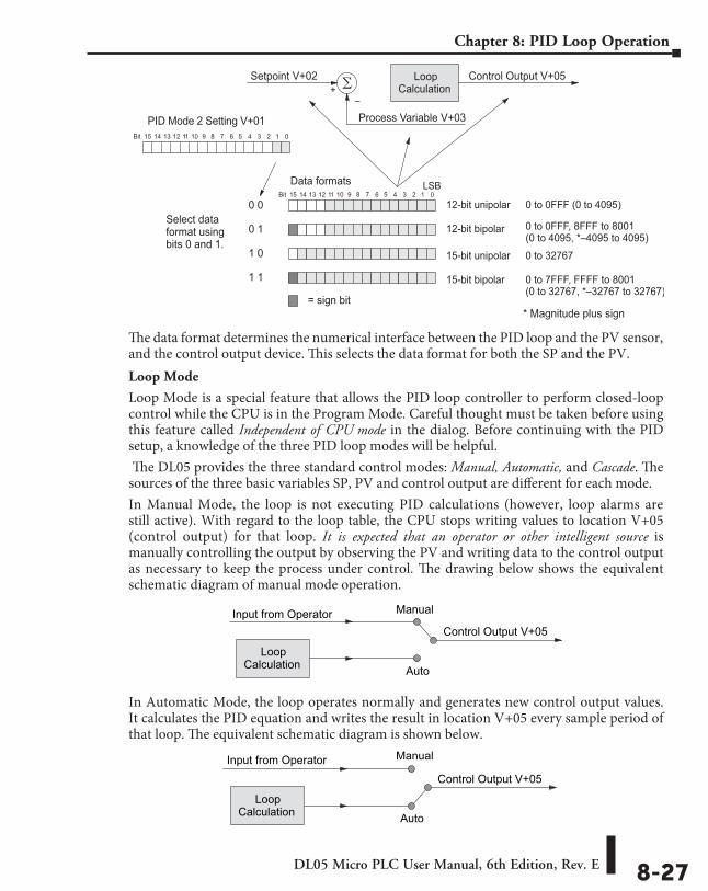
DL05 Micro PLC User Manual, 6th Edition, Rev. E 8-27
Chapter 8: PID Loop Operation
The data format determines the numerical interface between the PID loop and the PV sensor, and the control output device. This selects the data format for both the SP and the PV.Loop Mode
Loop Mode is a special feature that allows the PID loop controller to perform closed-loop control while the CPU is in the Program Mode. Careful thought must be taken before using this feature called Independent of CPU mode in the dialog. Before continuing with the PID setup, a knowledge of the three PID loop modes will be helpful. The DL05 provides the three standard control modes: Manual, Automatic, and Cascade. The sources of the three basic variables SP, PV and control output are different for each mode.In Manual Mode, the loop is not executing PID calculations (however, loop alarms are still active). With regard to the loop table, the CPU stops writing values to location V+05 (control output) for that loop. It is expected that an operator or other intelligent source is manually controlling the output by observing the PV and writing data to the control output as necessary to keep the process under control. The drawing below shows the equivalent schematic diagram of manual mode operation.
In Automatic Mode, the loop operates normally and generates new control output values. It calculates the PID equation and writes the result in location V+05 every sample period of that loop. The equivalent schematic diagram is shown below.
Process Variable V+03
LoopCalculation+
–
Control Output V+05Setpoint V+02
013456789101112131415 2Bit
12-bit unipolar
12-bit bipolar
15-bit bipolar
15-bit unipolar
0 to 0FFF (0 to 4095)
0 to 0FFF, 8FFF to 8001(0 to 4095, *–4095 to 4095)
0 to 32767
0 to 7FFF, FFFF to 8001(0 to 32767, *–32767 to 32767)
Data formats
013456789101112131415 2Bit
PID Mode 2 Setting V+01
0 0
0 1
1 0
1 1
Select dataformat usingbits 0 and 1.
= sign bit
LSB
* Magnitude plus sign
LoopCalculation
Control Output V+05Input from Operator Manual
Auto
LoopCalculation
Control Output V+05Input from Operator Manual
Auto
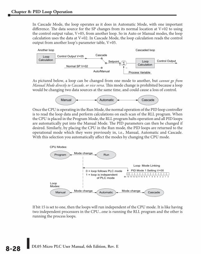
DL05 Micro PLC User Manual, 6th Edition, Rev. E8-28
Chapter 8: PID Loop Operation
In Cascade Mode, the loop operates as it does in Automatic Mode, with one important difference. The data source for the SP changes from its normal location at V+02 to using the control output value, V+05, from another loop. So in Auto or Manual modes, the loop calculation uses the data at V+02. In Cascade Mode, the loop calculation reads the control output from another loop’s parameter table, V+05.
As pictured below, a loop can be changed from one mode to another, but cannot go from Manual Mode directly to Cascade, or vice versa. This mode change is prohibited because a loop would be changing two data sources at the same time, and could cause a loss of control.
Once the CPU is operating in the Run Mode, the normal operation of the PID loop controller is to read the loop data and perform calculations on each scan of the RLL program. When the CPU is placed in the Program Mode, the RLL program halts operation and all PID loops are automatically put into the Manual Mode. The PID parameters can then be changed if desired. Similarly, by placing the CPU in the Run mode, the PID loops are returned to the operational mode which they were previously in, i.e., Manual, Automatic and Cascade. With this selection you automatically affect the modes by changing the CPU mode.
If bit 15 is set to one, then the loops will run independent of the CPU mode. It is like having two independent processors in the CPU...one is running the RLL program and the other is running the process loops.
Process Variable
+–
Setpoint
Cascade
Auto/Manual
Control Output V+05
Normal SP V+02Loop
CalculationControl Output
LoopCalculation
Cascaded loopAnother loop
Manual Automatic Cascade
Manual Automatic CascadeMode change
0 = loop follows PLC mode
Mode change
Program RunMode change
CPU Modes:
LoopModes:
PID Mode 1 Setting V+00
013456789101112131415 2Bit
Loop Mode Linking
1 = loop is independent of PLC mode
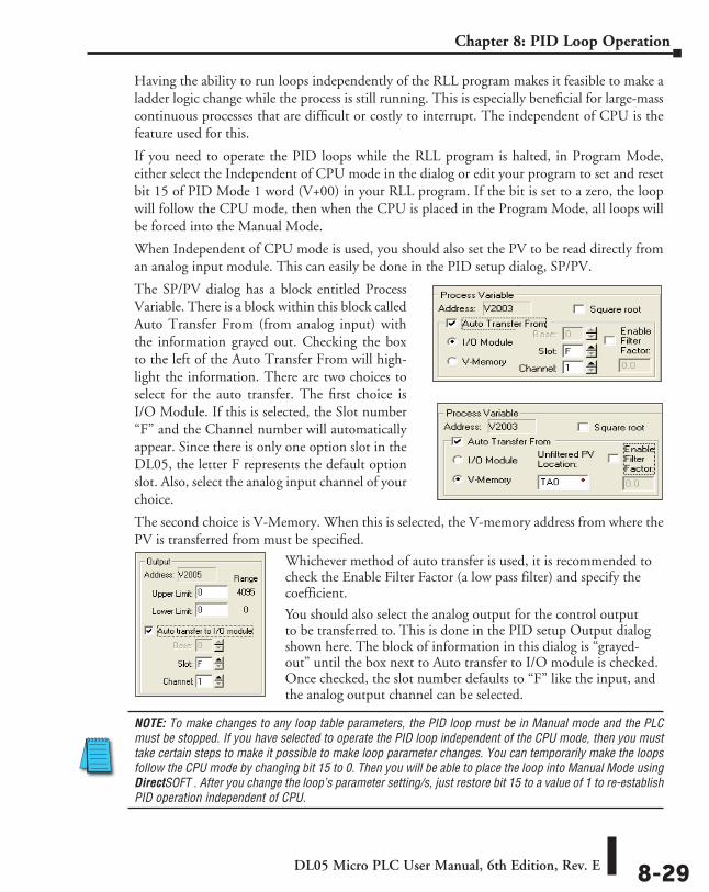
DL05 Micro PLC User Manual, 6th Edition, Rev. E 8-29
Chapter 8: PID Loop Operation
Having the ability to run loops independently of the RLL program makes it feasible to make a ladder logic change while the process is still running. This is especially beneficial for large-mass continuous processes that are difficult or costly to interrupt. The independent of CPU is the feature used for this.
If you need to operate the PID loops while the RLL program is halted, in Program Mode, either select the Independent of CPU mode in the dialog or edit your program to set and reset bit 15 of PID Mode 1 word (V+00) in your RLL program. If the bit is set to a zero, the loop will follow the CPU mode, then when the CPU is placed in the Program Mode, all loops will be forced into the Manual Mode.
When Independent of CPU mode is used, you should also set the PV to be read directly from an analog input module. This can easily be done in the PID setup dialog, SP/PV.
The SP/PV dialog has a block entitled Process Variable. There is a block within this block called Auto Transfer From (from analog input) with the information grayed out. Checking the box to the left of the Auto Transfer From will high-light the information. There are two choices to select for the auto transfer. The first choice is I/O Module. If this is selected, the Slot number “F” and the Channel number will automatically appear. Since there is only one option slot in the DL05, the letter F represents the default option slot. Also, select the analog input channel of your choice.
The second choice is V-Memory. When this is selected, the V-memory address from where the PV is transferred from must be specified.
Whichever method of auto transfer is used, it is recommended to check the Enable Filter Factor (a low pass filter) and specify the coefficient.
You should also select the analog output for the control output to be transferred to. This is done in the PID setup Output dialog shown here. The block of information in this dialog is “grayed-out” until the box next to Auto transfer to I/O module is checked. Once checked, the slot number defaults to “F” like the input, and the analog output channel can be selected.
NOTE: To make changes to any loop table parameters, the PID loop must be in Manual mode and the PLC must be stopped. If you have selected to operate the PID loop independent of the CPU mode, then you must take certain steps to make it possible to make loop parameter changes. You can temporarily make the loops follow the CPU mode by changing bit 15 to 0. Then you will be able to place the loop into Manual Mode using DirectSOFT . After you change the loop’s parameter setting/s, just restore bit 15 to a value of 1 to re-establish PID operation independent of CPU.
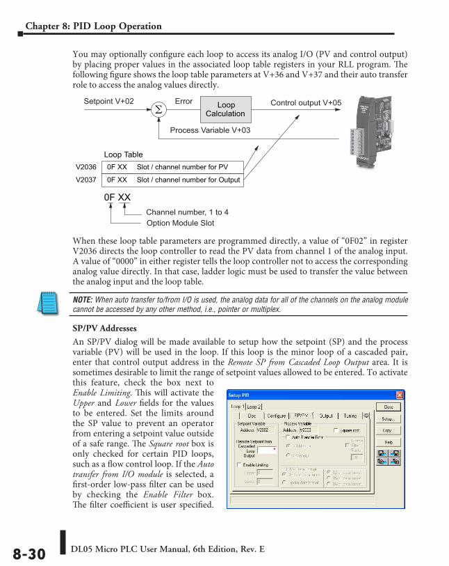
DL05 Micro PLC User Manual, 6th Edition, Rev. E8-30
Chapter 8: PID Loop Operation
You may optionally configure each loop to access its analog I/O (PV and control output) by placing proper values in the associated loop table registers in your RLL program. The following figure shows the loop table parameters at V+36 and V+37 and their auto transfer role to access the analog values directly.
When these loop table parameters are programmed directly, a value of “0F02” in register V2036 directs the loop controller to read the PV data from channel 1 of the analog input. A value of “0000” in either register tells the loop controller not to access the corresponding analog value directly. In that case, ladder logic must be used to transfer the value between the analog input and the loop table.
NOTE: When auto transfer to/from I/O is used, the analog data for all of the channels on the analog module cannot be accessed by any other method, i.e., pointer or multiplex.
SP/PV Addresses
An SP/PV dialog will be made available to setup how the setpoint (SP) and the process variable (PV) will be used in the loop. If this loop is the minor loop of a cascaded pair, enter that control output address in the Remote SP from Cascaded Loop Output area. It is sometimes desirable to limit the range of setpoint values allowed to be entered. To activate this feature, check the box next to Enable Limiting. This will activate the Upper and Lower fields for the values to be entered. Set the limits around the SP value to prevent an operator from entering a setpoint value outside of a safe range. The Square root box is only checked for certain PID loops, such as a flow control loop. If the Auto transfer from I/O module is selected, a first-order low-pass filter can be used by checking the Enable Filter box. The filter coefficient is user specified.
LoopCalculation
Loop TableV2036 Slot / channel number for PV0F XX
V2037 Slot / channel number for Output0F XX
0F XX
Setpoint V+02 Control output V+05
Process Variable V+03
Error
Channel number, 1 to 4Option Module Slot
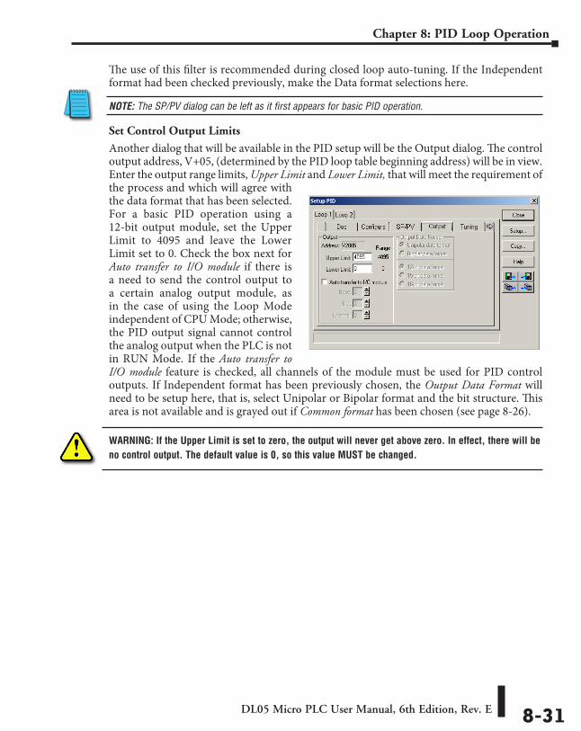
DL05 Micro PLC User Manual, 6th Edition, Rev. E 8-31
Chapter 8: PID Loop Operation
The use of this filter is recommended during closed loop auto-tuning. If the Independent format had been checked previously, make the Data format selections here.
NOTE: The SP/PV dialog can be left as it first appears for basic PID operation.
Set Control Output Limits
Another dialog that will be available in the PID setup will be the Output dialog. The control output address, V+05, (determined by the PID loop table beginning address) will be in view. Enter the output range limits, Upper Limit and Lower Limit, that will meet the requirement of the process and which will agree with the data format that has been selected. For a basic PID operation using a 12-bit output module, set the Upper Limit to 4095 and leave the Lower Limit set to 0. Check the box next for Auto transfer to I/O module if there is a need to send the control output to a certain analog output module, as in the case of using the Loop Mode independent of CPU Mode; otherwise, the PID output signal cannot control the analog output when the PLC is not in RUN Mode. If the Auto transfer to I/O module feature is checked, all channels of the module must be used for PID control outputs. If Independent format has been previously chosen, the Output Data Format will need to be setup here, that is, select Unipolar or Bipolar format and the bit structure. This area is not available and is grayed out if Common format has been chosen (see page 8-26).
WARNING: If the Upper Limit is set to zero, the output will never get above zero. In effect, there will be no control output. The default value is 0, so this value MUST be changed.
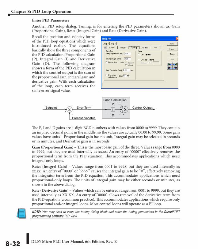
DL05 Micro PLC User Manual, 6th Edition, Rev. E8-32
Chapter 8: PID Loop Operation
Enter PID Parameters
Another PID setup dialog, Tuning, is for entering the PID parameters shown as: Gain (Proportional Gain), Reset (Integral Gain) and Rate (Derivative Gain).Recall the position and velocity forms of the PID loop equations which were introduced earlier. The equations basically show the three components of the PID calculation: Proportional Gain (P), Integral Gain (I) and Derivative Gain (D). The following diagram shows a form of the PID calculation in which the control output is the sum of the proportional gain, integral gain and derivative gain. With each calculation of the loop, each term receives the same error signal value.
The P, I and D gains are 4-digit BCD numbers with values from 0000 to 9999. They contain an implied decimal point in the middle, so the values are actually 00.00 to 99.99. Some gain values have units – Proportional gain has no unit, Integral gain may be selected in seconds or in minutes, and Derivative gain is in seconds. Gain (Proportional Gain) – This is the most basic gain of the three. Values range from 0000 to 9999, but they are used internally as xx.xx. An entry of “0000” effectively removes the proportional term from the PID equation. This accommodates applications which need integral-only loops.Reset (Integral Gain) – Values range from 0001 to 9998, but they are used internally as xx.xx. An entry of “0000” or “9999” causes the integral gain to be “`”, effectively removing the integrator term from the PID equation. This accommodates applications which need proportional-only loops. The units of integral gain may be either seconds or minutes, as shown in the above dialog.Rate (Derivative Gain) – Values which can be entered range from 0001 to 9999, but they are used internally as XX.XX. An entry of “0000” allows removal of the derivative term from the PID equation (a common practice). This accommodates applications which require only proportional and/or integral loops. Most control loops will operate as a PI loop.
NOTE: You may elect to leave the tuning dialog blank and enter the tuning parameters in the DirectSOFT programming software PID View.
Process Variable
Error Term+
–
Control OutputSetpoint+
P
I
D
Loop Calculation
+
+
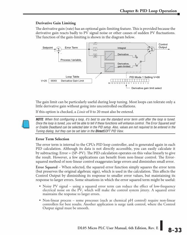
DL05 Micro PLC User Manual, 6th Edition, Rev. E 8-33
Chapter 8: PID Loop Operation
Derivative Gain Limiting
The derivative gain (rate) has an optional gain-limiting feature. This is provided because the derivative gain reacts badly to PV signal noise or other causes of sudden PV fluctuations. The function of the gain-limiting is shown in the diagram below.
The gain limit can be particularly useful during loop tuning. Most loops can tolerate only a little derivative gain without going into uncontrolled oscillations.If this option is checked, a Limit of 0 to 20 must also be entered.
NOTE: When first configuring a loop, it’s best to use the standard error term until after the loop is tuned. Once the loop is tuned, you will be able to tell if these functions will enhance control. The Error Squared and/or Enable Deadband can be selected later in the PID setup. Also, values are not required to be entered in the Tuning dialog, but they can be set later in the DirectSOFT PID View.
Error Term Selection
The error term is internal to the CPUs PID loop controller, and is generated again in each PID calculation. Although its data is not directly accessible, you can easily calculate it by subtracting: Error = (SP–PV). The PID calculation operates on this value linearly to give the result. However, a few applications can benefit from non-linear control. The Error-squared method of non-linear control exaggerates large errors and diminishes small error.Error Squared – When selected, the squared error function simply squares the error term (but preserves the original algebraic sign), which is used in the calculation. This affects the Control Output by diminishing its response to smaller error values, but maintaining its response to larger errors. Some situations in which the error squared term might be useful:
• Noisy PV signal – using a squared error term can reduce the effect of low-frequency electrical noise on the PV, which will make the control system jittery. A squared error maintains the response to larger errors.
• Non-linear process – some processes (such as chemical pH control) require non-linear controllers for best results. Another application is surge tank control, where the Control Output signal must be smooth.
Process Variable
Error Term+
–
ControlOutputSetpoint
PID Mode 1 Setting V+00
013456789101112131415 2Bit
Derivative gain limit select
+
P
I
D
Loop Calculation
+
+
Derivative
Derivative,gain-limited
0
1
Integral
Proportional
Loop TableV+25 Derivative Gain Limit00XX
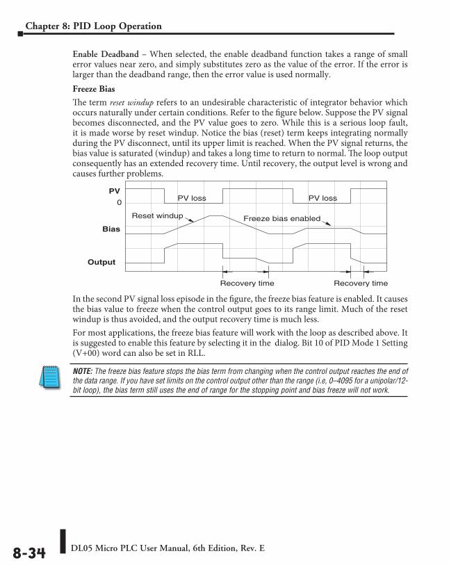
DL05 Micro PLC User Manual, 6th Edition, Rev. E8-34
Chapter 8: PID Loop Operation
Enable Deadband – When selected, the enable deadband function takes a range of small error values near zero, and simply substitutes zero as the value of the error. If the error is larger than the deadband range, then the error value is used normally.Freeze Bias
The term reset windup refers to an undesirable characteristic of integrator behavior which occurs naturally under certain conditions. Refer to the figure below. Suppose the PV signal becomes disconnected, and the PV value goes to zero. While this is a serious loop fault, it is made worse by reset windup. Notice the bias (reset) term keeps integrating normally during the PV disconnect, until its upper limit is reached. When the PV signal returns, the bias value is saturated (windup) and takes a long time to return to normal. The loop output consequently has an extended recovery time. Until recovery, the output level is wrong and causes further problems.
In the second PV signal loss episode in the figure, the freeze bias feature is enabled. It causes the bias value to freeze when the control output goes to its range limit. Much of the reset windup is thus avoided, and the output recovery time is much less.For most applications, the freeze bias feature will work with the loop as described above. It is suggested to enable this feature by selecting it in the dialog. Bit 10 of PID Mode 1 Setting (V+00) word can also be set in RLL.
NOTE: The freeze bias feature stops the bias term from changing when the control output reaches the end of the data range. If you have set limits on the control output other than the range (i.e, 0–4095 for a unipolar/12-bit loop), the bias term still uses the end of range for the stopping point and bias freeze will not work.
PV
Output
0
Bias
Reset windup Freeze bias enabled
Recovery time Recovery time
PV loss PV loss
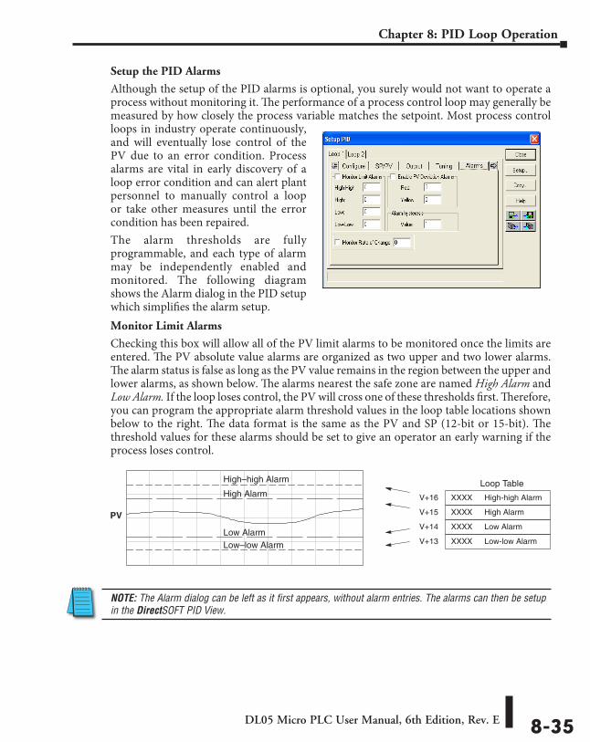
DL05 Micro PLC User Manual, 6th Edition, Rev. E 8-35
Chapter 8: PID Loop Operation
Setup the PID Alarms
Although the setup of the PID alarms is optional, you surely would not want to operate a process without monitoring it. The performance of a process control loop may generally be measured by how closely the process variable matches the setpoint. Most process control loops in industry operate continuously, and will eventually lose control of the PV due to an error condition. Process alarms are vital in early discovery of a loop error condition and can alert plant personnel to manually control a loop or take other measures until the error condition has been repaired.The alarm thresholds are fully programmable, and each type of alarm may be independently enabled and monitored. The following diagram shows the Alarm dialog in the PID setup which simplifies the alarm setup.Monitor Limit Alarms
Checking this box will allow all of the PV limit alarms to be monitored once the limits are entered. The PV absolute value alarms are organized as two upper and two lower alarms. The alarm status is false as long as the PV value remains in the region between the upper and lower alarms, as shown below. The alarms nearest the safe zone are named High Alarm and Low Alarm. If the loop loses control, the PV will cross one of these thresholds first. Therefore, you can program the appropriate alarm threshold values in the loop table locations shown below to the right. The data format is the same as the PV and SP (12-bit or 15-bit). The threshold values for these alarms should be set to give an operator an early warning if the process loses control.
NOTE: The Alarm dialog can be left as it first appears, without alarm entries. The alarms can then be setup in the DirectSOFT PID View.
PV
High–high Alarm
High Alarm
Low AlarmLow–low Alarm
Loop Table
V+16 High-high AlarmXXXX
V+15 High AlarmXXXX
V+14 Low AlarmXXXX
V+13 Low-low AlarmXXXX
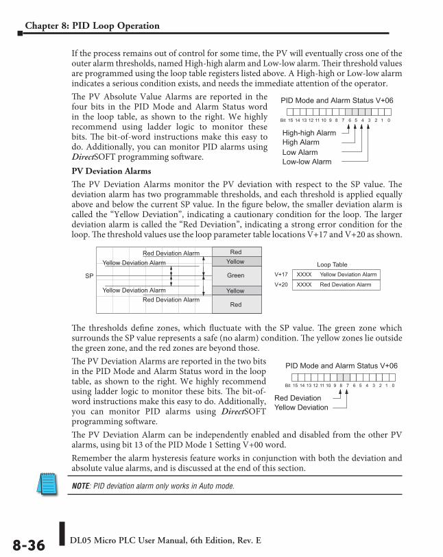
DL05 Micro PLC User Manual, 6th Edition, Rev. E8-36
Chapter 8: PID Loop Operation
If the process remains out of control for some time, the PV will eventually cross one of the outer alarm thresholds, named High-high alarm and Low-low alarm. Their threshold values are programmed using the loop table registers listed above. A High-high or Low-low alarm indicates a serious condition exists, and needs the immediate attention of the operator.The PV Absolute Value Alarms are reported in the four bits in the PID Mode and Alarm Status word in the loop table, as shown to the right. We highly recommend using ladder logic to monitor these bits. The bit-of-word instructions make this easy to do. Additionally, you can monitor PID alarms using DirectSOFT programming software.PV Deviation Alarms
The PV Deviation Alarms monitor the PV deviation with respect to the SP value. The deviation alarm has two programmable thresholds, and each threshold is applied equally above and below the current SP value. In the figure below, the smaller deviation alarm is called the “Yellow Deviation”, indicating a cautionary condition for the loop. The larger deviation alarm is called the “Red Deviation”, indicating a strong error condition for the loop. The threshold values use the loop parameter table locations V+17 and V+20 as shown.
The thresholds define zones, which fluctuate with the SP value. The green zone which surrounds the SP value represents a safe (no alarm) condition. The yellow zones lie outside the green zone, and the red zones are beyond those.The PV Deviation Alarms are reported in the two bits in the PID Mode and Alarm Status word in the loop table, as shown to the right. We highly recommend using ladder logic to monitor these bits. The bit-of-word instructions make this easy to do. Additionally, you can monitor PID alarms using DirectSOFT programming software.The PV Deviation Alarm can be independently enabled and disabled from the other PV alarms, using bit 13 of the PID Mode 1 Setting V+00 word.Remember the alarm hysteresis feature works in conjunction with both the deviation and absolute value alarms, and is discussed at the end of this section.
NOTE: PID deviation alarm only works in Auto mode.
PID Mode and Alarm Status V+06
013456789101112131415 2Bit
High-high Alarm
High Alarm
Low Alarm
Low-low Alarm
SP
Red Deviation Alarm
Yellow Deviation Alarm Loop Table
V+17 Yellow Deviation AlarmXXXX
V+20 Red Deviation AlarmXXXXYellow Deviation Alarm
Red Deviation Alarm
Green
Yellow
Red
Yellow
Red
PID Mode and Alarm Status V+06
013456789101112131415 2Bit
Red Deviation
Yellow Deviation
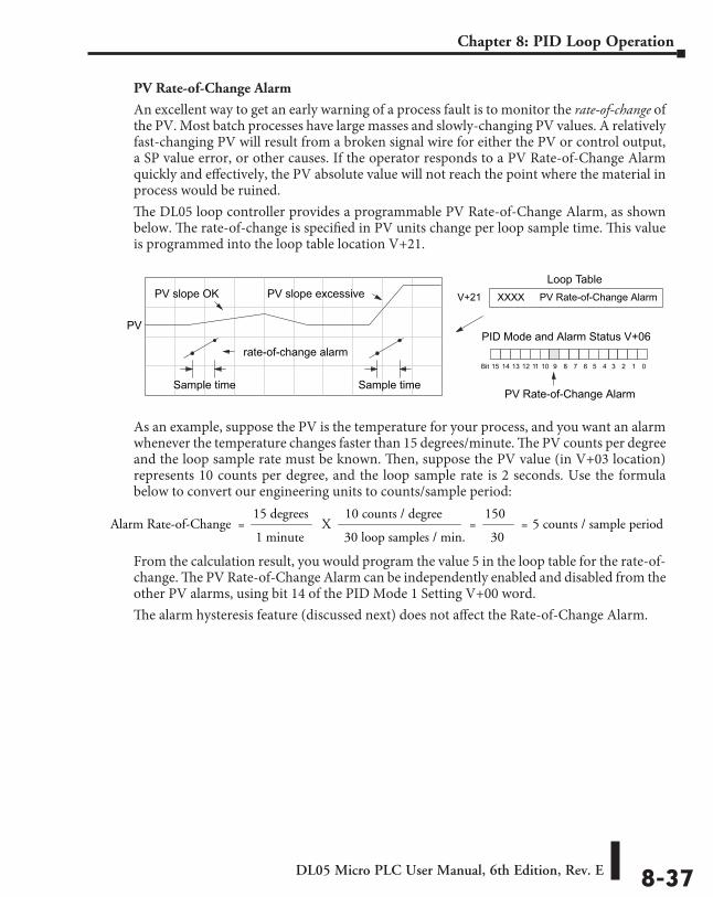
DL05 Micro PLC User Manual, 6th Edition, Rev. E 8-37
Chapter 8: PID Loop Operation
PV Rate-of-Change Alarm
An excellent way to get an early warning of a process fault is to monitor the rate-of-change of the PV. Most batch processes have large masses and slowly-changing PV values. A relatively fast-changing PV will result from a broken signal wire for either the PV or control output, a SP value error, or other causes. If the operator responds to a PV Rate-of-Change Alarm quickly and effectively, the PV absolute value will not reach the point where the material in process would be ruined.The DL05 loop controller provides a programmable PV Rate-of-Change Alarm, as shown below. The rate-of-change is specified in PV units change per loop sample time. This value is programmed into the loop table location V+21.
As an example, suppose the PV is the temperature for your process, and you want an alarm whenever the temperature changes faster than 15 degrees/minute. The PV counts per degree and the loop sample rate must be known. Then, suppose the PV value (in V+03 location) represents 10 counts per degree, and the loop sample rate is 2 seconds. Use the formula below to convert our engineering units to counts/sample period:
From the calculation result, you would program the value 5 in the loop table for the rate-of-change. The PV Rate-of-Change Alarm can be independently enabled and disabled from the other PV alarms, using bit 14 of the PID Mode 1 Setting V+00 word.The alarm hysteresis feature (discussed next) does not affect the Rate-of-Change Alarm.
Loop TableV+21 PV Rate-of-Change AlarmXXXX
PV
PV slope OK
Sample time
PV slope excessive
rate-of-change alarm
Sample time
PID Mode and Alarm Status V+06
013456789101112131415 2Bit
PV Rate-of-Change Alarm
15 degreesAlarm Rate-of-Change =
1 minuteX
10 counts / degree
30 loop samples / min.=
150
30= 5 counts / sample period
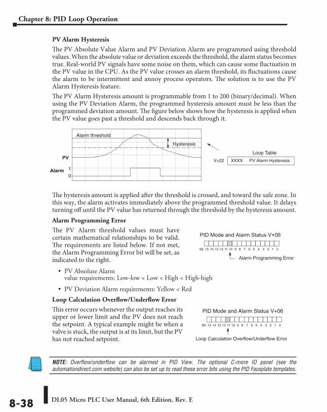
DL05 Micro PLC User Manual, 6th Edition, Rev. E8-38
Chapter 8: PID Loop Operation
PV Alarm Hysteresis
The PV Absolute Value Alarm and PV Deviation Alarm are programmed using threshold values. When the absolute value or deviation exceeds the threshold, the alarm status becomes true. Real-world PV signals have some noise on them, which can cause some fluctuation in the PV value in the CPU. As the PV value crosses an alarm threshold, its fluctuations cause the alarm to be intermittent and annoy process operators. The solution is to use the PV Alarm Hysteresis feature.The PV Alarm Hysteresis amount is programmable from 1 to 200 (binary/decimal). When using the PV Deviation Alarm, the programmed hysteresis amount must be less than the programmed deviation amount. The figure below shows how the hysteresis is applied when the PV value goes past a threshold and descends back through it.
The hysteresis amount is applied after the threshold is crossed, and toward the safe zone. In this way, the alarm activates immediately above the programmed threshold value. It delays turning off until the PV value has returned through the threshold by the hysteresis amount.Alarm Programming Error
The PV Alarm threshold values must have certain mathematical relationships to be valid. The requirements are listed below. If not met, the Alarm Programming Error bit will be set, as indicated to the right.
• PV Absolute Alarm value requirements: Low-low < Low < High < High-high
• PV Deviation Alarm requirements: Yellow < Red
Loop Calculation Overflow/Underflow Error
This error occurs whenever the output reaches its upper or lower limit and the PV does not reach the setpoint. A typical example might be when a valve is stuck, the output is at its limit, but the PV has not reached setpoint.
NOTE: Overflow/underflow can be alarmed in PID View. The optional C-more IO panel (see the automationdirect.com website) can also be set up to read these error bits using the PID Faceplate templates.
Loop Table
V+22 PV Alarm HysteresisXXXXPV
Alarm threshold
Alarm01
Hysteresis
PID Mode and Alarm Status V+06
013456789101112131415 2Bit
Alarm Programming Error
PID Mode and Alarm Status V+06
013456789101112131415 2Bit
Loop Calculation Overflow/Underflow Error
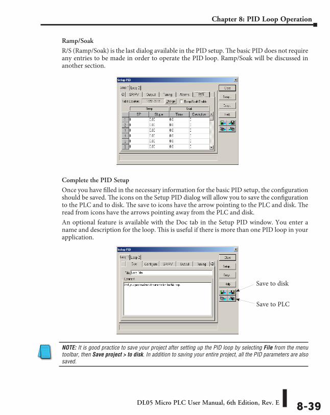
DL05 Micro PLC User Manual, 6th Edition, Rev. E 8-39
Chapter 8: PID Loop Operation
Ramp/Soak
R/S (Ramp/Soak) is the last dialog available in the PID setup. The basic PID does not require any entries to be made in order to operate the PID loop. Ramp/Soak will be discussed in another section.
Complete the PID Setup
Once you have filled in the necessary information for the basic PID setup, the configuration should be saved. The icons on the Setup PID dialog will allow you to save the configuration to the PLC and to disk. The save to icons have the arrow pointing to the PLC and disk. The read from icons have the arrows pointing away from the PLC and disk.An optional feature is available with the Doc tab in the Setup PID window. You enter a name and description for the loop. This is useful if there is more than one PID loop in your application.
NOTE: It is good practice to save your project after setting up the PID loop by selecting File from the menu toolbar, then Save project > to disk. In addition to saving your entire project, all the PID parameters are also saved.
Save to disk
Save to PLC
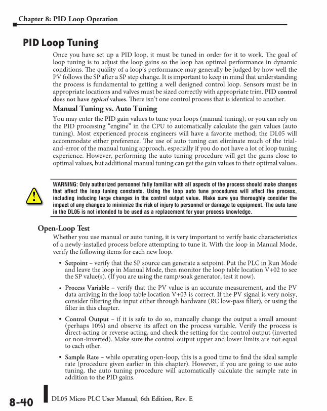
DL05 Micro PLC User Manual, 6th Edition, Rev. E8-40
Chapter 8: PID Loop Operation
PID Loop TuningOnce you have set up a PID loop, it must be tuned in order for it to work. The goal of loop tuning is to adjust the loop gains so the loop has optimal performance in dynamic conditions. The quality of a loop’s performance may generally be judged by how well the PV follows the SP after a SP step change. It is important to keep in mind that understanding the process is fundamental to getting a well designed control loop. Sensors must be in appropriate locations and valves must be sized correctly with appropriate trim. PID control does not have typical values. There isn’t one control process that is identical to another.Manual Tuning vs. Auto TuningYou may enter the PID gain values to tune your loops (manual tuning), or you can rely on the PID processing “engine” in the CPU to automatically calculate the gain values (auto tuning). Most experienced process engineers will have a favorite method; the DL05 will accommodate either preference. The use of auto tuning can eliminate much of the trial-and-error of the manual tuning approach, especially if you do not have a lot of loop tuning experience. However, performing the auto tuning procedure will get the gains close to optimal values, but additional manual tuning can get the gain values to their optimal values.
WARNING: Only authorized personnel fully familiar with all aspects of the process should make changes that affect the loop tuning constants. Using the loop auto tune procedures will affect the process, including inducing large changes in the control output value. Make sure you thoroughly consider the impact of any changes to minimize the risk of injury to personnel or damage to equipment. The auto tune in the DL05 is not intended to be used as a replacement for your process knowledge.
Open-Loop TestWhether you use manual or auto tuning, it is very important to verify basic characteristics of a newly-installed process before attempting to tune it. With the loop in Manual Mode, verify the following items for each new loop.
• Setpoint – verify that the SP source can generate a setpoint. Put the PLC in Run Mode and leave the loop in Manual Mode, then monitor the loop table location V+02 to see the SP value(s). (If you are using the ramp/soak generator, test it now).
• Process Variable – verify that the PV value is an accurate measurement, and the PV data arriving in the loop table location V+03 is correct. If the PV signal is very noisy, consider filtering the input either through hardware (RC low-pass filter), or using the filter in this chapter.
• Control Output – if it is safe to do so, manually change the output a small amount (perhaps 10%) and observe its affect on the process variable. Verify the process is direct-acting or reverse acting, and check the setting for the control output (inverted or non-inverted). Make sure the control output upper and lower limits are not equal to each other.
• Sample Rate – while operating open-loop, this is a good time to find the ideal sample rate (procedure given earlier in this chapter). However, if you are going to use auto tuning, the auto tuning procedure will automatically calculate the sample rate in addition to the PID gains.
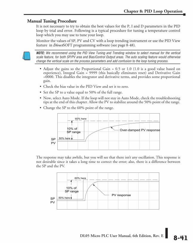
DL05 Micro PLC User Manual, 6th Edition, Rev. E 8-41
Chapter 8: PID Loop Operation
Manual Tuning ProcedureIt is not necessary to try to obtain the best values for the P, I and D parameters in the PID loop by trial and error. Following is a typical procedure for tuning a temperature control loop which you may use to tune your loop.Monitor the values of SP, PV and CV with a loop trending instrument or use the PID View feature in DirectSOFT programming software (see page 8-48).
NOTE: We recommend using the PID View Tuning and Trending window to select manual for the vertical scale feature, for both SP/PV area and Bias/Control Output areas. The auto scaling feature would otherwise change the vertical scale on the process parameters and add confusion to the loop tuning process.
• Adjust the gains so the Proportional Gain = 0.5 or 1.0 (1.0 is a good value based on experience), Integral Gain = 9999 (this basically eliminates reset) and Derivative Gain =0000. This disables the integrator and derivative terms, and provides some proportional gain.
• Check the bias value in the PID View and set it to zero.
• Set the SP to a value equal to 50% of the full range.
• Now, select Auto Mode. If the loop will not stay in Auto Mode, check the troubleshooting tips at the end of this chapter. Allow the PV to stabilize around the 50% point of the range.
• Change the SP to the 60% point of the range.
The response may take awhile, but you will see that there isn’t any oscillation. This response is not desirable since it takes a long time to correct the error; also, there is a difference between the SP and the PV.
PV
10% ofSP range
SP
Over-damped PV response
60% here
50% here
PV
10% ofSP range
SPPV response
60% here
50% here
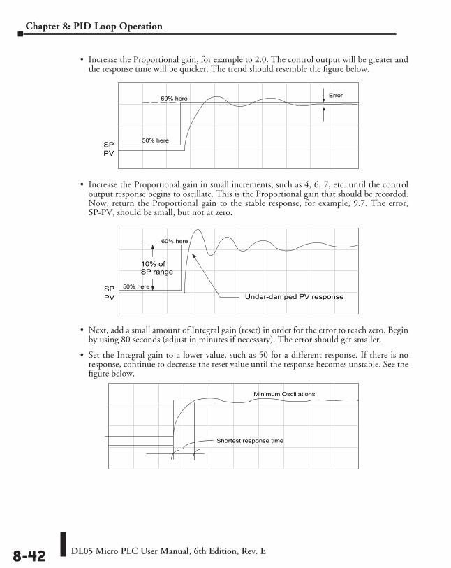
DL05 Micro PLC User Manual, 6th Edition, Rev. E8-42
Chapter 8: PID Loop Operation
• Increase the Proportional gain, for example to 2.0. The control output will be greater and the response time will be quicker. The trend should resemble the figure below.
• Increase the Proportional gain in small increments, such as 4, 6, 7, etc. until the control output response begins to oscillate. This is the Proportional gain that should be recorded.Now, return the Proportional gain to the stable response, for example, 9.7. The error, SP-PV, should be small, but not at zero.
• Next, add a small amount of Integral gain (reset) in order for the error to reach zero. Begin by using 80 seconds (adjust in minutes if necessary). The error should get smaller.
• Set the Integral gain to a lower value, such as 50 for a different response. If there is no response, continue to decrease the reset value until the response becomes unstable. See the figure below.
PVSP
60% here
50% here
Error
PV
10% ofSP range
SPUnder-damped PV response
60% here
50% here
Minimum Oscillations
Shortest response time
DL05 Micro PLC User Manual, 6th Edition, Rev. E 8-43
Chapter 8: PID Loop Operation
For discussion, let us say that a reset value of 35 made the control output unstable. Return the reset value to the stable value, such as 38. Be careful with this adjustment since the oscillation can destroy the process.
The control output response should be optimal now, without a Derivative gain. The recorded values are: Proportional gain = 9.7 and Integral gain = 38 seconds. Note that the error has been minimized.
The foregone method is the most common method used to tune a PID loop. Derivative gain is almost never used in a temperature control loop. This method can also be used for other control loops, but other parameters may need to be added for a stable control output.
Test your loop for a high PV of 80% and again for a low PV of 20%, and correct the values if necessary. Small adjustments of the parameters can make the control output more precise or more unstable. It is sometimes acceptable to have a small overshoot to make the control output react quicker.The derivative gain can be helpful for those control loops which are not controlling temperature. For these loops, try adding a value of 0.5 for the derivative gain and see if this improves the control output. If there is little or no response, increase the derivative by increments of 0.5 until there is an improvement to the output trend. Recall that the derivative gain reacts with a rate of change of the error.
DL05 Micro PLC User Manual, 6th Edition, Rev. E8-44
Chapter 8: PID Loop Operation
Alternative Manual Tuning Procedures by OthersThe following tuning procedures have been extracted from various publications about PID process control. These procedures are for comparison to the procedure in this manual.
Tuning PID ControllersTwo-Mode Simple Method – for P-I controllers
1. Turn off reset and set the gain to a small value (0.5 - 1.0).
2. Increase gain until cycling starts, then decrease gain slightly.
3. Make setpoint changes to observe offset (error).
4. Increase reset to eliminate offset (error).
5. Repeat steps 2 through 4 until you obtain the largest gain and reset consistent with the criteria of the control desired, i.e., offset, overshoot, stability.
Zeigler-Nichols Method– “Quarter amplitude decay”1. Turn off reset and rate; set the proportional gain to a fairly large value.
2. Make a small setpoint change and observe how the controlled variable cycles.
3. Adjust the gain until the cycle is self-sustaining, and of constant amplitude; this value is the ultimate gain (Gu).
4. Measure the period of cycling in minutes. This is the ultimate period (Pu).
5. Calculate the controller adjustments as follows:P only: G = Gu/2P & I : G = Gu/2.2Ti = 1.2/Pu (repeats/minute)P-I-D: G = Gu/1.6Ti = 2.0/Pu (repeats/minute)Td = Pu/8.0 (minutes)
Pessen Method1. Follow the procedure described above (Zeigler-Nichols) to
determine the ultimate gain and ultimate period.
2. Apply the formulas below.
For no overshoot during startup:G = Gu/5.0Ti = 3/Pu (repeats/minute)Td = Pu/2 (minutes)For some overshoot, but better response to disturbances:G = Gu/3Ti = 3/Pu (repeats/minute)Td = Pu/3 (minutes)
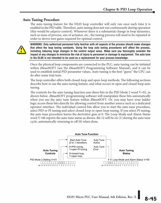
DL05 Micro PLC User Manual, 6th Edition, Rev. E 8-45
Chapter 8: PID Loop Operation
Auto Tuning ProcedureThe auto tuning feature for the DL05 loop controller will only run once each time it is enabled in the PID table. Therefore, auto tuning does not run continuously during operation (this would be adaptive control). Whenever there is a substantial change in loop dynamics, such as mass of process, size of actuator, etc., the tuning process will need to be repeated in order to derive new gains required for optimal control.
WARNING: Only authorized personnel fully familiar with all aspects of the process should make changes that affect the loop tuning constants. Using the loop auto tuning procedures will affect the process, including inducing large changes in the control output value. Make sure you thoroughly consider the impact of any changes to minimize the risk of injury to personnel or damage to equipment. The auto tune in the DL05 is not intended to be used as a replacement for your process knowledge.
Once the physical loop components are connected to the PLC, auto tuning can be initiated within DirectSOFT (see the DirectSOFT Programming Software Manual), and it can be used to establish initial PID parameter values. Auto tuning is the best “guess” the CPU can do after some trial tests.The loop controller offers both closed-loop and open-loop methods. The following sections describe how to use the auto tuning feature, and what occurs in open and closed-loop auto tuning.The controls for the auto tuning function uses three bits in the PID Mode 2 word V+01, as shown below. DirectSOFT programming software will manipulate these bits automatically when you use the auto tune feature within DirectSOFT. Or, you may have your ladder logic access these bits directly for allowing control from another source such as a dedicated operator interface. The individual control bits allow you to start the auto tune procedure, select PID or PI tuning and select closed-loop or open-loop tuning. If you select PI tuning, the auto tune procedure leaves the derivative gain at 0. The Loop Mode and Alarm Status word V+06 reports the auto tune status as shown. Bit 12 will be on (1) during the auto tune cycle, automatically returning to off (0) when done.
PID Mode 2 Setting V+01
013456789101112131415 2Bit
Auto Tune Function
Auto Tuning Controls 0=closed loop,
1=open loop
0=PID tuning,1=open PI tuning
Start Auto Tune(0 to 1 transition)
013456789101112131415 2Bit
Loop Mode and Alarm Status V+06
Auto TuneActive
Auto TuneError Auto Tuning
Status
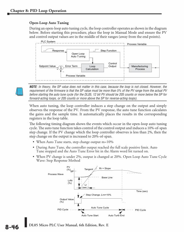
DL05 Micro PLC User Manual, 6th Edition, Rev. E8-46
Chapter 8: PID Loop Operation
Open-Loop Auto Tuning
During an open-loop auto tuning cycle, the loop controller operates as shown in the diagram below. Before starting this procedure, place the loop in Manual Mode and ensure the PV and control output values are in the middle of their ranges (away from the end points).
NOTE: In theory, the SP value does not matter in this case, because the loop is not closed. However, the requirement of the firmware is that the SP value must be more than 5% of the PV range from the actual PV before starting the auto tune cycle (for the DL05, 12 bit PV should be 205 counts or more below the SP for forward-acting loops, or 205 counts or more above the SP for reverse-acting loops).
When auto tuning, the loop controller induces a step change on the output and simply observes the response of the PV. From the PV response, the auto tune function calculates the gains and the sample time. It automatically places the results in the corresponding registers in the loop table.The following timing diagram shows the events which occur in the open-loop auto tuning cycle. The auto tune function takes control of the control output and induces a 10%-of-span step change. If the PV change which the loop controller observes is less than 2%, then the step change on the output is increased to 20%-of-span.
• When Auto Tune starts, step change output m=10%
• During Auto Tune, the controller output reached the full scale positive limit. Auto Tune stopped and the Auto Tune Error bit in the Alarm word bit turned on.
• When PV change is under 2%, output is changed at 20%. Open Loop Auto Tune Cycle Wave: Step Response Method
Tangent Rr = Slope
Process WaveSP
PV(%)
Base Line
Lr(sec.)
LrRr(%)
Time (sec)
Output Value(%)
Step Change m=10%
PID Cycle
Auto Tune Start Auto Tune End
PID CycleAuto Tune Cycle
Process Variable
LoopCalculation
ManufacturingProcess
Setpoint ValueControlOutput
Error Term
+–
PLC System
Open LoopAuto T uning
Step Function
Process Variable
Response
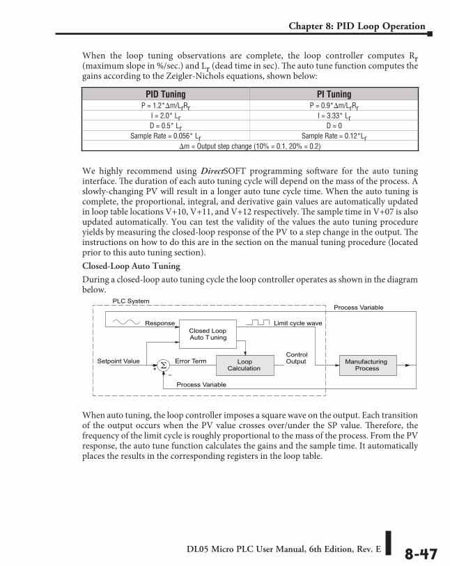
DL05 Micro PLC User Manual, 6th Edition, Rev. E 8-47
Chapter 8: PID Loop Operation
When the loop tuning observations are complete, the loop controller computes Rr (maximum slope in %/sec.) and Lr (dead time in sec). The auto tune function computes the gains according to the Zeigler-Nichols equations, shown below:
We highly recommend using DirectSOFT programming software for the auto tuning interface. The duration of each auto tuning cycle will depend on the mass of the process. A slowly-changing PV will result in a longer auto tune cycle time. When the auto tuning is complete, the proportional, integral, and derivative gain values are automatically updated in loop table locations V+10, V+11, and V+12 respectively. The sample time in V+07 is also updated automatically. You can test the validity of the values the auto tuning procedure yields by measuring the closed-loop response of the PV to a step change in the output. The instructions on how to do this are in the section on the manual tuning procedure (located prior to this auto tuning section).Closed-Loop Auto Tuning
During a closed-loop auto tuning cycle the loop controller operates as shown in the diagram below.
When auto tuning, the loop controller imposes a square wave on the output. Each transition of the output occurs when the PV value crosses over/under the SP value. Therefore, the frequency of the limit cycle is roughly proportional to the mass of the process. From the PV response, the auto tune function calculates the gains and the sample time. It automatically places the results in the corresponding registers in the loop table.
Process Variable
LoopCalculation
ManufacturingProcess
Setpoint ValueControlOutput
Error Term
+–
PLC System
Closed LoopAuto T uning
Limit cycle wave
Process Variable
Response
PID Tuning PI TuningP = 1.2*im/LrRr P = 0.9*im/LrRr
I = 2.0* Lr I = 3.33* LrD = 0.5* Lr D = 0
Sample Rate = 0.056* Lr Sample Rate = 0.12*Lrim = Output step change (10% = 0.1, 20% = 0.2)
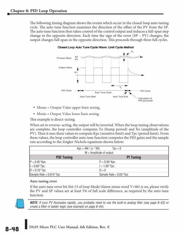
DL05 Micro PLC User Manual, 6th Edition, Rev. E8-48
Chapter 8: PID Loop Operation
The following timing diagram shows the events which occur in the closed-loop auto tuning cycle. The auto tune function examines the direction of the offset of the PV from the SP. The auto tune function then takes control of the control output and induces a full-span step change in the opposite direction. Each time the sign of the error (SP – PV) changes, the output changes full-span in the opposite direction. This proceeds through three full cycles.
• Mmax = Output Value upper limit setting.
• Mmin = Output Value lower limit setting.
This example is direct–acting.When set to reverse–acting, the output will be inverted. When the loop tuning observations are complete, the loop controller computes To (bump period) and Xo (amplitude of the PV). Then it uses these values to compute Kpc (sensitive limit) and Tpc (period limit). From these values, the loop controller auto tune function computes the PID gains and the sample rate according to the Zeigler-Nichols equations shown below:
Auto tuning error
If the auto tune error bit (bit 13 of loop Mode/Alarm status word V+06) is on, please verify the PV and SP values are at least 5% of full scale difference, as required by the auto tune function.
NOTE: If your PV fluctuates rapidly, you probably need to use the built-in analog filter (see page 8–53) or create a filter in ladder logic (see example on page 8–54).
Kpc = 4M / (f *X0) Tpc = 0M = Amplitude of output
PID Tuning PI TuningP = 0.45*Kpc P = 0.30*KpcI = 0.60*Tpc I = 1.00*TpcD = 0.10*Tpc D = 0Sample Rate = 0.014*Tpc Sample Rate = 0.03*Tpc
SPPV
Output Value
PID Cycle
Auto Tune Start Auto Tune End
PID CycleAuto Tune Cycle
Xo
M
To
Process Wave
Calculation ofPID parameter
Closed Loop Auto Tune Cycle Wave: Limit Cycle Method
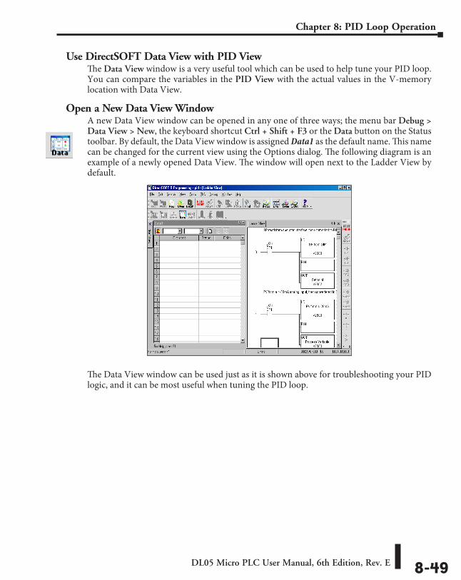
DL05 Micro PLC User Manual, 6th Edition, Rev. E 8-49
Chapter 8: PID Loop Operation
Use DirectSOFT Data View with PID ViewThe Data View window is a very useful tool which can be used to help tune your PID loop. You can compare the variables in the PID View with the actual values in the V-memory location with Data View.
Open a New Data View WindowA new Data View window can be opened in any one of three ways; the menu bar Debug > Data View > New, the keyboard shortcut Ctrl + Shift + F3 or the Data button on the Status toolbar. By default, the Data View window is assigned Data1 as the default name. This name can be changed for the current view using the Options dialog. The following diagram is an example of a newly opened Data View. The window will open next to the Ladder View by default.
The Data View window can be used just as it is shown above for troubleshooting your PID logic, and it can be most useful when tuning the PID loop.
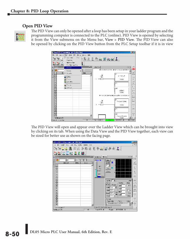
DL05 Micro PLC User Manual, 6th Edition, Rev. E8-50
Chapter 8: PID Loop Operation
Open PID ViewThe PID View can only be opened after a loop has been setup in your ladder program and the programming computer is connected to the PLC (online). PID View is opened by selecting it from the View submenu on the Menu bar, View > PID View. The PID View can also be opened by clicking on the PID View button from the PLC Setup toolbar if it is in view
The PID View will open and appear over the Ladder View which can be brought into view by clicking on its tab. When using the Data View and the PID View together, each view can be sized for better use as shown on the facing page.
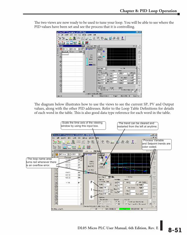
DL05 Micro PLC User Manual, 6th Edition, Rev. E 8-51
Chapter 8: PID Loop Operation
The two views are now ready to be used to tune your loop. You will be able to see where the PID values have been set and see the process that it is controlling.
The diagram below illustrates how to use the views to see the current SP, PV and Output values, along with the other PID addresses. Refer to the Loop Table Definitions for details of each word in the table. This is also good data type reference for each word in the table.
Scale the time axis of the viewing window by using this input box.
The trend can be cleared and restarted from the left at anytime.
Process Variable and Setpoint trends are color coded.
P
I
D
The loop name area turns red whenever there is an overflow error.
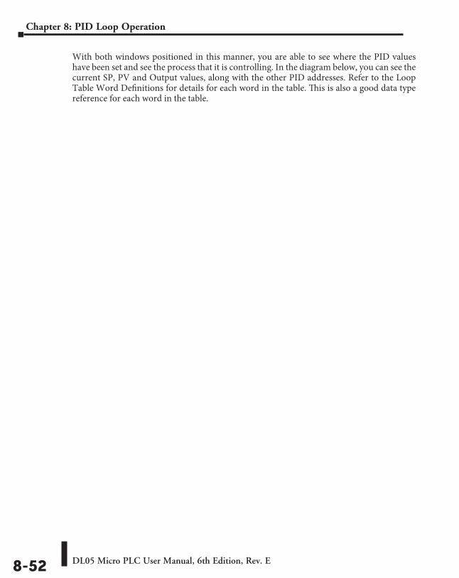
DL05 Micro PLC User Manual, 6th Edition, Rev. E8-52
Chapter 8: PID Loop Operation
With both windows positioned in this manner, you are able to see where the PID values have been set and see the process that it is controlling. In the diagram below, you can see the current SP, PV and Output values, along with the other PID addresses. Refer to the Loop Table Word Definitions for details for each word in the table. This is also a good data type reference for each word in the table.
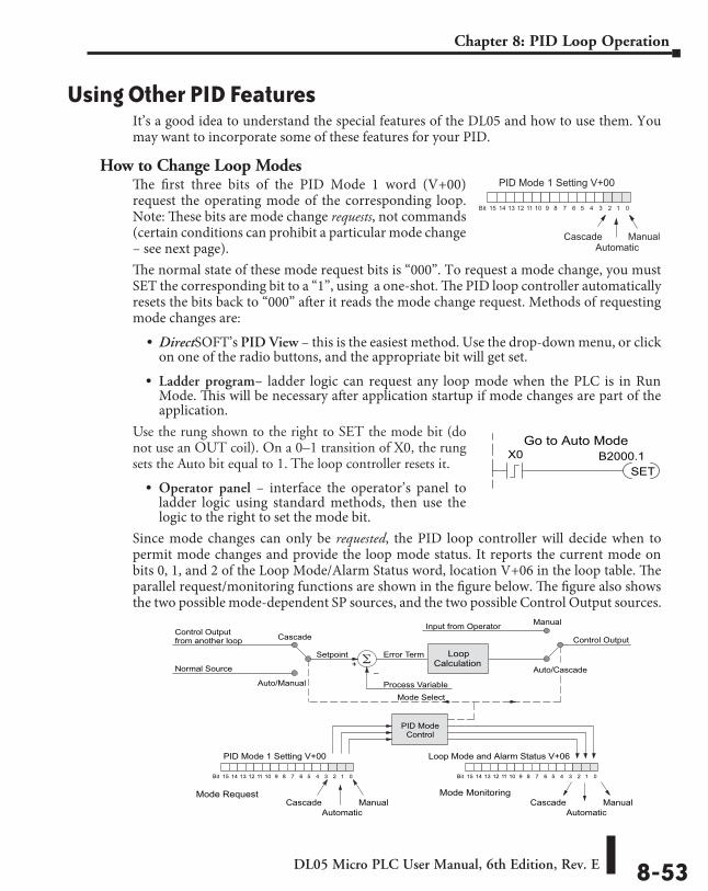
DL05 Micro PLC User Manual, 6th Edition, Rev. E 8-53
Chapter 8: PID Loop Operation
Using Other PID FeaturesIt’s a good idea to understand the special features of the DL05 and how to use them. You may want to incorporate some of these features for your PID.
How to Change Loop ModesThe first three bits of the PID Mode 1 word (V+00) request the operating mode of the corresponding loop. Note: These bits are mode change requests, not commands (certain conditions can prohibit a particular mode change – see next page).The normal state of these mode request bits is “000”. To request a mode change, you must SET the corresponding bit to a “1”, using a one-shot. The PID loop controller automatically resets the bits back to “000” after it reads the mode change request. Methods of requesting mode changes are:
• DirectSOFT’s PID View – this is the easiest method. Use the drop-down menu, or click on one of the radio buttons, and the appropriate bit will get set.
• Ladder program– ladder logic can request any loop mode when the PLC is in Run Mode. This will be necessary after application startup if mode changes are part of the application.
Use the rung shown to the right to SET the mode bit (do not use an OUT coil). On a 0–1 transition of X0, the rung sets the Auto bit equal to 1. The loop controller resets it.
• Operator panel – interface the operator’s panel to ladder logic using standard methods, then use the logic to the right to set the mode bit.
Since mode changes can only be requested, the PID loop controller will decide when to permit mode changes and provide the loop mode status. It reports the current mode on bits 0, 1, and 2 of the Loop Mode/Alarm Status word, location V+06 in the loop table. The parallel request/monitoring functions are shown in the figure below. The figure also shows the two possible mode-dependent SP sources, and the two possible Control Output sources.
PID Mode 1 Setting V+00
013456789101112131415 2Bit
AutomaticCascade Manual
X0SET
B2000.1Go to Auto Mode
Process Variable
Error Term+
–
Input from Operator
Control Output
Setpoint
Manual
Auto/Cascade
Cascade
Auto/Manual
PID Mode 1 Setting V+00
013456789101112131415 2Bit
AutomaticCascade Manual
Control Outputfrom another loop
Normal Source
LoopCalculation
PID ModeControl
Mode Select
Loop Mode and Alarm Status V+06
013456789101112131415 2Bit
AutomaticCascade Manual
Mode Request Mode Monitoring
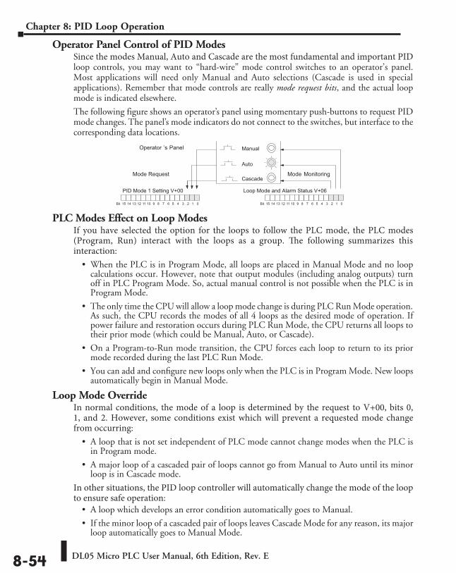
DL05 Micro PLC User Manual, 6th Edition, Rev. E8-54
Chapter 8: PID Loop Operation
Operator Panel Control of PID ModesSince the modes Manual, Auto and Cascade are the most fundamental and important PID loop controls, you may want to “hard-wire” mode control switches to an operator’s panel. Most applications will need only Manual and Auto selections (Cascade is used in special applications). Remember that mode controls are really mode request bits, and the actual loop mode is indicated elsewhere.
The following figure shows an operator’s panel using momentary push-buttons to request PID mode changes. The panel’s mode indicators do not connect to the switches, but interface to the corresponding data locations.
PLC Modes Effect on Loop ModesIf you have selected the option for the loops to follow the PLC mode, the PLC modes (Program, Run) interact with the loops as a group. The following summarizes this interaction:
• When the PLC is in Program Mode, all loops are placed in Manual Mode and no loop calculations occur. However, note that output modules (including analog outputs) turn off in PLC Program Mode. So, actual manual control is not possible when the PLC is in Program Mode.
• The only time the CPU will allow a loop mode change is during PLC Run Mode operation. As such, the CPU records the modes of all 4 loops as the desired mode of operation. If power failure and restoration occurs during PLC Run Mode, the CPU returns all loops to their prior mode (which could be Manual, Auto, or Cascade).
• On a Program-to-Run mode transition, the CPU forces each loop to return to its prior mode recorded during the last PLC Run Mode.
• You can add and configure new loops only when the PLC is in Program Mode. New loops automatically begin in Manual Mode.
Loop Mode OverrideIn normal conditions, the mode of a loop is determined by the request to V+00, bits 0, 1, and 2. However, some conditions exist which will prevent a requested mode change from occurring:
• A loop that is not set independent of PLC mode cannot change modes when the PLC is in Program mode.
• A major loop of a cascaded pair of loops cannot go from Manual to Auto until its minor loop is in Cascade mode.
In other situations, the PID loop controller will automatically change the mode of the loop to ensure safe operation:
• A loop which develops an error condition automatically goes to Manual.
• If the minor loop of a cascaded pair of loops leaves Cascade Mode for any reason, its major loop automatically goes to Manual Mode.
PID Mode 1 Setting V+00
013456789101112131415 2Bit
Operator ’s Panel
Loop Mode and Alarm Status V+06
013456789101112131415 2Bit
Mode Request Mode Monitoring
Auto
Cascade
Manual
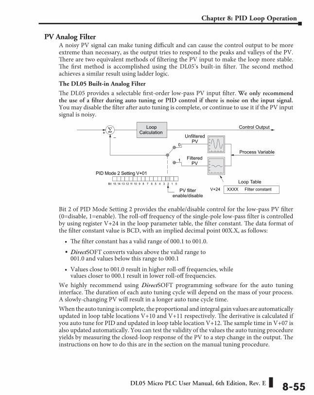
DL05 Micro PLC User Manual, 6th Edition, Rev. E 8-55
Chapter 8: PID Loop Operation
PV Analog FilterA noisy PV signal can make tuning difficult and can cause the control output to be more extreme than necessary, as the output tries to respond to the peaks and valleys of the PV. There are two equivalent methods of filtering the PV input to make the loop more stable. The first method is accomplished using the DL05’s built-in filter. The second method achieves a similar result using ladder logic.The DL05 Built-in Analog Filter
The DL05 provides a selectable first-order low-pass PV input filter. We only recommend the use of a filter during auto tuning or PID control if there is noise on the input signal. You may disable the filter after auto tuning is complete, or continue to use it if the PV input signal is noisy.
Bit 2 of PID Mode Setting 2 provides the enable/disable control for the low-pass PV filter (0=disable, 1=enable). The roll-off frequency of the single-pole low-pass filter is controlled by using register V+24 in the loop parameter table, the filter constant. The data format of the filter constant value is BCD, with an implied decimal point 00X.X, as follows:
• The filter constant has a valid range of 000.1 to 001.0.
• DirectSOFT converts values above the valid range to 001.0 and values below this range to 000.1
• Values close to 001.0 result in higher roll-off frequencies, while values closer to 000.1 result in lower roll-off frequencies.
We highly recommend using DirectSOFT programming software for the auto tuning interface. The duration of each auto tuning cycle will depend on the mass of your process. A slowly-changing PV will result in a longer auto tune cycle time.When the auto tuning is complete, the proportional and integral gain values are automatically updated in loop table locations V+10 and V+11 respectively. The derivative is calculated if you auto tune for PID and updated in loop table location V+12. The sample time in V+07 is also updated automatically. You can test the validity of the values the auto tuning procedure yields by measuring the closed-loop response of the PV to a step change in the output. The instructions on how to do this are in the section on the manual tuning procedure.
LoopCalculation+
–
Control Output
PID Mode 2 Setting V+01
013456789101112131415 2Bit
PV filterenable/disable
0
1
UnfilteredPV
FilteredPV
Process Variable
Loop TableV+24 FIlter constantXXXX
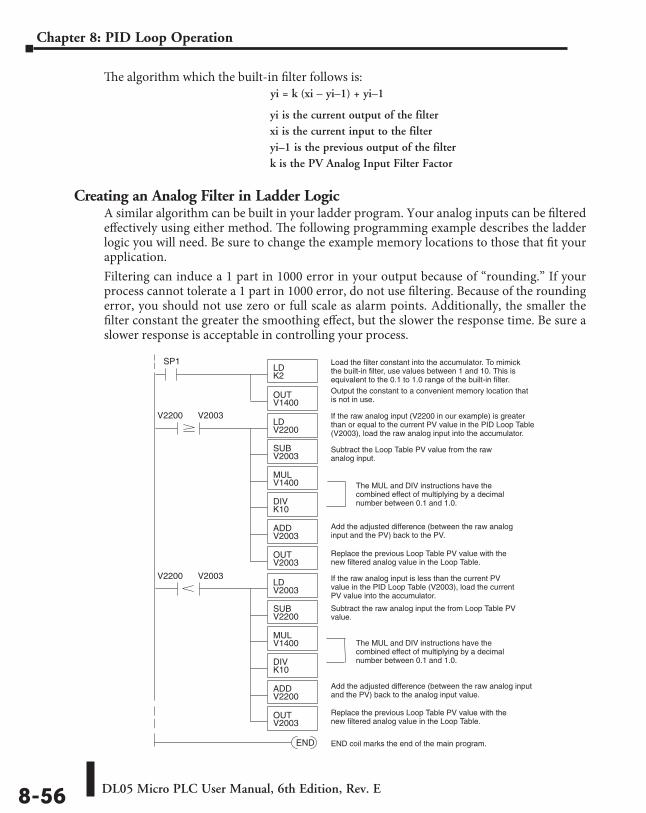
DL05 Micro PLC User Manual, 6th Edition, Rev. E8-56
Chapter 8: PID Loop Operation
The algorithm which the built-in filter follows is:yi = k (xi – yi–1) + yi–1
Creating an Analog Filter in Ladder LogicA similar algorithm can be built in your ladder program. Your analog inputs can be filtered effectively using either method. The following programming example describes the ladder logic you will need. Be sure to change the example memory locations to those that fit your application.Filtering can induce a 1 part in 1000 error in your output because of “rounding.” If your process cannot tolerate a 1 part in 1000 error, do not use filtering. Because of the rounding error, you should not use zero or full scale as alarm points. Additionally, the smaller the filter constant the greater the smoothing effect, but the slower the response time. Be sure a slower response is acceptable in controlling your process.
SP1LDK2
Output the constant to a convenient memory location thatis not in use.
If the raw analog input (V2200 in our example) is greaterthan or equal to the current PV value in the PID Loop Table(V2003), load the raw analog input into the accumulator.
Subtract the raw analog input the from Loop Table PVvalue.
END END coil marks the end of the main program.
Add the adjusted difference (between the raw analog inputand the PV) back to the analog input value.
If the raw analog input is less than the current PVvalue in the PID Loop Table (V2003), load the currentPV value into the accumulator.
Load the filter constant into the accumulator. To mimickthe built-in filter, use values between 1 and 10. This isequivalent to the 0.1 to 1.0 range of the built-in filter.
OUTV1400
Add the adjusted difference (between the raw analoginput and the PV) back to the PV.
SUBV2200
MULV1400
DIVK10
V2200LDV2003
ADDV2200
OUTV2003
V2003
SUBV2003
MULV1400
DIVK10
V2200LDV2200
ADDV2003
OUTV2003
V2003
Subtract the Loop Table PV value from the rawanalog input.
The MUL and DIV instructions have thecombined effect of multiplying by a decimalnumber between 0.1 and 1.0.
The MUL and DIV instructions have thecombined effect of multiplying by a decimalnumber between 0.1 and 1.0.
Replace the previous Loop Table PV value with thenew filtered analog value in the Loop Table.
Replace the previous Loop Table PV value with thenew filtered analog value in the Loop Table.
yi is the current output of the filterxi is the current input to the filteryi–1 is the previous output of the filterk is the PV Analog Input Filter Factor
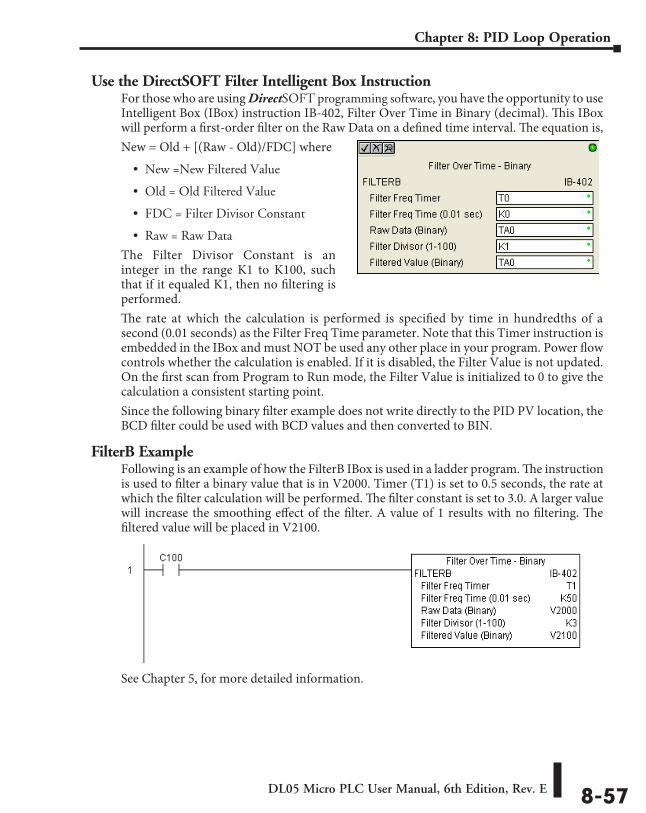
DL05 Micro PLC User Manual, 6th Edition, Rev. E 8-57
Chapter 8: PID Loop Operation
Use the DirectSOFT Filter Intelligent Box InstructionFor those who are using DirectSOFT programming software, you have the opportunity to use Intelligent Box (IBox) instruction IB-402, Filter Over Time in Binary (decimal). This IBox will perform a first-order filter on the Raw Data on a defined time interval. The equation is,New = Old + [(Raw - Old)/FDC] where
• New =New Filtered Value
• Old = Old Filtered Value
• FDC = Filter Divisor Constant
• Raw = Raw Data
The Filter Divisor Constant is an integer in the range K1 to K100, such that if it equaled K1, then no filtering is performed.The rate at which the calculation is performed is specified by time in hundredths of a second (0.01 seconds) as the Filter Freq Time parameter. Note that this Timer instruction is embedded in the IBox and must NOT be used any other place in your program. Power flow controls whether the calculation is enabled. If it is disabled, the Filter Value is not updated. On the first scan from Program to Run mode, the Filter Value is initialized to 0 to give the calculation a consistent starting point.Since the following binary filter example does not write directly to the PID PV location, the BCD filter could be used with BCD values and then converted to BIN.
FilterB ExampleFollowing is an example of how the FilterB IBox is used in a ladder program. The instruction is used to filter a binary value that is in V2000. Timer (T1) is set to 0.5 seconds, the rate at which the filter calculation will be performed. The filter constant is set to 3.0. A larger value will increase the smoothing effect of the filter. A value of 1 results with no filtering. The filtered value will be placed in V2100.
See Chapter 5, for more detailed information.
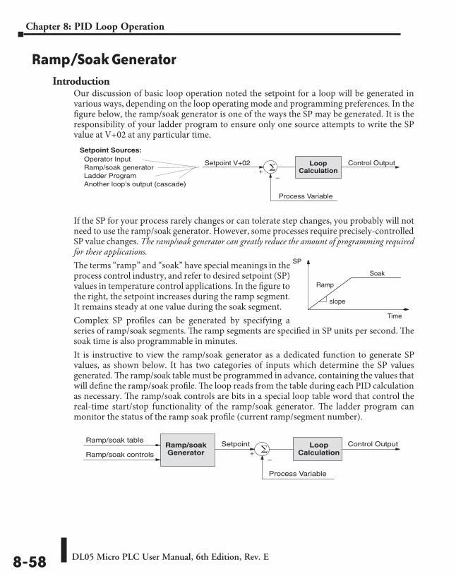
DL05 Micro PLC User Manual, 6th Edition, Rev. E8-58
Chapter 8: PID Loop Operation
Ramp/Soak GeneratorIntroduction
Our discussion of basic loop operation noted the setpoint for a loop will be generated in various ways, depending on the loop operating mode and programming preferences. In the figure below, the ramp/soak generator is one of the ways the SP may be generated. It is the responsibility of your ladder program to ensure only one source attempts to write the SP value at V+02 at any particular time.
If the SP for your process rarely changes or can tolerate step changes, you probably will not need to use the ramp/soak generator. However, some processes require precisely-controlled SP value changes. The ramp/soak generator can greatly reduce the amount of programming required for these applications.
The terms “ramp” and “soak” have special meanings in the process control industry, and refer to desired setpoint (SP) values in temperature control applications. In the figure to the right, the setpoint increases during the ramp segment. It remains steady at one value during the soak segment.Complex SP profiles can be generated by specifying a series of ramp/soak segments. The ramp segments are specified in SP units per second. The soak time is also programmable in minutes.It is instructive to view the ramp/soak generator as a dedicated function to generate SP values, as shown below. It has two categories of inputs which determine the SP values generated. The ramp/soak table must be programmed in advance, containing the values that will define the ramp/soak profile. The loop reads from the table during each PID calculation as necessary. The ramp/soak controls are bits in a special loop table word that control the real-time start/stop functionality of the ramp/soak generator. The ladder program can monitor the status of the ramp soak profile (current ramp/segment number).
Process Variable
LoopCalculation +
–
Control OutputSetpoint V+02
Setpoint Sources:Operator InputRamp/soak generatorLadder ProgramAnother loop’s output (cascade)
Time
SP
Ramp
Soak
slope
Process Variable
LoopCalculation +
–
Setpoint Control OutputRamp/soakGenerator
Ramp/soak table
Ramp/soak controls
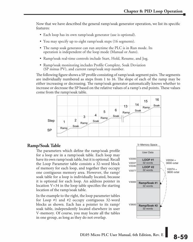
DL05 Micro PLC User Manual, 6th Edition, Rev. E 8-59
Chapter 8: PID Loop Operation
Now that we have described the general ramp/soak generator operation, we list its specific features:
• Each loop has its own ramp/soak generator (use is optional).
• You may specify up to eight ramp/soak steps (16 segments).
• The ramp soak generator can run anytime the PLC is in Run mode. Its operation is independent of the loop mode (Manual or Auto).
• Ramp/soak real-time controls include Start, Hold, Resume, and Jog.
• Ramp/soak monitoring includes Profile Complete, Soak Deviation (SP minus PV), and current ramp/soak step number.
The following figure shows a SP profile consisting of ramp/soak segment pairs. The segments are individually numbered as steps from 1 to 16. The slope of each of the ramp may be either increasing or decreasing. The ramp/soak generator automatically knows whether to increase or decrease the SP based on the relative values of a ramp’s end points. These values come from the ramp/soak table.
Ramp/Soak TableThe parameters which define the ramp/soak profile for a loop are in a ramp/soak table. Each loop may have its own ramp/soak table, but it is optional. Recall the Loop Parameter table consists a 32-word block of memory for each loop, and together they occupy one contiguous memory area. However, the ramp/soak table for a loop is individually located, because it is optional for each loop. An address pointer in location V+34 in the loop table specifies the starting location of the ramp/soak table.In the example to the right, the loop parameter tables for Loop #1 and #2 occupy contiguous 32-word blocks as shown. Each has a pointer to its ramp/soak table, independently located elsewhere in user V-memory. Of course, you may locate all the tables in one group, as long as they do not overlap.
SPRamp
Soak
Step 1 2Ramp
Soak3 4
RampSoak
5 6Ramp
Soak13 14
RampSoak
15 16
V–Memory Space
User Data
LOOP #1V2000
32 words
LOOP #232 words
V2037
Ramp/Soak #132 words
V3000
V2034 =3000 octal
Ramp/Soak #232 words
V3600
V2074 =3600 octal
V2040
V2077
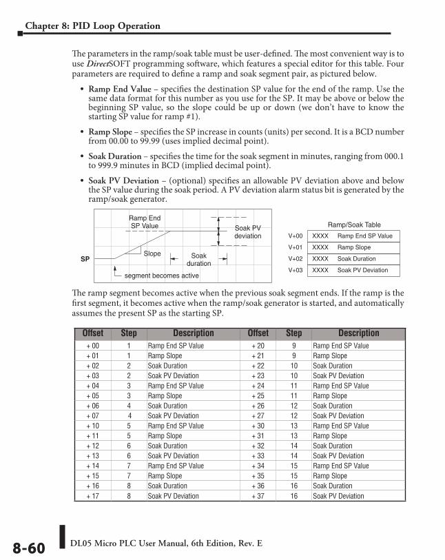
DL05 Micro PLC User Manual, 6th Edition, Rev. E8-60
Chapter 8: PID Loop Operation
The parameters in the ramp/soak table must be user-defined. The most convenient way is to use DirectSOFT programming software, which features a special editor for this table. Four parameters are required to define a ramp and soak segment pair, as pictured below.
• Ramp End Value – specifies the destination SP value for the end of the ramp. Use the same data format for this number as you use for the SP. It may be above or below the beginning SP value, so the slope could be up or down (we don’t have to know the starting SP value for ramp #1).
• Ramp Slope – specifies the SP increase in counts (units) per second. It is a BCD number from 00.00 to 99.99 (uses implied decimal point).
• Soak Duration – specifies the time for the soak segment in minutes, ranging from 000.1 to 999.9 minutes in BCD (implied decimal point).
• Soak PV Deviation – (optional) specifies an allowable PV deviation above and below the SP value during the soak period. A PV deviation alarm status bit is generated by the ramp/soak generator.
The ramp segment becomes active when the previous soak segment ends. If the ramp is the first segment, it becomes active when the ramp/soak generator is started, and automatically assumes the present SP as the starting SP.
Ramp/Soak Table
V+00 Ramp End SP ValueXXXX
SP
Soak PVdeviation
V+01 Ramp SlopeXXXX
V+02 Soak DurationXXXX
V+03 Soak PV DeviationXXXX
Ramp EndSP Value
Soakduration
segment becomes active
Slope
Offset Step Description Offset Step Description+ 00 1 Ramp End SP Value + 20 9 Ramp End SP Value+ 01 1 Ramp Slope + 21 9 Ramp Slope+ 02 2 Soak Duration + 22 10 Soak Duration+ 03 2 Soak PV Deviation + 23 10 Soak PV Deviation+ 04 3 Ramp End SP Value + 24 11 Ramp End SP Value+ 05 3 Ramp Slope + 25 11 Ramp Slope+ 06 4 Soak Duration + 26 12 Soak Duration+ 07 4 Soak PV Deviation + 27 12 Soak PV Deviation+ 10 5 Ramp End SP Value + 30 13 Ramp End SP Value+ 11 5 Ramp Slope + 31 13 Ramp Slope+ 12 6 Soak Duration + 32 14 Soak Duration+ 13 6 Soak PV Deviation + 33 14 Soak PV Deviation+ 14 7 Ramp End SP Value + 34 15 Ramp End SP Value+ 15 7 Ramp Slope + 35 15 Ramp Slope+ 16 8 Soak Duration + 36 16 Soak Duration+ 17 8 Soak PV Deviation + 37 16 Soak PV Deviation
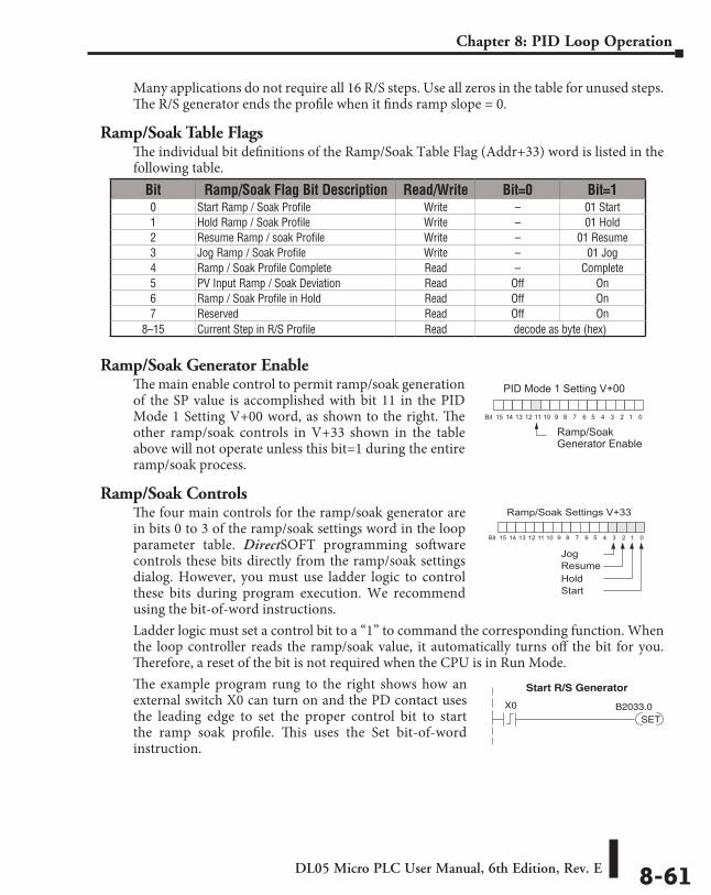
DL05 Micro PLC User Manual, 6th Edition, Rev. E 8-61
Chapter 8: PID Loop Operation
Many applications do not require all 16 R/S steps. Use all zeros in the table for unused steps. The R/S generator ends the profile when it finds ramp slope = 0.
Ramp/Soak Table FlagsThe individual bit definitions of the Ramp/Soak Table Flag (Addr+33) word is listed in the following table.
Ramp/Soak Generator EnableThe main enable control to permit ramp/soak generation of the SP value is accomplished with bit 11 in the PID Mode 1 Setting V+00 word, as shown to the right. The other ramp/soak controls in V+33 shown in the table above will not operate unless this bit=1 during the entire ramp/soak process.
Ramp/Soak ControlsThe four main controls for the ramp/soak generator are in bits 0 to 3 of the ramp/soak settings word in the loop parameter table. DirectSOFT programming software controls these bits directly from the ramp/soak settings dialog. However, you must use ladder logic to control these bits during program execution. We recommend using the bit-of-word instructions.Ladder logic must set a control bit to a “1” to command the corresponding function. When the loop controller reads the ramp/soak value, it automatically turns off the bit for you. Therefore, a reset of the bit is not required when the CPU is in Run Mode.The example program rung to the right shows how an external switch X0 can turn on and the PD contact uses the leading edge to set the proper control bit to start the ramp soak profile. This uses the Set bit-of-word instruction.
Bit Ramp/Soak Flag Bit Description Read/Write Bit=0 Bit=10 Start Ramp / Soak Profile Write – 01 Start1 Hold Ramp / Soak Profile Write – 01 Hold2 Resume Ramp / soak Profile Write – 01 Resume3 Jog Ramp / Soak Profile Write – 01 Jog4 Ramp / Soak Profile Complete Read – Complete5 PV Input Ramp / Soak Deviation Read Off On6 Ramp / Soak Profile in Hold Read Off On7 Reserved Read Off On
8–15 Current Step in R/S Profile Read decode as byte (hex)
PID Mode 1 Setting V+00
013456789101112131415 2Bit
Ramp/SoakGenerator Enable
Ramp/Soak Settings V+33
013456789101112131415 2Bit
Jog
Resume
Hold
Start
X0
SETB2033.0
Start R/S Generator
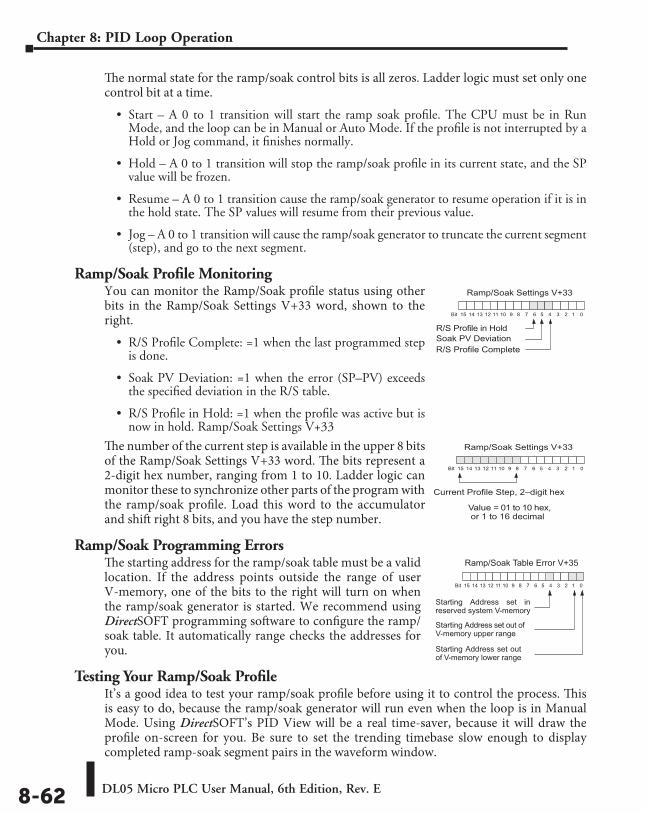
DL05 Micro PLC User Manual, 6th Edition, Rev. E8-62
Chapter 8: PID Loop Operation
The normal state for the ramp/soak control bits is all zeros. Ladder logic must set only one control bit at a time.
• Start – A 0 to 1 transition will start the ramp soak profile. The CPU must be in Run Mode, and the loop can be in Manual or Auto Mode. If the profile is not interrupted by a Hold or Jog command, it finishes normally.
• Hold – A 0 to 1 transition will stop the ramp/soak profile in its current state, and the SP value will be frozen.
• Resume – A 0 to 1 transition cause the ramp/soak generator to resume operation if it is in the hold state. The SP values will resume from their previous value.
• Jog – A 0 to 1 transition will cause the ramp/soak generator to truncate the current segment (step), and go to the next segment.
Ramp/Soak Profile MonitoringYou can monitor the Ramp/Soak profile status using other bits in the Ramp/Soak Settings V+33 word, shown to the right.
• R/S Profile Complete: =1 when the last programmed step is done.
• Soak PV Deviation: =1 when the error (SP–PV) exceeds the specified deviation in the R/S table.
• R/S Profile in Hold: =1 when the profile was active but is now in hold. Ramp/Soak Settings V+33
The number of the current step is available in the upper 8 bits of the Ramp/Soak Settings V+33 word. The bits represent a 2-digit hex number, ranging from 1 to 10. Ladder logic can monitor these to synchronize other parts of the program with the ramp/soak profile. Load this word to the accumulator and shift right 8 bits, and you have the step number.
Ramp/Soak Programming ErrorsThe starting address for the ramp/soak table must be a valid location. If the address points outside the range of user V-memory, one of the bits to the right will turn on when the ramp/soak generator is started. We recommend using DirectSOFT programming software to configure the ramp/soak table. It automatically range checks the addresses for you.
Testing Your Ramp/Soak ProfileIt’s a good idea to test your ramp/soak profile before using it to control the process. This is easy to do, because the ramp/soak generator will run even when the loop is in Manual Mode. Using DirectSOFT’s PID View will be a real time-saver, because it will draw the profile on-screen for you. Be sure to set the trending timebase slow enough to display completed ramp-soak segment pairs in the waveform window.
Ramp/Soak Settings V+33
013456789101112131415 2Bit
R/S Profile Complete
Soak PV Deviation
R/S Profile in Hold
Ramp/Soak Settings V+33
013456789101112131415 2Bit
Current Profile Step, 2–digit hex
Value = 01 to 10 hex, or 1 to 16 decimal
Ramp/Soak Table Error V+35
013456789101112131415 2Bit
Starting Address set out ofV-memory upper range
Starting Address set outof V-memory lower range
Starting Address set inreserved system V-memory
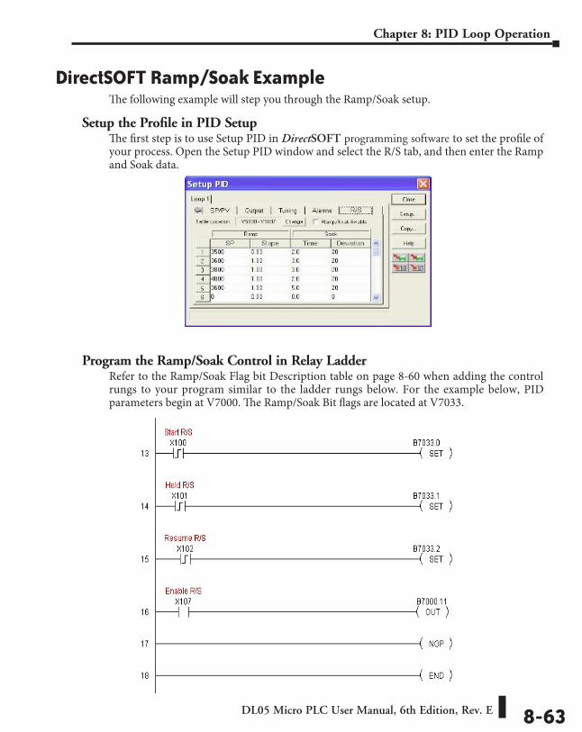
DL05 Micro PLC User Manual, 6th Edition, Rev. E 8-63
Chapter 8: PID Loop Operation
DirectSOFT Ramp/Soak ExampleThe following example will step you through the Ramp/Soak setup.
Setup the Profile in PID SetupThe first step is to use Setup PID in DirectSOFT programming software to set the profile of your process. Open the Setup PID window and select the R/S tab, and then enter the Ramp and Soak data.
Program the Ramp/Soak Control in Relay LadderRefer to the Ramp/Soak Flag bit Description table on page 8-60 when adding the control rungs to your program similar to the ladder rungs below. For the example below, PID parameters begin at V7000. The Ramp/Soak Bit flags are located at V7033.
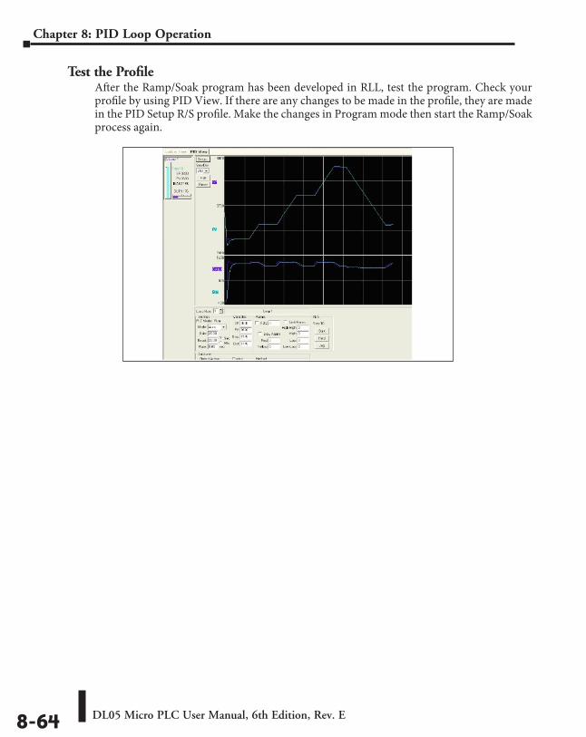
DL05 Micro PLC User Manual, 6th Edition, Rev. E8-64
Chapter 8: PID Loop Operation
Test the ProfileAfter the Ramp/Soak program has been developed in RLL, test the program. Check your profile by using PID View. If there are any changes to be made in the profile, they are made in the PID Setup R/S profile. Make the changes in Program mode then start the Ramp/Soak process again.
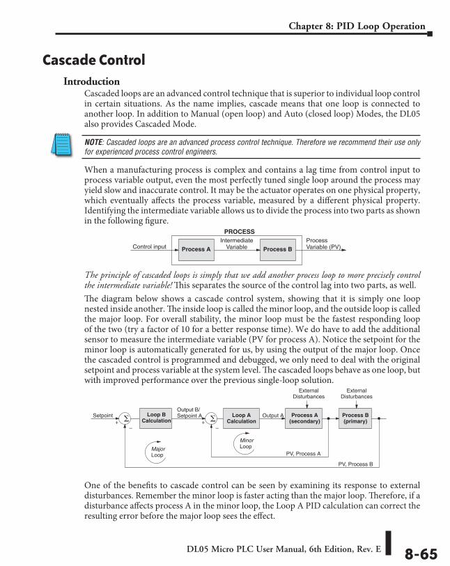
DL05 Micro PLC User Manual, 6th Edition, Rev. E 8-65
Chapter 8: PID Loop Operation
Cascade ControlIntroduction
Cascaded loops are an advanced control technique that is superior to individual loop control in certain situations. As the name implies, cascade means that one loop is connected to another loop. In addition to Manual (open loop) and Auto (closed loop) Modes, the DL05 also provides Cascaded Mode.
NOTE: Cascaded loops are an advanced process control technique. Therefore we recommend their use only for experienced process control engineers.
When a manufacturing process is complex and contains a lag time from control input to process variable output, even the most perfectly tuned single loop around the process may yield slow and inaccurate control. It may be the actuator operates on one physical property, which eventually affects the process variable, measured by a different physical property. Identifying the intermediate variable allows us to divide the process into two parts as shown in the following figure.
The principle of cascaded loops is simply that we add another process loop to more precisely control the intermediate variable! This separates the source of the control lag into two parts, as well.The diagram below shows a cascade control system, showing that it is simply one loop nested inside another. The inside loop is called the minor loop, and the outside loop is called the major loop. For overall stability, the minor loop must be the fastest responding loop of the two (try a factor of 10 for a better response time). We do have to add the additional sensor to measure the intermediate variable (PV for process A). Notice the setpoint for the minor loop is automatically generated for us, by using the output of the major loop. Once the cascaded control is programmed and debugged, we only need to deal with the original setpoint and process variable at the system level. The cascaded loops behave as one loop, but with improved performance over the previous single-loop solution.
One of the benefits to cascade control can be seen by examining its response to external disturbances. Remember the minor loop is faster acting than the major loop. Therefore, if a disturbance affects process A in the minor loop, the Loop A PID calculation can correct the resulting error before the major loop sees the effect.
IntermediateVariableProcess A Process BControl input
ProcessVariable (PV)
PROCESS
+–
Setpoint Loop BCalculation +
–
Loop ACalculation
Process A(secondary)
Process B(primary)
PV, Process A
PV, Process B
Output B/Setpoint A
MajorLoop
MinorLoop
ExternalDisturbances
ExternalDisturbances
Output A
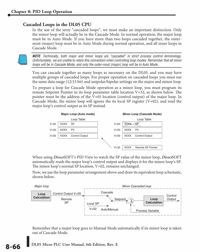
DL05 Micro PLC User Manual, 6th Edition, Rev. E8-66
Chapter 8: PID Loop Operation
Cascaded Loops in the DL05 CPUIn the use of the term “cascaded loops”, we must make an important distinction. Only the minor loop will actually be in the Cascade Mode. In normal operation, the major loop must be in Auto Mode. If you have more than two loops cascaded together, the outer-most (major) loop must be in Auto Mode during normal operation, and all inner loops in Cascade Mode.
NOTE: Technically, both major and minor loops are “cascaded” in strict process control terminology. Unfortunately, we are unable to retain this convention when controlling loop modes. Remember that all minor loops will be in Cascade Mode, and only the outer-most (major) loop will be in Auto Mode.
You can cascade together as many loops as necessary on the DL05, and you may have multiple groups of cascaded loops. For proper operation on cascaded loops you must use the same data range (12/15 bit) and unipolar/bipolar settings on the major and minor loop.To prepare a loop for Cascade Mode operation as a minor loop, you must program its remote Setpoint Pointer in its loop parameter table location V+32, as shown below. The pointer must be the address of the V+05 location (control output) of the major loop. In Cascade Mode, the minor loop will ignore the its local SP register (V+02), and read the major loop’s control output as its SP instead.
When using DirectSOFT’s PID View to watch the SP value of the minor loop, DirectSOFT automatically reads the major loop’s control output and displays it for the minor loop’s SP. The minor loop’s normal SP location, V+02, remains unchanged.Now, we use the loop parameter arrangement above and draw its equivalent loop schematic, shown below.
Remember that a major loop goes to Manual Mode automatically if its minor loop is taken out of Cascade Mode.
Loop Table
V+02 SPXXXX
V+03 PVXXXX
V+32 Remote SP PointerXXXX
V+02 SPXXXX
V+03 PVXXXX
V+05 Control OutputXXXXV+05 Control OutputXXXX
Loop Table
Major Loop (Auto mode) Minor Loop (Cascade Mode)
Process Variable
+–
Setpoint
Cascade
Auto/Manual
Control Output V+05
Local SP
LoopCalculation
ControlOutput
LoopCalculation
Minor Cascaded loopMajor loop
RemoteSP
V+02
DL05 Micro PLC User Manual, 6th Edition, Rev. E 8-67
Chapter 8: PID Loop Operation
Tuning Cascaded LoopsWhen tuning cascaded loops, you will need to de-couple the cascade relationship and tune the minor loop using one of the loop tuning procedures previously covered. Once this has been done, have the minor loop in cascade mode and auto tune the major loop (see Step 4).
1. If you are not using auto tuning, then find the loop sample rate for the minor loop, using the method discussed earlier in this chapter. Then set the sample rate of the major loop slower than the minor loop by a factor of 10. Use this as a starting point.
2. Tune the minor loop first. Leave the major loop in Manual Mode, and you will need to generate SP changes for the minor loop manually as described in the loop tuning procedure.
3. Verify the minor loop gives a critically-damped response to a 10% SP change while in Auto Mode. Then we are finished tuning the minor loop.
4. In this step, you will need to get the minor loop in Cascade Mode, and then the Major loop in Auto Mode. We will be tuning the major loop with the minor loop treated as a series component its overall process. Therefore, do not go back and tune the minor loop again while tuning the major loop.
5. Tune the major loop, following the standard loop tuning procedure in this section. The response of the major loop PV is actually the overall response of the cascaded loops together.
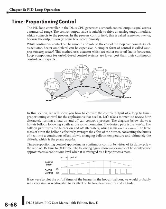
DL05 Micro PLC User Manual, 6th Edition, Rev. E8-68
Chapter 8: PID Loop Operation
Time-Proportioning ControlThe PID loop controller in the DL05 CPU generates a smooth control output signal across a numerical range. The control output value is suitable to drive an analog output module, which connects to the process. In the process control field, this is called continuous control, because the output is on (at some level) continuously.While continuous control can be smooth and robust, the cost of the loop components (such as actuator, heater amplifiers) can be expensive. A simpler form of control is called time-proportioning control. This method uses actuator which are either on or off (no in-between). Loop components for on/off-based control systems are lower cost than their continuous control counterparts.
In this section, we will show you how to convert the control output of a loop to time-proportioning control for the applications that need it. Let’s take a moment to review how alternately turning a load on and off can control a process. The diagram below shows a hot-air balloon following a path across some mountains. The desired path is the setpoint. The balloon pilot turns the burner on and off alternately, which is his control output. The large mass of air in the balloon effectively averages the effect of the burner, converting the bursts of heat into a continuous effect, slowly changing balloon temperature and ultimately the altitude, which is the process variable.Time-proportioning control approximates continuous control by virtue of its duty-cycle – the ratio of ON time to OFF time. The following figure shows an example of how duty-cycle approximates a continuous level when it is averaged by a large process mass.
If we were to plot the on/off times of the burner in the hot-air balloon, we would probably see a very similar relationship to its effect on balloon temperature and altitude.
DesiredEffect
On/OffControl Off
On
period
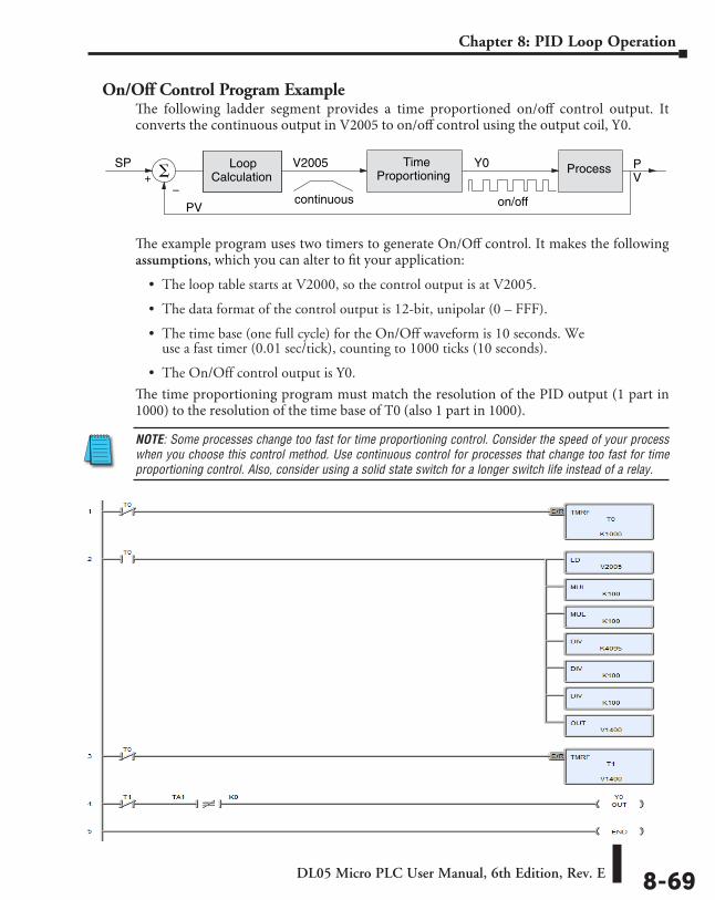
DL05 Micro PLC User Manual, 6th Edition, Rev. E 8-69
Chapter 8: PID Loop Operation
On/Off Control Program ExampleThe following ladder segment provides a time proportioned on/off control output. It converts the continuous output in V2005 to on/off control using the output coil, Y0.
The example program uses two timers to generate On/Off control. It makes the following assumptions, which you can alter to fit your application:
• The loop table starts at V2000, so the control output is at V2005.
• The data format of the control output is 12-bit, unipolar (0 – FFF).
• The time base (one full cycle) for the On/Off waveform is 10 seconds. We use a fast timer (0.01 sec/tick), counting to 1000 ticks (10 seconds).
• The On/Off control output is Y0.
The time proportioning program must match the resolution of the PID output (1 part in 1000) to the resolution of the time base of T0 (also 1 part in 1000).
NOTE: Some processes change too fast for time proportioning control. Consider the speed of your process when you choose this control method. Use continuous control for processes that change too fast for time proportioning control. Also, consider using a solid state switch for a longer switch life instead of a relay.
PV
LoopCalculation+
–
V2005SP TimeProportioning
ProcessY0 PV
continuous on/off
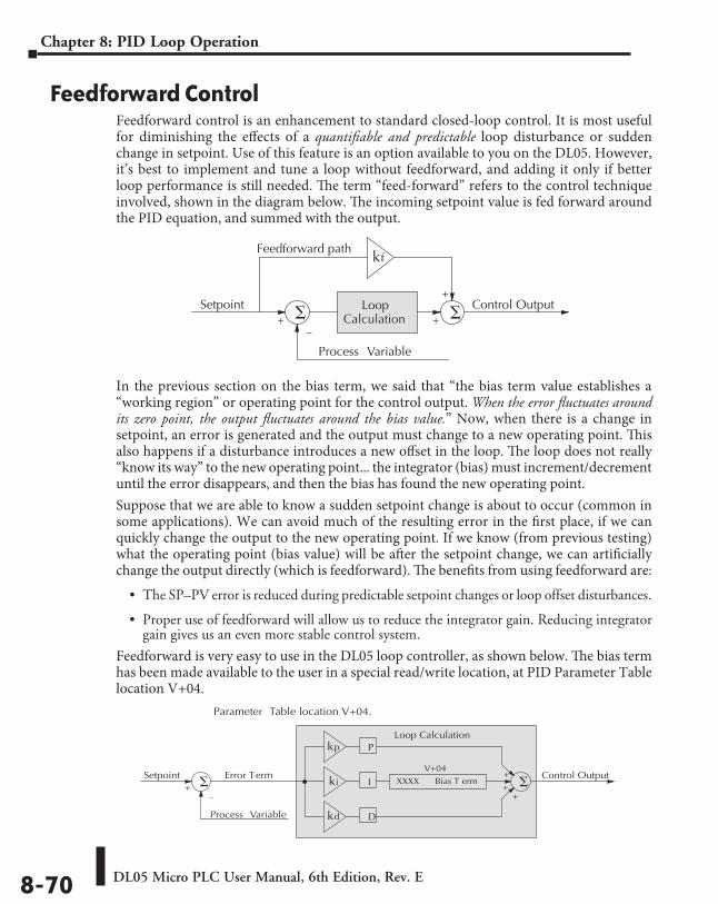
DL05 Micro PLC User Manual, 6th Edition, Rev. E8-70
Chapter 8: PID Loop Operation
Feedforward ControlFeedforward control is an enhancement to standard closed-loop control. It is most useful for diminishing the effects of a quantifiable and predictable loop disturbance or sudden change in setpoint. Use of this feature is an option available to you on the DL05. However, it’s best to implement and tune a loop without feedforward, and adding it only if better loop performance is still needed. The term “feed-forward” refers to the control technique involved, shown in the diagram below. The incoming setpoint value is fed forward around the PID equation, and summed with the output.
In the previous section on the bias term, we said that “the bias term value establishes a “working region” or operating point for the control output. When the error fluctuates around its zero point, the output fluctuates around the bias value.” Now, when there is a change in setpoint, an error is generated and the output must change to a new operating point. This also happens if a disturbance introduces a new offset in the loop. The loop does not really “know its way” to the new operating point... the integrator (bias) must increment/decrement until the error disappears, and then the bias has found the new operating point.Suppose that we are able to know a sudden setpoint change is about to occur (common in some applications). We can avoid much of the resulting error in the first place, if we can quickly change the output to the new operating point. If we know (from previous testing) what the operating point (bias value) will be after the setpoint change, we can artificially change the output directly (which is feedforward). The benefits from using feedforward are:
• The SP–PV error is reduced during predictable setpoint changes or loop offset disturbances.
• Proper use of feedforward will allow us to reduce the integrator gain. Reducing integrator gain gives us an even more stable control system.
Feedforward is very easy to use in the DL05 loop controller, as shown below. The bias term has been made available to the user in a special read/write location, at PID Parameter Table location V+04.
Process Variable
LoopCalculation +
–
Control OutputSetpoint +
kfFeedforward path
+
Parameter Table location V+04.
Process Variable
Error Term
+–
Control OutputSetpoint +
P
I
D
Loop Calculation
+
+
kp
ki
kd
V+04
Bias T ermXXXX
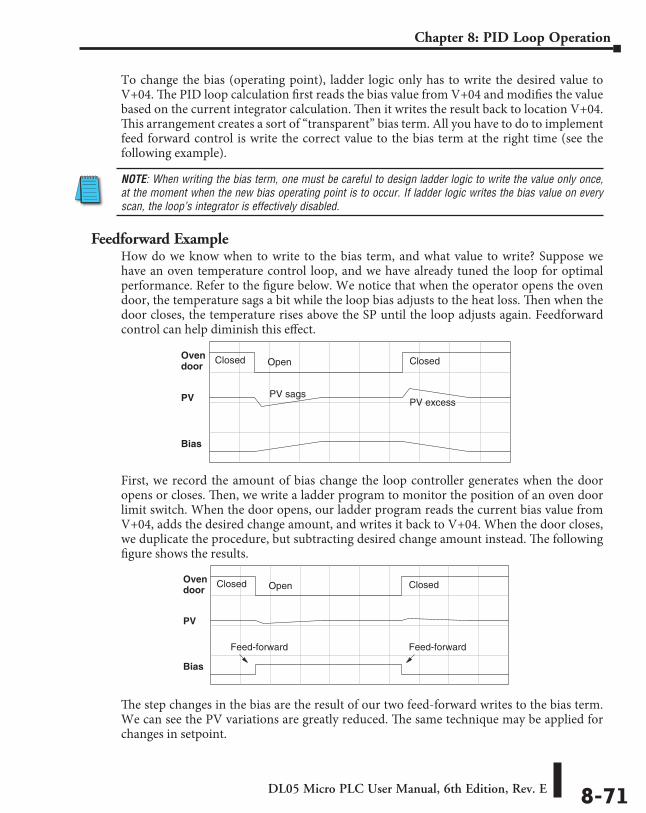
DL05 Micro PLC User Manual, 6th Edition, Rev. E 8-71
Chapter 8: PID Loop Operation
To change the bias (operating point), ladder logic only has to write the desired value to V+04. The PID loop calculation first reads the bias value from V+04 and modifies the value based on the current integrator calculation. Then it writes the result back to location V+04. This arrangement creates a sort of “transparent” bias term. All you have to do to implement feed forward control is write the correct value to the bias term at the right time (see the following example).
NOTE: When writing the bias term, one must be careful to design ladder logic to write the value only once, at the moment when the new bias operating point is to occur. If ladder logic writes the bias value on every scan, the loop’s integrator is effectively disabled.
Feedforward ExampleHow do we know when to write to the bias term, and what value to write? Suppose we have an oven temperature control loop, and we have already tuned the loop for optimal performance. Refer to the figure below. We notice that when the operator opens the oven door, the temperature sags a bit while the loop bias adjusts to the heat loss. Then when the door closes, the temperature rises above the SP until the loop adjusts again. Feedforward control can help diminish this effect.
First, we record the amount of bias change the loop controller generates when the door opens or closes. Then, we write a ladder program to monitor the position of an oven door limit switch. When the door opens, our ladder program reads the current bias value from V+04, adds the desired change amount, and writes it back to V+04. When the door closes, we duplicate the procedure, but subtracting desired change amount instead. The following figure shows the results.
The step changes in the bias are the result of our two feed-forward writes to the bias term. We can see the PV variations are greatly reduced. The same technique may be applied for changes in setpoint.
PV
Bias
Ovendoor
PV sagsPV excess
Closed Open Closed
PV
Bias
Ovendoor
Closed Open Closed
Feed-forward Feed-forward
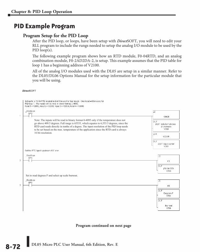
DL05 Micro PLC User Manual, 6th Edition, Rev. E8-72
Chapter 8: PID Loop Operation
PID Example ProgramProgram Setup for the PID Loop
After the PID loop, or loops, have been setup with DirectSOFT, you will need to edit your RLL program to include the rungs needed to setup the analog I/O module to be used by the PID loop(s).The following example program shows how an RTD module, F0-04RTD, and an analog combination module, F0-2AD2DA-2, is setup. This example assumes that the PID table for loop 1 has a beginning address of V2100. All of the analog I/O modules used with the DL05 are setup in a similar manner. Refer to the DL05/DL06 Options Manual for the setup information for the particular module that you will be using.
Program continued on next page
DirectSOFT
Set to read degrees F and select up scale burnout.
Note: The inputs will be read in binary format 0-4095 only if the temperature does notgo above 409.5 degrees. Full range is 65535, which equates to 6,553.5 degrees, since theRTD card reads directly in tenths of a degree. The input resolution of the PID loop needs to be set based on the max. temperature of the application since the RTD card is always16 bit resolution.
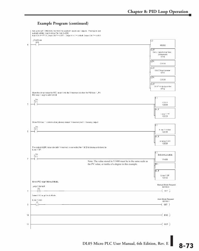
DL05 Micro PLC User Manual, 6th Edition, Rev. E 8-73
Chapter 8: PID Loop Operation
Example Program (continued)
Manual Mode Request B2100.0
Auto Mode Request B2100.1
Note: The value stored in V1400 must be in the same scale as the PV value, or tenths of a degree in this example.
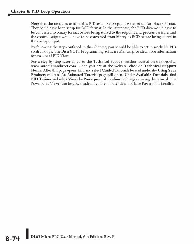
DL05 Micro PLC User Manual, 6th Edition, Rev. E8-74
Chapter 8: PID Loop Operation
Note that the modules used in this PID example program were set up for binary format. They could have been setup for BCD format. In the latter case, the BCD data would have to be converted to binary format before being stored to the setpoint and process variable, and the control output would have to be converted from binary to BCD before being stored to the analog output.By following the steps outlined in this chapter, you should be able to setup workable PID control loops. The DirectSOFT Programming Software Manual provided more information for the use of PID View.For a step-by-step tutorial, go to the Technical Support section located on our website, www.automationdirect.com. Once you are at the website, click on Technical Support Home. After this page opens, find and select Guided Tutorials located under the Using Your Products column. An Animated Tutorial page will open. Under Available Tutorials, find PID Trainer and select View the Powerpoint slide show and begin viewing the tutorial. The Powerpoint Viewer can be downloaded if your computer does not have Powerpoint installed.
DL05 Micro PLC User Manual, 6th Edition, Rev. E 8-75
Chapter 8: PID Loop Operation
Troubleshooting TipsQ. The loop will not go into Automatic Mode.
A. Check the following for possible causes:
• A PV alarm exists, or a PV alarm programming error exists.
• The loop is the major loop of a cascaded pair, and the minor loop is not in Cascade Mode.
Q. The Control Output stays at zero constantly when the loop is in Automatic Mode.
A. Check the following for possible causes:
• The Control Output upper limit in loop table location V+31 is zero.
• The loop is driven into saturation, because the error never goes to zero value and changes (algebraic) sign.
Q. The Control Output value is not zero, but it is incorrect.A. Check the following for possible causes:
• The gain values are entered improperly. Remember, gains are entered in the loop table in BCD, while the SP and PV are in binary. If you are using DirectSOFT, PID View will display the SP, PV, Bias and Control output in decimal (BCD), converting it to binary before updating the loop table.
Q. The Ramp/Soak Generator does not operate when I activate the Start bit.A. Check the following for possible causes:
• The Ramp/Soak enable bit is off. Check the status of bit 11 of loop parameter table location V+00. It must be set =1.
• The hold bit or other bits in the Ramp/Soak control are on.
• The beginning SP value and the first ramp ending SP value are the same, so first ramp segment has no slope and consequently has no duration. The ramp/soak generator moves quickly to the soak segment, giving the illusion the first ramp is not working.
• The loop is in Cascade Mode, and is trying to get the SP remotely.
• The SP upper limit value in the loop table location V+27 is too low.
• Check your ladder program to verify it is not writing to the SP location (V+02 in the loop table). A quick way to do this is to temporarily place an end coil at the beginning of your program, then go to PLC Run Mode, and manually start the ramp/soak generator.
Q. The PV value in the table is constant, even though the analog module receives the PV signal.
A. Your ladder program must read the analog value from the module successfully and write it into the loop table V+03 location. Verify the analog module is generating the value, and the ladder is working.
DL05 Micro PLC User Manual, 6th Edition, Rev. E8-76
Chapter 8: PID Loop Operation
Q. The Derivative gain doesn’t seem to have any affect on the output.A. The derivative limit is probably enabled (see section on derivative gain limiting).
Q. The loop Setpoint appears to be changing by itself.A. Check the following for possible causes:
• The Ramp/Soak generator is enabled, and is generating setpoints.
• If this symptom occurs on loop Manual-to-Auto Mode changes, the loop automatically sets the SP=PV if set to bumless transfer mode 1 (bumpless transfer feature).
• Check your ladder program to verify it is not writing to the SP location (V+02 in the loop table). A quick way to do this is to temporarily place an end coil at the beginning of your program, then go to PLC Run Mode.
Q. The SP and PV values I enter with DirectSOFT work okay, but these values do not work properly when the ladder program writes the data.
A. The PID View in DirectSOFT lets you enter SP, PV, and Bias values in decimal, and displays them in decimal for your convenience. For example, when the data format is 12 bit unipolar, the values range from 0 to 4095. However, the loop table actually requires these to be in hex, so DirectSOFT converts them for you. Your ladder program must convert constant values from their BCD format (when entered as Kxxxx) to binary with the BIN instruction or you must enter them in the constant field (Kxxxx) as the hex equivalent of the decimal value.
Q. The loop seems unstable and impossible to tune, no matter what gains I use.A. Check the following for possible causes:
• The loop sample time is set too long. Refer to the section near the front of this chapter on selecting the loop update time.
• The gains are too high. Start out by reducing the derivative gain to zero. Then reduce the integral gain by increasing the integral time value and the proportional gain if necessary.
• There is too much transfer lag in your process. This means the PV reacts sluggishly to control output changes. There may be too much “distance” between actuator and PV sensor, or the actuator may be weak in its ability to transfer energy into the process.
• There may be a process disturbance that is over-powering the loop. Make sure the PV is relatively steady when the SP is not changing.
DL05 Micro PLC User Manual, 6th Edition, Rev. E 8-77
Chapter 8: PID Loop Operation
Glossary of PID Loop TerminologyAutomatic Mode – An operational mode of a loop, in which it makes PID calculations and updates the loop’s control output.Bias Freeze – A method of preserving the bias value (operating point) for a control output, by inhibiting the integrator when the output goes out-of-range. The benefit is a faster loop recovery.Bias Term – In the position form of the PID equation, it is the sum of the integrator and the initial control output value.Bumpless Transfer – A method of changing the operation mode of a loop while avoiding the usual sudden change in control output level. This consequence is avoided by artificially making the SP and PV equal, or the bias term and control output equal at the moment of mode change.Cascaded Loops – A cascaded loop receives its setpoint from the output of another loop. Cascaded loops have a major/minor relationship, and work together to ultimately control one PV.Cascade Mode – An operational mode of a loop, in which it receives its SP from another loop’s output.Continuous Control – Control of a process done by delivering a smooth (analog) signal as the control output.Control Output – The numerical result of a PID equation which is sent by the loop with the intention of nulling out the current error.Derivative Gain – A constant that determines the magnitude of the PID derivative term in response to the current error.Direct-Acting Loop – A loop in which the PV increases in response to a control output increase. In other words, the process has a positive gain.Error – The difference in value between the SP and PV, Error = SP – PV.Error Deadband – An optional feature which makes the loop insensitive to errors when they are small. You can specify the size of the deadband.Error Squared – An optional feature which multiplies the error by itself, but retains the original algebraic sign. It reduces the effect of small errors, while magnifying the effect of large errors.Feedforward – A method of optimizing the control response of a loop when a change in setpoint or disturbance offset is known and has a quantifiable effect on the bias term.Integral Gain – A constant that determines the magnitude of the PID integral term in response to the current error.Major Loop – In cascade control, it is the loop that generates a setpoint for the cascaded loop.Manual Mode – An operational mode of a loop, it which the PID calculations are stopped. The operator must manually control the loop by writing to the control output value directly.Minor Loop – In cascade control, the minor loop is the subordinate loop that receives its SP from the major loop.On/Off Control – A simple method of controlling a process, through on/off application of energy into the system. The mass of the process averages the on/off effect for a relatively smooth PV. A simple ladder program can convert the DL05’s continuous loop output to on/off control.
DL05 Micro PLC User Manual, 6th Edition, Rev. E8-78
Chapter 8: PID Loop Operation
PID Loop – A mathematical method of closed-loop control involving the sum of three terms based on proportional, integral, and derivative error values. The three terms have independent gain constants, allowing one to optimize (tune) the loop for a particular physical system.Position Algorithm – The control output is calculated so it responds to the displacement (position) of the PV from the SP (error term).Process – A manufacturing procedure which adds value to raw materials. Process control particularly refers to inducing chemical changes to the material in process.Process Variable (PV) – A quantitative measurement of a physical property of the material in process, which affects final product quality and is important to monitor and control.Proportional Gain – A constant that determines the magnitude of the PID proportional term in response to the current error.PV Absolute Alarm – A programmable alarm that compares the PV value to alarm threshold values.PV Deviation Alarm – A programmable alarm that compares the difference between the SP and PV values to a deviation threshold value.Ramp/Soak Profile – A set of SP values called a profile, which is generated in real time upon each loop calculation. The profile consists of a series of ramp and soak segment pairs, greatly simplifying the task of programming the PLC to generate such SP sequences.Rate – Also called differentiator, the rate term responds to the changes in the error term.Remote Setpoint – The location where a loop reads its setpoint when it is configured as the minor loop in a cascaded loop topology.Reset – Also called integrator, the reset term adds each sampled error to the previous, maintaining a running total called the bias.Reset Windup A condition created when the loop is unable to find equilibrium, and the persistent error causes the integrator (reset) sum to grow excessively (windup). Reset windup causes an extra recovery delay when the original loop fault is remedied.Reverse-Acting Loop – A loop in which the PV increases in response to a control output decrease. In other words, the process has a negative gain.Sampling Time – The time between PID calculations. The CPU method of process control is called a sampling controller, because it samples the SP and PV only periodically.Setpoint (SP) – The desired value for the process variable. The setpoint (SP) is the input command to the loop controller during closed loop operation.Soak Deviation – The soak deviation is a measure of the difference between the SP and PV during a soak segment of the Ramp/Soak profile, when the Ramp/Soak generator is active.Step Response – The behavior of the process variable in response to a step change in the SP (in closed loop operation), or a step change in the control output (in open loop operation).Transfer – To change from one loop operational mode to another (between Manual, Auto, or Cascade). The word “transfer” probably refers to the transfer of control of the control output or the SP, depending on the particular mode change.Velocity Algorithm – The control output is calculated to represent the rate of change (velocity) for the PV to become equal to the SP.
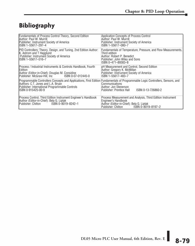
DL05 Micro PLC User Manual, 6th Edition, Rev. E 8-79
Chapter 8: PID Loop Operation
Bibliography Fundamentals of Process Control Theory, Second Edition Author: Paul W. Murrill Publisher: Instrument Society of America ISBN 1–55617–297–4
Application Concepts of Process Control Author: Paul W. Murrill Publisher: Instrument Society of America ISBN 1–55617–080–7
PID Controllers: Theory, Design, and Tuning, 2nd Edition Author: K. Astrom and T Hagglund Publisher: Instrument Society of America ISBN 1–55617–516–7
Fundamentals of Temperature, Pressure, and Flow Measurements, Third edition Author: Robert P. Benedict Publisher: John Wiley and Sons ISBN 0–471–89383–8
Process / Industrial Instruments & Controls Handbook, Fourth Edition Author (Editor-in-Chief): Douglas M. Considine Publisher: McGraw-Hill, Inc ISBN 0-07-012445-0
pH Measurement and Control, Second Edition Author: Gregory K. McMillan Publisher: Instrument Society of America ISBN 1–55617–483–7
Programmable Controllers Concepts and Applications, First Edition Authors: C.T. Jones and L.A. Bryan Publisher: International Programmable Controls ISBN 0-915425-00-9
Fundamentals of Programmable Logic Controllers, Sensors, and Communications Author: Jon Stenerson Publisher: Prentice Hall ISBN 0-13-726860-2
Process Control, Third Edition Instrument Engineer’s Handbook Author (Editor-in-Chief): Bela G. Liptak Publisher: Chilton ⸠⸠⸠⸠⸠⸠⸠⸠⸠⸠⸠⸠⸠⸠ISBN 0–8019–8242–1
Process Measurement and Analysis, Third Edition Instrument Engineer’s Handbook Author (Editor-in-Chief): Bela G. Liptak Publisher: Chilton ⸠⸠⸠⸠⸠⸠⸠⸠⸠⸠⸠⸠⸠⸠ISBN 0–8019–8197–2
Maintenance and troubleshooting 999
ChapterChapterChapter
In This Chapter...Hardware System Maintenance ................................................................................ 9-2
Diagnostics ................................................................................................................. 9-2
CPU Indicators ........................................................................................................... 9-6
Communications Problems ....................................................................................... 9-7
I/O Point Troubleshooting ........................................................................................ 9-8
Noise Troubleshooting ............................................................................................ 9-10
Machine Startup and Program Troubleshooting ................................................... 9-11
DL05 Micro PLC User Manual, 6th Edition, Rev. E9-2
Chapter 9: Maintenance and Troubleshooting
Hardware System MaintenanceStandard Maintenance
No regular or preventative maintenance is required for this product (there are no internal batteries); however, a routine maintenance check (about every one or two months) of your PLC and control system is good practice, and should include the following items:
• Air Temperature – Check the air temperature in the control cabinet, so the operating temperature range of any component is not exceeded.
• Air Filter – If the control cabinet has an air filter, clean or replace it periodically as required.
• Fuses or breakers – Verify that all fuses and breakers are intact.
• Cleaning the Unit – Check that all air vents are clear. If the exterior case needs cleaning, disconnect the input power, and carefully wipe the case using a damp cloth. Do not let water enter the case through the air vents and do not use strong detergents because this may discolor the case.
DiagnosticsDiagnostics
Your DL05 Micro PLC performs many pre-defined diagnostic routines with every CPU scan. The diagnostics can detect various errors or failures in the PLC. The two primary error classes are fatal and non-fatal.
Fatal ErrorsFatal errors are errors which may cause the system to function improperly, perhaps introducing a safety problem. The CPU will automatically switch to Program Mode if it is in Run Mode. (Remember, in Program Mode all outputs are turned off.) If the fatal error is detected while the CPU is in Program Mode, the CPU will not allow you to transition to Run Mode until the error has been corrected.
Some examples of fatal errors are:
• Power supply failure
• Parity error or CPU malfunction
• Particular programming errors
Non-fatal ErrorsNon-fatal errors are errors that need your attention, but should not cause improper operation. They do not cause or prevent any mode transitions of the CPU. The application program can use special relay contacts to detect non-fatal errors, and even take the system to an orderly shutdown or switch the CPU to Program Mode if desired. An example of a non-fatal error is:
• Particular programming errors The programming devices will notify you of an error if one occurs while online.
• DirectSOFT provides the error number and an error message.
• The handheld programmer displays error numbers and short descriptions of the error.
Appendix B has a complete list of error messages in order by error number. Many error messages point to supplemental V-memory locations which contain related information. Special relays (SP contacts) also provide error indications.
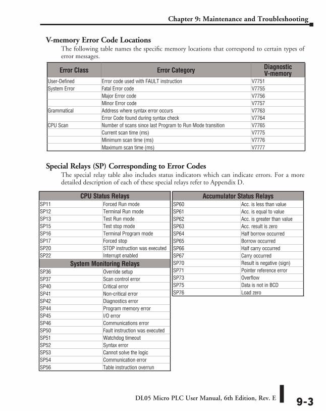
DL05 Micro PLC User Manual, 6th Edition, Rev. E 9-3
Chapter 9: Maintenance and Troubleshooting
V-memory Error Code LocationsThe following table names the specific memory locations that correspond to certain types of error messages.
Special Relays (SP) Corresponding to Error CodesThe special relay table also includes status indicators which can indicate errors. For a more detailed description of each of these special relays refer to Appendix D.
Accumulator Status RelaysSP60 Acc. is less than valueSP61 Acc. is equal to valueSP62 Acc. is greater than valueSP63 Acc. result is zeroSP64 Half borrow occurredSP65 Borrow occurredSP66 Half carry occurredSP67 Carry occurredSP70 Result is negative (sign)SP71 Pointer reference errorSP73 OverflowSP75 Data is not in BCDSP76 Load zero
Error Class Error Category Diagnostic V-memory
User-Defined Error code used with FAULT instruction V7751System Error Fatal Error code V7755
Major Error code V7756Minor Error code V7757
Grammatical Address where syntax error occurs V7763Error Code found during syntax check V7764
CPU Scan Number of scans since last Program to Run Mode transition V7765Current scan time (ms) V7775Minimum scan time (ms) V7776Maximum scan time (ms) V7777
CPU Status RelaysSP11 Forced Run modeSP12 Terminal Run modeSP13 Test Run modeSP15 Test stop modeSP16 Terminal Program modeSP17 Forced stopSP20 STOP instruction was executedSP22 Interrupt enabled
System Monitoring RelaysSP36 Override setupSP37 Scan control errorSP40 Critical errorSP41 Non-critical errorSP42 Diagnostics errorSP44 Program memory errorSP45 I/O errorSP46 Communications errorSP50 Fault instruction was executedSP51 Watchdog timeoutSP52 Syntax errorSP53 Cannot solve the logicSP54 Communication errorSP56 Table instruction overrun
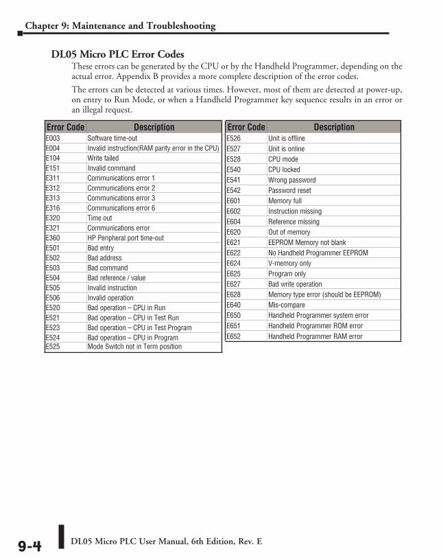
DL05 Micro PLC User Manual, 6th Edition, Rev. E9-4
Chapter 9: Maintenance and Troubleshooting
DL05 Micro PLC Error CodesThese errors can be generated by the CPU or by the Handheld Programmer, depending on the actual error. Appendix B provides a more complete description of the error codes.
The errors can be detected at various times. However, most of them are detected at power-up, on entry to Run Mode, or when a Handheld Programmer key sequence results in an error or an illegal request.
Error Code DescriptionE003 Software time-outE004 Invalid instruction(RAM parity error in the CPU)E104 Write failedE151 Invalid commandE311 Communications error 1E312 Communications error 2E313 Communications error 3E316 Communications error 6E320 Time outE321 Communications errorE360 HP Peripheral port time-outE501 Bad entryE502 Bad addressE503 Bad commandE504 Bad reference / valueE505 Invalid instructionE506 Invalid operationE520 Bad operation – CPU in RunE521 Bad operation – CPU in Test RunE523 Bad operation – CPU in Test ProgramE524 Bad operation – CPU in ProgramE525 Mode Switch not in Term position
Error Code DescriptionE526 Unit is offlineE527 Unit is onlineE528 CPU modeE540 CPU lockedE541 Wrong passwordE542 Password resetE601 Memory fullE602 Instruction missingE604 Reference missingE620 Out of memoryE621 EEPROM Memory not blankE622 No Handheld Programmer EEPROME624 V-memory onlyE625 Program onlyE627 Bad write operationE628 Memory type error (should be EEPROM)E640 Mis-compareE650 Handheld Programmer system errorE651 Handheld Programmer ROM errorE652 Handheld Programmer RAM error
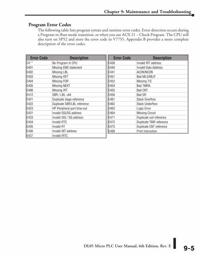
DL05 Micro PLC User Manual, 6th Edition, Rev. E 9-5
Chapter 9: Maintenance and Troubleshooting
Program Error CodesThe following table lists program syntax and runtime error codes. Error detection occurs during a Program-to-Run mode transition, or when you use AUX 21 – Check Program. The CPU will also turn on SP52 and store the error code in V7755. Appendix B provides a more complete description of the error codes.
Error Code DescriptionE4** No Program in CPUE401 Missing END statementE402 Missing LBLE403 Missing RETE404 Missing FORE405 Missing NEXTE406 Missing IRTE412 SBR / LBL >64E421 Duplicate stage referenceE422 Duplicate SBR/LBL referenceE423 HP Peripheral port time-outE431 Invalid ISG/SG addressE433 Invalid ISG / SG addressE434 Invalid RTCE435 Invalid RTE436 Invalid INT addressE437 Invalid IRTC
Error Code DescriptionE438 Invalid IRT addressE440 Invalid Data AddressE441 ACON/NCONE451 Bad MLS/MLRE453 Missing T/CE454 Bad TMRAE455 Bad CNTE456 Bad SRE461 Stack OverflowE462 Stack UnderflowE463 Logic ErrorE464 Missing CircuitE471 Duplicate coil referenceE472 Duplicate TMR referenceE473 Duplicate CNT referenceE499 Print instruction
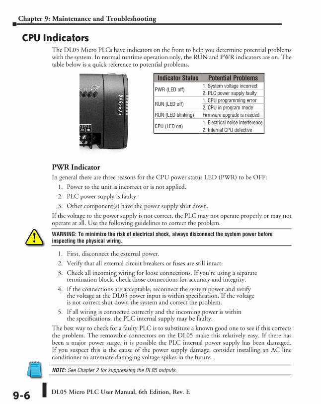
DL05 Micro PLC User Manual, 6th Edition, Rev. E9-6
Chapter 9: Maintenance and Troubleshooting
CPU IndicatorsThe DL05 Micro PLCs have indicators on the front to help you determine potential problems with the system. In normal runtime operation only, the RUN and PWR indicators are on. The table below is a quick reference to potential problems.
PWR IndicatorIn general there are three reasons for the CPU power status LED (PWR) to be OFF:
1. Power to the unit is incorrect or is not applied.
2. PLC power supply is faulty.
3. Other component(s) have the power supply shut down.
If the voltage to the power supply is not correct, the PLC may not operate properly or may not operate at all. Use the following guidelines to correct the problem.
WARNING: To minimize the risk of electrical shock, always disconnect the system power before inspecting the physical wiring.
1. First, disconnect the external power.
2. Verify that all external circuit breakers or fuses are still intact.
3. Check all incoming wiring for loose connections. If you’re using a separate termination block, check those connections for accuracy and integrity.
4. If the connections are acceptable, reconnect the system power and verify the voltage at the DL05 power input is within specification. If the voltage is not correct shut down the system and correct the problem.
5. If all wiring is connected correctly and the incoming power is within the specifications, the PLC internal supply may be faulty.
The best way to check for a faulty PLC is to substitute a known good one to see if this corrects the problem. The removable connectors on the DL05 make this relatively easy. If there has been a major power surge, it is possible the PLC internal power supply has been damaged. If you suspect this is the cause of the power supply damage, consider installing an AC line conditioner to attenuate damaging voltage spikes in the future.
NOTE: See Chapter 2 for suppressing the DL05 outputs.
Indicator Status Potential Problems
PWR (LED off) 1. System voltage incorrect2. PLC power supply faulty
RUN (LED off) 1. CPU programming error2. CPU in program mode
RUN (LED blinking) Firmware upgrade is needed
CPU (LED on) 1. Electrical noise interference2. Internal CPU defective
DL05 Micro PLC User Manual, 6th Edition, Rev. E 9-7
Chapter 9: Maintenance and Troubleshooting
RUN IndicatorIf the CPU will not enter the Run mode (the RUN indicator is off), the problem is usually in the application program, unless the CPU has a fatal error. If a fatal error has occurred, the CPU LED should be on. You can use a programming device to determine the cause of the error.
The RUN indicator is blinking: the PLC firmware needs to be upgraded.
Both of the programming devices, Handheld Programmer and DirectSOFT, will return an error message describing the problem. Depending on the error, there may also be an AUX function you can use to help diagnose the problem. The most common programming error is “Missing END Statement”. All application programs require an END statement for proper termination. A complete list of error codes can be found in Appendix B.
CPU IndicatorIf the CPU indicator is on, a fatal error has occurred in the CPU. Generally, this is not a programming problem but an actual hardware failure. You can power cycle the system to clear the error. If the error clears, you should monitor the system and determine what caused the problem. You will find this problem is sometimes caused by high frequency electrical noise introduced into the CPU from an outside source. Check your system grounding and install electrical noise filters if the grounding is suspected. If power cycling the system does not reset the error, or if the problem returns, you should replace the CPU.
Communications ProblemsIf you cannot establish communications with the CPU, check for these problems:
• The cable is disconnected.
• The cable has a broken wire or has been wired incorrectly.
• The cable is improperly terminated or grounded.
• The device connected is not operating at the correct baud rate (9600 baud).
• The device connected to the port is sending data incorrectly.
• A grounding difference exists between the two devices.
• Electrical noise is causing intermittent errors.
• The PLC has a bad communication port and should be replaced.
For problems in communicating with DirectSOFT on a personal computer, refer to the DirectSOFT manual. It includes a troubleshooting section that can help you diagnose PC problems in communications port setup, address or interrupt conflicts, etc.
DL05 Micro PLC User Manual, 6th Edition, Rev. E9-8
Chapter 9: Maintenance and Troubleshooting
I/O Point TroubleshootingPossible Causes
If you suspect an I/O error, there are several things that could be causing the problem.
• High-Speed I/O configuration error
• A blown fuse in your machine or panel (the DL05 does not have internal I/O fuses)
• A loose terminal block
• The auxiliary 24VDC supply has failed
• The Input or Output Circuit has failed
Some Quick StepsWhen troubleshooting the DL05 Micro PLCs there are a few facts you should be aware of. These facts may assist you in quickly correcting an I/O problem.
• HSIO configuration errors are commonly mistaken for I/O point failure during program development. If the I/O point in question is in X0–X2, or Y0–Y1, check all parameter locations listed in Chapter 3 that apply to the HSIO mode you have selected.
• The output circuits cannot detect shorted or open output points. If you suspect one or more faulty points, measure the voltage drop from the common to the suspect point. Remember when using a Digital Volt Meter, leakage current from an output device such as a triac or a transistor must be considered. A point which is off may appear to be on if no load is connected the point.
• The I/O point status indicators are logic-side indicators. This means the LED which indicates the on or off status reflects the status of the point with respect to the CPU. On an output point the status indicators could be operating normally while the actual output device (transistor, triac etc.) could be damaged. With an input point, if the indicator LED is on the input circuitry is probably operating properly. Verify the LED goes off when the input signal is removed.
• Leakage current can be a problem when connecting field devices to an I/O point. False input signals can be generated when the leakage current of an output device is great enough to turn on the connected input device. To correct this, install a resistor in parallel with the input or output of the circuit. The value of this resistor will depend on the amount of leakage current and the voltage applied but usually a 10K to 20K resistor will work. Verify the wattage rating of the resistor is correct for your application.
• Because of the removable terminal blocks on the DL05, the easiest method to determine if an I/O circuit has failed is to replace the unit if you have a spare. However, if you suspect a field device is defective, that device may cause the same failure in the replacement PLC as well. As a point of caution, you may want to check devices or power supplies connected to the failed I/O circuit before replacing the unit with a spare.
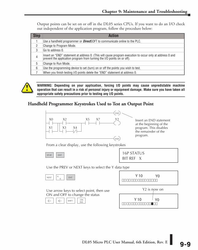
DL05 Micro PLC User Manual, 6th Edition, Rev. E 9-9
Chapter 9: Maintenance and Troubleshooting
Output points can be set on or off in the DL05 series CPUs. If you want to do an I/O check out independent of the application program, follow the procedure below:
WARNING: Depending on your application, forcing I/O points may cause unpredictable machine operation that can result in a risk of personal injury or equipment damage. Make sure you have taken all appropriate safety precautions prior to testing any I/O points.
Handheld Programmer Keystrokes Used to Test an Output Point
Step Action1 Use a handheld programmer or DirectSOFT to communicate online to the PLC.2 Change to Program Mode.3 Go to address 0.
4 Insert an “END” statement at address 0. (This will cause program execution to occur only at address 0 and prevent the application program from turning the I/O points on or off).
5 Change to Run Mode.6 Use the programming device to set (turn) on or off the points you wish to test.7 When you finish testing I/O points delete the “END” statement at address 0.
BIT REF X16P STATUS
From a clear display, use the following keystrokes
Use the PREV or NEXT keys to select the Y data type
Y2X0
END
X2
X3X1 X4
X5 X7
END
Insert an END statementat the beginning of theprogram. This disablesthe remainder of theprogram.
ST AT ENT
NEXT0
A ENT
Use arrow keys to select point, then useON and OFF to change the status
Y2 is now on
SHFT ONINS
Y 10
Y0
Y0
Y 10
DL05 Micro PLC User Manual, 6th Edition, Rev. E9-10
Chapter 9: Maintenance and Troubleshooting
Noise TroubleshootingElectrical Noise Problems
Noise is one of the most difficult problems to diagnose. Electrical noise can enter a system in many different ways and they fall into one of two categories, conducted or radiated. It may be difficult to determine how the noise is entering the system but the corrective actions for either of the types of noise problems are similar.
• Conducted noise is when the electrical interference is introduced into the system by way of a attached wire, panel connection ,etc. It may enter through an I/O circuit, a power supply connection, the communication ground connection, or the chassis ground connection.
• Radiated noise is when the electrical interference is introduced into the system without a direct electrical connection, much in the same manner as radio waves.
Reducing Electrical NoiseWhile electrical noise cannot be eliminated, it can be reduced to a level that will not affect the system.
• Most noise problems result from improper grounding of the system. A good earth ground can be the single most effective way to correct noise problems. If a ground is not available, install a ground rod as close to the system as possible. Ensure all ground wires are single point grounds and are not daisy chained from one device to another. Ground metal enclosures around the system. A loose wire can act as a large antenna, introducing noise into the system. Therefore, tighten all connections in your system. Loose ground wires are more susceptible to noise than the other wires in your system. Review Chapter 2 Installation, Wiring, and Specifications if you have questions regarding how to ground your system.
• Electrical noise can enter the system through the power source for the PLC and I/O circuits. Installing an isolation transformer for all AC sources can correct this problem. DC sources should be well-grounded good quality supplies.
• Separate input wiring from output wiring. Never run low-voltage I/O wiring close to high voltage wiring.
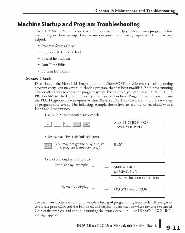
DL05 Micro PLC User Manual, 6th Edition, Rev. E 9-11
Chapter 9: Maintenance and Troubleshooting
Machine Startup and Program TroubleshootingThe DL05 Micro PLCs provide several features that can help you debug your program before and during machine startup. This section discusses the following topics which can be very helpful.
• Program Syntax Check
• Duplicate Reference Check
• Special Instructions
• Run Time Edits
• Forcing I/O Points
Syntax CheckEven though the Handheld Programmer and DirectSOFT provide error checking during program entry, you may want to check a program that has been modified. Both programming devices offer a way to check the program syntax. For example, you can use AUX 21, CHECK PROGRAM to check the program syntax from a Handheld Programmer, or you can use the PLC Diagnostics menu option within DirectSOFT. This check will find a wide variety of programming errors. The following example shows how to use the syntax check with a Handheld Programmer.
See the Error Codes Section for a complete listing of programming error codes. If you get an error, just press CLR and the Handheld will display the instruction where the error occurred. Correct the problem and continue running the Syntax check until the NO SYNTAX ERROR message appears.
1:SYN 2:DUP REFAUX 21 CHECK PRO
Use AUX 21 to perform syntax check
BUSY
Select syntax check (default selection)
MISSING END$00050 E401
One of two displays will appear
?NO SYNTAX ERROR
Error Display (example)
(You may not get the busy displayif the program is not very long.)
Syntax OK display
(shows location in question)
CLR1
B2
C AUX ENT
ENT
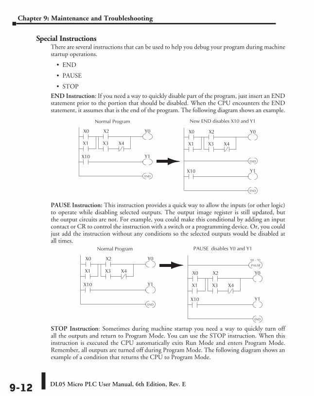
DL05 Micro PLC User Manual, 6th Edition, Rev. E9-12
Chapter 9: Maintenance and Troubleshooting
Special InstructionsThere are several instructions that can be used to help you debug your program during machine startup operations.
• END
• PAUSE
• STOP
END Instruction: If you need a way to quickly disable part of the program, just insert an END statement prior to the portion that should be disabled. When the CPU encounters the END statement, it assumes that is the end of the program. The following diagram shows an example.
PAUSE Instruction: This instruction provides a quick way to allow the inputs (or other logic) to operate while disabling selected outputs. The output image register is still updated, but the output circuits are not. For example, you could make this conditional by adding an input contact or CR to control the instruction with a switch or a programming device. Or, you could just add the instruction without any conditions so the selected outputs would be disabled at all times.
STOP Instruction: Sometimes during machine startup you need a way to quickly turn off all the outputs and return to Program Mode. You can use the STOP instruction. When this instruction is executed the CPU automatically exits Run Mode and enters Program Mode. Remember, all outputs are turned off during Program Mode. The following diagram shows an example of a condition that returns the CPU to Program Mode.
New END disables X10 and Y1
Y0X0
END
X2
X3X1 X4
Y1X10
Normal Program
Y0X0
END
X2
X3X1 X4
Y1X10
END
PAUSE disables Y0 and Y1
Y0X0
END
X2
X3X1 X4
Y1X10
Normal Program
Y0X0
END
X2
X3X1 X4
Y1X10
PAUSE
Y0 – Y1
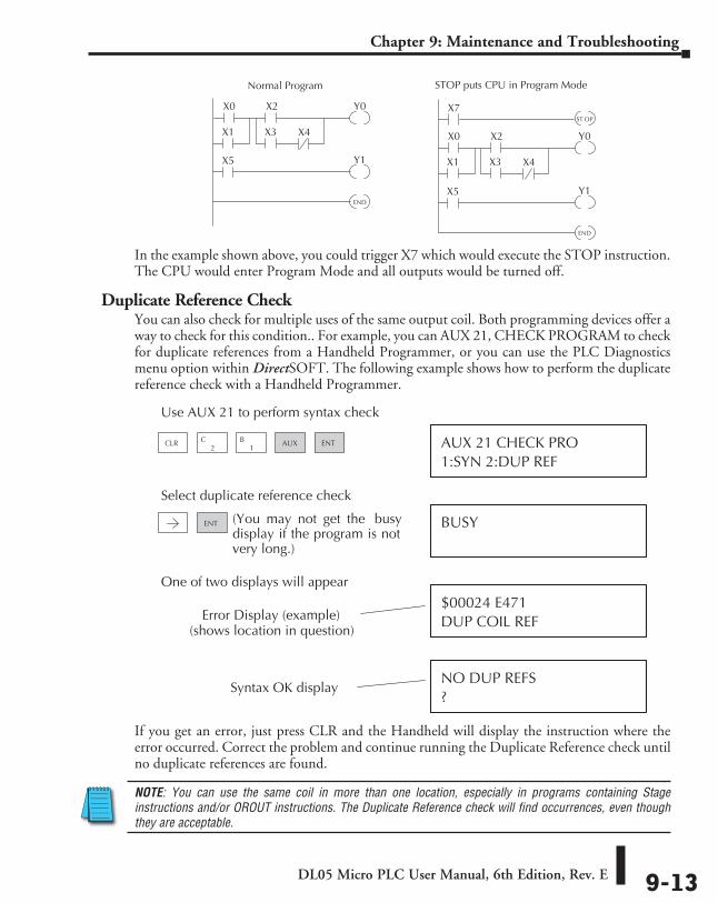
DL05 Micro PLC User Manual, 6th Edition, Rev. E 9-13
Chapter 9: Maintenance and Troubleshooting
In the example shown above, you could trigger X7 which would execute the STOP instruction. The CPU would enter Program Mode and all outputs would be turned off.
Duplicate Reference CheckYou can also check for multiple uses of the same output coil. Both programming devices offer a way to check for this condition.. For example, you can AUX 21, CHECK PROGRAM to check for duplicate references from a Handheld Programmer, or you can use the PLC Diagnostics menu option within DirectSOFT. The following example shows how to perform the duplicate reference check with a Handheld Programmer.
If you get an error, just press CLR and the Handheld will display the instruction where the error occurred. Correct the problem and continue running the Duplicate Reference check until no duplicate references are found.
NOTE: You can use the same coil in more than one location, especially in programs containing Stage instructions and/or OROUT instructions. The Duplicate Reference check will find occurrences, even though they are acceptable.
STOP puts CPU in Program Mode
Y0X0
END
X2
X3X1 X4
Y1X5
Normal Program
Y0X0
END
X2
X3X1 X4
Y1X5
X7ST OP
DUP COIL REF$00024 E471
One of two displays will appear
?NO DUP REFS
Error Display (example)
Syntax OK display
(shows location in question)
1:SYN 2:DUP REFAUX 21 CHECK PRO
Use AUX 21 to perform syntax check
BUSY
Select duplicate reference check
(You may not get the busydisplay if the program is notvery long.)
CLR1
B2
C AUX ENT
ENT
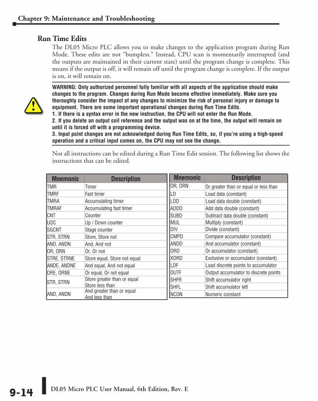
DL05 Micro PLC User Manual, 6th Edition, Rev. E9-14
Chapter 9: Maintenance and Troubleshooting
Run Time EditsThe DL05 Micro PLC allows you to make changes to the application program during Run Mode. These edits are not “bumpless.” Instead, CPU scan is momentarily interrupted (and the outputs are maintained in their current state) until the program change is complete. This means if the output is off, it will remain off until the program change is complete. If the output is on, it will remain on.
WARNING: Only authorized personnel fully familiar with all aspects of the application should make changes to the program. Changes during Run Mode become effective immediately. Make sure you thoroughly consider the impact of any changes to minimize the risk of personal injury or damage to equipment. There are some important operational changes during Run Time Edits. 1. If there is a syntax error in the new instruction, the CPU will not enter the Run Mode. 2. If you delete an output coil reference and the output was on at the time, the output will remain on until it is forced off with a programming device. 3. Input point changes are not acknowledged during Run Time Edits, so, if you’re using a high-speed operation and a critical input comes on, the CPU may not see the change.
Not all instructions can be edited during a Run Time Edit session. The following list shows the instructions that can be edited.
Mnemonic DescriptionTMR TimerTMRF Fast timerTMRA Accumulating timerTMRAF Accumulating fast timerCNT CounterUDC Up / Down counterSGCNT Stage counterSTR, STRN Store, Store notAND, ANDN And, And notOR, ORN Or, Or notSTRE, STRNE Store equal, Store not equalANDE, ANDNE And equal, And not equalORE, ORNE Or equal, Or not equal
STR, STRN Store greater than or equal Store less than
AND, ANDN And greater than or equal And less than
Mnemonic DescriptionOR, ORN Or greater than or equal or less thanLD Load data (constant)LDD Load data double (constant)ADDD Add data double (constant)SUBD Subtract data double (constant)MUL Multiply (constant)DIV Divide (constant)CMPD Compare accumulator (constant)ANDD And accumulator (constant)ORD Or accumulator (constant)XORD Exclusive or accumulator (constant)LDF Load discrete points to accumulatorOUTF Output accumulator to discrete pointsSHFR Shift accumulator rightSHFL Shift accumulator leftNCON Numeric constant
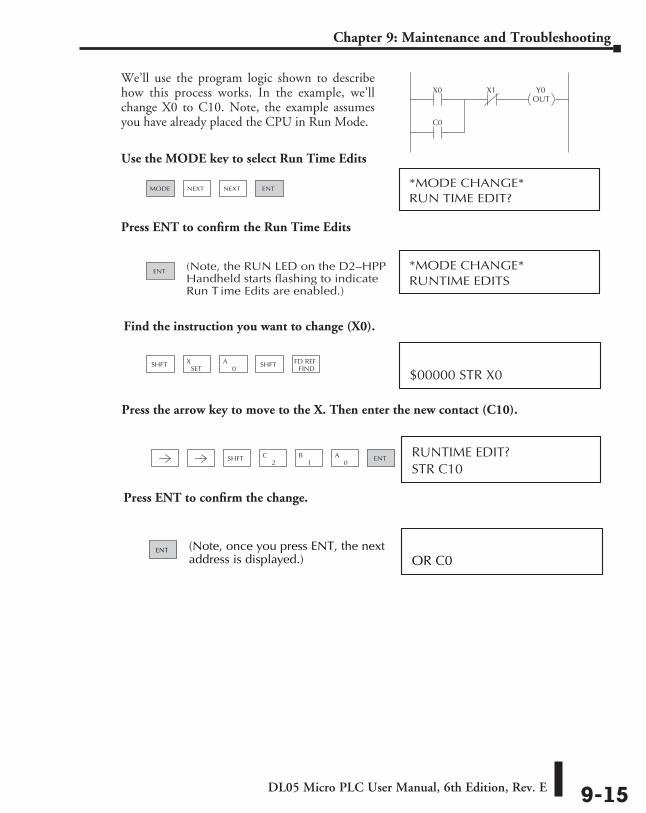
DL05 Micro PLC User Manual, 6th Edition, Rev. E 9-15
Chapter 9: Maintenance and Troubleshooting
We’ll use the program logic shown to describe how this process works. In the example, we’ll change X0 to C10. Note, the example assumes you have already placed the CPU in Run Mode.
Use the MODE key to select Run Time Edits
Press ENT to confirm the Run Time Edits
X0 X1 Y0OUT
C0
RUN TIME EDIT?*MODE CHANGE*
Use the MODE key to select Run T ime Edits
MODE ENTNEXT NEXT
RUNTIME EDITS*MODE CHANGE*
ENT (Note, the RUN LED on the D2–HPPHandheld starts flashing to indicateRun T ime Edits are enabled.)
STR C10RUNTIME EDIT?
SHFT1
B2
C0
A ENT
OR C0ENT (Note, once you press ENT, the next
address is displayed.)
Find the instruction you want to change (X0).
Press the arrow key to move to the X. Then enter the new contact (C10).
Press ENT to confirm the change.
$00000 STR X0SHFT
SETX
0A SHFT FD REF
FIND
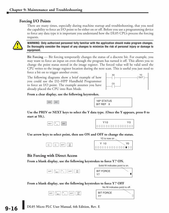
DL05 Micro PLC User Manual, 6th Edition, Rev. E9-16
Chapter 9: Maintenance and Troubleshooting
Forcing I/O PointsThere are many times, especially during machine startup and troubleshooting, that you need the capability to force an I/O point to be either on or off. Before you use a programming device to force any data type it is important you understand how the DL05 CPUs process the forcing requests.
WARNING: Only authorized personnel fully familiar with the application should make program changes. Do thoroughly consider the impact of any changes to minimize the risk of personal injury or damage to equipment.
Bit Forcing — Bit forcing temporarily changes the status of a discrete bit. For example, you may want to force an input on even though the program has turned it off. This allows you to change the point status stored in the image register. The forced value will be valid until the CPU writes to the image register location during the next scan. This is useful you just need to force a bit on to trigger another event.
The following diagrams show a brief example of how you could use the D2–HPP Handheld Programmer to force an I/O point. The example assumes you have already placed the CPU into Run Mode.
From a clear display, use the following keystrokes.
Use the PREV or NEXT keys to select the Y data type. (Once the Y appears, press 0 to start at Y0.).
Use arrow keys to select point, then use ON and OFF to change the status.
Bit Forcing with Direct AccessFrom a blank display, use the following keystrokes to force Y 7 ON.
From a blank display, use the following keystrokes to force Y 7 OFF
BIT REF X16P STATUS
STAT ENT
NEXT0
A ENT 0 0 Y 1 Y
SHFT ONINS
0 0 Y 1 Y
Y2 is now on
Y7BIT FORCE
Solid fill indicates point is on.
MLSY
7HSHFT SHFT ON
INS
Y7BIT FORCE
No fill indicates point is off.
MLSY
7HSHFT SHFT OFF
DEL
X0 Y0OUT
C0
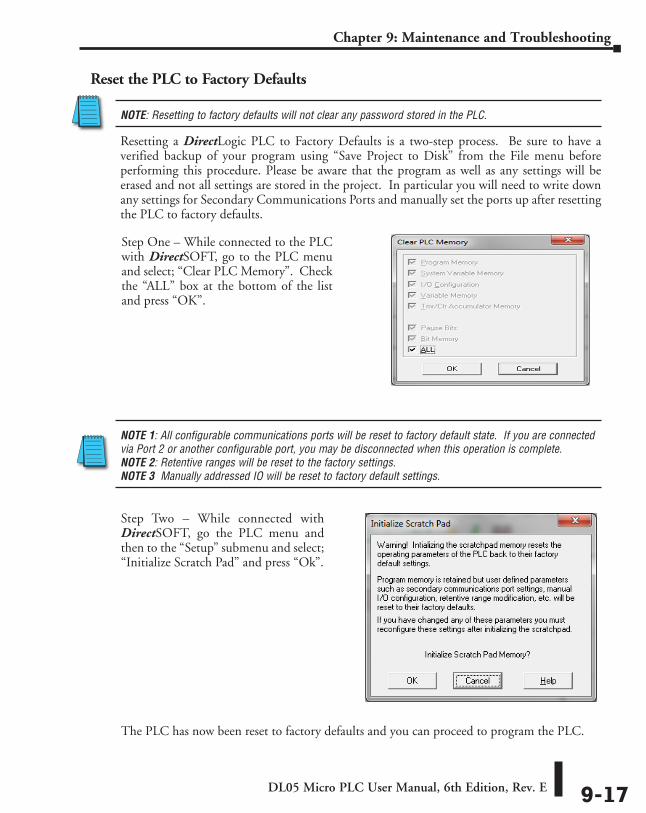
DL05 Micro PLC User Manual, 6th Edition, Rev. E 9-17
Chapter 9: Maintenance and Troubleshooting
Reset the PLC to Factory Defaults
NOTE: Resetting to factory defaults will not clear any password stored in the PLC.
Resetting a DirectLogic PLC to Factory Defaults is a two-step process. Be sure to have a verified backup of your program using “Save Project to Disk” from the File menu before performing this procedure. Please be aware that the program as well as any settings will be erased and not all settings are stored in the project. In particular you will need to write down any settings for Secondary Communications Ports and manually set the ports up after resetting the PLC to factory defaults.
NOTE 1: All configurable communications ports will be reset to factory default state. If you are connected via Port 2 or another configurable port, you may be disconnected when this operation is complete. NOTE 2: Retentive ranges will be reset to the factory settings. NOTE 3 Manually addressed IO will be reset to factory default settings.
The PLC has now been reset to factory defaults and you can proceed to program the PLC.
Step One – While connected to the PLC with DirectSOFT, go to the PLC menu and select; “Clear PLC Memory”. Check the “ALL” box at the bottom of the list and press “OK”.
Step Two – While connected with DirectSOFT, go the PLC menu and then to the “Setup” submenu and select; “Initialize Scratch Pad” and press “Ok”.
101010MeMory Cartridge/ real tiMe CloCk (dl05 only)
ChapterChapterChapter
In This Chapter...General Information about the D0–01MC .............................................................. 10-2
Setting the Write Enable/Disable Jumper............................................................... 10-3
Plugging-in the Memory Cartridge ........................................................................ 10-4
Software and Firmware Requirements ................................................................... 10-5
Naming the Memory Cartridge .............................................................................. 10-6
Setting the Time and Date ...................................................................................... 10-7
Memory Transfers .................................................................................................... 10-8
LED Indicator Lights ................................................................................................ 10-9
Password Protected Programs ................................................................................ 10-9
Memory Map and Forwarding Range .................................................................. 10-10
Battery Back-up During AC Power Loss ................................................................ 10-11
Specifications and Agency Approvals ................................................................... 10-12
Clock/Calendar Instructions .................................................................................. 10-13
Error Codes ............................................................................................................ 10-18
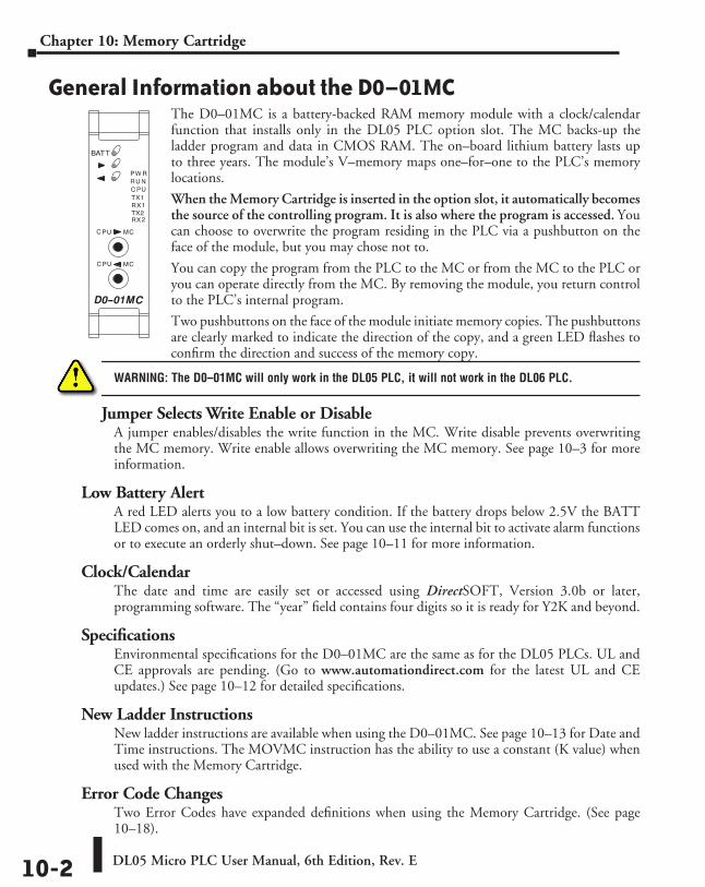
DL05 Micro PLC User Manual, 6th Edition, Rev. E10-2
Chapter 10: Memory Cartridge
General Information about the D0–01MCThe D0–01MC is a battery-backed RAM memory module with a clock/calendar function that installs only in the DL05 PLC option slot. The MC backs-up the ladder program and data in CMOS RAM. The on–board lithium battery lasts up to three years. The module’s V–memory maps one–for–one to the PLC’s memory locations.
When the Memory Cartridge is inserted in the option slot, it automatically becomes the source of the controlling program. It is also where the program is accessed. You can choose to overwrite the program residing in the PLC via a pushbutton on the face of the module, but you may chose not to.
You can copy the program from the PLC to the MC or from the MC to the PLC or you can operate directly from the MC. By removing the module, you return control to the PLC’s internal program.
Two pushbuttons on the face of the module initiate memory copies. The pushbuttons are clearly marked to indicate the direction of the copy, and a green LED flashes to confirm the direction and success of the memory copy.
WARNING: The D0–01MC will only work in the DL05 PLC, it will not work in the DL06 PLC.
Jumper Selects Write Enable or DisableA jumper enables/disables the write function in the MC. Write disable prevents overwriting the MC memory. Write enable allows overwriting the MC memory. See page 10–3 for more information.
Low Battery AlertA red LED alerts you to a low battery condition. If the battery drops below 2.5V the BATT LED comes on, and an internal bit is set. You can use the internal bit to activate alarm functions or to execute an orderly shut–down. See page 10–11 for more information.
Clock/CalendarThe date and time are easily set or accessed using DirectSOFT, Version 3.0b or later, programming software. The “year” field contains four digits so it is ready for Y2K and beyond.
SpecificationsEnvironmental specifications for the D0–01MC are the same as for the DL05 PLCs. UL and CE approvals are pending. (Go to www.automationdirect.com for the latest UL and CE updates.) See page 10–12 for detailed specifications.
New Ladder InstructionsNew ladder instructions are available when using the D0–01MC. See page 10–13 for Date and Time instructions. The MOVMC instruction has the ability to use a constant (K value) when used with the Memory Cartridge.
Error Code ChangesTwo Error Codes have expanded definitions when using the Memory Cartridge. (See page 10–18).
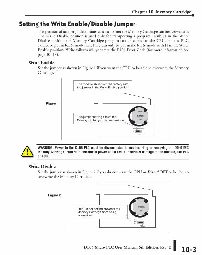
DL05 Micro PLC User Manual, 6th Edition, Rev. E 10-3
Chapter 10: Memory Cartridge
Setting the Write Enable/Disable JumperThe position of jumper J1 determines whether or not the Memory Cartridge can be overwritten. The Write Disable position is used only for transporting a program. With J1 in the Write Disable position the Memory Cartridge program can be copied to the CPU, but the PLC cannot be put in RUN mode. The PLC can only be put in the RUN mode with J1 in the Write Enable position. Write failures will generate the E104 Error Code (for more information see page 10–18).
Write EnableSet the jumper as shown in Figure 1 if you want the CPU to be able to overwrite the Memory Cartridge.
WARNING: Power to the DL05 PLC must be disconnected before inserting or removing the D0–01MC Memory Cartridge. Failure to disconnect power could result in serious damage to the module, the PLC or both.
Write DisableSet the jumper as shown in Figure 2 if you do not want the CPU or DirectSOFT to be able to overwrite the Memory Cartridge.
J1
This jumper setting allows theMemory Cartridge to be overwritten.
BATTERY
3V
The module ships from the factory withthe jumper in the Write Enable position.
Write
Disable
Enable
Figure 1
This jumper setting prevents theMemory Cartridge from beingoverwritten.
BATTERY
3V
J1
Write
Disable
Enable
Figure 2
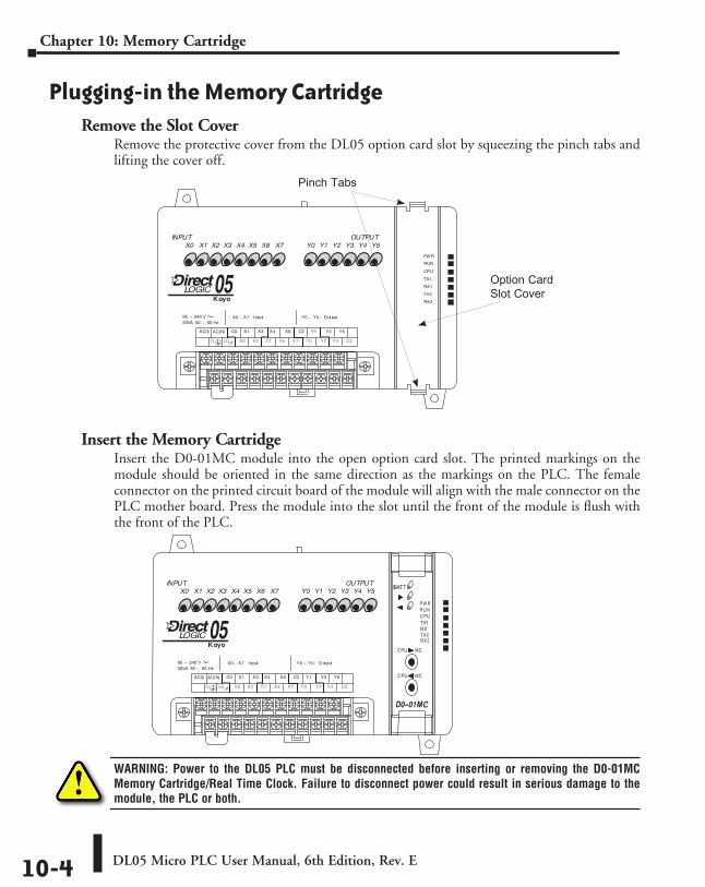
DL05 Micro PLC User Manual, 6th Edition, Rev. E10-4
Chapter 10: Memory Cartridge
Plugging-in the Memory CartridgeRemove the Slot Cover
Remove the protective cover from the DL05 option card slot by squeezing the pinch tabs and lifting the cover off.
Insert the Memory CartridgeInsert the D0-01MC module into the open option card slot. The printed markings on the module should be oriented in the same direction as the markings on the PLC. The female connector on the printed circuit board of the module will align with the male connector on the PLC mother board. Press the module into the slot until the front of the module is flush with the front of the PLC.
WARNING: Power to the DL05 PLC must be disconnected before inserting or removing the D0-01MC Memory Cartridge/Real Time Clock. Failure to disconnect power could result in serious damage to the module, the PLC or both.
Pinch Tabs
Option Card Slot Cover
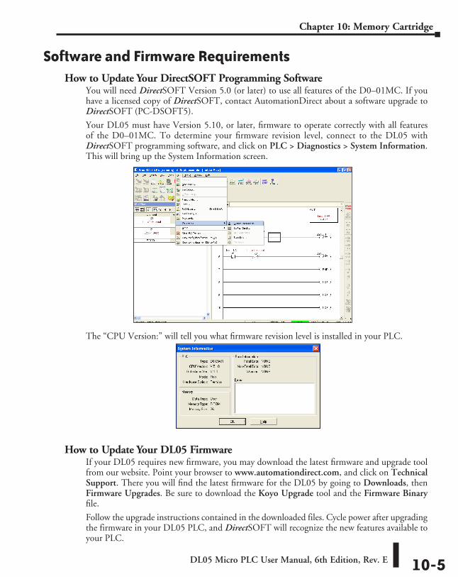
DL05 Micro PLC User Manual, 6th Edition, Rev. E 10-5
Chapter 10: Memory Cartridge
Software and Firmware RequirementsHow to Update Your DirectSOFT Programming Software
You will need DirectSOFT Version 5.0 (or later) to use all features of the D0–01MC. If you have a licensed copy of DirectSOFT, contact AutomationDirect about a software upgrade to DirectSOFT (PC-DSOFT5).
Your DL05 must have Version 5.10, or later, firmware to operate correctly with all features of the D0–01MC. To determine your firmware revision level, connect to the DL05 with DirectSOFT programming software, and click on PLC > Diagnostics > System Information. This will bring up the System Information screen.
The “CPU Version:” will tell you what firmware revision level is installed in your PLC.
How to Update Your DL05 FirmwareIf your DL05 requires new firmware, you may download the latest firmware and upgrade tool from our website. Point your browser to www.automationdirect.com, and click on Technical Support. There you will find the latest firmware for the DL05 by going to Downloads, then Firmware Upgrades. Be sure to download the Koyo Upgrade tool and the Firmware Binary file.
Follow the upgrade instructions contained in the downloaded files. Cycle power after upgrading the firmware in your DL05 PLC, and DirectSOFT will recognize the new features available to your PLC.
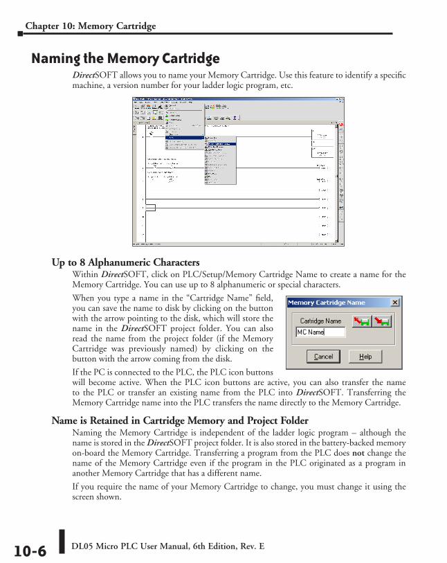
DL05 Micro PLC User Manual, 6th Edition, Rev. E10-6
Chapter 10: Memory Cartridge
Naming the Memory CartridgeDirectSOFT allows you to name your Memory Cartridge. Use this feature to identify a specific machine, a version number for your ladder logic program, etc.
Up to 8 Alphanumeric CharactersWithin DirectSOFT, click on PLC/Setup/Memory Cartridge Name to create a name for the Memory Cartridge. You can use up to 8 alphanumeric or special characters.
When you type a name in the “Cartridge Name” field, you can save the name to disk by clicking on the button with the arrow pointing to the disk, which will store the name in the DirectSOFT project folder. You can also read the name from the project folder (if the Memory Cartridge was previously named) by clicking on the button with the arrow coming from the disk.
If the PC is connected to the PLC, the PLC icon buttons will become active. When the PLC icon buttons are active, you can also transfer the name to the PLC or transfer an existing name from the PLC into DirectSOFT. Transferring the Memory Cartridge name into the PLC transfers the name directly to the Memory Cartridge.
Name is Retained in Cartridge Memory and Project FolderNaming the Memory Cartridge is independent of the ladder logic program – although the name is stored in the DirectSOFT project folder. It is also stored in the battery-backed memory on-board the Memory Cartridge. Transferring a program from the PLC does not change the name of the Memory Cartridge even if the program in the PLC originated as a program in another Memory Cartridge that has a different name.
If you require the name of your Memory Cartridge to change, you must change it using the screen shown.
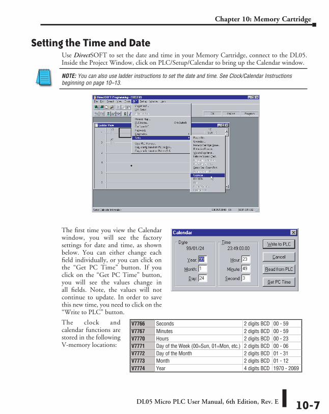
DL05 Micro PLC User Manual, 6th Edition, Rev. E 10-7
Chapter 10: Memory Cartridge
Setting the Time and DateUse DirectSOFT to set the date and time in your Memory Cartridge, connect to the DL05. Inside the Project Window, click on PLC/Setup/Calendar to bring up the Calendar window.
NOTE: You can also use ladder instructions to set the date and time. See Clock/Calendar Instructions beginning on page 10–13.
The first time you view the Calendar window, you will see the factory settings for date and time, as shown below. You can either change each field individually, or you can click on the “Get PC Time” button. If you click on the “Get PC Time” button, you will see the values change in all fields. Note, the values will not continue to update. In order to save this new time, you need to click on the “Write to PLC” button.
V7766 Seconds 2 digits BCD 00 - 59V7767 Minutes 2 digits BCD 00 - 59V7770 Hours 2 digits BCD 00 - 23V7771 Day of the Week (00=Sun, 01=Mon, etc.) 2 digits BCD 00 - 06V7772 Day of the Month 2 digits BCD 01 - 31V7773 Month 2 digits BCD 01 - 12V7774 Year 4 digits BCD 1970 - 2069
The clock and calendar functions are stored in the following V-memory locations:
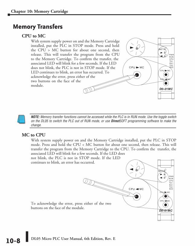
DL05 Micro PLC User Manual, 6th Edition, Rev. E10-8
Chapter 10: Memory Cartridge
Memory TransfersCPU to MC
With system supply power on and the Memory Cartridge installed, put the PLC in STOP mode. Press and hold the CPU > MC button for about one second, then release. This will transfer the program from the CPU to the Memory Cartridge. To confirm the transfer, the associated LED will blink for a few seconds. If the LED does not blink, the PLC is not in STOP mode. If the LED continues to blink, an error has occurred. To acknowledge the error, press either of the two buttons on the face of the module.
NOTE: Memory transfer functions cannot be accessed while the PLC is in RUN mode. Use the toggle switch on the DL05 to switch the PLC out of RUN mode, or use DirectSOFT programming software to make the change.
MC to CPUWith system supply power on and the Memory Cartridge installed, put the PLC in STOP mode. Press and hold the CPU < MC button for about one second, then release. This will transfer the program from the Memory Cartridge to the CPU. To confirm the transfer, the associated LED will blink for a few seconds. If the LED does not blink, the PLC is not in STOP mode. If the LED continues to blink, an error has occurred.
To acknowledge the error, press either of the two buttons on the face of the module.
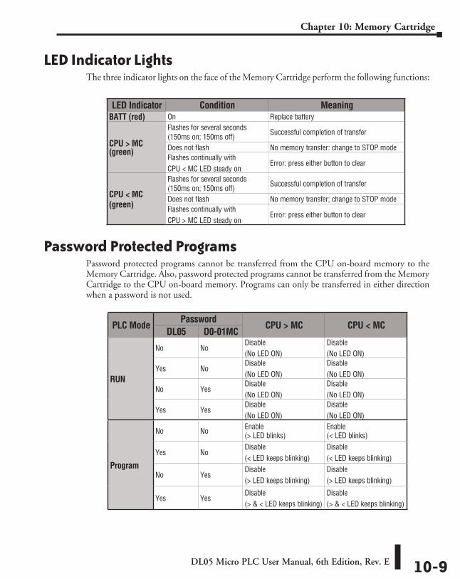
DL05 Micro PLC User Manual, 6th Edition, Rev. E 10-9
Chapter 10: Memory Cartridge
LED Indicator LightsThe three indicator lights on the face of the Memory Cartridge perform the following functions:
Password Protected ProgramsPassword protected programs cannot be transferred from the CPU on-board memory to the Memory Cartridge. Also, password protected programs cannot be transferred from the Memory Cartridge to the CPU on-board memory. Programs can only be transferred in either direction when a password is not used.
LED Indicator Condition MeaningBATT (red) On Replace battery
CPU > MC (green)
Flashes for several seconds(150ms on; 150ms off) Successful completion of transfer
Does not flash No memory transfer: change to STOP modeFlashes continually withCPU < MC LED steady on
Error: press either button to clear
CPU < MC (green)
Flashes for several seconds(150ms on; 150ms off) Successful completion of transfer
Does not flash No memory transfer; change to STOP modeFlashes continually withCPU > MC LED steady on
Error: press either button to clear
PLC ModePassword
CPU > MC CPU < MCDL05 D0-01MC
RUN
No NoDisable(No LED ON)
Disable(No LED ON)
Yes No Disable(No LED ON)
Disable(No LED ON)
No Yes Disable(No LED ON)
Disable(No LED ON)
Yes Yes Disable(No LED ON)
Disable(No LED ON)
Program
No No Enable (> LED blinks)
Enable (< LED blinks)
Yes No Disable(< LED keeps blinking)
Disable(< LED keeps blinking)
No Yes Disable(> LED keeps blinking)
Disable(> LED keeps blinking)
Yes YesDisable(> & < LED keeps blinking)
Disable(> & < LED keeps blinking)
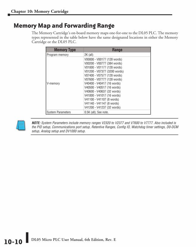
DL05 Micro PLC User Manual, 6th Edition, Rev. E10-10
Chapter 10: Memory Cartridge
Memory Map and Forwarding RangeThe Memory Cartridge’s on-board memory maps one-for-one to the DL05 PLC. The memory types represented in the table below have the same designated locations in either the Memory Cartridge or the DL05 PLC.
Memory Type RangeProgram memory 2K (all)
V-memory
V00000 - V00177 (128 words)V00200 - V00777 (384 words)V01000 - V01177 (128 words)V01200 - V07377 (3200 words)V07400 - V07577 (128 words)V07600 - V07777 (128 words)V40400 - V40417 (16 words)V40500 - V40517 (16 words)V40600 - V40637 (32 words)V41000 - V41017 (16 words)V41100 - V41107 (8 words)V41140 - V41147 (8 words)V41200 - V41237 (32 words)
System Parameters 0.5K (all); See note.
NOTE: System Parameters include memory ranges V2320 to V2377 and V7600 to V7777. Also included is the PID setup, Communications port setup, Retentive Ranges, Config IO, Watchdog timer settings, D0-DCM setup, Analog setup and DV1000 setup.
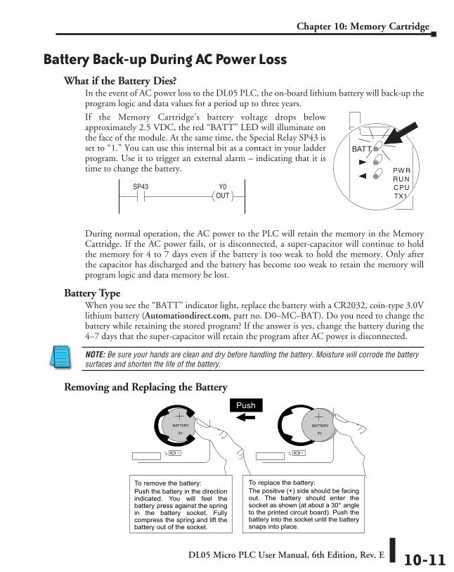
DL05 Micro PLC User Manual, 6th Edition, Rev. E 10-11
Chapter 10: Memory Cartridge
Battery Back-up During AC Power LossWhat if the Battery Dies?
In the event of AC power loss to the DL05 PLC, the on-board lithium battery will back-up the program logic and data values for a period up to three years.
If the Memory Cartridge’s battery voltage drops below approximately 2.5 VDC, the red “BATT” LED will illuminate on the face of the module. At the same time, the Special Relay SP43 is set to “1.” You can use this internal bit as a contact in your ladder program. Use it to trigger an external alarm – indicating that it is time to change the battery.
During normal operation, the AC power to the PLC will retain the memory in the Memory Cartridge. If the AC power fails, or is disconnected, a super-capacitor will continue to hold the memory for 4 to 7 days even if the battery is too weak to hold the memory. Only after the capacitor has discharged and the battery has become too weak to retain the memory will program logic and data memory be lost.
Battery TypeWhen you see the “BATT” indicator light, replace the battery with a CR2032, coin-type 3.0V lithium battery (Automationdirect.com, part no. D0–MC–BAT). Do you need to change the battery while retaining the stored program? If the answer is yes, change the battery during the 4–7 days that the super-capacitor will retain the program after AC power is disconnected.
NOTE: Be sure your hands are clean and dry before handling the battery. Moisture will corrode the battery surfaces and shorten the life of the battery.
Removing and Replacing the Battery
Inst
alla
tion
and
J1
BATTERY
3V
J1
BATTERY
3V
Push
To remove the battery:Push the battery in the directionindicated. You will feel thebattery press against the springin the battery socket. Fullycompress the spring and lift thebattery out of the socket.
To replace the battery:The positive (+) side should be facingout. The battery should enter thesocket as shown (at about a 30° angleto the printed circuit board). Push thebattery into the socket until the batterysnaps into place.
SP43 Y0OUT
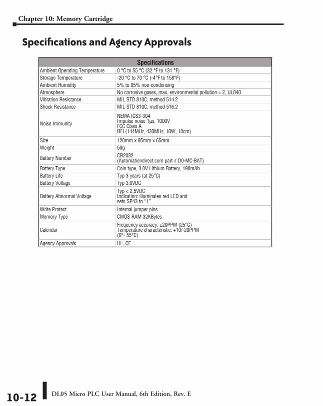
DL05 Micro PLC User Manual, 6th Edition, Rev. E10-12
Chapter 10: Memory Cartridge
Specifications and Agency Approvals
SpecificationsAmbient Operating Temperature 0 °C to 55 °C (32 °F to 131 °F)Storage Temperature -20 °C to 70 °C (-4°F to 158°F)Ambient Humidity 5% to 95% non-condensingAtmosphere No corrosive gases, max. environmental pollution = 2, UL840Vibration Resistance MIL STD 810C, method 514.2Shock Resistance MIL STD 810C, method 516.2
Noise ImmunityNEMA ICS3-304 Impulse noise 1µs, 1000V FCC Class A RFI (144MHz, 430MHz, 10W, 10cm)
Size 120mm x 95mm x 65mmWeight 50g
Battery Number CR2032 (Automationdirect.com part # D0-MC-BAT)
Battery Type Coin type, 3.0V Lithium Battery, 190mAhBattery Life Typ 3 years (at 25°C)Battery Voltage Typ 3.0VDC
Battery Abnormal VoltageTyp < 2.5VDC Indication: illuminates red LED and sets SP43 to “1”
Write Protect Internal jumper pinsMemory Type CMOS RAM 32KBytes
CalendarFrequency accuracy: ±20PPM (25°C) Temperature characteristic: +10/-20PPM (0°- 55°C)
Agency Approvals UL, CE
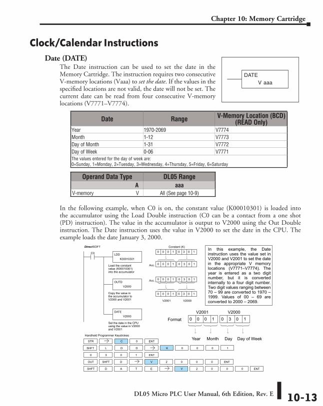
DL05 Micro PLC User Manual, 6th Edition, Rev. E 10-13
Chapter 10: Memory Cartridge
Clock/Calendar InstructionsDate (DATE)
The Date instruction can be used to set the date in the Memory Cartridge. The instruction requires two consecutive V-memory locations (Vaaa) to set the date. If the values in the specified locations are not valid, the date will not be set. The current date can be read from four consecutive V-memory locations (V7771–V7774).
In the following example, when C0 is on, the constant value (K00010301) is loaded into the accumulator using the Load Double instruction (C0 can be a contact from a one shot (PD) instruction). The value in the accumulator is output to V2000 using the Out Double instruction. The Date instruction uses the value in V2000 to set the date in the CPU. The example loads the date January 3, 2000.
In this example, the Dateinstruction uses the value set inV2000 and V2001 to set the datein the appropriate V memorylocations (V7771–V7774). Theyear is entered as a two digitnumber, but it is convertedinternally to a four digit number.Two digit values ranging between70 – 99 are converted to 1970 –1999. Values of 00 – 69 areconverted to 2000 – 2069.
DirectSOFT
Handheld Programmer Keystrokes
LDDK00010301
C0
Load the constantvalue (K00010301)into the accumulator
DATEV2000
Set the date in the CPUusing the value in V2000and V2001
OUTDV2000
Copy the value inthe accumulator toV2000 and V2001
STR C 0
L D K 0 0 0 1
OUT SHFT D V 2 0 0 0
SHFT D A T E V 2 0 0 0
0 3 0 1
V2000
Acc.
0 3 0 1
0 3 0 1
0 0 0 1 0 3 0 1
0 0 0 1
V2001
0 0 0 1
Constant (K)
Acc. 0 0 0 1 0 3 0 1
Day Day of WeekYear Month
0 3 0 10 0 0 1V2001 V2000
Format
ENT
SHFT D
ENT
ENT
ENT
Date Range V-Memory Location (BCD) (READ Only)
Year 1970-2069 V7774Month 1-12 V7773Day of Month 1-31 V7772Day of Week 0-06 V7771 The values entered for the day of week are: 0=Sunday, 1=Monday, 2=Tuesday, 3=Wednesday, 4=Thursday, 5=Friday, 6=Saturday
Operand Data Type DL05 Range A aaaV-memory V All (See page 10-9)
V aaaDATE
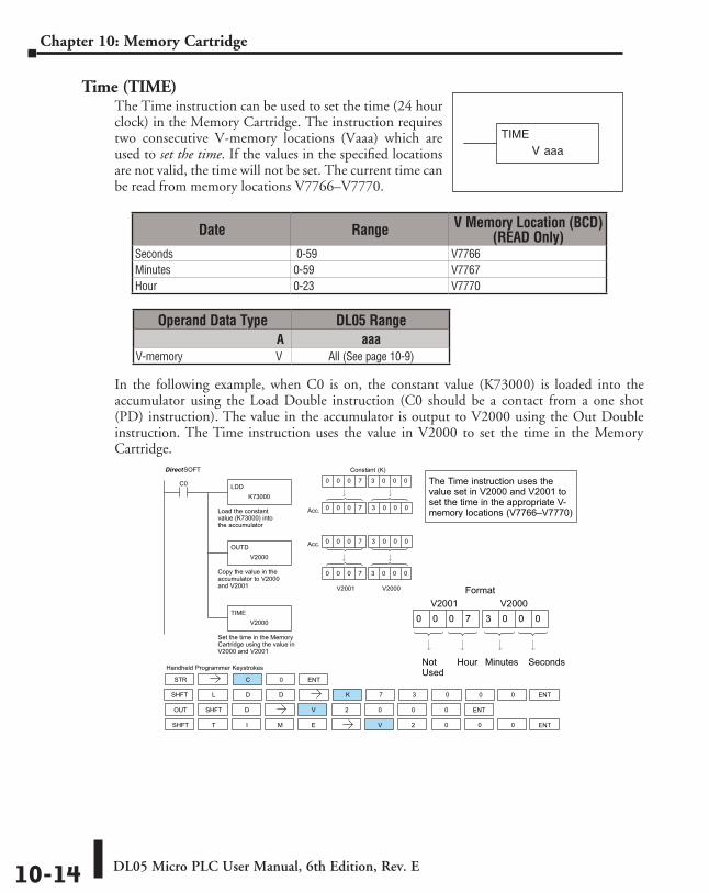
DL05 Micro PLC User Manual, 6th Edition, Rev. E10-14
Chapter 10: Memory Cartridge
Time (TIME)The Time instruction can be used to set the time (24 hour clock) in the Memory Cartridge. The instruction requires two consecutive V-memory locations (Vaaa) which are used to set the time. If the values in the specified locations are not valid, the time will not be set. The current time can be read from memory locations V7766–V7770.
In the following example, when C0 is on, the constant value (K73000) is loaded into the accumulator using the Load Double instruction (C0 should be a contact from a one shot (PD) instruction). The value in the accumulator is output to V2000 using the Out Double instruction. The Time instruction uses the value in V2000 to set the time in the Memory Cartridge.
DirectSOFT
Handheld Programmer Keystrokes
LDDK73000
C0
Load the constantvalue (K73000) intothe accumulator
TIMEV2000
Set the time in the MemoryCartridge using the value inV2000 and V2001
OUTDV2000
Copy the value in theaccumulator to V2000and V2001 V2000
Acc.
3 0 0 0
3 0 0 0
0 0 0 7 3 0 0 0
0 0 0 7
V2001
0 0 0 7
Constant (K)
Acc. 0 0 0 7 3 0 0 0
The Time instruction uses thevalue set in V2000 and V2001 toset the time in the appropriate V-memory locations (V7766–V7770)
Minutes SecondsNotUsed
Hour
3 0 0 00 0 0 7V2001 V2000
Format
STR C 0
L D K 7 3 0 0
OUT SHFT D V 2 0 0 0
SHFT T I M E V 2 0 0 0
ENT
SHFT D ENT
ENT
ENT
0
Date Range V Memory Location (BCD) (READ Only)
Seconds 0-59 V7766Minutes 0-59 V7767Hour 0-23 V7770
Operand Data Type DL05 Range A aaa
V-memory V All (See page 10-9)
V aaaTIME
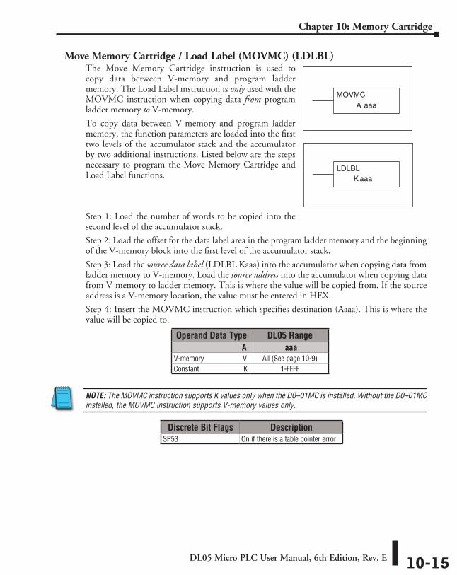
DL05 Micro PLC User Manual, 6th Edition, Rev. E 10-15
Chapter 10: Memory Cartridge
Move Memory Cartridge / Load Label (MOVMC) (LDLBL)The Move Memory Cartridge instruction is used to copy data between V-memory and program ladder memory. The Load Label instruction is only used with the MOVMC instruction when copying data from program ladder memory to V-memory.
To copy data between V-memory and program ladder memory, the function parameters are loaded into the first two levels of the accumulator stack and the accumulator by two additional instructions. Listed below are the steps necessary to program the Move Memory Cartridge and Load Label functions.
Step 1: Load the number of words to be copied into the second level of the accumulator stack.
Step 2: Load the offset for the data label area in the program ladder memory and the beginning of the V-memory block into the first level of the accumulator stack.
Step 3: Load the source data label (LDLBL Kaaa) into the accumulator when copying data from ladder memory to V-memory. Load the source address into the accumulator when copying data from V-memory to ladder memory. This is where the value will be copied from. If the source address is a V-memory location, the value must be entered in HEX.
Step 4: Insert the MOVMC instruction which specifies destination (Aaaa). This is where the value will be copied to.
NOTE: The MOVMC instruction supports K values only when the D0–01MC is installed. Without the D0–01MC installed, the MOVMC instruction supports V-memory values only.
Operand Data Type DL05 Range A aaa
V-memory V All (See page 10-9)Constant K 1-FFFF
Discrete Bit Flags DescriptionSP53 On if there is a table pointer error
A aaaMOVMC
LDLBLaaaK
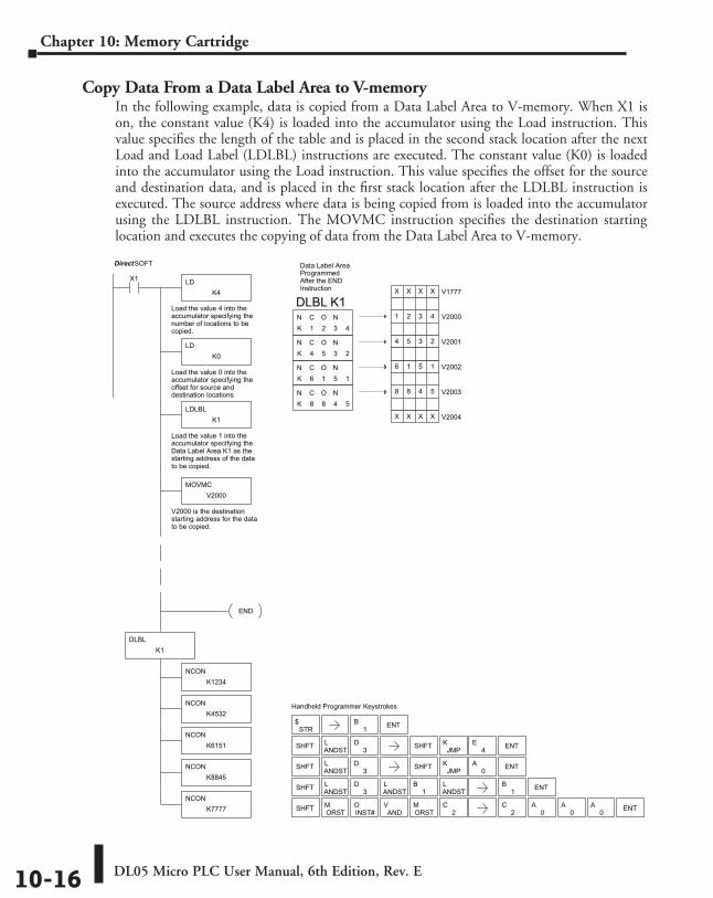
DL05 Micro PLC User Manual, 6th Edition, Rev. E10-16
Chapter 10: Memory Cartridge
Copy Data From a Data Label Area to V-memoryIn the following example, data is copied from a Data Label Area to V-memory. When X1 is on, the constant value (K4) is loaded into the accumulator using the Load instruction. This value specifies the length of the table and is placed in the second stack location after the next Load and Load Label (LDLBL) instructions are executed. The constant value (K0) is loaded into the accumulator using the Load instruction. This value specifies the offset for the source and destination data, and is placed in the first stack location after the LDLBL instruction is executed. The source address where data is being copied from is loaded into the accumulator using the LDLBL instruction. The MOVMC instruction specifies the destination starting location and executes the copying of data from the Data Label Area to V-memory.
1 2 3 4C O N
4 5 3 2C O N
6 1 5 1C O N
8 8 4 5C O N
KN
KN
KN
KN
DirectSOFT
Handheld Programmer Keystrokes
LDK4
X1
Load the value 4 into theaccumulator specifying thenumber of locations to becopied.
LDK0
Load the value 0 into theaccumulator specifying theoffset for source anddestination locations
LDLBLK1
Load the value 1 into theaccumulator specifying theData Label Area K1 as thestarting address of the datato be copied.
V20014 5 3 2
V20026 1 5 1
V20038 8 4 5
V2004X X X X
V1777X X X X
V20001 2 3 4
Data Label AreaProgrammedAfter the ENDInstruction
MOVMCV2000
V2000 is the destinationstarting address for the datato be copied.
DLBL K1
STR$
SHFT ANDSTL
3D SHFT JMP
K ENT
SHFT ANDSTL
3D
ANDSTL
1B
ANDSTL
SHFT ORSTM
ANDV
INST#O
ORSTM
2C
1B ENT
ENT1B
2C
0A
0A
0A ENT
SHFT ANDSTL
3D SHFT JMP
K0
A ENT
4E
NCONK1234
DLBLK1
NCONK6151
NCONK7777
NCONK4532
NCONK8845
END
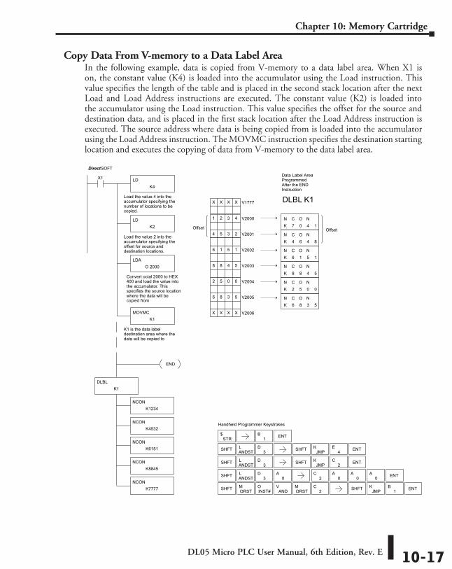
DL05 Micro PLC User Manual, 6th Edition, Rev. E 10-17
Chapter 10: Memory Cartridge
Copy Data From V-memory to a Data Label AreaIn the following example, data is copied from V-memory to a data label area. When X1 is on, the constant value (K4) is loaded into the accumulator using the Load instruction. This value specifies the length of the table and is placed in the second stack location after the next Load and Load Address instructions are executed. The constant value (K2) is loaded into the accumulator using the Load instruction. This value specifies the offset for the source and destination data, and is placed in the first stack location after the Load Address instruction is executed. The source address where data is being copied from is loaded into the accumulator using the Load Address instruction. The MOVMC instruction specifies the destination starting location and executes the copying of data from V-memory to the data label area.
6 1 5 1C O N
8 8 4 5C O N
2 5 0 0C O N
6 8 3 5C O N
KN
KN
KN
KN
DirectSOFT
Handheld Programmer Keystrokes
LDK4
X1
Load the value 4 into theaccumulator specifying thenumber of locations to becopied.
LDK2
Load the value 2 into theaccumulator specifying theoffset for source anddestination locations.
LDA O 2000
V20014 5 3 2
V20026 1 5 1
V20038 8 4 5
V20042 5 0 0
V1777X X X X
V20001 2 3 4
Data Label AreaProgrammedAfter the ENDInstruction
MOVMCK1
K1 is the data labeldestination area where thedata will be copied to
V20056 8 3 5
V2006X X X X
DLBL K1
Offset 7 0 4 1C O N
4 6 4 8C O N
KN
KN
Offset
Convert octal 2000 to HEX400 and load the value intothe accumulator. Thisspecifies the source locationwhere the data will becopied from
STR$
SHFT ANDSTL
3D SHFT JMP
K ENT4E
SHFT ANDSTL
3D
SHFT ORSTM
ANDV
INST#O
ORSTM
2C SHFT ENT
0A
2C
0A
0A
0A ENT
JMPK
1B
SHFT ANDSTL
3D SHFT JMP
K ENT2C
1B ENT
NCONK1234
DLBLK1
NCONK6151
NCONK7777
NCONK4532
NCONK8845
END
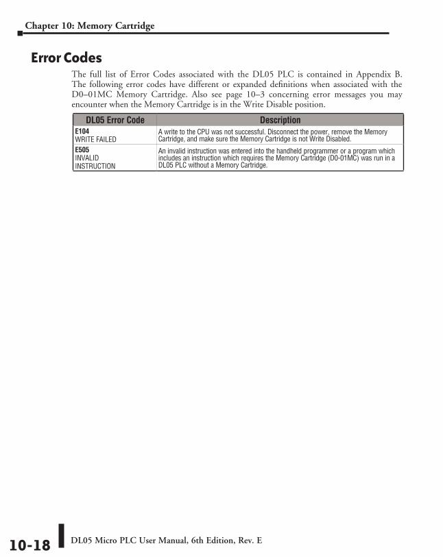
DL05 Micro PLC User Manual, 6th Edition, Rev. E10-18
Chapter 10: Memory Cartridge
Error CodesThe full list of Error Codes associated with the DL05 PLC is contained in Appendix B. The following error codes have different or expanded definitions when associated with the D0–01MC Memory Cartridge. Also see page 10–3 concerning error messages you may encounter when the Memory Cartridge is in the Write Disable position.
DL05 Error Code DescriptionE104 WRITE FAILED
A write to the CPU was not successful. Disconnect the power, remove the Memory Cartridge, and make sure the Memory Cartridge is not Write Disabled.
E505 INVALID INSTRUCTION
An invalid instruction was entered into the handheld programmer or a program which includes an instruction which requires the Memory Cartridge (D0-01MC) was run in a DL05 PLC without a Memory Cartridge.
AuxiliAry Functions AAAAppendixAppendixAppendix
In This Appendix...Introduction ............................................................................................................... A-2
AUX 2* — RLL Operations ......................................................................................... A-4
AUX 3* — V-memory Operations .............................................................................. A-4
AUX 4* — I/O Configuration ..................................................................................... A-5
AUX 5* — CPU Configuration ................................................................................... A-5
AUX 6* — Handheld Programmer Configuration .................................................... A-8
AUX 7* — EEPROM Operations ................................................................................. A-8
AUX 8* — Password Operations ............................................................................... A-9
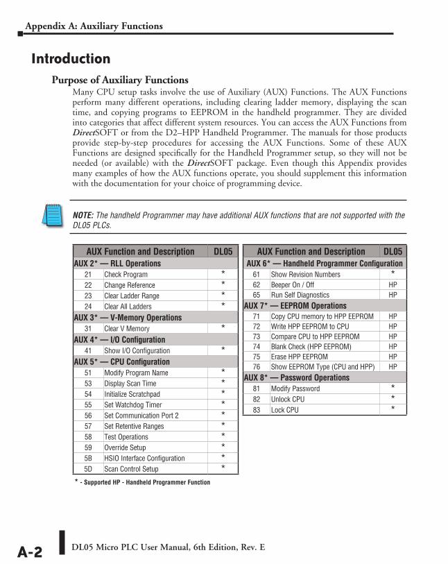
DL05 Micro PLC User Manual, 6th Edition, Rev. EA-2
Appendix A: Auxiliary Functions
IntroductionPurpose of Auxiliary Functions
Many CPU setup tasks involve the use of Auxiliary (AUX) Functions. The AUX Functions perform many different operations, including clearing ladder memory, displaying the scan time, and copying programs to EEPROM in the handheld programmer. They are divided into categories that affect different system resources. You can access the AUX Functions from DirectSOFT or from the D2–HPP Handheld Programmer. The manuals for those products provide step-by-step procedures for accessing the AUX Functions. Some of these AUX Functions are designed specifically for the Handheld Programmer setup, so they will not be needed (or available) with the DirectSOFT package. Even though this Appendix provides many examples of how the AUX functions operate, you should supplement this information with the documentation for your choice of programming device.
NOTE: The handheld Programmer may have additional AUX functions that are not supported with the DL05 PLCs.
AUX Function and Description DL05AUX 6* — Handheld Programmer Configuration
61 Show Revision Numbers *62 Beeper On / Off HP65 Run Self Diagnostics HP
AUX 7* — EEPROM Operations71 Copy CPU memory to HPP EEPROM HP72 Write HPP EEPROM to CPU HP73 Compare CPU to HPP EEPROM HP74 Blank Check (HPP EEPROM) HP75 Erase HPP EEPROM HP76 Show EEPROM Type (CPU and HPP) HP
AUX 8* — Password Operations81 Modify Password *82 Unlock CPU *83 Lock CPU *
AUX Function and Description DL05AUX 2* — RLL Operations
21 Check Program *22 Change Reference *23 Clear Ladder Range *24 Clear All Ladders *
AUX 3* — V-Memory Operations31 Clear V Memory *
AUX 4* — I/O Configuration41 Show I/O Configuration *
AUX 5* — CPU Configuration51 Modify Program Name *53 Display Scan Time *54 Initialize Scratchpad *55 Set Watchdog Timer *56 Set Communication Port 2 *57 Set Retentive Ranges *58 Test Operations *59 Override Setup *5B HSIO Interface Configuration *5D Scan Control Setup *
* - Supported HP - Handheld Programmer Function
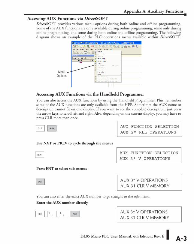
DL05 Micro PLC User Manual, 6th Edition, Rev. E A-3
Appendix A: Auxiliary Functions
Accessing AUX Functions via DirectSOFTDirectSOFT provides various menu options during both online and offline programming. Some of the AUX functions are only available during online programming, some only during offline programming, and some during both online and offline programming. The following diagram shows an example of the PLC operations menu available within DirectSOFT.
Accessing AUX Functions via the Handheld ProgrammerYou can also access the AUX functions by using the Handheld Programmer. Plus, remember some of the AUX functions are only available from the HPP. Sometimes the AUX name or description cannot fit on one display. If you want to see the complete description, just press the arrow keys to scroll left and right. Also, depending on the current display, you may have to press CLR more than once.
Use NXT or PREV to cycle through the menus
Press ENT to select sub-menus
You can also enter the exact AUX number to go straight to the sub-menu.
Enter the AUX number directly
AUX 2* RLL OPERATIONSAUX FUNCTION SELECTION
CLR AUX
AUX 3* V OPERATIONSAUX FUNCTION SELECTION
NEXT
AUX 31 CLR V MEMORYAUX 3* V OPERATIONSENT
AUX 31 CLR V MEMORYAUX 3* V OPERATIONS
CLR3
D1
B AUX
Menu Options
DL05 Micro PLC User Manual, 6th Edition, Rev. EA-4
Appendix A: Auxiliary Functions
AUX 2* — RLL OperationsRLL Operations auxiliary functions allow you to perform various operations on the ladder program.
AUX 21 Check ProgramBoth the Handheld and DirectSOFT automatically check for errors during program entry. However, there may be occasions when you want to check a program that has already been in the CPU. Two types of checks are available:
• Syntax• Duplicate References
The Syntax check will find a wide variety of programming errors, such as missing END statements. If you perform this check and get an error, see Appendix B for a complete listing of programming error codes. Correct the problem and then continue running the Syntax check until the message, NO SYNTAX ERROR, appears.
Use the Duplicate Reference check to verify you have not used the same output coil reference more than once. Note, this AUX function will also find the same outputs even if they have been used with the OROUT instruction, which is perfectly acceptable.
This AUX function is available on the PLC Diagnostics sub-menu in DirectSOFT.
AUX 22 Change ReferenceThere will probably be times when you need to change an I/O address reference or control relay reference. AUX 22 allows you to quickly and easily change all occurrences, (within an address range), of a specific instruction. For example, you can replace every instance of X5 with X10.
AUX 23 Clear Ladder RangeThere have been many times when we’ve taken existing programs and added or removed certain portions to solve new application problems. By using AUX 23 you can select and delete a portion of the program. DirectSOFT does not have a menu option for this AUX function, but you can just select the appropriate portion of the program and cut it with the editing tools.
AUX 24 Clear LaddersAUX 24 clears the entire program from CPU memory. Before you enter a new program, you should always clear ladder memory. This AUX function is available on the PLC/Clear PLC sub-menu within DirectSOFT.
AUX 3* — V-memory OperationsAUX 31 Clear V-Memory
AUX 31 clears all the information from the V-memory locations available for general use. This AUX function is available on the PLC/Clear PLC sub-menu within DirectSOFT.
DL05 Micro PLC User Manual, 6th Edition, Rev. E A-5
Appendix A: Auxiliary Functions
AUX 4* — I/O ConfigurationAUX 41 Show I/O Configuration
This AUX function allows you to display the current I/O configuration on the DL05. Both the Handheld Programmer and DirectSOFT will show the I/O configuration.
AUX 5* — CPU ConfigurationThe following auxiliary AUX functions allow you to setup, view, or change the CPU configuration.
AUX 51 Modify Program NameDL05 PLCs can use a program name for the CPU program or a program stored on EEPROM in the Handheld Programmer (multiple programs cannot be stored on the EEPROM). The program name can be up to eight characters in length and can use any of the available characters (A–Z, 0–9). AUX 51 allows you to enter a program name. You can also perform this operation in DirectSOFT by using the PLC/Setup sub-menu. Once you’ve entered a program name, you can only clear the name by using AUX 54 to reset the system memory. Make sure you understand the possible effects of AUX 54 before you use it!
AUX 53 Display Scan TimeAUX 53 displays the current, minimum, and maximum scan times. The minimum and maximum times are the ones that have occurred since the last Program Mode to Run Mode transition. You can also perform this operation from within DirectSOFT by using the PLC/Diagnostics sub-menu.
AUX 54 Initialize ScratchpadThe CPU maintains system parameters in a memory area often referred to as the “scratchpad”. In some cases, you may make changes to the system setup that will be stored in system memory. For example, if you specify a range of Control Relays (CRs) as retentive, these changes are stored.
NOTE: You may never have to use this feature unless you have made changes that affect system memory. Usually, you’ll only need to initialize the system memory if you are changing programs and the old program required a special system setup. You can usually change from program to program without ever initializing system memory.
AUX 54 resets the system memory to the default values. You can also perform this operation from within DirectSOFT by using the PLC/Setup sub-menu.
AUX 55 Set Watchdog TimerDL05 PLCs have a “watchdog” timer that is used to monitor the scan time. The default value set from the factory is 200 ms. If the scan time exceeds the watchdog time limit, the CPU automatically leaves RUN mode and enters PGM mode. The Handheld displays the following message E003 S/W TIMEOUT when the scan overrun occurs.
Use AUX 55 to increase or decrease the watchdog timer value. You can also perform this operation from within DirectSOFT by using the PLC/Setup sub-menu.
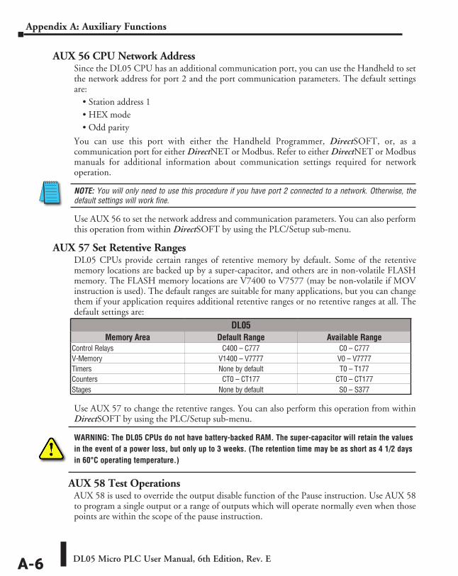
DL05 Micro PLC User Manual, 6th Edition, Rev. EA-6
Appendix A: Auxiliary Functions
AUX 56 CPU Network AddressSince the DL05 CPU has an additional communication port, you can use the Handheld to set the network address for port 2 and the port communication parameters. The default settings are:
• Station address 1• HEX mode• Odd parity
You can use this port with either the Handheld Programmer, DirectSOFT, or, as a communication port for either DirectNET or Modbus. Refer to either DirectNET or Modbus manuals for additional information about communication settings required for network operation.
NOTE: You will only need to use this procedure if you have port 2 connected to a network. Otherwise, the default settings will work fine.
Use AUX 56 to set the network address and communication parameters. You can also perform this operation from within DirectSOFT by using the PLC/Setup sub-menu.
AUX 57 Set Retentive RangesDL05 CPUs provide certain ranges of retentive memory by default. Some of the retentive memory locations are backed up by a super-capacitor, and others are in non-volatile FLASH memory. The FLASH memory locations are V7400 to V7577 (may be non-volatile if MOV instruction is used). The default ranges are suitable for many applications, but you can change them if your application requires additional retentive ranges or no retentive ranges at all. The default settings are:
Use AUX 57 to change the retentive ranges. You can also perform this operation from within DirectSOFT by using the PLC/Setup sub-menu.
WARNING: The DL05 CPUs do not have battery-backed RAM. The super-capacitor will retain the values in the event of a power loss, but only up to 3 weeks. (The retention time may be as short as 4 1/2 days in 60°C operating temperature.)
AUX 58 Test OperationsAUX 58 is used to override the output disable function of the Pause instruction. Use AUX 58 to program a single output or a range of outputs which will operate normally even when those points are within the scope of the pause instruction.
DL05Memory Area Default Range Available Range
Control Relays C400 – C777 C0 – C777V-Memory V1400 – V7777 V0 – V7777Timers None by default T0 – T177Counters CT0 – CT177 CT0 – CT177Stages None by default S0 – S377
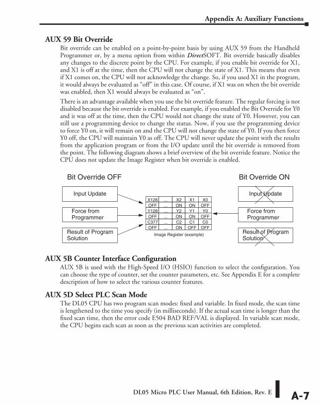
DL05 Micro PLC User Manual, 6th Edition, Rev. E A-7
Appendix A: Auxiliary Functions
AUX 59 Bit OverrideBit override can be enabled on a point-by-point basis by using AUX 59 from the Handheld Programmer or, by a menu option from within DirectSOFT. Bit override basically disables any changes to the discrete point by the CPU. For example, if you enable bit override for X1, and X1 is off at the time, then the CPU will not change the state of X1. This means that even if X1 comes on, the CPU will not acknowledge the change. So, if you used X1 in the program, it would always be evaluated as “off” in this case. Of course, if X1 was on when the bit override was enabled, then X1 would always be evaluated as “on”.
There is an advantage available when you use the bit override feature. The regular forcing is not disabled because the bit override is enabled. For example, if you enabled the Bit Override for Y0 and it was off at the time, then the CPU would not change the state of Y0. However, you can still use a programming device to change the status. Now, if you use the programming device to force Y0 on, it will remain on and the CPU will not change the state of Y0. If you then force Y0 off, the CPU will maintain Y0 as off. The CPU will never update the point with the results from the application program or from the I/O update until the bit override is removed from the point. The following diagram shows a brief overview of the bit override feature. Notice the CPU does not update the Image Register when bit override is enabled.
AUX 5B Counter Interface ConfigurationAUX 5B is used with the High-Speed I/O (HSIO) function to select the configuration. You can choose the type of counter, set the counter parameters, etc. See Appendix E for a complete description of how to select the various counter features.
AUX 5D Select PLC Scan ModeThe DL05 CPU has two program scan modes: fixed and variable. In fixed mode, the scan time is lengthened to the time you specify (in milliseconds). If the actual scan time is longer than the fixed scan time, then the error code E504 BAD REF/VAL is displayed. In variable scan mode, the CPU begins each scan as soon as the previous scan activities are completed.
Input Update
Result of ProgramSolution
OFF
Image Register (example)
Y1Y2...Y128ONON...OFF
C0C1C2...C377OFFOFFON...OFF
Y0OFF
X1X2...X128ONON...OFF
X0
Bit Override OFF
Force fromProgrammer
Input Update
Result of ProgramSolution
Bit Override ON
Force fromProgrammer
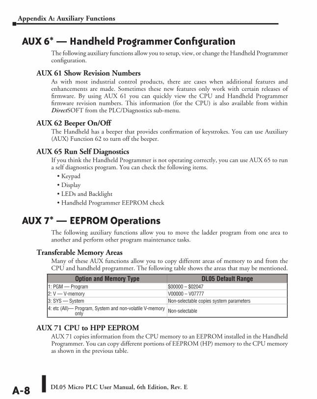
DL05 Micro PLC User Manual, 6th Edition, Rev. EA-8
Appendix A: Auxiliary Functions
AUX 6* — Handheld Programmer ConfigurationThe following auxiliary functions allow you to setup, view, or change the Handheld Programmer configuration.
AUX 61 Show Revision NumbersAs with most industrial control products, there are cases when additional features and enhancements are made. Sometimes these new features only work with certain releases of firmware. By using AUX 61 you can quickly view the CPU and Handheld Programmer firmware revision numbers. This information (for the CPU) is also available from within DirectSOFT from the PLC/Diagnostics sub-menu.
AUX 62 Beeper On/OffThe Handheld has a beeper that provides confirmation of keystrokes. You can use Auxiliary (AUX) Function 62 to turn off the beeper.
AUX 65 Run Self DiagnosticsIf you think the Handheld Programmer is not operating correctly, you can use AUX 65 to run a self diagnostics program. You can check the following items.
• Keypad• Display• LEDs and Backlight• Handheld Programmer EEPROM check
AUX 7* — EEPROM OperationsThe following auxiliary functions allow you to move the ladder program from one area to another and perform other program maintenance tasks.
Transferable Memory AreasMany of these AUX functions allow you to copy different areas of memory to and from the CPU and handheld programmer. The following table shows the areas that may be mentioned.
AUX 71 CPU to HPP EEPROMAUX 71 copies information from the CPU memory to an EEPROM installed in the Handheld Programmer. You can copy different portions of EEPROM (HP) memory to the CPU memory as shown in the previous table.
Option and Memory Type DL05 Default Range1: PGM — Program $00000 – $020472: V — V-memory V00000 – V077773: SYS — System Non-selectable copies system parameters4: etc (All)— Program, System and non-volatile V-memory
only Non-selectable
DL05 Micro PLC User Manual, 6th Edition, Rev. E A-9
Appendix A: Auxiliary Functions
AUX 72 HPP EEPROM to CPUAUX 72 copies information from the EEPROM installed in the Handheld Programmer to CPU memory in the DL05. You can copy different portions of EEPROM (HPP) memory to the CPU memory as shown in the previous table.
AUX 73 Compare HPP EEPROM to CPUAUX 73 compares the program in the Handheld programmer (EEPROM) with the CPU program. You can compare different types of information as shown previously.
AUX 74 HPP EEPROM Blank CheckAUX 74 allows you to check the EEPROM in the handheld programmer to make sure it is blank. It’s a good idea to use this function anytime you start to copy an entire program to an EEPROM in the handheld programmer.
AUX 75 Erase HPP EEPROMAUX 75 allows you to clear all data in the EEPROM in the handheld programmer. You should use this AUX function before you copy a program from the CPU.
AUX 76 Show EEPROM TypeYou can use AUX 76 to quickly determine what size EEPROM is installed in the Handheld Programmer.
AUX 8* — Password OperationsThere are several AUX functions available that you can use to modify or enable the CPU password. You can use these features during on-line communications with the CPU, or, you can also use them with an EEPROM installed in the Handheld Programmer during off-line operation. This will allow you to develop a program in the Handheld Programmer and include password protection.
• AUX 81 — Modify Password• AUX 82 — Unlock CPU• AUX 83 — Lock CPU
AUX 81 Modify PasswordYou can use AUX 81 to provide an extra measure of protection by entering a password that prevents unauthorized machine operations. The password must be an eight-character numeric (0–9) code. Once you’ve entered a password, you can remove it by entering all zeros (00000000). (This is the default from the factory.)
Once you’ve entered a password, you can lock the CPU against access. There are two ways to lock the CPU with the Handheld Programmer.
• The CPU is always locked after a power cycle (if a password is present).
• You can use AUX 82 and AUX 83 to lock and unlock the CPU.
DL05 Micro PLC User Manual, 6th Edition, Rev. EA-10
Appendix A: Auxiliary Functions
You can also enter or modify a password from within DirectSOFT by using the PLC/Password sub-menu. This feature works slightly differently in DirectSOFT. Once you’ve entered a password, the CPU is automatically locked when you exit the software package. It will also be locked if the CPU is power cycled.
WARNING: Make sure you remember the password before you lock the CPU. Once the CPU is locked you cannot view, change, or erase the password. If you do not remember the password, you have to return the CPU to the factory for password removal. It is the policy of AutomationDirect to clear the PLC memory which includes the password and the program.
NOTE: The DL05 CPUs support multi-level password protection of the ladder program. This allows password protection while not locking the communication port to an operator interface. The multi-level password can be invoked by creating a password with an upper case “A” followed by seven numeric characters (e.g. A1234567).
AUX 82 Unlock CPUAUX 82 can be used to unlock a CPU that has been password protected. DirectSOFT will automatically ask you to enter the password if you attempt to communicate with a CPU that contains a password.
AUX 83 Lock CPUAUX 83 can be used to lock a CPU that contains a password. Once the CPU is locked, you will have to enter a password to gain access. Remember, this is not necessary with DirectSOFT since the CPU is automatically locked whenever you exit the software package.
DL05 Error CoDEs BBBAppendixAppendixAppendix
In This Appendix...DL05 Error Codes....................................................................................... ..B–1
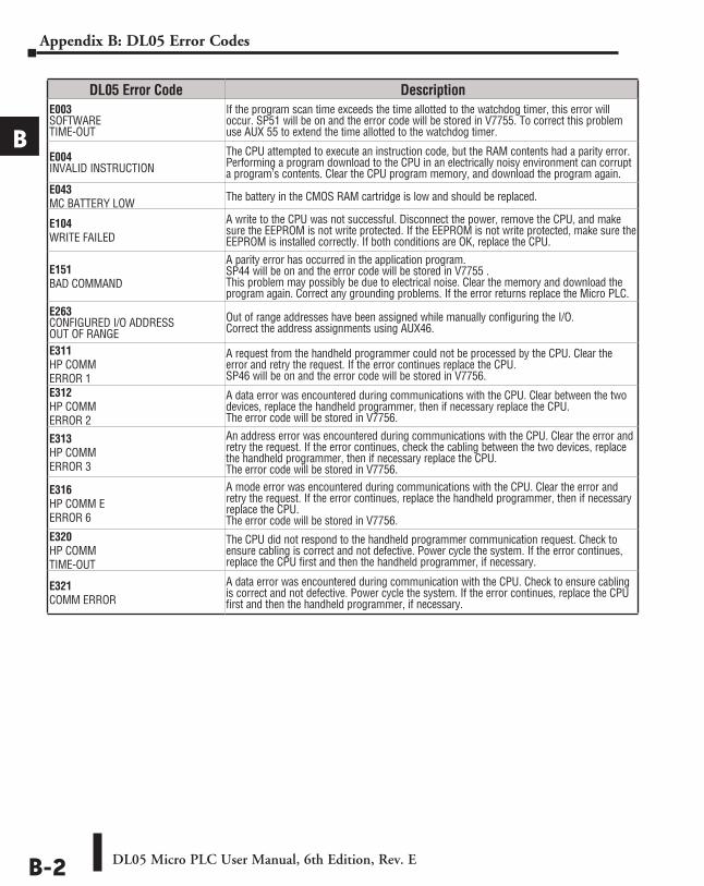
DL05 Micro PLC User Manual, 6th Edition, Rev. EB-2
Appendix B: DL05 Error Codes
A
B
3
4
5
6
7
8
9
10
11
12
13
14
A
B
C
D
DL05 Error Code DescriptionE003 SOFTWARE TIME-OUT
If the program scan time exceeds the time allotted to the watchdog timer, this error will occur. SP51 will be on and the error code will be stored in V7755. To correct this problem use AUX 55 to extend the time allotted to the watchdog timer.
E004 INVALID INSTRUCTION
The CPU attempted to execute an instruction code, but the RAM contents had a parity error. Performing a program download to the CPU in an electrically noisy environment can corrupt a program’s contents. Clear the CPU program memory, and download the program again.
E043 MC BATTERY LOW The battery in the CMOS RAM cartridge is low and should be replaced.
E104 WRITE FAILED
A write to the CPU was not successful. Disconnect the power, remove the CPU, and make sure the EEPROM is not write protected. If the EEPROM is not write protected, make sure the EEPROM is installed correctly. If both conditions are OK, replace the CPU.
E151 BAD COMMAND
A parity error has occurred in the application program. SP44 will be on and the error code will be stored in V7755 . This problem may possibly be due to electrical noise. Clear the memory and download the program again. Correct any grounding problems. If the error returns replace the Micro PLC.
E263 CONFIGURED I/O ADDRESS OUT OF RANGE
Out of range addresses have been assigned while manually configuring the I/O. Correct the address assignments using AUX46.
E311 HP COMM ERROR 1
A request from the handheld programmer could not be processed by the CPU. Clear the error and retry the request. If the error continues replace the CPU. SP46 will be on and the error code will be stored in V7756.
E312 HP COMM ERROR 2
A data error was encountered during communications with the CPU. Clear between the two devices, replace the handheld programmer, then if necessary replace the CPU. The error code will be stored in V7756.
E313 HP COMM ERROR 3
An address error was encountered during communications with the CPU. Clear the error and retry the request. If the error continues, check the cabling between the two devices, replace the handheld programmer, then if necessary replace the CPU. The error code will be stored in V7756.
E316 HP COMM E ERROR 6
A mode error was encountered during communications with the CPU. Clear the error and retry the request. If the error continues, replace the handheld programmer, then if necessary replace the CPU. The error code will be stored in V7756.
E320 HP COMM TIME-OUT
The CPU did not respond to the handheld programmer communication request. Check to ensure cabling is correct and not defective. Power cycle the system. If the error continues, replace the CPU first and then the handheld programmer, if necessary.
E321 COMM ERROR
A data error was encountered during communication with the CPU. Check to ensure cabling is correct and not defective. Power cycle the system. If the error continues, replace the CPU first and then the handheld programmer, if necessary.
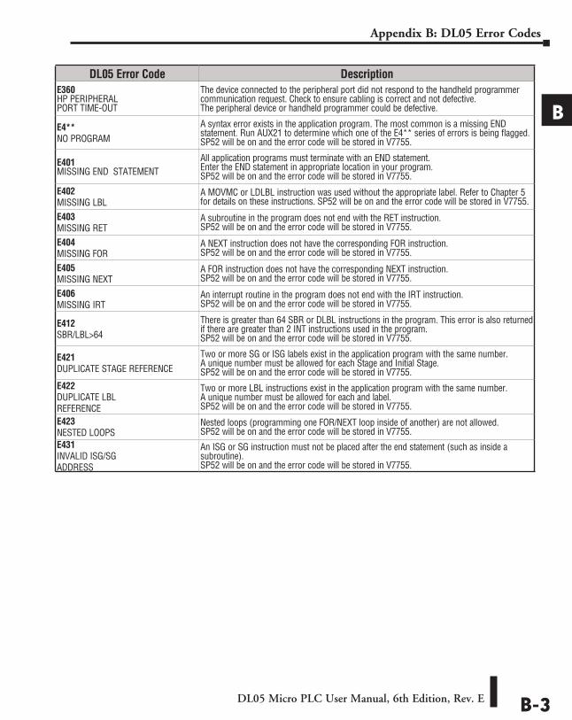
DL05 Micro PLC User Manual, 6th Edition, Rev. E B-3
Appendix B: DL05 Error Codes
A
B
3
4
5
6
7
8
9
10
11
12
13
14
A
B
C
D
DL05 Error Code DescriptionE360 HP PERIPHERAL PORT TIME-OUT
The device connected to the peripheral port did not respond to the handheld programmer communication request. Check to ensure cabling is correct and not defective. The peripheral device or handheld programmer could be defective.
E4** NO PROGRAM
A syntax error exists in the application program. The most common is a missing END statement. Run AUX21 to determine which one of the E4** series of errors is being flagged. SP52 will be on and the error code will be stored in V7755.
E401 MISSING END STATEMENT
All application programs must terminate with an END statement. Enter the END statement in appropriate location in your program. SP52 will be on and the error code will be stored in V7755.
E402 MISSING LBL
A MOVMC or LDLBL instruction was used without the appropriate label. Refer to Chapter 5 for details on these instructions. SP52 will be on and the error code will be stored in V7755.
E403 MISSING RET
A subroutine in the program does not end with the RET instruction. SP52 will be on and the error code will be stored in V7755.
E404 MISSING FOR
A NEXT instruction does not have the corresponding FOR instruction. SP52 will be on and the error code will be stored in V7755.
E405 MISSING NEXT
A FOR instruction does not have the corresponding NEXT instruction. SP52 will be on and the error code will be stored in V7755.
E406 MISSING IRT
An interrupt routine in the program does not end with the IRT instruction. SP52 will be on and the error code will be stored in V7755.
E412 SBR/LBL>64
There is greater than 64 SBR or DLBL instructions in the program. This error is also returned if there are greater than 2 INT instructions used in the program. SP52 will be on and the error code will be stored in V7755.
E421 DUPLICATE STAGE REFERENCE
Two or more SG or ISG labels exist in the application program with the same number. A unique number must be allowed for each Stage and Initial Stage. SP52 will be on and the error code will be stored in V7755.
E422 DUPLICATE LBL REFERENCE
Two or more LBL instructions exist in the application program with the same number. A unique number must be allowed for each and label. SP52 will be on and the error code will be stored in V7755.
E423 NESTED LOOPS
Nested loops (programming one FOR/NEXT loop inside of another) are not allowed. SP52 will be on and the error code will be stored in V7755.
E431 INVALID ISG/SG ADDRESS
An ISG or SG instruction must not be placed after the end statement (such as inside a subroutine). SP52 will be on and the error code will be stored in V7755.
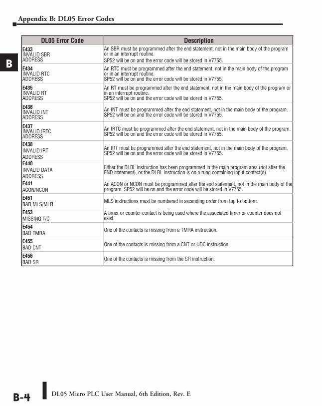
DL05 Micro PLC User Manual, 6th Edition, Rev. EB-4
Appendix B: DL05 Error Codes
A
B
3
4
5
6
7
8
9
10
11
12
13
14
A
B
C
D
DL05 Error Code DescriptionE433 INVALID SBR ADDRESS
An SBR must be programmed after the end statement, not in the main body of the program or in an interrupt routine. SP52 will be on and the error code will be stored in V7755.
E434 INVALID RTC ADDRESS
An RTC must be programmed after the end statement, not in the main body of the program or in an interrupt routine. SP52 will be on and the error code will be stored in V7755.
E435 INVALID RT ADDRESS
An RT must be programmed after the end statement, not in the main body of the program or in an interrupt routine. SP52 will be on and the error code will be stored in V7755.
E436 INVALID INT ADDRESS
An INT must be programmed after the end statement, not in the main body of the program. SP52 will be on and the error code will be stored in V7755.
E437 INVALID IRTC ADDRESS
An IRTC must be programmed after the end statement, not in the main body of the program. SP52 will be on and the error code will be stored in V7755.
E438 INVALID IRT ADDRESS
An IRT must be programmed after the end statement, not in the main body of the program. SP52 will be on and the error code will be stored in V7755.
E440 INVALID DATA ADDRESS
Either the DLBL instruction has been programmed in the main program area (not after the END statement), or the DLBL instruction is on a rung containing input contact(s).
E441 ACON/NCON
An ACON or NCON must be programmed after the end statement, not in the main body of the program. SP52 will be on and the error code will be stored in V7755.
E451 BAD MLS/MLR MLS instructions must be numbered in ascending order from top to bottom.
E453 MISSING T/C
A timer or counter contact is being used where the associated timer or counter does not exist.
E454 BAD TMRA One of the contacts is missing from a TMRA instruction.
E455 BAD CNT One of the contacts is missing from a CNT or UDC instruction.
E456 BAD SR One of the contacts is missing from the SR instruction.
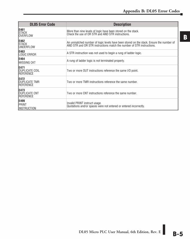
DL05 Micro PLC User Manual, 6th Edition, Rev. E B-5
Appendix B: DL05 Error Codes
A
B
3
4
5
6
7
8
9
10
11
12
13
14
A
B
C
D
DL05 Error Code DescriptionE461 STACK OVERFLOW
More than nine levels of logic have been stored on the stack. Check the use of OR STR and AND STR instructions.
E462 STACK UNDERFLOW
An unmatched number of logic levels have been stored on the stack. Ensure the number of AND STR and OR STR instructions match the number of STR instructions.
E463 LOGIC ERROR A STR instruction was not used to begin a rung of ladder logic.
E464 MISSING CKT A rung of ladder logic is not terminated properly.
E471 DUPLICATE COIL REFERENCE
Two or more OUT instructions reference the same I/O point.
E472 DUPLICATE TMR REFERENCE
Two or more TMR instructions reference the same number.
E473 DUPLICATE CNT REFERENCE
Two or more CNT instructions reference the same number.
E499 PRINT INSTRUCTION
Invalid PRINT instruct usage. Quotations and/or spaces were not entered or entered incorrectly.
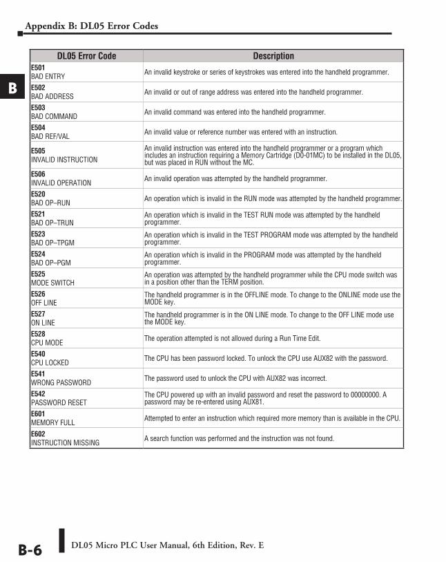
DL05 Micro PLC User Manual, 6th Edition, Rev. EB-6
Appendix B: DL05 Error Codes
A
B
3
4
5
6
7
8
9
10
11
12
13
14
A
B
C
D
DL05 Error Code DescriptionE501 BAD ENTRY An invalid keystroke or series of keystrokes was entered into the handheld programmer.
E502 BAD ADDRESS An invalid or out of range address was entered into the handheld programmer.
E503 BAD COMMAND An invalid command was entered into the handheld programmer.
E504 BAD REF/VAL An invalid value or reference number was entered with an instruction.
E505 INVALID INSTRUCTION
An invalid instruction was entered into the handheld programmer or a program which includes an instruction requiring a Memory Cartridge (D0-01MC) to be installed in the DL05, but was placed in RUN without the MC.
E506 INVALID OPERATION An invalid operation was attempted by the handheld programmer.
E520 BAD OP–RUN An operation which is invalid in the RUN mode was attempted by the handheld programmer.
E521 BAD OP–TRUN
An operation which is invalid in the TEST RUN mode was attempted by the handheld programmer.
E523 BAD OP–TPGM
An operation which is invalid in the TEST PROGRAM mode was attempted by the handheld programmer.
E524 BAD OP–PGM
An operation which is invalid in the PROGRAM mode was attempted by the handheld programmer.
E525 MODE SWITCH
An operation was attempted by the handheld programmer while the CPU mode switch was in a position other than the TERM position.
E526 OFF LINE
The handheld programmer is in the OFFLINE mode. To change to the ONLINE mode use the MODE key.
E527 ON LINE
The handheld programmer is in the ON LINE mode. To change to the OFF LINE mode use the MODE key.
E528 CPU MODE The operation attempted is not allowed during a Run Time Edit.
E540 CPU LOCKED The CPU has been password locked. To unlock the CPU use AUX82 with the password.
E541 WRONG PASSWORD The password used to unlock the CPU with AUX82 was incorrect.
E542 PASSWORD RESET
The CPU powered up with an invalid password and reset the password to 00000000. A password may be re-entered using AUX81.
E601 MEMORY FULL Attempted to enter an instruction which required more memory than is available in the CPU.
E602 INSTRUCTION MISSING A search function was performed and the instruction was not found.
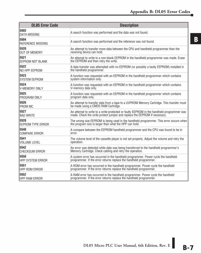
DL05 Micro PLC User Manual, 6th Edition, Rev. E B-7
Appendix B: DL05 Error Codes
A
B
3
4
5
6
7
8
9
10
11
12
13
14
A
B
C
D
DL05 Error Code DescriptionE603 DATA MISSING A search function was performed and the data was not found.
E604 REFERENCE MISSING A search function was performed and the reference was not found.
E620 OUT OF MEMORY
An attempt to transfer more data between the CPU and handheld programmer than the receiving device can hold.
E621 EEPROM NOT BLANK
An attempt to write to a non-blank EEPROM in the handheld programmer was made. Erase the EEPROM and then retry the write.
E622 NO HPP EEPROM
A data transfer was attempted with no EEPROM (or possibly a faulty EEPROM) installed in the handheld programmer.
E623 SYSTEM EEPROM
A function was requested with an EEPROM in the handheld programmer which contains system information only.
E624 V-MEMORY ONLY
A function was requested with an EEPROM in the handheld programmer which contains V-memory data only.
E625 PROGRAM ONLY
A function was requested with an EEPROM in the handheld programmer which contains program data only.
E626 PROM MC
An attempt to transfer data from a tape to a UVPROM Memory Cartridge. This transfer must be made using a CMOS RAM Cartridge.
E627 BAD WRITE
An attempt to write to a write-protected or faulty EEPROM in the handheld programmer was made. Check the write protect jumper and replace the EEPROM if necessary.
E628 EEPROM TYPE ERROR
The wrong size EEPROM is being used in the handheld programmer. This error occurs when the program size is larger than what the HPP can hold.
E640 COMPARE ERROR
A compare between the EEPROM handheld programmer and the CPU was found to be in error.
E641 VOLUME LEVEL
The volume level of the cassette player is not set properly. Adjust the volume and retry the operation.
E642 CHECKSUM ERROR
An error was detected while data was being transferred to the handheld programmer’s Memory Cartridge. Check cabling and retry the operation.
E650 HPP SYSTEM ERROR
A system error has occurred in the handheld programmer. Power cycle the handheld programmer. If the error returns replace the handheld programmer.
E651 HPP ROM ERROR
A ROM error has occurred in the handheld programmer. Power cycle the handheld programmer. If the error returns replace the handheld programmer.
E652 HPP RAM ERROR
A RAM error has occurred in the handheld programmer. Power cycle the handheld programmer. If the error returns replace the handheld programmer.
InstructIon ExEcutIon tImEs CCC
AppendixAppendixAppendix
In This Appendix...Introduction ............................................................................................................... C-2
Instruction Execution Times ...................................................................................... C-3
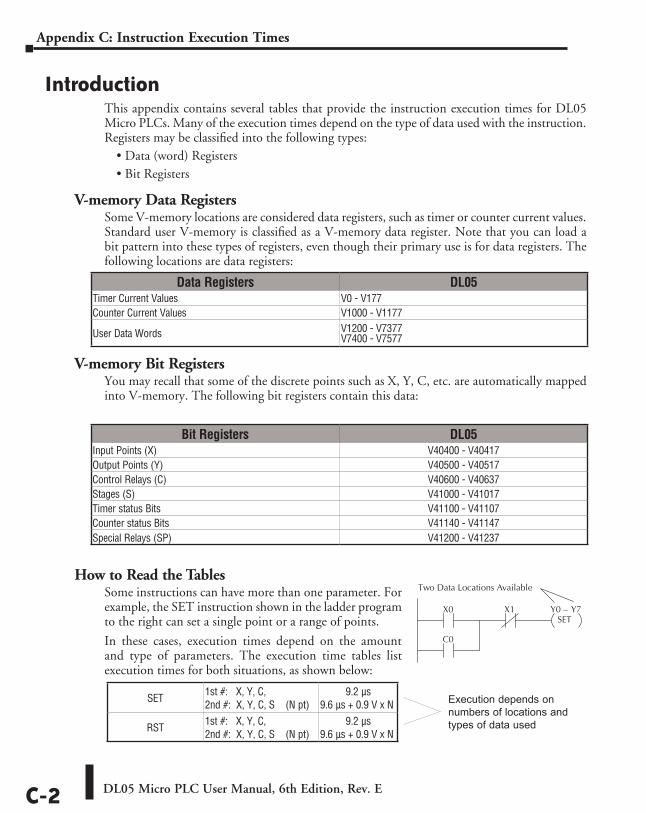
DL05 Micro PLC User Manual, 6th Edition, Rev. EC-2
Appendix C: Instruction Execution Times
IntroductionThis appendix contains several tables that provide the instruction execution times for DL05 Micro PLCs. Many of the execution times depend on the type of data used with the instruction. Registers may be classified into the following types:
• Data (word) Registers• Bit Registers
V-memory Data RegistersSome V-memory locations are considered data registers, such as timer or counter current values. Standard user V-memory is classified as a V-memory data register. Note that you can load a bit pattern into these types of registers, even though their primary use is for data registers. The following locations are data registers:
V-memory Bit RegistersYou may recall that some of the discrete points such as X, Y, C, etc. are automatically mapped into V-memory. The following bit registers contain this data:
How to Read the TablesSome instructions can have more than one parameter. For example, the SET instruction shown in the ladder program to the right can set a single point or a range of points.
In these cases, execution times depend on the amount and type of parameters. The execution time tables list execution times for both situations, as shown below:
Data Registers DL05Timer Current Values V0 - V177Counter Current Values V1000 - V1177
User Data Words V1200 - V7377 V7400 - V7577
Bit Registers DL05Input Points (X) V40400 - V40417Output Points (Y) V40500 - V40517Control Relays (C) V40600 - V40637Stages (S) V41000 - V41017Timer status Bits V41100 - V41107Counter status Bits V41140 - V41147Special Relays (SP) V41200 - V41237
X0 X1 Y0 – Y7SET
C0
Two Data Locations Available
SET 1st #: X, Y, C, 2nd #: X, Y, C, S (N pt)
9.2 µs9.6 µs + 0.9 V x N
RST 1st #: X, Y, C, 2nd #: X, Y, C, S (N pt)
9.2 µs9.6 µs + 0.9 V x N
Execution depends on numbers of locations and types of data used
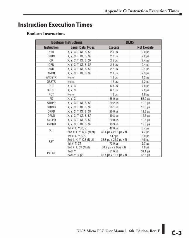
DL05 Micro PLC User Manual, 6th Edition, Rev. E C-3
Appendix C: Instruction Execution Times
Instruction Execution TimesBoolean Instructions
Boolean Instructions DL05Instruction Legal Data Types Execute Not Execute
STR X, Y, C, T, CT, S, SP 2.0 µs 2.0 µsSTRN X, Y, C, T, CT, S, SP 2.2 µs 2.2 µs
OR X, Y, C, T, CT, S, SP 2.5 µs 2.4 µsORN X, Y, C, T, CT, S, SP 2.5 µs 2.4 µsAND X, Y, C, T, CT, S, SP 2.2 µs 2.1 µs
ANDN X, Y, C, T, CT, S, SP 2.3 µs 2.3 µsANDSTR None 1.2 µs 1.2 µsORSTR None 1.2 µs 1.2 µs
OUT X, Y, C 6.8 µs 7.0 µsOROUT X, Y, C 6.7 µs 7.2 µs
NOT None 1.6 µs 1.6 µsPD X, Y, C 55.0 µs 55.0 µs
STRPD X, Y, C, T, CT, S, SP 20.2 µs 12.9 µsSTRND X, Y, C, T, CT, S, SP 20.1 µs 13.0 µsORPD X, Y, C, T, CT, S, SP 20.0 µs 12.6 µsORND X, Y, C, T, CT, S, SP 19.8 µs 12.7 µsANDPD X, Y, C, T, CT, S, SP 20.0 µs 12.6 µsANDND X, Y, C, T, CT, S, SP 19.9 µs 12.8 µs
SET 1st #: X, Y, C, S, 2nd #: X, Y, C, S (N pt)
42.0 µs 32.4 µs + 25.6 µs x N
3.7 µs 4.7 µs
RST
1st #: X, Y, C,S 2nd #: X, Y, C,S (N pt)
44.5µs 33.8 µs + 25.7 µs x N
3.9 µs 4.8 µs
1st #: T, CT 2nd #: T, CT (N pt)
73.0 µs 80.9 µs + 2.6 µs x N
3.7 µs 4.8 µs
PAUSE 1wd: Y 2wd: Y (N pt)
31.6 µs 48.4 µs + 12.1 µs x N
31.1 µs 48.8 µs
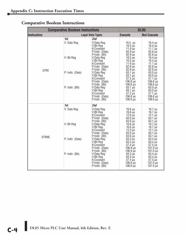
DL05 Micro PLC User Manual, 6th Edition, Rev. EC-4
Appendix C: Instruction Execution Times
Comparative Boolean Instructions
Comparative Boolean Instructions DL05Instruction Legal Data Types Execute Not Execute
STRE
1st V: Data Reg. V: Bit Reg P: Indir. (Data) P: Indir. (Bit)
2ndV:Data Reg. V:Bit Reg K:Constant P:Indir. (Data) P:Indir. (Bit) V:Data Reg V:Bit Reg K:Constant P:Indir. (Data) P:Indir. (Bit) V:Data Reg V:Bit Reg K:Constant P:Indir. (Data) P:Indir. (Bit) V:Data Reg V:Bit Reg K:Constant P:Indir. (Data) P:Indir. (Bit)
16.5 µs 16.5 µs 11.9 µs 62.9 µs 62.9 µs 16.5 µs 16.5 µs 11.9 µs 62.9 µs 62.9 µs 63.1 µs 63.1 µs 57.2 µs 106.8 µs 106.8 µs 63.1 µs 63.1 µs 57.2 µs 106.8 µs 106.8 µs
16.4 µs 16.4 µs 11.7 µs 62.8 µs 62.8 µs 16.4 µs 16.4 µs 11.7 µs 62.8 µs 62.8 µs 63.0 µs 63.0 µs 57.1 µs 106.6 µs 106.6 µs 63.0 µs 63.0 µs 57.1 µs 106.6 µs 106.6 µs
STRNE
1st V: Data Reg V: Bit Reg P: Indir. (Data) P: Indir. (Bit)
2ndV:Data Reg V:Bit Reg K:Constant P:Indir. (Data) P:Indir. (Bit) V:Data Reg V:Bit Reg K:Constant P:Indir. (Data) P:Indir. (Bit) V:Data Reg V:Bit Reg K:Constant P:Indir. (Data) P:Indir. (Bit) V:Data Reg V:Bit Reg K:Constant P:Indir. (Data) P:Indir. (Bit)
16.6 µs 16.6 µs 12.0 µs 63.0 µs 63.0 µs 16.6 µs 16.6 µs 12.0 µs 63.0 µs 63.0 µs 63.3 µs 63.3 µs 57.4 µs 106.9 µs 106.9 µs 63.3 µs 63.3 µs 57.4 µs 106.9 µs 106.9 µs
16.7 µs 16.7 µs 12.1 µs 63.1 µs 63.1 µs 16.7 µs 16.7 µs 12.1 µs 63.1 µs 63.1 µs 63.4 µs 63.4 µs 57.5 µs 107.0 µs 107.0 µs 63.4 µs 63.4 µs 57.5 µs 107.0 µs 107.0 µs
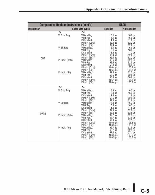
DL05 Micro PLC User Manual, 6th Edition, Rev. E C-5
Appendix C: Instruction Execution Times
Comparative Boolean Instructions (cont’d) DL05Instruction Legal Data Types Execute Not Execute
ORE
1st V: Data Reg V: Bit Reg P: Indir. (Data) P: Indir. (Bit)
2ndV:Data Reg V:Bit Reg K:Constant P:Indir. (Data) P:Indir. (Bit) V:Data Reg. V:Bit Reg K:Constant P:Indir. (Data) P:Indir. (Bit) V:Data Reg V:Bit Reg K:Constant P:Indir. (Data) P:Indir. (Bit) V:Data Reg V:Bit Reg K:Constant P:Indir. (Data) P:Indir. (Bit)
16.1 µs 16.1 µs 11.3 µs 62.4 µs 62.4 µs 16.1 µs 16.1 µs 11.3 µs 62.4 µs 62.4 µs 62.6 µs 62.6 µs 56.8 µs 106.4 µs 106.4 µs 62.6 µs 62.6 µs 56.8 µs 106.4 µs 106.4 µs
16.0 µs 16.0 µs 11.2 µs 62.2 µs 62.2 µs 16.0 µs 16.0 µs 11.2 µs 62.2 µs 62.2 µs 62.5 µs 62.5 µs 56.8 µs 106.2 µs 106.2 µs 62.5 µs 62.5 µs 56.8 µs 106.2 µs 106.2 µs
ORNE
1st V: Data Reg. V: Bit Reg. P: Indir. (Data) P: Indir. (Bit)
2ndV:Data Reg. V:Bit Reg. K:Constant P:Indir. (Data) P:Indir. (Bit) V:Data Reg V:Bit Reg. K:Constant P:Indir. (Data) P:Indir. (Bit) V:Data Reg. V:Bit Reg. K:Constant P:Indir. (Data) P:Indir. (Bit) V:Data Reg. V:Bit Reg. K:Constant P:Indir. (Data) P:Indir. (Bit)
16.3 µs 16.3 µs 11.5 µs 62.5 µs 62.5 µs 16.3 µs 16.3 µs 11.5 µs 62.5 µs 62.5 µs 62.7 µs 62.7 µs 57.0 µs 106.5 µs 106.5 µs 62.7 µs 62.7 µs 57.0 µs 106.5 µs 106.5 µs
16.3 µs 16.3 µs 11.6 µs 62.6 µs 62.6 µs 16.3 µs 16.3 µs 11.6 µs 62.6 µs 62.6 µs 62.9 µs 62.9 µs 57.1 µs 106.6 µs 106.6 µs 62.9 µs 62.9 µs 57.1 µs 106.6 µs 106.6 µs
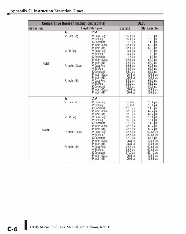
DL05 Micro PLC User Manual, 6th Edition, Rev. EC-6
Appendix C: Instruction Execution Times
Comparative Boolean Instructions (cont’d) DL05Instruction Legal Data Types Execute Not Execute
ANDE
1st V: Data Reg. V: Bit Reg. P: Indir. (Data) P: Indir. (Bit)
2ndV:Data Reg V:Bit Reg K:Constant P:Indir. (Data) P:Indir. (Bit) V:Data Reg V:Bit Reg K:Constant P:Indir. (Data) P:Indir. (Bit) V:Data Reg V:Bit Reg K:Constant P:Indir. (Data) P:Indir. (Bit) V:Data Reg V:Bit Reg K:Constant P:Indir. (Data) P:Indir. (Bit)
16.1 µs 16.1 µs 11.3 µs 62.4 µs 62.4 µs 16.1 µs 16.1 µs 11.3 µs 62.4 µs 62.4 µs 62.6 µs 62.6 µs 56.9 µs 106.4 µs 106.4 µs 62.6 µs 62.6 µs 56.9 µs 106.4 µs 106.4 µs
16.0 µs 16.0 µs 11.3 µs 62.2 µs 62.2 µs 16.0 µs 16.0 µs 11.3 µs 62.2 µs 62.2 µs 62.5 µs 62.5 µs 56.7 µs 106.2 µs 106.2 µs 62.5 µs 62.5 µs 56.7 µs 106.2 µs 106.2 µs
ANDNE
1stV: Data Reg. V: Bit Reg. P: Indir. (Data) P: Indir. (Bit)
2ndV:Data Reg. V:Bit Reg. K:Constant P:Indir. (Data) P:Indir. (Bit) V:Data Reg. V:Bit Reg K:Constant P:Indir. (Data) P:Indir. (Bit) V:Data Reg. V:Bit Reg. K:Constant P:Indir. (Data) P:Indir. (Bit) V:Data Reg. V:Bit Reg. K:Constant P:Indir. (Data) P:Indir. (Bit)
16.2µs 16.2µs 11.5 µs 62.5 µs 62.5 µs 16.2 µs 16.2 µs 11.5 µs 62.5 µs 62.5 µs 62.7 µs 62.7 µs 57.0 µs 106.5 µs 106.5 µs 62.7 µs 62.7 µs 57.0 µs 106.5 µs 106.5 µs
16.4 µs 16.4 µs 11.6 µs 62.7 µs 62.7 µs 16.4 µs 16.4 µs 11.6 µs 62.7 µs 62.7 µs 62.85 µs 62.85 µs 57.1 µs 106.6 µs 106.6 µs 62.85 µs 62.85 µs 57.10 µs 106.6 µs 106.6 µs
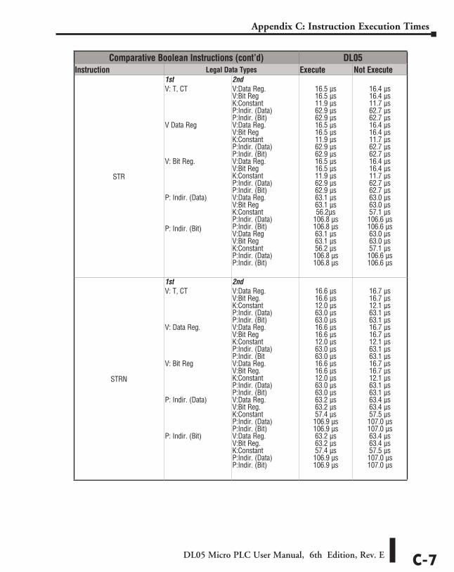
DL05 Micro PLC User Manual, 6th Edition, Rev. E C-7
Appendix C: Instruction Execution Times
Comparative Boolean Instructions (cont’d) DL05Instruction Legal Data Types Execute Not Execute
STR
1st V: T, CT V Data Reg V: Bit Reg. P: Indir. (Data) P: Indir. (Bit)
2ndV:Data Reg. V:Bit Reg K:Constant P:Indir. (Data) P:Indir. (Bit) V:Data Reg. V:Bit Reg K:Constant P:Indir. (Data) P:Indir. (Bit) V:Data Reg. V:Bit Reg K:Constant P:Indir. (Data) P:Indir. (Bit) V:Data Reg. V:Bit Reg K:Constant P:Indir. (Data) P:Indir. (Bit) V:Data Reg V:Bit Reg K:Constant P:Indir. (Data) P:Indir. (Bit)
16.5 µs 16.5 µs 11.9 µs 62.9 µs 62.9 µs 16.5 µs 16.5 µs 11.9 µs 62.9 µs 62.9 µs 16.5 µs 16.5 µs 11.9 µs 62.9 µs 62.9 µs 63.1 µs 63.1 µs 56.2µs
106.8 µs 106.8 µs 63.1 µs 63.1 µs 56.2 µs 106.8 µs 106.8 µs
16.4 µs 16.4 µs 11.7 µs 62.7 µs 62.7 µs 16.4 µs 16.4 µs 11.7 µs 62.7 µs 62.7 µs 16.4 µs 16.4 µs 11.7 µs 62.7 µs 62.7 µs 63.0 µs 63.0 µs 57.1 µs 106.6 µs 106.6 µs 63.0 µs 63.0 µs 57.1 µs 106.6 µs 106.6 µs
STRN
1st V: T, CT V: Data Reg. V: Bit Reg P: Indir. (Data) P: Indir. (Bit)
2ndV:Data Reg. V:Bit Reg. K:Constant P:Indir. (Data) P:Indir. (Bit) V:Data Reg. V:Bit Reg K:Constant P:Indir. (Data) P:Indir. (Bit V:Data Reg. V:Bit Reg. K:Constant P:Indir. (Data) P:Indir. (Bit) V:Data Reg. V:Bit Reg. K:Constant P:Indir. (Data) P:Indir. (Bit) V:Data Reg. V:Bit Reg. K:Constant P:Indir. (Data) P:Indir. (Bit)
16.6 µs 16.6 µs 12.0 µs 63.0 µs 63.0 µs 16.6 µs 16.6 µs 12.0 µs 63.0 µs 63.0 µs 16.6 µs 16.6 µs 12.0 µs 63.0 µs 63.0 µs 63.2 µs 63.2 µs 57.4 µs 106.9 µs 106.9 µs 63.2 µs 63.2 µs 57.4 µs 106.9 µs 106.9 µs
16.7 µs 16.7 µs 12.1 µs 63.1 µs 63.1 µs 16.7 µs 16.7 µs 12.1 µs 63.1 µs 63.1 µs 16.7 µs 16.7 µs 12.1 µs 63.1 µs 63.1 µs 63.4 µs 63.4 µs 57.5 µs 107.0 µs 107.0 µs 63.4 µs 63.4 µs 57.5 µs 107.0 µs 107.0 µs
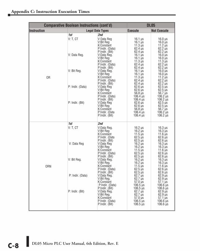
DL05 Micro PLC User Manual, 6th Edition, Rev. EC-8
Appendix C: Instruction Execution Times
Comparative Boolean Instructions (cont’d) DL05Instruction Legal Data Types Execute Not Execute
OR
1st V: T, CT V: Data Reg. V: Bit Reg. P: Indir. (Data) P: Indir. (Bit)
2ndV Data Reg V:Bit Reg K:Constant P:Indir. (Data) P:Indir. (Bit) V:Data Reg. V:Bit Reg K:Constant P:Indir. (Data) P:Indir. (Bit) V:Data Reg. V:Bit Reg K:Constant P:Indir. (Data) P:Indir. (Bit) V:Data Reg V:Bit Reg K:Constant P:Indir. (Data) P:Indir. (Bit) V:Data Reg V:Bit Reg K:Constant P:Indir. (Data P:Indir. (Bit)
16.1 µs 16.1 µs 11.3 µs 62.4 µs 62.4 µs 16.1 µs 16.1 µs 11.3 µs 62.4 µs 62.4 µs 16.1 µs 16.1 µs 11.3 µs 62.4 µs 62.4 µs 62.6 µs 62.6 µs 56.8 µs 106.4 µs 106.4 µs 62.6 µs 62.6 µs 56.8 µs 106.4 µs 106.4 µs
16.0 µs 16.0 µs 11.2 µs 62.2 µs 62.2 µs 16.0 µs 16.0 µs 11.3 µs 62.2 µs 62.2 µs 16.0 µs 16.0 µs 11.2 µs 62.2 µs 62.2 µs 62.5 µs 62.5 µs 56.7 µs 106.2 µs 106.2 µs 62.5 µs 62.5 µs 56.7 µs 106.2 µs 106.2 µs
ORN
1st V: T, CT V: Data Reg V: Bit Reg. P: Indir. (Data) P: Indir. (Bit)
2ndV:Data Reg. V:Bit Reg K:Constant P:Indir. (Data P:Indir. (Bit) V:Data Reg V:Bit Reg K:Constant P:Indir. (Data) P:Indir. (Bit) V:Data Reg. V:Bit Reg. K:Constant P:Indir. (Data) P:Indir. (Bit) V:Data Reg. V:Bit Reg. K:Constant P:Indir. (Data) P:Indir. (Bit) V:Data Reg. V:Bit Reg. K:Constant P:Indir. (Data) P:Indir. (Bit)
16.2 µs 16.2 µs 11.5 µs 62.5 µs 62.5 µs 16.2 µs 16.2 µs 11.5 µs 62.5 µs 62.5 µs 16.2 µs 16.2 µs 11.5 µs 62.5 µs 62.5 µs 62.7 µs 62.7 µs 57.0 µs 106.5 µs 106.5 µs 62.7 µs 62.7 µs 57.0 µs 106.5 µs 106.5 µs
16.3 µs 16.3 µs 11.6 µs 62.6 µs 62.6 µs 16.3 µs 16.3 µs 11.6 µs 62.6 µs 62.6 µs 16.3 µs 16.3 µs 11.6 µs 62.6 µs 62.6 µs 62.9 µs 62.9 µs 57.1 µs 106.6 µs 106.6 µs 62.9 µs 62.9 µs 57.1 µs 106.6 µs 106.6 µs
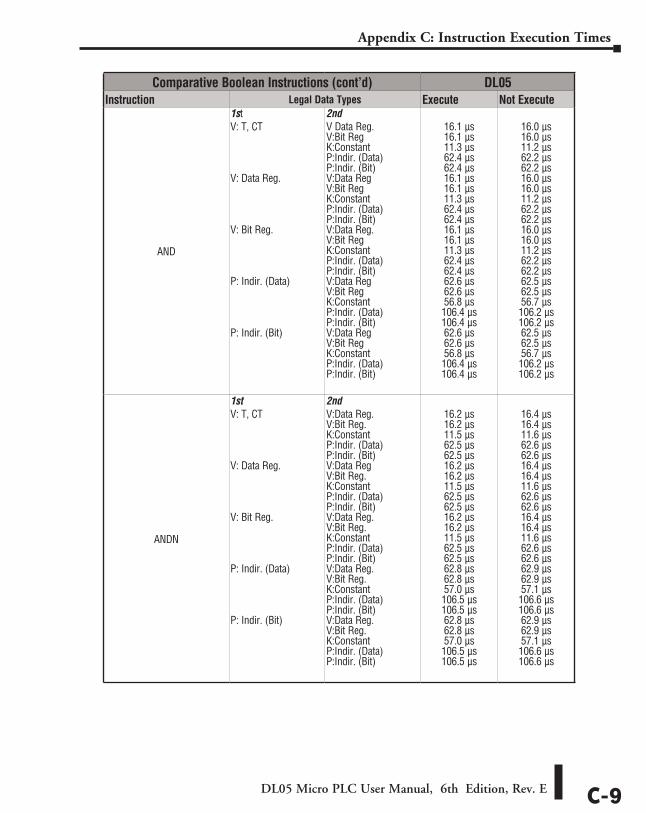
DL05 Micro PLC User Manual, 6th Edition, Rev. E C-9
Appendix C: Instruction Execution Times
Comparative Boolean Instructions (cont’d) DL05Instruction Legal Data Types Execute Not Execute
AND
1stV: T, CT V: Data Reg. V: Bit Reg. P: Indir. (Data) P: Indir. (Bit)
2ndV Data Reg. V:Bit Reg K:Constant P:Indir. (Data) P:Indir. (Bit) V:Data Reg V:Bit Reg K:Constant P:Indir. (Data) P:Indir. (Bit) V:Data Reg. V:Bit Reg K:Constant P:Indir. (Data) P:Indir. (Bit) V:Data Reg V:Bit Reg K:Constant P:Indir. (Data) P:Indir. (Bit) V:Data Reg V:Bit Reg K:Constant P:Indir. (Data) P:Indir. (Bit)
16.1 µs 16.1 µs 11.3 µs 62.4 µs 62.4 µs 16.1 µs 16.1 µs 11.3 µs 62.4 µs 62.4 µs 16.1 µs 16.1 µs 11.3 µs 62.4 µs 62.4 µs 62.6 µs 62.6 µs 56.8 µs 106.4 µs 106.4 µs 62.6 µs 62.6 µs 56.8 µs 106.4 µs 106.4 µs
16.0 µs 16.0 µs 11.2 µs 62.2 µs 62.2 µs 16.0 µs 16.0 µs 11.2 µs 62.2 µs 62.2 µs 16.0 µs 16.0 µs 11.2 µs 62.2 µs 62.2 µs 62.5 µs 62.5 µs 56.7 µs 106.2 µs 106.2 µs 62.5 µs 62.5 µs 56.7 µs 106.2 µs 106.2 µs
ANDN
1stV: T, CT V: Data Reg. V: Bit Reg. P: Indir. (Data) P: Indir. (Bit)
2ndV:Data Reg. V:Bit Reg. K:Constant P:Indir. (Data) P:Indir. (Bit) V:Data Reg V:Bit Reg. K:Constant P:Indir. (Data) P:Indir. (Bit) V:Data Reg. V:Bit Reg. K:Constant P:Indir. (Data) P:Indir. (Bit) V:Data Reg. V:Bit Reg. K:Constant P:Indir. (Data) P:Indir. (Bit) V:Data Reg. V:Bit Reg. K:Constant P:Indir. (Data) P:Indir. (Bit)
16.2 µs 16.2 µs 11.5 µs 62.5 µs 62.5 µs 16.2 µs 16.2 µs 11.5 µs 62.5 µs 62.5 µs 16.2 µs 16.2 µs 11.5 µs 62.5 µs 62.5 µs 62.8 µs 62.8 µs 57.0 µs 106.5 µs 106.5 µs 62.8 µs 62.8 µs 57.0 µs 106.5 µs 106.5 µs
16.4 µs 16.4 µs 11.6 µs 62.6 µs 62.6 µs 16.4 µs 16.4 µs 11.6 µs 62.6 µs 62.6 µs 16.4 µs 16.4 µs 11.6 µs 62.6 µs 62.6 µs 62.9 µs 62.9 µs 57.1 µs 106.6 µs 106.6 µs 62.9 µs 62.9 µs 57.1 µs 106.6 µs 106.6 µs
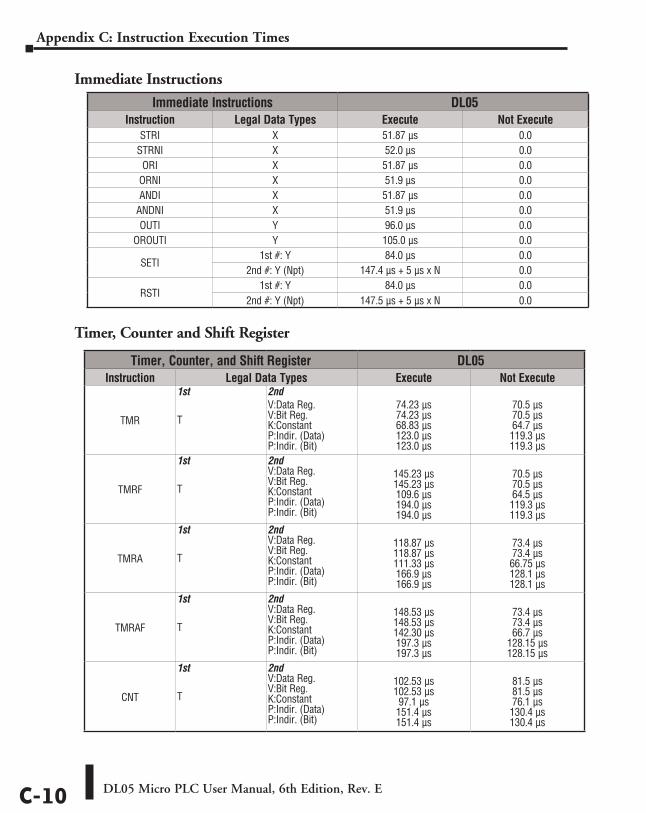
DL05 Micro PLC User Manual, 6th Edition, Rev. EC-10
Appendix C: Instruction Execution Times
Immediate Instructions
Timer, Counter and Shift Register
Immediate Instructions DL05Instruction Legal Data Types Execute Not Execute
STRI X 51.87 µs 0.0STRNI X 52.0 µs 0.0
ORI X 51.87 µs 0.0 ORNI X 51.9 µs 0.0 ANDI X 51.87 µs 0.0
ANDNI X 51.9 µs 0.0 OUTI Y 96.0 µs 0.0
OROUTI Y 105.0 µs 0.0
SETI 1st #: Y 84.0 µs 0.0
2nd #: Y (Npt) 147.4 µs + 5 µs x N 0.0
RSTI 1st #: Y 84.0 µs 0.0
2nd #: Y (Npt) 147.5 µs + 5 µs x N 0.0
Timer, Counter, and Shift Register DL05Instruction Legal Data Types Execute Not Execute
TMR
1st T
2nd V:Data Reg. V:Bit Reg. K:Constant P:Indir. (Data) P:Indir. (Bit)
74.23 µs 74.23 µs 68.83 µs 123.0 µs 123.0 µs
70.5 µs 70.5 µs 64.7 µs 119.3 µs 119.3 µs
TMRF
1st T
2nd V:Data Reg. V:Bit Reg. K:Constant P:Indir. (Data) P:Indir. (Bit)
145.23 µs 145.23 µs 109.6 µs 194.0 µs 194.0 µs
70.5 µs 70.5 µs 64.5 µs 119.3 µs 119.3 µs
TMRA
1st T
2nd V:Data Reg. V:Bit Reg. K:Constant P:Indir. (Data) P:Indir. (Bit)
118.87 µs 118.87 µs 111.33 µs 166.9 µs 166.9 µs
73.4 µs 73.4 µs 66.75 µs 128.1 µs 128.1 µs
TMRAF
1st T
2nd V:Data Reg. V:Bit Reg. K:Constant P:Indir. (Data) P:Indir. (Bit)
148.53 µs 148.53 µs 142.30 µs 197.3 µs 197.3 µs
73.4 µs 73.4 µs 66.7 µs
128.15 µs 128.15 µs
CNT
1st T
2nd V:Data Reg. V:Bit Reg. K:Constant P:Indir. (Data) P:Indir. (Bit)
102.53 µs 102.53 µs 97.1 µs 151.4 µs 151.4 µs
81.5 µs 81.5 µs 76.1 µs 130.4 µs 130.4 µs
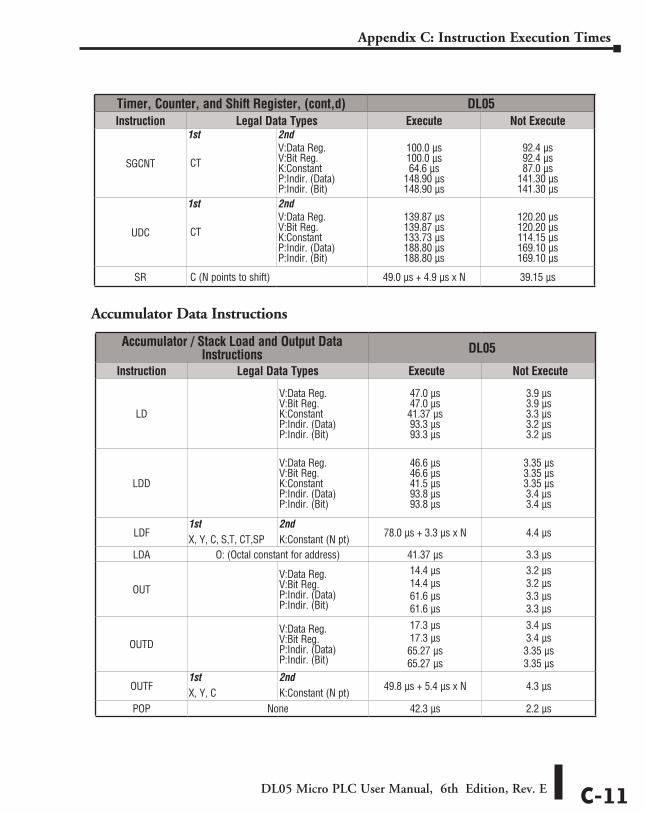
DL05 Micro PLC User Manual, 6th Edition, Rev. E C-11
Appendix C: Instruction Execution Times
Accumulator Data Instructions
Accumulator / Stack Load and Output Data Instructions DL05
Instruction Legal Data Types Execute Not Execute
LD
V:Data Reg. V:Bit Reg. K:Constant P:Indir. (Data) P:Indir. (Bit)
47.0 µs 47.0 µs 41.37 µs 93.3 µs 93.3 µs
3.9 µs 3.9 µs 3.3 µs 3.2 µs 3.2 µs
LDD
V:Data Reg. V:Bit Reg. K:Constant P:Indir. (Data) P:Indir. (Bit)
46.6 µs 46.6 µs 41.5 µs 93.8 µs 93.8 µs
3.35 µs 3.35 µs 3.35 µs 3.4 µs 3.4 µs
LDF 1stX, Y, C, S,T, CT,SP
2nd K:Constant (N pt)
78.0 µs + 3.3 µs x N 4.4 µs
LDA O: (Octal constant for address) 41.37 µs 3.3 µs
OUT V:Data Reg. V:Bit Reg. P:Indir. (Data) P:Indir. (Bit)
14.4 µs 14.4 µs 61.6 µs 61.6 µs
3.2 µs 3.2 µs 3.3 µs 3.3 µs
OUTD V:Data Reg. V:Bit Reg. P:Indir. (Data) P:Indir. (Bit)
17.3 µs 17.3 µs 65.27 µs 65.27 µs
3.4 µs 3.4 µs 3.35 µs 3.35 µs
OUTF 1st X, Y, C
2nd K:Constant (N pt)
49.8 µs + 5.4 µs x N 4.3 µs
POP None 42.3 µs 2.2 µs
Timer, Counter, and Shift Register, (cont,d) DL05Instruction Legal Data Types Execute Not Execute
SGCNT
1st CT
2nd V:Data Reg. V:Bit Reg. K:Constant P:Indir. (Data) P:Indir. (Bit)
100.0 µs 100.0 µs 64.6 µs
148.90 µs 148.90 µs
92.4 µs 92.4 µs 87.0 µs
141.30 µs 141.30 µs
UDC
1st CT
2nd V:Data Reg. V:Bit Reg. K:Constant P:Indir. (Data) P:Indir. (Bit)
139.87 µs 139.87 µs 133.73 µs 188.80 µs 188.80 µs
120.20 µs 120.20 µs 114.15 µs 169.10 µs 169.10 µs
SR C (N points to shift) 49.0 µs + 4.9 µs x N 39.15 µs
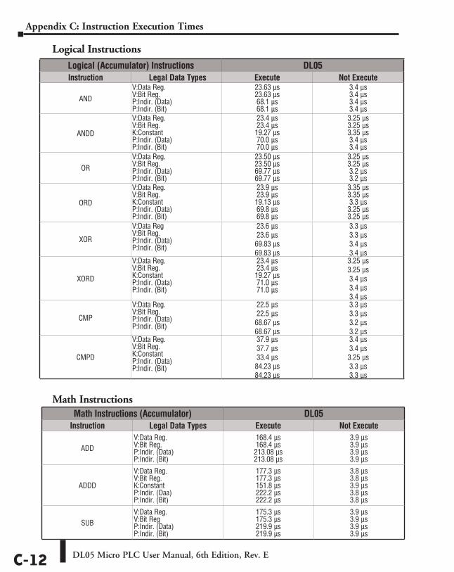
DL05 Micro PLC User Manual, 6th Edition, Rev. EC-12
Appendix C: Instruction Execution Times
Logical Instructions
Math Instructions
Logical (Accumulator) Instructions DL05Instruction Legal Data Types Execute Not Execute
ANDV:Data Reg. V:Bit Reg. P:Indir. (Data) P:Indir. (Bit)
23.63 µs 23.63 µs 68.1 µs 68.1 µs
3.4 µs 3.4 µs 3.4 µs 3.4 µs
ANDD
V:Data Reg. V:Bit Reg. K:Constant P:Indir. (Data) P:Indir. (Bit)
23.4 µs 23.4 µs 19.27 µs 70.0 µs 70.0 µs
3.25 µs 3.25 µs 3.35 µs 3.4 µs 3.4 µs
OR V:Data Reg. V:Bit Reg. P:Indir. (Data) P:Indir. (Bit)
23.50 µs 23.50 µs 69.77 µs 69.77 µs
3.25 µs 3.25 µs 3.2 µs 3.2 µs
ORD
V:Data Reg. V:Bit Reg. K:Constant P:Indir. (Data) P:Indir. (Bit)
23.9 µs 23.9 µs 19.13 µs 69.8 µs 69.8 µs
3.35 µs 3.35 µs 3.3 µs 3.25 µs 3.25 µs
XOR
V:Data Reg V:Bit Reg. P:Indir. (Data) P:Indir. (Bit)
23.6 µs 23.6 µs 69.83 µs 69.83 µs
3.3 µs 3.3 µs 3.4 µs 3.4 µs
XORD
V:Data Reg. V:Bit Reg. K:Constant P:Indir. (Data) P:Indir. (Bit)
23.4 µs 23.4 µs 19.27 µs 71.0 µs 71.0 µs
3.25 µs 3.25 µs 3.4 µs 3.4 µs 3.4 µs
CMP
V:Data Reg. V:Bit Reg. P:Indir. (Data) P:Indir. (Bit)
22.5 µs 22.5 µs 68.67 µs 68.67 µs
3.3 µs 3.3 µs 3.2 µs 3.2 µs
CMPD
V:Data Reg. V:Bit Reg. K:Constant P:Indir. (Data) P:Indir. (Bit)
37.9 µs 37.7 µs 33.4 µs 84.23 µs 84.23 µs
3.4 µs 3.4 µs 3.25 µs 3.3 µs 3.3 µs
Math Instructions (Accumulator) DL05Instruction Legal Data Types Execute Not Execute
ADD V:Data Reg. V:Bit Reg. P:Indir. (Data) P:Indir. (Bit)
168.4 µs 168.4 µs 213.08 µs 213.08 µs
3.9 µs 3.9 µs 3.9 µs 3.9 µs
ADDD
V:Data Reg. V:Bit Reg. K:Constant P:Indir. (Daa) P:Indir. (Bit)
177.3 µs 177.3 µs 151.8 µs 222.2 µs 222.2 µs
3.8 µs 3.8 µs 3.9 µs 3.8 µs 3.8 µs
SUB V:Data Reg. V:Bit Reg P:Indir. (Data) P:Indir. (Bit)
175.3 µs 175.3 µs 219.9 µs 219.9 µs
3.9 µs 3.9 µs 3.9 µs 3.9 µs
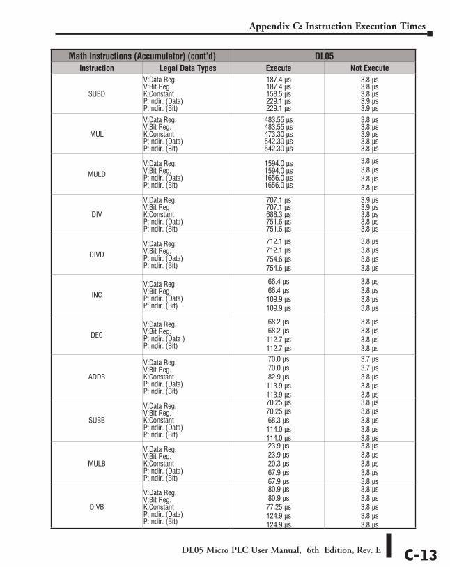
DL05 Micro PLC User Manual, 6th Edition, Rev. E C-13
Appendix C: Instruction Execution Times
Math Instructions (Accumulator) (cont’d) DL05Instruction Legal Data Types Execute Not Execute
SUBD
V:Data Reg. V:Bit Reg. K:Constant P:Indir. (Data) P:Indir. (Bit)
187.4 µs 187.4 µs 158.5 µs 229.1 µs 229.1 µs
3.8 µs 3.8 µs 3.8 µs 3.9 µs 3.9 µs
MUL
V:Data Reg. V:Bit Reg. K:Constant P:Indir. (Data) P:Indir. (Bit)
483.55 µs 483.55 µs 473.30 µs 542.30 µs 542.30 µs
3.8 µs 3.8 µs 3.9 µs 3.8 µs 3.8 µs
MULD V:Data Reg. V:Bit Reg. P:Indir. (Data) P:Indir. (Bit)
1594.0 µs 1594.0 µs 1656.0 µs 1656.0 µs
3.8 µs 3.8 µs 3.8 µs 3.8 µs
DIV
V:Data Reg. V:Bit Reg K:Constant P:Indir. (Data) P:Indir. (Bit)
707.1 µs 707.1 µs 688.3 µs 751.6 µs 751.6 µs
3.9 µs 3.9 µs 3.8 µs 3.8 µs 3.8 µs
DIVD V:Data Reg. V:Bit Reg. P:Indir. (Data) P:Indir. (Bit)
712.1 µs 712.1 µs 754.6 µs 754.6 µs
3.8 µs 3.8 µs 3.8 µs 3.8 µs
INC V:Data Reg V:Bit Reg P:Indir. (Data) P:Indir. (Bit)
66.4 µs 66.4 µs 109.9 µs 109.9 µs
3.8 µs 3.8 µs 3.8 µs 3.8 µs
DECV:Data Reg. V:Bit Reg. P:Indir. (Data ) P:Indir. (Bit)
68.2 µs 68.2 µs 112.7 µs 112.7 µs
3.8 µs 3.8 µs 3.8 µs 3.8 µs
ADDB
V:Data Reg. V:Bit Reg. K:Constant P:Indir. (Data) P:Indir. (Bit)
70.0 µs 70.0 µs 82.9 µs 113.9 µs 113.9 µs
3.7 µs 3.7 µs 3.8 µs 3.8 µs 3.8 µs
SUBB
V:Data Reg. V:Bit Reg. K:Constant P:Indir. (Data) P:Indir. (Bit)
70.25 µs 70.25 µs 68.3 µs 114.0 µs 114.0 µs
3.8 µs 3.8 µs 3.8 µs 3.8 µs 3.8 µs
MULB
V:Data Reg. V:Bit Reg. K:Constant P:Indir. (Data) P:Indir. (Bit)
23.9 µs 23.9 µs 20.3 µs 67.9 µs 67.9 µs
3.8 µs 3.8 µs 3.8 µs 3.8 µs 3.8 µs
DIVB
V:Data Reg. V:Bit Reg. K:Constant P:Indir. (Data) P:Indir. (Bit)
80.9 µs 80.9 µs 77.25 µs 124.9 µs 124.9 µs
3.8 µs 3.8 µs 3.8 µs 3.8 µs 3.8 µs
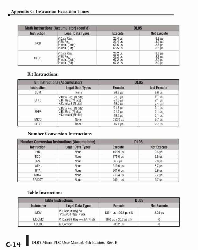
DL05 Micro PLC User Manual, 6th Edition, Rev. EC-14
Appendix C: Instruction Execution Times
Math Instructions (Accumulator) (cont’d) DL05Instruction Legal Data Types Execute Not Execute
INCB V:Data Reg. V:Bit Reg. P:Indir. (Data) P:Indir. (Bit)
23.4 µs 23.4 µs 66.5 µs 66.5 µs
3.9 µs 3.9 µs 3.8 µs 3.8 µs
DECBV:Data Reg. V:Bit Reg. P:Indir. (Data) P:Indir. (Bit)
23.2 µs 23.2 µs 67.2 µs 67.2 µs
3.8 µs 3.8 µs 3.9 µs 3.9 µs
Bit Instructions (Accumulator) DL05Instruction Legal Data Types Execute Not Execute
SUM None 26.9 µs 2.6 µs
SHFLV:Data Reg. (N bits) V:Bit Reg. (N bits) K:Constant (N bits)
21.8 µs 21.8 µs 19.5 µs
2.1 µs 2.1 µs 2.1 µs
SHFRV:Data Reg. (N bits) V:Bit Reg. (N bits) K:Constant (N bits)
21.5 µs 21.5 µs 19.6 µs
2.1 µs 2.1 µs 2.1 µs
ENCO None 382.0 µs 2.7 µsDECO None 16.4 µs 2.7 µs
Number Conversion Instructions (Accumulator) DL05Instruction Legal Data Types Execute Not Execute
BIN None 159.9 µs 2.6 µsBCD None 175.0 µs 2.6 µsINV None 6.7 µs 2.6 µsATH None 319.0 µs 3.7 µsHTA None 301.6 µs 3.9 µs
GRAY None 213.4 µs 2.7 µsSFLDGT None 259.1 µs 2.7 µs
Table Instructions DL05Instruction Legal Data Types Execute Not Execute
MOV V: Data/Bit Reg. to Vdata/Bit Reg (N pt) 136.1 µs + 20.8 µs x N 3.25 µs
MOVMC V: Data/Bit Reg <=> E2 (N pt) 86.0 µs + 30.7 µs x N 0LDLBL K: Constant 33.2 µs 0
Table Instructions
Number Conversion Instructions
Bit Instructions
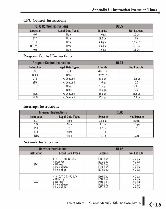
DL05 Micro PLC User Manual, 6th Edition, Rev. E C-15
Appendix C: Instruction Execution Times
CPU Control Instructions
Program Control Instructions
Interrupt Instructions
Network Instructions
CPU Control Instructions DL05Instruction Legal Data Types Execute Not Execute
NOP None 1.0 µs 1.0 µsEND None 21.8 µs 0.0STOP None 2.6 µs 1.15 µs
RSTWDT None 6.3 µs 2.6 µsNOT None 1.6 µs 1.6 µs
Program Control Instructions DL05Instruction Legal Data Types Execute Not Execute
FOR V, K 202.9 µs 15.0 µsNEXT None 62.27 µs -GTS K: Constant 27.6 µs 15.3 µsSBR K: Constant 1.6 µs 0.0RTC None 25.7 µs 12.1 µsRT None 21.6 µs 0.0
MLS K: Constant 35.6 µs 35.6 µsMLR K: Constant 15.4 µs 15.4 µs
Interrupt Instructions DL05Instruction Legal Data Types Execute Not Execute
ENI None 23.8 µs 2.2 µsDISI None 9.4 µs 2.3 µsINT O 7.5 µs 0IRT None 6.6 µs 0
IRTC None 0.9 µs 1.3 µs
Network Instructions DL05Instruction Legal Data Types Execute Not Execute
RX
X, Y, C, T, CT, SP, S,V V:Data Reg. V:Bit Reg. P:Indir. (Data) P:Indir. (Bit)
1639.0 µs 1639.0 µs 1639.0 µs 1674.0 µs 1674.0 µs
4.2 µs 4.2 µs 4.2 µs 4.2 µs 4.2 µs
WX
X, Y, C, T, CT, SP, S, V V:Data Reg. V:Bit Reg. P:Indir. (Data) P:Indir. (Bit)
1691.0 µs 1691.0 µs 1691.0 µs 1726.0 µs 1726.0 µs
4.2 µs 4.2 µs 4.2 µs 4.2 µs 4.2 µs
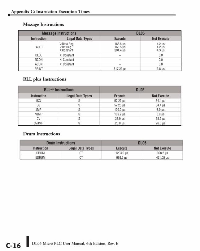
DL05 Micro PLC User Manual, 6th Edition, Rev. EC-16
Appendix C: Instruction Execution Times
Message Instructions
RLL plus Instructions
Drum Instructions
Message Instructions DL05Instruction Legal Data Types Execute Not Execute
FAULT V:Data Reg. V:Bit Reg. K:Constant
163.5 µs 163.5 µs 204.4 µs
4.2 µs 4.2 µs 4.3 µs
DLBL K: Constant – 0.0NCON K: Constant – 0.0ACON K: Constant – 0.0PRINT 817.23 µs 3.8 µs
RLLplus Instructions DL05Instruction Legal Data Types Execute Not Execute
ISG S 57.27 µs 54.4 µsSG S 57.25 µs 54.4 µs
JMP S 109.2 µs 8.9 µsNJMP S 109.2 µs 8.9 µs
CV S 38.9 µs 38.9 µsCVJMP S 26.0 µs 26.0 µs
Drum Instructions DL05Instruction Legal Data Types Execute Not Execute
DRUM CT 1204.0 µs 398.2 µsEDRUM CT 989.2 µs 421.05 µs
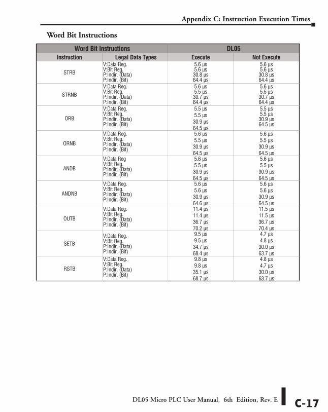
DL05 Micro PLC User Manual, 6th Edition, Rev. E C-17
Appendix C: Instruction Execution Times
Word Bit Instructions
Word Bit Instructions DL05Instruction Legal Data Types Execute Not Execute
STRBV:Data Reg. V:Bit Reg. P:Indir. (Data) P:Indir. (Bit)
5.6 µs 5.6 µs 30.8 µs 64.4 µs
5.6 µs 5.6 µs 30.8 µs 64.4 µs
STRNB V:Data Reg. V:Bit Reg. P:Indir. (Data) P:Indir. (Bit)
5.6 µs 5.5 µs 30.7 µs 64.4 µs
5.6 µs 5.5 µs 30.7 µs 64.4 µs
ORB
V:Data Reg. V:Bit Reg. P:Indir. (Data) P:Indir. (Bit)
5.5 µs 5.5 µs 30.9 µs 64.5 µs
5.5 µs 5.5 µs 30.9 µs 64.5 µs
ORNB
V:Data Reg. V:Bit Reg. P:Indir. (Data) P:Indir. (Bit)
5.6 µs 5.5 µs 30.9 µs 64.5 µs
5.6 µs 5.5 µs 30.9 µs 64.5 µs
ANDB
V:Data Reg V:Bit Reg. P:Indir. (Data) P:Indir. (Bit)
5.6 µs 5.5 µs 30.9 µs 64.5 µs
5.6 µs 5.5 µs 30.9 µs 64.5 µs
ANDNB
V:Data Reg. V:Bit Reg. P:Indir. (Data) P:Indir. (Bit)
5.6 µs 5.6 µs 30.9 µs 64.6 µs
5.6 µs 5.6 µs 30.9 µs 64.5 µs
OUTB
V:Data Reg. V:Bit Reg. P:Indir. (Data) P:Indir. (Bit)
11.4 µs 11.4 µs 36.7 µs 70.2 µs
11.5 µs 11.5 µs 36.7 µs 70.4 µs
SETBV:Data Reg. V:Bit Reg. P:Indir. (Data) P:Indir. (Bit)
9.5 µs 9.5 µs 34.7 µs 68.4 µs
4.7 µs 4.8 µs 30.0 µs 63.7 µs
RSTB
V:Data Reg. V:Bit Reg. P:Indir. (Data) P:Indir. (Bit)
9.8 µs 9.8 µs 35.1 µs 68.7 µs
4.8 µs 4.7 µs 30.0 µs 63.7 µs
Special RelayS DDDAppendixAppendixAppendix
In this Appendix...DL05 PLC Special Relays............................................................................D–2
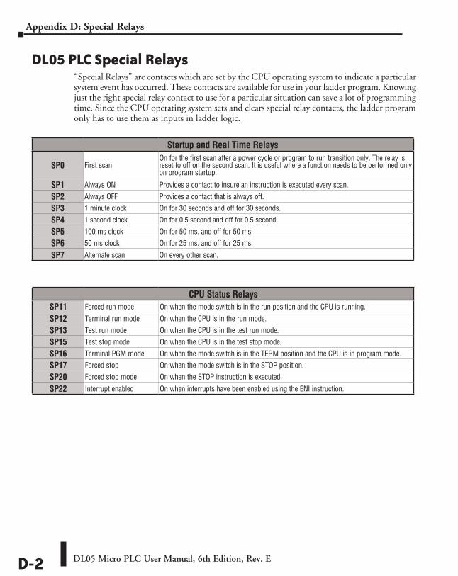
DL05 Micro PLC User Manual, 6th Edition, Rev. ED-2
Appendix D: Special Relays
DL05 PLC Special Relays“Special Relays” are contacts which are set by the CPU operating system to indicate a particular system event has occurred. These contacts are available for use in your ladder program. Knowing just the right special relay contact to use for a particular situation can save a lot of programming time. Since the CPU operating system sets and clears special relay contacts, the ladder program only has to use them as inputs in ladder logic.
Startup and Real Time Relays
SP0 First scan On for the first scan after a power cycle or program to run transition only. The relay is reset to off on the second scan. It is useful where a function needs to be performed only on program startup.
SP1 Always ON Provides a contact to insure an instruction is executed every scan.
SP2 Always OFF Provides a contact that is always off.
SP3 1 minute clock On for 30 seconds and off for 30 seconds.
SP4 1 second clock On for 0.5 second and off for 0.5 second.
SP5 100 ms clock On for 50 ms. and off for 50 ms.
SP6 50 ms clock On for 25 ms. and off for 25 ms.
SP7 Alternate scan On every other scan.
CPU Status RelaysSP11 Forced run mode On when the mode switch is in the run position and the CPU is running.
SP12 Terminal run mode On when the CPU is in the run mode.
SP13 Test run mode On when the CPU is in the test run mode.
SP15 Test stop mode On when the CPU is in the test stop mode.
SP16 Terminal PGM mode On when the mode switch is in the TERM position and the CPU is in program mode.
SP17 Forced stop On when the mode switch is in the STOP position.
SP20 Forced stop mode On when the STOP instruction is executed.
SP22 Interrupt enabled On when interrupts have been enabled using the ENI instruction.
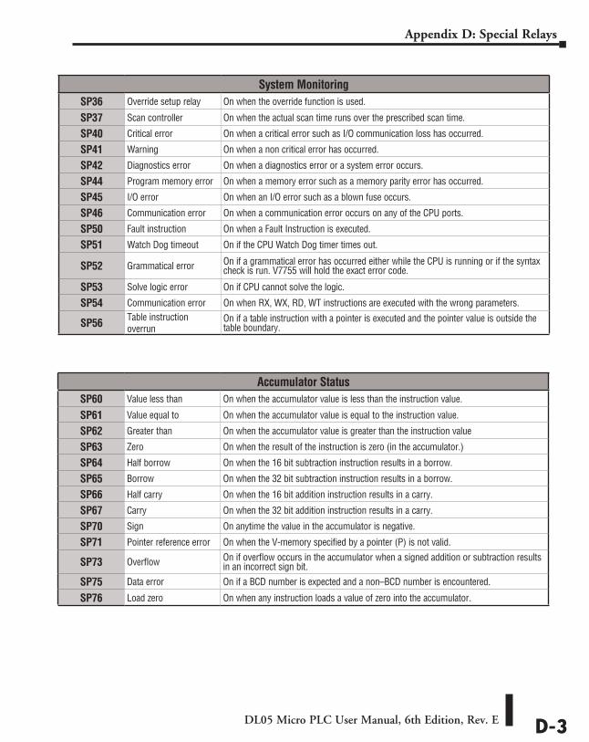
DL05 Micro PLC User Manual, 6th Edition, Rev. E D-3
Appendix D: Special Relays
System MonitoringSP36 Override setup relay On when the override function is used.
SP37 Scan controller On when the actual scan time runs over the prescribed scan time.
SP40 Critical error On when a critical error such as I/O communication loss has occurred.
SP41 Warning On when a non critical error has occurred.
SP42 Diagnostics error On when a diagnostics error or a system error occurs.
SP44 Program memory error On when a memory error such as a memory parity error has occurred.
SP45 I/O error On when an I/O error such as a blown fuse occurs.
SP46 Communication error On when a communication error occurs on any of the CPU ports.
SP50 Fault instruction On when a Fault Instruction is executed.
SP51 Watch Dog timeout On if the CPU Watch Dog timer times out.
SP52 Grammatical error On if a grammatical error has occurred either while the CPU is running or if the syntax check is run. V7755 will hold the exact error code.
SP53 Solve logic error On if CPU cannot solve the logic.
SP54 Communication error On when RX, WX, RD, WT instructions are executed with the wrong parameters.
SP56 Table instruction overrun
On if a table instruction with a pointer is executed and the pointer value is outside the table boundary.
Accumulator StatusSP60 Value less than On when the accumulator value is less than the instruction value.
SP61 Value equal to On when the accumulator value is equal to the instruction value.
SP62 Greater than On when the accumulator value is greater than the instruction value
SP63 Zero On when the result of the instruction is zero (in the accumulator.)
SP64 Half borrow On when the 16 bit subtraction instruction results in a borrow.
SP65 Borrow On when the 32 bit subtraction instruction results in a borrow.
SP66 Half carry On when the 16 bit addition instruction results in a carry.
SP67 Carry On when the 32 bit addition instruction results in a carry.
SP70 Sign On anytime the value in the accumulator is negative.
SP71 Pointer reference error On when the V-memory specified by a pointer (P) is not valid.
SP73 Overflow On if overflow occurs in the accumulator when a signed addition or subtraction results in an incorrect sign bit.
SP75 Data error On if a BCD number is expected and a non–BCD number is encountered.
SP76 Load zero On when any instruction loads a value of zero into the accumulator.
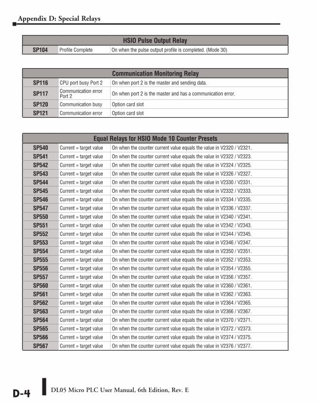
DL05 Micro PLC User Manual, 6th Edition, Rev. ED-4
Appendix D: Special Relays
HSIO Pulse Output RelaySP104 Profile Complete On when the pulse output profile is completed. (Mode 30)
Equal Relays for HSIO Mode 10 Counter PresetsSP540 Current = target value On when the counter current value equals the value in V2320 / V2321.
SP541 Current = target value On when the counter current value equals the value in V2322 / V2323.
SP542 Current = target value On when the counter current value equals the value in V2324 / V2325.
SP543 Current = target value On when the counter current value equals the value in V2326 / V2327.
SP544 Current = target value On when the counter current value equals the value in V2330 / V2331.
SP545 Current = target value On when the counter current value equals the value in V2332 / V2333.
SP546 Current = target value On when the counter current value equals the value in V2334 / V2335.
SP547 Current = target value On when the counter current value equals the value in V2336 / V2337.
SP550 Current = target value On when the counter current value equals the value in V2340 / V2341.
SP551 Current = target value On when the counter current value equals the value in V2342 / V2343.
SP552 Current = target value On when the counter current value equals the value in V2344 / V2345.
SP553 Current = target value On when the counter current value equals the value in V2346 / V2347.
SP554 Current = target value On when the counter current value equals the value in V2350 / V2351.
SP555 Current = target value On when the counter current value equals the value in V2352 / V2353.
SP556 Current = target value On when the counter current value equals the value in V2354 / V2355.
SP557 Current = target value On when the counter current value equals the value in V2356 / V2357.
SP560 Current = target value On when the counter current value equals the value in V2360 / V2361.
SP561 Current = target value On when the counter current value equals the value in V2362 / V2363.
SP562 Current = target value On when the counter current value equals the value in V2364 / V2365.
SP563 Current = target value On when the counter current value equals the value in V2366 / V2367.
SP564 Current = target value On when the counter current value equals the value in V2370 / V2371.
SP565 Current = target value On when the counter current value equals the value in V2372 / V2373.
SP566 Current = target value On when the counter current value equals the value in V2374 / V2375.
SP567 Current = target value On when the counter current value equals the value in V2376 / V2377.
Communication Monitoring RelaySP116 CPU port busy Port 2 On when port 2 is the master and sending data.
SP117 Communication error Port 2 On when port 2 is the master and has a communication error.
SP120 Communication busy Option card slot
SP121 Communication error Option card slot
HigH-speed input and pulse Output Features EEE
AppendixAppendixAppendix
In This Appendix...Introduction ................................................................................................................E-2
Choosing the HSIO Operating Mode .........................................................................E-4
Mode 10: High-Speed Counter ..................................................................................E-6
Mode 20: Quadrature Counter ................................................................................E-18
Mode 30: Pulse Output ............................................................................................E-24
Trapezoidal Profile Operation ..................................................................................E-31
Registration Profile Operation .................................................................................E-34
Velocity Profile Operation ........................................................................................E-42
Mode 40: High-Speed Interrupts .............................................................................E-47
Mode 50: Pulse Catch Input .....................................................................................E-52
Mode 60: Discrete Inputs with Filter .......................................................................E-55
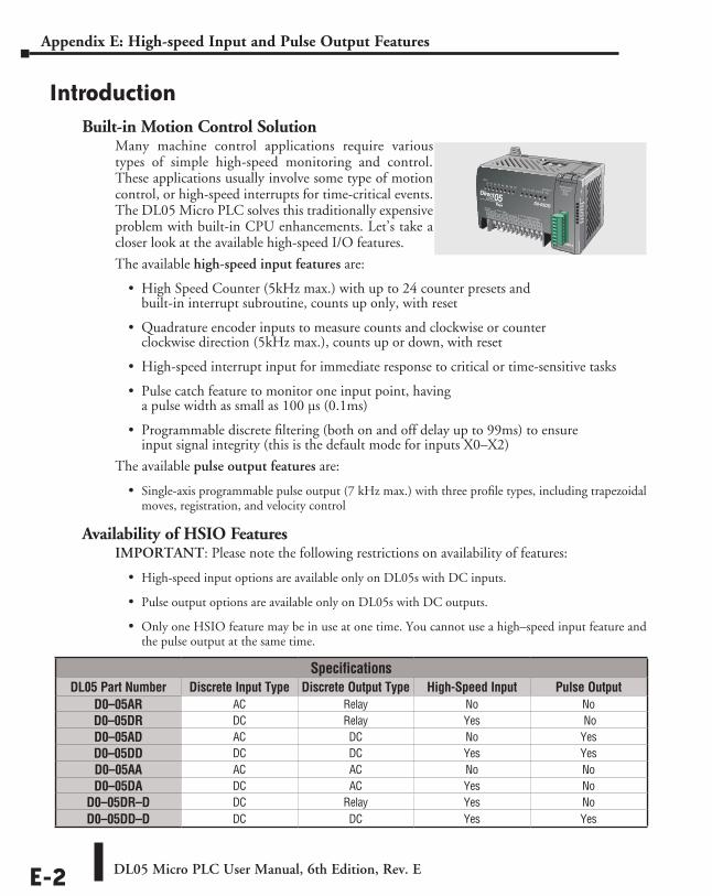
DL05 Micro PLC User Manual, 6th Edition, Rev. EE-2
Appendix E: High-speed Input and Pulse Output Features
IntroductionBuilt-in Motion Control Solution
Many machine control applications require various types of simple high-speed monitoring and control. These applications usually involve some type of motion control, or high-speed interrupts for time-critical events. The DL05 Micro PLC solves this traditionally expensive problem with built-in CPU enhancements. Let’s take a closer look at the available high-speed I/O features.
The available high-speed input features are:
• High Speed Counter (5kHz max.) with up to 24 counter presets and built-in interrupt subroutine, counts up only, with reset
• Quadrature encoder inputs to measure counts and clockwise or counter clockwise direction (5kHz max.), counts up or down, with reset
• High-speed interrupt input for immediate response to critical or time-sensitive tasks
• Pulse catch feature to monitor one input point, having a pulse width as small as 100 µs (0.1ms)
• Programmable discrete filtering (both on and off delay up to 99ms) to ensure input signal integrity (this is the default mode for inputs X0–X2)
The available pulse output features are:
• Single-axis programmable pulse output (7 kHz max.) with three profile types, including trapezoidal moves, registration, and velocity control
Availability of HSIO FeaturesIMPORTANT: Please note the following restrictions on availability of features:
• High-speed input options are available only on DL05s with DC inputs.
• Pulse output options are available only on DL05s with DC outputs.
• Only one HSIO feature may be in use at one time. You cannot use a high–speed input feature and the pulse output at the same time.
PWR
RUN
CPU
TX1
RX1
TX2
RX2
SpecificationsDL05 Part Number Discrete Input Type Discrete Output Type High-Speed Input Pulse Output
D0–05AR AC Relay No NoD0–05DR DC Relay Yes NoD0–05AD AC DC No YesD0–05DD DC DC Yes YesD0–05AA AC AC No NoD0–05DA DC AC Yes No
D0–05DR–D DC Relay Yes NoD0–05DD–D DC DC Yes Yes
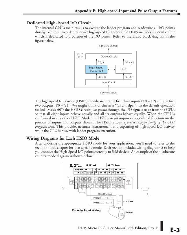
DL05 Micro PLC User Manual, 6th Edition, Rev. E E-3
Appendix E: High-speed Input and Pulse Output Features
Dedicated High- Speed I/O CircuitThe internal CPU’s main task is to execute the ladder program and read/write all I/O points during each scan. In order to service high-speed I/O events, the DL05 includes a special circuit which is dedicated to a portion of the I/O points. Refer to the DL05 block diagram in the figure below.
The high-speed I/O circuit (HSIO) is dedicated to the first three inputs (X0 – X2) and the first two outputs (Y0 – Y1). We might think of this as a “CPU helper”. In the default operation (called “Mode 60”) the HSIO circuit just passes through the I/O signals to or from the CPU, so that all eight inputs behave equally and all six outputs behave equally. When the CPU is configured in any other HSIO Mode, the HSIO circuit imposes a specialized function on the portion of inputs and outputs shown. The HSIO circuit operates independently of the CPU program scan. This provides accurate measurement and capturing of high-speed I/O activity while the CPU is busy with ladder program execution.
Wiring Diagrams for Each HSIO ModeAfter choosing the appropriate HSIO mode for your application, you’ll need to refer to the section in this chapter for that specific mode. Each section includes wiring diagram(s) to help you connect the High-Speed I/O points correctly to field devices. An example of the quadrature counter mode diagram is shown below.
Output Circuit
Input Circuit
CPU
8 Discrete Inputs
6 Discrete Outputs
PLCDL05
High-SpeedI/O Circuit
X0 - X2
Y0, Y1
X3 -X7
Y2 - Y5
Encoder Input Wiring
+
–12 – 24 VDCPhase A
Phase B
Encoder
Signal Common
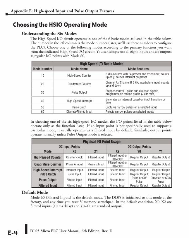
DL05 Micro PLC User Manual, 6th Edition, Rev. EE-4
Appendix E: High-speed Input and Pulse Output Features
Choosing the HSIO Operating ModeUnderstanding the Six Modes
The High-Speed I/O circuit operates in one of the 6 basic modes as listed in the table below. The number in the left column is the mode number (later, we’ll use these numbers to configure the PLC). Choose one of the following modes according to the primary function you want from the dedicated High-Speed I/O circuit. You can simply use all eight inputs and six outputs as regular I/O points with Mode 60.
In choosing one of the six high-speed I/O modes, the I/O points listed in the table below operate only as the function listed. If an input point is not specifically used to support a particular mode, it usually operates as a filtered input by default. Similarly, output points operate normally unless Pulse Output mode is selected.
Default ModeMode 60 (Filtered Inputs) is the default mode. The DL05 is initialized to this mode at the factory, and any time you reset V-memory scratchpad. In the default condition, X0–X2 are filtered inputs (10 ms delay) and Y0–Y1 are standard outputs
High Speed I/O Basic ModesMode Number Mode Name Mode Features
10 High-Speed Counter 5 kHz counter with 24 presets and reset input, counts up only, causes interrupt on preset
20 Quadrature Counter Channel A / Channel B 5 kHz quadrature input, counts up and down
30 Pulse Output Stepper control – pulse and direction signals, programmable motion profile (7kHz max.)
40 High-Speed Interrupt Generates an interrupt based on input transition or time
50 Pulse Catch Captures narrow pulses on a selected input60 Discrete/Filtered Input Rejects narrow pulses on selected inputs
Physical I/O Point UsageDC Input Points DC Output Points
Mode X0 X1 X2 Y0 Y1
High-Speed Counter Counter clock Filtered Input Filtered Input or Reset Cnt Regular Output Regular Output
Quadrature Counter Phase A Input Phase B Input Filtered Input or Reset Cnt Regular Output Regular Output
High-Speed Interrupt Interrupt Input Filtered Input Filtered Input Regular Output Regular OutputPulse Catch Pulse Input Filtered Input Filtered Input Regular Output Regular Output
Pulse Output Filtered Input Filtered Input Filtered Input Pulse or CW Pulse
Direction or CCW Pulse
Filtered Input Filtered Input Filtered Input Filtered Input Regular Output Regular Output
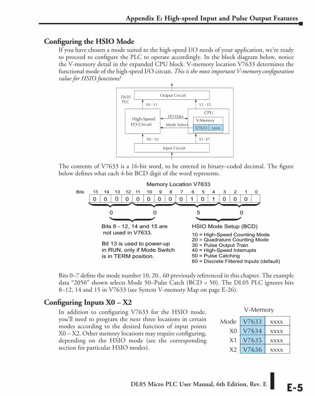
DL05 Micro PLC User Manual, 6th Edition, Rev. E E-5
Appendix E: High-speed Input and Pulse Output Features
Configuring the HSIO ModeIf you have chosen a mode suited to the high-speed I/O needs of your application, we’re ready to proceed to configure the PLC to operate accordingly. In the block diagram below, notice the V-memory detail in the expanded CPU block. V-memory location V7633 determines the functional mode of the high-speed I/O circuit. This is the most important V-memory configuration value for HSIO functions!
The contents of V7633 is a 16-bit word, to be entered in binary–coded decimal. The figure below defines what each 4-bit BCD digit of the word represents.
Bits 0–7 define the mode number 10, 20.. 60 previously referenced in this chapter. The example data “2050” shown selects Mode 50–Pulse Catch (BCD = 50). The DL05 PLC ignores bits 8–12, 14 and 15 in V7633 (see System V-memory Map on page E-26).
Configuring Inputs X0 – X2
Output Circuit
Input Circuit
CPU
PLCDL05
High-Speed I/O Circuit
X0 - X2
Y0 - Y1
X3 -X7
Y2 - Y5
V-Memory
V7633 xxxx Mode Select
I/O Data
V-Memory
V7633 xxxxModeV7634 xxxxX0V7635 xxxxX1V7636 xxxxX2
014 13 12
Memory Location V763311 10 123456789Bits
00 0010100
HSIO Mode Setup (BCD)
0 0 0 0
10 = High-Speed Counting Mode20 = Quadrature Counting Mode30 = Pulse Output Train
0
40 = High-Speed Interrupts50 = Pulse Catching60 = Discrete Filtered Inputs (default)
5
0
00
Bits 8 - 12, 14 and 15 are not used in V7633.
15
0
Bit 13 is used to power-upin RUN, only if Mode Switchis in TERM position.
In addition to configuring V7633 for the HSIO mode, you’ll need to program the next three locations in certain modes according to the desired function of input points X0 – X2. Other memory locations may require configuring, depending on the HSIO mode (see the corresponding section for particular HSIO modes).
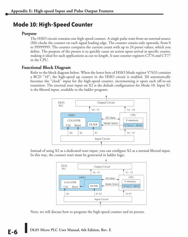
DL05 Micro PLC User Manual, 6th Edition, Rev. EE-6
Appendix E: High-speed Input and Pulse Output Features
Mode 10: High-Speed CounterPurpose
The HSIO circuit contains one high-speed counter. A single pulse train from an external source (X0) clocks the counter on each signal leading edge. The counter counts only upwards, from 0 to 99999999. The counter compares the current count with up to 24 preset values, which you define. The purpose of the presets is to quickly cause an action upon arrival at specific counts, making it ideal for such applications as cut-to-length. It uses counter registers CT76 and CT77 in the CPU.
Functional Block DiagramRefer to the block diagram below. When the lower byte of HSIO Mode register V7633 contains a BCD “10”, the high-speed up counter in the HSIO circuit is enabled. X0 automatically becomes the “clock” input for the high-speed counter, incrementing it upon each off-to-on transition. The external reset input on X2 is the default configuration for Mode 10. Input X1 is the filtered input, available to the ladder program.
Instead of using X2 as a dedicated reset input, you can configure X2 as a normal filtered input. In this way, the counter reset must be generated in ladder logic.
Next, we will discuss how to program the high-speed counter and its presets.
Input Circuit
CPU
PLCDL05
X0
Y0 - Y1
X3-X7
Y2 - Y5
V-memory
V7633 0010 Mode Select
I/O data HSIO
COUNTER
CLK Reset
X1-X2
FILTER
Output Circuit
Input Circuit
CPU
PLCDL05
X0
Y0 - Y1
X3 - X7
Y2 - Y5
V-memory
V7633 0010Mode Select
I/O data HSIO
COUNTER
CLK Reset
X2 X1
FILTER
Output Circuit
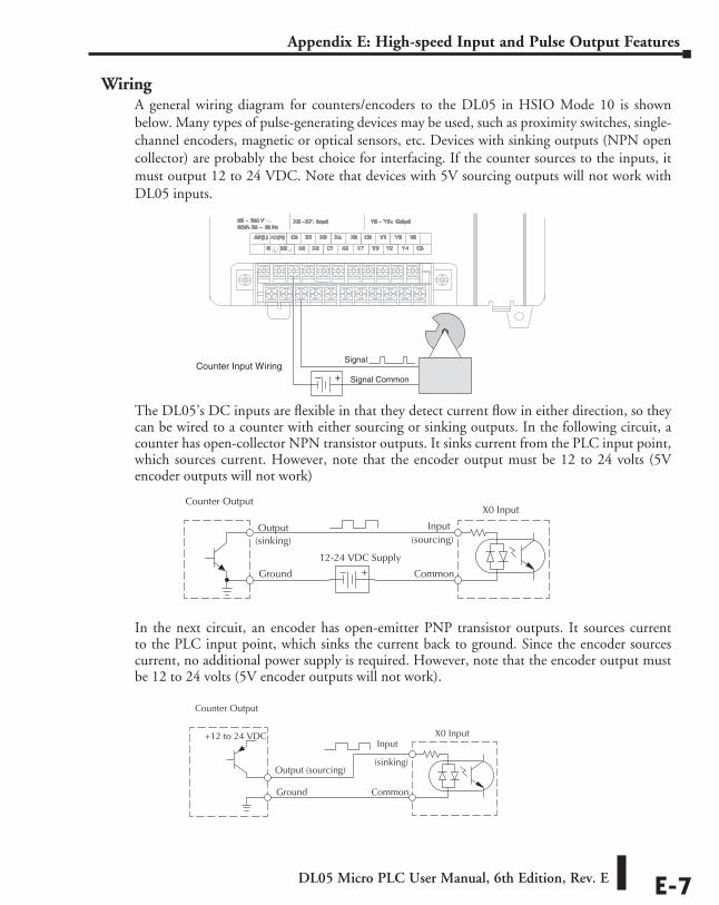
DL05 Micro PLC User Manual, 6th Edition, Rev. E E-7
Appendix E: High-speed Input and Pulse Output Features
WiringA general wiring diagram for counters/encoders to the DL05 in HSIO Mode 10 is shown below. Many types of pulse-generating devices may be used, such as proximity switches, single-channel encoders, magnetic or optical sensors, etc. Devices with sinking outputs (NPN open collector) are probably the best choice for interfacing. If the counter sources to the inputs, it must output 12 to 24 VDC. Note that devices with 5V sourcing outputs will not work with DL05 inputs.
The DL05’s DC inputs are flexible in that they detect current flow in either direction, so they can be wired to a counter with either sourcing or sinking outputs. In the following circuit, a counter has open-collector NPN transistor outputs. It sinks current from the PLC input point, which sources current. However, note that the encoder output must be 12 to 24 volts (5V encoder outputs will not work)
In the next circuit, an encoder has open-emitter PNP transistor outputs. It sources current to the PLC input point, which sinks the current back to ground. Since the encoder sources current, no additional power supply is required. However, note that the encoder output must be 12 to 24 volts (5V encoder outputs will not work).
Counter Input WiringSignal Common
Signal
+–
Counter Output
+–
X0 Input
Output
Ground
Input
Common
12-24 VDC Supply
(sinking) (sourcing)
X0 Input
Output (sourcing)
:
Ground
Common
+12 to 24 VDC (sinking)
Counter Output
Input
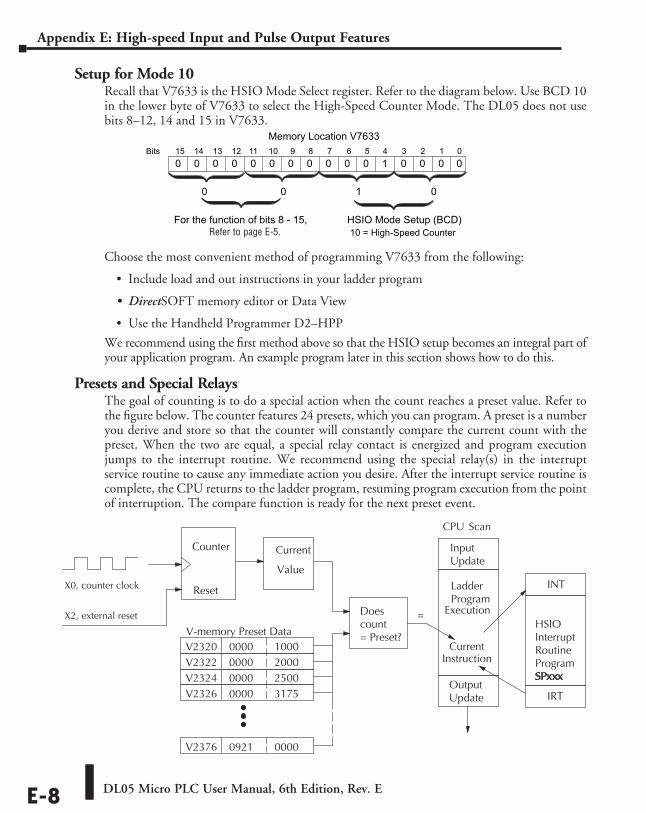
DL05 Micro PLC User Manual, 6th Edition, Rev. EE-8
Appendix E: High-speed Input and Pulse Output Features
Setup for Mode 10Recall that V7633 is the HSIO Mode Select register. Refer to the diagram below. Use BCD 10 in the lower byte of V7633 to select the High-Speed Counter Mode. The DL05 does not use bits 8–12, 14 and 15 in V7633.
Choose the most convenient method of programming V7633 from the following:
• Include load and out instructions in your ladder program
• DirectSOFT memory editor or Data View
• Use the Handheld Programmer D2–HPP
We recommend using the first method above so that the HSIO setup becomes an integral part of your application program. An example program later in this section shows how to do this.
Presets and Special RelaysThe goal of counting is to do a special action when the count reaches a preset value. Refer to the figure below. The counter features 24 presets, which you can program. A preset is a number you derive and store so that the counter will constantly compare the current count with the preset. When the two are equal, a special relay contact is energized and program execution jumps to the interrupt routine. We recommend using the special relay(s) in the interrupt service routine to cause any immediate action you desire. After the interrupt service routine is complete, the CPU returns to the ladder program, resuming program execution from the point of interruption. The compare function is ready for the next preset event.
015 14 13 12
Memory Location V763311 10 123456789Bits
HSIO Mode Setup (BCD)10 = High-Speed Counter
0 0 01
For the function of bits 8 - 15, refer to page 3-5.
00 0010000 0 0 0 000 0
X0, counter clock
CPU Scan
Counter
Reset
X2, external reset
Current
Value
V2320 0000V2322 0000V2324 0000V2326 0000
1000200025003175
V2376 0921 0000
InputUpdate
LadderProgram
Execution
Output Update
Does count = Preset?
INT
HSIOInterruptRoutineProgramSPxxx
IRT
=
Current
Instruction
V-memory Preset Data
Refer to page E-5.
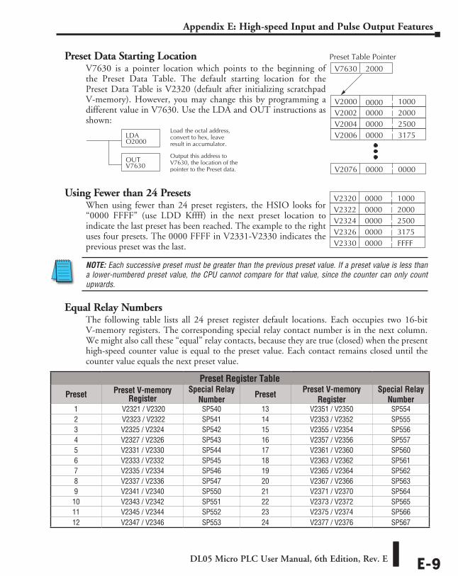
DL05 Micro PLC User Manual, 6th Edition, Rev. E E-9
Appendix E: High-speed Input and Pulse Output Features
Preset Data Starting LocationV7630 is a pointer location which points to the beginning of the Preset Data Table. The default starting location for the Preset Data Table is V2320 (default after initializing scratchpad V-memory). However, you may change this by programming a different value in V7630. Use the LDA and OUT instructions as shown:
Using Fewer than 24 PresetsWhen using fewer than 24 preset registers, the HSIO looks for “0000 FFFF” (use LDD Kffff) in the next preset location to indicate the last preset has been reached. The example to the right uses four presets. The 0000 FFFF in V2331-V2330 indicates the previous preset was the last.
NOTE: Each successive preset must be greater than the previous preset value. If a preset value is less than a lower-numbered preset value, the CPU cannot compare for that value, since the counter can only count upwards.
Equal Relay NumbersThe following table lists all 24 preset register default locations. Each occupies two 16-bit V-memory registers. The corresponding special relay contact number is in the next column. We might also call these “equal” relay contacts, because they are true (closed) when the present high-speed counter value is equal to the preset value. Each contact remains closed until the counter value equals the next preset value.
LDAO2000
Load the octal address,convert to hex, leaveresult in accumulator.
OUTV7630
Output this address toV7630, the location of thepointer to the Preset data.
Preset Register Table
Preset Preset V-memory Register
Special Relay Number Preset Preset V-memory
Register Special Relay
Number1 V2321 / V2320 SP540 13 V2351 / V2350 SP5542 V2323 / V2322 SP541 14 V2353 / V2352 SP5553 V2325 / V2324 SP542 15 V2355 / V2354 SP5564 V2327 / V2326 SP543 16 V2357 / V2356 SP5575 V2331 / V2330 SP544 17 V2361 / V2360 SP5606 V2333 / V2332 SP545 18 V2363 / V2362 SP5617 V2335 / V2334 SP546 19 V2365 / V2364 SP5628 V2337 / V2336 SP547 20 V2367 / V2366 SP5639 V2341 / V2340 SP550 21 V2371 / V2370 SP56410 V2343 / V2342 SP551 22 V2373 / V2372 SP56511 V2345 / V2344 SP552 23 V2375 / V2374 SP56612 V2347 / V2346 SP553 24 V2377 / V2376 SP567
V2000 0000V2002 0000V2004 0000V2006 0000
1000200025003175
V2076 0000 0000
V7630 2000
Preset Table Pointer
V2320 0000V2322 0000V2324 0000V2326 0000
1000200025003175
V2330 0000 FFFF
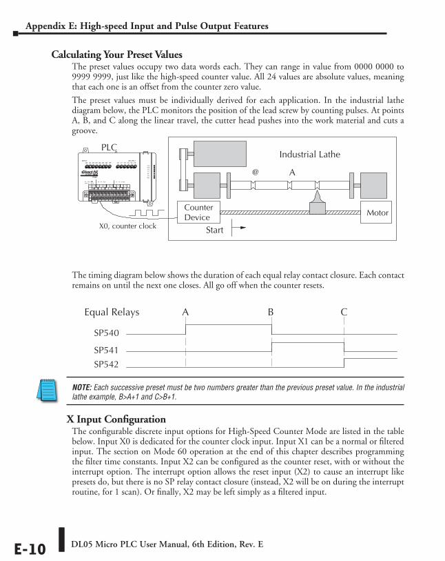
DL05 Micro PLC User Manual, 6th Edition, Rev. EE-10
Appendix E: High-speed Input and Pulse Output Features
Calculating Your Preset ValuesThe preset values occupy two data words each. They can range in value from 0000 0000 to 9999 9999, just like the high-speed counter value. All 24 values are absolute values, meaning that each one is an offset from the counter zero value.
The preset values must be individually derived for each application. In the industrial lathe diagram below, the PLC monitors the position of the lead screw by counting pulses. At points A, B, and C along the linear travel, the cutter head pushes into the work material and cuts a groove.
The timing diagram below shows the duration of each equal relay contact closure. Each contact remains on until the next one closes. All go off when the counter resets.
NOTE: Each successive preset must be two numbers greater than the previous preset value. In the industrial lathe example, B>A+1 and C>B+1.
X Input ConfigurationThe configurable discrete input options for High-Speed Counter Mode are listed in the table below. Input X0 is dedicated for the counter clock input. Input X1 can be a normal or filtered input. The section on Mode 60 operation at the end of this chapter describes programming the filter time constants. Input X2 can be configured as the counter reset, with or without the interrupt option. The interrupt option allows the reset input (X2) to cause an interrupt like presets do, but there is no SP relay contact closure (instead, X2 will be on during the interrupt routine, for 1 scan). Or finally, X2 may be left simply as a filtered input.
Equal Relays
SP540
SP541
SP542
A B C
PLCIndustrial Lathe
Start
@ A
CounterDevice
X0, counter clock
Motor
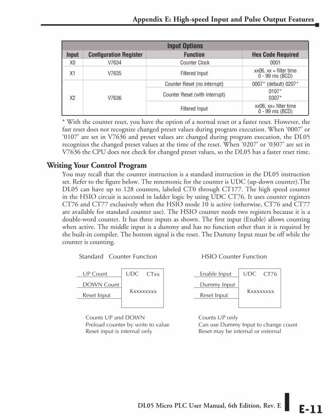
DL05 Micro PLC User Manual, 6th Edition, Rev. E E-11
Appendix E: High-speed Input and Pulse Output Features
* With the counter reset, you have the option of a normal reset or a faster reset. However, the fast reset does not recognize changed preset values during program execution. When ‘0007’ or ‘0107’ are set in V7636 and preset values are changed during program execution, the DL05 recognizes the changed preset values at the time of the reset. When ‘0207’ or ‘0307’ are set in V7636 the CPU does not check for changed preset values, so the DL05 has a faster reset time.
Writing Your Control ProgramYou may recall that the counter instruction is a standard instruction in the DL05 instruction set. Refer to the figure below. The mnemonic for the counter is UDC (up-down counter).The DL05 can have up to 128 counters, labeled CT0 through CT177. The high speed counter in the HSIO circuit is accessed in ladder logic by using UDC CT76. It uses counter registers CT76 and CT77 exclusively when the HSIO mode 10 is active (otherwise, CT76 and CT77 are available for standard counter use). The HSIO counter needs two registers because it is a double-word counter. It has three inputs as shown. The first input (Enable) allows counting when active. The middle input is a dummy and has no function other than it is required by the built-in compiler. The bottom signal is the reset. The Dummy Input must be off while the counter is counting.
Input OptionsInput Configuration Register Function Hex Code Required
X0 V7634 Counter Clock 0001
X1 V7635 Filtered Input xx06, xx = filter time 0 - 99 ms (BCD)
X2 V7636
Counter Reset (no interrupt) 0007* (default) 0207*
Counter Reset (with interrupt) 0107* 0307*
Filtered Input xx06, xx= filter time 0 - 99 ms (BCD)
Reset Input
UDC CT76
Kxxxxxxxx
Enable Input
Dummy Input
Reset Input
UDC CTxx
Kxxxxxxxx
UP Count
DOWN Count
Standard Counter Function HSIO Counter Function
Counts UP and DOWN Counts UP only
Reset input is internal only Reset may be internal or external Preload counter by write to value Can use Dummy Input to change count
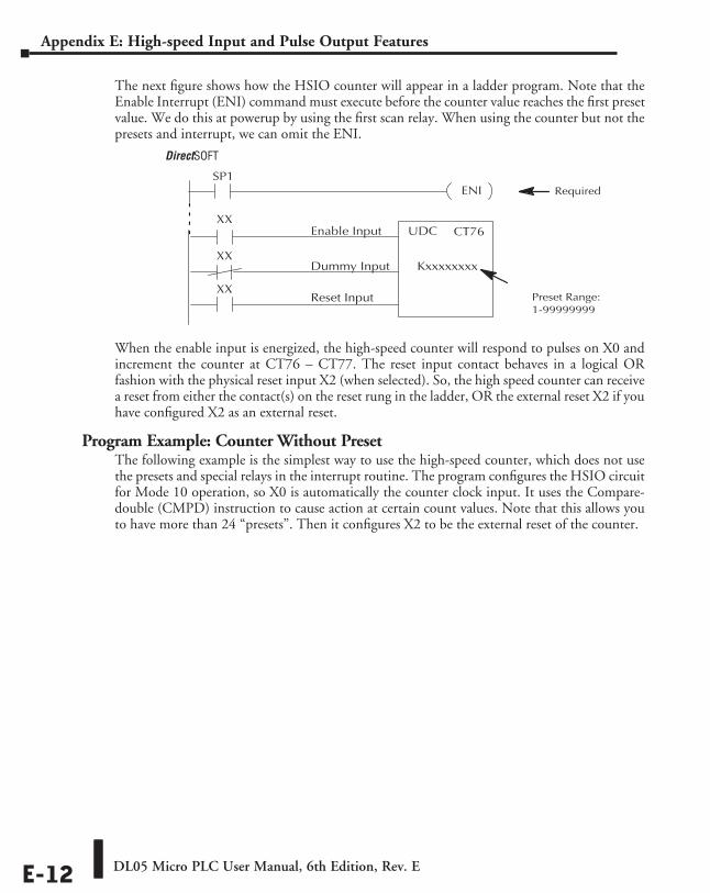
DL05 Micro PLC User Manual, 6th Edition, Rev. EE-12
Appendix E: High-speed Input and Pulse Output Features
The next figure shows how the HSIO counter will appear in a ladder program. Note that the Enable Interrupt (ENI) command must execute before the counter value reaches the first preset value. We do this at powerup by using the first scan relay. When using the counter but not the presets and interrupt, we can omit the ENI.
When the enable input is energized, the high-speed counter will respond to pulses on X0 and increment the counter at CT76 – CT77. The reset input contact behaves in a logical OR fashion with the physical reset input X2 (when selected). So, the high speed counter can receive a reset from either the contact(s) on the reset rung in the ladder, OR the external reset X2 if you have configured X2 as an external reset.
Program Example: Counter Without PresetThe following example is the simplest way to use the high-speed counter, which does not use the presets and special relays in the interrupt routine. The program configures the HSIO circuit for Mode 10 operation, so X0 is automatically the counter clock input. It uses the Compare-double (CMPD) instruction to cause action at certain count values. Note that this allows you to have more than 24 “presets”. Then it configures X2 to be the external reset of the counter.
Direct SOFT32
Required
Preset Range:
1-99999999Reset Input
UDC CT76
Kxxxxxxxx
Enable Input
Dummy Input
ENISP1
XX
XX
XX
DirectSOFT
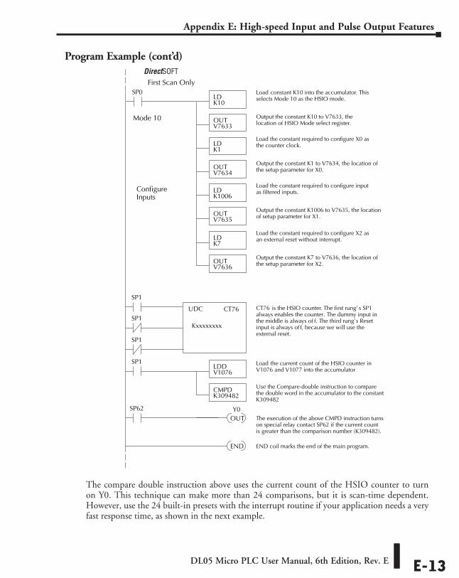
DL05 Micro PLC User Manual, 6th Edition, Rev. E E-13
Appendix E: High-speed Input and Pulse Output Features
Program Example (cont’d)
The compare double instruction above uses the current count of the HSIO counter to turn on Y0. This technique can make more than 24 comparisons, but it is scan-time dependent. However, use the 24 built-in presets with the interrupt routine if your application needs a very fast response time, as shown in the next example.
SP0LDK10
Load constant K10 into the accumulator. Thisselects Mode 10 as the HSIO mode.
OUTV7633
Output the constant K10 to V7633, thelocation of HSIO Mode select register.
LDK1
Load the constant required to configure X0 asthe counter clock.
OUTV7634
Output the constant K1 to V7634, the location ofthe setup parameter for X0.
First Scan Only
Direct SOFT32
UDC CT76
KxxxxxxxxSP1
SP1
SP1
END END coil marks the end of the main program.
CT76 is the HSIO counter. The first rung’ s SP1always enables the counter. The dummy input inthe middle is always of f. The third rung’s Resetinput is always of f, because we will use theexternal reset.
LDK7
Load the constant required to configure X2 asan external reset without interrupt.
OUTV7636
Output the constant K7 to V7636, the location ofthe setup parameter for X2.
LDK1006
Load the constant required to configure inputas filtered inputs.
OUTV7635
Output the constant K1006 to V7635, the locationof setup parameter for X1.
Mode 10
ConfigureInputs
SP1LDDV1076
Load the current count of the HSIO counter inV1076 and V1077 into the accumulator
CMPDK309482
Use the Compare-double instruction to comparethe double word in the accumulator to the constantK309482
SP62
OUT The execution of the above CMPD instruction turnson special relay contact SP62 if the current countis greater than the comparison number (K309482).
Y0
DirectSOFT
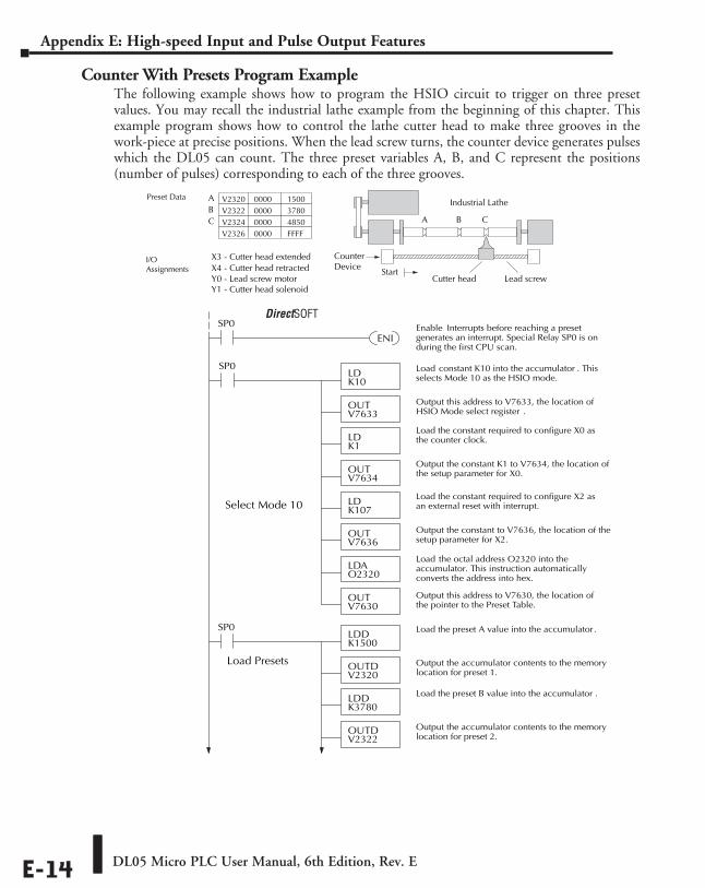
DL05 Micro PLC User Manual, 6th Edition, Rev. EE-14
Appendix E: High-speed Input and Pulse Output Features
Counter With Presets Program ExampleThe following example shows how to program the HSIO circuit to trigger on three preset values. You may recall the industrial lathe example from the beginning of this chapter. This example program shows how to control the lathe cutter head to make three grooves in the work-piece at precise positions. When the lead screw turns, the counter device generates pulses which the DL05 can count. The three preset variables A, B, and C represent the positions (number of pulses) corresponding to each of the three grooves.
Industrial Lathe
A
Preset Data V2320 0000V2322 0000V2324 0000V2326 0000
150037804850FFFF
B C
ABC
CounterDevice
Start Lead screw Cutter head
X4 - Cutter head retracted Y0 - Lead screw motorY1 - Cutter head solenoid
X3 - Cutter head extended
I/OAssignments
SP0LDK10
Load constant K10 into the accumulator . Thisselects Mode 10 as the HSIO mode.
OUTV7633
Output this address to V7633, the location ofHSIO Mode select register .
LDK107
Load the constant required to configure X2 asan external reset with interrupt.
OUTV7636
Output the constant to V7636, the location of thesetup parameter for X2.
Select Mode 10
Direct SOFT32SP0
ENIEnable Interrupts before reaching a presetgenerates an interrupt. Special Relay SP0 is onduring the first CPU scan.
LDDK1500
Load the preset A value into the accumulator.
OUTDV2320
Output the accumulator contents to the memorylocation for preset 1.
LDDK3780
Load the preset B value into the accumulator .
OUTDV2322
Output the accumulator contents to the memorylocation for preset 2.
Load Presets
SP0
LDAO2320
Load the octal address O2320 into theaccumulator. This instruction automaticallyconverts the address into hex.
OUTV7630
Output this address to V7630, the location ofthe pointer to the Preset Table.
LDK1
Load the constant required to configure X0 asthe counter clock.
OUTV7634
Output the constant K1 to V7634, the location ofthe setup parameter for X0.
DirectSOFT
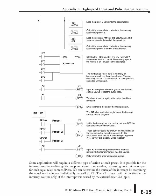
DL05 Micro PLC User Manual, 6th Edition, Rev. E E-15
Appendix E: High-speed Input and Pulse Output Features
Some applications will require a different type of action at each preset. It is possible for the interrupt routine to distinguish one preset event from another, by turning on a unique output for each equal relay contact SPxxx. We can determine the source of the interrupt by examining the equal relay contacts individually, as well as X2. The X2 contact will be on (inside the interrupt routine only) if the interrupt was caused by the external reset, X2 input.
UDC CT76
KxxxxxxxxSP1
SP1
SP1
END END coil marks the end of the main program.
INT O0
CT76 is the HSIO counter. The first rung’s SP1always enables the counter. The dummy input inthe middle is off (unused in this example).
IRT Return from the interrupt service routine.
Y0SP540Inside the interrupt service routine, we turn OFF thelead screw motor immediately.
The INT label marks the beginning of the interruptservice routine program.
RSTI
X3
RST Input X3 energizes when the groove has finishedcutting. So, we retract the cutter head.
Y1
X4
SET Turn lead screw on again, after cutter head hasretracted.
Y0
LDDK4850
Load the preset C value into the accumulator.
OUTDV2324
Output the accumulator contents to the memorylocation for preset 3.
LDDKffff
Load the constant Kffff into the accumulator. Thisvalue represents the end of the preset list.
OUTDV2326
Output the accumulator contents to the memorylocation for preset 4 (end of preset marker).
SP541
SP542
These special “equal” relays turn on individually asthe corresponding preset is reached. In thisapplication, each results in the cutting of a groove(Y1), so they are logically ORed together.
Preset 1
Preset 2
Preset 3
SETY1
SP0
X2
SET Input X2 will be energized inside the interruptroutine if X2 external interrupt was the source.
The third rung’s Reset input is normally off,because we will use the external reset. You canoptionally reset the counter value on each powerupusing the SP0 contact.
Y2
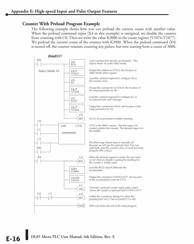
DL05 Micro PLC User Manual, 6th Edition, Rev. EE-16
Appendix E: High-speed Input and Pulse Output Features
Counter With Preload Program ExampleThe following example shows how you can preload the current count with another value. When the preload command input (X4 in this example) is energized, we disable the counter from counting with C0. Then we write the value K3000 to the count register (V1076-V1077). We preload the current count of the counter with K3000. When the preload command (X4) is turned off, the counter resumes counting any pulses, but now starting from a count of 3000.
SP0LDK10
Load constant K10 into the accumulator . Thisselects Mode 10 as the HSIO mode.
OUTV7633
Output this address to V7633, the location ofHSIO Mode select register .
LDK107
Load the constant required to configure X2 asan external reset with interrupt.
OUTV7636
Output the constant to V7636, the location of thesetup parameter for X2.
Select Mode 10
Direct SOFT32
SET Set C0 on at powerup to enable counting.
C0
X4
RST
When the preload request is made, the user turnson X4. First we disable counting by resetting C0,the counter ’s enable input.
UDC CT76
K99999999C1
C0
C2
CT76 is the HSIO counter . The first rung’ s C0contact enables the counter. The dummy input is inthe middle.
C0
PDGenerate a preload counter input pulse, whichcauses the counter to preload from V1076-V1077.
C1
SP0
LDDK3000
Load the BCD value K3000 into theaccumulator.
OUTDV1076
Output the constant to V1076/V1077, the locationof the accumulated count for CT76.
END END coil marks the end of the main program.
C1C0
SETC0
Enable the counter by setting C0, when thepreolad pulse on C1 has occurred (C1 is off).
LDK1
Load the constant required to configure X0 asthe counter clock.
OUTV7634
Output the constant K1 to V7634, the location ofthe setup parameter for X0.
The third rung’s Reset input is normally off,because we will use the external reset. You canoptionally reset the counter value on each powerupusing the SP0 contact.
DirectSOFT
DL05 Micro PLC User Manual, 6th Edition, Rev. E E-17
Appendix E: High-speed Input and Pulse Output Features
Troubleshooting Guide for Mode 10If you’re having trouble with Mode 10 operation, please study the following symptoms and possible causes. The most common problems are listed below.
Symptom: The counter does not count.Possible causes:
1. Field sensor and wiring – Verify that the encoder, proximity switch, or counter actually turns on and illuminates the status LED for X0. The problem could be due to sinking-sourcing wiring problem, etc. Remember to check the signal ground connection. Also verify that the pulse on-time is long enough for the PLC to recognize it.
2. Configuration – use the Data View window to check the configuration parameters. V7633 must be set to 10, and V7634 must be set to 1 to enable the HSIO counter mode.
3. Stuck in reset – check the input status of the reset input, X2. If X2 is on, the counter will not count because it is being held in reset.
4. Ladder program – make sure you are using counter CT76 in your program. The top input is the enable signal for the counter. It must be on before the counter will count. The middle input is the dummy input. The bottom input is the counter reset, and must be off during counting.
Symptom: The counter counts but the presets do not function.Possible causes:
1. Configuration – Ensure the preset values are correct. The presets are 32-bit BCD values having a range of 0 to 99999999. Make sure you write all 32 bits to the reserved locations by using the LDD and OUTD instructions. Use only even–numbered addresses, from V2320 to V2376. If using less than 24 presets, be sure to place “0000FFFF” in the location after the last preset used.
2. Interrupt routine – Only use Interrupt #0. Make sure the interrupt has been enabled by executing an ENI instruction prior to needing the interrupt. The interrupt routine must be placed after the main program, using the INT label and ending with an interrupt return IRT.
3. Special relays – Check the special relay numbers in your program. Use SP540 for Preset 1, SP541 for Preset 2, etc. Remember that only one special equal relay contact is on at a time. When the counter value reaches the next preset, the SP contact which is on now goes off and the next one turns on.
Symptom: The counter counts up but will not reset.Possible causes:
• Check the LED status indicator for X2 to make sure it is active when you want a reset. Or, if you are using an internal reset, use the status mode of DirectSOFT to monitor the reset input to the counter.
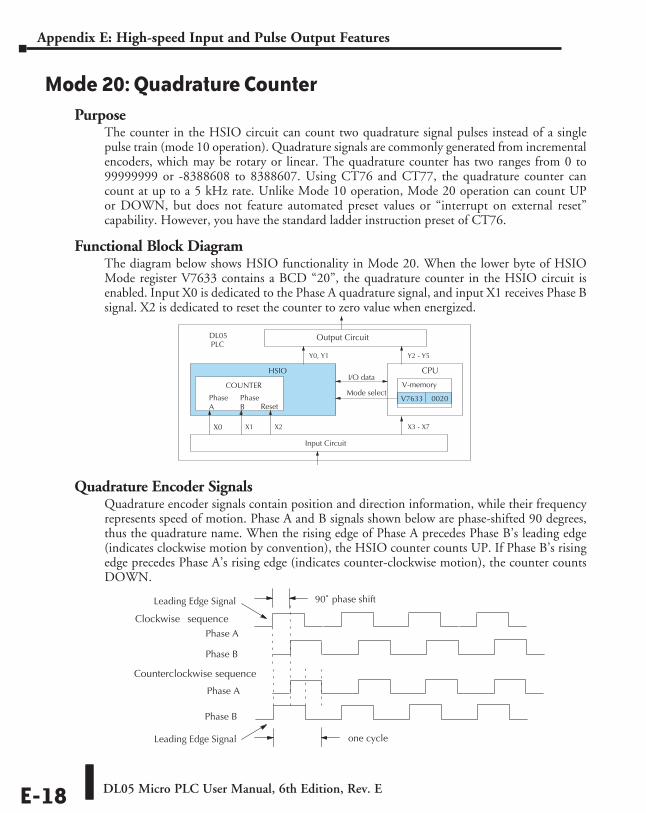
DL05 Micro PLC User Manual, 6th Edition, Rev. EE-18
Appendix E: High-speed Input and Pulse Output Features
Mode 20: Quadrature CounterPurpose
The counter in the HSIO circuit can count two quadrature signal pulses instead of a single pulse train (mode 10 operation). Quadrature signals are commonly generated from incremental encoders, which may be rotary or linear. The quadrature counter has two ranges from 0 to 99999999 or -8388608 to 8388607. Using CT76 and CT77, the quadrature counter can count at up to a 5 kHz rate. Unlike Mode 10 operation, Mode 20 operation can count UP or DOWN, but does not feature automated preset values or “interrupt on external reset” capability. However, you have the standard ladder instruction preset of CT76.
Functional Block DiagramThe diagram below shows HSIO functionality in Mode 20. When the lower byte of HSIO Mode register V7633 contains a BCD “20”, the quadrature counter in the HSIO circuit is enabled. Input X0 is dedicated to the Phase A quadrature signal, and input X1 receives Phase B signal. X2 is dedicated to reset the counter to zero value when energized.
Quadrature Encoder SignalsQuadrature encoder signals contain position and direction information, while their frequency represents speed of motion. Phase A and B signals shown below are phase-shifted 90 degrees, thus the quadrature name. When the rising edge of Phase A precedes Phase B’s leading edge (indicates clockwise motion by convention), the HSIO counter counts UP. If Phase B’s rising edge precedes Phase A’s rising edge (indicates counter-clockwise motion), the counter counts DOWN.
90˚ phase shift
Phase A
Phase B
Leading Edge Signal
Phase A
Phase B
Leading Edge Signal
Clockwise sequence
Counterclockwise sequence
one cycle
Input Circuit
CPU
PLCDL05
Y0, Y1
X3 - X7
Y2 - Y5
V-memory
V7633 0020 Mode select
I/O data
HSIO
COUNTER
PhaseA
PhaseB
X2
Reset
X1
Output Circuit
X0
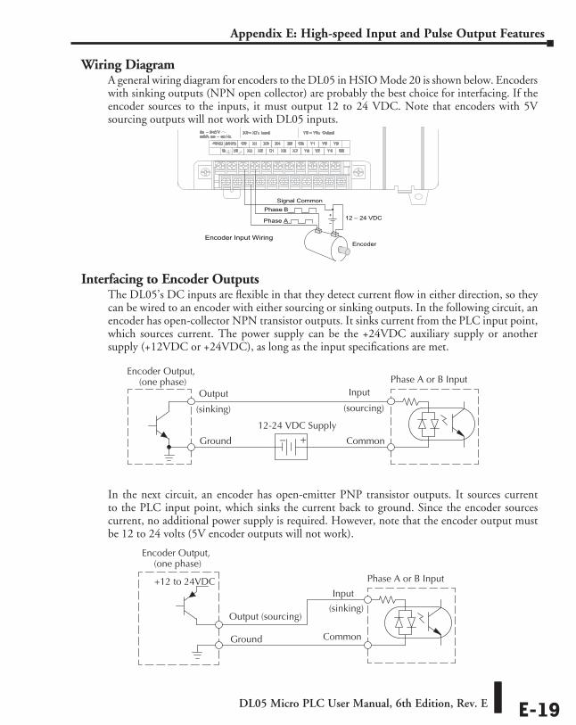
DL05 Micro PLC User Manual, 6th Edition, Rev. E E-19
Appendix E: High-speed Input and Pulse Output Features
Wiring DiagramA general wiring diagram for encoders to the DL05 in HSIO Mode 20 is shown below. Encoders with sinking outputs (NPN open collector) are probably the best choice for interfacing. If the encoder sources to the inputs, it must output 12 to 24 VDC. Note that encoders with 5V sourcing outputs will not work with DL05 inputs.
Interfacing to Encoder OutputsThe DL05’s DC inputs are flexible in that they detect current flow in either direction, so they can be wired to an encoder with either sourcing or sinking outputs. In the following circuit, an encoder has open-collector NPN transistor outputs. It sinks current from the PLC input point, which sources current. The power supply can be the +24VDC auxiliary supply or another supply (+12VDC or +24VDC), as long as the input specifications are met.
In the next circuit, an encoder has open-emitter PNP transistor outputs. It sources current to the PLC input point, which sinks the current back to ground. Since the encoder sources current, no additional power supply is required. However, note that the encoder output must be 12 to 24 volts (5V encoder outputs will not work).
Encoder Output,(one phase)
+–
Phase A or B InputOutput
Ground
Common
12-24 VDC Supply
(sinking) (sourcing)
Input
Phase A or B Input
Output (sourcing)
Ground
Input +12 to 24VDC (sinking)
Encoder Output,(one phase)
Common
Encoder Input Wiring
+
–12 – 24 VDC
Phase B
Phase A
Encoder
Signal Common
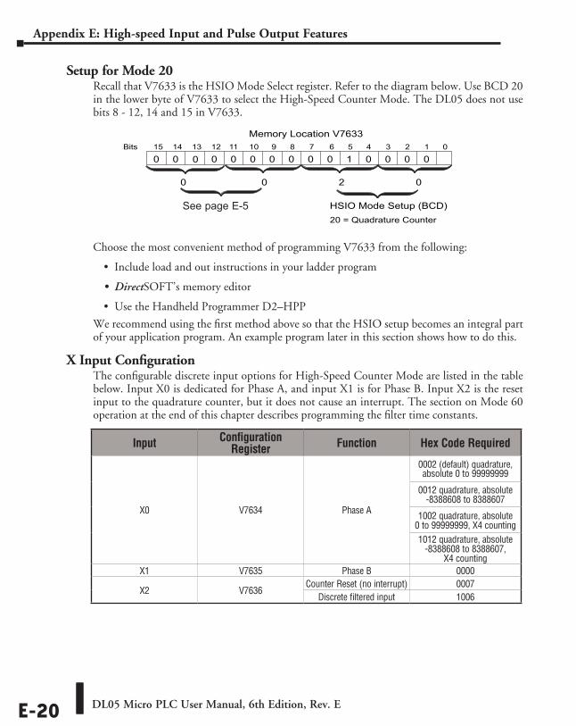
DL05 Micro PLC User Manual, 6th Edition, Rev. EE-20
Appendix E: High-speed Input and Pulse Output Features
Setup for Mode 20Recall that V7633 is the HSIO Mode Select register. Refer to the diagram below. Use BCD 20 in the lower byte of V7633 to select the High-Speed Counter Mode. The DL05 does not use bits 8 - 12, 14 and 15 in V7633.
Choose the most convenient method of programming V7633 from the following:
• Include load and out instructions in your ladder program
• DirectSOFT’s memory editor
• Use the Handheld Programmer D2–HPP
We recommend using the first method above so that the HSIO setup becomes an integral part of your application program. An example program later in this section shows how to do this.
X Input ConfigurationThe configurable discrete input options for High-Speed Counter Mode are listed in the table below. Input X0 is dedicated for Phase A, and input X1 is for Phase B. Input X2 is the reset input to the quadrature counter, but it does not cause an interrupt. The section on Mode 60 operation at the end of this chapter describes programming the filter time constants.
015 14 13 12
Memory Location V763311 10 123456789Bits
00 0001000
HSIO Mode Setup (BCD)
0 0 0 0
20 = Quadrature Counter
0 0 02
00
Input Configuration Register Function Hex Code Required
X0 V7634 Phase A
0002 (default) quadrature, absolute 0 to 99999999
0012 quadrature, absolute -8388608 to 8388607
1002 quadrature, absolute 0 to 99999999, X4 counting1012 quadrature, absolute
-8388608 to 8388607, X4 counting
X1 V7635 Phase B 0000
X2 V7636 Counter Reset (no interrupt) 0007
Discrete filtered input 1006
See page E-5
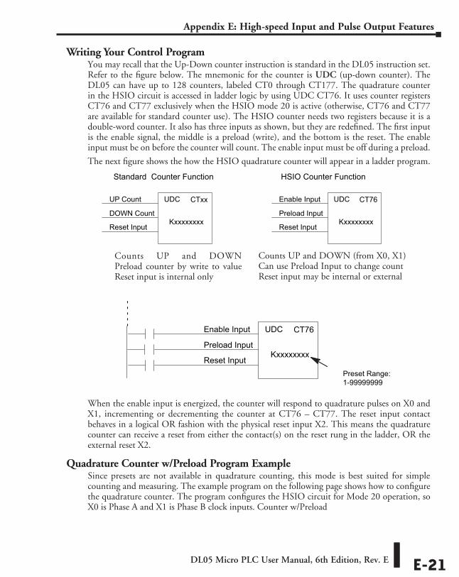
DL05 Micro PLC User Manual, 6th Edition, Rev. E E-21
Appendix E: High-speed Input and Pulse Output Features
Writing Your Control ProgramYou may recall that the Up-Down counter instruction is standard in the DL05 instruction set. Refer to the figure below. The mnemonic for the counter is UDC (up-down counter). The DL05 can have up to 128 counters, labeled CT0 through CT177. The quadrature counter in the HSIO circuit is accessed in ladder logic by using UDC CT76. It uses counter registers CT76 and CT77 exclusively when the HSIO mode 20 is active (otherwise, CT76 and CT77 are available for standard counter use). The HSIO counter needs two registers because it is a double-word counter. It also has three inputs as shown, but they are redefined. The first input is the enable signal, the middle is a preload (write), and the bottom is the reset. The enable input must be on before the counter will count. The enable input must be off during a preload.
The next figure shows the how the HSIO quadrature counter will appear in a ladder program.
When the enable input is energized, the counter will respond to quadrature pulses on X0 and X1, incrementing or decrementing the counter at CT76 – CT77. The reset input contact behaves in a logical OR fashion with the physical reset input X2. This means the quadrature counter can receive a reset from either the contact(s) on the reset rung in the ladder, OR the external reset X2.
Quadrature Counter w/Preload Program ExampleSince presets are not available in quadrature counting, this mode is best suited for simple counting and measuring. The example program on the following page shows how to configure the quadrature counter. The program configures the HSIO circuit for Mode 20 operation, so X0 is Phase A and X1 is Phase B clock inputs. Counter w/Preload
Preset Range:1-99999999
Reset Input
UDC CT76
Kxxxxxxxx
Enable Input
Preload Input
Reset Input
UDC CT76
Kxxxxxxxx
Enable Input
Preload Input
Reset Input
UDC CTxx
Kxxxxxxxx
UP Count
DOWN Count
Standard Counter Function HSIO Counter Function
Counts UP and DOWN (from X0, X1) Can use Preload Input to change count Reset input may be internal or external
Counts UP and DOWN Preload counter by write to value Reset input is internal only
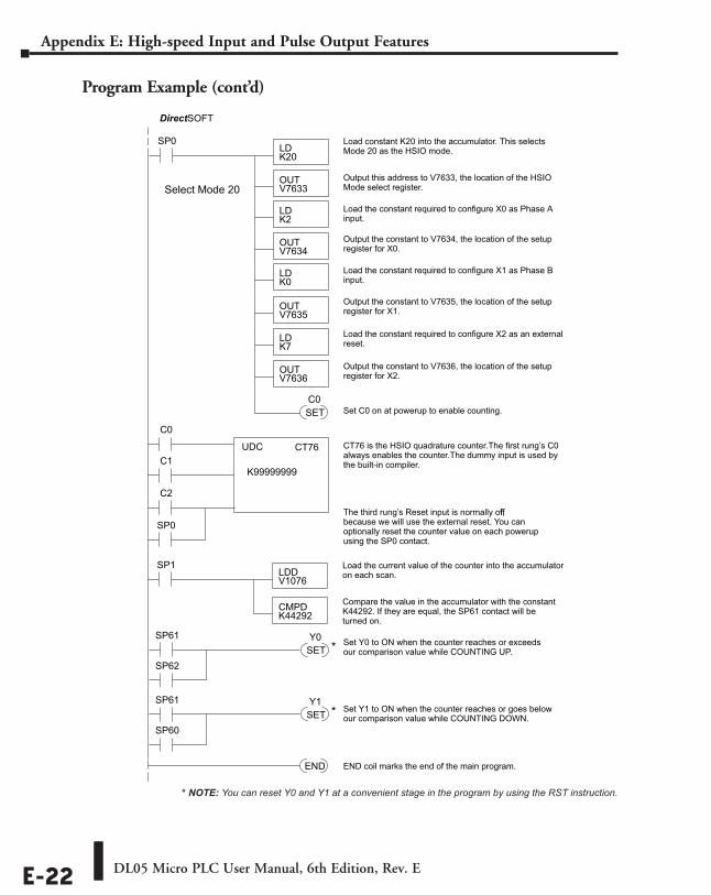
DL05 Micro PLC User Manual, 6th Edition, Rev. EE-22
Appendix E: High-speed Input and Pulse Output Features
Program Example (cont’d)
SP0LDK20
Load constant K20 into the accumulator. This selectsMode 20 as the HSIO mode.
OUTV7633
Output this address to V7633, the location of the HSIOMode select register.
LDK2
Load the constant required to configure X0 as Phase Ainput.
OUTV7634
Output the constant to V7634, the location of the setupregister for X0.
DirectSOFT
UDC CT76
K99999999C1
C0
C2
END END coil marks the end of the main program.
CT76 is the HSIO quadrature counter. The first rung’s C0always enables the counter. The dummy input is used bythe built-in compiler.
LDK0
Load the constant required to configure X1 as Phase Binput.
OUTV7635
Output the constant to V7635, the location of the setupregister for X1.
LDK7
Load the constant required to configure X2 as an externalreset.
OUTV7636
Output the constant to V7636, the location of the setupregister for X2.
SET Set C0 on at powerup to enable counting.C0
SP0
Select Mode 20
The third rung’s Reset input is normally offf,because we will use the external reset. You canoptionally reset the counter value on each powerupusing the SP0 contact.
SP1LDDV1076
Load the current value of the counter into the accumulatoron each scan.
CMPDK44292
Compare the value in the accumulator with the constantK44292. If they are equal, the SP61 contact will beturned on.
Set Y0 to ON when the counter reaches or exceedsour comparison value while COUNTING UP.
SP61SETY0
*SP62
SP61SETY1
*SP60
Set Y1 to ON when the counter reaches or goes belowour comparison value while COUNTING DOWN.
* NOTE: You can reset Y0 and Y1 at a convenient stage in the program by using the RST instruction.
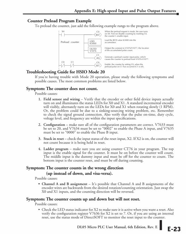
DL05 Micro PLC User Manual, 6th Edition, Rev. E E-23
Appendix E: High-speed Input and Pulse Output Features
Counter Preload Program ExampleTo preload the counter, just add the following example rungs to the program above.
Troubleshooting Guide for HSIO Mode 20If you’re having trouble with Mode 20 operation, please study the following symptoms and possible causes. The most common problems are listed below.
Symptom: The counter does not count.Possible causes:
1. Field sensor and wiring – Verify that the encoder or other field device inputs actually turn on and illuminates the status LEDs for X0 and X1. A standard incremental encoder will visibly, alternately turn on the LEDs for X0 and X1 when rotating slowly (1 RPM). Or, the problem could be due to a sinking-sourcing wiring problem, etc. Remember to check the signal ground connection. Also verify that the pulse on-time, duty cycle, voltage level, and frequency are within the input specifications.
2. Configuration – make sure all of the configuration parameters are correct. V7633 must be set to 20, and V7634 must be set to “0002” to enable the Phase A input, and V7635 must be set to “0000” to enable the Phase B input.
3. Stuck in reset – check the input status of the reset input, X2. If X2 is on, the counter will not count because it is being held in reset.
4. Ladder program – make sure you are using counter CT76 in your program. The top input is the enable signal for the counter. It must be on before the counter will count. The middle input is the dummy input and must be off for the counter to count. The bottom input is the counter reset, and must be off during counting.
Symptom: The counter counts in the wrong direction (up instead of down, and visa-versa).
Possible causes:
• Channel A and B assignment – It’s possible that Channel A and B assignments of the encoder wires are backwards from the desired rotation/counting orientation. Just swap the X0 and X1 inputs, and the counting direction will be reversed.
Symptom: The counter counts up and down but will not reset.Possible causes:
• Check the LED status indicator for X2 to make sure it is active when you want a reset. Also verify the configuration register V7636 for X2 is set to 7. Or, if you are using an internal reset, use the status mode of DirectSOFT to monitor the reset input to the counter.
X4
RST
When the preload request is made, the user turnson X4. First we disable counting by resetting C0,the counter ’s enable input.
C0
PDGenerate a preload counter input pulse, whichcauses the counter to preload from V1076-V1077.
C1
LDDK3000
Load the BCD value K3000 into theaccumulator.
OUTDV1076
Output the constant to V1076/V1077, the locationof the accumulated pulse count.
Preload counter
C1C0
SETC0
Enable the counter by setting C0, when thepreload pulse on C1 has occurred (C1 is off).
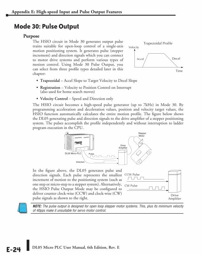
DL05 Micro PLC User Manual, 6th Edition, Rev. EE-24
Appendix E: High-speed Input and Pulse Output Features
Mode 30: Pulse OutputPurpose
The HSIO circuit in Mode 30 generates output pulse trains suitable for open-loop control of a single-axis motion positioning system. It generates pulse (stepper increment) and direction signals which you can connect to motor drive systems and perform various types of motion control. Using Mode 30 Pulse Output, you can select from three profile types detailed later in this chapter:
• Trapezoidal – Accel Slope to Target Velocity to Decel Slope
• Registration – Velocity to Position Control on Interrupt (also used for home search moves)
• Velocity Control – Speed and Direction only
The HSIO circuit becomes a high-speed pulse generator (up to 7kHz) in Mode 30. By programming acceleration and deceleration values, position and velocity target values, the HSIO function automatically calculates the entire motion profile. The figure below shows the DL05 generating pulse and direction signals to the drive amplifier of a stepper positioning system. The pulses accomplish the profile independently and without interruption to ladder program execution in the CPU.
In the figure above, the DL05 generates pulse and direction signals. Each pulse represents the smallest increment of motion to the positioning system (such as one step or micro-step to a stepper system). Alternatively, the HSIO Pulse Output Mode may be configured to deliver counter clock-wise (CCW) and clock-wise (CW) pulse signals as shown to the right.
NOTE: The pulse output is designed for open loop stepper motor systems. This, plus its minimum velocity of 40pps make it unsuitable for servo motor control.
Trapezoidal Profile
Time
Decel
Velocity
Accel
DriveAmplifier
StepperMotor
Pulse
Direction
DL05 Micro PLC
CCW Pulse
CW Pulse
DriveAmplifier
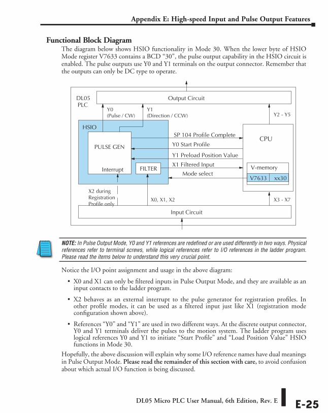
DL05 Micro PLC User Manual, 6th Edition, Rev. E E-25
Appendix E: High-speed Input and Pulse Output Features
Functional Block DiagramThe diagram below shows HSIO functionality in Mode 30. When the lower byte of HSIO Mode register V7633 contains a BCD “30”, the pulse output capability in the HSIO circuit is enabled. The pulse outputs use Y0 and Y1 terminals on the output connector. Remember that the outputs can only be DC type to operate.
NOTE: In Pulse Output Mode, Y0 and Y1 references are redefined or are used differently in two ways. Physical references refer to terminal screws, while logical references refer to I/O references in the ladder program. Please read the items below to understand this very crucial point.
Notice the I/O point assignment and usage in the above diagram:
• X0 and X1 can only be filtered inputs in Pulse Output Mode, and they are available as an input contacts to the ladder program.
• X2 behaves as an external interrupt to the pulse generator for registration profiles. In other profile modes, it can be used as a filtered input just like X1 (registration mode configuration shown above).
• References “Y0” and “Y1” are used in two different ways. At the discrete output connector, Y0 and Y1 terminals deliver the pulses to the motion system. The ladder program uses logical references Y0 and Y1 to initiate “Start Profile” and “Load Position Value” HSIO functions in Mode 30.
Hopefully, the above discussion will explain why some I/O reference names have dual meanings in Pulse Output Mode. Please read the remainder of this section with care, to avoid confusion about which actual I/O function is being discussed.
Output Circuit
Input Circuit
CPU
PLCDL05
Y0
X3 - X7
Y2 - Y5
V-memory
V7633 xx30 Mode select
Y1 Preload Position Value
X2 duringRegistrationProfile only X0, X1, X2
Y1
SP 104 Profile Complete
Y0 Start Profile
HSIO
X1 Filtered Input
(Pulse / CW) (Direction / CCW)
FILTER
PULSE GEN
Interrupt
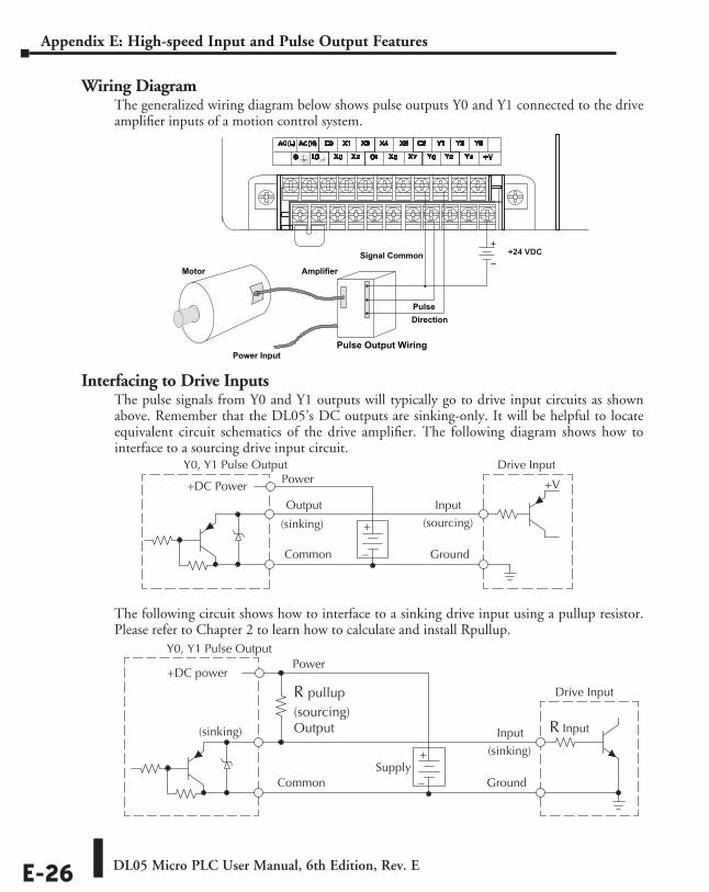
DL05 Micro PLC User Manual, 6th Edition, Rev. EE-26
Appendix E: High-speed Input and Pulse Output Features
Wiring DiagramThe generalized wiring diagram below shows pulse outputs Y0 and Y1 connected to the drive amplifier inputs of a motion control system.
Interfacing to Drive InputsThe pulse signals from Y0 and Y1 outputs will typically go to drive input circuits as shown above. Remember that the DL05’s DC outputs are sinking-only. It will be helpful to locate equivalent circuit schematics of the drive amplifier. The following diagram shows how to interface to a sourcing drive input circuit.
The following circuit shows how to interface to a sinking drive input using a pullup resistor. Please refer to Chapter 2 to learn how to calculate and install Rpullup.
Drive Input
Ground
Input
Common
Y0, Y1 Pulse Output
+DC power
+
–
(sinking)
Power
(sinking)
Supply
R pullup(sourcing)Output R Input
Signal Common
Motor Amplifier
Pulse Output WiringPower Input
PulseDirection
+
–+24 VDC
Drive Input
Output
Ground
Input
Common
+V
Y0, Y1 Pulse Output
+DC Power
+
–
(sourcing) (sinking)
Power
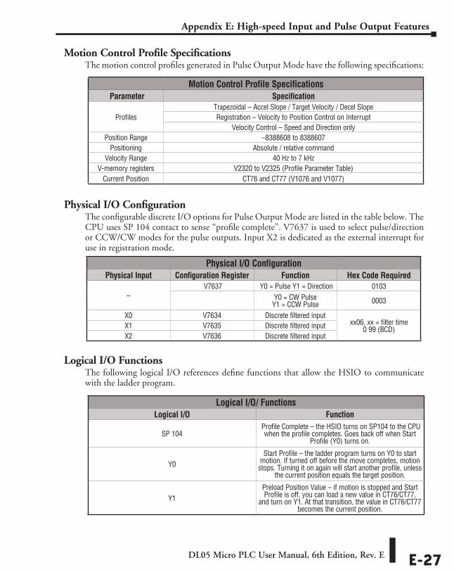
DL05 Micro PLC User Manual, 6th Edition, Rev. E E-27
Appendix E: High-speed Input and Pulse Output Features
Motion Control Profile SpecificationsThe motion control profiles generated in Pulse Output Mode have the following specifications:
Physical I/O ConfigurationThe configurable discrete I/O options for Pulse Output Mode are listed in the table below. The CPU uses SP 104 contact to sense “profile complete”. V7637 is used to select pulse/direction or CCW/CW modes for the pulse outputs. Input X2 is dedicated as the external interrupt for use in registration mode.
Logical I/O FunctionsThe following logical I/O references define functions that allow the HSIO to communicate with the ladder program.
Physical I/O ConfigurationPhysical Input Configuration Register Function Hex Code Required
– V7637 Y0 = Pulse Y1 = Direction 0103
Y0 = CW Pulse Y1 = CCW Pulse 0003
X0 V7634 Discrete filtered input xx06, xx = filter time
0 99 (BCD)X1 V7635 Discrete filtered input X2 V7636 Discrete filtered input
Motion Control Profile Specifications Parameter Specification
Profiles Trapezoidal – Accel Slope / Target Velocity / Decel SlopeRegistration – Velocity to Position Control on Interrupt
Velocity Control – Speed and Direction onlyPosition Range –8388608 to 8388607
Positioning Absolute / relative commandVelocity Range 40 Hz to 7 kHz
V-memory registers V2320 to V2325 (Profile Parameter Table)Current Position CT76 and CT77 (V1076 and V1077)
Logical I/O/ FunctionsLogical I/O Function
SP 104 Profile Complete – the HSIO turns on SP104 to the CPU
when the profile completes. Goes back off when Start Profile (Y0) turns on.
Y0 Start Profile – the ladder program turns on Y0 to start
motion. If turned off before the move completes, motion stops. Turning it on again will start another profile, unless
the current position equals the target position.
Y1 Preload Position Value – if motion is stopped and Start Profile is off, you can load a new value in CT76/CT77,
and turn on Y1. At that transition, the value in CT76/CT77 becomes the current position.
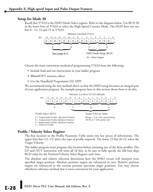
DL05 Micro PLC User Manual, 6th Edition, Rev. EE-28
Appendix E: High-speed Input and Pulse Output Features
Setup for Mode 30Recall that V7633 is the HSIO Mode Select register. Refer to the diagram below. Use BCD 30 in the lower byte of V7633 to select the High-Speed Counter Mode. The DL05 does not use bits 8 - 12, 14 and 15 in V7633.
Choose the most convenient method of programming V7633 from the following:
• Include load and out instructions in your ladder program
• DirectSOFT memory editor
• Use the Handheld Programmer D2–HPP
We recommend using the first method above so that the HSIO setup becomes an integral part of your application program. An example program later in this section shows how to do this.
Profile / Velocity Select RegisterThe first location in the Profile Parameter Table stores two key pieces of information. The upper four bits (12–15) select the type of profile required. The lower 12 bits (0-11) select the Target Velocity.
The ladder program must program this location before initiating any of the three profiles. The LD and OUT instruction will write all 16 bits, so be sure to fully specify the full four-digit BCD value for the Position/Velocity Select Register each time.
The absolute and relative selection determines how the HSIO circuit will interpret your specified target position. Absolute position targets are referenced to zero. Relative position targets are referenced to the current position (previous target position). You may choose whichever reference method that is most convenient for your application.
014 13 12
Memory Location V2320 (default) 11 10 123456789Bits
00 0000000
Target Velocity ValueProfile Select (BCD)
0 1 1 1
0 = Trapezoidal Profile, Absolute Position8 = Trapezoidal Profile, Relative Position
Range = 4 to 700, representing40 Hz to 7 kHz pulse rate
0 7 00
0
9 = Registration Profile, Relative Position2 = Velocity Profile
15
0
015 14 13 12
Memory Location V763311 10 123456789Bits
00 0011000
HSIO Mode Setup (BCD)
0 0 0 0
30 = Pulse Output
0 0 03
00
See page E-5
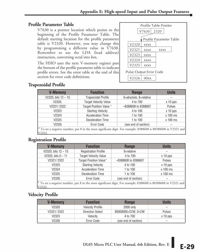
DL05 Micro PLC User Manual, 6th Edition, Rev. E E-29
Appendix E: High-speed Input and Pulse Output Features
Profile Parameter TableV7630 is a pointer location which points to the beginning of the Profile Parameter Table. The default starting location for the profile parameter table is V2320. However, you may change this by programming a different value in V7630. Remember to use the LDA (load address) instruction, converting octal into hex.
The HSIO uses the next V-memory register past the bottom of the profile parameter table to indicate profile errors. See the error table at the end of this section for error code definitions.
Trapezoidal Profile
Registration Profile
Velocity Profile
V-Memory Function Range UnitsV2320, bits 12 – 15 Trapezoidal Profile 0=absolute, 8=relative –
V2320, Target Velocity Value 4 to 700 x 10 ppsV2321/ 2322 Target Position Value * –8388608 to 8388607 Pulses
V2323 Starting Velocity 4 to 100 x 10 ppsV2324 Acceleration Time 1 to 100 x 100 msV2325 Deceleration Time 1 to 100 x 100 msV2326 Error Code (see end of section) –
* To set a negative number, put 8 in the most significant digit. For example: 8388608 is 88388608 in V2321 and V2322.
V-Memory Function Range UnitsV2320, bits 12 – 15 Registration Profile 9=relative –V2320, bits 0 – 11 Target Velocity Value 4 to 700 x 10 pps
V2321/ 2322 Target Position Value* –8388608 to 8388607 PulsesV2323 Starting Velocity 4 to 100 x 10 ppsV2324 Acceleration Time 1 to 100 x 100 msV2325 Deceleration Time 1 to 100 x 100 msV2326 Error Code (see end of section) –
* To set a negative number, put 8 in the most significant digit. For example: 8388608 is 88388608 in V2321 and V2322.
V-Memory Function Range UnitsV2320 Velocity Profile 2000 only –
V2321/ 2322 Direction Select 80000000=CCW, 0=CW PulsesV2323 Velocity 4 to 700 x 10 ppsV2326 Error Code (see end of section) –
Profile Parameter Table V2320 xxxxV2321 xxxxV2323 xxxxV2324 xxxx
xxxx
V7630 2320
Profile Table Pointer
V2325 xxxx
V2326 00xx
Pulse Output Error Code
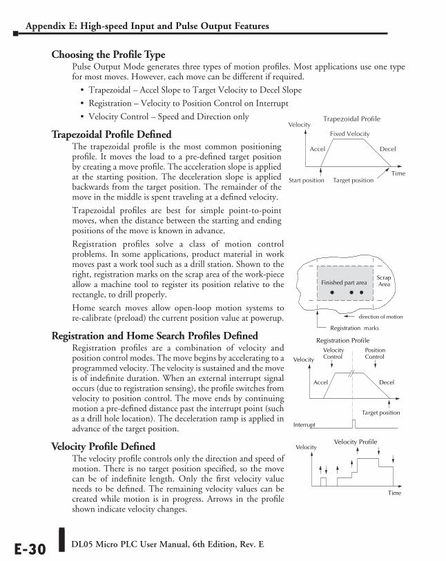
DL05 Micro PLC User Manual, 6th Edition, Rev. EE-30
Appendix E: High-speed Input and Pulse Output Features
Choosing the Profile TypePulse Output Mode generates three types of motion profiles. Most applications use one type for most moves. However, each move can be different if required.
• Trapezoidal – Accel Slope to Target Velocity to Decel Slope
• Registration – Velocity to Position Control on Interrupt
• Velocity Control – Speed and Direction only
Trapezoidal Profile DefinedThe trapezoidal profile is the most common positioning profile. It moves the load to a pre-defined target position by creating a move profile. The acceleration slope is applied at the starting position. The deceleration slope is applied backwards from the target position. The remainder of the move in the middle is spent traveling at a defined velocity.
Trapezoidal profiles are best for simple point-to-point moves, when the distance between the starting and ending positions of the move is known in advance.
Registration profiles solve a class of motion control problems. In some applications, product material in work moves past a work tool such as a drill station. Shown to the right, registration marks on the scrap area of the work-piece allow a machine tool to register its position relative to the rectangle, to drill properly.
Home search moves allow open-loop motion systems to re-calibrate (preload) the current position value at powerup.
Registration and Home Search Profiles DefinedRegistration profiles are a combination of velocity and position control modes. The move begins by accelerating to a programmed velocity. The velocity is sustained and the move is of indefinite duration. When an external interrupt signal occurs (due to registration sensing), the profile switches from velocity to position control. The move ends by continuing motion a pre-defined distance past the interrupt point (such as a drill hole location). The deceleration ramp is applied in advance of the target position.
Velocity Profile DefinedThe velocity profile controls only the direction and speed of motion. There is no target position specified, so the move can be of indefinite length. Only the first velocity value needs to be defined. The remaining velocity values can be created while motion is in progress. Arrows in the profile shown indicate velocity changes.
Registration Profile
Accel Decel
Velocity
Interrupt
VelocityControl
PositionControl
Registration marks
Finished part areaScrapArea
Target position
direction of motion
Velocity Profile
Time
Velocity
Trapezoidal Profile
Time
Accel Decel
Velocity
Start position Target position
Fixed Velocity
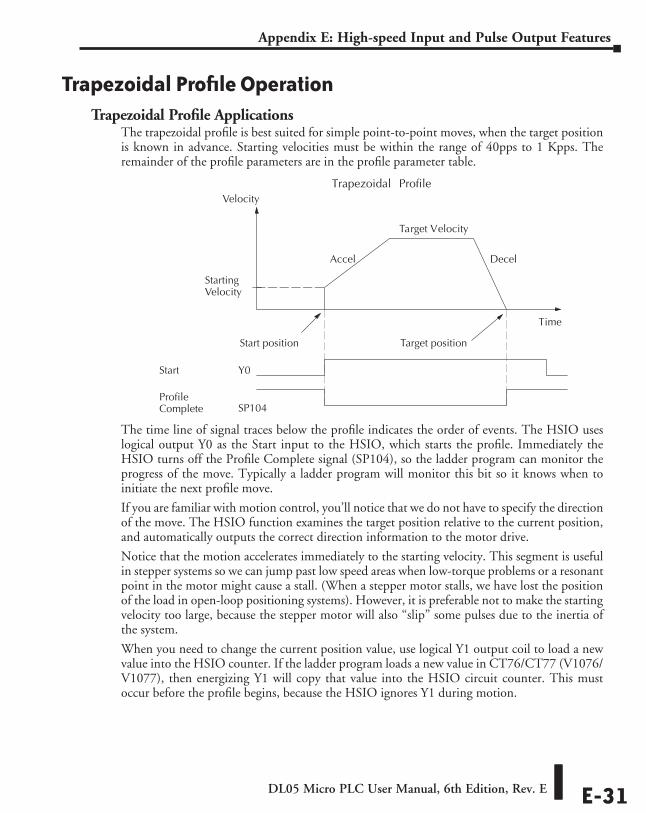
DL05 Micro PLC User Manual, 6th Edition, Rev. E E-31
Appendix E: High-speed Input and Pulse Output Features
Trapezoidal Profile OperationTrapezoidal Profile Applications
The trapezoidal profile is best suited for simple point-to-point moves, when the target position is known in advance. Starting velocities must be within the range of 40pps to 1 Kpps. The remainder of the profile parameters are in the profile parameter table.
The time line of signal traces below the profile indicates the order of events. The HSIO uses logical output Y0 as the Start input to the HSIO, which starts the profile. Immediately the HSIO turns off the Profile Complete signal (SP104), so the ladder program can monitor the progress of the move. Typically a ladder program will monitor this bit so it knows when to initiate the next profile move.
If you are familiar with motion control, you’ll notice that we do not have to specify the direction of the move. The HSIO function examines the target position relative to the current position, and automatically outputs the correct direction information to the motor drive.
Notice that the motion accelerates immediately to the starting velocity. This segment is useful in stepper systems so we can jump past low speed areas when low-torque problems or a resonant point in the motor might cause a stall. (When a stepper motor stalls, we have lost the position of the load in open-loop positioning systems). However, it is preferable not to make the starting velocity too large, because the stepper motor will also “slip” some pulses due to the inertia of the system.
When you need to change the current position value, use logical Y1 output coil to load a new value into the HSIO counter. If the ladder program loads a new value in CT76/CT77 (V1076/V1077), then energizing Y1 will copy that value into the HSIO circuit counter. This must occur before the profile begins, because the HSIO ignores Y1 during motion.
Trapezoidal Profile
Time
Accel Decel
Velocity
Start position Target position
Target Velocity
StartingVelocity
Start
ProfileComplete
Y0
SP104
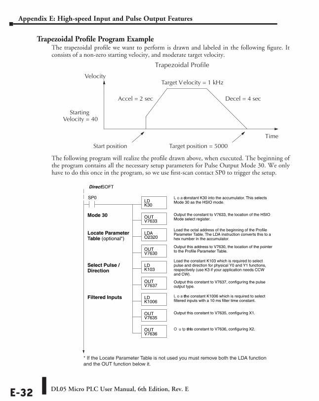
DL05 Micro PLC User Manual, 6th Edition, Rev. EE-32
Appendix E: High-speed Input and Pulse Output Features
Trapezoidal Profile Program ExampleThe trapezoidal profile we want to perform is drawn and labeled in the following figure. It consists of a non-zero starting velocity, and moderate target velocity.
The following program will realize the profile drawn above, when executed. The beginning of the program contains all the necessary setup parameters for Pulse Output Mode 30. We only have to do this once in the program, so we use first-scan contact SP0 to trigger the setup.
SP0LDK30
L o a d constant K30 into the accumulator. This selectsMode 30 as the HSIO mode.
OUTV7633
Output the constant to V7633, the location of the HSIOMode select register.
LDAO2320
Load the octal address of the beginning of the ProfileParameter Table. The LDA instruction converts this to ahex number in the accumulator.
OUTV7630
Output this address to V7630, the location of the pointerto the Profile Parameter Table.
DirectSOFT
Mode 30
LDK1006
L o a d the constant K1006 which is required to selectfiltered inputs with a 10 ms filter time constant.
OUTV7635
Output this constant to V7635, configuring X1.
Filtered Inputs
OUTV7636
O u tp u t this constant to V7636, configuring X2.
LDK103
Load the constant K103 which is required to selectpulse and direction for physical Y0 and Y1 functions,respectively (use K3 if your application needs CCWand CW).
OUTV7637
Output this constant to V7637, configuring the pulseoutput type.
Select Pulse /Direction
Locate ParameterTable (optional*)
* If the Locate Parameter Table is not used you must remove both the LDA function and the OUT function below it.
Trapezoidal Profile
Time
Accel = 2 sec Decel = 4 sec
Velocity
Start position Target position = 5000
Target Velocity = 1 kHz
StartingVelocity = 40
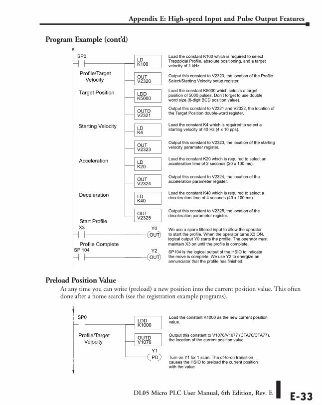
DL05 Micro PLC User Manual, 6th Edition, Rev. E E-33
Appendix E: High-speed Input and Pulse Output Features
Program Example (cont’d)
Preload Position ValueAt any time you can write (preload) a new position into the current position value. This often done after a home search (see the registration example programs).
Profile/Target Velocity
LDK100
Load the constant K100 which is required to selectTrapzoidal Profile, absolute positioning, and a targetvelocity of 1 kHz.
OUTV2320
Output this constant to V2320, the location of the ProfileSelect/Starting Velocity setup register.
Target Position
SP0
LDDK5000
Load the constant K5000 which selects a targetposition of 5000 pulses. Don’t forget to use doubleword size (8-digit BCD position value).
OUTDV2321
Output this constant to V2321 and V2322, the location ofthe Target Position double-word register.
OUTV2323
Output this constant to V2323, the location of the startingvelocity parameter register.
LDK4
Load the constant K4 which is required to select astarting velocity of 40 Hz (4 x 10 pps).
Starting Velocity
OUTV2324
Output this constant to V2324, the location of theacceleration parameter register.
LDK20
Load the constant K20 which is required to select anacceleration time of 2 seconds (20 x 100 ms).Acceleration
OUTV2325
Output this constant to V2325, the location of thedeceleration parameter register.
LDK40
Load the constant K40 which is required to select adeceleration time of 4 seconds (40 x 100 ms).Deceleration
X3OUT
We use a spare filtered input to allow the operatorto start the profile. When the operator turns X3 ON,logical output Y0 starts the profile. The operator mustmaintain X3 on until the profile is complete.
Y0Start Profile
SP 104OUT
SP104 is the logical output of the HSIO to indicatethe move is complete. We use Y2 to energize anannunciator that the profile has finished.
Y2Profile Complete
LDDK1000
Load the constant K1000 as the new current positionvalue.
OUTDV1076
Output this constant to V1076/V1077 (CTA76/CTA77),the location of the current position value.
SP0
PD Turn on Y1 for 1 scan. The off-to-on transitioncauses the HSIO to preload the current positionwith the value
Y1
Profile/Target Velocity
Profile/Target Velocity
LDK100
Load the constant K100 which is required to selectTrapzoidal Profile, absolute positioning, and a targetvelocity of 1 kHz.
OUTV2320
Output this constant to V2320, the location of the ProfileSelect/Starting Velocity setup register.
Target Position
SP0
LDDK5000
Load the constant K5000 which selects a targetposition of 5000 pulses. Don’t forget to use doubleword size (8-digit BCD position value).
OUTDV2321
Output this constant to V2321 and V2322, the location ofthe Target Position double-word register.
OUTV2323
Output this constant to V2323, the location of the startingvelocity parameter register.
LDK4
Load the constant K4 which is required to select astarting velocity of 40 Hz (4 x 10 pps).
Starting Velocity
OUTV2324
Output this constant to V2324, the location of theacceleration parameter register.
LDK20
Load the constant K20 which is required to select anacceleration time of 2 seconds (20 x 100 ms).Acceleration
OUTV2325
Output this constant to V2325, the location of thedeceleration parameter register.
LDK40
Load the constant K40 which is required to select adeceleration time of 4 seconds (40 x 100 ms).Deceleration
X3OUT
We use a spare filtered input to allow the operatorto start the profile. When the operator turns X3 ON,logical output Y0 starts the profile. The operator mustmaintain X3 on until the profile is complete.
Y0Start Profile
SP 104OUT
SP104 is the logical output of the HSIO to indicatethe move is complete. We use Y2 to energize anannunciator that the profile has finished.
Y2Profile Complete
LDDK1000
Load the constant K1000 as the new current positionvalue.
OUTDV1076
Output this constant to V1076/V1077 (CTA76/CTA77),the location of the current position value.
SP0
PD Turn on Y1 for 1 scan. The off-to-on transitioncauses the HSIO to preload the current positionwith the value
Y1
Profile/Target Velocity
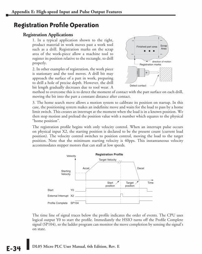
DL05 Micro PLC User Manual, 6th Edition, Rev. EE-34
Appendix E: High-speed Input and Pulse Output Features
Registration Profile OperationRegistration Applications
1. In a typical application shown to the right, product material in work moves past a work tool such as a drill. Registration marks on the scrap area of the work-piece allow a machine tool to register its position relative to the rectangle, to drill properly.
2. In other examples of registration, the work piece is stationary and the tool moves. A drill bit may approach the surface of a part in work, preparing to drill a hole of precise depth. However, the drill bit length gradually decreases due to tool wear. A method to overcome this is to detect the moment of contact with the part surface on each drill, moving the bit into the part a constant distance after contact.
3. The home search move allows a motion system to calibrate its position on startup. In this case, the positioning system makes an indefinite move and waits for the load to pass by a home limit switch. This creates an interrupt at the moment when the load is in a known position. We then stop motion and preload the position value with a number which equates to the physical “home position”.
The registration profile begins with only velocity control. When an interrupt pulse occurs on physical input X2, the starting position is declared to be the present count (current load position). The velocity control switches to position control, moving the load to the target position. Note that the minimum starting velocity is 40pps. This instantaneous velocity accommodates stepper motors that can stall at low speeds.
The time line of signal traces below the profile indicates the order of events. The CPU uses logical output Y0 to start the profile. Immediately the HSIO turns off the Profile Complete signal (SP104), so the ladder program can monitor the move completion by sensing the signal’s on state.
Registration Profile
Time
Accel Decel
Velocity
Startposition
Targetposition
Target Velocity
StartingVelocity
Start
External Interrupt
Y0
X2
Profile Complete SP104
Detect contact
Finished part area ScrapArea
Registration marksdirection of motion
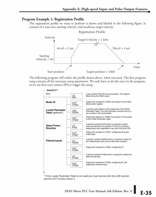
DL05 Micro PLC User Manual, 6th Edition, Rev. E E-35
Appendix E: High-speed Input and Pulse Output Features
Program Example 1: Registration Profile The registration profile we want to perform is drawn and labeled in the following figure. It consists of a non-zero starting velocity, and moderate target velocity.
The following program will realize the profile drawn above, when executed. The first program rung contains all the necessary setup parameters. We only have to do this once in the program, so we use first-scan contact SP0 to trigger the setup.
Registration Profile
Time
Accel = 2 sec Decel = 4 sec
Velocity
Start position Target position = 5000
Target Velocity = 1 kHz
StartingVelocity = 40
SP0LDK30
Load constant K30 into the accumulator. This selectsMode 30 as the HSIO mode.
OUTV7633
Output this constant to V7633, the location of the HSIOMode select register.
LDAO2320
Load the octal address of the beginning of the ProfileParameter Table. The LDA instruction converts this to ahex number in the accumulator.
OUTV7630
Output this address to V7630, the location of the pointerto the Profile Parameter Table
DirectSOFT
Mode 30
LDK2006
Load the constant K2006 which is required to select X1as a filtered input with a 20 ms filter time constant.Filtered Inputs
OUTV7635
Output this constant to V7635, configuring X1.
LDK103
Load the constant K103 which is required to selectpulse and direction for physical Y0 and Y1 functions,respectively (your application may use CCW and CW).
OUTV7637
Output this constant to V7637, configuring the pulseoutput type.
Select Pulse /Direction
LDK1006
Load the constant K1006 which is required to select theexternal interrupt.
OUTV7636
Output this constant to V7636, configuring X2, theregistration interrupt input.
Locate ParameterTable (optional*)
* If the Locate Parameter Table is not used you must remove both the LDA function and the OUT function below it.
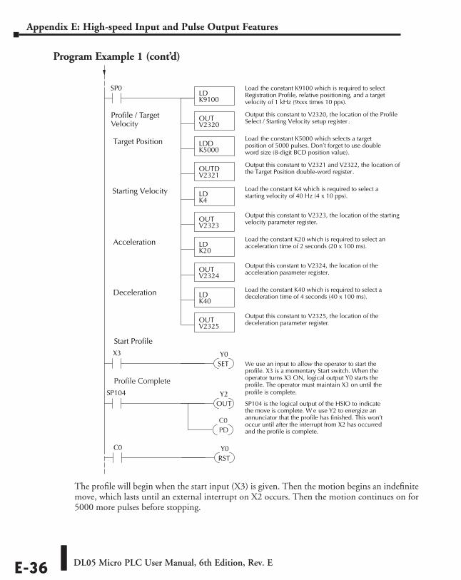
DL05 Micro PLC User Manual, 6th Edition, Rev. EE-36
Appendix E: High-speed Input and Pulse Output Features
Program Example 1 (cont’d)
The profile will begin when the start input (X3) is given. Then the motion begins an indefinite move, which lasts until an external interrupt on X2 occurs. Then the motion continues on for 5000 more pulses before stopping.
Start Profile
Profile / TargetVelocity
LDK9100
Load the constant K9100 which is required to selectRegistration Profile, relative positioning, and a targetvelocity of 1 kHz (9xxx times 10 pps).
OUTV2320
Output this constant to V2320, the location of the ProfileSelect / Starting Velocity setup register .
Target Position
SP0
LDDK5000
Load the constant K5000 which selects a targetposition of 5000 pulses. Don’t forget to use doubleword size (8-digit BCD position value).
OUTDV2321
Output this constant to V2321 and V2322, the location ofthe Target Position double-word register.
OUTV2323
Output this constant to V2323, the location of the startingvelocity parameter register.
LDK4
Load the constant K4 which is required to select astarting velocity of 40 Hz (4 x 10 pps).
Starting Velocity
OUTV2324
Output this constant to V2324, the location of theacceleration parameter register.
LDK20
Load the constant K20 which is required to select anacceleration time of 2 seconds (20 x 100 ms).Acceleration
OUTV2325
Output this constant to V2325, the location of thedeceleration parameter register.
LDK40
Load the constant K40 which is required to select adeceleration time of 4 seconds (40 x 100 ms).Deceleration
X3
SET We use an input to allow the operator to start theprofile. X3 is a momentary Start switch. When theoperator turns X3 ON, logical output Y0 starts theprofile. The operator must maintain X3 on until theprofile is complete.
Y0
SP104
OUT SP104 is the logical output of the HSIO to indicatethe move is complete. W e use Y2 to energize anannunciator that the profile has finished. This won’toccur until after the interrupt from X2 has occurredand the profile is complete.
Y2
Profile Complete
PDC0
C0
RSTY0
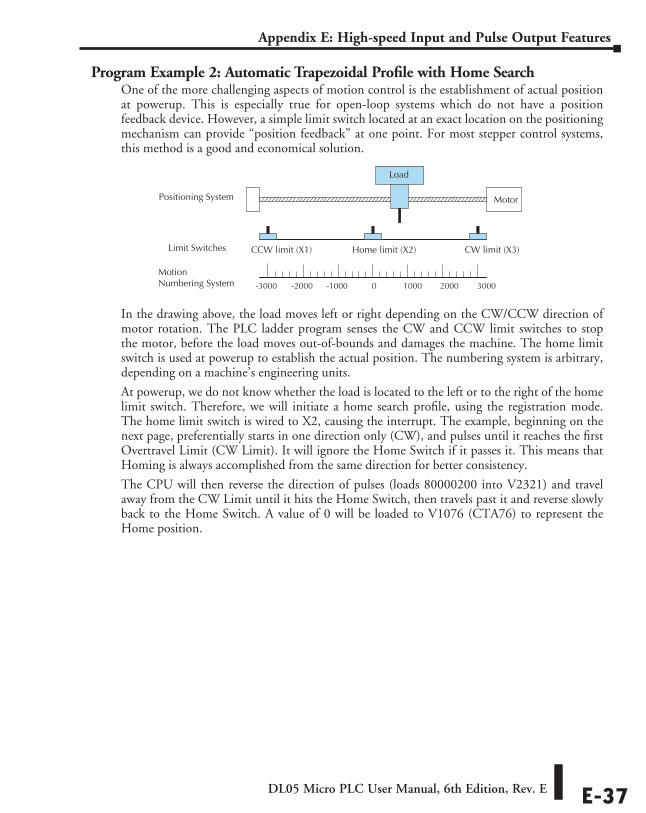
DL05 Micro PLC User Manual, 6th Edition, Rev. E E-37
Appendix E: High-speed Input and Pulse Output Features
Program Example 2: Automatic Trapezoidal Profile with Home SearchOne of the more challenging aspects of motion control is the establishment of actual position at powerup. This is especially true for open-loop systems which do not have a position feedback device. However, a simple limit switch located at an exact location on the positioning mechanism can provide “position feedback” at one point. For most stepper control systems, this method is a good and economical solution.
In the drawing above, the load moves left or right depending on the CW/CCW direction of motor rotation. The PLC ladder program senses the CW and CCW limit switches to stop the motor, before the load moves out-of-bounds and damages the machine. The home limit switch is used at powerup to establish the actual position. The numbering system is arbitrary, depending on a machine’s engineering units.
At powerup, we do not know whether the load is located to the left or to the right of the home limit switch. Therefore, we will initiate a home search profile, using the registration mode. The home limit switch is wired to X2, causing the interrupt. The example, beginning on the next page, preferentially starts in one direction only (CW), and pulses until it reaches the first Overtravel Limit (CW Limit). It will ignore the Home Switch if it passes it. This means that Homing is always accomplished from the same direction for better consistency.
The CPU will then reverse the direction of pulses (loads 80000200 into V2321) and travel away from the CW Limit until it hits the Home Switch, then travels past it and reverse slowly back to the Home Switch. A value of 0 will be loaded to V1076 (CTA76) to represent the Home position.
MotionNumbering System
Motor
Load
CCW limit (X1) CW limit (X3)Home limit (X2)
0 1000 2000 3000-1000-2000-3000
Limit Switches
Positioning System
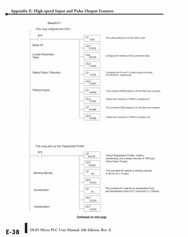
DL05 Micro PLC User Manual, 6th Edition, Rev. EE-38
Appendix E: High-speed Input and Pulse Output Features
Continued on next page
SP0 LD
K30 This selects Mode 30 as the HSIO mode.
OUT V7633
LDA O2320
OUT V7630
Direct SOFT
Mode 30
LD K2006 The constant K2006 selects a 20 mS filter time constant. Filtered Inputs
OUT V7635
Output this constant to V7635 to configure X1.
LD K103
Configure the Y0 and Y1 pulse outputs for pulse and direction, respectively.
OUT V7637
Select Pulse / Direction
OUTV7636 Output this constant to V7636 to configure X2.
Locate Parameter T able
LDK1006
The constant K1006 selects a 10 mS filter time constant.
Configure the address of the parameter table.
This rung sets up the Trapezoidal Profile
LD K9100 Select Registration Profile, relative
positioning, and a target velocity of 1000 pps(9xxx times 10 pps).OUT
V2320
SP0
LD K4
The constant K4 selects a starting velocity of 40 Hz (4 x 10 pps).
OUT V2323
OUT V2324
LD K1
Starting V elocity
OUT V2325
Acceleration
Deceleration
The constant K1 selects an acceleration time and deceleration time of 0.1 seconds (1 x 100ms).
This rung cofigures the CPU.
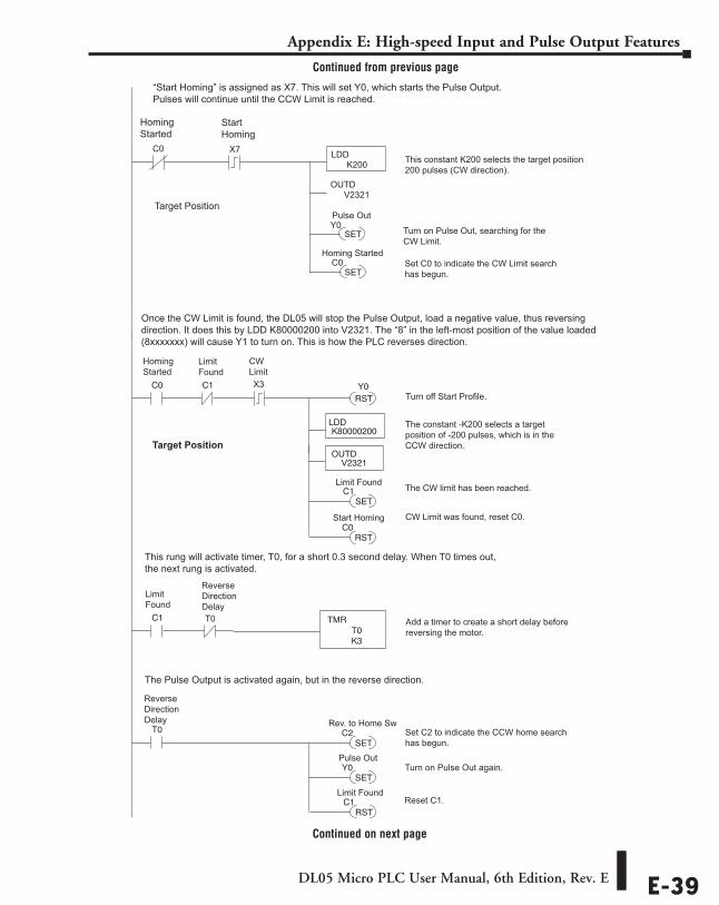
DL05 Micro PLC User Manual, 6th Edition, Rev. E E-39
Appendix E: High-speed Input and Pulse Output Features
Continued on next page
Homing Started
Target Position
X7
SET
“Start Homing” is assigned as X7. This will set Y0, which starts the Pulse Output. Pulses will continue until the CCW Limit is reached.
Y0
SET C0
Pulse Out
C0
Homing Started
LDD
OUTD
Start Homing
K200
V2321
Turn on Pulse Out, searching for the CW Limit.
Set C0 to indicate the CW Limit search has begun.
C0
RSTY0
LDDK80000200
OUTDV2321
SET
The CW limit has been reached. C1
C1
C1 TMR
K3 T0
T0
SETC2
SETY0
RSTC0
RSTC1
X3
Target Position
T0 Add a timer to create a short delay before reversing the motor.
Turn off Start Profile.
The constant -K200 selects a target position of -200 pulses, which is in the CCW direction.
CW Limit was found, reset C0.
Set C2 to indicate the CCW home search has begun.
Turn on Pulse Out again.
Reset C1.
Homing Started
Limit Found
CW Limit
Limit Found
Reverse Direction Delay
Reverse Direction Delay
Once the CW Limit is found, the DL05 will stop the Pulse Output, load a negative value, thus reversingdirection. It does this by LDD K80000200 into V2321. The “8” in the left-most position of the value loaded(8xxxxxxx) will cause Y1 to turn on. This is how the PLC reverses direction.
This rung will activate timer, T0, for a short 0.3 second delay. When T0 times out, the next rung is activated.
The Pulse Output is activated again, but in the reverse direction.
This constant K200 selects the target position 200 pulses (CW direction).
Limit Found
Start Homing
Pulse Out
Limit Found
Rev. to Home Sw
Continued from previous page
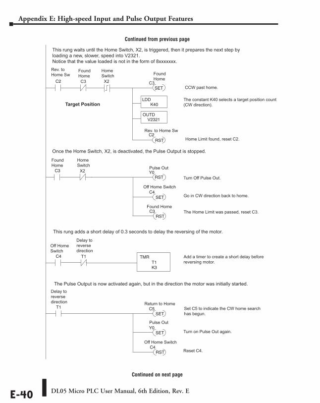
DL05 Micro PLC User Manual, 6th Edition, Rev. EE-40
Appendix E: High-speed Input and Pulse Output Features
Continued from previous page
Continued on next page
C3 Y0
SET
RSTC3
RST
C4 TMR
K3 T1
T1 Add a timer to create a short delay before reversing motor.
T1
SETC5
SETY0
RSTC4
Set C5 to indicate the CW home search has begun.
Turn on Pulse Out again.
Reset C4.
Delay to reverse direction
X2
Home Switch
Found Home
Off Home Switch
Delay to reverse direction
C4 Off Home Switch
C2
LDDK40
OUTDV2321
RSTC2
X2
Found Home C3 C3 SET
This rung waits until the Home Switch, X2, is triggered, then it prepares the next step byloading a new, slower, speed into V2321.Notice that the value loaded is not in the form of 8xxxxxxx.
Once the Home Switch, X2, is deactivated, the Pulse Output is stopped.
This rung adds a short delay of 0.3 seconds to delay the reversing of the motor.
The Pulse Output is now activated again, but in the direction the motor was initially started.
Home Switch
Rev. to Home Sw
Rev. to Home Sw
Found Home
The constant K40 selects a target position count(CW direction).
Turn Off Pulse Out.
Go in CW direction back to home.
Found Home The Home Limit was passed, reset C3.
Return to Home
Pulse Out
Off Home Switch
Target Position
CCW past home.
Home Limit found, reset C2.
Pulse Out
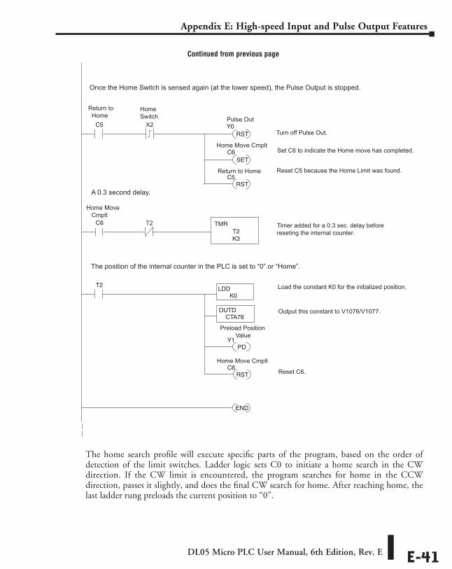
DL05 Micro PLC User Manual, 6th Edition, Rev. E E-41
Appendix E: High-speed Input and Pulse Output Features
Continued from previous page
The home search profile will execute specific parts of the program, based on the order of detection of the limit switches. Ladder logic sets C0 to initiate a home search in the CW direction. If the CW limit is encountered, the program searches for home in the CCW direction, passes it slightly, and does the final CW search for home. After reaching home, the last ladder rung preloads the current position to “0”.
C5
RSTY0
SET
Set C6 to indicate the Home move has completed. C6
C6 TMR
K3 T2
T2
RSTC5
X2
Once the Home Switch is sensed again (at the lower speed), the Pulse Output is stopped.
T2 Timer added for a 0.3 sec. delay before reseting the internal counter.
LDDK0
OUTDCTA76
PD Y1
END
RSTC6
Turn off Pulse Out.
Reset C5 because the Home Limit was found.
Load the constant K0 for the initialized position.
Output this constant to V1076/V1077.
Reset C6.
Return to Home
Home Move Cmplt
Home Switch
A 0.3 second delay.
The position of the internal counter in the PLC is set to “0” or “Home”.
Pulse Out
Return to Home
Home Move Cmplt
Home Move Cmplt
Preload Position Value
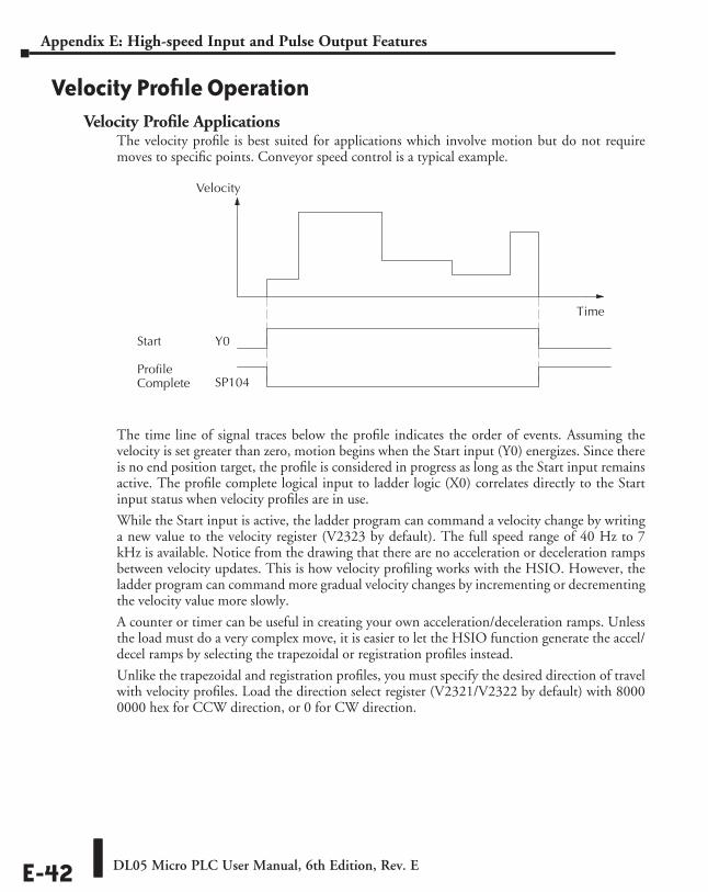
DL05 Micro PLC User Manual, 6th Edition, Rev. EE-42
Appendix E: High-speed Input and Pulse Output Features
Velocity Profile OperationVelocity Profile Applications
The velocity profile is best suited for applications which involve motion but do not require moves to specific points. Conveyor speed control is a typical example.
The time line of signal traces below the profile indicates the order of events. Assuming the velocity is set greater than zero, motion begins when the Start input (Y0) energizes. Since there is no end position target, the profile is considered in progress as long as the Start input remains active. The profile complete logical input to ladder logic (X0) correlates directly to the Start input status when velocity profiles are in use.
While the Start input is active, the ladder program can command a velocity change by writing a new value to the velocity register (V2323 by default). The full speed range of 40 Hz to 7 kHz is available. Notice from the drawing that there are no acceleration or deceleration ramps between velocity updates. This is how velocity profiling works with the HSIO. However, the ladder program can command more gradual velocity changes by incrementing or decrementing the velocity value more slowly.
A counter or timer can be useful in creating your own acceleration/deceleration ramps. Unless the load must do a very complex move, it is easier to let the HSIO function generate the accel/decel ramps by selecting the trapezoidal or registration profiles instead.
Unlike the trapezoidal and registration profiles, you must specify the desired direction of travel with velocity profiles. Load the direction select register (V2321/V2322 by default) with 8000 0000 hex for CCW direction, or 0 for CW direction.
Time
Velocity
Start
ProfileComplete
Y0
SP104
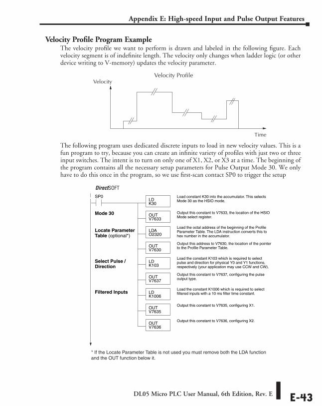
DL05 Micro PLC User Manual, 6th Edition, Rev. E E-43
Appendix E: High-speed Input and Pulse Output Features
Velocity Profile Program ExampleThe velocity profile we want to perform is drawn and labeled in the following figure. Each velocity segment is of indefinite length. The velocity only changes when ladder logic (or other device writing to V-memory) updates the velocity parameter.
The following program uses dedicated discrete inputs to load in new velocity values. This is a fun program to try, because you can create an infinite variety of profiles with just two or three input switches. The intent is to turn on only one of X1, X2, or X3 at a time. The beginning of the program contains all the necessary setup parameters for Pulse Output Mode 30. We only have to do this once in the program, so we use first-scan contact SP0 to trigger the setup
SP0LDK30
Load constant K30 into the accumulator. This selectsMode 30 as the HSIO mode.
OUTV7633
Output this constant to V7633, the location of the HSIOMode select register.
LDAO2320
Load the octal address of the beginning of the ProfileParameter Table. The LDA instruction converts this tohex number in the accumulator.
OUTV7630
Output this address to V7630, the location of the pointerto the Profile Parameter Table.
DirectSOFT 5
Mode 30
LDK1006
Load the constant K1006 which is required to selectfiltered inputs with a 10 ms filter time constant.
OUTV7635
Output this constant to V7635, configuring X1.
Filtered Inputs
OUTV7636
Output this constant to V7636, configuring X2.
LDK103
Load the constant K103 which is required to selectpulse and direction for physical Y0 and Y1 functions,respectively (your application may use CCW and CW).
OUTV7637
Output this constant to V7637, configuring the pulseoutput type.
Select Pulse /Direction
Locate ParameterTable (optional*)
* If the Locate Parameter Table is not used you must remove both the LDA function and the OUT function below it.
Velocity Profile
Time
Velocity
DirectSOFT
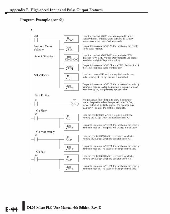
DL05 Micro PLC User Manual, 6th Edition, Rev. EE-44
Appendix E: High-speed Input and Pulse Output Features
Program Example (cont’d)
DL05 Micro PLC User Manual, 6th Edition, Rev. CE-44
Profile / TargetVelocity
LDK2000
Load the constant K2000 which is required to selectVelocity Profile. This data word contains no velocityinformation in the case of velocity mode.
OUTV2320
Output this constant to V2320, the location of the ProfileSelect setup register .
Select Direction
SP0
LDDK80000000
Load the constant K80000000 which selects CCWdirection for Velocity Profiles. Don’t forget to use doubleword size (8-digit BCD position value).
OUTDV2321
Output this constant to V2321 and V2322, the location ofthe Target Position double-word register.
OUTV2323
Output this constant to V2323, the location of the velocityparameter register . After the program is running, we canwrite here again, using discrete input switches.
LDK10
Load the constant K10 which is required to select aninitial velocity of 100 pps (uses x10 multiplier).
Set Velocity
X1
OUT
We use a spare filtered input to allow the operatorto start the profile. When the operator turns X1 ON,logical output Y0 starts the profile. The operator mustmaintain X1 on until the profile is complete.
Y0
Start Profile
LDK50
OUTV2323
X2
Output this constant to V2323, the location of the velocityparameter register . The speed will change immediately.
Load the constant K50 which is required to select avelocity of 500 pps when the operator closes X2.
Go Slow
LDK200
OUTV2323
X3
Output this constant to V2323, the location of the velocityparameter register . The speed will change immediately.
Load the constant K200 which is required to select avelocity of 2000 pps when the operator closes X3.
Go Moderately
LDK600
OUTV2323
X4
Output this constant to V2323, the location of the velocityparameter register . The speed will change immediately.
Load the constant K600 which is required to select avelocity of 6000 pps when the operator closes X4.
Go Fast
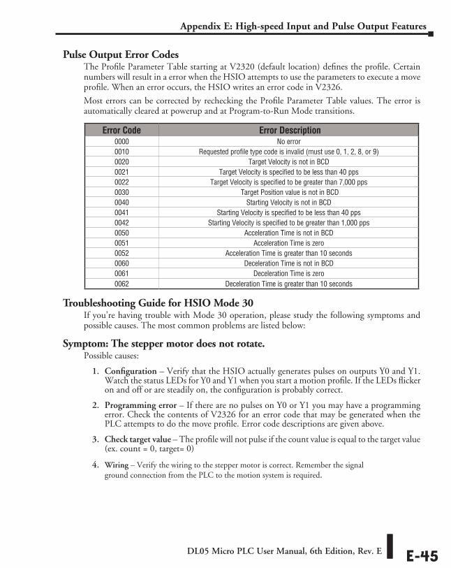
DL05 Micro PLC User Manual, 6th Edition, Rev. E E-45
Appendix E: High-speed Input and Pulse Output Features
Pulse Output Error CodesThe Profile Parameter Table starting at V2320 (default location) defines the profile. Certain numbers will result in a error when the HSIO attempts to use the parameters to execute a move profile. When an error occurs, the HSIO writes an error code in V2326.
Most errors can be corrected by rechecking the Profile Parameter Table values. The error is automatically cleared at powerup and at Program-to-Run Mode transitions.
Troubleshooting Guide for HSIO Mode 30If you’re having trouble with Mode 30 operation, please study the following symptoms and possible causes. The most common problems are listed below:
Symptom: The stepper motor does not rotate.Possible causes:
1. Configuration – Verify that the HSIO actually generates pulses on outputs Y0 and Y1. Watch the status LEDs for Y0 and Y1 when you start a motion profile. If the LEDs flicker on and off or are steadily on, the configuration is probably correct.
2. Programming error – If there are no pulses on Y0 or Y1 you may have a programming error. Check the contents of V2326 for an error code that may be generated when the PLC attempts to do the move profile. Error code descriptions are given above.
3. Check target value – The profile will not pulse if the count value is equal to the target value (ex. count = 0, target= 0)
4. Wiring – Verify the wiring to the stepper motor is correct. Remember the signal ground connection from the PLC to the motion system is required.
Error Code Error Description0000 No error0010 Requested profile type code is invalid (must use 0, 1, 2, 8, or 9)0020 Target Velocity is not in BCD0021 Target Velocity is specified to be less than 40 pps0022 Target Velocity is specified to be greater than 7,000 pps0030 Target Position value is not in BCD0040 Starting Velocity is not in BCD0041 Starting Velocity is specified to be less than 40 pps0042 Starting Velocity is specified to be greater than 1,000 pps0050 Acceleration Time is not in BCD0051 Acceleration Time is zero0052 Acceleration Time is greater than 10 seconds0060 Deceleration Time is not in BCD0061 Deceleration Time is zero0062 Deceleration Time is greater than 10 seconds
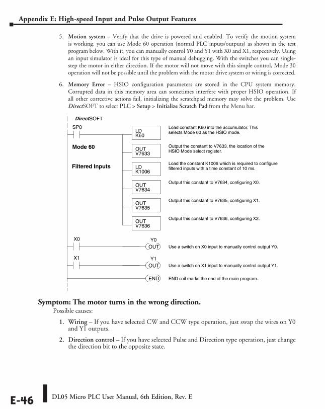
DL05 Micro PLC User Manual, 6th Edition, Rev. EE-46
Appendix E: High-speed Input and Pulse Output Features
5. Motion system – Verify that the drive is powered and enabled. To verify the motion system is working, you can use Mode 60 operation (normal PLC inputs/outputs) as shown in the test program below. With it, you can manually control Y0 and Y1 with X0 and X1, respectively. Using an input simulator is ideal for this type of manual debugging. With the switches you can single-step the motor in either direction. If the motor will not move with this simple control, Mode 30 operation will not be possible until the problem with the motor drive system or wiring is corrected.
6. Memory Error – HSIO configuration parameters are stored in the CPU system memory. Corrupted data in this memory area can sometimes interfere with proper HSIO operation. If all other corrective actions fail, initializing the scratchpad memory may solve the problem. Use DirectSOFT to select PLC > Setup > Initialize Scratch Pad from the Menu bar.
Symptom: The motor turns in the wrong direction.Possible causes:
1. Wiring – If you have selected CW and CCW type operation, just swap the wires on Y0 and Y1 outputs.
2. Direction control – If you have selected Pulse and Direction type operation, just change the direction bit to the opposite state.
SP0LDK60
Load constant K60 into the accumulator. Thisselects Mode 60 as the HSIO mode.
OUTV7633
Output the constant to V7633, the location of theHSIO Mode select register.
DirectSOFT
Mode 60
OUTV7635
Output this constant to V7635, configuring X1.
Filtered Inputs
OUTV7636
Output this constant to V7636, configuring X2.
LDK1006
Load the constant K1006 which is required to configurefiltered inputs with a time constant of 10 ms.
OUTV7634
Output this constant to V7634, configuring X0.
END END coil marks the end of the main program..
X0
OUT Use a switch on X0 input to manually control output Y0.
Y0
X1
OUT Use a switch on X1 input to manually control output Y1.
Y1
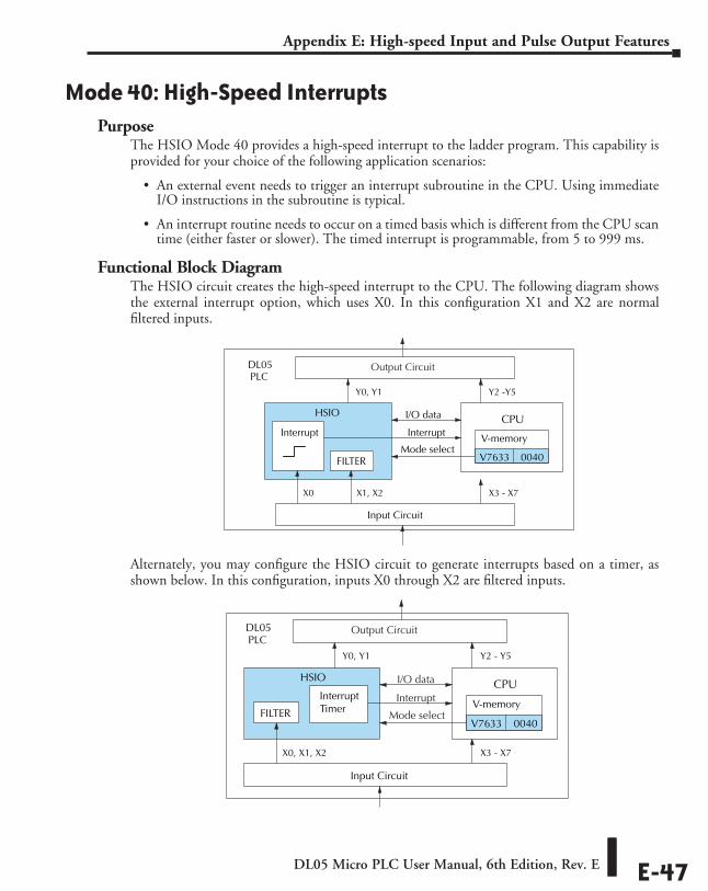
DL05 Micro PLC User Manual, 6th Edition, Rev. E E-47
Appendix E: High-speed Input and Pulse Output Features
Mode 40: High-Speed InterruptsPurpose
The HSIO Mode 40 provides a high-speed interrupt to the ladder program. This capability is provided for your choice of the following application scenarios:
• An external event needs to trigger an interrupt subroutine in the CPU. Using immediate I/O instructions in the subroutine is typical.
• An interrupt routine needs to occur on a timed basis which is different from the CPU scan time (either faster or slower). The timed interrupt is programmable, from 5 to 999 ms.
Functional Block DiagramThe HSIO circuit creates the high-speed interrupt to the CPU. The following diagram shows the external interrupt option, which uses X0. In this configuration X1 and X2 are normal filtered inputs.
Alternately, you may configure the HSIO circuit to generate interrupts based on a timer, as shown below. In this configuration, inputs X0 through X2 are filtered inputs.
Input Circuit
CPU
PLCDL05
Y0, Y1
X3 - X7
Y2 - Y5
V-memory
V7633 0040Mode select
I/O dataHSIO
X0, X1, X2
InterruptInterruptTimerFILTER
Output Circuit
Input Circuit
CPU
PLCDL05
X0
Y0, Y1
X3 - X7
Y2 -Y5
V-memory
V7633 0040Mode select
I/O dataHSIO
Interrupt
X1, X2
Interrupt
FILTER
Output Circuit
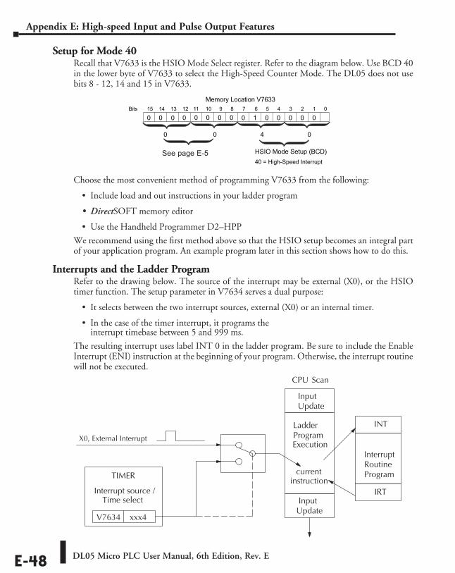
DL05 Micro PLC User Manual, 6th Edition, Rev. EE-48
Appendix E: High-speed Input and Pulse Output Features
Setup for Mode 40Recall that V7633 is the HSIO Mode Select register. Refer to the diagram below. Use BCD 40 in the lower byte of V7633 to select the High-Speed Counter Mode. The DL05 does not use bits 8 - 12, 14 and 15 in V7633.
Choose the most convenient method of programming V7633 from the following:
• Include load and out instructions in your ladder program
• DirectSOFT memory editor
• Use the Handheld Programmer D2–HPP
We recommend using the first method above so that the HSIO setup becomes an integral part of your application program. An example program later in this section shows how to do this.
Interrupts and the Ladder ProgramRefer to the drawing below. The source of the interrupt may be external (X0), or the HSIO timer function. The setup parameter in V7634 serves a dual purpose:
• It selects between the two interrupt sources, external (X0) or an internal timer.
• In the case of the timer interrupt, it programs the interrupt timebase between 5 and 999 ms.
The resulting interrupt uses label INT 0 in the ladder program. Be sure to include the Enable Interrupt (ENI) instruction at the beginning of your program. Otherwise, the interrupt routine will not be executed.
015 14 13 12
Memory Location V763311 10 123456789Bits
00 0000100
HSIO Mode Setup (BCD)
0 0 0 0
40 = High-Speed Interrupt
0 0 04
00
X0, External Interrupt
CPU Scan
Interrupt source /
Time select
V7634 xxx4
InputUpdate
LadderProgram Execution
InputUpdate
currentinstruction
INT
InterruptRoutineProgram
IRT
TIMER
See page E-5
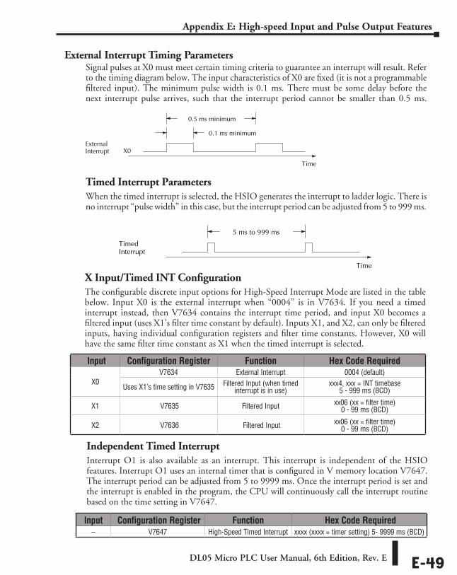
DL05 Micro PLC User Manual, 6th Edition, Rev. E E-49
Appendix E: High-speed Input and Pulse Output Features
Independent Timed InterruptInterrupt O1 is also available as an interrupt. This interrupt is independent of the HSIO features. Interrupt O1 uses an internal timer that is configured in V memory location V7647. The interrupt period can be adjusted from 5 to 9999 ms. Once the interrupt period is set and the interrupt is enabled in the program, the CPU will continuously call the interrupt routine based on the time setting in V7647.
Time
TimedInterrupt
5 ms to 999 ms
Time
ExternalInterrupt X0
0.1 ms minimum
0.5 ms minimum
Input Configuration Register Function Hex Code Required– V7647 High-Speed Timed Interrupt xxxx (xxxx = timer setting) 5- 9999 ms (BCD)
Input Configuration Register Function Hex Code Required
X0 V7634 External Interrupt 0004 (default)
Uses X1’s time setting in V7635 Filtered Input (when timed interrupt is in use)
xxx4, xxx = INT timebase 5 - 999 ms (BCD)
X1 V7635 Filtered Input xx06 (xx = filter time) 0 - 99 ms (BCD)
X2 V7636 Filtered Input xx06 (xx = filter time) 0 - 99 ms (BCD)
X Input/Timed INT ConfigurationThe configurable discrete input options for High-Speed Interrupt Mode are listed in the table below. Input X0 is the external interrupt when “0004” is in V7634. If you need a timed interrupt instead, then V7634 contains the interrupt time period, and input X0 becomes a filtered input (uses X1’s filter time constant by default). Inputs X1, and X2, can only be filtered inputs, having individual configuration registers and filter time constants. However, X0 will have the same filter time constant as X1 when the timed interrupt is selected.
External Interrupt Timing ParametersSignal pulses at X0 must meet certain timing criteria to guarantee an interrupt will result. Refer to the timing diagram below. The input characteristics of X0 are fixed (it is not a programmable filtered input). The minimum pulse width is 0.1 ms. There must be some delay before the next interrupt pulse arrives, such that the interrupt period cannot be smaller than 0.5 ms.
Timed Interrupt ParametersWhen the timed interrupt is selected, the HSIO generates the interrupt to ladder logic. There is no interrupt “pulse width” in this case, but the interrupt period can be adjusted from 5 to 999 ms.
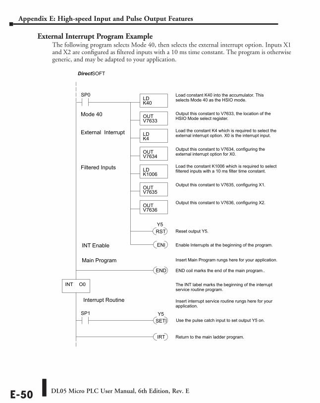
DL05 Micro PLC User Manual, 6th Edition, Rev. EE-50
Appendix E: High-speed Input and Pulse Output Features
External Interrupt Program ExampleThe following program selects Mode 40, then selects the external interrupt option. Inputs X1 and X2 are configured as filtered inputs with a 10 ms time constant. The program is otherwise generic, and may be adapted to your application.
SP0LDK40
Load constant K40 into the accumulator. Thisselects Mode 40 as the HSIO mode.
OUTV7633
Output this constant to V7633, the location of theHSIO Mode select register.
DirectSOFT
Mode 40
LDK1006
Load the constant K1006 which is required to selectfiltered inputs with a 10 ms filter time constant.
OUTV7635
Output this constant to V7635, configuring X1.
Filtered Inputs
OUTV7636
Output this constant to V7636, configuring X2.
LDK4
Load the constant K4 which is required to select theexternal interrupt option. X0 is the interrupt input.
OUTV7634
Output this constant to V7634, configuring theexternal interrupt option for X0.
External Interrupt
INT Enable ENI Enable Interrupts at the beginning of the program.
END END coil marks the end of the main program..
INT O0
IRT Return to the main ladder program.
The INT label marks the beginning of the interruptservice routine program.
Main Program Insert Main Program rungs here for your application.
Interrupt Routine Insert interrupt service routine rungs here for yourapplication.
Use the pulse catch input to set output Y5 on.SP1
SETIY5
RST Reset output Y5.Y5
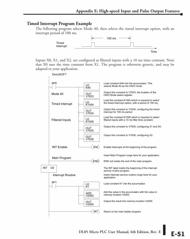
DL05 Micro PLC User Manual, 6th Edition, Rev. E E-51
Appendix E: High-speed Input and Pulse Output Features
Timed Interrupt Program ExampleThe following program selects Mode 40, then selects the timed interrupt option, with an interrupt period of 100 ms.
Inputs X0, X1, and X2, are configured as filtered inputs with a 10 ms time constant. Note that X0 uses the time constant from X1. The program is otherwise generic, and may be adapted to your application.
Time
TimedInterrupt
100 ms
SP0LDK40
Load constant K40 into the accumulator. Thisselects Mode 40 as the HSIO mode.
OUTV7633
Output this constant to V7633, the location of theHSIO Mode select register.
DirectSOFT
Mode 40
LDK1006
Load the constant K1006 which is required to selectfiltered inputs with a 10 ms filter time constant.
OUTV7635
Output this constant to V7635, configuring X1 and X0.
Filtered Inputs
OUTV7636
Output this constant to V7636, configuring X2.
LDK1004
Load the constant K1004 which is required to selectthe timed interrrupt option, with a period of 100 ms.
OUTV7634
Output this constant to V7634, configuring the timedinterrupt for 100 ms period.
Timed Interrupt
INT Enable ENI Enable Interrupts at the beginning of the program.
END END coil marks the end of the main program.
INT O0
IRT Return to the main ladder program.
The INT label marks the beginning of the interruptservice routine program.
Main ProgramInsert Main Program rungs here for your application.
Interrupt Routine Insert interrupt service routine rungs here for yourapplication.
SP1LDK1
Load constant K1 into the accumulator.
ADDV2000
OUTV2000
Add the value in the accumulator with the value inmemory location V2000.
Output the result into memory location V2000.
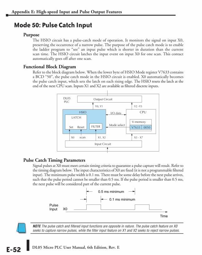
DL05 Micro PLC User Manual, 6th Edition, Rev. EE-52
Appendix E: High-speed Input and Pulse Output Features
Mode 50: Pulse Catch InputPurpose
The HSIO circuit has a pulse-catch mode of operation. It monitors the signal on input X0, preserving the occurrence of a narrow pulse. The purpose of the pulse catch mode is to enable the ladder program to “see” an input pulse which is shorter in duration than the current scan time. The HSIO circuit latches the input event on input X0 for one scan. This contact automatically goes off after one scan.
Functional Block DiagramRefer to the block diagram below. When the lower byte of HSIO Mode register V7633 contains a BCD “50”, the pulse catch mode in the HSIO circuit is enabled. X0 automatically becomes the pulse catch input, which sets the latch on each rising edge. The HSIO resets the latch at the end of the next CPU scan. Inputs X1 and X2 are available as filtered discrete inputs.
Pulse Catch Timing ParametersSignal pulses at X0 must meet certain timing criteria to guarantee a pulse capture will result. Refer to the timing diagram below. The input characteristics of X0 are fixed (it is not a programmable filtered input). The minimum pulse width is 0.1 ms. There must be some delay before the next pulse arrives, such that the pulse period cannot be smaller than 0.5 ms. If the pulse period is smaller than 0.5 ms, the next pulse will be considered part of the current pulse.
NOTE The pulse catch and filtered input functions are opposite in nature. The pulse catch feature on X0 seeks to capture narrow pulses, while the filter input feature on X1 and X2 seeks to reject narrow pulses.
Time
PulseInput X0
0.1 ms minimum
0.5 ms minimum
Input Circuit
CPU
PLCDL05
X0
Y0, Y1
X3 - X7
Y2 -Y5
V-memory
V7633 0050 Mode select
I/O data HSIO
LATCH
Set Reset
X1, X2 scan
FILTER
Output Circuit
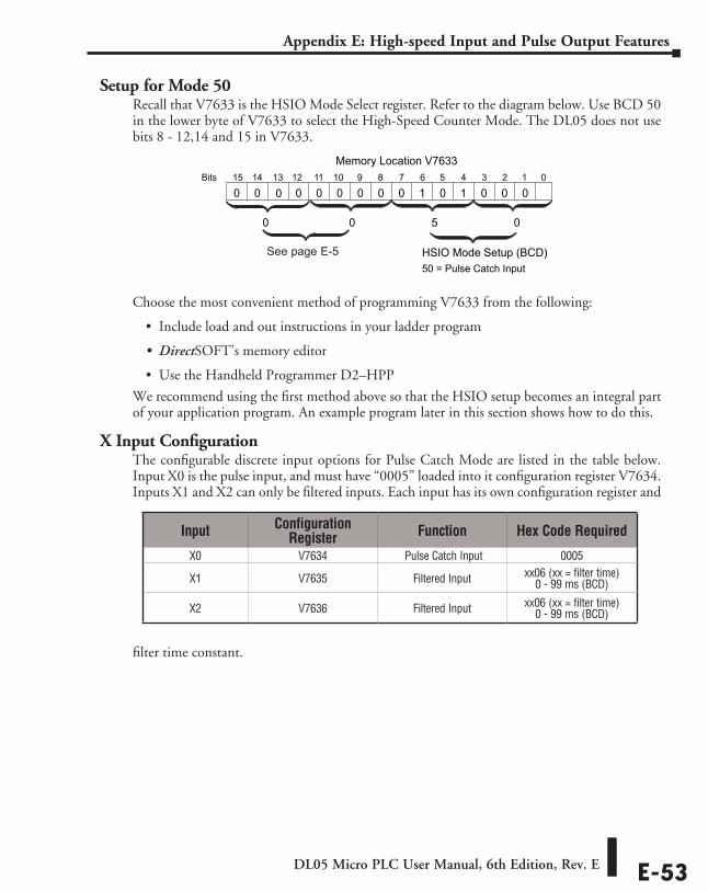
DL05 Micro PLC User Manual, 6th Edition, Rev. E E-53
Appendix E: High-speed Input and Pulse Output Features
Setup for Mode 50Recall that V7633 is the HSIO Mode Select register. Refer to the diagram below. Use BCD 50 in the lower byte of V7633 to select the High-Speed Counter Mode. The DL05 does not use bits 8 - 12,14 and 15 in V7633.
Choose the most convenient method of programming V7633 from the following:
• Include load and out instructions in your ladder program
• DirectSOFT’s memory editor
• Use the Handheld Programmer D2–HPP
We recommend using the first method above so that the HSIO setup becomes an integral part of your application program. An example program later in this section shows how to do this.
X Input ConfigurationThe configurable discrete input options for Pulse Catch Mode are listed in the table below. Input X0 is the pulse input, and must have “0005” loaded into it configuration register V7634. Inputs X1 and X2 can only be filtered inputs. Each input has its own configuration register and
filter time constant.
015 14 13 12
Memory Location V763311 10 123456789Bits
00 0010100
HSIO Mode Setup (BCD)
0 0 0 0
50 = Pulse Catch Input
0 0 05
00
Input Configuration Register Function Hex Code Required
X0 V7634 Pulse Catch Input 0005
X1 V7635 Filtered Input xx06 (xx = filter time) 0 - 99 ms (BCD)
X2 V7636 Filtered Input xx06 (xx = filter time) 0 - 99 ms (BCD)
See page E-5
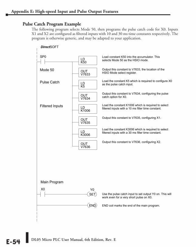
DL05 Micro PLC User Manual, 6th Edition, Rev. EE-54
Appendix E: High-speed Input and Pulse Output Features
Pulse Catch Program ExampleThe following program selects Mode 50, then programs the pulse catch code for X0. Inputs X1 and X2 are configured as filtered inputs with 10 and 30 ms time constants respectively. The program is otherwise generic, and may be adapted to your application.
SP0LDK50
Load constant K50 into the accumulator. Thisselects Mode 50 as the HSIO mode.
OUTV7633
Output this constant to V7633, the location of theHSIO Mode select register.
DirectSOFT
Mode 50
LDK1006
Load the constant K1006 which is required to selectfiltered inputs with a 10 ms filter time constant.
OUTV7635
Output this constant to V7635, configuring X1.
Filtered Inputs
OUTV7636
Output this constant to V7636, configuring X2.
LDK5
Load the constant K5 which is required to configure X0as the pulse catch input.
OUTV7634
Output this constant to V7634, configuring the pulsecatch option for X0.
Pulse Catch
END END coil marks the end of the main program.
Main Program
Use the pulse catch input to set output Y0 on. This willwork even for a very short pulse on X0.
LDK3006
Load the constant K3006 which is required to selectfiltered inputs with a 30 ms filter time constant.
X0SETY0
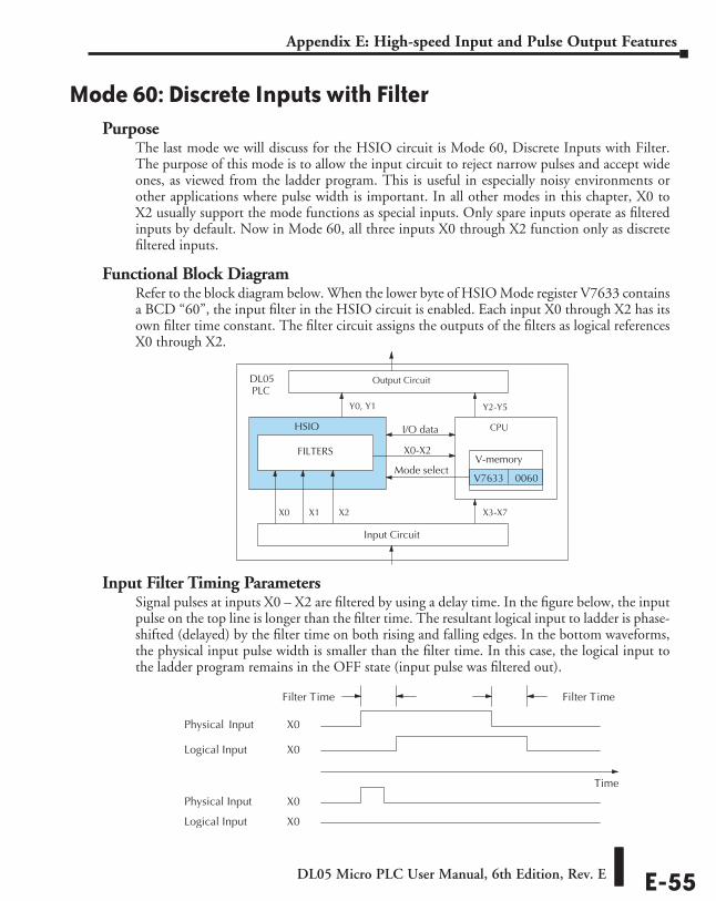
DL05 Micro PLC User Manual, 6th Edition, Rev. E E-55
Appendix E: High-speed Input and Pulse Output Features
Mode 60: Discrete Inputs with FilterPurpose
The last mode we will discuss for the HSIO circuit is Mode 60, Discrete Inputs with Filter. The purpose of this mode is to allow the input circuit to reject narrow pulses and accept wide ones, as viewed from the ladder program. This is useful in especially noisy environments or other applications where pulse width is important. In all other modes in this chapter, X0 to X2 usually support the mode functions as special inputs. Only spare inputs operate as filtered inputs by default. Now in Mode 60, all three inputs X0 through X2 function only as discrete filtered inputs.
Functional Block DiagramRefer to the block diagram below. When the lower byte of HSIO Mode register V7633 contains a BCD “60”, the input filter in the HSIO circuit is enabled. Each input X0 through X2 has its own filter time constant. The filter circuit assigns the outputs of the filters as logical references X0 through X2.
Input Filter Timing ParametersSignal pulses at inputs X0 – X2 are filtered by using a delay time. In the figure below, the input pulse on the top line is longer than the filter time. The resultant logical input to ladder is phase-shifted (delayed) by the filter time on both rising and falling edges. In the bottom waveforms, the physical input pulse width is smaller than the filter time. In this case, the logical input to the ladder program remains in the OFF state (input pulse was filtered out).
Input Circuit
PLCDL05
X0
Y0, Y1
X3-X7
Y2-Y5
V-memory
V7633 0060Mode select
I/O data
HSIO
FILTERS X0-X2
X1 X2
Output Circuit
CPU
Time
Physical Input X0
Filter Time
Logical Input X0
Physical Input X0
Logical Input X0
Filter Time
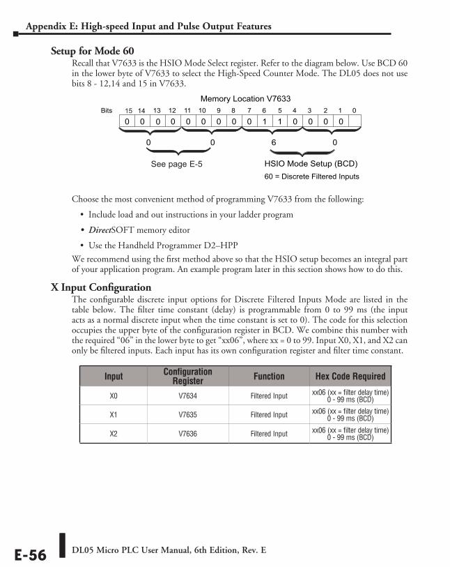
DL05 Micro PLC User Manual, 6th Edition, Rev. EE-56
Appendix E: High-speed Input and Pulse Output Features
Setup for Mode 60Recall that V7633 is the HSIO Mode Select register. Refer to the diagram below. Use BCD 60 in the lower byte of V7633 to select the High-Speed Counter Mode. The DL05 does not use bits 8 - 12,14 and 15 in V7633.
Choose the most convenient method of programming V7633 from the following:
• Include load and out instructions in your ladder program
• DirectSOFT memory editor
• Use the Handheld Programmer D2–HPP
We recommend using the first method above so that the HSIO setup becomes an integral part of your application program. An example program later in this section shows how to do this.
X Input ConfigurationThe configurable discrete input options for Discrete Filtered Inputs Mode are listed in the table below. The filter time constant (delay) is programmable from 0 to 99 ms (the input acts as a normal discrete input when the time constant is set to 0). The code for this selection occupies the upper byte of the configuration register in BCD. We combine this number with the required “06” in the lower byte to get “xx06”, where xx = 0 to 99. Input X0, X1, and X2 can only be filtered inputs. Each input has its own configuration register and filter time constant.
014 13 12
Memory Location V763311 10 123456789Bits
00 0001100
HSIO Mode Setup (BCD)
0 0 0 0
60 = Discrete Filtered Inputs
0 0 06
015
0
Input Configuration Register Function Hex Code Required
X0 V7634 Filtered Input xx06 (xx = filter delay time) 0 - 99 ms (BCD)
X1 V7635 Filtered Input xx06 (xx = filter delay time) 0 - 99 ms (BCD)
X2 V7636 Filtered Input xx06 (xx = filter delay time) 0 - 99 ms (BCD)
See page E-5
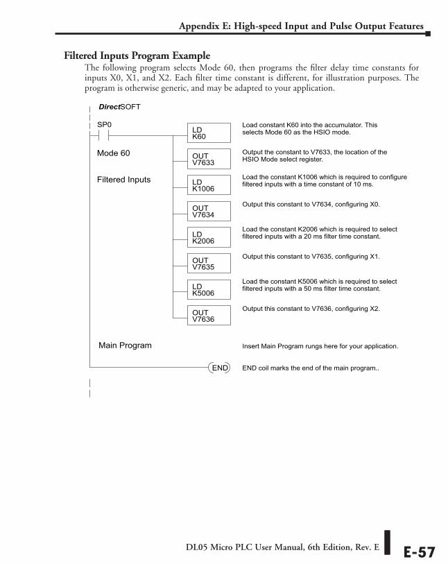
DL05 Micro PLC User Manual, 6th Edition, Rev. E E-57
Appendix E: High-speed Input and Pulse Output Features
Filtered Inputs Program ExampleThe following program selects Mode 60, then programs the filter delay time constants for inputs X0, X1, and X2. Each filter time constant is different, for illustration purposes. The program is otherwise generic, and may be adapted to your application.
SP0LDK60
Load constant K60 into the accumulator. Thisselects Mode 60 as the HSIO mode.
OUTV7633
Output the constant to V7633, the location of theHSIO Mode select register.
DirectSOFT
Mode 60
LDK2006
Load the constant K2006 which is required to selectfiltered inputs with a 20 ms filter time constant.
OUTV7635
Output this constant to V7635, configuring X1.
Filtered Inputs
OUTV7636
Output this constant to V7636, configuring X2.
LDK1006
Load the constant K1006 which is required to configurefiltered inputs with a time constant of 10 ms.
OUTV7634
Output this constant to V7634, configuring X0.
END END coil marks the end of the main program..
Main Program Insert Main Program rungs here for your application.
LDK5006
Load the constant K5006 which is required to selectfiltered inputs with a 50 ms filter time constant.

PLC MeMory EFFAppendixAppendixAppendix
In this Appendix...DL05 PLC Memory..................................................................................... ................ F–2
DL05 Micro PLC User Manual, 6th Edition, Rev. EF-2
Appendix F: PLC Memory
DL05 PLC MemoryWhen designing a PLC application, it is important for the PLC user to understand the different types of memory in the PLC. The DL05 PLC uses two types of memory: RAM and EEPROM. RAM is Random Access Memory and EEPROM is Electrically Erasable Programmable Read Only Memory. The PLC program is stored in EEPROM, and the PLC V-memory data is stored in RAM. There is also a small range of V-memory that can be copied to EEPROM which will be explained later.
The V-memory in RAM can be configured as either retentive or non-retentive.
Retentive memory is memory that is configured by the user to maintain values through a power cycle or a PROGRAM to RUN transition. Non-retentive memory is memory that is configured by the PLC user to clear data after a power cycle or a PROGRAM to RUN transition. The retentive ranges can be configured with either the handheld programmer using AUX57 or DirectSOFT 5 (PLC Setup).
The contents of RAM memory can be written to and read from for an infinite number of times, but RAM requires a power source to maintain the contents of memory. The contents of RAM are maintained by the internal power supply (5VDC) only while the PLC is powered by an external source, normally 120VAC. When power to the PLC is turned off, the contents of RAM are maintained by a”Super-Capacitor”. If the Super-Capacitor ever discharges, the contents of RAM will be lost. The data retention time of the Super-Capacitor backed RAM is 3 weeks maximum, and 4 1/2 days minimum (at 60! C).
The contents of EEPROM memory can be read an infinite number of times, but there is a limit to the number of times it can be written to (typical specification is 100,000 writes). EEPROM does not require a power source to maintain the memory contents. It will retain the contents of memory indefinitely.
PLC user V-memory is stored in both volatile RAM and non-volatile EEPROM memory. Data being stored in RAM uses V400-V677, V1200-V7377 and V10000-V17777 which is volatile. Data stored in EEPROM uses V7400-V7577 and V700-V777, V7600-V7777 and V36000-V37777 are non-volatile.
Data values that must be retained for long periods of time, when the PLC is powered off, should be stored in EEPROM based V-memory. Since EEPROM is limited to the number of times it can be written to, it is suggested that transitional logic, such as a one-shot, be used to write the data one time instead on each CPU scan.
Data values that are continually changing or which can be initialized with program logic should be stored in RAM based V-memory.
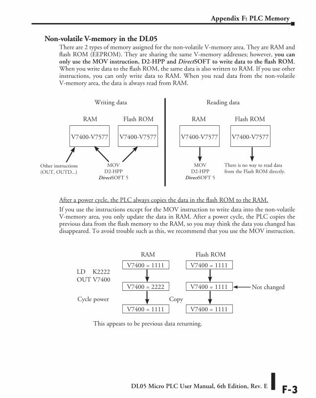
DL05 Micro PLC User Manual, 6th Edition, Rev. E F-3
Appendix F: PLC Memory
Non-volatile V-memory in the DL05There are 2 types of memory assigned for the non-volatile V-memory area. They are RAM and flash ROM (EEPROM). They are sharing the same V-memory addresses; however, you can only use the MOV instruction, D2-HPP and DirectSOFT to write data to the flash ROM. When you write data to the flash ROM, the same data is also written to RAM. If you use other instructions, you can only write data to RAM. When you read data from the non-volatile V-memory area, the data is always read from RAM.
After a power cycle, the PLC always copies the data in the flash ROM to the RAM.
If you use the instructions except for the MOV instruction to write data into the non-volatile V-memory area, you only update the data in RAM. After a power cycle, the PLC copies the previous data from the flash memory to the RAM, so you may think the data you changed has disappeared. To avoid trouble such as this, we recommend that you use the MOV instruction.
Writing data Reading data
RAM Flash ROM RAM
V7400-V7577
V7400-V7577
V7400-V7577
V7400-V7577
Flash ROM
Other instructions (OUT, OUTD...)
MOV D2-HPP
DirectSOFT 5
MOV D2-HPP
DirectSOFT 5
There is no way to read data from the Flash ROM directly.
RAM Flash ROM
V7400 = 1111
V7400 = 2222
V7400 = 1111
V7400 = 1111
V7400 = 1111
V7400 = 1111
LD K2222OUT V7400
Not changed
Cycle power Copy
This appears to be previous data returning.

ASCII TAble EGGAppendixAppendixAppendix
In This Appendix...ASCII Table .................................................................................................................G-2
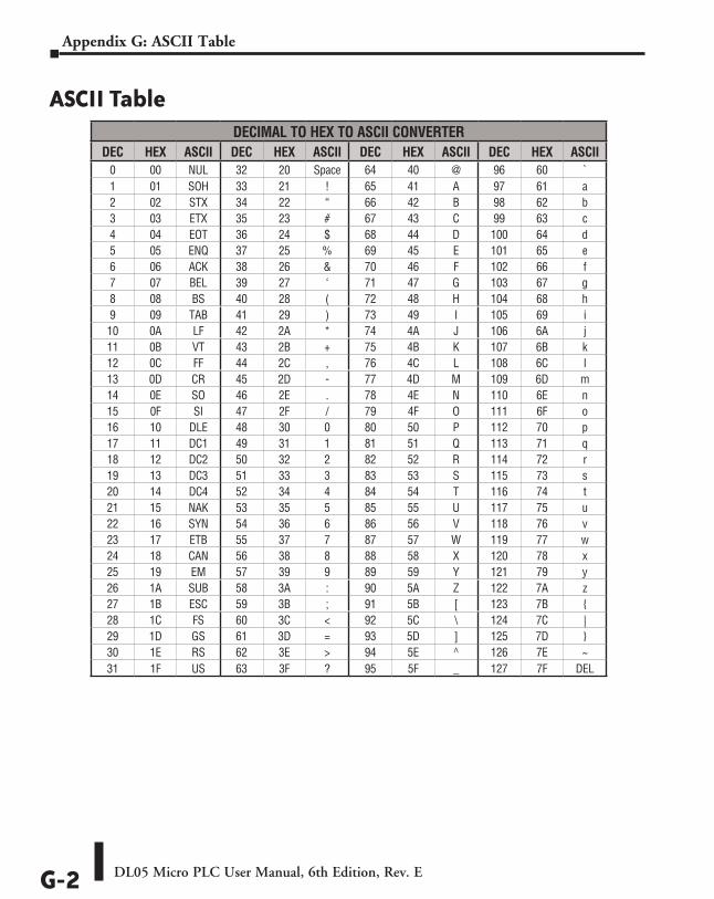
DL05 Micro PLC User Manual, 6th Edition, Rev. EG-2
Appendix G: ASCII Table
ASCII TableDECIMAL TO HEX TO ASCII CONVERTER
DEC HEX ASCII DEC HEX ASCII DEC HEX ASCII DEC HEX ASCII0 00 NUL 32 20 Space 64 40 @ 96 60 `1 01 SOH 33 21 ! 65 41 A 97 61 a2 02 STX 34 22 “ 66 42 B 98 62 b3 03 ETX 35 23 # 67 43 C 99 63 c4 04 EOT 36 24 $ 68 44 D 100 64 d5 05 ENQ 37 25 % 69 45 E 101 65 e6 06 ACK 38 26 & 70 46 F 102 66 f7 07 BEL 39 27 ‘ 71 47 G 103 67 g8 08 BS 40 28 ( 72 48 H 104 68 h9 09 TAB 41 29 ) 73 49 I 105 69 i10 0A LF 42 2A * 74 4A J 106 6A j11 0B VT 43 2B + 75 4B K 107 6B k12 0C FF 44 2C , 76 4C L 108 6C l13 0D CR 45 2D - 77 4D M 109 6D m14 0E SO 46 2E . 78 4E N 110 6E n15 0F SI 47 2F / 79 4F O 111 6F o16 10 DLE 48 30 0 80 50 P 112 70 p17 11 DC1 49 31 1 81 51 Q 113 71 q18 12 DC2 50 32 2 82 52 R 114 72 r19 13 DC3 51 33 3 83 53 S 115 73 s20 14 DC4 52 34 4 84 54 T 116 74 t21 15 NAK 53 35 5 85 55 U 117 75 u22 16 SYN 54 36 6 86 56 V 118 76 v23 17 ETB 55 37 7 87 57 W 119 77 w24 18 CAN 56 38 8 88 58 X 120 78 x25 19 EM 57 39 9 89 59 Y 121 79 y26 1A SUB 58 3A : 90 5A Z 122 7A z27 1B ESC 59 3B ; 91 5B [ 123 7B 28 1C FS 60 3C < 92 5C \ 124 7C |29 1D GS 61 3D = 93 5D ] 125 7D 30 1E RS 62 3E > 94 5E ^ 126 7E ~31 1F US 63 3F ? 95 5F _ 127 7F DEL

Product Weights HHHAppendixAppendixAppendix
In This Appendix...Product Weight Table ................................................................................................H-2
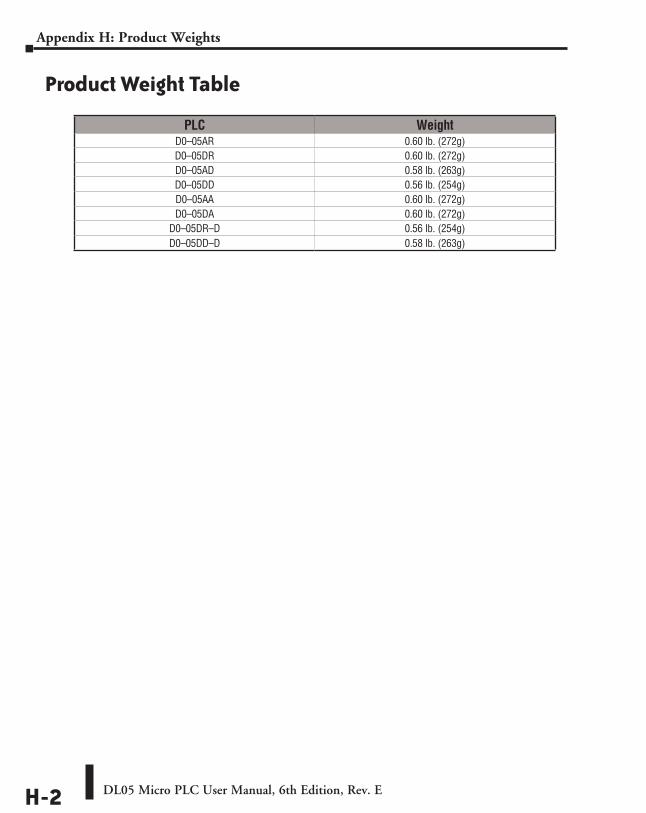
DL05 Micro PLC User Manual, 6th Edition, Rev. EH-2
Appendix H: Product Weights
Product Weight Table
PLC WeightD0–05AR 0.60 lb. (272g)D0–05DR 0.60 lb. (272g)D0–05AD 0.58 lb. (263g)D0–05DD 0.56 lb. (254g)D0–05AA 0.60 lb. (272g)D0–05DA 0.60 lb. (272g)
D0–05DR–D 0.56 lb. (254g)D0–05DD–D 0.58 lb. (263g)
NumberiNg SyStemS IIIAppendixAppendixAppendix
In This Appendix...Introduction ................................................................................................................ I-2
Binary Numbering System ......................................................................................... I-2
Hexadecimal Numbering System ............................................................................... I-3
Octal Numbering System ........................................................................................... I-4
Binary Coded Decimal (BCD) Numbering System .................................................... I-5
Real (Floating Point) Numbering System .................................................................. I-5
BCD/Binary/Decimal/Hex/Octal - What is the Difference? .............................................................................................. I-6
Data Type Mismatch ................................................................................................... I-7
Signed vs. Unsigned Integers ..................................................................................... I-8
AutomationDirect.com Products and Data Types ..................................................... I-9
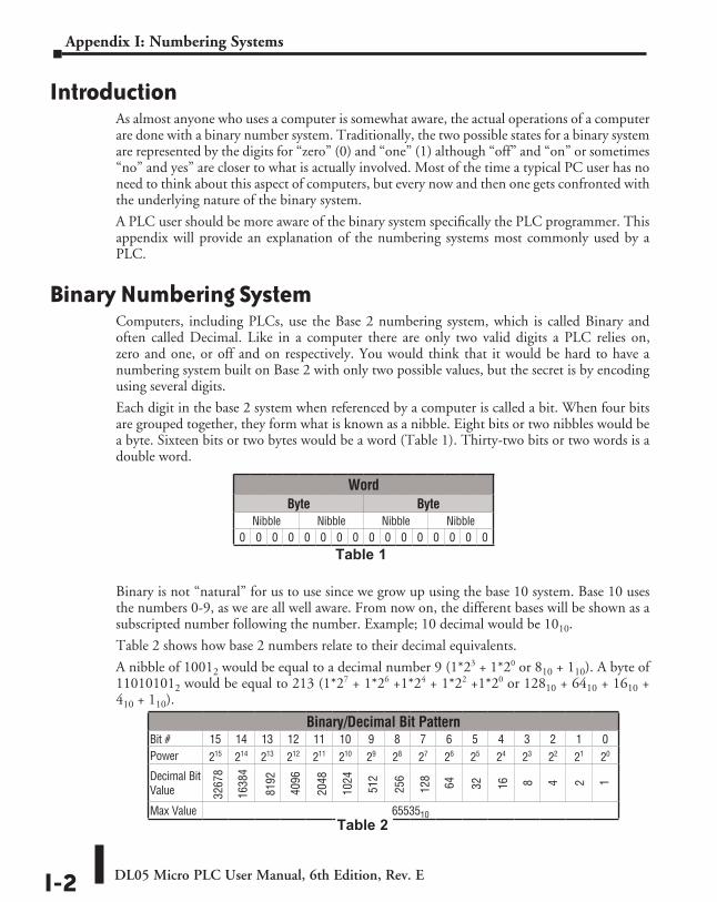
DL05 Micro PLC User Manual, 6th Edition, Rev. EI-2
Appendix I: Numbering Systems
IntroductionAs almost anyone who uses a computer is somewhat aware, the actual operations of a computer are done with a binary number system. Traditionally, the two possible states for a binary system are represented by the digits for “zero” (0) and “one” (1) although “off” and “on” or sometimes “no” and yes” are closer to what is actually involved. Most of the time a typical PC user has no need to think about this aspect of computers, but every now and then one gets confronted with the underlying nature of the binary system.
A PLC user should be more aware of the binary system specifically the PLC programmer. This appendix will provide an explanation of the numbering systems most commonly used by a PLC.
Binary Numbering SystemComputers, including PLCs, use the Base 2 numbering system, which is called Binary and often called Decimal. Like in a computer there are only two valid digits a PLC relies on, zero and one, or off and on respectively. You would think that it would be hard to have a numbering system built on Base 2 with only two possible values, but the secret is by encoding using several digits.
Each digit in the base 2 system when referenced by a computer is called a bit. When four bits are grouped together, they form what is known as a nibble. Eight bits or two nibbles would be a byte. Sixteen bits or two bytes would be a word (Table 1). Thirty-two bits or two words is a double word.
Binary is not “natural” for us to use since we grow up using the base 10 system. Base 10 uses the numbers 0-9, as we are all well aware. From now on, the different bases will be shown as a subscripted number following the number. Example; 10 decimal would be 1010.
Table 2 shows how base 2 numbers relate to their decimal equivalents.
A nibble of 10012 would be equal to a decimal number 9 (1*23 + 1*20 or 810 + 110). A byte of 110101012 would be equal to 213 (1*27 + 1*26 +1*24 + 1*22 +1*20 or 12810 + 6410 + 1610 + 410 + 110).
WordByte Byte
Nibble Nibble Nibble Nibble 0 0 0 0 0 0 0 0 0 0 0 0 0 0 0 0
Table 1
Binary/Decimal Bit PatternBit # 15 14 13 12 11 10 9 8 7 6 5 4 3 2 1 0Power 215 214 213 212 211 210 29 28 27 26 25 24 23 22 21 20
Decimal Bit Value
Max Value 6553510
3267
8
1638
4
8192
4096
2048
1024
512
256
128
64 32 816 24 1
Table 2
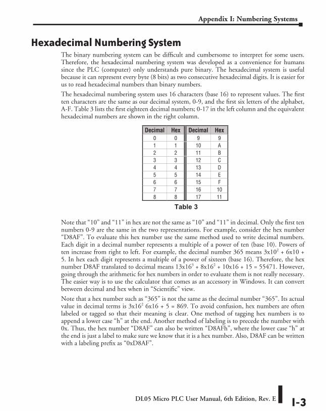
DL05 Micro PLC User Manual, 6th Edition, Rev. E I-3
Appendix I: Numbering Systems
Hexadecimal Numbering SystemThe binary numbering system can be difficult and cumbersome to interpret for some users. Therefore, the hexadecimal numbering system was developed as a convenience for humans since the PLC (computer) only understands pure binary. The hexadecimal system is useful because it can represent every byte (8 bits) as two consecutive hexadecimal digits. It is easier for us to read hexadecimal numbers than binary numbers.
The hexadecimal numbering system uses 16 characters (base 16) to represent values. The first ten characters are the same as our decimal system, 0-9, and the first six letters of the alphabet, A-F. Table 3 lists the first eighteen decimal numbers; 0-17 in the left column and the equivalent hexadecimal numbers are shown in the right column.
Note that “10” and “11” in hex are not the same as “10” and “11” in decimal. Only the first ten numbers 0-9 are the same in the two representations. For example, consider the hex number “D8AF”. To evaluate this hex number use the same method used to write decimal numbers. Each digit in a decimal number represents a multiple of a power of ten (base 10). Powers of ten increase from right to left. For example, the decimal number 365 means 3x10² + 6x10 + 5. In hex each digit represents a multiple of a power of sixteen (base 16). Therefore, the hex number D8AF translated to decimal means 13x163 + 8x162 + 10x16 + 15 = 55471. However, going through the arithmetic for hex numbers in order to evaluate them is not really necessary. The easier way is to use the calculator that comes as an accessory in Windows. It can convert between decimal and hex when in “Scientific” view.
Note that a hex number such as “365” is not the same as the decimal number “365”. Its actual value in decimal terms is 3x162 6x16 + 5 = 869. To avoid confusion, hex numbers are often labeled or tagged so that their meaning is clear. One method of tagging hex numbers is to append a lower case “h” at the end. Another method of labeling is to precede the number with 0x. Thus, the hex number “D8AF” can also be written “D8AFh”, where the lower case “h” at the end is just a label to make sure we know that it is a hex number. Also, D8AF can be written with a labeling prefix as “0xD8AF”.
Table 3
Decimal Hex Decimal Hex 0 0 9 91 1 10 A2 2 11 B3 3 12 C4 4 13 D5 5 14 E6 6 15 F7 7 16 108 8 17 11
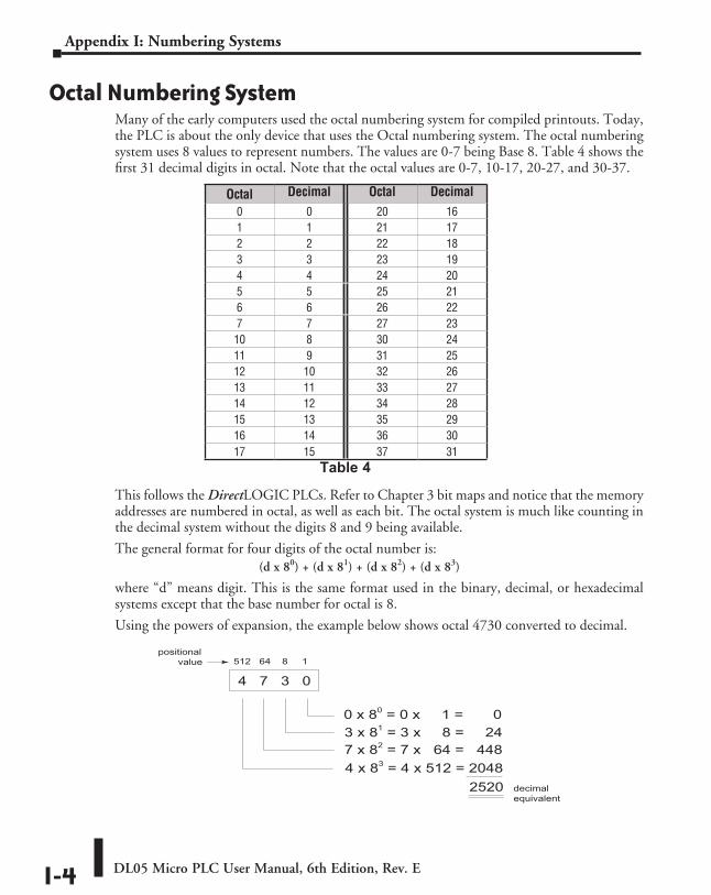
DL05 Micro PLC User Manual, 6th Edition, Rev. EI-4
Appendix I: Numbering Systems
Octal Numbering SystemMany of the early computers used the octal numbering system for compiled printouts. Today, the PLC is about the only device that uses the Octal numbering system. The octal numbering system uses 8 values to represent numbers. The values are 0-7 being Base 8. Table 4 shows the first 31 decimal digits in octal. Note that the octal values are 0-7, 10-17, 20-27, and 30-37.
This follows the DirectLOGIC PLCs. Refer to Chapter 3 bit maps and notice that the memory addresses are numbered in octal, as well as each bit. The octal system is much like counting in the decimal system without the digits 8 and 9 being available.
The general format for four digits of the octal number is:(d x 80) + (d x 81) + (d x 82) + (d x 83)
where “d” means digit. This is the same format used in the binary, decimal, or hexadecimal systems except that the base number for octal is 8.
Using the powers of expansion, the example below shows octal 4730 converted to decimal.
Table 4
Octal Decimal Octal Decimal0 0 20 161 1 21 172 2 22 183 3 23 194 4 24 205 5 25 216 6 26 227 7 27 2310 8 30 2411 9 31 2512 10 32 2613 11 33 2714 12 34 2815 13 35 2916 14 36 3017 15 37 31
4 7 3 0
512 64 8 1
0 x 80 = 0 x 1 = 03 x 81 = 3 x 8 = 247 x 82 = 7 x 64 = 4484 x 83 = 4 x 512 = 2048
2520
positional value
decimalequivalent
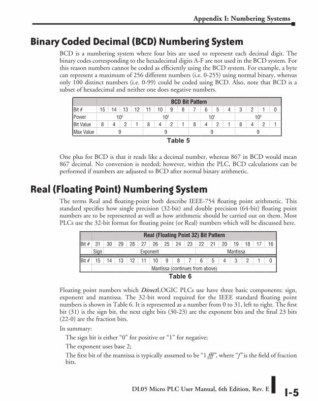
DL05 Micro PLC User Manual, 6th Edition, Rev. E I-5
Appendix I: Numbering Systems
Binary Coded Decimal (BCD) Numbering SystemBCD is a numbering system where four bits are used to represent each decimal digit. The binary codes corresponding to the hexadecimal digits A-F are not used in the BCD system. For this reason numbers cannot be coded as efficiently using the BCD system. For example, a byte can represent a maximum of 256 different numbers (i.e. 0-255) using normal binary, whereas only 100 distinct numbers (i.e. 0-99) could be coded using BCD. Also, note that BCD is a subset of hexadecimal and neither one does negative numbers.
One plus for BCD is that it reads like a decimal number, whereas 867 in BCD would mean 867 decimal. No conversion is needed; however, within the PLC, BCD calculations can be performed if numbers are adjusted to BCD after normal binary arithmetic.
Real (Floating Point) Numbering SystemThe terms Real and floating-point both describe IEEE-754 floating point arithmetic. This standard specifies how single precision (32-bit) and double precision (64-bit) floating point numbers are to be represented as well as how arithmetic should be carried out on them. Most PLCs use the 32-bit format for floating point (or Real) numbers which will be discussed here.
Floating point numbers which DirectLOGIC PLCs use have three basic components: sign, exponent and mantissa. The 32-bit word required for the IEEE standard floating point numbers is shown in Table 6. It is represented as a number from 0 to 31, left to right. The first bit (31) is the sign bit, the next eight bits (30-23) are the exponent bits and the final 23 bits (22-0) are the fraction bits.
In summary:The sign bit is either “0” for positive or “1” for negative; The exponent uses base 2; The first bit of the mantissa is typically assumed to be “1.fff”, where “f” is the field of fraction bits.
BCD Bit PatternBit # 15 14 13 12 11 10 9 8 7 6 5 4 3 2 1 0Power 103 102 101 100
Bit Value 8 4 2 1 8 4 2 1 8 4 2 1 8 4 2 1Max Value 9 9 9 9
Table 5
Real (Floating Point 32) Bit PatternBit # 31 30 29 28 27 26 25 24 23 22 21 20 19 18 17 16
Sign Exponent Mantissa
Bit # 15 14 13 12 11 10 9 8 7 6 5 4 3 2 1 0Mantissa (continues from above)
Table 6
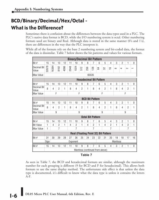
DL05 Micro PLC User Manual, 6th Edition, Rev. EI-6
Appendix I: Numbering Systems
BCD/Binary/Decimal/Hex/Octal - What is the Difference?
Sometimes there is confusion about the differences between the data types used in a PLC. The PLC’s native data format is BCD, while the I/O numbering system is octal. Other numbering formats used are binary and Real. Although data is stored in the same manner (0’s and 1’s), there are differences in the way that the PLC interprets it.
While all of the formats rely on the base 2 numbering system and bit-coded data, the format of the data is dissimilar. Table 7 below shows the bit patterns and values for various formats.
As seen in Table 7, the BCD and hexadecimal formats are similar, although the maximum number for each grouping is different (9 for BCD and F for hexadecimal). This allows both formats to use the same display method. The unfortunate side effect is that unless the data type is documented, it’s difficult to know what the data type is unless it contains the letters A-F.
3267
8
1638
4
8192
4096
1024
512
256
128
64 32 816 24 1
2048
Binary/Decimal Bit PatternBit # 15 14 13 12 11 10 9 8 7 6 5 4 3 2 1 0
Decimal Bit Value
Max Value 65535
Hexadecimal Bit PatternBit # 15 14 13 12 11 10 9 8 7 6 5 4 3 2 1 0Decimal Bit Value 8 4 2 1 8 4 2 1 8 4 2 1 8 4 2 1
Max Value F F F F
BCD Bit PatternBit # 15 14 13 12 11 10 9 8 7 6 5 4 3 2 1 0Decimal Bit Value 8 4 2 1 8 4 2 1 8 4 2 1 8 4 2 1
Max Value 9 9 9 9
Octal Bit PatternBit # 15 14 13 12 11 10 9 8 7 6 5 4 3 2 1 0Bit Value 1 4 2 1 4 2 1 4 2 1 4 2 1 4 2 1Max Value 1 7 7 7 7 7
Real (Floating Point 32) Bit PatternBit # 31 30 29 28 27 26 25 24 23 22 21 20 19 18 17 16
Sign Exponent Mantissa
Bit # 15 14 13 12 11 10 9 8 7 6 5 4 3 2 1 0Mantissa (continued from above)
Table 7
3267
8
1638
4
8192
4096
2048
1024
512
256
128
64 32 816 24 1
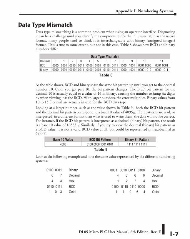
DL05 Micro PLC User Manual, 6th Edition, Rev. E I-7
Appendix I: Numbering Systems
Data Type MismatchData type mismatching is a common problem when using an operator interface. Diagnosing it can be a challenge until you identify the symptoms. Since the PLC uses BCD as the native format, many people tend to think it is interchangeable with binary (unsigned integer) format. This is true to some extent, but not in this case. Table 8 shows how BCD and binary numbers differ.
As the table shows, BCD and binary share the same bit pattern up until you get to the decimal number 10. Once you get past 10, the bit pattern changes. The BCD bit pattern for the decimal 10 is actually equal to a value of 16 in binary, causing the number to jump six digits by when viewing it as the BCD. With larger numbers, the error multiplies. Binary values from 10 to 15 Decimal are actually invalid for the BCD data type.
Looking at a larger number, such as the value shown in Table 9, both the BCD bit pattern and the decimal bit pattern correspond to a base 10 value of 409510. If bit patterns are read, or interpreted, in a different format than what is used to write them, the data will not be correct. For instance, if the BCD bit pattern is interpreted as a decimal (binary) bit pattern, the result is a base 10 value of 1653310. Similarly, if you try to view the decimal (binary) bit pattern as a BCD value, it is not a valid BCD value at all, but could be represented in hexadecimal as 0xFFF.
Look at the following example and note the same value represented by the different numbering systems.
Base 10 Value BCD Bit Pattern Binary Bit Pattern4095 0100 0000 1001 0101 1111 1111 1111
Table 9
Data Type MismatchDecimal 0 1 2 3 4 5 6 7 8 9 10 11BCD 0000 0001 0010 0011 0100 0101 0110 0111 1000 1001 0001 0000 0001 0001Binary 0000 0001 0010 0011 0100 0101 0110 0111 1000 1001 0000 1010 0000 1011
Table 8
0100 0011 Binary
1 0 3 Octal
4 3 Hex6 7 Decimal
0110 0111 BCD
0001 0010 0011 0100 Binary
0100 0110 0110 0000 BCD1 1 0 6 4 Octal
1 2 3 4 Hex4 6 6 0 Decimal
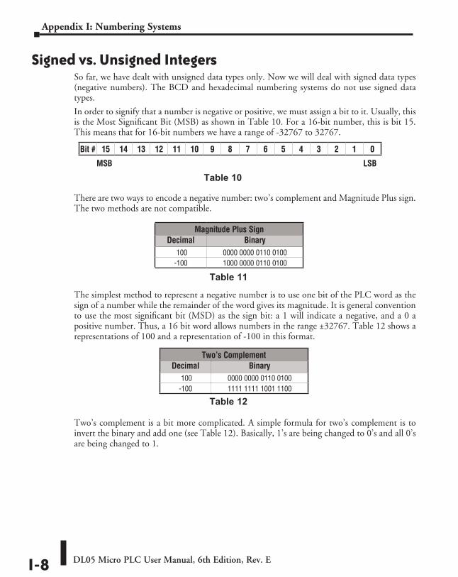
DL05 Micro PLC User Manual, 6th Edition, Rev. EI-8
Appendix I: Numbering Systems
Signed vs. Unsigned IntegersSo far, we have dealt with unsigned data types only. Now we will deal with signed data types (negative numbers). The BCD and hexadecimal numbering systems do not use signed data types.
In order to signify that a number is negative or positive, we must assign a bit to it. Usually, this is the Most Significant Bit (MSB) as shown in Table 10. For a 16-bit number, this is bit 15. This means that for 16-bit numbers we have a range of -32767 to 32767.
There are two ways to encode a negative number: two’s complement and Magnitude Plus sign. The two methods are not compatible.
The simplest method to represent a negative number is to use one bit of the PLC word as the sign of a number while the remainder of the word gives its magnitude. It is general convention to use the most significant bit (MSD) as the sign bit: a 1 will indicate a negative, and a 0 a positive number. Thus, a 16 bit word allows numbers in the range ±32767. Table 12 shows a representations of 100 and a representation of -100 in this format.
Two’s complement is a bit more complicated. A simple formula for two’s complement is to invert the binary and add one (see Table 12). Basically, 1’s are being changed to 0’s and all 0’s are being changed to 1.
Magnitude Plus SignDecimal Binary
100 0000 0000 0110 0100-100 1000 0000 0110 0100
Table 11
Two’s ComplementDecimal Binary
100 0000 0000 0110 0100-100 1111 1111 1001 1100
Table 12
Table 10
Bit # 15 14 13 12 11 10 9 8 7 6 5 4 3 2 1 0
MSB LSB
DL05 Micro PLC User Manual, 6th Edition, Rev. E I-9
Appendix I: Numbering Systems
AutomationDirect.com Products and Data TypesDirectLOGIC PLCs
The DirectLOGIC PLC family uses the octal numbering system for all addressing which includes: inputs, outputs, internal V-memory locations, timers, counters, internal control relays (bits), etc. Most data in the PLC, including timer and counter current values, is in BCD format by default. User data in V-memory locations may be stored in other data types if it is changed by the programmer, or comes from some external source, such as an operator interface. Any manipulation of data must use instructions appropriate for that data type which includes: Load instructions, Math instructions, Out box instructions, comparison instructions, etc. In many cases, the data can be changed from one data type to another, but be aware of the limitations of the various data types when doing so. For example, to change a value from BCD to decimal (binary), use a BIN instruction box. To change from BCD to a real number, use a BIN and a BTOR instruction box. When using Math instructions, the data types must match. For example, a BCD or decimal (binary) number cannot be added to a real number, and a BCD number cannot be added to a decimal (binary) number. If the data types are mismatched, the results of any math operation will be meaningless.
To simplify making, number conversions Intelligent Box (IBox) Instructions are available with DirectSOFT. These instruction descriptions are located in Volume 1, Chapter 5, in the Math IBox group.
Most DirectLOGIC analog modules can be setup to give the raw data in decimal (binary) format or in BCD format, so it is necessary to know how the module is being used. DirectLOGIC PID is another area where not all values are in BCD. In fact, nearly all of the PID parameters are stored in the PLC memory as decimal (binary) numbers.
NOTE: The PID algorithm uses magnitude plus sign for negative decimal (binary) numbers, whereas the standard math functions use two’s complement. This can cause confusion while debugging a PID loop.
When using the Data View in DirectSOFT, be certain that the proper format is selected for the element to be viewed. The data type and length is selected using the drop-down boxes at the top of the Data View window. Also notice that BCD is called BCD/Hex. Remember that BCD is a subset of hexadecimal so they share a display format even though the values may be different. This is where good documentation of the data type stored in memory is crucial.
C-more and C-more Micro-Graphic Panels In the C-more and C-more Micro-Graphic HMI operator panels, the 16-bit BCD format is listed as “BCD int 16”. Binary format is either “Unsigned int 16” or “Signed int 16” depending on whether or not the value can be negative. Real number format is “Floating PT 32”.
More available formats are, “BCD int 32”, “Unsigned int 32” and “Signed int 32”.
EuropEan union DirEctivEs (cE) JJJ
AppendixAppendixAppendix
In This AppendixEuropean Union (EU) Directives ................................................................................ J-2
Basic EMC Installation Guidelines .............................................................................. J-5
DL05 Micro PLC User Manual, 6th Edition, Rev. EJ-2
Appendix J: European Union Directives (CE)
European Union (EU) Directives
NOTE: The information contained in this section is intended as a guideline and is based on our interpretation of the various standards and requirements. Since the actual standards are issued by other parties, and in some cases governmental agencies, the requirements can change over time without advance warning or notice. Changes or additions to the standards can possibly invalidate any part of the information provided in this section.
This area of certification and approval is absolutely vital to anyone who wants to do business in Europe. One of the key tasks that faced the EU member countries and the European Economic Area (EEA) was the requirement to bring several similar yet distinct standards together into one common standard for all members. The primary purpose of a single standard was to make it easier to sell and transport goods between the various countries and to maintain a safe working and living environment. The Directives that resulted from this merging of standards are now legal requirements for doing business in Europe. Products that meet these Directives are required to have a CE mark to signify compliance.
Member CountriesAs of January 1, 2007, the members of the EU are Austria, Belgium, Bulgaria, Cyprus, Czech Republic, Denmark, Estonia, Finland, France, Germany, Greece, Hungary, Ireland, Italy, Latvia, Lithuania, Luxembourg, Malta, Netherlands, Poland, Portugal,Romania, Slovakia, Slovenia, Spain, Sweden, and United Kingdom. Iceland, Liechtenstein, and Norway together with the EU members make up the European Economic Area (EEA) and all are covered by the Directives.
Applicable DirectivesThere are several Directives that apply to our products. Directives may be amended, or added, as required.
• Electromagnetic Compatibility Directive (EMC) — this Directive attempts to ensure that devices, equipment, and systems have the ability to function satisfactorily in an electromagnetic environment without introducing intolerable electromagnetic disturbance to anything in that environment.
• Machinery Safety Directive — this Directive covers the safety aspects of the equipment, installation, etc. There are several areas involved, including testing standards covering both electrical noise immunity and noise generation.
• Low Voltage Directive — this Directive is also safety related and covers electrical equipment that has voltage ranges of 50–1000VAC and/or 75–1500VDC.
• Battery Directive — this Directive covers the production, recycling, and disposal of batteries.
DL05 Micro PLC User Manual, 6th Edition, Rev. E J-3
Appendix J: European Union Directives (CE)
Compliance
NOTE: As of July 22, 2017 ROHS has been added as an additional requirement for CE Compliance per Directive 2011/65/EU. All products bearing the CE mark must be ROHS compliant.
Certain standards within each Directive already require mandatory compliance. The EMC Directive, which has gained the most attention, became mandatory as of January 1, 1996. The Low Voltage Directive became mandatory as of January 1, 1997.
Ultimately, we are all responsible for our various pieces of the puzzle. As manufacturers, we must test our products and document any test results and/or installation procedures that are necessary to comply with the Directives. As an end user, you are responsible for installing these products in a manner which will ensure compliance with the applicable standards is maintained. You are also responsible for testing any combinations of products that may (or may not) comply with the Directives when used together. The end user of the products must comply with any Directives that may cover maintenance, disposal, etc. of equipment or various components. Although we strive to provide the best assistance available, it is impossible for us to test all possible configurations of our products with respect to any specific Directive. Because of this, it is ultimately your responsibility to ensure that your machinery (as a whole) complies with these Directives and to keep up with applicable Directives and/or practices that are required for compliance.
As of January 1, 1999, the DL05, DL06, DL205, DL305, and DL405 PLC systems (except for the D2-262) manufactured by Koyo Electronics Industries, FACTS Engineering or HOST Engineering, when properly installed and used, conform to the Electromagnetic Compatibility (EMC), Low Voltage Directive, and Machinery Directive requirements of the following standards.
• EMC Directive Standards Relevant to PLCs:
EN50081–1 Generic emission standard for residential, commercial, and light industry
EN50081–2 Generic emission standard for industrial environment
EN50082–1 Generic immunity standard for residential, commercial, and light industry
EN50082–2 Generic immunity standard for industrial environment• Low Voltage Directive Standards Applicable to PLCs
EN61010–1 Safety requirements for electrical equipment for measurement, control, and laboratory use.
• Product Specific Standard for PLCs
EN61131–2 Programmable controllers, equipment requirements and tests. This standard replaces the above generic standards for immunity and safety. However, the generic emissions standards must still be used in conjunction with the following standards:
EN 61000-3-2 Harmonics
EN 61000-3-2 Fluctuations
DL05 Micro PLC User Manual, 6th Edition, Rev. EJ-4
Appendix J: European Union Directives (CE)
WARNING: Electrostatic Discharge (ESD) We recommend that all personnel take necessary precautions to avoid the risk of transferring static charges within the control cabinet and provide clear warnings and instructions on the cabinet exterior. Such precautions may include the use of earth straps, grounding mats and similar static-control devices, or the powering off of the equipment inside the enclosure before the door is opened.
WARNING: Radio Interference (RFI) This is a class A product. In a domestic environment this product may cause radio interference in which case the user may be required to take adequate preventative measures.
General Safety• External switches, circuit breaker or external fusing are required for these devices.
• The switch or circuit breaker should be mounted near the programmable controller equipment.
As of this printing AutomationDirect is in the process of changing their testing procedures from the generic standards to the product specific standards.
Other Sources of InformationAlthough the EMC Directive gets the most attention, other basic Directives such as the Machinery Directive and the Low Voltage Directive, also place restrictions on the control panel builder. Because of these additional requirements it is recommended that the following publications be purchased and used as guidelines:
• BSI publication BS TH 42073: November 2000 – covers the safety and electrical aspects of the Machinery Directive
• EN 60204–1:2016 – Safety of Machinery; General electrical requirements for machinery, including Low Voltage and EMC considerations
• IEC 61000–5–2: EMC earthing and cabling requirements
• IEC 61000–5–1: EMC general considerations
It may be possible for you to obtain this information locally; however, the official source of applicable Directives and related standards is:
• The Office for Official Publications of the European Communities L–2985 Luxembourg.
The quickest contact is via the World Wide Web at http://publications.europa.eu/index_en.htm
Other sources are:
British Standards Institution – Sales Department
Linford Wood
Milton Keynes
MK14 6LE
United Kingdom;
The quickest contact is via the World Wide Web at http://www.bsi.org.uk
Or a commercial provider of Standards at www.ihs.com
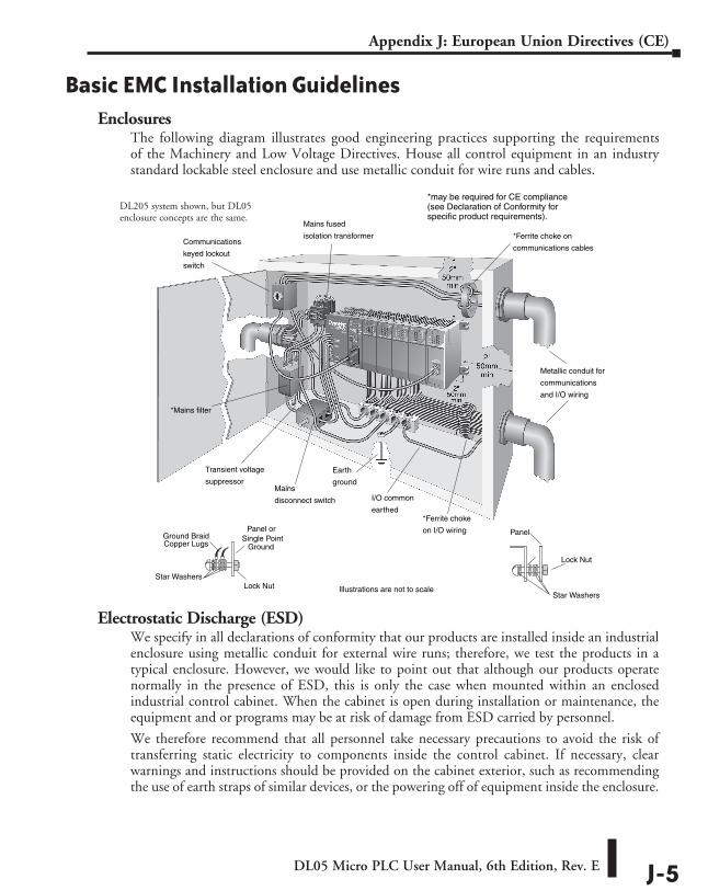
DL05 Micro PLC User Manual, 6th Edition, Rev. E J-5
Appendix J: European Union Directives (CE)
Basic EMC Installation GuidelinesEnclosures
The following diagram illustrates good engineering practices supporting the requirements of the Machinery and Low Voltage Directives. House all control equipment in an industry standard lockable steel enclosure and use metallic conduit for wire runs and cables.
Electrostatic Discharge (ESD)We specify in all declarations of conformity that our products are installed inside an industrial enclosure using metallic conduit for external wire runs; therefore, we test the products in a typical enclosure. However, we would like to point out that although our products operate normally in the presence of ESD, this is only the case when mounted within an enclosed industrial control cabinet. When the cabinet is open during installation or maintenance, the equipment and or programs may be at risk of damage from ESD carried by personnel.
We therefore recommend that all personnel take necessary precautions to avoid the risk of transferring static electricity to components inside the control cabinet. If necessary, clear warnings and instructions should be provided on the cabinet exterior, such as recommending the use of earth straps of similar devices, or the powering off of equipment inside the enclosure.
Mains fused
isolation transformer
*Mains filter
Mains
disconnect switch
*Ferrite choke
on I/O wiring
I/O common
earthed
Earth
ground
*Ferrite choke on
communications cables
Metallic conduit for
communications
and I/O wiring
Communications
keyed lockout
switch
Star Washers
PanelGround BraidCopper Lugs
Panel orSingle Point
Ground
*may be required for CE compliance(see Declaration of Conformity forspecific product requirements).
Star Washers
Illustrations are not to scaleLock Nut
Lock Nut
Transient voltage
suppressor
DL205 system shown, but DL05 enclosure concepts are the same.
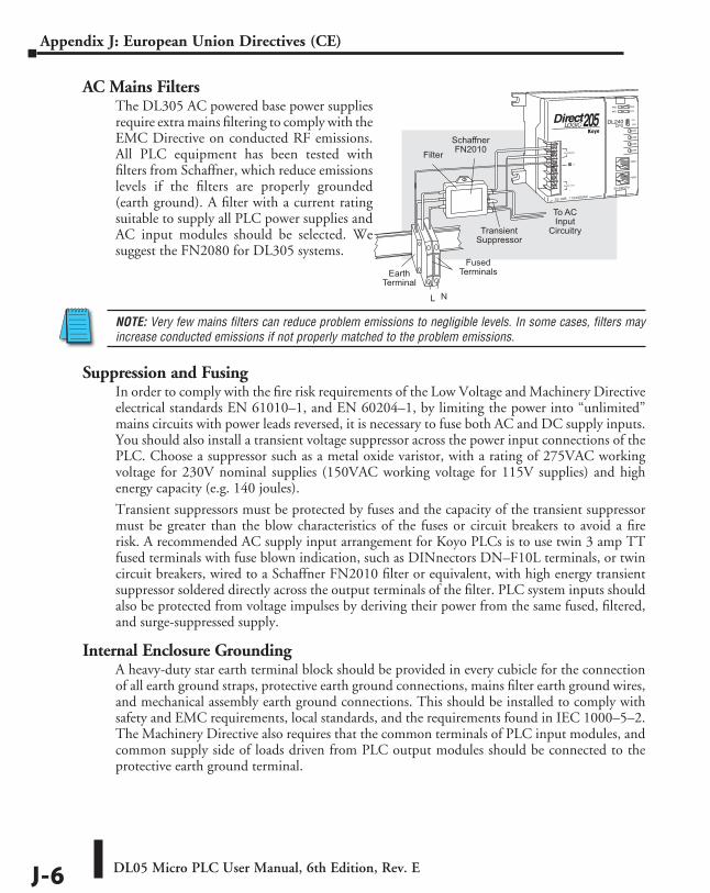
DL05 Micro PLC User Manual, 6th Edition, Rev. EJ-6
Appendix J: European Union Directives (CE)
AC Mains FiltersThe DL305 AC powered base power supplies require extra mains filtering to comply with the EMC Directive on conducted RF emissions. All PLC equipment has been tested with filters from Schaffner, which reduce emissions levels if the filters are properly grounded (earth ground). A filter with a current rating suitable to supply all PLC power supplies and AC input modules should be selected. We suggest the FN2080 for DL305 systems.
NOTE: Very few mains filters can reduce problem emissions to negligible levels. In some cases, filters may increase conducted emissions if not properly matched to the problem emissions.
Suppression and FusingIn order to comply with the fire risk requirements of the Low Voltage and Machinery Directive electrical standards EN 61010–1, and EN 60204–1, by limiting the power into “unlimited” mains circuits with power leads reversed, it is necessary to fuse both AC and DC supply inputs. You should also install a transient voltage suppressor across the power input connections of the PLC. Choose a suppressor such as a metal oxide varistor, with a rating of 275VAC working voltage for 230V nominal supplies (150VAC working voltage for 115V supplies) and high energy capacity (e.g. 140 joules).
Transient suppressors must be protected by fuses and the capacity of the transient suppressor must be greater than the blow characteristics of the fuses or circuit breakers to avoid a fire risk. A recommended AC supply input arrangement for Koyo PLCs is to use twin 3 amp TT fused terminals with fuse blown indication, such as DINnectors DN–F10L terminals, or twin circuit breakers, wired to a Schaffner FN2010 filter or equivalent, with high energy transient suppressor soldered directly across the output terminals of the filter. PLC system inputs should also be protected from voltage impulses by deriving their power from the same fused, filtered, and surge-suppressed supply.
Internal Enclosure GroundingA heavy-duty star earth terminal block should be provided in every cubicle for the connection of all earth ground straps, protective earth ground connections, mains filter earth ground wires, and mechanical assembly earth ground connections. This should be installed to comply with safety and EMC requirements, local standards, and the requirements found in IEC 1000–5–2.The Machinery Directive also requires that the common terminals of PLC input modules, and common supply side of loads driven from PLC output modules should be connected to the protective earth ground terminal.
EarthTerminal
FusedTerminals
Filter
TransientSuppressor
To ACInput
Circuitry
SchaffnerFN2010
L N
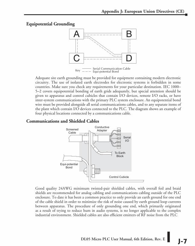
DL05 Micro PLC User Manual, 6th Edition, Rev. E J-7
Appendix J: European Union Directives (CE)
Equipotential Grounding
Adequate site earth grounding must be provided for equipment containing modern electronic circuitry. The use of isolated earth electrodes for electronic systems is forbidden in some countries. Make sure you check any requirements for your particular destination. IEC 1000–5–2 covers equipotential bonding of earth grids adequately, but special attention should be given to apparatus and control cubicles that contain I/O devices, remote I/O racks, or have inter-system communications with the primary PLC system enclosure. An equipotential bond wire must be provided alongside all serial communications cables, and to any separate items of the plant which contain I/O devices connected to the PLC. The diagram shows an example of four physical locations connected by a communications cable.
Communications and Shielded Cables
Good quality 24AWG minimum twisted-pair shielded cables, with overall foil and braid shields are recommended for analog cabling and communications cabling outside of the PLC enclosure. To date it has been a common practice to only provide an earth ground for one end of the cable shield in order to minimize the risk of noise caused by earth ground loop currents between apparatus. The procedure of only grounding one end, which primarily originated as a result of trying to reduce hum in audio systems, is no longer applicable to the complex industrial environment. Shielded cables are also efficient emitters of RF noise from the PLC
Key Serial Communication CableEqui-potential Bond
ScreenedCable
Equi-potentialBond
Control Cubicle
To EarthBlock
ConductiveAdapter
SerialI/O
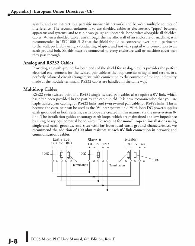
DL05 Micro PLC User Manual, 6th Edition, Rev. EJ-8
Appendix J: European Union Directives (CE)
system, and can interact in a parasitic manner in networks and between multiple sources of interference. The recommendation is to use shielded cables as electrostatic “pipes” between apparatus and systems, and to run heavy gauge equipotential bond wires alongside all shielded cables. When a shielded cable runs through the metallic wall of an enclosure or machine, it is recommended in IEC 1000–5–2 that the shield should be connected over its full perimeter to the wall, preferably using a conducting adapter, and not via a pigtail wire connection to an earth ground bolt. Shields must be connected to every enclosure wall or machine cover that they pass through.
Analog and RS232 CablesProviding an earth ground for both ends of the shield for analog circuits provides the perfect electrical environment for the twisted pair cable as the loop consists of signal and return, in a perfectly balanced circuit arrangement, with connection to the common of the input circuitry made at the module terminals. RS232 cables are handled in the same way.
Multidrop CablesRS422 twin twisted pair, and RS485 single twisted pair cables also require a 0V link, which has often been provided in the past by the cable shield. It is now recommended that you use triple twisted pair cabling for RS422 links, and twin twisted pair cable for RS485 links. This is because the extra pair can be used as the 0V inter-system link. With loop DC power supplies earth grounded in both systems, earth loops are created in this manner via the inter-system 0v link. The installation guides encourage earth loops, which are maintained at a low impedance by using heavy equipotential bond wires. To account for non–European installations using single-end earth grounds, and sites with far from ideal earth ground characteristics, we recommend the addition of 100 ohm resistors at each 0V link connection in network and communications cables.
RXDMaster
RXDTXD 0V+ – + –
Slave nTXD 0V
+ – + –
Last SlaveRXD TXD0V+ – + –
Termination
100 100
Termination
100
DL05 Micro PLC User Manual, 6th Edition, Rev. E J-9
Appendix J: European Union Directives (CE)
Shielded Cables within EnclosuresWhen you run cables between PLC items within an enclosure which also contains susceptible electronic equipment from other manufacturers, remember that these cables may be a source of RF emissions. There are ways to minimize this risk. Standard data cables connecting PLCs and/or operator interfaces should be routed well away from other equipment and their associated cabling. You can make special serial cables where the cable shield is connected to the enclosure’s earth ground at both ends, the same way as external cables are connected.
Analog Modules and RF InterferenceThe readings from all analog modules will be affected by the use of devices that exhibit high field strengths, such as mobile phones and motor drives.
All Automationdirect products are tested to withstand field strength levels up to 10V/m, which is the maximum required by the relevant EU standards. While all products passs this test, analog modules will typically exhibit deviations of their readings. This is quite normal, however, systems designers should be aware of this and plan accordingly.
When assembling a control system using analog modules, these issues must be adhered to and should be integrated into the system design. This is the responsibility of the system builder/commissioner.
Network IsolationFor safety reasons, it is a specific requirement of the Machinery Directive that a keyswitch must be provided that isolates any network input signal during maintenance, so that remote commands cannot be received that could result in the operation of the machinery. The FA–ISONET does not have a keyswitch! Use a keylock and switch on your enclosure which when open removes power from the FA–ISONET. To avoid the introduction of noise into the system, any keyswitch assembly should be housed in its own earth grounded steel box and the integrity of the shielded cable must be maintained.
Again, for further information on EU directives we recommend that you check the EU commission’s official site at: http://ec.europa.eu/index_en.htm
DC Powered VersionsDue to slightly higher emissions radiated by the DC powered versions of the DL05, and the differing emissions performance for different DC supply voltages, the following stipulations must be met:
• The PLC must be housed within a metallic enclosure with a minimum amount of orifices.
• I/O and communications cabling exiting the cabinet must be contained within metallic conduit/trunking.
DL05 Micro PLC User Manual, 6th Edition, Rev. EJ-10
Appendix J: European Union Directives (CE)
Items Specific to the DL05• The rating between all circuits in this product are rated as basic insulation only, as appropriate for
single fault conditions.
• There is no isolation offered between the PLC and the analog inputs of this product.
• It is the responsibility of the system designer to earth one side of all control and power circuits, and to earth the braid of screened cables.
• This equipment must be properly installed while adhering to the installation standards IEC 1000–5–1, IEC 1000–5–2 and IEC 1131–4.
• It is a requirement that all PLC equipment must be housed in a protective steel enclosure, which limits access to operators by a lock and power breaker. If access is required by operators or untrained personnel, the equipment must be installed inside an internal cover or secondary enclosure.
• It should be noted that the safety requirements of the machinery directive standard EN60204–1 state that all equipment power circuits must be wired through isolation transformers or isolating power supplies, and that one side of all AC or DC control circuits must be earthed.
• Both power input connections to the PLC must be separately fused using 3 amp T-type anti–surge fuses, and a transient suppressor fitted to limit supply overvoltages.
• If the user is made aware by notice in the documentation that if the equipment is used in a manner not specified by the manufacturer the protection provided by the equipment may be impaired.
IntroductIon to SerIal communIcatIonS KKK
AppendixAppendixAppendix
In This Appendix...Introduction to Serial Communications .................................................................... K-2
DL05 Micro PLC User Manual, 6th Edition, Rev. EK-2
Appendix K: Introduction to Serial Communications
Introduction to Serial CommunicationsDirectLOGIC® PLCs have two built-in serial communication ports which can be used to communicate to other PLCs or to other serial devices. In order to fully understand the capabilities and limitations of the serial ports, a brief introduction to serial communications is in order.
There are three major components to any serial communications setup:
• Wiring standard
• Communications protocol
• Communications parameters
Each of these will be discussed in more detail as they apply to DirectLOGIC PLCs.
Wiring StandardsThere are three different wiring standards that can be used with most of the DirectLOGIC PLCs: RS-232C, RS-422 and RS-485. DL05 PLCs only support RS-232C, although RS-422/RS-485 can be accomplished by using converters, such as the FA-ISOCON.
RS-232C is a point-to-point wiring standard with a practical wiring distance of 15 meters, or 50 feet, maximum. This means that only two devices can communicate on an RS-232C network, a single master device and a single slave device, and the total cable length cannot exceed 50 feet. AutomationDirect L19772 cable (Belden® 8102), or equivalent, is recommended for RS-232C networks.
Ports 1 and 2 on the DL05 use RJ12 phone type connectors (see pages 4-4 and 4-5 for the cable connections).
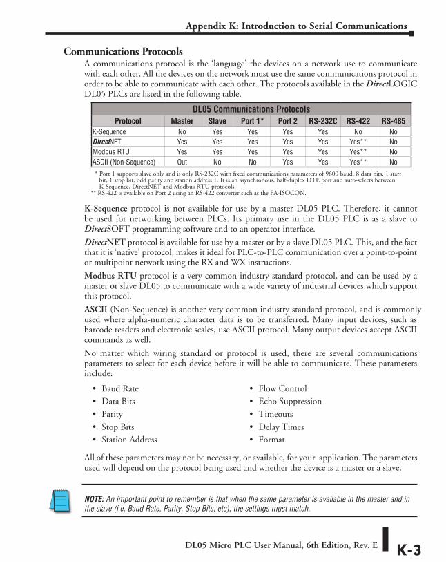
DL05 Micro PLC User Manual, 6th Edition, Rev. E K-3
Appendix K: Introduction to Serial Communications
Communications ProtocolsA communications protocol is the ‘language’ the devices on a network use to communicate with each other. All the devices on the network must use the same communications protocol in order to be able to communicate with each other. The protocols available in the DirectLOGIC DL05 PLCs are listed in the following table.
K-Sequence protocol is not available for use by a master DL05 PLC. Therefore, it cannot be used for networking between PLCs. Its primary use in the DL05 PLC is as a slave to DirectSOFT programming software and to an operator interface.
DirectNET protocol is available for use by a master or by a slave DL05 PLC. This, and the fact that it is ‘native’ protocol, makes it ideal for PLC-to-PLC communication over a point-to-point or multipoint network using the RX and WX instructions.
Modbus RTU protocol is a very common industry standard protocol, and can be used by a master or slave DL05 to communicate with a wide variety of industrial devices which support this protocol.
ASCII (Non-Sequence) is another very common industry standard protocol, and is commonly used where alpha-numeric character data is to be transferred. Many input devices, such as barcode readers and electronic scales, use ASCII protocol. Many output devices accept ASCII commands as well.
No matter which wiring standard or protocol is used, there are several communications parameters to select for each device before it will be able to communicate. These parameters include:
All of these parameters may not be necessary, or available, for your application. The parameters used will depend on the protocol being used and whether the device is a master or a slave.
NOTE: An important point to remember is that when the same parameter is available in the master and in the slave (i.e. Baud Rate, Parity, Stop Bits, etc), the settings must match.
• Baud Rate • Flow Control• Data Bits • Echo Suppression• Parity • Timeouts• Stop Bits • Delay Times• Station Address • Format
DL05 Communications ProtocolsProtocol Master Slave Port 1* Port 2 RS-232C RS-422 RS-485
K-Sequence No Yes Yes Yes Yes No NoDirectNET Yes Yes Yes Yes Yes Yes** NoModbus RTU Yes Yes Yes Yes Yes Yes** NoASCII (Non-Sequence) Out No No Yes Yes Yes** No* Port 1 supports slave only and is only RS-232C with fixed communications parameters of 9600 baud, 8 data bits, 1 start
bit, 1 stop bit, odd parity and station address 1. It is an asynchronous, half-duplex DTE port and auto-selects between K-Sequence, DirectNET and Modbus RTU protocols.
** RS-422 is available on Port 2 using an RS-422 converter such as the FA-ISOCON.
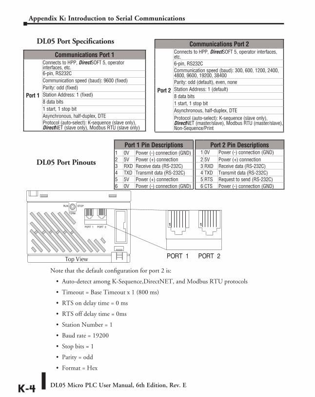
DL05 Micro PLC User Manual, 6th Edition, Rev. EK-4
Appendix K: Introduction to Serial Communications
Note that the default configuration for port 2 is:
• Auto-detect among K-Sequence,DirectNET, and Modbus RTU protocols
• Timeout = Base Timeout x 1 (800 ms)
• RTS on delay time = 0 ms
• RTS off delay time = 0ms
• Station Number = 1
• Baud rate = 19200
• Stop bits = 1
• Parity = odd
• Format = Hex
DL05 Port Pinouts
Communications Port 2
Port 2
Connects to HPP, DirectSOFT 5, operator interfaces, etc.6-pin, RS232CCommunication speed (baud): 300, 600, 1200, 2400, 4800, 9600, 19200, 38400Parity: odd (default), even, noneStation Address: 1 (default)8 data bits1 start, 1 stop bitAsynchronous, half-duplex, DTEProtocol (auto-select): K-sequence (slave only), DirectNET (master/slave), Modbus RTU (master/slave), Non-Sequence/Print
Port 1 Pin Descriptions1 0V Power (-) connection (GND)2 5V Power (+) connection3 RXD Receive data (RS-232C)4 TXD Transmit data (RS-232C)5 5V Power (+) connection6 0V Power (-) connection (GND)
Port 2 Pin Descriptions1 0V Power (-) connection (GND)2 5V Power (+) connection3 RXD Receive data (RS-232C)4 TXD Transmit data (RS-232C)5 RTS Request to send (RS-232C)6 CTS Power (-) connection (GND)
Communications Port 1
Port 1
Connects to HPP, DirectSOFT 5, operator interfaces, etc.6-pin, RS232CCommunication speed (baud): 9600 (fixed)Parity: odd (fixed)Station Address: 1 (fixed)8 data bits1 start, 1 stop bitAsynchronous, half-duplex, DTEProtocol (auto-select): K-sequence (slave only), DirectNET (slave only), Modbus RTU (slave only)
DL05 Port Specifications
Top View
1 1
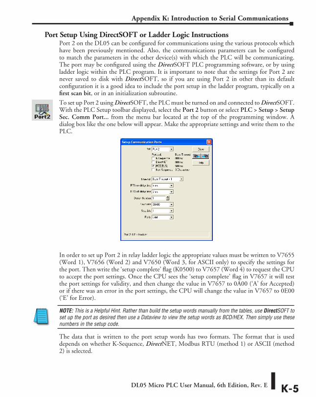
DL05 Micro PLC User Manual, 6th Edition, Rev. E K-5
Appendix K: Introduction to Serial Communications
Port Setup Using DirectSOFT or Ladder Logic InstructionsPort 2 on the DL05 can be configured for communications using the various protocols which have been previously mentioned. Also, the communications parameters can be configured to match the parameters in the other device(s) with which the PLC will be communicating. The port may be configured using the DirectSOFT PLC programming software, or by using ladder logic within the PLC program. It is important to note that the settings for Port 2 are never saved to disk with DirectSOFT, so if you are using Port 2 in other than its default configuration it is a good idea to include the port setup in the ladder program, typically on a first scan bit, or in an initialization subroutine.
To set up Port 2 using DirectSOFT, the PLC must be turned on and connected to DirectSOFT. With the PLC Setup toolbar displayed, select the Port 2 button or select PLC > Setup > Setup Sec. Comm Port... from the menu bar located at the top of the programming window. A dialog box like the one below will appear. Make the appropriate settings and write them to the PLC.
In order to set up Port 2 in relay ladder logic the appropriate values must be written to V7655 (Word 1), V7656 (Word 2) and V7650 (Word 3, for ASCII only) to specify the settings for the port. Then write the ‘setup complete’ flag (K0500) to V7657 (Word 4) to request the CPU to accept the port settings. Once the CPU sees the ‘setup complete’ flag in V7657 it will test the port settings for validity, and then change the value in V7657 to 0A00 (‘A’ for Accepted) or if there was an error in the port settings, the CPU will change the value in V7657 to 0E00 (‘E’ for Error).
NOTE: This is a Helpful Hint. Rather than build the setup words manually from the tables, use DirectSOFT to set up the port as desired then use a Dataview to view the setup words as BCD/HEX. Then simply use these numbers in the setup code.
The data that is written to the port setup words has two formats. The format that is used depends on whether K-Sequence, DirectNET, Modbus RTU (method 1) or ASCII (method 2) is selected.
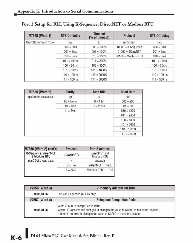
DL05 Micro PLC User Manual, 6th Edition, Rev. EK-6
Appendix K: Introduction to Serial Communications
Port 2 Setup for RLL Using K-Sequence, DirectNET or Modbus RTU
V7655 (Word 1) RTS On-delay Timeout (% of timeout) Protocol RTS Off-delay
0yyy 0ttt mmmm mxxx yyy ttt mmmmm xxx000 = 0ms 000 = 100% 10000 = K-Sequence 000 = 0ms001 = 2ms 001 = 120% 01000 = DirectNET 001 = 2ms010 = 5ms 010 = 150% 00100 = Modbus RTU 010 = 5ms 011 = 10ms 011 = 200% 011 = 10ms100 = 20ms 100 = 500% 100 = 20ms101 = 50ms 101 = 1000% 101 = 50ms110 = 100ms 110 = 2000% 110 = 100ms111 = 500ms 111 = 5000% 111 = 500ms
V7656 (Word 2) Parity Stop Bits Baud Ratepps0 0bbb xaaa aaaa pp s bbb
00 = None 0 = 1 bit 000 = 30010 = Odd 1 = 2 bits 001 = 60011 = Even 010 = 1200
011 = 2400100 = 4800101 = 9600110 = 19200111 = 38400
V7656 (Word 2) cont’d Protocol Port 2 AddressK-Sequence, DirectNET
& Modbus RTU (DirectNET) DirectNET and Modbus RTU
pps0 0bbb xaaa aaaa x aaaaaaa0 = Hex DirectNET: 1-90
1 = ASCII Modbus RTU: 1-247
V7650 (Word 3) V-memory Address for Data
DL05/DL06 For Non-Sequence (ASCII) only
V7657 (Word 4) Setup and Completion Code
DL05/DL06Write K0500 to accept Port 2 setup.When PLC accepts the changes, it changes the value to K0A00 in the same location.If there is an error it changes the value to K0E00 in the same location.
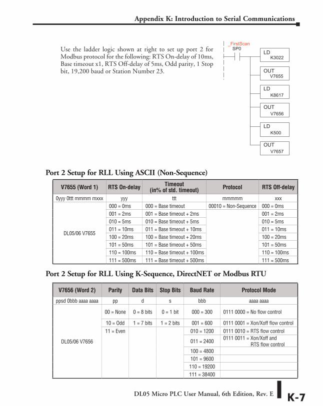
DL05 Micro PLC User Manual, 6th Edition, Rev. E K-7
Appendix K: Introduction to Serial Communications
Use the ladder logic shown at right to set up port 2 for Modbus protocol for the following: RTS On-delay of 10ms, Base timeout x1, RTS Off-delay of 5ms, Odd parity, 1 Stop bit, 19,200 baud or Station Number 23.
Port 2 Setup for RLL Using ASCII (Non-Sequence)
V7655 (Word 1) RTS On-delay Timeout (in% of std. timeout) Protocol RTS Off-delay
0yyy 0ttt mmmm mxxx yyy ttt mmmmm xxx
DL05/06 V7655
000 = 0ms 000 = Base timeout 00010 = Non-Sequence 000 = 0ms001 = 2ms 001 = Base timeout + 2ms 001 = 2ms010 = 5ms 010 = Base timeout + 5ms 010 = 5ms 011 = 10ms 011 = Base timeout + 10ms 011 = 10ms100 = 20ms 100 = Base timeout + 20ms 100 = 20ms101 = 50ms 101 = Base timeout + 50ms 101 = 50ms110 = 100ms 110 = Base timeout + 100ms 110 = 100ms111 = 500ms 111 = Base timeout + 500ms 111 = 500ms
V7656 (Word 2) Parity Data Bits Stop Bits Baud Rate Protocol Mode
ppsd 0bbb aaaa aaaa pp d s bbb aaaa aaaa
DL05/06 V7656
00 = None 0 = 8 bits 0 = 1 bit 000 = 300 0111 0000 = No flow control
10 = Odd 1 = 7 bits 1 = 2 bits 001 = 600 0111 0001 = Xon/Xoff flow control11 = Even 010 = 1200 0111 0010 = RTS flow control
011 = 2400 0111 0011 = Xon/Xoff and RTS flow control
100 = 4800101 = 9600110 = 19200111 = 38400
LDK3022
OUTV7655
LDK8617
LDK500
OUT V7656
OUT V7657
SP0_FirstScan
Port 2 Setup for RLL Using K-Sequence, DirectNET or Modbus RTU
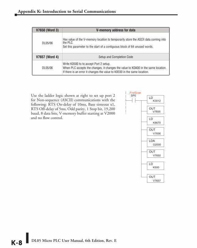
DL05 Micro PLC User Manual, 6th Edition, Rev. EK-8
Appendix K: Introduction to Serial Communications
Use the ladder logic shown at right to set up port 2 for Non-sequence (ASCII) communications with the following: RTS On-delay of 10ms, Base timeout x1, RTS Off-delay of 5ms, Odd parity, 1 Stop bit, 19,200 baud, 8 data bits, V-memory buffer starting at V2000 and no flow control.
V7650 (Word 3) V-memory address for data
DL05/06Hex value of the V-memory location to temporarily store the ASCII data coming into the PLC.Set this parameter to the start of a contiguous block of 64 unused words.
V7657 (Word 4) Setup and Completion Code
DL05/06Write K0500 to to accept Port 2 setup.When PLC accepts the changes, it changes the value to K0A00 in the same location.If there is an error it changes the value to K0E00 in the same location.
LDK3012
OUTV7655
LDK8670
LDAO2000
OUT V7656
OUT
LD
OUT
V7650
K500
V7657
SP0_FirstScan
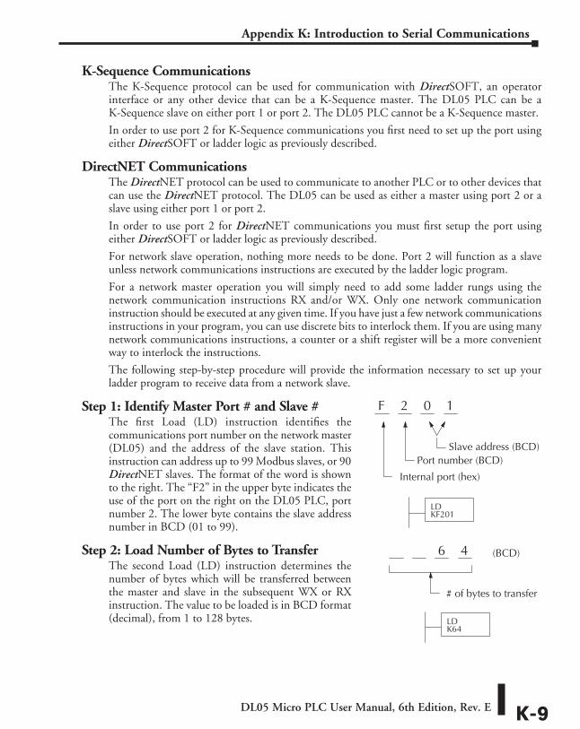
DL05 Micro PLC User Manual, 6th Edition, Rev. E K-9
Appendix K: Introduction to Serial Communications
K-Sequence CommunicationsThe K-Sequence protocol can be used for communication with DirectSOFT, an operator interface or any other device that can be a K-Sequence master. The DL05 PLC can be a K-Sequence slave on either port 1 or port 2. The DL05 PLC cannot be a K-Sequence master.
In order to use port 2 for K-Sequence communications you first need to set up the port using either DirectSOFT or ladder logic as previously described.
DirectNET CommunicationsThe DirectNET protocol can be used to communicate to another PLC or to other devices that can use the DirectNET protocol. The DL05 can be used as either a master using port 2 or a slave using either port 1 or port 2.
In order to use port 2 for DirectNET communications you must first setup the port using either DirectSOFT or ladder logic as previously described.
For network slave operation, nothing more needs to be done. Port 2 will function as a slave unless network communications instructions are executed by the ladder logic program.
For a network master operation you will simply need to add some ladder rungs using the network communication instructions RX and/or WX. Only one network communication instruction should be executed at any given time. If you have just a few network communications instructions in your program, you can use discrete bits to interlock them. If you are using many network communications instructions, a counter or a shift register will be a more convenient way to interlock the instructions.
The following step-by-step procedure will provide the information necessary to set up your ladder program to receive data from a network slave.
Step 1: Identify Master Port # and Slave #The first Load (LD) instruction identifies the communications port number on the network master (DL05) and the address of the slave station. This instruction can address up to 99 Modbus slaves, or 90 DirectNET slaves. The format of the word is shown to the right. The “F2” in the upper byte indicates the use of the port on the right on the DL05 PLC, port number 2. The lower byte contains the slave address number in BCD (01 to 99).
Step 2: Load Number of Bytes to TransferThe second Load (LD) instruction determines the number of bytes which will be transferred between the master and slave in the subsequent WX or RX instruction. The value to be loaded is in BCD format (decimal), from 1 to 128 bytes.
2 0 1F
Internal port (hex)
Port number (BCD)Slave address (BCD)
LDKF201
6 4 (BCD)
# of bytes to transfer
LDK64
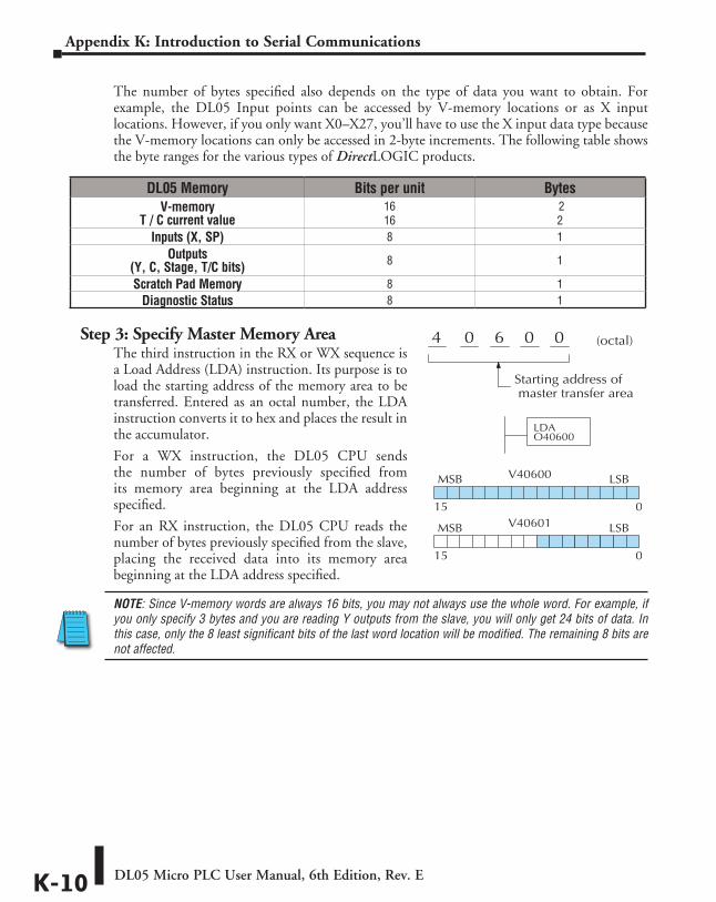
DL05 Micro PLC User Manual, 6th Edition, Rev. EK-10
Appendix K: Introduction to Serial Communications
The number of bytes specified also depends on the type of data you want to obtain. For example, the DL05 Input points can be accessed by V-memory locations or as X input locations. However, if you only want X0–X27, you’ll have to use the X input data type because the V-memory locations can only be accessed in 2-byte increments. The following table shows the byte ranges for the various types of DirectLOGIC products.
Step 3: Specify Master Memory AreaThe third instruction in the RX or WX sequence is a Load Address (LDA) instruction. Its purpose is to load the starting address of the memory area to be transferred. Entered as an octal number, the LDA instruction converts it to hex and places the result in the accumulator.
For a WX instruction, the DL05 CPU sends the number of bytes previously specified from its memory area beginning at the LDA address specified.
For an RX instruction, the DL05 CPU reads the number of bytes previously specified from the slave, placing the received data into its memory area beginning at the LDA address specified.
NOTE: Since V-memory words are always 16 bits, you may not always use the whole word. For example, if you only specify 3 bytes and you are reading Y outputs from the slave, you will only get 24 bits of data. In this case, only the 8 least significant bits of the last word location will be modified. The remaining 8 bits are not affected.
DL05 Memory Bits per unit BytesV-memory
T / C current value16 16
2 2
Inputs (X, SP) 8 1Outputs
(Y, C, Stage, T/C bits) 8 1
Scratch Pad Memory 8 1Diagnostic Status 8 1
6 0 00 (octal)
LDAO40600
4
Starting address of master transfer area
V40600MSB LSB
015V40601MSB LSB
015
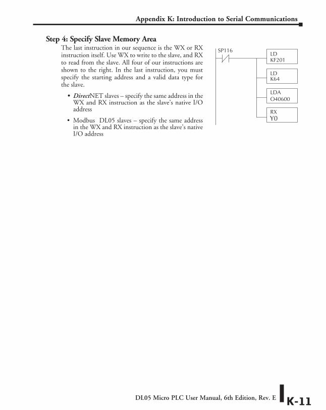
DL05 Micro PLC User Manual, 6th Edition, Rev. E K-11
Appendix K: Introduction to Serial Communications
Step 4: Specify Slave Memory AreaThe last instruction in our sequence is the WX or RX instruction itself. Use WX to write to the slave, and RX to read from the slave. All four of our instructions are shown to the right. In the last instruction, you must specify the starting address and a valid data type for the slave.
• DirectNET slaves – specify the same address in the WX and RX instruction as the slave’s native I/O address
• Modbus DL05 slaves – specify the same address in the WX and RX instruction as the slave’s native I/O address
LDKF201
LDK64
LDAO40600
RX
SP116
Y0
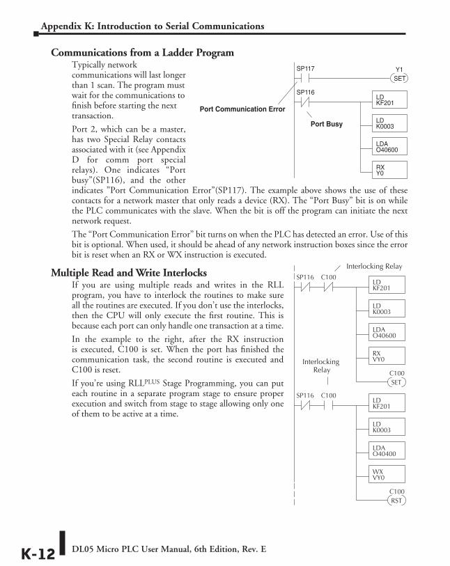
DL05 Micro PLC User Manual, 6th Edition, Rev. EK-12
Appendix K: Introduction to Serial Communications
Communications from a Ladder ProgramTypically network communications will last longer than 1 scan. The program must wait for the communications to finish before starting the next transaction.
Port 2, which can be a master, has two Special Relay contacts associated with it (see Appendix D for comm port special relays). One indicates “Port busy”(SP116), and the other indicates ”Port Communication Error”(SP117). The example above shows the use of these contacts for a network master that only reads a device (RX). The “Port Busy” bit is on while the PLC communicates with the slave. When the bit is off the program can initiate the next network request.
The “Port Communication Error” bit turns on when the PLC has detected an error. Use of this bit is optional. When used, it should be ahead of any network instruction boxes since the error bit is reset when an RX or WX instruction is executed.
Multiple Read and Write InterlocksIf you are using multiple reads and writes in the RLL program, you have to interlock the routines to make sure all the routines are executed. If you don’t use the interlocks, then the CPU will only execute the first routine. This is because each port can only handle one transaction at a time.
In the example to the right, after the RX instruction is executed, C100 is set. When the port has finished the communication task, the second routine is executed and C100 is reset.
If you’re using RLLPLUS Stage Programming, you can put each routine in a separate program stage to ensure proper execution and switch from stage to stage allowing only one of them to be active at a time.
Port Communication Error
LDKF201
LDK0003
LDAO40600
RXY0
SP116
Port Busy
SP117
SETY1
Interlocking Relay
LDKF201
LDK0003
LDAO40600
RXVY0
SP116
SETC100
C100
LDKF201
LDK0003
LDAO40400
WXVY0
SP116
RSTC100
C100
InterlockingRelay
DL05 Micro PLC User Manual, 6th Edition, Rev. E K-13
Appendix K: Introduction to Serial Communications
Modbus RTU CommunicationsThe Modbus RTU protocol can be used for communication with any device that uses the Modbus RTU protocol. The protocol is very common and is probably the closest thing to an “industry standard” protocol in existence. The DL05 can be a Modbus RTU slave on either port 1 or port 2, and it can be a Modbus RTU master on port 2.
In order to use port 2 for Modbus RTU communications you must first set up the port using either DirectSOFT or ladder logic as previously described.
For network slave operation, nothing more needs to be done. Port 2 will function as a slave unless network communications instructions are executed by the ladder logic program.
For Modbus network master operations RX and/or WX instructions must be added to the program. Modbus addresses can be calculated using the Excel spreadsheet, application note AN-MISC-010. This application note is located in the Technical Notes PLC Hardware Communications section of our website found here:
http://support.automationdirect.com/technotes.html#plccomm
If more than one network communication instruction is used, the rungs need to be interlocked to ensure that only one communication instruction is executed at any given time. If only a few network communications instructions are used in your program, discrete bits can be used to interlock them. If many network communications instructions are used, either a counter or a shift register will be a more convenient way to interlock the instructions.