disintegration of microorganisms - theseus
TRANSCRIPT

Annika Lindgren & Jonna Oikarinen
DISINTEGRATION OF MICROORGANISMS
Thesis
CENTRAL OSTROBOTHNIA UNIVERSITY OF APPLIED
SCIENCES
Degree programme in Chemical engineering
September 2009

ABSTRACT
CENTRAL OSTROBOTHNIA
UNIVERSITY OF APPLIED
SCIENCES
Technology and Business, Kokkola
Date
September 2009
Authors
Annika Lindgren &
Jonna Oikarinen
Degree programme
Degree programme for Chemical engineering
Name of thesis
Disintegration of microorganisms
Instructors
Marco Rupprich & Thomas Obholzer
Pages
67 pages + 3 pages of
appendices
Supervisor
Jana Holm
The effects of ionized air in this study were determined for protein content and
disintegration of microorganisms in a Baker’s yeast-sodium chloride-solution. The
Bradford method was used for determining the protein content and the Koch method was
used for determining the microorganisms. Non-ionized air and ionized air was used in both
methods, so the effects of ionized air could be compared with the non-ionized air. Ionized
air came from an ionizator, which made micro bubbles in to the solution.
There is previous research of disintegration of microorganisms with using ozone and it is
very effective for that. In this work were found out if ionized air or ozone is better to use
taking into account every sides of them; economy, toxicity and effectiveness. The results
for this comparison were that disintegration of microorganisms is as successful with both
airs. Ozone is more toxic and economically more expensive than ionized air, but it suits
better to bigger amount of disintegration of microorganisms.
The results for the impact of ionized air were as same as for ozone, but only with doing
disintegration with Bradford method and using bovine serum albumin (BSA) solution. The
results of yeast-sodium chloride solution were not successful. The Koch method gave only
one expected result, so they are not enough for saying that the method worked.
Key words
Bradford method, ionized air, Koch method, microorganism, protein, yeast cell

TIIVISTELMÄ OPINNÄYTETYÖSTÄ
Yksikkö
Tekniikka ja liikenne,
Kokkola
Aika
Syyskuu 2009 Tekijät
Annika Lindgren &
Jonna Oikarinen
Koulutusohjelma
Kemiantekniikka
Työn nimi
Mikro-organismien tuhoaminen
Työn ohjaajat
Marco Rupprich & Thomas Obholzer Sivumäärä
67 sivua + 3 sivua liitteitä
Työelämäohjaaja
Jana Holm
Tässä työssä määritettiin ionisoidun ilman tehokkuus proteiinien määrästä sekä tutkittiin
mikro-organismien tuhoamista liuoksessa, joka sisälsi hiivaa ja natriumkloridia.
Proteiinien määrää määritettäessä käytettiin Bradfordin menetelmää ja mikro-organismien
määrittämiseen käytettiin Kochin menetelmää. Molemmissa menetelmissä käytettiin sekä
ionisoimatonta että ionisoitua ilmaa, jotta ionisoidun ilman tehokkuutta voitiin vertailla.
Ionisoitu ilma syntyi ionisaattorissa, joka teki mikrokuplia liuokseen.
Aikaisemmin on tutkittu mikro-organismien tuhoamista käyttämällä otsonia ja se on
todettu olevan tehokas tähän tarkoitukseen. Tässä työssä selvitettiin onko ionisoitu ilma
vai otsoni parempi käytettäväksi, ottaen huomioon ionisoidun ilman sekä otsonin hyvät ja
huonot puolet, kuten taloudellisuus, myrkyllisyys ja tehokkuus. Tämän vertailun
tulokseksi saatiin että molemmat ilmat ovat tehokkaita mikro-organismien tuhoamiseen.
Otsoni on myrkyllisempi ja kalliimpi kuin ionisoitu ilma, mutta se sopii paremmin
suurempien määrien mikro-organismien tuhoamiseen.
Ionisoidulla ilmalla saadut tulokset ovat samanlaiset kuin otsonilla, mutta vain tehtäessä
Bradfordin menetelmällä ja käytettäessä bovine serum albumin (BSA)-liuosta. Hiivan ja
natriumkloridin liuoksessa tulokset eivät olleet odotusten mukaiset. Kochin menetelmä
antoi vain yhdet odotetut tulokset, joten ei voida päätellä että menetelmä toimi.
Asiasanat
Bradfordin menetelmä, hiivasolu, ionisoitu ilma, Kochin menetelmä, mikro-organismi,
proteiini

PREFACE
We would want to give the greatest thanks for Management Center Innsbruck that we got the
possibility to do this final thesis there. It was the best time and in the same time the hardest
time in Innsbruck when we made this; spending very long days in laboratory, sometimes even
twelve hours.
Especially thank you goes to our supervisors Master of Science Marco Rupprich and Diploma
Engineer Thomas Obholzer. They helped us always when help was needed and had patience to
teach, although language problems came many times against us. And thank you goes also to
Marc and Benjamin, they were also very helpful.
The greatest thank you goes to our supervisor Master in Philosophy Jana Holm and Licentiate
in Philosophy Esko Johnson. They helped us very well, so we got good help to write this
thesis. And most important thing they did not pressurize us too much, so everything went great
with own weight.
The warmest thank you goes to our families and friends. Especially our common friends, who
we got to know in Austria. They were very interested in our thesis and were asking all the time
when the thesis is finished. Now it is finished, because we got so motivated from friends. And
of course we motivated each other hard working with many long phone calls.

Concept words
Absorbance: In spectroscopy the absorbance is also called optical density. It
describes the solution’s ability to absorb the light in some specific
wavelength.
Agar: Agar is made by brown algae and it is acid polysaccharide. It is
used to solidify the liquid growth media and it is both chemically
and microbiologically strong enough.
Autoclave: Autoclave is a pressured vessel and used to sterilize with
overpressure water steam.
Baker’s yeast: Usually Baker’s yeast is called saccharomuces cerevisiae. It is
used in microbiology and also baking.
Calibration curve: Calibration curve is a general method for determining the
concentration of a substance in an unknown sample by comparing
the unknown sample to the linear line of standard samples, which
concentrations are known.
Cell culture: Microbe cells forming in this culture.
Centrifugation: Centrifugation is a separation method based on gravitation from
different weights of solutions or solid substances in liquid.
Colony: Colony is made of cells and it is a group of cells in a basic plate.
The colony is shown in the plate and can be seen without a
micrograph.
Correlation coefficient: Correlation coefficient describes dependence of two variables and
means correlation of observations from experience.

Coomassie: Coomassie dyes are commonly used to stain proteins in sodium
dodecyl sulfate and blue native polyacrylamide electrophoresis
gels. For determining protein concentration in a solution with the
Bradford test coomassie dyes are an integral component.
Culture: Microbes or cells in the solid or liquid culture.
Fungi: Eukaryotic organisms that include microorganisms as yeasts and
molds.
Homogeneous: In the homogeneous solution the solid substances are mixed very
well to the liquid, so that all particles are dissolved.
Heterogeneous: Heterogeneous is opposite to homogeneous. It is a solution with
different kind of particles, which can be seen with bare eyes.
Microorganism: Microorganism, also called microbe, is a micrographic small
organism belonging to the group of protozoa, bacteria, algae, fungi
and virus.
Pathogens: Pathogens, potentially present in wastewater, can be divided into
three separate groups, which are the viruses, bacteria and the
pathogenic protozoan/helminthes.
Protozoa: Unicellular eukaryotes classified from microorganisms.
Sludge: Originates from wastewater treatment process or industrial
processes. Sludge tends to concentrate heavy metals and poorly
biodecrable trace organic compounds and potentially pathogenic
organisms, such as viruses or bacteria, present in wastewater.

Van der Waals forces: Van der Waals forces are much weaker than chemical bonds. They
can be shared in three different groups (dispersion forces, bond
strength and electric attractions) depending on atoms or molecules.

TABLE OF CONTENTS
ABSTRACT
ABSTRACT IN FINNISH
CONCEPT WORDS
PREFACE
1 INTRODUCTION 1
2 WASTEWATER 3
2.1 Industrial wastewater 3
2.2 Biological technologies for wastewater treatment 4
2.3 Trickle-Flow reactor 4
3 OZONE AND IONIZED AIR 6
3.1 Ozone and ozonation 6
3.2 Air ionizer and micro bubbles 7
3.3 Difference between ionized air and ozone 8
4 PROTEINS 9
4.1 The Bradford method for determining the protein content 9
4.2 Spectrophotometer for measuring the samples absorbances 11
4.3 Protein assay standard 11
4.3.1 Determining the protein content with the Bradford
method 12
4.3.2 Preparing the solution for the experiment 13
4.3.3 Calibration for the spectrophotometer 13
4.3.4 Calibration curve with Excel 13
4.3.5 Measuring the samples with the spectrophotometer 14
5 MICROBIOLOGY AND MICROORGANISMS 16
5.1 Disintegration of microorganisms 16
5.2 Microorganisms as cells 16
5.3 Yeast and yeast cell 17
5.4 Agar for a substrate to the microorganisms 18
5.5 An autoclave for sterilization 18
5.6 Culturing the microorganisms in a laboratory 19
5.7 The viable count for cells 19
5.8 Diluting the samples 21
5.9 Determining the microorganisms with the Koch method 21
5.9.1 Preparing the yeast solution 22
5.9.2 Making the agar solution 22
5.9.3 Preparing the agar plates 23

5.9.4 Making the plates from the samples 24
5.9.5 Counting the microorganisms 24
6 RESULTS 26
6.1 Calibration curves for calculating the protein concentrations 26
6.2 Determining the protein content with the Bradford method 35
6.3 Determining the microorganisms with the Koch method 58
7 CONCLUSION AND DISCUSSION 62
REFERENCES 65
APPENDICES
1. Roti Nanoquant®
2. Failed calibration curves

1
1 INTRODUCTION
This final thesis’ topic was given by Management Center Innsbruck Technical Unit in Austria.
This thesis looks into how ionized air destroys microorganisms with Baker’s yeast. It has been
already researched that ozone is effective for disintegration of microorganisms but if ionized
air is usable for disintegration of microorganisms too, it is better to use it. Ozone is more toxic
and expensive than ionized air. The main task in this thesis is to study how ionized air destroys
microorganisms and protein content. The Bradford method is used in this research for
determining the protein content and the Koch method for determining the disintegration of
microorganisms.
In both methods are used non-ionized air and ionized air, so the effects of ionized air could be
compared. Ionized air comes from a compressor to the solution via an ionizator but the non-
ionized air comes directly from a compressor. The non-ionized and ionized air comes to the
solution as micro bubbles. The suitable pressure is needed to find out for a successful
disintegration of microorganisms. From the solution are taken the samples in different time
points for the measurements.
The Bradford method is based on the sample’s absorbance measured with a
spectrophotometer. In this case is used a spectrophotometer with wavelength 595 nanometer.
The samples should be directly comparable to time, which means that after the sample has
been taken, the absorbances should decrease after every minute. Before measuring the
samples, is needed to do a calibration with the spectrophotometer. From these results is made
a calibration curve with excel, which is needed when the experiments results are analyzed. In
the Bradford method is used as solution water, Baker’s yeast and bovine serum albumin
(BSA), which is a Bradford’s protein assay. It is needed to find out the amounts of Baker’s
yeast and BSA, which are suitable for disintegration of microorganisms. Filtration and
centrifugation for samples are used in the Bradford method for finding out how they affect to
the results.

2
The Koch method is based on the amount of microorganisms in the sample. In this method the
sample is directly comparable to time, which means that after the sample has been taken, the
amount of microorganisms on the plate should decrease after every minute. Water, sodium
chloride and Baker’s yeast are used as solution in the Koch method.
Based on the results, it is compared, if ionized air or ozone is better for protein content and
disintegration of microorganisms in a solution with sodium chloride and Baker’s yeast, taking
into account every sides of them; economy, toxicity and effectiveness. The aim of this study is
to find out if the ionized air disintegrates the microorganisms and how effective it is.

3
2 WASTEWATER
Between storm water and sanitary wastes the characteristics of the waste water effluent depend
upon the population and industrial sector served, land uses, groundwater levels and degree of
separation. Various gases, organic and inorganic compounds comprise the chemical waste
water. Proteins, fat and greases, carbohydrates, oils, surfactants, pecticides and fenols are
organic components. Heavy metals, phosphorus, nitrogen, chlorides, pH, sulfur alkalinity and
toxic compounds are inorganic components. Methane, hydrogen sulfide, ammonia, oxygen,
nitrogen and carbon dioxide are the common waste waters dissolved gases. Dissolved gases in
waste water are commonly hydrogen sulfide, methane, ammonia, oxygen, carbon dioxide and
nitrogen. Biologically, wastewater incorporates diverse microorganisms. Protista, animals and
plants are the biggest concern, where protista consist bacteria, protozoa, fungi and algae, and
plants from mosses, seed plants, ferns and liverworts. Animals consists from vertebrates and
invertebrates and the most important category in wastewater treatment are the protista,
bacteria, protozoa and algae. (The Green Lane 2002.)
Microorganisms role in disease transmission and in biological treatment processes are
significant in water and wastewater. There should be no pathogenic microorganisms in
drinking water. The microbial quality of drinking water is controlled by specified treatment
techniques and monitoring for the presence of coli form bacteria. (Spellman 2003, 307.)
2.1 Industrial wastewater
Several industrial production effluents can cause major disturbance of the biological
equilibrium by consumption of dissolved oxygen in a water resource because they are polluted
by various organic substances. (DAS Environmental Expert GmbH 2009.)
Released effluent water into the sewer or a water resource is set limits to the biological oxygen
demand (BOD) and chemical oxygen demand (COD). Effluent has to be therefore treated

4
partially or completely before releasing it into the sewer or into a water resource and can also
be a way to recycle process water. (DAS Environmental Expert GmbH 2009.)
2.2 Biological technologies for wastewater treatment
By the growth of aerobic organisms, most compounds will be completely converted to CO2
and water can be removed from effluent waste water in this way at relatively low cost. The
demand of industrial effluents oxygen is often in the range of 1000 to 10000 mg/l when
normally the solubility of oxygen in water is only a few mg/l. Using modern methods, high
concentrations of biomass can be reached but the air has to be introduced against the pressure
of the water column and causes high operation costs. Anaerobic methods operate in the
absence of oxygen, but start-up and stable operation of these methods are difficult. (DAS
Environmental Expert GmbH 2009.)
2.3 Trickle-Flow reactor
The Trickle-Flow reactor can, by biological microorganisms, treat the organic load (BOD,
COD) of industrial production effluent. Easily transportable materials are used, small grains,
which are overgrown with a highly active mixed population and adapts to the specific
operating conditions. The carrier material can be aerated easily, meanwhile to the conventional
technology, because it is not submersed in bulk water. Ambient air is ventilated from the
bottom and the effluent water trickles continuously from top to bottom over the packed bed.
The carrier material does not need to be exchanged because it is stable and growing biomass is
flushed out in an automatic regeneration cycle. The basis for the high and stable biological
degradation of pollutants is the high density of microorganisms and the optimal conditions for
chemical transfer between biomass, water pollutants and oxygen in excess. The investment
cost is low because of the simple principle and the high efficiency. Also the operating cost is
low due to minimal operating and maintenance needs. The design is advantageous since

5
corrosion protection is not necessary and maintenance times are low. (DAS Environmental
Expert GmbH 2009.)
GRAPH 1. Trickle-Flow reactor (adapted from Penz 2008, 7)
6
3 OZONE AND IONIZED AIR
3.1 Ozone and ozonation
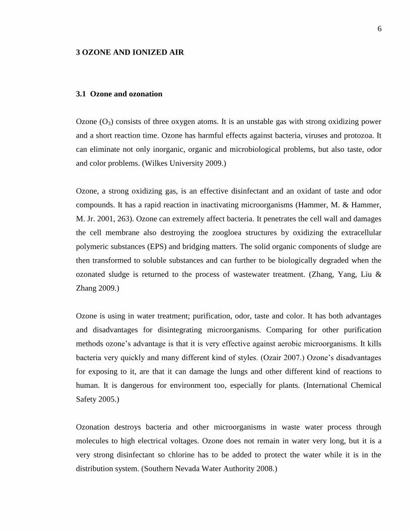
Ozone (O3) consists of three oxygen atoms. It is an unstable gas with strong oxidizing power
and a short reaction time. Ozone has harmful effects against bacteria, viruses and protozoa. It
can eliminate not only inorganic, organic and microbiological problems, but also taste, odor
and color problems. (Wilkes University 2009.)
Ozone, a strong oxidizing gas, is an effective disinfectant and an oxidant of taste and odor
compounds. It has a rapid reaction in inactivating microorganisms (Hammer, M. & Hammer,
M. Jr. 2001, 263). Ozone can extremely affect bacteria. It penetrates the cell wall and damages
the cell membrane also destroying the zoogloea structures by oxidizing the extracellular
polymeric substances (EPS) and bridging matters. The solid organic components of sludge are
then transformed to soluble substances and can further to be biologically degraded when the
ozonated sludge is returned to the process of wastewater treatment. (Zhang, Yang, Liu &
Zhang 2009.)
Ozone is using in water treatment; purification, odor, taste and color. It has both advantages
and disadvantages for disintegrating microorganisms. Comparing for other purification
methods ozone’s advantage is that it is very effective against aerobic microorganisms. It kills
bacteria very quickly and many different kind of styles. (Ozair 2007.) Ozone’s disadvantages
for exposing to it, are that it can damage the lungs and other different kind of reactions to
human. It is dangerous for environment too, especially for plants. (International Chemical
Safety 2005.)
Ozonation destroys bacteria and other microorganisms in waste water process through
molecules to high electrical voltages. Ozone does not remain in water very long, but it is a
very strong disinfectant so chlorine has to be added to protect the water while it is in the
distribution system. (Southern Nevada Water Authority 2008.)

7
3.2 Air ionizator and micro bubbles
An air ionizer is a negative ion generator which uses high voltage to ionize air molecules.
These negative ions, which are anions, are particles with one or more extra electrons. These
electrons give a net negative charge to the particle. (Air ioniser 2009.)
Compressor
Ionizator
GRAPH 2. The experiment with ionized air to a yeast solution (Photo: authors)
Micro bubbles are tiny gas bubbles in the water, with diameters less than 50 μm. In recent
years there has been a lot of research on micro bubbles. The micro bubbles can remain
suspended in the water for an extended time. The micro bubbles with the gas, in this case
ionized air, dissolves into the water. (Suwa Precision Group 2009.)
Microorganisms attract suspended floating particles very effectively by having electrical
charges. This appropriate feature has been used in sludge treatment by using the micro bubbles
to capture and float organic matters and it does not need so much time for sludge treatment.
(Suwa Precision Group 2009.)
In this thesis the used air was inserted to the solution true an ionizator, which converted the air
to ionized air. The ionized air was inserted as micro bubbles to our solution. A very low

8
pressure was applied, so that in the solution appeared only few bubbles. This is because in the
first experiments the used pressure was too high and the amount of ionized air were too much,
so the results were not successful. (Suwa Precision Group 2009.)
.
Micro bubbles
GRAPH 3. Ionized micro bubbles to a yeast solution (Photo: authors)
3.3 Difference between ionized air and ozone
Both ionizers and ozone generators devices operate in a similar way but they should not be
mixed. Ionizers produce positively or negatively charged gas ions. Ozone generators use either
a corona discharge tube or UV light to attract an extra oxygen ion to the O2 molecule. All
ionizers produce a small amount of ozone, and ozone generators gaseous ions of molecules
other than ozone. (Air ioniser 2009.)
Pure ozone is a highly toxic and extremely reactive gas and can damage odor bulb cells
directly. At high concentrations it can also be toxic to air-borne bacteria and may destroy or
kill these sometimes infectious organisms. Ionized air is not as toxic as ozone. (Air ioniser
2009.)

9
4 PROTEINS
Proteins are polymers of amino acids covalently bonded by peptide bonds. Dipeptide
constitutes two together bonded amino acids, tripeptide three amino acids and so on. Many of
these amino acids are covalently linked together via peptide bonds and to form a polypeptide.
Proteins are consisted of one or more polypeptides. (Wiesmann, Choi & Dombrowski 2007,
45.)
Protein plays key roles in cell function and the major classes of proteins are catalytic proteins
(enzymes) and structural proteins. The catalysts for the wide variety of chemical reactions that
occurs in cells are enzymes. Structural proteins become integral parts of the structures of cells
in membranes, walls and cytoplasmic components. From bacterial cell mass nearly 50% is
proteins. (Wiesmann et al. 2007, 45.)
In living organisms nearly all reaction steps are catalyzed by a special enzyme, which are
biocatalytic proteins. Without the effect of enzyme, no organism would survive. Each reaction
step must be catalyzed by a special enzyme. (Wiesmann et al. 2007, 45.)
4.1 The Bradford method for determining the protein content
The Bradford method is used for determining protein content of cell fractions and assessing
protein concentrations for gel electrophoresis. (Caprette 2005.) It is a spectroscopic analytical
procedure used to measure the concentration of protein in a solution, but also dependent on the
amino acid composition of the measured protein. The Bradford method is based on a
solution’s ability to absorb the light on the wavelength from max = 465 to 595 nanometer.
(Waldmann & Janning 2006, 120.)

10
Absorbances can be calculated from formula 1,
(1)
where Aλ is the calculating absorbance, I is the intensity of light at the specified wavelength
that has passed through the sample. Io is the intensity of light before it enters the sample or
incident the light intensity. (Absorbance 2009.)
The Bradford assay is a colorimetric protein assay. It is based on an absorbance transition in
the dye coomassie when it changes and stabilizes by the binding of protein from the red form
coomassie reagent into coomassie blue. Two types of bond interaction take place during the
formation of this complex. The red form of coomassie dye first donates its free proton to the
ionizable groups on the protein. It causes a disruption of the protein’s native state,
consequently exposing its hydrophobic pockets. On the protein tertiary structure, these pockets
bind non-covalently to the non-polar region of the dye via van der Waals forces positioning
the positive amine groups in proximity with the negative charge of the dye. Further, the bond
is strengthened by the ionic interaction between the two. The binding of protein stabilizes the
blue form of coomassie dye. Thus the amount of complex present in solution is a measure for
the protein concentration by use of an absorbance reading. (Bradford protein assay 2009.)
The assay is based on the observation that the absorbance maximum for an acidic solution of
Coomassie Brilliant Blue G-250 (see the manual by Roti®-Nanoquant in Appendix 1)
transfers from 465 nm to 595 nm, and appears binding to the protein. Hydrophobic and ionic
interaction stabilizes the anionic form of the dye and causes a visible color change. Since the
extinction coefficient of a dye-albumin complex solution is constant over a 10-fold
concentration range, the assay is necessary. (Caprette 2005.) Sodium dodecyl sulfate (SDS) is
a common detergent and could be found in protein extract because it is used in lysing cells by
disrupting the membrane lipid bilayer. Sodium dodecyl sulfate tends to bind well with protein,
inhibiting the protein binding sites for dye reagent. (Bradford protein assay 2009.)

11
4.2 Spectrophotometer for measuring the samples absorbances
A spectrophotometer consists of two instruments. A spectrometer produces light of any
selected wavelength. A photometer is for measuring the intensity of light. The liquid in a
cuvette can be placed between the spectrometer beam and the photometer and the amount of
light passing through the tube is measured by the photometer. A voltage signal is delivered to
a display device, normally a galvanometer, by the photometer and the signal changes as the
amount of light absorbed by the liquid changes. Concentration can be measured by
determining the extent of absorption of light at the appropriate wavelength if development of
color is linked to the concentration of a substance in solution. (Caprette 2005.)
GRAPH 4. A spectrophotometer SHIMADZU UV Mini 1240 used in the Bradford method for
measuring the protein content (Photo: authors)
4.3 Protein assay standard
To choose a protein standard can be the largest source of fault in any protein assay. A purified,
known concentration of the predominant protein found in the sample is the best choice for a
standard. But the highly purified version of the protein is not always available or it is too

12
expensive to use as the standard. In this study bovine serum albumin (BSA) was used for
general protein assay work. BSA works well for a protein standard because it is widely
available in high purity and it is not very expensive. BSA standard is the most widely-used
protein assay standard. It is sterile-filtered, stable and consistent.
Comparing sample assay response to determine protein concentration to that of a standard
whose concentration is known, is a typical protein assay. Protein samples and protein
standards are processed by mixing them with the assay reagent and using a spectrophotometer
to measure the absorbances. Table 1 shows how BSA solution standards are made. (Thermo
Fischer Scientific 2009.)
TABLE 1. BSA solution standards (Praktikum umwelt technology 2009)
Standard Protein concentration [ g/ml] BSA Standard solution [ l] 0,9% NaCl [ l]
1 0 0 1000
2 1 10 990
3 2.5 25 975
4 5 50 950
5 10 100 900
6 15 150 850
7 20 200 800
8 25 250 750
9 30 300 700
4.3.1 Determining the protein content with the Bradford method
The first experiment of this thesis was determining the protein content with Bradford method.
About 2 grams of yeast and 0.1 bar pressure with the ionized air were used for the first
experiment. Several experiments were made with different amounts of yeast and different
amounts of ionized air. The experiments were made with and without filter (0.45 m) and also
with using centrifuge (1 min and 5000 rpm).

13
4.3.2 Preparing the solution for the experiment
One litre of 0.9% sodium chloride (NaCl) solution was first made, where the yeast were added
and mixed with magnetic mixer to a homogenous solution. When the solution was
homogenous, a zero sample was taken and adding ionized air was started. The ionized air was
taken with help of a compressor through an ionizator in a very low pressure. The ionized air
was added in to the solution for 1.5 hours and taken about 8 ml samples in different time
points: 0, 5, 10, 15, 20, 30, 40, 50, 60 and 90 minutes. The same experiment was made also
with non-ionized air. In some experiments half of the samples were filtered and in some
experiments 1 ml from the samples was centrifuged. Absorbance from all samples was
measured by using a spectrophotometer.
4.3.3 Calibration for the spectrophotometer
The protein content was determined with a spectrophotometer. First a calibration had to be
made with the spectrophotometer. A volume of 1 ml samples were made, from nine different
protein concentrations, with different amount of NaCl and protein assay reagent (BSA). A
volume of 200 µl of Roti®-Nanoquant was pipetted to cuvettes, and by using this substance
reproducible protein amounts could be analyzed. Then 800 µl of the sample 1–9 was added
and in five minutes after inserting the first protein concentration sample, the absorbance was
measured with the spectrophotometer at 595 nm. From these results a calibration curve could
be made with Excel, which was needed when the experiments’ results were analyzed.
4.3.4 Calibration curve with Excel
A graph was made in the excel sheet from standard protein concentrations and absorbances
from the measured samples. A linear line was drawn through the points. The absorbances must
rise constantly to get a linear line. From the linear line a correlation coefficient (R2) was
created and equation of linear line could be calculated from formula,

14
(2)
where k is angular coefficient and b is constant value. The points from the measured samples
needed to be as near to the linear line as possible. The correlation coefficient of calibration
curve must be close to 1. The calibration curve was needed to calculate samples
concentrations. The correlation coefficient showed how well the calibration went. It is not
needed later in calculations. The angular coefficient and constant value were needed in the
calculations.
4.3.5 Measuring the samples with the spectrophotometer
After making the calibration, the measurement of the samples could be made. First 200 µl of
Roti®-Nanoquant was pipette into the cuvettes and then 800 µl of the sample and mixed them.
After five minutes, since inserting into the cuvette the first sample, the absorbance was
measured. With the results and with help of the calibration curve it could be measured what
the protein contents were in the samples. The protein concentration was determined from the
unknown sample with comparing the results with the calibration curve. From the calibration
curve constant value (b) and angular coefficient (k) were determined. The dilution was needed
to take into account. Protein concentrations in the solution were calculated with previous
information with formula 3.
(3)
Tables 21–32 present concentrations from pure and diluted samples. The concentrations are
calculated by using the formula in theory part (formula 3). In the 1:10 dilutions concentrations,
the dilution has taken into consideration too with calculating them also with the formula 4. In
the dilutions 1:10 was usually 1000 µl of ion changed water and 100 µl of pure sample. In

15
some dilutions was 900 µl of ion changed water and 90 µl of pure sample. Formula for these
diluted samples concentrations are:
(4)

16
5 MICROBIOLOGY AND MICROORGANISMS
Microbiology is the research of microorganisms, also called microbes, a massive and versatile
group of microscopic small organisms that exist as single cells or cell groups. Microorganisms
belong to group of protozoa, bacteria, algae, fungi and virus. Microbial cells are thus different
from the cells of animals and plants, which are unable to live alone in nature and can exist
only as parts of multicellular organisms. Microbiology is about microbial versatility and
evolution, about how different kinds of microorganisms arose and why. After a fashion,
microorganisms affect all other life forms in Earth. (Madigan et al. 2003, 1)
5.1 Disintegration of microorganisms
Disintegration of microorganisms can be made by three different methods. The first is a
biological method, which includes disintegration with enzyme, bacteriophage and autolyse.
The second method is a chemical method, which handles disintegration with acids or base,
solvent, surfactant, chelating agenda, antibiotic and ozone. The third is a physical method, and
it has two different ways: non-mechanical and mechanical. To non-mechanical methods
include osmotic shock, congeal, drying and decompression. To mechanical methods include
high-pressure-homogenizer and ultrasound-homogenizer. (Kampen & Michel 2009, 3–4.) This
thesis focuses on how to disintegrate microorganisms with ionized air. Disintegration of
microorganisms with ionized air is inexpensive and easy way to destroy the yeast cell’s wall.
5.2 Microorganisms as cells
A fundamental unit of life is cell. A single cell is a cloistered and isolated from other cells by a
cell membrane and contains a variety of chemicals and subcellular structures, which make it
possible for the cell to function. The cell membrane separates the inside of the cell from
outside. (Madigan et al. 2003, 2–3.) All cells are made up of proteins, nucleic acids, lipids and
polysaccharides, which are called macromolecules. Nucleous or nucleoid, where the genetic

17
information (deoxyribonucleic acid, DNA) is, are the key structures. Every cell has a distinct
structure and size. Thus a cell is a dynamic unit, constantly undergoing change and replacing
its parts. (Madigan et al. 2003, 2–3.) A cell may be acquiring material from its environment
and incorporating them into its own fabric even when it is not growing. It can at the same time
discard waste products into its environment. (Madigan et al. 2003, 2–3.)
5.3 Yeast and a yeast cell
Yeast cell is typically 5–10 μm big. A yeast cell consists of 70–85% water and its drying
weight is mostly polymer: protein 50%, cell wall 10–20%, RNA 10–20%, DNA 3–4% and
lipid 10%. The cell wall from yeast cell is mostly made up of bacteria. (Kampen & Michel
2009, 4)
GRAPH 5. Structure of a yeast cell (adapted from Kampen & Michel 2009, 4)

18
5.4 Agar for a substrate to the microorganisms
Agar is a polysaccharide derived from red algae and it was widely used in 19th
century as a
gelling agent. An agar diffusion method is a commonly used procedure for studying
antimicrobial action. For solid media is added usually about 1,5% of agar as a gelling agent,
before sterilizing the media. In the sterilization process the agar melts and the molten medium
is poured into sterile Petri dishes and allowed to solidify before use. (Madigan et al. 2003, 15.)
The sterilization has to be done before use because microorganisms are to be found
everywhere. Usually this is done by heating, typically by moist heat in a large pressure cooker
called an autoclave. In every step aseptic techniques have to be practiced for successful
cultivation of pure cultures of microorganisms. (Madigan et al. 2003, 109.)
5.5 An autoclave for the sterilization
An autoclave is normally used for sterilizing solutions and equipment in laboratory. It is a
large pressure cooker. Normal temperature in an autoclave is 120˚C or more, and it has to be
kept in this temperature for about 20 minutes. For more than 1–2 liter sterilization, more
sterilization time is needed. (Aittomäki, Leisola, Ojamo, Suominen & Weymarn 2002, 138.)
GRAPH 6. An autoclave (Photo: authors)

19
5.6 Culturing the microorganisms in a laboratory
Culturing microorganisms can be done in number of ways. In this thesis Petri dishes were
used, where individual cells that were spread out on the plate, grow and divide to form
colonies. In order to sustain life processes, microorganisms must carry out one or more series
of reactions that conserve energy. (Madigan et al. 2003, 109.)
The nutrient solutions, which are used to grow microorganisms in the laboratory, are culture
media. Microbiology uses broad classes of culture media that are chemically defined and
undefined. In chemically defined media, precise amounts of highly purified inorganic or
organic chemicals are added to distilled water. (Madigan et al. 2003, 107.)
When the culture medium has been prepared, the microorganisms can be added and incubated
under conditions that will support microbial growth. In a pure culture is appeared growth in
most cases, which is containing only a single kind of microorganisms. To obtain or maintain a
pure culture it is essential that other organisms, called contaminants, are prevented from
entering it. Microbiological techniques are designed to avoid contaminants. For obtaining pure
cultures and for assessing the purity of a culture, a major method is the use of solid media,
specifically, solid media in the Petri plate. (Madigan et al. 2003, 108–109.)
5.7 The viable count for cells
The viable cell counting method can be easily used to count only the living cells. Viable count
is often called the plate count or colony count because the number of cells in the sample
capable of forming colonies on a suitable agar medium can be determined. The two ways of
performing a plate count are called the spread plate method and the pore plate method. In this
thesis the first of these methods was used. (see Madigan et al. 2003, 146.)

20
GRAPH 7. Pipetting the sample GRAPH 8. Steeping the spreader in
on the agar (Photo: authors) to ethanol (Photo: authors)
GRAPH 9. Burning the ethanol in GRAPH 10. Spreading the sample
the flame (Photo: authors) over the agar (Photo: authors)

21
In Graph 7, a volume of 200 µl of an appropriately diluted culture is spread over the surface of
an agar plate using a sterile pipette. The spreader was steeped into ethanol for sterilizing the
spreader in Graph 8 and burned the ethanol away in a flame in Graph 9. In Graph 10 the
sample was spread evenly over the surface of agar with the sterile spreader so long that it was
dried up. After spreading the sample over the agar, the plate was incubated until the colonies
appeared and the number of colonies was counted. It took about 24 to 30 hours that all the
colonies were appeared.
5.8 Diluting the samples
The colony number must not be very high because counting the colonies is impossible from
plates with over 500 colonies. But the number of colonies cannot be very low either so there
should be over 30 colonies on the plate. That is why the sample should almost always be
diluted, and with more than one dilution, before plating. It is common to use several 10-fold
dilutions of the sample. The dilutions were done with in an autoclave sterile made 0,9% NaCl
solution.
5.9 Determining the microorganisms with the Koch method
With the Koch method it is possible to determine the number (not exact number) of living
cells. For this, defined amounts of cell suspension containing agar are needed to pour to Petri
dishes, then to incubate them and to count the grown microorganism colonies. It is necessary
to use a homogeneous cell suspension with a total microorganism number between 30 and 500
to get reproducible results. The cells have to be diluted with physiological 0,9% brine in 1:10
steps after sampling to avoid the growth of the microorganism.
Even though nutrient gelatin is a marvelous culture medium for the isolation and study of
various bacteria, it does not remain solid at body temperature (37˚C) which is the optimum
temperature for growth of most human pathogens. (Madigan et al. 2003, 15.)

22
5.9.1 Preparing the yeast solution
One liter of 0,9% NaCl solution with few grams of yeast was used for the experiment. Nine
grams of NaCl and one gram of Baker’s yeast were mixed to one liter of ion changed water
with a magnetic mixer that the solution was homogeneous. The yeast did not dissolve
completely.
Ionized air was added to the solution through an ionizator with a low pressure for 60 minutes,
so that only few bubbles appeared. The mixing was continued for the whole procedure. The
first sample was taken at zero point, when the ionized air was added to the solution. After this
the samples were taken after 5, 10, 15, 20, 30, 40, 50 and 60 minutes. The same procedure was
repeated also with non-ionized air. The samples were kept in a fridge in the mean while when
preparing the plates for the next procedure.
5.9.2 Making the agar solution
An agar solution was used in this thesis as culture media. Microorganisms were cultured from
the yeast solution to these agar plates. The solution was made in three laboratory media
bottles, which were autoclavable. Autoclaving was used to make the solutions sterilized. A
volume of 333 ml of ion changed water and the right amount of substances were weighed in
every bottle as follows: 1 g yeast extract, 1 g malt extract broth (liquid medium for cultivation
of yeasts and moulds), 1,67 g peptone (soya beans), 3,33 g glucose and 5 g agar
bacteriological (gelling agent selected for solidifying the microbiological culture media). The
agar had to be added into the solution last because it did not dissolve into the solution without
heat but it dissolved in the autoclaving.
The autoclave was a steam autoclave. The caps on the bottles had to be little bit opened so that
it would not explore from the effect of pressure and that the steam could get in to the bottle.
Making autoclaving in this way, the solution became sterilized. A tape destined for
autoclaving was put to the bottles. The tape was permanent imprinted graduations and marking

23
spots and its color changes in the autoclaving so that it was seen what had already been
autoclaved. The autoclaving took approximately two hours.
5.9.3 Preparing the agar plates
After autoclaving the plates were prepared. Making the plates was done in sterilized
conditions so the plates were prepared next to a gas flame. The mouth of the bottle was heated
for a few seconds in the flame before decanting the solution in to the Petri dish, so that it was
sterile (Graph 11). The solution was poured to the plate so that the bottom was covered and
placed a cap on it. The plates must solidify before they could be used in the experiments
(Graph 12). Heating the mouth of the bottle was done before decanting the solution to every
Petri dish.
GRAPH 11. Heating the bottle mouth in a GRAPH 12. Pouring the agar solution to
flame to make it sterile (Photo: authors) the Petri dish (Photo: authors)
More solutions than needed were sometimes made. Then the bottles were kept in a locker,
because the whole agar solution was not needed to use at the same time. The solution
solidified in room temperature, but it became usable liquid again by warming it up in a
microwave. In this way, more plates could be done later.

24
5.9.4 Making the plates from the samples
When preparing the plates with the samples, the agar plates were first dried in a sterile fume
hood for about 10 minutes. Then the samples were diluted with 0,9% sodium chloride, which
had been autoclaved to make them sterile. In the first experiment, the solution was diluted for
1:10, 1:100 and 1:1000; in other words, one part of the sample and 10 parts of 0,9% sodium
chloride, for example. The amounts were 90 µl of solution and 900 µl of NaCl. The further
dilutions were made the same way from the previous dilution.
Preparing the plates was done in very sterile conditions. The table was cleaned with ethanol
and the whole work was done near a gas fire. Also sterile, autoclaved pipettes were used. A
volume of 200 µl of the diluted sample was pipetted to the plate, on the agar. Then a
cultivation spreader was taken and dunked to ethanol and the ethanol was burned from it in the
gas fire, so that it was as sterile as possible. The sample was distributed with the cultivation
rod until it was dried and it was then distributed on the whole plate. The plate was placed into
an oven of 30˚C and kept there 24 hours. Finally the microorganisms were counted.
5.9.5 Counting the microorganisms
The microorganisms grown on the plate were counted after 24–48 hours. Counting the
microorganisms was done with a counter and pen. The microorganisms were colored with the
pen so that the counting was exact. Only 500 or fewer microorganisms could be counted. It
was impossible to count microorganisms more than 500.

25
GRAPH 13. Counting the microorganisms (Photo: authors)

26
6 RESULTS
The results are presented in three sections. The first part discusses the calibrations, which have
been made with the spectrophotometer with the BSA standard solution. The calibrations
curves are needed in the second part’s calculations, using the Bradford method for determining
the protein contents. Different kind of proving was made in the test, like how centrifuging,
filtering, different amount of yeast and BSA affects on the protein content. Some tests were
just determined ionized air impacts comparing to non-ionized air. The third part study looks
into how microorganisms disintegrate with the Koch method.
6.1 Calibration curves for calculating the protein concentrations
Calibration of the Bradford method needed to be done before almost every experiment.
Calibrations were sometimes done before and after the tests to see if the calibrations were
similar. In some calibrations, average values were calculated for the calculations. A calibration
curve could be made from the calibration’s absorbances with Excel and this calibration curve
was used in the calculations for determining the protein content. Absorbances in the
calibration must increase constantly so that the line is linear and useful for the second part,
which is the Bradford method for determining the protein content. The closer to linear the line
is, the better the calibration, so the correlation coefficient of calibration curve must be as near
as possible to 1. Many calibrations had to be done sometimes, to get enough successful
calibration curves. The calibrations were made several times in the beginning, almost every
time when the tests were done. But then were used the same calibration curve many times,
because it was not necessary to do the calibration every time again. The previous calibration
curve what have been done needed to use in the samples’ concentrations calculations.
Doing the calibration, even one small mistake ruined the whole calibration curve. Mistakes
could be easily done by weighting the BSA, because it just stuck to the spoon and float with
the air current. Weighting 0.01 g of the BSA was so punctual without its floating away.
Pipetting the BSA-, NaCl- or Roti Nanoquant solution needs to be done very carefully to get

27
the exact amount of these. The calibration was very sensitive with even very small wrong drop
with every substance. Also time was very important thing, for that the reaction time after
mixing the substances is same with every sample. After pipetting protein standard to the first
assay reagent sample, an exact time needed to be taken from this point to the point when the
first sample was measured in the spectrophotometer. This same time were needed in every
spectrophotometer measurement, both in calibration and test samples (5 minutes). Mixing the
substances in cuvettes need to be done very carefully, so that even every small drop is staying
in the cuvette and it needs to be done the same way every time.
The first calibration (see Table 2) shows that the values increased almost constantly. In the
calibration curve had some mistake in samples 4 and 5, which made the correlation coefficient
lower. Graph 14 indicates that samples 4 and 5 diverged from the linear line more than the
other points. This calibration curve was still useable and was used in some experiments
calculations.
TABLE 2: Absorbances for calibration 1
Sample no: Protein conc. [ g/ml] Absorbance [A]
1 0 494
2 1 527
3 2.5 571
4 5 685
5 10 795
6 15 875
7 20 969
8 25 1078
9 30 1185

28
GRAPH 14. Calibration curve 1
Calibration was sometimes necessary to ensure, that could be sure that the calibration before
the test is right. Table 3 presents absorbances the after calibration. They increased constantly
but sample number 9 was not on the line. The correlation coefficient is 0,9863 which divorces
0,0011 decimal compared to the previous calibration. And the equation of linear line in Graphs
14 and 15 was almost the same. This means that the post-calibration is not changing
considerably from the pre-calibration, so the pre-calibration could be used in the calculations
in the future experiments.
TABLE 3. Absorbances for calibration 2
Sample no: Proteinconc. [ g/ml] Absorbance [A]
1 0 491
2 1 523
3 2.5 598
4 5 653
5 10 787
6 15 879
7 20 995
8 25 1132
9 30 1163

29
GRAPH 15. Calibration curve 2
The absorbances in the third calibration were increased constantly, but again sample 4 and 5
diverged from the linear line. The correlation coefficient was only 0,9666, so the post-
calibration was made to get better average from these calibrations to the calculations in future
experiments.
TABLE 4. Absorbances for calibration 3
Sample no: Protein conc. [ g/ml] Absorbance [A]
1 0 422
2 1 456
3 2.5 533
4 5 650
5 10 822
6 15 853
7 20 976
8 25 1067
9 30 1173

30
GRAPH 16. Calibration curve 3
The correlation coefficient in Graph 16 (pre-calibration) and in Graph 17 (post-calibration)
was not exactly the same. The correlation coefficient was still slightly rising so the average
from these values could be calculated and used in the experiments calculations.
TABLE 5. Absorbances for calibration 4
Sample no: Protein conc. [ g/ml] Absorbance [A]
1 0 437
2 1 473
3 2.5 523
4 5 631
5 10 801
6 15 910
7 20 950
8 25 1053
9 30 1166

31
GRAPH 17. Calibration curve 4
Table 6 indicates that absorbances in calibration 5 increased but sample number 6 diverged
from the line. Although the points scattered on the line, especially the point for sample number
6, the correlation coefficient was required and could be used it in the tests calculations.
TABLE 6. Absorbances for calibration 5
Sample no: Protein conc. [ g/ml] Absorbance [A]
1 0 428
2 1 470
3 2.5 518
4 5 616
5 10 772
6 15 965
7 20 999
8 25 1148
9 30 1274

32
GRAPH 18. Calibration curve 5
Graph 19, for calibration 6 shows that absorbances in samples 4 and 5 diverged from the line
again. The correlation coefficient is lower than in calibration 5, but it was still useable and
therefore used in the calculations in future experiments.
TABLE 7. Absorbances for calibration 6
Sample no Protein conc. [ g/ml] Absorbance [A]
1 0 503
2 1 529
3 2.5 594
4 5 717
5 10 866
6 15 946
7 20 1084
8 25 1163
9 30 1259

33
GRAPH 19. Calibration curve 6
Calibration 7 finally succeeded. The calibration curve is linear and the correlation coefficient
is 0.9971, which can be seen in Graph 20. The correlation coefficient is better than in any
previous calibrations and this calibration was used in the rest of the experiment calculations.
TABLE 8. Absorbances for calibration 7
Sample no: Protein conc. [ g/ml] Absorbance [A]
1 0 524
2 1 559
3 2.5 610
4 5 657
5 10 750
6 15 870
7 20 943
8 25 1070
9 30 1178

34
GRAPH 20. Calibration curve 7
The calibrations in the beginning and in the end were quite successful but the few calibrations
between them were not so successful. Still these calibrations were useable and needed in some
calculations.
TABLE 9. All calibration curve values, used in tests calculations
Date Correlation coefficient Angular coefficient Constant value
Calibration 1 0.9874 22.364 528.05
Calibration 2 (after calibration) 0.9863 22.967 525.45
Calibration 3 0.9666 24.253 480.06
Calibration 4 (after calibration) 0.9694 23.800 484.63
Calibration 3+4 (average) 0.9680 24.077 482.35
Calibration 5 0.9855 27.982 461.55
Calibration 6 0.9778 25.268 546.61
Calibration 7 0.9971 21.083 541.50

35
6.2 Determining the protein content with the Bradford method
The Bradford method was used for determining the protein content with in the NaCl-yeast
solution. The samples were analyzed in a spectrophotometer. For calculating the protein
concentration the calibrations curves from the earlier calibrations were used.
Calibration curve from Graph 14 was used the first test. From its angular coefficient and
constant value concentrations were calculated concentrations introduced in the chapter 4.4.5
Measuring the samples (formula 3). The concentrations are negative because the absorbances
are lower than the constant value. The constant value needs to be higher than the absorbances,
because the value is subtracted from the absorbance and then divided with the angular
coefficient. Test 1 looked into how centrifuging and filtering affected the absorbances and
concentrations. As can be seen in Tables 10 and 11, the absorbances are not increasing, which
means that disintegrations were not happening. The amounts fluctuate, especially the
absorbances from the centrifuged solution with non-ionized air, as can be seen in Table 11.
Because all the concentrations are negative with ionized air, the experiment was not
successful.
TABLE 10. Absorbances and concentrations with ionized air
Time [min]
Absorbance [A]
Concentration [ g/l]
Absorbance [A]
Filtered+Centrifuged
Concentration [ g/l]
0 466 -2.77 476 -2.33
5 468 -2.69 504 -1.08
10 475 -2.37 516 -0.54
15 496 -1.43 494 -1.52
20 489 -1.75 527 -0.05
30 462 -2.95 524 -0.18
40 485 -1.92 498 -1.34
50 493 -1.57 484 -1.97
60 485 -1.92 517 -0.49
90 482 -2.06 515 -0.58

36
TABLE 11. Absorbances and concentrations with non-ionized air
Time [min]
Absorbance [A]
Concentration [ g/l]
Absorbance [A]
Filtered+Centrifuged
Concentration [ g/l]
0 487 -1.84 512 -0.72
5 481 -2.10 515 -0.58
10 511 -0.76 1245 32.06
15 497 -1.39 562 1.52
20 484 -1.97 531 0.13
30 477 -2.28 517 -0.49
40 492 -1.61 534 0.27
50 500 -1.25 781 11.31
60 491 -1.66 500 -1.25
90 487 -1.84 483 -2.01
In test 2, all samples were filtered with 0,45 m filters (see Table 12). The calibration curve
from Graph 14 was used there. The protein concentrations were calculated with these values.
Table 12 shows that the concentration values increased with ionized air until 60 minutes and
after that the effect was opposite. First the protein concentration was rising from the use of
ionized air but after a while the ionized air started to destroy the proteins. With non-ionized air
the effect is not beneficial, because the values are negative and almost the same during the
whole experiment.

37
TABLE 12. Absorbances and concentrations with ionized and non-ionized air
Time [min]
Absorbance [A]
ionized air
Concentration [ g/l]
Absorbance [A]
non-ionized air
Concentration [ g/l]
0 482 -2.06 495 -1.48
5 501 -1.21 490 -1.70
10 563 1.56 506 -0.99
15 698 7.60 505 -1.03
20 787 11.58 501 -1.21
30 884 15.92 530 0.09
40 950 18.87 502 -1.16
50 1050 23.34 498 -1.34
60 1169 28.66 504 -1.08
90 495 -1.48 498 -1.34
In test 3, the 0,45 m filters were used again (see Table 13). The average from the pre- and
post-calibration from Graphs 15 and 16 were used calculations. The correlation coefficient
was unexpected in both calibrations and that is why the average was calculated from them. In
either of ionized air or non-ionized air there was no effect, because the results were similar
and did not change at any time. The experiment was again unsuccessful.
TABLE 13. Absorbances and concentration with ionized and non-ionized air
Time [min]
Absorbance [A]
ionized air
Concentration [ g/l]
Absorbance [A]
non-ionized air
Concentration [ g/l]
0 421 -2.55 425 -2.39
5 436 -1.93 431 -2.14
10 424 -2.43 471 -0.47
15 427 -2.30 435 -1.97
20 438 -1.85 427 -2.30
30 418 -2.68 425 -2.39
40 406 -3.18 420 -2.59
50 432 -2.10 427 -2.30
60 426 -2.35 444 -1.60
90 428 -2.26 462 -0.85

38
The samples in test 4, were filtered again with 0,45 m filters (see Table 14). The same
calibration as in test 3 was used in calculations. Table 14 shows that the results are similar to
those in test 3. There was again no effect from ionized air or non-ionized air, because the
results were not changing.
TABLE 14. Absorbances and concentrations to ionized and non-ionized air
Time [min]
Absorbance [A]
ionized air
Concentration [ g/ml]
Absorbance [A]
non-ionized air
Concentration [ g/ml]
0 496 0.57 501 0.78
5 508 1.07 495 0.53
10 512 1.23 505 0.94
15 504 0.90 531 2.03
20 501 0.78 501 0.78
30 512 1.23 511 1.19
40 505 0.94 503 0.86
50 496 0.57 492 0.40
60 503 0.86 512 1.23
90 517 1.44 500 0.73
Test 5 was looked into how ionized air affected in comparison to non-ionized air. All the
samples from both ionized air and non-ionized air were filtered with 0,45 m filters. The
results were not successful, because any difference between them cannot be seen (see Table
15). The calibration curve from the Graph 18 was used for calculating the protein
concentrations. The concentrations were again negative, which means that the absorbances
were lower that the constant value.

39
TABLE 15. Absorbances and concentrations with ionized and non-ionized air
Time [min]
Absorbance [A]
Ionized air
Concentration [ g/l] Absorbance [A]
non-ionized air
Concentration [ g/l]
0 455 -0.23 454 -0.27
5 422 -1.41 432 -1.06
10 410 -1.84 432 -1.06
15 420 -1.48 432 -1.06
20 435 -0.95 441 -0.73
30 419 -1.52 443 -0.66
40 449 -0.45 435 -0.95
50 437 -0.88 430 -1.13
60 427 -1.23 431 -1.09
90 441 -0.73 425 -1.31
In test 6, the non-filtered and filtered samples were compared (see Table 16). The experiment
times were shortened from 90 minutes to 60 minutes, because after 60 minutes absorbances
always went down. 10 ml samples were took in this test and 5 ml of them were filtered with
0,45 m filters. The rest 5 ml from the 10 ml samples was used as pure samples for the
measurements. Calibration curve from the Graph 18 was used for calculating the protein
concentrations. As is shown in Table 16, the concentrations with filtered samples are
unsuccessful, like also in the previous experiments.
TABLE 16. Absorbances and concentrations with ionized air
Time [min]
Absorbance [A]
non-filtered
Concentration [ g/l]
Absorbance [A]
filtered
Concentration [ g/l]
0 1505 37.29 502 1.45
10 2155 60.52 505 1.55
20 791 11.77 486 0.87
30 990 18.89 488 0.95
40 1382 32.89 496 1.23
50 1267 28.78 497 1.27
60 1463 35.79 500 1.37

40
TABLE 17. Absorbances and concentrations with non-ionized air
Time [min]
Absorbance [A]
non-filtered
Concentration [ g/l]
Absorbance [A]
filtered
Concentration [ g/l]
0 1450 35.32 483 0.77
10 1442 35.04 499 1.34
20 1268 28.82 489 0.98
30 1527 38.08 490 1.02
40 1832 48.98 503 1.48
50 1899 51.37 513 1.84
60 1849 49.58 492 1.09
In test 7, other kind of filters (MN 614 ¼) were used with 5 ml of the sample and
centrifugation with 5 ml of the sample (see Table 18 and 19). Calibration curve from Graph 20
were used for calculating the protein concentrations. The results with this other filter are not
successful either, because they fluctuate so much. It can be said now that there is no reason to
use filters in the tests. Tables 18 and 19 show that the centrifugation was not worked either,
because the results were also fluctuated very much. In non-ionized air the results in
centrifuging increased slightly but centrifuging was not used anymore, because the effect from
ionized air would have been needed.
TABLE 18. Absorbances and concentrations with ionized air
Time [min]
Absorbance [A]
Filtered
Concentration [ g/l]
Absorbance [A]
Centrifuged
Concentration [ g/l]
0 890 13.59 2113 61.99
10 969 16.72 1146 23.72
20 1244 27.60 919 14.74
30 995 17.75 1479 36.90
40 930 15.17 1188 25.38
50 1013 18.46 2041 59.14
60 1069 20.67 1274 28.79

41
TABLE 19. Absorbances and concentrations with non-ionized air
Time [min]
Absorbance [A]
Filtered
Concentration [ g/l]
Absorbance [A]
Centrifuged
Concentration [ g/l]
0 1052 20.00 1057 20.20
10 1250 27.84 1043 19.65
20 1300 29.82 1068 20.63
30 1375 32.78 1106 22.14
40 1279 28.98 1329 30.96
50 1106 22.14 1260 28.23
60 1527 38.80 1351 31.83
The Bovine serum albumin (BSA) was used in test 8 beside the yeast, because the experiments
with yeast were not worked. In the first test (see Table 20), using BSA with ionized air,
approximately 9 g of NaCl and 20 mg/l of BSA were placed in to one liter of ion changed
water. Yeast is not used in the tests anymore. Different amounts of BSA were used, to find
which destroys the microorganisms best. Calibration 6 was used in the calculations.
Concentrations, as shown in Table 20 were constantly decreasing, but more experiences were
needed to do with different amounts of BSA.
TABLE 20. Absorbances and concentrations with ionized air by using BSA
Time [min] Absorbance [A] Concentration [ g/l]
0 955 16.16
5 869 17.45
10 719 11.52
15 659 9.14
20 599 6.77
30 518 3.56
40 495 2.65
50 510 3.25
60 499 2.81

42
GRAPH 21. Protein concentration with 20 mg/l of BSA
Test 9 included an experiment with BSA concentration 500 mg/l (see Table 21 and 22). In this
test there appeared so much foam, in the beginning, that one drop of foam inhibitor was added
to the solution but still some foam was appearing. Calibration 6 was used in the concentrations
calculations. Table 21 and 22 show that the absorbances were unsuccessful so could be
presumed that this was because of the foam inhibitor.
TABLE 21. Absorbances and concentrations to ionized air
Time
[min]
Absorbance [A]
Pure 1:1
Concentration
[ g/l]
Absorbance [A]
Diluted 1:10
Concentration
[ g/l]
Absorbance [A]
Diluted 1:100
Concentration
[ g/l]
0 2121 62.31 1418 34.49 653 4.21
5 2114 62.03 1411 34.21 651 4.13
10 2114 62.03 1396 33.62 661 4.53
15 2121 62.31 1401 33.81 656 4.33
20 2114 62.03 1407 34.05 679 5.24
30 2098 61.40 1432 35.04 656 4.33
40 2106 61.71 1429 34.92 647 3.97
50 2114 62.03 1402 33.85 660 4.49
60 2130 62.66 1401 33.81 641 3.74

43
TABLE 22. Absorbances and concentrations to non-ionized air
Time
[min]
Absorbance [A]
Pure 1:1
Concentration
[ g/l]
Absorbance [A]
Diluted 1:10
Concentration
[ g/l]
Absorbance [A]
Diluted 1:100
Concentration
[ g/l]
0 2146 63.30 1399 33.73 632 3.38
5 2164 64.01 1436 35.20 661 4.53
10 2146 63.30 1444 35.51 662 4.57
15 2130 62.66 1444 35.51 648 4.01
20 2121 62.31 1415 34.37 660 4.49
30 2098 61.40 1377 32.86 667 4.76
40 2106 61.71 1328 30.92 633 3.42
50 2015 58.11 1240 27.44 638 3.62
60 2034 58.86 1240 27.44 609 2.47
In test 10, 100 mg/l of BSA and ionized air was used (see Table 23), because 500 mg/l was
very much. Because there was so much foam and lots of BSA effervesced from the vessel, the
test was challenging to do. The foam inhibitor could not be used anymore because it affected
the results very much. Calibration 6 was used in the concentrations calculations. Graph 22
shows the concentration from the pure samples and from the 1:10 diluted samples. From the
results it could be presumed that the experiment worked. The BSA concentrations decreased
but the experiment was challenging to do with such a large volume of BSA, because of the
foam. That is why more experiments were made with smaller volumes of BSA.

44
TABLE 23. Absorbances and concentrations with ionized air
Time
[min]
Absorbance [A]
Pure 1:1
Concentration
[ g/l]
Absorbance [A]
Diluted 1:10
Concentration
[ g/l]
0 1618 42.40 814 116.4
5 1522 38.60 733 81.1
10 1270 28.63 696 65.0
15 1123 22.81 647 43.7
20 1080 21.11 629 35.9
30 943 15.69 580 14.5
40 801 10.07 571 10.6
50 739 7.61 569 9.7
60 712 6.55 566 8.4
GRAPH 22. Protein concentration with 100 mg/l of BSA
Calibration 6 from Graph 19 was used in test 11 calculations (see Table 24 and 25). Tables 24
and 25 show the absorbances of pure solution. The absorbances increased with ionized air but
not with non-ionized air. The same results were in diluted 1:10 samples, but not anymore in
diluted 1:100 samples. Diluting the samples with 1:100 must be very punctual that it was not

45
always possible to do it. The results decreased constantly, as was expected, but there appeared
again slightly of foam.
TABLE 24. Absorbances and concentrations with ionized air
Time
[min]
Absorbance [A]
Pure 1:1
Concentration
[mg/l]
Absorbance [A]
Diluted 1:10
Concentration
[mg/l]
Absorbance [A]
Diluted 1:100
Concentration
[mg/l]
0 1219 26.61 682 53.58 560 0.53
5 1160 24.28 650 40.92 547 0.02
10 1033 19.25 632 33.79 538 -0.34
15 926 15.01 608 24.30 544 -0.10
20 925 14.98 636 35.38 551 0.17
30 856 12.24 600 21.13 551 0.17
40 840 11.61 572 10.05 559 0.49
50 742 7.73 567 8.07 554 0.29
60 757 8.33 575 11.24 579 1.28
TABLE 25. Absorbances and concentrations with non-ionized air
Time
[min]
Absorbance [A]
Pure 1:1
Concentration
[mg/l]
Absorbance [A]
Diluted 1:10
Concentration
[mg/l]
Absorbance [A]
Diluted1:100
Concentration
[mg/l]
0 1236 27.28 692 57,54 557 0.41
5 1151 23.92 662 45,67 545 -0.06
10 1171 24.71 673 50,02 557 0.41
15 1155 24.08 698 59,91 541 -0.22
20 1173 24.79 704 62,29 548 0.06
30 1185 25.26 717 67,43 558 0.45
40 1200 25.86 703 61,89 545 -0.06
50 1199 25.82 691 57,14 545 -0.06
60 1224 26.81 687 55,56 579 1.28

46
GRAPH 23. Protein concentration with 50 mg/l of BSA
To get more information how ionized air destroys the BSA, a higher amount of BSA
concentration was used. In test 12, 80 mg/l of BSA was used (see Table 26). Calibration 6 in
Graph 19 was used in the calculations. Table 26 indicates that the absorbances increased with
pure solution. But dilution samples 1:10 was not successful anymore. In the vessel appeared
lots of foam and it effervesced, so the experiment with also this high BSA concentration was
challenging to do. Comparing the results from tests 12 and 8 shows that the results were
successful enough with less than 80 mg/l of BSA concentration. Some experiments were made
with 30 mg/l of BSA concentration.

47
TABLE 26. Absorbances and concentrations wit ionized air
Time
[min]
Absorbance [A]
Pure 1:1
Concentration
[mg/l]
Absorbance [A]
Diluted 1:10
Concentration
[mg/l]
0 1610 42.08 780 92.4
5 1350 31.79 696 59.1
10 1131 23.13 637 35.8
15 1031 19.17 616 27.5
20 966 16.60 592 18.0
30 953 16.08 590 17.2
40 936 15.41 611 25.5
50 873 12.92 576 11.6
60 782 9.32 564 6.9
GRAPH 24. Protein concentration with 80 mg/l of BSA
In test 13 (see Table 27), 30 mg/l BSA concentration was used for seeing if the results are as
successful as in the previous experiments with higher concentration, because with 50 mg/l was
shown some foam. Calibration 7 from the Graph 20 was used in the concentrations
calculations. Table 27 indicates that the BSA concentration in the 0 sample was 23,12 mg/l
when it should be 30 mg/l. The results decreased still with the pure solution samples, as can be
seen from Table 27, where the protein concentration decreased constantly.

48
The first dilution 1:10 samples results were unsuccessful. The BSA concentration was very
high in the first samples and the points scattered a lot around the curve in Graph 25 and from
the results in pure samples. The dilution 1:100 samples were difficult to interpret and more
than 1:10 dilutions were not necessary to do.
TABLE 27. Absorbances and concentrations with ionized air
Time
[min]
Absorbance [A]
Pure 1:1
Conc.
[mg/l]
Absorbance [A]
Diluted 1:10
Conc.
[mg/l]
Absorbance [A]
Diluted 1:100
Conc.
[mg/l]
0 1029 23.12 640 46.72 542 0.024
5 904 17.19 625 39.61 554 0.593
10 796 12.07 580 18.26 560 0.877
15 698 7.42 579 17.79 543 0.071
20 686 6.85 578 17.31 539 -0.119
30 655 5.38 568 12.57 541 -0.024
40 651 5.19 593 24.43 542 0.024
50 600 2.77 570 13.52 553 0.545
60 598 2.68 550 4.03 558 0.783
GRAPH 25. Protein concentration with 30 mg/l of BSA

49
The results of test 14 indicate that the BSA concentration in the 0 sample was 34,7 mg/l when
it should be 30 mg/l (see Table 28). This could have been caused by a mistake in weighting
the BSA. The results decreased still constantly. Calibration 7 from Graph 20 was used in the
concentrations calculations. The ionized air destroyed the BSA concentration the longer
ionized air was added. In the first dilution 1:10 samples the results decreased also constantly.
The third dilution 1:100 samples did not decrease constantly anymore and could have been
caused by a mistake in dilution, because the exact dilutions were challenging to do.
Graph 26 shows that the points in this case were not also in the curve. The curve with the
results from the dilution 1:10 samples did not decrease constantly and scattered around the
pure samples curve.
TABLE 28. Absorbances and concentrations with ionized air
Time
[min]
Absorbance [A]
Pure 1:1
Conc.
[mg/l]
Absorbance [A]
Diluted 1:10
Conc.
[mg/l]
Absorbance [A]
Diluted 1:100
Conc.
[mg/l]
0 1273 34.70 724 86.56 545 0.166
5 1179 30.24 695 72.81 588 2.206
10 1070 25.07 641 47.19 570 1.352
15 976 20.61 628 41.03 542 0.024
20 906 17.29 622 38.18 549 0.356
30 855 14.87 581 18.74 550 0.403
40 848 14.54 584 20.16 573 1.494
50 798 12.17 572 14.47 545 0.166
60 744 9.60 571 13.99 559 0.830

50
GRAPH 26. Protein concentration with 30 mg/l of BSA
In test 15 the concentration in the 0 sample was very low (see Table 29). The concentration
was 22,08 mg/l when it supposed to be 30 mg/l. Calibration 7 in Graph 20 was used in the
concentrations calculations. Graph 27 shows that the BSA concentration decreases but not
linearly, based on which it could be presumed that the ionized air worked the way it was
supposed to. The exponent from the y value (straight curve equation) is expected 0,028 when
it should be 0,03. When the value is multiplied with 1000 it should be the same BSA
concentration that has been placed in the beginning of the experiment. The dilutions in 1:10
samples worked but the y exponent is very high. The dilution 1:100 samples did not work
again so it could be presumed that too much diluted samples do not give successful results.

51
TABLE 29. Absorbances and concentrations with ionized air
Time
[min]
Absorbance [A]
Pure 1:1
Conc.
[mg/l]
Absorbance [A]
Diluted 1:10
Conc.
[mg/l]
Absorbance [A]
Diluted 1:100
Conc.
[mg/l]
0 1007 22.08 626 40.08 566 1.162
5 813 12.88 597 26.32 556 0.688
10 738 9.32 567 12.10 561 0.925
15 642 4.77 566 11.62 562 0.972
20 657 5.48 559 8.30 556 0.688
30 655 5.38 575 15.89 557 0.735
40 619 3.68 551 4.51 570 1.352
50 630 4.20 548 3.08 552 0.498
60 596 2.59 546 2.13 553 0.545
GRAPH 27. Protein concentration with 30 mg/l of BSA
Calibration 7 from Graph 20 was used in the concentrations calculations in test 16 (see Table
30). The results were quite similar comparing to those found in test 15. The BSA
concentration in sample 0 is 21,42 mg/l when it supposed to be 30 mg/l, so it seems possible
that the weighting scale was not calibrated. In both tests 15 and 16 the pressure in the ionized
air flow was perhaps too much in the beginning, because the protein concentration came down
rapidly in the first minutes and stabilised after that.

52
TABLE 30. Absorbances and concentrations with ionized air
Time
[min]
Absorbance [A]
Pure 1:1
Conc.
[mg/l]
Absorbance [A]
Diluted 1:10
Conc.
[mg/l]
Absorbance [A]
Diluted 1:100
Conc.
[mg/l]
0 993 21.42 642 47.67 548 0.308
5 700 7.52 594 24.90 588 2.206
10 674 6.28 576 16.36 548 0.308
15 646 4.96 578 17.31 545 0.166
20 641 4.72 563 10.20 574 1.542
30 573 1.49 550 4.03 548 0.308
40 571 1.40 551 4.51 553 0.545
50 571 1.40 541 -0.24 559 0.830
60 541 -0.02 543 0.71 574 1.542
GRAPH 28. Protein concentration with 30 mg/l of BSA
Calibration 7 from Graph 20 was used in the concentrations calculations in test 17. The
dilution did not work in this test, because the calculated concentration was two times higher
than the real one in the pure 0 sample, when they have to be the same amount (see Table 31).
This can also be seen from the exponential curve from the diluted sample results the dilution
went wrong because the points are not on the curve. The BSA concentration in the pure 0
sample was also too low but better than the concentrations in tests 9 and 10. The protein

53
concentration dropped rapidly in the first minutes also in this test and slowed down to become
more stable after that. From in could be presumed that the ionized air affected strongly in the
beginning and came weaker after that. But the results decreased constantly and the points were
in the exponential curve.
TABLE 31. Absorbances and concentrations with ionized air
Time
[min]
Absorbance [A]
Pure 1:1
Conc.
[mg/l]
Absorbance [A]
Diluted 1:10
Conc.
[mg/l]
Absorbance [A]
Diluted 1:100
Conc.
[mg/l]
0 1078 25.45 649 50.99 554 0.59
5 800 12.26 580 18.26 578 1.73
10 779 11.27 562 9.72 550 0.40
15 753 10.03 576 16.36 549 0.36
20 751 9.94 573 14.94 565 1.11
30 661 5.67 552 4.98 564 1.07
40 622 3.82 541 -0.24 553 0.55
50 611 3.30 561 9.25 559 0.83
60 588 2.21 558 7.83 555 0,64
GRAPH 29. Protein concentration with 30 mg/l of BSA
In test 18 the results were again very similar compared to test 17 results (see Table 32).
Calibration 7 in Graph 20 was used in concentrations calculation. The BSA concentrations
were very low again in the beginning but still the same affects could be seen that in previous

54
expermients. The ionized air affected very strongly in the first minutes and stabilised after this.
But the pure samples results in test 18 were successful, because the points are on the
exponential curve.
TABLE 32. Absorbances and concentrations with ionized air
Time
[min]
Absorbance [A]
Pure 1:1
Conc.
[mg/l]
Absorbance [A]
Diluted 1:10
Conc.
[mg/l]
Absorbance [A]
Diluted 1:100
Conc.
[mg/l]
0 1062 24.69 649 50.99 580 1.83
5 828 13.59 598 26.80 551 0.45
10 809 12.69 559 8.30 547 0.26
15 766 10.65 552 4.98 550 0.40
20 714 8.18 568 12.57 561 0.92
30 717 8.32 547 2.61 537 -0.21
40 672 6.19 556 6.88 542 0.02
50 618 3.63 556 6.88 534 -0.36
60 595 2.54 546 2.13 553 0.55
GRAPH 30. Protein concentration with 50 mg/l of BSA

55
The three last experiments were made with 30 mg/l of BSA (see Table 33) but only the pure
samples were measured. No dilutions were done anymore, because it could be seen from the
results of the previous experiments that the dilutions did not work and were not relevant to
compare the results of pure samples and diluted samples.
Calibration 7 in Graph 20 was used in concentrations calculations. In test 1 (see Table 33) can
be seen that something was not working in sample 0, because the concentration was lower
than in sample at 5 minutes. Otherwise it could be seen that the experiments were successful
and the results are comparable with the previous experiments. An exception in these
experiments is test number 3 (see Table 33), where the two last sample concentration are
rising again.
TABLE 33. Three 30 mg/l BSA concentration
Test no 1
Test no 2
Test no 3
Time
[min]
Absorbance
[A]
Pure 1:1
Concentration
[mg/l]
Absorbance
[A]
Pure 1:1
Concentration
[mg/l]
Absorbance
[A]
Pure 1:1
Concentration
[mg/l]
0 1015 22.46 1034 23.36 1040 23.64
5 1050 24.12 959 19.80 965 20.09
10 955 19.61 878 15.96 871 15.63
15 969 20.28 859 15.06 826 13.49
20 926 18.24 811 12.78 763 10.51
30 836 13.97 783 11.45 738 9.32
40 791 11.83 802 12.36 690 7.04
50 782 11.41 755 10.13 714 8.18
60 763 10.51 750 9.89 752 9.98

56
GRAPH 31. Three 30 mg/l BSA concentration
Placing all the results from 30 mg/l of BSA in the same graph (see Graph 32), it can be seen
that, if test concentration 2 is left out, the results remind each other well. From this could be
made an assumption, that the effect of ionized air is strongest in the first minutes and
constantly slows down after that.
TABLE 34. All BSA 30 mg/l absorbances and concentrations with ionized air
Time
[min] Absorbance 1 Conc. Absorbance 2 Conc. Absorbance 3 Conc.
0 1029 23.12 1273 34.70 1007 22.08
5 904 17.19 1179 30.24 813 12.88
10 796 12.07 1070 25.07 738 9.32
15 698 7.42 976 20.61 642 4.77
20 686 6.85 906 17.29 657 5.48
30 655 5.38 855 14.87 655 5.38
40 651 5.19 848 14.54 619 3.68
50 600 2.77 798 12.17 630 4.20
60 598 2.68 744 9.60 596 2.59
(cont.)

57
TABLE 34 (cont.)
Time
[min] Absorbance 4 Conc. Absorbance 5 Conc. A.bsorbance 6 Conc.
0 993 21.42 1078 25.45 1062 24.69
5 700 7.52 800 12.26 828 13.59
10 674 6.28 779 11.27 809 12.69
15 646 4.96 753 10.03 766 10.65
20 641 4.72 751 9.94 714 8.18
30 573 1.49 661 5.67 717 8.32
40 571 1.40 622 3.82 672 6.19
50 571 1.40 611 3.30 618 3.63
60 541 -0.02 588 2.21 595 2.54
GRAPH 32. All 30 mg/l BSA concentration curves

58
6.3 Determining the microorganisms with the Koch method
With the Koch method was made the research, how ionized air affects to the microorganisms
in NaCl-yeast solution. The same solution and the samples were made with the same
procedure in the Koch method as in the Bradford method with NaCl-yeast solution. The Koch
method was also made with non-ionized and ionized air to compare them. In this method the
samples were first cultivated on a Petri dish containing agar gel and next grown on the plate
for about 24 hours and they were finally counted after that. The line in Tables 35–37 means
that there were more than 600 microorganisms in the plate and they could not be counted.
In the first experiment (as shown in Table 35) the pure solution, diluted samples 1:10 and
1:100 had very much microorganisms, because in most time points there were more than 600
microorganisms on the plate. If dilution 1:1000 or 1:10 000 had been made, there could have
been seen how the ionized air is affecting the solution in very beginning. The amount of
microorganisms was not under 500 until 20 minutes of adding the ionized air to the solution.
After adding ionized air for 20 minutes the amount of microorganisms decreased constantly
(see Table 35). From these results it can be presumed that the ionized air disintegrated the
microorganisms in the expected way. Meaning that the longer the solution was treated with the
ionized air the fewer microorganisms appeared on the plates. From the samples dilutions could
be calculated how many microorganisms one liter solution contained. This was done with
multiplying the amount of microorganisms, for example, the 1:100 dilutions with 1 x 10⁸.

59
TABLE 35. The amount of microorganisms with ionized air
Time [min] Pure 1:1 Diluted 1:10 Diluted 1:100 In 1 liter of solution
0 - - - -
5 - - - -
10 - - - -
15 - - >500 -
20 - - 504 5.04 x 10¹⁰
30 - - 276 2.76 x 10¹⁰
40 - >500 120 1.20 x 10¹⁰
50 - >500 133 1.33 x 10¹⁰
60 - 389 25 2.50 x 10⁹
Test 2 was made with non-ionized and ionized air (see Table 36 and 37) to find out how non-
ionized air affected the microorganisms comparing to ionized air. Dilution 1:1000 was needed
to get fewer than 600 microorganisms, because usually in samples dilutions 1:10 and 1:100
were more than 600 microorganisms and they could not be counted. Table 36 indicates that the
non-ionized air did not disintegrate the microorganisms, because the amount of
microorganisms fluctuates in every sample.
With ionized air (see Table 37) were used 1:1000 dilutions, because in test 1 the 1:100
dilutions were not enough. From Table 37 it can be seen that the ionized air affected to the
amount of microorganisms in the solution and decreased constantly after every minute. The
more ionized air was added the fewer microorganisms appeared. The amount of
microorganisms was also counted in one liter solution, which can be seen from Table 37.

60
TABLE 36. The amount of microorganisms with non-ionized air
Time [min] Diluted 1:10 Diluted 1:100 Diluted 1:1000 In 1 liter of solution
0 - - 372 3.72 x 10¹⁰
5 - - 552 5.52 x 10¹⁰
10 - - 475 4.75 x 10¹⁰
15 - - - -
20 - - 60 6.00 x 10⁹
30 - - - -
40 - - - -
50 - - - -
60 - - - -
TABLE 37. The amount of microorganisms with ionized air
Time [min] Diluted 1:10 Diluted 1:100 Diluted 1:1000 In 1 liter of solution
0 - - 679 6.79 x 10¹⁰
5 - - 534 5.34 x 10¹⁰
10 - - 359 3.59 x 10¹⁰
15 - >600 222 2.22 x 10¹⁰
20 - >600 348 3.48 x 10¹⁰
30 - >600 109 1.09 x 10¹⁰
40 >600 259 21 2.10 x 10⁹
50 >600 140 7 7.00 x 10⁸
60 - 182 7 7.00 x 10⁸
Test 3 was made with non-ionized air (see Table 38) once more to be sure that it was not
working for disintegration of microorganisms. Because in previous test the amount of
microorganisms in smaller dilutions were over 600, only 1:10 000 samples dilutions were used
in this test. Table 38 indicates the same as was presumed from test 2, in other words that the
non-ionized air did not affect for disintegration of microorganisms. The amount of
microorganisms fluctuated in every minute and from this it could be presumed that it was not
useful to make this experiment with non-ionized air anymore. With ionized air (see Table 39)
the results fluctuated in every minute with samples dilutions 1:1000 and 1:10 000 and it can be

61
presumed that it was because the samples were in the fridge for one day before culturing the
plates. It was also possible that there had been made other errors, because the experiment was
very sensitive in every step and it was hard to know if something went wrong at some step
before seeing the results.
TABLE 38. The amount of microorganisms with non-ionized air
Time [min] Diluted 1:10 000 In 1 liter of solution
0 16 1.60 x 10⁹
5 49 4.90 x 10⁹
10 59 5.90 x 10⁹
15 64 6.40 x 10⁹
20 67 6.70 x 10⁹
30 198 1.98 x 10¹⁰
40 61 6.10 x 10⁹
50 92 9.20 x 10⁹
60 100 1.00 x 10¹⁰
TABLE 39. The amount of microorganisms with ionized air
Time [min] Diluted 1:1000 Diluted 1:10 000 In 1 liter of solution
0 195 15 1.5 x 10⁹
5 252 39 3.9 x 10⁹
10 588 76 7.6 x 10⁹
15 203 31 3.1 x 10⁹
20 211 28 2.8 x 10⁹
30 172 43 4.3 x 10⁹
40 438 62 6.2 x 10⁹
50 213 21 2.1 x 10⁹
60 310 19 1.9 x 10⁹

62
7 CONCLUSION AND DISCUSSION
In this study were determined the effect of ionized air for protein content and disintegration of
microorganisms in a Baker’s yeast-sodium chloride-solution. The Bradford method was used
for determining the protein content and the Koch method was used for determining the
microorganisms. Non-ionized air and ionized air was used in both methods, so the effects of
ionized air could be compared with the non-ionized air. The samples in all experiments were
taken in different time points.
The second part of experiments was determining protein contents in NaCl-yeast solution with
Bradford method. Approximately the same amount of yeast (4 g) and NaCl (9 g) in one liter
solution were used in NaCl-yeast solution. The pressure changed between 0,1–1 bar to see
how different pressures affected in experiments. One bar pressure was too high, because the
absorbances in the samples did not change much. Lower air pressure was used in other
experiments but the results were still not successful, because they fluctuated very much. Other
reason for fluctuating results could be a cause of varying air flow, because the pressure of the
air flow in the compressor did not stay stable all the time. The successful pressure for
disintegration of protein content and microorganisms was 0,1–0,2 bars.
It could be presumed that the Bradford method was not suitable for yeast, because only one
result was received which diverged from the others. In this result, which diverged from others,
the protein content increased constantly. The results between ionized air and non-ionized air
had no difference between each other. The Bradford method did not give the expected results
with yeast, so an attempt was made to apply the Bradford method by adding BSA standard
beside yeast. Non-ionized and ionized air was used in the experiments to see how it affected to
BSA concentration.
Different amounts of BSA concentrations were used between 20–500 mg/l. A foam inhibitor
was needed to use with 500 mg/l, otherwise it was too challenging to do the experiment. The
experiment was not successful, because the results were not changing much and it could be
presumed that it was because of the foam inhibitor, which slowed down the reactions. So

63
much foam was created in the experiment that it came out from the vessel and it was very
difficult to handle it. The protein could be also on the vessel wall and then the results were not
very strict. In other BSA concentrations the results increased constantly (between 20–100
mg/l). The best concentration, which was 30 mg/l, was chosen from these results, where was
not appearing very much foam and was the easiest to do. Several experiments were made with
this concentration to get as much information about disintegrations as possible.
Successful results were got with pure solution in every experiment. The dilution 1:10 was also
quite successful, but the more diluted the samples the more inaccurate the results. Dilutions
were very strict that it was very difficult to make them. In earlier laboratory work the dilutions
have always been done only with ion changed water, so it was not known that would be better
to do the dilutions with 0.9% NaCl. Other errors could be that magnetic mixer was not used in
the first experiments (only in the beginning mixing the substances). So the solutions were not
so homogeneous, but it was used through the whole last experiments. With non-ionized air
there was no impact to the results. Based on the results of experiments with ionized air can be
assumed that it destroys the protein content, because the protein concentration decreased after
every minute of adding ionized air.
The third part of the experiments determined the amount of microorganisms with the Koch
method. The Koch method had to be done in very sterile conditions to get successful results. It
was very punctual that everything, the substances and equipment, were very sterile. Making
the dilutions was difficult in high dilutions, because it needed to be exact. With the pipettes
were needed to be very careful. There was very big risk to make mistakes with this. The first
samples were made with the pure solution so there were large amounts of microorganisms and
was not possible to be counted. The first dilution from where the microorganisms could be
counted was diluted 1:100 but the best results were got from the dilution 1:1000. It could be
presumed that the Koch method can be successful in disintegration of microorganisms with
using of ionized air. Non-ionized air had not affects to the disintegration of microorganisms.
The results for the impact of ionized air were as same as for ozone, but only with doing
disintegration with Bradford method and using bovine serum albumin (BSA) solution. The

64
results of yeast-sodium chloride solution were not successful. The Koch method gave only one
expected result, so they are not enough for saying that the method worked. Because of ozone’s
disadvantage of being dangerous for people and environment, ionized air is better alternative
for disintegrating of microorganisms from the wastewater. Ionized air has no disadvantage for
them at all and it has only healthy affects for people. Ozone kills effectively bacteria (Zhang,
Yang, Liu & Zhang 2009) and the same kind of results was obtained with ionized air. Ionized
air is very much cheaper than ozone. It can be presumed that ionized air is an better alternative
for small amounts and ozone with higher amounts of disintegration of microorganisms.

65
REFERENCES
Absorbance article. 2009. Available: http://en.wikipedia.org/wiki/Absorbance. Accessed 10
August 2009.
Air ionizer article. 2009. Available: http://en.wikipedia.org/wiki/Air_ioniser. Accessed 20 July
2009.
Aittomäki, E., Leisola, M., Ojamo, H., Suominen, I. and Weymarn, N. 2002. BIO Prosessi
tekniikka. Helsinki: Werner Söderström Osakeyhtiö.
Bradford protein assay article. 2009. Available:
http://en.wikipedia.org/wiki/Bradford_protein_assay. Accessed 27 July 2009.
Caprette, D. 2005. Experimental Biosciences: Introductory Laboratory – Bios 211. Houston,
Texas: Rice University. Available:
http://www.ruf.rice.edu/~bioslabs/methods/protein/bradford.html. Accessed 27 July 2009.
DAS Environmental Expert GmbH. 2009. Available:
http://212.111.226.50/en/waste_water_treatment. Accessed 21 July 2009.
Hammer, M. and Hammer, M. Jr. 2001. Water and wastewater technology (4th
edition).
Upper Saddle River, New Jersey: Prentice Hall.
IPCS CEC. 2005. International Chemical Safety Cards (ICSC). Available:
http://kappa.ttl.fi/kemikaalikortit/khtml/nfin0068.htm. Accessed 12 September 2009.
Kampen, I. and Michel, S. 2009. Verfahrenstechnisches Laborpraktikum. Mechanischer
Zellaufschluss. Innsbruck: Management Center Innsbruck.

66
Korhola, M., Schauman, K., Kivisalmi, V., Rasimus, S., Salmela, H. and Björklöf, K.
2008. Mikrobiologian sanasto. Tampere: Mikrobiologikilta r.y.
Madigan, M., Martinko, J. and Parker, J. 2003. Brock biology of Microorganisms. 10th
Edition. Upper Saddle River, New Jersey: Pearson Education.
Micro Bubbles and Its Applications. 2009. Suwa Precision Group. Available:
http://www.suwaprecision.com/SIV/micro_bubbles_applications.html. Accessed 20 July 2009.
Municipal Wastewater sources and characteristics. 2002. Ottawa, Ontario: The Green LaneTM
.
Environment Canada's World Wide Web site. Available:
http://www.atl.ec.gc.ca/epb/issues/wstewtr.html. Accessed 26 July 2009.
Ozair ja Netliberator. 2007. Tampere: Netliberator. Available: http://www.ozair.fi/foto.html.
Accessed 12 Semptember 2009.
Ozonation article. 2008. Las Vegas: Southern Nevada Water Authority. Available:
http://www.snwa.com/html/wq_treatment_ozonation.html. Accessed 20 July 2009.
Ozonation in Water Treatment. 2009. Wilkes-Barre: Wilkes University. Available:
http://www.water-research.net/ozone.htm. Accessed 9 September 2009.
Penz, W. 2008. Vergleichende Untersuchung zur Abbauleistung eines Rieselstromreaktors mit
synthetischen Mikroorganismen. Diplomarbeit. Innsbruck: Management Center Innsbruck.
Praktikum Umwelttechnologien. 2009. Optimierung des
Betriebes einer Molkkereiabwasserreinigugsanlage, Theorieteil & Praktikumsanleitung.
Innsbruck: Management Center Innsbruck.

67
Ready-to-use solutions to construct a standard curve for most protein assay methods. 2009.
Rockford: Thermo Fisher Scientific Inc. 2009. Available:
http://www.piercenet.com/Products/Browse.cfm?fldID=02020108. Accessed 28 August
2009.
Senese, F. 2007. General Chemistry.What are Van der Waals forces? Frostburg, Maryland:
Frostburg State University. Available:
http://antoine.frostburg.edu/chem/senese/101/liquids/faq/h-bonding-vs-london-forces.shtml.
Accessed 10 September 2009.
Spellman, F. 2003. Handbook of water and wastewater treatment plant operations. Boca
Raton, Florida: Lewis Public.
Turpeenoja, L. 2001. Biokemiaa (4th
edition). Vantaa: Tummavuoren Kirjapaino Oy.
Waldmann, H. and Janning, P. 2006. Chemical Biology. Weinheim: WILEY-VCH Verlag
GmbH & Co.
Wiesmann, U., Choi, I. and Dombrowski, E. 2007. Fundamental of Biological
Wastewater Treatment. Weinheim: WILEY-VCH Verlag GmbH & Co.
Zhang, G., Yang, J., Liu, H. and Zhang, J. 2009. Sludge ozonation: Disintegration, supernatant
changes and mechanisms. Available: http://www.elsevier.com/locate/biortech. Accessed 6
March 2009.

APPENDIX 1/2
Roti® – Nanoquant manual
Protein-assay
A. Introduction
Roti® - Nanoquant solution has resulted from a modification of Bradford’s protein assay (1,2).
By using the required amount of solution, reproducible protein amounts from 200 ng onwards
(c = 1 ng/µl, V = 200 µl) can be analyzed in aqueous solutions.
Each sample is measured at 590 nm and 450 nm.
Linearity results from the quotient OD590/450.
B. Formulas
Roti® - Nanoquant working solution:
20 ml Roti® - Nanoquant (5X–Conc.) + 80 ml H2Odd Roti® - Nanoquant working solution
need to be filtered
BSA-concentrations for calibration series
200 ng/200 µl = 1 µg/ml to
20 µg/200 µl = 100 µg/ml
We recommend using BSA in flakes (Albumin Fraktion V), Art. No. T844.1.
C. Literature
(1) Bradford, M., 1976, Anal. Biochem. 72, 248–254.
(2) Zor, T. und Selinger, Z., 1996, Anal. Biochem. 236, 305–308.
D. Instructions: Measuring range 200 ng–20 µg
1. Pipette the following volumes into clean cuvettes:
For the zero value (Sample 1) of the calibration line: 200 µl H2Odd + 800 µl Roti® -
Nanoquant working solution
For the calibration series (Sample 2 to Sample S): 200 µl each of standard + 800 µl
Roti® - Nanoquant working solution
For the actual analysis (Sample T to Sample Z): 200 µl of each sample + 800 µl Roti®
- Nanoquant working solution
2. Mix by inverting repeatedly.
3. Pipette H2Odd in your reference cuvette.
4. Determine OD590 of all your samples (Sample 1 to Sample Z) with H2Odd as a reference
(Figure 1)
5. Determine OD450 of all your samples (Sample 1 to Sample Z) with H2Odd as a reference
(Figure 1)
6. Plot quotient OD590/OD450 and compare to amount of protein used (Figure 2). The protein
amount in your sample corresponds to a certain value of calibration line.

APPENDIX 1/2
E. Tips for better pipetting accuracy
1. Submerge the tip only few mm into liquid.
2. Hold pipette vertically.
3. Wet tip with protein solution prior to sample removal.
4. Lean tip against the tube when releasing liquid.
5. Only use high-quality tips. We recommend Mµlti® - standard tips 1–200 µl, (Art. No.
7058.1) and 100–1000 µl (Art. No. 8163.1).
F. Protein assay in 96-well culture plates
1. Required equipment
Roti®-Nanoquant
96-well culture plate
ELISA reader
BSA stock solution (400 µg/ml); We recommend using our BSA in flakes
(Albumin Fraktion V), Art. No. T844.1
2. Preparation
Please prepare your calibration standards. We recommend making the solution with a
concentration of 100 µg BSA/ml first, because thereafter the remaining solutions can easily
be prepared by dilution.
3. Procedure
Please dilute the samples to be measured, e.g. cell extract (ce).
If avaible: Make a copy of your pipetting schedule with Procalc and lay it under
your culture plate.
According to your schedule pipette into the wells of your culture plate 50 µl of each
calibration standard and of the cell extract dilutions. We recommend pipetting each
solution at least two times to verify your results within a double assay.
Please dilute 1 volume Roti® - Nanoquant (5x) in 4 volumes H2Odd and 200 µl of
this solution to the standards and the samples on your plate.
Incubate the culture plate for 5 min at room temperature and thereafter measure the
OD590 and OD450.
For automated calculation: Store your data as an ASCII file and import them into
Protcalc. Manual calculation: Plot and compare the quotient OD590/OD450 of each
sample to the calibration curve.
G. Safety information:
Roti® - Nanoquant: R-codes: 11–20/21/22–33–34
S-codes: 16–26–45

APPENDIX 2
Failed calibration curves