discontinuous displacement mapping for volume graphics
TRANSCRIPT
Volume Graphics (2006)T. Möller, R. Machiraju, T. Ertl, M. Chen (Editors)
Discontinuous Displacement Mapping for Volume Graphics
Carlos D. Correa1 Deborah Silver1 Min Chen2†
1Rutgers, The State University of New Jersey 2University of Wales Swansea, UK
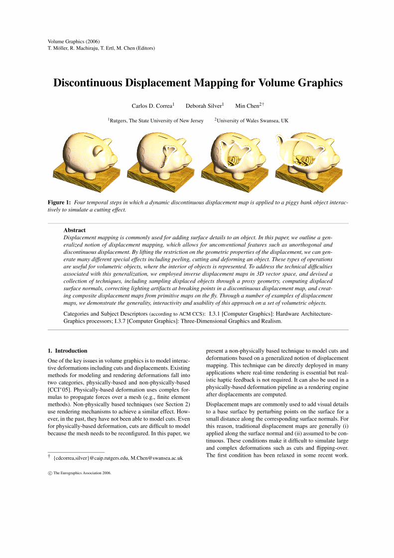
Figure 1: Four temporal steps in which a dynamic discontinuous displacement map is applied to a piggy bank object interac-tively to simulate a cutting effect.
AbstractDisplacement mapping is commonly used for adding surface details to an object. In this paper, we outline a gen-eralized notion of displacement mapping, which allows for unconventional features such as unorthogonal anddiscontinuous displacement. By lifting the restriction on the geometric properties of the displacement, we can gen-erate many different special effects including peeling, cutting and deforming an object. These types of operationsare useful for volumetric objects, where the interior of objects is represented. To address the technical difficultiesassociated with this generalization, we employed inverse displacement maps in 3D vector space, and devised acollection of techniques, including sampling displaced objects through a proxy geometry, computing displacedsurface normals, correcting lighting artifacts at breaking points in a discontinuous displacement map, and creat-ing composite displacement maps from primitive maps on the fly. Through a number of examples of displacementmaps, we demonstrate the generality, interactivity and usability of this approach on a set of volumetric objects.
Categories and Subject Descriptors (according to ACM CCS): I.3.1 [Computer Graphics]: Hardware Architecture-Graphics processors; I.3.7 [Computer Graphics]: Three-Dimensional Graphics and Realism.
1. IntroductionOne of the key issues in volume graphics is to model interac-tive deformations including cuts and displacements. Existingmethods for modeling and rendering deformations fall intotwo categories, physically-based and non-physically-based[CCI∗05]. Physically-based deformation uses complex for-mulas to propagate forces over a mesh (e.g., finite elementmethods). Non-physically based techniques (see Section 2)use rendering mechanisms to achieve a similar effect. How-ever, in the past, they have not been able to model cuts. Evenfor physically-based deformation, cuts are difficult to modelbecause the mesh needs to be reconfigured. In this paper, we
† {cdcorrea,silver}@caip.rutgers.edu, [email protected]
present a non-physically based technique to model cuts anddeformations based on a generalized notion of displacementmapping. This technique can be directly deployed in manyapplications where real-time rendering is essential but real-istic haptic feedback is not required. It can also be used in aphysically-based deformation pipeline as a rendering engineafter displacements are computed.Displacement maps are commonly used to add visual detailsto a base surface by perturbing points on the surface for asmall distance along the corresponding surface normals. Forthis reason, traditional displacement maps are generally (i)applied along the surface normal and (ii) assumed to be con-tinuous. These conditions make it difficult to simulate largeand complex deformations such as cuts and flipping-over.The first condition has been relaxed in some recent work.
c© The Eurographics Association 2006.
C. D. Correa & D. Silver & M. Chen / Discontinuous Displacement Mapping for Volume Graphics
Wang et al. [WWT∗03] employed volumetric displacementfunctions in order to simulate non-orthogonal displacementson surface objects. Similar ideas are found in [WTL∗04]and [PBFJ05]. These approaches, nonetheless, consider onlydisplacements within small volumetric regions along the sur-face. The removal of the second condition is critical to ren-dering large cuts and breaks. Surface meshes do not containadequate volumetric information, such as surface thicknessand interior structure, to allow the creation of correct visualeffects. Although this can be handled using a tetrahedral de-scription of the interior, re-tessellation of such meshes is atime-consuming task, which limits the quality, smoothnessand thickness of cuts and breaks.In this paper, we introduce a generalized notion of a dis-placement map, which allows for unconventional featuressuch as unorthogonal and discontinuous displacements. Fig-ure 2 illustrates the difference between the traditional andgeneralized displacement mapping. We discuss the majortechnical difficulties associated with this generalization, andoutline our solutions to these problems. In particular, weconsider a GPU-based volumetric approach without involv-ing any mesh structure and the intensive computation associ-ated. By employing inverse displacement maps in 3D vectorspace, we are able to apply complex displacements to vol-umes. Our rendering approach involves the use of a proxygeometry for sampling of the inverse displacement map,which is then mapped into the original object space. Correctcalculation of surface normals becomes a particular issuesince conventional normal estimation would lead to notice-able lighting artifacts on surfaces displaced in varying direc-tions, and at breaking points in a discontinuous displacementmap. We show how to specify discontinuous maps in RGBαtexture memory, and to render objects displaced under suchmaps on current GPU hardware. We adapted slicing-basedrendering strategies, so that the deformed space is sampledin a view-oriented manner. We show how displacement mapscan be combined to produce complex volumetric effects.Through these examples, we demonstrate the generality, in-teractivity and usability of this new approach, and its po-tential as a powerful technique for rendering many types ofobject interactions.
2. Related WorkDisplacement Mapping. Displacement mapping was intro-duced by Cook [Coo84] as a type of texture mapping tech-nique for modifying the geometry of a surface, resultingin correct shadows and silhouettes (in contrast to bumpmapping [Bli78]). Typical approaches to the realization ofdisplacement mapping include explicit surface subdivision(e.g., [CCC87]), direct ray tracing (e.g., [LP95,PH96]), andimage space warping (e.g., [SP99]).In surface subdivision [CCC87], geometric primitives aresubdivided into micro-polygons, resulting in an explicitrepresentation of the displaced surface. The method has
been made available through commercial software such asRenderManTMand MayaTM. Hardware solutions were alsodeveloped [GH99, DH00]. Discontinuities are introducedwith costly re-meshing of the object. This approach can-not be extended easily for volume graphics, since no surfacemodel is available.In ray tracing, the conventional approach is to pre-computean inverse displacement map, and perform the intersectioncalculation in the displaced space of a surface [LP95,PH96],similar to Barr’s suggestion for rendering deformed objects[Bar86]. To alleviate the cost of ray-tracing an entire scene,recent approaches to displacement mapping propose to tra-verse rays through extruded triangles in the texture space[WWT∗03, WTL∗04, PBFJ05]. In image space warping, thevisual effect of a displacement is achieved in the image spacerather than the object space. The method was first introducedby Schaufler and Priglinger [SP99], focusing on warping theimage of the base surface according to the projected dis-placement, and later extended by Oliveira et al. [OBM00].The extension of ray tracing to the modeling of cuts is diffi-cult, since it requires to determine a ray intersection with thenew surface produced by the cut. Further, current approachesfor displacement mapping based on extruded triangles can-not model large or discontinuous displacements. In our pa-per, we exploit the GPU capabilities of contemporary graph-ics boards to solve the limitations of the inverse displace-ment maps and image-space warping approaches when ap-plied to discontinuous displacement on volumetric objects.Non-physically based deformation. As an alternative todisplacement maps, cuts and deformations have been ex-plored as a modeling problem. The work presented hereis not about physically-based deformation, or surgical sim-ulation, for which there is a wide collection of literature(see [NMK∗05] and [CCI∗05]). While physically based de-formations are useful for realistic haptic feedback, they re-quire a huge computational cost which limits the complex-ity that can be achieved with desktop commodity hardware.Non-physically based deformation is a cost-effective alter-native in many applications, such as illustrative, educationaland entertainment software, where it is necessary to ren-der complex deformations at interactive rates Existing non-physically-based methods in volume graphics include raydeflectors [KY97], spatial transfer functions [CSW∗03], vol-ume splitting [IDSC04], volume browsing [MTB03] andnon-linear warping [BNG06]. Volume browsing uses pointprimitives to render cuts via forward transformations, whichinherently allows for discontinuities. However, the use ofpoints limits its quality in rendering, as undersampling oc-curs for large deformations. Ray deflectors and spatial trans-fer functions are ray-based approaches that use inverse map-ping. They can be used to simulate cuts and other defor-mation effects such as magic lenses [WZMK05]. However,the issue of correct normal estimation along the cuts andbreaks was not considered in the existing ray-based meth-ods. It is also difficult for discrete ray casting to achieve
c© The Eurographics Association 2006.
C. D. Correa & D. Silver & M. Chen / Discontinuous Displacement Mapping for Volume Graphics
surfacedisplacedn
p’
p
base surface
nbase surface
p
n’p’
Dn’
d pointbreak
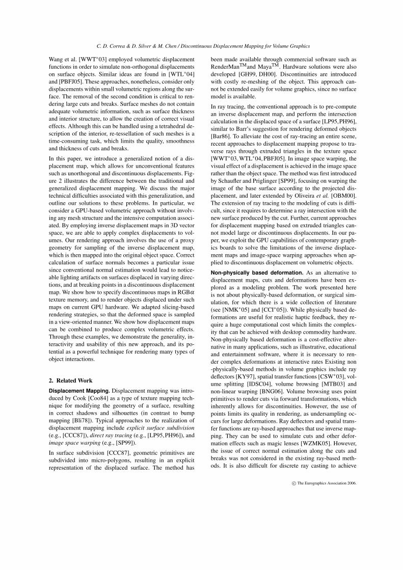
Figure 2: A cross section illustration of the traditional dis-placement mapping (left) and the generalized displacementmapping allowing for unorthogonal and discontinuous dis-placement (right).
the same level of performance as texture-based volume ren-dering without special data structures, which further compli-cates the simulation of cuts. In [BNG06], deformations arehard-coded in the GPU. An initial effort at inverse mappingis presented, but cuts cannot be achieved in real-time. Otherdeformation approaches, such as [WS01] and [RSSSG01]are based in the forward deformation of proxy geometry. It isdifficult to extend these approaches for modeling cuts, sinceit would require a fine re-tessellation of the proxy geometry.Both displacement mapping and texture-based volume ren-dering are desirable because of their suitability for GPU-based rendering. In this paper, we combine the best of both,remove the dimensional and geometric constraints normallyassociated with surface-based displacement mapping, andsolve the technical challenges in the integration of general-ized displacement mapping into a texture-based volume ren-dering pipeline.
3. Displacement MappingDisplacement mapping is traditionally considered as a vari-ation of 2D texture mapping, and it is used to alter the basesurface geometrically. A volumetric displacement mappingcan be considered as a variation of 3D texture mapping,where 3D displacements are used to perturb the volume, en-abling the simulation of large deformations and cuts. Sincetexture mapping in 2D or 3D often involves textures definedin a higher dimensional parametric space, we consider a gen-eral notion of space Λ without explicitly distinguishing be-tween geometry and texture spaces.A Generalized Notation. Let Λ be a common reference co-ordinate system shared by an object position function P andan object displacement function −→D B. We consider the fol-lowing generalized mapping from a point on the object P(λ )to a new point P′(λ )
P′(λ ) = P(λ )+−→D B(λ ) (1)
λ ∈ Λ is a common reference. P defines a coordinate map-ping from a common reference to a point in E
3. DB is a vec-tor function that can be specified procedurally or by using adiscretized representation such as a texture. In Eq.(1), it is nolonger a must that the surface normal determines the direc-tion of displacement, and function −→D B is no longer assumed
to be continuous. As illustrated in Figure 2, in comparisonwith the traditional notion on the left, this generalized notionallows for unorthogonal and discontinuous displacement.Λ can be a 2D parametric space as in the traditional no-tion, the 3D Euclidean space as in [KL96], or any referencesystem appropriate to an application. In this work, we useΛ = E
3 as the common reference coordinate system. In thefollowing discussions, we use mainly the inverse form of Eq.(1), that is,
P(λ ) = P′(λ )+−→D C(λ ) (2)
where −→D C is the inverse of −→D B. Since Λ = E3, we can make
P(λ ) = p and P′(λ ) = p′ where p,p′ ∈E3. By decomposing
−→D C as D(P′(λ )) = D(p′), Eq. (2) can thus be rewritten asp = p′ +D(p′) (3)
For simplicity, we consider the backward displacement map-ping function in the form of D in the following discussions.There is no constraint as to the displacement values of D.The displacement can be of any direction and magnitude.
4. RenderingOur approach uses texture-based volume rendering withview-aligned slices. We use slicing as a rendering mecha-nism for discrete sampling of the displaced object space,rather than for storing a view-dependent representation ofthe displaced object. Since this space is unknown we definea bounding box object as a proxy scene geometry.Let O be the function of an object and O′ that of the dis-placed object. The proxy scene geometry in effect definesa bounded spatial domain of O′. If the proxy scene geome-try contains a volume data set, we can use the texture-basedvolume rendering method which samples the proxy scenegeometry with slices parallel to the view plane. Each pixelin a slice is then mapped back to the original object spacewhere O is defined, via an inverse displacement map. Func-tion O can be any object representation such that given aposition p in the original object space, it returns appropriateluminance attributes at p. O(p) can easily be an implicit sur-face function, a level set surface, a distance field or a colorvolume texture. In our case, we use a scalar volume dataset,which we denote as O j , and store it as a 3D texture in GPUmemory. We also obtain a discretization of a displacementfunction, which we denote as Dk, from a procedural spec-ification. Dk is stored as a texture of 8-bit or 16-bit pointnumbers, normalized in the interval [−1,1].
4.1. Displacement SetupTo create a displacement texture, Dk, of size w× h× d, wefirst specify −→D B procedurally, and then sample its inversetransformation D =
−→D C at discrete positions {x,y,z|x =0,1, . . . ,w;y = 0,1, . . . ,h;z = 0,1, . . . ,d}. For a discontinu-ous transformation, however, its inverse D that is analyti-cally valid at all points does not exist, since some points in
c© The Eurographics Association 2006.
C. D. Correa & D. Silver & M. Chen / Discontinuous Displacement Mapping for Volume Graphics
SAMPLEOBJECT
GETNORMAL
TRANSFORMEq (4) CUTS: Eq (5)
ADJUST NEAR (p’)nn(p)
APPLYLIGTHING RGBα(
FINAL)
αDk)(
j(O )
Oj
αDk
Dkα
(D .x)k
k(D .y)k(D .z)
αDk)(
Dk
RGBαRGBαHANDLEDISCONTINUITIES
ADDp’+d = pp’ DISPLACEMENT
J
gradients
d
Scene Bounding Box
JD D
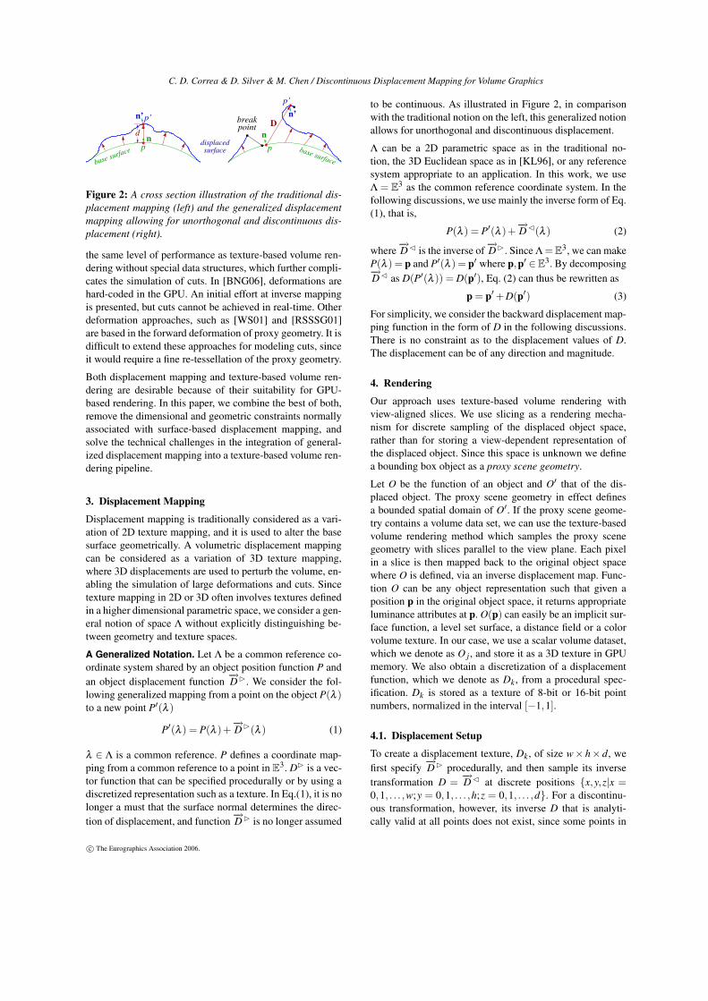
Figure 3: System diagram for discontinuous displacement mapping. As we sample the bounding box of the scene, each fragmentp′ is displaced by a distance d obtained by sampling the displacement texture Dk. The resulting position p = p′ + d is used tosample the object texture O j and gradient texture ∇(O j), to obtain color and normal information. Color, normal and opacity(obtained from alpha mask αDk ) are used to compute the final color of the fragment.
the domain of D do not have a pre-image. For this reason, wecompute a pseudo-inverse Dk, which is defined as the inverseD for those points in the co-domain of −→D B, and it maintainsC0 continuity.In other words, Dk is valid for all points in the proxy scenegeometry, including those where there should be a discon-tinuity. Dk is then normalized in the interval [−1,1], thenscaled and biased to fit in the range of valid values of GPUtextures. In order to model the actual discontinuity, we definea mask αDk , such that αDk (p′) is 1 if p′ has a pre-image inthe co-domain of −→D B and 0 otherwise, and discretize it in a3D texture. Dk and αDk are illustrated in Figure 3, where thestriped pattern in the displacement map is used to show thestretching that occurs at the discontinuity. The actual breakis modeled as 0 values in the alpha texture. Having the dis-placement map as a continuous field and the alpha maskto model discontinuities, we have addressed the need forproper trilinear interpolation of displacements performed bythe graphics hardware. If an arbitrary displacement value isused to represent an empty voxel (e.g., 1 or −1) due to a cut,voxels in the boundary of the cut would have displacementvalues interpolated between the displacement of the nearestvoxel in the surface of the cut and this arbitrary value, whichclearly results in visual artifacts.
4.2. Displaced Object PointsIn order to determine the displaced volume, we slice theproxy scene geometry into view-oriented slices, as shownin Figure 3. The bounding box of O′ can easily be foundby combining the bounding boxes of the object(s) and theirdisplacements. The slices are rendered in back-to-front or-der and finally composited using alpha blending. For eachpoint p′ on the slice, we must find the appropriate displace-ment, since there can be more than one displacement actingon the object (See Section 6 on composite maps). We use a
fragment program to find the opacity and color values of agiven pixel with texture coordinates p′. This program com-putes p = p′+Dk(p′), where p is the position in the originalobject O that corresponds to the texture coordinate p′. It thensamples the 3D texture of O at the position p and retrieve thecolor components. Finally, in order to handle discontinuities,it samples the alpha mask αDk at the position p′ and modu-late the pixel’s color components with the mask. In order toavoid aliasing artifacts in the cut, the program considers apoint as transparent if the alpha mask is less than 0.5, andthe resulting pixel will not contribute to compositing. Theprocess of the fragment shader is depicted in Figure 3.
4.3. Displaced Surface NormalIn order to properly shade the object, we need the normal in-formation at each point. Since we store objects as volumes,normals can be obtained using finite differences or more so-phisticated filters such as the Sobel operator. For interactiverendering, the gradient can be pre-computed and stored ina 3D texture. When processing fragments, a texture fetchof the gradient texture yields the normal of the voxel andits magnitude (This is shown as ∇O j in Figure 3). Thereare three cases to be considered: the points that are not dis-placed, the displaced points, and those in the boundary ofa discontinuity. For points not displaced, the pre-computednormals can be used directly. The other two cases are han-dled as follows.
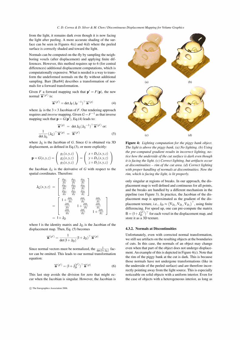
4.3.1. Normals at Displaced PointsFor a point undergoing displacement, we must obtain a newnormal. Figure 4(b) shows the case where the pre-computednormal is used, which results in incorrect shading. In Fig-ure 4(b), we peel the top of a piggy bank object (the light isabove the piggy bank). We see the incorrect shading of thepeeled surface. Since the surface was originally facing away
c© The Eurographics Association 2006.
C. D. Correa & D. Silver & M. Chen / Discontinuous Displacement Mapping for Volume Graphics
from the light, it remains dark even though it is now facingthe light after peeling. A more accurate shading of the sur-face can be seen in Figures 4(c) and 4(d) where the peeledsurface is correctly shaded and toward the light.Normals can be computed on-the-fly by sampling the neigh-boring voxels (after displacement) and applying finite dif-ferences. However, this method requires up to 6 (for centraldifferences) additional displacement computations, which iscomputationally expensive. What is needed is a way to trans-form the undeformed normals on the fly without additionalsampling. Barr [Bar84] describes a transformation of nor-mals for a forward transformation.Given F a forward mapping such that p′ = F(p), the newnormal −→n (p′) is:
−→n (p′) = detJF(JF−1)>−→n (p) (4)
where JF is the 3×3 Jacobian of F . Our rendering approachrequires and inverse mapping. Given G = F−1 as that inversemapping such that p = G(p′), Eq.(4) leads to:
−→n (p) = detJG(JG−1)>−→n (p′) or:
1detJG
(JG)>−→n (p) = −→n (p′) (5)
where JG is the Jacobian of G. Since G is obtained via 3Ddisplacement, as defined in Eq.(3), or more explicitly:
p = G(x,y,z) =
g1(x,y,z)g2(x,y,z)g3(x,y,z)
=
x+Dx(x,y,z)y+Dy(x,y,z)z+Dz(x,y,z)
the Jacobian JG is the derivative of G with respect to thespatial coordinates. Therefore:
JG(x,y,z) =
∂g1∂x
∂g1∂y
∂g1∂ z
∂g2∂x
∂g2∂y
∂g2∂ z
∂g3∂x
∂g3∂y
∂g3∂ z
=
1+ ∂Dx∂x
∂Dx∂y
∂Dx∂ z
∂Dy∂x 1+
∂Dy∂y
∂Dy∂ z
∂Dz∂x
∂Dz∂y 1+ ∂Dz
∂ z
= I+JD
where I is the identity matrix and JD is the Jacobian of thedisplacement map. Then, Eq. (5) becomes
−→n (p′) =1
det(I+JD)(I+JD)>−→n (p)
Since normal vectors must be normalized, the 1det(I+JD)
fac-tor can be omitted. This leads to our normal transformationequation:
−→n (p′) = (I+J(p′)D )>−→n (p) (6)
This last step avoids the division for zero that might oc-cur when the Jacobian is singular. However, the Jacobian is
(a) (b)
(c) (d)
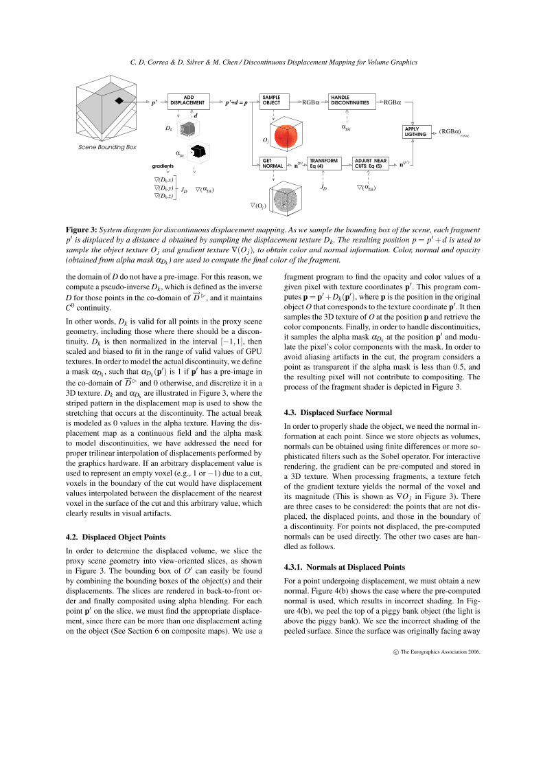
Figure 4: Lighting computation for the piggy bank object.The light is above the piggy bank. (a) No lighting. (b) Usingthe pre-computed gradient results in incorrect lighting, no-tice how the underside of the cut surface is dark even thoughit is facing the light. (c) Correct lighting, but artifacts occurat discontinuities – rim of the cut area. (d) Correct lightingwith proper handling of normals at discontinuities. Now therim, which is facing the light, is lit properly.
only singular at regions of breaks. In our approach, the dis-placement map is well defined and continuous for all points,and the breaks are handled by a different mechanism in thepipeline (see Figure 3). In practice, the Jacobian of the dis-placement map is approximated as the gradient of the dis-placement texture, i.e., JD ≈
(
∇Dx ,∇Dy ,∇Dz
)>, using finitedifferencing. For speed up, one can pre-compute the matrixB = (I+J
(p′)D )> for each voxel in the displacement map, and
store it as a 3D texture.
4.3.2. Normals at DiscontinuitiesUnfortunately, even with corrected normal transformation,we still see artifacts on the resulting objects at the boundariesof cuts. In this case, the normals of an object may changeeven when that part of the object does not undergo displace-ment. An example of this is depicted in Figure 4(c). Note thatthe rim of the piggy bank at the cut is dark. This is becausethose normals have not undergone transformations (like inthe underside of the peeled surface) and are therefore incor-rectly pointing away from the light source. This is especiallynoticeable on solid objects with a uniform interior. Even forthe case of objects with a heterogeneous interior, as long as
c© The Eurographics Association 2006.
C. D. Correa & D. Silver & M. Chen / Discontinuous Displacement Mapping for Volume Graphics
their normals are not directed orthogonal to the cut, the cutsurface will be lit incorrectly.To properly compute the normals at the discontinuities, weneed a way to determine the new surface that has been cre-ated. This information is stored in the alpha map αDk . Wecan compute the gradient of the alpha mask ∇(αDk ), and usethis value only at the boundary of a cut. However, applyingonly this gradient in the boundary, may generate artifactsnear the boundary. To solve this, we gradually correct thenormal in the vicinity of the cut to the desired normal, viablending:
−→n (p′) = ω(I+JD)>−→n (p) +(1−ω)∇(αDk )(p′) (7)
where ω ∈ [0,1] is a blending factor. Figure 4(d) shows theresult of applying this method for the piggy bank object.Note that the pixels at the rim of the cut are now properlyshaded. This blending mechanism is similar to the solutionproposed by Weiskopf et al. [WEE03] for volumetric cut-aways. Although the alpha gradient can be computed on thefly using finite differencing, it can also be precomputed andstored in a 3D texture for speedup.
5. Construction of Displacement MapsThis section describes the process of creating a displacementmap, using deformation of the bunny dataset as an example(Figure 8). This displacement uses a 3D Gaussian functionto simulate a pull in the Z direction. The displacement canbe constructed as:
D(x,y,z) =(
0, 0, −ze(x−0.5)2+(y−0.5)2
2σ2
)>(8)
for (x,y,z) in a unit cube, and σ chosen so that displacementbecomes 0 at the XY boundaries of the unit cube. This dis-placement is discretized and stored in a 3D texture of size64× 64× 64. Note that the z value is used to modulate theamplitude of the Gaussian pull, and that the Z component ofthe displacement is negative, since D stores the inverse dis-placement. For instance, the point (32,32,32) in the 3D tex-ture, corresponding to the normalized point (0.5,0.5,0.5) inthe unit cube, contains the displacement vector (0,0,−0.5).When considering cuts, we follow a similar process. First,we compute the alpha channel of the cut procedurally, sothat αDk (x,y,z) is 0 whenever there is a cut, and 1 elsewhere,and discretize it in a texture volume. In addition, we apply asmoothing operator over the alpha mask in order to obtain asmooth region around the boundaries needed for the blend-ing of the normals, as described in Section 4.3.2. The resultis stored in the alpha component of the displacement texture.One challenge in the creation of displacements is the pro-vision of user interfaces that would allow the user to definecuts and peels of arbitrary size and shape. In addition, userinterface widgets are required to manipulate the different pa-rameters of the displacement while rendering the volume.This is an important issue and it is ongoing research.
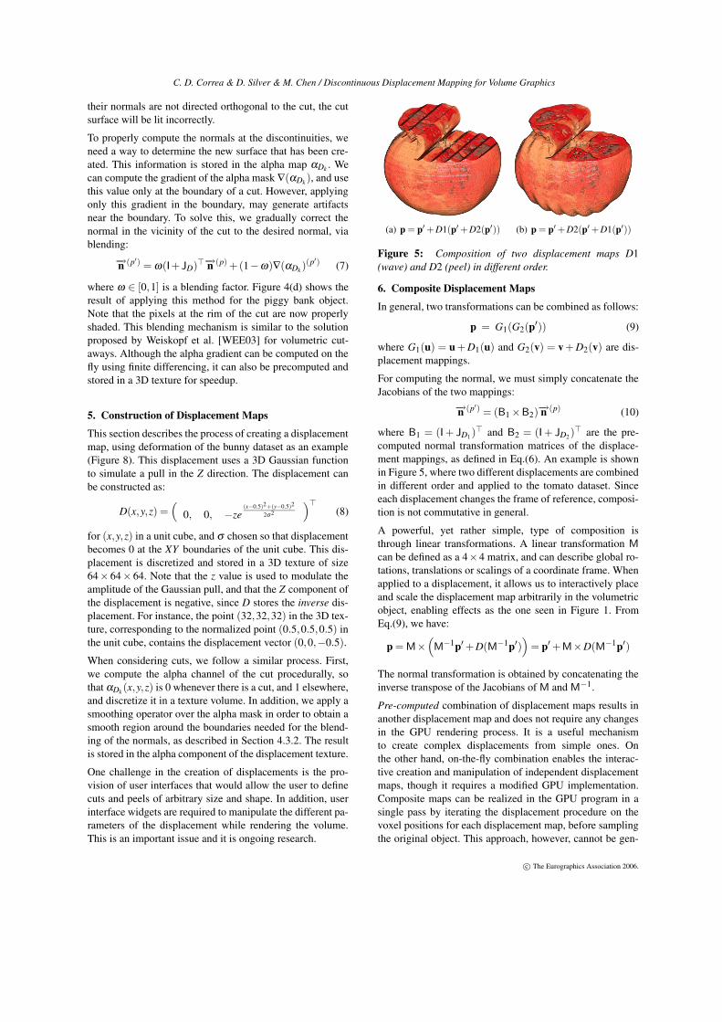
(a) p = p′ +D1(p′ +D2(p′)) (b) p = p′ +D2(p′ +D1(p′))
Figure 5: Composition of two displacement maps D1(wave) and D2 (peel) in different order.
6. Composite Displacement MapsIn general, two transformations can be combined as follows:
p = G1(G2(p′)) (9)
where G1(u) = u + D1(u) and G2(v) = v + D2(v) are dis-placement mappings.For computing the normal, we must simply concatenate theJacobians of the two mappings:
−→n (p′) = (B1 ×B2)−→n (p) (10)
where B1 = (I + JD1)> and B2 = (I + JD2)
> are the pre-computed normal transformation matrices of the displace-ment mappings, as defined in Eq.(6). An example is shownin Figure 5, where two different displacements are combinedin different order and applied to the tomato dataset. Sinceeach displacement changes the frame of reference, composi-tion is not commutative in general.A powerful, yet rather simple, type of composition isthrough linear transformations. A linear transformation M
can be defined as a 4×4 matrix, and can describe global ro-tations, translations or scalings of a coordinate frame. Whenapplied to a displacement, it allows us to interactively placeand scale the displacement map arbitrarily in the volumetricobject, enabling effects as the one seen in Figure 1. FromEq.(9), we have:
p = M×(
M−1p′ +D(M−1p′)
)
= p′ +M×D(M−1p′)
The normal transformation is obtained by concatenating theinverse transpose of the Jacobians of M and M
−1.Pre-computed combination of displacement maps results inanother displacement map and does not require any changesin the GPU rendering process. It is a useful mechanismto create complex displacements from simple ones. Onthe other hand, on-the-fly combination enables the interac-tive creation and manipulation of independent displacementmaps, though it requires a modified GPU implementation.Composite maps can be realized in the GPU program in asingle pass by iterating the displacement procedure on thevoxel positions for each displacement map, before samplingthe original object. This approach, however, cannot be gen-
c© The Eurographics Association 2006.
C. D. Correa & D. Silver & M. Chen / Discontinuous Displacement Mapping for Volume Graphics
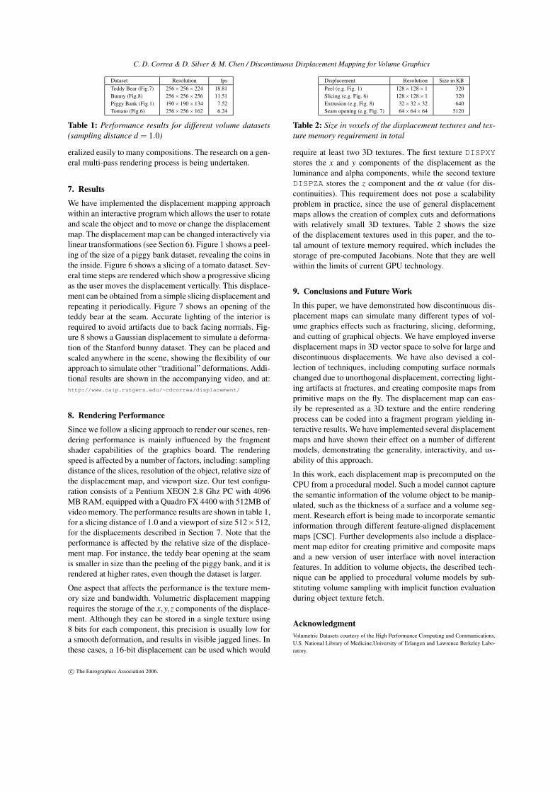
Dataset Resolution fpsTeddy Bear (Fig.7) 256×256×224 18.81Bunny (Fig.8) 256×256×256 11.51Piggy Bank (Fig.1) 190×190×134 7.52Tomato (Fig.6) 256×256×162 6.24
Table 1: Performance results for different volume datasets(sampling distance d = 1.0)
eralized easily to many compositions. The research on a gen-eral multi-pass rendering process is being undertaken.
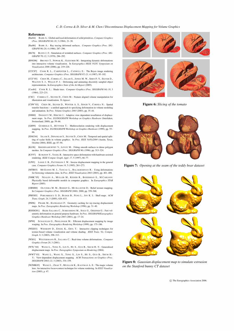
7. ResultsWe have implemented the displacement mapping approachwithin an interactive program which allows the user to rotateand scale the object and to move or change the displacementmap. The displacement map can be changed interactively vialinear transformations (see Section 6). Figure 1 shows a peel-ing of the size of a piggy bank dataset, revealing the coins inthe inside. Figure 6 shows a slicing of a tomato dataset. Sev-eral time steps are rendered which show a progressive slicingas the user moves the displacement vertically. This displace-ment can be obtained from a simple slicing displacement andrepeating it periodically. Figure 7 shows an opening of theteddy bear at the seam. Accurate lighting of the interior isrequired to avoid artifacts due to back facing normals. Fig-ure 8 shows a Gaussian displacement to simulate a deforma-tion of the Stanford bunny dataset. They can be placed andscaled anywhere in the scene, showing the flexibility of ourapproach to simulate other “traditional” deformations. Addi-tional results are shown in the accompanying video, and at:http://www.caip.rutgers.edu/~cdcorrea/displacement/
8. Rendering PerformanceSince we follow a slicing approach to render our scenes, ren-dering performance is mainly influenced by the fragmentshader capabilities of the graphics board. The renderingspeed is affected by a number of factors, including: samplingdistance of the slices, resolution of the object, relative size ofthe displacement map, and viewport size. Our test configu-ration consists of a Pentium XEON 2.8 Ghz PC with 4096MB RAM, equipped with a Quadro FX 4400 with 512MB ofvideo memory. The performance results are shown in table 1,for a slicing distance of 1.0 and a viewport of size 512×512,for the displacements described in Section 7. Note that theperformance is affected by the relative size of the displace-ment map. For instance, the teddy bear opening at the seamis smaller in size than the peeling of the piggy bank, and it isrendered at higher rates, even though the dataset is larger.One aspect that affects the performance is the texture mem-ory size and bandwidth. Volumetric displacement mappingrequires the storage of the x,y,z components of the displace-ment. Although they can be stored in a single texture using8 bits for each component, this precision is usually low fora smooth deformation, and results in visible jagged lines. Inthese cases, a 16-bit displacement can be used which would
Displacement Resolution Size in KBPeel (e.g. Fig. 1) 128×128×1 320Slicing (e.g. Fig. 6) 128×128×1 320Extrusion (e.g. Fig. 8) 32×32×32 640Seam opening (e.g. Fig. 7) 64×64×64 5120
Table 2: Size in voxels of the displacement textures and tex-ture memory requirement in total
require at least two 3D textures. The first texture DISPXYstores the x and y components of the displacement as theluminance and alpha components, while the second textureDISPZA stores the z component and the α value (for dis-continuities). This requirement does not pose a scalabilityproblem in practice, since the use of general displacementmaps allows the creation of complex cuts and deformationswith relatively small 3D textures. Table 2 shows the sizeof the displacement textures used in this paper, and the to-tal amount of texture memory required, which includes thestorage of pre-computed Jacobians. Note that they are wellwithin the limits of current GPU technology.
9. Conclusions and Future WorkIn this paper, we have demonstrated how discontinuous dis-placement maps can simulate many different types of vol-ume graphics effects such as fracturing, slicing, deforming,and cutting of graphical objects. We have employed inversedisplacement maps in 3D vector space to solve for large anddiscontinuous displacements. We have also devised a col-lection of techniques, including computing surface normalschanged due to unorthogonal displacement, correcting light-ing artifacts at fractures, and creating composite maps fromprimitive maps on the fly. The displacement map can eas-ily be represented as a 3D texture and the entire renderingprocess can be coded into a fragment program yielding in-teractive results. We have implemented several displacementmaps and have shown their effect on a number of differentmodels, demonstrating the generality, interactivity, and us-ability of this approach.In this work, each displacement map is precomputed on theCPU from a procedural model. Such a model cannot capturethe semantic information of the volume object to be manip-ulated, such as the thickness of a surface and a volume seg-ment. Research effort is being made to incorporate semanticinformation through different feature-aligned displacementmaps [CSC]. Further developments also include a displace-ment map editor for creating primitive and composite mapsand a new version of user interface with novel interactionfeatures. In addition to volume objects, the described tech-nique can be applied to procedural volume models by sub-stituting volume sampling with implicit function evaluationduring object texture fetch.
AcknowledgmentVolumetric Datasets courtesy of the High Performance Computing and Communications,U.S. National Library of Medicine,University of Erlangen and Lawrence Berkeley Labo-ratory.
c© The Eurographics Association 2006.
C. D. Correa & D. Silver & M. Chen / Discontinuous Displacement Mapping for Volume Graphics
References[Bar84] BARR A.: Global and local deformation of solid primitives. Computer Graphics
(Proc. SIGGRAPH 84) 18, 3 (1984), 21–30.
[Bar86] BARR A.: Ray tracing deformed surfaces. Computer Graphics (Proc. SIG-GRAPH 86) 20, 4 (1986), 287–296.
[Bli78] BLINN J. F.: Simulation of wrinkled surfaces. Computer Graphics (Proc. SIG-GRAPH 78) 12, 3 (1978), 286–292.
[BNG06] BRUNET T., NOWAK K., GLEICHER M.: Integrating dynamic deformationsinto interactive volume visualization. In Eurographics /IEEE VGTC Symposium onVisualization 2006 (2006), pp. 219–226.
[CCC87] COOK R. L., CARPENTER L., CATMULL E.: The Reyes image renderingarchitecture. Computer Graphics (Proc. SIGGRAPH 87) 21, 4 (1987), 95–102.
[CCI∗05] CHEN M., CORREA C., ISLAM S., JONES M. W., SHEN P.-Y., SILVER D.,WALTON S. J., WILLIS P. J.: Deforming and animating discretely sampled objectrepresentations. In Eurographics State of the Art Report (2005).
[Coo84] COOK R. L.: Shade trees. Computer Graphics (Proc. SIGGRAPH 84) 18, 3(1984), 223–231.
[CSC] CORREA C., SILVER D., CHEN M.: Feature aligned volume manipulation forillustration and visualization. To Appear.
[CSW∗03] CHEN M., SILVER D., WINTER A. S., SINGH V., CORNEA N.: Spatialtransfer functions – a unified approach to specifying deformation in volume modelingand animation. In Proc. Volume Graphics 2003 (2003), pp. 35–44.
[DH00] DOGGETT M., HIRCHE J.: Adaptive view dependent tessellation of displace-ment maps. In Proc. EG/SIGGRAPH Workshop on Graphics Hardware (Interlaken,Switzerland, 2000), pp. 59–66.
[GH99] GUMHOLD S., HÜTTNER T.: Multiresolution rendering with displacementmapping. In Proc. EG/SIGGRAPH Workshop on Graphics Hardware (1999), pp. 55–66.
[IDSC04] ISLAM S., DIPANKAR S., SILVER D., CHEN M.: Temporal and spatial split-ting of scalar fields in volume graphics. In Proc. IEEE VolVis2004 (Austin, Texas,October 2004), IEEE, pp. 87–94.
[KL96] KRISHNAMURTHY V., LEVOY M.: Fitting smooth surfaces to dense polygonmeshes. In Computer Graphics (Proc. SIGGRAPH 96) (1996), pp. 313–324.
[KY97] KURZION Y., YAGEL R.: Interactive space deformation with hardware-assistedrendering. IEEE Comput. Graph. Appl. 17, 5 (1997), 66–77.
[LP95] LOGIE J. R., PATTERSON J. W.: Inverse displacement mapping in the generalcase. Computer Graphics Forum 14, 5 (1995), 261–273.
[MTB03] MCGUFFIN M. J., TANCAU L., BALAKRISHNAN R.: Using deformationsfor browsing volumetric data. In Proc. IEEE Visualization 2003 (2003), pp. 401–408.
[NMK∗05] NEALEN A., MULLER M., KEISER R., BOXERMAN E., M.CARLSON:Physically based deformable models in computer graphics. In Eurographics STARReport (2005).
[OBM00] OLIVEIRA M. M., BISHOP G., MCALLISTER D.: Relief texture mapping.In Computer Graphics (Proc. SIGGRAPH 2000). 2000, pp. 359–368.
[PBFJ05] PORUMBESCU S. D., BUDGE B., FENG L., JOY K. I.: Shell maps. ACMTrans. Graph. 24, 3 (2005), 626–633.
[PH96] PHARR M., HANRAHAN P.: Geometry caching for ray-tracing displacementmaps. In Proc. Eurographics Rendering Workshop (1996), pp. 31–40.
[RSSSG01] REZK-SALAMA C., SCHEUERING M., SOZA G., GREINER G.: Fast vol-umetric deformation on general purpose hardware. In Proc. SIGGRAPH/EurographicsGraphics Hardware Workshop 2001 (2001), pp. 17–24.
[SP99] SCHAUFLER G., PRIGLINGER M.: Efficient displacement mapping by imagewarping. In Proc. Eurographics Rendering Workshop (1999), pp. 175–186.
[WEE03] WEISKOPF D., ENGEL K., ERTL T.: Interactive clipping techniques fortexture-based volume visualization and volume shading. IEEE Trans. Vis. Comput.Graph. 9, 3 (2003), 298–312.
[WS01] WESTERMANN R., SALAMA C.: Real-time volume deformations. ComputerGraphics Forum 20, 3 (2001).
[WTL∗04] WANG L., TONG X., LIN S., HU S., GUO B., SHUM H.-Y.: Generalizeddisplacement maps. In Proc. Eurographics Symposium on Rendering (2004).
[WWT∗03] WANG L., WANG X., TONG X., LIN S., HU S., GUO B., SHUM H.-Y.: View-dependent displacement mapping. ACM Transactions on Graphics (Proc.SIGGRAPH 2003) 22, 3 (2003), 334–339.
[WZMK05] WANG L., ZHAO Y., MUELLER K., KAUFMAN A. E.: The magic volumelens: An interactive focus+context technique for volume rendering. In IEEE Visualiza-tion (2005), p. 47.
Figure 6: Slicing of the tomato
Figure 7: Opening at the seam of the teddy bear dataset
Figure 8: Gaussian displacement map to simulate extrusionon the Stanford bunny CT dataset
c© The Eurographics Association 2006.