diode limiters or clippers
TRANSCRIPT
3/17/2019
1
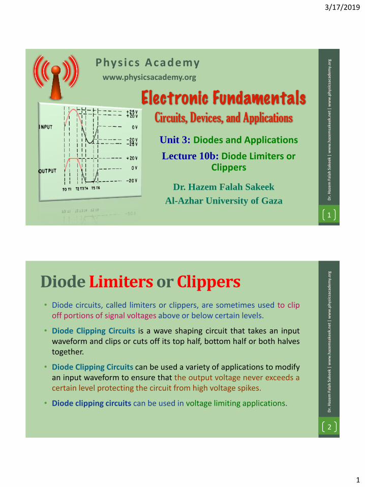
Unit 3: Diodes and Applications
Lecture 10b: Diode Limiters or Clippers
www.physicsacademy.org
Physics Academy
Dr. Hazem Falah Sakeek
Al-Azhar University of Gaza Dr.
Haz
em F
alah
Sak
eek
| w
ww
.haz
emsa
keek
.ne
t |
ww
w.p
hys
icsa
cad
em
y.o
rg
1
Diode Limiters or Clippers• Diode circuits, called limiters or clippers, are sometimes used to clip
off portions of signal voltages above or below certain levels.
• Diode Clipping Circuits is a wave shaping circuit that takes an inputwaveform and clips or cuts off its top half, bottom half or both halvestogether.
• Diode Clipping Circuits can be used a variety of applications to modifyan input waveform to ensure that the output voltage never exceeds acertain level protecting the circuit from high voltage spikes.
• Diode clipping circuits can be used in voltage limiting applications.
2
Dr.
Haz
em F
alah
Sak
eek
| w
ww
.haz
em
sake
ek.n
et
| w
ww
.ph
ysic
saca
de
my.
org
3/17/2019
2
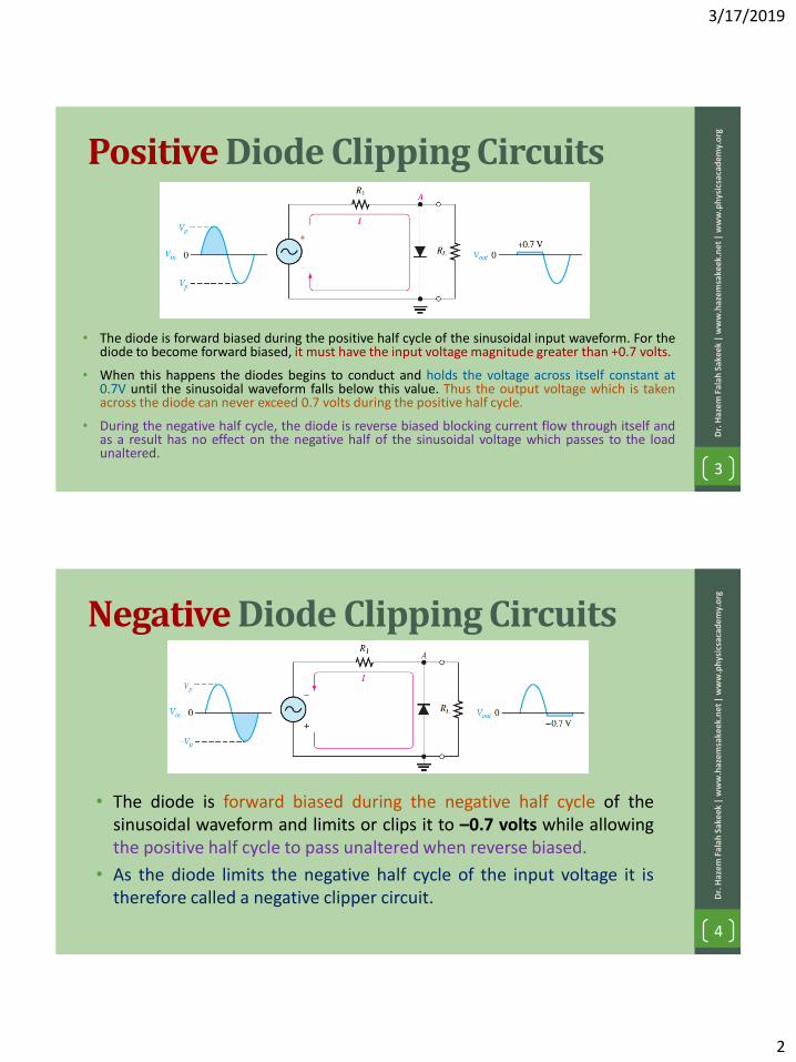
Positive Diode Clipping Circuits
• The diode is forward biased during the positive half cycle of the sinusoidal input waveform. For thediode to become forward biased, it must have the input voltage magnitude greater than +0.7 volts.
• When this happens the diodes begins to conduct and holds the voltage across itself constant at0.7V until the sinusoidal waveform falls below this value. Thus the output voltage which is takenacross the diode can never exceed 0.7 volts during the positive half cycle.
• During the negative half cycle, the diode is reverse biased blocking current flow through itself andas a result has no effect on the negative half of the sinusoidal voltage which passes to the loadunaltered.
3
Dr.
Haz
em F
alah
Sak
eek
| w
ww
.haz
emsa
keek
.ne
t |
ww
w.p
hys
icsa
cad
em
y.o
rg
Negative Diode Clipping Circuits
• The diode is forward biased during the negative half cycle of thesinusoidal waveform and limits or clips it to –0.7 volts while allowingthe positive half cycle to pass unaltered when reverse biased.
• As the diode limits the negative half cycle of the input voltage it istherefore called a negative clipper circuit.
4
Dr.
Haz
em F
alah
Sak
eek
| w
ww
.haz
em
sake
ek.n
et
| w
ww
.ph
ysic
saca
de
my.
org
3/17/2019
3
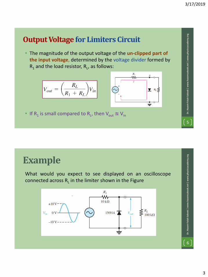
Output Voltage for Limiters Circuit
• The magnitude of the output voltage of the un-clipped part of the input voltage, determined by the voltage divider formed by R1 and the load resistor, RL, as follows:
• If R1 is small compared to RL, then Vout ≊ Vin
5
Dr.
Haz
em F
alah
Sak
eek
| w
ww
.haz
emsa
keek
.ne
t |
ww
w.p
hys
icsa
cad
em
y.o
rg
ExampleWhat would you expect to see displayed on an oscilloscopeconnected across RL in the limiter shown in the Figure
6
Dr.
Haz
em F
alah
Sak
eek
| w
ww
.haz
em
sake
ek.n
et
| w
ww
.ph
ysic
saca
de
my.
org

3/17/2019
4
Solution• The diode is forward-biased and
conducts when the input voltage goesbelow -0.7 V. (so it is negative limiter).
• The peak output voltage across RL
7
Dr.
Haz
em F
alah
Sak
eek
| w
ww
.haz
emsa
keek
.ne
t |
ww
w.p
hys
icsa
cad
em
y.o
rg
The scope will display an
output waveform
Clipping of Both Half Cycles• Diode D1 clips the positive half
cycle of the sinusoidal inputwaveform, while diode D2 clipsthe negative half cycle.
• Then diode clipping circuits canbe used to clip the positive halfcycle, the negative half cycle orboth.
8
Dr.
Haz
em F
alah
Sak
eek
| w
ww
.haz
em
sake
ek.n
et
| w
ww
.ph
ysic
saca
de
my.
org
We can increase this ±0.7V threshold to any value up to the maximum value,(VPEAK) of the sinusoidal waveform either by connecting together morediodes in series creating multiples of 0.7 volts, or by adding a voltage bias tothe diodes.

3/17/2019
5
+ve Biased Diode Clipping Circuits
• The level to which an ac voltage is limited can be adjusted by addinga bias voltage, VBIAS, in series with the diode.
• The voltage at point A must equal VBIAS + 0.7 V before the diode willbecome forward-biased and conduct.
• Once the diode begins to conduct, the voltage at point A is limitedto VBIAS+0.7 V so that all input voltage above this level is clipped off. 9
Dr.
Haz
em F
alah
Sak
eek
| w
ww
.haz
emsa
keek
.ne
t |
ww
w.p
hys
icsa
cad
em
y.o
rg
-Ve Biased Diode Clipping Circuits
• To limit a voltage to a specified negative level, the diode and biasvoltage must be connected as in the Figure.
• In this case, the voltage at point A must go below –VBIAS–0.7 V toforward-bias the diode and initiate limiting action.
10
Dr.
Haz
em F
alah
Sak
eek
| w
ww
.haz
em
sake
ek.n
et
| w
ww
.ph
ysic
saca
de
my.
org
3/17/2019
6
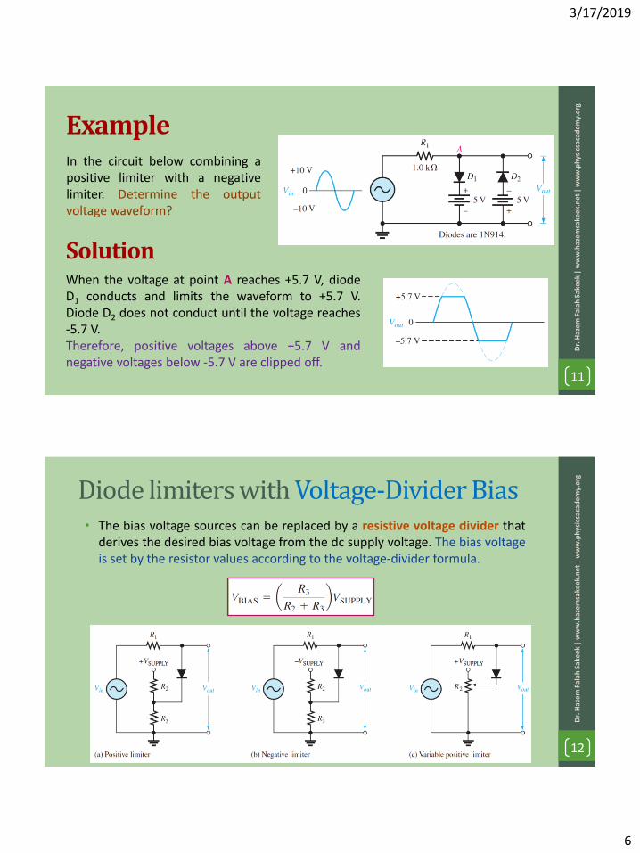
ExampleIn the circuit below combining apositive limiter with a negativelimiter. Determine the outputvoltage waveform?
11
Dr.
Haz
em F
alah
Sak
eek
| w
ww
.haz
emsa
keek
.ne
t |
ww
w.p
hys
icsa
cad
em
y.o
rg
When the voltage at point A reaches +5.7 V, diodeD1 conducts and limits the waveform to +5.7 V.Diode D2 does not conduct until the voltage reaches-5.7 V.Therefore, positive voltages above +5.7 V andnegative voltages below -5.7 V are clipped off.
Solution
Diode limiters with Voltage-Divider Bias• The bias voltage sources can be replaced by a resistive voltage divider that
derives the desired bias voltage from the dc supply voltage. The bias voltageis set by the resistor values according to the voltage-divider formula.
12
Dr.
Haz
em F
alah
Sak
eek
| w
ww
.haz
em
sake
ek.n
et
| w
ww
.ph
ysic
saca
de
my.
org
3/17/2019
7
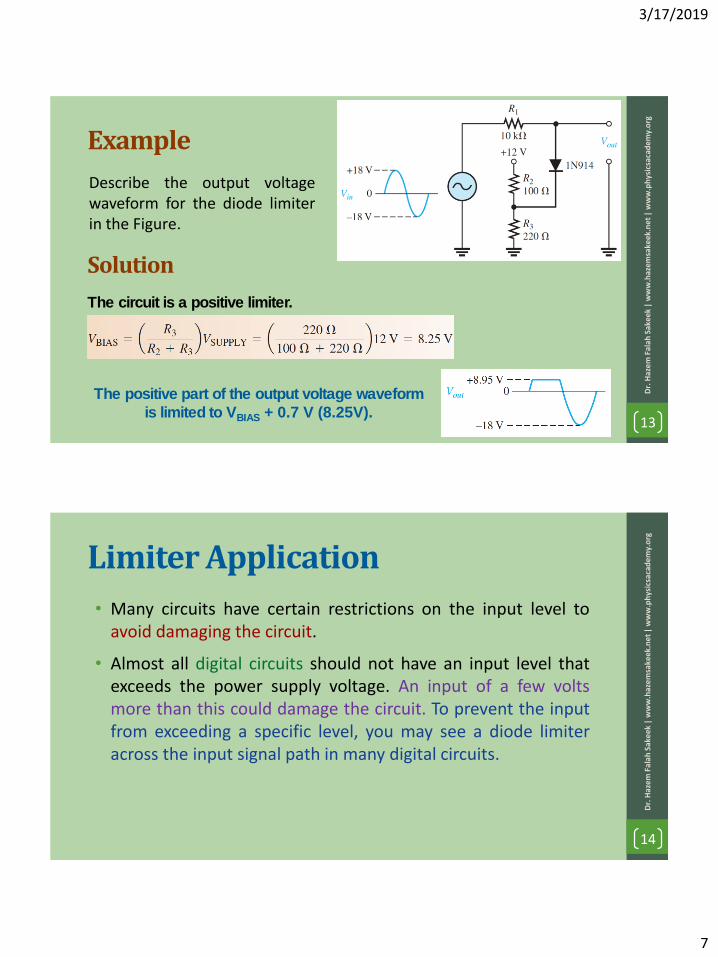
Example
Describe the output voltagewaveform for the diode limiterin the Figure.
13
Dr.
Haz
em F
alah
Sak
eek
| w
ww
.haz
emsa
keek
.ne
t |
ww
w.p
hys
icsa
cad
em
y.o
rg
Solution
The circuit is a positive limiter.
The positive part of the output voltage waveform
is limited to VBIAS + 0.7 V (8.25V).
Limiter Application
• Many circuits have certain restrictions on the input level toavoid damaging the circuit.
• Almost all digital circuits should not have an input level thatexceeds the power supply voltage. An input of a few voltsmore than this could damage the circuit. To prevent the inputfrom exceeding a specific level, you may see a diode limiteracross the input signal path in many digital circuits.
14
Dr.
Haz
em F
alah
Sak
eek
| w
ww
.haz
em
sake
ek.n
et
| w
ww
.ph
ysic
saca
de
my.
org
3/17/2019
8
Quiz
15
Dr.
Haz
em F
alah
Sak
eek
| w
ww
.haz
emsa
keek
.ne
t |
ww
w.p
hys
icsa
cad
em
y.o
rg
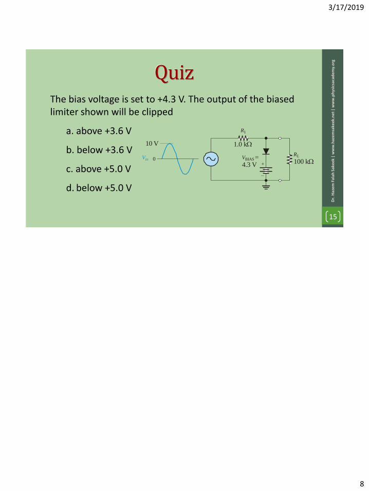
The bias voltage is set to +4.3 V. The output of the biased limiter shown will be clipped
a. above +3.6 V
b. below +3.6 V
c. above +5.0 V
d. below +5.0 V
VinRL
R1
0+
–
VBIAS
10 V
4.3 V=
1.0 k
100 k