digitech-gnx4-genetx-manuel-utilisateur-en-30701.pdf - zikinf
TRANSCRIPT


WARNING FOR YOUR PROTECTIONPLEASE READ THE FOLLOWING:
KEEP THESE INSTRUCTIONS
HEED ALL WARNINGS
FOLLOW ALL INSTRUCTIONS
DO NOT USE THIS APPARATUS NEAR WATER
CLEAN ONLY WITH A DRY CLOTH.
DO NOT BLOCK ANY OF THE VENTILATION OPENINGS. INSTALLIN ACCORDANCE WITH THE MANUFACTURER’S INSTRUC-TIONS.
DO NOT INSTALL NEAR ANY HEAT SOURCES SUCH AS RADIA-TORS, HEAT REGISTERS, STOVES, OR OTHER APPARATUS(INCLUDING AMPLIFIERS) THAT PRODUCE HEAT.
ONLY USE ATTACHMENTS/ACCESSORIES SPECIFIED BY THE MAN-UFACTURER.
UNPLUG THIS APPARATUS DURING LIGHTNING STORMS ORWHEN UNUSED FOR LONG PERIODS OF TIME.
Do not defeat the safety purpose of the polarized or grounding-typeplug. A polarized plug has two blades with one wider than the other. Agrounding type plug has two blades and a third grounding prong. Thewide blade or third prong are provided for your safety. If the providedplug does not fit your outlet, consult an electrician for replacement ofthe obsolete outlet.
Protect the power cord from being walked on or pinched particularlyat plugs, convenience receptacles, and the point where they exit fromthe apparatus.
Use only with the cart stand, tripod bracket, or table specified by themanufacture, or sold with the apparatus. When a cart is used, use cau-tion when moving the cart/apparatus combination to avoid injury fromtip-over.
Refer all servicing to to qualified service personnel. Servicing isrequired when the apparatus has been damaged in any way, such aspower-supply cord or plug is damaged, liquid has been spilled or objectshave fallen into the apparatus, the apparatus has been exposed to rainor moisture, does not operate normally, or has been dropped.
POWER ON/OFF SWITCH: For products provided with a powerswitch, the power switch DOES NOT break the connection from themains.
MAINS DISCONNECT: The plug shall remain readily operable. Forrack-mount or installation where plug is not accessible, an all-polemains switch with a contact separation of at least 3 mm in each poleshall be incorporated into the electrical installation of the rack or build-ing.
FOR UNITS EQUIPPED WITH EXTERNALLY ACCESSIBLE FUSERECEPTACLE: Replace fuse with same type and rating only.
MULTIPLE-INPUT VOLTAGE:This equipment may require the use of adifferent line cord, attachment plug, or both, depending on the availablepower source at installation. Connect this equipment only to the powersource indicated on the equipment rear panel.To reduce the risk of fireor electric shock, refer servicing to qualified service personnel orequivalent.
This Equipment is intended for rack mount use only.
SAFETY INSTRUCTIONS
NOTICE FOR CUSTOMERS IF YOUR UNIT IS EQUIPPEDWITH A POWER CORD.
WARNING: THIS APPLIANCE MUST BE EARTHED.
The cores in the mains lead are coloured in accordance withthe following code:
GREEN and YELLOW - Earth BLUE - Neutral BROWN - Live
As colours of the cores in the mains lead of this appliance maynot correspond with the coloured markings identifying the ter-minals in your plug, proceed as follows:
• The core which is coloured green and yellow must beconnected to the terminal in the plug marked with theletter E, or with the earth symbol, or coloured green, orgreen and yellow.
• The core which is coloured blue must be connected tothe terminal marked N or coloured black.
• The core which is coloured brown must be connected tothe terminal marked L or coloured red.
This equipment may require the use of a different line cord,attachment plug, or both, depending on the available powersource at installation. If the attachment plug needs to bechanged, refer servicing to qualified service personnel whoshould refer to the table below. The green/yellow wire shall beconnected directly to the units chassis.
WARNING: If the ground is defeated, certain fault conditions inthe unit or in the system to which it is connected can result infull line voltage between chassis and earth ground. Severe injuryor death can then result if the chassis and earth ground aretouched simultaneously.
LIVE
E
NEUTRAL
EARTH GND
CONDUCTOR
L
N
BROWN
BLUE
GREEN/YEL
BLACK
Normal Alt
WIRE COLOR
WHITE
GREEN
The symbols shown above are internationally acceptedsymbols that warn of potential hazards with electricalproducts. The lightning flash with arrowpoint in an equi-lateral triangle means that there are dangerous voltagespresent within the unit. The exclamation point in an equi-lateral triangle indicates that it is necessary for the user torefer to the owner’s manual.
These symbols warn that there are no user serviceableparts inside the unit. Do not open the unit. Do notattempt to service the unit yourself. Refer all servicing toqualified personnel. Opening the chassis for any reasonwill void the manufacturer’s warranty. Do not get the unitwet. If liquid is spilled on the unit, shut it off immediatelyand take it to a dealer for service. Disconnect the unitduring storms to prevent damage.
IMPORTANT SAFETY INSTRUCTIONS

U.K. MAINS PLUG WARNINGA molded mains plug that has been cut off from the cord is unsafe. Discardthe mains plug at a suitable disposal facility. NEVER UNDER ANY CIRCUM-STANCES SHOULD YOU INSERT A DAMAGED OR CUT MAINS PLUGINTO A 13 AMP POWER SOCKET. Do not use the mains plug without thefuse cover in place. Replacement fuse covers can be obtained from your localretailer. Replacement fuses are 13 amps and MUST be ASTA approved toBS1362.
LITHIUM BATTERY WARNING
CAUTION!This product may contain a lithium battery.There is dan-ger of explosion if the battery is incorrectly replaced.Replace only with an Eveready CR 2032 or equivalent.Make sure the battery is installed with the correct polari-ty. Discard used batteries according to manufacturer’sinstructions.ADVARSEL!Lithiumbatteri - Eksplosjonsfare.Ved utskifting benytteskun batteri som anbefalt av apparatfabrikanten. Brukt bat-teri returneres apparatleverandøren.ADVARSEL!Lithiumbatteri - Eksplosionsfare ved fejlagtig håndtering.Udskiftning må kun ske med batteri av samme fabrikat ogtype. Levér det brugte batteri tilbage til leverandøren.VAROITUS!Paristo voi räjähtää, jos se on virheellisesti asennettu.Vaihda paristo ainoastaan laitevalmistajan suosittelemaantyyppin. Hävitä käytetty paristo valmistajan ohjeidenmukaisesti.VARNING!Explosionsfara vid felaktigt batteribyte.Använd samma bat-terityp eller en ekvivalent typ som rekommenderas avapparattillverkaren. Kassera använt batteri enligt fabrikan-tens instruktion.
IMPORTANT SAFETY INSTRUCTIONS
ELECTROMAGNETICCOMPATIBILITY
This unit conforms to the ProductSpecifications noted on the Declarationof Conformity. Operation is subject tothe following two conditions:
• this device may not cause harmfulinterference, and
• this device must accept any interfer-ence received, including interferencethat may cause undesired operation.
Operation of this unit within significantelectromagnetic fields should be avoided.
• use only shielded interconnectingcables.
Manufacturer’s Name: DigiTechManufacturer’s Address: 8760 S. Sandy Parkway
Sandy, Utah 84070, USA
declares that the product:
Product name: GNX4
Note: Product name may be suffixed by the letters EU, JA, NPand UK.
Product option: all (requires Class II poweradapter that conforms to therequirements of EN60065,EN60742, or equivalent.)
conforms to the following Product Specifications:
Safety: IEC 60065 (1998)
EMC: EN 55013 (1990)EN 55020 (1991)
Supplementary Information:
The product herewith complies with the requirements of theLow Voltage Directive 72/23/EEC and the EMC Directive89/336/EEC as amended by Directive 93/68/EEC.
Vice-President of Engineering8760 S. Sandy ParkwaySandy, Utah 84070, USADate: March 15, 2004
European Contact: Your local DigiTech Sales andService Office or
Harman Music Group8760 South Sandy ParkwaySandy, Utah 84070 USAPh: (801) 566-8800Fax: (801) 568-7583
DECLARATION OFCONFORMITY

Warranty
We at DigiTech are very proud of our products and back-up each one we sell with the following warranty:
1.The warranty registration card must be mailed within ten days after purchase date to validate this warranty.
2. DigiTech warrants this product, when used solely within the U.S., to be free from defects in materials andworkmanship under normal use and service.
3. DigiTech liability under this warranty is limited to repairing or replacing defective materials that show evidence of defect, provided the product is returned to DigiTech WITH RETURN AUTHORIZATION,where all parts and labor will be covered up to a period of one year.A Return Authorization number maybe obtained from DigiTech by telephone.The company shall not be liable for any consequential damage asa result of the product's use in any circuit or assembly.
4. Proof-of-purchase is considered to be the burden of the consumer.
5. DigiTech reserves the right to make changes in design, or make additions to, or improvements upon thisproduct without incurring any obligation to install the same on products previously manufactured.
6.The consumer forfeits the benefits of this warranty if the product's main assembly is opened and tampered with by anyone other than a certified DigiTech technician or, if the product is used with AC voltages outside of the range suggested by the manufacturer.
7.The foregoing is in lieu of all other warranties, expressed or implied, and DigiTech neither assumes norauthorizes any person to assume any obligation or liability in connection with the sale of this product. Inno event shall DigiTech or its dealers be liable for special or consequential damages or from any delay inthe performance of this warranty due to causes beyond their control.
NOTE: The information contained in this manual is subject to change at any time without notification. Some information contained in this manual may also be inaccurate due to undocumented changes in the product or operating system since this version of the manualwas completed.The information contained in this version of the owner's manual supersedes allprevious versions.

Introduction . . . . . . . . . . . . . . . . . . . . . . . . . . .1Included Items . . . . . . . . . . . . . . . . . . . . . . . . . . . . .1Quick Start . . . . . . . . . . . . . . . . . . . . . . . . . . . . . . .2
Make Connections . . . . . . . . . . . . . . . . . . . . . . . .2Speaker Compensation . . . . . . . . . . . . . . . . . . . .2Apply Power . . . . . . . . . . . . . . . . . . . . . . . . . . . .2Select an Output Setup Mode . . . . . . . . . . . . . . .2Select a Preset . . . . . . . . . . . . . . . . . . . . . . . . . . .2
A Guided Tour of the GNX4 . . . . . . . . . . . . . . . . .3The Front Panel . . . . . . . . . . . . . . . . . . . . . . . . . .3The Rear Panel . . . . . . . . . . . . . . . . . . . . . . . . . .6
Audio Routing Setups . . . . . . . . . . . . . . . . . . . .9Setups Introduction . . . . . . . . . . . . . . . . . . . . . . . . .9
Output Setups and Speaker Compensation . . . . .9Mic and Line Setups . . . . . . . . . . . . . . . . . . . . . . .12Optimizing the Mic Input Level . . . . . . . . . . . . . .13Optimizing the Line Input Levels . . . . . . . . . . . . .13
Making Connections . . . . . . . . . . . . . . . . . . . . .14For Live Performance . . . . . . . . . . . . . . . . . . . . . . .14
Small Club Setup (Mono Amp Rig) . . . . . . . . . . . .14Medium Stage Setup (Stereo Amp Rig) . . . . . . . .14Large Stage Setup (Stereo Amp/Cabinet Rig) . . . .15Talker™ Performance Setup . . . . . . . . . . . . . . . . . .16Coffee House/Solo Performance Setup . . . . . . . .17
For Recording . . . . . . . . . . . . . . . . . . . . . . . . . . . . .18Onboard Recorder Application . . . . . . . . . . . . . .18Computer Recording Application . . . . . . . . . . . . .19
Applying Power . . . . . . . . . . . . . . . . . . . . . . . . . . .20
About the GNX4 . . . . . . . . . . . . . . . . . . . . . . . .21Presets . . . . . . . . . . . . . . . . . . . . . . . . . . . . . . . . . .21Footswitch Modes . . . . . . . . . . . . . . . . . . . . . . . . . .21
Preset Mode . . . . . . . . . . . . . . . . . . . . . . . . . . . .21Preset Bounceback . . . . . . . . . . . . . . . . . . . . . .22
Stompbox/Control Mode . . . . . . . . . . . . . . . . . . .22Recorder Mode . . . . . . . . . . . . . . . . . . . . . . . . . .22
Expression Pedal . . . . . . . . . . . . . . . . . . . . . . . . . .22Bypass . . . . . . . . . . . . . . . . . . . . . . . . . . . . . . . . . . .23Tuner . . . . . . . . . . . . . . . . . . . . . . . . . . . . . . . . . . .23
GNX4 Matrix Functions . . . . . . . . . . . . . . . . . .24The GNX4 Matrix . . . . . . . . . . . . . . . . . . . . . . . . .24Viewing/Editing GeNetX™ and Amp Parameter Values . . . . . . . . . . . . . . . . . . . . . .24Viewing/Editing Effect Parameter Values . . . . . . . . . .25GENETX Row . . . . . . . . . . . . . . . . . . . . . . . . . . . .26CHAN ONE EQ and CHAN TWO EQ Rows . . . .27TONE Row . . . . . . . . . . . . . . . . . . . . . . . . . . . . . . .29
Amp/Cabinet Modeling . . . . . . . . . . . . . . . . . . .30Amp Models . . . . . . . . . . . . . . . . . . . . . . . . . . . .30Cabinet Types . . . . . . . . . . . . . . . . . . . . . . . . . . .31
Editing Amp Models and Cabinet Types . . . . . . . . . .31Selecting Amp Models and Cabinet Types . . . . . . .32Adjusting Amp Parameters . . . . . . . . . . . . . . . . . .32Cabinet Tuning . . . . . . . . . . . . . . . . . . . . . . . . . . .32Storing Amp Parameter Edits . . . . . . . . . . . . . . . .33
Creating HyperModels™ . . . . . . . . . . . . . . . . . . . . .33Saving HyperModels (Amp Save) . . . . . . . . . . . . . . .33
Effects and Parameters . . . . . . . . . . . . . . . . . . .34Editing a Preset’s Effects . . . . . . . . . . . . . . . . . . . . .34Effect Definitions . . . . . . . . . . . . . . . . . . . . . . . . . . .35Preset Levels . . . . . . . . . . . . . . . . . . . . . . . . . . . . . .35
Wah-Pickup . . . . . . . . . . . . . . . . . . . . . . . . . . . . .35Compressor . . . . . . . . . . . . . . . . . . . . . . . . . . . .35Whammy™/IPS/Talk . . . . . . . . . . . . . . . . . . . . . . .36
Whammy . . . . . . . . . . . . . . . . . . . . . . . . . . . .36Intelligent Pitch Shifting (IPS) . . . . . . . . . . . . . .37Detune . . . . . . . . . . . . . . . . . . . . . . . . . . . . . .37Pitch Shift . . . . . . . . . . . . . . . . . . . . . . . . . . . . .37Talker™ . . . . . . . . . . . . . . . . . . . . . . . . . . . . . . .37
Stomp Box Modeling . . . . . . . . . . . . . . . . . . . . . .38Noise Gate . . . . . . . . . . . . . . . . . . . . . . . . . . . . .39Chorus/Mod Effects . . . . . . . . . . . . . . . . . . . . . . .39
Chorus . . . . . . . . . . . . . . . . . . . . . . . . . . . . . . .39Flanger . . . . . . . . . . . . . . . . . . . . . . . . . . . . . . .40Phaser . . . . . . . . . . . . . . . . . . . . . . . . . . . . . . .40Triggered Flanger . . . . . . . . . . . . . . . . . . . . . . .40Triggered Phaser . . . . . . . . . . . . . . . . . . . . . . . .40Tremolo . . . . . . . . . . . . . . . . . . . . . . . . . . . . . .41Panner . . . . . . . . . . . . . . . . . . . . . . . . . . . . . . .41Vibrato . . . . . . . . . . . . . . . . . . . . . . . . . . . . . . .41Rotary Speaker . . . . . . . . . . . . . . . . . . . . . . . . .41AutoYa™ . . . . . . . . . . . . . . . . . . . . . . . . . . . . . .42YaYa™ . . . . . . . . . . . . . . . . . . . . . . . . . . . . . . . .42SynthTalk™ . . . . . . . . . . . . . . . . . . . . . . . . . . . .42Envelope Filter . . . . . . . . . . . . . . . . . . . . . . . . .42Detune . . . . . . . . . . . . . . . . . . . . . . . . . . . . . . .43Pitch Shift . . . . . . . . . . . . . . . . . . . . . . . . . . . . .43
Delay . . . . . . . . . . . . . . . . . . . . . . . . . . . . . . . . . .43Reverb . . . . . . . . . . . . . . . . . . . . . . . . . . . . . . . .44
Expression Pedal Assignment . . . . . . . . . . . . . .45Expression Pedal . . . . . . . . . . . . . . . . . . . . . . . . .45Expression Pedal Links 1-3 . . . . . . . . . . . . . . . . . .45Wah Pedal . . . . . . . . . . . . . . . . . . . . . . . . . . . . .45Amp Channel Footswitch . . . . . . . . . . . . . . . . . .46Control Footswitches . . . . . . . . . . . . . . . . . . . . .46Control A, B, and C Links . . . . . . . . . . . . . . . . . .46LFOs . . . . . . . . . . . . . . . . . . . . . . . . . . . . . . . . .47LFO Links 1-2 . . . . . . . . . . . . . . . . . . . . . . . . . . .47Expression Parameter Assignment List . . . . . . . . .48
Whammy™/IPS/Talker™ Effect Parameters . . . . .48Stompbox Effect Parameters . . . . . . . . . . . . . .48Modulation Effects Parameters . . . . . . . . . . . . .49
Creating a Preset . . . . . . . . . . . . . . . . . . . . . . .50Selecting a Preset . . . . . . . . . . . . . . . . . . . . . . . . . .50Create a HyperModel™ . . . . . . . . . . . . . . . . . . . . . .50
Select the Channel 1 Amp and Cabinet . . . . . . . .50Select the Channel 2 Amp and Cabinet . . . . . . . .50Adjust the Channel 1 Parameters . . . . . . . . . . . .51Adjust the Channel 2 Parameters . . . . . . . . . . . .51Adjust the EQ/Tune the Cabinets . . . . . . . . . . . .52Warping Amp Channels Together . . . . . . . . . . . . .53
Table of Contents

Save the HyperModel™ . . . . . . . . . . . . . . . . . . . . .53Select Models for the Preset’s Channels . . . . . . .54Edit the Presets Effects . . . . . . . . . . . . . . . . . . . .54
Select the Pickup Type . . . . . . . . . . . . . . . . . . .55Turn the Compressor Off . . . . . . . . . . . . . . . .55Turn the Whammy™/IPS/Talker™ Off . . . . . . . . .55Turn the Stompbox Modeling Off . . . . . . . . . . .55Adjust the Noise Gate . . . . . . . . . . . . . . . . . . .56Select and Adjust the Chorus . . . . . . . . . . . . .56Turn the Delay Off . . . . . . . . . . . . . . . . . . . . . .56Select and Adjust the Reverb . . . . . . . . . . . . . .57
Store the Preset . . . . . . . . . . . . . . . . . . . . . . . . .57
Storing/Copying a Preset . . . . . . . . . . . . . . . . . .58Storing a Preset . . . . . . . . . . . . . . . . . . . . . . . . . . . .58Copying a Preset . . . . . . . . . . . . . . . . . . . . . . . . . . .58
Footswitch Functions for Modes . . . . . . . . . . . .59Preset Mode - Green . . . . . . . . . . . . . . . . . . . . . . .59Stompbox/Control Mode - Yellow . . . . . . . . . . . . . .60Recorder Mode - Red . . . . . . . . . . . . . . . . . . . . . . .61
Drum Machine/MP3 Player . . . . . . . . . . . . . . . .62Control Panel - Drum Machine/MP3Player Buttons . . . . . . . . . . . . . . . . . . . . . . . . . . . . .62
Stop/Play . . . . . . . . . . . . . . . . . . . . . . . . . . . . . . .62Pattern/File . . . . . . . . . . . . . . . . . . . . . . . . . . . . .62
Internal Drum Pattern List . . . . . . . . . . . . . . . .62Level . . . . . . . . . . . . . . . . . . . . . . . . . . . . . . . . . .62Tempo . . . . . . . . . . . . . . . . . . . . . . . . . . . . . . . . .62Kit . . . . . . . . . . . . . . . . . . . . . . . . . . . . . . . . . . .62
Internal Drum Kit List . . . . . . . . . . . . . . . . . . .62Footswitch Operation . . . . . . . . . . . . . . . . . . . . . . .63GNX4 MP3 Demo (Internal) . . . . . . . . . . . . . . . . . .63
Audio Routing for Recording . . . . . . . . . . . . . .64GNX4 Inputs and Recorder Routing . . . . . . . . . . . .64GNX4 Input Sources . . . . . . . . . . . . . . . . . . . . . . .64
(Compact Flash) CF/USB 1-2 Source . . . . . . . . . .64USB 3-4 Source . . . . . . . . . . . . . . . . . . . . . . . . . .65Guitar Signal Routing . . . . . . . . . . . . . . . . . . . . . .66Mic Signal Routing . . . . . . . . . . . . . . . . . . . . . . . .66Line Signal Routing . . . . . . . . . . . . . . . . . . . . . . . .67
The GNX4’s 8-Track Recorder . . . . . . . . . . . . .68Recorder Control and USB/Signal Routing Panel . . . . . . . . . . . . . . . . . . . . .68Song Setup . . . . . . . . . . . . . . . . . . . . . . . . . . . . . . .70
Drums/MP3 (Pattern/File) . . . . . . . . . . . . . . . . . .70Drums/MP3 Level . . . . . . . . . . . . . . . . . . . . . . . .70Song Tempo . . . . . . . . . . . . . . . . . . . . . . . . . . . . .71Drum Kit . . . . . . . . . . . . . . . . . . . . . . . . . . . . . . .72Click Track . . . . . . . . . . . . . . . . . . . . . . . . . . . . . .72Pre-Roll . . . . . . . . . . . . . . . . . . . . . . . . . . . . . . . .73Song Repeat . . . . . . . . . . . . . . . . . . . . . . . . . . . . .73Auto Stop . . . . . . . . . . . . . . . . . . . . . . . . . . . . . .74Quantize . . . . . . . . . . . . . . . . . . . . . . . . . . . . . . .74Format . . . . . . . . . . . . . . . . . . . . . . . . . . . . . . . . .75
Using Compact Flash Memory Cards . . . . . . . . . . .75Let’s Start Recording! . . . . . . . . . . . . . . . . . . . . . . .76
Selecting an Input Source . . . . . . . . . . . . . . . . . . .76Using the Record and Playback Meters . . . . . . . . .76
Using the GNX4’s Recorder Panel for Recording . . .77Recording a Track . . . . . . . . . . . . . . . . . . . . . . . .77Playing Back a Recorded Track . . . . . . . . . . . . . . .78Recording Multiple Tracks . . . . . . . . . . . . . . . . . .78Setting Track Playback Levels and Panning . . . . . .78
Setting Each Track’s Playback Level: . . . . . . . . . .79Setting Each Track’s Pan: . . . . . . . . . . . . . . . . . .79
Adjusting the Recorder’s PlaybackMaster Level . . . . . . . . . . . . . . . . . . . . . . . . . . . . .79Undoing/Erasing a Track . . . . . . . . . . . . . . . . . . . .80
Using Undo While the Recorder is Stopped . . .80Using Undo While Recording is in Progress . . .80
Changing Track Status . . . . . . . . . . . . . . . . . . . . .81Punching In / Punching Out . . . . . . . . . . . . . . . . .81Bouncing/Merging Tracks . . . . . . . . . . . . . . . . . . .81
Re-Amping Using the GNX4’s Recorder . . . . . . . . .82Hands-Free Recording . . . . . . . . . . . . . . . . . . . . . . .83
Using the RECORD Footswitchto Record a Track . . . . . . . . . . . . . . . . . . . . . . . . .83Using the PLAY Footswitch to Play Back a Recorded Track . . . . . . . . . . . . . . . . . .83Using the Footswitches to Record Multiple Tracks . . . . . . . . . . . . . . . . . . . . .83Using the UNDO Footswitchto Erase a Track . . . . . . . . . . . . . . . . . . . . . . . . . .84
Using Undo While the Recorder is Stopped . . .84Using Undo While Recording is in Progress . . .84
Using the Footswitches for Punching In/Punch Outing . . . . . . . . . . . . . . . . . . .84
Hands-Free Recording with the GNXFC . . . . . . . . .85Using the GNXFC to Record a Track . . . . . . . . .85Using the GNXFC to Play Backa Recorded Track . . . . . . . . . . . . . . . . . . . . . . . . .85Using the GNXFC to RecordMultiple Tracks . . . . . . . . . . . . . . . . . . . . . . . . . . .85Using the GNXFC to Undo/Erase a Track . . . . . .86
Using Undo While the Recorder is Stopped . . .86Using Undo While Recording is in Progress . . .86
Using the GNXFC forPunching In/Punching Out . . . . . . . . . . . . . . . . . .86
Using the GNX4’s JamMan™ Delay Looper . . . . . . . .87Recording a Loop . . . . . . . . . . . . . . . . . . . . . . .87Recording Layered Overdubs to Your Loop . . .88Using Quantize for Seamless Loops . . . . . . . . . .88
Using the GNXFC for Looping . . . . . . . . . . . . . . . .89Recording a Loop . . . . . . . . . . . . . . . . . . . . . . . .89Recording Layered Overdubs to Your Loop . . . . .89
Drum Machine Recorder Operation . . . . . . . . . . . .90Setting Up Playback Files with a Song . . . . . . . . .90Recording Drums . . . . . . . . . . . . . . . . . . . . . . . .90
MIDI and Recording . . . . . . . . . . . . . . . . . . . . . . . . .91Working with Songs and Loops . . . . . . . . . . . . . . . .91
Selecting Songs and Loops . . . . . . . . . . . . . . . .91Deleting Songs and Loops . . . . . . . . . . . . . . . . .91
Table of Contents

Computer Recording via USB . . . . . . . . . . . . . .92USB Recording Introduction . . . . . . . . . . . . . . . . . .92
Installing the GNX4’s Software Suite . . . . . . . . . .92Connecting the GNX4 to the Computer . . . . . .92
Using Pro Tracks Plus™ . . . . . . . . . . . . . . . . . . . . . .93Installing Pro Tracks Software . . . . . . . . . . . . . . . .93Setting Up the GNX4 MIDI Device . . . . . . . . . . .93Setting up the GNX4 for Hands-Free Recording .93Setting up Pro Tracks Plus™ for GNX4 Audio . . . .94
Using the GNX4’s Footswitches for Hands-Free Computer Recording . . . . . . . . . . . . . .95
Recording a Track or Tracks . . . . . . . . . . . . . . . . .95Playing Back a Recorded Track . . . . . . . . . . . . . . .95Recording Multiple Tracks . . . . . . . . . . . . . . . . . .95Using the UNDO Footswitch to Erase a Track . .96
Using the GNXFC for Hands-free ComputerRecorder Functions . . . . . . . . . . . . . . . . . . . . . . . . .96Re-Amping a Guitar Track . . . . . . . . . . . . . . . . . . . .97GNX4 Drums and MIDI . . . . . . . . . . . . . . . . . . . . .98
Recording the GNX4 Drums as Audio . . . . . . . . .98Recording the GNX4 Drums as MIDI . . . . . . . . . .98
USB Playback Mix . . . . . . . . . . . . . . . . . . . . . . . . . .99USB 1-2 Level/USB 3-4 Level . . . . . . . . . . . . . . . . . .99Using BIAS® Deck™ SE . . . . . . . . . . . . . . . . . . . . . . .100
Configuring the Audio Settingsfor BIAS Deck SE . . . . . . . . . . . . . . . . . . . . . . . . .100
Compact Flash File Functions . . . . . . . . . . . . . .101Compact Flash File Structure . . . . . . . . . . . . . . . . . .101
Songs . . . . . . . . . . . . . . . . . . . . . . . . . . . . . . . . . .101MIDI . . . . . . . . . . . . . . . . . . . . . . . . . . . . . . . . . .101MP3 . . . . . . . . . . . . . . . . . . . . . . . . . . . . . . . . . . .101Presets . . . . . . . . . . . . . . . . . . . . . . . . . . . . . . . . .101
Compact Flash Storage/File Transfer . . . . . . . . . . . . .102Windows® Users . . . . . . . . . . . . . . . . . . . . . . . . . .102Mac® Users . . . . . . . . . . . . . . . . . . . . . . . . . . . . . .102
Memory Card/Computer File Format . . . . . . . . . . .103
Utilities . . . . . . . . . . . . . . . . . . . . . . . . . . . . . . .104Volume Pedal Update . . . . . . . . . . . . . . . . . . . . . . .104V-Switch Threshold/Sensitivity . . . . . . . . . . . . . . . . .104Expression Pedal Calibration . . . . . . . . . . . . . . . . . .104Preset Bounceback . . . . . . . . . . . . . . . . . . . . . . . . .105Hands-Free Default . . . . . . . . . . . . . . . . . . . . . . . . .105Bank Names . . . . . . . . . . . . . . . . . . . . . . . . . . . . . .105MIDI Channel . . . . . . . . . . . . . . . . . . . . . . . . . . . . .106Bulk Dump . . . . . . . . . . . . . . . . . . . . . . . . . . . . . . .106MIDI Preset Dump . . . . . . . . . . . . . . . . . . . . . . . . .106User HyperModel™ Amp Dump . . . . . . . . . . . . . . .106MIDI Mapping . . . . . . . . . . . . . . . . . . . . . . . . . . . . .107MIDI Merge . . . . . . . . . . . . . . . . . . . . . . . . . . . . . . .107Drum MIDI . . . . . . . . . . . . . . . . . . . . . . . . . . . . . . .107Default Drum Kit . . . . . . . . . . . . . . . . . . . . . . . . . .108Factory Reset . . . . . . . . . . . . . . . . . . . . . . . . . . . . .108
Trouble Shooting Guide . . . . . . . . . . . . . . . . . .109
Appendix . . . . . . . . . . . . . . . . . . . . . . . . . . . . . .112Preset List . . . . . . . . . . . . . . . . . . . . . . . . . . . . . . . .112MIDI Implementation Chart . . . . . . . . . . . . . . . . . .112MIDI CC List . . . . . . . . . . . . . . . . . . . . . . . . . . . . .113General MIDI Drum Sample List . . . . . . . . . . . . . . .114Specifications . . . . . . . . . . . . . . . . . . . . . . . . . . . . . .115
Table of Contents


IntroductionCongratulations on your purchase of the GNX4 Guitar Workstation™. The GNX4 is the most advancedproduct of its kind, delivering an award-winning GeNetX™ multi-modeling guitar processor, onboard 8-trackdigital recorder, General MIDI drum machine, MP3 player, and USB audio/MIDI interface in a single integratedpackage. Combined with the included suite of recording, editing, and production software, the GNX4 GuitarWorkstation is a complete solution for your performing and recording needs.
The intuitive user interface makes programming as simple as turning a knob. However, your time would bewell spent by reading through this Owner’s Manual with your GNX4 in front of you.
Included ItemsPlease check to make sure the following items have been included:
• DigiTech GNX4 Guitar Workstation• DigiTech PSS3 Power Supply• DigiTech GNX4 Owner’s Manual• DigiTech Warranty Card• Pro Tracks Plus™ User’s Guide• Pro Tracks Plus™ Quick Start Guide• Lexicon® Pantheon™ User’s Guide• DigiTech GNX4 Software Suite Package
•• X-Edit™ Editor/Librarian and USB Drivers CD•• Pro Tracks Plus™ Software CD (Windows® XP/2000) •• BIAS® Deck™ SE Software CD (Mac® OSX)•• GNX4 Software Installation Guide
• USB Cable
The utmost care was taken in the manufacturing and packaging your GNX4. Everything should be includedand in perfect working condition. However, if you find anything missing, please contact the factory at once.Please take a moment to fill out the warranty card. It is your safeguard in the unlikely event that the GNX4develops a problem.
1
Introduction

Quick StartThis Quick Start section is included for those of you who would rather play now and read later.
Make Connections1. Connect your instrument to the GUITAR/INSTRUMENT INPUT jack on the GNX4’s rear panel.2. Connect either the 1/4” or the XLR LEFT/RIGHT OUTPUTS to the input(s) of your amplifier(s),
power amp, or mixer.
Speaker CompensationThe GNX4 is equipped with SPEAKER COMPENSATION filtering that can be used with its 1/4”,XLR, and HEADPHONE OUTPUTS.1. If you are using the GNX4 with headphones or connecting it directly to a mixer via the XLR
OUTPUTS, switch the XLR OUTPUTS’ SPEAKER COMPENSATION on. The switch islocated to the right of the XLR jacks on the rear panel.
2. If you are connecting the GNX4 directly to a guitar amplifier with a built-in speaker via the 1/4”OUTPUTS, switch the 1/4” OUTPUTS’ SPEAKER COMPENSATION off. The switch islocated to the right of the 1/4” jacks on the rear panel.
Apply Power1.Turn the OUTPUT level knobs (for both the 1/4” and XLR OUTPUTS), on the rear panel of the
GNX4, all the way down (fully counter clockwise).2. Connect the PSS3 power supply to the POWER jack on the GNX4.3. Connect the other end of the PSS3 power supply to an AC outlet.4.Turn the GNX4 POWER switch on.5.Turn your amplifier(s) on, and adjust the volume(s) to a normal playing level. Gradually turn up the
GNX4’s OUTPUT level.
Select an Output Setup Mode1. Press the OUTPUT SETUP button located in the control panel to the right of the DATA WHEEL.2. Rotate the DATA WHEEL to select an Output Setup mode.3. Select the Output Setup mode that applies to your application, they include: SteroAll, Mono All,Mono 1/4, Mono XLR, Split 1 and Split 2.
Note: See page 9 for a detailed explanation of the Output Setups.5. Press the EXIT button located in the control panel.
Select a PresetThe GNX4 comes with 80 pre-programmed Factory Presets, and 80 User Presets. From the factory, theUser Presets are exact duplicates of the Factory Presets.1. Press the UP/DOWN footswitches to select a Bank.2. Press Footswitches 1-5 to select a preset, or rotate the DATA WHEEL.
2
Introduction

A Guided Tour of the GNX4The Front Panel
1. Footswitches 1-5 Depending on the selected mode, these 5 footswitches select presets, change amp channels, turnindividual effects on and off, control drum machine operations, control playback of MP3 files, and give youhands-free operation of the GNX4’s onboard recorder. Drums/MP3, Bypass,Tuner, Mode, and Pattern/Filefunctions are accessed by pressing the labeled pair of footswitches.
2. Recorder Control and USB/Signal Routing PanelThis control panel operates the GNX4’s onboard digital recorder, USB audio routing, and mass storagefunctions. (See page 68 for more details regarding the Recorder Control and USB/Signal RoutingPanel.)
3. Record/Play Level Meters These 4 Segment LED Meters allow you to monitor the Record/Play signal levels during use.
4. Effect Select Buttons The Effect Select buttons are used together with the Matrix LEDs to choose the effects you want to edit.
5.Amp Control ButtonsThe Amp Control buttons are used to select one of the amp/cabinet model edit rows including:CHAN ONE EQ (Green), GENETX (Yellow), CHAN TWO EQ (Red), and TONE (Silver)
6. Status Button The Status button is used to select amp channels for editing purposes and to turn each respective ampchannel’s EQ on and off. With the CHAN ONE EQ (Green) amp/cabinet model edit row selected, theStatus button turns Channel One’s EQ on and off. With the GENETX (Yellow) amp/cabinet model editrow selected, the Status button selects between the Channel One, Channel Two, and the Warp Channels(if a Warped state between both channels exists). With the CHAN TWO EQ (Red) amp/cabinet model
3
Introduction
CONTROL A CONTROL B CONTROL C TAP TEMPOAMP CHANNEL
1
3 7 98 11 12 13 14 155 642 10a b
edit row selected, the Status button turns Channel Two’s EQ on and off. With the TONE (Silver) edit rowselected, the Status button selects between Channel One Amp,Warped Amp, and Channel Two Amp. TheAmp Gain, Bass, Midrange,Treble, and Amp Levels alternate between editing Channel One’s (lit green) orChannel Two’s (lit red) amp settings as the status button is pressed. When editing effects in the EffectMatrix, the Status Button turns the selected effect on and off, or selects a controller type for theexpression assignment.
7. Knobs Depending on which amp control row or effect row is selected using the Amp Control or EffectSelect buttons, these 5 knobs adjust the parameters listed in the column directly above or below eachknob.
8. Matrix
a. GeNetX™ Amp Controls MatrixThe GeNetX Amp Controls Matrix displays the GNX4’s Channel One and Channel Two amp types,cabinet types, EQ/tone controls, and cabinet tuning parameters available for editing in each preset.
b. Effects MatrixThe Effects Matrix displays the effects parameters available for editing in each preset.
9. Displays The Displays give feedback of the various functions that are being used in the GNX4, including presetname, editing functions, tuner, utility menus, drum machine and recorder settings.
10. Preset Bank LEDsThe Preset Bank LEDs indicate whether the selected preset is an internal Factory or User preset, or ifthe preset is a user preset saved externally on the optional Compact Flash memory card.
11. Data Wheel The Data Wheel is a multi-function control used for selecting presets, editing preset parameters or foradjusting the settings of the Recorder, Drum Machine, Utility, and Output Setup menus.
12. Status Indicator LEDs (+48V,V-Switch, and USB Active) The Status Indicator LEDs illuminate when the Microphone Input has +48V Phantom Power active, theExpression Pedal’s V-Switch is engaged, or the USB connection is active.
13. Control Panel ButtonsThe Control Panel Buttons are used to select the GNX4’s Footswitch Modes, Output Setups, Utilityfunctions, and to store Amp/Cabinet Model edits and Preset changes. They also access the GNX4’sonboard General MIDI Drum Machine and MP3 Player. The buttons are labeled as follows:
MODE - This button changes the functionality of footswitches 1-5 (see the Footswitch Functionsfor Modes section on page 59). When the Mode button is lit yellow, footswitches 1-5toggle effects on and off, change amp channels, or can be assigned to various parametersusing the control footswitches. When the Mode button is lit green, footswitches 1-5 selectpresets in the current preset bank. When the Mode button is lit red, footswitches 1-5control the GNX4’s recorder functions.
4
Introduction
OUTPUT SETUP - This button selects one of the GNX4 Output Setups: Stereo All, Mono All,Mono 1/4”, Mono XLR, Split 1 and Split 2. Stereo and Mono All have all theinput sources (guitar, mic, line, drums, onboard recorder playback and audioplayback from USB) routed to both output pairs in either stereo or monorespectively. Split 1 routes the guitar signal to just the 1/4” outputs while allother sources are routed out the XLR outputs. Split 2 is the same as Split 1but the guitar signal is also routed out the XLR outputs.
UTILITY - This button accesses the GNX4’s global functions including:Volume Pedal Update,V-Switch Threshold/Sensitivity, Expression Pedal Calibration, Preset Bounceback, Hands-Free, Bank Naming, MIDI Channel selection, Sysex Bulk Dump, MIDI Preset Dump, UserHyperModel™ Amp Dump, MIDI Mapping, MIDI Merge, Drum MIDI, Default Drum Kit, andFactory Reset (see the Utilities section on page 104).
AMP SAVE - This button stores Amp and Cabinet changes (tone, gain, level, amp type, cabinet type,warp, or cabinet tuning) as HyperModels.
STORE - This button is used to save Preset edits to the GNX4’s User Presets or to an optionalCompact Flash card.
(STOP/PLAY) - This button is used to turn the GNX4’s General MIDI Drum Machine/MP3Player on and off.
PATTERN/FILE - Pressing this button and using the DATA WHEEL selects the GNX4’s internaldrum patterns, external MIDI, or MP3 files to be played. MIDI and MP3 files mustbe resident in the GNX4>MIDI and GNX>MP3 directories on your CompactFlash card in order for them to be recognized (see the MemoryCard/Computer File Format section on page 103).
LEVEL - This button adjusts the GNX4’s Drum Machine output level or the playback level of MP3s.
TEMPO - This button adjusts the tempo of the GNX4’s Drum Machine. Tempo is ignored when anMP3 is selected.
KIT - This button selects one of the GNX4’s drum kits. Kit is ignored when an MP3 is selected.
EXIT - Exits all functions back to the preset display.
14. Down/Up Footswitches These footswitches select songs (Recorder Mode), move up and down through the User preset banks(Preset Mode), and navigate through presets (Stompbox/Control Mode). Pressing and holding thesefootswitches simultaneously temporarily enables them to select the GNX4’s drum patterns or any MIDIand MP3 files available on an optional Compact Flash memory card.
15. Expression Pedal The Expression Pedal controls effect parameters in real time. Most GNX4 parameters can be assigned tothe Expression Pedal. Applying extra pressure to the toe of the Expression Pedal enables the V-Switchfeature which changes the Expression Pedal’s function to control the Wah (see V-SwitchThreshold/Sensitivity on page 104).
5
Introduction

The Rear Panel
1. Guitar/Instrument Input Connect your guitar/instrument to this jack.
2. Mic Level Controls the gain of the mic input preamp.
3. Microphone Input Connect a low impedance microphone to this jack for recording vocals or acoustic instruments into theGNX4’s Recorder. It can also be used for the Talker™ Vocoder effect (see Talker on page 37). The micsignal can remain dry or processed through the GNX4’s effects for live and recording applications.
4. -20dB Pad SwitchThe -20dB pad is a resistive attenuator that drops the level coming from the mic input jack. Its purposeis to give you a way of preventing overload of the preamp when incoming signals become excessive.When the pad is on, the net gain of the preamp is 20dB lower than normal.
5. +48V Phantom Power SwitchThis switches on the phantom power to the Microphone Input. Dynamic microphones do not requirephantom power to operate, but are not harmed by it. Most condenser microphones do require phantompower to operate. If you are unsure about the phantom power requirements for your microphone,consult your microphone’s documentation or contact the manufacturer.
6. Left/Right Balanced Line Inputs Connect line level sources to these jacks for recording or live performance mixing into the GNX4. Linesignals can remain dry or be processed through the GNX4’s effects for live and recording applications.
7. Output Level (1/4” Outputs Only)Controls the overall volume level of the 1/4” outputs of the GNX4.
8. Left/Right Line 1/4” Balanced OutputsConnect these outputs to your guitar amplifier(s), power amplifier(s), or to a mixing console that accepts1/4” balanced connections.
9. Speaker Compensation Switch (1/4” Outputs Only)This switch enables Speaker Compensation on the 1/4” Outputs for when they are connected to a full-range speaker system. This switch should be set to the off position when the 1/4” outputs areconnected to a guitar amp or power amp/guitar cabinet system.
10. Output Level (XLR and Headphone Outputs Only)Controls the overall volume level of the balanced XLR and Headphone outputs of the GNX4.
1 2 3 4 5 6 7 98 10 11 12 13 14 15 16 17 18 2019
6
Introduction

11. Left/Right XLR Balanced OutputsConnect these outputs to your power amplifier/speaker system or to a mixing console that accepts XLRbalanced connections.
12. Speaker Compensation Switch (XLR and Headphone Outputs Only)This switch enables Speaker Compensation on the XLR and Headphone Outputs for when they areconnected to a full-range speaker system. This switch should be set to the off position when the XLRoutputs are connected to a power amp/guitar cabinet system.
13. Ground Lift SwitchThis switch lifts pin 1 of the XLR Outputs from all ground references. This may be necessary to breaktroublesome ground loops that can cause hum in the system, especially when both XLR and 1/4” outputsare used together.
14. Headphone Output Connect a pair of stereo headphones to this jack. Do not connect a mono plug to this jack, as it maydamage the output driver.
15. Footswitch(Optional ) Connect a GNXFC footswitch to this jack for remote control of the GNX4’s recorderfunctions.
16. USB Jack Connect this jack to your computer’s USB port for hard disk recording and computer preset editing viathe X-Edit™ Editor/Librarian software. A standard USB cable is included. The GNX4 is compatible withUSB 2.0 high speed ports, however the USB 2.0 bus will switch to a USB v1.1 full speed data rate towork with the GNX4.
ATTENTION: Before using the GNX4’s USB connection, it is necessary to first installthe USB drivers provided on the X-Edit Software CD. Please read the SoftwareInstallation Guide that came with your GNX4 for the proper instructions on how toinstall the drivers for your operating system.
17. MIDI In The MIDI In jack receives all incoming MIDI data. MIDI preset changes and CC control messagesreceived from external MIDI devices connected to the MIDI In jack can be used to control the GNX4and its presets parameters. When the GNX4 is connected to the computer via USB, the MIDI In can beused as a MIDI interface for recording any MIDI data in Pro Tracks Plus™ or other MIDI recordingsoftware.
18. MIDI Out/Thru The MIDI Out/Thru jack sends MIDI data from the GNX4 including system exclusive information andMIDI preset changes. When the GNX4 is connected to the computer via USB, it can act as a MIDIinterface for sending MIDI data from Pro Tracks Plus™ or other MIDI recording software to externalkeyboards or sound modules. When MIDI Merge is enabled in the Utility menu, the MIDI Out acts as aMIDI Thru for any data coming into the GNX4 from the MIDI In jack.
19. Power SwitchTurns the power on and off.
7
Introduction

20. Power Input Connect only the provided DigiTech PSS3 power supply to this jack.
21. Compact Flash Memory Card Slot(Optional ) Insert an optional Compact Flash (CF) card in this slot for use with the GNX4’s on boardrecorder. Songs, Presets, MIDI files, and MP3 files can be saved and retrieved from the CF card as well.The GNX4 can also function as a Compact Flash card reader by using a Compact Flash card (insertedinto this slot) and connecting the GNX4 to your computer via the USB port. The Compact Flash cardwill be recognized as a hard disk (mass storage drive) for transferring files. See Compact FlashStorage/File Transfer on page 102 for more information regarding this function.
NOTE: The GNX4 is compatible with Type I Compact Flash cards only. It is not compatiblewith Type II cards or IBM/Hitachi Microdrives™.
8
Introduction

Setups IntroductionThe GNX4 is equipped with four inputs and four outputs that can be configured several different ways forboth live and recording applications. These settings determine which pair of outputs the mic, line, and guitarprocessing are routed to and how the mic or line inputs are routed through the GNX4’s effects processing.
Output Setups and Speaker Compensation
The GNX4 features both 1/4” and XLR outputs on the rear panel. These jacks let you simultaneouslyconnect the GNX4 to an amplifier/speaker system on stage via the 1/4” outputs and connect directly toyour PA system via the XLR outputs. The GNX4 incorporates Speaker Compensation filtering that canbe turned on or off independently for each output pair depending on your application needs.
Use the OUTPUT SETUP button along with the DATA WHEEL to select one of the Output Setupoptions.
The six Output Setups are as follows:
steroall - All input sources (guitar, mic, line, drums, onboard 8-track recorder playback and USB playback) are routed to both output pairs in stereo. Speaker Compensation can be turnedon and off independently for either the 1/4" or XLR outputs using the SpeakerCompensation switch associated with each pair on the rear panel.
Mic Input
Guitar Input
Line Left
Line Right
mic rvb mic dry
line rvb line dry
DRUMS,RECORDER,
USB PLAYBACK
SC
mic fx
line fx
= Speaker Compensation Module
Delay Reverb+
+
XLR Left OutputXLR Right Output
1/4" Left Output1/4" Right Output
++
+SC
SC
SC
SC
PickupSim Wah Comp Stompbox
CH 1 Cabinet
CompDetector
GateDetector
Whammy/IPS(except Talker)
CH 1 AmpModeling/
Tone
CH 1 Cabinet
CH 1 AmpModeling/
Tone
CH 2 Cabinet
CH 2 AmpModeling/
Tone
GateWhammy/IPS
(Talker)Chorus/
Mod
+
+
Output Setup button
Control PanelData Wheel
9
Audio Routing Setups
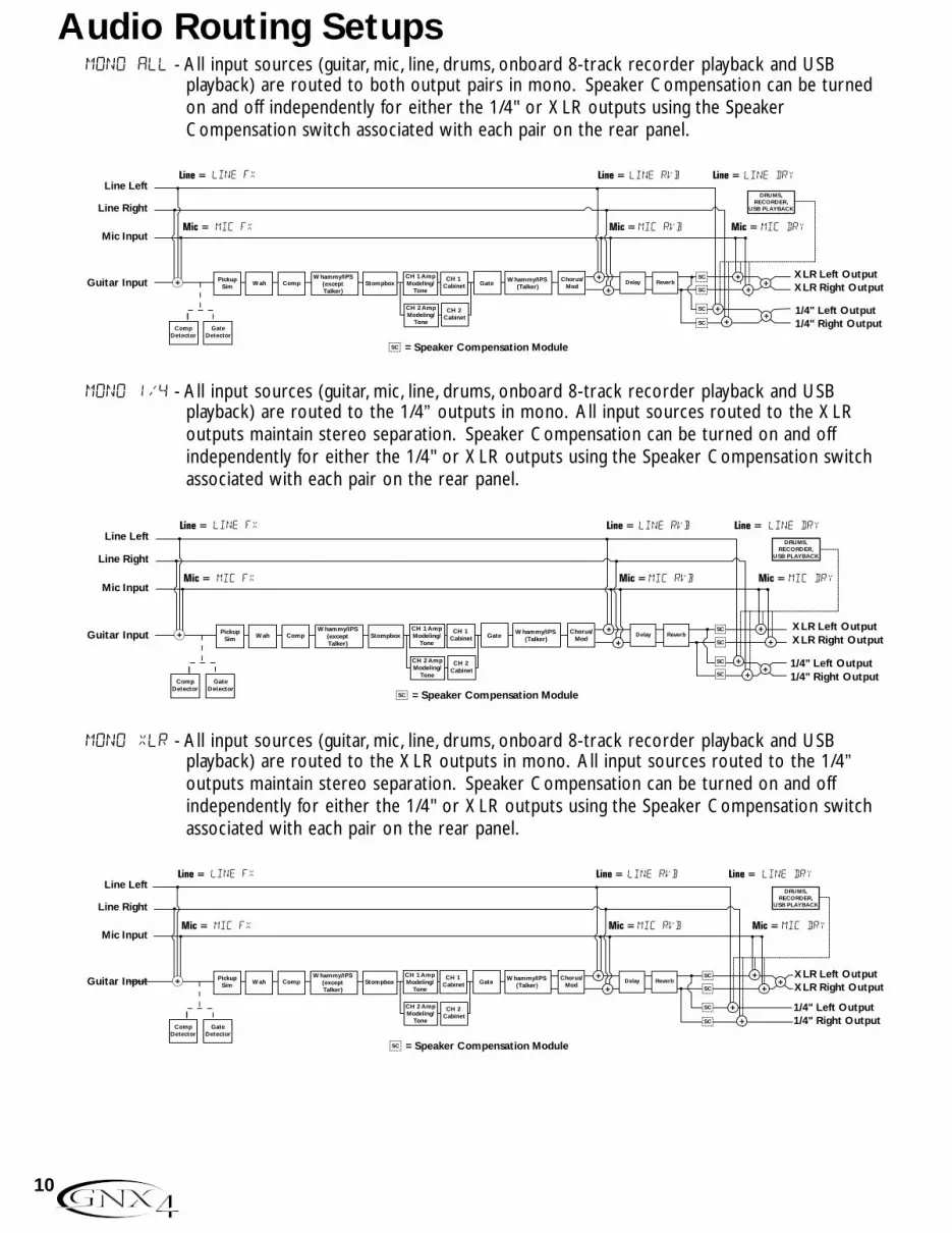
mono all - All input sources (guitar, mic, line, drums, onboard 8-track recorder playback and USB playback) are routed to both output pairs in mono. Speaker Compensation can be turnedon and off independently for either the 1/4" or XLR outputs using the SpeakerCompensation switch associated with each pair on the rear panel.
mono 1/4 - All input sources (guitar, mic, line, drums, onboard 8-track recorder playback and USB playback) are routed to the 1/4” outputs in mono. All input sources routed to the XLR outputs maintain stereo separation. Speaker Compensation can be turned on and off independently for either the 1/4" or XLR outputs using the Speaker Compensation switchassociated with each pair on the rear panel.
mono xlr - All input sources (guitar, mic, line, drums, onboard 8-track recorder playback and USB playback) are routed to the XLR outputs in mono. All input sources routed to the 1/4” outputs maintain stereo separation. Speaker Compensation can be turned on and off independently for either the 1/4" or XLR outputs using the Speaker Compensation switchassociated with each pair on the rear panel.
Mic Input
Guitar Input
Line Left
Line Right
mic rvb mic dry
line rvb line dry
SC
mic fx
line fx
= Speaker Compensation Module
Delay Reverb+
+
XLR Left OutputXLR Right Output
1/4" Left Output1/4" Right Output
+
++
SC
SC
SC
SC
PickupSim Wah Comp Stompbox
CH 1 Cabinet
CompDetector
GateDetector
Whammy/IPS(except Talker)
CH 1 AmpModeling/
Tone
CH 1 Cabinet
CH 1 AmpModeling/
Tone
CH 2 Cabinet
CH 2 AmpModeling/
Tone
GateWhammy/IPS
(Talker)Chorus/
Mod +
+
+
DRUMS,RECORDER,
USB PLAYBACK
Mic Input
Guitar Input
Line Left
Line Right
mic rvb mic dry
line rvb line dry
SC
mic fx
line fx
= Speaker Compensation Module
Delay Reverb+
+
XLR Left OutputXLR Right Output
1/4" Left Output1/4" Right Output
++
+SC
SC
SC
SC
PickupSim Wah Comp Stompbox
CH 1 Cabinet
CompDetector
GateDetector
Whammy/IPS(except Talker)
CH 1 AmpModeling/
Tone
CH 1 Cabinet
CH 1 AmpModeling/
Tone
CH 2 Cabinet
CH 2 AmpModeling/
Tone
GateWhammy/IPS
(Talker)Chorus/
Mod
+
++
DRUMS,RECORDER,
USB PLAYBACK
Mic Input
Guitar Input
Line Left
Line Right
mic rvb mic dry
line rvb line dry
SC = Speaker Compensation Module
mic fx
line fx
Delay Reverb+
+
XLR Left OutputXLR Right Output
1/4" Left Output1/4" Right Output
++
+SC
SC
SC
SC
PickupSim Wah Comp Stompbox
CH 1 Cabinet
CompDetector
GateDetector
Whammy/IPS(except Talker)
CH 1 AmpModeling/
Tone
CH 1 Cabinet
CH 1 AmpModeling/
Tone
CH 2 Cabinet
CH 2 AmpModeling/
Tone
GateWhammy/IPS
(Talker)Chorus/
Mod
+
+
+
+
DRUMS,RECORDER,
USB PLAYBACK
10
Audio Routing Setups

The SPLIT1 Output mode routes guitar signal to the 1/4” outputs while the mic, line input sources,drums, and audio playback from the onboard 8-track recorder and the computer are routed out the XLRoutputs. SPLIT2 is the same as SPLIT1 but the guitar signal with Speaker Compensation is also routedout the XLR outputs.
SPLIT1 - Stereo guitar processing is routed to the 1/4” outputs. Audio playback from the computer, mic,and line sources are routed to the XLR outputs. Speaker Compensation can be individuallyturned on and off either the 1/4” or XLR outputs using the Speaker Compensation switchlocated next to each output pair on the rear panel.
SPLIT2 - Stereo guitar processing is routed to the 1/4” outputs without Speaker Compensation. Stereoguitar processing, audio playback from the computer, mic, and line sources are routed to theXLR outputs with Speaker Compensation. Speaker Compensation can be individually turnedon and off either the 1/4” or XLR outputs using the Speaker Compensation switch locatednext to each output pair on the rear panel.
Mic Input
Guitar Input
Line Left
Line Right
mic rvb mic dry
line rvb line dry
mic fx
line fx
DRUMS,RECORDER,
USB PLAYBACK
Delay Reverb+
+ +
XLR Left OutputXLR Right Output
1/4" Left Output1/4" Right Output
SC
SC
SC = Speaker Compensation Module
PickupSim Wah Comp Stompbox
CH 1 Cabinet
CompDetector
GateDetector
Whammy/IPS(except Talker)
CH 1 AmpModeling/
Tone
CH 1 Cabinet
CH 1 AmpModeling/
Tone
CH 2 Cabinet
CH 2 AmpModeling/
Tone
GateWhammy/IPS
(Talker)Chorus/
Mod+
SC
SC
+
Mic Input
Guitar Input
Line Left
Line Right
mic rvb mic dry
line rvb line dry
SC
mic fx
line fx
= Speaker Compensation Module
SC
SC
DRUMS,RECORDER,
USB PLAYBACK
Delay Reverb+
++
+
XLR Left OutputXLR Right Output
1/4" Left Output1/4" Right Output
PickupSim Wah Comp Stompbox
CH 1 Cabinet
CompDetector
GateDetector
Whammy/IPS(except Talker)
CH 1 AmpModeling/
Tone
CH 1 Cabinet
CH 1 AmpModeling/
Tone
CH 2 Cabinet
CH 2 AmpModeling/
Tone
GateWhammy/IPS
(Talker)Chorus/
Mod+
11
Audio Routing Setups
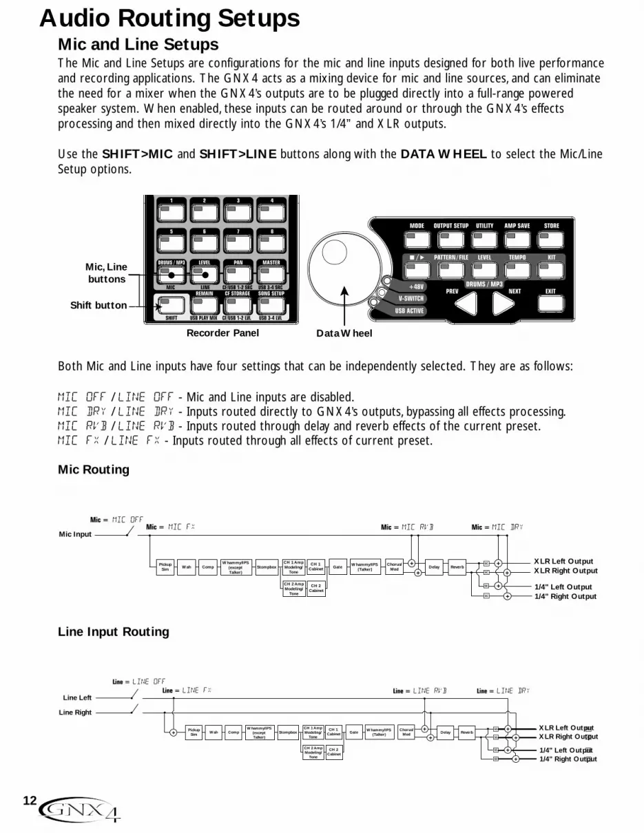
Mic and Line SetupsThe Mic and Line Setups are configurations for the mic and line inputs designed for both live performanceand recording applications. The GNX4 acts as a mixing device for mic and line sources, and can eliminatethe need for a mixer when the GNX4’s outputs are to be plugged directly into a full-range poweredspeaker system. When enabled, these inputs can be routed around or through the GNX4’s effects processing and then mixed directly into the GNX4’s 1/4” and XLR outputs.
Use the SHIFT>MIC and SHIFT>LINE buttons along with the DATA WHEEL to select the Mic/LineSetup options.
Both Mic and Line inputs have four settings that can be independently selected. They are as follows:
MIC OFF / LINe OFF - Mic and Line inputs are disabled.MIC DRY / LINe DRY - Inputs routed directly to GNX4’s outputs, bypassing all effects processing.MIC RVB / LINe RVB - Inputs routed through delay and reverb effects of the current preset.MIC FX / LINE FX - Inputs routed through all effects of current preset.
Mic Routing
Line Input Routing
Line Left
Line Right
line fx line rvb line dry
+
line off
SC
SC
SC
SC
SC
SC
SC
Delay Reverb+
+
+
+
XLR Left OutputXLR Right Output
1/4" Left Output1/4" Right Output
PickupSim Wah Comp Stompbox
CH 1 Cabinet
Whammy/IPS(except Talker)
CH 1 AmpModeling/
Tone
CH 1 Cabinet
CH 1 AmpModeling/
Tone
CH 2 Cabinet
CH 2 AmpModeling/
Tone
GateWhammy/IPS
(Talker)Chorus/
Mod
+
+
mic offmic rvb mic dry
Mic Input
PickupSim Wah Comp Stompbox
CH 1 Cabinet Delay Reverb
+
+
+
+
XLR Left OutputXLR Right Output
1/4" Left Output1/4" Right Output
Whammy/IPS(except Talker)
CH 1 AmpModeling/
Tone
CH 1 Cabinet
CH 1 AmpModeling/
Tone
CH 2 Cabinet
CH 2 AmpModeling/
Tone
GateWhammy/IPS
(Talker)Chorus/
Mod
+
+
mic fx
SC
SC
SC
SC
Mic, Line buttons
Shift button
Recorder Panel Data Wheel
12
Audio Routing Setups
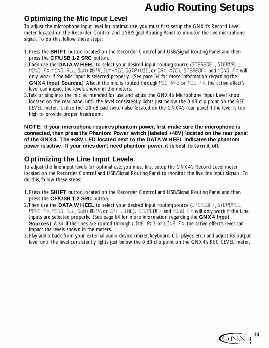
Optimizing the Mic Input LevelTo adjust the microphone input level for optimal use, you must first setup the GNX4’s Record Levelmeter located on the Recorder Control and USB/Signal Routing Panel to monitor the live microphonesignal. To do this, follow these steps:
1. Press the SHIFT button located on the Recorder Control and USB/Signal Routing Panel and thenpress the CF/USB 1-2 SRC button.
2.Then use the DATA WHEEL to select your desired input routing source (STEREOfx, STEROALL,MONO fx, MONO ALL, SUM+DGTR, SUM+MIC, DGTR+MIC, or DRY MIC). STEREOfx and mono fx willonly work if the Mic Input is selected properly. (See page 64 for more information regarding theGNX4 Input Sources.) Also, if the mic is routed through MIC RVB or MIC FX, the active effect’slevel can impact the levels shown in the meters.
3.Talk or sing into the mic as intended for use and adjust the GNX4’s Microphone Input Level knoblocated on the rear panel until the level consistently lights just below the 0 dB clip point on the RECLEVEL meter. Utilize the -20 dB pad switch also located on the GNX4’s rear panel if the level is toohigh to provide proper headroom.
NOTE: If your microphone requires phantom power, first make sure the microphone isconnected, then press the Phantom Power switch (labeled +48V) located on the rear panelof the GNX4. The +48V LED located next to the DATA WHEEL indicates the phantompower is active. If your mics don’t need phantom power, it is best to turn it off.
Optimizing the Line Input LevelsTo adjust the line input levels for optimal use, you must first setup the GNX4’s Record Level meter located on the Recorder Control and USB/Signal Routing Panel to monitor the live line input signals. Todo this, follow these steps:
1. Press the SHIFT button located on the Recorder Control and USB/Signal Routing Panel and thenpress the CF/USB 1-2 SRC button.
2.Then use the DATA WHEEL to select your desired input routing source (STEREOfx, STEROALL,MONO fx, MONO ALL, SUM+DGTR, or DRY line). STEREOfx and mono fx will only work if the LineInputs are selected properly. (See page 64 for more information regarding the GNX4 InputSources.) Also, if the lines are routed through line RVB or line FX, the active effect’s level canimpact the levels shown in the meters.
3. Play audio back from your external audio device (mixer, keyboard, CD player, etc.) and adjust its outputlevel until the level consistently lights just below the 0 dB clip point on the GNX4’s REC LEVEL meter.
13
Audio Routing Setups

For Live Performance The GNX4 was designed to be extremely flexible to meet any of your application needs. For many GNX4users, its primary purpose will be for use in live performances. Whether you are a solo performer whospends weekends playing at a small club or the power-user playing the largest venues each night, the GNX4has just what you need to do the gig right. The following diagrams show examples of how to utilize theGNX4 in typical live performance applications.Before connecting the GNX4, make sure both the GNX4 and your amplifier(s) are turned OFF.
Small Club Setup (Mono Amp Rig)
This diagram demonstrates a minimum setup for using the GNX4 in a typical, small club performancesetup. All you need is your guitar, a couple of guitar cables, and an amp. This connection scheme alsoapplies for use with a power amp/speaker cabinet rig.1. Connect your guitar to the GNX4’s Guitar Input.2. Connect a single mono instrument cable from the Left 1/4” Balanced Output of the GNX4 to the
instrument input or the effect return on your amplifier.3. Switch the GNX4’s Speaker Compensation for the 1/4” Balanced Outputs to the OFF position.4. Press the GNX4’s Output Setup button and select “MONO 1/4” mode using the Data Wheel.NOTE: When using a guitar amp(s), it may be best to connect the GNX4’s Output to youramp’s effects return to avoid coloration of the tone due to the amplifier’s tone controls.
Medium Stage Setup (Stereo Amp Rig)
Whether your gig is at a large club or a small hall, nothing beats running your guitar in stereo. Thisdiagram demonstrates a typical setup using your GNX4’s line outputs, and two guitar combo amps.1. Connect your guitar to the GNX4’s Guitar Input.2. Connect mono instrument cables from the Left and Right 1/4” Balanced Outputs of the GNX4 to the
instrument inputs or the effect returns on your amplifiers.3. Switch the GNX4’s Speaker Compensation for the 1/4” Balanced Outputs to the OFF position.4. Press the GNX4’s Output Setup button and select “STEROAll” mode using the Data Wheel.
Amplifier
Guitar Input
1/4" Balanced Outputs
Guitar
Amplifier
Speaker Compensation Switch (1/4" Outputs)
Guitar Input Left 1/4" Balanced Output
Guitar
Amplifier
Speaker Compensation Switch (1/4" Outputs)
14
Making Connections

Large Stage Setup (Stereo Amp/Cabinet Rig)
A large stage rig lets you really pull out all the stops since space isn’t necessarily an issue, but volumeusually is. For this application, plug your guitar into the GNX4 and connect mono instrument cables fromthe GNX4’s 1/4” outputs into a stereo power amp feeding two cabinets. Using two cabinets gives youmuch more dramatic stereo separation and helps widen the sweet spot for your sound when you moveonstage. Another great idea is to run the GNX4’s XLR outputs directly into the house P.A. and have thesound engineer control your front of house volume in the overall mix. Then if you need to turn up yourstage volume, you won’t upset him by trying to rebalance your guitar volume in the house mix. Thisdiagram demonstrates a typical, large stage performance setup.1. Connect your guitar to the GNX4’s Guitar Input.2. Connect mono instrument cables from the GNX4’s Left and Right 1/4” Line Outputs to a stereo
power amplifier amplifier and switch the 1/4” Outputs Speaker Compensation to the OFF position.3. Connect XLR cables from the GNX4’s Left and Right XLR outputs to the house P.A. mixer and switch
the XLR Outputs Speaker Compensation to the ON position.4. Press the GNX4’s OUTPUT SETUP button and select “STEROALL“ as the output mode using the
DATA WHEEL.
Stereo Power Amp 2- Speaker Cabs
Guitar Input
PA Speaker (Left)
XLR Balanced Outputs1/4" Balanced Outputs
PA Speaker (Right)
Pan
Mute
-10
0
+5
+10
-20
-30-∞
-5
L / R
Mute
L / R
Mute
L / R
Mute
L / R
-5
-4
-3
-2-1 0 +1
+2
+3
+4
+5 Pan-5
-4
-3
-2-1 0 +1
+2
+3
+4
+5 Pan-5
-4
-3
-2-1 0 +1
+2
+3
+4
+5 Pan-5
-4
-3
-2-1 0 +1
+2
+3
+4
+5 Pan-5
-4
-3
-2-1 0 +1
+2
+3
+4
+5 Pan-5
-4
-3
-2-1 0 +1
+2
+3
+4
+5 Pan-5
-4
-3
-2-1 0 +1
+2
+3
+4
+5 Pan-5
-4
-3
-2-1 0 +1
+2
+3
+4
+5
1 2 3 4
-10
0
+5
+10
-20
-30-∞
-5
-10
0
+5
+10
-20
-30-∞
-5
-10
0
+5
+10
-20
-30-∞
-5
Mute
L / R
5
-10
0
+5
+10
-20
-30-∞
-5
Mute
L / R
6
-10
0
+5
+10
-20
-30-∞
-5
Mute
L / R
-10
0
+5
+10
-20
-30-∞
-5
Aux 10
2
4 6
8
10
Aux 20
2
4 6
8
10
Aux 10
2
4 6
8
10
Aux 20
2
4 6
8
10
Aux 10
2
4 6
8
10
Aux 20
2
4 6
8
10
Aux 10
2
4 6
8
10
Aux 20
2
4 6
8
10
Aux 10
2
4 6
8
10
Aux 20
2
4 6
8
10
Aux 10
2
4 6
8
10
Aux 20
2
4 6
8
10
Aux 10
2
4 6
8
10
Aux 20
2
4 6
8
10
Aux 10
2
4 6
8
10
Aux 20
2
4 6
8
10
Mute
L / R
-10
0
+5
+10
-20
-30-∞
-5
Guitar
Mixer
Speaker Compensation Switch (1/4" Outputs)
Speaker Compensation Switch (XLR Outputs)
15
Making Connections
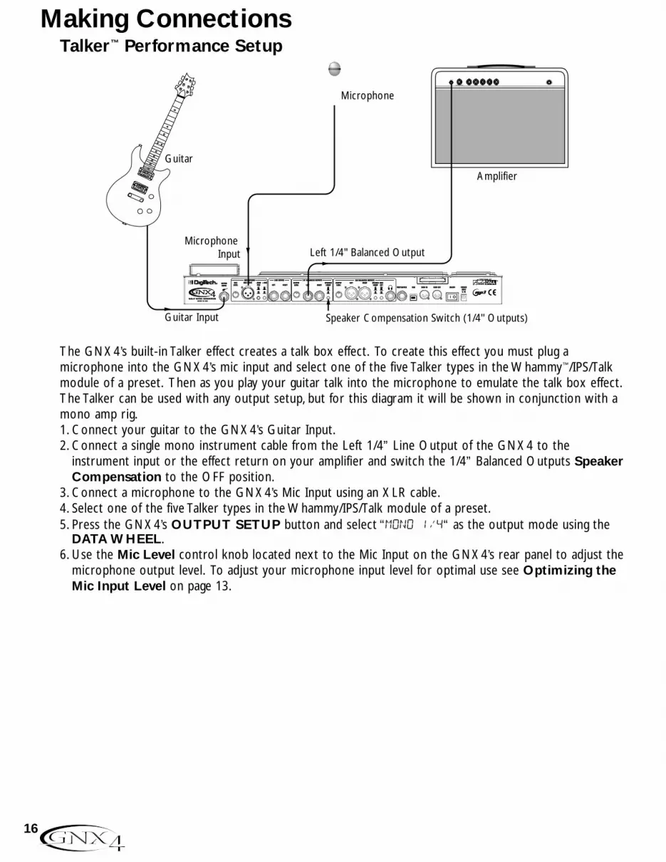
Talker™ Performance Setup
The GNX4’s built-in Talker effect creates a talk box effect. To create this effect you must plug amicrophone into the GNX4’s mic input and select one of the five Talker types in the Whammy™/IPS/Talkmodule of a preset. Then as you play your guitar talk into the microphone to emulate the talk box effect.The Talker can be used with any output setup, but for this diagram it will be shown in conjunction with amono amp rig.1. Connect your guitar to the GNX4’s Guitar Input.2. Connect a single mono instrument cable from the Left 1/4” Line Output of the GNX4 to the
instrument input or the effect return on your amplifier and switch the 1/4” Balanced Outputs SpeakerCompensation to the OFF position.
3. Connect a microphone to the GNX4’s Mic Input using an XLR cable.4. Select one of the five Talker types in the Whammy/IPS/Talk module of a preset.5. Press the GNX4’s OUTPUT SETUP button and select “MONO 1/4“ as the output mode using the
DATA WHEEL.6. Use the Mic Level control knob located next to the Mic Input on the GNX4’s rear panel to adjust the
microphone output level. To adjust your microphone input level for optimal use see Optimizing theMic Input Level on page 13.
Speaker Compensation Switch (1/4" Outputs)Guitar Input
Microphone Input Left 1/4" Balanced Output
Guitar
Microphone
Amplifier
16
Making Connections

Coffee House/Solo Performance Setup
As a solo performer, we all know how important it is to minimize the amount of gear we have to cart toa gig. For the more elaborate system, this may include electronic keyboards, a CD player, and a mixer.The GNX4 virtually eliminates the need for most of this hardware. First, for your backing tracks, just ripyour CD audio tracks into MP3s and place these in the MP3 folder created by the GNX4 on the compactflash card. If you need a mic for vocals or an acoustic instrument, just plug it into the GNX4’s mic input.You have a variety of routings you can select from including taking advantage of the GNX4’s effectsprocessing. For the more advanced setup or if you have a partner on keyboards, just plug them into theGNX4’s line inputs and select the appropriate routing needed. Everything can now be run out theGNX4’s XLR outputs directly into powered speakers. You can even run to a floor monitor out one ofthe available 1/4” Line Outputs and enable Speaker Compensation on both pairs of outputs.1. Connect your guitar to the GNX4’s Guitar Input.2. Connect a microphone to the GNX4’s XLR Mic Input use the Mic Level control knob located next to
the Mic Input on the GNX4’s rear panel to adjust the microphone output level. To adjust yourmicrophone input level for optimal use see Optimizing the Mic Input Level on page 13.
3. Connect a mono instrument cable from the GNX4’s Left 1/4” Line Output to a powered monitor.4. Connect the GNX4’s balanced XLR Left and Right Outputs to a pair of powered PA speakers.5. Switch the Speaker Compensation on for both the XLR and 1/4” outputs.6. Press the GNX4’s OUTPUT SETUP button and select “STEROALL” as the output mode using the
DATA WHEEL.7. Use the Mic Level control knob located next to the Mic Input on the GNX4’s rear panel to adjust the
microphone output level. To adjust your microphone input level for optimal use see Optimizing theMic Input Level on page 13.
CF Card
Powered MonitorPA Speaker (Left) PA Speaker (Right)
Guitar
Microphone
Guitar Input Speaker CompensationSwitch (XLR Outputs)
Left 1/4" OutputMic Input
CompactFlash®
256 MB
XLR Balanced Outputs
17
Making Connections

For Recording The GNX4 also offers great flexibility for recording applications. Listed below are a couple typical recordingsetups.
Onboard Recorder Application
Ever had a moment where the band just clicked with a great song idea? Then you came back the nextnight to go over it again and….how did that go? Never again thanks to the GNX4’s onboard recorderand its ability to remotely capture that idea forever. Just plug a mic into the GNX4’s mic input, or if youhave multiple mics and a mixer, use the stereo output of the mixer into the GNX4’s Line Inputs. Use theShift>CF/USB 1-2 Source buttons located on the GNX4’s Recorder Panel to set the output routing to“STEROALl“ and hit record. Now you can ensure that spontaneous genius will never be lost again.1. Connect your guitar to GNX4’s Guitar Input.2. Connect a microphone to the GNX4’s Mic Input and use the Mic Level control knob located next to
the Mic Input on the GNX4’s rear panel to adjust the microphone output level. To adjust yourmicrophone input level for optimal use see Optimizing the Mic Input Level on page 13.
3. Connect a single mono instrument cable from the GNX4’s Left 1/4” Balanced Output to theinstrument input or the effect return on your amplifier and switch the 1/4” Balanced Outputs SpeakerCompensation to the OFF position.
4. Connect a pair of stereo headphones to the Headphone Output.5. (Advanced Setup) Connect microphones and a keyboard to your mixer and connect the mixer’s stereo
outputs to the GNX4’s Left and Right Line Inputs. To adjust your line input levels for optimal use seeOptimizing the Line Input Levels on page 13.
6. Press the GNX4’s OUTPUT SETUP button and select “STEROALL” as the output mode using theDATA WHEEL.
7. Optimize your recording levels by either increasing or decreasing your source material’s signal level orby using the GNX4’s SHIFT>CF/USB 1-2 LVL button along with the DATA WHEEL and adjustthe levels while playing your guitar. It is best that the recording level consistently lights the -6dB LEDon the meter. (See the Using the Record and Playback Meters section on page 76 for moreinformation on optimizing your recording and playback levels.)
CF Card
HeadphonesSpeaker CompensationSwitch (1/4" Outputs)
- Advanced Setup -
Guitar
Pan
Mute
-10
0
+5
+10
-20
-30-∞
-5
L / R
Mute
L / R
Mute
L / R
Mute
L / R
-5
-4
-3
-2-1 0 +1
+2
+3
+4
+5 Pan-5
-4
-3
-2-1 0 +1
+2
+3
+4
+5 Pan-5
-4
-3
-2-1 0 +1
+2
+3
+4
+5 Pan-5
-4
-3
-2-1 0 +1
+2
+3
+4
+5 Pan-5
-4
-3
-2-1 0 +1
+2
+3
+4
+5 Pan-5
-4
-3
-2-1 0 +1
+2
+3
+4
+5 Pan-5
-4
-3
-2-1 0 +1
+2
+3
+4
+5 Pan-5
-4
-3
-2-1 0 +1
+2
+3
+4
+5
1 2 3 4
-10
0
+5
+10
-20
-30-∞
-5
-10
0
+5
+10
-20
-30-∞
-5
-10
0
+5
+10
-20
-30-∞
-5
Mute
L / R
5
-10
0
+5
+10
-20
-30-∞
-5
Mute
L / R
6
-10
0
+5
+10
-20
-30-∞
-5
Mute
L / R
7
-10
0
+5
+10
-20
-30-∞
-5
Aux 10
2
4 6
8
10
Aux 20
2
4 6
8
10
Aux 10
2
4 6
8
10
Aux 20
2
4 6
8
10
Aux 10
2
4 6
8
10
Aux 20
2
4 6
8
10
Aux 10
2
4 6
8
10
Aux 20
2
4 6
8
10
Aux 10
2
4 6
8
10
Aux 20
2
4 6
8
10
Aux 10
2
4 6
8
10
Aux 20
2
4 6
8
10
Aux 10
2
4 6
8
10
Aux 20
2
4 6
8
10
Aux 10
2
4 6
8
10
Aux 20
2
4 6
8
10
Mute
L / R
8
-10
0
+5
+10
-20
-30-∞
-5
MicrophoneMicrophone
Keyboard
Microphone
Guitar Input
Amplifier
Mic Input
Line Inputs
Left 1/4" Balanced Output
Mixer
CompactFlash®
256 MB
18
Making Connections
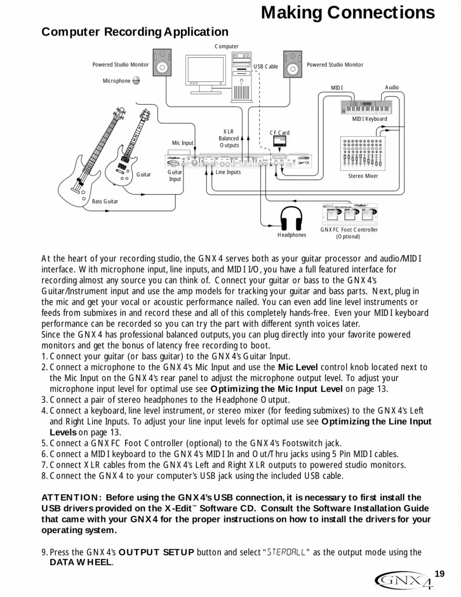
Computer Recording Application
At the heart of your recording studio, the GNX4 serves both as your guitar processor and audio/MIDIinterface. With microphone input, line inputs, and MIDI I/O, you have a full featured interface forrecording almost any source you can think of. Connect your guitar or bass to the GNX4’sGuitar/Instrument input and use the amp models for tracking your guitar and bass parts. Next, plug inthe mic and get your vocal or acoustic performance nailed. You can even add line level instruments orfeeds from submixes in and record these and all of this completely hands-free. Even your MIDI keyboardperformance can be recorded so you can try the part with different synth voices later.Since the GNX4 has professional balanced outputs, you can plug directly into your favorite poweredmonitors and get the bonus of latency free recording to boot.1. Connect your guitar (or bass guitar) to the GNX4’s Guitar Input.2. Connect a microphone to the GNX4’s Mic Input and use the Mic Level control knob located next to
the Mic Input on the GNX4’s rear panel to adjust the microphone output level. To adjust yourmicrophone input level for optimal use see Optimizing the Mic Input Level on page 13.
3. Connect a pair of stereo headphones to the Headphone Output.4. Connect a keyboard, line level instrument, or stereo mixer (for feeding submixes) to the GNX4’s Left
and Right Line Inputs. To adjust your line input levels for optimal use see Optimizing the Line InputLevels on page 13.
5. Connect a GNXFC Foot Controller (optional) to the GNX4’s Footswitch jack.6. Connect a MIDI keyboard to the GNX4’s MIDI In and Out/Thru jacks using 5 Pin MIDI cables.7. Connect XLR cables from the GNX4’s Left and Right XLR outputs to powered studio monitors.8. Connect the GNX4 to your computer’s USB jack using the included USB cable.
ATTENTION: Before using the GNX4’s USB connection, it is necessary to first install theUSB drivers provided on the X-Edit™ Software CD. Consult the Software Installation Guidethat came with your GNX4 for the proper instructions on how to install the drivers for youroperating system.
9. Press the GNX4’s OUTPUT SETUP button and select “STEROALL” as the output mode using theDATA WHEEL.
CF Card
Guitar Input
Line Inputs
XLRBalanced Outputs
MIDI Keyboard
MIDI AudioMicrophone
Guitar
Headphones
Bass Guitar
Powered Studio MonitorPowered Studio Monitor
Pan
Mute
-10
0
+5
+10
-20
-30-∞
-5
L / R
Mute
L / R
Mute
L / R
Mute
L / R
-5
-4
-3
-2-1 0 +1
+2
+3
+4
+5 Pan-5
-4
-3
-2-1 0 +1
+2
+3
+4
+5 Pan-5
-4
-3
-2-1 0 +1
+2
+3
+4
+5 Pan-5
-4
-3
-2-1 0 +1
+2
+3
+4
+5 Pan-5
-4
-3
-2-1 0 +1
+2
+3
+4
+5 Pan-5
-4
-3
-2-1 0 +1
+2
+3
+4
+5 Pan-5
-4
-3
-2-1 0 +1
+2
+3
+4
+5 Pan-5
-4
-3
-2-1 0 +1
+2
+3
+4
+5
1 2 3 4
-10
0
+5
+10
-20
-30-∞
-5
-10
0
+5
+10
-20
-30-∞
-5
-10
0
+5
+10
-20
-30-∞
-5
Mute
L / R
5
-10
0
+5
+10
-20
-30-∞
-5
Mute
L / R
6
-10
0
+5
+10
-20
-30-∞
-5
Mute
L / R
7
-10
0
+5
+10
-20
-30-∞
-5
Aux 10
2
4 6
8
10
Aux 20
2
4 6
8
10
Aux 10
2
4 6
8
10
Aux 20
2
4 6
8
10
Aux 10
2
4 6
8
10
Aux 20
2
4 6
8
10
Aux 10
2
4 6
8
10
Aux 20
2
4 6
8
10
Aux 10
2
4 6
8
10
Aux 20
2
4 6
8
10
Aux 10
2
4 6
8
10
Aux 20
2
4 6
8
10
Aux 10
2
4 6
8
10
Aux 20
2
4 6
8
10
Aux 10
2
4 6
8
10
Aux 20
2
4 6
8
10
Mute
L / R
8
-10
0
+5
+10
-20
-30-∞
-5
Pan-5
-4
-3
-2-1 0 +1
+2
+3
+4
+5 Pan-5
-4
-3
-2-1 0 +1
+2
+3
+4
+5
Mute
L / R
-10
0
+5
+10
-20
-30-∞
-5
Aux 10
2
4 6
8
10
Aux 20
2
4 6
8
10
Aux 10
2
4 6
8
10
Aux 20
2
4 6
8
10
Mute
L / R
-10
0
+5
+10
-20
-30-∞
-5
L R
Stereo Mixer
USB Cable
Computer
GNXFC Foot Controller (Optional)
Mic InputCompactFlash®
256 MB
19
Making Connections
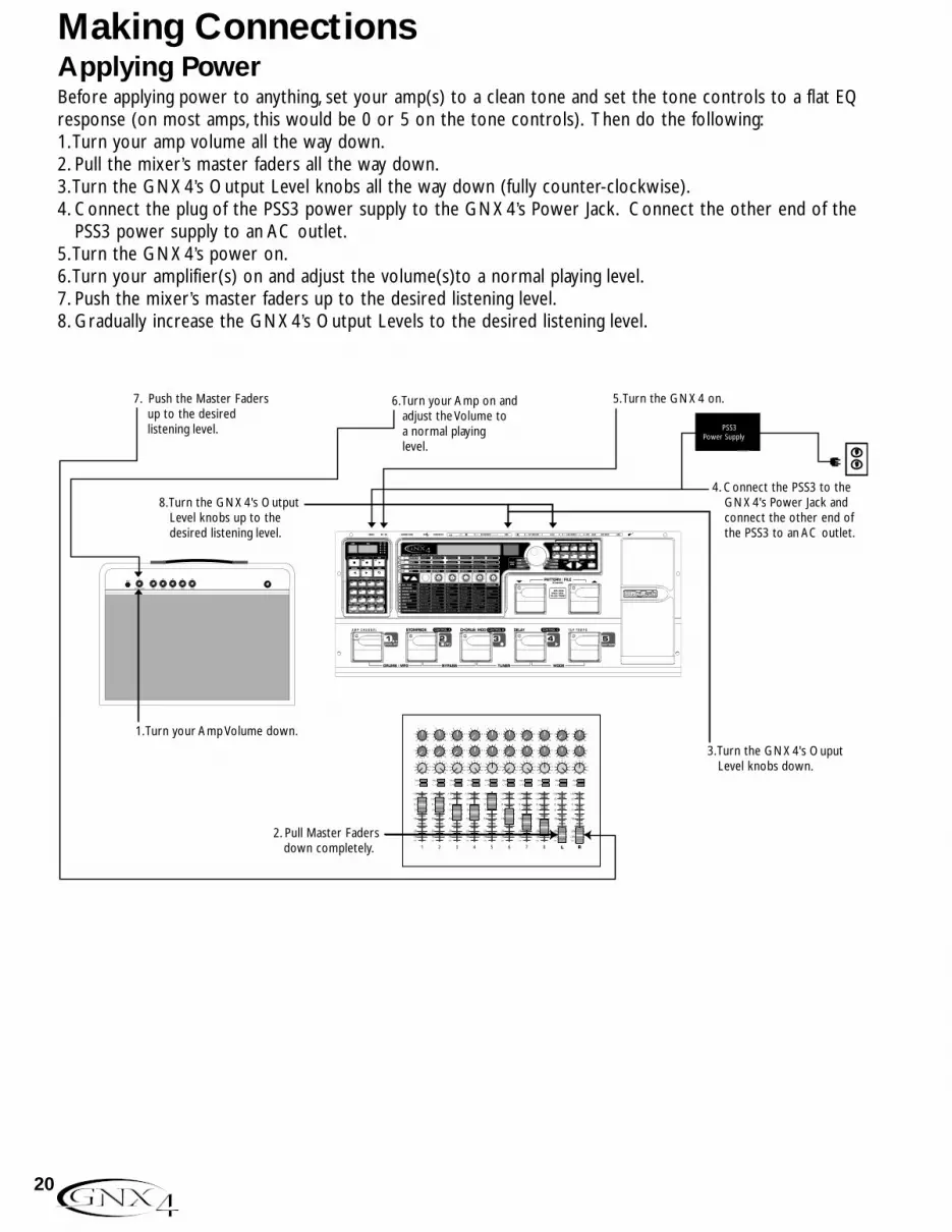
Applying Power Before applying power to anything, set your amp(s) to a clean tone and set the tone controls to a flat EQresponse (on most amps, this would be 0 or 5 on the tone controls). Then do the following:1.Turn your amp volume all the way down.2. Pull the mixer’s master faders all the way down.3.Turn the GNX4’s Output Level knobs all the way down (fully counter-clockwise).4. Connect the plug of the PSS3 power supply to the GNX4’s Power Jack. Connect the other end of the
PSS3 power supply to an AC outlet.5.Turn the GNX4’s power on.6.Turn your amplifier(s) on and adjust the volume(s)to a normal playing level.7. Push the mixer’s master faders up to the desired listening level.8. Gradually increase the GNX4’s Output Levels to the desired listening level.
3. Turn the GNX4's Ouput Level knobs down.
8. Turn the GNX4's Output Level knobs up to the desired listening level.
4. Connect the PSS3 to the GNX4's Power Jack and connect the other end of the PSS3 to an AC outlet.
Pan
Mute
-10
0
+5
+10
-20
-30-∞
-5
L / R
Mute
L / R
Mute
L / R
Mute
L / R
-5
-4
-3
-2-1 0 +1
+2
+3
+4
+5 Pan-5
-4
-3
-2-1 0 +1
+2
+3
+4
+5 Pan-5
-4
-3
-2-1 0 +1
+2
+3
+4
+5 Pan-5
-4
-3
-2-1 0 +1
+2
+3
+4
+5 Pan-5
-4
-3
-2-1 0 +1
+2
+3
+4
+5 Pan-5
-4
-3
-2-1 0 +1
+2
+3
+4
+5 Pan-5
-4
-3
-2-1 0 +1
+2
+3
+4
+5 Pan-5
-4
-3
-2-1 0 +1
+2
+3
+4
+5
1 2 3 4
-10
0
+5
+10
-20
-30-∞
-5
-10
0
+5
+10
-20
-30-∞
-5
-10
0
+5
+10
-20
-30-∞
-5
Mute
L / R
5
-10
0
+5
+10
-20
-30-∞
-5
Mute
L / R
6
-10
0
+5
+10
-20
-30-∞
-5
Mute
L / R
7
-10
0
+5
+10
-20
-30-∞
-5
Aux 10
2
4 6
8
10
Aux 20
2
4 6
8
10
Aux 10
2
4 6
8
10
Aux 20
2
4 6
8
10
Aux 10
2
4 6
8
10
Aux 20
2
4 6
8
10
Aux 10
2
4 6
8
10
Aux 20
2
4 6
8
10
Aux 10
2
4 6
8
10
Aux 20
2
4 6
8
10
Aux 10
2
4 6
8
10
Aux 20
2
4 6
8
10
Aux 10
2
4 6
8
10
Aux 20
2
4 6
8
10
Aux 10
2
4 6
8
10
Aux 20
2
4 6
8
10
Mute
L / R
8
-10
0
+5
+10
-20
-30-∞
-5
Pan-5
-4
-3
-2-1 0 +1
+2
+3
+4
+5 Pan-5
-4
-3
-2-1 0 +1
+2
+3
+4
+5
Mute
L / R
-10
0
+5
+10
-20
-30-∞
-5
Aux 10
2
4 6
8
10
Aux 20
2
4 6
8
10
Aux 10
2
4 6
8
10
Aux 20
2
4 6
8
10
Mute
L / R
-10
0
+5
+10
-20
-30-∞
-5
L R
7. Push the Master Faders up to the desired listening level.
6. Turn your Amp on and adjust the Volume to a normal playing level.
1. Turn your Amp Volume down.
2. Pull Master Faders down completely.
5. Turn the GNX4 on.
CONTROL A CONTROL B CONTROL C TAP TEMPOAMP CHANNEL
PSS3 Power Supply
20
Making Connections
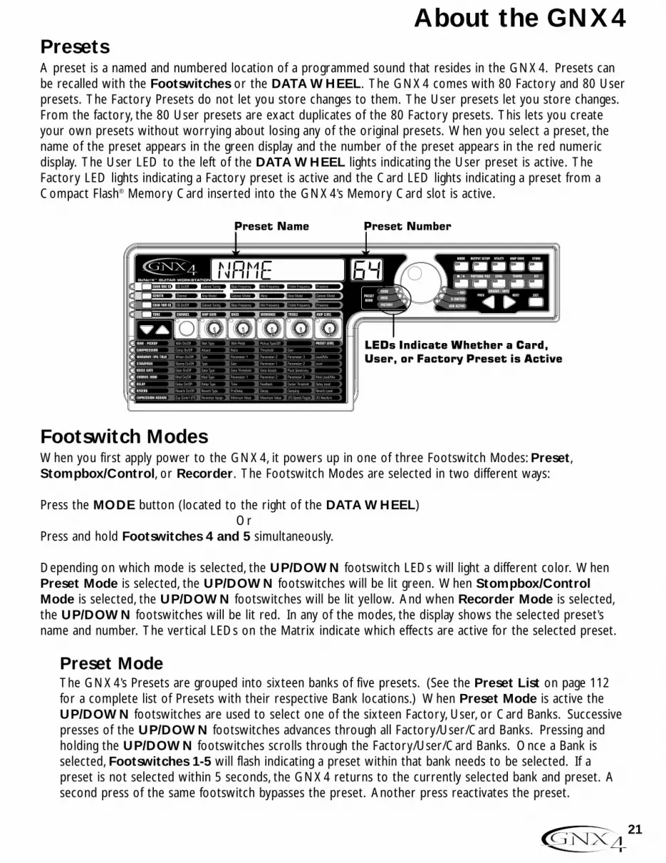
Presets A preset is a named and numbered location of a programmed sound that resides in the GNX4. Presets canbe recalled with the Footswitches or the DATA WHEEL. The GNX4 comes with 80 Factory and 80 Userpresets. The Factory Presets do not let you store changes to them. The User presets let you store changes.From the factory, the 80 User presets are exact duplicates of the 80 Factory presets. This lets you createyour own presets without worrying about losing any of the original presets. When you select a preset, thename of the preset appears in the green display and the number of the preset appears in the red numericdisplay. The User LED to the left of the DATA WHEEL lights indicating the User preset is active. TheFactory LED lights indicating a Factory preset is active and the Card LED lights indicating a preset from aCompact Flash® Memory Card inserted into the GNX4’s Memory Card slot is active.
Footswitch Modes When you first apply power to the GNX4, it powers up in one of three Footswitch Modes: Preset,Stompbox/Control, or Recorder. The Footswitch Modes are selected in two different ways:
Press the MODE button (located to the right of the DATA WHEEL)Or
Press and hold Footswitches 4 and 5 simultaneously.
Depending on which mode is selected, the UP/DOWN footswitch LEDs will light a different color. WhenPreset Mode is selected, the UP/DOWN footswitches will be lit green. When Stompbox/ControlMode is selected, the UP/DOWN footswitches will be lit yellow. And when Recorder Mode is selected,the UP/DOWN footswitches will be lit red. In any of the modes, the display shows the selected preset’sname and number. The vertical LEDs on the Matrix indicate which effects are active for the selected preset.
Preset ModeThe GNX4’s Presets are grouped into sixteen banks of five presets. (See the Preset List on page 112for a complete list of Presets with their respective Bank locations.) When Preset Mode is active theUP/DOWN footswitches are used to select one of the sixteen Factory, User, or Card Banks. Successivepresses of the UP/DOWN footswitches advances through all Factory/User/Card Banks. Pressing andholding the UP/DOWN footswitches scrolls through the Factory/User/Card Banks. Once a Bank isselected, Footswitches 1-5 will flash indicating a preset within that bank needs to be selected. If apreset is not selected within 5 seconds, the GNX4 returns to the currently selected bank and preset. Asecond press of the same footswitch bypasses the preset. Another press reactivates the preset.
LEDs Indicate Whether a Card,User, or Factory Preset is Active
Name
21
About the GNX4

Preset BouncebackIf you would rather not bypass individual presets in Preset Mode by pressing their footswitchesrepeatedly, you can enable the Preset Bounceback function in the Utility menu. For example, let’s sayyou select Preset 1 using FOOTSWITCH 1 as your rhythm tone. Then you select Preset 4 usingFOOTSWITCH 4 as your solo tone. You can now press FOOTSWITCH 4 again and Preset 1will be selected again. Pressing FOOTSWITCH 4 repeatedly will bounceback between Preset 4 andPreset 1. To enable the Preset Bounceback feature, do the following:1. Press the UTILITY control panel button and use the PREV/NEXT arrow buttons to locate the
Bounceback feature. The display will read BOUNCBAK.2. Rotate the DATA WHEEL to turn the BounceBack feature on.3. When finished press the EXIT button.
NOTE:The Preset Bounceback feature only works when the GNX4 is in Preset Mode.
For more information regarding the footswitch functions for Preset Mode see page 59.
Stompbox/Control ModeStompbox/Control Mode is another mode of operation that can be used during a performance. WhenStompbox/Control Mode is active, the UP/DOWN footswitches are used to select the GNX4’s presets.Footswitches 1-4 turn the effects on and off. Footswitch 5 is used as a Tap-Tempo switch for setting thedelay time during a live performance.
For more information regarding the footswitch functions for Stompbox/Control Mode see page 60.
Recorder ModeWhen Recorder Mode is active, the GNX4’s UP/DOWN footswitches are used for selecting songsand loops that reside in the recorder’s memory. The 1-5 footswitches are used for hands-free control ofthe recorder’s functions.
For more information regarding the footswitch functions for Recorder Mode see page 61.
Expression Pedal The Expression Pedal can control three different parameters simultaneously in each preset. Rock theExpression Pedal back and forth to change the values of the assigned parameters. Each parameter theExpression Pedal controls has an adjustable minimum and maximum range. The Expression Pedal alsoincludes a feature called V-Switch and when enabled, it turns on the wah effect and switches from controllingthe parameters assigned to the Expression Pedal and controls the Wah. See page 45 for more information onExpression Pedal Pedal Assignment.
22
About the GNX4

BypassThe GNX4 presets can be bypassed for a clean, unprocessed guitar tone. Bypass turns off all effects andmodeling. To bypass the GNX4 in Preset Mode, press the active preset’s Footswitch (the 1-5 footswitchthat is lit), or press Footswitches S 2 and 3 simultaneously. To bypass the GNX4 while inStompbox/Control or Recorder Mode, press Footswitches 2 and 3 simultaneously. When the GNX4 isbypassed, the display reads BYPASS and all LEDs in the Matrix are off. Press any Footswitch to exit Bypassand return to the last preset. The Matrix and Programming buttons do not function when Bypass is activated.
NOTE: If Preset Bounceback is enabled in the Utility menu, pressing the active preset’sfootswitch while in Bank Mode will not bypass the GNX4’s effects. To bypass the GNX4’s presets while Preset Bounceback is enabled you must press Footswitches 2 and 3 simultaneously.
TunerThe Tuner in the GNX4 lets you quickly tune or check the tuning on your guitar. Press Footswitches 3 and4 simultaneously to access the Tuner. The display briefly flashes TUNER. To begin tuning, play a note on yourguitar (a harmonic at the 12th fret usually works best).The red numeric display shows the note being played,and the green alpha-numeric display indicates whether the note is sharp or flat. Arrows to the left (<<<)indicate the note is sharp and should be tuned down. Arrows to the right (>>>) indicate the note is flat andshould be tuned up. When your note is in tune, -><- is displayed.
While the tuner is selected, you can set your tuning reference with the DATA WHEEL. The default factorysetting is A=440 Hz. The tuning references range from 427 Hz to 453 Hz (± 50 cents (1/2 semitone) fromeither direction of 440 Hz). Below 427 Hz, are alternate dropped tunings. The alternate tunings are REF A(A=Ab), REF G(A=G), and REF G(A=Gb). The display window briefly flashes the selected tuning preference.
23
About the GNX4

The GNX4 Matrix
The main panel of the GNX4 is the Matrix. The Matrix is comprised of two main sections, Amp/Cabinetand Effects. It is used to navigate through the GNX4’s amp/cabinet modeling and effects parameters. Uponpower up, the GNX4 defaults to the TONE amp control row in the Amp/Cabinet section and any effectsthat are enabled within a preset will have their corresponding LEDs lit in the Effects section of the Matrix.You can select one of the other three Amp Control rows, CHAN 1 EQ, GENETX, or CHAN 2 EQ usingthe Amp Control Buttons or you can select the different effects and their parameters using the EffectSelect buttons. The LED to the left of each row indicates which row is active, while the Status Buttonand five Knobs control the corresponding parameter above or below each knob.
Viewing/Editing GENETX™ and Amp Parameter ValuesTo view or edit an amp parameter’s current value, you must first select the row in which the parameterresides using the Amp Control buttons located to the left of the amp parameter rows. After selectingthe desired row, use the Status Button and Knobs to adjust the parameters. When turning a knob oneclick position the current value of the selected parameter will show in the display. If a Knob is turnedagain within 3 seconds, the parameter value will be changed. If a Knob is not turned within 3 seconds,the main display returns back to the preset name.
NOTE: If a parameter name is shown in the display while editing both Amps and Effects, theDATA WHEEL can change the value as well as the Knobs.
AMP/CABINET SECTION
Status Button Knobs
Amp Control Buttons
Data Wheel
AMP/CABINET SECTION
EFFECTSSECTION
Effect Select Buttons
Status Button Knobs
Amp Control Buttons
24
GNX4 Matrix Functions
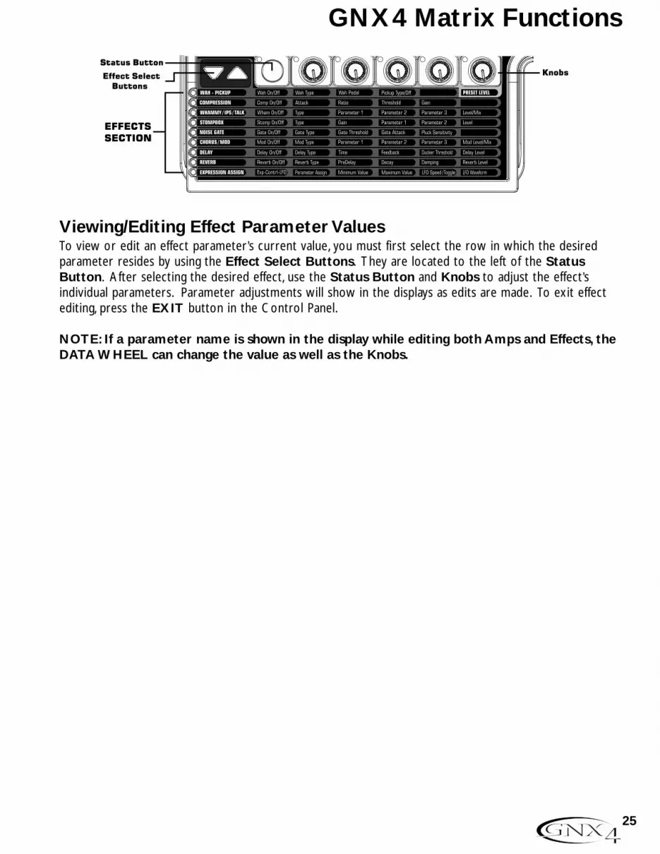
Viewing/Editing Effect Parameter ValuesTo view or edit an effect parameter’s current value, you must first select the row in which the desiredparameter resides by using the Effect Select Buttons. They are located to the left of the StatusButton. After selecting the desired effect, use the Status Button and Knobs to adjust the effect’sindividual parameters. Parameter adjustments will show in the displays as edits are made. To exit effectediting, press the EXIT button in the Control Panel.
NOTE: If a parameter name is shown in the display while editing both Amps and Effects, theDATA WHEEL can change the value as well as the Knobs.
EFFECTSSECTION
Effect Select Buttons
Status Button Knobs
25
GNX4 Matrix Functions

GENETX Row
The GENETX row is where amp and cabinet models are selected for the current preset. It is alsowhere the Warp function resides allowing GeNetX™ warping between the two amp models. When theGENETX row is selected, the Knobs and Status Button perform the following functions:
STATUS BUTTONSelects between Amp Channel 1 (Green) and Amp Channel 2 (Red) and lets you hear each channelindependently, or if a Warped state (Yellow) between both channels exists, this button selects it andlets you hear the warped amp. The Status Button’s LED will light Green, Red, or Yellow depending onwhich channel is selected.
KNOB 1Selects the Channel 1 (Green) amp model and the LED for Knob 1 is lit green.
KNOB 2Selects the Channel 1 (Green) cabinet model and the LED for Knob 2 is lit green.
KNOB 3Warps the Channel 1 and Channel 2 amp and cabinet models together. Setting this knob to itsminimum position selects Channel 1’s amp and cabinet only and the LED for Knob 3 is lit green.Setting this knob to its maximum position selects Channel 2’s amp and cabinet only and the LED forKnob 3 is lit red. Setting Knob 3 to any other position selects a warped state, a combination ofChannel 1 and 2’s amp and cabinet models and the LED will be lit yellow.
KNOB 4Selects the Channel 2 (Red) amp model and the LED for Knob 4 is lit red.
KNOB 5Selects the Channel 2 (Red) cabinet model and the LED for Knob 2 is lit red.
GENETX ROW
STATUS BUTTON
KNOB 1
KNOB 2
KNOB 3
KNOB 4
KNOB 5
26
GNX4 Matrix Functions

CHAN ONE EQ and CHAN TWO EQ Rows
The CHAN ONE EQ and CHAN TWO EQ rows are used for modifying the center frequencies ofthe Bass, Midrange, and Treble controls of that reside within the TONE Row. A Presence control isavailable here for editing amp tone as well. There is also a Cabinet Tuning control for changing the tuningof a selected channel’s cabinet resonance. When either the CHAN ONE EQ or CHAN TWO EQrow is selected, the knobs and STATUS button perform the following functions:
STATUS BUTTONTurns the EQ on and off for the selected channel.
KNOB 1Adjusts the Cabinet Tuning resonance of the cabinet model for the selected channel. The CabinetTuning ranges are from one octave below (-1™0) to one octave above (1™0).
KNOB 2Selects the Bass Center Frequency for the selected channel. The Bass Center Frequency range isfrom 50Hz (50) to 300Hz (300).
KNOB 3Selects the Midrange Center Frequency for the selected channel. The Midrange Center Frequencyrange is from 300Hz (300 HZ) to 5000Hz (5000 HZ).
KNOB 4Selects the Treble Center Frequency for the selected channel. The Treble Center Frequency range isfrom 500Hz (500 HZ) to 8000Hz (8000 HZ).
KNOB 5Boosts or cuts the Presence Level for the selected channel. The Presence Control is a shelf EQ andhas a fixed frequency of 7500Hz. The Presence Level range is from -12dB (-12) to 12dB (12).
CHAN ONE EQ & CHAN TWO EQ ROWS
STATUS BUTTON
KNOB 1
KNOB 2
KNOB 3
KNOB 4
KNOB 5
27
GNX4 Matrix Functions
Here is an example of how the CHAN ONE EQ row would function when the button is pressed:
Warped Amp Sound being heard:If the sound being heard is a Warped sound of both amp models, pressing the CHAN ONE EQ buttonselects the knobs to control the CHAN ONE EQ’s row of parameters. The STATUS button LED willlight yellow, indicating a Warped sound is being heard, and the knobs will all light green. You can modifythe CHAN ONE EQ row parameters which will be heard as the knobs are turned. The STATUSbutton will turn the CHAN ONE EQ on or off and indicate this status by turning the button LED onand off.
CHAN ONE amp sound being heard:If the sound being heard is the CHAN ONE amp tone, pressing the CHAN ONE EQ button selectsthe knobs to control CHAN ONE EQ’s row of parameters. The STATUS button and the knobs willlight green. You can modify the CHAN ONE EQ row parameters, which can be heard as the knobs areturned. The STATUS button will turn the CHAN ONE EQ on or off and indicate this status byturning the button LED on and off.
CHAN TWO amp sound being heard:If the sound being heard is the CHAN TWO amp tone, pressing the CHAN ONE EQ button selectsthe knobs to control the CHAN ONE EQ’s row of parameters. The STATUS button will be lit redindicating you are still listening to the CHAN TWO amp tone. The knobs however will be lit green andonce any of them are turned, the sound will change from the CHAN TWO amp tone to the CHANONE amp tone. You can then modify the CHAN ONE EQ parameters and these changes can beheard as the knobs are turned. The STATUS button will also turn green at this time and can be usedto turn the CHAN ONE EQ on or off as will be indicated by the button’s LED turning on and off.
28
GNX4 Matrix Functions

TONE Row
The TONE row is where the amp tone controls are located for Channel 1 or Channel 2. The soundthat you hear while adjusting these parameters will depend on the channel status (see chart below).TONE control row parameters are Channel,Amp Gain, Bass, Midrange,Treble, and Amp Level.
STATUS BUTTONSelects one of the four channel states in the following order:Ch1 amp -The status button LED lights green and the five control knobs light green indicating that
you are listening to Channel 1 and the control knobs affect Channel 1’s tone settings.Ch1 warp -The status button LED lights yellow and the five control knobs light green indicating that
you are listening to a warped sound and the control knobs affect Channel 1’s tonesettings.
Ch2 amp -The status button LED lights red and the five control knobs light red indicating that youyou are listening to Channel 2 and the control knobs affect Channel 2’s tone settings.
Ch2 warp -The status button LED lights yellow and the five control knobs light red indicating thatyou are listening to a warped sound and the control knobs affect Channel 2’s tonesettings.
KNOB 1Controls the amount of Amp Gain.The Amp Gain range is from 0 to 99.
KNOB 2Controls the Bass EQ Level (boost/cut). The Bass EQ Level range is from -12dB (-12) to 12dB (12).
KNOB 3Controls the Midrange EQ Level (boost/cut). The Midrange EQ Level range is from -12dB (12) to12dB (12).
KNOB 4Selects the Treble EQ Level (boots/cut). The Treble EQ Level range is from -12dB (-12) to 12dB (12).
KNOB 5Controls the Amp Level. The Amp Level Range is from 0 to 99.
STATUS BUTTON
KNOB 1
KNOB 2
KNOB 3
KNOB 4
KNOB 5
TONE ROW
29
GNX4 Matrix Functions

Amp/Cabinet ModelingThe GNX4 was designed to make sound processing easy and intuitive. Because the GNX4 provides bothAmp Modeling and Effects Processing, the editing functions are divided into two sections: the Amp/CabinetModeling section and the Effects section. The GeNetX™ technology contained in the GNX4 lets you go muchfurther than mere Amp Modeling. GeNetX lets you create your own Amp/Cabinet HyperModel™ and storethis custom creation to a User Amp/Cabinet location. When editing either the Amp/Cabinet Modeling, or theEffects section, you must start with one of the User or Factory Presets. The preset you begin with does notneed to be in the location that you intend to save it.
After selecting a preset, you can select the Amp Models or Cabinet Types for your preset. Amp/CabinetModeling applies the tone of one of several vintage or modern Amp Models and Cabinet Types to your guitarsignal. The GNX4 includes accurate emulations of 15 guitar Amp Models, 10 Bass Amp Models, one AcousticGuitar Simulation, and 22 Speaker Cabinet Types.Your choices include:
Amp Models
Marshall, Vox, Fender, Matchless, HiWatt, Ashdown,Ampeg,Trace-Elliot, Sunn, Hartke and Mesa Boogie, are trademarks of their respectivecompanies and are in no way associated with DigiTech®.
direct 1 Turns the amp modeling offblackfac 2 Based on a '65 Fender Twin Reverbboutique 3 Based on a Matchless DC30rectfied 4 Based on a Mesa Dual Rectifierhot rod 5 Based on a Mesa Boogie Mark II C Tweed 6 Based on a '57 Fender Tweed Deluxe britcmbo 7 Based on a Vox AC30 top boost cleantub 8 A clean tube combo settingbritstck 9 Based on a '78 Marshall Master Volumecrunch 10 A nice crunchy tube amp combohi gain 11 A high gain tube amp blues 12 A sweet, tube, blues tone mdrngain 13 Based on a Marshall JCM900 fuzz 14 A high gain fuzz distortion bass man 15 Based on a Fender Bassman hiwattag 16 Based on a HiWatt 50 watt stack acoustic 17 A flat top acoustic guitar rockbass 18 Based on an Ampeg SVT mdrnbass 19 Based on an Ashdown ABM-C410H britbass 20 Based on a Trace-Elliot Commando solar 21 Based on a Sunn 200S vintage 22 Based on a ‘69 Ampeg SVT Classic bomber 23 Based on a Ampeg B15 basic 24 Based on a SWR Basic Black Dualshow 25 Based on a Fender Dual Showman boogiman 26 Based on a Mesa Boogie Bass 400+ hartkey 27 Based on a Hartke Model 2000 empty u1 to u9 User HyperModel Locations
Guitar Amps
Acoustic
Bass Amps
User
Direct
30
Amp/Cabinet Modeling

Cabinet Types
Fender,Ampeg,Ashdown, Sunn, Fane, Acoustic, Hartke, SWR, are trademarks of their respective companies and are in no way associated withDigiTech®.
Editing Amp Models and Cabinet TypesEach GNX4 preset has three channels, Channel 1 (green), Channel 2 (red), and Warp (yellow). Amp channels1 and 2 have selectable amps and cabinets. Each channel has independent controls for gain, level, EQ, andcabinet tuning. The Warp channel is effectively a mixture of the Channel 1 and 2 amps and cabinets using theWarp knob in the Amp Controls section of the matrix. When parameter values have changed, the Store LEDlights indicating the preset has been modified and needs to be stored (see page 58 for more on the storingprocedure).
Once you have selected your amps for Channel 1 and 2, you can switch between these, as well as the Warpchannel, using the Amp Channel footswitch (Stompbox/Control Mode only) or the Status button (GeNetXrow is active) when the preset name is displayed. The following sections guide you through the process ofselecting amps and cabinets, adjusting amp parameters, performing cabinet tuning, and creating then saving aHypermodel™ Amp.
direct 1 Turns the cabinet modeling offamer2x12 2 Based on an American 2x12brit4x12 3 Based on a British 4x12vntg4x12 4 Based on a Vintage 30 4x12brit2x12 5 Based on a British 2x12 twed1x12 6 Based on an American 1x12blnd2x12 7 Based on a Blonde 2x12fane4x12 8 Based on a Fane 4x12grnb4x12 9 Based on a Greenback 4x12botq4x12 10 Based on a Boutique 4x12amer4x10 11 Based on a Bassman 4x10 65 1x12 12 Based on a '65 Tweed 1x12jazz1x15 13 Based on a Fender Pro 1x15bass1x15 14 Based on an Ampeg Portaflex bass4x10 15 Based on an Ashdown 4x10 w/Tweeterbass2x15 16 Based on a Sunn 200S 2x15fold1x18 17 Based on a Acoustic 360hart1x15 18 Based on a Hartke 1x15basic 15h 19 Based on a SWR Basic Blackvntg8x10 20 Based on an Ampeg 8x10 ash 4x10 21 Based on an Ashdown ABM 410 glth4x10 22 Based on an SWR Goliath IIIhart4x10 23 Based on a Hartke 4x10empty U1 to U9 User Locations
Guitar Cabinets
Bass Cabinets
User
Direct
31
Amp/Cabinet Modeling
Selecting Amp Models and Cabinet TypesThe first step to editing an Amp, Cabinet Type, or creating your own HyperModel is to select the Ampand Cabinet types for Channel 1 and Channel 2 in your preset. The procedure for selecting Amps orCabinets is as follows:
1. Press the GENETX Amp Control button.2. Use Knob 1 to select the Amp for Channel 1. The Amp name appears in the display. (See page 30
for a complete list of Amp Models.) 4. Use Knob 2 to select the Cabinet for Channel 1. The Cabinet name appears in the display. See
page 31 for a complete list of Cabinet Types.) 5. Use Knob 4 to select the Amp for Channel 2. The Amp name appears in the display.6. Use Knob 5 to select the Cabinet for Channel 2. The Cabinet name appears in the display.
Adjusting Amp ParametersThe Gain, EQ, and Level Parameters can be adjusted individually for the Channel 1 and Channel 2.This is accomplished by pressing the TONE Amp Control button. The sound that you hear whileadjusting the knobs depends on the state of the Status Button and the Knobs (see chart below).When the TONE row is selected, the Status Button steps through four states in the following order:
Ch1 amp -The status button LED lights green and the five control knobs light green indicating thatyou are listening to Channel 1 and the control knobs affect Channel 1’s tone settings.
Ch1 warp -The status button LED lights yellow and the five control knobs light green indicating thatyou are listening to a warped sound and the control knobs affect Channel 1’s tonesettings.
Ch2 amp -The status button LED lights red and the five control knobs light red indicating that youyou are listening to Channel 2 and the control knobs affect Channel 2’s tone settings.
Ch2 warp -The status button LED lights yellow and the five control knobs light red indicating thatyou are listening to a warped sound and the control knobs affect Channel 2’s tonesettings.
The Gain ranges from 0 (0) to 99 (99). The Bass, Midrange, and Treble EQ range from -12 db(-12) to+12db (12). The Level ranges from 0 (0) to 99 (99). The procedure for adjusting these parameters is asfollows:
1. Press the TONE Amp Control button.2. Press the STATUS button to select either Channel 1 Amp (Green) or Channel 2 Amp (Red).3. Use Knobs 1 through 5 to adjust the Gain,Tone, and Level of the selected amp channel.
Cabinet TuningCabinet tuning actually changes the resonant frequency of the selected cabinet. This is useful for changingthe tonality of your sound without having to touch the EQ parameters. Tuning down gives the soundmore bottom end while tuning up enhances higher frequencies. The procedure for tuning the cabinets isas follows:
1. Press the CHAN ONE EQ or the CHAN TWO EQ Amp Control button to access the CabinetTuning parameters.
2. Use Knob 1 to adjust the Cabinet Tuning resonance. The Cabinet Tuning ranges are from -1™0
(one octave below) to 1™0 (one octave above) the cabinet’s standard resonance.
32
Amp/Cabinet Modeling

Storing Amp Parameter EditsOnce you are satisfied with your amp edits, these changes need to be stored so that they can be recalledlater. See page 58 for more information on storing changes to a preset.
Creating HyperModels™
Creating new, unique HyperModels is what GeNetX™ is all about. Once both channels Amps and Cabinetsare selected and the Amp Parameters and Cabinet Tunings have been adjusted, GeNetX technology lets youdo something amazing. The characteristics of each Amp and Cabinet can be combined or “Warped” to createa completely new HyperModel Amp. The procedure for Warping the Channel 1 and Channel 2 Ampstogether is as follows:
1. Press the GENETX amp control button.2. Rotate Knob 3 to Warp the Channel 1 and Channel 2 Amps and Cabinets together. Rotating it
counter-clockwise emphasizes the Channel 1 characteristics while rotating it clockwise emphasizes theChannel 2 characteristics. A warp value of 1 produces the amp tone of only the Channel 1 (Green)Amp. A warp value of 99 produces the amp tone of only the Channel 2 (Red) Amp.
Saving HyperModels (Amp Save)When you have found your ideal warp setting for Channel 1’s and Channel 2’s Amp Models, you can save thissound as a HyperModel for future use. This HyperModel can be saved in one of 9 User locations. After ithas been saved, it can now be selected by either Amp Channel as the starting point for a new Hypermodel.The Amp Save procedure is as follows:
1. Press the AMP SAVE button. The AMP SAVE button will begin flashing and the display will readNEWAMP. The N of NEWAMP is flashing indicating that you can name your HyperModel.
2. Use the DATA WHEEL to select the alpha-numeric character.3. Use the NEXT button to move to the next character (to the right), or the PREV button to select
the previous character (to the left).4. Repeat steps 2 and 3 you have finished naming the new HyperModel.5. Press the AMP SAVE button again to select one of the 9 User HyperModel locations. If the GNX4
has any unused HyperModel locations available, the display will read U1. The U1 flashes indicating thatthis is the first available location for HyperModel to be stored. If all 9 HyperModel locations are full,the GNX4 defaults to the first HyperModel location and displays the name of HyperModel stored inthe first location.
6. Use the DATA WHEEL to select a User location to save the HyperModel. If all locations have beenused, the display shows the name of the HyperModel about to be overwritten.
7. Press the AMP SAVE button again to complete the Amp Save procedure.Press the EXIT button at any time during the Amp Save procedure to abort the process.
NOTE: The Amp Save procedure only saves Amp/Cabinet combinations to the UserHyperModel locations. It does not store changes or the new HyperModel to theselected preset. See page 58 for information on storing changes to a preset.
33
Amp/Cabinet Modeling

Effects and ParametersThe GNX4 features a comprehensive set of effects for creating just the sound you need for any musicalapplication. These effects are connected in a standard effects chain with pickup simulator, wah, compressor,Whammy™/IPS, and distortion stompbox effects placed before the amps. Effects placed post amp are thosethat typically sound best when heard in stereo like modulation effects, delay and reverb. The followingdiagram show the signal path through the effects of the GNX4:
Editing a Preset’s EffectsThe Effects section is accessed with the Effect Select Up/Down buttons.The Matrix LEDs light one at atime to identify the selected row of effects . Each effect has up to 5 Parameters that can be edited. Pressingthe Status Button turns the effect row on and off. The 5 knobs control the Parameters listed directlybeneath the corresponding knob. Each effect’s parameter is labeled in the Matrix. When a knob is turned,the corresponding parameter name and value appear in the displays.
Rotating the Knobs increases or decreases the value of the parameter (except for Type which selectsdifferent effect types) and you hear the change in real time. Changing presets, or turning the power offbefore storing any changes will erase your changes and revert to the stored values. When the preset hasbeen edited, the Store LED turns on indicating that a change has been made. You may store your settings toany of the 80 User Preset locations or on to an optional compact flash card.
Edit
GNX4OUTPUTS
SPEAKERCOMPENSATION
PRESETLEVEL
34
Effects and Parameters
Effect DefinitionsEach Effect within the GNX4 is fully programmable. Understanding how these effects modify the sound, andhow each parameter alters the effect will help you achieve the sound you are looking for. The followingoverview outlines how each effect and parameter in the GNX4 works.
Preset LevelsThe GNX4 presets each have an independent level control for quick balancing of the levels between presets.Preset Level is accessed by selecting the Wah – Pickup row of the Matrix using the Effect Select buttonsand then adjusting Knob 5. The Preset Level adjusts the overall output gain of the active Preset and therange is from 0 to 99. Preset Level changes need to be saved and stored to a user preset location just as anyother effect changes. See page 58 for more information on Storing a Preset.
Wah-PickupA Wah is an effect controlled by the Expression Pedal. A Wah applies a boost in gain to a narrow bandof frequencies. As the Expression Pedal is rocked back and forth, the center frequency receiving theboost is swept up and down making the guitar sound as if it is saying “Wah”. The Wah is engaged anddisengaged by applying pressure to the V-Switch located under the toe of the Expression Pedal. See page104 for more information regarding the V-Switch.
The Pickup Simulator applies the warmth and thickness of a double coil humbucker pickup to a single coilguitar, or the unique, crisp sound of a single coil pickup to a guitar with a humbucker. This allows you tohave the best of both worlds without ever changing guitars.Wah On/Off - The Status button (or the V-Switch) turns the Wah (Wah) on and off.Wah Type - Knob 1 selects the type of Wah.Values include: Cry Wah (CRY) is a traditional sounding
Wah, Boutique Wah (BOuTIQUe) is a wide sweeping Wah with a more modern sound andFull Range Wah (fullrang) sweeps the entire spectrum of audible frequencies.
Wah Pedal - Knob 2 controls the pedal (wah pdl) parameter that adjusts the wah sweep when thewah is active. The wah sweep range is from 0-99. The Expression Pedal is automaticallylinked to this parameter when the V-Switch is engaged. To adjust the minimum andmaximum range, see the Expression Pedal section on page 45.
Pickup Type/Off - Knob 3 selects the type of Pick Up to be be simulated. Values include: PickupSimulator Off (pick off), Single Coil>Humbucker (SC>humb) gives a single coil pickup the warm tone of a humbucker, and Humbucker>Single Coil (humb>SC) gives ahumbucker the unique sound of a single coil.
Knob 4 has no function when the Wah-Pickup is selected.Preset Level - Knob 5 adjusts the overall preset level. Ranges from 0-99.
Compressor A compressor is used to increase sustain, and even out the volume dynamics in guitar signal. Acompressor sets boundaries for a signal’s strength. When a signal exceeds the set boundary, it is forcedback into the set boundary. As the signal fades to a point where it no longer exceeds the boundary, thecompressor expands the signal strength and increases sustain. The compression parameters are asfollows:Comp On/Off - The Status button turns the Compressor (Compress) on and off.Attack - Knob 1 adjusts the length of time it takes for the Compressor to respond to a signal
exceeding the Threshold. Values include: fast, meDIUM, and slOw.Ratio - Knob 2 adjusts the input to output ratio once the Threshold has been exceeded. For instance, a
Ratio of 4 to 1 means that a signal exceeding the Threshold by 4 dB will only be allowed 1 dB ofincreased output. Higher settings yield a tighter, sound and increase sustain. Lower settings allow
35
Effects and Parameters

better dynamics. Ratio settings are: 1.2:1 (¡2-1), 1.5:1 (¡5-1), 1.8:1 (¡8-1), 2:1 (™0-1), 2.5:1(™5-1), 3:1 (£0-1), 4:1 (¢0-1), 5:1 (∞0-1), 8:1 (•0-1), 10:1 (10-1), 20:1 (20-1), and Infinity:1(INFnty-1).
Threshold - Knob 3 selects the Threshold (threshld). The Threshold is the level a signal is allowed toreach before the compressor begins to work. Low Threshold settings activate thecompressor with weaker signals. Higher settings require a stronger signal to activatecompression. Ranges from 0 to 99.
Gain - Knob 4 adjusts the Output Gain (CMP Gain) from the Compressor. This parameter is used tobalance the level of the Compressor to reach unity gain. Other effects can clip if the CompressorGain too high. Ranges from 0 to 20(dB).
Knob 5 has no function when the Compressor is selected.
Whammy™/IPS/Talk This module includes four types of pitch altering effects:Whammy, IPS, Detune, Pitch Shift, and the Talker™
effect. Only one of the effects in this row can be used at a time. After selecting the type of effect in thismodule, the Knobs 2-5 can then be used to adjust the individual parameters associated with the selectedeffect. The following pages describe each effect and their parameters in more detail.Whammy/IPS/Talk On/Off - When the Whammy/IPS/Talk effects module is selected the Status
button turns the Whammy/IPS/Talk effects on and off.Whammy/IPS/Talk Select - Knob 1 selects whether the module is a Whammy (WHAMMY), Intelligent
Pitch Shifting (IPS), Detuner (DETUNE), Pitch Shift (PITCH), or Talker(Talker 1-5).
WhammyWhammy is an effect that uses an Expression Pedal to bend the pitch of the incoming signal, or add abendable harmony with the original signal. As the Pedal is moved, the note bends either up or down.When Whammy is selected, it is automatically placed before the Amp Modeling as shown in the blockdiagram (see page 34). The Whammy effect must be linked to the Expression Pedal in order tofunction. See page 45 for more information on linking the Expression Pedal.Parameter 1 - Knob 2 selects the interval and direction of the pitch bend. Choices are as follows:
Parameter 2 - Knob 3 provides a manual control of the Whammy Pedal (wham pdl) position.Ranges from 0 to 99.
Knob 4 has no function when the Whammy is selected.Level - Knob 5 adjusts the Whammy Mix (Wham mix) of all of the pitch-altering effects in this
module. Ranges from 0 to 99.
Whammy (no Dry Signal)1 OCT UP (1 octave up) 2 OCT UP (2 octaves up)2NDDOWN (a second down)REV2NDDN (a second down reversed pedal
action)4TH DOWN (a fourth down)1 OCT DN (an octave down)2 OCT DN (2 octaves down)DIVEBOMB (Dive Bomb)
Harmony Bends (Dry Signal Added)M3->MAJ3 (a minor third to a Major third)2ND->MAJ3 (a second above to a Major third
up) 3RD->4TH (a third above to a fourth up) 4TH->5TH (a fourth above to a fifth up) 5TH->OCT (a fifth above to an octave up)H OCT UP (one octave up)H OCT DN (one octave down)octup->Dn (one octave up to one octave
down)
36
Effects and Parameters
Intelligent Pitch Shifting (IPS) Intelligent Pitch Shifting makes a copy of the incoming signal, and then changes the pitch of the copiednote to a diatonically correct interval specified by the Amount parameter. An Intelligent Pitch Shiftersharpens or flattens the shifted pitch in order to keep the specified interval within the selected keyand scale creating a true harmony.Parameter 1 - Knob 2 selects the Amount or harmony interval for the Intelligent Pitch Shifter.
Interval choices include:
Parameter 2 - Knob 3 selects the scale the IPS will use. Scale choices include: Major (MAJOR),Minor (MINOR), Dorian (DORIAN), Mixolydian (MIXoLYDn), Lydian (LYDIAN),Harmonic Minor (HARMINor).
Parameter 3 - Knob 4 selects the musical key the IPS uses. Key choices range from the Key of E(KEY E) through the Key of Eb (KEY Eb).
Level - Knob 5 adjusts the IPS Level (IPS LEVL) of all the pitch-altering effects in this module.Ranges from 0 to 99.
Detune A Detuner makes a copy of your incoming signal, takes the copied signal slightly out of tune from theoriginal, and mixes the two signals together. The result is a doubling type of effect as if two guitarswere playing the same part together.Parameter 1 - Knob 2 selects the Amount (AMouNT) of detuning applied to the copied pitch in
cents (100 cents equals 1 semitone). Ranges are from 24 cents below (-24) to 24cents above (24).
Knob 3 and Knob 4 have no function when Detune is selected.Level - Knob 5 adjusts the Detune Level (dtn LeVL) of all pitch-altering effects in this module.
Ranges from 0 to 99.
Pitch Shift A Pitch Shifter copies the incoming signal, then shifts the pitch of the copied note to a different note.The shifted note is then mixed back with the original signal sounding as if two guitars were playingparallel notes.Parameter 1 - Knob 2 selects the Shift (SHIFT) of the pitch in semitone intervals. Ranges from
two octaves below (-24) to two octaves above (24).Knob 3 and Knob 4 have no function when Pitch Shift is selected.Level - Knob 5 adjusts the Pitch Level (pch LeVL) of all pitch-altering effects in this module.
Ranges from 0 to 99.
Talker™
The Talker is an effect that lets your instrument’s signal be manipulated by your voice. The Talkerrequires a microphone be connected to the Mic Input on the rear panel of the GNX4. As you speakinto the microphone, your instrument mimics what you say. There are five Talker types.
OCT DowN (octave down)7TH DowN (a seventh below)6tH DowN (a sixth below)5tH DowN (a fifth below)4tH DowN (a fourth below)3RD DowN (a third below)2ND DowN (a second below)
2ND UP (a second above)3RD UP (a third above)4TH UP (a fourth above)5TH UP (a fifth above)6TH UP (a sixth above)7TH UP (a seventh above)OCT UP (an octave above)
37
Effects and Parameters

Type - Knob 1 is used to select one of the 5 Talker types. Talker types range from talker 1 (deeptonal characteristics), to talker 5 (bright tonal characteristics).
Sensitivity - Knob 2 adjusts the sensitivity of the microphone level (MIC LEVL). The input levelfrom your microphone must be loud enough for the Talker to work properly. If the microphone inputis too weak, the Talker will have trouble tracking. If the input is too strong, the Talker will clip makingthe words unintelligible. Adjust the mic level on the GNX4’s rear panel so that the LEDs light, butstay below the the clip level. (See Optimizing the Mic Input Level on page 13 for moreinformation regarding mic level adjustment.) The mic level sensitivity ranges are from 0 (leastsensitive) to 99 (most sensitive).Knob 3, Knob 4, and Knob 5 have no function when Talker is selected.
Stomp Box ModelingThe GNX4 Stomp Box Modeling emulates the tones of the most popular distortion boxes ever usedincluding the DOD OD250, Boss DS-1,Arbiter Fuzz Face, Electro Harmonix Big Muff, ProCo RAT, DODGrunge, Boss Metal Zone, Ibanez TS-9,Voodoo Labs Sparkle Drive, and the Guyatone OD-2*.*Arbiter, Boss, Electro-Harmonix, ProCo, Ibanez,Voodoo Labs, Guyatone, DS-1, Fuzz Face, Big Muff, RAT, Metal Zone,TS-9, Sparkle Drive, and OD-2 are trademarks of their respective companies and are in no way associated with DigiTech
Stomp Box On/Off - The Status button turns the Stomp Box Modeling on and off.Type - Knob 1 selects the type of Stomp Box to be used. Choices include:Screamer Based on an Ibanez TS-9 Guy OD Based on a GuyaTone OD-2RODENT Based on a ProCo Rat Distortion SpArkDrv Based on a Voodoo Labs SparkleDriveDS Dist Based on a Boss DS-1 Grunge Based on a DigiTech® Grunge®
DOD 250 Based on a DOD Overdrive 250 Fuzzy Based on an Arbiter Fuzz FaceBIG MP Based on the Electro Harmonix Zone Based on a Boss Metal Zone
Big Muff Pi
Type Gain Param1 Param2 Param3* Param4* LevelScreamer drive tone level
Rodent dist filter volume
DS Dist dist tone level
DOD 250 gain level
Big MP sustain tone volume
Guy OD drive level
Sparkdrv gain tone clean volume
Grunge grnggain butt face loud
Fuzzy fuzz volume
Zone dist mid freq mid lvl low high level
Gain - Knob 2 controls the amount of Gain or distortion in the Stomp Box model. Range is from 0 to99.
Parameter 1 - Knob 3 acts as a Tone control for each Stomp Box and controls the Mid Frequency ofthe Zone model. Range is from 0 to 99.
Parameter 2 - Knob 4 acts as a second Tone control for the SparkleDrive, and Grunge Stomp Boxmodels and controls the Mid Level of the Zone model. Range is from 0 to 99.
*Parameter 3 - Controls the Low Frequency of the Zone model. Range is from 0 to 99.*Parameter 4 - Controls the High Level of the Zone model. Range is from 0 to 99.Level - Knob 5 controls the output level of the Stompbox model. Range is from 0 to 99.
*These Parameters are only available using the X-EDIT™ Editor/Librarian software.
38
Effects and Parameters

Noise GateA Noise Gate is designed to eliminate hiss and ambient noise while you are not playing. A Noise Gatecan also be used to create an automatic swell in volume. The GNX4 includes two different types ofNoise Gates: Silencer™ and Pluck.The Silencer™ operates as a standard Noise Gate.The Pluck feature isdesigned to close after every note (depending on the Pluck Sensitivity).This allows automatic volumeswells to occur on a note by note basis.Gate On/Off - The Status button turns the Noise Gate (gate) on and off.Gate Type - Knob 1 selects between the Silencer™ (Silencer) or Pluck (PLUCK) type of Noise Gates.Gate Threshold - Knob 2 sets the signal strength required to open or close the Noise Gate. The
Gate Threshold (THRESHld) parameter ranges from 0 (opens easily) to 99 (requiresstrong signals to open).
Gate Attack - Knob 3 adjusts the length of time it takes the gate to open (ATTACK) and the signal tobecome audible once the Threshold has been exceeded. Ranges from 0 (immediatesignal), to 9 (This setting will gradually ramp up the volume).
Pluck Sensitivity - Knob 4 selects the threshold (PLUCKSNS) where the Gate re-triggers when usingthe Pluck type Noise Gate. This parameter is only available when Pluck is theselected type of Noise Gate. Ranges from 0 (requires strong signals) to 99 (re-triggers with weak signals).
Knob 5 has no function when the Noise Gate is selected.
Chorus/Mod EffectsThe Modulation Effects group is a multi-function module allowing you to select effects such as: Chorus,Flanger, Phaser,Triggered Flanger,Triggered Phaser,Tremolo, Panner,Vibrato, Rotary Speaker,AutoYa™,YaYa™, SynthTalk™, Envelope Filter (auto wah), Detune, and Pitch Shift. Only one of the effects in this rowcan be used at a time. After selecting the type of effect in this module, the Knobs 2-5 can then be usedto adjust the individual parameters associated with the selected effect. The following pages describe eacheffect and their parameters in more detail.Chorus/Mod Effects On/Off - When the Chorus/Mod group is selected, the Status button turns the
Chorus/Mod Effects module on and off.Chorus/Mod Effects Select - Knob 1 selects whether the module is a Chorus (Chorus), Flanger
(Flanger), Phaser (Phaser),Triggered Flanger (trigflng),TriggeredPhaser (trigphas),Tremolo (TREMOLO), Panner (PANNER),Vibrato(VIBRATO), Rotary (ROTARY),AutoYa (AUTOYA),YaYa (YAYA),SynthTalk (SYNTHTLK), Envelope Filter (ENVELOPE), Detune(DETUNE), Pitch Shift (PITCH).
ChorusA Chorus adds a short delay to your signal.The delayed signal is modulated in and out of tune andthen mixed back with the original signal to create a thicker sound.Parameter 1 - Knob 2 adjusts the rate (Speed) of the modulation. Ranges from 0 to 99.Parameter 2 - Knob 3 adjusts the intensity (Depth) of the modulation. Ranges from 0 to 99.Parameter 3 - Knob 4 adjusts the PreDelay (PREDeLaY) or length of time before the Chorus effect
is applied to the input signal. Ranges from 1 to 20.*Parameter 4 - Selects the waveform used by the Chorus. Waveforms include:Triangle, Sine, and
Square. Ranges from 1 to 20.*Parameter 5 - Adjusts the left to right balance of the wet signal, Ranges from L 99 to R 99.Mod Level - Knob 5 controls the level (mod levl) of the Chorus. Ranges from 0 to 99.
*These Parameters are only available using the X-EDIT™ Editor/Librarian software.
39
Effects and Parameters

FlangerA Flanger uses the same principle as a Chorus but has a shorter delay time and adds regeneration (orrepeats) to the modulating delay. This results in an exaggerated up and down sweeping motion to theeffect.Parameter 1 - Knob 2 adjusts the rate (Speed) of the modulation. Ranges from 0 to 99.Parameter 2 - Knob 3 adjusts the intensity (Depth) of the Modulation. Ranges from 0 to 99.Parameter 3 - Knob 4 adjusts the amount of feedback (Regen) added to the Flanger delay. Ranges
from 0 to 99.Mod Mix - Knob 5 controls the mix (mod mix) of wet and dry signal. Ranges from 0 (all dry) to 99
(all wet).PhaserA Phaser splits the incoming signal, takes the split signal in and out of phase and mixes it back in withthe original signal. As the phasing changes, different frequencies are canceled resulting in a warm sortof twisting sound.Parameter 1 - Knob 2 adjusts the rate (Speed) of the modulating phase. Ranges from 0 to 99.Parameter 2 - Knob 3 adjusts the intensity (Depth) of the modulation. Ranges from 0 to 99.Parameter 3 - Knob 4 adjusts the amount of effected signal returned to the input of the Phaser
(Regen). Ranges from 0 to 99.*Parameter 4 - Selects the waveform used by the Phaser. Waveforms include: Triangle , Sine, and
Square.*Parameter 5 - Adjusts the left to right balance of the wet signal. Ranges from L 99 to R 99.Mod Level - Knob 5 controls the level (mod levl) of wet and dry signal. Ranges from 0 (all dry)
to 99 (all wet).
Triggered FlangerA Triggered Flanger is the same sound as a regular Flanger but it lets you choose the starting point ofthe Flanger sweep. With a regular Flanger, the low frequency oscillator (LFO) is continually sweepingup and down. Therefore, when you begin to play, the flanger may be at the top, bottom, or anyrandom point of the sweep. With a Triggered Flanger, every time the signal exceeds the Sensitivitylevel setting, the Flanger begins at the LFO Start Parameter.Parameter 1 - Knob 2 adjusts the rate (Speed) of the modulation. Ranges from 0 to 99.Parameter 2 - Knob 3 adjusts the strength the signal must be (senstvty) in order to trigger the
Flanger. Ranges from 0 (strong signals) to 99 (weak signals).Parameter 3 - Knob 4 selects the Flanger sweep starting point (LFO STrt). Ranges from 0
(bottom of the sweep point) to 99 (top of the sweep point).Mod Mix - Knob 5 controls the mix (mod mix) of wet and dry signal. Ranges from 0 (all dry) to
99 (all wet).
Triggered PhaserA Triggered Phaser is the same sound as a regular Phaser but it lets you choose the starting point ofthe Phaser sweep. In a regular Phaser, the low frequency oscillator (LFO) is continually changing thephase of the signal. Therefore, when you begin to play, the phaser may be at any random point of thephase. With a Triggered Phaser, every time the signal exceeds the Sensitivity level setting, the Phaserbegins at the LFO Start Parameter.
Parameter 1 - Knob 2 adjusts the rate (Speed) of the modulating phase. Ranges from 0 to 99.Parameter 2 - Knob 3 adjusts the strength the signal must be (senstvty) in order to trigger the
Phaser. Ranges from 0 (strong signals) to 99 (weak signals).
*These Parameters are only available using the X-EDIT™ Editor/Librarian software.40
Effects and Parameters

Parameter 3 - Knob 4 selects the Phaser sweep starting point (LFO STrt). Ranges from 0(bottom of the sweep point) to 99 (top of the sweep point).
Mod Mix - Knob 5 controls the mix (mod mix) of wet and dry signal. Ranges from 0 (all dry) to 99(all wet).
TremoloA Tremolo effect modulates the volume of the signal at an even rate.Parameter 1 - Knob 2 adjusts the rate (Speed) at which the volume modulates. Ranges from 0 to
99.Parameter 2 - Knob 3 adjusts the intensity (Depth) of the modulating volume. Ranges from 0 to
99.Parameter 3 - Knob 4 selects the type of wave form the modulation uses. Choices include:
Triangle , Sine, and Square.Knob 5 has no function when the Tremolo is selected.
PannerAn Auto Panner modulates the sound from left to right at an even rate.Parameter 1 - Knob 2 adjusts the rate (Speed) at which the signal pans from side to side. Ranges
from 0 to 99.Parameter 2 - Knob 3 adjusts the intensity (Depth) of the changing pan. Ranges from 0 to 99.Parameter 3 - Knob 4 selects the type of wave form the modulation uses. Choices include:
Triangle , Sine, and Square.Knob 5 has no function when the Panner is selected.
VibratoA Vibrato effect modulates the pitch of the incoming signal at an even rate.Parameter 1 - Knob 2 adjusts the rate (Speed) at which the pitch modulates. Ranges from 0 to
99.Parameter 2 - Knob 3 adjusts the intensity (Depth) of the modulating pitch. Ranges from 0 to 99.Parameter 3 - Knob 4 selects the type of wave form the modulation uses. Choices include:
Triangle , Sine, and Square.Knob 5 does not function when the Vibrato is selected.
Rotary SpeakerRotary Speaker is an emulation of a device that includes a spinning horn and rotor (woofer). Therotation of these two speakers produces an interesting combination of sound panning from side toside, as well as a slight pitch change due to the speed of the sound coming towards, and then goingaway from the listener.Parameter 1 - Knob 2 adjusts the rate (Speed) of the spinning speakers. Ranges from 0 to 99.Parameter 2 - Knob 3 controls the intensity (Depth) of the Effect. Ranges from 0 to 99.Parameter 3 - Knob 4 controls the Pitch Shift (doppler) effect that is the ratio between the horn
and the rotor positions. Ranges from 0 to 99.*Parameter 4 - Selects the crossover frequency between the horn and rotor. Ranges from 200Hz
to 1500Hz.Mod Mix - Knob 5 controls the mix (mod mix) of wet and dry signal. Ranges from 0 (all dry) to
99 (all wet).
*These Parameters are only available using the X-EDIT™ Editor/Librarian software.
41
Effects and Parameters

AutoYa™
An AutoYa combines the characteristics of a Wah and a Flanger together creating an almost humanvowel sound as if the guitar were saying “Yah.” The AutoYa automatically provides this animation bymodulating the sound at an even rate.Parameter 1 - Knob 2 adjusts the rate (Speed) of the AutoYa. Ranges from 0 to 99.Parameter 2 - Knob 3 adjusts the intensity (Depth) of the AutoYa effect. Ranges from 0 to 99.Parameter 3 - Knob 4 adjusts the throaty quality (Range) of the AutoYa effect. Ranges from 1 to
50.*Parameter 4 - Adjusts the left to right balance of the wet signal. Ranges from L 99 to R 99.Mod Mix - Knob 5 controls the mix (mod mix) of wet and dry signal. Ranges from 0 (all dry) to
99 (all wet).
YaYa™
The YaYa is an effect exclusive to DigiTech® products. The YaYa is controlled by the Expression Pedaland combines the characteristics of a wah and a flanger together providing a unique talk box type ofeffect. As the Expression Pedal is rocked back and forth, the guitar appears to say “Yah.” The YaYaeffect must be linked to the Expression Pedal in order to function. See page 45 for more informationon linking the Expression Pedal.Parameter 1 - Knob 2 adjusts the Ya Pedal position (YA PeDaL). Ranges from 0 to 99.Parameter 2 - Knob 3 adjusts the intensity (Depth) of the YaYa effect. Ranges from 0 to 99.Parameter 3 - Knob 4 adjusts the throaty quality (Range) of the YaYa effect. Ranges from 1 to 50.*Parameter 4 - Adjusts the left to right balance of the wet signal. Ranges from L 99 to R 99.Mod Mix - Knob 5 controls the mix (mod mix) of wet and dry signal. Ranges from 0 (all dry) to 99
(all wet).
SynthTalk™
SynthTalk is another effect exclusive to DigiTech. It makes your guitar appear to speak based uponthe dynamics of your playing style.Parameter 1 - Knob 2 adjusts the Attack (attack)of the synthesized voice. Ranges from 0 to 99.Parameter 2 - Knob 3 adjusts the Release (release) of the synthesized voice. Ranges from 0 to
99, and oo (infinity).Parameter 3 - Knob 4 changes the characteristics of the various synth voices (VOX). Ranges from
0 to 99.*Parameter 4 - Adjusts the left to right balance of the wet signal. Ranges from L 99 to R 99.Sensitivity - Knob 5 knob adjusts the sensitivity (senstvty) of the input signal required to trigger
the SynthTalk effect. Ranges from 0 to 99.
Envelope FilterThe Envelope Filter is an automatic Wah effect that alters your sound according to how hard thestrings are struck.Parameter 1 - Knob 2 adjusts the sensitivity (Senstvty) of the input signal required to trigger the
Wah effect. Ranges from 0 to 99.Parameter 2 - Knob 3 adjusts the frequency range (Range) of the Wah effect. Ranges from 0 to
99.Parameter 3 - Knob 4 adjusts the left/right balance of the Wah signal. Ranges from left 99 (mod
left 99) to right 99 (mod rght 99).Mod Mix - Knob 5 controls the mix (mod mix) of wet and dry signal. Ranges from 0 (all dry) to
99 (all wet).
*These Parameters are only available using the X-EDIT™ Editor/Librarian software.42
Effects and Parameters

Detune A Detuner makes a copy of your incoming signal, takes the copied signal slightly out of tune from theoriginal, and mixes the two signals together. The result is a doubling type of effect as if two guitarswere playing the same part together.Parameter 1 - Knob 2 selects the Amount (AMouNT) of detuning applied to the copied pitch in
cents (100 cents equals 1 semitone). Ranges are from 24 cents below (-24) to 24cents above (24).
Parameter 2 - Knob 3 adjusts the left/right balance of the detuned signal. Ranges from left 99 (modleft 99) to right 99 (mod rght 99).
Knob 4 has no function when Detune is selected.Mod Level - Knob 5 controls the level (mod levl) of the detuned note. Ranges from 0 to 99.
Pitch ShiftA Pitch Shifter copies the incoming signal, then shifts the pitch of the copied note to a different note.The shifted note is then mixed back with the original signal sounding as if two guitars were playingparallel notes.Parameter 1 - Knob 2 adjusts the Amount of Pitch Shift (SHIFT) in intervals of one semi-tone.
Ranges from 12 semitones (-12) below to 24 semitones (24) above.Parameter 2 - Knob 3 adjusts the left/right balance of the shifted pitch. Ranges from left 99 (mod
left 99) to right 99 (mod rght 99).Knob 4 has no function when Pitch Shift is selected.Mod Level - Knob 5 controls the level (mod levl) of the shifted pitch. Ranges from 0 to 99.
DelayDelay records a portion of the incoming signal, and plays it back a short time later. The recorded segmentcan repeat just once, several times, or infinitely (that turns off the input to the Delay and lets you playover the top of a passage in the Delay loop). The Delay in the GNX4 also includes a Ducker Thresholdthat lets you set the signal strength required before the Delay records. This feature lets you control theDelay with your playing.Delay On/Off - The Status button turns the Delay (delay) on and off.Delay Type - Knob 1 selects one of the 5 different types of Delay. The Delay choices include:
Time - Knob 2 adjusts the length of time between repeats. Ranges from 0 through 2000 milliseconds (0MS through 2000 MS) in 1 ms increments. Use the DATA WHEEL while the Delay Timeappears in the Display to adjust the Delay Time in 100 ms increments.
Feedback - Knob 3 adjusts the number of times the delayed signal will repeat (feedback). Rangesfrom 0 to 99 and rpt hold (infinite repeat).
Ducker Threshold - Knob 4 adjusts the level (threshld) the input signal must reach before the Delaysignal is attenuated. Ranges from 1 to 99 and off (oF).
*Ducker Attenuation - The Ducker Level selects the amount of attenuation applied to the Delay signalwhen the Ducker Threshold has been exceeded. Ranges from 0 to 99.
*Delay Balance - The Delay Balance adjusts the left/right balance of the Delay signal. Ranges from L 99to R 99.
Spread - This parameter increases or decreases the stereo imaging for the Spread Delay. Range is 1-50.Delay Level - Knob 5 adjusts the volume (dly levl) of the Delay signal. Ranges from 0 to 99.
*These Parameters are only available using the X-EDIT™ Editor/Librarian software.
MONO (clear concise repeats)pingpong (bounces from side to side)ANALOG (deteriorates with each repeat)
anlgpong (side to side with deterioration)Spread (clear concise repeats with stereo
imaging)
43
Effects and Parameters

Reverb Reverb gives the listener a sense that the music is being performed in various acoustical environments. Itcan provide the tight acoustics of a small room, or the ambience of a huge arena.Reverb On/Off - The Status button turns the Reverb (reverb) on and off.Reverb Type - Knob 1 selects the type of Reverb or acoustic environment. The GNX4 provides ten
different environments to choose from including:
PreDelay - Knob 2 adjusts the amount of time (PREDeLaY) it takes for the initial sound to reach thefirst reflective surface in the simulated environment. Ranges from 0 to 15.
Decay - Knob 3 adjusts the length of time the Reverb is audible (DECAY). Ranges from 0 to 99.Damping - Knob 4 controls the amount of sound which is absorbed (damping) in the simulated
environment. Ranges from 0 to 99.*Reverb Balance - The Reverb Balance adjusts the left/right balance of the Reverb signal. Ranges from
L 99 to R 99.Reverb Level - Knob 5 adjusts the level (rvb levl) of the Reverb. Ranges from 0 to 99.
*These Parameters are only available using the X-EDIT™ Editor/Librarian software.
STUDIO = StudioROOM = Wood RoomCLUB = ClubPLATE = Plate HALL = Hall
THEATER = AmphitheaterCHURCH = ChurchGARAGE = Parking GarageARENA = ArenaSPRING = Spring
44
Effects and Parameters

The GNX4 has several options for real-time control over effects parameters in each of its presets.Parameters can be modified during performance both manually and automatically by several methods. Theseare referred to as expression controllers and include the following: the built-in Expression Pedal, InternalLFOs (low frequency oscillators), and the Control Footswitches. Each of these controllers can beprogrammed specifically for each preset, giving you many options for manipulating each in a different manner.
Expression PedalThe Expression Pedal on the GNX4 can control up to 3 parameters in real time. Each parameter assignedto the Expression Pedal can have specific ranges of how much the parameter is controlled by using theminimum and maximum controls. The GNX4’s Expression Pedal includes DigiTech®’s exclusive V-Switch.The V-Switch lets you switch the Expression Pedal assignment on the fly. Apply extra pressure to the toeof the Expression Pedal to engage the V-Switch, and the Expression Pedal switches between the assignedparameter and the Wah. The sensitivity or amount of pressure required to engage the V-Switch can beadjusted to suit your personal taste (or weight of your foot). See page 104 for the V-SwitchThreshold/Sensitivity adjustment procedure.
Expression Pedal Links 1-3Each preset can have up to 3 parameters assignments to the Expression Pedal. Each assignment hasthe following assignment options:
1. Parameter Type (see parameter list on page 48)2. Min Value3. Max Value
The procedure for assigning a parameter to the Expression Pedal is as follows:1. Press either Effect Select button until the Expression Assign row is selected.2. Press the STATUS button until the display reads exp pdl1 (Expression Pedal Link 1), exp pdl2
(Expression Pedal Link 2), or exp pdl3 (Expression Pedal Link 3), depending upon which assignmentyou want to use or the number of parameters you intend to assign.
3. Rotate Knob 1 until the parameter appears in the display. See the Expression Parameter AssignmentList on page 48 for a complete list of assignable parameters.
4. Rotate Knob 2 to select the minimum value the parameter reaches with the Expression Pedal in thetoe up position.
5. Rotate Knob 3 to select the maximum value the parameter reaches with the Expression Pedal in thetoe down position.
6. Store your Expression Pedal assignment to your preset. See page 58 for more information on storingpresets.
Wah PedalThe GNX4’s wah effect can be programmed to have specific heel and toe ranges in each preset. Thesesettings are configured in the Expression Assign row of the matrix. To customize the heel/toe range forthe wah effect, follow these steps:
1. Press either EFFECT SELECT button until the Expression Assign row is selected.2. Press the STATUS button multiple times until WAH PDL appears in the display.3. Rotate Knob 2 to set the heel position of the wah effect. Ranges from 0 to 99.4. Rotate Knob 3 to set the toe position of the wah effect. Ranges from 0 to 99.5. Press EXIT when finished.
45
Expression Pedal Assignment
Amp Channel Footswitch From the factory, the Amp Channel Footswitch selects between the Channel 1 Amp, Channel 2 Amp, andthe Warped Amp state when the GNX4 is in Stompbox/Control mode. However, you can configurethe function of the Amp Channel Footswitch within a preset.The procedure for assigning the function of the Amp Footswitch is as follows:1. Press either EFFECT SELECT button until the Expression Assign row is selected.2. Press the STATUS button until the display reads AMP FS (Amp Footswitch).3. Rotate Knob 1 to select the Amp Footswitch function. Your choices include:
CH1-CH2 - Switches between the Channel 1 (Green) and the Channel 2 (Red) Amp Channels.CH1-Warp - Switches between the Channel 1 (Green) and the Warped Amp (Yellow) Channels.CH2-Warp - Switches between the Channel 2 (Red) and the Warped Amp (Yellow) Channels.C1-c2-wp - Switches between the Channel 1(Green), the Warped (Yellow) Channel, and the
Channel 2 (Red) Channels.4. Store your Amp Footswitch assignment to your preset. See page 58 for more information on storing
presets.
Control FootswitchesWhen using the GNX4 in Stompbox/Control mode, FOOTSWITCHES 2, 3, and 4 become aControl Footswitches. This provides even more real-time expressive control during performance whenused in conjunction with the Expression pedal. Up to three 3 parameters can be controlled between twodifferent values in each preset using the Control footswitches. The Control footswitches can function intwo different ways, as Toggle footswitches or as Momentary footswitches.
When using the Toggle function, a Control footswitch behaves like a normal footswitch in that it switchesto an ON state when pressed once and then an OFF state when pressed again. This type of function isuseful when you want to use it for turning effects like the Compressor or Whammy on and off. It canalso be used to toggle between two different parameter settings, for instance, a delay level of 10 or aDelay level of 50.
When using the Momentary function, a Control footswitch turns an effect ON as long as it is beingpressed, and turns OFF once it is released. Experimenting with different parameters can produce somevery interesting results. For instance, you can assign Pitch Shift amount and have your guitar shift from afifth above when a Control footswitch is pressed and return to normal pitch when it is released.
Control A, B, and C LinksWhen the GNX4 is in Stompbox/Control mode, the five numbered footswitches have the followingdefault functions:
FS 1 – Amp ChannelFS 2 (CONTROL A) – Stompbox On/Off FS 3 (CONTROL B) – Chorus/Mod On/Off FS 4 (CONTROL C) – Delay On/OffFS 5 – Tap Tempo
Footswitches 2, 3, and 4, which are also labeled as Control A,B, and C footswitches, are programmablefootswitches that can control of up to 3 parameters each per preset. These are displayed as CnTRL A1-3, CnTRL B 1-3, and CnTRL C 1-3 in the Expression Assign menu. Each Control footswitch has thefollowing assignment options:
1. Parameter Type (see attached parameter list) 3. Max Value2. Min Value 4.Toggle or Momentary
46
Expression Pedal Assignment

The procedure for assigning the Control Footswitches in the GNX4 is as follows:1. Press either EFFECT SELECT button until the Expression Assign row is selected.2. 2. Press the Status button until the display reads CNTRL A1 (Control A1), cntrl a2 (Control A2),
CNTRL A3 (Control A3), CNTRL B1 (Control B1), cntrl B2 (Control B2), CNTRL B3 (ControlB3), CNTRL C1 (Control C1), cntrl C2 (Control C2), CNTRL C3 (Control C3).
3. Rotate Knob 1 until the Parameter is displayed. See the Expression Parameter Assignment Liston page 48 for a complete list of assignable Parameters.
4. Rotate Knob 2 to select the minimum value the assigned parameter reaches when the Controlfootswitch is turned off.
5. Rotate Knob 3 to select the maximum value the assigned parameter reaches when the Controlfootswitch is turned on.
6.While on Control Footswitch assignment #1 only, rotate the Knob 4 to select the type of footswitchfunction you want it to perform,Toggle, toggle, or Momentary, momentary.
7. Store the assignment to your preset. See page 58 for more information on storing.
LFOsThe GNX4 includes two low frequency oscillators (LFO1 and LFO2) that can each be assigned to a singleparameter. A low frequency oscillator automatically varies the value of the assigned parameter at a steadyrate. A minimum and maximum value can be assigned. For instance: if the Amp Gain was assigned toLFO1, and the minimum value was set at 1 and the maximum value was set at 99, the GNX4 wouldautomatically sweep the amount of distortion from clean to distorted and back to clean. Individual LFOspeeds can also be assigned. In the previous example, the LFO speed would determine the length of timeit took the LFO to sweep from the clean to the distorted sound.
LFO Links 1-2Each preset has two LFOs that can each be assigned to a single parameter. Each LFO has the followingassignment options:
1. Parameter Type (see attached parameter list) 3. Max Value 5. LFO Speed2. Min Value 4. LFO Waveform
The procedure for assigning a parameter to the LFO 1 or LFO 2 is as follows:1. Press either EFFECT SELECT button until the Expression Assign row is selected.2. Press the STATUS button to assign LFO1 (LFO 1) or LFO2 (LFO 2).3. Rotate Knob 1 until the Parameter is displayed. See the Expression Parameter Assignment List
on page 48 for a complete list of assignable Parameters.4. Rotate Knob 2 to select the minimum value the assigned parameter reaches at the bottom turn
around point for the LFO.5. Rotate Knob 3 to select the maximum value the assigned parameter reaches at the top turn around
point for the LFO.6. Rotate Knob 4 to select the speed that the LFO oscillates from the minimum to the maximum values.
LFO speed ranges from (.O5 Hz) to 10 Hz (1ºO HZ).7. Rotate Knob 5 to select the waveform the LFO oscillates on. Your choices include:
triangle (Triangle) - a smooth rise and fall, but abrupt turn around in oscillation.SINE (Sine) - a smooth rise, fall, and turn around in oscillation.SQUARE (Square) - an abrupt rise, fall, and turn around in oscillation.
8. Store your LFO assignment to your preset. See page 58 for more information on the storingprocedure.
47
Expression Pedal Assignment

Expression Parameter Assignment ListThe following parameters can be assigned to any of the 3 Expression Pedal, Control A, B, C footswitches,or LFO 1 and LFO 2.
NO LINK (No Link) No Parameter is assignedAMP CHaN (Amp Channel) Switches Amp ChannelsAmp WARP (Amp Warp) Warps the Channel 1 and Channel 2 Amp ModelsCab WARP (Cabinet Warp) Warps the Channel 1 and Channel 2 Cabinet typesWARP (Warp) Warps Channel 1 and Channel 2ch1 GAIN (Green Gain) Controls the Amp Gain for Channel 1ch1 LeVL (Green Level) Controls the Volume of Channel 1ch2 GAIN (Red Gain) Controls the Amp Gain for Channel 2ch2 LeVL (Red Level) Controls the Volume of Channel 2wahonoff (Wah On/Off) Turns the Wah on and offwah pdl (Wah Pedal) Adjusts the Wah sweeppckonoff (Pickup Simulator On/Off) Turns the Pickup Simulator on and offpck type (Pickup Type) Selects the Pickup typecmponoff (Compressor On/Off) Turns the Compressor effect on and offcmpattak (Compressor Attack) Controls the Compressor’s Attack timecmpratio (Compressor Ratio) Controls the Compressor’s Ratiocmpthres (Compressor Threshold) Controls the Compressor’s ThresholdCMP GAiN (Compressor Gain) Controls the Compressor’s Gainipsonoff (Whammy™/IPS/Talker™ On/Off) Turns the Whammy/IPS/Talker module on and off
Whammy™/IPS/Talker™ Effect ParametersActive EffectWHAMMY (Whammy) SHIFTAMT WHAM PDL WHAM MIX
IPS (IPS) SHIFTAMT SCALE KEY IPS LEVL
DETUNE (Detune) sHIFTAMT DTN LEVL
PITCH (Pitch) SHIFTAMT PCH LEVL
TALKER 1 (Talker 1) MIC LEVL
TALKER 2 (Talker 2) MIC LEVL
TALKER 3 (Talker 3) MIC LEVL
TALKER 4 (Talker 4) MIC LEVL
TALKER 5 (Talker 5) MIC LEVL
sboxonof (Stompbox On/Off) Turns the Stompbox module on and off
Stompbox Effect ParametersActive StompboxScreamer (Screamer) drive tone level
rodent (Rodent) dist filter volume
ds dist (DS Dist) dist tone level
dod 250 (DOD 250) gain level
big mp (Big MP) sustain tone volume
guy od (Guy OD) drive level
sparkdrv (Sparkdrv) gain tone clean volume
grunge (Grunge) grnggain butt face loud
fuzzy (Fuzzy) fuzz volume
zone (Zone) dist mid freq mid levl level low high
48
Expression Pedal Assignment

gatonoff (Noise Gate On/Off) Turns the Noise Gate on and off gatthres (Noise Gate Threshold) Controls the Noise Gate’s Threshold gatattak (Noise Gate Attack) Controls the Noise Gate’s Attack time PLucksNS (Noise Gate Pluck) Controls the Noise Gate’s Pluck Sensitivity fx onoff (Chorus/Mod On/Off) Turns the Chorus/Mod module on and off
Modulation Effects ParametersActive EffectChorus (Chorus) Speed Depth predelay MOD levl MOD wave mod bal
Flanger (Flanger) Speed Depth Regen MOD mix MOD wave mod bal
Phaser (Phaser) Speed Depth Regen MOD levl mOD wave mod bal
Trigflng (Trig. Flngr.)Speed Senstvty LFO Strt MOD MIX
Trigphas (Trig. Phsr.) Speed Senstvt LFO Strt MOD MIX
Tremolo (Tremolo) Speed Depth waveform
panner (Panner) Speed Depth waveform
vibrato (Vibrato) Speed Depth waveform
rotary (Rotary) Speed Depth Doppler mod mix xover MOD bal
autoya (Auto Ya™) Speed Depth RANGE MOD mix MOD bal
yaya (Ya Ya™) yAya PDL Depth RANGE MOD mix MOD bal
synthtlk (SynthTalk) Attack Release Vox Senstvty mod bal
Envelope (Env. Fltr.) Senstvty Range MOD Bal MOD MIX
DETUNe (Detune) Amount MOD Bal MOD LeVL
pitch (Pitch Shift) SHIFT MOD Bal MOD LeVL
dlyonoff (Delay On/Off) Turns the Delay module on and off DLY fdbk (Delay Feedback) Controls the amount of Delay Feedback threshld (Delay Threshold) Controls the Ducker Threshold for the Delay duckattn (Ducker Attenuation) Controls the attenuation level applied to the Delay signal
when the Ducker Threshold is exceeded DLY levl (Delay Level) Controls the Mix Level of the selected Delay Type DLY BAL (Delay Balance) Controls the left/right balance of the selected Delay Type*DLY sprd (Delay Spread) Controls the left/right balance of the selected Delay Type rvbonoff (Reverb On/Off) Turns the Reverb effect on and of RVB PRE (Reverb Predelay) Controls the Reverbs Predelay time rvbdecay (Reverb Decay) Controls the Reverbs Decay time RVB levl (Reverb Level) Controls the Reverbs Mix Level RVB BAL (Reverb Balance) Controls the left/right balance of the selected Reverb Type VOL PRE (Volume Pre) Controls the Volume after the Amp Modeling, but before the
Effects VOL PoST (Volume Post) Controls the Volume at the end of the Effects chain LFo1 SPD (LFO 1 Speed) Controls the modulation speed of Expression LFO 1 LFo2 SPD (LFO 2 Speed) Controls the modulation speed of Expression LFO 2
*Delay Balance is replaced by Delay Spread when Spread Delay is selected.
49
Expression Pedal Assignment

Suppose you wanted to create your own HyperModel™ that incorporates the sweet tones of a vintage Tweedusing an American 2x12 cabinet, and the ripping distortion of a Rectified Amp with a British 4x12 cabinet.Let’s also suppose that you want to be able to toggle between an acoustic guitar simulation and this newHyperModel with a preset that gives your single coil pickup a humbucker sound, uses no Compression, has aNoise Gate that opens quickly, a subtle Chorus effect, no Delay, and a little bit of a Hall reverb.The followingguide steps you through the process of creating just that preset in the GNX4.
Selecting a PresetThe first step to create a custom preset of your own is to select a starting point. You can start with anyexisting preset, but for this example let’s start with Preset 40. Use the DATA WHEEL or Footswitches(when the GNX4 is in either Preset or Stompbox/Control Mode) to select Preset 40.
Create a HyperModel™
For this example, we are going to use a vintage Tweed amp with an American 2x12 Cabinet, and warp it witha Rectified Amp using a British 4x12 cabinet.
Select the Channel 1 Amp and CabinetTo assign the vintage Tweed amp to Channel 1 do the following:1. Press the GENETX Amp Control button to access each channel’s amp and cabinet models.2. Rotate Knob 1 until the display reads TWEED (Tweed).3. Rotate Knob 2 until the display reads amer2X12 (American 2x12).
Select the Channel 2 Amp and CabinetTo assign the Rectified amp to the Channel 2 do the following:1. Rotate Knob 4 until the display reads Rectfied (Rectified).2. Rotate Knob 5 until the display reads brit4x12 (British 4x12).
1. Rotate Parameter 4 Knob Until Display Reads rectfied
2. Rotate Parameter 5 Knob Until Display Reads brit4x12
1. Press the GENTEX Amp Control Button
2. Rotate Parameter 1 Knob Until Display Reads TWEED
3. Rotate Parameter 2 Knob Until Display Reads AMER2X12
50
Creating a Preset
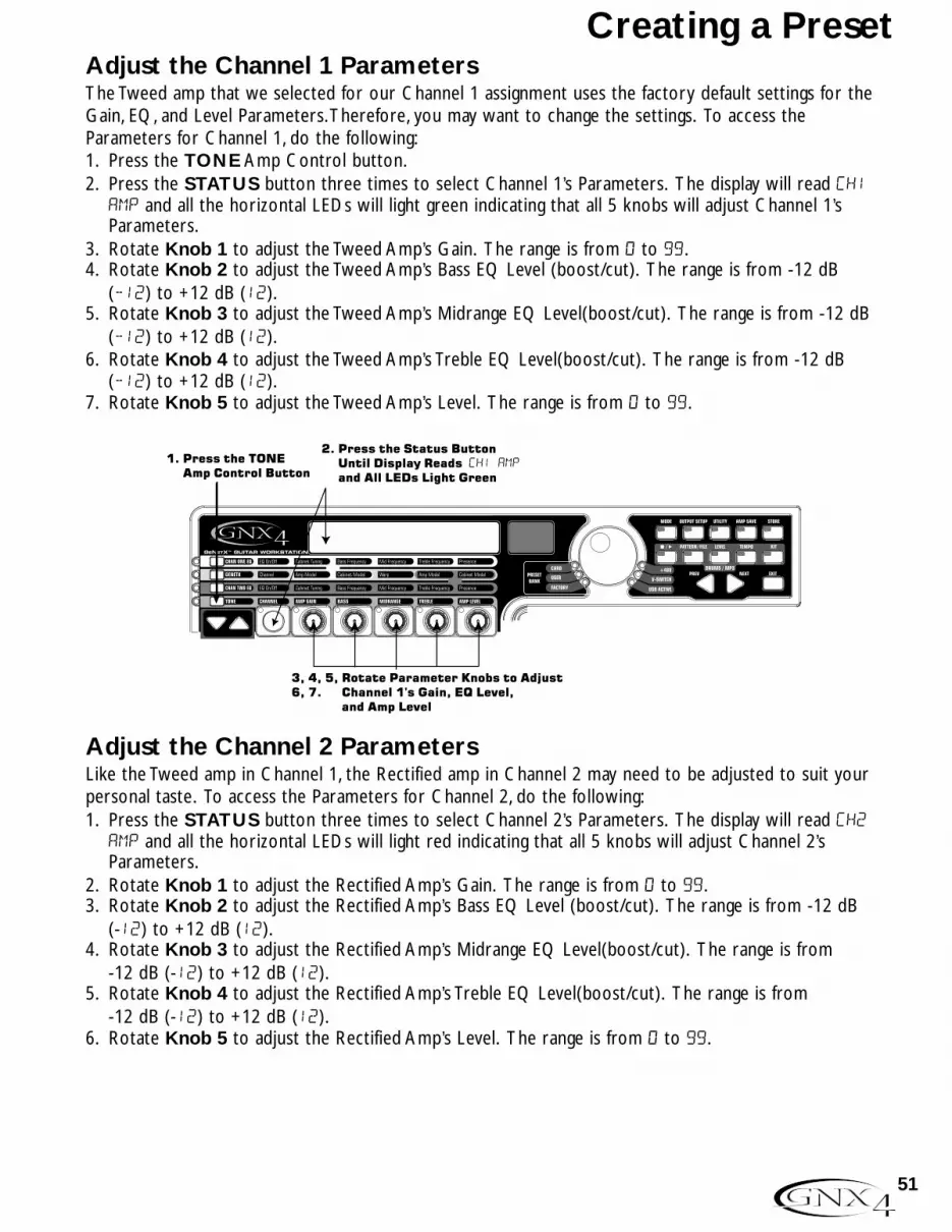
Adjust the Channel 1 ParametersThe Tweed amp that we selected for our Channel 1 assignment uses the factory default settings for theGain, EQ, and Level Parameters.Therefore, you may want to change the settings. To access theParameters for Channel 1, do the following:1. Press the TONE Amp Control button.2. Press the STATUS button three times to select Channel 1’s Parameters. The display will read ch1
amp and all the horizontal LEDs will light green indicating that all 5 knobs will adjust Channel 1’sParameters.
3. Rotate Knob 1 to adjust the Tweed Amp’s Gain. The range is from 0 to 99.4. Rotate Knob 2 to adjust the Tweed Amp’s Bass EQ Level (boost/cut). The range is from -12 dB
(-12) to +12 dB (12).5. Rotate Knob 3 to adjust the Tweed Amp’s Midrange EQ Level(boost/cut). The range is from -12 dB
(-12) to +12 dB (12).6. Rotate Knob 4 to adjust the Tweed Amp’s Treble EQ Level(boost/cut). The range is from -12 dB
(-12) to +12 dB (12).7. Rotate Knob 5 to adjust the Tweed Amp’s Level. The range is from 0 to 99.
Adjust the Channel 2 ParametersLike the Tweed amp in Channel 1, the Rectified amp in Channel 2 may need to be adjusted to suit yourpersonal taste. To access the Parameters for Channel 2, do the following:1. Press the STATUS button three times to select Channel 2’s Parameters. The display will read ch2
amp and all the horizontal LEDs will light red indicating that all 5 knobs will adjust Channel 2’sParameters.
2. Rotate Knob 1 to adjust the Rectified Amp’s Gain. The range is from 0 to 99.3. Rotate Knob 2 to adjust the Rectified Amp’s Bass EQ Level (boost/cut). The range is from -12 dB
(-12) to +12 dB (12).4. Rotate Knob 3 to adjust the Rectified Amp’s Midrange EQ Level(boost/cut). The range is from
-12 dB (-12) to +12 dB (12).5. Rotate Knob 4 to adjust the Rectified Amp’s Treble EQ Level(boost/cut). The range is from
-12 dB (-12) to +12 dB (12).6. Rotate Knob 5 to adjust the Rectified Amp’s Level. The range is from 0 to 99.
1. Press the TONE Amp Control Button
2. Press the Status Button Until Display Reads CH1 AMP and All LEDs Light Green
3, 4, 5, Rotate Parameter Knobs to Adjust6, 7. Channel 1's Gain, EQ Level, and Amp Level
51
Creating a Preset

Adjust the EQ/Tune the CabinetsAs an option, you may also want to modify each channel’s EQ center frequencies (Bass, Midrange, andTreble found in the TONE row) and adjust the resonance for the American 2x12 and the British 4x12Cabinets. To access the EQ center frequency settings and Cabinet tuning, do the following:1. Select the amp channel that you would like to edit by pressing either the CHAN ONE EQ Amp
Control button or the CHAN TWO EQ Amp Control button.2. Press the STATUS button to turn the EQ on and off.3. Rotate Knob 1 to adjust the Cabinet Tuning resonance. The Cabinet Tuning ranges are from -1™0
(one octave below) to 1™0 (one octave above).4. Rotate Knob 2 to select the Bass center frequency. The range is from 50 Hz (50 HZ) to 300 Hz
(300 HZ).5. Rotate Knob 3 to select the Midrange center frequency. The range is from 300 Hz (300 HZ) to 5000
Hz (5000 HZ).6. Rotate Knob 4 to select the Treble center frequency. The range is from 500 Hz (500 HZ) to 8000 Hz
(8000 HZ).7. Rotate Knob 5 boosts or cuts the Presence Level. The range is from -12 dB (-12) to +12 dB (12).
1. Press either the CHAN ONE EQ or CHAN TWO EQ Amp Control Button
2. Press the Status Button To Turn the EQ On and Off
3, 4, 5, Rotate Parameter Knobs to Adjust6, 7. Cabinet Tuning,EQ Center Frequencies, and Presence Level
1. Press the Status Button Until Display Reads CH2 AMP and All LEDs Light Red
2, 3, 4, Rotate Parameter Knobs to Adjust5, 6. Channel 2's Gain, EQ Level, and Amp Level
52
Creating a Preset
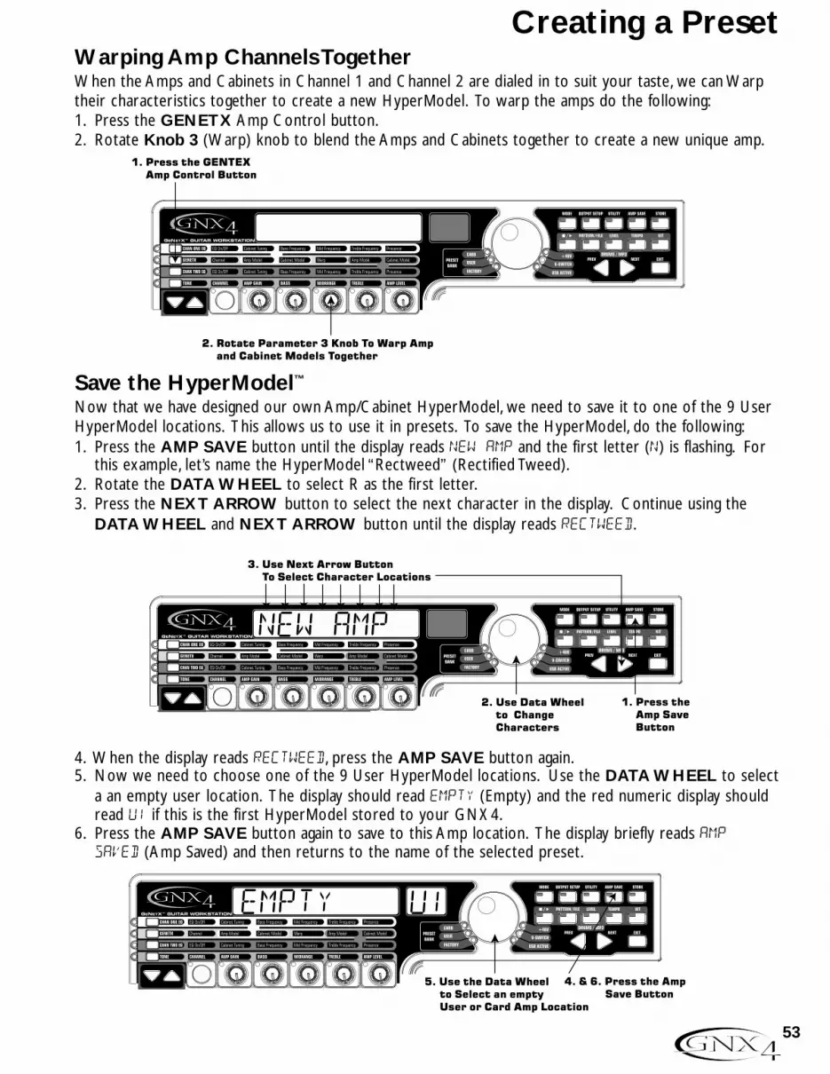
Warping Amp Channels TogetherWhen the Amps and Cabinets in Channel 1 and Channel 2 are dialed in to suit your taste, we can Warptheir characteristics together to create a new HyperModel. To warp the amps do the following:1. Press the GENETX Amp Control button.2. Rotate Knob 3 (Warp) knob to blend the Amps and Cabinets together to create a new unique amp.
Save the HyperModel™
Now that we have designed our own Amp/Cabinet HyperModel, we need to save it to one of the 9 UserHyperModel locations. This allows us to use it in presets. To save the HyperModel, do the following:1. Press the AMP SAVE button until the display reads NEW AMP and the first letter (N) is flashing. For
this example, let’s name the HyperModel “Rectweed” (Rectified Tweed).2. Rotate the DATA WHEEL to select R as the first letter.3. Press the NEXT ARROW button to select the next character in the display. Continue using the
DATA WHEEL and NEXT ARROW button until the display reads RECTWeeD.
4. When the display reads RECTWeeD, press the AMP SAVE button again.5. Now we need to choose one of the 9 User HyperModel locations. Use the DATA WHEEL to select
a an empty user location. The display should read EMPTY (Empty) and the red numeric display shouldread U1 if this is the first HyperModel stored to your GNX4.
6. Press the AMP SAVE button again to save to this Amp location. The display briefly reads AMPSaVeD (Amp Saved) and then returns to the name of the selected preset.
4. & 6. Press the Amp Save Button
5. Use the Data Wheel to Select an empty User or Card Amp Location
EMPTY U1
1. Press the Amp Save Button
3. Use Next Arrow Button To Select Character Locations
2. Use Data Wheel to Change Characters
NEW AMP
1. Press the GENTEX Amp Control Button
2. Rotate Parameter 3 Knob To Warp Amp and Cabinet Models Together
53
Creating a Preset

Select Models for the Preset’s ChannelsIn the previous steps, we selected a Tweed amp model for the Channel 1 amp and a Rectified amp modelfor the Channel 2 amp. Then we warped the two together to create our HyperModel™. ThisHyperModel is saved as an amp type that we named Rectweed, but it is not currently part of our preset.In this example preset, we need to be able to toggle between an acoustic guitar simulation and our newHyperModel. To do this we need to now select the Acoustic model for Channel 1’s amp and Rectweedfor Channel 2’s amp in our preset. This procedure is as follows:1. Press the GENETX Amp Control button.2. Rotate Knob 1 until the display reads ACOUSTic. This is Channel 1’s Model for the preset.3. Rotate Knob 4 until the display reads RECTWeeD (our new HyperModel). This is Channel 2’s Model
for the preset. This lets us toggle between these two sounds using the Amp Footswitch (when PresetMode is active).
Edit the Preset EffectsThe next step to creating our example preset involves editing the effects. To edit the preset, do thefollowing:1. Press the EFFECT SELECT DOWN button. The display will briefly read EDIT and the Matrix LED
in the Wah-Pickup row will light.2. If the red display reads WAH On, press the STATUS button once to turn the Wah off (since our
example does not use a Wah).
wah of
2. If necessary, press the Status Button to turn the Wah effect off
1. Press the Effect Select Down Button and the LED will light on the Wah-Pickup effect row
3. Rotate Knob 4 until the display reads Rectweed
2. Rotate Knob 1 until the display reads acoustic
1. Press the GENETX Amp Control button
54
Creating a Preset
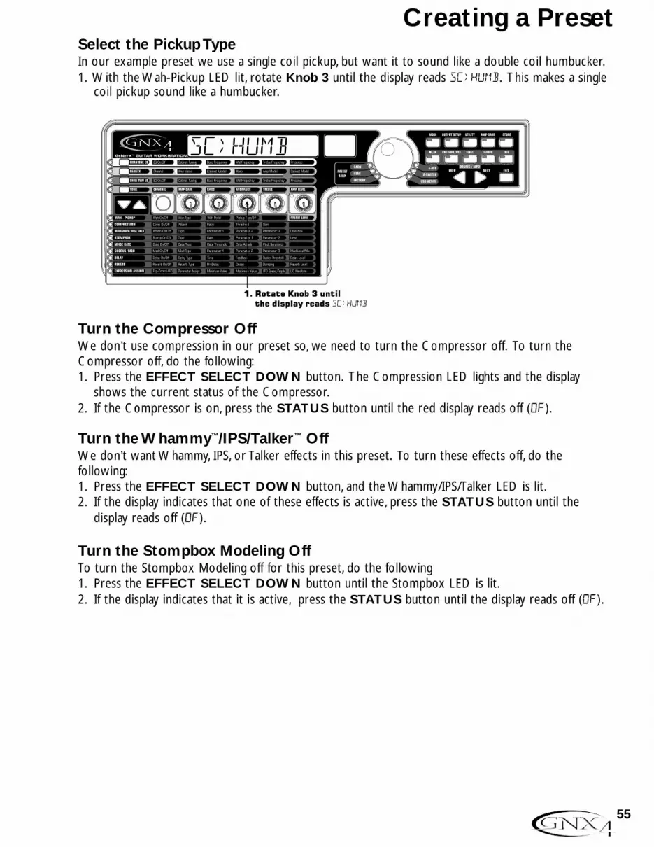
Select the Pickup TypeIn our example preset we use a single coil pickup, but want it to sound like a double coil humbucker.1. With the Wah-Pickup LED lit, rotate Knob 3 until the display reads SC>Humb. This makes a single
coil pickup sound like a humbucker.
Turn the Compressor OffWe don’t use compression in our preset so, we need to turn the Compressor off. To turn theCompressor off, do the following:1. Press the EFFECT SELECT DOWN button. The Compression LED lights and the display
shows the current status of the Compressor.2. If the Compressor is on, press the STATUS button until the red display reads off (Of).
Turn the Whammy™/IPS/Talker™ OffWe don’t want Whammy, IPS, or Talker effects in this preset. To turn these effects off, do thefollowing:1. Press the EFFECT SELECT DOWN button, and the Whammy/IPS/Talker LED is lit.2. If the display indicates that one of these effects is active, press the STATUS button until the
display reads off (Of).
Turn the Stompbox Modeling OffTo turn the Stompbox Modeling off for this preset, do the following1. Press the EFFECT SELECT DOWN button until the Stompbox LED is lit.2. If the display indicates that it is active, press the STATUS button until the display reads off (Of).
sc>humb
1. Rotate Knob 3 until the display reads SC>HUMB
55
Creating a Preset

Adjust the Noise GateFor our example, we want our Noise Gate to open quickly with a relatively weak signal. This type ofgate uses the Silencer™ with a low threshold and short attack time. To create this type of Noise Gate,do the following:1. Press the AMP FOOTSWITCH to select the Channel 2 Amp (CH2 AMP), our high gain model.
(The GNX4 must be in Stompbox/Control mode to complete this function.)2. Press the EFFECT SELECT DOWN button and the Noise Gate’s LED lights.3. If the display reads off (Of), press the STATUS button until the display reads on (On).4. Rotate Knob 1 until the display reads SILeNCeR for the type of gate.5. Rotate Knob 2 to set the Threshold to 15 (this may need to be adjusted depending upon your
guitar).6. Rotate Knob 3 to set the Attack Time to 0 (fast attack).
Select and Adjust the Chorus Next we wanted to thicken up the sound, by adding a subtle Chorus effect, in the following manner:1. Press the EFFECT SELECT DOWN button again and the LED in the Chorus/Mod row lights.2. If the display reads off (Of), press the STATUS button until the display reads on (On).3. Rotate Knob 1 until the display reads Chorus (Chorus) for the effect type.4. Rotate Knob 2 to set the Chorus Speed to 5.5. Rotate Knob 3 to set the Chorus Depth to 30.6. Rotate Knob 4 to set the PreDelay to 1.7. Rotate Knob 5 to set the Chorus Level to 50.
Turn the Delay OffTo bypass the Delay, do the following:1. Press the EFFECT SELECT DOWN button until the LED in the Delay row lights.2. If the display reads on (On), press the STATUS button until the display reads off (Of).
chorus
1. Press Effect Select Down again until the Chorus/Mod LED Lights
2. Press the Status Button to turn the Chorus/Mod effect on
3. Rotate Knob 1 to select Chorus
4. Rotate Knob 2 to set the Chorus Speed to 5.
5. Rotate Knob 3 to set the Chorus Depth to 30.
6. Rotate Knob 4 to set the PreDelay to 1.
7. Rotate Knob 5 to set the Chorus Level to 50.
56
Creating a Preset

Select and Adjust the ReverbIn our example preset we wanted a little bit of Hall Reverb to provide some ambience. To add thereverb, do the following:1. Press the EFFECT SELECT DOWN button until the LED in the Reverb row lights.2. If the display reads off (Of), press the STATUS button until the display reads on (On).3. Rotate Knob 1 to select Hall (Hall) for the Reverb Type.4. Rotate Knob 2 to set the Reverb Predelay to 2.5. Rotate Knob 3 to set the Reverb Decay to 15.6. Rotate Knob 4 to set the Reverb Damping to 40.7. Rotate Knob 5 to set the Reverb Level to 30.
Store the PresetThe last step is to store our changes to a User Preset. If we changed presets or turned the GNX4 offwithout storing these settings, it would forget what we had done and revert back to the original preset.To store the preset, do the following:1. Press STORE. The first letter in the display begins to flash. Since this is an example preset, let’s name
the preset examplE.2. Rotate the DATA WHEEL until the flashing character in the display is an E.3. Press the NEXT button once and the second character begins to flash.4. Rotate the DATA WHEEL again until the flashing character is an X. Continue using the Next Arrow
button to select the character location and the DATA WHEEL to change the characters.
5. Once the Display reads exampLE, press STORE again.The numbers in the red numeric display areflashing.
6. Rotate the DATA WHEEL to select 48 as the destination.7. Press STORE once more to save the preset.Congratulations! You have successfully created a Preset.
1. Press the Store Button
3. Use the Next Arrow Button to select character locations
2. Use Data Wheel to change characters
Store
Hall
1. Press Effect Select Down again until the Reverb LED lights.
2. Press the Status Button to turn the Reverb on.
3. Rotate Knob 1 to select Hall as the Reverb type.
4. Rotate Knob 2 to set the Reverb PreDelay to 2.
5. Rotate Knob 3 to set the Reverb Decay to 15.
7. Rotate Knob 5 to set the Reverb Level to 30.
6. Rotate Knob 4 to set the Reverb Damping to 40.
57
Creating a Preset
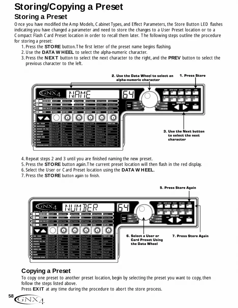
Storing a PresetOnce you have modified the Amp Models, Cabinet Types, and Effect Parameters, the Store Button LED flashesindicating you have changed a parameter and need to store the changes to a User Preset location or to aCompact Flash Card Preset location in order to recall them later. The following steps outline the procedurefor storing a preset:
1. Press the STORE button.The first letter of the preset name begins flashing.2. Use the DATA WHEEL to select the alpha-numeric character.3. Press the NEXT button to select the next character to the right, and the PREV button to select the
previous character to the left.
4. Repeat steps 2 and 3 until you are finished naming the new preset.5. Press the STORE button again.The current preset location will then flash in the red display.6. Select the User or Card Preset location using the DATA WHEEL.7. Press the STORE button again to finish.
Copying a PresetTo copy one preset to another preset location, begin by selecting the preset you want to copy, thenfollow the steps listed above.Press EXIT at any time during the procedure to abort the store process.
6. Select a User or Card Preset Using the Data Wheel
5. Press Store Again
5 Press Store Again5 Press Store Again5 Press Store Again
7. Press Store Again
NumberNumber
3. Use the Next button to select the next character
1. Press Store
5 Press Store Again5 Press Store Again5 Press Store Again
2. Use the Data Wheel to select an alpha-numeric character
Numbername
58
Storing/Copying a Preset

The GNX4’s Footswitches perform different functions specific to the Mode that has been selected. Listedbelow are descriptions of each footswitch’s function within each of the three Modes.
Preset Mode - GreenBank Up Footswitch - Selects the next bank of presets. Pressing and holding this footswitch scrolls up through banks. When a new bank is selected the 1 through 5 footswitch LEDs will strobe left to right prompting the user to select a preset. If a preset is not selected within 5 seconds, the GNX4 returns to the currently selected bank and preset. Pressing and holding both the Bank Up and Bank DownFootswitches together will temporarily enable both footswitches to navigate through the GNX4’s drum patterns or user MIDI files and MP3s stored on an optional CF card.
Bank Down Footswitch - Selects the previous bank of presets. Pressing and holding this footswitch scrolls down through banks. When a new bank is selected the 1 through 5 footswitch LEDs will strobe left to right prompting the user to select a preset. If a preset is not selected within 5 seconds, the GNX4 returns to the currentlyselected bank and preset.Pressing and holding both the Bank Up and Bank DownFootswitches together will temporarily enable both footswitches to navigate through the GNX4’s drum patterns or user MIDI files and MP3s stored on an optional CF card.
Footswitch 1 - Selects the first preset in the active bank. A second press puts the GNX4 into Bypass or selects the previous preset if Preset Bounceback is enabled (see page 22 for more instructions on the Preset Bounceback function). Pressing and holding Footswitches 1 and 2 together will enable or disable the Drums/MP3 Sync button in the Recorder Panel.
Footswitch 2 - Selects the second preset within the active bank. A second press puts the GNX4 into Bypass or selects the previous preset if Preset Bounceback is enabled (see 22 for more instructions on the Preset Bounceback function).
Pressing and holding Footswitches 1 and 2 together will enable or disable the Drums/MP3 Sync button in the Recorder Panel. Pressing and holding Footswitches 2 and 3 together will bypass the GNX4’s effects and amp models.
Footswitch 3 - Selects the third preset in the active bank. A second press puts the GNX4 into Bypass or selects the previous preset if Preset Bounceback is enabled (see 22 for more instructions on the Preset Bounceback function). Pressing
and holding Footswitches 2 and 3 together will bypass the GNX4’s effects and amp models. Pressing and holding Footswitches 3 and 4 together accesses the Tuner.
Footswitch 4 - Selects the fourth preset in the active Bank. A second press puts the GNX4 into Bypass or selects the previous preset if Preset Bounceback is enabled (see 22 for more instructions on the Preset Bounceback function). Pressing
and holding Footswitches 3 and 4 together accesses the Tuner. Pressing and holding Footswitches 4 and 5 together will change the Footswitch Modes.
Footswitch 5 - Selects the fifth preset in the active Bank. A second press puts the GNX4 into Bypass or selects the previous preset if Preset Bounceback is enabled (see page 22 for more instructions on the Preset Bounceback function). Pressing and holding Footswitches 4 and 5 together will change the Footswitch Modes.
TAP TEMPO
CONTROL C
CONTROL B
CONTROL A
AMP CHANNEL
59
Footswitch Functions for Modes

Stompbox/Control Mode - Yellow Preset Up Footswitch - Selects the next preset. Pressing and holding this footswitchscrolls up through presets. After releasing, the preset that is landed on is loaded and becomes active. Pressing and holding both the Preset Up and Preset DownFootswitches together will temporarily enable both footswitches to navigate through the GNX4’s drum patterns or user MIDI files and MP3s stored on an optional CF card.
Preset Down Footswitch - Selects the previous preset. Pressing and holding this footswitch scrolls down through presets. After releasing, the preset that is landed on isloaded and becomes active. Pressing and holding both the Preset Up and Preset Down Footswitches together will temporarily enable both footswitches to navigate through the GNX4’s drum patterns or user MIDI files and MP3s stored on a CF card.
Amp Channel Footswitch selects a preset’s amp channel (Ch1 amp, Ch2 amp, or warp amp). This footswitch’s function can be changed in the EXPRESSION ASSIGN menu. (See page 45 for more information regarding Expression Pedal Assignment.) Pressing and holding Footswitches 1 and 2 together will enable and disable the Drums/MP3 Sync button in the Recorder Panel.
Stompbox (Control A) Footswitch turns the Stompbox Modeling on and off. This footswitch’s function can be changed in the EXPRESSION ASSIGN menu to controlup to 3 parameters at one time and can be setup as a toggle or momentary switch.(See page 45 for more information regarding Expression Pedal Assignment.) Pressing and holding Footswitches 1 and 2 together will enable or disable the Drums/MP3 Sync button in the Recorder Panel. Pressing and holding Footswitches 2 and 3 together will Bypass the GNX4’s effects and amp models.
Chorus/Mod (Control B) Footswitch turns the Chorus/Mod Effects on and off.This footswitch’s function can be changed in the EXPRESSION ASSIGN menu to control up to 3 parameters at one time and can be setup as a toggle or momentary switch. (See page 45 for more information regarding Expression Pedal Assignment.) Pressing and holding Footswitches 2 and 3 together will Bypass the GNX4’s effects and amp models. Pressing and holding Footswitches 3 and 4 togetheraccesses the Tuner.
Delay (Control C) Footswitch turns the Delay on and off. This footswitch’s function can be changed in the EXPRESSION ASSIGN menu to control up to 3 parameters at one time and can be setup as a toggle or momentary switch. (See page 45 for more information regarding Expression Pedal Assignment.) Pressing and holding Footswitches 3 and 4 together accesses the Tuner. Pressing and holding Footswitches 4 and 5 together will change the Footswitch Modes.
Tap Tempo Footswitch is used for setting the repeat time of the Delay effect. By tapping this switch repeatedly, you can set the delay to repeat in time with your music.Pressing and holding Footswitches 4 and 5 together will change the GNX4’s Footswitch Modes.
TAP TEMPO
CONTROL C
CONTROL B
CONTROL A
AMP CHANNEL
60
Footswitch Functions for Modes

Recorder Mode - Red Song Up Footswitch - Selects the next song. Pressing and holding both the Song Up and Song Down Footswitches simultaneously will temporarily enable these footswitches to navigate through the GNX4’s drum patterns or user MIDI files and MP3s stored on an optional CF card.
Song Down Footswitch - Selects the previous song. Pressing and holding both the Song Up and Song Down Footswitches together will temporarily enable these footswitches to navigate through the GNX4’s drum patterns or user MIDI files andMP3s stored on an optional CF card.
Drums/MP3 Stop/Play Footswitch - Starts and stops playback of the GNX4’s drumpatterns, or user MIDI files and MP3s in the drum machine file list. Pressing and holding Footswitches 1 and 2 together will enable or disable the Drums/MP3 Sync button in the Recorder Panel.
Stop/Undo Footswitch - Stops the recorder. Pressing and holding this footswitch deletes the last track recorded or can delete the current song. Pressing and holding Footswitch 1 and 2 together will enable or disable the Drums/MP3 Sync button in the Recorder Panel. Pressing and holding Footswitches 2 and 3 together will Bypass the GNX4’s effects and amp models.
Record Footswitch - Enables tracks for recording and starts the recorder. It is also used for setting the JamMan™ delay loop length and arming and disarming record when overdubbing onto the active track(s) being recorded. Pressing and holdingFootswitches 2 and 3 together will Bypass the GNX4’s effects and amp models.Pressing and holding Footswitches 3 and 4 together accesses the Tuner.
Playback Footswitch - Starts playback of the recorder. It is also used for setting the JamMan delay loop length by putting the first track (or 2 tracks if stereo recording) that were recorded into playback and automatically arming the next track (or two tracks if stereo recording) to continue recording the next loop layer. Pressing and holding Footswitches 3 and 4 together accesses the Tuner. Pressing and holding Footswitches 4 and 5 together will change the Footswitch Modes.
Drum Tempo Footswitch - Tapping this footswitch while the drum machine is on sets the playback tempo. It must be tapped at least 2 times within 3 seconds to set a tempo. When a new song is selected from the Recorder Panel, tapping this button will set the song tempo (which sets the tempo for any drum pattern or MIDI file if selected) as well. Once a track is recorded in a song, the tempo of a song cannot be changed by tapping this footswitch until the song has been deleted. You can still tap thetempo when using the drum machine by itself but not with a previously recorded song.The Drum Tempo Footswitch also works with MIDI files, however it does not function when playing MP3s. The Tempo can range from 40 to 240 beats per minute.
Drum Tempo is ignored if a song already has tracks recorded and the LED will flash at the song tempo.Pressing and holding Footswitches 4 and 5 together will change the Footswitch Modes.
TAP TEMPO
CONTROL C
CONTROL B
CONTROL A
AMP CHANNEL
61
Footswitch Functions for Modes

The GNX4 is equipped with a Built-in General MIDI Drum Machine and MP3 Player. You can select froma variety of Factory and User created MIDI drum patterns and drum kits or your own MP3s to play alongwith. The GNX4’s Drum Machine/MP3 Player can be set up in different ways as shown below:
Control Panel - Drum Machine/MP3 Player Buttons
(STOP/PLAY)Press this button to start or stop the drum machine or MIDI File/MP3 playback.
PATTERN/FILE Press this button to select the Pattern/File library. Use the DATA WHEEL or PREV and NEXTbuttons to select one of the GNX4’s internal drum patterns. If a CF card is present in the memorycard slot and MP3s and MIDI files are resident on the card, you can select these files for playback aswell. MIDI and MP3 files must be resident in the GNX4>MIDI and GNX4>MP3 directoriesrespectively on your compact flash card in order for them to be recognized. Please refer to theCompact Flash Card Usage section of this manual for more information. There are 110 differentdrum patterns and 5 metronome settings available including:
Internal Drum Pattern List
LEVEL Press this button to select the drum machine playback level. Using the DATA WHEEL or PREVand NEXT buttons to adjust the volume level of the drum machine or MP3file playback.
TEMPO Press this button to select the Drum Machine tempo setting. Use the DATA WHEEL or PREV andNEXT buttons to adjust the playback speed of the drum or MIDI file being played back. Tempo rangeis 40-240 BPM (beats per minute). The TEMPO button has no function when MP3 files are selected.KIT The GNX4 is equipped with several drum kits that cover a variety of music genres. Press this buttonto select the drum kit menu. Use the DATA WHEEL or PREV and NEXT buttons to changebetween the different drum kits available. The KIT button has no function when MP3 files areselected. Listed below are the drum kit types:
Internal Drum Kit Listrock
alterntv
power
heavy
pop
studio
jazzbrsh
techno
8th Beat 1-1016thBeat 1-5Rock 1-10
HardRock 1-10 Metal 1-10Blues 1-5
Funk 1-10groove 1-5Country 1-5R and B 1-5Jazz 1-5prog 1-2
prog 6/8 3
prog 7/8 4-5
HipHop 1-5dance 1-5Latin 1-5Reggae 1-5
Percusn 1-5METR 4/4 1
METR 3/4 1
METR 5/8 1
METR 7/8 1
metronom 5
62
Drum Machine/MP3 Player

Footswitch OperationWhen the GNX4 is in Recorder Mode, FOOTSWITCH 1 and 5 control drum machine operations.
Drums/MP3 Stop/Play Footswitch - Starts and stops playback of drum patterns or user MIDI files and MP3s in the drum machine file list. Pressing and holding Footswitches 1 and 2 simultaneously will enable or disable the Drums/MP3 Syncbutton in the Recorder Panel.
Drum Tempo Footswitch - Tapping this footswitch while the drum machine is on sets the playback tempo. It must be tapped at least 2 times within 3 seconds to set a tempo. When a new song is selected from the Recorder Panel, tapping this button will set the song tempo (which sets the tempo for any drum pattern or MIDI file if selected) as well. Once a track is recorded in a song, the tempo of a song cannot be changed by tapping this footswitch until the song has been deleted. You can still tap thetempo when using the drum machine by itself but not with a previously recorded song.The Drum Tempo Footswitch also works with MIDI files, however it does not function when playing MP3s. The Tempo can range from 40 to 240 beats per minute.
Pattern/File Footswitches - From any of the GNX4’s FootswitchModes, you can press and hold the UP/DOWN footswitches simultaneously to enable them to select any factory drum patterns or any user MIDI files and MP3s that reside on an optional compact flash card. To access these patterns and files using the footswitches, do the following:
1. Press and hold the UP/DOWN Footswitches until PAT/FILE appearsin the display. The currently selected pattern or file will then appear inthe display. The UP/DOWN Footswitches will now flash indicating theyare available to select any of the GNX4’s drum patterns, user MIDI files,or MP3s.
2. Press either the UP or DOWN Footswitch to navigate through theavailable patterns and files or press and hold down either footswitch toscroll through the patterns. You can have the drum machine playing if youwant to hear the files as they are selected.
3. If neither footswitch is pressed within five seconds, the UP/DOWNFootswitches will stop flashing and return to their normal functiondepending on which mode is currently selected.
GNX4 MP3 Demo (Internal)The GNX4 comes with an internal 30 second MP3 demo that permanently resides in GNX4 memory(not on a Compact Flash card). To start the demo, remove the Compact Flash card (if one is installed inyour GNX4). Press the PLAY button located on the GNX4’s Recorder Panel and the demo will startplaying. At the end of the song it will automatically loop and playback until you press the Recorder PanelSTOP button. All other Recorder Panel buttons and GNX4 footswitches are effectively disabled whenthe MP3 demo is playing.
TAP TEMPO
AMP CHANNEL
63
Drum Machine/MP3 Player

This section will cover the GNX4’s inputs and how they are routed for recording internally using CompactFlash memory and recording on your computer via USB.
GNX4 Inputs and Recorder RoutingThe GNX4’s has four audio inputs, the Guitar Input, Mic Input, and Left/Right Line Inputs. It also has a MIDIinput. Each of these inputs can be used to record audio and each has multiple different routing configurationsavailable. For instance, in a given recording session you may want to record guitar with effects, a dry guitaronly, vocal with or without effects, or both the guitar processing and the line inputs. The GNX4’s flexiblerouting lets you record each of these inputs in different combinations and even lets you utilize the GNX4’seffects processing if desired, giving you a wide variety of options for your particular recording application.Having an understanding of how the GNX4’s inputs and routing options function is the best way to optimizeyour recording experience.
GNX4 Input SourcesThe GNX4 has two recorder input selections called Input Sources. Each of these Input Sources offer severalrouting configurations for a variety of recording options. The Input Sources are selected using the CF/USB1-2 SRC and USB 3-4 SRC buttons in the Recorder Panel and the DATA WHEEL. Up to four tracks ofaudio can be recorded on the computer via USB (two tracks maximum to the onboard recorder using anoptional CF memory card). Each Input Source routes a pair of signals (except MONO FX, MONO ALL, DRYGUITAR, DRY MIC, and DRUMS MN which are mono signals) to either the computer or the onboard recorder.The Input Sources signal combinations are as follows:
(Compact Flash) CF/USB 1-2 Source
stereofx - All input sources that are routed through the GNX4’s effects are sent as a stereo pair totwo available tracks on the onboard recorder or up USB 1 and 2 channels. Drums or MP3,Dry Mic, and Dry Line are not recorded.
steroall - All input sources that are routed through the GNX4’s effects, Drums or MP3, Dry Mic, DryLine, and Recorder Click Track are sent as a stereo pair to two available tracks on theonboard recorder or up USB 1 and 2 channels.
mono fx - All input sources that are routed through the GNX4’s effects are summed to mono and sentto one available track on the onboard recorder or up the USB 1 channel. Nothing is sent upUSB 2 channel. Drums or MP3, Dry Mic, and Dry Line are not recorded.
mono all - All input sources that are routed through the GNX4’s effects, Drums or MP3, Dry Mic, DryLine, and Recorder Click Track are summed to mono and sent to one available track on theonboard recorder or up the USB 1 channel. Nothing is sent up USB 2 channel.
sum+dGTR - All input sources that are routed through the GNX4’s effects are summed to mono and sentto one available track of the onboard recorder or up the USB 1 channel. Dry guitar is sentto the other available track of the onboard recorder or up the USB 2 channel.
sum+mic - All input sources that are routed through the GNX4’s effects are summed to mono and sentto one available track of the onboard recorder or up the USB 1 channel. Dry mic signal issent to the other available track of the onboard recorder or up the USB 2 channel.
dgtr+mic - Dry guitar signal is sent to one available track of the onboard recorder or up the USB 1channel. Dry mic is sent to the other available track of the onboard recorder or up the USB2 channel.
64
Audio Routing for Recording
dry line - Dry Line Left signal is sent to one available track of the onboard recorder or up the USB 1channel. Dry Line Right is sent to the other available track of the onboard recorder or upthe USB 2 channel.
dryguitr - Dry Guitar signal is sent to an available track of the onboard recorder or up the USB 1channel. Nothing is sent up the USB 2 channel.
dry mic - Dry Mic signal is sent to an available track of the onboard recorder or up the USB 1 channel.Nothing is sent up the USB 2 channel.
drums st - The GNX4 drums playback or MP3 is sent to two available tracks of the onboard recorderor up the USB 1 and 2 channels.
drums mn - The GNX4 drums playback or MP3 (summed to mono) is sent to one available track of theonboard recorder or up the USB 1 channel. Nothing is sent up the USB 2 channel.
reamp 1-8/usb - Playback of a pre-recorded, dry guitar track can be routed back through the GNX4’seffects processing and recorded back onto two available tracks of the onboardrecorder or back up the USB 1 and 2 busses. Selecting REAMP 1-8 determines thesource of the dry guitar from the onboard recorder playback. Selecting REAMPUSBdetermines the source of the dry guitar is from the computer. See Re-Amping aGuitar Track on pages 82 and 97 for more information how this feature works.
USB 3-4 Source
USB OFF - USB 3 and 4 are disabled.DGTR+Mic - Dry guitar signal is sent up the USB 3 channel. Dry mic signal is sent up the USB 4 channel.dry line - Dry Line Left signal is sent up the USB 3 channel and Dry Line Right signal is sent up the
USB 4 channel.DRYGuiTR - Dry guitar signal is sent up the USB 3 channel. Nothing is sent up the USB 4 channel.DRY MIC - Dry mic signal is sent up the USB 3 channel. Nothing is sent up the USB 4 channel.DRUMS st - GNX4 drum playback is sent stereo up the USB 3 and 4 channels.DRUMS mn - GNX4 drum playback is sent mono up the USB 3 channel. Nothing is sent up the USB 4channel.
65
Audio Routing for Recording

The following diagrams outline how the different input signals are routed through the GNX4 and out toboth the Compact Flash and computer (USB) for recording:
Guitar Signal RoutingThe guitar signal is routed from the input through the GNX4’s effects processing and then to the pairs ofoutputs. The signal sent to the onboard recorder and up USB can be tapped off either at the input(CF/USB Send Path A), or at the end of the effects chain (CF/USB Send Path C). Signals recordedfrom CF/USB Send Path A can be played back later through the GNX4 for re-amping. See Re-Ampinga Guitar Track on pages 97 for more information on how this feature works.
The guitar signal has two paths in which it is routed to the onboard recorder and up the USB port to thecomputer. Path A taps the guitar signal off at the input and sends unprocessed signal to the GNX4’srecorder and up the USB port. Path C taps the guitar signal at the output of the GNX4 and can includeany effects processing that may be used. Below is a matrix to show where the signal is tapped based onhow the CF/USB 1-2 Source and the USB 3-4 Source settings are configured.
Mic Signal RoutingThe mic signal can be routed in different ways through the GNX4. mic off disables the mic input frombeing heard, but it still may be recorded using steroall, Mono all, suM+MIC, DGTR+MIC, or DRY MICas the input source. mic dry routes the mic signal around the GNX4’s effects processing and mixes it inat the outputs. mic rvb routes the mic signal only through the GNX4’s Delay and Reverb modules.mic fx routes the mic signal through all of the GNX4’s effects.
mic off
mic rvb mic dryMic Input
SC+
+
+
+SC
XLR Left OutputXLR Right Output
1/4" Left Output1/4" Right Output
SC
SC
(1/4" USB Playback disabled in Split Modes)
CF/USB DrySend Path
E CF/USB SendPath
C CF/USB Playback Return Path
D
= Speaker Compensation ModuleSC
CH 1 AMPMODELING/
TONE
CH 1 AMPCABINET
CH 2 AMPMODELING/
TONE
CH 2 AMPCABINET
PICKUP SIM WAH COMP WHAMMY/IPS(except TALKER)
STOMPBOX GATE WHAMMY/IPS(except TALKER)
CHORUS/MOD
DELAY REVERB
mic fx
stereofx
steroall
SUM+DGtr
SUM+MIC
DGTR+Mic
dry line
DRYGuiTR
DRY MIC
DRUMS st
drums mn
Guitar Guitar
CF/USB 1-2 Source
C C C, A C A • A • • •
Routing of Guitar Input to CF/USB
usb off
dgtr+mic
dry line
dryguitr
dry mic
drums st
USB 3-4 Source
• A • A • •
mono fx
mono all
C
reamp 1-8/usb
•
drums Mn
•C
Guitar Input
= Speaker Compensation Module
SC
SC
SC
XLR Left OutputXLR Right Output
1/4" Left Output1/4" Right Output
CF/USB DrySend Path
A CF/USB Re-Amp Return Path
B CF/USB SendPath
C CF/USB Playback Return Path
D
SC
SC
(1/4" USB Playback disabled in Split Modes)
CH 1 AMPMODELING/
TONE
CH 1 AMPCABINET
CH 2 AMPMODELING/
TONE
CH 2 AMPCABINET
PICKUP SIM WAH COMP WHAMMY/IPS(except TALKER)
STOMPBOX GATE WHAMMY/IPS(except TALKER)
CHORUS/MOD
DELAY REVERB
66
Audio Routing for Recording

The mic signal, as can be seen in the previous Mic Signal Routing diagram, has two paths in which it is routed to the onboard recorder and up the USB port to the computer. Path E taps the mic signal off atthe mic input and sends unprocessed signal up to the USB port. Path C taps the signal at the output ofthe GNX4 and can include any effects processing that may be used. Below is a matrix to show where thesignal is tapped based on how the Mic, CF/USB 1-2 Source, and USB 3-4 Source settings are configured.
Line Signal RoutingThe Line signals, like the mic signal, can be routed in different ways through the GNX4. Line OFFdisables the line inputs from being heard but dry line signal can still be recorded using steroall, Monoall, and dry line as the input source. LINE DRY routes the left and right line signals around theGNX4’s effects processing and mixes them in at the left and right outputs respectively. line rvb routesthe line signal only through the GNX4’s Delay and Reverb modules. LINE FX sums the left and rightinput signals together and then routes this signal through all the GNX4’s effects.
The line input signals, as can be seen in the previous Line Signal Routing diagram, has two paths in whichthey are routed to the onboard recorder and up the USB port to the computer. Path F taps the lineinput signals off at the line input and sends unprocessed signal to the GNX4’s recorder and up the USBport. Path C taps these signals at the output of the GNX4 and can include any effects processing thatmay be used. Below is a matrix to show where the signal is tapped based on how the Line,CF/USB 1-2 Source, and USB 3-4 Source settings are configured.
Routing of Line Inputs to CF/USB
usb off
dgtr+mic
dry line
dryguitr
dry mic
drums st
LINe off
LINe dry
LINe RVB
LINe FX
Line
USB 3-4 Source
• • F • • •• • F • • •• • F • • •• • F • • •
drums mn
••••
stereofx
MONO all
SUM+DGtr
SUM+MIC
DGTR+Mic
dry line
DRYGuiTR
DRY MIC
DRUMS st
Drums mn
line off
line dry
line FX
Line• F • • • F • • • • • F • • • F • • • •C C, F
C, F C • F • • • •
C C, FC, F
• F • • • •
steroall
FF
MONO fx
••CC
CF/USB 1-2 Source
reamp 1-8/usb
••••
C, FC, F
Line RVB
C
Line Left
Line Right
line fx line rvb line dry
+
line off
SC
+
+
SC XLR Left OutputXLR Right Output
1/4" Left Output1/4" Right Output
SC
SC
(1/4" USB Playback disabled in Split Modes)
+
+
= Speaker Compensation ModuleSC
CH 1 AMPMODELING/
TONE
CH 1 AMPCABINET
CH 2 AMPMODELING/
TONE
CH 2 AMPCABINET
PICKUP SIM WAH COMP WHAMMY/IPS(except TALKER)
STOMPBOX GATE WHAMMY/IPS(except TALKER)
CHORUS/MOD
DELAY REVERB
USB DrySend Path
FUSB Send
PathC USB Playback
Return PathD
stereofx
MONO all
SUM+DGtr
SUM+MIC
DGTR+Mic
dry line
DRYGuiTR
DRY MIC
DRUMS st
Drums mn
mic off
mic dry
mic RVB
MIC FX
Mic• E • E E • • E • • • E • E E • • E • •C C, E C C, E E • • E • •C C, E C C, E E • • E • •
Routing of Mic Inputs to CF/USB
usb off
dgtr+mic
dry line
dryguitr
dry mic
drums st
mic off
mic dry
mic RVB
MIC FX
Mic
USB 3-4 Source
• E • • E •• E • • E •• E • • E •• E • • E •
steroall
EE
MONO fx
••CC
drums mn
••••
CF/USB 1-2 Source
reamp 1-8/usb
••••
C, EC, E
67
Audio Routing for Recording
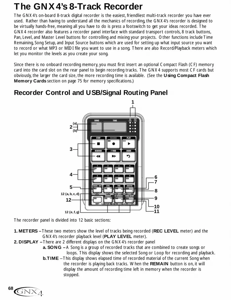
The GNX4’s on-board 8-track digital recorder is the easiest, friendliest multi-track recorder you have everused. Rather than having to understand all the mechanics of recording, the GNX4’s recorder is designed tobe virtually hands-free, meaning all you have to do is press a footswitch to get your ideas recorded. TheGNX4 recorder also features a recorder panel interface with standard transport controls, 8 track buttons,Pan, Level, and Master Level buttons for controlling and mixing your projects. Other functions include TimeRemaining, Song Setup, and Input Source buttons which are used for setting up what input source you wantto record or what MP3 or MIDI file you want to use in a song. There are also Record/Playback meters whichlet you monitor the levels as you create your song.
Since there is no onboard recording memory, you must first insert an optional Compact Flash (CF) memorycard into the card slot on the rear panel to begin recording tracks. The GNX4 supports most CF cards butobviously, the larger the card size, the more recording time is available. (See the Using Compact FlashMemory Cards section on page 75 for memory specifications.)
Recorder Control and USB/Signal Routing Panel
The recorder panel is divided into 12 basic sections:
1. METERS – These two meters show the level of tracks being recorded (REC LEVEL meter) and theGNX4’s recorder playback level (PLAY LEVEL meter).
2. DISPLAY – There are 2 different displays on the GNX4’s recorder panela. SONG – A Song is a group of recorded tracks that are combined to create songs or
loops. This display shows the selected Song or Loop for recording and playback.b.TIME – This display shows elapsed time of recorded material of the current Song when
the recorder is playing back tracks. When the REMAIN button is on, it willdisplay the amount of recording time left in memory when the recorder isstopped.
(b)
3
4
5
1
12 12 (a, b, c, d)
12 (e, f, g) 1110
9
8
76
2 (a)
68
The GNX4’s 8-Track Recorder

3. TRANSPORT – The 6 transport buttons just below the displays are used for the record, playback, andsearch functions of recorded material. They include STOP, RECORD, PLAY,REWIND, FAST FORWARD, and UNDO.
4.TRACKS – A Track is an individual memory location in a song that you record audio to. The GNX4 haseight individual tracks that can be recorded to.
5. DRUMS/MP3 – This button is used to start the GNX4’s drum machine when the recorder beginsplaying. When the button is lit green, the drum machine will playback the pattern orMIDI file selected in the Song Setup menu. When this button is lit yellow, an MP3 file hasbeen selected in the Song Setup menu to start playing when the recorder begins playing.(See the Song Setup section on page 70.) When this button is lit red, the selectedpattern, MIDI file, or MP3 file can be recorded to a track if one of the proper recordersources is selected. (See the (Compact Flash) CF/USB 1-2 Source section on page64.)
6. LEVEL – Accesses the playback level for each track.7. PAN – Accesses the pan controls for each track.8. MASTER – This controls the stereo output playback level of tracks recorded on the Compact Flash card.9. REMAIN – When this button is enabled, the TIME display shows the remaining recording time available
in track minutes when the recorder is stopped. When the recorder is playing back tracks, thedisplay shows the amount of time remaining in the current song.
10. CF STORAGE – This button is to be pressed first when files are to be copied to and from theCompact Flash card and your computer’s hard drive. When this button is engaged, thecompact flash card will appear as a new drive on your computer allowing files to betransferred back and forth. Since file transferring will use up some USB bandwith, it isnot recommended that you record audio to the computer when this is active.
11. SONG SETUP – Accesses setup options for each song including Click Track, Tempo, Pre-Roll, SongRepeat, and more. See more about the Song Setup options in the next section.
12. SHIFT – When this button is lit, the secondary functions labeled below each button are now active.
a. MIC - Selects the mic input routing menu and how the mic signal is routed through theGNX4’s effects processing for both recording and performance.
b. LINE - Selects the line input routing menu and how both line inputs are routed through theGNX4’s effects processing for both recording and performance.
c. CF/USB 1-2 SOURCE - Selects what inputs are to be recorded to the onboard recorderor up the USB 1-2 channels.
d. USB 3-4 SOURCE - Selects what inputs are to be recorded up the USB 3-4 channels.e. USB PLAY MIX - Controls the level balance between the GNX4’s processing and the USB
stream played back from your computer.f. CF/USB 1-2 LVL - A gain/attenuation control to optimize the level of sources being
recorded to the Compact Flash card and up the USB 1-2 channel.g. USB 3-4 LVL - A gain/attenuation control to optimize the level of sources being recorded
up the USB 3-4 channel.
69
The GNX4’s 8-Track Recorder

Song SetupBefore you begin recording your first song, you will want to become acquainted with the recorder Setupfunctions. Setup functions include: Drums-MP3 (Pattern/File), Drum/MP3 Level,Tempo, Drum Kit, ClickTrack, Pre Roll, Song Repeat,Auto Stop, Quantize, and Format. These functions dictate how the recorderworks for each song. Each song can have these functions setup in different ways so that you can customizehow the recorder works depending on your needs. A Song Setup file is saved off to the Compact Flash cardfor each song and is resaved whenever any changes are made.
Drums/MP3 (Pattern/File)The Drums/MP3 (Pattern/File) setup lets you select one of the GNX4’s drum patterns or an externalMIDI or MP3 file to be played back along with any recorded audio in a given song. This is a useful featureas it lets you have backing tracks in a song without having to allocate audio tracks to play them. Whenthe DRUMS/MP3 button is enabled, this setting will override the DRUMS/MP3 Pattern selected in theControl Panel when the PLAY button is pressed on the recorder. To select a pattern or file that youwould like played back with a song, follow these steps:
1. Press the SONG SETUP button once and the GNX4’s main display will show one of the drumpatterns. For example, the 8th Beat pattern will display as 8th beat.
2. Use the DATA WHEEL to select a Drum Pattern, MIDI, or MP3 file.3.When finished, press EXIT.
Drums/MP3 LevelThe Drums/MP3 Level setup sets the playback level of the file selected in the Drums/MP3 (Pattern/File)setup menu. When the DRUMS/MP3 button is enabled in the Recorder Panel and the PLAY button ispressed on the recorder, this setting will override the DRUMS/MP3 Level button located in the far rightControl Panel. To select a pattern or file that you would like played back with a song, follow these steps:
1. Press the Song Setup button
2. Use the Data Wheel to adjust the Output Level of the Drums or MP3 file
3. When finished press Exit
drum lvl
1. Press the Song Setup button
2. Use the Data Wheel to select a Drum Pattern, MIDI, or MP3 file
3. When finished press Exit
8th beat
70
The GNX4’s 8-Track Recorder
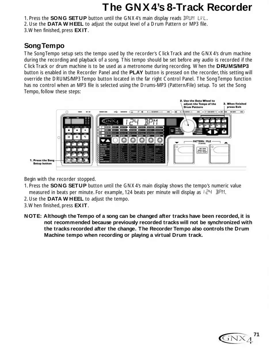
1. Press the SONG SETUP button until the GNX4’s main display reads drum lvl.2. Use the DATA WHEEL to adjust the output level of a Drum Pattern or MP3 file.3.When finished, press EXIT.
Song TempoThe Song Tempo setup sets the tempo used by the recorder’s Click Track and the GNX4’s drum machineduring the recording and playback of a song. This tempo should be set before any audio is recorded if theClick Track or drum machine is to be used as a metronome during recording. When the DRUMS/MP3button is enabled in the Recorder Panel and the PLAY button is pressed on the recorder, this setting willoverride the DRUMS/MP3 Tempo button located in the far right Control Panel. The Song Tempo functionhas no control when an MP3 file is selected using the Drums-MP3 (Pattern/File) setup. To set the SongTempo, follow these steps:
Begin with the recorder stopped.1. Press the SONG SETUP button until the GNX4’s main display shows the tempo’s numeric value
measured in beats per minute. For example, 124 beats per minute will display as 124 BPm.2. Use the DATA WHEEL to adjust the tempo.3.When finished, press EXIT.
NOTE: Although the Tempo of a song can be changed after tracks have been recorded, it isnot recommended because previously recorded tracks will not be synchronized withthe tracks recorded after the change. The Recorder Tempo also controls the DrumMachine tempo when recording or playing a virtual Drum track.
1. Press the Song Setup button
2. Use the Data Wheel to adjust the Tempo of the Drum Pattern
3. When finished press Exit
124 BPM
71
The GNX4’s 8-Track Recorder

Drum KitThe Drum Kit setup selects the drum kit that the Drum Pattern will use during playback. The Drum Kitsetup has no function if an MP3 is selected. To select a Drum Kit, follow these steps:
Begin with the recorder stopped.1. Press the SONG SETUP button until the GNX4’s main display shows the currently selected drum kit
being used by the drum machine.2. Use the DATA WHEEL to select your desired drum kit.3.When finished, press EXIT.
Click TrackThe Click Track keeps time when the recorder is recording. When Click Track is enabled, a metronomeplays at the selected song’s tempo while recording. To setup the Click Track, follow these steps:
Begin with the recorder stopped.1. Press the SONG SETUP button until the GNX4’s main display reads clicktrk.2. Use the DATA WHEEL to turn Click Track on and off.3.When finished, press EXIT.
1. Press the Song Setup button
2. Use the Data Wheel to turn the Click Track on and off
3. When finished press Exit
clicktrk
1. Press the Song Setup button
2. Use the Data Wheel to select a Drum Kit 3. When finished
press Exit
KIT
72
The GNX4’s 8-Track Recorder

Pre-RollPre-Roll is an amount of time you can have the recorder count off before it actually begins recording.Pre-Roll can also be used as a count in cue, indicating when the very beginning of the song starts. TheGNX4’s Pre-Roll has five settings Off, 3, 4, 8, or 16 counts. To setup the Pre-Roll function, follow thesesteps:
Begin with the recorder stopped.1. Press the SONG SETUP button until the GNX4’s main display reads pre-roll.2. Use the DATA WHEEL to select the amount of Pre Roll or turn it off. You can select from 3, 4, 8, or
16 counts before recording begins.3.When finished, press EXIT.
Song RepeatTo rehearse with the song you just created, Song Repeat continuously plays the song without having topress the REWIND and PLAY buttons to re-start it. Each time the song ends during playback, itautomatically restarts from the beginning when this feature is turned on. To enable Song Repeat, followthese steps:
Begin with the recorder stopped.1. Press the SONG SETUP button until the GNX4’s main display reads song rpt.2. Use the DATA WHEEL to turn Song Repeat on and off.3.When finished, press EXIT.
1. Press the Song Setup button
2. Use the Data Wheel to turn the Song Repeat on and off
3. When finished press Exit
song rpt
1. Press the Song Setup button
2. Use the Data Wheel to turn the Pre Roll on and off
3. When finished press Exit
Pre-ROll
73
The GNX4’s 8-Track Recorder

Auto StopWhen trying to conserve recording memory, or to help automate the recording process, you can use therecorder’s Auto Stop feature. Begin by recording your longest track first in a new song. Then enable theAuto Stop feature in the recorder Setup menu. The recorder will now automatically stop at the end ofplayback of the longest recorded track while recording new tracks. To enable the Auto Stop follow thesesteps:
1. Press the SONG SETUP button until the GNX4’s main display reads autostop.2. Use the DATA WHEEL to turn the Auto Stop feature on and off.3.When finished, press EXIT.
QuantizeThis option is applicable only when the GNX4’s recorder is used as a JamMan™ delay looper. TheQuantize function creates perfectly timed loops to the nearest eighth note of a given tempo. Therefore,if you set a loop length just a little too long to sync with the recorder click track or the GNX4’s drummachine, the quantize function pulls in the actual loop length to make it sync up exactly with the tempoyou have selected. More about this is found in the Using the GNX4’s JamMan™ Delay Loopersection on page 87. To setup the Quantize function, follow these steps:
Begin with the recorder stopped.1. Press the SONG SETUP button until the GNX4’s main display reads Quantize.2. Use the DATA WHEEL to turn the quantize function on or off.3.When finished, press EXIT.
1. Press the Song Setup button
2. Use the Data Wheel to turn the Quantize function on and off
3. When finished press Exit
quantize
1. Press the Song Setup button
2. Use the Data Wheel to turn the Auto Stop on and off
3. When finished press Exit
autostop
74
The GNX4’s 8-Track Recorder
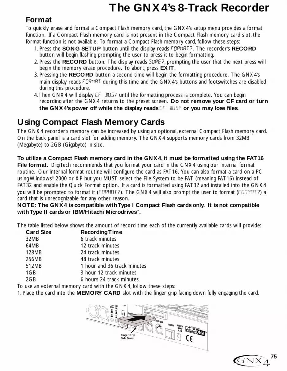
FormatTo quickly erase and format a Compact Flash memory card, the GNX4’s setup menu provides a formatfunction. If a Compact Flash memory card is not present in the Compact Flash memory card slot, theformat function is not available. To format a Compact Flash memory card, follow these steps:
1. Press the SONG SETUP button until the display reads format?. The recorder’s RECORDbutton will begin flashing prompting the user to press it to begin formatting.
2. Press the RECORD button. The display reads SURE?, prompting the user that the next press willbegin the memory erase procedure. To abort, press EXIT.
3. Pressing the RECORD button a second time will begin the formatting procedure. The GNX4’smain display reads format during this time and the GNX4’s buttons and footswitches are disabledduring this procedure.
4.Then GNX4 will display CF BUSY until the formatting process is complete. You can beginrecording after the GNX4 returns to the preset screen. Do not remove your CF card or turnthe GNX4’s power off while the display reads CF BUSY or you may lose files.
Using Compact Flash Memory CardsThe GNX4 recorder’s memory can be increased by using an optional, external Compact Flash memory card.On the back panel is a card slot for adding memory. The GNX4 supports memory cards from 32MB(Megabyte) to 2GB (Gigabyte) in size.
To utilize a Compact Flash memory card in the GNX4, it must be formatted using the FAT16File format. DigiTech recommends that you format your card in the GNX4 using our internal formatroutine. Our internal format routine will configure the card as FAT16. You can also format a card on a PCusing Windows® 2000 or XP but you MUST select the File System to be FAT (meaning FAT16) instead ofFAT32 and enable the Quick Format option. If a card is formatted using FAT32 and installed into the GNX4you will be prompted to format it (FORMAT?). The GNX4 will also prompt the user to format (FORMAT?) acard that is unrecognizable for any other reason.NOTE: The GNX4 is compatible with Type I Compact Flash cards only. It is not compatiblewith Type II cards or IBM/Hitachi Microdrives™.
The table listed below shows the amount of record time each of the currently available cards will provide:Card Size Recording Time 32MB 6 track minutes64MB 12 track minutes128MB 24 track minutes256MB 48 track minutes512MB 1 hour and 36 track minutes1GB 3 hour 12 track minutes2GB 6 hours 24 track minutes
To use an external memory card with the GNX4, follow these steps:1. Place the card into the MEMORY CARD slot with the finger grip facing down fully engaging the card.
Finger GripSide Down
75
The GNX4’s 8-Track Recorder

Let’s Start Recording!The GNX4’s recorder can record one or two tracks simultaneously. You can operate the GNX4’s recordermanually using the Recorder Panel’s buttons, or record hands-free using the GNX4’s footswitches or aGNXFC (optional).
Selecting an Input SourceTo begin recording on the GNX4, it is important to select the source input using the CF/USB 1-2 SRCbutton. There are multiple input sources to select from which are outlined in the GNX4 Inputs andRecorder Routing section on page 64. The source defaults on a new song to Stereo All.
Using the Record and Playback MetersThe GNX4 has two meters located in the upper right corner of the Recorder Panel. The Record metercan be configured to constantly look at any signals coming into the GNX4 (guitar, mic input, line inputs,and drum/MP3 playback) and displays their level in reference to the optimum recording level. Before youbegin recording, it is wise to set the levels appropriately to optimize signal to noise. To adjust the source’srecording levels, follow these steps:1. Play your guitar or make sure the source you want to record is playing.2. It is best that the recording level is consistently lighting the -6dB LED on the meter and only lighting
the 0dB LED occasionally.3. If you need to boost or reduce the level as determined by the Record meter, there are two options:
a. Increase or decrease the level of the source material.b. Use the GNX4’s CF/USB level compensation control (see steps 4 and 5).
4. If you cannot adjust the source level, press the SHIFT button and then the CF/USB 1-2 LVL button.5. Use the DATA WHEEL to increase or decrease the level of audio until the optimum level (as
described in step 2) is achieved. The range is from -12 to +24dB.6. Press the EXIT button.
NOTE: Since what you are hear when you record is not representative of the actual recordlevel going to the recorder, using the CF/USB 1-2 LVL control to boost or attenuatelevels so as to optimize them for recording will result in an increased or decreasedlevel during playback versus your monitor level. Use the MASTER button andDATA WHEEL to adjust playback levels to the desired level as you record.
For more information on Optimizing Microphone and Line Input Levels, see page 13.
76
The GNX4’s 8-Track Recorder
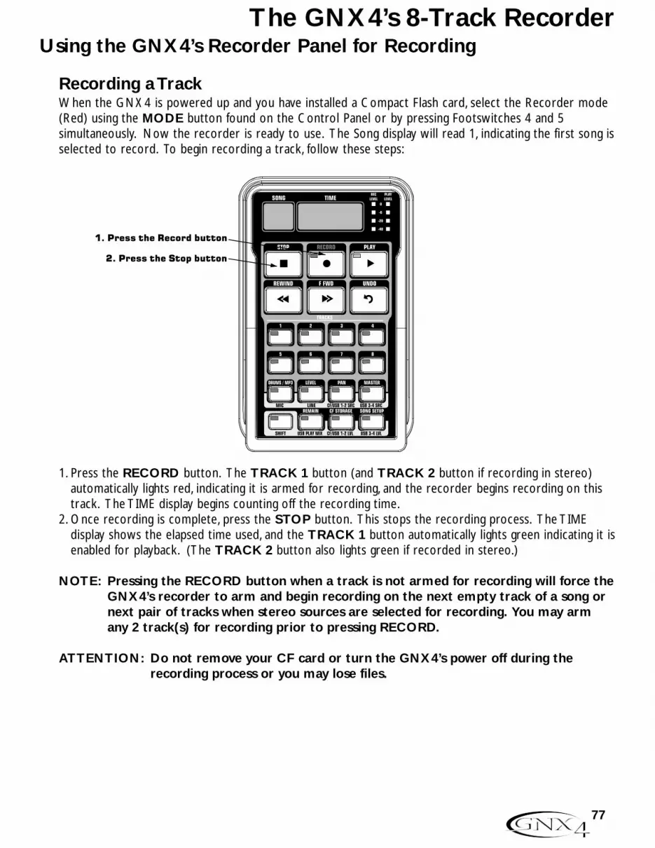
Using the GNX4’s Recorder Panel for Recording
Recording a TrackWhen the GNX4 is powered up and you have installed a Compact Flash card, select the Recorder mode(Red) using the MODE button found on the Control Panel or by pressing Footswitches 4 and 5simultaneously. Now the recorder is ready to use. The Song display will read 1, indicating the first song isselected to record. To begin recording a track, follow these steps:
1. Press the RECORD button. The TRACK 1 button (and TRACK 2 button if recording in stereo)automatically lights red, indicating it is armed for recording, and the recorder begins recording on thistrack. The TIME display begins counting off the recording time.
2. Once recording is complete, press the STOP button. This stops the recording process. The TIMEdisplay shows the elapsed time used, and the TRACK 1 button automatically lights green indicating it isenabled for playback. (The TRACK 2 button also lights green if recorded in stereo.)
NOTE: Pressing the RECORD button when a track is not armed for recording will force theGNX4’s recorder to arm and begin recording on the next empty track of a song ornext pair of tracks when stereo sources are selected for recording. You may armany 2 track(s) for recording prior to pressing RECORD.
ATTENTION: Do not remove your CF card or turn the GNX4’s power off during therecording process or you may lose files.
1. Press the Record button
2. Press the Stop button
The GNX4’s 8-Track Recorder
77

78
The GNX4’s 8-Track RecorderPlaying Back a Recorded TrackAfter a track is recorded, playing it back is simple. If you are at the end of the track or the song, press thePLAY button. The recorder automatically begins playing back the track/song from the very beginning. Ifyou want to start playback at the beginning of a track or song but are someplace other than the end ofthe song, follow these steps:
Begin with the Recorder stopped.1. Press the REWIND button once to move to the beginning of the song.2. Press the PLAY button. The newly recorded track is automatically armed in PLAY status (the track
button is lit green) and the track begins playing back.
ATTENTION: Do not remove your CF card or turn the GNX4’s power off while playingback a track or you may lose files.
Recording Multiple TracksAfter a track has been recorded, you may want to record other tracks (overdub) that will play along withit. You will want to play the previously recorded track(s) as a monitoring source while recording newtracks. To add a new track to previously recorded tracks do the following:1. Press the RECORD button. The next available track for recording automatically lights red, indicating it
is armed to record, and the recorder begins recording on this track from the beginning of the song.The TIME display begins counting off the recording time. If Autostop is turned on, the recorder willautomatically stop when the longest track playing back is finished. If Autostop is turned off, go to step2.
2.When recording is complete, press the STOP button.
Setting Track Playback Levels and PanningAfter a track has been recorded, you can set the pan and playback level for each track. This is done usingthe LEVEL and PAN buttons. This feature is most useful if done while the recording is playing back soyou can hear the changes as they are being made. To set level and pan controls for each track, followthese steps:
2. Press the Play button
1. Press the Rewind button

79
The GNX4’s 8-Track Recorder
Setting Each Track’s Playback Level:1. Press the REWIND button once to return the song to the beginning.2. Enable any track(s) you want to playback by pressing their TRACK buttons until they are lit green.3. Press the PLAY button. Playback of the tracks begins.4.To adjust the playback level of the tracks, press the LEVEL button once.5. Press any track button that is playing back. The selected TRACK button will light green and the
other TRACK button LEDs turn off. The main display reads tkx levl 50 (X = track number).6.Turn the DATA WHEEL to adjust this track’s playback level. The range is from 0 to 99.7. Select other tracks and adjust their playback level by repeating steps 5 and 6.8. Press the LEVEL button to exit.
Setting Each Track’s Pan:1. Press the PAN button once. It will light green and the main display will read tkx cntr 0
(X=track number).2.Turn the DATA WHEEL to the left to pan the track to the left in the stereo field (tkx left).
Turn the DATA WHEEL to the right to pan the track to the right (tkx rght).3. Select other tracks and adjust their pan position by pressing the track button and repeating step 2.4. Press the PAN button again to exit.
Adjusting the Recorder’s Playback Master LevelAs more tracks are recorded, the output level will begin to increase. You will notice the PlaybackMeter will reach clipping much easier which will cause distortion in the audio being played back. Tocompensate for this, the GNX4 recorder has a Master Level to control the overall playback level of theinternal recorder. To adjust the Master playback level, follow these steps:1. Press the PLAY button to start playback of the song.2. Press the MASTER button and use the DATA WHEEL to reduce or increase the playback level so
that the PLAYBACK meter level is consistently lighting the -6dB LED on the meter and only lightingthe 0dB LED occasionally.
NOTE: As more tracks are recorded, further adjustments to the Master Level may need to be made
to prevent clipping.
Trak lvl 50
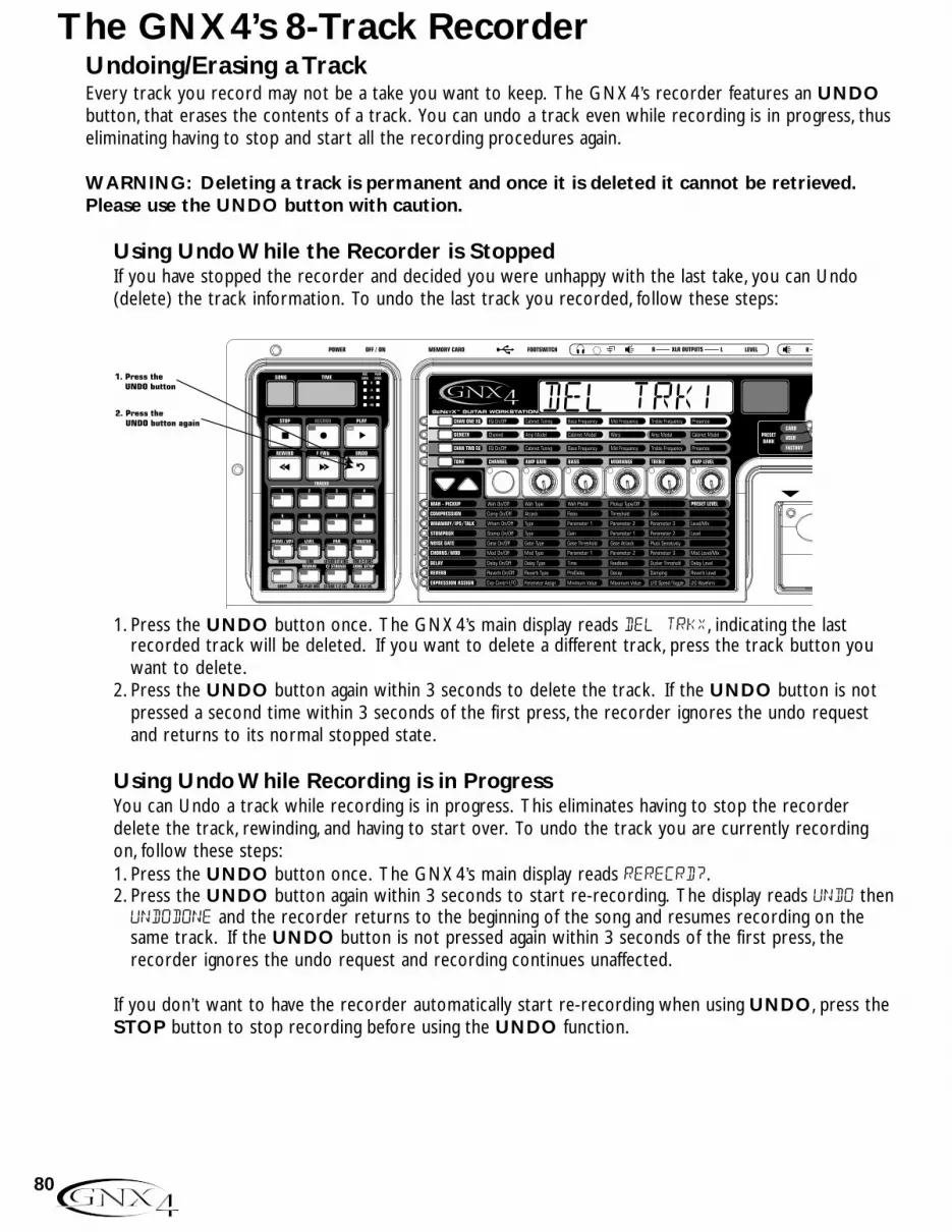
Undoing/Erasing a TrackEvery track you record may not be a take you want to keep. The GNX4’s recorder features an UNDObutton, that erases the contents of a track. You can undo a track even while recording is in progress, thuseliminating having to stop and start all the recording procedures again.
WARNING: Deleting a track is permanent and once it is deleted it cannot be retrieved.Please use the UNDO button with caution.
Using Undo While the Recorder is StoppedIf you have stopped the recorder and decided you were unhappy with the last take, you can Undo(delete) the track information. To undo the last track you recorded, follow these steps:
1. Press the UNDO button once. The GNX4’s main display reads del trkx, indicating the lastrecorded track will be deleted. If you want to delete a different track, press the track button youwant to delete.
2. Press the UNDO button again within 3 seconds to delete the track. If the UNDO button is notpressed a second time within 3 seconds of the first press, the recorder ignores the undo requestand returns to its normal stopped state.
Using Undo While Recording is in ProgressYou can Undo a track while recording is in progress. This eliminates having to stop the recorderdelete the track, rewinding, and having to start over. To undo the track you are currently recordingon, follow these steps:1. Press the UNDO button once. The GNX4’s main display reads rerecrd?.2. Press the UNDO button again within 3 seconds to start re-recording. The display reads UNDO thenundodone and the recorder returns to the beginning of the song and resumes recording on thesame track. If the UNDO button is not pressed again within 3 seconds of the first press, therecorder ignores the undo request and recording continues unaffected.
If you don’t want to have the recorder automatically start re-recording when using UNDO, press theSTOP button to stop recording before using the UNDO function.
del trk1
80
The GNX4’s 8-Track Recorder
81
The GNX4’s 8-Track RecorderChanging Track StatusEach recorded track can be in 1 of 4 states; playback, record, merge, or off. Tracks with recorded materialcan be turned on for playback (TRACK button is lit green), armed for recording (TRACK button is litred), armed for merging other recorded tracks to it (TRACK button is lit yellow) or turned off (buttonis not lit). If a track does not have material recorded on it, it can only be enabled for recording, merge, orturned off. To change the status of a track, do the following:1. Press any TRACK button repeatedly until it lights green, red, or yellow. If the button lights green,
there is recorded material present. If the RECORD or PLAY button is pressed the material is playedback. If the button lights red and the RECORD button is pressed, audio will be recorded on thistrack. If the button lights yellow, it merges tracks armed for playback, including recorded materialalready present on this track.
Punching In/Punching OutThere may be times you want to replace a track section in the middle of a song. Rather than recordingon a new track at the very beginning and wasting recording time with silence, you can “punch in” thephrase you want to record at a certain point on the track. To punch in record, follow these steps:1.Arm the track that you want to punch in and record on (the TRACK button turns red).2. Press the PLAY button. All tracks that are armed for playback and record begin playing, and the
TRACK button armed for recording begins flashing red.3.When you reach the point in the playback that you want the recording to begin, press the RECORD
button. The TRACK button armed for recording lights solid red and recording begins on this track atthis point.
4.When you are finished recording, press the RECORD button again to disable the track armed forrecording (the track button flashes red) and continue listening to the playback.
Bouncing/Merging TracksOnce you have recorded several tracks, you may want to combine them onto a single track or pair oftracks to free up recording memory. This is done using the recorder’s Merge function. Merging isessentially the same as bouncing tracks as you would on old analog 4 and 8-track tape recorders, onlywithout any signal degradation. You can merge playback tracks with recorded tracks and retain therecorded material on the tracks you are merging to. This means you don’t need empty tracks to mergeto if all tracks have recorded material on them.
NOTE: Merging tracks is irreversible to the tracks that are merged to. It is wise to makesure your individual track levels and pans are set prior to merging tracks with recordedmaterial present. Once tracks are merged, the individual track information cannot beadjusted.
To merge recorded tracks, follow these steps:1. Begin with the recorder stopped.2. Arm the track(s) you want to merge for playback (TRACK buttons lit green).3. Press the TRACK button(s) you want to merge to until they light yellow. Only a maximum of two
tracks at a time can be selected to merge to.4. Press the RECORD button. The recorder begins merging the audio from the tracks armed for
playback onto the tracks armed for merge. Once merging has begun, it cannot be stopped untilplayback through the entire song is completed.

Re-Amping Using the GNX4’s RecorderRe-amping is a feature that allows you to record a dry, unprocessed guitar track and then play it back throughthe GNX4’s effects afterward. This allows you to record a part just once and then experiment with differentamp/cabinet/effect combinations until the sound fits well in the mix. One great thing about using the GNX4’sre-amp capability is that you can record this unprocessed track while still monitoring your performancethrough the GNX4’s processing. This lets you get the feel of hearing the guitar through the amp and effectswhile tracking, while only recording the dry guitar. To re-amp a guitar track, follow these steps:
1. Begin with the recorder stopped.2. Press the SHIFT button on the Recorder Panel.3. Press the CF/USB 1-2 SRC button on the Recorder Panel.4. Use the DATA WHEEL to select DRYGUITR as the source.5. Press the EXIT button.6. Use the DATA WHEEL to select a preset that gives you a good feel for the performance you are about
to record.7. Press the RECORD button. A new track will arm itself and you can begin recording your performance.8. When finished, press the STOP button.9. Press the SHIFT button on the Recorder Panel (if it is not already lit).10. Press the CF/USB 1-2 SRC button on the Recorder Panel.11. Use the DATA WHEEL to select REAMP X (X = the track number you just recorded to).12. Press the PLAY button.
You will now hear your performance played back through the currently selected preset. Use the DATAWHEEL to hear this performance played through different presets. Another re-amping method is to recorda guitar using the amp modeling only, without Chorus/Mod, Delay, or Reverb effects by selecting MONOALL asthe recording source. You can then select a direct amp and cabinet model upon playback and re-amp throughthe GNX4’s effects only.
82
The GNX4’s 8-Track Recorder

Hands-Free RecordingThe GNX4’s footswitches can perform different functions depending on the mode. (See the FootswitchFunctions for Modes section on page 59 for more information.) When Recorder mode is selected, theUP/DOWN footswitches are used to select Songs. The 5 numbered footswitches are used to Play DrumPatterns/MIDI files/MP3s, Stop/Undo, Record, Play, and set Drum Pattern Tempo. Use the Mode buttonlocated in the Control Panel or press Footswitches 4 and 5 simultaneously (until they light red) to selectRecorder mode. This turns your GNX4’s pedalboard into a hands-free remote control for the recorder andtracks are armed automatically for recording and playback.
Using the RECORD Footswitch to Record a TrackTo begin recording a track using the footswitches, follow these steps:1. Press the RECORD footswitch. The TRACK 1 button (and TRACK 2 button if recording stereo
tracks) automatically lights red, indicating it is armed to record, and the recorder begins recording onthe track. The TIME display begins counting off the recording time.
2.When you are finished recording the track, press the STOP/UNDO footswitch. This stops therecording process, and the track is saved. The TIME display shows the elapsed time used and theTRACK 1 button (and TRACK 2 button if recording stereo tracks) is lit green indicating it is nowenabled for playback.
Using the PLAY Footswitch to Play Back a Recorded TrackAfter a track has been recorded, playing it back is simple. If you are at the end of the track or the song,press the PLAY footswitch. The recorder automatically begins playing back the track/song from the verybeginning. If you want to start playback at the beginning of a track or song, but are someplace other thanthe end of the song, follow these steps:1. Press the STOP/UNDO footswitch twice. This will rewind to the beginning of the current song.2. Press the PLAY footswitch. The newly recorded track is automatically armed in PLAY status (track
button is lit green) and the track begins playing back.
Using the Footswitches to Record Multiple TracksAfter a track has been recorded, you may want to record other tracks (overdub) that will play along withit. You will want to play the previously recorded track(s) as a monitoring source while recording newtracks. To add a new track to previously recorded tracks do the following:1. Press the RECORD footswitch. The next available track for recording automatically lights red,
indicating it is armed to record, and the recorder begins recording on this track from the beginning ofthe song. The TIME display begins counting off the recording time. If Autostop is enabled in theRecorder setup, the recorder will automatically stop when the longest track playing back is finished. IfAutostop is turned off, go to step 2.
2.When you are finished recording the track, press the STOP/UNDO footswitch.
CONTROL A CONTROL B CONTROL C TAP TEMPOAMP CHANNEL
83
The GNX4’s 8-Track Recorder

Using the UNDO Footswitch to Erase a TrackIf you are not happy with a track you just recorded, no problem. You can easily delete, or Undo the lastrecorded track using the GNX4’s footswitches. To Undo a track that was just recorded, follow thesesteps:
Using Undo While the Recorder is Stopped1. Press and hold the STOP/UNDO footswitch once. The GNX4’s main display reads del trkx,
indicating the last recorded track will be deleted.2. Press the STOP/UNDO footswitch again within 3 seconds to delete the track. If the
STOP/UNDO footswitch is not pressed a second time within 3 seconds of the first press, therecorder ignores the undo request and returns to its normal stopped state.
Using Undo While Recording is in ProgressYou can Undo a track while recording is in progress. This eliminates having to stop the recorder,rewinding, and having to start over. To undo the track you are currently recording on, follow thesesteps:1. Press and hold the STOP/UNDO footswitch once. The GNX4’s main display reads rerecrd?.2. Press the STOP/UNDO footswitch again within 3 seconds to start re-recording. The display readsundo then undodone and the recorder returns to the beginning of the song and resumesrecording on the same track. If the UNDO footswitch is not pressed again within 3 seconds of thefirst press, the recorder ignores the undo request and recording continues unaffected. If you don’twant to have the recorder automatically start re-recording when using UNDO, press theSTOP/UNDO footswitch to stop recording before using the UNDO function.
Using the Footswitches for Punching In/Punching OutThere may be times you want to replace a track section in the middle of a song. Rather than recordingon a new track at the very beginning and wasting recording time with silence, you can “punch in” thephrase you want to record at a certain point on the track. To punch in record, follow these steps:1. Begin with the Recorder stopped.2.Arm the track that you want to punch in and record on (the TRACK button will light red).2. Press the PLAY footswitch. Tracks that are armed for playback begin playing, and the TRACK button
armed for recording flashes red.3.When you reach the point in the playback that you want the recording to begin, press the RECORD
footswitch. The TRACK button armed for recording, lights solid red and recording begins on thetrack at this point.
4.When you are finished recording, press the RECORD footswitch to continue listening to playback anddisable the track armed for recording, or press the STOP/UNDO footswitch to stop.
84
The GNX4’s 8-Track Recorder

Hands-Free Recording with the GNXFC
The GNX4 is equipped with a footswitch jack that allows you to connect an optional GNXFC for controllingthe GNX4’s recorder. This 3-button footswitch features functions for STOP/UNDO, RECORD, andPLAY. The GNXFC is also an ideal companion for JamMan™ (see the Using the GNX4’s JamMan™
Delay Looper section on page 87 for more information) users as it allows you to leave your GNX4footswitches setup for changing presets or switching amp channels and effects on and off while the GNXFCis used for both recording songs and creating loops.
Using the GNXFC to Record a TrackTo begin recording a track using the GNXFC footswitches, follow these steps:1. Press the RECORD footswitch. The TRACK 1 button will automatically light red, which will arm it
to record, and the recorder will begin recording on this track. The TIME display will begin counting offthe recording time.
2. Once recording is completed, press the STOP/UNDO footswitch. This stops the recording process,and saves the track. The TIME display will show the elapsed time used and the TRACK 1 button willbe lit green indicating it is now enabled for playback. (The TRACK 2 button also lights green ifrecorded in stereo.)
Using the GNXFC to Play Back a Recorded TrackAfter a track has been recorded, playing it back is simple. If you are at the end of the track or the song,press the PLAY footswitch. The recorder automatically begins playing back the track/song from the verybeginning. If you want to start playback at the beginning of a track or song but are someplace other thanthe end of the song, follow these steps:1. Press the STOP/UNDO footswitch twice. This will rewind to the beginning of the current song.2. Press the PLAY footswitch. The newly recorded track is automatically armed in PLAY status (track
button is lit green) and the track begins playing back.
Using the GNXFC to Record Multiple TracksAfter a track has been recorded, you may want to record other tracks (overdub) that will play along withit. You will want to play the previously recorded track(s) as a monitoring source while recording newtracks. To add a new track to previously recorded tracks do the following:1. Press the RECORD footswitch. The next available track for recording automatically lights red,
indicating it is armed to record, and the recorder begins recording on this track from the beginning ofthe song. The TIME display begins counting off the recording time. If Autostop is enabled in theRecorder setup, the recorder will automatically stop when the longest track playing back is finished. IfAutostop is turned off, go to step 2.
2.When you are finished recording the track, press the STOP/UNDO footswitch.
85
The GNX4’s 8-Track Recorder
Using the GNXFC to Undo/Erase a TrackIf you are not happy with a track you just recorded, no problem. You can easily delete, or Undo the lastrecorded track using the GNX4’s footswitches. To Undo a track that was just recorded, follow thesesteps:
Using Undo While the Recorder is Stopped1. Press and hold the STOP/UNDO footswitch once. The GNX4’s main display reads del trkx,
indicating the last recorded track will be deleted.2. Press the STOP/UNDO footswitch again within 3 seconds to delete the track. If the
STOP/UNDO footswitch is not pressed a second time within 3 seconds of the first press, therecorder ignores the undo request and returns to its normal stopped state.
Using Undo While Recording is in ProgressYou can Undo a track while recording is in progress. This eliminates having to stop the recorder,rewinding, and having to start over. To undo the track you are currently recording on, follow thesesteps:1. Press and hold the STOP/UNDO footswitch once. The GNX4’s main display reads rerecrd?.2. Press the STOP/UNDO footswitch again within 3 seconds to start re-recording. The display readsundo then undodone and the recorder returns to the beginning of the song and resumesrecording on the same track. If the UNDO footswitch is not pressed again within 3 seconds of thefirst press, the recorder ignores the undo request and recording continues unaffected. If you don’twant to have the recorder automatically start re-recording when using UNDO, press theSTOP/UNDO footswitch to stop recording before using the UNDO function.
Using the GNXFC for Punching In/Punching OutThere may be times you will want to record in the middle of a song rather than from the very beginning.Rather than recording on a new track at the very beginning and wasting recording time with silence, youwill want to “punch in” the phrase you want to record at a certain point on the track and then punchout. To punch in record do the following:1.Arm the track you want to punch in record on (TRACK button will light red).2. Press the PLAY footswitch. Any tracks that are armed for playback will begin playing and the TRACK
button armed for recording will flash red.3.When you reach the point in the playback that you want the recording to begin, press the RECORD
footswitch. The TRACK button armed for recording will now light solid red and recording will nowbegin on this track at this point.
4.When you are finished recording, press the PLAY footswitch to continue listening to playback anddisable the track armed for recording, or press the STOP/UNDO footswitch to stop.
86
The GNX4’s 8-Track Recorder

Using the GNX4’s JamMan™ Delay LooperThe GNX4’s recorder also doubles as a JamMan Delay Looper. The JamMan is used to create a recordingloop that you can playback with. The JamMan functions are accessed using the GNX4’s footswitches whilethey are in Recorder mode. The only difference between regular multi-track recording and looping is theway you use the footswitches after recording your first track.
When recording multiple tracks for a song, you would normally record your first track, stop, rewind, and thenset up for recording your overdub track. The GNX4’s footswitches provide hands-free operation for thesefunctions. But when you want to create loops on the fly that you can layer, you want the transition from thefirst take to the second and so on to be seamless.
To use the JamMan feature of the GNX4 you must first have the footswitches in Recorder mode. To do this,press Footswitches 4 and 5 simultaneously until the DOWN/UP footswitches are lit red. If you havesongs already in memory, you must select a new Song to record your loop to. To select a new song, pressthe UP footswitch. A new song is defined as a song that has no previously recorded material present on anyof its tracks.
You are now ready to begin recording a loop.
Recording a LoopRecording a loop is no different than doing multi-track recordings. Here are the steps for creating a loop:1. Press the RECORD footswitch. The TRACK 1 button automatically lights red, indicating it is armed to
record, and the recorder begins recording on this track. The TIME display begins counting off therecording time.
2. Just as you reach the end of your take, press the PLAY footswitch. This sets the loop length andplaces TRACK 1 into playback. You can listen to what you just recorded, and the TRACK 2 buttonwill flash red indicating it is now armed and ready to begin recording on.
NOTE: If the RECORD footswitch is pressed instead of the PLAY footswitch after recordingthe first pass, recording is disabled and the loop’s length is set. The TRACK 1 buttonis still armed for recording (flashing red) but is now playing back what you justrecorded. You can now add material to track 1 rather than record on a new track bypressing the RECORD footswitch to record on this track again. The new material isadded to existing recorded material. Until the PLAY footswitch is pressed, onlytrack 1 is available to record on.
87
The GNX4’s 8-Track Recorder
Recording Layered Overdubs to your LoopAdding overdubbed layers to your first loop is easy. After recording your first track and pressing thePLAY footswitch,TRACK 2 is already armed for recording. To add overdubs to the current loop, followthese steps:
1. Press the RECORD footswitch. The TRACK 2 button lights solid red and begins recording on thistrack.
2.When finished, you can press PLAY to stage the next track for recording or press RECORD todisable recording and remain on the same track.
If at anytime you are not satisfied with your current take while recording overdubs with your originalloop, you can undo it by pressing the STOP/UNDO footswitch. This erases the contents of a track andlets you proceed with trying another take without having to stop. To use the UNDO function whilerecording a loop, follow these steps:1. Press the STOP/UNDO footswitch once. The GNX4’s main display reads rerecrd?.2. Press the STOP/UNDO footswitch again within 3 seconds to start re-recording. The display readsundo then undodone and the recorder returns to the beginning of the song and resumes recording onthe same track. If the STOP/UNDO footswitch is not pressed again within 3 seconds of the firstpress, the recorder ignores the undo request and recording continues unaffected.
Using Quantize for Seamless LoopsWhen recording loops, it is important that you set the loop length exactly so that your loop is seamlessfrom finish to start. Sometimes our timing may not be perfect when pressing the PLAY footswitch to setthe length. The GNX4 provides a Quantize feature that corrects these timing problems to the nearesteighth note. Quantize looks at the point where you pressed the PLAY footswitch in relation to thetempo you are using for your loop. Lets say you were recording a four second loop and you pressed thePLAY footswitch just a little late. No problem, with Quantize enabled, the looper will automatically cutoff the extra recording and give you a perfect four second loop. To enable the Quantize feature, followthese steps:1. Begin with the recorder stopped by pressing the STOP/UNDO footswitch.2. Press the SONG SETUP button and use the PREV/NEXT buttons until the GNX4’s main display
reads: QUANTIZE.3. Use the DATA WHEEL to turn the Quantize feature on and off. Quantize only affects delay loops
and does not affect songs.4. Press the EXIT button.
88
The GNX4’s 8-Track Recorder

Using the GNXFC for Looping
Recording a LoopTo begin recording a loop is no different than when you are doing multi-track recording. You must beginwith a new song in order to create a loop. Press the GNX4’s UP Footswitch (the GNX4’sfootswitches must be in Recorder mode first) or the FFWD button on the Recorder Panel to select anew song that has not been recorded on. Here are the steps for creating a loop:1. Press the RECORD footswitch. The TRACK 1 button will automatically light red, which will arm it
to record, and the recorder will begin recording on this track. The TIME display will begin counting offthe recording time.
2. Just as you reach the end of your take, press the PLAY footswitch. This will set the loop length andplace TRACK 1 into playback. You will now begin hearing what you just recorded. You will now seethat the TRACK 2 button is flashing red meaning it is now armed and ready to begin recording on.
You have just successfully recorded you first loop and are now ready to start layering overdubs.
NOTE: If the RECORD footswitch is pressed instead of the PLAY footswitch after recordingthe first pass, recording is disabled and the loop’s length will be set. The TRACK 1button will now be armed for record (flashing red). You will begin hearing playbackof track 1 at this time. If you decide you want to add material to track 1 ratherthan recording on a new track, press the RECORD footswitch again to enablerecording on this track again. The new material will now be added to existingrecorded material. Until the PLAY footswitch is pressed, only track 1 will beavailable to record on.
Recording Layered Overdubs to Your LoopTo begin adding overdubbed layers to your first loop is easy. Since TRACK 2 is already armed forrecording, press the RECORD footswitch when you are ready to begin recording your overdub.1. Press the RECORD footswitch. The TRACK 2 button will light solid red and will begin recording on
this track.2.When finished, you can press PLAY to arm the next track for recording or just press RECORD to
begin adding your next overdub.If at anytime you are not satisfied with your current take, you can undo it by pressing and holding theSTOP/UNDO footswitch. This will erase the last recorded track and let you proceed with tryinganother take without having to stop. (See Using Undo While Recording is in Progress on page 86.)
89
The GNX4’s 8-Track Recorder

Drum Machine Recorder OperationThe Drum Machine can be assigned to play a particular pattern, MIDI file, or an MP3 in any song when theDRUMS/MP3 button on the Recorder panel is enabled. This button will light green if an internal drumpattern or MIDI file has been selected for playback, or it will light yellow if an MP3 file has been selected.When using externally created MIDI files or MP3s for use as playback files, the following rules must befollowed in order for these files to work:
• MP3s and MIDI files must be located in their specific folders within the GNX4 folder on the CompactFlash card. This will ensure that all .mid and .mp3 files can be located and appended to the end of thefactory PATTERN/FILE list. (See page 101 for information regarding Compact Flash File Structure.)
• MP3s must be encoded as stereo, 64kb (or greater), 44.1kHz files.• MIDI files and internal drum patterns cannot be played while an MP3 is being played and vice-versa.• MIDI files must be Type 0 (Zero) format in order to be recognized by the GNX4.• Externally created MIDI files can play the internal drum machine if they were recorded using MIDI
Channel 10.
Setting Up Playback Files with a SongTo select a drum pattern, a MIDI file, or MP3 file to be played back when the recorder’s PLAY button ispressed, follow these steps:1. Select a new song using the FFWD or REWIND buttons, or using the UP/DOWN footswitches when
they are in recorder footswitch mode.2. Press the DRUMS/MP3 [play/stop] button in the Control Panel. The drum machine will begin playing.3. Press the PATTERN button and use the DATA WHEEL to select which internal drum pattern, MIDI file,
or MP3 file from the list that you want to use with the song.4. Press the LEVEL, TEMPO, and KIT buttons and use the DATA WHEEL to set these functions as you
like. Tempo and Kit are unavailable when an MP3 is selected.5. Press the DRUMS/MP3 [play/stop] button in the Control Panel to stop the drum machine.6. Press the DRUMS/MP3 button in Recorder Panel until it lights green (drum pattern or MIDI file is
selected) or yellow (MP3 file is selected).
These settings will be automatically saved as part of the song setup for this song once you begin recording. Ifyou have an existing song in which you want to change the playback file settings, you need to manually editthese settings in the SONG SETUP menu as follows:
1. Press the SONG SETUP button once. The currently selected pattern being used by the GNX4’s drummachine will be displayed (New song only). Existing songs may have a different file displayed.
2. Use the DATA WHEEL to select a new pattern, MIDI file, or MP3 you want associated with the song.3. Press the NEXT to access the other drum machine menus (level, tempo, kit) and use the DATA WHEEL
to change these settings. Tempo and Kit are unavailable if any MP3 has been selected.4. Press the EXIT button.
Once these settings are saved with a song, they will override any the settings changed using the ControlPanel Drum machine button once the song begins playing
Recording DrumsIf you want to record the actual drum machine audio rather than just have it sync to recorded tracks, followthese steps:1. Press the SHIFT button located on the Recorder Panel.2. Press the CF/USB 1-2 SRC or USB 3-4 button also located on the Recorder Panel.
90
The GNX4’s 8-Track Recorder
3. Select one of the following recording input sources: STEROALL, MONOALL, DRUMS ST, or DRUMS MN.4. Press the EXIT button.5. Press the DRUMS/MP3 button on the Recorder Panel until it lights red.
When recording begins using either the GNX4’s recorder or while recording to the computer, the drummachine audio will be captured on the recorded tracks.
MIDI and RecordingThe GNX4 features MIDI In and Out jacks which serve several purposes:1. MIDI In can be used for remote control of the GNX4 from external MIDI devices such as MIDI
sequencers and MIDI controller pedals (GNX4 receives program changes, CC parameter control).2. MIDI In can be used for receiving Sysex preset and bulk dumps into the GNX43.The GNX4’s Drum Machine responds to MIDI note events received on MIDI Channel 10.4. MIDI In can be used as your MIDI interface to the computer allowing recording of MIDI events to Pro
Tracks Plus™ or other MIDI recording software applications via USB.NOTE: There is no recording of MIDI to the Compact Flash card.5. MIDI Out can be used for Sysex preset and bulk dumps to another GNX4 or a MIDI data recording
device.6. MIDI Out can be used as the MIDI out of your computer recording and sequencer application for
controlling external MIDI devices such as keyboards or sound modules.
Whenever a MIDI device (sequencer, keyboard, etc..) is plugged into the GNX4’s MIDI In and is transmittingMIDI data, this data is automatically being sent to the computer via the GNX4’s USB port. Any sequencer orrecording application that records MIDI data can record these messages. See the application’s manual or helpfiles for more information on recording MIDI.
Working with Songs and LoopsA Song and a Loop are a group of recorded tracks. You must have a Compact Flash memory card installed inthe GNX4 to work with songs and loops using the GNX4’s recorder.
Selecting Songs and LoopsTo select songs, follow these steps:1. Press the STOP button (if the recorder isn’t already stopped).2. Use the FFWD or REWIND buttons to select the next or previous song. The GNX4’s main display
shows READING and the number in the SONG display changes as the new song is selected. The TIMEdisplay shows the selected song’s length.
NOTE: You can also use the DOWN and UP Footswitches to select songs when Recordermode is active.
Deleting Songs and LoopsTo delete songs from the Compact Flash card, follow these steps:1. Select the song you want to delete by quickly pressing the FFWD or REWIND button until the song
number you wish to delete appears in the Song display.2. Press and hold the UNDO button until the GNX4’s main display reads DEL SONG.3. Press the UNDO button again within 3 seconds to delete the song. The display reads DELETING and
returns to the preset screen when deletion is complete. If the UNDO button is not pressed againwithin 3 seconds of the first press, the recorder ignores the undo request and recording continuesunaffected.
91
The GNX4’s 8-Track Recorder

USB Recording IntroductionThe GNX4’s USB connection provides 4 channels of audio streaming into the computer and 2 channels ofplayback from the computer simultaneously. Recording has never been easier thanks to the hands-free tracking environment that the GNX4 and the Pro Tracks Plus™ software provide. The GNX4’s footswitchesand Pro Tracks Plus software work seamlessly together to automatically arm, record, play, and delete trackson the fly without ever having to take your hands off the guitar. Multiple recording configurations can beselected to best optimize your recording needs. For more information please refer to the Audio Routingfor Recording section starting on page 64.
Installing the GNX4’s Software SuiteThe GNX4 USB drivers must first be installed before using either the X-Edit Editor/Librarian or ProTracks Plus recording software. These drivers are found on the X-Edit Software CD that came packagedwith the GNX4. Please review the Pro Tracks Plus documentation to ensure your computer systemmeets the necessary requirements prior to installation. Once installed and configured, the GNX4 canthen control Pro Tracks Plus and its recording functions.
Connecting the GNX4 to the ComputerThe GNX4 comes equipped with a USB cable that is to be connected to your computer whenever your willbe recording or using the X-Edit Editor/Librarian. We recommend that you only use the USB cable that isshipped with the GNX4 since it has been tested and approved for this specific use. Before connecting theGNX4 to your computer, please read the “Software Installation Guide”.
To connect the GNX4 to the computer, follow these steps:1. Begin with the power turned off on the GNX4.2. Plug the small end of the USB cable in to the USB jack on the back of the GNX4.3. Plug the large flat end of the USB cable into an available USB port on your computer.4. Turn on the power to the GNX4.
NOTE: DigiTech recommends that you do not use the GNX4 as your default sound playbackdevice. This is configured in Windows in the Control Panel under the Sounds and AudioDevices Properties. Windows Audio Samples are generally recorded at full scale level and ifplayed back through the GNX4 may be very loud in comparison with the configuration of audiolevel in the GNX4.
ATTENTION: PLEASE READ THE SOFTWARE INSTALLATIONGUIDE BEFORE CONTINUING!
92
Computer Recording via USB

Using Pro Tracks Plus™
When Pro Tracks Plus is first launched after installation, you will have to configure the MIDI device and Audiosettings to recognize the GNX4 as the hardware you want to use. These procedures must be followed toensure you will be able to record audio through all of the GNX4’s inputs and to enable the hands-freerecording capabilities the GNX4 offers.
NOTE: Read the Software Installation sheet that came packaged with the GNX4 for instructions on installing USB drivers before connecting the GNX4 to the USB port on yourPC and using Pro Tracks Plus.
Installing Pro Tracks Plus SoftwarePro Tracks Plus software must be installed on your computer in order to use the recording capabilities ofthe GNX4. To install Pro Tracks Plus, please consult the installation instructions provided with the ProTracks Plus installation CD.
Setting Up the GNX4 MIDI DeviceThe GNX4 uses MIDI commands to communicate with Pro Tracks Plus. These commands are used todetermine which USB 1-2 Source and USB 3-4 Source settings have been selected so that Pro Tracks Pluscan function properly when using the GNX4’s hands-free recording features. To configure Pro TracksPlus’ MIDI settings for use with the GNX4 follow the steps outlined below:
1. Start Pro Tracks Plus application on your computer.2. If the Tip of the Day window appears, click the Close button.3. If no previous MIDI outputs have been selected, the No MIDI Outputs Selected window will
appear. Click the Choose MIDI Outputs Now button. The MIDI Devices window will open.4. Under both Input and Output Selections, choose GNX4 USB MIDI. Do not select DigiTech USB
X-Edit or any other available selections. Click the Move Selected Devices to Top button.5. Click the OK button and the window will close.6. If the Quick Start window appears, click the Close button.
Setting up the GNX4 for Hands-Free Recording1. From the Pro Tracks Plus menu bar, select Options>Control Surfaces. The Control Surfaces win-
dow will appear.2. Click the + button to add a new control surface. The Control Surface Settings window will open.3. In the Control Surface pull-down menu, select DigiTech GNX. Verify that the Input and Output
port settings still have GNX4 USB MIDI selected. If they do not, do this now.4. Click the OK button. DigiTech GNX should now be displayed as the Connected Surface in the
Control Surfaces Window.6. Click the Close button.7. Pro Tracks Plus can now respond to the GNX4 for automated recording functions. See the
Hands-Free Default section on page 105 for more information on using Hands-Free USB and CF recording information.
93
Computer Recording via USB

Setting up Pro Tracks Plus™ for GNX4 Audio1. From the Pro Tracks Plus menu bar, select Options>Audio. The Audio Options window will
appear. Click the Drivers tab.2. Under the Input Drivers settings, select DigiTech USB 1-2 In/Out and DigiTech USB 3-4 In
Only and deselect all other options.3. Under the Output Drivers settings, select DigiTech USB 1-2 In/Out and deselect all other
options.4. Click the OK button.5. Click the OK button when the window stating changes will be saved upon re-start appears.6. Close the Pro Tracks Plus application. When you are prompted to save changed, click No.7. Re-start the Pro Tracks Plus application again.8. Close the Tip of the Day and Quick Start windows if they appear.9. From the Pro Tracks Plus menu bar, select Options>Audio.
10. Verify that the Playback and Record Timing Master settings have DigiTech USB 1-2 In/Out select-ed. If not, select these now.
11. Click the Wave Profiler button at the bottom.12. Click the Yes button to continue performing the tests.13. When the profiling operation is successfully completed, click the OK button.14. Click the OK button to close the Audio Options window if it is still open.
You are now ready to use the GNX4 with Pro Tracks Plus recording software.
CAUTION: Do not disconnect power or disconnect the USB cable from the GNX4 or thecomputer while the Pro Tracks Plus software is running. Doing so can result in unpre-dictable behavior from your computer’s operating system.
94
Computer Recording via USB

Using the GNX4’s Footswitches for Hands-Free ComputerRecording FunctionsThe GNX4’s footswitches are capable of controlling the Pro Tracks Plus™ recording software, creating ahands-free recording interface. To do this, the GNX4 must be connected to the computer via the includedUSB cable and the Pro Tracks Plus application must be installed and open.
Recording a Track or TracksTo begin recording a track using the footswitches, follow these steps:1. Start the Pro Tracks Plus application.2. From the Pro Tracks Plus menu bar, select File>New. The New Project File window will appear.3. From the New Project File window, select Normal - Hands-Free Session.4. Put the GNX4 into Recorder mode by pressing the MODE button located on the Control Panel or
by pressing FOOTSWITCHES 4 and 5 simultaneously until the display flashes recorder.5. Press the SHIFT and CF/USB 1-2 SRC buttons, then use the DATA WHEEL to select the sources
you’d like to record. (Additional sources can be selected by pressing the USB 3-4 SRC button andusing the DATA WHEEL.)
6. Press the RECORD footswitch. The GNX4’s display reads record. A track or tracks areautomatically inserted in the current session of the Pro Tracks Plus software and recording on thesetracks begins.
7. To stop recording, press the STOP/UNDO footswitch. The GNX4’s display reads stop and ProTracks Plus stops recording. The wave data for the track(s) can now be viewed on your computermonitor.
Playing Back a Recorded TrackAfter a track or tracks have been recorded, playing them back is easy. If you want to start playback at thebeginning of a track or song but are someplace other than the end of the song, follow these steps:1. Press the STOP/UNDO footswitch once. The GNX4 display will read rewind Pro Tracks Plus will
rewind to the beginning of the current song.2. Press the PLAY footswitch. The recorded track(s) will begin playing back.
Recording Multiple TracksAfter tracks have been recorded, you may want to record other tracks that play along with them. Torecord a new track or tracks with previously recorded tracks, follow these steps:1. Press the SHIFT and CF/USB 1-2 SRC buttons, then use the DATA WHEEL to select the sources
you’d like to record. (Additional sources can be selected by pressing the USB 3-4 SRC button andusing the DATA WHEEL.)
2. Press the STOP/UNDO footswitch twice. This will rewind to the beginning of the current song.3. Press the RECORD footswitch. The GNX4’s display reads record. A track or tracks are
automatically inserted in the current session of the Pro Tracks Plus software and recording on thesetracks begins.
4. To stop recording, press the STOP/UNDO footswitch.
CONTROL A CONTROL B CONTROL C TAP TEMPOAMP CHANNEL
95
Computer Recording via USB

Using the UNDO Footswitch to Erase a TrackYou can undo the last take or previous tracks using the GNX4’s footswitches. To undo tracks, followthese steps:1. Press and hold the STOP/UNDO footswitch. The GNX4’s display reads undo, indicating the last
recorded track(s) are being deleted.
Using the GNXFC for Hands-Free Computer RecordingFunctions
The GNX4 is equipped with a footswitch jack that lets you connect an optional GNXFC for controlling theGNX4’s recorder. This 3-button footswitch features functions for STOP/UNDO, RECORD, and PLAY.The GNXFC is an ideal companion for recording as it lets you leave your GNX4 footswitches setup forchanging presets and switching amp channels while the GNXFC is used specifically for controlling the ProTracks Plus recording software. Use only a TRS stereo 1/4” cable when connecting the GNXFC to theGNX4.
The GNXFC functions are exactly the same as the GNX4 footswitches when it is in Recording mode. Referto the previous section Using the GNX4’s Footswitches for Hands-free Computer Recording foroperating instructions.
96
Computer Recording via USB

Re-Amping a Guitar TrackUsing one of the Dry Guitar configurations for recording gives you the opportunity of playing a dry take backinto the GNX4 for re-processing. The advantages of having this feature are you can experiment playing thedry guitar take back through different amp models, effects, or entirely new presets once you have your othertracks recorded. This helps when trying to fit a guitar sound into a mix after the song is assembled ratherthan relying on tricky EQ settings that can tarnish the tone you originally recorded.To re-amp a track back through the GNX4, follow these steps:1. Put the GNX4 into Recorder Mode by pressing the MODE button located on the Control Panel or by
pressing FOOTSWITCHES 4 and 5 simultaneously until the display flashes recorder.2. From the Pro Tracks Plus menu bar, select File>New. The New Project File window will open.3. Select the Normal-Hands Free Session project template.4. Press the SHIFT and CF/USB 1-2 SRC buttons, then use the DATA WHEEL to select dryguitr.
Then press the USB 3-4 SRC button and use the DATA WHEEL to select usb off.5. Press the RECORD footswitch. The GNX4’s display reads record. A track is automatically inserted in
the current session of the Pro Tracks Plus software and recording on this track begins.6. To stop recording, press the STOP/UNDO footswitch. The GNX4’s display reads stop and recording
will stop. Press Stop again to rewind to the beginning of the track.7. In the Out box of the track you just recorded, select B(Digitech USB 1-2 In/Out).
9. In the tool bar press the Console View button to see the mixing console.
10. Pan the B - Mains Output hard left and the A - Mains Output hard right.
97
Computer Recording via USB

11. Press the SHIFT and CF/USB 1-2 SRC buttons, then use the DATA WHEEL to select reamPusb.This configures the recording software to playback audio through the GNX4’s effects processing.
12. Press the PLAY footswitch then put the GNX4 into to Preset Mode by pressing the MODE buttonlocated on the Control Panel or by pressing FOOTSWITCHES 4 and 5 simultaneously until thedisplay flashes Preset. You can now audition presets until you find one you like. Once you have doneso, return to Recorder Mode.
13. Press the STOP/UNDO footswitch twice to rewind to the beginning of the track.14. Press the RECORD footswitch and the recorder will now insert and record a stereo track of processed
guitar.15. To stop recording, press the STOP/UNDO footswitch.
GNX4 Drums and MIDIThe GNX4’s Drum machine samples are mapped so that they may be triggered by MIDI notes played fromPro Tracks Plus. Each of the drum patterns programmed in the GNX4 has been programmed as a MIDI trackin the Pro Tracks Plus project file library.
For a complete list of the General MIDI Drum Samples see page 114.
Recording the GNX4 Drums as AudioThe GNX4’s drum machine can be recorded using Pro Tracks Plus. Each of the GNX4 drum patternshave been saved as pattern template files which can be selected from the Pro Tracks Plus project filelibrary for playback control of the GNX4’s drum samples. To record the GNX4 drums using the patterntemplates provided in Pro Tracks Plus, follow these steps:1. From the Pro Tracks Plus menu bar, select File>New. The New Project File window will appear.2. Select one of the DigiTech GNX4 drum templates and click the OK button. This will open up a new
recording session.3. On the GNX4, use the either the CF/USB 1-2 Source or USB 3-4 Source knobs to select drums
stereo or drums Mono.4. Press the RECORD footswitch. The GNX4’s display reads record. A new track is automatically
inserted in the current session of the Pro Tracks Plus software and recording on these tracks begins.5. To stop recording, press the STOP/UNDO footswitch.
Recording the GNX4 Drums as MIDIYou can use MIDI drum files for playing the GNX4 drum samples as long as the events are mapped to theMIDI notes shown above. The drum samples of the GNX4 only respond to MIDI messages transmittedon MIDI channel 10, which is the default channel for General MIDI drums.
For a complete list of the General MIDI Drum Samples see page 114.
98
Computer Recording via USB
USB Playback MixThe DATA WHEEL is an easy way to balance the GNX4’s processing with playback from the Pro TracksPlus software using a single control. This function is only available when the GNX4 is connected to the computer via USB and Pro Tracks Plus is up and running. To change the USB Playback mix, follow these steps:1. Start playback of a session from Pro Tracks Plus.2. Press the SHIFT button then press the USB PLAY MIX button (both are located in the Recorder
Panel).3. Turn the DATA WHEEL to balance the level of GNX4 guitar processing and playback level. When the
display reads USB MIX 0 it indicates that only GNX4 signals will be heard. Rotating this knob clockwise,you will begin to hear the playback level increase. GNX mix 50 indicates the GNX4/computer playbackmix is a 50/50 mix of both signals. Continuing to rotate the knob clockwise will decrease GNX4 level.GNX MIX 0 indicates that only playback from the computer will be heard.
When the GNX4 is not connected to your computer via USB, the USB Playback Mix parameter is hiddenand returned to normal operating levels independent of USB. If your GNX4 is not connected to your computer and you press the SHIFT button and then the USB PLAY MIX button, the GNX4 will displayNO USB.
USB 1-2 Level/USB 3-4 LevelThe USB 1-2 LEVEL and USB 3-4 LEVEL knobs are used for boosting or cutting the amount of signalsent out the USB port to the computer. These controls are to be used if the signal level of the input source(mic, line, guitar) isn’t optimized into your recording software (consult the Pro Tracks Plus User’s Guide forinformation on proper recording levels). If the signal is too hot to Pro Tracks Plus, use these controls todecrease the level. The USB 1-2 Level and USB 3-4 Level knobs control the level for each USB pair of outputs so for example, if sum+mic is the selected USB 1-2 Source, increasing the level for the mic 6dB goingup USB 2 will also increase the summed signal by 6dB going up USB 1. To increase or decrease the level ofaudio going up to the computer, follow these steps.1. Play/sing through the GNX4 and check the level of signal reaching the recording software (consult the Pro
Tracks Plus User’s Guide for information on how to view recording signal levels).2. Use which ever USB Level knob to boost or cut the signal level going to the recording software. The
boost/cut range is from -6db (usb 1-2 -12) to +24dB (usb 1-2 24).
99
Computer Recording via USB
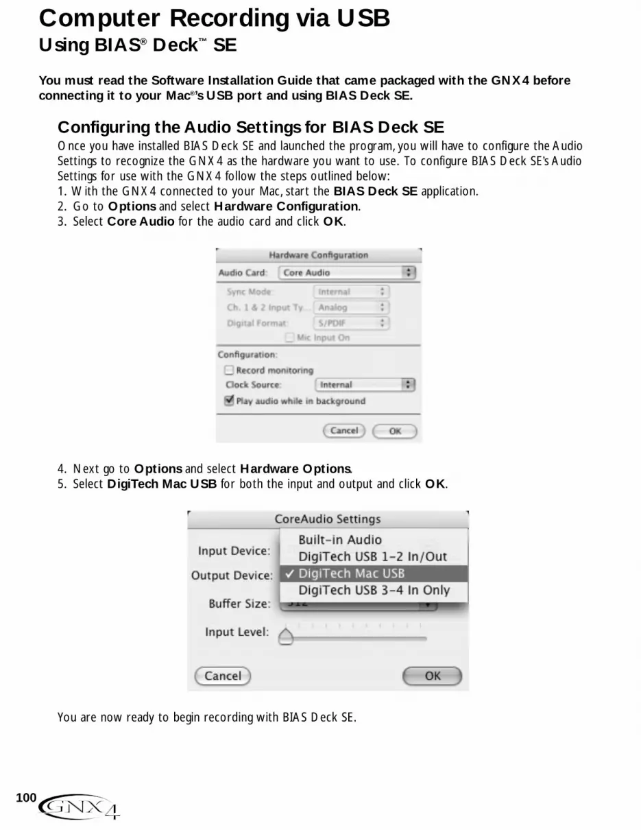
Using BIAS® Deck™ SE
You must read the Software Installation Guide that came packaged with the GNX4 beforeconnecting it to your Mac®’s USB port and using BIAS Deck SE.
Configuring the Audio Settings for BIAS Deck SEOnce you have installed BIAS Deck SE and launched the program, you will have to configure the Audio Settings to recognize the GNX4 as the hardware you want to use. To configure BIAS Deck SE’s AudioSettings for use with the GNX4 follow the steps outlined below:1. With the GNX4 connected to your Mac, start the BIAS Deck SE application.2. Go to Options and select Hardware Configuration.3. Select Core Audio for the audio card and click OK.
4. Next go to Options and select Hardware Options.5. Select DigiTech Mac USB for both the input and output and click OK.
You are now ready to begin recording with BIAS Deck SE.
100
Computer Recording via USB

Compact Flash File StructureThe GNX4 requires a specific file structure for organizing the different file types it uses. To utilize aCompact Flash memory card in the GNX4 it must be formatted using the FAT16 File format.DigiTech recommends that you format your card in the GNX4 using our internal format routine. Ourinternal format routine will configure the card as FAT16. You can also format a card on a PC using Windows®
2000 or XP but you MUST select the File System to be FAT (meaning FAT16) instead of FAT32 and enablethe Quick Format option. To quickly format a Compact Flash memory card, the GNX4’s setup menuprovides a format function. If a Compact Flash memory card is not present in the Compact Flash memorycard slot, the format function is not available. To format a Compact Flash memory card, follow the stepsdocumented on page 75.NOTE: The GNX4 is compatible with Type I Compact Flash cards only. It is not compatiblewith Type II cards or IBM/Hitachi Microdrives™.
When you view the card’s contents on your computer, you will see a main directory folder called GNX4.Inside this directory are four sub directory folders in which you can move Song, MIDI, MP3, and Card Presetfiles to and from. These sub directories are labeled as follows:
SONGSThis is the folder in which all songs or loops that are created on the GNX4 reside. Within the Songsfolder, each song is individually named. (For more information on song and track file naming conventionssee page 103.) A SETUP.XML file is created within each song folder that stores song setup informationincluding:Tempo, Pre-Roll, etc. Please refer to the Song Setup section on page 70.
MIDIThis is the folder in which you will place any Type 0 MIDI (.mid) files that are to be played by the GNX4’sDRUMS/MP3 player. The GNX4 plays any MIDI file that appears in this folder both to the internal drummachine and out the GNX4’s MIDI output jack. The GNX4’s drum machine only responds to noteinformation on MIDI channel 10. If the note data was saved using any other channel, the GNX4’s drummachine ignores it.
Type 0 files contain only one track, and all of the MIDI messages (ie, the entire performance) is placed inthat one track, even if it represents many musical parts upon different MIDI channels.Type 1 files separateeach musical part upon its own track and are not compatible with the GNX4’s playback engine.
MP3This is the folder in which you will place any MP3 files you want to play back on the GNX4. The filenames will be added to the end of the user MIDI patterns that are accessed using the PATTERN buttonin the Control Panel section of the GNX4.
PresetsThis folder is where any user created presets that are stored to the compact flash (CF) card are stored.The card preset file is a special format file, not separate preset files like those dumped from MIDI orsaved using the X-Edit editor librarian. Individual preset files or bulk dumps placed in this directory willnot be recognized by the GNX4. Conversely, the preset file created by the GNX4 will appear in the X-Edit librarian thus allowing you to select and edit individual presets.
MIDI files and MP3s can use most any naming convention provided they have the .mid suffix for MIDI filesand the .mp3 suffix for MP3s added at the end of the name.
101
Compact Flash File Functions
Compact Flash Storage/File Transfer Since the GNX4 is equipped with both a compact flash (CF) d USB, it can act as a card reader fortransferring any files that may reside on a card to and from any USB equipped computer. To enable the cardreader function, follow these steps:1. Place a CF card in the GNX4’s memory card slot.2. Connect your computer via USB to the GNX4 (you must install the drivers from the X-Edit™
Editor/Librarian and USB Drivers CD prior to connecting the GNX4 to your computer).ATTENTION: Do not remove your CF card during file transfer or you may lose files.
The CF STORAGE button in the Recorder panel will light indicating the CF card is being recognized by thecomputer. When the CF STORAGE button is lit, the GNX4’s onboard recorder functions are disabled andthe recorder display will read CF STOR. When you are finished transferring files, press the CF STORAGEbutton to disable the card reader function. The recorder display will return to its normal song/time statusand you may resume recording onto the CF card. To copy files back and forth between the GNX4 and yourcomputer, follow these steps:
Windows® Users1. Connect the GNX4 to your computer via the included USB cable.2. Press the CF STORAGE button (if it is not already enabled) to enable the card reader function. This
disables using the GNX4’s onboard recorder functions.3. Double-click the My Computer icon on your computer’s desktop. A new drive icon named GNX4 will
appear in this window.4. Double-click the GNX4 icon and the next window that appears will show all the contents on the
Compact Flash card installed in your GNX4 including the GNX4 root directory folder.5. Double-click the GNX4 folder to access the subdirectories. You can now drag song folders as well as
MIDI files, MP3s, and card preset files to and from their appropriate folders on the card and your PC.6.When finished, close the GNX4 window.7. Press the CF STORAGE button to disengage it. The audio drivers for the GNX4 will now reinitialize
and it can be used for USB audio streaming once again.NOTE: If using Pro Tracks Plus Plus™ or any other audio recording application, it is
recommended you save your work and exit the program to maximize USBbandwith for faster file transfer.
Mac® Users1. Connect the GNX4 to your computer via the included USB cable.2.Turn on the GNX4. Wait for the display to read the current preset.3. Insert your Compact Flash card in the GNX4’s memory card slot if you have not already done so.4. Press the CF STORAGE button (if it is not already enabled) to enable the card reader function. This
disables use of the GNX4’s onboard recorder functions and a new drive should appear on yourcomputer’s desktop.
5. Double click the new drive to open it in a finder window. If you have this feature disabled, open thefinder and select the new drive from the drive list in the left pane. The contents of the Compact Flashcard will now be displayed in the window.
6. Double click the GNX4 folder to access the subdirectories. You can now drag your song folders, MIDIfiles, MP3s, and card preset files to and from their appropriate folders on the card and your computer.
7.When finished, eject the compact flash drive by selecting File>Eject from the menu bar.8. Press the CF STORAGE button to disengage it.The audio drivers for the GNX4 will now reinitialize and allow the Compact Flash card tobe used for USB audio streaming.
102
Compact Flash File Functions

Memory Card/Computer File FormatThe GNX4 uses a specific song and track file naming convention that needs to be maintained whenexchanging files with a computer. When a card is inserted into the GNX4, the songs appear in the Songsfolder named: SONG01, SONG02, etc… The number of songs can change depending on how many songs orloops are saved on the memory card. Inside each of the song folders are the separate audio tracks whichwill be named TRAK01.wav,TRAK02.wav, up to TRAK08.wav. It is important that each song’s name startswith SONGXX (XX = song number) with no spaces, and each audio track is named TRAK01-TRAK08 with a.wav extension in order for the GNX4 to recognize these files. You can rename tracks and songs whileviewing them in the computer with some restrictions. Here are some naming formats that are acceptable.
MIDI files and MP3s can use most any naming convention provided they have the .mid suffix for MIDI filesand the .mp3 suffix for MP3s added at the end of the name. These files must reside in their respectivefolders in order to be recognized by the GNX4.
The following names are acceptable for song folders:Song01_rocksong01 rockSONG01 rockSong01rock
The following names are not acceptable for song folders:Song_01Song 01Song 1
The following names are acceptable for individual audio track files:Trak01_solo.wavtrak03lead.wav,trak04 rhythm.wavTRAK05 bass.wav
The following names are not acceptable for audio track files:TRAK_01Track 01track 1
It is possible to have duplicate songs or tracks when renaming them in the computer. For instance,song01_rock and song01_jazz are really the same name to the GNX4 as are trak01_solo.wav andtrak01_solo2.wav. The GNX4 only looks at the first six characters to identify the song and trackinformation. The remainder of the name is not recognized but is provided for the purpose of identifying songand track names in your file system. There can only be a maximum of 99 songs on a memory card, and amaximum number of 8 tracks in each song.
103
Compact Flash File Functions
The Utility section contains all of the menus for assigning global functions to the GNX4. Global functionsaffect the GNX4 in its entirety rather than on a per preset basis.The Utility menus include: Volume PedalUpdate,V-Switch Threshold, Expression Pedal Calibration, Bounce-Back, Bank Naming, MIDI Channel, MIDISysex Dumps,Amp Dumps, MIDI Mapping, MIDI Merge, and Factory Reset. To enter the Utility section, pressthe UTILITY button. Once in the Utility menu, the NEXT button selects the next menu (scrolls to theright), and the PREV button selects the previous menu (scrolls to the left). Each of these Utility menus isdescribed in more detail in the following pages.
Volume Pedal UpdateThe GNX4 lets you select the Expression Pedal’s position to be updated, after changing presets, when it islinked to the Volume Parameter. This feature lets you change presets and keep the volume level from theprevious preset, if the Expression Pedal controls the volume for both presets. If this feature is disabled,new presets are set to the volume level value stored with the preset.The procedure for enabling ordisabling the Volume Pedal Update is as follows:1. Press the UTILITY button. The button will light indicating you are in the Utility menu.2. Use the PREV or NEXT buttons to select volumpdl (Volume Pedal Update) is displayed.3. Rotate the DATA WHEEL to select On (enabled), or OF (disabled).4.When finished, press EXIT.
V-Switch Threshold/SensitivityApplying extra pressure to the toe of the Expression Pedal engages a feature called V-Switch. V-Switch isused to alternate between controlling assigned Parameter(s) with the pedal, and using the pedal as a Wahpedal.The sensitivity of the V-Switch can be set to the amount of pressure you want to use. The followingsteps explain how to set the V-Switch Threshold:1. Press the UTILITY button.The button will light indicating you are in the Utility menu.2. Use the PREV or NEXT buttons to select vSWItCH (V-Switch).3. Rotate the DATA WHEEL to select the threshold setting. Ranges are from 0 to 99, then off (Of) to
disable (with 99 requiring more pressure to engage). The sensitivity may be auditioned while makingadjustments. Use the V-Switch LED as an indicator of the switching status.
4.When finished, press EXIT.
Expression Pedal CalibrationThe Expression Pedal on the GNX4 needs to be recalibrated for use after a factory reset has beenperformed. This calibration procedure is automatically activated after a factory reset procedure. In theevent the pedal’s calibration fails, or if the pedal does not function properly, it can be re-calibrated usingthe Pedal Calibration menu. The procedure for Calibrating the Expression Pedal is as follows:1. Press the UTILITY button. The button will light indicating you are in the Utility menu.2. Use the PREV or NEXT buttons to select pedalcal (Expression Pedal Calibration).3. Press the flashing STORE button to enter the Pedal Calibration Menu.The display will read TOE DowN
(Toe Down).4. Rock the Expression Pedal all the way forward to the toe down position and press the blinking number
4 Footswitch.The display changes to read TOE UP (toe up).5. Rock the Expression Pedal all the way back to the toe up position and press the blinking number 5
Footswitch. VSW cal is displayed and allows you to adjust the V-Switch Threshold.6. Rock the Expression Pedal forward and apply the V-Switch pressure to the toe of the pedal. If further
adjustment to the threshold is required, use the DATA WHEEL to select the threshold.NOTE: If the Display shows cal eRR, a calibration error has occurred and steps 2 through 5
need to be repeated.7. When finished, press EXIT.
104
Utilities
Preset BouncebackIf you would rather not bypass individual presets in Preset Mode by pressing their footswitchesrepeatedly, you can enable the Preset Bounceback function in the Utility menu. For example, let’s say youselect Preset 1 using FOOTSWITCH 1 as your rhythm tone. Then you select Preset 4 usingFOOTSWITCH 4 as your solo tone. You can now press FOOTSWITCH 4 again and Preset 1 will beselected again. Pressing FOOTSWITCH 4 repeatedly will bounceback between Preset 4 and Preset 1.To enable the Preset Bounceback feature, do the following:1. Press the UTILITY control panel button and use the PREV/NEXT arrow buttons to locate the
Bounceback feature. The display will read BOUNCBAK.2. Rotate the DATA WHEEL to turn the BounceBack feature on.3.When finished, press EXIT.
NOTE:The Preset Bounceback feature only works when the GNX4 is in Preset Mode.
For more information regarding the footswitch functions for Preset Mode see page 59.
Hands-Free DefaultThe GNX4 has the ability to have hands free recording using either the onboard recorder or whenconnected to the computer while Pro Tracks Plus is running. The GNX4 cannot however have hands freecontrol both the internal computer and the computer simultaneously.
When only a card is present in the memory card slot and no USB is connected, the hands free functionsare dedicated to the onboard recorder. When only USB is connected and no card present, hands freefunctions are dedicated to the computer. But if you have both a card present in the memory card slotand USB connected, you must select which method of recording is going to have the hands free function.This is set using the Hands Free utility menu. To set this option, follow these steps:1. Press the UTILITY button.The button will light indicating you are in the Utility menu.2. Press the NEXT button several times to select handfree (Hands Free Default).3. Use the DATA WHEEL to select the default hands free function to the GNX4’s recorder (HandFREECf) or to the computer (HandFREE US).
4.When finished, press EXIT.
Bank NamesThe GNX4 lets you customize the names of the 16 User Banks where the 80 User Presets reside as wellas the 16 Card Banks where the 80 Card Presets reside when a Compact Flash card is installed.Customized Bank names aids in quickly identifying the User Bank containing the presets you may need fora particular song or set.The procedure for naming the User Banks is as follows:1. Press the UTILITY button.The button will light indicating you are in the Utility menu.2. Use the PREV or NEXT buttons to select BANKS (Bank Names).3. Use the DATA WHEEL to select the User Bank or Card Bank you want to rename. The Preset Bank
LEDs to the left of the DATA WHEEL indicate whether a User Bank or a Card Bank is selected.4. Press STORE to access the naming menu.The far left character of the Bank name begins to blink.5. Use the DATA WHEEL to select the desired alpha-numeric character.6. Press the NEXT button to select the next character to the right, and the PREV button to select the
previous character to the left.7. Repeat steps 5 and 6 until the Bank name appears in the display.8. Once the Bank name appears correctly in the display, press STORE again. namesavd is displayed
briefly indicating the Bank name has been saved, and then new Bank name appears.9.When finished, press EXIT.
105
Utilities
MIDI ChannelThe GNX4 MIDI channel is only used for receiving incoming MIDI data. The GNX4 does not send MIDIprogram change commands or CC data.The procedure for selecting the MIDI channel is as follows:1. Press the UTILITY button. The button will light indicating you are in the Utility menu.2. Use the PREV or NEXT buttons to select the midichnl (MIDI Channel). The numeric display show
the selected MIDI channel.3. Rotate the DATA WHEEL to select the MIDI channel. Your choices include 1 through 16, AL (all),
and of (off).4.When finished, press EXIT.
Bulk DumpThe Sysex Bulk Dump uploads all the GNX4 presets and utility data to a sysex librarian, or MIDIrecording device.This is useful for making a backup copy of all your customized settings. The procedurefor performing a Bulk Dump is as follows:1. Connect a MIDI cable from the GNX4 MIDI Out to the the MIDI In of a MIDI recording device.2. Press the UTILITY button. The button will light indicating you are in the Utility menu.3. Use the PREV or NEXT buttons to select Bulkdump (Bulk Dump). The STORE button will flash
indicating it must be pressed to begin the bulk dump.4. Set the MIDI recording device to record. (This step is not necessary if dumping to another GNX4.) 5. Press the STORE button to begin the dump. The display reads SeND pst 1 and counts up to SeND pst 80 when the dump is complete at which time the display returns to bulkdump.
6.When finished, press EXIT.NOTE: Bulk Dump sends information on the MIDI channel defined in the MIDI Channel
Menu.
MIDI Preset DumpThe Sysex Preset Dump uploads individual GNX4 presets to a sysex librarian, or MIDI recording device.This is useful for making a backup copy of customized presets, or copying your presets into anotherGNX4. The procedure for performing a Sysex Preset Dump is as follows:1. Connect a MIDI cable from the GNX4 MIDI Out to the the MIDI In of a MIDI recording device or the
MIDI in of another GNX4.2. Press the UTILITY button.The Utility button’s LED will light.3. Use the PREV or NEXT buttons to select PrSTDuMP (Preset Dump).4. Use the DATA WHEEL to select the preset number you want to dump.5. Press the STORE button. The Display will read SeND TO.6. Use the DATA WHEEL to select the destination preset number.7. Set the MIDI recording device to record. (This step is not necessary if dumping to another GNX4.) 8.Press the STORE button again. The display will read send pst until the dump is complete at which
time the display returns to PrSTDuMP.9.When finished, press EXIT.NOTE: MIDI Preset Dump sends information on the MIDI channel defined in the MIDI
Channel Menu.
User Hypermodel™ Amp DumpUser Amp Dump uploads the GNX4 Amp HyperModels to a sysex librarian, or MIDI recording device.This is useful for making a backup copy of your customized Amp HyperModels, and copying yourHyperModels into another GNX4. The procedure for performing a User Amp Dump is as follows:1. Connect a MIDI cable from the GNX4 MIDI Out to the the MIDI In of a MIDI recording device or the
MIDI in of another GNX4.106
Utilities

2. Press the UTILITY button.The Utility button’s LED lights.3. Use the PREV or NEXT buttons to select AMP DuMP (Amp Dump).4. Use the DATA WHEEL to select the Amp number you want to dump.5. Press the STORE button. The display will read SND TO.6. Use the DATA WHEEL to select the destination User Amp number.7. Set the MIDI recording device to record.8. Press the STORE button again. The display will read send amp until the dump is complete at which
time the display returns to AMP DuMP.9.When finished, press EXIT.
NOTE: Amp Dump sends information on the MIDI channel defined in the MIDI ChannelMenu.
MIDI MappingMIDI Mapping provides access to all factory and user presets from external MIDI program changecommands that may not correspond to the GNX4 preset. This is useful when multiple MIDI devices arechained together and controlled by one central unit. For example, the main MIDI controller can send outa program change command telling a particular MIDI unit to change to Program 10, but you may want theGNX4 to change to User Preset 27. You can remap the GNX4 so when it receives MIDI Program change10, it calls up User Preset 27. The Procedure for mapping MIDI program changes is as follows:1. Press the UTILITY button.The Utility button’s LED lights.2. Use the PREV or NEXT buttons to select M 1>U 1 (MIDI Mapping).3. Use the DATA WHEEL to select the incoming MIDI program number you want to remap. The
flashing number to the right of the M increases and decreases as you turn the DATA WHEEL.4. Press the NEXT button. The number in the red numeric display begins flashing. This number
represents the GNX4 preset number that is selected when the GNX4 receives the MIDI programnumber shown to the right of the M in the alpha-numeric display.
5. Rotate the DATA WHEEL to select the preset number the GNX4 will use when it receives theselected MIDI program change.
6.When finished, press EXIT.
MIDI MergeThe MIDI Merge function echoes the incoming MIDI data to the MIDI Out port of the GNX4. This isuseful when multiple MIDI devices are chained together, and you want to pass incoming MIDI Data on toMIDI devices downstream from the GNX4.The procedure for enabling or disabling the MIDI Mergefunction is as follows:1. Press the UTILITY button located in the Control Panel. The Utility button’s LED lights.2. Use the PREV or NEXT buttons to select midimrge (MIDI Merge). The red numeric display reflects
the current MIDI Merge status On or OF.3. Use the DATA WHEEL to select the status.4.When finished, press EXIT.
Drum MIDIThe GNX4’s drum machine uses standard Type 0 MIDI files for each of its internal patterns. This MIDIinformation can be transmitted out the GNX4’s MIDI output and up to the computer via USB. You canenable or disable these MIDI messages from being transmitted out these ports. Disabling these MIDImessages resolves the issue of having messages that are sent from the GNX4 being echoed by thecomputer back to the GNX4 and erroneously retriggering the drums if the drums are on. To enable ordisable the drum pattern MIDI messages from being transmitted, follow these steps:
107
Utilities

1. Press the UTILITY button. The button will light indicating you are in the Utility menu.2. Use the PREV or NEXT buttons to select DRUMMIDI (Drum MIDI). The red display reflects the
current Drum MIDI status On or OF.3. Use the DATA WHEEL to enable or disable transmission of the drum pattern MIDI messages.4.When finished, press EXIT.
Default Drum KitEach drum machine pattern in the GNX4’s drum machine has a default drum kit assigned to it when thepattern is played. This default kit can be disabled so that all patterns may be auditioned with the same kitwithout having to re-select the kit each time the pattern is changed. To enable or disable the default kitfeature, follow these steps:1. Press the UTILITY button located in the Control Panel.2. Use the PREV or NEXT buttons to select dFlt kit (Default Drum Kit). This feature is turned on
from the factory.3. Use the DATA WHEEL to enable (On) or disable (Of) this feature.4.When finished, press EXIT.
Factory ResetThis function resets the GNX4 to its original factory settings. This procedure erases ALL custom userpresets, utility settings, and re-calibration of the Expression Pedal. The procedure for performing aFactory Reset is as follows:
NOTE: Performing this function will erase all user-programmed data. Be sure you want toerase the memory and start fresh before continuing with this procedure. A factoryreset does not erase any of the content on a Compact Flash card if installed in theGNX4.
1. Press the UTILITY button.The Utility button’s LED lights.2. Use the NEXT button to select RESET ? (Reset) and the STORE button will begin to flash.
NOTE:This procedure resets ALL user settings. Press the EXIT button now to abort thefactory reset function.
3. Press the STORE button once and the display will show CONFIRM?.4. Press the STORE button again and the display will display FACRESET and then TOE DowN. You must
recalibrate the Expression Pedal at this time.5.While the display reads TOE DowN, rock the Expression Pedal forward (toe down) and then press the
flashing Footswitch 4.6.When the display reads TOE UP, rock the Expression Pedal back (toe up) and press the flashing
Footswitch 5. The display will then read VSW cal which is a prompt for you to calibrate the V-Switch.
7. Press the Expression Pedal forward firmly as if activating a wah pedal and then rock it back. The displaywill now read VSWITCH 50, which is the default sensitivity. Test the V-Switch by pressing theExpression Pedal firmly forward a couple of times. The V-Switch LED next to the DATA WHEELshould turn on and off. If you find the V-Switch is too easy or to difficult to engage, you can adjust theV-Switch value higher (makes it harder to engage) or lower (makes it easier to engage). The Range is 0to 99. Above 99 the V-Switch can be set to OFF to disable it.
8.When finished, press EXIT.
108
Utilities
My computer does not recognize my GNX4.• If after turning on and initializing the GNX4 the USB Active led does not stay lit, the computer may not have
correctly enumerated the GNX4 USB connection. The computer may give you message stating that a USBDevice is not recognized. If this happens reboot your computer.
• If you are using Windows 2000, you must first install drivers from the X-Edit™ Editor/Librarian and USB DriversCD before connecting the GNX4 to your computer. See the Software Installation Guide.
Audio playback from Pro Tracks Plus™ has pops and clicks.• Try the Wave Profiler under Options->Audio. This seems to fix most problems. Otherwise, try using MME
drivers in the Options->Audio->Advanced, Driver Mode selection. These are the safest drivers but alsohave the most latency.
• Try increasing the latency slider in the audio settings.• Try installing the Service Pack 1A (or later) download (Windows XP®) available from www.microsoft.com.
Hands-Free recording on GNX4 doesn’t work or has stopped working.• If it was working at one point but has stopped working, try exiting Pro Tracks Plus and then restarting it (make
sure to save your project).• Cycle power to the GNX4 before entering Pro Tracks Plus or X-Edit™.• If it has never worked at all, there is a problem with USB MIDI The most probable causes are using incorrect or
incorrectly installed drivers and/or .dll or a bad USB cable.• See the section on driver installation.• Make sure DigiTech USB MIDI is highlighted for MIDI Input under Options>MIDI devices.• Make sure ‘Hands-Free’ is set as the default setting in the Utility Menu.• Check the utility menu handfree is set to US for recording to ProTracks or CF to record to the internal
recorder.
I can’t hear audio playback from Pro Tracks Plus.• If the ‘Reamp’ mode in the GNX4 is active try switching to a different mode like ’STEROALL’.• Make sure the faders in Pro Tracks Plus are turned up.• Check that the tracks you want to playback are un-muted.• Go to Options->Audio->Drivers and under output drivers, select ‘DigiTech USB 1-2 In/Out’ and de-select
everything else.• See the section on driver installation.• Make sure your speakers are connected properly and the volume is turned up.
My GNX4 doesn’t record to Pro Tracks Plus.• Go to Options->Audio->Drivers and under input drivers, select ‘DigiTech USB 1-2 In/Out’ and ‘DigiTech
USB 3-4 In Only’ De-select everything else.• Make sure the proper drivers are installed.• See the section on driver installation.• For an initial track, make sure ’Reampusb’ mode in the GNX4 is not selected in the CF/USB 1-2 Source
menu.• Make sure the track that you are recording on has the correct input assignment and that it is armed.
I can’t get Re-Amping to work.• See the Re-Amping a Guitar Track section of this Owner’s Manual.
Where did my wave files go?• Wave files all get saved to the folder specified in Options->Global, Audio Data.
My waves are low/too high in level.• The recording signal level can be boosted or reduced using the CF/USB1-2 and USB3-4 Level controls.
109
Trouble Shooting Guide
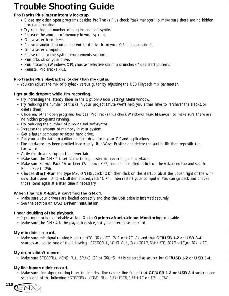
Pro Tracks Plus intermittently locks up.• Close any other open programs besides Pro Tracks Plus check "task manager" to make sure there are no hidden
programs running.• Try reducing the number of plug-ins and soft-synths.• Increase the amount of memory in your system.• Get a faster hard drive.• Put your audio data on a different hard drive from your OS and applications.• Get a faster computer.• Please refer to the system requirements section.• Run chkdisk on your drive.• Run msconfig (Windows XP), choose “selective start” and uncheck “load startup items”.• Reinstall Pro Tracks Plus.
Pro Tracks Plus playback is louder than my guitar.• You can adjust the mix of playback versus guitar by adjusting the USB Playback mix parameter.
I get audio dropout while I’m recording.• Try increasing the latency slider in the Option>Audio Settings Menu window.• Try reducing the number of tracks in your project (mute won't help, you either have to "archive" the tracks, or
delete them) • Close any other open programs besides Pro Tracks Plus check Windows Task Manager to make sure there are
no hidden programs running.• Try reducing the number of plug-ins and soft-synths.• Increase the amount of memory in your system.• Get a faster computer or faster hard drive.• Put your audio data on a different hard drive from your OS and applications.• The hardware has been profiled incorrectly. Run Wave Profiler and delete the aud.ini file then reprofile the
hardware.• Verify the driver setup on the driver tab.• Make sure the GNX4 is set as the timing master for recording and playback.• Make sure Service Pack 1A or later (Windows XP®) has been installed. Click on the Advanced Tab and set the
Buffer Size to 256.• Choose Start>Run and type MSCONFIG, click “OK” then click on the Startup Tab at the upper right of the win-
dow that opens. Uncheck all items listed, click “OK”. Then restart your computer. You can go back and choosethose items again at a later time if necessary.
When I launch X-Edit, it can’t find the GNX4.• Make sure your drivers are loaded correctly and that the USB cable is inserted securely.• See the section on USB Driver installation.
I hear doubling of the playback.• Input monitoring is probably active. Go to Options->Audio->Input Monitoring to disable.• Make sure the GNX4 is the playback device, not your internal sound card.
My mic didn’t record.• Make sure mic signal routing is set to mic dry, mic rvb, or mic fx and that CF/USB 1-2 or USB 3-4
sources are set to one of the following : steroall, mono all, sum+dgtr, sum+mic, dgtr+mic,or dry mic.
My drums didn’t record.• Make sure steroall, mono all, drums st or drums mn is selected as source for CF/USB 1-2 or USB 3-4.
My line inputs didn’t record.• Make sure line signal routing is set to line dry, line rvb, or line fx and that CF/USB 1-2 or USB 3-4 sources are
set to one of the following : steroall, mono all, sum+dgtr,sum+mic or dry line.
110
Trouble Shooting Guide

Pro Tracks Plus Plus won’t launch.• This was probably caused by interrupting the USB connection while in a previous Pro Tracks Plus session. You
must reboot your system to fix this problem.• There is a conflict with your computer’s video card. By disabling the theater audio driver in the video card, the
software should work.
I don’t hear playback from USB 3-4.• Playback is only available on USB 1-2. USB 3-4 is used for additional track recording – like dry guitar, mic, drums,
etc.
I only get sound on one side of the recording.• Locate the Mono/Stereo box at the bottom of each track and make sure the mono tracks are set to mono and the
stereo tracks are set to stereo.
When I export my song to a Wave file my CD burning program says the file type is not recognized as aWave file.
• Make sure when you export the audio that you choose 16 bit not 24.
Using a Mac to receive audio stream from the GNX4, the Mac USB input and output is visible, but so isthe PC selection. Can these be removed?
• The PC audio will work on a Mac. However some Mac applications can't select more than one audio device andthus those applications must use the Mac device to record all 4 channels.
111
Trouble Shooting Guide

Preset List
MIDI Implementation Chart
BANK 1 SHOWCASE
1. HYBRID2. CLNCHRS3. DUAL AMP4. BAD BASS5. GREASER
BANK 2 STARS 1
6. STEVERAY7. SATCH8. JIMIHAZE9. RANDY10. MAYQUEEN
BANK 3 AMPS 111. BASS MAN12. MATCHED13. VOXTOP14. HIWATTAG15. JAZZDRIV
BANK 4 GENETX16. WARP ME17. BLAKBASS18. MEAT X 219. GNX DIRT20. MEAN/CLN
BANK 5 BASS AMP21. MOD BASS22. GTR>BASS23. ROCKIN24. GRUVIN25. GRINDER
BANK 6 METAL
26. RECTIFY27. SOLO28. WHAMMY29. RAT FINK30. DUCKSOLO
BANK 7 ROCK
31. MO WAH32. PHASE 433. STEREOZE34. WARM PIE35. STACKED
BANK 8 BLUES
36. BLUE DLY37. BLUEBALL38. LONESTAR39. GTRORGAN40. MO SLIDE
BANK 9 COUNTRY
41. PICKEN42. PDLSTEEL43. A MIXLDN44. HODOWN45. ROTARY
BANK 10 JAZZFUSN
46. DRIVIN47. CHIMES48. SMOOTHY49. LATENITE50. COLDFUSN
BANK 11 CLEAN
51. ACOUSTIC52. COMP CLN53. SCHWELL54. 5THS55. CLEANWAH
BANK 12 STARS 2
56. ERIC J57. ANGUS58. CARLOS59. EDDIE VH60. PAT JAZZ
BANK 13 AMPS 2
61. TWEEDY62. MDRNBRIT63. JC-JAZZ64. TWINVERB65. BOOGEY
BANK 14 ALT ROCK
66. SURFIN67. FUZZO68. TREMBO69. HILLBLLY70. ENVELOPE
BANK 15 HYBRID
71. TWEEDFUZ72. TUNE CAB73. MEGAWARP74. CLNCRNCH75. DBLCHUNK
BANK 16 SPECIAL
76. STUTTER77. TRIPLET78. DIVEBOMB79. RIFMATIC80. YAYA
112
Appendix

MIDI CC ListParameter CC#Pickup Type/On/Off CC2Pickup Type/Type CC3Expression Pedal CC4 Volume Post CC6Volume Pre CC7Wah On/Off CC8Wah Type CC9Wah Pedal CC10Compressor On/Off CC11Compressor Attack CC12Compressor Ratio CC13Compressor Threshold CC14Compressor Gain CC15Whammy/IPS On/Off CC16Whammy/IPS Type CC17Whammy/IPS Level CC18Whammy/IPS Parameter 1 CC19Whammy/IPS Parameter 2 CC20Whammy/IPS Parameter 3 CC21Stompbox On/Off CC22Stompbox Type CC23Stompbox Gain CC24Stompbox Level CC25Stompbox Param1 CC26Stompbox Param2 CC27Stompbox Param3 CC28Stompbox Param4 CC29Amp Channel CC30Ch 1 Amp Type CC31Ch 1 Amp Gain CC33Ch 1 Amp Level CC34Ch 1 Cabinet CC35Ch 1 Cabinet Tuning CC36Ch 1 EQ On/Off CC37Ch 1 Bass Frequency CC38Ch 1 Bass CC39Ch 1 Midrange Frequency CC40Ch 1 Midrange CC41Ch 1 Treble Frequency CC42Ch 1 Treble CC43Ch 1 Presence CC44Ch 2 Amp Type CC45Ch 2 Amp Gain CC46Ch 2 Amp Level CC47Ch 2 Cabinet CC48Ch 2 Cabinet Tuning CC49Ch 2 EQ On/Off CC50Ch 2 Bass Frequency CC51Ch 2 Bass CC52Ch 2 Midrange Frequency CC53Ch 2 Midrange CC54Ch 2 Treble Frequency CC55Ch 2 Treble CC56Ch 2 Presence CC57Noise Gate On/Off CC58Noise Gate Type CC59Noise Gate Threshold CC60
Parameter CC#Noise Gate Attack CC61Noise Gate Pluck Sensitivity CC62Chorus/Mod On/Off CC65Chorus/Mod Type CC66Chorus/Mod Level CC67Chorus/Mod Param1 CC68Chorus/Mod Param2 CC69Chorus/Mod Param3 CC70Chorus/Mod Param4 CC71Chorus/Mod Param5 CC72Delay On/Off CC73Delay Type CC74Delay Level CC75Delay Time CC76Delay Feedback CC77Delay Ducker Threshold CC78Delay Ducker Attenuation CC79Delay Balance CC80 Genetx Warp Amp CC83Genetx Warp Cabinet CC84Genetx Amp/Cabinet Warp CC85Reverb On/Off CC89Reverb Type CC90Reverb Level CC91Reverb Decay CC92Reverb Damping CC93Reverb PreDelay CC94Reverb Balance CC95LFO1 Speed CC105LFO1 Waveform CC106LFO2 Speed CC110LFO2 Waveform CC111
113
Appendix

General MIDI Drum Sample ListSample Name #Acoustic Bass Drum 35 Bass Drum 1 36 Side Stick 37 Acoustic Snare 38 Hand Clap 39 Electric Snare 40 Low Floor Tom 41 Closed Hi-Hat 42 High Floor Tom 43 Pedal Hi-Hat 44 Low Tom 45 Open Hi-Hat 46 Low-Mid Tom 47 Hi-Mid Tom 48 Crash Cymbal 1 49 High Tom 50 Ride Cymbal 1 51 Chinese Cymbal 52 Ride Bell 53 Tambourine 54 Splash Cymbal 55 Cowbell 56 Crash Cymbal 2 57 Vibraslap 58
Sample Name # Ride Cymbal 2 59Hi Bongo 60Low Bongo 61Mute Hi Conga 62Open Hi Conga 63Low Conga 64High Timbale 65Low Timbale 66High Agogo 67Low Agogo 68Cabasa 69Maracas 70Short Whistle 71Long Whistle 72Short Guiro 73Long Guiro 74Claves 75Hi Wood Block 76Low Wood Block 77Mute Cuica 78Open Cuica 79Mute Triangle 80Open Triangle 81
114
Appendix
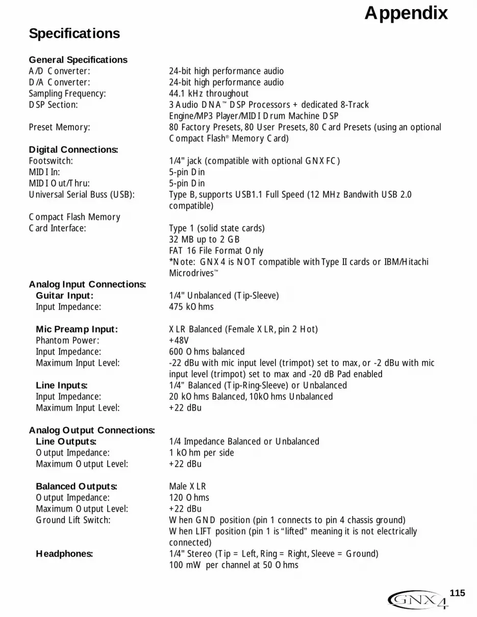
Specifications
General SpecificationsA/D Converter: 24-bit high performance audioD/A Converter: 24-bit high performance audioSampling Frequency: 44.1 kHz throughoutDSP Section: 3 Audio DNA™ DSP Processors + dedicated 8-Track
Engine/MP3 Player/MIDI Drum Machine DSPPreset Memory: 80 Factory Presets, 80 User Presets, 80 Card Presets (using an optional
Compact Flash® Memory Card)Digital Connections:Footswitch: 1/4" jack (compatible with optional GNXFC)MIDI In: 5-pin DinMIDI Out/Thru: 5-pin DinUniversal Serial Buss (USB): Type B, supports USB1.1 Full Speed (12 MHz Bandwith USB 2.0
compatible)Compact Flash MemoryCard Interface: Type 1 (solid state cards)
32 MB up to 2 GBFAT 16 File Format Only*Note: GNX4 is NOT compatible with Type II cards or IBM/Hitachi Microdrives™
Analog Input Connections:Guitar Input: 1/4" Unbalanced (Tip-Sleeve)Input Impedance: 475 kOhms
Mic Preamp Input: XLR Balanced (Female XLR, pin 2 Hot)Phantom Power: +48VInput Impedance: 600 Ohms balancedMaximum Input Level: -22 dBu with mic input level (trimpot) set to max, or -2 dBu with mic
input level (trimpot) set to max and -20 dB Pad enabledLine Inputs: 1/4” Balanced (Tip-Ring-Sleeve) or UnbalancedInput Impedance: 20 kOhms Balanced, 10kOhms UnbalancedMaximum Input Level: +22 dBu
Analog Output Connections:Line Outputs: 1/4 Impedance Balanced or UnbalancedOutput Impedance: 1 kOhm per sideMaximum Output Level: +22 dBu
Balanced Outputs: Male XLR Output Impedance: 120 OhmsMaximum Output Level: +22 dBuGround Lift Switch: When GND position (pin 1 connects to pin 4 chassis ground)
When LIFT position (pin 1 is “lifted” meaning it is not electrically connected)
Headphones: 1/4" Stereo (Tip = Left, Ring = Right, Sleeve = Ground)100 mW per channel at 50 Ohms
115
Appendix

Analog Inputs to Analog Outputs:Guitar Input to 1/4” OutputsS/N ratio: > 106 dB A-weighted; ref = max signal @ 1kHz, 22kHz measurement
bandwidthFrequency Response: 20 Hz - 17 kHz (+0 / - 3 dB)THD+N: < 0.0018% typical at -4 dBu, 1 kHz, 0 dB input gain
Guitar Input to XLR OutputsS/N ratio: > 106 dB A-weighted; ref = max signal @ 1kHz, 22kHz measurement
bandwidthFrequency Response: 20 Hz - 17 kHz (+0 / - 3 dB)THD+N: < 0.0018% typical at -4 dBu, 1 kHz, 0 dB input gain
Mic Input to 1/4” Outputs (Mic Dry selected)S/N ratio: > 106 dB A-weighted; ref = max signal @ 1kHz, 22kHz measurement
bandwidthFrequency Response: 20 Hz - 17 kHz (+0 / - 1 dB)THD+N: < 0.0015% typical at -10 dBu, 1 kHz, 0 dB input gain
Mic Input to XLR OutputsS/N ratio: > 106 dB A-weighted; ref = max signal @ 1kHz, 22kHz measurement
bandwidthFrequency Response: 20 Hz - 20 kHz (+0 / - 1 dB)THD+N: < 0.0018% typical at -18.4 dBu, 1 kHz, 0 dB input gain
Line Inputs to 1/4” Outputs (Line Dry selected)S/N ratio: > 106 dB A-weighted; ref = max signal @ 1kHz, 22kHz measurement
bandwidthFrequency Response: 20 Hz - 20 kHz (+0 / - 1 dB)THD+N: < 0.0023% typical at +10 dBu, 1 kHz, 0 dB input gain
Line Inputs to XLR OutputsS/N ratio: > 106 dB A-weighted; ref = max signal @ 1kHz, 22kHz measurement
bandwidth Frequency Response: 20 Hz - 20 kHz (+0 / - 1 dB)THD+N: < 0.0025% typical at +10 dBu, 1 kHz, 0 dB input gain
116
Appendix

GNX4 On-board Digital Recorder:General Specification: 16-bit, 44.1 kHz (CD quality)
GNX4 USB Recording Specifications:Bit depth: supports 16-bit or 24-bit (depends on setup in Recording Software)Sample Rate: 44.1 kHz
The following measurements were made using 24-bit mode:
Line Input to USB (Dry Line recorded to USB)Analog to Digital Converter Performance:S/N ratio: > 110 dB A-weighted; ref = max signal @ 1kHz, 22kHz measurement
bandwidth
USB to 1/4” Outputs (Audio Playback from USB to GNX4)Digital to Analog Converter Performance:S/N ratio: > 106 dB A-weighted; ref = max signal @ 1kHz, 22kHz measurement
bandwidth
USB to XLR Outputs (Audio Playback from USB to GNX4)Digital to Analog Converter Performance:S/N ratio: > 106 dB A-weighted; ref = max signal @ 1kHz, 22kHz measurement
bandwidth
Power Requirements:US and Canada: 120 VAC, 60 Hz Adapter: PSS3-120Japan: 100 VAC, 50/60 Hz Adapter: PSS3-100Europe: 230 VAC, 50 Hz Adapter: PSS3CE-230UK: 240 VAC, 50 Hz Adapter: PSS3-240Power Consumption: 21.0 WattsDimensions: 21.5” Length x 9” Width x 3.25” HeightUnit Weight: 10 lbs.
DigiTech engineers are constantly working to improve the quality of our products. Specifications are therefore subject to change without notice.
117
Appendix

Notes

Notes


8760 S. Sandy ParkwaySandy, Utah 84070
PH (801) 566-8800 FAX (801) 566-7005
International Distribution8760 S. Sandy ParkwaySandy, Utah 84070 USA
PH (801) 566-8800 FAX (801) 566-7005
DigiTech, GeNetX,Audio DNA, Guitar Workstation,and GNX4 are trademarks of
Harman Music Group Inc.
Copyright Harman Music GroupPrinted in the USA 5/2004
GNX4 Owner’s Manual 18-0449-A
Please visit DigiTech on the World Wide Web at:http://www.digitech.com
or
http://www.guitarworkstation.com