development of a biosolids management strategy for u.s
TRANSCRIPT
I ll
US Army Corps of Engineers Construction Engineering Research Laboratories
USACERL Technical Report 97/143 November 1997
Development of a Biosolids Management Strategy for U.S. Forces, Korea Installations by Byung J. Kim Amy R. Swanson
pnC QUALITY INSPECTED S
Currently, wastewater sludge for the U.S. Forces, Korea (USFK) and the Eighth U.S. Army (EUSA) is disposed at landfills by Korean contractors. In the United States, CFR 40, Part 503 regulations encourage the beneficial use of biosolids. However, beneficial use of sludge is not practiced in Korea. This report discusses the different regulatory frameworks in the United States and Korea, the current status of USFK/EUSA sludge management at four Directorates of Public Works (DPWs) and improved sludge management systems. Technical alternatives for improving sludge management include mobile mechanical dewatering, alkaline stabilization, composting, reed bed use, and autothermal thermophilic aerobic digestion (ATAD). Technologies were chosen for review
Approved for public release; distribution is unlimited.
based on their ability to comply with U.S. and Korean regulations and to achieve long-term improvement, and their availability in Korea. The study recommended:
1. Use of mobile mechanical dewatering followed by either aerated static pile composting, windrow composting or alkaline stabilization for the Western Corridor DPW
2. Discontinuation of the current secondary treatment at the Yongsan DPW
3. Conversion of the Camp Humphreys' current sand-drying beds to reed beds
4. Establishment of a long term goal to convert Camp Casey's aerobic digester to ATAD and using the biosolids as a soil supplement at Camp Casey.
19980317 070
The contents of this report are not to be used for advertising, publication, or promotional purposes. Citation of trade names does not constitute an official endorsement or approval of the use of such commercial products. The findings.of this report are not to be construed as an official Department of the Army position, unless so designated by other authorized documents.
DESTROY THIS REPORT WHEN IT IS NO LONGER NEEDED
DO NOT RETURN IT TO THE ORIGINATOR
USER EVALUATION OF REPORT
REFERENCE: USACERL Technical Report 97/143, Development ofBiosolids Management Strategy for U.S. Forces, Korea Installations
Please take a few minutes to answer the questions below, tear out this sheet, and return it to USACERL. As user of this report, your customer comments will provide USACERL with information essential for improving future reports.
1. Does this report satisfy a need? (Comment on purpose, related project, or other area of interest for which report will be used.)
2. How, specifically, is the report being used? (Information source, design data or procedure, management procedure, source of ideas, etc.)
3. Has the information in this report led to any quantitative savings as far as manhours/contract dollars saved, operating costs avoided, efficiencies achieved, etc.? If so, please elaborate.
4. What is your evaluation of this report in the following areas?
a. Presentation:
b. Completeness:
c. Easy to Understand:
d. Easy to Implement:
e. Adequate Reference Material:
f. Relates to Area of Interest: _
g. Did the report meet your expectations?
h. Does the report raise unanswered questions?
i. General Comments. (Indicate what you think should be changed to make this report and future reports of this type more responsive to your needs, more usable, improve readability, etc.)
5. If you would like to be contacted by the personnel who prepared this report to raise specific questions or discuss the topic, please fill in the following information.
Name: .
Telephone Number: ___
Organization Address:
6. Please mail the completed form to:
Department of the Army CONSTRUCTION ENGINEERING RESEARCH LABORATORIES ATTN: CECER-TR-I P.O. Box 9005 Champaign, IL 61826-9005
REPORT DOCUMENTATION PAGE Form Approved OMB No. 0704-0188
Public reporting burden for this collection of information is estimated to average 1 hour per response, including the time for reviewing instructions, searching existing data sources, gathering and maintaining the data needed, and completing and reviewing the collection of information. Send comments regarding this burden estimate or any other aspect of this collection of information, including suggestions for reducing this burden, to Washington Headquarters Services, Directorate for information Operations and Reports, 1215 Jefferson Davis Highway, Suite 1204, Arlington, VA 22202-4302, and to the Office of Management and Budget, Paperwork Reduction Project (0704-0188), Washington, DC 20503.
1. AGENCY USE ONLY (Leave Blank) 2. REPORT DATE November 1997
3. REPORT TYPE AND DATES COVERED Final
4. TITLE AND SUBTITLE Development of Biosolids Management Strategy for U.S. Forces, Korea Installations
5. FUNDING NUMBERS
MIPR 7-017
6. AUTHOR(S)
Byung J. Kim and Amy R. Swanson
7. PERFORMING ORGANIZATION NAME(S) AND ADDRESS(ES)
U.S. Army Construction Engineering Research Laboratories (USACERL) P.O. Box 9005 Champaign, IL 61826-9005
8. PERFORMING ORGANIZATION REPORT NUMBER
TR 97/143
9. SPONSORING / MONITORING AGENCY NAME(S) AND ADDRESS(ES)
Headquarters, U.S. Forces, Korea (USFK) and 8th U.S. Army (EUSA) ATTN: HQUSFK/EUSA Environmental Program Office, Unit 15237 APO 96205-0010
10. SPONSORING / MONITORING AGENCY REPORT NUMBER
11. SUPPLEMENTARY NOTES
Copies are available from the National Technical Information Service, 5285 Port Royal Road, Springfield, VA 22161.
12a. DISTRIBUTION / AVAILABILITY STATEMENT
Approved for public release; distribution is unlimited.
12b. DISTRIBUTION CODE
13. ABSTRACT (Maximum 200 words)
Currently, wastewater sludge for the U.S. Forces, Korea (USFK) and the Eighth U.S. Army (EUSA) is disposed at landfills by Korean contractors. In the United States, CFR 40, Part 503 regulations encourage the beneficial use of biosolids. However, beneficial use of sludge is not practiced in Korea. This report discusses the different regulatory frameworks in the United States and Korea, the current status of USFK/EUSA sludge management at four Directorates of Public Works (DPWs) and improved sludge management systems. Technical alternatives for improving sludge management include mobile mechanical dewatering, alkaline stabilization, composting, reed bed use, and autothermal thermophilic aerobic digestion (ATAD). Technologies were chosen for review based on their ability to comply with both U.S. and Korean regulations and to achieve long-term improvement, and their availability in Korea. The study recommended:
1. Use of mobile mechanical dewatering followed by either aerated static pile composting, windrow composting or alkaline stabilization for the Western Corridor DPW
2. Discontinuation of the current secondary treatment at the Yongsan DPW
3. Conversion of the Camp Humphreys' current sand-drying beds to reed beds
4. Establishment of a long term goal to convert Camp Casey's aerobic digester to AT AD and using the biosolids as a soil supplement at Camp Casey.
14. SUBJECT TERMS
Korea waste management sludge disposal wastewater treatment systems
15. NUMBER OF PAGES 160
16. PRICE CODE
17. SECURITY CLASSIFICATION OF REPORT
Unclassified
18. SECURITY CLASSIFICATION OF THIS PAGE
Unclassified
19. SECURITY CLASSIFICATION OF ABSTRACT
Unclassified
20. LIMITATION OF ABSTRACT
SAR
NSN 7540-01-280-5500 Standard Form 298 (Rev. 2-89) Prescribed by ANSI Std 239-18 298-102
USACERL TR 97/143
Foreword
This study was performed for the United States Forces, Korea (USFK) and the Eighth United States Army (EUSA). Environmental Program Office, under MIPR 7-017, Work Unit V17, «USFK/EUSA Sludge (Biosolids) Management Study." The technical monitors were Ernest P. Eddy and Munkyu Park, HQ, USFK/EUSA, Assistant Chief of Staff Engineer, Environmental Program Office,
Unit #15237, APO 96205-0010.
This work was performed by the Industrial Operations Division (UL-I) of the Utilities and Industrial Operations Laboratory (UL), U.S. Army Construction Engineering Research Laboratories (USACERL). Amy R. Swanson is a Civil Engineer employed as a Research Assistant by USACERL while studying at the University of Illinois towards her masters degree in Environmental Engineering. The USACERL principal investigator was Dr. Byung J. Kim. Walter J. Mikucki is Chief, CECER-UL-I; Martin J. Savoie is Acting Laboratory Operations Chief, CECER-UL; and Gary W Schanche is the responsible Technical Director, CECER-UL. The USACERL technical editor was William J. Wolfe, Technical Resources.
COL James A. Walter is Commander and Dr. Michael J. O'Connor is Director of USACERL.
USACERLTR-97/143
Contents SF298 1
Foreword 2
1 Introduction 5
Background 5
Objectives 6 Approach 6
Scope 6 Mode of Technological Transfer 7
2 Regulatory Framework 8
United States Environmental Regulations 8
Part 503 Overview 9
Korean Environmental Regulations 14
3 Current USFK/EUSA Sludge Management 17
Technical Options for Improved USFK/EUSA Biosolids Management .18
Western Corridor 18
Yongsan 30
Camp Humphreys 30
Camp Casey 34
4 Conclusions and Recommendations 37
Conclusions 37
Recommendations 37
References 39
Abbreviations and Acronyms 41
Appendix A: Frontier Technology Belt Filter Press A1
Appendix B: JWI J-press B1
Appendix C: Sharpies Centrifuge C1
USACERL TR 97/143
Appendix D: TRIMAX Environmental D1
Appendix E: N-Viro E1
Appendix F: CemenTech F1
Appendix G: Davis Industries G1
Appendix H: Resource Recovery Systems H1
Appendix I: Transcripts of Phone Interviews With Composting Facilities 11
Appendix J: Krüger J1
Distribution
USACERLTR-97/143
1 Introduction
Background
Effective sludge management can be a difficult and expensive task for wastewater treatment plant (WWTP) operators. As sludge regulations become more stringent and more landfills are closed down, many WWTPs are consequently forced to develop new and more effective residual management plans. Solids residual management is a global environmental problem. While it may appear that each nation takes a different approach for residual management, in reality, individual WWTPs have unique combinations of environmental conditions and regulatory requirements. The best solution for solids residual problems may vary by location and by individual WWTP. Key factors affecting the success of good residual management for a WWTP include, but are not limited to:
• the regulatory framework and attitude of government
• available technologies and "know-how"
• economical feasibility and available resources
• public awareness and acceptance.
The U.S. Forces, Korea (USFK) and Eighth United States Army (EUSA) installations have been proactive in environmental protection within the Republic of Korea. In Korea, all host country WWTP's sludge is landfilled. Currently, USFK/EUSA spend about $1 million a year for contracted sludge disposal. Korean sludge contractors transport sludge to local WWTPs for further thickening, stabilization, and disposal at landfills. One of USFK/EUSA Environmental Program Office initiatives is to develop a sludge management strategy for USFK/EUSA's wastewater treatment plants.
USACERL TR 97/143
Objectives
The objectives of this study were:
1. To compile and analyze design and operational data of the 10 USFK/EUSA WWTPs operated by the Western Corridor Directorate of Public Works (DPW), the Yongsan DPW, the Camp Humphreys DPW, and the Camp Casey
DPW
2. To identify and evaluate technical alternatives for beneficial use of sludge and improved sludge management at USFK/EUSA WWTPs.
3. To recommend a sludge management program in which: (a) the technology can comply with Korean environmental regulations as well as U.S. regulations, (b) the system is cost effective and could be implemented with a 5-year return on investment, and (c) the technology is readily available or accessible to USFK/EUSA.
Approach
1. An extensive literature search was performed to review technologies available for dewatering and/or ultimate use and disposal of WWTP biosolids. Appropriate vendors of the feasible technologies were contacted.
2. U.S. WWTPs that operate compost facilities of similar size to USFK/EUSA's needs were contacted and interviewed.
3. The USFK/EUSA WWTPs discussed in this report were visited by an author to review the unit operations that generate, treat, and affect the beneficial use of sludge as well as available space and equipment that would affect decisions on implementation of sludge management systems.
4. Preliminary cost information from vendors and existing facilities was compiled and compared.
Scope
Since the technology implementation must meet both Korean and U.S. regulations, this study's recommendations pertain specifically to U.S. Forces, Korea installations. However, USFK sludge generation volume is extremely small in comparison with the volume generated in Korea. It is hoped that the
USACERLTR-97/143
implementation of improved USFK/EUSA sludge management systems, designed to meet both U.S. and Korean requirements, may provide a constructive model for improved sludge management in Korea and for closer cooperation between the Korean Government and U.S. Forces, Korea.
Mode of Technology Transfer
It is anticipated that the USFK/EUSA will implement the technologies presented in this report at such a time when sludge disposal costs have risen to a level where a 5-year return on investment is possible.
USACERL TR 97/143
2 Regulatory Framework
United States Environmental Regulations
Although manure and sludge have long been used as agricultural fertilizer, the scientific evaluation of sludge use is relatively recent. Rudolfs (1928) determined the fertilizer value of various sludges at different wastewater treatment plants. Five decades later, the Federal Water Pollution Control Amendments of 1972 recognized land application of sludges as an alternative method for sludge disposal, and also recognized a need for land application research. In 1979, the U.S. Environmental Protection Agency (USEPA) implemented land application criteria including pH, cadmium application rates, and polychlorinated-biphenyl (PCB) concentrations. In 1984, the USEPA issued its "Policy on Municipal Sludge Management," which actively promoted the beneficial use of sludge while maintaining and improving environmental quality and protecting public health. The "beneficial use of sludge" provides two benefits: (1) it saves landfill space while reducing liability from landfill, inciner- ation, and ocean dumping, and (2) it improves soil properties by increasing nutrient levels while reducing the use of chemical fertilizers as soil amendments or organic fertilizers. In 1993, the USEPA adopted the most comprehensive, technically based sludge regulation to date. These regulations, known as Part 503, encourage the beneficial use of biosolids. (Note that this report uses the terms "biosolids," "sludge," and "residual" interchangeably.)
Residual management strategy is greatly affected by different federal, as well as State and local policies, laws, and regulations. In addition to Part 503 regulations, the Federal regulations applied to sludge use and disposal include:
• Marine Protection, Research and Sanctuaries Act, which bans ocean dumping
of sludge.
• Toxic Substance Control Act, which requires sludge containing PCB to be disposed of in a hazardous waste incinerator, in a chemical waste landfill or by an USEPA approved alternative method.
USACERLTR-97/143
• Clean Air Act Ambient Air Quality Standards, New Source Performance Standards, and National Emissions Standards for Hazardous Air Pollutants, which apply to the operation of sludge incinerators and dryers.
• Resource Conservation and Recovery Act, which considers a sludge with hazardous characteristics as hazardous waste and regulates landfill and land application.
• Clean Water Act, which requires the USEPA to identify all major sludge use and disposal methods. The USEPA established Part 503 regulations to meet these requirements.
• National Environmental Policy Act, which may require an environmental impact statement for sludge facilities that significantly affect the environment.
• Comprehensive Environmental Response, Compensation, Liability Act and Superfund Amendments and Reauthorization Act, which apply to clean-up of sludge containing hazardous substance, and information release to the public.
Part 503 Overview
Title 40 of the Code of Federal Regulations, Part 503 was published on 19 February 1993 and became effective on 22 March 1993. Commonly referred as "Part 503," these regulations establish standards for beneficial land application, surface disposal, and incineration of biosolids. However, since the focus of this study is on the beneficial use of sludge, surface disposal and incineration regulations will not be discussed in this report. The requirements of Part 503 apply to generators, preparers, and appliers of sewage sludge. Land application requirements include pollutant limits, pathogen, and vector attraction reduction as well as site restrictions, management regulations, general requirements, monitoring, and recordkeeping and reporting requirements. Since Part 503 was published, many biosolids treatment processes that previously had not been used in the United States have been re-explored as technologies capable of meeting the new regulations.
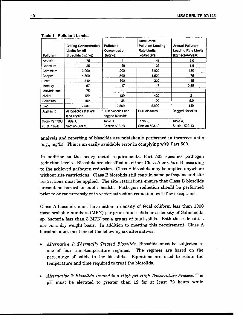
Part 503 regulates the concentrations of 10 heavy metals in land applied biosolids. All biosolids must meet the ceiling concentration limits shown in Table 1 to be applied to land. In addition to the ceiling concentration limits, at least one of the other requirements, i.e., pollutant concentration limits, cumulative pollutant loading limits, or annual pollutant loading limits (Table 1) must be met. Note that the limits are on a dry weight basis. Commonly,
10 USACERLTR 97/143
Table 1. Pol utant Limits.
Pollutant
Ceiling Concentration
Limits for All Biosolids (mg/kg)
Pollutant Concentration
(mg/kg)
Cumulative Pollutant Loading
Rate Limits (kg/hectare)
Annual Pollutant
Loading Rate Limits (kg/hectare/year)
Arsenic 75 41 41 2.0
Cadmium 85 39 39 1.9 Chromium 3,000 1,200 3,000 150 Copper 4,300 1,500 1,500 75 Lead 840 300 300 15 Mercury 57 17 17 0.85
Molybdenum 75 — — — Nickel 420 420 420 21
Selenium 100 36 100 5.0
Zinc 7,500 2,800 2,800 140
Applies to All biosolids that are
land applied
Bulk biosolids and
bagged biosolids
Bulk biosolids Bagged biosolids
From Part 503
(EPA, 1994)
Table 1,
Section 503.13
Table 3,
Section 503.13
Table 2,
Section 503.13
Table 4,
Section 503.13
analysis and reporting of biosolids are mistakenly performed in incorrect units (e.g., mg/L). This is an easily avoidable error in complying with Part 503.
In addition to the heavy metal requirements, Part 503 specifies pathogen reduction levels. Biosolids are classified as either Class A or Class B according to the achieved pathogen reduction. Class A biosolids may be applied anywhere without site restrictions. Class B biosolids still contain some pathogens and site restrictions must be applied. The site restrictions ensure that Class B biosolids present no hazard to public health. Pathogen reduction should be performed prior to or concurrently with vector attraction reduction, with few exceptions.
Class A biosolids must have either a density of fecal coliform less than 1000 most probable numbers (MPN) per gram total solids or a density of Salmonella sp. bacteria less than 3 MPN per 4 grams of total solids. Both these densities are on a dry weight basis. In addition to meeting this requirement, Class A biosolids must meet one of the following six alternatives:
• Alternative 1: Thermally Treated Biosolids. Biosolids must be subjected to one of four time-temperature regimes. The regimes are based on the percentage of solids in the biosolids. Equations are used to relate the temperature and time required to treat the biosolids.
Alternative 2: Biosolids Treated in a High pH-High Temperature Process. The pH must be elevated to greater than 12 for at least 72 hours while
USACERLTR-97/143 11
maintaining the temperature above 52 °C for at least 12 of the 72 hours. The biosolids must be air dried to over 50 percent solids after this period.
Alternative 3: Biosolids Treated in Other Known Processes. The preparer must demonstrate that the process can reduce enteric viruses and viable helminth ova. The operating conditions used in the demonstration must be maintained after the pathogen reduction demonstration is completed.
Alternative 4: Biosolids Treated in Unknown Processes. This alternative applies to cases where the biosolids treatment is either unknown or operated under conditions that are less stringent than would qualify under any other Class A alternative. Under this alternative, the biosolids are analyzed for enteric viruses and viable helminth ova when being used, disposed, or prepared for sale, give away or tests to ensure that EQ requirements are met.
• Alternative 5: Biosolids Treated in a Process To Further Reduce Pathogens. Biosolids must be treated in one of the following Processes to Further Reduce Pathogens (PFRP): composting, heat drying, heat treatment, thermophilic aerobic digestion, beta ray irradiation, gamma ray irradiation, or pasteurization. Minimum operating requirements for each of these PFRPs are established in Appendix B of Part 503. These requirements are presented throughout this report where they apply to USFK/EUSA sludge.
• Alternative 6: Biosolids Treated in a Process Equivalent to a PFRP. The treatment process used must be determined to be equivalent to a PFRP by the permitting authority. The treatment process must consistently reduce pathogens to levels that compare to those achieved using one of the listed PFRPs and must be operated under conditions that do so. The permitting authority is responsible for verifying equivalency.
Class B biosolids must meet one of the following three alternatives:
• Alternative 1: Monitoring of Indicator Organisms. Seven samples of the treated biosolids must be collected shortly before use or disposal. The geometric mean fecal coliform density of the samples must be less than 2 million colony forming units (CFU) or less than 2 million MPN per gram biosolids. These seven samples should be collected over a 2-week period since the fecal coliform density test has poor precision and biosolids quality can vary.
12 USACERL TR 97/143
• Alternative 2: Biosolids Treated as a Process To Significantly Reduce Pathogens. Biosolids must be treated in one of the following Processes to Significantly Reduce Pathogens (PSRP): aerobic digestion, air drying, anaerobic digestion, composting, or lime stabilization. Minimum operating requirements for each of these PFRPs are established in Appendix B of Part 503. These requirements are presented throughout this report where they apply to USFK/EUSA sludge.
• Alternative 3: Biosolids Treated in a Process Equivalent to a PSRP. The treatment process used must be determined to be equivalent to a PSRP by the permitting authority. The permitting authority is responsible for
verifying equivalency.
Vector attraction reduction (VAR) requirements are necessary since vectors, such as flies, mosquitoes, fleas, rodents, and birds, are capable of transmitting pathogens from wastewater sludge to humans and animals. Part 503 contains 12 options for the reduction of vector attraction. Options 1 through 8 reduce the attractiveness of the sludge to vectors. Options 9 and 10 prevent vectors from coming in contact with the biosolids. Options 11 and 12 apply to surface disposal and incineration.
• Option 1: Reduction in Volatile Solids Content. The mass of volatile solids in the biosolids is reduced by at least 38 percent during treatment.
• Options 2 and 3: Additional Digestion of Anaerobically Digested or Aerobically Digested Biosolids. The preparer must demonstrate after 40 additional days in the digester at temperatures between 30 and 37 °C that the volatile solids in the biosolids are reduced by less than 17 percent during
the bench test.
• Option 4: Specific Oxygen Uptake Rate for Aerobically Digested Solids. Adequate VAR is demonstrated when the specific oxygen uptake rate (SOUR) of the biosolids is equal to or less than 1.5 milligrams of oxygen per hour per gram of total biosolids, at 20 °C.
• Option 5: Aerobic Processes at Greater Than 40 °C. The biosolids must be treated aerobically for at least 14 days at an average temperature of 45 °C. The temperature must not drop below 40 °C during this time.
• Option 6: Addition of Alkaline Material. Adequate VAR is achieved when enough alkaline material is added to raise the pH to at least 12, at 25 °C, and maintain the pH without adding any more alkaline material. In addition, the pH must be maintained at 11.5 for an extra 22 hours without adding more alkaline material.
USACERLTR-97/143 13
• Option 7: Moisture Reduction of Biosolids Containing No Unstabilized Solids. Water must be removed from biosolids containing no unstabilized solids to achieve a solids content of at least 75 percent.
• Option 8: Moisture Reduction of Biosolids Containing Unstabilized Solids. Water must be removed from biosolids containing unstabilized solids to achieve a solids content of at least 90 percent.
• Option 9'. Biosolids Injection Biosolids Are Injected Below the Ground Surface. Class A biosolids must be injected within 8 hours after the pathogen-reducing process is complete. No biosolids may be present on the surface within 1 hour of injection.
• Option 10: Incorporation of Biosolids into the Soil. Biosolids are incorporated into the soil within 6 hours of application by plowing or some other means of mixing. Class A biosolids must be applied within 8 hours after the pathogen- reducing process is complete.
The heavy metal, pathogen, and vector attraction reduction requirements discussed above are used to determine which land application option is met. Four options, all of which equally protect public health through management practices, site restrictions, and general requirements, are (in order of increasing regulatory requirements) Exceptional Quality (EQ), Pollutant Concentration (PC), Cumulative Pollutant Loading Rate (CPLR), and Annual Pollutant Loading Rate (APLR).
To qualify under the EQ option, biosolids must meet the ceiling concentration and the pollutant concentration limits in Table 1, Class A pathogen requirements and one of the first eight VAR options. EQ standards are typically met through alkaline stabilization, composting, and heat drying. During land application, the following are not required: site restrictions, general require- ments, management practices, and tracking of added pollutants.
To qualify under the PC option, biosolids must meet the ceiling concentration and the pollutant concentration limits in Table 1, Class B pathogen requirements, and one of the first 10 VAR options. Class A biosolids, which meet either VAR Option 9 or 10, are considered PC biosolids. PC biosolids may be land applied anywhere except lawn and home gardens. PC biosolids must meet all management requirements, and PC biosolids that only meet Class B pathogen requirements also require site restrictions.
CPLR biosolids must meet the ceiling concentration limits and the Cumulative Pollutant Loading Rates in Table 1, either Class A or Class B pathogen
14 USACERL TR 97/143
requirements, and one of the first 10 VAR options. In addition, CPLR biosolids are subject to general requirements, applicable site restrictions, and manage- ment practices. CPLR biosolids may be applied in bulk. When any one or more of the CPLRs in Table 1 is reached at a site, no additional bulk solids subject to these limits may be applied.
APLR biosolids must meet the ceiling concentration limits and the Annual Pollutant Loading Rates in Table 1, Class A pathogen requirements, one of the first eight VAR options and Part 503 general requirements, applicable site restrictions and management practices. APLR biosolids may be sold or given away in labeled bags or other labeled containers. The APLR option limits the total amount of biosolids that may be applied at one site annually. When any one or more of the APLRs in Table 1 is reached at a site in a given year, no additional biosolids may be applied that year.
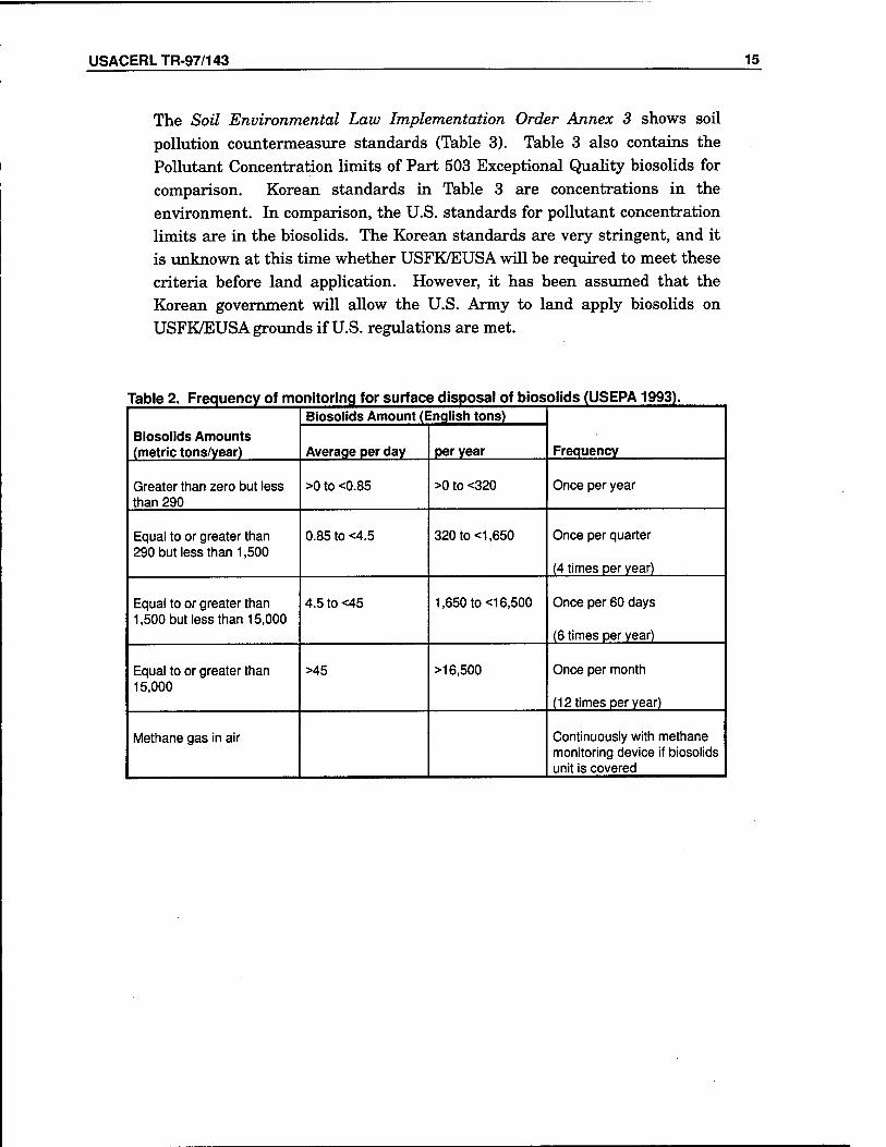
To ensure the requirements of Part 503 are met, all biosolids, regardless of which land application option is met, must follow frequency of monitoring, recordkeeping, and reporting requirements through sampling and analysis of biosolids. Typically, the preparer is responsible for sampling the sludge. However, the land applier, surface disposer, and incinerator of biosolids may be responsible, depending on the circumstances. When biosolids are to be land applied, they must be sampled for metals, pathogens, vector attraction reduction and nitrogen. Part 503 has a frequency of monitoring schedule for biosolids sampling (Table 2). The main purpose is to ensure that biosolids are sampled before use or disposal. Part 503 provides specific analytical methods to be used during sampling.
Korean Environmental Regulations
The Korean Ministry of Environment has no specific regulations such as the United States Part 503 to encourage and regulate beneficial use of sludge. Korean environmental regulations potentially related to sludge include:
1. Water Environment Preservation Law, Presidential Decree and Implemen- tation Orders, which regulates the discharge of wastewater into Korean waters and emphasizes industrial wastewater treatment.
2. Waste Management Law, Presidential Decree and Implementation Orders, which regulates hazardous waste generated from industrial activities.
3. Soil Environment Preservation Law, Presidential Decree and Implementation Orders, which regulates disposal of hazardous waste to soil environment.
USACERLTR-97/143 15
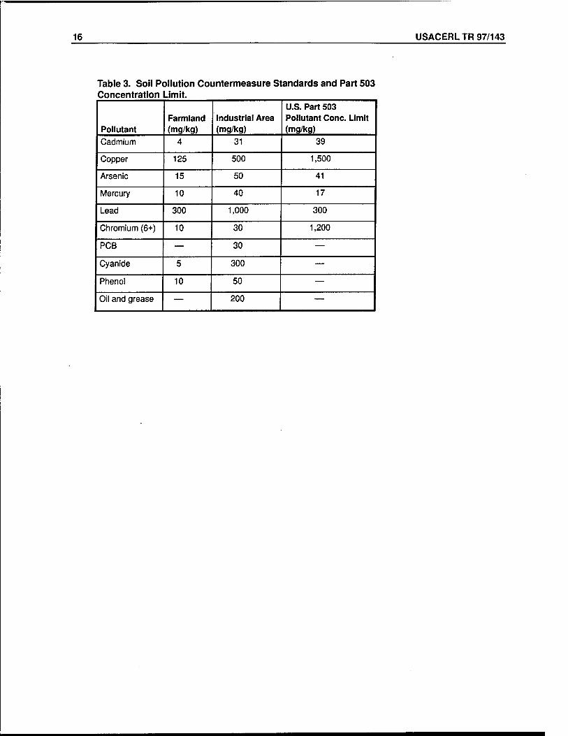
The Soil Environmental Law Implementation Order Annex 3 shows soil pollution countermeasure standards (Table 3). Table 3 also contains the Pollutant Concentration limits of Part 503 Exceptional Quality biosolids for comparison. Korean standards in Table 3 are concentrations in the environment. In comparison, the U.S. standards for pollutant concentration limits are in the biosolids. The Korean standards are very stringent, and it is unknown at this time whether USFK/EUSA will be required to meet these criteria before land application. However, it has been assumed that the Korean government will allow the U.S. Army to land apply biosolids on USFK/EUSA grounds if U.S. regulations are met.
Table 2. Frequency of monitoring for surface disposal of biosolids (USEPA1993).
Biosolids Amounts (metric tons/year)
Biosolids Amount (English tons)
Frequency Average per day per year
Greater than zero but less than 290
>0 to <0.85 >0 to <320 Once per year
Equal to or greater than 290 but less than 1,500
0.85 to <4.5 320 to <1,650 Once per quarter
(4 times per year)
Equal to or greater than 1,500 but less than 15,000
4.5 to <45 1,650 to <16,500 Once per 60 days
(6 times per year)
Equal to or greater than 15,000
>45 >16,500 Once per month
(12 times per year)
Methane gas in air Continuously with methane monitoring device if biosolids unit is covered
16 USACERL TR 97/143
Table 3. Soil Pollution Countermeasure Standards and Part 503 Concentration Limit.
Pollutant Farmland (mg/kg)
Industrial Area (mg/kg)
U.S. Part 503 Pollutant Cone. Limit (mg/kg)
Cadmium 4 31 39
Copper 125 500 1,500
Arsenic 15 50 41
Mercury 10 40 17
Lead 300 1,000 300
Chromium (6+) 10 30 1,200
PCB — 30 —
Cyanide 5 300 —
Phenol 10 50 —
Oil and grease — 200 —
USACERLTR-97/143 17
3 Current USFK/EUSA Sludge Management
The USFK and EUSA own and operate approximately 30 small wastewater treatment plants with design capacities ranging from 0.03 to 2.5 million gallons per day (MGD) (1 gal = 3.78 L). Of these plants, WWTPs in four DPWs are discussed below as typical examples in USFK/EUSA and are analyzed in this report.
The Western Corridor DPW operates the seven following WWTPs: (1) Camp Howze (design flow of 0.18 MGD), (2) Camp Edwards (0.09 MGD), (3) Camp Pelham (0.15 MGD), (4) Camp Giant (0.03 MGD), (5) Camp Stanton (0.10 MGD), (6) Camp Greaves (0.10 MGD), and (7) Liberty Bell (0.80 MGD). These are package WWTPs consisting of primary clarification, rotating biological contactors (RBC), secondary clarification, and aerobic sludge digestion. Digested sludge is collected by a Korean contractor and further treated at a Korean night soil plant. The night soil plant sludge is disposed at Kimpo Landfill. Approximately 1,333,488 gal of sludge is disposed annually. Currently, the Western Corridor DPW spends $90,737 annually for removal and disposal of accumulated sewage sludge.
The Yongsan DPW operates the Yongsan WWTP, which treats wastewater produced by the industrial and residential complexes of Yongsan Main Garrison. The plant discharges into the Han River. Designed for a flow of 2.5 MGD and an influent BOD concentration of 250 mg/L, this WWTP consists of a bar screen, a grit channel, Imhoff tank, RBC, a final clarifier, a sludge storage tank and chlorine contact. Secondary sludge from the final clarifier is returned to the Imhoff tanks where the sludge is resettled and anaerobically digested with the primary sludge in the bottom of the tank. Digested sludge is collected in the storage tank and disposed by a Korean contractor. However, USFK/EUSA pays a sewer user fee for the Yongsan WWTP, and Korean regulations do not require secondary treatment of the wastewater.
The Camp Humphreys DPW operates the Camp Humphreys WWTP, which treats wastewater produced by the industrial and residential complexes of Camp Humphreys. The plant was designed for a flow of 0.5 MGD and discharges into
18 USACERL TR 97/143
an enclosed lake, which receives intermittent discharge. Currently, the daily flow rate into the plant is 0.65 MGD. The plant configuration consists of an Imhoff tank, RBC, a final clarifier, sludge drying beds, and chlorine contact. After anaerobic digestion in the Imhoff tank, sludge is dried on the sludge- drying beds. The present estimate of sludge production is 350 dry kg/day. The sludge-drying beds have a total surface area of 14,480 sq ft (1345 m2). Dried sludge is removed and disposed by a Korean contractor. Currently, the Camp Humphreys' DPW spends $19,213 annually for removal and disposal of sludge.
The Camp Casey DPW operates the Camp Casey WWTP, which treats wastewater produced by Camp Casey, a typical troop installation. Designed for a flow of 1.45 MGD, this WWTP currently handles 2.0 MGD and discharges into Casey Creek. The plant consists of three primary clarifiers, two RBC trains with six stages each, three secondary clarifiers, a dissolved air flotation thickener and an aerobic digester. Vacuum assisted drying beds are currently under construction. Sludge is collected and disposed by a Korean contractor.
Technical Options for Improved USFK/EUSA Biosolids Management
Sludge management consists of the following major steps: thickening, stabilization, conditioning, dewatering, and beneficial use or disposal. These steps should be compatible with each other, and the overall system management should be integrated to minimize total costs. This section briefly summarizes technical options for each plant and recommends strategies to improve USFK/EUSA sludge management.
Western Corridor
Technical options considered for the Western Corridor's WWTPs must be capable of producing higher quality biosolids, including greater solids content, than the current aerobic digesters. Aerobic digestion is listed as a Process to Significantly Reduce Pathogens (PSRP) in Appendix B of 40 CFR, Part 503. Using aerobic digestion as a PSRP, biosolids must be agitated with either air or oxygen to maintain aerobic conditions with the mean cell residence time and temperature between 40 days at 20 °C and 60 days at 15 °C. Since aerobic digestion is only capable of meeting Class B requirements, site restrictions would be applied. A process that could meet Class A requirements is more desirable. The option explored for the Western Corridor DPW is a mobile
USACERLTR-97/143 19
mechanical dewatering system followed by either alkaline stabilization or composting.
Mobile Mechanical Dewatering
The mobile dewatering system would be designed to service all seven WWTPs in the Western Corridor with the capacity to collect from each plant two to three times per month. Such a service would include trailer-mounted equipment, provision of technicians and operators to run the dewatering device, and any required dewatering aids (e.g., polymer). Operational costs include polymer, maintenance, transportation, and power. Water must also be provided for mixing the polymer. All dewatered sludge would be transported to a single location (i.e., regional facility) where either an alkaline stabilization or a composting facility would be located.
Dewatering devices explored for this purpose include a belt filter press, a fixed- volume filter press, and solid bowl centrifuges. In a belt filter press, water is squeezed from the cake by sandwiching biosolids between two filter belts and exerting pressure using rollers. Belt filter presses are the most common dewatering choice, especially for small wastewater treatment plants, i.e., less than 5 MGD. Using a polymer, belt filter presses are capable of producing sludge cake with 16 to 35 percent solids (Black and Veatch 1995). Appendix A to this report includes further information on a belt filter press from Frontier Technology, Inc.
A fixed-volume filter press consists of a series of metal or heavy plastic plates that have filter media lining their sides. Slurry is pushed through the plates and pressure is released when the filtrate flow gets small. The plates are separated and dried cake falls off the plates. This option requires continuous operator attention since the press operates in batch and the operator may need to scrape the cake from the filter plates. (This may not be a concern if a mobile system is used since mobile system operation requires the operator to be present continuously.) The possible solids content of the final product ranges from 30 to 60 percent (Black and Veatch 1995). Appendix B provides information on a filter press from JWI.
Solid bowl centrifuges rely on centrifugal force and the density differences in liquid and solid portions of the sludge to separate them. Centrifuges are the most economical choice to install at large treatment plants, i.e., greater than 50 MGD, but are not usually economical for small treatment plants. Conventional centrifuges achieve between 15 and 25 percent solids. High-solids centrifuges
20 USACERL TR 97/143
are capable of achieving between 20 and 32 percent solids, depending on the type of sludge. However, when compared to conventional centrifuges, high- solids centrifuges have a higher capital cost and use double the electricity (Black and Veatch 1995). Appendixes C and D give more information on centrifuges.
The characteristics of the sludge may be important in choosing the most appropriate dewatering option. Western Corridor needs to have its sludge tested in each option to ensure that it is possible to achieve 20 percent solids or greater. Most manufacturers perform these tests free of charge.
Alkaline Stabilization
Advanced alkaline stabilization combines lime stabilization with pasteurization to achieve Class A biosolids. During lime stabilization, quicklime is added to the sludge. The exothermic reaction of the quicklime with water raises the temperature to 50 °C, which is high enough to inactivate worm eggs, and raises the pH above 12 to kill any pathogens (Metcalf and Eddy 1991). Lime stabilization meets PSRP requirements listed in Appendix B, 40 CFR, Part 503. Advanced alkaline stabilization uses the principles of lime stabilization while also achieving pasteurization. The PFRP requirement for pasteurization is to maintain the temperature of the biosolids at 70 °C or higher for 30 minutes or longer. Most advanced alkaline stabilization processes are proprietary, and the ways in which pasteurization is accomplished differ. Chemicals may be added in addition to the lime to achieve pasteurization. These chemicals may include cement kiln dust, lime kiln dust, Portland cement, or fly ash. A high heat regime may also be used to achieve pasteurization.
Lime stabilization provides no direct reduction of organic matter. Thus, the quantity of sludge produced is not reduced as it would be in a biological stabilization process (USEPA1979). A larger sludge volume will be a concern for the Western Corridor if the Korean government does not allow land application of sludge. Increasing the quantity of sludge by adding lime will dilute the concentration of metals in the sludge. If land application is allowed, this may be an advantage when meeting the Korean regulations for metals in soil.
Two proprietary alkaline stabilization processes were studied for the treatment of Western Corridor sludge. The first, the N-Viro process, is a patented system that can meet PFRP requirements. Technically, the process is defined as an "advanced alkaline stabilization with subsequent accelerated drying." Two alternative methods of conducting the N-Viro process have been approved by the USEPA as PFRP equivalent processes. In the first process, alkaline materials
USACERLTR-97/143 21^
are added to and mixed with the sludge in sufficient quantity to achieve a pH of 12.0 or greater for at least 7 days. For example, Burnham et al. (1992) used 35 percent kiln dust and a small amount of quicklime. Following mixing, the alkaline-stabilized sludge is dried in windrows for at least 30 days and until a minimum solids concentration of at least 65 percent is achieved. In the second process, a pH greater than 12.0 is maintained for at least 72 hours while the sludge is heated to a temperature of at least 53 °C, and maintained at that temperature for at least 12 hours. The Western Corridor will windrow-stabilize biosolids rather than heat drying. Information provided by N-Viro International Corporation is in Appendix E.
CemenTech, Inc. provides a lime/high heat stabilization process, which has been approved by the USEPA as a process to produce Class A biosolids. In this process, the temperature of the sludge is raised to 70 °C for 30 minutes and the pH is raised to 12 for 2 hours and 11.5 for an additional 22 hours. In the Western Corridor's case, manual operating controls will be used due to the very small quantity of sludge produced. Normally, lime is provided to the system from a bulk material silo, but the Western Corridor does not require enough alkaline material to need a silo. Bagged lime would be used instead. Both these factors lower the cost of the system when compared to most alkaline stabilization systems. Appendix F includes more information on CemenTech.
Fresh alkaline stabilization soil has been shown to inhibit seed germination. Any or all of the following soil characteristics may be responsible: high soluble salts, free NH3, fatty acids, and pH. Testing performed at Ohio State University show that a passive storage period of at least 6 months is required before seed germination will occur in N-Viro soil. The tests also showed that the odor of the soil changed from a cement-like smell to that of a moist field soil by the seventh month (Logan et al. 1995). Thus, curing of biosolids for at least 6 months is necessary to achieve a desirable land applicable soil.
Ammonia odors are typically encountered at alkaline stabilization facilities. The elevated pH resulting from the addition of alkaline materials causes the dissolved ammonia in the liquid to be released as a gas. Odor control systems can be chosen from simple enhanced ventilation with a single scrubber to a three-stage system, packed tower/mist scrubber/packed tower. The latter system may use sulfuric acid, sodium hypochlorite, and sodium hydroxide to neutralize and oxidize the odor-causing compounds (WEF 1995a). Alkaline stabilization does have an advantage over other sludge treatment processes that have odor problems in addition to ammonia. The pH is sufficiently high so that hydrogen sulfide odors will not be present (Lue-Hing 1992). In addition,
22 USACERL TR 97/143
alkaline stabilization destroys the organisms involved in decomposition of organic matter, which otherwise would cause odor.
Operator safety is a concern with alkaline stabilization. If adequate ventilation is not provided, operators may need to wear respirators due to the ammonia vapors released. In addition, alkaline material creates a caustic dust that causes skin and eye irritation. This is of special concern if bagged lime is used.
Composting
Composting is an aerobic sludge stabilization process. The heat generated from biochemical reactions destroys pathogens, and the humus-like end product can be used as soil amendment meeting Class A requirements of Part 503 regulations. In composting, where temperatures reach the thermophilic range, practically all viral, bacterial, and parasitic pathogens are eliminated (WEF
1995a).
Historically, composting has been more of an art than a science. About 50 years ago, several mechanical composting systems were introduced in Europe. The static pile method was introduced by the U.S. Department of Agriculture in the 1970s. Many advances were made in composting based on this early work (WEF 1995b). Almost 300 WWTPs in the United States either currently use or plan to use composting for their sludge stabilization (Goldstein and Steuteville 1996).
The objectives of composting are to: (1) reduce pathogens to meet PFRP requirements in Part 503 regulations; (2) further stabilize biosolids by decomposing odor-producing compounds; (3) dry the biosolids; and (4) produce a marketable product. The major factors affecting composting processes include biosolids and amendment characteristics (solids content, carbon-to-nitrogen (C/N) ratio, particle size and shape, porosity, biodegradability, and energy content), initial mix ratios, aeration rates, temperature, and detention time (WEF 1995b).
Aeration must be provided during the composting process to satisfy the oxygen demand of organic decomposition, to remove moisture and to control the temperature. The air flow rate for forced aeration composting is governed by temperature control, which is the most critical and most easily measured of the three air functions. During the early stages of composting, the temperature of the composting mass is the critical operational parameter. As the compost matures, moisture levels decrease to a point where the need to retain moisture becomes more of a concern than temperature control. At this point, forced
USACERLTR-97/143 23
aeration of the compost should be limited. Turning of compost piles can be a more effective way to control temperature. As a rule of thumb, aeration demands for temperature control should be approximately 0.2 to 0.25 standard m7ton (WEF 1995b).
Before composting, a mix is formed with the dewatered sludge cake and a bulking agent. The bulking agent provides structural integrity, is a source of carbon, and increases porosity while also increasing the solids content. To allow adequate structural integrity along with porosity and free space, bulking the initial total solids concentration to 40 percent is recommended. The bulking agent is a combination of an organic amendment and recycled compost (Lue- Hing et al. 1992). A higher concentration of recycled compost is economical in that less amendment needs to be purchased. However, too high a recycled concentration in the bulking agent will result in reduced porosity in the mix. A wide variety of organic amendments have been used: wood chips, sawdust, shredded yard wastes, processed agricultural wastes, earthworms, and shredded tires. Lang and Jager (1993) reported that some amendments such as wood ash suppress compost odors. Reducing particle size increases surface area and thereby enhances composting rates because the optimum conditions of decomposition occur on the surfaces of organic materials. However, reducing particle size reduces the pore size, limiting the movement of oxygen required for composting. Thus, an optimum range of particle size exists, depending on the method of aeration used. Coarse amendments can be recovered in post proces- sing, typically by screening. Benedict (1986) indicated that compost screening typically results in the recovery of 65 to 85 percent of wood chips entering the composting process.
Carbon and nitrogen, the principal nutrients in composting, affect the process speed and final volume of the compost. C/N ratios, also referred to as the biodegradable C/N, between 20 and 50 have been cited as optimum. Low C/N ratios (less than 20) result in a loss of excess nitrogen from ammonia volatilization (Haug 1993). In severe cases of nitrogen deficiency, the addition of urea or other nitrogen sources may be required (Kulhman 1990). High C/N ratios (greater than 80) result in a slowing of decomposition rate and subsequent reduction of composting temperatures (WEF 1990). Municipal sludges generally contain adequate nutrients to support composting (Haug 1993).
Composting is performed in two phases, a high rate phase followed by a curing phase. The high rate phase has higher oxygen transfer rates, higher (thermophilic) temperatures, higher biodegradable volatile solids reductions, and higher odor potential than the curing phase. The curing phase is less
24 USACERL TR 97/143
controlled and often has fewer design considerations. However, it is equally as important as the high rate phase (Haug 1993). If space is limiting, the bulking agent may be screened from the compost before curing.
The most common types of composting processes used are the in-vessel process, the windrow process, and the aerated static pile process. In-vessel composting processes are proprietary while aerated static pile and windrow composting processes have to be designed by an engineer. Usually, while any of the three processes may be used for the high rate composting phase, the curing phase is either static pile or windrow (Haug 1993).
In the in-vessel composting process, the mixture is fed into one end of a silo, tunnel, or open channel and moved continuously toward the discharge end where it is outloaded after the required detention time. The mixture may move as an undisturbed plug, or be periodically agitated as it is moved through the vessel. Air is forced through the mixture. A retention time of 21 days followed by 30 days of curing is needed. Appendix G gives further information on an in- vessel composting process from Davis Industries.
In the windrow process, the mixture is stacked in trapezoidal windrows with sufficient ratio of surface area to volume to provide aeration by natural convection and diffusion. The windrow is remixed periodically by a mechanical aerator, such as an auger, to further aerate. Smaller facilities may use the same front end loader that is used to build the windrows to turn them. Using a front end loader to turn the windrows allows the operator to pile the windrow higher than mechanical aerators allow. This will reduce the required land area (Roberts 1997). This would be a more cost effective option for the Western Corridor than buying a large and expensive turning machine. Appendix H contains information on a compost turner from Resource Recovery Systems. The amendments are typically of a smaller particle size than with aerated static pile and may include recirculated compost. The active windrow composting period is around 30 days. In the aerated windrow process, the natural convection and diffusion provided in the windrow process are supplemented by forced aeration. Air is supplied through trenches in the paved working surface.
Presently, 43 percent of the composting facilities in the United States use aerated static pile systems (Goldstein and Steuteville 1996). This type of composting has been widely applied for wet substrates, such as sludge cake (Haug 1993). In this process, approximately 1 ft of bulking agent is stacked over a porous bed above air piping that is connected to blowers. The cake/bulking agent mixture is piled over the bulking agent. The piles are covered with a layer
USACERLTR-97/143 25
of either bulking agent or finished compost to provide insulation and to capture odor (Story 1997). Air is provided to the pile either through positive aeration or negative aeration, i.e., air is either forced upward or drawn downward through the mixture. When the pile is taken down after composting, the bulking agent may be partially recovered by screening and then reused. Compost from the aerated static pile is usually not dry enough to be screened. Thus, either a curing or a separate drying phase may be needed before screening.
An advantage of the aerated static pile is its low labor requirement. The operator will need only to check the temperature daily and adjust the air flow to the pile, if necessary. All other associated operator tasks are performed periodically (Story 1997). A disadvantage of the aerated static pile is clumping of compost caused by incomplete mixing and nonaerated parts of the pile. Front end loaders may not mix the compost uniformly and may compact the compost, reducing pore size. This can lead to anaerobic conditions that result in odors and inadequate decomposition and pathogen destruction to achieve Class A biosolids. However, operators who were interviewed for this report had no problems with the quality of the compost (Hutchinson 1997; Story 1997). Appendix I contains transcripts from these interviews. An active composting period of 21 days followed by 30 days of curing is required.
When choosing a bulking agent for aerated static piles, the optimum particle size range is between 12.5 and 50 mm (0.5 and 2 in). Use of a larger bulking agent maintains air voids without the need of periodic agitation, as in the windrow process (Haug 1993). For example, sawdust will not provide enough air cavities for proper aeration and heat flow. Wood chips are most commonly used for aerated static pile bulking agent. Using the correct mix ratio is essential in reaching thermophilic temperatures. When starting up a facility, the operator may need to experiment until the correct ratio is found (Hutchinson 1997). For example, a North Carolina facility at Burnsville was able to maintain temperatures between 150 °F (65 °C) and 160 °F (71 °C) for at least 15 days using a mix ratio of 2:1, tree bark: sludge (Story 1997).
The USEPA (1993) established minimum requirements for composting as a PFRP in Appendix B of Part 503 regulations: (1) using either the within-vessel composting method or the aerated static pile composting method, the temperature of the biosolids is maintained at 55 °C or higher for 3 days; and (2) using the windrow composting method, the temperature for biosolids is maintained at 55 °C or higher for 15 days or longer. During the period when the compost is maintained at 55 °C or higher, the windrow is turned a minimum of every 5 days. Appendix B of Part 503 regulations also established minimum
26 USACERL TR 97/143
requirements for composting as a PSRP. The biosolids temperature must be raised to 40 °C or higher for 5 days and during 4 hours of that period, the temperature in the pile must exceed 55 °C. This requirement applies to all three types of composting. The Western Corridor's goal is to meet the PFRP requirements.
Odor control is an important aspect of successful composting operation. In- vessel composting facilities suppress odors better than the other processes due to the nature of the enclosed "reactor." Proper mixing is essential for odor control since unmixed sludge clumps can lead to anaerobic conditions (Benedict et al. 1986). The treatment methods for compost odors include wet chemical scrubbing and regenerative absorption (WEF 1995 a). In the aerated static pile method, pile cover material acts as an odor scrubber during positive aeration. Negative aeration, however, requires a separate exhaust scrubber system (Benedict et al. 1986). Biofilters using compost and bulking agents have become more popular for odor treatment at composting facilities in the United States.
Condensate and leachate from the composting pile need to be collected and treated. Condensate forms when the moist, hot exhaust gas is cooled (Haug 1993). A composting facility for the Western Corridor would need to be located at one of the WWTPs where pipes could carry runoff from the piles back to the headworks.
Structures to house the composting process provide protection from the weather and play a critical role in odor control. Depending on the circumstances, a structure may only have a roof or it may have walls. For example, the Fort Collins, CO facility has three walls in addition to a roof due to high winds (Putnam 1997). Wind will carry odor from the composting facility. Rain reduces the solids content in the compost, and thus, the composting time must be increased. In the winter, snow and cold temperatures may cause the compost temperature to fall below the Part 503 requirements. The Springville, UT windrow facility, which does not have a shelter, has not been able to maintain their temperatures at high enough levels to meet requirements. In addition, when the snow melts in the spring, the windrows become too wet and the fecal coliform requirements are not met (Roberts 1997). Current aerated static pile facilities that operate without shelters do not experience any problems detrimental to the quality of the compost. The layer of bulking agent over the pile acts as an odor filter and provides insulation from the elements to keep the pile temperature above levels required for pathogen destruction (Story 1997; Steuteville and Goldstein 1997). In Korea, a shelter may not be required, but should be considered due to the volume of rain in the summer months.
USACERLTR-97/143 27
Numerous testing methods exist for measuring compost stability. No single test is accepted universally (Jimenez and Garcia). These test methods (WEF 1995a; Haug) include: testing for percent volatile solids, using a respiration test to measure carbon dioxide or oxygen demand, measuring for a C/N ratio less than 20 for manure compost, seed germination and root elongation tests, and measuring redox potential.
Cost Comparison
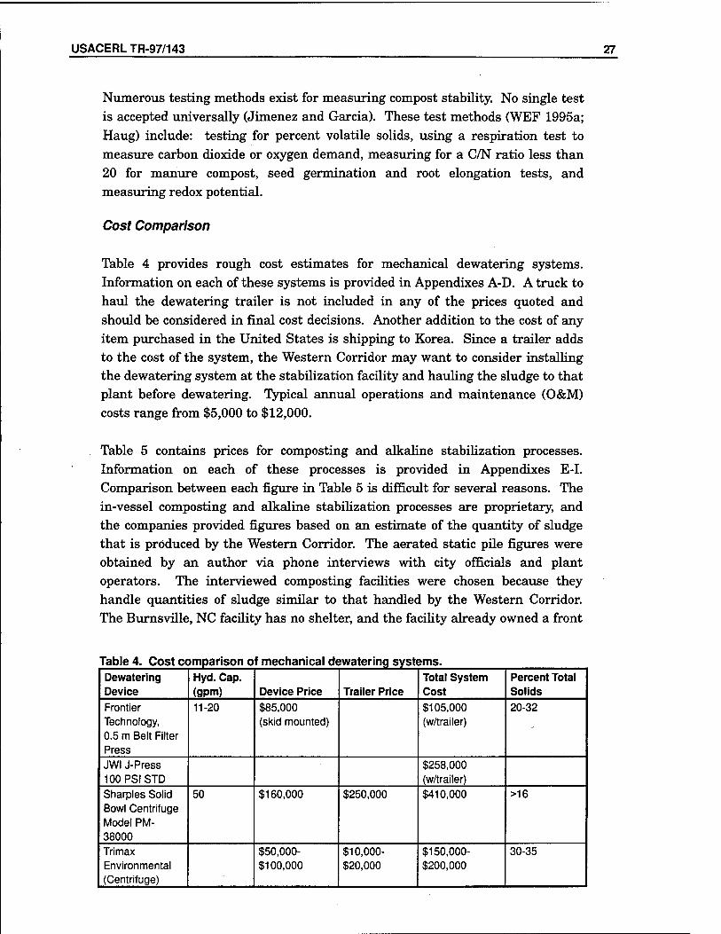
Table 4 provides rough cost estimates for mechanical dewatering systems. Information on each of these systems is provided in Appendixes A-D. A truck to haul the dewatering trailer is not included in any of the prices quoted and should be considered in final cost decisions. Another addition to the cost of any item purchased in the United States is shipping to Korea. Since a trailer adds to the cost of the system, the Western Corridor may want to consider installing the dewatering system at the stabilization facility and hauling the sludge to that plant before dewatering. Typical annual operations and maintenance (O&M) costs range from $5,000 to $12,000.
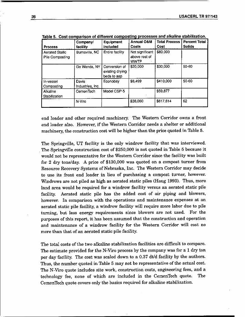
Table 5 contains prices for composting and alkaline stabilization processes. Information on each of these processes is provided in Appendixes E-I. Comparison between each figure in Table 5 is difficult for several reasons. The in-vessel composting and alkaline stabilization processes are proprietary, and the companies provided figures based on an estimate of the quantity of sludge that is produced by the Western Corridor. The aerated static pile figures were obtained by an author via phone interviews with city officials and plant operators. The interviewed composting facilities were chosen because they handle quantities of sludge similar to that handled by the Western Corridor. The Burnsville, NC facility has no shelter, and the facility already owned a front
Table 4. Cost comparison of mechanical dewatering systems. Dewatering Device
Hyd. Cap. (gpm) Device Price Trailer Price
Total System Cost
Percent Total Solids
Frontier Technology, 0.5 m Belt Filter Press
11-20 $85,000 (skid mounted)
$105,000 (w/trailer)
20-32
JWI J-Press 100PSISTD
$258,000 (w/trailer)
Sharpies Solid Bowl Centrifuge Model PM- 38000
50 $160,000 $250,000 $410,000 >16
Trimax Environmental (Centrifuge)
$50,000- $100,000
$10,000- $20,000
$150,000- $200,000
30-35
28 USACERLTR 97/143
Table 5. Cost comparison of different composting processes and alkaline stabilization.
Process Company/ facility
Equipment included
Annual O&M Costs
Total Process Cost
Percent Total Solids
Aerated Static Pile Composting
Bumsville, NC Entire facility Not significant above rest of WWTP
$80,000
Go Wanda, NY Conversion of existing drying beds to asp
$20,000 $30,000 50-60
In-vessel Composting
Davis Industries, Inc.
Econobay $8,499 $410,000 50-60
Alkaline Stabilization
CemenTech Model CSP-5 $59,877
N-Viro $38,060 $617,614 62
end loader and other required machinery. The Western Corridor owns a front end loader also. However, if the Western Corridor needs a shelter or additional machinery, the construction cost will be higher than the price quoted in Table 5.
The Springville, UT facility is the only windrow facility that was interviewed. The Springville construction cost of $250,000 is not quoted in Table 5 because it would not be representative for the Western Corridor since the facility was built for 2 dry tons/day. A price of $130,000 was quoted on a compost turner from Resource Recovery Systems of Nebraska, Inc. The Western Corridor may decide to use its front end loader in lieu of purchasing a compost turner, however. Windrows are not piled as high as aerated static piles (Haug 1993). Thus, more land area would be required for a windrow facility versus an aerated static pile facility. Aerated static pile has the added cost of air piping and blowers, however. In comparison with the operations and maintenance expenses at an aerated static pile facility, a windrow facility will require more labor due to pile turning, but less energy requirements since blowers are not used. For the purposes of this report, it has been assumed that the construction and operation and maintenance of a windrow facility for the Western Corridor will cost no more than that of an aerated static pile facility.
The total costs of the two alkaline stabilization facilities are difficult to compare. The estimate provided for the N-Viro process by the company was for a 1 dry ton per day facility. The cost was scaled down to a 0.37 dt/d facility by the authors. Thus, the number quoted in Table 5 may not be representative of the actual cost. The N-Viro quote includes site work, construction costs, engineering fees, and a technology fee, none of which are included in the CemenTech quote. The CemenTech quote covers only the basics required for alkaline stabilization.
USACERLTR-97/143 29
As stated previously, the Western Corridor currently spends $90,737 annually on sludge disposal. Assuming that the sludge produced from any of the stabilization processes above can be land applied, a 5-year savings of $453,685 will be achieved. The following combinations could be used to achieve a 5-year payback:
• CemenTech alkaline stabilization, and a Frontier Technology belt filter press
• aerated static pile composting, and any dewatering option except Sharpies with a trailer and JWI J-Press
• windrow composting, and any dewatering option except Sharpies with a trailer and JWI J-Press.
These combinations were calculated using an O&M cost of $12,000/yr for all the dewatering devices, $20,000/yr O&M, and $80,000 construction cost for aerated static pile composting, and assuming that, over a 5-year period, windrow composting would cost less than aerated static pile composting, if a front loader were used instead of a compost turner. All other prices were taken from Table 5 as shown.
If the produced biosolids cannot be land applied, the Western Corridor should still consider the processes above. The solids content will be increased dramatically above that of the current aerobically digested sludge that is landfilled. The following sludge volumes were calculated for each process:
• dewatering to 20 percent solids: 166,686 gal/yr
• composting to 50 percent solids: 66,674 gal/yr
• alkaline stabilization to 40 percent solids: 96,700 gal/yr.
A comparison of these volumes to the current sludge volume of 1,333,488 gal/yr shows significant reduction. The tipping fees will be increased, however, due to greater solids content. It is believed that, with the reduced volume and increased fees, the sludge disposal fees for composting and alkaline stabilization will be within 5 percent of the current disposal fees.
Sludge collection/disposal costs are expected to rise sharply in a few years. This study recommends the Western Corridor continue using current procedures and implement the mobile mechanical dewatering system with either aerated static pile composting, windrow composting, or alkaline stabilization when disposal costs significantly rise. The belt filter press is the most suitable dewatering option due to economics. However, before a final decision is made on the
30 USACERL TR 97/143
dewatering technology, Western Corridor should have its sludge tested in the various dewatering devices. A greater volume of sludge will be produced from alkaline stabilization than from composting. Thus, if land application is not permitted, aerated static pile or windrow composting will be the more cost effective option. Windrow composting should not be chosen over aerated static pile due to the believed lower costs. Careful consideration should be taken as to how much labor the Western Corridor wishes to expend on stabilization. Aerated static piles are well suited for small treatment plants. Each WWTP has an unique approach, as may be seen from the interviewed composting facilities, and capital costs vary from a few tens of thousand to millions of dollars. It is extremely important that engineers/operators take an active interest in improving sludge management system before any new technology is
implemented.
Yongsan
Due to space restriction, a sludge treatment program cannot be implemented at the Yongsan WWTP. However, the need for a sludge treatment program can easily be eliminated at the plant. Currently, the Korean Ministry of Environment does not require secondary treatment at the Yongsan WWTP, and USFK/EUSA pays a wastewater system users fee to the Korean Government. Therefore, it is recommended that RBC operation be halted and the Imhoff tank effluent be directly discharged to Seoul's sewer system. This will result in significant reduction of disposal costs for the secondary treatment sludge from RBCs.
Camp Humphreys
Upgrading the existing sludge drying beds to reed beds is the option considered for Camp Humphreys. Sand-drying beds can have long dewatering times (2 to 4 weeks), intensive labor requirements to remove dried sludge, and can experience clogging. Camp Humphreys WWTP has actually experienced clogging and poor drainage. Reed beds may be a more cost effective technology at this site by virtue of its added microbial degradation and by lesser requirement for operator
attention.
Although it was started in Europe more than 10 years ago, reed bed dewatering is still an emerging technology in the United States and a new technology in Korea. Reed bed technology has been largely used in the northeastern United
USACERLTR-97/143 31
States, including New Jersey, Pennsylvania, Maine, and Vermont. Like sand- drying beds, the reed bed is a natural dewatering system that is well suited for smaller treatment plants. A disadvantage with such natural systems is the greater requirement for available land. This will only be a concern at Camp Humphrey if the current sludge drying beds do not provide enough area. The reed bed process can produce biosolids with a solids content ranging from 30 to 60 percent (Kim et al. 1993). USACERL has experience with the implementation and operation of reed bed technology through a demonstration at Fort Campbell, KY.
The reed bed process basically operates as a modified sand-drying bed with a dense growth of reed vegetation. Therefore, the construction is similar to that of sand-drying beds. An excavated trench is first lined with an impermeable barrier to prevent leaching to the surrounding soil. Precast Hypalon liners have been successfully demonstrated for lining the trenches at several installations. A 10-in. layer of gravel is placed over the drainage pipe and is then covered with a 10-in. layer of sand. The side walls are commonly made of concrete and include at least 1 m freeboard. This freeboard ensures adequate storage capacity of the sludge for a design period of 10 years. Camp Humphreys' current drying beds may easily be converted to reed beds by raising the side walls. A door, or some other means to facilitate the removal of dried biosolids, also needs to be constructed in each bed.
Once the beds are constructed, reeds are planted at 1-ft centers. Several species are available, but generally the common reed Phragmites is used. Phragmites is well suited for reed bed use because of its elevated evapotranspiration rate and its great tolerance for variable climates. In fact, on a visit to Korea, Phragmites was found in the Han River banks. Once the reeds are established, sludge may be applied to the beds. Reed beds are designed to accommodate stabilized sludge that contains 3 to 4 percent solids.
Reed beds have some important advantages over other natural systems. The dried sludge removed at the end of bed is very similar in quality to compost with regards to pathogen content and stabilization. These results are mainly due to the long detention of the sludge, added microbial degradation due to oxygen provided through the root system, and an additional storage period that follows the final sludge addition. While not yet documented, it is believed that, if the sludge is allowed to weather for 1 year following the last sludge application, it will pass the EQ biosolids criteria. The root system of the reeds enables long term storage through evapotranspiration and maintenance of a pathway for the liquid to drain through.
32 USACERL TR 97/143
Reed beds require very little operator attention in comparison with sand-drying beds. Typical operator attention is 200 hours per year to monitor sludge additions and to perform other miscellaneous tasks. Labor requirements for sand-drying beds range from 0.5 hr/yr/m2, for large systems, to 4 hr/yr/m2, for small systems (USEPA 1987). Thus, for the current sand-drying bed area (1345 m2) at Camp Humphreys, the operators may spend between 672.5 and 5,380 hours per year working on the sand-drying beds. Unlike sand beds, which require the removal of the sludge after each individual sludge application, reed beds are designed to hold sludge for a period of 10 years. The time and cost of periodic replacing of sand torn up during sludge removal would be eliminated. One relevant manpower requirement is harvesting of the reeds each fall. Harvesting may be performed manually with hedge clippers or sickles or using mechanical devices. Alternately, the reeds may be burned after filling the bed with 2 in. of water, if local authorities permit.
At the time of disposal, the final volume is significantly lower than the total volume from a sand bed after 10 years, which results in disposal savings. Several ultimate disposal alternatives are available for the sludge after it is removed from the beds. It is likely that the weathering of the sludge over the storage period will result in Class A biosolids. Therefore, under U.S. standards, the material could be as freely used as any commercial soil conditioner, in a manner similar to compost. In the worst case, the biosolids would meet the Class B standards and could still be beneficially applied to land. The solids content of over 40 percent would facilitate ease of application. Landfilling of the sludge remains an alternative. Since the volume of sludge would be reduced through organic destruction, landfilling would be less expensive than currently
practiced.
The reed bed has a few disadvantages or potential problems. One commonly occurring problem with the reed bed is infestation, especially by aphids, during the first year of growth. This problem is typically controlled by purchasing lady bugs, a natural predator of the aphids. Another problem that must be considered is the removal and extinction of the reed system from the final compost product. This may possibly be addressed by killing the reeds at the beginning of the 1-year holding period and screening the final product. Another potential disadvantage is the preparation period before the reed bed becomes fully operational. Reeds must be planted during the growing season. The establishment of healthy reeds requires several weeks of growth. Sludge should not be applied until the plants are well established. Some sites have waited up to 2 months before applying sludge (Kim et al. 1993).
USACERLTR-97/143 33
The reed bed process is an empirical technology. Further science-based research is needed to "fine tune" this technology. Design parameters for reed bed sizing are widespread based on the number of variables that affect the dewatering rate. Also, data from existing reed bed facilities varies significantly. Experience at Fort Campbell indicates that approximately 20,000 sq ft of reed bed area is required per 1 MGD of wastewater flow when anaerobic digestion is used for stabilization (Kim et al. 1993). This would correspond to 13,000 sq ft (1208 m2) for the Camp Humphreys WWTP. The solids loading rate must also be considered, though. Solids loading rates for operational reed bed systems using anaerobically digested sludge with 5 percent total solids range between 2.5 and 12 lb/sq ft/yr (12 and 58.6 kg/m7yr) (Kim et al. 1993). For Camp Humphreys' present estimated solids production of 350 dry kg/day, a reed bed area between 19,300 and 94,184 sq ft (1792 and 8750 m2) is required. The hydraulic loading rate may also be considered. Hydraulic loading rates for operational reed bed systems using anaerobically digested sludge with 5 percent total solids range between 0.49 and 3.28 cu ftfeq ft/yr (0.15 and 1.0 mVmVyr) (Kim et al. 1993). For Camp Humphreys, a reed bed area between 22,150 and 147,700 sq ft (2058 and 13,720 m2) is required. These ranges of possible required space illustrate that a good estimate of the requirements for Camp Humphreys is not feasible without more data on sludge characteristics and volume. The solids and hydraulic loading rate estimates are based on typical values for conventional anaerobic digesters. No data is available for Imhoff tank sludge. In addition to the required bed space, at least two extra beds need to be built to allow a reed bed to remain idle the year prior to its excavation and for emergencies. Thus, even at the 13,000 sq ft approximation, which is below the low end of the both loading rate approximations, the current 14,480 sq ft may not be adequate since the additional space for two extra beds is not available.
Costs of implementing reed beds vary as much as the design parameters. Retrofitting existing sand-drying beds to reed beds range in cost from $0.45/sq ft to $9.30/sq ft. If Camp Humphreys had only to retrofit the existing beds, implementing this option would be ideal. However, construction of new reed beds is quite costly in comparison, with a range from $9.33/sq ft to $25/sq ft (Kim et al. 1993). Without an in-depth analysis of Camp Humphreys' sludge and construction costs in Korea, an exact construction cost cannot be calculated. However, assuming that the cost of retrofitting Camp Humphreys' sand beds to reed beds would be $4.88/sq ft, the DPW would spend $70,660 to implement this change, which is within the 5-year payback criteria. This study recommends the conversion of Camp Humphreys' current sand-drying beds to reed beds.
34 USACERL TR 97/143
Camp Casey
The options explored for the Camp Casey WWTP include: (1) upgrading the current aerobic digester to autothermal thermophilic aerobic digestion (ATAD) with land application, and (2) maintaining the existing aerobic digester with the vacuum-assisted bed currently under construction followed by either composting or alkaline stabilization. The current aerobic digester is larger than required and loses energy. A more efficient process is desirable. In addition, as mentioned earlier, conventional aerobic digestion is not capable of producing Class A biosolids. However, implementing composting or alkaline stabilization would also produce Class A biosolids. This is important since the final biosolids products may be reused at golf course or training area rehabilitation projects on
Camp Casey grounds.
Autothermal thermophilic aerobic digestion (ATAD) was developed by Pöpel in the 1970s in Germany. In 1977, Herr Fuchs installed the first German ATAD system in Vilsbiburg. Fuchs system is the most commonly used ATAD system in the Federal Republic of Germany (FRG) and probably in the world. Currently, ATAD facilities are successfully being operated in FRG, the United Kingdom, France, Italy, Switzerland, and Canada. Since 1993, when Part 503 came into effect, ATAD has emerged in the United States as a technology capable of meeting PFRP requirements. Currently, Krüger, Inc. has 12 operating ATAD systems in the United States with five more under construction.
ATAD is a compact, fully enclosed process which, with an adequate supply of oxygen, microorganisms, and nutrients, will decompose complex organic substances in wastewater. The heat produced during decomposition is adequate to maintain the desired operating temperature. Thus, ATAD is more efficient than aerobic digestion since no external heat supply is required. This results in lower operation and maintenance costs. ATAD does, however, require energy for aeration and mixing as aerobic digestion does. ATAD achieves a greater reduction of bacteria and pathogens than aerobic digestion in about one fifth the time. Removal rates of up to 70 percent of the biodegradable organics are achievable in thermophilic aerobic digestion (Metcalf and Eddy 1991). When comparing ATAD to other sludge management strategies, advantages include no nitrification and no required chemical additions or amendments.
The ATAD process works well with both primary and secondary sludges and may be operated on either a semi-continuous or a batch basis. Typically, a batch system is used. Since ATAD systems rely on heat to achieve the operating temperature, sludge must be thickened prior to entering the digester to limit
USACERLTR-97/143 35
energy needed for heating and mixing. Ideal conditions are obtained when the sludge is thickened to 4 to 6 percent total suspended solids (TSS) (USEPA1990) and has a chemical oxygen demand of 40 mg/L or greater (WEF 1995a). Camp Casey currently has a dissolved air flotation unit that is capable of meeting the 4 to 6 percent TSS requirement.
The current digester at Camp Casey would be replaced with a minimum of two insulated reactors in series. While single reactor processes do achieve similar reduction in volatile suspended solids, they will not achieve the required pathogen reduction. Temperature and pH parameters vary between the two reactors. The first reactor should maintain a temperature between 35 and 50 °C and a pH greater than or equal to 7.2 while the second reactor maintains a temperature between 50 and 65 °C with a pH around 8. Desired temperatures are acquired through adequately thickened sludge, good reactor insulation, efficient aeration, and foam management. Since the thermophilic operating temperatures in the reactors suppress nitrification, the pH usually will not have to be specially considered during design.
Biosolids treated through ATM) meet the requirements for Class A pathogen reduction in Part 503. Thermophilic aerobic digestion is one of the PFRPs listed in Appendix B of 40 CFR Part 503. To meet these requirements liquid biosolids must be agitated with air or oxygen to maintain aerobic conditions with a mean cell residence time of 10 days at 55 to 60 °C. In addition, Kelly (1993) showed that ATAD reduces volatile solids by 38 percent in a system with a degree C-day product of 400 and a 7-day total retention time. Thus, ATAD is capable of meeting both the Class A and the VAR requirements to create exceptional quality biosolids. ATAD is ideal over aerobic digestion in that Class A instead of Class B requirements are met.
Aerating at the appropriate rate is important. If air is supplied at a higher rate than needed, evaporative latent heat loss will cause cooling in the tank. Inadequate aeration and/or mixing causes poor digestion and a musty or humus- like odor in the exhaust (Kelly 1993). This odor can be sufficiently controlled by returning exhaust air to the rotating biological contactors, water scrubbing, passing through a biofilter, or dilution with ambient air. Gaseous ammonia, which is released by thermophilic aerobic degradation, also releases odor. The elevated pH in the second reactor enhances the stripping of ammonia in the exhaust. Various aeration and mixing devices have been used including aspirating aerators, turbines, and diffused air.
36 USACERL TR 97/143
A dense foam layer develops quickly on the reactor due to aeration of the substrate and plays an important part in the ATAD system. Wolinski (1985) reported that the foam layer enhances biological activity, improves oxygen use, and provides insulation to the reactor. However, foam also retards the volume of air entering the reactor (USEPA 1990). Thus, foam volume must be controlled. Methods of foam control include mechanical horizontal shaft foam cutter, vertical mixers and spray systems, and chemical defoamers.
Post treatment of the biosolids includes cooling and thickening. Twenty days of cooling is desirable to reduce the temperature to 20 °C. Post thickening is most successful after the sludge is allowed to cool. Thickening of ATAD biosolids by gravity will typically achieve 6 to 10 percent solids (USEPA 1990).
To completely install an ATAD system, the Camp Casey DPW would spend around a million dollars. Annual operations and maintenance costs would be $33,800. Over 5 years, the Camp Casey DPW would spend roughly $1,182,000 on an ATAD for Camp Casey's sludge management. Exact information on the operation and maintenance costs for the plant's current aerobic digester and sludge disposal costs are needed to prove whether a 5-year return on investment is attainable in this situation. It is assumed that a 5-year payback is not possible. However, conversion of the aerobic digester to an ATAD system is a project that most likely would achieve a 10-year return on investment.
Sludge disposal costs are expected to rise significantly in the near future based on rapidly changing Korean environmental regulations and the high inflation rate. This study recommends that, when such a time arrives, upgrading the existing aerobic digester to an ATAD system with land application be compared to the addition of either composting or alkaline stabilization in conjunction with the facility's current processes, and that one of these options be implemented. The final biosolids product will be used as soil amendments at Camp Casey golf courses and for training area land management/erosion control.
USACERLTR-97/143 37
4 Conclusions and Recommendations
Conclusions
It is hoped that this study will open a new era in USFK/EUSA sludge management where beneficial use of biosolids replaces landfill disposal. However, regulatory and economic barriers may make this a difficult task. Since no biosolids regulations or practices currently exist in Korea, the management improvements discussed in this report are based on Part 503 criteria for beneficial land application of biosolids. It is assumed that biosolids that meet Part 503 regulations may be land applied at USFK/EUSA installations. The USFK/EUSA Environmental Program Office recommended a 5-year payback as a criteria to compete with other real property improvement projects. This study concludes that, even considering the economic benefits of using processed biosolids as soil amendments, a 5-year payback is currently a difficult criteria to meet. However, an increase in sludge disposal costs is foreseen. At that time, the recommendations in this report should be implemented.
Recommendations
This study recommends that:
1. The Western Corridor DPW use a mobile mechanical dewatering device to dewater sludge at its seven plants, transport the sludge to a regional facility for stabilization, and install either aerated static pile composting, windrow composting, or alkaline stabilization at the regional facility.
2. The USFK/EUSA discontinue the current secondary treatment at the Yongsan WWTP to reduce operation costs and sludge generation.
3. The Camp Humphreys DPW convert the current sand-drying beds at the Camp Humphreys WWTP to reed beds. This conversion requires low capital investment and can be accomplished with in-house labor.
38 USACERL TR 97/143
4. The Camp Casey DPW set a long-term goal to convert the aerobic digester to an ATAD system and, after dewatering in the vacuum-assisted bed, the biosolids be used as soil supplements at Camp Casey's golf course and training land management/erosion control.
Appendix G interview data show the wide variety of approaches and costs to implementing improved biosolids management. It is strongly recommended that USFK/EUSA engineers/operators start implementing improved sludge management strategies in the very near future for the benefit of both Korea and the United States.
USACERLTR-97/143 39
References Benedict, H., E. Epstein, and J. English, "Municipal Sludge Composting Technology Evaluation,"
Journal of Water Pollut. Control Fed., vol 58 (1986), p 279.
Black and Veatch, and The Electric Power Research Institute, Wastewater Biosolids and Water Residuals: Reference Manual on Conditioning, Thickening, Dewatering and Drying (Kansas City, MO, 1995).
Burnham, J., N. Hatfield, G.F. Bennet, and T.J. Logan, Use of Kiln Dust With Quicklime for Effective Municipal Sludge Treatment With Pasteurization and Stabilization With the N-Viro Soil Process, ASTM Stand. Tech. Publication 1135 (American Society for Testing and Materials [ASTM], Philadelphia, PA, 1992).
Goldstein, N., and R. Steuteville, "Biocycle Survey: Steady Climb for Biosolids Composting," Biocycle (1996), pp 68-78.
Haug, R., The Practical Handbook of Compost Engineering (CRC Press, Boca Raton, FL, 1993).
Hutchinson, M., Phone interview with author, 24 April 1997.
Jimenez, E., and V. Garcia, "Evaluation of City Refuse Compost Maturity: A Review," Biol. Wastes, vol 27 (1989), p 115.
Kelly, H.G., H. Melcer, and D.S. Mavinic, "Autothermal Thermophilic Aerobic Digestion of Municipal Sludges: A One-Year, Full-Scale Demonstration Project," Water Environment Research, vol 65, No. 7 (1993), p 849.
Kim, B.J., R.R. Cardenas, and S.P. Chennupati, An Evaluation of Reed Bed Technology To Dewater Army Wastewater Treatment Plant Sludge, Technical Report (TR) EP-93/09/ADA273500 (U.S. Army Construction Engineering Research Laboratories [USACERL], 1993).
Kuhlman, L.R., "Windrow Composting of Agricultural and Municipal Wastes," Resources, Conservation and Recycling, vol 4, No. 151 (1990), p 160.
Lang, M., and R. Jager, "Compost Marketing in New England," Biocycle, vol 34, No. 8 (1993), p 78.
Logan, T.J., B.J. Harrison, L.E. Goins, and N. Hatfield, "Soil Substitute From Alkaline Stabilization," Biocycle, vol 36, No. 9 (1995), p 80.
Lue-Hing, C, D. Zenz, and R. Kuchenrither, eds., Municipal Sludge Management: Processing, Utilization and Disposal (Technomic Publishing Co., Inc., Lancaster, PA, 1992).
Metcalf and Eddy, Inc., Wastewater Engineering: Treatment, Disposal, and Reuse, 3d ed. (McGraw Hill, Inc., New York, 1991).
40 USACERL TR 97/143
Putnam, S., Phone interview with author, 15 April 1997.
Roberts, R., Phone interview with author, 13 May 1997.
Rudolfs, W., "Sewage Sludge as Fertilizer," Soil Sei., vol 26 (1997), p 455.
Story, T., Phone interview with author, 23 April 1997.
Steuteville, R, and N. Goldstein, "Compost Structure Options," Biocycle, vol 38, No. 2 (1997), pp 58-62.
United States Environmental Protection Agency (USEPA), Process Design Manual: Sludge Treatment and Disposal, EPA 625/1-79-011 (USEPA ORD, Cincinnati, OH, 1979).
USEPA, Design Manual: Dewatering Municipal Wastewater Sludges, EPA/625/1-87/014 (USEPA ORD, Cincinnati, OH, 1987).
USEPA, Environmental Regulations and Technology: Autothermal Thermophilic Aerobic Digestion of Municipal Wastewater Sludge, EPA/625/10-90/007 (USEPA ORD, Washington, DC, 1990).
USEPA, 40 CFR Part 503, The Standards for the Use or Disposal of Sewage Sludge, FR 58 (1993), pp 9248-9404.
Water Environment Federation (WEF), Operation of Municipal Wastewater Treatment Plants, Manual of Practice No. 11 (WEF, Alexandria, VA, 1990).
WEF, Wastewater Residuals Stabilization, Manual of Practice FD-9 (WEF, Alexandria, VA, 1995a).
WEF, Biosolids Composting, A Special Publication (Residuals Subcommittee of the Technical Practice Committee, WEF, Alexandria, VA, 1995b).
Wolinski, W.K., "Aerobic Thermophilic Sludge Stabilization Using Air," J. Water Pollut. Control, vol 57 (1985), p 433.
USACERLTR-97/143 41
Abbreviations and Acronyms
APLR Annual Pollutant Loading Rate
ATAD Autothermal Thermophilic Aerobic Digestion
C/N ratio Carbon-to-Nitrogen Ratio
CFU Colony Forming Unit
CPLR Cumulative Pollutant Loading Rate
DPW Directorate of Public Works
EQ Exceptional Quality
EUSA Eighth United States Army
FRG Federal Republic of Germany
MGD Million Gallons per Day
MPN Most Probable Number
O&M Operation and Maintenance
PC Pollutant Concentration
PCB Polychlorinated Biphenyl
42 USACERL TR 97/143
PFRP Process to Further Reduce Pathogens
PSRP Process to Significantly Reduce Pathogens
RBC Rotating Biological Contactors
SOUR Specific Oxygen Uptake Rate
TSS Total Suspended Solids
USACERL U.S. Army Construction Engineering Research Laboratories
USEPA U.S. Environmental Protection Agency
USFK United States Forces, Korea
VAR Vector Attraction Reduction
WEF Water Environment Federation
WWTP Wastewater Treatment Plant
USACERLTR-97/143 A1
Appendix A: Frontier Technology Belt Filter Press
Note: the following appendixes include information and proposals regarding specific products, provided by commercial manufacturers to USACERL researchers for use in this study. All information cited here remains the property of the cited manufacturers. All data reproduced here is meant to be used for informational purposes only; citation of trade names does not constitute an endorsement or approval of the use of such commercial products. Views or opinions expressed herein do not represent either the views or policies of any agency of the Federal government, including the U.S. Army, the U.S. Army Corps of Engineers, or the U.S. Army Construction Engineering Research Laboratories.
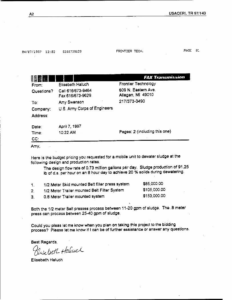
A2 USACERL TR 97/143
04/07/1997 12:02 6166739629 FRONTIER TECH. PAGE 01
FAX Transmission ss m mm n ^mm From: Elisebeth Haluch Frontier Technology
Questions? Call 616/673-9464 609 N. Eastern Ave. Fax 616/673-9629. Allegan, Ml 49010
To: Amy Swanson 217/373-3490
Company: U.S. Army Corps of Engineers
Address:
Date: April 7, 1997
Time: 10:22 AM Pages: 2 (including this one)
CC:
Amy,
Here is the budget pricing you requested for a mobile unit to dewater sludge at the following design and production rates.
The design flow rate of 0.73 million gallons per day. Sludge production of 91.25 lb of d.s. per hour on an 8 hour day to achieve 20 % solids during dewatering.
1. 1/2 Meter Skid mounted Belt filter press system $85,000.00
2. 1/2 Meter Trailer mounted Belt Filter System $105,000.00
3. 0.8 Meter Trailer mounted system $153,000.00
Both the 1/2 meter Belt presses process between 11-20 gpm of sludge. The .8 meter press can process between 25-40 gpm of sludge,
Could you pleas let me know when you plan on taking this project to the bidding process? Please let me know if I can be of further assistance or answer any questions.
Best Regards,
'^i^tfUuU. Elisebeth Haluch
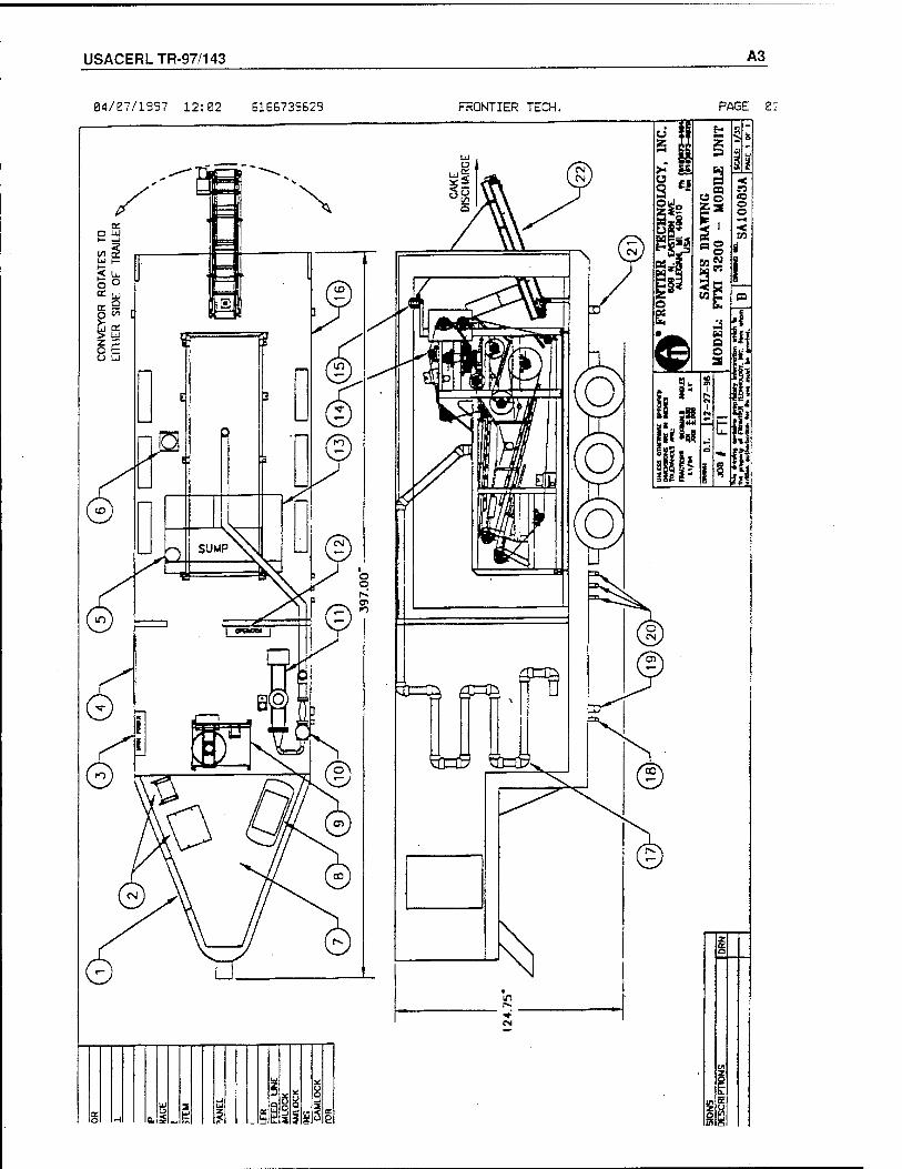
USACERLTR-97/143 A3
04/07/1997 12:02 B1BB739629 FRONTIER TECH. PAGE ß2
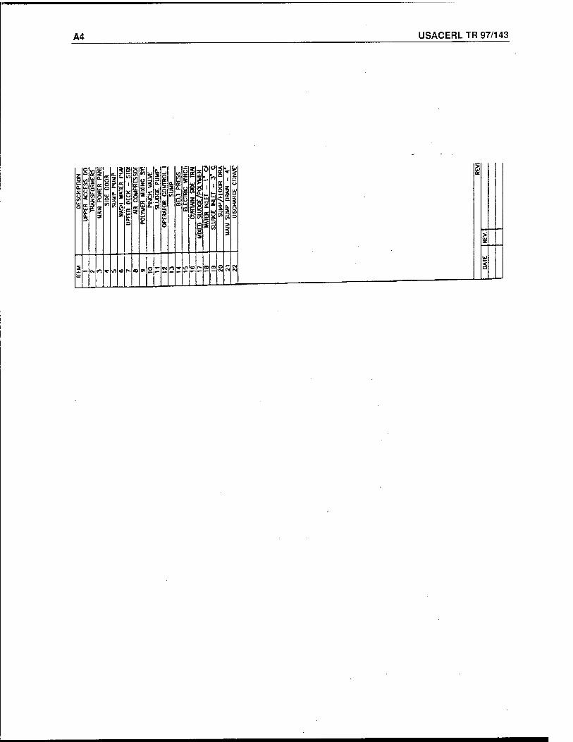
USACERL TR 97/143
a
<
A4
a. ' CL Si
a.
is:
j5; Zi
i ES:
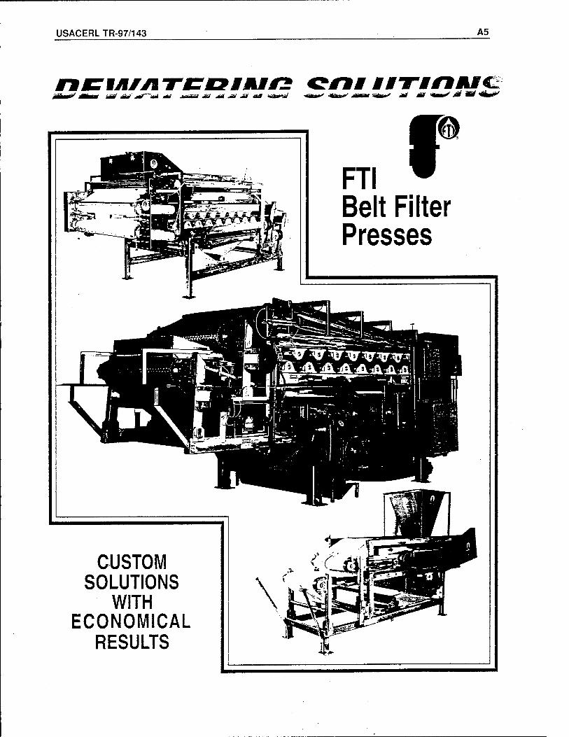
USACERLTR-97/143 A5
ÜMV m^/ £&' jtfr~ÜM MS nwVW *& <*t ^ M( Ä* *übß*iü -4^^y ^ftkiit"^ jütät0 ■ ** -tf «M** ^ ÄC
CUSTOM SOLUTIONS
WITH ECONOMICAL
RESULTS

A6 USACERL TR 97/143
While no two applications are identical, Frontier Technology, Inc. believes in taking an individual approach to your dewatering applications. Working together to go beyond the scope of original objectives with common sense engineering, keeping it simple, efficient and cost effective for capital purchase and operation.
Our broad experience over a wide range of dewatehng applications has allowed us to efficiently manufacture continuous dewatehng systems to the application for both process and sludge dewatehng.
Frontier Technology has made it possible for the highest quality equipment to be built at economical prices solving your dewatehng problems for the years to come.
THE COST EFFECTIVE SOLUTION FOR PR
DIFFERING APPROACHES TO EFFICIENT REMOVAL OF SLUDGES/SLURRIES
Frontier Technology, tailored Belt Press Dewatering Systems assures you of the right equipment for the application, no one model fits all applications. Time/pressure profiles are designed to meet the application and are adjustable to maximize performance, reducing the cake solids volume to be handled.
Water (moisture) in the sludge or slurry is held in different ways requiring different approaches to the efficient removal. Some applications will require polymers to break the bonding of the liquids/solids in the sludge/slurry, agglomerating the particles,
releasing the inter-cellular moisture and allowing the solids to be effectively dewatered. Many other applications however, will not require any polymer addition to be efficiently dewatered, this is much of the time with more fibrous sludges/slurries.
Frontier Technology, users can look forward to high throughput capacities with the highest cake solids, trouble-free operation requiring minimal maintenance, labor savings of continuous operation and superior reliability using the highest quality design and construction.
OUR FLEXIBLE CONSTRUCTION DESIGN ALLOWS FOR EASY ADAPTATION TO YOUR SPECIFIC REQUIREMENTS
INCLINED DRAINAGE SECTION
WEDGE SECTION
BELT HIGH PRESSURE
BELT WASH
HORIZONTAL DRAINAGE SECTION
WASH\^ Nlp SECT]ON
BELT WASH
INCREASING ROLL PRESSURE SECTION
rjY I profile is tailored for delicate sludge such r I Al as municipal sludge with low solids in the product feed, utilizing increased filtration area and time under pressure for low polymer use and highest cake solids.
WEDGE SECTION
BELT WASH DISCHARGE
FEED
rTry profile is tailored fcr higher solids in the I I t A slurry/sludge product stream and fibrous products which require very short drainage time, increased shear pressure to achieve maximum cake dryness.
FEED
HORIZONTAL DRAINAGE SECTION
WEDGE SECTION MEDIUM
PRESSURE ,„-„.„„„„ SECTION HIGH ™|SSURE
NIP SECTION
y BELT
WASH CAKE DISCHARGE
P"R A /p profile is designed for delicate product I I VV I dewatering over a wide range of applications with constant automatic pressure control with no shearing pressure applied to difficult- to-dewater product streams.
rTM n profile is used for solids that are not I I Mr pressure sensitive, dewater rapidly, and can accept nip pressure. Cantilever frame allows for the use of seamless belts which is crucial for high nip roll pressures.
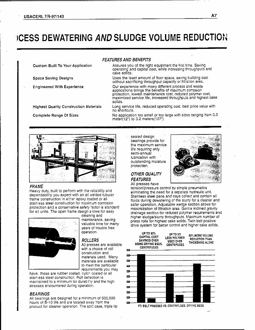
USACERLTR-97/143 A7
(CESS DEWATERING AND SLUDGE VOLUME REDUCTION
Custom Built To Your Application
Space Saving Designs
Engineered With Experience
Highest Quality Construction Materials
Complete Range Of Sizes
FEATURES AND BENEFITS Assures you of the right equipment the first time. Saving operating and capital cost, while increasing throughputs and cake solids. Uses the least amount of floor space, saving building cost without sacrificing throughput capacity or filtration area. Our experience with many different process and waste applications brings the benefits of maximum corrosion protection, lowest maintenance cost, reduced polymer cost, maximized service life, increased throughputs and highest cake solids. Long service life, reduced operating cost, best price value with no shortcuts. No application too small or too large with sizes ranging from 0.3 meter(12") to 3.2 meters(127")
FRAME Heavy duty, built to perform with the reliability and dependability you expect with an all welded tubular frame construction in either epoxy coated or all stainless steel construction for maximum corrosion protection and a conservative safety factor is standard for all units. The open frame design allows for easy
cleaning and maintenance, saving valuable time for many years of trouble free operation.
ROLLERS All presses are available with a choice of roll construction and materials used. Many materials are available to meet the particular requirements you may
have, these are rubber coated, nylon coated or all stainless steel construction. Roll deflection is maintained to a minimum for durability and the high stresses encountered during operation.
BEARINGS All bearings are designed for a minimum of 500,000 hours of B-10 life and are located away from the product for cleaner operation. The split case, triple lip
sealed design bearings provide for the maximum service life requiring only semi-annual lubrication with outstanding moisture protection.
OTHER QUALITY FEATURES All presses have tension/pressure control by simple pneumatics eliminating the need for a separate hydraulic unit. Stainless steel pans and trays collect and contain all fluids during dewatering of the slurry for a cleaner and safer operation. Adjustable wedge section allows for maximization of filtration area. Gentle inclined gravity drainage section for reduced polymer requirements and higher sludge/slurry throughputs. Maximum number of press rolls for highest cake solids. Twin belt positive drive system for better control and higher cake solids.
ES-
UPT0 90% CAPITAL COST SAVINGS OVER
USING DRYING BEDS, CENTRIFUGES
UP TO 2/3 LESS POLYMER USED OVER
CENTRIFUGES
50% MORE VOLUME REDUCTION THAN
THICKENING ALONE
FTI BELT PRESSES VS. CENTRIFUGES. DRYING BEDS
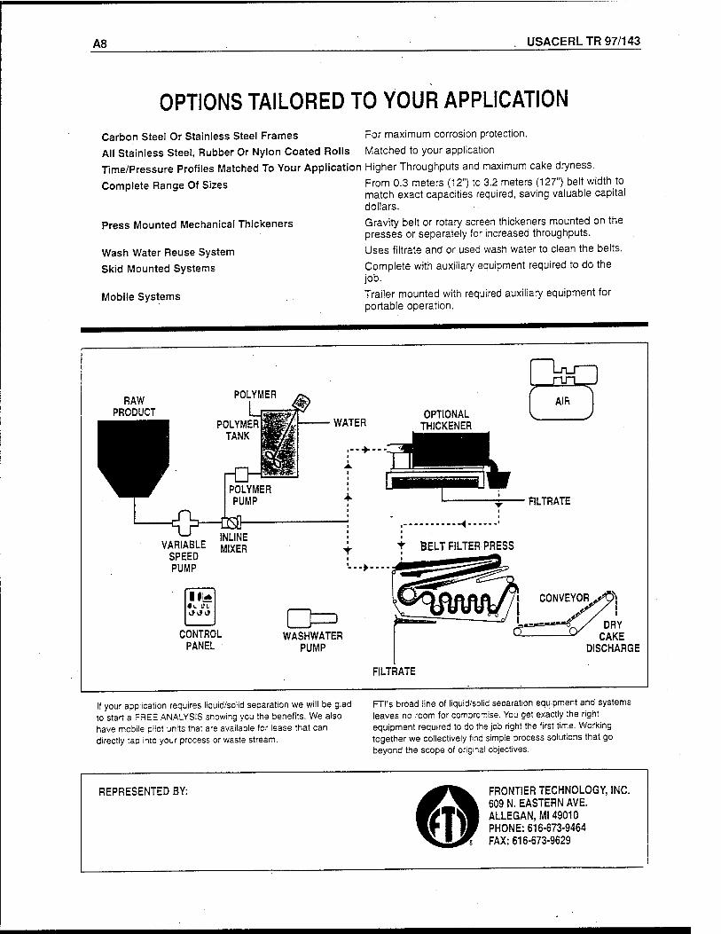
A8 USACERL TR 97/143
OPTIONS TAILORED TO YOUR APPLICATION
Carbon Stee! Or Stainless Steel Frames For maximum corrosion protection.
All Stainless Steel, Rubber Or Nylon Coated Rolls Matched to your application
Time/Pressure Profiles Matched To Your Application Higher Throughputs and maximum cake dryness.
Complete Range Of Sizes From 0.3 meters (12") to 3.2 meters (127") belt width to match exact capacities required, saving valuable capital dollars.
Gravity belt or rotary screen thickeners mounted on the presses or separately for increased throughputs.
Uses filtrate and or used wash water to clean the belts.
Complete with auxiliary equipment required to do the job.
Trailer mounted with required auxiliary equipment for portable operation.
Press Mounted Mechanical Thickeners
Wash Water Reuse System
Skid Mounted Systems
Mobile Systems
RAW PRODUCT
POLYMER
POLYMER TANK
rCH POLYMER
WATER OPTIONAL
THICKENER
■ --■►■■
PUMP
w IMI IM
SPEED PUMP
III* «V. til
CONTROL PANEL
0=3 WASHWATER
PUMP
FILTRATE
«
BELT FILTER PRESS
-►-■
DRY CAKE
DISCHARGE
FILTRATE
If your application requires liquid/solid separation we will be glad to start a FREE ANALYSIS showing you the benefits. We also have mobile pilot units that are available for lease that can directly tap into your process or waste stream.
FTI's broad line of liquid/solid separation equipment and systems leaves no room for compromise. You get exactly the right equipment required to do the job right the first time. Working together we collectively find simple process solutions that go beyond the scope of original objectives.
REPRESENTED BY: FRONTIER TECHNOLOGY, INC. 609 N. EASTERN AVE. ALLEGAN, Ml 49010 PHONE: 616-673-9464 FAX: 616-673-9629
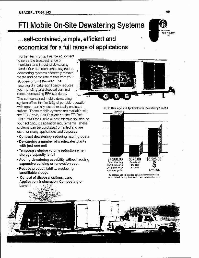
USACERLTR-97/143 A9
FTI Mobile On-Site Dewatering Systems IK- "*
...self-contained, simple, efficient and economical for a full range of applications Frontier Technology has the equipment to serve the broadest range of municipal and industrial dewatering needs. Our common sense engineered dewatering systems effectively remove waste and particulate matter from your sludge/slurry wastewater. The resulting dry cake significantly reduces your handling and disposal cost and meets demanding EPA standards.
The self-contained mobile dewatering system offers the flexibility of portable operation with open, partially closed or totally enclosed trailers. These mobile systems are available with the FTI Gravity Belt Thickener or the FTI Belt Filter Press for a simple, cost effective solution, to your solid/liquid separation requirements. These systems can be purchased or rented and are used for many applications and purposes:
• Contract dewatering- reducing hauling costs
• Dewatering a number of wastewater plants with just one unit
•Temporary sludge volume reduction when storage capacity is full
• Adding dewatering capability without adding expensive building or renovation cost
• Reduce product liability, producing landfillable sludge
• Control of disposal options, Land Application, Incineration, Composting or Landfill , % ' '
FRONTIER TECHNOLOGY
INC.
Liquid Hauling/Land Application vs. Dewatering/Landfill
87,200.00 $675.00 Cost of hauling Dewatered
90,000 gallons of and sent 2% sludge @ .08 to landfill cents per gallon
All cost savings are based on actual customer information and include all hauling, labor, tipping fees and chemical used.
$6,525.00
$ SAVINGS
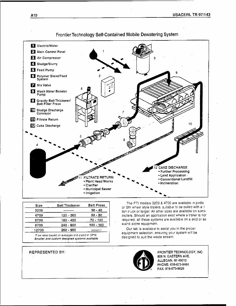
A10 USACERL TR 97/143
Frontier Technology Self-Contained Mobile Dewatering System
Q Electric/Water
H Main Control Panel
Fl Air Compresso
Q Sludge/Slurry
H Feed Pump
n Polymer Blend/Feed System
Q Mix Valve
13 Wash Water Booster Pump
Fl Gravity Belt Thickener/ Belt Filter Press
£fjj Sludge Discharge Conveyor
ED Fiitrate Return
E5 Cake Discharge
FILTRATE RETURN • Plant Head Works • Clarifier • Municipal Sewer • Irrigation
CAKE DISCHARGE • Further Processing • Land Application • Conventional Landfill • Incineration
Size Belt Thickener Belt Press
3200 30-40 4700 120-300 50-80
6700 180-450 70-120 8700 240 - 600 100-160
12700 360 - 950 Fiow rates based on averages and stated in GPM.
Smaller and custom designed systems available
The FTI models 3200 & 4700 are available in pintle or 5th wheel style trailers, suitable to be pulled with a 1 ton truck- or larger. All other sizes are available on semi- trailers. Should an application exist where a trailer is not required, all these systems are available on a skid,or as stand alone equipment.
Our lab is available to assist you in the proper equipment selection, ensuring your system will be designed to suit the waste stream.
REPRESENTED BY: FRONTIER TECHNOLOGY, INC. 609 N. EASTERN AVE. ALLEGAN, Ml 49010 PHONE: 616-673-9464 FAX: 616-673-9629
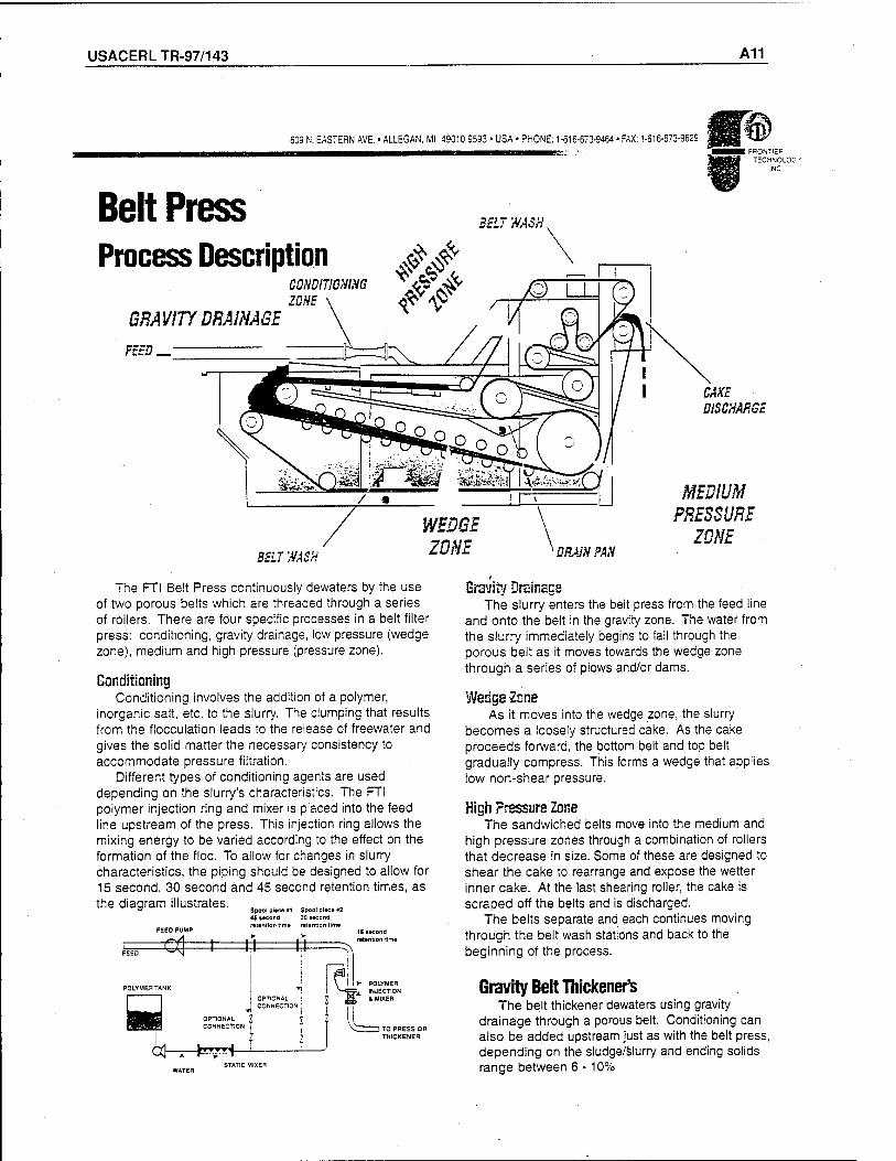
USACERLTR-97/143 A11
609 N. EASTERN AVE. • ALLEGAN, Ml 49010 9593 • USA • PHONE: 1-616-673-9464 • FAX: 1-616-673-9629
Belt Press Process Description
FRONTIEF
TECHNOLOG'
INC
BELT WASH.
GRAVITY DRAINAGE \
FEED_ "t=cj
CONDITIONING ^ <SfJ& ZONE x <T $ /-
BELT WASH
WEDGE ZONE
I CAKE DISCHARGE
MEDIUM PRESSURE
ZONE DRAIN PAN
The FTI Belt Press continuously dewaters by the use of two porous belts which are threaded through a series of rollers. There are four specific processes in a belt filter press: conditioning, gravity drainage, low pressure (wedge zone), medium and high pressure (pressure zone).
Conditioning Conditioning involves the addition of a polymer,
inorganic salt, etc. to the slurry. The clumping that results from the flocculation leads to the release of freewater and gives the solid matter the necessary consistency to accommodate pressure filtration.
Different types of conditioning agents are used depending on the slurry's characteristics. The FTI polymer injection ring and mixer is placed into the feed line upstream of the press. This injection ring allows the mixing energy to be varied according to the effect on the formation of the floe. To allow for changes in slurry characteristics, the piping should be designed to allow for 15 second, 30 second and 45 second retention times, as the diagram illustrates.
Spool piece '1 Spool pi«» »2 45 second 30 second retention time retention time
C(| I 1,1 #
POLYMERTANK
OPTIONAL CONNECTION
OPTIONAL ! ? CONNECTION ; J
15 second retention time
POLYMER Sx INJECTION
& MIXER
cd- TO PRESS OR THICKENER
STATIC MIXER
Gravity Drainage The slurry enters the belt press from the feed line
and onto the belt in the gravity zone. The water from the slurry immediately begins to fall through the porous belt as it moves towards the wedge zone through a series of plows and/or dams.
Wedge-Zone As it moves into the wedge zone, the slurry
becomes a loosely structured cake. As the cake proceeds forward, the bottom belt and top belt gradually compress. This forms a wedge that applies low non-shear pressure.
High Pressure Zone The sandwiched belts move into the medium and
high pressure zones through a combination of rollers that decrease in size. Some of these are designed to shear the cake to rearrange and expose the wetter inner cake. At the last shearing roller, the cake is scraped off the belts and is discharged.
The belts separate and each continues moving through the belt wash stations and back to the beginning of the process.
Gravity Belt Thickener's The belt thickener dewaters using gravity
drainage through a porous belt. Conditioning can also be added upstream just as with the belt press, depending on the sludge/slurry and ending solids range between 6 -10%
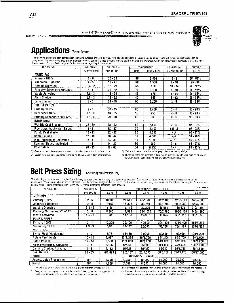
A12 USACERL TR 97/143
609 N. EASTERN AVE. • ALLEGAN, Ml 49010 9593 • USA • PHONE: 1-616-673-9464 • FAX: 1-616-673-9629
Applications
FRONTIER TECHNOLOGY
INC
Typical Results
The following sizes have been compiled for estimating purposes only and may vary for a specific application. Comparable or better results with similar sludges/slurries can be anticipated. We recommend a lab and/or pilot test, when the pertinent sludge or slurry exist, to confirm degree of dewaterability. polymer consumption, flow rates and capture rates. Please contact Frontier Technology for further information regarding those services.
APPLICATION
MUNICIPAL
AVG. FEED %
% DRY SOLIDS
TYP. CAKE %
DRY SOLIDS
THROUGHPUT POLYMER lbs/ CAPTURE
GPM Ibs/d.s./hr/M ton DRY SOLIDS Rate %
Primary 100% 2-6 26-38 80 2.400 4-6 96 - 98% Anaerobic Digested 2-5 18-26 60 1,500 7-10 96-98 Aerobic Digested 0.5-2 12-20 55 550 10-14 96 - 98% Primary/ Secondary 50%/50% 3-6 20-32 70 2.100 6-10 96 - 98% Waste Activated 1.5-3 16-24 45 675 8-14 96 - 98% Alum Sludge 1.5-3 16-22 40 600 5-12 96 - 98% Lime Sludge 3-5 38-45 50 1,250 2-5 96 - 98% PULP & PAPER Primary 100% 2-4 38-45 80 1.500 2-4 96 - 98% Secondary 100% 1.5-3 18-25 50 750 4-8 96 - 98% Primary/Secondary 50%/50% 1.5-3 20-30 60 900 3-6 96 - 98% INDUSTRIAL Wet Die Cast Sludge 28-30 78-82 50 7,600 2-4 95 - 97% Fiberglass Washwater Sludge 4-6 38-47 70 2.100 1.5-3 97 - 98% Potato Peel Waste 10-15 32-40 60 4.503 N/A 95 - 97% Cattle Paunch 12-16 36-44 50 4.000 N/A 94 - 96% Meat Processing, Activated 2-4 23-30 50 1.000 4-10 95 - 97% Canning Sludge. Activated 1 -3 14-22 60 900 3-6 95 - 97% Coal Refuse 20-35 60-68 '50 8.750 1 -4 95 - 97%
1) Cake solids and throughputs are based on
2! Design rates will vary in direct proportion
standard pressure roll configurations,
to differences in °'o feed concentration.
3) Yields will decrease with a higher proportion of secondary sludge.
4) Numbers listed are expected but can not be guaranteed as this is a function of sludge characteristics, concentration, etc. and other variables involved.
Belt Press Sizing Use for Approximation Only
The following sizes have been compiled for estimating purposes only and may vary for a specific application. Comparable or better results with s anticipated. We recommend a lab and/or pilot test, when the pertinent sludge of slurry exist, to confirm model to be used, degree of wewaterao: capture rates. Please contact Frontier Technology for further information regarding those services. , -
imilar sludges/slurries can be ity. polymer consumption, flow rates and
APPLICATION AVG. FEED %
DRY SOLIDS
THROUGHPUT - GPM/lbl. D.S. Hr.
0.3 m 0.5 m 0.8 m 1.2 m 1.7 m 2.2 m
MUNICIPAL Primary 100% 2-6 10/300 20/600 40/1,200 80/2.400 120/3,600 160/4,800 Anaerobic Digested 2-5 7/187 15/375 30/750 60/1.500 90/2.250 120/3,000 Aerobic Digested 0.5-2 6/56 13/112 27/225 55/550 80/825 110/1,100 Primary/ Secondary 50%/50% 3-6 8/260 17/525 35/1.050 70/2,100 105/3,150 140/4,200 Waste Activated 1.5-3 5/84 11/168 22/337 45/675 65/1.010 90/1,350 PULP & PAPER Primary 100% 2-4 10/200 20/400 40/800 80/1,600 120/2,400 160/3,200 Secondary 100% 1.5-3 6/93 12/187 25/375 50/750 75/1.125 100/1,500 INDUSTRIAL Swine Flush Wastewater 1 -2 7/75 15/150 30/300 60/600 90/900 120/1,200 Potato Peel Waste 10-15 7/687 15/1,375 30/2,750 60/4.500 90/6,750 120/9,000 Cattle Paunch 12-16 8/500 15/1.000 40/2,000 60/4.000 90/6.000 120/6,000 Meat Processing, Activated 2-4 6/125 12/250 25/500 50/1.000 75/1.500 100/2,000 Canning Sludge. Activated 1 -3 7/112 15/225 30/450 80/900 90/1,350 120/1,800 Coal Refuse 20-35 6/1.093 12/2.187 25/4.375 50/8.750 75/13,125 100/17,500 FOOD THROU GHPUT - in Lbs/H
Aoples. Juice Processing N/A 1.300 4.000 10,000 16.000 25,000 30,000 Relish N/A 1,000 3.000 6.500 10.000 14,000 19.000
"TP series of oresses is to oe used with a gravity thickener or Wedge Press.
■signs can vary m proportion to differences in -', leed concentration, desired cake :ds siunne.'Slurry to be oevvatered and existing planr eauipment
3) Fiow rates will decrease with a higher proportion of secondary sludge and model used.
4) Numbers listed are expected but can not be guaranteed as this is a function of sludge characteristics, concentration, etc. and other variables involved.
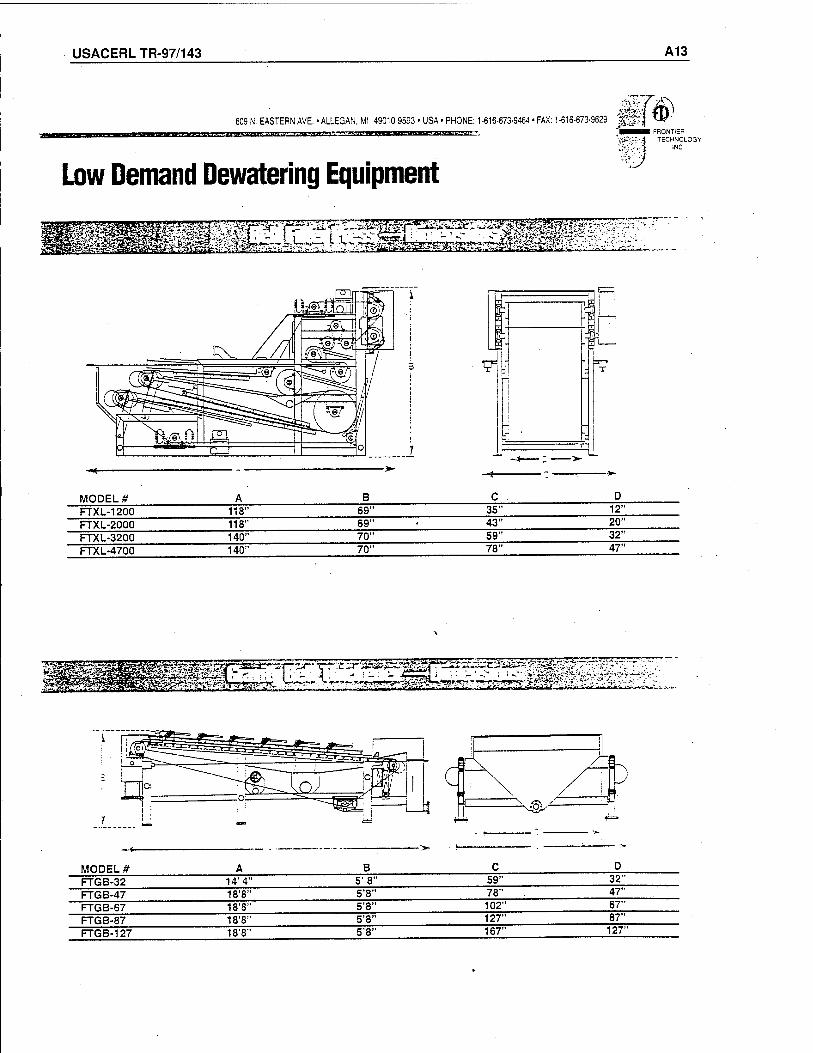
USACERLTR-97/143 A13
609 N. EASTERN AVE. • ALLEGAN, Ml 49010 9593 • USA -PHONE: 1-616-673-9464 • FAX: 1-616-673-9629 m Low Demand Dewatering Equipment
FRONTIER TECHNOLOGY
INC
u
MODEL* FTXL-1200 FTXL-2000 FTXL-3200 FTXL-4700
118" 118" 140" 140"
69" 69" 70" 70"
35" 43" 59" 78"
12" 20" 32" 47"
MODEL # FTGB-32 FTGB-47 FTGB-67 FTGB-87 FTGB-127
14' 4" 18'8" 18'8" 18'8" 18'8"
5'8" 5'8"
59" 78"
5'8" 102" 5'8" 127" 5'8" 167"
32" 47" 67" 87" 127"
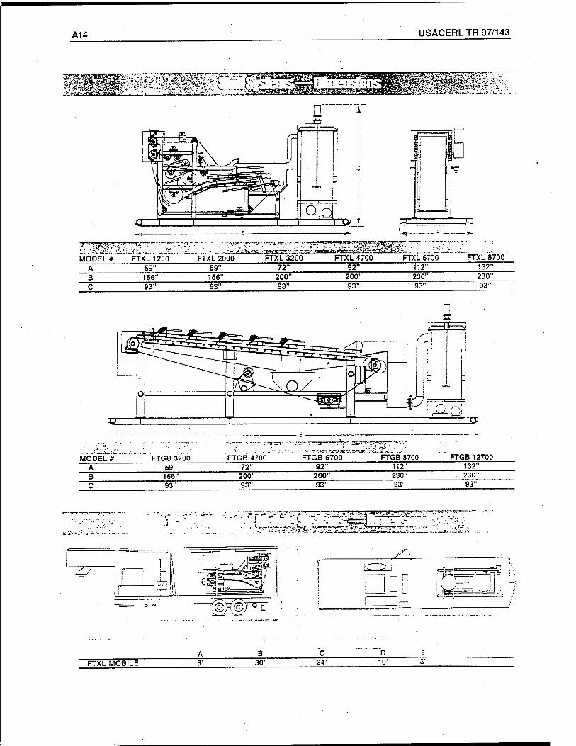
A14 USACERL TR 97/143
täS&tt%ms,
I n P flH
-
:j J
i L
j
=9
^ w
MODEL**
!15j»r3>t~5>-»^!EasP
FTXL 1200 FTXL 2000 FTOX320(f FTXL 4700 FTXL670"Ö" FTXL 8700
A 59" 59" 72" 92" 112" 132" B 166" 166" 200" 200" 230" 230" C 93" 93" 93" 93" 93" 93"
r_cp
?V--„.
MODEL*" '" FTG8 3200 FTGB4700~ FTGB 6700 -iiJSSL-i;
FTGB 8700 ' FTGB 12700 A . 59" 72" 92" 112" 132" B 166" 200" 200" 230" 230" C 93" 93" 93" 93" 93"
-.^..-^--^"^y .•"■■*--*■"»■?~ifk^,?yff!|reit*<T ^r~-~
"^K^T^T
FTXL MOBILE 30' 24' 10'
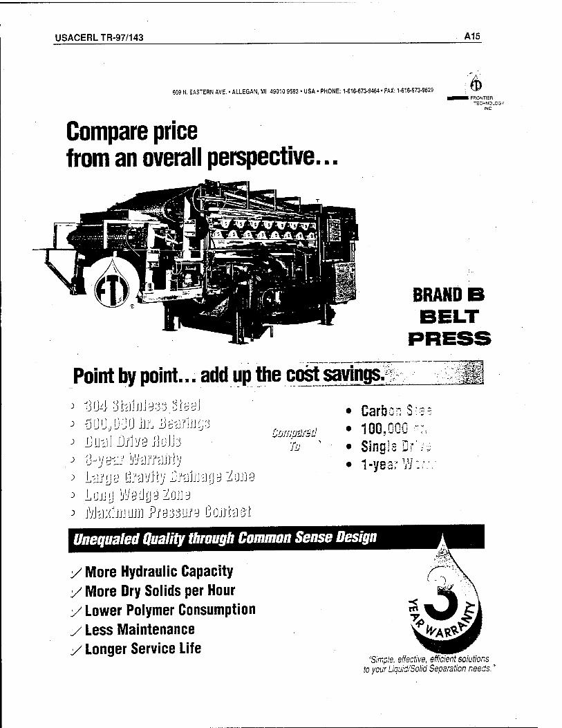
USACERLTR-97/143 A15
609 N. EASTERN AVE. • ALLEGAN, Ml 49010 9593 • USA • PHONE: 1-616-673-9464 • FAX: 1-616-673-9629 %■
I FRONTIER TECHNOLOGY
INC
Compare price from an overall perspective...
BRAND
Point by point... add up the cost savings.
J üU4 ShJjJjJys-j §lw\
Coifjpä/äd
■fü '
• Garbon S: • 100,000 - • Singla Dr' • 1-yearW:
Un equaled Quality through Common Sense Design
y More Hydraulic Capacity y More Dry Solids per Hour y Lower Polymer Consumption y Less Maintenance y Longer Service Life
"Simple, effective, efficient solutions to your Liquid/Solid Separation needs.
USACERLTR-97/143 B1
Appendix B: JWI J-Press
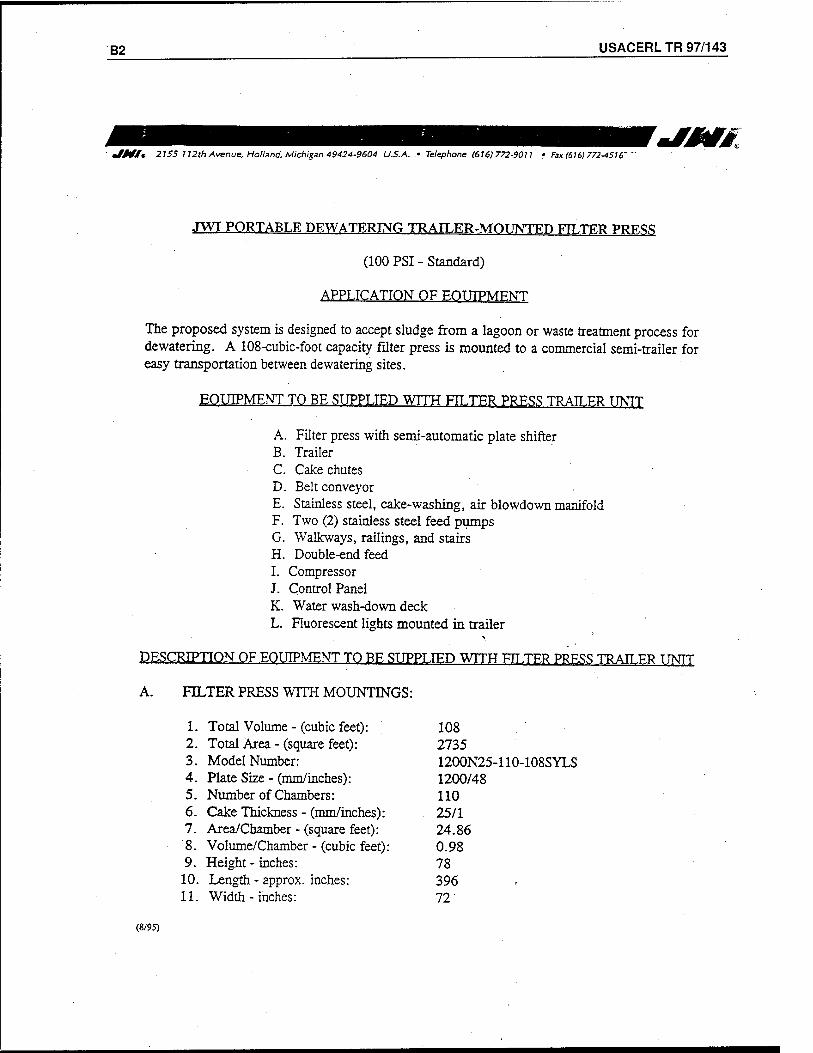
B2 USACERL TR 97/143
JMi* 21SS 112th Avenue, Holland, Michigan 49424-9604 U.S.A. • Telephone (616)772-9011 • Fax 1616) 772-4516'
JWI PORTABLE DEWATERING TRAILER-MOUNTED FTLTER PRESS
(100 PSI - Standard)
APPLICATION OF EOUTPMF.NT
The proposed system is designed to accept sludge from a lagoon or waste treatment process for dewatering. A 108-cubic-foot capacity filter press is mounted to a commercial semi-trailer for easy transportation between dewatering sites.
EQUIPMENT TO BE SUPPLIED WITH FITTER PRESS TRAILER TINTT
A. Filter press with semi-automatic plate shifter B. Trailer C. Cake chutes D. Belt conveyor E. Stainless steel, cake-washing, air blowdown manifold F. Two (2) stainless steel feed pumps G. Walkways, railings, and stairs H. Double-end feed I. Compressor J. Control Panel K. Water wash-down deck L. Fluorescent lights mounted in trailer
DESCRIPTION OF EQUIPMENT TO BE SUPPLIED WITH FILTER PRESS TRAILER TINTT
A. FILTER PRESS WITH MOUNTINGS:
1. Total Volume - (cubic feet): 108 2. Total Area - (square feet): 2735 3. Model Number: 1200N25-110-108SYLS 4. Plate Size - (mm/inches): 1200/48 5. Number of Chambers: 110 6. Cake Thickness - (mm/inches): 25/1 7. Area/Chamber - (square feet): 24.86 8. Volume/Chamber - (cubic feet): 0.98 9. Height - inches: 78
10. Length - approx. inches: 396 11. Width - inches: 72
(8/95)
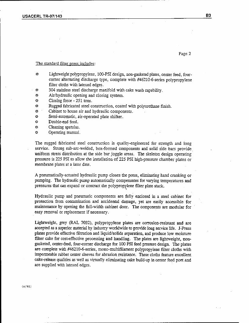
USACERLTR-97/143 B3
Page 2
The standard filter press includes:
«• Lightweight polypropylene, 100-PSI design, non-gasketed plates, center feed, four- corner alternating discharge type, complete with #46210-6-series polypropylene filter cloths with latexed edges.
$■ 304 stainless steel discharge manifold with cake wash capability. Ö- Air/hydraulic opening and closing system. Ü Closing force - 251 tons. & Rugged fabricated steel construction, coated with polyurethane finish. $■ Cabinet to house air and hydraulic components. # Semi-automatic, air-operated plate shifter. & Double-end feed. # Cleaning spatulas. if- Operating manual.
The rugged fabricated steel construction is quality-engineered for strength and long service. Strong sub-arc-welded, box-formed components and solid side bars provide uniform stress distribution at the side bar joggle areas. The skeleton design operating pressure is 225 PSI to allow the installation of 225 PSI high-pressure chamber plates or membrane plates at a later date.
A pneumatically-actuated hydraulic pump closes the press, eliminating hand cranking or pumping. The hydraulic pump automatically compensates for varying temperatures and pressures that can expand or contract the polypropylene filter plate stack.
Hydraulic pump and pneumatic components are fully enclosed in a steel cabinet for protection from contamination and accidental damage, yet are easily accessible for maintenance by opening the full-width cabinet door. The components are modular for easy removal or replacement if necessary.
Lightweight, grey (RAL 7032), polypropylene plates are corrosion-resistant and are accepted as a superior material by industry worldwide to provide long service life. J-Press plates provide effective filtration and liquid/solids separation, and produce low moisture filter cake for cost-effective processing and handling. The plates are lightweight, non- gasketed, center-feed, four-corner discharge for 100 PSI feed pressure design. The plates are complete with #46210-6-series, mono-multifilament polypropylene filter cloths with impermeable rubber center sleeves for abrasion resistance. These cloths feature excellent cake-release qualities as well as virtually eliminating cake build-up in center feed port and are supplied with latexed edges.
(8/9S)
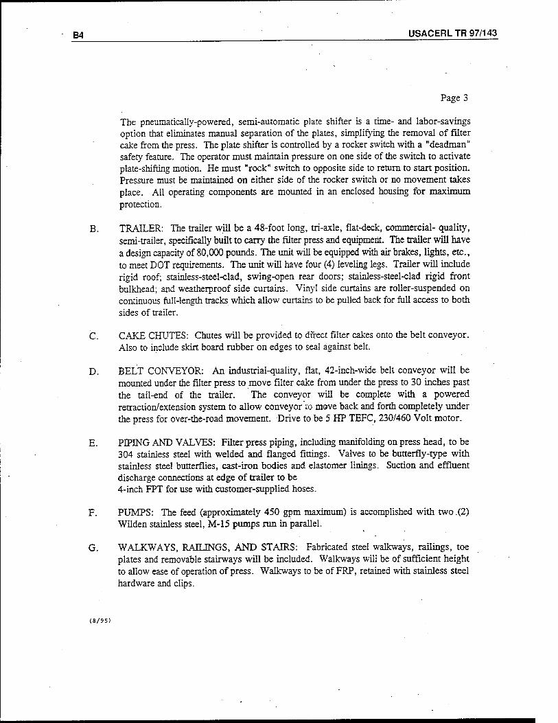
B4 USACERL TR 97/143
Page 3
The pneumatically-powered, semi-automatic plate shifter is a time- and labor-savings option that eliminates manual separation of the plates, simplifying the removal of filter cake from the press. The plate shifter is controlled by a rocker switch with a "deadman" safety feature. The operator must maintain pressure on one side of the switch to activate plate-shifting motion. He must "rock" switch to opposite side to return to start position. Pressure must be maintained on either side of the rocker switch or no movement takes place. All operating components are mounted in an enclosed housing for maximum protection.
B. TRAILER: The trailer will be a 48-foot long, tri-axle, flat-deck, commercial- quality, semi-trailer, specifically built to carry the filter press and equipment. The trailer will have a design capacity of 80,000 pounds. The unit will be equipped with air brakes, lights, etc., to meet DOT requirements. The unit will have four (4) leveling legs. Trailer will include rigid roof; stainless-steel-clad, swing-open rear doors; stainless-steel-clad rigid front bulkhead; and weatherproof side curtains. Vinyl side curtains are roller-suspended on continuous full-length tracks which allow curtains to be pulled back for full access to both sides of trailer.
C. CAKE CHUTES: Chutes will be provided to direct filter cakes onto the belt conveyor. Also to include skirt board rubber on edges to seal against belt.
D. BELT CONVEYOR: An industrial-quality, flat, 42-inch-wide belt conveyor will be mounted under the filter press to move filter cake from under the press to 30 inches past the tail-end of the trailer. The conveyor will be complete with a powered retraction/extension system to allow conveyor to move back and forth completely under the press for over-the-road movement. Drive to be 5 HP TEFC, 230/460 Volt motor.
E. PIPING AND VALVES: Filter press piping, including manifolding on press head, to be 304 stainless steel with welded and flanged fittings. Valves to be butterfly-type with stainless steel butterflies, cast-iron bodies and elastomer linings. Suction and effluent discharge connections at edge of trailer to be 4-inch FPT for use with customer-supplied hoses.
F. PUMPS: The feed (approximately 450 gpm maximum) is accomplished with two (2) Wilden stainless steel, M-15 pumps run in parallel.
G. WALKWAYS, RAILINGS, AND STAIRS: Fabricated steel walkways, railings, toe plates and removable stairways will be included. Walkways will be of sufficient height to allow ease of operation of press. Walkways to be of FRP, retained with stainless steel hardware and clips.
(8/95)
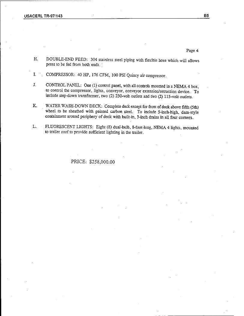
USACERLTR-97/143 B5
Page 4
H. DOUBLE-END FEED: 304 stainless steel piping with flexible hose which will allows press to be fed from both ends. '
I. COMPRESSOR: 40 HP, 176 CFM, 100 PSI Quincy air compressor.
J. CONTROL PANEL: One (1) control panel, with all controls mounted in a NEMA 4 box, to control the compressor, lights, conveyor, conveyor extension/retraction device. To include step-down transformer, two (2) 230-volt outlets and two (2) 115-volt outlets.
K. WATER WASH-DOWN DECK: Complete deck except for front of deck above fifth (5th) wheel to be sheathed with painted carbon steel. To include 5-inch-high, dam-style containment around periphery of deck with built-in, 3-inch drains in all four corners.
L. FLUORESCENT LIGHTS: Eight (8) dual-bulb, 8-foot-long, NEMA 4 lights, mounted to trailer roof to provide sufficient lighting in the trailer.
PRICE: $258,000.00
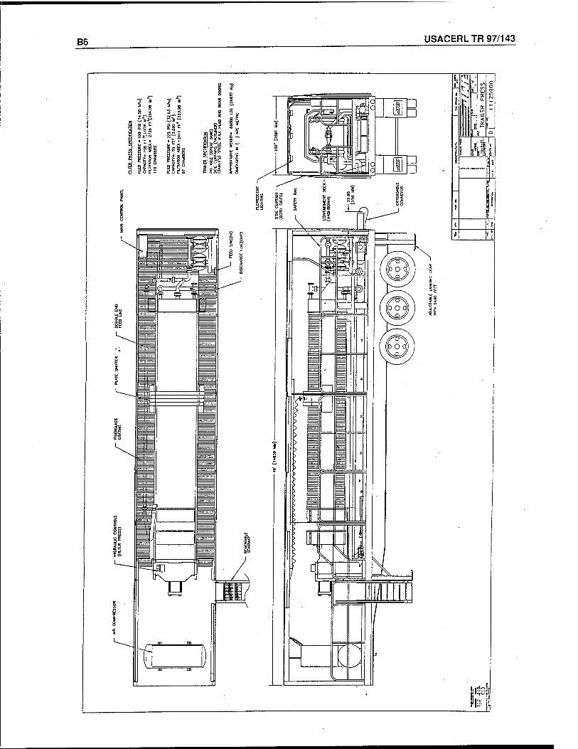
B6 USACERL TR 97/143
i_r
ifll
i.iüd|
JÜiLÜ
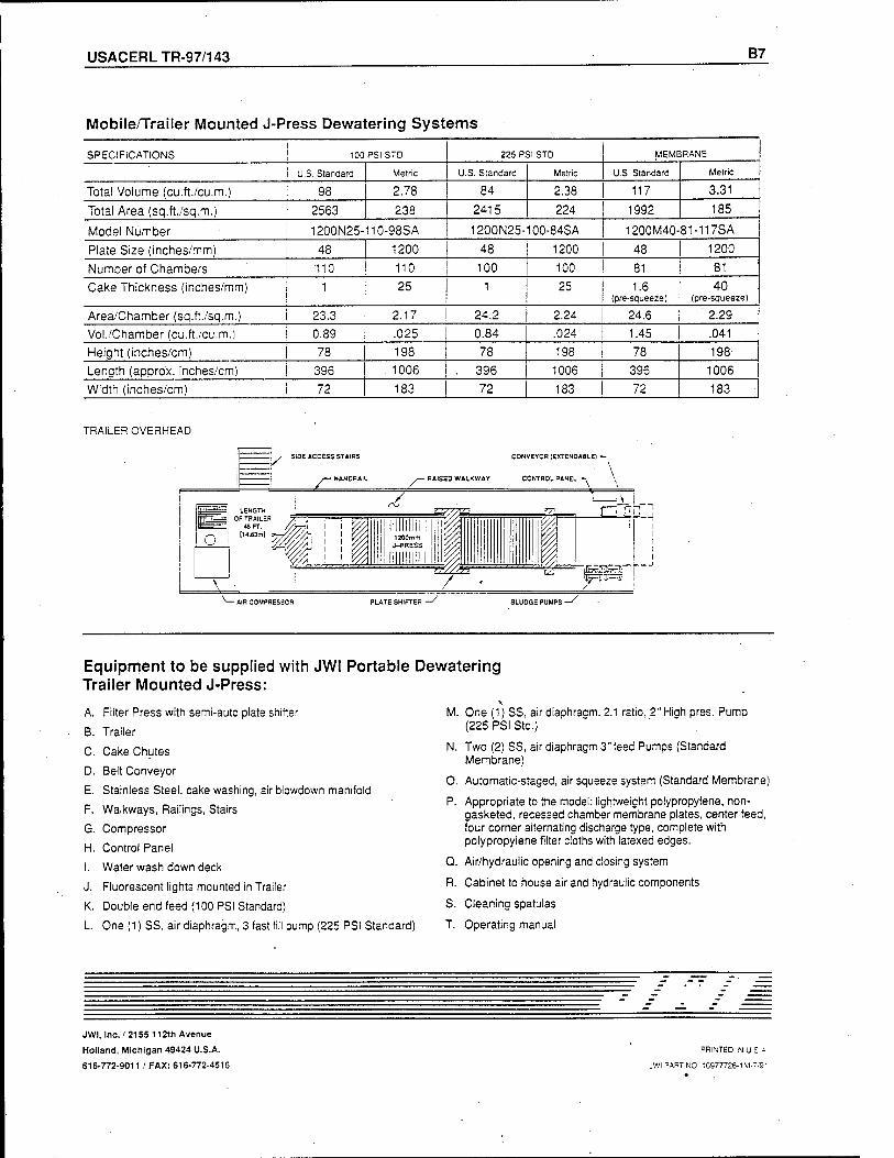
USACERLTR-97/143 B7
Mobile/Trailer Mounted J-Press Dewatering Systems
SPECIFICATIONS i I 100PSISTD 225 PSI STD MEMBRANE
| U.S. Standard | Metric U.S. Standard Metric U.S. Standard Metric
Total Volume (cu.ft./cu.m.) i 98 | 2.78 84 2.38 117 3.31
Total Area (sq.ft./sq.m.) i 2563 238 2415 224 1992 185
Model Number i 1200N25-110-98SA 1200N25-100-84SA 1200M40-81-117SA
Plate Size (inches/mm) i 48 1200 48 1200 48 1200
Number of Chambers i 110 110 100 100 81 81
Cake Thickness (inches/mm) j 1 25 1 25 1.6 (pre-squeeze)
40 (pre-squeeze)
Area/Chamber (sq.ft./sq.m.) I 23.3 2.17 24.2 2.24 24.6 2.29 Vol./Chamber (cu.ft./cu.m.) I 0.89 .025 0.84 .024 1.45 .041
Height (inches/cm) I 78 198 78 198 78 198 Length (appro'x. inches/cm) I 396 . 1006 . 396 1006 396 1006 Width (inches/cm) ! 72 183 72 183 72 183
TRAILER OVERHEAD
CONVEYOR {EXTENDABLE! -
-AIR COMPRESSOR PLATE SHIFTER SLUDGE PUMPS -
Equipment to be supplied with JWI Portable Dewatering Trailer Mounted J-Press:
A. Filter Press with semi-auto plate shifter
B. Trailer
C. Cake Chutes
D. Belt Conveyor
E. Stainless Steel, cake washing, air blowdown manifold
F. Walkways, Railings, Stairs
G. Compressor
H. Control Panel
I. Water wash down deck
J. Fluorescent lights mounted in Trailer
K. Double end feed (100 PSI Standard)
L. One (1) SS, air diaphragm, 3 fast fill pump (225 PSI Standard)
M. One (1) SS, air diaphragm. 2.1 ratio, 2"High pres. Pump (225PSIStd.)
N. Two (2) SS, air diaphragm 3"feed Pumps (Standard Membrane)
O. Automatic-staged, air squeeze system (Standard Membrane)
P. Appropriate to the model: lightweight polypropylene, non- gasketed, recessed chamber membrane plates, center feed, four corner alternating discharge type, complete with polypropylene filter cloths with latexed edges.
Q. Air/hydraulic opening and closing system
R. Cabinet to house air and hydraulic components
S. Cleaning spatulas
T Operating manual
JWI, Inc. / 2155 112th Avenue
Holland, Michigan 49424 U.S.A.
616-772-9011 / FAX: 616-772-4516
PRINTED INU Si
JWI PART NO 10977726-1M-7/9"
USACERLTR-97/143 C1
Appendix C: Sharpies Centrifuge
C2 USACERL TR 97/143
Phone Conversation
Company: Sharpies
Contact Person: Ron Moody
phone #: (630) 571-6120
date: 3/20/97
The Sharpies PM-38000 was recommended for the Western Corridor's needs. It has a capacity of 50 gpm. The centrifuge costs $160,000. A trailer, which would include the feed pumps, polymer system, conveyors, etc., is an additional
$250,000.
USACERLTR-97/143 C3
Alfa Laval and Sharpies Leaders in Advanced Separation Technology
Alfa Laval and Sharpies products have been on the leading edge of sep- aration technology for over 100 years each, establishing themselves as the dominant powers in the world market. By joining forces, the largest and most advanced separation company in the world was created — unmatched in applications experience, technical expertise, product quality and service. Our products represent the state of the art in separation technology. We manufacture the most versatile cen- trifuge line available today.
Wastewater Treatment and the Environment
For over 30 years. Sharpies prod- ucts have provided wastewater treat- ment technology that not only meets the current needs of an expanding population but anticipates future envi- ronmental controls. Using new and innovative separation technologies, we have achieved the highest levels of wastewater treatment efficiency and cost effectiveness. We offer the high-performance alternative to older, less effective treatment methods.
Alfa Laval and Sharpies® 300.000 square foot factory in Wanninster. PA.
Sharpies® .-.;•* v-tv^i'
.. . . •&:•'
Sharpies Global Product Center and headquarters in Wanninster. PA.
Sharpies wastewater and potable water installa- tions in North America.
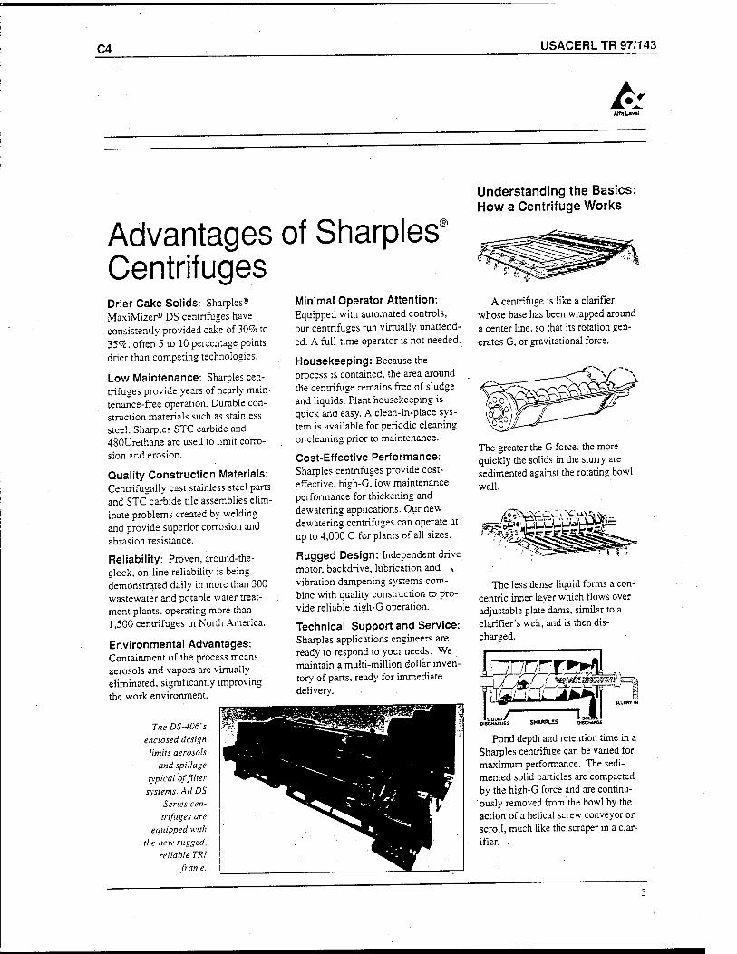
C4 USACERL TR 97/143
AKaUval
Advantages of Sharpies Centrifuges
Understanding the Basics: How a Centrifuge Works
Drier Cake Solids: Sharpies® MaxiMizer® DS centrifuges have consistently provided cake of 30% to 359c often 5 to 10 percentage points drier than competing technologies.
Low Maintenance: Sharpies cen- trifuges provide years of nearly main- tenance-free operation. Durable con- struction materials such as stainless steel, Sharpies STC carbide and 480Urethane are used to limit corro- sion and erosion.
Quality Construction Materials: Centrifugally cast stainless steel parts and STC carbide tile assemblies elim- inate problems created by welding and provide superior corrosion and abrasion resistance.
Reliability: Proven, around-the- clock, on-line reliability is being demonstrated daily in more than 300 wastewater and potable water treat- ment plants, operating more than 1,500 centrifuges in North America.
Environmental Advantages: Containment of the process means aerosols and vapors are virtually eliminated, significantly improving the work environment.
The DS-406's enclosed design
limits aerosols and spillage
typical of filter systems. All DS
Series cen- trifuges are
equipped with the new rugged,
reliable TRl frame.
Minimal Operator Attention: Equipped with automated controls, our centrifuges run virtually unattend- ed. A full-time operator is not needed.
Housekeeping: Because the process is contained, the area around the centrifuge remains free of sludge and liquids. Plant housekeeping is quick and easy. A clean-in-place sys- tem is available for periodic cleaning or cleaning prior to maintenance.
Cost-Effective Performance: Sharpies centrifuges provide cost- effective, high-G, low maintenance performance for thickening and dewatering applications. Our new dewatering centrifuges can operate at up to 4,000 G for plants of all sizes.
Rugged Design: Independent drive motor, backdrive, lubrication and , vibration dampening systems com- bine with quality construction to pro- vide reliable high-G operation.
Technical Support and Service: Sharpies applications engineers are ready to respond to your needs. We maintain a multi-million dollar inven- tory of pans, ready for immediate delivery.
A centrifuge is like a clarifier whose base has been wrapped around a center line, so that its rotation gen- erates G, or gravitational force.
The greater the G force, the more quickly the solids in the slurry are sedimented against the rotating bowl wall.
r^*ii3 iCysssssg'
The less dense liquid forms a con- centric inner layer which flows over adjustable plate dams, similar to a clarifier's weir, and is then dis- charged.
J /ügasssBässagai'■
SHARPUS oiscmwcE
Pond depth and retention time in a Sharpies centrifuge can be varied for maximum performance. The sedi- mented solid particles are compacted by the high-G force and are continu- ously removed from the bowl by the action of a helical screw conveyor or scroll, much like the scraper in a clar- ifier.
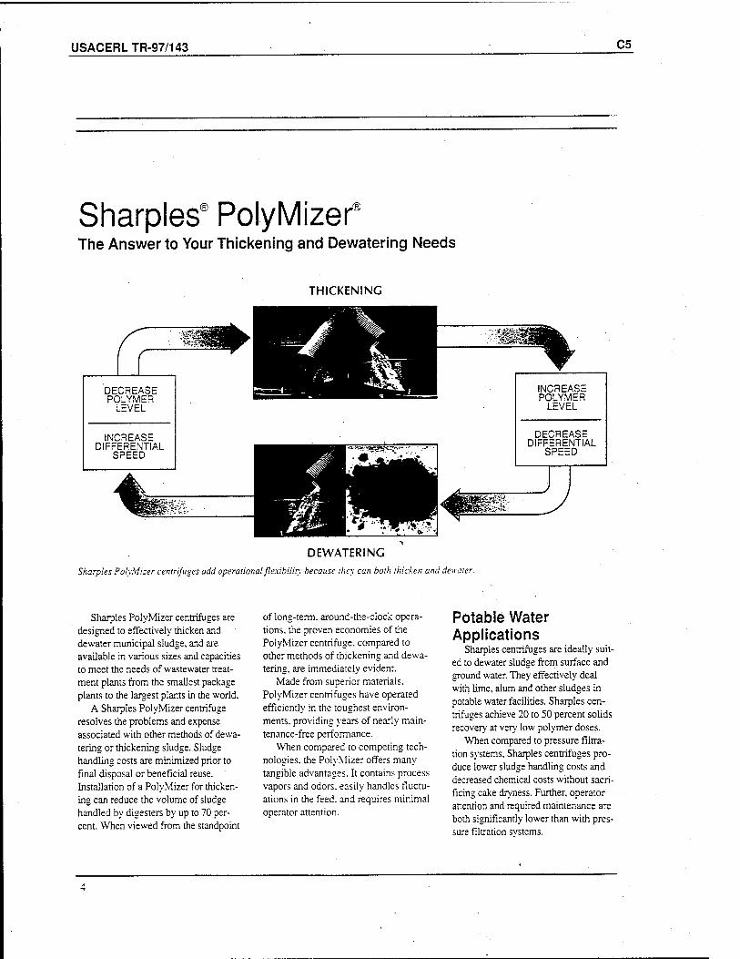
USACERLTR-97/143 C5
Sharpies" PolyMizer8
The Answer to Your Thickening and Dewatering Needs
THICKENING
:'ü
DECREASE POLYMER
LEVEL
INCREASE DIFFERENTIAL
SPEED
INCREASE POLYMER
LEVEL
DECREASE DIFFERENTIAL
SPEED
DEWATERING
Sharpies PolyMizer centrifuges add operational flexibility because they can both thicken and dewater.
Sharpies PolyMizer centrifuges are designed to effectively thicken and dewater municipal sludge, and are available in various sizes and capacities to meet the needs of wastewater treat- ment plants from the smallest package plants to the largest plants in the world.
A Sharpies PolyMizer centrifuge resolves the problems and expense associated with other methods of dewa- tering or thickening sludge. Sludge handling costs are minimized prior to final disposal or beneficial reuse. Installation of a PolyMizer for thicken- ing can reduce the volume of sludge handled by digesters by up to 70 per- cent. When viewed from the standpoint
of long-term, around-the-clock opera- tions, the proven economies of the PolyMizer centrifuge, compared to other methods of thickening and dewa- tering, are immediately evident.
Made from superior materials. PolyMizer centrifuges have operated efficiently in the toughest environ- ments, providing years of nearly main- tenance-free performance.
When compared to competing tech- nologies, the PolyMizer offers many tangible advantages. It contains process vapors and odors, easily handles fluctu- ations in the feed, and requires minimal operator attention.
Potable Water Applications
Sharpies centrifuges are ideally suit- ed to dewater sludge from surface and ground water. They effectively deal with lime, alum and other sludges in potable water facilities. Sharpies cen- trifuges achieve 20 to 50 percent solids recovery at very low polymer doses.
When compared to pressure filtra- tion systems, Sharpies centrifuges pro- duce lower sludge handling costs and decreased chemical costs without sacri- ficing cake dryness. Further, operator attention and required maintenance are both significantly lower than with pres- sure filtration systems.
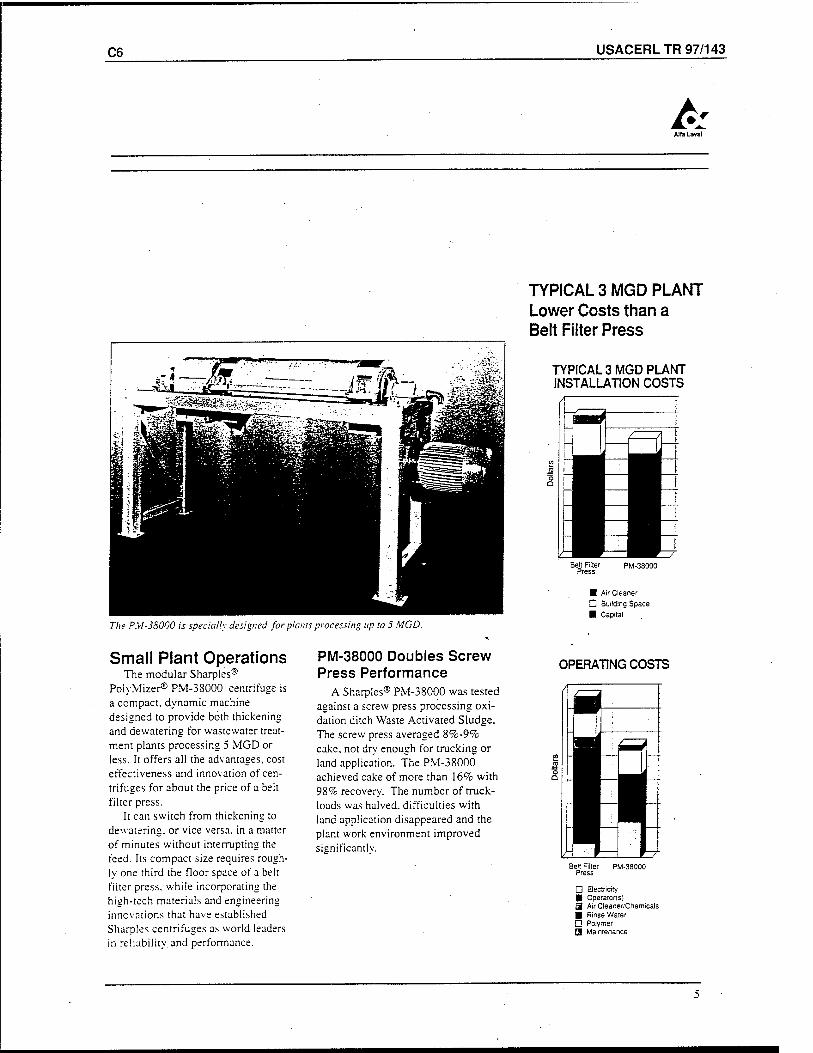
C6 USACERL TR 97/143
Alfa Lava]
The P.V1-38000 is specially designed for plants processing up to 5 MGD.
Small Plant Operations The modular Sharpies®
PolyMizer® PM-38000 centrifuge is a compact, dynamic machine designed to provide both thickening and dewatering for wastewater treat- ment plants processing 5 MGD or less. It offers all the advantages, cost effectiveness and innovation of cen- trifuges for about the price of a belt filter press.
It can switch from thickening to dewatering. or vice versa, in a matter of minutes without interrupting the feed. Its compact size requires rough- ly one third the floor space of a belt filter press, while incorporating the high-tech materials and engineering innovations that have established Sharpies centrifuges as world leaders in reliability and performance.
PM-38000 Doubles Screw Press Performance
A Sharpies® PM-38000 was tested against a screw press processing oxi- dation ditch Waste Activated Sludge. The screw press averaged 8%-9% cake, not dry enough for trucking or land application. The PM-38000 achieved cake of more than 16% with 98% recovery. The number of truck- loads was halved, difficulties with land application disappeared and the plant work environment improved sianificantlv.
TYPICAL 3 MGD PLANT Lower Costs than a Belt Filter Press
TYPICAL 3 MGD PLANT INSTALLATION COSTS
PM-38000
■ Air Cleaner D Building Space ■ Capital
OPERATING COSTS
Belt Filter PM-38000 Press
n Electricity ■ Ooerator(s) 3 Air Cleaner/Chemicals ■ Rinse Water □ Polymer 3 Maintenance
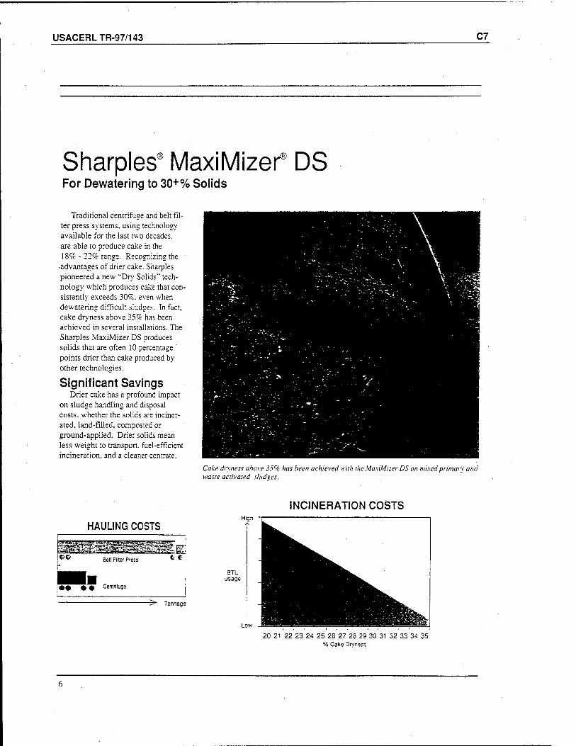
USACERLTR-97/143 C7
Sharpies9 MaxiMizef DS For Dewatering to 30+% Solids
Traditional centrifuge and belt fil- ter press systems, using technology available for the last two decades, are able to produce cake in the 18% - 22% range. Recognizing the
•advantages of drier cake. Sharpies pioneered a new "Dry Solids" tech- nology which produces cake that con- sistently exceeds 30%. even when dewatering difficult sludges. In fact, cake dryness above 35% has been achieved in several installations. The Sharpies MaxiMizer DS produces solids that are often 10 percentage ' points drier than cake produced by other technologies.
Significant Savings Drier cake has a profound impact
on sludge handling and disposal costs, whether the solids are inciner- ated, land-filled, composted or ground-applied. Drier solids mean less weight to transport, fuel-efficient incineration, and a cleaner centrate.
Cake dryness above 35% has been achieved with the MaxiMizer DS on mixed primary and waste activated slud°es.
HAULING COSTS
OG Bell Filter Press
Centrifuge
t- e
-5" Tonnage
INCINERATION COSTS
20 21 22 23 24 25 26 27 28 29 30 31 32 33 34 35 % Cake Dryness
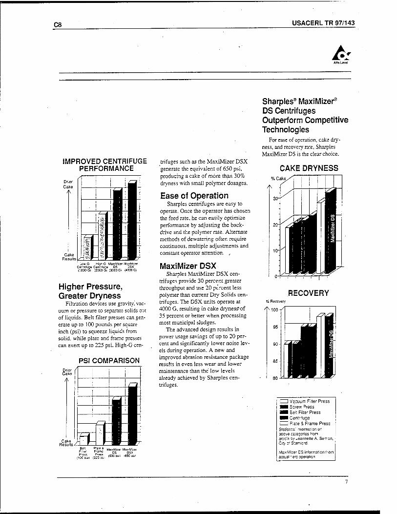
C8 USACERL TR 97/143
A
IMPROVED CENTRIFUGE PERFORMANCE
Low-G Hign-G MaxiMizer MaxiMizer Centrifuge Centnfuge DS DSX (1000 G) (2000 G) (3000 G) (4000 G)
Higher Pressure, Greater Dryness
Filtration devices use gravity, vac- uum or pressure to separate solids out of liquids. Belt filter presses can gen- erate up to 100 pounds per square inch (psi) to squeeze liquids from solid, while plate and frame presses can exert up to 225 psi. High-G cen-
PSI COMPARISON
Cake /-, Results/ 1
triftiges such as the MaxiMizer DSX generate the equivalent of 650 psi, producing a cake of more than 30% dryness with small polymer dosages.
Ease of Operation Sharpies centrifuges are easy to
operate. Once the operator has chosen the feed rate, he can easily optimize performance by adjusting the back- drive and the polymer rate. Alternate methods of dewatering often require continuous, multiple adjustments and constant operator attention. r
MaxiMizer DSX Sharpies MaxiMizer DSX cen-
trifuges provide 30 percent greater throughput and use 20 percent less polymer than current Dry Solids cen- trifuges. The DSX units operate at 4000 G, resulting in cake dryness'of 35 percent or better when processing most municipal sludges.
The advanced design results in power usage savings of up to 20 per- cent and significantly lower noise lev- els during operation. A new and improved abrasion resistance package results in even less wear and lower maintenance than the low levels already achieved by Sharpies cen- trifuges.
Sharpies® MaxiMizer® DS Centrifuges Outperform Competitive Technologies
For ease of operation, cake dry- ness, and recovery rate, Sharpies MaxiMizer DS is the clear choice.
CAKE DRYNESS % Cake
RECOVERY Recovery
Beit Plate & Filter F'ame
(100 DS«) (225 psil
MaxiMizer ManMizer DS DSX
(500 OSi) (650 psil
I I Vacuum Filter Press ■■ Screw Press ■1 Belt Filter Press ■■ Centrifuge ' Piate & Frame Press Statistical information on aoove categories from article oy Jeannerte A. Semon. City of Stamford.
MaxiMizer DS information from actual field ooeration.
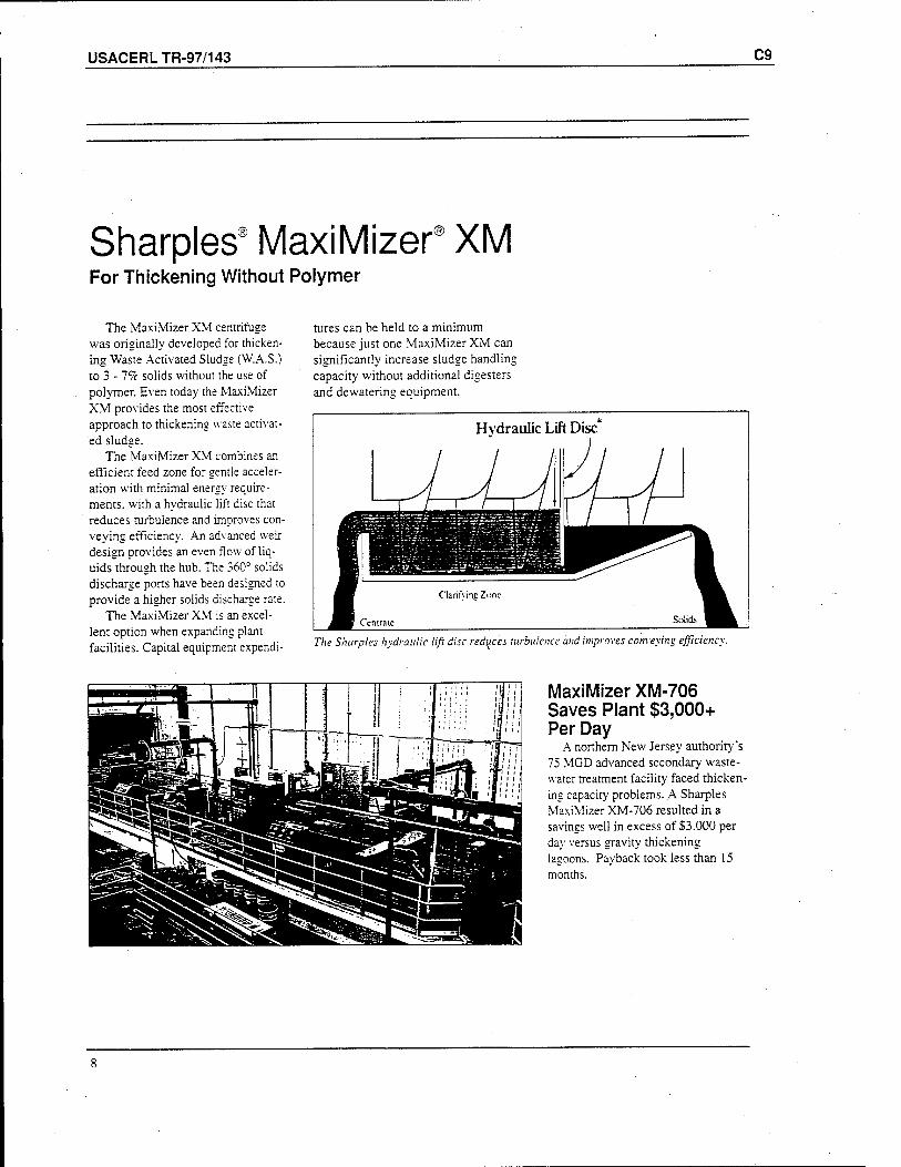
USACERLTR-97/143 C9
Sharpies' MaxiMizer XM For Thickening Without Polymer
The MaxiMizer XM centrifuge was originally developed for thicken- ing Waste Activated Sludge (W.A.S.) to 3 -1% solids without the use of polymer. Even today the MaxiMizer XM provides the most effective approach to thickening waste activat- ed sludge.
The MaxiMizer XM combines an efficient feed zone for gentle acceler- ation with minimal energy require- ments, with a hydraulic lift disc that reduces turbulence and improves con- veying efficiency. An advanced weir design provides an even flow of liq- uids through the hub. The 360° solids discharge ports have been designed to provide a higher solids discharge rate.
The MaxiMizer XM is an excel- lent option when expanding plant facilities. Capital equipment expendi-
tures can be held to a minimum because just one MaxiMizer XM can significantly increase sludge handling capacity without additional digesters and dewatering equipment.
Hydraulic Lift Disc
1 JJ\\JJJ_ / 1 / U
^KL < "cntraic
Clarifying Zone
Solids B^
The Sharpies hydraulic lift disc reduces turbulence and improves conveying efficiency.
MaxiMizer XM-706 Saves Plant $3,000+ Per Day
A northern New Jersey authority's 75 MGD advanced secondary waste- water treatment facility faced thicken- ing capacity problems. A Sharpies MaxiMizer XM-706 resulted in a savings well in excess of S3.000 per day versus gravity thickening lagoons. Payback took less than 15 months.
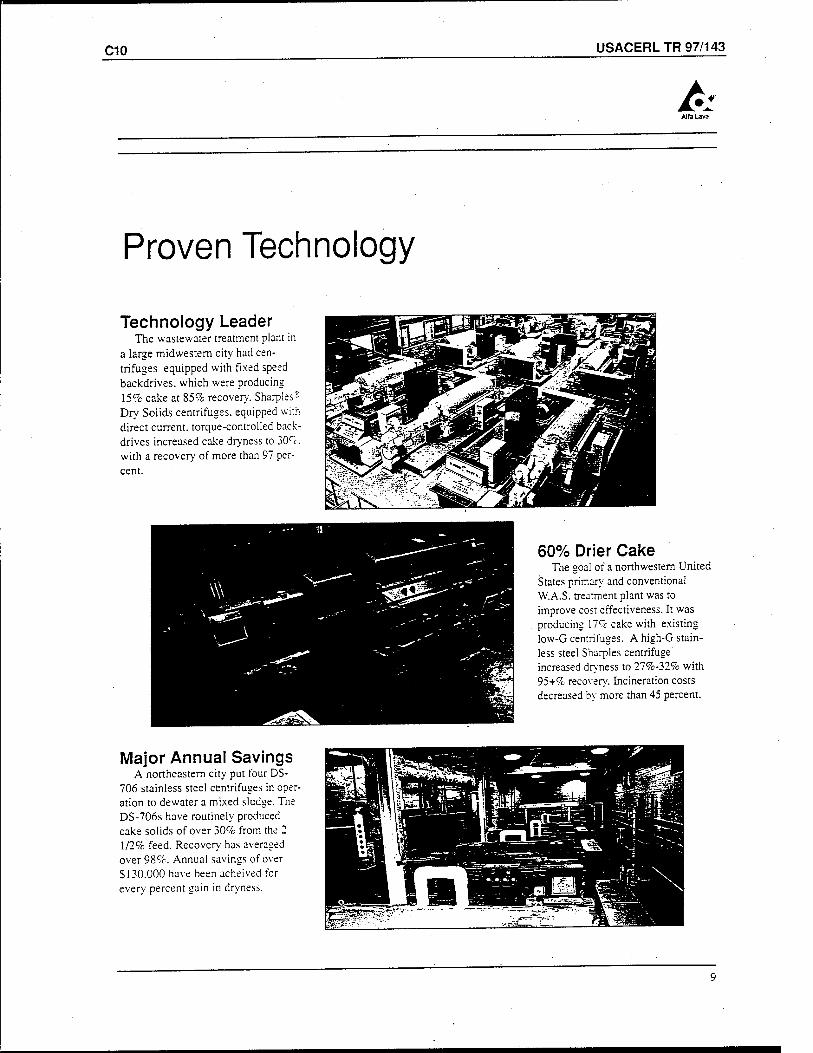
C10 USACERL TR 97/143
A
Proven Technology
Technology Leader The wastewater treatment plant in
a large midwestem city had cen- trifuges equipped with fixed speed backdrives. which were producing 15% cake at 85% recovery. Sharpies5
Dry Solids centrifuges, equipped with direct current, torque-controlled back- drives increased cake dryness to 30<~c. with a recovery of more than 97 per- cent.
60% Drier Cake The goal of a northwestern United
States primary and conventional W.A.S. treatment plant was to improve cost effectiveness. It was producing 17% cake with existing low-G centrifuges. A high-G stain- less steel Sharpies centrifuge increased dryness to 27%-32% with 95+% recovery. Incineration costs decreased by more than 45 percent.
Major Annual Savings A northeastern city put four DS-
706 stainless steel centrifuges in oper- ation to dewater a mixed sludge. The DS-706s have routinely produced cake solids of over 30% from the 2 1/2% feed. Recovery has averaged over 98%. Annual savings of over S130.000 have been acheived for every percent gain in dryness.
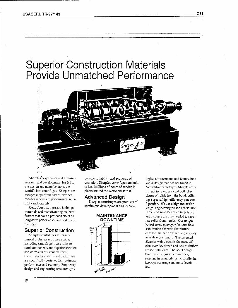
USACERLTR-97/143 C11
Superior Construction Materials Provide Unmatched Performance
Sharpies® experience and extensive research and development, has led to the design and manufacture of the world's best centrifuges. Sharpies cen- trifuges outperform competitive cen- trifuges in terms of performance, relia- bility and long life.
Centrifuges vary greatly in design, materials and manufacturing methods, factors that have a profound effect on long-term performance and cost effec- tiveness.
Superior Construction Sharpies centrifuges are unsur-
passed in design and construction. including centrifugally cast stainless steel components and superior abrasion and corrosion resistant materials. Proven starter systems and backdrives are specifically designed for maximum performance and economy. Proprietary desisn and enaineerina breakthroushs
provide reliability and economy of operation. Sharpies centrifuges are built to last. Millions of hours of service in plants around the world attest to it.
Advanced Design Sharpies centrifuges are products of
continuous development and techno-
MAINTENANCE DOWNTIME
*^v-
logical advancement, and feature inno- vative design features not found in competitive centrifuges. Sharpies cen- trifuges have unrestricted 360° dis- charge of solids from the bowl, utiliz- ing a special high-efficiency port con- figuration. We use a high molecular weight engineering plastic accelerator in the feed zone to reduce turbulence and decrease the time needed to sepa- rate solids from liquids. Our unique helical screw conveyor features flow stabilization channels that further enhance laminer flow and allow solids to settle more rapidly. The patented Sharpies weir design is the most effi- cient ever developed and acts to further reduce turbulence. The bowl design keeps protrusions to a minimum, resulting in an aerodynamic profile that keeps power usage and noise levels low.
10
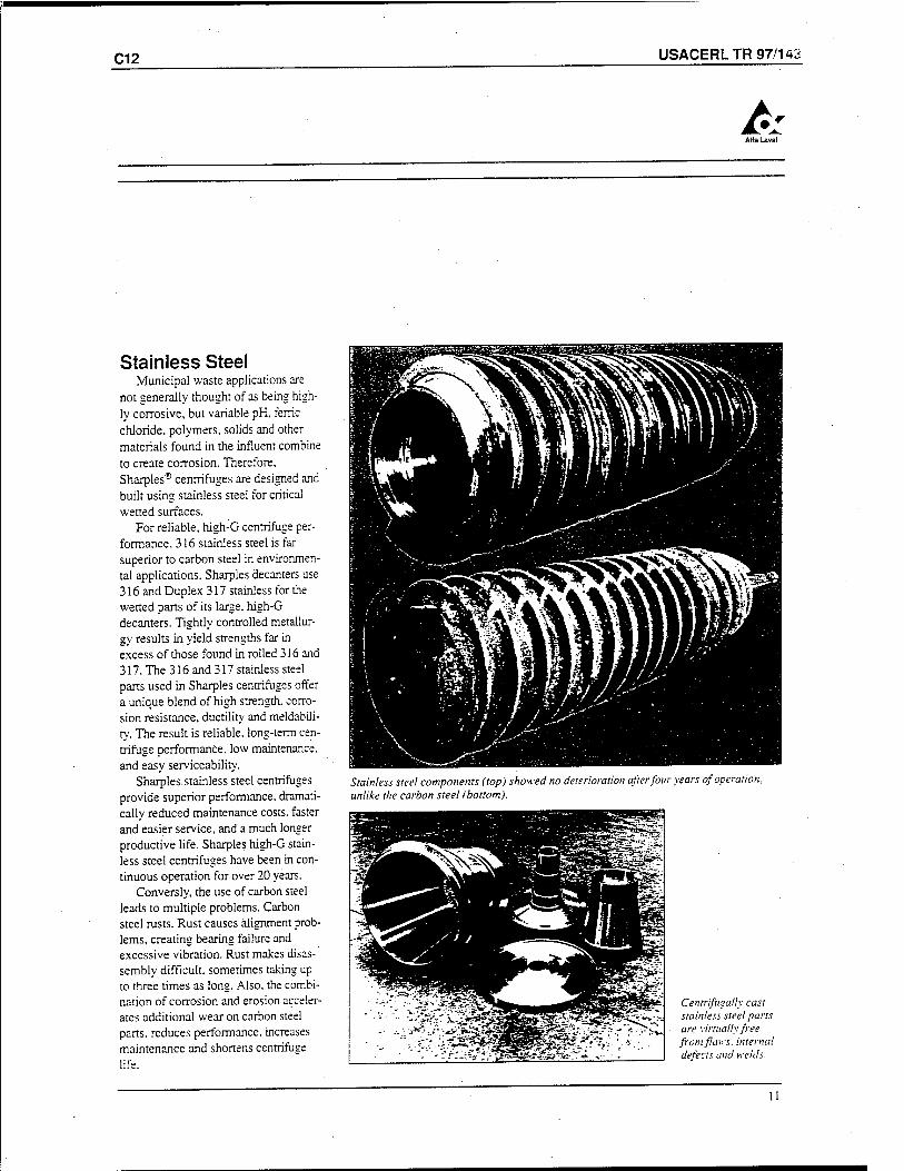
C12 USACERL TR 97/143
A
Stainless Steel Municipal waste applications are
not generally thought of as being high- ly corrosive, but variable pH, ferric chloride, polymers, solids and other materials found in the influent combine to create corrosion. Therefore, Sharpies® centrifuges are designed and built using stainless steel for critical wetted surfaces.
For reliable, high-G centrifuge per- formance, 316 stainless steel is far superior to carbon steel in environmen- tal applications. Sharpies decanters use 316 and Duplex 317 stainless for the wetted parts of its large, high-G decanters. Tightly controlled metallur- gy results in yield strengths far in excess of those found in rolled 316 and 317. The 316 and 317 stainless steel parts used in Sharpies centrifuges offer a unique blend of high strength, corro- sion resistance, ductility and meldabili- ty. The result is reliable, long-term cen- trifuge performance, low maintenance, and easy serviceability.
Sharpies stainless steel centrifuges provide superior performance, dramati- cally reduced maintenance costs, faster and easier service, and a much longer productive life. Sharpies high-G stain- less steel centrifuges have been in con- tinuous operation for over 20 years.
Conversly, the use of carbon steel leads to multiple problems. Carbon steel rusts. Rust causes alignment prob- lems, creating bearing failure and excessive vibration. Rust makes disas- sembly difficult, sometimes taking up to three times as long. Also, the combi- nation of corrosion and erosion acceler- ates additional wear on carbon steel parts, reduces performance, increases maintenance and shortens centrifuge life.
Stainless steel components (top) showed no deterioration after four years of operation, unlike the carbon steel (bottom).
sSsiE^*-
*'.:£3 l^\K^3 BBÜüIOT M ^K^j^
^^__—__^BM.'1J ^E£?' -*"■„ ^^^^^5Jj MEsg jSt M^^F?£™:
SS?**-.»» TU". ■ «f •»•■■
Centrifugally cast stainless steel parts are virtually free from flaws, internal defects and welds.
11
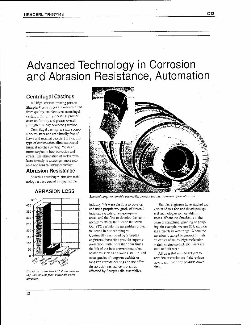
USACERLTR-97/143 C13
Advanced Technology in Corrosion and Abrasion Resistance, Automation
Centrifugal Castings All high stressed rotating parts in
Sharpies® centrifuges are manufactured from quality, stainless steel centrifugal castings. Centrifugal castings provide truer uniformity and greater overall strength than any competing method.
Centrifugal castings are more corro- sion-resistant and are virtually free of flaws and internal defects. Further, this type of construction eliminates metal- lurgical notches (welds). Welds are more subject to both corrosion and stress. The elimination of welds trans- lates directly to a stronger, more reli- able and longer-lasting centrifuge.
Abrasion Resistance Sharpies centrifuges'abrasion tech-
nology is recognized throughout the
ABRASION LOSS
^läf^« ^
Sintered tungsten carbide assemblies protect Sharpies conveyors from abrasion.
Based on a standard ASTM test measur- ing volume loss from materials under abrasion.
industry. We were the first to develop and use a proprietary grade of sintered tungsten carbide on erosion-prone areas, and the first to develop the tech- nology to attach the tiles to the scroll. Our STC carbide tile assemblies protect the scroll in our centrifuges. Continually improved by Sharpies engineers, these tiles provide superior protection, with more than four times the life of the best conventional tiles. Materials such as ceramics, stellite. and other grades of tungsten carbide or tungsten carbide coatings do not offer the abrasion resistance protection afforded by Sharpies tile assemblies.
Sharpies engineers have studied the effects of abrasion and developed spe- cial technologies to meet different needs. Where the abrasion is in the form of scratching, grinding or goug- ing, for example, we use STC carbide tiles, inserts or wear rings. Where the abrasion is caused by impact or high velocities of solids, high molecular weight engineering plastic liners are used to limit wear.
All parts that may be subject to abrasion or erosion are field replace- able to minimize any possible down- time.
12
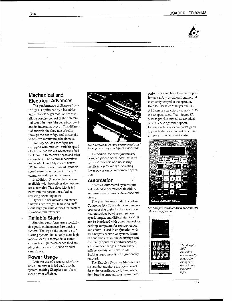
C14 USACERL TR 97/143
A
Mechanical and Electrical Advances
The performance of Sharpies® cen- . triftiges is optimized by a backdrive
and a planetary gearbox system that allows precise control of the differen- tial speed between the centrifuge bowl and its internal conveyor. This differen- tial controls the flow rate of solids through the centrifuge and is essential to achieve maximum cake dryness.
Our Dry Solids centrifuges are equipped with efficient, variable speed electronic backdrives which use a feed- back circuit to measure speed and other parameters. The electrical backdrives are available as eddy current brakes. DC backdrive systems or AC variable speed systems and provide excellent central overall operating ranges.
In addition, Sharpies decanters are available with backdrives that regener- ate electricity. This electricity is fed back into the power lines, further reducing operating costs.
Hydraulic backdrives used on non- Sharpies centrifuges, tend to be ineffi- cient, high pressure devices that require significant maintenance.
Reliable Starts Sharpies centrifuges use a specially
designed, maintenance-free starting system. The wye delta starter is a soft starting system that reliably starts high inertial loads. The wye delta starter eliminates high maintenance fluid cou- pling starter systems found on other centrifuges.
Power Usage With the use of a regenerative back-
drive, the power is fed back into the system, making Sharpies centrifuges more power efficient.
The Sharpies noise ring system results in lower power usage and quieter operation.
In addition, the aerodynamically designed profile of the bowl, with its recessed fasteners and noise ring, results in less "windage." creating lower power usage and quieter opera- tion.
Automation Sharpies Automated systems pro-
vide extended operational flexibility and insure maximum performance effi- ciency.
The Sharpies Automatic Backdrive Controller (ABC) is a dedicated micro- processor that digitally displays infor- mation such as bowl speed, pinion speed, torque, and differential RPM. It can be interfaced with other network or desktop computers for remote readout and control. Used in conjunction with the Sharpies backdrive system, it sens- es conditions inside the centrifuge and constantly optimizes performance by adjusting for changes in flow rates, . influent quality and cake solids. Staffing requirements are significantly reduced.
The Sharpies Decanter Manager is a system that monitors the operation of the entire centrifuge, including vibra- tion, bearing temperatures, main motor
performance and backdrive motor per- formance. .Any deviation from normal is instantly relayed to the operator. Both the Decanter Manager and the ABC can be connected, via modem, to the computer at our Warminster, PA plant to provide immediate technical process and diagnostic support. Features include a specially-designed high-tech electronic control panel that insures easy and efficient startup.
The Sharpies Decanter Manager monitors all operating functions.
The Sharpies ABC controller automatically adjusts for changes in feed without operator input.
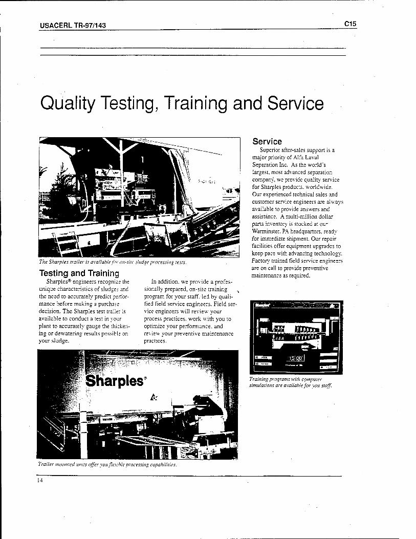
USACERLTR-97/143 C15
Quality Testing, Training and Service
The Sharpies trailer is available for on-site sludge processing tests.
Testing and Training Sharpies® engineers recognize the
unique characteristics of sludges and the need to accurately predict perfor- mance before making a purchase decision. The Sharpies test trailer is available to conduct a test in your plant to accurately gauge the thicken- ing or dewatering results possible on your sludge.
In addition, we provide a profes- sionally prepared, on-site training program for your staff, led by quali- fied field service engineers. Field ser- vice engineers will review your process practices, work with you to optimize your performance, and review your preventive maintenance practices.
Service Superior after-sales support is a
major priority of Alfa Laval Separation Inc. As the world's largest, most advanced separation company, we provide quality service for Sharpies products, worldwide. Our experienced technical sales and customer service engineers are always available to provide answers and assistance. A multi-million dollar pans inventor}' is stocked at our Warminster. PA headquarters, ready for immediate shipment. Our repair facilities offer equipment upgrades to keep pace with advancing technology. Factor}' trained field service engineers are on call to provide preventive maintenance as required.
Training programs with computer simulations are available for you staff.
Trailer mounted units offer you flexible processing capabilities.
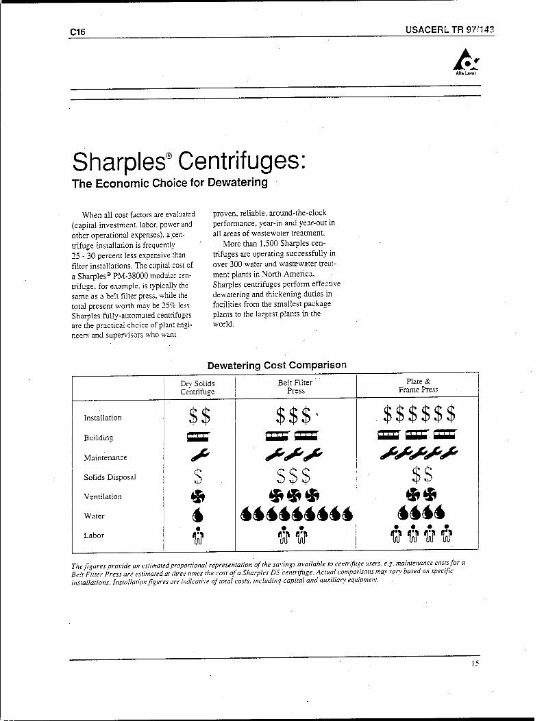
C16 USACERL TR 97/143
A
Sharpies® Centrifuges The Economic Choice for Dewatering
When all cost factors are evaluated (capital investment, labor, power and other operational expenses), a cen- trifuge installation is frequently 25 - 30 percent less expensive than filter installations. The capital cost cf a Sharpies® PM-38000 modular cen- trifuge, for example, is typically the same as a belt filter press, while the total present worth may be 25% less. Sharpies fully-automated centrifuges are the practical choice of plant engi- neers and supervisors who want
proven, reliable, around-the-clock performance, year-in and year-out in all areas of wastewater treatment.
More than 1,500 Sharpies cen- trifuges are operating successfully in over 300 water and wastewater treat- ment plants in North America. Sharpies centrifuges perform effective dewatering and thickening duties in facilities from the smallest package plants to the largest plants in the world.
Dewatering Cost Comparison
Dry Solids Centrifuge
Belt Filter Press
Plate & Frame Press
Installation $$ $$$' . *p *p *P «P »P «P
Building ST SETCSB SET oar CDS'
Maintenance * 4*<*'S> AM**' Solids Disposal s $$$ %%
Ventilation $ <£<&« *® Water 4 ********* MM Labor V ww flUfflltf
The figures provide an estimated proportional representation of the savings available to centrifuge users, e.g. maintenance costs for a Belt Filter Press are estimated at three times the cost of a Sharpies DS centrifuge. Actual comparisons may vary based on specific installations. Installation figures are indicative of total costs, including capital and auxiliary equipment.
15
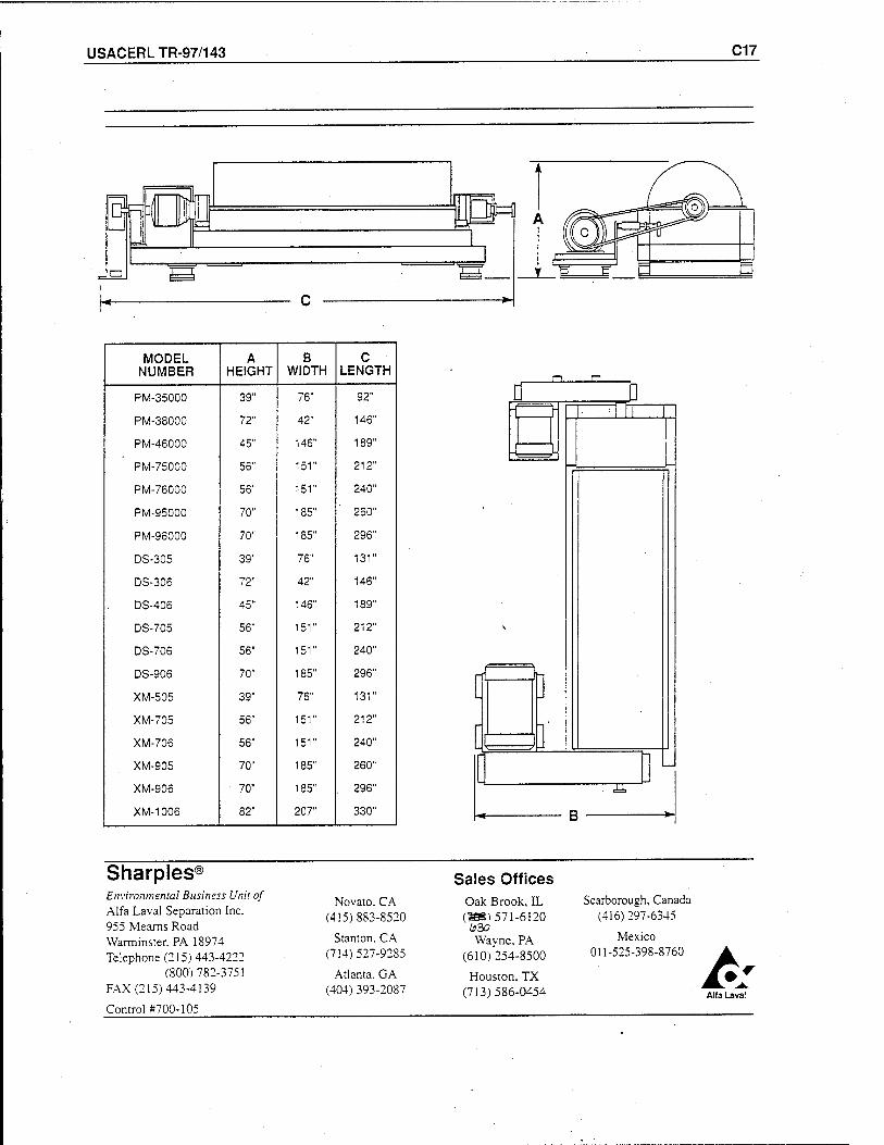
USACERLTR-97/143 C17
MODEL NUMBER
A HEIGHT
B WIDTH
c LENGTH
PM-35000 39" 76" 92"
PM-38000 72" 42" 146"
PM-46000 45" 146" 189"
PM-75000 56" 151" 212"
PM-76000 56" 151" 240"
PM-95000 70" 185" 260"
PM-96000 70" 185" 296"
DS-305 39" 76" 131"
DS-306 72" 42" 146"
DS-406 45" 146" 189"
DS-705 56" 151" 212"
DS-706 56" 151" 240"
DS-906 70" 185" 296"
XM-505 39" 76" 131"
XM-705 56" 151" 212"
XM-706 56" 151" 240"
XM-905 70" 185" 260"
XM-906 70" 185" . 296"
XM-1006 82" 207" 330"
1^^
F=ta [ ]'
"H"
B
Sharpies ®
Environmental Business Unit of Alfa Laval Separation Inc. 955 Meams Road Warminster. PA 18974 Telephone (215) 443-4222
(800)782-3751 FAX (215) 443-4139
Control #700-105
Novato. CA (415)883-8520
Stanton. CA (714)527-9285
Atlanta. GA (404) 393-2087
Sales Offices Oak Brook, IL (TBS) 571-6120
Wayne, PA (610)254-8500
Houston, TX (713)586-0454
Scarborough, Canada (416)297-6345
Mexico 011-525-398-8760
Alfa Lava!
USACERLTR-97/143 DI
Appendix D: TRIMAX Environmental
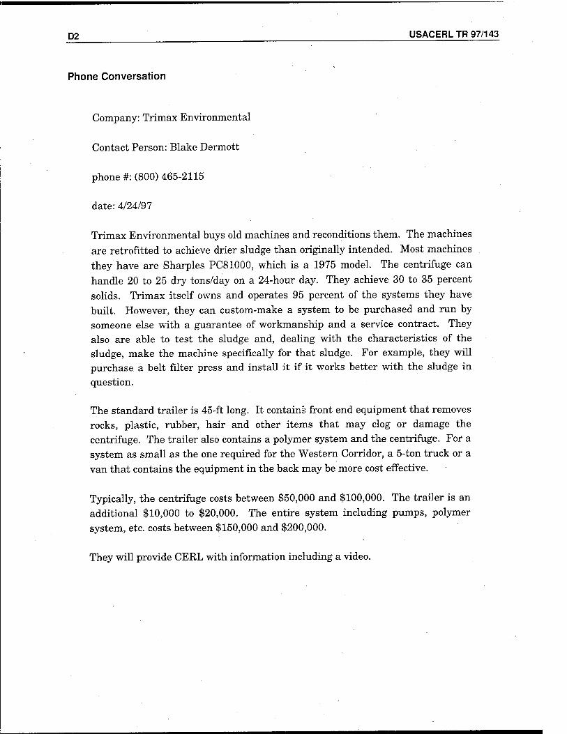
D2 USACERL TR 97/143
Phone Conversation
Company: Trimax Environmental
Contact Person: Blake Dermott
phone #: (800) 465-2115
date: 4/24/97
Trimax Environmental buys old machines and reconditions them. The machines
are retrofitted to achieve drier sludge than originally intended. Most machines
they have are Sharpies PC81000, which is a 1975 model. The centrifuge can
handle 20 to 25 dry tons/day on a 24-hour day. They achieve 30 to 35 percent
solids. Trimax itself owns and operates 95 percent of the systems they have
built. However, they can custom-make a system to be purchased and run by
someone else with a guarantee of workmanship and a service contract. They
also are able to test the sludge and, dealing with the characteristics of the sludge, make the machine specifically for that sludge. For example, they will
purchase, a belt filter press and install it if it works better with the sludge in
question.
The standard trailer is 45-ft long. It contains front end equipment that removes
rocks, plastic, rubber, hair and other items that may clog or damage the
centrifuge. The trailer also contains a polymer system and the centrifuge. For a
system as small as the one required for the Western Corridor, a 5-ton truck or a
van that contains the equipment in the back may be more cost effective.
Typically, the centrifuge costs between $50,000 and $100,000. The trailer is an
additional $10,000 to $20,000. The entire system including pumps, polymer
system, etc. costs between $150,000 and $200,000.
They will provide CERL with information including a video.
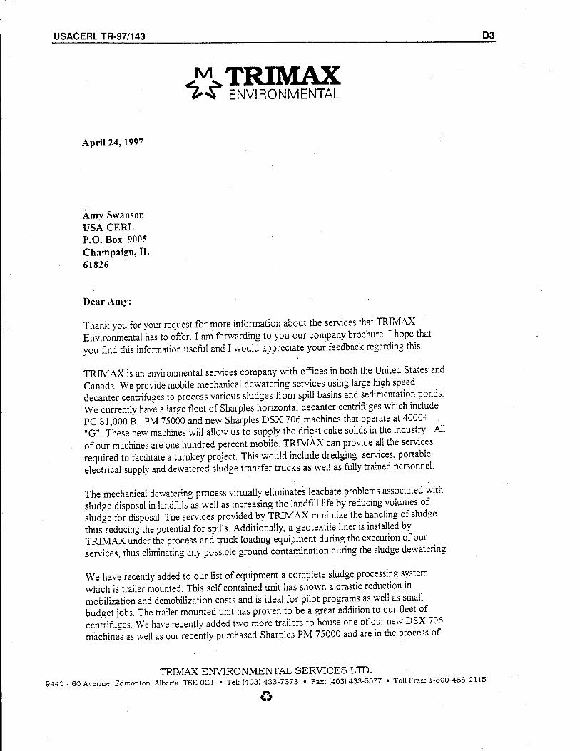
USACERLTR-97/143 D3
M TRIMAX *>«* ENVIRONMENTAL
April 24, 1997
Amy Swanson USA CERL P.O.Box 9005 Champaign, EL 61826
Dear Amy:
Thank you for your request for more information about the services that TRIMAX Environmental has to offer. I am forwarding to you our company brochure. I hope that you find this information useful and I would appreciate your feedback regarding this.
TRIMAX is an environmental services company with offices in both the United States and Canada. We provide mobile mechanical dewatering services using large high speed decanter centrifuges to process various sludges from spill basins and sedimentation ponds. We currently have a large fleet of Sharpies horizontal decanter centrifuges which include PC 81,000 B, PM 75000 and new Sharpies DSX 706 machines that operate at 4000+ "G". These new machines will allow us to supply the driest cake solids in the industry. All of our machines are one hundred percent mobile. TRIMAX can provide all the services required to facilitate a turnkey project. This would include dredging services, portable electrical supply and dewatered sludge transfer trucks as well as fully trained personnel.
The mechanical dewatering process virtually eliminates leachate problems associated with sludge disposal in landfills~as well as increasing the landfill life by reducing volumes of sludge for disposal. The services provided by TRIMAX minimize the handling of sludge thus reducing the potential for spills. Additionally, a geotextile liner is installed by TRIMAX under the process and truck loading equipment during the execution of our services, thus eliminating any possible ground contamination during the sludge dewatering.
We have recently added to our list of equipment a complete sludge processing system which is trailer mounted. This self contained unit has shown a drastic reduction in mobilization and demobilization costs and is ideal for pilot programs as well as small budget jobs. The trailer mounted unit has proven to be a great addition to our fleet of centrifuses. We have recently added two more trailers to house one of our new DSX 706 machines as well as our recently purchased Sharpies PM 75000 and are in the process of
TRIMAX ENVIRONMENTAL SERVICES LTD. S440 - 60 Avenue. Edmonton. Alberta T6E OC1 • Tel: (403) 433-7373 • Fax: (403) 433-5577 • Toll Free: 1-800-465-2115
D4 USACERL TR 97/143
building our fourth. These new trailers will give us different process capabilities of approximately 2000, 3000, and 4000 "G"s. In our discussions I had mentioned our interest in designing and manufacturing a custom system for your needs. We have been approached by Sharpies to consider the potential to manufacture trailers for them. We can use all new or reconditioned equipment.
We also offer consulting on a individual project basis. This could include everything from design, to purchasing of all equipment including centrifuges and pumps etc., to the complete set up and management of your dewatering program. This type of program is evident in the longterm contracts we have with the cities of Vancouver and Kelowna in BC Canada.
I have enclosed our literature in a brochure form as well as a video which illustrates some of our successful projects-. We would be pleased to forward to you a list of references upon request.
If any further information is required, please feel free to contact me at your earliest convenience.
In the near future, I will be contacting you to further discuss the above. Thank you once again for your interest.
'Blake Dermott Manager of Marketina And Sales
TRIMAX
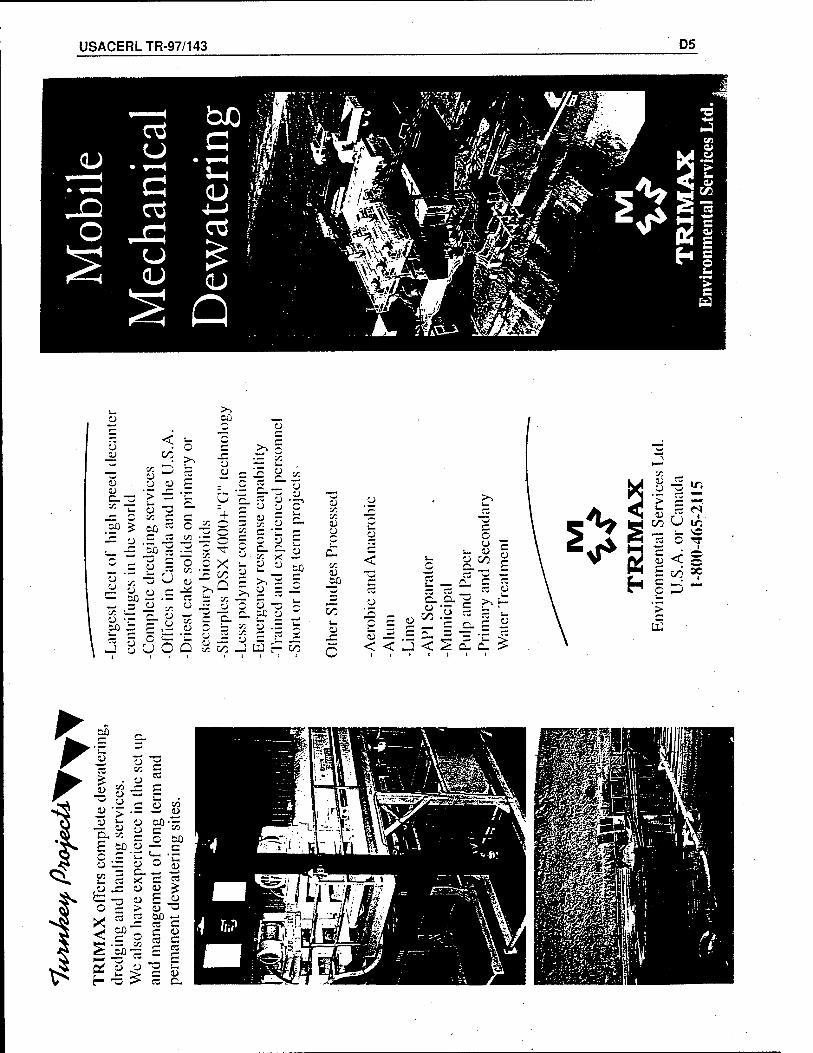
USACERL TR-97/143 D5
ü
4J
O O c ■y.
<
o
o
•_-='«- '
o
Cß
= P S •- -5 U
.= « * ZZ P —
i6o
sß
o
~ !/3 • —
• — V T
o X in o r^ -^ ^
C3 ~ v. o • « o .X c o o —
T" o Ü
Q oc
5 '■A
+ =
_ u
c o
v. o
£ ft-
Cß
00
o
5 <
o o
Ü
E ü
< '-J
c c o S i: •_
ft- «E < 2 ££ £
M u .2 i/i
rS 'j > ;s —< <
al S
er
or C
ai
465-
2
HH C -' '<«*>
Ü 0) <. o E oo °?
H §D-
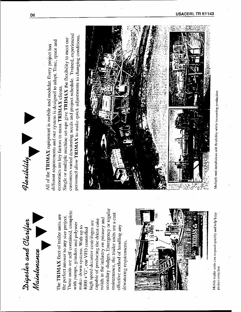
D6 USACERL TR 97/143
► ►
A ^
(!) <l) , (1) _J 00 1— ^— , l-.P <; rt o (!) w O u XA, <u t- p -*l s r-~
u F
C CJ ■J:
o >^ o P >^ -^ ~ >, i- o o ;r «>-. »w TZ
o if "3
5S Q
SO .2 p (J ■y. CO
>> c
h ■a o
O 60 I— Ü
5 *-* :/:'
C o o o ;/: (_> eo
O P _u ■£? 5
s DCS
—
o v2
13
vT
- dow
n sy
slcn
+
"G", o
ur V
F
ü o c
«2 r;
1)
ü 60
T)
u
U
CJ
0)
o P o >
p
p
P°
3 H 1) " o
•6 o 'A O
*■», c/3 T) 5 o ti
u o O til
^v 5 £ ^ £ ("•> r) __ :j
i_ ~^-": t- = "sf J^ o oc C/S f-m o w»
= *
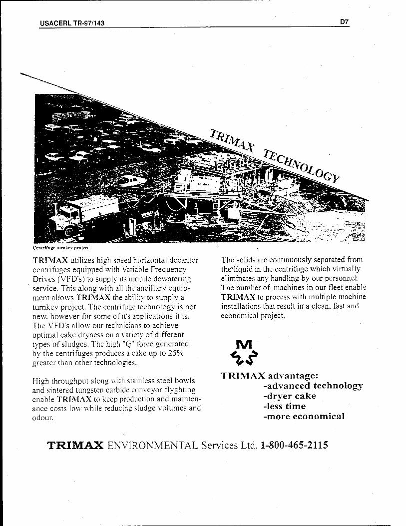
USACERLTR-97/143 D7
Centrifuge turnkey project
TRIMAX utilizes high speed horizontal decanter centrifuges equipped with Variable Frequency Drives (VFD's) to supply its mobile dewatering service. This along with all the ancillary equip- ment allows TRIMAX the ability to supply a turnkey project. The centrifuge technology is not new, however for some of it's applications it is. The VFD's allow our technicians to achieve optimal cake dryness on a variety of different types of sludges. The high "G" force generated by the centrifuges produces a cake up to 25% greater than other technologies.
High throughput along with stainless steel bowls and sintered tungsten carbide conveyor flyghting enable TRIMAX to keep production and mainten- ance costs low while reducing sludge volumes and odour.
The solids are continuously separated from theMiquid in the centrifuge which virtually eliminates any handling by our personnel. The number of machines in our fleet enable TRIMAX to process with multiple machine installations that result in a clean, fast and economical project.
IVI
TRIMAX advantage: -advanced technology -dryer cake -less time -more economical
TRIMAX ENVIRONMENTAL Services Ltd. 1-800-465-2115
USACERLTR-97/143 E1
Appendix E: N-Viro
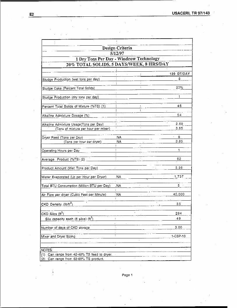
E2 USACERL TR 97/143
Design Criteria 5/12/97
1 Dry Tons Per Day - Windrow Technology 20% TOTAL SOLIDS, 5 DAYS/WEEK, 8 HRS/DAY
Sludge Production (wet tons per day)
Sludge Cake (Percent Total Solids)
Sludge Production (dry tons per day)
Percent Total Solids of Mixture (%TS) (1)
Alkaline Admixture Dosage (%)
Alkaline Admixture Usage(Tons per Day)
120 DT/DAY
20%
48
54
2.69 (Tons of mixture per hour per mixer) 3.85
Dryer Feed (Tons per Day) 'NA (Tons per hour per dryer) NA 3.85
Operating Hours per Day
Average Product (%TS) (2) 62
Product Amount (Wet Tons per Day) 5.96
Water Evaporated (Lb per Hour per Dryer) NA 1,737
Total BTU Consumption (Million BTU per Day) , NA
Air Flow per dryer (Cubic Feet per Minute) NA 40,000
CKD Density (lb/ft-3 55
CKD Silos (ffi 294
Silo capacity each (6 silos) (ft ) 49
Number of days of CKD storage 3.00
Mixer and Dryer Sizing 1-CSP-10
NOTES: (1) Can range from 42-48% TS feed to dryer. (2) Can range from 62-68% TS product.
Page 1
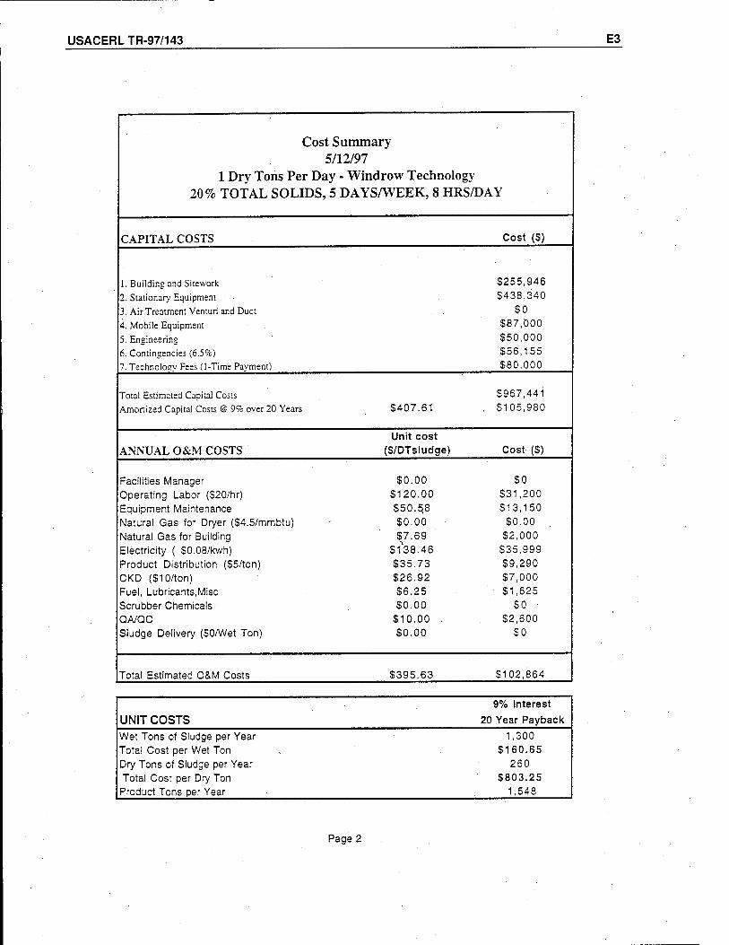
USACERLTR-97/143 E3
Cost Summary 5/12/97
1 Dry Tons Per Day - Windrow Technology 20% TOTAL SOLIDS, 5 DAYS/WEEK, 8 HRS/DAY
CAPITAL COSTS Cost (S)
1. Building and Sitework $255,946
2. Stationär)' Equipment $438,340
3. Air Treatment Venturi and Duct $0 4. Mobile Equipment $87,000
5. Ensineerins $50,000 6. Contingencies (6.5%) $56,155 7. Technology Fees (1-Time Payment) S80.000
Total Estimated Capital Costs $967,441 Amortized Capital Costs @ 9% over 20 Years S407.61 $105,980
Unit cost ANNUAL O&M COSTS (S/DTsludge) Cost (S)
Facilities Manager $0.00 SO Operating Labor ($20/hr). S120.00 $31,200 Equipment Maintenance $50.5,8 $13,150 Natural Gas for Dryer (S4.5/mmbtu) $0.00 $0.00 Natural Gas for Building $7.69 $2,000 Electricity ( S0.08/kwh) $138.46 $35,999 Product Distribution (S5/ton) $35.73 $9,290 CKD (S10/ton) $26.92 $7,000 Fuel, Lubricants,Misc $6.25 $1,625 Scrubber Chemicals $0.00 $0 ■
QA/QC $10.00 . $2,600 Sludge Delivery ($0/Wet Ton) $0.00 so
Total Estimated O&M Costs $395.63 $102,864
9% Interest
UNIT COSTS 20 Year Payback
Wet Tons of Sludge per Year 1,300 Total Cost per Wet Ton $160.65 Dry Tons of Sludge per Year 260 Total Cost per Dry Ton $803.25
Product Tons Der Year 1,548
Page 2
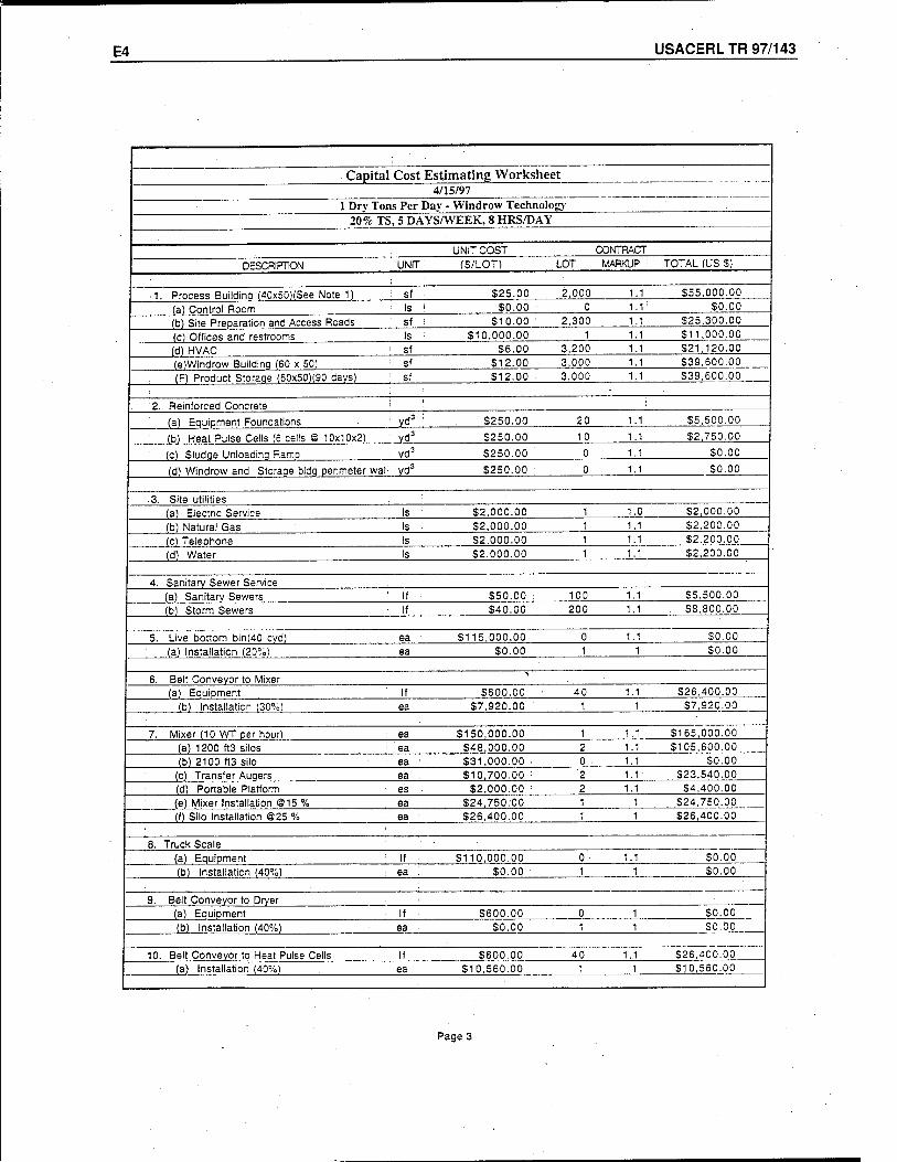
E4 USACERL TR 97/143
Capital Cost Estimating Worksheet 4/15/97
1 Dry Tons Per Day - Windrow Technology
20% TS, 5 DAYS/WEEK, 8 HRS/DAY
UNIT COST CONTRACT
DESCRIPTION UNIT (S/LOT) LOT MARKUP TOTAL (US S)
■ 1 Process Buildina (40x50)(See Note 1) i sf S25.00 2,000 1.1 $55,000.00
(a) Control Room ■ Is SO.00 0 1.1 $0.00
(b) Site Preparation and Access Roads sf $10.00 ■ 2,300 1.1 $25,300.00
(c) Offices and restrooms Is 310,000.00 1 1.1 $11,000.00
(d) HVAC ' sf S6.00 3,200 1.1. $21,120.00
(e)Windrow Building (60 x 50) sf $12.00 3,000 1.1' $39,600.00
(F) Product Storaqe (60x50)(90 days) : sf $12.00 3,000 1.1 $39,600.00
2 Reinforced Concrete ! (a) Equipment Foundations ■ yd3 $250.00 20 1.1 $5,500.00
(b) Heat Pulse Cells (6 cells © 10x10x2) ' yd3 $250.00 10 1.1 $2,750.00
(c) Sludqe Unloadinq Ramp : yd3 $250.00 0 1.1 SO.00
(d) Windrow and Storage bldg pe imeter wall yd3 $250.00 : 0 1.1 SO.00
3. Site utilities (a) Electric Service Is $2,000.00 1 1.0 $2,000.00
(b) Natural Gas Is $2,000.00 1 1.1 $2,200.00
(c) Telephone Is $2,000.00 1 1.1 $2.200.00
(d) Water Is $2,000.00 1 1.1 $2,200.00
4. Sanitary Sewer Service (a) Sanitary Sewers ' If $50.00 : 100 1.1 $5,500.00
(b) Storm Sewers If $40.00 200 1.1 $8,800.00
5. Live bottom bin(40 cvd) i ea ' S115.000.00 . 0 1.1 SO.00
(a) Installation (20%) ea $0.00 . 1 1 $0.00
6. Belt Conveyor to Mixer ■\
(a) Equipment If $600.00 ■ 40 1.1 $26,400.00
(b) Installation (30%) ea $7,920.00 1 1 ■ $7,920.00
7. Mixer (10 WT per hour) ea $150,000.00 1 1.1 $165,000.00
(a) 1200 ft3 silos '■ ea $48,000.00 2 1.1 $105,600.00
(b) 2100 tt3 silo : ea ■ $31,000.00 . 0 • 1.1 SO.00
(c) Transfer Auqers ea : S10.700.00 : '2 1.1 $23,540.00
(d) Portable Platform ! es ■ $2,000.00 ■■ 2 1.1 $4,400.00 (e) Mixer Installation ©15 % ea $24,750:00 1 1 $24,750.00 (f) Silo Installation ©25 % ea $26,400.00 1 1 $26,400.00
■
8. Truck Scale (a) Equipment : If $110,000.00 0 1.1 $0.00 (b) Installation (40%) : ea '. $0.00 1 1 $0.00
9. Belt Conveyor to Dryer (a) Equipment ■ If : $600.00 0 1 SO.00
(b) Installation (40%) ea $0.00 1 1 $0.00
10 Belt Conveyor to Heat Pulse Cells If $600.00 40 1.1 $26,400.00 (a) Installation (40%) ea $10,560.00 1 1 $10,560.00
Page 3
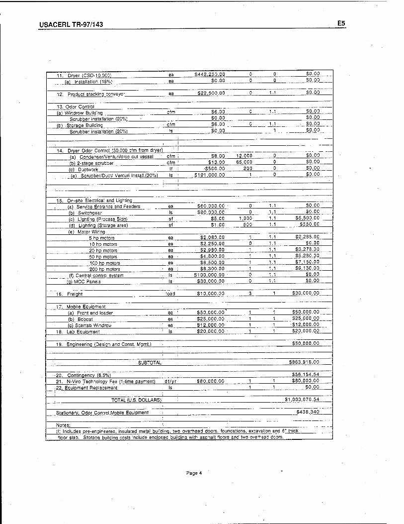
USACERLTR-97/143 E5
11. Dryer (CSD-10.000) ea S442.250.00 0 0 SO.00
(a) Installation (15%) ea ■ SO.00 0 0 SO.00
12. Product stackina conveyor ea S22.500.00 0 1.1 SO.00
13. Odor Control (a) Windrow Buildina cfm S6.00 0 1.1 SO.00
Scrubber installation (20%) SO.00 SO.00
'(b) Storaqe Buildinq cfm S6.00 0 1.1 50.00
Scrubber installation (20%) Is SO.00 1 SO.00
! 14. Drver Odor Control (30,000 cfm from dryer)
(a) Condenser/Venturi/drop out vessel cfm S8.00 12,000 0 SO.00
(b) 2-staqe scrubber cfm : $13.00 65,000 0 SO.00
(c) Ductwork If •S500.00 200 0 SO.00
(e) Scrubber/Duct/ Venturi Install.(20%) Is : S191.000.00 1 0 SO.00
15. On-site Electrical and Liahting (a) Service Entrance and Feeders ea S60.000.00 0 1.1 SO.00
(b) Switchaear Is 580,000.00 0 1.1 1.1
SO.00 55,500.00 (c) Liqhtinq (Process Bldq) sf S5.00 1,000
(d) Lighting (Storage area) Sf ; S1.00 500 1.1 S550.00
(e) Motor Wiring ' 5 hp motors ea : S2.080.00 1 1.1 52,288.00
10 hp motors ea : S2.250.00 0 1.1 50.00
20 hp motors ea S2.980.00 ; 1 1.1 53,278.00
50 hp motors ea ■ S4,80O.00 1 1.1 S5.280.00
100 ho motors ea 56,500.00 1 1.1 57,150.00
200 hp motors ea : S8.300.00 1 1.1 59,130.00
(f) Central control system Is ' S100.000.00 0 1.1 SO.00
(g) MCC Panels Is S30.000.00 0 1.1 50.00
16. Freight load S10.000.00 3 1 530,000.00
17. Mobile Equipment (a) Front end loader ea ' S50.000.00' 1 1 550,000.00
(b) Bobcat ea : S25,000.00 1 1 S25.000.00
(c) Scarrab Windrow ea S12.000.00 1 1 •512,000.00
18. Lab Equipment Is 520,000.00 1 1 S20.000.00
19. Engineering (Design and Const Momt.) 550,000.00
': SUBTOTAL 5863,916.00
20. Contingency (6.5%) S56.154.54
21. N-Viro Technoloqv Fee (1-time payment) dt/yr 580,000.00 1 1 580,000.00
22. Equipment Replacement Is 1 1 SO.00
TOTAL (U.S. DOLLARS) S1,000,070.54
Stationary, Odor Control.Mobile Equipment S438.340 !
Notes: (!) ncludes Dre-enaineered. insulated metal buildinq. two overhead doors, foundations, excavation and 6 " thick
floor slab. Storaae buildina costs i iclude enclosed buildinq with asphalt floors and two overhead doors.
Page 4
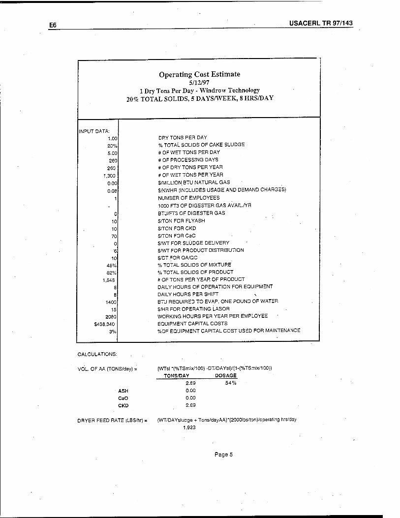
E6 USACERL TR 97/143
Operating Cost Estimate 5/12/97
1 Dry Tons Per Day - Windrow Technology 20 % TOTAL SOLIDS, 5 DAYS/WEEK, 8 HRS/DAY
INPUT DATA: 1.00 DRY TONS PER DAY
20% % TOTAL SOLIDS OF CAKE SLUDGE
5.00 # OF WET TONS PER DAY
260 # OF PROCESSING DAYS
260 # OF DRY TONS PER YEAR
1,300 # OF WET TONS PER YEAR
0.00 S/MILLIONBTU NATURAL GAS
0.08 S/KWHR (INCLUDES USAGE AND DEMAND CHARGES)
1 NUMBER OF EMPLOYEES
. 1000 FT3 OF DIGESTER GAS AVAIL./YR
0 BTU/FT3 OF DIGESTER GAS
10 SATON FOR FLY ASH
10 S/TON FOR CKD
70 S/TON FOR CaO
0 SAVT FOR SLUDGE DELIVERY
6 S/WT FOR PRODUCT DISTRIBUTION
10 S/DTFORQA/QC
48% % TOTAL SOLIDS OF MIXTURE
62% % TOTAL SOLIDS OF PRODUCT
1,548 # OF TONS PER YEAR OF PRODUCT
8 DAILY HOURS OF OPERATION FOR EQUIPMENT
8 DAILY HOURS PER SHIFT
1400 BTU REQUIRED TO EVAP. ONE POUND OF WATER
15 S/HR FOR OPERATING LABOR
2080 WORKING HOURS PER YEAR PER EMPLOYEE
S438.340 EQUIPMENT CAPITAL COSTS
3% %OF EQUIPMENT CAPITAL COST USED FOR MAINTENANCE
CALCULATIONS:
VOL. OF AA (TONS/day) =
ASH CaO CKD
DRYER FEED RATE (LBS/hr) =
(WTsI *(%TSmix/100) -DT/DAYsl)/(1-(%TSmix/100)) TONS/DAY DOSAGE
2.69 54%
0.00
0.00
2.69
(WT/DAYs!udge + Tons/dayAA)*(2000lbs/ton)/operating hrs/day
1,923
Page 5
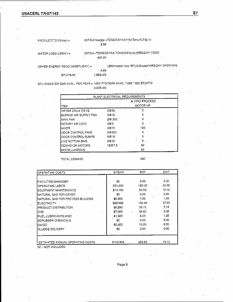
USACERLTR-97/143 E7
PRODUCT(TONS/day) = (WT/DAYsludge+TONS/DAYAA)*(%TSmix'%TSpro)
5.96
WATER LOSS (LBS/hr) =
DRYER ENERGY REQD (MMBTU/DAY) =
BTU/YEAR
(WT/Dsl+TONS/DAYAA-TONS/DAYpro)/(HRS/DAY)*2000
434.24
LBS/hrwater loss -BTU/LBwaterHRS/DAY OPER/IO^
4.86 1.26E+09
BTU DIGESTER GAS AVAIL. PER YEAR = 1000 FT3/YEAR AVAIL.*1000 * 600 BTU/FT3 0.00E+00
PLANT ELECTRICAL REQUIREMENTS
N-VIRO PROCESS
ITEM ' MOTOR HP
DRYER DRUM DRIVE 2©50 0
BURNER AIR SUPPLY FAN 2@15 0
MAIN FAN 2® 200 0
ROTARY AIR LOCK 2@3 0
MIXER 2075 150
ODOR CONTROL FANS 2 ©200 0
ODOR CONTROL PUMPS 6@15 0
LIVE BOTTOM BINS 2@30 ' 0 .
CONVEYOR MOTORS [email protected] 90
MISCELLANEOUS 50
TOTAL DEMAND 290
OPERATING COSTS S/YEAR $TDT S/WT
FACILITIES MANAGER SO 0.00 0.00
OPERATING LABOR 331,200 120.00 24.00
EQUIPMENT MAINTENANCE 513,150 50.58 10.12
NATURAL GAS FOR DRYER SO 0.00. 0.00
NATURAL GAS FOR PROCESS BUILDING $2,000 7.69 1.54
ELECTRICITY $35,999 138.46 27.69
PRODUCT DISTRIBUTION $9,290 35.73 7.15
CKD $7,000 26.92 5.38
FUEL.LUBRICANTS.MISC $1,625 6.25 1.25
SCRUBBER CHEMICALS $0 0.00 0.00
QA/QC $2,600 10.00 2.00
SLUDGE DELIVERY $0 0.00 0.00
ESTIMATED ANNUAL OPERATING COSTS S102.864 395.63 79.13
N/l - NOT INCLUDED
Page 6
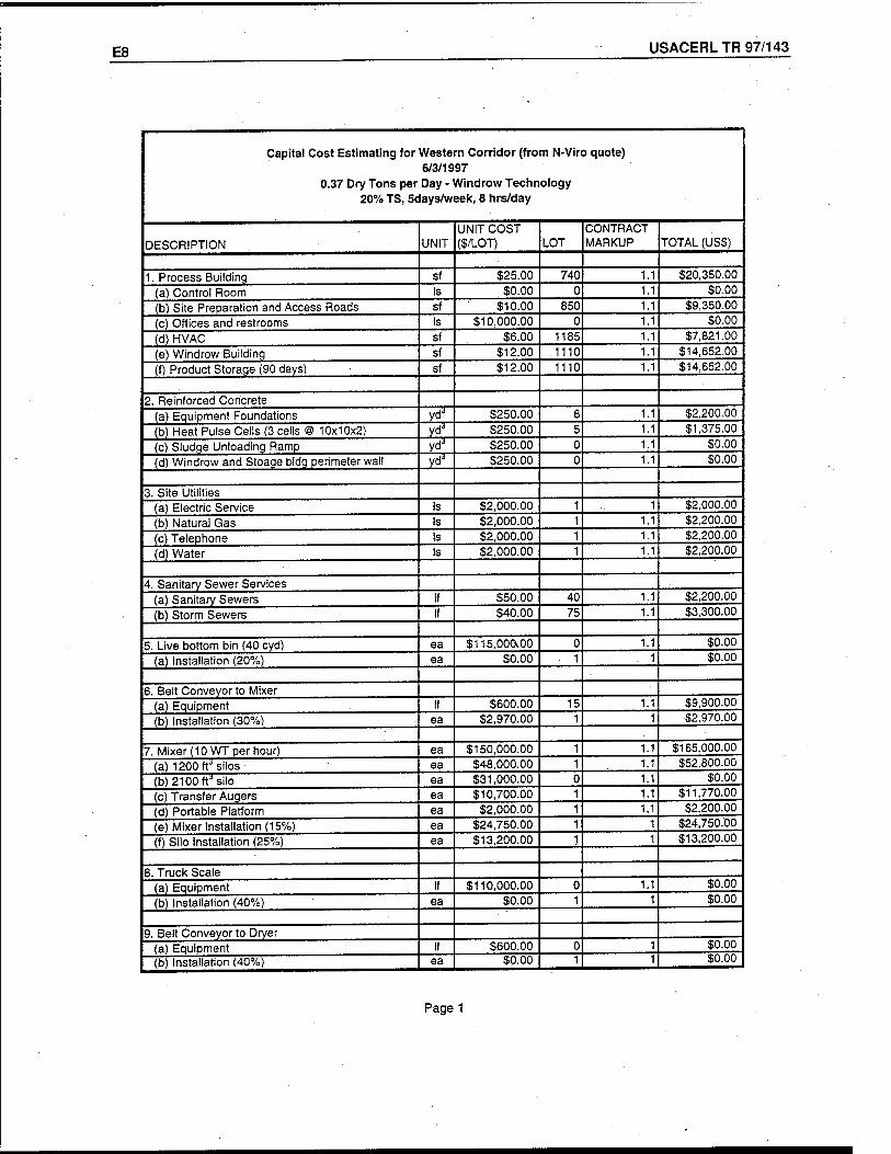
E8 USACERL TR 97/143
— ,
Capital Cost Estimating for Western Corridor (from N-Viro quote) 6/3/1997
0.37 Dry Tons per Day - Windrow Technology 20% TS, 5days/week, 8 hrs/day
DESCRIPTION UNIT UNIT COST ($/LOT) LOT
CONTRACT MARKUP TOTAL (US$)
1. Process Building sf $25.00 740 1.1 $20,350.00
(a) Control Room Is $0.00 0 1.1 $0.00
(b) Site Preparation and Access Roads sf $10.00 850 1.1 $9,350.00
(c) Offices and restrooms Is $10,000.00 0 1.1 $0.00
(d) HVAC sf $6.00 1185 1.1 $7,821.00
(e) Windrow Building sf $12.00 1110 1.1 $14,652.00
(f) Product Storage (90 days) sf $12.00 1110 1.1 $14,652.00
2. Reinforced Concrete (a) Equipment Foundations y<
$250.00 8 1.1 $2,200.00
(b) Heat Pulse Cells (3 cells @ 10x10x2) yd $250.00 5 1.1 $1,375.00
(c) Sludge Unloading Ramp ydJ $250.00 0 1.1 $0.00
(d) Windrow and Stoage bldg perimeter wall ydJ $250.00 0 1.1 $0.00
3. Site Utilities (a) Electric Service Is $2,000.00 1 1 $2,000.00
(b) Natural Gas Is $2,000.00 1 1.1 $2,200.00
(c) Telephone Is $2,000.00 1 1.1 $2,200.00
(d) Water Is $2,000.00 1 1.1 $2,200.00
4. Sanitary Sewer Services (a) Sanitary Sewers If $50.00 40 1.1 $2,200.00
(b) Storm Sewers If $40.00 75 1.1 $3,300.00
5. Live bottom bin (40 cyd) ea $n5,ooaoo 0 1.1 $0.00
(a) Installation (20%) ea $0.00 1 . 1 $0.00
6. Belt Conveyor to Mixer (a) Equipment If $600.00 15 1.1 $9,900.00
(b) Installation (30%) ea $2,970.00 1 1 $2,970.00
7. Mixer (10 WT per hour) ea $150,000.00 1 1.1 $165,000.00
(a) 1200 ftJ silos ea $48,000.00 1 1.1 $52,800.00
(b) 2100 ftJ silo ea $31,000.00 0 1.1 $0.00
(c) Transfer Augers ea $10,700.00 1 1.1 $11,770.00
(d) Portable Platform ea $2,000.00 1 1.1 $2,200.00
(e) Mixer Installation (15%) ea $24,750.00 1 1 $24,750.00
(f) Silo Installation (25%) ea $13,200.00 1 1 $13,200.00
8. Truck Scale (a) Equipment If $110,000.00 0 1.1 $0.00
(b) Installation (40%) ea $0.00 1 1 $0.00
9. Belt Conveyor to Dryer (a) Equipment If $600.00 0 1 $0.00
(b) Installation (40%) ea $0.00 1 1 $0.00
Page 1
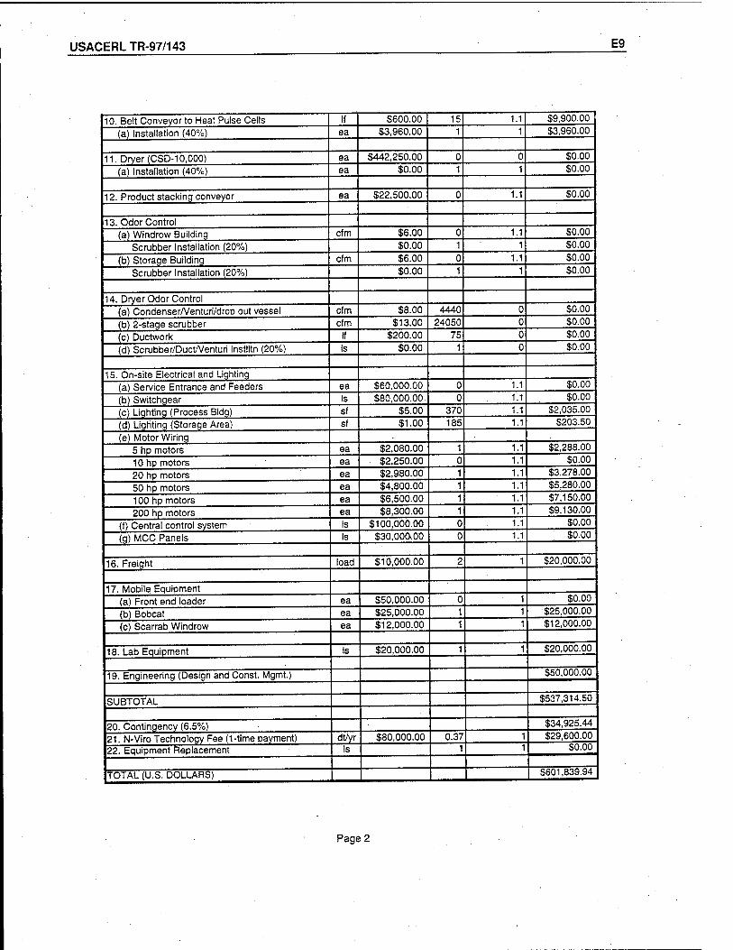
USACERLTR-97/143 E9
10. Belt Conveyor to Heat Pulse Cells If $600.00 15 1.1 $9,900.00
(a) Installation (40%) ea $3,960.00 1 1 $3,960.00
11. Dryer (CSD-10,000) ea $442,250.00 0 0 $0.00
(a) Installation (40%) ea $0.00 1 1 $0.00
12. Product stacking conveyor ea $22,500.00 0 1.1 $0.00
13. Odor Control (a) Windrow Building cfm $6.00 0 1.1 $0.00
Scrubber Installation (20%) $0.00 1 1 $0.00
(b) Storaqe Building cfm $6.00 0 1.1 $0.00
Scrubber Installation (20%) $0.00 1 1 $0.00
14. Dryer Odor Control (a) Condenser/Venturi/drop out vessel cfm $8.00 4440 0 $0.00
(b) 2-stage scrubber cfm $13.00 24050 0 $0.00
(c) Ductwork If $200.00 75 0 $0.00
(d) Scrubber/Duct/Venturi Instlltn (20%) Is $0.00 1 0 $0.00
15. On-site Electrical and Lighting (a) Service Entrance and Feeders ea $60,000.00 0 1.1 $0.00
(b) Switchgear Is $80,000.00. 0 1.1 $0.00
(c) Lighting (Process Bldg) sf $5.00 370 1.1 $2,035.00
(d) Lighting (Storage Area) sf $1.00 185 1.1 $203.50
(e) Motor Wiring 5 hp motors ea $2,080.00 1 $2,288.00
10 hp motors ea $2,250.00 0 $0.00
20 hp motors ea $2,980.00 1 $3,278.00
50 hp motors ea $4,800.00 1 $5,280.00
100 hp motors ea $6,500.00 1 $7,150.00
200 hp motors ea $8,300.00 1 1.1 $9,130.00
(f) Central control system Is $100,000.00 0 $0.00
(g) MCC Panels Is $30,ooaoo 0 $0.00
16. Freight load $10,000.00 2 1 $20,000.00
17. Mobile Equipment (a) Front end loader ea $50,000.00 0 1 $0.00
(b) Bobcat ea $25,000.00 1 1 $25,000.00
(c) Scarrab Windrow ea $12,000.00 1 1 $12,000.00
18. Lab Equipment Is $20,000.00 1 1 $20,000.00
19. Engineering (Design and Const. Mgmt.) $50,000.00
SUBTOTAL $537,314.50
20. Contingency (6.5%) $34,925.44
21. N-Viro Technoloqy Fee (1-time payment) dt/yr $80,000.00 0.37 1 $29,600.00
22. Equipment Replacement Is 1 1 $0.00
TOTAL (U.S. DOLLARS) $601,839.94 I
Page 2
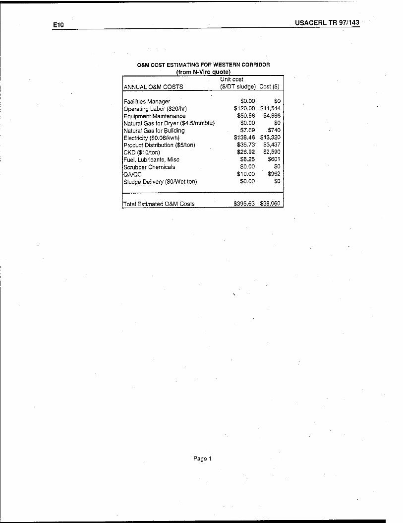
E10 USACERL TR 97/143
O&M COST ESTIMATING FOR WESTERN CORRIDOR (from N-Viro quote)
Unit cost ANNUAL O&M COSTS ($/DT sludge) Cost ($)
Facilities Manager $0.00 $0 Operating Labor ($20/hr) $120.00 $11,544 Equipment Maintenance $50.58 $4,866 Natural Gas for Dryer ($4.5/mmbtu) $0.00 $0 Natural Gas for Building $7.69 $740 Electricity ($0.08/kwh) $138.46 $13,320 Product Distribution ($5/ton) $35.73 $3,437 CKD($10/ton) $26.92 $2,590 Fuel, Lubricants, Misc $6.25 $601 Scrubber Chemicals $0.00 $0 QA/QC $10.00 $962 Sludge Delivery ($0/Wet ton) $0.00 $0
Total Estimated O&M Costs $395.63 $38,060
Page 1
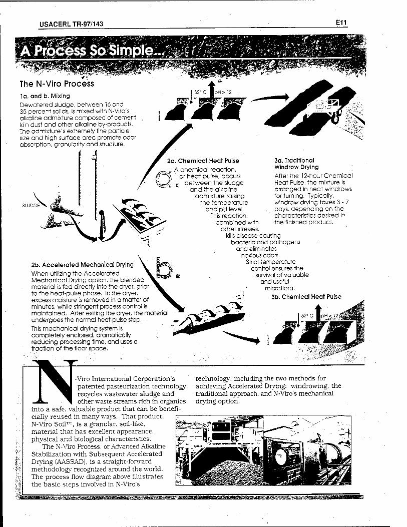
USACERLTR-97/143 E11
The N-Viro Process la. and b. Mixing Dewatered sludge, between 16 and 35 percent solids, is mixed with N-Viro's alkaline admixture composed of cement kiln dust and other alkaline by-products. The admixture's extremely fine particle size and high surface area promote odor absorption, granularity and structure.
SLUDGE
2a. Chemical Heat Pulse A chemical reaction,
y, or heat pulse, occurs
2b. Accelerated Mechanical Drying When utilizing the Accelerated Mechanical Drying option, the blended material is fed directly into the dryer, prior to the heat-pulse phase. In the dryer, excess moisture is removed in a matter of minutes, while stringent process control is maintained. After exiting the dryer, the material undergoes the normal heat-pulse step. This mechanical drying system is completely enclosed, dramatically reducing processing time, and uses a fraction of the floor space.
between the sludge and the alkaline
admixture raising the temperature
and pH level. This reaction,
combined with other stresses,
kills disease-causing bacteria and pathogens
and eliminates noxious odors.
Strict temperature control ensures the
3a. Traditional Windrow Drying After the 12-hour Chemical Heat Pulse, the mixture is arranged in neat windrows for turning. Typically, windrow drying takes 3 - 7 days, depending on the characteristics desired in the finished product.
survival of valuable and useful
microflora. 3b. Chemical Heat Pulse
NViro International Corporation's patented pasteurization technology recycles wastewater sludge and other waste streams rich in organics
into a safe, valuable product that can be benefi- cially reused in many ways. That product, N-Viro Soil™, is a granular, soil-like, material that has excellent appearance, physical and biological characteristics.
The N-Viro Process, or Advanced Alkaline Stabilization with Subsequent Accelerated Drying (AASSAD), is a straight-forward methodology recognized around the world. The process flow diagram above illustrates the basic steps involved in N-Viro's
technology, including the two methods for achieving Accelerated Drying: windrowing, the traditional approach, and N-Viro's mechanical drying option.
m^d^^^imzismsm
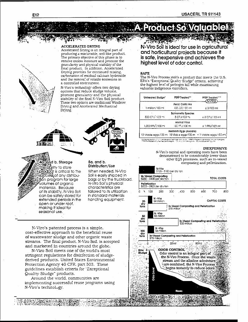
E12 USACERL TR 97/143
; ^PlX>äU^$\fo^
■:*i;l
ACCELERATED DRYING Accelerated Drying is an integral part of producing a marketable, soil-like product. The primary objective of this phase is to remove excess moisture and promote the granularity and physical stability of the final product. In addition. Accelerated Drying provides for continued mixing, carbonation of residual calcium hydroxide and the removal of volatile emissions in a controlled environment. N-Viro's technology offers two drying options that reduce sludge volume, promote granularity and the physical stability of the final N-Viro Soil product. These two options are traditional Windrow Drying and Accelerated Mechanical Drying.
4aEand b. Storage jlj^fe:qgjjlity to store product is critical to the ;Sc£ess\of any distribu- ion program for large
Volumes of organic materials. Because of its stability, N-Viro Soil can be safely stored for extended periods in the open or under roof, making it ideal for seasonal use.
5a. and b. Distribution/Use When needed, N-Viro Soil is easily shipped in bags or by the truckload. N-Viro Soil's physical characteristics are tailored to its utilization in standard materials handling equipment.
N-Viro's patented process is a simple, cost-effective approach to the beneficial reuse of wastewater sludge and other organic waste streams. The final product. N-Viro Soil, is accepted and marketed in countries around the globe.
N-Viro Soil meets one of the world's most stringent regulations for disinfection of sludge- derived products. United Stares Environmental Protection Agency 40 CFR. part 503. These guidelines establish criteria for "Exceptional Quality Sludge" products.
Around the world, communities are implementing successful reuse programs using N-Viro's technology.
N-Viro Soil is ideal for use in agricultural and horticultural projects because it is safe, inexpensive and achieves the highest level of odor control.
SAFE The N-Viro Process yields a product that meets the U.S. EPA's "Exceptional Quality Sludge" criteria, achieving the highest level of pathogen kill while maintaining valuable indigenous microflora.
Untreated Sludge" PSRP Treated" PFRP Treated-"
Fecal Conforms 1 million/100 ml lCC.CCO/lCOml s3/100 ml
Salmonella Species 500CFU71C0ml 5CFü/100ml <3CFU/lC0ml
Animal Virus 1,000 PFUV100 ml lCC::J/lC0ml <1 PFU/100ml
Helminth Eggs (Ascaris) 10 Viable eggs/100 ml 10 Vicble eggs/100 ml < Vicble eggs/100 ml
—pcpp * Process ;o :_—*■ «*c;ce *cr-o;e^s z i^r-^czr.^y "ec-se ^atrsgsns
INEXPENSIVE N-Viro's capital and operating costs have been
demonstrated to be considerably lower than other EQS processes, such as in-vessel
composting and pelletization.
1 N-VIro | S125- er cry ton
In-Vessel Composting . $250 - $300 per dry ton TOTAL COSTS
Pelletization S500 - S800 per dry ton 1 1 i 1 r-' i 1 1
100 200 300 ..400 500 600 700 800
CAPITAL COSTS
In-Vessel Composting and Pelletization S18 million .
In-Vessel Composting and Pelletization S30 million ■ ■■-.-..i ':■-;.
In-Vessel Composting and Pelletization $75 million
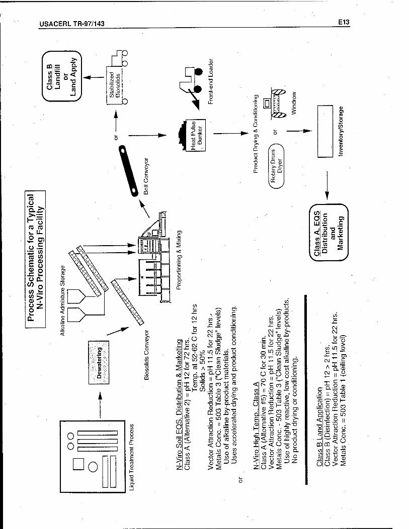
USACERLTR-97/143 E13
CD Ü
Q. >. >. H o cc 03 i_ LL o U) Ü
C
*J «3 03 Ü)
E 0)
QJ O £ i—
O Q. en o tn i-
> I
U ?* o !_ D.
<
i «> w- k_
-j 0)
°- r (D
3 £2
* • I
£?> c o
o Ü
a> r; '>. Q
O
D •a c
<zz>
Q CD >.£• c5 Q o
cc
o CO
CO
CM CM
Ü
X3 O
Ü o r-
ii
!£
re c
CO en re O
II =_
0) o t3
CD CC CO
O
5"£
re h-
XI 0 _c
"re ^ . re o5
in
CD
re c CD ~ 1— >v
c .y , >>-u 0
x: ,
x o 0 °-
CO O 3 Z
(0 o
j/5 >. o c > c
t /" \ a o w Ul •=. .£ , 3 "Ü tS < £ =.* in k. (u b to « 5 re 5 fe
CO
c _o re .o "D. Q. < C re _j CD
CO CO
_ro Ü
CM CM L. -—~. o fl) *"" >
CO in 0 JZ
T" m r\i ' c A X —
a -0 CM CJ
X CL II
c o 0
X) zs re
c o
T3 h-
X o o 0 c
o n r '*-< CO
Q
u CO o c o
m <ü L. CO
en O CO re o
0 >
fl) Ü 2
USACERLTR-97/143 F1
Appendix F: CemenTech
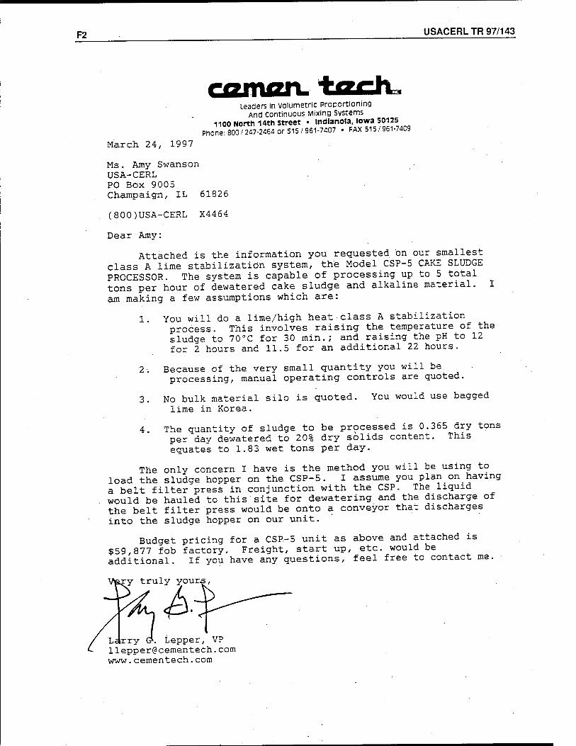
F2 USACERL TR 97/143
Leaders in volumetric Proportioning And continuous Mixing Systems
1100 North 14th Street • Indianola, Iowa 50125 Phone: 800/247-2464 or 515/961-7407 • FAX 515 / 961-7409
March 24, 1997
Ms. Amy Swanson USA-CERL PO Box 9005 Champaign, IL 61826
(800)USA-CERL X4464
Dear Amy:
Attached is the information you requested on our smallest class A lime stabilization system, the Model CSP-5 CAKE SLUDGE PROCESSOR. The system is capable of processing up to 5 total tons per hour of dewatered cake sludge and alkaline material, am making a few assumptions which are:
1. You will do a lime/high heat class A stabilization process. This involves raising the temperature of the sludge to 70°C for 30 min.; and raising the pH to 12 for 2 hours and 11.5 for an additional 22 hours.
Because of the very small quantity you will be processing, manual operating controls are quoted.
3. No bulk material silo is quoted, lime in Korea.
You would use bagged
4. The quantity of sludge to be processed is 0.365 dry tons per day dewatered to 20% dry solids content. This equates to 1.83 wet tons per day.
The only concern I have is the method you will be using to load the sludge hopper on the CSP-5. I assume you plan on having a belt filter press in conjunction with the CSP. The liquid would be hauled to this site for dewatering and the discharge of the belt filter press would be onto a conveyor that discharges into the sludge hopper on our unit.
Budget pricing for a CSP-5 unit as above and attached is $59,877 fob factory. Freight, start up, etc. would be additional. If you have any questions, feel free to contact me.
:y truly yours,
Ldrry (?. Lepper, VP llepper@cementech. com www.cementech.com
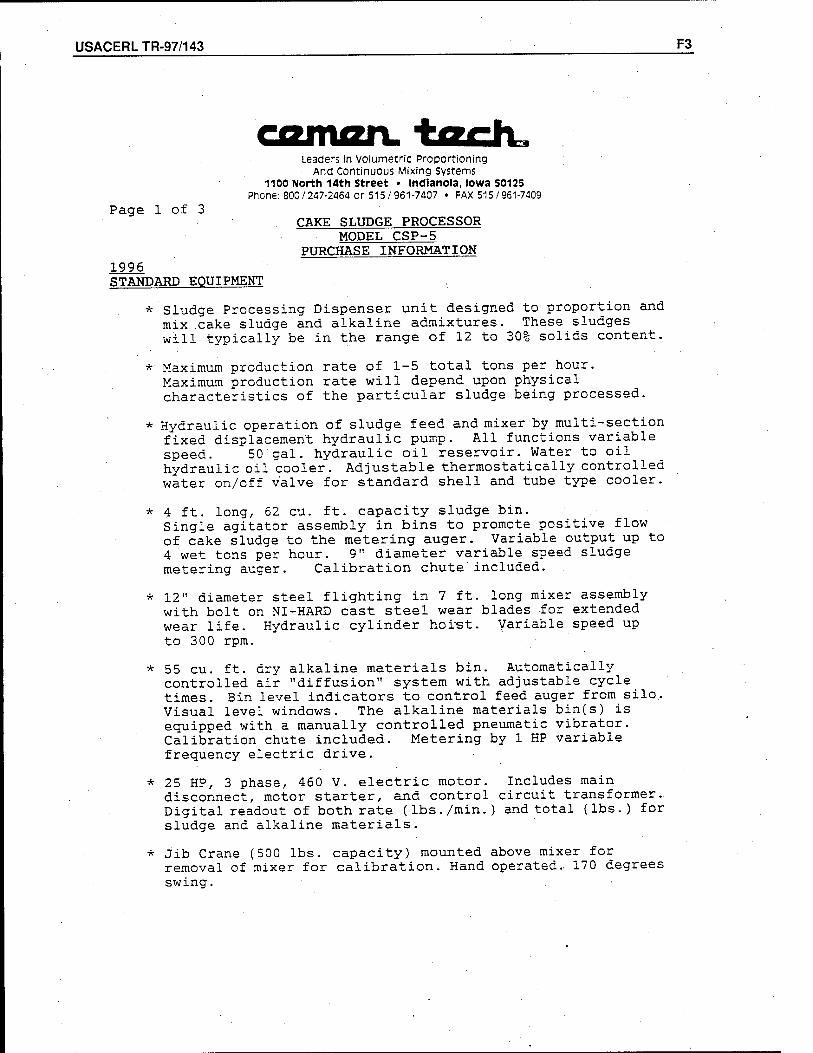
USACERLTR-97/143 F3
Leaders In volumetric Proportioning And Continuous Mixing Systems
1100 North 14th Street • Indianola, Iowa 50125 Phone: 800/247-2464 or 515/961-7407 • FAX 515 / 961-7409
Page 1 of 3 CAKE SLUDGE PROCESSOR
MODEL CSP-5 PURCHASE INFORMATION
1996 STANDARD EQUIPMENT
* Sludge Processing Dispenser unit designed to proportion and mix cake sludge and alkaline admixtures. These sludges will typically be in the range of 12 to 30% solids content.
*■ Maximum production rate of 1-5 total tons per hour. Maximum production rate will depend upon physical characteristics of the particular sludge being processed.
* Hydraulic operation of sludge feed and mixer by multi-section fixed displacement hydraulic pump. All functions variable speed. 50 gal. hydraulic oil reservoir. Water to oil hydraulic oil cooler. Adjustable thermostatically controlled water on/off valve for standard shell and tube type cooler.
* 4 ft. long,. 62 cu. ft. capacity sludge bin. Single agitator assembly in bins to promote positive flow of cake sludge to the metering auger. Variable output up to 4 wet tons per hour. 9" diameter variable speed sludge metering auger.. Calibration chute included.
* 12" diameter steel flighting in 7 ft. long mixer assembly with bolt on NI-HARD cast steel wear blades for extended wear life. Hydraulic cylinder horst. Variable speed up to 300 rpm.
* 55 cu. ft. dry alkaline materials bin. Automatically controlled air "diffusion" system with adjustable cycle times. Bin level indicators to control feed auger from silo. Visual level windows. The alkaline materials bin(s) is equipped with a manually controlled pneumatic vibrator. Calibration chute included. Metering by 1 HP variable frequency electric drive.
* 25 HP, 3 phase, 460 V. electric motor. Includes main disconnect, motor starter, and control circuit transformer.. Digital readout of both rate (lbs./min.) and total (lbs.) for sludge and alkaline materials.
* Jib Crane (500 lbs. capacity) mounted above mixer for removal of mixer for calibration. Hand operated.. 170 degrees swing.
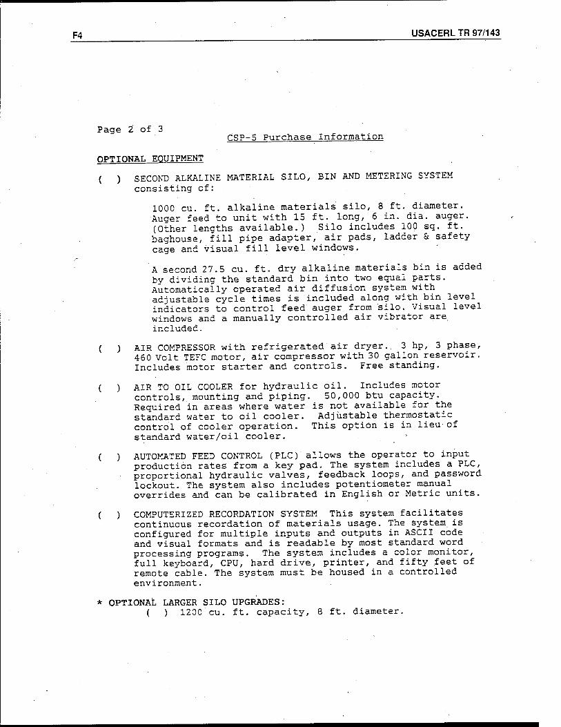
F4 USACERL TR 97/143
Page 2 of 3 CSP-5 Purchase Information
OPTIONAL EQUIPMENT
( ) SECOND ALKALINE MATERIAL SILO, BIN AND METERING SYSTEM consisting of:
1000 cu. ft. alkaline materials silo, 8 ft. diameter. Auger feed to unit with 15 ft. long, 6 in. dia. auger. (Other lengths available.) Silo includes 100 sq. ft. baghouse, fill pipe adapter, air pads, ladder & safety cage and.visual fill level windows.
A second 27.5 cu. ft. dry alkaline materials bin is added by dividing the standard bin into two equal parts. Automatically operated air diffusion system with adjustable cycle times is included along with bin level indicators to control feed auger from 'silo. Visual level windows and a manually controlled air vibrator are. included.
( ) AIR COMPRESSOR with refrigerated air dryer. 3 hp, 3 phase, 460 Volt TEFC motor, air compressor with 30 gallon reservoir. Includes motor starter and controls. Free standing.
( ) AIR TO OIL COOLER for hydraulic oil. Includes motor controls, mounting and piping. 50,000 btu capacity. Required in areas where water is not available for the standard water to oil cooler. Adjustable thermostatic control of cooler operation. This option is in lieu-of standard water/oil cooler.
( ) AUTOMATED FEED CONTROL (PLC) allows the operator to input production rates from a key pad. The system includes a PLC, proportional hydraulic valves, feedback loops, and password lockout. The system also includes potentiometer manual overrides and can be calibrated in English or Metric units.
( ) COMPUTERIZED RECORDATION SYSTEM This system facilitates continuous recordation of materials usage. The system is configured for multiple inputs and outputs in ASCII code and visual formats and is readable by most standard word processing programs. The system includes a color monitor, full keyboard, CPU, hard drive, printer, and fifty feet of remote cable. The system must be housed in a controlled environment.
* OPTIONAL LARGER SILO UPGRADES: ( ) 1200 cu. ft. capacity, 8 ft. diameter.
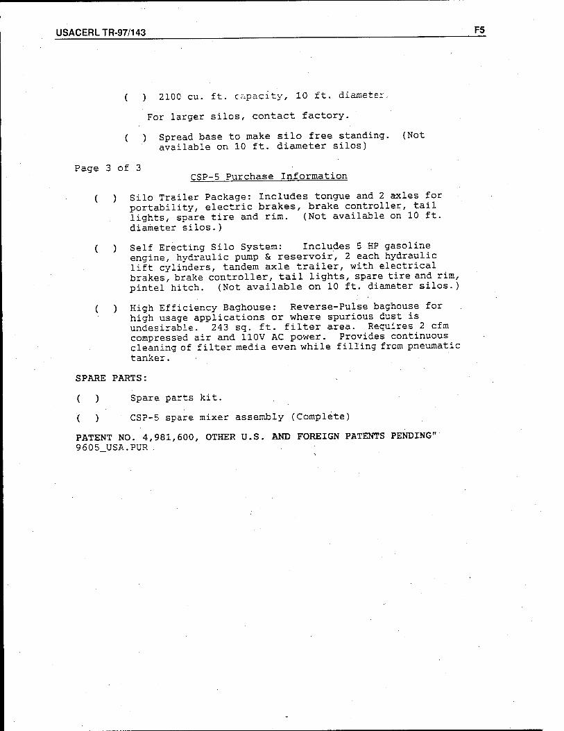
USACERL TR-97/143 F5
( ) 2100 cu. ft. capacity, 10 ft. diameter.
For larger silos, contact factory.
( ) Spread base to make silo free standing. (Not available on 10 ft. diameter silos)
Page 3 of 3 CSP-5 Purchase Information
( ) Silo Trailer Package: Includes tongue and 2 axles for portability, electric brakes, brake controller, tail lights, spare tire and rim. (Not available on 10 ft. diameter silos.)
( ) Self Erecting Silo System: Includes 5 HP gasoline engine, hydraulic pump & reservoir, 2 each hydraulic lift cylinders, tandem axle trailer, with electrical brakes, brake controller, tail lights, spare tire and rim, pintel hitch. (Not available on 10 ft. diameter silos.)
( ) High Efficiency Baghouse: Reverse-Pulse baghouse for high usage applications or where spurious dust is undesirable. 243 sq. ft. filter area. Requires 2 cfm compressed air and 110V AC power. Provides continuous cleaning of filter media even while filling from pneumatic tanker.
SPARE PARTS:
( ) Spare parts kit.
( ) CSP-5 spare mixer assembly (Complete)
PATENT NO. 4,981,600, OTHER U.S. AND FOREIGN PATENTS PENDING" 9605 USA .'PUR .
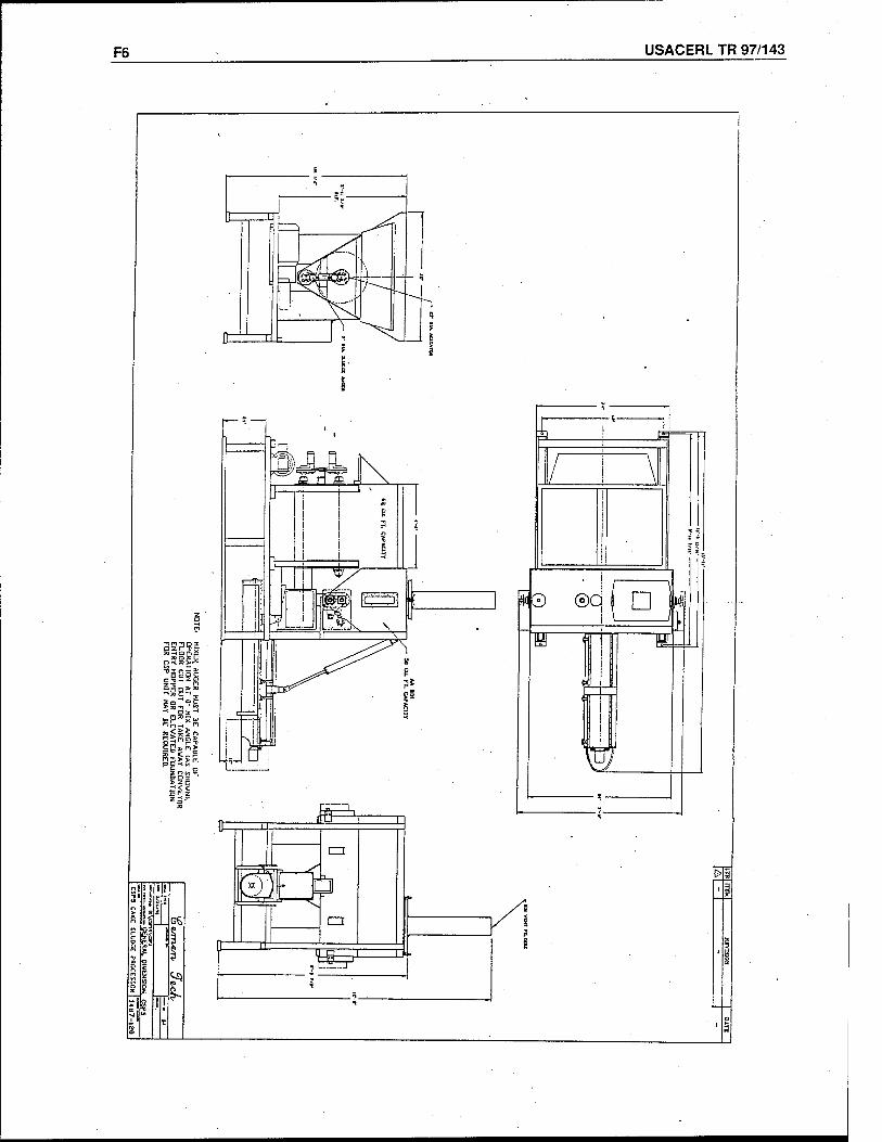
F6 USACERL TR 97/143
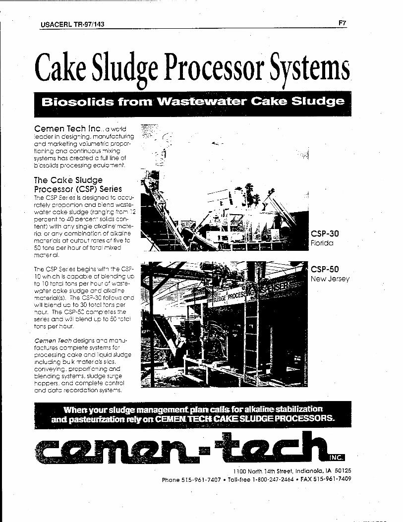
USACERLTR-97/143 F7
Cake Sludge Processor Systems Biosolids from Wastewater Cake Sludge
Cemen Tech Inc., a world leader in designing, manufacturing and marketing volumetric propor- tioning and continuous mixing systems has created a full line of biosolids processing eguipment.
The Cake Sludge Processor (CSP) Series The CSP Series is designed to accu- rately proportion and blend wcste- water cake sludge (ranging from 12 percent to 40 percent solids con- tent) with any single alkcline'mate- rial or any combination of alkaline materials at output rates cf five to 50 tons per hour of totcl mixed material.
The CSP Series begins with the CSF- 10 which is capable of blending up to 10 totci tons per hour of waste- water ecke sludge and elkciine. material(s). The CSP-30 follows and will biend up to 30 total tens per hour. The CSP-50 completes the series and will blend up to 50 totcl tons per hour.
Cemen Tech designs and manu- factures complete systems for processing cake and liquid sludge including bulk materials silos, conveying, proportioning end blending systems, sludge surge hoppers, and complete control and data recordation systems.
r:
rl
CSP-30 Florida
CSP-50 New Jersey
When your sludge management pfarecairs for alkaline stabilization and pasteurization rely on CEMEMTECK CAKE SLUDGE PROCESSORS.
1100 North 14th Street, Indianola, IA 50125 Phone 515-961-7407 • Toll-free 1-800-247-2464 • FAX 515-961-7409
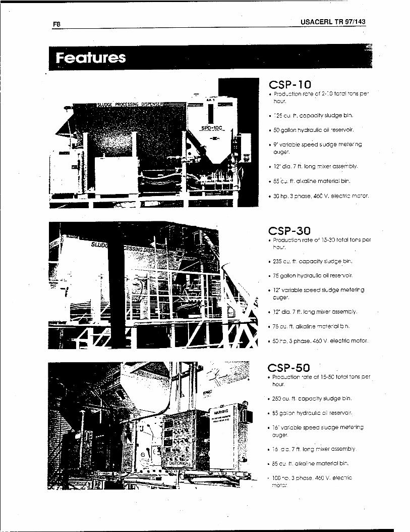
F8 USACERL TR 97/143
CSP-10 • Production rate of 2-10 total tons per
hour.
• 125 cu. ft. capacity sludge bin.
• 50 gallon hydraulic oil reservoir.
• 9" variable speed sludge metering auger.
t 12" dia. 7 ft. long mixer assembly.
• 55 cu. ft. alkaline material bin,
• 30 hp, 3 phase, 460 V, electric motor.
CSP-30 • Production rate of 15-30 total tons per
hour.
• 235 cu. ft. capacity sludge bin.
• 75 gallon hydraulic oil reservoir.
• ■ 12' variable speed sludge metering auger.
• 12" dia. 7 ft. long mixer assembly,
• 75 cu. ft. alkaline material bin.
• 50 hp, 3 phase, 460 V. electric motor.
CSP-50 • Production rate of 15-50 total tons per
hour.
• 250 cu. ft. capacity sludge bin.
• 85 gcilon hydraulic oil reservoir.
• 16" variable speed sludge metering auger,
• 16" dia. 7 ft. long mixer assembly,
• 35 cu. ft. alkaline material bin.
' 10C ho, 3 phase, 460 V. electric rnbtcr.
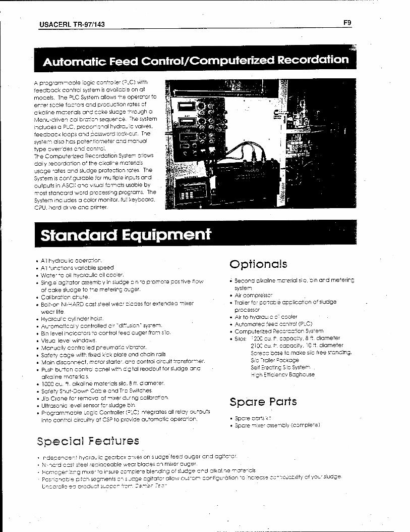
USACERLTR-97/143 F9
Automatic Feed Control/Computerized Recordation
A programmable logic controller (PLC) with feedback control system is available on all models. The PLC System allows the operator to enter scale factors and production rates of alkaline materials and cake sludge through a Menu-driven calibration sequence. The system includes a PLC, proportional hydraulic valves, feedback loops and pcssword lock-out. The system also has potentiometer and manual type overrides and control. The Computerized Recordation System cllows daily recordction of the clkaiine matericis usage rates and sludge protection rates. The System is configurable for multiple inputs and outputs in ASCII and visual formats usable by most standcrd word processing programs. The System includes a color monitor, full keyboard, CPU, hard drive and printer.
Standard Equipment All hydraulic operation. All functions varicble speed. Water to oil hydraulic oil cooler. Single agitator cssembly in sludge bin to promote positive flow of cake sludge to the metering cuger. Calibration chute. Boif-on NI-HARD cast steel wecr blcdes for extended mixer
wear life. Hydraulic cylinder hoist. Automatically controlled air "diffusion" system. Bin level indicators to control feed auger from silo. Visual levei windows. Manually controlled pneumatic vibrator. Safety cage with fixed kick plate end chain rails. Main disconnect, motor starter, end control circuit transformer. Push button control panel with digital readout for sludge and alkaline matericis. 10C0 cu. ft. aikaline materials silo, 8 ft. diameter. Safety Shut-Down Cable and Trip Switches, Jib Crane for removal of mixer during calibration. Ultrasonic level sensor for sludge bin. Programmable Logic Controller (PLC) integrates all relay outputs into contrci circuitry of CSP to provide automatic operation.
Optionals • Second elkciine material silo, bin and metering
system • Air compressor • Trailer for pcrtacie application of sludge
processor • Air to hydrcuiic oii cooler • Automated feed contrci (PLC) • Computerized Recordcfion System • Silos: 1200 cu. ft. capacity, 8 ft. diameter
210Q cu. ft. cccccity, 10 ft. diameter Spread bese to make silo free standing. Siio Trailer Package Seif Erecting Silo System High Efficiency Bcghouse
Spare Parts • Spare parts kit • Spare mixer assembly (complete)
Special Features Indepencent hydrcuiic gearbox drives on sludge'feed auger end agitator. Ni-hcrd cast steel repicceable wear blades on mixer auger. Homogenizing mixer to insure complete blending of sludge and alkaline matericis. Pcs;ficncb!e pitch segments on siucge agitator allow custom configuration to increase Unccralle'ec product suppcrt from "smsr "=.--
utility of your sludge.
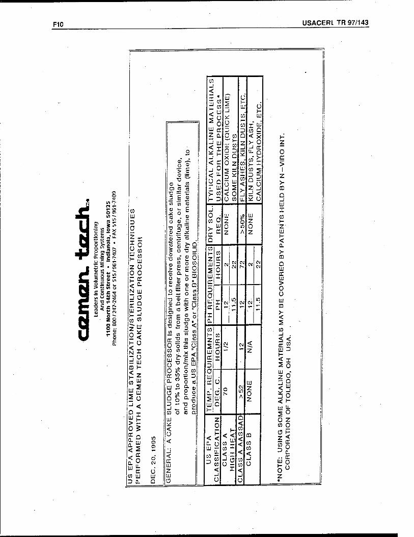
F10 USACERL TR 97/143
o t?
m i> r* T- r- o O 01 It) —
5 « £ O x = .< »a"-
Bl5 o s=SS
h5 • §
- - w *- o c u -> c o u
in O c
W <T ■o r- rx
•D c < r u t! (N
*8 O °
USACERLTR-97/143 G1
Appendix G: Davis Industries
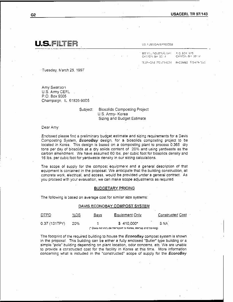
G2 USACERL TR 97/143
U.S.I U.S. FiLTtK/DAVIS PROCESS
555 MILL INDUSTÄAL WAY P. O. SCX 16'5 CA.'JTCM.SA ZC'.'i-i CANTON. SA 301!
TE-E-HCNE 77C-<:73-3C7<: FACSIMILE 770-475--
"uesday, March 25, 1997
Amy Swanson U.S. Army CERL . P.O. BoxS005 Champaign, IL 61826-9005
Subject: Biosolids Composting Project U.S. Army- Korea Sizing and Budget Estimate
Dear Amy:
Enclosed please find a preliminary budget estimate and sizing requirements for a Davis Composting System, EconoBay design, for a biosolids composting project to be located in Korea. This design is based on a composting plant to process 0.365 dry tons per day of biosolids at a dry solids content of 20% and using yardwaste as the carbon amendment. We have assumed 60 lbs. per cubic foot for biosolids density and 16 lbs. per cubic foot for yardwaste density in our sizing calculations.
The scope of supply for the compost equipment and a general description of that equipment is contained in the proposal. We anticipate that the building construction, all concrete work, electrical, and access, would be provided under a general contract. As you proceed with your evaluation, we can make scope adjustments as required.
BUDGETARY PRICING
The following is based on average cost for similar size systems:
DAVIS ECONOBAY COMPOST SYSTEM
DTPD
0.37(131TPY)
%DS Bays Equipment Only
1 S 410,000* (* Does not include transport to Korea, startup and training)
Constructed Cost
S NA.'
The footprint of the required building to house the EconoBay compost system is shown in the proposal. This building can be either a fully enclosed "Butler" type building or a simple "pole" building depending on plant location, odor concerns, etc. We are unable to provide a constructed cost for the facility in Korea at this time. More information concerning what is included in the "constructed" scope of supply for the EconoBay
USACERLTR-97/143 G3
system is included in the proposal.
We are assuming that some type of vegetative waste from yard trimmings, etc., is available as a bulking agent. Generally speaking, any source of available carbon is acceptable as a bulking agent. As the finished compost will take the physical characteristics of the bulking agent, particle size of the amendment is important. A sawdust type material probably makes the best compost, but a wide variety of amendments are acceptable.
The following is a typical analysis of compost produced by U.S. Filter, Davis Process Composting Systems using sewage sludge (chemical constituents e.g.: copper, zinc, lead, etc., will vary dependent upon industrial contribution to the sewage system).
Moisture: 40 - 50% pH: 5.5-6.5 Nitrogen: 1.0-1.7% Phosphorous: • 0.8-2.5% Potassium: 0.1-0.4% Bulk Density: . 30 - 40 lbs/cu. ft.
amy, after reviewing this material, please call me with any questions you may have. We appreciate the consideration you have given us and would like to work with you on this project. Our local salesman is Mark McGuire, who can be reached at pager (800) 815-9883.
Very truly yours,
U.S. FILTER, DAVIS PROCESS A Unit of Davis Water & Waste Industries '
Robert H. Harris Engineering & Operations Manager
Enclosures
cc: Mark McGuire
G4 USACERL TR 97/143
PROCESS di\f fffiiiniffrj-y'ww3
PROPOSAL PREPARED ESPECIALLY FOR
&
ENCLOSED MECHANICAL COMPOSTING SYSTEMS
Davis Residuals Management
USACERLTR-97/143 <*1
U. S. FILTER, Davis Process Composting Systems
Enclosed Process Solutions for Waste Management
Composting of municipal wastes in this country has been practiced since the early 1970's. The first technologies employed the "open pile" method, simply mixing the correct ratios of materials and placing them in a windrow. Because this method allowed for very little control of the composting environment, a poor quality compost product was usually the result. The process also required 6 to 9 months to convert the
waste product into compost.
In the last decade, "in-vessel or enclosed" composting has become the preferred method of composting. By confining or enclosing the process, the composting environment can be controlled by forced aeration and monitoring the process. This control over the biological composting process offers two distinct advantages over open pile composting. First the time required for composting is reduced from 6-9 months to 30-40 days, thereby greatly reducing the land requirement and manpower requirement. Second, by controlling the composting process you are able to produce a compost product of a much higher quality and greater utility.
Since 1982, U.S. FILTER, Davis Process has established itself as the leader of enclosed vessel composting technology with over 50 plants presently operating worldwide. These composting plants operate on all types of sludges, digested and non-digested, primary and secondary, and waste activated. This level of expertise and full scale plant experience makes us the world's leading in-vessel composting system vendor for composting wastewater sludges.
To date, U.S. FILTER, Davis Process has supplied systems for twelve U.S. municipalities. These include plants located in Portland, Oregon; East Richland County, South Carolina; Dothan, Alabama; Clayton County, Georgia; Endicott, New York; Lancaster, Pennsylvania; Springfield, Massachusetts; Binghamton, New York; Musconetcong Sewerage Authority, New Jersey, Bristol, Tennessee, Geneva, New York and Guelph, Ontario. The U.S. Filter Davis system has been selected as the basis of design as the most cost effective alternative for sludge management by many municipalities, and several other municipalities have decided to build the Davis system as a part of a negotiated procurement process.
ECOSTEM2M.S S.-~SS>~ S:Si?\t
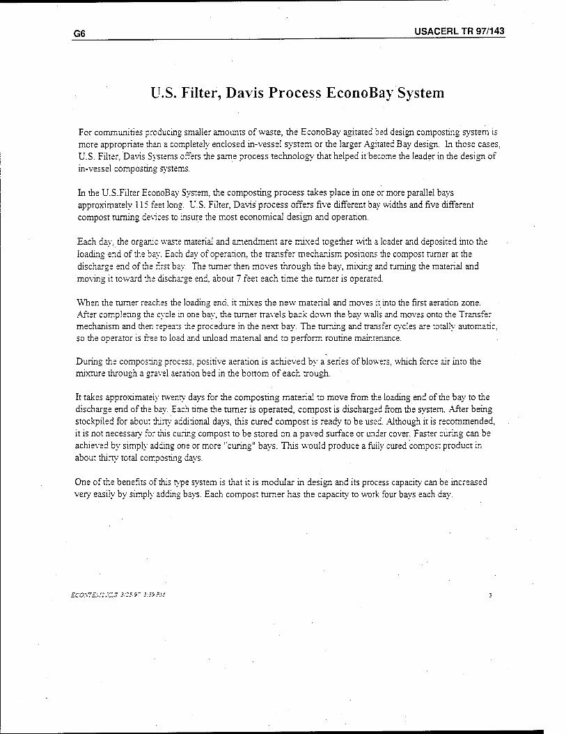
G6 USACERL TR 97/143
U.S. Filter, Davis Process EconoBay System
For communities producing smaller amounts of waste, the EconoBay agitated bed design composting system is more appropriate than a completely enclosed in-vessel system or the larger Agitated Bay design. In those cases, U.S. Filter, Davis Systems offers the same process technology that helped it become the leader in the design of in-vessel composting systems.
In the U.S.Filter EconoBay System, the composting process takes place in one or more parallel bays approximately 115 feet long. U.S. Filter, Davis process offers five different bay widths and five different compost turning devices to insure the most economical design and operation.
Each day, the organic waste material and amendment are mixed together with a loader and deposited into the loading end of the bay. Each day of operation, the transfer mechanism positions the compost turner at the discharge end of the first bay. The turner then moves through the bay, mixing and turning the material and moving it toward the discharge end, about 7 feet each time the turner is operated.
When the turner reaches the loading end, it mixes the new material and moves it into the first aeration zone. .After complenng the cycle in one bay, the turner travels back down the bay walls and moves onto the Transfer mechanism and then repeats the procedure in the next bay. Tne turning and transfer cycles are totally automatic, so the operator is free to load and unload material and to perform routine maintenance.
During the composting process, positive aeration is achieved by a series of blowers, which force air into the mixture through a gravel aeration bed in the bottom of each trough.
It takes approximately twenty days for the composting material to move from the loading end of the bay to the discharge end of the bay. Each time the turner is operated, compost is discharged from the system. After being stockpiled for about thirty additional days, this cured compost is ready to be used. Although it is recommended, it is not necessary for this curing compost to be stored on apaved surface or under cover. Faster curing can be achieved by simply adding one or more "curing" bays. This would produce a fully cured compost product in about thirty total composting days.
One of the benefits of this type system is that it is modular in design and its process capacity can be increased very easily by simply adding bays. Each compost turner has the capacity to work four bays each day.
ECOSTE\::JCS *;is.i~ i:yj?si
USACERLTR-97/143 Q7
U.S. Filter, Davis Process Composting
Sizing Data
Typical EconoBay Composting System
The following three pages are sizing requirements for a composting system to compost the organic wastes specified. The number of composting bays required is dictated by the number of days process retention time and the length of the bays. A standard bay length of 115 feet (105 feet process length) will allow for 21 days retention time if the plant is operated (loaded) 5 days per week. The material is moved and agitated five days per week. If longer retention is desired or if the plant operates 7 days per week, it may be preferable to increase the length of each bay rather than increase the number of bay. This eliminates the need for additional materials handling.
EC0.\7£MZJZS 3/25/97 2:39 PM
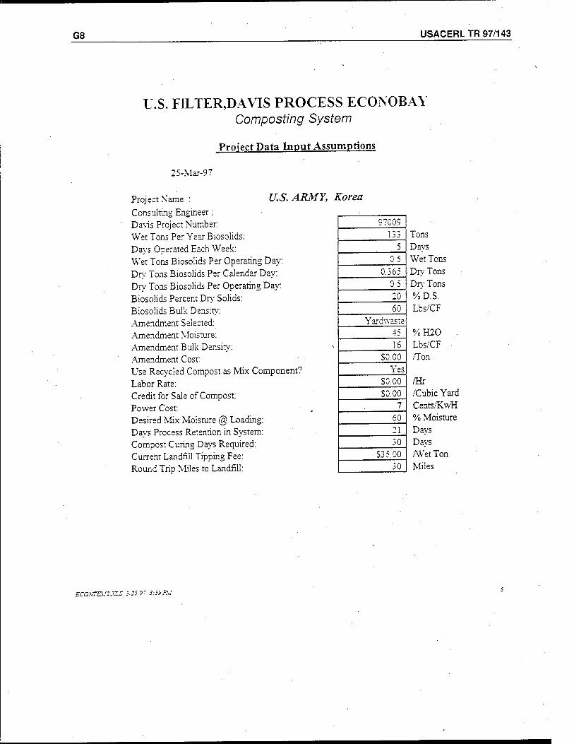
G8 USACERL TR 97/143
U.S. FILTER,DAVIS PROCESS ECONOBAY Composting System
Project Data Input Assumptions
25-Mar-97
Project Name : Consulting Engineer: Davis Project Number: Wet Tons Per Year Biosolids: Days Operated Each Week: Wet Tons Biosolids Per Operating Day: Dry Tons Biosolids Per Calendar Day: Dry Tons Biosolids Per Operating Day: Biosolids Percent Dry Solids: Biosolids Bulk Density: .Amendment Selected: .Amendment Moisture: Amendment Bulk Density: Amendment Cost: Use Recycled Compost as Mix Component Labor Rate: Credit for Sale of Compost: Power Cost: Desired Mix Moisture @. Loading: Days Process Retention in System: Compost Curing Days Required: Current Landfill Tipping Fee: Round Trip Miles to Landfill:
U.S. ARMY, Korea
97009 133 Tons
5 Davs 0.5 Wet Tons
0.365 Drv Tons 0.5 Dry Tons •20 %D.S. 60 Lbs/CF
Yardwaste 45 % H20 16 Lbs/CF
S0.00 /Ton Yes
S0.00 /Hr S0.00 /Cubic Yard
7 Cents/KwH 60 % Moisture 21 Days 30 Davs
S3 5.00 /Wet Ton 30 Miles
ECO.VTE\f2.XLS 3.3S »' 3:3» P.U
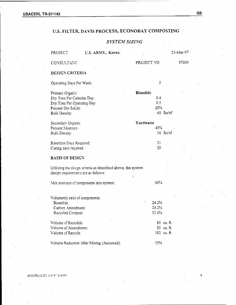
USACERLTR-97/143 G9
U.S. FILTER, DAVIS PROCESS, ECONOBAY COMPOSTING
SYSTEMSIZING
PROJECT: U.S. ARMY, Korea
CONSULTANT:
DESIGN CRITERIA
Operating Days Per Week:
Primary Organic: Dry Tons Per Calendar Day: Dry Tons Per Operating Day: Percent Dry Solids: Bulk Density:
Secondary Organic: Percent Moisture: Bulk Densitv:
PROJECT NO:
25-Mar-97
97009
Biosolids 0.4 0.5
20% 60 lbs/cf
Yardwaste
Retention Days Required: Curing days required:
BASIS OF DESIGN
Utilizing the design criteria as described above, the system design requirements are as follows:
Mix moisture of components into system:
45% 16 lbs/cf
21 30
60%
Volumetric ratio of components: Biosolids: Carbon Amendment: Recycled Compost:
Volume of Biosolids: Volume of .Amendment: Volume of Recycle:
Volume Reduction .After Mixing (Assumed):
24.2% 24.2% 51.6%
85 cu. ft 85 cu. ft
182 cu. ft
15%
ECOSTEM2J<LS 323 9' 3:39 PM
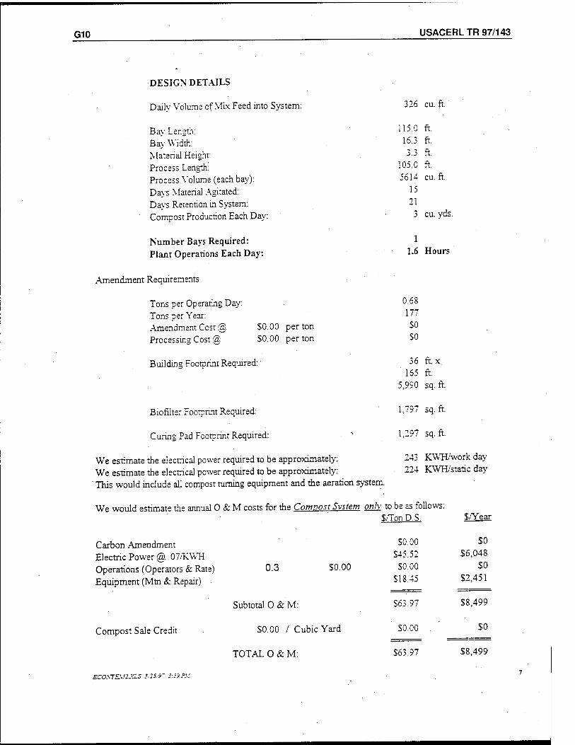
G10 USACERL TR 97/143
DESIGN DETAILS
Daily Volume of Mix Feed into System:
Bay Length: Bay Width: Material Height: Process Length: Process Volume (each bay): Days Material Agitated: Days Retention in System: Compost Production Each Day:
Number Bays Required: Plant Operations Each Day:
326 cu. ft.
115.0 ft. 16.3 ft. 3.3 ft.
105.0 ft. 5614 cu. ft.
15 21
3 cu. yds
1 1.6 Hours
Amendment Requirements
Tons per Operating Day: Tons per Year: Amendment Cost @ $0.00 per ton Processing Cost @. $0.00 per ton
Building Footprint Required:
Biofilter Footprint Required:
Curing Pad Footprint Required:
We estimate the electrical power required to be approximately: We estimate the electrical power required to be approximately:
' This would include all compost turning equipment and the aeration system.
We would estimate the annual O & M costs for the Compost System only to be as follows
Carbon Amendment Electric Power @ .07/KWH Operations (Operators & Rate) Equipment (Mm & Repair)
Compost Sale Credit
0.68
177
SO
SO
36
165
5,990
ft.x ft. sq. ft.
1,797 sq. ft.
1,297 sq. ft.
243
224
KWH/work day KWH/static day
$/TonD.S. $/Year
S0.00 $0
S45.52 $6,048
0.3 S0.00 S0.00 SO
SI 8.45 $2,451
Subtotal O & M: S63.97 $8,499
$0.00 / Cubic Yard S0.00 $0
TOTAL O&M: S63.97 $8,499
ECO\TE\f2.XLS 1,25,9- >:-9P.'.f
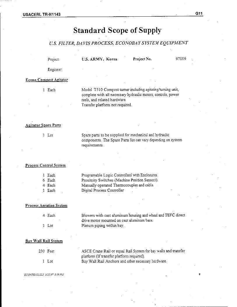
USACERLTR-97/143 G11
Standard Scope of Supply
U.S. FILTER, DAVIS PROCESS, ECONOBAY SYSTEM EQUIPMENT
Project:
Engineer:
Econo Compost Agitator
1 Each
U.S.ARMY, Korea Project No. 97009
Model T510 Compost turner including agitating'tuming unit, complete with all necessary hydraulic motors, controls, power reels, and related hardware. Transfer platform not required.
Agitator Spare Parts
1 Lot Spare parts to be supplied for mechanical and hydraulic components. The Spare Parts list can vary depending on system requirements.
Process Control Svstem
1 Each 6 Each 4 Each 1 Each
Process Aeration Svstem
Programable Logic Controllers with Enclosures. Proximity Switches (Machine Position Sensors). Manually operated Thermocouples and cable. Digital Process Controller
4 Each
1 Lot
Blowers with cast aluminum'housing and wheel and TEFC direct drive motor mounted on cast aluminum base. Plenum piping within bay.
Bav Wall Rail Svstem
230 Feet
1 Lot
ASCE Crane Rail or equal Rail System for bay walls and transfer platform (If transfer platform required). Bay Wall Rail Anchors and other necessary hardware.
ECOKTEU2J2.S 3/25/97 3:39 PM
G12 USACERL TR 97/143
Mixing Equipment
1 Each Batch Mixer unit with automatic weight scales. (Optional, but included in estimate)
Biomass Moisture Adjustment Svstem
1 Each Header system with directional spray nozzles to adjust moisture of composting material if necessary.
Start-up and Training
1 Lot System start-up and initial operational assistance, including operator training for process operations and equipment maintenence.
ECOSTE.V2.XLS 3/25/97 3:39 PM
USACERLTR-97/143 G13
Not included in U.S. FILTER,Davis Equipment Scope of Supply
Constracrion Management Grading. Site Preparation, and Foundation Site Utilities Concrete Construction Cure Pad Paving Building or Building Erection Aeration Gravel Heating, Ventilation, .Air Conditioning Building Electric and Lighting Motor Control Centers Plumbing Aeration Piping Outside of Bay Walls Rolling Equipment (except Mixer Truck) Amendment Storage, Metering & Transporting System Amendment Processing Equipment Odor Control Equipment Installation and Erection of Equipment Conveying Systems Outside of Compost Building Dewatering Equipment Permitring and Site Engineering Bonding and Taxes
The estimated "Constructed" price includes all composting equipment, enclosed compost building, all slab and bay wall concrete work, building erection and installation of equipment, electrical, and system engineering. Land cost, site preperation, site utilities,Aand any equipment not contained in Davis' scope of supply or specifically noted are not included in this estimate.
The estimated price provided with this proposal is based on current pricing and assumes a twelve month construction period. This is an estimate only, and prices are subject to change without notice at any time.
£CO.\T£W.C5 i2.' >" .'.-.'P.'.'.' 10
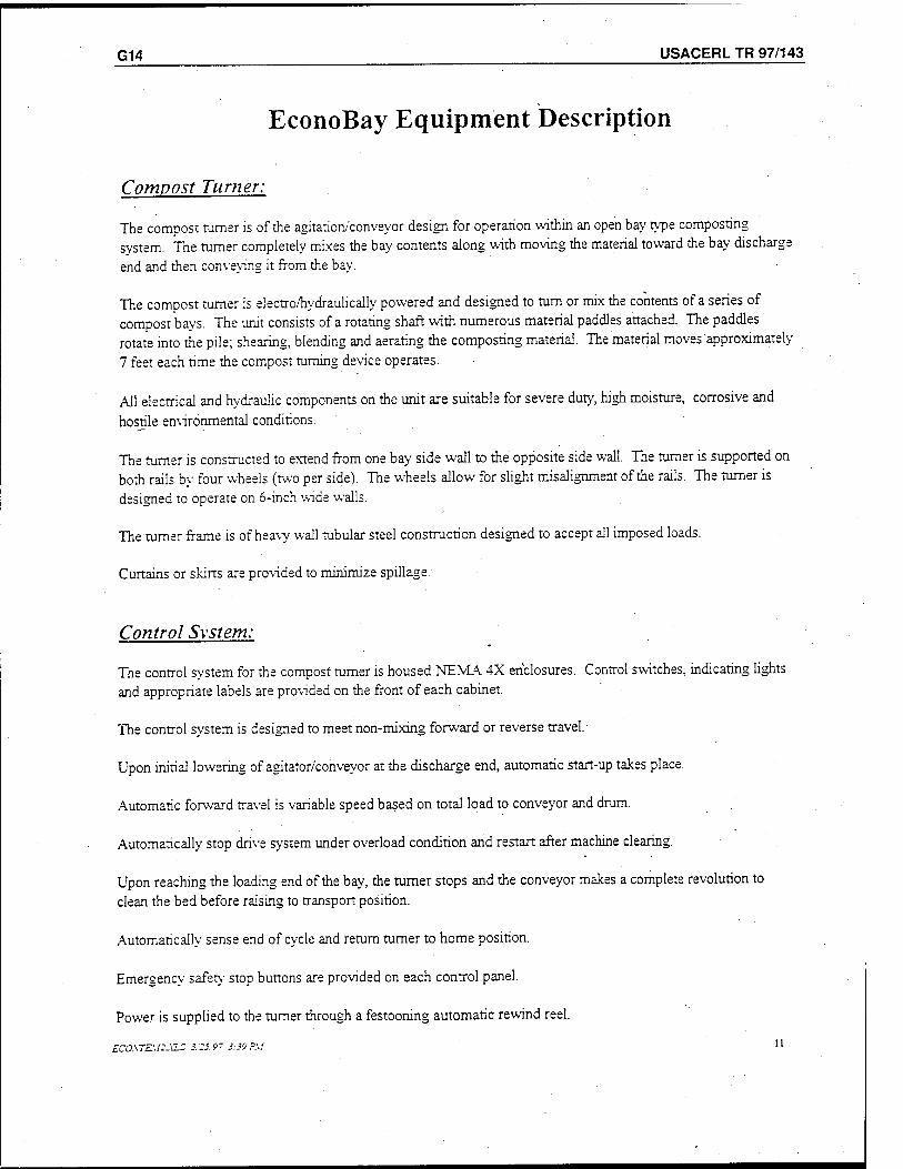
G14 USACERL TR 97/143
EconoBay Equipment Description
Compost Turner:
The compost turner is of the agitation/conveyor design for operation within an open bay type composting system. The turner completely mixes the bay contents along with moving the material toward the bay discharge
end and then conveying it from the bay.
The compost turner is electro/hydraulically powered and designed to turn or mix the contents of a series of compost bays. The unit consists of a rotating shaft with numerous material paddles attached. The paddles rotate into the pile; shearing, blending and aerating the composting material. The material moves approximately
7 feet each rime the compost turning device operates.
All electrical and hydraulic components on the unit are suitable for severe duty, high moisture, corrosive and
hostile environmental conditions.
The turner is constructed to extend from one bay side wall to the opposite side wall. The turner is supported on both rails by four wheels (two per side). The wheels allow for slight misalignment of the rails. The turner is
designed to operate on 6-inch wide walls.
The turner frame is of heavy wall tubular steel construction designed to accept all imposed loads.
Curtains or skirts are provided to minimize spillage.
Control System:
The control system for the compost turner is housed NEMA 4X enclosures. Control switches, indicating lights and appropriate labels are provided on the front of each cabinet.
The control system is designed to meet non-mixing forward or reverse travel.
Upon initial lowering of agitator/conveyor at the discharge end, automatic start-up takes place.
Automatic forward travel is variable speed based on total load to conveyor and drum.
Automatically stop drive system under overload condition and restart after machine clearing.
Upon reaching the loading end of the bay, the turner stops and the conveyor makes a complete revolution to clean the bed before raising to transport position.
Automatically sense end of cycle and return turner to home position.
Emergency safety stop buttons are provided on each control panel.
Power is supplied to the turner through a festooning automatic rewind reel.
ECOSTZ.U2J-ZZ 3.25.9- 3:39 ?M u
USACERLTR-97/143 G15
Aeration System:
The aeration system consists of a series of blowers in each standard length bay. Each blower feeds air into a separate aeration plenum in the floor of the bay. The blowers supply necessary oxygen to the biomass and can be used for temperature control. Each blower is controlled based on temperatures throughout the bay. .
A thermocouple assembly is provided for each blower to be mounted in each aeration zone.
Each blower has a piping assembly to supply air distribution in each plenum to properly control the biomass conditions.
Moisture Control System:
Each bay is supplied with an overhead moisture adjustment system consisting of PVC headers with directional spray nozzles to adjust the moisture content of the bay contents if necessary. If the moisture content of the composting biomass falls below desired levels, water can be added at precise volumes to adjust the moisture of the compost and return the process to optimum composting conditions.
ECO.\TE!.!2jaS 3:25.97 3:39 P\t
G16 , USACERL TR 97/143
U.S. Filter, Davis Composting
Typical EconoBay System Drawings
The drawings that follow are for a typical EconoBay system of the size necessary to process the volume of wastes specified. The building dimensions stated in the sizing requirements for the system are approximate and can be modified depending upon equipment selection and space requirements:
ECOSTZM2.XLS 3/25/9? 3:39 PM
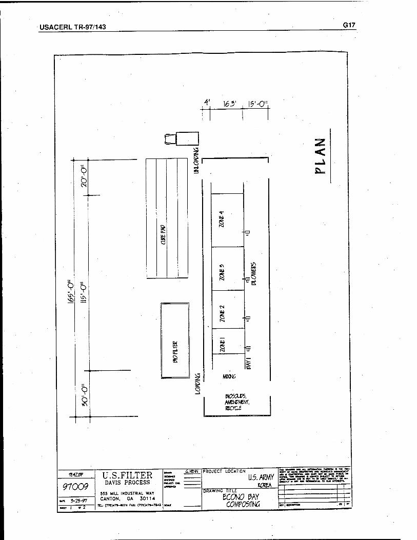
USACERLTR-97/143 G17
MS
O CM
o vis
8
TE425P
97009 •« 5-25-?7
"1 VT
,4' 16.?' , Ig'-O1
s
1
£
^
II MEOW
acmes. AMENDMENT. ISCYGi
Ü.S.FILTER DAVIS PROCESS
555 MIR INDUSTRIAL WAT CANTON, GA 30114
a.**** PROJECT LOCATION
U5.W K3SA
DRAWING TITLE
KONÖ PAY COMPOSTING
POTT of wa LI—WIT—I «• ■
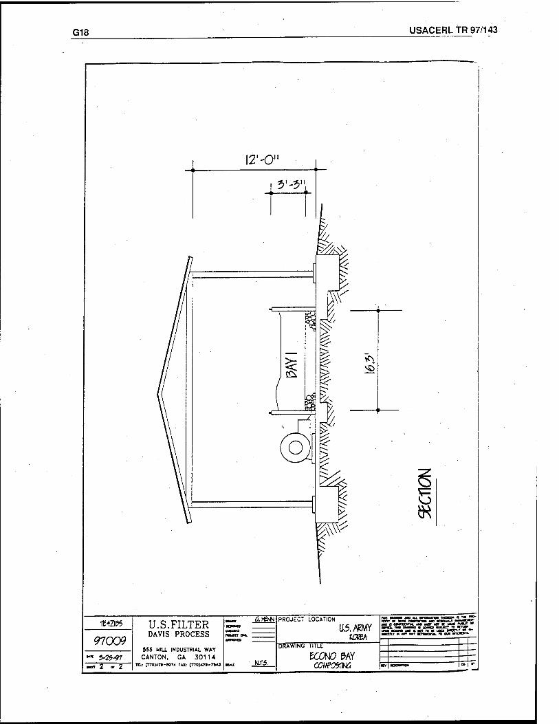
G18 USACERL TR 97/143
IK
97009 ' ?-2g-97 m 2 "2
U.S.FILTER DAVIS PROCESS
S55 HILL INDUSTRIAL WAY CANTON. GA 301U
TO: C*70>*7»-BO74 PA* C7T0H7»-7**3
a.¥ti*i
N.T5,
PROJECT LOCATION
U.5.,*KMY KCKA
DRAWING TITLE
KOtf PAY
USACERLTR-97/143 -H1
Appendix H: Resource Recovery Systems
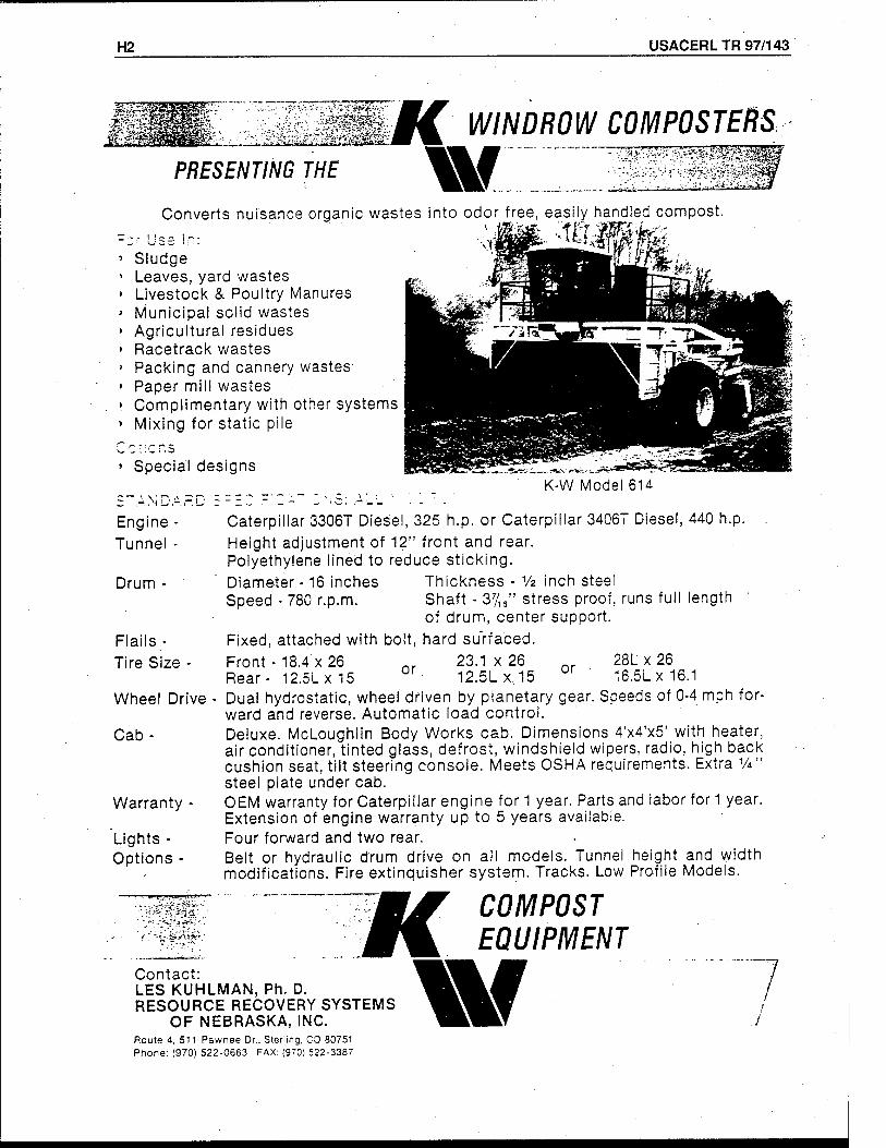
H2 USACERL TR 97/143
PRESENTING THE
§£ WINDROW COMPOSTERS
w:::z3! ;y-'u,-.ayj.i^"-.,uJK.!!'
Converts nuisance organic wastes into odor free, easily handled compost.
Sludge Leaves, yard wastes Livestock & Poultry Manures Municipal solid wastes Agricultural residues Racetrack wastes Packing and cannery wastes- Paper mill wastes Complimentary with other systems Mixing for static pile
' Special designs K-W Model 614
Engine Tunnel
Drum -
Flails- Tire Size -
Wheel Drive
Cab-
Warranty -
Lights - Options -
'" <* C',*.J-JI. '-''■"' *
' * - ;•'*".*"■£ f'■,"!* *' '_
Caterpillar 3306T Diesel, 325 h.p. or Caterpillar 3406T Diesel, 440 h.p. Height adjustment of 12" front and rear. Polyethylene lined to reduce sticking. Diameter -16 inches Speed - 780 r.p.m.
Thickness - Vz inch steel Shaft - 37/16" stress proof, runs full length of drum, center support.
Fixed, attached with bolt, hard surfaced. Front - 18.4 x 26 nr 23.1x26 nr 28Lx26 Rear- 12.5LX15 0r 12.5Lx,15 or ' 16.5L x 16.1 Dual hydrostatic, wheel driven by planetary gear. Speeds of 0-4 mph for- ward and reverse. Automatic load control. Deluxe. McLoughlin Body Works cab. Dimensions 4'x4'x5' with heater, air conditioner, tinted glass, defrost, windshield wipers, radio, high back cushion seat, tilt steering console. Meets OSHA requirements. Extra V*" steel plate under cab. OEM warranty for Caterpillar engine for 1 year. Parts and labor for 1 year. Extension of engine warranty up to 5 years available. Four forward and two rear. • Belt or hydraulic drum drive on all models. Tunnel height and width modifications. Fire extinguisher system. Tracks. Low Profile Models.
Contact: LES KUHLMAN, Ph. D. RESOURCE RECOVERY SYSTEMS
OF NEBRASKA, INC. Route 4, 511 Pawnee Dr.. Sterling. CO 80751 Phone: (970) 522-0663 FAX: (970) 522-3387
K W
COMPOST EQUIPMENT
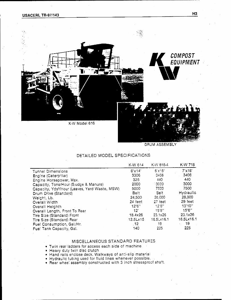
USACERLTR-97/143 H3
COMPOST EQUIPMENT
DRUM ASSEMBLY
DETAILED MODEL SPECIFICATIONS
K-W 614 K-W 616-4 K-W 718
Tunnel Dimensions 6'x14' 6'x16' 7'x1B' Engine (Caterpillar) 3306 3406 3406 Engine Horsepower, Max. 325 440 440 Capacity, Tons/Hour (Sludge & Manure) 2000 3000 3000 Capacity, YdsVHour (Leaves, Yard Waste, MSW) 5000 7500 7500 Drum Drive (Standard) Belt Belt Hydraulic Weight, Lb. 24,500 26.000 28,000 Overall Width 24 feet 27 feet 29 feet Overall Heighth 12'6" 12'6" 13'10" Overall Length. Front To Rear 12' 15'6" 15*6" Tire Size (Standard) Front 18.4x26 23.1x26 23.1x26 Tire Size (Standard) Rear 12.5LX15 16.51x16.1 16.5LX16.1 Fuel Consumption, Gal./Hr. 12 19 19 Fuel Tank Capacity, Gal. 140 225 225
MISCELLANEOUS STANDARD FEATURES Twin rear ladders for access each side of machine Heavy duty twin disc clutch Hand rails enclose deck. Walkways of anti-slip material Hydraulic tubing used for fluid lines whenever possible. Rear wheel assembly constructed with 3 inch stressproof shaft.
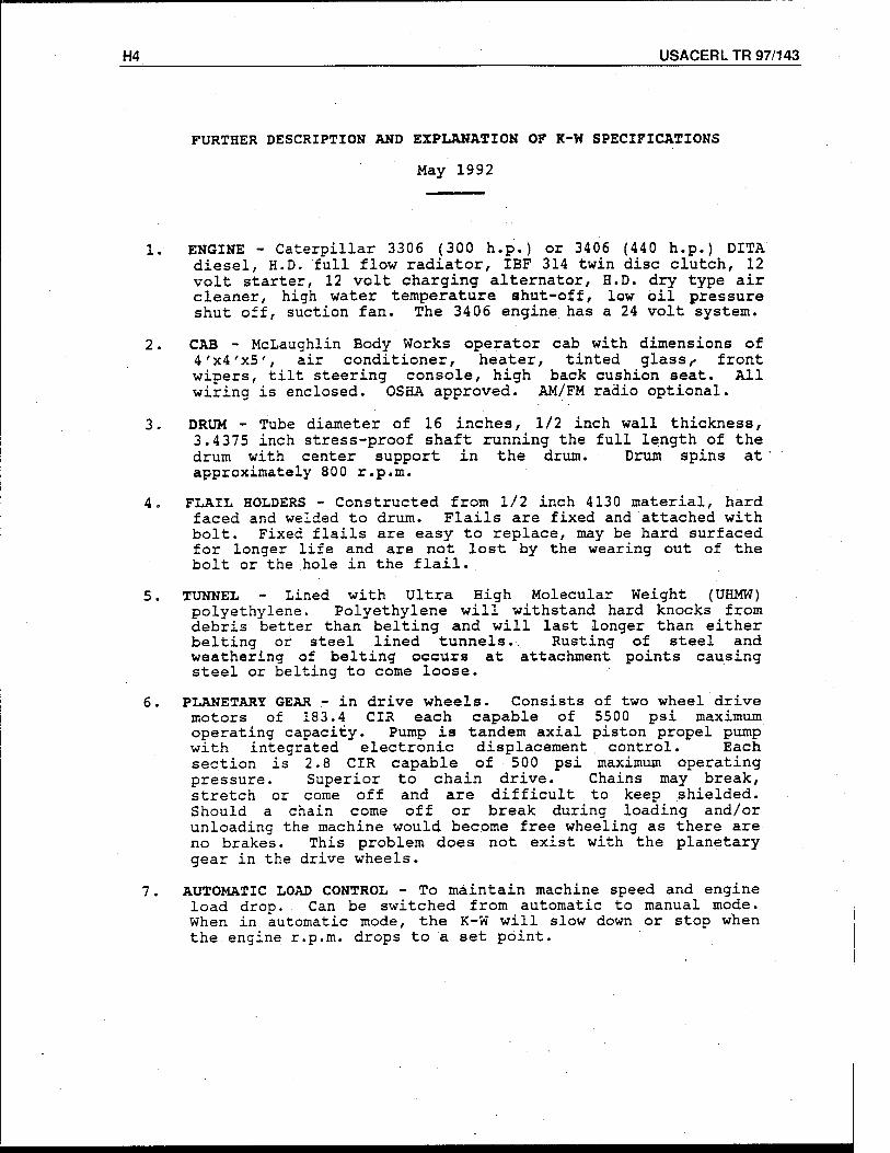
H4 USACERL TR 97/143
FURTHER DESCRIPTION AND EXPLANATION OF K-W SPECIFICATIONS
May 1992
1. ENGINE - Caterpillar 3306 (300 h.p.) or 3406 (440 h.p.) DITA diesel, H.D. full flow radiator, IBF 314 twin disc clutch, 12 volt starter, 12 volt charging alternator, H.D. dry type air cleaner, high water temperature shut-off, low oil pressure shut off, suction fan. The 3406 engine has a 24 volt system.
2. CAB - McLaughlin Body Works operator cab with dimensions of 4'x4'x5', air conditioner, heater, tinted glass,- front wipers, tilt steering console, high back cushion seat. All wiring is enclosed. OSHA approved. AM/FM radio optional.
3. DRUM - Tube diameter of 16 inches, 1/2 inch wall thickness, 3.4375 inch stress-proof shaft running the full length of the drum with center support in the drum. Drum spins at ' approximately 800 r.p.m.
4. FLAIL HOLDERS - Constructed from 1/2 inch 4130 material, hard faced and welded to drum. Flails are fixed and attached with bolt. Fixed flails are easy to replace, may be hard surfaced for longer life and are not lost by the wearing out of the bolt or the hole in the flail.
5. TUNNEL - Lined with Ultra High Molecular Weight (UHMW) polyethylene. Polyethylene will withstand hard knocks from debris better than belting and will last longer than either belting or steel lined tunnels.. Rusting of steel and weathering of belting occurs at attachment points causing steel or belting to come loose.
6. PLANETARY GEAR - in drive wheels. Consists of two wheel drive motors of 183.4 CIR each capable of 5500 psi maximum operating capacity. Pump is tandem axial piston propel pump with integrated electronic displacement control. Each section is 2.8 CIR capable of 500 psi maximum operating pressure. Superior to chain drive. Chains may break, stretch or come off and are difficult to keep shielded. Should a chain come off or break during loading and/or unloading the machine would become free wheeling as there are no brakes. This problem does not exist with the planetary gear in the drive wheels.
7. AUTOMATIC LOAD CONTROL - To maintain machine speed and engine load drop. Can be switched from automatic to manual mode. When in automatic mode, the K-W will slow down or stop when the.engine r.p.m. drops to a set point.
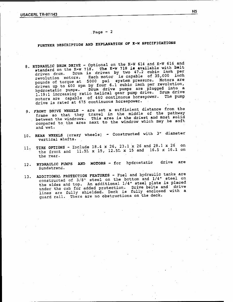
USACERLTR-97/143 H5
Page - 2
FURTHER DESCRIPTION AND EXPLANATION OF K-W SPECIFICATIONS
8 HYDRAULIC DRUM DRIVE - Optional on the K-W 614 and K-W616 and standard on the K-W 718. The K-W 718 ü available with.belt dr Ken drum. Drum is driven by two 47 2 cubic inch p revolution motors. Each motor is capable of 35,000 inch pounds of torque at 5000 psi system pressure. Motors are driven up to 600 rpm by four 6.1 cubic inch per revolution, hydrostatic pumps. Drum drive pumps are plugged into a 1 19:1 increasing ratio helical gear pump drive. Drum drive motors are capable of 460 continuous horsepower. The pump drive is rated at 675 continuous horsepower.
9 FRONT DRIVE WHEELS - are set a sufficient distance from the frame so that they travel in the middle of the pathway between the windrows. This area is the driest and most solid
' compared to the area next to the windrow which may be soft and wet.
10. REAR WHEELS (crazy wheels) - Constructed with 3" diameter vertical shafts.
11. TIRE OPTIONS - Include 18.4 x 26, 23.1 x 26 and 28.1 x 26 on the front and 11.5L x 15, 12.5L x 15 and 16.5 x 16.1 on the rear.
12. HYDRAULIC PUMPS AND MOTORS - for hydrostatic drive are Sundstrand.
13 ADDITIONAL PROTECTION FEATURES - Fuel and hydraulic tanks are constructed of 3/8" steel on the bottom and 1/4" .steel on the sides and top. An additional 1/4" steel plate is placed under the cab for added protection. Drive belts and drive lines are fully shielded. Deck is fully enclosed with a guard rail. There are no obstructions on the deck.
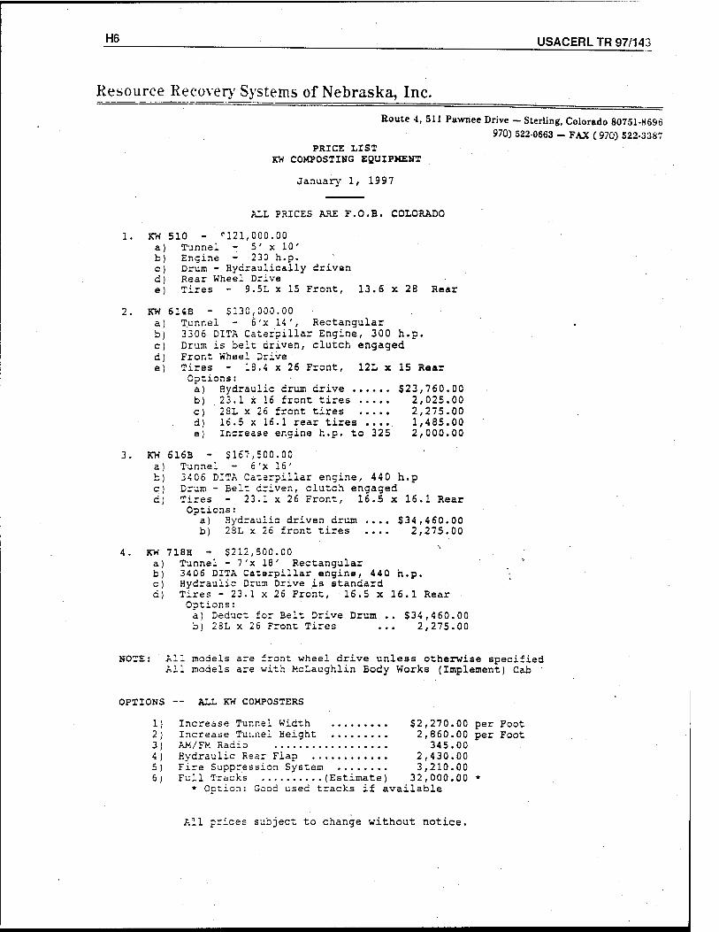
H§ ___ USACERL TR 97/143
Resource Recover)'Systems of Nebraska, Inc.
Route 4, 511 Pawnee Drive - Sterling, Colorado 80751-8696 970) 522-0663 - FAX ( 970) 522-3387
PRICE LIST KW COMPOSTING EQUIPMENT
January 1, 1997
ALL PRICES ARE F.O.B. COLORADO
1. KW 510 - '■121,000.00 a) Tunnel - 5' x 10' b) Engine - 230 h.p. c) Drum - Hydraulically driven d) Rear Wheel Drive e) Tires - 9.5L x 15 Front, 13.6 x 28 Rear
2. KW 614B - $130,000.00 a) Tunnel - 6'x 14', Rectangular b) 3306 DITA Caterpillar Engine, 300 h.p. c) Drum is belt driven, clutch engaged d) Front Wheel Drive e) Tires - 18.4 x 26 Front, 12L x 15 Rear
Options: a) Hydraulic drum drive $23,760.00 b) 23.1 x 16 front tires 2,025.00 c) 28L x 26 front tires 2,275.00 d) 16.5 x 16.1 rear tires .... 1,485.00 e) Increase engine h.p. to 325 2,000.00
3. KW 616B - $167,500.00 a) Tunnel - 6'x 16' b) 3406 DITA Caterpillar engine, 440 h.p c) Drum - Belt driven, clutch engaged d) Tires - 23.1 x 26 Front, 16.5 x 16.1 Rear
Options: a) Hydraulic driven drum .... $34,460.00 b) 28L x 26 front tires .... 2,275.00
4. KW 718H - $212,500.00 " a) Tunnel - 7'x 18' Rectangular b) 3406 DITA Caterpillar engine, 440 h.p. c) Hydraulic Drum Drive is standard d) Tires - 23.1 x 26 Front, 16.5 x 16.1 Rear
Options: a) Deduct for Belt Drive Drum .. $34,4 60.00 b) 28L x 26 Front Tires ... 2,275.00
NOTE: All models are front wheel drive unless otherwise specified Ail models are with McLaughlin Body Works (Implement) Cab
OPTIONS — ALL KW CCMPOSTERS
1) Increase Tunnel Width $2,270.00 per Foot 2) Increase Tui.nel Height 2,860.00 per Foot 3) AM/FM Radio 345.00 4) Hydraulic Rear Flap 2,430.00 5) Fire Suppression System 3,210.00 6) Full Tracks (Estimate) 32,000.00 *
» Ootion: Good used tracks if available
All prices subject to change without notice.
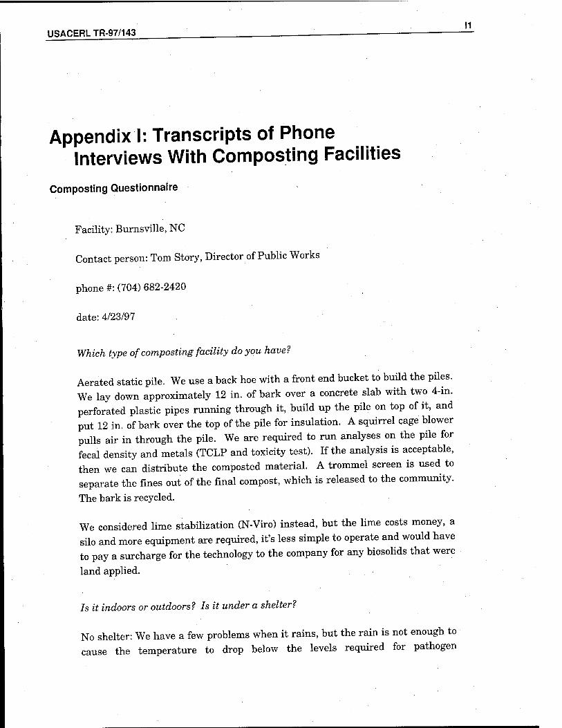
USACERL TR-97/143 .
Appendix I: Transcripts of Phone Interviews With Composting Facilities
Composting Questionnaire
Facility: Burnsville, NC
Contact person: Tom Story, Director of Public Works
phone #: (704) 682-2420
date: 4/23/97
Which type of composting facility do you have?
Aerated static pile. We use a back hoe with a front end bucket to build the piles. We lay down approximately 12 in. of bark over a concrete slab with two 4-in. perforated plastic pipes running through it, build up the pile on top of it, and put 12 in. of bark over the top of the pile for insulation. A squirrel cage blower pulls air in through the pile. We are required to run analyses on the pile for fecal density and metals (TCLP and toxicity test). If the analysis is acceptable, then we can distribute the composted material. A trommel screen is used to separate the fines out of the final compost, which is released to the community.
The bark is recycled.
We considered lime stabilization (N-Viro) instead, but the lime costs money, a silo and more equipment are required, it's less simple to operate and would have to pay a surcharge for the technology to the company for any biosolids that were
land applied.
Is it indoors or outdoors? Is it under a shelter?
No shelter: We have a few problems when it rains, but the rain is not enough to cause the temperature to drop below the levels required for pathogen
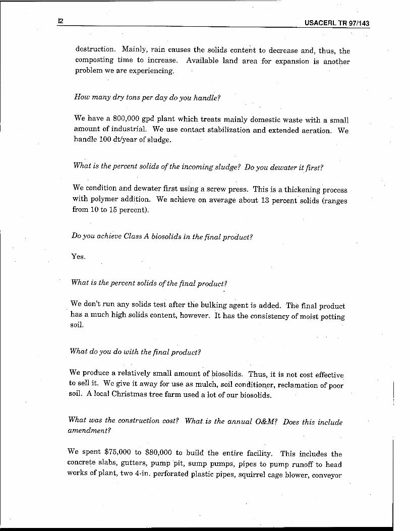
J? USACERL TR 97/143
destruction. Mainly, rain causes the solids content to decrease and, thus, the composting time to increase. Available land area for expansion is another problem we are experiencing.
How many dry tons per day do you handle?
We have a 800,000 gpd plant which treats mainly domestic waste with a small amount of industrial. We use contact stabilization and extended aeration. We handle 100 dt/year of sludge.
What is the percent solids of the incoming sludge ? Do you dewater it first?
We condition and dewater first using a screw press. This is a thickening process with polymer addition. We achieve on average about 13 percent solids (ranges from 10 to 15 percent).
Do you achieve Class A biosolids in the final product?
Yes.
What is the percent solids of the final product ?
We don't run any solids test after the bulking agent is added. The final product has a much high solids content, however. It has the consistency of moist potting soil.
What do you do with the final product?
We produce a relatively small amount of biosolids. Thus, it is not cost effective to sell it. We give it away for use as mulch, soil conditioner, reclamation of poor soil. A local Christmas tree farm used a lot of our biosolids.
What was the construction cost? What is the annual O&M? Does this include amendment?
We spent $75,000 to $80,000 to build the entire facility. This includes the concrete slabs, gutters, pump pit, sump pumps, pipes to pump runoff to head works of plant, two 4-in. perforated plastic pipes, squirrel cage blower, conveyor
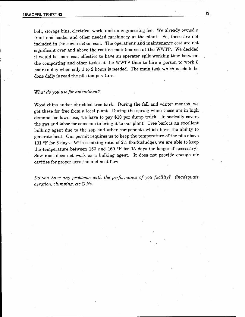
USACERLTR-97/143 I3
belt, storage bins, electrical work, and an engineering fee. We already owned a front end loader and other needed machinery at the plant. So, these are not included in the construction cost. The operations and maintenance cost are not significant over and above the routine maintenance at the WWTP. We decided it would be more cost effective to have an operator split working time between the composting and other tasks at the WWTP than to hire a person to work 8 hours a day when only 1 to 2 hours is needed. The main task which needs to be done daily is read the pile temperature.
"What do you use for amendment?
Wood chips and/or shredded tree bark. During the fall and winter months, we get these for free from a local plant. During the spring when these are in high demand for lawn use, we have to pay $10 per dump truck. It basically covers the gas and labor for someone to bring it to our plant. Tree, bark is an excellent bulking agent due to the sap and other components which have the ability to generate heat. Our permit requires us to keep the temperature of the pile above 131 °F for 3 days. With a mixing ratio of 2:1 (bark:sludge), we are able to keep the temperature between 150 and 160 °F for 15 days (or longer if necessary). Saw dust does not work as a bulking agent. It does not provide enough air cavities for proper aeration and heat flow.
Do you have any problems with the performance of you facility'? (inadequate
aeration, clumping, etc. ?) No.
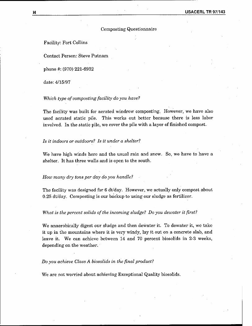
J4 ______ USACERL TR 97/143
Composting Questionnaire
Facility: Fort Collins
Contact Person: Steve Putnam
phone #: (970) 221-6932
date: 4/15/97
Which type of composting facility do you have?
The facility was built for aerated windrow composting. However, we have also used aerated static pile. This works out better because there is less labor involved. In the static pile, we cover the pile with a layer of finished compost.
Is it indoors or outdoors? Is it under a shelter?
We have high winds here and the usual rain and snow. So, we have to have a shelter. It has three walls and is open to the south.
How many dry tons per day do you handle?
The facility was designed for 6 dt/day. However, we actually only compost about 0.25 dt/day. Composting is our backup to using our sludge as fertilizer.
What is the percent solids of the incoming sludge? Do you dewater it first?
We anaerobically digest our sludge and then dewater it. To dewater it, we take it up in the mountains where it is very windy, lay it out on a concrete slab, and leave it. We can achieve between 14 and 70 percent biosolids in 2-3 weeks, depending on the weather.
Do you achieve Class A biosolids in the final product?
We are not worried about achieving Exceptional Quality biosolids.
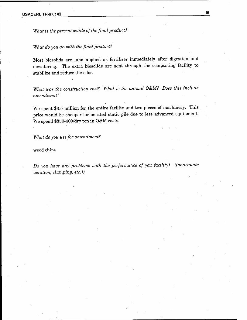
USACERLTR-97/143 !5.
What is the percent solids of the final product1?
What do you do with the final product?
Most biosolids are land applied as fertilizer immediately after digestion and dewatering. The extra biosolids are sent through the composting facility to
stabilize and reduce the odor.
What was the construction cost? What is the annual O&M? Does this include
amendment?
We spent $3.5 million for the entire facility and two pieces of machinery. This price would be cheaper for aerated static pile due to less advanced equipment. We spend $350-400/dry ton in O&M costs.
What do you use for amendment?
wood chips
Do you have any problems with the performance of you facility? (inadequate
aeration, clumping, etc. ?)
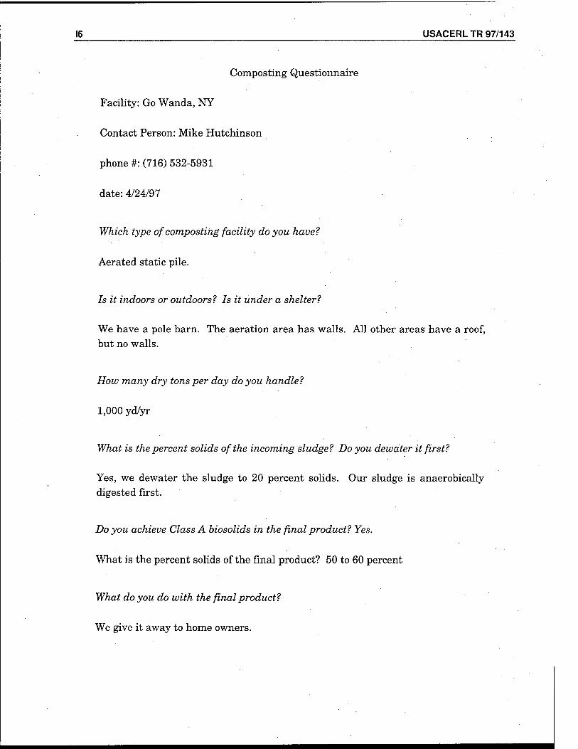
J6 USACERL TR 97/143
Composting Questionnaire
Facility: Go Wanda, NY
Contact Person: Mike Hutchinson
phone #: (716) 532-5931
date: 4/24/97
Which type of composting facility do you have1?
Aerated static pile.
Is it indoors or outdoors? Is it under a shelter?
We have a pole barn. The aeration area has walls. All other areas have a roof, but no walls.
How many dry tons per day do you handle?
1,000 yd/yr
What is the percent solids of the incoming sludge? Do you dewater it first?
Yes, we dewater the sludge to 20 percent solids. Our sludge is anaerobically digested first.
Do you achieve Class A biosolids in the final product? Yes.
What is the percent solids of the final product? 50 to 60 percent
What do you do with the final product?
We give it away to home owners.
USACERLTR-97/143 ; . ■
What was the construction cost? What is the annual O&M? Does this include
amendment?
We converted our existing drying beds into the composting area. This cost us roughly $30,000. We have been composting since 1990. We designed everything
ourselves, and a consulting firm handled the permits.
We spend $20/yd in O&M costs.
What do you use for amendment?
Wood chips. The most important thing is to get the correct mixture. You may
have to experiment for a while until the right mix is found to reach the proper temperatures. The amount of carbon is important. We use a 2:1 ratio of wood
chip to sludge.
Do you have any problems with the performance of you facility? (inadequate
aeration, clumping, etc. ?)
We have experienced no problems with compost quality (i.e., aeration, clumping). We have had problems with our shredding and screening equipment,
however.
Could you please send me a copy of your report?
Mike Hutchinson
Village of Go Wanda
Sewage Department ,
Aldrich Street Extension
Go Wanda, NY 14070
18 USACERL TR 97/143
Composting Questionnaire
Facility: Springville, Utah
Contact Person: Rick Roberts
phone #:(801) 489-2745
date: 5/13/97
Which type of composting facility do you have?
Windrow, piled
Is it indoors or outdoors? Is it under a shelter?
We have no shelter. The winter causes problems. In the spring, the compost is too wet and our fecal Coliform count does not pass.
How many dry tons per day do you handle?
2 dry tons/day
What is the percent solids of the incoming sludge? Do you dewater it first?
We dewatered it to 18 to 20 percent solids.
Do you achieve Class A biosolids in the final product?
Yes.
What is the percent solids of the final product?
50 to 60 percent moisture (40-50 percent solids)
USACERL TR-97/143 19
What do you do with the final product?
We sell it to the public for use on flowers and other things like that. We do not
advertise, and we do not make a profit.
What was the construction cost? What is the annual O&M? Does this include
amendment?
For the composting facility with a belt press, we spent $250,000. We use an old loader we already owned to turn our piles. We can build the piles higher than can be used with a turner. We also spent about 30 percent of $250,000 on a
grinder, which we share.
What do you use for amendment?
Green waste from the city which residents bring to us for free. Otherwise, they would have to pay to have their yard waste landfilled.
Do you have any problems with the performance of you facility? (inadequate
aeration, clumping, etc. ?)
We may need to look into keeping more of our bulking agent. We need to buy
screens.
Winter is our biggest problem. It don't take long to lose temperature. One winter I reheated the piles by mixing in an ammonia fertilizer. We were able to bring the temperatures back up to pass. However, this winter's compost will
most likely not meet regulations.
Personally, I wouldn't do it if it is in a moist climate. I would not compost. We are lucky. Most other operations around here cannot meet Class A and end up
with Class B biosolids.
USACERLTR-97/143 . . . —
Appendix J: Krüger
J2 • USACERL TR 97/143
PROPOSAL
for the
ATAD PROCESS Camp Casey, Korea
for
U.S. Army Corps of Engineers
P.O. Box 9005
Champaign, IL 61826-9005
Submitted
April 17,1997
By
John Brinkley
Krüger, Inc.
401 Harrison Oaks Blvd., Suite 100
Cary, North Carolina 27513
Krüger Project No.: 139701
USACERLTR-97/143 J3
Table of Contents
I. Prologue
||. Introduction to Krüger
III. ATAD Process Description A. Introduction B. Process Specifics C. Land Disposal
IV. Design Basis
V. Scope of Supply
VI. Aeration Equipment Description, Operation, Design, and Function
VII. ATAD System Price, Present Worth and Cost/Dry Ton
Page
1
1
2
4
5
6
8
J4_ USACERL TR 97/143
Prologue
Krüger, Inc. is pleased to offer Camp Casey, Korea a proven solution to meet the U.S. federal requirements regulating the use or disposal of sewage sludge. These standards promulgated in the EPA regulation 40 CFR Part 503, in conjunction with 40 CFR Parts 122, 123, and 501, defining permitting requirements, comprise the regulatory framework of the national sewage sludge program.
Autothermal thermophilic aerobic digestion or ATAD has been studied since the 1960s and significantly developed since the mid-1970s. Currently, there are over 45 full- scale operating facilities in Europe and North America. The Fuchs system now offered through Krüger has a proven track record and has been responsible for the sale of over 90 percent of all systems operating.
The following proposal is offered to Camp Casey, Korea utilizing the entire practical, as well as technical, experience of Fuchs Gas. '
Introduction to Krüger
Krüger is an environmental technology company. The Krüger Group based in Denmark operates worldwide within the fields of energy conservation, water supply, wastewater treatment, solid waste management, and rural development.
The Krüger Group employs about 1,100 people; approximately half of these people are engineers and scientists with vast experience in their related fields.
Krüger has subsidiaries and offices throughout the world, e.g. Belgium, France, Greece, Ireland. Germany, Cameroon, Burkina Faso, Guinea, Niger, Tanzania, Hong Kong, Indonesia, China, the Philippines, Sri Lanka, and the United States.
Krüger, Inc. (USA) located in Cary, North Carolina operates as an equipment supplier based on Krüger's worldwide patented processes for biological treatment of wastewater. Krüger's process know-how was acquired through years of extensive research and development, which is a continuous effort. Krüger's R&D division currently employs more than 50 engineers and scientists and includes two fully- equipped research and biotechnology laboratories.
Krüger acquired the wastewater business of Air Products & Chemicals, Inc., including the patents for the A/O, A2/0 and OASES processes, in June 1991. This coincided with Krüger's acquisition of the worldwide exclusive license right to the OWASA process (optimization of biological phosphorous removal through the fermentation technology). Krüger is now capable of offering the equipment and the process know- how for both secondary and advanced wastewater treatment.
USACERLTR-97/143 _5
III. ATAD Process Description
A. Introduction
The ATAD process was developed in the Federal Republic of Germany (FRG) in 1970 by Popel and his colleagues working on animal manure and sewage sludge. Much of the available data and process know-how are based upon Fuchs research and design. Fuchs has the most FRG installations and has by far the most process knowledge.
Autothermai Thermophilic Aerobic Digestion (ATAD) is an aerobic digestion . process that operates within a thermophilic temperature range (40'C to 80=C) without the introduction of supplemental heat.
The typical ATAD system consists of two reactors that are covered and . insulated. Sludge, which has been thickened to a minimum of 4-percent solids, is fed to the reactors on a batch basis. Each batch is 23 hours allowing 1 hour total for the fill and discharge cycles. Sludge in the reactors is mixed and aerated throughout the 23-hour cycle. Temperatures in the first reactor normally exceed 45"'C in 6 days detention time and can reach up .to 60'C in the second reactor, depending on mixing and tank insulation. As the sludge aerobically digests, heat is released, creating an autothermai environment. The temperature of the reactors being greater than 40/C inhibits nitrification and limits the oxygen demand to approximately 1.4-kg Oa for every kg of V.S. destroyed. Volatile solids reduction normally ranges from 30 to 50 percent and occurs in just 6 to 8 days HRT. The rate of digestion in the system doubles at 50;C as compared to 20=C. The number of viable organisms in the system start drying off and V.S. reduction stabilizes as the temperature approaches 60" to 65'C; hence, the process is self-regulating. ,
B. Process Specifics
Feed solids must be prethickened to a minimum of 4-percent solids; 4- to 6- percent solids is desirable. Typically, primary and WAS is co-thickened in the primary clarifier. Gravity belt thickening or DAF thickening may also be used. Sludge less than 3-percent solids will have difficulty achieving thermophilic temperatures because of too much liquid mass. Sludge greater than 6-percent solids is difficult to mix and aerate. The feed solids must also contain ä minimum of 55-percent volatile solids.
Influent screening should be used at the plant to eliminate plastics and stringy material from the sludge (10-12. mm bar, spacing maximum). A good grit removal system is recommended to minimize abrasion on mixers and aerators. If 100% primary sludge is to be processed through an ATAD system it is recommended that a macerator be put in-line before the ATAD feed.
J6 USACERL TR 97/143
Typically an ATAD system has ä minimum of 2 reactors operating in series. Both concrete and steel reactors have been used, but steel is the most commonly used due to heat stress concerns in concrete. The steel reactors are cylindrical, fiat-bottomed and covered. Each reactor is insulated with 4 inches of mineral wool along the wails with 4 inches of high compression foam glass insulation for the top and bottom. The reactors are then clad with ribbed aluminum sheeting for protection from the elements.
Waste sludge is fed to the reactors on a batch basis. Batch feeding in 1- hour/day periods is preferred to minimize short circuiting potential and to ensure that the incoming waste sludge is exposed to thermophilic reactor temperatures for a minimum of 23 hours/day without interruption. This ensures the highest degree of pathogen reduction. A typical reactor detention time is 6 to 8 days (3 to 4 days per reactor). Sixty percent of the volatile solids destruction occurs in the second reactor. Reactor temperatures are monitored with temperature probes.
Waste sludge mixing and aeration is provided with aspirating aerators mounted tangentially through the reactor wall. A circulation aeration device mounted in the center of the reactor can be used in conjunction with the spiral aerators. The waste sludge aeration leads to the generation of surface scum, which is controlled, with foam cutters supported from the reactor roof. The foam cutters do not eliminate the foam, but instead keep it at a manageable level to allow its beneficial use.
Off gas from the process can typically have a slight musty odor and should be either water scrubbed, passed through a biofiiter, or diluted with ambient air.
Sludge from the second stage reactor must be cooled down prior to dewatering. Typically, this is done in gravity thickeners, holding tanks, or via heat exchangers. Twenty-five day minimum post-digestion holding is desirable to bring the temperature to 20°C. Mixing should be done in the holding tank for 1 hour each day.
Land Disposal
Through the use of a Krüger/Fuchs ATAD system, "Exceptional Quality" sewage sludge can be land-applied on any type of site. There are no human or animal contact restrictions, time limits for land use after application or crop specific limitations associated with land disposal of Class A biosolids from ATAD systems.
The EPA requires periodic sampling to ensure that land applied biosolids meet all the criteria set forth in 40 CFR Part 503 regulation. Generally, this proof is recorded en a daily basis with ATAD waste. Normal system temperature recording. V.S. testing, and metals testing will provide the necessary data required as proof of regulation conformance. This virtually eliminates any unusual sampling methods as may be associated with conventionally digested or lime stabilized biosolids.
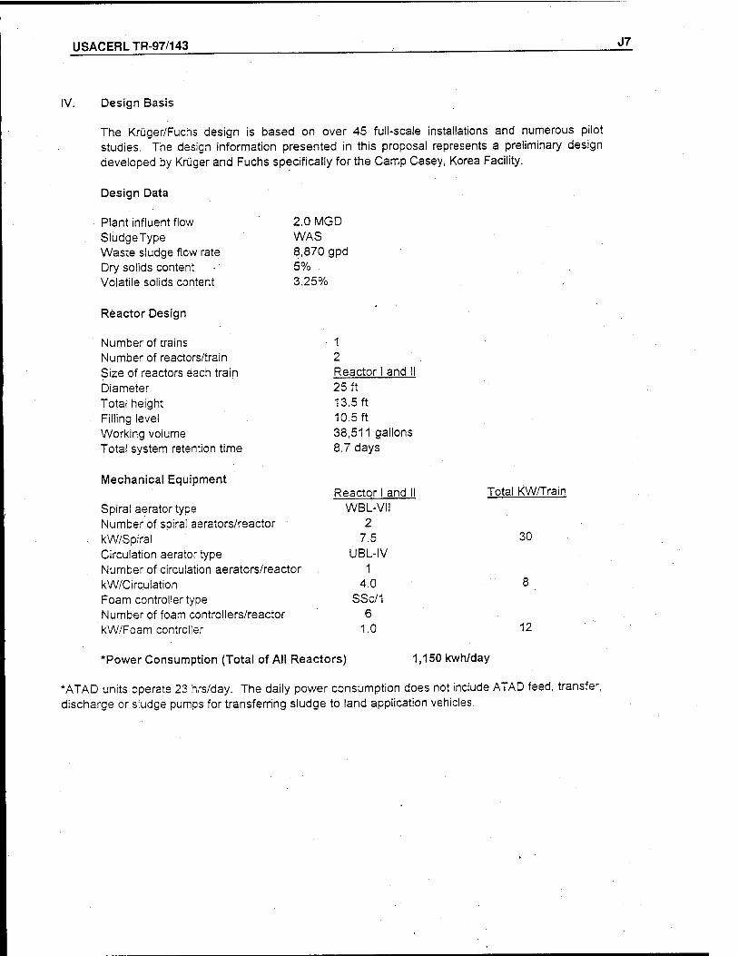
USACERLTR-97/143 J7
IV. Design Basis
The Krüger/Fuchs design is based on over 45 full-scale installations and numerous pilot studies. The design information presented in this proposal represents a preliminary design developed by Krüger and Fuchs specifically for the Camp Casey, Korea Facility.
Design Data
Plant influent flow SludgeType Waste sludge flow rate Dry solids content Volatile solids content
2.0 MGD WAS 8,870 gpd 5% 3.25%
Reactor Design
Number of trains 1 Number of reactors/train 2 Size of reactors each train Reactor I and II Diameter 25 ft Total height 13.5 ft Filling level 10.5 ft Working volume 38,511 gallons Total system retention time 8.7 days
Mechanical Equipment Reactor I and II Total KW/Train
Spiral aerator type WBL-VH Number of spiral aerators/reactor 2 kW/Spiral 7.5 30
Circulation aerator type UBL-IV Number of circulation aerators/reactor 1 kW/Circulation 4.0 8
Foam controller type SSc/1 Number of foam controllers/reactor 6 kW/Foam controller 1.0 12
"Power Consumption (Total of All Rea< :tors) 1,150 kwh/day
*ATAD units operate 23 hrs/day. The daily power consumption does not include ATAD feed, transfer, discharge or sludge pumps for transferring sludge to land application vehicles.
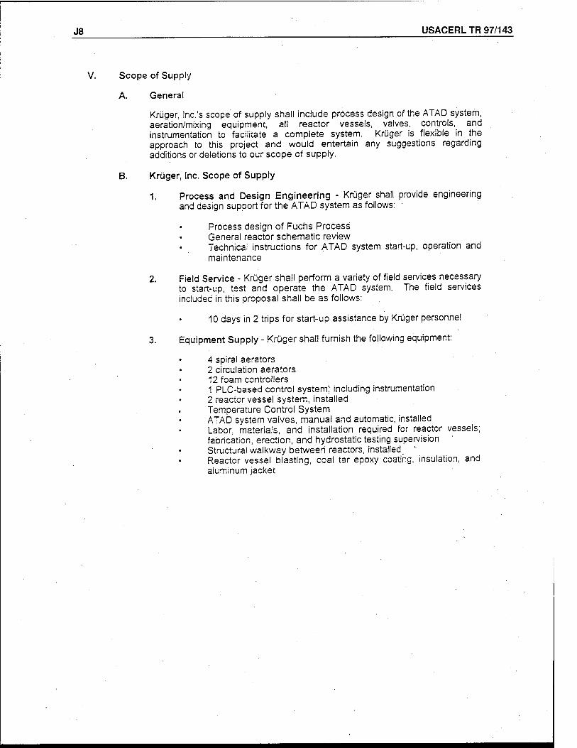
J8 USACERL TR 97/143
V. Scope of Supply
A. General
Krüger, Inc.'s scope of supply shall include process design of the ATAD system, aeration/mixing equipment, all reactor vessels, valves, controls, and instrumentation to facilitate a complete system. Krüger is flexible in the approach to this project and would entertain any suggestions regarding additions or deletions to our scope of supply.
B. Krüger, Inc. Scope of Supply
1. Process and Design Engineering - Krüger shall provide engineering and design support for the ATAD system as follows: '
Process design of Fuchs Process General reactor schematic review Technical instructions for ATAD system start-up, operation and maintenance
2. Field Service - Krüger shall perform a variety of field services necessary to start-up, test and operate the ATAD system. The field services included in this proposal shall be as follows:
10 days in 2 trips for start-up assistance by Krüger personnel.
3. Equipment Supply - Krüger shall furnish the following equipment:
4 spiral aerators 2 circulation aerators 12 foam controllers 1 PLC-based control system^ including instrumentation 2 reactor vessel system, installed Temperature Control System ATAD system valves, manual and automatic, installed Labor, materials, and installation required for reactor vessels; fabrication, erection, and hydrostatic testing supervision Structural walkway between reactors, installed " Reactor vessel blasting, coal tar epoxy coating, insulation, and aluminum jacket
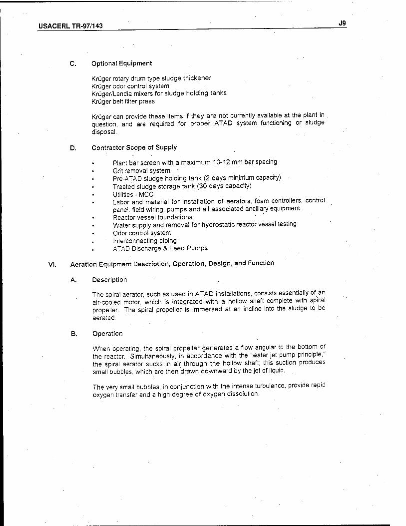
USACERLTR-97/143 J9
C. Optional Equipment
Krüger rotary drum type sludge thickener Krüger odor control system Krüger/Landia mixers for sludge holding tanks Krüger belt filter press
Krüger can provide these items if they are not currently available at the plant in question, and are required for proper ATAD system functioning or sludge disposal.
D. Contractor Scope of Supply
Plant bar screen with a maximum 10-12 mm bar spacing Grit removal system • Pre-ATAD sludge holding tank (2 days minimum capacity) Treated sludge storage tank (30 days capacity) Utilities - MCC Labor and material for installation of aerators, foam controllers, control panel, field wiring, pumps and all associated ancillary equipment Reactor vessel foundations Water supply and removal for hydrostatic reactor vessel testing Odor control system Interconnecting piping ATAD Discharge & Feed Pumps
VI. Aeration Equipment Description, Operation, Design, and Function
A. Description ,
The spiral aerator, such as used in ATAD installations, consists essentially of an air-cooled motor, which is integrated with a hollow shaft complete with spiral propeller. The spiral propeller is immersed at an incline into the sludge to be aerated.
B. Operation
When operating, the spiral propeller generates a flow angular to the bottom of the reactor. Simultaneously, in accordance with the "water jet pump principle," the spiral aerator sucks in air through the hollow shaft; this suction produces small bubbles, which are then drawn downward by the jet of liquid.
The very small bubbles, in conjunction with the intense turbulence, provide rapid oxygen transfer and a high degree of oxygen dissolution.
J10 USACERL TR 97/143
C. Design
The spiral aerators are sturdy and simple in design. The hollow shaft with its shank, the spiral propeller, the intermediate flange, as well as all fasteners, is manufactured from AISI 304 stainless steel.
The drive units are special motors with hollow shafts. The units are high efficiency and equipped with permanently lubricated grooved ball bearings. The motor housings are manufactured from aluminum or a high quality cast-iron.
The aerator shafting is manufactured to allow for easy insertion or extraction. The aerator shaft is inserted into the hollow motor shaft. This allows for accurate and precise shaft guidance.
The aerator shaft is manufactured from extruded seamless AISI 304 stainless steel tube, and is dynamically balanced together with the coupling and the spirai propeller.
The immersion section does not contain any bearings or seals, which eliminates any maintenance work and virtually eliminates wear.
D. Function
. The spiral aerators provide the ATAD system with the necessary supply of oxygen and the thorough mixing of the sludge. The spirai aerators also accelerate a rotation of the entire content of the reactor around the vertical axis. They are arranged tangentially on a standpipe which, in turn, is welded at an angle to the reactor casing. The aerator driving facility and the motor end of the shaft, with the air entry ports are exposed to the atmosphere. The hollow shaft with the spiral propeller leads through the standpipe and the reactor wall into the sludge.
E. General
The ATAD process has many benefits that include.high disinfection capability, minimum area requirements, a high sludge treatment rate, and a high V.S. reduction rate, which all spell reduced disposal costs. This technology is easy to operate, does not require full-time staff, and is a cost-effective solution to aerobic digestion consistent with the new U.S. regulations on sludge disposal.
F. Temperature Control System
Generally speaking, the majority of ATAD systems will not require temperature control. When designing an ATAD system a thorough heat balance is generated to determine whether or not the system will be autothermal. Considering all the variables that effect the system, we can determine whether heat supplement, transfer or removal will be needed. We then custom design
- the system required for the application in question.
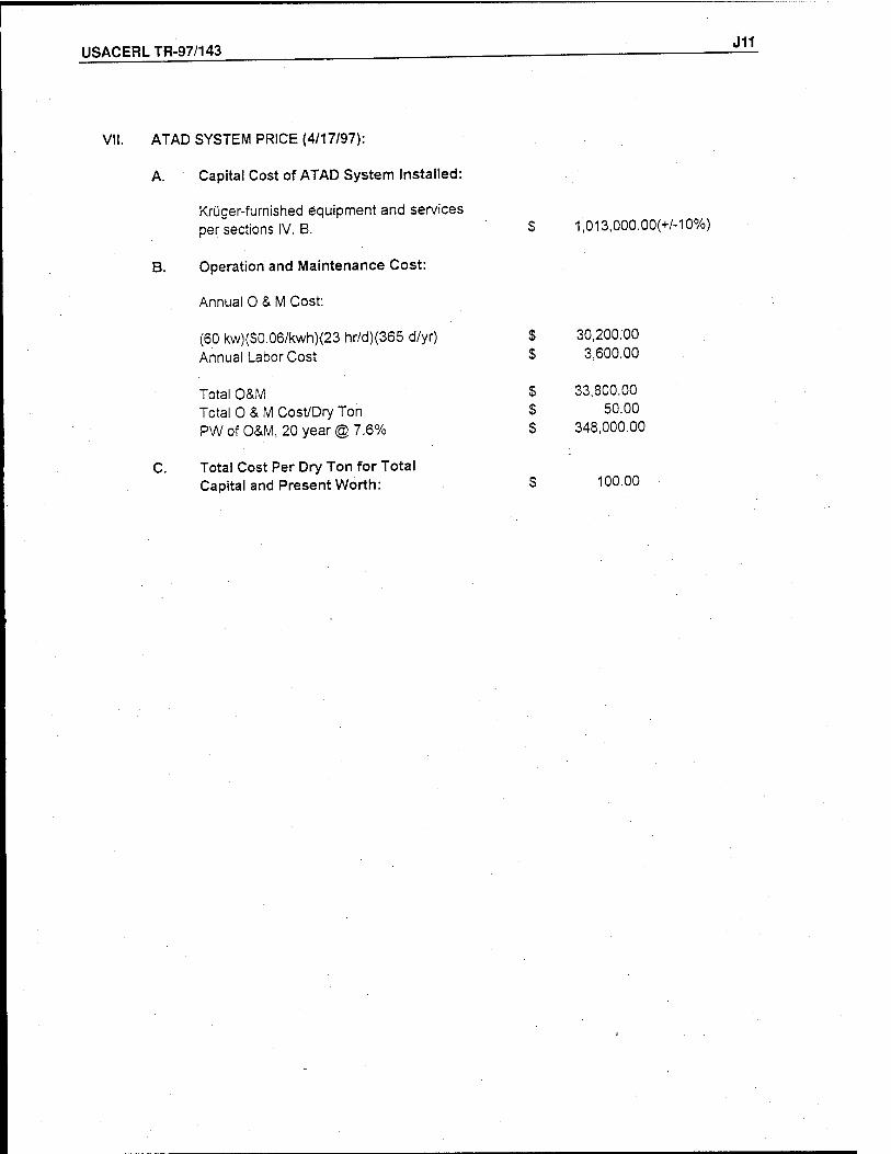
USACERLTR-97/143 J11
VII. ATAD SYSTEM PRICE (4/17/97):
A. Capital Cost of ATAD System Installed:
Krüger-fumished equipment and services per sections IV. B. $ 1,013,000.00(+/-10%)
B. Operation and Maintenance Cost:
Annual 0 & M Cost:
(60 kw)(S0.06/kwh){23 hr/d)(365 d/yr) S 30,200.00 Annual Labor Cost $ 3,600.00
Total O&M S 33,800.00 Total O & M Cost/Dry Ton S 50.00 PW of O&M, 20 year® 7.6% $ 348,000.00
C. Total Cost Per Dry Ton for Total Capital and Present Worth: $ 100.00
USACERL DISTRIBUTION
Chief of Engineers ATTN: CEHEC-IM-LH (2) ATTN: CEHEC-IM-LP (2) ATTN: CECC-R ATTN: CERD-L ATTN: CERD-M
Defense Tech Info Center 22304 ATTN: DTIC-O (2)
8th US Army, Korea ATTN: HQ USFK/EUSA (20)
29 03/98
This publication was reproduced on recycled paper.