design of roofs dach+ - frilo software
TRANSCRIPT
Manual Dach+ (Roofs)
FRILO Software GmbH 02.02.2022 Page 1
Design of roofs Dach+
Table of contents
Possible applications 2
Input 5
Wizard 5Basic parameters 5
System 6
General 6Geometry 6Support 8Cross-sections 9
Loading 10
Dead Load 10Snow and wind 10Load cases 11Standard Load Cases 11Additional Load Cases 12
Design 14
Design settings 14Connection Details 16
Calculation 17
Output 18
Note: this program with its licensable options is the successor to the previous roof programs D9 -Continuous Rafter, D11 - Purlin and Rafter Roof, D12 - Collar Beam Roof - DGK Hip Rafter / ValleyRafter.
Basic documentation - overview
In addition to the individual program manuals, you can find basic explanations on how to operate theprograms on our homepage www.frilo.eu (ServiceArticles InformationBasic Operating Instructions).
Farther documents:
Roof-Loads-Design
Fire protection analysis timber
Manual Dach+ (Roofs)
FRILO Software GmbH 02.02.2022 Page 2
Possible applications
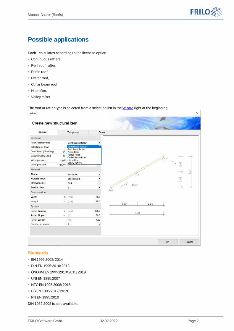
Dach+ calculates according to the licensed option
Continuous rafters,
Pent roof rafter,
Purlin roof
Rafter roof,
Collar beam roof,
Hip rafter,
Valley rafter.
The roof or rafter type is selected from a selection list in the Wizard right at the beginning.
Standards EN 1995:2008/2014
DIN EN 1995:2010/2013
ÖNORM EN 1995:2010/2015/2019
UNI EN 1995:2007
NTC EN 1995:2008/2018
BS EN 1995:2012/2019
PN EN 1995:2010
DIN 1052:2008 is also available.
Manual Dach+ (Roofs)
FRILO Software GmbH 02.02.2022 Page 3
Options S / P / K / GKDach-S option: Continuous Rafter or Pent Roof Rafters
With this option, single and multiple span continuous rafters can be calculated and designed as a singlecomponent. Cantilever arms are possible on both sides.
Dach-P option: Purlin and Rafter Roof
With this option, purlin roofs and rafter roofs as well as mixed constructions of both systems can becalculated, e.g. purlin roofs with ridge joint. The rafters on the left and right are designed as continuousbending beams.
Dach-K option: Collar Beam Roof
Calculation of collar beam roofs with movable / fixed collar beam.The collar beam can consist of one or two parts.
Dach GK option: Hip and Valley Rafter
Calculation of hip rafters and optionally valley rafters.
Systems Dach-P / Dach-K The roof halves can have different roof pitches
The purlins can be at different heights
The left and right halves of the house can be of different widths
Horizontal and vertical bearings can be rigid, spring-loaded or movable
Loads Area loads, weight, snow and wind loads Additional loads as uniform, single or trapezoidal loads Man loads and wind currents in overhangs
CalculationThe system is treated statically as a framework system, taking into account the normal force deformationsand the effect of the real, specified support conditions.
All load combinations are calculated and designed according to the applicable combination regulations.
Design settingsOptionally selectable: proof against wind suction (see also document Roof_Loads-Design) earthquake combinations fire design
For the permissible span/cantilever deflections of the respective verifications (based on the length L), therecommended values of the respective standard are preset as standard. These can be customized.
Since the negative deflection there usually determines the design result in the case of short cantilevers, thisoften undesirable influence can be optionally eliminated with the option "only positive deflection oncantilevers".
Manual Dach+ (Roofs)
FRILO Software GmbH 02.02.2022 Page 4
Proofs of stabilityFor the proof of stability, a continuous tilt bracket and continuous lateral support are used as standard and thebuckling length in the rafter level is limited to 0.9 · component length.
These boundary conditions can be adapted individually.
There are various options available for determining the stability lengths.
For each superposition, the associated effective lengths for the individual bars are determined from theeigenvalue solution. Due to numerical problems, however, the effective lengths of bars with a low normal forcecan be too great.
For precisely such cases, there is the option of limiting the buckling length to a maximum value.
Optionally, the buckling and tilting lengths can be specified individually for each bar.
Alternatively, the buckling/tilting length can always be set to the bar length, component length or a specifiedvalue.
ServiceabilityThe serviceability verification is carried out according to the rules of EN 1995-1-1 with initial and finaldeformation and consideration of creep deformation.
Support forcesSupport forces are output as characteristic maximum values and sum per action.
Characteristic support forces are transferred to the subsequent components for each load case, for which thedecisive combinations are then created in the program called up.
In addition, the load cases per individual load case and the superpositions can optionally be output.
Load Forwarding / Associated ProgramsThe bearing loads can (with Roof-S /P/K) be passed on to the multi-span timber beam HTM+.
See also document Roof_Loads-Design.
The interface to the RSX Framework enables an alternative calculation.
Entered connection details (rafter base point) can optionally be passed on to the corresponding toolboxmodule for calculation (the corresponding item "TB Toolbox" is then displayed here).
SEMA import/export"*.sema" files can be imported/exported via FileImport or Export.
Find out more about this in the SEMA manual.
Manual Dach+ (Roofs)
FRILO Software GmbH 02.02.2022 Page 5
Input
General information on the input fields
This program can be used to calculate according to various standards or national annexes. These standardsdiffer considerably in terms of load approaches, combination rules, determination of the decisive internalforces and verification.
The input fields and selection options described below can therefore differ from one another depending on theselected standard.
Wizard
After starting the program, the wizard opens automatically, with which you can quickly and easily create acalculable basic system.
Here you select the type of roof or rafter: continuous or pent roof rafters, purlin or collar beam roof, hip andvalley rafters.
Furthermore, the necessary/most important parameters are queried here.
An item can then be further developed on this basis.
Note: the other roof types can also be called up using the "Other roof types" button in the upper menu ribbon.
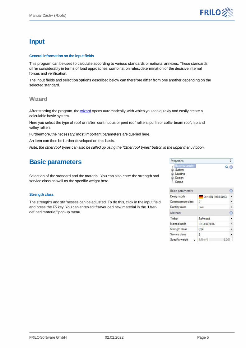
Basic parameters
Selection of the standard and the material. You can also enter the strength andservice class as well as the specific weight here.
Strength class
The strengths and stiffnesses can be adjusted. To do this, click in the input fieldand press the F5 key. You can enter/edit/save/load new material in the "User-defined material" pop-up menu.
Manual Dach+ (Roofs)
FRILO Software GmbH 02.02.2022 Page 6
System
Note: the following entries differ depending on the selected roof or rafter type.
RemarksYou can enter remarks about the system that optionally appear in the output.
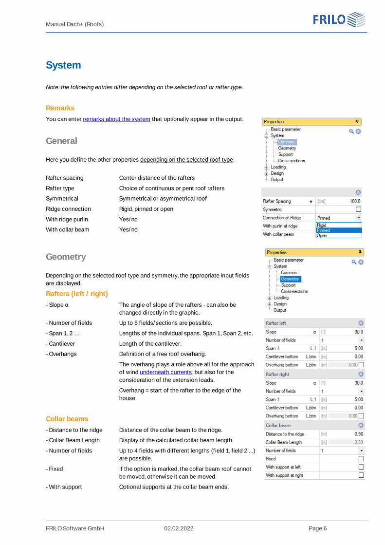
General
Here you define the other properties depending on the selected roof type.
Rafter spacing Center distance of the rafters
Rafter type Choice of continuous or pent roof rafters
Symmetrical Symmetrical or asymmetrical roof
Ridge connection Rigid, pinned or open
With ridge purlin Yes/no
With collar beam Yes/no
Geometry
Depending on the selected roof type and symmetry, the appropriate input fieldsare displayed.
Rafters (left / right)- Slope α The angle of slope of the rafters - can also be
changed directly in the graphic.
- Number of fields Up to 5 fields/sections are possible.
- Span 1, 2 … Lengths of the individual spans. Span 1, Span 2, etc.
- Cantilever Length of the cantilever.
- Overhangs Definition of a free roof overhang.
The overhang plays a role above all for the approachof wind underneath currents, but also for theconsideration of the extension loads.
Overhang = start of the rafter to the edge of thehouse.
Collar beams- Distance to the ridge Distance of the collar beam to the ridge.
- Collar Beam Length Display of the calculated collar beam length.
- Number of fields Up to 4 fields with different lengths (field 1, field 2 ...)are possible.
- Fixed If the option is marked, the collar beam roof cannotbe moved, otherwise it can be moved.
- With support Optional supports at the collar beam ends.
Manual Dach+ (Roofs)
FRILO Software GmbH 02.02.2022 Page 7
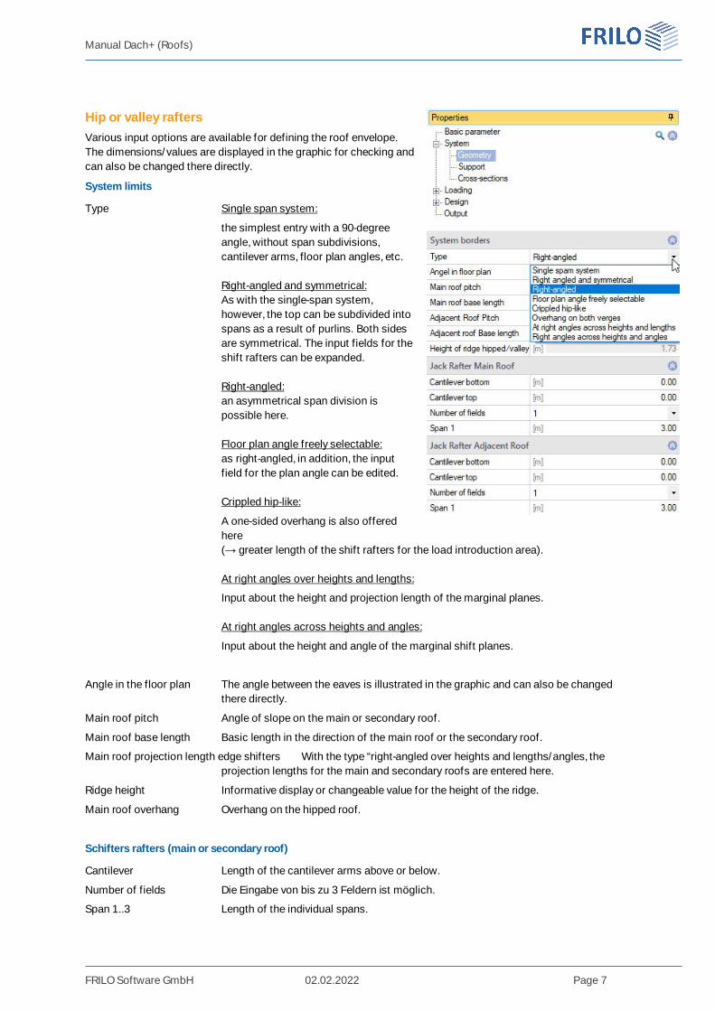
Hip or valley raftersVarious input options are available for defining the roof envelope.The dimensions/values are displayed in the graphic for checking andcan also be changed there directly.
System limits
Type Single span system:
the simplest entry with a 90-degreeangle, without span subdivisions,cantilever arms, floor plan angles, etc.
Right-angled and symmetrical:As with the single-span system,however, the top can be subdivided intospans as a result of purlins. Both sidesare symmetrical. The input fields for theshift rafters can be expanded.
Right-angled:an asymmetrical span division ispossible here.
Floor plan angle freely selectable:as right-angled, in addition, the inputfield for the plan angle can be edited.
Crippled hip-like:
A one-sided overhang is also offeredhere(→ greater length of the shift rafters for the load introduction area).
At right angles over heights and lengths:
Input about the height and projection length of the marginal planes.
At right angles across heights and angles:
Input about the height and angle of the marginal shift planes.
Angle in the floor plan The angle between the eaves is illustrated in the graphic and can also be changedthere directly.
Main roof pitch Angle of slope on the main or secondary roof.
Main roof base length Basic length in the direction of the main roof or the secondary roof.
Main roof projection length edge shifters With the type “right-angled over heights and lengths/angles, theprojection lengths for the main and secondary roofs are entered here.
Ridge height Informative display or changeable value for the height of the ridge.
Main roof overhang Overhang on the hipped roof.
Schifters rafters (main or secondary roof)
Cantilever Length of the cantilever arms above or below.
Number of fields Die Eingabe von bis zu 3 Feldern ist möglich.
Span 1..3 Length of the individual spans.
Manual Dach+ (Roofs)
FRILO Software GmbH 02.02.2022 Page 8
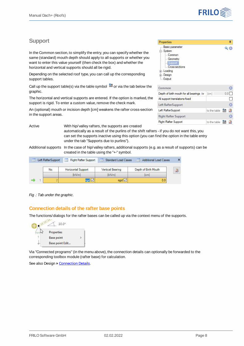
Support
In the Common section, to simplify the entry, you can specify whether thesame (standard) mouth depth should apply to all supports or whether youwant to enter this value yourself (then check the box) and whether thehorizontal and vertical supports should all be rigid.
Depending on the selected roof type, you can call up the correspondingsupport tables.
Call up the support table(s) via the table symbol or via the tab below thegraphic.
The horizontal and vertical supports are entered. If the option is marked, thesupport is rigid. To enter a custom value, remove the check mark.
An (optional) mouth or incision depth [cm] weakens the rafter cross-sectionin the support areas.
Active With hip/valley rafters, the supports are createdautomatically as a result of the purlins of the shift rafters - if you do not want this, youcan set the supports inactive using this option (you can find the option in the table entryunder the tab "Supports due to purlins").
Additional supports In the case of hip/valley rafters, additional supports (e.g. as a result of supports) can becreated in the table using the "+-" symbol.
Fig .: Tab under the graphic.
Connection details of the rafter base pointsThe functions/dialogs for the rafter bases can be called up via the context menu of the supports.
Via "Connected programs" (in the menu above), the connection details can optionally be forwarded to thecorresponding toolbox module (rafter base) for calculation.
See also DesignConnection Details.
Manual Dach+ (Roofs)
FRILO Software GmbH 02.02.2022 Page 9
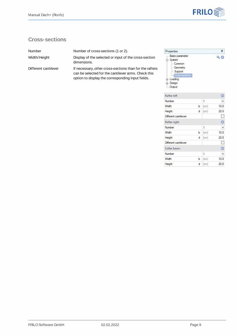
Cross-sections
Number Number of cross-sections (1 or 2).
Width/Height Display of the selected or input of the cross-sectiondimensions.
Different cantilever If necessary, other cross-sections than for the rafterscan be selected for the cantilever arms. Check thisoption to display the corresponding input fields.
Manual Dach+ (Roofs)
FRILO Software GmbH 02.02.2022 Page 10
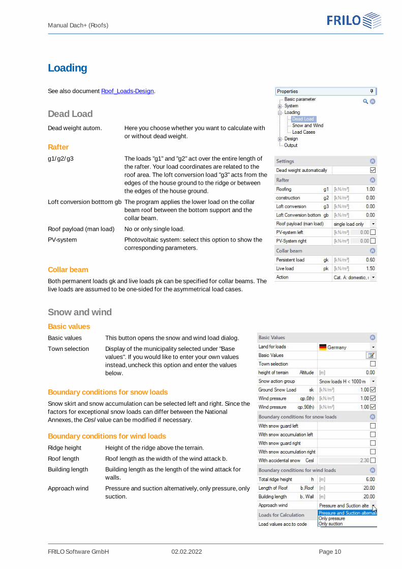
Loading
See also document Roof_Loads-Design.
Dead LoadDead weight autom. Here you choose whether you want to calculate with
or without dead weight.
Rafterg1/g2/g3 The loads "g1" and "g2" act over the entire length of
the rafter. Your load coordinates are related to theroof area. The loft conversion load "g3" acts from theedges of the house ground to the ridge or betweenthe edges of the house ground.
Loft conversion botttom gb The program applies the lower load on the collarbeam roof between the bottom support and thecollar beam.
Roof payload (man load) No or only single load.
PV-system Photovoltaic system: select this option to show thecorresponding parameters.
Collar beamBoth permanent loads gk and live loads pk can be specified for collar beams. Thelive loads are assumed to be one-sided for the asymmetrical load cases.
Snow and windBasic valuesBasic values This button opens the snow and wind load dialog.
Town selection Display of the municipality selected under "Basevalues". If you would like to enter your own valuesinstead, uncheck this option and enter the valuesbelow.
Boundary conditions for snow loadsSnow skirt and snow accumulation can be selected left and right. Since thefactors for exceptional snow loads can differ between the NationalAnnexes, the Cesl value can be modified if necessary.
Boundary conditions for wind loadsRidge height Height of the ridge above the terrain.
Roof length Roof length as the width of the wind attack b.
Building length Building length as the length of the wind attack forwalls.
Approach wind Pressure and suction alternatively, only pressure, onlysuction.
Manual Dach+ (Roofs)
FRILO Software GmbH 02.02.2022 Page 11
Wind range With the ridge/valley rafter, you can optionally choose which wind range is to be used asthe basis for the averaged wind load on the main/secondary roof. Otherwise the programautomatically takes the area with the greatest wind pressure.
Loads for CalculationLoad values acc. to code Deactivate this option to be able to enter your own values.
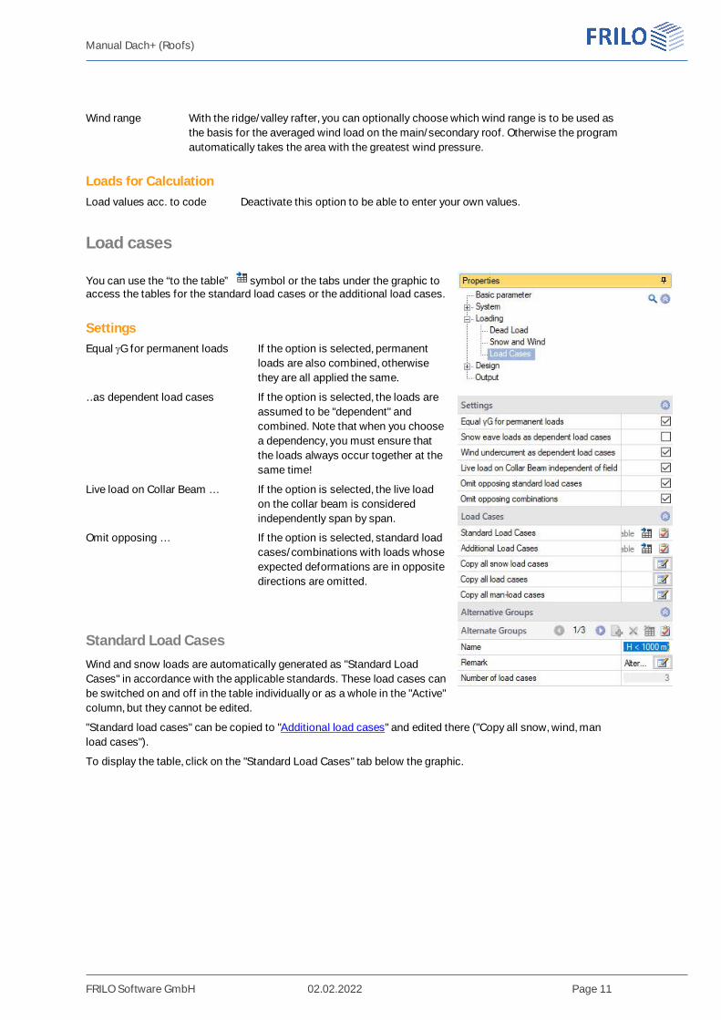
Load cases
You can use the “to the table” symbol or the tabs under the graphic toaccess the tables for the standard load cases or the additional load cases.
SettingsEqual G for permanent loads If the option is selected, permanent
loads are also combined, otherwisethey are all applied the same.
…as dependent load cases If the option is selected, the loads areassumed to be "dependent" andcombined. Note that when you choosea dependency, you must ensure thatthe loads always occur together at thesame time!
Live load on Collar Beam … If the option is selected, the live loadon the collar beam is consideredindependently span by span.
Omit opposing … If the option is selected, standard loadcases/combinations with loads whoseexpected deformations are in oppositedirections are omitted.
Standard Load CasesWind and snow loads are automatically generated as "Standard LoadCases" in accordance with the applicable standards. These load cases canbe switched on and off in the table individually or as a whole in the "Active"column, but they cannot be edited.
"Standard load cases" can be copied to "Additional load cases" and edited there ("Copy all snow, wind, manload cases").
To display the table, click on the "Standard Load Cases" tab below the graphic.
Manual Dach+ (Roofs)
FRILO Software GmbH 02.02.2022 Page 12
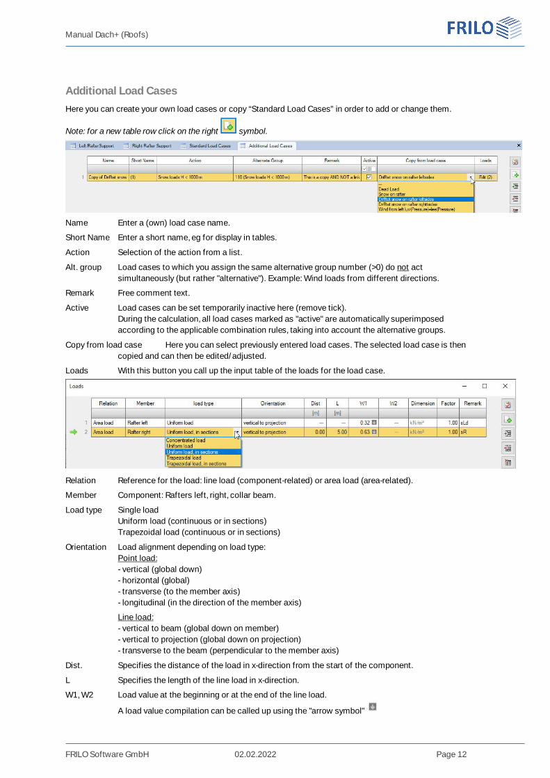
Additional Load CasesHere you can create your own load cases or copy “Standard Load Cases” in order to add or change them.
Note: for a new table row click on the right symbol.
Name Enter a (own) load case name.
Short Name Enter a short name, eg for display in tables.
Action Selection of the action from a list.
Alt. group Load cases to which you assign the same alternative group number (>0) do not actsimultaneously (but rather "alternative"). Example: Wind loads from different directions.
Remark Free comment text.
Active Load cases can be set temporarily inactive here (remove tick).During the calculation, all load cases marked as "active" are automatically superimposedaccording to the applicable combination rules, taking into account the alternative groups.
Copy from load case Here you can select previously entered load cases. The selected load case is thencopied and can then be edited/adjusted.
Loads With this button you call up the input table of the loads for the load case.
Relation Reference for the load: line load (component-related) or area load (area-related).
Member Component: Rafters left, right, collar beam.
Load type Single loadUniform load (continuous or in sections)Trapezoidal load (continuous or in sections)
Orientation Load alignment depending on load type:Point load:- vertical (global down)- horizontal (global)- transverse (to the member axis)- longitudinal (in the direction of the member axis)
Line load:- vertical to beam (global down on member)- vertical to projection (global down on projection)- transverse to the beam (perpendicular to the member axis)
Dist. Specifies the distance of the load in x-direction from the start of the component.
L Specifies the length of the line load in x-direction.
W1, W2 Load value at the beginning or at the end of the line load.
A load value compilation can be called up using the "arrow symbol"

Manual Dach+ (Roofs)
FRILO Software GmbH 02.02.2022 Page 13
Factor The load value is multiplied by this freely definable factor.
Remark Optional entry of free text.
See also document Roof_Loads-Design.
Manual Dach+ (Roofs)
FRILO Software GmbH 02.02.2022 Page 14
Design
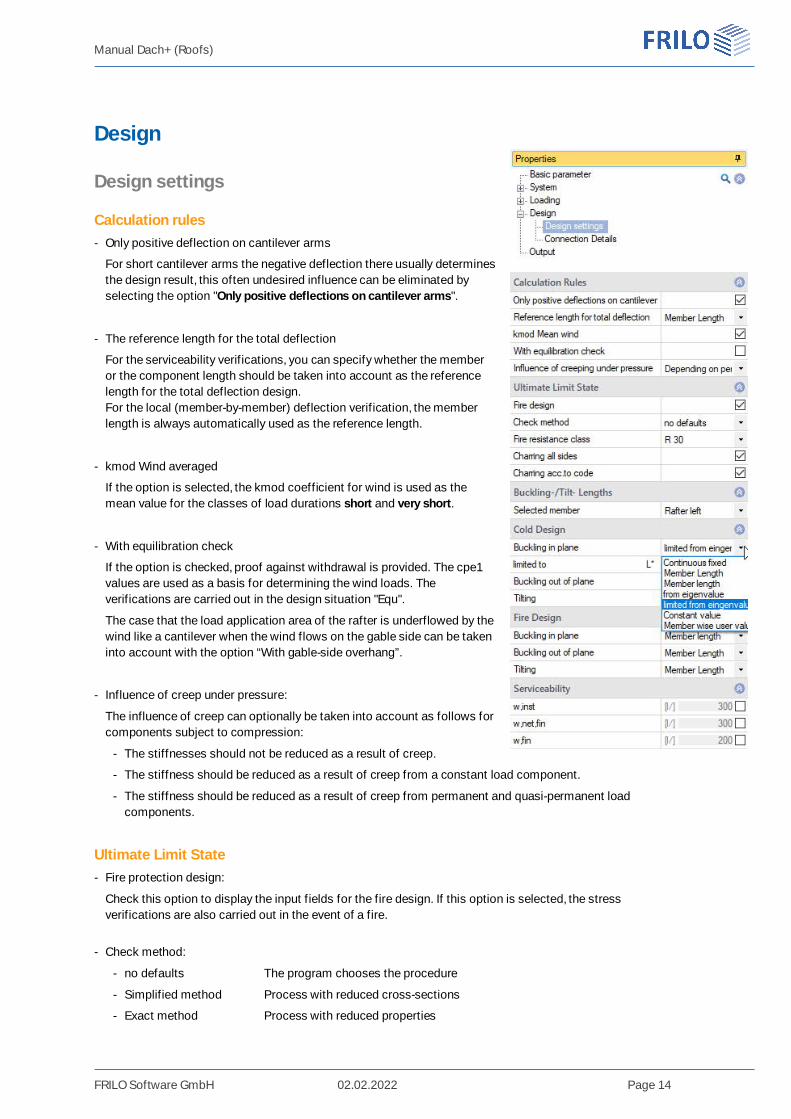
Design settings
Calculation rules- Only positive deflection on cantilever arms
For short cantilever arms the negative deflection there usually determinesthe design result, this often undesired influence can be eliminated byselecting the option "Only positive deflections on cantilever arms".
- The reference length for the total deflection
For the serviceability verifications, you can specify whether the memberor the component length should be taken into account as the referencelength for the total deflection design.For the local (member-by-member) deflection verification, the memberlength is always automatically used as the reference length.
- kmod Wind averaged
If the option is selected, the kmod coefficient for wind is used as themean value for the classes of load durations short and very short.
- With equilibration check
If the option is checked, proof against withdrawal is provided. The cpe1values are used as a basis for determining the wind loads. Theverifications are carried out in the design situation "Equ".
The case that the load application area of the rafter is underflowed by thewind like a cantilever when the wind flows on the gable side can be takeninto account with the option “With gable-side overhang”.
- Influence of creep under pressure:
The influence of creep can optionally be taken into account as follows forcomponents subject to compression:
- The stiffnesses should not be reduced as a result of creep.
- The stiffness should be reduced as a result of creep from a constant load component.
- The stiffness should be reduced as a result of creep from permanent and quasi-permanent loadcomponents.
Ultimate Limit State- Fire protection design:
Check this option to display the input fields for the fire design. If this option is selected, the stressverifications are also carried out in the event of a fire.
- Check method:
- no defaults The program chooses the procedure
- Simplified method Process with reduced cross-sections
- Exact method Process with reduced properties
Manual Dach+ (Roofs)
FRILO Software GmbH 02.02.2022 Page 15
- Fire resistance class:
Selection of the desired fire resistance class or user-defined input of the burn time.
- Charring all sides:
Uncheck to select individual sides for fire exposure.
- Charring according to code:
Remove the tick if you want to specify the charring rates βn for the individual sides yourself, otherwise thestandard values will be used.
See also document Fire protection analysis timber.
Buckling and tilting lengths- Selected member Selection of the component (rafter, collar beam).
Cold Design
The boundary conditions for the buckling lengths in and out of the rafter plane as well as the tilting length orthe lengths themselves can be specified separately for each component.
The following conditions are available:
- continuously fixed
- Buckling/tilting length = bar length
- Buckling/tilting length = component length
- from the determination of the eigenvalue for each load combination, optionally with an upper limit
- Specification of a constant value for each bar
- Specification of the values for each individual bar
In the event of a fire, the option of determining the eigenvalues is not applicable, since the cross-sectionvalues would vary depending on the design method for the individual verifications!
Serviceabilityw,inst Limit of elastic deflection
w,net,fin Limit value of the sum of elastic deflection and creep deformation
w,fin Limit of the final deformation
Manual Dach+ (Roofs)
FRILO Software GmbH 02.02.2022 Page 16
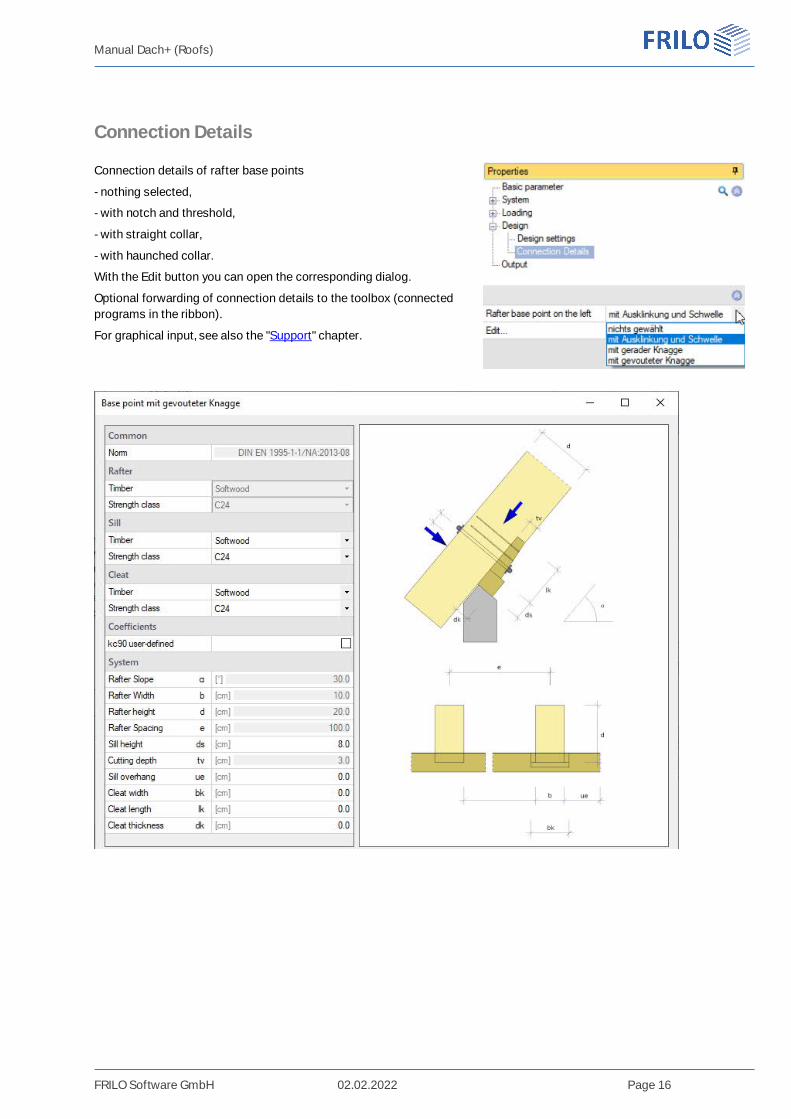
Connection Details
Connection details of rafter base points
- nothing selected,
- with notch and threshold,
- with straight collar,
- with haunched collar.
With the Edit button you can open the corresponding dialog.
Optional forwarding of connection details to the toolbox (connectedprograms in the ribbon).
For graphical input, see also the "Support" chapter.
Manual Dach+ (Roofs)
FRILO Software GmbH 02.02.2022 Page 17
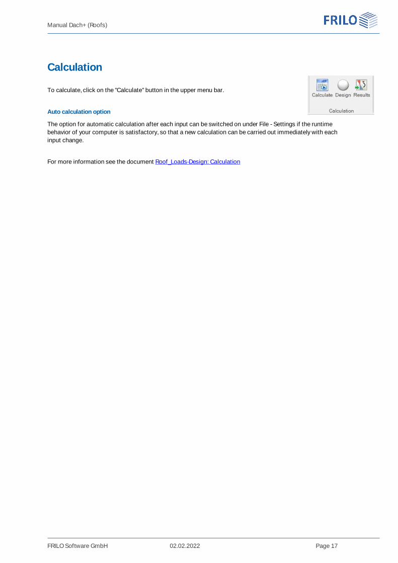
Calculation
To calculate, click on the "Calculate" button in the upper menu bar.
Auto calculation option
The option for automatic calculation after each input can be switched on under File - Settings if the runtimebehavior of your computer is satisfactory, so that a new calculation can be carried out immediately with eachinput change.
For more information see the document Roof_Loads-Design: Calculation
Manual Dach+ (Roofs)
FRILO Software GmbH 02.02.2022 Page 18
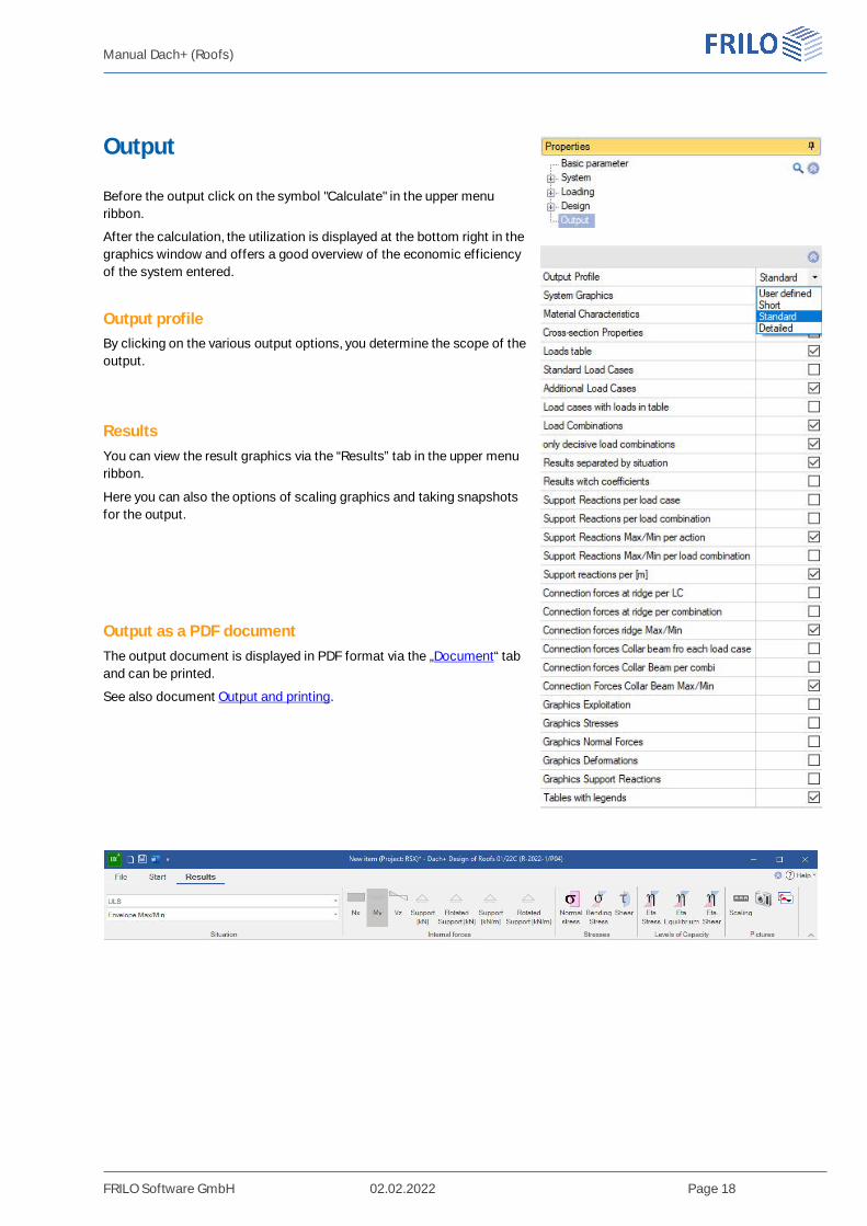
Output
Before the output click on the symbol "Calculate" in the upper menuribbon.
After the calculation, the utilization is displayed at the bottom right in thegraphics window and offers a good overview of the economic efficiencyof the system entered.
Output profileBy clicking on the various output options, you determine the scope of theoutput.
ResultsYou can view the result graphics via the “Results” tab in the upper menuribbon.
Here you can also the options of scaling graphics and taking snapshotsfor the output.
Output as a PDF documentThe output document is displayed in PDF format via the „Document“ taband can be printed.
See also document Output and printing.