design and development on automated - um students
TRANSCRIPT
DESIGN AND DEVELOPMENT ON AUTOMATEDPNEUMATIC BUMPER DRIVEN BY BRAKE ACTUATION
ANAND A/L GANASON
FACULTY OF ENGINEERINGUNIVERSITY OF MALAYA
KUALA LUMPUR
2018
Univers
ity of
Mala
ya
DESIGN AND DEVELOPMENT ON AUTOMATEDPNEUMATIC BUMPER DRIVEN BY BRAKE
ACTUATION
ANAND A/L GANASON
RESEARCH REPORT SUBMITTEDIN PARTIAL FULFILMENT OF THE
REQUIREMENTS FOR THE DEGREEOF MASTER ENGINEERING
FACULTY OF ENGINEERINGUNIVERSITY OF MALAYA
KUALA LUMPUR
2018
Univers
ity of
Mala
ya
ii
UNIVERSITY OF MALAYA
ORIGINAL LITERARY WORK DECLARATION
Name of Candidate: Anand A/L Ganason
Matric No: KQK170004
Name of Degree: Master Mechanical Engineering
Title of Project Paper/Research Report/Dissertation/Thesis (“this Work”): Design
and Development on Automated Pneumatic Bumper Driven By Brake Actuation
Field of Study: Master of Mechanical Engineering
I do solemnly and sincerely declare that:
(1) I am the sole author/writer of this Work;(2) This Work is original;(3) Any use of any work in which copyright exists was done by way of fair
dealing and for permitted purposes and any excerpt or extract from, orreference to or reproduction of any copyright work has been disclosedexpressly and sufficiently and the title of the Work and its authorship havebeen acknowledged in this Work;
(4) I do not have any actual knowledge nor do I ought reasonably to know thatthe making of this work constitutes an infringement of any copyright work;
(5) I hereby assign all and every rights in the copyright to this Work to theUniversity of Malaya (“UM”), who henceforth shall be owner of thecopyright in this Work and that any reproduction or use in any form or by anymeans whatsoever is prohibited without the written consent of UM havingbeen first had and obtained;
(6) I am fully aware that if in the course of making this Work I have infringedany copyright whether intentionally or otherwise, I may be subject to legalaction or any other action as may be determined by UM.
Candidate’s Signature: Date:
Subscribed and solemnly declared before,
Witness’s Signature : Date:
Name:
Designation:
Univers
ity of
Mala
ya
iii
DESIGN AND DEVELOPMENT ON AUTOMATED PNEUMATIC BUMPERDRIVEN BY BRAKE ACTUATION
ABSTRACT
The key concern of this project is the design and development of the technology of
pneumatics which plays a major role in the field of automation, modern machine shops
and space robots. The aim is to develop a control system based on intelligent and
electronically controlled pneumatic bumper and braking system. This project consists
of ultrasonic transmitter and receiver circuit, control unit, solenoid valve, pneumatic
bumper system and pneumatic braking system. The ultrasonic sensor senses the
obstacle closer to the vehicle (within 4-7 feet), then the control signal is given to the
pneumatic bumper as well as pneumatic braking system simultaneously. This bumper
and braking system is activated only when the vehicle speed is above 40-50 km per
hour. This vehicle speed is sensed by the ultrasonic sensor and it is given to the control
unit. The control unit controls the solenoid valve so that the pneumatic bumper and
braking system is actuated.
Univers
ity of
Mala
ya
iv
MENGKAJI DAN MEMBANGUNKAN TEKNOLOGI PNEUMATICBERDASARKAN SISTEM BUMPER PNEUMATIK DAN SISTEM KAWALAN
BREK YANG BIJAK DAN ELEKTRONIK
ABSTRAKKebimbangan utama projek ini adalah untuk mengkaji dan memajukan teknologi
pneumatik yang memainkan peranan utama dalam bidang automasi, kedai mesin moden
dan robot ruang. Tujuannya adalah untuk membangunkan sistem kawalan berdasarkan
sistem bumper pneumatik dan sistem kawalan brek yang bijak dan elektronik. Projek ini
terdiri daripada litar pemancar dan penerima ultrasonik, unit kawalan, injap solenoid,
sistem bumper pneumatik dan sistem brek pneumatik. Sensor ultrasonik merasakan
penghalang dekat dengan kenderaan (dalam jarak 4-7 kaki), maka isyarat kawalan
diberikan kepada bumper pneumatik serta sistem brek pneumatik secara serentak.
Sistem bumper dan brek ini diaktifkan hanya apabila kelajuan kenderaan melebihi 40-
50 km sejam. Kelajuan kenderaan ini dirasakan oleh sensor ultrasonik dan ia diberikan
kepada unit kawalan. Unit kawalan mengawal injap solenoid supaya sistem bumper
pneumatik dan brek digerakkan.
Univers
ity of
Mala
ya
v
ACKNOWLEDGEMENTS
I hereby want to say thanks to University of Malaya for giving me an opportunity to
carry out this research which definitely will improvise my technical career in future.
Very importantly, I also want to thank my supervisor Assoc. Prof. Dr. Farazila Binti
Yusof, who have provided a great supervisory work and given lots of useful feedback
during the progression of my project. His advice, guidance and supports are deeply
appreciated by me. I would have not successfully completed this project without his
help. Next I would like to express sincere gratitude to my friends and engineers for
helping and guiding me in the process of getting a better understanding of my project
requirements and also getting basic information for my project. Last but not the least,
many thanks to my family members and friends as well who directly or indirectly have
helped me to complete the report.
Univers
ity of
Mala
ya
vi
TABLE OF CONTENTS
ABSTRACT ................................................................................................................iii
ABSTRAK ..................................................................................................................iv
ACKNOWLEDGEMENTS .........................................................................................v
TABLE OF CONTENTS ............................................................................................vi
LIST OF FIGURES......................................................................................................x
LIST OF TABLES .....................................................................................................xii
CHAPTER 1: INTRODUCTION ................................................................................1
1.1 Pneumatic system ...............................................................................................1
1.2 Problem Statements ............................................................................................3
1.3 Objective..........................................................................................................3
1.4 Scope of the Project ............................................................................................3
1.5 Components of pneumatic system ......................................................................3
1.5.1.1 Intake filter...........................................................................................4
1.5.1.2 Compressor ..........................................................................................4
1.5.1.3 Electric motor ......................................................................................5
1.5.1.4 Receiver ...............................................................................................5
1.5.1.5 Cooler and separator ............................................................................5
1.5.1.6 Secondary air treatment .......................................................................6
1.5.1.7 Lubricator.............................................................................................6
1.5.1.8 Control valve........................................................................................6
Univers
ity of
Mala
ya
vii
1.5.1.9 Actuators..............................................................................................7
1.5.2 Advantages of pneumatic system...............................................................8
1.5.3 Limitations of pneumatic system .................................................................9
1.5.4 Applications of pneumatic system ...........................................................10
1.6 Pneumatic actuators ......................................................................................10
1.6.1 Types of pneumatic cylinders /linear actuators .....................................11
1.6.1.1 Based on the cylinder action..............................................................12
1.7 Solenoid valve...............................................................................................14
1.7.1 Advantages of solenoid valve ....................................................................15
1.7.2 Applications of solenoid valve...................................................................15
1.8 Brake.............................................................................................................16
1.8.1 Functions of brake .................................................................................16
1.8.2 Classification of brake...........................................................................16
1.9 Sensor........................................................................................................17
1.9.1 Sensor fundamentals..............................................................................17
1.9.2 Types of sensor......................................................................................18
1.9.2.1 Sound sensor ...........................................................................................18
1.9.2.2 Proximity sensor .....................................................................................18
CHAPTER 2: LITERATURE REVIEW ...................................................................20
CHAPTER 3: EXISTING SYSTEM .........................................................................22
3.1 Block diagram of existing system.....................................................................22
3.2 List of components ...........................................................................................22
Univers
ity of
Mala
ya
viii
3.3 Components description .................................................................................23
3.3.1 IR Sensor unit.............................................................................................23
3.3.2 Wheel .........................................................................................................23
3.3.3 Pneumatic cylinder.....................................................................................24
3.3.4 Solenoid valve............................................................................................24
3.3.5 Motor..........................................................................................................25
3.4 Existing model ..................................................................................................25
3.5 Disadvantage of existing system ......................................................................26
CHAPTER 4: PROPOSED SYSTEM AND METHODOLOGY..............................27
4.1 Block diagram of proposed system...................................................................27
4.2. List of components ..........................................................................................27
4.3 Description of components ...............................................................................28
4.3.1 Ultrasonic sensor........................................................................................28
4.3.2 3/2 Solenoid valve......................................................................................28
4.3.3 Double acting pneumatic cylinder .............................................................29
4.3.4 Bumper arrangement..................................................................................29
4.3.5 Brake arrangement .....................................................................................30
4.3.6 Microcontroller ..........................................................................................31
4.3.6.1 PIC16F877A ...........................................................................................32
4.3.7 Memory organization.................................................................................33
4.3.7.1 Program memory organization................................................................33
4.3.7.2 Data memory organization......................................................................33
Univers
ity of
Mala
ya
ix
4.4 Working principle.............................................................................................34
4.4.1 Proposed system.........................................................................................34
4.4.2 Working principle of automatic pneumatic bumper and brake actuation..34
4.5 Coding...........................................................................................................37
4.5.1 Ultrasonic program ....................................................................................37
4.5.2 LCD program .............................................................................................38
4.6 List of materials ................................................................................................40
CHAPTER 5: CONCLUSION...................................................................................41
CHAPTER 6: COST ESTIMATION .........................................................................42
REFERENCES...........................................................................................................43
Univers
ity of
Mala
ya
x
LIST OF FIGURES
Figure 1.1: Basic pneumatic system ........................................................................................2
Figure 1.2: Main components of pneumatic system ................................................................4
Figure 1.3: Single acting cylinder......................................................................................... 13
Figure 1.4: Double acting cylinder ....................................................................................... 14
Figure 1.5: Solenoid valve .................................................................................................... 15
Figure 3.2: Block diagram of existing system ...................................................................... 22
Figure 3.3: IR sensor unit ..................................................................................................... 23
Figure 3.4: Wheel ................................................................................................................. 23
Figure 3.5: Single acting cylinder......................................................................................... 24
Figure 3.6: Solenoid valve .................................................................................................... 24
Figure 3.7: Motor.................................................................................................................. 25
Figure 3. 8: Existing model .................................................................................................. 25
Figure 4.1: Block diagram of proposed system .................................................................... 27
Figure 4.2: Ultrasonic sensor ................................................................................................ 28
Figure 4.3: Solenoid valve .................................................................................................... 29
Figure 4.4: Double acting pneumatic cylinder...................................................................... 29
Figure 4.5: Bumper arrangement .......................................................................................... 30
Figure 4.6: Brake arrangement ............................................................................................. 30
Figure 4.7: Pin diagram of PIC16F877A.............................................................................. 33
Figure 4.8: Memory organization of PIC16F877A............................................................... 34
Univers
ity of
Mala
ya
xi
Figure 4.9: Fabricated model ................................................................................................ 36
Univers
ity of
Mala
ya

xii
LIST OF TABLES
Table 4.1: List of materials ................................................................................................... 40
Univers
ity of
Mala
ya
1
CHAPTER 1: INTRODUCTION
The achievement of automation can be via robotics, pneumatics, computers,
hydraulics, etc., among all the listed sources, a medium of attraction for less expensive
automation is formed from pneumatics. It is also important to note that economy as well
as simplicity are the major benefits of all pneumatic systems. Hence, in mass
production, an essential role is being played by Automation. The roles played are:
To ensure mass production achievement.
To ensure the reduction of man-power.
To make sure that the plant’s efficiency is increased.
To ensure work load reduction.
To ensure reduction in the cost of production.
To ensure reduction in the time taken to produce.
To ensure reduction of the material handling.
To help in reduce workers’ fatigue.
To ensure the achievement of a good quality of product.
To lessen the process of Maintenance.
1.1 Pneumatic system
With regards to the performance of mechanical works, for a long time now, a vital
role has being played by Pneumatics as a technology. Also, it has being made use of in
developing automated solutions. There is a similarity between the hydraulic system and
the Pneumatic system, however the use of compressed air is replaced with hydraulic
fluid in these systems. Furthermore, a system can be referred to as pneumatic if it uses
compressed air for the control and transmission of energy. These systems are made use
of in diverse industries to a large extent. They are provided via a compressor of air. Air
Univers
ity of
Mala
ya
2
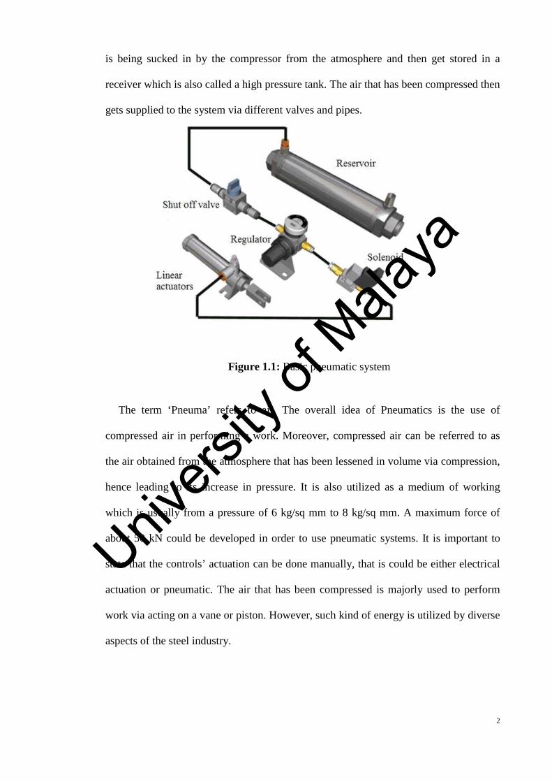
is being sucked in by the compressor from the atmosphere and then get stored in a
receiver which is also called a high pressure tank. The air that has been compressed then
gets supplied to the system via different valves and pipes.
Figure 1.1: Basic pneumatic system
The term ‘Pneuma’ refers to air. The overall idea of Pneumatics is the use of
compressed air in performing a work. Moreover, compressed air can be referred to as
the air obtained from the atmosphere that has been lessened in volume via compression,
hence leading to its increase in pressure. It is also utilized as a medium of working
which is usually from a pressure of 6 kg/sq mm to 8 kg/sq mm. A maximum force of
about 50 kN could be developed in order to use pneumatic systems. It is important to
state that the controls’ actuation can be done manually, that is could be either electrical
actuation or pneumatic. The air that has been compressed is majorly used to perform
work via acting on a vane or piston. However, such kind of energy is utilized by diverse
aspects of the steel industry.
Univers
ity of
Mala
ya

3
1.2 Problem Statements
Rigorous efforts are made by researchers and vehicle manufacturers to improve the
efficiency on improving automated breaking system in order to minimize accident made
by human. One of the method used is to develop a control system based on intelligent
and electronically controlled pneumatic bumper and braking system. However, many
studies conducted focus mainly on autonomous emergency braking systems.
1.3 Objective
The proposed system consists of an Ultrasonic sensor, this sensor senses the
obstacle in above 4 to 7 feet when the vehicle runs above 40-50 km per hour and also its
sense the obstacle in the wide area of the path within the distance it can sense the
obstacle so as to control the bumper and braking mechanism.
1.4 Scope of the Project
The scope of the project is to compare the existing system and propose a new system.
As a conclusion, the overall design and fabrication, are analysed and upgrading is done for
the overall pneumatic system’s efficiency.
1.5 Components of pneumatic system
The movement and force for majority of the pneumatic systems is being provided by
air motors, pneumatic cylinders and rotatory actuators and this is used to hold, move,
form and process materials. In operating and controlling of these actuators, additional
pneumatic constituents needs to be in place such as, units of air service for compressed
air preparation and valves for pressure control, direction as well as flow of the actuators
movement. There are two major sections by which a fundamental pneumatic system is
Univers
ity of
Mala
ya
4
consisted of. They are: 1) compressed production of air, transportation and system of
distribution, 2) compressed system for the consumption of air.
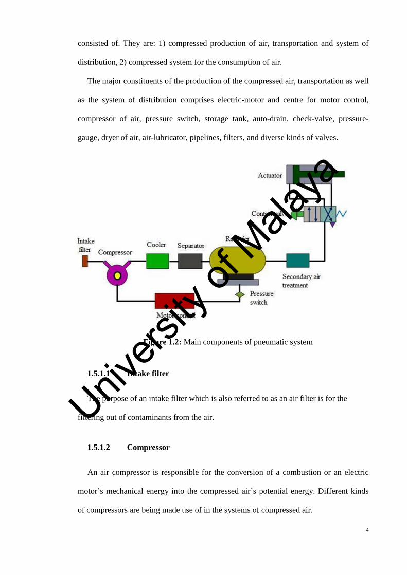
The major constituents of the production of the compressed air, transportation as well
as the system of distribution comprises electric-motor and centre for motor control,
compressor of air, pressure switch, storage tank, auto-drain, check-valve, pressure-
gauge, dryer of air, air-lubricator, pipelines, filters, and diverse kinds of valves.
Figure 1.2: Main components of pneumatic system
1.5.1.1 Intake filter
The purpose of an intake filter which is also referred to as an air filter is for the
filtering out of contaminants from the air.
1.5.1.2 Compressor
An air compressor is responsible for the conversion of a combustion or an electric
motor’s mechanical energy into the compressed air’s potential energy. Different kinds
of compressors are being made use of in the systems of compressed air.
Univers
ity of
Mala
ya
5
A compressor that is used for generating compressed air is chosen based on the
preferred maximum pressure of delivery and the needed air-flow rate. However, in
compressed air systems, the kinds of compressors therein are:
i) Piston or reciprocating compressors
a) Single stage or double stage piston compressor
b) Diaphragm compressorii) Rotary compressors
a) Sliding vane compressor
b) Screw compressor
iii) Centrifugal compressors
iv) Axial flow compressors
1.5.1.3 Electric motor
The transformation of electric energy into mechanical energy is done by an
electric motor. It can also be used for the driving of the air compressor.
1.5.1.4 Receiver
The air receiver serves as a storage place for the compressor’s obtained compressed
air. The aim of the air-receiver is to ensure smoothness in the compressor’s pulsating
flow. Also, it serves as an aid to the air for cooling and condensing the present
moisture.
1.5.1.5 Cooler and separator
In order to ensure that the pneumatic system is being operated satisfactorily, there is
need for cleaning and drying the air. This is because air in the atmosphere is humid in
nature and is contaminated with smoke and dust. Such particles could lead to the
wearing of the system components and corrosion might be caused by the presence of
moisture. Therefore, to be able to get rid of such impurities, air treatment is very
Univers
ity of
Mala
ya
6
important and a necessity. In the course of the operation of compression, there is an
increase in the temperature of the air.
1.5.1.6 Secondary air treatment
Air treatment can be split into three phases. The 1st phase deals with the prevention
of large-sized particles from getting into the air compressor via an intake-filter. The air
that escapes out of the compressor might be humid in nature and might also have a high
temperature. In the 2nd phase, treatment of the compressed air from the compressor
occurs. In this phase, there is a reduction of the compressed air’s temperature via the use
of a cooler and a dryer is used to dry the air. Furthermore, a system for air-drying could
be absorption type, refrigeration type, adsorption type, or a kind that makes use of semi-
permeable membranes. There is also the provision of an in-line filter for purpose of
removing any existing contaminant particles. Such treatment is referred to as basic
treatment of air. However, in the 3rd phase, also referred to as the secondary process for
air treatment, additional filtering is conducted.
1.5.1.7 Lubricator
The lubrication of a cylinder’s moving parts as well as the valves is of much
essentiality in a pneumatic system. Due to this, compressed lubricators of air are
utilized before the pneumatic equipment. A fine oil mist is being introduced into the
compressed air by the lubricator. This however assists in lubricating the system’s
moving components of which application is being made by the compressed air. About
20-50 centistokes of kinematic viscosity is being agreed to be the accurate grade for oil
lubrication.
1.5.1.8 Control valve
Control valves are used for the control, regulation, and monitoring of the flow of
direction, pressure, and others. A control valve’s key function is the maintenance of
Univers
ity of
Mala
ya
7
continuous down-stream pressure in the air-line, not minding the variances in the
upstream pressure. As a result of the compressed air-flow’s high velocity, there
exists a dependent flow of pressure drop in the midst of the load (application) and
the receiver. Therefore, the receiver’s pressure is continuously kept at a higher point
than the pressure of the system. In the site of the application, in order to keep it
fixed, there is a regulation of the pressure. Three mediums for the controlling of
local pressures exists and they are provided thus. The 1st method ensures that air is
being vented into the atmosphere regularly by the load. Hence the airflow to the
load is being restricted by the pressure-regulator, thereby regulating the air-pressure.
For this kind of pressure-regulation, some minimal flow is needed for the regulator
to be operated. However, if the load is a type that is dead-end and does not draw any
air, the receiver’s pressure will rise to a quite high pressure. Such kinds of regulators
are referred to as: ‘non-relieving regulators’, due to reason being that there must be
a flow of air via the load. In the 2nd type, the load is seen as a dead-end load.
Nevertheless, in order to ensure reduction in pressure, there is a venting of air to the
atmosphere by the regulator.
1.5.1.9 Actuators
Actuators like motors and air-cylinders are used for obtaining the needed movements
of pneumatic system’s mechanical elements. Actuators refer to output devices that
ensures energy conversion from a compressed air to the needed kind of motion or
action. Generally, pneumatic systems are used in different industries to move and grip
operations. Those operations are being executed via the use of actuators. Typical
pressure of hydraulic cylinders is around 100 kg/sq mm, while that of pneumatic
cylinders is approximately 10 kg/mm2.
Univers
ity of
Mala
ya
8
1.5.2 Advantages of pneumatic system
Pneumatic systems are extensively used in diverse industries to drive automatic
machines. Hence, these systems have many advantages, some of which have been
explained below:
a) High effectiveness: An unrestricted supply of air exists in the atmosphere for the
production of compressed air. Furthermore, it is possible to easily store items in
big volumes. The usage of compressed air is not limited by distance, due to the
fact that it can be easily transported via pipes. After its usage, the air that is
compressed can be directly released to the atmosphere without having the need to
process.
b) High durability and reliability: The components of the pneumatic system are of
much durability and are not easy to damage. Furthermore, they are much more
reliable and durable when put in comparison with electromotive components.
c) Simple design: Designs of the components of pneumatic systems are of relative
simplicity. Hence, they are more appropriate to use in easy-going automated control
systems. With operational speeds that are of continuous variability and simplicity, a
choice of movement like angular movement of rotation or linear movement are
available.
d) Safety aspects: Unlike electro-motive systems, there is a higher level of safety with
the pneumatic systems, this is due to reason being that they have the ability to work
in an environments that is flammable without instigating explosion or fire outbreak.
Not only that, also pneumatic system’s overloading only results to operation
termination or sliding. The components of the pneumatic system doesn’t get
Univers
ity of
Mala
ya
9
overheated or burned when being overloaded unlike an electromotive system’s
components.
e) Environmental friendly: The production of pollutants does not occur during the
operation of a pneumatic system. Also, these systems maintain a neat environment
and undergo appropriate treatment of air exhaust which could be installed for the
cleaning of room standards. Hence, pneumatic systems have the ability to perform
well in environs with a high level demand of neatness/cleanliness. One of such
examples is integrated circuits lines of production.
1.5.3 Limitations of pneumatic system
Even though a lot of benefits are being possessed by pneumatic systems, yet
they still have numerous limitations. Such limitations are presented below:
1. Relatively low accuracy – Due to reason being that the powering of pneumatic
systems are done with force enacted by the compressed air, hence the compressed
air’s operational volume determines their operation. Knowing well that when air
undergoes heating or compression, its volume might change, the system’s air supply
might also not be accurate which could lead to a reduction in the systems overall
accuracy.
2. Processing required before use – It is mandatory for compressed air to undergo
some processing before it is used, this is to make sure that dust or water vapour are
absent. If this is not done, it could cause the pneumatic components to rapidly wear-
out because of friction.
3. Uneven moving speed – There is a relative unevenness in the moving speeds of a
piston because it is very easy for air to be compressed.
4. Noise – There is a usual production of noise when the pneumatic components
releases air that is compressed.
Univers
ity of
Mala
ya
10
1.5.4 Applications of pneumatic system
Numerous applications are available for pneumatic systems. Some of such
applications are: process equipment’s operation, operations of forming, riveting,
welding/brazing holdings, fixtures and jigs holdings, spray printing, objects moving and
lifting, pneumatic rammers, machine tools, bins and hoppers unloading, chemicals or
water, air system valves operation, pneumatic drills and pneumatic presses, etc. Other
specific applications are explained below:
Previously, air brakes on trucks and buses are known to be air-brake systems
that are compressed. However, these systems makes use of a kind of friction
brake wherein compressed air is being pressed on a piston, and then the pressure
is applied to the brake pad which eventually stops the vehicle.
Pneumatic systems can be the building base for machines that are used for
exercise. An air-pressure adjustable resistance can be created by a pneumatic
cylinder.
In the measurement of liquids or gases, pressure sensors are utilized.
Expandable structures like: bouncy castles, blown-up figures or balloons are
being inflated with a gas-air, nitrogen, hydrogen or helium. Also the gas
pressure retains the inflation of the structure.
Compressed air is used to create pneumatic tires so as to form and inflate a
tyre’s body on either a car, bike or any other vehicle.
A jack-hammer that is hand-held is a tool which combines both a chisel and a
hammer, and compressed air is normally used to power it.
1.6 Pneumatic actuators
Pneumatic actuators are devices which are used to convert the pressure of a
compressed air energy into the mechanical energy so as to ensure the performance of
Univers
ity of
Mala
ya
11
useful work. In other terms, actuators are used for task performance that exerts the
needed force at the end of a stroke or they are used for the creation of displacement via
the piston’s movement. This pressurized air obtained from the compressor is then
supplied to the reservoir. Furthermore, the storage-obtained pressurized air is supplied
to the pneumatic actuator in order to perform task. The air cylinder is an efficient and
easy device which is used to provide straight-line motions or linear thrust with a quick
rate of response. Friction losses are low and sometimes exceeds 5 percent (%). They are
also appropriate to be used under conditions that excludes the usage of hydraulic
cylinders which are at a high ambient temperature of about 200 to 2500C. Actuators can
be categorised into three and they are:
a) Linear actuators: These deals with the conversion of pneumatic energy to linear
motion.
b) Rotary actuators: They deal with the conversion of pneumatic energy to rotary
motion.
c) Actuators to operate flow control valves: They are used for controlling the pressure
and flow of fluids like steam, liquids or gases.
1.6.1 Types of pneumatic cylinders /linear actuators
Pneumatic cylinders refer to devices that are used to convert air pressure to linear
mechanical motion and force. These cylinders are used mainly for single application
purposes like turning, bending, metering, tilting, branching, allocating, ejecting,
transferring, stamping, clamping and a lot of other applications. The diverse schemes
of classification of pneumatic cylinders are presented as follows:
1. Based on application for which air cylinders are used
i) Light duty-air cylinders
ii) Medium duty-air cylinders
Univers
ity of
Mala
ya
12
iii) Heavy duty-air cylinders
2. Based on the action of the cylinder
i) Single-acting cylinder
ii) Double-acting cylinder
3. Based on the movement of the cylinder
i) Rotating type air cylinder
ii) Non-rotating type air cylinder
1.6.1.1 Based on the cylinder action
With regards to the action of the cylinder, the cylinders can be classified as double
acting and single acting. Cylinders with single acting have a single line of air inlet,
while those that are double acting cylinders have dual lines for the inlet of air. The
advantages of double acting cylinders over the single acting ones are given below:
i. For single acting cylinders, the compression of air is just fed at one side. Therefore,
such cylinders can only work in one direction, however in the case of a double
acting cylinder, the air that has been compressed shifts the piston in dual directions
so that they can work in the two directions.
ii. In a single acting cylinder, there is a limit in the length of the stroke by the
spring’s compressed length. However in principle, the length of the stroke is not
limited in a double acting cylinder.
iii. In a single acting cylinder, the spring’s pressure has to be overcome by air while
the piston moves forward and therefore some strength is displaced even before the
commencement of the actual piston stoke. However such problem does not occur
in a double acting cylinder.
Univers
ity of
Mala
ya
13
(A)Single acting cylinder
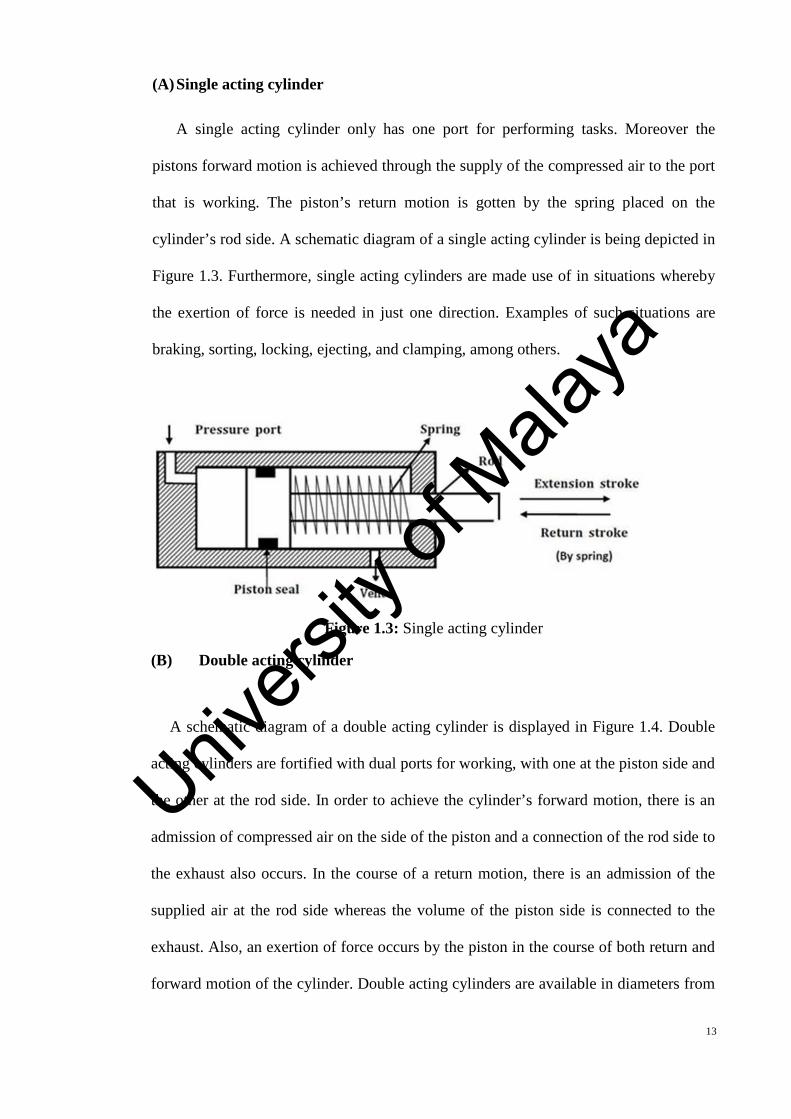
A single acting cylinder only has one port for performing tasks. Moreover the
pistons forward motion is achieved through the supply of the compressed air to the port
that is working. The piston’s return motion is gotten by the spring placed on the
cylinder’s rod side. A schematic diagram of a single acting cylinder is being depicted in
Figure 1.3. Furthermore, single acting cylinders are made use of in situations whereby
the exertion of force is needed in just one direction. Examples of such situations are
braking, sorting, locking, ejecting, and clamping, among others.
Figure 1.3: Single acting cylinder
(B) Double acting cylinder
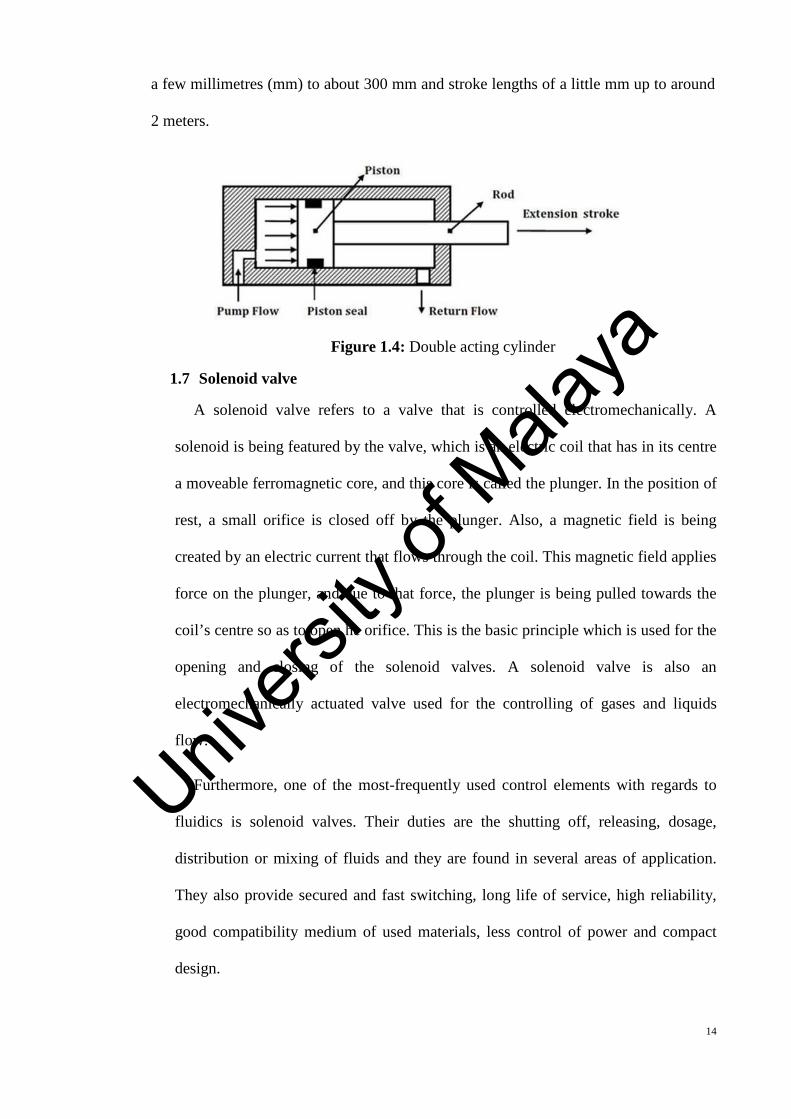
A schematic diagram of a double acting cylinder is displayed in Figure 1.4. Double
acting cylinders are fortified with dual ports for working, with one at the piston side and
the other at the rod side. In order to achieve the cylinder’s forward motion, there is an
admission of compressed air on the side of the piston and a connection of the rod side to
the exhaust also occurs. In the course of a return motion, there is an admission of the
supplied air at the rod side whereas the volume of the piston side is connected to the
exhaust. Also, an exertion of force occurs by the piston in the course of both return and
forward motion of the cylinder. Double acting cylinders are available in diameters from
Univers
ity of
Mala
ya
14
a few millimetres (mm) to about 300 mm and stroke lengths of a little mm up to around
2 meters.
Figure 1.4: Double acting cylinder
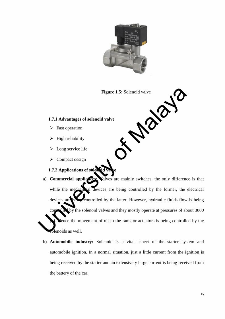
1.7 Solenoid valve
A solenoid valve refers to a valve that is controlled electromechanically. A
solenoid is being featured by the valve, which is an electric coil that has in its centre
a moveable ferromagnetic core, and this core is called the plunger. In the position of
rest, a small orifice is closed off by the plunger. Also, a magnetic field is being
created by an electric current that flows through the coil. This magnetic field applies
force on the plunger, and due to that force, the plunger is being pulled towards the
coil’s centre so as to open he orifice. This is the basic principle which is used for the
opening and closing of the solenoid valves. A solenoid valve is also an
electromechanically actuated valve used for the controlling of gases and liquids
flow.
Furthermore, one of the most-frequently used control elements with regards to
fluidics is solenoid valves. Their duties are the shutting off, releasing, dosage,
distribution or mixing of fluids and they are found in several areas of application.
They also provide secured and fast switching, long life of service, high reliability,
good compatibility medium of used materials, less control of power and compact
design.
Univers
ity of
Mala
ya
15
.
Figure 1.5: Solenoid valve
1.7.1 Advantages of solenoid valve
Fast operation
High reliability
Long service life
Compact design
1.7.2 Applications of solenoid valve
a) Commercial appliances: Valves are mainly switches, the only difference is that
while the mechanical devices are being controlled by the former, the electrical
devices are being controlled by the latter. However, hydraulic fluids flow is being
controlled by the solenoid valves and they mostly operate at pressures of about 3000
psi. Hence the movement of oil to the rams or actuators is being controlled by the
solenoids as well.
b) Automobile industry: Solenoid is a vital aspect of the starter system and
automobile ignition. In a normal situation, just a little current from the ignition is
being received by the starter and an extensively large current is being received from
the battery of the car.
Univers
ity of
Mala
ya
16
c) Electromechanical solenoids: These solenoids comprises of an electromechanical
inductive coil and are wounded about an armature. Furthermore, the wounding of
the coil is for the purpose of enabling the movement of the armature from its mean
point and hence making it to become and electromagnet via the inductance of the
coil.
1.8 Brake
As a result of a vehicle’s motion, there is a dissipation of the kinetic energy in
form of heat energy because of friction amidst the moving parts (that is: wheel drum
or wheel) and the stationary parts of the vehicle (brake shoes). Therefore, it is a
necessity to have braking system in an automobile to enable the vehicle to be able to
stop. The application of brakes on the wheels is for the slowing down or stoppage of
a vehicle.
1.8.1 Functions of brake
There are two main functions of brakes:
For slowing down or stopping the vehicle at the possibly shortest time when the
need arises.
For the controlling of the vehicle’s speed at bends and also at periods when
driving down on a sloppy hill.
1.8.2 Classification of brake
a) Based on the actuation method
Foot brake
Hand brake
b) Bases on the mode of operation
Mechanical brake
Hydraulic brake
Air brake
Univers
ity of
Mala
ya
17
Vacuum brake
Electric brake
c) Based on the front or rear wheel’s action
Front wheel brake
Rear wheel brake
d) Based on the braking contract’s application method
Internally expanding brake
Externally contracting brake
1.9 Sensor
A sensor is referred to as device which is able to detect and respond to some
kinds of physical environmental input. Precise input can be heat, moisture, pressure,
light, or any other phenomena of an environment. Thus, the output form a general
point of view is a converted signal of a readable human display located at the sensor
or electronically transmitted via a network for further processing or reading.
1.9.1 Sensor fundamentals
a) Range: All kinds of sensors are designed to be able to work via a precise range.
These design ranges are normally fixed, and if the go beyond the normal fixed
point, it will lead to permanent damage or to a sensor being destroyed. It is therefore
normal to make use of transducing elements via just the portion of their range where
predictable performance is being provided by them and most times enhanced
linearity.
b) Zero: In the process of the making of a measurement, it is very important to begin at
a datum that is known, and it is also most times convenient to adjust the instruments
output to zero at the datum. Hence, this value is one which is ascribed to some
definite points in the ranges that are measured.
Univers
ity of
Mala
ya
18
c) Zero drift: There might be variance in the level of signal from the original set value
of zero during the working period of the sensor. This initiates an error into the
measurement which is equivalent to the varied amount, or ‘drift’ as it’s usually
referred to. More so, the drift in zero might be due to changes in temperature,
stabilization of electronics, or even the transducer’s age or electronic components.
d) Linearity: The sensor with the most conveniences for usage is the linear transfer
function sensor. In this case, it involves a direct proportion of the output to the input
via the overall range, thereby describing a straight line through the output graph
slope versus that of the input.
1.9.2 Types of sensor
Diverse kinds of sensors are available to select from and for purpose of the research,
the characteristics of a few sensors has been identified below. Also, the comprehension
of why and where they are used is also explored.
1.9.2.1 Sound sensor
As the name suggests, this sensor (generally a microphone) is responsible for the
detection of sound and hence returns a voltage that is proportional to that of the level of
sound. A simple robot could be designed for navigation based on the received sounds.
Take for instance a robot that turns to the right for one hand clap and then turns to the
left for two hand claps. Fortunately even a complex robot can make use of the same
microphone for the recognition of both speech and voice.
1.9.2.2 Proximity sensor
This kind of sensor can detect that a close-by object is present within a known
distance, and without contacting any physical object. A proximity sensor’s working
principle is quite simple. An electromagnetic radiation is being transmitted by a
transmitter or an electrostatic field is being created by a transmitter and then the
Univers
ity of
Mala
ya
19
transmitter analyses the return signal to find out if interruptions exists. There are
diverse kinds of proximity sensors and a few of them which are used generally in
robots shall be discussed.
a) Infrared (IR) transceiver: A beam of IR light is being transmitted by an IR LED
and peradventure it discovers an obstacle, the light will simply reflect back, and this
light is captured by an IR receiver. However, just a few IR transceivers can be used for
the measurement of distance.
b) Ultrasonic sensor: Sound waves of high frequency are being generated by these
sensors. Echo’s that is being received recommends that an object is being interrupted.
Also, these ultrasonic sensors can be used for measurement of distance.
c) Photo-resistor: Photo-resistor is a light sensor; however, it can still serve the
purpose of a proximity sensor. Whenever a sensor has a close proximity with an object,
there is a variance in the level of light which in return causes some variations in the
photoresistor’s resisting power. Such variations can be detected and further processed.
There are numerous diverse proximity sensors types and just a little of them are
generally suitable for robots. For instance, “capacitive proximity sensors” are available
which detects variance in the capacitance about it. Furthermore, Inductive proximity
sensor is able to detect objects and distances via the utilization of magnetic fields.
Univers
ity of
Mala
ya
20
CHAPTER 2: LITERATURE REVIEW
Some researchers have described that to design and develop a control system that is
based on intelligent electronically controlled automotive bumper activation as well as an
automatic braking system, it will comprise of IR transmitter and Receiver circuit, and
the Control Unit (Chari, 2015). Furthermore, Pneumatic bumper system and pneumatic
braking system of the vehicle speed is sensed by the proximity sensor and this signal is
given to the control unit, the pneumatic bumper and the braking activation system.
Furthermore, studies on auto brake collision warnings exists in literature (B
Mustapha et al., 2012). The Auto Brake can be described as where the area in front of
the vehicle is continuously monitored with the help of long range radar and a forward-
sensing wide-angle camera fitted in front of the interior rear-view mirror. In a study, a
warning and brake support was provided for collisions with other vehicles, both moving
and stationary (Coelingh et al., 2007).
Baharuddin Mustapha et al. (2013) Informed that an obstacle detection system is
built based on two types of sensors. The system is intended for use by the elderly and
people with vision impairment. From their study, results from experiments showed that
ultrasonic and infrared sensors have diverse features in terms of measurements of output
voltage (Baharuddin Mustapha et al., 2013). It is clearly indicated that ultrasonic sensor
gives a linear output characteristic whereas infrared sensor shows a nonlinear output
characteristic.
The study of (Mohammad, 2009) described about the amplitude response of infrared
(IR) sensors depends on the reflectance properties of the target. Therefore, in order to
use IR sensor for measuring distances accurately, prior knowledge of the surface
Univers
ity of
Mala
ya

21
Ultrasonic (US) sensor can provide the initial information on distance to obtain the
parameters for this method.
An original ultrasonic reverse warning system is a new system that can assist drivers
while car is braking. It includes ultrasonic emitter and receiver that can produce and
receive the ultrasonic waves to determine the distance between car and obstacle. Some
researchers designed a system that could assist drivers stop the car automatically, an
electronic circuit was constructed (Kim, 2015; Sobers et al., 2009). According to this
circuit that was designed, a signal was produced to the braking system of a car based on
the distance between the car and obstacle for a safe braking purpose.
Univers
ity of
Mala
ya
22
CHAPTER 3: EXISTING SYSTEM
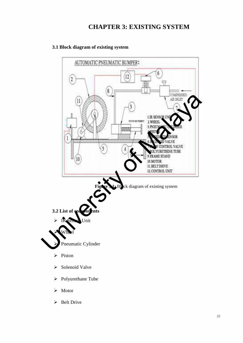
3.1 Block diagram of existing system
Figure 3.1: Block diagram of existing system
3.2 List of components
IR Sensor Unit
Wheel
Pneumatic Cylinder
Piston
Solenoid Valve
Polyurethane Tube
Motor
Belt Drive
Univers
ity of
Mala
ya
23
3.3 Components description
3.3.1 IR Sensor unit
An infrared sensor is an electronic device that has the ability to emit for purpose of
sensing some parts of a surrounding. Furthermore, it can measure the heat of an object
as well as detect its motion. These kinds of sensors only measures the radiation of
infrared, instead of its emission which is known as passive IR sensor.
Figure 3.2: IR sensor unit
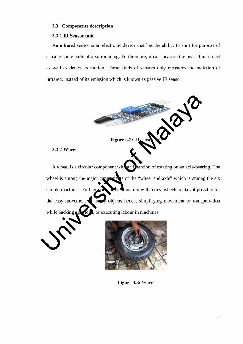
3.3.2 Wheel
A wheel is a circular component with an intention of rotating on an axle-bearing. The
wheel is among the major components of the “wheel and axle” which is among the six
simple machines. Furthermore, in combination with axles, wheels makes it possible for
the easy movement of heavy objects hence, simplifying movement or transportation
while backing up a load, or executing labour in machines.
Figure 3.3: Wheel
Univers
ity of
Mala
ya
24
3.3.3 Pneumatic cylinder
The cylinder is a Single acting cylinder one, meaning that there is a forward
operation of the air pressure and a backward return of the spring. Additionally, the
obtained air from the compressor flows via the regulator that is responsible for the
control of pressure to the needed amount via the adjustment of its knob.
Figure 3.4: Single acting cylinder
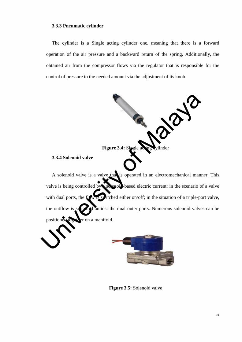
3.3.4 Solenoid valve
A solenoid valve is a valve that is operated in an electromechanical manner. This
valve is being controlled by a solenoid-based electric current: in the scenario of a valve
with dual ports, the flow is switched either on/off; in the situation of a triple-port valve,
the outflow is switched amidst the dual outer ports. Numerous solenoid valves can be
positioned together on a manifold.
Figure 3.5: Solenoid valve
Univers
ity of
Mala
ya
25
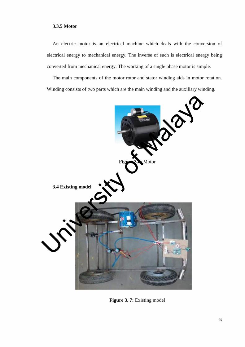
3.3.5 Motor
An electric motor is an electrical machine which deals with the conversion of
electrical energy to mechanical energy. The inverse of such is electrical energy being
converted from mechanical energy. The working of a single phase motor is simple.
The main components of the motor rotor and stator winding aids in motor rotation.
Winding consists of two parts which are the main winding and the auxiliary winding.
Figure 3.6: Motor
3.4 Existing model
Figure 3. 7: Existing model
Univers
ity of
Mala
ya
26
3.5 Disadvantage of existing system
Much sensitivity of its sensor to sunlight and IR lights.
Weakness to darker colours, such as black.
Ability to sense only in a narrow direction.
Time consumption of retraction is more.
Univers
ity of
Mala
ya
27
CHAPTER 4: PROPOSED SYSTEM ANDMETHODOLOGY
4.1 Block diagram of proposed system
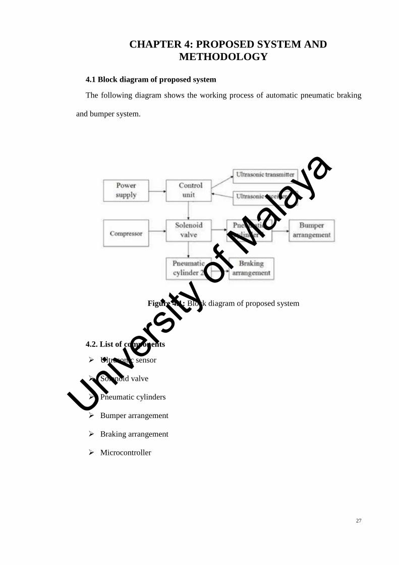
The following diagram shows the working process of automatic pneumatic braking
and bumper system.
Figure 4.1: Block diagram of proposed system
4.2. List of components
Ultrasonic sensor
Solenoid valve
Pneumatic cylinders
Bumper arrangement
Braking arrangement
Microcontroller
Univers
ity of
Mala
ya
28
4.3 Description of components
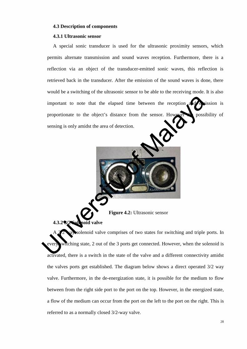
4.3.1 Ultrasonic sensor
A special sonic transducer is used for the ultrasonic proximity sensors, which
permits alternate transmission and sound waves reception. Furthermore, there is a
reflection via an object of the transducer-emitted sonic waves, this reflection is
retrieved back in the transducer. After the emission of the sound waves is done, there
would be a switching of the ultrasonic sensor to be able to the receiving mode. It is also
important to note that the elapsed time between the reception and emission is
proportionate to the object’s distance from the sensor. However the possibility of
sensing is only amidst the area of detection.
Figure 4.2: Ultrasonic sensor
4.3.2 3/2 Solenoid valve
A 3/2 way solenoid valve comprises of two states for switching and triple ports. In
every switching state, 2 out of the 3 ports get connected. However, when the solenoid is
activated, there is a switch in the state of the valve and a different connectivity amidst
the valves ports get established. The diagram below shows a direct operated 3/2 way
valve. Furthermore, in the de-energization state, it is possible for the medium to flow
between from the right side port to the port on the top. However, in the energized state,
a flow of the medium can occur from the port on the left to the port on the right. This is
referred to as a normally closed 3/2-way valve.
Univers
ity of
Mala
ya
29
Figure 4.3: Solenoid valve
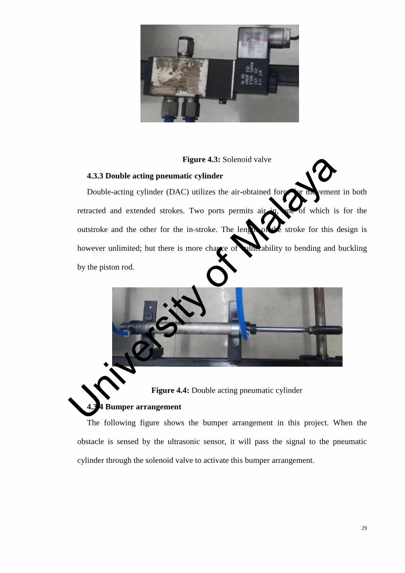
4.3.3 Double acting pneumatic cylinder
Double-acting cylinder (DAC) utilizes the air-obtained force for movement in both
retracted and extended strokes. Two ports permits air in, one of which is for the
outstroke and the other for the in-stroke. The length of the stroke for this design is
however unlimited; but there is more chance of vulnerability to bending and buckling
by the piston rod.
Figure 4.4: Double acting pneumatic cylinder
4.3.4 Bumper arrangement
The following figure shows the bumper arrangement in this project. When the
obstacle is sensed by the ultrasonic sensor, it will pass the signal to the pneumatic
cylinder through the solenoid valve to activate this bumper arrangement.
Univers
ity of
Mala
ya
30
Figure 4.5: Bumper arrangement
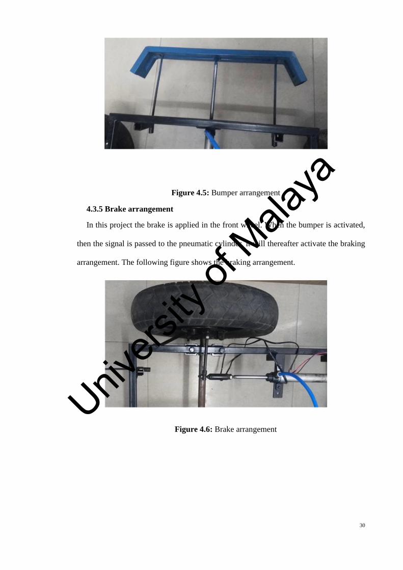
4.3.5 Brake arrangement
In this project the brake is applied in the front wheel. When the bumper is activated,
then the signal is passed to the pneumatic cylinder, it will thereafter activate the braking
arrangement. The following figure shows the braking arrangement.
Figure 4.6: Brake arrangement
Univers
ity of
Mala
ya
31
4.3.6 Microcontroller
All needed functions are on a single chip. It is important to note that there is a
difference between a microcontroller and a microprocessor, which is a generic-purpose
chip used for creating multiple-function computer or device and it needs numerous
chips to be able to handle different tasks. A microcontroller is supposed to possess more
self-containing and independence, and ought to function as a dedicated, minute
computer. This kind of devices are designed typically through the use of CMOS
(Complementary Metal Oxide Semiconductor) technology, an effective fabricating
technique which uses reduced power and has more immunity to power spikes than other
techniques. Also, multiple architectures wherein a microcontroller is seen as an
integrated chip which is most times a part of an embedded system. Such
microcontrollers includes a RAM, CPU, I/O ports, ROM, and timers just like a
conventional computer, however due to reason being that their design is for the
execution of just a single precise task for controlling of a single system, they are of
more smaller sizes and more simplified to include usage as a normal computer.
However, CISC (Complex Instruction Set Computer) is a predominant architecture
which permits the microcontroller to include numerous instructions for control that can
be executed with just a single macro instruction.
Some use a RISC (Reduced Instruction Set Computer) architecture, which
implements lesser instructions, but provides a more simplicity and lesser consumption
of power. The earlier generation of controllers were built typically from logic
components and were mostly very big. However, in the later times, microprocessors
were used and it was possible for controllers to get fitted onto a circuit board.
In many areas microcontrollers have become quite common and they can be found in
a number of appliances at home, instrumentation, and computer equipment.
Univers
ity of
Mala
ya
32
Furthermore, they are used mostly in automobiles, and they have lot of industrial
usages, and have grown to become a centric part of the industrial robotics.
Microcontrollers do not need a processing power that is significant due to reason being
that they are mostly used for the control of an independent process and in executing
simple instructions.
4.3.6.1 PIC16F877A
The term PIC, or Peripheral Interface Controller, is the name given by Microchip
Technologies to its single – chip microcontrollers. PIC micros have grown to become
the most widely used microcontrollers in the 8- bit microcontroller segment. The
PIC16F877A CMOS FLASH-based 8-bit microcontroller is upward compatible with the
PIC16C5x, PIC12Cxxx and PIC16C7x devices. It features 200 ns instruction execution,
256 bytes of EEPROM data memory, self-programming, an ICD, 2 Comparators, 8
channels of 10-bit Analog-to-Digital (A/D) converter, 2 capture/compare/PWM
functions, a synchronous serial port that can be configured as either 3-wire SPI or 2-
wire I2C bus, a USART, and a Parallel Slave Port.
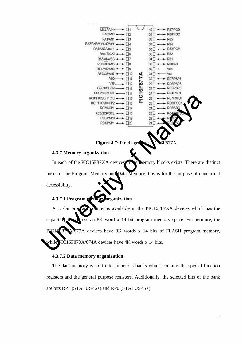
Pin configuration and description
Univers
ity of
Mala
ya
33
Figure 4.7: Pin diagram of PIC16F877A
4.3.7 Memory organization
In each of the PIC16F87XA devices, three memory blocks exists. There are distinct
buses in the Program Memory and Data Memory, this is for the purpose of concurrent
accessibility.
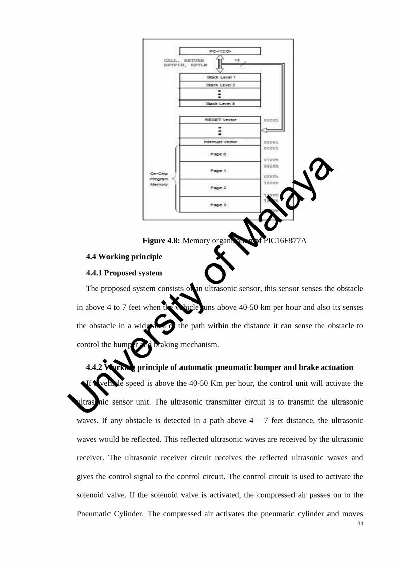
4.3.7.1 Program memory organization
A 13-bit program counter is available in the PIC16F87XA devices which has the
capability to address an 8K word x 14 bit program memory space. Furthermore, the
PIC16F876A/877A devices have 8K words x 14 bits of FLASH program memory,
while PIC16F873A/874A devices have 4K words x 14 bits.
4.3.7.2 Data memory organization
The data memory is split into numerous banks which contains the special function
registers and the general purpose registers. Additionally, the selected bits of the bank
are bits RP1 (STATUS<6>) and RP0 (STATUS<5>).
Univers
ity of
Mala
ya
34
Figure 4.8: Memory organization of PIC16F877A
4.4 Working principle
4.4.1 Proposed system
The proposed system consists of an ultrasonic sensor, this sensor senses the obstacle
in above 4 to 7 feet when the vehicle runs above 40-50 km per hour and also its senses
the obstacle in a wide area of the path within the distance it can sense the obstacle to
control the bumper and braking mechanism.
4.4.2 Working principle of automatic pneumatic bumper and brake actuation
If a vehicle speed is above the 40-50 Km per hour, the control unit will activate the
ultrasonic sensor unit. The ultrasonic transmitter circuit is to transmit the ultrasonic
waves. If any obstacle is detected in a path above 4 – 7 feet distance, the ultrasonic
waves would be reflected. This reflected ultrasonic waves are received by the ultrasonic
receiver. The ultrasonic receiver circuit receives the reflected ultrasonic waves and
gives the control signal to the control circuit. The control circuit is used to activate the
solenoid valve. If the solenoid valve is activated, the compressed air passes on to the
Pneumatic Cylinder. The compressed air activates the pneumatic cylinder and moves
Univers
ity of
Mala
ya
35
the piston rod. If the piston moves forward, then the bumper arrangement and braking
arrangements are activated. The piston speed is varied by adjusting the flow control
valve. We have applied this arrangement in one wheel as a model. The compressed air
is drawn from the compressor. The compressed air flows via the Polyurethane tube to
the flow control valve. The flow control valve is connected to the solenoid valve. Once
the solenoid valve is activated, the bumper and brake are actuated and the vehicle stops.
Univers
ity of
Mala
ya
36
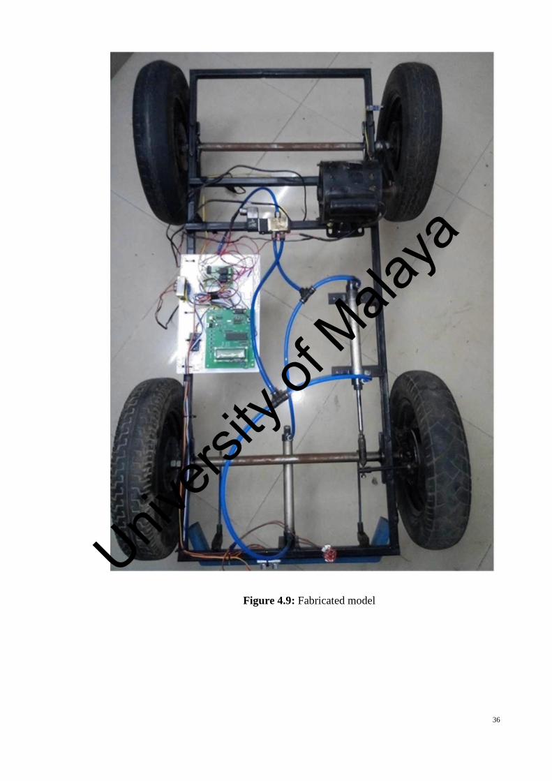
Figure 4.9: Fabricated model
Univers
ity of
Mala
ya
37
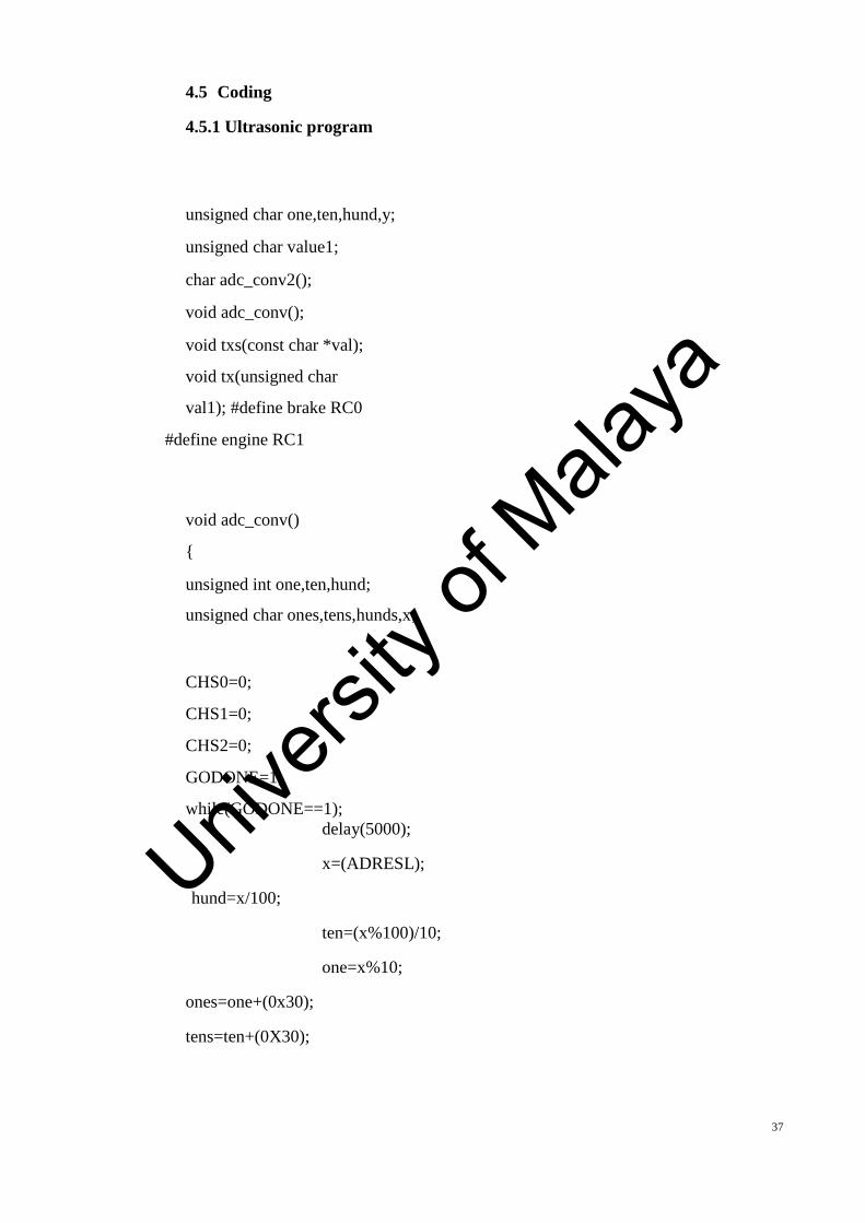
4.5 Coding
4.5.1 Ultrasonic program
unsigned char one,ten,hund,y;
unsigned char value1;
char adc_conv2();
void adc_conv();
void txs(const char *val);
void tx(unsigned char
val1); #define brake RC0
#define engine RC1
void adc_conv()
{
unsigned int one,ten,hund;
unsigned char ones,tens,hunds,x;
CHS0=0;
CHS1=0;
CHS2=0;
GODONE=1;
while(GODONE==1);delay(5000);
x=(ADRESL);
hund=x/100;
ten=(x%100)/10;
one=x%10;
ones=one+(0x30);
tens=ten+(0X30);
Univers
ity of
Mala
ya

38
hunds=hund+(0X30);
lcdcommand(0x86);
ones=one+(0x30);
tens=ten+(0X30);
hunds=hund+(0X30);
lcddat(hunds);
lcddelay(6500);
lcddat(tens);
lcddelay(6500);
lcddat(ones);
lcddelay(6500);
while(1);
}
}
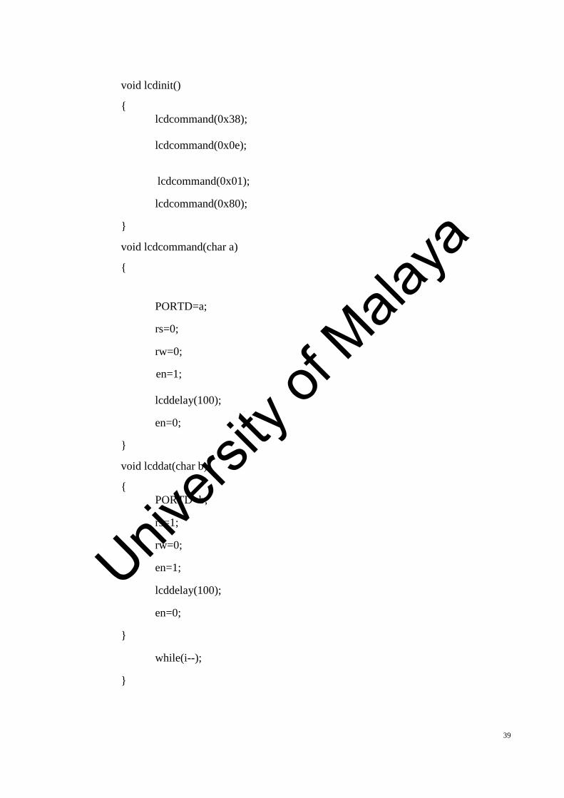
4.5.2 LCD program
#define rs RE2
#define rw RE1
#define en RE0
//#define output PORTD
void lcdinit();
void lcdcommand(char a);
void lcddat(char b);
void lcdstr(const char
*x); void lcddelay(int i);
void delay(int i);
Univers
ity of
Mala
ya
39
void lcdinit()
{lcdcommand(0x38);
lcdcommand(0x0e);
lcdcommand(0x01);
lcdcommand(0x80);
}
void lcdcommand(char a)
{
PORTD=a;
rs=0;
rw=0;
en=1;
lcddelay(100);
en=0;
}
void lcddat(char b)
{PORTD=b;
rs=1;
rw=0;
en=1;
lcddelay(100);
en=0;
}
while(i--);
}
Univers
ity of
Mala
ya
40
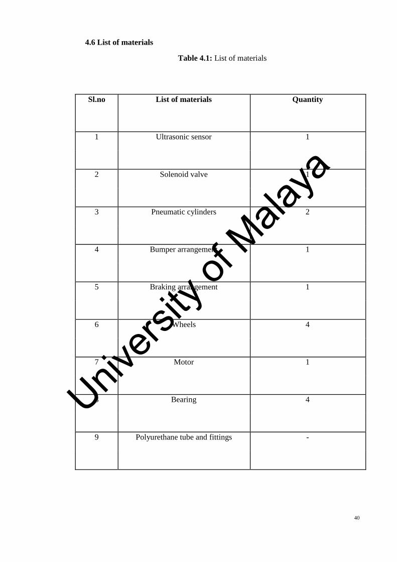
4.6 List of materials
Table 4.1: List of materials
Sl.no List of materials Quantity
1 Ultrasonic sensor 1
2 Solenoid valve 1
3 Pneumatic cylinders 2
4 Bumper arrangement 1
5 Braking arrangement 1
6 Wheels 4
7 Motor 1
8 Bearing 4
9 Polyurethane tube and fittings -
Univers
ity of
Mala
ya
41
CHAPTER 5: CONCLUSION
This project work has provided us an excellent opportunity and experience, in using
my limited knowledge. By use of an ultrasonic sensor in the proposed system, it
improves the retraction timing of cylinder actuation, sensing the wide area path instead
of narrow path and reduces the wear and tear of belt in the motor and also reduces the
speed of the motor when the obstacles was nearer to the vehicle. Thus it overcomes the
existing system with IR sensor which results better prevention of accident and also
reduces the damage of vehicles and driver. Hence, I conclude that my proposed system
will give better result in real time implementation.
Univers
ity of
Mala
ya
42
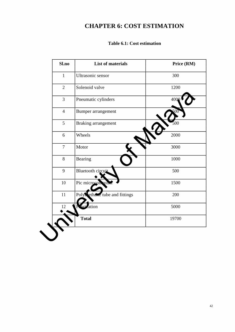
CHAPTER 6: COST ESTIMATION
Table 6.1: Cost estimation
Sl.no List of materials Price (RM)
1 Ultrasonic sensor 300
2 Solenoid valve 1200
3 Pneumatic cylinders 4000
4 Bumper arrangement 500
5 Braking arrangement 500
6 Wheels 2000
7 Motor 3000
8 Bearing 1000
9 Bluetooth circuit 500
10 Pic microcontroller 1500
11 Polyurethane tube and fittings 200
12 Fabrication 5000
Total 19700
Univers
ity of
Mala
ya
43
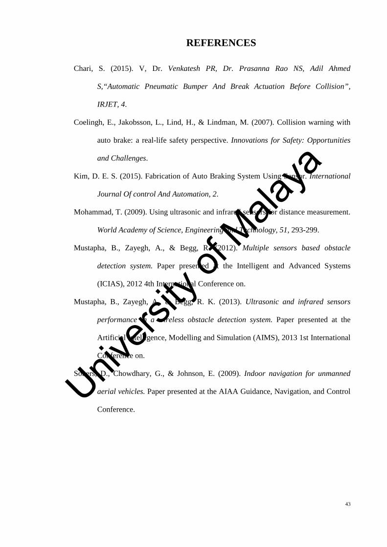
REFERENCES
Chari, S. (2015). V, Dr. Venkatesh PR, Dr. Prasanna Rao NS, Adil Ahmed
S,“Automatic Pneumatic Bumper And Break Actuation Before Collision”,
IRJET, 4.
Coelingh, E., Jakobsson, L., Lind, H., & Lindman, M. (2007). Collision warning with
auto brake: a real-life safety perspective. Innovations for Safety: Opportunities
and Challenges.
Kim, D. E. S. (2015). Fabrication of Auto Braking System Using Sensor. International
Journal Of control And Automation, 2.
Mohammad, T. (2009). Using ultrasonic and infrared sensors for distance measurement.
World Academy of Science, Engineering and Technology, 51, 293-299.
Mustapha, B., Zayegh, A., & Begg, R. (2012). Multiple sensors based obstacle
detection system. Paper presented at the Intelligent and Advanced Systems
(ICIAS), 2012 4th International Conference on.
Mustapha, B., Zayegh, A., & Begg, R. K. (2013). Ultrasonic and infrared sensors
performance in a wireless obstacle detection system. Paper presented at the
Artificial Intelligence, Modelling and Simulation (AIMS), 2013 1st International
Conference on.
Sobers, D., Chowdhary, G., & Johnson, E. (2009). Indoor navigation for unmanned
aerial vehicles. Paper presented at the AIAA Guidance, Navigation, and Control
Conference.Univ
ersity
ofMala
ya