declarative enhancement framework for business processes
TRANSCRIPT
Declarative Enhancement Framework forBusiness Processes ?
Heerko Groefsema, Pavel Bulanov, and Marco Aiello
Distributed Systems Group, Johann Bernoulli Institute, University of Groningen,Nijenborgh 9, 9747 AG Groningen, The Netherlands
h.groefsema, p.bulanov, [email protected]://www.cs.rug.nl/ds/
Abstract. While Business Process Management (BPM) was designedto support rigid production processes, nowadays it is also at the core ofmore flexible business applications and has established itself firmly inthe service world. Such a shift calls for new techniques. In this paper, weintroduce a variability framework for BPM which utilizes temporal logicformalisms to represent the essence of a process, leaving other choicesopen for later customization or adaption. The goal is to solve two majorissues of BPM: enhancing reusability and flexibility. Furthermore, byenriching the process modelling environment with graphical elements,the complications of temporal logic are hidden from the user.
Keywords: BPM, Variability, Temporal Logic, e-Government
1 Introduction
The world of Business Process Management (BPM) has gone through somemajor changes [4] due, among other things, to the advent of Web services andService-orientation; providing opportunities as well as challenges [2]. Variabilityis an abstraction and management method that addresses a number of the openissues. In the domain of software engineering, variability refers to the possibilityof changes in software products and models [13]. When this is introduced tothe BPM domain, it indicates that parts of a business process remain eitheropen to change, or not fully defined, in order to support different versions ofthe same process depending on the intended use or execution context, see forinstance our survey [3]. Since BPM is moving into more fields of business andrely on autonomous remote building blocks, a need for flexible processes hasarisen. Today, when a number of closely related processes are in existence, theyare either described in different process models or in one large model usingintricate branching routes, resulting in redundancy issues in case of the formerand maintainability and readability issues in the case of the latter [14, 3]. Whenapplied to process models, variability introduces solutions to both issues byoffering support for reusability and flexibility.
? The research is supported by the NWO SaS-LeG project, http://www.sas-leg.net,contract No. 638.001.207.

Considering the two features introduced by variability, we immediately noticehow the two tend to coincide with design– and run–time aspects. The reusabil-ity attribute is usually introduced at design–time, and the flexibility attributeat run–time. Generally two approaches to variability are considered, impera-tive and declarative ones [12]. While imperative approaches focus on how atask is performed, declarative approaches focus on what tasks are performed.When mapping these to the two areas where variability would operate, design–and run–time, we notice four possible directions regarding variability in BPM.Most research currently focuses on the areas of imperative/design–time anddeclarative/run–time, while in this paper we shall focus on an approach which isable to capture both imperative and declarative methods at design–time [3]. Thecommon problem with the frameworks of the imperative/design–time area is thatin many cases they introduce unnecessary restrictions for process designers [1].The source of such restrictions lies in the fact that imperative approaches requireall variations from the main process to be predefined, limiting variations to onlythose added explicitly. On the other hand, declarative run–time frameworks lieon the far side of the semantic gap between the traditional and well–understoodway of imperative process specification and the unintuitive way of declarativespecification. We intend to solve these issues through a design–time declarativeframework, in which the principles of process designing are similar to the ones oftraditional imperative–based process modelling. This is achieved via introducinga set of visual modelling elements, which are internally transposed into a set ofdeclarative constraints.
In this paper, we start by introducing the Process Variability - Declara-tive’n’Imperative (PVDI) framework which enhances process models with vari-ability management through the introduction of temporal logics which capturethe essence of a process. In doing so, we provide both the BPM and servicecomposition domains with a formal way to model processes such that they canbe used as a template for either the modelling of process variants or automaticservice composition. In addition, by enriching the traditional process modellingenvironment with graphical elements, the complications of the underlying tem-poral logic is hidden from the user. We then show the expressive power of thesegraphical elements by utilizing them on an e-Government related case–study.Then, we evaluate the strengths and weaknesses of the framework by looking atthe requirements for variability management in service-oriented systems intro-duced in [3]. Finally, we conclude with related work, and some final remarks.
2 The PVDI Framework
A PVDI process is defined as a directed graph and can serve as a frame for amodal logic of processes, including computational tree logic+(CTL+)[6]. UsingCTL+, we can introduce constraints for processes, which allow us to capture thebasic meaning of a process in such a way that we can control changes within theprocess while keeping its essence, its intended use, intact as long as none of these

constraints are violated. It is then possible to allow anyone to design a variantfrom such a template process without compromising its intended use.
Definition 1 (Process). A process P is a tuple 〈A,G, T 〉 where:
– A is a finite set of activities, with selected start and final ⊗ activities;– G = Ga ∪Go ∪Gx is a set of gateways, consisting of and, or, and xor gates
as defined by BPMN, respectively;– S = A ∪G is a set of states;– T = Ta ∪ Tg, where:– Ta : (A\⊗)→ S is a finite set of transitions, which assign a next state for
each activity;– Tg : G → 2S is a finite set of transitions, which assign a nonempty set of
next states for each gateway.
In order to use a process as a model, we introduce a set of variables and avaluation function. We use the so–called natural valuation, that is, for eachstate (i.e., for each activity or gateway) we introduce its dedicated variable, andthis variable is valuated to TRUE on this state only. Additionally, under thenatural valuation we can use the same letter to represent both activity and itscorresponding variable.
Definition 2 (Constraint). A constraint over the process P is a computa-tion tree logic+(CTL+) formula. A constraint is valid for a process P iff it isvaluated to TRUE in each state of the process under the natural valuation. Moreformally, let φ be a constraint, M be a model built on the process P using thenatural valuation, and S be the set of states of the process P . Then φ is valid iffM, x, φ |= TRUE ∀x ∈ S
Notice how, now that we introduced constraints, a template process can bedefined without strictly defining the precise structure of all activities and theirrespective ordering. The mapping of T can therefore be a partial one. As aresult, a template may range from being a list of tasks to being a fully specifiedprocess. On the other hand, templates are enriched with a set of constraints,which outline the general shape of a process or set of processes.
Definition 3 (Template). A template T is a tuple 〈A,G, T, Φ〉 where:
– A, G, S, and T are from Definition 1;– Ta : (A\⊗)→ S is a finite set of transitions, which assign a next state for
some activities;– Tg : G → 2S is a finite set of transitions, which assign a nonempty set of
next states for some gateways.– Φ is a finite set of constraints.
In order to facilitate template design we introduce a number of graphic–elementsfor the design process. Constraints as embedded within templates are then gener-ated from these graphical–elements. For every element contained in the template,

we generate one or more CTL+ formulas. Of course, this process differs greatlyper element and even per situation. Some of the simpler elements directly re-semble simple CTL+ formulas, whereas other more complex structures resemblea set of CTL+ formulas . A potentially large number of graphic–elements canbe considered for the template design, ranging from simple flows to complexgroupings of tasks. We discuss only those elements needed in order to introducethe wide variety of options available trough PVDI.
2.1 Flow Constraints
Flow Constraints state that all elements from one set are followed by at leastone element from another set in either a single or all paths. With a path beinga series of consecutive transitions.
Fig. 1. Flow elements.
Definition 4 (Flow Constraint). A Flow Constraint F is a tuple 〈s, t, Ω,Π,N〉where:
– s is a finite set of process elements;– t is a finite set of process elements; s
⋂t = ∅;
– Ω ∈ A,E is a state quantifier from CTL+;– Π ∈ X,F,G is a path quantifier from CTL+;– N ∈ TRUE,FALSE being a negation.
The graphical–elements related to Flow Constraints are shown in Figure 1. Thesegraphical–elements describe flow relations over two dimensions; path and dis-tance. The rows of Figure 1 relate to the temporal dimensions; F (Finally) andX (neXt), which require the linked elements to either follow each other eventu-ally or immediately. The first two columns relate to the paths; E (there Existsa path) and A (for All paths), which require the linked elements to follow eachother in either a path or all paths respectively. The third column represents anegation of two of these flows. These flows are related to simple CTL+ formulasof the form M, p |= AXq (At p, in All paths, the neXt task is q), M, p |= EFq(At p, there Exists a path, where Finally a task is q), and their negations.
The CTL+ constraints are generated from the graphical–elements accordingto the steps below. Remember that we reuse the same symbol to represent boththe state and the variable representing that state.
1. Let s1, . . . sn be elements of source, and t1, . . . tm be elements of target.2. If N = TRUE, then create a formula (s1∨s2∨ . . . sn)⇒ ΩΠ(t1∨t2∨ . . . tm).3. If N = FALSE, then create a formula (s1 ∨ s2 ∨ . . . sn) ⇒ ΩΠ¬(t1 ∨ t2 ∨. . . tm).
4. If N = FALSE and Π = F , then create a formula (s1 ∨ s2 ∨ . . . sn) ⇒ΩG¬(t1 ∨ t2 ∨ . . . tm).
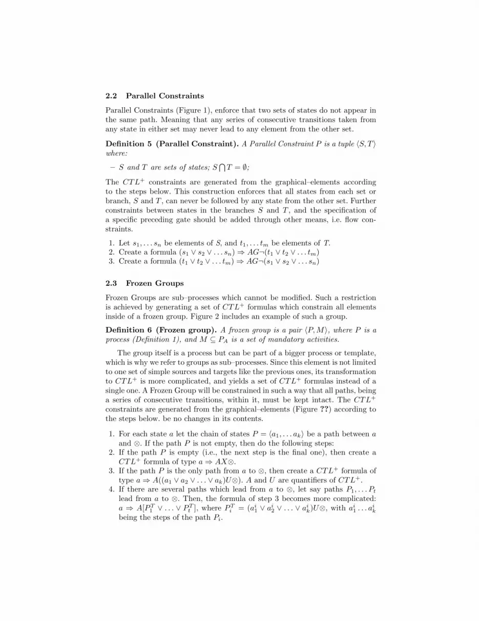
2.2 Parallel Constraints
Parallel Constraints (Figure 1), enforce that two sets of states do not appear inthe same path. Meaning that any series of consecutive transitions taken fromany state in either set may never lead to any element from the other set.
Definition 5 (Parallel Constraint). A Parallel Constraint P is a tuple 〈S, T 〉where:
– S and T are sets of states; S⋂T = ∅;
The CTL+ constraints are generated from the graphical–elements accordingto the steps below. This construction enforces that all states from each set orbranch, S and T , can never be followed by any state from the other set. Furtherconstraints between states in the branches S and T , and the specification ofa specific preceding gate should be added through other means, i.e. flow con-straints.
1. Let s1, . . . sn be elements of S, and t1, . . . tm be elements of T.2. Create a formula (s1 ∨ s2 ∨ . . . sn)⇒ AG¬(t1 ∨ t2 ∨ . . . tm)3. Create a formula (t1 ∨ t2 ∨ . . . tm)⇒ AG¬(s1 ∨ s2 ∨ . . . sn)
2.3 Frozen Groups
Frozen Groups are sub–processes which cannot be modified. Such a restrictionis achieved by generating a set of CTL+ formulas which constrain all elementsinside of a frozen group. Figure 2 includes an example of such a group.
Definition 6 (Frozen group). A frozen group is a pair 〈P,M〉, where P is aprocess (Definition 1), and M ⊆ PA is a set of mandatory activities.
The group itself is a process but can be part of a bigger process or template,which is why we refer to groups as sub–processes. Since this element is not limitedto one set of simple sources and targets like the previous ones, its transformationto CTL+ is more complicated, and yields a set of CTL+ formulas instead of asingle one. A Frozen Group will be constrained in such a way that all paths, beinga series of consecutive transitions, within it, must be kept intact. The CTL+
constraints are generated from the graphical–elements (Figure ??) according tothe steps below. be no changes in its contents.
1. For each state a let the chain of states P = 〈a1, . . . ak〉 be a path between aand ⊗. If the path P is not empty, then do the following steps:
2. If the path P is empty (i.e., the next step is the final one), then create aCTL+ formula of type a⇒ AX⊗.
3. If the path P is the only path from a to ⊗, then create a CTL+ formula oftype a⇒ A((a1 ∨ a2 ∨ . . . ∨ ak)U⊗). A and U are quantifiers of CTL+.
4. If there are several paths which lead from a to ⊗, let say paths P1, . . . Pt
lead from a to ⊗. Then, the formula of step 3 becomes more complicated:a ⇒ A[PT
1 ∨ . . . ∨ PTt ], where PT
i = (ai1 ∨ ai2 ∨ . . . ∨ aik)U⊗, with ai1 . . . aik
being the steps of the path Pi.

Example 1 (Frozen Group).
- a - b 3
QQQs
c -
e -
d
f 3
QQQs⊗
a⇒ A[(b ∨ c ∨ d)U⊗]∨[(b ∨ e ∨ f)U⊗]
b⇒ A[(c ∨ d)U⊗] ∨ [(e ∨ f)U⊗]c⇒ A(dU⊗)e⇒ A(fU⊗)d⇒ AX⊗f ⇒ AX⊗
In this example, the process illustrated above is encoded as a set of CTL+ formu-las. To do that, we take each step one by one and generate a formula according tothe algorithm presented above. The first two formulas are the most complicated,because there are two possible paths from a to ⊗ (and from b to ⊗ as well).Therefore, according to the step 4 of the algorithm, the formula splits into twopieces, one per each path. In the case of activity b, one path contains activitiesc and d, and the other one contains e and f .
2.4 Semi–frozen Group
Semi–frozen groups are Frozen Groups with less strict constrains, allowing forremoval or replacement, addition, or moving of activities. The advantage of thisgroup representation is that for example any activity inside a frozen group can bemade optional and can therefore be removed during the customization process.
Optional activities will not affect the consistency of the group, since theCTL+ formulas remain valid as long as at least no new activity is added intothe group. Actually, if an activity a is removed, then all formulas of kind a⇒ . . .become automatically valid, and formulas of kind b ⇒ aU⊗ are valid as longas there is either activity a or nothing between b and ⊗. The same is true formore complicated cases like b⇒ a∨ . . . U⊗. In other words, any activity can beremoved from a frozen group but not replaced by another one.
Weaken a link between two states thus allowing to insert a new activity intoa specific place(s) in a group. To do that, we have to modify the base algorithm.
1. Let the chain of states P = 〈a1, . . . ak〉 be a path between a and ⊗. Forexample, the link between ai and ai+1 is “weak”. Then the appropriateCTL+ formula is a⇒ A[(a1 ∨ . . . ai)UAFA[(ai+1 ∨ . . . an)U⊗]].
2. If there are several “weak” links in a path, for example, links ai → ai+1 andaj → aj+1, i < j are weak. In this case, build a formula aj ⇒ φ according top.1, and the final formula is a⇒ A[(a1∨ . . . ai)UA[(ai+1∨ . . . aj)Uφ]], whereφ is retrieved in the previous step.
3. The same recursive rule applies in the case of three or more “weak” links.

Making an activity floating thus allowing to swap two activities or drag anactivity into another place in the group. The algorithm is as follows:
1. Create the set of constraints for the group as described above;2. To make an activity a floating, remove all constraints of kind a⇒ φ.
Each move of an activity can be split into two atomic operations: (i) removethe activity (ii) insert this activity into another place. As it has already beenshown above, no special correction needed in order to remove the activity. Thenext step, however, is only possible when there is a “weak” link in the process –otherwise we can only put the activity back into its original place.
Fig. 2. Simplified WMO process (Left) and template (Right).
3 Case–Study: Variability in local eGovernment
The Netherlands consists of 418 municipalities which all differ greatly. Becauseof this, each municipality is allowed to operate independently according to theirlocal requirements. However, all the municipalities have to provide the sameservices and execute the same laws. An example of such a law which is heavilysubjected to local needs is the WMO (Wet maatschappelijke ondersteuning, So-cial Support Act, 2006), a law providing needing citizens with support rangingfrom wheelchairs, help at home, home improvement and homeless sheltering.Figure 2 illustrates a simplified version of a WMO process found at one of theDutch municipalities of the Northern region of the Netherlands (Left), and anexample of how one transforms this process into a template usable by all munici-palities (Right). Variant processes can then be obtained via customization of thetemplate process. The flexibility of a process, bounded with such constraints, canvary from zero (a frozen block over the whole process) to unlimited, when thereare no constraints at all. On examination of the figure, we notice how constraintsare not evaluated for templates but only for processes resulting from templates.Using a frozen group we restrict the decision making process, which because ofthis must be kept intact at all times. The rest of the template is captured usingsimple flow constraints and one parallel constraint. Therefore, extra activitiescould be easily included at most places except the frozen group, and certainparts could be moved around without affecting the correctness of the process.
4 Related Work
Existing tools and frameworks for variability management in BPM concentrateon a single view on variability. Most focus either on imperative design–time oron declarative run–time solutions, while we combine imperative and declara-tive techniques. In addition, most research disregards services entirely and fo-cuses solely on the BPM aspects. One framework which does look at servicesspecifically is the Variability extension to Business Process Execution Language(VxBPEL) [15] that we proposed previously. This BPEL extension introduces anumber of new keywords allowing for the inclusion of variation points, variations,and realization relations into BPEL. Other imperative frameworks focus solelyon BPM, most notably ADEPT [5], Process Variants by Options(Provop) [8],and configurable workflow models [7]. These imperative frameworks however re-quire that all variability options must be included into the template processdirectly, leading to maintainability and readability issues. On the other hand,our framework does not focus on what can be done, but on what should be done,and leaves any other options open; resulting in a much higher degree of flexi-bility. Declarative frameworks focus mostly on run–time solutions to flexibilityissues, of which most notable are the DECLARE framework [10], and BusinessProcess Constraint Network (BPCN) and Process Variant Repository(PVR) [9,11]. Our framework on the contrary hides this complexity by the introductionof simple graphical elements which can be directly incorporated into businessprocess models.

Requirement Support
Structural variations
(a) Insert Process Fragment Achieved via introducing a “weak” link in a frozen group.(b) Delete Process Fragment Achieved via making an activity optional.(c) Move Process Fragment Achieved via an floating activity at frozen groups.(d) Replace Process Fragment Achieved through a combination of an optional activity
and a weak link.(e) Swap Process Fragment Special case of moving a process fragment, therefore it
is also supported.
Constraint expressions
(a) Mandatory selection Achieved with PVDI through a flow constraint emergingfrom and targeting the activity.
(b) Prohibitive selection Achieved with PVDI through a negated flow constraintemerging from and targeting the prohibited activity.
(h) Mandatory execution Achieved with PVDI through a flow constraint of thetype “for All paths” emerging from .
(i) Order of execution Achieved through flow constraints.(j) Parallel execution Achieved through a combination of flow constraints
emerging from a gate and a parallel constraint.(k) Exclusive execution Achieved through a combination of flow constraints
emerging from a gate and a parallel constraint.
Table 1. Evaluation on Requirements
5 Conclusion
We have shown how a variability framework for process modelling adds a largeamount of functionality to both the area of BPM, as well as service composition.By enriching the process modelling environment with graphical elements, weprovided an easy way to hide the complications of temporal logic from the enduser. Using a case–study from the area of e–Government, we then explained howthe high amount of reusability and flexibility enriches templates in such a waythat variants become easily maintainable and templates easily readable.
In order to evaluate the flexibility of PVDI, we consider the expressive powerrequirements proposed in [3]. Two types are discussed: structural variations re-lated to imperative techniques, and constraint expressions related to declarativetechniques. In Table 1 the requirements which are directly supported by ourframework are enlisted along with the description of the support. Due to the ap-proach taken with PVDI, both declarative and imperative techniques are beingconsidered. In cases of imperative techniques we consider a semi–frozen block,which keeps the process structure intact while allowing some modification.
Many items are open for further investigation, among which the support ofdata flows, dependencies between constraints, template publication, and auto-mated composition from templates as a constraint satisfaction problem.

References
1. van der Aalst, W., Hofstede, A.H.M.T., Weske, M.: Business Process Management:A Survey. In: Int. Conference on Business Process Management. pp. 1–12 (2003)
2. van der Aalst, W., Jablonski, S.: Dealing with workflow change: Identificationof issues and solutions. International Journal of Computer Systems, Science, andEngineering 15(5), 267–276 (2000)
3. Aiello, M., Bulanov, P., Groefsema, H.: Requirements and tools for variabilitymanagement. In: IEEE workshop on Requirement Engineering for Services (REFS2010) at IEEE COMPSAC (2010)
4. Bandara, W., Indulska, M., Sadiq, S., Chong, S.: Major issues in business pro-cess management: an expert perspective. In: European Conference on InformationSystems (ECIS) (2007)
5. Dadam, P., Reichert, M.: The adept project: a decade of research and developmentfor robust and flexible process support. Computer Science - R&D 23(2), 81–97(2009)
6. Emerson, E.A., Halpern, J.Y.: Decision procedures and expressiveness in the tem-poral logic of branching time. In: Proceedings of the fourteenth annual ACM sym-posium on Theory of computing. pp. 169–180 (1982)
7. Gottschalk, F., van der Aalst, W.M.P., Jansen-Vullers, M.H., Rosa, M.L.: Config-urable workflow models. Int. J. Cooperative Inf. Syst. 17(2), 177–221 (2008)
8. Hallerbach, A., Bauer, T., Reichert, M.: Managing process variants in the processlife cycle. In: ICEIS (3-2). pp. 154–161 (2008)
9. Lu, R., Sadiq, S., Governatori, G.: On managing business processes variants. DataKnowl. Eng. 68(7), 642–664 (2009)
10. Pesic, M., Schonenberg, M.H., Sidorova, N., van der Aalst, W.M.P.: Constraint-based workflow models: Change made easy. In: OTM Conferences (1). pp. 77–94(2007)
11. Sadiq, S.W., Orlowska, M.E., Sadiq, W.: Specification and validation of processconstraints for flexible workflows. Inf. Syst. 30(5), 349–378 (2005)
12. Schonenberg, H., Mans, R., Russell, N., Mulyar, N., van der Aalst, W.M.P.: Processflexibility: A survey of contemporary approaches. In: Dietz, J.L.G., Albani, A.,Barjis, J. (eds.) CIAO! / EOMAS. LNBIP, vol. 10, pp. 16–30. Springer (2008)
13. Sinnema, M., Deelstra, S., Hoekstra, P.: The COVAMOF Derivation Process. In:Int. Conf. On Software Reuse. vol. LNCS, pp. 101–114. Springer (2006)
14. Sun, C., Rossing, R., Sinnema, M., Bulanov, P., Aiello, M.: Modelling and manag-ing the variability of web service-based systems. Journal of Systems and Software,Elsevier 83, 502–516 (2010)
15. Sun, C., Aiello, M.: Towards variable service compositions using VxBPEL. In: Int.Conf. On Software Reuse. vol. LNCS 5030, pp. 257–261. Springer (2008)