de novo bone formation on macro/microporous silk and silk/nano-sized calcium phosphate scaffolds
TRANSCRIPT

http://jbc.sagepub.com/Polymers
Journal of Bioactive and Compatible
http://jbc.sagepub.com/content/28/5/439The online version of this article can be found at:
DOI: 10.1177/0883911513503538
2013 28: 439Journal of Bioactive and Compatible PolymersLe-Ping Yan, António J Salgado, Joaquim M Oliveira, Ana L Oliveira and Rui L Reis
phosphate scaffoldsDe novo bone formation on macro/microporous silk and silk/nano-sized calcium
Published by:
http://www.sagepublications.com
can be found at:Journal of Bioactive and Compatible PolymersAdditional services and information for
http://jbc.sagepub.com/cgi/alertsEmail Alerts:
http://jbc.sagepub.com/subscriptionsSubscriptions:
http://www.sagepub.com/journalsReprints.navReprints:
http://www.sagepub.com/journalsPermissions.navPermissions:
http://jbc.sagepub.com/content/28/5/439.refs.htmlCitations:
What is This?
- Sep 13, 2013Version of Record >>
at Northwest Normal University on September 14, 2013jbc.sagepub.comDownloaded from

Journal of Bioactive andCompatible Polymers
28(5) 439 –452© The Author(s) 2013
Reprints and permissions: sagepub.co.uk/journalsPermissions.nav
DOI: 10.1177/0883911513503538jbc.sagepub.com
JOURNAL OF
Bioactiveand
CompatiblePolymers
De novo bone formation on macro/microporous silk and silk/nano-sized calcium phosphate scaffolds
Le-Ping Yan1,2, António J Salgado2,3, Joaquim M Oliveira1,2, Ana L Oliveira1,2,4 and Rui L Reis1,2
AbstractMacro/microporous silk/nano-sized calcium phosphate scaffolds (SC16) with bioactive and superior physicochemical properties are currently being developed. In this study, we evaluated the new bone formation ability in rat femur of the SC16 scaffolds in vivo, using silk fibroin scaffolds (S16) as control. The CaP distribution profile in the scaffolds was characterized by micro-computed tomography and the CaP phase was found to be distributed homogeneously in the SC16 scaffolds. Mineralization was only observed in SC16 scaffolds, and both scaffolds gradually degraded with time. By staining the explants, new bone growth was observed directly on the SC16 surface and with higher density than that observed on the S16 scaffolds. These results demonstrated that the SC16 hybrid scaffolds are osteoconductive and can be good candidates for bone tissue engineering as they promote superior de novo bone formation.
KeywordsBone tissue engineering, nano-sized calcium phosphate, nanocomposite, silk fibroin, scaffold, in vivo new bone formation
1 3B’s Research Group—Biomaterials, Biodegradables and Biomimetics, University of Minho, Headquarters of the European Institute of Excellence on Tissue Engineering and Regenerative Medicine, Guimarães, Portugal
2 ICVS/3B’s—PT Government Associate Laboratory, Braga/Guimarães, Portugal3Life and Health Sciences Research Institute, School of Health Sciences, University of Minho, Braga, Portugal4Department of Health Sciences, Portuguese Catholic University, Viseu, Portugal
Corresponding author:Rui L Reis, 3B’s Research Group—Biomaterials, Biodegradables and Biomimetics, University of Minho, Headquarters of the European Institute of Excellence on Tissue Engineering and Regenerative Medicine, AvePark, S. Cláudio de Barco, 4806-909 Taipas, Guimarães, Portugal. Email: [email protected]
503538 JBC28510.1177/0883911513503538Journal of Bioactive and Compatible PolymersYan et al.2013
Original Article
at Northwest Normal University on September 14, 2013jbc.sagepub.comDownloaded from

440 Journal of Bioactive and Compatible Polymers 28(5)
Introduction
Bone defects derived from trauma or diseases often require grafts to regenerate the function of the impaired bone tissues.1,2 Currently, autografts and allografts are the dominant treatments for bone defects.1,2 However, both of them have limitations, such as lack of sufficient supplies and risks of disease transmission.1,2 To counter such drawbacks, tissue engineered bone can be a promising alter-native strategy for bone regeneration.3,4 Porous biodegradable scaffolds play a crucial role toward this goal.5 Several ceramic-based or polymeric biomaterials have been investigated as scaffold materials, such as hydroxyapatite, tricalcium phosphate,6–9 collagen, chitosan, and silk fibroin (SF).10–13 However, it has been recognized that the ideal scaffolds for bone regeneration are those with osteo-conductive or osteoinductive properties, as well as with good mechanical performance.7,14,15 Calcium phosphate–based biomaterials are osteoconductive; however, the mechanical properties are compro-mised by their fragile nature.16 With this in mind, composite-based scaffolds composed of a calcium phosphate (CaP) phase and a polymeric phase have been studied intensively.17–20
SF derived from Bombyx mori or other species has been used as versatile degradable biomate-rial for years.21–26 Several methods have been used to prepare silk scaffolds with controlled struc-ture and mechanical properties.11,12,27–32 The compatibility of silk-based biomaterials with different kinds of cells has also been studied.15,23–26,33–35 Scaffolds composed of SF and CaP have been explored in a few studies,16,18,19,36 but the homogeneous distribution of the inorganic phase within the SF matrix remains challenging.19 In order to overcome this problem, we have developed a novel strategy, which uses an in situ synthesis method to produce SF/nano-sized CaP composites and subsequently generates the macro/microporous scaffolds by salt leaching/freeze drying.37 The final scaffolds have a homogeneous distribution of submicron CaP particles. These macro/micropo-rous silk/nano-sized calcium phosphate (Silk/Nano-CaP) scaffolds have bioactivity and good mechanical properties. Systematic in vitro mineralization and in vitro long-term stability of the scaffolds were assessed in this study. In parallel, the in vivo new bone formation ability of these scaffolds was evaluated by implantation in rat femur defects.
Materials and methods
Materials and reagents
B. mori cocoons were purchased from the Portuguese Association of Parents and Friends of Mentally Disabled Citizens (APPACDM, Castelo Branco, Portugal). Commercial sodium chloride particles were obtained from the local market (Portugal). The silicone tubing was purchased from Deltalab (Barcelona, Spain). All the other materials or reagents were purchased from Sigma–Aldrich (St. Louis, MO, USA) unless addressed otherwise.
Scaffold preparation
The SF extraction and scaffold preparations were made by following previously reported meth-ods.12,37 Briefly, 0.02 mol/L of boiling sodium carbonate solution was used to remove sericin from the cocoons for 1 h. And then, the purified SF was dissolved in 9.3 mol/L of lithium bromide solution for 1 h at 70°C, followed by dialyzing in distilled water for 48 h using a benzoylated dialysis tubing (molecular weight cutoff (MWCO) = 2000). The concentrated SF solution was obtained by dialyzing the SF solution against a 20 wt% poly(ethylene glycol) solution. The final SF content in the solution was determined by drying the SF solution at 70°C overnight. The SF solution was kept at temperature below 6°C before use. Normally, the SF solution was stored for less than 24 h before use.
at Northwest Normal University on September 14, 2013jbc.sagepub.comDownloaded from

Yan et al. 441
Silk/Nano-CaP scaffold preparation
6 mol/L of calcium chloride and 3.6 mol/L of ammonia dibasic phosphate solutions were sequen-tially added into the 16 wt% SF solution. The final calcium-to-phosphate atomic ratio in the silk solution was fixed at 1.67, equaling that in Ca10(PO4)6(OH)2 (hydroxyapatite).37 The mixture of the calcium chloride and ammonia dibasic phosphate solutions will form the CaP particles in an aque-ous environment with an appropriate pH value. The CaP particles will transform into hydroxyapatite by aging the suspension under basic conditions. The viscous silk solution (16 wt%) prevents the aggregation of the formed CaP particles, and thus, a homogeneous dispersion of the CaP particles was achieved. The CaP content was 16 wt% of the SF mass, with the assumption that all the intro-duced calcium and phosphate ions reacted completely and transformed into hydroxyapatite. The pH value of the obtained milky suspension was adjusted to 8.5. The mixture was gently stirred for 30 min and subsequently aged for 24 h. Then, 2 g of sodium chloride particles (500–1000 µm) was added into 1 mL of Silk/Nano-CaP suspension in a silicone tube, and the tube was dried in air for 2 days. The final Silk/Nano-CaP scaffolds were prepared by leaching out the sodium chloride parti-cles in distilled water followed by lyophilization of the scaffolds. The salt-leached SF scaffolds were prepared by addition of the sodium chloride particles into the 16 wt% SF solution, and the remaining steps were the same as mentioned earlier. The salt-leached Silk/Nano-CaP scaffolds and SF scaf-folds were denoted as SC16 and S16. We have chosen SC16 and S16 for our current studies on bone regeneration on the basis of previous mechanical property and in vitro mineralization studies.37 CaP particles were prepared using the procedure mentioned earlier, but the silk solution was replaced with distilled water. The prepared particles were washed after aging, followed by freeze-drying.
Scaffold characterization
The scaffolds were coated with a layer of Au/Pd SC502-314B in an evaporator coater (E6700; Quorum Technologies, East Grinstead, UK) before morphology observation by scanning electron microscopy (SEM) (Nova NanoSEM 200; FEI, Hillsboro, OR, USA). The distribution of CaP particles into the SF matrix was examined in a backscattered SEM model without any coating on the powder from the SC16. Three specimens were tested for each group of scaffolds.
The crystallinity states of SF and CaP in the scaffolds were determined in an X-ray diffractom-eter (PW1710; Philips, Eindhoven, the Netherlands) with Cu-Kα radiation (λ = 0.154056 nm). The data were recorded from 0° to 60° 2θ values, with step width and counting time set at 0.02° and 2 s/step, respectively. Three specimens were analyzed for each group.
The SF conformation and scaffold composition information were evaluated by attenuated total reflectance (ATR) model in a Fourier transform infrared (FTIR) spectroscopy (IRPrestige-21, Shimadzu, Kyoto, Japan), equipped with a germanium crystal. Each specimen was scanned 48 times with a resolution of 4 cm−1. Triplicate samples were used for each group of scaffolds. CaP control was also analyzed.
The compressive modulus of the scaffolds was recorded in a universal testing machine (Instron 4505), with a compressive speed of 2 mm/min. The modulus was determined from the slope of the linear domain in the stress–strain curve. At least five samples were examined for S16 or SC16 scaffolds.
The porosity, CaP distribution profile in the scaffolds, and total CaP content (vol.%) in the scaf-folds were analyzed by micro-computed tomography (micro-CT, 1072 scanner; SkyScan, Kontich, Belgium).37,38 For the porosity determination, the S16 and SC16 samples were scanned at 40 keV/248 µA and 61 keV/163 µA, respectively. For the CaP distribution and CaP content, the scaf-folds were both scanned at 61 keV/163 µA. The data sets were processed into bitmap images in
at Northwest Normal University on September 14, 2013jbc.sagepub.comDownloaded from

442 Journal of Bioactive and Compatible Polymers 28(5)
NRecon v1.4.3 software (SkyScan) in a cone-beam model. For the porosity calculation, the images were transformed into binary images using a gray value ranging from 40 to 255. Regarding the CaP content analysis, gray values comprised between 120 and 255 were used. The CaP content and distribution in the scaffolds were analyzed vertically. At least three specimens were evaluated for each formulation.
The mineralization of the scaffolds was performed by immersing the S16 and SC16 scaffolds in a simulated body fluid (SBF) solution at 37°C for 1, 3, 7, and 14 days.9,37,38 At the end of each time point, the samples were removed, and the surfaces were observed by SEM as mentioned earlier. The energy dispersive X-ray (EDX) detector (Nova NanoSEM 200; FEI) was used to analyze the surface elements of the scaffolds after in vitro mineralization. An area of 5 × 5 µm was selected to scan each specimen. Three samples were used for each group at each time point.
The long-term hydration degree and degradation profile were studied by immersing the scaf-folds in 0.154 mol/L of sodium chloride isotonic saline solution (ISS; pH = 7.4) at 37°C in a water bath (GFL 1086) at dynamic condition (60 r/min).12,37 The wet weight of each specimen was meas-ured immediately after removing the samples at the end of 1, 3, 6, 9, and 12 months. The dry weight was recorded after drying the samples at 60°C for 24 h. The hydration degree and the weight loss ratio were obtained by the following equations.
Hydration degree
Weight loss ratio =
=
×
( )%
(
,m m
mw t o
o
−
−
100
mo mm
md t
o
, )%
×100
where mo is the original weight of the specimen before hydration, mw,t is the wet weight after removing from ISS at the end of each time point, and md,t is the dry weight after immersion in ISS. Five samples were measured for each group at each time point.
In vivo implantation and evaluation
Implantation procedure. Young male Wistar rats (n = 6 per group) with body weight of 125–150 g were purchased from Charles River (Senneville, Quebec, Canada), housed in light- and temperature-con-trolled rooms, and fed a standard diet. Bone defects were drilled bilaterally in each distal femur, proximal to the epiphyseal plate, of every rat.39 The defects were made using a low-speed drill (2.3 mm in diameter) with copious saline irrigation. The defects were made until it reached the bone mar-row domain. Previously prepared scaffolds were then press fit into the defects. Before the implanta-tion, the wet scaffolds were cut into 3 mm in height and punched into 4 mm in diameter, followed by lyophilization and subsequently sterilized by ethylene oxide. The diameter of the lyophilized scaffold was around 3.3 mm. Thus, the diameters of the defect and the scaffolds were very close. The mainte-nance and use of animals were in accordance to the Ethics Committee of University of Minho.
Histological processing. Animals were sacrificed after 3 weeks, and the femurs were removed. The femurs (n = 5 per group) were fixed in neutral formalin, decalcified in a 1:1 mixture of 45% formic acid and 20% sodium citrate, dehydrated, and embedded in paraffin. Serial sections, 5-µm thick, perpendicular to the long axis of the implant were cut with a Spencer 820 microtome (American Optical Company, New York, NY, USA). Sections were then stained with Masson’s trichrome stain
at Northwest Normal University on September 14, 2013jbc.sagepub.comDownloaded from

Yan et al. 443
to selectively stain muscle, collagen fibers, fibrin, and erythrocytes. A green color is attributed to collagen in the newly formed bone.
Histomorphometry. Bone histomorphometry was evaluated by using ImageJ (National Institutes of Health, Bethesda, MD, USA). The images of the Masson’s trichrome slides (area for each slide = 0.45 mm × 0.35 mm) of each explants were first converted to gray-value images. And then, proper threshold values were selected for each image in order to best match the new bone area in original images.13 The new bone area in each slide image was calculated by the software. Slides from four explants were used for each group, and at least 10 slides were evaluated per explant.
Statistical analysis
The data were presented as an average and its standard deviation. The compressive modulus, porosity, CaP content, and new bone area were assessed by one-way analysis of variance (ANOVA). The average values of each group were compared by Tukey’s test, and p < 0.05 was considered statistically significant.
Results and discussion
Conformation and chemical composition
It is generally recognized that there are mainly three conformations in native and regenerated SF, namely, random coil (amorphous), silk-I (also called α-helix or type II β-turn), and silk-II (antipar-allel β-sheet).40 The amorphous state usually exists in diluted regenerated aqueous SF solution, silk-I is generated from amorphous silk solution by a well-controlled water annealing procedure, and silk-II can also be induced from the amorphous silk solution by many stimuli (such as tempera-ture, pH value, organic solvent, or saline).26,41 Among these three conformations, silk-II is the most stable state and has been taken advantage of in formulating silk-based matrices for tissue engineer-ing and regenerative medicine.21,22 Regarding the scaffold preparation, Kim et al.27 found that the addition of sodium chloride particles in aqueous silk solution could induce β-sheet formation, and this finding led to the formation of salt-leached silk scaffold derived from aqueous solution. Recently, we have produced SF scaffolds from high-concentration aqueous SF solution.12 Salt-leached Silk/Nano-CaP scaffolds were also produced using this process.37
The conformation of SF has been studied by different technologies, such as X-ray diffraction (XRD), cross-polarization/magic-angle spinning 13C nuclear magnetic resonance, and FTIR.40,42 The most typical XRD peak of β-sheet structure in SF is at 20.8°.40 Hydroxyapatite presents char-acteristic XRD peaks at around 32° and 39°.7 In Figure 1, it was found that both S16 and SC16 had main peaks at ~20.5°, confirming the silk-II structure in both scaffolds. Furthermore, the XRD patterns also had peaks at ~32° and ~39°, which are feature peaks of hydroxyapatite. The low intensity of these two peaks may due to the low crystallinity of the formed CaP and also the low content of CaP in the silk matrix. The lower crystallinity of the CaP phase is related with the prepa-ration procedure.7 ATR-FTIR has been used as a reliable and facile way to reflect any subtle con-formation change of SF, normally in the absorbance areas of amide-I and amide-II.43 Figure 2 shows the ATR-FTIR spectra of S16 and SC16 scaffolds, and spectra of CaP control were shown in Figure S1. Both scaffolds have broad absorbances between 1480–1590 cm−1 and 1590–1700 cm−1, with peaks located at 1520 and 1627 cm−1. These two absorbance ranges are assigned to amide-I and amide-II, respectively.43 Both peaks (1520 and 1627 cm−1) indicated the β-sheet
at Northwest Normal University on September 14, 2013jbc.sagepub.comDownloaded from

444 Journal of Bioactive and Compatible Polymers 28(5)
conformation in the silk matrix.27,43 Similar to the CaP control spectra (Figure S1), SC16 scaffold had a distinct absorbance between 1000 and 1100 cm−1 (peak position was around 1030 cm−1), which was the vibration from a PO4
3− group in the CaP.9,37 The XRD patterns and the ATR-FTIR spectra proved that the CaP was incorporated into the scaffolds, and the scaffolds were composed of SF in β-sheet conformation and CaP of low crystallinity. The β-sheet conformation of silk matrix is crucial for the mechanical properties and structural stability of the produced scaffolds.
Figure 1. X-ray diffraction patterns of the salt-leached silk fibroin–based scaffolds: (a) S16 and (b) SC16.
Figure 2. Attenuated total reflectance Fourier transform infrared spectra of the salt-leached silk fibroin–based scaffolds: (a) S16 and (b) SC16.
at Northwest Normal University on September 14, 2013jbc.sagepub.comDownloaded from

Yan et al. 445
Structure, CaP distribution, and mechanical properties
For bone tissue engineering, the pore size and porosity of the scaffolds are important.1,5,44 The ideal scaffold should have adequate porosity and proper pore size in order to facilitate the new bone ingrowth, vessel invasion, cell migration, and nutrients/metabolic product transportation.2 Many methods have been used to generate porous scaffolds for bone tissue engineering, including rapid prototyping,1 salt leaching,27 and supercritical fluid evaporation.45 Based on our previous work,12 salt leaching was selected for this study and produced porous structures in both S16 and SC16 scaf-folds (Figure 3(a) and (b)). As observed from the SEM images, both scaffolds presented a macro/microporous structure (Figure 3(d) and (e)), with the macropore size ranging between 500 and 1000 µm. Based on the micro-CT analysis data given in Table 1, the porosities of S16 and SC16 were 79.8% and 63.6%, respectively. SC16 displayed an inferior mean pore size and a higher tra-becular thickness as compared with S16. The structure information indicated that CaP does affects the structure of the scaffolds, but the porosity of the SC16 scaffolds is still higher than 63% and thus still adequate for bone tissue regeneration.5
The homogeneous distribution of CaP particles in the scaffolds is challenging to produce.19 By physically blending nano-sized CaP particles in the scaffolds, it is difficult to maintain their origi-nal size. The particles usually aggregate and subsequently lead to inhomogeneous dispersions. Herein, an in situ synthesis method was used to introduce CaP into the silk scaffolds. The in situ formed nano-sized CaP particle was homogeneously distributed in the silk matrix (Figure 3(c)) at a microscopic level. And the size of the CaP particles was less than 200 nm. From our previous study, it was found that around 87% of the introduced CaP was maintained in the scaffolds after leaching out the sodium chloride particles. Based on the micro-CT analysis, the CaP occupied ~9.2 vol.% in the scaffolds. As shown in Figure 4, the CaP distribution was quite even along the SC16 scaffold. By the procedure used herein for micro-CT analysis, there was 0% of CaP detected in the S16 scaffold (data not shown). Considering the resolution of micro-CT, the volume percentage obtained cannot completely reflect the CaP volume percentage, but it still can give us an idea of the CaP distribution in the scaffolds at a macroscopic level. Compared to previous work, the SC16 scaffolds prepared in this study presented better CaP distribution.
The mechanical properties of the scaffolds are quite important since they certainly will be under load once implanted.1 Attention has been paid to strengthen the silk-based scaffolds for bone tissue engineering, such as by means of chemical crosslinking, fiber filling, or particle reinforce-ment.20,29,31 The S16 and SC16 scaffolds present similar compressive modulus as given in Table 1, which indicated that the introduction of CaP did not compromise the scaffold strength. In the
Table 1. Structural and mechanical properties of the silk and Silk/Nano-CaP scaffolds.
Groups Mean porosity (%)a
Mean pore size (µm)a
Mean trabecular thickness (µm)a
Compressive modulus (MPa)b
CaP content (vol.%)c
S16d 79.8 ± 0.3 285.1 ± 52.3 69.8 ± 1.2 15.1 ± 1.7 0SC16e 63.6 ± 2.4 251.0 ± 15.0 90.1 ± 1.4 19.0 ± 5.8 9.2 ± 0.4
Micro-CT: micro-computed tomography; Silk/Nano-CaP: silk/nano-sized calcium phosphate.aThe mean porosity, mean pore size, and mean trabecular thickness were obtained from the micro-CT analysis.bThe compressive test was performed in a dry state.cThe CaP content was determined by micro-CT analysis.dSalt-leached silk fibroin scaffolds derived from 16 wt% aqueous silk fibroin solution.e Salt-leached silk fibroin/nano-CaP scaffolds derived from 16 wt% aqueous silk fibroin solution and contains theoretically 16 wt% CaP (CaP:silk, wt%) in the silk matrix.
at Northwest Normal University on September 14, 2013jbc.sagepub.comDownloaded from

446 Journal of Bioactive and Compatible Polymers 28(5)
Figure 3. Morphologies of the salt-leached silk fibroin–based scaffolds and the nano-CaP particle distribution in the scaffold: (a) and (b) macroscopic photographs of S16 and SC16, respectively (scale bar: 3 mm); (c) backscattered scanning electron microscopy image of SC16, the white spots are nano-CaP particles and the gray domain is silk matrix (scale bar: 3 µm); and (d) and (e) scanning electron microscopy images of S16 and SC16, respectively (scale bar: 500 µm).
Figure 4. Calcium phosphate distribution in the SC16 scaffold as determined by micro-CT.CT: computed tomography.
at Northwest Normal University on September 14, 2013jbc.sagepub.comDownloaded from

Yan et al. 447
previous study, we tested the dynamic mechanical properties of the scaffolds in a wet state, and the SC16 had a slightly higher storage modulus as compared to that for S16. The mechanical proper-ties of the scaffolds produced in this study were superior to the scaffolds produced in previous studies using freeze-drying or salt-leaching approaches.18,19,27 The good mechanical properties of the S16 and SC16 scaffolds came from the β-sheet conformation of the silk matrix in the scaffolds and also from the high-concentration aqueous silk solution.
In vitro mineralization and long-term stability
The bioactivity test in SBF solution is a commonly used method to predict the osteoconductive properties of materials.9,38 There are numerous successful examples using this method to evaluate the in vivo bone bonding ability of materials, such as hydroxyapatite and bioactive glass.46 Using this method, we found that SC16 scaffolds rapidly induce apatite crystal formation on their surface on the first day (Figure 5(a). This finding is confirmed by the EDX spectra (Figure 5(e)). The num-ber of crystal clusters increased at day 3 (Figure 5(b)). At day 7, the crystals almost covered the
Figure 5. Mineralization of the SC16 and S16 scaffolds. (a–d) SEM images of SC16 scaffolds after immersion in simulated body fluid (SBF) solution for 1, 3, 7, and 14 days at 37°C, respectively (scale bar: 10 µm); (e and f) EDX spectra of (a) and (d), respectively (scan area: 10 µm × 10 µm); and (g and h) SEM image and EDX spectra of S16 scaffolds after immersion in SBF solution for 14 days at 37°C, respectively (scale bar: 10 µm).SEM: scanning electron microscopy; SBF: simulated body fluid; EDX: energy dispersive X-ray.
at Northwest Normal University on September 14, 2013jbc.sagepub.comDownloaded from
448 Journal of Bioactive and Compatible Polymers 28(5)
entire surface of the SC16 scaffold (Figure 5(c)). After 2 weeks, the surface was completely cov-ered by the crystal (Figure 5(d)), with improved elemental signal of calcium and phosphate (Figure 5(f)). No apatite crystal formation was observed on the S16 scaffold surface after 2 weeks (Figure 5(g) and (h)). These results confirmed that the SC16 scaffolds possess good bioactivity and induce apatite crystal formation in a short time. This finding also validated that the in situ synthesis of nano-sized CaP particles in silk matrix can endow the final porous scaffolds with bioactivity.
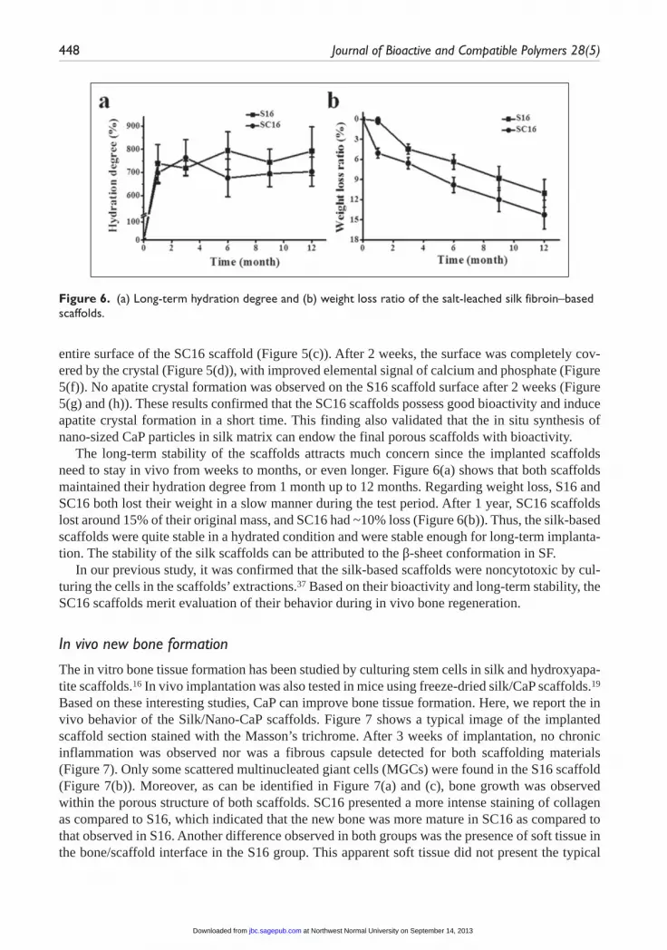
The long-term stability of the scaffolds attracts much concern since the implanted scaffolds need to stay in vivo from weeks to months, or even longer. Figure 6(a) shows that both scaffolds maintained their hydration degree from 1 month up to 12 months. Regarding weight loss, S16 and SC16 both lost their weight in a slow manner during the test period. After 1 year, SC16 scaffolds lost around 15% of their original mass, and SC16 had ~10% loss (Figure 6(b)). Thus, the silk-based scaffolds were quite stable in a hydrated condition and were stable enough for long-term implanta-tion. The stability of the silk scaffolds can be attributed to the β-sheet conformation in SF.
In our previous study, it was confirmed that the silk-based scaffolds were noncytotoxic by cul-turing the cells in the scaffolds’ extractions.37 Based on their bioactivity and long-term stability, the SC16 scaffolds merit evaluation of their behavior during in vivo bone regeneration.
In vivo new bone formation
The in vitro bone tissue formation has been studied by culturing stem cells in silk and hydroxyapa-tite scaffolds.16 In vivo implantation was also tested in mice using freeze-dried silk/CaP scaffolds.19 Based on these interesting studies, CaP can improve bone tissue formation. Here, we report the in vivo behavior of the Silk/Nano-CaP scaffolds. Figure 7 shows a typical image of the implanted scaffold section stained with the Masson’s trichrome. After 3 weeks of implantation, no chronic inflammation was observed nor was a fibrous capsule detected for both scaffolding materials (Figure 7). Only some scattered multinucleated giant cells (MGCs) were found in the S16 scaffold (Figure 7(b)). Moreover, as can be identified in Figure 7(a) and (c), bone growth was observed within the porous structure of both scaffolds. SC16 presented a more intense staining of collagen as compared to S16, which indicated that the new bone was more mature in SC16 as compared to that observed in S16. Another difference observed in both groups was the presence of soft tissue in the bone/scaffold interface in the S16 group. This apparent soft tissue did not present the typical
Figure 6. (a) Long-term hydration degree and (b) weight loss ratio of the salt-leached silk fibroin–based scaffolds.
at Northwest Normal University on September 14, 2013jbc.sagepub.comDownloaded from

Yan et al. 449
Figure 7. Masson’s trichrome staining of the salt-leached silk fibroin–based scaffolds after implantation in rat femur defect for 3 weeks: (a and b) S16 scaffold and (c and d) SC16 scaffold ((b) and (d) are enlarged images of (a) and (c), respectively). Among the images, “S,” “B,” “M,” and “R” correspond to scaffold residuals, formed new bone, bone marrow, and rapid forming new bone (scale bar: 200 µm for (a) and (c) and 100 µm for (b) and (d)).
morphology of fibrous tissue. Instead, as it can be observed in Figure 7(b), there is some continuity with the surrounding bone. For the silk/CaP group, this fibrous tissue was not detected, and in fact, bone seemed to grow directly on the surface of the scaffolds (Figure 7(d)). Furthermore, the bone histomorphometric analysis of the SC16 group had a much higher new bone area (~45%) in the Masson’s trichrome slide images than that from S16 group as shown in Figure 8(e). From Figure 8(a) to (d), it was found that bone area in the processed images (black area in Figure 8(c) and (d)) matched very well with that in the original images (Figure 8(a) and (b)).
Our results indicate that both tested scaffolds were biocompatible as no obvious inflammation or fibrous encapsulation was observed. Additionally, the macroporous structure and high poros-ity of both S16 and SC16 scaffolds supported new bone formation and ingrowths. The fibrous tissue observed for the S16 group was not identified as inflammatory tissue, as it resembles what has been previously described as rapidly forming bone by Salgado et al.39 This tissue most likely represents an early bone matrix similar to that seen in advancing fronts of intramembranous bone formation. As previously mentioned, this tissue was not found in the SC16 group, which may indicate that for this group, bone is being synthesized and remodeled at a higher rate when com-pared to the S16 group. Furthermore, this group also had bone growing directly on its surface, which indicated that this scaffold has osteoconductive properties. Impressively, the SC16 group
at Northwest Normal University on September 14, 2013jbc.sagepub.comDownloaded from

450 Journal of Bioactive and Compatible Polymers 28(5)
Figure 8. Bone histomorphometry of the S16 and SC16 explants by means of using the software WCIF ImageJ: (a and b) representative trichrome images of S16 and SC16, respectively; (c and d) processed images from (a) and (b) for bone histomorphometry analysis, respectively; (e) calculation of the new bone area in the Masson’s trichrome images (area for each slide: 0.45 mm × 0.35 mm) after image processing. Four explants were used for each group, and at least 10 slides were evaluated per explant (scale bar: 50 µm).*Significant difference (p < 0.05).
exhibited an outstanding ability to induce new bone formation after 3 weeks of implantation, compared with the S16 group. Therefore, the SC16 scaffold induced better new bone formation and is more osteoconductive than the S16 group. These data are also consistent with the in vitro mineralization results.
at Northwest Normal University on September 14, 2013jbc.sagepub.comDownloaded from
Yan et al. 451
Conclusion
Novel salt-leached Silk/Nano-CaP scaffolds were prepared with a homogeneous CaP distribution and a rapid bioactive response in vitro. During long-term degradation, both the silk and Silk/Nano-CaP scaffolds had adequate biostability in terms of hydration degree along with a slow weight loss. After 3 weeks of implantation, both scaffold types supported new bone ingrowth, and no acute inflamma-tory response was observed. The silk-based scaffolds were shown to be osteoconductive since they supported new bone formation on their surfaces. Furthermore, Silk/Nano-CaP scaffolds induced sig-nificantly higher amount of new bone formation as compared to that observed for silk scaffolds. The Silk/Nano-CaP scaffolds are potentially good candidates for bone tissue engineering.
Declaration of conflicting interests
The authors declare that there is no conflict of interest.
Funding
This study was supported by the Portuguese Foundation for Science and Technology (FCT) projects OsteoCart (PTDC/CTM-BPC/115977/2009) and Tissue2Tissue (PTDC/CTM/105703/2008). Research leading to these results has received funding from the European Union’s Seventh Framework Programme (FP7/2007-2013) under grant agreement no REGPOT-CT2012-316331-POLARIS. Le-Ping Yan is an FCT PhD scholarship holder (SFRH/BD/64717/2009).
References
1. Hutmacher DW. Scaffolds in tissue engineering bone and cartilage. Biomaterials 2000; 21: 2529–2543.
2. Salgado AJ, Coutinho OP and Reis RL. Bone tissue engineering: state of the art and future trends. Macromol Biosci 2004; 4: 743–765.
3. Langer R and Vacanti JP. Tissue engineering. Science 1993; 260: 920–926.
4. Hutmacher DW, Schantz JT, Lam CX, et al. State of the art and future directions of scaffold-based bone engineering from a biomaterials perspective. J Tissue Eng Regen M 2007; 1: 245–260.
5. Karageorgiou V and Kaplan DL. Porosity of 3D biomaterial scaffolds and osteogenesis. Biomaterials 2005; 26: 5474–5491.
6. Dorozhkin SV. Amorphous calcium (ortho)phosphates. Acta Biomater 2010; 6: 4457–4475.
7. Dorozhkin SV and Epple M. Biological and medical significance of calcium phosphates. Angew Chem Int Ed Engl 2002; 41: 3130–3146.
8. LeGeros RZ. Calcium phosphate-based osteoinductive materials. Chem Rev 2008; 108: 4742–4753.
9. Oliveira JM, Silva SS, Malafaya PB, et al. Macroporous hydroxyapatite scaffolds for bone tissue engineering applications: physicochemical characterization and assessment of rat bone marrow stromal cell viability. J Biomed Mater Res A 2009; 91: 175–186.
10. Yan LP, Wang YJ, Ren L, et al. Genipin-cross-linked collagen/chitosan biomimetic scaffolds for articular cartilage tissue engineering applications. J Biomed Mater Res A 2010; 95: 465–475.
11. Oliveira AL, Sun L, Kim HJ, et al. Aligned silk-based 3-D architectures for contact guidance in tissue engineering. Acta Biomater 2012; 8: 1530–1542.
12. Yan LP, Oliveira JM, Oliveira AL, et al. Macro/microporous silk fibroin scaffolds with potential for articular cartilage and meniscus tissue engineering applications. Acta Biomater 2012; 8: 289–301.
13. Oliveira JM, Kotobuki N, Tadokoro M, et al. Ex vivo culturing of stromal cells with dexamethasone-loaded carboxymethylchitosan/poly(amidoamine) dendrimer nanoparticles promotes ectopic bone formation. Bone 2010; 46: 1424–1435.
14. Kim HJ, Kim UJ, Kim HS, et al. Bone tissue engineering with premineralized silk scaffolds. Bone 2008; 42: 1226–1234.
15. Motta A, Barbato B, Foss C, et al. Stabilization of Bombyx mori silk fibroin/sericin films by crosslinking with PEG-DE 600 and genipin. J Bioact Compat Polym 2011; 26: 130–143.
16. Bhumiratana S, Grayson WL, Castaneda A, et al. Nucleation and growth of mineralized bone matrix on silk-hydroxyapatite composite scaffolds. Biomaterials 2011; 32: 2812–2820.
at Northwest Normal University on September 14, 2013jbc.sagepub.comDownloaded from

452 Journal of Bioactive and Compatible Polymers 28(5)
17. Rezwan K, Chen QZ, Blaker JJ, et al. Biodegradable and bioactive porous polymer/inorganic composite scaffolds for bone tissue engineering. Biomaterials 2006; 27: 3413–3431.
18. Liu L, Liu JY, Wang MQ, et al. Preparation and characterization of nano-hydroxyapatite/silk fibroin porous scaffolds. J Biomater Sci Polym Ed 2008; 19: 325–338.
19. Zhang YF, Wu C, Friis T, et al. The osteogenic properties of CaP/silk composite scaffolds. Biomaterials 2010; 31: 2848–2856.
20. Collins AM, Skaer NJV, Gheysens T, et al. Bone-like resorbable silk-based scaffolds for load-bearing osteoregenerative applications. Adv Mater 2009; 21: 75–78.
21. Altman GH, Diaz F, Jakuba C, et al. Silk-based biomaterials. Biomaterials 2003; 24: 401–416.
22. Vepari C and Kaplan DL. Silk as a biomaterial. Prog Polym Sci 2007; 32: 991–1007.
23. Kundu B and Kundu SC. Osteogenesis of human stem cells in silk biomaterial for regenerative therapy. Prog Polym Sci 2010; 35: 1116–1127.
24. Mandal BB and Kundu SC. Osteogenic and adipogenic differentiation of rat bone marrow cells on non-mulberry and mulberry silk gland fibroin 3D scaffolds. Biomaterials 2009; 30: 5019–5030.
25. Fuchs S, Jiang X, Schmidt H, et al. Dynamic processes involved in the pre-vascularization of silk fibroin constructs for bone regeneration using outgrowth endothelial cells. Biomaterials 2009; 30: 1329–1338.
26. Fini M, Motta A, Torricelli P, et al. The healing of confined critical size cancellous defects in the presence of silk fibroin hydrogel. Biomaterials 2005; 26: 3527–3536.
27. Kim UJ, Park J, Kim HJ, et al. Three-dimensional aqueous-derived biomaterial scaffolds from silk fibroin. Biomaterials 2005; 26: 2775–2785.
28. Wray LS, Rnjak-Kovacina J, Mandal BB, et al. A silk-based scaffold platform with tunable architecture for engineering critically-sized tissue constructs. Biomaterials 2012; 33: 9214–9224.
29. Rajkhowa R, Gil ES, Kluge J, et al. Reinforcing silk scaffolds with silk particles. Macromol Biosci 2010; 10: 599–611.
30. Gomes S, Leonor IB, Mano JF, et al. Natural and genetically engineered proteins for tissue engineering. Prog Polym Sci 2012; 37: 1–17.
31. Mandal BB, Grinberg A, Gil ES, et al. High-strength silk protein scaffolds for bone repair. P Natl Acad Sci 2012; 109: 7699–7704.
32. Makaya K, Terada S, Ohgo K, et al. Comparative study of silk fibroin porous scaffolds derived from salt/water and sucrose/hexafluoroisopropanol in cartilage formation. J Biosci Bioeng 2009; 108: 68–75.
33. Mandal BB and Kundu SC. Cell proliferation and migration in silk fibroin 3D scaffolds. Biomaterials 2009; 30: 2956–2965.
34. Correia C, Bhumiratana S, Yan LP, et al. Development of silk-based scaffolds for tissue engineering of bone from human adipose-derived stem cells. Acta Biomater 2012; 8: 2483–2492.
35. Mandal BB and Kundu SC. Non-mulberry silk gland fibroin protein 3-D scaffold for enhanced differentiation of human mesenchymal stem cells into osteocytes. Acta Biomater 2009; 5: 2579–2590.
36. Oliveira AL, Sampaio SC, Sousa RA, et al. Controlled mineralization of nature-inspired silk fibroin/hydroxyapatite hybrid bioactive scaffolds for bone tissue engineering applications. In: 20th European conference on biomaterials, Nantes, France, 27 September–1 October 2006.
37. Yan LP, Silva-Correia J, Correia C, et al. Bioactive macro/micro porous silk fibroin/nano-sized calcium phosphate scaffolds with potential for bone tissue engineering application. Nanomedicine 2013; 8: 359–378.
38. Oliveira AL, Malafaya PB, Costa SA, et al. Micro-computed tomography (µ-CT) as a potential tool to assess the effect of dynamic coating routes on the formation of biomimetic apatite layers on 3D-plotted biodegradable polymeric scaffolds. J Mater Sci Mater M 2007; 18: 211–223.
39. Salgado AJ, Coutinho OP, Reis RL, et al. In vivo response to starch-based scaffolds designed for bone tissue engineering applications. J Biomed Mater Res A 2007; 80: 983–989.
40. Jin HJ and Kaplan DL. Mechanism of silk processing in insects and spiders. Nature 2003; 24: 1057–1061.
41. Kim UJ, Park J, Li CM, et al. Structure and properties of silk hydrogels. Biomacromolecules 2004; 5: 786–792.
42. Asakura T, Kuzuhara A, Tabeta R, et al. Conformational characterization of Bombyx mori silk fibroin in the solid state by high-frequency carbon-13 cross polarization-magic angle spinning NMR, X-ray diffraction, and infrared spectroscopy. Macromolecules 1985; 18: 1841–1845.
43. Jin HJ, Park J, Karageorgiou V, et al. Water-stable silk films with reduced β-sheet content. Adv Funct Mater 2005; 15: 1241–1247.
44. Stoppato M, Carletti E, Sidarovich V, et al. Influence of scaffold pore size on collagen I development: a new in vitro evaluation perspective. J Bioact Compat Polym 2013; 28: 16–32.
45. Duarte AR, Mano JF and Reis RL. Perspectives on: supercritical fluid technology for 3D tissue engineering scaffold applications. J Bioact Compat Polym 2009; 24: 385–400.
46. Kokubo T and Takadama H. How useful is SBF in predicting in vivo bone bioactivity? Biomaterials 2006; 27: 2907–2915.
at Northwest Normal University on September 14, 2013jbc.sagepub.comDownloaded from