das werk's new kit!
TRANSCRIPT

WIN!
No.1 For Sail & Scale
March 2021
Vol.71 No.844
MO
DE
LL
IN
G G
RO
UP
£5.65
Magnificent projects showcased
We chat with Hornby's Darrell Burge about some exciting future releases
YOUR MODELS
COMING SOON...
GET ON BOARDwwww.modelboats.co.uk
WINDJAMMER
Your chance to win this finely detailed new 1:72 scale World War I German U-Boat
Constructing & saling an historic beauty
FREE!AUDACITY
PLAN No: MM2157 No. OF SHEETS: 2 OF 2
BY GLYNN GUESTFirst published in
Model Boats March 2021
BOWPIECE
B1B
B1A
B2 & B3
BOWPIECE, BULKHEADS & TRANSOM
FROM 1/4” (6mm) BALSA SHEET
HULL SECTION AHEAD B1A
INTERNAL SIDE EDGING STRIPS
1/4” (6mm) SQ.
REINFORCEMENT
STRIPS
HULL BASESTRIPS
SHEET SLIDINTO SLOT HULL SIDES
BELOW SLOT
HULL SIDES
ABOVE SLOT
HULL BOTTOM
HULL SECTION AFT B2
INTERNAL SIDE EDGING STRIPS
1/2” (12mm) SQ. FRAME FITS INTO HULL
2mm LITE PLY FLIGHT DECK
HULL BASE STRIPS
HULL SIDES
HULL BOTTOM
B1A
B2
B3
TRANSOM ADDED
AFTER SIDES
INVERTED VIEW OF HULL
OVERSIZE SHEET SLID INTO SLOTS
IN HULL SIDES, GLUED & THEN
TRIMMED FLUSH
BOWPIECE
TRANSOM
CHAMFER EDGES TO MATCH HULL BOTTOM
& TOP EDGE OF HULL SIDES
HULL BOTTOM
6” x 1/4” (150 x 6mm) BALSA SHEET
HULL BASE STRIPS
1/2” x 1/4” (12 x 6mm) BALSA
LONGITUDINAL STRIP 34 1/4” (870mm) LONG
NOTE SPACE
FOR TRANSOM
HOLES FOR
RUDDER TUBES
INTERNAL SIDE EDGING STRIPS
1” x 1/4” (25 x 6mm) BALSA
HULL SIDES
2mm LITE PLY
SLOT
AUDACITYPLAN No: MM2157
No. OF SHEETS: 1 OF 2BY GLYNN GUEST
First published in
Model Boats March 2021
A FREELANCE SCALE MODEL BASED ON
A PROPOSED ‘HARRIER CARRIER’
SCALE APPROX. 1/144
SKETCH OF SUPERSTRUCTURE
SKETCH SHOWING GTDA
EXHAUSTS ON BOTH SIDES
SKETCH OF BOWS
SHOWING SKI JUMP
SKI JUMP FROM SCRAP BALSA/PLY
AA MISSILE
LAUNCHER
RADAR
CIWS
BOWPIECE
BALSA
LAMINATIONS
HARDWOOD BOW
REINFORCEMENT1/2” x 1/4” (12 x 6mm) BALSA
BASE STRIPS
1/4” (6mm) BALSA SHEET HULL BOTTOM
1” x 1/4” (25 x 6mm) INTERNAL SIDE EDGING STRIP
SUPERSTRUCTURE FROM BALSA/CARD
COUPLING
MOTOR
B1A
B2
B3
RUDDER
SERVO
8” (200mm) PROP TUBE
B1B
1/4” (6mm) SQ. REINFORCEMENT STRIPS
1/4” (6mm) SQ.
WATERLINE
RUDDER
TRANSOM
SEA HARRIER
SKI JUMP
DECK FROM 2mm LITE PLY
LYNX AUDACITY PLANS &BUILD INSTRUCTIONS
DAS WERK'S NEW KIT!
NEW TOOLING!
Dave Metcalf's superb new 1:12 scale Liverpool Class lifeboat kit
JUST LAUNCHED

Model and Kit Building Made EasierSyl Create CREATOR KITS
Order today at SylCreate.com or over the phone on +44(0)1444 831459
Superglue Kit
Thin - - Medium- Thick
4-Way Flexi-File & Micro Abrasive Liquid
Three grades of Sylmasta Supergluefor fast, precision bonds
Plus 4x Superfine Application NozzlesSuperglue Kit - £20.00
Part of the Sylmasta Group
Casting Kit Everything you need to make high detailreusable moulds to produce professional quality resin casts
Casting Kit - £39.90400g Casting Resin and 450g Moulding Rubber Casting Kit XL - £59.202kg Casting Resin and 1kg Moulding RubberDouble the materials for only £19.30 more
Both Kits include Release Agent, Mixing Cups, Pipettes, Stirrers, Glovesand easy-to-follow instructions
Superglue Kit - £24.50+ Activator 50ml For an instant bond, use Activator
Precision Nozzle
for bonding fine gaps and hairline cracksfor general purpose bondingfor gap-filling and vertical bonding
A special offer...
Give surfaces the wet look - a highly glossyfinish to materials. Work through the four grades of abrasive on the Flexi-File and then finish with 1-micron Micro Abrasive Liquid.
... just £7.20 until the end of March
Available as part of the relaunched SylCreate Micro Abrasives Range

`
Tugging Ahead…………………………….. with
MOBILE MARINE MODELS Model Tugnology……………………………..…………………………….. the driving force
The Boat Shed, Highcliffe Park, Ingham Cliff, Lincoln LN1 2YQ tel: 01522 730731 / 689209

6 A fond farewell to Model Boats’ former editor Paul FreshneyColin Bishop pays tribute
7 Compass 360The fantastic new Dave Metcalf
Boat Models’ 1:12 scale Liverpool
class lifeboat, plus Navarino Models
Brockley Combe and Revell Titanic
Prize Draw winners announced
12 MB Q&AThis month we chat to Hornby’s
Darrell Burge about some exciting
newly tooled models on the horizon
14 WIN Das Werk’s superb 1:72 scale WWI U-Boat kit Your chance to win and build
this truly striking display model
Vol.71 Issue 844: March 2021
contents
18 A wondrous WindjammerNev Wades talks us through the
construction and sailing of his
magnificent historic beauty, Parma
26 MSC ArcherPhil Button explains the
challenges presented and
the innovative solutions he came up
with in order to make changes to this
live steam tug
Published by MyTimeMedia Ltd., Suite 25, Eden House, Enterprise Way,Edenbridge, Kent, TN8 6HF.UK and Overseas:Tel: +44 (0) 1689 869 840www.modelboats.co.uk
SUBSCRIPTIONS My Time Media Ltd., 3 Queensbridge, The Lakes, Northampton, NN4 7BF.
UK – New, Renewals & EnquiriesTel: 0344 243 9023Email: [email protected] & CANADA – New, Renewals & EnquiriesTel: (001)-866-647-9191REST OF WORLD – New, Renewals & EnquiriesTel: +44 1604 828 748Email: [email protected]
CURRENT AND BACK ISSUESVisit: www.mags-uk.comTelephone: 01795 662976
EDITORIALEditor: Lindsey AmraniSuite 25, Eden House, Enterprise Way,Edenbridge, Kent, TN8 6HF.Email: [email protected]
PRODUCTIONDesigner: Richard Dyer Illustrator: Grahame Chambers Retouching Manager: Brian Vickers Ad Production: Nik Harber
ADVERTISING SALES EXECUTIVE Angela Price:Email: [email protected]
SUBSCRIPTIONS MANAGER Kate Hall
MANAGEMENT Commercial Sales Manager: Rhona BolgerEmail: [email protected] Tel: 0204 522 8221 Chief Executive: Owen Davies
© MyTimeMedia Ltd. 2021
All rights reserved ISSN 0140-2910
The Publisher’s written consent must be obtained before any part of this publication may be reproduced in any form whatsoever, including photocopiers, and information retrieval systems. All reasonable care is taken in the preparation of the magazine contents, but the publishers cannot be held legally responsible for errors in the contents of this magazine or for any loss however arising from such errors, including loss resulting from negligence of our staff. Reliance placed upon the contents of this magazine is at reader’s own risk.
Model Boats, ISSN 0140 - 2910, is published monthly by MyTimeMedia Ltd, Suite 25S, Eden House, Enterprise Way, Edenbridge, Kent, TN8 6HF, UK. The US annual subscription price is 89USD. Airfreight and mailing in the USA by agent named WN Shipping USA, 156-15, 146th Avenue, 2nd Floor, Jamaica, NY 11434, USA. Periodicals postage paid at Brooklyn, NY 11256. US Postmaster: Send address changes to Model Boats, WN Shipping USA, 156-15, 146th Avenue, 2nd Floor, Jamaica, NY 11434, USA. Subscription records are maintained at DSB.net Ltd, 3 Queensbridge, The Lakes, Northampton, NN4 5DT. Air Business Ltd is acting as our mailing agent.
Follow us on Facebook and Twitter
www.facebook.com/modelboatsmag twitter.com/modelboatsmag
4 Model Boats March 2021

5
WELCOME TO THE MARCH 2021 ISSUE OF MODEL BOATS....
I hope you are all managing to keep safe and well and that in that in some small way having a
hobby to fall back on is helping you maintain your sanity through what feels like an eternity of lock downs and restrictions. For me, the importance of hanging in there and continuing to abide by rules until the vaccine is rolled out was sharply underlined when over the Christmas holidays I received the dreadful news that former Model Boats Editor Paul Freshney had lost his life just weeks after having contracted the COVID virus. Paul should have had many happy years of retirement ahead of him and my heart goes out to his wife, Rose, and the rest of his family. Overleaf, you will find a touching tribute to him penned by long term contributor and one of his close personal friends, Colin Bishop. Although I didn’t know Paul as well as Colin, over the years as fellow editors we would often chat on the phone or exchange emails and he really was a truly lovely man: admirably pragmatic and super organised but also delightfully witty. Always genuinely supportive of others, on learning I’d been brought on board as editor of Model Boats, he immediately rang to wish me well and let me know I could call on him should I need and help and advice going forward. Knowing how much of himself he’d invested in the magazine over the years, and how much its continued success meant to him, he couldn’t have been more kind. But, then, I’m sure everyone who knew Paul will have fond memories of him, including, of course, our designer, Richard Dyer. So, it’s been with flag at half-mast we’ve completed this issue, ever conscious of trying to honour and live up to Paul’s exacting standards. As well as Glynn Guest’s splendid free plan and supporting feature, we’ve got loads of inspirational and informative feature length articles for you, along with some exciting industry announcements, reviews, a not to be missed prize draw courtesy of Das Werk and a truly salute worthy selection of completed projects the Your Models section. Unfortunately, we’ve not been able to squeeze in any of your letters this month, but please keep them coming as we’ll be running as many as we can pack into the next edition.
Enjoy your read! Lindsey
FREE
PLAN
34 FREE PLAN & supporting featureGlynn Guest provides a comprehensive guide
to the build of his semi-scale (approx 1:144)
Harrier carrier Audacity
42 Box rattle reviewsIn the market for a new kit? Fellow modellers
Clive Barclay and Gary Radford lift the lid on
what you’ll get for your money
45 Selecting motors & propellersColin Bishop kicks off Part 1 with some helpful
explanatory advice
50 Boiler Room Richard Simpson begins a
three-parter that focuses on
a very useful and transferable
skill: soft soldering
54 SoobrazitelnyyDave Woolley continues his 1:72 scale build
of the new Russian multi-purpose
Soobrazitelnyy corvette
60 Servo sorceryReady for a little troubleshooting?
66 Your modelsWow, there’s some serious talent out there!
Check out the fabulous completed projects
showcased at this month’s launch party
71 Coming next month...Hungry for more? Here’s just a little taste of
what you can look forward to in the April issue

www.modelboats.co.uk Model Boats March 20216
In memorial
Paul took up model boating in the late
1970s, starting in multi racing where he
proved to be a dedicated competitor. The
arrival of Mark in 1980, however, made it
difficult to balance top class competition
demands with domestic responsibilities
and so something less time consuming was
called for. After flirting briefly with model cars
and then yachts he settled for scale model
boating, which offered a better balance
between family life and hobby interests. Scale
boating had its own competitions under the
auspices of the MPBA but was much less
pressurised than the multi scene.
It was during the mid 1980s that I first
became aware of Paul, both from judging his
work at the Model Engineer Exhibition (MEX)
and reading his articles in Model Boats. Our
paths also crossed occasionally on the scale
regatta circuit, where he was usually very
successful both in the steering competitions
and the static judging. He entered some of his
best work in the MEX and always impressed
the judges with his meticulous craftsmanship
and in particular his expertise in painting
and finishing. In one MEX report I referred to
him a “The Airbrush Wizard”. Paul was able
to build equally well with kits, semi kits and
totally from scratch and won many first place
Colin Bishop pays tribute…
Paul was brought up in the 1950s when,
as older readers will know, times could
be tough. He was born in London, before
his parents then moved to Eastbourne where
he spent most of his youth. On leaving school
he tried a variety of jobs, including a short stint
in the RAF, but would go on to spend most of
his working life in the pharmaceutical industry.
This involved a return to the Capital, where
he was initially employed as a salesman for a
wholesaler. Later, in the 1990s, he retrained and
became a dispensing technician, serving the
NHS in a hospital pharmacy at Romford, Essex.
In 1978 Paul married Rose, a teacher, and the
couple had a son, Mark, and a daughter, Sara.
Mark now works in international finance, while
Sara is a West Country GP. In recent years three
grandchildren came along from both sides of
the family: Reuben, Harriet and Imogen.
Paul Freshney 1952–2020
Mersey class lifeboat from Sievers kit.
Paul with Rose on a Cunard cruise.

“One of his most endearing
characteristics was a rapier
sharp wit…”
awards in these categories. The first of his
models I remember was the semi kit HMS
Cleopatra in 1986, but this was followed by
many more, with the scratchbuilt gunboat
HMS Kite and Monitor HMS M15 being
outstanding examples.
In 2007 Model Boats Editor John Cundell
retired after 30 years and Paul, with his
extensive model boating, writing and
organisational skills, was ideally qualified for
the job. His appointment followed my early
retirement, when I was looking for some part
time work to give me a bit of a focus. As I knew
him fairly well by then I congratulated him on
becoming editor and our discussions resulted
in me taking on some aspects of his new job
that he was keen to shed, thus enabling him
to concentrate on the key editorial functions.
These included acting as website editor and
forum moderator. The arrangement worked
out well for both of us and the icing on the
cake for him was that I was able to deputise
while he was on leave so that he and Rose
were able to commence their much loved
programme of cruising holidays. Previously
the production schedule had prevented him
taking much more than a week off at a time.
Once in the editor’s chair Paul soon got a
grip on his new responsibilities. He set himself
very high standards and expected those he
came into contact with to do the same. This
did sometimes result in friction and trodden on
toes when people didn’t meet his expectations.
He was, however, always supportive of those
who were doing their best and provided a lot of
help and encouragement to new contributors in
presenting their material. I think he was probably
the most organised person I have ever met; he
would have copy for the Autumn Winter Special
issues in preparation many months in advance.
During his ten years as editor, his priority
was always to focus on what he saw as the
mainstream elements of model boating – those
that attracted the greatest readership and thus
ensured that the magazine remained healthily
solvent. This did mean that some of the more
niche areas fell by the wayside and there was
always a shortage of correspondents willing to
write about the more competitive areas of the
hobby such as power boating and yachting,
despite his open invitation to those able to do
so. His previous background in sales made
him very conscious of the fragile commercial
environment in which hobbyist magazines exist
and he always took a keen interest in circulation
figures and revenue income.
One of his most endearing characteristics
was a rapier wit, which he could employ both
publicly and privately in such a deadpan way
he would have you in stitches. Not always
politically correct but always on the mark!
After ten years at the helm, in 2017 he
decided that it was time to retire so that
he and Rose could expand their travelling
plans, which they did successfully for the
next couple of years until the virus struck.
Retirement also provided the opportunity
to refurbish his workshop and get back into
modelling again, which had been partially
put on hold during his editorial years. From
2017 onwards a string of new boats emerged
from the workshop and he spent many happy
hours testing and running them at the Fishers
Green MBC with his club mates. He was also
active at national level, serving as President
of The Model Boat Convention held annually
at Haydock Park.
Paul and Rose had many plans for the
future, including spending more time with the
grandchildren. He was also looking forward
to a new project he had planned for 2021, a
Fairmile B motor launch. Alas, as a result of
this dreadful pandemic, these things are not to
be. Paul will, however, be remembered not just
as an excellent editor of this magazine and
a top class scale modeller by model boaters
worldwide but also as a good friend to so
many of us in the model boating community,
on whose behalf I would like to extend deepest
condolences to Rose and the family.
I will miss him very much. l
In memorial
ABOVE LEFT: MPBA Scale Finals 2007. ABOVE RIGHT: Paul with Glynn Guest at a Model Boat Convention.
BELOW: HMS Bicester his last scratch built model. RIGHT: Monitor HMS M15. Totally scratch built.


MODEL BOAT BUILDER
Find us on Facebook
PLANS / MOULDINGS / WOODPACKS / TOOLS / ACCESSORIES / DVDs / BOOKSThe World's biggest selection of Radio Controlled Aircraft, Boat & Model Engineering plans & parts
SECURE ONLINE ORDERING
www.sarikhobbies.com
The store for the model builder
6T6 MAR2322 £11.50
Altair MAR2521 £36.00
Ardent MAR3022 £20.00
E Boat MM667 £12.50
Enterprise MM1040 Static Sail MM1040 £13.50
Fairey Huntress 23 MB2131 £16.00
Fairey Huntsman MM680 £12.50
Fairey Huntsman MM2111 £12.50
Fleetfoot MM2109 £12.50
HMS Blazer MAR2970 £17.00
HMS Goliath M2084 £12.50
HMS Iveston MM1452 £23.00
HMS Kite MM1497 £19.00
Hovercraft MAR2437 £13.50
Invictus of Allington MM2117 £12.50
Louis Heloise MAR2431 £26.00
Magga Dan MM456 £12.50
MODEL BOAT PLANS
Mannnyy NNewww RRCC &&& SSttaatiicc Model Boat Kits now availablewww. sarikhobbies.com
NEW
Miranda Steam Launch MM1348 £13.50
MV Hauk MAR3790 £12.50
Norfolk Wherry MM1367 £12.50
Pocahontas MAR2489 £14.50
RAF Seaplane Tender MAGM2041 £13.50
Range Safety Launch MM412 £18.00
Silver Mist MM524 £12.50
SRN 1 Hovercraft MM583 £13.50
Starlet MM1048 £12.50
Thorneycroft Mtb MM337 £12.50
Union Castle Cargo Liner MM2121 £12.50
US Coast Guard 38 Foot Picket Boat MM2098 £12.50
Vamoose MM2067 £13.50
Varmint MM2129 £14.50
Vosper Rttl MM530 £14.50
Waverley Paddle Ship C55 £13.50
Wild Duck MM2127 £12.50
Scale Boats & Ships Sailing Boats & YachtsEasy to Build BoatsEngineering
Competition BoatsHovercraftHydroplanesStraight Runners
EXTENSIVE RANGE of model boat plans to keep any builder busy
SubmarinesUnconventionalX-List Plans
1000S OF MODEL PLAN DESIGNS
FAIREY HUNTRESS 23Period charm in abundance, a build
quality to admire and detailing that’s crisp. It’s nautical indulgence.
Plan MM2131 £15.50Laser Cut Wood Pack WPMB2131 £36.00
Short Kit SET2131 £49.50
NIMBUS MK3This One Metre has proved very
popular for home building in timber. For International 1 metre Rules
Plan MAR3133 £20.00 Laser Cut Wood Pack WP3133 £43.50
Short Kit SET3133 £59.50
w w w. s a r i k h o b b i e s . co mUnits 8 - 12, Willow End Park, Blackmore Park Road, Welland, Malvern. WR13 6NN. UK
All prices exclude P&P/S&H. Prices are subject to change so please check current pricing on website or by phone. E&OE.
Email: [email protected] Tel: 01684 311682
MODELMAKING TOOLS, ACCESSORIES & SUPPLIES
Find us on Facebook
SCREWDRIVERS, HAND FILES, SANDING BLOCKS, TOOLS & CLAMPS, EPOXY, AEROSOL, & MORE
• BALSA & HARDWOOD DOWEL • BALSA & SPRUCE STRIP • SHAPED BALSA LEADING EDGE • SHAPED BALSA TRAILING EDGE • SYMMETRICAL LEADING EDGE • TRAILING & LEADING EDGE • TRIANGULAR BALSA • BALSA SHEET & STRIP • BIRCH PLY
1:12 Short KitSET2552£65.50
1:24 Short KitWP2552-50PC-1
£29.50
RIVA AQUARAMAA 1:12 Scale Riva Powerboat for
twin electric motors. Designed by JJ Laugere.
(1:12 or 1:24 scale)
PILOT BOATSemi scale (length 630mm and 190mm beam) river patrol boat
model designed by Richard Webb.
Plan MAR3062 £17.50Laser Cut Wood Pack WP3062 £58.00
Short Kit SET3062 £72.50
VOSPER MTB
A Glynn Guest design for a semi-scale MTB. (approx. 1:32)
Plan MM2062 £14.50Laser Cut Wood Pack WPMM2062 £39.00
Additional Wood Pack AWPMM2062 £13.00 Short Kit AWPMM2062 £62.50
Biber Class U Boat MAR2393 £13.50
Charlie Class MM1210 £13.50
HMS Affray/Aenas MAR2318 £11.50
HMS Tabard MAR2317 £11.50
HMS Talent/Tireless MAR2319 £11.50
HMS Tiptoe MAR2315 £17.00
HMS Unseen MAR3361 £13.50
SUBMARINE PLANS
Hollandi MM1378 £13.50
Late U-Class MAR2152 £17.00
Molch & Hecht BM1392 £19.00
Nautilus MM285 £13.50
Resolution & Type XXIC MM1155 £11.50
Sardine MM485 £13.50
Sprat MM624 £13.50
Submarines F & B1 MM1248 £13.50
Type IX U-Boat MM471 £13.50
Type XVII MAGM2030 £13.50
Undine MAR2901 £12.50
Undine, Ursula & Unity MAR2134 £17.00
USS Nautilus MM433 £13.50
X51 Class Midget MAR2096 £30.00
A library of
Model Aircraft & Boat books and DVDs
also available!www.sarikhobbies.com
VOSPER MTB379Built for the Royal Navy, these heavily armed and fast patrol boats were very
active during and after WW2.
Plan MAR3505 £14.50Laser Cut Wood Pack WP3505 £76.50Short Kit (+ DVD) SET3505DVD £89.50
THAMES BARGE VERONICAAn iconic sailing work boat that plied its trade in and around the
River Thames and Medway.
Plan MAR3584 £41.50Laser Cut Wood Pack WP3584 £67.00
Short Kit (+ DVD) SET3584 £111.00
UTE WORK BOATThis is a semi-scale model of a typical workboat and the model is 24.5 inches (62cm) long and 8 inches (20cm) beam.
Plan MM2079UTE £14.50Laser Cut Wood Pack WPMM2079 £50.50
Short Kit SETMM2079 UTE £59.00
ETOILEA semi-scale model for 540 electric motors either as fast runabout or ski
boat with 1:12th scale figure.
Plan MAR2324 £14.50Laser Cut Wood Pack WP2324 £50.50
Short Kit SET2324 £59.00
MARINER US 80’ TOW BOAT
This typical US classic 80” tugboat with traditional curved wheelhouse can still be seen operational in many harbours.
Plan MAR3532 £17.50Laser Cut Wood Pack WP3532 £96.50
Short Kit SET3532 £112.50
WHITE METAL FITTINGS
Bollards, anchors, wheels,
ladders, portholes & more
www.sarikhobbies.com www.fb.com/modelboatbuilder
Be the first to hear about our special offers
Sign up to our newsletter or follow us on Facebook
TID TUGThe wartime chine hulled tug ever popular as amodel drawn to 1:24th scale. Designed by Adrian Brewer.
Plan MAR2447 £14.50 Laser Cut Wood Pack WP2447 £50.00
Short Kit SET2447 £61.00
STRATHCLYDE 70: WEE NIP SAILING YACHT
Modest cost and simple rig makes it ideal club or school project.
Designer Graham Bantock.
Plan MAR2966 £17.50 Laser Cut Wood Pack WP2966 £32.50
DVD DV504 £7.50Plan & DVD DV504 P £24.00
Short Kit SET2966 £54.50
Signals
Model Boats March 2021 www.modelboats.co.uk
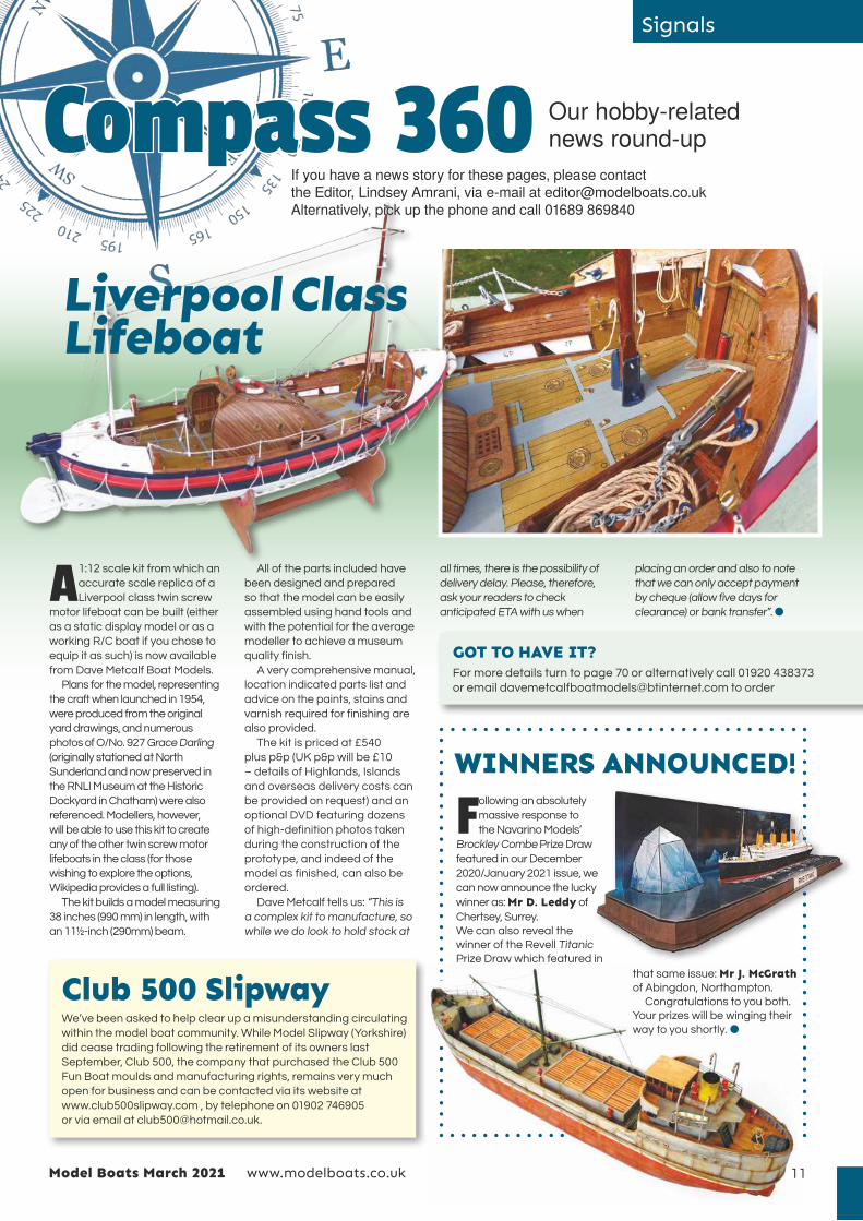
A 1:12 scale kit from which an
accurate scale replica of a
Liverpool class twin screw
motor lifeboat can be built (either
as a static display model or as a
working R/C boat if you chose to
equip it as such) is now available
from Dave Metcalf Boat Models.
Plans for the model, representing
the craft when launched in 1954,
were produced from the original
yard drawings, and numerous
photos of O/No. 927 Grace Darling
(originally stationed at North
Sunderland and now preserved in
the RNLI Museum at the Historic
Dockyard in Chatham) were also
referenced. Modellers, however,
will be able to use this kit to create
any of the other twin screw motor
lifeboats in the class (for those
wishing to explore the options,
Wikipedia provides a full listing).
The kit builds a model measuring
38 inches (990 mm) in length, with
an 11½-inch (290mm) beam.
Compass 360 Our hobby-related news round-up
Club 500 SlipwayWe’ve been asked to help clear up a misunderstanding circulating
within the model boat community. While Model Slipway (Yorkshire)
did cease trading following the retirement of its owners last
September, Club 500, the company that purchased the Club 500
Fun Boat moulds and manufacturing rights, remains very much
open for business and can be contacted via its website at
www.club500slipway.com , by telephone on 01902 746905
or via email at [email protected].
Following an absolutely
massive response to
the Navarino Models’
Brockley Combe Prize Draw
featured in our December
2020/January 2021 issue, we
can now announce the lucky
winner as: Mr D. Leddy of
Chertsey, Surrey.
We can also reveal the
winner of the Revell Titanic
Prize Draw which featured in
All of the parts included have
been designed and prepared
so that the model can be easily
assembled using hand tools and
with the potential for the average
modeller to achieve a museum
quality finish.
A very comprehensive manual,
location indicated parts list and
advice on the paints, stains and
varnish required for finishing are
also provided.
The kit is priced at £540
plus p&p (UK p&p will be £10
– details of Highlands, Islands
and overseas delivery costs can
be provided on request) and an
optional DVD featuring dozens
of high-definition photos taken
during the construction of the
prototype, and indeed of the
model as finished, can also be
ordered.
Dave Metcalf tells us: “This is
a complex kit to manufacture, so
while we do look to hold stock at
all times, there is the possibility of
delivery delay. Please, therefore,
ask your readers to check
anticipated ETA with us when
placing an order and also to note
that we can only accept payment
by cheque (allow five days for
clearance) or bank transfer”. l
11
GOT TO HAVE IT?For more details turn to page 70 or alternatively call 01920 438373
or email [email protected] to order
WINNERS ANNOUNCED!
that same issue: Mr J. McGrath of Abingdon, Northampton.
Congratulations to you both.
Your prizes will be winging their
way to you shortly. l
If you have a news story for these pages, please contact the Editor, Lindsey Amrani, via e-mail at [email protected] Alternatively, pick up the phone and call 01689 869840
Liverpool Class Lifeboat

Shooting the breeze
12
Q For the sake of our readers,
can I begin, Darrell, by
asking you to explain a little
bit about your role at Hornby…
A Though not one for titles,
mine Is Head of Brand –
for Airfix, Corgi and
Humbrol. My role involves
working with the different internal
teams to build ranges that both
satisfy our customers and meet
the needs of the business from
a sales and profit point of view.
We also put the multi-channel
marketing campaigns together.
Q Just announced in
the 2021 Corgi line
are two new
Queen Elizabeth-class
aircraft carriers: the
HMS Queen Elizabeth
(RO8) and the
HMS Prince of Wales
(RO9). Anyone with
an interest in Royal
Navy vessels will
be aware of their
development and
significance but
for those who
are not, can tell
us a little more
about them and explain,
in brief, their importance…
A Well, in the Corgi range
the ship category has
been dormant for quite
a few years now, so I’ve been
looking for an opportunity to
re-enter this collectors’ area
and introduce some new
customers to the brand.
By introducing these two new
models we wil be making
a statement and showing
collectors how serious we are
about this category.
Q The vessels are being
modelled to 1:1250 scale
so how much in the way
of detail can we expect, and,
as they’re not, like many other
ships built to this scale, waterline
models, how will they be
presented for display?
A At this scale we’ll be able
to include some really
nice hull and deck detail.
The lifts will be modelled in
‘operational position’ on both
of the ships but the aircraft
included and their positioning
on the decks will differ. Another
benefit of 1:1250 scale is that
the models will be easy to
display in terms of space
required and they won’t be
overly heavy either.
Q Tooling up for a new
diecast model is extremely
expensive and so in order
for manufacturers to see a return
on their investment consideration
usually has to be given to further
outings in different guises,
liveries/schemes, colours, etc,
after that first release. So, with
these carriers being such unique
vessels, how do you plan to make
them pay their way?
A The plan Is that rather than
being released as limited
editions – which just wouldn’t
be sensible as both of these new
vessels are expected to remain
in Royal Navy service for the next
half a century or so – the models
will simply remain available within
the range. As the ships’ crews
constantly change, that should
keep sales ticking over. There
will also be ‘Specials’ produced
at certain times during the lives/
careers of these ships, which
could include detail/modifications
or perhaps see the models
presented in specially dedicated
commemorative boxes/packaging.
Q Having long followed
the Corgi brand, I was
delighted but, I must say,
surprised to see these new
carriers announced. Are you
simply testing the water, or is the
plan that these two models will
launch an entire new series?
This month we’re chatting with Hornby’s Darrell Burge about some exciting newly tooled releases scheduled for later this year…
MB Q&AOn the horizon…
ABOVE: A diecast first shot from the new tooling for HMS Queen Elizabeth.
BELOW: A 3-D printed prototype like the one shown below allows the designer to check dimensions, scale thicknesses and various other aspects of a model’s
construction during the development process of new tooling.

13
Shooting the breeze
A I’m pleased we‘ve already
delighted you. That’s
a good start. At this
stage we’re watching the
pre-orders and general feedback
very closely but, yes, provided
all goes well, the intention is to
expand on the theme. These
mighty carriers don’t operate
independently, so there are
numerous candidates, serving
both in defence and support
roles, to chose from
Q I know back in 2014 Airfix
was commissioned to make
a one-off 1:350 scale model
of HMS Queen Elizabeth, expertly
put together by Dave Coventry,
which was then displayed on
board for visitors to the ship, so
I am assuming this is how you
were able to gain access to all
the material your Research &
Development team needed to
create the CAD [Computer Aided
Design] files for the Corgi models.
For the kit builders amongst
our readership, then, I must ask
whether Airfix kits are also planned
for general release? If so, can you
disclose whether work is already
underway and whether that same
scale has been decided upon?
Likewise, as there’s been no new
tooling for model ships/boats in the
Airfix range for a while now, can
you hint at any other exciting new
tooling in the pipeline that Model
Boats readers can look forward to?
A Yes, Dave produced a
marvellous ship back
in 2014. But in 2019 he
began further updates and
improvements and in the
November of that year we took
his model of the Queen Elizabeth
with us to the Scale Model
World show to gauge opinion
and Interest. We referenced
Dave’s model a lot during the
QUICK FIRE QUESTIONS
Q If you were writing an autobiography and had to
give each chapter a name, what would the one that
included 2020 be called?
A Annus horribilis turned Into annus opportunus!
Q If you were forced to participate in karaoke, which song would
you choose to ace or slaughter?
A Dream, dream, dream
Q Name something that loads of people are obsessed with but
that you just don’t get the point of?
A Mrs Browns Boys!
Q Name the charity you’d nominate to receive any winnings if you
were a celebrity game show contestant?
A Models for Heroes
Q If I could grant you the adventure of a lifetime, what would it be?
A A road trip criss-crossing all parts of Australia.
initial stages of development,
but of course our R&D team also
worked from photographs and
using various other material to
create these 1:1250 scale Corgi
diecast versions.
When considering larger-scale
Airfix versions,1:350 would be
the ideal as this would allow us
to incorporate a level of detail
(even to the aircraft) that would
satisfy even the most discerning
of modellers. However, due to the
top secret nature of these new
vessels, the shipbuilder would
be able to offer us little in the
way of help, so certain aspects,
such as the under the waterline
detailing, would most likely
have to be based on educated
guesswork. Clearly it’s issues like
these we’ll have to ponder before
committing to such a huge
investment. So for now I guess all
I can say is, watch this space! l
LEFT: An early deco sample of the 1 : 1250 scale diecast model of aircraft carrier HMS Queen Elizabeth scheduled
for release within the Corgi range later this year.
BELOW: A colour artwork profile of the Queen Elizabeth Class aircraft carrier HMS Prince of Wales.
ABOVE & BELOW: Early mock-ups for the new aircraft carriers HMS Queen Elizabeth and
sister ship HMS Prince of Wales.

This month we’re able to offer you the opportunity
to win Das Werk’s newly tooled 1:72 scale plastic
kit for S.M. U-9 (Ref. DW72001) featuring:
* 164 parts of accurate shape and dimension;
* Highly detailed surfaces with realistic rivet details;
* Optional sail railings, with fine details on both sides;
* The option to model open or closed hatches and torpedo doors;
* Name plaques for all four submarines in this class
(U-9, U-10, U-11 and U-12);
* Optional upper rudders and optional masts;
* A positionable exhaust stack;
* Turnbuckles for advanced modellers;
* A display stand.
www.modelboats.co.uk Model Boats March 2021
WIN!
PRIZE DRAW COURTESY OF DAS WERK
DAS WERK’S NEW 1:72 SCALE WORLD WAR 1 U-BOAT KIT!
RRP €99!
On completion, the model will display at 804mm long
and 150mm high, with an 83mm beam.
Commissioned as the first vessel in its class, SM U9
(Seiner Majestät U-Boot), was launched in February
1910. This double hulled U-Boat measured 57.38 metres
long, 6 metres wide, had a draft of 3.13 metres and a
displacement of 493 tons above and 611 tons under
water. It could dive to a maximum of 50 metres in about
50–90 seconds.
It was powered by 1000 HP petroleum motors on the
surface and by 1160 HP electric motors while submerged,
facilitating a speed 14.2 knots above water and 8.1 knots
under water. Armament consisted of six torpedoes, which
could be fired through two bow and two stern tubes.
Remarkably, during World War I U-9 destroyed five
warships (no other boat was attributed with sinking more
warships than this during the conflict) and 13 merchant
ships. Surrendered to the British at end of the war in
1918, she was subsequently scrapped in Morecambe,
Lancashire in 1919.
14

15
During the course of Das Werk’s in-depth research and
development for this kit, two divers were employed to measure and
photograph the wreckage of SM U-12, a vessel of the same type
located on the seabed at a depth of around 50 metres approximately
25 kilometers off the Scottish coast. The information that surfaced,
along with lots of the archive material sourced on U-9 and its
missions, is shared in a fascinating illustrated 100-page paperback
book that’s included free with the first edition of Das Werk’s U-9 kit.
HOW TO ENTER
All you have to do to be entered in this fabulous prize draw is complete
the entry form below and return it to us at:
Das Werk U-9 Prize Draw
Model Boats
MyTimeMedia Ltd
Suite 25, Eden House
Enterprise Way
Edenbridge
Kent TN8 6HF
before the closing date: March 12, 2020.
Model Boats March 2021 www.modelboats.co.uk
PRIZE DRAW COURTESY OF DAS WERK
TERMS & CONDITIONS
Entry is open to all UK residents with a permanent UK
address, with the exception of employees (and their families)
of MyTimeMedia Ltd, its printers and agents, and any other
companies associated with the competition. All entrants
must be aged 18 or over. Only one entry per household is
permissible. No responsibility can be accepted for entries
lost, damaged or delayed in the post. Winners will be notified
by post. Prizes are not transferable to another individual
and no cash or other alternatives will be offered. The
promoters reserve the right to amend or alter the terms of
the competitions. The winner will be chosen from all correct
entries received by the closing date specified. Please note
that data will be managed in compliance with GDPR law.
Our privacy policy can be found at www.mytimemedia.co.uk/
privacy. The decision of the judges is final and
no correspondence will be entered into.
Name:
Address:
Postcode:
Tel No:
Email:
DAS WERK U-9 PRIZE DRAW
Das Werk
To explore the entire Das Werk range,
visit https://www.das-werk-models.com
GOT TO HAVE IT?
Orders for this kit can be now be placed via the
website of Das Werk’s UK distributor Albion Hobbies
(https://www.albionhobbies.com) or through
Das Werk’s own web shop at
https://www.modellbau-koenig.de/en

Designed, developed and produced in the UKDesigned, developed and produced in the UK
Recent Releases - Two kits designed specifically for beginners, but with enough detail to satisfy the more experienced.�e 80 Foot sailing Zulu Lady Isabella and the 70 Foot Fifie Lady Eleanor. Both kits come with step by step full colour instruction manuals, supplemented by plans to guide you through every stage of the build. Laser cut wood parts and second planking is in high quality pear wood, with each having a fully detailed laser engraved and pre cut deck. A brass photo etched sheet with smaller details is also included.
HM Brig Sloop Flirt - 1782Scale - 1:64
Length overall - 656mm
Width overall - 230mm
Height overall - 492mm
Price - VM/05 Flirt– £282
Price - VM/05/MS - Master Shipwright Flirt– £450
The 80Foot Zulu Lady Isabella
Scale - 1:64
Length overall - 600mm
Width overall - 100mm
Height overall - 387mm
Price - VM/03 Lady Isabella – £158.00
VM/03/Sail set for Lady Isabella (3 SAILS) £36.00
To order, please visit our website at:www.vanguardmodels.co.uk
Vanguard Models70B High Street
CinderfordGloucestershire
GL14 2SZUK
Tel - 01594 824610Email - [email protected]
If you wish to order by post, please make cheques payable to Burncroft Limited and
add £6.50 for UPS deliveryOrders by phone are now accepted
VM/18F/C 18 Foot Cutter (86mm Long) £19.50 (+£3.50 P&P)
VM/22FY 22 Foot Yawl (107mm Long) £25 (+£3.50 P&P)
VM/24FL 24 Foot Launch (114mm Long) £26.50 (+£3.50 P&P)
VM/28FP 28 Foot Pinnace (134mm Long) £29.50 (+£3.50 P&P)
The 70 Foot Fifie Lady Eleanor
Scale - 1:64
Length overall - 380mm
Width overall - 105mm
Height overall - 327mm
Price - VM/04 Lady Eleanor– £142.00
VM/04/Sail set for Lady Eleanor (2 SAILS) £28.00Now available - We now have a selection of details boat kits which included laser cut parts
including pear wood and photo etched brass.Four are available now, with another five kits arriving very soon
Our latest main kit development is in progress and should be available around June 2021

©Vanguard Models Kits are
Designed, developed and made
in the UK
by Chris Watton
Our latest release, in stock now, is the royal yacht built for The Duchess of Kingston (1778)�is kit has been developed using the original plans, and developed to be as easy to build as it can be, while keeping every detail possible. To achieve this, there are almost 20 separate laser cut sheets, 9 of which are in solid pear wood (Second planking is also pear wood), and 5 photo etched brass sheets. �e stern decoration and figurehead are in fine cast resin, and the kit comes with a second stand in acetate, complete with laser engraved nameplate. �e decks are also laser engraved and cut in maple veneer.�e 81 page full colour instruction manual is the most comprehensive yet, along with 13 full size plan sheets which include all masting and rigging drawings.All of the area at and above deck level is pre-cut, it is only the area below this that requires planking - even the main wales are pre-cut.
All laser cutting now done in-house
HM Cutter Alert 1777
Scale - 1:64
Length overall - 637mm
Width overall - 256mm
Height overall - 517mm
Price - VM/01 HM Cutter Alert– £221.50
VM/01/PB/ Optional machined pear wood block &
deadeye set £20.00
HM Brig Sloop Speedy
Lord Cochran’s Command
Scale - 1:64
Length overall - 700mm
Width overall - 230mm
Height overall - 492mm
Price:
VM/02 HMS Speedy– £286.50
VM/02/MS Master Shipwright Edition (Boxwood) - £465.
VM/02/PB/ Optional machined pear wood block & deadeye set
(Included in Master Shipwright version) - £40.00
Scale - 1:64
Length overall - 576mm
Width overall - 208mm
Height overall - 480mm
Price - VM/06 Duchess of Kingston – £356.00
VM/06/PB/ Optional machined pear wood block &
deadeye set £35.00
UK Postage - £6.50

18
Someone once said that sailing ships were
man’s most beautiful industrial creation.
I couldn’t agree more and take great
pleasure in building and sailing models of
them. As modellers, we all have our favourites,
and Parma is mine…
She was built at Port Glasgow in 1902, as
Arrow, for the Anglo-American Oil Company.
Her builders were A. Roger & Co, and she was
made for the Case Oil trade, between New
York and the Far East. Case Oil (kerosene) was
used to power all the oil lamps in use from
Saigon to New Zealand in the days before
widespread electrification. Supplied in large
cans, packed two to a case, transportation
didn’t need to be particularly speedy and a
large sailing ship therefore proved ideal for
this bulky cargo. Arrow was one of the last
such ships built specifically for this purpose,
continuing her duties until 1908. She was then
bought by the Laeisz company of Hamburg,
who changed her name to Parma and
Tall ship modelling
Nev Wade talks us through not only the build of his astoundingly beautiful model of Parma but also explains the basics of how to sail one of these magnificent square riggers…
A wondrous Windjammer
ABOVE: This is Arrow, leaving Hong Kong, in her Case Oil days. BELOW: Nearly 30 years later, in 1932, this is Parma, shortening sail off Mariehamn in the Aland Islands, her Baltic home port at the time of the Grain Races.

s
“At around 3000Ts of ship
and with a capacity of 5300Ts,
Parma really was the epitome
of a big windjammer”
used her for the carriage of general cargo
outward to the ports of the west coast of
South America, where she’d take on cargos
of nitrates for the return trip to Germany. She
sailed out and back around Cape Horn, deep
loaded both ways, from 1908 to 1914, until
she was interned during World War 1, fully
loaded with nitrate, at Iquique in Chile. She
remained there until 1920 when, awarded to
the UK as war reparations, she was sailed
back to Europe.
The British, however, had no use for her
and Laeisz bought her back, to help rebuild
its fleet of nitrate carriers. Once again, she
served this, the hardest of trades, well, until
worldwide economic depression forced her
lay-up in 1930. It was at this point that she
was acquired by a consortium including
Reuben de Cloux, one of the most famous
windjammer masters, and the sailor/author
Alan Villiers. They pressed her into service
in the last ever trade for big sailing ships,
the carriage of grain from South Australia
to Europe and it was during this period she
participated in the Grain Races, making the
fastest ever passage home to Europe (83
days) in 1933.
Sadly, in 1936, accidental contact with a
dock wall in Glasgow resulted in damage
that proved uneconomic to repair, and she
ended up being sent to the shipbreakers. A
real loss as, at around 3000Ts of ship and with
a capacity of 5300Ts, Parma really was the
epitome of a big windjammer – and that’s the
reason she’s my favourite.
Construction
I made the model from Harold Underhill plans.
The hull is of conventional plank-on-frame
construction, but it does differ from the norm
in a number of key ways... I made the decision
long ago to use removable sailing keels on my
model square-riggers. The keels are heavy
(in this case 8.2kgs), so it’s more convenient
to carry them to the water in a rucksack and
there attach them prior to sailing. Rather than
having the full weight required inside the hull,
therefore, the hull has a strengthened ‘kelson’,
an interior keel, and a bottom is fitted with
wooden blocks to accommodate three keel
attachment bolts.
My sailing keel is an aluminium plate
attached to these keel bolts, with torpedo
shaped lead strips attached to the plate.
Besides providing the necessary weight
to float Parma to an almost fully loaded
waterline, this plate allows the model to better
‘grip’ the water, which is important when
sailing to windward.
Real sailing ships’ rudders were on the
small side, mainly because they were
operated manually, with no mechanical
assistance. On a model, however, such
Tall ship modellingLEFT: Nev’s model of Parma serves as a reminder of why windjammers are such beautiful ships to behold.
RIGHT: Parma becalmed in the Atlantic, c.1932/33.
19Model Boats March 2021
“The hull is of conventional
plank-on-frame construction,
but it does differ from the norm in
a number of key ways...”
RIGHT: The vastly oversized rudder.
BELOW: The hull of Nev’s model almost complete.

www.modelboats.co.uk Model Boats March 202120
Tall ship modelling
a rudder wouldn’t offer a quick enough
response in going about or avoiding other
boats being sailed in close proximity, so I
made my rudder about ten times oversize.
Having crafted the hull, complete with
the above mentioned peculiarities, I then
moved on to the installation of the radio and
electrical gear (which I’ll expand upon further
as you read on) all of which was attached to
wooden battens fastened into the hull.
After all the electrics had been installed,
I stepped the lower masts (simple dowel)
into blocks on the kelson, using ‘thwarts’ set
across the hull to locate them at deck level.
These ‘thwarts’ also provide deck support
and a place into which to set the fairleads
which carry the braces up the masts (again,
something I will elaborate on in due course). I
use ‘false decks’, made of very thin ply, to start
deck installation and it was these that I fitted
next. They were cut to be a close fit with the
sides of the hull and the masts, and into them
were cut the hatch openings, through which I
would later gain access to the electrics. After
gluing them in place and fitting the hatch
coamings I sealed all around the deck with
decorators’ caulk, the first stage in making
the decks completely watertight.
With the ‘false decks’ in and sealed, I
planked the decks, using 8 x 2mm limewood
strip. I ran resin all around the edges of the The sail arm servos, for the yards on the fore and main masts.
ABOVE: The trim trial at Tynemouth lake.
INSET RIGHT: The 8.2kg removable sailing keel fitted.
The ‘ring bolts’ (below), and belaying pins in their pin rail. Shrouds and backstays fasten to ring bolts,
running rigging to belaying pins.

21Model Boats March 2021 www.modelboats.co.uk
Tall ship modellings
deck; the idea being that the caulk would fill
all the gaps and the resin would solidify on
top. After all that had gone off, I varnished
the decks, the last stage of water-proofing
process. A water test followed, with the hull
being laid right over, thereby dipping each
edge of the deck under water. If any leaks
had been found, the leak proofing would have
needed re-doing until the test was passed.
Fortunately, that did not prove to be the case.
Finishing the decks consisted of making
and fitting hatch covers and deckhouses,
followed by installation of the preparations for
the ship’s rigging: ‘ring bolts’ in the scuppers
and pin rails on the bulwarks. The ‘ring bolts’
are the attachment points for the ‘standing
rigging’ (which supports the masts) and these
were simply fashioned from bent wire. The
pin rails house the belaying pins to which the
‘running rigging’ (which did the controlling
aloft on the real ship) is attached and these
were made from thin ply and glued halfway
up the bulwarks.
In essence, that was the hull complete, now
it was time to go aloft. I made the upper masts
(topmasts and topgallant masts) from simple
dowel and fastened them to the lower masts
using doublings, as in the real ship. The next
task was to make and fit all the spars that
carry the sails. These were all cut and shaped
from simple dowel, just like the masts, and
were each fitted with pivots made from bent
brass wire. The yards, which carry the ‘square’
sails (those set across the hull), had their bent
wire fitted centrally, while the spanker ‘boom’
and ‘gaff’ (top and bottom of the small fore
and aft sail on the aftermost mast) had theirs
glued into their inboard ends.
Each spar was then attached to its mast
by fastening short pieces of brass tube at the
appropriate places, using brass strip bolted
around the masts to secure it. The bent brass
wire was then inserted into the tube, to allow
each spar to pivot, allowing the spanker to
be hauled in and out and the yards to swing
about their masts. It’s worth noting here
that it’s vital that the bend in the wire is long
enough to set the yards about 15mm forward
of their masts. This allows the yards to swing
right ‘round’ the masts – the importance of
which we’ll come to shortly.
Sails
The sails were cut from kite material to
patterns taken from the sail plan, with
sufficient extra allowed for the sewing of good
hems. In addition, the three ‘course’ sails,
those at the bottom of each square-rigged
mast, had a piece of stiff brass wire sewn into
the hems, down each side and across the
bottom. These sails have no yard below them
ABOVE: The arrangement of one pair of braces, for a course (lowest square sail) on one mast. BELOW: The stiff wire, sewn into a course. Also shown is the ‘endless sheet’, which holds the sail back, into the wind, when the yard is braced to any angle.
RIGHT: The start of fitting the ‘false decks’. Note the thwarts supporting the deck and locating the masts. The lines tied to the masts are the braces.

www.modelboats.co.uk Model Boats March 202122
Tall ship modelling
and thus no support, so the wire enables them
to take the wind from ahead without wrapping
themselves around the masts. This permits
them to play their part in ‘tacking’ (which I shall
explain in more detail as we progress).
The fore and aft sails between the masts
and those forward of the foremast were
fitted by simply tying their corners to the
appropriate places on the masts. The spanker
was laced to its boom and gaff, while the gaff
topsail was attached via hooks to the jigger
mast and spanker gaff, so that it can be easily
removed for heavy weather sailing.
The square sails were each laced to their
yards and their bottom corners (clews) tied to
the ends of the yards below to hold them to
the wind. The top two sails on each square-
rigged mast (the ‘royal’ and ‘upper topgallant’)
were made removable (to allow for sailing
in stronger winds) by sewing hooks to the
bottom corners of the lower of each pair (the
‘upper topgallant’); these hooks engage in
small ‘goalposts’ at the appropriate positions
on the yards below.
With all the sails fitted (‘bent’), I then
attached the braces and set up their control.
RiggingThe last of the windjammers were made
from iron or steel, with enormous steel tubes
for masts and spars. All the standing rigging
and lots of the running rigging was made
from steel wire rope and chain. Don’t forget,
these ships were built to withstand the gales
they encountered during their passages
through the ‘Roaring Forties’, south of latitude
40-degrees S in the Southern Ocean.
On my model, the ‘shrouds’ and ‘backstays’
(the lines which run up, astern of each side
of the mast to provide support) were fitted
ABOVE: Shrouds and backstays on the main, mizzen and jigger masts.
Not easy to see, but visible here is the stiff wire sewn into the edges of a ‘course’.

23Model Boats March 2021 www.modelboats.co.uk
s
With the construction and finish now
covered, I’ll now backtrack a little, to explain
the electrics and control of the sails.
Electrics and ControlThe electrics and radio aspects of this model
are at the simpler end of its complexities. The
boat is powered by a 7.2V NiMH battery, with
the master switch fitted through the inner
hatch cover, under the main deckhouse. The
switch has a built-in charging point and can
be reached by sliding open a ‘skylight’ in the
roof of the deckhouse. Therefore, the battery
can be charged, and the boat turned on and
off, without having to ‘go below’.
Five radio channels are in use: one each for
the three sets of yards, one for the boom of the
spanker and one for the rudder. The power
from the battery is sent to the receiver by way
of a ‘Switched Mode UBEC’, a kind of voltage
regulator (I think!), which ensures that the servos
are not starved of power. I set up the transmitter
sticks and a toggle switch to provide the most
intuitive way possible (for me) of controlling
the yards, particularly in the most difficult
manoeuvre, that of ‘tacking’ (see below).
ControlModel yachts are relatively simple to sail.
They will easily ‘come to windward’, i.e. sail
into the wind. This is because they’re ‘fore
and aft rigged’ – that is to say, their sails are
set along the vessel. Sails can be pulled in so
that they’re exactly along the centreline of the
boat, and this allows a model yacht to easily
come to within 35-degrees of the wind.
Windjammers, however, are not like that.
These ships were square-rigged in order to use
the wind from ‘abaft the beam’ (from astern).
In order to make progress to windward, they
had to brace their yards right round, ‘on to the
backstays’, to try and make them as near fore
and aft as possible. Because yards will only
go so far round, square-rigging would only get
65-degrees to the wind, at best. Inevitably, on a
pond, a square rigged model will spend almost
all its time coming to windward because it will
sail very quickly downwind and then run out of
water, then spend lots more time ‘beating’ back
‘up’ the pond.
So, square-riggers used the wind to make
progress by ‘bracing’ (swinging) round their
‘yards’. To brace the yards, ‘braces’ were
pulled ‘in’ on one side, while being let ‘out’
on the other side, thus pulling round the
yards. I’ve achieved the same thing aboard
the model by the use of sail arm servos, with
home-made, centrally pivoted, servo arms.
With braces attached, as the servo rotates it
pulls in one side and lets out the other.
But, inevitably, it’s a little more complicated
than that. The masts are named, from
forward to aft: fore, main, mizzen and jigger.
To take one single brace, for the foremast
yards, say, on the port side, as an example,
the run of the line is as follows… The braces
were made from fishermen’s ‘braid’, which is
faithful to the real ship. Also fitted were a
selection of the lines representing the running
rigging. In my opinion, to have included all
that were present on the real ship would
have made the model look overly ‘heavy’ and
ponderous, as well as getting in the way of the
model’s necessary running rigging essential
for model sailing. For the same reason, you
will find no ‘ratlines’ (rungs up the rigging)
either. The shrouds and backstays were
rigged to the ringbolts set into the deck in the
scuppers, and the running rigging lines were
attached to the belaying pins in the pin rails.
FinishingWith the ship rigged and all the sails bent,
I finished off the model with all the deck
furniture and crew that would have been
present on the real Parma. To make the
model ‘ready for sea’ it was necessary to
tape up all the inner hatch covers and then
tightly fit the outer, visible, hatch covers and
deckhouses over the taped hatches. In this
way the hatches are almost as watertight
as the edges of the deck. Windjammers put
their lee rails under water regularly and often,
and so it was vital that as my model would do
the same, she’d be almost submarine-like in
terms of leakage.
“Windjammers put their lee rails under water regularly
and often, and so it was vital my model would be almost
submarine-like in terms of leakage”
Tall ship modelling
The charging lead plugged into the master switch assembly.
The hook arrangement used to make the top two square sails per mast removable. Also seen is the ‘swivel’ snap link, which attaches the brace to the yard arm.


vital because, as mentioned above, to make
progress to windward, the yards have to be
braced round as far as possible. If they’re
not braced round to within 30-degrees of the
centreline of the hull, the model will not come
to windward. The ‘pulleys’ on servo and yard
arms are fishermen’s ‘swivels’, simple snap
links, which allow the ends of the braces to be
disconnected easily. The ‘pulley’ on the main
mast is a screw eye, screwed into the mast.
I braced two yards on each square-rigged
mast, the course, at the bottom and the
lower topgallant – the fourth yard up. You will
see, therefore, that there are four braces per
square-rigged mast.
Having attached all the braces, it was a
relatively simple task to set them up. The yards
were ‘squared’, set at 90-degrees to the hull’s
centreline. The servo arms were also put at
90-degrees to the hull, and in the middle of their
travel, and the bowsies were tied off halfway
between the two masts they spanned. This
would give plenty of leeway for later adjustment,
if required. The spanker was connected to a
normal sized servo, operated by a toggle switch,
to pull ‘in’ or let ‘out’ the spanker.
Tall ship modelling
thin, strong and runs easily, and the end was
attached to the port side hull frame next to
the main mast. The servo for the foremast
was fitted centrally across the hull, between
the fore and main masts, and the brace was
led forward to it. A pulley was fitted at the
end of the port side servo arm and the brace
was led around it and then sent back to a
fairlead, by the port side of the main mast,
where it was led up through the deck. From
deck level it was then led up the main mast
to the level of the yard it was to brace. Here,
it was led around a pulley and sent across to
the foremast yard to be braced via a bowsie,
used to adjust brace length. At the yard arm,
it was looped through another pulley so that
it could be sent back across to the bowsie;
there, it was tied on, ready for setting up.
The reason that the brace was sent
around a pulley at the servo arm end, rather
than simply being tied to it, was to give as
much movement of the yard as possible,
for a given servo arm movement. In effect,
it is a multiplying pulley system. That was
www.modelboats.co.uk Model Boats March 202124
BELOW: The lee rail is about to go under, illustrating why making this model completely water-tight was essential.
ABOVE: Sailing with the wind from astern. BELOW: ‘Beating’ on the starboard tack. RIGHT: A tall ship to be sure!

25Model Boats March 2021 www.modelboats.co.uk
SailingTo sail a model windjammer, it’s essential to
be able to sail to windward. If you can’t, your
boat will simply end up at the leeward corner
of the pond. It is, unfortunately, as simple as
that. So, to recap, some things are essential
to be able to do that. It helps if there is a
deep keel; the rudder must be oversized, to
achieve quick, positive reaction; the yards
must brace round to within 30-degrees of the
hull centreline; the hull must be thoroughly
watertight; the courses must have stiffness
sewn in and the square sails must be ‘flat’
(not billowing).
Given that all has been achieved, let’s look
at a typical ‘voyage’ down, and then back
up, a pond. Sailing down wind is easy, just
square the yards and steer. Very soon, you’ll
begin to run out of water and have to turn
into the wind to get it on to one side of the
boat or the other in order to sail back up the
pond. Let’s assume you have the bank on
your starboard bow and so have to turn to
port. Set the rudder hard to port and brace
round the yards, on to the ‘port tack’, with
the port side yard arms forward. Your model
will now be sailing across the wind. If you
keep on turning, the wind will, very quickly,
get on the forward side of the square sails
and you will have been ‘caught aback’ and
will stop, and then sail astern into the bank.
Therefore, you have to manage the boat so
that you sail as close to the wind as possible,
without getting caught aback. This is where
the 65-degrees to the wind comes in, as the
best you can do. You have to watch the sails
for any signs of shaking. If you see that, you
have to steer away from the wind a little,
to keep going forward. Eventually, another
bank will start to loom up and you’ll have to
perform the most complicated manoeuvre of
all: tacking.
Tacking is the execution of a turn to
windward, to get the wind on to the other
side of the ship. You’ll remember that
we are on the port tack, port yard arms
forward. With good speed on the model,
turn the rudder hard over, to port. As the
bows of the model cross the eye of the
wind, brace the yards on all the masts,
except the foremast, on to the other
(starboard) tack, with the starboard yard
arms forward. If you have enough speed,
the model will continue to turn, through
the wind, with the ‘backed’ foremast sails
pushing round the bows. When the model
has swung far enough round for success
to be assured, brace the foremast yards
round on to the new tack and you will sail
away from the bank and back up the pond.
You will then need to make as many tacks
as are necessary, both ways, until you can
reach your starting point, when the whole
exercise can be repeated.
There are other manoeuvres (none of
them as tricky as tacking) which for the
sake of brevity I will not be going into here;
suffice to say, most of them will not possible
until you’ve mastered control of the model
as outlined above. l
Virtual viewingI’m happy to report that Parma sails really well. At 1,425mm long and with a
sailing keel weight of 8.2kgs, she commands the water and is able to maintain her
speed through any manoeuvre. She can come to windward (‘beat’) with the minimum of
trouble and deals successfully with winds of 15/20mph, and the waves that go with them.
For those of you interested, I’ve posted footage on YouTube of her on the water along
with two other videos focused on her construction. These can be viewed by copying the
following links into your browser.
https://www.youtube.com/watch?v=Ole_8pwVVyA
https://www.youtube.com/watch?v=j32GWC9lfL4
https://www.youtube.com/watch?v=nRXev0qF2eg
Enjoy!
Tall ship modelling
ABOVE: Windjammer weather! BELOW: Heeling to a good breeze, on the port tack, two sailors aloft.

26 www.modelboats.co.uk Model Boats March 2021
1
Way back in the mists of time – well, as far
back as 2009, I built a model live steam
tug using a Jim Pottinger free plan of
MSC Archer from the October 2008 issue of
Model Boats. (see Photo 1). The construction
of the tug and details of how I fitted her out with
a steam plant of my own design and build (see
Photo 2) was covered in a two-part Model
Boats feature run in the February and March
2011 issues.
For years she gave me a lot of fun and
very good service on a number of boating
lakes, but she sat slightly lower in the water
than she should have, especially as the
engine room portholes aft were always
under water.
As a result, I began wondering how her weight
could be reduced, without this involving me in
building a completely new set of machinery –
something not very likely to happen!
Then in 2010, I was between projects and
casting around for a suitable prototype to form
the basis of another live steam model I could
carry out the design work for over the winter
MSC ArcherPhil Button explains the challenges presented and the interesting solutions he came up with in order to make changes to this live steam tug model
Live steam low down
2
TOP: Archer ‘As Built’ and in her natural habitat. BELOW: The steam plant originally fitted to Archer.

27Model Boats March 2021
Live steam low downs
(funnily enough, the workshop seems
to lose its attraction when it gets cold). I
was ‘surfing the Internet’ one day when
I came across a brief history of an 1855
steam ship called Mullogh (I’m told that
this is pronounced ‘Mulloy’). Unfortunately,
an artist’s impression of her was is the only
pictorial information I was able to find, but
undeterred I decided to build her and she
became the subject of six part series published
in Model Boats’ November/December 2017 and
January-April 2018 issues.
In order to complete the hull design,
however, I needed to find the right engine
and boiler for her. Initial thoughts were that
I could ‘kill two birds with one stone’ by using
the gas fired horizontal Scotch type boiler
from MSC Archer to reduce her weight, as I
had a much lighter vertical boiler (from another
steam ship of mine, TSS Manxman) that could
be used to replace this. I also reasoned that, if I
was going to ‘steal’ the boiler from Archer and
use it in Mullogh, I might just as well take the twin
cylinder compound engine as well, since they’d
worked so well together as a set in the tug.
Engine installationSo, what could Archer’s comparatively slow
revving compound engine (which had been
directly coupled to the propeller shaft and
ran at around 750rpm maximum in normal
operation) be replaced with?
It occurred to me that I’d recently removed
one of an original pair of engines from
Manxman (see Photo 3 of the pair of engines
as originally fitted in Manxman) as part of
her weight loss exercise. This was, however,
a twin cylinder oscillating engine that ran
at around 2200rpm and couldn’t be directly
coupled to the propeller shaft as it ran far too
fast to drive an 80mm four blade propeller.
So, with a bit of ‘thinking outside the box’,
I decided to try using reduction gearing
between the engine and propeller shaft. I’ve
tried this before with electric boats and found
that a surprisingly small electric motor can
actually power quite a large model.
This thinking was helped on its way, since
the engine that was removed from Manxman
already had a geared countershaft running
in ball bearings, originally put there to drive a
boiler feed pump – although that facility had
actually never been used as it robbed too
much power from the engine.
Unfortunately, the gearing that this ‘new’
engine already had would’ve given far too low
a propeller speed, since it was set up to drive
a piston type boiler feed pump at around
450rpm. After a search among my odds and
ends boxes, however, I found several plastic
gearwheels (salvaged from defunct inkjet
printers) and two of these actually gave
me somewhere near the right gear ratio
while also fitting in with the centre distance
between the engine and countershaft.
Sometimes, you just get lucky!
After machining a pair of aluminium bosses
to carry the plastic gears (see Photo 4), the
gears were fitted to the engine crankshaft and
to a new countershaft, carried in the original ball
bearings on the engine baseplate (see Photo 5 showing the completed assembly).
That gave me a new engine unit to install
in the stripped out hull, which was a daunting
prospect as the machinery spaces in the
Archer hull were vast in comparison to the
size of the new engine. I also wanted
to retain the original engine
mountings in the hull (to
hedge my bets in case
I needed to revert to
the original engine at
3
5
LEFT: Phil machined his own pair of aluminium bosses to carry the plastic gears.
BELOW: The plastic gears were fitted to the engine crankshaft and to a new countershaft, carried in the original ball bearings on the engine’s baseplate.
ABOVE: The pair of engines while they still were installed in Manxman; the engine on the starboard side was the one removed for use in Archer.
4

28
Live steam low down 6
a later date – especially if the new installation
didn’t work). After some playing around with
engine position and trying out how it could
be fitted to the existing mountings so as
to align with the propeller shaft, I came up
with a new arrangement (see Photo 6); this
image also shows how small the new engine
is in comparison with the original engine
mountings. In order to make the engine fit, it
was necessary to cut away part of one of the
existing engine mountings in the hull, using a
Black & Decker Powerfile to clear an engine
assembly bolt that projected below the
engine base plate (see Photo 7).
Although what Photo 7 shows was only a
temporary installation, using a piece of steel
angle to bridge two of the existing engine
mountings and a piece of wood carrying the
other side of the new engine, this proved that the
arrangement could work. However, spanning
the distance between engine and propeller shaft
would require the use of two universal couplings
connected back to back. Using two couplings in
this way can have its advantages: if the engine
and propeller shaft don’t line up exactly, they will
accept a great deal of misalignment.
A second steel angle was made up to replace
the wood block under one side of the engine and
this was fixed in place in the hull using car body
filler (see Photo 8). Note that, as the model had
been in use for some years and was liberally
coated in oil, it had to be thoroughly degreased
LEFT: Phil’s completed assembly shows how small the new engine is in comparison with the original engine mountings.
BELOW: In order to make the engine fit, it was necessary to cut away part of one of the existing engine mountings in the hull, using a Black & Decker Powerfile to clear an engine assembly bolt that projected below the engine base plate
before trying to stick anything to it. Even when
using two couplings, I still try to get engine
alignment as accurate as possible and that
explains the packing piece of blue aluminium
under the fixing screw.
Boiler installation
The vertical boiler as removed from
Manxman was a single flue unit with water
tubes across the centre flue and ‘hedgehog’
spikes into the firebox to increase its heating
surface (see Photo 9).
I needed to position the flue from the new
boiler centrally in the funnel on Archer, so a
new aluminium boiler plate was cut out and
7
8 9
ABOVE: A second steel angle was made up to replace the wood block under one side of the engine and this was fixed in place in the hull using car body filler. When using two couplings, good engine alignment can prove a challenge, but it’s been successfully achieved here thanks to the packing piece of blue aluminium seen under the fixing screw. RIGHT: A cross-section drawing of a similar boiler to the one used in Archer, showing the ‘hedgehog’ spikes through the boiler bottom plate – although Archer’s boiler does not have cross tubes in the flue.

Model Boats March 2021 www.modelboats.co.uk
s
11
fitted in place in the hull, with the boiler being
moved around until it was in the right place
(see Photo 10). The holes for mounting the
boiler were then marked out before removing
both parts for drilling the plate.
Other than the water level sight glass, this
boiler had no steam fittings (they had been
retained for the replacement horizontal boiler
in Manxman) so these had to be made up and
fitted. The fittings comprised a clack (non-
return) valve for filling the boiler with water, the
boiler safety valve, a steam outlet to supply
steam to the engine and a further steam outlet
for the pressure gauge (see Photos 11 and 12)
The boiler had come complete with
ceramic burner. However, I’d improved the
design of the gas/air mixing tube since this
burner had originally been built, so I cut off the
old mixing tube and made up and fitted the
new design. This new design gives a much
improved performance to the burner – more
heat for less gas (see Photo 13 showing the
burner under test with the new parts).
With an earlier boiler of this type, I’d
found that a great deal of heat was wasted
as it went straight up the central flue and
emerged as very hot gas at the top. To get
more of this otherwise wasted heat into the
boiler, I experimented with a screwed up
bunch (‘nest’ probably best describes its
appearance) of stainless steel wire simply
pushed inside the bottom of the flue. This
glows red in the heat from the burner and
provides additional radiant heat to the boiler.
It did, however, frequently fall out of the flue
onto the top of the burner and was a real
pain to replace in position.
To overcome this problem, I made up a
baffle of thin stainless steel sheet to fit over
the base of the flue to retain the wire (see
Photo 14). This baffle was held in place by
10BA screws, threaded into two of the boiler
spikes. This seems to have worked fine so far!
Steam plant installationThe engine and boiler are only a small part of
a steam plant installation. A gas bottle and
gas control valve, an engine control valve (for
ahead, astern and speed control), an engine
lubricator (to supply steam oil to the cylinders),
an oil interceptor (to catch the ‘used’ steam oil
in the exhaust) a whistle and whistle valve and
an assortment of steam, gas and water pipes
and valves would also be required. So, not too
much left to do, then!
For the pipework between the engine
exhaust at the engine control valve and
the oil interceptor I used silicone rubber
flexible tubing, as there is very little residual
pressure at this point and the pipe needs to
be easily disconnected to drain steam oil and
condensed water from the interceptor. I like to
make my oil interceptors removable so that I
can tip the contents out rather than messing
about with syringes.
Live steam low down10
13
14
12
ABOVE: The clack valve fitted to the bottom of the boiler.
ABOVE: The rest of the fittings on the top of the boiler.
The baffle of thin stainless steel sheet made by Phil, held in place by 10BA screws, threaded into two of the boiler spikes.

Live steam low down
R/C installationFollowing all of the changes to the steam
plant (See Photos 15, 16, 17 and 18)., the
radio control system required some revision to
operate the new engine (see Photo 19).
The original installation used a total of five
servos: steering; engine speed control; ahead/
astern control; compound/simple valve and
whistle. The new installation did not require
the compound/simple valve and control of the
engine for ahead/astern and speed was taken
care of using the engine control valve (similar to
using an electronic speed controller in an electric
model), so only three servos were needed.
The rudder and whistle servos (the blue
ones) remained where they’d originally been,
it was only the engine control servo that
needed relocation. The receiver battery pack
was installed out of sight below the servo
plate and the Spektrum receiver alongside
the rudder servo.
15
16
17 18
ABOVE: The engine fitted with its control valve. The steam inlet is at the bottom and the exhaustat the top. The ‘asbestos’ insulation on the pipes is actually string, glued on with contact adhesive and painted with white emulsion paint.
BELOW LEFT: The steam manifold (painted green) with the lubricator, whistle valve and its associated pipework. The lubricator provides the engine with a measured volume of steam oil to lubricate the cylinders – this oil leaves the engine in the exhaust and is caught by the oil interceptor to prevent it being thrown all over the model (not to mention the boating lake!). BELOW RIGHT: The gas pipework (painted yellow) between the gas control valve on the commercial gas canister and the burner. Also shown is the boiler filling valve with its connecting pipe to the clack valve (painted blue) and the pressure gauge fitted to the boiler.

Live steam low down
Having made up connecting links between
the servos and their respective controls using
recycled (sorry about the pun!) bicycle spokes,
the radio control installation was completed
by powering it up and checking and adjusting
all of its functions via the transmitter.
Testing and setting upWith the refit completed, a trip to the domestic
test tank was called for to check the effects on
ballasting with the new installation (see Photo 20). The original installation had been so heavy
that no additional ballast had been required
as she already floated rather low in the water –
hence all these changes!
The bath tests showed that she needed
two pieces of lead ballast, each weighing
around 1lb, fitted either side of the hull
amidships. This was created from lengths
of water pipe salvaged from my daughter’s
house, cut into usable lengths and squashed
flat in the vice. The lead was fixed in place in
the hull using silicone mastic so that it can
be easily removed if required (see Photo 21,
where one of the lead pieces is visible beside
the lubricator).
A quick tilt test proved that the model was
stable with these pieces of lead in place. The
tilt test involves tilting the hull as far as possible
(without flooding it!) and letting it go. If it recovers
quickly then stability is OK, if it continues to tilt
further then you have a big problem!
After ballasting, the model was returned to the
workshop for a full steam test on the bench. First,
the boiler was filled with water and the lubricator
with steam oil and all radio control functions
checked for correct operation.
The steam test was used first of all to set and
check the operation of the new safety valve
against the boiler pressure gauge. With the
engine stop valve closed (so that there is no
steam outlet from the boiler, other than through
the safety valve), the burner was lit and steam
pressure raised towards the 25PSI that was
intended for the setting of the safety valve. If the
safety valve opened before that pressure was
attained, the valve adjuster could be screwed
down to increase the pressure setting. Similarly,
if the valve was not open at 25PSI, the valve
adjuster could be slackened off to reduce the
pressure setting. Once the safety valve pressure
was correctly set, the burner was left at its
maximum rate to check that the safety valve
was limiting the maximum boiler pressure to no
more than 10% above its 25PSI nominal setting.
On completion of the safety valve setting, the
engine stop valve was opened and the engine
control valve set to ‘full ahead’. The engine
was turned over (initially by hand) to warm the
cylinders and expel any water resulting from
condensed steam to the oil interceptor. Then
the engine was allowed to run on steam for the
first time and checked for correct operation of
the engine control valve. The first run on steam
showed up all sorts of minor steam leaks in
the engine glands, valve faces and pipework
joints, and notes were made of these for later
rectification.
During bench testing, I always check how
long the engine can run at full power before the
boiler water level drops far enough to require
refilling. I measure this time from boiler lighting
until the water level drops to the bottom fitting
on the water level sight glass. When steaming
on the lake, I use the timer function on my
Spektrum transmitter (programmed with slightly
less than the total steaming time) to nag me with
electronic beeps as a warning that I need to
bring the model back for a drink.
On the waterThere followed a trip to the boating lake at
Woodbridge in Suffolk (home of the Woodbridge
Model Boat Club) on an absolutely flat calm and
not too cold day in January 2014 for a maiden
voyage with the newly geared steam plant.
After filling the boiler with water and the engine
lubricator with steam oil, the gas was turned on
and the burner lit from the top of the funnel. While
waiting for steam pressure, the engine was oiled
all round and radio control functions checked for
correct operation. When steam pressure was
available, the engine control valve was set to ‘full
ahead’ and the engine turned over by hand to
expel condensed steam to the oil interceptor.
The engine control valve was then closed to
wait for the safety valve to lift as a check that it
was working. As a general safety requirement
for any live steamer, before each sailing a safety
valve operation check should always be made;
it’s not unknown for these small valves to stick
closed, with potentially disastrous results! At the
very least, a boiler explosion will destroy your
pride and joy, but it is quite capable of maiming
or even killing bystanders.
Then it was into the water for a trial run,
whereupon she behaved impeccably, running
at pretty much the same speed as with the
earlier and much bigger compound engine and
steering like a dream! In addition, she will now go
astern when asked – something that couldn’t
always be relied upon with the old installation.
Adapting what I’d learnt about previously
with electric propulsion proved satisfying and
successful here: a geared high-speed steam
engine of quite small size works very well indeed
– the only, very minor, downside being the
reduced running time that Archer’s new
(and much smaller) boiler affords. l
19
20 21
BELOW LEFT: With the refit completed, a trip to the domestic test tank was called for to check the effects on ballasting with the new installation. BELOW RIGHT: The bath tests revealed that two pieces of lead ballast, each weighing around one pound, would need to be fitted either side of the hull amidships. One of the lead pieces is visible here beside the lubricator.
The radio control compartment with its original servo mounting plate now fitted with a reduced number of servos. The original rudder and whistle servos (the blue ones) remain in situ, only the engine control servo has been relocated. The receiver battery pack is installed out of sight below the servo plate and the Spektrum receiver can be seen alongside the rudder servo.

SUBSCRIBE TODAY
CARD PAYMENTS & OVERSEAS
Mr/Mrs/Miss/Ms ....................Initial ...........................Surname ..................................
Address ......................................................................................................................
.....................................................................................................................................
Postcode ................................................... Country .................................................
Tel ............................................................................. Mobile ......................................
Email .......................................................... D.O.B ....................................................
Mr/Mrs/Miss/Ms ....................Initial ...........................Surname ..................................
Address ......................................................................................................................
.....................................................................................................................................
Postcode ................................................... Country .................................................
Postal Order/Cheque Visa/MasterCard Maestro Please make cheques payable to MyTimeMedia Ltd and write code MB2021 on the back
Cardholder’s name........................................................................................................
Card no: (Maestro)
Valid from............................... Expiry date.................... Maestro issue no....................
Signature.................................................................................. Date............................
Originator’s reference 422562
Name of bank ...............................................................................................................
Address of bank ..........................................................................................................
.....................................................................................................................................
..................................................................................Postcode ..................................
Account holder ............................................................................................................
Signature ....................................................................................... Date ....................
Sort code Account number
Instructions to your bank or building society: Please pay MyTimeMedia Ltd. Direct Debits from the account detailed in this instruction subject to the safeguards assured by the Direct Debit Guarantee. I understand that this instruction may remain with MyTimeMedia Ltd and if so, details will be passed electronically to my bank/building society.
Reference Number (official use only)
Please note that banks and building societies may not accept Direct Debit instructions from some types of account.
SUBSCRIPTION ORDER FORM
POST THIS FORM TO: MODEL BOATS SUBSCRIPTIONS, MYTIMEMEDIA LTD, 3 QUEENSBRIDGE, THE LAKES, NORTHAMPTON, NN4 7BF
Please visit www.mytimemedia.co.uk/terms for full terms & conditions CODE MB2021
DIRECT DEBIT SUBSCRIPTIONS (uk only)
Yes, I would like to subscribe to Model Boats
Print + Digital: £14.00 quarterly
Print Subscription: £11.75 quarterly
UK ONLY:
Print + Digital: £58.49 Print: £49.49
EUROPE & ROW:
EU Print + Digital: £74.99 EU Print: £65.99 ROW Print + Digital: £74.99 ROW Print: £65.99
YOUR DETAILS must be completed
PAYMENT DETAILS
I WOULD LIKE TO SEND A GIFT TO:
INSTRUCTIONS TO YOUR BANK/BUILDING SOCIETY
Yes, I would like to subscribe to Model Boats, for 1 year with a one-off payment
PRINT + DIGITAL SUBSCRIPTION
PRINT SUBSCRIPTION
l 1 years worth of issues delivered to your door
l Great savings on the shop price
l Download each new issue to your device
l A discount on your digital subscription
l Access your subscription on multiple devices
l 1 years worth of issues delivered to your door
l Great savings on the shop price
l Never miss an issue
HURRY
OFFER CLOSES 31st DECEMBER
2021
TERMS & CONDITIONS: Offer ends 31 December 2021. MyTime Media collects your data so that we can fulfil your subscription. We may also, from time to time, send you details of MyTime Media offers, events and competitions but you always have a choice and can opt out by emailing us at [email protected]. Please select here if you are happy to receive such offers by email ❏ by post ❏ , by phone ❏ . We do not share or sell your data with/to third parties. Details you share with us will be managed as outlined in our Privacy Policy here www.mytimemedia.co.uk/privacy-policy. Issue frequency is subject to change, current annual term is 12 issues.

DIGITAL
SUBSCRIPTIONS
AVAILABLE ONLINE!
SUBSCRIBE SECURELY ONLINE CALL OUR ORDER LINE
http://mb.secureorder.co.uk/MODB/MB2021 0344 243 9023Lines open Mon - Fri - 8.00am - 8.00pm GMT & Sat - 9.30am - 3.30pm GMT.
Calls are charged at the same rate as standard UK landlines and are included as part of any inclusive or free minutes allowances. There are no additional charges with this number. Overseas calls will cost more.
Quote ref: MB2021
TERMS & CONDITIONS: Offer ends 31 December 2021 *This digital discount is only available when you subscribe to the ‘Print + Digital’ package. You can still get a great discount on the digital package, please visit the URL stated below for more information. Please see www.mytimemedia.co.uk/terms for full terms & conditions.
l Now in its 66th year of continuous
publication, Model Boats remains the
world’s best-selling monthly consumer
magazine of its kind.
l Packed with content that
encompasses all aspects of the
hobby, whether your passion lies in it
static models, radio controlled scale,
fast electric or internal combustion
engine models, steam driven craft
or model yachts, we guarantee that
amongst all the news, reviews and
fascinating full length features you’ll
find something that floats your boat!
l Reader input is actively
encouraged. The letters pages
are dedicated to views aired and
information shared, while the
readers’ models section serves as a
launch party for all those wishing to
showcase their latest successfully
completely projects.
l What’s more, every other
issue includes a free model plan,
supported by an illustrated feature
on the vessel that inspired it and
how to achieve the best results
from your build.
So, subscribe today and broaden
your horizons!
Hurry! Subscribe now and make huge savings!
SAVE
70%*ON
DIGITALISSUES

Glynn Guest provides an in-depth guide to building a semi-scale model of a small Harrier/helicopter Carrier from this month’s free plan…
“My model was built around what I
had available during lock-down, but
you will find the design can quite easily be adapted to suit other materials”
Free Plan
This model that will result from this month’s
free plan was based on a proposed class
of small Carriers capable of operating
helicopters or Sea Harriers, which were
designed to appeal to smaller navies or to
serve as support vessels for larger fleet units.
Once built, Audacity will measure in at around
36-inches (92 cm) in length, with a 6 -inch (15
cm) beam, thereby making her approximately
1:144 scale – a suitable match with numerous
plastic aircraft kits.
Construction is mainly from balsa and
liteply. With a shallow draught design, you’ll
find she light in weight (4.5lb - 2 kg) yet has
more than adequate stability. Power can
be provided by two RE 360/385 motors
and, with twin rudders, she will easily travel
at scale speeds and demonstrate good
manoeuvrability.
OriginsIf I told you this model took me 35 years to
complete, I wouldn’t blame you for thinking I’m
either a very slow worker or that I’m challenging
you to build something very impressive but
seriously complex – neither of these scenarios,
however, happen to be the case.
The truth is that the original concept for this
model can be traced back to the mid 1980s
when the desire to build an aircraft carrier
first fired my imagination. I got as far as going
out and buying a copy of Royal Navy Aircraft
Carriers 1945-1990 by Leo Marriott (ISBN 0
7110 15619), only to find the book was lacking
kind of detail I was hoping for in regards the
Colossus class of light fleet carriers that
were interesting me at the time. Reluctantly,
therefore, this particular ambition was
shelved. Some years later, in the September
2013 issue of Model Boats, I noted with interest
the release of a book on HMS Goliath. This
did include details of the small Harrier Carrier
design proposed by Vosper Thornycroft, so,
enthusiasm rekindled, I set about drawing up
a rough draft. Life’s little distractions, however,
were then see this lay dormant in my files for a
further three and a half decades – until…
Lock-downThe voluntary home incarceration of 2020
forced me to re-evaluate what I’d materials
I had to hand and what could be built from
them. The best that could be found were some
sheets of ¼ inch (6mm) balsa and a large sheet
of 2 mm thick liteply, plus an embarrassingly
large stash of 1:144 plastic kits – all of which
led me to resurrect the Harrier Carrier plans.
Audacity
www.modelboats.co.uk Model Boats March 202134

tricky. These slots need to be straight and
at the same time wide enough to slip some
suitable sheet into so that the bow shape so
characteristic of vessels can be accurately
captured. Not trusting myself to cut these slots
with a knife, I hit on the idea of taping the two
sides together and then firmly clamping them
down onto my adjustable workbench so that
the position of the slot was above the narrow
gap between the table halves. Then, using a
Tenon-saw (because it had a stiff rather than
flexible blade) I carefully cut the slot out of both
sides at the same time (see Photo 3). This
method might sound somewhat ludicrous,
and probably amused my neighbours no
end, as I did it outside on the drive for more
space and better light, but it met its
objective, resulting in the creation
of two satisfyingly identical, and
suitably wide, slots.
The side pieces
need to be stiffened
up by gluing two
strips of 1 x ¼ inch
(25 x 6mm) balsa along
their top edges (see Photo 4), remembering
to make both right and left handed sides.
Once again, a trial fit of the sides onto the hull
base is a sensible move before reaching for
your glue (see Photo 5). At this point,
your transom should be cut out and
tried in place. I found the lower
edge, which sits on the
hull bottom, required
some chamfering
Free Plan
4
5
3
2
1
35Model Boats March 2021 www.modelboats.co.uk
s
Frustratingly, there wasn’t enough material
to build the model as originally designed,
so lots of discarded pencil sketches were
created until the idea of using a shallow
draught occurred to me. This had been
successfully tested on a model (Caerleon
Castle, see the May/June 2018 issues of
Model Boats) and had proved very stable.
Adopting this method allowed both the large
flight deck and the two hull side pieces to be
cut from the 12-inch (30cm) wide sheet of
liteply – problem solved!
As a result, the design of the model moved
further way from the original Vosper plans
and evolved into a small multipurpose vessel
which could be outfitted with Sea Harriers
(needing a ski-jump in the bows) and Lynx
helicopters for naval roles or, with the ski-jump
removed, as a helicopter assault vessel. The
hull shape had also to be modified to make
better use of the liteply and became more
appropriate to the current ‘boxy’ hull styles.
Wooden notes
My model was built around what I had
available during lock-down, but you will find
the design can quite easily be adapted to suit
other materials. The sizes and thicknesses
are, within sensible limits of course, not crucial
to adhere to, but if any changes are made
then the consequences must be thought
through. The parts will still need to be strong
enough to do the job and fit together!
For all the wood to wood joints, I used an
exterior grade wood glue: Everbuild 502, to be
exact. It has all the qualities of being strong,
having a convenient drying time and it doesn’t
smell awful or make a mess, which more than
makes up for not being able to leave the hull
full of water after each sailing session – not
that I do anyway! A little epoxy was also used
when sticking the propeller and rudder tubes
through the hull bottom.
Bottom first
My build began by making the base upon
which the hull was created, and which indeed
formed its bottom. For this reason, the base
must be flat, square and true, otherwise your
hull will be out of shape. My lockdown stock
included a single 6-inch (150mm) wide sheet
of ¼ inch (6mm) balsa, but the likelihood is
you’ll need to join two 3-inch (75mm) sheets.
I then glued a frame of ½ x ¼ inch (12 x 6mm)
strips onto the base frame (see Photo 1).
For those of you working to my plan, I should
point out here that it’s very important that
your two longitudinal strips match the length
of the lower edges of the hull sides. The three
bulkheads (1A, 2 and 3) need to be cut to fit on
the hull base and so need slots in their corners,
and a trial fit without glue first is recommended
(see Photo 2).
Make sure the two hull sides you cut from
your liteply sheet are identical. Their outlines
are simple enough but creating the necessary
slots within their front halves can prove a little

although I also used a couple of clamps to
ensure the sides and bulkheads were firmly
held together while my glue set (see Photo 6).
The hull sides from B2 forward now need
to be pulled together and glued to the hull
base, strips and B1A, but only once the glued
applied to the previously mentioned parts
has fully dried (see Photo 7). The inside joint
where the two sides meet at the bows can
be strengthened by pressing a piece of glue
soaked fabric across it. I’ve employed this
little trick numerous times over the years and
as a result have yet to experience a failure
in what is often the most vulnerable part of
a model boat’s hull – and believe me, I’ve
unintentionally put the resulting reliability to
the test on countless occasions!
To create a larger gluing area, I recommend
gluing some strips of balsa along the inner
edges of the sides from B1A to the bow joint
(see Photo 8), as this is going to be a glued
joint that will be hard to access later on.
Completion of the bow requires pulling the
sides inwards and gluing the bow piece into
place (see Photo 9). Make sure the curved
sides are symmetrical here. I also added a
couple of triangular fillets at these joints –
although, on reflection, these may not have
actually been necessary. The sheet that
slides into the slots in the side pieces can be
made from balsa, liteply or any other suitable
material. I used some card, cut from a large
sheet that I’d bought in an art store some
years ago for another project. Whatever you
opt for, though, should be slightly oversized for
the job in hand. I found that my slot needed
a little widening before the card would slide
smoothly down to fit against B2. I therefore
withdrew the card, applied glue to the
surfaces and reinserted it into the slot, before
leaving the glue to set (see Photo 10).
The excess card on the outside of the hull
can easily trimmed away with a knife and then
the edge sanded back to be flush with the hull
sides. Some of my card was also cut away
inside the hull to give afford access; remember,
totally sealed spaces can become traps for
6
Free Plan
www.modelboats.co.uk Model Boats March 2021
“I’ve employed this little trick
numerous times over the years
and as a result have yet to
experience a failure in what is
often the most vulnerable part of
a model boat’s hull”
to make a good joint. Only when you’re totally
happy with the fit should the sides be glued
to bulkheads 2 and 3, the hull base and strips
set in place between them and the transom
fixed to the base and sides. One of the nice
thing about working with liteply is that you
can secure parts by pushing pins through it;
10
8
9
7

dampness and lead to rot. The top part of the
first bulkhead (B1B) can now be glued into
place and the gap between it and the top of
B1A filled with a strip of balsa (see Photo 11).
With the excess sheet cut way from the
hull base, B2 forward, the bottom edges of
the hull can be sanded flush to the sides (see
Photo 12). Now, only three things are left
to add to the hull… Firstly, the deck needs
to be fitted into the hull using a plug on its
underside made from square balsa strips. As
the transom is angled, a strip has to be glued
across it to create a vertical surface for the
plug to fit securely within. I found the face
glued to the transom needed be chamfered
(see Photo 13). Use a sanding block was
to ensure that this strip and the top of
the transom are flush with the hull sides,
otherwise your deck will not fit properly. You
can either leave the bow of your hull with a
blunt appearance or chose to do as I did and
undertake a little streamlining. This involves
sticking a few laminations of scrap balsa to it
and then carving and sanding it into shape.
The block ought to stand above the top of
the bow piece by an amount equal to the
thickness of the deck sheet, thereby creating
a flush appearance. The final addition on my
build was a strip of hardwood to reinforce
the junction between the hull side sheets
(see Photo 14).
With the hull beginning to look a bit more
ship-shape, all the external surfaces can
be lightly sanded and at the same time
examined for any defects. Should you detect
any visible cracks, firmly press glue into them
and, likewise, fill any larger imperfections with
glue coated slivers of balsa. The odd dent
can be treated with some domestic filler,
which can then be easily sanded flush with
the wood. By the way, always use a sanding
block (either a commercial item or sandpaper
wrapped around a suitable flat surfaced
block) to avoid gouging into the wood and
creating more damage. The hull bottom,
where it joins the hull sides, can now be
sanded to create a modest radius (see the
cross-section on the plans), but don’t go
mad and seriously weaken this joint!
Removable deck
The whole of the flight deck is designed
to be removable – a much better option
than having to struggling through small
hatches in order to gain interior access!
Also, to be truthful, I find that if most of the
decks and superstructure can be removed
37Model Boats March 2021 www.modelboats.co.uk
sFree Plan
11 12
14
15
13
from a model, I’m far less likely to damage
any fine detail while carrying out routine
maintenance.
I built a plug made up from ½ inch (12mm)
square balsa inside the strips around the hull
opening so that it sat flush with the edges (see
Photo 15). Transverse crosspieces were also
added at roughly 6-inch (150mm) spacing.
If you’re following my lead, care needs to be
taken not to get any glue between the plug
strips and the hull. Once the glue is dry, and I

www.modelboats.co.uk Model Boats March 202138
17 18
Free Plan
really do mean dry, the frame can be gently
lifted out of the hull, but not before putting a
mark on its top surface (see Photo 16).
It always pays to plan ahead, so I took
great care when cutting up my original sheet
of liteply and set a piece just the right size to
make the flight deck from aside. When you
get to this stage the plug can be affixed to
the deck. Applying your glue to the previously
marked upper surfaces will help you ensure
your deck is correctly positioned. It’s a good
idea to hold it down on a flat surface with
suitable weights. Leave it like this for as
long as possible; the glue may say it can be
handled after a few hours, but overnight is
always a safer bet.
The deck plug might display a little
reluctance to fit into the hull opening. I know
mine did! A little sanding of tight spots on the
plug, along with a small radius at the corner
which fits into the hull opening, usually cures
this. A little trimming of the deck will no doubt
be required to clear the bow block and fit
neatly; also, any excess should be cut and
sanded away from the deck edge.
Surface sealingIt’s up to you, but I’ve always found it easier to
seal and prepare the external surfaces of a
hull and deck before adding or installing other
items. How you chose to treat bare wood will
be a personal preference; there’s nothing
wrong with opting for a method you know
from past experience will work.
I like to use something which is quick
to apply and which toughens the hull up
against the inevitable knocks and scrapes
a working model can experience. My
preferred choice, therefore, is cellulose
dope and tissue paper. My usual approach
is to first apply a couple of coats of thinned
dope, which I find readily penetrates into
the wood. A light sanding after each coat
will remove any loose wood fibres from
the surface. Next, I use panels of model
aircraft tissue, which I fix to the model by
laying them on the surface and brushing
some neat dope through them. I find that
starting in the centre of a panel and working
outwards usually avoids creases; if creases
do, however, occur, then the tissue can be
peeled back and re-laid with more dope.
Adjacent panels should be overlapped
slightly. The angular shape of this model
makes the application of tissue relatively
easy. By giving my model another two or
three coats of neat dope and lightly sanding
between each application, a satisfyingly
smooth surface was achieved.
No, I didn’t seal the inner surfaces! My
models are built to keep water on the outside
of the hull and rarely does any enter the
interior. Even if the internal spaces look
totally dry after a sailing session, I always
leave a model ‘opened up’ for a day or two
afterwards, hence my dislike of enclosed
spaces within a hull. This has always worked
for me, as over the past five decades none
of my models have ever suffered from wet
rot – something that can occur if water gets
trapped in the wood. But, if it makes you feel
better, by all means swill sealant around
inside your hull.
R/C gearI always like to conduct ‘on water’ tests as
soon as it’s possible to do so, as I find it very
reassuring to know the boat I’m working
on will actually float before progressing
the build any further. Also, if you find your
motivation flagging a bit, this will give you the
encouragement to complete the damn thing!
I fitted twin propellers to my prototype,
which have proven to work well, but a single
prop and rudder arrangement should
be OK too. In either case, the model only
requires modest power, and I went for two
RE 360 motors driving 30mm three-blade
propellers via 8-inch (200mm) shaft/tubes
(Radio Active 1-RMA3048 type). Suitable
alternative motors would be the RE 385,
but not the similar looking but way too
powerful RE 380 or 400 types! My rudders
were commercially sourced items but
equally you could chose to make these
from suitable rods, tubes and sheet metal.
The plans show the positions of the rudders
in the hull bottom sheet; the propeller
tubes should be installed in line with them,
by cutting slots through the hull bottom
around the position of B3 (see Photo 17).
My motors were fitted in plastic mounts,
which required a wedge of balsa to be
positioned underneath them so that the
motor and propeller shafts were aligned. It’s
probably a good idea not to glue your prop
tubes into the hull until things are correctly
positioned (see Photo 18). The rudder servo
should be secured to a strip of balsa glued to
the rear of B3 and a balsa block glued to the
hull bottom. Two simple straight wire links will
16

Free Plan
need to be made between the servo arm and
tillers (see Photo 19).
After making a quick, and admittedly dirty,
installation of the battery (a six cell nimh
pack) and the receiver, plus ESC, my hull was
dropped into the garden pond where it sat in
a bows down attitude. Adding some weights
just ahead of the transom, however, soon had
it floating level and at the desired waterline.
This proved to be very stable and a later
weighing showed that my estimate of about
4.5lb (2 kg) was indeed correct.
The best I could manage was some gentle
manoeuvring around the pond, but it all looked
good, the twin rudders being effective both
ahead and astern. Thus encouraged, I was ready
to tackle the fiddly bits with real enthusiasm!
Fiddly bitsThe superstructure, bridge, funnel and mast
are simple shapes that can be made from
balsa, and decks can be cut from card. On my
prototype, to give them a ‘solid’ appearance
and, to be honest, hide the gaps in their
construction, the vertical surfaces were
covered in thin card before applying a couple
of coats of dope (see Photo 20).
The ski-jump can be made up from scrap
pieces of balsa and ply (see Photo 21). To
give me the option of sailing the model in
Harrier or helicopter assault carrier mode,
my ski-jump was made to be detachable and
fixed with a screw from underneath the deck.
The original Vosper design was intended
to be powered by several GTDA (Gas Turbine
Driven Alternators) distributed throughout the
vessel. This is the reason for the four exhaust
vents in the top of the funnel and the three
either side of the hull at the stern. I figured
that a modern design would feature lots of
inflatable life raft canisters and so added a
couple of ledges on either side of the hull for
them. The remaining details on my model
were the result of imagination tempered with
the realism, what I felt might be appropriate
and a firm sense of proportion!
As is typical for a warship based model,
when it comes to paint, you’ll need grey – lots
of grey! When it came to the hull sides above
the waterline and the superstructure block,
I applied a medium shade. I chose a darker
shade of grey for the flight deck, while for a
little contrast the decks on the superstructure
were finished in green. Black was used
underneath the waterline of the hull, for the
funnel top and for around the exhaust vents
at the stern. Things were lightened up with
a little white on the radar aerials and life raft
containers.
The flight deck markings can, of course,
be hand painted but I instead used some
strips of self-adhesive tape. The numbers and
letters came from commercially available
self-adhesive sheets and, I have to say,
I was pleasantly surprised by how much
the model’s appearance was improved by
them. As I’d used a mixture of gloss and matt
paints, the whole model was finished with a
light dusting of clear satin varnish, which tied
everything together nicely.
Plastic aircraft kitsThe Audacity was designed and drawn up to
a scale that would closely match the popular
1:144 scale aircraft kits. It would be quite
easy to ruin the model by simply by covering
the deck with aircraft of the wrong scale
and type, so choose wisely. Appropriate kits
may not be readily available from your local
corner shop, but you will certainly find a good
selection offered online.
The Sea-Harriers FRS-1 types used on
my prototype were built from old Revell and
Minicraft kits, which may not be easy to get
hold of now, but other Harrier versions seem
plentiful. The Lynx helicopters, however, were
built from a couple of old Fujimi kits, which can
still be found. For the assault helicopters, a
couple of Sea Kings (Sweet kits) and a Chinook
(Revell) were used. If you’re not able to source
suitable scale assembly kits, then it might
be worth looking at the plastic and die-cast
readybuilts on the market. Some are, perhaps
19
20
21
39Model Boats March 2021 www.modelboats.co.uk
s

after a little ‘modification’, surprisingly good
looking, provided they are of the right size
of course. Failing that, you could try scratch
build some aircraft/helicopters. Rather than
straining for absolute accuracy in outline, it
will be sufficient to settle for visual uniformity
because, unless you only sail your models at
arm’s length, this will still look quite effective.
Once I’d figured out how to attach them
to the model, I found building the aircraft kits
I used fairly straightforward, if a little taxing
on the eyes at times. While assembling the
fuselages, a length of plastic coated steel
wire (sold in shops dealing with plastic kits)
was embedded into the build. The top of this
wire was bent into an ‘L’ shape so that with
the application of a little glue it would become
locked into the model (see Photo 22). The
wire was then be able to be fitted through a
small hole drilled into the flight deck. I found
that with a small piece of rubber tubing
slipped up the wire, the models could be held
secure yet accept the odd knock with minimal
risk of damage and likewise could be moved
around safely.
Pre-sailing trialsBefore heading out for the trial runs, my
model had another session on the garden
pond. Since the last float, a lot of things had
been added, so a final ballasting session
was needed. Rather than a rough and ready
Free Plan
Model Boats March 202140
22

placement of internal items, they all needed
securely holding in place to avoid the model’s
sailing trim changing in the middle of the lake.
The R/C gear was fixed using blocks of foam
plastic, which is both light and sufficiently
‘springy’ to do the job. Ballast was still needed
at the stern and so I employed some old
metal weights previously used to balance
auto tyres. This bucket full of scrap weights
had only cost me a pint of beer when I last
bought some tyres! Glued in place using
an all-purpose adhesive, this brought the
models weight back up to 4.5lb (2 kg), still with
excellent stability.
One minor problem was detected during
this re-ballasting session: the deck had
developed a small but irritating twist –
nothing too serious but annoying nonetheless,
as the deck would not sit firmly on the hull.
Press a high point down and it would rise up
elsewhere. The simple solution was, with the
deck pressed firmly down into the hull, to drill
a couple of holes in the sides of the hull and
through the ½ inch (12mm) square frame on
the underside of the deck. Some metal rods
that matched these holes were pushed into
them and through the deck frame. The ends
of these rods stood a little proud of the hull
but, when painted, almost disappeared from
sight. (If anyone spots them on your build, you
can always claim they are vents or some such
item!) This cured the twist and also ensured
that deck would never part company with the
hull, unless, of course, I wanted it to.
Sailing trialsMy sailing trials were approached with
suspicion, as conditions on the day, bright
with just the lightest of winds, seemed almost
too ideal. Launching the model proved easy,
due to its light weight, so there was no risk of it
toppling into the canal turning basin.
Low speeds uncovered no problems and
the model was soon running at its reasonable
top speed of around 3ft/s (0.9 m/s). This
produced a modest bow wave but little
disturbance, as it almost appeared to sweep
over rather than through the water; this effect
had been noted on the previous shallow
draught model and if anything adds a little to
its realism. The rudder response was good,
with little heeling when turning. I did feel that
the minimum turning circle was a shade too
large; moving the linkage inwards by one hole
on the tiller arms, however, reduced it to a
more comfortable 10 foot (3m) in diameter.
Another observation was that any
crosswinds could see the model start to
drift sideways. No doubt the modest weight
and shallow draught encouraged the effect.
Fortunately, I was easily able to correct this
and maintain the desired sailing course.
At the end of this initial run, no problems
had occurred and the model had proved
relaxing to sail while still being capable of
any manoeuvres I could reasonably demand
of it, and subsequent runs have proved just
as satisfying.
Final fleeting thoughts…Like most model designs, the Audacity has
the potential to be modified to suit your needs
and preferences. It can be easily scaled up.
Indeed, you can simply double its size if you
want to use 1:72 scale plastic aircraft kits.
Another option, if you’re not happy with the
shallow draught idea, would be to increase
the draught by simply deepening the hull
sides, bulkheads and transom.
It’s also good fun to sail in the company
of warship models of a similar scale and
era. But, while sailing along with one frigate/
destroyer shouldn’t prove too difficult, with
two or three it gets harder and with anymore
can be impressive until someone gets a turn
to port or starboard confused! l
“Like most model designs,
the Audacity has the potential to be modified to suit your needs and preferences. It can be easily
scaled up. Indeed, you can simply double its size if
you want to use 1:72 scale plastic aircraft kits”
41Model Boats March 2021 www.modelboats.co.uk
Free Plan

Crow’s nest
2
1
Considering shelling out for a new kit? On these pages, fellow modellers lift the lid on you what you’ll get for your money.
Those in the industry that supports the hobby wishing to send in review samples for inclusion should contact the editor via email at [email protected] or post samples, together with all supporting information, to Models Boats, MyTimeMedia Ltd, Suite 25, Eden Hse, Enterprise Way, Edenbridge, Kent TN8 6HR.
Box rattle reviews
Hands-on hobby-related product assessments
www.modelboats.co.uk Model Boats March 202142
l A nice transparent plastic
compartmented box of small
fittings (see Photo 3);
l A set of pre-sewn sails, printed
flag and seven reels of various
rigging threads (in eco-friendly
brown paper bags);
l Two A4 size booklets of
building instructions and a set
of A3 1x scale plans of the masts
and sails;
l A bag of real stone chips for
the ballast.
The kit is based on the
approximately 8m (26 ft) long
mid-section of the hull, which,
as you can see from the box
artwork, includes the main mast,
complete with standing rigging,
yards (spars) and its suit of sails
with associated running rigging.
You also get the main yard
studding sail booms, although
not the studding sails. The scale
is 1:90 (close to 1/8 inch to 1ft),
which results in completed model
dimensions of 90mm in length
(along hull), 415mm in width 415
and 876mm in height
The hull structure comprises
three identical main frames
that form a parallel section of
“The hull structure
comprises three
identical main frames
that form a parallel
section of hull. This
makes OcCre’s kit
particularly suitable for
any modeller venturing
into plan-on-frame
modelling for the first time, as no plank
bending is required”
ABOVE: The box and its contents. BELOW: The rigging material and laser cut ply sheets.
Santisima Trinidad Section Kit from Ocio Creativo,reviewed by Clive BarclayI’ve always been attracted to
cross-section models as you can
see so many of a ship’s details
that are normally hidden from
view. So, when I spotted this kit
by Ocio Creativo (OcCre) online,
it was duly ordered from Hobbies
Ltd. The kit arrived well packaged
and within two days of placing
my order, very efficient service
considering it was purchased
online during the Christmas/New
Year holiday – well done Hobbies!
The Santisima Trinidad was
built in Havana as a 112-gun
(three-decker) ship for the
Spanish Navy and launched
in 1769. Later in her career,
however, her forecastle and
quarter decks were joined to
make a fourth continuous upper
gun deck for 8-pounders. This
increase in number of cannon
to 130 meant the Santisima
Trinidad carried more guns
than any other 18th Century
warship, thus making her a very
interesting subject for a cross-
section kit.
Packaged in a robust
cardboard box (61.5 x 23
x 8 cm), the kit contains all
the materials necessary to
construct the model, apart from
glues and paints. So, what’s
inside? Well, the contents
(see Photos 1 & 2) are listed below:
l Two bundles of quality strip
walnut, sapele, lime wood and
dowels of various diameter;
l Four sheets of laser cut ply
parts, that include a display
stand plus a separate hull
framing jig;
Image courtesy of Ocio Creativo.

43Model Boats March 2021 www.modelboats.co.uk
s
6
3
4
5
This kit is packed with plenty of
detail and will definitely build into
an eye-catching and interesting
static display model. If you are
interested in this kit, or others by
Ocio Creativo, the company’s
website allows you to download
a PDF file of the instruction book
before parting with your money –
a real bonus, as this enables you
to get a better feel for the kit of
your choice. l
FACTS AT YOUR FINGERTIPS Product: Static model construction kit
Ref No: 16800
Price: £125 (Hobbies Ltd. www.hobbies.co.uk)
Manufacturer: Ocio Creativo
Website: www.occre.com
cut plywood decks provide the
bases for lime wood deck planks.
The internal hull section is
outfitted with 16 metal cannon
barrels of three different sizes,
representing the range of
calibres for 32lb to 8lb shot.
These metal castings are well
detailed, with minimal flash
material (see Photo 4).
The gun carriages can
be found in the finely
laser cut ply sheet (see
Photo 5). In addition to
the artillery, there are lots
more goodies, in white metal,
wood and wire, included in the
small parts box (gun port frames
with separate lids, fighting top
frame, rigging blocks, deadeyes,
ring bolts, plus barrels and
casks – to name but a few),
some of which are illustrated
here (see Photo 6).
As indicated in Photo 2,
rigging thread for the main mast
is provided on seven reels, in two
shades of brown and in different
diameters. The sails are pre-cut,
with the hems sewn, and are well
detailed to represent the canvas
seams and reefing bands.
The two instruction
booklets are both clear and
straightforward, with the
coloured isometric diagrams
making the assembly sequence
easy to follow. All individual parts
are identified in the parts list,
which specifies part quantity,
dimensions and material type;
however, a list of box contents
could not be found, e.g.
number of Sapele wood strips
of a particular size, making it
more difficult to check if you
have sufficient quantities of a
particular item that is used in
several locations. The A3 booklet
provides 1:90 scale drawings of
the masts and yards that clearly
indicate the rigging attachments,
although additional reference
information on period rigging
details may be also needed.
hull. This makes OcCre’s kit
particularly suitable for any
modeller venturing into plan-on-
frame modelling for the first time,
as no plank bending is required.
The frames are planked both
externally and internally with
individual strips of wood, with
backing plywood giving accurate
locations for the gun ports. Laser
Crow’s nest
ABOVE: The laser cut gun carriages. BELOW: A selection of fittings.
ABOVE LEFT: The fittings included in the box. ABOVE RIGHT: The well detailed cannon barrels.
Image courtesy of Ocio Creativo.

Crow’s nest
44
FACTS AT YOUR FINGERTIPS Product: Static model Construction kit
H.M.S. NorfolkManufacturer: AoshimaRef No: 056691
RRP: £39.99
H.M.S. CornwallManufacturer: Aoshima
Ref No. 056721
RRP: £39.99
Our sincere thanks to Expo Tools (www.expotools.com) for the supply of the kits reviewed here.
H.M.S. Cornwall and Norfolk plastic waterline kits from Aoshima, assessed by Gary RadfordThese two County Class Heavy
Cruisers are produced by the
Japanese company Aoshima
in the 1:700 scale Water Line
Series of kits.
Although both ships came
under the County Class Cruiser
grouping, H.M.S. Cornwall was
in the Kent sub-class. Launched
in 1926, she spent most of her
service life out in the Far East,
being first assigned to the China
Station. In 1939 Cornwall was
transferred to the South Atlantic
where she escorted convoys
before returning to the Indian
Ocean in 1941. In 1942 she was
assigned to the Eastern Fleet,
where on April 5, 1942 she was
sunk by Japanese aircraft.
This H.M.S Cornwall kit from
Aoshima comes moulded on
15 light grey sprues, some of
which – for example the 8ins
armament – are duplicated.
Having given each sprue a
thorough examination, I could
find no evidence of flash or
ejector pin marks on any of the
parts. Another good sign was
the almost invisible moulding
seam around the parts, which
considering how fine some
of them are is a bonus for the
builder. The hull sides have
raised plate lines, while the deck
has finely engraved plank detail,
which a few careful washes will
no doubt enhance. As a bonus
you also get a very nice-looking
S-Class destroyer moulded on
four sprues, along with a sprue
containing the ship’s Walrus
aircraft, a Sunderland flying boat
and a Wellington bomber. Decals
for all of these are provided
on two sheets: one containing
ensigns and four types of
pennant numbers, while the
other, common to both these kits,
contains the markings for the
aircraft and additional ensigns.
H.M.S Norfolk was launched
in 1928. At the outbreak of World
War II, she was already part of
the Home Fleet and became
involved in the chase for the
German battleships Gneisenau
and Scharnhorst in the Channel
dash. She was also involved in
the sinking of both the Bismarck
and the Scharnhorst. H.M.S.
Norfolk survived the war and
after a time in the East Indies she
returned to Britain to be scraped
in January 1950.
This kit differs from the
Cornwall, as it consists of 16 light
grey sprues, some of which are
common to both kits. Again, the
quality of the parts is equally as
good, with no flash, etc, evident at
all. The main deck is moulded in
tan plastic, with the same level of
detail as the Cornwall. Clear parts
are also provided for the search
lights, while the tops of the three
funnels come moulded in black
plastic. All components are finely
moulded and have good crisp
detail. A small photo-etched sheet
with a separate instruction leaflet
is supplied along with the decal
sheet mentioned above.
Both ships come with two
metal plates that fit inside the
hull to aid stability.
So, if you collect 1:700 scale
scale ships, especially British ones,
I highly recommend these good
value for money Aoshima kits. l
“Both ships come with
two metal plates that
fit inside the hull to aid stability”

Having keyed in the headline for this
article heading I am very much aware
that I’m deliberately venturing into a
minefield. I can clearly picture hardened
modellers fleeing, gibbering in horror at the
prospect of coming up with a formula for
selecting motor/prop combinations, faint cries
of “Can’t be done, can’t be done” floating in
their wake….
Well, it can, to some extent – although
admittedly only in specific areas, such as
racing, or perhaps by delving into the kind
of abstruse mathematical equations and
calculations that the average modeller would
require a brain transplant to be able to get to
grips with. The reality is that when it comes to
scale, or scale-ish type, boats there are just
too many variables involved to come up with
any ‘one size fits all’ formula.
This article, therefore, offers an empirical
practical approach and aims to identify
the pertinent issues scale modellers need
to factor in when selecting motors and
propellers for their own specific builds.
Racing is a different matter entirely and will
not be considered here, as it’s a specialist
area of modelling where the applicable rules
do indeed determine power installations
to a very large degree. Nor will I consider
the other niche area occupied by steam
powered models. For the sake of simplicity
and recognising the needs of the average
modeller, I will be confining myself to
electrically driven scale models, which is quite
enough to be going on with!
Of course, those of you who’ve subscribed
to, or regularly bought, the magazine for
many years now may remember the subject
previously being addressed in the 2011 Model
Boats Special Issue. However, it’s become
abundantly clear both from correspondence
recently received by the magazine and the
almost daily posts that appear on model
boating forums that there’s a continuing need
for help and advice, particularly amongst
those new to the hobby and lacking the
experience that enables more seasoned
modellers to know roughly what will work in a
given situation. Also, the enforced leisure time
bought about by COVID-19 has encouraged
many people back into the hobby, all of whom
are keen to familiarise themselves with the
latest developments.
As there is much to cover, I have split this
feature (which has been thoroughly updated
– both in terms of the information contained
and explanatory images featured– since I last
tackled the subject for Model Boats back in
2011) into two parts. Before we get started,
though, I would first like to thank former editor
Paul Freshney for his input on brushless
motors (read on for more details).
Performance
We all strive for good performance from our
models. What does that actually mean?
Well, essentially, we want a model boat
that looks ‘right’ on the water, operates at
a ‘realistic’ (another minefield!) speed and
has a power plant that gives us reasonable
sailing duration. But, as with all things, there
are inherent trade-offs. Your tug with a nice
big lead-acid gel cell in its belly will happily
trundle around the pond for a couple of
hours or more. If, however, you have a ASRL
fast boat then the exciting performance you
expect will come with a short duration so
you will be looking at being able to swap in
a second set of batteries, NiMHs or LiPos,
and perhaps fast charging the initial set
during your sailing session. This is only to be
expected. What you don’t want is for your
fast launch to limp around the pond in a nose
down attitude. Nor do you want to bring your
tug into the bank after half an hour, only to
find that the motors are too hot to touch, and
the battery is almost drained. These are just
the sort of practical problems that modellers
frequently encounter through not knowing
the optimum setup for their boat or the main
factors that determine it. The introduction and
now commonplace use of brushless motors
and high performance LiPo cells offer exciting
options which bring complications of their
own for those not familiar with them.
What constitutes scale speed is always
a bit of a bone of contention. The generally
acknowledged formula is based on Froude’s
Law and states that scale speed equals the
square root of S x full size speed, where S is
the scale of the model. So, for a 1:100 scale 30
knot destroyer the scale speed would be 1/10
x 30 = 3 knots, or around fast walking speed,
which I think most people would regard as
reasonable. This formula should also produce
a wave pattern similar to the original vessel
at corresponding full size speed. It doesn’t
always look that way because the viscosity
of water doesn’t scale down and instead
Selecting motors and propellers - Part 1Colin Bishop puts together some practical advice…
“Essentially, we want a model boat
that looks ‘right’ on the water, op-
erates at a ‘realistic’ (another mine-
field!) speed and has a power plant that gives us reasonable sailing
duration. But, as with all things,
there are inherent trade-offs…”
Help at hand…
Just what a scale model ship should look like: Chris Hoddinott’s Ballyloran.
45Model Boats March 2021
s
Realistic wave patterns, as exemplified by Laurent Gontier Versailles’ SS Proteus.

Model Boats March 2021
traditional 380/400 or 500/540/550 type of
brushed motor.
In-runners produce much higher rpm and
are really only suitable for fast electric racing
craft. An Out-runner brushless motor will have
to be installed either bolted to a bulkhead
or, more practically, within a traditional
aluminium or plastic motor mount. This is
because the casing rotates and therefore you
cannot simply hold the motor in place in the
hull with a blob of silicone or an elastic band
fitted over it on to a shaped balsawood base.
A brushless motor can only be used with a
suitable compatible speed controller with a
three wire output and you need to ensure that
it has a full reverse function, something which
doesn’t feature on units intended for model
aircraft use for obvious reasons.
Motor specificationsPublished motor information for brushed
motors will normally include things like voltage
range, maximum RPM, possibly typical
current draw and stall current (stall current
being the current drawn by the motor if it is
stalled at full throttle; for example, by weed
round the prop). In the absence of specific
usage recommendations, this will give some
idea of the motor characteristics. A relatively
low RPM and stall current indicates that the
motor is likely to be low drain and suitable for
more sedate models. A high RPM and high
current draw or stall current shows that the
motor is more performance orientated.
Brushless motors are specified differently.
A typical Brushless Out-runner may be
described as 2822-1100KV. To confuse things,
some manufacturers may add an oblique
after those first four digits (as do Turnigy),
followed by another number, such as 8, 12, 14
or 17. Here, we are only concerned with the
first four digits.
The first two digits (28) refer to the case
diameter in mm and, rather handily, this
means it will bolt into a standard traditional
360/380 brushed motor mount. Likewise, if the
first two digits are ‘35’, this means it will bolt
into a 540/550 brushed motor mount but, of
course, be of a larger diameter.
The next two digits ‘22’ refer to the case
length. However, what we are really interested
in is the KV rating and somewhere within
the specification will be listed the motor’s
maximum Wattage, which is 102 for this
particular motor. In this motor series Turnigy
offer an identically sized motor, Ref: 2822/8-
2600KV, but of 260 Watts, a truly remarkable
performance from something just over an
inch in diameter and barely an inch long.
Physically, size for size, a brushless motor will
be much more powerful than a brushed type.
1100Kv means that the motor will produce
1100 revs per volt with no load. So, on a 7.4v
two cell LiPo battery this means it will (if it is
running at maximum speed) produce 7.4 x 1100
rpm = 8140rpm or, on an 11.1v three cell 11.1v
LiPo, 12210rpm. Let’s be clear though, you can
use any battery to power a brushless motor,
Help at hand…
of getting impressive sheets of spray at full
whack the model dispenses dollops of water
instead. (Ideally, you need to slow down time
too, but this introduces aspects of quantum
mechanics which are beyond the scope of
this article).
This is not a bad basis for assessing
performance, but in practice people like
their boats to have more ‘welly’. Firstly,
many people think this actually looks more
realistic and secondly, it gives you a reserve
of power if the weather kicks up, producing
rather unscale conditions on the pond. I
am all in favour of extra power; if it’s there
you don’t have to use it but if it isn’t then
you may well regret it if the model can’t
cope. Most model boats can comfortably
accommodate a power plant setup which
gives that comforting extra bit in hand. So, the
next step is to consider how you can get the
performance you want.
Motor typesThere are a bewildering number of motors out
there and choosing the right one isn’t always
easy. Size is no indication of what is inside that
bland looking casing. 540/545 type motors are a
case(!) in point. The standard outside dimensions
can conceal a huge performance range from
low-drain units which will run almost indefinitely
to power-hungry monsters that will flatten your
battery in minutes. Tiny brushless motors can
produce an astounding amount of power for
their size.
There are two basic types of electric motor,
conventional brushed and the brushless
versions. The latter initially became very popular
for model flight applications due to their high
power to weight ratio but are now increasingly
the norm in scale models and almost de rigueur
for any type of scale performance boat when
coupled with LiPo batteries.
For many scale boats, conventional
brushed motors, often teamed up with NiMH
cells will be perfectly adequate, especially
if weight and performance are not critical
issues. This sort of setup also has the virtue of
being relatively inexpensive and there are no
special charging issues to consider. People
with tugs and other large volume hulls still
sometimes prefer to use lead-acid sealed Gel
cells, which are cheap and do double duty as
ballast. After all, if you need lead in the bottom
of your boat it might as well be doing some
work for you.
There is nothing very complicated about
brushless motors, although in some situations
a brushed motor might be more appropriate.
Generally, the former can do everything that
the latter does, even to in terms of first class
slow speed control There are two types of
brushless motor: Out-runners and In-runners.
Out-runners are generally thought to be
the best for R/C scale models and these
are the ones that look like an enlarged fizzy
drink bottle top; whereas In-runners are ‘can-
like’ and not dissimilar in appearance to a
LEFT: A bit of extra power is always useful, as this shot of Model Slipway’s Conserver demonstrates.
A twin screw installation using belt drive to gear down the propellers.

including a Sealed Lead Acid, NiMH, Dry Cells
or whatever. The critical thing is that the volts
supplied meet the motor’s minimum needs
and do not exceed its specification or that of its
associated speed controller. Your battery must
also be able to deliver the high currents often
demanded by high wattage brushless motors,
which can rule out SLA types.
Many of the model suppliers, including
those advertising in Model Boats, list a wide
range of motors on their websites, together
with detailed technical data and suggested
applications, and this information can be very
helpful indeed when deciding what to buy.
It’s also handy for ‘sizing’ matching speed
controllers and fuse values.
Propellers
Scale model propellers come in three main
types: plastic or nylon, white metal (as
commonly supplied with kits) and hard metal
(normally brass or bronze).
Plastic props, usually in black or red nylon,
are the cheapest type and are extensively
used. In my experience, they tend to be
designed for maximum forward thrust and
can often be a bit feeble when astern power is
applied. I’ve found that with the red Graupner
variety this can be overcome by screwing the
prop on its shaft and then dunking it in boiling
water while tweaking it with a pair of pliers to
increase the pitch. Immediately then plunging
into cold water sets the changed configuration,
although you have to judge each blade angle
by eye. Neither red nor black are realistic
colours and the props will benefit from painting
with bronze or brass coloured paint, although
this does tend to flake off after a while.
White metal propellers are favoured by kit
manufacturers as they are cheap to cast, but
they do require quite a bit of work to clean up
and balance. The soft material also renders
them vulnerable to damage if a rotating prop
hits something hard, such as a stone near the
edge of the pond, which is not uncommon.
They are quite heavy as well. Personally,
I discard these in favour of aftermarket
offerings, preferably in brass or bronze.
Brass propellers offer the widest range of
options and are available from a variety of
sources, from the standard ranges sold by
the likes of Rivabo to the more upmarket and
specialised offerings, e.g. from Raboesch
and Prop Shop, who offer exact scale items
for specific types of ship – these include the
complex patterns fitted to modern warships,
with their multi blade scimitar shapes that
look as if they have escaped from a liquidiser!
Electric motors are most efficient when
running at high RPM. These speeds are not
optimal for the propellers we use, which
are much happier at considerably lower
revolutions. This discrepancy is bridged by
the load exerted by the propeller reducing the
motor revs or by introducing gearing.
Help at hand…
47
s
LEFT: A fishery cruiser built by Colin Bishop, with standard high pitch brass propellers.
BELOW: The running gear for the SLEC 1:16 scale Fairey Swordsman kit.
LEFT: A selection of brushed motors and propellers from a typical modeller’s ‘bits box’.

48 Model Boats March 2021
With direct drive installations, the idea is
to achieve a tolerable compromise between
balancing the propeller revs against the motor
revs. The motor RPM is brought down, but
not so much as to unacceptably increase
current draw, while the propeller delivers an
acceptable level of thrust to give the required
performance. The load exerted by the propeller
can be reduced either by having a finer pitch or
simply by fitting a smaller prop. For those who
are wondering, the pitch of a propeller is the
theoretical distance it would move (or screw)
through a solid medium in the course of one
revolution. So, if the blades are angled to ‘bite’
more, the pitch will be high. If they are ‘flatter’
the pitch will be lower. In practical terms this
means that a low pitch propeller can have a
larger diameter than a high pitched one for the
same thrust output. This has scale implications
as you would expect a tug to have quite a
large prop as opposed to a tiny one – even if
does deliver the same thrust. Fitting a smaller
or finer pitched propeller will not necessarily
reduce thrust and boat speed as it may well
enable the motor to rev more efficiently and
develop more power.
Another important factor affecting thrust
and motor loading is blade area. For a similar
pitch, a four-bladed prop will deliver more
thrust than a three-bladed one of the same
type at similar revolutions.
The other method of matching the motor
revs to the propeller is to introduce some
means of gearing, either by gears themselves
or by belt drive. Unless built into the motor, or
fitted very accurately indeed, gears can be
noisy and absorb power. Many people prefer
belt drive, either of the toothed or smooth
variety (which tends to be quieter). For most
purposes a ratio of 2:1 or 2.5:1 works well as
expressed in terms of pulley diameters, with
the smaller one being fitted to the motor. Of
course, if you have a paddle steamer then
you will need a much higher ratio of perhaps
10:1 to achieve the appropriate RPM for the
paddles. Fitting a 2:1 ratio in this case could
entail the boat briefly emulating a duck taking
off before the battery explodes!
Chicken or the egg?So, which should we give priority to when
setting up our boat: the motor or the
propeller? Many might say the former, but in
fact you may be faced with more limitations
affecting the prop. For example, clearance
between the shaft and the bottom of the boat,
particularly in a twin-screw configuration,
may place a practical limit on the prop
diameter. Many modern tugs and workboats
are fitted with Kort nozzles; these obviously
affect the maximum diameter of the prop and
may not operate properly if the prop is too
small, particularly if they’re of the steerable
type. Then there’s the question of maintaining
scale appearance. Traditional tugs usually
have a slow revving large three- or four-
bladed prop. Fitting a very small one in the
keel aperture may improve efficiency by
allowing the motor to rev faster, but it won’t
look right so you will need a high torque slow
revving motor and/or to introduce gearing.
If you have a semi or near scale
performance model such as a fast launch
or the SLEC Fairey kits then these often
compromise by having a single screw when
the corresponding full size boat would
probably have twin props so your single
screw will need to be ‘oversize’. For example,
the full-size Fairey Huntsman was typically
fitted with twin 17 inch props which for
the 1:16 scale SLEC kit would equate to
25mm but the kit has a single shaft and the
recommended size is 35mm. Of course, you
can fit a smaller diameter prop and run it at
a faster speed but at small sizes it might not
‘bite’ quite so well as a larger one and deliver
less thrust. By all means experiment but
going with the manufacturer’s suggestions is
the safe route to take.
Getting the right combination is still more of
an art than a science, which is why this article
looks at practice rather than theory. One rough
rule of thumb for brushed motors often quoted
is that the propeller diameter should not exceed
the motor casing diameter when directly driven.
Again, supplier websites are often a good guide
for matching the two together.
So how do you know when you’ve got
it right? Well, unless the boat is a high
performance type, such as a rescue launch,
you will be looking for a setup that gives a
decent scale speed at full throttle, coupled with
a good duration of at least an hour or so when
sailing round the lake at various speeds and
stopping for short periods as you would during
a typical sailing session. For faster boats, 20
minutes might be a more realistic target.
You can make some informed judgements
from static testing in the water. If the motor(s)
draw a total of say 3-amps in the bath at full
speed then you can assume maybe half that
as the average draw on the pond. So, if you
have a 6 amp hour lead acid battery aboard
then the boat should give you a duration of
two hours before the battery is depleted to
50% of its nominal capacity (see next section).
Alternatively, you could have a 3.5-amp hour
(3500mAh) NiMH battery to give a similar
performance, as these can be depleted down
to most of their nominal capacity. These
examples should be treated with caution, as
much will depend on your driving style.
If your motor gets hot then something is
wrong. Unless there is friction in the driveline
then it’s likely that the motor is too small or
the prop loading is too high and you will need
to fit a bigger motor, reduce the propeller
pitch, diameter or the blade area, or even
resort to gearing, to allow the motor to run
more efficiently. You will see accounts in the
modelling press and online forums of people
water-cooling their motors by winding copper
pipe around them but this is simply treating
the symptom rather than the cause in a
scale model. Heat is simply energy from your
battery which is being wasted rather than
applied to driving the boat.
Help at hand…
“Fitting a 2:1 ratio in this case
could entail the boat briefly emulating a duck taking off before
the battery explodes!”
An example of a wiring diagram produced by Dave Milbourn for an ACTion Electronics customer.
Bluff bowed fishing boats need a fair bit of power to push them through the water.

this. Inexpensive visual and audible voltage
monitor alarms can also be fitted into the
wiring. Afterwards, the cells need to be
discharged or recharged to the specified
storage voltage. If you have LiPo batteries
then an intelligent charger/discharger is a
must. LiPo cells typically self-discharge at
around 5% per month, so you will need to
ensure that they are charged back up to
storage voltage at regular intervals when not
being used. It is generally considered to be
good practice to store LiPo batteries outside
the model in a fireproof container or pouch.
Better safe than sorry.
Set against the undoubted advantages of
LiPo batteries is the need for a more ‘hands
on’ maintenance and charging regime,
together with considerably higher costs and
much shorter lifespan than NiMH cells.
When calculating your battery capacity
requirements do take into account that in a
typical sailing session most scale boats will
be drawing on average far less than their full
speed current consumption and sailing time
will be extended correspondingly.
Part 2
Well, that’s all for this month. Next time we will
be looking at testing and practical examples
of models that work! l
The only instance where motors should
be allowed to get hot is where you are
aiming for ultimate speed irrespective of
power consumption, rather like overclocking
the processor in a computer for gaming
purposes. Some people may disagree but my
view is that this should rarely be necessary in
the average scale boat.
Batteries
A quick note on batteries is appropriate, as
they deliver the juice that the motors and
props require. Basically, there are three
common types…
Sealed Lead-Acid (SLA) Gel Cells are heavy,
useful as ballast and very suitable for the
more sedate scale models that do not require
high currents. In these circumstances they will
give good running times at a very reasonable
cost. They can be installed and charged in
any position but remember that the weight
distribution of the battery is not even: the ‘top’
is lighter than the ‘bottom’, which can affect
the placing if you lie it flat in the hull.
Gel cells are pretty much maintenance
free but should be kept charged when not in
use, so after your sailing session recharge
the battery and keep it topped up every
three months or so if the boat is laid up. Lead
acid cells used in model boats are usually
6-volts or 12-volts and cheap automatic
plug in chargers which avoid overcharging
are readily available. One other thing to
remember is that lead acid cells don’t like to
be discharged beyond 50% of their nominal
capacity, otherwise irreversible internal
damage can occur. So, for example, a 7-amp
hour cell should be treated as having a 3.5-
amp hour capacity for practical purposes.
Lead acid cells are a bit ‘old hat’ in some
respects but still very useful in many types of
model where they can combine ballast with
power capacity.
Probably the most common battery type
these days is Nickel Metal Hydride (NiMH),
which has replaced the traditional NiCads.
These cylindrical cells have a good power
to weight ratio and individual cell capacity
has increased by leaps and bounds in recent
years. As each cell has a nominal voltage
of 1.2v there are many options available
for battery pack total voltage. Although
perhaps not delivering the very high currents
the old NiCads were capable of, they are
environmentally more friendly, do not suffer
appreciably from capacity reduction ‘memory
effect’ and are perfectly suited to most scale
model boating applications. Unlike lead
acid cells, almost all their nominal capacity
is available so they are almost twice as
efficient. NiMH cells are the standard general
purpose battery of choice for scale models.
They are easy to look after with cheap
automatic chargers. Unused NiMH cells do
self-discharge over a period of time; this will
depend on temperature and construction
characteristics but, for our purposes, once
fully charged the standard type can be left for
three months or so before recharging. There
are also low self-discharge types which can
hold their charge for up to a year or more
Always charge the cells before a sailing
session and then recharge afterwards before
putting the model away.
Rapidly coming up on the inside track
are Lithium Polymer or LiPo cells, which
combine high capacity and high discharge
rates with low weight. This makes them
ideal for performance scale models or those
where weight is critical or extra capacity is
required for longer running times. They come
in multiples of 3.7v nominal (around 4v at full
charge), so a 2S pack will be 7.4-8v and a 3S
pack 11.1v-12v. Be aware they do require
careful handling, charging and storage, as if
misused can explode or catch fire. They are,
however, quite safe if the manufacturer’s
usage recommendations are correctly
followed. Buy only from reputable sources
and you make absolutely sure you read the
instructions! The cells are typically stored
at a reduced voltage and topped up prior
to a sailing session. During the session the
voltage must not be allowed to drop below
a specified level and good speed controllers
will be fitted with a cut-off function to prevent
Help at hand…“You will see accounts in the
modelling press and online forums
of people water-cooling their
motors by winding copper pipe
around them, but this is simply
treating the symptom rather than
the cause in a scale model”
49Model Boats March 2021
This little Deans Medea kit requires very little power to give a realistic performance. A low drain 280 type motor is fine.
A lifeboat model like this at full speed means that you are getting into hot motor territory!

www.modelboats.co.uk Model Boats March 202150
Steam basics Pt.114
Meeting up with fellow enthusiasts
pondside inevitably leads to
discussions on all things model boat
related. Sadly, due to the pandemic, it’s been
a while now since that’s been possible so, as
some of you may remember, last year I invited
you, the readers, to put forward the topics
you’d most like to see included in this series.
I’m delighted to say response has been good,
and while some of the suggested subjects
have been covered in Model Boats in the
past, I feel many of them will be well worth
revisiting. What’s more, most of them involve
tasks undertaken in our workshops, which is
no bad thing considering winter is still far from
over. Soldering, in particular, jumped out at
me as one of those useful and transferable
skills crying out for more coverage…
As steam modellers we tend to concentrate
on silver soldering rather than soft soldering,
considering the former as the only acceptable
process for assembling the parts of our model
copper boilers and pipe work, and perhaps
viewing it as a ‘resolve all’ process. The more I
think about it, though, the more I’m convinced
that it’s a mistake to overlook the numerous
possibilities offered by the latter, both in
terms of model engineering and general
modelling. Because although mainly seen as
a means of joining two wires or a wire and an
electrical component together, soft soldering
lends itself to all sorts of other applications.
Considering this reminds me of metalwork
classes at school – yes, a good memory helps
– and in particular how we were taught to
bend sheet tin to form boxes, soft soldering
the corners together with a soldering iron.
Said soldering iron was heated up in a huge
gas burner to almost red hot temperature,
and I can well recall trying to hold the half
pound weight of copper tip steady while it
heated up the joint with one hand while trying
to keep the huge chunk of solder steady with
the other. Hardly any wonder those were not
the neatest joints I’ve ever created! However,
if it did nothing else this taught me a lot about
heat transfer, which really is the key to soft
soldering success – and understanding
this helped me in later life when it came to
assembling and soldering up a complex
arrangement of handrails going right the way
around a fo’c’s’le and down a companionway
ladder in a single run (see Photo 1). It likewise
proved invaluable when assisting Stan Reffin
with the design, manufacture and soldering
together of the components for the superb
mast arrangement featured on his Gambier
Bay model (see Photo 2) and the beautiful
brass detailing on his minesweeper model
(see Photo 3).
Most of us are, of course, aware of the
value of using soft solder in electrical
work, as basically a well soldered joint with
a heat shrink covering is just about the
best cable joint you are ever going to get.
But why would we want to use soft solder
anywhere else? I think of it this way: soft
solder is nothing more than a convenient
glue that will hold two pieces of metal
together. Unlike glue, however, it reaches
full strength in a minute or so, is extremely
easy and convenient to apply, and it will
adhere to metal with far more tenacity
than most glues. So, why reach for the
Araldite and not the soldering iron when
we want to stick two bits of brass together?
Yes, soft soldering needs a little bit more
thought and preparation in its application,
a little bit more consideration from a safety
aspect and, of course, that understanding
of heat flow, but all that pays dividends, so
let’s see if we can make it a little easier to
understand…
Boiler RoomRichard Simpson begins a three-parter on a very useful, transferrable, skill: soft soldering…
1
Handrails are one of those things that can make or break a model. Strong brass stanchions and rails make for a sturdy arrangement, but a good secure joint at every point is needed to hold everything together. As far as Richard is concerned, soft soldering is the only way to go here.

51Model Boats March 2021 www.modelboats.co.uk
Steam basics Pt.114s
The theoryTo completely simplify things, what we are doing
with soft soldering is heating up two pieces of
metal to a point above the melting point of the
soft solder and then allowing that metal to melt
the solder. If you make sure it’s the parent metal
that melts the solder, you can be confident it
will flow. If you allow the heat source to melt the
solder, however, the parent metal may not be up
to temperature, so as soon as the molten solder
touches the job it will cool to below the melting
point and solidify again.
Important Point 1The parent metal must melt the solder, not the
heat source.
We now need to consider how the solder
acts as a glue. It does this by adhering to
every microscopic surface imperfection of
the metal, excluding all air and filling the
gaps in the surface at a molecular level. This
is what gives it such a good grip. To help it
do this we must remove all imperfections
on the surface that may get in the way of
the process, such as dirt, oxidization, paint,
grease, etc. The only way to ensure this is
with the use of mechanical abrasion. So, the
area we want the solder to adhere to must be
cleaned up with emery cloth, a file or wet and
dry paper. Unless this is done, something will
almost certainly act as a barrier, probably an
oxidization layer, and prevent the solder from
flowing all over the surface. You don’t want
the solder to simply sit on the surface as a
molten blob until it falls to the floor or, worse
still, burns through your slipper! I would advise
avoiding the use of any form of chemical as
you might just introduce another barrier. Rely
on abrasives.
Important Point 2Clean all surfaces of the joint with abrasive,
right back to clean, bare, shiny metal.
The problem is that as soon as you clean
a piece of metal back to bare it immediately
starts to form a new oxide coating. This
will happen within minutes and is greatly
accelerated with heat; so, as we heat up the
metal, the oxide coating will increase and
again prevent the solder from flowing. More
holes in your slippers! What we need to do
therefore is to introduce an acid that remains
active for long enough to keep the surface
etched and clean while the solder flows onto
it. This is, of course, the flux. It can be in the
form of a paste, after mixing a powder with
water, a gel, a liquid or, in the case of fine
3
2
“If you remember and apply
these three main points, you will
be well on the way to getting
successful soldered joints every
time. Not only that but you will
be able to do it quickly and easily
and move on long before the
Araldite is even mixed”
ABOVE: Brass photo-etched parts are commonplace nowadays, with some modellers even making their own. Many use glue to hold the parts together, but soft solder is far stronger and holds to the surface of the metal with far greater tenacity, providing a delicate but strong structure. as demonstrated here by Stan Reffin’s Gambier bay mast.
Another Stan Reffin lesson in brass work is the detailing he’s added to his Schutze minesweeper model. Again, all brass to brass joints are soft soldered for strength.

www.modelboats.co.uk Model Boats March 202152
Steam basics Pt.114
electrical solder, can be contained within the
solder itself (i.e. a ‘multicore’ solder).
Important Point 3The surface must remain clean throughout
the heating process with flux.
The hardwareBefore we talk about the
procedure we’re going to
adopt for the soldering,
let’s just take a brief look
at what’s available to do
the job...
SolderSo, first up the solder. This
can be purchased very
commonly in wire form,
frequently on a spool but
can also be bought in stick form, where good
quantities of flux are needed and usually
a significant source of heat is required. It
should be noted that soft solder is supplied in
a wide range of melting points to enable the
user to create complex structures in stages,
where subsequent layers are built using
lower melting point solder to avoid disturbing
the earlier work. Great care must be taken
to control the temperature so that it’s not
allowed to rise higher than the melting point
of a previous stage.
FluxFlux can be supplied as either a powder –
which is mixed up into a paste and applied
with a spatula, a grease – supplied in a tin
and brushed on, or a liquid – which you
can either paint on or dip into (Photo 5).
Traditional flux is an acidic compound, which
is designed to etch the surface of the metal
and prevent oxidation during the heating
process while the solder flows and then cools.
The problem with this type of flux is that it
should be cleaned off, or neutralized, after
the job is done. This can be fiddly at best
and sometimes just not possible. Failure to
5
6
4
also as a loose loop (see Photo 4). It’s also
readily available with flux contained inside
the wire, usually five very fine cores; this is
fine for electrical work where the items being
soldered are frequently very small,
such as wires and solder pads
on electronic equipment,
but there’s frequently
not enough flux for
bigger jobs. Solder
Although soft solder can still be purchased in stick form for plumbers’ use, most modellers will opt to purchase it in wire form, which is either supplied loose or on a spool, as this can be very accurately placed for neat and tidy joints.
ABOVE: Straightforward, simple, non-controllable soldering irons are very inexpensive, but your only control will be deciding on what size to use. The battery powered ones are limited in power but very handy for pondside wire repairs.
While flux paste can still be purchased, flux in either gel or liquid form is far more convenient. Nowadays, there are non-acidic liquid fluxes available which not require cleaning off after the joint is made.

53Model Boats March 2021 www.modelboats.co.uk
successfully carry out this task will leave an
acidic residue on the soldered joint, which
will corrode the metal over time. It’s still quite
common to see wire leads soldered onto a
motor with a green deposit surrounding the
joint. This is due to the acidic flux reacting with
the copper wire, thereby resulting in corrosion
and the formation of verdi gris deposits. More
modern fluxes don’t use an acidic process to
prevent oxidisation during soldering and so
don’t require cleaning off after the job is done.
This is the type of flux I use.
Heat
Heat can be provided from a number of
different sources, with the most common
for electrical and electronic work being a
soldering iron. Soldering irons can take the
form of anything from a basic standard non-
controllable iron powered by mains or even a
7.2 v battery (see Photo 6), through variable
temperature irons (see Photo 7) and right
up to solder stations with full control and
temperature readouts of both the iron and a
heat gun for handy fitting of lengths of heat
shrink over completed joints (see Photo 8).
Soldering irons, however, do present
modellers with a number of challenges when
it comes to sticking delicate pieces of metal
together. Perhaps the most problematic is
that the tip has to touch the work to heat it
up, so there’s the risk of disturbing a carefully
arranged assembly and knocking things over.
Another factor to take into consider is that the
molten solder on the tip can deposit itself onto
your work as it reaches temperature and,
quite frequently, the iron will also touch the job
next to your joint rather than specifically and
directly on it. You may then have to clean up
solder deposits after everything is finished,
which can prove tricky on fine photo-etched
brass. An alternative is to use a gas or petrol
torch (see Photo 9). The advantage is then
that nothing actually touches the work, so you
run a lower risk of things falling over during
soldering. The big disadvantage, however, is
that the products of combustion within the
flame are usually rich in oxygen so actually
further accelerate the formation of an oxide
layer on the work. You may well find that
additional flux is required to help deal with
this effect. It could also be argued that a
naked flame is a bit more difficult to control;
however, you’ll soon learn just how far away
from your work you’ll need to hold the torch in
order to get the temperature just right.
Next month…
In the April edition, we’ll be delving a little
deeper into heat flow and how it can be
used to our advantage, and we’ll be looking
at just what is meant by the expression
‘tinning’. Then, looking further forward in the
June magazine I’ll be sharing some actual
examples that will hopefully allow you to
get a little bit more out of soldering than just
sticking two pieces of wire together! l
7
98
Steam basics Pt.114“Failure to successfully carry
out this task will leave an
acidic residue on the soldered
joint, which will corrode the
metal over time”
LEFT: Richard uses a petrol torch for just about all of the soft soldering jobs he
undertakes that are not electrical. It’s accurate in
putting the heat into a job, very controllable and you
can get the parts up to temperature without even
touching them.
A fully controllable soldering station gives you complete temperature control of the soldering iron tip as well as a fully controllable heat gun for sliding a heat shrink into place to protect the joint. When working with such a tool it’s important that you don’t use an acidic flux, as sealing the flux residue in will guarantee eventual failure of the joint.
A little higher up the evolutionary scale is a
controllable iron. You will need to buy a size with a
maximum capacity to be able to tackle the biggest jobs and
replaceable tips will give the tool longer life.

www.modelboats.co.uk Model Boats March 202154
Warship Scale - Part 23
Soobrazitelnyy
Once the size has been determined
(working to 1:72 scale), and in my case with
the advantage of having the ancillary drawing
to hand, all the basic parts that make up the
reel (as listed below) can be formed, ready for
assembly (see Photo 3).
The bearings The bearing into which will pass the
common tube for the drum should be cut
from brass tube 1.2mm ID and, then, with
a simple jig made to both position and
secure the baring in place on the top of
the reel frame it’s ready for soldering (see
Dave Wooley continues his 1:72 scale build of the new Russian multi-purpose Soobrazitelnyy corvette...
ABOVE: A view along the forecastle on the model, taking in the stealth turret and gun.
This month we will be focusing on the
making of the large cordage reel and
winches, installing davits and the
sonar handling gear and the construction
of the search lights, plus we’ll be taking a
brief look at the development of the model
thus far.
Cordage reel The cordage reel, while being low tech,
is still regarded (by the Russian Navy) as
an essential piece of kit for reeving out
cordage when securing the ship to a dock.
Basically, cordage reels have changed
little in shape and function, but that
matters little if they do the job (Photo 1).
On the model the first task involved in
creating a scaled down cordage reel is to form
an outer ring frame. Fortunately, I just happened
to have a plastic tube of the right diameter.
All that was required was to coil a length of
soft brass around the tube and remove any
excess before repeating the task. The simplest
methods often produce the best results and
there you have it: one of the two rings required
ready for soldering (see Photo 2).
Here I’ll endeavour to show how the reel fitted
to Soobrazitelnyy is made from scratch in about
two hours…
2
Photo 1: Soobrazitelnyy’s PK10 decoy launcher and mounting, and to the rear one of two large cordage reels.
Photo 2: Forming the outer ring frame, ready for soldering.
Photo 3: Each of the components that make up the cordage reel prepared for assembly.
1 3
Part MaterialA Reel frame 0.8mm soft brass
B Cordage drum 9mm styrene tube
C Cross frame supports 0.8mm soft brass
D End frame support 0.8mm soft brass
E Outer ring frame 0.8mm soft brass
F Inner ring support .50 styrene
G Common tube 1mm od brass tube
H Bearing 1.2mm

Warship Scale - Part 23s
4 5
6 7
8
9
10
Photo 6: The outer ring frame is added to the inner support.
Photo 7: Dave’s method for ensuring alignment and determining the length of the common tube that will fit between the bearings
Photo 8: Preparing the feet.
Photo 9: Cleaned and airbrushed, with the cordage on the winding drum.
Photo 10: The cordage reel is positioned adjacent to the PK10 decoy launcher.
Photo 4) .Using a small amount of solder
paste, both the bearing and end frame
need to be soldered (see Photo 5) .
The next task, which requires the use of
cyanoacrylate, is to add the brass outer ring
to the inner styrene disk. It’s worth noting that
the inner ring support needs to be made up
of an inner disc with eight strips at intervals
around the circumference (see Photo 6).
Your reel will now be almost fully assembled
awaiting the feet. Given the method of
construction, a tube can be inserted through
the bearings and drum to determine the length
required (see Photo 7), allowing the latter to
rotate; alternatively, the reel frames can be fixed
to each end of the drum (see Photo 8). With
the feet in place, the reel can be prepared for
airbrushing with a final sand down to remove
any bures. Once your paint is dry, a suitably
sized cordage can be wrapped around the
drum (see Photo 9). Your reel can now be fitted
into place on the forecastle (see Photo 10).
Additional fittings As you approach the final stages of a build
you’ll often find a number of fittings on the list
have been quietly forgotten. Soobrazitelnyy
is no exception. There are those that remain
outside of the initial build cycle – in other
words, left until the last; for example, the deck
vents, smoke generators the winch that’s
positioned just behind the forecastle break
and, to accompany that winch, a control
Photo 4: The use of a simple timber jig for positioning and holding the bearing in place makes soldering such a small fitting far less problematic.
Photo 5: One of the two cordage reel frames prepared.

Model Boats March 2021
pedestal inboard of the breakwater. These
and other late commers in the process are
illustrated here (see Photo 11).
The smoke canister, vents and life
ring can now be fitted to the model (see
Photos 13). The ‘smoke canisters’ on
Soobrazitelnyy should be positioned
on either side of the hull, forward of but
adjacent to the VLS deck housing (see
Photo 12). I use that description with
caution, as their actual purpose is unclear.
They could construed as depth charges, but
this doesn’t fit the usual practice for Soviet
/Russian warships. For a long period of
time both mines and depth charges where
moved around the ship on rails and depth
charges discharged well clear of the ship.
Other fittings to be added rather late in
the day will be the forward winch and winch
control (see Photo 14) .Interestingly, while
these are clearly present on the full size ship,
their exact function is, once again, a bit of
a mystery, other than that they’re clearly
associated with handling cordage.
Fitting out the bridge wings Fitting out the bridge wings presents a few
difficulties, being in mind that the objective
here is to get close to representing what can
be seen on the full-size vessel as possible. The
only images available of the fittings located
in and around the bridge wings are those
taken of Boikiy, the third vessel in the class.
I doubt very much that there are any major
differences, though, other than the small
extension to the bridge wing which does not
feature on Soobrazitelnyy.
As an enthusiast that has spent the best
part of 30 years photographing warships,
when viewing any such picture I study the
details first, before then trying to establish the
function of certain fittings. Of course, you can
have a superb image but be largely ignorant
of what you are looking at. When referencing
the port bridge wing on Boikiy, I saw a number
of seemingly shared fittings which could
easily be modelled; for example, the two life
11
13
Item LocationA Large cordage Reel Forecastle close to forward deck housing
B Compass Repeaters Either side of bridge wings
C Winch control Inboard of the break water
D Winch Forecastle deck on the deck break forward
E Small deck vents Forecastle deck inboard adjacent to the smoke generators
F Large deck vent Forecastle deck
G Goose neck vents small Aft flight deck
H Goose neck vents large Forecastle deck
I Smoke canisters Forecastle deck either side of the deck housing
J Anappa dipping sonar Crew boat deck starboard
Warship Scale - Part 23
Photo 11: Even towards the end of your build, there are always fittings on the list still to be added.
Photo 13: A similar shot, but as seen on the model.
12 Photo 12: Ringed in red, the smoke generator as fitted to Soobrazitelnyy; just one of those late in the day fittings.

57Model Boats March 2021 www.modelboats.co.uk
Warship Scale - Part 23s
raft containers and their mountings running
along the inboard edge of the bulwark (see
Photo 15). Ringed in red is a gyro compass
repeater, also featured on the starboard
bridge wing. Ringed in yellow is part of
the ship’s tannoy, or loudspeaker system.
Perhaps less familiar is the NBC wash down
head, ringed in white.
When modelling it is often the obvious yet
innocuous fittings that give the model more
depth and meaning. An example in practice is
the fitting of the life ring with its accompanying
coil of cordage and the slatted walkway (see
Photo 16). Equally important is the box for
housing the starboard navigation light; here
the shape must conform with the sloping and
angled frontage of the bridge (see Photo 17).
Life raft containers
Soobrazitelnyy, like most ships, is fitted with
life raft containers (the construction of which
was covered in the November 2020 issue).
To refresh the memory, or for those who
may have missed that particular edition, I’ve
included an image illustrating the basic parts
used for construction of the life raft mounting
and, also, the rubber mould and master
used to repeat the four life raft containers.
With the help of the construction drawings
available as an extra with the main GA, much
of my mounting framework was formed from
Evergreen angle strip (see Photo 18).
14
15
18
16
17
Photo 16: Fitting out the port bridge wing, with provision made when installing the duck board to accommodate the two life raft containers.
Photo 17: Installing the starboard navigation light box prior to fitting the bulwark.
Photo 18: Refreshing the memory on the method and materials used for constructing the life raft containers and mountings, as covered in a previous issue.
Photo 14: The forecastle with the new fittings added.
Photo 15: An impressive image of the fittings within the port bridge wing on the fourth in the class Boikiy.
Photo 14: The forecastle with the new fittings added.

58
Photo 25: Each of the components that will form the two search lights.
You’ll need to insert two of the containers
inboard of the bridge wing, with provision in the
duck boards to accommodate each mounting
(see Photos 19 and 20). All that is required now is
to fit the securing straps around each container.
Rigging the crew boat davit and Anapa sonar crane In the October 2020 issue of Model Boats, the
construction of the crew boat was covered,
followed in December 2020/January 2021 issue
with the airbrushing. Now the crew boat can
be moved to its location on the starboard side,
adjacent to the hanger (see Photo 21), but first
there is the essential job of rigging the davit. (For
this task I used a favourite thread of mine, metal
coated Krenik yearn. At one time this American
product was readily available in the
UK. Sadly, however, this no longer
seems to be the case and I now
have to order directly from the USA.)
Rigging is a straightforward operation;
the thread needs to be secured at the
end of the arm and rove through the
pullies to the winding drum at the base
(see Photo 22).
The Anapa dipping sonar has two threads.
There’s the Krenik thread for the purchase or
lift of the sonar, which is first connected to the
top of the sonar and rove through the smaller
of the two pullies to the hand winch drum. A
slightly thicker thread representing the sonar
cabling is connected to the sonar hub and rove
through the larger pully thence to a paying out
drum sited on the deck (see Photo 23).
Search light Here the search light, ringed in yellow (see
Photo 24), is associated with the operation
of crew boat, and this is duplicated for the
RHIB. Once again, we can reduce the fitting
to its component parts, which confirms the
simplicity of its construction (see Photo 25).
Part Material A Baseplate (sits on the timber capping) Styrene 1mm
B Baseplate support (fits under the capping) Styrene 1mm
C Lens formed by using a leather punch 0.5mm acetate sheet
D Outer lens cover 0.5mm styrene
E Lamp body 6mm od aluminium tube
F U-frame for lamp body 0.45mm brass wire
G Backplate cover 0.5 mm styrene
H Light holder 1.6 mm dia Styrene rod
I U-frame stand swivel bearing 1.2mm dia styrene rod
19
21
22
23
25
24
20
Photo 19: A general view of the positioning of the life rafts within the starboard bridge wing.
Photo 20: Getting in close to the port bridge wing.
Photo 22: Rigging the davit using Krenik metal coated thread.
Photo 21: The very stylish crew boat before getting its customary lick of Russian Northern Fleet grey. It’s worth noting that the davit purchase is not coupled up to the boat.
Warship Scale - Part 23
Photo 24: The search light conveniently positioned to illuminate the launching and recovery of the crew boat at night.
Photo 23: The model crew boat, resplendent in its original livery, is fixed into place.

Thanks to…Mark Hawkins at Shapeways, for the 3-D name plate
Anthony Horabin, for the preparation of the etched fret.
Mark Findler, for use of his images of the Soobrazitelnyy.
Kurt Grainer, Warships Underway USA
Peter Brown, former naval architect at Vosper Thornycroft,
for his help and assistance
Points of reference for research purposes Severnnaya Verf, St Petersburg Russia.
Almaz Central Marine Design Bureau, Project 80382,
Tiger official images
Sourcing of parts and materialsDave’s GRP hull was purchased from Fleetscale, www.fleetscale.com
The litho plate, tubes, rods, wire, etc, for Dave’s build were sourced from Albion Hobbies,
http://www.albionhobbies.com/ 59
Warship Scale - Part 23
As the lamp is glazed, with the latter being a
push fit, the outer lens cover is fitted first. Once
the U-frame is added to the lamp body, the
U-frame swivel bearings can fixed on either
side (see Photo 26). Prior to tidying up the
construction, various part of the search light
can be given a coat of Russian Northern Fleet
grey (see photo 27). Before adding the all-
important lens, the interior of the lamp body will
need a coat of matt black, but the inside of the
backplate cover should remain un-painted (see
Photo 28). To ensure that the lens sits evenly
against the inner surface of the lens cover, a
suitably sized styrene tube needs to be used
as a push fit in the lamp body (see Photo 29).
With the lens now secure within the lamp body,
the back-plate cover can be fixed to the open
end. Covering over the surface of the lens, the
search light can be cleaned in preparation for a
final airbrush coating. Once your paint is dry, the
entire fitting can be fixed to the timber capping
with a most satisfying result (see Photo 30 –
and note the completed Anapa depth Sonar
array in the background).
Part 24…
Next month we will be moving aft to install
all the detail in and around the flight deck,
including making a start on the injection
moulded Kamov KA 27 helicopter kit and the
1:72 scale Italeri figures (see Photo 31). l
26 27
28
29
30
31
Photo 30: Job done: the search light is now fitted to the top of the timber capping.
Photo 31: Soobrazitelnyy supports a single helicopter known as the Kamov KA27. This can be represented with a 1:76 scale injection moulded kit produced by the Russian manufacturer Zvedza but also marketed here in the UK. A set of naval flight deck crew and pilots can be added to the build courtesy of Italieri.
Photo 26: Assembling the parts, commencing with the lens cover, lamp body and U-frame.
Photo 27: Applying a coat of grey paint prior to inserting the lens.
Photo 28: Inserting the lens into the lamp body.
Photo 29: The lens is a tight fit within the lamp body, thus an even, but gentle pressure is called for to avoid damage to the surface of the acetate.

60
Servo Sorcery, Part 2Having last month explained how anolog servos work, this month Glynn Guest provides some helpful troubleshooting advice…
We’ve all probably experienced
switching something on and then
being rewarded with… nothing, zilch,
nada or whatever term you use to describe
that awful quietness of failure! If it happens
with a servo, don’t immediately discard it and
order a replacement, because there are a few
simple things to check first.
This may seem blindingly obvious but is
your RC system actually switched on – and
by that, I mean both the transmitter and the
receiver? Likewise, if you own more than one
R/C outfit, are you inadvertently trying to use
the wrong transmitter? If so, then clearly the
receiver will just sit there totally oblivious, no
matter how hard you try to bend the sticks.
With 2.4 GHz outfits, it’s also worth checking
that transmitter and receiver are ‘bound’.
Even the old fogies amongst us that didn’t
abandon the 27 and 40 MHz frequencies
ought to make sure the receiver crystal
matches the one on the transmitter!
Having ruled out the above, you’ll need
to establish that both transmitter and
receiver, although physically switched on,
are actually powered up. Battery packs,
with rechargeable or disposable cells, don’t
hold their charge for ever. Feeling indignant
because you are pretty sure they were fully
charged or replaced only a year ago isn’t
justifiable.
If a second servo plugged into the same
receiver socket works perfectly, you can be
confident that this servo and only this servo,
is at fault.
Silent servosIf your servo is unresponsive to any
transmitter commands, then it might not be
getting any power and/or signal via the three-
wire lead that connects it to the receiver. The
first thing to check, therefore, is the plug at
the end of the servo lead – and here I am
assuming that the receiver socket is OK if a
second servo works when plugged into it.
What you can see of the three metal
contact within the plug should be bright and
clean. If this is not the case, you could try
using an electrical contact cleaner, which
usually comes as an aerosol spray. Follow the
instructions and this just might restore just
restore your servo to life.
If this does works, however, you might just
want to question how you operate and store
your models. Metallic corrosion suggests
prolonged exposure to a damp atmosphere.
The relatively short time we spend outdoors
sailing is, therefore, highly unlikely to be the
cause. Corrosion is far more likely to occur
in storage, especially during any particularly
lengthy periods between sailing sessions. With
the best will in the world, it’s nigh on impossible
to keep every drop of water out of a model’s
hull while you’re sailing it, so storing a model
in a sealed state immediately afterwards
recreates the kind of conditions under which
a material’s resistance to corrosion is tested
in a laboratory. Removing servos and just
chucking them into a box you then leave in a
space prone to damp is, however, equally as
bad. No wonder things go rusty!
Failure to work can also be the result of
physical damage to the plug and lead. The
servo plugs will be ‘polarized’, so that they
will make the correct connections with the
signal and two power pins within the receiver
socket. This is achieved by the shape of the
plug’s body, which should only fit into the
socket one way. Manufacturers used to go to
great lengths to ensure that this polarity was
obvious. They now seem to have opted for an
almost universal design, where two corners
of the plugs are chamfered and the socket
matches this (see Figure 1), something not
always easy to see while working on the
inside a model or when you’re in a hurry.
Since the plug needs to be a secure fit, it
needs to be firmly pushed into, and pulled out
of, the receiver’s socket. Consequently, some
people apply a lot of force, sometimes not
recognising that the plug is the wrong way
around. This error can damage the plug and
lead to poor contact when it is then fitted the
right way around.
Another failure can occur in the flexible
lead; the breakage of any one of the three
wires will stop a servo from working. The only
problems I’ve encountered have been at
the ends of these leads, that is, the plug or
where it enters the servo body (see Figure 2);
opposite ends maybe, but the same cause
of failure, a flexible wire suddenly being held
rigid. This can result in very localised bending
and overstressing of the wires, resulting in
fracture. Think about breaking something like
a paperclip: it can accommodate a single
bend, even a very tight one, but repeated
bending backwards and forwards will break it.
Sometimes ‘jiggling’ the lead at the suspect
point will get a reaction from the servo.
However, if this restores the servo back to
life, I have to caution you not to regard the
problem as fixed. You have just located the
problem, not solved it! The best – well, only
safe – solution is to either repair or replace
“If this restores the servo back to
life, I have to caution you not to
regard the problem as fixed. You have just located the prob-
lem, not solved it!”
Help at hand
Figure 2
Figure 1

61Model Boats March 2021 www.modelboats.co.uk
s
the lead. This will involve removing the
damaged part, cutting back to the sound wire
and resoldering it into place. Careful work
with a soldering iron, getting the wires in the
right place and the avoidance of causing any
damage, especially to the servo’s electronics,
is essential. You know your own soldering skill
level, so I leave this decision up to you.
Nervous servosAnother common servo problem is a ‘jittery’
movement. The servo arm may move with
no transmitter stick input or sit stationary
until the stick is moved and it rotates to the
commanded position in a ‘jittery’ fashion.
Provided that you’ve tried another servo to
prove the fault doesn’t lie with the transmitter
or receiver, then it’s likely to be a problem with
the servos Feedback Pot.
It’s not unknown for this problem to
‘disappear’ after the servo has been through
a few full right to left cycles, after which it
performs perfectly. I’ll admit that one of my
models which is kept in a ‘Ready to Run’ state
(i.e. just top up the battery packs and off it
goes) has a rudder servo that jitters when first
switched on. A couple of full rudder cycles
to clear this problem and I’m off sailing but
willing to accept that it’s my fault if anything
goes wrong.
The cause of this erratic performance us
usually the resistance track inside the feedback
Pot. You can get Pots where the resistance is
made from a length of wire wound around a
curved insulating shape, but I suspect that all
of the Pots used in our servos use a resistance
track made from carbon. Now, carbon is a very
suitable material for this job; the track resistance
can be adjusted with the width and thickness of
the track and it allows the wiper to slide smoothly
over it. But, as ever, there’s a drawback, in that
carbon is relatively soft and as the wiper moves
across it will wear and particles can be freed;
these can build up and interfere with the smooth
operation of the wiper. leading to an irregular
feedback voltage, hence the jittery servo action.
Some servos have the feedback Pot
moulded into the underside of the gearbox
assembly. A couple of small screws may allow
you to remove the back of the Pot and expose
the carbon track and wiper. It’s a good idea to
mark the Pot so you can reassemble it in the
correct position, otherwise the servos neutral
position will be altered.
The track can be cleaned with a piece of
tissue or a cotton bud. A surprising amount
of ‘carbon dirt’ can be present on a well-used
servo. You must avoid scraping the track and
damaging the carbon, as this may alter its
resistance or even break it. Simple cleaning
may solve the problem but a light spray with
contact cleaner and a careful wipe should
remove any dirt still present. If reassembly
and retesting produces a smoothly working
servo, then you can feel proud.
Should the feedback Pot be of a sealed
type, without obvious internal access, then
you could still try to squirt some contact
cleaner into any gaps or joints in the Pot body.
There’s no guarantee this will work but, hey,
you got the faulty servo opened up in front of
you so it’s worth a try. Even if it doesn’t work,
don’t discard the servo, a possible use for it
comes later.
Servo reversingServo reversing switches must be one of the
most welcome features to have been added
to our R/C transmitters. Before that, you had
either to buy opposite rotating servos or make
up some linkage to reverse their action. Now, if a
servo rotates in the wrong sense, you just flick a
switch on the transmitter to banish the problem.
There can, however, still be situations
where the rotation of one servo needs
reversing without using the transmitters
switch. Consider two servos that are
connected to a single receiver socket via a
‘Y lead’ (see Figure 3). When the transmitter
control operating that function is moved then
both servos will rotate in the same direction
and by the same amount, which is fine if
that’s what you want but not if you need these
servos to rotate in opposite directions. One
example could be gun turrets on a warship,
which cover the bow and stern of the hull. The
usual requirement is for them to swing to port
of starboard together; in other words, rotate in
opposite directions. I’m sure you can come up
with other examples.
True, there are extra devises that you can
buy and plug into a servo’s lead to reverse
or otherwise modify its action, but my own
experience with them hasn’t been totally
satisfactory, as I’ve found the servo moment
under load to be somewhat jerky. And
anyway, reversing a servo action will only cost
me five minutes with soldering iron!
Going back to the connections between
the servo’s electronics, motor and feedback
Pot (see Figure 4), if the voltage signal from
the Pot’s central wiper contact is not what the
electronics want to see, then an error signal
is created, which sends power to the motor.
Via the motor driven gearbox, the wiper will
then be moved until it produces the voltage
that the electronics desire. This is a ‘negative
feedback’ system, where the error signal acts
to reduce the error.
Now, if we were to simply change the
motors power connections over, much the
same would happen, except the motor would
rotate the wrong way and increase the error
“There’s no guarantee this will
work but, hey, you got the faulty
servo opened up in front of you so
it’s worth a try”
Figure 3
Figure 4
Help at hand

www.modelboats.co.uk Model Boats March 202162
signal. It wouldn’t stop rotating until it hit some
physical stop in the Pot or gears, and even
then, the electronics would still be powering
it to create that worrying sound of a stalled,
and very unhappy, servo. It’s an example of
‘positive feedback’ where the error signal
drives a system to extremes – fine for warning
systems but awful for our servos. This can be
avoided by swapping over both the motor
and track connection on your Pot (once again,
see Figure 4). Not the error signal will drive
the servo in the right direction and reduce the
error signal to zero.
Increased travelThe typical servo travel is around 45 degrees
either side of the neutral position, i.e. some
90- degrees in total. This is a good range of
movement for mechanical linkages such
as those between a servo and a rudder’s
tiller arm, but sometimes you might need a
more travel, say, 180 degrees (see Figure 5).
Servos that feature this increased travel can
be bought, or you could instead purchase
another thing to plug into your servo’s lead.
Alternatively, reading the instructions that
came with the transmitter may reveal how
an adjustment that alters the pulse length
it sends to the servo can be made. It is,
however, not a hard job to modify a servo to
increase its travel.
Returning to a feedback Pot with 5 volts
being applied across it (see Figure 6), the
wiper will search between the 2 to 3 volt
section for the correct value to send back to
the servo’s electronics. This means the Pot
wiper, and the servos output arm to which
it is attached, will move through an angle of
90 degrees. If we were to ‘stretch’ the portion
of feedback Pot that covers the range from
2 to 3 volts, then the wiper and servo arm
would rotate through a larger angle. This
can be easily done by attaching two extra
resistances to the wires connected to the
ends of the Pot track (see Figure 7). In effect,
you’ve then added two extra resistances
in series to the single Pot resistance while
still applying the same voltage across the
new arrangement. The larger these extra
resistances are, the greater the servo travel
will become. The value of the feedback Pot
resistance may be printed on it, but all the
ones I’ve encountered have had a value of
around 5 k ohms (5,000 ohms). So, a good size
to start with for the extra resistances would
be 1 k ohm.
As we are dealing with modest voltages not
large currents, only small low power resistors
are needed. This should allow the servo to be
reassembled with care, ensuring that nothing
is fouled or shorted out. Also important to
check is that the servo can move to the new
ends of the travel without stalling the motor.
Some motors have a mechanical stop in the
gear train, which will need to be adjusted. On
one of my servos this was simply a peg that
could be cut away, but only after checking the
servo would still operate reliably!
Servo PowerEarlier, I commented that if a servo’s
feedback Pot was not capable of being
restored to good health, it could still be of use
in our hobby. In what capacity? Well, as a
possible drive motor for a small model.
A project I undertook to install R/C into a
13-inch (34cm) long plastic Lindberg Diesel
Tug, a kit first sold in the 1950s, serves as a
classic example of this. I figured a working
model’s operating weight would likely be
around 1lb (450 g), so after deducting the
weight of the hefty pieces of plastic that make
up this kit, I realised there wouldn’t much left
for the R/C gear. I knew, however, this small
model wouldn’t require much in the way
of power to move, so my thoughts turned
towards converting a standard size servo into
a motor and using its electronics as the ESC
(Electronic Speed Controller). This, plus using
the four AA cells that normally operated the
R/C system as the model’s drive battery, kept
the final model’s weight within limits.
This diminutive model was built in the late
1970s and still sits on my shelf, ready to go
at a moment’s notice. It can be quite good
fun to sail on scale steering courses. Where
portly tug and lifeboat models struggle to sail
through obstacle gaps, this tiny tug can slip
through with ease. If the wind is right, I can
sometimes even let it drift through sideways,
much to the irritation of the sailing course’s
designer. On the other hand, it can be damn
hard to see what it’s doing at any distance,
which tends to even things up.
To convert a servo to propel such models
is quite easy. The servo is dismantled and the
motor removed from the gear assembly if
you plan to connect it directly to the propeller
shaft. If a geared drive is planned, for, say, a
paddle-wheel driven model, then some part
of the gear box could be used. If the motor is
soldered directly to the electronic board, then
leave it in place. If wires connect the motor
to the electronics then try to avoid breaking
them, perhaps adding a little extra support to
the soldered joints?
The feedback Pot is unlikely to be usable,
being part of output shaft of the gear
assembly. The wires can be cut off the Pot
terminals but not before identifying which two
go to the track ends and which one goes to
the wiper. The servo Pot is best replaced by
using a small ‘Preset’ or ‘Trimmer’ Pot; this
works in just the same, except the wiper is
“It’s an example of ‘positive feedback’ where the error signal
drives a system to extremes – fine for warning systems but
awful for our servos”
Help at hand
Figure 5
Figure 6
Figure 7

63Model Boats March 2021 www.modelboats.co.uk
manually adjustable and stays where you put
it. The best way I’ve found to use these small
preset Pots is to solder them on to a piece
of Veroboard (a plastic board with holes into
which the terminals/wires from electronic
components can be pushed and then
soldered to copper strips on the other side).
It is of course vital to make sure the wires are
joined to the correct Pot terminals and you
end up with a layout as illustrated in Figure 8.
A bench test is recommended before
even thinking about fitting anything inside a
hull. With the transmitter sticks and trims in
the neutral (centre) position, switch on the
receiver and, if you’re dead lucky, the servo
and drive motor will just twitch and then
remain stationary. More than likely the rudder
servo will behave itself but the drive motor
will start to run. What this means is that the
preset Pot wiper is not in the correct position;
it simply needs adjusting and can be turned
by inserting a screwdriver into a slot in the
wiper. A delicate hand is needed, since this
will be quite sensitive and you may find it
difficult to make the motor stop, meaning
it slowly creeps forwards or backwards. I
usually find that a stopped motor is best
achieved by making a final adjustment with
a single click or two on the transmitter trims.
Some modellers regard this sensitivity to the
neutral or stop position of the transmitter stick
as a problem but, in my experience, it isn’t. If
you can’t bring the motor to a full stop, any
slow turning of the propeller, and believe me
it is slow, will hardly be noticed when sailing
and doesn’t seriously affect the running time.
If the motor refuses to respond to adjusting
the preset Pot wiper, then likely as not you
have got the wires from the servo electronics
connected to wrong ends of the Pot tracks, or
a faulty soldered joint. Just switch off, resolder
the joints and then try again.
Installation into a model isn’t difficult. The
only problem might be connecting the motor
to the propeller shafts. The motor will have
a small gear wheel fitted and removal could
end up damaging the motor. It’s better to use
something like a silicone rubber tube that will
fit over this gear wheel to make the connection.
I have also heard of small springs, taken from
disposable cigarette lighters, being used.
Always worth a tryIf this article has done its job, then you will try
all the troubleshooting techniques you can
before even considering scraping a servo that
isn’t performing correctly. Who knows, maybe
I’ll even have persuaded you to look again at
any old servos you’ve ‘binned’, just to see if
there’s any chance they could be given a new
lease of life. l
Help at hand
Figure 8

TERMS & CONDITIONS: Offer ends 31st December 2021. *UK print subscriptions offer only. Subscriptions will begin with the next available issue.
MyTime Media collects your data so that we can fulfil your subscription. We may also, from time to time, send you details of MyTime Media offers, events and competitions but you always
have a choice and can opt out by emailing us at [email protected]
We do not share or sell your data with/to third parties. Details you share with us will be managed as outlined in our Privacy Policy here http://www.mytimemedia.co.uk/privacy-policy.
Please visit www.mytimemedia.co.uk/terms for full terms & conditions.
SUBSCRIBE SECURELY ONLINE: WWW.MYTIMEMEDIA.CO.UK/6FOR20
CALL 0344 243 9023** AND QUOTE 6FOR20
**Calls are charged at the same rate as standard UK landlines and are included as part of any inclusive or free minutes allowances. There are no additional charges with this number. Overseas calls will cost more.
AMAZING SAVINGS!
£206 issuesfor
Saving 42%
Saving40%
Saving 30%
Saving 37%
Saving 37%
Saving 33%
Saving 33%
Saving 33%
Saving 33%
Saving 28%
Saving 41%
Saving 33%


Your ModelsWhether you’re highly skilled and experienced or completely new to the hobby, you’re definitely invited to this launch party! So please keep the contributions coming by emailing your stories and photos to [email protected]
Armoured Troop/ Helicopter CarrierI first saw this Glyn Guest Armoured Troop/
Helicopter Carrier free plan in Model Boats in the
late ‘90s and liked the concept straight away,
immediately realising there was lots of potential
to super detail using Verlinden figures and
military equipment. With the plan designed to be
built to 1:35 scale, this allowed lots of interesting
accessories to be added, such as oil drums,
jerry cans, etc. As you will see, the helicopter I
All hands on deck!
www.modelboats.co.uk Model Boats March 202166
chose was a 1:35 scale Huey gun ship and I also
went on to incorporate various working features,
such as interior lighting, navigation lights, a
collision beacon and rotating blades. The model
is powered by 2 x 385 motors and a one speed
controller, while a voltage reducer provides
power to the working radar that is driven by a
small motor and an elastic band. I’ve fitted a
4-channel radio system and I use a 6-volt 2-amp
NIMH battery to provide power.
This model won the Best Model Boat
built from a Glyn Guest Plan competition at
Haydock Park a few years ago (2017, if my
memory serves correctly).
STAN REFFINEMAIL
Definitely a deserving and inspirational winner!
I absolutely love how cleverly you have used
your imagination to pack in so much extra detail
to this particular Glyn Guest plan, Stan. It’s clear
you’ve had so much fun and there is so much to
take in and marvel at. Ed

All hands on deck!
Meerkat
Subscribing to Model Boats inspired me to
scratch built the R/C Azimut 70 in the photos
I am sending you. From drawing up the plans
to completing the build, the project has taken
me about 16 months in total.
RICH HILLIER
Fabulous work and lovely pics, Rich.
That’s one very cute first mate
you’ve got there! Ed
67Model Boats March 2021
s

BismarckYou may be surprised to receive a
communication from South Africa.
I have, however, been a subscriber to Model
Boats for many years, and, having built model
warships since I was a youngster (I am now
a 78 year old retired Chartered Secretary),
my work has featured in the magazine on a
number of occasions: HMS Belfast in the March
2009 edition; HMS Bulwark in the January and
October 2013 issues and HMS Euryalus in the
March 2017 — all having been completely
scratch built.
Back in 1970 I began construction of my
first R/C model of the legendry Bismarck. At
that time, here in South Africa information and
publications on naval matters had to be sourced
from overseas, mainly the UK. Fortunately, I
spotted an advertisement for warship plans in
another magazine I’d subscribed to. So, I wrote
off to A & A plans in London (no e-mails in 1970),
and they replied to say that they could indeed
supply plans of the Bismarck. I replied and
attached a bank draft for the princely sum of
£2.50. The plans duly arrived but were drawn to
a scale of 1:144. As I intended to build the model
to 1:180 (1inch to 15 feet) I was required to make
numerous calculations to convert the plans to
All hands on deck!
68
this scale. These were the days before we had
electronic equipment that could calculate sums
quickly or enlarge drawings.
I duly started to scratch build the model. It was
my first attempt at plank on frame from balsa
wood coated with fibreglass and the hull turned
out quite well. The superstructure, guns and
fine detail were all made from balsa, no plastic
strips and sheeting in those days. Motors for
propulsion (small Monoperms) were sourced
from a local hobby shop as was the 2-channel
radio transmitter and receiver. Prop shafts and
propellers (red plastic props) were sourced
from a hobby outlet in the UK whose name
escapes me. The speed controller was a
simple mechanical Marlin Mk. 2.
Construction took four years and during this
time I purchased from a UK source a German
book titled Schlachtsciff Bismarck by Elfrath
and Herzog, which contains many excellent
photographs of the various details of the ship. It
wasn’t necessary to be able to speak German
as the photos visually explained exactly what I
needed to know in order to fashion the various
small parts. I finally completed the model in 1974
and was very happy with how well it performed
on the pond close to where I lived.
Now, nearly 47 years on, she still sails
very well. I am sending you a recently taken
photograph of her on the water. The pond is
the Blue Lagoon sailing area of the Durban
Radio Boat Club of which I am a member.
As May this year will mark 80 years since the
Bismarck sailed towards the convoy routes
in the North Atlantic to disrupt the Atlantic
lifeline, only to be sunk by the battleships
of the Home Fleet after the Bismarck’s
sinking of the legendry HMS Hood, I thought
you might be interested in placing the photo in
the magazine’s ‘Your Models’ section.
MERVYN POLLITT
DURBAN, SOUTH AFRICA
Well, that’s a build that has certain stood the
test of time, Mervyn. She’s beautifully detailed
and looks as if she sails like a dream. Ed

69Model Boats March 2021 www.modelboats.co.uk
All hands on deck!
South Goodwin
I am sending you some photos of my semi-
scale model of Trinity House’s Lightvessel
South Goodwin made recently from
Meccano. It was based on the ‘Model of the
Month’ in the April 1957 issue of Meccano
Magazine. This showed some blurry
photographs, but no building instructions or
parts list. Originally these could be obtained
from the editor by sending a 2d (0.8p) stamp
but with this no longer an option all I had to
work from was the article, some information
I managed to find on the internet and the
parts I had available.
Inevitably, the build did include some
non-Meccano items. I used 4mm screwed
rod from my local hardware shop for
the masts. For the anchor chains I used
a glasses’ chain which I spotted in my
opticians – how about that for an example
of pirating items not intended for model
ships! The lettering is paper, tacked on with
removeable glue.
I decided to send in these photos for two
reasons. Firstly, many readers may have
some Meccano in their sheds or attics and
might like the idea of making a ship in a
different medium. Secondly, I thought a
lightvessel makes an interesting model and
is an unusual subject.
While researching this ship, I found it
met a tragic fate. It was moored south
of the large Goodwin Sands, which are
in the busy Dover Strait, about six miles
off the east coast of Kent. The sands are
notorious. At the lowest spring tide, they
project 2m above sea level and around
2,000 wrecks lie there. In November 1954
in the worst storm in two centuries, the
South Goodwin could not hold its anchors
and, as these vessels did not have an
engine or propeller, it was driven onto the
sandbank and capsized onto its side. The
captain and six crew were never found; a
visiting government researcher, however,
managed to get onto the uppermost side
of the ship. Two RNLI lifeboats were unable
to get near him, but a USAF helicopter from
Manston airbase made a daring attempt
and saved him. The crew were awarded
medals by the RNLI. It was the first time a
helicopter rescue had been made when the
RNLI were on scene but unable to do it. The
wreck can still be seen.
As far as making models, many people
will not have even seen a Lightvessel,
as there are only nine operating around
England and they are moored out at sea. An
exception is the 1914 Calshot Spit, which is
being restored at the Solent Sky Museum
in Southampton, having been transported
there through the city streets on a many-
wheeled trailer! Frog, Revell and Ark Models
(Russia) have offered plastic kits of the
South Goodwin, and Lindberg a model of
the Nantucket Lightvessel (the Nantucket
was sunk in 1934 after being struck by
RMS Olympic, sister ship of the Titanic).
DAVID NEAL
What a striking display model and, I’d
imagine with that fascinating backstory
and the fact that it’s based on an old
Meccano kit, a real conservation starter.
Many thanks indeed, David! Ed
Starlet
I thought that you might be interested to see
my Starlet yacht. I built her using Vic Smeed’s
plans. The wood pack was ordered from
Belair kits, while the sails were ordered from
Nylet. The mast and booms were cobbled
from a decommissioned Seawind yacht. The
controls used are a standard rudder servo
and a Hitec sail arm servo, all run from a
Ikonik receiver and transmitter. She is seen
here at Chantry Model Boat Club’s water,
located at Bluewater Shopping Centre, Kent.
The club is closed for the time being, as are
most other clubs, but we hope to be back
sailing again come the spring.
BRIAN BARBER
She’s so pretty she absolutely lives up to her
name, Brian. Let’s hope she’ll be out on the
water again sometime in the very near future. Ed


71
Signals
l The world’s your lobster!More of your fantastic builds showcased
Model Boats March 2021 www.modelboats.co.uk
Next month in
If you can’t always find a copy of this magazine, help is at hand!
Complete this form and hand in at your local store, they’ll arrange for a copy of each issue to be reserved for you. Some stores may even be able to arrange for it to be delivered to your home. Just ask!
Please reserve/deliver my copy of
on a regular basis, starting with issue..........................................
Title............... First name.................................................................
Surname...........................................................................................
Address.............................................................................................
............................................................................................................
............................................................................................................
Postcode...........................................................................................
Telephone number..........................................................................
If you don’t want to miss an issue
You will find more about the exciting content coming next, features of particular interest you may have missed in past editions and details of the very latest subscription offers on our website at www.modelboats.co.uk You can, of course, order you copy of the April issue, which goes on sale at all good newsagents from March 19, now, but why not treat yourself to an annual subscription, as monthly copies will then be delivered directly to your door. What’s more, the unique subscriber number allocated to you will provide website access to digital copies of the current issue and to our archive of back numbers. It will also unlock subscriber exclusive bonus material not featured in the magazine.
In our April issue, on sale from March 19, 2021, be sure not to miss...
l Let there be light!How to retro fit a model railway lighting system to a model boat
l DIY Shroud LoomHow to knock this easy to use loom up using a small quantity of rubber bands and some odds and ends of wood from your scrap box
l Loch DoonThere’s never been a better time to try your hand at a bit of junk modelling!

Call Angelato advertise in
07841 019607
angela.price@
mytimemedia.com
www.modelboatbits.com 01597 870437 / 07921 032624 [email protected]

WEB GUIDE SHOP GUIDEPlease call Angela 07841 019607
The No.1 specialist in complete kitsof modern & classic ferrieswww.linkspanmodels.co.uk
www.facebook.com/linkspanmodels+44 (0)1527 328548
£456.50 + p&pFree Enterprise V /
Pride of Hythe1:96
£588.50 + p&PNorland / Norstar
1:96
Re-live the classic days of ferry travel - in miniature
length: 122cm beam: 20cmdraught: 4.4cm weight: 5.7kg
length: 159cm beam: 26cmdraught: 6.3cm weight:
14.6kg
All Linkspan Models kits contain:Fibreglass hull, laser-cut styrene superstructures, 3D printed fittings, etched metal details,propshafts & tubes, brass propellers, instructions, drawings & CD of photographs of the
prototype build
*2021 release *Spirit of Free
Enterprise1:96
length: 137cm beam: 24cmdraught: 6cm weight: 9kg
Call Angelato advertise in
07841 [email protected]

Pendle Steam Boilers
t: (07452) 875912 e: [email protected]
www.pendlesteamboilers.com
Makers of High Quality Affordable Steam Boilers for Marine and
Stationary Enthusiasts

Please check out
our full range of Scale Plastic
Propellers, lots of new sizes
and thread sizes availiable
Hoga pearl
harbour tug
Aeronaut RC
Anna 3 Fishing Cutter with Fittings £237.60
Aeronaut Bella Sailing Yacht £159.95
Bellissima Sailing Yacht £228.95
Bismarck Battle Ship £462.95
Capri Sport Boat £129.95
Delphin Fishing Boat £108.95
Diva Cabin Cruiser £69.95
Hansjollie Sailing Yacht £217.99
Jenny 1930’s American Motor Boat £124.99
Johnny Harbour Tug 990mm £438.95
Kalle Harbour Tug £159.98
Marina £145.99
Pilot Boat £164.95
Spitfire Outboard Racing Boat £104.99
Torben,Hamburg Harbour Tug 730mm £249.95
Victoria Motor Yacht £134.94
Queen Sports Boat circa 1960’S £169.99
Tirpitz Battleship with Fittings Set £492.95
Amati Static Display Kits
Arno XI Ferrari 800kg Hydroplane 1953 £329.00
Blue Fishing Nose Schooner £83.95
Endeavour America’s Cup Challenger 1:35 £255.00
Grand Banks 46’ Modern Schooner 720mm £366.00
HMS Bounty 1787 720mm £204.95
Oseberg Viking Ship 1:50 Scale £97.00
Rainbow J Class Yacht 1:80 Scale £73.99
Riva Aquarama- Italian Runabout Static £279.00
Robert E Lee Mississippi River Boat £243.95
Amati Radio Control Kits
Bellezza Italian Sports Boat £125.00
Fifie Scottish Motor Fishing Vessel 1:32 £224.00
Grand Banks 46 Foot Modern Schooner £366.00
Riva Aquarama - Italian Runabout 850mm £279.00
Sexy Lady Riva Type Launch 850mm £159.99
Billings Static Boats
Andrea Gail Perfect Storm B726 £105.00
Cux 87 Krabbencutter Static B474 £150.00
Sir Winston Churchill £165.00
Norlandsbaaden B419 £160.00
HMS Endeavour B514 £202.00
Billings Radio Control Boats
Absalon Navel Ship B500 £549.00
African Queen B588 £183.95
Andrea Gail - Perfect Storm B726 £269.99
Bankert B516 £179.00
Boulogne Etaples £163.00
Calypso Research Vessel B560 £390.00
Colin Archer B728 £495.95
Elbjorn Icebreaker B536 £199.00
Faimount Alpine B506 £314.00
Hoga Pearl Harbour Tug B708 £179.99
Jylland Steam and Sail Frigate £341.98
Kadet B566 £115.96
Nordkap Trawler B476 £278.00
Phantom B710 £119.00
RMS Titanic 1:144 B510 £870.00
Slo-Mo-Shun B520 £162.99
Smit Nederland B528C £390.00
Smit Rotterdam £314.00
St Canute Tug B700 £141.99
HMS Titanic B510 £870.00
White Star Motor Boat B570 £105.00
Zwarte Zee B592 £229.00
Caldercraft Radio Controlled
Alte Liebe - Harbour Tug C7020 £340.00
Brannaren - Swedish Coastal Tanker C7015 £395.00
Cumbrae - Clyde Pilot Cutter C7009 £350.00
Imara - Single Screw / Twin Screw Steam £610.00
Joffre - Tyne Tug C7000 £330.00
Marie Felling - Single Screw/ Twin Screw £520.00
Milford Star - Side Trawler C7019 £305.00
Motor Fifie Amaranth Herring Drifter C7010 £156.00
North Light - Steam Clyde Puffer C7001 £330.00
Resolve - Twin Screw Naval C7024 £669.00
Schaarhorn - Steam Yacht C7021 £440.00
Sir Kay Round Table Class Minesweeper £390.00
SS Talacre - Single Hatch Coaster C7005 £334.00
Caldercraft Heritage Series
HMAV Bounty 1789 1:64 C9008 £234.95
HM Bark Endeavour 1768 1:64 C9006 £288.95
The Mary Rose 1510 Tudor Warship C9004 £310.00
Caldercraft Nelsons Navy static
HMS Agamemnon 1781 C9003 £790.00
HMAV Bounty 1789 C9008 £234.95
HM Brig Badger 1778 C9017 £209.95
HM Schooner Ballahoo 1804 C9013 £74.95
HM Mortar Vessel Convulsion 1804 C9012 £114.95
HMS Cruiser 1797 1:64 Scale C9001 £245.00
HMS Diana 1794 1:64 Scale C9000 £564.95
HM Bark Endeavour 1768 1:64 Scale C9006 £288.95
HM Bomb Vessel Granado 1756 C9015 £260.00
HMS Jalouse 1794 1:64 Scale C9007 £268.99
HMS Mars 1:64 Scale C9009 £239.95
The Mary Rose 1510 Tudor Warship C9004, £310.00
HM Schooner Pickle 1778 1:64 Scale C9018 £154.99
HMS Snake 1797 1:64 Scale C9002 £245.00
HM Brig Supply 1759 1:64 Scale C9005 £174.95
HMS Victory 1781 1:72 Scale C9014 £890.00
HM Gunboat William 1795 1:32 Scale C9016 £236.95
Corel Static Display Kits
Cocca Veneta 16th Century Merchant Vessel £160.00
Eagle American Brig 1812 SM61 £165.00
Galeone Veneta 16 Century Armed Vessel £198.00
HM Endeavour Bark 1768 SM41 £222.00
HMS Greyhound 20 Gun Frigate SM59 £130.00
HMS Neptune 58 Gun Warship 1:90 SM58 £264.00
HMS Victory 1:98 Scale Sm23 £360.00
HMS Victory Cross Section SM24 £105.00
Disar Models New to CMB
HMS Agamemnon £67.50
Atrevida 1:30 Scale £84.50
Altsu Mendi Basque Tugboat £135.00
Barquera Motor Fishing Boat £92.50
Sans Luis Spanish Galleon £130.00
Vanguard Wooden Paddle Tug £167.00
Patin Del Mediterraneo Catamaran £42.13
Soverign of the seas Lifeboat £50.95
Drakker Viking Boat £67.50
Dumas Radio Controlled
Big Swam Buggy Airboat Kit #1505 £150.40
Barrel Back Mahogany Runabout 1940 #1234 £373.43
Chris-Craft 16’ Hydroplane 1941 #1254 £259.00
Chris Craft 16’ Painted Racer #1263 £165.00
Chris Craft 16’ Utility Boat #1240 £263.00
Chris Craft 16’ Super Sport 1964 #1255 £325.00
Chris-Craft 23’ Continental 1956 #1243 £349.00
Chris Craft 24’ Mahogany Runabout #1230 £387.00
Cobra Speedster 1955 #1232 £285.74
Commander Express Cruiser 1954 #1244 £353.00
Chris Craft Racer 1949 #1249 £248.14
Triple Cockpit Barrel Back Mahogany
Runabout 1938 #1241 £425.80
Dumas Naval & Patrol Boats
PT-109 US Navy Boat #1233 £192.69
PT-212 Higgins 78’ Patrol Boat #1257 £201.76
SC-1 Class Sub Chaser #1259 £198.00
US Army Tug ST-74 1941 #1256 £127.00
U.S.S. Crockett #1218 £210.22
U.S.S. Whitehall #1252 £99.00
Dumas Coastguard Vessels
US Coastguard 40’ Utility Boat #1210 £160.00
US Coastguard 41’ Utility Boat #1214 £180.49
US Coastguard 44’ Lifeboat #1203 £175.99
Dusek Static Display Kits and lots more
Chinese Junk #1010 £26.30
Chris-Craft 19’ Racer #1702 £60.00
DN Iceboat #1123 £56.00
Skip Jack Yacht #1704 £70.00
Joysway
Joysway Blue Mania Brushless ARTR £164.90
Joysway Bullet V2 ARTR 2.4GHz £189.95
Joysway Super Mono 2.4GHz RTR £142.49
Dragon Force 65 V6 Yacht RTR 2.4Ghz £208.99
Magic Vee V5 RTR 2.4Ghz £42.73
Krick Kits Suitable for Electric or Steam Power
Alexandra Steam Launch with Fittings £330.00
Borkum Island Supply Vessel with Fittings £370.00
Grimmershorn Motor Vessel £273.00
Lisa M Motor Yacht £119.99
Krick HE4 Police Boat £485.35
Nordstrand Trawler Yacht £180.00
Mantua & Panart Suitable for RC
Anteo Harbour Tug 1:30 £358.00
Aiace Cargo Ship £379.00
Mincio Freelance Mahogany Runabout 1:20 £97.00
RMS Titanic Complete R/C Kit 1:200 £840.00
Venetian Passenger Motor Boat 1:28 £246.00
Mantua Static Display Kits
Albatros. US Coastguard Clipper £128.00
Amerigo Vespucci. Italian Navy 1.100 £312.00
Astrolabe. French Sloop £211.00
Bruma Open Cruiser Yacht 1:43 £192.00
Golden Star. English Brig £84.00
Gorch Fock. German Sail Training Ship £282.00
HMS Victory. Nelson’s Flagship 1.200 £114.00
HMS Victory. Nelson’s Flagship 1.98 £294.99
Le Superbe. 74 Gun French Fighting Ship £351.99
Mercator. Belgian Sail Training Ship £158.00
Santa Maria. Flagship of Columbus £171.99
Model Shipways Static Display Kits
Benjamin Latham 1:48 Scale £214.99
Bluenose, Canadian Fishing Schooner £166.99
Chaperon, Sternwheel Steam £214.99
Emma C. Berry, Lobster Smack £103.00
Fair American, 14-Gun Privateer £179.95
Gunboat Philadelphia 1776 1:24 £151.00
Victory Models
Lady Nelson Cutter XVIII Century 1:64 Scale £95.95
HM Bomb Vessel Granado 1:64 Scale £235.00
HMS Fly 1776 1:64 Scale £244.00
HMS Pegasus 1:64 scale £318.00
Mercury 1829 Russian 20 Gun Ship £343.00
Revenge 1577 Navy Royal Warship £364.990
Occre Static Display Models
Albatros Schooner 1:100 Scale £89.95
Aurora Brig 1:65 Scale £129.95
Buccaneer 1:100 Scale £89.95
Corsair Brig 1:80 Scale £149.95
Diana Frigate 1792 1:85 Scale £225.00
Endeavour 1:54 Scale, £239.95
Essex Whaling Ship With Sails 1:60 Scale £114.00
Gorch Fock 1:95 Scale £334.99
HMS Revenge 1:85 Scale £149.95
HMS Beagle 1:65 Scale £95.95
HMS Terror 1:75 Scale £109.00
Mississippi Paddle Steamer £185.00
Santisima Trinidad £364.95
Ulises Ocean Going Steam £195.00
Panart Static & R /C Kits
Amerigo Vespucci. Italian £710.00
Anteo Harbour Tug 1:30 £358.00
HMS Victory Bow Section £176.00
Lynx. Baltimore Schooner £149.00
Royal Caroline 1749 £290.00
Panart Section Between Gun Bays £138.00
San Felipe Spanish 104 Gun Man of War £590.00
Venetian Passenger Motor boat 1:28 £246.00
RO-Marin (Robbe)
Dolly II Harbor Launch 1:20 £113.42
RO Marin Comtesse Sailing Yacht with Fittings £216.50
Ro-Marin Antje Fishing Boat £173.9
Sergal Static Display Kits
Achilles. American Pilot Cutter £83.00
Dutch Whaler Baleniera Olandese £275.00
Cutty Sark Tea Clipper £375.00
HMS Bounty 1787 1:60 £181.00
HMS Jamaica 14 Gun Sloop £149.00
HMS Peregrine Galley Runner Class £193.00
Mississippi River Steamboat £382.00
Soleil Royale £709.00
Sovereign of the Seas £709.00
NOW IN STOCKA LARGE SELECTION OF
DISAR MODELS BOATS
AND VARIOUS FITTINGS
