curriculum @bullet section 1: ccna introduction and understanding basic networking
TRANSCRIPT

CURRICULUM
• SECTION 1:
CCNA introduction and understanding basic networking
• 1 Discount Details and How to access Couse on Udemy 14:23
• 2 CCNA introduction by sikandar CCIE (RS/SP) # 35012 20:51
CCNA R/S TOPIC : 01
Introduction to CCNA and cisco Technologies by sikandar CCIE (RS/SP) # 35012
this video give an overview of Cisco technologies and specializations on different tracks CISCO provides ..
• 3 Basic Networking 07:43
this video give an overview of IP addressing scheme with clear explanation of classes in ip addressing , importance of subnet mask, network ID , broadcast ID
it also discusses the difference between private and public IP .
• 4 Introduction to Basic IP addressing part 1 11:11
PART 1
This IP addressing is divided in to three parts which discusses about
IP addressing scheme with clear explanation of classes in ip addressing , importance of subnet mask, network ID broadcast ID
• 5 Introduction to Basic IP addressing part 2 30:05
PART 2
This IP addressing is divided in to three parts which discusses about
IP addressing scheme with clear explanation of classes in ip addressing , importance of subnet mask, network ID broadcast ID
• 6 Introduction to Basic IP addressing part 3 29:36
PART 3
This IP addressing is divided in to three parts which discusses about
IP addressing scheme with clear explanation of classes in ip addressing , importance of subnet mask, network ID broadcast ID
• 7

Private and Public IP addresses 14:06
PRIVATEIP PUBLIC IP
·Used with the LAN or withinthe organization
·Not recognized on internet
·Given by the administrator
·Unique within the network or organization
·Free
·Unregistered IP
·Used on public network ( INTERNET)
·Recognized on internet
·Given by the service provider ( from IANA)
·Globally unique
·Pay to service provider ( or IANA )
·Registered
Private IP Address
There are certain addresses in each class of IP address that are reserved for Private Networks. These addresses are called private addresses.
RANGE OF PRIVATEIP:
Class A10.0.0.0 to 10.255.255.255
Class B172.16.0.0 to 172.31.255.255
Class C192.168.0.0 to 192.168.255.255
• SECTION 2:
OSI model & TCP/IP
• 8 Understanding OSI model part 1 26:26
OSI REFERENCE MODEL
OSI was developed by the International Organization for Standardization (ISO) and introduced around 1980.
It is a layered architecture (consists of seven layers) which defines and explains how the communication happens in between two or more network devices within the organization or internet.
ØEach layer defines a set of functions in data communication.
Application Layer(Layer 7)
• Application Layer is responsible for providing an interface for the users to interact with application services or Networking Services.
• Ex: Web browser etc. • Identification of Services is done using Port Numbers. • Port is a logical communication Channel • Port number is a 16 bit identifier.

• Total No. Ports0 – 65535 • Reserved Ports1 - 1023 • Unreserved Ports1024 – 65535
</ul> Service Port No.
HTTP 80
FTP 21
SMTP 25
TELNET 23
TFTP 69
Presentation Layer(Layer 6)
·Presentation LayerIs responsible for defining a standard format for the data.
·It deals with data presentation.
·The major functions described at this layer are..
Encoding– Decoding
·Ex: ASCII, EBCDIC (Text)
·JPEG,GIF,TIFF (Graphics)
·MIDI,WAV (Voice)
·MPEG,DAT,AVI (Video)
Encryption – Decryption
·Ex: DES, 3-DES, AES
Compression – Decompression
·Ex: Predictor, Stacker, MPPC
Session Layer (Layer 5)
• It is responsible for establishing, maintaining and terminating the sessions. • It deals with sessions or Interactions between the applications. • Session ID is used to identify a session or interaction
·Ex: RPC, SQL, NFS
• 9 Understanding OSI model part 2 33:58
Transport Layer (Layer 4)
·It is responsible for end-to-end transportation of data between the applications.
·The major functions described at the Transport Layer are...
§Identifying Service
§Multiplexing & De-multiplexing
§Segmentation
§Sequencing & Reassembling
§Error Correction
§Flow Control
Identifying a Service:
Services are identified at this layer with the help of Port No’s.The major protocols which takes care of Data Transportation at Transport layer are…TCP, UDP
TCP UDP
• Transmission Control Protocol • Connection Oriented • Reliable communication( with
Ack’s ) • Slower data Transportation • Protocol No is6 • Eg: HTTP, FTP, SMTP
• User Datagram Protocol • Connection Less • Unreliable communication ( no Ack’s ) • Faster data Transportation • Protocol Nois17 • Eg: DNS, DHCP, TFTP
Network Layer(Layer 3)
§It is responsible for end-to end Transportation of data across multiple networks.
§
Logical addressing & Path determination (Routing) are described at this layer.
§The protocols works at Network layer are
Routed Protocols:
§Routed protocols acts as data carriers and defines logical addressing.
§IP, IPX, AppleTalk... Etc
Routing Protocols:
§Routing protocols performs Path determination (Routing).
§RIP, IGRP, EIGRP, OSPF.. Etc
§Devices works at Network Layer are Router, Multilayer switch etc..
Data-link Layer (Layer 2)
§It is responsible for end-to-end delivery of data between the devices on a LAN Network segment.Data link layer comprises of two sub-layers.
1) MAC (Media Access Control)
§It deals with hardware addresses (MAC addresses).
§MAC addresses are 12 digit Hexa-decimal identifiers used to identify the devices uniquely on the network segment.
§It also provides ERROR DETECTION using CRC (Cyclic Redundancy Check) andFRAMING (Encapsulation).
Ex: Ethernet, Token ring…etc
2) LLC (Logical Link Control)
§It deals with Layer 3 (Network layer)

§Devices works at Data link layer are Switch, Bridge, NIC card.
Physical Layer (Layer 1)
• It deals with physical transmission of Binary data on the given media (copper, Fiber, wireless...).
• It also deals with electrical, Mechanical and functional specifications of the devices, media.. etc
• The major functions described at this layer are..
Encoding/decoding: It is the process of converting the binary data into signals based on the type of the media.
·Copper media: Electrical signals of different voltages
·Fiber media: Light pulses of different wavelengths
·Wireless media: Radio frequency waves
§Mode of transmissions of signals: Signal Communication happens in three different modesSimplex, Half-duplex, Full-duplex
§Devices works at physical layer are Hub, Modems, Repeater, and Transmission Media
• 10 TCP/IP protocols part 1 29:27
TCP/IP
The Transmission Control Protocol/Internet Protocol (TCP/IP) suit was created by the Department of Defense (DoD).
The DoD Model
·The Process / Application Layer
·The Host-to-Host Layer
·The Internet Layer
·The Network-access Layer
• 11 TCP/IP protocols part 2 17:13
• SECTION 3:
SUBNETTING
• 12 Why is subnetting required ? 21:50
·Subnettingis the process of Dividing a Single Network into Multiple smaller networks.
·Converting Host bits into Network Bits i.e. Converting 0’s into 1’s
Subnetting helps in minimizing the wastage of IP address
• 13 FLSM using C-class example-1 22:16
FLSM: Example—1
Req = 40 hosts using C-class address network 192.168.1.0/24
2h - 2>= req
26 – 2>= 40
64 – 2 >= 40
62>=40
oHost bits required (h) = 6
oConvertednetwork Bits (n) = Total. H. Bits -- req. H. Bits
= 8 --- 6 = 2
oConvertednetwork Bits (n) = 2
oTotal . N. Bits =defaultN bits+ converted N bits=24 + 2 =/26
oHosts/Subet =2h - 2= 26 – 2=64 – 2
= 62Hosts/Subet
·Subnets = 2n = 22 = 4 Subnets
·Customized subnet mask = (/26) =255.255.255.192
Range:2h = 26= 64
Network ID ---Broadcast ID
·192.168.1.0/26-----192.168.1.63/26
·192.168.1.64/26-----192.168.1.127/26
·192.168.1.128/26-----192.168.1.191/26
·192.168.1.192/26-----192.168.1.255/26
• 14 FLSM using C-class example-2 15:00
FLSM: Example—2
Req = 30 hosts using C-class address network 192.168.1.0/24
2h - 2>= req
25 – 2>= 30
32 – 2 >= 30
30>=30
oHost bits required (h) = 5
oConvertednetwork Bits (n) = Total. H. Bits -- req. H. Bits
= 8 --- 5 = 3
oConvertednetwork Bits (n) = 3
oTotal . N. Bits =defaultN bits+ converted N bits=24 + 3 =/27
oHosts/Subet =2h - 2=25 – 2=32 – 2

= 30Hosts/Subet
·Subnets = 2n = 23 = 8 Subnets
·Customized subnet mask = (/27) =255.255.255.224
Range:2h =25= 32
Network ID ---Broadcast ID
·192.168.1.0/27-----192.168.1.31/27
·192.168.1.32/27-----192.168.1.63/27
·192.168.1.64/27-----192.168.1.95/27
·192.168.1.96/27-----192.168.1.127/27
·192.168.1.128/27-----192.168.1.159/27
·192.168.1.160/27-----192.168.1.191/27
·192.168.1.192/27-----192.168.1.223/27
·192.168.1.224/27-----192.168.1.255/27
• 15 Understand how subnets Works 18:09
• 16 FLSM using B-class 18:03
FLSM: Example—3
Req = 500 hosts using B-class address network 172.16.0.0/16
2h - 2 >= req
29 – 2 >= 500
512 – 2 >= 500
510 >= 500
Host bits required (h) = 9
Convertednetwork Bits (n) = Total. H. Bits -- req. H. Bits
= 16 --- 9 = 7
Convertednetwork Bits(n)= 7
Total. N. Bits = defaultN bits+ converted N bits= 16 + 7 =/23
Hosts/Subet=2h - 2=29 – 2=512 – 2
= 510 Hosts/Subet
Subnets = 2n = 27 =128 Subnets
Customized subnet mask =(/23)=255.255.254.0
Range:2h = 29 = 512
Network ID ---Broadcast ID
·172.16.0.0/23----172.16.1.255/23

·172.16.2.0/23----172.16.3.255/23
·172.16.4.0/23----172.16.5.255/23
·172.16.6.0/23----172.16.7.255/23
…
…
….
·172.16.254.0/23----172.16.255.255/23
• 17 FLSM using A-class 16:09
Req = 32000 hosts using A-class address network 10.0.0.0/8
2h - 2>= req
215 – 2>= 32000
32768 – 2 >= 32000
32766 >=32000
·Host bits required(h)= 15
·Converted network Bits (n) = Total. H. Bits -- req. H. Bits
= 24 --- 15 = 9
·Convertednetwork Bits (n) = 9
·Total. N. Bits = defaultN bits+ converted N bits= 8+ 9 = /17
·Hosts/Subnet = 2h - 2=215 – 2 =32768 – 2
= 32766 Hosts/Subnet
·Subnets = 2n = 29 = 512Subnets
·Customized subnet mask = (/17) =255.255.128.0
Range:2h=32768
Network ID ---Broadcast ID
·10.0.0.0/17…10.0.127.255/17
·10.0.128.0/17…10.0.255.255/17
·10.1.0.0/17…10.1.127.255/17
·10.1.128.0/17…10.1.255.255/17
·10.2.0.0/17…10.2.127.255/17
·10.2.128.0/17…10.2.255.255/17
·10.3.0.0/17…10.3.127.255/17
·10.3.128.0/17…10.3.255.255/17
·10.4.0.0/17…10.4.127.255/17
·10.4.128.0/17…10.4.255.255/17
·10.5.0.0/17…10.5.127.255/17

·10.5.128.0/17…10.5.255.255/17
……
…
…
…
…
…
·10.255.0.0/17…10.255.127.255/17
·10.255.128.0/17…10.255.255.255/17
• SECTION 4:
Advance Subnetting (VLSM & shorcuts)
• 18 What is /value 16:21
/Value Bits Subnet mask
/208.8.4.0255.255.240.0
/188.8.2.0255.255.192.0
/238.8.7.0255.255.254.0
/258.8.8.1255.255.255.128
/198.8.3.0255.255.224.0
/288.8.8.4255.255.255.240
/298.8.8.5255.255.255.248
/308.8.8.6255.255.255.252
/228.8.6.0255.255.252.0
• 19 Understanding VLSM with basic example 21:50
Variable-Length Subnet Mask (VLSM):
vVLSM is used for proper implementation of IP addresses which allows more than one subnet mask for a given network according to the individual needs
vLogically dividing one network into smaller networks is called as Subnetting or VLSM.
vOne subnet can be sub-netted for multiple times for efficient use.
vRequires Classless Routing Protocols.
Advantages
Efficient Use of IP addresses:Without VLSMs, networks would have to use the same subnet mask throughout the network. But all your networks don’t have the same number of hosts requirement.

• 20 VLSM using Shortcuts 10:23
• 21 VLSM for B-class and A-class 19:29
• 22 Answering Subnetting Quetions (simple) 13:00
• 23 Answering Subnetting Quetions (Complex) 12:04
• SECTION 5:
GET STARTED WITH CISCO ROUTERS
• 24 Introduction to Cisco routers 09:39
INTRODUCTION TO ROUTERS
What is a Router?
Router is a device which makes communication possible between two or more different networks present in same or different geographical locations.
–It is an internetworking device used to connect two or more different networks
–It works on layer 3 (i.e. network layer.)
•It does two basic things:-
–Select the best path from the routing table.
–Forward the packet on that path
Other Vendors apart from Cisco
Many companies are manufacturing Router:
•Nortel
•Multicom
•Juniper
•Dlink
•Linksys
•3Com
• 25 Cisco Routers Hierarchy 17:46
Router Classification
FIXED ROUTER MODULAR ROUTER
• Fixed router (Non Upgradeable cannot add and remove the Ethernet or serial
• Modular router (Upgradeable can add and remove interfaces as per the
interfaces)
• Doesn’t have anyslot
requirement)
• Number of slots available depend on the series of the router
• 26 External Ports 18:38
EXTERNAL PORTS OF ROUTER
•LAN interfaces - Ethernet
–AUI (Attachment Unit Interface) (E0)– 15 pin
–10baseT – RJ45
•WAN interfaces
–Serial interface (S0, S1, s0/0, s0/1 , s0/0/0etc) – 60 pin/26 pin(smart serial)
–ISDN interface(BRI0 etc) – RJ45( used for ISDN wan connections )
•Administration interfaces
–Console – RJ45 – Local Administration
–Auxiliary – RJ45 – Remote Administration
• 27 Internal Components 14:20
INTERNAL COMPONENTS OF THE ROUTER
ROM:
·Is a chip integrated on the motherboard which contains a Bootstrap program which tells how to load the IOS
·Used to start and maintain the router. Holds the POST and the bootstrap program, as well as the mini-IOS.
POST (power-on self-test)
·Stored in the microcode of the ROM, the POST is used to check the basic functionality of the router hardware and determines which interfaces are present.
Mini-IOS
·Also called the RXBOOT or boot loader by Cisco, the mini-IOS is a small IOS in ROM that can be used to bring up an interface and load a Cisco IOS into flash memory.
·The mini-IOS can also perform a few other maintenance operations.
RAM (random access memory)
•Used to hold the temporary config , recent packet buffers information , ARP cache, routing tables, and also the software and data structures that allow the router to function.
•Also called as Running-config
•The IOS is loaded in to the RAM from the Flash at the time of booting.

Flash memory
•Stores the Cisco IOS by default. Flash memory is not erased when the router is reloaded.
NVRAM (nonvolatile RAM)
·Used to hold the router and switch configuration. NVRAM is not erased when the router or switch is reloaded.
·It will not store an IOS.
·The configuration register is stored in NVRAM.
Configuration register file
•Used to control how the router boots up. This value can be found as the last line of the show version command output
•By default is set to 0x2102, which tells the router to load the IOS from flash memory as well as to load the configuration from NVRAM.
• SECTION 6:
Getting in to CLI and Implementing Basic configurations
• 28 Understanding Cisco CLI modes and Basic commmands (part1) 27:35
BASIC COMMANDS
User mode:
Router >
Router > enable
Privilege mode:
Router # show running-config
Router # show startup-config
Router # showflash
Router # show version
Router #show ip interface brief
Router # configure terminal
(To enter in Global configuration mode)
Global configuration mode :
Router (config) # hostname Sikandar
Assigningip address to Ethernet interface :
Router(config) # interface </strong> </p>
Router(config-if) # ip address </strong> (Interface Mode) </p>
Router(config-if) # no shutdown
• 29 Understanding Cisco CLI modes and Basic commmands (part2) 41:03

Assigning console password:
Router(config) # line con0
(To enter into Console line mode)
Router(config-line) # password
Router(config-line) # login
Router(config-line) # exit
Router(config) # exit
Assigning Auxiliary password:
Router(config) # line aux 0
(To enter into Auxiliary line mode)
Router(config-line) # password
Router(config-line) # login
Router(config-line) # exit
Router(config) # exit
Assigning Telnet password:
Router(config) # line vty 0 4
(To enter into VTY line mode)
Router(config-line) #password
Router(config-line) #login
Router(config-line) #exit
Router(config) #exit
Assigning enable password:
Router(config) # enablepassword
(The will be password saved in clear text)
OR
Router(config) # enable secret
(The password will be saved in encrypted text)
To encrypt all passwords
(config)#service password-encryption
Commands to save the configuration:
Router # copy running-config startup-config
( OR )
Router # write memory
( OR )
Router # write
TO erase NVRAM configuration:
Router# erase startup-config

( to erase the NVRAM )
• SECTION 7:
Connectivity
• 30 Connectivity (LAN) 08:04
<img
• 31 Connectivity (WAN) 17:15
• 32 What is DTE and DCE 11:44 DCE DTE
•Data Communication Equipment
•Generate clocking(i.e. Speed).
•Example of DCE device in Leased line setup : V.35 & G.703 Modem & Exchange (Modem & MUX)
•Example of DCE device in Dial up setup: Dialup Modem
•Data Termination Equipment
•Accept clocking (i.e. Speed).
•Example of DTE device in Leased line setup : Router
•Example of DTE device in Dial up setup : Computer
• SECTION 8:
IP addrress Configuration & Troubleshooting connectivity
• 33 Rules to Assign IP address on Cisco routers 14:26
Rules to assign the IP address to the router:
1.All the LAN and WAN should be in different networks (or should not repeat the same networks).
2.Router Ethernet IP and the LAN network assigned should be in the same network.
3.Both the interfaces of router facing each other should be in the same network.
4.All the interfaces of routers should be in the different network.
• 34 Basic IP address configuration on cisco routers 21:07
1.Design the topology

2.Ip addressing as per the diagram and rules
3.# SHOW IP INTERFACE BRIEF
• 35 Troubleshooting Connectivity 28:52
Troubleshooting the connectivity:
Router # show ip interface Brief
1) Serial is up, line protocol is up
·Connectivity is fine.
2) Serial is down, line protocol is down
·remote device turned off
·remote port is in shutdown state
ointerface on the remote router has to be configured
·problem with connectivity
3) Serial is administratively down, line protocol is down
·local port is inshut down state
§No Shutdown has to be given on the local router interface
4) Serial is up, line protocol is down
·Encapsulation mismatch
·clock rate command not given on serial interface ( only applies in lab scenario )
·if using PPP , then authentication mismatch
• SECTION 9:
ROUTING
• 36 Introduction to Routing Concepts and Static Routing 20:46
Routing
•Forwarding of packets from one network to another network choosing the best path from the routing table.
•Routing makes possible for two or more different networks to communicate with each other.
•Routing table consist of only the best routes for every destinations.
Types of Routing
• Static Routing • Default Routing • Dynamic Routing
• 37 Static Routing LAB Part 1 26:28

Static Routing
•It is configured manually by the Administrator.
•Mandatory need for the Destination Network ID
•For every destination routing has to be done manually
•Used for Small organizations
•Administrative distance for Static Route is 0 or 1.
Advantages:
•There is no overhead on the router CPU
•There is no bandwidth usage between routers
•It adds security because the administrator can choose to allow routing access to certain networks only.
Disadvantages of static routing:-
•Used for small network. (It’s not feasible in large networks )
•Each and every network has to be manually configured
•The administrator must really understand the internetwork and how each router is connected in order to configure routes correctly.
•Any changes in the internetwork has to be updated in all routers
• 38 Static Routing LAB Part 2 07:30
Configuring Static Route
Router(config)# ip route </strong> </p>
Or
Router(config)# ip route </strong> </p>
• 39 Understanding the Routing Process 09:58
• 40 When we need Default routing 20:06
STATIC DEFAULT ROUTING:
•Default route is used when destination is unknown ( internet )
•Also can be used at end locations where there is only one exit path for any destination
•Default routes help in reducing the size of your routing table.
•If the routers do not found an entry for the destination network in a routing table, the router will forward the packet to its default route.
•Last preferred route in the routing table
• 41 Default Routing LAB 16:00

Configuring Default Route
Router(config)# ip route </strong> </p>
Or
Router(config)# ip route </strong> </p>
• SECTION 10:
DYNAMIC ROUTING (using RIP)
• 42 Dynamic Routing Introduction 25:10
Advantages of Dynamic over static:
•There is no need to know the destination networks.
•Need to advertise the directly connected networks.
•Updates the topology changes dynamically.
•Administrative work is reduced
•Used for large organizations.
•Neighbor routers exchange routing information and build the routing table automatically.
•this is easier than using static or default routing
Types of Dynamic Routing Protocols
•Distance Vector Protocol
•Link State Protocol
•Hybrid Protocol
Distance Vector Protocol Link State Protocol Hybrid Protocol
(Advance Distance vector Protocol)
•Works with Bellman Ford algorithm
•Periodic updates
•Full Routing tables are exchanged
•Classful routing protocol
•Updates are through broadcast
•Example: RIP v1, RIPv2,IGRP
•Works with Dijkstra algorithm
•Incremental updates
•Missing routes are exchanged
•Classless routing protocol
•Updates are through multicast
•Example : OSPF, IS-IS
•Works with DUAL algorithm
•Incremental updates
•Missing routes are exchanged
•Classless routing protocol
•Updates are through multicast
•Example :,EIGRP
•Also called as Advance Distance vector Protocol
•Less overhead

•Less overhead
•Easyto configure
•Link state updates
•More overhead
•Difficult to configure
•Easyto configure
Classful Protocols:
·Classful routing protocol do not carry the subnet mask information along with updates
·which means that all devices in the network must use the same subnet mask (FLSM or default )
§Ex : RIPv1 , IGRP
Classless Protocols:
·Classless routing protocolcarry the subnet mask information along with updates
·That’s why they support sub networks( VLSM and FLSM) anddefault networksalso
§Ex : RIPv2 , EIGRP , OSPF, IS-IS
• 43 RIPv1 and RIPv2 19:30
ROUTING INFORMATION PROTOCOL V1
•Open Standard Protocol ( Cisco and non-Cisco )
•Classful routing protocol
•Updates are broadcasted via 255.255.255.255
•Administrative distance is 120
•Metric : Hop count( least hops is the best)
Max Hop counts: 15Max routers: 16
•16 th hop is unreachable
•Load Balancing of 4 equal paths
•Used for small organizations
•Periodic updates and Exchange entire routing table for every 30 seconds
Rip Timers
•Update timer : 30 sec
–Time between consecutive updates
•Invalidtimer : 180 sec
–Time a router waits to hear updates
–The route is marked unreachable if there is no update during this interval.
•Flush timer : 240 sec
–Time before the invalid route is removed from the routing table
•Hold down timer 180sec
–Stabilizes routing information and helps preventing routing loops during periods when the topology is converging on new information.
–Once aroute is marked as unreachable, it must stay in holddown long enough for all routers in the topology tolearn about the unreachable network
Convergence time is the time taken by the router to use alternate route if the best route is down.
RIP Version 2
•Classless routing protocol ( support default and sub networks )
•Supports VLSM
•Supports authentication
•Uses multicast address 224.0.0.9
Advantages of RIP
–Easy to configure
–No design constraints like OSPF protocol
–No complexity
–Less overhead
Disadvantage of RIP
–Bandwidth utilization is very high as broadcast for every 30 second
–Works only on hop count ( not consider the Bandwidth)
–Not scalable as hop count is only 15
–Slow convergence
• 44 LAB : Implementing RIPv2 15:15
Configuring RIPv 1
Router(config)# router rip
Router(config-router)# network
Configuring RIP v2
Router (config) #routerrip
Router (config-router)# network
Router (config-router)# version 2
• 45 What is Administrative Distance 12:10
Administrative Distance
•It is the trustworthiness of the information received by the router.
•The Number is between 0 and 255
•Least value is more preferred.

•# show ip protocols
•Default administrative distances are as follows :
•Directly Connected = 0
•Static Route = 1
•IGRP = 100
•OSPF = 110
•RIP = 120
•EIGRP = 90/170
•IS-IS = 115
• 46 Understanding Autonomous System number, IGP and EGP 19:01
Autonomous System Number
• An autonomous system is a collection of networks under a common administrative domain
• A unique number identifying the Routing domain of the routers. • Ranges from 1- 65535 • Public – 1 – 64512 Private – 64513 – 65535
Private AS: used within the same service providers
Public AS: used in between multiple service providers
Routing Protocol Classification
IGP EGP
•Interior Gateway Protocol
•Routing protocols used withinthe same autonomous system number
•All routers will be routing within the same Autonomous boundary
•Ex : RIP, IGRP, EIGRP, OSPF, IS-IS
•Exterior Gateway Protocol
•Routing protocol used between different autonomous systems
•Routers in different AS need an EGP
•Ex : Border Gateway Protocol
–IGPs operate within an autonomous system
–EGPs connect different autonomous systems
• SECTION 11:
DYNAMIC ROUTING using EIGRP
• 47 EIGRP 19:02
ENHANCED INTERIOR GATEWAY ROUTING PROTOCOL
Cisco calls EIGRP a distance-vector routing protocol or sometimes an advanced

distance-vector or even a hybrid routing protocol
•Cisco proprietary protocol
•Classless routing protocol
•Includes all features of IGRP
•Metric (32 bit) : Composite Metric(BW + Delay + load + MTU + reliability )
•Administrative distance is 90
•Updates are through Multicast (224.0.0.10 )
•Max Hop count is 255 (100 by default)
•Supports IP, IPX and Apple Talk protocols (Obviously we won’t use IPX and AppleTalk, but EIGRP does support them.)
•Hello packets are sent every 5 seconds ( dead interval 15 sec)
•Convergence rate is very fast
•It uses DUAL (diffusion update algorithm)
•Summarization can be done on every router
•Supports equal andunequal cost load balancing
• 48 EIGRP Metric 10:46
•Metric (32 bit) : Composite Metric(BW + Delay + load + MTU + reliability )
• 49 LAB: Verifying Basic EIGRP 15:01
Configuring EIGRP
Router(config)# router eigrp
Router(config-router)# network
• 50 Feasible Distance & Advertise Distance in EIGRP 13:08
• 51 Feasibility condition in EIGRP Part 1 16:32
• 52 Feasibility condition in EIGRP part 2 14:20
• SECTION 12:
DYNAMIC ROUTING using OSPF
• 53 7 Stages of OSPF Process 25:55
MoVerNnKwMAjh9bV1PtraVJkJWV2mph9CjB3shIXUlJZskSbQCAlZW

pZIEOOhfyLoDOhUzxa+ci2o29s//i+V1VFV4NDL+mBv+8HJeQ4K3Zmc4sZsCTlMOhIdtIRI/Ger+mBv+6Gp/z53btszJ1clqVm+0smQeYXhuGTK3mZrs0Nfg31vsRC91DgrY+fGDb1ODXWO937coe632mgQFbnqQcPhNqWZjv1tsdlphwCABw4sR6ySBXcm3MxoCE+EMuzl9Y7zN1d1uTkuzAbAxAph28Tm203rfkUaJ9Xq6Lk+NKe/vlj1MOXzi/637swcZ6//g4W9uDy04cX/+0yptM8vBwX2u1d/H5sztrqk9LSuOgcyHvAuhcyBS/6dz6Ot/WlqCOthDJALO5KaCzPZTFDGDU+rY0B3a2h0pe39Tg394a0toS1MYO/r1C3taWoK720OamAEbtVO5BZ3somxWEjC7b2FNFxmxWUGd7aH2db2T4diMjDRwOk5Vx9NeVxw0MP+R0bFZgOzuYzQpqYPgy6nybGvzb2MGtLUFIhQVyWHZzYEdbCJsVWF/n28oKkhQfs5oC2tnBraygNnawJKcYOhfyjoDOhUyBODc99XB7azCLGfi/RQszkP1qMuF/2b359e7s5sCmBv89uxcZG2tEhm9vbQn6vcMiLWne2Dp1qFeP39z6y+v89RHYzYHs5sCdOxdA50JmFuhcyBQikXjpkoU3ovYQC90L8lz/IpGT5ZyT5UyjHi/Id3uf5y3Mdy3Md924Uf/GjegP/clAPimgcyFTDA8P6+vrY7FoHA7z1wk8Hicjg5OS+jBnR6NRt2/f/tCfDOSTAjoXAoFA3h/QuRAIBPL++P9sBjPJfTL7xgAAAABJRU5ErkJggg==" alt="">
<img
• 54 Why OSPF uses a Concept of Areas 12:40
•OSPF is supposed to be designed in a hierarchical fashion, which basically means that you can separate the larger internetwork into smaller internetworks called areas.
•The following are reasons for creating OSPF in a hierarchical design:
•To decrease routing overhead
•To speed up convergence
•To confine network instability to single areas of the network
This does not make configuring OSPF easier, but more elaborate and difficult.
• 55 OSPF Tables 04:29
• 56 LAB: OSPF using Single Area 14:09
Configuring OSPF
Router(config)# router ospf
Router(config-router)# network </strong>area </p>
• 57 LAB: OSPF using Multiple Areas 09:06
Configuring OSPF
Router(config)# router ospf
Router(config-router)# network </strong>area </p>

• SECTION 13:
ACCESS CONTROL LIST (ACL)
• 58 Introduction to Access control list 18:27
ACCESS CONTROL LIST
•ACL is a set of rules which will allow or deny the specific traffic moving through the router
•It is a Layer 3 security which controls the flow of traffic from one router to another.
•It is also called as Packet Filtering Firewall.
Standard Access List Extended Access List
•The access-list number range is 1 – 99
•Can block a Network, Host and Subnet
•All services are blocked.
•Implemented closest to the destination.
•Filtering is done based on only source IP address
•The access-list number range is 100 – 199
•We can allow or deny a Network, Host,Subnet and Service
•Selected services can be blocked.
•Implemented closest to the source.
•Filtering is done based on source IP , destination IP , protocol, port no
• 59 LAB: Understanding Standard ACL part 1 24:30
Three things need to understand before you configure any ACL.
1)Which router to configure ACL
2) Identify the Source /destination address
3)understand and select In /out direction
Creation of Standard Access List
Router(config)# access-list</strong> </p>
Implementation of Standard Access List
Router(config)# interface </strong> </p>
Router(config-if)# ip access-group</strong> </p>
To Verify :
Router# show access-list
Router# show access-list

• 60 LAB: Understanding Standard ACL part 2 16:06
Three things need to understand before you configure any ACL.
1)Which router to configure ACL
2) Identify the Source /destination address
3)understand and select In /out direction
• 61 LAB: Understanding Standard ACL part 3 11:36
Rules of Access List
•Works in Sequential order (It’s always compared with each line of the access list in sequential order—that is, it’ll always start with the first line of the access list, then go to line 2, then line 3, and so on)
•All deny statements have to be given First ( preferable most cases )
•There should be at least one Permit statement ( mandatory )
•An implicit deny blocks all traffic by default when there is no match (an invisible statement).
•Can have one access-list per interface per direction. (i.e.) Two access-lists per interface, one in inbound direction and one in outbound direction.
•Any time a new entry is added to the access list, it will be placed at the bottom of the list.Using a text editor for access lists is highly suggested.
•You cannot remove one line from an access list. If you try to do this, you will remove the entire list. It is best to copy the access list to a text editor before trying to edit the list. The only exception is when using named access lists.
• 62 LAB: Extended ACL 26:57
Creation of Extended Access List
Router(config)#access-list </strong> </p>
</strong> </p>
< destination wildcard mask> </strong> </p>
Implementation of Extended Access List
Router(config)#interface</strong> </p>
Router(config-if)#ip access-group</strong> </p>
• 63 Named ACL (Standard and Extended) 08:44
Named Access List
•Named access lists are just another way to create standard and extended access lists.
•Access-lists are identified using Names rather than Numbers.

•Names are Case-Sensitive
•No limitation of Numbers here.
•One Main Advantage is Editing of ACL is Possible (i.e) Removing a specific statement from the ACL is possible.
•IOS version 11.2 or later allows Named ACL
Creation of Standard Named Access List
Router(config)# ip access-list standard
Router(config-std-nacl)# </strong> </p>
Implementation of Standard Named Access List
Router(config)#interface </strong> </p>
Router(config-if)#ip access-group </strong> </p>
Creation of Extended Named Access List
Router(config)# ip access-list extended
Router(config-ext-nacl)# </strong> </p>
</strong> </p>
< destination wildcard mask> </strong> </p>
Implementation of Extended Named Access List
Router(config)#interface </strong> </p>
Router(config-if)#ip access-group </strong> </p>
• 64 LAB :Restricting Telnet Access using standard ACL 09:43
Restricting Telnet Access To The Router To Specified Networks Or Hosts
Should You Secure Your Telnet Lines on a Router?
•You’re monitoring your network and notice that someone has telnetted into your core router by using the show users command.
•You use the disconnect command and they are disconnected from the router, but you notice they are back into the router a few minutes later. You are thinking about putting an access list on the router interfaces, but you don’t want to add a lot of latency on each interface since your router is already pushing a lot of packets.
•The access-class command illustrated in this lab is the best way to dorestrict the users who can telnet and who should not
•Because it doesn’t use an access list that just sits on an interface looking at every packet that is coming and going. This can cause overhead on the packets trying to be routed.
•When you put the access-class command on the VTY lines, only packets trying to telnet intothe router will be looked at and compared. This provides nice, easy-to-configure security foryour router.
• SECTION 14:

Network Address Translation (NAT)
• 65 Introduction 14:48
NETWORK ADDRESS TRANSLATION
•NAT is the method of Translationof private IP address into public IP address ".
•In order to communicate with internet we must have registered public IP address.
Address translation was originally developed to solve two problems:
• to handle a shortage of IPv4 addresses • Hide network addressing schemes.
·Small companies typically get their public IP addresses directly from their ISPs, which have a limited number.
·Large companies can sometimes get their public IP addresses from a registration authority, such as the Internet Assigned Numbers Authority (IANA).
·Common devices that can perform address translation include firewalls, routers, and servers. Typically address translation is done at the perimeter of the network by either a firewall (more commonly) or a router.
·There are certain addresses in each class of IP address that are reserved for Private Networks. These addresses are called private addresses.
Class A 10.0.0.0 to 10.255.255.255
Class B 172.16.0.0 to 172.31.255.255
Class C 192.168.0.0 to 192.168.255.255
Here’s a list of situations when it’s best to have NAT on your side:
•You need to connect to the Internet and your hosts don’t have globally unique IP addresses.
•You change to a new ISP that requires you to renumber your network.
•You need to merge two intranets with duplicate addresses.
Advantages
•Conserves legally registered addresses.
•Reduces address overlap occurrence. Increases flexibility when connecting to Internet.
•Eliminates address renumbering as network changes
Disadvantages
•Translation introduces switching path delays.
•Loss of end-to-end IP traceability.
•Certain applications will not function with NAT enabled.
• 66 LAB: Static NAT 19:52

Static NAT
•This type of NAT is designed to allow one-to-one mapping between local and global addresses.
•Keep in mind that the static version requires you to have one real Internet IP address for every host on your network..
Syntax:
(Config)# IP nat inside source static <<strong>private IP></strong>
Implementation :
(Config) # interfacef0/0
(Config-if)# ip nat inside ( interfacefacing towards LAN)
(Config)# interfaces0/0
(Config-if)# ip nat outside ( interfacefacing towards ISP )
• 67 LAB: Dynamic NAT 11:21
Dynamic NAT
•This version gives you the ability to map an unregistered IP address to a registered IP address from out of a pool of registered IP addresses.
•You don’t have to statically configure your router to map an inside to an outside address as you would use static NAT, but you do have to have enough real IP addresses for everyone who’s going to be sending packets to and receiving them from the Internet.
Syntax :
(Config)# access-list < ACL-NO> permit <NET.ID>
(Config)#ip nat pool <NAME> </strong> netmask </p>
(Config)# ip nat inside source list pool
Implementation :
(Config) # interfacef0/0
(Config-if)# ip nat inside ( interfacefacing towards LAN)
(Config)# interfaces0/0
(Config-if)# ip nat outside ( interfacefacing towards ISP )
• 68 LAB: PAT (Port Addres Translation) 14:16
Dynamic NAT Overload
•This is the most popular type of NAT configuration. Understand that overloading really is a form of dynamic NAT that maps multiple unregistered IP addresses to a single registered IP address—many-to-one—by using different ports.
•It is also known as Port Address Translation (PAT), and by using PAT (NAT Overload), you get to have thousands of users connect to the Internet using only one real global IP address.

•NAT Overload is the real reason we haven’t run out of valid IP address on the Internet
(Config)# access-list < ACL-NO> permit <NET.ID>
(Config)#ip nat inside pool <NAME> </strong> netmask < mask> </p>
(Config)# ip nat inside source list pool overload
Implementation :
(Config) # interfacef0/0
(Config-if)# ip nat inside ( interfacefacing towards LAN)
(Config)# interfaces0/0
(Config-if)# ip nat outside ( interfacefacing towards ISP )
• SECTION 15:
BASIC SWITCHING
• 69 Difference Between Hub and Switch part 1 19:07 Hub Switch
•It is a Physical layer device (Layer 1)
•It has no intelligence.
•It works with 0’s and 1’s (Bits)
•Italways do broadcasts
•It works with shared bandwidth
•It has 1 Broadcast Domain
•It has 1 Collision Domain
•Collisions are identified using Access Methods called CSMA/CD and CSMA/CA
•It is Data-link layer device (Layer 2)
•Its is An Intelligent device
•It works with Physical addresses (i.e. MAC addresses)
•It uses broadcastand Unicast
•It works with fixed bandwidth
•It has 1 Broadcast domain by default
•Number of Collision domains depends upon the number of ports.
•It maintains a MAC address table
• 70 Difference Between Hub and Switch part 2 15:09
Broadcast Domain
•Set of all devices that receive broadcast frames originating from any device within the set.
Collision domain
•In Ethernet, the network area within which frames that have collided are propagated is called a collision domain.
•A collision domain is a network segment with two or more devices sharing the

same bandwidth.
• 71 Basic Switching concepts 16:48
Address resolution protocol
ARP protocol helps the switch to resolve the IP address in to respective MAC address. It is inbuilt protocol in TCP/IP
Types of Switches
•Unmanageable switches
•These switches are just plug and play
•No configurations and verifications can be done
•There is no console port.
•Manageable switches
•These switches are also plug and play
•It has console port and CLI access.
•We can verify and modify configurations and can implementand test some advance switching technologies ( VLAN, trunking , STP)
• SECTION 16:
Virtual LAN (VLAN)
• 72 Virtual LAN ( VLAN) 13:44
VIRTUAL LAN
•Divides a Single Broadcast domain into Multiple Broadcast domains.
•A Layer 2 Security
•By default all ports of the switch are in VLAN1. This VLAN1 is known as Administrative VLAN or Management VLAN
•VLAN can be created from 2 – 1001
•Can be Configured on a Manageable switch only
•2 Types of VLAN Configuration
–Static VLAN
–Dynamic VLAN
• 73 Static VLAN 15:11
Static VLAN
•Static VLAN’s are based on port numbers
•Need to manually assign a port on a switch to a VLAN

•Also called Port-Based VLANs
•One port can be a member of only oneVLAN
1 ) VLAN Creation in config Mode:
Switch(config)# vlan
Switch(config-Vlan)# name
Switch(config-Vlan)# Exit
Assigning ports in Vlan
Switch(config)# interface </p>
Switch(config-if)# switchport mode access
Switch(config-if)# switchport access Vlan
2 ) Static VLAN using Database command:
Creation of VLAN:-
Switch #vlan database
Switch(vlan)#vlanname </p>
Switch(vlan)# exit
Assigning port in VLAN:-
Switch#config t
Switch(config)# int fastethernet
Switch(config-if)# switchportmode access
Switch(config-if)# switchport access vlan
• 74 Dynamic VLAN 07:50
Dynamic VLAN
•Dynamic VLAN’s are based on the MAC address of a PC
•Switch automatically assigns the port to a VLAN
•Each port can be a member of multiple VLAN’s
•For Dynamic VLAN configuration, a software called VMPS( VLAN Membership Policy Server) is needed
• 75 Trunking 21:38
•Trunk links
–Trunks can carry multiple VLANs traffic.
–A trunk link is a 100- or 1000Mbps point-to-point link between two switches, between a switch and router, or between a switch and server. These carry the traffic of multiple VLANs—from1 to 1005 at a time.
–Trunking allows you to make a single port part of multiple VLANs at the same time.
VLAN Identification Methods (Frame Tagging)
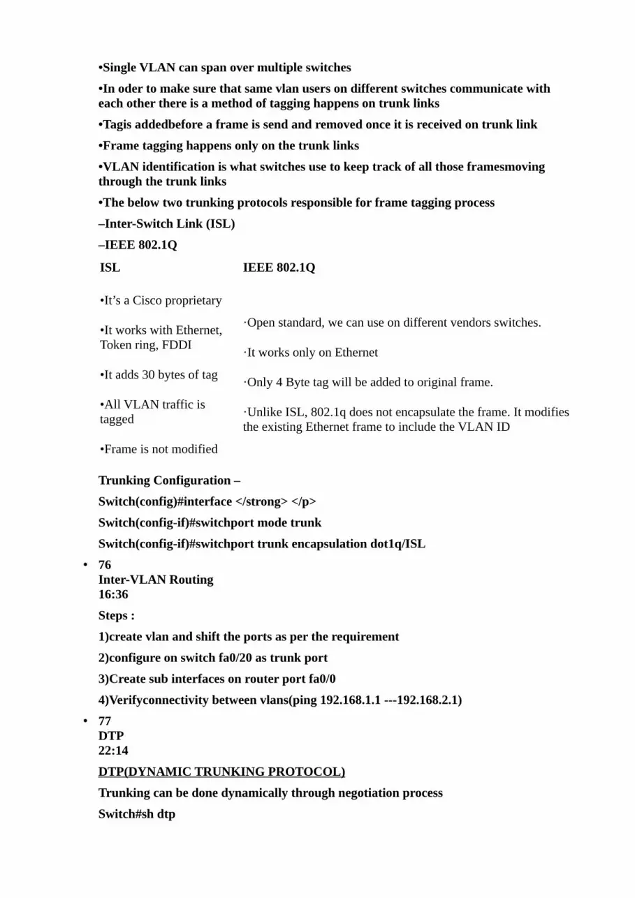
•Single VLAN can span over multiple switches
•In oder to make sure that same vlan users on different switches communicate with each other there is a method of tagging happens on trunk links
•Tagis addedbefore a frame is send and removed once it is received on trunk link
•Frame tagging happens only on the trunk links
•VLAN identification is what switches use to keep track of all those framesmoving through the trunk links
•The below two trunking protocols responsible for frame tagging process
–Inter-Switch Link (ISL)
–IEEE 802.1Q
ISL IEEE 802.1Q
•It’s a Cisco proprietary
•It works with Ethernet, Token ring, FDDI
•It adds 30 bytes of tag
•All VLAN traffic is tagged
•Frame is not modified
·Open standard, we can use on different vendors switches.
·It works only on Ethernet
·Only 4 Byte tag will be added to original frame.
·Unlike ISL, 802.1q does not encapsulate the frame. It modifies the existing Ethernet frame to include the VLAN ID
Trunking Configuration –
Switch(config)#interface </strong> </p>
Switch(config-if)#switchport mode trunk
Switch(config-if)#switchport trunk encapsulation dot1q/ISL
• 76 Inter-VLAN Routing 16:36
Steps :
1)create vlan and shift the ports as per the requirement
2)configure on switch fa0/20 as trunk port
3)Create sub interfaces on router port fa0/0
4)Verifyconnectivity between vlans(ping 192.168.1.1 ---192.168.2.1)
• 77 DTP 22:14
DTP(DYNAMIC TRUNKING PROTOCOL)
Trunking can be done dynamically through negotiation process
Switch#sh dtp

Global DTP information
Sending DTP Hello packets every 30 seconds
Dynamic Trunk timeout is 300 seconds
0 interfaces using DTP
DTP MODES
DESIRABLE:
desires to become trunk ( always want to become trunk)
Sends and reply to DTP messages
default mode on 3550 switches
AUTO:
Only reply to DTP messages ( not send )
Default mode on all switches except 3550
TRUNK
Configuring trunk manually
ACCESS
Configuring access manually
NO-NEGOTIATE
Turn off DTP messages (disable DTP)
• SECTION 17:
Spanning Tree Protocol
• 78 Understanding STP part 1 18:28
SPANNING TREE PROTOCOL
•Spanning Tree Protocol (STP) uses Spanning Tree Algorithm to avoid the Switching loops in layer-2 devices (bridges or switches).
•STP works when multiple switches are used with redundant links avoiding Broadcast Storms, Multiple Frame Copies & Database instability.
•First Developed By DEC
•STP is a open standard (IEEE 802.1D)
•STP is enabled by default on all Cisco Catalyst switches
• 79 Understanding STP part 2 19:49
Root Bridge Election
–The bridge with the Best (Lowest) ID.
–Out of all the switches in the network , one is elected as aroot bridge that becomes the focal point in the network.

·A root bridge is elected to serve as a common reference point for the topology. A switch's bridge ID is composed of two parts:
oBridge priority (2 bytes) - Administratively set; defaults to 32,768 (0x8000)
oMAC address (6 bytes) - One of the switch's MAC addresses
Non-Root bridge
• All Switches other than the Root Bridge are Non-Root Bridges
Root Port Election
·All non-root bridges look the best way to go to root bridge.
·every non-root bridge have one root port
·The port with the lowest path cost to the root bridge is designated as the root port.
·The root path cost noted in a BPDU is incremented by the cost assigned to the port on which it was received.
• Root port with the least cost (Speed) connecting to the root bridge. • The bridge with the Best (Lowest) of forwarding Switch ID. • Lowest Physical Port Number.
Port costs
Bandwidth Cost
4 Mbps 250
10 Mbps 100
16 Mbps 62
45 Mbps 39
100 Mbps 19
155 Mbps 14
622 Mbps6
1 Gbps 4
10 Gbps 2
• 80 Spaning tree portfast 11:48
Portfast is a Cisco-proprietary enhancement to Spanning Tree that helps speed up network convergence. It is for access(user) ports only
·Spanning-tree PortFast causes a port to enter the spanning-tree forwarding state immediately, bypassing the listening and learning states. You can use PortFast on switch ports connected to a single workstation or server to allow those devices to connect to the network immediately, instead of waiting for the port to transition from the listening and learning states to the forwarding state.
·Note :PortFast should be usedonlywhen connecting a single end station to a switch port. If you enable PortFast 0on a port connected to another networking device, such as a switch, you can create network loops.
Portfast on specific ports
(config-if)spanning-tree portfast
to enable on each all access portsglobally
(config)#spanning-tree portfast default
• 81 Spaning tree uplinkfast and backbonefast 13:38
·UplinkFast is for speeding convergence when a direct link to an upstream switch fails. The switch identifies backup ports for the root port. (These are called an uplink group.)
·If the root port fails, one of the ports in the uplink group is unblocked and transitions immediately to forwarding; it bypasses the listening and learning stages.
·BackboneFastis simple to configure and operates by short-circuiting the Max Age timer when needed. Although this function shortens the time a switch waits to detect a root path failure, ports still must go through full-length Forward Delay timer intervals during the Listening and Learning states.
·Where PortFast and Uplink Fast enable immediate transitions, but the BackboneFast can reduce the maximum convergence delay only from 50 to 30 seconds.
• 82 Rapid STP (RSTP) 11:08
• 83 Per Vlan STP (PVSTP) 08:40
• SECTION 18:
IPV6
• 84 Basics of IPV6 08:49
IP Network Addressing
–INTERNET à world’s largest public data network, doubling in size every nine months
–IPv4, defines a 32-bit address - 232 (4,294,967,296) IPv4 addresses available
–The first problem is concerned with the eventual depletion of the IP address space.
–Traditional model of classful addressing does not allow the address space to be used to its maximum potential.
An IPv6 address is represented as eight groups of fourhexadecimaldigits, each group representing 16bits(twooctets). The groups are separated bycolons(:). An example of an IPv6 address is:
2001:0db8:85a3:0000:0000:8a2e:0370:7334

The hexadecimal digits are case-insensitive. The full representation of eight 4-digit groups may be simplified by several techniques, eliminating parts of the representation.
Leading zeroes
Leading zeroes in a group may be omitted.[1]Thus, the example address may be written as:
2001:db8:85a3:0:0:8a2e:370:7334
Groups of zeroes
One or more consecutive groups of zero value may be replaced with a single empty group using two consecutive colons (::).[1]Thus, the example address can be further simplified:
2001:db8:85a3::8a2e:370:7334
• 85 IPV6 address Addressing 06:36
Types of unicast address in IPV6
1) Global unicast
olike public IP ( routable )
ostarts with 2000::/3( the first three bits 001) assigned by IANA
2) unique local
·like private ip( routable)
·any address whichever starts with FCor FD in the first two numbers
Aunique local address(ULA) is anIPv6address in the blockfc00::/7,
3) link local
·default IPV6 address on every ipv6 enabled interface ( non routable )FE80::/10
MULTICAST
·In IPV6 multicast address will be starting with FF( FF00::/8)
Firsttwo numbers will be always FF and remaining can be any (ex:FF
• 86 IPV6 address Types 17:13
An anycast address is an address that is assigned to a set of interfaces that typically belong to different nodes.
• similar to multicast , identify multiple interfaces but sends to only one whichever it finds first.
• the above ( unique local and Global unicast addresses can be used as anycast). • 87
LAB : IPV6 Static address Configuration 10:47

Assigning the IPV6 address
1)Static( Manual )
2)Autoconfiguration
·Statefull (via DHCP)
·Stateless( device getsIPv6 add by including the MAC add)
A single interface can have multilple IPV6 addresses
• 88 IPV6 Address stateless Autoconfiguration 11:08
• 89 IPV6 address stateless Auto configuration LAB 06:24
• 90 IPV6 Static & Default Routing 13:22
IPV6 ROUTING
IPv6 uses the same types of routing protocols as IPv4,but with some slight modifications to account for specific requirements of IPv6.
IPv6 ROUTING TYPES
·Static
·RIPng (RFC 2080)
·IS-IS for IPv6
·OSPFv3 (RFC 2740)
·MP-BGP (RFC 2545/2858)
·EIGRP for IPv6
IPv6 support static and default routing and the working principle ( when to use and how it works is same what we learned in IPV4 routing )
·Syntax for writing static and default routing is similar in IPV6 when compared with IPV4
·As in IPv4, IPv6 has 2 families of routing protocols: IGP and EGP, and still uses the longest-prefix match routingalgorithm
STATIC ROUTING
Static routing with IPv6 is used and configured in the same way as with IPv4. There is an IPv6-specific requirement per RFC 2461: “A router must be able to determine the link-local address of each of its neighboring routers in order to ensure that the target address of a redirect message identifies the neighbor router by its link-local address.” This basically states that it is not recommended to use a global unicast address as a next-hop address with routing.
• 91 IPV6 Routing using RIPng 11:56

RIPng
·Same as IPv4:
·Distance-vector, 15-hops Based on RIPv2
·Updated features for IPv6:
Uses IPv6 for transport
IPv6 prefix, next-hop IPv6 address
Uses the multicast group FF02::9 for RIP updates
• 92 IPV6 Routing using OSPFV3 13:43
OSPFv3
·Based on OSPFv2, with enhancements
oDistributes IPv6 prefixes
oRuns directly over IPv6
• 93 IPV6 Routing using EIGRP 14:57
EIGRP FOR IPv6
·Same EIGRP used with IPv4
·Best of distance vector and link state (advanced distance vector)
·Multiprotocol EIGRP has a protocol-dependent module for IPv4, IPX, AppleTalk, and now IPv6
·Easy to configure and fast convergence
• SECTION 19:
WAN Technologies
• 94 understanding Leased lines 19:20
Dedicated line:-
üPermanent connection for the destination
üUsed for short or long distance
üBandwidth is fixed
üAvailability is 24/7
üCharges are fixed whether used or not.
üUses analog circuits
üAlways same path is used for destination
üExample is Leased Line
• 95 Frame Relay part 1

24:27
FRAME RELAY
Frame Relay is a connection oriented, standard NBMA layer 2 WAN protocol
Connections in Frame Relay are provided by Virtual circuits.
Virtual circuits are multiple logical connections on same physical connection
• 96 Frame Relay part 2 18:23
DLCI (data link connection identifier):-
üAddress of Virtual connections
üFor every VC there is one DLCI number.
üLocally significant and provided by Frame Relay service provider.
LMI (Local management interface):-
LMI allows DTE (router) to send status enquiry messages (keep alive)to DCE(frame relay switch) to exchange status information about the virtual circuits devices for checking the connectivity.
Frame relay LMI types?
1. CISCO (Default)
2. ANSI
3. Q933A
Note:- On Cisco router LMI is auto sense able no need to configure
• 97 LAB : Frame Relay 17:36
R1
interface Serial0/0
no sh
ip address 10.0.0.1 255.0.0.0
encapsulation frame-relay
R2
interface Serial0/0
no sh
ip address 10.0.0.2 255.0.0.0
encapsulation frame-relay
# sh run int s0/0
Sh ip int brief

On FRSW
En
Conf t
frame-relay switching
( to make the router to act as FR SWITCH)
int s0/0
no shutdown
encapsulation frame-relay
frame-relay intf-type dce
frame-relay lmi-type cisco
frame-relay route 100 int s0/1 200
int s0/1
no shutdown
encapsulation frame-relay
frame-relay intf-type dce
frame-relay lmi-type cisco
frame-relay route 200 int s0/0 100
• 98 MEtro ethernet 17:10
A metropolitan-area Ethernet, Ethernet MAN, or metro Ethernetnetwork is a metropolitan area network (MAN) that is based on Ethernet standards.
It is commonly used to connect subscribers to a larger service network or the Internet.
Businesses can also use metropolitan-area Ethernet to connect their own offices to each other.
Advantages:
An Ethernet interface is much less expensive
Ethernet also supports high bandwidths with fine granularity
Ethernet-based access network is that it can be easily connected to the customer network, due to the prevalent use of Ethernet in corporate and, more recently, residential networks.
• 99 VPN 06:46
A virtual private network (VPN) provides connection between two or more private networks across a public network, such as the Internet.
It enables a computer to send and receive data across shared or public networks as if it were directly connected to the private network

while benefiting from the functionality, security and management policies of the private network.
This is done by establishing a virtual point-to-point connection through the use of dedicated connections, encryption, or a combination of the two.
A VPN connection across the Internet is similar to a wide area network (WAN) link between the sites.
From a user perspective, the extended network resources are accessed in the same way as resources available from the private network.
Site-to-site VPN
Site-to-site VPNs Site-to-site VPNs, or intranet VPNs, allow a company to connect �itsremote sites to the corporate backbone securely over a public medium like the Internet instead of requiring more expensive WAN connections like Frame Relay.
A remote-access VPN �Remote access VPNs Remote access VPNs allow remote users like telecommuters to �securely access the corporate network wherever and whenever they need to.
�• 100
DSL cable modems 10:39
Cable Modems
In a modern HFC network, typically 500 to 2,000 active data subscribers
All are connected to a certain cable network segment andall sharing the upstream and downstream Bandwidth.
Hybrid fibre-coaxialor HFC,
is telecommunications industry term for a network that incorporates both optical fiber and coaxial cable to create a broadband network.)
DSL Modems
Digital subscriber line is a technology used by traditional telephone companies to
deliver advanced services (high-speed data and sometimes video) over twisted-pair copper telephone wires
It typically has lower data carrying capacity than HFC networks, and data speeds
can be range limited by line lengths and quality
Symmetrical DSL
The speed for both downstream and upstream connections are equal, or symmetrical.
Asymmetrical DSL
Different transmission speeds occur between two ends of a network—downstream speed is usually faster.