current sensor catalog (en) - 甲神電機
TRANSCRIPT
KOHSHIN - Challenge and innovate for a better tomorrow -
Instruction for use ・・・・・・・・・・・・・・・・・・・・・・・・・・・・・・・・・・・・・・・・・・・・・・・・・・・・・・・・・・・・・・・・・・・・・・・Characteristic ・・・・・・・・・・・・・・・・・・・・・・・・・・・・・・・・・・・・・・・・・・・・・・・・・・・・・・・・・・・・・・・・・・・・・・・・・・・Product marking ・・・・・・・・・・・・・・・・・・・・・・・・・・・・・・・・・・・・・・・・・・・・・・・・・・・・・・・・・・・・・・・・・・・・・・・・・Model list ・・・・・・・・・・・・・・・・・・・・・・・・・・・・・・・・・・・・・・・・・・・・・・・・・・・・・・・・・・・・・・・・・・・・・・・・・・・・・・・
HC-MJ ・・・・・・・・・・・・・・・・・・・・・・・・・・・・・・・・・・・・・・・・・・・・・・・・・・・・・・・・・・・・・・・・・・・・・・・・・・・・・・・・・HC-L ・・・・・・・・・・・・・・・・・・・・・・・・・・・・・・・・・・・・・・・・・・・・・・・・・・・・・・・・・・・・・・・・・・・・・・・・・・・・・・・・・・・HC-ML ・・・・・・・・・・・・・・・・・・・・・・・・・・・・・・・・・・・・・・・・・・・・・・・・・・・・・・・・・・・・・・・・・・・・・・・・・・・・・・・・・HC-MN ・・・・・・・・・・・・・・・・・・・・・・・・・・・・・・・・・・・・・・・・・・・・・・・・・・・・・・・・・・・・・・・・・・・・・・・・・・・・・・・・・HC-MSL ・・・・・・・・・・・・・・・・・・・・・・・・・・・・・・・・・・・・・・・・・・・・・・・・・・・・・・・・・・・・・・・・・・・・・・・・・・・・・・・・HC-MSN ・・・・・・・・・・・・・・・・・・・・・・・・・・・・・・・・・・・・・・・・・・・・・・・・・・・・・・・・・・・・・・・・・・・・・・・・・・・・・・・・HC-TF ・・・・・・・・・・・・・・・・・・・・・・・・・・・・・・・・・・・・・・・・・・・・・・・・・・・・・・・・・・・・・・・・・・・・・・・・・・・・・・・・・HC-TTA ・・・・・・・・・・・・・・・・・・・・・・・・・・・・・・・・・・・・・・・・・・・・・・・・・・・・・・・・・・・・・・・・・・・・・・・・・・・・・・・・HC-TTB ・・・・・・・・・・・・・・・・・・・・・・・・・・・・・・・・・・・・・・・・・・・・・・・・・・・・・・・・・・・・・・・・・・・・・・・・・・・・・・・・HC-SL ・・・・・・・・・・・・・・・・・・・・・・・・・・・・・・・・・・・・・・・・・・・・・・・・・・・・・・・・・・・・・・・・・・・・・・・・・・・・・・・・・HC-SN ・・・・・・・・・・・・・・・・・・・・・・・・・・・・・・・・・・・・・・・・・・・・・・・・・・・・・・・・・・・・・・・・・・・・・・・・・・・・・・・・・HC-TN ・・・・・・・・・・・・・・・・・・・・・・・・・・・・・・・・・・・・・・・・・・・・・・・・・・・・・・・・・・・・・・・・・・・・・・・・・・・・・・・・・HC-TS ・・・・・・・・・・・・・・・・・・・・・・・・・・・・・・・・・・・・・・・・・・・・・・・・・・・・・・・・・・・・・・・・・・・・・・・・・・・・・・・・・HC-U ・・・・・・・・・・・・・・・・・・・・・・・・・・・・・・・・・・・・・・・・・・・・・・・・・・・・・・・・・・・・・・・・・・・・・・・・・・・・・・・・・・・HC-W ・・・・・・・・・・・・・・・・・・・・・・・・・・・・・・・・・・・・・・・・・・・・・・・・・・・・・・・・・・・・・・・・・・・・・・・・・・・・・・・・・・・HC-WT ・・・・・・・・・・・・・・・・・・・・・・・・・・・・・・・・・・・・・・・・・・・・・・・・・・・・・・・・・・・・・・・・・・・・・・・・・・・・・・・・・HC-VT ・・・・・・・・・・・・・・・・・・・・・・・・・・・・・・・・・・・・・・・・・・・・・・・・・・・・・・・・・・・・・・・・・・・・・・・・・・・・・・・・・
HC-PZ ・・・・・・・・・・・・・・・・・・・・・・・・・・・・・・・・・・・・・・・・・・・・・・・・・・・・・・・・・・・・・・・・・・・・・・・・・・・・・・・・・HC-PT ・・・・・・・・・・・・・・・・・・・・・・・・・・・・・・・・・・・・・・・・・・・・・・・・・・・・・・・・・・・・・・・・・・・・・・・・・・・・・・・・・HC-PTW ・・・・・・・・・・・・・・・・・・・・・・・・・・・・・・・・・・・・・・・・・・・・・・・・・・・・・・・・・・・・・・・・・・・・・・・・・・・・・・・・HC-PG ・・・・・・・・・・・・・・・・・・・・・・・・・・・・・・・・・・・・・・・・・・・・・・・・・・・・・・・・・・・・・・・・・・・・・・・・・・・・・・・・・HC-PJ ・・・・・・・・・・・・・・・・・・・・・・・・・・・・・・・・・・・・・・・・・・・・・・・・・・・・・・・・・・・・・・・・・・・・・・・・・・・・・・・・・HC-PVT ・・・・・・・・・・・・・・・・・・・・・・・・・・・・・・・・・・・・・・・・・・・・・・・・・・・・・・・・・・・・・・・・・・・・・・・・・・・・・・・・HC-PSG ・・・・・・・・・・・・・・・・・・・・・・・・・・・・・・・・・・・・・・・・・・・・・・・・・・・・・・・・・・・・・・・・・・・・・・・・・・・・・・・・HC-PSE ・・・・・・・・・・・・・・・・・・・・・・・・・・・・・・・・・・・・・・・・・・・・・・・・・・・・・・・・・・・・・・・・・・・・・・・・・・・・・・・・HC-PD ・・・・・・・・・・・・・・・・・・・・・・・・・・・・・・・・・・・・・・・・・・・・・・・・・・・・・・・・・・・・・・・・・・・・・・・・・・・・・・・・・HC-PDN ・・・・・・・・・・・・・・・・・・・・・・・・・・・・・・・・・・・・・・・・・・・・・・・・・・・・・・・・・・・・・・・・・・・・・・・・・・・・・・・・HC-PDG ・・・・・・・・・・・・・・・・・・・・・・・・・・・・・・・・・・・・・・・・・・・・・・・・・・・・・・・・・・・・・・・・・・・・・・・・・・・・・・・・HC-PDK ・・・・・・・・・・・・・・・・・・・・・・・・・・・・・・・・・・・・・・・・・・・・・・・・・・・・・・・・・・・・・・・・・・・・・・・・・・・・・・・・HC-PL ・・・・・・・・・・・・・・・・・・・・・・・・・・・・・・・・・・・・・・・・・・・・・・・・・・・・・・・・・・・・・・・・・・・・・・・・・・・・・・・・・HC-PFG ・・・・・・・・・・・・・・・・・・・・・・・・・・・・・・・・・・・・・・・・・・・・・・・・・・・・・・・・・・・・・・・・・・・・・・・・・・・・・・・・HC-PRC ・・・・・・・・・・・・・・・・・・・・・・・・・・・・・・・・・・・・・・・・・・・・・・・・・・・・・・・・・・・・・・・・・・・・・・・・・・・・・・・・HC-PRD ・・・・・・・・・・・・・・・・・・・・・・・・・・・・・・・・・・・・・・・・・・・・・・・・・・・・・・・・・・・・・・・・・・・・・・・・・・・・・・・・
HD-TS ・・・・・・・・・・・・・・・・・・・・・・・・・・・・・・・・・・・・・・・・・・・・・・・・・・・・・・・・・・・・・・・・・・・・・・・・・・・・・・・・・
HP-PU ・・・・・・・・・・・・・・・・・・・・・・・・・・・・・・・・・・・・・・・・・・・・・・・・・・・・・・・・・・・・・・・・・・・・・・・・・・・・・・・・・
2-15
1-11-21-41-5
2-12-32-52-72-92-112-13
3-5
2-172-192-212-232-252-272-292-312-33
3-13-3
3-29
3-73-93-113-133-153-173-193-213-233-253-27
3-31
4-1
5-1
1 Introduce
2 Hall Current Sensor HC series <Bolt on> - Hall element / Open-loop type -
3 Hall Current Sensor HC series <PCB mounting> - Hall element / Open-loop type -
Contents
4 Hall Current Sensor HD series - Hall element / Open-loop / Digital output type -
5 Hall Current Sensor HP series - Hall IC / Open-loop type -
HS-PHA ・・・・・・・・・・・・・・・・・・・・・・・・・・・・・・・・・・・・・・・・・・・・・・・・・・・・・・・・・・・・・・・・・・・・・・・・・・・・・・・・HS-PHB ・・・・・・・・・・・・・・・・・・・・・・・・・・・・・・・・・・・・・・・・・・・・・・・・・・・・・・・・・・・・・・・・・・・・・・・・・・・・・・・・HS-PKF ・・・・・・・・・・・・・・・・・・・・・・・・・・・・・・・・・・・・・・・・・・・・・・・・・・・・・・・・・・・・・・・・・・・・・・・・・・・・・・・・HS-P ・・・・・・・・・・・・・・・・・・・・・・・・・・・・・・・・・・・・・・・・・・・・・・・・・・・・・・・・・・・・・・・・・・・・・・・・・・・・・・・・・・・HS-PKD ・・・・・・・・・・・・・・・・・・・・・・・・・・・・・・・・・・・・・・・・・・・・・・・・・・・・・・・・・・・・・・・・・・・・・・・・・・・・・・・・HS-PTA ・・・・・・・・・・・・・・・・・・・・・・・・・・・・・・・・・・・・・・・・・・・・・・・・・・・・・・・・・・・・・・・・・・・・・・・・・・・・・・・・HS-U ・・・・・・・・・・・・・・・・・・・・・・・・・・・・・・・・・・・・・・・・・・・・・・・・・・・・・・・・・・・・・・・・・・・・・・・・・・・・・・・・・・・HS-UFB ・・・・・・・・・・・・・・・・・・・・・・・・・・・・・・・・・・・・・・・・・・・・・・・・・・・・・・・・・・・・・・・・・・・・・・・・・・・・・・・・HS-UD ・・・・・・・・・・・・・・・・・・・・・・・・・・・・・・・・・・・・・・・・・・・・・・・・・・・・・・・・・・・・・・・・・・・・・・・・・・・・・・・・・HS-K ・・・・・・・・・・・・・・・・・・・・・・・・・・・・・・・・・・・・・・・・・・・・・・・・・・・・・・・・・・・・・・・・・・・・・・・・・・・・・・・・・・・
HC-AK ・・・・・・・・・・・・・・・・・・・・・・・・・・・・・・・・・・・・・・・・・・・・・・・・・・・・・・・・・・・・・・・・・・・・・・・・・・・・・・・・・HC-ASA ・・・・・・・・・・・・・・・・・・・・・・・・・・・・・・・・・・・・・・・・・・・・・・・・・・・・・・・・・・・・・・・・・・・・・・・・・・・・・・・・HC-ASB ・・・・・・・・・・・・・・・・・・・・・・・・・・・・・・・・・・・・・・・・・・・・・・・・・・・・・・・・・・・・・・・・・・・・・・・・・・・・・・・・
HF-A ・・・・・・・・・・・・・・・・・・・・・・・・・・・・・・・・・・・・・・・・・・・・・・・・・・・・・・・・・・・・・・・・・・・・・・・・・・・・・・・・・・・
HM-A ・・・・・・・・・・・・・・・・・・・・・・・・・・・・・・・・・・・・・・・・・・・・・・・・・・・・・・・・・・・・・・・・・・・・・・・・・・・・・・・・・・・HM-D ・・・・・・・・・・・・・・・・・・・・・・・・・・・・・・・・・・・・・・・・・・・・・・・・・・・・・・・・・・・・・・・・・・・・・・・・・・・・・・・・・・・HM-Z ・・・・・・・・・・・・・・・・・・・・・・・・・・・・・・・・・・・・・・・・・・・・・・・・・・・・・・・・・・・・・・・・・・・・・・・・・・・・・・・・・・・
HR-PA ・・・・・・・・・・・・・・・・・・・・・・・・・・・・・・・・・・・・・・・・・・・・・・・・・・・・・・・・・・・・・・・・・・・・・・・・・・・・・・・・・
HA-06RS-C ・・・・・・・・・・・・・・・・・・・・・・・・・・・・・・・・・・・・・・・・・・・・・・・・・・・・・・・・・・・・・・・・・・・・・・・・・・・・・HA-06RP-C ・・・・・・・・・・・・・・・・・・・・・・・・・・・・・・・・・・・・・・・・・・・・・・・・・・・・・・・・・・・・・・・・・・・・・・・・・・・・・HA-12SS-C ・・・・・・・・・・・・・・・・・・・・・・・・・・・・・・・・・・・・・・・・・・・・・・・・・・・・・・・・・・・・・・・・・・・・・・・・・・・・・HA-12SP-CK ・・・・・・・・・・・・・・・・・・・・・・・・・・・・・・・・・・・・・・・・・・・・・・・・・・・・・・・・・・・・・・・・・・・・・・・・・・・・HA-12SP-KM ・・・・・・・・・・・・・・・・・・・・・・・・・・・・・・・・・・・・・・・・・・・・・・・・・・・・・・・・・・・・・・・・・・・・・・・・・・・・HA-16SP-CK ・・・・・・・・・・・・・・・・・・・・・・・・・・・・・・・・・・・・・・・・・・・・・・・・・・・・・・・・・・・・・・・・・・・・・・・・・・・・HA-16SP-KM ・・・・・・・・・・・・・・・・・・・・・・・・・・・・・・・・・・・・・・・・・・・・・・・・・・・・・・・・・・・・・・・・・・・・・・・・・・・・HA-24RP-CK ・・・・・・・・・・・・・・・・・・・・・・・・・・・・・・・・・・・・・・・・・・・・・・・・・・・・・・・・・・・・・・・・・・・・・・・・・・・・HA-24RP-KM ・・・・・・・・・・・・・・・・・・・・・・・・・・・・・・・・・・・・・・・・・・・・・・・・・・・・・・・・・・・・・・・・・・・・・・・・・・・・HA-36RP-CK ・・・・・・・・・・・・・・・・・・・・・・・・・・・・・・・・・・・・・・・・・・・・・・・・・・・・・・・・・・・・・・・・・・・・・・・・・・・・HA-36RP-KM ・・・・・・・・・・・・・・・・・・・・・・・・・・・・・・・・・・・・・・・・・・・・・・・・・・・・・・・・・・・・・・・・・・・・・・・・・・・・HA-A ・・・・・・・・・・・・・・・・・・・・・・・・・・・・・・・・・・・・・・・・・・・・・・・・・・・・・・・・・・・・・・・・・・・・・・・・・・・・・・・・・・・HA-B, C ・・・・・・・・・・・・・・・・・・・・・・・・・・・・・・・・・・・・・・・・・・・・・・・・・・・・・・・・・・・・・・・・・・・・・・・・・・・・・・・・HA-BV, CV ・・・・・・・・・・・・・・・・・・・・・・・・・・・・・・・・・・・・・・・・・・・・・・・・・・・・・・・・・・・・・・・・・・・・・・・・・・・・・・
HB-10RS ・・・・・・・・・・・・・・・・・・・・・・・・・・・・・・・・・・・・・・・・・・・・・・・・・・・・・・・・・・・・・・・・・・・・・・・・・・・・・・ 12-1
6-15
6-16-36-56-76-96-116-13
10-1
11-2311-2511-27
6-176-19
7-17-3
8-1
9-1
7-5
9-39-5
11-111-311-5
11-1711-1911-21
11-711-911-1111-1311-15
6 Hall Current Sensor HS series - Hall element / Closed-loop type -
8 Flux Gate Current Sensor HF series - Closed-loop type -
9 Flux Gate Current Sensor HM series - Closed-loop type -
11 Clamp-Type Alternating Current Sensor HA series
7 Hall Current Sensor HC series <For automotive> - Open-loop type -
Contents
10 MR Type Current Sensor HR series - Closed-loop type -
12 Clamp-Type Direct Current Sensor HB series
HC series, HD series and HP series current sensors1)
2)
3)
4)
HS series, HF series, HM series and HR series current sensors1)
2)
3)
4)
5)
6)
Common instruction for all series1)
2)
3)
4)
5)
6)
7)
Usage limitations for current sensors
Export limitations for Foreign Exchange and Foreign Trade Law
Concern for safety
Do not store the sensors in hot or humid environments.
The products listed in our catalog are intended for use in general equipments (business machines, measuring equipments,industrial equipments, and home appliances, etc.), not for use under circumstances which may involve human life. Theyare not intended for use in special applications wherein high quality and reliability are required and the failure ormalfunction of the product may cause danger to human body, such as nuclear power stations, transportation apparatuses(automobile, trains, ships, etc.), medical equipments for life support, or safety systems. If you need to use any of ourproducts in one of the above mentioned special applications, please notify us or our agent beforehand for assistance.
A product designated as 'strategic item' is controlled under the Foreign Exchange and Foreign Trade Law and WMDcatchall and requires permission from the Japanese Government prior to export. If you are unsure whether a product iscontrolled, please contact us or our agent for assistance.
While we constantly strive to improve quality and reliability and use materials compliant with safety guidelines, eventhough unlikely, current sensors can sometimes fail or malfunction. We caution the designer to respect all aspects ofsafety in order to protect life, prevent injury and prevent property damage should our product accidentally fail or
In addition to making the control wiring as short as possible to protect it from outside noise, use twisted wire orshielding wire.
Connect a capacitor of approximately 0.1μF between the control power supply and GND.
Attach PCB mounting type current sensors firmly to the installation board so that they are not separated from it bymore than 0.5mm.Furthermore, perform the soldering under the following conditions.
<Pb-free>
Flow solder: Solder temperature approx. 250 degrees C, within 5 secondsHand solder: Solder temperature approx. 280~300 degrees C, within 3 secondsFlow solder: Solder temperature approx. 260 degrees C, within 5 secondsHand solder: Solder temperature approx. 340 degrees C, within 4 seconds
The current sensor may be corroded under corrosive gas atmosphere. Make sufficient confirmation under actualservice environmental conditions before use.
If static electricity or surge voltage is applied, the residual voltage may be increased.
When the frequency of the input current is high, the core generates an unusual amount of heat due to core loss, andthis heat may damage the internal circuits. The amount of heat generated is influenced by the frequency and amountof the input current and differs depending on the type of sensor, so check the performance on the actual machine.We are able to produce heat generation countermeasure products which use different core materials. Please consultus for the details.
Since the output varies depending on the size of the load resistance, use with the specified resistance. (The size of theload resistance can be specified by the user.)
The signal output driver of the HD Series uses a C-MOS IC. Be careful when handling and avoid direct contact.
Output terminal pins 9 and 10 of the HD Series are analog output terminals for small signal input.Do not connect them to the lead wire or they will be affected by the data and clocking signal.
Use a resistance which has good accuracy and temperature characteristics for the load resistance which is connectedto current output type sensors.
Prepare a control power supply the capacity of which is at least twice the rated output current.
If the connector is inserted or removed while the control power is being applied, residual magnetism may occur in thecore due to the terminal contact timing becoming out of sequence, and the residual voltage may be affected. Inaddition to turning the power supply on and off while the connector is connected, ensure that the + side and - side ofthe power supply are matched.
In inputting current above rating, note that some models specify energization time.If the product is used in excess of this time, internal circuit may fail.
When current exceeding saturation current is input, magnet compensation will not work, and residual output will causedisplacement, therefore, use the product always at current below saturation current.
Demagnetize the sensors without applying electric power.
Erroneous connection of the control terminals will cause the internal circuits to be instantaneously destroyed. Paysufficient attention to the connection.
Instruction for use
1-1
1)
2)
3)
4)
5)
6)
7)
8)
9)
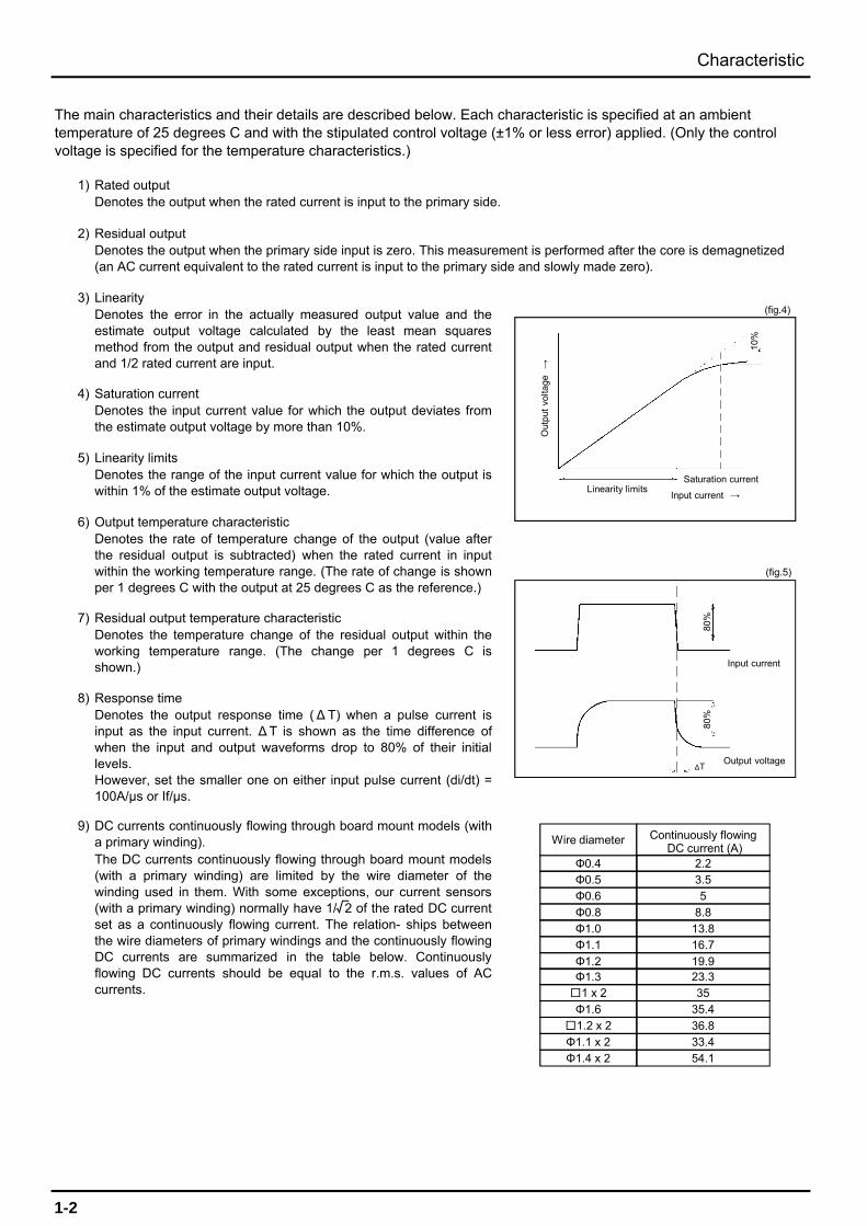
Denotes the output response time (∆ T) when a pulse current isinput as the input current. ∆T is shown as the time difference ofwhen the input and output waveforms drop to 80% of their initiallevels.However, set the smaller one on either input pulse current (di/dt) =100A/μs or If/μs.
Response time
Saturation current
Output temperature characteristic
The main characteristics and their details are described below. Each characteristic is specified at an ambienttemperature of 25 degrees C and with the stipulated control voltage (±1% or less error) applied. (Only the controlvoltage is specified for the temperature characteristics.)
Rated outputDenotes the output when the rated current is input to the primary side.
Residual outputDenotes the output when the primary side input is zero. This measurement is performed after the core is demagnetized(an AC current equivalent to the rated current is input to the primary side and slowly made zero).
LinearityDenotes the error in the actually measured output value and theestimate output voltage calculated by the least mean squaresmethod from the output and residual output when the rated currentand 1/2 rated current are input.
Denotes the temperature change of the residual output within theworking temperature range. (The change per 1 degrees C isshown.)
DC currents continuously flowing through board mount models (witha primary winding).The DC currents continuously flowing through board mount models(with a primary winding) are limited by the wire diameter of thewinding used in them. With some exceptions, our current sensors(with a primary winding) normally have 1/ 2 of the rated DC currentset as a continuously flowing current. The relation- ships betweenthe wire diameters of primary windings and the continuously flowingDC currents are summarized in the table below. Continuouslyflowing DC currents should be equal to the r.m.s. values of ACcurrents.
Residual output temperature characteristic
Denotes the input current value for which the output deviates fromthe estimate output voltage by more than 10%.
Linearity limitsDenotes the range of the input current value for which the output iswithin 1% of the estimate output voltage.
Denotes the rate of temperature change of the output (value afterthe residual output is subtracted) when the rated current in inputwithin the working temperature range. (The rate of change is shownper 1 degrees C with the output at 25 degrees C as the reference.)
(fig.4)
Linearity limits
Out
put
volta
ge→
Input current →
10%
Saturation current
(fig.5)
80%
80%
Input current
Output voltage∆T
Characteristic
1-2
Φ0.4
Wire diameter Continuously flowingDC current (A)
2.2Φ0.5 3.5Φ0.6 5
Φ0.8 8.8Φ1.0 13.8Φ1.1 16.7
Φ1.2 19.9Φ1.3 23.31 x 2 35Φ1.6 35.4
1.2 x 2 36.8Φ1.1 x 2 33.4Φ1.4 x 2 54.1
√

10)
11)①
②
Testing method
Noise testing methodEffects of dv/dtWaveform of the output voltage when the voltage pulse of dv/dt=300V/μs is applied.
Testing method
Effects of impulse noiseWaveform of the output voltage when the impulse noise of rise time 1ns, pulse with 1μs, and voltage 2,000V isapplied.
Characteristics of core
Input current frequency (kHz)
0 2 4 6 8 10 12 14 160
30
40
50
10
20
Relationship between input current frequency and core temperature increase
18 20
80
90
100
60
70
Cor
e te
mpe
ratu
re i
ncre
ase
(deg
ree)
Silicon steel plate t=0.23
Silicon steel plate t=0.1
Amorphous t=0.025
Ferrite
Input current = 106A(r.m.s), Sine waveMaterials: HC-TN series (gap=1.7)
Characteristic
Primary conductor
+
GND
-
Control power supply
Voltage pulse
【Bolt-on type】 【PCB-mounting type】
Primary conductor
Steel plate
Control power supply
Impulse noise
Impulse noise
Input terminal
+
GND-
Control power supply
+
GND-
Feedthrough current (A)
Saturation curve of the core (silicon steel plate)
0 100 200 300 400 500 600 700 800
Mag
netic
flu
x de
nsity
(T
)
0
0.3
0.4
0.5
0.1
0.2
Materials: HC-TN series Gap = 1.7
Gap = 2.5
Gap = 3.5
Feedthrough current (A)
0 100 200 300 400 500 600 700 8000
0.3
0.4
0.5
0.1
0.2
Saturation curve of the core
Mag
netic
flu
x de
nsity
(T
)
Materials: HC-TN series (gap=1.7) Silicon steel plate
Amorphous
Ferrite
1-3
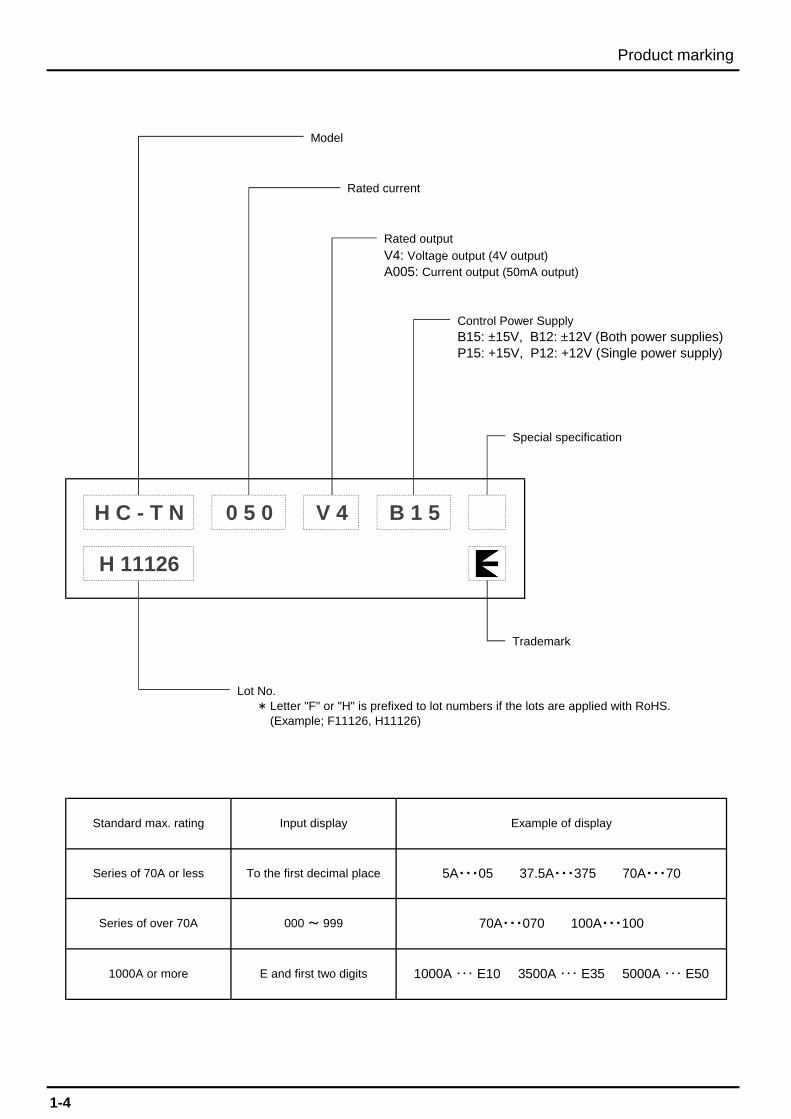
B15: ±15V, B12: ±12V (Both power supplies)
Model
Rated output
V4: Voltage output (4V output) A005: Current output (50mA output)
Control Power Supply
Rated current
Lot No.*
Example of display
5A・・・05 37.5A・・・375 70A・・・70
H C - T N V 4 B 1 50 5 0
70A・・・070 100A・・・100
1000A ・・・ E10 3500A ・・・ E35 5000A ・・・ E50
Special specification
P15: +15V, P12: +12V (Single power supply)
H 11126
1000A or more
Trademark
Standard max. rating
Series of 70A or less
Series of over 70A
Input display
To the first decimal place
000 ~ 999
E and first two digits
Letter "F" or "H" is prefixed to lot numbers if the lots are applied with RoHS.(Example; F11126, H11126)
Product marking
1-4
HC-PRD ±15, ±12 +5 Built-in Bus-bar
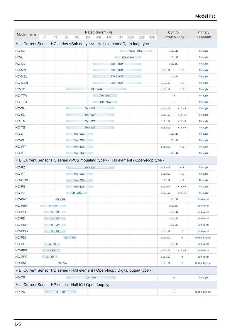
Hall Current Sensor HD series - Hall element / Open-loop / Digital output type -
HD-TS +5 Through
Hall Current Sensor HP series - Hall IC / Open-loop type -
HP-PU +5 Built-in Bus-bar
HC-PFG ±15, ±12 +12, +5 Built-in coil
HC-PRC ±15, ±12 +5 Built-in coil
HC-PDK ±15, ±12 +5 Built-in Bus-bar
HC-PL ±15, ±12 Built-in coil
HC-PDN ±15, ±12 Built-in coil
HC-PDG ±15, ±12 +5 Built-in coil
HC-PSE ±15, ±12 Built-in coil
HC-PD ±15, ±12 Built-in coil
HC-PVT ±15, ±12 Built-in coil
HC-PSG ±15, ±12 Built-in coil
HC-PG ±15, ±12 +12, +5 Through
HC-PJ ±15, ±12 +12, +5 Through
HC-PT ±15, ±12 +12 Through
HC-PTW ±15, ±12 +12 Through
HC-VT ±15, ±12 Through
Hall Current Sensor HC series <PCB mounting type> - Hall element / Open-loop type -
HC-PZ ±15, ±12 +12 Through
HC-W ±15, ±12 Through
HC-WT ±15, ±12 +12 Through
HC-TS ±15, ±12 +12, +5 Through
HC-U ±15, ±12 Through
HC-SN ±15, ±12 +12, +5 Through
HC-TN ±15, ±12 +12, +5 Through
HC-TTB +5 Through
HC-SL ±15, ±12 +12, +5 Through
HC-TF ±15, ±12 +12 Through
HC-TTA +5 Through
HC-MSL ±15, ±12 Through
HC-MSN ±15, ±12 +12 Through
HC-ML ±15, ±12 Through
HC-MN ±15, ±12 +12 Through
HC-MJ ±15, ±12 Through
HC-L ±15, ±12 Through
600 1000 2000 3000 4000
Hall Current Sensor HC series <Bolt on type> - Hall element / Open-loop type -
Model nameRated current (A) Control
power supplyPrimary
conductor5 10 50 100 200 400
1000A ~ 4000A
800A ~ 3000A
300A ~ 3000A
50A ~ 1600A
300A ~ 900A
300A ~ 3000A
300A ~ 900A
50A ~ 800A
50A ~ 300A
50A ~ 800A
50A ~ 200A
10A ~ 50A
1A ~ 50A
5A ~ 50A
5A ~ 50A
40A ~ 100A
5A ~ 30A
3A ~ 30A
3A ~ 20A
25A ~ 50A
300A ~ 3000A
300A ~ 3000A
50A ~ 800A
50A ~ 800A
50A ~ 800A
50A ~ 300A
50A ~ 300A
50A ~ 300A
50A ~ 300A
50A ~ 300A
50A ~ 300A
5A ~ 50A
5A ~ 50A
Model list
1-5
50A ~ 800A
5A ~ 100A
HA-12SS-C
HA-12SP-CK
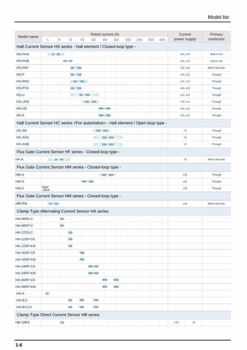
Clamp-Type Direct Current Sensor HB series
HB-10RS ±12 +5
HA-16SP-CK
HA-16SP-KM
HA-24RP-CK
HA-B,C
HA-BV,CV
HA-24RP-KM
HA-36RP-CK
HA-36RP-KM
HA-A
HA-12SP-KM
±15 Built-in Bus-bar
Flux Gate Current Sensor HM series - Closed-loop type -
HM-Z ±15 Through
Clamp-Type Alternating Current Sensor HA series
Flux Gate Current Sensor HM series - Closed-loop type -
HR-PA
HA-06RS-C
HA-06RP-C
HM-D ±15 Through
HM-A ±15 Through
HC-ASB +5 Through
Flux Gate Current Sensor HF series - Closed-loop type -
HF-A +5 Built-in Bus-bar
HS-K ±15, ±12 Through
Hall Current Sensor HC series <For automotive> - Hall element / Open-loop type -
HC-AK +5 Through
HC-ASA +5 Through
HS-UFB ±15, ±12 Through
HS-UD ±15, ±12 Through
HS-PTA ±15, ±12 Through
HS-U ±15, ±12 Through
HS-P ±15, ±12 Through
HS-PKD ±15, ±12 Through
HS-PHB ±15, ±12 Built-in coil
HS-PKF ±15, ±12 Built-in Bus-bar
Hall Current Sensor HS series - Hall element / Closed-loop type -
HS-PHA ±15, ±12 Built-in coil
2000 3000 400050 100 200 400 600 1000Model name
Rated current (A) Controlpower supply
Primaryconductor5 10
5A ~ 30A
35A ~ 50A
50A ~ 100A
50A ~ 100A
50A ~ 150A
50A ~ 100A
50A ~ 300A
100A ~ 300A
300A ~ 500A
300A ~ 500A
200A ~ 500A
6A ~ 50A
Model list
1-6
5A ~ 10A
200A ~ 800A
5A
100A 250A
100A 250A
50A
50A
100A
50A
30A
30A
50A
400A 600A
400A 600A
100A
50A
250A
250A
200A
200A
300A ~ 600A
100A ~ 200A
300mA600mA
15A
200A ~ 800A
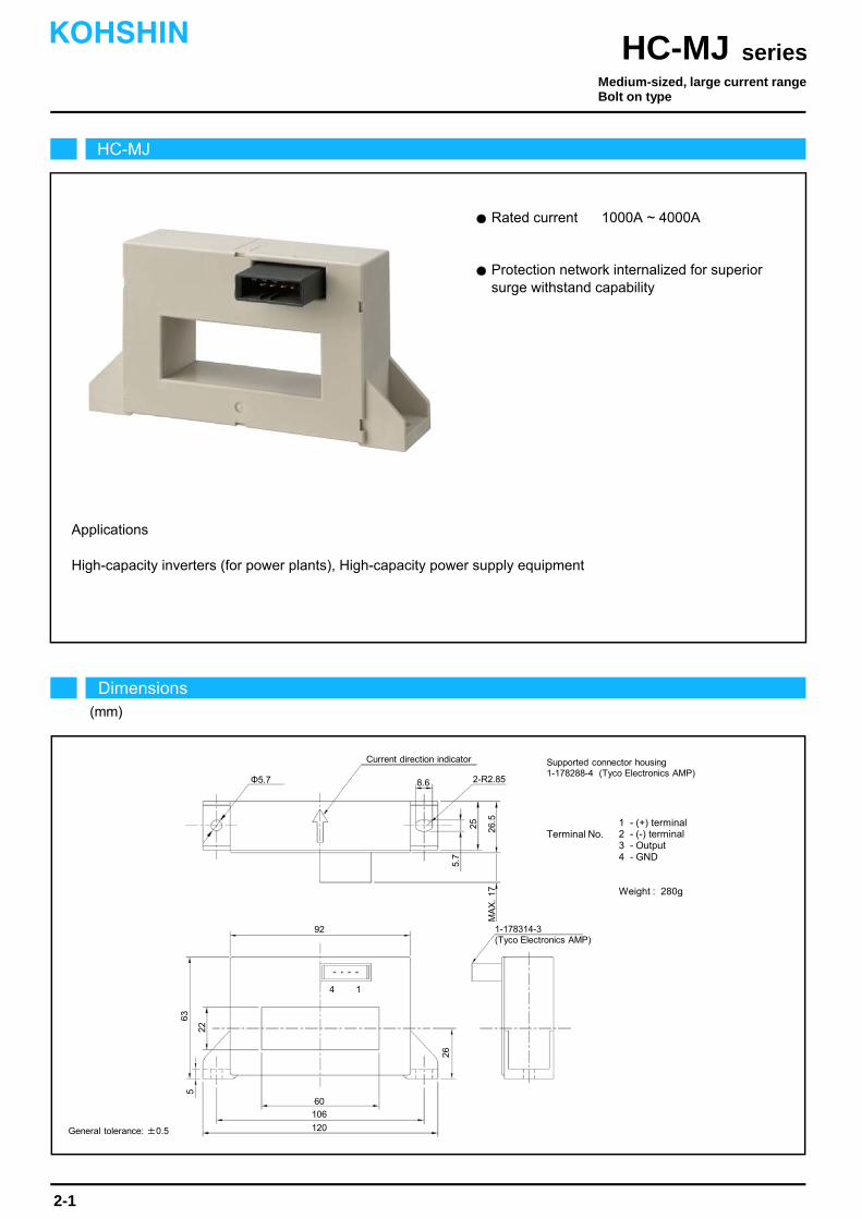
Protection network internalized for superior surge withstand capability.
Rated current 1000A ~ 4000A
Applications
High-capacity inverters (for power plants), High-capacity power supply equipment
HC-MJ
Dimensions(mm)
Medium-sized, large current rangeBolt on type
seriesHC-MJKOHSHIN
2-1
4
92
106
60
63
26
26.5
225
8.6
Terminal No.1 - (+) terminal2 - (-) terminal3 - Output4 - GND
Weight : 280g
General tolerance: ±0.5
Supported connector housing1-178288-4 (Tyco Electronics AMP)
1
5.7
MA
X.
17
120
25
2-R2.85
Current direction indicator
Φ5.7
1-178314-3(Tyco Electronics AMP)

The indicated rated output is the one when no load is applied.
The indicated residual output is the one after the core hysteresis is removed.Note2)
Note1)
Characteristics chart HC-MJE10V4B15 5μs/div. Time base
HC-MJE10V4B15Type
Rated current
Saturation current
Linearity limits
Rated output
Residual output
Output linearity
Response time
Response performance
Hysteresis voltage range
Consumption current
Residual output Temp. Coef.
Output Temp. Coef.
Control power supply
Operating Temp.
Storage Temp.
Dielectric withstand voltage
Insulation resistance
HC-MJE20V4B15 HC-MJE30V4B15 HC-MJE40V4B15
±1000A
±2400A
0~±2000A
±2000A
±2400A
0~±2000A
±3000A
±4800A
0~±4000A
±4000A
±4800A
0~±4000A
±4V±1.5%
Within ±30mV
Within ±1%
Within 10μs (at di/dt=100A/μs)
Within 10%
Within 30mV
Within ±0.1%/
Within ±1.5mV/
±15V±5%
Within 50mA
-40~+80
-40~+85
2500V AC 50/60Hz 1minute
Not less than 500MΩ 500V DC
[ If ]
[ Is ]
[ Vh ]
[ Vo ]
seriesHC-MJ
Output voltage0.2V/div.
Output voltage100mV/div.
Input voltage150V/div.
Input current50A/div.
Ta=25
Output voltage0.1V/div.
Note: The marks " " means 0V or 0A.
Specification Ta=25
2-2
Pulse current response characteristic
Noise characteristics (Effects of impulse noise)
Noise characteristics (Effects of dV/dt)
Input/output characteristics
HC-MJE10V4B15
HC-MJE40V4B15
0
-4000 -1000 -2000 -3000 0
4000 30002000 1000
5
10
15
-5
-10
-15
Out
put v
olta
ge(V
)
Input current(A)
HC-MJE20V4B15
HC-MJE30V4B15
KOHSHIN

Superior noise-resistance
Rated current 800A ~ 3000A
Applications
High-capacity inverters (for power plants), High-capacity power supply equipment
9 7 5 3 1
10 8 6 4 2
113
84
170
150
27
21
78
4-Φ6
102
37
8
MAX. 3 4
25
1
M4Shield
PS-10PE-D4T1-LP1 (JAE)129
Current direction indicator
2-R3
Φ6 10
HC-L
Dimensions(mm)
Medium-sized, large current rangeBolt on type
seriesHC-LKOHSHIN
2-3
Terminal No. 1, 2 - (+) terminal3, 4, 8 - GND5, 6 - (-) terminal7 - Not used9, 10 - Output
Weight : 660g
General tolerance: ±0.5
Supported connector housingPS-10SEN-D4P1-1 (JAE)PS-D4C10 (JAE)

The indicated rated output is the one when no load is applied.
The indicated residual output is the one after the core hysteresis is removed.Note2)
Note1)
Characteristics chart HC-LE20V4B15 Time base: 5μs/div.
HC-L800V4B15Type
Rated current
Saturation current
Linearity limits
Rated output
Residual output
Output linearity
Response time
Response performance
Hysteresis voltage range
Consumption current
Residual output Temp. Coef.
Output Temp. Coef.
Control power supply
Operating Temp.
Storage Temp.
Dielectric withstand voltage
Insulation resistance
HC-LE10V4B15 HC-LE20V4B15 HC-LE30V4B15
±800A
±1200A
0~±1000A
±1000A
±2500A
0~±2000A
±2000A
±4000A
0~±3500A
±3000A
±5000A
0~±4000A
±4V±1%
Within ±30mV
Within ±1%
Within 10μs (at di/dt=100A/μs)
Within 10%
Within 30mV
Within ±0.05%/
Within ±2mV/
±15V±5%
Within 50mA
-10~+80
-15~+85
2500V AC 50/60Hz 1minute
Not less than 500MΩ 500V DC
[ If ]
[ Is ]
[ Vh ]
[ Vo ]
seriesHC-L
Output voltage0.1V/div.
Output voltage50mV/div.
Input voltage150V/div.
Input current50A/div.
Ta=25
Output voltage0.2V/div.
Note: The marks " " means 0V or 0A.
Specification Ta=25
2-4
Pulse current response characteristic
Noise characteristics (Effects of impulse noise)
Noise characteristics (Effects of dV/dt)
Input/output characteristics
HC-LE30V4B15
0
-4000 -1000 -2000 -3000 0
4000 30002000 1000
15
-15
Out
put v
olta
ge(V
)
Input current(A)
HC-LE20V4B15HC-L800V4B15
HC-LE10V4B15
-5
-10
5
10
KOHSHIN
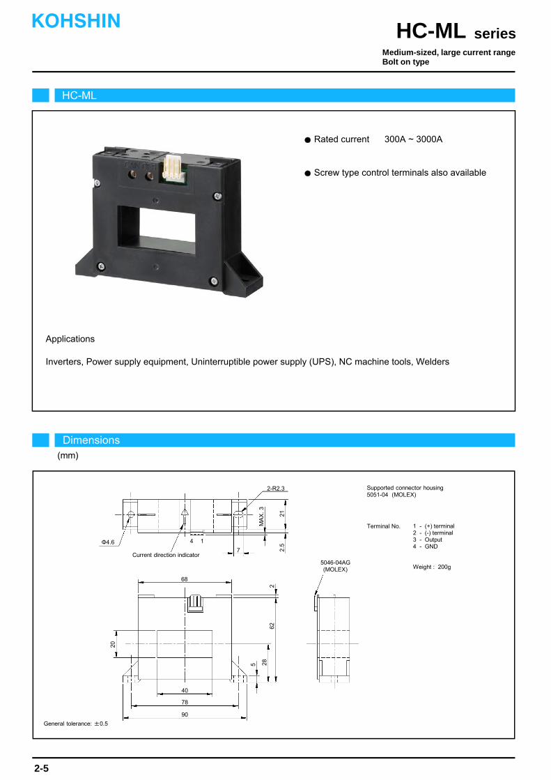
Rated current 300A ~ 3000A
Screw type control terminals also available
Applications
Inverters, Power supply equipment, Uninterruptible power supply (UPS), NC machine tools, Welders
HC-ML
Dimensions(mm)
Medium-sized, large current rangeBolt on type
seriesHC-MLKOHSHIN
2-5
Φ4.6
2-R2.3
4
40
90
78
20
262
21
285
68
Current direction indicator5046-04AG (MOLEX)
Terminal No. 1 - (+) terminal2 - (-) terminal3 - Output4 - GND
Weight : 200g
General tolerance: ±0.5
Supported connector housing5051-04 (MOLEX)
1
7
MA
X.
3
2.5

The indicated rated output is the one when no load is applied.
The indicated residual output is the one after the core hysteresis is removed.Note2)
Note1)
Characteristics chart HC-MLE10V4B15 Time base: 5μs/div.
seriesHC-ML
Output voltage0.2V/div.
Output voltage50mV/div.
Input voltage150V/div.
Input current50A/div.
Ta=25
Output voltage0.2V/div.
Note: The marks " " means 0V or 0A.
Specification Ta=25
2-6
Pulse current response characteristic
Noise characteristics (Effects of impulse noise)
Noise characteristics (Effects of dV/dt)
Input/output characteristics
HC-ML300V4B15Type
Rated current
Saturation current
Linearity limits
Rated output
Residual output
Output linearity
Response time
Response performance
Hysteresis voltage range
Consumption current
Residual output Temp. Coef.
Output Temp. Coef.
Control power supply
Operating Temp.
Storage Temp.
Dielectric withstand voltage
Insulation resistance
HC-ML600V4B15 HC-MLE10V4B15 HC-MLE15V4B15
±300A
±900A
0~±900A
±600A
±1200A
0~±1000A
±1000A
±2400A
0~±2100A
±1500A
±2400A
0~±2100A
[ If ]
[ Is ]
[ Vh ]
[ Vo ]
HC-MLE30V4B15
±3000A
±5000A
0~±4500A
±4V±1%
Within ±30mV
Within ±1%
Within 10μs (at di/dt=100A/μs)
Within 10%
Within 30mV
Within ±0.1%/
Within ±1mV/
±15V±5%
Within 30mA
-10~+80
-15~+85
2500V AC 50/60Hz 1minute
Not less than 500MΩ 500V DC
±4V±2%
Within 50mA
0
-4000 -2000 -3000 0
4000 30002000 1000
15
-15
Out
put v
olta
ge(V
)
Input current(A)
-1000
HC-ML300V4B15
HC-MLE10V4B15
HC-ML600V4B15
HC-MLE30V4B15
HC-MLE15V4B155
10
-5
-10
KOHSHIN
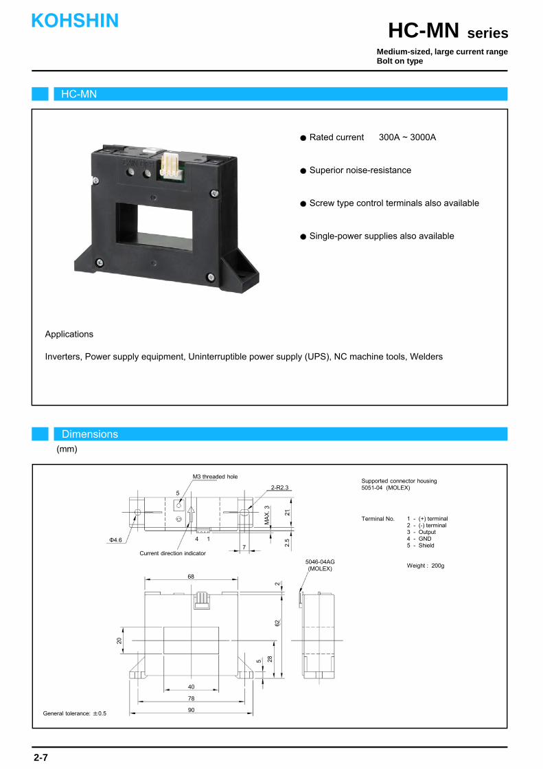
Inverters, Power supply equipment, Uninterruptible power supply (UPS), NC machine tools, Welders
Superior noise-resistance
Rated current 300A ~ 3000A
Screw type control terminals also available
Single-power supplies also available
Applications
Φ4.6
2-R2.3
4
40
90
78
20
262
21
285
68
Current direction indicator
5046-04AG (MOLEX)
1
7
MA
X.
3
2.5
5
M3 threaded hole
HC-MN
Dimensions(mm)
Medium-sized, large current rangeBolt on type
seriesHC-MNKOHSHIN
2-7
Terminal No. 1 - (+) terminal2 - (-) terminal3 - Output4 - GND5 - Shield
Weight : 200g
General tolerance: ±0.5
Supported connector housing5051-04 (MOLEX)

The indicated rated output is the one when no load is applied.
The indicated residual output is the one after the core hysteresis is removed.Note2)
Note1)
Characteristics chart HC-MNE10V4B15 Time base: 5μs/div.
seriesHC-MN
Output voltage0.2V/div.
Output voltage50mV/div.
Input voltage150V/div.
Input current50A/div.
Ta=25
Output voltage0.2V/div.
Note: The marks " " means 0V or 0A.
Specification Ta=25
2-8
Pulse current response characteristic
Noise characteristics (Effects of impulse noise)
Noise characteristics (Effects of dv/dt)
Input/output characteristics
HC-MN300V4B15Type
Rated current
Saturation current
Linearity limits
Rated output
Residual output
Output linearity
Response time
Response performance
Hysteresis voltage range
Consumption current
Residual output Temp. Coef.
Output Temp. Coef.
Control power supply
Operating Temp.
Storage Temp.
Dielectric withstand voltage
Insulation resistance
HC-MN600V4B15 HC-MNE10V4B15 HC-MNE15V4B15
±300A
±900A
0~±900A
±600A
±1200A
0~±1000A
±1000A
±2400A
0~±2100A
±1500A
±2400A
0~±2100A
[ If ]
[ Is ]
[ Vh ]
[ Vo ]
HC-MNE30V4B15
±3000A
±5000A
0~±4500A
±4V±1%
Within ±30mV
Within ±1%
Within 10μs (at di/dt=100A/μs)
Within 10%
Within 30mV
Within ±0.1%/
Within ±1mV/
±15V±5%
Within 30mA
-10~+80
-15~+85
2500V AC 50/60Hz 1minute
Not less than 500MΩ 500V DC
±4V±2%
Within 50mA
0
-4000 -2000 -3000 0
4000 30002000 1000
5
15
-15
Out
put v
olta
ge(V
)
Input current(A)
-1000
10
HC-MN300V4B15
HC-MNE10V4B15
HC-MN600V4B15
HC-MNE30V4B15
HC-MNE15V4B15
-5
-10
KOHSHIN
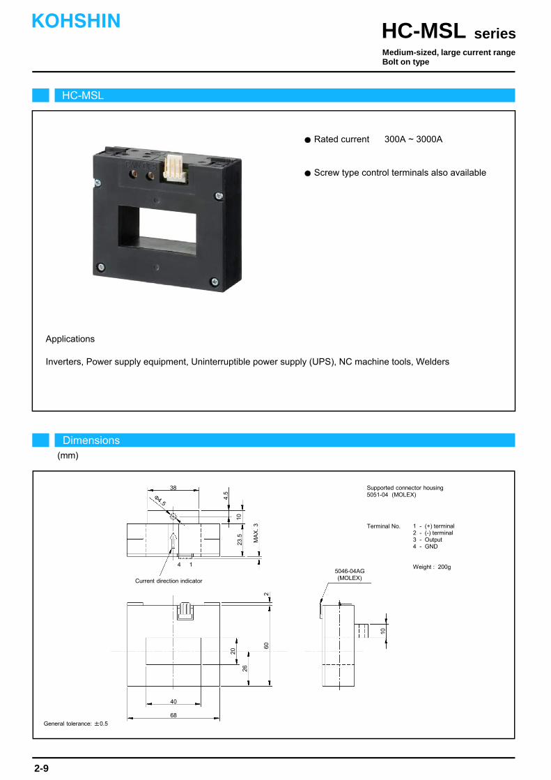
Rated current 300A ~ 3000A
Screw type control terminals also available
Applications
Inverters, Power supply equipment, Uninterruptible power supply (UPS), NC machine tools, Welders
4
40
68
10
60
23.5
2
26
38
Current direction indicator
5046-04AG (MOLEX)
1
MA
X.
3
4.5
20
10
Φ4.5
HC-MSL
Dimensions(mm)
Medium-sized, large current rangeBolt on type
seriesHC-MSLKOHSHIN
2-9
Terminal No. 1 - (+) terminal2 - (-) terminal3 - Output4 - GND
Weight : 200g
General tolerance: ±0.5
Supported connector housing5051-04 (MOLEX)

The indicated rated output is the one when no load is applied.
The indicated residual output is the one after the core hysteresis is removed.Note2)
Note1)
Characteristics chart HC-MSLE10V4B15 Time base: 5μs/div.
seriesHC-MSL
Output voltage0.2V/div.
Output voltage50mV/div.
Input voltage150V/div.
Input current50A/div.
Ta=25
Output voltage0.2V/div.
Note: The marks " " means 0V or 0A.
Specification Ta=25
2-10
Pulse current response characteristic
Noise characteristics (Effects of impulse noise)
Noise characteristics (Effects of dv/dt)
Input/output characteristics
HC-MSL300V4B15Type
Rated current
Saturation current
Linearity limits
Rated output
Residual output
Output linearity
Response time
Response performance
Hysteresis voltage range
Consumption current
Residual output Temp. Coef.
Output Temp. Coef.
Control power supply
Operating Temp.
Storage Temp.
Dielectric withstand voltage
Insulation resistance
HC-MSL600V4B15 HC-MSLE10V4B15 HC-MSLE15V4B15
±300A
±900A
0~±900A
±600A
±1200A
0~±1000A
±1000A
±2400A
0~±2100A
±1500A
±2400A
0~±2100A
[ If ]
[ Is ]
[ Vh ]
[ Vo ]
HC-MSLE30V4B15
±3000A
±5000A
0~±4500A
±4V±1%
Within ±30mV
Within ±1%
Within 10μs (at di/dt=100A/μs)
Within 10%
Within 30mV
Within ±0.1%/
Within ±1mV/
±15V±5%
Within 30mA
-10~+80
-15~+85
2500V AC 50/60Hz 1minute
Not less than 500MΩ 500V DC
±4V±2%
Within 50mA
0
-4000 -2000 -3000 0
4000 30002000 1000
5
15
-5
Out
put v
olta
ge(V
)
Input current(A)
-1000
-10
10
HC-MSL300V4B15
HC-MLSE10V4B15
HC-MSL600V4B15
HC-MSLE30V4B15
HC-MSLE15V4B15
-15
KOHSHIN
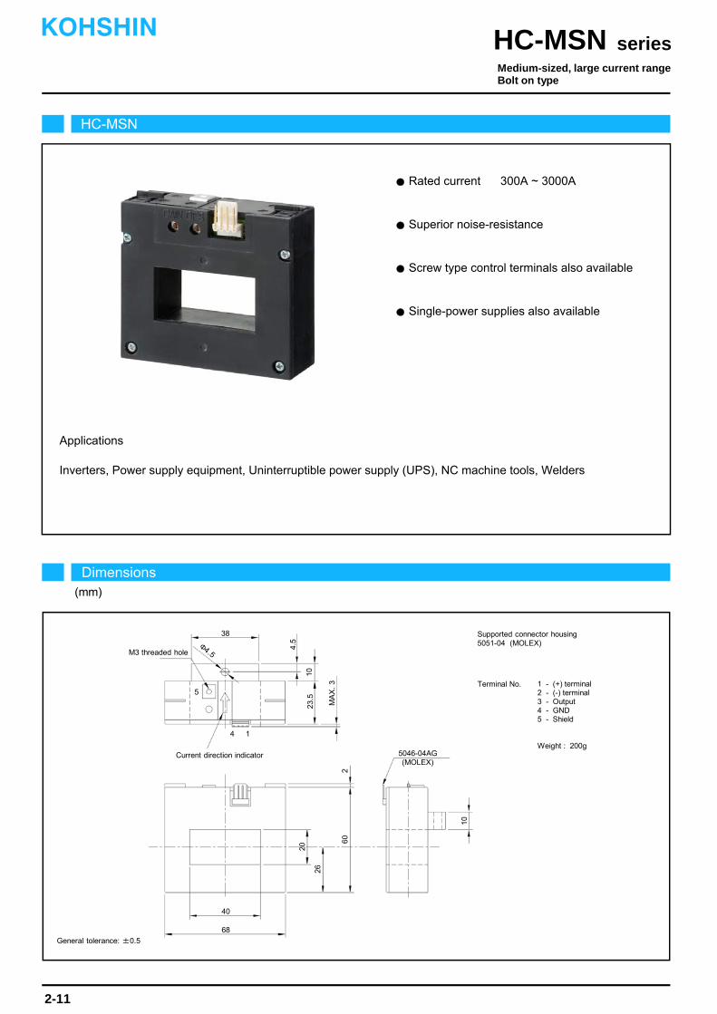
Screw type control terminals also available
Superior noise-resistance
Rated current 300A ~ 3000A
Applications
Inverters, Power supply equipment, Uninterruptible power supply (UPS), NC machine tools, Welders
Single-power supplies also available
4
40
68
10
60
23.5
2
26
38
Current direction indicator
1
MA
X.
3
4.5
20
10
Φ4.5
HC-MSN
Dimensions(mm)
seriesHC-MSNKOHSHIN
2-11
Terminal No. 1 - (+) terminal2 - (-) terminal3 - Output4 - GND5 - Shield
Weight : 200g
General tolerance: ±0.5
Supported connector housing5051-04 (MOLEX)
5046-04AG (MOLEX)
M3 threaded hole
5
Medium-sized, large current rangeBolt on type
The indicated rated output is the one when no load is applied.
The indicated residual output is the one after the core hysteresis is removed.Note2)
Note1)
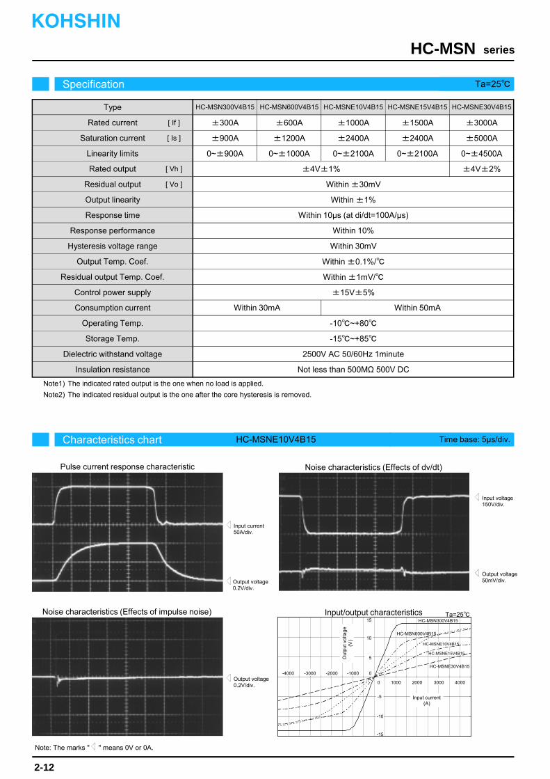
Characteristics chart HC-MSNE10V4B15 Time base: 5μs/div.
seriesHC-MSN
Output voltage0.2V/div.
Output voltage50mV/div.
Input voltage150V/div.
Input current50A/div.
Ta=25
Output voltage0.2V/div.
Note: The marks " " means 0V or 0A.
Specification Ta=25
2-12
Pulse current response characteristic
Noise characteristics (Effects of impulse noise)
Noise characteristics (Effects of dv/dt)
Input/output characteristics
HC-MSN300V4B15Type
Rated current
Saturation current
Linearity limits
Rated output
Residual output
Output linearity
Response time
Response performance
Hysteresis voltage range
Consumption current
Residual output Temp. Coef.
Output Temp. Coef.
Control power supply
Operating Temp.
Storage Temp.
Dielectric withstand voltage
Insulation resistance
HC-MSN600V4B15 HC-MSNE10V4B15 HC-MSNE15V4B15
±300A
±900A
0~±900A
±600A
±1200A
0~±1000A
±1000A
±2400A
0~±2100A
±1500A
±2400A
0~±2100A
[ If ]
[ Is ]
[ Vh ]
[ Vo ]
HC-MSNE30V4B15
±3000A
±5000A
0~±4500A
±4V±1%
Within ±30mV
Within ±1%
Within 10μs (at di/dt=100A/μs)
Within 10%
Within 30mV
Within ±0.1%/
Within ±1mV/
±15V±5%
Within 30mA
-10~+80
-15~+85
2500V AC 50/60Hz 1minute
Not less than 500MΩ 500V DC
±4V±2%
Within 50mA
0
-4000 -2000 -3000 0
4000 30002000 1000
5
15
-5
-15
Out
put v
olta
ge(V
)
Input current(A)
-1000
-10
10
HC-MSN300V4B15
HC-MSNE10V4B15
HC-MSN600V4B15
HC-MSNE30V4B15
HC-MSNE15V4B15
KOHSHIN
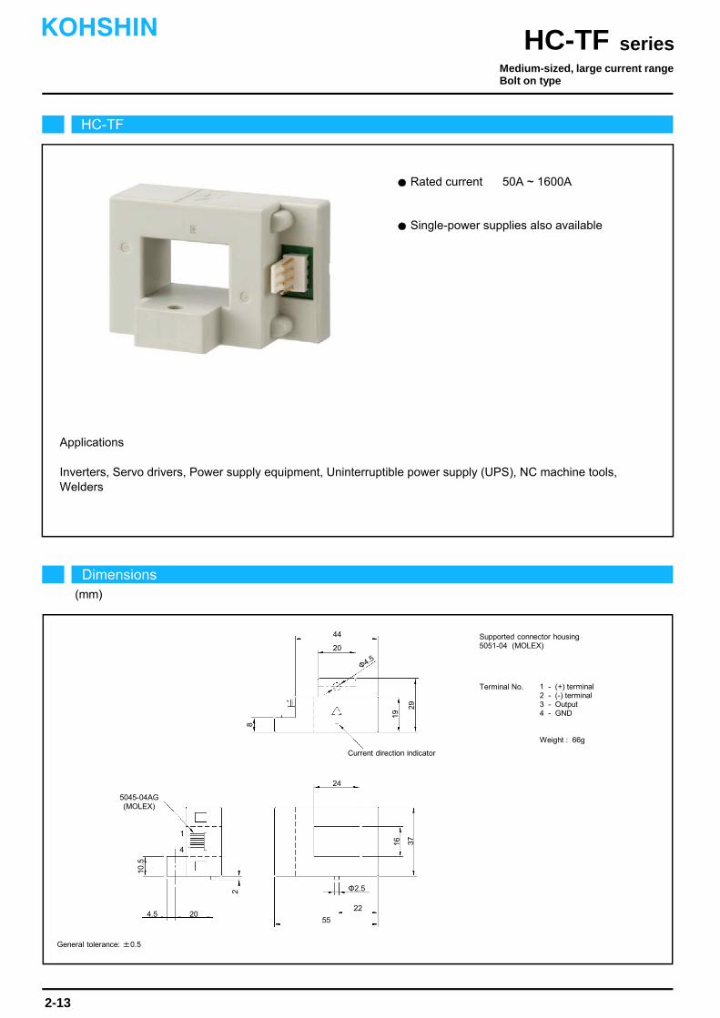
Rated current 50A ~ 1600A
Single-power supplies also available
Applications
Inverters, Servo drivers, Power supply equipment, Uninterruptible power supply (UPS), NC machine tools,Welders
HC-TF
Dimensions(mm)
seriesHC-TFKOHSHIN
2-13
Supported connector housing5051-04 (MOLEX)
Medium-sized, large current rangeBolt on type
Terminal No. 1 - (+) terminal2 - (-) terminal3 - Output4 - GND
Weight : 66g
44
Φ2.5
22
55
24
1916
2
4.5
Current direction indicator
20
8
2937
20
4
10.5
5045-04AG (MOLEX)
General tolerance: ±0.5
Φ4.5
1

The indicated residual output is the one after the core hysteresis is removed.Note1)
Characteristics chart HC-TF100V4B15 Time base: 5μs/div.
seriesHC-TF
Output voltage2V/div.
Output voltage100mV/div.
Input voltage150V/div.
Input current50A/div.
Ta=25
Output voltage0.5V/div.
Specification Ta=25
2-14
Pulse current response characteristic
Noise characteristics (Effects of impulse noise)
Noise characteristics (Effects of dv/dt)
Input/output characteristics
HC-TF050V4B15Type
Rated current
Saturation current
Linearity limits
Rated output
Residual output
Output linearity
Response time
Response performance
Hysteresis voltage range
Consumption current
Residual output Temp. Coef.
Output Temp. Coef.
Control power supply
Operating Temp.
Storage Temp.
Dielectric withstand voltage
Insulation resistance
HC-TF100V4B15 HC-TF400V4B15 HC-TFE10V4B15H
±50A
±150A
0~±150A
±100A
±300A
0~±300A
±400A
±1000A
0~±800A
±1000A
±2700A
0~±2200A
[ If ]
[ Is ]
[ Vo ]
HC-TFE16V4B15H
±1600A
±2700A
0~±2200A
V0+4V±1% (RL=10kΩ)
Within ±70mV
Within ±1%
Within 10μs (The smaller one on either at di/dt = 100 A/μs or If/μs.)
Within 10%
Within 30mV
Within ±0.1%/
Within ±3mV/
±15V±5%
Within 30mA
-10~+80
-15~+85
2500V AC 50/60Hz 1minute
Not less than 500MΩ 500V DC
V0+4V±2% (RL=10kΩ)
Within ±50mV
Within ±1mV/
0
-1500 -1000 0
15001000500
5
15
-5
-15
Out
put v
olta
ge(V
)
Input current(A)
-500
-10
10
HC-TF100V4B15
HC-TFE10V4B15H
HC-TF050V4B15
HC-TFE16V4B15H
HC-TF400V4B15
-2000
2000
+If
-If V0-4V±1% (RL=10kΩ) V0-4V±2% (RL=10kΩ)
Within ±1.5mV/°C
KOHSHIN
[ Vh ]
Note: The marks " " means 0V or 0A.
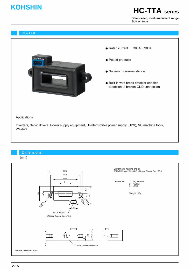
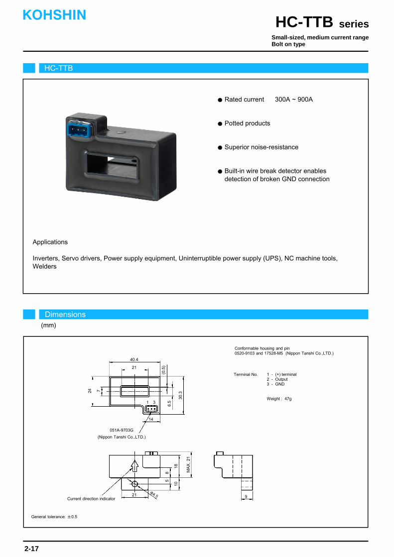
Potted products
Rated current 300A ~ 900A
Superior noise-resistance
Built-in wire break detector enables detection of broken GND connection
Applications
Inverters, Servo drivers, Power supply equipment, Uninterruptible power supply (UPS), NC machine tools,Welders
HC-TTA
Dimensions(mm)
seriesHC-TTAKOHSHIN
2-15
General tolerance: ±0.5
Small-sized, medium current rangeBolt on type
56.2
Current direction indicator
48.6
051A-9703G
14
40.4
18
MA
X.
21
24 7
5.5
8
5.2
1 3
21
(Nippon Tanshi Co.,LTD.)
2-Φ
3.5
2-R3.8
4-R3
30.3
2.2
Conformable housing and pin0520-9103 and 17528-M5 (Nippon Tanshi Co.,LTD.)
Terminal No. 1 - (+) terminal2 - Output3 - GND
Weight : 45g

The indicated residual output is the one after the core hysteresis is removed.Output specifications include 100-Ω output resistance and 0.7-mA maximum output current.The rated output and residual output vary with the value of the control power because the are ratiometric outputs.Output is +4.8 V or greater when GND line is disconnected.
Note3)Note4)
Note2)Note1)
Type
Rated current
Saturation current
Linearity limits
Rated output
Residual output
Output linearity
Response time
Response performance
Hysteresis voltage range
Consumption current
Residual output Temp. Coef.
Output Temp. Coef.
Control power supply
Operating Temp.
Storage Temp.
Dielectric withstand voltage
Insulation resistance
Characteristics chart HC-TTA600V2PP5 Time base: 5μs/div.
seriesHC-TTA
Output voltage0.2V/div.
Output voltage50mV/div.
Input voltage150V/div.
Input current50A/div.
Ta=25
Output voltage0.2V/div.
Specification Ta=25
2-16
Pulse current response characteristic
Noise characteristics (Effects of impulse noise)
Noise characteristics (Effects of dv/dt)
Input/output characteristics
HC-TTA300V2PP5 HC-TTA600V2PP5
±300A
±330A
0~±300A
±600A
±660A
0~±600A
[ If ]
[ Is ]
[ Vh ]
[ V0 ]
HC-TTA900V2PP5
±900A
±990A
0~±900A
V0±2V±50mV (RL=10kΩ)
Within ±1%
Within 10μs (at di/dt=100A/μs)
Within 10%
Within 30mV
Within ±0.1%/
+5V±5%
Within 30mA
-10~+80
-15~+85
2500V AC 50/60Hz 1minute
Not less than 500MΩ 500V DC
Within Vcc/2±50mV
Within ±1mV/
-750 -500 0
750500 250
3
5
2
0
Out
put v
olta
ge(V
)
Input current(A)
-250
1
4
HC-TTA600V2PP5HC-TTA300V2PP5
HC-TTA900V2PP5
-1000
1000
-1250
1250
KOHSHIN
Note: The marks " " means 0V or 0A.
0
[ Vcc ]
Potted products
Rated current 300A ~ 900A
Applications
Inverters, Servo drivers, Power supply equipment, Uninterruptible power supply (UPS), NC machine tools,Welders
Superior noise-resistance
Built-in wire break detector enables detection of broken GND connection
HC-TTB
Dimensions(mm)
seriesHC-TTBKOHSHIN
2-17
General tolerance: ±0.5
Small-sized, medium current rangeBolt on type
Current direction indicator
051A-9703G
14
40.4
18
MA
X.
21
24 7
8
1 3
21
(Nippon Tanshi Co.,LTD.)
30.3
6.5
(0.5
)
Φ4.5 9
5
21
10
Conformable housing and pin0520-9103 and 17528-M5 (Nippon Tanshi Co.,LTD.)
Terminal No. 1 - (+) terminal2 - Output3 - GND
Weight : 47g
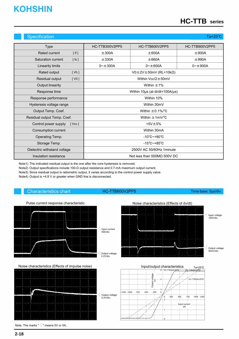
The indicated residual output is the one after the core hysteresis is removed.Output specifications include 100-Ω output resistance and 0.7-mA maximum output current.Since residual output is ratiometric output, it varies according to the control power supply value.Output is +4.8 V or greater when GND line is disconnected.Note4)
Note2)Note3)
Note1)
Type
Rated current
Saturation current
Linearity limits
Rated output
Residual output
Output linearity
Response time
Response performance
Hysteresis voltage range
Consumption current
Residual output Temp. Coef.
Output Temp. Coef.
Control power supply
Operating Temp.
Storage Temp.
Dielectric withstand voltage
Insulation resistance
Characteristics chart HC-TTB600V2PP5 Time base: 5μs/div.
seriesHC-TTB
Output voltage0.2V/div.
Output voltage50mV/div.
Input voltage150V/div.
Input current50A/div.
Ta=25
Output voltage0.2V/div.
Specification Ta=25
2-18
Pulse current response characteristic
Noise characteristics (Effects of impulse noise)
Noise characteristics (Effects of dv/dt)
Input/output characteristics
HC-TTB300V2PP5 HC-TTB600V2PP5
±300A
±330A
0~±300A
±600A
±660A
0~±600A
[ If ]
[ Is ]
[ Vh ]
[ V0 ]
HC-TTB900V2PP5
±900A
±990A
0~±900A
V0±2V±50mV (RL=10kΩ)
Within ±1%
Within 10μs (at di/dt=100A/μs)
Within 10%
Within 30mV
Within ±0.1%/
+5V±5%
Within 30mA
-10~+80
-15~+85
2500V AC 50/60Hz 1minute
Not less than 500MΩ 500V DC
Within Vcc/2±50mV
Within ±1mV/
-750 -500 0
750500 250
3
5
2
0
-250
1
4
HC-TTB600V2PP5HC-TTB300V2PP5
HC-TTB900V2PP5
-1000
1000
-1250
1250
KOHSHIN
Note: The marks " " means 0V or 0A.
0
[ Vcc ]
Out
put v
olta
ge(V
)
Input current(A)
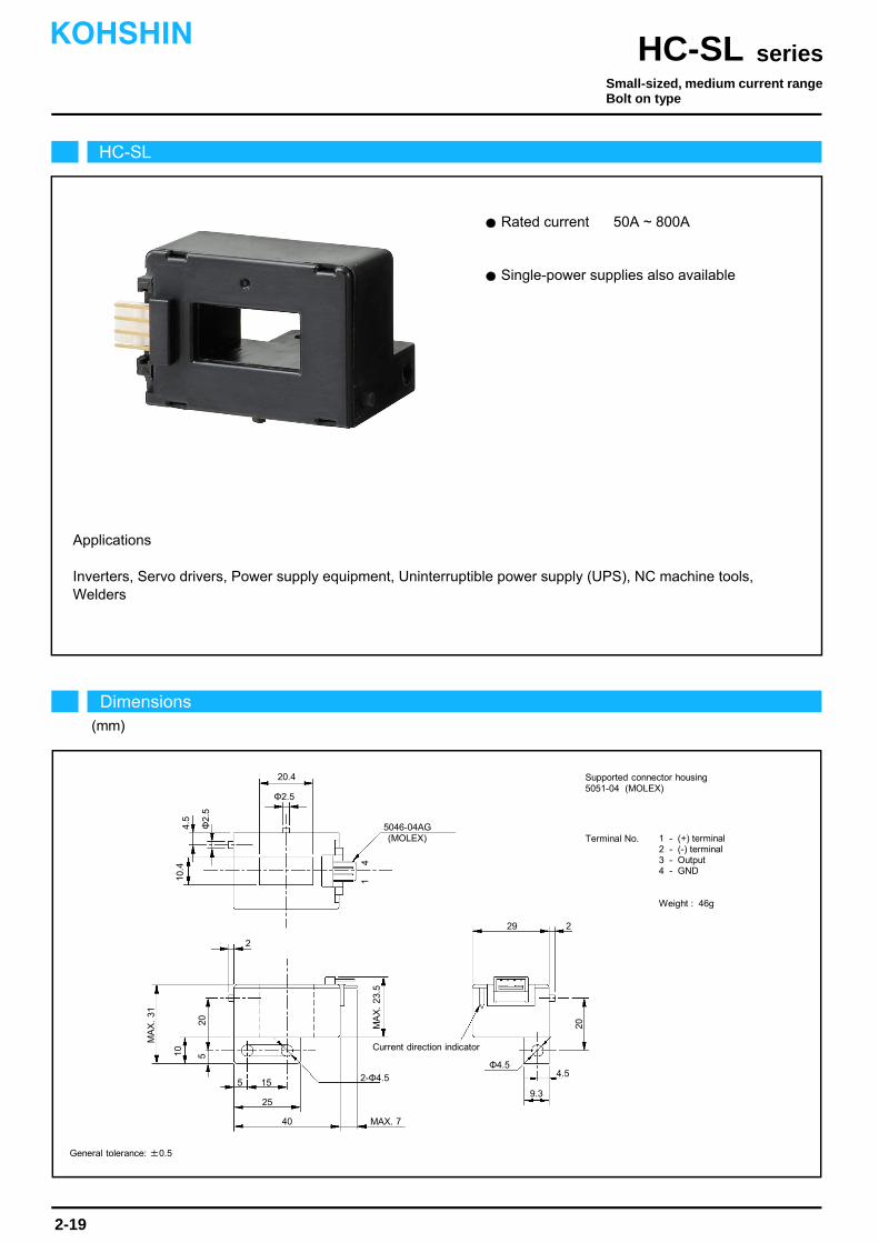
Rated current 50A ~ 800A
Applications
Inverters, Servo drivers, Power supply equipment, Uninterruptible power supply (UPS), NC machine tools,Welders
Single-power supplies also available
4
20.4
Current direction indicator
1
MA
X.
31
Φ2.5
5046-04AG (MOLEX)
229
20
4.5Φ4.5
9.3
MAX. 740
25
155
2
MA
X.
23.5
20
10.4
4.5
Φ2.
5
2-Φ4.5
10 5
HC-SL
Dimensions(mm)
seriesHC-SLKOHSHIN
2-19
General tolerance: ±0.5
Supported connector housing5051-04 (MOLEX)
Small-sized, medium current rangeBolt on type
Terminal No. 1 - (+) terminal2 - (-) terminal3 - Output4 - GND
Weight : 46g

The indicated residual output is the one after the core hysteresis is removed.Note1)
Characteristics chart HC-SL100V4B15 Time base: 5μs/div.
seriesHC-SL
Output voltage2V/div.
Output voltage50mV/div.
Input voltage150V/div.
Input current50A/div.
Ta=25
Output voltage0.2V/div.
Specification Ta=25
2-20
Pulse current response characteristic
Noise characteristics (Effects of impulse noise)
Noise characteristics (Effects of dv/dt)
Input/output characteristics
HC-SL050V4B15Type
Rated current
Saturation current
Linearity limits
Rated output
Residual output
Output linearity
Response time
Response performance
Hysteresis voltage range
Consumption current
Residual output Temp. Coef.
Output Temp. Coef.
Control power supply
Operating Temp.
Storage Temp.
Dielectric withstand voltage
Insulation resistance
HC-SL100V4B15 HC-SL300V4B15 HC-SL600V4B15
±50A
±150A
0~±150A
±100A
±300A
0~±300A
±300A
±900A
0~±700A
±600A
±1000A
0~±900A
[ If ]
[ Is ]
[ Vh ]
[ Vo ]
HC-SL800V4B15
±800A
±1000A
0~±900A
±4V±1% (RL=10kΩ)
Within ±50mV
Within ±1%
Within 10μs (The smaller one on either at di/dt = 100A/μs or If/μs.)
Within 10%
Within 30mV
Within ±0.1%/
Within ±3mV/
±15V±5%
Within 30mA
-10~+80
-15~+85
2500V AC 50/60Hz 1minute
Not less than 500MΩ 500V DC
Within ±30mV
Within ±1mV/
±4V±1.5%(RL=10kΩ)
0
-800 -400-600 0
800600400 200
5
15
-5
-15
Out
put v
olta
ge(V
)
Input current(A)
-200
-10
10
HC-SL100V4B15
HC-SL600V4B15
HC-SL050V4B15
HC-SL800V4B15
HC-SL300V4B15
-1000
1000
-1200
1200
KOHSHIN
Within ±1.5mV/°C
Note: The marks " " means 0V or 0A.
Superior noise-resistance
Rated current 50A ~ 800A
Applications
Inverters, Servo drivers, Power supply equipment, Uninterruptible power supply (UPS), NC machinetools, Welders
Single-power supplies also available4
20.4
Current direction indicator
1
MA
X.
31
Φ2.5
229
20
4.5Φ4.5
9.3
1.540
25
15
2
MA
X.
30
10.4
2-Φ4.5
10 5
5045-04AG (MOLEX)
Φ2.
5
4.5
20
5
HC-SN
Dimensions(mm)
seriesHC-SNKOHSHIN
2-21
General tolerance: ±0.5
Small-sized, medium current rangeBolt on type
Supported connector housing5051-04 (MOLEX)
Terminal No. 1 - (+) terminal2 - (-) terminal3 - Output4 - GND
Weight : 46g
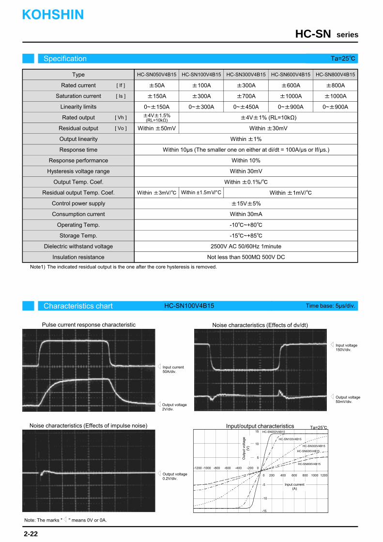
The indicated residual output is the one after the core hysteresis is removed.Note1)
Characteristics chart HC-SN100V4B15 Time base: 5μs/div.
seriesHC-SN
Output voltage2V/div.
Output voltage50mV/div.
Input voltage150V/div.
Input current50A/div.
Ta=25
Output voltage0.2V/div.
Specification Ta=25
2-22
Pulse current response characteristic
Noise characteristics (Effects of impulse noise)
Noise characteristics (Effects of dv/dt)
Input/output characteristics
HC-SN050V4B15Type
Rated current
Saturation current
Linearity limits
Rated output
Residual output
Output linearity
Response time
Response performance
Hysteresis voltage range
Consumption current
Residual output Temp. Coef.
Output Temp. Coef.
Control power supply
Operating Temp.
Storage Temp.
Dielectric withstand voltage
Insulation resistance
HC-SN100V4B15 HC-SN300V4B15 HC-SN600V4B15
±50A
±150A
0~±150A
±100A
±300A
0~±300A
±300A
±700A
0~±450A
±600A
±1000A
0~±900A
[ If ]
[ Is ]
[ Vh ]
[ Vo ]
HC-SN800V4B15
±800A
±1000A
0~±900A
±4V±1% (RL=10kΩ)
Within ±50mV
Within ±1%
Within 10μs (The smaller one on either at di/dt = 100A/μs or If/μs.)
Within 10%
Within 30mV
Within ±0.1%/
Within ±3mV/
±15V±5%
Within 30mA
-10~+80
-15~+85
2500V AC 50/60Hz 1minute
Not less than 500MΩ 500V DC
Within ±30mV
Within ±1mV/
±4V±1.5%(RL=10kΩ)
0
-800 -400-600 0
800600400 200
5
15
-5
-15
Out
put v
olta
ge(V
)
Input current(A)
-200
-10
10
HC-SN100V4B15
HC-SN600V4B15
HC-SN050V4B15
HC-SN800V4B15
HC-SN300V4B15
-1000
1000
-1200
1200
Within ±1.5mV/°C
KOHSHIN
Note: The marks " " means 0V or 0A.
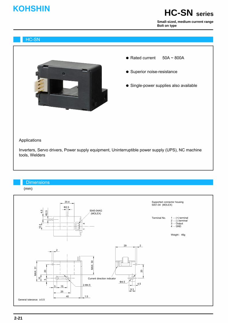
Applications
Inverters, Servo drivers, Power supply equipment, Uninterruptible power supply (UPS), NC machine tools,Welders
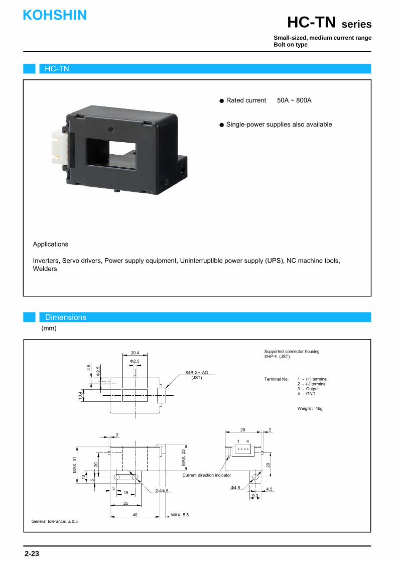
Rated current 50A ~ 800A
Single-power supplies also available
HC-TN
Dimensions(mm)
seriesHC-TNKOHSHIN
2-23
General tolerance: ±0.5
Small-sized, medium current rangeBolt on type
20.4
Current direction indicator
MA
X.
31
Φ2.5
S4B-XH-AG(JST)
229
20
4.5Φ4.5
9.3
MAX. 5.540
25
5
2
MA
X.
23
10.4
4.5
Φ2.
5
Supported connector housingXHP-4 (JST)
Terminal No. 1 - (+) terminal2 - (-) terminal3 - Output4 - GND
Weight : 46g
10 520
2-Φ4.515
1 4

The indicated residual output is the one after the core hysteresis is removed.Note1)
Characteristics chart HC-TN100V4B15 Time base: 5μs/div.
seriesHC-TN
Output voltage2V/div.
Output voltage50mV/div.
Input voltage150V/div.
Input current50A/div.
Ta=25
Output voltage0.2V/div.
Specification Ta=25
2-24
Pulse current response characteristic
Noise characteristics (Effects of impulse noise)
Noise characteristics (Effects of dv/dt)
Input/output characteristics
HC-TN050V4B15Type
Rated current
Saturation current
Linearity limits
Rated output
Residual output
Output linearity
Response time
Response performance
Hysteresis voltage range
Consumption current
Residual output Temp. Coef.
Output Temp. Coef.
Control power supply
Operating Temp.
Storage Temp.
Dielectric withstand voltage
Insulation resistance
HC-TN100V4B15 HC-TN300V4B15 HC-TN600V4B15
±50A
±150A
0~±150A
±100A
±300A
0~±300A
±300A
±900A
0~±700A
±600A
±1000A
0~±900A
[ If ]
[ Is ]
[ Vh ]
[ Vo ]
HC-TN800V4B15
±800A
±1000A
0~±900A
±4V±1% (RL=10kΩ)
Within ±50mV
Within ±1%
Within 10μs (The smaller one on either at di/dt = 100A/μs or If/μs.)
Within 10%
Within 30mV
Within ±0.1%/
Within ±3mV/
±15V±5%
Within 30mA
-10~+80
-15~+85
2500V AC 50/60Hz 1minute
Not less than 500MΩ 500V DC
Within ±30mV
Within ±1.5mV/ Within ±1mV/
±4V±1.5%(RL=10kΩ)
0
-800 -400-600 0
800600400 200
5
15
-5
-15
Out
put v
olta
ge(V
)
Input current(A)
-200
-10
10
HC-TN100V4B15
HC-TN600V4B15
HC-TN050V4B15
HC-TN800V4B15
HC-TN300V4B15
-1000
1000
-1200
1200
KOHSHIN
Note: The marks " " means 0V or 0A.
Inverters, Servo drivers, Power supply equipment, Uninterruptible power supply (UPS), NC machine tools,Welders
Single-power supplies also available
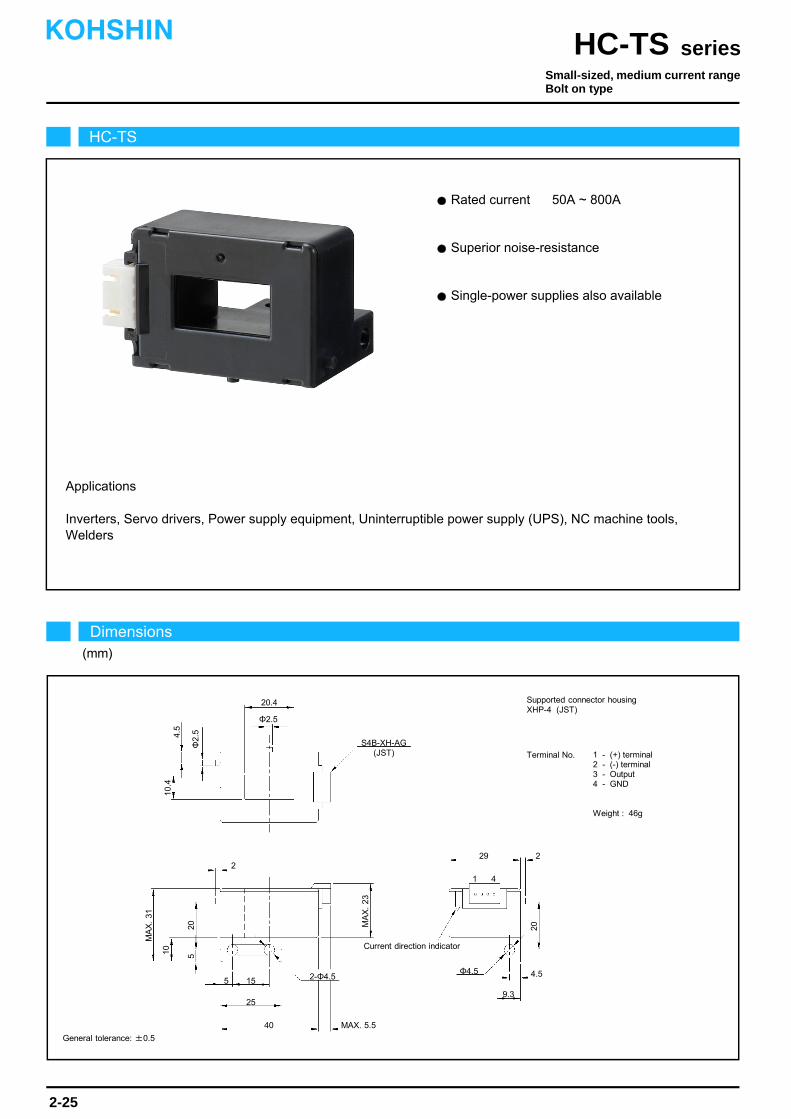
Rated current 50A ~ 800A
Applications
Superior noise-resistance
HC-TS
Dimensions(mm)
seriesHC-TSKOHSHIN
2-25
General tolerance: ±0.5
Small-sized, medium current rangeBolt on type
20.4
Current direction indicator
MA
X.
31
Φ2.5
S4B-XH-AG(JST)
229
20
4.5Φ4.5
9.3
MAX. 5.540
25
5
2
MA
X.
23
10.4
4.5
Φ2.
5
Supported connector housingXHP-4 (JST)
Terminal No. 1 - (+) terminal2 - (-) terminal3 - Output4 - GND
Weight : 46g
10 520
2-Φ4.515
1 4

The indicated residual output is the one after the core hysteresis is removed.Note1)
Characteristics chart HC-TS100V4B15 Time base: 5μs/div.
seriesHC-TS
Output voltage2V/div.
Output voltage50mV/div.
Input voltage150V/div.
Input current50A/div.
Ta=25
Output voltage0.2V/div.
Specification Ta=25
2-26
Pulse current response characteristic
Noise characteristics (Effects of impulse noise)
Noise characteristics (Effects of dv/dt)
Input/output characteristics
HC-TS050V4B15Type
Rated current
Saturation current
Linearity limits
Rated output
Residual output
Output linearity
Response time
Response performance
Hysteresis voltage range
Consumption current
Residual output Temp. Coef.
Output Temp. Coef.
Control power supply
Operating Temp.
Storage Temp.
Dielectric withstand voltage
Insulation resistance
HC-TS100V4B15 HC-TS300V4B15 HC-TS600V4B15
±50A
±150A
0~±150A
±100A
±300A
0~±300A
±300A
±900A
0~±700A
±600A
±1000A
0~±900A
[ If ]
[ Is ]
[ Vh ]
[ Vo ]
HC-TS800V4B15
±800A
±1000A
0~±900A
±4V±1% (RL=10kΩ)
Within ±50mV
Within ±1%
Within 10μs (The smaller one on either at di/dt = 100A/μs or If/μs.)
Within 10%
Within 30mV
Within ±0.1%/
Within ±3mV/
±15V±5%
Within 30mA
-10~+80
-15~+85
2500V AC 50/60Hz 1minute
Not less than 500MΩ 500V DC
Within ±30mV
Within ±1.5mV/ Within ±1mV/
±4V±1.5%(RL=10kΩ)
0
-800 -400-600 0
800600400 200
5
15
-5
-15
Out
put v
olta
ge(V
)
Input current(A)
-200
-10
10
HC-TS100V4B15
HC-TS600V4B15
HC-TS050V4B15
HC-TS800V4B15
HC-TS300V4B15
-1000
1000
-1200
1200
KOHSHIN
Note: The marks " " means 0V or 0A.

Inverters, Power supply equipment, NC machine tools, Welders
Rated current 50A ~ 300A
Applications
HC-U
Dimensions(mm)
seriesHC-UKOHSHIN
2-27
Small-sized, medium current rangeBolt on type
37.8
Current direction indicator
5045-04AG(MOLEX)
20
54
Φ20
46
8
64
Supported connector housing5051-04 (MOLEX)
Terminal No. 1 - (+) terminal2 - (-) terminal3 - Output4 - GND
Weight : 59g
45
5
29
2-Φ4
1 4
General tolerance: ±0.5

The indicated rated output is the one when no load is applied.
The indicated residual output is the one after the core hysteresis is removed.Note2)
Note1)
Characteristics chart HC-U100V4B15 Time base: 5μs/div.
seriesHC-U
Output voltage2V/div.
Output voltage50mV/div.
Input voltage150V/div.
Input current50A/div.
Ta=25
Output voltage0.5V/div.
Specification Ta=25
2-28
Pulse current response characteristic
Noise characteristics (Effects of impulse noise)
Noise characteristics (Effects of dv/dt)
Input/output characteristics
HC-U050V4B15Type
Rated current
Saturation current
Linearity limits
Rated output
Residual output
Output linearity
Response time
Response performance
Hysteresis voltage range
Consumption current
Residual output Temp. Coef.
Output Temp. Coef.
Control power supply
Operating Temp.
Storage Temp.
Dielectric withstand voltage
Insulation resistance
HC-U100V4B15
±50A
±150A
0~±150A
±100A
±300A
0~±300A
[ If ]
[ Is ]
[ Vh ]
[ Vo ]
HC-U300V4B15
±300A
±700A
0~±600A
±4V±1%
Within ±50mV
Within ±1%
Within 10μs (The smaller one on either at di/dt = 100A/μs or If/μs.)
Within 10%
Within 30mV
Within ±0.08%/
Within ±2.5mV/
±15V±5%
Within 30mA
-10~+80
-15~+85
2500V AC 50/60Hz 1minute
Not less than 500MΩ 500V DC
Within ±30mV
Within ±1.5mV/
0
-600 -400 0
600400200
5
15
-5
-15
Out
put v
olta
ge(V
)
Input current(A)
-200
-10
10
HC-U100V4B15
HC-U050V4B15
HC-U300V4B15
-800
800
±4V±1.5%
KOHSHIN
Note: The marks " " means 0V or 0A.
Inverters, Power supply equipment, NC machine tools
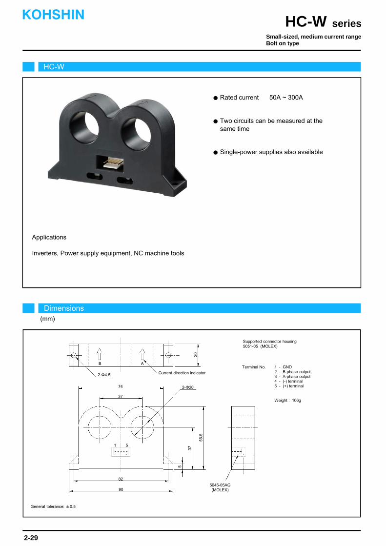
Rated current 50A ~ 300A
Two circuits can be measured at the same time
Single-power supplies also available
Applications
HC-W
Dimensions(mm)
seriesHC-WKOHSHIN
2-29
General tolerance: ±0.5
Small-sized, medium current rangeBolt on type
37
Current direction indicator
5045-05AG(MOLEX)
20
90
2-Φ20
82
55.5
Supported connector housing5051-05 (MOLEX)
Terminal No. 1 - GND2 - B-phase output3 - A-phase output4 - (-) terminal5 - (+) terminal
Weight : 106g
37
5
2-Φ4.5
1 5
74
AB

The indicated rated output is the one when no load is applied.
The indicated residual output is the one after the core hysteresis is removed.Note2)
Note1)
Characteristics chart HC-W100V4B15 Time base: 5μs/div.
seriesHC-W
Output voltage2V/div.
Output voltage50mV/div.
Input voltage150V/div.
Input current50A/div.
Ta=25
Output voltage0.5V/div.
Specification Ta=25
2-30
Pulse current response characteristic
Noise characteristics (Effects of impulse noise)
Noise characteristics (Effects of dv/dt)
Input/output characteristics
HC-W050V4B15Type
Rated current
Saturation current
Linearity limits
Rated output
Residual output
Output linearity
Response time
Response performance
Hysteresis voltage range
Consumption current
Residual output Temp. Coef.
Output Temp. Coef.
Control power supply
Operating Temp.
Storage Temp.
Dielectric withstand voltage
Insulation resistance
HC-W100V4B15
±50A
±150A
0~±150A
±100A
±300A
0~±300A
[ If ]
[ Is ]
[ Vh ]
[ Vo ]
HC-W300V4B15
±300A
±700A
0~±600A
±4V±1%
Within ±50mV
Within ±1%
Within 10μs (The smaller one on either at di/dt = 100A/μs or If/μs.)
Within 10%
Within 30mV
Within ±0.08%/
Within ±2.5mV/
±15V±5%
Within 60mA
-10~+80
-15~+85
2500V AC 50/60Hz 1minute
Not less than 500MΩ 500V DC
Within ±30mV
Within ±1.5mV/
0
-600 -400 0
600400200
5
15
-5
-15
Out
put v
olta
ge(V
)
Input current(A)
-200
-10
10
HC-W100V4B15
HC-W050V4B15
HC-W300V4B15
-800
800
KOHSHIN
±4V±1.5%
Note: The marks " " means 0V or 0A.
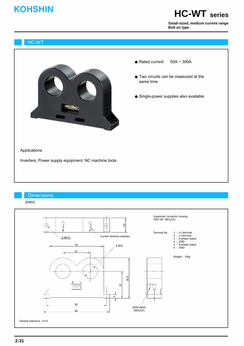
Rated current 50A ~ 300A
Inverters, Power supply equipment, NC machine tools
Applications
Two circuits can be measured at the same time
Single-power supplies also available
HC-WT
Dimensions(mm)
seriesHC-WTKOHSHIN
2-31
Small-sized, medium current rangeBolt on type
General tolerance: ±0.5
37
Current direction indicator
5045-06AG(MOLEX)
20
90
2-Φ20
82
55.5
Supported connector housing5051-06 (MOLEX)
Terminal No. 1 - (+) terminal2 - (-) terminal3 - A-phase output4 - GND5 - B-phase output6 - GND
Weight : 106g
37
5
2-Φ4.5
6 1
74
AB

The indicated rated output is the one when no load is applied.
The indicated residual output is the one after the core hysteresis is removed.Note2)
Note1)
Characteristics chart HC-WT100V4B15 Time base: 5μs/div.
seriesHC-WT
Output voltage2V/div.
Output voltage50mV/div.
Input voltage150V/div.
Input current50A/div.
Ta=25
Output voltage0.5V/div.
Specification Ta=25
2-32
Pulse current response characteristic
Noise characteristics (Effects of impulse noise)
Noise characteristics (Effects of dv/dt)
Input/output characteristics
HC-WT050V4B15Type
Rated current
Saturation current
Linearity limits
Rated output
Residual output
Output linearity
Response time
Response performance
Hysteresis voltage range
Consumption current
Residual output Temp. Coef.
Output Temp. Coef.
Control power supply
Operating Temp.
Storage Temp.
Dielectric withstand voltage
Insulation resistance
HC-WT100V4B15
±50A
±150A
0~±150A
±100A
±300A
0~±300A
[ If ]
[ Is ]
[ Vh ]
[ Vo ]
HC-WT300V4B15
±300A
±700A
0~±600A
±4V±1%
Within ±50mV
Within ±1%
Within 10μs (The smaller one on either at di/dt = 100A/μs or If/μs.)
Within 10%
Within 30mV
Within ±0.08%/
Within ±2.5mV/
±15V±5%
Within 60mA
-10~+80
-15~+85
2500V AC 50/60Hz 1minute
Not less than 500MΩ 500V DC
Within ±30mV
Within ±1.5mV/
0
-600 -400 0
600400200
5
15
-5
-15
Out
put v
olta
ge(V
)
Input current(A)
-200
-10
10
HC-WT100V4B15
HC-WT050V4B15
-800
800
HC-WT300V4B15
KOHSHIN
±4V±1.5%
Note: The marks " " means 0V or 0A.
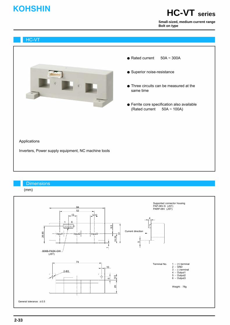
Inverters, Power supply equipment, NC machine tools
Ferrite core specification also available (Rated current 50A ~ 100A)
Rated current 50A ~ 300A
Superior noise-resistance
Three circuits can be measured at the same time
Applications
HC-VT
Dimensions(mm)
seriesHC-VTKOHSHIN
2-33
General tolerance: ±0.5
Small-sized, medium current rangeBolt on type
Current direction
B06B-PASK-GW(JST)
74
3-12
84
5
Supported connector housingPAP-06V-S (JST)PARP-06V (JST)
Terminal No. 1 - (+) terminal2 - GND3 - (-) terminal4 - Output15 - Output26 - Output3
Weight : 78g
9.5
5
31
2-Φ3
1 6
1
52
Input1 Input2 Input3
10
4
15.2
5
9.5
26.8
5
13
20
The indicated residual output is the one after the core hysteresis is removed.Note1)
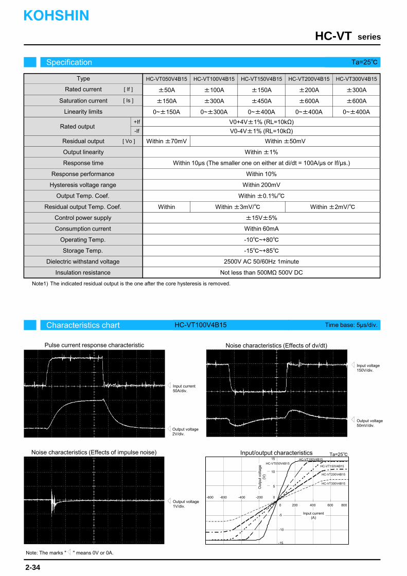
Characteristics chart HC-VT100V4B15 Time base: 5μs/div.
seriesHC-VT
Output voltage2V/div.
Output voltage50mV/div.
Input voltage150V/div.
Input current50A/div.
Ta=25
Output voltage1V/div.
Specification Ta=25
2-34
Pulse current response characteristic
Noise characteristics (Effects of impulse noise)
Noise characteristics (Effects of dv/dt)
Input/output characteristics
HC-VT050V4B15Type
Rated current
Saturation current
Linearity limits
Rated output
Output linearity
HC-VT100V4B15 HC-VT150V4B15 HC-VT200V4B15
±50A
±150A
0~±150A
±100A
±300A
0~±300A
±150A
±450A
0~±400A
±200A
±600A
0~±400A
[ If ]
[ Is ]
[ Vo ]
HC-VT300V4B15
±300A
±600A
0~±400A
V0+4V±1% (RL=10kΩ)
Within ±70mV
Within ±1%
Within 10μs (The smaller one on either at di/dt = 100A/μs or If/μs.)
Within 10%
Within 200mV
Within ±0.1%/
Within
±15V±5%
Within 60mA
-10~+80
-15~+85
2500V AC 50/60Hz 1minute
Not less than 500MΩ 500V DC
Within ±50mV
Within ±3mV/ Within ±2mV/
0
-600 -400 0
600400200
5
15
-5
-15
Out
put v
olta
ge(V
)
Input current(A)
-200
-10
10
HC-VT150V4B15
HC-VT300V4B15
HC-VT100V4B15
HC-VT200V4B15
-800
800
HC-VT050V4B15
KOHSHIN
V0-4V±1% (RL=10kΩ)
Residual output
Response time
Response performance
Hysteresis voltage range
Output Temp. Coef.
Residual output Temp. Coef.
Control power supply
Consumption current
Operating Temp.
Storage Temp.
Dielectric withstand voltage
Insulation resistance
+If
-If
Note: The marks " " means 0V or 0A.
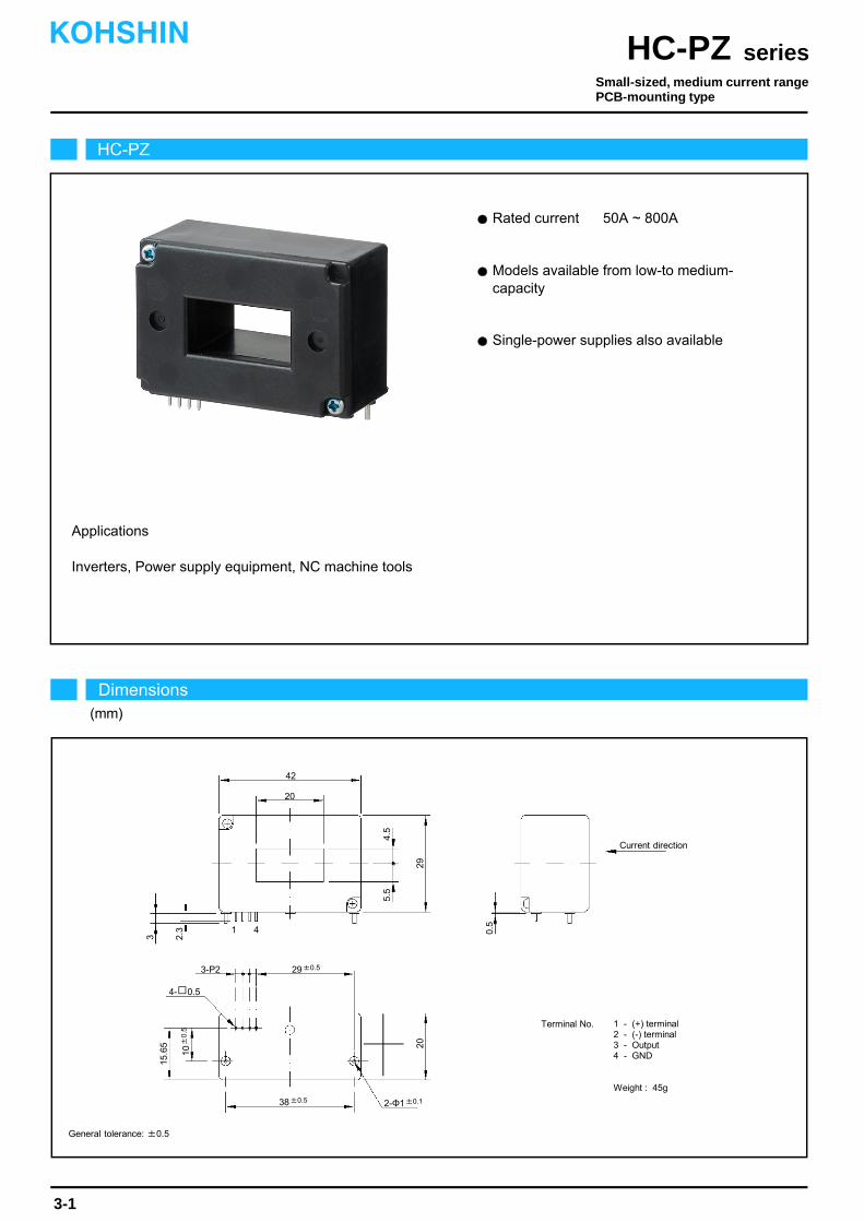
Rated current 50A ~ 800A
Models available from low-to medium- capacity
Inverters, Power supply equipment, NC machine tools
Single-power supplies also available
Applications
3
3-P2
20
2.3 0.
5
4.5
HC-PZ
Dimensions(mm)
seriesHC-PZKOHSHIN
3-1
General tolerance: ±0.5
Small-sized, medium current rangePCB-mounting type
Terminal No. 1 - (+) terminal2 - (-) terminal3 - Output4 - GND
Weight : 45g
41
2-Φ1±0.1
29
5.5
20
42
4- 0.5
10±
0.5
15.6
5
38±0.5
Current direction
29±0.5

The indicated rated output is the one when no load is applied.
The indicated residual output is the one after the core hysteresis is removed.Note2)
Note1)
Characteristics chart HC-PZ100V4B15 Time base: 5μs/div.
seriesHC-PZ
Output voltage2V/div.
Output voltage100mV/div.
Input voltage150V/div.
Input current50A/div.
Ta=25
Output voltage5V/div.
Specification Ta=25
3-2
Pulse current response characteristic
Noise characteristics (Effects of impulse noise)
Noise characteristics (Effects of dv/dt)
Input/output characteristics
HC-PZ050V4B15Type
Rated current
Saturation current
Linearity limits
Rated output
Residual output
Output linearity
Response time
Response performance
Hysteresis voltage range
Consumption current
Residual output Temp. Coef.
Output Temp. Coef.
Control power supply
Operating Temp.
Storage Temp.
Dielectric withstand voltage
Insulation resistance
HC-PZ100V4B15 HC-PZ300V4B15 HC-PZ600V4B15
±50A
±150A
0~±150A
±100A
±300A
0~±300A
±300A
±900A
0~±700A
±600A
±1000A
0~±800A
[ If ]
[ Is ]
[ Vh ]
[ Vo ]
HC-PZ800V4B15
±800A
±1000A
0~±800A
±4V±1%
Within ±1%
Within 10μs (The smaller one on either at di/dt = 100A/μs or If/μs.)
Within 10%
Within 200mV
Within ±0.1%/
Within ±4mV/
±15V±5%
Within 30mA
-10~+80
-15~+85
2500V AC 50/60Hz 1minute
Not less than 500MΩ 500V DC
Within ±50mV
Within ±2mV/ Within ±1mV/
0
-800 -400-600 0
800600400 200
5
15
-5
-15
Out
put v
olta
ge(V
)
Input current(A)
-200
-10
10
HC-PZ100V4B15
HC-PZ600V4B15
HC-PZ050V4B15
HC-PZ800V4B15
HC-PZ300V4B15
-1000
1000
-1200
1200
KOHSHIN
Note: The marks " " means 0V or 0A.
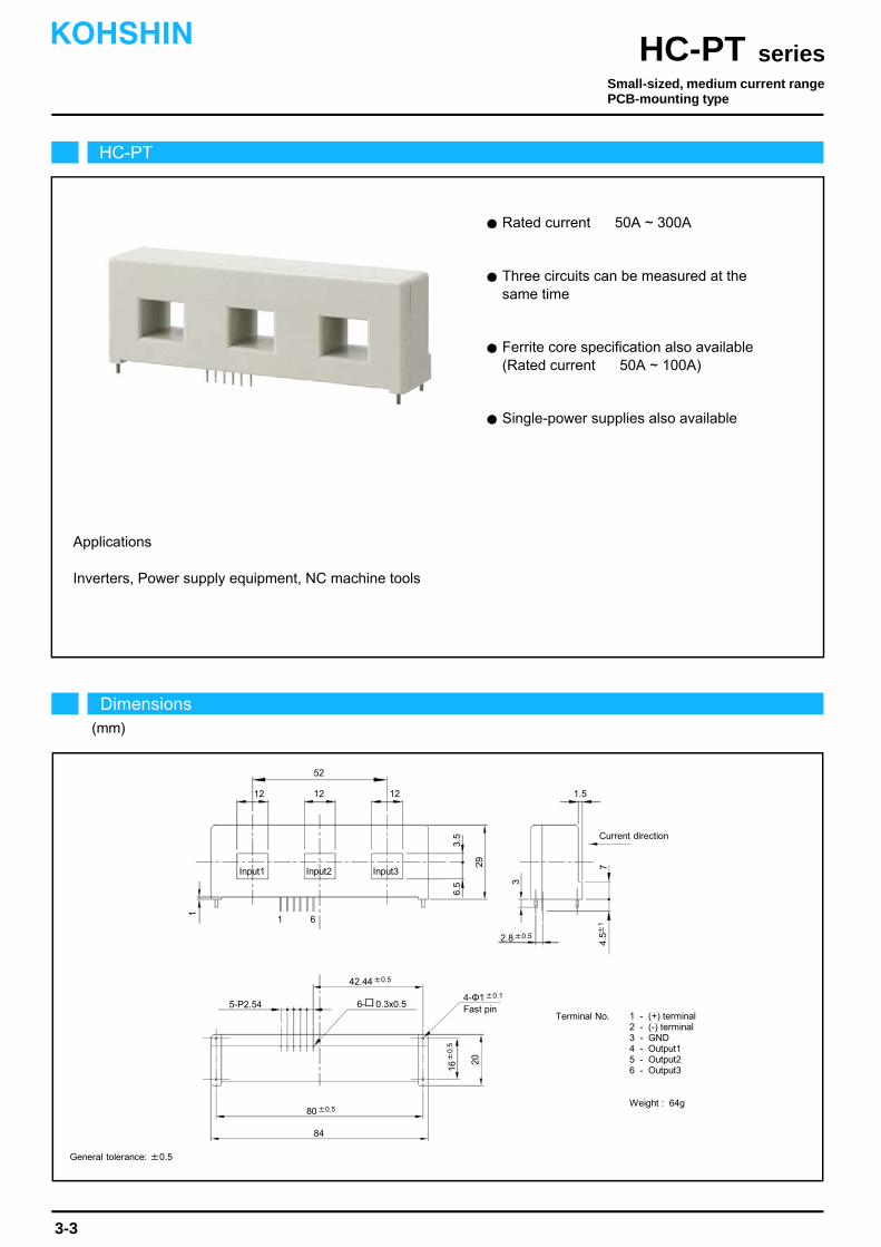
Rated current 50A ~ 300A
Three circuits can be measured at the same time
Ferrite core specification also available (Rated current 50A ~ 100A)
Inverters, Power supply equipment, NC machine tools
Applications
Single-power supplies also available
HC-PT
Dimensions(mm)
seriesHC-PTKOHSHIN
3-3
General tolerance: ±0.5
Small-sized, medium current rangePCB-mounting type
Terminal No. 1 - (+) terminal2 - (-) terminal3 - GND4 - Output15 - Output26 - Output3
Weight : 64g
Input1 Input2 Input3
52
6
20
1
29
6- 0.3x0.5
3.5
80±0.5
12
4.5±
1
1.5
Current direction
12 12
16±
0.5
1
3
7
2.8±0.5
6.5
5-P2.544-Φ1±0.1
Fast pin
42.44±0.5
84

The indicated rated output is the one when no load is applied.
The indicated residual output is the one after the core hysteresis is removed.Note2)
Note1)
Characteristics chart HC-PT100V4B15 Time base: 5μs/div.
seriesHC-PT
Output voltage2V/div.
Output voltage50mV/div.
Input voltage150V/div.
Input current50A/div.
Ta=25
Output voltage5V/div.
Specification Ta=25
3-4
Pulse current response characteristic
Noise characteristics (Effects of impulse noise)
Noise characteristics (Effects of dv/dt)
Input/output characteristics
HC-PT050V4B15Type
Rated current
Saturation current
Linearity limits
Rated output
Residual output
Output linearity
Response time
Response performance
Hysteresis voltage range
Consumption current
Residual output Temp. Coef.
Output Temp. Coef.
Control power supply
Operating Temp.
Storage Temp.
Dielectric withstand voltage
Insulation resistance
HC-PT100V4B15 HC-PT150V4B15 HC-PT200V4B15
±50A
±150A
0~±150A
±100A
±300A
0~±300A
±150A
±450A
0~±400A
±200A
±600A
0~±400A
[ If ]
[ Is ]
[ Vh ]
[ Vo ]
HC-PT300V4B15
±300A
±600A
0~±400A
±4V±1%
Within ±1%
Within 10μs (The smaller one on either at di/dt = 100A/μs or If/μs.)
Within 10%
Within 200mV
Within ±0.1%/
Within ±4mV/
±15V±5%
Within 60mA
-10~+80
-15~+85
2500V AC 50/60Hz 1minute
Not less than 500MΩ 500V DC
Within ±50mV
Within ±3mV/ Within ±2mV/
0
-400-600 0
600400 200
5
15
-15
Out
put v
olta
ge(V
)
Input current(A)
-200
10
800
-800
HC-PT100V4B15
HC-PT200V4B15HC-PT050V4B15
HC-PT300V4B15
HC-PT150V4B15
-5
-10
KOHSHIN
Note: The marks " " means 0V or 0A.
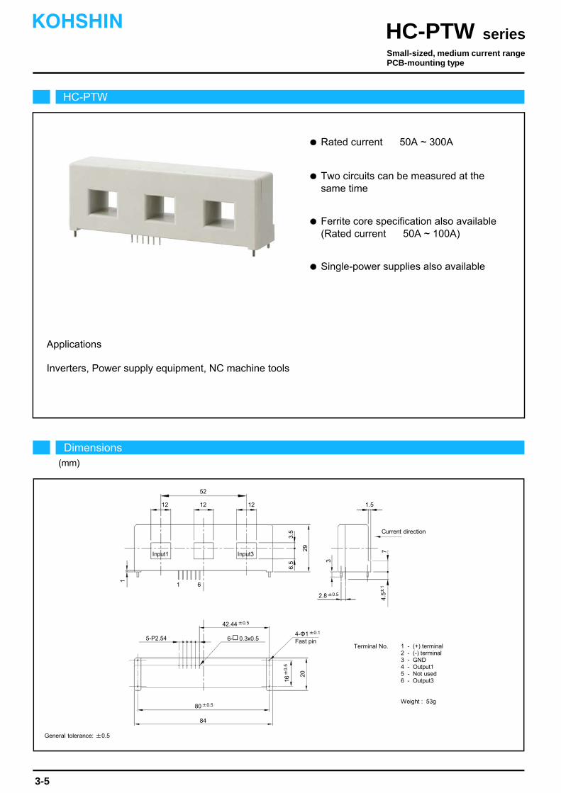
Inverters, Power supply equipment, NC machine tools
Applications
Rated current 50A ~ 300A
Two circuits can be measured at the same time
Ferrite core specification also available (Rated current 50A ~ 100A)
Single-power supplies also available
HC-PTW
Dimensions(mm)
seriesHC-PTWKOHSHIN
3-5
General tolerance: ±0.5
Small-sized, medium current rangePCB-mounting type
Terminal No. 1 - (+) terminal2 - (-) terminal3 - GND4 - Output15 - Not used6 - Output3
Weight : 53g
Input1 Input3
52
6
20
1
29
6- 0.3x0.5
3.5
80±0.5
12
4.5±
1
1.5
Current direction
12 12
16±
0.5
1
3
7
2.8±0.5
6.5
5-P2.544-Φ1±0.1
Fast pin
42.44±0.5
84

The indicated rated output is the one when no load is applied.
The indicated residual output is the one after the core hysteresis is removed.Note2)
Note1)
Characteristics chart HC-PTW100V4B15 Time base: 5μs/div.
seriesHC-PTW
Output voltage2V/div.
Output voltage50mV/div.
Input voltage150V/div.
Input current50A/div.
Ta=25
Output voltage5V/div.
Specification Ta=25
3-6
Pulse current response characteristic
Noise characteristics (Effects of impulse noise)
Noise characteristics (Effects of dv/dt)
Input/output characteristics
HC-PTW050V4B15Type
Rated current
Saturation current
Linearity limits
Rated output
Residual output
Output linearity
Response time
Response performance
Hysteresis voltage range
Consumption current
Residual output Temp. Coef.
Output Temp. Coef.
Control power supply
Operating Temp.
Storage Temp.
Dielectric withstand voltage
Insulation resistance
HC-PTW100V4B15 HC-PTW150V4B15 HC-PTW200V4B15
±50A
±150A
0~±150A
±100A
±300A
0~±300A
±150A
±450A
0~±400A
±200A
±600A
0~±400A
[ If ]
[ Is ]
[ Vh ]
[ Vo ]
HC-PTW300V4B15
±300A
±600A
0~±400A
±4V±1%
Within ±1%
Within 10μs (The smaller one on either at di/dt = 100A/μs or If/μs.)
Within 10%
Within 200mV
Within ±0.1%/
Within ±4mV/
±15V±5%
Within 40mA
-10~+80
-15~+85
2500V AC 50/60Hz 1minute
Not less than 500MΩ 500V DC
Within ±50mV
Within ±3mV/ Within ±2mV/
0
-400-600 0
600400 200
5
15
-15
Out
put v
olta
ge(V
)
Input current(A)
-200
10
800
-800
HC-PTW100V4B15
HC-PTW200V4B15
HC-PTW050V4B15
HC-PTW300V4B15
HC-PTW150V4B15
-5
-10
KOHSHIN
Note: The marks " " means 0V or 0A.
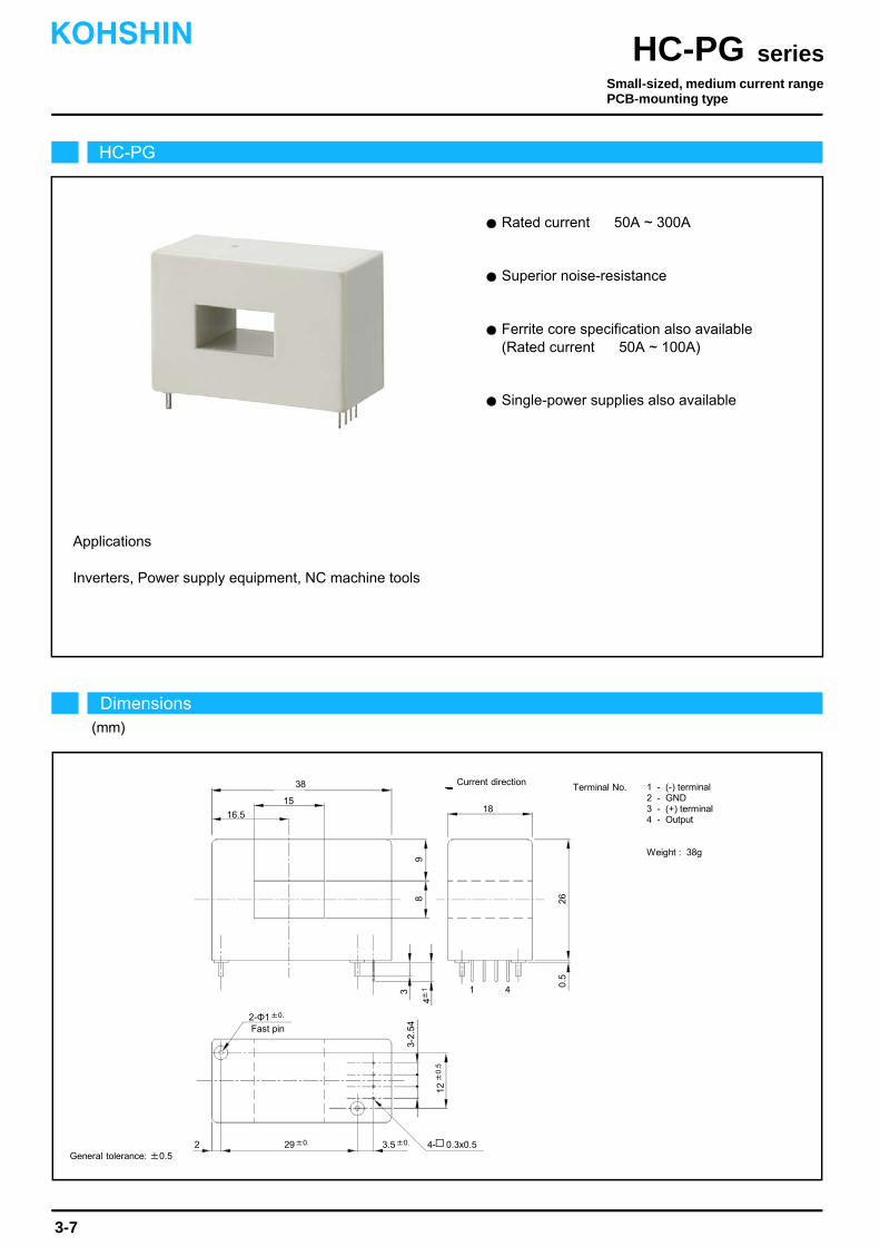
Inverters, Power supply equipment, NC machine tools
Rated current 50A ~ 300A
Superior noise-resistance
Ferrite core specification also available (Rated current 50A ~ 100A)
Applications
Single-power supplies also available
HC-PG
Dimensions(mm)
seriesHC-PGKOHSHIN
3-7
General tolerance: ±0.5
Small-sized, medium current rangePCB-mounting type
Terminal No. 1 - (-) terminal2 - GND3 - (+) terminal4 - Output
Weight : 38g
38
3-2.
54
4±1
12±
0.5
41
9
29±0.
2-Φ1±0.
18
2
15
16.5
Fast pin
3.5±0. 4- 0.3x0.5
8
3
260.
5
Current direction

The indicated rated output is the one when no load is applied.
The indicated residual output is the one after the core hysteresis is removed.Note2)
Note1)
Characteristics chart HC-PG100V4B15 Time base: 5μs/div.
seriesHC-PG
Output voltage2V/div.
Output voltage50mV/div.
Input voltage150V/div.
Input current50A/div.
Ta=25
Output voltage0.2V/div.
Note: The marks " " means 0V or 0A.
Specification Ta=25
3-8
Pulse current response characteristic
Noise characteristics (Effects of impulse noise)
Noise characteristics (Effects of dv/dt)
Input/output characteristics
HC-PG050V4B15Type
Rated current
Saturation current
Linearity limits
Rated output
Residual output
Output linearity
Response time
Response performance
Hysteresis voltage range
Consumption current
Residual output Temp. Coef.
Output Temp. Coef.
Control power supply
Operating Temp.
Storage Temp.
Dielectric withstand voltage
Insulation resistance
HC-PG100V4B15 HC-PG150V4B15 HC-PG200V4B15
±50A
±150A
0~±150A
±100A
±300A
0~±300A
±150A
±450A
0~±450A
±200A
±600A
0~±500A
[ If ]
[ Is ]
[ Vh ]
[ Vo ]
HC-PG300V4B15
±300A
±900A
0~±700A
±4V±1%
Within ±1%
Within 10μs (The smaller one on either at di/dt = 100A/μs or If/μs.)
Within 10%
Within 100mV
Within ±0.1%/
Within ±4mV/
±15V±5%
Within 30mA
-10~+80
-15~+85
2500V AC 50/60Hz 1minute
Not less than 500MΩ 500V DC
Within ±50mV
Within ±3mV/ Within ±2mV/
0
-800 -400-600 0
800 600400 200
5
15
-5
-15
Out
put v
olta
ge(V
)
Input current(A)
-200
-10
10
HC-PG100V4B15HC-PG050V4B15
HC-PG150V4B15
1000
-1000
HC-PG200V4B15
HC-PG300V4B15
KOHSHIN
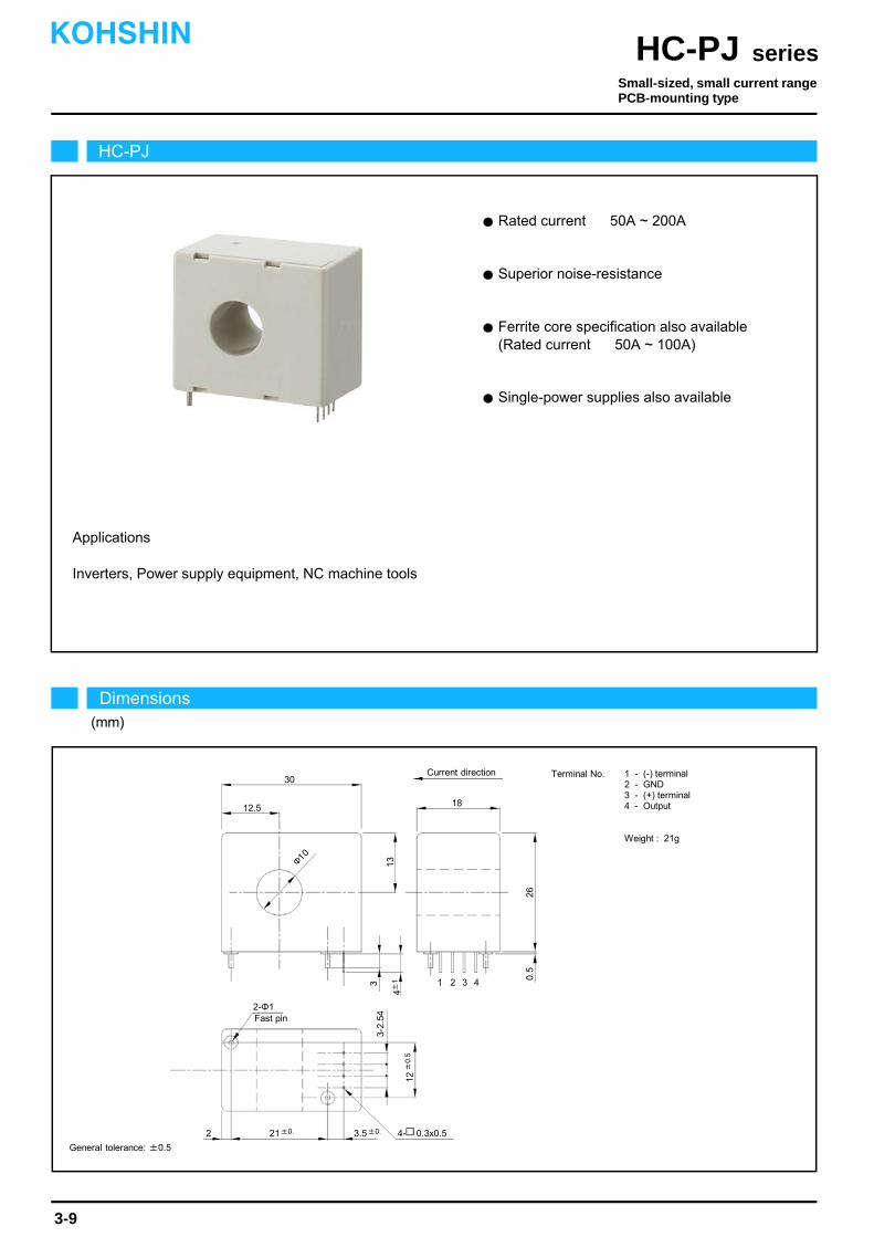
Rated current 50A ~ 200A
Applications
Superior noise-resistance
Inverters, Power supply equipment, NC machine tools
Single-power supplies also available
Ferrite core specification also available (Rated current 50A ~ 100A)
HC-PJ
Dimensions(mm)
seriesHC-PJKOHSHIN
3-9
General tolerance: ±0.5
Terminal No. 1 - (-) terminal2 - GND3 - (+) terminal4 - Output
Weight : 21g
30
3-2.
54
4±1
12±
0.5
41
13
21±0.
2-Φ1
18
2
12.5
Fast pin
3.5±0. 4- 0.3x0.5
3
260.
5
2 3
Φ10
Current direction
Small-sized, small current rangePCB-mounting type

The indicated rated output is the one when no load is applied.
The indicated residual output is the one after the core hysteresis is removed.Note2)
Note1)
Characteristics chart HC-PJ100V4B15 Time base: 5μs/div.
seriesHC-PJ
Output voltage2V/div.
Output voltage50mV/div.
Input voltage150V/div.
Input current50A/div.
Ta=25
Output voltage0.2V/div.
Note: The marks " " means 0V or 0A.
Specification Ta=25
3-10
Pulse current response characteristic
Noise characteristics (Effects of impulse noise)
Noise characteristics (Effects of dv/dt)
Input/output characteristics
HC-PJ050V4B15Type
Rated current
Saturation current
Linearity limits
Rated output
Residual output
Output linearity
Response time
Response performance
Hysteresis voltage range
Consumption current
Residual output Temp. Coef.
Output Temp. Coef.
Control power supply
Operating Temp.
Storage Temp.
Dielectric withstand voltage
Insulation resistance
HC-PJ100V4B15 HC-PJ150V4B15 HC-PJ200V4B15
±50A
±150A
0~±150A
±100A
±300A
0~±300A
±150A
±450A
0~±450A
±200A
±600A
0~±500A
[ If ]
[ Is ]
[ Vh ]
[ Vo ]
±4V±1%
Within ±1%
Within 10μs (The smaller one on either at di/dt = 100A/μs or If/μs.)
Within 10%
Within 100mV
Within ±0.1%/
Within ±4mV/
±15V±5%
Within 30mA
-10~+80
-15~+85
2500V AC 50/60Hz 1minute
Not less than 500MΩ 500V DC
Within ±50mV
Within ±3mV/ Within ±2mV/
0
-400-600 0
600400 200
5
15
-5
-15
Out
put v
olta
ge(V
)
Input current(A)
-200
-10
10
HC-PJ100V4B15HC-PJ050V4B15
HC-PJ150V4B15
800
-800
HC-PJ200V4B15
KOHSHIN
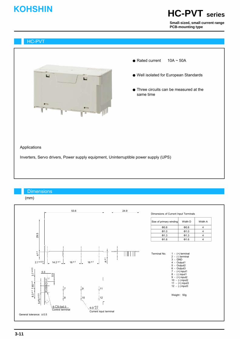
Inverters, Servo drivers, Power supply equipment, Uninterruptible power supply (UPS)
Rated current 10A ~ 50A
Applications
Three circuits can be measured at the same time
Well isolated for European Standards
HC-PVT
Dimensions(mm)
seriesHC-PVTKOHSHIN
3-11
General tolerance: ±0.5
Size of primary winding Width D
Dimensions of Current Input Terminals
Width A
Φ1.3
Φ1.6
Φ1.3
Φ1.6
4
4
Φ0.8
Φ1.0
Φ0.8
Φ1.0
4
4
Terminal No. 1 - (+) terminal2 - (-) terminal3 - GND4 - Output15 - Output26 - Output37 - (+) input18 - (-) input19 - (+) input210 - (-) input211 - (+) input312 - (-) input3
Weight : 50g
53.6 24.9
14.2±1 16±1 16±1
7
8
9
10
11
12
6
12345
3.7±
0.5
7.65
±1
0.3
0.5
6- 0.5x0.3 6-D+0.2-0.1Control terminal
Current input terminal
29.5
4±
1
A±
1
2.7±0.5
5-P
2±
0.5
8.3±
1
Small-sized, small current rangePCB-mounting type

The indicated residual output is the one after the core hysteresis is removed.Note1)
Characteristics chart HC-PVT10V4B15 Time base: 5μs/div.
seriesHC-PVT
Output voltage2V/div.
Output voltage50mV/div.
Input voltage150V/div.
Input current5A/div.
Ta=25
Output voltage0.2V/div.
Specification Ta=25
3-12
Pulse current response characteristic
Noise characteristics (Effects of impulse noise)
Noise characteristics (Effects of dv/dt)
Input/output characteristics
V0±4V±2% (RL=10kΩ)
Within ±1%
Within 10μs (at di/dt=If/μs)
Within 10%
Within 100mV
Within ±0.1%/
±15V±5%
Within 60mA
-10~+80
-15~+85
2500V AC 50/60Hz 1minute
Not less than 500MΩ 500V DC
Within ±100mV
Within ±3mV/
HC-PVT10V4B15 HC-PVT20V4B15 HC-PVT30V4B15 HC-PVT50V4B15
±10A
±27.6A
0~±20A
±20A
±46A
0~±33.3A
±30A
±69A
0~±50A
±50A
±138A
0~±100A
Φ1.0 Φ1.0 Φ1.3 Φ1.6
0
-100 0
100 50
5
15
-5
-15
Out
put v
olta
ge(V
)
Input current(A)
-50
-10
10
HC-PVT10V4B15
HC-PVT30V4B15
150
-150
HC-PVT50V4B15
HC-PVT20V4B15
±13.8A ±13.8A ±23.3A ±35.4A
5 3 2 1
Insulation resistance
Continuously flowing DC current
Type
Rated current
Saturation current
Linearity limits
Rated output
Residual output
Output linearity
Response time
Response performance
Hysteresis voltage range
Consumption current
Residual output Temp. Coef.
Output Temp. Coef.
Control power supply
Operating Temp.
Storage Temp.
Dielectric withstand voltage
[ If ]
[ Is ]
[ Vh ]
[ Vo ]
Size of primary winding
Turns
KOHSHIN
Note: The marks " " means 0V or 0A.
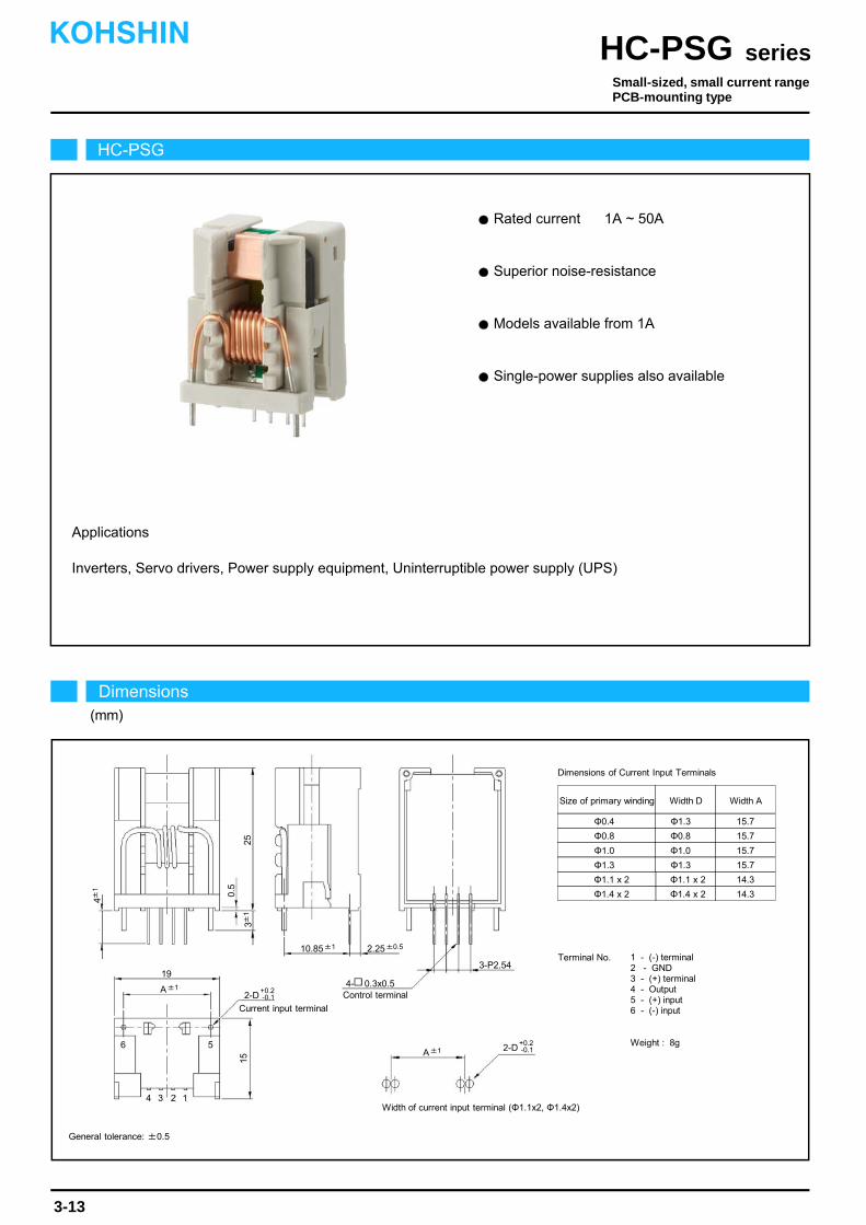
Rated current 1A ~ 50A
Applications
Superior noise-resistance
Models available from 1A
Single-power supplies also available
Inverters, Servo drivers, Power supply equipment, Uninterruptible power supply (UPS)
HC-PSG
Dimensions(mm)
seriesHC-PSGKOHSHIN
3-13
General tolerance: ±0.5
Small-sized, small current rangePCB-mounting type
19
6
15
4±1
Control terminal
5
4 3 2 1
25
4- 0.3x0.5
3-P2.54
Φ0.4x1
Φ0.8x1
Φ1.3x1
Φ0.800
Size of primary winding Width D
Dimensions of Current Input Terminals
15.7
15.7
Terminal No. 1 - (-) terminal2 - GND3 - (+) terminal4 - Output5 - (+) input6 - (-) input
Weight : 8g
Φ1.1 x 2
Φ1.4 x 2
Φ1.1 x 2
Φ1.4 x 2
14.3
14.3
Width A
2-D+0.2-0.1
Current input terminal
0.5
10.85±1 2.25±0.5
A±1
3±1
A±1 2-D+0.2-0.1
Width of current input terminal (Φ1.1x2, Φ1.4x2)
Φ1.0x1
Φ1.3x1
Φ1.000
Φ1.3x1
15.7
15.7

The indicated residual output is the one after the core hysteresis is removed.Note1)
Characteristics chart HC-PSG05V4B15 Time base: 5μs/div.
seriesHC-PSG
Output voltage2V/div.
Output voltage50mV/div.
Input voltage150V/div.
Input current2.5A/div.
Ta=25
Output voltage0.2V/div.
Specification Ta=25
3-14
Pulse current response characteristic
Noise characteristics (Effects of impulse noise)
Noise characteristics (Effects of dv/dt)
Input/output characteristics
Type
Output linearity
Response time
Response performance
Hysteresis voltage range
Consumption current
Residual output Temp. Coef.
Output Temp. Coef.
Control power supply
Operating Temp.
Storage Temp.
Dielectric withstand voltage
Insulation resistance
[ Is ]
±4V±2% (RL=10kΩ)
Within ±100mV
Within 10%
Within 100mV
Within ±0.1%/
±15V±5%
Within 30mA
-10~+80
-15~+85
2500V AC 50/60Hz 1minute
Not less than 500MΩ 500V DC
Within ±6mV/
HC-PSG01V4B15 HC-PSG05V4B15 HC-PSG10V4B15 HC-PSG20V4B15
±1A
±2.2A
±3A
±5A
±8.8A
±15A
±10A
±13.8A
±30A
±20A
±23.3A
±45A
0~±2.5A 0~±12.5A 0~±25A 0~±37.5A
HC-PSG30V4B15
±30A
±33.4A
±90A
0~±75A
HC-PSG50V4B15
±50A
±54.1A
±90A
0~±75A
Continuously flowing DC current
Rated current
Linearity limits
Rated output
Residual output
Size of primary winding
Saturation current
Turns
[ If ]
[ Vh ]
[ Vo ]
Within ±1%
Within 10μs (at di/dt=If/μs)
Φ0.4 Φ0.8 Φ1.0 Φ1.3 Φ1.1 x 2 Φ1.4 x 2
30 6 3 2 1 1
0
-60 -30 -45 0
60 4530 15
5
15
-5
-15
Out
put v
olta
ge(V
)
Input current(A)
-15
-10
10
HC-PSG10V4B15
HC-PSG30V4B15
HC-PSG05V4B15
HC-PSG50V4B15
HC-PSG20V4B15
-75
75
KOHSHIN
Note: The marks " " means 0V or 0A.
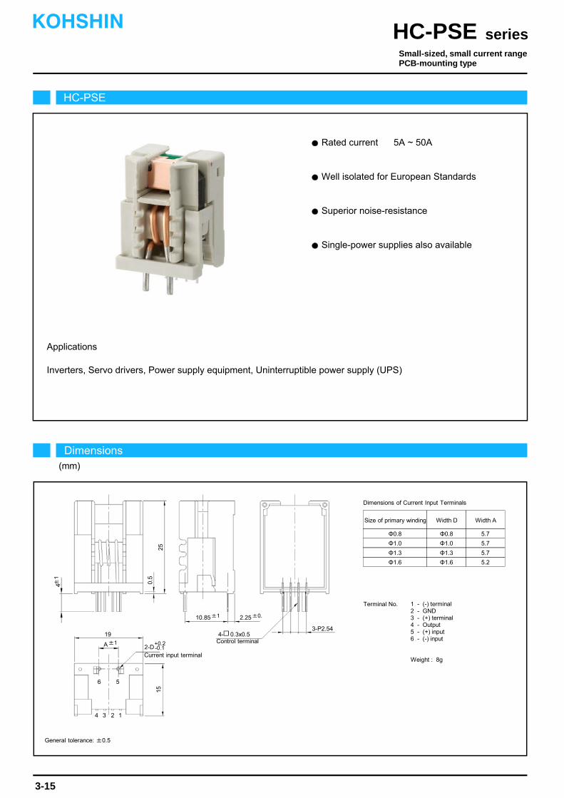
Rated current 5A ~ 50A
Applications
Well isolated for European Standards
Superior noise-resistance
Single-power supplies also available
Inverters, Servo drivers, Power supply equipment, Uninterruptible power supply (UPS)
HC-PSE
Dimensions(mm)
seriesHC-PSEKOHSHIN
3-15
General tolerance: ±0.5
Small-sized, small current rangePCB-mounting type
19
6
15
4±1
Control terminal
5
4 3 2 1
25
4- 0.3x0.53-P2.54
Terminal No. 1 - (-) terminal2 - GND3 - (+) terminal4 - Output5 - (+) input6 - (-) input
Weight : 8g
Φ0.8
Φ1.0
Φ1.3
Φ1.6
Φ0.8
Φ1.0
Φ1.3
Φ1.6
Size of primary winding Width D
Dimensions of Current Input Terminals
5.7
5.7
5.7
5.2
Width A
Current input terminal
0.5
10.85±1 2.25±0.
A±12-D
+0.2-0.1

The indicated residual output is the one after the core hysteresis is removed.Note1)
Characteristics chart HC-PSE05V4B15 Time base: 5μs/div.
seriesHC-PSE
Output voltage2V/div.
Output voltage50mV/div.
Input voltage150V/div.
Input current2.5A/div.
Ta=25
Output voltage0.2V/div.
Specification Ta=25
3-16
Pulse current response characteristic
Noise characteristics (Effects of impulse noise)
Noise characteristics (Effects of dv/dt)
Input/output characteristics
Type
Output linearity
Response time
Response performance
Hysteresis voltage range
Consumption current
Residual output Temp. Coef.
Output Temp. Coef.
Control power supply
Operating Temp.
Storage Temp.
Dielectric withstand voltage
Insulation resistance
[ Is ]
±4V±2% (RL=10kΩ)
Within ±100mV
Within 10%
Within 100mV
Within ±0.1%/
±15V±5%
Within 30mA
-10~+80
-15~+85
2500V AC 50/60Hz 1minute
Not less than 500MΩ 500V DC
Within ±6mV/
HC-PSE05V4B15 HC-PSE10V4B15 HC-PSE20V4B15
±5A
±8.8A
±15A
±10A
±13.8A
±30A
±20A
±23.3A
±45A
0~±12.5A 0~±25A 0~±37.5A
HC-PSE30V4B15
±30A
±23.3A
±90A
0~±75A
HC-PSE50V4B15
±50A
±35.4A
±90A
0~±75A
Continuously flowing DC current
Rated current
Linearity limits
Rated output
Residual output
Size of primary winding
Saturation current
Turns
[ If ]
[ Vh ]
[ Vo ]
Within ±1%
Within 10μs (at di/dt=If/μs)
Φ0.8 Φ1.0 Φ1.3 Φ1.3 Φ1.6
6 3 2 1 1
0
-60 -30 -45 0
60 4530 15
5
15
-5
-15
Out
put v
olta
ge(V
)
Input current(A)
-15
-10
10
HC-PSE10V4B15
HC-PSE30V4B15
HC-PSE05V4B15
HC-PSE50V4B15
HC-PSE20V4B15
-75
75
KOHSHIN
Note: The marks " " means 0V or 0A.
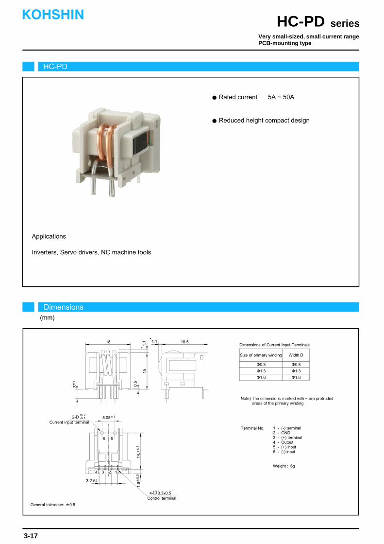
Rated current 5A ~ 50A
Reduced height compact design
Inverters, Servo drivers, NC machine tools
Applications
2-D+0.2-0.1
18
6
0.5
Current input terminal
18.51.1
5.08±1
3±1
14.7±
11.
8±0
.5
Control terminal
5
4 3 2 1
151.
1*
*
4- 0.3x0.5
3-2.54
HC-PD
Dimensions(mm)
seriesHC-PDKOHSHIN
3-17
General tolerance: ±0.5
Very small-sized, small current rangePCB-mounting type
Φ0.8
Φ1.3
Φ1.6
Φ0.8
Φ1.3
Φ1.6
Size of primary winding Width D
Dimensions of Current Input Terminals
Note) The dimensions marked with are protrudedareas of the primary winding
*
Terminal No. 1 - (-) terminal2 - GND3 - (+) terminal4 - Output5 - (+) input6 - (-) input
Weight : 6g

The indicated residual output is the one after the core hysteresis is removed.Note1)
Characteristics chart HC-PD05V4B15 Time base: 5μs/div.
seriesHC-PD
Output voltage2V/div.
Output voltage100mV/div.
Input voltage150V/div.
Input current2.5A/div.
Ta=25
Output voltage5V/div.
Note: The marks " " means 0V or 0A.
Specification Ta=25
3-18
Pulse current response characteristic
Noise characteristics (Effects of impulse noise)
Noise characteristics (Effects of dv/dt)
Input/output characteristics
Type
Output linearity
Response time
Response performance
Hysteresis voltage range
Consumption current
Residual output Temp. Coef.
Output Temp. Coef.
Control power supply
Operating Temp.
Storage Temp.
Dielectric withstand voltage
Insulation resistance
[ Is ]
±4V±2% (RL=10kΩ)
Within ±100mV
Within 10%
Within 100mV
Within ±0.1%/
±15V±5%
Within 30mA
-10~+80
-15~+85
2500V AC 50/60Hz 1minute
Not less than 500MΩ 500V DC
Within ±6mV/
HC-PD05V4B15 HC-PD10V4B15 HC-PD20V4B15
±5A
±8.8A
±15A
±10A
±23.3A
±30A
±20A
±23.3A
±45A
0~±12.5A 0~±25A 0~±37.5A
HC-PD30V4B15
±30A
±35.4A
±90A
0~±75A
HC-PD50V4B15
±50A
±35.4A
±90A
0~±75A
Continuously flowing DC current
Rated current
Linearity limits
Rated output
Residual output
Size of primary winding
Saturation current
Turns
[ If ]
[ Vh ]
[ Vo ]
Within ±1%
Within 10μs (at di/dt=If/μs)
Φ0.8 Φ1.3 Φ1.3 Φ1.6 Φ1.6
6 3 2 1 1
0
-60 -30 -45 0
60 4530 15
5
15
-15
Out
put v
olta
ge(V
)
Input current(A)
-15
10
HC-PD10V4B15
HC-PD30V4B15
HC-PD05V4B15
HC-PD50V4B15
HC-PD20V4B15
-75
75
-5
-10
KOHSHIN
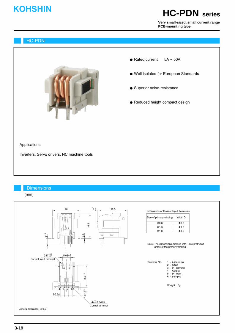
Rated current 5A ~ 50A
Superior noise-resistance
Inverters, Servo drivers, NC machine tools
Well isolated for European Standards
Applications
Reduced height compact design
HC-PDN
Dimensions(mm)
seriesHC-PDNKOHSHIN
3-19
General tolerance: ±0.5
Very small-sized, small current rangePCB-mounting type
2-ΦD+0.
-
18
6
0.5
Current input terminal
18.51.1
5.08±1
3±1
14.7±
11.
8±
0.5
Control terminal
5
4 3 2 1
16.5
*
4- 0.3x0.5
Φ0.8
Φ1.3
Φ1.6
Φ0.8
Φ1.3
Φ1.6
Size of primary winding Width D
Dimensions of Current Input Terminals
Note) The dimensions marked with are protrudedareas of the primary winding
*
Terminal No. 1 - (-) terminal2 - GND3 - (+) terminal4 - Output5 - (+) input6 - (-) input
Weight : 6g
2-D+0.2-0.1
3-2.54

The indicated residual output is the one after the core hysteresis is removed.Note1)
Characteristics chart HC-PDN05V4B15 Time base: 5μs/div.
seriesHC-PDN
Output voltage2V/div.
Output voltage50mV/div.
Input voltage150V/div.
Input current2.5A/div.
Ta=25
Output voltage0.2V/div.
Note: The marks " " means 0V or 0A.
Specification Ta=25
3-20
Pulse current response characteristic
Noise characteristics (Effects of impulse noise)
Noise characteristics (Effects of dv/dt)
Input/output characteristics
Type
Output linearity
Response time
Response performance
Hysteresis voltage range
Consumption current
Residual output Temp. Coef.
Output Temp. Coef.
Control power supply
Operating Temp.
Storage Temp.
Dielectric withstand voltage
Insulation resistance
[ Is ]
±4V±2% (RL=10kΩ)
Within ±100mV
Within 10%
Within 100mV
Within ±0.1%/
±15V±5%
Within 30mA
-10~+80
-15~+85
2500V AC 50/60Hz 1minute
Not less than 500MΩ 500V DC
Within ±6mV/
HC-PDN05V4B15 HC-PDN10V4B15 HC-PDN20V4B15
±5A
±8.8A
±15A
±10A
±23.3A
±30A
±20A
±23.3A
±45A
0~±12.5A 0~±25A 0~±37.5A
HC-PDN30V4B15
±30A
±35.4A
±90A
0~±75A
HC-PDN50V4B15
±50A
±35.4A
±90A
0~±75A
Continuously flowing DC current
Rated current
Linearity limits
Rated output
Residual output
Size of primary winding
Saturation current
Turns
[ If ]
[ Vh ]
[ Vo ]
Within ±1%
Within 10μs (at di/dt=If/μs)
Φ0.8 Φ1.3 Φ1.3 Φ1.6 Φ1.6
6 3 2 1 1
0
-60 -30 -45 0
60 4530 15
5
15
-5
-15
Out
put v
olta
ge(V
)
Input current(A)
-15
-10
10
HC-PDN10V4B15
HC-PDN30V4B15
HC-PDN05V4B15
HC-PDN50V4B15
HC-PDN20V4B15
-75
75
KOHSHIN
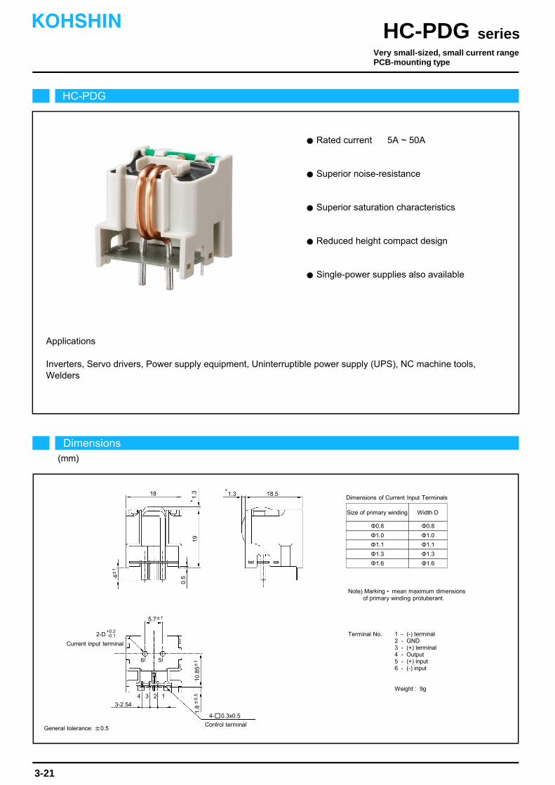
Rated current 5A ~ 50A
Superior saturation characteristics
Single-power supplies also available
Inverters, Servo drivers, Power supply equipment, Uninterruptible power supply (UPS), NC machine tools,Welders
Superior noise-resistance
Applications
Reduced height compact design
Terminal No. 1 - (-) terminal2 - GND3 - (+) terminal4 - Output5 - (+) input6 - (-) input
Weight : 9g
Φ0.8
Φ1.0
Φ1.1
Φ1.3
Φ0.8
Φ1.0
Φ1.1
Φ1.3
Size of primary winding Width D
Dimensions of Current Input Terminals
Note) Marking mean maximum dimensionsof primary winding protuberant.
*
HC-PDG
Dimensions(mm)
seriesHC-PDGKOHSHIN
3-21
General tolerance: ±0.5
Very small-sized, small current rangePCB-mounting type
Φ1.6 Φ1.6
18
6
0.5
Current input terminal
18.51.3
5.7±1
4±1
10.8
5±1
1.8±
0.5
Control terminal
5
4 3 1
191.
3*
*
4- 0.3x0.5
3-2.54
2-D+0.2-0.1
2

The indicated residual output is the one after the core hysteresis is removed.Note1)
Out
put v
olta
ge(V
)
Input current(A)
0
-120 -60 -90 0
120 9060 30
5
15
-5
-15
-30
-10
10
HC-PDG10V4B15
HC-PDG30V4B15HC-PDG05V4B15
HC-PDG50V4B15
HC-PDG20V4B15
Characteristics chart HC-PDG20V4B15 Time base: 5μs/div.
seriesHC-PDG
Output voltage2V/div.
Output voltage50mV/div.
Input voltage150V/div.
Input current10A/div.
Ta=25
Output voltage0.2V/div.
Note: The marks " " means 0V or 0A.
Specification Ta=25
3-22
Pulse current response characteristic
Noise characteristics (Effects of impulse noise)
Noise characteristics (Effects of dv/dt)
Input/output characteristics
Response performance
Hysteresis voltage range
Consumption current
Residual output Temp. Coef.
Output Temp. Coef.
Control power supply
Operating Temp.
Storage Temp.
Dielectric withstand voltage
Insulation resistance
±4V±1.5% (RL=10kΩ)
Within ±50mV
Within 10%
Within 60mV
Within ±0.1%/
±15V±5%
Within 20mA
-10~+80
-15~+85
2500V AC 50/60Hz 1minute
Not less than 500MΩ 500V DC
Within ±2mV/
HC-PDG05V4B15 HC-PDG10V4B15 HC-PDG20V4B15
±5A
±8.8A
±15A
±10A
±13.8A
±25A
±20A
±23.3A
±50A
0~±13.5A 0~±22.5A 0~±45A
HC-PDG30V4B15
±30A
±23.3A
±75A
0~±67.5A
HC-PDG50V4B15
±50A
±35.4A
±150A
0~±135A
Within ±1%
Within 10μs (at di/dt=If/μs)
Φ0.8 Φ1.0 Φ1.3 Φ1.3 Φ1.6
10 6 3 2 1
KOHSHIN
Type
Rated current
Continuously flowing DC current
Saturation current
Linearity limits
Size of primary winding
Turns
Rated output
Residual output
Output linearity
Response time
[ Is ]
[ If ]
[ Vh ]
[ Vo ]
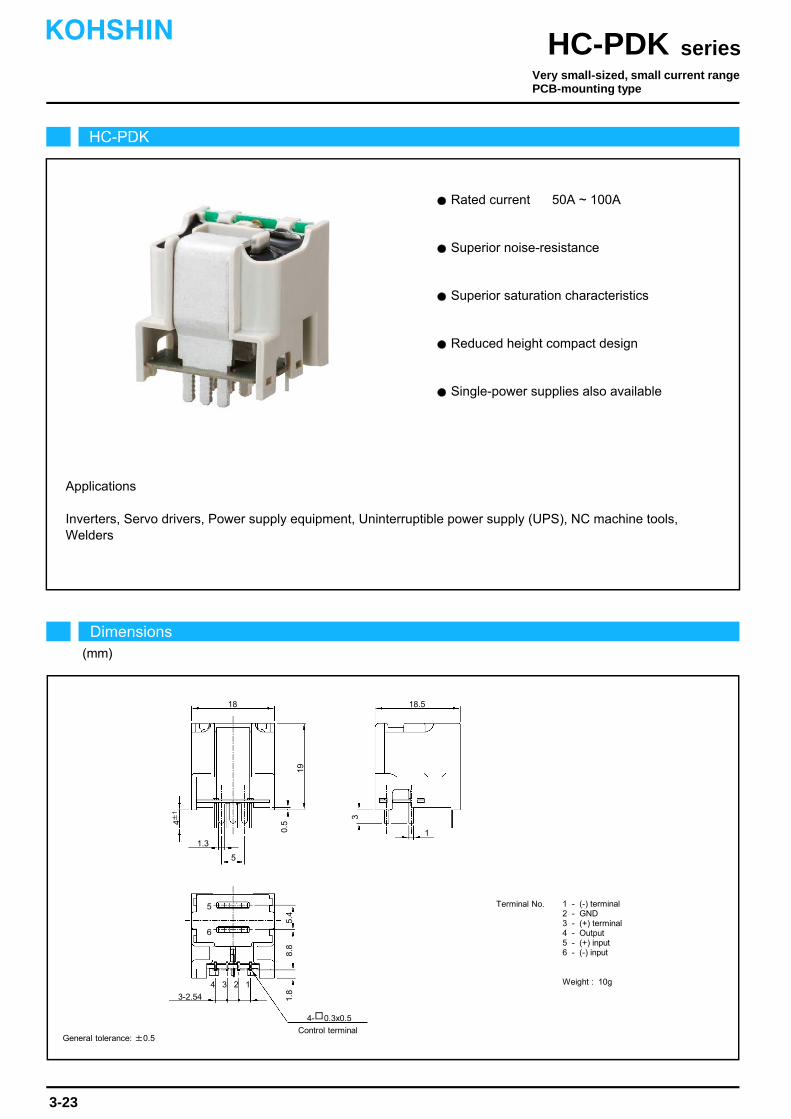
Rated current 50A ~ 100A
Superior saturation characteristics
Single-power supplies also available
Inverters, Servo drivers, Power supply equipment, Uninterruptible power supply (UPS), NC machine tools,Welders
Superior noise-resistance
Applications
Reduced height compact design
Terminal No. 1 - (-) terminal2 - GND3 - (+) terminal4 - Output5 - (+) input6 - (-) input
Weight : 10g
HC-PDK
Dimensions(mm)
seriesHC-PDKKOHSHIN
3-23
General tolerance: ±0.5
Very small-sized, small current rangePCB-mounting type
18
6
0.5
18.5
4±1
8.8
1.8
Control terminal
5
4 3 1
19
4- 0.3x0.5
3-2.54
2
3
11.3
5
5.4

The indicated residual output is the one after the core hysteresis is removed.Note1)
0
-120 -60 -90 0
120 9060 30
5
15
-5
-15
-30
-10
10
HC-PDK60V4B15
HC-PDK100V4B15
HC-PDK50V4B15
150
-150
Characteristics chart HC-PDK60V4B15 Time base: 5μs/div.
seriesHC-PDK
Output voltage2V/div.
Output voltage50mV/div.
Input voltage150V/div.
Input current30A/div.
Ta=25
Output voltage0.2V/div.
Note: The marks " " means 0V or 0A.
Specification Ta=25
3-24
Pulse current response characteristic
Noise characteristics (Effects of impulse noise)
Noise characteristics (Effects of dv/dt)
Input/output characteristics
Response performance
Hysteresis voltage range
Consumption current
Residual output Temp. Coef.
Output Temp. Coef.
Control power supply
Operating Temp.
Storage Temp.
Dielectric withstand voltage
Insulation resistance
±4V±1.5% (RL=10kΩ)
Within ±50mV
Within 10%
Within 60mV
Within ±0.1%/
±15V±5%
Within 20mA
-10~+80
-15~+85
2500V AC 50/60Hz 1minute
Not less than 500MΩ 500V DC
Within ±2mV/
Within ±1%
Within 10μs (at di/dt=If/μs)
KOHSHIN
Type
Rated current
Continuously flowing DC current
Saturation current
Linearity limits
Size of primary busbar
Turns
Rated output
Residual output
Output linearity
Response time
[ Is ]
[ If ]
[ Vh ]
[ Vo ]
Out
put v
olta
ge(V
)
Input current(A)
HC-PDK50V4B15 HC-PDK60V4B15
±50A
±100A
±150A
±60A
0~±135A
HC-PDK100V4B15
±100A
Busbar 1 x 7.8
1

Inverters, Srevo drivers, Power supply equipment, NC machine tools
Rated current 5A ~ 30A
Applications
Requires little space on the PCB
Single-power supllies also avaiable
HC-PL
Dimensions(mm)
seriesHC-PLKOHSHIN
3-25
General tolerance: ±0.5
Very small-sized, small current rangePCB-mounting type
Terminal No. 1 - (+) terminal2 - (-) terminal3 - Output4 - GND5 - (+) input6 - (-) input
Weight : 6g
Φ0.6
Φ0.8
Φ1.0
Φ1.3
Φ0.6
Φ0.8
Φ1.0
Φ1.3
Size of primary winding Width D
Dimensions of Current Input Terminals15
6
14.8
12±1
5
4 3 2 1
20
Current input terminal2-D
+0.2-0.1
4±1
11±12.3±0.5
Control terminal4- 0.3x0.5
3-2.54

The indicated residual output is the one after the core hysteresis is removed.Note1)
Characteristics chart HC-PL10V4B15 Time base: 5μs/div.
seriesHC-PL
Output voltage2V/div.
Output voltage50mV/div.
Input voltage150V/div.
Input current5A/div.
Ta=25
Output voltage1V/div.
Specification Ta=25
3-26
Pulse current response characteristic
Noise characteristics (Effects of impulse noise)
Noise characteristics (Effects of dv/dt)
Input/output characteristics
Type
Output linearity
Response time
Response performance
Hysteresis voltage range
Consumption current
Residual output Temp. Coef.
Output Temp. Coef.
Control power supply
Operating Temp.
Storage Temp.
Dielectric withstand voltage
Insulation resistance
[ Is ]
±4V±2% (RL=10kΩ)
Within ±100mV
Within 10%
Within 100mV
Within ±0.1%/
±15V±5%
Within 30mA
-10~+80
-15~+85
2500V AC 50/60Hz 1minute
Not less than 500MΩ 500V DC
Within ±2mV/
HC-PL05V4B15 HC-PL10V4B15 HC-PL20V4B15
±5A
±8.8A
±12.5A
±10A
±8.8A
±25A
±20A
±13.8A
±37.5A
0~±10A 0~±20A 0~±30A
HC-PL30V4B15
±30A
±23.3A
±75A
0~±60A
Continuously flowing DC current
Rated current
Linearity limits
Rated output
Residual output
Size of primary winding
Saturation current
Turns
[ If ]
[ Vh ]
[ Vo ]
Within ±1%
Within 10μs (at di/dt=If/μs)
Φ0.8 Φ0.8 Φ1.0 Φ1.3
6 3 2 1
0
-60 -30 -45 0
60 4530 15
5
15
-5
-15
Out
put v
olta
ge(V
)
Input current(A)
-15
-10
10
HC-PL10V4B15
HC-PL30V4B15
HC-PL05V4B15HC-PL20V4B15
-75
75
KOHSHIN
Note: The marks " " means 0V or 0A.
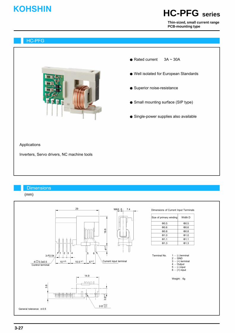
Rated current 3A ~ 30A
Superior noise-resistance
Single-power supplies also available
Inverters, Servo drivers, NC machine tools
Well isolated for European Standards
Applications
Small mounting surface (SIP type)
HC-PFG
Dimensions(mm)
seriesHC-PFGKOHSHIN
3-27
General tolerance: ±0.5
Thin-sized, small current rangePCB-mounting type
Dimensions of Current Input Terminals29
6
3.8
Current input terminal
MAX. 6
4±1
3.6±
1
Control terminal
54321
19.6
4- 0.3x0.5
2-D+0.2-0.1
10.5±110±0. 6±1
3-P2.54
7.4
Terminal No. 1 - (-) terminal2 - GND3 - (+) terminal4 - Output5 - (-) input6 - (+) input
Weight : 6g
Φ0.5
Φ0.6
Φ0.5
Φ0.6
Size of primary winding Width D
Φ1.1
Φ1.3
Φ1.1
Φ1.3
Φ0.8 Φ0.8
Φ1.0 Φ1.0
14.9

The indicated residual output is the one after the core hysteresis is removed.Note1)
Characteristics chart HC-PFG10V4B15 Time base: 5μs/div.
seriesHC-PFG
Output voltage2V/div.
Output voltage50mV/div.
Input voltage150V/div.
Input current5A/div.
Ta=25
Output voltage0.5V/div.
Note: The marks " " means 0V or 0A.
Specification Ta=25
3-28
Pulse current response characteristic
Noise characteristics (Effects of impulse noise)
Noise characteristics (Effects of dv/dt)
Input/output characteristics
Type
Output linearity
Response time
Response performance
Hysteresis voltage range
Consumption current
Residual output Temp. Coef.
Output Temp. Coef.
Control power supply
Operating Temp.
Storage Temp.
Dielectric withstand voltage
Insulation resistance
[ Is ]
±4V±2% (RL=10kΩ)
Within ±100mV
Within 10%
Within 100mV
Within ±0.1%/
±15V±5%
Within 30mA
-10~+80
-15~+85
2500V AC 50/60Hz 1minute
Not less than 500MΩ 500V DC
Within ±3mV/
HC-PFG03V4B15 HC-PFG05V4B15 HC-PFG10V4B15
±3A
±5A
±9A
±5A
±8.8A
±15A
±10A
±8.8A
±30A
0~±7.5A 0~±12.5A 0~±25A
HC-PFG20V4B15
±20A
±23.3A
±60A
0~±60A
HC-PFG30V4B15
±30A
±23.3A
±75A
0~±62.5A
Continuously flowing DC current
Rated current
Linearity limits
Rated output
Residual output
Size of primary winding
Saturation current
Turns
[ If ]
[ Vh ]
[ Vo ]
Within ±1%
Within 10μs (at di/dt=If/μs)
Φ0.6 Φ0.8 Φ0.8 Φ1.3 Φ1.3
16 10 5 2 2
0
-50 -25-37.5 0
50 37.525 12.5
5
15
-5
-15
Out
put v
olta
ge(V
)
Input current(A)
-12.5
-10
10
HC-PFG05V4B15HC-PFG03V4B15
HC-PFG30V4B15
HC-PFG10V4B15
-62.5
62.5
HC-PFG20V4B15
KOHSHIN
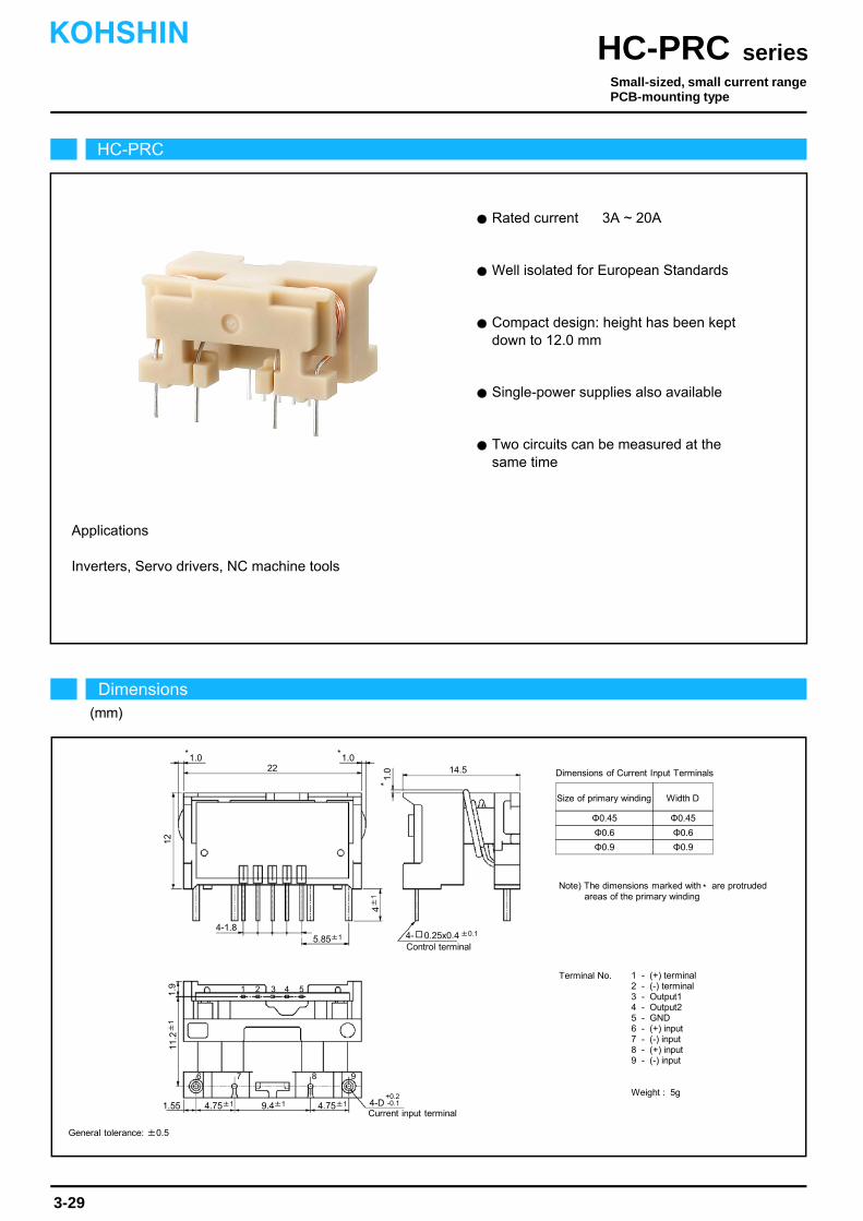
Rated current 3A ~ 20A
Well isolated for European Standards
Applications
Inverters, Servo drivers, NC machine tools
Compact design: height has been kept down to 12.0 mm
Single-power supplies also available
Two circuits can be measured at the same time
22 14.5
Control terminal
1
12
5432
7 8 9
11.2
±1
1.9
4±
1
5.85±1
9.4±14.75±1 4.75±1
6
1.55
1.0
*
1.0*1.0*
4- 0.25x0.4 ±0.1
Current input terminal4-D
+0.2-0.1
4-1.8
HC-PRC
Dimensions(mm)
seriesHC-PRCKOHSHIN
3-29
General tolerance: ±0.5
Small-sized, small current rangePCB-mounting type
Terminal No. 1 - (+) terminal2 - (-) terminal3 - Output14 - Output25 - GND6 - (+) input7 - (-) input8 - (+) input9 - (-) input
Weight : 5g
Φ0.45
Φ0.6
Φ0.9
Φ0.45
Φ0.6
Φ0.9
Size of primary winding Width D
Dimensions of Current Input Terminals
Note) The dimensions marked with are protrudedareas of the primary winding
*

The indicated residual output is the one after the core hysteresis is removed.Note1)
Characteristics chart HC-PRC05V4B15 Time base: 5μs/div.
seriesHC-PRC
Output voltage2V/div.
Output voltage100mV/div.
Input voltage150V/div.
Input current2.5A/div.
Ta=25
Output voltage1V/div.
Specification Ta=25
3-30
Pulse current response characteristic
Noise characteristics (Effects of impulse noise)
Noise characteristics (Effects of dv/dt)
Input/output characteristics
Type
Output linearity
Response time
Response performance
Hysteresis voltage range
Consumption current
Residual output Temp. Coef.
Output Temp. Coef.
Control power supply
Operating Temp.
Storage Temp.
Dielectric withstand voltage
Insulation resistance
[ Is ]
V0+4V±1.5% (RL=10kΩ)
Within ±100mV
Within 10%
Within 120mV
Within ±0.1%/
±15V±5%
Within 40mA
-10~+80
-15~+85
2500V AC 50/60Hz 1minute
Not less than 500MΩ 500V DC
Within ±3mV/
HC-PRC03V4B15 HC-PRC05V4B15 HC-PRC10V4B15
±3A
±3.5A
±9A
±5A
±3.5A
±15A
±10A
±8.8A
±30A
0~±7.5A 0~±12.5A 0~±25A
HC-PRC20V4B15
±20A
±8.8A
±45A
0~±37.5A
Continuously flowing DC current
Rated current
Linearity limits
Rated output
Residual output
Size of primary winding
Saturation current
Turns
[ If ]
[ Vh ]
[ Vo ]
Within ±1%
Within 10μs (at di/dt=If/μs)
Φ0.45 Φ0.45 Φ0.9 Φ0.9
10 6 3 2
0
-60 -30 -45 0
60 4530 15
5
15
-5
-15
Out
put v
olta
ge(V
)
Input current(A)
-15
-10
10
HC-PRC10V4B15
HC-PRD30V4B15
HC-PRC05V4B15
HC-PRD50V4B15
HC-PRC20V4B15
-75
75
V0-4V±1.5% (RL=10kΩ)
+If
-If
KOHSHIN
Note: The marks " " means 0V or 0A.
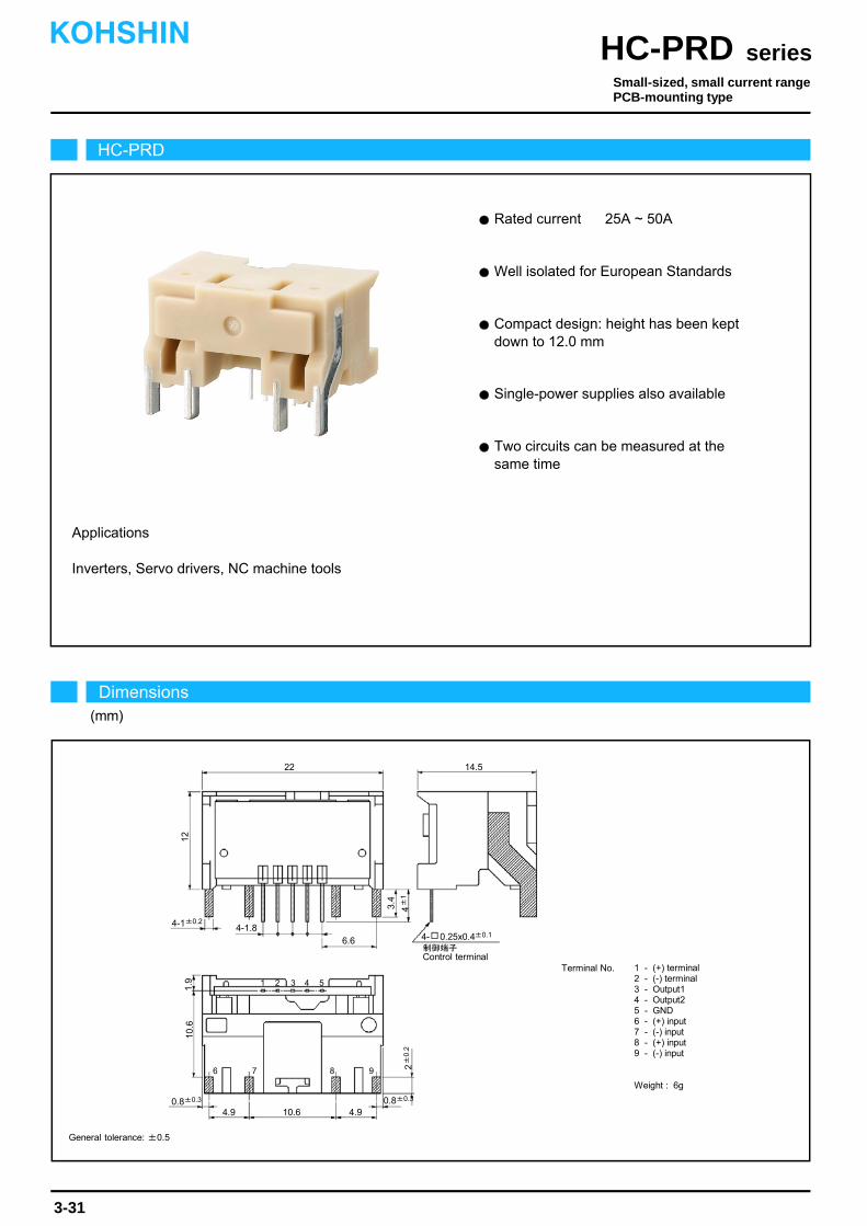
Applications
Well isolated for European Standards
Single-power supplies also available
Rated current 25A ~ 50A
Compact design: height has been kept down to 12.0 mm
Inverters, Servo drivers, NC machine tools
Two circuits can be measured at the same time
HC-PRD
Dimensions(mm)
seriesHC-PRDKOHSHIN
3-31
Small-sized, small current rangePCB-mounting type
22
6
3.4
14.5
4-1±0.2
制御端子Control terminal
1
12
5432
7 8 9
10.6
1.9
4±
12±
0.2
4-1.86.6
10.64.9 4.90.8±0.3 0.8±0.3
4- 0.25x0.4±0.1
Terminal No. 1 - (+) terminal2 - (-) terminal3 - Output14 - Output25 - GND6 - (+) input7 - (-) input8 - (+) input9 - (-) input
Weight : 6g
General tolerance: ±0.5

The indicated residual output is the one after the core hysteresis is removed.Note1)
Characteristics chart HC-PRD30V4B15 Time base: 5μs/div.
seriesHC-PRD
Output voltage2V/div.
Output voltage100mV/div.
Input voltage150V/div.
Input current15A/div.
Ta=25
Output voltage1V/div.
Specification Ta=25
3-32
Pulse current response characteristic
Noise characteristics (Effects of impulse noise)
Noise characteristics (Effects of dv/dt)
Input/output characteristics
Type
Output linearity
Response time
Response performance
Hysteresis voltage range
Consumption current
Residual output Temp. Coef.
Output Temp. Coef.
Control power supply
Operating Temp.
Storage Temp.
Dielectric withstand voltage
Insulation resistance
[ Is ]
V0+4V±1.5% (RL=10kΩ)
Within ±100mV
Within 10%
Within 120mV
Within ±0.1%/
±15V±5%
Within 40mA
-10~+80
-15~+85
2500V AC 50/60Hz 1minute
Not less than 500MΩ 500V DC
Within ±3mV/
HC-PRD25V4B15 HC-PRD30V4B15 HC-PRD40V4B15
±25A
±35A
±75A
±30A
±35A
±90A
±40A
±35A
±90A
0~±75A 0~±75A 0~±75A
HC-PRD50V4B15
±50A
±35A
±90A
0~±75A
Continuously flowing DC current
Rated current
Linearity limits
Rated output
Residual output
Size of primary busbar
Saturation current
Turns
[ If ]
[ Vh ]
[ Vo ]
Within ±1%
Within 10μs (at di/dt=If/μs)
1 x 2 1 x 2 1 x 2 1 x 2
1 1 1 1
0
-60 -30 -45 0
60 4530 15
5
15
-15
Out
put v
olta
ge(V
)
Input current(A)
-15
10
HC-PRC10V4B15
HC-PRD30V4B15
HC-PRC05V4B15
HC-PRD50V4B15
HC-PRC20V4B15
-75
75
-5
-10
V0-4V±1.5% (RL=10kΩ)
+If
-If
KOHSHIN
Note: The marks " " means 0V or 0A.
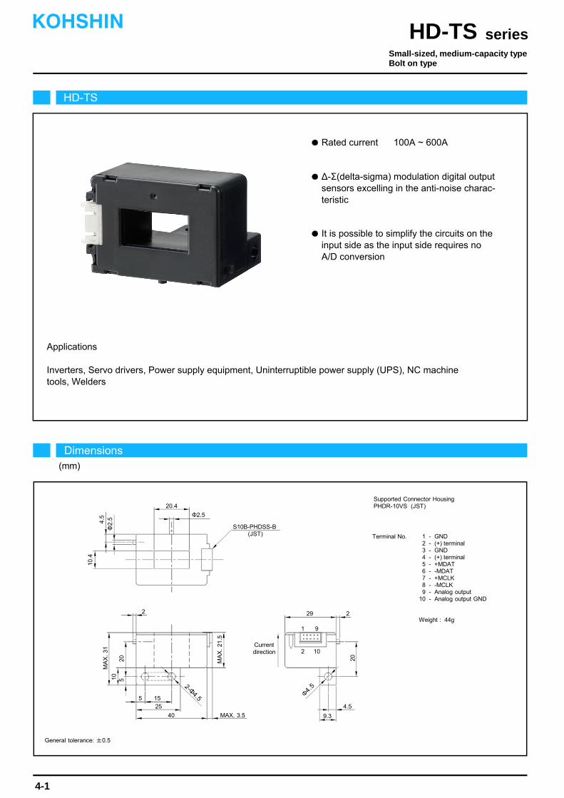
∆-Σ(delta-sigma) modulation digital output sensors excelling in the anti-noise charac- teristic.
It is possible to simplify the circuits on the input side as the input side requires no A/D conversion.
Applications
Rated current 100A ~ 600A
Inverters, Servo drivers, Power supply equipment, Uninterruptible power supply (UPS), NC machinetools, Welders
HD-TS
Dimensions(mm)
seriesHD-TSKOHSHIN
4-1
General tolerance: ±0.5
Small-sized, medium-capacity typeBolt on type
20.4
Current direction
MA
X.
31
Φ2.5
S10B-PHDSS-B(JST)
2 29
20
4.5
9.3MAX. 3.540
255
2
MA
X.
21.5
10.4
4.5
Φ2.
5
Supported Connector HousingPHDR-10VS (JST)
Terminal No. 1 - GND2 - (+) terminal3 - GND4 - (+) terminal5 - +MDAT6 - -MDAT7 - +MCLK8 - -MCLK9 - Analog output
10 - Analog output GND
Weight : 44g
10 520
15
1 9
2 10
Φ4.52-Φ
4.5
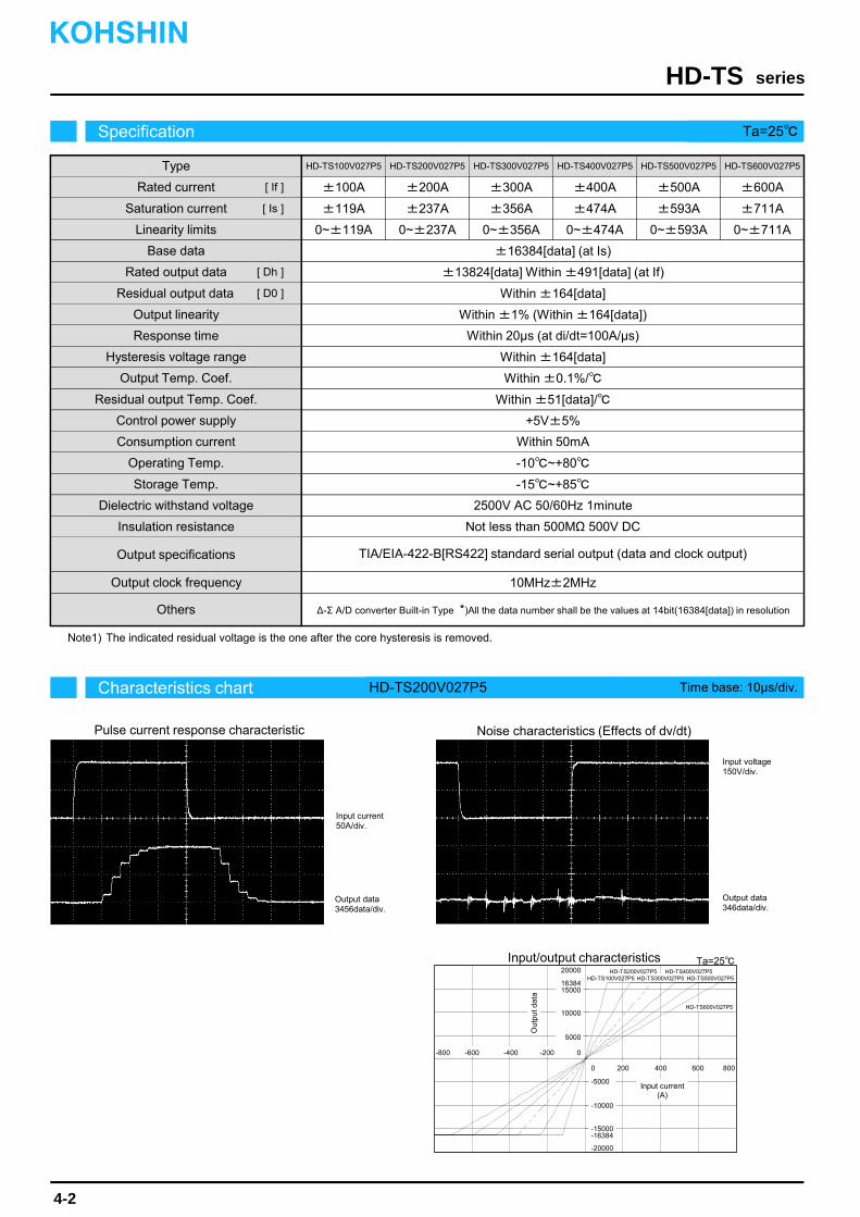
The indicated residual voltage is the one after the core hysteresis is removed.Note1)
Characteristics chart HD-TS200V027P5 Time base: 10μs/div.
seriesHD-TS
Output data3456data/div.
Output data346data/div.
Input voltage150V/div.
Input current50A/div.
Ta=25
Specification Ta=25
4-2
Pulse current response characteristic Noise characteristics (Effects of dv/dt)
Input/output characteristics
Type
Output linearity
Response time
Hysteresis voltage range
Consumption current
Residual output Temp. Coef.
Output Temp. Coef.
Control power supply
Operating Temp.
Storage Temp.
Dielectric withstand voltage
Others
[ Is ]
±13824[data] Within ±491[data] (at If)
Within ±164[data]
Within ±164[data]
Within ±0.1%/
+5V±5%
Within 50mA
-10~+80
-15~+85
2500V AC 50/60Hz 1minute
Within ±51[data]/
HD-TS100V027P5 HD-TS200V027P5 HD-TS300V027P5 HD-TS400V027P5
±100A
±119A
±200A
±237A
±300A
±356A
±400A
±474A
0~±119A 0~±237A 0~±356A 0~±474A
HD-TS500V027P5
±500A
±593A
0~±593A
HD-TS600V027P5
±600A
±711A
0~±711A
Rated current
Linearity limits
Rated output data
Residual output data
Saturation current
Base data
[ If ]
[ Dh ]
[ D0 ]
Within ±1% (Within ±164[data])
Within 20μs (at di/dt=100A/μs)
±16384[data] (at Is)
Output specifications
Insulation resistance Not less than 500MΩ 500V DC
Output clock frequency 10MHz±2MHz
TIA/EIA-422-B[RS422] standard serial output (data and clock output)
∆-Σ A/D converter Built-in Type *)All the data number shall be the values at 14bit(16384[data]) in resolution
0
-600 -400 0
600400200
10000
20000
-5000
-20000
Out
put d
ata
Input current(A)
-200
-10000
16384
-800
800
15000
5000
-15000-16384
HD-TS600V027P5
HD-TS200V027P5 HD-TS400V027P5HD-TS100V027P5 HD-TS300V027P5 HD-TS500V027P5
KOHSHIN
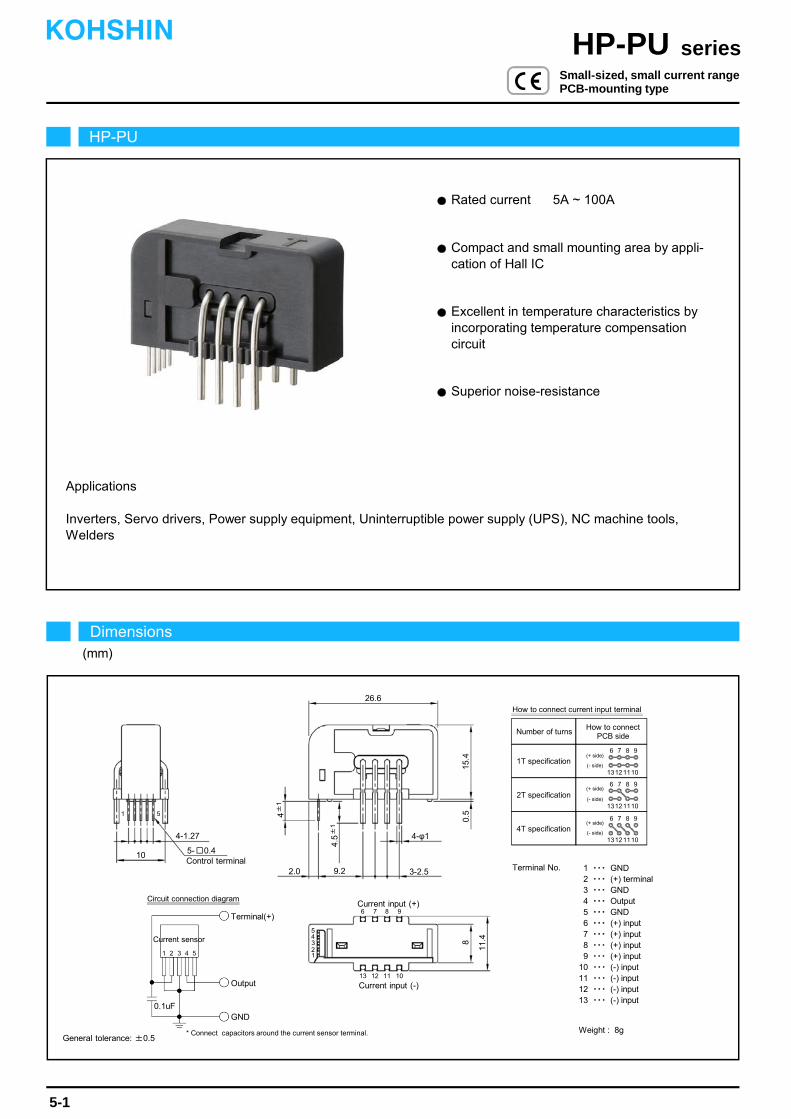
Rated current 5A ~ 100A
Superior noise-resistance
Excellent in temperature characteristics by incorporating temperature compensation circuit
Applications
Compact and small mounting area by appli- cation of Hall IC
Inverters, Servo drivers, Power supply equipment, Uninterruptible power supply (UPS), NC machine tools,Welders
HP-PU
Dimensions(mm)
seriesHP-PUKOHSHIN
5-1
Small-sized, small current rangePCB-mounting type
General tolerance: ±0.5
Terminal No. 1 ・・・ GND2 ・・・ (+) terminal3 ・・・ GND4 ・・・ Output5 ・・・ GND6 ・・・ (+) input7 ・・・ (+) input8 ・・・ (+) input9 ・・・ (+) input
10 ・・・ (-) input11 ・・・ (-) input12 ・・・ (-) input13 ・・・ (-) input
Weight : 8g
Terminal(+)
Output
GND
Current sensor
0.1uF
1 2 3 4 5
Circuit connection diagram
10Control terminal
15.4
0.54±
1
2.0
5- 0.4
4-1.27 4-φ1
3-2.59.2
4.5±
1
26.6
6 7 8 9
13 12 11 10
Current input (+)
Current input (-)
* Connect capacitors around the current sensor terminal.
8
11.4
12345
1 5
Number of turns
1T specification
2T specification
4T specification
How to connect current input terminal
How to connectPCB side
13121110
6 7 8 9
13121110
6 7 8 9
13121110
6 7 8 9
(- side)
(+ side)
(- side)
(+ side)
(- side)
(+ side)
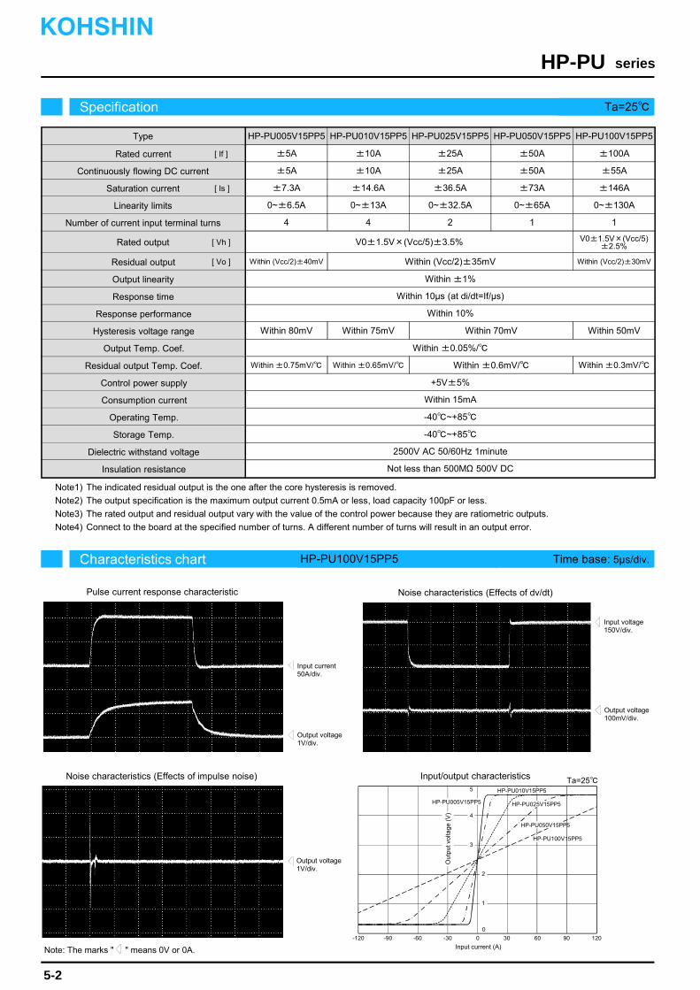
The indicated residual output is the one after the core hysteresis is removed.
The output specification is the maximum output current 0.5mA or less, load capacity 100pF or less.
The rated output and residual output vary with the value of the control power because they are ratiometric outputs.
Connect to the board at the specified number of turns. A different number of turns will result in an output error.
Note1)
Note4)
Note3)
Note2)
Note: The marks " " means 0V or 0A.
Characteristics chart HP-PU100V15PP5 Time base: 5μs/div.
seriesHP-PU
Output voltage1V/div.
Output voltage100mV/div.
Input voltage150V/div.
Input current50A/div.
Output voltage1V/div.
Specification Ta=25
5-2
Pulse current response characteristic
Noise characteristics (Effects of impulse noise)
Noise characteristics (Effects of dv/dt)
V0±1.5V×(Vcc/5)±3.5%
Within (Vcc/2)±35mV
Within 10%
Within 80mV
Within ±0.05%/
+5V±5%
Within 15mA
-40~+85
-40~+85
2500V AC 50/60Hz 1minute
Not less than 500MΩ 500V DC
Within ±0.75mV/
HP-PU005V15PP5 HP-PU010V15PP5 HP-PU025V15PP5
±5A
±5A
±7.3A
±10A
±10A
±14.6A
±25A
±25A
±36.5A
0~±6.5A 0~±13A 0~±32.5A
HP-PU050V15PP5
±50A
±50A
±73A
0~±65A
Within ±1%
Within 10μs (at di/dt=If/μs)
4 4 2 1
KOHSHIN
Within (Vcc/2)±40mV
HP-PU100V15PP5
±100A
±55A
±146A
0~±130A
1
V0±1.5V×(Vcc/5)
Within (Vcc/2)±30mV
±2.5%
Within 75mV Within 70mV Within 50mV
Within ±0.65mV/ Within ±0.6mV/ Within ±0.3mV/
Response performance
Hysteresis voltage range
Consumption current
Residual output Temp. Coef.
Output Temp. Coef.
Control power supply
Operating Temp.
Storage Temp.
Dielectric withstand voltage
Insulation resistance
Type
Rated current
Continuously flowing DC current
Saturation current
Linearity limits
Number of current input terminal turns
Rated output
Residual output
Output linearity
Response time
[ Is ]
[ If ]
[ Vh ]
[ Vo ]
Ta=25Input/output characteristics
0-120 -60-90 120 906030
Out
put v
olta
ge (
V)
Input current (A)
-30
HP-PU010V15PP5
HP-PU050V15PP5
HP-PU005V15PP5
HP-PU100V15PP5
HP-PU025V15PP5
2
3
5
0
4
1
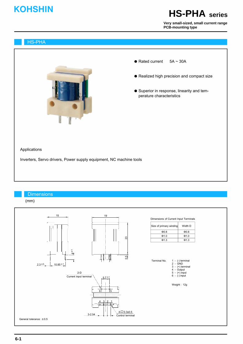
Realized high precision and compact size
Superior in response, linearity and tem- perature characteristics
Rated current 5A ~ 30A
Inverters, Servo drivers, Power supply equipment, NC machine tools
Applications
HS-PHA
Dimensions(mm)
seriesHS-PHAKOHSHIN
6-1
Very small-sized, small current rangePCB-mounting type
Terminal No. 1 - (-) terminal2 - GND3 - (+) terminal4 - Output5 - (+) input6 - (-) input
Weight : 12g
Φ0.8
Φ1.0
Φ1.3
Φ0.8
Φ1.0
Φ1.3
Size of primary winding Width D
Dimensions of Current Input Terminals19
3-2.54
0.5
4±
1
23
2.3±0.
4- 0.3x0.5
2-D
Control terminal
Current input terminal
15
10.85±1
5.7±1
1234
56
General tolerance: ±0.5

The indicated residual output is the one after the core hysteresis is removed.
Energization time of saturation current shall be within 1 second.
Energization time of continuous live DC current x150% shall be within 1 minute.Note3)
Note2)
Note1)
Characteristics chart HS-PHA05V4B15 (RL=10kΩ) Time base: 5μs/div.
seriesHS-PHA
Output voltage2V/div.
Output voltage50mV/div.
Input voltage150V/div.
Input current2.5A/div.
Ta=25
Output voltage0.5V/div.
Specification Ta=25
6-2
Pulse current response characteristic
Noise characteristics (Effects of impulse noise)
Noise characteristics (Effects of dv/dt)
Input/output characteristics
Type
Output linearity
Response time
Response performance
Hysteresis voltage range
Consumption current
Residual output Temp. Coef.
Output Temp. Coef.
Control power supply
Operating Temp.
Storage Temp.
Dielectric withstand voltage
Insulation resistance
[ Is ]
±4V±1.5% (RL=10kΩ)
Within ±30mV
Within 20%
Within 50mV
Within ±0.04%/
±15V±5%
20mA+(Input current x N)/1270
-10~+80
-15~+85
2500V AC 50/60Hz 1minute
Not less than 500MΩ 500V DC
Within ±1mV/
HS-PHA05V4B15 HS-PHA10V4B15 HS-PHA20V4B15
±5A
±3.6A
±12.5A
±10A
±7.2A
±25A
±20A
±14.4A
±50A
0~±10A 0~±20A 0~±40A
HS-PHA30V4B15
±30A
±21.6A
±75A
0~±60A
Continuously flowing DC current
Rated current
Linearity limits
Rated output
Residual output
Size of primary winding
Saturation current
Turns
[ If ]
[ Vh ]
[ Vo ]
Within ±0.5%
Within 3μs (at di/dt=If/μs)
Φ0.8 Φ1.0 Φ1.3 Φ1.3
6 3 1 1
Voltage output type
0
-120 -60 -90 0
120 9060 30
5
15
-5
-15
Out
put v
olta
ge(V
)
Input current(A)
-30
-10
10
HS-PHA10V4B15
HS-PHA30V4B15
HS-PHA05V4B15 HS-PHA20V4B15
KOHSHIN
Note: The marks " " means 0V or 0A.
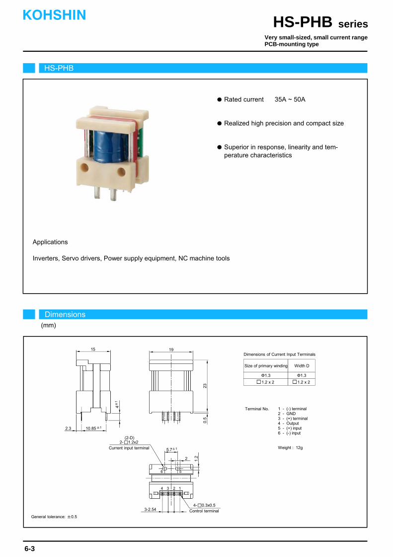
Rated current 35A ~ 50A
Realized high precision and compact size
Superior in response, linearity and tem- perature characteristics
Inverters, Servo drivers, Power supply equipment, NC machine tools
Applications
HS-PHB
Dimensions(mm)
seriesHS-PHBKOHSHIN
6-3
Very small-sized, small current rangePCB-mounting type
Terminal No. 1 - (-) terminal2 - GND3 - (+) terminal4 - Output5 - (+) input6 - (-) input
Weight : 12g
Φ1.3 Φ1.3
Size of primary winding Width D
Dimensions of Current Input Terminals
1.2 x 2 1.2 x 2
19
3-2.54
0.5
4±1
23
2.3
4- 0.3x0.5
(2-D)
Control terminal
Current input terminal
15
10.85±1
5.7±1
1234
56
2- 1.2x2
2 1.2
General tolerance: ±0.5

The indicated residual output is the one after the core hysteresis is removed.
Energization time of saturation current shall be within 1 second.
Energization time of continuous live DC current x150% shall be within 1 minute.
Note1)
Note3)
Note2)
Characteristics chart HS-PHB35V4B15 (RL=10kΩ) Time base: 5μs/div.
seriesHS-PHB
Output voltage2V/div.
Output voltage50mV/div.
Input voltage150V/div.
Input current20A/div.
Ta=25
Output voltage0.5V/div.
Specification Ta=25
6-4
Pulse current response characteristic
Noise characteristics (Effects of impulse noise)
Noise characteristics (Effects of dv/dt)
Input/output characteristics
Type
Output linearity
Response time
Response performance
Hysteresis voltage range
Consumption current
Residual output Temp. Coef.
Output Temp. Coef.
Control power supply
Operating Temp.
Storage Temp.
Dielectric withstand voltage
Insulation resistance
[ Is ]
±4V±1.5% (RL=10kΩ)
Within ±30mV
Within 20%
Within 50mV
Within ±0.04%/
±15V±5%
20mA+(Input current x N)/1270
-10~+80
-15~+85
2500V AC 50/60Hz 1minute
Not less than 500MΩ 500V DC
Within ±1mV/
HS-PHB35V4B15 HS-PHB40V4B15 HS-PHB50V4B15
±35A
±25.2A
±87.5A
±40A
±28.8A
±100A
±50A
±36A
±125A
0~±70A 0~±80A 0~±100A
Continuously flowing DC current
Rated current
Linearity limits
Rated output
Residual output
Size of primary winding
Saturation current
Turns
[ If ]
[ Vh ]
[ Vo ]
Within ±0.5%
Within 3μs (at di/dt=If/μs)
Φ1.3 1.2 x 2 1.2 x 2
1 1 1
Voltage output type
0
-160 -80 -120 0
160 12080 40
5
15
-5
-15
Out
put v
olta
ge(V
)
Input current(A)
-40
-10
10
HS-PHB35V4B15
HS-PHB50V4B15
HS-PHB40V4B15
KOHSHIN
Note: The marks " " means 0V or 0A.
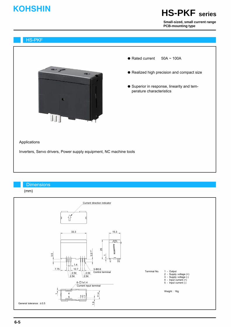
Rated current 50A ~ 100A
Inverters, Servo drivers, Power supply equipment, NC machine tools
Realized high precision and compact size
Superior in response, linearity and tem- perature characteristics
Applications
12.7
1.4
3.5 1
25
Current direction indicator
3-Φ0.6
11.41 4
15.333.3
7.75
5 3 2 1
2.542.54 2.54
2.54
6- 1x1.4
Control terminal
Current input terminal
1.9
3.5±
1
HS-PKF
Dimensions(mm)
seriesHS-PKFKOHSHIN
6-5
Small-sized, small current rangePCB-mounting type
General tolerance: ±0.5
Terminal No. 1 - Output2 - Supply voltage (+)3 - Supply voltage (-)4 - Input current (+)5 - Input current (-)
Weight : 16g

The indicated residual output is the one after the core hysteresis is removed.
Energization time of saturation current shall be within 1 second.
Energization time of continuous live DC current x150% shall be within 1 minute.Note3)
Note2)
Note1)
-150 -90
1509030
-60-180
180
0
2
8
6
4
0
-2
-8
-4
-6
-30
60
100Ω
130Ω
45Ω
75Ω
-120
120
Characteristics chart HS-PKF100A005B15 (RL=45Ω) Time base: 5μs/div.
seriesHS-PKF
Output voltage1V/div.
Output voltage50mV/div.
Input voltage150V/div.
Input current50A/div.
Output voltage1V/div.
Specification Ta=25
6-6
Pulse current response characteristic
Noise characteristics (Effects of impulse noise)
Noise characteristics (Effects of dv/dt)
Type
Output linearity
Response time
Response performance
Hysteresis voltage range
Consumption current
Residual output Temp. Coef.
Output Temp. Coef.
Control power supply
Operating Temp.
Storage Temp.
Dielectric withstand voltage
Insulation resistance
[ Is ]
Continuously flowing DC current
Rated current
Linearity limits
Rated output
Residual output
Saturation current
[ If ]
[ I0 ]
Voltage output type
Second coil resistance
+If
-If
Ta=25
Out
put v
olta
ge
(V)
Input current(A)
Load resistance-output characteristics (Current output type)
KOHSHIN
Note: The marks " " means 0V or 0A.
HS-PKF050A0025B15 HS-PKF100A005B15
I0+25mA±0.5%
Within ±0.2mA
Within 10% (at di/dt=If/μs)
Within 0.15mA
Within ±0.01%/
±15V±5%
20mA+(Input current/2000)
-25~+85
-40~+90
2500V AC 50/60Hz 1minute
Not less than 500MΩ 500V DC
Within ±0.005mA/
Within ±0.15% at If
I0+50mA±0.5%
Approx. 82Ω
Within 0.5μs (at di/dt=If/μs)
±50A
±50A
±100A
0~±100A (RL=45Ω)
±100A
±71A
±160A
0~±160A (RL=45Ω)
I0-25mA±0.5% I0-50mA±0.5%[ Ih ]
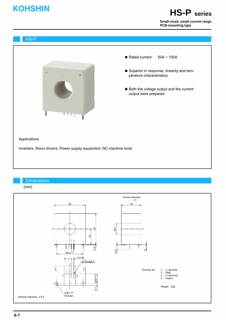
Rated current 50A ~ 100A
Superior in response, linearity and tem- perature characteristics
Both the voltage output and the current output were prepared
Inverters, Srevo drivers, Power supply equipment, NC machine tools
Applications
HS-P
Dimensions(mm)
seriesHS-PKOHSHIN
6-7
General tolerance: ±0.5
Small-sized, small current rangePCB-mounting type
30
3-2.54
19
0.5
2.1
Φ11
3
15
Current direction
4- 0.3x0.5
8.89
±0
.5
2-Φ1±0.
4±
1
30
25.4±0.
1 4
Fast pin
Terminal No. 1 - (-) terminal2 - GND3 - (+) terminal4 - Output
Weight : 20g
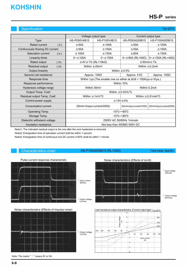
The indicated residual output is the one after the core hysteresis is removed.
Energization time of saturation current shall be within 1 second.
Energization time of continuous live DC current x150% shall be within 1 minute.Note3)
Note2)
Note1)
Characteristics chart HS-P100A005B15 (RL=20Ω) Time base: 5μs/div.
seriesHS-P
Output voltage0.5V/div.
Output voltage50mV/div.
Input voltage150V/div.
Input current50A/div.
Output voltage0.2V/div.
Specification Ta=25
6-8
Pulse current response characteristic
Noise characteristics (Effects of impulse noise)
Noise characteristics (Effects of dv/dt)
Type
Output linearity
Response time
Response performance
Hysteresis voltage range
Consumption current
Residual output Temp. Coef.
Output Temp. Coef.
Control power supply
Operating Temp.
Storage Temp.
Dielectric withstand voltage
Insulation resistance
[ Is ]
±4V±1% (RL=10kΩ)
Within ±20mV
Within 10%
Within 30mV
Within ±0.02%/
±15V±5%
20mA+(Input current/2000)
-10~+80
-15~+85
2500V AC 50/60Hz 1minute
Not less than 500MΩ 500V DC
Within ±1mV/
HS-P050V4B15 HS-P100V4B15 HS-P050A005B15
±50A
±50A
±100A
±100A
±100A
±150A
±50A
±50A
±80A
0~±100A 0~±150A 0~±80A (RL=50Ω)
HS-P100A005B15
±100A
±100A
±150A
0~±150A (RL=40Ω)
Continuously flowing DC current
Rated current
Linearity limits
Rated output
Residual output
Saturation current
[ If ]
[ Vh,
[ V0,
Within ±0.5%
Voltage output type Current output type
±50mA±1%
Within ±0.2mA
Second coil resistance Approx. 100Ω
Within 0.2mA
Within ±0.01mA/
Approx. 51Ω Approx. 100Ω
Within 1μs (The smaller one on either at di/dt = 100A/μs or If/μs.)
Ta=25
-200 -150
20015050
Out
put v
olta
ge(V
)
Input current (A)
-100-250
250
20Ω
0
2
8
6
Load resistance-output characteristics (Current output type)
4
0
-2
-8
-4
-6
-50
100
20mA+(Input current/1000) 20mA+(Input current/2000)
40Ω
80Ω
KOHSHIN
Note: The marks " " means 0V or 0A.
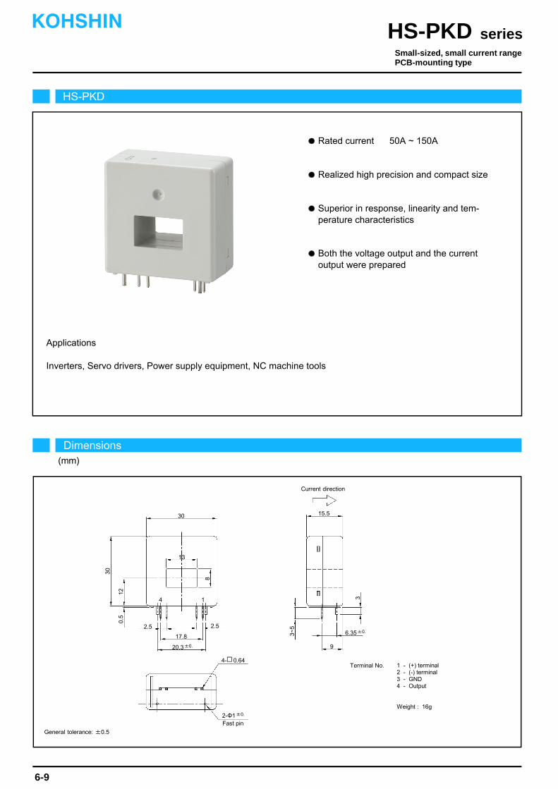
Rated current 50A ~ 150A
Inverters, Servo drivers, Power supply equipment, NC machine tools
Realized high precision and compact size
Superior in response, linearity and tem- perature characteristics
Both the voltage output and the current output were prepared
Applications
HS-PKD
Dimensions(mm)
seriesHS-PKDKOHSHIN
6-9
Small-sized, small current rangePCB-mounting type
General tolerance: ±0.5
30
2.5
0.5
8
12
Current direction
4- 0.64
2-Φ1±0.
30
20.3±0.
Fast pin
13
17.8
2.5
9
6.35±0.
3
3~5
15.5
14
Terminal No. 1 - (+) terminal2 - (-) terminal3 - GND4 - Output
Weight : 16g

The indicated residual output is the one after the core hysteresis is removed.
Energization time of saturation current shall be within 1 second.
Energization time of continuous live DC current x150% shall be within 1 minute.Note3)
Note2)
Note1)
Characteristics chart HS-PKD100V4B15S Time base: 5μs/div.
seriesHS-PKD
Output voltage2V/div.
Output voltage50mV/div.
Input voltage150V/div.
Input current50A/div.
Output voltage0.5V/div.
Specification Ta=25
6-10
Pulse current response characteristic
Noise characteristics (Effects of impulse noise)
Noise characteristics (Effects of dv/dt)
Type
Output linearity
Response time
Response performance
Hysteresis voltage range
Consumption current
Residual output Temp. Coef.
Output Temp. Coef.
Control power supply
Operating Temp.
Storage Temp.
Dielectric withstand voltage
Insulation resistance
[ Is ]
V0+4V±1% (RL=10kΩ)
Within ±20mV
Within 10%
Within 20mV
Within ±0.01%/
±15V±5%
20mA+(Input current/2500)
-10~+80
-15~+85
2500V AC 50/60Hz 1minute
Not less than 500MΩ 500V DC
Within ±0.8mV/
Continuously flowing DC current
Rated current
Linearity limits
Rated output
Residual output
Saturation current
[ If ]
[ V0, I0 ]
Within ±0.5%
Voltage output type Current output type
I0+25mA±1%
Within ±0.2mA
Second coil resistance Approx. 47Ω
Within 0.2mA
Within ±0.01mA/
20mA+(Input current/2000)
Approx. 63Ω Approx. 38Ω
Within 1μs (The smaller one on either at di/dt = 100A/μs or If/μs.)
±50A
±50A
±125A
0~±100A
±100A
±72A
±250A
0~±200A
±150A
±108A
±375A
0~±300A
±50A
±50A
±100A
±100A
±72A
±150A
V0-4V±1% (RL=10kΩ) I0-25mA±1%
+If
-If
I0+50mA±1%
I0-50mA±1%
0~±100A(RL=100~180Ω)
0~±150A(RL=120Ω)
Ta=25
-150
15050
Out
put v
olta
ge
(V)
Input current (A)
-200
200
120Ω
0
3
12
9
Load resistance-output characteristics (Current output type)
6
0
-3
-12
-6
-9
-50
150Ω
180Ω
-100
100
HS-PKD050V4B15 HS-PKD100V4B15S HS-PKD150V4B15S HS-PKD050A0025B15
20mA+(Input current/3200)
HS-PKD100A005B15
KOHSHIN
Note: The marks " " means 0V or 0A.
[ Vh,

Rated current 50A ~ 100A
Three circuits can be measured at the same time
Realized high precision and compact size
Inverters, Servo drivers, Power supply equipment, NC machine tools
Both the voltage output and the current output were prepared
Applications
Superior in response, linearity and tem- perature characteristics
HS-PTA
Dimensions(mm)
seriesHS-PTAKOHSHIN
6-11
General tolerance: ±0.5
Medium-sized, small current rangeBolt on type
64
B06B-PASK(LF)(SN) (JST)
10
15.5
37
1 6
Current direction indicator
98
109
7.2
20
10
2-Φ4.5
Input3
3-Φ
12
max. 5
Input2 Input1
Supported connector housingPAP-06V-S (JST)
Terminal No. 1 - Output32 - Output23 - Output14 - -Vc5 - GND6 - +Vc
Weight : 60g
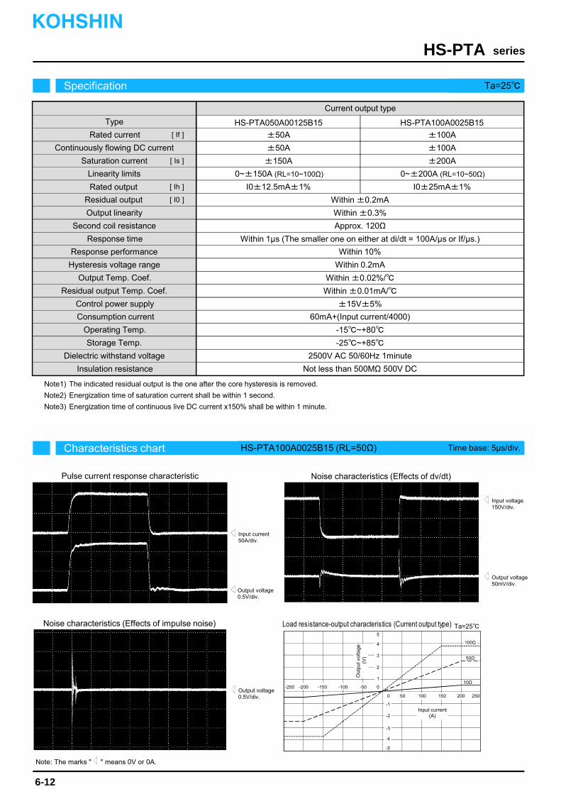
The indicated residual output is the one after the core hysteresis is removed.
Energization time of saturation current shall be within 1 second.
Energization time of continuous live DC current x150% shall be within 1 minute.
Note1)
Note3)
Note2)
-200 -150
20015050
-100-250
250
10Ω0
1
5
4
2
0
-1
-5
-2
-3
-50
100
50Ω
100Ω
3
-4
Characteristics chart HS-PTA100A0025B15 (RL=50Ω) Time base: 5μs/div.
seriesHS-PTA
Output voltage0.5V/div.
Output voltage50mV/div.
Input voltage150V/div.
Input current50A/div.
Output voltage0.5V/div.
Specification Ta=25
6-12
Pulse current response characteristic
Noise characteristics (Effects of impulse noise)
Noise characteristics (Effects of dv/dt)
Type
Output linearity
Response time
Response performance
Hysteresis voltage range
Consumption current
Residual output Temp. Coef.
Output Temp. Coef.
Control power supply
Operating Temp.
Storage Temp.
Dielectric withstand voltage
Insulation resistance
[ Is ]
Within 10%
Within ±0.02%/
±15V±5%
60mA+(Input current/4000)
-15~+80
-25~+85
2500V AC 50/60Hz 1minute
Not less than 500MΩ 500V DC
Continuously flowing DC current
Rated current
Linearity limits
Residual output
Saturation current
[ If ]
[ I0 ]
Within ±0.3%
Current output type
I0±12.5mA±1%
Within ±0.2mA
Second coil resistance Approx. 120Ω
Within 0.2mA
Within ±0.01mA/
Within 1μs (The smaller one on either at di/dt = 100A/μs or If/μs.)
HS-PTA050A00125B15
±50A
±50A
±150A
0~±150A (RL=10~100Ω)
HS-PTA100A0025B15
±100A
±100A
±200A
0~±200A (RL=10~50Ω)
I0±25mA±1%
Ta=25
Out
put v
olta
ge(V
)
Input current (A)
Load resistance-output characteristics (Current output type)
KOHSHIN
Note: The marks " " means 0V or 0A.
Rated output [ Ih ]
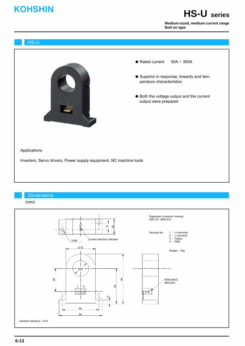
Rated current 50A ~ 300A
Superior in response, linearity and tem- perature characteristics
Both the voltage output and the current output were prepared
Applications
Inverters, Servo drivers, Power supply equipment, NC machine tools
HS-U
Dimensions(mm)
seriesHS-UKOHSHIN
6-13
General tolerance: ±0.5
37.8
Current direction indicator
5045-04AG(MOLEX)
20
54
Φ20
46
8
64
Supported connector housing5051-04 (MOLEX)
Terminal No. 1 - (+) terminal2 - (-) terminal3 - Output4 - GND
Weight : 43g
45
5
29
2-Φ4
1 4
Medium-sized, medium current rangeBolt on type
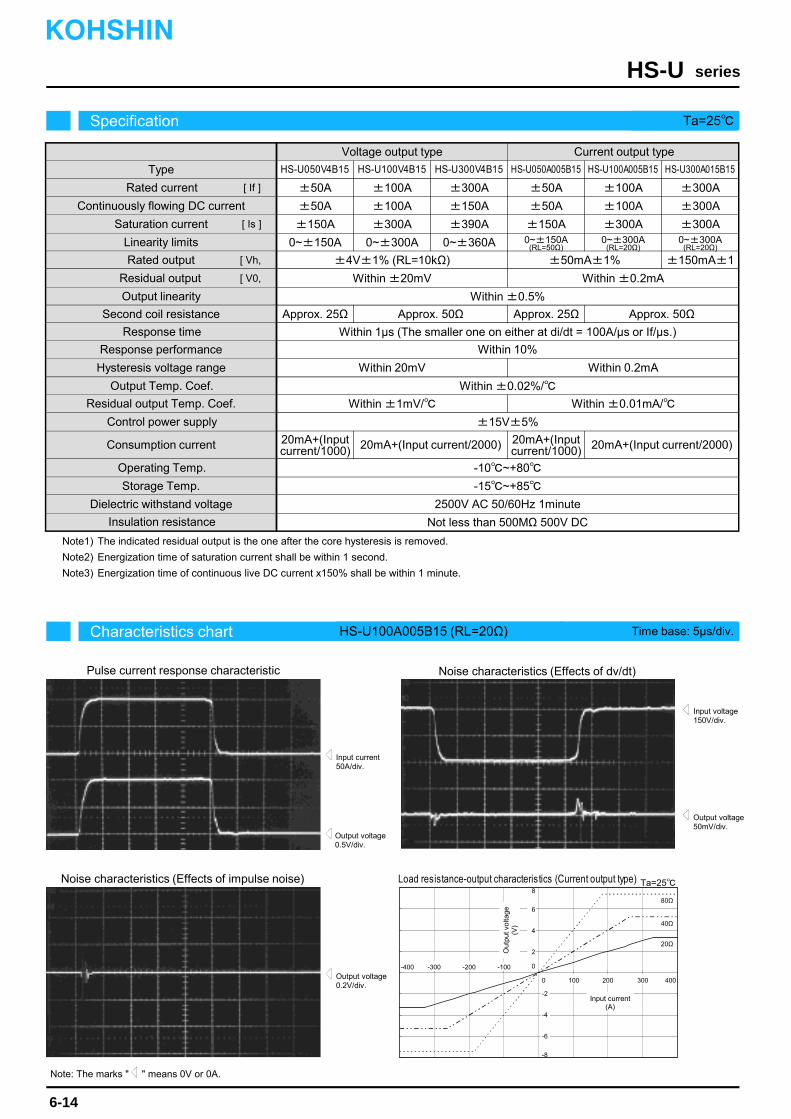
The indicated residual output is the one after the core hysteresis is removed.
Energization time of saturation current shall be within 1 second.
Energization time of continuous live DC current x150% shall be within 1 minute.Note3)
Note2)
Note1)
Characteristics chart HS-U100A005B15 (RL=20Ω) Time base: 5μs/div.
seriesHS-U
Output voltage0.5V/div.
Output voltage50mV/div.
Input voltage150V/div.
Input current50A/div.
Output voltage0.2V/div.
Specification Ta=25
6-14
Pulse current response characteristic
Noise characteristics (Effects of impulse noise)
Noise characteristics (Effects of dv/dt)
Type
Output linearity
Response time
Response performance
Hysteresis voltage range
Consumption current
Residual output Temp. Coef.
Output Temp. Coef.
Control power supply
Operating Temp.
Storage Temp.
Dielectric withstand voltage
Insulation resistance
[ Is ]
±4V±1% (RL=10kΩ)
Within ±20mV
Within 10%
Within 20mV
Within ±0.02%/
±15V±5%
20mA+(Input current/2000)
-10~+80
-15~+85
2500V AC 50/60Hz 1minute
Not less than 500MΩ 500V DC
Within ±1mV/
±50A
±50A
±150A
±100A
±100A
±300A
±50A
±50A
±150A
0~±150A 0~±300A
±100A
±100A
±300A
Continuously flowing DC current
Rated current
Linearity limits
Rated output
Residual output
Saturation current
[ If ]
[ Vh,
[ V0,
Within ±0.5%
Current output type
±50mA±1%
Within ±0.2mA
Second coil resistance Approx. 25Ω
Within 0.2mA
Within ±0.01mA/
20mA+(Input current/2000)
Approx. 25Ω Approx. 50Ω
Within 1μs (The smaller one on either at di/dt = 100A/μs or If/μs.)
±300A
±150A
±390A
0~±360A
±300A
±300A
±300A0~±150A
(RL=50Ω)0~±300A
(RL=20Ω)0~±300A
(RL=20Ω)
±150mA±1
Approx. 50Ω
HS-U050V4B15
Voltage output type
HS-U100V4B15 HS-U300V4B15 HS-U050A005B15 HS-U100A005B15 HS-U300A015B15
Ta=25
-300
300100
Out
put v
olta
ge
(V)
Input current (A)
-400
400
40Ω
0
2
8
6
Load resistance-output characteristics (Current output type)
4
0
-2
-8
-4
-6
-100
20Ω
80Ω
-200
200
20mA+(Inputcurrent/1000)
20mA+(Inputcurrent/1000)
KOHSHIN
Note: The marks " " means 0V or 0A.
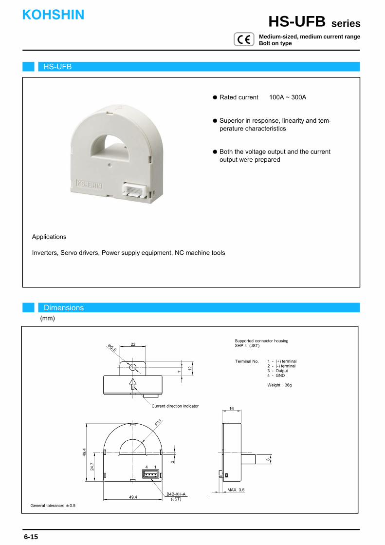
Superior in response, linearity and tem- perature characteristics
Rated current 100A ~ 300A
Both the voltage output and the current output were prepared
Inverters, Servo drivers, Power supply equipment, NC machine tools
Applications
16Current direction indicator
B4B-XH-A(JST)
12
MAX. 3.5
49.4
7
49.4
24.7
8
2
22
14
Φ5.5
R11
HS-UFB
Dimensions(mm)
seriesHS-UFBKOHSHIN
6-15
General tolerance: ±0.5
Terminal No. 1 - (+) terminal2 - (-) terminal3 - Output4 - GND
Weight : 36g
Medium-sized, medium current rangeBolt on type
Supported connector housingXHP-4 (JST)

The indicated residual output is the one after the core hysteresis is removed.
Energization time of saturation current shall be within 1 second.
Energization time of continuous live DC current x150% shall be within 1 minute.Note3)
Note2)
Note1)
-600
600200
-800
800
50Ω
0
2
8
6
4
0
-2
-8
-4
-6
-200
20Ω
90Ω
-400
400
5Ω
Second coil resistance
Characteristics chart HS-UFB200A005B15 (RL=10Ω) Time base: 5μs/div.
seriesHS-UFB
Output voltage0.1V/div.
Output voltage50mV/div.
Input voltage150V/div.
Input current50A/div.
Output voltage0.2V/div.
6-16
Pulse current response characteristic
Noise characteristics (Effects of impulse noise)
Noise characteristics (Effects of dv/dt)
Output linearity
Type
Response time
Response performance
Hysteresis voltage range
Consumption current
Residual output Temp. Coef.
Output Temp. Coef.
Control power supply
Operating Temp.
Storage Temp.
Dielectric withstand voltage
Insulation resistance
[ Is ]
Continuously flowing DC current
Rated current
Linearity limits
Rated output
Residual output
Saturation current
[ If ]
[ V0, I0 ]
Voltage output type Current output type
Ta=25
Out
put v
olta
ge(V
)
Input current(A)
Load resistance-output characteristics (Current output type)
KOHSHIN
Note: The marks " " means 0V or 0A.
Specification Ta=25
[ Vh, Ih ]
HS-UFB100V4B15 HS-UFB200V4B15 HS-UFB300V4B15 HS-UFB100A0025B15 HS-UFB200A005B15 HS-UFB300A0075B15
±100A ±200A ±300A ±100A ±200A ±300A
V0±4V±1% (RL=10kΩ)
Within ±20mV
Within 10%
Within 20mV
Within ±0.02%/
±15V±5%
20mA+(Input current/4000)
-15~+80
-25~+85
2500V AC 50/60Hz 1minute
Not less than 500MΩ 500V DC
Within ±1mV/
Within ±0.3%
I0±25mA±1%
Within ±0.2mA
Approx. 53Ω
Within 0.2mA
Within ±0.01mA/
Within 1μs (at di/dt=100A/μs)
±100A
±300A
0~±250A
±200A
±600A
0~±500A
±230A
±750A
0~±700A
±100A
±300A (RL=90Ω)
±200A
±600A (RL=5Ω)
I0±50mA±1%
0~±250A(RL=5~90Ω)
0~±500A(RL=5~20Ω)
±230A
±750A (RL=5Ω)
0~±700A(RL=5Ω)
I0±75mA±1%
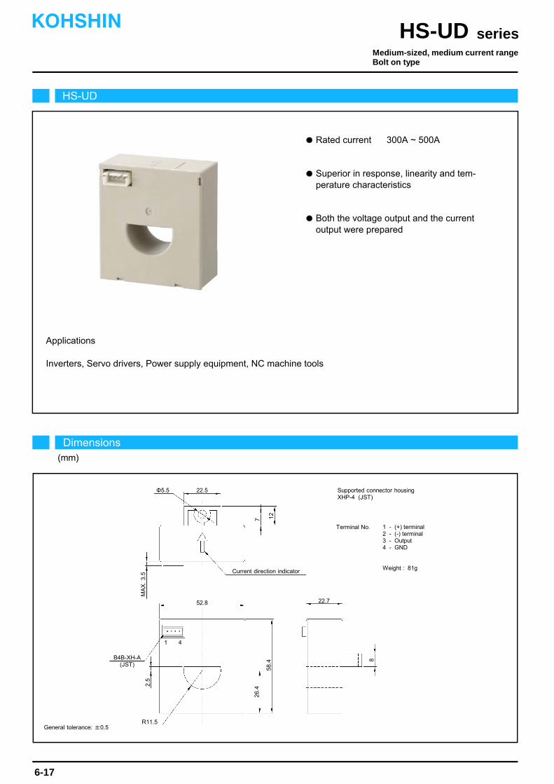
Rated current 300A ~ 500A
Superior in response, linearity and tem- perature characteristics
Both the voltage output and the current output were prepared
Applications
Inverters, Servo drivers, Power supply equipment, NC machine tools
HS-UD
Dimensions(mm)
seriesHS-UDKOHSHIN
6-17
General tolerance: ±0.5
Medium-sized, medium current rangeBolt on type
22.7
Current direction indicator
B4B-XH-A(JST)
12
R11.5
Φ5.5
52.8
7
58.4
26.4
8
2.5
22.5
1 4
MA
X.
3.5
Supported connector housingXHP-4 (JST)
Terminal No. 1 - (+) terminal2 - (-) terminal3 - Output4 - GND
Weight : 81g
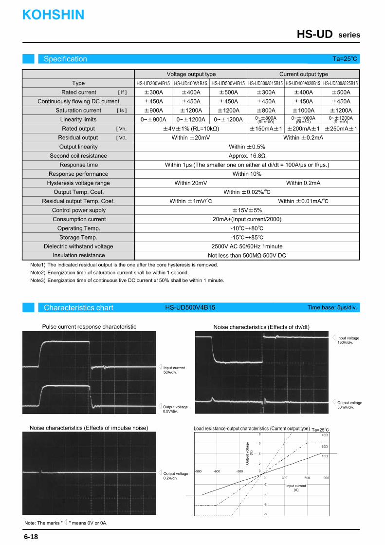
The indicated residual output is the one after the core hysteresis is removed.
Energization time of saturation current shall be within 1 second.
Energization time of continuous live DC current x150% shall be within 1 minute.Note3)
Note2)
Note1)
Characteristics chart HS-UD500V4B15 Time base: 5μs/div.
seriesHS-UD
Output voltage0.5V/div.
Output voltage50mV/div.
Input voltage150V/div.
Input current50A/div.
Output voltage0.2V/div.
Specification Ta=25
6-18
Pulse current response characteristic
Noise characteristics (Effects of impulse noise)
Noise characteristics (Effects of dv/dt)
Type
Output linearity
Response time
Response performance
Hysteresis voltage range
Consumption current
Residual output Temp. Coef.
Output Temp. Coef.
Control power supply
Operating Temp.
Storage Temp.
Dielectric withstand voltage
Insulation resistance
[ Is ]
±4V±1% (RL=10kΩ)
Within ±20mV
Within 10%
Within 20mV
Within ±0.02%/
±15V±5%
-10~+80
-15~+85
2500V AC 50/60Hz 1minute
Not less than 500MΩ 500V DC
Within ±1mV/
±300A
±450A
±900A
±400A
±450A
±1200A
±300A
±450A
±800A
0~±900A 0~±1200A
±400A
±450A
±1000A
Continuously flowing DC current
Rated current
Linearity limits
Rated output
Residual output
Saturation current
[ If ]
[ Vh,
[ V0,
Within ±0.5%
Voltage output type Current output type
±150mA±1
Within ±0.2mA
Second coil resistance Approx. 16.8Ω
Within 0.2mA
Within ±0.01mA/
Within 1μs (The smaller one on either at di/dt = 100A/μs or If/μs.)
±500A
±450A
±1200A
0~±1200A
±500A
±450A
±1200A0~±800A
(RL=10Ω)0~±1000A
(RL=5Ω)0~±1200A
(RL=1Ω)
±250mA±1
20mA+(Input current/2000)
±200mA±1
HS-UD400V4B15HS-UD300V4B15 HS-UD500V4B15 HS-UD300A015B15 HS-UD400A020B15 HS-UD500A025B15
Ta=25
-600
600300
Out
put v
olta
ge(V
)
Input current (A)
-900
900
20Ω
0
2
8
6
Load resistance-output characteristics (Current output type)
4
0
-2
-8
-4
-6
-300
10Ω
40Ω
KOHSHIN
Note: The marks " " means 0V or 0A.

Rated current 300A ~ 500A
Superior in response, linearity and tem- perature characteristics
Both the voltage output and the current output were prepared
Applications
Inverters, Power supply equipment
30
MA
X.
4.5
6
Φ4.2
13.5
2-R2.1
78
50
6
7
5.5
41
79
5
40
13.5
14
Φ37
52
Current direction indicator
1
5046-04AG(MOLEX)
HS-K
Dimensions(mm)
seriesHS-KKOHSHIN
6-19
General tolerance: ±0.5
Medium-sized, medium current rangeBolt on type
Supported connector housing5051-04 (MOLEX)
Terminal No. 1 - (+) terminal2 - (-) terminal3 - Output4 - GND
Weight : 226g
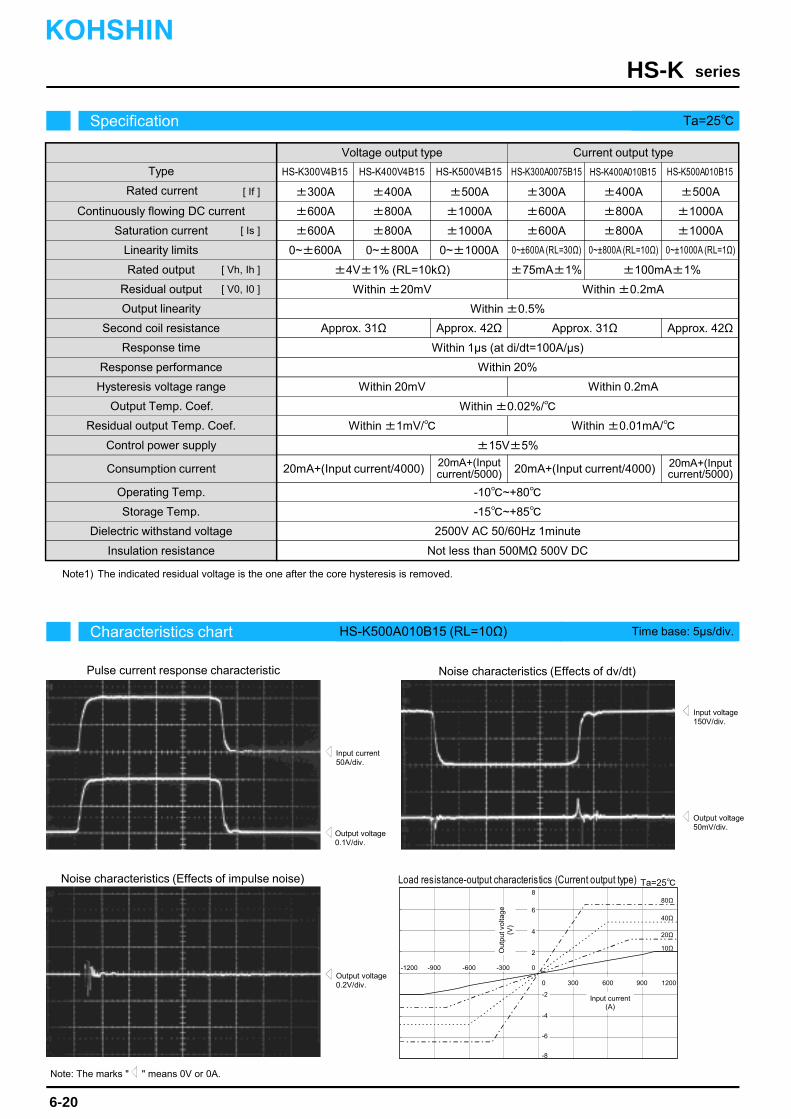
The indicated residual voltage is the one after the core hysteresis is removed.Note1)
Characteristics chart HS-K500A010B15 (RL=10Ω) Time base: 5μs/div.
seriesHS-K
Output voltage0.1V/div.
Output voltage50mV/div.
Input voltage150V/div.
Input current50A/div.
Ta=25
Output voltage0.2V/div.
Specification Ta=25
6-20
Pulse current response characteristic
Noise characteristics (Effects of impulse noise)
Noise characteristics (Effects of dv/dt)
Type
Output linearity
Response time
Response performance
Hysteresis voltage range
Consumption current
Residual output Temp. Coef.
Output Temp. Coef.
Control power supply
Operating Temp.
Storage Temp.
Dielectric withstand voltage
Insulation resistance
[ Is ]
±4V±1% (RL=10kΩ)
Within ±20mV
Within 20%
Within 20mV
Within ±0.02%/
±15V±5%
-10~+80
-15~+85
2500V AC 50/60Hz 1minute
Not less than 500MΩ 500V DC
Within ±1mV/
±300A
±600A
±600A
±400A
±800A
±800A
±300A
±600A
±600A
0~±600A 0~±800A
±400A
±800A
±800A
Continuously flowing DC current
Rated current
Linearity limits
Rated output
Residual output
Saturation current
[ If ]
[ Vh, Ih ]
[ V0, I0 ]
Within ±0.5%
Voltage output type Current output type
±75mA±1%
Within ±0.2mA
Second coil resistance Approx. 31Ω
Within 0.2mA
Within ±0.01mA/
Approx. 42Ω
Within 1μs (at di/dt=100A/μs)
±500A
±1000A
±1000A
0~±1000A
±500A
±1000A
±1000A
±100mA±1%
Approx. 42Ω Approx. 31Ω
20mA+(Input current/4000) 20mA+(Input current/4000)
-900 -600
900600300
Out
put v
olta
ge(V
)
Input current (A)
-300
80Ω
-1200
1200
40Ω
20Ω
10Ω
0
2
8
6
Load resistance-output characteristics (Current output type)
20mA+(Inputcurrent/5000)
20mA+(Inputcurrent/5000)
HS-K400V4B15HS-K300V4B15 HS-K500A010B15HS-K300A0075B15 HS-K400A010B15HS-K500V4B15
0~±600A (RL=30Ω) 0~±1000A (RL=1Ω)0~±800A (RL=10Ω)
4
0
-2
-8
-4
-6
KOHSHIN
Note: The marks " " means 0V or 0A.
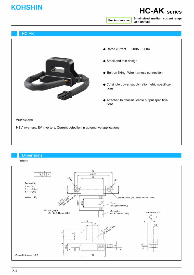
HEV inverters, EV inverters, Current detection in automotive applications
Rated current 200A ~ 500A
Applications
Small and thin design
Bolt-on fixing, Wire harness connection
5V single power supply ratio metric specifica- tions
Attached to chassis, cable output specifica- tions
1 2 3 4
Weight : 40g
Terminal No.
1 ・・・ Vcc3 ・・・ Output4 ・・・ GND
Connector04CPT-B1-2A (JST)
TubeER2 (SUMITOMO)
54
11
5
6.5
19
10.5
16
17
(275
)
300
±5
※1 Pin gaugeGo Φ4.3, No go Φ4.4 Current direction
45±0.15
322-R5
2-Φ4.3
Metallic collar (2 locations on both sides)
R5
11.5
35
6
5
5
4-R1
2 13
11
HC-AK
Dimensions(mm)
seriesHC-AKKOHSHIN
7-1
Small-sized, medium current rangeBolt on type
General tolerance: ±0.5
For Automotive
Metallic co
llar
inner diameter ※
1
(Through hole)

The indicated residual voltage is the one after the core hysteresis is removed.
Output specifications include 100-Ω output resistance and 1-mA maximum output current.
Since residual output is ratiometric output, it varies according to the control power supply value.
Code at the end of the model name represents harness specifications. Note4)
Note3)
Note2)
Note1)
-300 -200 300200 100
3
5
2
0-100
1
4
HC-AK200V2PP5-1
HC-AK500V2PP5-1
-400 400-600 6000
HC-AK300V2PP5-1
HC-AK400V2PP5-1
500-500
Out
put v
olta
ge (
V)
Input current (A)
Note: The marks " " means 0V or 0A.
Characteristics chart HC-AK200V2PP5-1 Time base: 5μs/div.
seriesHC-AK
Output voltage0.5V/div.
Output voltage50mV/div.
Input voltage150V/div.
Input current50A/div.
Output voltage0.5V/div.
Specification Ta=25
7-2
Pulse current response characteristic
Noise characteristics (Effects of impulse noise)
Noise characteristics (Effects of dv/dt)
KOHSHIN
Output Temp. Coef.
Residual output Temp. Coef.
Consumption current
Power variation characteristics change
Control power supply
Operating Temp.
Storage Temp.
Dielectric withstand voltage
Insulation resistance
Type
Rated current
Saturation current
Linearity limits
Residual output
Output linearity
Rated output
Response time
Response performance
Hysteresis voltage range
[ Is ]
[ If ]
[ Vh ]
[ V0 ]
Input/output characteristics
HC-AK200V2PP5-1 HC-AK300V2PP5-1
±200A
0~±200A
±300A
0~±300A
HC-AK400V2PP5-1
±400A
0~±400A
Within V0-2V×(Vcc/5)±1.5% (RL=10kΩ)
Within ±1%
Within 10μs (at di/dt=100A/μs)
Within 10%
Within ±0.04%/
+5V±4%
Within 30mA
-40~+105
-40~+105
2500V AC 50/60Hz 1minute
Not less than 500MΩ 500V DC
Within Vcc/2±30mV
HC-AK500V2PP5-1
±500A
0~±500A
Within 30mV Within 22mV Within 16mV Within 13mV
Within V0+2V×(Vcc/5)±1.5% (RL=10kΩ)
Within ±2mV/ Within ±1.7mV/ Within ±1.3mV/ Within ±0.9mV/
±220A ±330A ±440A ±550A
3.5~4.5%
3~5%
I=+If
I=-If
[ Vcc ]
I=±If
I=0[ +5V±4% ] 3.1~4.9% 3.2~4.8% 3.3~4.7%
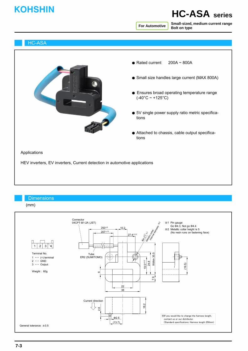
Rated current 200A ~ 800A
Applications
Small size handles large current (MAX 800A)
Ensures broad operating temperature range (-40°C ~ +125°C)
5V single power supply ratio metric specifica- tions
Attached to chassis, cable output specifica- tions
HEV inverters, EV inverters, Current detection in automotive applications
HC-ASA
Dimensions(mm)
seriesHC-ASAKOHSHIN
7-3
Small-sized, medium current rangeBolt on type
General tolerance: ±0.5
For Automotive
Weight : 60g
1 2 3 4
Terminal No.
1 ・・・ (+) terminal2 ・・・ GND3 ・・・ Output
Connector04CPT-B1-2A (JST)
TubeER2 (SUMITOMO)
250±5
207±10
10.2
62.
8
Φ2.5
(13.7)
18.2
7.9
2238
27.4±0.2
(19.
5)With
in 3
5.5
24.8
19.5
±0.
2Φ
4.3
+0.1
0※
1
※1 Pin gaugeGo Φ4.3, Not go Φ4.4
※2 Metallic collar height is 5(No resin runs on fastening face)
Current direction
※If you would like to change the harness length,
contact us or our distributor.
(Standard specifications: Harness length 250mm)
※2
Met
allic
col
lar
inte
rnal
dia
met
er
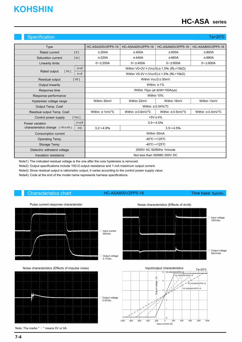
The indicated residual voltage is the one after the core hysteresis is removed.
Output specifications include 100-Ω output resistance and 1-mA maximum output current.
Since residual output is ratiometric output, it varies according to the control power supply value.
Code at the end of the model name represents harness specifications. Note4)
Note3)
Note2)
Note1)
Ta=25
-600 -400 600400 200
3
5
2
0
Out
put v
olta
ge (
V)
Input current (A)
-200
1
4
HC-ASA200V2PP5-16
HC-ASA800V2PP5-16
-800 800-1000 10000
HC-ASA400V2PP5-16
HC-ASA600V2PP5-16
Note: The marks " " means 0V or 0A.
Characteristics chart HC-ASA800V2PP5-16 Time base: 5μs/div.
seriesHC-ASA
Output voltage0.1V/div.
Output voltage50mV/div.
Input voltage150V/div.
Input current50A/div.
Output voltage0.5V/div.
Specification Ta=25
7-4
Pulse current response characteristic
Noise characteristics (Effects of impulse noise)
Noise characteristics (Effects of dv/dt)
KOHSHIN
Output Temp. Coef.
Residual output Temp. Coef.
Consumption current
Power variation characteristics change
Control power supply
Operating Temp.
Storage Temp.
Dielectric withstand voltage
Insulation resistance
Type
Rated current
Saturation current
Linearity limits
Residual output
Output linearity
Rated output
Response time
Response performance
Hysteresis voltage range
[ Is ]
[ If ]
[ Vh ]
[ V0 ]
Input/output characteristics
HC-ASA200V2PP5-16 HC-ASA400V2PP5-16
±200A
0~±200A
±400A
0~±400A
HC-ASA600V2PP5-16
±600A
0~±600A
Within V0-2V×(Vcc/5)±1.5% (RL=10kΩ)
Within ±1%
Within 10μs (at di/dt=100A/μs)
Within 10%
Within ±0.04%/
+5V±4%
Within 30mA
-40~+125
-40~+125
2500V AC 50/60Hz 1minute
Not less than 500MΩ 500V DC
Within Vcc/2±30mV
HC-ASA800V2PP5-16
±800A
0~±800A
Within 30mV Within 22mV Within 16mV Within 13mV
Within V0+2V×(Vcc/5)±1.5% (RL=10kΩ)
Within ±1mV/ Within ±0.6mV/ Within ±0.5mV/ Within ±0.4mV/
±220A ±440A ±660A ±880A
3.5~4.5%
3.2~4.8% 3.5~4.5%
I=+If
I=-If
[ Vcc ]
I=±If
I=0[ +5V±4% ]

Rated current 200A ~ 800A
Applications
Small size handles large current (MAX 800A)
Ensures broad operating temperature range (-40°C ~ +125°C)
5V single power supply ratio metric specifica- tions
Attached to bus-bar, cable output specifica- tions
HEV inverters, EV inverters, Current detection in automotive applications
HC-ASB
Dimensions(mm)
seriesHC-ASBKOHSHIN
7-5
Small-sized, medium current rangeBolt on type
General tolerance: ±0.5
For Automotive
Weight : 63g
1 2 3 4
Terminal No.
1 ・・・ (+) terminal2 ・・・ GND3 ・・・ Output
Connector04CPT-B1-2A (JST)
250±5
207±10
TubeER2 (SUMITOMO)
10.2
62.
8
Φ2.5
13.7
18.2
7.9
22
38
19.5W
ithin
35.
5
24.8
11
26
(5.1)
No metallic collar (Use in fastening application not allowed)
6
12
Current direction
Φ4.3 +0.10 ※1
※1 Pin gaugeGo Φ4.3, Not go Φ4.4
※2 Metallic collar height is 5(No resin runs on fastening face)
※If you would like to change the harness length,
contact us or our distributor.
(Standard specifications: Harness length 250mm)
※2
Metallic collar internal diameter

The indicated residual voltage is the one after the core hysteresis is removed.
Output specifications include 100-Ω output resistance and 1-mA maximum output current.
Since residual output is ratiometric output, it varies according to the control power supply value.
Code at the end of the model name represents harness specifications. Note4)
Note3)
Note2)
Note1)
Ta=25
-600 -400 600400 200
3
5
2
0
Out
put v
olta
ge (
V)
Input current (A)
-200
1
4
HC-ASA200V2PP5-16
HC-ASA800V2PP5-16
-800 800-1000 10000
HC-ASA400V2PP5-16
HC-ASA600V2PP5-16
Note: The marks " " means 0V or 0A.
Characteristics chart HC-ASB800V2PP5-16 Time base: 5μs/div.
seriesHC-ASB
Output voltage0.1V/div.
Output voltage50mV/div.
Input voltage150V/div.
Input current50A/div.
Output voltage0.5V/div.
Specification Ta=25
7-6
Pulse current response characteristic
Noise characteristics (Effects of impulse noise)
Noise characteristics (Effects of dv/dt)
KOHSHIN
Output Temp. Coef.
Residual output Temp. Coef.
Consumption current
Power variation characteristics change
Control power supply
Operating Temp.
Storage Temp.
Dielectric withstand voltage
Insulation resistance
Type
Rated current
Saturation current
Linearity limits
Residual output
Output linearity
Rated output
Response time
Response performance
Hysteresis voltage range
[ Is ]
[ If ]
[ Vh ]
[ V0 ]
Input/output characteristics
HC-ASB200V2PP5-16 HC-ASB400V2PP5-16
±200A
0~±200A
±400A
0~±400A
HC-ASB600V2PP5-16
±600A
0~±600A
Within V0-2V×(Vcc/5)±1.5% (RL=10kΩ)
Within ±1%
Within 10μs (at di/dt=100A/μs)
Within 10%
Within ±0.04%/
+5V±4%
Within 30mA
-40~+125
-40~+125
2500V AC 50/60Hz 1minute
Not less than 500MΩ 500V DC
Within Vcc/2±30mV
HC-ASB800V2PP5-16
±800A
0~±800A
Within 30mV Within 22mV Within 16mV Within 13mV
Within V0+2V×(Vcc/5)±1.5% (RL=10kΩ)
Within ±1mV/ Within ±0.6mV/ Within ±0.5mV/ Within ±0.4mV/
±220A ±440A ±660A ±880A
3.5~4.5%
3.2~4.8% 3.5~4.5%
I=+If
I=-If
[ Vcc ]
I=±If
I=0[ +5V±4% ]
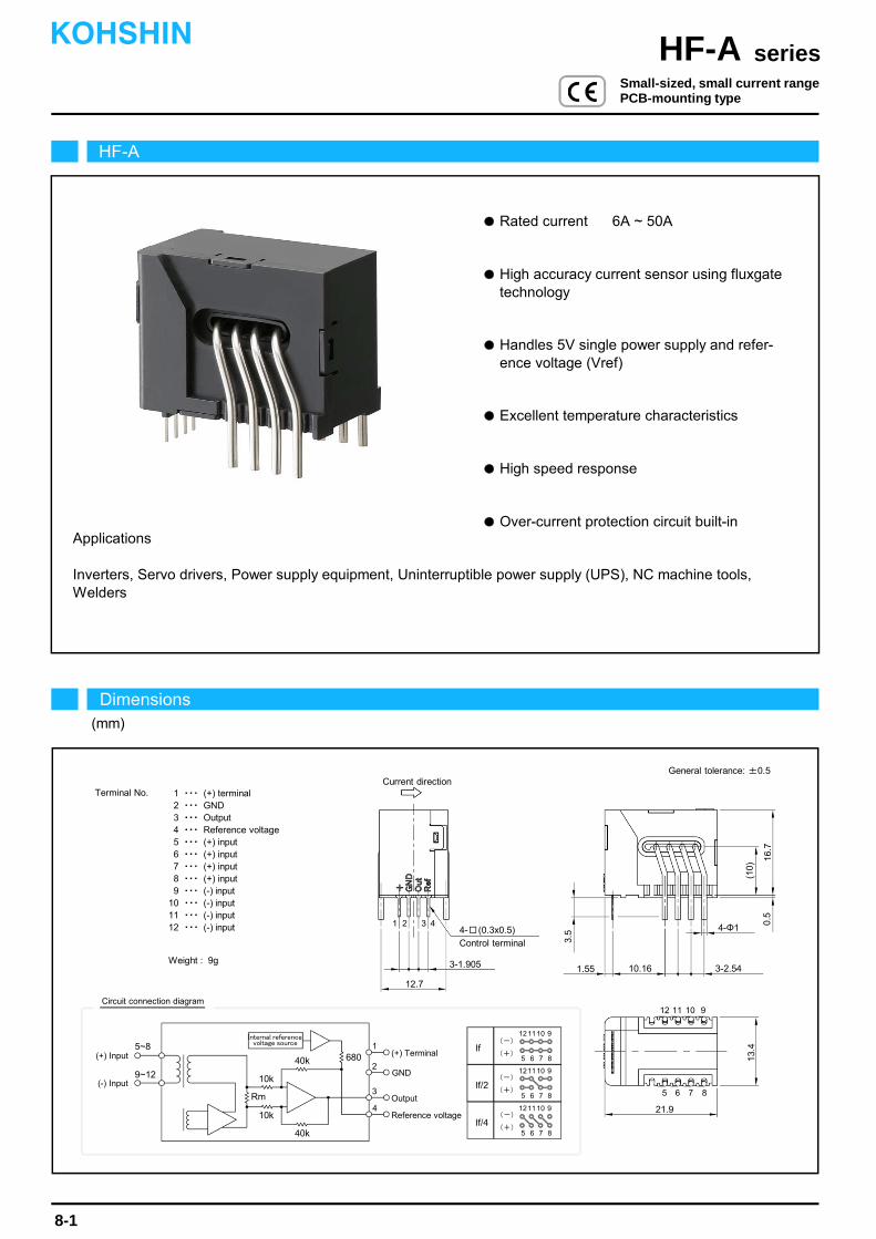
Rated current 6A ~ 50A
Applications
Inverters, Servo drivers, Power supply equipment, Uninterruptible power supply (UPS), NC machine tools,Welders
High accuracy current sensor using fluxgate technology
Handles 5V single power supply and refer- ence voltage (Vref)
Excellent temperature characteristics
High speed response
Over-current protection circuit built-in
12.7
Control terminal
16.7
0.5
1.55
4- (0.3x0.5)
3-1.905
4-Φ1
3-2.5410.16
3.5
Current direction
1 2 3 4
5 6 7 8
12 11 10 9
21.9
13.4
(10)
HF-A
Dimensions(mm)
seriesHF-AKOHSHIN
8-1
Small-sized, small current rangePCB-mounting type
General tolerance: ±0.5
Internal reference
5~8
9~12
If
If/2
If/4
121110 9
5 6 7 8
121110 9
5 6 7 8
121110 9
5 6 7 8
(-)
(+)1
2
3
4
GND
Circuit connection diagram
Terminal No. 1 ・・・ (+) terminal2 ・・・ GND3 ・・・ Output4 ・・・ Reference voltage5 ・・・ (+) input6 ・・・ (+) input7 ・・・ (+) input8 ・・・ (+) input9 ・・・ (-) input
10 ・・・ (-) input11 ・・・ (-) input12 ・・・ (-) input
Weight : 9g
10k
10k
40k 680
Rm
40k
(+) Input (+) Terminal
(-) Input
Output
Reference voltage
(-)
(+)
(-)
(+)
voltage source
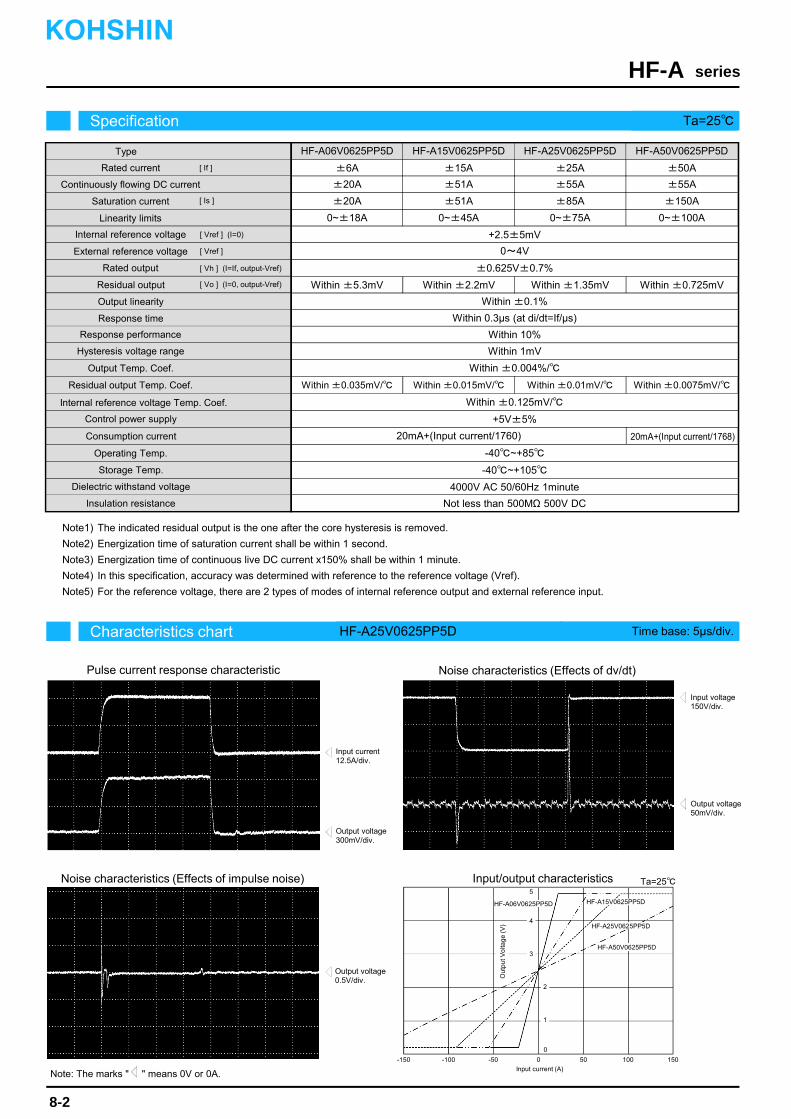
The indicated residual output is the one after the core hysteresis is removed.
Energization time of saturation current shall be within 1 second.
Energization time of continuous live DC current x150% shall be within 1 minute.
In this specification, accuracy was determined with reference to the reference voltage (Vref).
For the reference voltage, there are 2 types of modes of internal reference output and external reference input.Note5)
Note3)
Note2)
Note1)
Note4)
2
0-150 -100 150 10050
3
5
0
-50
4
HF-A15V0625PP5D
HF-A50V0625PP5D
HF-A06V0625PP5D
HF-A25V0625PP5D
1
Characteristics chart HF-A25V0625PP5D Time base: 5μs/div.
seriesHF-A
Output voltage300mV/div.
Output voltage50mV/div.
Input voltage150V/div.
Input current12.5A/div.
Output voltage0.5V/div.
Specification Ta=25
8-2
Pulse current response characteristic
Noise characteristics (Effects of impulse noise)
Noise characteristics (Effects of dv/dt)
Ta=25
KOHSHIN
Note: The marks " " means 0V or 0A.
Type
Output linearity
Response time
Response performance
Hysteresis voltage range
Consumption current
Residual output Temp. Coef.
Output Temp. Coef.
Control power supply
Operating Temp.
Storage Temp.
Dielectric withstand voltage
Insulation resistance
±0.625V±0.7%
Within ±2.2mV
Within 10%
Within 1mV
Within ±0.004%/
+5V±5%
20mA+(Input current/1760)
-40~+85
-40~+105
4000V AC 50/60Hz 1minute
Not less than 500MΩ 500V DC
Within ±0.035mV/
HF-A06V0625PP5D HF-A15V0625PP5D HF-A25V0625PP5D
±6A
±20A
±20A
±15A
±51A
±51A
±25A
±55A
±85A
0~±18A 0~±45A 0~±75A
HF-A50V0625PP5D
±50A
±55A
±150A
0~±100A
Continuously flowing DC current
Rated current
Linearity limits
Residual output
Saturation current
Internal reference voltage
[ If ]
[ Vo ] (I=0, output-Vref)
Within ±0.1%
Within 0.3μs (at di/dt=If/μs)
+2.5±5mV
Rated output
Within ±5.3mV
Within ±0.015mV/ Within ±0.01mV/ Within ±0.0075mV/
Within ±1.35mV Within ±0.725mV
External reference voltage 0~4V
[ Is ]
[ Vh ] (I=If, output-Vref)
Internal reference voltage Temp. Coef. Within ±0.125mV/
[ Vref ] (I=0)
[ Vref ]
Input/output characteristics
20mA+(Input current/1768)
Ou
tpu
t Vo
ltag
e (
V)
Input current (A)
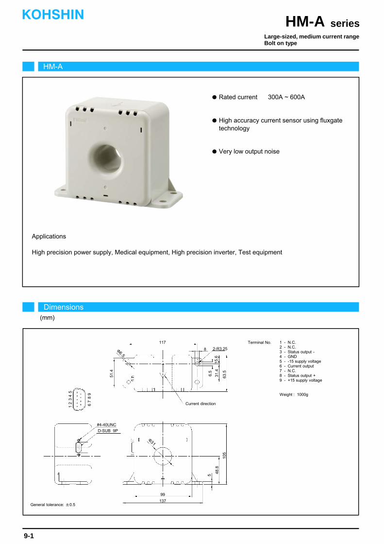
Rated current 300A ~ 600A
Very low output noise
High precision power supply, Medical equipment, High precision inverter, Test equipment
Applications
High accuracy current sensor using fluxgate technology
HM-A
Dimensions(mm)
seriesHM-AKOHSHIN
9-1
General tolerance: ±0.5
Large-sized, medium current rangeBolt on type
117
Current direction
48.8
2-R3.25
99
137
8
105
51.4
15.6
6.5
5
63.5
Φ6.5
31.4
Φ31
D-SUB 9P
Terminal No. 1 - N.C.2 - N.C.3 - Status output -4 - GND5 - -15 supply voltage6 - Current output7 - N.C.8 - Status output +9 - +15 supply voltage
Weight : 1000g
12
34
5
67
89
#4-40UNC
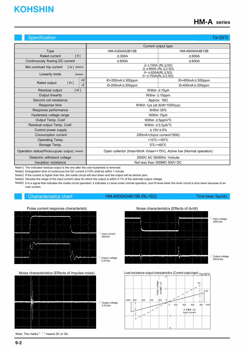
The indicated residual output is the one after the core hysteresis is removed.Energization time of continuous live DC current x110% shall be within 1 minute.If the current is higher than this, the inside circuit will shut down and the output will be almost zero.Denotes the range of the input current value for which the output is within 0.1% of the estimate output voltage.
Note5) It is a signal that indicates the inside circuit operation; it indicates Lo level under normal operation, and Hi level when the inner circuit is shut down because of anover current.
Note3)Note4)
Note1)Note2)
Characteristics chart HM-A600A04B15B (RL=5Ω) Time base: 5μs/div.
seriesHM-A
Output voltage0.2V/div.
Output voltage50mV/div.
Input voltage200V/div.
Input current50A/div.
Output voltage0.5V/div.
Specification Ta=25
Pulse current response characteristic
Noise characteristics (Effects of impulse noise)
Noise characteristics (Effects of dv/dt)
Type
Output linearity
Response time
Response performance
Hysteresis voltage range
Consumption current
Residual output Temp. Coef.
Output Temp. Coef.
Control power supply
Operating Temp.
Storage Temp.
Dielectric withstand voltage
Insulation resistance
[ Is ]
±15V±5%
250mA+(Input current/1500)
+10~+50
0~+60
2500V AC 50/60Hz 1minute
Not less than 500MΩ 500V DC
Continuously flowing DC current
Rated current
Linearity limits
Rated output
Residual output
Min.overload trip current
[ If ]
[ I0 ]
Current output type
I0+200mA±300ppm
Within ±10μA
Within ±10ppm
Second coil resistance
Within 35%
Within 15μA
Within ±5ppm/
Within ±0.2μA/
Approx. 16Ω
HM-A300A02B15B
±300A
±600A
HM-A600A04B15B
±600A
±600A
I0-200mA±300ppm
+If
-If
I0+400mA±300ppm
I0-400mA±300ppm
≧±750A (RL≦5Ω)≧±850A (RL≦2.5Ω)0~±650A(RL≦5Ω)
0~±750A(RL≦2.5Ω)
Within 1μs (at di/dt=100A/μs)
Operation status(Photocupuler output) Open collector (Imax=6mA Vmax=+15V), Active low (Normal operation)
Ta=25Load resistance-output characteristics (Current output type)
9-2
Note: The marks " " means 0V or 0A.
KOHSHIN
[ Ih ]
(Note3)
(Note4)
(Note5)
-600
600400
Out
put v
olta
ge
出力電圧
(V)
Input current入力電流 (A)
-1000
1000
5Ω
0
4
2
0
-4
-2
-400
2.5Ω
-200-800
200 800
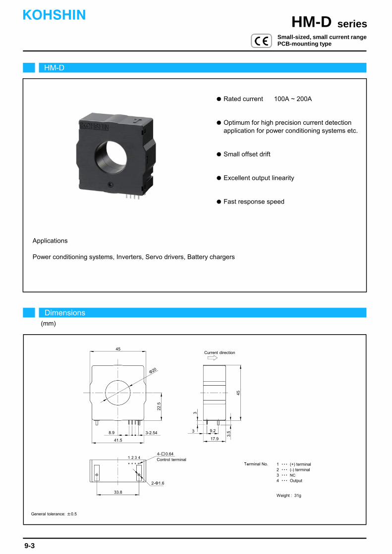
Rated current 100A ~ 200A
Small offset drift
Power conditioning systems, Inverters, Servo drivers, Battery chargers
Applications
Optimum for high precision current detection application for power conditioning systems etc.
Excellent output linearity
Fast response speed
HM-D
Dimensions(mm)
seriesHM-DKOHSHIN
9-3
General tolerance: ±0.5
Small-sized, small current rangePCB-mounting type
Terminal No. 1 ・・・ (+) terminal2 ・・・ (-) terminal3 ・・・ NC
4 ・・・ Output
Weight : 31g
45Current direction
2-Φ1.6
9.2
17.9
8.9
45
3.5
22.5
3
Φ20
1 2 3 4
33.8
4- 0.64Control terminal
3-2.54
41.5
3

The indicated residual output is the one after the core hysteresis is removed.
Energization time of continuous live DC current x150% shall be within 1 minute.Note2)
Note1)
-300
300200
70Ω
0
4
2
0
-4
-2
-200
30Ω
-100-400
100 400
-6
-8
6
8
10Ω
Characteristics chart HM-D200A00625B15 (RL=10Ω) Time base: 5μs/div.
seriesHM-D
Output voltage0.15V/div.
Output voltage50mV/div.
Input voltage150V/div.
Input current50A/div.
Output voltage0.1V/div.
Specification Ta=25
9-4
Pulse current response characteristic
Noise characteristics (Effects of impulse noise)
Noise characteristics (Effects of dv/dt)
Ta=25
Out
put v
olta
ge(V
)
Input current (A)
Load resistance-output characteristics (Current output type)
KOHSHIN
Note: The marks " " means 0V or 0A.
Type
[ Is ]
Continuously flowing DC current
Rated current
Linearity limits
Rated output
Residual output
Saturation current
[ If ]
[ I0 ]
Current output type
+If
-If
HM-D100A003125B15 HM-D200A00625B15
I0+31.25mA±0.5%
Within ±0.01mA
I0+62.5mA±0.5%
Output linearity
Response time
Response performance
Hysteresis voltage range
Consumption current
Residual output Temp. Coef.
Output Temp. Coef.
Control power supply
Operating Temp.
Storage Temp.
Dielectric withstand voltage
Insulation resistance
Second coil resistance
Within 10%
Within 0.05mA
Within ±0.003%/
±15V±5%
35mA+(Input current/3200)
-40~+80
-40~+85
3500V AC 50/60Hz 1minute
Not less than 500MΩ 500V DC
Within ±1μA/
Within ±0.1%
Approx. 100Ω
Within 1μs (at di/dt=100A/μs)
±100A
±100A
±220A
0~±200A
±200A
±200A (RL=30Ω)
±320A
0~±300A
I0-31.25mA±0.5% I0-62.5mA±0.5%[ Ih ]
Load resistance range 10~70Ω 10~30Ω[ RL ]
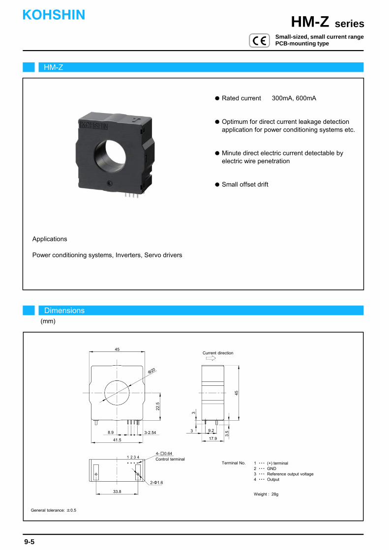
Rated current 300mA, 600mA
Power conditioning systems, Inverters, Servo drivers
Applications
Optimum for direct current leakage detection application for power conditioning systems etc.
Small offset drift
Minute direct electric current detectable by electric wire penetration
HM-Z
Dimensions(mm)
seriesHM-ZKOHSHIN
9-5
General tolerance: ±0.5
Small-sized, small current rangePCB-mounting type
45Current direction
2-Φ1.6
9.2
17.9
8.9
45
3.5
22.5
3
Φ20
1 2 3 4
33.8
4- 0.64Control terminal
3-2.54
41.5
3
Terminal No. 1 ・・・ (+) terminal2 ・・・ GND3 ・・・ Reference output voltage4 ・・・ Output
Weight : 28g
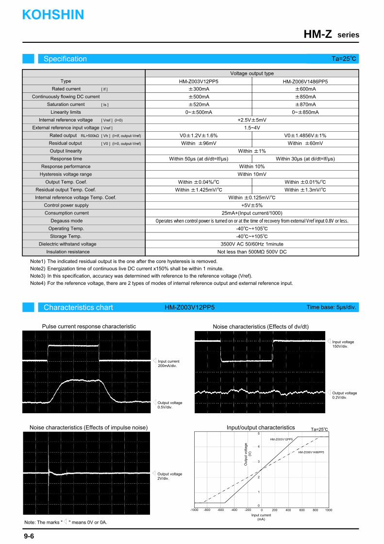
The indicated residual output is the one after the core hysteresis is removed.
Energization time of continuous live DC current x150% shall be within 1 minute.
In this specification, accuracy was determined with reference to the reference voltage (Vref).
For the reference voltage, there are 2 types of modes of internal reference output and external reference input.
Note1)
Note4)
Note3)
Note2)
-600 -400 600400 200
3
5
2
0-200
1
4
HM-Z006V1486PP5
-800 8000 1000-1000
HM-Z003V12PP5
Characteristics chart HM-Z003V12PP5 Time base: 5μs/div.
seriesHM-Z
Output voltage0.5V/div.
Output voltage0.2V/div.
Input voltage150V/div.
Input current200mA/div.
Output voltage2V/div.
Specification Ta=25
9-6
Pulse current response characteristic
Noise characteristics (Effects of impulse noise)
Noise characteristics (Effects of dv/dt)
Ta=25
Out
put v
olta
ge(V
)
Input current (mA)
KOHSHIN
Note: The marks " " means 0V or 0A.
Type
Response time
Response performance
Hysteresis voltage range
Consumption current
Residual output Temp. Coef.
Output Temp. Coef.
Control power supply
Operating Temp.
Storage Temp.
Dielectric withstand voltage
Insulation resistance
Continuously flowing DC current
Rated current
Linearity limits
Residual output
Saturation current
Voltage output type
HM-Z003V12PP5 HM-Z006V1486PP5
V0±1.2V±1.6%
Within ±96mV
Within 10%
Within 10mV
Within ±0.04%/
+5V±5%
25mA+(Input current/1000)
-40~+105
-40~+105
3500V AC 50/60Hz 1minute
Not less than 500MΩ 500V DC
Within ±1.425mV/
Output linearity Within ±1%
V0±1.4856V±1%
Within 50μs (at di/dt=If/μs)
±300mA
±500mA
±520mA
0~±500mA
±600mA
±850mA
±870mA
0~±850mA
Internal reference voltage Temp. Coef. Within ±0.125mV/
Internal reference voltage +2.5V±5mV
External reference input voltage 1.5~4V
Rated output
[ Is ]
[ If ]
[ V0 ] (I=0, output-Vref)
[ Vh ] (I=If, output-Vref)
Degauss mode Operates when control power is turned on or at the time of recovery from external Vref input 0.8V or less.
Within ±60mV
Within 30μs (at di/dt=If/μs)
Within ±0.01%/
Within ±1.3mV/
Input/output characteristics
RL>500kΩ
[ Vref ] (I=0)
[ Vref ]
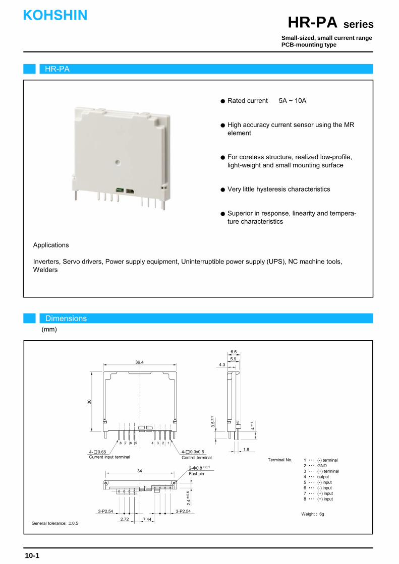
Rated current 5A ~ 10A
Applications
High accuracy current sensor using the MR element
For coreless structure, realized low-profile, light-weight and small mounting surface
Very little hysteresis characteristics
Superior in response, linearity and tempera- ture characteristics
Inverters, Servo drivers, Power supply equipment, Uninterruptible power supply (UPS), NC machine tools,Welders
Current input terminal
30
4±
1
4- 0.651.8
3.5±
1
36.4
4 3 2 1
4- 0.3x0.5Control terminal
3-P2.54
2-Φ0.8±0.1
Fast pin
7.442.72
34
3-P2.54
5.94.3
8 7 6 5
2.4±
0.6
6.6
HR-PA
Dimensions(mm)
seriesHR-PAKOHSHIN
10-1
General tolerance: ±0.5
Terminal No. 1 ・・・ (-) terminal2 ・・・ GND3 ・・・ (+) terminal4 ・・・ output5 ・・・ (-) input6 ・・・ (-) input7 ・・・ (+) input8 ・・・ (+) input
Weight : 6g
Small-sized, small current rangePCB-mounting type
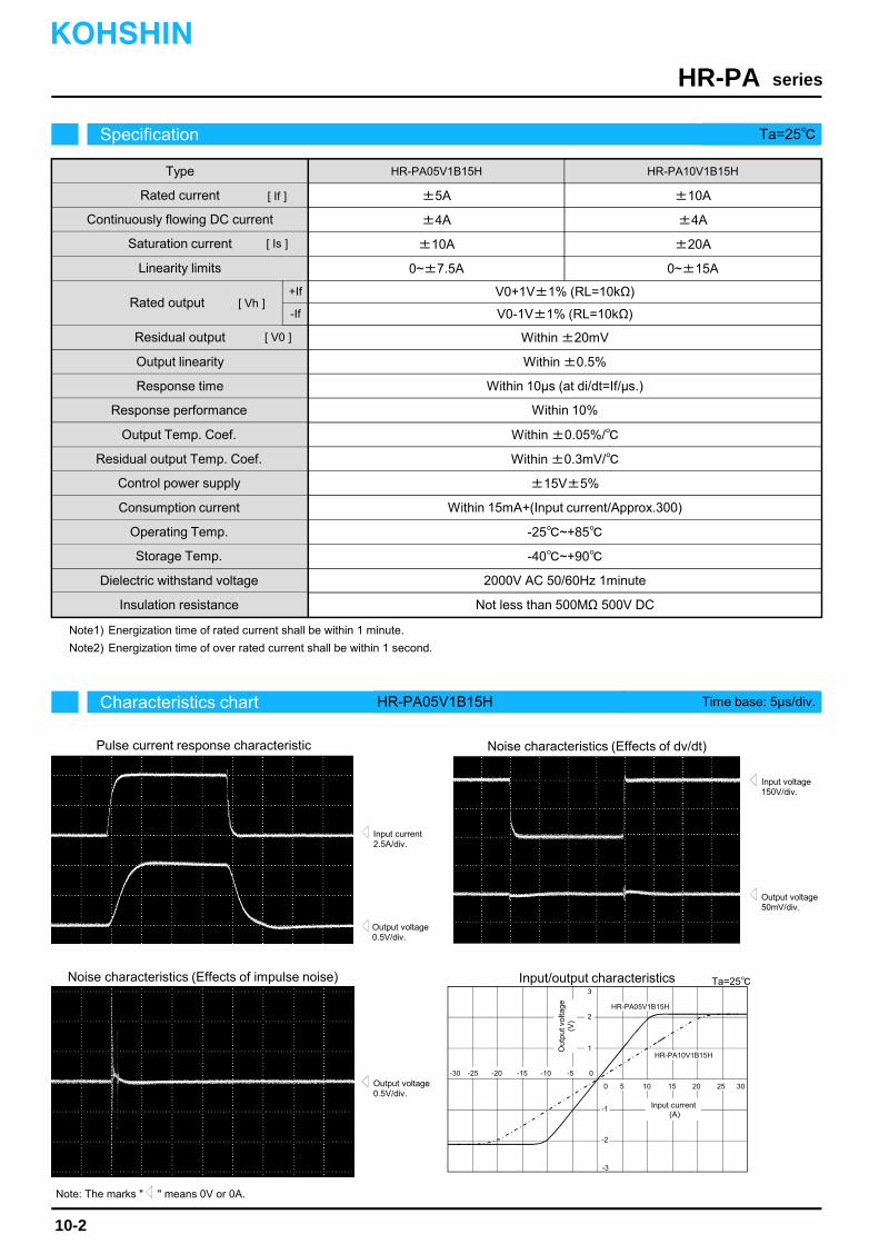
Energization time of rated current shall be within 1 minute.
Energization time of over rated current shall be within 1 second.Note2)
Note1)
Characteristics chart HR-PA05V1B15H Time base: 5μs/div.
seriesHR-PA
Output voltage0.5V/div.
Output voltage50mV/div.
Input voltage150V/div.
Input current2.5A/div.
Ta=25
Output voltage0.5V/div.
Specification Ta=25
10-2
Pulse current response characteristic
Noise characteristics (Effects of impulse noise)
Noise characteristics (Effects of dv/dt)
Input/output characteristics
HR-PA05V1B15HType
Rated current
Continuously flowing DC current
Linearity limits
Output linearity
HR-PA10V1B15H
±5A
±4A
0~±7.5A
±10A
±4A
0~±15A
[ If ]
[ V0 ]
V0+1V±1% (RL=10kΩ)
Within ±20mV
Within ±0.5%
Within 10μs (at di/dt=If/μs.)
Within 10%
Within ±0.05%/
Within ±0.3mV/
±15V±5%
Within 15mA+(Input current/Approx.300)
-25~+85
-40~+90
2000V AC 50/60Hz 1minute
Not less than 500MΩ 500V DC
KOHSHIN
V0-1V±1% (RL=10kΩ)
Residual output
Response time
Response performance
Output Temp. Coef.
Residual output Temp. Coef.
Control power supply
Consumption current
Operating Temp.
Storage Temp.
Dielectric withstand voltage
Insulation resistance
+If
-If
Note: The marks " " means 0V or 0A.
Saturation current ±10A ±20A[ Is ]
HR-PA05V1B15H
HR-PA10V1B15H
-1
0-30 -15-25
3025155
1
3
-3
-5
2
-2
0 2010
-10-20
Out
put v
olta
ge
(V)
Input current(A)
Rated output [ Vh ]
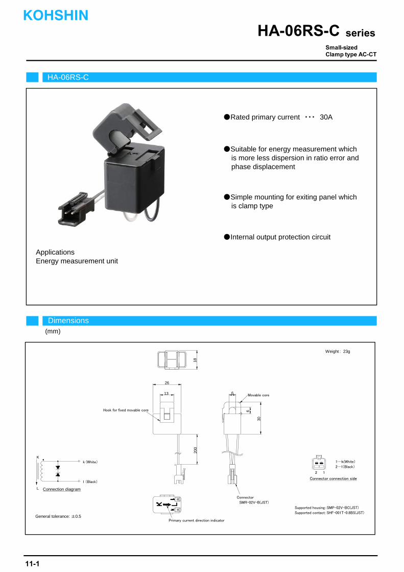
Applications
Supported housing SMP-02V-BC(JST)
Suitable for energy measurement whichis more less dispersion in ratio error andphase displacement
Simple mounting for exiting panel whichis clamp type
適合ハウジング SMP-02V-BC(JST)
Rated primary current ・・・ 30A
Internal output protection circuit
Energy measurement unit
HA-06RS-C
seriesHA-06RS-C
写真準備中
(mm)
General tolerance: ±0.5
Supported housing:SMP-02V-BC(JST)
Supported contact:SHF-001T-0.8BS(JST)
Weight : 23g
Connection diagram
Dimensions
Hook for fixed movable core
Movable core
Connector
SMR-02V-B(JST)
Primary current direction indicator
6
26
13
18
6
30
200
1…k(White)
2…l(Black)
2 1
Connector connection side
K
L
k (White)
l (Black)
Small-sizedClamp type AC-CT
11-1
KOHSHIN

Dispersion in phase displacement
Current transformation ratio
Output line UL1007 AWG24 L=200mmConnector SMR-02V-B (JST)
Internal output protection circuit
UL94-V0
RoHS
23g
Others
1000V AC 1minute
Not less than 100MΩ 500V DC
Ferrite
100
±45minute(0.1If~If RL=10Ω)±60minute(0.05If RL=10Ω)
3000:1
±1%(RL=10Ω)
-10~+55
-20~+60
Rated secondary current
Ratio error
HA-06RS030-10C
1.5~30Arms
10mArms
45~65Hz
30Arms
Type
Rated primary current
Measuring bound
Frequency
Saturation current 50Arms
Weight
Application standard
Permission installation number of time
Operating Temp.
Storage Temp.
Dielectric withstand voltage
Insulation resistance
Resisting grade
Core materials
Characteristics chart
seriesHA-06RS-C
Ta=25°C
Specification Ta=25°C
Input/output characteristics
0 10 20 30 40 50
0
2
4
16
18
Primary current [Arms]
Ou
tpu
t cu
rren
t [m
Arm
s]
8
12
14
6
10
KOHSHIN
11-2

Suitable for energy measurement whichis more less dispersion in ratio error andphase displacement
Simple mounting for exiting panel whichis clamp type
Internal output protection circuit
Applications
適合ハウジング SMP-02V-BC(JST)Supported housing SMP-02V-BC(JST)
Rated primary current ・・・ 30A
Energy measurement unit
HA-06RP-C
Small-sizedClamp type AC-CT
seriesHA-06RP-C
General tolerance: ±0.5 Connection diagram
Weight : 22g
Supported housing:SMP-02V-BC(JST)
Supported contact:SHF-001T-0.8BS(JST)
Dimensions
Movable core
Hook for fixed movable
Connector
SMR-02V-B(JST)
Primary current direction indicator
7.5
23.5
11.5
24.5
200
6.5
30
(mm)
K
L
k (White)
l (Black)
1…k(White)
2…l(Black)
2 1
Connector connection
KOHSHIN
11-3
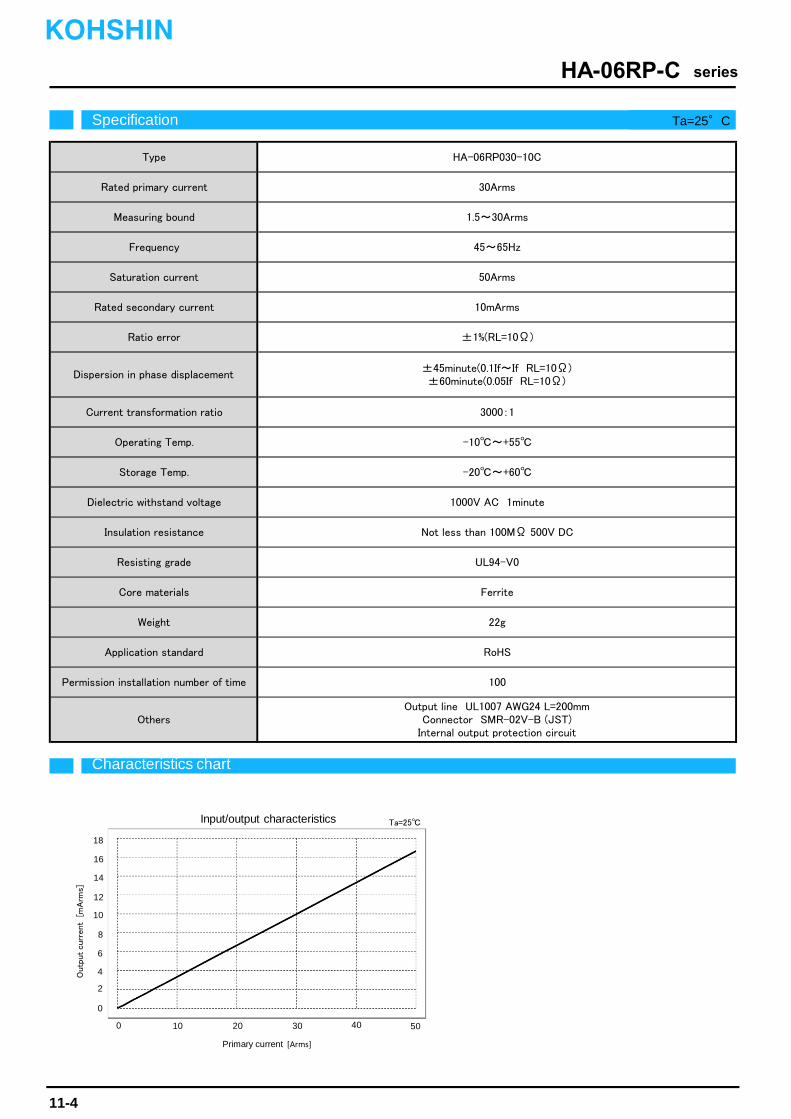
Ratio error
Insulation resistance
22g
Others
Ferrite
100
±1%(RL=10Ω)
RoHS
±45minute(0.1If~If RL=10Ω)±60minute(0.05If RL=10Ω)
-10~+55
1.5~30Arms
HA-06RP030-10C
Frequency
Saturation current
Rated secondary current
Output line UL1007 AWG24 L=200mmConnector SMR-02V-B (JST)
Internal output protection circuit
30Arms
45~65Hz
50Arms
10mArms
UL94-V0
1000V AC 1minute
Not less than 100MΩ 500V DC
Dielectric withstand voltage
3000:1
-20~+60
Current transformation ratio
Storage Temp.
Type
Rated primary current
Measuring bound
Resisting grade
Core materials
Weight
Application standard
Permission installation number of time
Dispersion in phase displacement
Operating Temp.
Outp
ut curr
ent
[mA
rms]
Primary current [Arms]
Characteristics chart
seriesHA-06RP-C
Ta=25°C
Specification Ta=25°C
Input/output characteristics
0 10 20 30 40 50
0
2
4
16
18
8
12
14
6
10
Ta=25
KOHSHIN
11-4
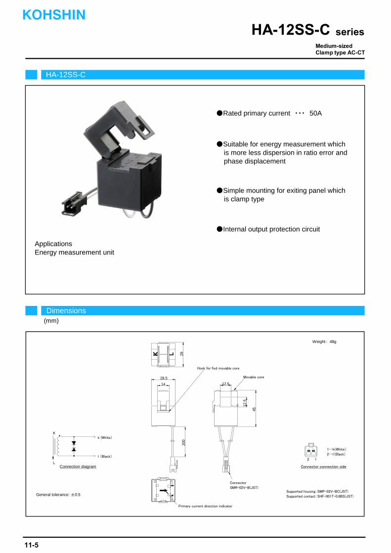
Internal output protection circuit
Applications
Supported housing SMP-02V-BC(JST)適合ハウジング SMP-02V-BC(JST)
Energy measurement unit
Rated primary current ・・・ 50A
Suitable for energy measurement whichis more less dispersion in ratio error andphase displacement
Simple mounting for exiting panel whichis clamp type
HA-12SS-C
Dimensions(mm)
seriesHA-12SS-C
Connection diagram
Weight : 48g
General tolerance: ±0.5Supported housing:SMP-02V-BC(JST)
Supported contact:SHF-001T-0.8BS(JST)
Hook for fixd movable core
Movable core
Connector
SMR-02V-B(JST)
Primary current direction indicator
28.5
14 12.5
29
12.5
45
200
K
L
k (White)
l (Black)
1…k(White)
2…l(Black)
2 1
Connector connection side
Medium-sizedClamp type AC-CT
KOHSHIN
11-5
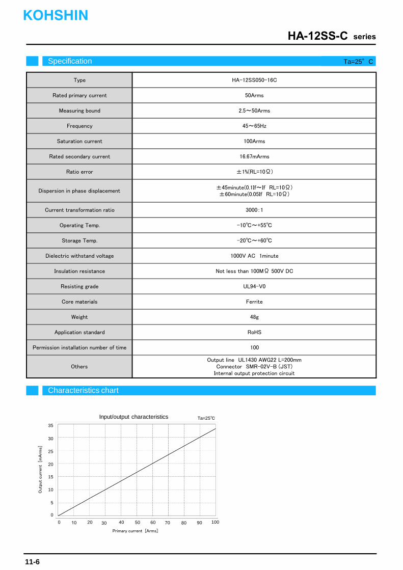
Operating Temp.
Storage Temp.
Dielectric withstand voltage
Insulation resistance
Resisting grade
Core materials
100
Output line UL1430 AWG22 L=200mmConnector SMR-02V-B (JST)
Internal output protection circuit
RoHSApplication standard
Permission installation number of time
Ferrite
48gWeight
Others
Not less than 100MΩ 500V DC
UL94-V0
-20~+60
1000V AC 1minute
±45minute(0.1If~If RL=10Ω)±60minute(0.05If RL=10Ω)
3000:1
-10~+55
Current transformation ratio
16.67mArms
±1%(RL=10Ω)Ratio error
45~65Hz
100Arms
Frequency
Saturation current
Rated secondary current
HA-12SS050-16C
Dispersion in phase displacement
Type
Rated primary current
Measuring bound
50Arms
2.5~50Arms
Characteristics chart
seriesHA-12SS-C
Ta=25
Specification Ta=25°C
Input/output characteristics
0 20 40 60 80 100
0
5
10
30
35
Primary current [Arms]
Outp
ut curr
ent [
mA
rms]
15
20
25
10 30 50 70 90
KOHSHIN
11-6
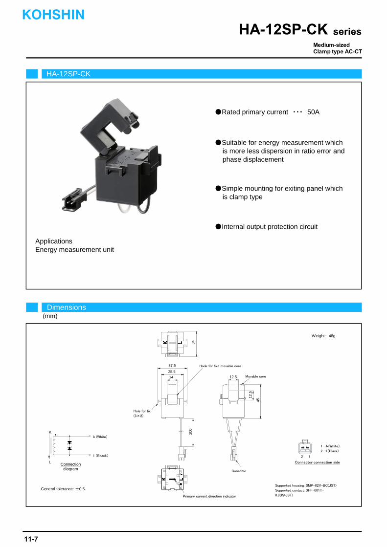
Rated primary current ・・・ 50A
Suitable for energy measurement whichis more less dispersion in ratio error andphase displacement
Simple mounting for exiting panel whichis clamp type
Internal output protection circuit
Applications
適合ハウジング SMP-02V-BC(JST)Supported housing SMP-02V-BC(JST)
Energy measurement unit
HA-12SP-CK
Dimensions(mm)
seriesHA-12SP-CK
Connection diagram
Weight : 48g
General tolerance: ±0.5Supported housing:SMP-02V-BC(JST)
Supported contact:SHF-001T-
0.8BS(JST)Primary current direction indicator
Conector
Hook for fixd movable core
Movable core
Hole for fix
(3×2)
37.5
28.5
14 12.5
45
12.5
3420
0
1…k(White)
2…l(Black)
2 1
Connector connection side
K
L
k (White)
l (Bkack)
Medium-sizedClamp type AC-CT
KOHSHIN
11-7
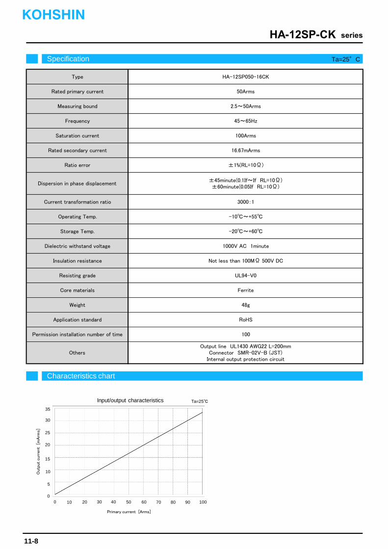
HA-12SP050-16CK
45~65Hz
100Arms
50Arms
2.5~50Arms
±45minute(0.1If~If RL=10Ω)±60minute(0.05If RL=10Ω)
3000:1
-10~+55
Dispersion in phase displacement
Current transformation ratio
16.67mArms
±1%(RL=10Ω)
Rated secondary current
Ratio error
Operating Temp.
Not less than 100MΩ 500V DC
UL94-V0
Insulation resistance
Resisting grade
-20~+60
1000V AC 1minute
Storage Temp.
Dielectric withstand voltage
Application standard
Permission installation number of time
Ferrite
48g
Core materials
Weight
Others
Type
Rated primary current
Measuring bound
Frequency
Saturation current
100
Output line UL1430 AWG22 L=200mmConnector SMR-02V-B (JST)
Internal output protection circuit
RoHS
Outp
ut curr
ent [
mA
rms]
Characteristics chart
seriesHA-12SP-CK
Ta=25
Specification Ta=25°C
Input/output characteristics
0 20 40 60 80 1000
5
10
30
35
Primary current [Arms]
15
20
25
10 30 50 70 90
KOHSHIN
11-8
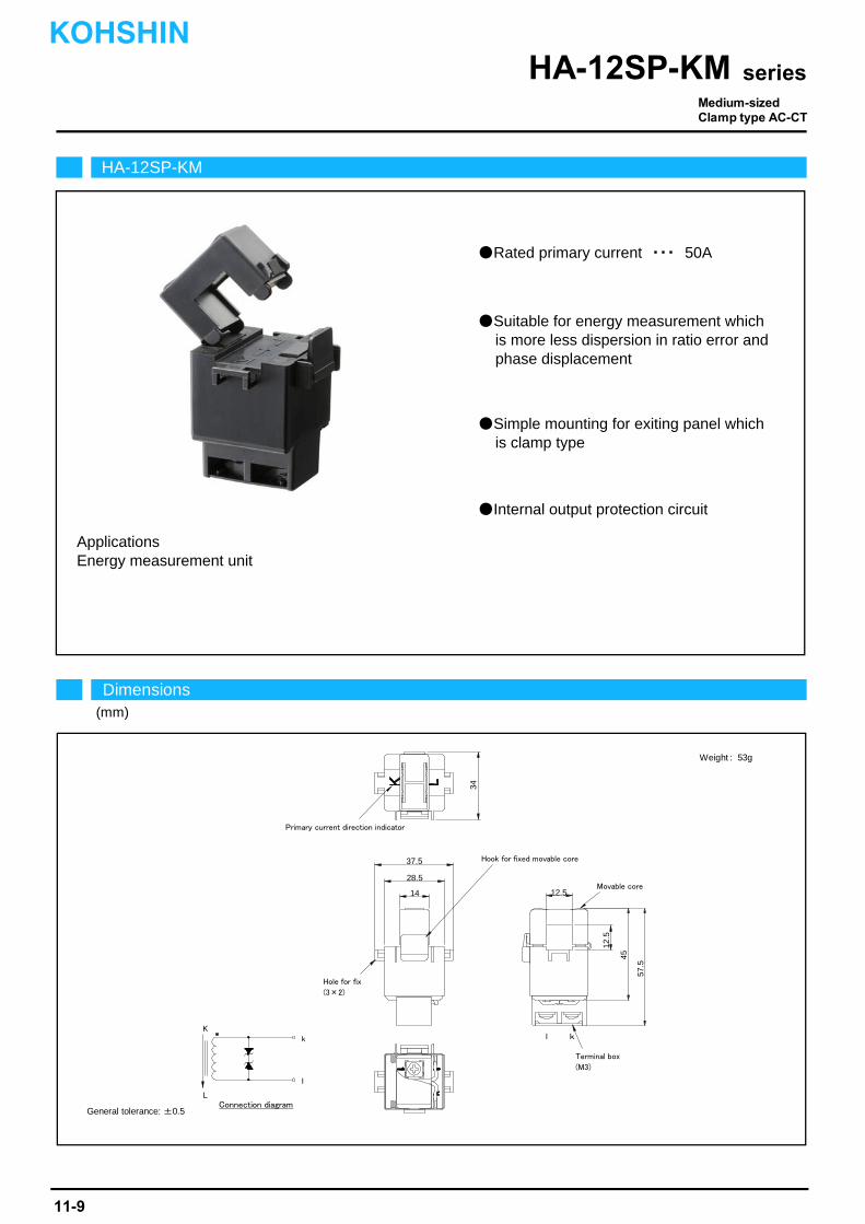
Energy measurement unit
Internal output protection circuit
Applications
Rated primary current ・・・ 50A
Suitable for energy measurement whichis more less dispersion in ratio error andphase displacement
Simple mounting for exiting panel whichis clamp type
HA-12SP-KM
Dimensions(mm)
seriesHA-12SP-KM
Connection diagram
Weight : 53g
General tolerance: ±0.5
Hook for fixed movable core
Movable core
Primary current direction indicator
Hole for fix
(3×2)
Terminal box
(M3)
37.5
28.5
14 12.5
57.5
12.5
45
34
K
L
k
l
l k
Medium-sizedClamp type AC-CT
KOHSHIN
11-9
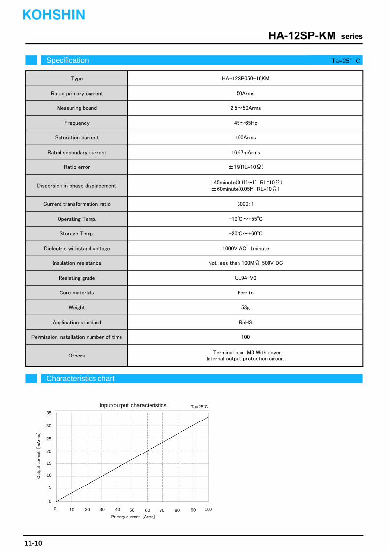
Core materials
Weight
Application standard
Permission installation number of time
Others
Rated secondary current
Ratio error
Dispersion in phase displacement
Current transformation ratio
Operating Temp.
Storage Temp.
Type
Rated primary current
Measuring bound
Frequency
Saturation current
3000:1
-10~+55
16.67mArms
2.5~50Arms
Dielectric withstand voltage
Insulation resistance
Resisting grade
±1%(RL=10Ω)
HA-12SP050-16KM
50Arms
45~65Hz
100Arms
±45minute(0.1If~If RL=10Ω)±60minute(0.05If RL=10Ω)
-20~+60
100
RoHS
Terminal box M3 With coverInternal output protection circuit
1000V AC 1minute
Not less than 100MΩ 500V DC
53g
UL94-V0
Ferrite
Outp
ut curr
ent [
mA
rms]
Characteristics chart
seriesHA-12SP-KM
Ta=25
Specification Ta=25°C
Input/output characteristics
0 20 40 60 80 100
0
5
10
30
Primary current [Arms]
35
15
20
25
10 30 50 70 90
KOHSHIN
11-10
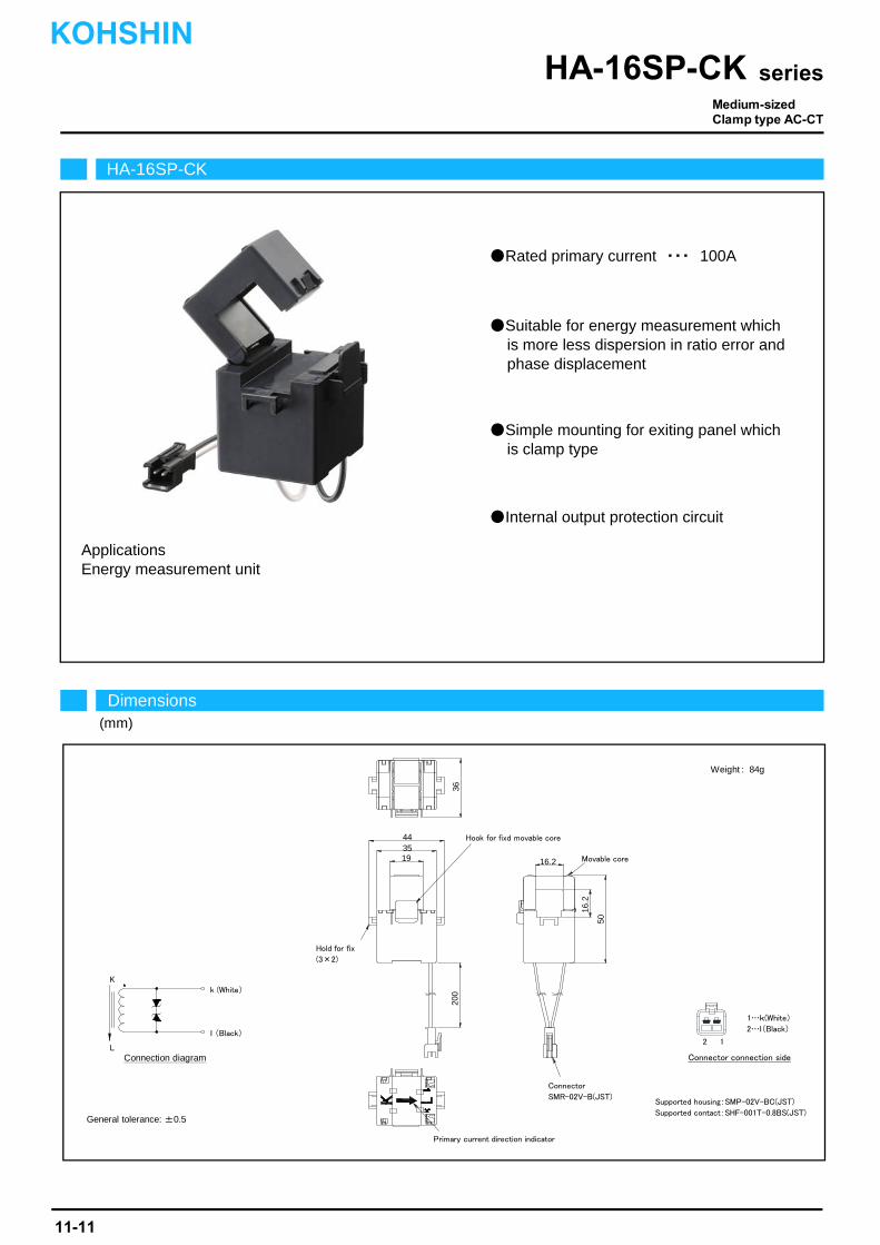
Rated primary current ・・・ 100A
Suitable for energy measurement whichis more less dispersion in ratio error andphase displacement
Simple mounting for exiting panel whichis clamp type
Internal output protection circuit
Applications
適合ハウジング SMP-02V-BC(JST)Supported housing SMP-02V-BC(JST)
Energy measurement unit
HA-16SP-CK
Dimensions(mm)
seriesHA-16SP-CK
Connection diagram
Weight : 84g
General tolerance: ±0.5
Supported housing:SMP-02V-BC(JST)
Supported contact:SHF-001T-0.8BS(JST)
Connector
SMR-02V-B(JST)
Hook for fixd movable core
Movable core
Primary current direction indicator
Hold for fix
(3×2)
443519 16.2
16.2
50
3620
0
K
L
k (White)
l (Black)
1…k(White)
2…l(Black)
2 1
Connector connection side
Medium-sizedClamp type AC-CT
KOHSHIN
11-11
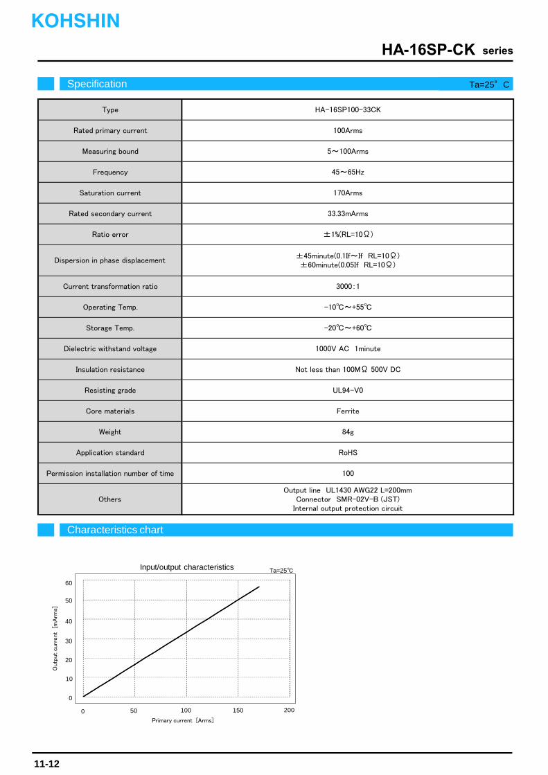
Resisting grade
Core materials
Weight
Application standard
Permission installation number of time
Others
Ratio error
Dispersion in phase displacement
Current transformation ratio
Operating Temp.
Storage Temp.
Dielectric withstand voltage
HA-16SP100-33CKType
100Arms
5~100Arms
Rated primary current
Measuring bound
45~65Hz
Insulation resistance
UL94-V0
170Arms
Frequency
Saturation current
Rated secondary current
±45minute(0.1If~If RL=10Ω)±60minute(0.05If RL=10Ω)
3000:1
33.33mArms
±1%(RL=10Ω)
RoHS
Ferrite
84g
100
Output line UL1430 AWG22 L=200mmConnector SMR-02V-B (JST)
Internal output protection circuit
-10~+55
-20~+60
1000V AC 1minute
Not less than 100MΩ 500V DC
Characteristics chart
seriesHA-16SP-CK
Ta=25
Specification Ta=25°C
Input/output characteristics
0 50 100 150 200
0
10
20
60
Primary current [Arms]
Outp
ut curr
ent [
mA
rms]
30
40
50
KOHSHIN
11-12
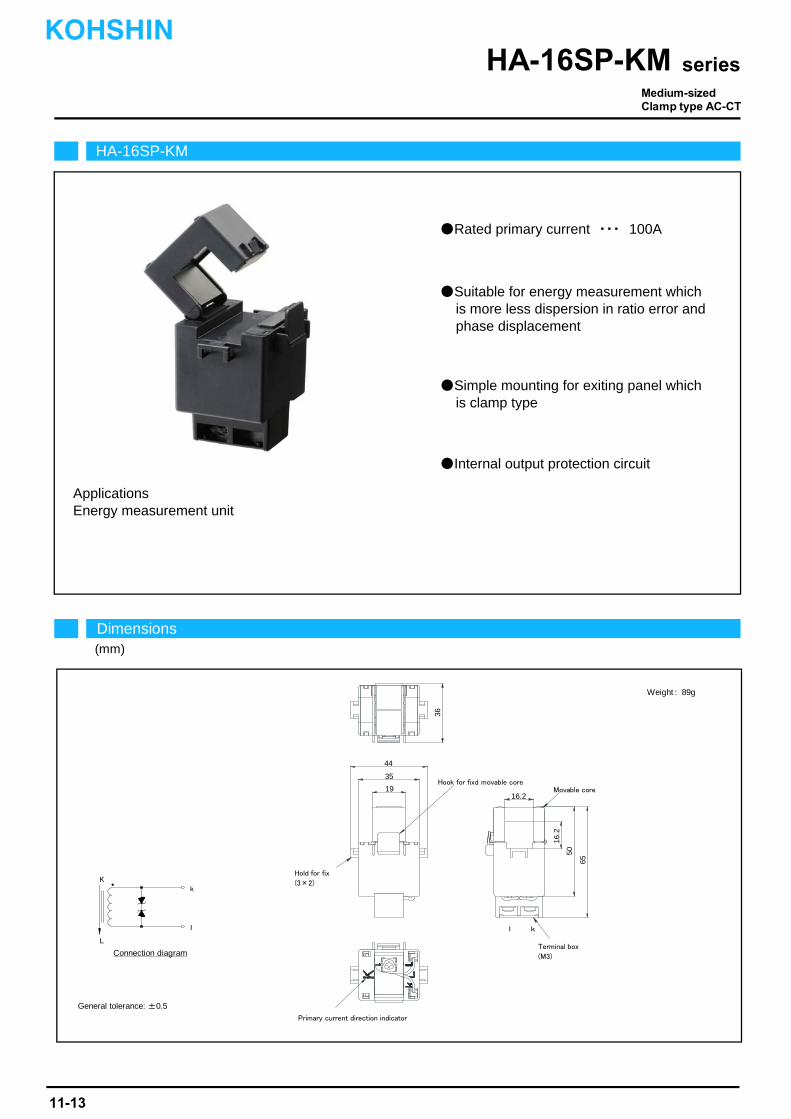
Energy measurement unit
Rated primary current ・・・ 100A
Suitable for energy measurement whichis more less dispersion in ratio error andphase displacement
Simple mounting for exiting panel whichis clamp type
Internal output protection circuit
Applications
HA-16SP-KM
Dimensions(mm)
seriesHA-16SP-KM
Connection diagram
Weight : 89g
General tolerance: ±0.5
Hook for fixd movable coreMovable core
Terminal box
(M3)
Primary current direction indicator
Hold for fix
(3×2)
44
35
1916.2
50
16.2
65
36
l k
K
L
k
l
Medium-sizedClamp type AC-CT
KOHSHIN
11-13
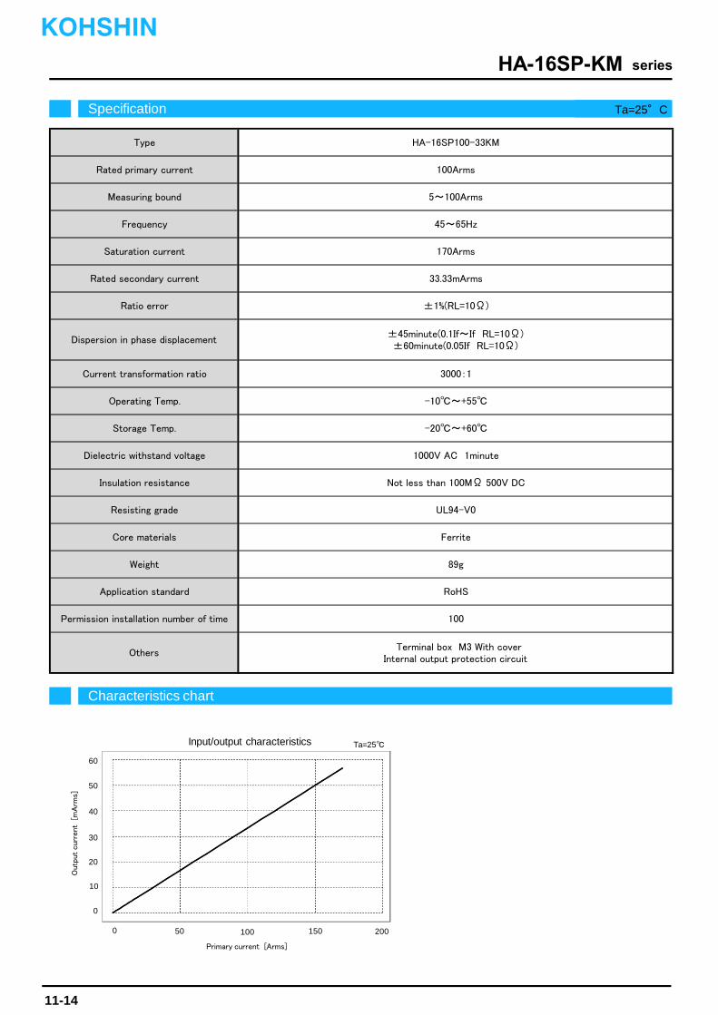
Storage Temp.
Permission installation number of time
Others
Dielectric withstand voltage
Insulation resistance
Resisting grade
Core materials
Weight
Application standard
45~65Hz
Rated secondary current
Ratio error
Dispersion in phase displacement
Current transformation ratio
Operating Temp.
89g
Not less than 100MΩ 500V DC
Type
Rated primary current
Measuring bound
Frequency
Saturation current
100Arms
5~100Arms
-20~+60
±1%(RL=10Ω)
±45minute(0.1If~If RL=10Ω)±60minute(0.05If RL=10Ω)
170Arms
33.33mArms
100
UL94-V0
1000V AC 1minute
RoHS
Ferrite
Terminal box M3 With coverInternal output protection circuit
HA-16SP100-33KM
3000:1
-10~+55
Characteristics chart
seriesHA-16SP-KM
Ta=25
Specification Ta=25°C
Input/output characteristics
0 50 100 150 200
0
10
20
60
Primary current [Arms]
Outp
ut curr
ent [
mA
rms]
30
40
50
KOHSHIN
11-14

Energy measurement unit
Supported housing SMP-02V-BC(JST)
Rated primary current ・・・ 200A ~ 250A
Suitable for energy measurement whichis more less dispersion in ratio error andphase displacement
Simple mounting for exiting panel whichis clamp type
Internal output protection circuit
Applications
適合ハウジング SMP-02V-BC(JST)
HA-24RP-CK
Dimensions(mm)
seriesHA-24RP-CK
General tolerance: ±0.5
Weight
HA-24RP200-66CK : 144g
HA-24RP250-66CK : 166g
Supported housing:SMP-02V-BC(JST)
Supported contact:SHF-001T-0.8BS(JST)
Connection diagram
Hook for fixd movable coreMovable core
Primary current direction indicator
Hole for fix
(3×2)
Connector
SMR-02V-B(JST)
42.233.225.2
49.524
24
62
200
K
L
k (White)
l (Black)
1…k(White)
2…l(Black)
2 1
Connector connection side
Large-sizedClamp type AC-CT
11-15
KOHSHIN

Permission installation number of time
Others
Dielectric withstand voltage
Insulation resistance
Resisting grade
Core materials
Weight
Application standard
Rated secondary current
Ratio error
Dispersion in phase displacement
Current transformation ratio
Operating Temp.
Storage Temp.
Type
Rated primary current
Measuring bound
Frequency
Saturation current
Ferrite Silicon steel plate
Output line UL1430 AWG22 L=200mmConnector SMR-02V-B (JST)
Internal output protection circuit
RoHS
-20~+60
144g 166g
Not less than 100MΩ 500V DC
UL94-V0
10~250Arms
300Arms 350Arms
66.67mArms 66.67mArms
45~65Hz
3000:1
100
2000V AC 1minute
-10~+55
3750:1
±1%(RL=10Ω)
±40minute(0.1If~If RL=10Ω)±45minute(0.05If RL=10Ω)
250Arms
10~200Arms
HA-24RP200-66CK HA-24RP250-66CK
200Arms
Characteristics chart
seriesHA-24RP-CK
Ta=25
Specification Ta=25°C
Input/output characteristics
0 100 200 300 400
0
20
40
120
Primary current [Arms]
Outp
ut curr
ent [
mA
rms]
60
80
100HA‐24RP200‐66CK
HA‐24RP250‐66CK
KOHSHIN
11-16
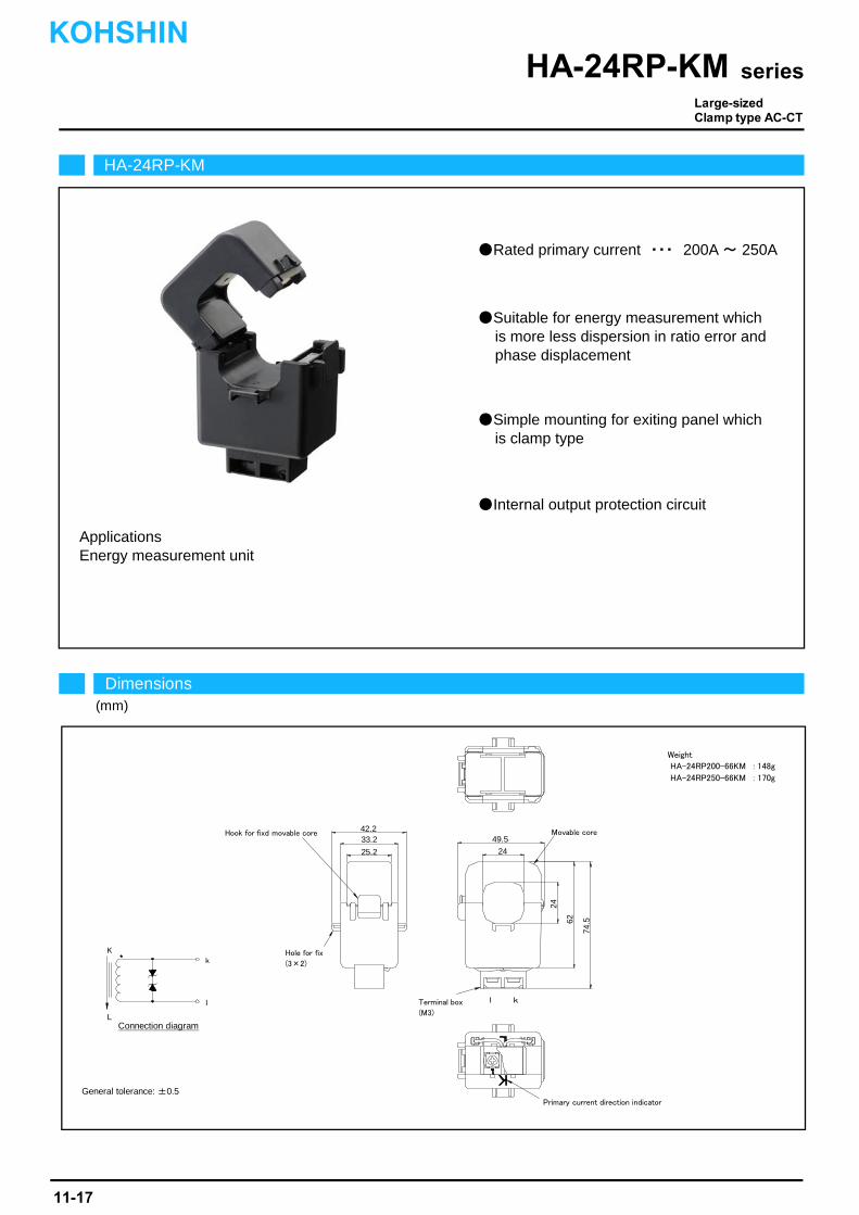
Rated primary current ・・・ 200A ~ 250A
Suitable for energy measurement whichis more less dispersion in ratio error andphase displacement
Simple mounting for exiting panel whichis clamp type
Applications
Internal output protection circuit
Energy measurement unit
HA-24RP-KM
Dimensions(mm)
seriesHA-24RP-KM
General tolerance: ±0.5
Connection diagram
Weight
HA-24RP200-66KM : 148g
HA-24RP250-66KM : 170g
Hook for fixd movable core
Hole for fix
(3×2)
Terminal box
(M3)
Primary current direction indicator
Movable core42.233.2
25.2 24
49.5
62
24
74.5
l k
K
L
k
l
Large-sizedClamp type AC-CT
KOHSHIN
11-17
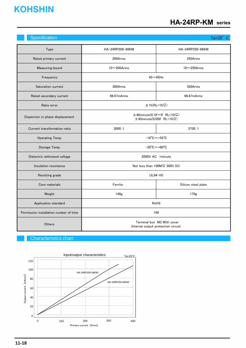
Dielectric withstand voltage
Insulation resistance
Resisting grade
Core materials
Terminal box M3 With coverInternal output protection circuit
Not less than 100MΩ 500V DC
Ferrite
100
RoHS
-10~+55
-20~+60
Silicon steel plate
170g148g
±40minute(0.1If~If RL=10Ω)±45minute(0.05If RL=10Ω)
UL94-V0
2000V AC 1minute
66.67mArms
45~65Hz
200Arms
10~200Arms
3750:1
±1%(RL=10Ω)
HA-24RP250-66KM
250Arms
HA-24RP200-66KM
10~250Arms
350Arms
66.67mArms
300Arms
3000:1
Type
Rated primary current
Measuring bound
Frequency
Saturation current
Weight
Application standard
Permission installation number of time
Others
Rated secondary current
Ratio error
Dispersion in phase displacement
Current transformation ratio
Operating Temp.
Storage Temp.
Characteristics chart
seriesHA-24RP-KM
Specification Ta=25°C
Input/output characteristics Ta=25
0 100 200 300 400
0
20
40
120
Primary current [Arms]
Outp
ut curr
ent [
mA
rms]
60
80
100HA‐24RP200‐66KM
HA‐24RP250‐66KM
KOHSHIN
11-18
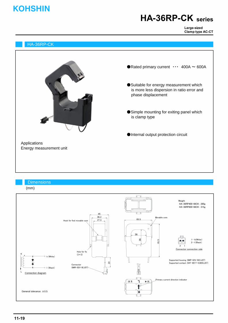
Internal output protection circuit
Applications
適合ハウジング SMP-02V-BC(JST)Supported housing SMP-02V-BC(JST)
Rated primary current ・・・ 400A ~ 600A
Suitable for energy measurement whichis more less dispersion in ratio error andphase displacement
Simple mounting for exiting panel whichis clamp type
Energy measurement unit
Dimensions(mm)
seriesHA-36RP-CK
Connection diagram
General tolerance: ±0.5
HA-36RP-CK
Weight
HA-36RP400-66CK : 280g
HA-36RP600-66CK : 315g
Supported housing:SMP-02V-BC(JST)
Supported contact:SHF-001T-0.8BS(JST)
Hook for fixd movable core
Hole for fix
(3×2)
Movable core
Primary current direction indicator
Connector
SMR-02V-B(JST)
45
36.227.3 65.5
36
81.536
20
1…k(White)
2…l(Black)
2 1
Connector connection side
Large-sizedClamp type AC-CT
K
L
k (White)
l (Black)
11-19
KOHSHIN
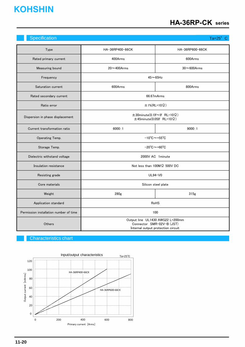
Insulation resistance
Resisting grade
Core materials
Ratio error
Dispersion in phase displacement
HA-36RP600-66CK
Rated secondary current
400Arms 600Arms
HA-36RP400-66CK
±1%(RL=10Ω)
±30minute(0.1If~If RL=10Ω)±45minute(0.05If RL=10Ω)
600Arms 800Arms
66.67mArms
20~400Arms 30~600Arms
45~65Hz
-20~+60
2000V AC 1minute
Storage Temp.
Dielectric withstand voltage
6000:1 9000:1
-10~+55
Current transformation ratio
Operating Temp.
280g 315g
Output line UL1430 AWG22 L=200mmConnector SMR-02V-B (JST)
Internal output protection circuit
RoHS
100
Not less than 100MΩ 500V DC
UL94-V0
Silicon steel plate
Weight
Application standard
Permission installation number of time
Others
Type
Rated primary current
Measuring bound
Frequency
Saturation current
Characteristics chart
seriesHA-36RP-CK
Specification Ta=25°C
Input/output characteristics Ta=25
0 200 400 600 800
0
20
40
120
Primary current [Arms]
Outp
ut curr
ent [
mA
rms]
60
80
100HA‐36RP400‐66CK
HA‐36RP600‐66CK
KOHSHIN
11-20

Energy measurement unit
Rated primary current ・・・ 400A ~ 600A
Suitable for energy measurement whichis more less dispersion in ratio error andphase displacement
Simple mounting for exiting panel whichis clamp type
Internal output protection circuit
Applications
Dimensions(mm)
seriesHA-36RP-KM
Connection diagram
General tolerance: ±0.5
HA-36RP-KM
Weight
HA-36RP400-66CK : 285g
HA-36RP600-66CK : 319g
Hook for fixd movable core
Movable core
Hole for fix
(3×2)
Terminal box
(M3)
Primary current direction indicator
4536.2
27.3
65.5
36
94
81.536
l k
K
L
k
l
Large-sizedClamp type AC-CT
KOHSHIN
11-21
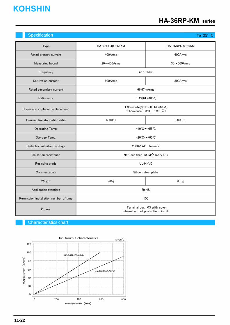
Type
Dispersion in phase displacement
HA-36RP600-66KM
±1%(RL=10Ω)
HA-36RP400-66KM
-10~+55
-20~+60
±30minute(0.1If~If RL=10Ω)±45minute(0.05If RL=10Ω)
6000:1
600Arms
9000:1
Core materials
2000V AC 1minute
400Arms 600Arms
20~400Arms 30~600Arms
800Arms
66.67mArms
45~65Hz
Not less than 100MΩ 500V DC
285g 319g
Silicon steel plate
Terminal box M3 With coverInternal output protection circuit
UL94-V0
RoHS
100
Rated primary current
Measuring bound
Frequency
Saturation current
Rated secondary current
Ratio error
Weight
Application standard
Permission installation number of time
Others
Current transformation ratio
Operating Temp.
Storage Temp.
Dielectric withstand voltage
Insulation resistance
Resisting grade
Characteristics chart
seriesHA-36RP-KM
Specification Ta=25°C
Input/output characteristics
0 200 400 600 800
0
20
40
120
Primary current [Arms]
Outp
ut curr
ent [
mA
rms]
60
80
100
Ta=25
HA‐36RP400‐66KM
HA‐36RP600‐66KM
KOHSHIN
11-22
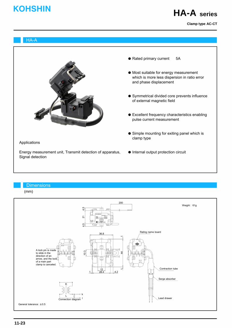
Rated primary current 5A
Simple mounting for exiting panel which is clamp type
Internal output protection circuitEnergy measurement unit, Transmit detection of apparatus,Signal detection
Applications
Most suitable for energy measurement which is more less dispersion in ratio error and phase displacement
Symmetrical divided core prevents influence of external magnetic field
Excellent frequency characteristics enabling pulse current measurement
HA-A
Dimensions(mm)
Clamp type AC-CT
seriesHA-AKOHSHIN
11-23
36.8
4.5
1
10.3
1
200
21
KOHSHIN
4.5
形名
定格
分割形電流センサ
HA-AAC5A
甲神電機株式会社
1228.4 4.2
44
A lock pin is made to slide in the direction of an arrow, and the lock of a main part clamp is canceled.
K
Lk
l Lead drawerConnection diagram
Rating name board
Contraction tube
Serge absorber
1
Weight : 61g
General tolerance: ±0.5

Characteristics chart HA-A005-016 Time base: 10ms/div.
seriesHA-A
Secondary current2mA/div.
Primary current5A/div.
Ta=25
Note: The marks " " means 0V or 0A.
Specification Ta=25
11-24
Secondary current waveform
Phase displacement characteristic Input/output characteristics
KOHSHIN
Others Internal output protection circuit
HA-A005-016Type
Rated primary current
Measuring bound
Frequency
Saturation current
Rated secondary current
Ratio error
Dispersion in phase displacement
Operating Temp.
Storage Temp.
Dielectric withstand voltage
Insulation resistance
5A
0.25~5Arms
45~65Hz
25A
1.67mArms
±1% (RL=200Ω)
-10~+55
-20~+60
1000V AC 1minute
Not less than 10MΩ 500V DC
[ If ]
[ Is ]
±60minute (0.05If RL=200Ω)
±45minute (0.1If~If RL=200Ω)
0 1 2 3 4 5 60
50
100
150
200
HA-A005-016(50Hz)
HA-A005-016(60Hz)
Primary current [Arms]
Pha
se d
ispl
acem
ent [
min
]
0 5 10 15 20 250
1
2
6
7
HA-A005-016
Primary current [Arms]
Out
put c
urre
nt [m
Arm
s]
3
4
5
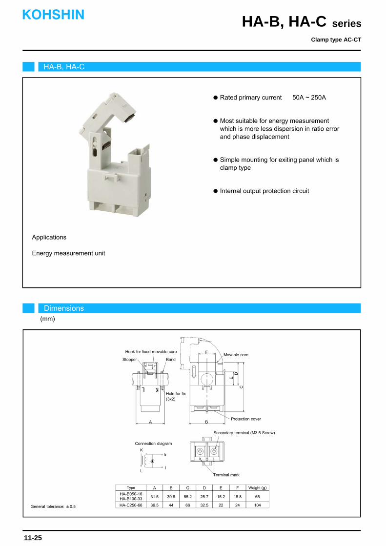
Rated primary current 50A ~ 250A
Most suitable for energy measurement which is more less dispersion in ratio error and phase displacement
Simple mounting for exiting panel which is clamp type
Internal output protection circuit
Energy measurement unit
Applications
HA-B, HA-C
Dimensions(mm)
Clamp type AC-CT
seriesHA-B, HA-CKOHSHIN
11-25
General tolerance: ±0.5
D
A B
C
K
L
k
l
Terminal mark
Connection diagram
Hole for fix(3x2)
Movable coreHook for fixed movable core
Type
HA-B050-16HA-B100-33
HA-C250-66
A
36.5
31.5
B
44
39.6
C
66
55.2
D
32.5
25.7
E
22
15.2
F
24
18.8
Weight (g)
104
65
E
Secondary terminal (M3.5 Screw)
Band Stopper
F
Protection cover
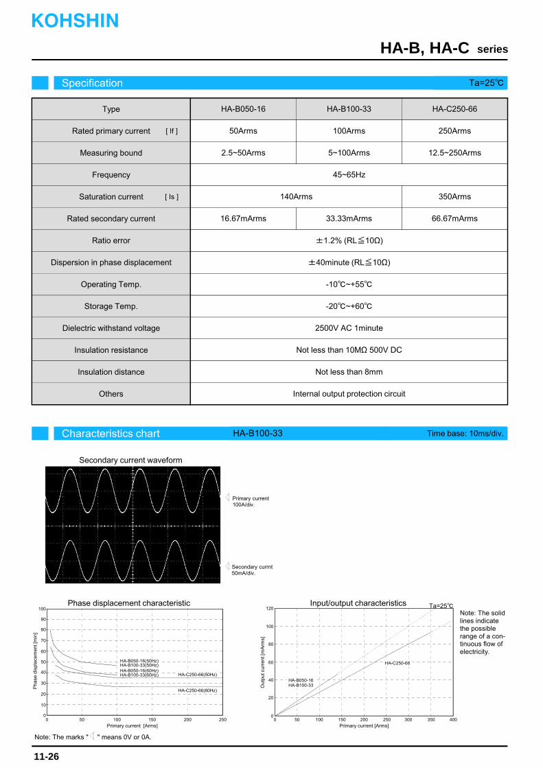
Characteristics chart HA-B100-33 Time base: 10ms/div.
seriesHA-B, HA-C
Secondary currnt50mA/div.
Primary current100A/div.
Ta=25
Note: The marks " " means 0V or 0A.
Specification Ta=25
11-26
Secondary current waveform
Phase displacement characteristic Input/output characteristics
KOHSHIN
Others Internal output protection circuit
HA-B050-16Type
Rated primary current
Measuring bound
Frequency
Saturation current
Rated secondary current
Ratio error
Dispersion in phase displacement
Operating Temp.
Storage Temp.
Dielectric withstand voltage
Insulation resistance
50Arms
2.5~50Arms
45~65Hz
140Arms
16.67mArms
±1.2% (RL≦10Ω)
±40minute (RL≦10Ω)
-10~+55
-20~+60
2500V AC 1minute
Not less than 10MΩ 500V DC
[ If ]
[ Is ]
0 50 100 150 200 2500
70
80
90
100
HA-B050-16(50Hz)
HA-C250-66(60Hz)
Primary current [Arms]
Pha
se d
ispl
acem
ent [
min
]
0 50 100 150 200 2500
20
100
120
HA-A005-016(60Hz)
Primary current [Arms]
Out
put c
urre
nt [m
Arm
s]
40
60
80
HA-B100-33
100Arms
5~100Arms
HA-C250-66
250Arms
12.5~250Arms
33.33mArms
350Arms
66.67mArms
Insulation distance Not less than 8mm
30
40
50
60
10
20
HA-B100-33(50Hz)HA-B050-16(60Hz)HA-B100-33(60Hz) HA-C250-66(50Hz)
300 350 400
Note: The solidlines indicatethe possiblerange of a con-tinuous flow ofelectricity.
HA-B050-16HA-B100-33
HA-C250-66
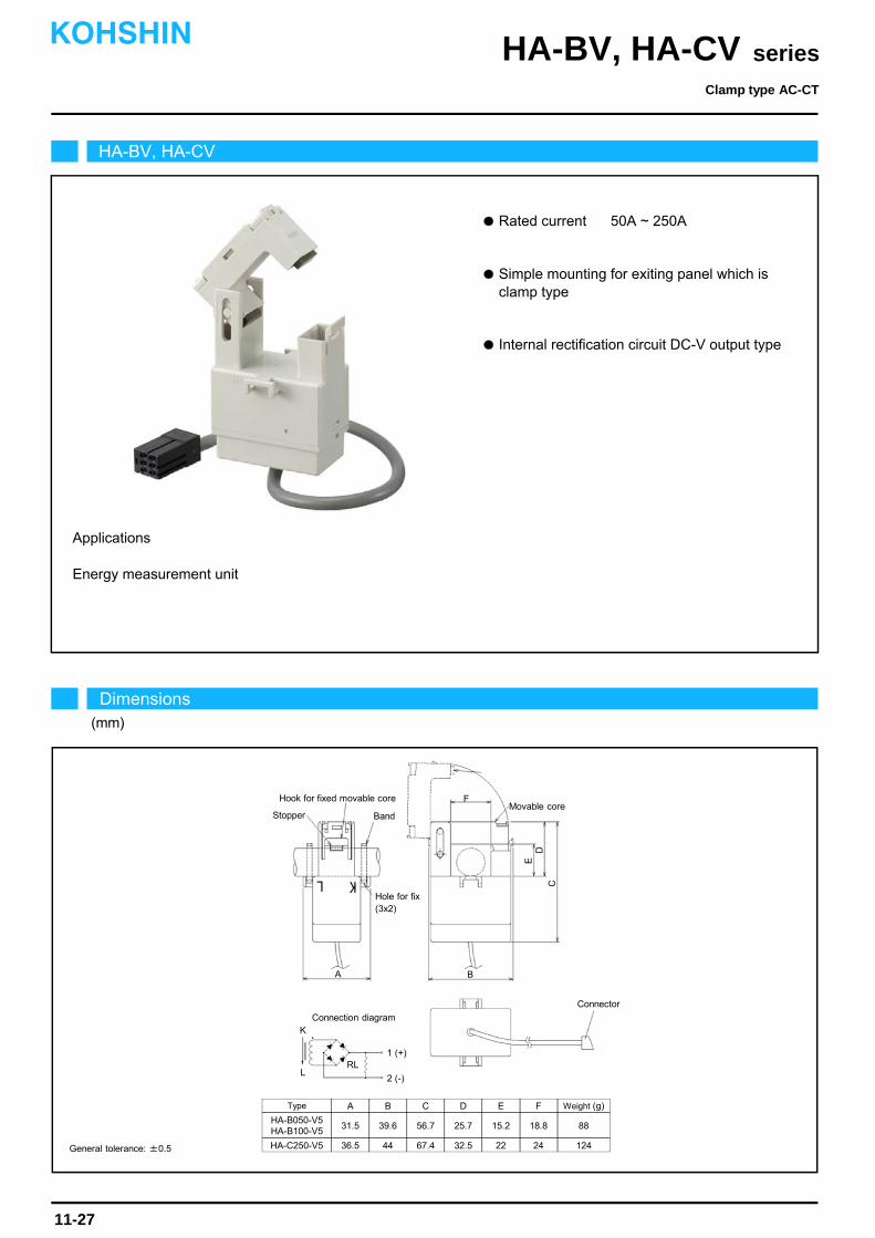
Applications
Energy measurement unit
Simple mounting for exiting panel which is clamp type
Rated current 50A ~ 250A
Internal rectification circuit DC-V output type
HA-BV, HA-CV
Dimensions(mm)
Clamp type AC-CT
seriesHA-BV, HA-CVKOHSHIN
11-27
General tolerance: ±0.5
D
A B
C
K
L
1 (+)
2 (-)
Connection diagram
Hole for fix(3x2)
Movable coreHook for fixed movable core
Type
HA-B050-V5HA-B100-V5
HA-C250-V5
A
36.5
31.5
B
44
39.6
C
67.4
56.7
D
32.5
25.7
E
22
15.2
F
24
18.8
Weight (g)
124
88
E
BandStopper
F
Connector
RL
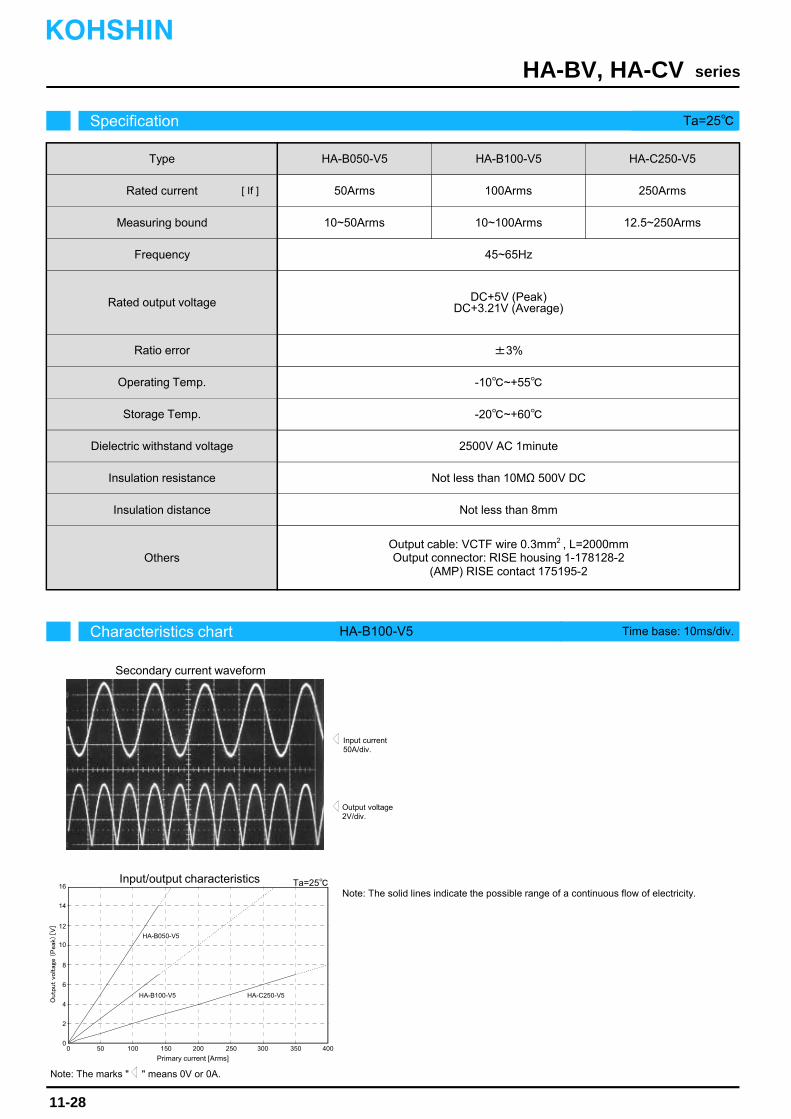
Characteristics chart HA-B100-V5 Time base: 10ms/div.
seriesHA-BV, HA-CV
Output voltage2V/div.
Input current50A/div.
Ta=25
Note: The marks " " means 0V or 0A.
Specification Ta=25
11-28
Secondary current waveform
Input/output characteristics
KOHSHIN
OthersOutput cable: VCTF wire 0.3mm , L=2000mmOutput connector: RISE housing 1-178128-2
(AMP) RISE contact 175195-2
HA-B050-V5Type
Rated current
Measuring bound
Frequency
Rated output voltage
Ratio error
Operating Temp.
Storage Temp.
Dielectric withstand voltage
Insulation resistance
50Arms
10~50Arms
45~65Hz
DC+5V (Peak)DC+3.21V (Average)
±3%
-10~+55
-20~+60
2500V AC 1minute
Not less than 10MΩ 500V DC
[ If ]
0 50 100 150 200 2500
6
14
16
HA-B050-V5
Primary current [Arms]
Outp
ut
voltag
e (
Peak
) [V
]
8
10
12
HA-B100-V5
100Arms
10~100Arms
HA-C250-V5
250Arms
12.5~250Arms
Insulation distance Not less than 8mm
300 350 400
Note: The solid lines indicate the possible range of a continuous flow of electricity.
2
4HA-B100-V5 HA-C250-V5
2
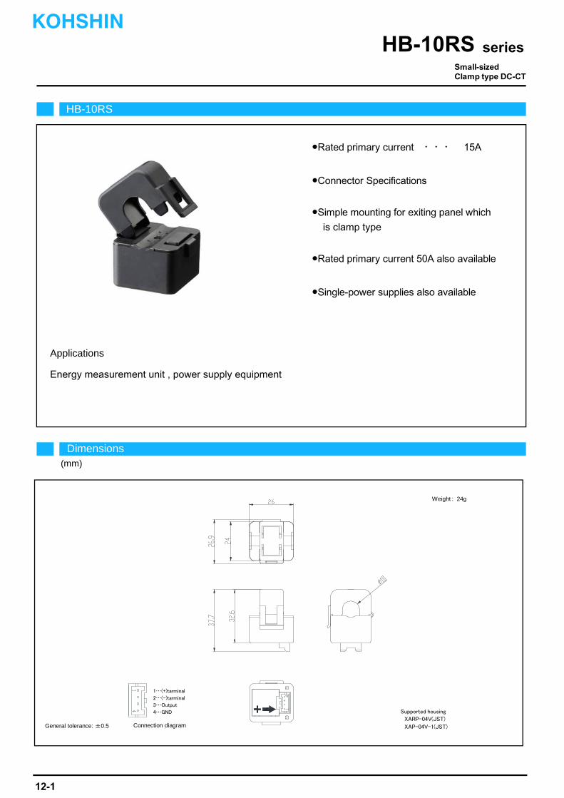
Rated primary current ・・・ 15A
Connector Specifications
Energy measurement unit , power supply equipment
Applications
Single-power supplies also available
Simple mounting for exiting panel which is clamp type
Supported housing SMP-02V-BC(JST)
Rated primary current 50A also available
HB-10RS
Small-sizedClamp type DC-CT
seriesHB-10RS
Dimensions(mm)
Connection diagramGeneral tolerance: ±0.5
Supported housing
XARP-04V(JST)
XAP-04V-1(JST)
Weight : 24g
1…(+)tarminal
2…(-)tarminal
3…Output
4…GND
KOHSHIN
12-1
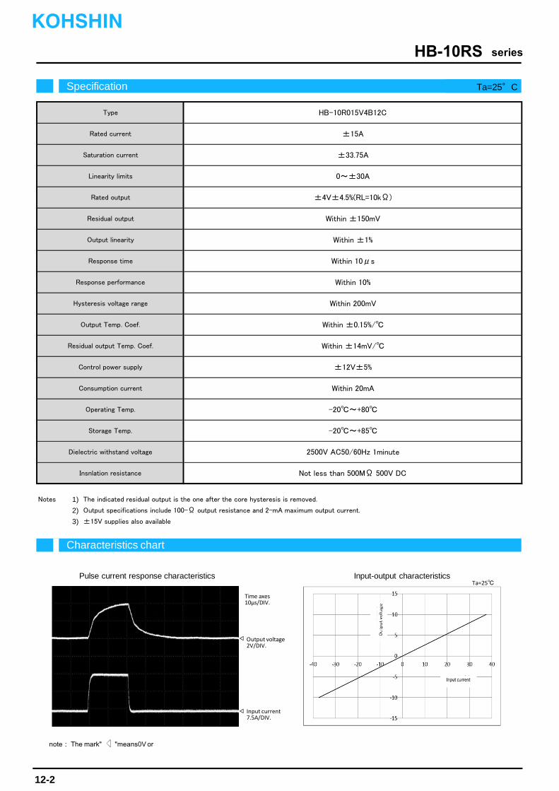
Notes 1) The indicated residual output is the one after the core hysteresis is removed.
2) Output specifications include 100-Ω output resistance and 2-mA maximum output current.
3) ±15V supplies also available
Not less than 500MΩ 500V DC
Output linearity
Response time
Response performance
Hysteresis voltage range
Output Temp. Coef.
Residual output Temp. Coef.
Control power supply
Consumption current
Operating Temp.
Storage Temp.
Dielectric withstand voltage
Insnlation resistance
Within ±14mV/
2500V AC50/60Hz 1minute
±12V±5%
±33.75A
HB-10R015V4B12CType
Rated current
Saturation current
±15A
0~±30ALinearity limits
Rated output ±4V±4.5%(RL=10kΩ)
Within ±150mVResidual output
Within ±1%
-20~+85
Within 10μs
Within ±0.15%/
Within 10%
Within 200mV
Within 20mA
-20~+80
Characteristics chart
seriesHB-10RS
Specification Ta=25°C
note: The mark" "means0V or
Pulse current response characteristics Input-output characteristics
Time axes10μs/DIV.
Input current7.5A/DIV.
Output voltage2V/DIV.
Ta=25
KOHSHIN
12-2
<Headquarters / Honsya Works>1608-10 Mobira, Kasaoka-shi, Okayama-pref. 714-0062, JAPANTEL +81-865-66-4877 FAX +81-865-66-2893<Fukuyama Works>1613-52 Hojoji, Ekiya-cho, Fukuyama-shi, Hiroshima-pref. 729-3431, JAPANTEL +81-84-983-2070 FAX +81-84-983-2081
http://www.kohshin-ele.com/en/
The performance and characteristics of the products are subject to changewithout prior notice.
Issued in September, 2016
KOHSHIN ELECTRIC CORPORATIONKOHSHIN