cummins isl-g - advanced transportation and logistics
TRANSCRIPT
Cummins ISL-G Fuel Systems
Level One
Technical Resource Guide
This material is based upon work supported by the California Energy Commission under Grant No. 12-041-008
ISL-G Fuel SystemsRevision 1October 1, 2014
Project Director/Editor Cal Macy
Development team of Subject Matter Experts Cal MacyBob VannixRich MenselPete Sparks
PhotographyCal MacyBob Vannix
Doing what matters for jobs and the economy with funding provided by the California Energy Commission (senate bill AB118) through a partnership with the California Community Colleges, Offi ce of Workforce Development, Advanced Transportation and Renewable Energy sector.
Created by:Long Beach City CollegeAdvanced Transportation Technology Center1305 E. Pacifi c Coast HighwayLong Beach, CA 90806562-938-3067http://www.lbcc.edu/attc/[email protected]
1ISL-G Fuel Systems
COURSE INTRODUCTION
Course TitleCummins ISL-G Level I
Course Length16 hours
Course DescriptionThis course is designed to give technicians the hands-on skills needed to diagnose and repair the 8.9L Cummins ISL-G CNG Fuel System. The course in-cludes discussion of:
▪ Computerized engine management system operation
▪ Sensors
▪ Actuators
▪ Pin-out voltage values
▪ Cummins Electronic Service Tools
It is intended to raise the reliability of the industry and the confidence of the general public in understanding the characteristics, safe handling and working around LNG storage systems.
Course BenefitsStudents receive a wealth of experience working on the system and understanding where everything is located and how it works. This class is a must for technicians involved with diagnosis and repair of CNG engine management and fuel delivery systems. Students will learn the proper and safe methods of working with the high-pressure CNG fuel systems using DVOMs and the laptop diagnostic software specific to the Cummins controllers.
Reference Material installed on technician-provided USB drive upon completion of levels I and II.
PrerequisitesFamiliarity with Multi-meters, Electrical I or CNG courses.
ObjectivesUpon completion of the course, students will be able to:
▪ Analyze Mass Air Flow Fuel Management Systems
▪ Identify and evaluate the following parameters with a DVOM
▪ Temperature Sensors
▪ Pressure Sensors
▪ Position Sensors
▪ Voltage Producing Sensors
▪ Mass Gas and Air Flow Sensors
▪ Set up INSITE™ to compare readings on parameters
Competence
Competence will be measured by both lab demonstration, pre and post tests.
ISL-G Fuel Systems2
Course Introduction
ImportantThe Material presented here is intended for instructional purposes only. Please be sure to follow manufacturer’s latest bulletins and procedures as the ultimate source.
Agenda ▪ Component Identification and Location
▪ Taking Resistance and Voltage Measurements
▪ Temperature Sensors
▪ Cummins Diagnostic Tools
▪ INSITE™ Introduction
▪ Pressure Sensors
▪ Position Sensors
▪ Voltage Producing Sensors
▪ Mass Gas and Air Flow Sensors
▪ Actuators, Solenoids, Switches and Miscellaneous Signals
3ISL-G Fuel Systems
Course Introduction
PretestISL-G Fuel Systems
1. What is the function of temperature sensors? a. Equates a resistance to a temperature b. Equates a temperature to a resistance c. Equates a current to a resistance d. Equates a voltage to a temperature
2. What is the function of pressure sensors? a. Equates a pressure to a resistance b. Equates a current to a pressure c. Equates a pressure to a voltage d. Equates a voltage to a pressure
3. What sensing device does the ECM look at to control fuel delivery? a. Engine Coolant Temperature Sensor / Pressure Sensor b. O2 Sensor c. Engine Manifold Pressure Sensor d. Engine Manifold Temperature Sensor
4. What is closed-loop? a. ECM gets the air fuel mixture data from the Exhaust Temperature Sensor b. ECM gets the air fuel mixture data from the Engine Coolant Sensor c. ECM gets the air fuel mixture data from the Engine Manifold Pressure Sensor d. ECM gets the air fuel mixture requirements from the O2 Sensor
5. What sensor acts as a choke for fuel enrichment? a. Turbine Temperature Sensor b. Intake Manifold Pressure Sensor c. Engine Coolant Temperature Sensor d. EGR Temperature Sensor
6. What is the purpose of the Knock Sensors? a. Sense for engine detonation and advances timing b. Sense for engine detonation and retards timing c. Sense for engine detonation and lean out the fuel mixture d. Sense for engine detonation and increase engine load
ISL-G Fuel Systems4
A. Introduction ▪ Pretest
1. Theory of Operation
▪ Mass Air Flow Systems ▪ Cummins Powertrain Management ▪ Inputs: Sensors ▪ Review Questions ▪ Activity 1.1
2. Inputs ▪ Temperature Sensors ▪ Testing Temperature Sensors ▪ Engine Coolant Temperature Sensor ▪ Intake Manifold Pressure/Temperature Sensor ▪ Turbocharger/Compressor Inlet Humidity/Temp Sensor ▪ Turbine Inlet Temperature Sensor ▪ EGR Temperature Sensor ▪ Fuel Outlet Pressure/Temperature Sensor ▪ Catalyst Temperature Sensor ▪ Mass Air Flow Temperature Sensor ▪ Review Questions ▪ Activity 1.2 ▪ Pressure Sensors ▪ Intake Manifold Pressure/Temperature Sensor ▪ Atmospheric Pressure Sensors ▪ Intake Manifold Pressure/Temperature Sensor ▪ EGR Differential Pressure Sensor ▪ Mixer Inlet Pressure Sensor ▪ Fuel Inlet Pressure Sensor ▪ Fuel Outlet Pressure/Temperature Sensor ▪ Engine Oil Pressure Sensor ▪ Review Questions ▪ Activity 1.3 ▪ Speed Sensors ▪ Speed Sensor Types ▪ Camshaft Speed/Position Sensor (EPS) ▪ Crankshaft Speed/Position Sensor (ESS) ▪ Vehicle Speed Sensors ▪ Position Sensors ▪ Throttle Plate Position Sensors 1 and 2 ▪ Accelerator Pedal Sensors
Table of Contents
5ISL-G Fuel Systems
▪ Remote Accelerator Pedal Assembly ▪ EGR Position Sensors ▪ Review Questions ▪ Activity 1.4 ▪ Signal Producing Sensors ▪ Catalyst Inlet Oxygen Sensor ▪ Catalyst Outlet Oxygen Sensor ▪ Testing Heated Oxygen Sensors ▪ Signal Producing Sensors ▪ Combustion Knock Sensors 1 and 2 ▪ Combustion Knock Control Systems ▪ Review Questions ▪ Activity 1.5 ▪ Mass Sensing ▪ Mass Gas Sensor ▪ Mass Air Flow Sensor ▪ Review Questions ▪ Activity 1.6 ▪ Turbocharger Compressor Inlet Humidity Sensor ▪ Coolant Level Sensor ▪ ICM Spark Voltage and Misfire Signals ▪ CAN, J1939 and J1587 Data Bus ▪ Switched ECM Inputs
3. Outputs ▪ Outputs, Actuators, Solenoids and Signals ▪ Fuel Control Valve ▪ Wastegate Control Valve ▪ Activity 1.7 ▪ Throttle Actuator ▪ Fuel Shut-Off Valve ▪ Activity 1.8 ▪ Electronic EGR Valve ▪ Warning and Indicator Lamps ▪ Control and Data Signals ▪ Ignition Control Module ▪ Coil Over Plus Ignition ▪ Review Questions
Test CNG Safety ConsiderationsReferences

ISL-G Fuel Systems6
Module One1
7ISL-G Fuel Systems
ISL-G Theory of OperationThe ISL-G system uses a mass airflow and mass gas measurements to determine the correct fuel delivery based upon the engine operating conditions that are present. The airflow measurement is used to precisely mix the correct amount of fuel delivery with the metered air entering the engine. A fuel control solenoid is used as an injector to meter fuel delivery with an O2 sensor. This allows the ECM to adjust fuel trim to maintain the most ideal ratio for the operating mode of the engine. An ideal ratio, switching evenly between lean and rich, called “stoichiometery” is needed for proper 3-way catalyst operation.
The control system for this engine is a closed-loop control system. The CM2180A ECM determines the amount of fuel being delivered by the fuel control valve. It also controls the throttle plate position and fuel control valve open time to provide the correct air/fuel ratio based upon driver and vehicle demands. In addition, the ECM monitors use the gas mass flow sensor to compare actual fuel flow to commanded fuel flow to compensate for errors.
The ECM uses preprogrammed look-up table parameters to meet various conditions to satisfy engine requirements when the engine is in open-loop (engine warming up or faults codes are set), and relies on the pre-cat O2 sensor to provide the air-fuel mixture update information when the engine is in closed-loop mode. Each time the engine is started it is in open-loop mode for approximately 1½ to 2 minutes before going into closed-loop mode.
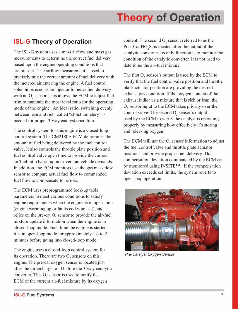
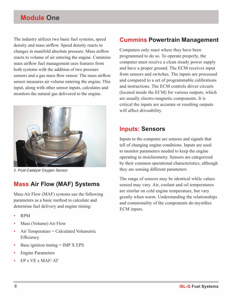
The engine uses a closed-loop control system for its operation. There are two O2 sensors on this engine. The pre-cat oxygen sensor is located just after the turbocharger and before the 3-way catalytic converter. This O2 sensor is used to notify the ECM of the current air-fuel mixture by its oxygen
Theory of Operation
content. The second O2 sensor, referred to as the Post-Cat HO2S, is located after the output of the catalytic converter. Its only function is to monitor the condition of the catalytic converter. It is not used to determine the air-fuel mixture.
The first O2 sensor’s output is used by the ECM to verify that the fuel control valve position and throttle plate actuator position are providing the desired exhaust gas condition. If the oxygen content of the exhaust indicates a mixture that is rich or lean, the O2 sensor input to the ECM takes priority over the control valve. The second O2 sensor’s output is used by the ECM to verify the catalyst is operating properly by measuring how effectively it’s storing and releasing oxygen.
The ECM will use the O2 sensor information to adjust the fuel control valve and throttle plate actuator positions and provide proper fuel delivery. This compensation deviation commanded by the ECM can be monitored using INSITE™. If the compensation deviation exceeds set limits, the system reverts to open-loop operation.
Pre-Catalyst Oxygen Sensor
ISL-G Fuel Systems8
Module One
The industry utilizes two basic fuel systems, speed density and mass airflow. Speed density reacts to changes in manifold absolute pressure. Mass airflow reacts to volume of air entering the engine. Cummins mass airflow fuel management uses features from both systems with the addition of two pressure sensors and a gas mass flow sensor. The mass airflow sensor measures air volume entering the engine. This input, along with other sensor inputs, calculates and monitors the natural gas delivered to the engine.
Mass Air Flow (MAF) SystemsMass Air Flow (MAF) systems use the following parameters as a basic method to calculate and determine fuel delivery and engine timing:
▪ RPM
▪ Mass (Volume) Air Flow
▪ Air Temperature = Calculated Volumetric Efficiency
▪ Base ignition timing = IMP X EPS
▪ Engine Parameters
▪ EP x VE x MAF/ AT
Cummins Powertrain ManagementComputers only react where they have been programmed to do so. To operate properly, the computer must receive a clean steady power supply and have a proper ground. The ECM receives input from sensors and switches. The inputs are processed and compared to a set of programmable calibrations and instructions. The ECM controls driver circuits (located inside the ECM) for various outputs, which are usually electro-magnetic components. It is critical the inputs are accurate or resulting outputs will affect driveability.
Inputs: SensorsInputs to the computer are sensors and signals that tell of changing engine conditions. Inputs are used to monitor parameters needed to keep the engine operating in stoichiometry. Sensors are categorized by their common operational characteristics, although they are sensing different parameters
The range of sensors may be identical while values sensed may vary. Air, coolant and oil temperatures are similar on cold engine temperature, but vary greatly when warm. Understanding the relationships and commonality of the components de-mystifies ECM inputs.
2. Post-Catalyst Oxygen Sensor
9ISL-G Fuel Systems
Review QuestionsWhat metering devices does the ECM look at to control fuel delivery?
What is closed versus open-loop?
What does TWC mean and what has to happen for it to work correctly?
Theory of Operation
ISL-G Fuel Systems10
Activity 1.1: ISL-G Component Orientation
Locate these components on the engine and place the number or letter of the item in the space provided.
TEMPERATURE SENSORS:
1. Coolant Temperature Sensor _______
2. Intake Manifold Pressure/Temperature Sensor _______
3. EGR Temperature Sensor _______
4. Catalyst Temperature Sensor _______
5. Turbine Inlet Temperature Sensor _______
6. Turbocharger Compressor Inlet Humidity/Temperature Sensor _______
7. Fuel Outlet Pressure/Temperature Sensor (secondary) _______
PRESSURE SENSORS:
8. Fuel Inlet Pressure Sensor (primary) _______
9. Intake Manifold Pressure/Temperature Sensor _______
10. EGR Pressure Sensor _______
11. Mixer Inlet Pressure Sensor (boost sensor) _______
12. Fuel Outlet Pressure/Temperature Sensor (secondary) _______
13. Oil Pressure Sensor _______
14. Compressor Inlet Pressure Sensor _______
SIGNAL PRODUCING SENSORS:
15. Catalyst Inlet Heated Oxygen Sensor _______
16. Catalyst Outlet Heated Oxygen Sensor _______
17. Knock Sensors (front 1,2,3 – rear 4,5,6) ___--___
Module One
11ISL-G Fuel Systems
POSITION SENSORS:
18. Throttle Position Sensor _______
19. Pedal Position Sensors (APP1 and APP2) _______
20. EGR Position Sensors 1, 2, 3 _______
21. Camshaft Speed/Position (timing) _______
22. Crankshaft Speed/Position (speed) _______
MASS SENSING:
26. Mass Gas Flow Sensor _______
27. Mass Air Flow Sensor _______
OUTPUTS and ACTUATORS:
28. Fuel Control Valve _______
29. Wastegate Control Valve _______
30. Throttle Plate Actuator _______
31. Fuel Shutoff Valve _______
32. Ignition Control Module Timing _______
33. Ignition Control Module Reference _______
34. EGR Valve _______
35. Data Link (Communication) _______
OTHER SENSORS:
36. Coolant Level Sensor _______
37. Turbocharger Compressor Intake Humidity/Temperature Sensor _______
OTHER DEVICES:
38. ECM _______
Theory of Operation

Module Two2
ISL-G Fuel Systems12
13ISL-G Fuel Systems
Inputs
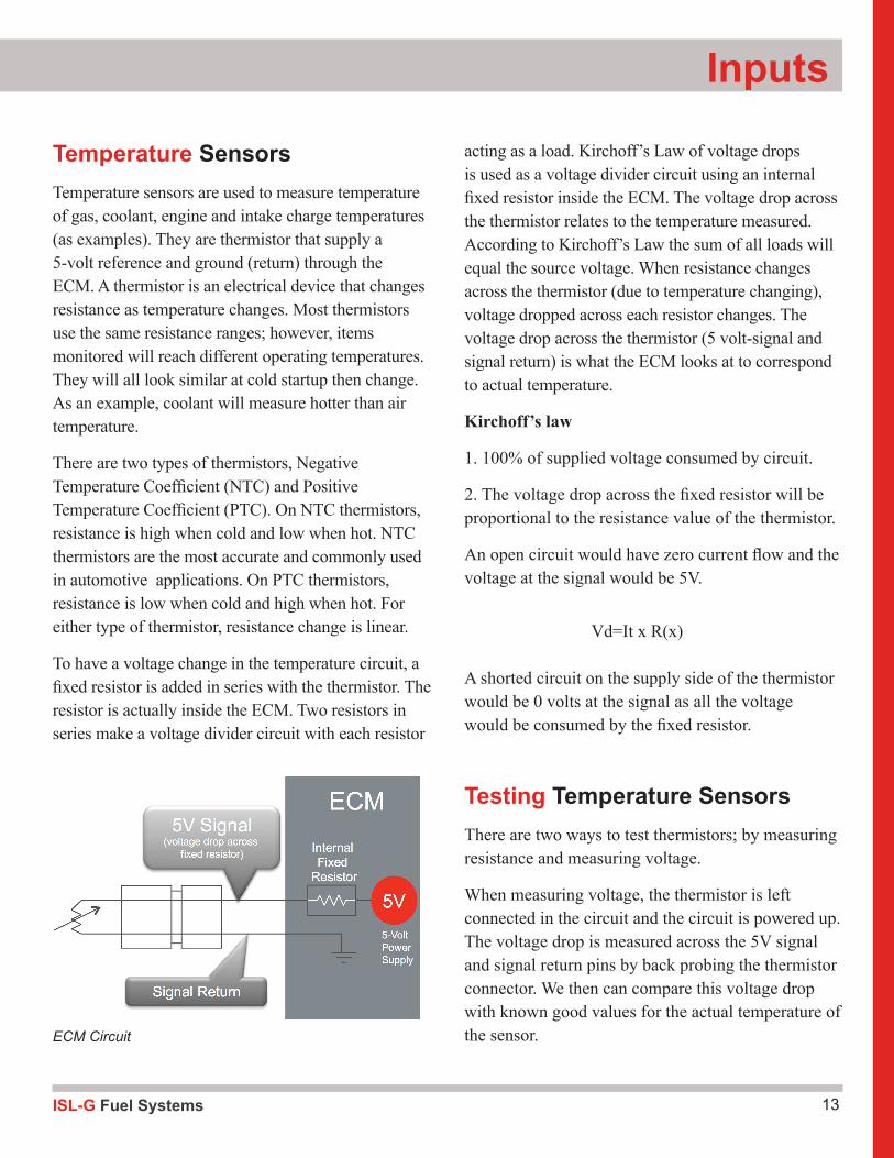
Temperature Sensors Temperature sensors are used to measure temperature of gas, coolant, engine and intake charge temperatures (as examples). They are thermistor that supply a 5-volt reference and ground (return) through the ECM. A thermistor is an electrical device that changes resistance as temperature changes. Most thermistors use the same resistance ranges; however, items monitored will reach different operating temperatures. They will all look similar at cold startup then change. As an example, coolant will measure hotter than air temperature.
There are two types of thermistors, Negative Temperature Coefficient (NTC) and Positive Temperature Coefficient (PTC). On NTC thermistors, resistance is high when cold and low when hot. NTC thermistors are the most accurate and commonly used in automotive applications. On PTC thermistors, resistance is low when cold and high when hot. For either type of thermistor, resistance change is linear.
To have a voltage change in the temperature circuit, a fixed resistor is added in series with the thermistor. The resistor is actually inside the ECM. Two resistors in series make a voltage divider circuit with each resistor
acting as a load. Kirchoff’s Law of voltage drops is used as a voltage divider circuit using an internal fixed resistor inside the ECM. The voltage drop across the thermistor relates to the temperature measured. According to Kirchoff’s Law the sum of all loads will equal the source voltage. When resistance changes across the thermistor (due to temperature changing), voltage dropped across each resistor changes. The voltage drop across the thermistor (5 volt-signal and signal return) is what the ECM looks at to correspond to actual temperature.
Kirchoff’s law
1. 100% of supplied voltage consumed by circuit.
2. The voltage drop across the fixed resistor will be proportional to the resistance value of the thermistor.
An open circuit would have zero current flow and the voltage at the signal would be 5V.
Vd=It x R(x)
A shorted circuit on the supply side of the thermistor would be 0 volts at the signal as all the voltage would be consumed by the fixed resistor.
Testing Temperature SensorsThere are two ways to test thermistors; by measuring resistance and measuring voltage.
When measuring voltage, the thermistor is left connected in the circuit and the circuit is powered up. The voltage drop is measured across the 5V signal and signal return pins by back probing the thermistor connector. We then can compare this voltage drop with known good values for the actual temperature of the sensor.ECM Circuit
ISL-G Fuel Systems14
Module Two
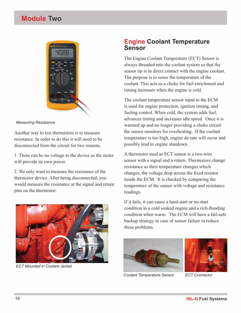
Another way to test thermistors is to measure resistance. In order to do this it will need to be disconnected from the circuit for two reasons.
1. There can be no voltage to the device as the meter will provide its own power.
2. We only want to measure the resistance of the thermistor device. After being disconnected, you would measure the resistance at the signal and return pins on the thermistor.
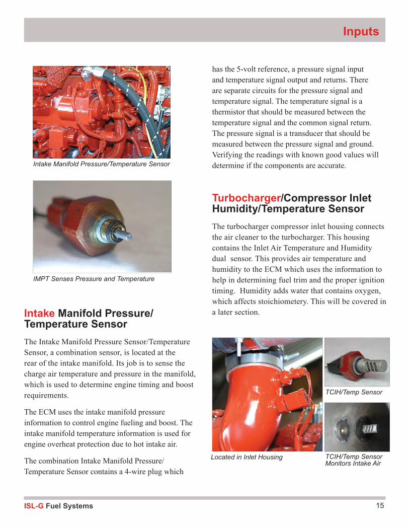
Engine Coolant Temperature SensorThe Engine Coolant Temperature (ECT) Sensor is always threaded into the coolant system so that the sensor tip is in direct contact with the engine coolant. The purpose is to sense the temperature of the coolant. This acts as a choke for fuel enrichment and timing increases when the engine is cold.
The coolant temperature sensor input to the ECM is used for engine protection, ignition timing, and fueling control. When cold, the system adds fuel, advances timing and increases idle speed. Once it is warmed up and no longer providing a choke circuit the sensor monitors for overheating. If the coolant temperature is too high, engine de-rate will occur and possibly lead to engine shutdown.
A thermistor used as ECT sensor is a two-wire sensor with a signal and a return. Thermistors change resistance as their temperature changes which changes, the voltage drop across the fixed resistor inside the ECM. It is checked by comparing the temperature of the sensor with voltage and resistance readings.
If it fails, it can cause a hard-start or no-start condition in a cold soaked engine and a rich-flooding condition when warm. The ECM will have a fail-safe backup strategy in case of sensor failure to reduce these problems.
Measuring Resistance
ECT Mounted in Coolant Jacket
Coolant Temperature Sensor ECT Connector
15ISL-G Fuel Systems
Inputs
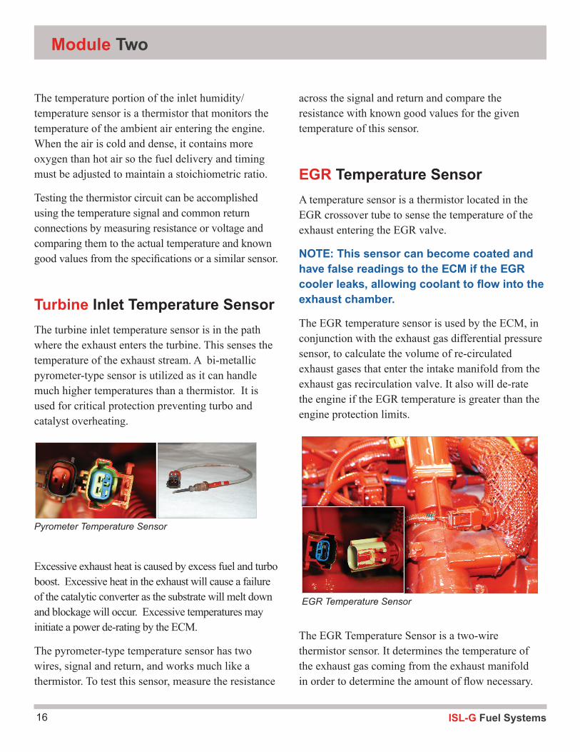
Intake Manifold Pressure/Temperature SensorThe Intake Manifold Pressure Sensor/Temperature Sensor, a combination sensor, is located at the rear of the intake manifold. Its job is to sense the charge air temperature and pressure in the manifold, which is used to determine engine timing and boost requirements.
The ECM uses the intake manifold pressure information to control engine fueling and boost. The intake manifold temperature information is used for engine overheat protection due to hot intake air.
The combination Intake Manifold Pressure/Temperature Sensor contains a 4-wire plug which
has the 5-volt reference, a pressure signal input and temperature signal output and returns. There are separate circuits for the pressure signal and temperature signal. The temperature signal is a thermistor that should be measured between the temperature signal and the common signal return. The pressure signal is a transducer that should be measured between the pressure signal and ground. Verifying the readings with known good values will determine if the components are accurate.
Turbocharger/Compressor Inlet Humidity/Temperature SensorThe turbocharger compressor inlet housing connects the air cleaner to the turbocharger. This housing contains the Inlet Air Temperature and Humidity dual sensor. This provides air temperature and humidity to the ECM which uses the information to help in determining fuel trim and the proper ignition timing. Humidity adds water that contains oxygen, which affects stoichiometery. This will be covered in a later section.
Intake Manifold Pressure/Temperature Sensor
IMPT Senses Pressure and Temperature
Located in Inlet Housing
TCIH/Temp Sensor
TCIH/Temp Sensor Monitors Intake Air
ISL-G Fuel Systems16
Module One
The temperature portion of the inlet humidity/temperature sensor is a thermistor that monitors the temperature of the ambient air entering the engine. When the air is cold and dense, it contains more oxygen than hot air so the fuel delivery and timing must be adjusted to maintain a stoichiometric ratio.
Testing the thermistor circuit can be accomplished using the temperature signal and common return connections by measuring resistance or voltage and comparing them to the actual temperature and known good values from the specifications or a similar sensor.
Turbine Inlet Temperature SensorThe turbine inlet temperature sensor is in the path where the exhaust enters the turbine. This senses the temperature of the exhaust stream. A bi-metallic pyrometer-type sensor is utilized as it can handle much higher temperatures than a thermistor. It is used for critical protection preventing turbo and catalyst overheating.
Excessive exhaust heat is caused by excess fuel and turbo boost. Excessive heat in the exhaust will cause a failure of the catalytic converter as the substrate will melt down and blockage will occur. Excessive temperatures may initiate a power de-rating by the ECM.
The pyrometer-type temperature sensor has two wires, signal and return, and works much like a thermistor. To test this sensor, measure the resistance
across the signal and return and compare the resistance with known good values for the given temperature of this sensor.
EGR Temperature SensorA temperature sensor is a thermistor located in the EGR crossover tube to sense the temperature of the exhaust entering the EGR valve.
NOTE: This sensor can become coated and have false readings to the ECM if the EGR cooler leaks, allowing coolant to flow into the exhaust chamber.
The EGR temperature sensor is used by the ECM, in conjunction with the exhaust gas differential pressure sensor, to calculate the volume of re-circulated exhaust gases that enter the intake manifold from the exhaust gas recirculation valve. It also will de-rate the engine if the EGR temperature is greater than the engine protection limits.
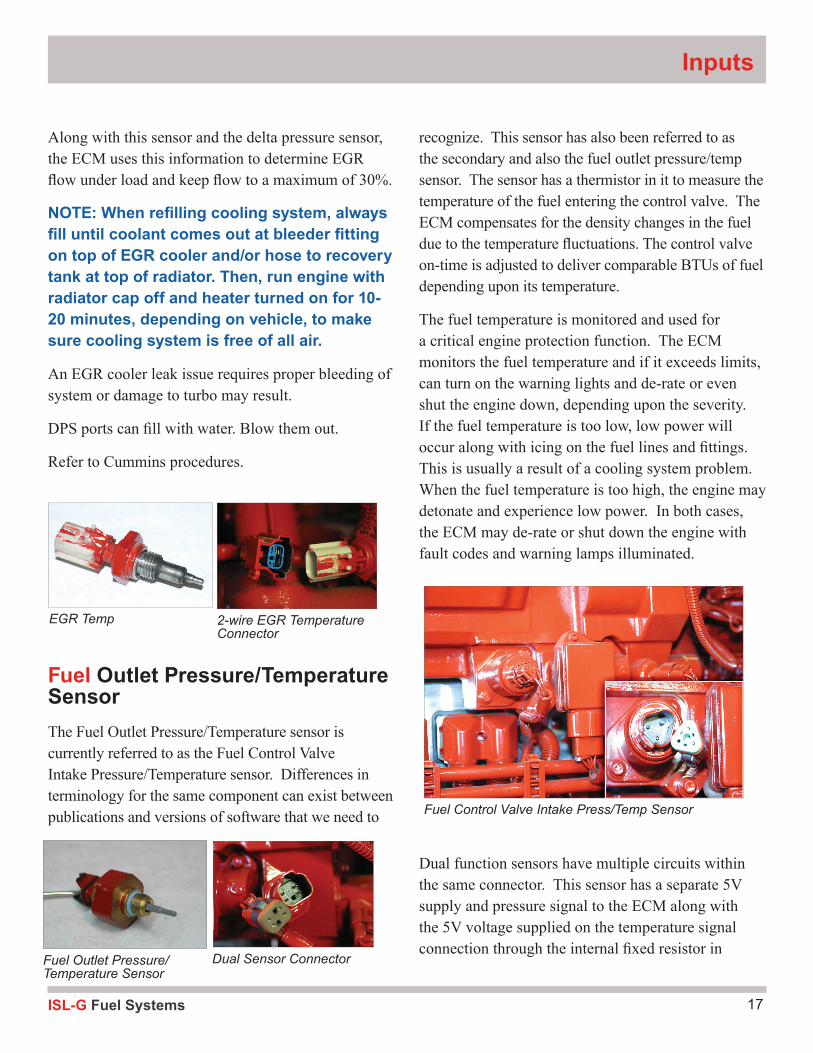
The EGR Temperature Sensor is a two-wire thermistor sensor. It determines the temperature of the exhaust gas coming from the exhaust manifold in order to determine the amount of flow necessary.
Module Two
EGR Temperature Sensor
Pyrometer Temperature Sensor
17ISL-G Fuel Systems
Inputs
Along with this sensor and the delta pressure sensor, the ECM uses this information to determine EGR flow under load and keep flow to a maximum of 30%.
NOTE: When refilling cooling system, always fill until coolant comes out at bleeder fitting on top of EGR cooler and/or hose to recovery tank at top of radiator. Then, run engine with radiator cap off and heater turned on for 10-20 minutes, depending on vehicle, to make sure cooling system is free of all air.
An EGR cooler leak issue requires proper bleeding of system or damage to turbo may result.
DPS ports can fill with water. Blow them out.
Refer to Cummins procedures.
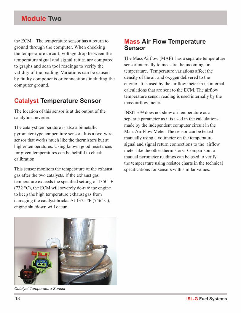
Fuel Outlet Pressure/Temperature SensorThe Fuel Outlet Pressure/Temperature sensor is currently referred to as the Fuel Control Valve Intake Pressure/Temperature sensor. Differences in terminology for the same component can exist between publications and versions of software that we need to
recognize. This sensor has also been referred to as the secondary and also the fuel outlet pressure/temp sensor. The sensor has a thermistor in it to measure the temperature of the fuel entering the control valve. The ECM compensates for the density changes in the fuel due to the temperature fluctuations. The control valve on-time is adjusted to deliver comparable BTUs of fuel depending upon its temperature.
The fuel temperature is monitored and used for a critical engine protection function. The ECM monitors the fuel temperature and if it exceeds limits, can turn on the warning lights and de-rate or even shut the engine down, depending upon the severity. If the fuel temperature is too low, low power will occur along with icing on the fuel lines and fittings. This is usually a result of a cooling system problem. When the fuel temperature is too high, the engine may detonate and experience low power. In both cases, the ECM may de-rate or shut down the engine with fault codes and warning lamps illuminated.
Dual function sensors have multiple circuits within the same connector. This sensor has a separate 5V supply and pressure signal to the ECM along with the 5V voltage supplied on the temperature signal connection through the internal fixed resistor in
EGR Temp 2-wire EGR Temperature Connector
Fuel Outlet Pressure/ Temperature Sensor
Dual Sensor Connector
Fuel Control Valve Intake Press/Temp Sensor
ISL-G Fuel Systems18
Mass Air Flow Temperature SensorThe Mass Airflow (MAF) has a separate temperature sensor internally to measure the incoming air temperature. Temperature variations affect the density of the air and oxygen delivered to the engine. It is used by the air flow meter in its internal calculations that are sent to the ECM. The airflow temperature sensor reading is used internally by the mass airflow meter.
INSITE™ does not show air temperature as a separate parameter as it is used in the calculations made by the independent computer circuit in the Mass Air Flow Meter. The sensor can be tested manually using a voltmeter on the temperature signal and signal return connections to the airflow meter like the other thermistors. Comparison to manual pyrometer readings can be used to verify the temperature using resistor charts in the technical specifications for sensors with similar values.
Module Two
the ECM. The temperature sensor has a return to ground through the computer. When checking the temperature circuit, voltage drop between the temperature signal and signal return are compared to graphs and scan tool readings to verify the validity of the reading. Variations can be caused by faulty components or connections including the computer ground.
Catalyst Temperature SensorThe location of this sensor is at the output of the catalytic converter.
The catalyst temperature is also a bimetallic pyrometer-type temperature sensor. It is a two-wire sensor that works much like the thermistors but at higher temperatures. Using known good resistances for given temperatures can be helpful to check calibration.
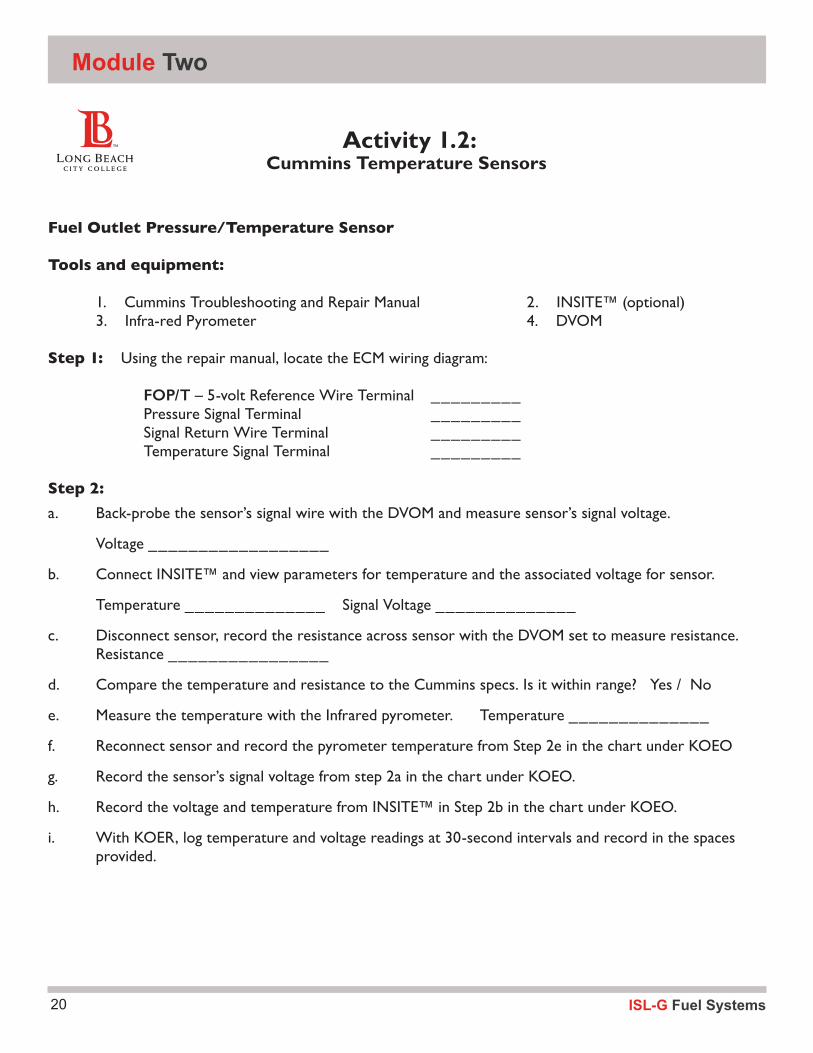
This sensor monitors the temperature of the exhaust gas after the two catalysts. If the exhaust gas temperature exceeds the specified setting of 1350 °F (732 °C), the ECM will severely de-rate the engine to keep the high temperature exhaust gas from damaging the catalyst bricks. At 1375 °F (746 °C), engine shutdown will occur.
Catalyst Temperature Sensor
19ISL-G Fuel Systems
Inputs
Review QuestionsA temperature sensor is what type of device?
What does NTC stand for? Explain the relationship.
What does the ECM have to make a temperature sensor work?
ISL-G Fuel Systems20
Module Two
Activity 1.2: Cummins Temperature Sensors
Fuel Outlet Pressure/Temperature Sensor
Tools and equipment:
1. Cummins Troubleshooting and Repair Manual 2. INSITE™ (optional) 3. Infra-red Pyrometer 4. DVOM Step 1: Using the repair manual, locate the ECM wiring diagram:
FOP/T – 5-volt Reference Wire Terminal _________ Pressure Signal Terminal _________ Signal Return Wire Terminal _________ Temperature Signal Terminal _________
Step 2:a. Back-probe the sensor’s signal wire with the DVOM and measure sensor’s signal voltage.
Voltage __________________
b. Connect INSITE™ and view parameters for temperature and the associated voltage for sensor.
Temperature ______________ Signal Voltage ______________
c. Disconnect sensor, record the resistance across sensor with the DVOM set to measure resistance. Resistance ________________
d. Compare the temperature and resistance to the Cummins specs. Is it within range? Yes / No
e. Measure the temperature with the Infrared pyrometer. Temperature ______________
f. Reconnect sensor and record the pyrometer temperature from Step 2e in the chart under KOEO
g. Record the sensor’s signal voltage from step 2a in the chart under KOEO.
h. Record the voltage and temperature from INSITE™ in Step 2b in the chart under KOEO.
i. With KOER, log temperature and voltage readings at 30-second intervals and record in the spaces provided.

21ISL-G Fuel Systems
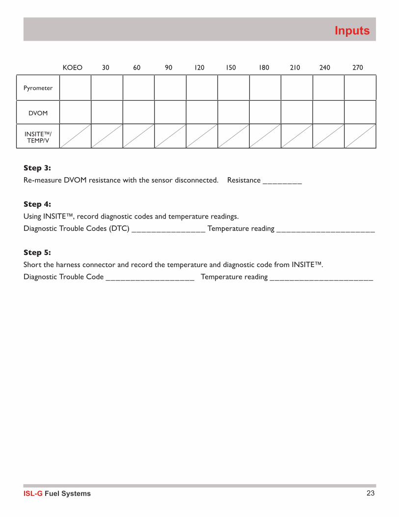
KOEO 30 60 90 120 150 180 210 240 270
Step 3:Re-measure DVOM resistance with the sensor disconnected. Resistance ________
Step 4:Using INSITE™, record diagnostic codes and temperature readings.
Diagnostic Trouble Codes (DTC) _______________ Temperature reading ____________________
Step 5:Short the harness connector and record the temperature and diagnostic code from INSITE™.
Diagnostic Trouble Code __________________ Temperature reading _____________________
Pyrometer
DVOM
INSITE™/TEMP/V
Inputs
ISL-G Fuel Systems22
Module Two
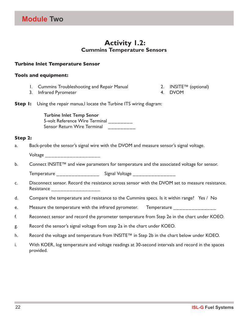
Activity 1.2: Cummins Temperature Sensors
Turbine Inlet Temperature Sensor
Tools and equipment:
1. Cummins Troubleshooting and Repair Manual 2. INSITE™ (optional) 3. Infrared Pyrometer 4. DVOM Step 1: Using the repair manua,l locate the Turbine ITS wiring diagram:
Turbine Inlet Temp Senor 5-volt Reference Wire Terminal ________ Sensor Return Wire Terminal _________
Step 2:a. Back-probe the sensor’s signal wire with the DVOM and measure sensor’s signal voltage.
Voltage __________________
b. Connect INSITE™ and view parameters for temperature and the associated voltage for sensor.
Temperature ______________ Signal Voltage ______________
c. Disconnect sensor. Record the resistance across sensor with the DVOM set to measure resistance. Resistance ________________
d. Compare the temperature and resistance to the Cummins specs. Is it within range? Yes / No
e. Measure the temperature with the infrared pyrometer. Temperature ______________
f. Reconnect sensor and record the pyrometer temperature from Step 2e in the chart under KOEO.
g. Record the sensor’s signal voltage from step 2a in the chart under KOEO.
h. Record the voltage and temperature from INSITE™ in Step 2b in the chart below under KOEO.
i. With KOER, log temperature and voltage readings at 30-second intervals and record in the spaces provided.
23ISL-G Fuel Systems
KOEO 30 60 90 120 150 180 210 240 270
Step 3:Re-measure DVOM resistance with the sensor disconnected. Resistance ________
Step 4:Using INSITE™, record diagnostic codes and temperature readings.
Diagnostic Trouble Codes (DTC) _______________ Temperature reading ____________________
Step 5:Short the harness connector and record the temperature and diagnostic code from INSITE™.
Diagnostic Trouble Code __________________ Temperature reading _____________________
Pyrometer
DVOM
INSITE™/TEMP/V
Inputs
ISL-G Fuel Systems24
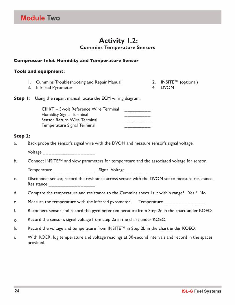
Module Two
Activity 1.2: Cummins Temperature Sensors
Compressor Inlet Humidity and Temperature Sensor
Tools and equipment:
1. Cummins Troubleshooting and Repair Manual 2. INSITE™ (optional) 3. Infrared Pyrometer 4. DVOM Step 1: Using the repair, manual locate the ECM wiring diagram:
CIH/T – 5-volt Reference Wire Terminal _________ Humidity Signal Terminal _________ Sensor Return Wire Terminal _________ Temperature Signal Terminal _________
Step 2:a. Back probe the sensor’s signal wire with the DVOM and measure sensor’s signal voltage.
Voltage __________________
b. Connect INSITE™ and view parameters for temperature and the associated voltage for sensor.
Temperature ______________ Signal Voltage ______________
c. Disconnect sensor, record the resistance across sensor with the DVOM set to measure resistance. Resistance ________________
d. Compare the temperature and resistance to the Cummins specs. Is it within range? Yes / No
e. Measure the temperature with the infrared pyrometer. Temperature ______________
f. Reconnect sensor and record the pyrometer temperature from Step 2e in the chart under KOEO.
g. Record the sensor’s signal voltage from step 2a in the chart under KOEO.
h. Record the voltage and temperature from INSITE™ in Step 2b in the chart under KOEO.
i. With KOER, log temperature and voltage readings at 30-second intervals and record in the spaces provided.

25ISL-G Fuel Systems
KOEO 30 60 90 120 150 180 210 240 270
Step 3:Re-measure DVOM resistance with the sensor disconnected. Resistance ________
Step 4:Using INSITE™, record diagnostic codes and temperature readings.
Diagnostic Trouble Codes (DTC) _______________ Temperature reading ____________________
Step 5:Short the harness connector and record the temperature and diagnostic code from INSITE™.
Diagnostic Trouble Code __________________ Temperature reading _____________________
Pyrometer
DVOM
INSITE™/TEMP/V
Inputs
ISL-G Fuel Systems26
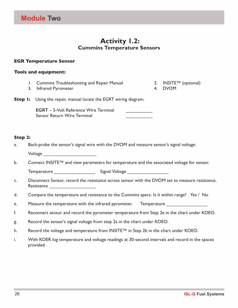
Module Two
Activity 1.2: Cummins Temperature Sensors
EGR Temperature Sensor
Tools and equipment:
1. Cummins Troubleshooting and Repair Manual 2. INSITE™ (optional) 3. Infrared Pyrometer 4. DVOM Step 1: Using the repair, manual locate the EGRT wiring diagram.
EGRT – 5-Volt Reference Wire Terminal _________ Sensor Return Wire Terminal _________
Step 2:a. Back-probe the sensor’s signal wire with the DVOM and measure sensor’s signal voltage.
Voltage __________________
b. Connect INSITE™ and view parameters for temperature and the associated voltage for sensor.
Temperature ______________ Signal Voltage ______________
c. Disconnect Sensor, record the resistance across sensor with the DVOM set to measure resistance. Resistance ________________
d. Compare the temperature and resistance to the Cummins specs. Is it within range? Yes / No
e. Measure the temperature with the infrared pyrometer. Temperature ______________
f. Reconnect sensor and record the pyrometer temperature from Step 2e in the chart under KOEO.
g. Record the sensor’s signal voltage from step 2a in the chart under KOEO.
h. Record the voltage and temperature from INSITE™ in Step 2b in the chart under KOEO.
i. With KOER log temperature and voltage readings at 30-second intervals and record in the spaces provided.

27ISL-G Fuel Systems
Inputs
KOEO 30 60 90 120 150 180 210 240 270
Step 3:Re-measure DVOM resistance with the sensor disconnected. Resistance ________
Step 4:Using INSITE™, record diagnostic codes and temperature readings.
Diagnostic Trouble Codes (DTC) _______________ Temperature reading ____________________
Step 5:Short the harness connector and record the temperature and diagnostic code from INSITE™.
Diagnostic Trouble Code __________________ Temperature reading _____________________
Pyrometer
DVOM
INSITE™/TEMP/V
ISL-G Fuel Systems28
Module Two
Activity 1.2: Cummins Temperature Sensors
Catalyst Temperature Sensor
Tools and equipment:
1. Cummins Troubleshooting and Repair Manual 2. INSITE™ (optional) 3. Infra-red Pyrometer 4. DVOM Step 1: Using the repair manual, locate the CAT TEMP wiring diagram.
Catalyst – 5-volt reference wire terminal ________
Sensor return wire terminal _________
Step 2:a. Back-probe the sensor’s signal wire with the DVOM and measure sensor’s signal voltage.
Voltage __________________
b. Connect INSITE™ and view parameters for temperature and the associated voltage for sensor.
Temperature ______________ Signal Voltage ______________
c. Disconnect Sensor, record the resistance across sensor with the DVOM set to measure resistance. Resistance ________________
d. Compare the temperature and resistance to the Cummins specs. Is it within range? Yes / No
e. Measure the temperature with the infrared pyrometer. Temperature ______________
f. Reconnect sensor and record the pyrometer temperature from Step 2e in the chart under KOEO.
g. Record the sensor’s signal voltage from step 2a in the chart under KOEO.
h. Record the voltage and temperature from INSITE™ in Step 2b in the chart under KOEO
i. With KOER, log temperature and voltage readings at 30-second intervals and record in the spaces provided.

29ISL-G Fuel Systems
Inputs
KOEO 30 60 90 120 150 180 210 240 270
Step 3:Re-measure DVOM resistance with the sensor disconnected. Resistance ________
Step 4:Using INSITE™, record diagnostic codes and temperature readings.
Diagnostic Trouble Codes (DTC) _______________ Temperature reading ____________________
Step 5:Short the harness connector and record the temperature and diagnostic code from INSITE™.
Diagnostic Trouble Code __________________ Temperature reading _____________________
Pyrometer
DVOM
INSITE™/TEMP/V
ISL-G Fuel Systems30
Module Two
Activity 1.2: Cummins Temperature Sensors
Engine Coolant Temperature Sensor
Tools and equipment:
1. Cummins Troubleshooting and Repair Manual 2. INSITE™ (optional) 3. Infrared Pyrometer 4. DVOM Step 1: Using the repair manual locate the ECM wiring diagram.
ECT – 5-Volt Reference Wire Terminal _________ Sensor Return Wire Terminal _________
Step 2:a. Back-probe the sensor’s signal wire with the DVOM and measure sensor’s signal voltage.
Voltage __________________
b. Connect INSITE™ and view parameters for temperature and the associated voltage for sensor.
Temperature ______________ Signal Voltage ______________
c. Disconnect Sensor, record the resistance across sensor with the DVOM set to measure resistance. Resistance ________________
d. Compare the temperature and resistance to the Cummins specs. Is it within range? Yes / No
e. Measure the temperature with the infrared pyrometer. Temperature ______________
f. Reconnect sensor and record the pyrometer temperature from Step 2e in the chart below under KOEO.
g. Record the sensor’s signal voltage from step 2a in the chart below under KOEO.
h. Record the voltage and temperature from INSITE™ in Step 2b in the chart below under KOEO.
i. With KOER, log temperature and voltage readings at 30-second intervals and record in the spaces provided below.

31ISL-G Fuel Systems
Inputs
KOEO 30 60 90 120 150 180 210 240 270
Step 3:Re-measure DVOM resistance with the sensor disconnected. Resistance ________
Step 4:Using INSITE™, record diagnostic codes and temperature readings.
Diagnostic Trouble Codes (DTC) _______________ Temperature reading ____________________
Step 5:Short the harness connector and record the temperature and diagnostic code from INSITE™.
Diagnostic Trouble Code __________________ Temperature reading _____________________
Pyrometer
DVOM
INSITE™/TEMP/V
ISL-G Fuel Systems32
Module Two
Activity 1.2: Cummins Temperature Sensors
Intake Manifold Temperature Sensor
Tools and equipment:
1. Cummins Troubleshooting and Repair Manual 2. INSITE™ (optional) 3. Infrared Pyrometer 4. DVOM Step 1: Using the repair manual locate the IMT wiring diagram
IMT – 5-volt Reference Wire Terminal _________ Sensor Return Wire Terminal _________
Step 2:a. Back-probe the sensor’s signal wire with the DVOM and measure sensor’s signal voltage.
Voltage __________________
b. Connect INSITE™ and view parameters for temperature and the associated voltage for sensor.
Temperature ______________ Signal Voltage ______________
c. Disconnect Sensor, record the resistance across sensor with the DVOM set to measure resistance. Resistance ________________
d. Compare the temperature and resistance to the Cummins specs. Is it within range? Yes / No
e. Measure the temperature with the infrared pyrometer. Temperature ______________
f. Reconnect sensor and record the pyrometer temperature from Step 2e in the chart under KOEO.
g. Record the sensor’s signal voltage from step 2a in the chart under KOEO.
h. Record the voltage and temperature from INSITE™ in Step 2b in the chart under KOEO.
i. With KOER, log temperature and voltage readings at 30-second intervals and record in the spaces provided.

33ISL-G Fuel Systems
Inputs
KOEO 30 60 90 120 150 180 210 240 270
Step 3:Re-measure DVOM resistance with the sensor disconnected. Resistance ________
Step 4:Using INSITE™, record diagnostic codes and temperature readings.
Diagnostic Trouble Codes (DTC) _______________ Temperature reading ____________________
Step 5:Short the harness connector and record the temperature and diagnostic code from INSITE™.
Diagnostic Trouble Code __________________ Temperature reading _____________________
Pyrometer
DVOM
INSITE™/TEMP/V
ISL-G Fuel Systems34
Module Two
Pressure SensorsPressure sensors are transducers that drop a supply voltage based upon the pressure being monitored. The input pressure sensors are used to control power output and emissions of the engine.
Intake Manifold Pressure/ Temperature SensorThe Intake Manifold Pressure/Temperature Sensor, a combination sensor, is located at the rear of the intake manifold.
The ECM uses intake manifold pressure to measure the charge air pressure in the manifold to determine engine timing and boost requirements. The timing signal is then sent to the (IM).
Atmospheric Pressure SensorsWhen working with pressure sensors, we need to take into consideration what pressure is being measured. Atmospheric pressure is the pressure around us and is referred to as barometric pressure. It is affected by altitude and weather conditions. The readings at sea level are reduced by 1”hg (inches of mercury) for every 1000 feet of altitude
Sea level = 29.8“ hg or 14.64 psi4.5 psi = 100 kPa“ = 1 BAR @ 32°F
Absolute pressure is the pressure without atmospheric pressure’s influence. These gauges would read 14.7 psi lower at sea level.
Intake Manifold Pressure/ Temperature SensorThe combination Intake Manifold Pressure/Tempera-ture Sensor has a 4-wire plug which has the 5-volt reference, a pressure signal input and temperature signal output and returns. There are separate cir-cuits for the pressure signal and temperature signal. The pressure signal is a transducer that should be measured between the pressure signal and ground. Verifying the readings with known good values will determine if the components are accurate.
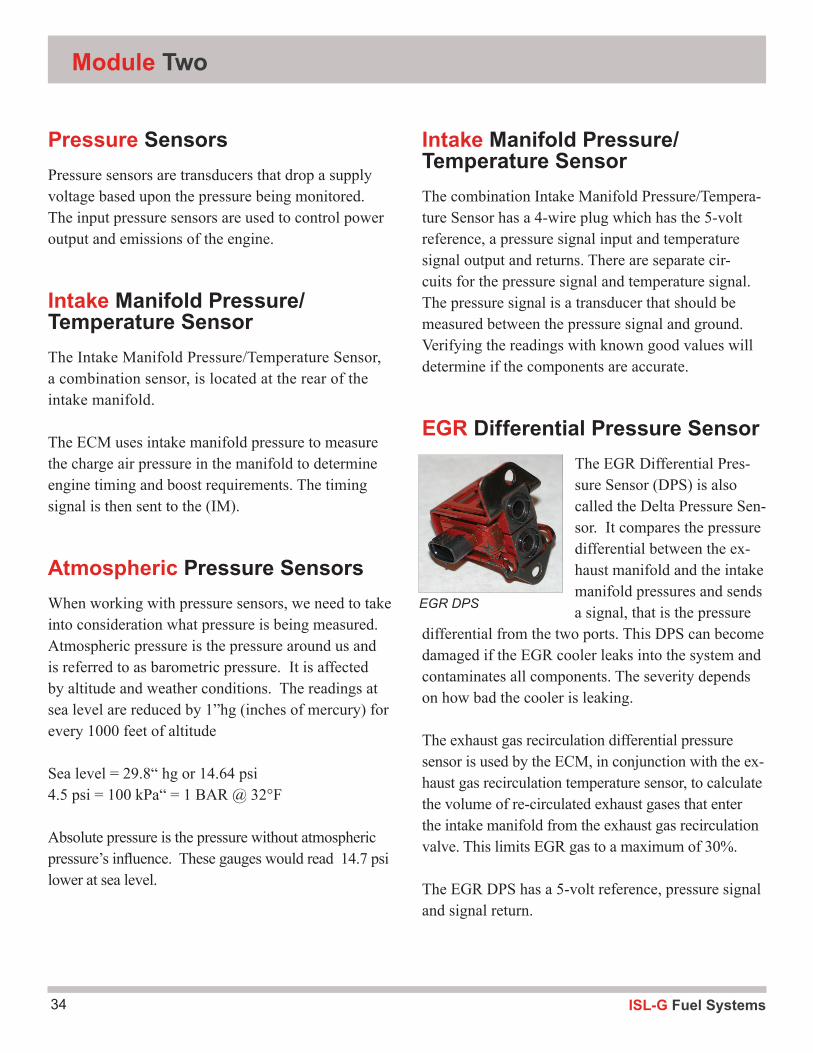
EGR Differential Pressure SensorThe EGR Differential Pres-sure Sensor (DPS) is also called the Delta Pressure Sen-sor. It compares the pressure differential between the ex-haust manifold and the intake manifold pressures and sends a signal, that is the pressure
differential from the two ports. This DPS can become damaged if the EGR cooler leaks into the system and contaminates all components. The severity depends on how bad the cooler is leaking.
The exhaust gas recirculation differential pressure sensor is used by the ECM, in conjunction with the ex-haust gas recirculation temperature sensor, to calculate the volume of re-circulated exhaust gases that enter the intake manifold from the exhaust gas recirculation valve. This limits EGR gas to a maximum of 30%.
The EGR DPS has a 5-volt reference, pressure signal and signal return.
EGR DPS
35ISL-G Fuel Systems
Inputs
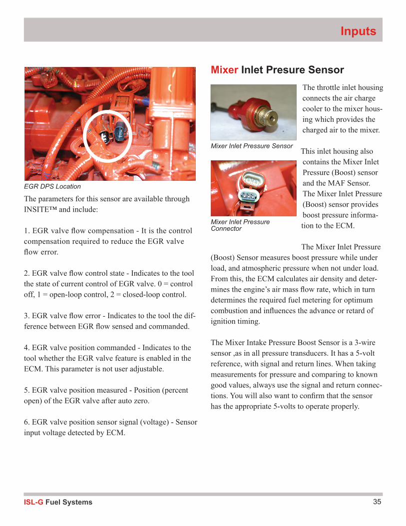
The parameters for this sensor are available through INSITE™ and include:
1. EGR valve flow compensation - It is the control compensation required to reduce the EGR valve flow error.
2. EGR valve flow control state - Indicates to the tool the state of current control of EGR valve. 0 = control off, 1 = open-loop control, 2 = closed-loop control.
3. EGR valve flow error - Indicates to the tool the dif-ference between EGR flow sensed and commanded.
4. EGR valve position commanded - Indicates to the tool whether the EGR valve feature is enabled in the ECM. This parameter is not user adjustable.
5. EGR valve position measured - Position (percent open) of the EGR valve after auto zero.
6. EGR valve position sensor signal (voltage) - Sensor input voltage detected by ECM.
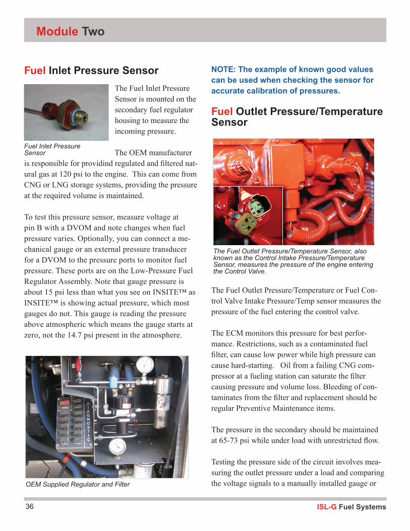
Mixer Inlet Presure SensorThe throttle inlet housing connects the air charge cooler to the mixer hous-ing which provides the charged air to the mixer.
This inlet housing also contains the Mixer Inlet Pressure (Boost) sensor and the MAF Sensor. The Mixer Inlet Pressure (Boost) sensor provides boost pressure informa-tion to the ECM.
The Mixer Inlet Pressure (Boost) Sensor measures boost pressure while under load, and atmospheric pressure when not under load. From this, the ECM calculates air density and deter-mines the engine’s air mass flow rate, which in turn determines the required fuel metering for optimum combustion and influences the advance or retard of ignition timing.
The Mixer Intake Pressure Boost Sensor is a 3-wire sensor ,as in all pressure transducers. It has a 5-volt reference, with signal and return lines. When taking measurements for pressure and comparing to known good values, always use the signal and return connec-tions. You will also want to confirm that the sensor has the appropriate 5-volts to operate properly.
Mixer Inlet Pressure Sensor
Mixer Inlet Pressure Connector
EGR DPS Location
ISL-G Fuel Systems36
Module Two
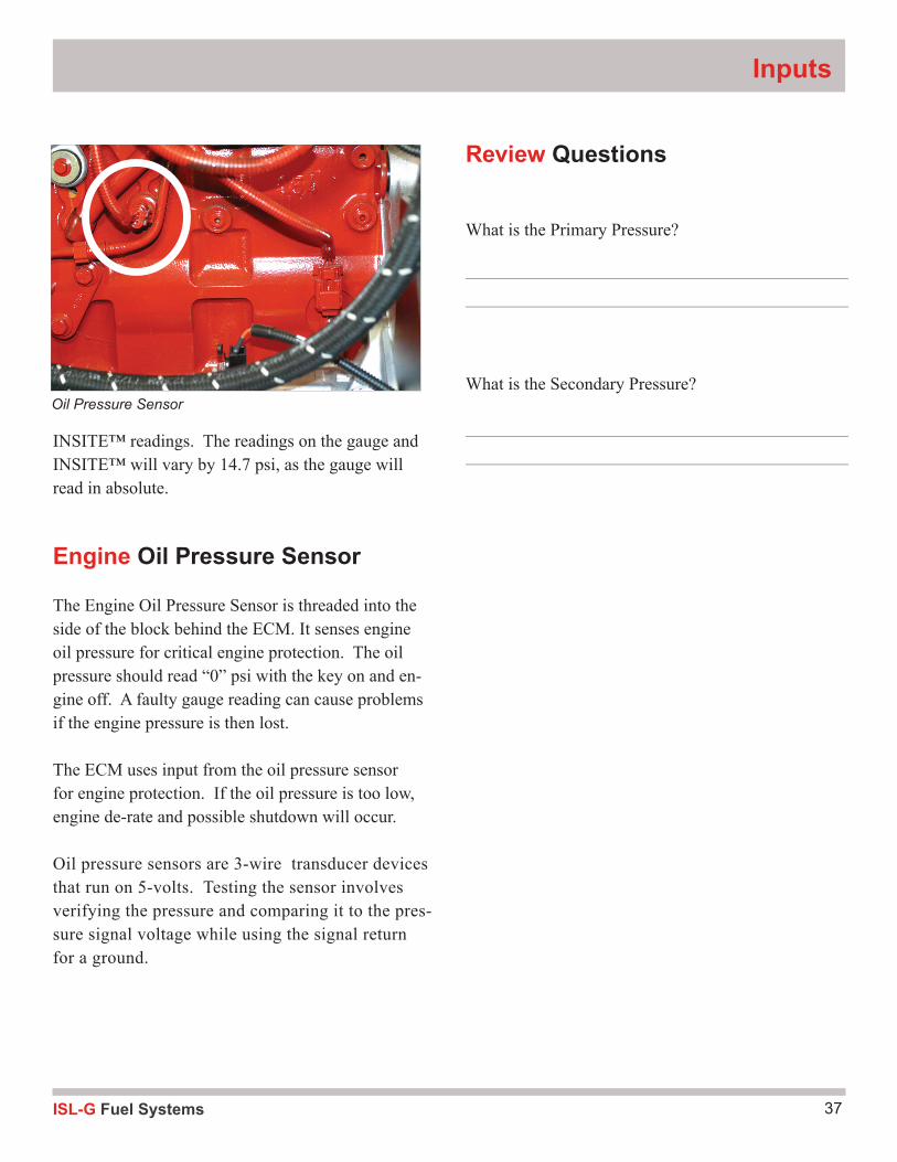
Fuel Inlet Pressure SensorThe Fuel Inlet Pressure Sensor is mounted on the secondary fuel regulator housing to measure the incoming pressure.
The OEM manufacturer is responsible for providind regulated and filtered nat-ural gas at 120 psi to the engine. This can come from CNG or LNG storage systems, providing the pressure at the required volume is maintained.
To test this pressure sensor, measure voltage at pin B with a DVOM and note changes when fuel pressure varies. Optionally, you can connect a me-chanical gauge or an external pressure transducer for a DVOM to the pressure ports to monitor fuel pressure. These ports are on the Low-Pressure Fuel Regulator Assembly. Note that gauge pressure is about 15 psi less than what you see on INSITE™ as INSITE™ is showing actual pressure, which most gauges do not. This gauge is reading the pressure above atmospheric which means the gauge starts at zero, not the 14.7 psi present in the atmosphere.
NOTE: The example of known good values can be used when checking the sensor for accurate calibration of pressures.
Fuel Outlet Pressure/Temperature Sensor
The Fuel Outlet Pressure/Temperature or Fuel Con-trol Valve Intake Pressure/Temp sensor measures the pressure of the fuel entering the control valve.
The ECM monitors this pressure for best perfor-mance. Restrictions, such as a contaminated fuel filter, can cause low power while high pressure can cause hard-starting. Oil from a failing CNG com-pressor at a fueling station can saturate the filter causing pressure and volume loss. Bleeding of con-taminates from the filter and replacement should be regular Preventive Maintenance items.
The pressure in the secondary should be maintained at 65-73 psi while under load with unrestricted flow.
Testing the pressure side of the circuit involves mea-suring the outlet pressure under a load and comparing the voltage signals to a manually installed gauge or
Fuel Inlet Pressure Sensor
OEM Supplied Regulator and Filter
The Fuel Outlet Pressure/Temperature Sensor, also known as the Control Intake Pressure/Temperature Sensor, measures the pressure of the engine entering the Control Valve.
37ISL-G Fuel Systems
Inputs
INSITE™ readings. The readings on the gauge and INSITE™ will vary by 14.7 psi, as the gauge will read in absolute.
Engine Oil Pressure Sensor
The Engine Oil Pressure Sensor is threaded into the side of the block behind the ECM. It senses engine oil pressure for critical engine protection. The oil pressure should read “0” psi with the key on and en-gine off. A faulty gauge reading can cause problems if the engine pressure is then lost.
The ECM uses input from the oil pressure sensor for engine protection. If the oil pressure is too low, engine de-rate and possible shutdown will occur.
Oil pressure sensors are 3-wire transducer devices that run on 5-volts. Testing the sensor involves verifying the pressure and comparing it to the pres-sure signal voltage while using the signal return for a ground.
Oil Pressure Sensor
Review Questions
What is the Primary Pressure?
What is the Secondary Pressure?
ISL-G Fuel Systems38
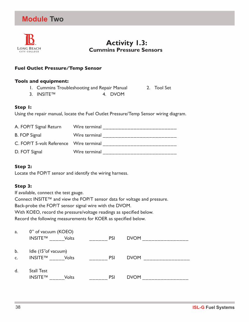
Fuel Outlet Pressure/Temp Sensor
Tools and equipment: 1. Cummins Troubleshooting and Repair Manual 2. Tool Set 3. INSITE™ 4. DVOM Step 1:Using the repair manual, locate the Fuel Outlet Pressure/Temp Sensor wiring diagram.
A. FOP/T Signal Return Wire terminal ________________________
B. FOP Signal Wire terminal ________________________
C. FOP/T 5-volt Reference Wire terminal ________________________
D. FOT Signal Wire terminal ________________________
Step 2:Locate the FOP/T sensor and identify the wiring harness.
Step 3:If available, connect the test gauge.Connect INSITE™ and view the FOP/T sensor data for voltage and pressure.Back-probe the FOP/T sensor signal wire with the DVOM.With KOEO, record the pressure/voltage readings as specified below.Record the following measurements for KOER as specified below.
a. 0” of vacuum (KOEO) INSITE™ _____Volts ______ PSI DVOM _______________
b. Idle (15”of vacuum)c. INSITE™ _____Volts ______ PSI DVOM _______________
d. Stall Test INSITE™ _____Volts ______ PSI DVOM _______________
Activity 1.3: Cummins Pressure Sensors
Module Two
39ISL-G Fuel Systems
Inputs
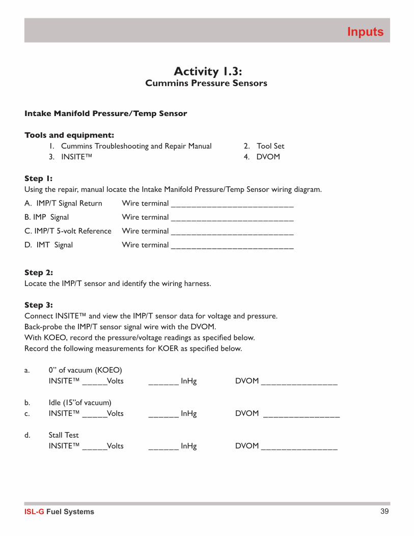
Intake Manifold Pressure/Temp Sensor
Tools and equipment: 1. Cummins Troubleshooting and Repair Manual 2. Tool Set 3. INSITE™ 4. DVOM Step 1:Using the repair, manual locate the Intake Manifold Pressure/Temp Sensor wiring diagram.
A. IMP/T Signal Return Wire terminal ________________________
B. IMP Signal Wire terminal ________________________
C. IMP/T 5-volt Reference Wire terminal ________________________
D. IMT Signal Wire terminal ________________________
Step 2:Locate the IMP/T sensor and identify the wiring harness.
Step 3:Connect INSITE™ and view the IMP/T sensor data for voltage and pressure.Back-probe the IMP/T sensor signal wire with the DVOM.With KOEO, record the pressure/voltage readings as specified below.Record the following measurements for KOER as specified below.
a. 0” of vacuum (KOEO) INSITE™ _____Volts ______ InHg DVOM _______________
b. Idle (15”of vacuum)c. INSITE™ _____Volts ______ InHg DVOM _______________
d. Stall Test INSITE™ _____Volts ______ InHg DVOM _______________
Activity 1.3: Cummins Pressure Sensors
ISL-G Fuel Systems40
Module Two
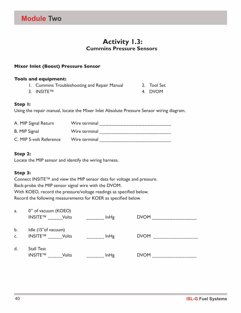
Mixer Inlet (Boost) Pressure Sensor
Tools and equipment: 1. Cummins Troubleshooting and Repair Manual 2. Tool Set 3. INSITE™ 4. DVOM Step 1:Using the repair manual, locate the Mixer Inlet Absolute Pressure Sensor wiring diagram.
A. MIP Signal Return Wire terminal ________________________
B. MIP Signal Wire terminal ________________________
C. MIP 5-volt Reference Wire terminal ________________________
Step 2:Locate the MIP sensor and identify the wiring harness.
Step 3:Connect INSITE™ and view the MIP sensor data for voltage and pressure.Back-probe the MIP sensor signal wire with the DVOM.With KOEO, record the pressure/voltage readings as specified below.Record the following measurements for KOER as specified below.
a. 0” of vacuum (KOEO) INSITE™ _____Volts ______ InHg DVOM _______________
b. Idle (15”of vacuum)c. INSITE™ _____Volts ______ InHg DVOM _______________
d. Stall Test INSITE™ _____Volts ______ InHg DVOM _______________
Activity 1.3: Cummins Pressure Sensors
41ISL-G Fuel Systems
Inputs
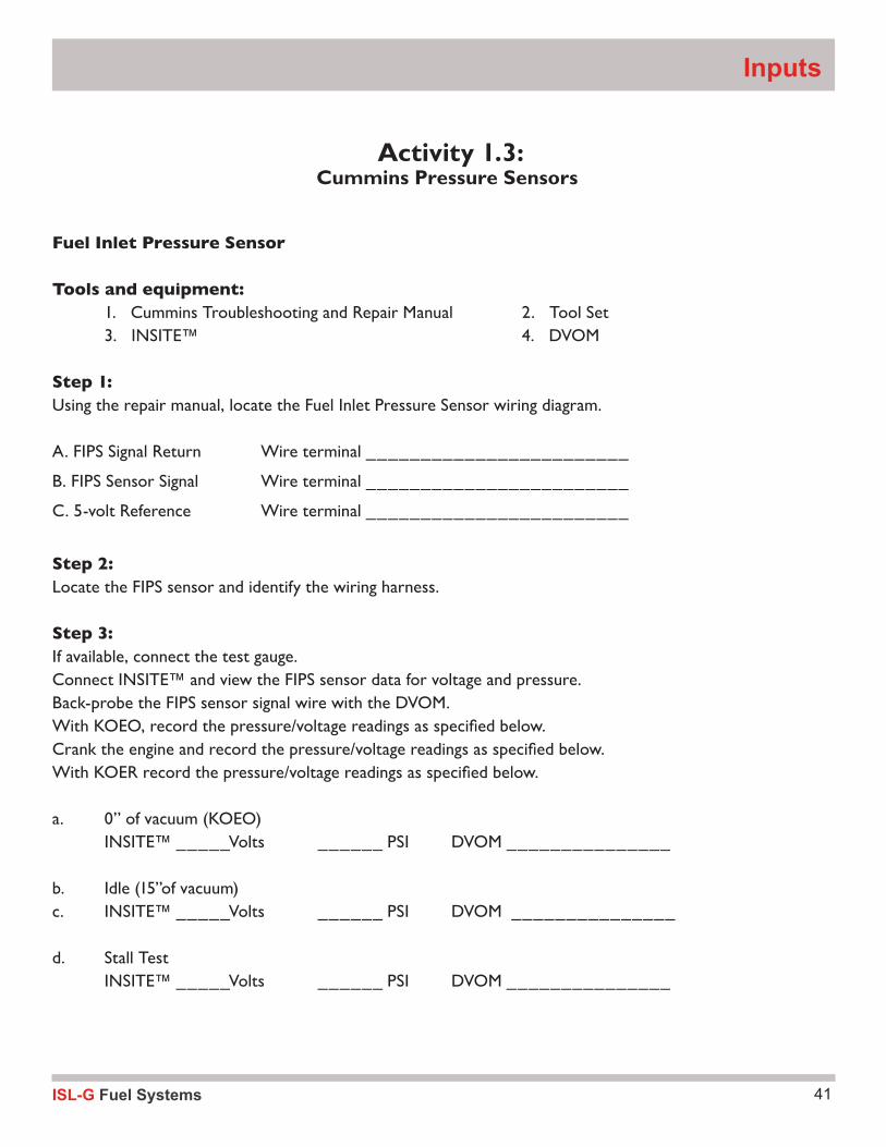
Fuel Inlet Pressure Sensor
Tools and equipment: 1. Cummins Troubleshooting and Repair Manual 2. Tool Set 3. INSITE™ 4. DVOM Step 1:Using the repair manual, locate the Fuel Inlet Pressure Sensor wiring diagram.
A. FIPS Signal Return Wire terminal ________________________
B. FIPS Sensor Signal Wire terminal ________________________
C. 5-volt Reference Wire terminal ________________________
Step 2:Locate the FIPS sensor and identify the wiring harness.
Step 3:If available, connect the test gauge.Connect INSITE™ and view the FIPS sensor data for voltage and pressure.Back-probe the FIPS sensor signal wire with the DVOM.With KOEO, record the pressure/voltage readings as specified below.Crank the engine and record the pressure/voltage readings as specified below.With KOER record the pressure/voltage readings as specified below.
a. 0” of vacuum (KOEO) INSITE™ _____Volts ______ PSI DVOM _______________
b. Idle (15”of vacuum)c. INSITE™ _____Volts ______ PSI DVOM _______________
d. Stall Test INSITE™ _____Volts ______ PSI DVOM _______________
Activity 1.3: Cummins Pressure Sensors
ISL-G Fuel Systems42
Module Two
Speed SensorsTwo types of speed sensors are present to sense engine and vehicle speed along with cylinder location.
Speed Sensor TypesA speed sensor senses speed of a rotating shaft and creates an electrical signal that can be interpreted by the ECM. There are two types of speed sensors:
▪ Hall-Effect Sensor (Switch), which produces a digital on-off signal that is very precise. Hall-Effect sensors are 3-wire sensors and are used for crankshaft and camshaft sensing.
▪ Magnetic Reluctance Sensor, which produces an A/C Signal.
These sensors are usually used to determine vehicle speed and as ABS wheel sensors.
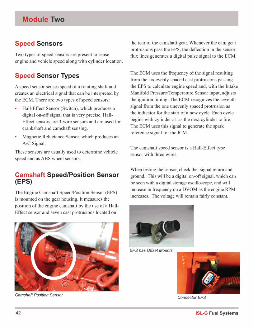
Camshaft Speed/Position Sensor (EPS)The Engine Camshaft Speed/Position Sensor (EPS) is mounted on the gear housing. It measures the position of the engine camshaft by the use of a Hall-Effect sensor and seven cast protrusions located on
the rear of the camshaft gear. Whenever the cam gear protrusions pass the EPS, the deflection in the sensor flux lines generates a digital pulse signal to the ECM.
The ECM uses the frequency of the signal resulting from the six evenly-spaced cast protrusions passing the EPS to calculate engine speed and, with the Intake Manifold Pressure/Temperature Sensor input, adjusts the ignition timing. The ECM recognizes the seventh signal from the one unevenly spaced protrusion as the indicator for the start of a new cycle. Each cycle begins with cylinder #1 as the next cylinder to fire. The ECM uses this signal to generate the spark reference signal for the ICM.
The camshaft speed sensor is a Hall-Effect type sensor with three wires.
When testing the sensor, check the signal return and ground. This will be a digital on-off signal, which can be seen with a digital storage oscilloscope, and will increase in frequency on a DVOM as the engine RPM increases. The voltage will remain fairly constant.
Camshaft Position Sensor
EPS has Offset Mounts
Connector EPS
43ISL-G Fuel Systems
Inputs
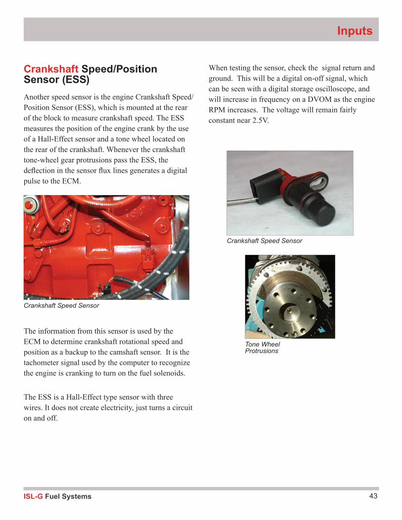
Crankshaft Speed/Position Sensor (ESS)Another speed sensor is the engine Crankshaft Speed/Position Sensor (ESS), which is mounted at the rear of the block to measure crankshaft speed. The ESS measures the position of the engine crank by the use of a Hall-Effect sensor and a tone wheel located on the rear of the crankshaft. Whenever the crankshaft tone-wheel gear protrusions pass the ESS, the deflection in the sensor flux lines generates a digital pulse to the ECM.
The information from this sensor is used by the ECM to determine crankshaft rotational speed and position as a backup to the camshaft sensor. It is the tachometer signal used by the computer to recognize the engine is cranking to turn on the fuel solenoids.
The ESS is a Hall-Effect type sensor with three wires. It does not create electricity, just turns a circuit on and off.
When testing the sensor, check the signal return and ground. This will be a digital on-off signal, which can be seen with a digital storage oscilloscope, and will increase in frequency on a DVOM as the engine RPM increases. The voltage will remain fairly constant near 2.5V.
Crankshaft Speed Sensor
Crankshaft Speed Sensor
Tone Wheel Protrusions
ISL-G Fuel Systems44
Module Two
Position Sensors Position sensors are potentiometers that are used to determine where a moving item is currently located. There are several potentiometers used to sense throttle position and demand, along with EGR movement.
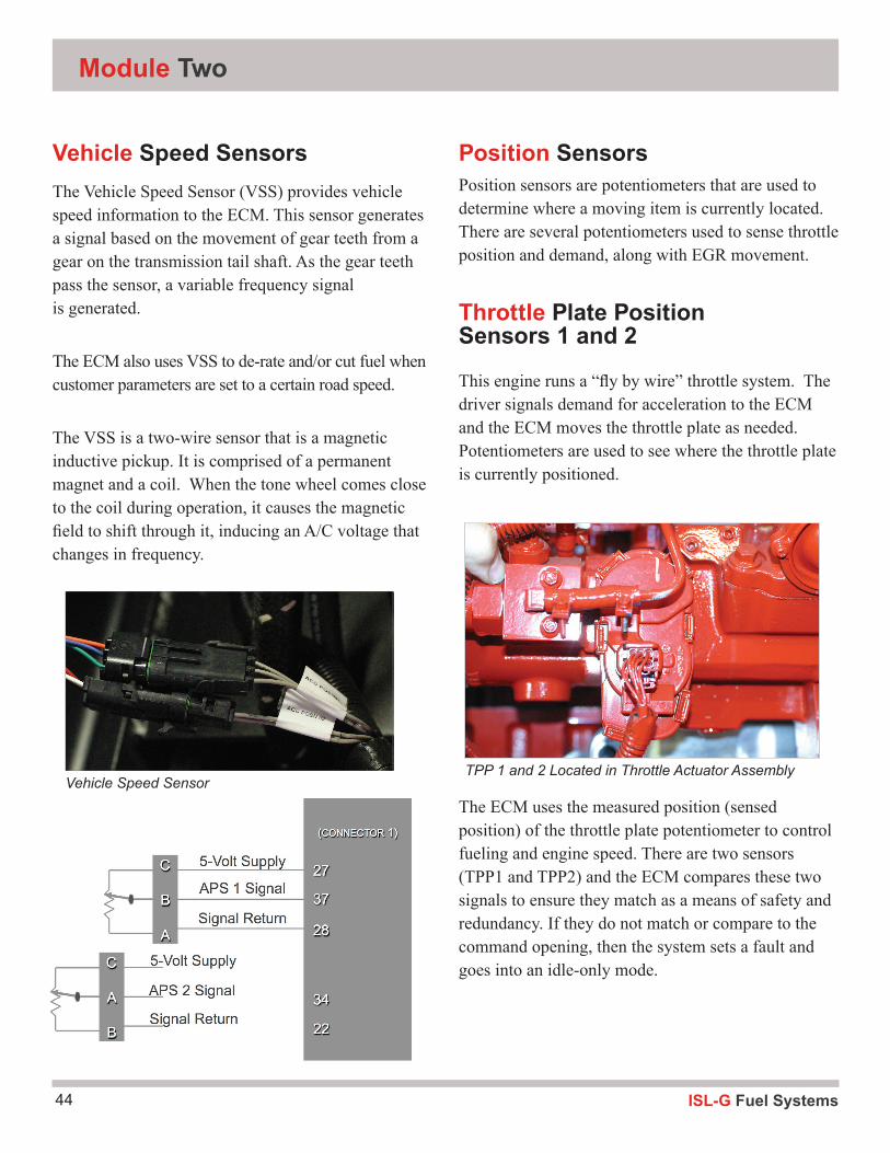
Throttle Plate Position Sensors 1 and 2
This engine runs a “fly by wire” throttle system. The driver signals demand for acceleration to the ECM and the ECM moves the throttle plate as needed. Potentiometers are used to see where the throttle plate is currently positioned.
The ECM uses the measured position (sensed position) of the throttle plate potentiometer to control fueling and engine speed. There are two sensors (TPP1 and TPP2) and the ECM compares these two signals to ensure they match as a means of safety and redundancy. If they do not match or compare to the command opening, then the system sets a fault and goes into an idle-only mode.
TPP 1 and 2 Located in Throttle Actuator Assembly
Vehicle Speed SensorsThe Vehicle Speed Sensor (VSS) provides vehicle speed information to the ECM. This sensor generates a signal based on the movement of gear teeth from a gear on the transmission tail shaft. As the gear teeth pass the sensor, a variable frequency signal is generated.
The ECM also uses VSS to de-rate and/or cut fuel when customer parameters are set to a certain road speed.
The VSS is a two-wire sensor that is a magnetic inductive pickup. It is comprised of a permanent magnet and a coil. When the tone wheel comes close to the coil during operation, it causes the magnetic field to shift through it, inducing an A/C voltage that changes in frequency.
Position Sensors
Vehicle Speed Sensor
45ISL-G Fuel Systems
components. This ability will always enable the engine to reach 100 percent commanded position, independent of variations in the accelerator pedal component. Accelerator Pedal Sensor 1 (APS1) and Accelerator Pedal Sensor 2 (APS2) have different position to voltage transfer functions. This allows the ECM accelerator algorithm to perform an integrity check of the two signals before outputting a final commanded accelerator value to the rest of the system. APS1 has a starting voltage of 1.25 volts and a wide open throttle voltage of 4.20 volts. APS2 has a starting voltage of 0.56 volts and a wide open throttle voltage of 2.06 volts. Note that both sensors start at two different points and rise together to a wide open throttle position. A fault code will be generated if any of a number of concerns happen: accelerator pedal position 2-signal circuit shorted to battery or 5-volt supply, open accelerator pedal return circuit in the harness or connections, accelerator supply shorted to battery, or failed accelerator pedal position sensor.
Inputs
These potentiometers are 3-wire sensors that run on a common 5-volt reference with a return. The movable arm in the sensor returns a portion of the voltage to the ECM with throttle plate movement. When performing a normal voltage check on TPP1 and TPP2 - you will notice that one sensor’s voltage starts higher and goes up while the other sensors voltage starts lower and goes higher.
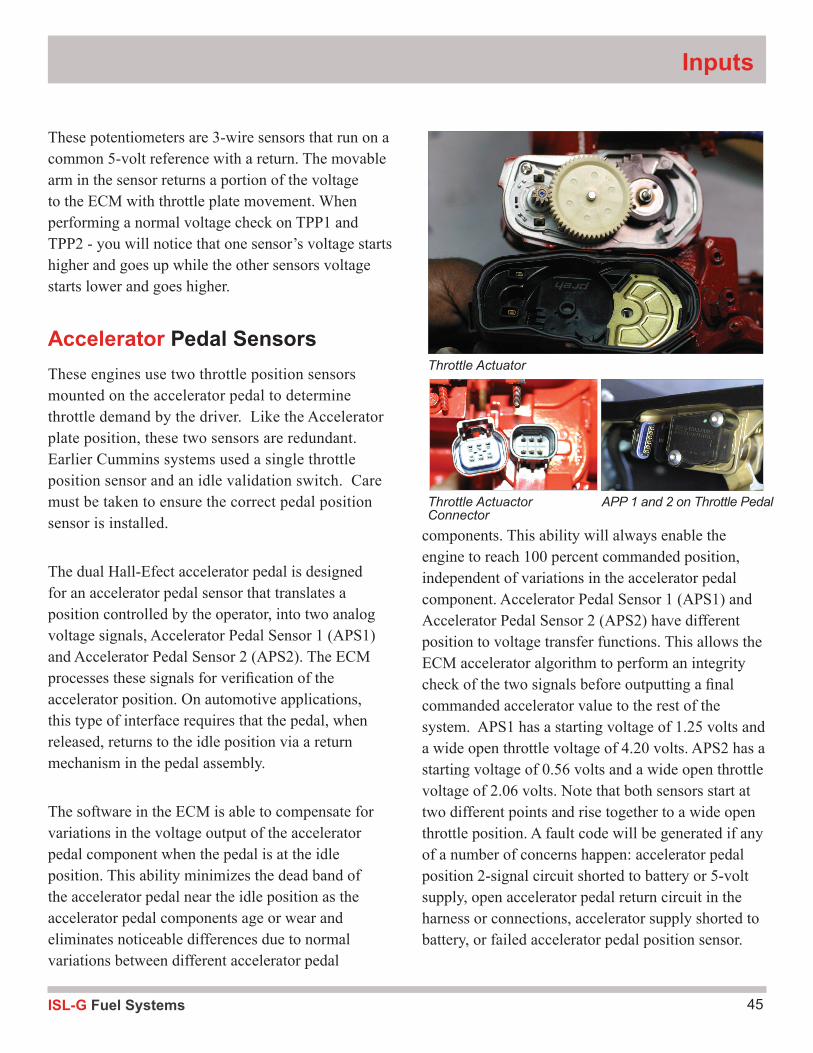
Accelerator Pedal SensorsThese engines use two throttle position sensors mounted on the accelerator pedal to determine throttle demand by the driver. Like the Accelerator plate position, these two sensors are redundant. Earlier Cummins systems used a single throttle position sensor and an idle validation switch. Care must be taken to ensure the correct pedal position sensor is installed.
The dual Hall-Efect accelerator pedal is designed for an accelerator pedal sensor that translates a position controlled by the operator, into two analog voltage signals, Accelerator Pedal Sensor 1 (APS1) and Accelerator Pedal Sensor 2 (APS2). The ECM processes these signals for verification of the accelerator position. On automotive applications, this type of interface requires that the pedal, when released, returns to the idle position via a return mechanism in the pedal assembly.
The software in the ECM is able to compensate for variations in the voltage output of the accelerator pedal component when the pedal is at the idle position. This ability minimizes the dead band of the accelerator pedal near the idle position as the accelerator pedal components age or wear and eliminates noticeable differences due to normal variations between different accelerator pedal
Throttle Actuator
Throttle Actuactor Connector
APP 1 and 2 on Throttle Pedal
ISL-G Fuel Systems46
Module Two
▪ Terminal A of the APP is connected to the ECM ground at terminal 17, and terminal B of the APP provides the position signal return data to the ECM at terminal 30.
▪ The APP can be pinpoint tested using a DVOM or an oscilloscope.
▪ The preferred method is to use an oscilloscope and perform a sweep test. The sweep test will detect opens, or glitches, that may not be detectable with the DVOM.
▪ Normally, the APP will return approximately 10% of the supply voltage at idle, and approximately 90% at wide open throttle.
▪ As the accelerator pedal is slowly pushed down, the signal return voltage at terminal B of the sensor will gradually increase from .5V to 4.0V.
▪ If the accelerator position voltage is determined to be out of range by the GCM, a code 18 will be set and the engine will idle.
▪ The override switch will provide limp-home operation of the system.
EGR Position SensorsThere are three EGR motor windings that move to control the EGR flow. The EGR valve motor has three position sensors inside that confirm the position of the EGR valve motors to the ECM.
The EGR valve is controlled by the ECM and regulates the amount of re-circulated exhaust gases that enter the intake manifold based on sensor input of motor rod location, EGR temperature sensor and EGR DPS (Delta Position sensor).
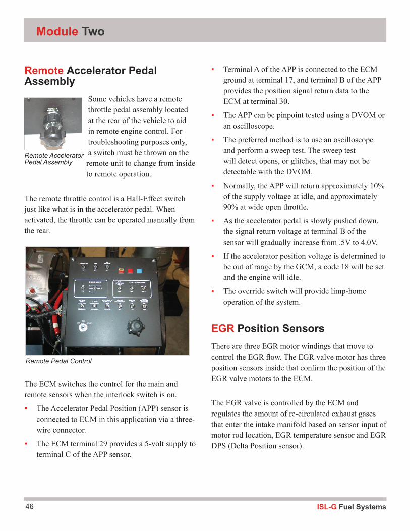
Remote Accelerator Pedal Assembly
Some vehicles have a remote throttle pedal assembly located at the rear of the vehicle to aid in remote engine control. For troubleshooting purposes only, a switch must be thrown on the remote unit to change from inside to remote operation.
The remote throttle control is a Hall-Effect switch just like what is in the accelerator pedal. When activated, the throttle can be operated manually from the rear.
The ECM switches the control for the main and remote sensors when the interlock switch is on.
▪ The Accelerator Pedal Position (APP) sensor is connected to ECM in this application via a three-wire connector.
▪ The ECM terminal 29 provides a 5-volt supply to terminal C of the APP sensor.
Remote Accelerator Pedal Assembly
Remote Pedal Control
47ISL-G Fuel Systems
Inputs
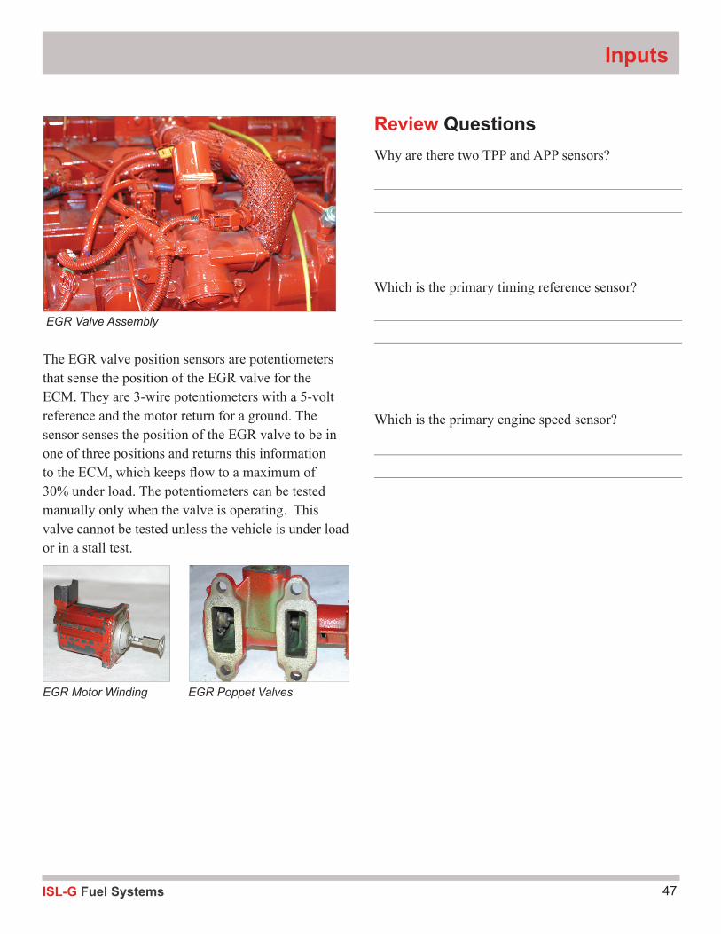
The EGR valve position sensors are potentiometers that sense the position of the EGR valve for the ECM. They are 3-wire potentiometers with a 5-volt reference and the motor return for a ground. The sensor senses the position of the EGR valve to be in one of three positions and returns this information to the ECM, which keeps fl ow to a maximum of 30% under load. The potentiometers can be tested manually only when the valve is operating. This valve cannot be tested unless the vehicle is under load or in a stall test.
Review QuestionsWhy are there two TPP and APP sensors?
Which is the primary timing reference sensor?
Which is the primary engine speed sensor?
EGR Valve Assembly
EGR Motor Winding EGR Poppet Valves
ISL-G Fuel Systems48
Module Two
Cam Speed/Position Sensor
Tools and equipment: 1. Cummins wiring diagram 2. Hand Tool Set 3. DVOM 4. INSITE™
Step 1: Using the repair manual, locate the Cam Speed/Position sensor wiring diagram:
CS/P 5-volt supply Wire terminal _______________________
CS/P Signal Return Wire terminal _______________________
CS/P Sensor Signal Wire terminal _______________________
Step 2: Do the wire terminals of the wiring diagram and the harness coincide? YES Or NO
Step 3:Back-probe the CS/P and perform the following exercise.
With the engine running record the following data.
Idle (DVOM/DC voltage and frequency) ____________________________
1500 RPM (DVOM/DC voltage and frequency) ________________________
Step 4:Will the engine run without the CS/P? Yes or No
Explain!
_______________________________________________________________________
_______________________________________________________________________
Step 5:What are the codes associated with the CS/P? _________________________________________
If the CS/P was defective, what would the INSITE™ display? ________________________________
Activity 1.4: Position Sensors
49ISL-G Fuel Systems
Inputs
Crank Speed/Position Sensor
Tools and equipment: 1. Cummins wiring diagram 2. Hand Tool Set 3. DVOM 4. INSITE™
Step 1: Using the repair manual, locate the Cam Speed/Position sensor wiring diagram:
CS/P 5-volt supply Wire terminal _______________________
CS/P Signal Return Wire terminal _______________________
CS/P Sensor Signal Wire terminal _______________________
Step 2: Do the wire terminals of the wiring diagram and the harness coincide? YES Or NO
Step 3:Back-probe the CS/P and perform the following exercise.
With the engine running record the following data.
Idle (DVOM/DC voltage and frequency) ____________________________
1500 RPM (DVOM/DC voltage and frequency) ________________________
Step 4:Will the engine run without the CS/P? Yes or No
Explain!
_______________________________________________________________________
_______________________________________________________________________
Activity 1.4: Position Sensors
ISL-G Fuel Systems50
Module Two
Accelerator Pedal Position Sensors 1 and 2
Tools and equipment: 1. Cummins wiring diagram 2. Hand Tool Set 3. DVOM 4. INSITE™
Step 1: Using the repair manual locate the APPS wiring diagram.
APPS Sensor 1 Return Wire terminal _______________
APPS Sensor 1 Signal Wire terminal _______________
APPS Sensor 1 5-volt Reference Wire terminal _______________
APPS Sensor 2 Return Wire terminal _______________
APPS Sensor 2 Signal Wire terminal _______________
APPS Sensor 2 5-volt Reference Wire terminal _______________
Does it have an Idle Validation Switch? Yes or No
Step 2: Visually locate APPS sensor and identify the wiring harness.Do the wire terminals of the wiring diagram and harness coincide? Yes or No
Step 3:Using two DVOMs connect the positive lead to APPS Signal wire for sensors 1 and 2, record the following measurements: KEY ON ENGINE OFF (KOEO)
Without depressing the accelerator pedal, what is the APPS sensor signal voltage 1______ 2_________
Depress the accelerator pedal 50%, what is the APP sensor signal voltage 1_______ 2____________
Fully depress the accelerator pedal. What is the APP sensor signal voltage 1_______ 2____________
Step 4:Using parameter ID from INSITE™ for APPS 1 and 2, record the following measurements:
KEY ON ENGINE OFF (KOEO)
Without depressing the accelerator pedal, what is the APP sensor signal voltage 1_____ 2__________
Depress the accelerator pedal 50%, what is the APP sensor signal voltage 1_______ 2____________
Fully depress the accelerator pedal. What is the APP sensor signal voltage 1_______ 2____________
Activity 1.4: Position Sensors
51ISL-G Fuel Systems
Inputs
Activity 1.4: Position Sensors
Accelerator Pedal Position Sensors 1 and 2
Tools and equipment: 1. Cummins wiring diagram 2. Hand Tool Set 3. DVOM 4. INSITE™
Step 1: Using the repair manual locate the TPS wiring diagram.
TPPS1 Sensor Signal Wire terminal ______________
TPPS2 Sensor Signal Wire terminal ______________
TPPS 5-volt Reference Wire terminal ______________
TPPS Sensor Return Wire terminal ______________
Step 2: Locate the TPPS sensor and identify the wiring harness.Do the wire terminals of the wiring diagram and harness coincide? Yes or No
Step 3:Using two DVOMs connect the positive lead to APPS Signal wire for sensors 1 and 2, record the following measurements: KEY ON ENGINE OFF (KOEO)
Without depressing the throttle pedal, what is the TPPS1 & 2 sensor signal voltage ______ __________
Fully depress the throttle pedal. What is the TPPS 1 & 2 sensor signal voltage _______ __________
Step 4:Using INSITE™ observe and record the following readings: KEY ON ENGINE RUNNING (KOER)
Without depressing the throttle pedal, what is the parameter ID for TPPS1 and 2 _______ ________
Depress the throttle pedal 50%, what is the parameter ID for TPPS1 and 2 _______ _________
SNAP the throttle pedal. What is MAX reading observed for TPPS1 and 2 _______ _________
Was there a difference between the readings in step 3 vs 4?
If so why?________________________________________________________________
ISL-G Fuel Systems52
Module Two
Signal Producing SensorsSignal producing sensors create a signal when they operate. This signal may be a voltage, current or fre-quency signal, depending upon the type of sensor.
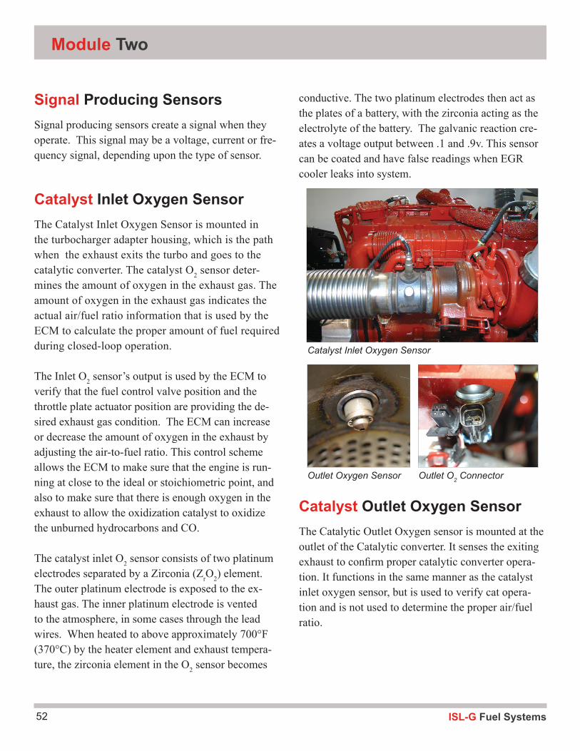
Catalyst Inlet Oxygen SensorThe Catalyst Inlet Oxygen Sensor is mounted in the turbocharger adapter housing, which is the path when the exhaust exits the turbo and goes to the catalytic converter. The catalyst O2 sensor deter-mines the amount of oxygen in the exhaust gas. The amount of oxygen in the exhaust gas indicates the actual air/fuel ratio information that is used by the ECM to calculate the proper amount of fuel required during closed-loop operation.
The Inlet O2 sensor’s output is used by the ECM to verify that the fuel control valve position and the throttle plate actuator position are providing the de-sired exhaust gas condition. The ECM can increase or decrease the amount of oxygen in the exhaust by adjusting the air-to-fuel ratio. This control scheme allows the ECM to make sure that the engine is run-ning at close to the ideal or stoichiometric point, and also to make sure that there is enough oxygen in the exhaust to allow the oxidization catalyst to oxidize the unburned hydrocarbons and CO.
The catalyst inlet O2 sensor consists of two platinum electrodes separated by a Zirconia (ZrO2) element. The outer platinum electrode is exposed to the ex-haust gas. The inner platinum electrode is vented to the atmosphere, in some cases through the lead wires. When heated to above approximately 700°F (370°C) by the heater element and exhaust tempera-ture, the zirconia element in the O2 sensor becomes
conductive. The two platinum electrodes then act as the plates of a battery, with the zirconia acting as the electrolyte of the battery. The galvanic reaction cre-ates a voltage output between .1 and .9v. This sensor can be coated and have false readings when EGR cooler leaks into system.
Catalyst Outlet Oxygen SensorThe Catalytic Outlet Oxygen sensor is mounted at the outlet of the Catalytic converter. It senses the exiting exhaust to confirm proper catalytic converter opera-tion. It functions in the same manner as the catalyst inlet oxygen sensor, but is used to verify cat opera-tion and is not used to determine the proper air/fuel ratio.
Catalyst Inlet Oxygen Sensor
Outlet Oxygen Sensor Outlet O2 Connector
53ISL-G Fuel Systems
Inputs
The output of this sensor is used by the ECM for ver-ification of proper operation of the three-way catalyst. When operating efficiently, the rear portion of the catalytic converter absorbs oxygen to continue the burning of the HC and CO. The voltage is normally flat-lined if the oxygen is being absorbed.
The voltage output of the sensor is tested much the same as the inlet sensor. Because it is usually flat-lined in a rich condition (.7-.9V), it won’t fluctuate except during warmup. It can be forced rich and lean similar to the inlet sensor.
CAUTION: Forcing the system rich can cause damage to the catalyst if done excessively.
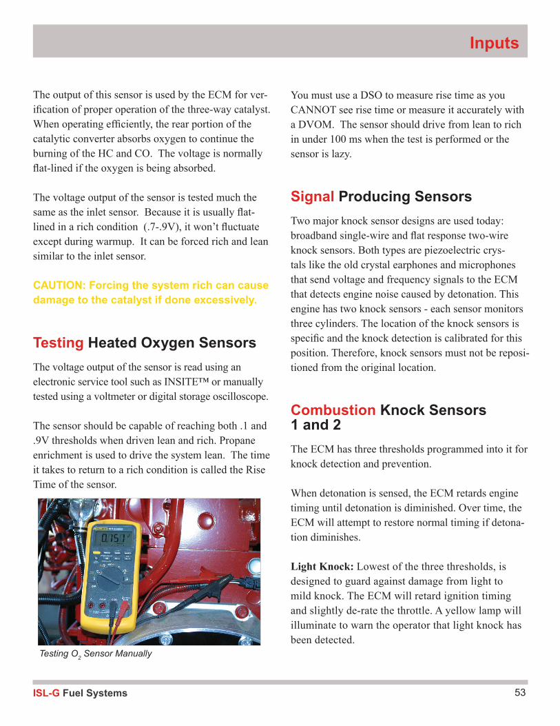
Testing Heated Oxygen SensorsThe voltage output of the sensor is read using an electronic service tool such as INSITE™ or manually tested using a voltmeter or digital storage oscilloscope.
The sensor should be capable of reaching both .1 and .9V thresholds when driven lean and rich. Propane enrichment is used to drive the system lean. The time it takes to return to a rich condition is called the Rise Time of the sensor.
You must use a DSO to measure rise time as you CANNOT see rise time or measure it accurately with a DVOM. The sensor should drive from lean to rich in under 100 ms when the test is performed or the sensor is lazy.
Signal Producing SensorsTwo major knock sensor designs are used today: broadband single-wire and flat response two-wire knock sensors. Both types are piezoelectric crys-tals like the old crystal earphones and microphones that send voltage and frequency signals to the ECM that detects engine noise caused by detonation. This engine has two knock sensors - each sensor monitors three cylinders. The location of the knock sensors is specific and the knock detection is calibrated for this position. Therefore, knock sensors must not be reposi-tioned from the original location.
Combustion Knock Sensors 1 and 2The ECM has three thresholds programmed into it for knock detection and prevention.
When detonation is sensed, the ECM retards engine timing until detonation is diminished. Over time, the ECM will attempt to restore normal timing if detona-tion diminishes.
Light Knock: Lowest of the three thresholds, is designed to guard against damage from light to mild knock. The ECM will retard ignition timing and slightly de-rate the throttle. A yellow lamp will illuminate to warn the operator that light knock has been detected.
Testing O2 Sensor Manually
ISL-G Fuel Systems54
Module Two
Heavy Knock: This warning will be activated if the light knock protection fails to eliminate the problem or a knock is detected that crosses the heavy knock threshold. The ECM will trigger a severe throttle de-rate and illuminate the red warning lamp.
Cold Knock Threshold: This provides severe pro-tection while the engine is reaching a stable operat-ing temperature. Time at this threshold is a function of coolant temperature at startup. The cold knock threshold is disabled when the engine temperature reaches 160 °F (71 °C).
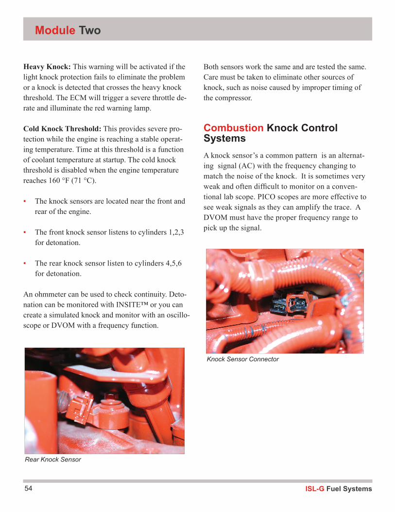
▪ The knock sensors are located near the front and rear of the engine.
▪ The front knock sensor listens to cylinders 1,2,3 for detonation.
▪ The rear knock sensor listen to cylinders 4,5,6 for detonation.
An ohmmeter can be used to check continuity. Deto-nation can be monitored with INSITE™ or you can create a simulated knock and monitor with an oscillo-scope or DVOM with a frequency function.
Both sensors work the same and are tested the same. Care must be taken to eliminate other sources of knock, such as noise caused by improper timing of the compressor.
Combustion Knock Control SystemsA knock sensor’s a common pattern is an alternat-ing signal (AC) with the frequency changing to match the noise of the knock. It is sometimes very weak and often difficult to monitor on a conven-tional lab scope. PICO scopes are more effective to see weak signals as they can amplify the trace. A DVOM must have the proper frequency range to pick up the signal.
Knock Sensor Connector
Rear Knock Sensor
55ISL-G Fuel Systems
Inputs
Review Questions
What is the voltage range of a normal O2 sensor?
What is wrong if it stays above .45V?
Why are there two knock sensors?
ISL-G Fuel Systems56
Module Two
Activity 1.5: Signal Producing Sensors
Catalyst Inlet and Outlet Oxygen Sensors
Tools and equipment: 1. Cummins Troubleshooting and Repair Manual 2. DVOM 3. INSITE™ 4. Propane Enrichment Tool
Step 1 Using the classroom manual, locate the Catalyst Inlet and Outlet Oxygen Sensor wiring diagram:
Inlet OutletHOS signal Wire terminal ___________ ____________HOS signal return Wire terminal ___________ ____________12v heater supply Wire terminal ___________ ____________12v heater return Wire terminal ___________ ____________
Step 2:Do the wire terminals of the wiring diagram and the harness coincide? YES Or NO
Step 3:Connect to the DVOM.Connect Insite and view the HO2S PID.Key On Engine Running (KOER).
Step 4:Insert a propane enrichment tool into the intake system. Open the propane valve to create a rich mixture over 800mv.Close the valve and create a lean mixture under 75mV.Snap the throttle and measure the rise time under 100ms.
Observations: _____________________________________________________________
Step 5:Repeat step 1-4 with the Catalyst Outlet Oxygen Sensor.
57ISL-G Fuel Systems
Inputs
Step 6: (Optional pending INSITE™ availability)Note the readings of the FUEL CONTROL VALVE while performing the propane enrichment exercise and write the value in the space provided. ___________________
Note the readings of the FUEL CONTROL VALVE while performing the FULL STALL TEST without propane enrichment and write the value in the space provided. ___________________
Note the readings of the FUEL CONTROL VALVE @ idle and write the value in the space provided. ___________________
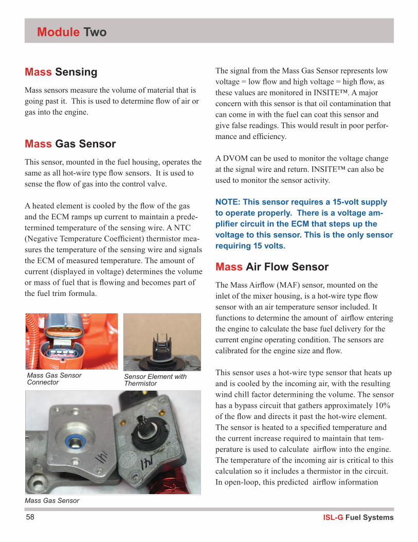
ISL-G Fuel Systems58
Module Two
Mass SensingMass sensors measure the volume of material that is going past it. This is used to determine flow of air or gas into the engine.
Mass Gas SensorThis sensor, mounted in the fuel housing, operates the same as all hot-wire type flow sensors. It is used to sense the flow of gas into the control valve.
A heated element is cooled by the flow of the gas and the ECM ramps up current to maintain a prede-termined temperature of the sensing wire. A NTC (Negative Temperature Coefficient) thermistor mea-sures the temperature of the sensing wire and signals the ECM of measured temperature. The amount of current (displayed in voltage) determines the volume or mass of fuel that is flowing and becomes part of the fuel trim formula.
The signal from the Mass Gas Sensor represents low voltage = low flow and high voltage = high flow, as these values are monitored in INSITE™. A major concern with this sensor is that oil contamination that can come in with the fuel can coat this sensor and give false readings. This would result in poor perfor-mance and efficiency.
A DVOM can be used to monitor the voltage change at the signal wire and return. INSITE™ can also be used to monitor the sensor activity.
NOTE: This sensor requires a 15-volt supply to operate properly. There is a voltage am-plifier circuit in the ECM that steps up the voltage to this sensor. This is the only sensor requiring 15 volts.
Mass Air Flow SensorThe Mass Airflow (MAF) sensor, mounted on the inlet of the mixer housing, is a hot-wire type flow sensor with an air temperature sensor included. It functions to determine the amount of airflow entering the engine to calculate the base fuel delivery for the current engine operating condition. The sensors are calibrated for the engine size and flow.
This sensor uses a hot-wire type sensor that heats up and is cooled by the incoming air, with the resulting wind chill factor determining the volume. The sensor has a bypass circuit that gathers approximately 10% of the flow and directs it past the hot-wire element. The sensor is heated to a specified temperature and the current increase required to maintain that tem-perature is used to calculate airflow into the engine. The temperature of the incoming air is critical to this calculation so it includes a thermistor in the circuit. In open-loop, this predicted airflow information
Mass Gas Sensor Connector
Sensor Element with Thermistor
Mass Gas Sensor
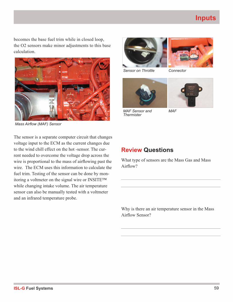
59ISL-G Fuel Systems
Inputs
Review QuestionsWhat type of sensors are the Mass Gas and Mass Airfl ow?
Why is there an air temperature sensor in the Mass Airfl ow Sensor?
becomes the base fuel trim while in closed loop, the O2 sensors make minor adjustments to this base calculation.
The sensor is a separate computer circuit that changes voltage input to the ECM as the current changes due to the wind chill effect on the hot -sensor. The cur-rent needed to overcome the voltage drop across the wire is proportional to the mass of airfl owing past the wire. The ECM uses this information to calculate the fuel trim. Testing of the sensor can be done by mon-itoring a voltmeter on the signal wire or INSITE™ while changing intake volume. The air temperature sensor can also be manually tested with a voltmeter and an infrared temperature probe.
Mass Airfl ow (MAF) Sensor
Sensor on Throttle
MAF Sensor and Thermister
Connector
MAF
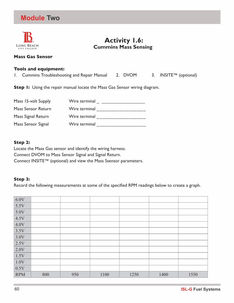
ISL-G Fuel Systems60
Module Two
Activity 1.6: Cummins Mass Sensing
Mass Gas Sensor
Tools and equipment: 1. Cummins Troubleshooting and Repair Manual 2. DVOM 3. INSITE™ (optional)
Step 1: Using the repair manual locate the Mass Gas Sensor wiring diagram.
Mass 15-volt Supply Wire terminal _ _______________
Mass Sensor Return Wire terminal _________________
Mass Signal Return Wire terminal _________________
Mass Sensor Signal Wire terminal _________________
Step 2:Locate the Mass Gas sensor and identify the wiring harness.Connect DVOM to Mass Sensor Signal and Signal Return.Connect INSITE™ (optional) and view the Mass Ssensor parameters.
Step 3:Record the following measurements at some of the specified RPM readings below to create a graph.
6.0V5.5V5.0V4.5V4.0V3.5V3.0V2.5V2.0V1.5V1.0V0.5VRPM 800 950 1100 1250 1400 1550
61ISL-G Fuel Systems
Inputs
Activity 1.6: Cummins Mass Sensing
Mass Air Flow Sensor
Tools and equipment: 1. Cummins Troubleshooting and Repair Manual 2. DVOM 3. INSITE™ (optional)
Step 1: Using the repair manual locate the Mass Gas Sensor wiring diagram
Mass 12-volt Supply Wire terminal _________________
Mass Sensor Return Wire terminal _________________
Mass Air Flow Signal Wire terminal ________
Mass Signal Return Wire terminal ________
Air Temperature Signal Wire terminal ________
Step 2:Locate the Mass Air sensor and identify the wiring harness.Connect DVOM to Mass Sensor Signal and Signal Return and set to measure frequency.
Connect INSITE™ (optional) and view the Mass sensor parameters
Step 3:Note: If using the DVOM to measure frequency, the units of measure will be (KHz). If using INSITE™, your units of measure will be lbs/hr.
Record the following measurements at the specified RPM readings to create a graph.
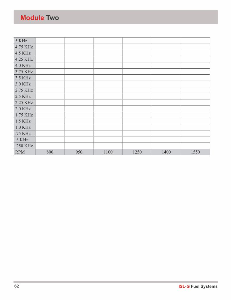
ISL-G Fuel Systems62
Module Two
5 KHz4.75 KHz4.5 KHz4.25 KHz4.0 KHz3.75 KHz3.5 KHz3.0 KHz2.75 KHz2.5 KHz2.25 KHz2.0 KHz1.75 KHz1.5 KHz1.0 KHz.75 KHz.5 KHz.250 KHzRPM 800 950 1100 1250 1400 1550
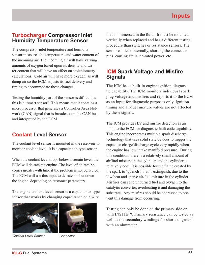
63ISL-G Fuel Systems
Inputs
Turbocharger Compressor Inlet Humidity Temperature SensorThe compressor inlet temperature and humidity sensor measures the temperature and water content of the incoming air. The incoming air will have varying amounts of oxygen based upon its density and wa-ter content that will have an effect on stoichiometry calculations. Cold air will have more oxygen, as will damp air so the ECM adjusts its fuel delivery and timing to accommodate these changes.
Testing the humidity part of the sensor is difficult as this is a “smart sensor”. This means that it contains a microprocessor that generates a Controller Area Net-work (CAN) signal that is broadcast on the CAN bus and interpreted by the ECM.
Coolant Level SensorThe coolant level sensor is mounted in the reservoir to monitor coolant level. It is a capacitance-type sensor.
When the coolant level drops below a certain level, the ECM will de-rate the engine. The level of de-rate be-comes greater with time if the problem is not corrected. The ECM will use this input to de-rate or shut down the engine, depending on customer parameters.
The engine coolant level sensor is a capacitance-type sensor that works by changing capacitance on a wire
that is immersed in the fluid. It must be mounted vertically when replaced and has a different testing procedure than switches or resistance sensors. The sensor can leak internally, shorting the connector pins, causing stalls, de-rated power, etc.
ICM Spark Voltage and Misfire SignalsThe ICM has a built-in engine ignition diagnos-tic capability. The ICM monitors individual spark plug voltage and misfires and reports it to the ECM as an input for diagnostic purposes only. Ignition timing and air/fuel mixture values are not affected by these signals.
The ICM provides kV and misfire detection as an input to the ECM for diagnostic fault code capability. This engine incorporates multiple spark discharge technology that uses solid state devices to trigger the capacitor charge/discharge cycle very rapidly when the engine has low intake manifold pressure. During this condition, there is a relatively small amount of air/fuel mixture in the cylinder, and the cylinder is relatively cool. It is possible for the flame created by the spark to ‘quench’, that is extinguish, due to the low heat and sparse air/fuel mixture in the cylinder. Misfires can send unburned fuel and oxygen to the catalytic converter, overheating it and damaging the substrate. Any misfires should be addressed to pre-vent this damage from occurring.
Testing can only be done on the primary side or with INSITE™. Primary resistance can be tested as well as the secondary windings for shorts to ground with an ohmmeter.
Coolant Level Sensor Connector
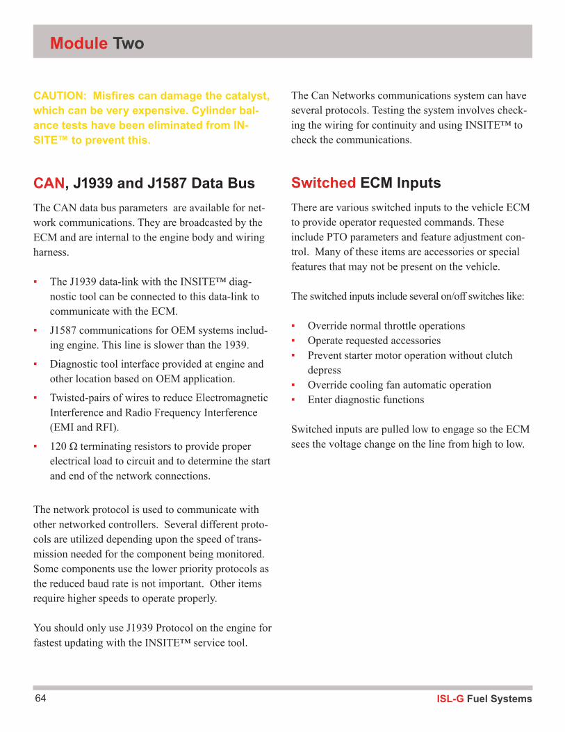
ISL-G Fuel Systems64
Module Two
CAUTION: Misfires can damage the catalyst, which can be very expensive. Cylinder bal-ance tests have been eliminated from IN-SITE™ to prevent this.
CAN, J1939 and J1587 Data BusThe CAN data bus parameters are available for net-work communications. They are broadcasted by the ECM and are internal to the engine body and wiring harness.
▪ The J1939 data-link with the INSITE™ diag-nostic tool can be connected to this data-link to communicate with the ECM.
▪ J1587 communications for OEM systems includ-ing engine. This line is slower than the 1939.
▪ Diagnostic tool interface provided at engine and other location based on OEM application.
▪ Twisted-pairs of wires to reduce Electromagnetic Interference and Radio Frequency Interference (EMI and RFI).
▪ 120 Ω terminating resistors to provide proper electrical load to circuit and to determine the start and end of the network connections.
The network protocol is used to communicate with other networked controllers. Several different proto-cols are utilized depending upon the speed of trans-mission needed for the component being monitored. Some components use the lower priority protocols as the reduced baud rate is not important. Other items require higher speeds to operate properly.
You should only use J1939 Protocol on the engine for fastest updating with the INSITE™ service tool.
The Can Networks communications system can have several protocols. Testing the system involves check-ing the wiring for continuity and using INSITE™ to check the communications.
Switched ECM InputsThere are various switched inputs to the vehicle ECM to provide operator requested commands. These include PTO parameters and feature adjustment con-trol. Many of these items are accessories or special features that may not be present on the vehicle.
The switched inputs include several on/off switches like:
▪ Override normal throttle operations ▪ Operate requested accessories ▪ Prevent starter motor operation without clutch
depress ▪ Override cooling fan automatic operation ▪ Enter diagnostic functions
Switched inputs are pulled low to engage so the ECM sees the voltage change on the line from high to low.

65ISL-G Fuel Systems
Inputs

ISL-G Fuel Systems66
Module Three3
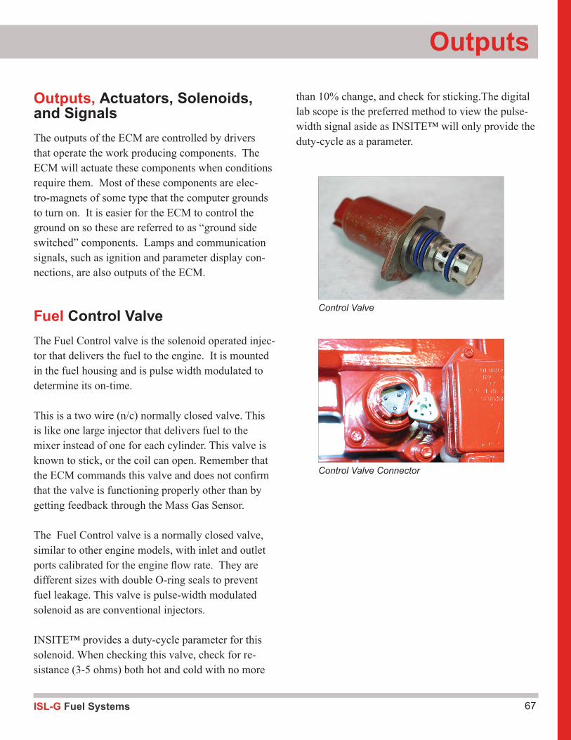
67ISL-G Fuel Systems
Outputs
Outputs, Actuators, Solenoids, and SignalsThe outputs of the ECM are controlled by drivers that operate the work producing components. The ECM will actuate these components when conditions require them. Most of these components are elec-tro-magnets of some type that the computer grounds to turn on. It is easier for the ECM to control the ground on so these are referred to as “ground side switched” components. Lamps and communication signals, such as ignition and parameter display con-nections, are also outputs of the ECM.
Fuel Control ValveThe Fuel Control valve is the solenoid operated injec-tor that delivers the fuel to the engine. It is mounted in the fuel housing and is pulse width modulated to determine its on-time.
This is a two wire (n/c) normally closed valve. This is like one large injector that delivers fuel to the mixer instead of one for each cylinder. This valve is known to stick, or the coil can open. Remember that the ECM commands this valve and does not confirm that the valve is functioning properly other than by getting feedback through the Mass Gas Sensor.
The Fuel Control valve is a normally closed valve, similar to other engine models, with inlet and outlet ports calibrated for the engine flow rate. They are different sizes with double O-ring seals to prevent fuel leakage. This valve is pulse-width modulated solenoid as are conventional injectors.
INSITE™ provides a duty-cycle parameter for this solenoid. When checking this valve, check for re-sistance (3-5 ohms) both hot and cold with no more
than 10% change, and check for sticking.The digital lab scope is the preferred method to view the pulse-width signal aside as INSITE™ will only provide the duty-cycle as a parameter.
Control Valve
Control Valve Connector
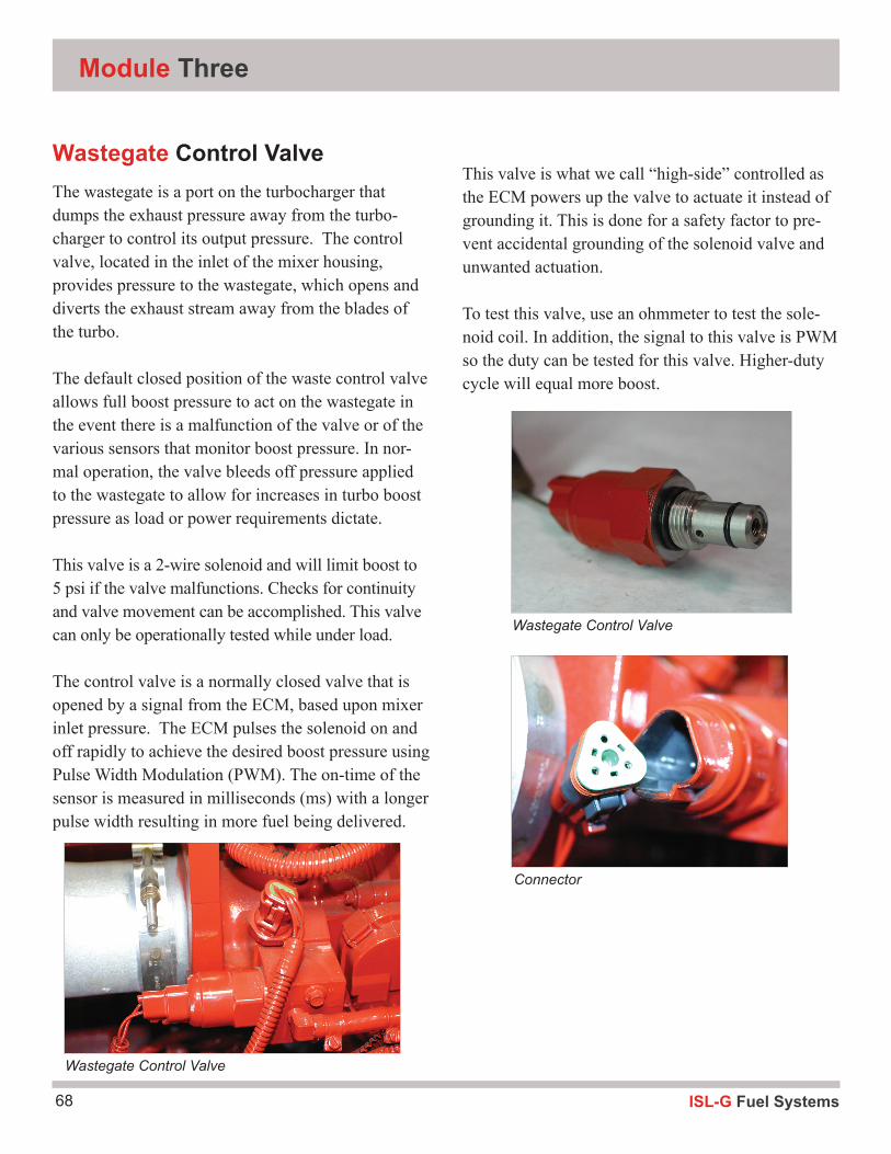
ISL-G Fuel Systems68
Module Three
Wastegate Control ValveThe wastegate is a port on the turbocharger that dumps the exhaust pressure away from the turbo-charger to control its output pressure. The control valve, located in the inlet of the mixer housing, provides pressure to the wastegate, which opens and diverts the exhaust stream away from the blades of the turbo.
The default closed position of the waste control valve allows full boost pressure to act on the wastegate in the event there is a malfunction of the valve or of the various sensors that monitor boost pressure. In nor-mal operation, the valve bleeds off pressure applied to the wastegate to allow for increases in turbo boost pressure as load or power requirements dictate.
This valve is a 2-wire solenoid and will limit boost to 5 psi if the valve malfunctions. Checks for continuity and valve movement can be accomplished. This valve can only be operationally tested while under load.
The control valve is a normally closed valve that is opened by a signal from the ECM, based upon mixer inlet pressure. The ECM pulses the solenoid on and off rapidly to achieve the desired boost pressure using Pulse Width Modulation (PWM). The on-time of the sensor is measured in milliseconds (ms) with a longer pulse width resulting in more fuel being delivered.
This valve is what we call “high-side” controlled as the ECM powers up the valve to actuate it instead of grounding it. This is done for a safety factor to pre-vent accidental grounding of the solenoid valve and unwanted actuation.
To test this valve, use an ohmmeter to test the sole-noid coil. In addition, the signal to this valve is PWM so the duty can be tested for this valve. Higher-duty cycle will equal more boost.
Wastegate Control Valve
Connector
Wastegate Control Valve
69ISL-G Fuel Systems
Outputs
Activity 1.7: Cummins Control Valves
Fuel Control Valve
Tools and equipment:
1. Cummins Troubleshooting and Repair Manual 2. INSITE™3. Hand Tool Set 4. DVOM
Step 1: Locate the Fuel Control Valve and identify the power and ground wires:
#1 ground Wire terminal ________________________
#1 power Wire terminal ________________________
Step 2:Using a propane enrichment tool, inject fuel into the intake manifold and proceed to step 3.
Step 3:Using the DVOM and INSITE™(optional), record the following readings in the space provided.
What is the FCV reading @ KOEO? DVOM _________ INSITE™ ___________
What is the FCV reading @ idle (no propane)? DVOM _________ INSITE™ ___________
What is the FCV reading @ full stall? DVOM _________ INSITE™ ___________
What is the FCV reading @ idle (with propane)? DVOM _________ INSITE™ ___________
Step 4: What is the Mass Gas Flow Compensation according to INSITE™ prior to propane enrichment? _____________________% Step 5:What is the Mass Gas Flow Compensation according to INSITE™ while performing the propane enrichment. _____________________%
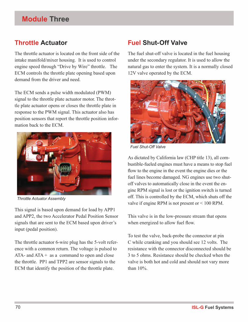
ISL-G Fuel Systems70
Module Three
Throttle ActuatorThe throttle actuator is located on the front side of the intake manifold/mixer housing. It is used to control engine speed through “Drive by Wire” throttle. The ECM controls the throttle plate opening based upon demand from the driver and need.
The ECM sends a pulse width modulated (PWM) signal to the throttle plate actuator motor. The throt-tle plate actuator opens or closes the throttle plate in response to the PWM signal. This actuator also has position sensors that report the throttle position infor-mation back to the ECM.
This signal is based upon demand for load by APP1 and APP2, the two Accelerator Pedal Position Sensor signals that are sent to the ECM based upon driver’s input (pedal position).
The throttle actuator 6-wire plug has the 5-volt refer-ence with a common return. The voltage is pulsed to ATA- and ATA + as a command to open and close the throttle. PP1 and TPP2 are sensor signals to the ECM that identify the position of the throttle plate.
Fuel Shut-Off ValveThe fuel shut-off valve is located in the fuel housing under the secondary regulator. It is used to allow the natural gas to enter the system. It is a normally closed 12V valve operated by the ECM.
As dictated by California law (CHP title 13), all com-bustible-fueled engines must have a means to stop fuel flow to the engine in the event the engine dies or the fuel lines become damaged. NG engines use two shut-off valves to automatically close in the event the en-gine RPM signal is lost or the ignition switch is turned off. This is controlled by the ECM, which shuts off the valve if engine RPM is not present or < 100 RPM.
This valve is in the low-pressure stream that opens when energized to allow fuel flow.
To test the valve, back-probe the connector at pin C while cranking and you should see 12 volts. The resistance with the connector disconnected should be 3 to 5 ohms. Resistance should be checked when the valve is both hot and cold and should not vary more than 10%.
Throttle Actuator Assembly
Fuel Shut-Off Valve
71ISL-G Fuel Systems
Outputs
Activity 1.8: Cummins Control Valves
Fuel Shut-off Valve
Tools and equipment: 1. Cummins Troubleshooting and Repair Manual 2. Hand Tool Set 3. DVOM 4. INSITE™ (Optional)
Step 1: Visually locate the Fuel Shut-off Valve and identify the power and ground wires:
#1 ground Wire terminal ________________________
#1 power Wire terminal ________________________
Step 2:
Using a DVOM, record the following readings in the space provided.
Connect INSITE™ and view the Fuel Shut-Off Valve parameters(Optional)
What is the FSV reading @ KOEO? DVOM _________ INSITE™ ___________
What is the FSV reading as engine starts to crank? DVOM _________ INSITE™ ___________
What is the FSV reading while engine cranks? DVOM _________ INSITE™ ___________
What engine activity turns on the FSV? DVOM _________ INSITE™ ___________
What is the FSV reading @ KOER? DVOM _________ INSITE™ ___________
Turn off the engine.
What is the FSV reading @KOEO? DVOM _________ INSITE™ ___________
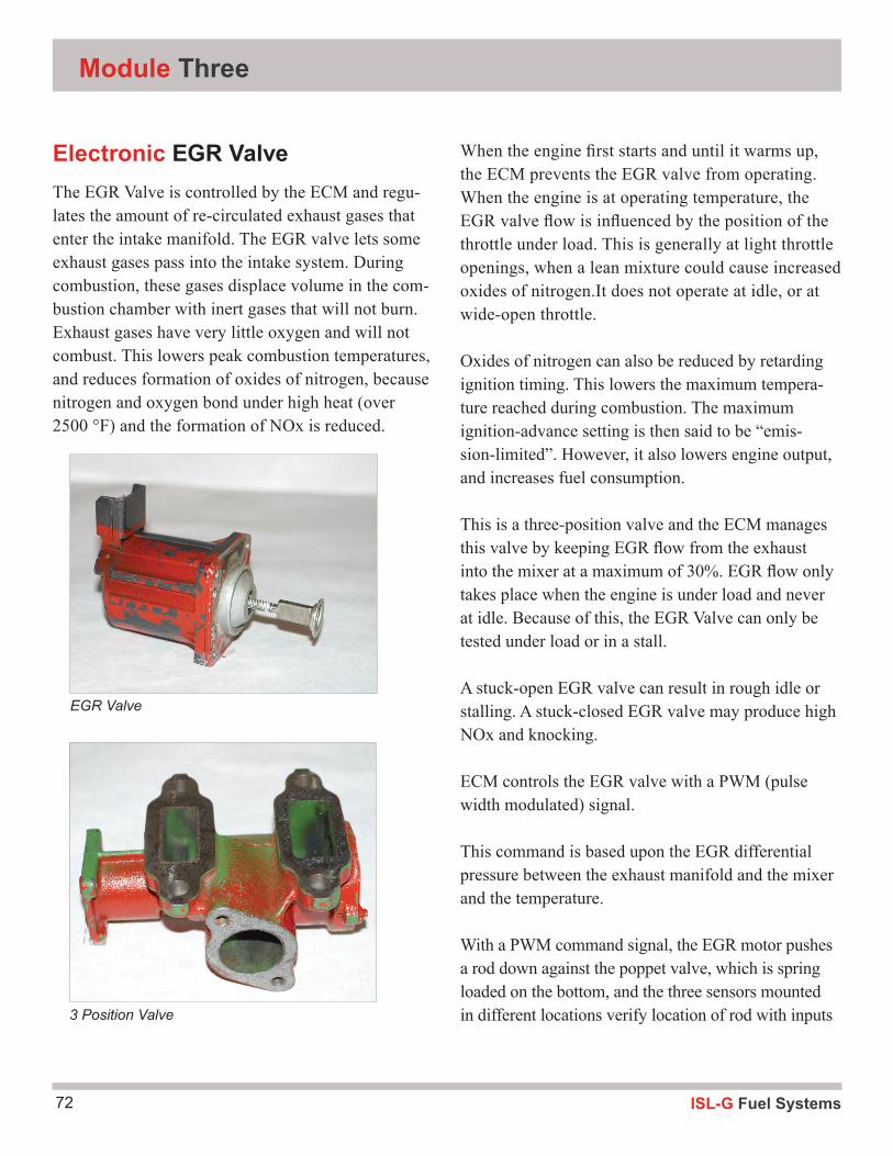
ISL-G Fuel Systems72
Module Three
Electronic EGR ValveThe EGR Valve is controlled by the ECM and regu-lates the amount of re-circulated exhaust gases that enter the intake manifold. The EGR valve lets some exhaust gases pass into the intake system. During combustion, these gases displace volume in the com-bustion chamber with inert gases that will not burn. Exhaust gases have very little oxygen and will not combust. This lowers peak combustion temperatures, and reduces formation of oxides of nitrogen, because nitrogen and oxygen bond under high heat (over 2500 °F) and the formation of NOx is reduced.
When the engine first starts and until it warms up, the ECM prevents the EGR valve from operating. When the engine is at operating temperature, the EGR valve flow is influenced by the position of the throttle under load. This is generally at light throttle openings, when a lean mixture could cause increased oxides of nitrogen.It does not operate at idle, or at wide-open throttle.
Oxides of nitrogen can also be reduced by retarding ignition timing. This lowers the maximum tempera-ture reached during combustion. The maximum ignition-advance setting is then said to be “emis-sion-limited”. However, it also lowers engine output, and increases fuel consumption.
This is a three-position valve and the ECM manages this valve by keeping EGR flow from the exhaust into the mixer at a maximum of 30%. EGR flow only takes place when the engine is under load and never at idle. Because of this, the EGR Valve can only be tested under load or in a stall.
A stuck-open EGR valve can result in rough idle or stalling. A stuck-closed EGR valve may produce high NOx and knocking.
ECM controls the EGR valve with a PWM (pulse width modulated) signal.
This command is based upon the EGR differential pressure between the exhaust manifold and the mixer and the temperature.
With a PWM command signal, the EGR motor pushes a rod down against the poppet valve, which is spring loaded on the bottom, and the three sensors mounted in different locations verify location of rod with inputs
EGR Valve
3 Position Valve
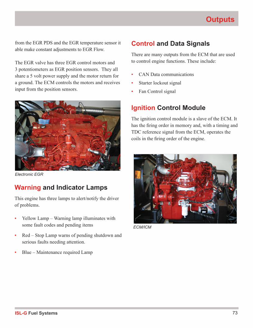
73ISL-G Fuel Systems
Outputs
Electronic EGR
Warning and Indicator LampsThis engine has three lamps to alert/notify the driver of problems.
▪ Yellow Lamp – Warning lamp illuminates with some fault codes and pending items
▪ Red – Stop Lamp warns of pending shutdown and serious faults needing attention.
▪ Blue – Maintenance required Lamp
ECM/ICM
from the EGR PDS and the EGR temperature sensor it able make constant adjustments to EGR Flow.
The EGR valve has three EGR control motors and 3 potentiometers as EGR position sensors. They all share a 5 volt power supply and the motor return for a ground. The ECM controls the motors and receives input from the position sensors.
Control and Data SignalsThere are many outputs from the ECM that are used to control engine functions. These include:
▪ CAN Data communications
▪ Starter lockout signal
▪ Fan Control signal
Ignition Control ModuleThe ignition control module is a slave of the ECM. It has the firing order in memory and, with a timing and TDC reference signal from the ECM, operates the coils in the firing order of the engine.
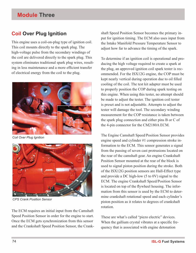
ISL-G Fuel Systems74
Module Three
shaft Speed Position Sensor becomes the primary in-put for ignition timing. The ECM also uses input from the Intake Manifold Pressure Temperature Sensor to adjust how far to advance the timing of the spark.
To determine if an ignition coil is operational and pro-ducing the high voltage required to create a spark at the plug, an approved ignition coil spark tester is rec-ommended. For the ISX12G engine, the COP must be kept nearly vertical during operation due to oil filled cooling of the coil. The test kit adapter must be used to properly position the COP during spark testing on this engine. When using this tester, no attempt should be made to adjust the tester. The ignition coil tester is preset and is not adjustable. Attempts to adjust the tester will damage the tool. The secondary winding measurement for the COP resistance is taken between the spark plug connection and either pins B or C of the 4-pin connector for the CM2180A ECM.
The Engine Camshaft Speed/Position Sensor provides engine speed and cylinder #1 compression stroke in-formation to the ECM. This sensor generates a signal from the passing of seven cast protrusions located on the rear of the camshaft gear. An engine Crankshaft Position Sensor mounted at the rear of the block is used to signal piston position during the stroke. Both of the ISX12G position sensors are Hall-Effect type and provide a DC high-low (5 to 0V) signal to the ECM. The engine Crankshaft Speed/Position Sensor is located on top of the flywheel housing. The infor-mation from this sensor is used by the ECM to deter-mine crankshaft rotational speed and each cylinder’s piston position as it relates to degrees of crankshaft rotation.
These are what’s called “piezo electric” devices. When the gallium crystal vibrates at a specific fre-quency that is associated with engine detonation
Coil Over Plug IgnitionThis engine uses a coil-on-plug type of ignition coil. This coil mounts directly to the spark plug. The high-voltage pulse from the secondary windings of the coil are delivered directly to the spark plug. This system eliminates traditional spark plug wires, result-ing in less maintenance and a more efficient transfer of electrical energy from the coil to the plug.
The ECM requires an initial input from the Camshaft Speed Position Sensor in order for the engine to start. Once the ECM gets synchronization from this sensor and the Crankshaft Speed Position Sensor, the Crank-
Coil Over Plug Ignition
CPS Crank Position Sensor
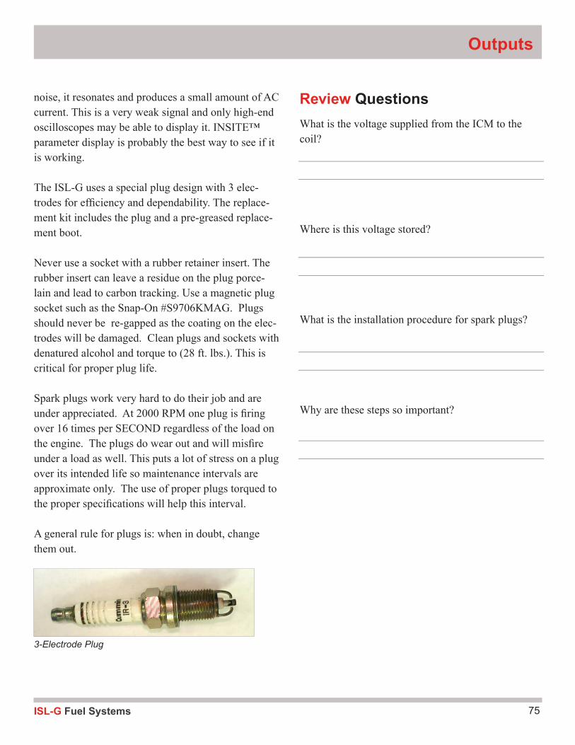
75ISL-G Fuel Systems
Outputs
3-Electrode Plug
noise, it resonates and produces a small amount of AC current. This is a very weak signal and only high-end oscilloscopes may be able to display it. INSITE™ parameter display is probably the best way to see if it is working.
The ISL-G uses a special plug design with 3 elec-trodes for effi ciency and dependability. The replace-ment kit includes the plug and a pre-greased replace-ment boot.
Never use a socket with a rubber retainer insert. The rubber insert can leave a residue on the plug porce-lain and lead to carbon tracking. Use a magnetic plug socket such as the Snap-On #S9706KMAG. Plugs should never be re-gapped as the coating on the elec-trodes will be damaged. Clean plugs and sockets with denatured alcohol and torque to (28 ft. lbs.). This is critical for proper plug life.
Spark plugs work very hard to do their job and are under appreciated. At 2000 RPM one plug is fi ring over 16 times per SECOND regardless of the load on the engine. The plugs do wear out and will misfi re under a load as well. This puts a lot of stress on a plug over its intended life so maintenance intervals are approximate only. The use of proper plugs torqued to the proper specifi cations will help this interval.
A general rule for plugs is: when in doubt, change them out.
Review QuestionsWhat is the voltage supplied from the ICM to the coil?
Where is this voltage stored?
What is the installation procedure for spark plugs?
Why are these steps so important?
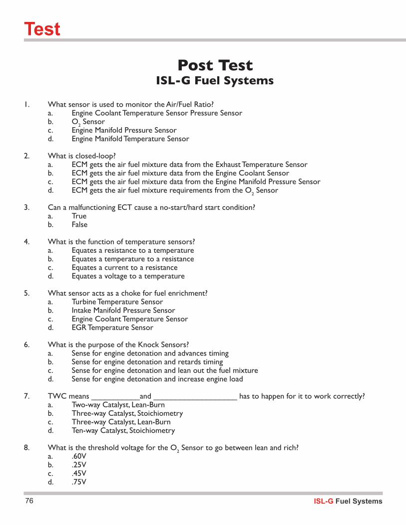
Test
76
Post TestISL-G Fuel Systems
1. What sensor is used to monitor the Air/Fuel Ratio? a. Engine Coolant Temperature Sensor Pressure Sensor b. O2 Sensor c. Engine Manifold Pressure Sensor d. Engine Manifold Temperature Sensor
2. What is closed-loop? a. ECM gets the air fuel mixture data from the Exhaust Temperature Sensor b. ECM gets the air fuel mixture data from the Engine Coolant Sensor c. ECM gets the air fuel mixture data from the Engine Manifold Pressure Sensor d. ECM gets the air fuel mixture requirements from the O2 Sensor
3. Can a malfunctioning ECT cause a no-start/hard start condition? a. True b. False
4. What is the function of temperature sensors? a. Equates a resistance to a temperature b. Equates a temperature to a resistance c. Equates a current to a resistance d. Equates a voltage to a temperature
5. What sensor acts as a choke for fuel enrichment? a. Turbine Temperature Sensor b. Intake Manifold Pressure Sensor c. Engine Coolant Temperature Sensor d. EGR Temperature Sensor
6. What is the purpose of the Knock Sensors? a. Sense for engine detonation and advances timing b. Sense for engine detonation and retards timing c. Sense for engine detonation and lean out the fuel mixture d. Sense for engine detonation and increase engine load
7. TWC means ___________and ___________________ has to happen for it to work correctly? a. Two-way Catalyst, Lean-Burn b. Three-way Catalyst, Stoichiometry c. Three-way Catalyst, Lean-Burn d. Ten-way Catalyst, Stoichiometry
8. What is the threshold voltage for the O2 Sensor to go between lean and rich? a. .60V b. .25V c. .45V d. .75V
ISL-G Fuel Systems

77ISL-G Fuel Systems
78 ISL-G Fuel Systems
TOXICITY: Nontoxic it is not a poison like carbon monoxide but it does displace oxygen.
FLAMMABILITY: Flammability range is narrow 5-15% -- below 5 is too lean to burn above 15 too rich. Edges of a cloud could be right mixture. Heaters and other spark producing items must be relocated.
VENTILATION: Must be trapped vertically to be dangerous - look up for traps at ceiling/false ceilings etc. Lighter than air so most shops are equipped with auto vents on the methane detection circuit.
LEAK DETECTION: Mercaptin NOT present in LNG unless infused so it will have no odor. Methane detectors and hand held combustible gas detectors available along with commercial bubble style leak detectors. CG detectors will go off on many substances such as glycol, silicone, diesel, hyd. fluid so it is just a gross indicator.
Natural Gas Safety Considerations
COLLISION: Cylinders must have a Detailed Visual Inspection and hardware should be carefully inspected for damage. Cylinders should be closed and ¼ turn valve closed if vehicle is involved in an accident
STORAGE: LNG vehicles should be stored outside due to venting of tank. CNG system are sealed and will not leak to atmosphere
SHOP SAFETY/EQUIPMENT: Methane detectors and ceiling ventilation should be reviewed by engineering. Special tools kit being provided to perform defueling etc.

79ISL-G Fuel Systems
References
80
Sources:
Compressed Gas Association1725 Jefferson Davis Highway,#1004 Arlington, VA 22202-4102 Telephone: 703-412-0900
Gas Research Institute 8600 W. Bryn Mawr Avenue Chicago, IL 60631-3652 Telephone: 773-399-8352
American National Standards Institute 11 W. 42nd Street New York, NY 10036 Telephone: 212-642-4900
National Fire Protection Association 11 Tracy Drive Avon, MA 02322 Telephone: 800-593-6372
Natural Gas Vehicle Coalition1515 Wilson Blvd. Suite 1030Arlington, VA 22209 Telephone: 703-527-3022
Department of Transportation 400 Seventh Street, SW Washington, DC 20590 Telephone: 202-366-4000
Publications:
CGA C-6.4, “Methods for External Visual Inspection of Natural Gas Vehicle Fuel Containers and Their Installations,” 1st Edition (1997)
NFPA 52, “Standards for Compressed Natural Gas Vehicular Fuel Systems” National Fire Protection Association, 1 Batterymarch Park, Box 9101, Quincy, MA 02269-9101
ANSI/AGA-NGV2, “ Basic Requirements for Compressed Natural Gas Vehicle Fuel Containers,” American Gas Association Laboratories, 8501 East Pleasant Valley Road, Cleveland, OH 44131
FMVSS304, “Compressed Natural Gas Fuel Container Integrity,” Federal Motor Vehicle Safety Standards, US DOT, NHTSA
Gas Research Institute, “ Natural Gas Vehicle Cylinder Care and Maintenance Handbook” (1997)
CHP Title 13
ISL-G Fuel Systems

81ISL-G Fuel Systems
Notes
ISL-G Fuel Systems82
83ISL-G Fuel Systems
Notes
ISL-G Fuel Systems84
Notes
85ISL-G Fuel Systems
Notes