cswsformha_03012022.pdf - ministry of home affairs
TRANSCRIPT
7*FA 116z
Arrit MahobavGovernment of lndiaMinistry of Home Affairs
Directorate Genera! National Security Guard(Provisioning Branch/Ord Section)
Mehram Nagar, Palam, New Delhi-l10037Fax No. 0l 1 -25663258 12567 1639
P 16041191389l0orner Shot /Prov/Ord/NSG/ Dated : 8l December 2021
FORWARD OF FINAL QUALITATIVE REQUIREMENT (QRs) AND TRIAL DIRECTIVESTDsl OF CORNER SHOT WEAPON SYSTEM FOR GLOCK PISTOL
1. lt is submitted that final QRs and TDs in respect of Corner Shot Weapon System for. Glock Pistol duly signed by DG, NSG was forwarded to Dte Gen CRPF on 05 Nov 2020 lor
uploading on MHA Website. The same has not been uploaded in MHA website.
2. ln view of the above, final QRs and TDs on the subject is forwarded herewith foruploading on MHA Website please.
Lt oS
r lG (Prov)Encls : As above
Senior Technical Di rector. lT Cell. NlC. North Block. New Delhi
;
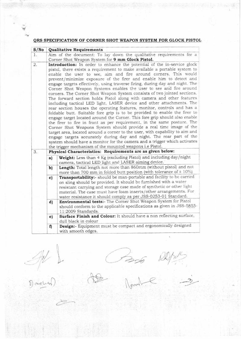
ORS SPECIFICATION OF CORNER SHOT WEAPON SYSTEM FOR GLOCK PIS?OL
1
2
S/No tative Re uirementsAim of the document: To la-v doun the qualitative requirements for aCorner Shot We S tcm for 9 mm Glock Pistol,Introduction: In order to enhance the potentiai of the in-sen'ice glock,pistol, there exists a requirement to n'rake available a portable s)isrcm toenable the user io see, aim and ire around comers. This rvouldprevent/minimize exposure of the firer and enabie htn lo delect and'engage targets effectively, using traverse firing, during da1.- and night. The :
Corner Shot Weapon Systems enables ihe user to see and llre aroundconrers. The Comer Shot \Yeapon Sl"stem consists of trvo jointed sections.The forward section holds Pistol along \rith camera and other featuresineluding tacticat LED light, LA-SER device and other attachments. Therear section houses the operating features, raonitor, controls and has a
foldable butt. Suitabie forc grip is to be prorided to enable the firer loengage target located around the Corner. This fore grip shoutd also enablethe {irer to irre in front as per requirement, in the same posture. TheCorner Shot Weapons S)'stem should provide a real Lime image of thetarget area, located around a comer to the user, *i'Jr capability to aim ardengage targets accurately during day and niglrt. The rear part of thesystem should have a monitor for tl.e camera and a trigger which activatesthe tri mechanism of the mounted ons i.e Pistol.PhFical Characterlstics: Requirements are as given below:
a) Yletght: L€ss than 4 Kg (excluding Pistol) and including day/nightcam tactical LED li I andLength: Total length not more lha:r 860rnm (*ithout pistol) and nomore than 700 mm in folded butt 'ition with toleralce of 1 i 0'14,
Transportability:- should be mar-poriable and facilit-v to be carr,ed
t:
on sling shnuld be prorided. it should be fumished with a waterresistant carrying and storage case made of slnthetic or other lightmaterial. The case must have foam inserts/other arrangements. Forwater resistance it should com AS JSS-0253-Oi StaxdardEnvironmental tests: - The Corner Shot Weapon System for Pistolshould conforrn to th1 1:2009 Standards.Surface Fintsh and Colour: Ir should have a non reflecting surface,du black in colourDeeign:- Equipment mus! be cornpact and ergonomically designedwith smooth S
e applicable specifrcadons as given in JSS-5855'
.:
i
b)
d)
e)
u4)
J.
t'=/.-
ORS SPECIFICATION OF CORNER SIIOT WEAPON SYSTEM FOR GLOCK PISTOL
4Colour Camera: D Camera should have followin bilities
Day ranging capability:- For a 'Single Staading Human Target' in clearday conditioos, camera should have follorving ra-nge capabilities (withoutzooming)Detection Minimum 75 mRecognition Minimum 50 mI denti.fi.cation Minimum 25 m
iiil
l\/ D€tachability - Detachable with arra:rgements to be attached/detached
Night Rarge Capabiltty - Day Camera be provided \r'rth IR illuminatoror be capable of identiff ing 'Single Standing Human Ta.rget' at minimum20m in a dark enclosure or closed room '*'ith no
aIl1
I
easil atn t and be interchal d with n t carlera,
vlllb) I{ight Camera - Night Camera :- iOptional) user has to specify if additional
nl t camera is uired I I tube based in the tender documenti)ii) Range Capabiltty - For a 'Single Standing Human Target'under Clear
starlight night conditions {no'r more than 1O-3 lux} and medium contrastDetection lvlinimum 50 mRecognition Minimum 30 mI dentification Minimum 15 m
Detachability - Detachable night camera wit.ll arrangements to beattached detached easil and be interch *ith da cameraReticule Pattern - Cross hair
vr) Field of Vlew - Horizontal lield - 10" lmialVertical field - 7.5" mut
1,T
/i
4.. n,.{ I ,>
S No
Zeroio Facili to car out Zeroin of aimin aticuleCa abili
v) Field of View - The field of view should be 35-40 degrees {H and V)Resolution - Equal to or greater than 2 mega pixelDigital Zoom - 10 XReticule Pattern - Cross hair rlpe
Zeroing Capability - Facility to carry our zeroing of aiming graticule
IR Capability - Provided l,rith IR illuminator and be capable ofidentifying a Slngle Standing lluman Target' at miaimum 15m ln andark room with ao t.
iv)
v)
Oualitative ReeuirementsSiehting Systems
RS ol{ oF co SHOT WEAPO}{
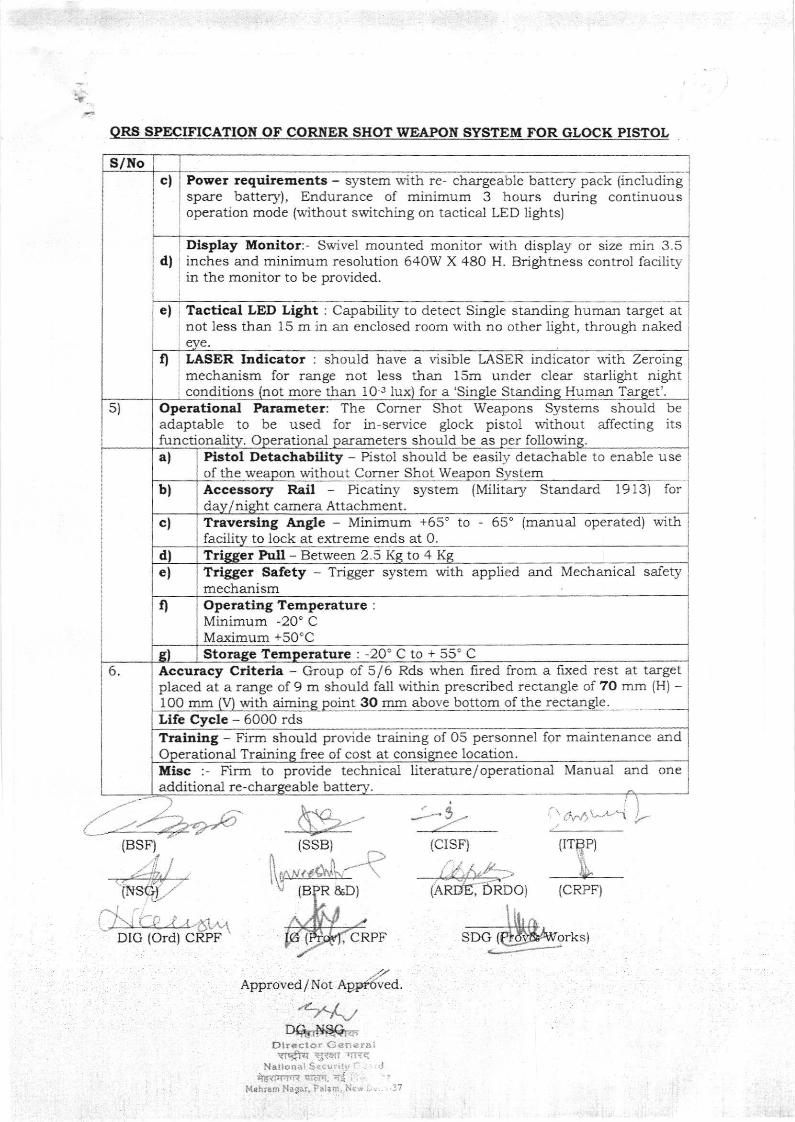
Power requiremeats - system with re- chargeable battery pack {includingspare battery), Endurance of minimum 3 hours during continuousoperation mode (without srvitching on tactica-l LED lights)
Dlsplay Monitor:- Srvivel mounled monitor wirh displa5r or sizc min 3.5d| ' inches and mj.nimum resolution 640W X 480 H- Brigfrtness control facility l
in the monitor to be provided.
e| Tactical LED Light : Capability to detect Single standing human target atnot less than 15 m in an enclosed room with no other light, through naked
f) LASER Inilicator : should have a visible LASER indicator u"ith Zeroingmechanism for range not less than 15m under clear starlight nightconditions not more than 10"1 lux for a 'Sin Standin Human Tar t
Operational Parameter: The Corner Shot Weapons Systems should beadaptable to be used for in-service glock pistol without affecting itsfunctionali tiona] a.rameters should be as er foll
Pistol Detachabi[ty - Pistol should be easilv detachable to enable useof the we w'ilhout Corner Shot Weapon SystemAccessory RaiI - Picatiny system (Military Standard 1913) ford t camera Attachment
Misc :- Firm to provide technica-l literature/ operational Manual and oneadditiooal re-ch able
a
(BSF) (SSB)
(B R &D)
CRPF
../,
ApprovedTNot Appmved,
/,,'.,DG'NAG.
RDOi {CRPF)
{CISF} {rreP)'t,.//-*
S/tlocf
s)
al
bl
c)
dl
?ravershg Angle - Minimum +65' to - 65" {manual operated) withfacility tr: lock at exteme ends at 0Trigger Pull - Between 2.5 Kg to 4 Kg
el Trigger Safety - Trigger system with applied alrd Mechanical saletymechanism
t Operatlng Temp€rature :
Minimum -20" CMaximum +50'C
s) Storage Temperature : -20'C to r- 55" CAccura.cy Crtteria - Group of 5/6 Rds when fired from a fixed res! at targetplaced at a range of 9 m should fall within prescribed rectangle of 7O mm {H) -
Life Cycle - 6O0O rds3O mm above bottom of the rectangle100 mm lV) with ajming point
Training - Firm should provide training of O5 personnel for maintenance andtional Trainin free of cost at consi ee location.
6
DIG (ord) C
I
I
I
I
't'r'j'/,\'t''\ i-
n-,.-\-
spcTlkAr*r.r-:=:-4
1. AIM :-Aim of this document is to formulate tria-l directive for evaluation for the CornerShot Weapon System (CSWSI for Glock Pistol.
2. Irtroduction:-Corner Shot Weapon System will be used by Special Forces in hostile situationsand counter insurgency operations. It allows its operator to see and attack anarmed target, without exposing himself for any counter attaek.
3. Test Procedure and Acceptance Criteria:The Integrated CSWS will be subjected to foilorving Tests.a) Physical and lbnctional parameter Testingb) Environmental Tests as per JSS 5855: i 1-2009c) Firing Trials
3.1 Physical and functioual paramete, Testlng:
Following physical ad functional parameters ltr' 1 be Tested for Integrated CSWSPiston Version separately.
3.1,1 Overall llletghtThe overall weight of Integrated CSWS will be checked as per followiag.
Rema-rks
Table 2 : Overall Ins ction Procedure
To becheckedphysically byBOOs
RemarLs
To bechecked byphysicallyby BOOs
following.
Max Lengthreadingshould be<860 mm
fi
TestPalalneter
Test Procedure AcceptanceCriteria
Weight a) Place the integrated CSWS(without Pistol) on weightingscale (No parts of CSWSshould be in contact of anyvertical face of the sca.le orwa.ll)b) Record the max weightreading 05 Nos of times
Max weightreadingshould be<4.0 Kg
TestPaf,ameter
Test Procedure AcceptanceCriteria
Overall length 1. Butt open:a) Place the integrated CSWS(without pistol) on white paperb) Mark both the extremefaees/points lvith the help offlat plates on u&ite paper.c) Measure the distancebetween two marked points.
kt"-"\--<
Trial Directives of Cor4e1 Shot Weapon Svstem for clock Pistol
! Table 1 : Overall weight Inspection Procedure
i
I
3.1.2 Overall Length:
The overall length of integrared CSWS of Pistol will be checked as per
I
q
II. Butt folded :
a) Place the integrated CSWSwith butt folded {$rithoutpisto! on white paper-
b) Mark both the extremefacesfpoints wirh the helpof flat plates on whitepaper.
c) Measure the distance
Max lcngthreadingshould be <700 mrn
To becheckedphysica-lly byBOOs.
between two ma-rked ilts.:3.r.2 Trigger Pull :
This test will be conducted lor CWSs Pistol Versions to check for the triggerpul1 parameters of the CSWS in all three orienlations t65', O', +65')
Figure 3 : CSWS Trlgger MechaaismTable 4 : r Pull Test at three orlentations
Remarks
Trigger Pull In Straight aligameat (O")i. Take a Corner Shot Weapon Systemii. Mount in-sen'ice glock Pistol with emptymagazineiii. Ensure that CSWS is locked and aligr:ed instraight axis (O degree)iv. Place the catch safety at "F (Fire) position of thepistol mounted and hammer in cocked position.v. Pull the CSWS trigger with Trigger pullmeasuring devicevi. Measure ald record the ma-x value of triggerull force u tn Pull measu Setu
Left position (-65'|i. Take a Corner Shot Weapon Systemii. Mount in-service glock Pistol lfith emptymagazineiii. Ensure that CSWS is locked and aligned in leftside (-65 deg)iv. Place tlle catch safety at "F (Fire) position of thepistol mounted and harnmer in cocked position.v. Pull the CSWS trigger with Trigger pullmeasuring devicevi. Measure and record the max value of trigger
ll force Tri Pull measurin SetuuTnvereing rlght Posltton {+65"1i. Mount the in-service glock Pistol wit]l emptymagazineii. Ensure that CSWS is locked and aligned in rightaxis (+65 degree)iii. Place the catch safety at "F {Fire) position of thepistol mounted and hammer in cocked position.iv. Pull the CSWS trigger with Trigger pullrneasuring devicev. Measure and record the max value of trigger pullforce Pull Setu
It1 all threeorientationtrigger pullshould bei,l betweeu2.5-4.o Kg
To becheckedat aaygovt.lab/govtapprovedlab byBOOs.
i'
-)'
-)>e6
AcceptanceCriteria
TestParameter
Test Procedure
!'*rrt-"-.{
u
k-.r4t$"-(
Lt/'t:-."+
i
i
I
I
j
I
I
i
I
I
I
i
I
&- k-)-....-..
^3.1.4 Traverse Angle
The test will be conducted for CSWS Pistol Version to check for thetraversing angle of the forearm of the CSWS- Free movement/proper functioning of theswivel arm on hinge, proper functioning of the locking ald releasing mechanism is tobe checked during the Test.
Table 5: Traverse Angle measurement procedure
Traverse angle atthree orientations
Remarks
To be checkedat any Govt.Lab / goitapproved labby BOOs
Angle betrveenfore stock andrear stockshould be -65 tO.5 deg
3,1.5 Quick DetachabllitSr of Weapon;This test will be conducted to Test the guick detachability of pistol mounted on cswswithout use of any specia-1 tool.
Table 6 : Quick Detachability Testing procedure
Test Procedure Acceptance Criteria Remarks
To be checled byBOOs
3.1.6 Colour, Su:face Flnlsh and Deslgn :This test will be caried out to veri& the Colour, Surface finishPistol VErs
i,
\- , . -
a.rrd Design of CSWS
.1.,;.1.,':^' 't: ''
I
^1.4 a. .l
Test Parameter
a)In Stra{ght alignment (O'l :i) Take integrated CSTVSii) Place the CSWS on a fixed r.ice and hrear stock.iii) Select suitable parailel flat faces ofRear Stock and fore stockiv) Dralp a straight line $,.r.t fore andRear stock and laces.v) Check angle betiveen lines
Test Procedure
o,
AcceptanceCriteria
Angle betweenfore stock andreal stockshould be 0"1O.5 deg
bl In traversing left posttton [-650]i) Take integrated CSWSii) Take integrated CSWS on a frxed viceand hold rear srock.iii) Select suitable parallel flat faces ofRear Stock and fore stockiv) Draw a straight line w.r.t fore andRear stock and faces.v) Check angle between iinescl In traverslng left posttion (+650)i) Take integrated CSWSii) Place the CSWS on a ixed vice afld hrear stock.iii) Select suitable parallel flat faces ofRear Stock arld fore stockiv) Draw a straight line w.r.t fore andRear stock and faces.v) Check angle betu'een lines
Angle betlveenfore stock aldrea-r stockshould be 6.5 tO.5 deg
Test Parametel
Detachability Remove Pistolmanually from CSWSw/o any special tools
Pistol should be ableto eaaily detach inless than OneItlinute
10n. l
[\g*t,oa-il-<-.""-y
I
l
I
I
I
II
I
I
L
lI
I
&er"
Table 7 : Colour aad Surface Flnish aad Desig:n
Visual Inspection by BOOs
3.1.7 Trigger Safcty TestingFollowing procedure and criteria will be adopred for ensuring safety rvhile firing of
CSWS Glock Pistol version. Pistol $/iU remain mounted (cocked arrd w/o loading
ammunition) with CSWS during conduct of triSger salety Test.
Should be a nonreflecting,Dull Black {Matt Finish) inColour
Remarks
a) Trigger should be notoperate when salety lever in"S" (Safe) position as well asin between "S" (Safe) and "F"(Fire) position.b) On application of highertrigger pull, trigger shouldnot override saiety lever andoperate.c) CSWS trigger shouldoperate "ONLY' when safelvlever in 'FIRE" position.d PISTOL should only firewhen CSWS safety lever infire mode.
CSWS trigger should be ableto operate "ONLY" on threeIocked positions (-65,0, +65degree) of Fore Stock.
Acceptaace CriteriaTest Parameter Test Procedure
Colour and Surface Finish
Should be compact withsmooth edges
Visual Inspection bi' BOOs
Table 8 :Trlgger Saf€ty Testlag Procedure
Test Parameter ?est Procedure Acceptance Criteria
1. Applied Safety L. Place the CSWS on afixed vice and hold rearstock.ii. Put CSWS safety leverin "S" (Safe) position.Iii. Press the triggeriv. Place safety lever inbetween "S" (Safe) ald"F" (Fire) position onCSWS.v. Press the trigger.vi. Press the trigger withhigher lorce malua.1ly.Vii. Repeat steps I to iiiby putting safety lever in"F" {Fire) position
ii. MechanicalSafety
I. Place the CSWS on afixed vice and hold rearstock.ii. Rotate fore stockusing slider and lockmechanism.
ry
I
I
I oesisn
.To be checked :
: at any Govt. t,
il,ablgolt i
approved lab by I
BOOs )
I
i
L
I
&t<5>.---
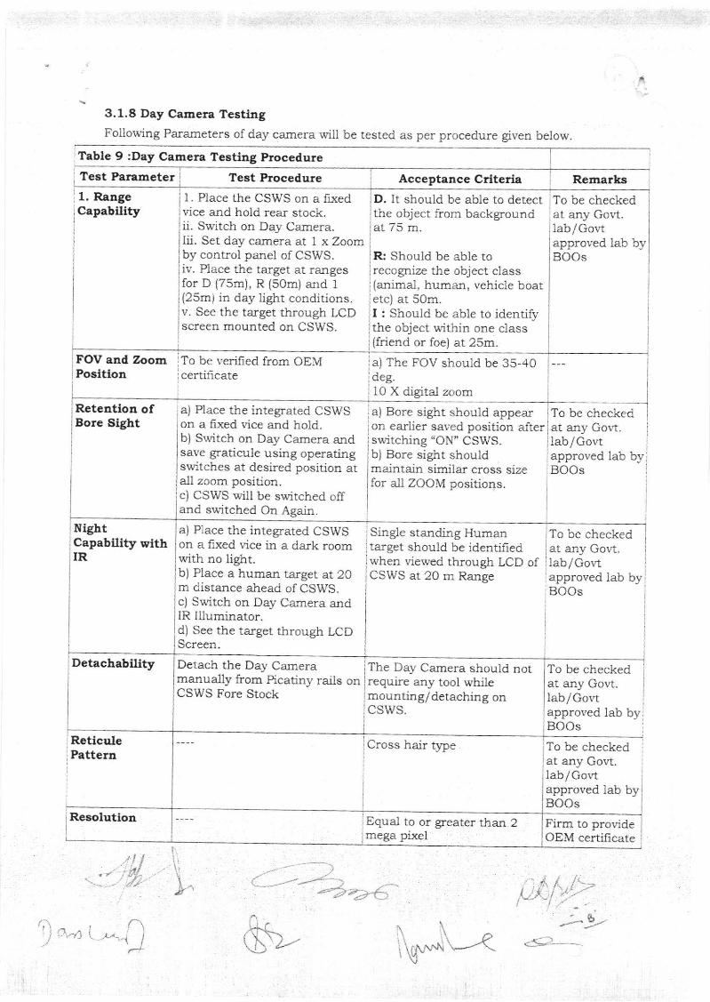
3.1.8 Day Camera TesthgFoilowing Pa.rameters of day camera will be tesaed as per procedure given below
'Table 9 :Day Camera Testirg Procedure
?est Paraaetet Test Procedure Aeceptance Criteria Remarks1. RangeCapability
FOV and ZoomPosltion
1. Place the CSWS on a lxedvice and hold rea-r stock.ii, Srvitch on Day Cermera.lii. Set day camera at I x Zoomby control panel of CSWS.iv. Place the target at rangesfor D (75m), R (5Om) and 1
(25m) in day light conditions.v. See the target througtr LCDscreen mounted on CSWS.
To be verifred from OEllcertificate
D. It should be able to detectthe object from backgroundat 75 m.
R: Should be able torecogrize the object class(anima1, humart, r,ehicle boatetc) at som.I : Should be able to identifythe object within one class(friend or foe) at 25m.
a) The FOV should be 35-.,10deg.10 X digital zoom
a) Bore sight should appearon earlier saved position afterswitching "ON" CSWS.b) Bore sight shouldmaintain similar cross sizefor all ZOOM positions.
Single sta;rding Humantarget should be identifiedwhen viewed through LCD ofCSWS at 20 n1 Range
The Day Camera should notrequire any tool whilemounting/detaching onCSWS.
Cross hair tlpe
To be checkedat anv Goltiab / Govtapproved lab byBOOs
To be checkedat any Gor't.lab/Govtapproved lab byBOOs
To be checkedat any Govt.lab/Gor,t
I approved lab byBOOs
To be checkedat any Govt.lab/Govtapproved lab byBOOs
To be checkedat any Govt.lab/Gor'tapproved lab byBOOs
Firm to provideOEM certificate
"-- 6 -
Retention ofBore Sight
Night'Cepability wtth.IR
Resolution
a) Place the integrared CSWSon a fixed vice and hold.b) Switch on Day Camera andsave graticule using operatingswitches at desired position atall zoom positioa.c) CSWS ryill be switched offand switched On Again.
a) Place the integated cswson a fixed ',ice in a dark roomwith no lighr.b) Place a human target at 20m distance ahead of CSWS.cl Su"itch on Day Camera andIR llluminator.d) See the ta.rget through LCDScreel.
ReticulePattern
:) 't i -\l
\t
t^-a'
Detach t}le Day Camer:amanua-1ly from Picatiny rails onCSWS Fore Stock
Detachability
Equa-l to or greater than 2mega pixel
\\^\ i,1,..^.Ll\t"---(V
I
6\-r-
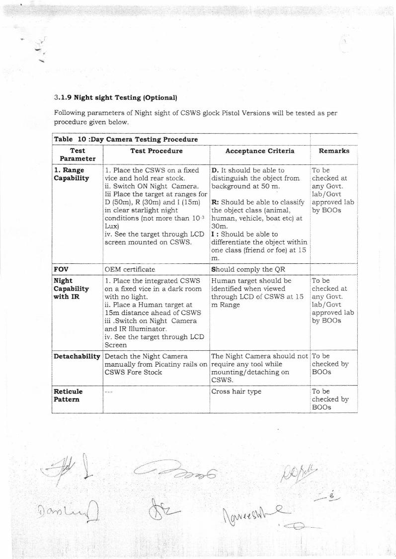
3.1.9 !I{ht sight Testltrg lOptionall
Following parameters of Night sight of CSWS glock Pistol Versions will be tested as perprocedure given below.
Table 1O :Day Camera Testiag Procedure
Acceptance Criteria
1. Place the CSWS on a fixedr"ice ald hold rear stock.ii. Switch ON Night Camera.Iii Place the ta.rget at ranges forD (som), R (3Om) and I {15m)in clear starlight nightconditions (not more than 10 3
Lux)iv. See the target through LCDscreen mounted on CSWS.
1. Place the integrated CSWSon a frxed vice il a dark roomwith no light.ii. Place a Human target at15m distance ahead of CSWSiii .Switch on Night Cameraand IR llluminator.iv. See the target through LCDScreen
D. It should be able todistinguish the object frombackground at 50 m.
R: Should be able to classifuthe object class (animal,human, vehicle, boat etc) at30m.I ; Should be able todifferentiate the object withinone class (friend or foe) at 15m
Human target should beidentijied when viewedthrough LCD of CSV/S at ] 5m Range
Cross hair tlpe
To bechecked atany Govt.lab / Go\,'tapproved labby BOOs
To bechecked ataly Govt.lablGovtapproved labby BOOs
To bechecked byBOOs
L.
TestParameter
Test Procedure
1. RangeCapability
rov OEM certilicate
lEhtCapabflitysrith IR
The Night Camera should notrequire aIIy tool whilemounting/detaching onCSWS.
To bechecked byBOOs
Detachabllity Detach the Night Cameramanually from Picadny rails onCSWS Fore Stock
ReticulePattern
tg* {{'y\'i
;,
Remarks
1
I
l
Should comply the QR
l
.i I
(\^
'w--
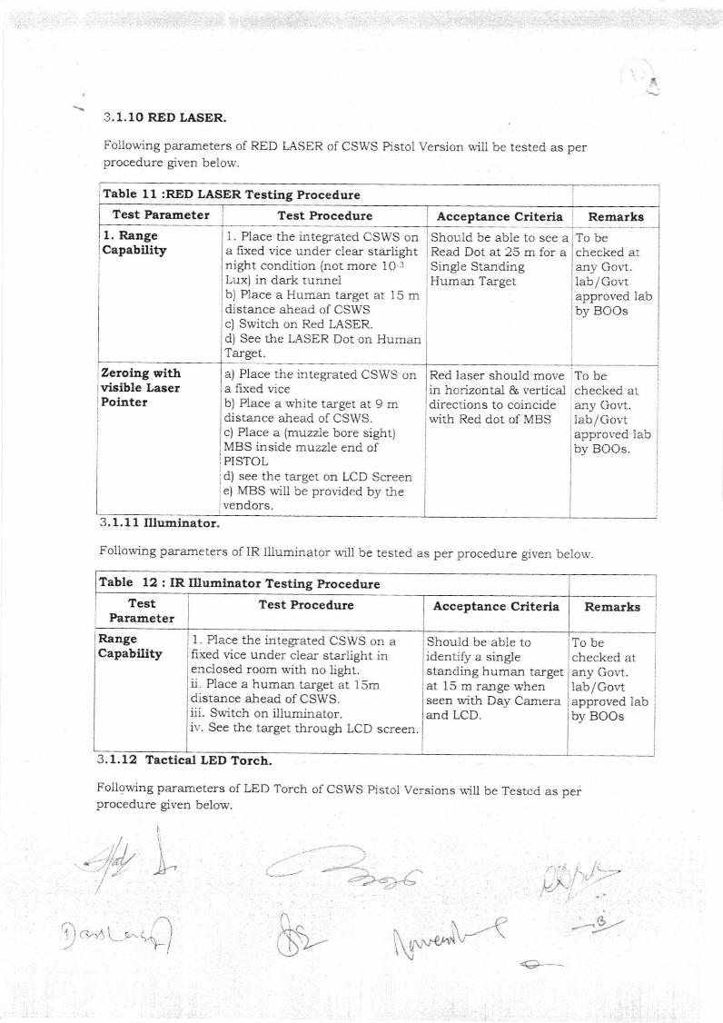
3.1.10 RED UTSER.
Following parameters of RED I-ASER of CSWS Pistol Version will be tested as perprocedure given below.
ITAbIC 11 :RED LASER TEsting Procedure
1. Place the inregrated CSWS on Should be able to see a1, RangeCapability
Zeroing withvisible LaserPolnter
RangeCapability
a fixed vi.ce under clear starlight I Read Dot at 25 m for aSingle StandingHuman Target
Red laser should movein horizontal & verticaldireclions to coincidelvith Red dot of MBS
To bechecked atafly Govt.lab/Govtapproved labby BOOs
To bechecked atany Go!t.lab/ Govtapproved labby BOOs.
To bechecked atany Govt.1ab/Govt
3.1.11 lUumlnator.
Following parameters of IR Illuminator will be tested as per procedure grven belorv
TestParameter
night condition (not more 10 3
Lux) in dark tunnelbj Place a Human targer ar 15 mdistalce ahead of CSWSc) Switch on Red LASER-d) See the LASER Dot on HumanTarget.
a) Place the integrared CSWS ona fixed viceb) Place a white target at 9 mdistance ahead of CSWS.c) Place a (muzzle bore sight)MBS inside muzzle end ofPISTOLd) see the target on LCD Screene) MBS will be provided by thevendors.
1. Place the integrated cSWS on afixed vice under clear starlight inenclosed room with no light.ii. Place a human target at I 5mdistance ahead of CSWS.iii. Switch on illuminator.iv. See the target through LCD screen
Should be able toidentify a singlestalding human targetat 15 m range whenseen with Day Camera approved lab Nd LCD by BOOs
3.1.12 Taetlcal LED Torcb.
Follgwing parameters of LED ?orch of CSWS pistol Versions u.ill be Tested as perprocedure given be1ow.
Table 12 : IR Illumlnator Testing procedure
Test Procedure
,al
\ r r M€l'!t v
I Test Parameter : Test Procedure I Acceptance Criteria Remarks-l
Acceptance Criteria I Remarks
I
t
\a.
<(}'-_
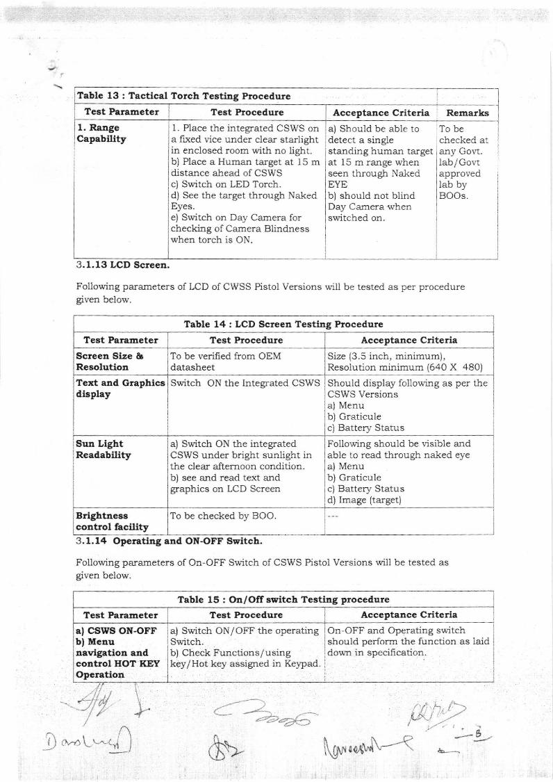
Tablc 13 : Tactical Torch Testhg Procedure
1, RaageCapabtltty
Sun LightReadabillty
,ta\-/, LL^- (i j
1. Place the integrated CSWS ona fixed vice under clear starlightin enclosed room with no light.b) Place a Human target at 15 mdistance ahead of CSWSc) Switch on LED Torch.d) See the target through NakedEyes.e) Srvitch on Day Camera forchecking of Camera Blindnesswhen torch is ON.
Switch ON the Integrated CSWS
a) switch oN the integratedCSWS under bright sunlight inthe clear afternoon condidon.b) see and read text andgraphics on LCD Screen
a) Switch ON/OFF the operatingSwitch.b) Check Functions/usingkey/Hot key assigned in Keypad
AcceptanceCriteria Remarks
a) Should be able to To bedetect a singlestanding human targetat l5 m range whenseen through Nal<edEYEbl should not blindDay Camera whensrfitched on-
checked ataly Colt.1ab/Govtapprovedlab byBOOs.
3.1.13 LCD Screen.
Following parameters of LCD of CWSS Pistol Versions v'ill be tested as per proceduregiven below.
Tablc 14: LCD Screen Testhg Procedure
To be checked bv BOO
3.1.14 Operatirg snd O}{-OFF Ssitch.
Foilowing parameters of On-OFF Switch of CSWS Pistol Versions will be rested asgiven below.
Table 15 : On/OIf ssitch Testlng procedure
Acceptance Criterla
Size (3.5 inch, minimum),Resolution minimum (640 X 480)
Should display following as per theCSWS Versionsa) Menub) Graticulec) Battery Status
Foliowing should be visibie andable to read through naked eyea) Menub) Graticulec) Battery Statusd) Image (target)
On-OFF and Operating switchshould perform the function as laiddown in specification.
{-.;
Test Procedure
T€st Procedure Acceptsnce CriteriaScreen Slze &Resolution
To be verifred from OEMdatasheet
Text and Graphicsilisplay
BrightEesscontrol hcillty
?est Proc€dureTest Parameter
a) CSWS OI{-OFFbl Mcauaavlgatiotr atrdcortrol HOT KEYOpcratiol
1) \r
Test Parameter l
!
!
I
Test Parameter i
I
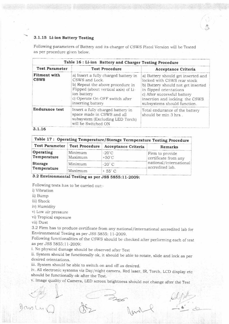
3.1.15 Ll-lotl Battery Testing
Following parameters of Battery and its charger of CSWS Pistol Version will be Testedas per procedure giten belou,.
Test
irtt-"rcsws
Irarameter
test
Table 16 : Li-ion Battery and Charger Testing Procedure
Acceptaace Criteriant with ja) Insert a fully charged battery in a) Battery should get
:CSWS and Lock.I b) Repeat the above procedure inI Flipped (abour vertica.l a-xis) of U,I ion batrery, c) Operate On-OFF su{tch afterinserting barrery
inserted and i
locked lrith CSWS rear stock:b) Battery should not get insertedin flipped orientations
I c) After successful battervI insertion and locking rhe CSWSsubsystems should function.
Tcral endurance of the batteryshould be min 3 hrs .
l
I
r Insert a fully charged battcry inI space made in CSWS and allI subsystem (Ercludiag LED Torch)lwill be Switched ON
3. 1.16
Table 17 : Operating Temperature/Sto rage Termperatnre Tcating ProcedureTest Parameter Test Procedure Acceptance Criteria Remarks
Operating?emperatute
StorageTemperature
1n1muma-xrmum
lllinirnum
\,latimum
-20'c'50.C
Firo to provideccrtilicale from anynational / in ternational
'+ 55" C3.2 Environmental Testing as per JSS 5855:11-2OO9:
Following tests has to be carried out:-i) Vibrationii) Bumpiii) Shockii,) Humidityv) Low air pressurevi) Tropical exposurer.ii) Dust3.2 Firm has to produce certificate from any national/intemational accredited lab forEnr.ironmental Testing as per JSS 5855: 1l-2009.Following functionalities of rhe csws shouid be checked after performing each of testas per JSS 5855: I 1-2009:i. No physicai damage should be observed aJter Testii. system should be functionally ok, it should be able to rorate, slide and lock as perdesired orientations.iii. System shoutcl be able to switch on and offas desired.iv. All electronic systems viz Day/night carnera, Red laser, IR, Torcb, LCD display etcshould be functionally ok after ihe Test.v. lmage quality of Camera, LED screen brightness should not cha.nge alter
,
\
" :2*r{.
the Test
ln-a t - ,'l\"_/
Test Procedure
, .- accrcdited lab.
$- i1,r.,*"--<
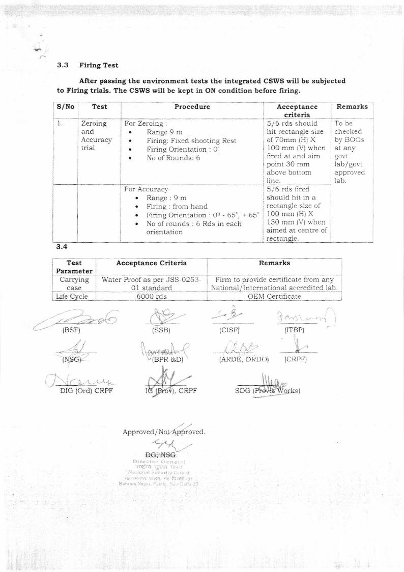
3"3 Firing Tcst
After passhg the environment tests the irtegrated CSWS will be subjectedto Flriag trials. The CStraS will be kept in OI{ condi8on before firing.
Procedure AcceptaDcecriteria
1 For Zeroing :
. Range 9 m
. Firing: Fixed shooring Rest
. Firing Orientatior : 0'
. No of Rounds: 6
For Accuracv. Range:9 m. Firing:from handr Firing Orienlation : Oc - 65', + 65'r No ofrounds : 6 Rds in each
orientation
lSSB) {cr sri}
5/6 rds shouldhit rectangie sizeof TOmm {H) X100 mm {V) whcnfired at and aimpoint 30 mmabove bottom1ine.
Remar
To becheckedb1' BOOsat anygovtlab/govrapprovedlab.
3.4
IBSF)
DIG {Ord} CRPF
I
{ITBP)
I
k(BPR &D)
}. CRPF
Approved/N or.{,pProved.
, DRDO) {CRPF)
SDG
S/Ito Test
ZeroingandAccuracy'trial
TestParameter
Acceptance Crlterla Remarks
CarryngCASC
Water Proof as per JSS-0253-01 standard
Firm to provide certilicate from anyNational/lnternational accredited lab
Life Cycle 6OO0 rds OEIU Certificate
I
i
i 5/6 rds fired 1
: should hit in a i
; rectalgle size of a
i100mm(H) X i
i tSO mm (V) r.r'hen :
i aimed at centre of i
rectanglc.
l
_:+---
{ .\ :'L-,1