control number: 52304 - puc interchange - texas.gov
TRANSCRIPT
Control Number: 52304
Item Number: 2
Addendum StartPage: 0
STANDARD APPLICATION FOR A CERTIFICATE OF
CONVENIENCE AND NECESSITY FOR A PROPOSED
TRANSMISSION LINE
~RECE/VE~ /2/ )*i) ~9;~ JUL 1 6 2021 0-
~ <4 By /CD~
AND
APPLICATION FOR A CERTIFICATE OF CONVENIENCE
AND NECESSITY FOR A PROPOSED TRANSMISSION
LINE PURSUANT TO 16 TEX. ADMIN. CODE § 25.174
DOCKET NO. 52304
Submit seven (7) copies ofthe application and aU attachments supporting the application.
If the application is being filed pursuant to 16 Tex. Admin. Code § 25.101(b)(3)(D) (TAC)
or 16 TAC § 25.174, include in the application atl direct testimony. The application and
other necessary documents shall be submitted to:
Public Utility Commission of Texas
Attn: Filing Clerk
1701 N. Congress Ave.
Austin, Texas 78711-3326
Standard Application for a Certificate of Convenience and Necessity for a Proposed Transmission Line and
Application for a Certificate of Convenience and Necessity for a Proposed Transmission Line Pursuant to 16 TAC § 25.174
Note: As used herein, the term "joint application" refers to an application for proposed transmission facilities for which ownership will be divided. All applications for such facilities should be filed jointly by the proposed owners ofthe facilities.
1. Applicant (Utility) Name: Entergy Texas, Inc. (Entergy Texas or ETI)
Certificate Number: Street Address: Mailing Address:
30076 350 Pine Street Beaumont, Texas 77704 P.O. Box 2951 Beaumont, Texas 77703
2. Please identify all entities that will hold an ownership interest or an investment interest in the proposed project but which are not subject to the Commission's jurisdiction.
There are no such entities in the proposed project.
3. Person to Contact: Carl Olson, P.E.
Title/Position: Phone Number:
Mailing Address:
Email Address:
Manager, Regulatory Affairs
(512) 487-3985
919 Congress Avenue, Suite 740, Austin, TX 78701
colson 1 @entergy.com
Legal Counsel:
Phone Number:
Mailing Address:
Email Address:
George G. Hoyt, Assistant General Counsel
(512) 487-3945
919 Congress Avenue, Suite 701, Austin, TX 78701
4. Project Description: Name or Designation of Project
Castle 230 kV Transmission Line and Substation
Provide a general description ofthe project, including the design voltage rating *V), the operating voltage (kV), the CREZ Zone(s) (if any) where the project is located (all or in part), any substations and/or substation reactive compensation constructed as part of the project, and any series elements such as sectionalizing switching devices, series line compensation, etc. For HVDC transmission lines, the converter stations should be considered to be project components and should be addressed in the project description.
If the project will be owned by more than one party, briefly explain the ownership arrangements between the parties and provide a description of the portion(s) that will be owned by each party. Provide a description of the responsibilities of each party for implementing the project (design, Right-of-Way acquisition, material procurement, construction, etc.)
If applicable, identify and explain any deviation in transmission project components from the original transmission specifications as previouslyapproved by the Commission or recommendedbya PURA §39.151 organization.
ETI proposes to add new electric transmission infrastructure in Montgomery and Grimes Counties. ETI is proposing to construct a new single-pole double-circuit 230 kV electric transmission line approximately 6-8 miles in length
2 Effective June 8,2017
Standard Application for a Certificate of Convenience and Necessity for a Proposed Transmission Line and
Application for a Certificate of Convenience and Necessity for a Proposed Transmission Line Pursuant to 16 TAC § 25.174
(depending on the final route) that would connect the new Castle Substation near Texas Highway 1774 and Highway 249 to the existing Ponderosa to Grimes (L-136) transmission line. The proposed new 230 kV line would be erected utilizing either concrete or steel predominantly single pole structures with a right-of-way that would be up to 125 feet wide (62.5 feet on either side of the centerline of the proposed transmission facilities, some of which would overlap with other compatible rights-of-way).
5. Conductor and Structures: Conductor Size and Type : 1272 kcmil Aluminum Conductor , Steel Supported ( ACSS ) " Bittern "
Number of conductors per phase : One 0 ) Conductor / phase
Continuous Summer Static Current Rating ( A ) 1957 A
Continuous Summer Static Line Capacity at Operating Voltage (MFA): 780 MVA @ 230 kV
Continuous Summer Static Line Capacity at Design Voltage (MVA): 780 MV A @ 230 kV
Type and composition ofSIructures : Steel or concrete double circuit poles ( vertical configuration )
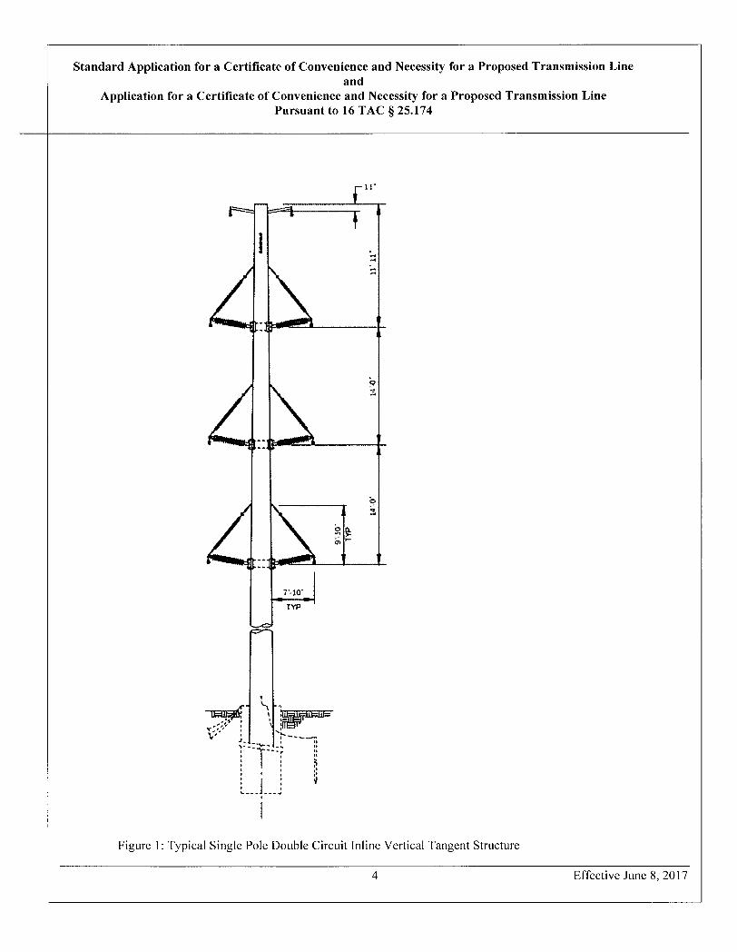
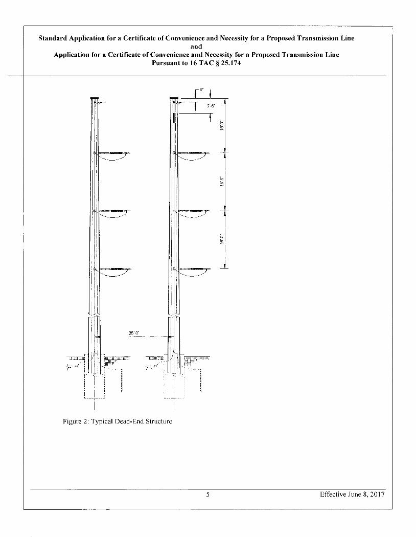
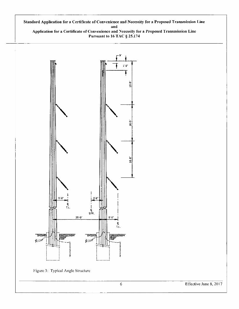
Height of Typical Structures : 85 feet - 125 feet
Estimated Maximum Height of Structures : maximum height 140 feet
Explain why these structures were selected; include such factors as landowner preference, engineering considerations, and costs comparisons to alternate structures that were considered. Provide dimensional drawings of the typical structures to be used in the project.
Steel or Concrete monopole structures were selected for this project due to their relatively small footprint compared to H-frame structures (two poles) or four leg steel lattice towers. They are also easier to engineer and are aesthetically more appealing to property owners than the other two alternatives. Steel or Concrete monopole construction also requires less right-of-way than the other alternatives. Depending on the need at a particular point in a proposed route, the typical structures will be one of the types as illustrated below.
3 Effective June 8, 2017
Standard Application for a Certificate of Convenience and Necessity for a Proposed Transmission Line and
Application for a Certificate of Convenience and Necessity for a Proposed Transmission Line Pursuant to 16 TAC § 25.174
f 11
t:1 .II.it
.O.M
4
Figure 1: Typical Single Pole Double Circuit Inline Vertical Tangent Structure
4 Effective June 8, 2017
-7.10-i TYP
C- h
T
%
Standard Application for a Certificate of Convenience and Necessity for a Proposed Transmission Line and
Application for a Certificate of Convenience and Necessity for a Proposed Transmission Line Pursuant to 16 TAC § 25.174
[9 i 26-
..m---
1.- h
a -h
r
25'-0
r - / 1 -- 3 r - P - n
I .t- i-- '.-~ -. t --E t t.t 7 l ? t
Figure 2: Typical Dead-End Structure
5 Effective June 8,2017
Standard Application for a Certificate of Convenience and Necessity for a Proposed Transmission Line and
Application for a Certificate of Convenience and Necessity for a Proposed Transmission Line Pursuant to 16 TAC § 25.174
1·9-
.O.6I .Cr.9I
.O 9I
9·0
q T.
121_
STR. 25'-0-
,
q
48WFU
L. |
r- P r- t# -ll~1*ID: .' · uru.-- 1AUS:% -113FIEEID: ..' .
* UM i * ES \ "
. ,-I . . '.
, . .
; ,
Figure 3: Typical Angle Structure
6 Effective June 8,2017
Standard Application for a Certificate of Convenience and Necessity for a Proposed Transmission Line and
Application for a Certificate of Convenience and Necessity for a Proposed Transmission Line Pursuant to 16 TAC § 25.174
For joint applications, provide and separately identify the above-required information regarding structures for th; portion(s) ofthe project owned by each applicant.
Not applicable.
6. Right-of-way: Miles of Right-of-Way. 6.23 - %.23
Miles of Circuit : 12 . 46 - 16 . 46
Width ofRight-of Way: up to 125 feet
Percent of Right - of - Way Acquired : 0 %
For joint applications, provide and separately identify the above-required information for each route for the portion(s) of the project owned by each applicant.
Not applicable.
Provide a brief description of the area traversed by the transmission line. Include a description of the general land uses in the area and the type of terrain crossed by the line.
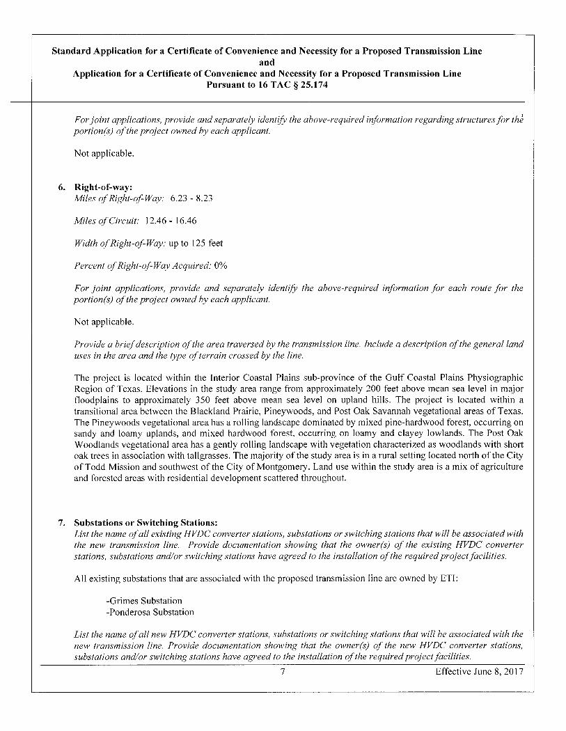
The project is located within the Interior Coastal Plains sub-province of the Gulf Coastal Plains Physiographic Region of Texas. Elevations in the study area range from approximately 200 feet above mean sea level in major floodplains to approximately 350 feet above mean sea level on upland hills. The project is located within a transitional area between the Blackland Prairie, Pineywoods, and Post Oak Savannah vegetational areas of Texas. The Pineywoods vegetational area has a rolling landscape dominated by mixed pine-hardwood forest, occurring on sandy and loamy uplands, and mixed hardwood forest, occurring on loamy and clayey lowlands. The Post Oak Woodlands vegetational area has a gently rolling landscape with vegetation characterized as woodlands with short oak trees in association with tallgrasses. The majority of the study area is in a rural setting located north of the City of Todd Mission and southwest of the City of Montgomery. Land use within the study area is a mix of agriculture and forested areas with residential development scattered throughout.
7. Substations or Switching Stations: List the name ofall existing HVDC converter stations, substations or switching stations that will be associated with the new transmission line. Provide documentation showing that the owner(s) of the existing HVDC converter stations, substations and/or switching stations have agreed to the installation ofthe required project facilities.
All existing substations that are associated with the proposed transmission line are owned by ETI:
-Grimes Substation -Ponderosa Substation
List the name ofall new HVDC converter stations, substations or switching stations that will be associated with the new transmission line. Provide documentation showing that the owner(s) of the new HVDC converter stations, substations andl or switching stations have agreed to the installation of the required project facilities.
7 Effective June 8,2017
Standard Application for a Certificate of Convenience and Necessity for a Proposed Transmission Line and
Application for a Certificate of Convenience and Necessity for a Proposed Transmission Line Pursuant to 16 TAC § 25.174
Entergy Texas will construct a new substation:
- Castle 230 kV Substation: Entergy Texas will construct a new 230 kV substation that will be served by the new in and out transmission loop from the existing Ponderosa - Grimes (L-136) 230 kV line and will serve distribution loads in the area. The scope includes installation of one (1) 50 MVA, 230/34.5 kV, LTC transformer and 230 kV through bus for two incoming lines with provision to build out a second transformer at a later date. The low-side build includes an operating and transfer bus arrangement with three feeder breakers and one outboard breaker.
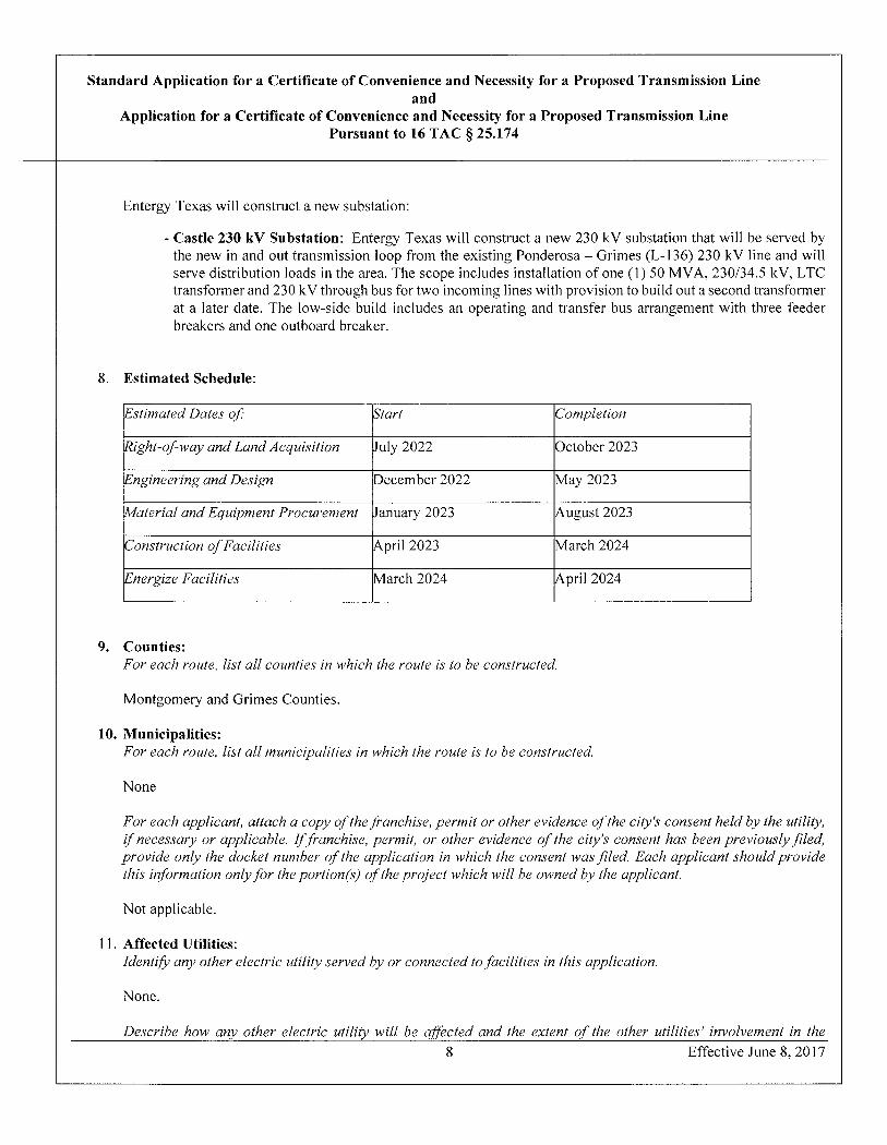
8. Estimated Schedule:
Estimated Dates of: Start Completion
Right - of - way and Land Acquisition July 2022 October 2023
Engineering and Design December 2022 May 2023
Material and Equipment Procurement January 2023 August 2023
Construction of Facilities April 2023 March 2024
Energize Facilities March 2024 April 2024
9. Counties: For each route, list all counties in which the route is to be constructed.
Montgomery and Grimes Counties.
10. Municipalities: For each route, list all municipalities in which the route is to be constructed.
None
For each applicant, attach a copy ofthefranchise, permit or other evidence of the city's consent held by the utility, if necessary or applicable. If.franchise, permit, or other evidence of the city's consent has been previously filed, provide only the docket number of the application in which the consent was filed. Each applicant should provide this information onlyfor the portion(s) of the project whichwill be owned by the applicant.
Not applicable.
11. Affected Utilities: Identify any other electric utility served by or connected to facilities in this application.
None.
Describe ho-w any other electric utility will be af.fected and the extent of the other utilities' involvement in the 8 Effective June 8,2017
Standard Application for a Certificate of Convenience and Necessity for a Proposed Transmission Line and
Application for a Certificate of Convenience and Necessity for a Proposed Transmission Line Pursuant to 16 TAC § 25.174
construction ofthis project. Include any other electric utilities whose existingfacilities will be utilizedfor the project (vacant circuit positions, ROW, substation sites and/or equipment, etc.) and provide documentation showing that the owner(s) of the existing facilities have agreed to the installation of the required project facilities.
Not applicable.
12. Financing: Describe the method offinancing this project. For each applicant that is to be reimbursedfor all or aportion of this project, identify the source and amount of the reimbursement (actual amount if known, estimated amount otherwise) and the portion(s) of the project for which the reimbursement will be made.
The Company plans to finance the construction through borrowings and equity5 either through withholding dividends and/or contributions from the Company's parent.
13. Estimated Costs: Provide cost estimates for each route of the proposed project using the following table. Provide a breakdown of "Other" costs by major cost category and amount. Provide the information for each route in an attachment to this application. For joint applications, provide and separately identify the above-required information.for the portion(s) of the project owned by each applicant.
Please see Attachment 1.
14. Need for the Proposed Project: For a standard application, describe the need for the construction and state how the proposed project will address the need. Describe the existing transmission system and conditions addressed by this application. For projects that are planned to accommodate load growth, provide historical load data and load projections for at least five years For projects to accommodate load growth or to address reliability issues, provide a description of the steady state load flow analysis that justifies the project. For interconnection projects, provide any documentation .from a transmission service customer, generator, transmission service provider, or other entity to establish that the proposed facilities are needed. For projects related to a Competitive Renewable Energy Zone, the foregoing requirements are not necessary; the applicant need only provide a specific reference to the pertinent portion(s) of an appropriate commission order specifying that the facilities are needed. For atl projects, provide any documentation of the review and recommendation ofa PURA § 39.151 organization.
As detailed below, the proposed project is needed to address a projected overload on transformer facilities at the Dobbin Substation, reduce customer counts on distribution feeders to improve area reliability and service quality, provide relief and support to the 138 kV transmission system in the area by constructing 230 kV facilities, and provide an infrastructure backbone to enable long-term, reliable, distribution service capacity to this growing area.
Dobbin Substation serves approximately 80 square miles including the cities of Plantersville and Todd Mission, TX with one 25 MVA transformer and two 34.5 kV feeders, 519DO and 920DO. The 2021 winter peak load on the Dobbin T-1 transformer was 22.9 MVA from 4,324 customers. Dobbin T-1 (25 MVA rating) is expected to have 26.9 MVA winter loading in 2025.
On-going residential load additions served by Dobbin Substation include the Blue Jack National, Crown Ranch, and High Meadows Ranch developments. Additionally, the new Magellan Pumping Station (DLOC# 3986027660) located in Montgomery County (served from 920DO feeder) began operations in December 2020 with a current
9 Effective June 8,2017
Standard Application for a Certificate of Convenience and Necessity for a Proposed Transmission Line and
Application for a Certificate of Convenience and Necessity for a Proposed Transmission Line Pursuant to 16 TAC § 25.174
peak demand of 3.38 MVA (June 2021) and is expected to ramp-up to 7.90 MVA of incremental load. New residential load growth is also expected from the 1,000 lot Magnolia Springs development in the 3rd Q of 2021.
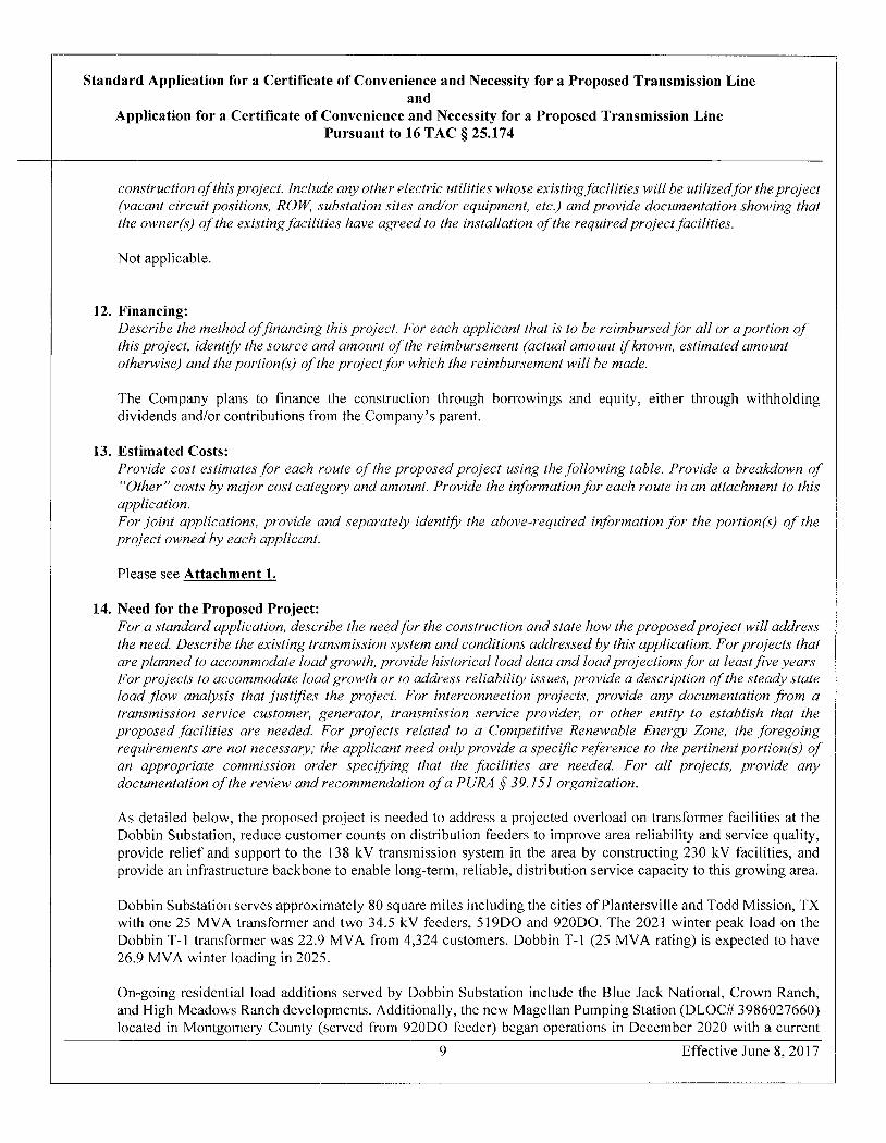
The Hwy 249 extension project will also drive additional area growth. This new roadway will create an additional pathway between the Houston/Harris County area and the Bryan/College Station area. The two segments of this project in Entergy Texas service area are expected to be completed in 2021-2022. The following Figure 3 shows the Hwy 249 extension project and the Company's facilities in the area.
Dobbin Sub Dobbin Sub feeders
Castle Sub
Hwy 249 Extension
Hwy 249 Extension
Figure 3 ETI Transmission and Distribution Facilities
Dobbin Substation with its single 25 MVA transformer and two 34.5 kV feeders primarily create the existing distribution system in this expected load growth area. Additionally, there is one field tie with Walden Substation that is approximately 10.1 miles away to the east.
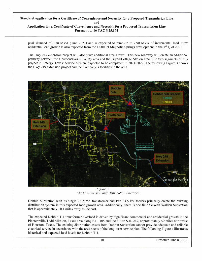
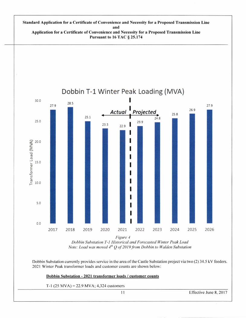
The expected Dobbin T-1 transformer overload is driven by significant commercial and residential growth in the Plantersville/Todd Mission, Texas area along S.H. 105 and the future S.H. 249, approximately 50 miles northwest of Houston. Texas. The existing distribution assets from Dobbin Substation cannot provide adequate and reliable electrical service in accordance with the area needs of the long-term service plan. The following Figure 4 illustrates historical and expected load levels for Dobbin T-1.
10 Effective June 8, 2017
Standard Application for a Certificate of Convenience and Necessity for a Proposed Transmission Line and
Application for a Certificate of Convenience and Necessity for a Proposed Transmission Line Pursuant to 16 TAC § 25.174
Dobbin T-1 Winter Pea k Loading (MVA) 30.0
28 5 27 9 27 9
Actual Projected, 26 9 25 8
25.1 24 8 25.0 23 9
23 3 22 9 1
> 20 0
15 0
10.0
5.0
0.0
2017 2018 2019 2020 2021 2022 2023 2024 2025 2026
Figure 4 Dobbin Substation T-1 Historical and Forecasted Winter Peak Load
Note: Load was moved 4"l O cf 2 0 19.*om Dobbin to Walden Substation
Dobbin Substation currently provides service in the area of the Castle Substation project via two (2) 34.5 kV feeders. 2021 Winter Peak transformer loads and customer counts are shown below:
Dobbin Substation - 2021 transformer loads / customer counts
T-1 (25 MVA) = 22.9 MVA; 4,324 customers
11 Effective June 8,2017
Standard Application for a Certificate of Convenience and Necessity for a Proposed Transmission Line and
Application for a Certificate of Convenience and Necessity for a Proposed Transmission Line Pursuant to 16 TAC § 25.174
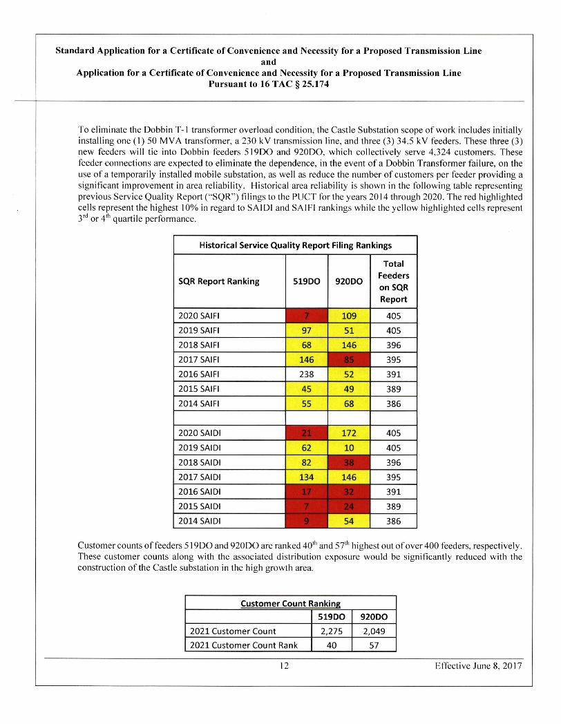
To eliminate the Dobbin T-1 transformer overload condition. the Castle Substation scope of work includes initially installing one (1)50 MVA transformer, a 230 kV transmission line. and three (3) 34.5 kV feeders. These three (3) new feeders will tie into Dobbin feeders 519DO and 920DO, which collectively serve 4,324 customers. These feeder connections are expected to eliminate the dependence, in the event of a Dobbin Transformer failure, on the use of a temporarily installed mobile substation, as well as reduce the number of customers per feeder providing a significant improvement in area reliability. Historical area reliability is shown in the following table representing previous Service Quality Report ("SQR") filings to the PUCT for the years 2014 through 2020. The red highlighted cells represent the highest 10% in regard to SAIDI and SAIFI rankings while the yellow highlighted cells represent 3,·d Or 4& quartile performance.
Historical Service Quality Report Filing Rankings
Total Feeders
SQR Report Ranking 519DO 920DO on SQR Report
2020 SAIFI . #i 109 405 2019 SAIFI 97 51 405
2018 SAIFI 68 146 396 2017 SAIFI 146 - 85 -V 395 2016 SAIFI
2015 SAIFI
2014 SAIFI
2020 SAIDI
2019 SAIDI
2018 SAIDI 2017 SAIDI
2015 SAIDI
38 52 391 15 49 389 35 68 386
172 405 32 10 405 32 ~ 38 ~ 396 34 146 395
32 391 7 a~24 389
~| 54 386
2016 SAIDI '-?,
2014 SAIDI ~ 9
Customer counts of feeders 519DO and 920DO are ranked 40th and 57th highest out of over 400 feeders, respectively. These customer counts along with the associated distribution exposure would be significantly reduced with the construction of the Castle substation in the high growth area.
Customer Count Ranking 519DO 920DO
2021 Customer Count 2,275 2,049 2021 Customer Count Rank 40 57
12 Effective June 8,2017
Standard Application for a Certificate of Convenience and Necessity for a Proposed Transmission Line and
Application for a Certificate of Convenience and Necessity for a Proposed Transmission Line Pursuant to 16 TAC § 25.174
Additionally, the existing 138 kV system around Dobbin has limited capacity for expansion without significant upgrades. Accordingly, an additional benefit ofthe proposed project is that it relieves the 138 kV system around Dobbin and it provides a transmission source in a transmission deficient area so that future substations can be developed as expected future loads materialize beyond the near term horizon.
This project builds Castle Substation, transmission line resources, and associated distribution feeders to eliminate the Dobbin T-1 transformer projected overload. Additionally, it will reduce customer counts on two feeders, provide long-term, reliable, distribution service capacity to this growing area, and provide 230 kV transmission assets in order to serve existing and future area customers.
INDEPENDENT REVIEW
ETI is a member ofthe Midcontinent Independent System Operator ("MISO"), a regional transmission organization.
MISO, as part of its annual transmission expansion planning ("MTEP") process, has reviewed the project with stakeholders and determined it does not adversely impact the transmission system. The project was classified as an "Other" project and included in MISO's Appendix A (project ID 15648) ofthe MTEP 2020 study cycle. The project was approved by the MISO board of directors on December 10,2020.
Pursuant to the MISO Transmission Owners Agreement, ETI, as the incumbent Transmission Owner, has the obligation to make a good faith effort to design, certify, pursue the approval of, and construct this MTEP 2020 Appendix A project, subject to such siting, permitting, and environmental constraints as may be imposed by state, local, and federal laws and regulations, and subject to the receipt of any necessary federal or state regulatory approvals.
The project is included in the MTEP20 report on MISO's website:
https://cdn.misoenergv.org//MTEP20%20Fu11%20Report485662.pdf
15. Alternatives to Project: For a standard application, describe alternatives to the construction of this project (not routing options). Include an analysis of distribution alternatives, upgrading voltage or bundling ofconductors ofexistingfacilities, adding transformers, and for utilities that have not unbundled, distributed generation as alternatives to the project. Explain how the project overcomes the insujficiencies of the other options that were considered.
TRANSMISSION AND DISTRIBUTION
1. Install additional capacity at Dobbin Substation:
Although this alternative would resolve the immediate capacity need at Dobbin Substation through the installation ofa second transformer, it does not effectively address the future expected growth and consequential load demands for transformer and feeder capacity, as well as the necessary supporting transmission lines for existing and future ETI customers. This option would require additional upgrades to the 138 kV transmission system resulting in an overall higher cost that is otherwise deferred with the 230 kV Castle Substation project.
From a reliability perspective, Dobbin Substation's location is not ideal (geographically) for sourcing new
13 Effective June 8,2017
Standard Application for a Certificate of Convenience and Necessity for a Proposed Transmission Line and
Application for a Certificate of Convenience and Necessity for a Proposed Transmission Line Pursuant to 16 TAC § 25.174
distribution circuits to the areas of expected load growth. The distribution feeder trunk lengths from Dobbin Substation are approximately 7 to 15 miles long, whereas the Castle substation sourced feeders would shorten these overalllengths down to approximately 3 to 5 miles. Customer counts on these feeders (from Dobbin Substation) are expected to rise as development materializes in this area of high exposure.
This solution presents the risk of increasing difficulty in securing transmission routes and substation sites in the needed area as load growth materializes.
2. Expedite Construction of Montgomery Substation near Montgomery. TX: Install Montgomery T-1 transformer and three new feeders.
This alternative encompasses a similar risk profile as alternative #1 and would site a new substation remotely from the load growth center. This remote location would create extended length feeders, increased exposure to outages, and the potential for a reduction in reliability performance for Entergy customers.
Similar to alternative #1, the solution presents the risk increasing difficulty in securing transmission routes and substation sites in the needed area as load growth materializes. While the Montgomery Substation is currently projected to be needed within the 10-year horizon to serve existing and future load in the Montgomery, TX area the solution does not address projected load growth in the load center as effectively as the Castle Substation.
DISTRIBUTED GENERATION ("DG")
1. Utility Owned As an alternative to this project, utility-owned distributed generation ("DG") does not provide an economical alternative nor does it provide the equivalent reliability benefits. In order to match the proposed solution ultimate capacity with DG, a minimum of ten (10 MVA or equivalent) units would have to be constructed and operated in the area. Additional units would be warranted to address availability risk during peak load conditions. The costs of large DG units range from $1000/kW (internal combustion) to $2,950/kw (solar PV). Applying the least expensive technology to the 100 MVA ultimate planned capacity and assuming an additional 20 MVA to address unit availability risk could cost approximately $120 million. From a reliability perspective, the use of distributed generation to address distribution system capacity deficits does not materially improve reliable service quality because it does not reduce the number of customers on each distribution feeder as planned in the proposed solution. Additionally, it introduces environmental impact and operational risk with interconnection through the local area distribution system.
2. Customer Owned Customer-owned DG is currently not established in the project area and the non-firm characteristics of customer-owned DG dictate that it could not be depended on to lower system peak or provide reliable and firm capacity to area customers. With no current DG production and the non-firm nature of future DG, these resources are not expected to meet the forecasted load growth or provide reliable service quality in the region.
SUMMARY
The proposed solution establishes the needed load serving capabilities through a new robust transmission sourced substation along with multiple distribution feeders that allow mutual support to adjacent substations and feeders. The alternative distribution and DG solutions are not as reliable or cost-efficient in providing
14 Effective June 8, 2017
Standard Application for a Certificate of Convenience and Necessity for a Proposed Transmission Line and
Application for a Certificate of Convenience and Necessity for a Proposed Transmission Line Pursuant to 16 TAC § 25.174
reliable service quality as the proposed solution.
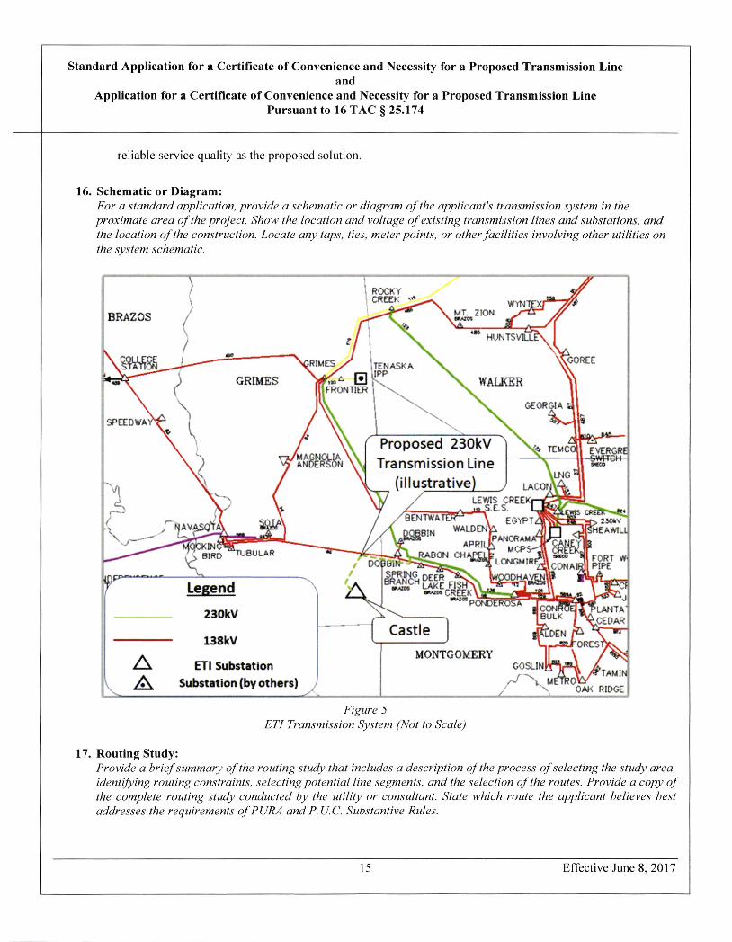
16. Schematic or Diagram: For a standard application, provide a schematic or diagram of the applicant's transmission system in the proximate area of the project. Show the location and voltage ofexisting transmission lines and substations, and the location of the construction. Locate any taps, ties, meter points, or other.facilities involving other utilities on the system schematic.
l ROCKY ) CREEK
BRAZOS
RIMES ITEM
GRIMES E le HFRONTIER i
~- MT. ZION WYN
HUNTSVLLE~l
IASKA ~GOREE
\ WALKER ~~
GEORGIA
SPEEDWAY'v a IIi-
\l Proposed 230kV '* TEMCo EVERGRE MAGNOLIA \\ ~;* ANDERSON * Transmission Line .CO
~l.NG ~CH
\k (illustrative) LAcoN\4. LEWIS CREEKr-L~39~ESJ
-Sts. l.,~SkW-mmt-4/ TWATM~-1 EGYPTZ~m=*-hr> 230•v 3]N WALDENh Al r| nj|IHEAWILL
APRIL-b (1 BIRD IUWULAK ARON CHAPELK
~9f LONGNIR E~\\ ""' 91 FORT W· Ql PIPE 1 - -- -- %1=Z.~ ~ LAKE FISH u ,=0
-©. CREEK -A,Z as PONCE1¥05X L.2- uJ
i '~»LAN'TA' N€EDAR I castle A , 6<- -
R Db Legend AN(
230kV
CONA
CON BULK
138kV c -1.-SUORESA MONTGOMERY / . Gt ETI Substation GOSL.Ir *-) ,TA)JIN
A Substation (by others) j/- j ., OAK RIDGE A ~X uffkoW
Figure 5 ETI Transmission System (Not to Scale)
17. Routing Study: Provide a briefsummary of the routing study that includes a description of the process ofselecting the study area, identifring routing constraints, selecting potential line segments, and the selection of the routes. Provide a copy of the complete routing study conducted by the utility or consulfant . State which route the applicant believes best addresses the requirements ofPURA and P.U.C. Substantive Rules.
15 Effective June 8.2017
Standard Application for a Certificate of Convenience and Necessity for a Proposed Transmission Line and
Application for a Certificate of Convenience and Necessity for a Proposed Transmission Line Pursuant to 16 TAC § 25.174
ETI retained POWER Engineers, Inc. ("POWER") to prepare the Entergy Texas, Inc. Castle 230 kV Transmission Line and Substation Project Environmental Assessment ("EA"), provided as Attachment 2 to the Application. Section 1.0 of the EA provides a description of the proposed project. Specific discussions regarding selection of the study area, identification of constraints, the selection of potential preliminary alternative route segments, and the alternative route evaluation are set forth in Section 2.0 of the EA. Information pertaining to the existing environment and potential impacts of the project are provided throughout sections 3.0 and 4.0 of the EA. Sections 5.0 and 6.0 of the EA provide specific information regarding agency correspondence and public involvement. Section 7.0 discusses POWER's Environmental Evaluation and ETI's Route Selection.
The objective of the EA was to develop and evaluate an adequate number ofgeographically differentiated alternative transmission line routes that comply with Public Utility Regulatory Act ("PURA") § 37.056(c)(4)(A) -(D), 16 TAC § 22.52(a)(4), and 16 TAC § 25.101(b)(3)(B), including the Commission's policy of prudent avoidance. The approach utilized by POWER for the EA included study area delineation based on the Project endpoints; identification and characterization of existing land use and environmental constraints; and identification of areas of potential routing possibilities located within the study area. POWER identified potentially affected resources and considered each during the route development process. Regulatory agency, local official, and public meeting comments were also incorporated into the alternative route development process. Modifications, additions, or deletions of preliminary alternative segments (also known as "links") were considered in regard to resource sensitivities, governmental agency guidance, and public input and comments. Feasible and geographically differentiated alternative routes were then selected for analysis and comparison using evaluation criteria to determine potential impacts to existing land use and environmental resources. The EA development process culminated with the ranking of the primary alternative routes by POWER from an environmental and land use perspective. Along with this recommendation from POWER, ETI also considered engineering and construction constraints, reliability issues, and estimated costs to identify one alternative route that ETI believes best addresses the requirements of PURA and Commission Substantive Rules. This alternative route, as well as other alternate routes that provide geographic diversity and sufficient routing options, are included in the EA for Commission consideration.
Study Area Delineation The first step in the process was to delineate a study area. This area needed to encompass the proposed Project termination points and include a large enough area within which a geographically differentiated set of alternative routes could be located to connect the proposed endpoints while also considering potential land use constraints and routing opportunities. The delineation of an initial preliminary study area for this proposed Project was dictated largely by the locations of the proposed endpoints at the time, which included ETI's existing Ponderosa-Grimes 230 kV transmission line (L-136) and proposed Castle Substation Siting Area. The area for the proposed Project, as shown on Figure 2-1 of the EA, is an irregular shaped area approximately 10 miles east to west and five miles north to south and encompasses approximately 45 square miles in Grimes and Montgomery counties. POWER mailed a copy of this study area location map (Figure 2-1 of the EA) along with a letter to federal, state, and local agencies soliciting information (Appendix A of the EA).
Data Collection and Constraints Mapping A fter delineation of the initial preliminary study area, a constraints map was prepared and used to initially display resource data and constraints for the study area. The constraints map provides a broad overview of various resource locations indicating obvious routing constraints and areas of potential routing opportunities. Information was constantly updated and the constraints map was revised accordingly.
Several methodologies were utilized to collect and review environmental and land use data including incorporation of readily available Geographic Information System ("GIS") coverage with associated metadata; review of maps and published literature; and review of files and records from numerous federal, state, and local agencies. Data
16 Effective June 8,2017

Standard Application for a Certificate of Convenience and Necessity for a Proposed Transmission Line and
Application for a Certificate of Convenience and Necessity for a Proposed Transmission Line Pursuant to 16 TAC § 25.174
collected for each resource area was mapped within the study area utilizing GIS layers. The conditions of the existing environment are discussed throughout Section 3.0 of the EA. Section 5.0 and Appendix A of the EA provides information regarding correspondence with agencies and officials.
Maps and/or data layers reviewed include (but are not limited to) United States Geological Survey ("USGS") 7.5 minute topographic maps, National Wetland Inventory ("NWI") maps, Texas Department of Transportation ("TxDOT") county highway maps, and recent aerial photography. USGS topographic maps and recent aerial photography were used as the background for the environmental and land use constraints maps (see Appendices C and D [map pockets] of the EA).
Agency Consultation A list of federal, state, and local regulatory agencies, elected officials, and organizations was developed to receive a consultation letter and study area location map regarding the proposed Project. The purpose of the letter was to inform the various agencies and officials ofthe Project and provide them with an opportunity to provide information regarding resources and potential issues within the study area. Various federal, state, and local agencies and officials that may have potential concerns and/or regulatory permitting requirements for the proposed Project were contacted. POWER utilized websites and telephone confirmations to identify local officials. A list ofagencies contacted and a summary ofresponses are included in Section 5.0 of the EA. Copies of all correspondence with the various state and federal regulatory agencies and local/county officials and departments are included in Appendix A of the EA.
Field Reconnaissance Reconnaissance surveys of the study area (from public viewpoints) were conducted by POWER personnel to confirm the findings of the research and data collection activities, identify changes in land use occurring after the date of the aerial photography and identi fy potential unknown constraints that may not have been previously noted in the data. Field reconnaissance surveys of the study area were conducted by POWER on June 2,2020 and December 22,2020.
Opportunities and Constraints Evaluation In order to identify preliminary alternative route segments, information gathered during the data collection task, review of agency comments and management plans, internal review and discussions with the Project team were used to determine routing opportunities and constraints within the study area. Routing opportunities were generally located within open, undeveloped areas, or parallel to existing linear corridors. For example, existing electric facilities, roadways, and apparent property boundaries and other natural or cultural features provided routing opportunities.
Preliminary Alternative Route Segments Preliminary alternative route segments were identified by the POWER planning team by using the environmental and land use constraints map while considering resource sensitivity. The preliminary alternative route segments were developed based upon maximizing the use of opportunity areas while avoiding areas of higher environmental constraint or conflicting land uses. Existing aerial photography and USGS topographic maps were used in conjunction with constraints superimposed to identify optimal locations of preliminary alternative route segment centerlines.
The preliminary alternative route segments were presented to ETI for review and comment. The preliminary alternative route segments were reviewed in accordance with PURA § 37.056 (c)(4)(A)-(D), 16 TAC § 22.52(a)(4), 16 TAC § 25.101, the PUCT's policy of prudent avoidance, and consistency with ETI's transmission line routing guidelines. It was POWER's intent to identify an adequate number of environmentally acceptable and geographically differentiated preliminary alternative route segments while considering such factors as community values, parks and recreational areas, historical and aesthetic values, environmental integrity, route length utilizing
17 Effective June 8, 2017
Standard Application for a Certificate of Convenience and Necessity for a Proposed Transmission Line and
Application for a Certificate of Convenience and Necessity for a Proposed Transmission Line Pursuant to 16 TAC § 25.174
and parallel to existing compatible corridors or parallel to apparent property boundaries, and prudent avoidance. ETI and POWER continually reviewed the preliminary alternative route segments throughout development and the preliminary alternative route segments were refined as more information became available.
Public Meetings Due to COVID-19 restrictions, ETI hosted a live online webinar as opposed to an in-person meeting and developed a website for the proposed Project for the surrounding communities to solicit comments, concerns and input from residents, landowners, public officials, and other interested parties in accordance with 16 TAC § 22.52(a)(4). Based on input, comments, and information received by ETI and POWER as further described in response to Question 18 below, POWER conducted a public meeting analysis. The purpose of the public meeting analysis was to identi fy and evaluate the comments and additional information received at and following the public meeting. Information obtained during the analysis was used to determine any issues that would warrant modifications to the preliminary alternative route segments presented at the meeting and/or the identification of new segments that were not presented during the online webinar. ETI and POWER made several revisions to the preliminary route segments after the online webinar in an attempt to further lessen the potential environmental and land use impacts. As a result, some segments were added, some were modified, and some were eliminated.
ETI and POWER initially identified 81 preliminary route segments that were presented to the public on the open house website and during the live online webinar held on November 5,2020.
Primary Alternative Route Selection Following the live online webinar, changes to the preliminary alternative segments were made, and 75 preliminary alternative segments were designated as primary alternative segments (alternative route segments). Using these primary alternative segments, ETI and POWER identified primary alternative routes for the Project, with each of the primary alternative segments incorporated in at least one route. Ultimately, 22 primary alternative routes were selected that represent an adequate number of reasonable and geographically differentiated primary alternative routes that reflect the previously discussed routing considerations. While additional alternative routes could be developed by combining the segments in different combinations, the alternative routes developed represent a set of geographically differentiated, logical, forward-progressing alternative routes that meet the Commission routing guidelines and meet Project goals. These primary alternative routes were then specifically studied and evaluated by POWER staff.
Environmental/land use criteria data was collected for all of the segments that were used to develop the 22 primary alternative routes. Additionally, potentially affected landowners along all of the 75 primary alternative segments will be notified of the Project. Therefore, to the extent necessary, various additional alternative routes could be formulated from the proposed segments.
Alternative Route Evaluation In evaluating the primary alternative routes, a variety of environmental criteria were considered. These criteria were selected because oftheir relevance to public and regulatory environmental concerns associated with the construction of transmission lines in a mixed urban-rural setting. Many of these criteria are factors contained in PURA § 37.056(c)(4), 16 TAC § 22.52(a)(4), and 16 TAC § 25.101(b)(3)(B) for granting of a CCN, as well as relevant questions in the PUCT's CCN application form. The environmental criteria evaluated are presented in Table 2-2 of the EA. The analysis of each route involved inventorying and tabulating the number or quantity of each environmental criterion located along each alternative route (e.g., number of habitable structures within 300 feet, length parallel to roads). The number or amount of each factor was determined by POWER using GIS layers, maps, recent aerial photography, and field verification from publicly accessible areas where practical.
The advantages and disadvantages of each alternative route were lhen evaluated. POWER conducted an 18 Effective June 8,2017
Standard Application for a Certificate of Convenience and Necessity for a Proposed Transmission Line and
Application for a Certificate of Convenience and Necessity for a Proposed Transmission Line Pursuant to 16 TAC § 25.174
environmental evaluation that was a comparison of 22 primary alternative routes from a strictly environmental viewpoint based upon the measurement of land use, aesthetics, ecology, and cultural resource criteria addressed in Section 4.0 of the EA. POWER used this information while considering landowner and agency concerns to select a route for recommendation that provided the best balance between land use, aesthetics, ecology, and cultural resource factors. POWER's evaluation ranking is discussed in Section 7.1 of the EA.
After POWER conducted an evaluation and provided a ranking of the primary alternative routes from a strictly environmental perspective (including land use, aesthetics, ecology, and cultural resources), ETI undertook a further evaluation that considered the evaluation conducted by POWER in conjunction with a wide range of factors to select a route that ETI believes to be the route which best addresses the requirements of PURA and the PUCT Substantive Rules. These additional factors not only included potential environmental and land use impacts, but also engineering and construction constraints, reliability issues, and estimated costs.
Selection of the Alternative Route the Applicant believes best addresses the requirements of PURA and Commission Substantive Rules ETI used a consensus process to independently select Route 21 as the primary alternative route that ETI representatives believe best addresses the requirements of PURA and PUCT Substantive Rules for this project. ETI initially reviewed POWER's evaluation and recommendations, followed by a review of each alternative route. This review included the consideration of the factors and criteria listed in PURA and the PUCT Substantive Rules including potential environmental, cultural, and land use impacts, engineering and construction constraints, reliability issues, and estimated costs. ETI concluded, after reviewing the results of POWER's routing study and a wide range of factors including cost, that Route 21 is the route which overall best addresses the requirements of PURA and the PUCT Substantive Rules. Route 21 is POWER's first ranked route and therefore ranks very well from an environmental and land use perspective. As such, POWER supports ETI's route selection. Route 21 has the following advantages:
Route 21:
• Is the second least expensive route, at $32,270,151; • Is the sixth shortest route, at 6.65 miles; • Is tied with Routes 7 and 8 for having the fifth fewest number of habitable structures within 300 feet of
the centerline with nine; • Is the one of the three routes utilizing existing electric facility ROW (transmission), at 0.73 mile; • Utilizes or parallels existing linear features (electric facility ROW, other existing compatible ROW, or
apparent property boundaries or other natural or cultural features) for approximately 86 percent of its length;
• Crosses only 3.08 total acres ofNWI mapped wetlands, 2.35 acres of which is mapped within the USACE Ft. Worth District;
• Has the fourth shortest length across bottomland/riparian forest, at 0.29 mile; • Has the shortest length across total woodlands (upland forest and bottomland/riparian woodlands
combined), at 0.85 mile; • Has no length across cropland; • Has no length across parks/recreation areas or within 1,000 feet of a route; • Has no IH, US Hwy or SH crossing; and • Has no recorded historic or prehistoric sites crossed or within 1,000 feet of a route.
In addition, Route 21:
19 Effective June 8,2017
Standard Application for a Certificate of Convenience and Necessity for a Proposed Transmission Line and
Application for a Certificate of Convenience and Necessity for a Proposed Transmission Line Pursuant to 16 TAC § 25.174
• Has no FM radio transmitters, microwave towers, etc., within 2,000 feet of the route; • Has no oil and gas wells within 200 feet ofthe route; • Crosses no known/occupied habitat of federally endangered or threatened species; and • Does not cross or is within 1,000 feet of any sites listed or eligible for listing on the NRHP.
18. Public Meeting or Public Open House: Provide the date and location for each public meeting or public open house that was held in accordance with 16 TAC § 22.52. Provide a summary of each public meeting or public open house including the approximate number ofattendants, and a copy of any survey provided to attendants and a summary of the responses received. For each public meeting or public open house provide a description of the method of' notice, a copy of any notices, and the number of notices that were mailed and/or published.
Information pertaining to public involvement is provided in sections 2.1.12 and 6.0 of the EA.
Due to COV1D-19 restrictions, ETI hosted a live online webinar and developed a website for the proposed Project for the surrounding communities to solicit comments, concerns and input from residents, landowners, public officials, and other interested parties. The live online webinar was held from 10:00-11:30 a.m. on November 5, 2020. The purpose of this webinar was to:
• Promote a better understanding of the proposed Project, including the purpose, need, potential benefits and impacts, and the PUCT CCN application approval process.
• Inform the public regarding the routing procedure, schedule, and decision-making process. • Ensure that the decision-making process adequately identifies and considers the values and concerns of the
public and community leaders.
Prior to the live online webinar, a Project open house website was developed to provide the Iandowner with information and encourage them to participate in the live online webinar. The Project's open house website contained typical 230 kV pole types, a list of agencies contacted, land-use and environmental criteria for transmission lines, and an environmental and land use constraints map on aerial and topographic base. The open house website also provided an interactive map that allowed landowners to view more-detailed digital maps of alternative route segments. Landowners were also able to submit questions and comments about the Project. The website was established to facilitate discussions as well as to encourage landowner interactions before, during, and after the live online webinar.
Additionally, on the Project's open house website the landowners were provided access to watch the live online webinar. The live online webinar panelists included subject matter experts from ETI and POWER to answer questions regarding the Project. During the webinar, the panelists provided a presentation to go over the Project and show participates where the information they were discussing could be found on the Project's open house website. The panelists explained the purpose and need of the Project, the PUCT certification process, ROW acquisition, typical transmission line structures and construction process, agency coordination, environmental evaluation criteria. Participants were provided a tutorial of the public meeting website on interactive map and where to locate informational boards on the open house website. After the presentation, the panelists held a question and answer session to address comments and questions during the live webinar. At the end of the webinar, participants were informed that a recording of the webinar would be available on the Project's open house website for those who missed the event. Participants were also encouraged to submit online, or by mail, a copy of the questionnaire that was available for download on the Project's open house website.
20 Effective June 8,2017
Standard Application for a Certificate of Convenience and Necessity for a Proposed Transmission Line and
Application for a Certificate of Convenience and Necessity for a Proposed Transmission Line Pursuant to 16 TAC § 25.174
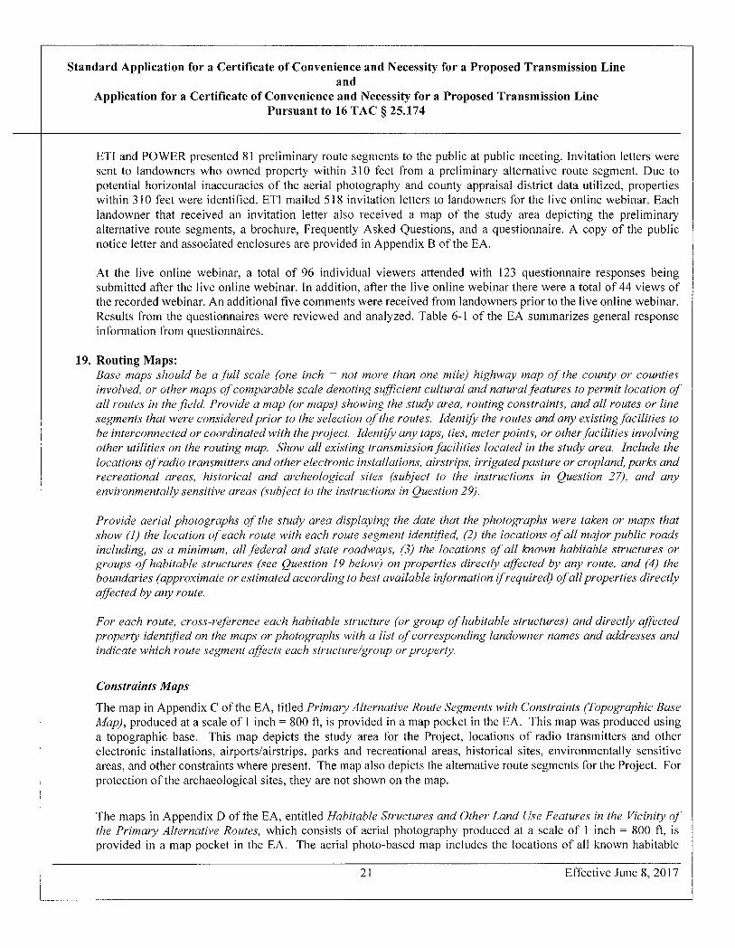
ET1 and POWER presented 81 preliminary route segments to the public at public meeting. Invitation letters were sent to landowners who owned property within 310 feet from a preliminary alternative route segment. Due to potential horizontal inaccuracies of the aerial photography and county appraisal district data utilized, properties within 310 feet were identified. ETI mailed 518 invitation letters to landowners for the live online webinar. Each landowner that received an invitation letter also received a map of the study area depicting the preliminary alternative route segments, a brochure, Frequently Asked Questions, and a questionnaire. A copy of the public notice letter and associated enclosures are provided in Appendix B of the EA.
At the live online webinar, a total of 96 individual viewers attended with 123 questionnaire responses being submitted after the live online webinar. In addition, after the live online webinar there were a total of 44 views of the recorded webinar. An additional five comments were received from landowners prior to the live online webinar. Results from the questionnaires were reviewed and analyzed. Table 6-1 of the EA summarizes general response information from questionnaires.
19. Routing Maps: Base maps should be a full scale (one inch = not more than one mile) highway map of the county or counties involved, or other maps of comparable scale denoting sufficient cultural and naturalfeatures to permit location of all routes in thefield. Provide a map (or maps) showing the study area, routing constraints, and all routes or line segments thatwere consideredprior to the selection ofthe routes. Identify the routes andany existing facilities to be interconnected orcoordinatedwiththeproject. Identify any taps, ties, meter points, orotherfacilities involving other utilities on the routing map. Show all existing transmission facilities located in the study area. Include the locations of radio transmitters and other electronic installations, airstrips, irrigated pasture or cropland, parks and recreational areas, historical and archeological sites (subject to the instructions in Question 27), and any environmentally sensitive areas (subject to the instructions in Question 29).
Provide aerial photographs of the study area displaying the date that the photographs were taken or maps that show (1) the location ofeach route with each route segment identified, (2) the locations of all major public roads including, as a minimum, all federal and state roadways, (3) the locations of all known habitable structures or groups of habitable structures (see Question 19 below) on properties directly affected by any route, and (4) the boundaries (approximate or estimated according to best available information if required) of dl properties directly qffected by any route.
For each route, cross-reference each habitable structure (or group of habitable structures) and directly affected property identified on the maps or photographs with a list of corresponding landowner names and addresses and indicate which route segment affects each structure/group or property.
Constraints Maps
The map in Appendix C ofthe EA , titled Primary Alternative Route Segments with Constraints ( Topographic Base Map ), produced at a scale of 1 inch = 800 ft , is provided in a map pocket in the EA . This map was produced using a topographic base. This map depicts the study area for the Project, locations of radio transmitters and other electronic installations, airports/airstrips, parks and recreational areas, historical sites, environmentally sensitive areas, and other constraints where present. The map also depicts the alternative route segments for the Project. For protection of the archaeological sites, they are not shown on the map.
The maps in Appendix D of the EA , entitled Habitable Structures and Other Land Use Features in the Vicinity of the Primary Alternative Routes , which consists of aerial photography produced at a scale of 1 inch = 800 ft , is provided in a map pocket in the EA. The aerial photo-based map includes the locations of all known habitable
21 Effective June 8,2017
Standard Application for a Certificate of Convenience and Necessity for a Proposed Transmission Line and
Application for a Certificate of Convenience and Necessity for a Proposed Transmission Line Pursuant to 16 TAC § 25.174
structures located within 310 feet of the centerline of primary alternative routes on properties directly affected by the Project. This map also includes other land use features within the vicinity ofthe alternative routes. The habitable structures and other land use features map was produced using a 2019 aerial photographic base.
The maps provided in the EA include sufficient cultural and natural features to permit location of the alternative routes in the field, and they depict existing electric transmission lines and substations (based on information available to POWER), and major public roads located within the study area, as applicable.
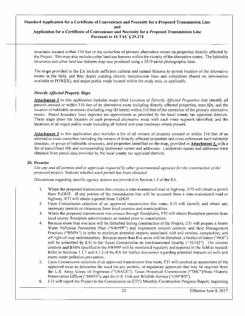
Directly Affected Property Maps
Attachment 3 to this application includes maps titled Location of Directly Affected Properties that identify all parcels crossed or within 310 feet of an alternative route including directly affected properties, tract IDs, and the location of habitable structures (including map ID labels) within 310 feet ofthe centerline ofthe primary alternative routes. Parcel boundary lines depicted are approximate as provided by the local county tax appraisal districts. These maps show the location of each proposed alternative route with each route segment identified, and the locations of all major public roads including all federal and state roadways where present.
Attachment 3 to this application also includes a list of all owners of property crossed or within 310 feet of an alternative route centerline including the owners of directly-affected properties and cross-references each habitable structure, or group of habitable structures, and properties identified on the map. provided in Attachment 3, with a list of parcel/tract IDs and corresponding landowner names and addresses. Landowner names and addresses were obtained from parcel data provided by the local county tax appraisal districts.
20. Permits: List any and all permits and/or approvals required by other governmental agencies for the construction of the proposed project. Indicate whether each permit has been obtained.
Discussions regarding specific agency actions are provided in Section 1.5 of the EA.
1. Where the proposed transmission line crosses a state-maintained road or highway, ETI will obtain a permit from TxDOT. If any portion of the transmission line will be accessed from a state-maintained road or highway, ETI will obtain a permit from TxDOT,
2. Upon Commission selection of an approved transmission line route, ETI will identify and obtain any necessary permits or clearances from local counties and municipalities.
3. Where the proposed transmission line crosses through floodplains, ETI will obtain floodplain permits from local county floodplain administrators as needed prior to construction.
4. Because more than one acre will be disturbed during construction of the Project, ETI will prepare a Storm Water Pollution Prevention Plan ("SWPPP") and implement erosion controls and Best Management Practices ("BMPs") in order to minimize potential impacts associated with soil erosion, compaction, and off right-of-way sedimentation. Because more than five acres will be disturbed, a Notice of Intent ("NOI") will be submitted by ETI to the Texas Commission on Environmental Quality ("TCEQ"). The erosion controls and BMPs specified in the SWPPP will be monitored regularly and repaired in the field as needed. Refer to Sections 1.5.7 and 4.1.2 of the EA for further discussion regarding potential impacts on soils and storm water pollution prevention.
5. Upon Commission selection of an approved transmission line route, ETI will conduct an assessment of the approved route to determine the need for any permits, or regulatory approvals that may be required from the U.S. Army Corps of Engineers ("USACE"), Texas Historical Commission ("THC")/State Historic Preservation Officer ("SHPO"), and the U.S. Fish and Wildlife Service ("USFWS").
6. ETI will report the Project to the Commission on ETI's Monthly Construction Progress Report, beginning
22 Effective June 8,2017
Standard Application for a Certificate of Convenience and Necessity for a Proposed Transmission Line and
Application for a Certificate of Convenience and Necessity for a Proposed Transmission Line Pursuant to 16 TAC § 25.174
with the first report following the filing of a CCN application, and in each subsequent monthly progress report until construction is completed and actual project costs have been reported.
7. The Texas General Land Office ("TGLO") requires a miscellaneous easement for right-of-way across, through, and under state-owned riverbeds and beds of navigable streams or tidally influenced waters. ET] will coordinate with the TGLO as needed after Commission approval of a route.
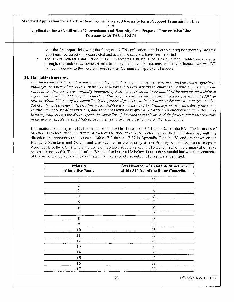
21. Habitable structures: For each route list all single-family and multi-family dwellings and related structures, mobile homes, apartment buildings, commercial structures, industrial structures, business structures, churches, hospitals, nursing homes, schools, or other structures normally inhabited by humans or intended to be inhabited by humans on a daily or regular basis within 300 feet of the centerli}le if the proposed project will be constructed for operation at 230kV or less, or within 500 feet of the centerline if the proposed project will be constructed for operation at greater than 230kV. Provide a general description of each habitable structure and its distancefrom the centerline of the route. In cities, towns or rural subdivisions, houses can be identified in groups. Provide the number ofhabitable structures in each group and list the distance from the centerline of the route to the closest and thefarthest habitable structure in the group. Locate all listed habitable structures or groups of structures on the routing map.
Information pertaining to habitable structures is provided in sections 3.2.1 and 4.2.1 of the EA. The locations of habitable structures within 310 feet of each of the alternative route centerlines are listed and described with the direction and approximate distance in Tables 7-2 through 7-23 in Appendix E of the EA and are shown on the Habitable Structures and Other Land Use Features in the Vicinity of the Primary Alternative Routes maps in Appendix D ofthe EA . The total numbers of habitable structures within 310 feet of each ofthe primary alternative routes are provided in Table 4-1 ofthe EA and also in the table below. Due to the potential horizontal inaccuracies of the aerial photography and data utilized, habitable structures within 310 feet were identified.
Primary Alternative Route
Total Number of Habitable Structures within 310 feet of the Route Centerline
1 11 2 11 3 6 4 8 5 7 6 8 7 9 8 9 9 22 10 18 11 10 12 27 13 8 14 2 15 12 16 19 17 30
23 Effective June 8, 2017
Standard Application for a Certificate of Convenience and Necessity for a Proposed Transmission Line and
Application for a Certificate of Convenience and Necessity for a Proposed Transmission Line Pursuant to 16 TAC § 25.174
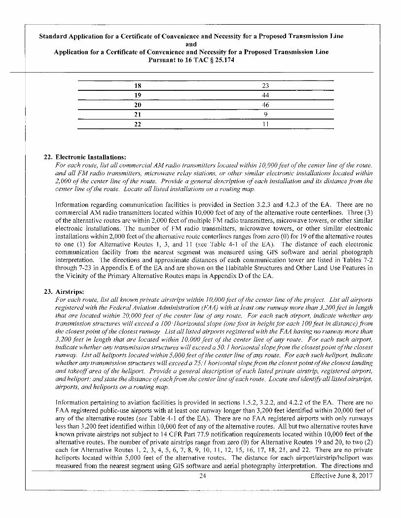
18 23 19 44 20 46 21 9 22 11
22. Electronic Installations: For each route, list all commercial AM radio transmitters located within 10,000 feet ofthe center line of the route, and all FM radio transmitters, microwave relay stations, or other similar electronic installations located within 2,000 of the center line of the route. Provide a general description of each installation and its distance.from the center line ofthe route. Locate all listed installations on a routing map.
Information regarding communication facilities is provided in Section 3.2.3 and 4.2.3 of the EA. There are no commercial AM radio transmitters located within 10,000 feet of any of the alternative route centerlines. Three (3) of the alternative routes are within 2,000 feet of multiple FM radio transmitters, microwave towers, or other similar electronic installations. The number of FM radio transmitters, microwave towers, or other similar electronic installations within 2,000 feet ofthe alternative route centerlines ranges from zero (0) for 19 ofthe alternative routes to one (1) for Alternative Routes 1,3, and 11 (see Table 4-1 of the EA). The distance of each electronic communication facility from the nearest segment was measured using GIS software and aerial photograph interpretation. The directions and approximate distances of each communication tower are listed in Tables 7-2 through 7-23 in Appendix E of the EA and are shown on the Habitable Structures and Other Land Use Features in the Vicinity ofthe Primary Alternative Routes maps in Appendix D of the EA.
23. Airstrips: For each route, list all known private airstrips within 10,000 feet ofthe center line ofthe project. List all airports registered with the Federal Aviation Administration (FAA) with at least one runway more than 3,200 feet in length that are located within 20,000 feet of the center line of any route. For each such airport, indicate whether any transmission structures will exceed a 100·lhorizontal slope (onefoot in heightfor each 100 feet in distance) from the closestpointoftheclosestrunway Listall listedairportsregisteredwiththe FAA having norunwaymorethan 3,200 feet in length that are located within 10,000 feet of the center line ofany route. For each such airport, indicate whether any fransmissionstructureswillexceed a 50.1 horizontalslopefrom the closest pointofthe closest runway. List all heliports located within 5,000 feet of the center line of any route. For each such heliport, indicate whether any transmissionstructureswillexceeda 25:1 horizontalslopefrom theclosestpointofthe closest landing and takeoff area of the hetiport. Provide a general description of each listed private airstrip, registered airport, and heliport; and state the distance ofeachfrom the center line of each route. Locate and identify all listed airstrips, airports, and heliports on a routing map.
Information pertaining to aviation facilities is provided in sections 1.5.2, 3.2.2, and 4.2.2 of the EA. There are no FAA registered public-use airports with at least one runway longer than 3,200 feet identified within 20,000 feet of any of the alternative routes ( see Table 4 - 1 of the EA ). There are no FAA registered airports with only runways less than 3,200 feet identified within 10,000 feet of any of the alternative routes. All but two alternative routes have known private airstrips not subject to 14 CFR Part 77.9 notification requirements located within 10,000 feet of the alternative routes. The number of private airstrips range from zero (0) for Alternative Routes I 9 and 20, to two (2) each for Alternative Routes 1, 2, 3, 4, 5, 6, 7, 8, 9, 10, 11, 12, 15, 16, 17, 18, 21, and 22. There are no private heliports located within 5,000 feet of the alternative routes. The distance for each airport/airstrip/heliport was measured from the nearest segment using GIS software and aerial photography interpretation. The directions and
24 Effective June 8,2017
Standard Application for a Certificate of Convenience and Necessity for a Proposed Transmission Line and
Application for a Certificate of Convenience and Necessity for a Proposed Transmission Line Pursuant to 16 TAC § 25.174
approximate distances of each airpordairstrip/heliport in relation to each alternative route are listed in Tables 7-2 through 7-23 in Appendix E of the EA and are shown on the Habitable Structures and Other Land Use Features in the Vicinity of the Primary Alternative Routes maps in Appendix D ofthe EA.
24. Irrigation Systems: For each route identify any pasture or cropland irrigated by traveling irrigation systems (rolling or pivot type) that will be traversed by the route. Provide adescription oftheirrigatedlandand state howitwillbe affected by each route (number and type ofstructures, etc.). Locate any such irrigatedpasture orcroplandona routingmap.
Information pertaining to agriculture is provided in sections 3.2.1 and 4.2.1 of the EA. None of the primary alternative routes cross agricultural lands irrigated by traveling systems (rolling or pivot type).
25. Notice: Notice is to be provided in accordance with 16 TAC § 22.52.
A. Provide a copy of the written direct notice to owners ofdirectly affected land. Attach a list of the names and addresses ofthe owners ofdirectly affected land receiving notice.
Please see Attachment 4 for the copy of notice provided to owners of land that may be directly affected, as well as owners of property within 300 feet of the centerline of the alternative routes. Please refer back to Attachment 3 for the lists of names and addresses of the landowners who were provided notice.
B. Provide acopy ojthe writtennotice toutilities that are located within.five miles ofthe routes.
CenterPoint Energy, Mid-South Synergy and San Bernard Electric Cooperative are located within five miles of the alternative routes. Please see Attachment 5 for the list of utilities to which ETI provided notice as well as the notice provided to utilities.
ETI also voluntarily provided notice to all known operators of oil and gas pipelines crossed by or within 100 feet of the alternative routes. Please see Attachment 6 for the list of oil and gas pipeline operators to which ETI provided notice as well as the notice provided to the pipeline operators. Please refer back to Attachment 4 for the attachments provided to landowners as well as pipelines.
C. Provide a copy of the written notice to county and municipal authorities, and the Department of Defense Siting Clearinghouse. Notice to the DoD Siting Clearinghouse should be provided at the email address found at http://www.acq.osd.mil/dodsc/.
Please see Attachment 7 for the list of county and municipal authorities to whom notice was provided as well as the written notice letter provided. Please see Attachment 8 for the notice provided to the Department of Defense Siting Clearinghouse. Please refer to Attachment 4 for the attachments to the notice provided to landowners as well as county and municipal authorities, and the Department of Defense Siting Clearinghouse.
D. Provide a copy of the notice that is to be published in newspapers of general circulation in the counties in which thefacilities are to be constructed. Attachalist ofthe newspapers thatwill publish the noticefor this application. After the notice is published, provide the publisher's affidavits and tear sheets.
Please see Attachment 9 for the form of notice published in newspapers of general circulation in the county in
25 Effective June 8,2017
Standard Application for a Certificate of Convenience and Necessity for a Proposed Transmission Line and
Application for a Certificate of Convenience and Necessity for a Proposed Transmission Line Pursuant to 16 TAC § 25.174
which the facilities are to be constructed and the newspaper list where notice was published. Please refer to Attachment 4 for Route Segment Descriptions and Notice Map, which were also included in the publication notice.
Please see Attachment 10 for the notice provided to the Office of Public Utility Counsel (OPUC) pursuant to 16 T.A.C. § 22.52. Please refer to Attachment 4 for the Route Segment Descriptions and Notice Map.
For a CREZ application, in addition to the requirements of 16 TAC § 22.52 the applicant shall, not less than twenty-one (21) days before the filing of the application, submit to the Commission stajf a "generic" copy of each type of alternativepublishedandwrittennoticefor review. Staff's comments, ifany, regarding the alternative notices will be provided to the applicant not later than seven days after receipt by Staffof the alternative notices, Applicant may take into consideration any comments made by Commission staff before the notices are published or sent by mail.
Not applicable.
26. Parks and Recreation Areas: For each route, list all parks and recreational areas owned by a governmental body or an organized group, club, or church and located within 1,000 feet of the center line of the route. Provide a general description of each area and its distance from the center line. Identify the owner of the park or recreational area (public agency, church, club, etc.). List the sources used fo identify the parks and recreational areas. Locate the listed sites on a routing map.
Information pertaining recreation and park areas is provided in sections 3.3 and 4.3 of the EA. There are no parks or recreational areas crossed or identified within 1,000 feetofany ofthe alternative routes.
27. Historical and Archeological Sites: For each route, list all historical and archeological sites known to be within 1,000 feet of the center line of the route. Include adescription ofeach site and its distance from the center line. List the sources (national, state or local commission or societies) used to identify the sites. Locate all historical sites on a routing map. For the protection of the sites, archeological sites need not be shown on maps.
Information pertaining to Cultural Resources is provided iii Section 1.5.8, Section 3.5, and Section 4.5 of the EA. Shapefiles containing the locations of archeological sites in and near the study area were obtained from the Texas Archeological Research Laboratory ("TARL"). Information pertaining to cultural resources and surveys was obtained from the Texas Historical Commission's ("THC") online restricted-access Texas Archeological Sites Atlas ("TASA"). The locations of and information pertaining to State Antiquities Landmarks, NRHP properties, cemeteries, Historical Texas Cemeteries ("HTC"), and Official Texas Historical Markers ("OTHM") within the study area were obtained from the THC's online Texas Historical Sites Atlas ("THSA") and TASA. TxDOT's historic bridges database was reviewed for bridges that are listed or determined eligible for listing on the NRHP within the study area. At the national level, the NRHP database and National Park Service websites for National Historic Landmarks and National Historic Trails were reviewed as well.
As shown in Table 4-1 of the EA, the number of cemeteries within 1,000 feet of alternative routes range from one for alternative routes 2,9,16,17,21, and 22 to two cemeteries within 1,000 feet for Alternative Route 19. None of the other alternative routes are within 1,000 feet of cemeteries. Rosehill Cemetery is within 1,000 feet of alternative routes 2, 21, and 22. Porter Chapel Cemetery is within 1,000 feet of alternative routes 9,16, and 17. Griffin Graves Cemetery and Gri ffin Cemetery is within 1,000 feet of Alternative Route 19. Cemeteries identified within 1,000 feet of each alternative route are shown in Appendix D (Habitable Structures and Other Land Use Features in the
26 Effective June 8, 2017

Standard Application for a Certificate of Convenience and Necessity for a Proposed Transmission Line and
Application for a Certificate of Convenience and Necessity for a Proposed Transmission Line Pursuant to 16 TAC § 25.174
Vicinity ofthe Primary Alternative Routes) and are listed in tables 7-2 through 7-23 ofthe EA.
As shown on Table 4-1 of the EA, one archeological site is crossed by Alternative Route 20. None of the other alternative routes cross previously recorded historic or prehistoric sites. There are no previously recorded historic or prehistoric sites within 1,000 feet of alternative routes 1,2, 3,4, 5,6, 7, 8,9, 21, and 22. The number of previously recorded historic or prehistoric sites within 1,000 feet range from one for Alternative Route 10, to four for A lternative Route 19. None of the alternative routes cross or are within 1,000 feet of archeological sites or historic properties listed on the NRHP. Archeological site information for each alternative route is also listed on Table 4-3 and tables 7-2 through 7-23 (Appendix E) of the EA. For the protection of the archeological sites, they are not shown on maps.
As shown in Table 4-3 and Tables 7-2 through 7-23 of the EA, four archeological sites are crossed or within 1,000 feet of alternative route centerlines. Sites 41 GM464 and 41 GM465 are recorded 923 and 450 feet, respectively, from the centerlines of Alternative Routes 11, 12, 16, and 17; and 574 and 465 feet, respectively, from the centerlines of Alternative Routes 13, 15, and 18; and 104 and 128 feet, respectively, from the centerlines of Alternative Routes 14, 19, and 20. Site 41 MQ172 is recorded 521 feet from the centerline of Alternative Route 19 and is crossed by the centerline of Alternative Route 20. Site 41 MQ1 74 is 884 feet from the centerlines of A Iternative Routes 10 and 18, and 641 feet from the centerlines of Alternative Routes 17,19, and 20.
Site 41GM465, and portions of sites 41 GM464 and 41 MQ174 have been determined ineligible for listing on the NRHP. Site 41 MQ172 has not been formally evaluated for listing on the NRHP. Site 41 GM464 is a prehistoric site and described as campsites consisting generally of ceramics, burned rock, lithic tools, and debitage. Site 41MQ174, a prehistoric site, described as lithic scatters, and no data was available for site 41 MQ172. The sole historic site, 41 GM465, contains a concrete house foundation and associated scatter of glass and nails.
As discussed in Section 4.5.3 of the EA, Sites 41 GM464 and 41 GM465 are recorded 923 and 450 feet, respectively, from the centerlines of Alternative Routes 11, 12, 16, and 17; and 574 and 465 feet, respectively, from the centerlines of Alternative Routes 13, 15, and 18; and 104 and 128 feet, respectively, from the centerlines of Alternative Routes 14,19, and 20 (Table 4-3 of the EA). Site 41 MQ1 72 is recorded 521 feet from the centerline of A lternative Route 19 and is crossed by the centerline of Alternative Route 20. Site 41 MQ174 is 884 feet from the centerlines of Alternative Routes 10 and 18, and 641 feet from the centerlines of Alternative Routes 17,19, and 20 (Table 4-3 of the EA). Sites 41 GM464 and 41 GM465 as recorded within TXDOT ROW have been determined by the State Historic Preservation Office to be ineligible for listing on the NRHP. No descriptive information is available for site 41MQ172, and it has not been formally evaluated for listing on the NRHP. Site 41MQ174, a prehistoric lithic scatter has been determined ineligible for listing on the NRHP.
28. Coastal Management Program: For each route, indicate whether the route is located, either in whole or in part, within the coastal management program boundary as defined in 31 TAC §503.1. Ifany route is, either in whole or in part, within the coastal management program boundary, indicate whether any part of the route is seaward of the Coastal Facilities Designation Line as defined in 31 TAC §19.2(a)(21) Using the designations in 31 TAC §501.3(b), identify the Iype(s) of Coastal Natural Resource Area(s) impacted by any part of the route and/or facilities.
Information regarding the Texas Coastal Management Program (CMP) and Coastal Natural Resource Areas (CNRAs) are provided in Section 1.5.12,3.1.4, and 4.1.4 ofthe EA. The study area is not situated within the CMP boundary and therefore CNRAs would not be impacted by the project.
27 Effective June 8,2017
Standard Application for a Certificate of Convenience and Necessity for a Proposed Transmission Line and
Application for a Certificate of Convenience and Necessity for a Proposed Transmission Line Pursuant to 16 TAC § 25.174
29. Environmental Impact: Provide copies ofany and allenvironmentalimpact studies and/or assessments oj the project. If noformalstudy was conductedfor this project, explain how the routing and construction of this project will impact the environment List the sources used to identify the existence or absence of sensitive environmental areas. Locate any environmentally sensitive areas on a routing map. In some instances, the location ofthe environmentally sensitive areas or the location ofprotected or endangered species should not be included on maps to ensure preservation of the areas or species. Within seven days after filing the application for the project, provide a copy of each environmental impact study and/or assessment to the Texas Parks and Wildlife Department (TPWD) for its review at the address below. Include with this application a copy of the letter of transmittal with which the studies/assessments were or will be sent to the TPWD.
Wildlife Habitat Assessment Program Wildlife Division Texas Parks and Wildlife Department 4200 Smith School Road Austin, Texas 78744
The applicant shall file an affidavit confirming that the letter of transmittal and studies/assessments were sent to TPWD.
Please see Attachment ll for the notice provided to TPWD. Please see the Environmental Assessment attached in a separate binder as referenced in Attachment 2.
30. Affidavit Attach a sworn affidavit from a qualified individual authorized by the applicant to verify and affirm that, to the best of their knowledge, all information provided, statements made, and matters set forth in this application and attachments are true and correct.
Please see Attachment 12 for the Affidavit of Carl Olson.
28 Effective June 8,2017
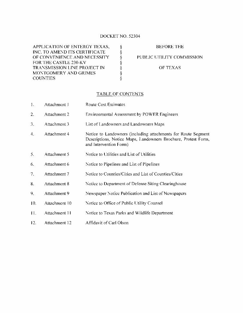
DOCKET NO. 52304
APPLICATION OF ENTERGY TEXAS, § BEFORE THE INC. TO AMEND ITS CERTIFICATE § OF CONVENIENCE AND NECESSITY § PUBLIC UTILITY COMMISSION FOR THE CASTLE 230-KV § TRANSMISSION LINE PROJECT IN § OF TEXAS MONTGOMERY AND GRIMES § COUNTIES §
1. Attachment 1
2. Attachment 2
3. Attachment 3
4. Attachment 4
5. Attachment 5
6. Attachment 6
7. Attachment 7
8. Attachment 8
9. Attachment 9
10. Attachment 10
11. Attachment 11
12. Attachment 12
TABLE OF CONTENTS
Route Cost Estimates
Environmental Assessment by POWER Engineers
List of Landowners and Landowners Maps
Notice to Landowners (including attachments for Route Segment Descriptions, Notice Maps, Landowners Brochure, Protest Form, and Intervention Form)
Notice to Utilities and List of Utilities
Notice to Pipelines and List of Pipelines
Notice to Counties/Cities and List of Counties/Cities
Notice to Department of Defense Siting Clearinghouse
Newspaper Notice Publication and List of Newspapers
Notice to Office of Public Utility Counsel
Notice to Texas Parks and Wildlife Department
Affidavit of Carl Olson
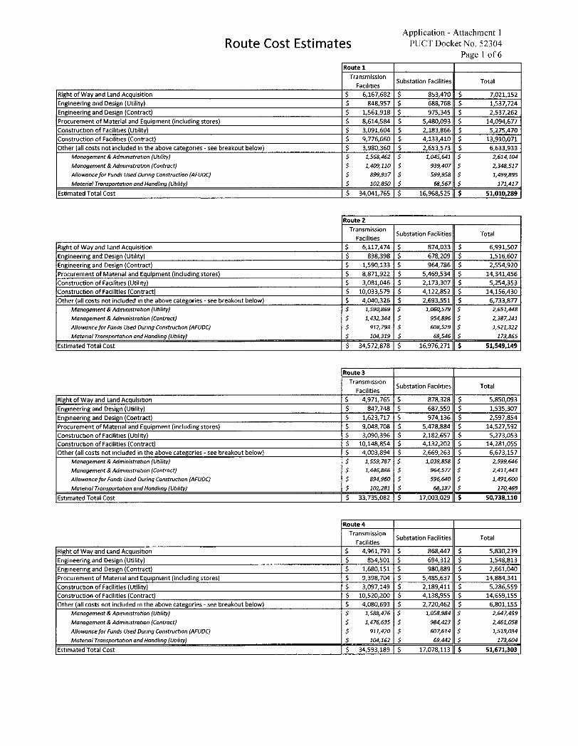
Route Cost Estimates Application - Attachment 1
PUCT Docket No. 52304 Page 1 of 6
Route 1 Transmission
Facilities Substation Facilities Total
Right of Way and Land Acquisition $ 6,167,682 $ 853,470 $ 7,021,152 Engineering and Design (Utility) $ 848,957 $ 688,768 $ 1,537,724 Engineering and Design (Contract) $ 1,561,918 $ 975,345 $ 2,537,262 Procurement of Material and Equipment (including stores) $ 8,614,584 $ 5,480,093 $ 14,094,677 Construction of Facilities (Utility) $ 3,091,604 $ 2,183,866 $ 5,275,470 Construction of Facilities (Contract) $ 9,776,660 $ 4,133,410 $ 13,910,071 Other Call costs not included in the above categories - see breakout below) $ 3,980,360 $ 2,653,573 $ 6,633,933
Management & Administration (Utility) $ 1,568,462 $ 1,045,641 $ 2,614,104 Management & Administration (Contract) $ 1,409,110 $ 939,407 $ 2,348,517 Allowance for Funds Used During Construction ( AFUDC ) $ 899 , 937 $ 599 , 958 $ 1 , 499 , 895 Material Transportation and Handling (Utility) $ 102,850 $ 68,567 $ 171,417
Estimated Total Cost $ 34,041,765 $ 16,968,525 $ 51,010,289
Route 2 Transmission
Facilities Substation Facilities Total
Right of Way and land Acquisition $ 6,117,474 $ 874,033 $ 6,991,507 Engineering and Design (Utility) $ 838,398 $ 678,209 $ 1,516,607 Engineering and Design (Contract) $ 1,590,133 $ 964,786 $ 2,554,920 Procurement of Material and Equipment (including stores) $ 8,871,922 $ 5,469,534 $ 14,341,456 Construction of Facilities (Utility) $ 3,081,046 $ 2,173,307 $ 5,254,353 Construction of Facilities (Contract) $ 10,033,579 $ 4,122,852 $ 14,156,430 Other (all costs not included in the above categories - see breakout below) $ 4,040,326 $ 2,693,551 $ 6,733,877
Management & Administration (Utility) $ 1,590,869 $ 1,060,579 $ 2,651,448 Management & Administration (Contract) $ 1,432,344 $ 954,896 $ 2,387,241 Allowance for Funds Used During Construction (AFUDC) $ 912,793 $ 608,529 $ 1,521,322 Material Transportation and Handling ( Utility ) $ 104 , 319 $ 69 , 546 S 173 , 865
Estimated Total Cost $ 34,572,878 $ 16,976,271 $ 51,549,149
Route 3 Transmission
Facilities Substation Facilities Total
Right of Way and Land Acquisition $ 4,971,765 $ 878,328 $ 5,850,093 Engineering and Design (Utility) $ 847,748 $ 687,559 $ 1,535,307 Engineering and Design (Contract) $ 1,623,717 $ 974,136 $ 2,597,854 Procurement of Material and Equipment (including stores) $ 9,048,708 $ 5,478,884 $ 14,527,592 Construcbon of Facilities (Utility) $ 3,090,396 $ 2,182,657 $ 5,273,053 Construction of Facilities (Contract) $ 10,148,854 $ 4,132,202 $ 14,281,055 Other (all costs not included in the above categories - see breakout below) $ 4,003,894 $ 2,669,263 $ 6,673,157
Management & Administration (Utility) $ 1,559,787 $ 1,039,858 $ 2,599,646 Management & Administration (Contract) $ 1,446,866 $ 964,577 $ 2,411,443 Allowance for Funds Used During Construction (AFUDC) $ 894,960 $ 596,640 $ 1,491,600
Material Transportation and Handhng ( Utility ) $ 102 , 281 $ 68 , 187 $ 170 , 469
Estimated Total Cost $ 33,735,082 $ 17,003,029 $ 50,738,110
Route 4 Transmission
Facilities Substation Facilities Total
Right of Way and Land Acquisition $ 4,961,793 $ 868,447 $ 5,830,239 Engineering and Design (Utility) $ 854,501 $ 694,312 $ 1,548,813 Engineering and Design (Contract) $ 1,680,151 $ 980,889 $ 2,661,040 Procurement of Material and Equipment (including stores) $ 9,398,704 $ 5,485,637 $ 14,884,341 Construction of Facilities (Utility) $ 3,097,149 $ 2,189,411 $ 5,286,559 Construction of Facilities (Contract) $ 10,520,200 $ 4,138,955 $ 14,659,155 Other (all costs not included in the above categories - see breakout below) $ 4,080,693 $ 2,720,462 $ 6,801,155
Management & Administration (Utility) $ 1,588,476 $ 1,058,984 $ 2,647,459 Management & Administration (Contract) $ 1,476,635 $ 984,423 $ 2,461,058
Allowance for Funds Used During Construction ( AFUDC ) $ 911 , 420 $ 60 % 614 S 1 , 519 , 034 Material Transportation and Handling (Utility) $ 104,162 $ 69,442 $ 173,604
Estimated Total Cost $ 34,593,189 $ 17,078,113 $ 51,671,303
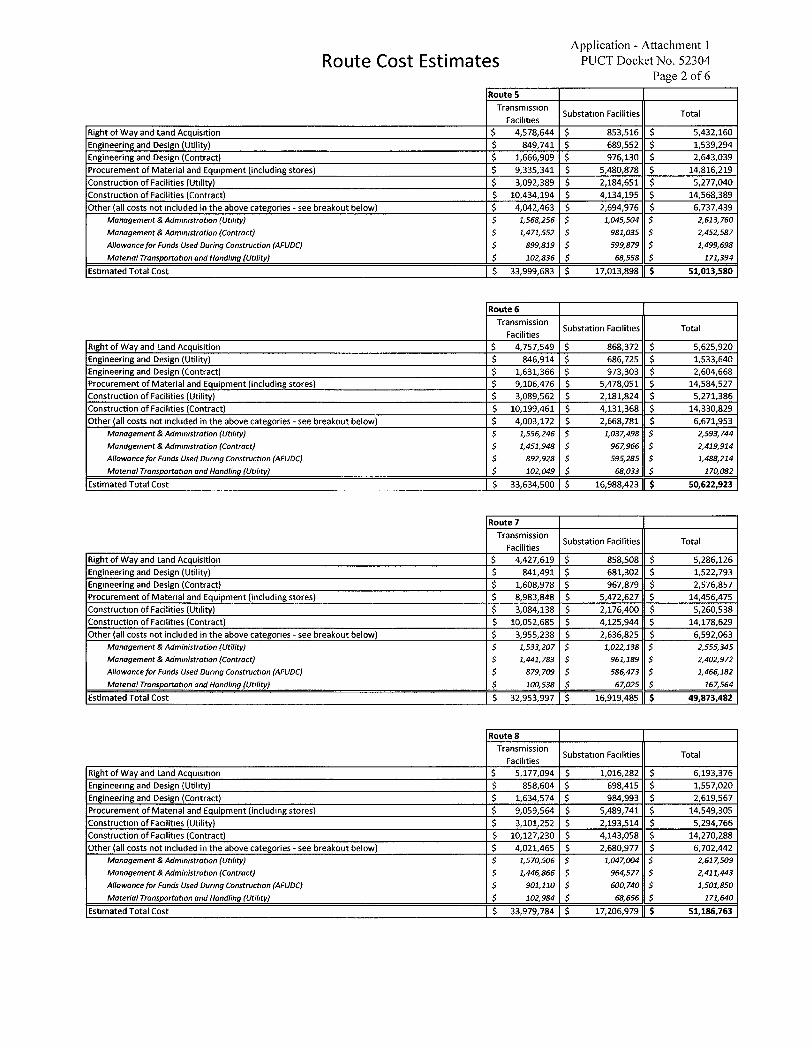
Route Cost Estimates Application - Attachment 1
PUCT Docket No. 52304 Page 2 o f 6
Route 5 Transmission
Facilities Substatton Facilities Total
Right of Way and Land Acquisition $ 4,578,644 $ 853,516 $ 5,432,160 Engineering and Design (Utility) $ 849,741 $ 689,552 $ 1,539,294 Engineering and Design (Contract) $ 1,666,909 $ 976,130 $ 2,643,039 Procurement of Material and Equipment (including stores) $ 9,335,341 $ 5,480,878 $ 14,816,219 Construction of Facilities (Utility) $ 3,092,389 $ 2,184,651 $ 5,277,040 Construction of Facilities (Contract) $ 10,434,194 $ 4,134,195 $ 14,568,389 Other (all costs not included in the above categories - see breakout below) $ 4,042,463 $ 2,694,976 $ 6,737,439
Management & Administration ( Utility ) $ 1 , 568 , 256 3 1 , 045 , 504 $ 2 , 613 , 760 Management & Administration (Contract) $ 1,471,552 $ 981,035 $ 2,452,587 Allowance for Funds Used During Construction (AFUDC) $ 899,819 $ 599,879 $ 1,499,698 Material Transportation and Handling (Utility) $ 102,836 $ 68,558 $ 171,394
Estimated Total Cost $ 33,999,683 $ 17,013,898 $ 51,013,580
Route 6 Transmission
Facilities Substation Facilities Total
Right of Way and Land Acquisition $ 4,757,549 $ 868,372 $ 5,625,920 Engineering and Design (Utility) $ 846,914 $ 686,725 $ 1,533,640 Engineering and Design (Contract) $ 1,631,366 $ 973,303 $ 2,604,668 Procurement of Material and Equipment (including stores) $ 9,106,476 $ 5,478,051 $ 14,584,527 Construction of Facilities (Utility) $ 3,089,562 $ 2,181,824 $ 5,271,386 Construction of Facilities (Contract) $ 10,199,461 $ 4,131,368 $ 14,330,829 Other (all costs not included in the above categories - see breakout below) $ 4,003,172 $ 2,668,781 $ 6,671,953
Management & Administration ( Utility ) 3 1 , 556 , 246 3 1 , 037 , 498 $ 2 , 593 , 744 Management & Administration ( Contract ) $ 1 , 451 , 948 $ 967 , 966 3 2 , 419 , 914 Allowance for Funds Used During Construction (AFUDC) $ 892,928 $ 595,285 $ 1,488,214 Material Transportation and Handling (Utility) $ 102,049 $ 68,033 $ 170,082
Estimated Total Cost $ 33,634,500 $ 16,988,423 $ 50,622,923
Route 7 Transmission
Facilities Substation Facilities Total
Right of Way and Land Acquisition $ 4,427,619 $ 858,508 $ 5,286,126 Engineering and Design (Utility) $ 841,491 $ 681,302 $ 1,522,793 Engineering and Design (Contract) $ 1,608,978 $ 967,879 $ 2,576,857 Procurement of Material and Equipment (including stores) $ 8,983,848 $ 5,472,627 $ 14,456,475 Construction of Facilities (Utility) $ 3,084,138 $ 2,176,400 $ 5,260,538 Construction of Facilities (Contract) $ 10,052,685 $ 4,125,944 $ 14,178,629 Other (all costs not included in the above categories - see breakout below) $ 3,955,238 $ 2,636,825 $ 6,592,063
Management & Administration ( Utility ) $ 1 , 533 , 207 $ 1 , 022 , 138 $ 2 , 555 , 345 Management & Administration ( Contract ) $ 1 , 441 , 783 $ 961 , 189 S 2 , 402 , 972 Allowance for Funds Used During Construction (AFUDC) $ 879,709 $ 586,473 $ 1,466,182 Material Transportation and Handling ( Utility ) $ 100 , 538 $ 67 , 025 $ 167 , 564
Estimated Total Cost $ 32,953,997 $ 16,919,485 $ 49,873,482
Route 8 Transmission
Facilities Substation Facilities Total
Right of Way and Land Acquisition $ 5,177,094 $ 1,016,282 $ 6,193,376 Engineering and Design (Utility) $ 858,604 $ 698,415 $ 1,557,020 Engineering and Design (Contract) $ 1,634,574 $ 984,993 $ 2,619,567 Procurement of Material and Equipment (including stores) $ 9,059,564 $ 5,489,741 $ 14,549,305 Construction of Facilities (Utility) $ 3,101,252 $ 2,193,514 $ 5,294,766 Construction of Facilities (Contract) $ 10,127,230 $ 4,143,058 $ 14,270,288 Other (all costs not included in the above categories - see breakout below) $ 4,021,465 $ 2,680,977 $ 6,702,442
Management & Administration ( Utility ) $ 1 , 570 , 506 $ 1 , 047 , 004 3 2 , 617 , 509 Management & Administration (Contract) $ 1,446,866 $ 964,577 $ 2,411,443 Allowance for Funds Used During Construction ( AFUDC ) $ 901 , 110 $ 600 , 740 S 1 , 501 , 850 Material Transportation and Handling ( Utility ) $ 102 , 984 $ 68 , 656 $ 17t640
Estimated Total Cost $ 33,979,784 $ 17,206,979 $ 51,186,763
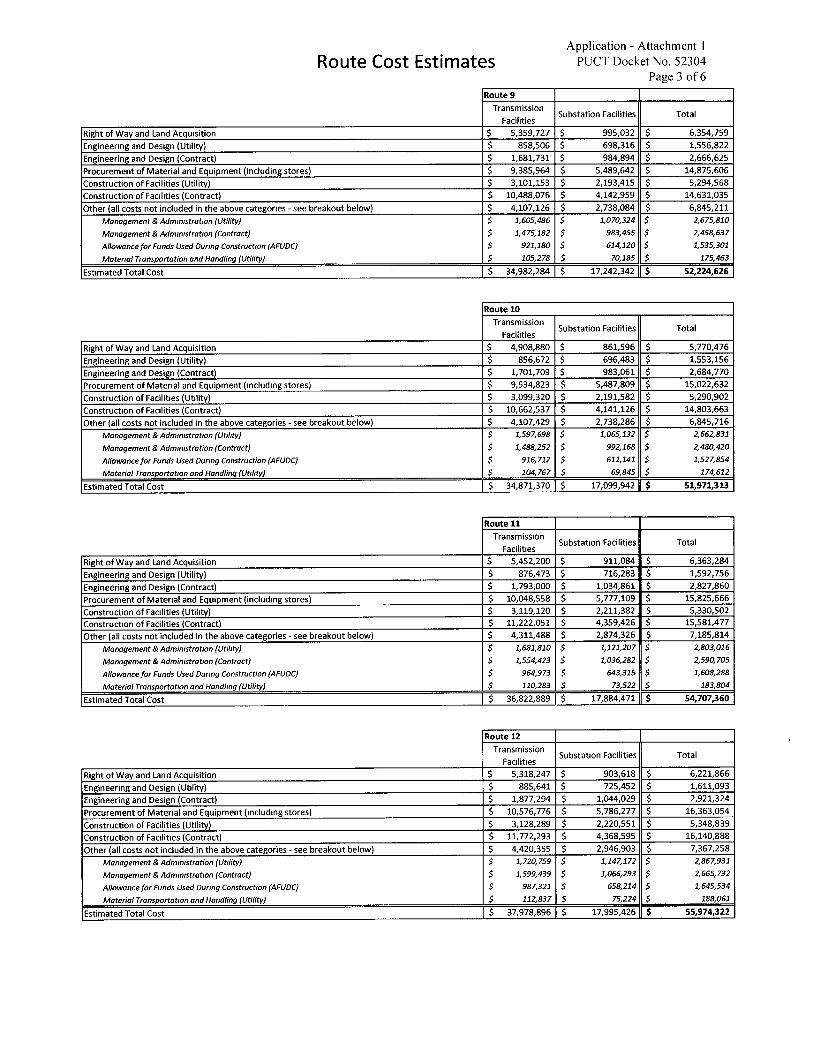
Route Cost Estimates Application - Attachment 1
PUCT Docket No. 52304 Page 3 of 6
Route 9 Transmission
Facilities Substation Facilities Total
Right of Way and Land Acquisition $ 5,359,727 $ 995,032 $ 6,354,759 Engineering and Design (Utility) $ 858,506 $ 698,316 $ 1,556,822 Engineering and Design (Contract) $ 1,681,731 $ 984,894 $ 2,666,625 Procurement of Material and Equipment (including stores) $ 9,385,964 $ 5,489,642 $ 14,875,606 Construction of Facilities (Utility) $ 3,101,153 $ 2,193,415 $ 5,294,568 Construction of Facilities (Contract) $ 10,488,076 $ 4,142,959 $ 14,631,035 Other (all costs not included in the above categories - see breakout below) $ 4,107,126 $ 2,738,084 $ 6,845,211
Management & Administration ( Utility ) 3 1 , 605 , 486 S 1 , 070 , 324 $ 2 , 675 , 810
Management & Administration (Contract) $ 1,475,182 $ 983,455 $ 2,458,637
Allowance for Funds Used During Construction (AFUDC) $ 921,180 $ 614,120 S 1,535,301
Material Transportation and Handling ( Utility ) $ 105 , 278 $ 70 , 185 $ 175 , 463
Estimated Total Cost $ 34,982,284 $ 17,242,342 $ 52,224,626
Route 10 Transmission
Facilities Substation Facilities Total
Right of Way and land Acquisition $ 4,908,880 $ 861,596 $ 5,770,476 Engineering and Design (Utility) $ 856,672 $ 696,483 $ 1,553,156 Engineering and Design (Contract) $ 1,701,709 $ 983,061 $ 2,684,770 Procurement of Material and Equipment (including stores) $ 9,534,823 $ 5,487,809 $ 15,022,632 Construction of Facilities (Utility) $ 3,099,320 $ 2,191,582 $ 5,290,902 Construction of Facilities (Contract) $ 10,662,537 $ 4,141,126 $ 14,803,663 Other (all costs not included in the above categories - see breakout below) $ 4,107,429 $ 2,738,286 $ 6,845,716
Management & Administration (Utility) $ 1,597,698 $ 1,065,132 $ 2,662,831
Management & Administration (Contract) $ 1,488,252 $ 992,168 $ 2,480,420
Allowance for Funds Used During Construction ( AFUDC ) $ 916 , 712 $ 611 , 141 $ 1 , 527 , 854 Material Transportation and Handling ( Utility ) S 104 , 767 S 69 , 845 $ 174 , 612
Estimated Total Cost $ 34,871,370 $ 17,099,942 $ 51,971,313
Route 11 Transmission
Facilities Substat,on Facilities Total
Right of Way and Land Acquisition $ 5,452,200 $ 911,084 $ 6,363,284 Engineering and Design (Utilit'y) $ 876,473 $ 716,283 $ 1,592,756 Engineering and Design (Contract) $ 1,793,000 $ 1,034,861 $ 2,827,860 Procurement of Material and Equipment (including stores) $ 10,048,558 $ 5,777,109 $ 15,825,666 Construction of Facilities (Utility) $ 3,119,120 $ 2,211,382 $ 5,330,502 Construction of Facilities (Contract) $ 11,222,051 $ 4,359,426 $ 15,581,477 Other (all costs not included in the above categories - see breakout below) $ 4,311,488 $ 2,874,326 $ 7,185,814
Management & Administration (Utility) $ 1,681,810 $ 1,121,207 $ 2,803,016
Management & Administration (Contract) $ 1,554,423 $ 1,036,282 $ 2,590,705
Allowance for Funds Used During Construction (AFUDC) $ 964,973 $ 643,315 $ 1,608,288
Material Transportation and Handling (Utility) $ 110,283 $ 73,522 $ 183,804
Estimated Total Cost $ 36,822,889 $ 17,884,471 $ 54,707,360
Route 12 Transmission
Facilities Substation Facilities Total
Right of Way and Land Acquisition $ 5,318,247 $ 903,618 $ 6,221,866 Engineering and Design (Utility) $ 885,641 $ 725,452 $ 1,611,093 Engineering and Design (Contract) $ 1,877,294 $ 1,044,029 $ 2,921,324 Procurement of Material and Equipment (Including stores) $ 10,576,776 $ 5,786,277 $ 16,363,054 Construction of Facilities (Utility) $ 3,128,289 $ 2,220,551 $ 5,348,839 Construction of Facilities (Contract) $ 11,772,293 $ 4,368,595 $ 16,140,888 Other (all costs not included in the above categories - see breakout below) $ 4,420,355 $ 2,946,903 $ 7,367,258
Management & Administration ( Utility ) $ 1 , 720 , 759 $ 1 , 147 , 172 S 2 , 867 , 931
Management & Administration ( Contract ) $ 1 , 599 , 439 3 1 , 066 , 293 $ 2 , 665 , 732
Allowance for Funds Used During Construction (AFUDC) $ 987,321 $ 658,214 $ 1,645,534
Material Transportation and Handling (Utility) $ 112,837 $ 75,224 $ 188,061
Estimated Total Cost $ 37,978,896 $ 17,995,426 $ 55,974,322
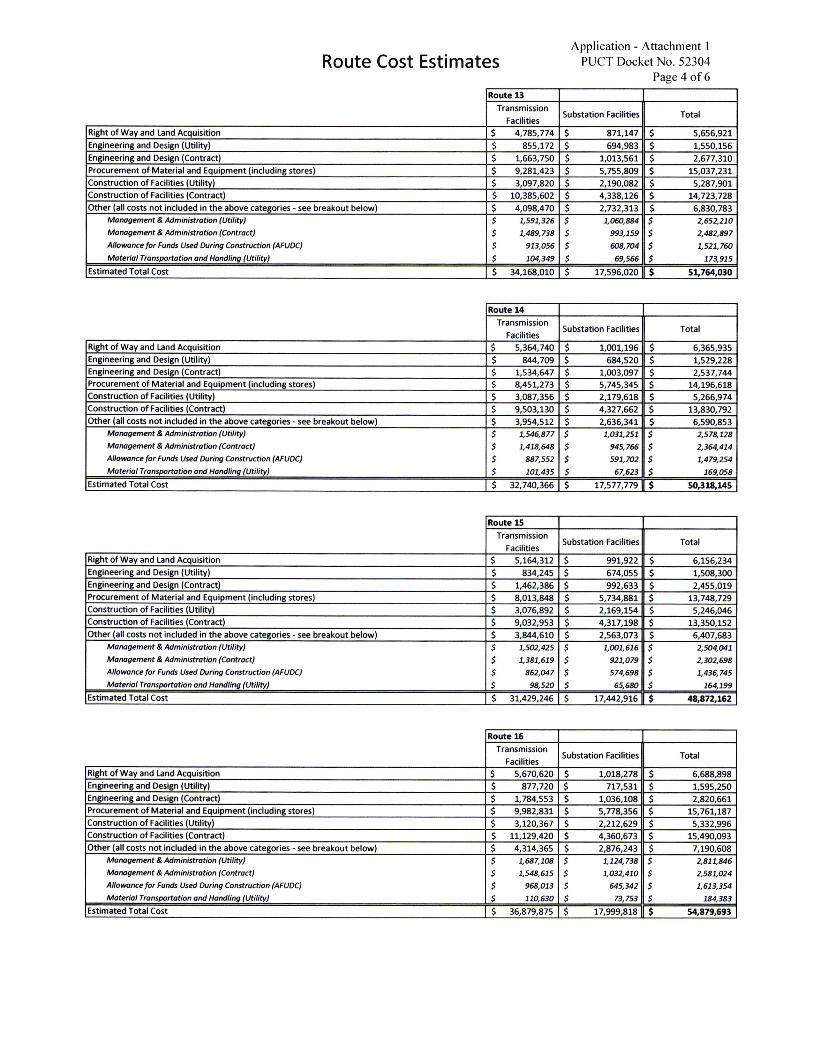
Route Cost Estimates Application - Attachment I
PUCT Docket No. 52304 Page 4 o f 6
Route 13 Transmission
Facilities Substation Facilities Total
Right of Way and Land Acquisition $ 4,785,774 $ 871,147 $ 5,656,921 Engineering and Design (Utility) $ 855,172 $ 694,983 $ 1,550,156 Engineering and Design (Contract) $ 1,663,750 $ 1,013,561 $ 2,677,310 Procurement of Material and Equipment (including stores) $ 9,281,423 $ 5,755,809 $ 15,037,231 Construction of Facilities (Utility) $ 3,097,820 $ 2,190,082 $ 5,287,901 Construction of Facilities (Contract) $ 10,385,602 $ 4,338,126 $ 14,723,728 Other (all costs not included in the above categories - see breakout below) $ 4,098,470 $ 2,732,313 $ 6,830,783
Management & Administration ( Utility ) 3 1 , 591 , 326 S 1 , 060 , 884 $ 2 , 652 , 210 Management & Administration ( Contract ) $ 1 , 489 , 738 $ 993 , 159 $ 2 , 482 , 897 Allowance for Funds Used During Construction (AFUDC) $ 913,056 $ 608,704 $ 1,521,760 Material Transportation and Handling ( Utility ) $ 104 , 349 $ 69 , 566 S 173 , 915
Estimated Total Cost $ 34,168,010 $ 17,596,020 $ 51,764,030
Route 14 Transmission
Facilities Substation Facilities Total
Right of Way and land Acquisition $ 5,364,740 $ 1,001,196 $ 6,365,935 Engineering and Design (Utility) $ 844,709 $ 684,520 $ 1,529,228 Engineering and Design (Contract) $ 1,534,647 $ 1,003,097 $ 2,537,744 Procurement of Material and Equipment (including stores) $ 8,451,273 $ 5,745,345 $ 14,196,618 Construction of Facilities (Utility) $ 3,087,356 $ 2,179,618 S 5,266,974 Construction of Facilities (Contract) $ 9,503,130 $ 4,327,662 $ 13,830,792 Other (all costs not included in the above categories - see breakout below) $ 3,954,512 $ 2,636,341 $ 6,590,853
Management & Administration (Utility) $ 1,546,877 $ 1,031,251 $ 2,578,128 Management & Administration ( Contract ) $ 1 , 418 , 648 $ 945 , 766 $ 2 , 364 , 414 Allowance for Funds Used During Construction (AFUDC) $ 887,552 $ 591,702 $ 1,479,254 Material Transportation and Handling (Utility) $ 101435 $ 67,623 $ 169,058
Estimated Total Cost $ 32,740,366 $ 17,577,779 $ 50,318,145
Route 15 Transmission
Facilities Substation Facilities Total
Right of Way and Land Acquisition $ 5,164,312 $ 991,922 $ 6,156,234 Engineering and Design (Utility) $ 834,245 $ 674,055 $ 1,508,300 Engineering and Design (Contract) $ 1,462,386 $ 992,633 $ 2,455,019 Procurement of Material and Equipment (including stores) $ 8,013,848 $ 5,734,881 $ 13,748,729 Construction of Facilities (Utility) $ 3,076,892 $ 2,169,154 $ 5,246,046 Construction of Facilities (Contract) $ 9,032,953 $ 4,317,198 $ 13,350,152 Other (all costs not included in the above categories - see breakout below) $ 3,844,610 $ 2,563,073 $ 6,407,683
Management & Administration ( Utility ) $ 1 , 502 , 425 $ 1 , 001 , 616 S 2 , 504 , 041 Management & Administration (Contract) S 1,381,619 $ 921,079 $ 2,302,698 Allowance for Funds Used During Construction ( AFUDC ) $ 862 , 047 $ 574 , 698 $ 1 , 436 , 745 Material Transportation and Handling ( Utility ) S 98 , 520 $ 65 , 680 $ 164199
Estimated Total Cost $ 31,429,246 $ 17,442,916 $ 48,872,162
Route 16 Transmission
Facilities Substation Facilities Total
Right of Way and Land Acquisition $ 5,670,620 $ 1,018,278 $ 6,688,898 Engineering and Design (Utility) $ 877,720 $ 717,531 $ 1,595,250 Engineering and Design (Contract) $ 1,784,553 $ 1,036,108 $ 2,820,661 Procurement of Material and Equipment (including stores) $ 9,982,831 $ 5,778,356 $ 15,761,187 Construction of Facilities (Utility) $ 3,120,367 $ 2,212,629 $ 5,332,996 Construction of Facilities (Contract) $ 11,129,420 $ 4,360,673 $ 15,490,093 Other (all costs not included in the above categories - see breakout below) $ 4,314,365 $ 2,876,243 $ 7,190,608
Management & Administration (Utility) $ 1,687,108 $ 1,124,738 $ 2,811,846 Management & Administration ( Contract ) S 1 , 548 , 615 $ 1 , 032 , 410 $ 2 , 581 , 024 Allowance for Funds Used During Construction ( AFUDC ) $ 968 , 013 $ 645 , 342 $ 1 , 613 , 354 Material Transportation and Handling (Utility) $ 110,630 $ 73,753 $ 184,383
Estimated Total Cost $ 36,879,875 $ 17,999,818 $ 54,879,693
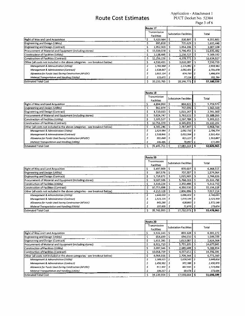
Route Cost Estimates Application - Attachment 1
PUCT Docket No. 52304 Page 5 of 6
Route 17 Transmission
Facilities Substation Facilities Total
Right of Way and Land Acquisition $ 5,420,964 $ 930,697 $ 6,351,661 Engineering and Design (Utility) $ 895,818 $ 735,629 $ 1,631,446 Engineering and Design (Contract) $ 1,952,903 $ 1,054,206 $ 3,007,108 Procurement of Material and Equipment (including stores) $ 11,039,028 $ 5,796,454 $ 16,835,482 Construction of Faciltties (Utility) $ 3,138,465 $ 2,230,727 $ 5,369,192 Construction of Facilities (Contract) $ 12,256,156 $ 4,378,771 $ 16,634,927 Other (all costs not included in the above categories - see breakout below) $ 4,530,431 $ 3,020,287 $ 7,550,719
Management & Administration (Utility) $ 1,763,988 $ 1,175,992 $ 2,939,981 Management & Administration (Contract) $ 1,638,647 $ 1,092,431 $ 2,731,078 Allowance for Funds Used During Construction (AFUDC) $ 1,012,124 $ 674,750 $ 1,686,874 Material Transportation and Handling ( Utility ) S 115 , 671 S 77 , 114 $ 192 , 786
Estimated Total Cost $ 39,233,765 $ 18,146,771 $ 57,380,536
Route 18 Transmission
Facilities Substation Facilities Total
Right of Way and land Acquisition $ 4,894,950 $ 864,622 $ 5,759,572 Engineering and Design (Utility) $ 862,879 $ 702,690 $ 1,565,569 Engineering and Design (Contract) $ 1,720,033 $ 1,021,267 $ 2,741,300 Procurement of Material and Equipment (including stores) $ 9,624,747 $ 5,763,515 $ 15,388,263 Construction of Facilities (Utility) $ 3,105,527 $ 2,197,788 $ 5,303,315 Construction of Facilities (Contract) $ 10,756,370 $ 4,345,833 $ 15,102,202 Other (all costs not included in the above categories - see breakout below) $ 4,181,246 $ 2,787,497 $ 6,968,744
Management & Administration (Utility) $ 1,624,064 $ 1,082,710 $ 2,706,774 Management & Administration (Contract) $ 1,518,846 $ 1,012,564 $ 2,531,410 Allowance for Funds Used During Construction ( AFUDC ) $ 931 , 840 $ 621 , 227 $ 1 , 553 , 067 Materml Transportation and Handling (Utility) $ 106 , 496 S 70 , 997 $ 177 , 493
Estimated Total Cost $ 35,145,751 $ 17,683,213 $ 52,828,965
Route 19 Transmission
Facilities Substatton Facilities Total
Right of Way and Land Acquisition $ 5,497,909 $ 870,607 $ 6,368,515 Engineering and Design (Utility) $ 867,576 $ 707,387 $ 1,574,964 Engineering and Design (Contract) $ 1,718,672 $ 1,025,965 $ 2,744,636 Procurement of Material and Equipment (including stores) $ 9,587,586 $ 5,768,213 $ 15,355,799 Construction of Facilities (Utility) $ 3,110,224 $ 2,202,486 $ 5,312,710 Construction of Facilities (Contract) $ 10,753,698 $ 4,350,530 $ 15,104,228 Other (all costs not included in the above categories - see breakout below) $ 4,210,328 $ 2,806,886 $ 7,017,214
Management & Administration ( Utility ) $ 1 , 644 , 019 $ 1 , 096 , 013 $ 2 , 740 , 031 Management & Administration ( Contract ) $ 1 , 515 , 215 S 1 , 010 , 144 $ 2 , 525 , 359 Allowance for Funds Used During Construction (AFUDC) $ 943,290 $ 628,860 $ 1,572,149 Material Transportation and Handling (Utility) $ 107,805 $ 71,870 $ 179,674
Estimated Total Cost $ 35,745,993 $ 17,732,073 $ 53,478,065
Route 20 Transmission
Facilities Substation Facilities Total
Right of Way and Land Acquisition $ 5,532,143 $ 859,128 $ 6,391,272 Engineering and Design (Utility) $ 854,699 $ 694,510 $ 1,549,209 Engineering and Design (Contract) $ 1,611,281 $ 1,013,087 $ 2,624,368 Procurement of Material and Equipment (including stores) $ 8,921,710 $ 5,755,335 $ 14,677,045 Construction of Facilities (Utility) $ 3,097,346 $ 2,189,608 $ 5,286,954 Construction of Facilities (Contract) $ 10,058,739 $ 4,337,652 $ 14,396,391 Other (all costs not included,n the above categories - see breakout below) $ 4,064,016 $ 2,709,344 $ 6,773,360
Management & Administration ( Utility ) S 1 , 589 , 315 S 1 , 051543 $ 2 , 648 , 858 Management & Administration (Contract) $ 1,458,582 $ 972,388 $ 2,430,970 Allowance for Funds Used During Construction ( AFUDC ) $ 911 , 902 $ 607 , 935 $ 1 , 519 , 836 Material Transportation and Handling ( Utility ) $ 104 , 217 $ 69 , 478 $ 173 , 696
Estimated Total Cost $ 34,139,934 $ 17,558,664 $ 51,698,599
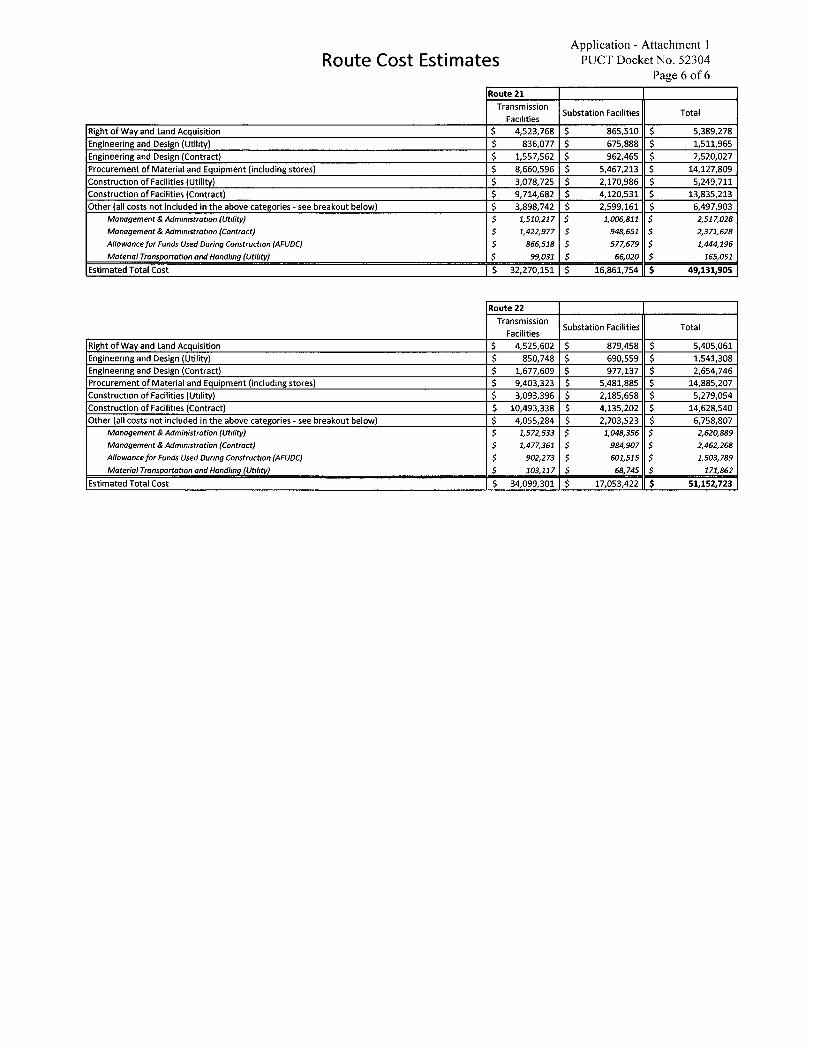
Route Cost Estimates Application - Attachment 1
PUCT Docket No. 52304 Page 6 of 6
Route 21 Transmission
Facilities Substation Facilities Total
Right of Way and Land Acquisition $ 4,523,768 $ 865,510 $ 5,389,278 Engineering and Design (Utility) $ 836,077 $ 675,888 $ 1,511,965 Engineering and Design (Contract) $ 1,557,562 $ 962,465 $ 2,520,027 Procurement of Material and Equipment (including stores) $ 8,660,596 $ 5,467,213 $ 14,127,809 Construction of Facilities (Utility) $ 3,078,725 $ 2,170,986 $ 5,249,711 Construction of Facilities (Contract) $ 9,714,682 $ 4,120,531 $ 13,835,213 Other (all costs not included in the above categories - see breakout below) $ 3,898,742 $ 2,599,161 $ 6,497,903
Management & Administration ( Ut , lity ) $ 1 , 510 , 217 $ 1 , 006 , 811 5 2 , 517 , 028 Management & Administration ( Contract ) $ 1 , 422 , 977 $ 948 , 651 S 2 , 371 , 628 Allowance for Funds Used During Construction ( AFUDC ) $ 866 , 518 $ 577 , 679 $ 1 , 444 , 196 Material Transportation and Handling ( Utility ) $ 99 , 031 $ 66 , 020 $ 165 , 051
Estimated Total Cost $ 32,270,151 $ 16,861,754 $ 49,131,905
Route 22 Transmission
Facilities Substation Facilities Total
Right of Way and Land Acquisition $ 4,525,602 $ 879,458 $ 5,405,061 Engineering and Design (Utility) $ 850,748 $ 690,559 $ 1,541,308 Engineering and Design (Contract) $ 1,677,609 $ 977,137 $ 2,654,746 Procurement of Material and Equipment (including stores) $ 9,403,323 $ 5,481,885 $ 14,885,207 Construction of Facilities (Utility) $ 3,093,396 $ 2,185,658 $ 5,279,054 Construction of Facilities (Contract) $ 10,493,338 $ 4,135,202 $ 14,628,540 Other (all costs not included in the above categories - see breakout below) $ 4,055,284 $ 2,703,523 $ 6,758,807
Management & Administration ( Utility ) $ 1 , 572 , 533 $ 1 , 048 , 356 3 2 , 620 , 889 Management & Administration (Contract) $ 1,477,361 $ 984,907 $ 2,462,268 Allowance for Funds Used During Construction (AFUDC) $ 902,273 $ 601,515 $ 1,503,789
Material Transportation and Handling (Utility) $ 103,117 $ 68,745 $ 171,862
Estimated Total Cost $ 34,099,301 $ 17,053,422 $ 51,152,723
POWER ENGINEERS, INC. Castle 230 kV Transmission Une and Substation Project
APPENDIX A AGENCY CORRESPONDENCE
APPENDIX A
POWER ENGINEERS, INC. Castle 230 kV Transmission Line and Substation Project
This page intentionally left blank.
APPENDIX A
Entergy Castle 230 kV Transmission Line And Substation Project Federal, State and Local Agencies/Officials Contact List
FEDERAL
Mr. Rob Lowe Southwest Regional Administrator Federal Aviation Administration 10101 Hillwood Parkway Fort Worth, TX 76177
Mr. Tony Robinson Region 6 Regional Administrator Federal Emergency Management Agency FRC 800 N. Loop 288 Denton, TX 76209-3698
Mr. Mike Reynolds Intermountain Regional Director National Parks Service I [email protected]
Ms. Drenda Williams Acting State Conservationist NRCS Texas State Office 101 South Main Street Temple, TX 76501
Colonel Timothy R. Vail District Commander USACE - Galveston District P.O. Box 1229 Galveston, TX 77553-1229
Colonel Kenneth N. Reed District Commander USACE - Fort Worth District 819 Taylor St Fort Worth, TX 76102
Mr. Ronald Tickle Executive Director US Department of Defense Siting Clearinghouse 3400 Defense Pentagon, Room 5C646 Washington, DC 20301-3400
Mr. Ken McQueen US EPA Region 6 Administrator 1201 Elm Street, Suite 500 Dallas, TX 75270
Mr. Chuck Ardizzone
Project Leader U.S. Fish & Wildlife Service - Houston Field Office 17629 El Camino Real, Suite 211 Houston, TX 77058
STATE
Ms. Nicole Bealle Region 12 Director Texas Commission on Environmental Quality 5425 Polk St. Ste H Houston, TX 77023-1452
Mr. David Van Soest Region 9 Director Texas Commission on Environmental Quality 6801 Sanger Ave, Suite 2500 Waco, TX 76710-7826
Mr. Dan Harmon Director, Department of Aviation Texas Department of Transportation 125 E. 11 th Street Austin, TX 78701-2483
Mr. Carlos Swonke, P.G. Director, Environmental Affairs Division Texas Department of Transportation 125 E. 11 th Street Austin, TX 78701-2483
Mr. Peter Smith, P.E. Director, Transportation Planning & Programming Texas Department of Transportation 125 E. 11th Street Austin, TX 78701-2483
Ms. Eliza Paul, P.E. Houston District Engineer Texas Department of Transportation P.O. Box 1386 Houston, TX 77251
Mr. George P. Bush Commissioner Texas General Land Office 1700 N. Congress Ave., Suite 935
Page I l
Entergy Castle 230 kV Transmission Line And Substation Project Federal, State and Local Agencies/Officials Contact List
Austin, TX 78701-1495
Ms. Laura Zebehazy Wildlife Habitat Assessment Program Texas Parks and Wildlife Department [email protected]
Mr. Jeff Walker Executive Administrator Texas Water Development Board P.O. Box 13231 Austin, TX 78711-3231
Mr. Mark Wolfe Executive Director Texas Historical Commission P.O. Box 12276 Austin, TX 78711
LOCAL
The Honorable Joe Fauth Ill Grimes County Judge P.O. Box 160 Anderson, TX 77830
The Honorable Mark J. Keough Montgomery County Judge 501 North Thompson, Suite 401 Conroe, TX 77301
The Honorable David Dobyanski Grimes County Commissioner, Precinct 2 P.O. Box 572 Anderson, TX 77830
100 Main St Anderson, TX 78070
Mr. Larry Forester Chair Montgomery County Historical Commission 414 West Phillips, Suite 100 Conroe, TX 77301
Mr. George Coulam City of Todd Mission Mayor 21718 FM 1774 Todd Mission, TX 77363-7722
Mr. William Miller III City ofNavasota Mayor 200 E. McAlpine St Navasota, TX 77868
Ms. Sara Countryman City of Montgomery Mayor P.O. Box 708 Montgomery, TX 77356
Mr. Brad Stafford Navasota Parks and Recreation Board 200 E. McAlpine St Navasota, TX 77868
Mr. Dave McCorquodale Director Planning and Development 101 Old Plantersville Rd Montgomery, TX 77316
The Honorable Mike Meador Montgomery County Commissioner, Precinct 1 510 Hwy 75 N. Willis, TX 77378
The Honorable Charlie Riley Montgomery County Commissioner, Precinct 2 19110 Unity Park Dr Magnolia, TX 77355
Mr. Al Peeler Chair Grimes County Historical Commission Chair
Mr. Tom Wilkinson Executive Director Brazos Valley Council of Governments P.O. Drawer 4128 Bryan, TX 77805-4128
Mr. Chuck Wemple Executive Director Houston-Galveston Area Council 3555 Timmons Lane, Suite 120 Houston, TX 77227-2777
Mr. Phil Jones Director
N>
Entergy Castle 230 kV Transmission Line And Substation Project Federal, State and Local Agencies/Officials Contact List
Montgomery County Permit Department 501 N. Thompson, Suite 100 Conroe, TX 77301
Mr. David Lilly Grimes County Floodplain Administrator P.O. Box 593 Anderson, TX 77830
Dr. Stu Musick Superintendent Navasota ISD 705 E. Washington Ave Navasota, TX 77868
Dr. Todd Stephens Superintendent Magnolia ISD 31141 Nichols Sawmill Rd Magnolia, TX 77355
Dr. Beau Rees Superintendent Montgomery ISD 20774 Eva St Montgomery, TX 77356
NON-GOVERNMENTAL ORGANIZATION
Ms. Lori Olson Texas Land Trust Council Executive Director P.O. Box 2677 Wimberley, TX 78676
Ms. Laura Huffman State Director The Nature Conservancy, Texas 318 Congress Avenue Austin, TX 78701
Ms. Blair Calvert Fitzsimons Chief Executive Officer Texas Agricultural Land Trust P.O. Box 6152 San Antonio, TX 78209
Mr. Mark Steinbach
Executive Director Texas Land Conservancy P. O. Box 162481 Austin, TX 78716
Ms. Jill Boullion Executive Director Bayou Land Conservancy 10220 Lake Road. Bldg J Houston, TX 77070
U'
l,POWER 2 ENGINEERS
POWER ENGINEERS, INC. 7600B N CAPITAL OF TEXAS HWY
SUITE 320 AUSTIN, TX 78731 USA
PHONE 512-735-1800 FAX 512-735-1899
May 27,2020 (via Mail)
Name Title Company Address City,State, Zip
RE: Entergy Texas, Inc.'s Castle 230 kV Transmission Line and Substation Project in Grimes and Montgomery Counties, Texas POWER Engineers, Inc. Project No. 164456
Dear Name :
Entergy Texas, Inc. (ETI) has identified a need to construct a new double-circuit 230 kilovolt (kV) transmission line approximately seven (7) miles in length (depending on the final route) in Grimes and Montgomery counties. The proposed double-circuit transmission line would cut-in and extend ETI's existing Grimes to Ponderosa 230 kV Transmission Line (L-136) to the proposed Castle substation. ETI intends for the cut-in along L-136 to be located within the study area between State Highway 105 and Farm-to-Market 149. The proposed Castle substation will be located within the vicinity of Farm-to-Market 1774 between Plantersville and Todd Mission. There are no proposed routes for the project at this time. The study area, existing L-136 230 kV transmission line, the Proposed Castle Substation Siting Area, and approximate locations of other existing transmission line facilities are shown on the enclosed study area map. The proposed double-circuit transmission line would be erected utilizing primarily single-pole, concrete or steel, structures within a typical right-of-way that would be approximately 120 feet wide but may vary depending on location and conditions.
POWER Engineers, Inc. (POWER) is preparing a state-level environmental assessment and alternative route analysis for the proposed project that will support ETI's application to the Public Utility Commission of Texas (PUC) to amend its Certificate of Convenience and Necessity (CCN). POWER is currently in the process of gathering data on the existing environment and land use within the study area that will be used in the development of an environmental and land use constraints map. POWER will also identify potential alternative route segments to multiple alternative cut-in locations that consider environmental and land use constraints.
We are requesting any information concerning important environmental and land use concerns that you may have regarding the potential environmental effects from the construction of a transmission line within the designated study area. Your input will be an important consideration towards the identification of constraints, the development of alternative routes, and in the avoidance, minimization, and assessment of potential impacts
AUS 146-1107 164456 (2020-05-15) GM
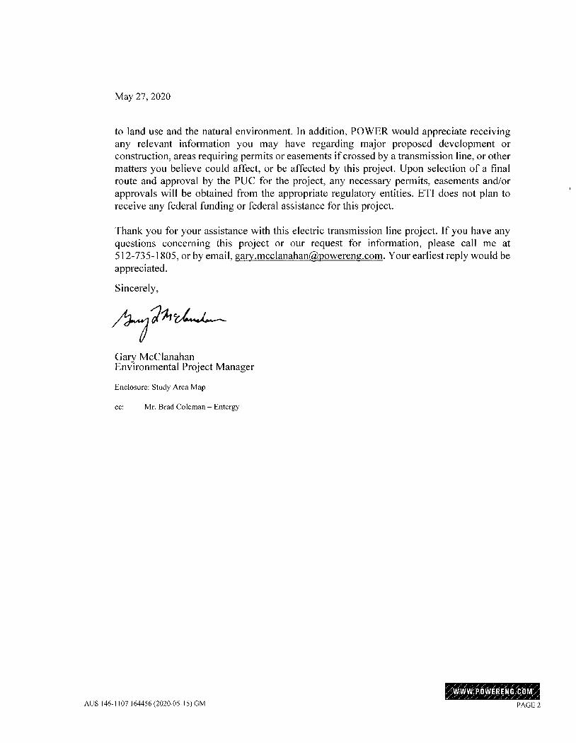
May 27,2020
to land use and the natural environment. In addition, POWER would appreciate receiving any relevant information you may have regarding major proposed development or construction, areas requiring permits or easements ifcrossed by a transmission line, or other matters you believe could affect, or be affected by this project. Upon selection of a final route and approval by the PUC for the project, any necessary permits, easements and/or approvals will be obtained from the appropriate regulatory entities. ETI does not plan to receive any federal funding or federal assistance for this project.
Thank you for your assistance with this electric transmission line project. If you have any questions concerning this project or our request for information, please call me at 512-735-1805, or by email, [email protected]. Your earliest reply would be appreciated.
Sincerely,
~*21244-
Gary McClanahan Environmental Project Manager
Enclosure: Study Area Map
ec: Mr. Brad Coleman - Entergy
.:WWW: PbWERENG.{{IOM>'' AUS 146-1107 ]64456 (2020-05-15) GM PAGE 2
t i- c \U t ' Towl Cr@ek n r / 1
Blackberry
'64> I,E RY. i #~I
L___.QountyRB
r-- -lE
d 313-
Sand Creek
MONTGOA Dobbjn
C
D· in
105
Bob~ille.
0
€D 48
f3 S 0
VM
.. ............... ......m................. .... ..1
- - ~ Lake C
Shady Oaks Country Oaks
Weeren
Hall
DD i Kan
) Grimes County MmITE county - r
WoS
JUO
W
==L=U
Castle 230 kV Transmission Line and Substation ProJect
STUDYAREA
egend ~ Study Area
Proposed Substation Siting Area
L
n € LJ Substation
4* 9 ---- Transmission Line % * Private Airstnp
-~= State Highway
FM Road
- County/Local Road
r'771 SH249 Right-of-Way ELLI (Under Construction) h» -r,-»- - Railroad
=0
Plantersvilla dounty3924293 =3 •Aeenan cut O•_Zo
<Ickapoo,fhek 1
r~ ~Ik,MMER,~ ,~ Lh AIRPIELDI , / . d
t#
: k .. U
-T £3 .
Intermittent Stream
Perennlal Stream
Waterbody Unincorporated Community
City Limits
County Boundary
. *: _._- f- #<i,<<4,·2 ~t * eek . ·- =>, Area of ;,
X Ilf- * 4* '.2£gly-BEE#i
LL ' Ggrk
L Miles
e 1.5
MISSI
Ekt
It\ Date: 5/20/2020 'G Entergy.
'.
U.S. Department of Transportation Federal Aviation Administration
Southwest Region 10101 Hillwood Parkway Fort Worth, TX 76177
June 22,2020
Gary McClanahan Power Engineers, Inc. 7600B N Capital of Texas Hwy Suite 320 Austin, TX 78731
Dear Mr. McClanahan:
This is in response to your May 27,2020, correspondence concerning Entergy Texas, Inc., proposed double-circuit 230-kilovolt transmission line in Grimes and Montgomery Counties, Texas. You requested information regarding environmental and land use concerns within the study area. You also requested any relevant information regarding proposed development or construction, permit or easement requirements, or other matters that may affect or be affected by the project.
As set forth in Title 14 of the Code of Federal Regulations Part 77, Objects that Affect the Navigable Airspace, the prime concern of the Federal Aviation Administration is the effect of certain proposed construction on the safe and efficient use o f the navigable airspace.
To accomplish this mission, aeronautical studies are conducted based on information provided by sponsors on FAA Form 7460-1, Notice of Proposed Construction or Alteration. If your organization is planning to sponsor any construction or alterations that may affect navigable airspace, you must file FAA Form 7460-1 electronically via https://oeaaa.faa.gov/oeaaa/external/portal..isp.
For additional information and assistance, please feel free to contact the Obstruction Evaluation Group at 10101 Hillwood Parkway, Fort Worth, Texas 76177 or (817) 222-5954.
Sincerely,
Rob Lowe Regional Administrator,
Southwest Region
CC: Obstruction Evaluation Group, AJV-15
0
From: Finn, Claire E <[email protected]> on behalf of IMRextrev, NPS <[email protected]>
Sent: Thursday, May 28,2020 2:55 PM To: Taylor, Ashley Subject: Re: [EXTERNAL] Proposed Castle 230 kV Transmission Line and Substation
Project
Dear Ms. Taylor,
The National Park Service (NPS) would like to thank you for the opportunity to be involved in this project. The NPS has reviewed this project and has no comments at this time.
National Park Service NPS Regional Office External Review Team Serving DOI Regions 6,7, and 8 [email protected]
From: [email protected] <[email protected]> Sent: Wednesday, May 27,2020 5:28 PM To: IMRextrev, NPS <[email protected]> Cc: [email protected] <[email protected]>; [email protected] <[email protected]> Subject: [EXTERNAL] Proposed Castle 230 kV Transmission Line and Substation Project
Dear Mr. Reynolds
On behalf of our client, Entergy Texas, Inc., attached please find a proposed project information letter.
Thank you for your assistance with this proposed electric transmission line project. Please contact the Project Manager, Gary McCIanahan, by phone at 512-735-1805, or by e-mail at [email protected], if you have any questions or require additional information.
Thanks,

A~hley Ta.ylo·r Environmental Specialist Central Env Svc PM Department 16825 Northchase Drive, Suite 1200 Houston, TX 77060 281-765-5512 direct 832-244-8654 cell
POWER Engineers, Inc. www.powereng.com
4% CURRENTS *C-v Environmental regulatory updates and insights
,~ Go Greenl Please print this email only when necessary. Thank you for helping POWER Engineers be environmentally responsible.
From: Sent: To: Subject: Attachments:
Villarreal, Carlos - NRCS, Temple,TX <[email protected]> Tuesday, June 16, 2020 3:30 PM McCIanahan, Gary EA - Castle 230 kV Transmission Line and Substation Project EA_Energy Texas Inc Castle 230 kV Transmission Line and Substation Project_Grimes and Montgomery County.pdf; Custom Soil Resource Report for Grimes and Montgomery County, Texas.pdf
Good afternoon,
Please find the attached EA of Natural Resources - Soils report for the proposed project located in Grimes and Montgomery County, Texas.
If you have further questions of comments, please feel free to contact me.
Best Regards,
Carlos J. Villarreal Soil Scientist Natural Resources Conservation Service United States Department of Agriculture o. 254.742.9836 c. 254.316.1458
Stay Connected with USDA: USDA fEN -Youledu gOVDELIVERY
This electronic message contains information generated by the USDA solely for the intended recipients. Any unauthorized interception of this message or the use or disclosure of the information it contains may violate the law and subject the violator to civil or criminal penalties. If you believe you have received this message in error, please notify the sender and delete the email immediately.
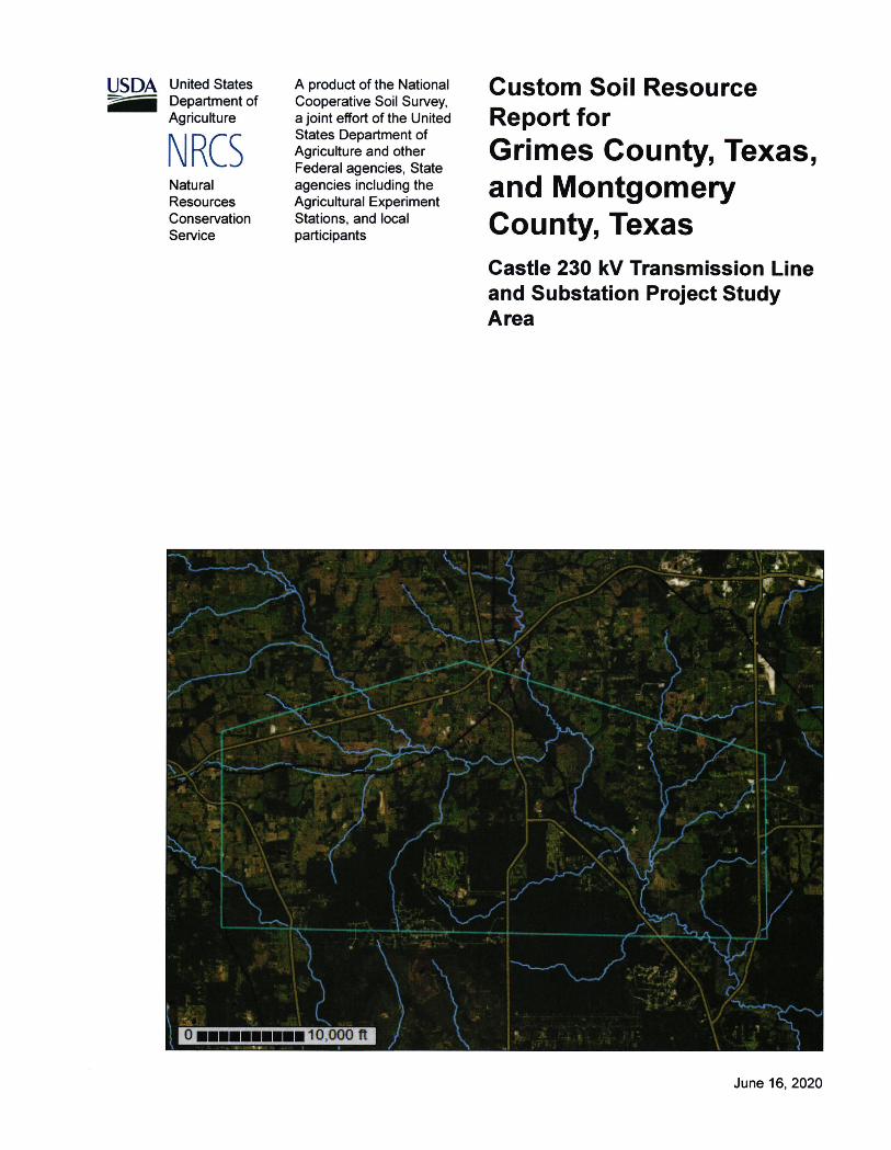
USDA United States ~ Department of
Agriculture
NRCS Natural Resources Conservation Service
A product of the National Cooperative Soil Survey, a joint effort of the United States Department of Agriculture and other Federal agencies, State agencies including the Agricultural Experiment Stations, and local participants
Custom Soil Resource Report for Grimes County, Texas, and Montgomery County, Texas Castle 230 kV Transmission Line and Substation Project Study Area
-273
"
• 1
i;
4
.T
4 t.
0 I,II,Illm, 10 ,ooo n jf 3/
June 16, 2020
Preface Soil surveys contain information that affects land use planning in survey areas. They highlight soil limitations that affect various land uses and provide information about the properties of the soils in the survey areas. Soil surveys are designed for many different users, including farmers, ranchers, foresters, agronomists, urban planners, community officials, engineers, developers, builders, and home buyers. Also, conservationists, teachers, students, and specialists in recreation, waste disposal, and pollution control can use the surveys to help them understand, protect, or enhance the environment. Various land use regulations of Federal, State, and local governments may impose special restrictions on land use or land treatment. Soil surveys identify soil properties that are used in making various land use or land treatment decisions. The information is intended to help the land users identify and reduce the effects of soil limitations on various land uses. The Iandowner or user is responsible for identifying and complying with existing laws and regulations. Although soil survey information can be used for general farm, local, and wider area planning, onsite investigation is needed to supplement this information in some cases. Examples include soil quality assessments (http://www. nrcs. usda.gov/wps/ portal/nrcs/main/soils/health/) and certain conservation and engineering applications. For more detailed information, contact your local USDA Service Center (https //offices. sc.egov. usda gov/locator/app?agency=nrcs) or your NRCS State Soil Scientist (http:Uwww. nrcs.usda.gov/wps/portal/nrcs/detail/soils/contactus/? cid=nrcs142p2_053951). Great differences in soil properties can occur within short distances. Some soils are seasonally wet or subject to flooding. Some are too unstable to be used as a foundation for buildings or roads. Clayey or wet soils are poorly suited to use as septic tank absorption fields. A high water table makes a soil poorly suited to basements or underground installations. The National Cooperative Soil Survey is a joint effort of the United States Department of Agriculture and other Federal agencies, State agencies including the Agricultural Experiment Stations, and local agencies. The Natural Resources Conservation Service (NRCS) has leadership for the Federal part of the National Cooperative Soil Survey. Information about soils is updated periodically. Updated information is available through the NRCS Web Soil Survey, the site for official soil survey information. The U.S. Department of Agriculture (USDA) prohibits discrimination in all its programs and activities on the basis of race, color, national origin, age, disability, and where applicable, sex, marital status, familial status, parental status, religion, sexual orientation, genetic information, political beliefs, reprisal, or because all or a part of an individual's income is derived from any public assistance program. (Not all prohibited bases apply to all programs.) Persons with disabilities who require
2

alternative means for communication of program information (Braille, large print, audiotape, etc.) should contact USDA's TARGET Center at (202) 720-2600 (voice and TDD). To file a complaint of discrimination, write to USDA, Director, Office of Civil Rights, 1400 Independence Avenue, S.W., Washington, D.C. 20250-9410 or call (800) 795-3272 (voice) or (202) 720-6382 (TDD). USDA is an equal opportunity provider and employer.
3
Contents Prefarg 2 How Soil Surveys Are Marlp 5 Soil Information for All I k•q 8
Suitabilities and Limitations for I IRP 8 Building Site Development 8
Dwellings On Concrete Slab (TX) 8 Soil Properties and Qualities..............................................................................21
Soil Physical Propertipq 21 Linear Extensibility 21
Water Featureq 30 Flooding Frequency Class...........................................................................30
4
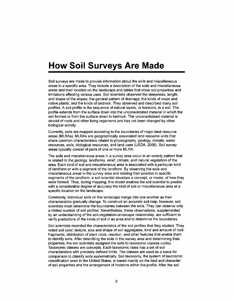
How Soil Surveys Are Made Soil surveys are made to provide information about the soils and miscellaneous areas in a specific area. They include a description of the soils and miscellaneous areas and their location on the landscape and tables that show soil properties and limitations affecting various uses. Soil scientists observed the steepness, length, and shape of the slopes; the general pattern of drainage; the kinds of crops and native plants; and the kinds of bedrock. They observed and described many soil profiles. A soil profile is the sequence of natural layers, or horizons, in a soil. The profile extends from the surface down into the unconsolidated material in which the soil formed or from the surface down to bedrock. The unconsolidated material is devoid of roots and other living organisms and has not been changed by other biological activity. Currently, soils are mapped according to the boundaries of major land resource areas (MLRAs). MLRAs are geographically associated land resource units that share common characteristics related to physiography, geology, climate, water resources, soils, biological resources, and land uses (USDA, 2006). Soil survey areas typically consist of parts of one or more MLRA.
The soils and miscellaneous areas in a survey area occur in an orderly pattern that is related to the geology, Iandforms, relief, climate, and natural vegetation of the area. Each kind of soil and miscellaneous area is associated with a particular kind of Iandform or with a segment of the Iandform. By observing the soils and miscellaneous areas in the survey area and relating their position to specific segments of the Iandform, a soil scientist develops a concept, or model, of how they were formed. Thus, during mapping, this model enables the soil scientist to predict with a considerable degree of accuracy the kind of soil or miscellaneous area at a specific location on the landscape. Commonly, individual soils on the landscape merge into one another as their characteristics gradually change. To construct an accurate soil map, however, soil scientists must determine the boundaries between the soils. They can observe only a limited number of soil profiles. Nevertheless, these observations, supplemented by an understanding of the soil-vegetation-landscape relationship, are sufficient to verify predictions of the kinds of soil in an area and to determine the boundaries. Soil scientists recorded the characteristics of the soil profiles that they studied. They noted soil color, texture, size and shape of soil aggregates, kind and amount of rock fragments, distribution of plant roots, reaction, and other features that enable them to identify soils. After describing the soils in the survey area and determining their properties, the soil scientists assigned the soils to taxonomic classes (units) Taxonomic classes are concepts. Each taxonomic class has a set of soil characteristics with precisely defined limits. The classes are used as a basis for comparison to classify soils systematically. Soil taxonomy, the system of taxonomic classification used in the United States, is based mainly on the kind and character of soil properties and the arrangement of horizons within the profile. After the soil
5
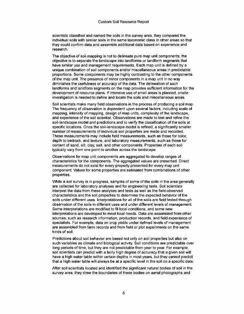
Custom Soil Resource Report
scientists classified and named the soils in the survey area, they compared the individual soils with similar soils in the same taxonomic class in other areas so that they could confirm data and assemble additional data based on experience and research. The objective of soil mapping is not to delineate pure map unit components; the objective is to separate the landscape into Iandforms or Iandform segments that have similar use and management requirements. Each map unit is defined by a unique combination of soil components and/or miscellaneous areas in predictable proportions. Some components may be highly contrasting to the other components of the map unit. The presence of minor components in a map unit in no way diminishes the usefulness or accuracy of the data. The delineation of such Iandforms and Iandform segments on the map provides sufficient information for the development of resource plans. If intensive use of small areas is planned, onsite investigation is needed to define and locate the soils and miscellaneous areas. Soil scientists make many field observations in the process of producing a soil map. The frequency of observation is dependent upon several factors, including scale of mapping, intensity of mapping, design of map units, complexity of the landscape, and experience of the soil scientist. Observations are made to test and refine the soil-landscape model and predictions and to verify the classification of the soils at specific locations. Once the soil-landscape model is refined, a significantly smaller number of measurements of individual soil properties are made and recorded. These measurements may include field measurements, such as those for color, depth to bedrock, and texture, and laboratory measurements, such as those for content of sand, silt, clay, salt, and other components. Properties of each soil typically vary from one point to another across the landscape. Observations for map unit components are aggregated to develop ranges of characteristics for the components. The aggregated values are presented. Direct measurements do not exist for every property presented for every map unit component. Values for some properties are estimated from combinations of other properties. While a soil survey is in progress, samples of some of the soils in the area generally are collected for laboratory analyses and for engineering tests. Soil scientists interpret the data from these analyses and tests as well as the field-observed characteristics and the soil properties to determine the expected behavior of the soils under different uses. Interpretations for all of the soils are field tested through observation of the soils in different uses and under different levels of management. Some interpretations are modified to fit local conditions, and some new interpretations are developed to meet local needs. Data are assembled from other sources, such as research information, production records, and field experience of specialists. For example, data on crop yields under defined levels of management are assembled from farm records and from field or plot experiments on the same kinds of soil. Predictions about soil behavior are based not only on soil properties but also on such variables as climate and biological activity. Soil conditions are predictable over long periods of time, but they are not predictable from year to year. For example, soil scientists can predict with a fairly high degree of accuracy that a given soil will have a high water table within certain depths in most years, but they cannot predict that a high water table will always be at a specific level in the soil on a specific date. After soil scientists located and identified the significant natural bodies of soil in the survey area, they drew the boundaries of these bodies on aerial photographs and
6

Custom Soil Resource Report
identified each as a specific map unit. Aerial photographs show trees, buildings, fields, roads, and rivers, all of which help in locating boundaries accurately.
7
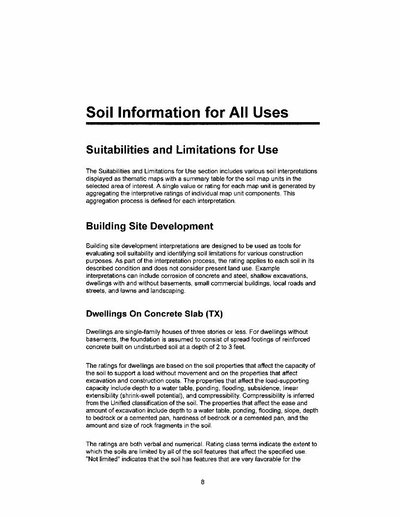
Soil Information for All Uses
Suitabilities and Limitations for Use The Suitabilities and Limitations for Use section includes various soil interpretations displayed as thematic maps with a summary table for the soil map units in the selected area of interest. A single value or rating for each map unit is generated by aggregating the interpretive ratings of individual map unit components. This aggregation process is defined for each interpretation.
Building Site Development
Building site development interpretations are designed to be used as tools for evaluating soil suitability and identifying soil limitations for various construction purposes. As part of the interpretation process, the rating applies to each soil in its described condition and does not consider present land use. Example interpretations can include corrosion of concrete and steel, shallow excavations, dwellings with and without basements, small commercial buildings, local roads and streets, and Iawns and landscaping.
Dwellings On Concrete Slab (TX)
Dwellings are single-family houses of three stories or less. For dwellings without basements, the foundation is assumed to consist of spread footings of reinforced concrete built on undisturbed soil at a depth of 2 to 3 feet.
The ratings for dwellings are based on the soil properties that affect the capacity of the soil to support a load without movement and on the properties that affect excavation and construction costs. The properties that affect the load-supporting capacity include depth to a water table, ponding, flooding, subsidence, linear extensibility (shrink-swell potential), and compressibility. Compressibility is inferred from the Unified classification of the soil. The properties that affect the ease and amount of excavation include depth to a water table, ponding, flooding, slope, depth to bedrock or a cemented pan, hardness of bedrock or a cemented pan, and the amount and size of rock fragments in the soil.
The ratings are both verbal and numerical. Rating class terms indicate the extent to which the soils are limited by all of the soil features that affect the specified use. "Not limited" indicates that the soil has features that are very favorable for the
8
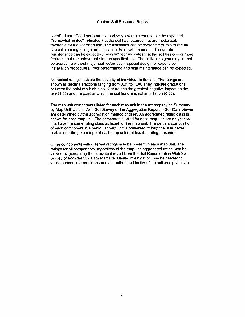
Custom Soil Resource Report
specified use. Good performance and very low maintenance can be expected. "Somewhat limited" indicates that the soil has features that are moderately favorable for the specified use. The limitations can be overcome or minimized by special planning, design, or installation. Fair performance and moderate maintenance can be expected. 'Very limited" indicates that the soil has one or more features that are unfavorable for the specified use. The limitations generally cannot be overcome without major soil reclamation, special design, or expensive installation procedures. Poor performance and high maintenance can be expected.
Numerical ratings indicate the severity of individual limitations. The ratings are shown as decimal fractions ranging from 0.01 to 1.00. They indicate gradations between the point at which a soil feature has the greatest negative impact on the use (1.00) and the point at which the soil feature is not a limitation (0.00).
The map unit components listed for each map unit in the accompanying Summary by Map Unit table in Web Soil Survey or the Aggregation Report in Soil Data Viewer are determined by the aggregation method chosen. An aggregated rating class is shown for each map unit. The components listed for each map unit are only those that have the same rating class as listed for the map unit. The percent composition of each component in a particular map unit is presented to help the user better understand the percentage of each map unit that has the rating presented.
Other components with different ratings may be present in each map unit. The ratings for all components, regardless of the map unit aggregated rating, can be viewed by generating the equivalent report from the Soil Reports tab in Web Soil Survey or from the Soil Data Mart site. Onsite investigation may be needed to validate these interpretations and to confirm the identity of the soil on a given site.
9
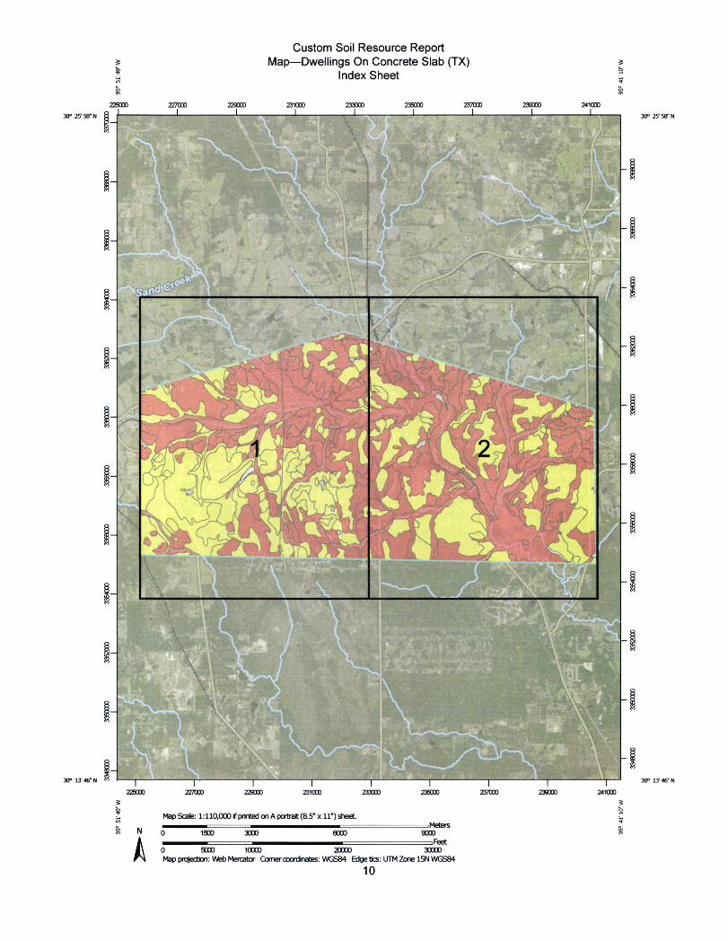
Custom Soil Resource Report Map-Dwellings On Concrete Slab (TX)
Index Sheet
Z27000 229000 231000 zm[Io 235000 237000 239000 241000
5 056 §- 1
D 056 30° 25' 58- N C 30° 25' 58" N
€.
'.
m/,
....8>
..,
r -
i 225000 227000 229000 231000 233000 235000 237000 238000 241000
9'W AA.0
30° 13'46~N M 30° 13' 46' N
Map Scale: 1:110,000 if pnnted on A port,ait (8.5' x 11") sheet N MZ A 0 1500 3000 6000 900[)
.--€ 0 5000 10000 20000 30000 Map pfvjecbon: Web Mercator Covercoordinates: WGS84 Edge Ucs: UTM Zone 15N WGS84
10
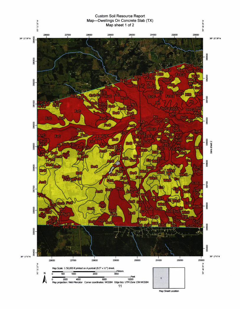
Custom Soil Resource Report Map-Dwellings On Concrete Slab (TX) *
Map sheet 1 of 2 #
30° 22' 39" N
2000 III) I
ZZ7000 228000 Z29000 230000 231000 Z32000 ZK 30° 27 39» N
TI'·
A
U•-'--Ob-C2.-4 '
f ..'. 't, ~2 A ,„*t~~FC SOC - . 1 'Su€*H,J,KiIBJ~ FeEs ~
22.-L
- Fr€ 4 H-Gb ~//,4/w
#4 erk
r- AQ §" CTI+Ec€-2·,,IfiB Wka;,i,f .4
. li,C MB 153' - * s~tc ¥ SuD @ VIHuC F *MC -- - l,IFMDW· ;4.
-··~ JC~QF((2' Su€ Ht'(.,P)(c~.1 . ~ }=.E„ .Fg ~ „r ED F -
Bli&
mec.
A/IA ErC
An£1
i,)eC A00 n
BgDJ
RHUCIJ
' '.BIC Sbt~_ * BisA . k€
Wkr
Z laalls
E
I A.€
Gki
* coe - " SBIB
~H-PQNa
COC _ I BIG
~ IIWA -20~ CnC, 6';@- Huc~uCV . ~ // NamD ~ 4:ugzsuc 0.-VVK[D -
1 -;SuD Si
coc Wej../n€-/Lra-€%--vl/1 B~M*;€*ClEUC£'BJZ cod du, 1-eC FeC~-~-=-------~ ·t~:.W'~ V_~LLEZEZ~Z~~~~~~ ~ . 1 -*' '/ t xK Y·t-1: ,X<.l~G:~?77;'3*<._. . ·#4g
t
2260(I) 227000
0. W
228000 229000 230000 231000 222000 233000 30° 176-N 30° 176'N
Map Scale: 1:50,000 if printed on A portlait (&5" x 11-) sheet k
N 0 500 1000 2000 3000 r,·1
0 2000 4000 800[) 12000 Map projection: Web Mercabor Corner coordinates: WGS84 Edge bcs: UTM Zone 15N WGS84
11
1
Map Sheet locaborl
Jih
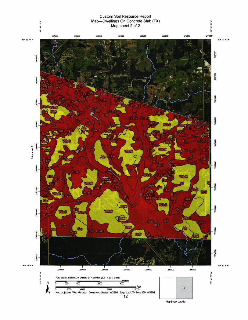
Custom Soil Resource Report 2 Map-Dwellings On Concrete Slab (TX) k 1 Map sheet 2 of 2
237000 Z38000 239000 240000 241000
L.
234000 235000 236000
95'
30° 22' 39" N 30° 22' 39" N
:4.
4.
Irq '+ ~ . Ji r , ti ;--,. i , .- r [ J U I/ -MS
~-Wkc ~LKZ 4'ii
4*!~5•'•'1R ¥ M.Fc[32 ib-€2©Fvv. *< ~RAX~1~ -iA~~1~ ~~~~D~,:*-9~~-'~ ~~.~~F ~ Tc 9 ~.*~I~~Jwh> AI kC~~( 2C-2
LI>Fct2{1~#*k,~ ~
An- :-, 'w'v,Ebr'SuD .U <c'rv '. - 7: 1.
Bi s~AIA€ :E2!f~ ~-tp --il. ~[Suclei,r - Fc[)2~ · 63' Vkc.,IA 4 >m-..,2~JFFC? C'Lf i
>U *H~
.'U 1419 U L,·~LJ DbC*OI
:D2,FcD SLiD , <<
-'~ SuB--1£f CC2 0 Z~
fsuD ASITCS t
A ¢WkC - + re tw~F Ks
Ab BisA .WI,Q
ViebC 2 I *
~ .' ru¥6
~ Th,·· WkC
Wk[) "_ CO€ SUC1
Tr\Al
COC
I- CnC B9yC. &
WaIA- illll=v -••-•
~Il/iBi€A'SoC
- COC t Gu
Cn€ C liC
*Il ~CoD Coc ..Co€HIIIII~'BICEBisA
234000 2350[J0 238000 237000 238000
9' W
30° 176" N 30° 17 6N
Map Scale: 1:50,000 if prir®ed on A portrait (8.5" x 11") sheet ----.-I=Meters
N 0 500 1000 2[XJo 3000
A r.nlt
0 2000 4000 8000 1E00 Map projecbon: Vkb Mercator Comer oooldinatg: WGS84 Edge tics: UTM Zone 15N WGS84
12
Bb- .
_L..Coe
238000 240000
2
M.6€,It, oS6
Map Sheet Locatjon
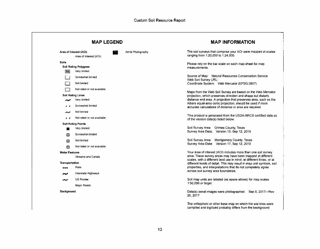
Custom Soil Resource Report
MAP LEGEND MAP INFORMATION
Area of Interest (AOI) Area of Interest (AOI)
Aenal Photography The soil surveys that comprise your AOI were mapped at scales ranging from 1:20,000 to 1:24,000.
Soils Soil Rating Polygons ~ Very limited
Please rely on the bar scale on each map sheet for map measurements.
~ Somewhat limited
~ Not limited
Source of Map: Natural Resources Conservation Service Web Soil Survey URL: Coordinate System: Web Mercator (EPSG:3857)
~ Not rated or not available
Soil Rating Lines *v• Very limited
Somewhat limited
Maps from the Web Soil Survey are based on the Web Mercator projection, which preserves direction and shape but distorts distance and area. A projection that preserves area, such as the Albers equal-area conic projection, should be used if more accurate calculations of distance or area are required.
,../ Not limited
.* Not rated or not available This product is generated from the USDA-NRCS certified data as of the version date(s) listed below,
Soil Rating Points I Very limited
Somewhat limited
Soil Survey Area Grimes County, Texas Survey Area Data: Version 15, Sep 12, 2019
EJ Not limited
¤ Not rated or not available
Soil Survey Area: Montgomery County, Texas Survey Area Data: Version 17, Sep 12, 2019
Water Features Streams and Canals
Transportation f-*-+ Rails
/,4 Interstate Highways
Your area of interest OAOI) includes more than one soil survey area. These survey areas may have been mapped at different scales, with a different land use in mind, at different times, or at different levels of detail. This may result in map unit symbols, soil properties, and interpretations that do not completely agree across soil survey area boundaries.
US Routes
Major Roads
Soil map units are labeled (as space allows) for map scales 1:50,000 or larger.
Background Date(s) aerial images were photographed: Sep 6, 2017-Nov 25,2017
The orthophoto or other base map on which the soil lines were compiled and digitized probably differs from the background
13
Custom Soil Resource Report
MAP LEGEND MAP INFORMATION
imagery displayed on these maps As a result, some minor shifting of map unit boundaries may be evident.
14
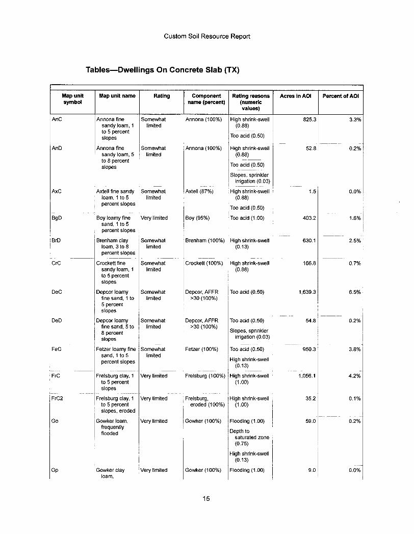
Custom Soil Resource Report
Tables-Dwellings On Concrete Slab (TX)
Map unit Map unit name Rating Component Rating reasons Acres in AOI Percent of AOI symbol name (percent) (numeric
values)
AnC Annona fine Somewhat Annona (100%) High shrink-swell 825.3 3.3% sandy Ioam, 1 limited (0.88) to 5 percent slopes Too acid (0.50)
AnD Annona fine Somewhat Annona (100%) High shrink-swell 52.8 0.2% sandy Ioam, 5 limited (0.88) to 8 percent - -slopes Too acid (0.50)
Slopes, sprinkler irrigation (0.03)
AxC Axtell fine sandy Somewhat Ao(tell (87%) High shrink-swell 1.5 0.0% Ioam, 1 to 5 limited , (0.88) percent slopes
Too acid (0.50)
BgD Boy Ioamy fine Very limited Boy (95%) Too acid (1.00) 403.2 1.6% sand, 1 to 5 percent slopes
BrD Brenham clay Somewhat Brenham (100%) High shrink-s~/veil 630.1 2.5% Ioam, 3 to 8 limited (0.13) percent slopes
CrC Crockett fine Somewhat Crockett (100%) High shrink-swell 166.8 0.7% sandy Ioam, 1 limited (0.88) to 5 percent slopes
DeC Depcor Ioamy Somewhat Depcor, AFFR Too acid (0.50) 1,639.3 6.5% fine sand, 1 to limited >30 (100%) 5 percent slopes
DeD Depcor Ioamy Somewhat Depcor, AFFR fine sand, 5 to limited >30 (100%) 8 percent slopes
Too acid (0.50) 54.8 0.2%
Slopes, spnnkler irrigation (0.03)
FeC Fetzer Ioamy fine Somewhat Fetzer (100%) Too acid (0.50) 950.3 3.8% sand, 1 to 5 limited percent slopes High shrink-swell
(0.13)
FrC Frelsburg clay, 1 Very limited Frelsburg (100%) High shrink-swell 1,056.1 4.2% to 5 percent (1.00) slopes
FrC2 Frelsburg clay, 1 Very limited Frelsburg, High shrink-swell 35.2 0.1% to 5 percent eroded (100%) (1.00) slopes, eroded
Go Gowker Ioam, Very limited Gowker (100%) Flooding (1.00) 59.0 0.2% frequently
Depth to flooded saturated zone (0.75)
High shrink-swell (0.13)
Gp Gowker clay Very limited Gowker (100%) Flooding (1.00) 9.0 0.0% Ioam,
15
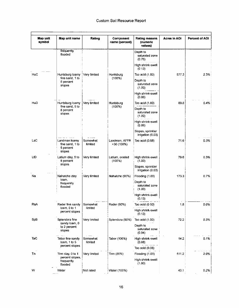
Custom Soil Resource Report
Map unit Map unit name Rating Component Rating reasons Acres In AOI Percent of AOI symbol name (percent) (numeric
values) frequently Depth to flooded saturated zone
(0.75)
~ High shrink-swell (013)
HuC Huntsburg loamy ~ Very limited Huntsburg fine sand, 1 to (100%) 5 percent slopes
Too acid (1.00) 577.3 2.3%
Depth to saturated zone (1.00)
~ High shrink-swell (0.88)
HuD Huntsburg Ioamy fine sand, 5 to 8 percent slopes
~ Very limited Huntsburg (100%)
Too acid (1.00) 89.8 0.4%
Depth to saturated zone (1.00)
High shrink-swell (0.88)
Slopes, sprinkler irrigation (0.03)
LaC Landman Ioamy Somewhat Landman, AFFR | Too acid (0.08) 71.6 0.3% fine sand, 1 to limited >30 (100%) 5 percent slopes
LtD Latium clay, 5 to Very limited Latium, eroded ~ High shrink-swell 79.6 0.3% 8 percent (100%) (1.00) slopes
Slopes, spnnkler irrigation (0.03)
Na Nahatche clay Very limited Nahatche (90%) Flooding (1.00) 173.3 07% Ioam, frequently Depth to flooded saturated zone
(1.00)
High shrink-swell (0.13)
RaA Rader fine sandy Somewhat Rader (90%) Too acid (0 50) 1.8 0.0% Ioam, 0 to 1 limited - -percent slopes High shrink-swell
(0.13)
SpB Splendora fine Very limited Splendora (90%) Too acid (1.00) 72.2 0.3% sandy Ioam, 0
Depth to to 2 percent slopes saturated zone
(0.94)
TaC Tabor fine sandy Somewhat Tabor (100%) High shrink-swell 14.2 0.1% Ioam, 1 to 5 limited (0.88) percent slopes
Too acid (0.08)
Tn Tinn clay, 0 to 1 Very limited Tinn (85%) Flooding (1.00) 511.2 2.0% percent slopes, frequently High shrink-swell flooded (1.00)
W Water Not rated Water (100%) 43.1 0.2%
16
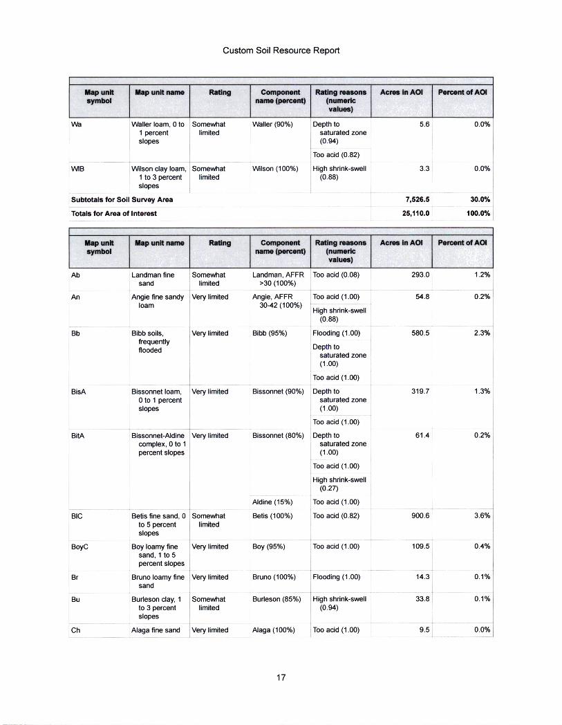
Custom Soil Resource Report
Map unit Map unit name Rating Component Rating reasons Acres In AOI Percent of AOI symbol name (percent) (numeric
values)
Wa Waller Ioam, 0 to Somewhat Waller (90%) Depth to 5.6 0.0% 1 percent limited saturated zone slopes (0.94)
Too acid (0.82)
\MB Wilson day Ioam, Somewhat Wilson (100%) High shrink-swell 3.3 0.0% 1 to 3 percent ~ limited i (0.88) slopes
Subtotals for Soil Survey Area 7,526.5 30.0%
Totals for Area of Interest 25,110.0 100.0%
Map unit Map unit name Rating Component Rating reasons Acres in AOI Percent of AOI symbol name (percent) (numeric
values)
Ab Landman fine Somewhat Landman, AFFR Too acid (0.08) 293.0 1.2% sand limited >30 (100%)
An Angie fine sandy Very limited Angie, AFFR Ioam 30-42 (100%)
Too acid (1.00) 54.8 0.296
High shrink-swell (0.88)
Bb Bibb soils, Very limited Bibb (95%) Flooding (1.00) 580.5 2.3% frequently
Depth to flooded saturated zone (1.00)
Too acid (1.00)
BisA Bissonnet Ioam, Very limited Bissonnet (90%) Depth to 319.7 1.3% 0 to 1 percent saturated zone slopes (1.00)
Too acid (1.00)
BitA Bissonnet-Aldine Very limited Bissonnet (80%) Depth to 61.4 0.2% complex, 0 to 1 saturated zone percent slopes (1.00)
Too acid (1.00)
High shrink-swell (0.27)
Aldine (15%) Too acid (1.00)
BIC Betis fine sand, 0 Somewhat Betis (100%) Too acid (0.82) 900.6 3.6% to 5 percent limited slopes
BoyC Boy Ioamy fine Very limited Boy (95%) Too acid (1.00) 109.5 0.4% sand, 1 to 5 percent slopes '
Br Bruno Ioamy fine Very limited Bruno (100%) Flooding (1.00) 14.3 o.1% sand ,
Bu Burleson clay, 1 Somewhat Burleson (85%) High shrink-swell 33.8 0.1% to 3 percent limited (0.94) slopes
Ch Alaga fine sand Very limited Alaga (100%) Too acid (1.00) 9.5 0.0%
17
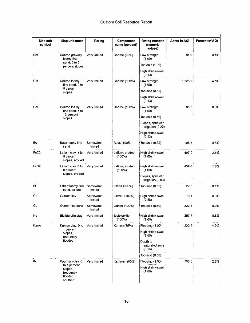
Custom Soil Resource Report
Map unit Map unit name Rating Component Rating reasons Acres in AOI Percent of AOI symbol name (percent) (numeric
values) CnC Conroe gravelly Very limited Conroe (90%) Low strength 91 0 0.4%
Ioamy fine (1.00) sand, 0 to 5
Too acid (1.00) percent slopes High shrink-swell
(013)
Coc Conroe Ioamy Very limited Conroe (100%) Low strength 1,126.0 4.5% fine sand, 0 to (1.00) 5 percent
Too acid (0.50) slopes High shrink-swell
(0.13)
CoD Conroe Ioamy Very limited Conroe (100%) Low strength 65.0 0.3% fine sand, 5 to (1.00) 12 percent
Too acid (0.50) slopes Slopes, sprinkler
irrigation (0 22) High shrink-swell
(0.13)
Eu Betis Ioamy fine Somewhat Betts (100%) Too acid (0.82) 188.5 0.8% sand limited
FcC2 Latium clay, 1 to Very limited Latium, eroded High shrink-swell 887.0 3.5% 5 percent (100%) (1.00) slopes, eroded
FcD2 Latium clay, 5 to Very limited Latium, eroded High shrink-swell 439.6 1 8% 8 percent (100%) (1.00) slopes, eroded
Slopes, sprinkler irrigation (0.03)
Ft Lilbert Ioamy fine Somewhat Lilbert (100%) Too acid (0.82) 22.6 0.1% sand, terrace limited
Ga Garner clay Somewhat Garner (100%) High shrink-swell 79.1 0.3% limited (0.88)
Gu Gunter fine sand Somewhat Gunter (100%) Too acid (0.50) 222.6 0.9% limited
Hs Bleiblerville clay Very limited Bleiblerville High shrink-swell 207.7 0.8% (100%) (1.00)
KanA Kaman clay, 0 to Very limited Kaman (85%) Flooding (1 00) 1,220.9 4.9% 1 percent
High shrink-swell slopes, frequently (1.00) flooded Depth to
saturated zone (0.56)
Too acid (0.50)
Kc Kaufman clay, 0 Very limited Kaufman (85%) Flooding (1.00) 705.0 2.8% to 1 percent slopes, High shrink-swell
(1.00) frequently flooded, southern
18
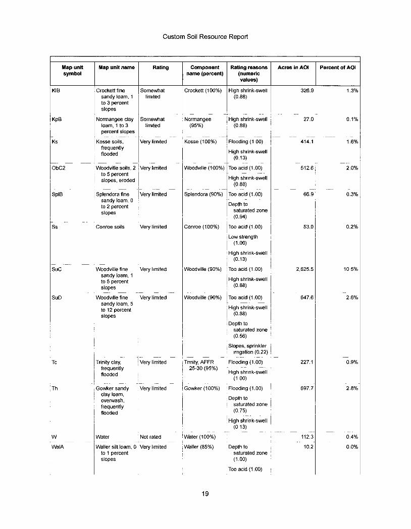
Custom Soil Resource Report
Map unit Map unit name Rating Component Rating reasons Acres in AOI Percent of AOI symbol name (percent) (numeric
values)
KIB Crockett fine Somewhat Crockett (100%) High shrink-swell 326.9 1.3% sandy Ioam, 1 limited (0.88) to 3 percent slopes
KpB Normangee clay Somewhat Normangee High shrink-swell 27.0 | o.1% Ioam, 1 to 3 limited (95%) (0.88) percent slopes
Ks Kosse soils, Very limited Kosse (100%) Flooding (1 00) 414.1 1.6% frequenUy flooded High shrink-swell
(0.13)
ObC2 Woodville soils, 2 Very limited Woodville (100%) Too acid (1.00) 512.6 2.0% to 5 percent
High shrink-swell slopes, eroded (0.88)
SpIB Splendora fine Very limited Splendora (90%) Too acid (1.00) 66.9 0.3% sandy Ioam, 0 to 2 percent Depth to
saturated zone slopes (0.94)
Ss Conroe soils Very limited Conroe (100%) Too acid (1.00) 53.0 0.2%
Low strength (1.00)
High shrink-swell (0.13)
SUC Woodville fine Very limited Woodville (90%) Too acid (1.00) 2,625.5 10 5% sandy Ioam, 1
High shrink-swell to 5 percent slopes (0.88)
SuD Woodville fine Very limited Woodville (90%) Too acid (1.00) 647.6 2.6% sandy Ioam, 5
High shrink-swell to 12 percent (0.88) slopes
Depth to saturated zone (0.56)
Slopes, sprinkler irrigation (0.22)
Tc Trinity clay, Very limited Trinity, AFFR frequently 25-30 (95%) flooded
Flooding (1.00) 227.1 0.9%
High shrink-swell (1 00)
Th Gowkersandy Very limited Gowker (100%) Flooding (1.00) 697.7 2.8% clay Ioam, oven/vash, Depth to frequently saturated zone flooded (0.75)
High shrink-swell (013)
W Water Not rated Water (100%) 112.3 0.4%
WaIA Waller silt Ioam, 0 Very limited Waller (85%) Depth to 10.2 0.0% to 1 percent saturated zone slopes (1.00)
Too acid (1.00)
19
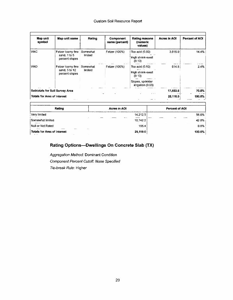
Custom Soil Resource Report
Map unit Map unit name Rating Component Rating reasons Acres in AOI Percent of AOI symbol name (percent) (numeric
values) WkC Fetzer Ioamy fine Somewhat ~ Fetzer (100%) Too acid (0.50) 3,616.0 14.4%
sand, 1 to 5 limited percent slopes High shrink-swell
(0.13)
WkD Fetzer Ioamy fine Somewhat I Fetzer (100%) Too acid (0.50) 614.8 2.4% sand, 5 to 12 limited percent slopes High shrink-swell
(013)
Slopes, sprinkler irrigation (0.03)
Subtotals for Soil Survey Area 17,583.6 70.0%
Totals for Area of Interest 25,110.0 100.0%
Rating Acres in AOI Percent of AOI
Very limited 14,212.5 56.6%
Somewhat limited 10,742 2 42 8%
Null or Not Rated 155.4 0.6%
Totals for Area of Interest 25,110.0 100.0%
Rating Options-Dwellings On Concrete Slab (TX)
Aggregation Method : Dominant Condition
Component Percent Cutoff: None Specified
Tie - break Rule : Higher
20
Custom Soil Resource Report
Soil Properties and Qualities
The Soil Properties and Qualities section includes various soil properties and qualities displayed as thematic maps with a summary table for the soil map units in the selected area of interest. A single value or rating for each map unit is generated by aggregating the interpretive ratings of individual map unit components. This aggregation process is defined for each property or quality.
Soil Physical Properties
Soil Physical Properties are measured or inferred from direct observations in the field or laboratory. Examples of soil physical properties include percent clay, organic matter, saturated hydraulic conductivity, available water capacity, and bulk density.
Linear Extensibility
Linear extensibility refers to the change in length of an unconfined clod as moisture content is decreased from a moist to a dry state. It is an expression of the volume change between the water content of the clod at 1/3- or 1/10-bar tension (33kPa or 10kPa tension) and oven dryness. The volume change is reported as percent change for the whole soil. The amount and type of clay minerals in the soil influence volume change.
For each soil layer, this attribute is actually recorded as three separate values in the database. A low value and a high value indicate the range of this attribute for the soil component. A "representative" value indicates the expected value of this attribute for the component. For this soil property, only the representative value is used.
21
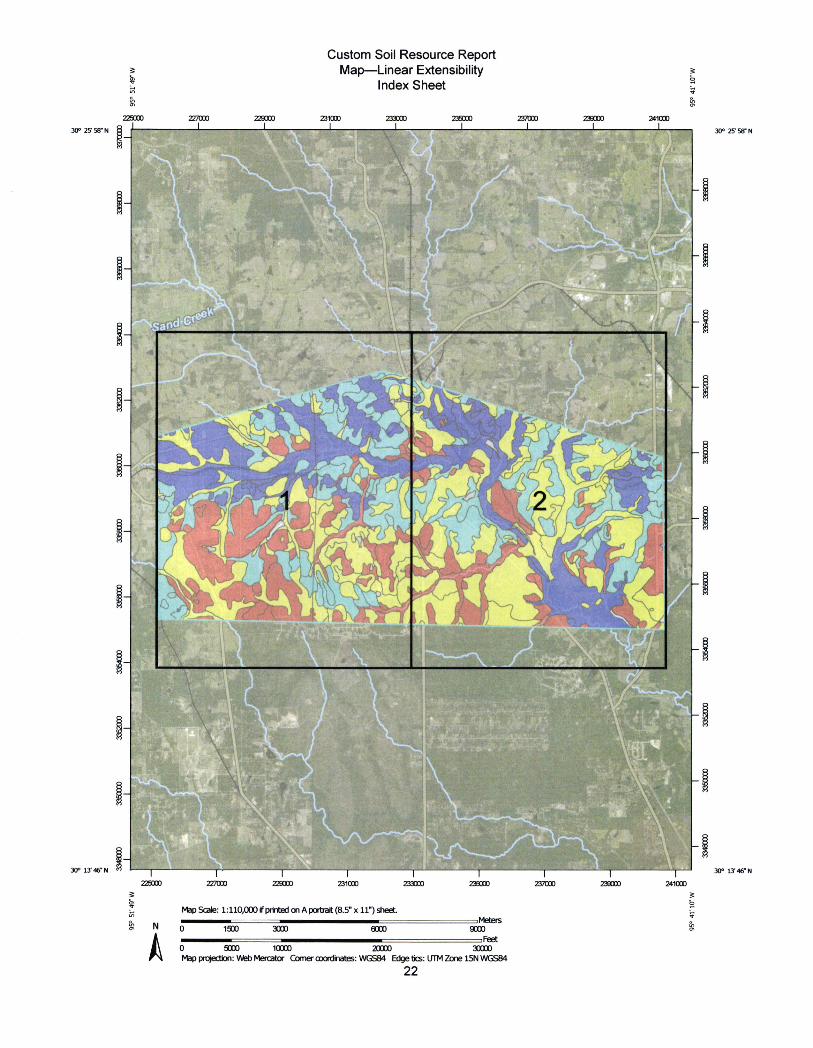
Custom Soil Resource Report Map-Linear Extensibility
Index Sheet LA
225[ K]0 Z27000 229000 ZMooo Z33000 235000 237000 239000 241000
!t
.
4't.il
* 056 30° 25' 58-N ¤ 30° 25' 58-N
2
r
'Ill,im../ r
---.Itam
225000 227000 Z29000 Z31CO[0 233000 235000 237[X]0 2~9000 241000
9' W
M.0
30° 13' 46« N m 30° 13 46- N
Map Scale: 1: 110,000 if pn,ted on A poroait (8.5" x 11") sheet.
0 1500 3000 60[JO 9000 r-,4
0 5000 10000 20000 30000 Map projedjon: Web Mercator Comer coo,·din*es: WGS84 Edge bcs: UTM Zone 15N WGS84
22
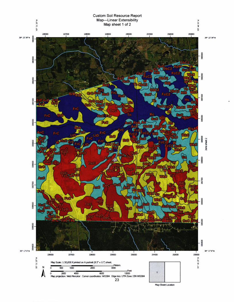
226000 Z27000
t
95° 51'20-w
Custom Soil Resource Report Map-Linear Extensibility *
Map sheet 1 of 2 #
ZID 30 ° 22 ' 39 - N ~ 30 ° 27 39 ' N
229000
ifc"
XI]CIO 231000
i
2P000 233000
- lm:-iti*2 )bC2
FcC2~ ~
~-TMSvgl
a
N *y. -mp~s- ·„-cug
Obe2 J~B~ IA#gl, .%
. -**//~~~~/0. --i: •-2 ~~nfE,0M,FrC•,~
~ %~"*4/6-.*b .-FrC '9~ DeC'~[*C- -Dh/ ~k€1
Kc - ~ ~Ra
B,~ FrC ~c i _-/MisA. l&11C FrC Lt]2~
110 //- A / Oa VrC
FrC ~ ~FrC2 rcuz KB
8 1:RgJT 'fl~ FrC ~-* ¤~AC~~ ~~~~l~~- | ~ LtD ~BT~-
M - - ' V --/ ~ / icc21~ " 9 ' ~ ///// ~ A <~//A~ FrC~Lt[~ 7.,/~idd~ue lllllll- SuC F c (-2*5~ MF,S , 4 Wmf/IWM¢1/V - ~~WWHA 4 Hu~ ~~ De~|0~ Eu,~ ~-~DeC~e~ 'CE€
r.,A/,uev- '~ d~JWke SpIB Dbd/- J. .-FdC'W.Fe (€- <'I,' F~.~. !2?~
)e C 141!&~gi, -~ ."4. N
Gu,
VaC DeC Fee a<S< _ Bg~ Zi~ ~S~~~~~~~u~~IW~~ji .FiEE~ BIC~b~ ~
jtc-, ' ~Gu (vj &(20~~ - 12.RAF;.=-fee-t ,•[€ '-- ·. . B.!1*30€cBIC®0(3·.¤in-¤lgEE,EI Ql - ~
Dlm
i~Fccj,~
DIS€-2
Suel
~b MIr*gmj €q
DeC,
Na
BgD, DeC ~~
~eD Bg.D,t
V'[Cocl
226000 227000 228000 229000 230000 231000 232000 233000 B k 20
'W
30° 176"N 30° 176N
Map bcale: 1::>U,~r pnnuea on A porua, (O.t·· x if··) sneet ---0 Meters
N 0 500 1000 2000 3000
A rr·r*
0 2000 4000 8000 12000 Map projecbon: Vkb Mercator Comer coordinates: WGS84 Edge bcs: UTM Zone 15N WGS84
23
1
Map Sheet Locabon
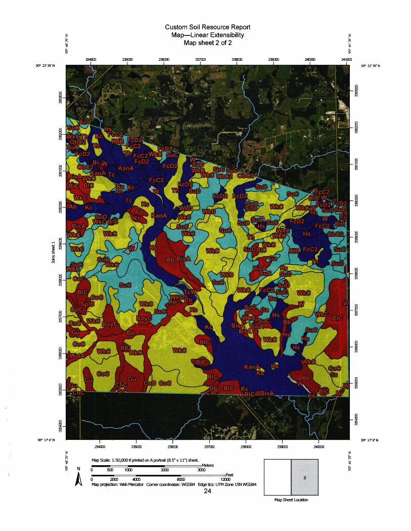
30° 22' 39" N
234000 235000 95
° 46
' 29
W
Custom Soil Resource Report Map-Linear Extensibility
Map sheet 2 of 2
Z3800) 237000 238000 Z39000 240000 241000 1 1 i 1 1
*-•rc J 30° 22' N N
.
!*a
%1 Bis
BI(
~- Ab
rcD2
[®b€2 4 - KanA M#KanA Tc
Tc Kc
FcD2 FcD2i dll
FcC2
-~D~~~anA~* ~ wJE ~ BisA
'44 V. . ~6[) Efi..~ FcC2/ ~~
Ab5BisA
SUD /..~TcW lal~k@-LFcC*~C-
Wk€
*--~
tic
3Pl~ ~
AWE
I- - -//Hs 22*@ M -BIC ~ 6.tsuc
il WaIA
i. (Dim ~ Ab
239000 240000
2
M.6E.It, 056
Kan* t
/Bb-7BI€4 '.Kc
BICy
rCOC=--VABI¢2BisA
NU 1 30° 176'N 30° 17 6 N
M Map Scale: 1:50,000 rp,inted on A portrait (8.5" x 11") sheet # -Meteg 8 0 500 1000 2[JOO 3000
r"r, 0 2000 4000 8000 12000 Map projeaion: Vkb Mercator Comeroootd,rates: WGS84 Edge ~cs: UTM Zone 15N WGS84
24 Map Sheet Locaborl
1 234000 235000 236000 237000 238000
R
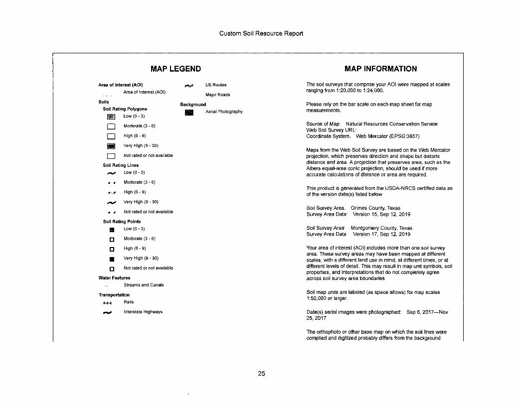
Custom Soil Resource Report
MAP LEGEND MAP INFORMATION
Area of Interest (AOI) 0'4 Area of Interest (AOI)
US Routes
Major Roads
The soil surveys that comprise your AOI were mapped at scales ranging from 1:20,000 to 1:24,000.
Soils Soil Rating Polygons ~] Low (0 - 3)
Background Please rely on the bar scale on each map sheet for map Aerial Photography measurements.
~ Moderate (3 - 6)
~ High (6 - 9)
~ Very High (9 - 30)
j Not rated or not available
Soil Rating Lines -%. Low (0 - 3)
Moderate (3 - 6)
High (6 - 9)
*#* Very High (9 - 30)
Not rated or not available
Soil Rating Points ~ Low (0 -3)
¤ Moderate (3 - 6)
¤ Hfgh (6- 9)
~ Very High (9 - 30)
¤ Not rated or not available
Water Features Streams and Canals
Transportation
+++ Rails
mo Interstate Highways
Source of Map: Natural Resources Conservation Service Web Soil Survey URL: Coordinate System. Web Mercator (EPSG:3857)
Maps from the Web Soil Survey are based on the Web Mercator projection, which preserves direction and shape but distorts distance and area A projection that preserves area, such as the Albers equal-area conic projection, should be used if more accurate calculations of distance or area are required.
This product is generated from the USDA-NRCS certified data as of the version date(s) listed below.
Soil Survey Area. Grimes County, Texas Survey Area Data- Version 15, Sep 12, 2019
Soil Survey Area· Montgomery County, Texas Survey Area Data Version 17, Sep 12, 2019
Your area of Interest (AOI) includes more than one soil survey area. These survey areas may have been mapped at different scales, with a different land use in mind, at different times, or at different levels of detail. This may result in map unit symbols, soil properties, and interpretations that do not completely agree across soil survey area boundaries
Soil map units are labeled (as space allows) for map scales 1:50,000 or larger.
Date(s) aerial images were photographed: Sep 6, 2017-Nov 25,2017
The orthophoto or other base map on which the soil lines were compiled and digitized probably differs from the background
25
Custom Soil Resource Report
MAP LEGEND MAP INFORMATION
imagery displayed on these maps. As a result, some minor shifting of map unit boundaries may be evident.
26
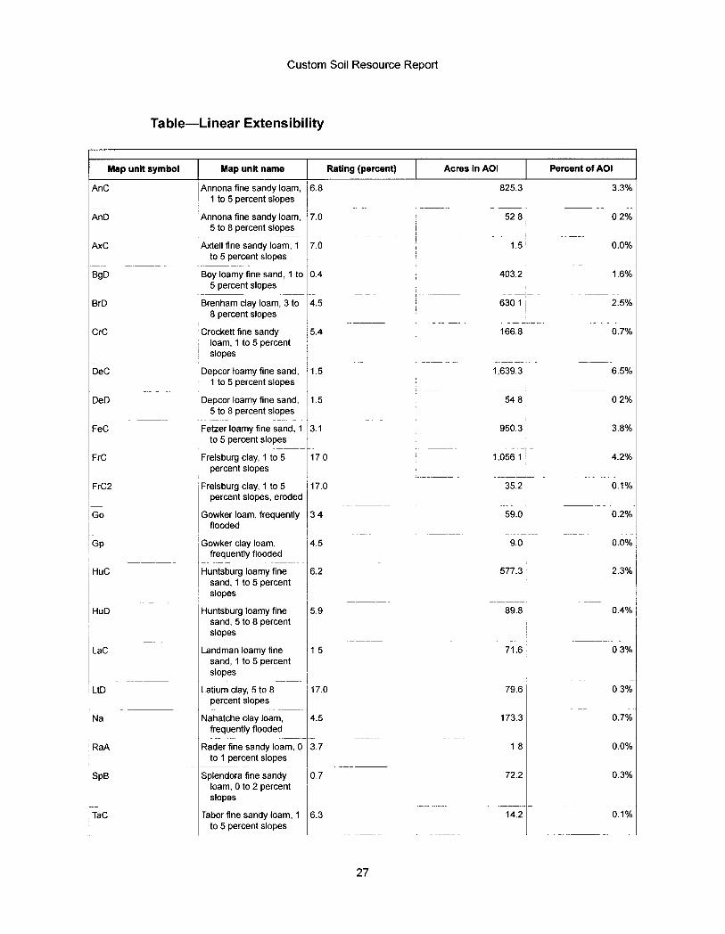
Custom Soil Resource Report
Table-Linear Extensibility
Map unit symbol Map unit name Rating (percent) Acres in AOI Percent of AOI
AnC Annona fine sandy Ioam, 6.8 825.3 3.3% 1 to 5 percent slopes
AnD Annona fine sandy Ioam, 7.0 52 8 02% 5 to 8 percent slopes
AxC Axtell fine sandy Ioam, 1 7.0 1.5 0.0% to 5 percent slopes
BgD Boy Ioamy fine sand, 1 to 0.4 403.2 16% 5 percent slopes
BrD Brenham clay Ioam, 3 to 4.5 630 1 2.5% 8 percent slopes
CrC Crockett fine sandy 5.4 166.8 0.7% Ioam, 1 to 5 percent slopes
DeC Depcor Ioamy fine sand, 1.5 1,639.3 6.5% 1 to 5 percent slopes
DeD Depcor Ioamy fine sand, 1.5 54 8 02% 5 to 8 percent slopes
FeC Fetzer Ioamy fine sand, 1 3.1 950.3 3.8% to 5 percent slopes
FrC Frelsburg clay , 1 to 5 170 1 , 056 1 4 . 2 % percent slopes
FrC2 Frelsburg clay, 1 to 5 17.0 35.2 0.1% percent slopes, eroded
Go Gowker Ioam, frequently 3 4 59.0 0.2% flooded
Gp Gowker clay Ioam, 4.5 9.0 0.0% frequently flooded
HuC Huntsburg Ioamy fine 6.2 577.3 2.3% sand, 1 to 5 percent slopes
HuD Huntsburg Ioamy fine 5.9 89.8 0.4% sand, 5 to 8 percent slopes
LaC Landman Ioamy fine 15 71.6 03% sand, 1 to 5 percent slopes
UD Latium clay, 5 to 8 17.0 79.6 03% percent slopes
Na Nahatche clay Ioam, 4.5 173.3 0.7% frequently flooded
RaA Rader fine sandy Ioam, 0 3.7 18 0.0% to 1 percent slopes
SpB Splendora fine sandy 0.7 72.2 0.3% Ioam, 0 to 2 percent slopes
TaC Tabor fine sandy Ioam, 1 6.3 14.2 0.1% to 5 percent slopes
27
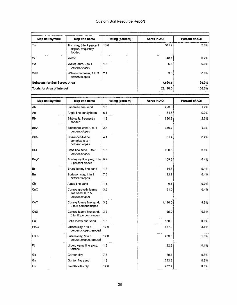
Custom Soil Resource Report
Map unit symbol Map unit name Rating (percent) Acres in AOI Percent of AOI
Tn Tinn clay, 0 to 1 percent 10.0 511.2 2.0% slopes, frequently
~ flooded I W ~ Water 43.1 0.2%
Wa Waller Ioam, 0 to 1 ~ 1.5 5.6 0.0% percent slopes
WIB ~ Wilson clay loam, 1 to 3 | 7.1 3.3 0.0% percent slopes
Subtotals for Soil Survey Area 7,526.5 30.0%
Totals for Area of Interest 25,110.0 100.0%
Map unit symbol Map unit name Rating (percent) Acres in AOI Percent of AOI
Ab Landman fine sand 1.5 293.0 1.2%
An Angie fine sandy Ioam 6.1 54.8 0.2%
Bb Bibb soils, frequently 1.5 580.5 2.3% flooded
BisA Bissonnet Ioam, 0 to 1 2.5 319.7 1.3% percent slopes
BitA Bissonnet-Aldine 4.1 61.4 0.2% complex, 0 to 1 percent slopes
BIC Betis fine sand, 0 to 5 1.5 900.6 3.6% percent slopes
BoyC Boy Ioamy fine sand, 1 to 0 4 109.5 0.4% 5 percent slopes
Br Bruno loamy fine sand 1.5 14.3 0.1%
Bu Burleson clay, 1 to 3 7.5 33.8 0.1% percent slopes
Ch Alaga fine sand 1.5 9.5 0.0%
CnC Conroe gravelly Ioamy 3.5 91.0 0.4% fine sand, 0 to 5 percent slopes
Coc Conroe Ioamy fine sand, 3.5 1,126.0 4.5% 0 to 5 percent slopes
CoD Conroe Ioamy fine sand, 3.5 65.0 0.3% 5 to 12 percent slopes
Eu Betis Ioamy fine sand 1.5 188.5 0.8%
FcC2 Latium clay, 1 to 5 17.0 887.0 3.5% percent slopes, eroded
FcD2 ~ Latium clay, 5 to 8 ~ 17.0 439.6 1.8% percent slopes, eroded :
Ft Lilbert Ioamy fine sand, ' 1.5 22.6 0.1% terrace
Ga Garner clay 7.5 79.1 0.3%
Gu Gunter fine sand 1.5 222.6 0.9%
Hs Bleiblerville clay 17.0 207.7 0.8%
28
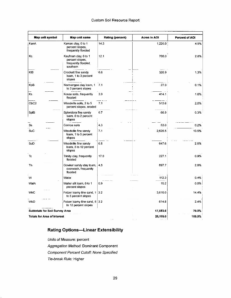
Custom Soil Resource Report
Map unit symbol Map unit name Rating (percent) Acres in AOI Percent of AOI
KanA Kaman clay, 0 to 1 14.3 1,220.9 4.9% percent slopes, frequently flooded
Kc Kaufman clay, 0 to 1 12.1 705.0 2.8%
~~~ntfjioe~ded, southern
KIB Crockett fine sandy 6.6 326.9 ~ 1.3% Ioam, 1 to 3 percent slope I
KpB ~ Normangee day loam, 1 7.1 27.0 ~ 0.1% to 3 percent slopes
Ks Kosse soils, frequently 3.9 414.1 flooded ~
1.6%
ObC2 Woodville soils, 2 to 5 7.1 512.6 2.0% percent slopes, eroded
SpIB ~ Splendora fine sandy 0.7 66.9 0.3% Ioam, 0 to 2 percent slopes
Ss Conroe soils 4.3 53.0 0.2%
SUC Woodville fine sandy 7.1 2,625.5 10.5% Ioam, 1 to 5 percent slopes
SuD Woodville fine sandy 6.8 647.6 2.6% Ioam, 5 to 12 percent slopes
Tc ~ Trinity clay, frequently 17.0 227.1 0.9% flooded
Th Gowker sandy clay Ioam, 4.5 697.7 2.8% overwash, frequently flooded
W ~ Water 112.3 | 0.4%
WaIA ~ Waller silt loam, 0 to 1 0.9 10.2 0.0% percent slopes
WkC ~Fetzer Ioamy fine sand, 1 3.2 3,616.0 ~ 14.4% to 5 percent slopes
WkD ~Fetzer loamy fine sand, 5 3.2 614.8 2.4% to 12 percent slopes
Subtotals for Soil Survey Area 17,583.6 70.0%
Totals for Area of Interest 25,110.0 100.0%
Rating Options-Linear Extensibility
Units of Measure : percent Aggregation Method : Dominant Component
Component Percent Cutoff: None Specified
Tie - break Rule : Higher
29
Custom Soil Resource Report
Interpret Nulls as Zero: No
Layer Options (Horizon Aggregation Method).- Depth Range (Weighted Average)
Top Depth: 0
Bottom Depth: 200
Units of Measure : Centimeters
Water Features
Water Features include ponding frequency, flooding frequency, and depth to water table.
Flooding Frequency Class
Flooding is the temporary inundation of an area caused by overflowing streams, by runoff from adjacent slopes, or by tides. Water standing for short periods after rainfall or snowmelt is not considered flooding, and water standing in swamps and marshes is considered ponding rather than flooding.
Frequency is expressed as none, very rare, rare, occasional, frequent, and very frequent.
"None" means that flooding is not probable. The chance of flooding is nearly 0 percent in any year. Flooding occurs less than once in 500 years.
'Very rare" means that flooding is very unlikely but possible under extremely unusual weather conditions. The chance of flooding is less than 1 percent in any year.
"Rare" means that flooding is unlikely but possible under unusual weather conditions. The chance of flooding is 1 to 5 percent in any year.
"Occasional" means that flooding occurs infrequently under normal weather conditions. The chance of flooding is 5 to 50 percent in any year.
"Frequent" means that flooding is likely to occur often under normal weather conditions. The chance of flooding is more than 50 percent in any year but is less than 50 percent in all months in any year.
'Very frequent" means that flooding is likely to occur very often under normal weather conditions. The chance of flooding is more than 50 percent in all months of any year.
30
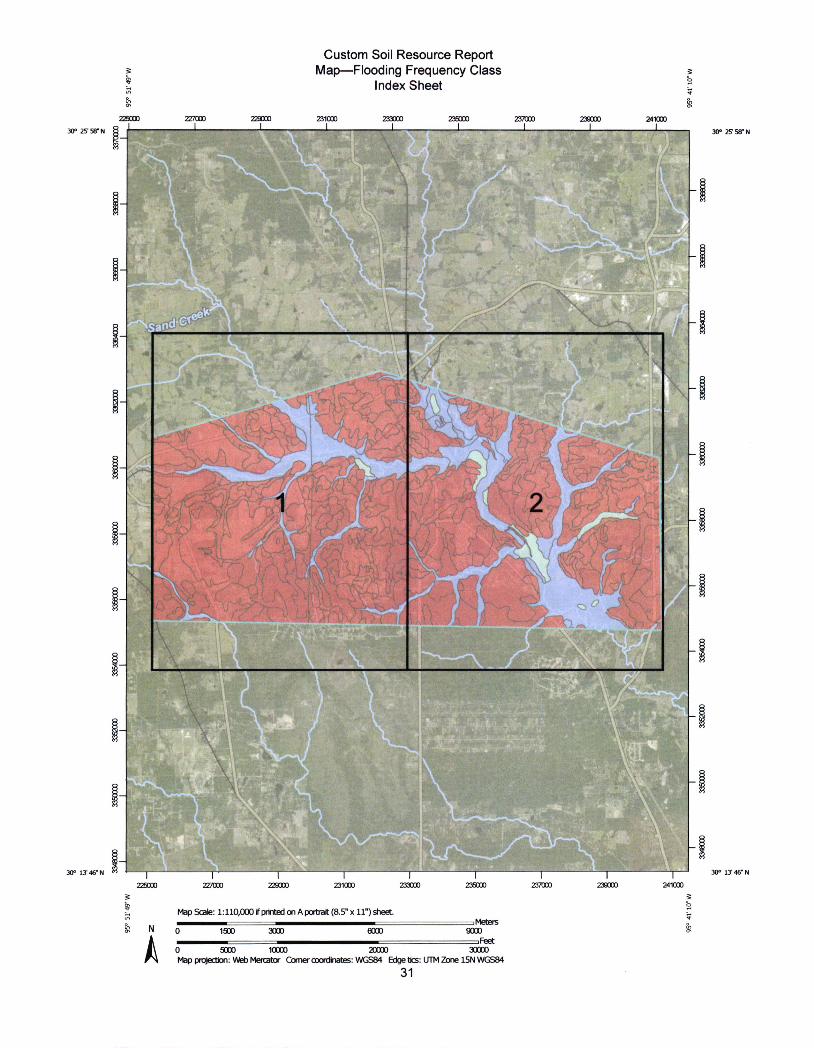
Custom Soil Resource Report Map-Flooding Frequency Class
Index Sheet
227000 229000 231000 233000 235000 Z37000 238000 241000 D 056
-11 95°5
30° 25 58" N ¤ 30° X 5/ N
LA
if4
:
€e....
.
1..
4
i
PN
30°13'46"N €9 30° 13'46 N
N
A Map Scale: 1:110,000 ifpinted on A porbat (8.5" x 11") sheet
~4,-+-i-·
0 1900 3000 6000 9000 I.qt
0 5000 10000 20000 30000 Map projecbon: Web Mercator Comer coordinates: WGS84 Edge bcs: UTM Zone 15N WGS84
31
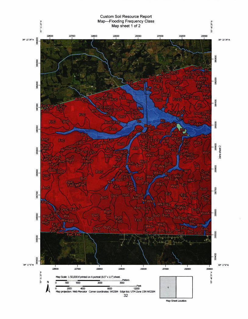
Custom Soil Resource Report Map-Flooding Frequency Class ~
Map sheet 1 of 2 W
30° 22 39-N
227000 228000 229000 230000
95'
231000 Z]X]00 233000 1 1
30° 22' 37 N
if i :»-€.-·:i-
L
Fr€
'k .hs° ·.·.Ili4 -4* :\, 2Ga'45 . a· · f: 'sJ€listKia f»'-twIBA,>FCCY4W Ak€-AnC m[
~Pllili'i(DhC?1:%.i
Fc€-2
:d€2 &-J WkC W;W;-
/gi?~IW; § M#
e-F ..,4/:.ip VA: M tr[)~ 'tu[J. ---~ A....WMEW"tpp 2-.-d'"VL,t~J #
~'~~Fr".~;ME.ce*KIBh'BIOAnt.liwkr -rD.ja# HuC-~fr*#.~IIIXIFF€IU~VIII~n~QeCKUSD2~w f.,*I .=b-FcCWS CI
.B]0.A,EK,Wk(DmiAW£EJ/IE ~
I Iillf-GC.WF:Eg~r.ebl:*:. r~yrf,Clkt;fli);2 ~~Eu 6'·*j
i
-<* DeC 13 4
,a
TAnC" f 7 1. f,-' KI "- yc 9. Na.W . 7~ -* .
Gl
FeC FeC
i
Z380[I) ZZ700[) 228000 229000 230000 231(]CIO 232000 23300[)
30° 176"N 300 176~N
Map Scale: 1:50,000 if prinbed on A portiait (8.5" x 11") Aeet
N 0 500 1000 2000 3000
0 2000 4000 8000 1~0 1
Map projec~on: VKeb Me,uator Corner motdinabes: WGSA Edge ties: UTM Zone 15N WGS84
32 Map Sheet Location
dLS u D\4-
"-..fQBIC . glc"r:rk '€OC *¤iri BIC r-r Mr
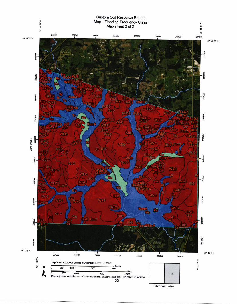
95° 46'29 W
Custom Soil Resource Report Map-Flooding Frequency Class
Map sheet 2 of 2
Ms
23000o 237000 23800[) 239000 240000 241000 235000
3oc 27 N N 30° 2Z 39 N
h >*Wk€1'gue.3.**~L," . . 1. / 44 JI ' , ~
DJ
i} tisAWQhB »•L .-4-
SOD F~cc~ -~ v.~ ,-52*Iil,r~A*f=1/KIB'AN
~ IBI
WDCL
ydBis#4 .ZZ EB~Ji®-25'f~tii[C
R - ·' 2 " Iam . i » 5 -- ~ 1 -·.
FcC@€JB
*Hm.6+ -jflwkCM-BISS~
.pnC
ainli.-2'Stt[) l
JCOC
X,AbLffa.
Ks-
240000
2
r~€d[).tgoti a, ~ w- ~ -€bC---·:205@i@6£BiEAI~
234000 235000 238000
r
237000 238000 239000
M.6€,I, 066
30° 176*N . 30° 176N
Map Scale: 1:50,000 #printed on A porbait (&5" x 117 sheet N 0--=-=,= Meters
500 1000 2000 3(]00 A 0 2000 4000 8000 10000 Map prgecbon: Web Mertabor Comercoofdnates: WGS84 Edge ties: UTM Zone 15N WGS84
33 Map Sheet Location
Custom Soil Resource Report
MAP LEGEND MAP INFORMATION
Area of Interest (AOI) Area of Interest (AOI)
¤ Not rated or not available
Water Features
The soil surveys that comprise your AOI were mapped at scales ranging from 1:20,000 to 1:24,000
Soils Soil Rating Polygons ~ None
Streams and Canals
Transportation .++ Rails
Please rely on the bar scale on each map sheet for map measurements.
Very Rare
Rare Interstate Highways
US Routes
Source of Map: Natural Resources Conservation Service Web Soil Survey URL: Coordinate System' Web Mercator (EPSG:3857)
Occasional Major Roads Maps from the Web Soil Survey are based on the Web Mercator Frequent projection, which preserves direction and shape but distorts Background
distance and area. A projection that preserves area, such as the Very Frequent ~ Aerial Photography Albers equal-area conic projection, should be used if more Not rated or not available accurate calculations of distance or area are required
Soil Rating Lines .•v None
This product is generated from the USDA-NRCS certified data as of the version date(s) listed below.
r-0 Very Rare
** Rare Soil Survey Area: Grimes County, Texas Survey Area Data: Version 15, Sep 12, 2019
Occasional
Frequent Soil Survey Area Montgomery County, Texas Survey Area Data: Version 17, Sep 12, 2019
Very Frequent
.. Not rated or not available
Soil Rating Points ~ None
Very Rare
Your area of interest (AOI) includes more than one soil survey area. These survey areas may have been mapped at different scales, with a different land use in mind, at different times, or at different levels of detail. This may result in map unit symbols, soil properties, and interpretations that do not completely agree across soil survey area boundaries.
¤ Rare Soil map units are labeled (as space allows) for map scales
Occasional 1:50,000 or larger. Frequent
Date(s) aerial images were photographed: Sep 6, 2017-Nov I Very Frequent 25,2017
The orthophoto or other base map on which the soil lines were compiled and digitized probably differs from the background
34
Custom Soil Resource Report
MAP LEGEND MAP INFORMATION
imagery displayed on these maps. As a result, some minor shifting of map unit boundaries may be evident.
35
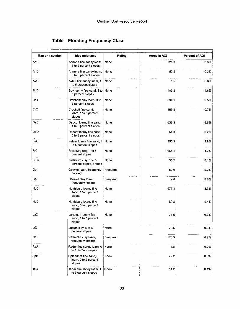
Custom Soil Resource Report
Table-Flooding Frequency Class
Map unit symbol Map unit name Rating Acres in AOI Percent of AOI
AnC Annona fine sandy Ioam, None 825 3 3.3% 1 to 5 percent slopes
AnD Annona fine sandy Ioam, None 52.8 02% 5 to 8 percent slopes
AxC Axtell fine sandy Ioam, 1 None 1.5 0.0% to 5 percent slopes
BgD Boy Ioamy fine sand, 1 to None 403.2 1.6% 5 percent slopes
BrD Brenham clay Ioam, 3 to None 630.1 2.5% 8 percent slopes
CrC Crockett fine sandy None 166.8 0.7% Ioam, 1 to 5 percent slopes
DeC Depcor Ioamy fine sand, None 1,639.3 6.5% 1 to 5 percent slopes
DeD Depcor Ioamy fine sand, None 54.8 0.2% 5 to 8 percent slopes
FeC Fetzer Ioamy fine sand, 1 None 950.3 3.8% to 5 percent slopes
FrC Frelsburg clay, 1 to 5 None 1,056.1 4.2% percent slopes
FrC2 Frelsburg clay, 1 to 5 None 35.2 0.1% percent slopes, eroded
Go Gowker Ioam, frequently Frequent 59.0 0.2% flooded
Gp Gowker clay Ioam, Frequent 9.0 0.0% frequently flooded
HuC Huntsburg Ioamy fine None 577.3 2.3% sand, 1 to 5 percent slopes
HuD Huntsburg Ioamy fine None 89.8 0.4% sand, 5 to 8 percent slopes
LaC Landman Ioamy fine None 71.6 0.3% sand, 1 to 5 percent slopes
LtD Latium clay, 5 to 8 None 79.6 0.3% percent slopes
Na Nahatche clay Ioam, Frequent 173.3 0.7% frequently flooded
RaA Rader fine sandy Ioam, 0 None 1.8 0.0% to 1 percent slopes
SpB Splendora fine sandy None 72.2 0.3% Ioam, 0 to 2 percent slopes
TaC Tabor fine sandy loam, 1 None 14.2 0.1% to 5 percent slopes
36
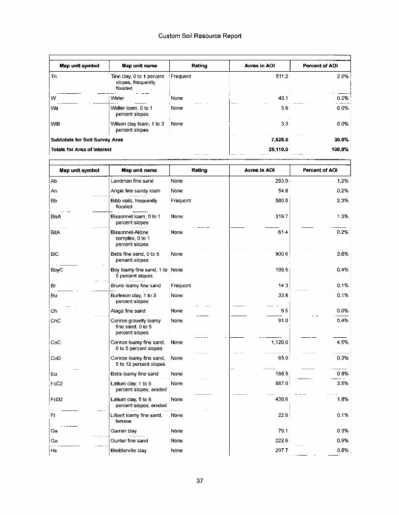
Custom Soil Resource Report
Map unit symbol Map unit name Rating Acres in AOI Percent of AOI
Tn Tinn clay, 0 to 1 percent Frequent 511.2 2.0% slopes, frequently flooded
W Water None 43.1 0.2%
Wa Waller Ioam, 0 to 1 None 5.6 0.0% percent slopes
WIB Wilson clay Ioam, 1 to 3 None 3.3 0.0% percent slopes
Subtotals for Soil Survey Area 7,526.5 30.0%
Totals for Area of Interest 25,110.0 100.0%
Map unit symbol Map unit name Rating Acres in AOI Percent of AOI
Ab Landman fine sand None 293.0 1.2%
An Angie fine sandy Ioam None 54.8 0.2%
Bb Bibb soils, frequently Frequent 580.5 2.3% flooded
BisA Bissonnet Ioam, 0 to 1 None 319.7 1.3% percent slopes
BitA Bissonnet-Aldine None 61.4 0.2% complex, 0 to 1 percent slopes
BIC Betis fine sand, 0 to 5 None 900 6 3.6% percent slopes
BoyC Boy Ioamy fine sand, 1 to None 109.5 0.4% 5 percent slopes
Br Bruno Ioamy fine sand Frequent 14 3 0.1%
Bu Burleson clay, 1 to 3 None 33.8 0.1% percent slopes
Ch Alaga fine sand None 95 0.0%
CnC Conroe gravelly Ioamy None 91.0 0.4% fine sand, 0 to 5 percent slopes
Coc Conroe Ioamy fine sand, None 1,126.0 4.5% 0 to 5 percent slopes
CoD Conroe Ioamy fine sand, None 65.0 0.3% 5 to 12 percent slopes
Eu Betis Ioamy fine sand None 188.5 0.8%
FcC2 Latium clay, 1 to 5 None 887.0 3.5% percent slopes, eroded
FcD2 Latium clay, 5 to 8 None 439.6 1.8% percent slopes, eroded
Ft Lilbert Ioamy fine sand, None 22 6 0.1% terrace
Ga Garner clay None 79.1 03%
Gu Gunter fine sand None 222.6 0.9%
Hs Bleiblerville clay None 207.7 0.8%
37
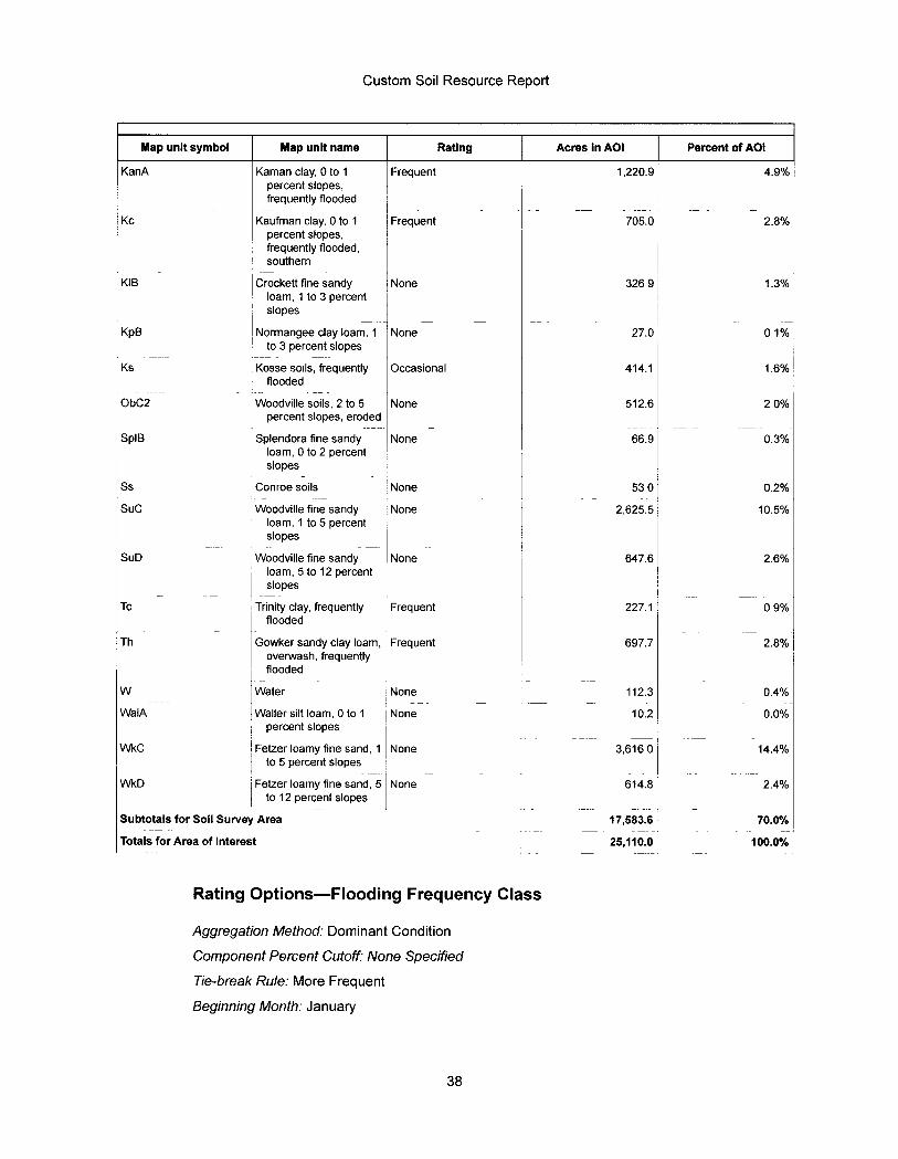
Custom Soil Resource Report
Map unit symbol Map unit name Rating Acres in AOI Percent of AOI
KanA Kaman clay, 0 to 1 Frequent 1,220.9 4.9% percent slopes, frequently flooded
Kc Kaufman clay, 0 to 1 Frequent 705.0 2.8% percent slopes, frequently flooded, southern
KIB Crockett fine sandy None 326 9 1.3% Ioam, 1 to 3 percent slopes
KpB Normangee clay Ioam, 1 None 27.0 01% to 3 percent slopes
Ks Kosse soils, frequently Occasional 414.1 1.6% flooded
ObC2 Woodville soils, 2 to 5 None 512.6 20% percent slopes, eroded
SpIB Splendora fine sandy None 66.9 0.3% Ioam, 0 to 2 percent slopes
Ss Conroe soils None 53 0 0.2%
SUC Woodville fine sandy None 2,625.5 10.5% Ioam, 1 to 5 percent slopes
SuD Woodville fine sandy None 647.6 2.6% Ioam, 5 to 12 percent slopes
Tc Trinity clay, frequently Frequent 227.1 09% nooded
Th Gowker sandy clay Ioam, Frequent 697.7 2.8% overwash, frequently flooded
W Water None 112.3 0.4%
WaIA Waller silt Ioam, 0 to 1 None 10.2 0.0% percent slopes
WkC Fetzer Ioamy fine sand, 1 None 3,616 0 14.4% to 5 percent slopes
WkD Fetzer Ioamy fine sand, 5 None 614.8 2.4% to 12 percent slopes
Subtotals for Soil Survey Area 17,583.6 70.0%
Totals for Area of Interest 25,110.0 100.0%
Rating Options-Flooding Frequency Class
Aggregation Method : Dominant Condition
Component Percent Cutoff: None Specified
Tie - break Rule : More Frequent
Beginning Month: January
38

Custom Soil Resource Report
Ending Month: December
39
From:
Sent: To: CC: Subject:
Gray, Natasha A CIV USARMY CESWF (USA) <[email protected]> Tuesday, June 2,2020 3:29 PM McCIanahan, Gary Madden, David E CIV USARMY CESWF (USA) [EXTERNAL] Submittal Process
CAUTION: This Email is from an EXTERNAL source. STOP. THINK before you CLICK links or OPEN attachments.
Mr. McCIanahan,
I sent you a separate email in reference to our electronic process. Wanted to touch base with you in reference to who to address your submittals to when sending paper copy submittals. Your office has been addressing your letters to Col. Kenneth Reed and they have been received by our front office. Any future submittals should be addressed to our Chief of Regulatory Mr. Brandon Mobley our address is as follows. Feel free to utilize our electronic process. In light of our current situation and limited staff in the office this will ensure that your submittals are received by our office, processed in a timely manner, and reduces the risk of getting misplaced.
U.S. Army Corps of Engineers Fort Worth District Regulatory Office 819 Taylor Street, Rm 3A37 Fort Worth, Texas 76102
Natasha Gray Legal Instruments Examiner Regulatory Division U.S. Army Corps of Engineers 819 Taylor Street, Rm 3A37 Fort Worth, Texas 76102 Phone: 817-886-1461 Email: [email protected]
Please do not mail hard copy documents to Regulatory staff or office, unless specifically requested. For further details on corresponding with us, please view our Electronic Application Submittals special public notice at: https://urldefense.proofpoint.com/v2/url?u=https-3A www.swf.usace.army.mil Portals 47 docs regulatory publicnotices 2020 PublicNoticeEIectronic Applications.pdf-3Fver-3D2019-2Dll-2D21-2D123723-2D627&d=DwIFAg&c=H8S5wzlwo-7G Ou9dgBE0MfTp0Xd5uFLOwdyviB0JwY&r=IFfWeD/gAcvUMEiHZY690ChzStlEg0MIQDFG9DRRt3c&m= NCGPkKiu6YZ866oqiIXIxz w-tJJHJpZsW9vp5gfvqA&s=7azLiUAdks6J IP8emgVffEuRrUPZN4k4yJfPXZzsgpQ&e=
USACE Fort Worth District Regulatory Division Website https://urldefense.proofpoint.com/v2/url?u=http-
3A www.swf.usace.army.mil Missions Regulatory.aspx&d=DwIFAg&c=H8S5wzlwo-7G Ou9dg8E0MfTp0Xd5uFLOwdvviB0JwY&r=IFfWeD72AcvUMEiHZY690ChzStlER0MiQDFG9DRRt3c&m= NCGPkKiu6YZ866oqiIXIxz w-tJJHJ pZsW9yp5gfvqA&s=139wdBTU IT9K14M FgbcAOQH EGvQDww 507IX4ViY5Kc&e=
Please assist us in better serving you by completing the survey at the following website: https://urldefense.proofpoint.com/v2/url?u=http-3A corpsmapu.usace.army.mil cm-5Fapex f-3Fp-3Dregulatory-5Fsurvey&d=DwIFAg&c=H8S5wzlwo-7G Ou9dg8E0MfTp0Xd5u FLOwdvviBOJwY&r=IFfWeD/RAcvUMEiHZY690ChzStl ER0MiQDFG9DRRt3c&m= NCGPkKiu6YZ866oqiIXIxz w-tJJHJpZsW9vp5gfvqA&s=CqwJIfVIFBv mfsbmWk5iD4Ca520epGxaVSygpoPYIU&e=
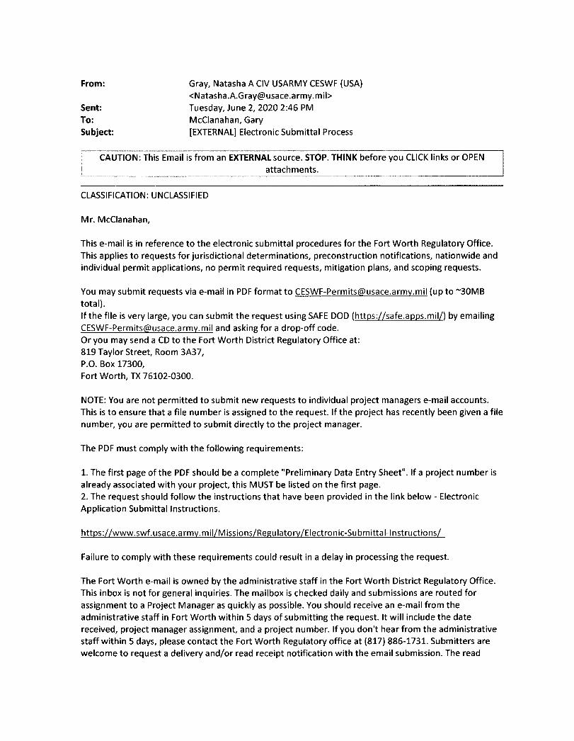
From:
Sent: To: Subject:
Gray, Natasha A CIV USARMY CESWF (USA) <[email protected]> Tuesday, June 2,2020 2:46 PM McCIanahan, Gary [EXTERNAL] Electronic Submittal Process
CAUTION: This Email is from an EXTERNAL source. STOP. THINK before you CLICK links or OPEN attachments.
CLASSIFICATION: UNCLASSIFIED
Mr. McCIanahan,
This e-mail is in reference to the electronic submittal procedures for the Fort Worth Regulatory Office. This applies to requests for jurisdictional determinations, preconstruction notifications, nationwide and individual permit applications, no permit required requests, mitigation plans, and scoping requests.
You may submit requests via e-mail in PDF format to [email protected] (up to -30MB total). If the file is very large, you can submit the request using SAFE DOD (https://safe.apps.mil/) by emailing [email protected] and asking fora drop-off code. Or you may send a CD to the Fort Worth District Regulatory Office at: 819 Taylor Street, Room 3A37, P.O. Box 17300, Fort Worth, TX 76102-0300.
NOTE: You are not permitted to submit new requests to individual project managers e-mail accounts. This is to ensure that a file number is assigned to the request. If the project has recently been given a file number, you are permitted to submit directly to the project manager.
The PDF must comply with the following requirements:
1. The first page of the PDF should be a complete "Preliminary Data Entry Sheet". If a project number is already associated with your project, this MUST be listed on the first page. 2. The request should follow the instructions that have been provided in the link below - Electronic Application Submittal Instructions.
https://www.swf.usace.army. mil/M issions/Regu latorv/Electron ic-Su bmitta I-I nstructions/
Failure to comply with these requirements could result in a delay in processing the request.
The Fort Worth e-mail is owned by the administrative staff in the Fort Worth District Regulatory Office. This inbox is not for general inquiries. The mailbox is checked daily and submissions are routed for assignment to a Project Manager as quickly as possible. You should receive an e-mail from the administrative staff in Fort Worth within 5 days of submitting the request. It will include the date received, project manager assignment, and a project number. If you don't hear from the administrative staff within 5 days, please contact the Fort Worth Regulatory office at (817) 886-1731. Submitters are welcome to request a delivery and/or read receipt notification with the email submission. The read
receipt notification date will correspond to our clock start / "stamped in" date. In other words, should a requestor submit something via email after five o'clock p.m. on Friday or over the weekend and we open the email Monday morning, then our processing timeline starts Monday.
Please contact me via e-mail or at the number below if you have questions.
Sincerely,
Natasha Gray Legal Instruments Examiner Regulatory Division U.S. Army Corps of Engineers 819 Taylor Street, Rm 3A37 Fort Worth, Texas 76102 Phone: 817-886-1461 Email: [email protected]
Please do not mail hard copy documents to Regulatory staff or office, unless specifically requested. For further details on corresponding with us, please view our Electronic Application Submittals special public notice at: https://www.swf.usace.army.mil/Portals/47/docs/regulatory/publicnotices/2020/PublicNoticeEIectronic Applications.pdf?ver=2019-11-21-123723-627
USACE Fort Worth District Regulatory Division Website http://www.swf.usace.army. mil/Missions/Regulatory.aspx
Please assist us in better serving you by completing the survey at the following website: http://corpsmapu.usace.army.mil/cm apex/f?p=regulatory survey
From: Gray, Natasha A CIV USARMY CESWF (USA) <[email protected]>
Sent: Monday, June 8, 2020 11:19 AM To: McCIanahan, Gary CC: Roeder, Katie O CIV USARMY CESWF (USA) Subject: [EXTERNAL] SWF-2020-00217, Castle 230kV Transmission Line and Substation
Project
CAUTION: This Email is from an EXTERNAL source. STOP. THINK before you CLICK links or OPEN attachments.
Dear Mr. McCIanahan:
Thank you for your letter received June 1, 2020, concerning a proposal by Entergy Texas to construct a new double circuit 230kV transmission line located in both Grimes and Montgomery Counties, Texas. The project has been assigned Project Number SWF-2020-00217, please include this number in all future correspondence concerning this project.
Ms. Katie Roeder has been assigned as the regulatory project manager for your request and will be evaluating it as expeditiously as possible.
You may be contacted for additional information about your request. For your information, please refer to the Fort Worth District Regulatory Division homepage at http://www.swf.usace.armv.mil/Missions/regulatory and particularly guidance on submittals at https://swf-apps.usace.army.mil/pubdata/environ/regulatory/introduction/submital.pdf and mitigation at https://www.swf.usace.army.mil/Missions/Regulatory/Permitting/Mitigation that may help you supplement your current request or prepare future requests.
If you have any questions about the evaluation of your submittal or would like to request a copy of one of the documents referenced above, please refer to our website at http://www.swf.usace.army.mil/Missions/Regulatory or contact Ms. Katie Roeder by telephone 817-886-1740, or by email [email protected], and refer to your assigned project number. Please note that it is unlawful to start work without a Department of the Army permit if one is required.
Please help the regulatory program improve its service by completing the survey on the following website: http://corpsmapu.usace.army.mil/cm apex/f?p=regulatory survey
Brandon W. Mobley Chief, Regulatory Division
Please do not mail hard copy documents to Regulatory staff or office, unless specifically requested. For further details on corresponding with us, please view our Electronic Application Submittals special public notice at: https://www.swf.usace.army.mil/Portals/47/docs/regulatory/publicnotices/2020/PublicNoticeEIectronic Applications.pdf?ver=2019-11-21-123723-627
USACE Fort Worth District Regulatory Division Website http://www.swf.usace.army.mil/Missions/Regulatory.aspx
Please assist us in better serving you by completing the survey at the following website: http://corpsmapu.usace.army.mil/cm apex/f?p=regulatory survey
From:
Sent: To: Subject: Attachments:
Roeder, Katie O CIV USARMY CESWF (USA) <[email protected]> Wednesday, July 1, 2020 9:42 AM McCIanahan, Gary SWF-2020-00217 NWP12TX (002).pdf; submittal guidance linear project_.pdf; USACE_NWP_12_Application_Form_HJH (002).doc
Hi Gary,
This project has been assigned Project Number SWF-2020-00217. Please include this number in all future correspondence concerning this project. I have attached the permit that this would fall under as well as some general guidelines and an application form.
We have reviewed this project in accordance with Section 404 of the Clean Water Act and Section 10 of the Rivers and Harbors Act of 1899. Under Section 404, the U. S. Army Corps of Engineers (USACE) regulates the discharge of dredged and fill material into waters of the United States, including wetlands. Our responsibility under Section 10 is to regulate any work in, or affecting, navigable waters of the United States. Any such discharge or work requires Department of the Army authorization in the form of a permit. For more information on the USACE Regulatory Program, please reference the Fort Worth District Regulatory Branch homepage at https://urldefense.proofpoint.com/v2/url?u=http-3A www.swf.usace.army.mil regulatory&d=DwIFAw&c=H8S5wzlwo-7G Ou9dg8E0MfTp0Xd5u FLOwdyviBOJwY&r=IFfWeD72AcvUMEiHZY690ChzStlEg0MiQDFG9DRRt3c&m= QUskYCDFZHcuECx-DnAmt51cSBMn-02aX6sSUZiV m4&s=hPIIEr5TnMgzCb-s7IDSFdcplTZcNqBTKnvrao7HVho&e= .
We are unable to determine from the information that you provided in your letter whether Department of the Army authorization will be required, and if so, in what form. The proposed construction activities may be authorized by general permit, such as Nationwide Permit 12 for Utility Line Activities.
So that we may continue our evaluation of your proposed project, we request that you provide the following information:
1. A detailed project description.
2. Confirm if federal funds are to be expended on this proposed project, and if so, identify lead federal agency.
3. A map (or maps) showing the entire route of the project. Please include complete project boundaries of the entire project (Including substations and connecting transmission lines).
4. Please provide documentation demonstrating compliance with the Endangered Species Act.
5. Please provide documentation demonstrating compliance with section 106 of the National Historic Preservation Act.
6. The proposed route of the project on 8 M by 11-inch copies of 7.5-minute United States Geological Survey (USGS) quadrangle maps, national wetland inventory maps, published soil survey maps, scaled aerial photographs, and/or other suitable maps. Identify all base maps, (e.g. "Fort Worth, Texas" 7.5-minute USGS quadrangle, Natural Resources Conservation Service Tarrant County Soil Survey sheet 10). Clearly mark (such as by circling) and number the location of each proposed utility line crossing of a water of the United States and any appurtenant structure(s) in waters of the United States on the map. Waters of the United States include streams and rivers and most lakes, ponds, mudflats, sandflats, wetlands, sloughs, wet meadows, abandoned sand and gravel mining and construction pits, and similar areas. Please find attached files that may assist you in developing an updated submittal.
7. For each potential utility line crossing or appurtenant structure in a water of the United States, the following site specific information when applicable:
a. 7.5-minute USGS quadrangle map name, universal transverse mercator (UTM) coordinates, county or parish, waterway name;
b. a brief characterization of the crossing area (stream, forested wetland, non-forested wetland, etc.) including the National Wetland Inventory classification and soil series;
c. distance between ordinary high water marks;
d. proposed method of crossing;
e. length of proposed crossing;
f. width of temporary and permanent rights-of-way;
g. type and amount of dredged or fill material proposed to be discharged;
h. acreage of proposed temporary and permanent adverse impacts to waters of the United States, including wetlands; and
i. a typical cross-section.
Please refer to the enclosed guidance for Department of the Army submittals for additional details about what you should submit for this and future linear projects. Additional information, including more detailed jurisdictional determination data, may be needed to complete our evaluation of your project in some cases. We encourage you to consult with a qualified specialist (biologist, ecologist or other specialist qualified in preliminary jurisdictional determinations) who is familiar with the Great Plains Regional Supplement to the 1987 Corps of Engineers Wetlands Delineation Manual and the USACE Regulatory Program (33 CFR Parts 320-331).
We encourage you to avoid and minimize adverse impacts to streams, wetlands, and other waters of the United States in planning this project. Please forward your response to us as soon as possible so that we may continue our evaluation of your request. If we do not receive the requested information within 30
days of the date of this letter, we will consider your application administratively withdrawn. If withdrawn, you may re-open your application at a later date by submitting the requested information.
Please note that it is unlawful to start work without a Department of the Army permit when one is required.
You may be contacted for additional information about your request. For your information, please refer to the Fort Worth District Regulatory Division homepage at https://urldefense.proofpoint.com/v2/url?u=http-3A www.swf.usace.army.mil Missions regulatorv&d=DwIFAw&c=H8S5wzlwo-7G Ou9dgBE0MfTp0Xd5uFLOwdyviB0JwY&r=IFfWeD/gAcvUMEiHZY690ChzStlER0MiQDFG9DRRt3c&m= QUskYCDFZHcuECx-DnAmt51cSBMn-02aX6sSUZiV m4&s=WZAPXlhiL5TptXqM lfMMSFT1VLCdi3IF8PYNak iB58&e= and particularly guidance on submittals at https://urldefense.proofpoint.com/v2/url?u=http-3A media.swf.usace.army.mil pubdata environ Regulatory introduction submital.pdf&d=DwIFAw&c =H8S5wzlwo-7G Ou9dgBE0MfTp0Xd5uFLOwdyviB0JwY&r=IFfWeD7gAcvUMEiHZY690ChzStlER0MiQDFG9DRRt3c&m= QUskYCDFZHcuECx-DnAmt5lcSBMn-02aX6sSUZiV m4&s=-OvLTVZB4EE1WWqp778tdfnVHDSniq7P-pqqcP4NIZ4&e=, and mitigation at https://urldefense.proofpoint.com/v2/url?u=http-3A www.swf.usace.army.mil Missions Regulatory Permitting Mitigation&d=DwIFAw&c=H8S5wzlwo-7G Ou9dg8E0MfTp0Xd5u FLOwdvviBOJwY&r=IFfWeD7gAcvUMEiHZY690ChzStlER0MiQDFG9DRRt3c&m= QUskYCDFZHcuECx-DnAmt51cSBMn-02aX6sSUZiV m4&s=uRu4QQQ-B8YDITOF6bbKGotfKbEDc2vYSxdE3Cgglps&e= that may help you supplement your current request or prepare future requests.
If you have any questions about the evaluation of your submittal or would like to request a copy of one of the documents referenced above, please contact Katie Roeder at the address above or telephone (817) 886-1740 and refer to your assigned project number.
Thank you,
Katie Roeder Regulatory Specialist, Evaluation Branch Regulatory Division U.S. Army Corps of Engineers Ft. Worth District 819 Taylor Street Fort Worth, Texas 76102-00300 Phone: 817-886-1740
Please do not mail hard copy documents to Regulatory staff or office, unless specifically requested. For further details on corresponding with us, please view our Electronic Application Submittals special public notice at: https://urldefense.proofpoint.com/v2/url?u=https-3A www.swf.usace.army.mil Portals 47 docs regulatory publicnotices 2020 PublicNoticeEIectronic Applications.pdf-3Fver-3D2019-2Dll-2D21-2D123723-2D627&d=DwIFAw&c=H8S5wzlwo-7G Ou9dg8E0MfTp0Xd5uFLOwdvviB0JwY&r=IFfWeD7gAcvUMEiHZY690ChzStlER0MiQDFG9DRRGc&m= QUskYCDFZHcuECx-DnAmt51cSBMn-02aX6sSUZiV m4&s=MWIWeHId ewlauC5BO-MiRh7JPGuVYZYubQ7JkG2vi8&e=
USACE Fort Worth District Regulatory Division Website: https://urldefense.proofpoint.com/v2/url?u=http-3A www.swf.usace.army.mil Missions Regulatory.aspx&d=DwIFAw&c=H8S5wzlwo-7G Ou9dg8E0MfTp0Xd5u FLOwdvviBOJwY&r=IFfWeD7&AcvUMEiHZY690ChzStlER0MiQDFG9DRRt3c&m= QUskYCDFZHcuECx-DnAmt51cSBMn-02aX6sSUZiV m4&s=RCXW-HJYBTJkEZixwTZmBvcWDfDxDcFzN5nCtmin668&e=
Please assist us in better serving you by completing the survey at the following website: https://urldefense.proofpoint.com/v2/url?u=http-3A corpsmapu.usace.army.mil cm-5Fapex f-3Fp-3Dregulatory-5Fsurvey&d=Dwl FAw&c=H8S5wzlwo-7G Ou9dgSE0MfTp0Xd5u FLOwdvviBOJwY&r=IFfWeD7%AcvUMEiHZY690ChzStl ER0MiQDFG9DRRt3c&m= QUskYCDFZHcuECx-DnAmt51cSBMn-02aX6sSUZiV m4&s=4aDLWu-5wtzceM7hFCdUVCEBhae3UumXx3ZOspLA4Xo&e=
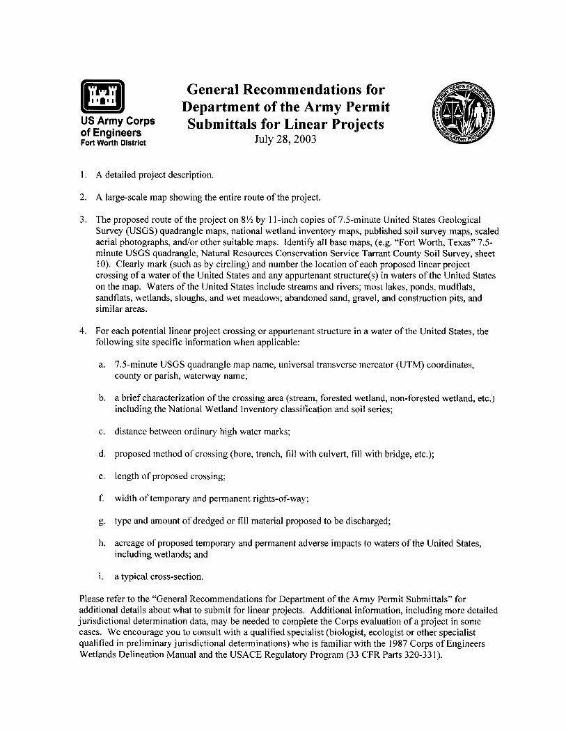
lim US Army Corps of Engineers Fort Worth District
General Recommendations for Department of the Army Permit Submittals for Linear Projects
July 28,2003
1. A detailed project description.
2. A large-scale map showing the entire route of the project.
3. The proposed route of the project on 8!4 by 11-inch copies of 7.5-minute United States Geological Survey (USGS) quadrangle maps, national wetland inventory maps, published soil survey maps, scaled aerial photographs, and/or other suitable maps. Identify all base maps, (e.g. "Fort Worth, Texas" 7.5-minute USGS quadrangle, Natural Resources Conservation Service Tarrant County Soil Survey, sheet 10). Clearly mark (such as by circling) and number the location of each proposed linear project crossing of a water ofthe United States and any appurtenant structure(s) in waters ofthe United States on the map. Waters of the United States include streams and rivers; most lakes, ponds, mudflats, sandflats, wetlands, sloughs, and wet meadows; abandoned sand, gravel, and construction pits, and similar areas.
4. For each potential linear project crossing or appurtenant structure in a water of the United States, the following site specific information when applicable:
a. 7.5-minute USGS quadrangle map name, universal transverse mercator (UTM) coordinates, county or parish, waterway name;
b. a brief characterization of the crossing area (stream, forested wetland, non-forested wetland, etc.) including the National Wetland Inventory classification and soil series;
c. distance between ordinary high water marks;
d. proposed method of crossing (bore, trench, fill with culvert, fill with bridge, etc.);
e. length of proposed crossing;
f. width oftemporary and permanent rights-of-way;
g. type and amount of dredged or fill material proposed to be discharged;
h. acreage of proposed temporary and permanent adverse impacts to waters of the United States, including wetlands; and
i. a typical cross-section.
Please refer to the "General Recommendations for Department of the Army Permit Submittals" for additional details about what to submit for linear projects. Additional information, including more detailed jurisdictional determination data, may be needed to complete the Corps evaluation of a project in some cases. We encourage you to consult with a qualified specialist (biologist, ecologist or other specialist qualified in preliminary jurisdictional determinations) who is familiar with the 1987 Corps of Engineers Wetlands Delineation Manual and the USACE Regulatory Program (33 CFR Parts 320-331).
U.S. Army Corps of Engineers (USACE) Fort Worth District
mi Nationwide Permit (NWP) Pre-Construction Notification (PCN) Form This form integrates requirements of the Nationwide Permit Program within the Fort Worth District, including General and Regional Conditions. Please consult instructions included at the end prior to completing this form.
Contents • Description of NWP 12 • Part I: NWP Conditions and Requirements Checklist
o General Conditions Checklist o NWP 12-Specific Requirements Checklist o Regional Conditions Checklist
• Part II: Project Information Form • Part III: Project Impacts and Mitigation Form • Part IV: Attachments Form • Instructions
DESCRIPTION OF NWP 12 - UTILITY LINE ACTIVITIES
Activities required for the construction, maintenance, repair, and removal of utility lines and associated facilities in waters of the United States (U.S.), provided the activity does not result in the loss of greater than 1/2-acre of waters of the U.S for each single and complete project.
Utility lines: This NWP authorizes the construction, maintenance, or repair of utility lines, including outfall and intake structures, into waters of the U.S., provided there is no change in pre-construction contours. A "utility line" is defined as any pipe or pipeline for the transportation of any gaseous, liquid, Iiquescent, or slurry substance, for any purpose, and any cable, line, or wire for the transmission for any purpose of electrical energy, telephone, and telegraph messages, and internet, radio and television communication. The term "utility line" does not include activities that drain a water of the U.S., such as drainage tile or french drains, but it does apply to pipes conveying drainage from another area. Material resulting from trench excavation may be temporarily sidecast into waters of the U.S. for no more than three months, provided the material is not placed in such a manner that it is dispersed by currents or other forces. The district engineer may extend the period of temporary side casting for no more than a total of 180 days, where appropriate. In wetlands, the top 6 to 12 inches of the trench should normally be backfilled with topsoil from the trench. The trench cannot be constructed or backfilled in such a manner as to drain waters of the U.S. (e.g., backfilling with extensive gravel layers, creating a french drain effect). Any exposed slopes and stream banks must be stabilized immediately upon completion of the utility line crossing of each waterbody. Utility line substations: This NWP authorizes the construction, maintenance, or expansion of substation facilities associated with a power line or utility line in non-tidal waters of the U.S., provided the activity, in combination with all other activities included in one single and complete project, does not result in the loss of greater than 1/2-acre of waters of the U.S. This NWP does not authorize discharges into non-tidal wetlands adjacent to tidal waters of the U.S. to construct, maintain, or expand substation facilities. Foundations for overhead utility line towers, poles, and anchors: This NWP authorizes the construction or maintenance of foundations for overhead utility line towers, poles, and
Page 1 of 22 SWF Recommended Application Form - NWP 12
anchors in all waters of the U.S., provided the foundations are the minimum size necessary and separate footings for each tower leg (rather than a larger single pad) are used where feasible. Access roads: This NWP authorizes the construction of access roads for the construction and maintenance of utility lines, including overhead power lines and utility line substations, in non-tidal waters of the U.S., provided the activity, in combination with all other activities included in one single and complete project, does not cause the loss of greater than 1/2-acre of non-tidal waters of the U.S. This NWP does not authorize discharges into non-tidal wetlands adjacent to tidal waters for access roads. Access roads must be the minimum width necessary. Access roads must be constructed so that the length of the road minimizes any adverse effects on waters of the U.S. and must be as near as possible to pre-construction contours and elevations (e.g., at grade corduroy roads or geotextile/gravel roads). Access roads constructed above pre-construction contours and elevations in waters of the U.S. must be properly bridged or culverted to maintain surface flows. This NWP may authorize utility lines in or affecting navigable waters of the U.S. even if there is no associated discharge of dredged or fill material (See 33 CFR part 322). Overhead utility lines constructed over section 10 waters and utility lines that are routed in or under section 10 waters without a discharge of dredged or fill material require a section 10 permit. This NWP authorizes, to the extent that Department of the Army authorization is required, temporary structures, fills, and work necessary for the remediation of inadvertent returns of drilling fluids to waters of the United States through sub-soil fissures or fractures that might occur during horizontal directional drilling activities conducted for the purpose of installing or replacing utility lines. These remediation activities must be done as soon as practicable, to restore the affected waterbody. District engineers may add special conditions to this NWP to require a remediation plan for addressing inadvertent returns of drilling fluids to waters of the United States during horizontal directional drilling activities conducted for the purpose of installing or replacing utility lines. This NWP also authorizes temporary structures, fills, and work, including the use of temporary mats, necessary to conduct the utility line activity. Appropriate measures must be taken to maintain normal downstream flows and minimize flooding to the maximum extent practicable, when temporary structures, work, and discharges, including cofferdams, are necessary for construction activities, access fills, or dewatering of construction sites. Temporary fills must consist of materials, and be placed in a manner, that will not be eroded by expected high flows. After construction, temporary fills must be removed in their entirety and the affected areas returned to pre-construction elevations. The areas affected by temporary fills must be revegetated, as appropriate. Notification: The permittee must submit a pre-construction notification to the district engineer prior to commencing the activity if any of the following criteria are met: (1) the activity involves mechanized land clearing in a forested wetland for the utility line right-of-way; (2) a section 10 permit is required; (3) the utility line in waters of the United States, excluding overhead lines, exceeds 500 feet; (4) the utility line is placed within a jurisdictional area (i.e., water of the United States), and it runs parallel to or along a stream bed that is within that jurisdictional area; (5) discharges that result in the loss of greater than 1/10-acre of waters of the United States; (6) permanent access roads are constructed above grade in waters of the United States for a distance of more than 500 feet; or (7) permanent access roads are constructed in waters of the United States with impervious materials. (See general condition 32.) (Authorities: Sections 10 and 404)
Page 2 of 22 SWF Recommended Application Form - NWP 12