contract t200504110.01 - state of delaware
TRANSCRIPT

STATE OF DELAWARE
DEPARTMENT OF TRANSPORTATION
BID PROPOSAL
for
CONTRACT T200504110.01
FEDERAL AID PROJECT NO. ESTP-N54(04)
HSIP NCC, N54, HOWELL SCHOOL ROAD, SR 896 TO SR 71
NEW CASTLE COUNTY
ADVERTISEMENT DATE: September 28, 2015
COMPLETION TIME: 649 Calendar Days
SPECIFICATIONS FOR ROAD AND BRIDGE CONSTRUCTIONDELAWARE DEPARTMENT OF TRANSPORTATION
AUGUST 2001
Bids will be received in the Bidder's Room at the Delaware Department of Transportation's AdministrationBuilding, 800 Bay Road, Dover, Delaware until 2:00 P.M. local time October 27, 2015
This Copy is for information only. You must request a CD from DelDOT in order to bid.
Contract No.T200504110.01 Federal Aid Project No. ESTP-N54(04)
HSIP NCC, N54, HOWELL SCHOOL ROAD, SR 896 TO SR 71NEW CASTLE COUNTY
GENERAL DESCRIPTION
LOCATION These improvements are located in NEW CASTLE County more specifically shown on the LocationMap(s) of the enclosed Plans.
DESCRIPTION
The improvements consist of furnishing all labor and materials for this contract. This Project will realignthe SR 896, Summit Bridge Road Intersections of N396, Denny Road and N54, Howell School Road. Inaddition, Howell School Road will be widened to provide two 11-foot lanes and two 5-foot shoulders(Shared Bicycle Lanes) from SR 896 to Robert Peoples Boulevard. A roundabout will be constructed at theintersection of Robert Peoples Boulevard and Howell School Road. A multi-use path will also beconstructed to connect access to Lums Pond from Denny Road, and other incidental construction inaccordance with the location, notes and details shown on the plans and as directed by the Engineer.
COMPLETION TIME
All work on this contract must be complete within 649 Calendar Days. The Contract Time includes anallowance for 105 Weather Days. It is the Department's intent to issue a Notice to Proceed such that workstarts on or about January 6, 2016.
PROSPECTIVE BIDDERS NOTES:
1. BIDDERS MUST BE REGISTERED with DelDOT and request a cd of the official plans andspecifications in order to submit a bid. Contact DelDOT at [email protected], or (302) 760-2031.
2. QUESTIONS regarding this project are to be e-mailed to [email protected] no less than six businessdays prior to the proposal opening date in order to receive a response. Please include T200504110.01 in the subject line. Responses to inquiries are posted on-line at http://www.bids.delaware.gov.
3. This project incorporates the electronic bidding system Expedite, version 5.9a. Bidders wishing to usethe electronic bidding option will find the installation file on the plan holders bid file disk. Theinstallation file and instructions are also available on DelDOT’s Website at: http://www.deldot.gov/information/business/bids/const_proj_bid_info.shtml.
4. Each proposal must be accompanied by a deposit of either surety bond or security for a sum equal to atleast 10% of the bid.
5. No retainage will be withheld on this contract.
6. The Department's External Complaint Procedure can be viewed on DelDOT’s Website at;http://www.deldot.gov/information/business/, or you may request a copy by calling (302) 760-2555.
--------------------------------7. SPECIFICATIONS: New Supplemental Specifications to the August 2001 Standard Specifications were
issued November 24, 2014 and apply to this project. They can be viewed here. The Department iscurrently updating the August 2001 Specifications for Road and Bridge Construction. Through thisupdate, some Divisions were renumbered and some new ones were created and added. TheSpecifications Note document is for the use by the bidders to reference the new numbers to the pastnumbers used for bidding purposes on previous Department contracts.
8. PLEASE NOTE the requirements of special provision ‘Changes to Project Documents DuringAdvertisement’ have moved to Supplemental Specifications, the special provision is no longer needed.
9. PLEASE NOTE federal requirements for the DBE program under 49CFR §26.53(b)(3)(i)(B) have
changed effective November 3, 2014. Submission of DBE participation information is now required from the lowest apparent bidder no later than seven (7) days after bid opening (formerly 10 days).
10. BREAKOUT SHEETS MUST be submitted either with your bid documents; or within seven (7)calendar days following the bid due date by the lowest apparent bidder. Refer to instructions adjacent tothe Breakout Sheets in this document.
i
Contract No. T200504110.01
11. PROPOSSED TRAINEE PLANS as required. Number of required programs is listed in the TrainingSpecial Provisions within Contract General Notices. The program(s) must be submitted within 10Calendar Days of notification of apparent low bidder status. Contract Award will not take place untilacceptable On-the-Job (OJT) program plans are received by the Civil Rights Group of the Department.
Failure of the apparent low bidder to present copies of an acceptable OJT Trainee Programs within ten(10) calendar days of notification of apparent low bidder status, shall create a rebuttable presumption thatthe bid is not responsive.
12. Contractor must add Joseph P. Murphy & Sarah E. Murphy as an “Additional Insured” to the Certificateof Liability Insurance, and provide a copy to:
Delaware Department of TransportationContract Administration
P.O. Box 778Dover, DE 19903
ii
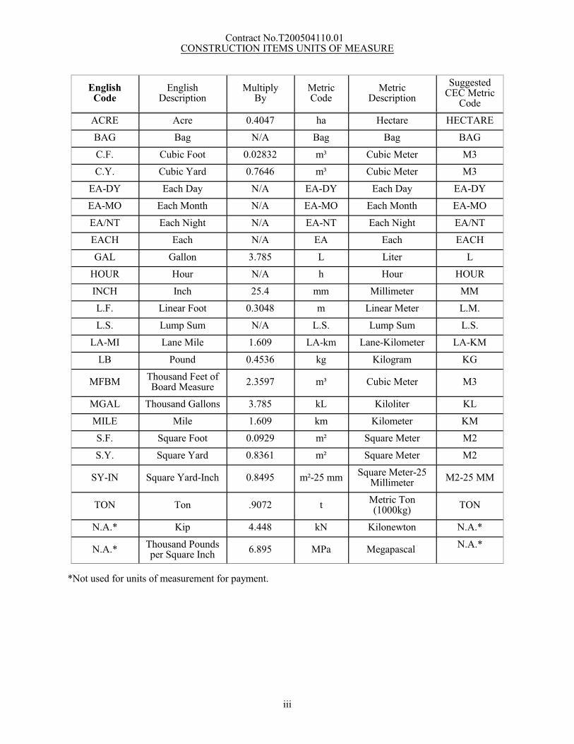
Contract No.T200504110.01 CONSTRUCTION ITEMS UNITS OF MEASURE
EnglishCode
EnglishDescription
MultiplyBy
MetricCode
MetricDescription
SuggestedCEC Metric
Code
ACRE Acre 0.4047 ha Hectare HECTARE
BAG Bag N/A Bag Bag BAG
C.F. Cubic Foot 0.02832 m³ Cubic Meter M3
C.Y. Cubic Yard 0.7646 m³ Cubic Meter M3
EA-DY Each Day N/A EA-DY Each Day EA-DY
EA-MO Each Month N/A EA-MO Each Month EA-MO
EA/NT Each Night N/A EA-NT Each Night EA/NT
EACH Each N/A EA Each EACH
GAL Gallon 3.785 L Liter L
HOUR Hour N/A h Hour HOUR
INCH Inch 25.4 mm Millimeter MM
L.F. Linear Foot 0.3048 m Linear Meter L.M.
L.S. Lump Sum N/A L.S. Lump Sum L.S.
LA-MI Lane Mile 1.609 LA-km Lane-Kilometer LA-KM
LB Pound 0.4536 kg Kilogram KG
MFBMThousand Feet ofBoard Measure
2.3597 m³ Cubic Meter M3
MGAL Thousand Gallons 3.785 kL Kiloliter KL
MILE Mile 1.609 km Kilometer KM
S.F. Square Foot 0.0929 m² Square Meter M2
S.Y. Square Yard 0.8361 m² Square Meter M2
SY-IN Square Yard-Inch 0.8495 m²-25 mmSquare Meter-25
MillimeterM2-25 MM
TON Ton .9072 tMetric Ton(1000kg)
TON
N.A.* Kip 4.448 kN Kilonewton N.A.*
N.A.* Thousand Poundsper Square Inch
6.895 MPa Megapascal N.A.*
*Not used for units of measurement for payment.
iii
Contract No. T200504110.01
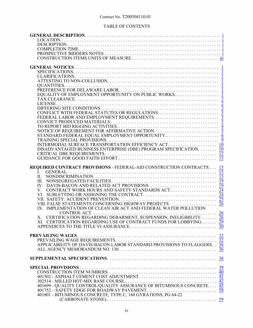
TABLE OF CONTENTS
GENERAL DESCRIPTION. . . . . . . . . . . . . . . . . . . . . . . . . . . . . . . . . . . . . . . . . . . . . . . . . . . . . . . . . . . . iLOCATION.. . . . . . . . . . . . . . . . . . . . . . . . . . . . . . . . . . . . . . . . . . . . . . . . . . . . . . . . . . . . . . . . . . . . . . iDESCRIPTION. . . . . . . . . . . . . . . . . . . . . . . . . . . . . . . . . . . . . . . . . . . . . . . . . . . . . . . . . . . . . . . . . . . . iCOMPLETION TIME.. . . . . . . . . . . . . . . . . . . . . . . . . . . . . . . . . . . . . . . . . . . . . . . . . . . . . . . . . . . . . . iPROSPECTIVE BIDDERS NOTES. . . . . . . . . . . . . . . . . . . . . . . . . . . . . . . . . . . . . . . . . . . . . . . . . . . . iCONSTRUCTION ITEMS UNITS OF MEASURE.. . . . . . . . . . . . . . . . . . . . . . . . . . . . . . . . . . . . . . iii
GENERAL NOTICES. . . . . . . . . . . . . . . . . . . . . . . . . . . . . . . . . . . . . . . . . . . . . . . . . . . . . . . . . . . . . . . . 1SPECIFICATIONS. . . . . . . . . . . . . . . . . . . . . . . . . . . . . . . . . . . . . . . . . . . . . . . . . . . . . . . . . . . . . . . . 1CLARIFICATIONS.. . . . . . . . . . . . . . . . . . . . . . . . . . . . . . . . . . . . . . . . . . . . . . . . . . . . . . . . . . . . . . . 1ATTESTING TO NON-COLLUSION. . . . . . . . . . . . . . . . . . . . . . . . . . . . . . . . . . . . . . . . . . . . . . . . . 1QUANTITIES. . . . . . . . . . . . . . . . . . . . . . . . . . . . . . . . . . . . . . . . . . . . . . . . . . . . . . . . . . . . . . . . . . . . 1PREFERENCE FOR DELAWARE LABOR. . . . . . . . . . . . . . . . . . . . . . . . . . . . . . . . . . . . . . . . . . . . 1EQUALITY OF EMPLOYMENT OPPORTUNITY ON PUBLIC WORKS.. . . . . . . . . . . . . . . . . . . 1TAX CLEARANCE. . . . . . . . . . . . . . . . . . . . . . . . . . . . . . . . . . . . . . . . . . . . . . . . . . . . . . . . . . . . . . . 2LICENSE.. . . . . . . . . . . . . . . . . . . . . . . . . . . . . . . . . . . . . . . . . . . . . . . . . . . . . . . . . . . . . . . . . . . . . . . 2DIFFERING SITE CONDITIONS. . . . . . . . . . . . . . . . . . . . . . . . . . . . . . . . . . . . . . . . . . . . . . . . . . . . 2CONFLICT WITH FEDERAL STATUTES OR REGULATIONS. . . . . . . . . . . . . . . . . . . . . . . . . . . 3FEDERAL LABOR AND EMPLOYMENT REQUIREMENTS.. . . . . . . . . . . . . . . . . . . . . . . . . . . . 3CONVICT PRODUCED MATERIALS:. . . . . . . . . . . . . . . . . . . . . . . . . . . . . . . . . . . . . . . . . . . . . . . 3TO REPORT BID RIGGING ACTIVITIES. . . . . . . . . . . . . . . . . . . . . . . . . . . . . . . . . . . . . . . . . . . . . 4NOTICE OF REQUIREMENT FOR AFFIRMATIVE ACTION.. . . . . . . . . . . . . . . . . . . . . . . . . . . . 5STANDARD FEDERAL EQUAL EMPLOYMENT OPPORTUNITY.. . . . . . . . . . . . . . . . . . . . . . . 6TRAINING SPECIAL PROVISIONS.. . . . . . . . . . . . . . . . . . . . . . . . . . . . . . . . . . . . . . . . . . . . . . . . . 9INTERMODAL SURFACE TRANSPORTATION EFFICIENCY ACT.. . . . . . . . . . . . . . . . . . . . . 10DISADVANTAGED BUSINESS ENTERPRISE (DBE) PROGRAM SPECIFICATION. . . . . . . . 10CRITICAL DBE REQUIREMENTS. . . . . . . . . . . . . . . . . . . . . . . . . . . . . . . . . . . . . . . . . . . . . . . . . 12GUIDANCE FOR GOOD FAITH EFFORT.. . . . . . . . . . . . . . . . . . . . . . . . . . . . . . . . . . . . . . . . . . . 13
REQUIRED CONTRACT PROVISIONS - FEDERAL-AID CONSTRUCTION CONTRACTS. . . . 15I. GENERAL. . . . . . . . . . . . . . . . . . . . . . . . . . . . . . . . . . . . . . . . . . . . . . . . . . . . . . . . . . . . . . . . . . 15II. NONDISCRIMINATION. . . . . . . . . . . . . . . . . . . . . . . . . . . . . . . . . . . . . . . . . . . . . . . . . . . . . . 15III. NONSEGREGATED FACILITIES.. . . . . . . . . . . . . . . . . . . . . . . . . . . . . . . . . . . . . . . . . . . . . . 19IV. DAVIS-BACON AND RELATED ACT PROVISIONS. . . . . . . . . . . . . . . . . . . . . . . . . . . . . . 19V. CONTRACT WORK HOURS AND SAFETY STANDARDS ACT.. . . . . . . . . . . . . . . . . . . . 24VI. SUBLETTING OR ASSIGNING THE CONTRACT. . . . . . . . . . . . . . . . . . . . . . . . . . . . . . . . 24VII. SAFETY: ACCIDENT PREVENTION. . . . . . . . . . . . . . . . . . . . . . . . . . . . . . . . . . . . . . . . . . . 25VIII. FALSE STATEMENTS CONCERNING HIGHWAY PROJECTS. . . . . . . . . . . . . . . . . . . . . 26IX. IMPLEMENTATION OF CLEAN AIR ACT AND FEDERAL WATER POLLUTION
CONTROL ACT. . . . . . . . . . . . . . . . . . . . . . . . . . . . . . . . . . . . . . . . . . . . . . . . . . . . . . . 26X. CERTIFICATION REGARDING DEBARMENT, SUSPENSION, INELIGIBILITY. . . . . . . 26XI. CERTIFICATION REGARDING USE OF CONTRACT FUNDS FOR LOBBYING. . . . . . . 29APPENDICES TO THE TITLE VI ASSURANCE. . . . . . . . . . . . . . . . . . . . . . . . . . . . . . . . . . . . . . 30
PREVAILING WAGES. . . . . . . . . . . . . . . . . . . . . . . . . . . . . . . . . . . . . . . . . . . . . . . . . . . . . . . . . . . . . 32PREVAILING WAGE REQUIREMENTS.. . . . . . . . . . . . . . . . . . . . . . . . . . . . . . . . . . . . . . . . . . . . 32APPLICABILITY OF DAVIS-BACON LABOR STANDARD PROVISIONS TO FLAGGERS. . 36ALL AGENCY MEMORANDUM NO. 130. . . . . . . . . . . . . . . . . . . . . . . . . . . . . . . . . . . . . . . . . . . 36
SUPPLEMENTAL SPECIFICATIONS. . . . . . . . . . . . . . . . . . . . . . . . . . . . . . . . . . . . . . . . . . . . . . . . 38
SPECIAL PROVISIONS.. . . . . . . . . . . . . . . . . . . . . . . . . . . . . . . . . . . . . . . . . . . . . . . . . . . . . . . . . . . . 39CONSTRUCTION ITEM NUMBERS. . . . . . . . . . . . . . . . . . . . . . . . . . . . . . . . . . . . . . . . . . . . . . . . 40401502 - ASPHALT CEMENT COST ADJUSTMENT. . . . . . . . . . . . . . . . . . . . . . . . . . . . . . . . . . 41302514 - MILLED HOT-MIX BASE COURSE. . . . . . . . . . . . . . . . . . . . . . . . . . . . . . . . . . . . . . . . . 42401699 - QUALITY CONTROL/QUALITY ASSURANCE OF BITUMINOUS CONCRETE. . . . 45401752 – SAFETY EDGE FOR ROADWAY PAVEMENT. . . . . . . . . . . . . . . . . . . . . . . . . . . . . . . 58401801 - BITUMINOUS CONCRETE, TYPE C, 160 GYRATIONS, PG 64-22
(CARBONATE STONE).. . . . . . . . . . . . . . . . . . . . . . . . . . . . . . . . . . . . . . . . . . . . . . . . 59
iv
Contract No. T200504110.01
401810 - BITUMINOUS CONCRETE, SUPERPAVE, TYPE B, 160 GYRATIONS, PG 64-22. . . 59401819 - BITUMINOUS CONCRETE, SUPERPAVE, BITUMINOUS CONCRETE BASE
COURSE, 160 GYRATIONS, PG 64-22. . . . . . . . . . . . . . . . . . . . . . . . . . . . . . . . . . . . 59601520 - TEMPORARY TIMBER MAT. . . . . . . . . . . . . . . . . . . . . . . . . . . . . . . . . . . . . . . . . . . . . . 71602547 - WATERPROOFING BRIDGE DECK. . . . . . . . . . . . . . . . . . . . . . . . . . . . . . . . . . . . . . . . 72602736 - PRECAST CONCRETE CULVERT. . . . . . . . . . . . . . . . . . . . . . . . . . . . . . . . . . . . . . . . . . 74602738 - PRECAST CONCRETE RETAINING WALL. . . . . . . . . . . . . . . . . . . . . . . . . . . . . . . . . . 78614508 - WATER SERVICE AND METER ASSEMBLIES.. . . . . . . . . . . . . . . . . . . . . . . . . . . . . . 82617515 - HEADWALL. . . . . . . . . . . . . . . . . . . . . . . . . . . . . . . . . . . . . . . . . . . . . . . . . . . . . . . . . . . . 87705530 – TRIANGULAR CHANNELIZING ISLANDS. . . . . . . . . . . . . . . . . . . . . . . . . . . . . . . . . . 88710506 - ADJUST AND REPAIR EXISTING SANITARY MANHOLE. . . . . . . . . . . . . . . . . . . . . 90712531 - CHANNEL BED FILL.. . . . . . . . . . . . . . . . . . . . . . . . . . . . . . . . . . . . . . . . . . . . . . . . . . . . 91715500 - UNDERDRAIN OUTLET PIPE, 6 .. . . . . . . . . . . . . . . . . . . . . . . . . . . . . . . . . . . . . . . . . 92720509 - GALVANIZED AND FUSION-BONDED POLYESTER COATED GUARDRAIL. . . . 93720586 - GUARDRAIL END TREATMENT ATTENUATOR, TYPE 2 - 31. . . . . . . . . . . . . . . . . 97727510 - WOOD RAIL FENCE. . . . . . . . . . . . . . . . . . . . . . . . . . . . . . . . . . . . . . . . . . . . . . . . . . . . . 99727535 - WOOD FENCE, 6' HIGH. . . . . . . . . . . . . . . . . . . . . . . . . . . . . . . . . . . . . . . . . . . . . . . . . 100727555 - RIGHT-OF-WAY MARKER, CAPPED REBAR. . . . . . . . . . . . . . . . . . . . . . . . . . . . . . . 101744506 - CONDUIT JUNCTION WELL, TYPE 7, PRECAST POLYMER CONCRETE. . . . . . . 102744523 - CONDUIT JUNCTION WELL, TYPE 4, PRECAST CONCRETE. . . . . . . . . . . . . . . . . 102744530 - CONDUIT JUNCTION WELL, TYPE 11, PRECAST CONCRETE/POLYMER LID-
FRAME. . . . . . . . . . . . . . . . . . . . . . . . . . . . . . . . . . . . . . . . . . . . . . . . . . . . . . . . . . . . . 102744531 - CONDUIT JUNCTION WELL, TYPE 14, PRECAST CONCRETE/POLYMER LID-
FRAME. . . . . . . . . . . . . . . . . . . . . . . . . . . . . . . . . . . . . . . . . . . . . . . . . . . . . . . . . . . . . 102745602 - FURNISH & INSTALL UP TO 4” SCHEDULE 80 HDPE CONDUIT (BORE). . . . . . . 104745603 - FURNISH & INSTALL UP TO 4” SCHEDULE 80 PVC CONDUIT (OPEN CUT). . . . 104745604 - FURNISH & INSTALL UP TO 4” SCHEDULE 80 PVC CONDUIT (TRENCH). . . . . 104746847 - POLE BASE, TYPE 3 .. . . . . . . . . . . . . . . . . . . . . . . . . . . . . . . . . . . . . . . . . . . . . . . . . . . 108746850 - POLE BASE, TYPE 4 .. . . . . . . . . . . . . . . . . . . . . . . . . . . . . . . . . . . . . . . . . . . . . . . . . . . 108746924 - FURNISH & INSTALL LOOP WIRE 1-CONDUCTOR #14 AWG ENCASED IN ¼”
FLEXIBLE TUBING IN A LOOP SAWCUT.. . . . . . . . . . . . . . . . . . . . . . . . . . . . . . . 110747516 - CABINET BASE TYPE P. . . . . . . . . . . . . . . . . . . . . . . . . . . . . . . . . . . . . . . . . . . . . . . . . 113748548 - PERMANENT PAVEMENT STRIPING, EPOXY RESIN PAINT, WHITE/YELLOW, 5"
. . . . . . . . . . . . . . . . . . . . . . . . . . . . . . . . . . . . . . . . . . . . . . . . . . . . . . . . . . . . . . . . . . . . 114748549 -PERMANENT PAVEMENT STRIPING, EPOXY RESIN PAINT, WHITE/YELLOW, 10"
. . . . . . . . . . . . . . . . . . . . . . . . . . . . . . . . . . . . . . . . . . . . . . . . . . . . . . . . . . . . . . . . . . . . 114748530 - REMOVAL OF PAVEMENT STRIPING.. . . . . . . . . . . . . . . . . . . . . . . . . . . . . . . . . . . . 124748553 - PREFORMED RETROREFLECTIVE THERMOPLASTIC PAVEMENT MARKINGS,
BIKE SYMBOL.. . . . . . . . . . . . . . . . . . . . . . . . . . . . . . . . . . . . . . . . . . . . . . . . . . . . . . 125749687 - INSTALLATION OR REMOVAL OF TRAFFIC SIGN ON SINGLE SIGN POST. . . . 129749690 - INSTALLATION OR REMOVAL OF TRAFFIC SIGN ON MULTIPLE SIGN POSTS
. . . . . . . . . . . . . . . . . . . . . . . . . . . . . . . . . . . . . . . . . . . . . . . . . . . . . . . . . . . . . . . . . . . . 130753516 - SANITARY SEWER SYSTEM.. . . . . . . . . . . . . . . . . . . . . . . . . . . . . . . . . . . . . . . . . . . . 131760507 - PROFILE MILLING, BITUMINOUS CONCRETE. . . . . . . . . . . . . . . . . . . . . . . . . . . . . 145763501 - CONSTRUCTION ENGINEERING. . . . . . . . . . . . . . . . . . . . . . . . . . . . . . . . . . . . . . . . . 147763508 - PROJECT CONTROL SYSTEM DEVELOPMENT PLAN.. . . . . . . . . . . . . . . . . . . . . . 151763509 - CPM SCHEDULE UPDATES AND/OR REVISED UPDATES. . . . . . . . . . . . . . . . . . . 151763533 - SUMP PUMP CONNECTIONS. . . . . . . . . . . . . . . . . . . . . . . . . . . . . . . . . . . . . . . . . . . . 156763537 - SUBDIVISION ENTRANCE SIGN. . . . . . . . . . . . . . . . . . . . . . . . . . . . . . . . . . . . . . . . . 158900500 - ENVIRONMENTAL PERFORMANCE INCENTIVE (DISINCENTIVE). . . . . . . . . . . 160905500 - SUPER SILT FENCE. . . . . . . . . . . . . . . . . . . . . . . . . . . . . . . . . . . . . . . . . . . . . . . . . . . . 162907506 - EARTH DIKE, TYPE A-1. . . . . . . . . . . . . . . . . . . . . . . . . . . . . . . . . . . . . . . . . . . . . . . . . 164
UTILITY STATEMENT. . . . . . . . . . . . . . . . . . . . . . . . . . . . . . . . . . . . . . . . . . . . . . . . . . . . . . . . . . . . 166
RIGHT OF WAY CERTIFICATE.. . . . . . . . . . . . . . . . . . . . . . . . . . . . . . . . . . . . . . . . . . . . . . . . . . . 173
ENVIRONMENTAL STATEMENT. . . . . . . . . . . . . . . . . . . . . . . . . . . . . . . . . . . . . . . . . . . . . . . . . . 174
RAILROAD STATEMENT. . . . . . . . . . . . . . . . . . . . . . . . . . . . . . . . . . . . . . . . . . . . . . . . . . . . . . . . . 178
v

Contract No. T200504110.01
BID PROPOSAL FORMS. . . . . . . . . . . . . . . . . . . . . . . . . . . . . . . . . . . . . . . . . . . . . . . . . . . . . . . . . . 179BREAKOUT SHEET. . . . . . . . . . . . . . . . . . . . . . . . . . . . . . . . . . . . . . . . . . . . . . . . . . . . . . . . . . . . 196
CERTIFICATION. . . . . . . . . . . . . . . . . . . . . . . . . . . . . . . . . . . . . . . . . . . . . . . . . . . . . . . . . . . . . . . . . 200
BID BOND. . . . . . . . . . . . . . . . . . . . . . . . . . . . . . . . . . . . . . . . . . . . . . . . . . . . . . . . . . . . . . . . . . . . . . . 202
vi
Contract No. T200504110.01
GENERAL NOTICESSPECIFICATIONS:
The specifications entitled "Delaware Standard Specifications for Road and Bridge Construction, August, 2001", hereinafter referred to as the Standard Specifications; Supplemental Standard Specifications; theSpecial Provisions; notes on the Plans; this Bid Proposal; and any addenda thereto, shall govern the work tobe performed under this contract.
CLARIFICATIONS:
Under any Section or Item included in the Contract, the Contractor shall be aware that when requirements,responsibilities, and furnishing of materials are outlined in the details and notes on the Plans and in theparagraphs preceding the " Basis of Payment" paragraph in the Standard Specifications or Special Provisions,no interpretation shall be made that such stipulations are excluded because reiteration is not made in the"Basis of Payment" paragraph.
ATTESTING TO NON-COLLUSION:
The Department requires as a condition precedent to acceptance of bids a sworn statement executed by, oron behalf of, the person, firm, association, or corporation to whom such contract is to be awarded, certifyingthat such person, firm, association, or corporation has not, either directly or indirectly, entered into anyagreement, participated in any collusion, or otherwise taken any action in restraint of free competitive biddingin connection with such contract. The form for this sworn statement is included in the proposal and must beproperly executed in order to have the bid considered.
QUANTITIES:
The quantities shown are for comparison of bids only. The Department may increase or decrease any quantityor quantities without penalty or change in the bid price.
PREFERENCE FOR DELAWARE LABOR:
Delaware Code, Title 29, Chapter 69, Section 6962, Paragraph (d), Subsection (4)b
"In the construction of all public works for the State or any political subdivision thereof, or by firmscontracting with the State or any political subdivision thereof, preference in employment of laborers,workmen or mechanics shall be given to bona fide legal citizens of the State who have establishedcitizenship by residence of at least 90 days in the State. Each public works contract for the constructionof public works for the State or any political subdivision thereof shall contain a stipulation that anyperson, company or corporation who violates this section shall pay a penalty to the Secretary of Financeequal to the amount of compensation paid to any person in violation of this section."
EQUALITY OF EMPLOYMENT OPPORTUNITY ON PUBLIC WORKS:
Delaware Code, Title 29, Chapter 69, Section 6962, Paragraph (d), Subsection (7)
"a. As a condition of the awarding of any contract for public works financed in whole or in part byState appropriation, such contracts shall include the following provisions:
`During the performance of this contract, the contractor agrees as follows:
1. The contractor will not discriminate against any employee or applicant for employment because ofrace, creed, color, sex, sexual orientation or natural origin. The contractor will take positive stepsto ensure that applicants are employed, and that employees are treated during employment, withoutregard to their race, creed, color, sex, sexual orientation or national origin. Such action shall include,but not be limited to, the following: employment, upgrading, demotion or transfer; recruitment orrecruitment advertising; layoff or termination; rates of pay or other forms of compensation; andselection for training, including apprenticeship. The contractor agrees to post in conspicuous placesavailable to employees and applicants for employment notices to be provided by the contractingagency setting forth this nondiscrimination clause.
1
Contract No. T200504110.01
2. The contractor will, in all solicitations or advertisements for employees placed by or on behalf of thecontractor, state that all qualified applicants will receive consideration for employment withoutregard to race, creed, color, sex or national origin.'
TAX CLEARANCE:
As payments to each vendor or contractor aggregate $2,000, the Division of Accounting will report suchvendor or contractor to the Division of Revenue, who will then check the vendor or contractor's compliancewith tax requirements and take such further action as may be necessary to insure compliance.
LICENSE:
A person desiring to engage in business in this State as a contractor shall obtain a license upon makingapplication to the Division of Revenue. Proof of said license compliance to be made prior to, or inconjunction with, the execution of a contract to which he has been named.
SUBCONTRACTOR LICENSE: 29 DEL. C. §6967:
(c) Any contractor that enters a public works contract must provide to the agency to which it is contracting,within 30 days of entering such public works contract, copies of all occupational and business licenses ofsubcontractors and/or independent contractors that will perform work for such public works contract.However, if a subcontractor or independent contractor is hired or contracted more than 20 days after thecontractor entered the public works contract the occupational or business license of such subcontractor orindependent contractor shall be provided to the agency within 10 days of being contracted or hired.
DIFFERING SITE CONDITIONS,
SUSPENSIONS OF WORK and SIGNIFICANT CHANGES IN THE CHARACTER OF WORK:
Differing site conditions: During the progress of the work, if subsurface or latent physical conditions areencountered at the site differing materially from those indicated in the contract of if unknown physicalconditions of an unusual nature, differing materially from those ordinarily encountered and generallyrecognized as inherent in the work provided for in the contract are encountered at the site, the partydiscovering such conditions shall promptly notify the other party in writing of the specific differingconditions before they are disturbed and before the affected work is performed.
Upon written notification, the engineer will investigate the conditions, and if he/she determines that theconditions materially differ and cause an increase or decrease in the cost or time required for the performanceof any work under the contract, an adjustment, excluding loss of anticipated profits, will be made and thecontract modified in writing accordingly. The engineer will notify the contractor of his/her determinationwhether or not an adjustment of the contract is warranted. No contract adjustment which results in a benefitto the contractor will be allowed unless the contractor has provided the required written notice.
No contract adjustment will be allowed under their clause for any effects caused on unchanged work.
Suspensions of work ordered by the engineer: If the performance of all or any portion of the work issuspended or delayed by the engineer in writing for an unreasonable period of time (not originally anticipated,customary or inherent to the construction industry) and the contractor believes that additional compensationand/or contract time is due as a result of such suspension or delay, the contractor shall submit to the engineerin writing a request for adjustment within 7 calendar days of receipt of the notice to resume work. Therequest shall set fourth the reasons and support for such adjustment.
Upon receipt, the engineer will evaluate the contractor's request. If the engineer agrees that the cost and/ortime required for the performance of the contract has increased as a result of such suspension and thesuspension was caused by conditions beyond the control of and not the fault of the contractor, its suppliers,or subcontractors at any approved tier, and not caused by weather, the engineer will make an adjustment(excluding profit) and modify the contract in writing accordingly. The engineer will notify the contractor ofhis/her determination whether or not an adjustment of the contract is warranted.
No contract adjustment will be allowed unless the contractor has submitted the request for adjustment withinthe time prescribed.
2
Contract No. T200504110.01
No contract adjustment will be allowed under this clause to the extent that performance would have beensuspended or delayed by any other cause, or for which an adjustment is provided for or excluded under anyother term or condition of this contract.
Significant changes in the character of work: The engineer reserves the right to make, in writing, at any timeduring the work, such changes in quantities and such alterations in the work as are necessary to satisfactorilycomplete the project. Such changes in quantities and alterations shall not invalidate the contract nor releasethe surety, and the contractor agrees to perform the work as altered.
If the alterations or changes in quantities significantly change the character of the work under the contract,whether or not changed by any such different quantities or alterations, an adjustment, excluding loss ofanticipated profits, will be made to the contract. The basis for the adjustment shall be agreed upon prior tothe performance of the work. If a basis cannot be agreed upon, then an adjustment will be made either foror against the contractor in such amount as the engineer may determine to be fair and equitable.
The term "significant change" shall be construed to apply only to the following circumstances:
(A) When the character of the work as altered differs materially in kind or nature from that involvedor included in the original proposed construction or
(B) When a major item of work, as defined elsewhere in the contract, is increased in excess of 125percent or decreased below 75 percent of the original contract quantity. Any allowance for anincrease in quantity shall apply only to that portion in excess of 125 percent of original contractitem quantity, or in case of a decrease below 75 percent, to the actual amount of work performed.
CONFLICT WITH FEDERAL STATUTES OR REGULATIONS:
Delaware Code, Title 29, Chapter 69, Section 6904, Paragraph (a):
"If any provision of this subchapter conflicts or is inconsistent with any statute, rule or regulation of thefederal government applicable to a project or activity, the cost of which is to be paid or reimbursed inwhole or in part by the federal government, and due to such conflict or inconsistency the availability offederal funds may be jeopardized, such provision shall not apply to such project or activity."
FEDERAL LABOR AND EMPLOYMENT REQUIREMENTS
Federal Regulation 23 CFR § 635.117(b) Labor and employment, states:
"No procedures or requirement shall be imposed by any State which will operate to discriminate againstthe employment of labor from any other State, possession or territory of the United States, in theconstruction of a Federal-aid project."
CONVICT PRODUCED MATERIALS:
(a) Materials produced after July 1, 1991, by convict labor may only be incorporated in a Federal-aidhighway construction project if such materials have been:
(1) Produced by convicts who are on parole, supervised release, or probation from a prison or
(2) Produced in a qualified prison facility and the cumulative annual production amount of suchmaterials for use in Federal-aid highway construction does not exceed the amount of suchmaterials produced in such facility for use in Federal-aid highway construction during the 12-month period ending July 1, 1987.
(b) Qualified prison facility means any prison facility in which convicts, during the 12-month periodending July 1, 1987, produced materials for use in Federal-aid highway construction projects.
3
Contract No. T200504110.01
TO REPORT BID RIGGING ACTIVITIES:
The U. S. Department of Transportation (DOT) operates the below toll-free "hotline" Monday through Friday,8:00 a.m. to 5:00 p.m. eastern time. Anyone with knowledge of possible bid rigging, bidder collusion, orother fraudulent activities should use the "hotline" to report such activities.
The "hotline" is part of the DOT's continuing effort to identify and investigate highway construction contractfraud and abuse and is operated under the direction of the DOT Inspector General. All information will betreated confidentially and caller anonymity will be respected.
TO REPORT BID RIGGING ACTIVITIES CALL 1-800-424-9071
4
Contract No. T200504110.01
NOTICE OF REQUIREMENT FOR AFFIRMATIVE ACTIONTO ENSURE EQUAL EMPLOYMENT OPPORTUNITY
(EXECUTIVE ORDER 11246)
1. The Offeror's or Bidder's attention is called to the "Equal Opportunity Clause" and the "Standard FederalEqual Employment Specifications" set forth herein.
2. The goals and timetables for minority and female participation, expressed in percentage terms for theContractor's aggregate work force in each trade on all construction work in the covered area, are asfollows:
Goals for Minority Participation InEach Trade
Goals for Female Participation InEach Trade
12.3% (New Castle County)14.5% (Kent & Sussex Counties)
6.9% (Entire State)
These goals are applicable to all the Contractor's construction work (whether or not it is Federal orfederally assisted) performed in the covered area. If the contractor performs construction work in ageographical area located outside of the covered area, it shall apply the goals established for suchgeographical area where the work is actually performed. With regard to this second area, the contractoralso is subject to the goals for both its federally involved and non-federally involved construction.
The Contractor's compliance with the Executive Order and the Executive Order and the regulations inCFR Part 60-4 shall be based on its implementation of the Equal Opportunity Clause, specific affirmativeaction obligations required by the specifications set forth in 41 CFR 60-4.3(a), and its efforts to meet thegoals. The hours of minority and female employment and training must be substantially uniformthroughout the length of the contract, and in each trade, and the contractor shall make a good faith effortto employ minorities and women evenly on each of its projects. The transfer of minority or femaleemployees or trainees from Contractor to Contractor or from project to project for the sole purpose ofmeeting the Contractor's goals shall be a violation of the contract, the Executive Order, and theregulations in 41 CFR Part 60-4. Compliance with the goals will be measured against the total workhours performed.
3. The Contractor shall provide written notification to the Director of the Office of Federal ContractCompliance Programs within 10 working days of award of any construction subcontract in excess of$10,000 at any tier for construction work under the contract resulting from this solicitation. Thenotification shall list the name, address, and telephone number of the subcontractor; employeridentification number of the subcontractor; estimated dollar amount of the subcontract; estimated startingand completion dates of the subcontract; and the geographical area in which the subcontract is to beperformed.
4. As used in this Notice, and in the contract resulting from this solicitation, the "covered area" is NEWCASTLE County.
REV. 11-3-80
5
Contract No. T200504110.01
STANDARD FEDERAL EQUAL EMPLOYMENT OPPORTUNITY CONSTRUCTION CONTRACT SPECIFICATIONS (EXECUTIVE ORDER 11246)
1. As used in these specifications:
a. "Covered area" means the geographical area described in the solicitation from which this contractresulted;
b. "Director" means Director, Office of Federal Contract Compliance Programs, United StatesDepartment of Labor, or any person to whom the Director delegates authority;
c. "Employer identification number" means the Federal Social Security number used on the Employer'sQuarterly Federal Tax Return, U.S. Treasury Department Form 941.
d. "Minority" includes:i. Black (all persons having origins in any of the Black African racial groups not of Hispanic
origin);ii. Hispanic (all persons of Mexican, Puerto Rican, Cuban, Central or South American or other
Spanish Culture or origin, regardless of race);iii. Asian and Pacific Islander (all persons having origins in any of the original peoples of the Far
East, Southeast Asia, the Indian Subcontinent, or the Pacific Islands); andiv. American Indian or Alaskan Native (all persons having origins in any of the original peoples of
North America and maintaining identifiable tribal affiliations through membership andparticipation or community identification).
2. Whenever the Contractor, or any Subcontractor at any tier, subcontracts a portion of the work involvingany construction trade, it shall physically include in each subcontract in excess of $10,000 the provisionsof these specifications and the Notice which contains the applicable goals for minority and femaleparticipation and which is set forth in the solicitations from which this contract resulted.
3. If the Contractor is participating (pursuant to 41 CFR 60-4.5) in a Hometown Plan approved by the U.S.Department of Labor in the covered area either individually or through an association, its affirmativeaction obligations on all work in the Plan area (including goals and timetables) shall be in accordancewith that Plan for those trades which have unions participating in the Plan. Contractors must be able todemonstrate their participation in and compliance with the provisions of any such Hometown Plan. EachContractor or Subcontractor participating in an approved Plan is individually required to comply withits obligations under the EEO clause, and to make a good faith effort to achieve each goal under the Planin each trade in which it has employees. The overall good faith performance by other Contractors orSubcontractors toward a goal in an approved plan does not excuse any covered Contractor's orSubcontractor's failure to take good faith efforts to achieve the Plan goals and timetables.
4. The Contractor shall implement the specific affirmative action standards provided in paragraphs 7athrough 7p of these specifications. The goals set forth in the solicitation from which this contract resultedare expressed as percentages of the total hours of employment and training of minority and femaleutilization the Contractor should reasonably be able to achieve in each construction trade in which it hasemployees in the covered area. Covered Construction contractors performing construction work ingeographical areas where they do not have a Federal or federally assisted construction contract shallapply the minority and female goals established for the geographical area where the work is beingperformed. Goals are published periodically in the Federal Register in notice form, and such notices maybe obtained from any Office of Federal Contract Compliance Program Office or from the Federalprocurement contracting offices. The Contractor is expected to make substantially uniform progress inmeeting its goals in each craft during the period specified.
5. Neither the provisions of any collective bargaining agreement, nor the failure by a union with whom theContractor has a collective bargaining agreement, to refer either minorities or women shall excuse theContractor's obligations under these specifications, Executive Order 11246, or the regulationspromulgated pursuant thereto.
6. In order for the nonworking training hours of apprentices and trainees to be counted in meeting the goals,such apprentices and trainees must be employed by the Contractor during the training period, and theContractor must have made a commitment to employ the apprentices and trainees at the completion oftheir training, subject to the availability of employment opportunities. Trainees must be trained pursuantto training programs approved by the U.S. Department of Labor.
6
Contract No. T200504110.01
7. The Contractor shall take specific affirmative actions to ensure equal employment opportunity. Theevaluation of the Contractor's compliance with these specifications shall be based upon its effort toachieve maximum results from its actions. The Contractor shall document these efforts fully, and shallimplement affirmative action steps at least as extensive as the following:
a. Ensure and maintain a working environment free of harassment, intimidation, and coercion at allsites, and in all facilities at which the Contractor's employees are assigned to work. The Contractor,where possible, will assign two or more women to each construction project. The Contractor shallspecifically ensure that all foremen, superintendents, and other on-site supervisory personnel areaware of and carry out the Contractor's obligation to maintain such a working environment, withspecific attention to minority or female individuals working at such sites or in such facilities.
b. Establish and maintain a current list of minority and female recruitment sources, provide writtennotification to minority and female recruitment sources and to community organizations when theContractor or its unions have employment opportunities available, and maintain a record of theorganizations' responses.
c. Maintain a current file of the names, addresses and telephone numbers of each minority and femaleoff-the-street applicant and minority or female referral from a union, a recruitment source orcommunity organization and of what action was taken with respect to each such individual. If suchindividual was sent to the union hiring hall for referral and was not referred back to the Contractorby the union or, if referred, not employed by the Contractor, this shall be documented in the file withthe reason therefor, along with whatever additional actions the Contractor may have taken.
d. Provide immediate written notification to the Director when the union or unions with which theContractor has a collective bargaining agreement has not referred to the Contractor a minority personor woman sent by the Contractor, or when the Contractor has other information that the union referralprocess has impeded the Contractor's efforts to meet its obligations.
e. Develop on-the-job training opportunities and/or participate in training programs for the area whichexpressly include minorities and women, including upgrading programs and apprenticeship andtrainee programs relevant to the Contractor's employment needs, especially those programs fundedor approved by the Department of Labor. The Contractor shall provide notice of these programs tothe sources compiled under 7b above.
f. Disseminate the Contractor's EEO policy by providing notice of the policy to unions and trainingprograms and requesting their cooperation in assisting the Contractor in meeting its EEO obligations;by including it in any policy manual and collective bargaining agreement; by publicizing it in thecompany newspaper, annual report, etc.; by specific review of the policy with all managementpersonnel and with all minority and female employees at least once a year; and by posting thecompany EEO policy on bulletin boards accessible to all employees at each location whereconstruction work is performed.
g. Review, at least annually, the company's EEO policy and affirmative action obligations under thesespecifications with all employees having any responsibility for hiring, assignment, layoff, terminationor other employment decisions including specific review of these items with on-site supervisorypersonnel such as Superintendents, General Foreman, etc., prior to the initiation of construction workat any job site. A written record shall be made and maintained identifying the time and place of thesemeetings, persons attending, subject matter discussed, and disposition of the subject matter.
h. Disseminate the Contractor's EEO policy externally by including it in any advertising in the newsmedia, specifically including minority and female news media, and providing written notification toand discussing the Contractor's EEO policy with other Contractors and Subcontractors with whomthe Contractor does or anticipates doing business.
i. Direct its recruitment efforts, both oral and written, to minority, female and communityorganizations, to schools with minority and female students and to minority and female recruitmentand training organizations serving the Contractor's recruitment area and employment needs. Not laterthan one month prior to the date for the acceptance of applications for apprenticeship or other trainingby any recruitment source, the Contractor shall send written notification to organizations such as theabove, describing the openings, screening procedures, and tests to be used in the selection process.
j. Encourage present minority and female employees to recruit other minority persons and women and,where reasonable, provide after school, summer and vacation employment to minority and femaleyouth both on the site and in other areas of a Contractor's work force.
k. Validate all tests and other selection requirements where there is an obligation to do so under 41 CFRPart 60-3.
7
Contract No. T200504110.01
l. Conduct, at least annually, an inventory and evaluation at least of all minority and female personnelfor promotional opportunities and encourage these employees to seek or to prepare for, throughappropriate training, etc., such opportunities.
m. Ensure that seniority practices, job classifications, work assignments and other personnel practices,do not have a discriminatory effect by continually monitoring all personnel and employment relatedactivities to ensure that the EEO policy and the Contractor's obligations under these specificationsare being carried out.
n. Ensure that all facilities and company activities are nonsegregated except that separate or single-usertoilet and necessary changing facilities shall be provided to assure privacy between the sexes.
o. Document and maintain a record of all solicitations of offers for subcontractors from minority andfemale construction contractors and suppliers, including circulation of solicitations to minority andfemale contractor associations and other business associations.
p. Conduct a review, at least annually, of all supervisors' adherence to and performance under theContractor's EEO policies and affirmative action obligations.
8. Contractors are encouraged to participate in voluntary associations which assist in fulfilling one or moreof their affirmative action obligations (7a through p). The efforts of a contractor association, jointcontractor-union, contractor-community, or other similar group of which the Contractor is a member andparticipant, may be asserted as fulfilling any one or more of its obligations under 7a through p of theseSpecifications provided that the Contractor actively participates in the group, makes every effort to assurethat the group has a positive impact on the employment of minorities and women in the industry, ensuresthat the concrete benefits of the program are reflected in the Contractor's minority and female work forceparticipating, makes a good faith effort to meet its individual goals and timetables, and can provide accessto documentation which demonstrates the effectiveness of actions taken on behalf of the Contractor. Theobligation to comply, however, is the Contractor's and failure of such a group to fulfill an obligation shallnot be a defense for the Contractor's noncompliance.
9. A single goal for minorities and a separate single goal for women have been established. The Contractor,however, is required to provide equal employment opportunity and to take affirmative action for allminority groups, both male and female, and all women, both minority and non-minority. Consequently,the Contractor may be in violation of the Executive Order if a particular group is employed in asubstantially disparate manner (for example, even though the Contractor has achieved its goals forwomen generally, the Contractor may be in violation of the Executive Order if a specific minority groupof women is under utilized).
10. The Contractor shall not use the goals and timetables or affirmative action standards to discriminateagainst any person because of race, color, religion, sex, or national origin.
11. The Contractor shall not enter into any Subcontract with any person or firm debarred from Governmentcontracts pursuant to Executive Order 11246.
12. The Contractor shall carry out such sanctions and penalties for violation of these specifications and ofthe Equal Opportunity Clause, including suspension, termination and cancellation of existing subcontractsas may be imposed or ordered pursuant to Executive Order 11246, as amended, and its implementingregulations, by the Order of Federal Contract Compliance Programs. Any Contractor who fails to carryout such sanctions and penalties shall be in violation of these specifications and Executive Order 11246,as amended.
13. The Contractor, in fulfilling its obligations under these specifications, shall implement specificaffirmative action steps, at least as extensive as those standards prescribed in paragraph 7 of thesespecifications, so as to achieve maximum results from its efforts to ensure equal employment opportunity. If the Contractor fails to comply with the requirements of the Executive Order, the implementingregulations, or these specifications, the Director shall proceed in accordance with 41 CFR 60-4.8.
14. The Contractor shall designate a responsible official to monitor all employment-related activity to ensurethat the company EEO policy is being carried out, to submit reports relating to the provisions hereof asmay be required by the Government, and to keep records. Records shall at least include for eachemployee the name, address, telephone numbers, construction trade, union affiliation if any, employeeidentification number when assigned, social security number, race, sex, status (e.g., mechanic, apprentice,trainee, helper, or laborer), dates of changes in status, hours worked per week in the indicated trade, rate
8
Contract No. T200504110.01
of pay, and locations at which the work was performed. Records shall be maintained in an easilyunderstandable and retrievable form; however, to the degree that existing records satisfy this requirement,contractors shall not be required to maintain separate records.
15. Nothing herein provided shall be construed as a limitation upon the application of other laws whichestablish different standards of compliance or upon the application of requirements for the hiring of localor other area residents (e.g., those under the Public Works Employment Act of 1977 and the CommunityDevelopment Block Grant Program).
* * * * *TRAINING SPECIAL PROVISIONS
This Training Special Provision supersedes subparagraph 7b of the Special Provision entitled "Specific EqualEmployment Opportunity Responsibilities", (Attachment 1), and is in implementation of 23 U.S.C. 140(a).As part of the contractor's equal employment opportunity affirmative action program, training shall beprovided as follows:
The contractor shall provide on-the-job training aimed at developing full journeyman in the type of trade orjob classification involved.
The number of trainees to be trained under the special provision will be 1 . In the event the contractorsubcontracts a portion of the contract work, he shall determine how many, if any, of the trainees are to betrained by the subcontractor, provided however, that the contractor shall retain the primary responsibility formeeting the training requirements imposed by this special provision. The contractor shall also insure that thisTraining Special Provision is made applicable to such subcontract. Where feasible, 25 percent of apprenticesor trainees in each occupation shall be in their first year apprenticeship or training.
The number of trainees shall be distributed among the work classification on the basis of the contractor'sneeds and the availability of journeymen in the various classifications within a reasonable area of recruitment. Prior to commencing construction, the contractor shall submit to the Department of Highways andTransportation for approval the number of trainees to be trained in each selected classification and trainingprogram to be used. Furthermore, the contractor shall specify the starting time for training in each of theclassifications. The contractor will be credited for each trainee employed by him on the contract work whois currently enrolled or becomes enrolled in an approved program and will be reimbursed for such traineesas provided hereinafter.
Training and upgrading of minorities and women toward journeyman status is a primary objective of thisTraining Special Provision. Accordingly, the contractor shall make every effort to enroll minority traineesand women (e.g., by conducting systematic and direct recruitment through public and private sources likelyto yield minority and women trainees) to the extent that such persons are available within a reasonable areaof recruitment. The contractor will be responsible for demonstrating the steps that he has taken in pursuancethereof, prior to a determination as to whether the contractor is in compliance with this Training SpecialProvision. This training commitment is not intended, and not be used, to discriminate against any applicantfor training, whether a member of a minority group or not.
No employee shall be employed as a trainee in any classification in which he has successfully completed atraining course leading to journeyman status or in which he has been employed as a journeyman. Thecontractor should satisfy this requirement by including appropriate questions in the employee application orby other suitable means. Regardless of the method used the contractor's records should document the findingsin each case.
The minimum length and type of training for each classification will be as established in the training programselected by the contractor and approved by the Department of Highways and Transportation and the FederalHighway Administration. The Department of Highways and Transportation and the Federal HighwayAdministration shall approve a program if it is reasonably calculated to meet the equal employmentopportunity obligations of the contractor and to qualify the average trainee for journeyman status in theclassification concerned by the end of the training period. Furthermore, apprenticeship programs registeredwith the U.S. Department of Labor, Bureau of Apprenticeship and Training, or with a State apprenticeshipagency recognized by the Bureau and training programs approved but not necessarily sponsored by the U.S.Department of Labor, Manpower Administration, Bureau of Apprenticeship and Training shall also beconsidered acceptable provided it is being administered in a manner consistent with the equal employment
9
Contract No. T200504110.01
obligations of Federal-aid highway construction contracts. Approval or acceptance of a training programshall be obtained from the State prior to commencing work the classification covered by the program. It isthe intention of these provisions that the training is to be provided in the construction crafts rather than clerk-typists or secretarial-type positions. Training is permissible in lower level management positions such asoffice engineers, estimators, timekeepers, etc., where the training is oriented toward construction applications. Training in the laborer classification may be permitted provided that significant and meaningful training isprovided and approved by the division office. Some off-site training is permissible as long as the trainingis an integral part of an approved training program and does not comprise a significant part of the overalltraining.
Except as otherwise noted below, the contractor will be reimbursed 80 cents per hour of training given anemployee on this contract in accordance with an approved training program. As approved by the engineer,reimbursement will be made for training persons in excess of the number specified herein. Thisreimbursement will be made even though the contractor receives additional training program funds from othersources, provided such other sources does not specifically prohibit the contractor from receiving otherreimbursement. Reimbursement for off-site training indicated above may only be made to the contractorwhere he does one or more of the following and the trainees are concurrently employed on a Federal-aidproject; contributes to the cost of the training; provides the instruction of the trainee; or pays the trainee'swages during the off-site training period.
No payment shall be made to the contractor if either the failure to provide the required training, or the failureto hire the trainees as a journeyman, is caused by the contractor and evidences a lack of good faith on the partof the contractor in meeting the requirements of this Training Special Provision. It is normally expected thata trainee will begin his training on the project as soon as feasible after start of work utilizing the skill involvedand remain on the project as long as training opportunities exist in his work classification or until he hascompleted his training program. It is not required that all trainees be on board for the entire length of thecontract. A contractor will have fulfilled his responsibilities under this Training Special Provision if he hasprovided acceptable training to the number of trainees specified. The number trained shall be determined onthe basis of the total number enrolled on the contract for a significant period.
Trainees will be paid a least 60 percent of the appropriate minimum journeymen's rate specified in thecontract for the first half of the of the training period, 75 percent for the third quarter of the training period,and 90 percent for the last quarter of the training period, unless apprentices or trainees is an approved existingprogram are enrolled as trainees on this project. In fact case, the appropriate rates approved by theDepartment of Labor or Transportation in connection with the existing program shall apply to all traineesbeing trained for the same classification who are covered by this Training Special Provisions.
The contractor shall furnish the trainee a copy of the program he will follow in providing the training.
The contractor shall provide each trainee with a certification showing the type and length of trainingsatisfactorily completed.
The contractor will provide for the maintenance of records and furnish periodic reports documenting hisperformance under this Training Special Provision.
* * * * *INTERMODAL SURFACE TRANSPORTATION EFFICIENCY ACT
& TRANSPORTATION EQUITY ACT
Recipients of Federal-aid highway funds authorized under Titles I (other than Part B) and V of the IntermodalSurface Transportation Efficiency Act of 1991 (ISTEA), or Titles I, III, and V of the Transportation EquityAct for the 21st Century (TEA-21) are required to comply with the regulations of 49 Code of FederalRegulations (CFR) Part 26 - Participation by Disadvantaged Business Enterprises in Department ofTransportation Financial Assistance Programs.
DISADVANTAGED BUSINESS ENTERPRISE (DBE) PROGRAM SPECIFICATION
The U.S. Department of Transportation (DOT) requires that the Delaware Department of Transportationcontinue the established Disadvantaged Business Enterprise (DBE) Program for participation in U.S. DOTprograms and that the program follow the final rules as stated in 49 CFR Part 26 and the Department'sapproved DBE Program plan.
The following definitions apply to this subpart:
10
Contract No. T200504110.01
Disadvantaged Business Enterprise or DBE means a for-profit small business concern (1) that is at least 51percent owned by one or more individuals who are both socially and economically disadvantaged or, in thecase of a corporation, in which 51 percent of the stock is owned by one or more such individuals; and, (2)whose management and daily business operations are controlled by one or more of the socially andeconomically disadvantaged individuals who own it.
DOT-assisted contract means any contract between a recipient and a contractor (at any tier) funded in wholeor in part with DOT financial assistance, including letters of credit or loan guarantees, except a contract solelyfor the purchase of land.
Good Faith Efforts means efforts to achieve a DBE goal or other requirement of this part which, by theirscope, intensity, and appropriateness to the objective, can reasonably be expected to fulfill the programrequirement.
Joint Venture means an association of a DBE firm and one or more other firms to carry out a single, for-profitbusiness enterprise, for which the parties combine their property, capital, efforts, skills and knowledge, andin which the DBE is responsible for a distinct, clearly defined portion of the work of the contract and whoseshare in the capital contribution, control, management, risks, and profits of the joint venture arecommensurate with its ownership interest.
Race-conscious measure or program is one that is focused specifically on assisting only DBEs, includingwomen-owned DBEs.
Race-neutral measure or program is one that is, or can be, used to assist all small businesses. For the purposesof this part, race-neutral includes gender neutrality.
Small Business concern means, with respect to firms seeking to participate as DBEs in DOT-assistedcontracts, a small business concern as defined pursuant to section 3 of the Small Business Act and SmallBusiness Administration regulations implementing it (13 CFR part 121) that also does not exceed the cap onaverage annual gross receipts specified in 49 CFR §26.65(b).
Socially and economically disadvantaged individuals means any individual who is a citizen (or lawfullyadmitted permanent resident) of the United States and who is - (1) any individual who a recipient finds to bea socially and economically disadvantaged individual on a case-by-case basis; (2) any individual in thefollowing groups, members of which are rebuttably presumed to be socially and economically disadvantaged:
(i) Black Americans which includes persons having origins in any of the Black racial groups of Africa;(ii) Hispanic Americans which includes persons of Mexican, Puerto Rican, Cuban, Dominican, Central
or South American, or other Spanish or Portuguese culture or origin, regardless of race;(iii) Native Americans which includes persons who are American Indians, Eskimos, Aluets, or Native
Hawaiians;(iv) Asian-Pacific Americans which includes persons whose origins are from Japan, China, Taiwan,
Korea, Burma (Myanmar), Vietnam, Laos, Cambodia (Kampuchea), Thailand, Malaysia, Indonesia,the Philippines, Brunei, Samoa, Guam, the U.S. Trust Territories of the Pacific Islands (Republicof Palau), the Commonwealth of the Northern Marianas Islands, Macao, Fiji, Tonga, Kirbati, Juvalu,Nauru, Federated States of Micronesia, or Hong Kong;
(v) Subcontinent Asian Americans which includes persons whose origins are from India, Pakistan,Bangladesh, Bhutan, the Maldives Islands, Nepal or Sri Lanka;
(vi) Women;(vii) Any additional groups whose members are designated as socially and economically disadvantaged
by the SBA, at such time as the SBA designation becomes effective.
DelDOT will establish specific goals for each particular DOT-assisted project which will be expressed as apercentage of the total dollar amount of contract bid. The specific contract goals for this contract are:
Disadvantaged Business Enterprise 6 % PercentDelDOT continues to reserve the right to approve DBE subcontractors and all substitutions of DBEsubcontractors prior to award and during the time of the contract.
Bidders are required to submit with their bids the completed DBE Program Assurance portion of theCertification document which will state the bidders intent of meeting the goals established for this contract;or in the instance where a contractor cannot meet the assigned DBE Goals for this contract, he/she shall atthe time of bid submit documentation required to verify that he/she has made a Good Faith Effort to meet theDBE Goals. Guidance for submitting a Good Faith Effort is identified in the next section and in the DBEProgram Plan. Further, the apparent low bidder must submit to DelDOT within seven (7) calendar days after
11
Contract No. T200504110.01
the bid opening, executed originals of each and every DBE subcontract to satisfy contract goals consistentwith the DBE Program Assurance submitted as part of the bid package.
No contract work shall be performed by a DBE subcontractor until the executed DBE subcontract is approvedin writing by DelDOT and the Department has issued the required Notice to Proceed. Any DBE subcontractrelating to work to be performed pursuant to this contract, which is submitted to DelDOT for approval, mustcontain all DBE subcontractor information, the requirements contained in this contract, and must be fullyexecuted by the contractor and DBE subcontractor.
Each contract between the prime contractor and each DBE subcontractor shall at the minimum include thefollowing:
1. All pertinent provisions and requirements of the prime contract.2. Description of the work to be performed by the DBE subcontractor.3. The dollar value of each item of work to be completed by the DBE subcontractor and the bid price
of each item of work to be completed by the DBE subcontractor.
* * * * *CRITICAL DBE REQUIREMENTS
A bid may be held to be non-responsive and not considered if the required DBE information is notprovided. In addition, the bidder may lose its bidding capability on Department projects and such othersanctions as the Department may impose. It is critical that the bidder understands:
1. In the event that the bidder cannot meet the DBE goal as set forth in this specification, he/she shall at thetime of bid submit to the Department that percentage of the DBE Goal that will be met, if any, on thewritten and notarized assurance made a part of this contract. The contractor shall also at the time of bidsubmit all documentation that the contractor wishes to have the Department consider in determining thatthe contractor made a Good Faith Effort to meet contract DBE Goals. The Department will not acceptGood Faith Effort documentation other than on the scheduled date and time of the bid opening. However,the Department may ask for clarification of information submitted should the need arise.
2. A bid which does not contain either a completely executed DBE Program Assurance and/or Good FaithEffort documentation, where appropriate, shall be declared non-responsive and shall not be consideredby the Department.
3. Failure of the apparent low bidder to present originals of all DBE subcontracts to substantiate the volumeof work to be performed by DBE's as indicated in the bid within seven (7) calendar days after the bidopening shall create a rebuttable presumption that the bid is not responsive.
4. Bidders are advised that failure to meet DBE Goals during the term of the contract may subject them toDepartment sanctions as identified in the DBE Program Plan.
5. In the execution of this contract, the successful bidder agrees to comply with the following contractclauses:
Prompt Payment: The prime contractor/consultant receiving payments shall, within 30 days of receiptof any payment, file a statement with the Department on a form to be determined by the Department thatall subcontractors furnishing labor or material have been paid the full sum due them at the stage of thecontract, except any funds withheld under the terms of the contract as required by Chapter 8, Title 17 ofthe Delaware Code, annotated and as amended. Any delay or postponement of payment from the abovereferenced time frame may occur only for good cause following written approval of DelDOT. Thisclause applies to both DBE and non-DBE subcontractors.
Retainage: The prime contractor agrees to return retainage to each subcontractor within 15 calendar daysafter the subcontractor's work is satisfactorily completed. Any delay or postponement of payment fromthe above referenced time frame may occur only for good cause following written approval of DelDOT. This clause covers both DBE and non-DBE subcontractors. As guidance, once a subcontractor hassatisfactorily completed the physical work, and has given to the prime contractor a certified statementthat all laborers, lower tier contractors, and materialmen who have furnished labor and materials to thesubcontractor have been paid all monies due them, the prime contractor shall return retainage to thesubcontractor within 15 calendar days.
6. In the execution of this contract, the successful bidder agrees to comply with the following contractassurance and will include this same language in each subcontractor contract:
"The contractor or subcontractor shall not discriminate on the basis of race, color, national origin, or sex
12
Contract No. T200504110.01
in the performance of this contract. The contractor shall carry out applicable requirements of 49 CFRPart 26 in the award and administration of DOT-assisted contracts. Failure by the contractor to carry outthese requirements is a material breach of this contract, which may result in the termination of thiscontract or such remedy as the recipient deems appropriate." 49 CFR Section 26.13
7. In addition to this specification, bidders must comply with all provisions of the rules and regulationsadopted by the U.S. Department of Transportation for DBE participation in U.S. DOT and DelDOTPrograms (49 CFR Part 26) and the Delaware Department of Transportation Disadvantaged BusinessEnterprise Program Plan; each of which is hereby incorporated and made part of this specification. Bidders are also reminded that they must be responsible and responsive bidders in all other aspects asidefrom the DBE Program in order to be awarded the contract.
8. In accordance with 49 CFR 26.53(f)(1), DelDOT requires that a prime contractor not terminate a DBEsubcontractor without prior written consent from the DelDOT Civil Rights Office. This includes, but isnot limited to, instances in which a prime contractor seeks to perform work originally designated for aDBE subcontractor with its own forces or those of an affiliate, a non-DBE firm, or with another DBEfirm.
* * * * *GUIDANCE FOR GOOD FAITH EFFORT
When the DBE Goals established for a contract by DelDOT are not met, the contractor shall demonstrategood faith efforts to meet the DBE contract goals. The contractor shall demonstrate that the efforts madewere those that a contractor actively and aggressively seeking to meet the goals established by DelDOT wouldmake, given all relevant circumstances. Evidence of this good faith effort will be submitted with the bid atthe time of the bid opening.
The contractor is expected to demonstrate good faith efforts by actively and aggressively seeking out DBEparticipation in the project to the maximum extent, given all relevant circumstances. Following are the kindsof efforts that may be taken but are not deemed to be exclusive or exhaustive and DelDOT will consider otherfactors and types of efforts that may be relevant:
1. Efforts made to select portions of the work proposed to be performed by DBEs in order to increase thelikelihood of achieving the stated goal. Selection of portions of work are required to at least equal thegoal for DBE utilization specified in this contract.
2. Written notification at least ten (10) calendar days prior to the opening of a bid soliciting DBE interestin participating in the contract as a subcontractor or supplier and for specific items of work.
3. Efforts made to obtain and negotiate with DBE firms for specific items of work:a. Description of the means by which firms were solicited (i.e. by telephone, e-mail, written notice,
advertisement).b. The names, addresses, telephone numbers of DBE's contacted, the dates of initial contact; and
whether initial solicitations of interest were followed-up by contacting the DBEs to determine withcertainty whether the DBEs were interested.
c. A description of the information provided to DBE firms regarding the plans, specifications andestimated quantities for portions of the work to be performed.
d. A statement of why additional agreements with DBE's were not reached in order to meet theprojected goal.
e. Listing of each DBE contacted but not contracted and the reasons for not entering a contract.
4. Efforts made to assist DBEs that need assistance in obtaining bonding, insurance, or lines of creditrequired by the contractor.
5. Reasons why certified DBEs are not available or not interested.
6. Efforts to effectively use the services of available disadvantaged community organizations; disadvantagedcontractor's groups; local, state and federal DBE assistance offices; and other organizations that provideassistance in recruitment and placement of DBEs.
The following are examples of actions that may not be used as justification by the contractor for failure tomeet DBE contract goals:
1. Failure to contract with a DBE solely because the DBE was unable to provide performance and/orpayment bonds.
2. Rejection of a DBE bid or quotation based on price alone.
3. Rejection of a DBE because of its union or non-union status.
13
Contract No. T200504110.01
4. Failure to contract with a DBE because the contractor normally would perform all or most of the workin the contract.
Administrative reconsideration:
Within five (5) days of being informed by DelDOT that it is not responsive because it has notdocumented sufficient good faith efforts, a bidder may request administrative reconsideration. Biddershould make this request in writing to the following reconsideration official: Director of Administration,DelDOT, P. O. Box 778, Dover, Delaware 19903. The reconsideration official will not have played anyrole in the original determination that the bidder did not document sufficient good faith efforts.
As part of this reconsideration, the bidder will have the opportunity to provide written documentation orargument concerning the issue of whether it met the goal or made adequate good faith efforts to do so. The bidder will have the opportunity to meet in person with the reconsideration official, explaining thebasis for finding that the bidder did or did not meet the goal or make adequate good faith efforts to doso. The final decision made by the reconsideration official will be communicated to the bidder in writing. The result of the reconsideration process is not administratively appealable to the U.S. Department ofTransportation.
* * * * *
14
Contract No. T200504110.01
REQUIRED CONTRACT PROVISIONS - FEDERAL-AID CONSTRUCTION CONTRACTS(Exclusive of Appalachian Contracts)
FHWA-1273 -- Revised May 1, 2012 http://www.fhwa.dot.gov/programadmin/contracts/1273/1273.docx
I. General II. NondiscriminationIII. Nonsegregated FacilitiesIV. Davis-Bacon and Related Act ProvisionsV. Contract Work Hours and Safety Standards Act ProvisionsVI. Subletting or Assigning the ContractVII. Safety: Accident PreventionVIII. False Statements Concerning Highway ProjectsIX. Implementation of Clean Air Act and Federal Water Pollution Control ActX. Compliance with Governmentwide Suspension and Debarment RequirementsXI. Certification Regarding Use of Contract Funds for Lobbying
I. GENERAL
1. Form FHWA-1273 must be physically incorporated in each construction contract funded under Title 23(excluding emergency contracts solely intended for debris removal). The contractor (or subcontractor)must insert this form in each subcontract and further require its inclusion in all lower tier subcontracts(excluding purchase orders, rental agreements and other agreements for supplies or services).
The applicable requirements of Form FHWA-1273 are incorporated by reference for work done under anypurchase order, rental agreement or agreement for other services. The prime contractor shall be responsiblefor compliance by any subcontractor, lower-tier subcontractor or service provider.
Form FHWA-1273 must be included in all Federal-aid design-build contracts, in all subcontracts and inlower tier subcontracts (excluding subcontracts for design services, purchase orders, rental agreements andother agreements for supplies or services). The design-builder shall be responsible for compliance by anysubcontractor, lower-tier subcontractor or service provider.
Contracting agencies may reference Form FHWA-1273 in bid proposal or request for proposal documents,however, the Form FHWA-1273 must be physically incorporated (not referenced) in all contracts,subcontracts and lower-tier subcontracts (excluding purchase orders, rental agreements and otheragreements for supplies or services related to a construction contract).
2. Subject to the applicability criteria noted in the following sections, these contract provisions shall applyto all work performed on the contract by the contractor's own organization and with the assistance ofworkers under the contractor's immediate superintendence and to all work performed on the contract bypiecework, station work, or by subcontract.
3. A breach of any of the stipulations contained in these Required Contract Provisions may be sufficientgrounds for withholding of progress payments, withholding of final payment, termination of the contract,suspension / debarment or any other action determined to be appropriate by the contracting agency andFHWA.
4. Selection of Labor: During the performance of this contract, the contractor shall not use convict labor forany purpose within the limits of a construction project on a Federal-aid highway unless it is laborperformed by convicts who are on parole, supervised release, or probation. The term Federal-aid highwaydoes not include roadways functionally classified as local roads or rural minor collectors.
II. NONDISCRIMINATION
The provisions of this section related to 23 CFR Part 230 are applicable to all Federal-aid constructioncontracts and to all related construction subcontracts of $10,000 or more. The provisions of 23 CFR Part 230are not applicable to material supply, engineering, or architectural service contracts.
In addition, the contractor and all subcontractors must comply with the following policies: Executive Order11246, 41 CFR 60, 29 CFR 1625-1627, Title 23 USC Section 140, the Rehabilitation Act of 1973, as
15
Contract No. T200504110.01
amended (29 USC 794), Title VI of the Civil Rights Act of 1964, as amended, and related regulationsincluding 49 CFR Parts 21, 26 and 27; and 23 CFR Parts 200, 230, and 633.
The contractor and all subcontractors must comply with: the requirements of the Equal Opportunity Clausein 41 CFR 60-1.4(b) and, for all construction contracts exceeding $10,000, the Standard Federal EqualEmployment Opportunity Construction Contract Specifications in 41 CFR 60-4.3.
Note: The U.S. Department of Labor has exclusive authority to determine compliance with Executive Order11246 and the policies of the Secretary of Labor including 41 CFR 60, and 29 CFR 1625-1627. Thecontracting agency and the FHWA have the authority and the responsibility to ensure compliance with Title23 USC Section 140, the Rehabilitation Act of 1973, as amended (29 USC 794), and Title VI of the CivilRights Act of 1964, as amended, and related regulations including 49 CFR Parts 21, 26 and 27; and 23 CFRParts 200, 230, and 633.
The following provision is adopted from 23 CFR 230, Appendix A, with appropriate revisions to conformto the U.S. Department of Labor (US DOL) and FHWA requirements.
1. Equal Employment Opportunity: Equal employment opportunity (EEO) requirements not to discriminateand to take affirmative action to assure equal opportunity as set forth under laws, executive orders, rules,regulations (28 CFR 35, 29 CFR 1630, 29 CFR 1625-1627, 41 CFR 60 and 49 CFR 27) and orders of theSecretary of Labor as modified by the provisions prescribed herein, and imposed pursuant to 23 U.S.C.140 shall constitute the EEO and specific affirmative action standards for the contractor's project activitiesunder this contract. The provisions of the Americans with Disabilities Act of 1990 (42 U.S.C. 12101 etseq.) set forth under 28 CFR 35 and 29 CFR 1630 are incorporated by reference in this contract. In theexecution of this contract, the contractor agrees to comply with the following minimum specificrequirement activities of EEO:
a. The contractor will work with the contracting agency and the Federal Government to ensure that it hasmade every good faith effort to provide equal opportunity with respect to all of its terms and conditionsof employment and in their review of activities under the contract.
b. The contractor will accept as its operating policy the following statement:"It is the policy of this Company to assure that applicants are employed, and that employees are treatedduring employment, without regard to their race, religion, sex, color, national origin, age or disability.Such action shall include: employment, upgrading, demotion, or transfer; recruitment or recruitmentadvertising; layoff or termination; rates of pay or other forms of compensation; and selection fortraining, including apprenticeship, pre-apprenticeship, and/or on-the-job training."
2. EEO Officer: The contractor will designate and make known to the contracting officers an EEO Officerwho will have the responsibility for and must be capable of effectively administering and promoting anactive EEO program and who must be assigned adequate authority and responsibility to do so.
3. Dissemination of Policy: All members of the contractor's staff who are authorized to hire, supervise,promote, and discharge employees, or who recommend such action, or who are substantially involved insuch action, will be made fully cognizant of, and will implement, the contractor's EEO policy andcontractual responsibilities to provide EEO in each grade and classification of employment. To ensure thatthe above agreement will be met, the following actions will be taken as a minimum:
a. Periodic meetings of supervisory and personnel office employees will be conducted before the start ofwork and then not less often than once every six months, at which time the contractor's EEO policy andits implementation will be reviewed and explained. The meetings will be conducted by the EEOOfficer.
b. All new supervisory or personnel office employees will be given a thorough indoctrination by the EEOOfficer, covering all major aspects of the contractor's EEO obligations within thirty days followingtheir reporting for duty with the contractor.
c. All personnel who are engaged in direct recruitment for the project will be instructed by the EEOOfficer in the contractor's procedures for locating and hiring minorities and women.
16
Contract No. T200504110.01
d. Notices and posters setting forth the contractor's EEO policy will be placed in areas readily accessibleto employees, applicants for employment and potential employees.
e. The contractor's EEO policy and the procedures to implement such policy will be brought to theattention of employees by means of meetings, employee handbooks, or other appropriate means.
4. Recruitment: When advertising for employees, the contractor will include in all advertisements foremployees the notation: "An Equal Opportunity Employer." All such advertisements will be placed inpublications having a large circulation among minorities and women in the area from which the projectwork force would normally be derived.
a. The contractor will, unless precluded by a valid bargaining agreement, conduct systematic and directrecruitment through public and private employee referral sources likely to yield qualified minoritiesand women. To meet this requirement, the contractor will identify sources of potential minority groupemployees, and establish with such identified sources procedures whereby minority and womenapplicants may be referred to the contractor for employment consideration.
b. In the event the contractor has a valid bargaining agreement providing for exclusive hiring hallreferrals, the contractor is expected to observe the provisions of that agreement to the extent that thesystem meets the contractor's compliance with EEO contract provisions. Where implementation of suchan agreement has the effect of discriminating against minorities or women, or obligates the contractorto do the same, such implementation violates Federal nondiscrimination provisions.
c. The contractor will encourage its present employees to refer minorities and women as applicants foremployment. Information and procedures with regard to referring such applicants will be discussedwith employees.
5. Personnel Actions: Wages, working conditions, and employee benefits shall be established andadministered, and personnel actions of every type, including hiring, upgrading, promotion, transfer,demotion, layoff, and termination, shall be taken without regard to race, color, religion, sex, nationalorigin, age or disability. The following procedures shall be followed:
a. The contractor will conduct periodic inspections of project sites to insure that working conditions and
employee facilities do not indicate discriminatory treatment of project site personnel. b. The contractor will periodically evaluate the spread of wages paid within each classification to
determine any evidence of discriminatory wage practices.
c. The contractor will periodically review selected personnel actions in depth to determine whether thereis evidence of discrimination. Where evidence is found, the contractor will promptly take correctiveaction. If the review indicates that the discrimination may extend beyond the actions reviewed, suchcorrective action shall include all affected persons.
d. The contractor will promptly investigate all complaints of alleged discrimination made to the contractorin connection with its obligations under this contract, will attempt to resolve such complaints, and willtake appropriate corrective action within a reasonable time. If the investigation indicates that thediscrimination may affect persons other than the complainant, such corrective action shall include suchother persons. Upon completion of each investigation, the contractor will inform every complainantof all of their avenues of appeal.
6. Training and Promotion:
a. The contractor will assist in locating, qualifying, and increasing the skills of minorities and women whoare applicants for employment or current employees. Such efforts should be aimed at developing fulljourney level status employees in the type of trade or job classification involved.
b. Consistent with the contractor's work force requirements and as permissible under Federal and Stateregulations, the contractor shall make full use of training programs, i.e., apprenticeship, and on-the-jobtraining programs for the geographical area of contract performance. In the event a special provisionfor training is provided under this contract, this subparagraph will be superseded as indicated in thespecial provision. The contracting agency may reserve training positions for persons who receivewelfare assistance in accordance with 23 U.S.C. 140(a).
17
Contract No. T200504110.01
c. The contractor will advise employees and applicants for employment of available training programsand entrance requirements for each.
d. The contractor will periodically review the training and promotion potential of employees who areminorities and women and will encourage eligible employees to apply for such training and promotion.
7. Unions: If the contractor relies in whole or in part upon unions as a source of employees, the contractorwill use good faith efforts to obtain the cooperation of such unions to increase opportunities for minoritiesand women. Actions by the contractor, either directly or through a contractor's association acting as agent,will include the procedures set forth below:
a. The contractor will use good faith efforts to develop, in cooperation with the unions, joint trainingprograms aimed toward qualifying more minorities and women for membership in the unions andincreasing the skills of minorities and women so that they may qualify for higher paying employment.
b. The contractor will use good faith efforts to incorporate an EEO clause into each union agreement tothe end that such union will be contractually bound to refer applicants without regard to their race,color, religion, sex, national origin, age or disability.
c. The contractor is to obtain information as to the referral practices and policies of the labor union exceptthat to the extent such information is within the exclusive possession of the labor union and such laborunion refuses to furnish such information to the contractor, the contractor shall so certify to thecontracting agency and shall set forth what efforts have been made to obtain such information.
d. In the event the union is unable to provide the contractor with a reasonable flow of referrals within thetime limit set forth in the collective bargaining agreement, the contractor will, through independentrecruitment efforts, fill the employment vacancies without regard to race, color, religion, sex, nationalorigin, age or disability; making full efforts to obtain qualified and/or qualifiable minorities andwomen. The failure of a union to provide sufficient referrals (even though it is obligated to provideexclusive referrals under the terms of a collective bargaining agreement) does not relieve the contractorfrom the requirements of this paragraph. In the event the union referral practice prevents the contractorfrom meeting the obligations pursuant to Executive Order 11246, as amended, and these specialprovisions, such contractor shall immediately notify the contracting agency.
8. Reasonable Accommodation for Applicants / Employees with Disabilities: The contractor must be familiarwith the requirements for and comply with the Americans with Disabilities Act and all rules andregulations established there under. Employers must provide reasonable accommodation in allemployment activities unless to do so would cause an undue hardship.
9. Selection of Subcontractors, Procurement of Materials and Leasing of Equipment: The contractor shallnot discriminate on the grounds of race, color, religion, sex, national origin, age or disability in theselection and retention of subcontractors, including procurement of materials and leases of equipment. Thecontractor shall take all necessary and reasonable steps to ensure nondiscrimination in the administrationof this contract.
a. The contractor shall notify all potential subcontractors and suppliers and lessors of their EEOobligations under this contract.
b. The contractor will use good faith efforts to ensure subcontractor compliance with their EEOobligations.
10. Assurance Required by 49 CFR 26.13(b):
a. The requirements of 49 CFR Part 26 and the State DOT’s U.S. DOT-approved DBE program areincorporated by reference.
b. The contractor or subcontractor shall not discriminate on the basis of race, color, national origin,or sex in the performance of this contract. The contractor shall carry out applicable requirementsof 49 CFR Part 26 in the award and administration of DOT-assisted contracts. Failure by thecontractor to carry out these requirements is a material breach of this contract, which may result inthe termination of this contract or such other remedy as the contracting agency deems appropriate.
18
Contract No. T200504110.01
11. Records and Reports: The contractor shall keep such records as necessary to document compliance withthe EEO requirements. Such records shall be retained for a period of three years following the date ofthe final payment to the contractor for all contract work and shall be available at reasonable times andplaces for inspection by authorized representatives of the contracting agency and the FHWA.
a. The records kept by the contractor shall document the following:
(1) The number and work hours of minority and non-minority group members and womenemployed in each work classification on the project;
(2) The progress and efforts being made in cooperation with unions, when applicable, toincrease employment opportunities for minorities and women; and
(3) The progress and efforts being made in locating, hiring, training, qualifying, and upgradingminorities and women;
b. The contractors and subcontractors will submit an annual report to the contracting agency eachJuly for the duration of the project, indicating the number of minority, women, and non-minoritygroup employees currently engaged in each work classification required by the contract work.This information is to be reported on Form FHWA-1391. The staffing data should represent theproject work force on board in all or any part of the last payroll period preceding the end of July.If on-the-job training is being required by special provision, the contractor will be required tocollect and report training data. The employment data should reflect the work force on boardduring all or any part of the last payroll period preceding the end of July.
III. NONSEGREGATED FACILITIES
This provision is applicable to all Federal-aid construction contracts and to all related constructionsubcontracts of $10,000 or more.
The contractor must ensure that facilities provided for employees are provided in such a manner thatsegregation on the basis of race, color, religion, sex, or national origin cannot result. The contractor mayneither require such segregated use by written or oral policies nor tolerate such use by employee custom. Thecontractor's obligation extends further to ensure that its employees are not assigned to perform their servicesat any location, under the contractor's control, where the facilities are segregated. The term "facilities"includes waiting rooms, work areas, restaurants and other eating areas, time clocks, restrooms, washrooms,locker rooms, and other storage or dressing areas, parking lots, drinking fountains, recreation or entertainmentareas, transportation, and housing provided for employees. The contractor shall provide separate orsingle-user restrooms and necessary dressing or sleeping areas to assure privacy between sexes.
IV. DAVIS-BACON AND RELATED ACT PROVISIONS
This section is applicable to all Federal-aid construction projects exceeding $2,000 and to all relatedsubcontracts and lower-tier subcontracts (regardless of subcontract size). The requirements apply to allprojects located within the right-of-way of a roadway that is functionally classified as Federal-aid highway.This excludes roadways functionally classified as local roads or rural minor collectors, which are exempt.Contracting agencies may elect to apply these requirements to other projects.
The following provisions are from the U.S. Department of Labor regulations in 29 CFR 5.5 “Contractprovisions and related matters” with minor revisions to conform to the FHWA-1273 format and FHWAprogram requirements.
1. Minimum wages
a. All laborers and mechanics employed or working upon the site of the work, will be paidunconditionally and not less often than once a week, and without subsequent deduction or rebate onany account (except such payroll deductions as are permitted by regulations issued by the Secretary ofLabor under the Copeland Act (29 CFR part 3)), the full amount of wages and bona fide fringe benefits(or cash equivalents thereof) due at time of payment computed at rates not less than those containedin the wage determination of the Secretary of Labor which is attached hereto and made a part hereof,regardless of any contractual relationship which may be alleged to exist between the contractor andsuch laborers and mechanics.
19
Contract No. T200504110.01
Contributions made or costs reasonably anticipated for bona fide fringe benefits under section 1(b)(2)of the Davis-Bacon Act on behalf of laborers or mechanics are considered wages paid to such laborersor mechanics, subject to the provisions of paragraph 1.d. of this section; also, regular contributionsmade or costs incurred for more than a weekly period (but not less often than quarterly) under plans,funds, or programs which cover the particular weekly period, are deemed to be constructively madeor incurred during such weekly period. Such laborers and mechanics shall be paid the appropriate wagerate and fringe benefits on the wage determination for the classification of work actually performed,without regard to skill, except as provided in 29 CFR 5.5(a)(4). Laborers or mechanics performingwork in more than one classification may be compensated at the rate specified for each classificationfor the time actually worked therein: Provided, That the employer's payroll records accurately set forththe time spent in each classification in which work is performed. The wage determination (includingany additional classification and wage rates conformed under paragraph 1.b. of this section) and theDavis-Bacon poster (WH–1321) shall be posted at all times by the contractor and its subcontractors atthe site of the work in a prominent and accessible place where it can be easily seen by the workers.
b. (1)The contracting officer shall require that any class of laborers or mechanics, including helpers,which is not listed in the wage determination and which is to be employed under the contract shallbe classified in conformance with the wage determination. The contracting officer shall approve anadditional classification and wage rate and fringe benefits therefore only when the following criteriahave been met:
(i) The work to be performed by the classification requested is not performed by a classificationin the wage determination; and
(ii) The classification is utilized in the area by the construction industry; and
(iii) The proposed wage rate, including any bona fide fringe benefits, bears a reasonablerelationship to the wage rates contained in the wage determination.
(2)If the contractor and the laborers and mechanics to be employed in the classification (if known), ortheir representatives, and the contracting officer agree on the classification and wage rate (includingthe amount designated for fringe benefits where appropriate), a report of the action taken shall besent by the contracting officer to the Administrator of the Wage and Hour Division, EmploymentStandards Administration, U.S. Department of Labor, Washington, DC 20210. The Administrator,or an authorized representative, will approve, modify, or disapprove every additional classificationaction within 30 days of receipt and so advise the contracting officer or will notify the contractingofficer within the 30-day period that additional time is necessary.
(3)In the event the contractor, the laborers or mechanics to be employed in the classification or theirrepresentatives, and the contracting officer do not agree on the proposed classification and wage rate(including the amount designated for fringe benefits, where appropriate), the contracting officershall refer the questions, including the views of all interested parties and the recommendation of thecontracting officer, to the Wage and Hour Administrator for determination. The Wage and HourAdministrator, or an authorized representative, will issue a determination within 30 days of receiptand so advise the contracting officer or will notify the contracting officer within the 30-day periodthat additional time is necessary.
(4)The wage rate (including fringe benefits where appropriate) determined pursuant to paragraphs1.b.(2) or 1.b.(3) of this section, shall be paid to all workers performing work in the classificationunder this contract from the first day on which work is performed in the classification.
c. Whenever the minimum wage rate prescribed in the contract for a class of laborers or mechanicsincludes a fringe benefit which is not expressed as an hourly rate, the contractor shall either pay thebenefit as stated in the wage determination or shall pay another bona fide fringe benefit or an hourlycash equivalent thereof.
d. If the contractor does not make payments to a trustee or other third person, the contractor may consideras part of the wages of any laborer or mechanic the amount of any costs reasonably anticipated inproviding bona fide fringe benefits under a plan or program, Provided, That the Secretary of Labor hasfound, upon the written request of the contractor, that the applicable standards of the Davis-Bacon Acthave been met. The Secretary of Labor may require the contractor to set aside in a separate accountassets for the meeting of obligations under the plan or program.
20
Contract No. T200504110.01
2. Withholding
The contracting agency shall upon its own action or upon written request of an authorized representativeof the Department of Labor, withhold or cause to be withheld from the contractor under this contract, orany other Federal contract with the same prime contractor, or any other federally-assisted contract subjectto Davis-Bacon prevailing wage requirements, which is held by the same prime contractor, so much of theaccrued payments or advances as may be considered necessary to pay laborers and mechanics, includingapprentices, trainees, and helpers, employed by the contractor or any subcontractor the full amount ofwages required by the contract. In the event of failure to pay any laborer or mechanic, including anyapprentice, trainee, or helper, employed or working on the site of the work, all or part of the wagesrequired by the contract, the contracting agency may, after written notice to the contractor, take such actionas may be necessary to cause the suspension of any further payment, advance, or guarantee of funds untilsuch violations have ceased.
3. Payrolls and basic records
a. Payrolls and basic records relating thereto shall be maintained by the contractor during the course ofthe work and preserved for a period of three years thereafter for all laborers and mechanics workingat the site of the work. Such records shall contain the name, address, and social security number of eachsuch worker, his or her correct classification, hourly rates of wages paid (including rates ofcontributions or costs anticipated for bona fide fringe benefits or cash equivalents thereof of the typesdescribed in section 1(b)(2)(B) of the Davis-Bacon Act), daily and weekly number of hours worked,deductions made and actual wages paid. Whenever the Secretary of Labor has found under 29 CFR5.5(a)(1)(iv) that the wages of any laborer or mechanic include the amount of any costs reasonablyanticipated in providing benefits under a plan or program described in section 1(b)(2)(B) of theDavis-Bacon Act, the contractor shall maintain records which show that the commitment to providesuch benefits is enforceable, that the plan or program is financially responsible, and that the plan orprogram has been communicated in writing to the laborers or mechanics affected, and records whichshow the costs anticipated or the actual cost incurred in providing such benefits. Contractors employingapprentices or trainees under approved programs shall maintain written evidence of the registration ofapprenticeship programs and certification of trainee programs, the registration of the apprentices andtrainees, and the ratios and wage rates prescribed in the applicable programs.
b. (1)The contractor shall submit weekly for each week in which any contract work is performed a copyof all payrolls to the contracting agency. The payrolls submitted shall set out accurately andcompletely all of the information required to be maintained under 29 CFR 5.5(a)(3)(i), except thatfull social security numbers and home addresses shall not be included on weekly transmittals.Instead the payrolls shall only need to include an individually identifying number for each employee( e.g. , the last four digits of the employee's social security number). The required weekly payrollinformation may be submitted in any form desired. Optional Form WH–347 is available for thisp u r p o s e f r o m t h e W a g e a n d H o u r D i v i s i o n W e b s i t e a thttp://www.dol.gov/esa/whd/forms/wh347instr.htm or its successor site. The prime contractor isresponsible for the submission of copies of payrolls by all subcontractors. Contractors andsubcontractors shall maintain the full social security number and current address of each coveredworker, and shall provide them upon request to the contracting agency for transmission to the StateDOT, the FHWA or the Wage and Hour Division of the Department of Labor for purposes of aninvestigation or audit of compliance with prevailing wage requirements. It is not a violation of thissection for a prime contractor to require a subcontractor to provide addresses and social securitynumbers to the prime contractor for its own records, without weekly submission to the contractingagency..
(2)Each payroll submitted shall be accompanied by a “Statement of Compliance,” signed by thecontractor or subcontractor or his or her agent who pays or supervises the payment of the personsemployed under the contract and shall certify the following:
(i) That the payroll for the payroll period contains the information required to be provided under§5.5 (a)(3)(ii) of Regulations, 29 CFR part 5, the appropriate information is beingmaintained under §5.5 (a)(3)(i) of Regulations, 29 CFR part 5, and that such information iscorrect and complete;
(ii) That each laborer or mechanic (including each helper, apprentice, and trainee) employed onthe contract during the payroll period has been paid the full weekly wages earned, without
21
Contract No. T200504110.01 rebate, either directly or indirectly, and that no deductions have been made either directly orindirectly from the full wages earned, other than permissible deductions as set forth inRegulations, 29 CFR part 3;
(iii)That each laborer or mechanic has been paid not less than the applicable wage rates andfringe benefits or cash equivalents for the classification of work performed, as specified inthe applicable wage determination incorporated into the contract.
(3)The weekly submission of a properly executed certification set forth on the reverse side of OptionalForm WH–347 shall satisfy the requirement for submission of the “Statement of Compliance”required by paragraph 3.b.(2) of this section.
(4)The falsification of any of the above certifications may subject the contractor or subcontractor tocivil or criminal prosecution under section 1001 of title 18 and section 231 of title 31 of the UnitedStates Code.
c. The contractor or subcontractor shall make the records required under paragraph 3.a. of this sectionavailable for inspection, copying, or transcription by authorized representatives of the contractingagency, the State DOT, the FHWA, or the Department of Labor, and shall permit such representativesto interview employees during working hours on the job. If the contractor or subcontractor fails tosubmit the required records or to make them available, the FHWA may, after written notice to thecontractor, the contracting agency or the State DOT, take such action as may be necessary to cause thesuspension of any further payment, advance, or guarantee of funds. Furthermore, failure to submit therequired records upon request or to make such records available may be grounds for debarment actionpursuant to 29 CFR 5.12.
4. Apprentices and trainees
a. Apprentices (programs of the USDOL).
Apprentices will be permitted to work at less than the predetermined rate for the work they performedwhen they are employed pursuant to and individually registered in a bona fide apprenticeship programregistered with the U.S. Department of Labor, Employment and Training Administration, Office ofApprenticeship Training, Employer and Labor Services, or with a State Apprenticeship Agencyrecognized by the Office, or if a person is employed in his or her first 90 days of probationaryemployment as an apprentice in such an apprenticeship program, who is not individually registered inthe program, but who has been certified by the Office of Apprenticeship Training, Employer and LaborServices or a State Apprenticeship Agency (where appropriate) to be eligible for probationaryemployment as an apprentice.
The allowable ratio of apprentices to journeymen on the job site in any craft classification shall not begreater than the ratio permitted to the contractor as to the entire work force under the registeredprogram. Any worker listed on a payroll at an apprentice wage rate, who is not registered or otherwiseemployed as stated above, shall be paid not less than the applicable wage rate on the wagedetermination for the classification of work actually performed. In addition, any apprentice performingwork on the job site in excess of the ratio permitted under the registered program shall be paid not lessthan the applicable wage rate on the wage determination for the work actually performed. Where acontractor is performing construction on a project in a locality other than that in which its program isregistered, the ratios and wage rates (expressed in percentages of the journeyman's hourly rate)specified in the contractor's or subcontractor's registered program shall be observed.
Every apprentice must be paid at not less than the rate specified in the registered program for theapprentice's level of progress, expressed as a percentage of the journeymen hourly rate specified in theapplicable wage determination. Apprentices shall be paid fringe benefits in accordance with theprovisions of the apprenticeship program. If the apprenticeship program does not specify fringebenefits, apprentices must be paid the full amount of fringe benefits listed on the wage determinationfor the applicable classification. If the Administrator determines that a different practice prevails forthe applicable apprentice classification, fringes shall be paid in accordance with that determination.
In the event the Office of Apprenticeship Training, Employer and Labor Services, or a StateApprenticeship Agency recognized by the Office, withdraws approval of an apprenticeship program,the contractor will no longer be permitted to utilize apprentices at less than the applicablepredetermined rate for the work performed until an acceptable program is approved.
22
Contract No. T200504110.01
b. Trainees (programs of the USDOL).
Except as provided in 29 CFR 5.16, trainees will not be permitted to work at less than thepredetermined rate for the work performed unless they are employed pursuant to and individuallyregistered in a program which has received prior approval, evidenced by formal certification by theU.S. Department of Labor, Employment and Training Administration. The ratio of trainees tojourneymen on the job site shall not be greater than permitted under the plan approved by theEmployment and Training Administration.
Every trainee must be paid at not less than the rate specified in the approved program for the trainee'slevel of progress, expressed as a percentage of the journeyman hourly rate specified in the applicablewage determination. Trainees shall be paid fringe benefits in accordance with the provisions of thetrainee program. If the trainee program does not mention fringe benefits, trainees shall be paid the fullamount of fringe benefits listed on the wage determination unless the Administrator of the Wage andHour Division determines that there is an apprenticeship program associated with the correspondingjourneyman wage rate on the wage determination which provides for less than full fringe benefits forapprentices. Any employee listed on the payroll at a trainee rate who is not registered and participatingin a training plan approved by the Employment and Training Administration shall be paid not less thanthe applicable wage rate on the wage determination for the classification of work actually performed.In addition, any trainee performing work on the job site in excess of the ratio permitted under theregistered program shall be paid not less than the applicable wage rate on the wage determination forthe work actually performed. In the event the Employment and Training Administration withdrawsapproval of a training program, the contractor will no longer be permitted to utilize trainees at less thanthe applicable predetermined rate for the work performed until an acceptable program is approved.
c. Equal employment opportunity. The utilization of apprentices, trainees and journeymen under this partshall be in conformity with the equal employment opportunity requirements of Executive Order 11246,as amended, and 29 CFR part 30.
d. Apprentices and Trainees (programs of the U.S. DOT).Apprentices and trainees working under apprenticeship and skill training programs which have beencertified by the Secretary of Transportation as promoting EEO in connection with Federal-aid highwayconstruction programs are not subject to the requirements of paragraph 4 of this Section IV. Thestraight time hourly wage rates for apprentices and trainees under such programs will be establishedby the particular programs. The ratio of apprentices and trainees to journeymen shall not be greater thanpermitted by the terms of the particular program.
5. Compliance with Copeland Act requirements. The contractor shall comply with the requirements of 29CFR part 3, which are incorporated by reference in this contract.
6. Subcontracts. The contractor or subcontractor shall insert Form FHWA-1273 in any subcontracts and alsorequire the subcontractors to include Form FHWA-1273 in any lower tier subcontracts. The primecontractor shall be responsible for the compliance by any subcontractor or lower tier subcontractor withall the contract clauses in 29 CFR 5.5.
7. Contract termination: debarment. A breach of the contract clauses in 29 CFR 5.5 may be grounds fortermination of the contract, and for debarment as a contractor and a subcontractor as provided in 29 CFR5.12.
8. Compliance with Davis-Bacon and Related Act requirements. All rulings and interpretations of theDavis-Bacon and Related Acts contained in 29 CFR parts 1, 3, and 5 are herein incorporated by referencein this contract.
9. Disputes concerning labor standards. Disputes arising out of the labor standards provisions of this contractshall not be subject to the general disputes clause of this contract. Such disputes shall be resolved inaccordance with the procedures of the Department of Labor set forth in 29 CFR parts 5, 6, and 7. Disputeswithin the meaning of this clause include disputes between the contractor (or any of its subcontractors)and the contracting agency, the U.S. Department of Labor, or the employees or their representatives.
10. Certification of eligibility.
23
Contract No. T200504110.01
a. By entering into this contract, the contractor certifies that neither it (nor he or she) nor any person orfirm who has an interest in the contractor's firm is a person or firm ineligible to be awardedGovernment contracts by virtue of section 3(a) of the Davis-Bacon Act or 29 CFR 5.12(a)(1).
b. No part of this contract shall be subcontracted to any person or firm ineligible for award of aGovernment contract by virtue of section 3(a) of the Davis-Bacon Act or 29 CFR 5.12(a)(1).
c. The penalty for making false statements is prescribed in the U.S. Criminal Code, 18 U.S.C. 1001.
V. CONTRACT WORK HOURS AND SAFETY STANDARDS ACT
The following clauses apply to any Federal-aid construction contract in an amount in excess of $100,000 andsubject to the overtime provisions of the Contract Work Hours and Safety Standards Act. These clauses shallbe inserted in addition to the clauses required by 29 CFR 5.5(a) or 29 CFR 4.6. As used in this paragraph,the terms laborers and mechanics include watchmen and guards.
1. Overtime requirements. No contractor or subcontractor contracting for any part of the contract work whichmay require or involve the employment of laborers or mechanics shall require or permit any such laboreror mechanic in any workweek in which he or she is employed on such work to work in excess of fortyhours in such workweek unless such laborer or mechanic receives compensation at a rate not less than oneand one-half times the basic rate of pay for all hours worked in excess of forty hours in such workweek.
2. Violation; liability for unpaid wages; liquidated damages. In the event of any violation of the clause setforth in paragraph (1.) of this section, the contractor and any subcontractor responsible therefor shall beliable for the unpaid wages. In addition, such contractor and subcontractor shall be liable to the UnitedStates (in the case of work done under contract for the District of Columbia or a territory, to such Districtor to such territory), for liquidated damages. Such liquidated damages shall be computed with respect toeach individual laborer or mechanic, including watchmen and guards, employed in violation of the clauseset forth in paragraph (1.) of this section, in the sum of $10 for each calendar day on which such individualwas required or permitted to work in excess of the standard workweek of forty hours without payment ofthe overtime wages required by the clause set forth in paragraph (1.) of this section.
3. Withholding for unpaid wages and liquidated damages. The FHWA or the contacting agency shall uponits own action or upon written request of an authorized representative of the Department of Labor withholdor cause to be withheld, from any moneys payable on account of work performed by the contractor orsubcontractor under any such contract or any other Federal contract with the same prime contractor, or anyother federally-assisted contract subject to the Contract Work Hours and Safety Standards Act, which isheld by the same prime contractor, such sums as may be determined to be necessary to satisfy anyliabilities of such contractor or subcontractor for unpaid wages and liquidated damages as provided in theclause set forth in paragraph (2.) of this section.
4. Subcontracts. The contractor or subcontractor shall insert in any subcontracts the clauses set forth inparagraph (1.) through (4.) of this section and also a clause requiring the subcontractors to include theseclauses in any lower tier subcontracts. The prime contractor shall be responsible for compliance by anysubcontractor or lower tier subcontractor with the clauses set forth in paragraphs (1.) through (4.) of thissection.
VI. SUBLETTING OR ASSIGNING THE CONTRACT
This provision is applicable to all Federal-aid construction contracts on the National Highway System.
1. The contractor shall perform with its own organization contract work amounting to not less than 30percent (or a greater percentage if specified elsewhere in the contract) of the total original contract price,excluding any specialty items designated by the contracting agency. Specialty items may be performedby subcontract and the amount of any such specialty items performed may be deducted from the totaloriginal contract price before computing the amount of work required to be performed by the contractor'sown organization (23 CFR 635.116).
a. The term “perform work with its own organization” refers to workers employed or leased by the primecontractor, and equipment owned or rented by the prime contractor, with or without operators. Suchterm does not include employees or equipment of a subcontractor or lower tier subcontractor, agents
24
Contract No. T200504110.01
of the prime contractor, or any other assignees. The term may include payments for the costs of hiringleased employees from an employee leasing firm meeting all relevant Federal and State regulatoryrequirements. Leased employees may only be included in this term if the prime contractor meets all ofthe following conditions:
(1) the prime contractor maintains control over the supervision of the day-to-day activities of theleased employees;
(2) the prime contractor remains responsible for the quality of the work of the leased employees;
(3) the prime contractor retains all power to accept or exclude individual employees from work onthe project; and
(4) the prime contractor remains ultimately responsible for the payment of predetermined minimumwages, the submission of payrolls, statements of compliance and all other Federal regulatoryrequirements.
b. "Specialty Items" shall be construed to be limited to work that requires highly specialized knowledge,abilities, or equipment not ordinarily available in the type of contracting organizations qualified andexpected to bid or propose on the contract as a whole and in general are to be limited to minorcomponents of the overall contract.
2. The contract amount upon which the requirements set forth in paragraph (1) of Section VI is computedincludes the cost of material and manufactured products which are to be purchased or produced by thecontractor under the contract provisions.
3. The contractor shall furnish (a) a competent superintendent or supervisor who is employed by the firm,has full authority to direct performance of the work in accordance with the contract requirements, and isin charge of all construction operations (regardless of who performs the work) and (b) such other of itsown organizational resources (supervision, management, and engineering services) as the contractingofficer determines is necessary to assure the performance of the contract.
4. No portion of the contract shall be sublet, assigned or otherwise disposed of except with the writtenconsent of the contracting officer, or authorized representative, and such consent when given shall not beconstrued to relieve the contractor of any responsibility for the fulfillment of the contract. Written consentwill be given only after the contracting agency has assured that each subcontract is evidenced in writingand that it contains all pertinent provisions and requirements of the prime contract.
5. The 30% self-performance requirement of paragraph (1) is not applicable to design-build contracts;however, contracting agencies may establish their own self-performance requirements.
VII. SAFETY: ACCIDENT PREVENTION
This provision is applicable to all Federal-aid construction contracts and to all related subcontracts.
1. In the performance of this contract the contractor shall comply with all applicable Federal, State, and locallaws governing safety, health, and sanitation (23 CFR 635). The contractor shall provide all safeguards,safety devices and protective equipment and take any other needed actions as it determines, or as thecontracting officer may determine, to be reasonably necessary to protect the life and health of employeeson the job and the safety of the public and to protect property in connection with the performance of thework covered by the contract.
2. It is a condition of this contract, and shall be made a condition of each subcontract, which the contractorenters into pursuant to this contract, that the contractor and any subcontractor shall not permit anyemployee, in performance of the contract, to work in surroundings or under conditions which areunsanitary, hazardous or dangerous to his/her health or safety, as determined under construction safety andhealth standards (29 CFR 1926) promulgated by the Secretary of Labor, in accordance with Section 107of the Contract Work Hours and Safety Standards Act (40 U.S.C. 3704).
25
Contract No. T200504110.01
3. Pursuant to 29 CFR 1926.3, it is a condition of this contract that the Secretary of Labor or authorizedrepresentative thereof, shall have right of entry to any site of contract performance to inspect or investigatethe matter of compliance with the construction safety and health standards and to carry out the duties ofthe Secretary under Section 107 of the Contract Work Hours and Safety Standards Act (40 U.S.C.3704).
VIII. FALSE STATEMENTS CONCERNING HIGHWAY PROJECTS
This provision is applicable to all Federal-aid construction contracts and to all related subcontracts.
In order to assure high quality and durable construction in conformity with approved plans and specificationsand a high degree of reliability on statements and representations made by engineers, contractors, suppliers,and workers on Federal-aid highway projects, it is essential that all persons concerned with the projectperform their functions as carefully, thoroughly, and honestly as possible. Willful falsification, distortion, ormisrepresentation with respect to any facts related to the project is a violation of Federal law. To prevent anymisunderstanding regarding the seriousness of these and similar acts, Form FHWA-1022 shall be posted oneach Federal-aid highway project (23 CFR 635) in one or more places where it is readily available to allpersons concerned with the project:
18 U.S.C. 1020 reads as follows:
"Whoever, being an officer, agent, or employee of the United States, or of any State or Territory, orwhoever, whether a person, association, firm, or corporation, knowingly makes any false statement, falserepresentation, or false report as to the character, quality, quantity, or cost of the material used or to beused, or the quantity or quality of the work performed or to be performed, or the cost thereof in connectionwith the submission of plans, maps, specifications, contracts, or costs of construction on any highway orrelated project submitted for approval to the Secretary of Transportation; or
Whoever knowingly makes any false statement, false representation, false report or false claim withrespect to the character, quality, quantity, or cost of any work performed or to be performed, or materialsfurnished or to be furnished, in connection with the construction of any highway or related projectapproved by the Secretary of Transportation; or
Whoever knowingly makes any false statement or false representation as to material fact in any statement,certificate, or report submitted pursuant to provisions of the Federal-aid Roads Act approved July 1, 1916,(39 Stat. 355), as amended and supplemented;
Shall be fined under this title or imprisoned not more than 5 years or both."
IX. IMPLEMENTATION OF CLEAN AIR ACT AND FEDERAL WATER POLLUTIONCONTROL ACT
This provision is applicable to all Federal-aid construction contracts and to all related subcontracts.
By submission of this bid/proposal or the execution of this contract, or subcontract, as appropriate, the bidder,proposer, Federal-aid construction contractor, or subcontractor, as appropriate, will be deemed to havestipulated as follows:
1. That any person who is or will be utilized in the performance of this contract is not prohibited fromreceiving an award due to a violation of Section 508 of the Clean Water Act or Section 306 of the CleanAir Act.
2. That the contractor agrees to include or cause to be included the requirements of paragraph (1) of thisSection X in every subcontract, and further agrees to take such action as the contracting agency may directas a means of enforcing such requirements.
X. CERTIFICATION REGARDING DEBARMENT, SUSPENSION, INELIGIBILITY ANDVOLUNTARY EXCLUSION
This provision is applicable to all Federal-aid construction contracts, design-build contracts, subcontracts,lower-tier subcontracts, purchase orders, lease agreements, consultant contracts or any other coveredtransaction requiring FHWA approval or that is estimated to cost $25,000 or more – as defined in 2 CFR Parts180 and 1200.
26
Contract No. T200504110.01
1. Instructions for Certification – First Tier Participants:
a. By signing and submitting this proposal, the prospective first tier participant is providing thecertification set out below.
b. The inability of a person to provide the certification set out below will not necessarily result in denialof participation in this covered transaction. The prospective first tier participant shall submit anexplanation of why it cannot provide the certification set out below. The certification or explanationwill be considered in connection with the department or agency's determination whether to enter intothis transaction. However, failure of the prospective first tier participant to furnish a certification or anexplanation shall disqualify such a person from participation in this transaction.
c. The certification in this clause is a material representation of fact upon which reliance was placed whenthe contracting agency determined to enter into this transaction. If it is later determined that theprospective participant knowingly rendered an erroneous certification, in addition to other remediesavailable to the Federal Government, the contracting agency may terminate this transaction for causeof default.
d. The prospective first tier participant shall provide immediate written notice to the contracting agencyto whom this proposal is submitted if any time the prospective first tier participant learns that itscertification was erroneous when submitted or has become erroneous by reason of changedcircumstances.
e. The terms "covered transaction," "debarred," "suspended," "ineligible," "participant," "person,""principal," and "voluntarily excluded," as used in this clause, are defined in 2 CFR Parts 180 and 1200.“First Tier Covered Transactions” refers to any covered transaction between a grantee or subgranteeof Federal funds and a participant (such as the prime or general contract). “Lower Tier CoveredTransactions” refers to any covered transaction under a First Tier Covered Transaction (such assubcontracts). “First Tier Participant” refers to the participant who has entered into a coveredtransaction with a grantee or subgrantee of Federal funds (such as the prime or general contractor).“Lower Tier Participant” refers any participant who has entered into a covered transaction with a FirstTier Participant or other Lower Tier Participants (such as subcontractors and suppliers).
f. The prospective first tier participant agrees by submitting this proposal that, should the proposedcovered transaction be entered into, it shall not knowingly enter into any lower tier covered transactionwith a person who is debarred, suspended, declared ineligible, or voluntarily excluded fromparticipation in this covered transaction, unless authorized by the department or agency entering intothis transaction.
g. The prospective first tier participant further agrees by submitting this proposal that it will include theclause titled "Certification Regarding Debarment, Suspension, Ineligibility and VoluntaryExclusion-Lower Tier Covered Transactions," provided by the department or contracting agency,entering into this covered transaction, without modification, in all lower tier covered transactions andin all solicitations for lower tier covered transactions exceeding the $25,000 threshold.
h. A participant in a covered transaction may rely upon a certification of a prospective participant in alower tier covered transaction that is not debarred, suspended, ineligible, or voluntarily excluded fromthe covered transaction, unless it knows that the certification is erroneous. A participant is responsiblefor ensuring that its principals are not suspended, debarred, or otherwise ineligible to participate incovered transactions. To verify the eligibility of its principals, as well as the eligibility of any lower tierprospective participants, each participant may, but is not required to, check the Excluded Parties ListSystem website (https://www.epls.gov/), which is compiled by the General Services Administration.
i. Nothing contained in the foregoing shall be construed to require the establishment of a system ofrecords in order to render in good faith the certification required by this clause. The knowledge andinformation of the prospective participant is not required to exceed that which is normally possessedby a prudent person in the ordinary course of business dealings.
j. Except for transactions authorized under paragraph (f) of these instructions, if a participant in a coveredtransaction knowingly enters into a lower tier covered transaction with a person who is suspended,debarred, ineligible, or voluntarily excluded from participation in this transaction, in addition to otherremedies available to the Federal Government, the department or agency may terminate this transactionfor cause or default.
27
Contract No. T200504110.01
* * * * *2. Certification Regarding Debarment, Suspension, Ineligibility and Voluntary Exclusion – First Tier
Participants:
a. The prospective first tier participant certifies to the best of its knowledge and belief, that it and itsprincipals:
(1)Are not presently debarred, suspended, proposed for debarment, declared ineligible, or voluntarilyexcluded from participating in covered transactions by any Federal department or agency;
(2)Have not within a three-year period preceding this proposal been convicted of or had a civiljudgment rendered against them for commission of fraud or a criminal offense in connection withobtaining, attempting to obtain, or performing a public (Federal, State or local) transaction orcontract under a public transaction; violation of Federal or State antitrust statutes or commission ofembezzlement, theft, forgery, bribery, falsification or destruction of records, making falsestatements, or receiving stolen property;
(3)Are not presently indicted for or otherwise criminally or civilly charged by a governmental entity(Federal, State or local) with commission of any of the offenses enumerated in paragraph (a)(2) ofthis certification; and
(4)Have not within a three-year period preceding this application/proposal had one or more publictransactions (Federal, State or local) terminated for cause or default.
b. Where the prospective participant is unable to certify to any of the statements in this certification, suchprospective participant shall attach an explanation to this proposal.
2. Instructions for Certification - Lower Tier Participants:
(Applicable to all subcontracts, purchase orders and other lower tier transactions requiring prior FHWAapproval or estimated to cost $25,000 or more - 2 CFR Parts 180 and 1200)
a. By signing and submitting this proposal, the prospective lower tier is providing the certification set outbelow.
b. The certification in this clause is a material representation of fact upon which reliance was placed whenthis transaction was entered into. If it is later determined that the prospective lower tier participantknowingly rendered an erroneous certification, in addition to other remedies available to the FederalGovernment, the department, or agency with which this transaction originated may pursue availableremedies, including suspension and/or debarment.
c. The prospective lower tier participant shall provide immediate written notice to the person to whichthis proposal is submitted if at any time the prospective lower tier participant learns that its certificationwas erroneous by reason of changed circumstances.
d. The terms "covered transaction," "debarred," "suspended," "ineligible," "participant," "person,""principal," and "voluntarily excluded," as used in this clause, are defined in 2 CFR Parts 180 and 1200.You may contact the person to which this proposal is submitted for assistance in obtaining a copy ofthose regulations. “First Tier Covered Transactions” refers to any covered transaction between agrantee or subgrantee of Federal funds and a participant (such as the prime or general contract). “LowerTier Covered Transactions” refers to any covered transaction under a First Tier Covered Transaction(such as subcontracts). “First Tier Participant” refers to the participant who has entered into a coveredtransaction with a grantee or subgrantee of Federal funds (such as the prime or general contractor).“Lower Tier Participant” refers any participant who has entered into a covered transaction with a FirstTier Participant or other Lower Tier Participants (such as subcontractors and suppliers).
e. The prospective lower tier participant agrees by submitting this proposal that, should the proposedcovered transaction be entered into, it shall not knowingly enter into any lower tier covered transactionwith a person who is debarred, suspended, declared ineligible, or voluntarily excluded fromparticipation in this covered transaction, unless authorized by the department or agency with which thistransaction originated.
28
Contract No. T200504110.01
f. The prospective lower tier participant further agrees by submitting this proposal that it will include thisclause titled "Certification Regarding Debarment, Suspension, Ineligibility and VoluntaryExclusion-Lower Tier Covered Transaction," without modification, in all lower tier coveredtransactions and in all solicitations for lower tier covered transactions exceeding the $25,000 threshold.
g. A participant in a covered transaction may rely upon a certification of a prospective participant in alower tier covered transaction that is not debarred, suspended, ineligible, or voluntarily excluded fromthe covered transaction, unless it knows that the certification is erroneous. A participant is responsiblefor ensuring that its principals are not suspended, debarred, or otherwise ineligible to participate incovered transactions. To verify the eligibility of its principals, as well as the eligibility of any lower tierprospective participants, each participant may, but is not required to, check the Excluded Parties ListSystem website (https://www.epls.gov/), which is compiled by the General Services Administration.
h. Nothing contained in the foregoing shall be construed to require establishment of a system of recordsin order to render in good faith the certification required by this clause. The knowledge and informationof participant is not required to exceed that which is normally possessed by a prudent person in theordinary course of business dealings.
i. Except for transactions authorized under paragraph e of these instructions, if a participant in a coveredtransaction knowingly enters into a lower tier covered transaction with a person who is suspended,debarred, ineligible, or voluntarily excluded from participation in this transaction, in addition to otherremedies available to the Federal Government, the department or agency with which this transactionoriginated may pursue available remedies, including suspension and/or debarment.
* * * * *Certification Regarding Debarment, Suspension, Ineligibility and Voluntary Exclusion--Lower TierParticipants:
1. The prospective lower tier participant certifies, by submission of this proposal, that neither it nor itsprincipals is presently debarred, suspended, proposed for debarment, declared ineligible, or voluntarilyexcluded from participating in covered transactions by any Federal department or agency.
2. Where the prospective lower tier participant is unable to certify to any of the statements in thiscertification, such prospective participant shall attach an explanation to this proposal.
* * * * *
XI. CERTIFICATION REGARDING USE OF CONTRACT FUNDS FOR LOBBYING
This provision is applicable to all Federal-aid construction contracts and to all related subcontracts whichexceed $100,000 (49 CFR 20).
1. The prospective participant certifies, by signing and submitting this bid or proposal, to the best of his orher knowledge and belief, that:
a. No Federal appropriated funds have been paid or will be paid, by or on behalf of the undersigned, toany person for influencing or attempting to influence an officer or employee of any Federal agency,a Member of Congress, an officer or employee of Congress, or an employee of a Member of Congressin connection with the awarding of any Federal contract, the making of any Federal grant, the makingof any Federal loan, the entering into of any cooperative agreement, and the extension, continuation,renewal, amendment, or modification of any Federal contract, grant, loan, or cooperative agreement.
b. If any funds other than Federal appropriated funds have been paid or will be paid to any person forinfluencing or attempting to influence an officer or employee of any Federal agency, a Member ofCongress, an officer or employee of Congress, or an employee of a Member of Congress in connectionwith this Federal contract, grant, loan, or cooperative agreement, the undersigned shall complete andsubmit Standard Form-LLL, "Disclosure Form to Report Lobbying," in accordance with itsinstructions.
2. This certification is a material representation of fact upon which reliance was placed when this transactionwas made or entered into. Submission of this certification is a prerequisite for making or entering into thistransaction imposed by 31 U.S.C. 1352. Any person who fails to file the required certification shall besubject to a civil penalty of not less than $10,000 and not more than $100,000 for each such failure.
29
Contract No. T200504110.01
3. The prospective participant also agrees by submitting its bid or proposal that the participant shall requirethat the language of this certification be included in all lower tier subcontracts, which exceed $100,000and that all such recipients shall certify and disclose accordingly.
* * * * * APPENDICES TO THE TITLE VI ASSURANCE
APPENDIX ADuring the performance of this contract, the contractor, for itself, its assignees, and successors in interest(hereinafter referred to as the "contractor") agrees as follows: 1. Compliance with Regulations: The contractor (hereinafter includes consultants) will comply with the Acts
and the Regulations relative to Non-discrimination in Federally-assisted programs of the U.S. Departmentof Transportation, (Federal Highway Administration (FHWA), or Federal Transit Authority (FTA ), asthey may be amended from time to time, which are herein incorporated by reference and made a part ofthis contract.
2. Non-discrimination: The contractor, with regard to the work performed by it during the contract, will not
discriminate on the grounds of race, color, or national origin in the selection and retention ofsubcontractors, including procurements of materials and leases of equipment. The contractor will notparticipate directly or indirectly in the discrimination prohibited by the Acts and the Regulations, includingemployment practices when the contract covers any activity, project, or program set forth in Appendix Bof 49 CFR Part 21.
3. Solicitations for Subcontracts, Including Procurements of Materials and Equipment: In all solicitations,either by competitive bidding, or negotiation made by the contractor for work to be performed under asubcontract, including procurements of materials, or leases of equipment, each potential subcontractor orsupplier will be notified by the contractor of the contractor's obligations under this contract and the Actsand the Regulations relative to Non-discrimination on the grounds of race, color, or national origin.
4. Information and Reports: The contractor will provide all information and reports required by the Acts andthe Regulations, and will permit access to its books, records, accounts, other sources of information, andits facilities as may be determined by the Recipient or the Federal Highway Administration (FHWA), orFederal Transit Authority (FTA) to be pertinent to ascertain compliance with such Acts, Regulations,and instructions. Where any information required of a contractor is in the exclusive possession of anotherwho fails or refuses to furnish the information, the contractor will so certify to the Recipient or the FederalHighway Administration (FHWA), or Federal Transit Authority (FTA), as appropriate, and will set forthwhat efforts ithas made to obtain the information.
5. Sanctions for Noncompliance: In the event of a contractor's noncompliance with the Non-discrimination
provisions of this contract, the Recipient will impose such contract sanctions as it or the Federal Highway Administration (FHWA), or Federal Transit Authority (FTA) may determine to be appropriate, including,but not limited to:
withholding payments to the contractor under the contract until the contractor complies;and/or cancelling, terminating, or suspending a contract, in whole or in part.
6. Incorporation of Provisions: The contractor will include the provisions of paragraphs one through five inevery subcontract, including procurements of materials and leases of equipment, unless exempt by the Actsand the Regulations . The contractor will take action with respect to any subcontract or procurement asthe Recipient or the Federal Highway Administration (FHWA), or Federal Transit Authority (FTA) maydirect as a means of enforcing such provisions including sanctions for noncompliance. Provided, that ifthe contractor becomes involved in, or is threatened with litigation by a subcontractor, or supplier becauseof such direction, the contractor may request the Recipient to enter into any litigation to protect theinterests of the Recipient. In addition, the contractor may request the United States to enter into thelitigation to protect the interests of the United States.
APPENDIX E During the performance of this contract, the contractor or consultant, for itself, its assignees, and successorsin interest (hereinafter referred to as the "contractor") agrees to comply with the following nondiscriminationstatutes and authorities; including but not limited to:
Pertinent Non-Discrimination Authorities:
Title VI of the Civil Rights Act of 1964 (42 U.S.C. $ 2000d et seq., 78 stat. 252), (prohibits discriminationon the basis of race, color, national origin); and 49 CFR Part 21.
30
Contract No. T200504110.01
The Uniform Relocation Assistance and Real Property Acquisition Policies Act of 1970,(42 U.S.C. $ 460I), (prohibits unfair treatment of persons displaced or whose property has been acquired because of Federalor Federal-aid programs and projects);
Federal-Aid Highway Act of 1973, (23 U.S.C. $ 324 et seq.), (prohibits discrimination on the basis ofsex);
Section 504 of the Rehabilitation Act of 1973, (29 U.S.C. $ 794 et seq.), as amended, (prohibitsdiscrimination on the basis of disability); and 49 CFR Part27;
The Age Discrimination Act of 1975, as amended, (42 U.S.C. $ 6101 et seq.), (prohibits discriminationon the basis of age);
Airport and Airway Improvement Act of 1982,(49 USC $471, Section 47123), as amended, (prohibitsdiscrimination based on race, creed, color, national origin, or sex);
The Civil Rights Restoration Act of 1987,(PL 100-209), (Broadened the scope, coverage and applicabilityof Title VI of the Civil Rights Act of l964,The AgeDiscrimination Act of 1975and Section 504 of theRehabilitation Act of l973,by expanding the defrnition of the terms "programs or activities" to include allof the programs or activities of the Federal-aid recipients, sub-recipients and contractors, whether suchprograms or activities are Federally funded or not);
Titles II and III of the Americans with Disabilities Act, which prohibit discrimination on the basis ofdisability in the operation of public entities, public and private transportation systems, places of publicaccommodation, and certain testing entities (42 U.S.C. $$ 12131 - 12189) as implemented by Departmentof Transportation regulations at 49 C.F.R. parts 37 and 38;
The Federal Aviation Administration's Non-discrimination statute (49 U.S.C. S 41123) (prohibitsdiscrimination on the basis of race, color, national origin, and sex);
Executive Order 12898, Federal Actions to Address Environmental Justice in Minority Populations andLow-Income Populations, which ensures nondiscrimination against minority populations by discouragingprograms; policies, and activities with disproportionately high and adverse human health or environmentaleffects on minority and low-income populations;
Executive Order 13166, Improving Access to Services for Persons with Limited English Proficiency, andresulting agency guidance, national origin discrimination includes discrimination because of limitedEnglish proficiency (LEP). To ensure compliance with Title VI, you must take reasonable steps to ensurethat LEP persons have meaningful access to your programs (70 Fed. Reg. at 74087 to 74100);
Title IX of the Education Amendments of 1972, as amended, which prohibits you from discriminatingbecause of sex in education programs or activities (20 U.S.C. 1681 et seq).
31
Contract No. T200504110.01
PREVAILING WAGES
Included in this proposal are the minimum wages to be paid various classes of laborers and mechanics asdetermined by the Department of Labor of the State of Delaware in accordance with Title 29 Del.C. §6960,relating to wages and the regulations implementing that Section.
REQUIREMENT BY DEPARTMENT OF LABOR FOR SWORN PAYROLL INFORMATION
Title 29 Del.C. §6960 stipulates;
(b) Every contract based upon these specifications shall contain a stipulation that the employer shall payall mechanics and laborers employed directly upon the site of the work, unconditionally and not less oftenthan once a week and without subsequent deduction or rebate on any account, the full amounts accruedat time of payment, computed at wage rates not less than those stated in the specifications, regardless ofany contractual relationship which may be alleged to exist between the employer and such laborers andmechanics. The specifications shall further stipulate that the scale of wages to be paid shall be posted bythe employer in a prominent and easily accessible place at the site of the work, and that there may bewithheld from the employer so much of accrued payments as may be considered necessary by theDepartment of Labor to pay to laborers and mechanics employed by the employer the difference betweenthe rates of wages required by the contract to be paid laborers and mechanics on the work and rates ofwages received by such laborers and mechanics to be remitted to the Department of Labor for distributionupon resolution of any claims.
(c) Every contract based upon these specifications shall contain a stipulation that sworn payrollinformation, as required by the Department of Labor, be furnished weekly. The Department of Labor shallkeep and maintain the sworn payroll information for a period of 6 months from the last day of the workweek covered by the payroll.
Bidders are specifically directed to note the Department of Labor's prevailing wage regulations implementing§6960 relating to the effective date of the wage rates, at Part VI., Section C., which in relevant part states:
"Public agencies (covered by the provisions of 29 Del.C. §6960) are required to use the rates which arein effect on the date of the publication of specifications for a given project. In the event that a contractis not executed within one hundred twenty (120) days from the date the specifications were published, therates in effect at the time of the execution of the contract shall be the applicable rates for the project."
PREVAILING WAGE REQUIREMENTS
It is DelDOT's understanding that the Davis-Bacon Act is not a preemptive statute in the broad sense, anddoes not preempt or displace State of Delaware prevailing wage requirements.
When a contract for a project contains both Federal Davis-Bacon and State of Delaware prevailing wagestandards because of concurrent Federal and State coverage, the employer's minimum wage obligations aredetermined by whichever standards are higher.
32
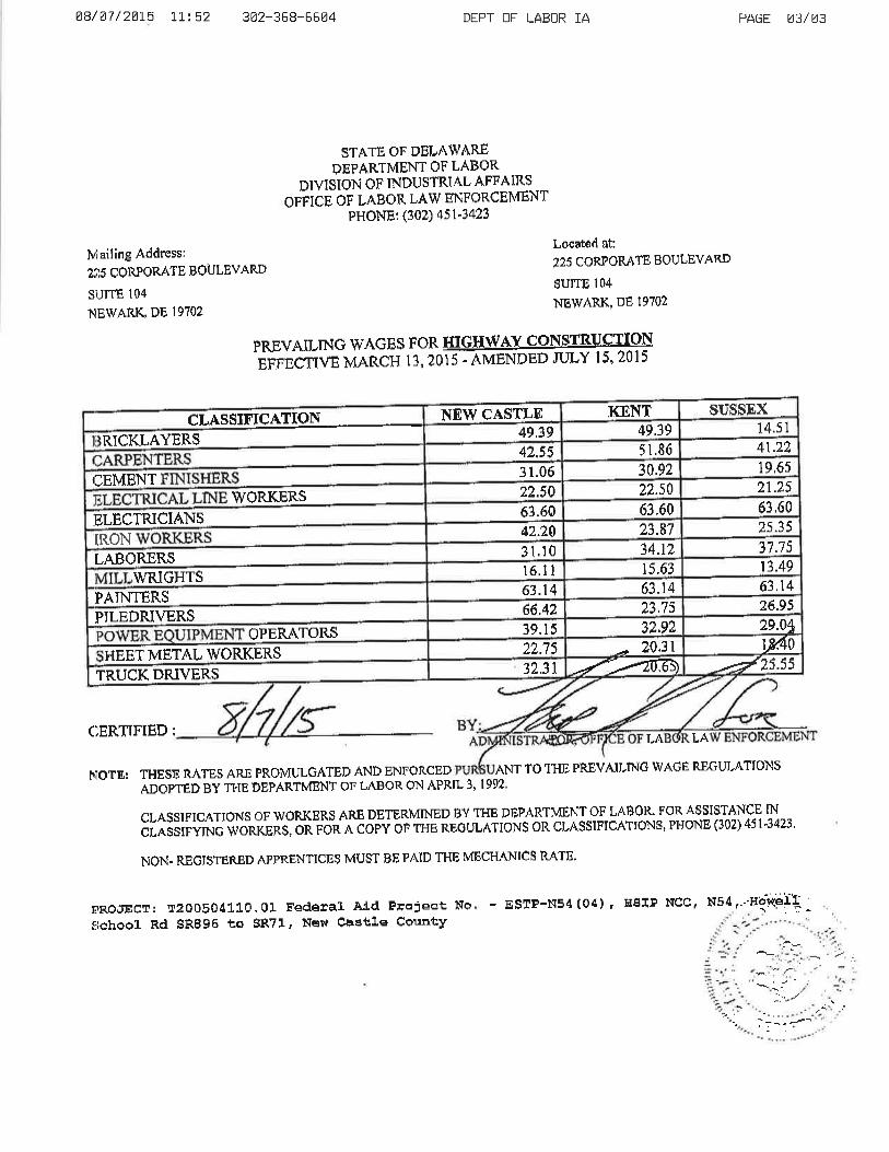
Ø8/ Ø7 / 2Ø1-5 U. : 52 3Ø2-368-66ø4
lvliailing Address:
2î.5 CORPORATE BOULEVARD
SUITE I04.NIEWARK, DE I9702
I?RöJECT: tr200504110.0I Fedêral Aíd Project No
fiêhôoI Rd gRE96 to SR?l' Nêvl Castle County
CERTTFIËD: LA
NOTE: THESE RATES AR.II PROMULG¡\TED AND ENFORCED ANT TO THE PREVAII,n\IG WACI1 REGUI-ATIONS
ADOPTËD EY TI.IE DEPARTMENT OT LABOR ON APRIL 3,1992
PREVATLTNG WAGES FOR IIIG@-ei:ntCirvg MARCH 13, 201 5 -
^MËNDED ruLY 15' 201 5
CLASSIFICATIONS OF WORKERS ARE DETERMINED BY THE DIiPARTMÉNT OF LABOR' FOR ASSISTANCE TN
cLAssrFyrNG wonrens]'o¡i eön À copv or r¡re REouL,\TroNs oR cLA$SIFIcATI0NS, PHoNE (302) 4st'34?3,
NON. REGISTË,RED APPRËNTICI]S MUST BE PAID THE MBCHANICS RATE.
DEPT OF LABOR ]A
STATË, OF DELAWi\RËDEPARTMENT OF LABOR
DIVISION OF INDUSTRI^L AFFAIRS
OFFICE OF L^BOR LAW ËNFORCEMÉNTPHONE: (302) 451-3423
Located at:
225 CORPORATE BOULEVARD
SUITE I04
NEWARK' DE I9702
- ESTÞ-N54(04), HSIP Ncc, N54/-' -Hãrtef'l
LA
PAGE ø3/ø3
$USSEX -KXNTNEW CASTLEct14.s 149,3949.3941.225l,8642.55
RICKLAYERS
I;EMENT19,6s30.923 1.0621.2522.s022.50IWORKBRS63,6063.6063.ó02s.3523.8742.24
:IELËCTRICIANS
II-ABORERSII,RON
37.7514.123l ,1013.4915.63r6.l IV/RIGHTS63.1463"1463.1,4ll'/\INTËRS 26.9523.7s66.42
]PILEDRIVERS 2e.o*32.9239.1 5OPERATORSty.4o20.3122.75WORKERSALMETHEET ¿Ézs.ssfrtffiÐ32.31TRUCK DRIVERS
' , :-'.
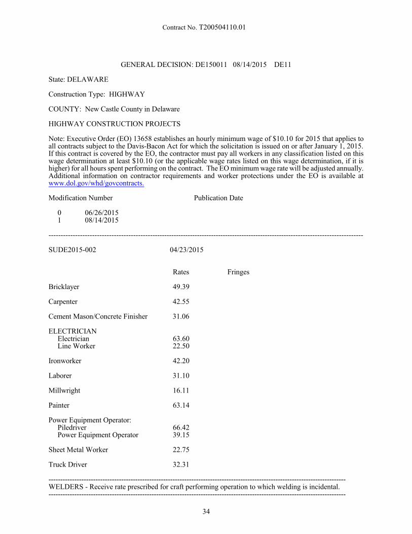
Contract No. T200504110.01
GENERAL DECISION: DE150011 08/14/2015 DE11
State: DELAWARE
Construction Type: HIGHWAY
COUNTY: New Castle County in Delaware
HIGHWAY CONSTRUCTION PROJECTS
Note: Executive Order (EO) 13658 establishes an hourly minimum wage of $10.10 for 2015 that applies toall contracts subject to the Davis-Bacon Act for which the solicitation is issued on or after January 1, 2015. If this contract is covered by the EO, the contractor must pay all workers in any classification listed on this wage determination at least $10.10 (or the applicable wage rates listed on this wage determination, if it ishigher) for all hours spent performing on the contract. The EO minimum wage rate will be adjusted annually. Additional information on contractor requirements and worker protections under the EO is available atwww.dol.gov/whd/govcontracts.
Modification Number Publication Date
0 06/26/20151 08/14/2015
------------------------------------------------------------------------------------------------------------------------------------
SUDE2015-002 04/23/2015
Rates Fringes
Bricklayer 49.39
Carpenter 42.55
Cement Mason/Concrete Finisher 31.06
ELECTRICIANElectricianLine Worker
63.6022.50
Ironworker 42.20
Laborer 31.10
Millwright 16.11
Painter 63.14
Power Equipment Operator:PiledriverPower Equipment Operator
66.4239.15
Sheet Metal Worker 22.75
Truck Driver 32.31
-------------------------------------------------------------------------------------------------------------------------------WELDERS - Receive rate prescribed for craft performing operation to which welding is incidental.-------------------------------------------------------------------------------------------------------------------------------
34
Contract No. T200504110.01
Unlisted classifications needed for work not included within the scope of the classifications listed may beadded after award only as provided in the labor standards contract clauses (29 CFR 5.5(a) (1) (ii)).
The body of each wage determination lists the classification and wage rates that have been found to beprevailing for the cited type(s) of construction in the area covered by the wage determination. Theclassifications are listed in alphabetical order of “identifiers” that indicate whether the particular rate is aunion rate (current union negotiated rate for local), a survey rate (weighted average rate) or a union averagerate (weighted union average rate).
Union Rate Identifiers
A four letter classification abbreviation identifier enclosed in dotted lines beginning with characters other than“SU” or “UAVG” denotes that the union classification and rate were prevailing for that classification in thesurvey. Example: PLUM0198-005 07/01/2014. PLUM is an abbreviation identifier of the union whichprevailed in the survey for this classification, which in this example would be Plumbers. 0198 indicates thelocal union number or district council number where applicable, i.e., Plumbers Local 0198. The next number,005 in the example, is an internal number used in processing the wage determination. 07/01/2014 is theeffective date of the most current negotiated rate, which in this example is July 1, 2014.
Union prevailing wage rates are updated to reflect all rate changes in the collective bargaining agreement(CBA) governing this classification and rate.
Survey Rate Identifiers
Classifications listed under an “SU” identifier indicated that no one rate prevailed for this classification inthe survey and the published rate is derived by computing a weighted average rate based on all the ratesreported in the survey for that classification. As this weighted average rate includes all rates reported in thesurvey, it may include both union and non-union rates. Example: SULA2012-007 5/13/2014. SU indicatesthe rates are survey rates based on a weighted average calculation of rates and are not majority rates. LAindicates the State of Louisiana. 2012 is the year of survey on which these classifications and rates are based. The next number, 007 in the example, is an internal number used in producing the wage determination. 5/13/2014 indicates the survey completion date for the classifications and rates under that identifier.
Survey wage rates are not updated and remain in effect until a new survey is conducted.
Union Average Rate Identifiers
Classification(s) listed under the UAVG identifier indicate that no single majority rate prevailed for thoseclassifications; however, 100% of the data reported for the classifications was union data. EXAMPLE:UAVG-OH-0010 08/29/2014. UAVG indicates that the rate is a weighted union average rate. OH indicatesthe state. The next number, 0010 in the example, is an internal number used in producing the wagedetermination. 08/29/2014 indicates the survey completion date for the classifications and rates under thatidentifier.
A UAVG rate will be updated once a year, usually in January of each year, to reflect a weighted average ofthe current negotiated/CBA rate of the union locals from which the rate is based.
WAGE DETERMINATION APPEALS PROCESS
1.) Has there been an initial decision in the matter? This can be:
* an existing published wage determination* a survey underlying a wage determination* a Wage and Hour Division letter setting forth a position on a wage determination matter* a conformance (additional classification and rate) ruling
On survey related matters, initial contact, including requests for summaries of surveys, should be with theWage and Hour Regional Office for the area in which the survey was conducted because those RegionalOffices have responsibility for the Davis-Bacon survey program. If the response from this initial contact isnot satisfactory, then the process described in 2.) and 3.) should be followed.
35
Contract No. T200504110.01
With regard to any other matter not yet ripe for the formal process described here, initial contact should bewith the Branch of Construction Wage Determinations. Write to:
Branch of Construction Wage DeterminationsWage and Hour DivisionU.S. Department of Labor
200 Constitution Avenue, N. W.Washington, D. C. 20210
2.) If the answer to the question in 1.) is yes, then an interested party (those affected by the action) canrequest review and reconsideration from the Wage and Hour Administrator (See 29 CFR Part 1.8 and 29 CFRPart 7). Write to:
Wage and Hour AdministratorU.S. Department of Labor
200 Constitution Avenue, N. W.Washington, D. C. 20210
The request should be accompanied by a full statement of the interested party's position and by anyinformation (wage payment data, project description, area practice material, etc.) that the requestor considersrelevant to the issue.
3.) If the decision of the Administrator is not favorable, an interested party may appeal directly to theAdministrative Review Board (formerly the Wage Appeals Board). Write to:
Administrative Review BoardU. S. Department of Labor
200 Constitution Avenue, N. W.Washington, D. C. 20210
4.) All decisions by the Administrative Review Board are final.
END OF GENERAL DECISION
APPLICABILITY OF DAVIS-BACON LABOR STANDARD PROVISIONS TO FLAGGERS
The U.S. Department of Labor has established that the duties of flaggers working on contracts coveredby the Davis-Bacon Act, are manual and physical in nature. Accordingly, all employees performing thework of flaggers on Davis-Bacon covered contracts shall be entitled to receive applicable prevailing wagerates.
* * * * *ALL AGENCY MEMORANDUM NO. 130
U.S. DEPARTMENT OF LABOREMPLOYMENT STANDARDS ADMINISTRATION
WAGE AND HOUR DIVISIONWASHINGTON, DC 20210
GUIDELINES
HIGHWAY CONSTRUCTION
Highway projects include the construction, alteration, or repair of roads, streets, highways, runways,taxiways, alleys, trails, paths, parking areas, and other similar projects not incidental to building or heavyconstruction.
EXAMPLES: Alleys, Base Courses, Bituminous treatments, Bridle Paths, Concrete pavement, Curbs,Excavation and embankment (for road construction), Fencing (highway), Grade crossing elimination(overpasses and underpasses), Guard rails on highway, Highway signs, Highway bridges (overpasses,underpasses, grade separation), Medians, Parking lots, Parkways, Resurfacing streets and highways,Roadbeds, Roadways, Runways, Shoulders, Stabilizing courses, Storm sewers incidental to road construction,Street paving, Surface courses, Taxiways, and Trails.
36

Contract No. T200504110.01
ANY QUESTIONS REGARDING THE APPLICATION OF THE GUIDELINES ABOVE TO APARTICULAR PROJECT OR ANY DISPUTES REGARDING THE APPLICATION OF THE WAGESCHEDULES ARE TO BE REFERRED TO THE WAGE AND HOUR DIVISION, U.S. DEPARTMENTOF LABOR FOR RESOLUTION, AND THE INSTRUCTIONS OF THE WAGE AND HOUR DIVISIONARE TO BE OBSERVED IN ALL INSTANCES.
* ALL AGENCY MEMORANDUM NO. 130U.S. DEPARTMENT OF LABOREMPLOYMENT STANDARDS ADMINISTRATIONWAGE AND HOUR DIVISIONWASHINGTON, DC 20210
37

Contract No. T200504110.01
SUPPLEMENTAL SPECIFICATIONSTO THE
AUGUST 2001 STANDARD SPECIFICATIONS
EFFECTIVE AS OF THE ADVERTISEMENTDATE OF THIS PROPOSAL
AND INCLUDED BY REFERENCE
The Supplemental Specifications can be viewed and printed fromthe Department's Website.
To access the Website;- in your internet browser, enter; http://www.deldot.gov - on the left side of the page under 'INFORMATION', Click; 'Publications' - scroll down under 'MANUALS' and Click; "Standard Specifications 2001"
The full Website Link is;http://www.deldot.gov/information/pubs_forms/manuals/standard_specifications/index.shtml
Printed copies of the Supplemental Specifications are available upon request. A printed copy ofthe above referenced Supplemental Specifications will be included in the final contractdocuments upon award.
The Contractor shall make himself aware of these revisions and corrections (SupplementalSpecifications), and apply them to the applicable item(s) of this contract.
38

Contract No. T200504110.01
SPECIAL PROVISIONS
39
Contract No. T200504110.01
CONSTRUCTION ITEM NUMBERS
All construction pay items are assigned a six (6) digit number, shown as Item Number on the Plans and/orin the Special Provisions, and shall be interpreted in accordance with the following:
Standard Item Number:
The first three digits of the construction item numbers indicates the Section number as described in theStandard Specifications, and all applicable requirements of the Section shall remain effective unless otherwisemodified by the Special Provisions. The last three digits of the construction item identifies the item bysequential number under that Section. Sequential numbers for all items covered under Standard Specificationsrange from 000 to 499. A comprehensive list of construction item numbers begins on page 421 of theStandard Specifications. Additions to this list will be made as required.
Special Provisions Item Number:
The first three digits of the construction items, covered under Special Provisions, indicates the applicableSection number of the Standard Specifications, and shall be governed fully by the requirements of the SpecialProvisions. The last three digit of the items covered under Special Provisions identifies the item by sequentialnumber. Sequential numbers for Special Provision items, range from 500 to 999.
Examples
Standard Item Number - 202000 Excavation and Embankment
202 Indicates Section Number
000 Indicates Sequential Number
Special Provision Item Number - 202500 Grading and Reshaping Roadway
202 Indicates Section Number
500 Indicates Sequential Number
NOTE:
PLEASE NOTE revised Supplemental Specifications to the August 2001 Standard Specifications wereissued November 24, 2014 and apply to this project. They can be viewed here and at www.deldot.gov.
SPECIFICATIONS: The Department is currently updating the August 2001 Specifications for Road andBridge Construction. Through this update, some Divisions were renumbered and some new ones werecreated and added. The Specifications Note document is for the use by the bidders to reference the newnumbers to the past numbers used for bidding purposes on previous Department contracts.
40
Contract No. T200504110.01
401502 - ASPHALT CEMENT COST ADJUSTMENT
For Sections 304, 401, 402, 403, 404, and 405, payments to the Contractor shall be adjusted to reflectincreases or decreases in the Delaware Posted Asphalt Cement Price when compared to the Project AsphaltCement Base Price, as defined in these Special Provisions.
The Delaware Posted Asphalt Cement Price will be issued monthly by the Department and will be theindustry posted price for Asphalt Cement, F.O.B. Philadelphia, Pennsylvania. The link for the posting ishttp://www.deldot.gov/information/business/bids/asphalt_cement_english.shtml.
The Project Asphalt Cement Base Price will be the Delaware Posted Asphalt Cement Price in effect onthe date of advertisement.
All deviations of the Delaware Posted Asphalt Cement Price from the Project Asphalt Cement Base Priceare eligible for cost adjustment. No minimum increases or decreases or corresponding percentages arerequired to qualify for cost adjustment.
Actual quantity of asphalt cement qualifying for any Asphalt Cement Cost Adjustment will be computedusing the weight of eligible asphalt that is shown on the QA/QC pay sheets as a percentage for the deliveredmaterial.
If the mix was not inspected and no QA/QC pay sheet was generated, then the asphalt percentage will beobtained from the job mix formula for that mix ID.
The asphalt percentage eligible for cost adjustment shall only be the virgin asphalt cement added to themix.
There shall be no separate payment per ton cost of asphalt cement. That cost shall be included in thevarious unit prices bid per ton for those bid items that contain asphalt cement (mentioned above).
The Asphalt cement cost adjustment will be calculated on grade PG 64-22 asphalt regardless of the actualgrade of asphalt used. The Project Asphalt Cement Base Price per ton for the project will be the DelawarePosted Asphalt Cement Price in effect on the date of project advertisement.
If the Contractor exceeds the authorized allotted completion time, the price of asphalt cement on the lastauthorized allotted work day, shall be the prices used for cost adjustment during the time liquidated damagesare assessed. However, if the industry posted price for asphalt cement goes down, the asphalt-cement costshall be adjusted downward accordingly.
NOTE:
Application of Asphalt Cement Cost Adjustment requirements as indicated above shall apply only to thosecontracts involving items related to bituminous base and pavements, and with bitumen, having a total of 1,000tons or more of hot-mix bid quantity in case of Sections 401, 402 and 403; and 15,000 gallons or more in caseof Sections 304, 404 and 405.
5/05/15
41
Contract No. T200504110.01
302514 - MILLED HOT-MIX BASE COURSE
Description:
It is the intent of this Special Provision to qualify the use of milled hot-mix asphalt pavement material inlieu of graded aggregate as a base course. All requirements of Section 302 shall remain in effect except asmodified below:
Materials:
The material used to construct milled hot-mix asphalt pavement base courses shall be uniformly gradedwith a maximum size of 1 1/2 (38 mm).
Subgrade Preparation:
The subgrade shall be properly constructed in accordance with Subsection 202.06. No base coursematerial shall be placed until the subgrade has been approved by the Engineer.
Placement:
a. Equipment. The milled material shall be spread uniformly by an approved spreading machine or boxin such a manner that no segregation occurs. A conventional motor grader will not be approved forplacement of milled material on mainline roadway sections.
Where it is not possible to use a spreading machine or box in patching or other tight areas, otherapproved methods can be used only in such manner that no segregation occurs. Compaction shall beuniformly attained by approved rollers or compactors. No milled materials shall be placed untilapproved equipment is on the Project site and is operational.
b. Spreading and Compacting. Milled material shall be placed in successive layers. Each layer shall beplaced in a level, uniform cross-section not to exceed 12 (300 mm) in depth, loose measurement,unless otherwise approved by the Engineer. The milled material shall be deposited and spread parallelto the centerline and the layer shall extend to the full width as shown on the Plans. The milled materialshall be handled so that no segregation of fine or coarse particles occurs. No more than 1,000 (300m) of material, as measured along the roadway centerline, shall be spread in advance of compactionoperations. Each layer shall be properly compacted as specified, before starting the next layer.
Compaction or rolling shall be performed parallel to the roadway centerline starting at the edges andprogressing toward the center. It shall continue until each layer is thoroughly and uniformly compactedto the full width as shown on the Plans.
The milled material shall be compacted by the following method: a sheepsfoot roller (minimal 50 tonstatic roller) shall make the required number of passes on the base material to achieve the target densityfollowed by a back-drag by either a bulldozer or a motor grader. After the pavement base material hasbeen placed, a 15 ton/1800 vpm (minimum) vibratory steel wheel roller shall compact the basematerial. Compaction will be measured per subsection Performance below. In small areas where theabove noted equipment cannot be used, the contractor must request approval from the Department toplace the millings with other equipment. The Department reserves the right to reject or approve theareas for placement of millings as determined by the Engineer.
After compaction, all voids in the surface of each layer will be filled with millings and compacted (withthe vibratory steel wheel roller) until the layer of base material is well bonded and firm, as determinedby the Engineer.
In no case shall vehicles be allowed to travel in a single track or to form ruts in the base course. If anysharp irregularities are formed int he subgrade or base course material, the affected area shall bescarified to a depth of 6 (150 mm) and compacted to conform to the requirements of Section 202 orthis Section.
42
Contract No. T200504110.01
c. Performance. Compaction of milled hot-mix asphalt pavement base courses will be monitored bymeasuring the in-place density using a nuclear density gauge and comparing it to a control strip targetdensity. The mean base compaction shall be at least 98% of the control strip target density andsufficiently uniform that individual test results are at least 96% of the control strip target density, thebase course represented by the test will be considered defective and the Contractor shall furthercompact the area. After further compaction, the original test site and one other randomly selected sitewithin the area will be tested. The average of two test results will be included in the mean density forthat day's placement.
To determine the control strip target density, a control strip with a minimum length of 300 (90 m) shallbe constructed at the beginning of work on each pavement base. Each control strip is to remain in placeand become a section of the completed roadway. A control strip shall have an area of at least 400 yd²(325 m²). For small areas, the Contractor may request to have a test strip waived. This request shallbe submitted to the Engineer for review.
Upon completion of the rolling, the mean density of the control strip will be determined by averagingthe results of ten nuclear density tests taken at randomly selected sites within the control strip. Themean density of the control strip shall be the target density for the remainder of the pavement basecourse which it represents. Compaction shall be expressed as a percentage of the target density.
The finished surface of the graded aggregate base course shall not vary from that required on the Plansby more than 1/2 (13 mm) when tested with a 10 (3.048 m) straightedge applied to the surfaceparallel to the centerline of the pavement and when tested with a template cut to the cross-section ofthe pavement. The actual thickness of the graded aggregate base course shall not be more than 1/2(13 mm) less than the thickness shown on Plans. Those portions of completed base course not meetingthese performance requirements shall be completely removed and replaced with proper material placedin accordance with this Section.
A straightedge meeting the approval of the Engineer shall be supplied by the Contractor at eachplacement operation. The straightedge shall be constructed of rigid materials that resist warping andbending.
Method of Measurement:
The quantity of milled hot-mix base course will be measured by the cubic yard (cubic meter) and will bepaid for under Item 302007 - Graded Aggregate Base Course. The volume of cubic yards (cubic meters) willbe measured as the number of square yards (square meters) of surface area of milled hot-mix base course,placed and accepted, multiplied by the depths shown on the Plans. If the depth of milled hot-mix base course,placed and accepted, is greater than the depth shown on the Plans, the Plan depth will be used to measure thequantity of payment.
If the limits of measurement for pay quantities for milled hot-mix base course are designated on the Plans,the quantity of milled hot-mix base course measured for payment will be the number of square yards (squaremeters) of surface area multiplied by the depth placed within the payment lines and grades shown on thePlans. If the limits are not designated on the Plans, or have been changed by the Engineer, in-placedimensions of the accepted milled hot-mix base course will be established. The computation of quantity willbe made from cross-sections taken after the completion of work under this Section.
Materials placed beyond the designated lines and grades as shown on the Plans or beyond the limitsestablished by the Engineer will not be measured for payment.
There will be no separate payment made for filling voids with millings as required under Placementsubsection (b) Spreading and Compaction.
Basis of Payment:
Millings used for Base Course will be paid at the unit bid price for Item 302007 - Graded Aggregate BaseCourse, Type B. All costs to bring the millings into compliance with the requirements of 302514 areincidental to Item 302007. No payment will be made under this item 302514.
43

Contract No. T200504110.01
Price and payment will constitute full compensation for hauling, stockpiling (includes any double handlingof material), preparing the subgrade, placing and compacting the materials, and for all labor, equipment, toolsand incidental required to complete the work.
No additional compensation will be made to the Contractor to crush, screen or otherwise modify the milledhot-mix base course to meet the necessary gradation.
No payment will be made for materials placed beyond the designated lines and grades as shown on thePlans or beyond the limits established by the Engineer.
10/31/05
44
Contract No. T200504110.01
401699 - QUALITY CONTROL/QUALITY ASSURANCE OF BITUMINOUS CONCRETE
.01 Description
This item shall govern the Quality Assurance Testing for supplying bituminous asphalt plant materials andconstructing bituminous asphalt pavements and the calculation for incentives and disincentives for materialsand construction. The Engineer will evaluate all materials and construction for acceptance. The proceduresfor acceptance are described in this Section. Include the costs for all materials, labor, equipment, tools, andincidentals necessary to meet the requirements of this specification in the bid price per ton for the bituminousasphalt. Payment to the Contractor for the bituminous asphalt item(s) will be based on the Contract priceper ton and the pay adjustments described in this specification.
.02 Bituminous Concrete Production – Quality Acceptance
(a) Material Production - Tests and Evaluations.
All acceptance tests shall be performed by qualified technicians at qualified laboratories followingAASHTO or DelDOT procedures, and shall be evaluated using Quality Level Analysis. The Engineer willconduct acceptance tests. The Engineer will directly base acceptance on the acceptance test results, theasphalt cement quality, the Contractor’s QC Plan work, and the comparisons of the acceptance test resultsto the QC test results. The Engineer may elect to utilize test results of the Contractor in some situationstoward judging acceptance.
Supply and capture samples, as directed by the Engineer under the purview of the Engineer from deliverytrucks before the trucks leave the production plant. Hand samples to the Engineer to be marked accordingly. The sample shall represent the material produced by the Contractor, and shall be of sufficient size to allowthe Engineer to complete all required acceptance tests. The Engineer will direct the Contractor when tocapture these samples, on a statistically random, unbiased basis, established before production begins eachday based upon the anticipated production tonnage. The captured sample shall be from the Engineer specifieddelivery truck. The Contractor may visually inspect the specified delivery load during sampling and elect toreject the load. If the contractor elects to reject the specified delivery truck, each subsequent load will beinspected until a visually acceptable load is produced for acceptance testing. All visually rejected loads shallnot be sent to a Department project.
The first sample of the production day will be randomly generated by the Engineer between loads 0 and12 (0-250 tons). Subsequent samples will be randomly generated by the Engineer on 500-ton sub-lots for theproduction day. Samples not retrieved in accordance with the Contractor’s QC plan will be deemedunacceptable and may be a basis for rejection of material produced. Parallel tests or dispute resolution testswill only be performed on material captured at the same time and location as the acceptance test sample. Parallel test samples or Dispute Resolution samples will be created by splitting a large sample or obtainingmultiple samples that equally represent the material. The Engineer will perform all splitting and handlingof material after it is obtained by the Contractor.
The Contractor may retain dispute resolution samples or perform parallel tests with the Engineer on anyacceptance sample.
The Engineer will evaluate and accept the material on a lot basis. All the material within a lot shall havethe same JMF (mixture ID). The lot size shall be targeted for 2000 tons or a maximum period of three days,whichever is reached first. If the 2000th ton target lot size is achieved during a production day, the lot sizeshall extend to the end of that production day. The Contractor may interrupt the production of one JMF inorder to produce different material; this type of interruption will not alter the determination of the size orlimits of material represented by a lot. The Engineer will evaluate each lot on a sublot basis. The size for eachsublot shall be 100 to 500 tons and testing for the sub lots will be completed on a daily basis. For each sublot,the Engineer will evaluate one sample.
The target size of sub-lots within each lot, except for the first sample of the production day, is equal-sized500 ton sub lots and will be based upon anticipated production, however, more or fewer sublots, withdiffering sizes, may result due to the production schedule and conditions. If the actual production is less thananticipated, and it’s determined a sample will not be obtained (based upon the anticipated tonnage), a newsample location will be determined on a statistically random, unbiased basis based upon the new actual
45
Contract No. T200504110.01
production. If the actual production is going to be 50 tons or greater over the anticipated sub lot production,a new sample location will be determined on a statistically random, unbiased basis based upon the new actualproduction. The Engineer will combine the evaluation and test results for all of the applicable sublots in orderto evaluate each individual lot.
If the Engineer is present, and the quantity exceeds 25 tons, a statistically random sample will be used foranalysis. When the anticipated production is less than 100 tons and greater than 25 tons, and the Engineer isnot present, the contractor shall randomly select a sample using the Engineer’s random location program. The captured sample shall be placed in a suitable box, marked to the attention of the Engineer, and submittedto the Engineer for testing. A box sample shall also be obtained by the contractor at the same time and willbe used as the Dispute Resolution sample if requested by the Engineer. The Contractor shall also obtain oneliquid asphalt sample (1 pint) per grade of asphalt used per day and properly label it with all pertinentinformation.
The Engineer will conduct the following tests in order to characterize the material for the pavementcompaction quality and to judge acceptance and the pay adjustment for the material:
- AASHTO T312 - Preparing and Determining the Density of Hot Mix Asphalt (HMA) Specimens byMeans of the Superpave Gyratory Compactor
- AASHTO T166, Method C (Rapid Method) - Bulk Specific Gravity of Compacted Hot Mix Asphalt(HMA) Using Saturated Surface Dry Specimens
- AASHTO T308 - Determining the Asphalt Binder Content of Hot Mix Asphalt (HMA) by the IgnitionMethod
- AASHTO T30 - Mechanical Analysis of Extracted Aggregate - AASHTO T209 - Theoretical Maximum Specific Gravity and Density of Hot Mix Asphalt (HMA)- ASTM D7227 - Standard Practice for Rapid Drying of Compacted Asphalt Specimens using Vacuum
Drying Apparatus
(b) Pavement Construction - Tests and Evaluations.
The Engineer will directly base acceptance on the compaction acceptance test results, and on the inspectionof the construction, the Contractor’s QC Plan work, ride smoothness as referenced in the contract documents,lift thickness as referenced in the contract documents, joint quality as referenced in the contract documents,surface texture as referenced in the contract documents, and possibly the comparisons of the acceptance testresults to the independent test results. For the compaction acceptance testing, the Engineer will sample thework on a statistically random basis, and will test and evaluate the work based on daily production.
Notify the Engineer of any locations within that road segment that may not be suitable to achieveminimum (93%) compaction due to existing conditions prior to paving the road segment. Schedule and holda meeting in the field with the Engineer in order to discuss all areas that may potentially be applicable toTable 5a before paving starts. Areas that will be considered for Table 5a will be investigated in accordanceto the method described in Appendix B. If this meeting is not held prior to paving, no areas will beconsidered for Table 5a. Areas of allowable exemptions that will not be cored include the following: partial-depth patch areas, driveway entrances, paving locations of less than 100 tons, areas around manholes anddriveway entrances, and areas of paving that are under 400 feet in continuous total length and/or 5 feet inwidth.
The exempt areas around manholes will be a maximum of 4 feet transversely on either side from the centerof the manhole, and 20 feet longitudinally on either side from the center of the manhole. The exempt areasaround driveway entrances shall be the entire width of the driveway, and 3 feet from the edge of thelongitudinal joint next to the driveway. Areas of exemption that will be cored for informational purposes onlyinclude: areas where the mat thickness is less than three times the nominal maximum aggregate size asdirected by the Engineer, violations of Section 401.08 in the Standard Specifications as directed by theEngineer, and areas shown to contain questionable subgrade properties as proven by substantial yieldingunder a fully legally loaded truck. Failure to obtain core samples in these areas will result in zero paymentfor compaction regardless of the exempt status. The Engineer will evaluate and accept the compaction workon a daily basis. Payment for the compaction will be calculated by using the material production lots asreferenced in .02 Acceptance Plan (a) Material Production - B Tests and Evaluation and analyzing thecompaction results over the individual days covered in the material production lot. The compaction resultswill be combined with the material results to obtain a payment for this item.
46
Contract No. T200504110.01
The minimum size of a compaction lot shall be 100 tons. If the compaction lot is between 101 and 1000tons, the Engineer shall randomly determine four compaction acceptance test locations. If the compaction lotis between 1001 and 1500 tons, the Engineer shall randomly determine six compaction acceptance testlocations. If the compaction lot is between 1501 and 2000 tons, the Engineer shall randomly determine eightcompaction acceptance test locations. If the compaction lot is greater than 2000 tons, the Engineer shallrandomly determine two compaction acceptance test locations per 500 tons.
If a randomly selected area falls within an Engineer approved exemption area, the Engineer will select onemore randomly generated location to be tested per the requirements of this Specification. If that cannot beaccomplished, or if an entire location has been declared exempt, the compaction testing shall be performedas per these Specifications but a note will be added to the results that the location was an Engineer approvedexempt location.
Testing locations will be a minimum of 1.0 feet from the newly placed longitudinal joint and 50 feet froma new transverse joint.
Cut one six (6) inch diameter core through the full lift depth at the exact location marked by the Engineer.Cores submitted that are not from the location designated by the Engineer will not be tested and will be paidat zero pay.
Notify the Engineer prior to starting paving operations with approximate tonnage to be placed. TheContractor is then responsible for notifying the appropriate Engineer test personnel within 12 hours ofmaterial placement. The Engineer will mark core locations within 24 hours of notification. Afterdetermination of locations, the Contractor shall complete testing within two operational days of the locationsbeing marked. If the cores are not cut within two operational days, the area in question will be paid at zeropay for compaction testing.
Provide any traffic control required for the structural number investigation, sampling, and testing workat no additional cost to the Department.
Commence coring of the pavement after the pavement has cooled to a temperature of 140EF or less. Cuteach core with care in order to prevent damaging the core. Damaged cores will not be tested. Label each corewith contract number, date of construction, and number XX of XX upon removal from the roadway Placecores in a 6-inch diameter plastic concrete cylinder mold or approved substitute for protection. Separate coresin the same cylinder mold with paper. Attach a completed QC test record for the represented area with thecorresponding cores. The Engineer will also complete a test record for areas tested for the QA report andprovide to Materials & Research. Deliver the cores to the Engineer for testing, processing, and reportdistribution at the end of each production day.
Repair core holes per Appendix A, Repairing Core Holes in Bituminous Asphalt Pavements. Core holesshall be filled immediately. Failure to repair core holes at the time of coring will result in zero pay forcompaction testing for the area in question.
The Engineer will conduct the following tests on the applicable portion of the cores in order to evaluatetheir quality:
- AASHTO T166, Method C (Rapid Method) B Bulk Specific Gravity of Compacted Hot Mix Asphalt(HMA) Using Saturated Surface Dry Specimens
- AASHTO T209 - Theoretical Maximum Specific Gravity and Density of Hot Mix Asphalt- ASTM D7227 - Standard Practice for Rapid Drying of Compacted Asphalt Specimens using Vacuum
Drying Apparatus
The Engineer will use the average of the last five test values of the same JMF (mixture ID) material at theproduction plant in order to calculate the average theoretical maximum specific gravity of the cores. Theaverage will be based on the production days test results and as many test results needed from previous daysproduction to have an average of five samples. If there are less than five values available, the Engineer willuse the JMF design value in addition to the available values to calculate the average theoretical maximumspecific gravity.
47
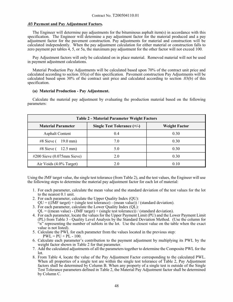
Contract No. T200504110.01
.03 Payment and Pay Adjustment Factors.
The Engineer will determine pay adjustments for the bituminous asphalt item(s) in accordance with thisspecification. The Engineer will determine a pay adjustment factor for the material produced and a payadjustment factor for the pavement construction. Pay adjustments for material and construction will becalculated independently. When the pay adjustment calculation for either material or construction falls tozero payment per tables 4, 5, or 5a, the maximum pay adjustment for the other factor will not exceed 100.
Pay Adjustment factors will only be calculated on in place material. Removed material will not be usedin payment adjustment calculations.
Material Production Pay Adjustments will be calculated based upon 70% of the contract unit price andcalculated according to section .03(a) of this specification. Pavement construction Pay Adjustments will becalculated based upon 30% of the contract unit price and calculated according to section .03(b) of thisspecification.
(a) Material Production - Pay Adjustment.
Calculate the material pay adjustment by evaluating the production material based on the followingparameters:
Table 2 - Material Parameter Weight Factors
Material Parameter Single Test Tolerance (+/-) Weight Factor
Asphalt Content 0.4 0.30
#8 Sieve ( 19.0 mm) 7.0 0.30
#8 Sieve ( 12.5 mm) 5.0 0.30
#200 Sieve (0.075mm Sieve) 2.0 0.30
Air Voids (4.0% Target) 2.0 0.10
Using the JMF target value, the single test tolerance (from Table 2), and the test values, the Engineer will usethe following steps to determine the material pay adjustment factor for each lot of material:
1. For each parameter, calculate the mean value and the standard deviation of the test values for the lotto the nearest 0.1 unit.
2. For each parameter, calculate the Upper Quality Index (QU): QU = ((JMF target) + (single test tolerance) - (mean value)) / (standard deviation).
3. For each parameter, calculate the Lower Quality Index (QL):QL = ((mean value) - (JMF target) + (single test tolerance)) / (standard deviation).
4. For each parameter, locate the values for the Upper Payment Limit (PU) and the Lower Payment Limit(PL) from Table 3 - Quality Level Analysis by the Standard Deviation Method. (Use the column for“n” representing the number of sublots in the lot. Use the closest value on the table when the exactvalue is not listed).
5. Calculate the PWL for each parameter from the values located in the previous step: PWL = PU + PL - 100.
6. Calculate each parameter’s contribution to the payment adjustment by multiplying its PWL by theweight factor shown in Table 2 for that parameter.
7. Add the calculated adjustments of all the parameters together to determine the Composite PWL for thelot.
8. From Table 4, locate the value of the Pay Adjustment Factor corresponding to the calculated PWL. When all properties of a single test are within the single test tolerance of Table 2, Pay Adjustmentfactors shall be determined by Column B. When any property of a single test is outside of the SingleTest Tolerance parameters defined in Table 2, the Material Pay Adjustment factor shall be determinedby Column C.
48
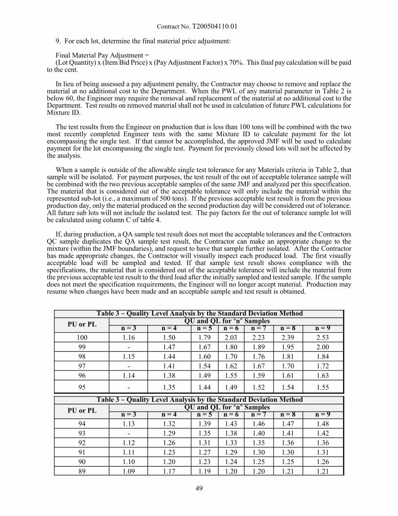
Contract No. T200504110.01
9. For each lot, determine the final material price adjustment:
Final Material Pay Adjustment = (Lot Quantity) x (Item Bid Price) x (Pay Adjustment Factor) x 70%. This final pay calculation will be paid
to the cent.
In lieu of being assessed a pay adjustment penalty, the Contractor may choose to remove and replace thematerial at no additional cost to the Department. When the PWL of any material parameter in Table 2 isbelow 60, the Engineer may require the removal and replacement of the material at no additional cost to theDepartment. Test results on removed material shall not be used in calculation of future PWL calculations forMixture ID.
The test results from the Engineer on production that is less than 100 tons will be combined with the twomost recently completed Engineer tests with the same Mixture ID to calculate payment for the lotencompassing the single test. If that cannot be accomplished, the approved JMF will be used to calculatepayment for the lot encompassing the single test. Payment for previously closed lots will not be affected bythe analysis.
When a sample is outside of the allowable single test tolerance for any Materials criteria in Table 2, thatsample will be isolated. For payment purposes, the test result of the out of acceptable tolerance sample willbe combined with the two previous acceptable samples of the same JMF and analyzed per this specification. The material that is considered out of the acceptable tolerance will only include the material within therepresented sub-lot (i.e., a maximum of 500 tons). If the previous acceptable test result is from the previousproduction day, only the material produced on the second production day will be considered out of tolerance. All future sub lots will not include the isolated test. The pay factors for the out of tolerance sample lot willbe calculated using column C of table 4.
If, during production, a QA sample test result does not meet the acceptable tolerances and the ContractorsQC sample duplicates the QA sample test result, the Contractor can make an appropriate change to themixture (within the JMF boundaries), and request to have that sample further isolated. After the Contractorhas made appropriate changes, the Contractor will visually inspect each produced load. The first visuallyacceptable load will be sampled and tested. If that sample test result shows compliance with thespecifications, the material that is considered out of the acceptable tolerance will include the material fromthe previous acceptable test result to the third load after the initially sampled and tested sample. If the sampledoes not meet the specification requirements, the Engineer will no longer accept material. Production mayresume when changes have been made and an acceptable sample and test result is obtained.
Table 3 B Quality Level Analysis by the Standard Deviation Method
PU or PL QU and QL for An@ Samplesn = 3 n = 4 n = 5 n = 6 n = 7 n = 8 n = 9
100 1.16 1.50 1.79 2.03 2.23 2.39 2.53
99 - 1.47 1.67 1.80 1.89 1.95 2.00
98 1.15 1.44 1.60 1.70 1.76 1.81 1.84
97 - 1.41 1.54 1.62 1.67 1.70 1.72
96 1.14 1.38 1.49 1.55 1.59 1.61 1.63
95 - 1.35 1.44 1.49 1.52 1.54 1.55
Table 3 B Quality Level Analysis by the Standard Deviation Method
PU or PL QU and QL for An@ Samplesn = 3 n = 4 n = 5 n = 6 n = 7 n = 8 n = 9
94 1.13 1.32 1.39 1.43 1.46 1.47 1.48
93 - 1.29 1.35 1.38 1.40 1.41 1.42
92 1.12 1.26 1.31 1.33 1.35 1.36 1.36
91 1.11 1.23 1.27 1.29 1.30 1.30 1.31
90 1.10 1.20 1.23 1.24 1.25 1.25 1.26
89 1.09 1.17 1.19 1.20 1.20 1.21 1.21
49
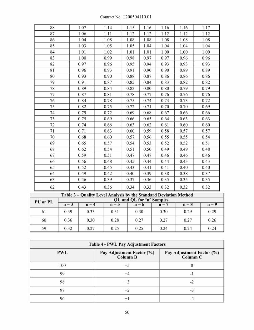
Contract No. T200504110.01
88 1.07 1.14 1.15 1.16 1.16 1.16 1.17
87 1.06 1.11 1.12 1.12 1.12 1.12 1.12
86 1.04 1.08 1.08 1.08 1.08 1.08 1.08
85 1.03 1.05 1.05 1.04 1.04 1.04 1.04
84 1.01 1.02 1.01 1.01 1.00 1.00 1.00
83 1.00 0.99 0.98 0.97 0.97 0.96 0.96
82 0.97 0.96 0.95 0.94 0.93 0.93 0.93
81 0.96 0.93 0.91 0.90 0.90 0.89 0.89
80 0.93 0.90 0.88 0.87 0.86 0.86 0.86
79 0.91 0.87 0.85 0.84 0.83 0.82 0.82
78 0.89 0.84 0.82 0.80 0.80 0.79 0.79
77 0.87 0.81 0.78 0.77 0.76 0.76 0.76
76 0.84 0.78 0.75 0.74 0.73 0.73 0.72
75 0.82 0.75 0.72 0.71 0.70 0.70 0.69
74 0.79 0.72 0.69 0.68 0.67 0.66 0.66
73 0.75 0.69 0.66 0.65 0.64 0.63 0.63
72 0.74 0.66 0.63 0.62 0.61 0.60 0.60
71 0.71 0.63 0.60 0.59 0.58 0.57 0.57
70 0.68 0.60 0.57 0.56 0.55 0.55 0.54
69 0.65 0.57 0.54 0.53 0.52 0.52 0.51
68 0.62 0.54 0.51 0.50 0.49 0.49 0.48
67 0.59 0.51 0.47 0.47 0.46 0.46 0.46
66 0.56 0.48 0.45 0.44 0.44 0.43 0.43
65 0.52 0.45 0.43 0.41 0.41 0.40 0.40
64 0.49 0.42 0.40 0.39 0.38 0.38 0.37
63 0.46 0.39 0.37 0.36 0.35 0.35 0.35
62 0.43 0.36 0.34 0.33 0.32 0.32 0.32
Table 3 B Quality Level Analysis by the Standard Deviation Method
PU or PL QU and QL for An@ Samplesn = 3 n = 4 n = 5 n = 6 n = 7 n = 8 n = 9
61 0.39 0.33 0.31 0.30 0.30 0.29 0.29
60 0.36 0.30 0.28 0.27 0.27 0.27 0.26
59 0.32 0.27 0.25 0.25 0.24 0.24 0.24
Table 4 - PWL Pay Adjustment Factors
PWL Pay Adjustment Factor (%)Column B
Pay Adjustment Factor (%)Column C
100 +5 0
99 +4 -1
98 +3 -2
97 +2 -3
96 +1 -4
50
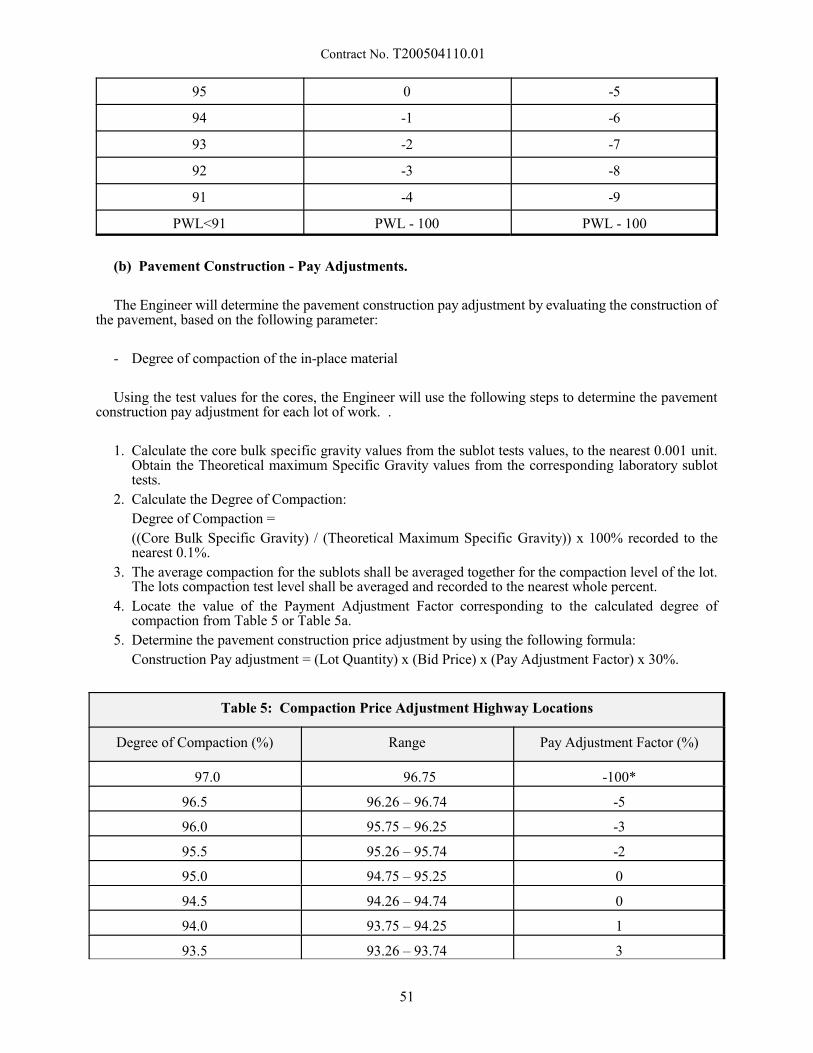
Contract No. T200504110.01
95 0 -5
94 -1 -6
93 -2 -7
92 -3 -8
91 -4 -9
PWL<91 PWL - 100 PWL - 100
(b) Pavement Construction - Pay Adjustments.
The Engineer will determine the pavement construction pay adjustment by evaluating the construction ofthe pavement, based on the following parameter:
- Degree of compaction of the in-place material
Using the test values for the cores, the Engineer will use the following steps to determine the pavementconstruction pay adjustment for each lot of work. .
1. Calculate the core bulk specific gravity values from the sublot tests values, to the nearest 0.001 unit. Obtain the Theoretical maximum Specific Gravity values from the corresponding laboratory sublottests.
2. Calculate the Degree of Compaction:
Degree of Compaction =
((Core Bulk Specific Gravity) / (Theoretical Maximum Specific Gravity)) x 100% recorded to thenearest 0.1%.
3. The average compaction for the sublots shall be averaged together for the compaction level of the lot. The lots compaction test level shall be averaged and recorded to the nearest whole percent.
4. Locate the value of the Payment Adjustment Factor corresponding to the calculated degree ofcompaction from Table 5 or Table 5a.
5. Determine the pavement construction price adjustment by using the following formula:
Construction Pay adjustment = (Lot Quantity) x (Bid Price) x (Pay Adjustment Factor) x 30%.
Table 5: Compaction Price Adjustment Highway Locations
Degree of Compaction (%) Range Pay Adjustment Factor (%)
97.0 96.75 -100*
96.5 96.26 – 96.74 -5
96.0 95.75 – 96.25 -3
95.5 95.26 – 95.74 -2
95.0 94.75 – 95.25 0
94.5 94.26 – 94.74 0
94.0 93.75 – 94.25 1
93.5 93.26 – 93.74 3
51
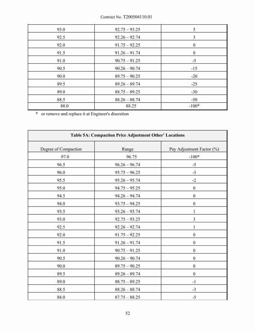
Contract No. T200504110.01
93.0 92.75 – 93.25 5
92.5 92.26 – 92.74 3
92.0 91.75 – 92.25 0
91.5 91.26 – 91.74 0
91.0 90.75 – 91.25 -5
90.5 90.26 – 90.74 -15
90.0 89.75 – 90.25 -20
89.5 89.26 – 89.74 -25
89.0 88.75 – 89.25 -30
88.5 88.26 – 88.74 -50
88.0 88.25 -100*
* or remove and replace it at Engineer's discretion
Table 5A: Compaction Price Adjustment Other1 Locations
Degree of Compaction Range Pay Adjustment Factor (%)
97.0 96.75 -100*
96.5 96.26 – 96.74 -5
96.0 95.75 – 96.25 -3
95.5 95.26 – 95.74 -2
95.0 94.75 – 95.25 0
94.5 94.26 – 94.74 0
94.0 93.75 – 94.25 0
93.5 93.26 – 93.74 1
93.0 92.75 – 93.25 3
92.5 92.26 – 92.74 1
92.0 91.75 – 92.25 0
91.5 91.26 – 91.74 0
91.0 90.75 – 91.25 0
90.5 90.26 – 90.74 0
90.0 89.75 – 90.25 0
89.5 89.26 – 89.74 0
89.0 88.75 – 89.25 -1
88.5 88.26 – 88.74 -3
88.0 87.75 – 88.25 -5
52
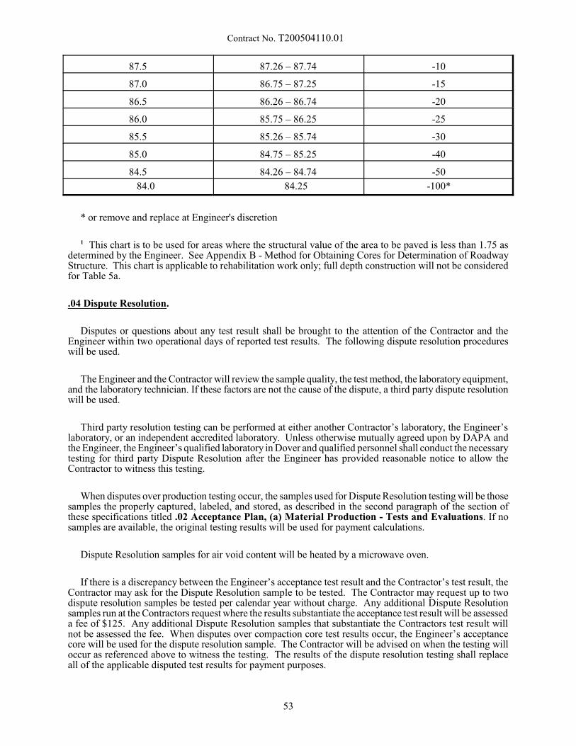
Contract No. T200504110.01
87.5 87.26 – 87.74 -10
87.0 86.75 – 87.25 -15
86.5 86.26 – 86.74 -20
86.0 85.75 – 86.25 -25
85.5 85.26 – 85.74 -30
85.0 84.75 – 85.25 -40
84.5 84.26 – 84.74 -50
84.0 84.25 -100*
* or remove and replace at Engineer's discretion
1 This chart is to be used for areas where the structural value of the area to be paved is less than 1.75 asdetermined by the Engineer. See Appendix B - Method for Obtaining Cores for Determination of RoadwayStructure. This chart is applicable to rehabilitation work only; full depth construction will not be consideredfor Table 5a.
.04 Dispute Resolution.
Disputes or questions about any test result shall be brought to the attention of the Contractor and theEngineer within two operational days of reported test results. The following dispute resolution procedureswill be used.
The Engineer and the Contractor will review the sample quality, the test method, the laboratory equipment,and the laboratory technician. If these factors are not the cause of the dispute, a third party dispute resolutionwill be used.
Third party resolution testing can be performed at either another Contractor’s laboratory, the Engineer’slaboratory, or an independent accredited laboratory. Unless otherwise mutually agreed upon by DAPA andthe Engineer, the Engineer’s qualified laboratory in Dover and qualified personnel shall conduct the necessarytesting for third party Dispute Resolution after the Engineer has provided reasonable notice to allow theContractor to witness this testing.
When disputes over production testing occur, the samples used for Dispute Resolution testing will be thosesamples the properly captured, labeled, and stored, as described in the second paragraph of the section ofthese specifications titled .02 Acceptance Plan, (a) Material Production - Tests and Evaluations. If nosamples are available, the original testing results will be used for payment calculations.
Dispute Resolution samples for air void content will be heated by a microwave oven.
If there is a discrepancy between the Engineer’s acceptance test result and the Contractor’s test result, theContractor may ask for the Dispute Resolution sample to be tested. The Contractor may request up to twodispute resolution samples be tested per calendar year without charge. Any additional Dispute Resolutionsamples run at the Contractors request where the results substantiate the acceptance test result will be assesseda fee of $125. Any additional Dispute Resolution samples that substantiate the Contractors test result willnot be assessed the fee. When disputes over compaction core test results occur, the Engineer’s acceptancecore will be used for the dispute resolution sample. The Contractor will be advised on when the testing willoccur as referenced above to witness the testing. The results of the dispute resolution testing shall replaceall of the applicable disputed test results for payment purposes.
53
Contract No. T200504110.01
Appendix A - Repairing Core Holes in Bituminous Asphalt Pavement
Description.
This appendix describes the procedure required to repair core holes in a bituminous concretepavement.
Materials and Equipment.
The following material shall be available to complete this work:
- Patch Material - DelDOT approved High Performance Cold Patch material shall be used.
The following equipment shall be available to complete this work:
- Sponge or other absorbent material - Used to extract water from the hole.
- Compaction Hammer - mechanical (electrical, pneumatic, or gasoline driven) tamping device with aflat, circular tamping face smaller than 6 inches in diameter.
Construction Method.
After core removal from the hole, remove all excess water from within the hole, and prevent water fromre-entering the hole.
Place the patch material in lifts no greater than 3 inches and compact with mechanical tamping device. If the hole is deeper than 3 inches, use two lifts of approximately equal depths so that optimum compactionis achieved. Make sure that the patch surface matches the grade of the existing roadway. Make every effortto achieve the greatest possible compaction
Performance Requirements.
The Engineer will judge the patch on the following basis:
- The patch shall be well compacted
- The patch surface shall match the grade of the surrounding roadway surface.
Basis of Payment.
No measurement or payment will be made for the patching work. The Contractor must gain the Engineer’sacceptance of the patching work before the Engineer will accept the material represented by the core.
54
Contract No. T200504110.01
Appenidx B - Method for Obtaining Cores for Determination of Roadway Structure
The Contractor is responsible for obtaining cores in areas that they propose are eligible for compactionprice adjustments according to Table 5a in this specification. Table 5a is not applicable for new full-depthpavement box construction. Cores submitted for this process shall be obtained according to the followingprocess.
1. Contact Materials & Research (M&R) personnel to determine if information about the area is alreadyavailable. If M&R has already obtained cores in the location that is being investigated, the contractormay opt to use the laboratory information for the investigation and not core the area on their own.
2. If M&R does not have information concerning the section of the roadway, the contractor needs tocontact M&R to arrange for verification of coring operations. Arrangements shall be made to allowfor an individual from M&R to be on the site when the cores are obtained. Cores will be turned overto M&R for evaluation.
3. The Contractor is responsible for providing all traffic control and repairing core holes in accordanceto 401699 Appendix A - Repairing Core Holes in Bituminous Asphalt Pavements.
4. Cores are to be taken throughout the entire project for the area in question. Cores will be spaced, fromthe start of the project in increments determined based on field and project specifics. Cores will beevenly distributed throughout the project location. The cores will be taken in the center of the lane inquestion.
5. Additional cores may be taken at other locations, if surface conditions indicate that there may be asubstantial difference in the underlying section. The location of these cores should be documented andsubmitted to M&R.
6. Cores shall be full depth and include underlying materials. If there is a stone base included in thepavement section, at a minimum 1 core must have information concerning the thickness of the base. This is determined by augering to the subgrade surface.
7. The calculations used to determine the structural capacity of the roadway is as follows. If thecontractor finds, upon starting the coring process, that the areas are of greater thickness than applicableto Table 5a, they may terminate the coring process on their own and retract the request.
55
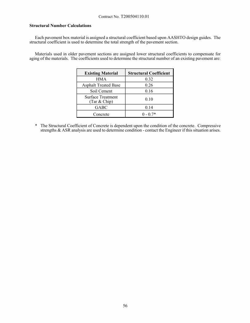
Contract No. T200504110.01
Structural Number Calculations
Each pavement box material is assigned a structural coefficient based upon AASHTO design guides. Thestructural coefficient is used to determine the total strength of the pavement section.
Materials used in older pavement sections are assigned lower structural coefficients to compensate foraging of the materials. The coefficients used to determine the structural number of an existing pavement are:
Existing Material Structural Coefficient
HMA 0.32
Asphalt Treated Base 0.26
Soil Cement 0.16
Surface Treatment(Tar & Chip)
0.10
GABC 0.14
Concrete 0 - 0.7*
* The Structural Coefficient of Concrete is dependent upon the condition of the concrete. Compressivestrengths & ASR analysis are used to determine condition - contact the Engineer if this situation arises.
56
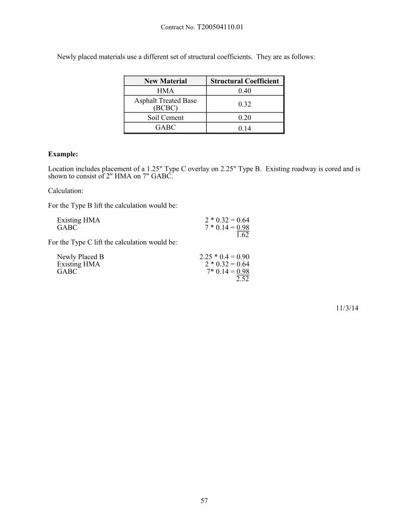
Contract No. T200504110.01
Newly placed materials use a different set of structural coefficients. They are as follows:
New Material Structural Coefficient
HMA 0.40
Asphalt Treated Base(BCBC)
0.32
Soil Cement 0.20
GABC 0.14
Example:
Location includes placement of a 1.25" Type C overlay on 2.25" Type B. Existing roadway is cored and isshown to consist of 2" HMA on 7" GABC.
Calculation:
For the Type B lift the calculation would be:
Existing HMA 2 * 0.32 = 0.64GABC 7 * 0.14 = 0.98
1.62For the Type C lift the calculation would be:
Newly Placed B 2.25 * 0.4 = 0.90Existing HMA 2 * 0.32 = 0.64GABC 7* 0.14 = 0.98
2.52
11/3/14
57
Contract No. T200504110.01
401752 – SAFETY EDGE FOR ROADWAY PAVEMENT
Description:
This work consists of the construction of safety edge(s) along bituminous concrete pavement or P.C.C.pavement in accordance with the details and notes on the Plans and as directed by the Engineer.
Construction Methods:
The safety edge shall not be constructed adjacent to curb or in front of guardrail sections.
In bituminous concrete pavement sections, prior to the construction of the safety edge, the fill or in situmaterial at the edge of pavement shall be compacted so that it is level with the top of the pavement, prior tothe final surface overlay.
In bituminous concrete pavement sections, the contractor shall attach a device to the screed of the paverunit that confines the material at the end of the gate and extrudes the asphalt material in such a way thatresults in a compacted wedge shape pavement edge of 32 degrees (+/- 2 degrees). Contact shall bemaintained between the device and the road shoulder surface. The device shall be manufactured so that it canbe easily adjusted to transition at cross roads, driveways and obstructions without stopping the paver unit. The device’s shape shall constrain the asphalt and cause compaction, as well as increase the density of theextruded profile.
In bituminous concrete pavement sections, the Transtech Shoulder Wedge Maker, Carlson Safety EdgeEnd Gate or an approved equal shall be used to produce the safety edge. Contact information for these wedgeshape compaction devices is listed below:
Transtech Systems, Inc.1594 State StreetSchenectady, NY 123041-800-724-6306www.transtechsys.com
or
Carlson Paving Products18425 50th Ave. ETacoma, WA 984461-253-278-9426www.carlsonpavingproducts.com
or an approved equal.
In P.C.C. pavement sections, the paver screed shall be modified to provide a chamfer at the end of theP.C.C. pavement in accordance with the details and notes on the Plans, or as directed by the Engineer.
Method of Measurement:
Safety Edge will not be measured for payment.
Basis of Payment:
The cost associated with the construction of safety edge(s), including but not limited to the wedge device,preparation and compaction of the fill or in situ material, and placement of the safety edge in accordance withthe Plans and Details shall be incidental to the bituminous concrete pavement or P.C.C. pavement item beingplaced.
10/15/2013
58
Contract No. T200504110.01
401800 - BITUMINOUS CONCRETE, SUPERPAVE, TYPE C, 115 GYRATIONS, PG 64-22
(CARBONATE STONE)401801 - BITUMINOUS CONCRETE, TYPE C, 160 GYRATIONS, PG 64-22 (CARBONATE
STONE)401802 - BITUMINOUS CONCRETE, TYPE C, 205 GYRATIONS, PG 64-22 (CARBONATE
STONE)
401803 - BITUMINOUS CONCRETE, TYPE C, 115 GYRATIONS, PG 70-22 (CARBONATESTONE)
401804 - BITUMINOUS CONCRETE, TYPE C, 160 GYRATIONS, PG 70-22 (CARBONATESTONE)
401805 - BITUMINOUS CONCRETE, TYPE C, 205 GYRATIONS, PG 70-22 (CARBONATESTONE)
401806 - BITUMINOUS CONCRETE, TYPE C, 115 GYRATIONS, PG 76-22 (CARBONATESTONE)
401807 - BITUMINOUS CONCRETE, TYPE C, 160 GYRATIONS, PG 76-22 (CARBONATESTONE)
401808 - BITUMINOUS CONCRETE, TYPE C, 205 GYRATIONS, PG 76-22 (CARBONATESTONE)
401809 - BITUMINOUS CONCRETE, SUPERPAVE, TYPE B, 115 GYRATIONS, PG 64-22401810 - BITUMINOUS CONCRETE, SUPERPAVE, TYPE B, 160 GYRATIONS, PG 64-22401811 - BITUMINOUS CONCRETE, SUPERPAVE, TYPE B, 205 GYRATIONS, PG 64-22
401812 - BITUMINOUS CONCRETE, SUPERPAVE, TYPE B, 115 GYRATIONS, PG 70-22401813 - BITUMINOUS CONCRETE, SUPERPAVE, TYPE B, 160 GYRATIONS, PG 70-22401814 - BITUMINOUS CONCRETE, SUPERPAVE, TYPE B, 205 GYRATIONS, PG 70-22
401815 - BITUMINOUS CONCRETE, SUPERPAVE, TYPE B, 115 GYRATIONS, PG 76-22401816 - BITUMINOUS CONCRETE, SUPERPAVE, TYPE B, 160 GYRATIONS, PG 76-22401817 - BITUMINOUS CONCRETE, SUPERPAVE, TYPE B, 205 GYRATIONS, PG 76-22
401818 - BITUMINOUS CONCRETE, SUPERPAVE, BITUMINOUS CONCRETE BASECOURSE, 115 GYRATIONS, PG 64-22
401819 - BITUMINOUS CONCRETE, SUPERPAVE, BITUMINOUS CONCRETE BASECOURSE, 160 GYRATIONS, PG 64-22
401820 - BITUMINOUS CONCRETE, SUPERPAVE, BITUMINOUS CONCRETE BASECOURSE, 205 GYRATIONS, PG 64-22
401821 - BITUMINOUS CONCRETE, SUPERPAVE, TYPE C, 160 GYRATIONS, PG 64-22,PATCHING
401822 - BITUMINOUS CONCRETE, SUPERPAVE, TYPE B, 160 GYRATIONS, PG 64-22,PATCHING
401823 - BITUMINOUS CONCRETE, SUPERPAVE, BITUMINOUS CONCRETE BASECOURSE, 160 GYRATIONS, PG 64-22, PATCHING
401824 - BITUMINOUS CONCRETE, SUPERPAVE, TYPE C, 160 GYRATIONS, PG-64-22,WEDGE
401825 - BITUMINOUS CONCRETE, SUPERPAVE, TYPE B, 160 GYRATIONS, PG-64-22,WEDGE
401826 - BITUMINOUS CONCRETE, SUPERPAVE, TYPE C, 115 GYRATIONS, PG 64-22,(NON-CARBONATE STONE)
401827 -BITUMINOUS CONCRETE, SUPERPAVE, TYPE C, 160 GYRATIONS, PG 64-22,(NON-CARBONATE STONE)
401828 - BITUMINOUS CONCRETE, SUPERPAVE, TYPE C, 205 GYRATIONS, PG 64-22,(NON-CARBONATE STONE)
59
Contract No. T200504110.01
401829 - BITUMINOUS CONCRETE, SUPERPAVE, TYPE C, 115 GYRATIONS, PG 70-22,(NON-CARBONATE STONE)
401830 - BITUMINOUS CONCRETE, SUPERPAVE, TYPE C, 160 GYRATIONS, PG 70-22,(NON-CARBONATE STONE)
401831 - BITUMINOUS CONCRETE, SUPERPAVE, TYPE C, 205 GYRATIONS, PG 70-22,(NON-CARBONATE STONE)
401832 - BITUMINOUS CONCRETE, SUPERPAVE, TYPE C, 115 GYRATIONS, PG 76-22,(NON-CARBONATE STONE)
401833 -BITUMINOUS CONCRETE, SUPERPAVE, TYPE C, 160 GYRATIONS, PG 76-22,(NON-CARBONATE STONE)
401834 - BITUMINOUS CONCRETE, SUPERPAVE, TYPE C, 205 GYRATIONS, PG 76-22,(NON-CARBONATE STONE)
401835 - THIN BITUMINOUS CONCRETE, SUPERPAVE, TYPE C, 115 GYRATIONS, PG 64-22401836 - THIN BITUMINOUS CONCRETE, SUPERPAVE, TYPE C, 160 GYRATIONS, PG 64-22401837 - THIN BITUMINOUS CONCRETE, SUPERPAVE, TYPE C, 115 GYRATIONS, PG 70-22401838 - THIN BITUMINOUS CONCRETE, SUPERPAVE, TYPE C, 160 GYRATIONS, PG 70-22401839 - THIN BITUMINOUS CONCRETE, SUPERPAVE, TYPE C, 115 GYRATIONS, PG 76-22401840 - THIN BITUMINOUS CONCRETE, SUPERPAVE, TYPE C, 160 GYRATIONS, PG 76-22
.01 Description:
This specification shall govern the production and construction of bituminous concrete pavement. Thefollowing Subsections of the Standard Specifications shall be applicable: 401.01, 401.03 - 401.10, 401.12,and 401.13. All other subsections have been modified herein.
Payment for bituminous concrete shall be in accordance with item 401699. The Contractor shall read andthoroughly understand the requirements of the QA/QC specification as defined in item 401699. It is theresponsibility of the Contractor to determine all costs associated with meeting these requirements and toinclude them in the per ton bids for the various Superpave bituminous concrete items. Payment adjustmentfactors will be calculated in accordance with the latest version of item 401699.
Bituminous concrete may be produced by one or a combination of several technologies involving asphaltfoaming processes and equipment or additives that facilitate the reduction of the temperature at which the mixcan be placed and satisfactorily compacted thereby permitting the mix to be produced at reducedtemperatures.
.02 Materials:
Use materials conforming to standard specifications 823.
Materials for bituminous concrete shall conform to the requirements of Subsections 823.01, 823.05-823.17, and 823.25 - 823.28 of the Standard Specifications and the following. If the Contractor proposes touse a combination of materials that are not covered by this Specification, the mix design shall be submittedand reviewed by the Engineer 30 calendar days prior to use.
a) Asphalt Binder:
Meet the requirements of Superpave performance-grade asphalt binder, as referenced in the Plans,according to M 320 1, Table 1 and tested according to AASHTO R29 with the following test ranges:
60
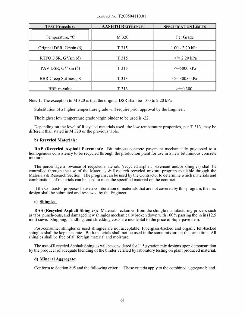
Contract No. T200504110.01
TEST Procedure AASHTO REFERENCE SPECIFICATION LIMITS
Temperature, °C M 320 Per Grade
Original DSR, G*/sin (ä) T 315 1.00 - 2.20 kPa1
RTFO DSR, G*/sin (ä) T 315 >/= 2.20 kPa
PAV DSR, G*/ sin (ä) T 315 </=5000 kPa
BBR Creep Stiffness, S T 313 </= 300.0 kPa
BBR m-value T 313 >/=0.300
Note 1: The exception to M 320 is that the original DSR shall be 1.00 to 2.20 kPa
Substitution of a higher temperature grade will require prior approval by the Engineer.
The highest low temperature grade virgin binder to be used is -22.
Depending on the level of Recycled materials used, the low temperature properties, per T 313, may bedifferent than stated in M 320 or the previous table.
b) Recycled Materials:
RAP (Recycled Asphalt Pavement): Bituminous concrete pavement mechanically processed to ahomogenous consistency to be recycled through the production plant for use in a new bituminous concretemixture.
The percentage allowance of recycled materials (recycled asphalt pavement and/or shingles) shall becontrolled through the use of the Materials & Research recycled mixture program available through theMaterials & Research Section. The program can be used by the Contractor to determine which materials andcombinations of materials can be used to meet the specified material on the contract.
If the Contractor proposes to use a combination of materials that are not covered by this program, the mixdesign shall be submitted and reviewed by the Engineer.
c) Shingles:
RAS (Recycled Asphalt Shingles): Materials reclaimed from the shingle manufacturing process suchas tabs, punch-outs, and damaged new shingles mechanically broken down with 100% passing the 2 in (12.5mm) sieve. Shipping, handling, and shredding costs are incidental to the price of Superpave item.
Post-consumer shingles or used shingles are not acceptable. Fiberglass-backed and organic felt-backedshingles shall be kept separate. Both materials shall not be used in the same mixture at the same time. Allshingles shall be free of all foreign material and moisture.
The use of Recycled Asphalt Shingles will be considered for 115 gyration mix designs upon demonstrationby the producer of adequate blending of the binder verified by laboratory testing on plant produced material.
d) Mineral Aggregate:
Conform to Section 805 and the following criteria. These criteria apply to the combined aggregate blend.
61
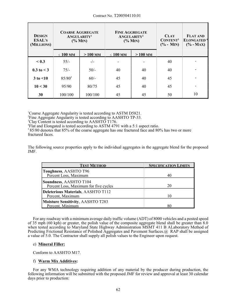
Contract No. T200504110.01
DESIGN
ESAL=S(MILLIONS)
COARSE AGGREGATEANGULARITY1
(% MIN)
FINE AGGREGATEANGULARITY2
(% MIN)CLAY
CONTENT3
(% - MIN)
FLAT ANDELONGATED 4
(% - MAX)
# 100 MM > 100 MM # 100 MM > 100 MM
< 0.3 55/- -/- - - 40 -
0.3 to < 3 75/- 50/- 40 40 40 -
3 to <10 85/805 60/- 45 40 45 -
10 < 30 95/90 80/75 45 40 45 -
30 100/100 100/100 45 45 50 10
1Coarse Aggregate Angularity is tested according to ASTM D5821.2Fine Aggregate Angularity is tested according to AASHTO TP-33.3Clay Content is tested according to AASHTO T176.4Flat and Elongated is tested according to ASTM 4791 with a 5:1 aspect ratio.5 85/80 denotes that 85% of the coarse aggregate has one fractured face and 80% has two or morefractured faces.
The following source properties apply to the individual aggregates in the aggregate blend for the proposedJMF.
TEST METHOD SPECIFICATION LIMITS
Toughness, AASHTO T96 Percent Loss, Maximum 40
Soundness, AASHTO T104 Percent Loss, Maximum for five cycles 20
Deleterious Materials, AASHTO T112 Percent, Maximum 10
Moisture Sensitivity, AASHTO T283 Percent, Minimum 80
For any roadway with a minimum average daily traffic volume (ADT) of 8000 vehicles and a posted speedof 35 mph (60 kph) or greater, the polish value of the composite aggregate blend shall be greater than 8.0when tested according to Maryland State Highway Administration MSMT 411 B ALaboratory Method ofPredicting Frictional Resistance of Polished Aggregates and Pavement Surfaces.@ RAP shall be assigneda value of 5.0. The Contractor shall supply all polish values to the Engineer upon request.
e) Mineral Filler:
Conform to AASHTO M17.
f) Warm Mix Additives:
For any WMA technology requiring addition of any material by the producer during production, thefollowing information will be submitted with the proposed JMF for review and approval at least 30 calendardays prior to production:
62
Contract No. T200504110.01
1. WMA technology and/or additive information.2. WMA technology manufacturer’s recommendation for usage.3. WMA technology target dosage rate and tolerance envelope. Support tolerance envelope with test data
demonstrating acceptable mix production properties conforming to all sections of this specification.4. WMA technology manufacturer’s material safety data sheets (MSDS).5. Documentation of past WMA technology field application including points of contact.6. Temperature ranges for mixing and compacting.7. Laboratory test data, samples, and sources of all mix components, and asphalt binder viscosity-
temperature relationships.
Follow the manufacturer’s recommendation for incorporating additives and WMA technologies into themix. Comply with the manufacturer’s recommendation regarding receiving, storage, and delivery ofadditives.
If the producer performs blending of the WMA technology in their tank, a separate Quality Control planshall be submitted by the producer to the Department for review and approval at least 30 calendar days priorto production.
g) Anti-stripping additives
Conform to standard specifications Section 829 and blend with the asphalt cement in accordance with thisspecification. Incorporate anti-stripping additives when the Tensile Strength Ratio (TSR) as determined inaccordance with AASHTO T283 is less than 80 or when specified for use by the Engineer.
.03 Bituminous Concrete Production – Quality Control (a) Process Control - Material Production Quality Control.
Submit through electronic mail a QC Plan from each proposed production plant to the Engineer; no hot-mix asphalt material will be accepted until the Engineer approves the QC Plan. This plan must be submittedto the Engineer on an annual basis for review and approval prior to material production. The Engineer willsend a signed copy back to the Contractor stating that it is approved. The approved QC Plan shall governcontractor operations.
The QC Plan shall include actions that will assure all materials and products will conform to thespecifications, whether manufactured or processed by the Contractor, or procured from suppliers,subcontractors, or vendors. The Contractor shall perform the inspection and tests required to substantiateproduct conformance to contract requirements. The Contractor shall document QC inspections and tests, andprovide copies to the Engineer when requested. The Contractor shall maintain records of all inspections andtests for at least one year. The records shall include the date, time, and nature of deficiency or deficienciesfound; the quantities of material involved until the deficiency was corrected; and the date, time, and natureof corrective actions taken.
In the QC Plan shall detail the type and frequency of inspection, sampling, and testing deemed necessaryto measure and control the various properties of material and construction governed by the Specifications. The QC Plan shall include the following elements as a minimum:
- Production Plant - make, type, capacity, and location.- Production Plant Calibration - components and schedule; address documentation. - Personnel - include name and telephone number for the following individuals: - Person responsible for quality control. - Qualified technician(s) responsible for performing the inspection, sampling, and testing. - Person who has the authority to make corrective actions on behalf of the Contractor. - Testing Laboratory - state the frequency of accuracy checks and calibrations of the equipment used for
testing; address documentation.- Load number of QC samples (1-10 if QA sample is not within trucks 1-10)- Locations where samples will be obtained and the sampling techniques for each test- Tests to be performed and their normal frequency; the following, at a minimum, shall be conducted:
- Mixture Temperature: each of the first five trucks, and each load that is sampled for QC oracceptance testing.
- Gradation analysis of aggregate (and RAP) stockpiles - one washed gradations per week for eachaggregate stockpile; RAP: five gradations and asphalt cement contents for dedicated stockpiles
63
Contract No. T200504110.01
where new material is not being added; one gradation and asphalt cement content test per week forstockpiles where material is continually being added to the stockpile.
- Gradation analysis of non-payment sieves- Dust to effective asphalt calculation- Moisture content analysis of aggregates - daily. - Gradation analysis of the combined aggregate cold feed - one per year per mixture.- Bulk specific gravity and absorption of blended material - one per year per mixture.- Ignition Oven calibration - one per year per mixture.- Hot-Bins: one per year per mixture.- Others, as appropriate.
- Procedures for reporting the results of inspection and tests (include schedule).- Procedures for dealing with non-compliant material or work.- Presentation of control charts. The contractor shall plot the results of testing on individual control
charts for each characteristic. The control charts shall be updated within on working day as test resultsfor each sublot become available. The control charts shall be easily and readily accessible at the plantlaboratory. The following parameters shall be plotted from the testing:- Asphalt cement content.- Volumetrics (air voids, voids in mineral aggregates [VMA])- Gradation values for the following sieves:
- 4.75 mm (#4).- 2.36 mm (#8). - 0.075 mm (#200). - Operational guidelines (trigger points) to address times when the following actions would be
considered:- Increased frequency of sampling and testing.- Plant control/settings/operations change.- JMF adjustment.- JMF change (See 401644 Section .04(a)(1)).- Change in the source of the component materials.- Calibration of material production equipment (asphalt pump, belt feeders, etc.).- Rejection of material.
When any point of non-compliance with the QC plan, or material not meeting the Specifications, comesto the attention of either the Contractor or the Engineer, the other party shall be notified immediately, and theContractor shall take appropriate corrective actions. Failure to take corrective actions immediately shall because for rejection of material or work by the Engineer.
The following are considered significant violations to the Contractor’s QC Plan:
- Using testing equipment that is knowingly out of calibration or is not working properly.- Reporting false information such as test data, JMF information, or any info requested by DelDOT- Failure to perform materials testing per their approved QC Plan - Deviating from AASHTO or DelDOT testing procedures.- Use of any material or the use of a JMF component in a proportion that exceeds the allowable tolerance
as specified in section 04(a)(1) of this specification not listed in the JMF.- Use of the wrong PG graded asphalt.- Failure to take corrective action per action points in the Contractors approved QC plan.
The following steps will be taken for violations listed above:
1. First offence: Written notice of violation to the Contractor.
2. Second offence: Written notice of violation and forfeiture of any bonus (material production orpavement construction) payment eligibility under 401699 section .03 for that production shift.
3. Third offence: Written notice of violation, forfeiture of bonus payment eligibility, and a 5% deductionof payment based upon contract unit price in addition to any calculated pay adjustment factors per401699 Section 03.
64

Contract No. T200504110.01
4. Fourth offence: Written notice of violation, forfeiture of bonus payment eligibility, 50% deduction ofpayment based upon contract unit price in addition to any calculated payment adjustment factor per401699 Section 03, and immediate suspension of the Contractor until corrective actions are taken. Corrective actions shall be submitted in writing to the Engineer for approval. The Engineer mayrequest a meeting with the Contractor to discuss proposed changes prior to lifting suspension.
Violations of Contractor QC plans shall be kept on record for a period of 1 year from the date of violationat the Central Lab.
(b) Material Production Test Equipment.
Establish, maintain, and operate a qualified testing laboratory at the production plant site of sufficient sizeand layout that will accommodate the testing operations of both the Contractor and the Engineer.
Facilities for the use of the Engineer and inspectors shall be a minimum of 600 square feet of floor spaceconditioned to maintain constant temperature of 77F with two windows and a door equipped with functionallocks and latches, located such that plant activities are plainly visible from one window of the building. Workspace shall be furnished with illumination, tables, chairs, desks, telephone, and water including drinkingwater, sanitary facilities, fuel, and power necessary to conduct all necessary tests.
Maintain all the equipment used for handling, preparing, and testing materials in proper operatingcondition. For any laboratory equipment malfunction, the Contractor shall remedy the situation within oneworking day or the Engineer may suspend production. In the case of an equipment malfunction, the Engineermay elect to test the material at another qualified testing laboratory while waiting for repairs to equipment.
Maintain minimum calibration records for the referenced equipment:- SUPERPAVER Gyratory Compactor: once every year; verified once every month by the Engineer.- Ovens: once every three months, verified once every month.- Vacuum Container and Gauge (Rice Bowls): once every three months, verified once every month.- Balances and Scales: once every year, verified once every month. - Thermometers: once a year; verified once every month. - Gyratory Compactor molds and base plates: once every year- Mechanical Shakers: once every year- Sieve Verifications: once every year
All calibrations shall be documented and on file for review by the Engineer at any time.
(c) Material Production Test Methods
- AASHTO T312 - Preparing and Determining the Density of Hot Mix Asphalt (HMA) Specimens byMeans of the Superpave Gyratory Compactor
- AASHTO T166, Method C (Rapid Method) - Bulk Specific Gravity of Compacted Hot Mix Asphalt(HMA) Using Saturated Surface Dry Specimens
- AASHTO T308 - Determining the Asphalt Binder Content of Hot Mix Asphalt (HMA) by the IgnitionMethod
- AASHTO T30 - Mechanical Analysis of Extracted Aggregate - AASHTO T209 - Theoretical Maximum Specific Gravity and Density of Hot Mix Asphalt (HMA)- ASTM D7227 - Standard Practice for Rapid Drying of Compacted Asphalt Specimens using Vacuum
Drying Apparatus
.04 Job Mix Formula (JMF)
Mix Design. Develop and submit a job mix formula for each mixture according to AASHTO R35. Each mixdesign shall be capable of being produced, placed, and compacted as specified. Assign a unique identificationnumber to each JMF.
a) Development of JMF
Gradation: Use the FHWA Superpave 0.45 Power Chart to define permissible gradations for the specifiedmixture. Type C shall be either a No.4 (4.75 mm), 3/8" (9.5 mm), or 1/2" (12.5 mm) Nominal MaximumAggregate Size bituminous concrete. Unless otherwise noted in the Plans, the Type C shall meet the 3/8" (9.5
65
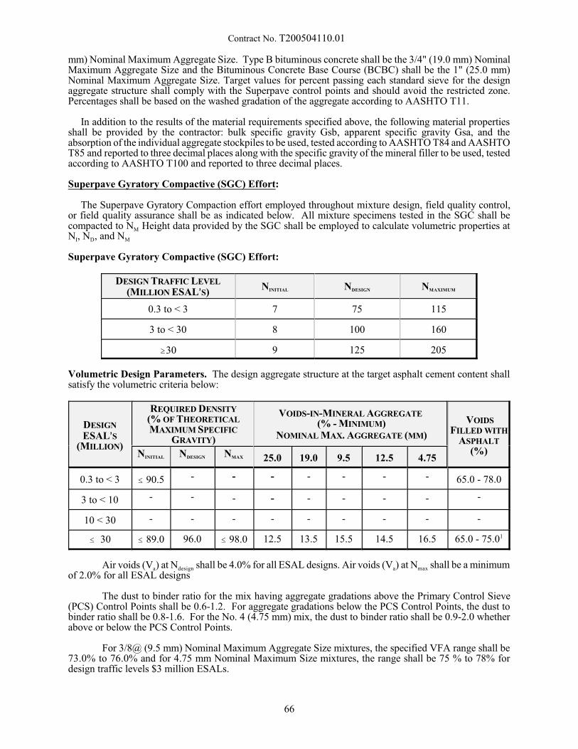
Contract No. T200504110.01
mm) Nominal Maximum Aggregate Size. Type B bituminous concrete shall be the 3/4" (19.0 mm) NominalMaximum Aggregate Size and the Bituminous Concrete Base Course (BCBC) shall be the 1" (25.0 mm)Nominal Maximum Aggregate Size. Target values for percent passing each standard sieve for the designaggregate structure shall comply with the Superpave control points and should avoid the restricted zone. Percentages shall be based on the washed gradation of the aggregate according to AASHTO T11.
In addition to the results of the material requirements specified above, the following material propertiesshall be provided by the contractor: bulk specific gravity Gsb, apparent specific gravity Gsa, and theabsorption of the individual aggregate stockpiles to be used, tested according to AASHTO T84 and AASHTOT85 and reported to three decimal places along with the specific gravity of the mineral filler to be used, testedaccording to AASHTO T100 and reported to three decimal places.
Superpave Gyratory Compactive (SGC) Effort:
The Superpave Gyratory Compaction effort employed throughout mixture design, field quality control,or field quality assurance shall be as indicated below. All mixture specimens tested in the SGC shall becompacted to NM Height data provided by the SGC shall be employed to calculate volumetric properties atNI, ND, and NM
Superpave Gyratory Compactive (SGC) Effort:
DESIGN TRAFFIC LEVEL
(MILLION ESAL=S)NINITIAL NDESIGN NMAXIMUM
0.3 to < 3 7 75 115
3 to < 30 8 100 160
$30 9 125 205
Volumetric Design Parameters. The design aggregate structure at the target asphalt cement content shallsatisfy the volumetric criteria below:
DESIGN
ESAL=S(MILLION)
REQUIRED DENSITY(% OF THEORETICALMAXIMUM SPECIFIC
GRAVITY)
VOIDS-IN-MINERAL AGGREGATE (% - MINIMUM)
NOMINAL MAX. AGGREGATE (MM)
VOIDSFILLED WITH
ASPHALT(%)NINITIAL NDESIGN NMAX 25.0 19.0 9.5 12.5 4.75
0.3 to < 3 # 90.5 - - - - - - - 65.0 - 78.0
3 to < 10 - - - - - - - - -
10 < 30 - - - - - - - - -
# 30 # 89.0 96.0 # 98.0 12.5 13.5 15.5 14.5 16.5 65.0 - 75.01
Air voids (Va) at Ndesign shall be 4.0% for all ESAL designs. Air voids (Va) at Nmax shall be a minimumof 2.0% for all ESAL designs
The dust to binder ratio for the mix having aggregate gradations above the Primary Control Sieve(PCS) Control Points shall be 0.6-1.2. For aggregate gradations below the PCS Control Points, the dust tobinder ratio shall be 0.8-1.6. For the No. 4 (4.75 mm) mix, the dust to binder ratio shall be 0.9-2.0 whetherabove or below the PCS Control Points.
For 3/8@ (9.5 mm) Nominal Maximum Aggregate Size mixtures, the specified VFA range shall be73.0% to 76.0% and for 4.75 mm Nominal Maximum Size mixtures, the range shall be 75 % to 78% fordesign traffic levels $3 million ESALs.
66
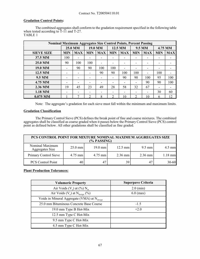
Contract No. T200504110.01
Gradation Control Points:
The combined aggregates shall conform to the gradation requirement specified in the following tablewhen tested according to T-11 and T-27.TABLE 1
Nominal Maximum Aggregates Size Control Points, Percent Passing
25.0 MM 19.0 MM 12.5 MM 9.5 MM 4.75 MM
SIEVE SIZE MIN MAX MIN MAX MIN MAX MIN MAX MIN MAX
37.5 MM 100 - - - - - - - - -
25.0 MM 90 100 100 - - - - - - -
19.0 MM - 90 90 100 100 - - - - -
12.5 MM - - - 90 90 100 100 - 100 -
9.5 MM - - - - - 90 90 100 95 100
4.75 MM - - - - - - - 90 90 100
2.36 MM 19 45 23 49 28 58 32 67 - -
1.18 MM - - - - - - - - 30 60
0.075 MM 1 7 2 8 2 10 2 10 6 12
Note: The aggregate’s gradation for each sieve must fall within the minimum and maximum limits.
Gradation Classification
The Primary Control Sieve (PCS) defines the break point of fine and coarse mixtures. The combinedaggregates shall be classified as coarse graded when it passes below the Primary Control Sieve (PCS) controlpoint as defined below. All other gradations shall be classified as fine graded.
PCS CONTROL POINT FOR MIXTURE NOMINAL MAXIMUM AGGREGATES SIZE(% PASSING)
Nominal MaximumAggregates Size
25.0 mm 19.0 mm 12.5 mm 9.5 mm 4.5 mm
Primary Control Sieve 4.75 mm 4.75 mm 2.36 mm 2.36 mm 1.18 mm
PCS Control Point 40 47 39 47 30-60
Plant Production Tolerances:
Volumeric Property Superpave Criteria
Air Voids (Va) at (%) Nm 2.0 (min)
Air Voids (Va) at Ndesign (%) 6.0 (max)
Voids in Mineral Aggregate (VMA) at Ndesign
25.0 mm Bituminous Concrete Base Course -1.5
19.0 mm Type B Hot-Mix +2.0
12.5 mm Type C Hot-Mix
9.5 mm Type C Hot-Mix
4.5 mm Type C Hot-Mix
67
Contract No. T200504110.01
The proposed JMF shall include the following:
Submit for approval to the Engineer the following documentation on Pinepave mixture designsoftware prior to starting production of a new mixture:
1. Job mix formula (JMF) design of the component materials and target characteristic values foreach mixture proposed for use. The component materials design shall include designating thesource and the expected proportion (within 1 percent for the aggregate components and within0.1 percent for the other components) of each component to be used in order to produceworkable bituminous concrete meeting the specified properties. Recycled Asphalt Pavement(RAP) is one individual aggregate component regardless of fractionation size. Recycled AsphaltShingles (RAS) is a separate component from RAP.
2. The JMF target characteristic values include the mixing temperature range, core temperaturerange for gyration, the percentage of the asphalt cement component (both total and virgin), andthe percentages of the aggregate amounts retained on the sieves to be addressed by the JMF asshown in Table 1.
3. Plot of the design aggregate structure on the FHWA Superpave 0.45 power chart showing themaximum density line and Superpave control points.
4. Plot of the three trial asphalt binder contents at +/- 0.5% gyratory compaction curves where thepercent of maximum specific gravity (% of Gmm) is plotted against the log base ten of thenumber of gyrations (log (N)) showing the applicable criteria for Ni, Nd, and Nm.
5. Plot of the percent asphalt binder by total weight of the mix (Pb) versus the following:
% of Gmm at Nd, VMA at Nd, VFA at Nd, Fines to effective asphalt binder (Pbe) ratio, and unitweight (kg/m5) at both Nd and Nm.
6. Summary of the consensus property standards test results for the design aggregate structure,summary of the source property standards test results for the individual aggregates in the designaggregate structure, target value of the asphalt binder content, and a table of Gmm of the asphaltmixture for the four trial asphalt binder contents determined according to AASHTO T209.
7. Test data with each JMF and tests performed by a Qualified Laboratory on representativematerials, verifying the adequacy of the design. Refer to the specifications for each mix typein order to determine the design requirements. The JMF sieve percentage values shall conformto the ranges shown in Table 1.
For any mixture that has a 20% or greater failure rate on any combined volumetric criteria, theJMF will not be approved for use on Department contracts.
8. Provide raw material of each JMF so NCAT Ignition Oven calibration correction numbers canbe established for the Engineers and Contractors ovens. The Engineer shall provide an ignitionoven correction number for each JMF.
.05 Approval of JMF
The Engineer will have up to three weeks once the JMF is submitted to review the submittedinformation.
All submitted JMF=s shall correspond to the Pinepave mixture design software. The Engineer, forevaluation of the submitted JMF, will use the first three test samples. These test results acquired duringproduction shall be within the following range compared to the submitted JMF on the Pinepave mixturedesign software: Gmm: + / -0.030 and Gmb: + / - 0.040
a) Design Evaluation:
The Engineer may elect to evaluate the proposed JMF and suitability of all materials throughlaboratory trial batches. All materials requested by the Engineer shall be provided at the contractor’s expense
68
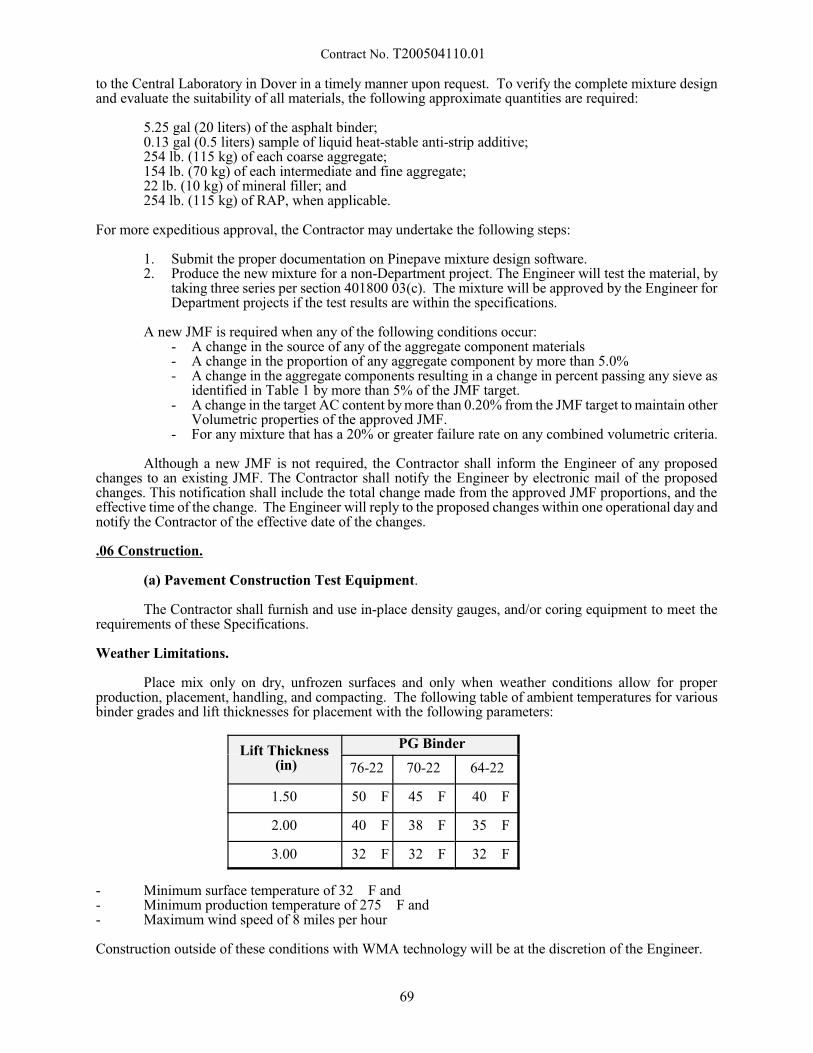
Contract No. T200504110.01
to the Central Laboratory in Dover in a timely manner upon request. To verify the complete mixture designand evaluate the suitability of all materials, the following approximate quantities are required:
5.25 gal (20 liters) of the asphalt binder;0.13 gal (0.5 liters) sample of liquid heat-stable anti-strip additive;254 lb. (115 kg) of each coarse aggregate; 154 lb. (70 kg) of each intermediate and fine aggregate;22 lb. (10 kg) of mineral filler; and 254 lb. (115 kg) of RAP, when applicable.
For more expeditious approval, the Contractor may undertake the following steps:
1. Submit the proper documentation on Pinepave mixture design software.2. Produce the new mixture for a non-Department project. The Engineer will test the material, by
taking three series per section 401800 03(c). The mixture will be approved by the Engineer forDepartment projects if the test results are within the specifications.
A new JMF is required when any of the following conditions occur:- A change in the source of any of the aggregate component materials- A change in the proportion of any aggregate component by more than 5.0%- A change in the aggregate components resulting in a change in percent passing any sieve as
identified in Table 1 by more than 5% of the JMF target.- A change in the target AC content by more than 0.20% from the JMF target to maintain other
Volumetric properties of the approved JMF.- For any mixture that has a 20% or greater failure rate on any combined volumetric criteria.
Although a new JMF is not required, the Contractor shall inform the Engineer of any proposedchanges to an existing JMF. The Contractor shall notify the Engineer by electronic mail of the proposedchanges. This notification shall include the total change made from the approved JMF proportions, and theeffective time of the change. The Engineer will reply to the proposed changes within one operational day andnotify the Contractor of the effective date of the changes.
.06 Construction.
(a) Pavement Construction Test Equipment.
The Contractor shall furnish and use in-place density gauges, and/or coring equipment to meet therequirements of these Specifications.
Weather Limitations.
Place mix only on dry, unfrozen surfaces and only when weather conditions allow for properproduction, placement, handling, and compacting. The following table of ambient temperatures for variousbinder grades and lift thicknesses for placement with the following parameters:
Lift Thickness (in)
PG Binder
76-22 70-22 64-22
1.50 50 F 45 F 40 F
2.00 40 F 38 F 35 F
3.00 32 F 32 F 32 F
- Minimum surface temperature of 32 F and- Minimum production temperature of 275 F and- Maximum wind speed of 8 miles per hour
Construction outside of these conditions with WMA technology will be at the discretion of the Engineer.
69
Contract No. T200504110.01
Compaction:
(b) Pavement Construction - Process Control.
Perform Quality Control of pavement compaction by testing in-place pavement density by thefollowing methods.
- ASTM D2950 Standard Test Method for Density of Bituminous Concrete in Place by NuclearMethods; the use of other density gauges shall be as per the manufacturer’s recommendations.
- AASHTO T166, Method C (Rapid Method) Bulk Specific Gravity of Compacted Hot MixAsphalt (HMA) Using Saturated Surface Dry Specimens
- ASTM D7227 - Standard Practice for Rapid Drying of Compacted Asphalt Specimens usingVacuum Drying Apparatus
Cores may be cut on the first day of paving or once after the change of a JMF for gauge calibration. The number of cores obtained for calibration purposes shall not exceed the number of QA samples obtainedby the Department for payment. The Contractor may use any method to select locations for the QualityControl calibration cores.
Repair all core holes in accordance with 401699 Appendix A.
Method of Measurement:
Method of Measurement will be in accordance with Subsections 401.14 and 401.15 of the StandardSpecifications.
Basis of Payment:
All work completed under this item shall be considered for full payment and subsequently modifiedin accordance with the procedures enumerated under 401699.
Material production quality shall be evaluated per item 401699 - Quality Control/Quality Assuranceof Bituminous Concrete .03 (a) Material Production - Tests and Evaluations.
Compaction quality shall be evaluated per Item 401699 - Quality Assurance of Bituminous Concrete.03 (b) Pavement Construction - Tests and Evaluations.
10/29/2014
70
Contract No. T200504110.01
601520 - TEMPORARY TIMBER MAT
Description:
The item shall consist of furnishing all materials and constructing a temporary timber mat for accessacross the wetland area as shown on the Plans and as directed by the Engineer. All equipment shall utilizethis temporary timber mat when trying to access the stockpile/staging area and the underside of the bridge.
Materials:
In accordance with Section 601 of the Standard Specifications and the following:
Timber shall have a strength and grade adequate to support the Contractor's anticipated vehicular orequipment loads. Any preservative treatment applied to the matting shall be environmentally safe for wetconditions and be preapproved by the Department.
Hardware shall be in accordance with Section 601.07 of the Standard Specifications.
Construction Methods:
The Contractor shall submit to the Department for approval shop drawings and design calculationsindicating the layout, size of members, arrangement of members and the construction methods at least twoweeks prior to initiating construction. This information shall be signed and sealed by a Professional Engineerregistered in the State of Delaware. A timber mat system is shown on the plans and shall be used forconceptual purposes only. The actual timber mat system utilized for the construction shall be designed forthe anticipated construction loads and shall be compatible with the environment. Placement of stone withinthe wetland area is not permitted.
The temporary timber matting should be periodically inspected by the Contractor and any damagedor deteriorated components should be replaced. The Contractor assumes full responsibility for the loadcarrying capability of the system and for its anchorage, as required, to resist high water flows. No additionalcompensation will be granted for repairing any portion of the system damaged during naturally occurringweather events or contractor usage. The Contractor is responsible for retrieving lost mats and repairing anydamage caused by naturally occurring weather events.
Basis of Payment:
The payment for the item shall be made for at the contract unit price bid per Lump Sum for "601520 -Temporary Timber Mat", which price and payment shall constitute full compensation for furnishing andplacing all materials, for design, submission of signed and sealed drawings and computations, installation andremoval of timber mat materials, and for all labor, equipment, tools and incidentals required to complete thework.
6/24/15
71
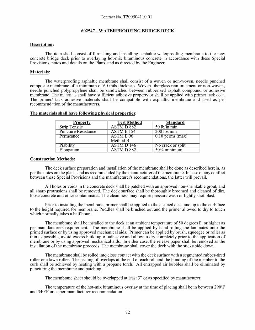
Contract No. T200504110.01
602547 - WATERPROOFING BRIDGE DECK
Description:
The item shall consist of furnishing and installing asphaltic waterproofing membrane to the newconcrete bridge deck prior to overlaying hot-mix bituminous concrete in accordance with these SpecialProvisions, notes and details on the Plans, and as directed by the Engineer.
Materials:
The waterproofing asphaltic membrane shall consist of a woven or non-woven, needle punchedcomposite membrane of a minimum of 60 mils thickness. Woven fiberglass reinforcement or non-woven,needle punched polypropylene shall be sandwiched between rubberized asphalt compound or adhesivemembrane. The materials shall have sufficient adhesive property or shall be applied with primer tack coat.The primer/ tack adhesive materials shall be compatible with asphaltic membrane and used as perrecommendation of the manufacturers.
The materials shall have following physical properties:
Property Test Method StandardStrip Tensile ASTM D 882 50 lb/in minPuncture Resistance ASTM E 154 200 lbs minPermeance ASTM E 96
Method B0.10 perms (max)
Piability ASTM D 146 No crack or splitElongation ASTM D 882 50% minimum
Construction Methods:
The deck surface preparation and installation of the membrane shall be done as described herein, asper the notes on the plans, and as recommended by the manufacturer of the membrane. In case of any conflictbetween these Special Provisions and the manufacturer's recommendations, the latter will prevail.
All holes or voids in the concrete deck shall be patched with an approved non-shrinkable grout, andall sharp protrusions shall be removed. The deck surface shall be thoroughly broomed and cleaned of dirt,loose concrete and other contaminates. The cleaniness may require pressure wash or lightly shot blast.
Prior to installing the membrane, primer shall be applied to the cleaned deck and up to the curb faceto the height required for membrane. Puddles shall be brushed out and the primer allowed to dry to touchwhich normally takes a half hour.
The membrane shall be installed to the deck at an ambient temperature of 50 degrees F. or higher asper manufacturers requirement. The membrane shall be applied by hand-rolling the laminates onto theprimed surface or by using approved mechanical aids. Primer can be applied by brush, squeegee or roller asthin as possible, avoid excess build up of adhesive and allow to dry completely prior to the application ofmembrane or by using approved mechanical aids. In either case, the release paper shall be removed as theinstallation of the membrane proceeds. The membrane shall cover the deck with the sticky side down.
The membrane shall be rolled into close contact with the deck surface with a segmented rubber-tiredroller or a lawn roller. The sealing of overlaps at the end of each roll and the bonding of the member to thecurb shall be achieved by heating with a propane torch. All entrapped air bubbles shall be eliminated bypuncturing the membrane and patching.
The membrane sheet should be overlapped at least 3” or as specified by manufacturer.
The temperature of the hot-mix bituminous overlay at the time of placing shall be in between 290oFand 340oF or as per manufacturer recommendation.
72

Contract No. T200504110.01
Method of Measurement:
The quantity of waterproofing membrane will be measured as the actual number of square yardscompleted and accepted.
Basis of Payment:
The quantity of waterproofing membrane will be paid for at the Contract unit price per square yard. Price and payment will constitute full compensation for surface preparation, furnishing and placing allmaterials including primer and membrane, equipment, tools, for all labor, and incidentals necessary tocomplete the work.
11/13/14
73
Contract No. T200504110.01
602736 - PRECAST CONCRETE CULVERT
Description:
This work consists of furnishing, fabricating, and constructing complete in place the precastreinforced concrete culvert(s) and other associated precast structures (toewalls, headwalls, baffles etc.) asspecified on the Plans, as described herein and as directed by the Engineer.
Materials:
1. Concrete
Concrete shall conform to Section 812 of the Standard Specifications except as amended herein. Minimum 28 days strength for precast concrete shall be 5000 psi (35 MPa). The Contractor shalldevelop his own concrete mix design, according to ACI 211.1-81, Standard Practice for SelectingProportions for Normal, Heavyweight, and Mass Concrete, which shall be submitted to the Engineerfor approval. The cement content shall not be less than 700 lb. per cubic yard (415 kg per cubicmeter). Portland Cement shall be Type I or Type II (ASTM C 150). In a salt water environment,Type II Cement shall be used.
2. Reinforcing Steel
Reinforcing steel in all associated structures shall meet the requirements of AASHTO M 31/M 31M,Grade 60 (Grade 400) (AASHTO M 31); and shall be protected with fusion bonded epoxy meetingthe requirements of Section 604 of the Standard Specifications
3. Hardware
All connection hardware shall be hot-dipped galvanized.
4. Closed-Cell Neoprene Sponge
Use elastomer conforming to ASTM D1056, Type 2, Class C.
5. Post-Tensioning Strands
Use 2@ (12.7 mm) diameter, 7 wire, uncoated, low-relaxation strands for unbonded post-tensioning,conforming to AASHTO M203, Grade 270 (Grade 1860). Encase strands in polymer sheathing. Usecorrosion inhibitor recommended by the manufacture between the strand and sheathing. Provideanchorages, bearing devices, fittings and couplings as shown on the plans and specified by the tendonmanufacturer.
6. Joint WrapThe external wrap shall be as per ASTM C-877.
Fabrication Plant:
The fabrication plant for precast concrete culvert shall be a National Precast Concrete Association(NPCA) certified plant and pre-approved from the Department.
Fabrication:
1. General
All materials, equipment, processes of manufacture, and the finished sections, including handling,storage, and transportation, shall be subject to inspection and approval. Any defective construction,which may adversely affect the strength or performance of a section, shall be cause for rejection. Rejected sections shall be replaced at no expense to the Department.
74
Contract No. T200504110.01
2. Forms
The forms used shall be sufficiently rigid and accurate to maintain the culvert dimensions within thetolerances hereinafter specified. The culverts forms shall be matched so that the internal dimensionsfrom one precast section to the next adjacent section shall not vary by more than 1/2" (13 mm). Theyshall be well constructed, carefully aligned, substantial and firm, securely braced and fastenedtogether, sufficiently tight to prevent leakage of mortar, and strong enough to withstand the actionof mechanical vibrators. All the casting surfaces shall be of a smooth material.
Form ties shall be either the threaded type or the snap-off type, so that no form wires or metal pieceswill be left at the surface of the finished concrete. Corners and angles shall be mitered or rounded.
Joints between panel forms shall be made smooth and tight.
3. Curing
The culvert shall be cured for a sufficient length of time so that the concrete will develop thespecified compressive strength in 28 days or less. Any one of the following methods of curing orcombinations thereof shall be used for culvert sections:
Steam Curing - The culvert sections may be low pressure, steam-cured by a system that will maintaina moist atmosphere.
Water Curing - The culvert sections may be water cured by any method that will keep the sectionsmoist.
Forms Left in Place - An accelerated overnight cure accomplished through the use of an external heatsource may be used, provided moisture loss from exposed surfaces is minimized.
The maximum temperature increase or decrease shall be 40_ F (22_ C) per hour. The initialapplication of the heat shall be two hours after the final placement of concrete to allow the initial setto take place.
4. Testing Requirements
Test Specimen - Concrete compressive strength shall be determined from compression tests madeon cylinders. Acceptance of the concrete culvert sections with respect to compressive strength willbe determined on a basis of production lots. A production lot is defined as a group of culvert sectionsrepresenting 10 culvert sections or a single day's production, whichever is less.
During the production of the culvert sections, the manufacturer shall randomly sample the concretein accordance with AASHTO T 141. A single compressive strength sample shall consist of aminimum of 4 cylinders randomly selected for every production lot. Cylinders for compressivestrength tests shall be 4" x 8" or as specified by the Engineer prepared and tested in accordance withAASHTO T 23 and T 22, respectively. For every compressive strength sample, a minimum of 2cylinders shall be cured in the same manner as the culvert sections and tested at approximately 7days. The average compressive strength of these cylinders will determine the initial strength of theconcrete. In addition, 2 cylinders shall be cured in accordance with AASHTO T 23 and tested at 28days. The average compressive strength of these two cylinders will determine the compressivestrength of the production lot.
Acceptability by Cylinder Tests - The compressive strength of the concrete for each production lotas previously defined is acceptable when the compressive strength is equal to or greater than thedesign concrete strength.
When the compressive strength of any production lot is less than the design concrete strength, theproduction lot shall be rejected. The rejection shall prevail unless the manufacturer, at his/her ownexpense, obtains and submits evidence of a type acceptable to the Engineer that the strength andquality of the concrete placed within the culvert sections of the production lot are acceptable. If theevidence consists of tests made on cores taken from the culvert sections within the production lot,the cores shall be obtained and tested in accordance with the requirements of AASHTO T 24. The
75
Contract No. T200504110.01
core holes shall be plugged and sealed by the manufacturer in a manner such that the culvert sectionwill meet all of the test requirements of this Special Provision. Culvert sections so sealed shall beconsidered satisfactory for use.
5. Tolerances
Internal Dimensions - The internal dimension shall vary not more than -0"/+1/4" (-0 mm/+25 mm)from the design dimensions.
Top Slab and Wall Thickness - The top slab and wall thickness shall not be less than the designdimensions by more than 5 percent. A thickness more than that required shall not be cause forrejection.
Length of Opposite Surfaces - Variations in laying lengths of two opposite surfaces of the culvertsections shall not be more than 1/8"/foot (10 mm/m) of internal span, with a maximum of 5/8" (16mm) for all sizes through 7' (2100 mm) internal span, and a maximum of 3/4" (19 mm) for internalspans greater than 7' (2100 mm).
Length of Section - The under run in length shall not be more than 1/8"/foot (10 mm/m) of lengthwith a maximum of 1/2" (13 mm) in any box section.
Position of Reinforcement - Clear cover shall be as detailed on the plans. The maximum variationin the position of the reinforcement shall be "3/8" (" 10 mm).
Construction Methods:
The foundation on which the culvert sections are to be placed shall be a layer of the type of coarseaggregate as specified on the Plans. The bedding areas on which the coarse aggregate will be placed shall beapproved by the Engineer. Coarse aggregate shall be carefully placed and tamped to form a solid, unyieldingmass with the exposed surface conforming to the form and dimensions shown on the Plans.
Precast sections shall be assembled in accordance with the recommendations of the manufacturer andas approved by the Engineer in the field. The culvert sections shall be so formed that when they are laidtogether they will make a continuous line of culverts with a smooth interior free of appreciable irregularities,and compatible with the permissible tolerances of this Special Provision.
Care shall be exercised to insure proper matching and aligning of joints of adjacent sections. Thejoints shall tongue and groove. The keyway surfaces shall be given a medium abrasive grit blast, 2000 psi(14 MPa) waterblast or a thorough wire brushing at the plant within four days prior to leaving the plant. Mortar for the keyway shall be a non-shrinking, non-metallic mortar having a minimum compressive strengthat 28 days of 5000 psi (35 MPa). Before applying the mortar, the surfaces shall be clean of all dirt, dust, andother foreign matter. The surfaces shall be wetted, but no free water shall be allowed to remain in thekeyway. The mortar shall be prepared, placed, and cured in accordance with the manufacturersrecommendations.
The joint exterior shall be covered with a minimum of a 9" (225 mm) wide wrap centered on the joint. Care shall be exercised to keep the joint wrap in its proper location during backfilling.
The section length shall not exceed that which permits lifting, moving, and placing of the sectionwithout any bending, distortion, or stress being induced therein. Devices or holes shall be permitted in eachculvert section for the purpose of handling. However, not more than four holes may be cast or drilled in eachsection. The holes shall be tapered unless drilled, and before backfilling, the tapered holes shall be filled withportland cement mortar, or with precast concrete plugs which shall be secured with portland cement mortaror other approved adhesive. Drilled holes shall be filled with portland cement mortar. Holes shall be coveredon the exterior with the joint wrap material previously specified. This wrap shall have a minimum length andwidth of 9" (225 mm) ) or 2@ beyond any edge, whichever is greater.
No construction equipment except for compaction shall be permitted to pass over the culvert untilthe fill height has reached the bottom of the pavement subbase. Hauling of materials over the culvert shallbe limited as directed, and in no case shall legal load limits specified in Section 105.12 of the StandardSpecifications be exceeded unless permitted in writing.
76
Contract No. T200504110.01
Method of Measurement:
The quantity of item 602736 - Precast Concrete Culvert will be measured as the number of cubicyards (cubic meters) of concrete placed and accepted. The volume will be computed using the dimensionsshown on the plans with no allowance for form deflection. No deduction in the computed volume of precastconcrete will be made for conduits, anchors, bolts, handling devices, post-tensioning ducts, etc.
The quantity of reinforcing bar will not be measured.
Basis of Payment:
The quantity of Precast Concrete Culvert will be paid for at the Contract unit price per cubic yard(cubic meter) for item 602736. Price and payment will constitute full compensation for furnishing allmaterials, including reinforcing bar, related to the precast culvert units; designing, fabricating and installingthe units on site; for all labor, tools, and equipment and necessary incidentals to complete the work. Priceand payment will also constitute full compensation for all materials including reinforcing bar, labor, tools,equipment and incidentals necessary to construct structures associated with the culvert (toewalls, headwalls,baffles, etc.) as specified on the Plans. Excavation, backfill, backfilling, and coarse aggregate will be paidseparately under their respective bid items for this contract.
11/13/14
77

Contract No. T200504110.01
602738 - PRECAST CONCRETE RETAINING WALL
Description:
This work consists of furnishing, fabricating, and constructing complete in place the precastreinforced concrete retaining wall(s) and other associated precast structures as specified on the Plans, asdescribed herein and as directed by the Engineer.
Materials:
1. Concrete
Concrete shall conform to Section 812 of the Standard Specifications except as amended herein. Minimum 28 days strength for precast concrete shall be 5076 psi (35 MPa). The Contractor shalldevelop his own concrete mix design, according to ACI 211.1-81, Standard Practice for SelectingProportions for Normal, Heavyweight, and Mass Concrete, which shall be submitted to the Engineerfor approval. The cement content shall not be less than 26 lb per cubic foot (415 kg per cubic meter).Portland Cement shall be Type I or Type II (ASTM C 150). In a salt water environmental Type IICement shall be used.
2. Reinforcing Steel
Reinforcing steel shall meet the requirements of ASTM A 615, Grade 400 (AASHTO M 31); andshall be protected with fusion bonded epoxy meeting the requirements of Section 604 of the StandardSpecifications.
3. Hardware
All connection hardware shall be hot-dipped galvanized.
4. Closed-Cell Neoprene Sponge
Use elastomer conforming to ASTM D1056, Type 2, Class C.
5. Post-Tensioning Strands
Use ½” (12.7 mm) diameter, 7 wire, uncoated, low-relaxation strands for unbonded post-tensioning,conforming to AASHTO M203, Grade 270 (Grade 1860). Encase strands in polymer sheathing. Usecorrosion inhibitor recommended by the manufacture between the strand and sheathing. Provideanchorages, bearing devices, fittings and couplings as shown on the plans and specified by the tendonmanufacturer.
6. Joint Wrap
The external wrap shall be as per ASTM C-877.
Design:
The precast concrete retaining wall shall be constructed in accordance with the notes and details inthe plans. The allowable soil bearing pressure shall be as shown on the Plans. If structural dimensions orreinforcement differ from the Plans, the Contractor shall submit design calculations and load ratings for thechanged design; and shop drawings showing all pertinent dimensions or reinforcement, reinforcement sizeand location to the Engineer for approval. The Precast Concrete Retaining Wall design shall be in accordancewith the Delaware Department of Transportation “Bridge Design Manual”, latest edition, and the AASHTOLRFD Bridge Design Specifications, latest edition. All calculations shall be certified by a registeredProfessional Engineer in the State of Delaware.
78
Contract No. T200504110.01
Fabrication Plant:
The fabrication plant for precast concrete retaining wall shall be a National Precast ConcreteAssociation (NPCA) certified plant and pre-approved from the Department.
Fabrication:
1. General
All materials, equipment, processes of manufacture, and the finished sections, including handling,storage, and transportation, shall be subject to inspection and approval. Any defective construction,which may adversely affect the strength or performance of a section, shall be cause for rejection. Rejected sections shall be replaced at no expense to the Department.
2. Forms
The forms used shall be sufficiently rigid and accurate to maintain the retaining wall dimensionswithin the tolerances hereinafter specified. The retaining wall forms shall be matched so that theinternal dimensions from one precast section to the next adjacent section shall not vary by more than½” (13 mm). They shall be well constructed, carefully aligned, substantial and firm, securely bracedand fastened together, sufficiently tight to prevent leakage of mortar, and strong enough to withstandthe action of mechanical vibrators. All the casting surfaces shall be of a smooth material unless Plansrequire textured surfaces.
Form ties shall be either the threaded type or the snap-off type, so that no form wires or metal pieceswill be left at the surface of the finished concrete. Corners and angles shall be mitered or rounded.
Joints between panel forms shall be made smooth and tight.
3. Curing
The retaining wall shall be cured for a sufficient length of time so that the concrete will develop thespecified compressive strength in 28 days or less. Any one of the following methods of curing orcombinations thereof shall be used for retaining wall sections:
Steam Curing - The wall sections may be low pressure, steam-cured by a system that will maintaina moist atmosphere.
Water Curing - The wall sections may be water cured by any method that will keep the sectionsmoist.
Forms Left in Place - An accelerated overnight cure accomplished through the use of an external heatsource may be used, provided moisture loss from exposed surfaces is minimized.
The maximum temperature increase or decrease shall be 40° F (22° C) per hour. The initialapplication of the heat shall be two hours after the final placement of concrete to allow the initial setto take place.
4. Testing Requirements
Test Specimen - Concrete compressive strength shall be determined from compression tests madeon cylinders. Acceptance of the concrete wall sections with respect to compressive strength will bedetermined on a basis of production lots. A production lot is defined as a group of wall sectionsrepresenting 10 wall sections or a single day's production, whichever is less.
During the production of the wall sections, the manufacturer shall randomly sample the concrete inaccordance with AASHTO T 141. A single compressive strength sample shall consist of a minimumof 4 cylinders randomly selected for every production lot. Cylinders for compressive strength testsshall be 4” x 8” or as specified by the Engineer prepared and tested in accordance with AASHTO T23 and T 22, respectively. For every compressive strength sample, a minimum of 2 cylinders shallbe cured in the same manner as the wall sections and tested at approximately 7 days. The average
79
Contract No. T200504110.01
compressive strength of these cylinders will determine the initial strength of the concrete. Inaddition, 2 cylinders shall be cured in accordance with AASHTO T 23 and tested at 28 days. Theaverage compressive strength of these two cylinders will determine the compressive strength of theproduction lot.
Acceptability by Cylinder Tests - The compressive strength of the concrete for each production lotas previously defined is acceptable when the compressive strength is equal to or greater than thedesign concrete strength.
When the compressive strength of any production lot is less than the design concrete strength, theproduction lot shall be rejected. The rejection shall prevail unless the manufacturer, at his/her ownexpense, obtains and submits evidence of a type acceptable to the Engineer that the strength andquality of the concrete placed within the wall sections of the production lot are acceptable. If theevidence consists of tests made on cores taken from the wall sections within the production lot, thecores shall be obtained and tested in accordance with the requirements of AASHTO T 24. The coreholes shall be plugged and sealed by the manufacturer in a manner such that the wall section willmeet all of the test requirements of this Special Provision. Wall sections so sealed shall beconsidered satisfactory for use.
5. Tolerances
Wall Thickness - Wall thickness shall not be less than the design dimensions by more than 5 percent. A thickness more than that required shall not be cause for rejection.
Length of Section - The under run in length shall not be more than 12_/ft (10 mm/m) of length witha maximum of 1/2_ (13 mm) in any box section.
Position of Reinforcement - Clear cover shall be 2” minimum except as noted or detailed on theplans. The maximum variation in the position of the reinforcement shall be +/-3/8" (+/-10 mm),except the cover over the reinforcement for the external surface of the wall shall not be less than 2”(50 mm).
Area of Reinforcement - The areas of steel reinforcement shall be the design steel areas per linearmeter. Steel areas greater than those required shall not be cause for rejection. The permissiblevariation in diameter of any reinforcement shall conform to the tolerances prescribed in the ASTMspecification for that type of reinforcement.
Construction Methods:
The foundation on which the retaining wall sections are to be placed shall be a layer of the type ofcoarse aggregate as specified on the Plans. The bedding areas on which the coarse aggregate will be placedshall be approved by the Engineer. Coarse aggregate shall be carefully placed and tamped to form a solid,unyielding mass with the exposed surface conforming to the form and dimensions shown on the Plans.
Precast sections shall be assembled in accordance with the Plans and approved shop drawings. Thewall sections shall be so formed that when they are laid together they will make a continuous line with asmooth face free of appreciable irregularities, and compatible with the permissible tolerances of this SpecialProvision.
Care shall be exercised to insure proper matching and aligning of joints of adjacent sections. Thejoints shall consist of mortar filled shear keyways. The keyway surfaces shall be given a medium abrasivegrit blast, 2000 psi (14 MPa) waterblast or a thorough wire brushing at the plant within four days prior toleaving the plant. Mortar for the keyway shall be a non-shrinking, non-metallic mortar having a minimumcompressive strength at 28 days of 5000 psi (35 MPa). Before applying the mortar, the surfaces shall be cleanof all dirt, dust, and other foreign matter. The surfaces shall be wetted, but no free water shall be allowed toremain in the keyway. The mortar shall be prepared, placed, and cured in accordance with the manufacturer’srecommendations.
The fill side of the joint shall be covered with a minimum of a 9” (225 mm) wide wrap centered onthe joint unless noted otherwise on the Plans. Care shall be exercised to keep the joint wrap in its properlocation during backfilling.
80
Contract No. T200504110.01
The wall section length shall not exceed that which permits lifting, moving, and placing of the sectionwithout any bending, distortion, or stress being induced therein. Devices or holes shall be permitted in eachwall section for the purpose of handling. However, not more than four holes may be cast or drilled in eachsection. The holes shall be tapered unless drilled, and before backfilling, the tapered holes shall be filled withportland cement mortar, or with precast concrete plugs which shall be secured with portland cement mortaror other approved adhesive. Drilled holes shall be filled with portland cement mortar. Holes shall be coveredon the fill side with the joint wrap material previously specified. This wrap shall have a minimum length andwidth of 9” (225 mm) or 2” beyond any edge, whichever is greater.
Method of Measurement:
The quantity of item 602738 - Precast Concrete Retaining Wall will be measured as the number ofcubic yards (cubic meters) of concrete placed and accepted. The volume will be computed using thedimensions shown on the plans with no allowance for form deflection. No deduction in the computed volumeof precast concrete will be made for conduits, anchors, bolts, handling devices, post-tensioning ducts, etc.
The quantity of reinforcing bar will not be measured.
Basis of Payment:
The quantity of Precast Concrete Retaining Wall will be paid for at the Contract unit price per cubicyard (cubic meter) for item 602738. Price and payment will constitute full compensation for furnishing allmaterials, including reinforcing bar, related to the precast retaining wall units; designing, fabricating andinstalling the units on site; for all labor, tools, equipment and necessary incidentals to complete the work. Price and payment will also constitute full compensation for all materials, labor, tools, equipment andincidentals necessary to construct structures associated with the retaining wall as specified on the Plans. Excavation, backfill, backfilling, and coarse aggregate will be paid separately under their respective bid itemsof this Contract.
11/13/14
81
Contract No. T200504110.01
614508 - WATER SERVICE AND METER ASSEMBLIES
Description:
This work consists of furnishing and installing the water service and accessories in accordance withthe locations, details and notes on the Plans, and as directed by the Engineer. The work shall be performedin accordance with these Special Provisions, DelDOT Standard Specifications, Artesian Water CompanyStandards and Specifications, and the requirements of the Owner (Department of Natural Resources andEnvironmental Control, Division of Parks and Recreation) of the water service. In case of conflict betweenthese Special Provisions, DelDOT Standard Specifications, and Artesian Water Company Standards andSpecifications, Artesian Water Company shall prevail. The existing water service and appurtenances shallbe abandoned in place unless required for construction activities and as otherwise specified on the Plans. Theexisting water service meter pit and meter assembly shall be removed in entirety.
Materials:
Materials including pipe, fittings, and all other accessories as listed under this Special Provisions,shall conform to the material and quality requirements of Artesian Water Company Standards andSpecifications. Any materials provided by the contractor that are not provided by the Artesian WaterCompany but are required to properly install or complete the project shall conform to the same Standards andProvisions. The Artesian Water Company and the Owner shall have the right to inspect and reject thematerials.
The Contractor shall furnish all materials including pipe, fittings, structures and appurtenances aslisted in the Breakout Sheet for Item 614508 and as necessary to install and put in complete working orderthe water service and structures pertaining thereto. Artesian Water Company will furnish and install theservice meter(s) to be installed in a new prefabricated meter pit. The Contractor is required to coordinate withArtesian Water Company and the Owner and shall provide the Owner with five (5) days’ notice prior to startof work and provide a safe, accessible location to accept the deliveries. The Contractor shall providesupplemental materials and accessories deemed necessary by the Contractor, Owner and Engineer to completethe project. If the Contractor believes that the material list provided is not adequate to complete the project,a written explanation shall be provided to the Owner detailing the additional items needed.
A. Pipe and Fittings:
1. All ductile iron pipe shall be Class 50 Tyton joint with a design pressure of 350 psi and amaximum working test pressure of 150 psi. Pipe joints shall be mechanical or rubber gasketedpush-on type. Rubber gasketed joints shall conform to ANSI/AWWA C111/A21.11-95. Adouble thickness cement mortar lining shall be provided in accordance with ANSI/AWWA-C104/A21.4.
2. M.J. Ductile Iron Retainer Glands: AWWA C111 and ANSI A21.11.
3. Joints on all ductile iron pipe shall be mechanical or rubber gasket push-on type.Mechanical joints shall be used on all fittings. In locations on the construction drawings whererestrained mechanical joint pipe and fittings are required, wedge action retainer glands shall beused for joint restraint. Wedge action retainer glands shall be EBAA Iron “Megalug” Series1100 or Ford Meter Box “Uniflange” Series 1400, or approved equal.
B. Valve Box:
1. Valve boxes shall be screw type with cast iron tops and base sections that are adjustable toaccommodate valve body depth of bury. Valve cover shall read “WATER”. The entire assemblyshall be casted for heavy traffic conditions and meet the applicable requirements of the owner. Valve boxes shall be Mueller H100350 or equal.
82
Contract No. T200504110.01
C. Valves:
1. Gate valve: epoxy coated ductile iron, to Artesian standards and of the resilient wedge type inaccordance with AWWA C509 or C515 with mechanical joint ends. Valves shall open left andbe furnished with Standard AWWA operating nut. Valves shall be manufactured by the MuellerCompany, model A-2350 or approved equal. All valves shall be supplied with a 2-inch squareoperating nut and an extension stem compatible with the valve box supplied such that themaximum distance from the actuator nut to finished grade is not greater than 4 feet. Gate valvesshall be used for all valves up to and including 8 inches.
D. Water Service Meter Pit and Assemblies:
1. Precast Meter Pit: prefabricated 6’Wx16’Lx7’D concrete meter pit with knockout panels, asmanufactured by A.C. Miller or another precast vender determined to be equal by Engineer. Meter pit shall be furnished with traffic rated 42”x42” Just Set Aluminum door with pentaheadlock or determined equal by the Artesian Water Company. Exterior shall have one coat ofCoopers Bitumastic C4-SP applied.
2. Water Service Meter Assembly: Meter assembly shall be 8” model FSAA-01 as manufacturedby Badger Meter, Inc., or approved equal. Meters will be provided by Artesian Water Companyand are subject to change without notice. Piping must be restrained with reaction angles on theexterior walls of the meter pit with rodding through the wall to the first flange on each end.
E. Steel Casing Pipes:
1. Shall be smooth walled and have a minimum yield strength of 36,000 psi (ASTM A-570, Grade36). Minimum wall thickness shall be .375 inches. Pipe shall conform to AWWA C-200.
2. The pipe shall be fabricated and field connected in accordance with the Approved Plan. Jointsshall be fully welded around the circumference of the pipe.
3. The exterior of the pipe including field connection shall be bituminous coated beforeinstallation.
4. Casing spacers/insulators shall be fabricated item capable of providing position, support, andseparation of carrier pipes inside casing pipes.
F. Cap: ANSI/AWWA C110/A21.10.
G. Joint Sealant: ASTM C 920 Type S, Grade P, Class 25, Use T, A.
H. Portland Cement Concrete required for the job shall be Class B, and shall conform to Section 812of the DelDOT Standard Specifications.
Special Requirements:
The Contractor's attention is directed to the following special requirements.
The Contractor shall coordinate all water service construction activities with the Artesian WaterCompany and the Owner including but not limited to requests for system shut downs and inspections. Contractor must request authorization for a water service shut down from the Owner a minimum of twoweeks in advance of any outage. Shut downs will not be permitted during the summer months or weekendsand the duration of the shutdown shall not exceed more than four hours unless otherwise authorized by theOwner. The Contractor shall coordinate any shut downs with Lums Pond State Park Superintendent MichaelMoyer by phone at (office): 302-368-6989 or (mobile): 302-229-8610.
The Contractor shall provide the Owner with reasonable time to respond to requests for informationand for coordination. The Contractor shall analyze the design drawings and develop a plan and logicalsequence for water service shut-downs and tie-ins and SUBMIT for review by the Owner prior to construction(3 weeks prior to beginning work on the water service). It is imperative that the plan consider means andmethods for minimizing loss of water service to Lums Pond.
83
Contract No. T200504110.01
The Contractor shall assist Artesian in disinfecting all water mains in accordance with AWWA C601,latest edition. Artesian shall be responsible for obtaining bacteriological tests to show that the disinfectionhas been satisfactory and the main can be placed in service.
The Artesian Water Company and the Owner shall determine at what times and in what order theContractor shall undertake work, of making connections, scheduling shutdowns, and modifications to theexisting water system. Prior notice, a minimum of forty- eight (48) hours shall be given to the Owner forinspection and supervision by the Contractor of his intention to begin work involving the water serviceinstallation. No work shall be started by the Contractor until he has received permission from both theEngineer and the Owner to proceed. The Contractor shall immediately notify both the Engineer and theOwner of all delays.
All materials and work, or parts thereof provided by the Contractor, which are unsatisfactory as toany or all requirements of the Owner or the Engineer, and/or as specified herein, shall be removed andreplaced or repaired in an acceptable manner by the Contractor at his own expense.
The Contractor shall guarantee that all workmanship, materials provided by him, and work performedunder the contract, shall be in strict accordance with the Drawings, Specifications, and other ContractDocuments. This guarantee shall be for a period of two years from and after the date of completion andacceptance of the work. The Contractor shall repair, correct or replace as required, promptly and withoutcharge, all work, equipment and material, or parts thereof, which fail to meet the above guarantee, or whichin any way fail to comply with or fail to be in strict accordance with the terms and provisions andrequirements of the contract during such two- year period.
Construction Methods:
All work in connection with construction of water service connections shall conform to the applicablerequirements of the latest Artesian Water Company Standard Specifications, except as modified by the Plansand these Special Provisions.
Excavation and Trenching - Excavation shall be performed in accordance with Section 208 -Excavation and Backfill for Pipe Trenches, except as amended herein. The bottom of the trench shall be cuttrue and even, so that the barrel of the pipe will have a bearing for the full length. The trenches for watermains and services shall be excavated to the minimum standard depth or to such depth as required to connectto existing mains. A minimum of 42” of cover shall be maintained along the entire length of all water mainsand water services. Payment for excavation and backfill shall be in accordance with Section 208 of theStandard Specifications. The Engineer and the Owner shall have the right to limit the amount of trenchopened in advance of pipe laid, and the amount of pipe laid in advance of backfilling. They shall beempowered at any time to require the refilling of open trenches over completed pipelines, if in their judgment,such action is necessary and the Contractor shall therefore have no claims for extra compensation, eventhough to accomplish such refilling, he is compelled to temporarily stop excavation or other work at anyplace.
If work is stopped on any trench or excavation for any reason and the excavation is left open for anunreasonable length of time (in the opinion of the Engineer) in advance of construction, the Contractor shall,if so directed, refill such trench or excavation at his own expense and shall not again open said trench untilhe is ready to complete the work therein.
Where rock is encountered and blasting is required for trenching, all rock excavation work shall beperformed in accordance with Subsection 107.11 of the Standard Specifications and as modified; and thetrench shall be excavated an additional six inches (6") below grade. After the excavation is completed, a bedsix inches (6") in depth of Borrow Type C shall be placed in the bottom of the trench, leveled off andthoroughly tamped.
In absence of item for Rock Excavation under this contract, a fixed price of $135.00 per cubic yardshall be paid for rock excavation.
Installation of Pipe and Fittings - The laying and jointing of water pipe shall be in accordance withthe requirements of Artesian Water Company latest Standards and Specification. All pipe and fittings shallbe thoroughly cleaned before laying, and shall be kept clean until acceptance of the work.
84
Contract No. T200504110.01
At the close of the work each day, the end of the pipe shall be tightly closed to prevent dirt, foreignsubstances, or small animals from entering the line until laying is again resumed.
Pipe and fittings shall be carefully handled and lowered into the trench. Special care shall be takento make sure all pipes are well bedded on a solid foundation. Any defects due to settlement shall be madegood by the Contractor at his expense.
Where the manufacturer's recommended pipe joint deflection is exceeded, mechanical joint bendsshall be required and installed to the satisfaction of the Owner and the Engineer.
Concrete buttresses, thrust blocks and reaction backing shall be provided at all bends, tees, plugs,tapping sleeves, etc. Contractor is to provide concrete, straps, anchor bolts, drive pipes, etc. No separatepayment shall be made for thrust blocks, mechanical and bell joint restraints, couplings, service saddles andother required incidentals; and payments for these shall be included in water main pipes.
No pipe shall be laid upon a foundation into which frost has penetrated, nor at any time when theOwner or the Engineer shall deem that there is danger of frost penetration at the bottom of the excavation,unless all requirements as to the minimum length of open trench and promptness of refilling are observed.
The Contractor shall keep all excavation free from water or other liquids during the progress of thework; and backfilling of trenches shall meet the applicable requirements of the latest Standard Specifications.
Hydrostatic Testing - The Contractor shall test completed sections of the underground ductile ironwater piping for leakage in accordance with the requirements of AWWA C600, 2-hour duration at 150 psi.Artesian shall be notified in advance of all tests and the tests shall be conducted to its entire satisfaction
Upon completion of the new water main or service and before connecting into the existing watermain, the ends of the relocated line shall be adequately plugged and the system shall be tested at a hydrostaticpressure equal to 150 psi. Under this pressure, maximum allowable leakage shall be in accordance withAWWA C-605. The Contractor shall install any taps required at all high points on the line to expel trappedair prior to the actual tests. Following the tests, all such taps shall be tightly plugged with suitable threadedbrass plugs. All costs of tapping and plugging the line for this purpose shall be borne by the Contractor.
Water for testing purposes shall be furnished by the Contractor. The Contractor shall furnish andinstall adequate pumping and gauging equipment to develop the required hydrostatic pressure and to measurethe pressure and amount of water lost by leakage. Duration of the pressure test shall not be less than two (2)hours. All visible leaks shall be repaired regardless of total leakage as shown by test.
If inspection or test shows defects, including visible leaks, such defective work or material shall bereplaced at the expense of the Contractor, and inspection and tests shall be repeated. All repairs shall be madewith new material; failure to meet the tests specified above will be sufficient cause to reject the work untilthe defects are satisfactorily repaired. All expenses and costs incurred in carrying out the specified tests shallbe borne by the Contractor at no extra cost to the Owner or to the State and shall be included in the contractunit price per linear foot bid for the various sizes of installing water main.
Sterilization of Main - Prior to the final connection of the newly installed pipe into the existing watermain, and with the plugs used in the pressure test still in place on the installed pipe, the entire installed systemshall be sterilized, using one of the procedures as specified in AWWA Standard C601 and as required by theOwner of the utility.
The Contractor shall provide an adequate blowoff for use in flushing of the main. Before the wateris turned on for use by the consumer from the relocated mains, the Contractor will assist Artesian to conductbacteriological tests on water samples taken from the blowoff. All expenses incurred in the making of thesetests by Artesian will be borne by the Contractor. No water shall be turned on for use by the consumer fromthe newly installed water service until Artesian receives final sanitary approval.
Before the final connection is made, all surfaces of the relocated line, and the existing water servicethat are to become part of the closing joint, including all gaskets and glands, shall be thoroughly cleaned, andshall be treated with a 5% solution of Sodium Hypochlorite. Extreme care is to be exercised in order toprevent the entrance of any contaminants into the main.
85
Contract No. T200504110.01
All expenses and cost incurred in carrying out the specified sterilization work shall be borne by theContractor at no extra cost to the Owner or the State and shall be included in the contract unit price per linearfoot bid for the item Installing Water Main for the various sizes.
Abandoning and/or Removing Existing Water Service - Artesian Water Company reserves the rightto inspect and retain existing water service meter(s) removed from the existing meter pit.
Final Location Drawings - Within thirty (30) days after completion of required work, the Contractorshall submit an accurate print or prints showing the horizontal and vertical location of mains, bends and otherappurtenances to the Engineer and the Owner.
Method of Measurement:
The measurement of payment shall be for the installation of the materials listed in the breakout sheetin accordance with the units indicated as Each and the number of Linear Feet of pipe(s) of specifieddiameter(s) excluding the portion of pipe inserted inside the accessories installed in place, complete andaccepted.
Basis of Payment:
The quantity of mains or services and accessories will be paid for at the Contract Lump Sum. Priceand payment shall constitute full compensation for installing the materials, concrete buttresses, pressuretesting, sterilizing the water mains/services and connecting to the existing water service, maintaining serviceas required and for all labor, equipment, tools and necessary incidentals to achieve and accept operationalwater main or service. Material Costs for the Water service, fittings, and accessories listed in Breakout Sheetfor Item 614508 will not be paid as part of the Lump Sum. The Contractor shall include unit cost to installeach item listed in the Breakout Sheet for Item 614508. No separate payment shall be made for salvagingor abandoning or removing and disposing of existing water mains and cost for such required work shall beincidental to the respective sizes for installing water main.
A breakout sheet attached to the Proposal lists the different elements of work or materials involvedin completing this item. The Contractor shall fill in a unit price to install each item and the cost (unit pricetimes the proposed quantity). The Lump Sum cost for Item 614508, shall be derived from the total sum ofthe cost of all items listed.
The Owner reserves the right to delete from the Contract one or more items listed and the right to addor subtract from the quantity of each item. The total price to be paid will be adjusted in accordance with theContractor's unit prices as required above. There will be no extra compensation or increase in unit prices inthe breakout sheet if such additions and/or deletions are made to the quantities.
8/3/15
86
Contract No. T200504110.01
617515 - HEADWALL
Description:
This work consists of furnishing and placing a concrete drainage headwall as shown on the Plans.
Materials:
Materials shall conform to the requirements of Section 612, 812 and 824 of the StandardSpecifications.
Construction Methods:
Concrete headwalls shall be placed in conformance with the details, dimensions, and notes as shownin the details found in the Plans and at the location shown on the Plans.
Method of Measurement and Basis of Payment:
The quantity of headwalls will be measured and paid for at the Contract unit price per each. Priceand payment will constitute full compensation for furnishing, hauling, and installing materials, includingconcrete and bar reinforcement; for excavating, backfilling, and compacting; for cribbing, shoring, andsheeting; and for all labor, equipment, tools, and incidentals required to complete the work.
87
Contract No. T200504110.01
705530 – TRIANGULAR CHANNELIZING ISLANDS
Description:
Furnish all materials to construct Triangular Channelizing Island(s) on a prepared foundation asshown on the details in Plans, at the location(s) shown on the Plans, and/or as directed by the Engineer.
Materials:
Provide materials as specified in:
Graded Aggregate Base Course Section 302Bituminous Pavement Section 401Bituminous Patching Section 406Portland Cement Concrete Section 812, Class BExpansion Joint Material Subsection 808.06Curing Compound Subsection 812.02 (i)Delineator As Submitted and approved by Engineer
General: Submit all proposed sources of materials to Materials and Research Section in accordance withSubsection 106.01.
Construction Methods:
A. Construction of Triangular Channelizing Island(s)
1. Sawcut existing bituminous concrete pavement or PCC pavement, if applicable;a. For bituminous concrete pavements, sawcut 2’ minimum from the proposed face of curb of
the island to allow enough room to achieve compaction for hot-mix patching;b. For PCC pavement, sawcut at the proposed face of curb.
2. Remove bituminous concrete pavement or PCC pavement and dispose of in accordance withSubsection 106.09 and/or permits, if applicable;
3. Prepare the foundation for the curb in accordance with Subsections 701.05;
4. Place Graded Aggregate Base Course (GABC) for curb installation at the location and depthsshown on the plans in accordance with Section 302;
5. Layout and pour PCC Curb Type II in accordance with Section 701 unless otherwise specifiedon the plans or directed by the Engineer;a. Finish curb in accordance with Subsection 701.11;b. Cure curb in accordance with Subsection 701.13;c. Backfill curb in accordance with Subsection 701.14 after removal of forms, or upon
completion of slip-form operation;
6. Prepare the foundation for the sidewalk in accordance with Subsection 705.05;
7. Place concrete for sidewalk at depth(s) shown on plans in accordance with Section 705; a. Install 4” PVC sleeve for signs at locations shown on plans;
8. Construct Curb Ramps, if applicable, in accordance with the requirements of the StandardConstruction Details, any modifications on the plans and to all the applicable requirements ofSection(s) 302 and 705 of the Standard Specifications.
9. Furnish and install Sidewalk Surface Detectable Warning System, if applicable, in accordancewith the requirements of the Standard Construction Details and to all the applicablerequirements of Section 705.
88
Contract No. T200504110.01
10. Perform bituminous concrete patching in accordance with Section 406 and/or PCC patching inaccordance with Section 503, if applicable, as shown on plans or otherwise match existingpavement structure;
11. Furnish and install Delineator(s) on the leading ends/corners of the island(s).
Method of Measurement:
The quantity of Triangular Channelizing Island(s) will be measured as the number of square foot(square meter), from face of curb to face of curb, of Triangular Channelizing Island(s) installed and accepted.
Sidewalk Surface Detectable Warning System will be measured and paid for under Item No. 705007.
Basis of Payment:
The quantity of Triangular Channelizing Island(s) will be paid for at the Contract unit price persquare foot (square meter). Price and payment constitutes full compensation for sawcutting hot-mix,sawcutting concrete full depth, removal and disposal of existing materials, foundation preparation, furnishingand placing all materials including but not limited to; GABC, concrete for curb and sidewalk, expansion jointmaterial, the construction of curb ramps within the limits of the island, bituminous pavement and/or PCCpavement patching, for furnishing and installing delineator(s) and for all labor, tools, and incidentalsnecessary to complete the work.
No additional payment will be made under other contract items for work necessary to construct theisland except Item No. 705007 - Sidewalk Surface Detectable Warning System.
Note: The curb and sidewalk components are not to be placed monolithically unless otherwisedirected by the Plans or the Engineer.
10/25/2013
89
Contract No. T200504110.01
710506 - ADJUST AND REPAIR EXISTING SANITARY MANHOLE
Description:
This work consists of adjusting and repairing existing sanitary manholes in accordance with notesand details on the Plans and as directed by the Engineer.
Materials and Construction Methods:
Materials and construction methods shall conform to the applicable requirements of Section 710 ofthe Standard Specifications, and the Standard Specifications of the owner of the sewer system. If there is aconflict between the Department's Specifications and the Specifications of the owner, the latter will prevail.
Method of Measurement and Basis of Payment:
The method of measurement and basis of payment for the item shall be made in accordance withSubsections 710.09 and 710.10 of the Standard Specifications.
8/28/01
90
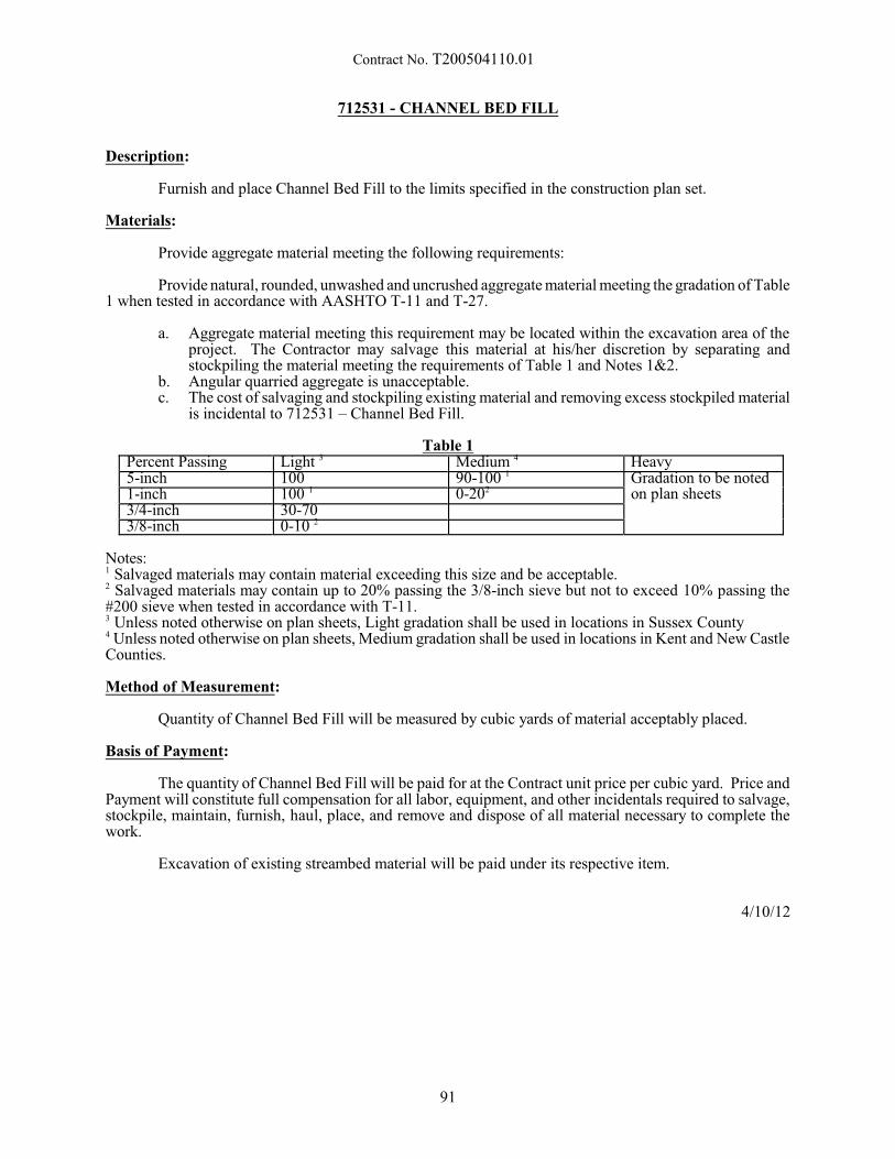
Contract No. T200504110.01
712531 - CHANNEL BED FILL
Description:
Furnish and place Channel Bed Fill to the limits specified in the construction plan set.
Materials:
Provide aggregate material meeting the following requirements:
Provide natural, rounded, unwashed and uncrushed aggregate material meeting the gradation of Table1 when tested in accordance with AASHTO T-11 and T-27.
a. Aggregate material meeting this requirement may be located within the excavation area of theproject. The Contractor may salvage this material at his/her discretion by separating andstockpiling the material meeting the requirements of Table 1 and Notes 1&2.
b. Angular quarried aggregate is unacceptable.c. The cost of salvaging and stockpiling existing material and removing excess stockpiled material
is incidental to 712531 – Channel Bed Fill.
Table 1Percent Passing Light 3 Medium 4 Heavy5-inch 100 90-100 1 Gradation to be noted1-inch 100 1 0-202 on plan sheets3/4-inch 30-703/8-inch 0-10 2
Notes:1 Salvaged materials may contain material exceeding this size and be acceptable.2 Salvaged materials may contain up to 20% passing the 3/8-inch sieve but not to exceed 10% passing the#200 sieve when tested in accordance with T-11.3 Unless noted otherwise on plan sheets, Light gradation shall be used in locations in Sussex County4 Unless noted otherwise on plan sheets, Medium gradation shall be used in locations in Kent and New CastleCounties.
Method of Measurement:
Quantity of Channel Bed Fill will be measured by cubic yards of material acceptably placed.
Basis of Payment:
The quantity of Channel Bed Fill will be paid for at the Contract unit price per cubic yard. Price andPayment will constitute full compensation for all labor, equipment, and other incidentals required to salvage,stockpile, maintain, furnish, haul, place, and remove and dispose of all material necessary to complete thework.
Excavation of existing streambed material will be paid under its respective item.
4/10/12
91
Contract No. T200504110.01
715500 - UNDERDRAIN OUTLET PIPE, 6 715504 - UNDERDRAIN OUTLET PIPE, 8
Description:
This work consists of furnishing and placing underdrain outlet pipe in accordance with the locations,notes and details shown on the Plans and as directed by the Engineer.
Materials and Construction Methods:
The materials and construction methods for underdrain outlet pipe shall conform to the applicablerequirements of Section 715 of the Standard Specifications, except there shall be no requirements for filterfabric and Del. No. 8 stone around the pipe and the pipe shall not be perforated. The material for underdrainoutlet pipe shall be the same as for perforated pipe underdrains.
The installed under drain outlet pipe shall be video inspected in accordance with Subsection 715.07of the Standard Specifications.
Method of Measurement:
The quantity of underdrain outlet pipe will be measured from end to end in linear feet (linear meters)of pipe completed and accepted.
Basis of Payment:
The quantity of underdrain outlet pipe will be paid for at the Contract unit price per linear foot (linearmeter) of the diameter as specified on the Plans. Price and payment will constitute full compensation forfurnishing all materials, excavation and backfilling, connectors, bolts to block outlet opening to prevent smallanimals from entering, video inspection for all labor, tools, equipment and incidentals to complete the item.
10/29/01
92
Contract No. T200504110.01
720509 - GALVANIZED AND FUSION-BONDED POLYESTER COATED GUARDRAIL
Description:
This work consists of surface preparation, application, and applying fusion-bonded polyester coatingover galvanized metal railing elements, posts, guardrail end terminals, guardrail transitions and any associatedhardware in shop facilities as specified in the Contract Documents, the Standard Construction Details, thisspecification, and as directed by the Engineer.
Materials:
Prior to coating any guardrail end terminals, Contractor shall submit written approval to Engineerfrom the end terminal manufacturer allowing the fusion-bonded polyester coating to be installed on the endterminal.
Approved rust-proof spray paint, color to match fusion-bonded polyester coating.
Galvanizing Coating:
Prior to galvanizing operations, the galvanizing facility shall inspect and remove all sharp edges onrails, posts, or other hardware used in assemblies. The easing of all sharp edges is essential to the durabilityof the fusion-bonded polyester coating process and failure on the part of the galvanizing facility to performthis step will be cause for rejection of the material.
All surfaces of beams, components and assemblies receiving fusion-bonded polyester coating shallnot be water-quenched, nor receive a chromate conversion coating after the galvanizing process.
Galvanized surfaces receiving fusion-bonded polyester coating shall be cleaned and prepared forcoating in accordance with SSPC SP 16, including all information noted in Appendix A and ASTM D 6386,Sections 5.1 through 5.3, Section 5.4.1 and Section 5.4.3 respectively. Prior to sweep blasting, all surfacesshall be inspected to ensure the galvanized layer is smooth. Should any locations be found to have excessiveliquid zinc run-off, dross or zinc oxide particles they shall be smoothed until the location is level with thesurrounding area using hand or power tools as described in SSPC SP 2 and 3. The resultant profile ofgalvanized layer produced after sweep blasting shall be 1.0 to 1.5 mils as determined by ASTM D 4417,Method C.
Thickness of the galvanized layer shall be measured before and after sweep blasting in accordancewith SSPC PA-2 to ensure all components conform to ASTM A 123 or ASTM A 153 as applicable. Anylocations found having insufficient thickness shall be repaired in accordance with ASTM A 780.
All shapes, except beams, shall be hot-dipped galvanized in accordance with AASHTO M 111. TheContractor may elect to use either hot-dipped galvanized rolled H sections or fabricated sections, that conformto the requirements of ASTM A 769, Grade 36 (Grade 250) (b) Beams. All beams shall conform to therequirements of AASHTO M 180, Class A, Type I or Type II. 397.
After galvanizing, all components shall be thoroughly inspected and protected from rain or moistureduring storage and shipment by a secured cover to the fusion-bonded polyester coating facility.
Fusion-Bonded Polyester Coating:
The fusion-bonded polyester coating applicator shall identify to the galvanizer all guardrail beam,components, and assemblies surfaces receiving fusion-bonded polyester coating to ensure the galvanizingmethod used on assemblies is compatible with subsequent application of powder coating.
Coating and cleaning systems shall be applied in an environmentally controlled plant that is fullyenclosed and preapproved by the Department's Materials & Research Section. A low pressure power washingto ensure removal of any organic contaminants prior to fusion-bonded polyester coating is required. Also,to ensure water and air molecules do not get trapped in the zinc coating and turn into pinholes and blistersdue to outgassing, a “pre-heat” treatment of the piece prior to fusion-bonded polyester coating is required.
93
Contract No. T200504110.01
Cleaned surfaces shall be protected from conditions of high humidity, rainfall, or surface moistureand shall not be allowed to flash rust. Sweep or brush blast to SSPC SP16. Blast profile shall beapproximately 1 to 1.5 mils, but not greater than 2 mils, as checked with a Test-O-Tex or Keane-Tator surfaceprofile gauge or as approved by the Engineer.
The fusion-bonded polyester coating shall be applied as an electrostatically charged dry powdersprayed onto grounded components using an electrostatic spray system. The coated components shall begiven a thermal time/temperature cure to provide a fully cured finish. The coating thickness, after cure, shallbe 7 mils plus or minus 2 mils in accordance with the manufacturer’s recommendation when measured inaccordance with ASTM D7091 and SSPC PA2.
After coating, each component shall be checked for continuity using a 67-1/2 volt wet spongedetector to check for holidays, pinholes, and discontinuities. Coating thickness shall be checked with aproperly calibrated magnetic gauge.
All components shall be padded and shall be handled with nylon slings during loading, unloadingand installation.
Control and acceptance of the Fusion-Bonded Polyester Coating will be based on the following testsas used on projects for the National Park Service:
Quality Test LimitsAbrasion Tabor Abraser CS-10
1000 Gram Load1000 Cycles
ASTM D1044
100 Mg. Max.Weight LossWeight Loss
Adhesion ASTM D-3359Initial
1000 Hrs. (Item H)
5A5A
Gloss ASTM D-523Initial 500 Hrs.
1000 Hrs. (Item H)
82%-60 degrees90%-60 degrees
Hardness ASTM D-3363 2H - No GougeImpact ASTM D-2794
DirectPass 80 Inc. Lb.
Salt Spray Resistance ASTM B-117ASTM D-1654
1000 Hrs. Unscribed400 Hrs. Scribed
Table 2 - 10Table 2 - 10
Thickness ASTM G-12 6 mils + 2 milsWeather Resistance ASTM G-23, 1000 Hrs., 18
min.1000 Hrs. Unscribed
400 Hrs. Scribed
Water Spray No Film Failure
Color Brown Polyester No. 20040,Mid-Gloss Chocolate Brown
Identify Infrared Finger Print Match OriginalFlexibility 180 degrees Bend-120 Min.
Light within 10 secondsNo Breaks, Flaking or Cracks.Tested w/a Q-Panel w/2 mils(50 mm) or less of Cracking
Humidity ASTM D-2247/1000 Hrs. No. Blister or Film Failure
Construction Methods:
Installation of guardrail, guardrail end terminals and guardrail transitions is specified in Sections 720and 721 of the Standard Specifications and paid for under the respective guardrail pay items of the Contract.
94
Contract No. T200504110.01
After curing and acceptance, the fusion-bonded polyester coating applicator shall protect the coatedassemblies with multiple layers of wrapping, or other protective materials specified in the project specificfusion-bonded polyester coating plan.
During storage and subsequent shipping, each assembly shall be separated from other assemblies byexpanded polystyrene spacers and other spacing materials specified in the project specific fusion-bondedpolyester coating plan.
All guardrail and components shall be off-loaded and installed using extreme care to ensure coatingsare not damaged. Upon delivery to the project site, coated assemblies and hardware shall be thoroughlyinspected by the Engineer for any coating defects or damage. If damage is found, the Engineer will determineif the extent of the damage will constitute a cause for rejection.
It is required a representative from the fusion-bonded polyester coating applicator’s firm be presentto witness proper handling and erection processes are being employed by the Contractor to minimize oreliminate coating damage. Wood or other suitable material shall be used to protect tops of posts when piledriving.
All coating damage due to shipping, storage, handling, and installation operations shall be repairedby the Contractor at no additional expense to the Department. The Contractor shall provide the Engineeraccess to all locations of all powder coated members for verification of coating conditions prior to andfollowing all coating repairs.
Repair damaged surfaces as follows:
1. Prepare surfaces in accordance with SSPC-SP 1 followed by SSPC-SP 2 or SSPC-SP 3. Solventsor degreasers used in SP 1 preparation shall be acceptable to the powder manufacturer and themanufacturer of the coating used for repair. Proof of acceptability shall be furnished to theEngineer. Extend the prepared area at least 2 inches into adjacent, tightly adhering, intactcoating.
2. Feather the existing coating system surrounding each repair location. Feather the repair area fora distance of 1 inch to 2 inches to provide a smooth, tapered transition into the existing intactcoating.
3. When the steel substrate is exposed in the repair area, the surface shall be prepared inaccordance with SSPC SP11. Apply a coat of Organic Zinc primer conforming to ASTM A 780in accordance with manufacturer’s instructions and feather back existing coatings as statedabove before re-application of topcoat.
4. The coating thickness of the touch-up material shall be the same thickness as the polyester andcan be applied in multiple coats.
After installation, coat all exposed hardware (bolts, nuts and washers) with an approved spray paintthat matches the color of the fusion-bonded polyester coating.
Warranty
Fusion-bonded polyester coated guardrail shall be warranted as specified herein for a period of threeyears from the date of acceptance. Should the coating system fail within three years after the project has beenaccepted, the coating shall be repaired by the Contractor in conjunction with the fusion-bonded polyestercoating applicator at no cost to the Department. The extent and method of repair must be acceptable andagreed upon by the Department. System failure does not include damage from external agents, such asscraping from snow removal equipment, vandalism, debris impacts, collisions, etc., or normal loss of glossand color. Once the duplex system (galvanizing and fusion-bonded polyester coating) has been accepted, afailure shall mean any visible corrosion, blistering, checking, cracking, or delamination (peeling) of thecoating.
95
Contract No. T200504110.01
Method of Measurement:
Measure the quantity of fusion-bonded polyester coated guardrail as the number of linear feet ofguardrail, including end terminals, transitions and associated hardware coated with fusion-bonded polyestercoating.
Basis of Payment:
The quantity of guardrail coated with fusion-bonded polyester coating will be paid for at the Contractunit price per linear foot. Price and payment constitute surface preparation of all guardrail materials,including end terminals and guardrail transitions, fusion-bonded polyester coating materials, application ofthe fusion-bonded polyester coating on all guardrail components, delivery of coated materials to the projectlocation, warranty, labor, equipment, tools, and necessary incidentals to complete the work as specified andas directed by the Engineer.
8/3/15
96
Contract No. T200504110.01
720585 - GUARDRAIL END TREATMENT ATTENUATOR, TYPE 1 - 31720586 - GUARDRAIL END TREATMENT ATTENUATOR, TYPE 2 - 31720588 - GUARDRAIL END TREATMENT ATTENUATOR, TYPE 3 - 31
Description:
This work consists of furnishing and installing an impact attenuating guardrail end treatment inaccordance with the locations, notes and details on the Plans, the Standard Construction Details, these SpecialProvisions, and as directed by the Engineer.
Materials:
The end treatment system shall meet the requirements of NCHRP Report No. 350 Test Level 3. TheGuardrail End Treatment, Type 1 shall be designed for installation parallel to the roadway. The GuardrailEnd Treatment, Type 2 shall be designed for installation with the end flared back from the roadway. TheGuardrail End Treatment, Type 3 shall be designed for installation where 2 runs of guardrail come together.
The entire end treatment shall be designed for quick and easy replacement after an impact.
Guardrail End Treatment Attenuator Type 1 shall have a minimum of 2 square feet (0.2 squaremeters) of yellow retroreflective material on the nose. Guardrail End Treatment Attenuator, Type 2 and Type3 shall have a minimum of 3 square feet (0.3 square meters) of yellow retroreflective material on the nose.
The Contractor shall submit shop drawings, the manufacturer's certification, and the manufacturer'sinstallation instructions to the Engineer. Installation cannot begin until these submissions have been approvedby the Engineer.
Construction Methods:
The end treatment system shall be fabricated and installed in accordance with the manufacturer'srecommendations and details shown on the Plans.
The end treatment system shall be installed so that there is no rigid object projecting more 4 (100mm) above ground level in that portion of the attenuator impacted and broken away by an errant vehicle. Itis the intent that the errant vehicle not be snagged by an embedded component of the end treatment attenuator.
The grading between the edge of pavement and the end treatment shall be 10:1 or flatter for the lengthof the end treatment.
Reflectorized washers are not to be used on attenuators unless specified and/or approved by themanufacturer.
The Guardrail End Treatment Attenuator, Type 1 shall be installed with steel tubes and soil platesfor the first 4 (min.) wood post. As an alternate, the first 4 (min.) post may be hinged, breakaway steel postif the manufacturer's specifications permit.
Unless otherwise noted on the Plans, the Guardrail End Treatment Attenuator, Type 1 shall beinstalled with a 25:1 taper beginning 50' (15 m) from the end of the end treatment.
Method of Measurement:
The quantity of guardrail end treatment attenuators will be measured as the number of each typefabricated, installed and accepted.
Note: All guardrail end treatment attenuators will be considered as 50 feet (15 meters) long. The 50' (15m) length will begin at the center of the nose post and extend back along the attenuator and guardrail to whichit is attached. Any guardrail within the 50' (15 m) length will be considered as part of the guardrail endtreatment attenuator and not be measured separately. Measurement for the guardrail will begin 50' (15 m)from the center of the nose post of the attenuator.
97
Contract No. T200504110.01
Basis of Payment:
The quantity of guardrail end treatment attenuators will be paid for at the Contract unit price per eachtype of guardrail end treatment attenuator. Price and payment will constitute full compensation for furnishingall materials, fabrication and installation and for all materials, labor, equipment, tools and incidentals requiredto complete the work.
Note: When this item is completely installed, the Contractor may notify the Engineer and requestacceptance. The Engineer will make an inspection of the installation and the Contractor shall correct anydeficiencies. Once the corrective work is completed to the satisfaction of the Engineer, the installation willbe accepted and the Contractor will be relieved from the responsibility for this item. If this item is damagedbefore the final acceptance of the project, and the damage is not the result of the Contractor's negligence, theEngineer will notify the Contractor to make repairs, and the Contractor will make repairs at the unit price bid(in the case of complete replacement) or at a negotiated price (in the case of partial replacement or repair). Damage caused by the Contractor shall be repaired at no cost to the Department.
8/12/2013
98
Contract No. T200504110.01
727510 - WOOD RAIL FENCE
Description:
This work consists of furnishing all materials and constructing wood rail fence in accordance withthe plans, details and specifications at the locations shown on the Plans and as directed by the Engineer.
Material and Construction Methods:
All materials, such as fence, posts, hardware and accessories shall be new. Concrete, if necessary,shall conform to Section 812, Class B of the Standard Specifications.
Lumber shall be grade 2, conforming to Subsection 601.02 of the Standard Specifications.
Lumber shall be treated in accordance with Subsection 814 (b) water bourne preservative of theStandard Specifications.
All hardware shall conform to the requirements and Subsection 601.07 of the Standard Specifications.
Method of Measurement:
The quantity of wood rail fence will be measured by the linear feet along the actual fence constructedand accepted.
Basis of Payment:
The quantity of wood rail fence will be paid for at the Contract unit price per linear foot. Price andpayment will constitute full compensation for all new materials and installing fence, concrete if required,excavation and backfilling, for all labor, tools, and incidentals necessary to complete the item.
6/24/15
99
Contract No. T200504110.01
727535 - WOOD FENCE, 6' HIGH
Description:
This work consists of furnishing all materials, and erecting a pressure treated wood fence inaccordance with the notes and details on the Plans, these specifications and as directed by the Engineer.
Materials:
The timber, including posts, backers and vertical boards, shall be Southern Yellow Pine, Number 2grade or better and shall be pressure treated with chromated copper arsenate, with 0.4 pounds retained percubic foot (6.5 kg retained per cubic meter), in conformance with Section 601.
The hardware, including nails, bolts and fasteners, shall be hot dipped galvanized and shall conformto Section 601. Concrete for footings shall meet the requirements of Section 812, Class B.
Construction Methods:
Installation methods shall conform to applicable portions of Section 727 of the StandardSpecifications and as noted on the Plans. Prior to fence installation, all required clearing and grubbing, andtree trimming shall be completed. Clearing and grubbing, tree and stump removal and tree trimming will allbe paid for under Item 201000, Clearing and Grubbing.
The fence shall be installed true to line, as indicated, and grade and the top elevation shall be uniform. The vertical boards shall be placed on the roadway side of posts and backers and shall be a nominal 3" (75mm) above the ground line unless shown otherwise in the Plans. If any grading is required to meet the 3" (75mm) above the ground criteria as stated above or details shown in the Plans, the cost for such work shall beconsidered as part of these items. The vertical boards of the fence shall be installed prior to cutting or shapingthe top as shown in the Plans.
Method of Measurement:
The quantity of wood fence will be measured as the actual number of linear feet (linear meters) alongthe fence, excluding gates, constructed and accepted.
Basis of Payment:
The quantity of wood fence will be paid for at the Contract unit price per linear foot (linear meter)for each size of fence. Price and payment will constitute full compensation for the furnishing of all materials,labor, tools, equipment, hauling, concrete footings, fasteners, excavation and backfilling for footings, gradingif required and incidentals necessary to complete the work.
6/24/15
100
Contract No. T200504110.01
727555 - RIGHT-OF-WAY MARKER, CAPPED REBAR
Description:
Furnish necessary materials and labor to set at the locations shown on the Plans, and as directed bythe Engineer.
Materials:
Provide Right-of-Way Marker, Capped Rebar constructed in accordance with the details shown in theStandard Construction Details using materials specified in:
Bar Reinforcement Section 603Aluminum 2” Flat Survey Marker for Rebar As Submitted and approved by Engineer
Construction Methods:
A. Exact location to be set by a Delaware Professional Land Surveyor in accordance with the plans oras directed by the Engineer;
B. Place Rebar in a vertical position at depth shown on the plans;C. Place Aluminum 2” flat survey marker on rebar taking care not to move the location of the rebar.
Method of Measurement:
Right-of-Way Marker, Capped Rebar will be measured as the actual number of Right-of-WayMarker, Capped Rebar set and accepted.
Basis of Payment:
The quantity of Right-of-Way Marker, Capped Rebar will be paid for at the Contract unit price perEach. Price and payment will constitute full compensation for furnishing all materials required and settingthe Right-of-Way Marker, Capped Rebar by a Delaware Professional Land Surveyor and any incidentalsnecessary to complete the item. Existing Right-of-Way Marker, Capped Rebar damaged will be replaced asrequired by Subsection 107.09 of the Standard Specifications and will be repaired, replaced, and set at theContractor’s expense.
9/15/11
101
Contract No. T200504110.01
744500 - CONDUIT JUNCTION WELL, TYPE 6, PRECAST POLYMER CONCRETE744506 - CONDUIT JUNCTION WELL, TYPE 7, PRECAST POLYMER CONCRETE744507 - CONDUIT JUNCTION WELL, TYPE 8, PRECAST POLYMER CONCRETE744508 - CONDUIT JUNCTION WELL, TYPE 9, PRECAST POLYMER CONCRETE
744509 - CONDUIT JUNCTION WELL, TYPE 10, PRECAST POLYMER CONCRETE744520 - CONDUIT JUNCTION WELL, TYPE 1, PRECAST CONCRETE744523 - CONDUIT JUNCTION WELL, TYPE 4, PRECAST CONCRETE744524 - CONDUIT JUNCTION WELL, TYPE 5, PRECAST CONCRETE
744530 - CONDUIT JUNCTION WELL, TYPE 11, PRECAST CONCRETE/POLYMER LID-FRAME
744531 - CONDUIT JUNCTION WELL, TYPE 14, PRECAST CONCRETE/POLYMER LID-FRAME
744532 - CONDUIT JUNCTION WELL, TYPE 15, PRECAST CONCRETE/POLYMER LID-FRAME
Description:
This work consists of supplying, constructing and installing conduit junction wells as shown on theapplicable Plan Sheets or Standard Construction details
Materials:
Concrete shall conform to Section 812, Class B of the Standard Specifications.
Castings shall conform to Section 708.05 of the Standard Specifications.
Frames and lids shall be in accordance with Sections 708 and 744 of the Standard Specifications.
All required hardware and wire for Bonding and Grounding as shown on the Standard Constructionor applicable Plan details.
Types 6, 7, 8 and 10 are precast polymer concrete stackable boxes with no base.
Precast polymer concrete is reinforced by heavy-weave fiberglass with a compressive strength of9,000-15,000 psi, impact energy of 30-72 ft. lbs. and a tensile strength of 800-1,100 psi. Precast polymerconcrete should be tested according to the requirements of ASTM Method D-543, Section 7, Procedure 1 forchemical resistance.
All precast polymer concrete covers shall be the heavy-duty type with a design load of 15,000 lbs.over a 10" square. The coefficient of friction should be greater than 0.5. The precast polymer concrete coverlogo shall bear the inscription "DelDOT" (Types 6, 8, and 10) or "DelDOT TRAFFIC FIBER OPTICS" (Type7).
Types 11, 14, and 15 are precast polymer frame and lids installed on a precast concrete base. Precastpolymer concrete frame and lids shall be the heavy-duty nonconductive type with a design load of 15,000 lbs.over a 10" square. The coefficient of friction should be greater than 0.5. The precast polymer concrete lidlogo shall bear the inscription "DelDOT ELECTRIC"(Types 11, 14, and 15)
Construction Methods:
The conduit junction well shall conform to the dimensions shown on the Standard Construction orapplicable Plan Details, or on the manufacturer’s specifications and shall be built so as to ensure that the castiron frame and lid or polymer concrete box and cover are set level with the surrounding surface whenconstructed within pavement, sidewalks, pedestrian curb ramps, etc., and set above grade and graded to drainaway from the junction well when constructed in unpaved areas. More than one conduit may extend intothe well and shall conform to the dimensions shown on the applicable plan sheets or Standard ConstructionDetails. A stone base shall be built for all types of junction wells. Grounding and bonding of the units shallbe performed as shown on the plans or Standard Construction details.
102
Contract No. T200504110.01
Method of Measurement:
The quantity of junction wells shall be the actual number of conduit junction wells by type, that aresupplied, constructed, complete in place, and accepted, including cast iron frames and lids with groundinglugs, precast polymer concrete frame and covers, or precast polymer concrete covers, stone base, bonding,grounding, and splicing if required. Frames and lids or precast polymer concrete covers must be installedprior to acceptance of this item.
Payment for all conduits extending into the junction well shall be included in the items for conduitinstallation.
The length of ALL conduits within a junction well shall conform to the Standard Construction orapplicable Plan Details or as directed by Engineer. Payment for cutting existing conduit as directed byEngineer, where a junction well is replaced with a larger type of junction well is included in the bid price. The removal and replacement of cables within the conduits to be shortened shall be handled under other itemsof this contract.
Basis of Payment:
Payment for conduit junction wells as measured above shall be made at the Contract unit price pereach junction well of the type indicated, completely installed and constructed, including excavation,backfilling, and stone base. Price and payment will constitute full compensation for all labor, equipment,tools, and incidentals required to complete the work.
2/29/12
103
Contract No. T200504110.01
745601 – FURNISH & INSTALL UP TO 3” FLEXIBLE METALLIC-LIQUIDTIGHT CONDUIT
745602 - FURNISH & INSTALL UP TO 4” SCHEDULE 80 HDPE CONDUIT (BORE)745603 - FURNISH & INSTALL UP TO 4” SCHEDULE 80 PVC CONDUIT (OPEN CUT)745604 - FURNISH & INSTALL UP TO 4” SCHEDULE 80 PVC CONDUIT (TRENCH)
745605 - FURNISH & INSTALL UP TO 4” SCHEDULE 80 PVC CONDUIT (ON STRUCTURE)745606 - FURNISH & INSTALL UP TO 4” GALVANIZED STEEL CONDUIT (TRENCH)
745607 - FURNISH & INSTALL UP TO 4” GALVANIZED STEEL CONDUIT (BORE)745608 - FURNISH & INSTALL UP TO 4” GALVANIZED STEEL CONDUIT (OPEN CUT)
745609 - FURNISH & INSTALL UP TO 4” GALVANIZED STEEL CONDUIT (ONSTRUCTURE)
745610 - FURNISH & INSTALL UP TO 4” NONMETALLIC POLE RISER SHIELD
Description:
Furnish and install HDPE, PVC, or Galvanized steel conduits of any size less than or equal to 4inches in diameter (3 inches or less for Flexible Metallic Liquidtight Conduit) as described below.
Materials:
All conduits shall be UL listed.
HDPE Conduit - 4" or less diameter, high density polyethylene (HDPE) schedule 80, smooth wall conduitwith permanently pre-lubricated lining, meeting ASTM D2447, ASTM D3035 and NEMA TC7specifications.
PVC Conduit - 4" or less diameter, schedule 80 rigid polyvinyl chloride (PVC) conduit, meeting CommercialStandard CS-272-65 (PVC), ASTM D-1785 and U.C. Standard 651 specifications.
Galvanized Steel Conduit - 4" or less diameter, rigid galvanized steel conduit meeting National ElectricCode 2002, Article 344.
Nonmetallic Pole Riser Shield – 4” diameter or less nonmetallic pole riser shield with belled ends meetingNEMA TC-19 specifications.
Flexible Metallic-Liquidtight Conduit – meets National Electric Code 2002, Article 350
Weatherhead for galvanized or PVC conduit – material shall match the adjoining conduit
Insulated grounding bushing with knockouts - meet or exceed UL 514 B
Condulets for conduit sizes - material shall match the adjoining conduit
Anchors - A 307, Galvanized per A 153
One hole conduit hangers - Steel City Series 6H or 6H-B, CADDY CD3B Rigid Conduit Hanger, orapproved equal
End caps - material shall match the adjoining conduit
LONG sweep sections for conduit sizes - material shall match the adjoining conduit, and shall bemanufactured 90 degree sweeping bends.
Construction Methods:
General Installation Requirements - The Department has the right to reject any installation methodproposed for a given work site. PVC shall not be installed under existing pavement unless it is on acontinuous roll or with the Engineer’s written approval.
104
Contract No. T200504110.01
Conduit installed underground shall be installed in a straight line between terminal points. In straightruns, junction well spacing shall be no more than 600 feet for fiber optic conduit or no more than 300 feetfor copper in conduit, or as directed by the Engineer. If bends are required during installation, they must bemanufactured sweeping bends. The Engineer will be consulted before any bends are installed to ensure thatthe proper arc is provided.
Conduit shall have a minimum cover as measured from the finished grade of 24 inches and amaximum cover of 48 inches.
The opening shall be filled half way with the cover material, and tamped down firmly before fillingin the remainder of the opening. Additional lifts shall be used as required to install the metallic warning tapeat the specified depth. All cover material shall be free of rocks, debris, vegetation or other deleteriousmaterial that may damage the conduit. An underground utility warning tape shall be installed as specifiedin this section and the remainder of the fill shall be added, tamping down the top layer.
Conduit not terminated to a base or in a junction well shall be terminated 2 feet beyond the edge ofthe pavement unless otherwise directed by the Engineer, and properly capped. Tape is NOT an approvedmethod. Conduit shall not extend more than 3 inches inside a junction well. See Standard ConstructionDetails or applicable Plan Details for typical methods of termination.
All underground conduits shall be marked in the ground with a metallic warning tape. The markingtape shall be buried directly above the conduit run that it identifies, at a depth of approximately 12 inchesbelow final grade. The tape identifying ALL conduits shall be at least 6 inches wide, and have a minimumthickness of 3 mils and 500 percent elongation.
The color of the metallic warning tape identifying fiber optic cable should be bright orange(preferably AULCC orange), and shall read "WARNING - OPTICAL CABLE" or other wording approvedby the Engineer that conveys the same message. The color of the tape identifying all other cables shall bebright red, and shall read "WARNING —BURIED ELECTRIC BELOW" or other wording approved by theEngineer that conveys the same message.
Using conduit tools, rigid metallic conduit shall be cut, reamed, and threaded. The thread length shallbe as necessary to ensure that the sections of conduits when screwed into a coupling and tightened correctlywill butt together and the joint will be watertight. A three-piece threaded union, as approved by the Engineer,shall be used to join two threaded lengths of conduit in the case where a standard coupling will not work. A threaded union shall not be used in a conduit run that is to be driven. At no time is a threadless couplingor a split-bolt coupling to be used for direct buried conduit.
All lengths of HDPE conduit shall be connected with irreversible fusion couplings. Mechanical andremovable couplings will not be accepted.
All lengths of PVC conduit shall be connected by one conduit end fitting inside the flared end of theother conduit section. If this is not possible, then a coupling may be used. Regardless of how connection ismade, all joints shall be sealed with the appropriate epoxy to ensure that the two conduit pieces bond to oneanother to form a solid waterproof link. Using conduit tools, the conduit shall be cut and prepared. Ifapproved by the Engineer, a coupler module may be used where conduit segments do not align properly toallow the flared end of one conduit segment to mate with the normal end of the other segment.
Sealed end caps (with knockouts if empty) shall be placed on the ends of all conduits, aftercompressed air has been used to clear all foreign matter.
If not already pre-installed by the manufacturer, a polyester or polypropylene pulling rope or tape(fish wire) with a minimum rated strength of 1250 pounds shall be installed in each conduit for future use. In instances where the Contractor installs the cable, the fish wire may be eliminated.
All PVC and HDPE conduits shall have a continuous metallic trace wire installed for the entire lengthof the conduit run for all fiber installations.
105
Contract No. T200504110.01
Installation Of Conduit Under Existing Pavement, Directional Bore -
Directional bore shall be used for installation of conduits under existing pavement with a conduitdiameter not less than 1-1/2". The size of a bore shall not exceed the outside diameter of the conduit by morethan 1 inch. If it does, cement grout shall be pumped into the void. Only HDPE and/or Galvanized Steelconduit may be installed by Directional Bore methods.
Installation Of Conduit Under Existing Pavement, Open Cut -
Installation by sawcutting the full pavement depth and removing the existing pavement with anexcavator or by hand methods, shall be used only for conduits not less than 1-1/2" diameter. The Engineermust first approve all open cutting of roadways. The width and length of open cut and patch restorationmaterials shall be as shown on the plan details. The Contractor shall be responsible for the removal of all cutpavement and surplus excavation, and for the replacement and correction of any damaged pavement outsidethe sawcut limits after the conduit(s) are installed. Asphalt pavement, concrete, base course, sawcutting,and/or borrow from an outside source as required to restore the roadway will be paid for separately undertheir respective bid items.
Installation Of Conduit Under Existing Pavement, Unpaved Trench -
Trenching or other approved method shall be used for installation of conduit in unpaved trench orunder new pavement. Backfill in conduit trenches shall be compacted thoroughly as it is being placed. Atthe discretion of the Engineer, sod, that must be removed for the placement of conduit, shall be removedeither by the use of an approved sod cutter and then replaced, or 6 inches of topsoil shall be placed and thesurface seeded in accordance with Section 734001 - Seeding. In areas where new pavement is to be placedor in areas where total reconstruction is taking place, sodding or seeding may not be required by the Engineer. Sodding and/or topsoil from an outside source if required will be paid for separately under their respectivebid items. Seeding is considered incidental to the conduit item.
Installation Of Conduit On Structure -
Conduit installed on structure shall consist of drilling anchors into concrete, brick, stone, steel orwood and mounting the conduit with the proper clamps or hangers. The conduit shall be attached to thestructure by use of one-hole conduit hangers and approved anchors not more than 36 inches apart. Any 90-degree turns in the conduit run shall be accomplished by placing the proper size and type manufacturedsweeping bends for the application needed.
Installation of Nonmetallic Riser Shield or Flexible Metallic Liquidtight Conduit -
Riser Shield and/or Flexible Metallic Liquidtight Conduit installed on wood poles, metal poles,structures, and/or mast arms shall be installed in a straight line. The conduit, when attached to poles, shallbe attached with 2-hole straps spaced not more than 36 inches apart with the top-most strap being 12 inchesfrom the weatherhead and the lower-most being 12 inches from the condulet. A weatherhead matching thediameter of the conduit shall be installed on the upper end of the conduit. A condulet of the same size as theconduit being installed, but not smaller than 2 inches shall be placed 48 inches above finished grade. Installtwo, 2-hole straps of the proper size, evenly spaced below the condulet. Nonmetallic pole risers (U-guard)shall be installed on poles to allow interduct to be connected directly to messenger cable. The undergroundconduit shall be as close to the base of the pole as possible. If the nonmetallic pole riser or metallicliquidtight conduit is not the same size as the conduit, an adapter shall be used at no additional cost to theDepartment. The nonmetallic pole riser or metallic liquidtight conduit shall be attached to the pole with 1/4"x 1-1/2" galvanized lag bolts with washers. Lag bolts will be used every 36 inches on BOTH sides of thenonmetallic pole riser or liquidtight conduit, and in the top most and bottom most set of slots. Flexiblemetallic liquidtight conduit shown on the plans to be installed on mast arms or on metal structure shall alsoinclude stainless steel banding placed at a maximum of 5 feet intervals.
106
Contract No. T200504110.01
Method of Measurement:
The quantity of conduit or riser shield installed as specified, shall be measured as the number of linearfeet of each conduit or riser shield installed as specified, complete in place, and accepted.
The length of each conduit installed under existing pavement by a directional bore or by open cuttingthe pavement shall be measured along the path of the bore or open cut, from the point that cannot be trenchedto the point that trenching can resume.
The length of any conduit that is reduced or divided (with a junction well or conduit body) shall bemeasured as part of the larger conduit.
Basis of Payment:
The quantity of conduit or riser shield will be paid for at the Contract unit price per linear foot. Priceand payment shall include full compensation for furnishing all conduit and/or riser shield materials,equipment, labor, and incidentals necessary to complete the item.
For conduit installed by Directional Bore, the linear foot payment also includes excavation andbackfilling for Bore Equipment, placing the conduit, caps if required, and all other requirements andincidentals listed in the body of this specification.
For conduit installed by Open Cutting existing pavement, the linear foot payment also includesexcavating, backfilling, placing the conduit, disposal of excess materials, and all other requirements andincidentals listed in the body of this specification.
For conduit installed in an Unpaved Trench, the linear foot payment also includes excavating,removal of sod if required, backfilling, placing the conduit, disposal of excess materials, replacing excavatedon-site sod if required, seeding if required, and all other requirements and incidentals listed in the body ofthis specification. Sod and/or topsoil furnished from an outside source, will be paid for separately.
For conduit installed on a structure, the linear foot payment also includes furnishing and installinganchors and hangers, removal of excess materials, and all other requirements and incidentals listed in thebody of this specification.
For riser shield or flexible metallic conduit installed on poles, mast arms, or structures the linear footpayment also includes furnishing and installing straps, weatherhead, condulet, lag bolts and washers, anyother required mounting hardware, and all other requirements and incidentals listed in the body of thisspecification.
2/29/12
107
Contract No. T200504110.01
746843 - POLE BASE, TYPE 1746844 - POLE BASE, TYPE 2
746845 - POLE BASE, TYPE 2A746846 - POLE BASE, TYPE 2B746847 - POLE BASE, TYPE 3 746848 - POLE BASE, TYPE 3A746849 - POLE BASE, TYPE 3B746850 - POLE BASE, TYPE 4 746851 - POLE BASE, TYPE 5 746852 - POLE BASE, TYPE 6
Description:
This work consists of constructing and furnishing round or square pole bases Types 1, 2, 2A, 2B, 3,3A, 3B, 4, 5, and 6 for poles in accordance with the Standard Construction Details and at locations as directedby the Engineer.
Materials:
The concrete for pole bases shall conform to Section 812, Class B.
Bar reinforcement shall meet the requirements of Section 603 Grade 60.
Ground rods shall be copper clad, approved by the Underwriter's Laboratory and be supplied withapproved clamps for connecting the grounding conductor to the rod.
Conduit for sweeps shall meet the requirements for galvanized rigid steel conduit in Section 745.
Anchor bolts will be supplied by the same entity that supplies the poles. This is the case for all polesbase types, with the exception of Type 4. For Type 4, drop-ins are used for breakaway and the Contractorwill supply the anchor bolts for Type 4. The anchor bolts and nuts for Types 5 and 6 shall not be hot-dippedgalvanized and these anchor bolts and nuts shall meet the requirements of AASHTO M 314. Anchor boltsshall have a minimum yield strength of 55,000 psi (380,000 kPa).
Construction Methods:
The bases shall conform to the dimensions as indicated on the Standard Construction Details. Aground rod shall be installed as shown. A minimum of 8 feet (2.5 m) of the ground rod must be driven intoundisturbed soil.
If a utility or a right-of-way conflict is found when a Type 2 or Type 3 base is specified in the Plans,an alternate base of equivalent strength may be used as directed by the Engineer. A Type 2 base has twoequivalents, namely Types 2A and 2B. A Type 3 base has two equivalents, namely Types 3A and 3B.
Though the contract calls for the use of a round pole base, the Contractor may use a square base atits discretion.
The end of the conduit sweeps in the ground shall be extended outside the concrete and any formsor sheeting by 12 inches (300 mm) and capped or connected to the existing conduit. If the conduit is to becapped underground for future use, it must be sealed with a galvanized threaded conduit plug. Tape is NOTan approved conduit plug. The location of the conduits shall be marked on the base with arrows drawn inthe wet concrete within 6 inches (150 mm) of the outer edge.
Excavation for the pole bases may not exceed the dimension of the foundation by more than 12 inches(300 mm) in any one direction. If a form is used in the excavation more than 18 inches (450 mm) below theground surface, it is necessary that the area between the form and excavation be filled with Borrow Type Cand tamped on all sides in continuous, horizontal layers not to exceed 68 inches (200150 mm) in depth, loosemeasurement.
108
Contract No. T200504110.01
Where a pole base is to be placed in existing concrete pavement such as a sidewalk, the concrete shallbe saw cut in a square pattern or removed to the nearest joint. In other pavement material, a round hole maybe cut using an appropriate tool. Any damage to the existing pavement shall be repaired at the Contractor'sexpense and shall meet the approval of the Engineer. Any removal or replacement of any type of pavementunder this item shall be an incidental cost to this item.
The bases shall be edged and have a broom finish.
Where water or highly unstable material is encountered during the excavation for the pole base, polebase sheeting may be required and the following steps shall apply:
1. The condition exists in the upper half of the excavation. Stop all work until the Bridge DesignSection reviews the condition.
2. The condition exists below the upper half of the excavation:a. For a proposed Type 4 Base, increase the depth to 4 feet (1.2 m).b. For a proposed Type 5 Base, substitute a Type 1 Base.c. For a proposed Type 1, 2, or 3 Pole Base, substitute a Type 3A Pole Base for all but a Type
3B Pole Base. The depth of the base shall be as determined in (e) below, or 9 feet (2.7 m),whichever is greater.
d. For a proposed Type 6 Pole Base, substitute a Type 2 Pole base and increase the depth inaccordance with (e) below.
e. Determine the depth of the base, which would be in the unsatisfactory area. Multiply thatdepth by 0.7 and add the result to the original required depth of the base to obtain the finaldepth of the base. The reinforcing bars shall be extended using the required pattern to matchthe final depth in accordance with the requirements of Section 603.07 of the StandardSpecifications.
Method of Measurement:
The quantity of pole bases will be measured as the actual number of bases constructed, complete inplace and accepted. Concrete, excavation and backfilling around the base, ground rods, and the two conduitsweeps in the base are included in this item.
Furnishing Borrow Type C backfill material will be measured and paid for separately by the cubicyard (cubic meter).
Payment for any additional sweeps shall be paid for separately under the appropriate conduit items. The Contractor's use of square base rather than a specified round base shall not result in any additional costto the Department.
Basis of Payment:
Borrow Type C will be paid for under Section 210. No payment for Borrow Type C backfill materialplaced outside of the vertical plans located 18" (450 mm) outside of the neat line perimeter of the vertical faceof the pole base foundation.
Any increase in the vertical dimension required herein shall be paid for separately under Item 746614,Pole Base Extension; another item of this contract.
The quantity of pole bases will be paid for at the Contract unit price for each pole base type. If analternate pole base type is selected by the Engineer, payment will be the Contract unit price for the alternateselected. Price and payment will constitute full compensation for furnishing and placing all materialsincluding concrete, ground rods, and a minimum of two conduit sweeps extending into the base; forexcavating, backfilling and compacting around the base; for repairs to damaged existing pavement; forremoval or replacement of pavement; and for all labor, equipment, tools, and incidentals required to completethe work.
3/1/12
109
Contract No. T200504110.01
746924 - FURNISH & INSTALL LOOP WIRE 1-CONDUCTOR #14 AWG ENCASED IN ¼”
FLEXIBLE TUBING IN A LOOP SAWCUT
Description:
Sawcut and seal existing pavement, furnish and install loop detector wire, aluminum shielded “home-run” cable, as shown on the Plans.
Materials:
1. 1-conductor #14 AWG Cable in ¼” Flexible Tubing - shall consist of cable preinstalled in apolyethylene (PE) plastic duct meeting IMSA 51-5. Cable shall be rated for 600 volts. The cableshall have a temperature tolerance range of at least - 65 to + 176 degrees Fahrenheit. The conductoris AWG #14 stranded copper. Outside diameter of the cable is 0.25 inches. Referred to as “loopwire”
2. 2-conductor #14 AWG Aluminum Shielded Cable – see specifications for furnish and install cable. Referred to as “home-run cable”.
3. Flexible embedding sealer - a cold poured, resilient type epoxy joint sealer, Bondo P 606 orDuracote D115 for concrete or asphalt pavement or E Poxy Industry 36 1 for concrete or E PoxyIndustry11 1 for asphalt pavement, or approved equal. A sealer accelerant or retarder may be addedper the manufacturers specifications.
4. Backer Rod - 5/8" closed cell foam
5. Tape – Vinyl electrical tape shall have a PVC base with rubber based pressure sensitive adhesive. The tape shall be a minimum 7 mils thick and be UL listed and marked per UL Standard 510 as flameretardant and cold resistant. It shall be compatible with synthetic cable insulations, jackets andsplicing compounds and rated for wire and cable splices up to 600-volts.
6. For splices in Junction Well (see plan detail):
a. Dual Wall Heat Shrink Tubing – Heat-shrink tubing shall be medium or heavy wall thickness,irradiated polyolefin tubing containing an adhesive mastic inner wall. Minimum wall thicknessprior to contraction shall be 40 mils. When heated, the inner wall shall melt and fill all crevicesand interstices of the object being covered while the outer wall shrinks to form a waterproofinsulation. Each end of the heat-shrink tube or the open end of the end cap of heat-shrinktubing shall, after contraction, overlap the conductor insulation at least one and one-half inches.Heat-shrink tubing shall conform to the requirements in UL Standard 468D and ANSI C119.1,for extruded insulated tubing at 600 V.
b. Soldering iron with Rosin Core solder
c. Splicing Kit- In-line barrel type design, resin encapsulating compound kit with UL486 rating.Suitable for use in wet or direct buried locations. Resin encapsulating compounds shall beacceptable for use at 16 degrees C.
Construction Methods:
Loop Wire Installation:
The pavement saw cut shall be 5/8” wide and up to 3½” deep. It shall be “wet-cut” in the directionsand sizes specified on the Plans, Standard Details or as directed by the Engineer. Contractor shall removesharp edges in the saw cut and round the corners.
The saw cut shall be blown out with compressed air to remove all dust, water and particles of loosematerial prior to sealing.
110
Contract No. T200504110.01
The loop detector wire will then be installed using blunt tools so as to prevent damage to thepolyethylene outer cover. One end of a loop detector wire shall be tagged to indicate start ("S"). A 5/8"backer rod will be placed into the bottom of the saw cut as needed to secure the wiring within the saw cut. All loop detector wires shall be laid in saw cuts in a clockwise rotation beginning with "S". The Engineer mayrequire a High Voltage Ground Test with a 500 VDC megger after the loop detector installation is completeand prior to sealing saw cuts. If the resistance to ground is less than 100 megohms, this work will be rejected.
A sealer and sealer accelerant or retarder (if necessary) shall be applied in accordance with themanufacturer's directions and protected from traffic until it has set. A minimum of 1 inch of sealer shall beinstalled on top of the loop detector wire and finished flush with the pavement. Drilled holes in the pavementshall also be sealed.
Two loop detector wires shall be installed in a saw cut from the loop to the edge of the road. Thesetwo wires shall then extend from the end of the saw cut to a junction well (see Plan Details). Wires shall beparallel, twisted a minimum of 5 wraps per foot, and taped every 12" to 18" from the end of the saw cut toa junction well up to the splice. The loop detector wire shall be installed between the end of the saw cut andjunction well through a penetration created by a 1 ½" rotary drill as directed by the Engineer.
The loop detector wire shall be continuous and without splices from the junction well, through thesaw cuts and conduit.
Home-run Wire Installation - refer to furnish and install cable specifications and conduit installationspecifications. Refer to plans for details.
Splicing – splices between the loop detector wire and home-run cable shall be done in accordance with theplan details.
Conductors to be soldered shall be placed side by side with the exposed copper aligned. The coppershall then be twisted clockwise with pliers until a good mechanical connection is affected. The splice shallbe coated with flux, heated with a soldering iron, and rosin core soldered in a manner that minimizesinsulation damage. After each soldered connection is completed, it shall be properly insulated with heatshrink tubing.
After the electrical and mechanical connection is completed and before the splicing kit is applied, atest shall be made by the Contractor to ensure that all circuits are complete. An approved splice kit shall beinstalled as per manufacturer's instructions. A continuity test will be performed at the cabinet by theDepartment technician after the splicing kit is applied. The Department will be notified of the test results. If the continuity test fails the Contractor shall remake the splice and/or loop at his own expense.
If a splice is found to be faulty within 90 calendar days of installation, it shall be the Contractor'sresponsibility to remake the splice at his own expense.
Method of Measurement:
The quantity of loop detector wire to be measured under this item shall be the number of linear feetof sawcut in which loop detector wire is installed, sealed, tested, and accepted. Sealer, sealer accelerant or retarder shall be incidental to this item.
Loop detector wire routed through the rotary drill penetration is considered incidental to the cost ofthe loop installation.
Conduit and associated home-run cable between the junction well and cabinet will be measured andpaid for under their respective items, separate from this specification.
Splicing of the loop detector wire to a home-run cable in a junction well shall be incidental to the costof the loop wire.
111

Contract No. T200504110.01
Basis of Payment:
The quantity of loop detector wire supplied and installed will be paid for at the Contract unit priceper linear foot, determined by measuring the footage of sawcut described above. Price and payment shallconstitute full compensation for “wet”-sawcutting, furnishing and placing all materials including loop detectorwire, backer rod, sealer, and for all labor, equipment, tools, splicing in the junction well, and incidentalsnecessary to complete this item.
The price bid per linear foot of sawcut with Loop Wire shall include drilling required for installation,concrete and pavement patching, sealing the conduit ends, internal bushings shown on the plans, and allincidentals necessary to complete the item.
7/18/14
112
Contract No. T200504110.01
747514 - CABINET BASE TYPE F747515 - CABINET BASE TYPE M747516 - CABINET BASE TYPE P747517 - CABINET BASE TYPE R
Description:
This work consists of constructing cabinet base Type F, M, P and R in accordance with the StandardConstruction Details or applicable Plan Details and at locations as directed by plans or the Engineer.
Materials:
Class B Concrete3/4” x 10’ sectional copperclad steel ground rods5/8" Zinc plated or Stainless Steel Drop-in Anchors manufactured by Hilti Systems, Concrete
Fastening Systems, or approved equal5/8" x 1-1/2" galvanized hex bolts3/4” acorn type ground clampsPVC conduit sweeps
Construction Methods:
The base shall conform to the dimensions as indicated in the cabinet base detail on the StandardConstruction Details or applicable Plan Sheets. A concrete collar is only required when installed in earth areasor as directed by the engineer. Conduits entering the base must enter only in the designated area. A minimumdistance of 1 inch shall be maintained between conduits and a minimum distance of 2 inches betweenconduits and the ground rods.
A minimum of 8 foot of the ground rods must be driven into undisturbed soil through the 2 inch PVCsleeve. The PVC sleeve shall be driven into the ground so that the top of the sleeve will be flush with theconcrete when the base is poured.
Method of Measurement:
The quantity of cabinet bases will be measured as the number of bases constructed in accordance withthese specifications, complete in place, and accepted.
All conduit sweeps extending into the cabinet base as shown on the Plans or Standard Details asapplicable shall be included in the price for each cabinet base..
Basis of Payment:
The quantity of cabinet bases will be paid for at the Contract unit price per each. Price and paymentwill constitute full compensation for all concrete, ground rods, labor, equipment, tools, conduit sweeps, andincidentals required to complete the work as shown on the standard details or applicable plan sheets.
10/9/2012
113
Contract No. T200504110.01
748506 - PERMANENT PAVEMENT STRIPING, EPOXY RESIN PAINT, WHITE/YELLOW, 4"748507 - PERMANENT PAVEMENT STRIPING, EPOXY RESIN PAINT, WHITE/YELLOW, 6"748508 - PERMANENT PAVEMENT STRIPING, EPOXY RESIN PAINT, WHITE/YELLOW, 8"748509 - PERMANENT PAVEMENT STRIPING, EPOXY RESIN PAINT, WHITE/YELLOW, 12"748510 - PERMANENT PAVEMENT STRIPING, SYMBOL/LEGEND, EPOXY RESIN PAINT
748535 - PERMANENT PAVEMENT STRIPING, EPOXY RESIN PAINT, BLACK, 4"748536 - PERMANENT PAVEMENT STRIPING, EPOXY RESIN PAINT, BLACK, 6"748537 - PERMANENT PAVEMENT STRIPING, EPOXY RESIN PAINT, BLACK, 8"
748538 - PERMANENT PAVEMENT STRIPING, EPOXY RESIN PAINT, BLACK, 10"748539 - PERMANENT PAVEMENT STRIPING, EPOXY RESIN PAINT, BLACK, 12"748540 - PERMANENT PAVEMENT STRIPING, EPOXY RESIN PAINT, BLACK, 16"
748548 - PERMANENT PAVEMENT STRIPING, EPOXY RESIN PAINT, WHITE/YELLOW, 5"748549 -PERMANENT PAVEMENT STRIPING, EPOXY RESIN PAINT, WHITE/YELLOW, 10"
748557 - PERMANENT PAVEMENT STRIPING, EPOXY RESIN PAINT, BLACK, 3"748559 - PERMANENT PAVEMENT STRIPING, EPOXY RESIN PAINT, BLACK, 5"748568 - PERMANENT PAVEMENT STRIPING, EPOXY RESIN PAINT, BLACK, 9"
748569 - PERMANENT PAVEMENT STRIPING, EPOXY RESIN PAINT, BLACK, 14"
Description:
This work consists of striping layout,furnishing and applying white or yellow, epoxy reflectorizedpavement markings or black epoxy contrast pavement markings at the locations and in accordance with thepatterns indicated on the Plans, or as directed by the Engineer, and in accordance with these specifications.
The white/yellow epoxy marking material shall be hot-applied by spray methods onto bituminousand/or Portland cement concrete pavement surfaces as required by the Plans. Following an application ofdouble drop glass beads of two sizes and upon curing, the resultant epoxy marking shall be an adherentreflectorized stripe of the specified thickness and width that is capable of resisting deformation by traffic.All marking materials shall be certified lead free and free of cadmium, mercury, hexvalent chromium, andother toxic heavy metals.
The black epoxy marking shall be a two-component, hot-spray applied epoxy resin pavement markingmaterial to be used for pavement marking on Portland cement concrete pavement surfaces. Following anaggregate drop, and upon curing, it shall produce an adherent stripe of specified thickness and width capableof resisting wear from traffic. Black contrast pavement markings will be required on all Portland cementconcrete pavements.
Materials Requirements:
A. White and Yellow Reflectorized Epoxy
1. Epoxy Composition Requirements:
The epoxy resin composition shall be specifically formulated for use as a pavement markingmaterial and for hot-spray application at elevated temperatures. The type and amounts of epoxyresins and curing agents shall be at the option of the manufacturer, providing the othercomposition and physical requirements of this specification are met.
The epoxy marking material shall be a two-component (Part A and Part B), 100% solids typesystem formulated and designed to provide a simple volumetric mixing ratio (e.g. two volumesof Part A to one volume of Part B).
Component A of both white and yellow shall conform to the following requirements:
% BY WEIGHTWHITE: YELLOW:
Pigments Titanium Dioxide - 18% Min.(ASTM D476, Type II)
Organic Yellow - 6%-10%
Epoxy Resin 75% Min., 82% Max. 70% Min., 77% Max.
114
Contract No. T200504110.01
The entire pigment composition shall consist of either titanium dioxide and/or organicyellow pigment. No extender pigments are permitted. The white pigment upon analysis,shall contain a minimum of 16.5% TiO2 (100% purity).
Epoxy Content-WPE (Component A) - The epoxy content of the epoxy resin will be testedin accordance with ASTM D1652 and calculated as the weight per epoxy equivalent (WPE)for both white and yellow. The epoxy content will be determined on a pigment free basis. The epoxy content (WPE) shall meet a target value provided by the manufacturer andapproved by the Department's Material and Research Section (from now on will beaddressed as Department). A + 50 tolerance will be applied to the target value to establishthe acceptance range.
Amine Value (Component B) - The amine value of the curing agent shall be tested inaccordance with ASTM D2074-66 to determine its total amine value. The total amine valueshall meet a target value provided by the manufacturer and approved by the Department. A+50 tolerance will be applied to the target value to establish the acceptance range.
Toxicity - Upon heating to application temperature, the material shall not exude fumes whichare toxic or injurious to persons or property.
Viscosity - Formulations of each component shall be such that the viscosity of bothcomponents shall coincide (within 10%) at a recommended spray application.
2. Physical Properties of Mixed Composition:
Unless otherwise noted, all samples are to be prepared and tested at an ambient temperatureof 73 ± 5 F. (23 ± 3 C).
a. Color. The white epoxy composition when applied at a minimum wet film thickness of20+1 mils (500 µm) as applicable and allowed to dry, shall plot within the boundariesdescribed by the four corner points listed in Tables 1 and 2 of ASTM D 6628-01 whenmeasured in accordance with the test methods prescribed in Section 7 of ASTM D 6628-01.
The yellow epoxy composition when applied at a minimum wet film thickness of 20+1 mils(500 µm) as applicable and allowed to dry, shall plot within the boundaries described by thefour corner points listed in Tables 1 and 2 of ASTM D 6628-01 when measured inaccordance with the test methods prescribed in Section 7 of ASTM D 6628-01.
b. Directional Reflectance. The white epoxy composition (without glass spheres) shall have adaylight directional reflectance of not less than 84% relative to a magnesium oxide standardwhen tested in accordance with Method 6121 of Federal Test Method Standard No. 141.
The yellow epoxy composition (without glass spheres) shall have a daylight directionalreflectance of not less than 55% relative to a magnesium oxide standard when tested inaccordance with Method 6121 of Federal Test Method Standard No. 141.
c. Drying Time (Laboratory). The epoxy composition, when mixed in the proper ratio andapplied at a 20+1 mils (500 µm) minimum wet film thickness, and immediately dressed withlarge reflective glass spheres (Federal Spec. Type 4)at a rate of 12 lb/gal (1.4 kg/l) of epoxypavement marking materials, immediately followed by a second drop of AASHTO M-247Type 1 glass spheres applied at a rate of 12 lb/gal (1.4 kg/L) of epoxy pavement markingmaterial, shall exhibit a no-track condition in 15 minutes or less (ASTM D711). A BirdApplicator or any other doctor blade shall be used to produce a uniform film thickness.
d. Drying Time (Field). When installed at a minimum wet film thickness of 20+1 mils (500or 625 um) and reflectorized with glass spheres, the maximum drying times shall correspondto these temperatures:
80 F (27 C) 10 minutes 70 F (21 C) 10 minutes 60 F (16 C) 15 minutes
115
Contract No. T200504110.01
50 F (10 C) 25 minutes40 F (4 C) 45 minutes35 F (2 C) 60 minutes
The composition shall dry to “no-tracking” in approximately 10 minutes, and after thirty (30)minutes shall show no damaging effect from traffic. Dry to no-tracking shall be consideredas the condition where no visual deposition of the epoxy marking to the pavement surface isobserved when viewed from a distance of 100 feet (30 meters), after a passenger car is passedover the line. Regardless of the temperature at the time of installation, the installationcontractor shall be responsible for protection of the markings material until dry to a non-trackingstate.
e. Abrasion Resistance. The wear index of the composition shall not exceed 82 when testedin accordance with ASTM C501 using a CS-17 wheel and under a load of 1000 grams for1000 cycles.
f. Tensile Strength. The tensile strength of the epoxy composition shall not be less than 6000psi (41 MPa) when tested in accordance with ASTM D638 using a Type IV specimen[0.125" ± 0.010" (3.18 ± 0.25 mm) thick]. Tests shall be conducted at an ambienttemperature of 75 ± 5 F (24 ± 3 C). The testing machine shall operate at a speed of 0.20"(5.1 mm) per minute.
The total conditioning or drying period, from the time the epoxy composition is first mixedto the time of testing, shall not be less than 24 hours nor more than 96 hours.
Test specimens for tensile strength determination will be prepared as follows:
A 1/8 inch (3 mm) thick sheet of epoxy material is cast from a reservoir-type mold,fabricated from polyterrafluorethylene (PTFE), 1/8" deep x 10" x 10" (3 mm deep x 250 mmx 250 mm).
Prior to casting, the mold is sprayed with a suitable release agent. A sufficient amount ofepoxy composition is mixed in the proper proportions (A:B) and poured level with the topof the mold. Care should be taken so as not to decrease or exceed the 1/8" (3 mm) thickness.
After a period of 1 to 4 hours, the material will have set into a semi-rigid sheet that is flexibleenough to die-cut yet rigid enough to retain its shape. While the material is in this “plastic”state, five (5) specimens shall be die-cut and then placed on a flat, smooth, PTFE surface forthe completion of the specified conditioning period.
g. Compressive Strength. The compressive strength of the epoxy composition shall not be lessthan 12,000 psi (83 MPa) when tested in accordance with ASTM D695 except that acompression tool shall not be necessary. The test specimen shall be a right cylinder [0.50inch diameter by 1.0 inch length (12 mm diameter by 25 mm length)]. Tests shall beconducted at an ambient temperature of 75 ± 5 F (24 ± 3 C).
The total conditioning or drying period, from the time the epoxy composition is first mixedto the time of testing shall not be less than 24 hours nor more than 96 hours.
Test specimens for compressive strength determinations will be prepared as follows:
Five molds will be prepared from 1/2" (12 mm) I.D., 1/16" (1.5 mm) wall thickness acrylictubing, cut in 1 1/2" (38 mm) lengths. After spraying the inside of the mold with a suitablerelease agent,(1) the cylindrical tubes are placed in a vertical position on a PTFE sheet base. A sufficient amount of epoxy composition is thoroughly mixed in the proper proportions(A:B) and poured into the mold to a depth of approximately 1 1/4" (32 mm). After aminimum of 72 hours curing, the specimens are removed from the molds and machined toa length of 1" ± 0.002" (25 mm ± 0.05 mm).
116
Contract No. T200504110.01
h. Hardness. The epoxy composition when tested in accordance with ASTM D2240 shall havea Shore D hardness of between 75 and 100. Samples shall be allowed to dry for not less than24 hours nor more than 96 hours prior to testing.
B. Reflective Glass Spheres/Beads
Reflective glass spheres for drop-on application shall conform to the following requirements:
The glass spheres shall be colorless; clean; transparent; free from milkiness or excessive airbubbles; and essentially clean from-surface scarring or scratching. They shall be spherical inshape and at least 80% of the glass beads shall be true spheres when tested in accordance withASTM D1155. At least 80% of the Type IV beads shall be true spheres as measured by thevisual method.
The refractive index of the spheres shall be a minimum of 1.50 as determined by the liquidimmersion method at 77 F (25 C).
The silica content of the glass spheres shall not be less than 60%.
The crushing resistance of the spheres shall be as follows: A 40 lb. (18 kg) dead weight, for 20to 30 (850 µm to 600 µm) mesh spheres shall be the average resistance when tested inaccordance with ASTM D1213.
The glass spheres shall have the following grading when tested in accordance with ASTMD1214.
M247 AASHTO Type 1 Glass SpheresU.S. Standard Sieve % Retained % Passing#20 (850µm) 0 100#30 (600µm) 5-25 75-95#50 (300µm) 40-65 15-35#100 (150µm) 15-35 0-5Pan 0-5
Type 4 Large SpheresU.S. Standard Sieve % Retained % Passing#10 (2000 µm) 0 100#12 (1680 µm) 0-5 95-100#14 (1410 µm) 5-20 80-95#16 (1190 µm) 40-80 10-40#18 (1000 µm) 10-40 0-5#20 (850 µm) 0-5 0-2Pan 0-2
The AASHTO M247 Type 1 glass spheres shall be treated with a moisture-proof coating. Theyshall show no tendency to absorb moisture in storage and shall remain free of clusters and hardlumps. They shall flow freely from dispensing equipment at any time when surface andatmosphere conditions are satisfactory for marking operations. The moisture-resistance of theglass spheres shall be determined in accordance with AASHTO M247 test method 4.4.1.
Type IV glass spheres shall be treated with an adhesion coating. They shall show no tendencyto absorb moisture in storage and shall remain free of clusters and hard lumps. They shall flow freely fromdispensing equipment at any time when surface and atmosphere conditions are satisfactory for markingoperations. The adhesion coating property of the Type IV beads shall be tested in accordance with the dansyl-chloride test.
C. Black Epoxy Contrast Markings
Epoxy Resin Requirements: The two-component, 100% solids, paint shall be formulated anddesigned to provide a simple volumetric mixing ratio (e.g. 2 part component A to 1 part component B)
117
Contract No. T200504110.01
specifically for service as a hot-spray applied binder for black aggregate in such a manner as to producemaximum adhesion. The material shall be composed of epoxy resins and pigments only.
The paint shall be well mixed in the manufacturing process and shall be free from defects andimperfections that may adversely affect the serviceability of the finished product. The paint shall not thicken,curdle, gel, settle excessively, or otherwise display any objectionable properties after storage. Individualcomponents shall not require mixing prior to use when stored for a maximum of 6 months.
The overall paint composition shall be left to the discretion of the manufacturer, but shall meet thefollowing requirements:
Composition: Component Percent By WeightCarbon Black
(ASTM D476 Type III)7±2 percent, by weight
Talc 14±2 percent, by weightEpoxy Resin 79±4 percent, by weight
D. Black Aggregate
The moisture resistant aggregate shall meet the gradation requirements (AASHTO T27) as follows:
Sieve Size Percent Retained#30 18-28%#40 60-80%#50 2-14%
The moisture resistant aggregate shall have a ceramic coating. The aggregate shall be angular withno dry dispensement pigment allowed.
Hardness: The black aggregate hardness shall be 6.5-7 on Moh's MineralScale.
Porosity: The black aggregate porosity shall be less than two (2) percent.Moisture Content: The black aggregate moisture content shall be less than a half (.5)
percent.
E. Packaging and Shipment
Epoxy pavement marking materials shall be shipped to the job site in strong substantial containers. Individual containers shall be plainly marked with the following information:
a. Name of Productb. Lot Numberc. Batch Numberd. Test Numbere. Date of Manufacturef. Date of expiration of acceptance (12 months from date of manufacture)g. The statement (as appropriate)
Part A - Contains Pigment & Epoxy ResinPart B - Contains Catalyst
h. Quantityi. Mixing proportions, Application Temperature and Instructionsj. Safety Informationk. Manufacturer's Name and Address
Reflective glass spheres shall be shipped in moisture resistant bags. Each bag shall be markedwith the name and address of the manufacturer and the name and net weight of the material.
118
Contract No. T200504110.01
F. The Department reserves the right to randomly take a one-quart sample of white, yellow andhardener, of the epoxy material or glass spheres without prior notice for testing to ensure the epoxy materialmeets specifications.
Epoxy Application Equipment:
Application equipment for the placement of epoxy reflectorized pavement markings shall beapproved by the Department, prior to the start of work.
At any time throughout the duration of the project, the Contractor shall provide free access to hisepoxy application equipment for inspection by the Engineer or his authorized representative.
In general, the application equipment shall be a mobile, truck mounted and self contained pavementmarking machine, specifically designed to apply epoxy resin materials and reflective glass spheres incontinuous and skip-line patterns. The application equipment shall be maneuverable to the extent that straightlines can be followed and normal curves can be made in a true arc. In addition, the truck mounted unit shallbe provided with accessories to allow for the marking of legends, symbols, crosswalks, and other specialpatterns.
The Engineer may approve the use of a portable applicator in lieu of truck mounted accessories, foruse in applying special markings only, provided such equipment can demonstrate satisfactory application ofreflectorized epoxy markings in accordance with these specifications.
The applicator shall be capable of installing up to 20,000 lineal feet (6,100 lineal meters) of epoxyreflectorized pavement markings in an 8-hour day and shall include the following features:
1. The applicator shall provide individual material reservoirs, or space, for the storage of Part Aand Part B of the epoxy resin composition; for the storage of water; and for the storage ofreflective glass spheres.
2. The applicator shall be equipped with heating equipment of sufficient capacity to maintain theindividual epoxy resin components at the manufacturer's recommended temperature for sprayapplication and for heating water to a temperature of approximately 140 F (60 C).
3. The glass spheres shall be gravity dropped upon 20 mils (500 um) of epoxy pavement markingsto produce a wet-night-reflective pavement marking. The large spheres (Federal Spec. Type 4)shall be applied at a rate of 12 pounds per gallon (1.4 kg/L) of epoxy pavement markingmaterial, immediately followed by a second drop of AASHTO M-247 Type 1 glass spheresapplied rate of 12 pounds per gallon (1.4 kg/L) of epoxy pavement marking material. Thisapplication rate and the following gradation shall conform to FHWA's FP-96: StandardSpecifications for Construction of Roads and Bridges on Federal Highway Projects (pages 757-761 Type 3 and Type 4 Beads).
4. The applicator shall be equipped with metering devices or pressure gauges, on the proportioningpumps. Metering devices or pressure gauges shall be visible to the Engineer.
5. The applicator shall be equipped with all the necessary spray equipment, mixers, compressors,and other appurtenances to allow for the placement of epoxy reflectorized pavement markingsin a simultaneous sequence of operations as described below in Construction Details, D. Applications of Epoxy Reflectorized Pavement Markings of this Special Provisions.
Construction Details.
A. General: All pavement marking and patterns shall be placed as shown on the Plans or as directedby the Engineer.
Before any pavement markings work is begun, a schedule of operations shall be submitted for theapproval of the Engineer. This schedule shall be submitted 2 weeks prior to the application of thestriping.
119
Contract No. T200504110.01
At least five (5) days prior to starting striping the Contractor shall provide the Engineer with theepoxy manufacturer's written instructions for use. These instructions shall include but not be limitedto: mixing ratios, application temperatures, and recommendations for use of water spray.
The application of pavement markings shall be done in the general direction of traffic. Stripingagainst the direction of traffic flow shall not be allowed.
The Contractor shall be responsible for removing, to the satisfaction of the Engineer, tracking marks,spilled epoxy or epoxy markings applied in unauthorized areas.
The hot water spray shall not be used in conjunction with markings applications on any pavementsurface, or on any existing durable type marking, unless specifically recommended by themanufacturer of the epoxy material.
B. Atmospheric Conditions: Epoxy pavement markings shall only be applied during conditions of dryweather and on substantially dry pavement surfaces. At the time of installation the pavement surfacetemperature shall be a minimum of 35 F (2 C) and the ambient temperature shall be a minimum of35 F (2 C) and rising. The Engineer shall be the sole determiner as to when atmospheric conditionsand pavement surface conditions are such to produce satisfactory results.
C. Surface Preparations: The Contractor shall clean the pavement or existing durable marking to thesatisfaction of the Engineer.
Surface cleaning and preparation work shall be performed only in the area of the epoxy markingsapplication.
At the time of application all pavement surfaces and existing durable markings shall be free of oil,dirt, dust, grease and similar foreign materials. The cost of cleaning these contaminants shall beincluded in the bid price of this item. Also, the item shall include the cost of removal of the curingcomponent in the area of the epoxy markings application, if concrete curing compounds on newportland cement concrete surfaces have been used. Waterblasting will not be permitted for removal.
D. Application of White/Yellow Epoxy Reflectorized Pavement Markings: White/yellow epoxyreflectorized pavement markings shall be placed at the widths and patterns designated on the ContractPlans.
Markings operations shall not begin until applicable surface preparation work is completed, andapproved by the Engineer.
White/yellow epoxy pavement markings shall be applied at a minimum uniform thickness of 20 mils(500 µm) on all Portland cement concrete and bituminous concrete pavement, including Stone MatrixAsphalt.
Large reflective glass spheres (Federal Spec. Type 4) shall be applied at the rate of 12 pounds pergallon (1.4 kg/L) of epoxy pavement marking material, immediately followed by a second drop ofAASHTO M-247 Type 1 glass spheres applied at a rate of 12 pounds per gallon (1.4 kg/L) of epoxypavement marking material. Glass spheres shall uniformly cover the length and width of thepavement marking.
E. Application of Black Epoxy Contrast Pavement Markings: Black epoxy contrast pavement markingsshall be placed at the widths designated on the Contract Plans.
Markings operations shall not begin until applicable surface preparation work is completed, andapproved by the Engineer.
Black epoxy contrast pavement markings shall be applied at a minimum uniform thickness of 20 mils(500 µm) on all Portland cement concrete surfaces followed by a single drop of graded blackaggregate.
120
Contract No. T200504110.01
The width of black epoxy line shall be applied for the following situations:
Center Skip Line - On Portland cement concrete pavements a black contrast skip line shall be 10 feet(3 m) in length of the same width as the white epoxy reflectorized skip. It is to lead the white skipand stop at the beginning of the white skip. The black contrast skip is to have a single applicationof graded black aggregate.
Edge Lines -White Edge lines on Portland cement concrete pavements shall have a 3 inch blackcontrast line running parallel to the white edge line. The contrast line shall be to the inside or travellane side of the edge line. The black contrast marking is to be applied with a single drop of gradedblack aggregate. Once it has cured sufficiently so as not to track, the reflectorized white line is tobe applied along side of the contrast line and the two lines shall adjoin each other.
Dotted Line: All dotted lines on Portland cement concrete pavements shall have a base of blackcontrast markings which is 4 inches (100 mm) wider than the reflective white marking. The blackcontrast marking is to be applied first with a single drop of graded black aggregate. Once it has curedsufficiently so as not to track, the reflectorized white line is to be applied on top of it. The reflectiveline is to be centered along the black contrast line such that a minimum of 2 inches (50 mm) of blackcontrast marking is visible on either side of the reflective marking.
F. Defective Epoxy Pavement Markings: Epoxy reflectorized pavement markings, which afterapplication and curing are determined by the Engineer to be defective and not in conformance withthis specification, shall be repaired. Repair of defective markings shall be the responsibility of theContractor and shall be performed to the satisfaction of the Engineer as follows:
1. Insufficient film thickness [(less than 20+1 mils (500 µm) as applicable] and line widths;insufficient glass bead coverage or inadequate glass bead retention.
Repair Method: Prepare the surface of the defective epoxy marking by shot blasting, sandblasting, or water blasting. No other cleaning methods will be allowed. Surface preparationshall be performed to the extent that a substantial amount of the reflective glass spheres areremoved and a roughened epoxy marking surface remains.
Immediately after surface preparation remove loose particles and foreign debris by broomingor blasting with compressed air.
Repair shall be made by re-striping over the cleaned surface, in accordance with therequirements of this specification and at a full 20+1 mils (500 µm) minimum line thickness asapplicable.
2. Uncured or discolored epoxy (brown patches); insufficient bond to pavement surface (or existingdurable marking).
Uncured epoxy shall be defined as applied material that fails to cure (dry) in accordance withthe requirements of this specification under MATERIALS, A, 2d. DRYING TIME (FIELD);or applied material that fails to cure (dry) within a reasonable time period under actual fieldconditions, as defined by the Engineer.
Discoloration (brown patches) shall be defined as localized areas or patches of brown or grayishcolored epoxy marking material. These areas often occur in a cyclic pattern and also, often arenot visible until several days or weeks after markings are applied.
Repair Method: The defective epoxy marking shall be completely removed and cleaned tothe underlying pavement surface to the satisfaction of the Engineer.
The extent of removal shall be the defective area plus any adjacent epoxy pavement markingmaterial extending one foot (300 mm) any direction.
After surface preparation work is complete, repair shall be made by re-applying epoxy over thecleaned pavement surface in accordance with the requirements of this specification.
121
Contract No. T200504110.01
3. Reflectivity for epoxy resin paint.
After satisfactory completion of all striping work and written notification from the Contractor,the Department shall test the striping to ensure it has the minimum reflectivity. The testing willbe completed within 30 calendar days from notification. The Contractor may request that testsbe conducted on completed phases or portions of the work. Approval of such a request will beat the discretion of the Engineer. Testing will be done using a LTL-X Retrometer (30 metergeometry). Five readings will be taken per line per mile (1.6 km). Projects less than 1 mile (1.6km) in length will have a minimum of 5 readings per line. These readings will then be averagedfor the overall project average.
The required average minimum initial reflectivity reading in millicandellas shall be:
White 450Yellow 325
Any single reading shall not be less than 350 millicandellas for white and 250 millicandellas foryellow. Without exception, any pavement markings installed that does not meet the aboveaverage minimum initial reflectivity numbers shall be removed and replaced, at the installationcontractor's expense.
Other defects not noted above, but determined by the Engineer to need repair, shall be repairedor replaced as directed by and to the satisfaction of the Engineer.
All work in conjunction with the repair or replacement of defective epoxy reflectorizedpavement markings shall be performed by the Contractor at no additional cost to the State.
Method of Measurement:
The quantity of permanent pavement striping (white, yellow, or black epoxy resin paint) will bemeasured by the number of linear feet (meters) of pavement striping line and number of square feet (meter)of symbol installed on the pavement and accepted in accordance with the Plans.
Basis of Payment:
The quantity of permanent pavement striping (white, yellow, or black epoxy resin paint) paymentwill be paid for at the Contract unit price per linear foot (meter) for 3", 4", 5", 6", 8", 9", 10", 12", 14", 16"(75 mm, 100 mm, 125 mm, 150 mm, 200 mm, 225 mm, 250 mm, 300 mm, 350 mm, or 400 mm) line and theContract unit price per square foot (meter) of symbol. The quantity of permanent pavement marking (white,yellow, or black epoxy resin paint) will be paid for at the Contract unit price per linear foot (meter) of lineand the Contract unit price per square foot (meter) of symbol. Price and payment shall include stripinglayout, cleaning and preparing the pavement surface, and placing all materials, for all labor, tools, equipmentand incidentals necessary to complete the work.
NOTE:
For information only:
The following manufacturers are known to us which manufacturer Epoxy Resin Paint for PavementStriping. The Department does not endorse or require the use of any of the manufacturers listed below. However, a bidder wishes to use another manufacturer’s product, it shall be submitted for review andapproval prior to submitting a bid proposal. Should the product be deemed unacceptable by the Department, the successful bidder will be required to use only an approved product.
1. POLY CARB, Inc.33095 Bainbridge RoadSolon, Ohio 44139Tel. 1-800-CALLMIX
122

Contract No. T200504110.01
2. IPS - Ennis PaintP.O. Box 13582Research Triangle Park, North Carolina 27709Tel. 1-877-477-7623
3. EpoplexOne Park Avenue Maple Shade, NJ 08052Tel. 1-800-822-6920
4. Or an approved equal.
8/7/2013
123
Contract No. T200504110.01
748530 - REMOVAL OF PAVEMENT STRIPING
Description:
This work consists of removing pavement markings of all kinds including paint, tape, etc., inaccordance with this special provision, notes on Plans and/or as directed by the Engineer. The Contractorshall coordinate with the Engineer for maintaining traffic during the operation, prior to starting the work.
Materials and Construction Methods:
Paint and Epoxy Resins:Shot/abrasive grit blasting or water blasting equipment shall be used for removal of markingsfrom pavement surfaces.
Alkyd Thermoplastic:In addition to the removal techniques discussed for paint and epoxy, grinding (erasing machines)equipment may also be used for removal of markings from pavement surfaces.
The removal operation shall be performed in a manner that will not damage the pavement surface.
The Contractor shall collect and dispose of all shot/abrasive grit and pavement marking materialsremoved from the pavement surface. Washing or sweeping such material to the roadside will not bepermitted.
After removal of striping on bituminous concrete asphalt sealer shall be used to cover any exposedaggregate or embedded paint at no additional cost.
Method of Measurement:
The quantity of pavement striping removal will be measured as the number of square feet (meters)of pavement striping removed and accepted. The area of lines will be calculated by multiplying the nominalwidth of line times the length and the area of symbols will be as specified in Subsection 748.10 of theStandard Specifications.
Basis of Payment:
The quantity of pavement striping removal will be paid for at the Contract unit price per square foot(meter) for "Removal of Pavement Striping". Price and payment shall be full compensation for furnishingall materials, removing the pavement markings, disposing of the removed marking material, covering up theexposed aggregate, and for all labor, equipment, tools and incidentals necessary to complete the work.
Note:
There will be no measurement and payment for removal of pavement markings placed incorrectlyby the Contractor.
5/21/2013
124
Contract No. T200504110.01
748541 - PREFORMED RETROREFLECTIVE THERMOPLASTIC PAVEMENT MARKINGS,
4”748542 - PREFORMED RETROREFLECTIVE THERMOPLASTIC PAVEMENT MARKINGS,
6"748543 - PREFORMED RETROREFLECTIVE THERMOPLASTIC PAVEMENT MARKINGS,
8"748544 - PREFORMED RETROREFLECTIVE THERMOPLASTIC PAVEMENT MARKINGS,
12”748545 - PREFORMED RETROREFLECTIVE THERMOPLASTIC PAVEMENT MARKINGS,
16"748546 - PREFORMED RETROREFLECTIVE THERMOPLASTIC PAVEMENT MARKINGS,
SYMBOL/LEGEND748553 - PREFORMED RETROREFLECTIVE THERMOPLASTIC PAVEMENT MARKINGS,
BIKE SYMBOL748554 - PREFORMED RETROREFLECTIVE THERMOPLASTIC PAVEMENT MARKINGS,
PEDESTRIAN SYMBOL748555 - PREFORMED RETROREFLECTIVE THERMOPLASTIC PAVEMENT MARKINGS,
HANDICAP SYMBOL
Description:
This work consists of furnishing and installing preformed retroreflective thermoplastic pavementmarking with a preapplied Federal Specification Type IV glass bead coating throughout its entire crosssection on bituminous asphalt pavement at the locations and in accordance with the patterns on the Plans, oras directed by the Engineer.
The preformed retroreflective markings shall conform to the size and dimensions as shown in theFederal “Standard Highway Signs” book found at: http://mutcd.fhwa.dot.gov/SHSe/pavement.pdf as referredto in the Delaware Manual on Uniform Traffic Control Devices, Part 3, Markings.
Materials:
General: Only materials listed on the Department’s Approved Pavement Markings Material List willbe used for this item. The preformed retroreflective markings shall be fusible to bituminous asphalt pavementby means of the normal heat of a propane type of torch. Adhesives, primers or sealers are not necessary priorto the preformed retroreflective markings application on bituminous asphalt pavement.
The preformed retroreflective markings shall conform to pavement contours, breaks and faultsthrough the action of traffic at normal pavement temperatures. The markings shall have resealingcharacteristics and be capable of fusing to itself and previously applied worn hydrocarbon and/or alkydthermoplastic pavement markings.
The preformed retroreflective markings shall be capable of application on bituminous asphaltpavement wearing courses during the paving operation in accordance with the manufacturer's instructions.After application the markings shall be immediately ready for traffic. The preformed retroreflective markingsshall be suitable for use for one year after the date of receipt when stored in accordance with themanufacturer's recommendations.
The preformed retroreflective thermoplastic markings shall not be brittle and must be sufficientlycohesive and flexible at temperatures exceeding 50oF (10oC) for one person to carry without the danger offracturing the material prior to application.
Composition: The retroreflective pliant rosin ester thermoplastic pavement markings shall consistof a homogeneous mixture of high quality polymeric thermoplastic binders, pigments, fillers and glass beads. The thermoplastic material must conform to AASHTO M249-79(86) with the exception of the relevantdifferences due to the material being preformed, and identified herein.
125
Contract No. T200504110.01
Intermix Glass Beads: The preformed retroreflective material shall contain a minimum of 30% glassspheres which shall conform to AASHTO M247-81 Type 1. Glass spheres shall have a minimum of 80% truespheres overall.
Top Beads: To provide the required retroreflectivity, the preapplied factory top coating of glass beadsshall be a combination of both Federal Spec. Type IV and AASHTO M247-81 Type I beads. Federal Spec.Type IV beads shall be evenly disbursed across the entire surface of the product at a minimum rate of 4 lb.(1.8 kg) per 100 ft2 (9.3 m2) and the AASHTO at 3 lb.(1.4 kg) per 100 ft2 (9.3 m2). In combination, the totalglass bead coverage shall be 7-8 lb. (3.2-3.6 kg) per 100 ft2 (9.3 m2). The AASHTO M247-81 Type I beadsshall have a minimum of 80% true spheres overall and the Federal Spec. Type IV beads shall be 80% truespheres on the 12 and 14 sieves and shall be no less than 75% true spheres on the remaining sieves.
Retroreflectivity: After satisfactory completion of all striping work and written notification fromthe contractor, the Department shall test the striping to ensure it has the minimum reflectivity. The testing willbe completed within 30 calendar days from notification. Testing will be done using a Delta LTL 2000Retrometer (30 meter geometry). The required minimum initial reflectivity reading in millicandellas shall be:
White 300Yellow 200Blue 200
Skid Resistance: The surface of the preformed retroreflective thermoplastic markings shall providea pre-appled minimum skid resistance value of 45-51 BPN and a post-applied minimum skid resistance valueof 45-55 BPN when tested according to ASTM E303-74.
Thickness: The thickness of the supplied material shall have a minimum average thickness of .090"(90 mils) for all Longitudinal lines and a thickness of .125" (125 mils) for all transverse lines andsymbols/legends.
Tensile Strength and Elongation: The preformed retroreflective thermoplastic material shall havea minimum tensile strength of 150 lb. per square inch (1054 kg per square mm) of cross section, at .002" (2.28mil) thickness, when tested according to ASTM D638-76 except that a sample 6" by 1" (150 mm by 25 mm)shall be tested at a temperature between 70oF and 80oF (21oC and 27oC) using a jaw speed of 10" to 12" (250mm to 300 mm) per minute. The sample shall have a maximum elongation of 20% at break when tested bythis method.
Flexibility: The preformed retroreflective thermoplastic marking material shall have flexibility at50oF such that when a 1" by 6" (25 mm by 150 mm) sample is bent through an arc of 90 degrees at a uniformrate in 10 seconds (9 degrees per second) over a 1" (25 mm) mandrel, no cracking occurs in the test sample.The sample must be conditioned prior to testing at 50oF±2 degrees (10oC) for a minimum of four hours. Atleast two specimens tested must meet the flexibility requirements at 50oF (10oC) for a passing result.
Environmental Resistance: The applied markings shall be resistance to deterioration due toexposure to sunlight, water, oil, diesel fuels, gasoline, pavement oil content, salt and adverse weatherconditions.
Effective Performance Life: When properly applied, in accordance with manufacturer's instructions,the preformed retroreflective pavement markings shall be neat and durable. The markings shall remain skidresistant and show no lifting, shrinkage, tearing, roll back or other signs of poor adhesion for a period of onewinter season.
Oil/grease Resistant Test: The preformed retroreflective thermoplastic material shall not dissolveor smear after rubbing a small amount of motor oil on a small piece of the thermoplastic material for twominutes.
Bond Strength: The material shall exhibit a bond strength to Portland Cement Concrete (PCC) equalor exceed 180 psi when tested at room temperature (73.4±3oF) (23oC) in accordance to ASTM Standard TestMethod for Bond Strength of thermoplastic marking Material D4796-88. Place a coarse brick in a 400oF(204oC) oven for 5 minutes. Prepare a 4 square inch test specimen. Place the test specimen on the brick andfurther heat in the 400oF (204oC) oven for 15 minutes. The test specimen is then allowed to cool to roomtemperature and prepared for testing.
126
Contract No. T200504110.01
Low Temperature Cracking (Stress) Resistance for Extended Period: The material shall be testedaccording to AASHTO T250 Section 7 with Section 7.2.3 modified for and extended cold temperature 15degrees ±3oF (-9.4±2oC) exposure period 72 hours. Any cracking shall constitute failure of the material forPCC road surfaces.
Impact Resistance (Gardner Falling Weight): A 2" by 7.5" (50 by 190 mm) specimen shall beapplied on a course concrete brick. Using a Gardner Impact Tester, a 2 lb (.91 kg) weight is dropped froma height of 80" (2032 mm). The specimen when tested at room temperature 73.4±3oF (23oC) should show nosign of cracking. (Test procedure is in accordance with ASTM D5420-93).
Packaging: The flexible preformed retroreflective thermoplastic marking materials, for use astransverse or longitudinal markings as well as legends, arrows and symbols shall be available in flat formmaterial or in rolls. Flat material shall be supplied in maximum of 4' (1.2 m) lengths up to 2' (.6 m) in width.The material shall be packed in suitable cartons clearly labeled for ease of identifying the contents.
Construction Methods:
The markings shall be applied in strict accordance with the manufacturer's recommendations on cleanand dry surfaces. Marking configurations shall be in accordance with the "Delaware Manual on UniformTraffic Control Devices, Part 3, Markings."
The preformed retroreflective thermoplastic material shall be fusible to the pavement by means ofa propane torch recommended by the manufacturer. Preheating the surface to remove any latent moisturewill be done just prior to the placement and installation of the Symbol/ Legend.
No markings shall be placed when the ambient temperature is below 40oF (4oC). The material shallbe kept in a location above 55oF (13oC) until just before application.
The supplier shall provide technical services as may be required.
Method of Measurement:
The quantity of pavement striping (748541-748545) will be measured by the number of linear feet(linear meters) of 4”, 6”, 8”, 12”, or 16” pavement striping line placed and accepted. The quantity of symbol/legend (748546) will be measured by the number of square feet (meters) of symbol/legend placed andaccepted. The quantity of bike symbol, pedestrian symbol, and handicap symbol (748551-748553) will bemeasured as each placed and accepted. The dimensions for the symbol/legends are as follows:
Bike Rider with Helmet shall be 3’ X 5’.Pedestrian shall be 4’ X 8’.Handicap Symbol shall be 40” X 40”.
Basis of Payment:
The quantity of pavement striping payment will be paid for at the Contract unit price per linear foot(linear meter) for 4”, 6”, 8”, 12” and 16” (100 mm, 150 mm, 200 mm, 300 mm, and 400 mm) line. Thequantity of symbol/legend will be paid for at the Contract unit price per square foot (meter). The quantityof bike symbol, pedestrian symbol, and handicap symbol will be paid for at the Contract unit price per each. Price and payment shall include cleaning and preparing the pavement surface, and placing all materials, forall labor, tools, equipment and incidentals necessary to complete the work.
Warranty:
The Contractor shall warrant to the Department that the installed retroreflective preformedthermoplastic pavement markings are free of defects, as hereafter defined, for a period of one winter seasonbeginning at the initial acceptance of the marking installation by the Department. The initial acceptance ofthe marking installation will occur upon the satisfactory correction of all deficiencies noted in the markinginstallation during the Final Inspection of the project. The markings shall be warranted against failure dueto blistering, excessive cracking, bleeding, staining, discoloration, oil content of the pavement materials,smearing and spreading under heat, deterioration due to contact with grease deposits, oil, diesel fuel, or
127

Contract No. T200504110.01
gasoline drippings, chipping, spalling, poor adhesion to the pavement materials, vehicular damage, and wearfrom normal maintenance activities including snow plowing.
The Contractor shall repair all defective areas identified by the Department after initial installationor during the Warranty Period. All repairs shall begin immediately following the notice to the Contractor bythe Department unless weather limitations prevent the corrective work. Should the contractor not commencework within the period stated in the notice, weather permitting, and pending severity, the Department reservesthe right to remedy the condition and charge the contractor for the work. Any corrective work shall be asrecommended by the manufacturer of the marking material and approved by the Department. The Departmentshall be given notification before the Contractor begins corrective work to allow for inspection of theoperation. All costs associated with the repair work shall be the responsibility of the contractor. These costsshall include, but are not limited to, removal, material, maintenance of traffic, etc.
2/28/09
128
Contract No. T200504110.01
749687 - INSTALLATION OR REMOVAL OF TRAFFIC SIGN ON SINGLE SIGN POST
Description:
This work consists of installing or removing traffic sign(s) on a single post or other type of pole atthe locations indicated on the Plans or as directed by the Engineer. This specification also includesinstallation of posts in boring holes constructed under other items.
A single sign totaling more than 9 square feet, or with any dimension, length or width, greater thanor equal to 48 inches shall be installed on multiple sign posts under Item 749690 - Installation or Removalof Traffic Sign on Multiple Sign Posts.
Materials:
The Department will provide all sign materials to be used on this project. The Contractor shall contactthe DelDOT Sign Shop Supervisor with project plans and quantity sheets at 302-760-2581. Sign fabricationorders require a minimum of four (4) weeks for completion. Orders placed with less than 4 weeks lead-timewill result in a delay. Any delay caused by inadequate lead-time due to a late order will be the soleresponsibility of the Contractor. The Contractor shall pick-up the sign materials from the DelDOT Sign Shopand deliver them to the job site without any damage to the sign materials.
Construction Methods:
The Contractor shall pick-up necessary signs, sign posts, hardware, and extensions from theDepartment and install the signs in the locations indicated on the Plans in accordance with the DelawareMUTCD or as directed by the Engineer. The Contractor shall be responsible for obtaining all necessaryutility clearances before the signs may be installed. Signs and plaques shall be mounted no lower than theminimum mounting height specified in the Delaware MUTCD. Signs and plaques shall be mounted no higherthan one foot above the minimum mounting height specified in the Delaware MUTCD. Any excess sign postprotruding above the top of the top sign shall be cut off and removed. For sign removals, the sign posts shallhave all nuts, bolts, and other connectors removed. The disturbed ground shall be graded and backfilledaccordingly. The Contractor is responsible for disposal of all signing material removed from the project
Method of Measurement:
The number of single sign installations or removals will be measured as the actual number of posts installed or removed and accepted.
Basis of Payment:
The quantity of single sign post installations or removals will be paid for at the Contract unit priceper each. Price and payment will constitute full compensation for installing or removing signs and signmaterials, pick-up and delivery of sign materials, grading disturbed areas, and for all labor, equipment, tools,and incidentals required to complete the work. Signs that are not installed in accordance with the DelawareMUTCD or signs installed in the incorrect location shall be moved at no additional cost to the Department.
6/25/2015
129
Contract No. T200504110.01
749690 - INSTALLATION OR REMOVAL OF TRAFFIC SIGN ON MULTIPLE SIGN POSTS
Description:
This work consists of installing or removing traffic sign(s) on multiple sign posts at the locationsindicated on the Plans or as directed by the Engineer. This specification also includes installation of posts inholes installed under other items.
A single sign totaling more than 9 square feet, or with any dimension, length or width, greater than48 inches shall be mounted on two (2) posts. Signs with a length greater than or equal to 78 inches shall bemounted on three (3) sign posts.
Materials:
The Department will provide all sign materials to be used on this project. The Contractor shallcontact the DelDOT Sign Shop Supervisor with project plans and quantity sheets at 302-760-2581. Signfabrication orders require a minimum of four (4) weeks for completion. Orders placed with less than 4 weekslead-time will result in a delay. Any delay caused by inadequate lead-time due to a late order will be the soleresponsibility of the Contractor. The Contractor shall pick-up the sign materials from the DelDOT Sign Shopand deliver them to the job site without any damage to the sign materials.
Construction Methods:
The Contractor shall pick-up necessary signs, sign posts, hardware, and extensions from theDepartment and install the signs in the locations indicated on the Plans in accordance with the DelawareMUTCD or as directed by the Engineer. The Contractor shall be responsible for obtaining all necessaryutility clearances before the signs may be installed. Signs and plaques shall be mounted no lower than theminimum mounting height specified in the Delaware MUTCD. Signs and plaques shall be mounted no higherthan one foot above the minimum mounting height specified in the Delaware MUTCD. Any excess sign postprotruding above the top of the top sign shall be cut off and removed. For sign removals, the sign posts shallhave all nuts, bolts, and other connectors removed For sign removals, the sign posts shall have all nuts, bolts,and other connectors removed. The disturbed ground shall be graded and backfilled accordingly. The Contractoris responsible for disposal of all signing material removed from the project..
Method of Measurement:
The number of sign installations or removals will be measured as the total square foot of the sign(s)installed or removed and accepted.
Basis of Payment:
The quantity of sign installations or removals will be paid for at the Contract unit price per square foot.Price and Payment will constitute full compensation for installing or removing signs and sign materials, pick-upand delivery of sign materials, grading disturbed areas, and for all labor, equipment, tools, and incidentalsrequired to complete the work. Signs that are not installed accordance with the Delaware MUTCD or signsinstalled in the incorrect location shall be moved at no additional cost to the Department.
5/28/2013
130
Contract No. T200504110.01
753516 - SANITARY SEWER SYSTEM
Description:
Work shall include all work as specified herein and as shown on the Plans.
A. Cutting and removal of existing pavement, trench excavation, dewatering, location and protectionof existing utilities.
B. Permanent and temporary shoring as required to protect the work and adjacent structures.
C. Furnishing, installing, and testing of all pipes, fittings, plugs, and other materials required toconstruct the sewers and force main.
D. Horizontal directional drill installation of force main.
E. Connection to existing and new piping, backfilling, accessories, appurtenances and miscellaneouswork.
F. Connections to pipelines and appurtenances;
G. Furnishing and installation of all valves, piping, flexible joints, pipe expansion joints, wall sleeves,wall pipe, appurtenances, manholes and structures.
H. Installation of concrete thrust blocks and supports.
References:
The Contractor shall review the noted references before submitting the bids. This work shall be inaccordance with these Special Provisions and the latest edition of following references:
A. New Castle County Department of Special Services Sewer Design Policy.
B. Recommended Standards for Wastewater Facilities (10 State Standards).
C. Delaware Department of Natural Resources and Environmental Control (DNREC)
D. Delaware Department of Transportation (DelDOT) Standard Specifications for Road and BridgeConstruction.
E. American Society for Testing and Material Standards
F. American Water Works Association Standards
G. American National Standards Institute
General Requirements:
All work shall be subject to inspection and subsequent approval/disapproval of the Engineer and therepresentative of the New Castle County; and the Contractor shall be required to correct the discrepancies athis/her expense.
It is of prime importance that the Contractor, in the performance of his/her work, does not disrupt theoperation of the existing sanitary sewer facilities in any manner or at any time, without the expressed priorapproval of the New Castle County. Following construction the Contractor shall construct, maintain, and removesuch temporary bypasses as may be required during construction to maintain sanitary sewer service.
131
Contract No. T200504110.01
Emergency Repairs
Any and all emergency repairs required during the period of this Contract shall be the responsibility ofthe Contractor. In the event New Castle County is unable to contact the Contractor for the immediateemergency repair items of work, or in the event the Contractor does not take action when contacted within areasonable length of time, New Castle County reserves the right to attend to any and all emergency repair workitems and to resubmit the costs directly to the Contractor for complete payment.
Materials:
Ductile Iron Pipe
A. Ductile iron pipe shall be centrifugally cast pipe conforming to the American National Standard forDuctile Iron Pipe, Centrifugally Cast in Metal Molds or Sand-Lined Molds for Water or Other Liquids,ANSI/AWWA Designation A21.51/C151, latest revision. The pipe sizes shall be as shown on thecontract plans with a thickness class of 52 unless otherwise shown on plans. All pipe fittings shall havejoints with body thickness and radii of curvature conforming to latest ANSI/AWWA DesignationA21.10/C110.
B. Joints shall employ a single, elongated gasket of such size and shape as to provide an adequatecompressive force against the spigot and socket after assembly to effect a positive seal under allcombinations of joint and gasket tolerances. Gaskets shall be vulcanized natural or vulcanized syntheticrubber, resistant to common ingredients of sewage, oils, and groundwater. Gaskets shall be free ofporous areas, foreign material, and visible defects.
C. The lubricant shall be suitable for lubricating the parts of the joint assembly. The lubricant shall benontoxic and shall not support the growth of bacteria and shall have no deteriorating effects on thegasket material.
D. Push-on joint and mechanical joints shall conform to AWWA C111 (ANSI A21.11), latest revision witha thickness class of 52 unless otherwise noted. Joints shall be U.S. Pipe and Foundry Co.'s "Tyton"Joint; Griffin Pipe Products Co.'s "Super Bell-Tite" Joint; or equivalent.
E. Cement lining shall be provided unless otherwise indicated. Linings shall conform to AWWA C104-71(ANSI A21.4) with bituminous seal coat. Cement lining shall be 1/8" thick for all pipes 12" diameterand smaller and 3/16" thick for all pipes 14" diameter and larger.
F. Flanged ductile iron pipe shall have ductile iron flanges conforming to ANSI B16.1 Class 125specifications designed for use with AWWA C110 (ANSI A21.10) flanged fittings, with pipe barrelconforming to AWWA C151-65 and AWWA C151a-68 (ANSI A21.51 and A21.51a), or latestrevisions. Ductile iron pipe shall be flanged in the foundry. The flanges shall be of the long hub type,shall be screwed on the pipe barrel and power tightened by machine, and faced and drilled aftertightening. No ductile iron pipe of class thickness less than Class 53, shall be threaded and flanged.
G. All buried ductile iron piping in the appurtenances shall receive outside bituminous coating inaccordance with AWWA C106-70.
H. Mechanical Coupling:
1. Coupling shall be designed to couple plain end piping by compression of a ring gasket at each endof the adjoining pipe sections.
2. The coupling shall consist of one middle ring flared or beveled at each end to provide a gasketseat; two follower rings; two resilient tapered rubber gaskets; and bolts and nuts to draw thefollower rings toward each other to compress the gaskets.
3. The middle and the follower rings shall be true circular sections free from irregularities, flat spots,and surface defects; the design shall be such as to provide for confinement and compression of thegaskets.
4. The restrained joining system shall be the EBAA Iron Series 3800 or approved equal.
132
Contract No. T200504110.01
I. Mechanical Joint Restraint:
1. Restraint devices for nominal pipe sizes 3 inch through 48 inch shall consist of multiple grippingwedges incorporated into a follower gland meeting the applicable requirements of ANSI/AWWAC110/A21.10.
2. The devices shall have a working pressure rating of 350 psi for 3-16 inch and 250 psi for 18-48inch. Ratings are for water pressure and must include a minimum safety factor of 2 to 1 in allsizes.
3. Gland body, wedges and wedge actuating components shall be cast from grade 65-45-12 ductileiron material in accordance with ASTM A536.
4. Ductile iron gripping wedges shall be heat treated within a range of 370 to 470 BHN.5. Three (3) test bars shall be incrementally poured per production shift as per Underwriter's
Laboratory (U.L.) specifications and ASTM A536. Testing for tensile, yield and elongation shallbe done in accordance with ASTM E8.
6. Chemical and nodularity tests shall be performed as recommended by the Ductile Iron Society, ona per ladle basis.
7. The restrained joining system shall be the EBAA Iron Series 1100 or approved equal.
J. Ductile Iron Fittings: All ductile iron fittings shall be Class 250 suitable for use with the pipe specifiedabove conforming to the latest edition of American National Standard for Gray Iron and Ductile IronFittings, 3 in. through 48 in. for Water and Other Liquids. ANSI/AWWA Designation A21.10/C-110. Fittings shall be externally coated with a uniform thickness of hot applied coal tar coating and the insideshall be cement lined and only mechanical joint fittings shall be used in pressure main lines. End plugsshall be setscrew type, as manufactured by the United States Pipe and Foundry Company, or equivalent. Bolts and gaskets shall conform to the latest edition of ANSI/AWWA Designation A21.11/C-111.
K. Mechanical Joint Retainer Glands: Standard mechanical joint retainer glands are designed to providea method for restraining mechanical joint pipe and fittings against possible joint separation, rupture orblow-out caused by internal water pressures. Mechanical joint retainer glands must meet thespecifications of AWWA C-111 (ANSI A21.11) American Standard for rubber gasket joints. Glandsshall be ductile iron and set screws shall be heat treated AISC 4140 steel.
High Density Polyethylene (HDPE) Pipe
A. All HDPE pipe and fittings shall be from a single manufacturer, who is fully experienced, reputable andqualified in the manufacture of the HDPE pipe to be furnished. The pipe shall be designed, constructedand installed in accordance with the best practices and methods and shall comply with theseSpecifications.
B. Qualified manufacturers: 1. ISCO Industries; HDPE Pipe2. Performance Pipe, Division of Chevron Phillips Chemical Company LP; DriscoPlex®3. JM Eagle; HDPE Pipe4. Flying W Plastics; HDPE Pipe5. Approved Equal.
C. Pipe Rating1. HDPE force main pipe and fittings shall be pressure rated at 160 psi at 73.4ºF meeting the
requirements of Dimension Ration (DR) 11 as MINIMUM STRENGTH.2. HDPE casing pipe, shall be pressure rated at 100 psi at 73.4ºF meeting the requirements of
Dimension Ration (DR) 17 as MINIMUM STRENGTH.
D. Materials1. Pipe shall be ductile iron pipe sized (DIPS)2. Materials used for the manufacture of polyethylene pipe and fittings shall be made from a PE 3408
high density polyethylene resin compound meeting cell classification 345434C per ASTM D3350;and meeting Type III, Class C, Category 5, Grade P34 per ASTM D1238.
3. Pipe and fittings shall comply with AWWA Specifications C901 and C906.4. If rework compounds are required, only those generated in the Manufacturer's own plant from resin
compounds of the same class and type from the same raw material supplier shall be used.
133
Contract No. T200504110.01
5. Dimensions and workmanship shall be as specified by ASTM F714. HDPE fittings and transitionsshall meet ASTM D3261.
6. HDPE pipe shall have a minimum density of 0.955 grams per cubic centimeter per ASTM D1505.
7. All HDPE pipe and fittings shall have a Hydrostatic Design Basis (HDB) of 1,600 psi per ASTMD2837.
8. The pipe Manufacturer must certify compliance with the above requirements.
E. Pipe Identification1. The following shall be continuously indent printed on the pipe or spaced at intervals not exceeding
5-feet:a. Name and/or trademark of the pipe manufacturer.b. Nominal pipe size.c. Dimension ratio.d. The letters PE followed by the polyethylene grade in accordance with ASTM
HDPE Fittings
A. All molded fittings and fabricated fittings shall be fully pressure rated to match the pipe DR pressurerating to which they are made. All fittings shall be molded or fabricated by the manufacturer. NoContractor fabricated fittings shall be used unless approved by New Castle County.
B. The manufacturer of the HDPE pipe shall supply all HDPE fittings and accessories as well as anyadapters and/or specials required to perform the work as shown on the Plans and specified herein.
C. All fittings shall be installed using butt-fused fittings, electro-fused fittings/couplings, or flangedadapters and must be approved by the Engineer.
D. All transition from HDPE pipe to stainless steel or PVC pipe shall be made per the approval ofEngineer and per the HDPE pipe manufacturer's recommendations and specifications. Ductile ironback-up rings shall mate with flanges per ANSI B16.1.1. Transition from new HDPE to existing HDPE piping or valves shall be approved by the Engineer
before installation.2. No solid sleeves shall be allowed between such material transitions.3. Fittings and transitions shall be as manufactured by the pipe manufacturer.4. The pipe supplier must certify compliance with the above requirements.
E. Physical Properties:1. Density - ASTM D15052. Melt Index - ASTM D12383. Flex Modulus - ASTM D7904. Tensile Strength at Yield - ASTM D6385. ESCR - Environmental Stress Crack Resistance - ASTM D16936. Hydrostatic Design Basis - ASTM D28377. ESCR - Compressed Ring - ASTM F12488. Cell Classification - ASTM D3350; PE 345434
F. All molded fittings shall be manufactured per ASTM D326.
G. Pipe joints and fittings shall be supplied to the job site ready for simultaneous butt fusion. Thefabricator shall show that the materials are capable of butt fusion and shall provide a procedure toconsistently produce sound welds.
H. End termination fittings shall be used to seal the system at the ends. The fitting shall be simultaneouslybutt fused to the carrier and containment pipe to seal the annular space. No other closure or terminationwill be allowed. This fitting will also provide transition to single wall.
I. Contractor is responsible for compatibility between pipe materials, fittings and appurtenances.
134
Contract No. T200504110.01
Electrofusion HDPE Fittings
A. Fittings shall be PE3408 HDPE, Cell Classification of 345464C as determined by ASTM D3350-02.
B. Electrofusion fittings shall have a manufacturing standard of ASTM F1055.
C. Fittings shall have a pressure rating equal to the pipe unless otherwise specified on the plans.
D. All electrofusion fittings shall be suitable for use as pressure conduits, and per AWWA C906, havenominal burst values of three and one-half times the Working Pressure Rating (WPR) of the fitting.
Casing Spacers
A. Band Material: 14 gauge 304 stainless steel
B. Liner: 1. Material: Polyvinyl Chloride2. Thickness: 0.090" minimum3. Hardness: Durometer "A" 85-90
C. Acceptable Manufacturers:1. PSI Model "S"2. CCI Pipeline Systems3. Advance Products & Systems
End Seals
A. Material: Neoprene Rubber 1/8" thick
B. Band clamps: ½" wide 304 stainless steel
C. Acceptable Manufacturers:1. PSI Model "C"2. CCI Pipeline Systems3. Advance Products & Systems
Tracer Wire
A. #10 AWG or larger copper clad steel wire with high molecular weight polyethylene insulation.
B. Green insulation cover in accordance with American Public Works Association (APWA) UniformColor Code for Underground Utility Lines.
Valves
A. The Contractor shall furnish and install all valves as necessary to fulfill the intent of the Plans andSpecifications.
B. Gate Valves1. Gate Valves: Gate valves 3"-12" shall be resilient seat, epoxy coated ASTM A126 Class B iron
body, non-rising bronze stem with modified wedge disk suitable for a working pressure of 250 psiand shop tested at 400 psi. The valves shall meet or exceed AWWA C509 Standard, latest edition.
2. Acceptable Manufacturera. US Pipe Metroseal 250b. Mueller® A-2360 Series Resilient Wedge Gate Valve c. or NCC approved equal.
3. The ends of the valves shall correspond in type and dimensions with those of the pipe. All valvesshall be arranged to open in counter-clockwise direction and operating nuts shall be 2" square. Thevalve shall be tested to a pressure of not less than 400 lbs. per square inch.a. Equip valve with a cast iron handwheel for operation.
C. Sewage Air Release Valves 1. Air release valves shall be installed at high points on the force main.
135
Contract No. T200504110.01
2. Air release valves shall be of full body design, unless otherwise approved by New Castle County. 3. The body and cover shall be of cast iron conforming to ASTM A126 class B. All internal parts of
the air release valve shall be of stainless steel. 4. The air release valve shall be float operated and shall employ a compound lever mechanism to
enable the valve to automatically release accumulated air and gases from the pipe while the systemis pressurized and operating. The linkage/lever mechanism shall be able to be removed from thevalve without disassembly of the mechanism.
5. The air release valve shall close drip tight, incorporating an adjustable orifice button. 6. Valve shall be specified with manufacturer's back flushing kit for backwashing with clear water. 7. Air /vacuum release valves shall be as manufactured by GA Industries, APCO, ARI or New Castle
County approved equal.
Line Caps
A. Ductile iron caps shall be installed as shown on the plans or as directed by the engineer. The caps shallbe mechanical joint fittings and be fully protected with adequate thrust blocking. The caps shallconform to all requirements outlined under ANSI/AWWA C110/A21.10 for caps and plugs.
B. The Contractor is to conduct cutting and capping of pressurized line during the night when usage islowest. Contractor is to coordinate with the Owner for the cut-in times and location of adjacent valves.
Concrete Thrust Blocks
A. Class of concrete for thrust blocks shall be DelDOT Class B and shall have a minimum twenty-eight(28) day comprehensive strength of 2,500 lbs. per square inch. All materials shall conform to theapplicable provisions of the latest edition of Section 812 of the DelDOT Standard Specifications forRoad and Bridge Construction.
Valve Vault
A. Precast Concrete (shown in NCC Detail SS-FM-5)1. Description: ASTM C 478, precast, reinforced concrete, of diameter and depth indicated, with
provision for sealant joints.2. Ballast: Increase thickness of precast concrete sections or add concrete to base section, as required
to prevent flotation.3. Base Section: 6-inch minimum thickness for floor slab and 5-inch minimum thickness for walls
and base riser section; with separate base slab or base section with integral floor.4. Riser Sections: 5-inch minimum thickness, of length to provide depth indicated.5. Top Section: Flat-slab-top type with New Castle County approved manhole frame and cover
(NCC Detail SS-MH-9)bolted to the slap top.6. Load Rating: H25 minimum7. Steps: New Castle County approved reinforced polypropylene manhole steps. (NCC Detail
SS-MH-10)8. Joint Sealant: ASTM C 990, bitumen or butyl rubber.9. Manufacturer:
a. Atlantic Concrete Productsb. Gillespie Precast
Warning Tape
A. Warning tape for sanitary sewer shall be printed polyethylene plastic tape with a metallic core,manufactured specifically for warning and identification of buried utility lines. The tape shall be of aroll type, 2" (50 mm) minimum width, and color coded for sewer (green), with warning andidentification imprinted in bold black letters continuously and repeatedly over entire length of tape. Thecode and letter color shall be permanent and unaffected by moisture and other substances contained intrench backfill materials. Imprinted on the tape shall be "Caution, Buried Sewer Line Below", or asimilar message as approved by the Engineer.
136
Contract No. T200504110.01
Construction Methods (Horizontal Directional Drilling):
Alignment:
A. The bore path alignment and design for HDD shall be based on the Engineer's plans and other factors. Some of these factors are the pipe bell and barrel diameters, bore path inside diameter and maximumdeflection capabilities of the joint. Prior to the start of drilling, reaming and pipe placement operations,the Contractor shall properly locate and identify all existing utilities in proximity to the pipe linealignment. The Contractor shall confirm the alignment of all critical utilities, using vacuum excavationor other suitable excavation method, for further detailed confirmations as necessary.1. The bore path shall be designed by the drilling contractor to ensure that pipe joints do not deflect
more that 50% of manufacturer's recommended maximum deflection.
Jointing Method
A. The pipe shall be joined with butt, heat fusion joints as outlined in ASTM D2657. All joints shall bemade in strict compliance with the manufacturer's recommendations. A factory qualified joiningtechnician as designated by pipe manufacturer or experienced, trained technician shall perform all heatfusion joints in the presence of the Engineer.
B. Lengths of pipe shall be assembled into suitable installation lengths by the butt-fusion process. Pipeso joined shall be made from the same class and type of raw material made by the same raw materialsupplier.
C. On days butt fusions are to be made, the first fusion shall be a trial fusion in the presence of theEngineer or inspector. The following shall apply:1. Heating plates shall be inspected for cuts and scrapes. The plate temperature shall be measured
at various locations to ensure proper heating/melting per manufacturer's recommendations andapproval by the Engineer.
2. The fusion or test section shall be cut out after cooling completely for inspection.3. The test section shall be 12" or 30 times (minimum) the wall thickness in length and 1" or 1.5
times the wall thickness in width (minimum).4. The joint shall be visually inspected as to continuity of "beads" from the melted material, and for
assurance of "cold joint" prevention (i.e. - joint shall have visible molded material between wallsof pipe). Joint spacing between the walls of the two ends shall be a minimum of 1/16" to amaximum 3/16".
D. The polyethylene flange adapters at pipe material transitions shall be backed up by stainless steelflanges conforming to ANSI B16.1 and shaped as necessary to suit the outside dimensions of the pipe. The flange adapter assemblies shall be connected with corrosion resisting bolts and nuts of Type 316Stainless Steel as specified in ASTM A726 and ASTM A307. All bolts shall be tightened to themanufacturer's specified torques. Bolts shall be tightened alternatively and evenly. After installationapply a bitumastic coating to bolts and nuts.
HDPE Piping Installation
A. HDPE Pipe shall be installed in accordance with the instruction of the manufacturer, as shown on thePlans and as specified herein. A factory qualified joining technician as designated by the pipemanufacturer shall perform all heat fusion joints.
B. Pipe shall be installed to lines and grade shown on the Plans.
C. When laying or drilling is not in progress, including lunchtime, the open ends of the pipe shall be closedby fabricated plugs, or by other approved means.
D. Sections of pipe with cuts, scratches or gouges exceeding 5 percent of the pipe wall thickness shall beremoved completely and the ends of the pipeline rejoined.
E. Mechanical connections of the polyethylene pipe to auxiliary equipment such as piping, valves, pumpsand tanks shall be through flanged connections which shall consists of the following:1. A polyethylene flanged mechanical joint adapter thermally butt-fused to the stub end of the pipe.
137
Contract No. T200504110.01
2. EBAA Iron Series 1100 Megalug, or approved equal.3. Flange connections shall be provided with a full-face nitrile gasket.
F. All HDPE pipe must be at the temperature of the surrounding soil at the time of backfilling andcompaction.
G. If a defective pipe is discovered after it has been installed, it shall be removed and replaced with a soundpipe in a satisfactory manner at no additional cost. All pipe and fittings shall be thoroughly cleanedbefore installation, shall be kept clean until they are used in the work and when laid, shall conform tothe lines and grades required.
Tracer Wire Installation
A. The #10 insulated solid wire must be laid directly over the sanitary sewer force main. To insure thatit is directly over the main and remains so during backfilling, the Wire must be attached to the pipe atregular intervals.
B. Wherever a length of Wire stops and another begins, the two ends shall be mechanically joined togetherby weatherproof Wire nuts.
Horizontal Directional Drilling
A. DelDOT and New Castle County must be notified five days in advance of starting work. Thedirectional bore shall not begin until an authorized representative is present at the job site and agreesthat proper preparations for the operation have been made. Approval for beginning the installation shallin no way relieve the Contractor of the ultimate responsibility for the satisfactory completion of thework as authorized under the Contract. The Plans show existing utilities believed to be near thedirectional drill alignment. There is no guarantee that these utilities are located as shown or otherutilities may not be present. The Contractor is to field locate existing utilities in advance of the workso as not to delay work and avoid conflict or disruption of utility services.
B. All personnel shall be fully trained in their respective duties as part of the directional drilling crew andin safety. Contractor must show job history and reference list of equal or greater size and length ofpiping involved. The Supervisor must have at least two years directional drilling experience. Acompetent and experienced supervisor representing the Drilling Contractor shall be present at all timesduring the actual drilling operations. A responsible representative who is thoroughly familiar with theequipment and type work to be performed, must be in direct charge and control of the operation at alltimes.
C. Work site as indicated on Plans, within right-of-way, shall be graded or filled to provide a level workingarea. No alterations beyond what is required for operations are to be made. Contractor shall confineall activities to designated work areas. Entire drill path shall be accurately surveyed with entry and exitstakes placed in the appropriate locations within the areas indicated on Plans. If Contractor is using amagnetic guidance system, drill path shall be surveyed for any surface geomagnetic variations oranomalies. Contractor shall adhere to all applicable state, federal and local safety regulations and alloperations shall be conducted in a safe manner. Pipe lengths shall be connected together in one length,if space permits. Pipe shall be placed on pipe rollers before pulling into bore hole with rollers spacedclose enough to prevent excessive sagging of pipe. Pilot hold shall be drilled on bore path with nodeviations greater that 5% of depth over a length of 100'. In the event that pilot does deviate from borepath more than 5% of depth in 100', Contractor shall notify Engineer and Engineer may requireContractor to pull-back and re-drill from the location along bore path before the deviation. Uponsuccessful completion of pilot hole, Contractor shall ream bore hole to a minimum of 25% greater thanoutside diameter of pipe bell for straight pulls and 50% greater for curved or radius pulls using theappropriate tools. Contractor shall have the option to pre-ream or ream and pull back pipe in oneoperation if conditions allow. Contractor shall not attempt to ream at one time more than the drillingequipment and mud system are designed to safely handle. After successfully reaming bore hole to therequired diameter, Contractor shall pull the pipe through the bore hole. In front of the pipe shall be aswivel. Once pull-back operations have commenced, operations must continue without interruptionuntil pipe is completely pulled into bore hole. During pull-back operations Contractor shall not applymore than the maximum safe pipe pull force at any time. In the event that pipe becomes stuck,Contractor shall notify Engineer. Engineer, Contractor, and/or the maintaining agency shall discuss
138
Contract No. T200504110.01
options and then work shall proceed accordingly. Excess pipe shall be removed and the bore holeassociated with this excess pipe shall be filled with flowable fill or grout unless the area of the excesspipe is excavated and backfilled as part of the tie-in operations. In the event that a drilling fluidfracture, inadvertent returns or returns loss occurs during pilot hole drilling operations, Contractor shallcease operations and shall discuss corrective options with the Engineer and/or maintaining agency, thenwork shall proceed accordingly.
Record Keeping:
A. Contractor shall maintain a daily record of the drilling operations and a guidance system log with a copygiven to Engineer at completion of boring. As-built drawings shall be certified by the Contractor, foraccuracy.
Drilling Systems:
A. The directional drilling machine shall consist of a hydraulically powered system to rotate, push and pullhollow drill pipe into the ground at variable angles down to 8 degrees above horizontal, whiledelivering a pressurized fluid mixture to a guidable drill (bore) head. The machine shall have a capacityto adequately complete the drilling and piping installation. The machine shall be anchored to theground to withstand the pulling, pushing and rotating pressure required to complete the crossing. Thehydraulic power system shall be self-contained with sufficient pressure and volume to power drillingoperations. Hydraulic system shall be free of leaks. Rig shall have a system to monitor the maximumpull-back pressure during the pull-back operation. The rig shall be grounded during drilling andpull-back operations. There shall be a system to detect electrical current from the drill string and anaudible alarm, which automatically sounds when an electrical current is detected. The drill head shallbe a steerable type and shall provide the necessary cutting surfaces and drilling fluid jets. Mud motorsshall be adequate power to turn the required drilling tools.
Guidance System:
A. A conventional electromagnetic sound walkover system, Magnetic Guidance System (MGS) probe orproven gyroscopic probe and interface shall be used to provide a continuous and accurate determinationof the location of the drill head during the drilling operation. The guidance shall be capable of trackingat the maximum depth required and in any soil condition, including hard rock. It shall enable the drillerto guide the drill head by providing immediate information to the tool face, azimuth (horizontaldirection), and inclination (vertical direction). The guidance system shall be accurate to ± 2% of thevertical depth of the borehole at sensing position at depths up to one hundred feed and accurate within1.5 meters horizontally. The Guidance System shall be of a proven type and shall be setup and operatedby personnel trained and experienced with this system. The Operator shall be aware of anygeo-magnetic anomalies and shall consider such influences in the operation of the guidance system ifusing a magnetic system.
Drilling Fluid (Mud) System:
A. A self-contained, closed, drilling fluid mixing system shall be of sufficient size to mix and deliverdrilling fluid composed of bentonite clay, potable water and appropriate additives. Mixing system shallbe able to molecularly shear individual bentonite particles from the dry powder to avoid clumping andensure thorough mixing. The drilling fluid reservoir tank shall be a minimum of 500 gallons. Mixingsystem shall continually agitate the drilling fluid during drilling operations. Additives to drilling fluidsuch as drill soap, polymers, etc. shall be "environmentally safe" and be approved for such usage. Nodiesel fuel shall be used.
Other Equipment:
A. Pipe Rollers1. Pipe rollers shall be of sufficient size to fully support the weight of the pipe while being
hydro-tested and during pull-back operations. Sufficient number of rollers shall be used to preventexcess sagging of pipe. Rollers shall be used as necessary to assist in pull back operations and inlayout/jointing of piping. Hydraulic or pneumatic pipe rammers may only be used if necessary andwith the authorization of Engineer. Other devices or utility placement systems for providinghorizontal thrust other than those previously defined in the preceding sections shall not be used
139
Contract No. T200504110.01
unless approved by the Engineer prior to commencement of the work. Consideration for approvalshall be made on an individual basis for each specified location. The proposed device or systemshall be evaluated prior to approval or rejection on its potential ability to complete the utilityplacement satisfactorily without undue stoppage and to maintain line and grade within thetolerances prescribed by the particular conditions of the project.
Field Quality Control
A. Prior to installation, all Polyethylene shall be thoroughly inspected for compliance with the materialsspecifications. Each length of Polyethylene shall be thoroughly cleaned, inspected, and examined fordefects before it is installed. Any split or defective piece discovered after installation shall be removedand replaced with a sound piece in a satisfactory condition.
B. The interior and the ends of all Polyethylene shall be kept free from dirt and foreign matter at all times.
C. All Polyethylene shall be thoroughly cleaned before it is laid and kept clean until it is accepted in thecompleted work.
D. At times when installation is not in progress, any open ends of Polyethylene shall be closed off, and atno times shall trench water be permitted to enter the Polyethylene
E. Inspect interior of piping to determine whether line displacement or other damage has occurred. Inspectafter approximately 24 inches of backfill is in place, and again at completion of Project.1. Submit separate report for each system inspection.2. Defects requiring correction include the following:
a. Alignment: Less than full diameter of inside of pipe is visible between structures.b. Deflection: Flexible piping with deflection that prevents passage of ball or cylinder of size not
less than 92.5 percent of piping diameter.c. Damage: Crushed, broken, cracked, or otherwise damaged piping.d. Infiltration: Water leakage into piping.e. Exfiltration: Water leakage from or around piping.
3. Replace defective piping using new materials, and repeat inspections until defects are withinallowances specified.
4. Re-inspect and repeat procedure until results are satisfactory.
F. Test new piping systems, and parts of existing systems that have been altered, extended, or repaired,for leaks and defects in accordance with Section 33 34 00 "Sanitary Utility Sewerage Force Mains."1. Do not enclose, cover, or put into service before inspection and approval.2. Test completed piping systems according to requirements of authorities having jurisdiction.3. Schedule tests and inspections by authorities having jurisdiction with at least 48 hours' advance
notice.4. Submit separate report for each test.
G. Leaks and loss in test pressure constitute defects that must be repaired.
H. Replace leaking piping using new materials, and repeat testing until leakage is within allowancesspecified.
Transition Anchor
A. Concrete anchor poured around HDPE pipe and wall stop prior to transition coupling into ductile ironpipe.
Surface Restoration
A. Following drilling operations, the Contractor shall de-mobilize equipment and restore the work-site tooriginal condition. Any noticeable surface defects, due to the drilling operation, shall be repaired bythe Contractor.
140
Contract No. T200504110.01 Construction Methods:
Pipe Installation
A. Where pipe crossings occur, the lower pipe shall be laid first and all backfill compacted to the level ofthe higher pipe before the higher pipe is laid. At the discretion of the Engineer, backfill material undersuch conditions may be earth, broken stone or 2500 lb. concrete.
B. The extent of excavation shall conform to the dimensions provided in the construction details. If theContractor exceeds these dimensions, it shall replace the specified pipe with a pipe of greater crushingstrength, or install pipe in a higher class bedding, or both, as directed by the Engineer at no increase incost to the Owner. The extent of excavation open at any time shall not exceed 50 lineal feet per pipecrew.
C. If, in the opinion of the Engineer, the material at or below the grade to which the excavation wouldnormally be carried is unsuitable for foundation, it shall be removed to such widths and depths asdirected and be replaced with coarse aggregate as specified in DelDOT standards.
D. If the bottom of any excavation is taken beyond the limits indicated on the Plans and details or inaccordance with the preceding specifications, it shall be backfilled at the Contractor's expense withcompacted granular material or crushed stone to the pipe subgrade designated on the plans. Noadditional payment will be made for excavation and/or backfill below the grade shown on the plan.
E. All suitable excavated materials shall be temporarily stored on-site in such a manner as to not interferewith traffic or to cause overloading of the sides of the trench.
F. If, in the opinion of the Engineer, the material from a portion of the pipe trench is unsuitable forbackfill, it shall be removed and disposed of at an off-site location.
G. All pipe shall be laid on a solid, dry foundation. Pipe shall be laid true to the lines and grades shownon the Contract Plans with the bell ends upstream. Each section of pipe shall rest upon the pipe bed thefull length of its barrel and for a minimum of one-half its diameter with recesses excavated toaccommodate bells and joints. Any pipe which has its grade or joints disturbed after laying shall betaken up and re-laid at the Contractor's expense. The Contractor shall close the ends of all unconnectedpipe with a waterproof stopper. Bedding shall be a minimum of six inches of AASHTO No. 57 stone.
H. All pipes and joints shall be installed in accordance with the manufacturer's requirements. When therequirements contained in this specification exceed the manufacturer's specifications, the specificationscontained herein shall govern.
I. All pipe shall be joined in strict accordance with the manufacturer's specifications. Voids under jointsshall be filled with proper bedding material.
J. Piping and appurtenances shall be cleaned of foreign matter before being lowered into the trench andshall be kept clean during the laying operations by plugging or other approved means. Cutting of pipeshall be done in a neat and workmanlike manner with an approved type of mechanical cutter withoutdamage to the pipe or lining so as to leave a smooth end at right angle to the axis of the pipe.
K. The vertical separation at a crossing of sewer and water shall be at least 18" with water on top. Wherethis is not possible the sewer shall be encased in concrete for a distance of at least 10 feet on either sideof the crossing and in conformance with concrete encasement detail.
L. Joints of piping, couplings, fittings and specials, whether push-on type, flange, or mechanical type, shallbe made up in accordance with the manufacturer's printed recommendations.
M. At areas where ductile iron pipe runs parallel to cathodically protected utility lines on the same side ofthe road or where ductile iron pipe and utility lines cross, the ductile iron pipe shall be protected byencasing it with polyethylene plastic pipe encasement. The polyethylene shall be applied loosely butcontinuously around the entire circumference of the pipe to the required limits with joints in plasticmade by overlapping a minimum of 1 foot and securing with 2" wide polyethylene adhesive tape. Careshall be taken in the installation and backfilling operation to prevent tearing the plastic and exposingthe metal pipe.
141

Contract No. T200504110.01
N. All gaskets and mating surfaces shall be thoroughly cleaned and lubricated in accordance with themanufacturer's specifications. The pipe shall be aligned with the previously installed pipe and, withgasket in place, put together. After pipes are put together, the joint shall be inspected to verify thatgasket is properly positioned and that the joint has been properly made and is tight.
O. If, while making the joint, the gasket becomes loose or misplaced, the pipe shall be removed and thejoint remade watertight.
P. Unless otherwise approved by the Engineer, the Contractor shall backfill and compact all trenches atthe end of each working day with suitable material from the trench excavation or temporary stockpile.
Q. All trenches shall be paved with bituminous stabilized based in accordance with these specificationswithin 24-hours of completion of backfill and compaction, unless approved otherwise by Engineer. Backfill shall be brought to elevations which allow construction of paving specified elsewhere in thesespecifications.
R. If, in the opinion of the Engineer, the excavated material is unsuitable, and material from temporarystockpile material is unavailable, select off-site material shall be provided as approved by DelDOT.
S. Upon completion of construction, all dirt and other foreign material shall be removed from pipelinesand their appurtenances.
T. Existing storm drains in roadways which are disturbed during construction shall be repaired. A brickcollar shall be built around the joint and floated with a cement layer.
Laying and Jointing - General
A. All pieces shall be carefully examined for defects, and no piece known to be defective shall be laid. Any defective piece discovered after laying, shall be removed and replaced in a satisfactory manner,regardless of any prior approvals.
B. All pipe and castings shall be thoroughly cleaned before being lowered into the trench, or beforejointing. The exposed ends of all uncompleted lines shall be closed with tight wooden plugs adequatelyset and thoroughly secured. Pipe shall be laid in a manner to assure that valve stems and boxes will beset plumb.
C. Special care shall be exercised at the outside face of structures and manholes to support piping bridgingthe excavation for such structures or manholes. The pipe shall be supported by compacted gravelbedding or Class D concrete or Class C concrete piers as directed by the Engineer. The cost for thesesupports shall be deemed included in the lump sum and/or unit price bid for the work.
D. Where required for proper location of laterals, valve fittings, or other castings, or for any other purposeor where ordered, pipe or fittings shall be cut with approved pipe cutter. Cutting shall be carefully doneby experienced men, in such a manner as to leave a smooth end normal to the axis of the pipe.
E. Concrete thrust blocks shall be provided on all pressure buried pipelines, all tees, bends, dead-ends, andwhere required by the Engineer. Thrust block placement and size shall be as indicated on the detail"Thrust Blocks Table." Class of concrete for thrust blocks shall be as shown on the detail in plans andshall have a minimum 28-day compressive strength of 4,000 lbs. per square inch. All materials shallconform to the applicable provisions of the latest edition of Section 812 of the DelDOT StandardSpecifications for Road and Bridge Construction.
Inspection and Rejection of Pipe
A. The quality of all materials, the process of manufacture, and the finished pipe shall be subject toinspection and approval of the Engineer. Such inspection may be made at the place of manufacture oron the work site after delivery, or at both places, and the pipe shall be subject to rejection at any timeon account of failure to meet any of the specification requirements even though sample pipes may havebeen accepted as satisfactory at the place of manufacture.
142
Contract No. T200504110.01
B. The Contractor shall submit to the Engineer, for its approval, material certificates from thismanufacturer indicating that the pipe and fittings meet the specifications set forth herein.
C. Any pipe or fitting found to be damaged after delivery will be rejected and, if such pipe has alreadybeen laid in the conduit line, it shall be repaired in a manner acceptable to the Engineer or, at theEngineer's option, removed and replaced and made good solely at the Contractor's expense. The endsof the pipe shall be free of dents and gouges which will affect the tightness of the joint. ASTM andANSI/AWWA specifications require rejection of any pipes or fittings containing cracks, holes, foreigninclusions, or other injurious defects.
Testing
A. General: The Contractor shall provide all labor, materials, equipment, gauges, air, water, caps, plugs,taps, temporary bracing, and all else necessary to pressure test all piping systems installed under thisContract. Temporary bracing shall be dismantled and removed upon completion of the pressure testby the Contractor.
B. The Contractor shall provide for hydraulic pressure test of the force main to be observed by the Owneras follows:1. Hydraulic pressure testing shall conform to AWWA Standard C-600.2. A hydrostatic test pressure shall be maintained in the pipeline for a minimum period of two (2)
hours. At the end of the test period, if the test pressure has remained constant, the pipeline shallhave passed the test. If the pipe does not hold pressure, the Contractor shall locate the leak,permanently repair the section of piping where the leak is occurring to the satisfaction of theEngineer, and retest the pipe line as specified above. This process shall be repeated until thepipeline has successfully passed the pressure test.
3. Contractor shall make certain that all air is expelled from a pipe line before it is tested. All caps,plugs, and fittings shall be adequately braced and anchored to withstand the test pressures.
4. Hydrostatic test pressure shall be 150 psi or 1.5 times the working pressure measured at the highestelevation in the pipeline under test, whichever is greater.
5. The leakage test may be performed concurrently with the pressure test. If no pressure drop is seenduring pressure test, the leakage test may be waived by the engineer.
6. If leakage is encountered during the hydrostatic test, the Contractor shall begin this leakage testwhich shall be accomplished by increasing the hydrostatic pressure to a specified value andmaintaining of water that must be supplied into the newly laid pipe, or any valved section thereof,to maintain the specified leakage test pressure after the air in the pipeline has been expelled.
7. The hydrostatic pressure for the leakage test shall be 150 psi.8. Flanged, victaulic, and welded pipe lines shall no leakage at the test pressure. The leakage for
mechanical joint, and push-on joint pipe lines shall not exceed the allowable leakage computed bythe following formula:
L = N D (P)1/27400
where:
L is the allowable leakage in gallons per hour.
N is the number of joints in the length of the pipeline being tested.
D is the nominal diameter of the pipe in inches.
P is the average test pressure during the leakage test in pounds per square inch gauge.
Excavation and Backfill
The excavation and backfill for the pipe shall be performed in accordance with the applicablerequirements including backfill requirements of Section 612 of the Delaware Standard Specifications, unlessotherwise modified on the Plans, or in conflict with the requirements of the New Castle County. If there is aconflict between the Delaware Standard Specifications (including these Special Provisions) and theSpecifications of New Castle County, the latter will prevail.
143
Contract No. T200504110.01
Emergency Repairs to Damaged Utilities
Known or Field Located Utilities - In the event that the Contractor or his Subcontractor during theexecution of the work breaks any known or field located pressure or gravity main causing the disruption ofservice and/or an eminent hazard, it shall be the responsibility of the Contractor/Subcontractor to immediatelynotify New Castle County at the designated emergency telephone number and immediately undertake measureto repair the damaged utility. To that effect the Contractor/Subcontractor shall ascertain prior to initiating thework that the necessary repair parts, tools, equipment, and labor are on ready and available onsite to completethe repair work without delays. New Castle County personnel shall witness the repair work.
If the Contractor/Subcontractor estimates or determines that he is not going to be able to restore servicewithin a less than two-hour period, the Contractor shall immediately contact the New Castle County to initiaterepair.
The New Castle County will undertake the repair work and will back charge the Contractor. The NewCastle County will submit an itemized bill within 30 calendar days from the occurrence of the event. Unknownor Inaccurately Located Utilities - If the utility was not field located or it was inaccurately located in accordancewith the prescribed procedures under the Miss Utility One-Call guidelines and the Contractor/Subcontractorcause a line break during the execution of the work, the same notification procedure as above must be followed.The Utility PCU Operations will undertake the repair work at no cost to the Contractor.
Basis of Payment:
Price and payment for the Sanitary Sewer System shall be included as part of the lump sum bid pricefor Item 753516 which shall constitute full compensation for furnishing and installing sanitary sewer pipes;bends, wyes, clean-outs, warning tape, tracer wire, valves and related fittings, concrete thrust blocks andconnection to the existing pipes. Backfill and the decommission (abandonment) of the existing pipe is incidentalto the cost of the items.
A breakout sheet attached to the Proposal lists the different elements of work or materials involved incompleting this item. The Contractor shall fill in a unit price to install each item and the cost (unit price timesthe proposed quantity). The Lump Sum cost for Item 753516, shall be derived from the total sum of the cost ofall items listed.
The Owner reserves the right to delete from the Contract one or more items listed and the right to addor subtract from the quantity of each item. The total price to be paid will be adjusted in accordance with theContractor's unit prices as required above. There will be no extra compensation or increase in unit prices in thebreakout sheet if such additions and/or deletions are made to the quantities.
11/13/14
144
Contract No. T200504110.01
760507 - PROFILE MILLING, BITUMINOUS CONCRETE
760508 - PROFILE MILLING, CONCRETE
Description:
This work consists of furnishing a pavement-milling machine or cold planer and planing the existingbituminous concrete pavement or P.C.C. Pavement at the locations and to the nominal depths shown on thePlans and/or as directed by the Engineer to obtain a smooth profile on the existing roadway surface. Unlessotherwise noted on the Plans or specifications the Contractor shall reuse, salvage and/or dispose of the milledmaterial.
Equipment:
The milling equipment shall be a commercially designed and manufactured milling machine capableof performing the work in a manner satisfactory to the Engineer. The machine shall be power-operated and self-propelled, shall have sufficient power, traction and stability to remove a thickness of material to a specifieddepth. In addition, the machine must accurately and automatically establish profile grades by referencing theexisting pavement surface. This shall be accomplished by means of 1.) a ski of 30 (9 m) minimum length withan accuracy of ±0.125 in 30 (3 mm in 9 m) or 2.) a minimum of three (3) ultra sonic, non-ground contactingsensors with an accuracy of ±0.100 in 25 (2.5 mm in 7.5 m). If noted on the Plans, a profile grade shall beestablished independent of the existing pavement surface. In such case the machine shall be capable offollowing the independent grade line (e.g. string line). The machine shall have an automatic system forcontrolling grade elevation and cross slope. The machine shall also be equipped with a means to effectivelycontrol dust generated by the cutting operation.
Construction Methods:
The surface resulting from the planing operation shall be in accordance with notes and details on thePlans and shall be characterized by uniform, discontinuous longitudinal striations and shall not be gouged ortorn. Imperfections exceeding 5/16" (8 mm) at any point along the surface as a result of missing teeth or faultyoperation shall be removed by approved methods. Before opening the milled surface to traffic, all loose materialshall be removed from the surface with a power vacuum sweeper.
Whenever the milling operation causes water to pond or lay within the wheelpaths of the roadway theContractor shall alleviate this problem by cutting bleeders into the shoulder or median to provide positivedrainage. Cost for such work will be incidental to this item.
If the road is to remain open to traffic, longitudinal vertical drop-offs in excess of 2" (50 mm) at lanelines or at the centerline shall not be left overnight. Transverse faces at the beginning and end of the millingoperation existing at the end of a work period shall be tapered 20:1 or flatter in a manner approved by theEngineer to avoid a hazard for traffic.
Surface material that cannot be removed by cold planing equipment because of physical or geometricalrestraints shall be removed by other methods acceptable to the Engineer.
If independent grade reference is required, it shall be designated in the Plans and/or Contract documentsand elevations shall be provided by the Plans or at the direction of the Engineer.
If a severe bump exist in the pavement surface extra effort shall be taken at these locations to improvethe profile. Manual changes to the cutter head may be needed at these locations to achieve this. It is the intentto remove bumps and irregularities in the pavement and produce a smooth milled surface for hot-mixresurfacing.
If the existing bituminous surface is over concrete the intent is to remove all of the existing bituminousmaterial to the top of the concrete surface unless otherwise directed by the Plans or the Engineer.
If milling to remove open graded hot mix, the milling operation must remove all of the open graded hotmix from the roadway surface.
145
Contract No. T200504110.01
Method of Measurement:
The quantity of pavement milling will be measured as the number of square yards per inch (squaremeters per 25 mm) of depth as shown on the Plans or established by the Engineer. The nominal depth shownon the Plans and initially set on the milling machine, even though it will vary automatically during profiling,will be the depth measured and paid.
Basis of Payment:
The quantity of pavement milling will be paid for at the Contract unit price per square yard per inch(square meter per 25 mm) of depth. Price and payment will constitute full compensation for furnishing anaccepted pavement-milling machine and operator, for removal and disposal of the milled material or deliveryto a designated site, for transporting equipment, for all labor, tools equipment and incidentals necessary tocomplete the item.
10/25/13
146
Contract No. T200504110.01
763501 - CONSTRUCTION ENGINEERING
Description:
This work consists of construction lay out including; stakes, lines and grades as specified below.Subsection 105.10 Construction Stakes, Lines and Grades of the Standard Specifications is voided.
Based on contract plans and information provided by the Engineer, the Contractor shall stake out right-of-way and easements lines, limits of construction and wetlands, slopes, profile grades, drainage system,centerline or offset lines, benchmarks, structure working points and any additional points to complete theproject.
The Engineer will only establish the following:
(a) Original and final cross-sections for borrow pits.(b) Final cross-sections for all excavation items.(c) Line and grade for extra work added on to the project plans.
Equipment:
The Contractor shall use adequate equipment/instruments in a good working order. He/she shall providewritten certification that the equipment/instrument has been calibrated and is within manufacturer’s tolerance.The certification shall be dated a maximum of 9 months before the start of construction. The Contractor shallrenew the certification a minimum of every 9 months. The equipment/instrument shall have a minimummeasuring accuracy of [3mm+2ppmxD] and an angle accuracy of up to 2.0 arc seconds or 0.6 milligons. If theContractor chooses to use GPS technology in construction stakeout, the Contractor shall provide the Engineerwith a GPS rover for the duration of the contract. The GPS rover shall be in good working condition and ofsimilar make and model used by the Contractor. The Contractor shall provide up to 8 hours of formal trainingon the Contractor’s GPS system to a maximum of four Engineer’s appointees. At the end of the contract, theEngineer will return the GPS rover to the Contractor. If any of the equipment/instruments are found to be outof adjustment or inadequate to perform its function, such instrument or equipment shall be immediately replacedby the Contractor to the satisfaction of the Engineer. The Contractor may utilize GPS equipment to perform theexcavation and embankment for the project as indicated on the plans. Use of this procedure and equipment isintended for grading the subgrade surface only; it is not intended for use in constructing final surface grades. GPS technology and machine control technology shall not be used in the construction of bridge or structuressuch as, but not limited to, curb, drainage inlets, manholes, junction boxes, pole bases and pipe inverts.
Engineering/Survey Staff:
The Contractor shall provide and have available for the project an adequate engineering staff that iscompetent and experienced to set lines and grades needed to construct the project. The engineering personnelrequired to perform the work outlined herein shall have experience and ability compatible with the magnitudeand scope of the project. Additionally, the Contractor shall employ an engineer or surveyor licensed in the Stateof Delaware to be responsible for the quality and accuracy of the work done by the engineering staff. Whenindividuals or firms other than the Contractor perform any professional services under this item, that work shallnot be subject to the subcontracting requirements of Subsection 108.01 of the Standard Specifications. TheContractor shall assume full responsibility for any errors and/or omissions in the work of the engineering staffdescribed herein. If construction errors are caused due to erroneous work done under Construction Engineeringthe Contractor accepts full responsibility, no matter when the error is discovered. Consideration will not be givenfor any extension of contract time or additional compensation due to delays, corrective work, or additional workthat may result from faulty and erroneous construction stakeout, surveying, and engineering required by thisspecification.
Construction Methods:
Performance Requirements:
(a) Construction Engineering shall include establishing the survey points and survey centerlines;finding, referencing, offsetting the project control points; running a horizontal and verticalcircuit to check the accuracy of given control points. Establishing plan coordinates and
147
Contract No. T200504110.01
elevations marks for culverts, slopes, subbase, subsurface drains, paving, subgrade, retainingwalls, and any other stakes required for control lines and grades; and setting vertical controlelevations, such as footings, caps, bridge seats and deck screed. The Contractor shall beresponsible for the preservation of the Department’s project control points and benchmarks.The Contractor shall establish and preserve any temporary control points (traverse points orbenchmarks) needed for construction. Any project control points (traverse points) orbenchmarks conflicting with construction of the project shall be relocated by the Contractor.The Contractor as directed by the Engineer must replace any or all stakes that are destroyed atany time during the life of the contract. The Contractor shall re-establish centerline points andstationing prior to final cross-sections by the Engineer. The Vertical Control error of closureshall not exceed 0.05 ft times [Square root of number of miles in the level run] (0.01 m times[square root of number of kilometers]). The Horizontal Control accuracy ratio shall not exceedan error of closure of 1 foot per 20,000 feet (1 meter per 20,000 meters or 1:20,000) of distancetraversed prior to adjustment.
(b) The Contractor shall perform construction centerline layout of all roadways, ramps andconnections, etc. from project control points set by the Engineer. The Contractor using theprofiles and typical sections provided in the plans shall calculate proposed grades at the edgeof pavement or verify information shown on Grades and Geometric sheets.
(c) The Contractor shall advise the Engineer of any horizontal or vertical alignment revisionsneeded to establish smooth transitions to existing facilities. The Contractor shall immediatelybring to the attention of the Engineer any potential drainage problem within the project limits. The Engineer must approve any proposed variation in profile, width or cross slope.
(d) The Contractor shall establish the working points, centerlines of bearings on bridge abutmentsand on piers, mark the location of anchor bolts to be installed, check the elevation of bearingsurfaces after they are ground and set anchor bolts at their exact elevation and alignment as perContract Plans. Before completion of the fabrication of beams for bridge superstructures, theContractor shall verify by accurate field measurements the locations both vertically andhorizontally of all bearings and shall assume full responsibility for fabricated beams fitting andbearing as constructed. After beam erection and concurrently with the Department projectsurveyors, the Contractor shall survey top of beam elevations at a maximum of 10-ft (3.0-meter) stations and compute screed grades. These shall be submitted to the Engineer for reviewand approval before the stay in place forms are set. Construction stakes and other referencecontrol marks shall be set at sufficiently frequent intervals to assure that all components of thestructure are constructed in accordance with the lines and grades shown on the plans. TheContractor will be responsible for all structure alignment control, grade control and allnecessary calculations to establish and set these controls.
(e) The Contractor, using contract plans, shall investigate proposed construction for possibleconflicts with existing and proposed utilities. The Contractor shall then report such conflictsto the Engineer for resolution. All stakes for advanced utility relocation, which will beperformed by others, shall be paid for under item 763597 – Utility Construction Engineering.
(f) The Contractor shall be responsible for the staking of all sidewalk and curb ramp grades inaccordance with the plans and the Departments Standard Construction Details. The Contractorshall review the stakeout with the Engineer prior to construction. The Engineer must approveany deviation from plans, Department Standard Construction Details and Specifications inwriting. The Contractor shall be responsible for any corrective actions resulting from problemscreated by adjustments if they fail to obtain such approval.
(g) If wetland areas are involved and specifically defined on the Plans the following shall apply:
i. It is the intent of these provisions to alert the Contractor, that he/she shall not damage ordestroy wetland areas, which exist beyond the construction limits. These provisions will bestrictly enforced and the Contractor shall advise his/her personnel and those of anySubcontractor of the importance of these provisions.
ii. All clearing operations and delineation of wetlands areas shall be performed in accordancewith these Special Provisions. Before any clearing operation commences the Contractor shall
148
Contract No. T200504110.01
demarcate wetlands at the Limits of Construction throughout the entire project as shown onthe Plans labeled as Limits of Construction or Wetland Delineation to the satisfaction of theEngineer.
iii. The material to be used for flagging the limits of construction shall be orange vinylmaterial with the wording "Wetland Boundary" printed thereon. In wooded areas, theflagging shall be tied on the trees, at approximate 20-foot (6.1 meter) intervals throughwetland areas. In open field and yard areas that have been identified as wetlands, 3foot (one meter) wooden grade stakes shall be driven into the ground at approximate20 foot (6.1 meter) intervals and tied with the flagging.
iv.If the flagging has been destroyed and the Engineer determines that its use is still required,the Contractor shall reflag the area at no cost to the Department. If the Contractor, afternotification by the Engineer that replacement flagging is needed, does not replace thedestroyed flagging within 48 hours, the Engineer may proceed to have the area reflagged. The cost of the reflagging by the Engineer will be charged to the Contractor and deductedfrom any monies due under the Contract.
v. At the completion of construction, the Contractor shall remove all stakes and flagging.
vi.The Contractor shall be responsible for any damages to wetlands located beyond theconstruction limits, which occurs from his/her operations during the life of the Contract. The Contractor shall restore all temporarily disturbed wetland areas to their preconstructionconditions. This includes restoring bank elevations, streambed and wetland surface contoursand wetlands vegetation disturbed or destroyed. The expense for this restoration shall beborne solely by the Contractor.
Submittals:
All computations necessary to establish the exact position of all work from the control points shall bemade and preserved by the Contractor. All computations, survey notes and other records necessary toaccomplish the work shall be made available to the Department in a neat and organized manner at anytime asdirected by the Engineer. The Engineer may check all or any portion of the stakeout survey work or notes madeby the Contractor and any necessary correction to the work shall be made as soon as possible. The Contractorshall furnish the Engineer with such assistance as may be required for checking all lines, grades, andmeasurements established by the Contractor and necessary for the execution of the work. Such checking by theEngineer shall not relieve the Contractor of his/her responsibility for the accuracy or completeness of the work.
The Contractor shall submit any of the following at the Engineer’s request:
(a) Proposed method of recording information in field books to ensure clarity and adequacy.
(b) A printout of horizontal control verification, as well as coordinates, differences and error ofclosure for all reestablished or temporary Control Points.
(c) A printout of vertical control verification, with benchmark location elevation and differencesfrom plan elevation.
(d) Sketch of location of newly referenced horizontal control, with text printout of coordinates,method of reference and field notes associated with referencing control.
(e) Description of newly established benchmarks with location, elevation and closed loop surveyfield notes.
(f) All updated electronic and manuscript survey records.
(g) Stakeout plan for each structure and culvert.
(h) Computations for buildups over beams, screed grades and overhang form elevations.
149
Contract No. T200504110.01
(i) A report showing differences between supplied baseline coordinates and field obtainedcoordinates, including a list of preliminary input data.
(j) Any proposed plan alteration to rectify a construction stakeout error, including designcalculations, narrative and sealed drawings.
(k) Baseline for each borrow pit location.
(l) Detailed sketch of proposed overhead ground mounted signs or signals showing obstructionsthat may interfere with their installation.
(m) Copies of cut sheets.
Method of Measurement:
The quantity of Construction Engineering will not be measured.
Basis of Payment:
Payment will be made at the Lump Sum price bid for the item "Construction Engineering". The pricebid shall include the cost of furnishing all labor, equipment, instruments, stakes and other material necessaryto satisfactorily complete the work as herein described under this item for all roads and structures that are a partof the contract. Adjustment in payment will be made for the deletion or addition of work not shown in thecontract documents.
Monthly payment will be made under this item in proportion to the amount of work done as determinedby the Engineer.
6/11/2012
150
Contract No. T200504110.01
763508 - PROJECT CONTROL SYSTEM DEVELOPMENT PLAN
763509 - CPM SCHEDULE UPDATES AND/OR REVISED UPDATES
Description:
Plan, schedule and construct the Project by using a Critical Path Method Project Schedule (CPM)meeting the requirements of these specifications. Use the CPM for coordinating and monitoring the Workspecified in the Contract Documents including all activities of Subcontractors, vendors, suppliers, utilities,railroads, the Department, and all other parties associated with the construction of the Contract. Include allWork in the CPM; including but not limited to submittals, major procurement, delivery, and constructionactivities. Include all activities, including bid items, quantified in the Contract Documents. Base the CPM uponthe entirety of the Contract Documents. Utilize CPM software that generates files compatible with PrimaveraP6 Project Management Release: 7.0.0.
Scheduling Representative:
Designate a scheduling representative prior to submission of the Original Critical Path Method ProjectSchedule (OCPM). The scheduling representative is the person primarily responsible for development andmaintenance of the CPM schedule; the Contractor’s representative in all matters regarding the schedule; and theContractor’s designated attendee for all schedule related meetings. The scheduling representative shall also beknowledgeable of the status of all parts of the Work throughout the duration of the Project. Replacement of thescheduling representative will require written approval from the Engineer.
Submit the qualifications of the scheduling representative to the Engineer for approval. This approvalis required before the OCPM will be accepted. The scheduling representative shall have at least three years ofverifiable experience for preparing and maintaining CPM project schedules on Contracts of similar size andcomplexity.
Critical Path, Project Completion Date, and Float:
The critical path is defined as the series of activities in a CPM that has the longest path in time. Thesubmitted activity sequence and durations must generate a CPM with only one critical path. Divide Project wideactivities such as Maintenance of Traffic, Construction Engineering, or Temporary Erosion Control that, by theirnature, generate long durations and complement other activities into “establish” and “conclude” activities toprevent this type of Work from occupying a significant portion of the critical path.
The project start date, or initial data date, of the original CPM shall be the first chargeable day of Work. Nonproductive Work and administrative activities may begin and/or end prior to the project start date. TheOriginal CPM must use all of the Contract Time and contain a critical path containing exactly zero float. Earlycompletion schedules are not permitted. The schedule ending date of the Original CPM that uses all of theProject Time is the contract completion date.
Total Float is the difference between the schedule’s finish date and the contract completion date. Freefloat is the difference in time between an activity’s early finish and late finish. Free float is a shared commodityfor the use of the Department and the Contractor and is not for the exclusive use or benefit of either party. Bothparties have the full use of free float until depleted.
Submittal of the OCPM; the Start of Work and the Schedule of Record:
Complete and submit the proposed original CPM schedule (OCPM) database and the written narrative(WN) within 30 calendar days after Contract is Awarded. The WN is a description of any elements of theSchedule that deviate from the proposed construction sequence shown in the Contract Documents. Submit theOCPM in CPM format fully compatible with Primavera P6 Project Management Release: 7.0.0 by email or CDROM as a single compressed database in CPM format.
The Engineer will complete the review of the OCPM within 30 calendar days after submittal. Ifrequired, a Joint Review Conference will be convened at which time the Engineer and Contractor may makecorrections and adjustments to the proposed OCPM. If a revision is necessary due to the Engineer’s review or
151
Contract No. T200504110.01
the Joint Review Conference, submit the proposed revision within seven calendar days after receiving theEngineer’s review comments or within seven calendar days after the date of the Joint Review Conference,whichever is the latest. Make revisions in accordance with the requirements for the OCPM. The Engineer willrespond to the revised OCPM within seven calendar days after receipt. Clearly identify each submittal andresubmittal for clarity by labeling “2nd Draft”, “3rd Draft”, etc.
Do not start any Work until the OCPM is accepted. If the Engineer is ready to issue a Notice to Proceedbut the OCPM is not yet accepted, the Engineer may issue the NTP and start Contract Time, but forbid Workto begin until the OCPM is accepted. The Engineer may partially accept a OCPM and allow Work to begin ifthe required corrections to the OCPM are minor, but the Engineer will not accept submittals that do not showthe complete schedule. The Engineer will not pay any estimates until the OCPM is partially accepted. Oncethe OCPM is partially accepted, the Engineer will pay the first estimate. If the Contractor fails to make a goodfaith effort to address the Engineer’s comments before the second estimate is due for payment, the Engineer willnot pay the second estimate until a good faith effort is made by the Contractor to comply. The Engineer maynot withhold an estimate payment if, within the estimate period in question, the Engineer has failed to providetimely review comments in response to the Contractor’s submittal. The Engineer may, however, withhold thepayment of subsequent estimates if the Contractor fails to make a good faith effort to address the Engineer’scomments. Upon issuance of the Notice to Proceed, the start date utilized in the OCPM will be adjusted tocomply with the first chargeable day of Work. Any delay in starting Work caused by the acceptance of theOCPM by the Engineer will not be considered as a basis for any adjustment in the Contract amount or time. For Contracts that have fast-tracked starts, the Engineer and the Contractor may agree to alter the response timesand approval dates listed above. Upon notification that the OCPM has been accepted, the corrected copy will become the CPM of record. TheCPM of record shall be the Contractor’s work plan for completing the entire Contract as specified in theContract Documents.
Requirements for the OCPM:
The format of the OCPM database shall be the precedence diagram method with days as the planningunit and shall be based on Calendar Days. Use the Department’s partially predetermined coding structure (CS)that is furnished by the Engineer.
Activity Sequencing. Activity sequence must be logical and representative of the Contractor’s order ofthe Work. Successors and predecessors determine the schedule logic or activity sequence. A given activitycannot start until all of the given activity’s predecessors have been completed. Use only finish to startdependency relationships (links); do not use lag times without approval from the Engineer. The Engineer mayrequest that the Contractor resequence the activities to reflect realistic job logic. When scheduling usingmultiple resources, each resource unit shall have a corresponding activity. Durations of activities include all thetime necessary to complete the activity including, but not limited to, Contractor’s non-work periods (other thanthose shown on the calendars), reasonably foreseeable inclement weather, weekends and holidays. Baseschedule calculations on retained logic, contiguous durations, and total float as finish float.
Activity Resources. Sequence activities to reflect resource apportionment. Logically connect and codeeach activity to reflect the crew (resource) performing the operation. Submit a summary list of crews, their crewcodes, and their operation(s) with each schedule submission, unless unchanged. Identify responsibility for eachactivity. Identify Subcontractors, DBE’s, utilities and Work performed by others that affects the Schedule.
Breakdown and Durations of Activities. An individual activity is required for each construction elementor each activity not under the control of the Contractor that affects the sequence or progress of the Work. TheEngineer reserves the right to require additional breakdown of the Work activities at any time. Each activitymust be identified by a name, symbol and coding, and shall have a duration, sequence, responsibility andresource(s). Choose activity names that are descriptive and identify single construction elements. Activitysymbols, or ID’s, shall be unique and systematic.
Activity types must be either “task”, “start milestone”, or “finish milestone”. Do not use “hammock”type activities. Date constraints, float and duration constraints, and/or flags for activities are not permitted.
Assign a reasonable duration to each activity representative of its scope. Durations may not exceed 14calendar days unless approved by the Engineer. Determine the duration of each activity by using productivityrates based on Calendar Days.
152
Contract No. T200504110.01
Include the preparation and approval of Working Drawings as activities. Include phasing (staging)milestones as activities. Correlate phasing milestones with the sequence of construction provided in the ContractDocuments. Use a separate start and finish milestone activity to delineate each phase (stage).
Utility Work. Include all Work performed by utilities on the Project as activities in the OCPM. Includeeach utility item of Work shown in the Contract’s Utility Statement as an activity. Durations for utility activitiesshall be the same as the durations shown in the Utility statement for each activity unless otherwise approved bythe Engineer.
Calendars. Assign a calendar to each activity in the schedule. Use a minimum of 6 calendars, whenapplicable: (1) Full Schedule; (2) Permit Requirements; (3) Winter Condition; (4) Concrete Work; (5) AsphaltPaving Work; and (6) Nighttime Asphalt Paving Work. Use additional calendars if needed. Calendar non-workperiods shall reflect the average Delaware weather history for the jobsite and the restrictions identified in theContract Documents. The Contractor may choose perform Work during an activity’s calendar non-work periodat no additional cost to the Department if weather conditions are favorable for such Work and the Work doesnot violate a set forth in the Contract Documents. The maximum allowable non-work period for each calendaris set forth below. The Contractor may choose to shorten non-work periods at his/her discretion.
CALENDAR MAXIMUM NON-WORK PERIOD
Full Schedule NoneWinter Condition December 1 through March 15Concrete Work December 1 through March 15Asphalt Paving November 15 through March 15Nighttime Asphalt Paving October 15 through April 30
Written Narrative (WN). Provide a written narrative (WN) as part of the OCPM explaining thefollowing:
(a) Relationships between activities not obviously identified(b) Equipment usage and limitations.(c) Manpower usage and limitations.(d) Use of additional shifts and overtime.(e) Activity codes, abbreviations, and activity identification system.(f) All calendars utilized in the CPM and the basis of determining each non-work period(g) All abbreviations.(h) Use of calendars.(i) Any other conditions that affect the schedule and are not readily discernible in the database.
CPM Updates:
Provide monthly updates to the CPM of record. Meet with the Engineer once a month prior tosubmitting the update to review the status of the schedule’s activities. Prepare an updated list of activitiesshowing all of the actual start and actual finish for each of the schedule’s activities so that both parties can agreeon the dates. Use the dates that were agreed upon in the meeting to status the CPM of record and submit theupdated schedule to the Engineer for approval. Assign a unique file name to each update (Number/version). The data date of the update shall be the next day after the end of the update period. As part of the monthlyupdate, submit a written description that identifies any delays or disruptions to the schedule experienced duringthe period of an update, any change in manpower or equipment, and any potential delays to the completion dateof the schedule.
Do not include any revisions to the CPM without prior approval. Failure to submit complete updatesin a timely manner may result in the withholding of estimates by the Engineer. The Engineer agrees to refrainfrom withholding estimates unless the Contractor is habitually late in providing updates, is more than four weekslate in submitting an update or has failed to submit an update that is part of a resolution to a serious problem thatmust be addressed immediately.
Revisions to the Schedule of Record:
Revisions are defined as any changes to the database other than status updates, log entries and movingthe data date. Discuss any proposed revisions to the CPM verbally with the Engineer. If the revision is minor
153
Contract No. T200504110.01
in nature, the Engineer may allow the revision to be included on the next Update of the CPM. If the Engineerdetermines that the revision is not minor in nature, submit the proposed revision for review and approval priorto deviating from the approved CPM. When a revision to the CPM is required due to changes in the Contractinitiated by the Engineer, immediately contact the Engineer to discuss the changes. The Engineer may allowa deviation from the approved CPM for specific mitigating activities.
The Engineer may direct the Contractor to revise the schedule of record at the Contractor’s expense if: the critical path has less than minus ten (-10) Calendar Days of total float due to the Contractor’s failure toperform the Work in accordance with the schedule; the Contractor requests to re-sequence the Work; and/or theContractor has performed a significant amount of Work out of sequence. The Engineer may direct theContractor to revise the schedule for any other reason; and such a revision will be paid at the unit cost for a CPMRevision.
The Engineer will review and respond to the proposed revision within 7 Calendar Days after receipt. Resubmit, if required, within seven calendar days after receipt of the Engineer’s review comments. TheEngineer reserves the right to reject any proposed revision that adversely impacts the Department, utilities, orother concerned parties.
Extensions of Contract Time and/or Incentive/Disincentive Dates.
Make requests for extension of Contract time in writing and subject to the notice and timeliness ofsubmission provisions as provided for elsewhere in the Contract. Requests for an extension of Contract timeor change in an incentive/disincentive date will be evaluated by the Engineer’s analysis of the CPM of recordand any proposed revision submitted. Include in the request a written narrative of the events that impacted theschedule and a detailed explanation of why the Contractor cannot meet the requirements of the schedule ofrecord. Only delays to activities that affect the Contract completion date or will be considered for an extensionof Contract time. Only delays to activities that affect the completion duration of an incentive/disincentive periodwill be considered for an extension of an incentive/disincentive completion date. The extension of the specifiedContract completion date or incentive/disincentive date will be based upon the number of Calendar Days theContract completion date or incentive/disincentive date is impacted as determined by the Engineer’s analysis. The Engineer and Contractor may agree to defer the analysis of a potential impact to the schedule until thecompletion of the activities that are affected. Such a deferment does not relieve the Contractor of his/her dutyto identify potential impacts to the schedule in the applicable schedule updates.
All requests for extensions of Contract Time must be supported by the most recent CPM Update. If,within a reasonable period of time, the Contractor fails to make a good faith effort to produce an acceptableCPM update and uses an unacceptable CPM update to support a request for a time extension, the Contractorloses the right to receive that time extension; and/or the right to receive compensation for that delay caused inwhole or in part by the Engineer.
Final As Built Schedule.
Submit a final CPM Schedule database within 14 Calendar Days of Substantial Completion. Failureto submit a final CPM Schedule may result in the withholding of estimates by the Engineer.
Method of Measurement:
The Project Control System will be measured in two items. The item, “Project Control SystemDevelopment Plan” will be lump sum. The item “CPM Schedule Updates and/or Revised Updates” will bemeasured one each per update that is submitted and accepted.
Basis of Payment:
The item, “763508 – Project Control System Development Plan” will be paid at the Contract’s lumpsum bid price on the next monthly estimate after completion of the requirements of the Project Control SystemDevelopment Plan, which includes the approval of the Original CPM Schedule. Price and payment willconstitute full compensation for preparing the CPM database, acquiring the necessary software, attending allscheduling meetings with the Department, submitting and resubmitting all documents and for all labor, tools,equipment and incidentals necessary to complete the Work.
154

Contract No. T200504110.01
The item, “763509 – CPM Schedule Updates and/or Revised Updates” will be paid at the Contract unitprice per each approved CPM schedule update as described above. Price and payment will constitute fullcompensation for preparing, submitting and resubmitting all CPM updates, for attendance at all schedulingmeetings with the Department, for preparing and reviewing a list of actual start and actual finish dates with theEngineer, and for all labor, tools, Equipment and incidentals necessary to complete the Work.
3/28/14
155
Contract No. T200504110.01
763533 - SUMP PUMP CONNECTIONS
Description:
This work consists of locating existing sump drains, stakeout of proposed sump pump drain andconnection locations, confirmation of outfall location with Engineer prior to construction, coordination withhomeowners and furnishing all materials, labor, tools, equipment, hauling, excavation and backfilling, gradingand incidentals necessary to complete the work in accordance with the notes on the Plans, these specificationsand as directed by the Engineer.
Materials:
PVC, Sch 40 pipe in accordance with ASTM D1785, ASTM D2665, ASTM D2564, ASTM D2321 andASTM F1668.
Construction Methods:
The Contractor shall notify the Engineer and Mark Harbeson ([email protected]) as soon asan existing sump drain is located. The Contractor shall note the size of the existing PVC drain and notify theEngineer accordingly prior to any further excavation in the area.
The Contractor shall identify, stakeout or paint, the proposed outfall location in DelDOT’s preferenceof outfall alternatives prior to construction for approval by the Engineer; (1) proposed ditch in front of property,(2) proposed drainage inlet in front of property, (3) proposed pipe, if no proposed ditch or proposed drainageinlet in front of property or (4) terminate at State right-of-way line in proposed curb and gutter condition withno enclosed drainage or ditch in front of property.
Contractor shall determine elevation of existing sump drain and ensure positive flow and minimumslope of ¼” per foot be achieved to ensure flow to the outfall and obtain Engineer approval prior toConstruction.
Contractor shall use PVC, Sch 40 pipe and match the size of existing sump drain. Contractor shall notuse PVC pipe less than 2” in diameter without Engineer approval. Contractor shall minimize use of bends andno bend shall exceed 45 degrees.
If the Sump Drain outfalls directly to a drainage inlet, the Contractor shall core drill the hole in thedrainage inlet (saw-cut and jack hammer not acceptable). Following installation of discharge sump pumpconnection, the hole shall be sealed with non-shrink grout to prevent leakage. The connection shall be at least12” from any walls, joints or holes and approved by the Engineer.
If the Sump Drain outfalls directly to a drainage pipe, the Contractor shall core drill the hole in thedrainage pipe (saw-cut and jack hammer not acceptable) in the upper half of the pipe. Discharge pipe shall notprotrude past the inside face of the pipe more than two (2) inches. Following installation of discharge sumppump connection, the hole shall be sealed with non-shrink grout to prevent leakage. The connection shall beat least 12” from any pipe joints and approved by the Engineer.
Prior to backfill and acceptance, the Engineer shall approve Sump Pump Drain and Connection systemis water tight.
During construction, the Contractor shall never leave the Sump Pump Drain and Connection excavationor system exposed or open to the homeowner. Plywood shall be used to temporarily cover the Sump PumpDrain and Connection excavation at all times as needed to ensure safety.
Method of Measurement:
The quantity of sump pump drain and connections will be measured as the actual number of linear feet(linear meters) constructed and accepted.
156

Contract No. T200504110.01
Basis of Payment:
The quantity of sump pump drain and connections will be paid for at the Contract unit price per linearfoot (linear meter) measured and approved by the Engineer. Price and payment will constitute fullcompensation for the stakeout and furnishing of all materials, coordination with homeowner, labor, tools,equipment, hauling, excavation and backfilling, grading and incidentals necessary to complete the work.
7/29/15
157
Contract No. T200504110.01
763537 - SUBDIVISION ENTRANCE SIGN
Description:
The item shall consist of preparing shop drawings to match existing sign to be replaced, furnishing allmaterials, constructing, painting and installing subdivision entrance sign in accordance with the specifiedlocation(s), details and notes on the Plans and as directed by the Engineer.
General Requirements:
Prior to the removal of the existing Meadow Glen subdivision entrance sign at Sweet Hollow Drive,the contractor shall survey the dimensions and features of the existing sign, to be used in the fabrication ofproposed subdivision entrance signs described herein.
The Contractor shall supply shop drawings detailing the proposed features of the sign, including thebrick pillars, caps and foundations, decorative fence connection between pillars, and sign structure in center ofentrance sign.
Materials and Construction Methods:
Following Department approval of the shop drawings, the sign materials shall be supplied and installedaccording to the details on the plans and approved shop drawings.
The wood portion used shall be pressure treated in accordance with Water Borne Preservative asspecified in Section 601 of the Standard Specifications. Treated timbers and boards shall be free from heatchecks, water bursts, excessive checking, results of chafing or from any other damage or defects that wouldimpair their usefulness or durability.
The masonry portions of the sign shall be detailed on the shop drawings, showing all foundation limitsand dimensions for pillars and caps.
The decorative fence portion of the sign shall be detailed on the shop drawings to match the existingprofile and material as surveyed in the field.
The dimensions of the wood sign portion, lettering sizes and style, the wording and word arrangementand hardware shall be as shown on the shop drawings. The sign wording shall be routed on one side to aminimum depth of one-quarter inch (1/4") and a maximum depth of one-half (1/2") unless otherwise requiredby the Plans.
The diameter of holes must match diameter of bolts. All holes shall be centered-straight andperpendicular from point of entry to point of exit on all surfaces to ensure optimum bearing of all hardware. All cuts and bore holes made after treatment shall be painted or swabbed with four heavy coats of CCA. Eachapplication shall be allowed to dry before applying subsequent coats. All routed letters shall be painted asspecified in this Special Provision.
All hardware to be used for the sign shall be steel galvanized conforming to the requirements of Section601 of the Standard Specifications. All lag screws shall be securely drawn, but at no point shall washers bedrawn into the wood surface.
Paint materials for painting the sign structure shall be a high quality exterior grade having at least a 10-year life expectancy.
Surface to be painted shall be clean and dry prior to the application of paint. Pitch pockets and knotsshall be scraped and sealed with a shellac varnish. No paint shall be applied until the prepared surfaces havebeen inspected and approved by the Department personnel. Unless otherwise specified on the drawings,surfaces shall be painted with one coat of exterior priming paint and two coats of exterior oil paint.
158
Contract No. T200504110.01
Each coat shall be applied in such a manner as to produce a paint film of uniform thickness with afinished surface free from runs, drops, ridges, laps or excessive brush marks. The drying time between coatsshall be in accordance with the manufacturer's recommendations. The coverage in square feet per unit shall notexceed the manufacturer's recommendations. The surface of each dried coat shall be cleaned, if necessary,before application of the next coat.
Paint shall not be applied when the temperature of the wood surface or of the surrounding air is less than45 degrees F., nor when atmospheric conditions result in condensation of moisture on the surface to be painted. Surfaces protected from atmospheric conditions by special cover, heating or ventilation shall remain so protecteduntil the paint is dry.
Basis of Payment:
The payment for the item shall be made for at the contract unit price per Each bid for "SubdivisionEntrance Sign", which price and payment shall constitute full compensation for supplying shop drawings,furnishing and installing all materials as described herein and on the Plans including excavation, grading,concrete foundations, brick pillars and caps, wood sign, painting, decorative fence connections and lettering forall labor, connection hard ware, tools, equipment and necessary incidentals to complete the work.
11/13/14
159
Contract No. T200504110.01
900500 - ENVIRONMENTAL PERFORMANCE INCENTIVE (DISINCENTIVE)
Description:
This work consists of maintaining the project’s erosion and sediment control items and provides anincentive payment for that Work.
Materials:
There are no materials included in this specification.
Construction Methods:
Continuously maintain all erosion and sediment control items per the approved plan throughout theduration of the Project. Repair, replace, and/or maintain any erosion and sediment control measures as notedon the ES2M Inspection Rating Reports
http://www.deldot.gov/information/business/drc/pd_files/plan_development/es2m_inspection_rating_form.pdf?050415
and as directed by the Engineer. Maintain access to all sediment control devices until construction phasing andstabilization allow the removal of those controls that are no longer required.
The incentive payment is based on performance. Performance is determined by the score obtained onlyon the weekly ES2M Inspection Rating Reports.
Compliance procedures for failure to perform will be implemented per Section 901.06.
Method of Measurement:
There is no method of measurement in this specification.
Basis of Payment:
The total incentive awarded for this Contract will not exceed $ 392,000.00 . This amount applies to allerosion and sediment control work shown on the Plans or required by the Engineer to complete the Work andany erosion and sediment control work that is required to perform work that is added to the Contract.
Divide the total incentive by the number of Calendar Days originally assigned to the Contract to obtainthe daily incentive amount. At the end of each estimate period, the Engineer will multiply the number ofCalendar Days consumed during the estimate period times the daily incentive amount times the incentive factortaken from the table below. This amount will be paid on the next estimate
Payments will be made per each Calendar Day charged until either (1) Substantial Completion or (2)the total incentive amount reaches $392,000.00 or (3) the expiration of Contract time (including approved timeextensions), whichever occurs first.
160
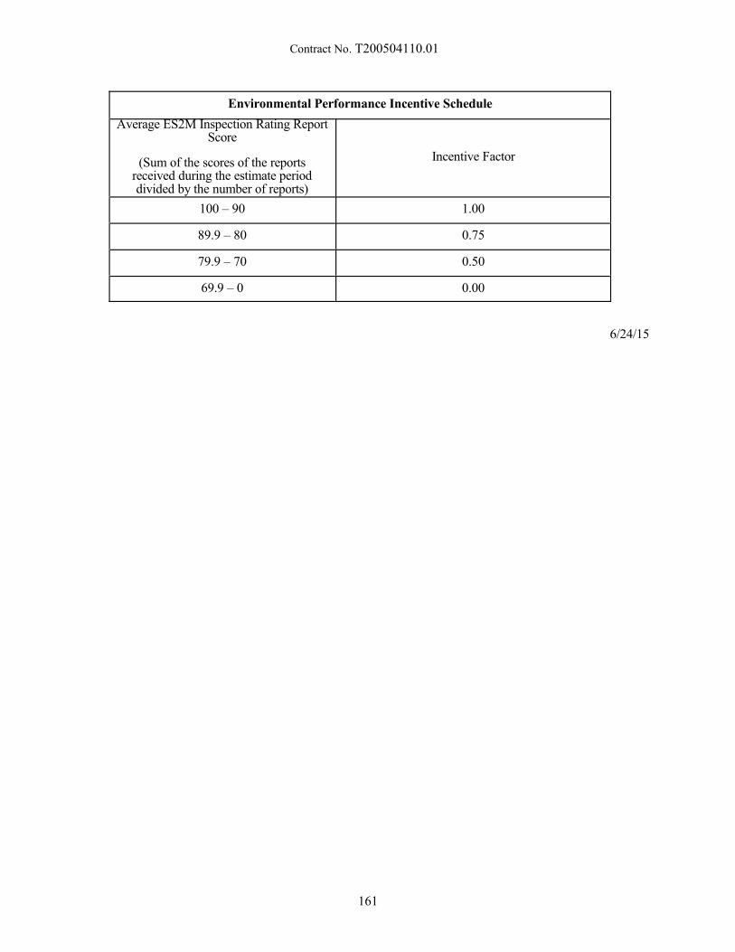
Contract No. T200504110.01
Environmental Performance Incentive Schedule
Average ES2M Inspection Rating ReportScore
(Sum of the scores of the reportsreceived during the estimate perioddivided by the number of reports)
Incentive Factor
100 – 90 1.00
89.9 – 80 0.75
79.9 – 70 0.50
69.9 – 0 0.00
6/24/15
161
Contract No. T200504110.01
905500 - SUPER SILT FENCE
Description:
This work consists of furnishing, installing, constructing, maintaining, and ultimately removing supersilt filter fences as a temporary measure to control sedimentation within the limits of construction. Super siltfence shall be constructed as shown on the details in the Plans, at the locations shown on the Plans, and asdirected by the Engineer.
Materials:
General. All materials shall be approved prior to use by the Department's Materials and ResearchSection.
Chain Link Fence. The construction requirements for the placement of the chain link fence shall beas specified in SECTION 727 FENCES AND GATES with the following exceptions:
(a) Concrete footings (727.07), Top Rail, Tension Wire, Horizontal Braces shall not be used.
Fasteners. Aluminized steel tie wires long enough to securely attach the fabric to the posts.
Seed. Seed shall conform to the requirements of Section 908.
Mulch. Mulch shall conform to the requirements of Section 908.
Geotextile. Geotextile shall conform to the requirements of Section 827. It shall be a minimum of 36"(900 mm) wide.
Construction Methods:
Construction of Super Silt Fence.
The Contractor shall excavate the trench along the upstream side of the post line as shown on StandardConstruction Detail, Super Silt Fence. Posts shall be installed on the Downstream edge of the trench, along theestablished fence line. The geotextile shall be fastened to the upstream side of the chain link. The geotextile andchain link must extend a minimum of 33” above the ground. The chain link fabric and geotextile shall beembedded 8 inches into the excavated trench. The trench shall be backfilled and compacted over the chain linkand geotextile to prevent water from flowing under the chain link and geotextile.
The super silt fence shall not be constructed across a ditch, or swale, or area of concentrated flow. Onslopes, the terminal ends of super silt fence shall be turned upslope a sufficient distance to eliminate flow aroundthe ends of the super silt fence. All geotextile damaged prior to installation, during installation, or during thelife of the Contract shall be repaired or replacedto the satisfaction of the Engineer.
Maintenance of Super Silt Fence.
Throughout the Project construction period, the super silt fence shall be maintained by removingtrapped sediment. The Contractor shall clean the geotextile of trapped sediment by tapping the geotextile whendry. No trash shall be allowed to accumulate to the height of the fence. Any geotextile that does not functiondue to clogging or deterioration shall be replaced.
Sediment Removal.
After every heavy rainfall, the Contractor shall check for excessive buildups of sediment which mustbe removed so that the super silt fence can continue to function as intended. Remove accumulated sedimentwhen it reaches 50% of the height of the super silt fence.
162
Contract No. T200504110.01
Removal of Super Silt Fence.
The super silt fence shall be removed when the Engineer determines that it is no longer required. Thesuper silt fence and all materials incidental to the super silt fence construction shall be removed. All areasaffected by the construction of the super silt fence shall be restored to the original or plan contours and stabilizedwith seed and mulch.
Method of Measurement:
The quantity of super silt fence will be measured as the actual number of linear feet (linear meters) ofsuper silt fence placed and accepted.
Basis of Payment:
The quantity of super silt fence will be paid for at the Contract unit price per linear foot (linear meter)for each type of fence. Price and payment will constitute full compensation for furnishing all materials; forexcavating and backfilling associated with the construction of the super silt fence; for maintaining the super siltfence during the Project construction period; sediment removal, for removing the super silt fence with all relatedhardware after completion of the Project; for restoring the site; for seeding and mulching; and for all labor,equipment, tools and incidentals required to complete the work. No payment will be made for any replacementof or repairs to the super silt fence damaged prior to installation, during installation, or during the life of theContract. No payment will be made for the replacement of the super silt fence.
11/18/2014
163
Contract No. T200504110.01
907506 - EARTH DIKE, TYPE A-1907507 - EARTH DIKE, TYPE A-2907508 - EARTH DIKE, TYPE B-1907509 - EARTH DIKE, TYPE B-2
Description:
Construct, maintain, and remove various types of earth dikes as detailed in this specification andindicated on the Plans. Prevent clean runoff from entering disturbed areas by intercepting and diverting runoffto stabilized outlets, or intercept sediment-laden runoff and divert it to a sediment trapping device.
Materials:
Borrow - Material excavated onsite or supplied from an outside source meeting 209.04(f)Seed and Mulch - Section 908.02Erosion Control Blanket - Section 908.02Riprap (R-4) - Section 712.04Geotextile - Section 827.06
Construction Methods:
General Requirements for all Types:
1. Convey runoff from disturbed areas to a sediment trapping device
2. Outlet diverted runoff from undisturbed areas to an undisturbed stabilized area at non-erosivevelocity.
3. Construct the earth berm having side slopes no steeper than 2:1. Top surface and heightdimensions as listed below under Type A-1, A-2, B-1, or B-2. Compact the soil usingearthmoving equipment or mechanical tamps to at least 90% of maximum density (per AASHTOT 99 Method C, Modified). Construct in lifts not to exceed 12 inches loose measurement.
4. Begin earth dike stabilization within seven days of the start of construction or prior to the earthdike becoming operational, whichever is sooner.
5. Stabilize the top surface and outside slope (opposite the side conveying runoff) with seed andmulch chosen by the Contractor.
6. Stabilize the side slope carrying water, and the adjoining existing ground using materials anddimensions specified below under Earth Dikes, Type A-1, A-2, B-1, or B-2.
7. Remove accumulated sediment when it reaches 50% of the earth dike height.
8. Maintain the original dimensions and function of the earth dike throughout its life.
9. Remove the temporary earth dike when no longer needed, or as directed by the Engineer. Performrestoration, final grading, seeding and stabilization of the area.
Type A-1: Use where shown on the plans when the profile of the water carrying channel is between 0.5% and2.0%. Stabilize the water carrying channel with seed and Erosion Control Blanket. Place the seedand blanket covering the water carrying channel created by the earth dike to a length of 14 inchesmeasured along the dike slope and a length of 48 inches along the adjoining existing ground. Construct the earth dike to an overall height of 12 inches measured from the channel flow line totop of earth dike. Top surface of the earth dike shall be 12 inches wide.
Type A-2: Use where shown on the plans when the profile of the water carrying channel is between 2.1% and8.0%. Stabilize the water carrying channel with stone meeting R-4 riprap gradation on geotextile. Excavate and place the riprap covering the water carrying channel created by the earth dike to a
164
Contract No. T200504110.01
length of 14 inches measured along the dike slope and a length of 48 inches along the adjoiningexisting ground. Construct the earth dike to an overall height of 12 inches measured from thechannel flow line to top of earth dike. Top surface of the earth dike shall be 12 inches wide.
Type B-1: Use where shown on the plans when the profile of the water carrying channel is between 0.5% and2.0%. Stabilize the water carrying channel with seed and Erosion Control Blanket. Place theblanket covering the water carrying channel created by the earth dike to a length of 27 inchesmeasured along the dike slope and a length of 72 inches along the adjoining existing ground. Construct the earth dike to an overall height of 18 inches measured from the channel flow line totop of earth dike. Top surface of the earth dike shall be 24 inches wide.
Type B-2: Use where shown on the plans when the profile of the water carrying channel is between 2.1% and8.0%. Stabilize the water carrying channel with stone meeting R-4 riprap gradation on geotextile. Excavate and place the riprap covering the water carrying channel created by the earth dike to alength of 27 inches measured along the dike slope and a length of 72 inches along the adjoiningexisting ground. Construct the earth dike to an overall height of 18 inches measured from thechannel flow line to top of earth dike. Top surface of the earth dike shall be 24 inches wide.
Method of Measurement:
Linear foot measured along the earth dike’s centerline at the top surface.
Basis of Payment:
Linear foot measurement includes soil placement, compacting, and grading; applicable stabilization(seeding and mulching, erosion control blanket, and /or riprap), removal when no longer required, maintenance,sediment removal, restoration, final grading, and final stabilization of the area. Pay for clearing and grubbingunder the respective items if required. Furnish and pay for soil required to construct the earth dikes as follows:
For Borrow from an outside source - Pay under item 209006, Borrow, Type F
For Borrow excavated from the job - Payment will be made under the applicable excavation item whenthe material is initially excavated. Hauling and placing the material in the earth dike is incidental to theapplicable earth dike being constructed.
1/14/15
165
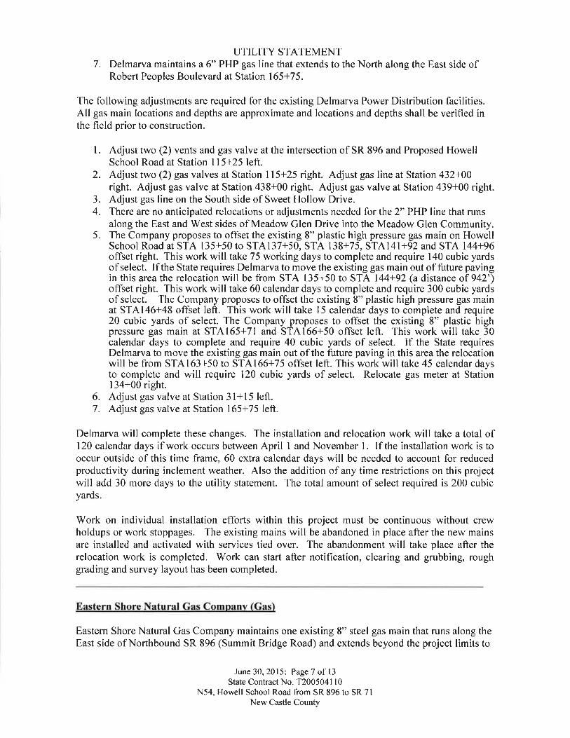
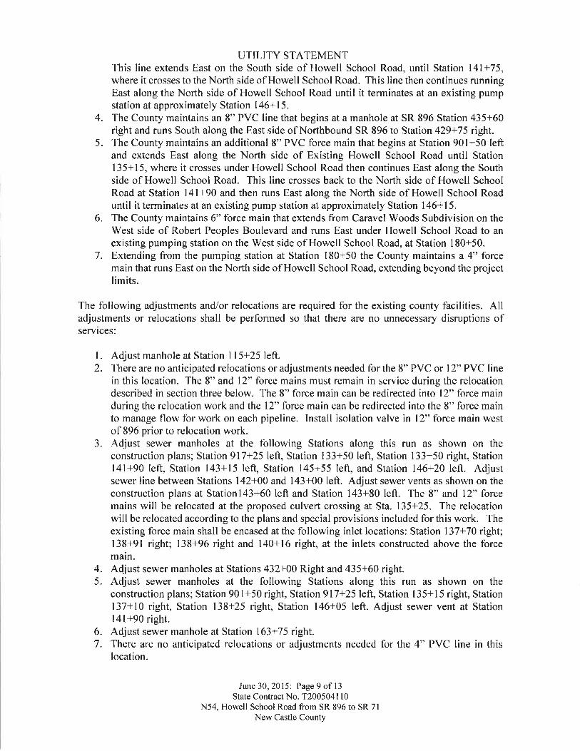
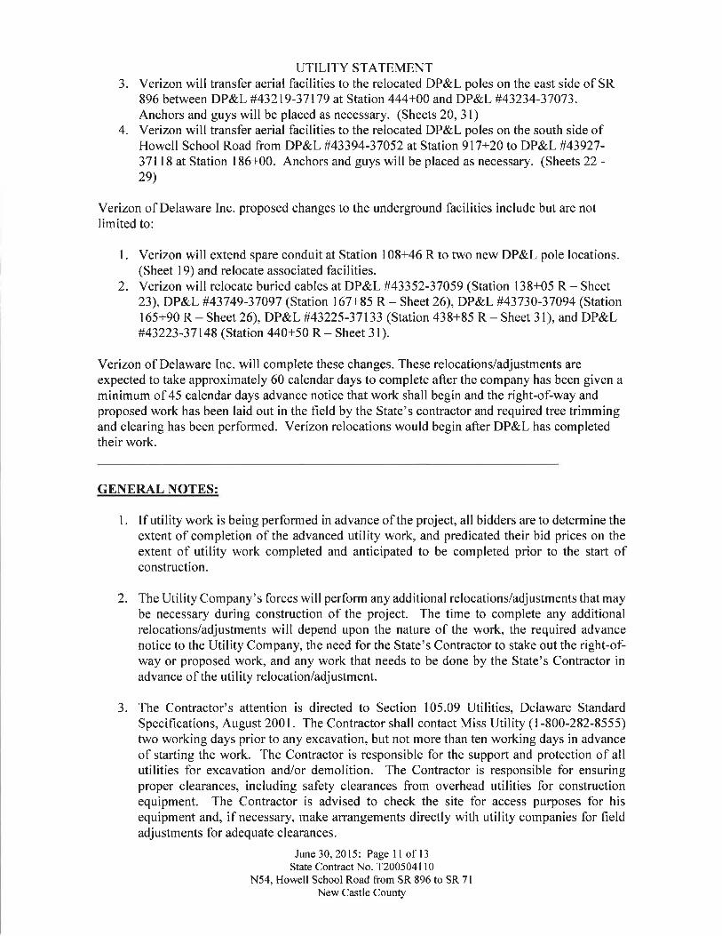
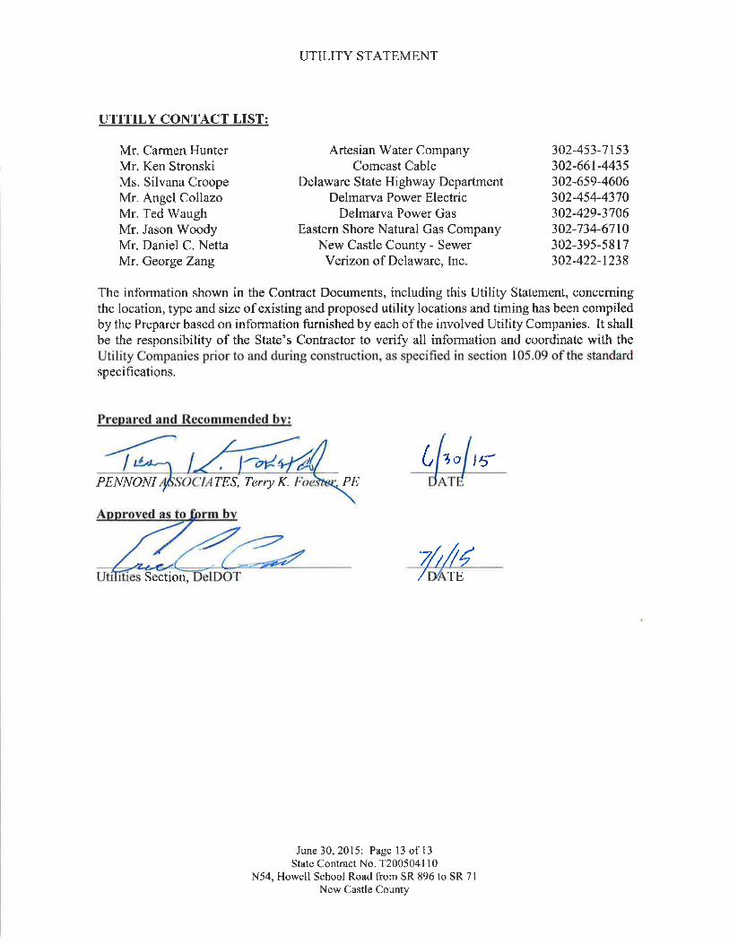
August 28, 2015
ENVIRONMENTAL REQUIREMENTS
FOR
State Contract No. T200504110
Federal Aid No.: ESTP-N054(04)
Contract Title: HSIP NCC, N54, Howell School Road, SR 896 to SR 71
In accordance with the procedural provisions for implementing the National
Environmental Policy Act of 1969, as amended, the referenced project has been processed
through the Department’s Environmental Review Procedures and has been classified as a Level
D/ Class II Action. As such, a Categorical Exclusion has been prepared to evaluate potential
adverse impacts resulting from construction of the proposed project (per 23 CFR 771.117 d(1)),
and the following special provisions have been developed to mitigate and/or minimize these
impacts.
PERMIT REQUIREMENTS:
The construction work that will occur as part of the HSIP NCC, SR 54, Howell School
Road, SR 896 to SR 71 project, New Castle County, Delaware requires permit approval from the
agencies listed below. It is the responsibility of the contracting agency -- the Delaware
Department of Transportation, Division of Transportation Solutions -- to obtain the necessary
permits to ensure that the contractor complies with the requirements and conditions established
by the regulatory agencies. The permit coordination for this project is ongoing. Written
authorization from the permitting agencies is required and paperwork for on-site posting is
anticipated. As such, the construction work that will occur as part of the HSIP NCC, SR 54,
Howell School Road, SR 896 to SR 71 project, New Castle County, Delaware is authorized
under the permits/exemptions listed below:
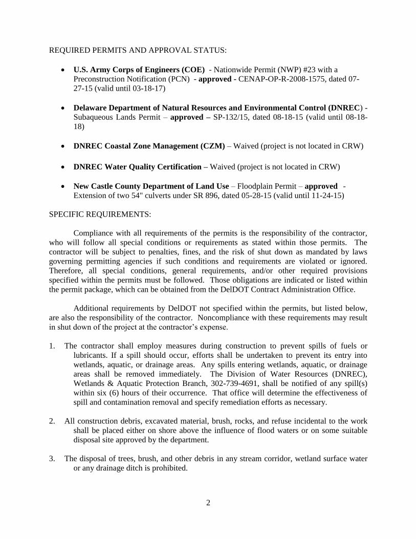
2
REQUIRED PERMITS AND APPROVAL STATUS:
U.S. Army Corps of Engineers (COE) - Nationwide Permit (NWP) #23 with a
Preconstruction Notification (PCN) - approved - CENAP-OP-R-2008-1575, dated 07-
27-15 (valid until 03-18-17)
Delaware Department of Natural Resources and Environmental Control (DNREC) -
Subaqueous Lands Permit – approved – SP-132/15, dated 08-18-15 (valid until 08-18-
18)
DNREC Coastal Zone Management (CZM) – Waived (project is not located in CRW)
DNREC Water Quality Certification – Waived (project is not located in CRW)
New Castle County Department of Land Use – Floodplain Permit – approved -
Extension of two 54" culverts under SR 896, dated 05-28-15 (valid until 11-24-15)
SPECIFIC REQUIREMENTS:
Compliance with all requirements of the permits is the responsibility of the contractor,
who will follow all special conditions or requirements as stated within those permits. The
contractor will be subject to penalties, fines, and the risk of shut down as mandated by laws
governing permitting agencies if such conditions and requirements are violated or ignored.
Therefore, all special conditions, general requirements, and/or other required provisions
specified within the permits must be followed. Those obligations are indicated or listed within
the permit package, which can be obtained from the DelDOT Contract Administration Office.
Additional requirements by DelDOT not specified within the permits, but listed below,
are also the responsibility of the contractor. Noncompliance with these requirements may result
in shut down of the project at the contractor’s expense.
1. The contractor shall employ measures during construction to prevent spills of fuels or
lubricants. If a spill should occur, efforts shall be undertaken to prevent its entry into
wetlands, aquatic, or drainage areas. Any spills entering wetlands, aquatic, or drainage
areas shall be removed immediately. The Division of Water Resources (DNREC),
Wetlands & Aquatic Protection Branch, 302-739-4691, shall be notified of any spill(s)
within six (6) hours of their occurrence. That office will determine the effectiveness of
spill and contamination removal and specify remediation efforts as necessary.
2. All construction debris, excavated material, brush, rocks, and refuse incidental to the work
shall be placed either on shore above the influence of flood waters or on some suitable
disposal site approved by the department.
3. The disposal of trees, brush, and other debris in any stream corridor, wetland surface water
or any drainage ditch is prohibited.
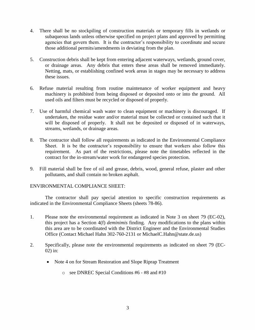
3
4. There shall be no stockpiling of construction materials or temporary fills in wetlands or
subaqueous lands unless otherwise specified on project plans and approved by permitting
agencies that govern them. It is the contractor’s responsibility to coordinate and secure
those additional permits/amendments in deviating from the plan.
5. Construction debris shall be kept from entering adjacent waterways, wetlands, ground cover,
or drainage areas. Any debris that enters these areas shall be removed immediately.
Netting, mats, or establishing confined work areas in stages may be necessary to address
these issues.
6. Refuse material resulting from routine maintenance of worker equipment and heavy
machinery is prohibited from being disposed or deposited onto or into the ground. All
used oils and filters must be recycled or disposed of properly.
7. Use of harmful chemical wash water to clean equipment or machinery is discouraged. If
undertaken, the residue water and/or material must be collected or contained such that it
will be disposed of properly. It shall not be deposited or disposed of in waterways,
streams, wetlands, or drainage areas.
8. The contractor shall follow all requirements as indicated in the Environmental Compliance
Sheet. It is be the contractor’s responsibility to ensure that workers also follow this
requirement. As part of the restrictions, please note the timetables reflected in the
contract for the in-stream/water work for endangered species protection.
9. Fill material shall be free of oil and grease, debris, wood, general refuse, plaster and other
pollutants, and shall contain no broken asphalt.
ENVIRONMENTAL COMPLIANCE SHEET:
The contractor shall pay special attention to specific construction requirements as
indicated in the Environmental Compliance Sheets (sheets 78-86).
1. Please note the environmental requirement as indicated in Note 3 on sheet 79 (EC-02),
this project has a Section 4(f) deminimis finding. Any modifications to the plans within
this area are to be coordinated with the District Engineer and the Environmental Studies
Office (Contact Michael Hahn 302-760-2131 or [email protected])
2. Specifically, please note the environmental requirements as indicated on sheet 79 (EC-
02) in:
Note 4 on for Stream Restoration and Slope Riprap Treatment
o see DNREC Special Conditions #6 - #8 and #10
4
Note 5 for Protection of Resources
o Specifically regarding the Northern Long Eared Bat -see DNREC Special
Condition #2 and Environmental Compliance Note 5E
o Specifically regarding the use of sandbags to secure silt fence in lieu of
trenching adjacent to wetlands/wooded uplands and streams – see DNREC
Special Condition #5 and Environmental Compliance Note 5C
Note 6 for Planting Guidance, work done by DelDOT
o Restoration of the forested and riparian buffers shall be restored as necessary
– see DNREC Special Condition #14
Note 7 for Mitigation which states that to offset for impacts associated with the
project, wetland replacement obligations will be met through the Glennville Bank
3. DelDOT Environmental Studies Section (302) 760-2264 must be notified if there are any
changes to the project methods, footprint, materials, or designs, to allow the Department
to coordinate with the appropriate resource agencies (COE, DNREC, DOI, NCC, and
SHPO), for approval.
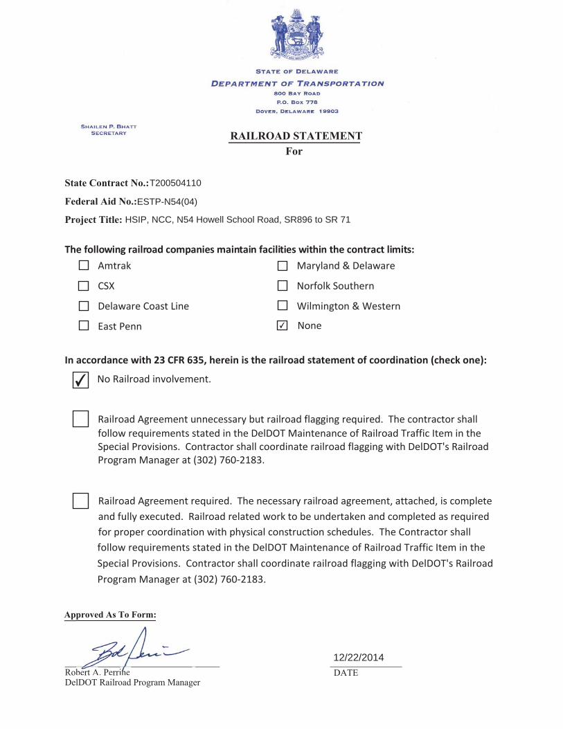
Amtrak Maryland & Delaware
CSX Norfolk Southern
Delaware Coast Line Wilmington & Western
East Penn
No Railroad involvement.
Railroad Agreement unnecessary but railroad flagging required.
Railroad Agreement required. The necessary railroad agreement, attached, is complete and fully executed. Railroad related work to be undertaken and completed as required for proper coordination with physical construction schedules.
12/22/2014
ESTP-N54(04)
HSIP, NCC, N54 Howell School Road, SR896 to SR 71
✔
✔
T200504110

BID PROPOSAL FORMS
CONTRACT T200504110.01
FEDERAL AID PROJECT ESTP-N54(04)
179

DELAWARE DEPARTMENT OF TRANSPORTATION PAGE: 1 SCHEDULE OF ITEMS DATE:
CONTRACT ID: T200504110.01 PROJECT(S): T200504110
All figures must be typewritten. CONTRACTOR :________________________________________________________________ ------------------------------------------------------------------------------- LINE| ITEM | APPROX. | UNIT PRICE | BID AMOUNT NO | DESCRIPTION | QUANTITY |----------------|-------------- | | AND UNITS | DOLLARS | CTS | DOLLARS |CTS -------------------------------------------------------------------------------
SECTION 0001 ROAD
------------------------------------------------------------------------------- |201000 CLEARING AND | | | 0010|GRUBBING |LUMP |LUMP | | | | | ------------------------------------------------------------------------------- |202000 EXCAVATION AND | | | 0020|EMBANKMENT | 52835.000| | | |CY | | ------------------------------------------------------------------------------- |207000 EXCAVATION AND | | | 0030|BACKFILL FOR STRUCTURES | 715.000| | | |CY | | ------------------------------------------------------------------------------- |208000 EXCAVATION AND | | | 0040|BACKFILLING FOR PIPE | 5614.000| | |TRENCHES |CY | | ------------------------------------------------------------------------------- |208001 FLOWABLE FILL | | | 0050| | 60.000| | | |CY | | ------------------------------------------------------------------------------- |209001 BORROW, TYPE A | | | 0060| | 4950.000| | | |CY | | ------------------------------------------------------------------------------- |209002 BORROW, TYPE B | | | 0070| | 6768.000| | | |CY | | ------------------------------------------------------------------------------- |210000 FURNISHING BORROW | | | 0080|TYPE "C" FOR PIPE, | 4849.000| | |UTILITY TRENCH, AND |CY | | |STRUCTURE BACKFILL | | | ------------------------------------------------------------------------------- |211000 REMOVAL OF | | | 0090|STRUCTURES AND |LUMP |LUMP | |OBSTRUCTIONS | | | -------------------------------------------------------------------------------
CANNOT BE USED FOR BIDDING

DELAWARE DEPARTMENT OF TRANSPORTATION PAGE: 2 SCHEDULE OF ITEMS DATE:
CONTRACT ID: T200504110.01 PROJECT(S): T200504110
All figures must be typewritten. CONTRACTOR :________________________________________________________________ ------------------------------------------------------------------------------- LINE| ITEM | APPROX. | UNIT PRICE | BID AMOUNT NO | DESCRIPTION | QUANTITY |----------------|-------------- | | AND UNITS | DOLLARS | CTS | DOLLARS |CTS ------------------------------------------------------------------------------- |212000 UNDERCUT | | | 0100|EXCAVATION | 8351.000| | | |CY | | ------------------------------------------------------------------------------- |302007 GRADED AGGREGATE | | | 0110|BASE COURSE, TYPE B | 11170.000| | | |CY | | ------------------------------------------------------------------------------- |302011 DELAWARE NO. 3 | | | 0120|STONE | 77.000| | | |TON | | ------------------------------------------------------------------------------- |401801 BITUMINOUS | | | 0130|CONCRETE, SUPERPAVE, | 6246.000| | |TYPE C, 160 GYRATIONS PG |TON | | |64-22 (CARBONATE STONE) | | | | | | | ------------------------------------------------------------------------------- |401810 BITUMINOUS | | | 0140|CONCRETE, SUPERPAVE, | 5363.000| | |TYPE B, 160 GYRATIONS, |TON | | |PG 64-22 | | | ------------------------------------------------------------------------------- |401819 BITUMINOUS | | | 0150|CONCRETE, SUPERPAVE, | 4885.000| | |BITUMINOUS CONCRETE BASE |TON | | |COURSE, 160 GYRATIONS, | | | |PG 64-22 | | | ------------------------------------------------------------------------------- |501001 PORTLAND CEMENT | | | 0160|CONCRETE PAVEMENT, 8" | 358.000| | | |SY | | ------------------------------------------------------------------------------- |601520 TEMPORARY TIMBER | | | 0170|MAT |LUMP |LUMP | | | | | ------------------------------------------------------------------------------- |602001 PORTLAND CEMENT | | | 0180|CONCRETE MASONRY, CLASS | 2.000| | |A |CY | | -------------------------------------------------------------------------------
CANNOT BE USED FOR BIDDING

DELAWARE DEPARTMENT OF TRANSPORTATION PAGE: 3 SCHEDULE OF ITEMS DATE:
CONTRACT ID: T200504110.01 PROJECT(S): T200504110
All figures must be typewritten. CONTRACTOR :________________________________________________________________ ------------------------------------------------------------------------------- LINE| ITEM | APPROX. | UNIT PRICE | BID AMOUNT NO | DESCRIPTION | QUANTITY |----------------|-------------- | | AND UNITS | DOLLARS | CTS | DOLLARS |CTS ------------------------------------------------------------------------------- |602547 WATERPROOFING | | | 0190|BRIDGE DECKS, SIDEWALKS | 135.000| | |ETC. |SF | | ------------------------------------------------------------------------------- |602736 PRECAST CONCRETE | | | 0200|CULVERT | 100.000| | | |CY | | ------------------------------------------------------------------------------- |602738 PRECAST CONCRETE | | | 0210|RETAINING WALL | 30.000| | | |CY | | ------------------------------------------------------------------------------- |608000 COARSE AGGREGATE | | | 0220|FOR FOUNDATION | 85.000| | |STABILIZATION AND |TON | | |SUBFOUNDATION BACKFILL | | | ------------------------------------------------------------------------------- |612002 REINFORCED | | | 0230|CONCRETE PIPE, 15", | 16.000| | |CLASS III |LF | | ------------------------------------------------------------------------------- |612003 REINFORCED | | | 0240|CONCRETE PIPE, 18", | 1452.000| | |CLASS III |LF | | ------------------------------------------------------------------------------- |612007 REINFORCED | | | 0250|CONCRETE PIPE, 30", | 2381.000| | |CLASS III |LF | | ------------------------------------------------------------------------------- |612010 REINFORCED | | | 0260|CONCRETE PIPE, 42", | 21.000| | |CLASS III |LF | | ------------------------------------------------------------------------------- |612012 REINFORCED | | | 0270|CONCRETE PIPE, 54", | 24.000| | |CLASS III |LF | | ------------------------------------------------------------------------------- |612200 REINFORCED | | | 0280|CONCRETE ELLIPTICAL PIPE,| 1509.000| | |14"X23", CLASS III |LF | | -------------------------------------------------------------------------------
CANNOT BE USED FOR BIDDING

DELAWARE DEPARTMENT OF TRANSPORTATION PAGE: 4 SCHEDULE OF ITEMS DATE:
CONTRACT ID: T200504110.01 PROJECT(S): T200504110
All figures must be typewritten. CONTRACTOR :________________________________________________________________ ------------------------------------------------------------------------------- LINE| ITEM | APPROX. | UNIT PRICE | BID AMOUNT NO | DESCRIPTION | QUANTITY |----------------|-------------- | | AND UNITS | DOLLARS | CTS | DOLLARS |CTS ------------------------------------------------------------------------------- |612201 REINFORCED | | | 0290|CONCRETE ELLIPTICAL PIPE,| 1068.000| | |19"X30", CLASS III |LF | | ------------------------------------------------------------------------------- |612202 REINFORCED | | | 0300|CONCRETE ELLIPTICAL PIPE,| 135.000| | |24"X38", CLASS III |LF | | ------------------------------------------------------------------------------- |612207 REINFORCED | | | 0310|CONCRETE ELLIPTICAL PIPE,| 361.000| | |29"X45", CLASS, III |LF | | ------------------------------------------------------------------------------- |614508 WATERMAIN AND | | | 0320|ACCESSORIES |LUMP |LUMP | | | | | ------------------------------------------------------------------------------- |617003 REINFORCED | | | 0330|CONCRETE FLARED END | 4.000| | |SECTION, 18" |EACH | | ------------------------------------------------------------------------------- |617007 REINFORCED | | | 0340|CONCRETE FLARED END | 4.000| | |SECTION, 30" |EACH | | ------------------------------------------------------------------------------- |617010 REINFORCED | | | 0350|CONCRETE FLARED END | 1.000| | |SECTION, 42" |EACH | | ------------------------------------------------------------------------------- |617164 REINFORCED | | | 0360|CONCRETE FLARED END | 3.000| | |SECTION, 19" X 30" |EACH | | ------------------------------------------------------------------------------- |617165 REINFORCED | | | 0370|CONCRETE FLARED END | 11.000| | |SECTION, 14" X 23" |EACH | | ------------------------------------------------------------------------------- |617171 REINFORCED | | | 0380|CONCRETE FLARED END | 2.000| | |SECTION, 29" X 45" |EACH | | ------------------------------------------------------------------------------- |617515 HEADWALL | | | 0390| | 3.000| | | |EACH | | -------------------------------------------------------------------------------
CANNOT BE USED FOR BIDDING

DELAWARE DEPARTMENT OF TRANSPORTATION PAGE: 5 SCHEDULE OF ITEMS DATE:
CONTRACT ID: T200504110.01 PROJECT(S): T200504110
All figures must be typewritten. CONTRACTOR :________________________________________________________________ ------------------------------------------------------------------------------- LINE| ITEM | APPROX. | UNIT PRICE | BID AMOUNT NO | DESCRIPTION | QUANTITY |----------------|-------------- | | AND UNITS | DOLLARS | CTS | DOLLARS |CTS ------------------------------------------------------------------------------- |701010 PORTLAND CEMENT | | | 0400|CONCRETE CURB, TYPE 1-8 | 268.000| | | |LF | | ------------------------------------------------------------------------------- |701011 PORTLAND CEMENT | | | 0410|CONCRETE CURB, TYPE 2 | 307.000| | | |LF | | ------------------------------------------------------------------------------- |701012 PORTLAND CEMENT | | | 0420|CONCRETE CURB, TYPE 1-4 | 286.000| | | |LF | | ------------------------------------------------------------------------------- |701016 INTEGRAL PORTLAND | | | 0430|CEMENT CONCRETE CURB & | 6902.000| | |GUTTER, TYPE 1-4 |LF | | ------------------------------------------------------------------------------- |701025 PORTLAND CEMENT | | | 0440|CONCRETE CURB, TYPE 2 | 315.000| | |MODIFIED |LF | | ------------------------------------------------------------------------------- |701027 PORTLAND CEMENT | | | 0450|CONCRETE CURB, TYPE 1-2 | 25.000| | |MODIFIED |LF | | ------------------------------------------------------------------------------- |705001 P.C.C. SIDEWALK, | | | 0460|4" | 1819.000| | | |SF | | ------------------------------------------------------------------------------- |705002 P.C.C. SIDEWALK, | | | 0470|6" | 3848.000| | | |SF | | ------------------------------------------------------------------------------- |705007 SIDEWALK SURFACE | | | 0480|DETECTABLE WARNING | 590.000| | |SYSTEM |SF | | ------------------------------------------------------------------------------- |705530 TRIANGULAR | | | 0490|CHANNELIZING ISLANDS | 13328.000| | | |SF | | -------------------------------------------------------------------------------
CANNOT BE USED FOR BIDDING

DELAWARE DEPARTMENT OF TRANSPORTATION PAGE: 6 SCHEDULE OF ITEMS DATE:
CONTRACT ID: T200504110.01 PROJECT(S): T200504110
All figures must be typewritten. CONTRACTOR :________________________________________________________________ ------------------------------------------------------------------------------- LINE| ITEM | APPROX. | UNIT PRICE | BID AMOUNT NO | DESCRIPTION | QUANTITY |----------------|-------------- | | AND UNITS | DOLLARS | CTS | DOLLARS |CTS ------------------------------------------------------------------------------- |707005 UNDERDRAIN OUTLET | | | 0500| | 13.000| | | |EACH | | ------------------------------------------------------------------------------- |708051 DRAINAGE INLET, | | | 0510|34" X 24" | 14.000| | | |EACH | | ------------------------------------------------------------------------------- |708052 DRAINAGE INLET, | | | 0520|48" X 30" | 19.000| | | |EACH | | ------------------------------------------------------------------------------- |708053 DRAINAGE INLET, | | | 0530|48" X 48" | 26.000| | | |EACH | | ------------------------------------------------------------------------------- |708054 DRAINAGE INLET, | | | 0540|66" X 30" | 1.000| | | |EACH | | ------------------------------------------------------------------------------- |708055 DRAINAGE INLET, | | | 0550|66" X 48" | 2.000| | | |EACH | | ------------------------------------------------------------------------------- |708056 DRAINAGE INLET, | | | 0560|66" X 66" | 1.000| | | |EACH | | ------------------------------------------------------------------------------- |708057 DRAINAGE INLET, | | | 0570|72" X 24" | 1.000| | | |EACH | | ------------------------------------------------------------------------------- |708058 DRAINAGE INLET, | | | 0580|72" X 48" | 7.000| | | |EACH | | ------------------------------------------------------------------------------- |708112 MANHOLE, 48" X | | | 0590|48" | 1.000| | | |EACH | | -------------------------------------------------------------------------------
CANNOT BE USED FOR BIDDING

DELAWARE DEPARTMENT OF TRANSPORTATION PAGE: 7 SCHEDULE OF ITEMS DATE:
CONTRACT ID: T200504110.01 PROJECT(S): T200504110
All figures must be typewritten. CONTRACTOR :________________________________________________________________ ------------------------------------------------------------------------------- LINE| ITEM | APPROX. | UNIT PRICE | BID AMOUNT NO | DESCRIPTION | QUANTITY |----------------|-------------- | | AND UNITS | DOLLARS | CTS | DOLLARS |CTS ------------------------------------------------------------------------------- |708113 MANHOLE, 66" X | | | 0600|30" | 1.000| | | |EACH | | ------------------------------------------------------------------------------- |710506 ADJUST AND REPAIR | | | 0610|EXISTING SANITARY | 23.000| | |MANHOLE |EACH | | ------------------------------------------------------------------------------- |712007 RIPRAP, R-6 | | | 0620| | 245.000| | | |SY | | ------------------------------------------------------------------------------- |712020 RIPRAP, R-4 | | | 0630| | 180.000| | | |TON | | ------------------------------------------------------------------------------- |712021 RIPRAP, R-5 | | | 0640| | 115.000| | | |TON | | ------------------------------------------------------------------------------- |712531 CHANNEL BED FILL | | | 0650| | 75.000| | | |CY | | ------------------------------------------------------------------------------- |713001 GEOTEXTILES, | | | 0660|STABILIZATION | 8320.000| | | |SY | | ------------------------------------------------------------------------------- |713003 GEOTEXTILES, | | | 0670|RIPRAP | 439.000| | | |SY | | ------------------------------------------------------------------------------- |715001 PERFORATED PIPE | | | 0680|UNDERDRAINS, 6" | 11680.000| | | |LF | | ------------------------------------------------------------------------------- |715500 UNDERDRAIN OUTLET | | | 0690|PIPE, 6" | 277.000| | | |LF | | -------------------------------------------------------------------------------
CANNOT BE USED FOR BIDDING

DELAWARE DEPARTMENT OF TRANSPORTATION PAGE: 8 SCHEDULE OF ITEMS DATE:
CONTRACT ID: T200504110.01 PROJECT(S): T200504110
All figures must be typewritten. CONTRACTOR :________________________________________________________________ ------------------------------------------------------------------------------- LINE| ITEM | APPROX. | UNIT PRICE | BID AMOUNT NO | DESCRIPTION | QUANTITY |----------------|-------------- | | AND UNITS | DOLLARS | CTS | DOLLARS |CTS ------------------------------------------------------------------------------- |720050 GALVANIZED STEEL | | | 0700|BEAM GUARDRAIL, TYPE | 792.000| | |1-31 |LF | | ------------------------------------------------------------------------------- |720054 GUARDRAIL OVER | | | 0710|CULVERTS, TYPE 2-31 | 3.000| | | |EACH | | ------------------------------------------------------------------------------- |720055 CURVED GUARDRAIL | | | 0720|SECTION | 121.000| | | |LF | | ------------------------------------------------------------------------------- |720509 GALVANIZED AND | | | 0730|FUSION - BONDED | 965.620| | |POLYESTER COATED |LF | | |GUARDRAIL | | | ------------------------------------------------------------------------------- |720586 GUARDRAIL END | | | 0740|TREATMENT ATTENUATOR, | 8.000| | |TYPE 2-31 |EACH | | ------------------------------------------------------------------------------- |726001 END ANCHORAGE 31 | | | 0750| | 2.000| | | |EACH | | ------------------------------------------------------------------------------- |727003 CHAIN-LINK FENCE, | | | 0760|4' HIGH | 556.000| | | |LF | | ------------------------------------------------------------------------------- |727004 CHAIN-LINK FENCE, | | | 0770|6' HIGH | 240.000| | | |LF | | ------------------------------------------------------------------------------- |727009 CHAIN-LINK FENCE, | | | 0780|5' HIGH | 49.000| | | |LF | | ------------------------------------------------------------------------------- |727014 CONSTRUCTION | | | 0790|SAFETY FENCE | 2156.000| | | |LF | | -------------------------------------------------------------------------------
CANNOT BE USED FOR BIDDING

DELAWARE DEPARTMENT OF TRANSPORTATION PAGE: 9 SCHEDULE OF ITEMS DATE:
CONTRACT ID: T200504110.01 PROJECT(S): T200504110
All figures must be typewritten. CONTRACTOR :________________________________________________________________ ------------------------------------------------------------------------------- LINE| ITEM | APPROX. | UNIT PRICE | BID AMOUNT NO | DESCRIPTION | QUANTITY |----------------|-------------- | | AND UNITS | DOLLARS | CTS | DOLLARS |CTS ------------------------------------------------------------------------------- |727015 MONUMENTS | | | 0800| | 25.000| | | |EACH | | ------------------------------------------------------------------------------- |727510 WOOD RAIL FENCE | | | 0810| | 609.000| | | |LF | | ------------------------------------------------------------------------------- |727535 WOOD FENCE, 6' | | | 0820|HIGH | 97.000| | | |LF | | ------------------------------------------------------------------------------- |727555 RIGHT-OF-WAY | | | 0830|MARKER, CAPPED REBAR | 34.000| | | |EACH | | ------------------------------------------------------------------------------- |743000 MAINTENANCE OF | | | 0840|TRAFFIC |LUMP |LUMP | | | | | ------------------------------------------------------------------------------- |743003 ARROWPANELS, TYPE | | | 0850|C | 480.000| | | |EADY | | ------------------------------------------------------------------------------- |743004 FURNISH AND | | | 0860|MAINTAIN PORTABLE | 480.000| | |CHANGEABLE MESSAGE SIGN |EADY | | | | | | ------------------------------------------------------------------------------- |743005 FURNISH AND | | | 0870|MAINTAIN PORTABLE LIGHT | 212.000| | |ASSEMBLY |EADY | | ------------------------------------------------------------------------------- |743006 PLASTIC DRUMS | | | 0880| | 15145.000| | | |EADY | | ------------------------------------------------------------------------------- |743007 TRAFFIC OFFICERS | | | 0890| | 2380.000| 75.00000| 178500.00 | |HOUR | | -------------------------------------------------------------------------------
CANNOT BE USED FOR BIDDING

DELAWARE DEPARTMENT OF TRANSPORTATION PAGE: 10 SCHEDULE OF ITEMS DATE:
CONTRACT ID: T200504110.01 PROJECT(S): T200504110
All figures must be typewritten. CONTRACTOR :________________________________________________________________ ------------------------------------------------------------------------------- LINE| ITEM | APPROX. | UNIT PRICE | BID AMOUNT NO | DESCRIPTION | QUANTITY |----------------|-------------- | | AND UNITS | DOLLARS | CTS | DOLLARS |CTS ------------------------------------------------------------------------------- |743010 FURNISH AND | | | 0900|MAINTAIN TRUCK MOUNTED | 364.000| | |ATTENUATOR, TYPE II |EADY | | ------------------------------------------------------------------------------- |743015 FURNISH AND | | | 0910|MAINTAIN PORTABLE PCC | 2142.000| | |SAFETY BARRIER |LF | | ------------------------------------------------------------------------------- |743016 RELOCATION | | | 0920|PORATBLE SAFETY BARRIER | 1830.000| | | |LF | | ------------------------------------------------------------------------------- |743023 TEMPORARY | | | 0930|BARRICADES, TYPE III | 33336.000| | | |LFDY | | ------------------------------------------------------------------------------- |743024 TEMPORARY WARNING | | | 0940|SIGNS AND PLAQUES | 47254.000| | | |EADY | | ------------------------------------------------------------------------------- |743025 INSTALL TEMPORARY | | | 0950|IMPACT ATTENUATOR | 3.000| | | |EACH | | ------------------------------------------------------------------------------- |743029 FURNISH TEMPORARY | | | 0960|IMPACT ATTENUATOR - | 5.000| | |NON-GATING, REDIRECTIVE, |EACH | | |TEST LEVEL 3 | | | ------------------------------------------------------------------------------- |743030 RELOCATE | | | 0970|TEMPORARY IMPACT | 2.000| | |ATTENUATOR |EACH | | ------------------------------------------------------------------------------- |743031 ATSSA CERTIFIED | | | 0980|TRAFFIC CONTROL | 3296.000| | |SUPERVISOR |HOUR | | ------------------------------------------------------------------------------- |743050 FLAGGER, NEW | | | 0990|CASTLE COUNTY, STATE | 5130.000| | | |HOUR | | -------------------------------------------------------------------------------
CANNOT BE USED FOR BIDDING

DELAWARE DEPARTMENT OF TRANSPORTATION PAGE: 11 SCHEDULE OF ITEMS DATE:
CONTRACT ID: T200504110.01 PROJECT(S): T200504110
All figures must be typewritten. CONTRACTOR :________________________________________________________________ ------------------------------------------------------------------------------- LINE| ITEM | APPROX. | UNIT PRICE | BID AMOUNT NO | DESCRIPTION | QUANTITY |----------------|-------------- | | AND UNITS | DOLLARS | CTS | DOLLARS |CTS ------------------------------------------------------------------------------- |743062 FLAGGER, NEW | | | 1000|CASTLE COUNTY, STATE, | 1026.000| | |OVERTIME |HOUR | | ------------------------------------------------------------------------------- |744506 CONDUIT JUNCTION | | | 1010|WELL, TYPE 7, PRECAST | 7.000| | |POLYMER CONCRETE |EACH | | ------------------------------------------------------------------------------- |744523 CONDUIT JUNCTION | | | 1020|WELL, TYPE 4, PRECAST | 1.000| | |CONCRETE |EACH | | ------------------------------------------------------------------------------- |744530 CONDUIT JUNCTION | | | 1030|WELL, TYPE 11, PRECAST | 13.000| | |CONCRETE/ POLYMER |EACH | | |LID-FRAME | | | ------------------------------------------------------------------------------- |744531 CONDUIT JUNCTION | | | 1040|WELL, TYPE 14, PRECAST | 17.000| | |CONCRETE/ POLYMER |EACH | | |LID-FRAME | | | ------------------------------------------------------------------------------- |745602 FURNISH & INSTALL | | | 1050|UP TO 4" SCHEDULE 80 | 173.000| | |HDPE CONDUIT (BORE) |LF | | ------------------------------------------------------------------------------- |745603 FURNISH & INSTALL | | | 1060|UP TO 4" SCHEDULE 80 PVC | 58.000| | |CONDUIT (OPEN CUT) |LF | | ------------------------------------------------------------------------------- |745604 FURNISH & INSTALL | | | 1070|UP TO 4" SCHEDULE 80 PVC | 9545.000| | |CONDUIT (TRENCH) |LF | | ------------------------------------------------------------------------------- |746847 POLE BASE, TYPE 3 | | | 1080| | 4.000| | | |EACH | | ------------------------------------------------------------------------------- |746850 POLE BASE, TYPE | | | 1090|4A | 8.000| | | |EACH | | -------------------------------------------------------------------------------
CANNOT BE USED FOR BIDDING

DELAWARE DEPARTMENT OF TRANSPORTATION PAGE: 12 SCHEDULE OF ITEMS DATE:
CONTRACT ID: T200504110.01 PROJECT(S): T200504110
All figures must be typewritten. CONTRACTOR :________________________________________________________________ ------------------------------------------------------------------------------- LINE| ITEM | APPROX. | UNIT PRICE | BID AMOUNT NO | DESCRIPTION | QUANTITY |----------------|-------------- | | AND UNITS | DOLLARS | CTS | DOLLARS |CTS ------------------------------------------------------------------------------- |746924 FURNISH & INSTALL | | | 1100|LOOP WIRE 1-CONDUCTOR | 1529.000| | |#14 AWG ENCASED IN 1/4" |LF | | |FLEXIBLE TUBING IN A | | | |LOOP SAWCUT | | | ------------------------------------------------------------------------------- |747516 CABINET BASE, | | | 1110|TYPE P | 2.000| | | |EACH | | ------------------------------------------------------------------------------- |748015 PERMANENT | | | 1120|PAVEMENT STRIPING, | 3391.000| | |SYMBOL/LEGEND |SF | | |ALKYD-THERMOPLAST IC | | | ------------------------------------------------------------------------------- |748019 TEMPORARY | | | 1130|MARKINGS, PAINT, 4" | 20514.000| | | |LF | | ------------------------------------------------------------------------------- |748026 TEMPORARY | | | 1140|MARKINGS, PAINT | 179.000| | |SYMBOL/LEGEND |SF | | ------------------------------------------------------------------------------- |748033 PERMANENT | | | 1150|PAVEMENT STRIPING, | 58.000| | |ALKYD-THERMOPLASTIC, 5" |LF | | | | | | ------------------------------------------------------------------------------- |748530 REMOVAL OF | | | 1160|PAVEMENT STRIPING | 2452.000| | | |SF | | ------------------------------------------------------------------------------- |748548 PERMANENT | | | 1170|PAVEMENT STRIPING, EPOXY | 38825.000| | |RESIN PAINT, |LF | | |WHITE/YELLOW, 5" | | | ------------------------------------------------------------------------------- |748549 PERMANENT | | | 1180|PAVEMENT STRIPING, EPOXY | 416.000| | |RESIN PAINT, |LF | | |WHITE/YELLOW, 10" | | | -------------------------------------------------------------------------------
CANNOT BE USED FOR BIDDING

DELAWARE DEPARTMENT OF TRANSPORTATION PAGE: 13 SCHEDULE OF ITEMS DATE:
CONTRACT ID: T200504110.01 PROJECT(S): T200504110
All figures must be typewritten. CONTRACTOR :________________________________________________________________ ------------------------------------------------------------------------------- LINE| ITEM | APPROX. | UNIT PRICE | BID AMOUNT NO | DESCRIPTION | QUANTITY |----------------|-------------- | | AND UNITS | DOLLARS | CTS | DOLLARS |CTS ------------------------------------------------------------------------------- |748553 PREFORMED | | | 1190|RETROREFLECTIVE | 47.000| | |THERMOPLASTIC PAVEMENT |EACH | | |MARKINGS, BIKE SYMBOL | | | ------------------------------------------------------------------------------- |749000 REINFORCED | | | 1200|CONCRETE MASONRY SIGN | 3.000| | |FOUNDATION |EACH | | ------------------------------------------------------------------------------- |749687 INSTALLATION OR | | | 1210|REMOVAL OF TRAFFIC | 111.000| | |SIGN(S) ON SINGLE SIGN |EACH | | |POST | | | ------------------------------------------------------------------------------- |749690 INSTALLATION OR | | | 1220|REMOVAL OF TRAFFIC SIGNS | 675.000| | |ON MULTIPLE SIGN POSTS |SF | | ------------------------------------------------------------------------------- |750000 ADJUST WATER | | | 1230|VALVE BOXES | 8.000| | | |EACH | | ------------------------------------------------------------------------------- |753516 SANITARY SEWER | | | 1240|SYSTEM |LUMP |LUMP | | | | | ------------------------------------------------------------------------------- |758000 REMOVAL OF | | | 1250|EXISTING PORTLAND | 1095.000| | |CEMENTCONCRETE PAVEMENT, |SY | | |CURB, SIDEWALK, ETC. | | | ------------------------------------------------------------------------------- |759004 FIELD OFFICE, | | | 1260|TYPE I | 19.000| | | |EAMO | | ------------------------------------------------------------------------------- |760000 PAVEMENT - | | | 1270|MILLING, HOT-MIX | 5400.000| | | |SYIN | | ------------------------------------------------------------------------------- |760507 PROFILE MILLING, | | | 1280|BITUMINOUS CONCRETE | 13242.000| | | |SYIN | | -------------------------------------------------------------------------------
CANNOT BE USED FOR BIDDING

DELAWARE DEPARTMENT OF TRANSPORTATION PAGE: 14 SCHEDULE OF ITEMS DATE:
CONTRACT ID: T200504110.01 PROJECT(S): T200504110
All figures must be typewritten. CONTRACTOR :________________________________________________________________ ------------------------------------------------------------------------------- LINE| ITEM | APPROX. | UNIT PRICE | BID AMOUNT NO | DESCRIPTION | QUANTITY |----------------|-------------- | | AND UNITS | DOLLARS | CTS | DOLLARS |CTS ------------------------------------------------------------------------------- |762001 SAW CUTTING, | | | 1290|BITUMINOUS CONCRETE | 5346.000| | | |LF | | ------------------------------------------------------------------------------- |762002 SAW CUTTING, | | | 1300|CONCRETE, FULL DEPTH | 155.000| | | |LF | | ------------------------------------------------------------------------------- |763000 INITIAL EXPENSE | | | 1310| |LUMP |LUMP | | | | | ------------------------------------------------------------------------------- |763501 CONSTRUCTION | | | 1320|ENGINEERING |LUMP |LUMP | | | | | ------------------------------------------------------------------------------- |763508 PROJECT CONTROL | | | 1330|SYSTEM DEVELOPMENT PLAN |LUMP |LUMP | | | | | ------------------------------------------------------------------------------- |763509 CPM SCHEDULE | | | 1340|UPDATES AND/OR REVISED | 19.000| | |UPDATES |EAMO | | ------------------------------------------------------------------------------- |763533 SUMP PUMP | | | 1350|CONNECTIONS | 160.000| | | |LF | | ------------------------------------------------------------------------------- |763537 SUBDIVISION | | | 1360|ENTRANCE SIGN | 2.000| | | |EACH | | ------------------------------------------------------------------------------- |900500 ENVIRONMENTAL | | | 1370|PERFORMANCE INCENTIVE |LUMP |LUMP | 392000.00 |(DISINCENTIVE) | | | ------------------------------------------------------------------------------- |905001 SILT FENCE | | | 1380| | 4391.000| | | |LF | | ------------------------------------------------------------------------------- |905003 SEDIMENT TRAP | | | 1390| | 972.000| | | |CY | | -------------------------------------------------------------------------------
CANNOT BE USED FOR BIDDING

DELAWARE DEPARTMENT OF TRANSPORTATION PAGE: 15 SCHEDULE OF ITEMS DATE:
CONTRACT ID: T200504110.01 PROJECT(S): T200504110
All figures must be typewritten. CONTRACTOR :________________________________________________________________ ------------------------------------------------------------------------------- LINE| ITEM | APPROX. | UNIT PRICE | BID AMOUNT NO | DESCRIPTION | QUANTITY |----------------|-------------- | | AND UNITS | DOLLARS | CTS | DOLLARS |CTS ------------------------------------------------------------------------------- |905004 INLET SEDIMENT | | | 1400|CONTROL, DRAINAGE INLET | 56.000| | | |EACH | | ------------------------------------------------------------------------------- |905005 INLET SEDIMENT | | | 1410|CONTROL, CURB INLET | 77.000| | | |EACH | | ------------------------------------------------------------------------------- |905500 SUPER SILT FENCE | | | 1420| | 1665.000| | | |LF | | ------------------------------------------------------------------------------- |906003 SUMP PIT | | | 1430| | 15.000| | | |EACH | | ------------------------------------------------------------------------------- |906005 WELL POINT SYSTEM | | | 1440| |LUMP |LUMP | | | | | ------------------------------------------------------------------------------- |907011 STONE CHECK DAM | | | 1450| | 34.000| | | |TON | | ------------------------------------------------------------------------------- |907506 EARTH DIKE, TYPE | | | 1460|A-1 | 1706.000| | | |LF | | ------------------------------------------------------------------------------- |908004 TOPSOIL, 6" DEPTH | | | 1470| | 49266.000| | | |SY | | ------------------------------------------------------------------------------- |908010 TOPSOILING, 6" | | | 1480|DEPTH | 9540.000| | | |SY | | ------------------------------------------------------------------------------- |908014 PERMANENT GRASS | | | 1490|SEEDING, DRY GROUND | 62795.000| | | |SY | | -------------------------------------------------------------------------------
CANNOT BE USED FOR BIDDING

DELAWARE DEPARTMENT OF TRANSPORTATION PAGE: 16 SCHEDULE OF ITEMS DATE:
CONTRACT ID: T200504110.01 PROJECT(S): T200504110
All figures must be typewritten. CONTRACTOR :________________________________________________________________ ------------------------------------------------------------------------------- LINE| ITEM | APPROX. | UNIT PRICE | BID AMOUNT NO | DESCRIPTION | QUANTITY |----------------|-------------- | | AND UNITS | DOLLARS | CTS | DOLLARS |CTS ------------------------------------------------------------------------------- |908015 PERMANENT GRASS | | | 1500|SEEDING, WET GROUND | 2278.000| | | |SY | | ------------------------------------------------------------------------------- |908017 TEMPORARY GRASS | | | 1510|SEEDING | 64582.000| | | |SY | | ------------------------------------------------------------------------------- |908020 EROSION CONTROL | | | 1520|BLANKET MULCH | 8912.000| | | |SY | | ------------------------------------------------------------------------------- |908021 TURF | | | 1530|REINFORCEMENT MATTING, | 693.000| | |TYPE 1 |SY | | ------------------------------------------------------------------------------- |908023 STABILIZED | | | 1540|CONSTRUCTION ENTRANCE | 86.000| | | |TON | | ------------------------------------------------------------------------------- |909001 SANDBAG DIKE | | | 1550| | 43.000| | | |CF | | ------------------------------------------------------------------------------- |909002 SANDBAG DIVERSION | | | 1560| | 102.000| | | |CF | | ------------------------------------------------------------------------------- | | | SECTION 0001 TOTAL |------------------------------------------------------------------------------- | | | TOTAL BID | -------------------------------------------------------------------------------
CANNOT BE USED FOR BIDDING

BREAKOUT SHEETINSTRUCTIONS
BREAKOUT SHEET(S) MUST BE SUBMITTED EITHER WITH YOUR BID DOCUMENTS; OR
WITHIN SEVEN (7) CALENDAR DAYS FOLLOWING THE BID DUE DATE BY THE LOWEST
APPARENT BIDDER.
BREAKOUT SHEETS ARE TO BE SUBMITTED TO DELDOT'S CONTRACT ADMINISTRATION AS
SHOWN BELOW. BREAKOUT SHEETS CANNOT BE CHANGED AFTER AWARD. THE
DEPARTMENT WILL REVIEW THE FIGURES SUBMITTED ON THE BREAKOUT SHEET(S) TO
ENSURE THEY MATCH THE RESPECTIVE LUMP SUM BID AMOUNT(S). MATHEMATICALLY
INCORRECT BREAKOUT SHEETS WILL BE RETURNED FOR IMMEDIATE CORRECTION.
BREAKOUT SHEETS MAY BE SUBMITTED;
VIA E-MAIL TO: [email protected] SUBJECT: T200504110.01 Breakout Sheet
OR MAILED TO: DELDOTCONTRACT ADMINISTRATIONPO BOX 778, DOVER, DE 19903
'BREAKOUT SHEET' AND THE PROJECT NUMBER MUST APPEAR ON THE ENVELOPE.
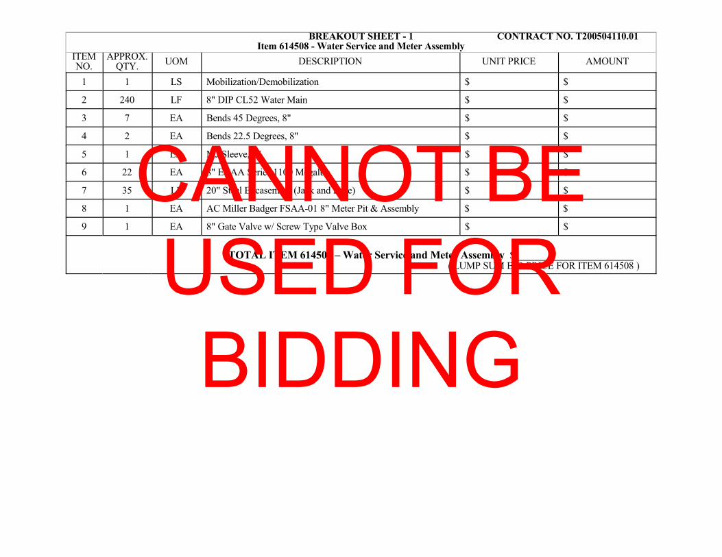
BREAKOUT SHEET - 1 CONTRACT NO. T200504110.01 Item 614508 - Water Service and Meter Assembly
ITEMNO.
APPROX.QTY.
UOM DESCRIPTION UNIT PRICE AMOUNT
1 1 LS Mobilization/Demobilization $ $
2 240 LF 8" DIP CL52 Water Main $ $
3 7 EA Bends 45 Degrees, 8" $ $
4 2 EA Bends 22.5 Degrees, 8" $ $
5 1 EA MJ Sleeve, 8" $ $
6 22 EA 8" EBAA Series 1100 Megalug $ $
7 35 LF 20" Steel Encasement (Jack and Bore) $ $
8 1 EA AC Miller Badger FSAA-01 8" Meter Pit & Assembly $ $
9 1 EA 8" Gate Valve w/ Screw Type Valve Box $ $
TOTAL ITEM 614508 – Water Service and Meter Assembly $
( LUMP SUM BID PRICE FOR ITEM 614508 )
CANNOT BE USED FOR BIDDING
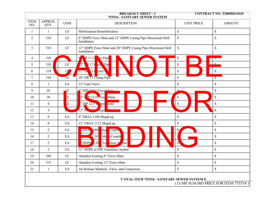
BREAKOUT SHEET - 2 CONTRACT NO. T200504110.01 753516 - SANITARY SEWER SYSTEM
ITEMNO.
APPROX.QTY. UOM DESCRIPTION UNIT PRICE AMOUNT
1 1 LS Mobilization/Demobilization $ $
2 310 LF 8" HDPE Force Main and 12" HDPE Casing Pipe Directional DrillInstallation
$ $
3 310 LF 12" HDPE Force Main and 20" HDPE Casing Pipe Directional DrillInstallation
$ $
4 310 LF 8" DR 11 Carrier Pipe $ $
5 310 LF 12" DR 17 Casing Pipe $ $
6 310 LF 12" DR 11 Carrier Pipe $ $
7 310 LF 20" DR 17 Casing Pipe $ $
8 1 EA 12" Gate Valve $ $
9 20 LF 8" DIP CL52 Force Main $ $
10 30 LF 12" DIP CL52 Force Main $ $
11 4 EA 8" DIP 22.5 Degree Bend $ $
12 4 EA 12" DIP 22.5 Degree Bend $ $
13 8 EA 8" EBAA 1108 MegaLug $ $
14 8 EA 12" EBAA 1112 MegaLug $ $
15 2 EA 8" EBAA 3808 Mega-Coupling $ $
16 2 EA 12" EBAA 3812 Mega-Coupling $ $
17 2 EA 8" HDPE to DIP Transition Anchor $ $
18 2 EA 12" HDPE to DIP Transition Anchor $ $
19 390 LF Abandon Existing 8" Force Main $ $
20 375 LF Abandon Existing 12" Force Main $ $
21 1 EA Air Release Manhole, Valve, and Connection $ $
T OTAL ITEM 753516 - SANITARY SEWER SYSTEM $ ( LUMP SUM BID PRICE FOR ITEM 753516 )
CANNOT BE USED FOR BIDDING

"ATTENTION"
TO BIDDERS
BREAKOUT SHEET(S) MUST BE SUBMITTED EITHER WITH YOUR BID DOCUMENTS; OR
WITHIN SEVEN (7) CALENDAR DAYS FOLLOWING THE BID DUE DATE BY THE LOWEST
APPARENT BIDDER.
BREAKOUT SHEETS ARE TO BE SUBMITTED TO DELDOT'S CONTRACT ADMINISTRATION AS
SHOWN BELOW. BREAKOUT SHEETS CANNOT BE CHANGED AFTER AWARD. THE
DEPARTMENT WILL REVIEW THE FIGURES SUBMITTED ON THE BREAKOUT SHEET(S) TO
ENSURE THEY MATCH THE RESPECTIVE LUMP SUM BID AMOUNT(S). MATHEMATICALLY
INCORRECT BREAKOUT SHEETS WILL BE RETURNED FOR IMMEDIATE CORRECTION.
BREAKOUT SHEETS MAY BE SUBMITTED;
VIA E-MAIL TO: [email protected] SUBJECT: T200504110.01 Breakout Sheet
OR MAILED TO: DELDOTCONTRACT ADMINISTRATIONPO BOX 778, DOVER, DE 19903
'BREAKOUT SHEET' AND THE PROJECT NUMBER MUST APPEAR ON THE ENVELOPE.

CERTIFICATION
Contract No. T200504110.01 Federal Aid Project No. ESTP-N54(04)
The undersigned bidder,
whose address is
and telephone number is hereby certifies the following:
I/We have carefully examined the location of the proposed work, the proposed plans and specifications,and will be bound, upon award of this contract by the Department of Transportation, to execute inaccordance with such award, a contract with necessary surety bond, of which contract this proposal and saidplans and specifications shall be a part, to provide all necessary machinery, tools, labor and other means ofconstruction, and to do all the work and to furnish all the materials necessary to perform and complete thesaid contract within the time and as required in accordance with the requirements of the Department ofTransportation, and at the unit prices for the various items as listed on the preceding pages.
Bidder's Certification Statement [US DOT Suspension and Debarment Regulation (49 CFR 29)]:
NOTICE: All contractors who hold prime contracts (Federal Aid) with DelDOT are advised that theprime contractor and subcontractors are required to submit to DelDOT a signed and notary attested copyof the Bidder Certification Statement for each and every subcontract that will be utilized by the primecontractor. This Certification must be filed with DelDOT prior to written approval being granted foreach and every subcontractor. Copies of the Certification Form are available from the appropriateDistrict Construction Office.
Under penalty of perjury under the laws of the United States, that I/We, or any person associatedtherewith in the capacity of (owner, partner, director, officer, principal, investigator, project director,manager, auditor, or any position involving the administration federal funds):a. am/are not currently under suspension, debarment, voluntary exclusion, or determination of
ineligibility by any federal agency;b. have not been suspended, debarred, voluntarily excluded or determined ineligible by any federal
agency within the past 3 years;c. do not have a proposed debarment pending; and,d. have not been indicted, convicted, or had a civil judgement rendered against (it) by a court of
competent jurisdiction in any matter involving fraud or official misconduct within the past 3 years.
Exceptions will not necessarily result in denial of award, but will be considered in determining bidderresponsibility. For any exception noted, indicate below to whom it applies, initiating agency, and dates ofaction. Providing false information may result in criminal prosection or administrative sanctions.
(Insert Exceptions)DBE Program Assurance:
NOTICE: In accordance with 49 CFR Part 26 the undersigned, a legally authorized representative of thebidder listed below, must complete this assurance.
By its signature affixed hereto, assures the Department that it will attain DBE participation as indicated:
Disadvantaged Business Enterprise percent (blank to be filled in by bidder)
CANNOT BE USED FOR BIDDING

The foregoing quantities are considered to be approximate only and are given as the basis for comparisonof bids. The Department of Transportation may increase or decrease the amount of any item or portion ofthe work as may be deemed necessary or expedient. Any such increase or decrease in the quantity for anyitem will not be regarded as a sufficient ground for an increase or decrease in the unit prices, nor in the timeallowed for the completion of the work, except as provided in the contract.
Accompanying this proposal is a surety bond or a security of the bidder assigned to the Department ofTransportation, for at least ten (10) percentum of total amount of the proposal, which deposit is to beforfeited as liquidated damages in case this proposal is accepted, and the undersigned shall fail to execute acontract with necessary bond, when required, for the performance of said contract with the Department ofTransportation, under the conditions of this proposal, within twenty (20) days after date of official notice ofthe award of the contract as provided in the requirement and specifications hereto attached; otherwise saiddeposit is to be returned to the undersigned.
I/We are licensed, or have initiated the license application as required by Section 2502, Chapter 25, Title30, of the Delaware Code.
By submission of this proposal, each person signing on behalf of the bidder, certifies as to its ownorganization, under penalty of perjury, that to the best of each signer’s knowledge and belief:
1. The prices in this proposal have been arrived at independently without collusion, consultation,communication, or Agreement with any other bidder or with any competitor for the purpose ofrestricting competition.
2. Unless required by law, the prices which have been quoted in this proposal have not beenknowingly disclosed and will not knowingly be disclosed by the bidder, directly or indirectly, toany other bidder or competitor prior to the opening of proposals.
3. No attempt has been made or will be made by the bidder to induce any other person, partnership,or corporation to submit or not to submit a proposal for the purpose of restricting competition.
===========================================================================I/We acknowledge receipt and incorporation of addenda to this proposal as follows:
No. Date No. Date No. Date No. Date No. Date
BIDDERS MUST ACKNOWLEDGE RECEIPT OF ALL ADDENDA
MUST INSERT DATE OF FINAL QUESTIONS AND ANSWERS ON WEBSITE: _____________ ³===========================================================================
Sealed and dated this day of in the year of our Lord two thousand ( 20 ).
Name of Bidder (Organization)
CorporateSeal
By:Authorized Signature
Attest Title
SWORN TO AND SUBSCRIBED BEFORE ME this day of , 20 .NotarySeal
Notary
CANNOT BE USED FOR BIDDING

BID BOND
TO ACCOMPANY PROPOSAL(Not necessary if security is used)
KNOW ALL MEN BY THESE PRESENTS That:
of in the County of and State of as
Principal, and of in the County of
and State of as Surety, legally authorized to do business in the State of
Delaware ("State"), are held and firmly unto the State in the sum of
Dollars ($ ), or percent not to exceed
Dollars ($ ) of amount of bid on ContractNo. T200504110.01 , to be paid to the State for the use and benefit of its Department of Transportation("DelDOT") for which payment well and truly to be made, we do bind ourselves, our and each of our heirs,executors, administrators, and successors, jointly and severally for and in the whole firmly by these presents.
NOW THE CONDITION OF THIS OBLIGATION IS SUCH That if the above bounden Principal whohas submitted to the DelDOT a certain proposal to enter into this contract for the furnishing of certainmateriel and/or services within the State, shall be awarded this Contract, and if said Principal shall well andtruly enter into and execute this Contract as may be required by the terms of this Contract and approved bythe DelDOT, this Contract to be entered into within twenty days after the date of official notice of the awardthereof in accordance with the terms of said proposal, then this obligation shall be void or else to be andremain in full force and virtue.
Sealed with seal and dated this day of in the year of our Lord
two thousand and ( 20 ).
SEALED, AND DELIVERED IN THEpresence of
Name of Bidder (Organization)
CorporateSeal
By:Authorized Signature
Attest Title
Name of Surety
Witness: By:
Title
CANNOT BE USED FOR BIDDING