contactors and contactor assemblies - control source inc
TRANSCRIPT
SIRIUS
Smart Infrastructure, Industrial Control Catalog 2020 2/1
2Co
nta
Ctors a
nd
a
ssemb
lies
c o n t e n t sSection Overview 2/2 - 2/5
Product Overview 2/6 - 2/7
SIRIUS Contactors3RT20, 3-pole to 95A 2/83RT10, 3-pole to 500A 2/93RT10, 3-pole to 500A with Integrated Safety 2/11 - 2/103RT12, 3-pole Vacuum to 500A 2/123RT23, 4-pole with 4 NO 2/133RT24, 3-pole for Resistive Loads 2/143RT25, 4-pole with 2 NO + 2 NC 2/153RT26, for Capacitor Switching 2/213RT20, Interface Coupling Contactors 2/22 - 2/233RT20 Motor Contactors for DC Operation 2/18 - 2/203RH21 Contactor Relays 2/16 - 2/173RA13 / 3RA23 Reversing Contactors 2/39 - 2/463RT, 3TF Safety Contactors and 3RH2, 3TH2 Safety Control Relays 2/24 - 2/25Function Modules for Communications 2/26 - 2/383RA24, Wye-Delta Starting 2/47 - 2/50 Contactor Coil Codes 2/51
SIRIUS Control Relays & Coupling Relays3RH2 Control Relays 2/523RH24 Latched Control Relays 2/53Auxiliary Switches 2/533RH21 Coupling Relays 2/54
Special Application Contactors (3TF6 / 3TB5 / 3TC)3TF6 Vacuum Contactors up to 820A 2/55 - 2/563TC DC Switching Contactors 2/57 - 2/583TB5 Contactor Coils 2/102 - 2/103
SIRIUS Contactor & Relay AccessoriesOverview 2/59 - 2/67Auxiliary Switches 2/68 - 2/71AuxiliaryTime Delay and Latching Blocks 2/72 - 2/73
Surge and EMC Suppressors 2/75 - 2/76Contactor Accessories 2/78 - 2/81Reversing Accessories 2/82 - 2/84Wye-delta Accessories 2/85NEMA 1 Enclosures 2/95
SIRIUS Current Monitoring Relays3RR21 Basic Versions 2/86 - 2/893RR22 Standard Versions 2/86 - 2/893RR24 with IO-Link 2/90 - 2/93Accessories 2/94
Special Application Contactor AccessoriesAuxiliary Contacts 2/55Box Terminals and Covers 2/56Surge Suppressors for 3TB, 3TC, 3TF 2/56
SIRIUS Contactor Spare PartsCoils 2/96 - 2/100Arc Chutes 2/101Contact Kits 2/101
Obsolete Contactor / Relay Spare Parts ..... 2/104 - 2/105
Design / Function Overview3RT20 Contactors, S00 to S3 2/106 - 2/1073RT10 Contactors, S6 to S12 2/108 - 2/109WYE-Delta Starters 2/112 - 2/1173RH2 Control Relays 2/1183TF6 Vacuum Contactors up to 820A 2/1193RT / 3RH Accessories 2/120 - 2/122
Technical Data3RT10 / 3RT20 Contactors 2/123 - 2/1533RT12 Vacuum Contactors 2/129, 2/154 - 2/1593RT24 Resistive Load Contactors 2/160 - 2/1673RT23 4-pole Contactors 4 NO 2/168 - 2/1693RT25 4-pole Contactors 2 NO & 2 NC 2/170 - 2/1713RT26 Capacitor Switching Contactors 2/1723RT20 Interface Relays 2/1733TF6 Vacuum Contactors up to 820A 2/174 - 2/1793TC DC Switching Contactors 2/180 - 2/183Accessories 2/184 - 2/1863RH2 Control and Latching Relays 2/187 - 2/1903RH21 Coupling Relays 2/191
Circuit Diagrams3RT Contactors & Accessories 2/192 - 2/2003RA23 Reversing Contactors 2/201WYE-Delta Starters 2/2023TF6 Vacuum Contactors up to 820A 2/2033RH2 Control & Latching Relays 2/2053RH21 Coupling Relays 2/204
Position of Terminals3RT Contactors and Accessories 2/205 - 2/2093RT Capacitor Contactors 2/2083TF6 Vacuum Contactors up to 820A 2/2103RH2 Control Relays 2/205
Dimensions3RT, 3-pole Contactors S00 to S3 2/211 - 2/2143RT10, 3-pole Contactors S6 to S12 2/215 - 2/2163RT24, 3-pole Contactors for Resistive Loads 2/215 - 2/2163RT10, Contactors S6 to S12, integrated safety 2/2173RT12, 3-pole Vacuum Contactors 2/2183RT23, 3RT25 4-pole Contactors 2/2193RT26, Contactors for Capacitor Switching 2/2203RA13 / 23 Reversing Contactors 2/221 - 2/2233TF6 Vacuum Contactors up to 820A 2/224Contactor Accessories 2/225 - 2/2263RH2 Control and Coupling Relays 2/227
2Contactors and Contactor assembliesIndustrial Control Product Catalog 2020 Section
(Section was last modified on 04/09/20)
New naming conventionic20-sect-02-iec-contactors
SIRIUS
Smart Infrastructure, Industrial Control Catalog 2020 2/2
2Co
nta
Cto
rs a
nd
a
ssem
bli
es
Siemens / Industrial Controls Previous folio: 2/2
IEC Power Control
Contactors and Contactor AssembliesContactors for switching three-phase motors
c o n t e n t s
Contactors for switching three-phase motors
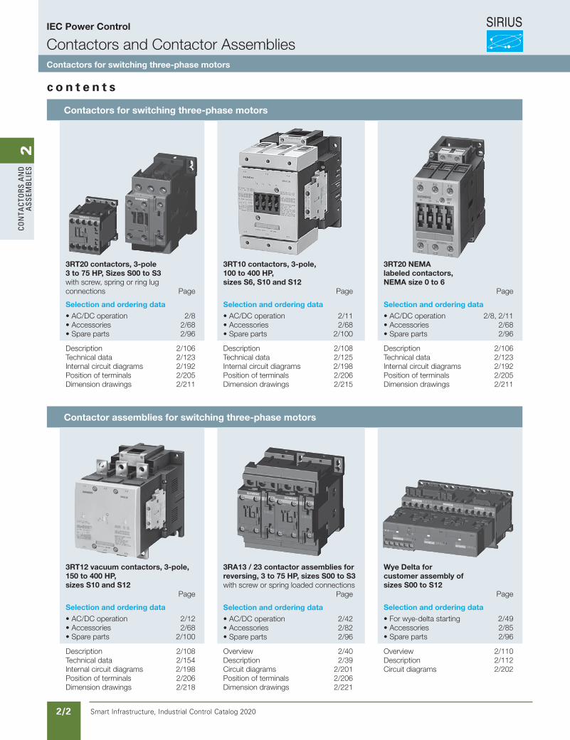
3RT20 contactors, 3-pole 3 to 75 HP, Sizes S00 to S3 with screw, spring or ring lug connections Page
Selection and ordering data
• AC/DC operation 2/8• Accessories 2/68• Spare parts 2/96
3RT10 contactors, 3-pole, 100 to 400 HP, sizes S6, S10 and S12 Page
Selection and ordering data
• AC/DC operation 2/11• Accessories 2/68• Spare parts 2/100
3RT20 NEMA labeled contactors, NEMA size 0 to 6 Page
Selection and ordering data
• AC/DC operation 2/8, 2/11• Accessories 2/68• Spare parts 2/96
Description 2/106Technical data 2/123Internal circuit diagrams 2/192Position of terminals 2/205Dimension drawings 2/211
Description 2/108Technical data 2/125Internal circuit diagrams 2/198Position of terminals 2/206Dimension drawings 2/215
Description 2/106Technical data 2/123Internal circuit diagrams 2/192Position of terminals 2/205Dimension drawings 2/211
Contactor assemblies for switching three-phase motors
3RT12 vacuum contactors, 3-pole, 150 to 400 HP, sizes S10 and S12 Page
Selection and ordering data
• AC/DC operation 2/12• Accessories 2/68• Spare parts 2/100
3RA13 / 23 contactor assemblies for reversing, 3 to 75 HP, sizes S00 to S3 with screw or spring loaded connections Page
Selection and ordering data
• AC/DC operation 2/42• Accessories 2/82• Spare parts 2/96
Wye Delta for customer assembly of sizes S00 to S12 Page
Selection and ordering data
• For wye-delta starting 2/49• Accessories 2/85• Spare parts 2/96
Description 2/108Technical data 2/154Internal circuit diagrams 2/198Position of terminals 2/206Dimension drawings 2/218
Overview 2/40Description 2/39Circuit diagrams 2/201Position of terminals 2/206Dimension drawings 2/221
Overview 2/110Description 2/112Circuit diagrams 2/202
SIRIUS
Smart Infrastructure, Industrial Control Catalog 2020 2/3
2Co
nta
Ctors a
nd
a
ssemb
lies
Siemens / Industrial Controls Previous folio: 2/3
IEC Power Control
Contactors and Contactor AssembliesContactors for special applications
IEC Power Control
Contactors and Contactor AssembliesContactors for special applications
c o n t e n t s
Contactors for special applications
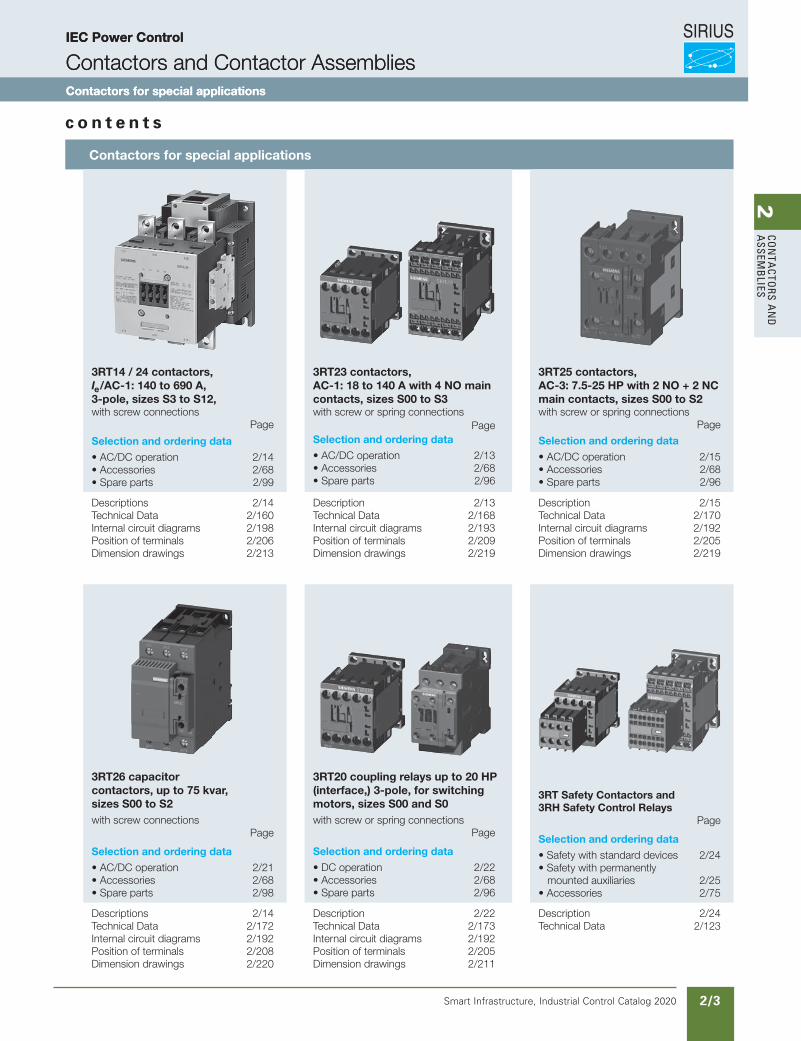
3RT14 / 24 contactors, Ie/AC-1: 140 to 690 A,3-pole, sizes S3 to S12, with screw connections Page
Selection and ordering data
• AC/DC operation 2/14• Accessories 2/68• Spare parts 2/99
3RT23 contactors, AC-1: 18 to 140 A with 4 NO main contacts, sizes S00 to S3 with screw or spring connections PageSelection and ordering data
• AC/DC operation 2/13• Accessories 2/68• Spare parts 2/96
3RT25 contactors, AC-3: 7.5-25 HP with 2 NO + 2 NC main contacts, sizes S00 to S2 with screw or spring connections Page
Selection and ordering data
• AC/DC operation 2/15• Accessories 2/68• Spare parts 2/96
Descriptions 2/14Technical Data 2/160Internal circuit diagrams 2/198Position of terminals 2/206Dimension drawings 2/213
Description 2/13Technical Data 2/168Internal circuit diagrams 2/193Position of terminals 2/209Dimension drawings 2/219
Description 2/15Technical Data 2/170Internal circuit diagrams 2/192Position of terminals 2/205Dimension drawings 2/219
3RT26 capacitor contactors, up to 75 kvar, sizes S00 to S2 with screw connections Page
Selection and ordering data
• AC/DC operation 2/21• Accessories 2/68• Spare parts 2/98
3RT20 coupling relays up to 20 HP (interface,) 3-pole, for switching motors, sizes S00 and S0with screw or spring connections Page
Selection and ordering data
• DC operation 2/22• Accessories 2/68• Spare parts 2/96
3RT Safety Contactors and 3RH Safety Control Relays Page
Selection and ordering data
• Safety with standard devices 2/24• Safety with permanently mounted auxiliaries 2/25• Accessories 2/75
Descriptions 2/14Technical Data 2/172Internal circuit diagrams 2/192Position of terminals 2/208Dimension drawings 2/220
Description 2/22Technical Data 2/173Internal circuit diagrams 2/192Position of terminals 2/205Dimension drawings 2/211
Description 2/24Technical Data 2/123
SIRIUS
Smart Infrastructure, Industrial Control Catalog 2020 2/4
2Co
nta
Cto
rs a
nd
a
ssem
bli
es
Siemens / Industrial Controls Previous folio: 2/4
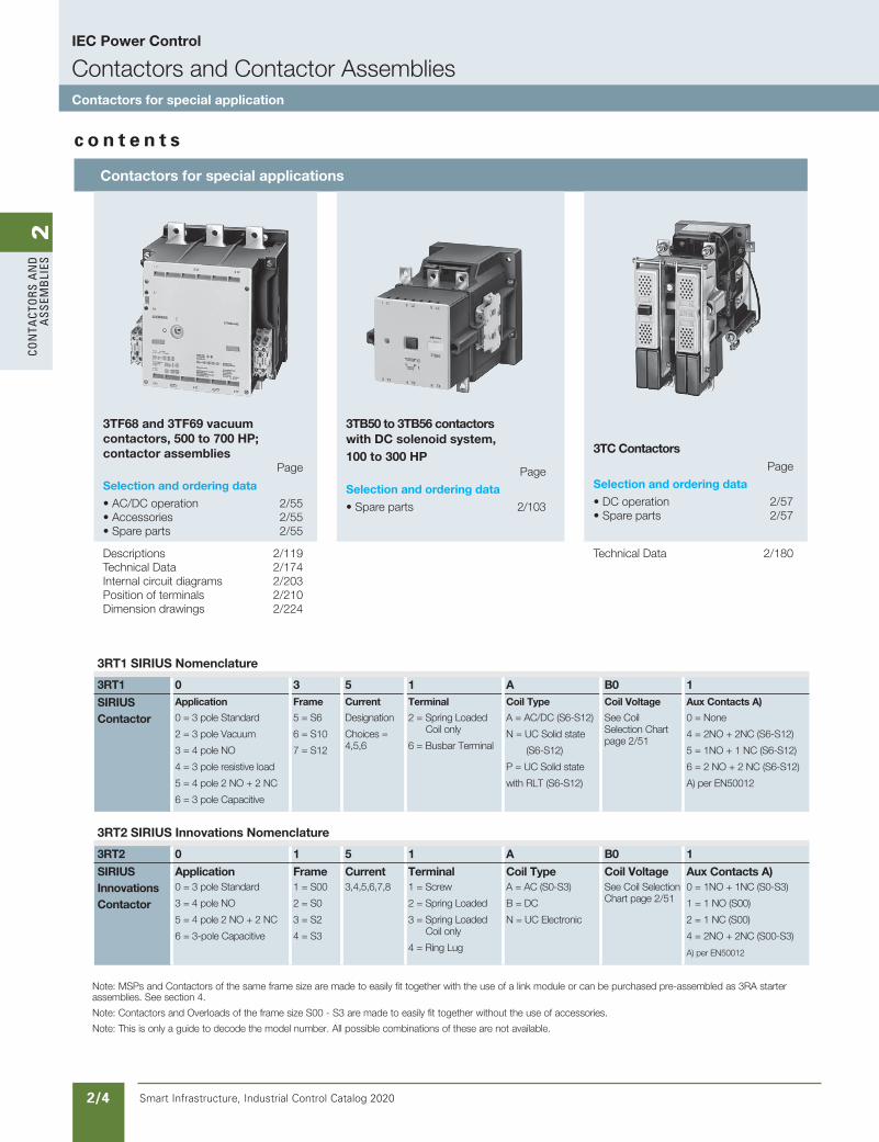
3RT1 SIRIUS Nomenclature
3RT1 0 3 5 1 A B0 1
SIRIUSContactor
Application Frame Current Terminal Coil Type Coil Voltage Aux Contacts A)
0 = 3 pole Standard
2 = 3 pole Vacuum
3 = 4 pole NO
4 = 3 pole resistive load
5 = 4 pole 2 NO + 2 NC
6 = 3 pole Capacitive
5 = S6
6 = S10
7 = S12
Designation
Choices = 4,5,6
2 = Spring Loaded Coil only
6 = Busbar Terminal
A = AC/DC (S6-S12)
N = UC Solid state
(S6-S12)
P = UC Solid state
with RLT (S6-S12)
See Coil Selection Chart page 2/51
0 = None
4 = 2NO + 2NC (S6-S12)
5 = 1NO + 1 NC (S6-S12)
6 = 2 NO + 2 NC (S6-S12)
A) per EN50012
3RT2 SIRIUS Innovations Nomenclature
3RT2 0 1 5 1 A B0 1
SIRIUSInnovationsContactor
Application Frame Current Terminal Coil Type Coil Voltage Aux Contacts A)0 = 3 pole Standard
3 = 4 pole NO
5 = 4 pole 2 NO + 2 NC
6 = 3-pole Capacitive
1 = S00
2 = S0
3 = S2
4 = S3
3,4,5,6,7,8 1 = Screw
2 = Spring Loaded
3 = Spring Loaded Coil only
4 = Ring Lug
A = AC (S0-S3)
B = DC
N = UC Electronic
See Coil Selection Chart page 2/51
0 = 1NO + 1NC (S0-S3)
1 = 1 NO (S00)
2 = 1 NC (S00)
4 = 2NO + 2NC (S00-S3)
A) per EN50012
Note: MSPs and Contactors of the same frame size are made to easily fit together with the use of a link module or can be purchased pre-assembled as 3RA starter assemblies. See section 4.
Note: Contactors and Overloads of the frame size S00 - S3 are made to easily fit together without the use of accessories.
Note: This is only a guide to decode the model number. All possible combinations of these are not available.
IEC Power Control
Contactors and Contactor AssembliesContactors for special application
c o n t e n t s
Contactors for special applications
3TF68 and 3TF69 vacuum contactors, 500 to 700 HP; contactor assemblies Page
Selection and ordering data
• AC/DC operation 2/55• Accessories 2/55• Spare parts 2/55
3TB50 to 3TB56 contactorswith DC solenoid system,100 to 300 HP Page
Selection and ordering data
• Spare parts 2/103
3TC Contactors Page
Selection and ordering data
• DC operation 2/57• Spare parts 2/57
Descriptions 2/119Technical Data 2/174Internal circuit diagrams 2/203Position of terminals 2/210Dimension drawings 2/224
Technical Data 2/180
2Co
nta
Ctors a
nd
a
ssemb
lies
Smart Infrastructure, Industrial Control Catalog 2020 2/5
Siemens / Industrial Controls Previous folio: 2/5
IEC Power Control
Contactors and Contactor AssembliesSIRIUS control relays
C o n t e n t s
SIRIUS contactor relays
3RH21, 3RH22 control relays 4- and 8-pole, size S00, AC/DC operation PageSelection and ordering data
• With screw connections 2/52• With spring connections 2/52• Accessories for 3RH2 2/53
3RH24 latched control relays, 4-pole, size S00, AC/DC operation PageSelection and ordering data
• With screw connections 2/53• Accessories for 3RH2 2/53
Overview 2/16Technical data 2/187Terminal diagrams 2/204Position of terminals 2/205Dimension drawings 2/227
Application 2/118Technical data 2/187Terminal diagrams 2/204Position of terminals 2/205Dimension drawings 2/227
SIRIUS coupling relays (interface) SIRIUS current monitoring relays
3RH21 coupling relays for switching auxiliary circuits, 4-pole, size S00, DC operation PageSelection and ordering data
• With screw connections 2/54• with Cage Clamp connections 2/54
3RR current monitoring relays for direct mounting to SIRIUS contactors PageSelection and ordering data
• Basic versions 2/89• Standard versions 2/89• Versions with IO-Link 2/93• Accessories for 3RR 2/94
Application 2/54Technical data 2/191Terminal diagrams 2/204Position of terminals 2/205Dimension drawings 2/227
Overview 2/86Application 2/86Technical data 2/87
2Co
nta
Cto
rs a
nd
a
ssem
bli
es
Smart Infrastructure, Industrial Control Catalog 2020 2/6
Siemens / Industrial Controls Previous folio: 2/6
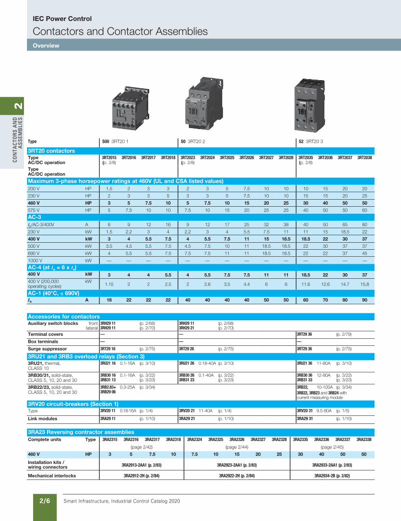
Type S00 3RT20 1 S0 3RT20 2 S2 3RT20 3
3RT20 contactorsType AC/DC operation
3RT2015 (p. 2/8)
3RT2016 3RT2017 3RT2018 3RT2023 (p. 2/8)
3RT2024 3RT2025 3RT2026 3RT2027 3RT2028 3RT2035 (p. 2/8)
3RT2036 3RT2037 3RT2038
Type AC/DC operation
Maximum 3-phase horsepower ratings at 460V (UL and CSA listed values)200 V HP 1.5 2 3 3 2 3 5 7.5 10 10 10 15 20 20
230 V HP 2 3 3 5 3 3 5 7.5 10 10 15 15 20 25
460 V HP 3 5 7.5 10 5 7.5 10 15 20 25 30 40 50 50
575 V HP 5 7.5 10 10 7.5 10 15 20 25 25 40 50 50 60
AC-3Ie/AC-3/400V A 6 9 12 16 9 12 17 25 32 38 40 50 65 80
230 V kW 1.5 2.2 3 4 2.2 3 4 5.5 7.5 11 11 15 18.5 22
400 V kW 3 4 5.5 7.5 4 5.5 7.5 11 15 18.5 18.5 22 30 37
500 V kW 3.5 4.5 5.5 7.5 4.5 7.5 10 11 18.5 18.5 22 30 37 37
690 V kW 4 5.5 5.5 7.5 7.5 7.5 11 11 18.5 18.5 22 22 37 45
1000 V kW — — — — — — — — — — — — — —
AC-4 (at Ia = 6 x Ie)400 V kW 3 4 4 5.5 4 5.5 7.5 7.5 11 11 18.5 22 30 37400 V (200,000 operating cycles)
kW1.15 2 2 2.5 2 2.6 3.5 4.4 6 6 11.6 12.6 14.7 15.8
AC-1 (40°C, ≤ 690V)Ie A 18 22 22 22 40 40 40 40 50 50 60 70 80 90
Accessories for contactorsAuxiliary switch blocks front
lateral3RH29 11 3RH29 11
(p. 2/68)(p. 2/70)
3RH29 11 3RH29 21
(p. 2/68)(p. 2/70)
Terminal covers — — 3RT29 36 (p. 2/79)
Box terminals — — —
Surge suppressor 3RT29 16 (p. 2/75) 3RT29 26 (p. 2/75) 3RT29 36 (p. 2/75)
3RU21 and 3RB3 overload relays (Section 3)3RU21, thermal, CLASS 10
3RU21 16 0.1-16A (p. 3/10) 3RU21 26 0.18-40A (p. 3/10) 3RU21 36 11-80A (p. 3/10)
3RB30/31, solid-state, CLASS 5, 10, 20 and 30
3RB30 16 3RB31 13
0.1-16A (p. 3/22) (p. 3/23)
3RB30 26 3RB31 23
0.1-40A (p. 3/22) (p. 3/23)
3RB30 36 3RB31 33
12-80A (p. 3/22) (p. 3/23)
3RB22/23, solid-state, CLASS 5, 10, 20 and 30
3RB2.83+ 3RB29 06
0.3-25A (p. 3/34) 3RB22, 10-100A (p. 3/34)3RB22, 3RB23 and 3RB24 with current measuring module
3RV20 circuit-breakers (Section 1)Type 3RV20 11 0.18-16A (p. 1/4) 3RV20 21 11-40A (p. 1/4) 3RV20 31 9.5-80A (p. 1/5)
Link modules 3RA29 11 (p. 1/10) 3RA29 21 (p. 1/10) 3RA29 31 (p. 1/10)
3RA23 Reversing contractor assembliesComplete units Type 3RA2315 3RA2316 3RA2317 3RA2318 3RA2324 3RA2325 3RA2326 3RA2327 3RA2328 3RA2335 3RA2336 3RA2337 3RA2338
(page 2/42) (page 2/44) (page 2/45)
460 V HP 3 5 7.5 10 7.5 10 15 20 25 30 40 50 50
Installation kits / wiring connectors 3RA2913-2AA1 (p. 2/83) 3RA2923-2AA1 (p. 2/83) 3RA2933-2AA1 (p. 2/83)
Mechanical interlocks 3RA2912-2H (p. 2/84) 3RA2922-2H (p. 2/84) 3RA2934-2B (p. 2/82)
IEC Power Control
Contactors and Contactor AssembliesOverview
2Co
nta
Ctors a
nd
a
ssemb
lies
Smart Infrastructure, Industrial Control Catalog 2020 2/7
Siemens / Industrial Controls Previous folio: 2/7
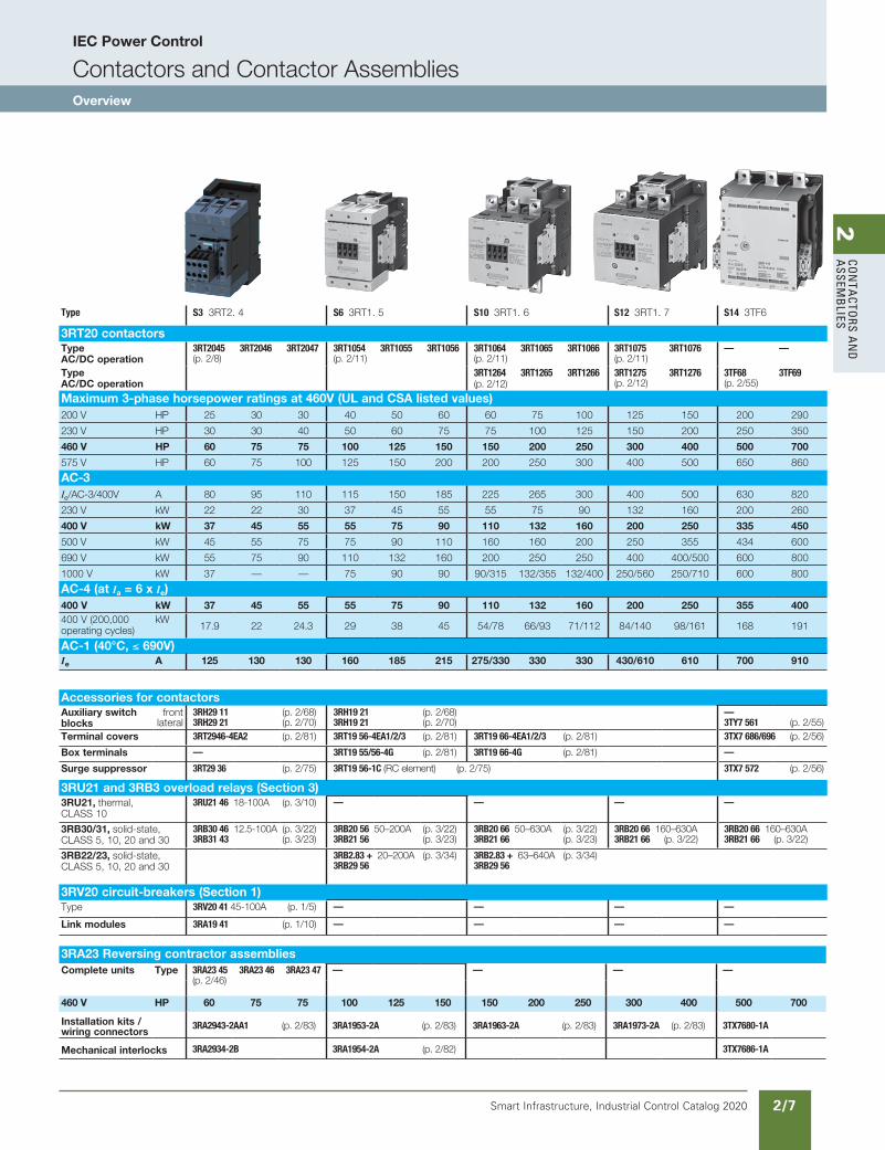
Type S3 3RT2. 4 S6 3RT1. 5 S10 3RT1. 6 S12 3RT1. 7 S14 3TF6
3RT20 contactorsType AC/DC operation
3RT2045 (p. 2/8)
3RT2046 3RT2047 3RT1054 (p. 2/11)
3RT1055 3RT1056 3RT1064 (p. 2/11)
3RT1065 3RT1066 3RT1075 (p. 2/11)
3RT1076 — —
Type AC/DC operation
3RT1264 (p. 2/12)
3RT1265 3RT1266 3RT1275 (p. 2/12)
3RT1276 3TF68 (p. 2/55)
3TF69
Maximum 3-phase horsepower ratings at 460V (UL and CSA listed values)200 V HP 25 30 30 40 50 60 60 75 100 125 150 200 290
230 V HP 30 30 40 50 60 75 75 100 125 150 200 250 350
460 V HP 60 75 75 100 125 150 150 200 250 300 400 500 700
575 V HP 60 75 100 125 150 200 200 250 300 400 500 650 860
AC-3Ie/AC-3/400V A 80 95 110 115 150 185 225 265 300 400 500 630 820
230 V kW 22 22 30 37 45 55 55 75 90 132 160 200 260
400 V kW 37 45 55 55 75 90 110 132 160 200 250 335 450
500 V kW 45 55 75 75 90 110 160 160 200 250 355 434 600
690 V kW 55 75 90 110 132 160 200 250 250 400 400/500 600 800
1000 V kW 37 — — 75 90 90 90/315 132/355 132/400 250/560 250/710 600 800
AC-4 (at Ia = 6 x Ie)400 V kW 37 45 55 55 75 90 110 132 160 200 250 355 400400 V (200,000 operating cycles)
kW17.9 22 24.3 29 38 45 54/78 66/93 71/112 84/140 98/161 168 191
AC-1 (40°C, ≤ 690V)Ie A 125 130 130 160 185 215 275/330 330 330 430/610 610 700 910
Accessories for contactorsAuxiliary switch blocks
front lateral
3RH29 11 (p. 2/68)3RH29 21 (p. 2/70)
3RH19 21 (p. 2/68)3RH19 21 (p. 2/70)
—3TY7 561 (p. 2/55)
Terminal covers 3RT2946-4EA2 (p. 2/81) 3RT19 56-4EA1/2/3 (p. 2/81) 3RT19 66-4EA1/2/3 (p. 2/81) 3TX7 686/696 (p. 2/56)
Box terminals — 3RT19 55/56-4G (p. 2/81) 3RT19 66-4G (p. 2/81) —
Surge suppressor 3RT29 36 (p. 2/75) 3RT19 56-1C (RC element) (p. 2/75) 3TX7 572 (p. 2/56)
3RU21 and 3RB3 overload relays (Section 3)3RU21, thermal, CLASS 10
3RU21 46 18-100A (p. 3/10) — — — —
3RB30/31, solid-state, CLASS 5, 10, 20 and 30
3RB30 46 12.5-100A (p. 3/22)3RB31 43 (p. 3/23)
3RB20 56 50–200A (p. 3/22)3RB21 56 (p. 3/23)
3RB20 66 50–630A (p. 3/22)3RB21 66 (p. 3/23)
3RB20 66 160–630A 3RB21 66 (p. 3/22)
3RB20 66 160–630A 3RB21 66 (p. 3/22)
3RB22/23, solid-state, CLASS 5, 10, 20 and 30
3RB2.83 + 20–200A (p. 3/34)3RB29 56
3RB2.83 + 63–640A (p. 3/34)3RB29 56
3RV20 circuit-breakers (Section 1)Type 3RV20 41 45-100A (p. 1/5) — — — —
Link modules 3RA19 41 (p. 1/10) — — — —
3RA23 Reversing contractor assembliesComplete units Type 3RA23 45
(p. 2/46)3RA23 46 3RA23 47 — — — —
460 V HP 60 75 75 100 125 150 150 200 250 300 400 500 700
Installation kits / wiring connectors
3RA2943-2AA1 (p. 2/83) 3RA1953-2A (p. 2/83) 3RA1963-2A (p. 2/83) 3RA1973-2A (p. 2/83) 3TX7680-1A
Mechanical interlocks 3RA2934-2B 3RA1954-2A (p. 2/82) 3TX7686-1A
IEC Power Control
Contactors and Contactor AssembliesOverview
SIRIUS
Smart Infrastructure, Industrial Control Catalog 2020 2/8
2Co
nta
Cto
rs a
nd
a
ssem
bli
es
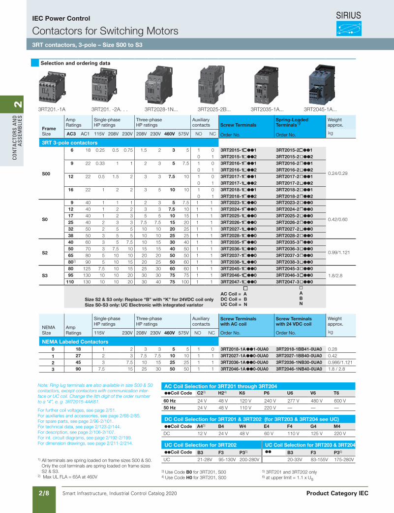
Selection and ordering data
FrameSize
Amp Ratings
Single-phase HP ratings
Three-phaseHP ratings
Auxiliarycontacts Screw Terminals
Spring-Loaded Terminals1)
Weightapprox.
AC3 AC1 115V 208V 230V 208V 230V 460V 575V NO NC Order No. Order No. kg
3RT 3-pole contactors
S00
6 18 0.25 0.5 0.75 1.5 2 3 5 1 0 3RT2015-11 3RT2015-21
0.24/0.29
0 1 3RT2015-12 3RT2015-2 2 9 22 0.33 1 1 2 3 5 7.5 1 0 3RT2016-11 3RT2016-2 1
0 1 3RT2016-12 3RT2016-2 212 22 0.5 1.5 2 3 3 7.5 10 1 0 3RT2017-11 3RT2017-2 1
0 1 3RT2017-12 3RT2017-2 216 22 1 2 2 3 5 10 10 1 0 3RT2018-11 3RT2018-2 1
0 1 3RT2018-12 3RT2018-2 2
S0
9 40 1 1 1 2 3 5 7.5 1 1 3RT2023-10 3RT2023-2 0
0.42/0.60
12 40 1 2 2 3 3 7.5 10 1 1 3RT2024-10 3RT2024-2 017 40 1 2 3 5 5 10 15 1 1 3RT2025-10 3RT2025-2 025 40 2 3 3 7.5 7.5 15 20 1 1 3RT2026-10 3RT2026-2 032 50 2 5 5 10 10 20 25 1 1 3RT2027-10 3RT2027-2 038 50 3 5 5 10 10 25 25 1 1 3RT2028-10 3RT2028-2 0
S2
40 60 3 5 7.5 10 15 30 40 1 1 3RT2035-10 3RT2035-3 0
0.99/1.12150 70 3 7.5 10 15 15 40 50 1 1 3RT2036-10 3RT2036-3 065 80 5 10 10 20 20 50 50 1 1 3RT2037-10 3RT2037-3 0802) 90 5 10 15 20 25 50 60 1 1 3RT2038-10 3RT2038-3 0
S3
80 125 7.5 10 15 25 30 60 60 1 1 3RT2045-10 3RT2045-3 0
1.8/2.895 130 10 10 20 30 30 75 75 1 1 3RT2046-10 3RT2046-3 0110 130 10 10 20 30 40 75 100 1 1 3RT2047-10 3RT2047-3 0
Size S2 & S3 only: Replace “B” with “K” for 24VDC coil onlySize S0-S3 only: UC Electronic with integrated varistor
AC Coil = ADC Coil = BUC Coil = N
ABN
NEMA SIze
Amp Ratings
Single-phase HP ratings
Three-phaseHP ratings
Auxiliarycontacts
Screw Terminalswith AC coil
Screw Terminalswith 24 VDC coil
Weightapprox.
115V 230V 208V 230V 460V 575V NO NC Order No. Order No. kg
NEMA Labeled Contactors0 18 1 2 3 3 5 5 1 0 3RT2018-1A 1-0UA0 3RT2018-1BB41-0UA0 0.28
1 27 2 3 7.5 7.5 10 10 1 1 3RT2027-1A0-0UA0 3RT2027-1BB40-0UA0 0.42
2 45 3 7.5 10 15 25 25 1 1 3RT2036-1A0-0UA0 3RT2036-1NB30-0UA0 0.986/1.121
3 90 7.5 15 25 30 50 50 1 1 3RT2046-1A0-0UA0 3RT2046-1NB40-0UA0 1.8 / 2.8
Siemens / Industrial Controls Previous folio: new page
Note: Ring lug terminals are also available in size S00 & S0 contactors, except contactors with communication inter-face or UC coil. Change the 8th digit of the order number to a “4”, e. g. 3RT2015-4AK61.
For further coil voltages, see page 2/51.For auxiliaries and accessories, see page 2/68-2/85.For spare parts, see page 2/96-2/101.For technical data, see page 2/123-2/144.For description, see page 2/106-2/107.For int. circuit diagrams, see page 2/192-2/199.For dimension drawings, see page 2/211-2/214.
3RT201.-1A 3RT201. -2A. . . 3RT2028-1N... 3RT2025-2B... 3RT2035-1A... 3RT2045-1A...
AC Coil Selection for 3RT201 through 3RT204Coil Code C23) H24) K6 P6 U6 V6 T6
60 Hz 24 V 48 V 120 V 240 V 277 V 480 V 600 V
50 Hz 24 V 48 V 110 V 220 V — — —
DC Coil Selection for 3RT201 & 3RT202 (for 3RT203 & 3RT204 see UC)Coil Code A45) B4 W4 E4 F4 G4 M4
DC 12 V 24 V 48 V 60 V 110 V 125 V 220 V
UC Coil Selection for 3RT202 UC Coil Selection for 3RT203 & 3RT204Coil Code B3 F3 P35) B3 F3 P36)
UC 21-28V 95-130V 200-280V 20-33V 83-155V 175-280V
3) Use Code B0 for 3RT201, S004) Use Code H0 for 3RT201, S00
5) 3RT201 and 3RT202 only6) at upper limit = 1.1 x Us
IEC Power Control
Contactors for Switching Motors3RT contactors, 3-pole – Size S00 to S3
Product Category IEC
1) All terminals are spring loaded on frame sizes S00 & S0. Only the coil terminals are spring loaded on frame sizes S2 & S3.
2) Max UL FLA = 65A at 460V
Revised on 11/20/19for new catalog
SIRIUS
Smart Infrastructure, Industrial Control Catalog 2020 2/9
2Co
nta
Ctors a
nd
a
ssemb
lies
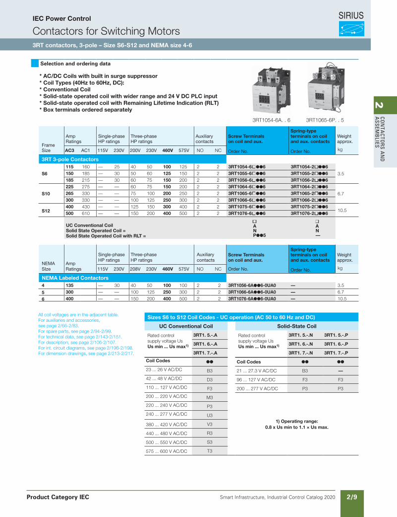
Selection and ordering data
Frame Size
Amp Ratings
Single-phase HP ratings
Three-phaseHP ratings
Auxiliarycontacts
Screw Terminals on coil and aux.
Spring-type terminals on coil and aux. contacts
Weightapprox.
AC3 AC1 115V 230V 200V 230V 460V 575V NO NC Order No. Order No. kg
3RT 3-pole Contactors
S6
115 160 — 25 40 50 100 125 2 2 3RT1054-6 6 3RT1054-2 6
3.5150 185 — 30 50 60 125 150 2 2 3RT1055-6 6 3RT1055-2 6185 215 — 30 60 75 150 200 2 2 3RT1056-6 6 3RT1056-2 6
S10
225 275 — — 60 75 150 200 2 2 3RT1064-6 6 3RT1064-2 6
6.7265 330 — — 75 100 200 250 2 2 3RT1065-6 6 3RT1065-2 6300 330 — — 100 125 250 300 2 2 3RT1066-6 6 3RT1066-2 6
S12400 430 — — 125 150 300 400 2 2 3RT1075-6 6 3RT1075-2 6
10.5500 610 — — 150 200 400 500 2 2 3RT1076-6 6 3RT1076-2 6 UC Conventional Coil Solid State Operated Coil =Solid State Operated Coil with RLT =
ANP5
AN—
NEMA SIze
Amp Ratings
Single-phase HP ratings
Three-phaseHP ratings
Auxiliarycontacts
Screw Terminalson coil and aux.
Spring-type terminals on coil and aux. contacts
Weightapprox.
115V 230V 208V 230V 460V 575V NO NC Order No. Order No. kg
NEMA Labeled Contactors4 135 — 30 40 50 100 100 2 2 3RT1056-6A6-0UA0 — 3.5
5 300 — — 100 125 250 300 2 2 3RT1066-6A6-0UA0 — 6.7
6 400 — — 150 200 400 500 2 2 3RT1076-6A6-0UA0 — 10.5
3RT1054-6A. . 6 3RT1065-6P. . 5
All coil voltages are in the adjacent table. For auxiliaries and accessories, see page 2/66-2/83.For spare parts, see page 2/94-2/99.For technical data, see page 2/143-2/151.For description, see page 2/106-2/107.For int. circuit diagrams, see page 2/196-2/198.For dimension drawings, see page 2/213-2/217.
* AC/DC Coils with built in surge suppressor* Coil Types (40Hz to 60Hz, DC):* Conventional Coil* Solid-state operated coil with wider range and 24 V DC PLC input* Solid-state operated coil with Remaining Lifetime Indication (RLT)* Box terminals ordered separately
Sizes S6 to S12 Coil Codes - UC operation (AC 50 to 60 Hz and DC)
UC Conventional Coil Solid-State Coil
Rated control supply voltage UsUs min ... Us max1)
3RT1. 5.-.A Rated control supply voltage UsUs min ... Us max1)
3RT1. 5.-.N 3RT1. 5.-.P
3RT1. 6.-.A 3RT1. 6.-.N 3RT1. 6.-.P
3RT1. 7.-.A 3RT1. 7.-.N 3RT1. 7.-.P
Coil Codes Coil Codes
23 ... 26 V AC/DC B3 21 ... 27.3 V AC/DC B3 —
42 ... 48 V AC/DC D3 96 ... 127 V AC/DC F3 F3
110 ... 127 V AC/DC F3 200 ... 277 V AC/DC P3 P3
200 ... 220 V AC/DC M3
1) Operating range: 0.8 x Us min to 1.1 × Us max.
220 ... 240 V AC/DC P3
240 ... 277 V AC/DC U3
380 ... 420 V AC/DC V3
440 ... 480 V AC/DC R3
500 ... 550 V AC/DC S3
575 ... 600 V AC/DC T3
Product Category IEC
IEC Power Control
Contactors for Switching Motors3RT contactors, 3-pole – Size S6-S12 and NEMA size 4-6
SIRIUS
Smart Infrastructure, Industrial Control Catalog 2020 2/10
2Co
nta
Cto
rs a
nd
a
ssem
bli
es
Siemens / Industrial Controls Previous folio: new page
IEC Power Control
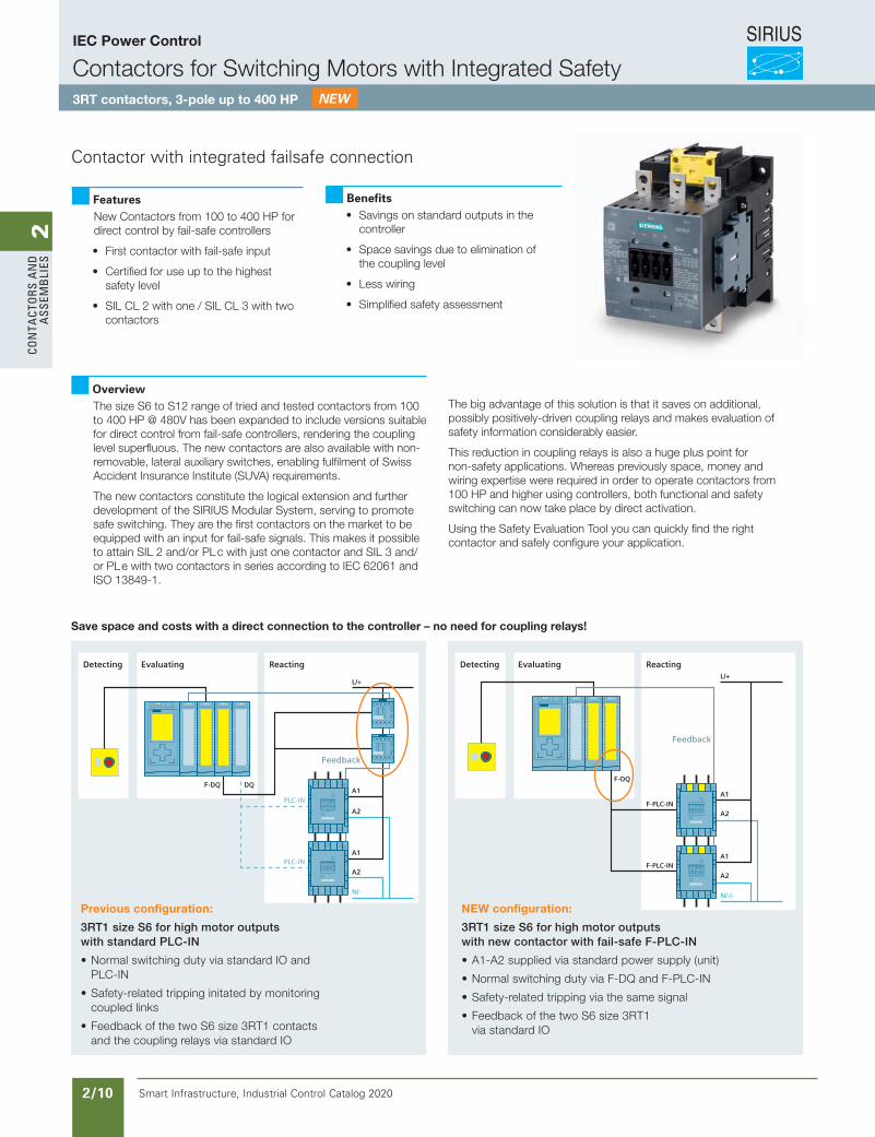
Contactors for Switching Motors with Integrated Safety3RT contactors, 3-pole up to 400 HP
FeaturesNew Contactors from 100 to 400 HP for direct control by fail-safe controllers
• First contactor with fail-safe input
• Certified for use up to the highest safety level
• SIL CL 2 with one / SIL CL 3 with two contactors
Contactor with integrated failsafe connection
Benefits• Savings on standard outputs in the
controller
• Space savings due to elimination of the coupling level
• Less wiring
• Simplified safety assessment
OverviewThe size S6 to S12 range of tried and tested contactors from 100 to 400 HP @ 480V has been expanded to include versions suitable for direct control from fail-safe controllers, rendering the coupling level superfluous. The new contactors are also available with non-removable, lateral auxiliary switches, enabling fulfilment of Swiss Accident Insurance Institute (SUVA) requirements.
The new contactors constitute the logical extension and further development of the SIRIUS Modular System, serving to promote safe switching. They are the first contactors on the market to be equipped with an input for fail-safe signals. This makes it possible to attain SIL 2 and/or PL c with just one contactor and SIL 3 and/or PL e with two contactors in series according to IEC 62061 and ISO 13849-1.
The big advantage of this solution is that it saves on additional, possibly positively-driven coupling relays and makes evaluation of safety information considerably easier.
This reduction in coupling relays is also a huge plus point for non-safety applications. Whereas previously space, money and wiring expertise were required in order to operate contactors from 100 HP and higher using controllers, both functional and safety switching can now take place by direct activation.
Using the Safety Evaluation Tool you can quickly find the right contactor and safely configure your application.
Evaluating
Feedback
Detecting
N/-
L/+
PLC-IN
PLC-IN
A1
A2
A1
A2
F-DQ DQ
Reacting EvaluatingDetecting Reacting
N/-/-
L/+
Feedback
F-PLC-IN
F-PLC-IN
A1
A2
A1
A2
F-DQ
Previous configuration:
3RT1 size S6 for high motor outputs with standard PLC-IN
• Normal switching duty via standard IO and PLC-IN
• Safety-related tripping initated by monitoring coupled links
• Feedback of the two S6 size 3RT1 contacts and the coupling relays via standard IO
NEW configuration:
3RT1 size S6 for high motor outputs with new contactor with fail-safe F-PLC-IN
• A1-A2 supplied via standard power supply (unit)
• Normal switching duty via F-DQ and F-PLC-IN
• Safety-related tripping via the same signal
• Feedback of the two S6 size 3RT1 via standard IO
Save space and costs with a direct connection to the controller – no need for coupling relays!
Revised on 01/23/20for new catalog
adapted from German catalog page 3/73
SIRIUS
Smart Infrastructure, Industrial Control Catalog 2020 2/11
2Co
nta
Ctors a
nd
a
ssemb
lies
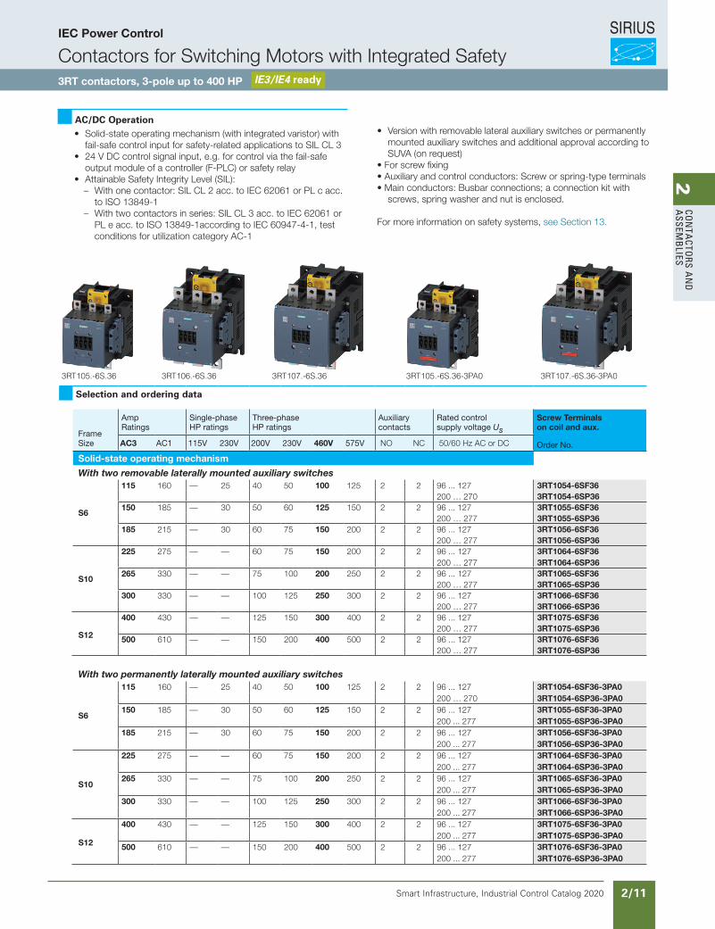
Selection and ordering data
Frame Size
Amp Ratings
Single-phase HP ratings
Three-phaseHP ratings
Auxiliarycontacts
Rated control supply voltage Us
Screw Terminals on coil and aux.
AC3 AC1 115V 230V 200V 230V 460V 575V NO NC 50/60 Hz AC or DC Order No.
Solid-state operating mechanism
With two removable laterally mounted auxiliary switches
S6
115 160 — 25 40 50 100 125 2 2 96 ... 127 3RT1054-6SF36200 … 270 3RT1054-6SP36
150 185 — 30 50 60 125 150 2 2 96 ... 127 3RT1055-6SF36200 … 277 3RT1055-6SP36
185 215 — 30 60 75 150 200 2 2 96 ... 127 3RT1056-6SF36200 … 277 3RT1056-6SP36
S10
225 275 — — 60 75 150 200 2 2 96 ... 127 3RT1064-6SF36200 … 277 3RT1064-6SP36
265 330 — — 75 100 200 250 2 2 96 ... 127 3RT1065-6SF36200 … 277 3RT1065-6SP36
300 330 — — 100 125 250 300 2 2 96 ... 127 3RT1066-6SF36200 … 277 3RT1066-6SP36
S12
400 430 — — 125 150 300 400 2 2 96 ... 127 3RT1075-6SF36200 … 277 3RT1075-6SP36
500 610 — — 150 200 400 500 2 2 96 ... 127 3RT1076-6SF36200 … 277 3RT1076-6SP36
With two permanently laterally mounted auxiliary switches
S6
115 160 — 25 40 50 100 125 2 2 96 ... 127 3RT1054-6SF36-3PA0200 … 270 3RT1054-6SP36-3PA0
150 185 — 30 50 60 125 150 2 2 96 ... 127 3RT1055-6SF36-3PA0200 ... 277 3RT1055-6SP36-3PA0
185 215 — 30 60 75 150 200 2 2 96 ... 127 3RT1056-6SF36-3PA0200 ... 277 3RT1056-6SP36-3PA0
S10
225 275 — — 60 75 150 200 2 2 96 ... 127 3RT1064-6SF36-3PA0200 ... 277 3RT1064-6SP36-3PA0
265 330 — — 75 100 200 250 2 2 96 ... 127 3RT1065-6SF36-3PA0200 ... 277 3RT1065-6SP36-3PA0
300 330 — — 100 125 250 300 2 2 96 ... 127 3RT1066-6SF36-3PA0200 ... 277 3RT1066-6SP36-3PA0
S12
400 430 — — 125 150 300 400 2 2 96 ... 127 3RT1075-6SF36-3PA0200 ... 277 3RT1075-6SP36-3PA0
500 610 — — 150 200 400 500 2 2 96 ... 127 3RT1076-6SF36-3PA0200 ... 277 3RT1076-6SP36-3PA0
IEC Power Control
Contactors for Switching Motors with Integrated Safety3RT contactors, 3-pole up to 400 HP IE3/IE4 ready
AC/DC Operation• Solid-state operating mechanism (with integrated varistor) with
fail-safe control input for safety-related applications to SIL CL 3• 24 V DC control signal input, e.g. for control via the fail-safe
output module of a controller (F-PLC) or safety relay• Attainable Safety Integrity Level (SIL):
– With one contactor: SIL CL 2 acc. to IEC 62061 or PL c acc. to ISO 13849-1
– With two contactors in series: SIL CL 3 acc. to IEC 62061 or PL e acc. to ISO 13849-1according to IEC 60947-4-1, test conditions for utilization category AC-1
• Version with removable lateral auxiliary switches or permanently mounted auxiliary switches and additional approval according to SUVA (on request)
• For screw fixing• Auxiliary and control conductors: Screw or spring-type terminals• Main conductors: Busbar connections; a connection kit with
screws, spring washer and nut is enclosed.
For more information on safety systems, see Section 13.
3/72 Siemens IC 10 · 2019* You can order this quantity or a multiple thereof.
Illustrations are approximate
Power Contactors for Switching Motors
SIRIUS 3RT contactors, 3-pole up to 250 kW
3
AC/DC operation • Solid-state operating mechanism (with integrated varistor)
with fail-safe control input for safety-related applications to SIL CL 3
• 24 V DC control signal input, e.g. for control via the fail-safe output module of a controller (F-PLC) or safety relay
• Attainable Safety Integrity Level (SIL):- With one contactor: SIL CL 2 acc. to IEC 62061 or PL c acc.
to ISO 13849-1- With two contactors in series: SIL CL 3 acc. to IEC 62061 or
PL e acc. to ISO 13849-1
• Version with removable lateral auxiliary switches or permanently mounted auxiliary switches and additional approval according to SUVA (on request)
• For screw fixing• Auxiliary and control conductors: Screw or spring-type
terminals• Main conductors: Busbar connections;
a connection kit with screws, spring washer and nut is enclosed.
For more information on safety systems, see from page 11/1 onwards.
Accessories and spare parts, see pages 3/76 to 3/125.
3RT105.-6S.36 3RT106.-6S.36 3RT107.-6S.36 3RT105.-6S.36-3PA0 3RT107.-6S.36-3PA0
Size Rated data according to IEC 60947-4-1 Auxiliary contacts, lateral
Rated control supply voltage Us
SD Screw terminals PU(UNIT,
SET, M)
PS* PG
AC-3,tu: 60 °C
Operational current Ie up to
Ratings of three-phase motors at 50 Hz and
Version 50/60 Hz AC or DC
Article No. Priceper PU
500 V 400 V
A kW NO NC V d
Solid-state operating mechanism With two removable laterally mounted auxiliary switchesS6 115 55 2 2 96 ... 127 5 3RT1054-6SF36 1 1 unit 41B
200 … 270 5 3RT1054-6SP36 1 1 unit 41B
150 75 2 2 96 ... 127 5 3RT1055-6SF36 1 1 unit 41B200 ... 277 5 3RT1055-6SP36 1 1 unit 41B
185 90 2 2 96 ... 127 5 3RT1056-6SF36 1 1 unit 41B200 ... 277 5 3RT1056-6SP36 1 1 unit 41B
S10 225 110 2 2 96 ... 127 5 3RT1064-6SF36 1 1 unit 41B200 ... 277 5 3RT1064-6SP36 1 1 unit 41B
265 132 2 2 96 ... 127 5 3RT1065-6SF36 1 1 unit 41B200 ... 277 5 3RT1065-6SP36 1 1 unit 41B
300 160 2 2 96 ... 127 5 3RT1066-6SF36 1 1 unit 41B200 ... 277 5 3RT1066-6SP36 1 1 unit 41B
S12 400 200 2 2 96 ... 127 5 3RT1075-6SF36 1 1 unit 41B200 ... 277 5 3RT1075-6SP36 1 1 unit 41B
500 250 2 2 96 ... 127 5 3RT1076-6SF36 1 1 unit 41B200 ... 277 5 3RT1076-6SP36 1 1 unit 41B
With two permanently laterally mounted auxiliary switchesS6 115 55 2 2 96 ... 127 5 3RT1054-6SF36-3PA0 1 1 unit 41B
200 … 270 5 3RT1054-6SP36-3PA0 1 1 unit 41B
150 75 2 2 96 ... 127 5 3RT1055-6SF36-3PA0 1 1 unit 41B200 ... 277 5 3RT1055-6SP36-3PA0 1 1 unit 41B
185 90 2 2 96 ... 127 5 3RT1056-6SF36-3PA0 1 1 unit 41B200 ... 277 5 3RT1056-6SP36-3PA0 1 1 unit 41B
S10 225 110 2 2 96 ... 127 5 3RT1064-6SF36-3PA0 1 1 unit 41B200 ... 277 5 3RT1064-6SP36-3PA0 1 1 unit 41B
265 132 2 2 96 ... 127 5 3RT1065-6SF36-3PA0 1 1 unit 41B200 ... 277 5 3RT1065-6SP36-3PA0 1 1 unit 41B
300 160 2 2 96 ... 127 5 3RT1066-6SF36-3PA0 1 1 unit 41B200 ... 277 5 3RT1066-6SP36-3PA0 1 1 unit 41B
S12 400 200 2 2 96 ... 127 5 3RT1075-6SF36-3PA0 1 1 unit 41B200 ... 277 5 3RT1075-6SP36-3PA0 1 1 unit 41B
500 250 2 2 96 ... 127 5 3RT1076-6SF36-3PA0 1 1 unit 41B200 ... 277 5 3RT1076-6SP36-3PA0 1 1 unit 41B
IC10_03_04.fm Page 72 Friday, January 24, 2020 9:51 AM
Revised on 01/23/20for new catalog
adapted from flier and powerpoint
SIRIUS
Smart Infrastructure, Industrial Control Catalog 2020 2/12
2Co
nta
Cto
rs a
nd
a
ssem
bli
es
.
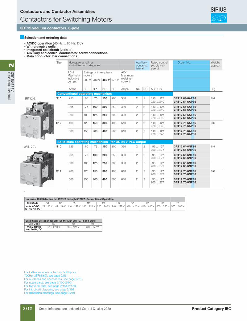
AC/DC operation (40 Hz ... 60 Hz, DC) Withdrawable coils Integrated coil circuit (varistor) Auxiliary and control conductors: screw connections Main conductor: bar connections
Size Horsepower ratings Auxiliary contacts, lateral
Rated control supply volt-age Us
Order No. Weight approx.and utilization categories
AC-3Maximuminductive current
Ratings of three-phasemotors
AC-1Maximum resistive current200 V 230 V 460 V 575 V
Amps HP HP HP HP Amps NO NC AC/DC V kg
Conventional operating mechanismS10 225 60 75 150 200 330 2 2 110 ... 127 3RT12 64-6AF36 6.4
220 ... 240 3RT12 64-6AP36
265 75 100 200 250 330 2 2 110 ... 127 3RT12 65-6AF36220 ... 240 3RT12 65-6AP36
300 100 125 250 300 330 2 2 110 ... 127 3RT12 66-6AF36220 ... 240 3RT12 66-6AP36
S12 400 125 150 300 400 610 2 2 110 ... 127 3RT12 75-6AF36 9.6220 ... 240 3RT12 75-6AP36
500 150 200 400 500 610 2 2 110 ... 127 3RT12 76-6AF36220 ... 240 3RT12 76-6AP36
Solid-state operating mechanism · for DC 24 V PLC outputS10 225 60 75 150 200 330 2 2 96 ... 127 3RT12 64-6NF36 6.4
200 ... 277 3RT12 64-6NP36
265 75 100 200 250 330 2 2 96 ... 127 3RT12 65-6NF36200 ... 277 3RT12 65-6NP36
300 100 125 250 300 330 2 2 96 ... 127 3RT12 66-6NF36200 ... 277 3RT12 66-6NP36
S12 400 125 150 300 400 610 2 2 96 ... 127 3RT12 75-6NF36 9.6200 ... 277 3RT12 75-6NP36
500 150 200 400 500 610 2 2 96 ... 127 3RT12 76-6NF36200 ... 277 3RT12 76-6NP36
Universal Coil Selection for 3RT126 through 3RT127: Conventional Operation
Coil Code B3 D3 F3 M3 P3 U3 V3 R3 S3 T3Volts AC/DC
40 - 60 Hz, DC23 .. 26 V 42 .. 48 V 110 .. 127 V 200 .. 220 V 220 .. 240 V 240 .. 277 V 380 .. 420 V 440 .. 480 V 500 .. 550 V 575 .. 600 V
Solid State Selection for 3RT126 through 3RT127: Solid-StateCoil Code B3 F3 P3
Volts AC/DC 40 - 60 Hz, DC
21 .. 27.3 V 96 .. 127 V 200 .. 277 V
Selection and ordering data
3RT12 6 .
3RT12 7 .
For further vacuum contactors, 500Hp and 700Hp (3TF68/69), see page 2/28.For auxiliaries and accessories, see page 2/37-50.For spare parts, see page 2/56-58.For technical data, see page 2/96, 2/91-122.For int. circuit diagrams, see page 2/156.For dimension drawings, see page 2/178.
Siemens / Industrial Controls Previous folio: IC10 2/10
For further vacuum contactors, 500Hp and700Hp (3TF68/69), see page 2/55.For auxiliaries and accessories, see page 2/70 .For spare parts, see page 2/100-2/101.For technical data, see page 2/154-2/159.For int. circuit diagrams, see page 2/198For dimension drawings, see page 2/218.
Contactors and Contactor Assemblies
Contactors for Switching Motors3RT12 vacuum contactors, 3-pole
Product Category IEC
SIRIUS
Smart Infrastructure, Industrial Control Catalog 2020 2/13
2Co
nta
Ctors a
nd
a
ssemb
lies
Siemens / Industrial Controls Previous folio: New from excel
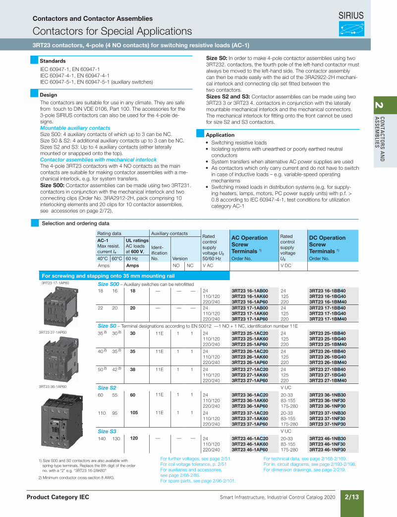
Standards
IEC 60947-1, EN 60947-1IEC 60947-4-1, EN 60947-4-1IEC 60947-5-1, EN 60947-5-1 (auxiliary switches)
DesignThe contactors are suitable for use in any climate. They are safe from touch to DIN VDE 0106, Part 100. The accessories for the 3-pole SIRIUS contactors can also be used for the 4-pole de-signs. Mountable auxiliary contacts Size S00: 4 auxiliary contacts of which up to 3 can be NC. Size S0 & S2: 4 additional auxiliary contacts up to 3 can be NC. Sizes S2 and S3: Up to 4 auxiliary contacts (either laterally mounted or snappped onto the top). Contactor assemblies with mechanical interlock The 4-pole 3RT23 contactors with 4 NO contacts as the main contacts are suitable for making contactor assemblies with a me-chanical interlock, e.g. for system transfers. Size S00: Contactor assemblies can be made using two 3RT231. contactors in conjunction with the mechanical interlock and two connecting clips (Order No. 3RA2912-2H, pack comprising 10 interlocking elements and 20 clips for 10 contactor assemblies, see accessories on page 2/72).
Size S0: In order to make 4-pole contactor assemblies using two 3RT232. contactors, the fourth pole of the left-hand contactor must always be moved to the left-hand side. The contactor assembly can then be made easily with the aid of the 3RA2922-2H mechani-cal interlock and connecting clip set fitted between the two contactors. Sizes S2 and S3: Contactor assemblies can be made using two 3RT23 3 or 3RT23 4. contactors in conjunction with the laterally mountable mechanical interlock and the mechanical connectors. The mechanical interlock for fitting onto the front cannot be used for size S2 and S3 contactors.
Application• Switching resistive loads• Isolating systems with unearthed or poorly earthed neutral
conductors• System transfers when alternative AC power supplies are used• As contactors which only carry current and do not have to switch
in case of inductive loads – e.g. variable-speed operating mechanisms
• Switching mixed loads in distribution systems (e.g. for supply-ing heaters, lamps, motors, PC power supply units) with p.f. > 0.8 according to IEC 60947-4-1, test conditions for utilization category AC-1
1) Size S00 and S0 contactors are also available with spring-type terminals. Replace the 8th digit of the order no. with a “2” e.g. “3RT23 16-2AK60”
2) Minimum conductor cross-section 8 AWG.
For further voltages, see page 2/51.For coil voltage tolerance, p. 2/51For auxiliaries and accessories, see page 2/68-2/85.For spare parts, see page 2/96-2/101.
For technical data, see page 2/168-2/169.For in. circuit diagrams, see page 2/193-2/198.For dimension drawings, see page 2/219.
Selection and ordering data
Rating data Auxiliary contactsRated controlsupply voltage Us 50/60 Hz
AC OperationScrew Terminals 1)
RatedcontrolsupplyvoltageUs
DC OperationScrew Terminals 1)
AC-1Max resist.current Ie
UL ratings AC loadsat 600 V,
Ident-ificationNo. Version40°C 60°C 60 Hz Order No. Order No.
Amps Amps NO NC V AC V DC
For screwing and stapping onto 35 mm mounting rail3RT23 17-1AP60 Size S00 – Auxiliary switches can be retrofitted
18 16 18 — — — 24110/120220/240
3RT23 16-1AB003RT23 16-1AK603RT23 16-1AP60
24125220
3RT23 16-1BB403RT23 16-1BG403RT23 16-1BM40
22 20 20 — — — 24110/120220/240
3RT23 17-1AB003RT23 17-1AK603RT23 17-1AP60
24125220
3RT23 17-1BB403RT23 17-1BG403RT23 17-1BM40
Size S0 – Terminal designations according to EN 50012 —1 NO + 1 NC, identification number 11E3RT23 27-1AP60 35 2) 30 2) 30 11E 1 1 24
110/120220/240
3RT23 25-1AC203RT23 25-1AK603RT23 25-1AP60
24125220
3RT23 25-1BB403RT23 25-1BG403RT23 25-1BM40
40 2) 35 2) 35 11E 1 1 24110/120220/240
3RT23 26-1AC203RT23 26-1AK603RT23 26-1AP60
24125220
3RT23 26-1BB403RT23 26-1BG403RT23 26-1BM40
50 2) 42 2) 38 11E 1 1 24110/120220/240
3RT23 27-1AC203RT23 27-1AK603RT23 27-1AP60
24125220
3RT23 27-1BB403RT23 27-1BG403RT23 27-1BM40
3RT23 36-1AP60 Size S2 V UC
60 55 60 11E 1 1 24110/120220/240
3RT23 36-1AC203RT23 36-1AK603RT23 36-1AP60
20-3383-155175-280
3RT23 36-1NB303RT23 36-1NF303RT23 36-1NP30
110 95 105 11E 1 1 24110/120220/240
3RT23 37-1AC203RT23 37-1AK603RT23 37-1AP60
20-3383-155175-280
3RT23 37-1NB303RT23 37-1NF303RT23 37-1NP30
Size S3 V UC
140 130 120 — — — 24110/120220/240
3RT23 46-1AC203RT23 46-1AK603RT23 46-1AP60
20-3383-155175-280
3RT23 46-1NB303RT23 46-1NF303RT23 46-1NP30
Contactors and Contactor Assemblies
Contactors for Special Applications3RT23 contactors, 4-pole (4 NO contacts) for switching resistive loads (AC-1)
Product Category IEC
SIRIUS
Smart Infrastructure, Industrial Control Catalog 2020 2/14
2Co
nta
Cto
rs a
nd
a
ssem
bli
es
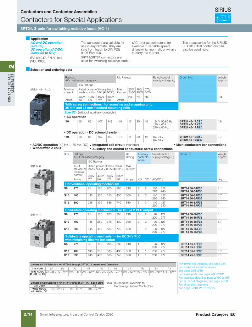
AC and DC operation (size S3)UC operation (AC/DC) (sizes S6 to S12)IEC 60 947, EN 60 947 (VDE 0660)
The contactors are suitable for use in any climate. They are safe from touch to DIN VDE 0106 Part 100.3RT14/3RT24 contactors are used for switching resistive loads.
(AC-1) or as contactors, for example in variable-speed drives which normally only have to carry the current.
The accessories for the SIRIUS 3RT10/3RT20 contactors can also be used here.
RatingsAC-1 utilization category,
UL Ratings Rated control supply voltage Us
Order No. Weight approx.
IEC Ratings
Maximumcurrent
Rated power of three phase loads cos Ø = 0.95 (@ 60°C)
MaxCurrent
230/240V
460/480V
575/600V
Amps230VkW
400VkW
500VkW
690VkW Amps
Hp Hp Hp kg
With screw connections · for screwing and snapping onto 35 mm and 75 mm standard mounting rails
Size S3 · (without auxiliary contacts)AC operation
140 50 86 107 148 140 15 30 40 24 V, 50/60 Hz 3RT24 46-1AC2 0 1.8120 V, 60 Hz 3RT24 46-1AK6 0240 V, 60 Hz 3RT24 46-1AP6 0
DC operation · DC solenoid system140 50 86 107 148 131 15 30 40 DC 24 V 3RT24 46-1BB4 0 2.7
DC 48 V 3RT24 46-1BW40
AC/DC operation (40 Hz ... 60 Hz, DC) Withdrawable coils
Size RatingsAC-1 utilization category,
ULRating
Auxiliary contacts, lateral
Rated control supply voltage Us
Order No. Weight approx.
IEC Ratings
AC-1Maximum resistive current
Rated power of three phase loads cos Ø = 0.95 (@ 60°C)
MaxCurrent
230V 400V 500V 690VAmps kW kW kW kW Amps NO NC AC/DC V kg
Conventional operating mechanismS6 275 95 165 205 285 210 2 2 110 ... 127 3RT14 56-6AF36 3.1
220 ... 240 3RT14 56-6AP36S10 400 145 250 315 430 360 2 2 110 ... 127 3RT14 66-6AF36 5.7
220 ... 240 3RT14 66-6AP36S12 690 245 430 535 740 580 2 2 110 ... 127 3RT14 76-6AF36 9.1
220 ... 240 3RT14 76-6AP36Solid-state operating mechanism · for DC 24 V PLC output
S6 275 95 165 205 285 210 2 2 96 ... 127 3RT14 56-6NF36 3.1200 ... 277 3RT14 56-6NP36
S10 400 145 250 315 430 360 2 2 96 ... 127 3RT14 66-6NF36 5.7200 ... 277 3RT14 66-6NP36
S12 690 245 430 535 740 580 2 2 96 ... 127 3RT14 76-6NF36 9.1200 ... 277 3RT14 76-6NP36
Solid-state operating mechanism · for DC 24 V PLC with remaining lifetime indication
S6 275 95 165 205 285 210 1 1 96 ... 127 3RT14 56-6PF35 3.1200 ... 277 3RT14 56-6PP35
S10 400 145 250 315 430 360 1 1 200 ... 277 3RT14 66-6PP35 5.7S12 690 245 430 535 740 580 1 1 200 ... 277 3RT14 76-6PP35 9.1
Selection and ordering data
3RT24 46-1A . .0
3RT14 6 .
3RT14 7 .
Universal Coil Selection for 3RT145 through 3RT147: Conventional OperationCoil Code B3 D3 F3 M3 P3 U3 V3 R3 S3 T3
Volts AC/DC 40 - 60 Hz, DC
23 .. 26 V 42 .. 48 V 110 .. 127 V 200 .. 220 V 220 .. 240 V 240 .. 277 V 380 .. 420 V 440 .. 480 V 500 .. 550 V 575 .. 600 V
Universal Coil Selection for 3RT145 through 3RT147: Solid-StateCoil Code B3 F3 P3
Volts AC/DC 40 - 60 Hz, DC
21 .. 27.3 V 96 .. 127 V 200 .. 277 V
Auxiliary and control conductors: screw connectionsMain conductor: bar connections Integrated coil circuit (varistor)
Application
Note: B3 code not available for Remaining Lifetime Contactors.
Siemens / Industrial Controls Previous folio: IC10 2/11
For further coil voltages, see page 2/51.For auxiliaries and accessories,see page 2/68-2/85.For spare parts, see page 2/96-2/101.For technical data, see page 2/160-2/167.For int. circuit diagrams, see page 2/198.For dimension drawings,see page 2/213, 2/215-2/216.
Contactors and Contactor Assemblies
Contactors for Special Applications3RT24, 3-pole for switching resistive loads (AC-1)
Product Category IEC
SIRIUS
Smart Infrastructure, Industrial Control Catalog 2020 2/15
2Co
nta
Ctors a
nd
a
ssemb
lies
1) For changing polarity; not suitable for reversing.
2) Size S00 and S0 contactors are also available with spring-type terminals. Replace the 8th digit of the order no. with a “2” e.g. “3RT25 16-2AK60”
3) Size S00: Coil voltage tolerance at 50 Hz: 0.8 ... 1.1 x Usat 60 Hz: 0.85 ... 1.1 x Us
4) The NC contact can switch up to 5 HP.
For further voltages, see page 2/51.For auxiliaries and accessories, see page 2/68-2/85.For spare parts, see page 2/96-2/101.For technical data, see page 2/170-2/171.For int. circuit diagrams, see page 2/193-2/198.For dimension drawings, see page 2/219.
Siemens / Industrial Controls Previous folio: IC10 2/14
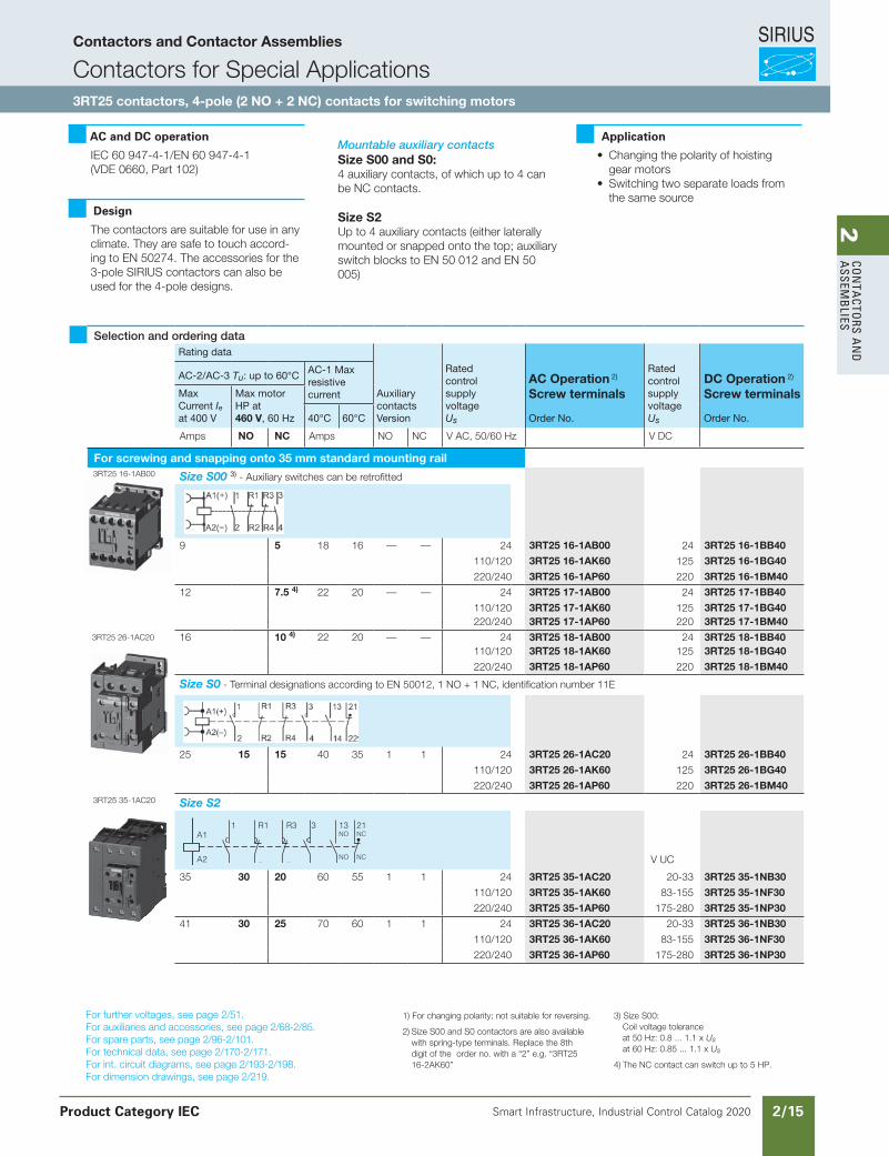
AC and DC operation IEC 60 947-4-1/EN 60 947-4-1(VDE 0660, Part 102)
Design
The contactors are suitable for use in any climate. They are safe to touch accord-ing to EN 50274. The accessories for the 3-pole SIRIUS contactors can also be used for the 4-pole designs.
Mountable auxiliary contactsSize S00 and S0:4 auxiliary contacts, of which up to 4 can be NC contacts.
Size S2Up to 4 auxiliary contacts (either laterally mounted or snapped onto the top; auxiliaryswitch blocks to EN 50 012 and EN 50 005)
Application
• Changing the polarity of hoisting gear motors
• Switching two separate loads from the same source
Selection and ordering dataRating data
AuxiliarycontactsVersion
Rated controlsupply voltageUs
AC Operation 2)
Screw terminals
RatedcontrolsupplyvoltageUs
DC Operation 2)
Screw terminals
AC-2/AC-3 Tu: up to 60°C AC-1 Max resistivecurrentMax
Current Ieat 400 V
Max motorHP at460 V, 60 Hz 40°C 60°C Order No. Order No.
Amps NO NC Amps NO NC V AC, 50/60 Hz V DC
For screwing and snapping onto 35 mm standard mounting rail3RT25 16-1AB00 Size S00 3) - Auxiliary switches can be retrofitted
9 5 18 16 — — 24 3RT25 16-1AB00 24 3RT25 16-1BB40
110/120 3RT25 16-1AK60 125 3RT25 16-1BG40
220/240 3RT25 16-1AP60 220 3RT25 16-1BM40
12 7.5 4) 22 20 — — 24 3RT25 17-1AB00 24 3RT25 17-1BB40
110/120 3RT25 17-1AK60 125 3RT25 17-1BG40220/240 3RT25 17-1AP60 220 3RT25 17-1BM40
3RT25 26-1AC20 16 10 4) 22 20 — — 24 3RT25 18-1AB00 24 3RT25 18-1BB40110/120 3RT25 18-1AK60 125 3RT25 18-1BG40
220/240 3RT25 18-1AP60 220 3RT25 18-1BM40
Size S0 - Terminal designations according to EN 50012, 1 NO + 1 NC, identification number 11E
25 15 15 40 35 1 1 24 3RT25 26-1AC20 24 3RT25 26-1BB40
110/120 3RT25 26-1AK60 125 3RT25 26-1BG40
220/240 3RT25 26-1AP60 220 3RT25 26-1BM403RT25 35-1AC20 Size S2
V UC
35 30 20 60 55 1 1 24 3RT25 35-1AC20 20-33 3RT25 35-1NB30
110/120 3RT25 35-1AK60 83-155 3RT25 35-1NF30
220/240 3RT25 35-1AP60 175-280 3RT25 35-1NP30
41 30 25 70 60 1 1 24 3RT25 36-1AC20 20-33 3RT25 36-1NB30
110/120 3RT25 36-1AK60 83-155 3RT25 36-1NF30
220/240 3RT25 36-1AP60 175-280 3RT25 36-1NP30
A2
A1
2 R2 R4 4 NO
14NC
22
1 R1 R3 3 13NO
21NC
Contactors and Contactor Assemblies
Contactors for Special Applications3RT25 contactors, 4-pole (2 NO + 2 NC) contacts for switching motors
Product Category IEC
SIRIUS
Smart Infrastructure, Industrial Control Catalog 2020 2/16
2Co
nta
Cto
rs a
nd
a
ssem
bli
es3RT, 3RH Contactors for Special Applications
Contactors with Extended Operating Range 0.7 ... 1.25 x , for Railway Applications
3RH21 contactor relays
3/53SIRIUS Innovations Supplement 2012
3
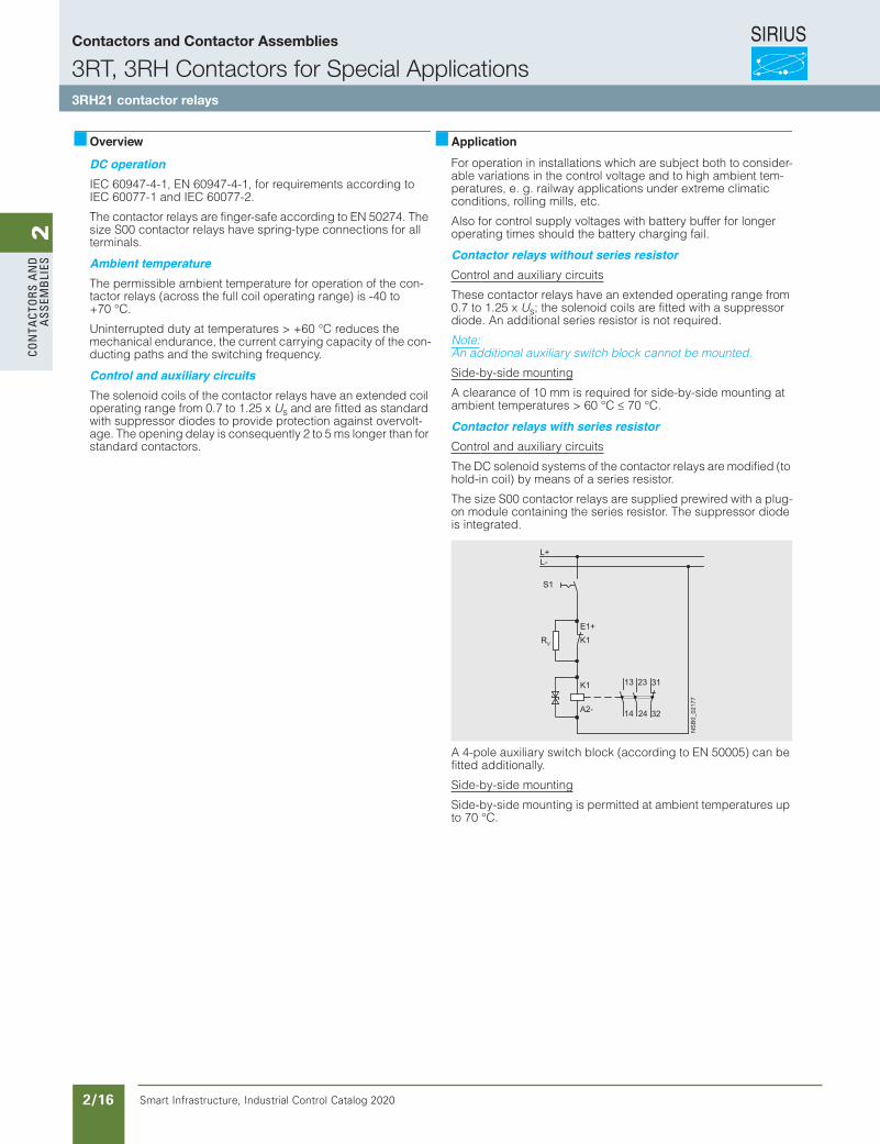
Overview
DC operationIEC 60947-4-1, EN 60947-4-1, for requirements according to IEC 60077-1 and IEC 60077-2.
The contactor relays are finger-safe according to EN 50274. The size S00 contactor relays have spring-type connections for all terminals.
Ambient temperatureThe permissible ambient temperature for operation of the con-tactor relays (across the full coil operating range) is -40 to +70 °C.
Uninterrupted duty at temperatures > +60 °C reduces the mechanical endurance, the current carrying capacity of the con-ducting paths and the switching frequency.
Control and auxiliary circuitsThe solenoid coils of the contactor relays have an extended coil operating range from 0.7 to 1.25 x Us and are fitted as standard with suppressor diodes to provide protection against overvolt-age. The opening delay is consequently 2 to 5 ms longer than for standard contactors.
ApplicationFor operation in installations which are subject both to consider-able variations in the control voltage and to high ambient tem-peratures, e. g. railway applications under extreme climatic conditions, rolling mills, etc.
Also for control supply voltages with battery buffer for longer operating times should the battery charging fail.
Contactor relays without series resistorControl and auxiliary circuits
These contactor relays have an extended operating range from 0.7 to 1.25 x Us; the solenoid coils are fitted with a suppressor diode. An additional series resistor is not required.
Note:An additional auxiliary switch block cannot be mounted.
Side-by-side mounting
A clearance of 10 mm is required for side-by-side mounting at ambient temperatures > 60 °C ≤ 70 °C.
Contactor relays with series resistorControl and auxiliary circuits
The DC solenoid systems of the contactor relays are modified (to hold-in coil) by means of a series resistor.
The size S00 contactor relays are supplied prewired with a plug-on module containing the series resistor. The suppressor diode is integrated.
A 4-pole auxiliary switch block (according to EN 50005) can be fitted additionally.
Side-by-side mounting
Side-by-side mounting is permitted at ambient temperatures up to 70 °C.
L-L+
32
31
24
23
14
13
+E1K1
K1
-A2
NSB0_02177
VR
S1
Us
LV1N_03_06.fm Page 53 Thursday, October 31, 2013 11:31 AM
Contactors and Contactor Assemblies
3RT, 3RH Contactors for Special Applications3RH21 contactor relays
SIRIUS
Smart Infrastructure, Industrial Control Catalog 2020 2/17
2Co
nta
Ctors a
nd
a
ssemb
lies3RT, 3RH Contactors for Special Applications
Contactors with Extended Operating Range 0.7 ... 1.25 x , for Railway Applications
3RH21 contactor relays
3/54 SIRIUS Innovations Supplement 2012 Illustrations are approximate
3
Selection and ordering data
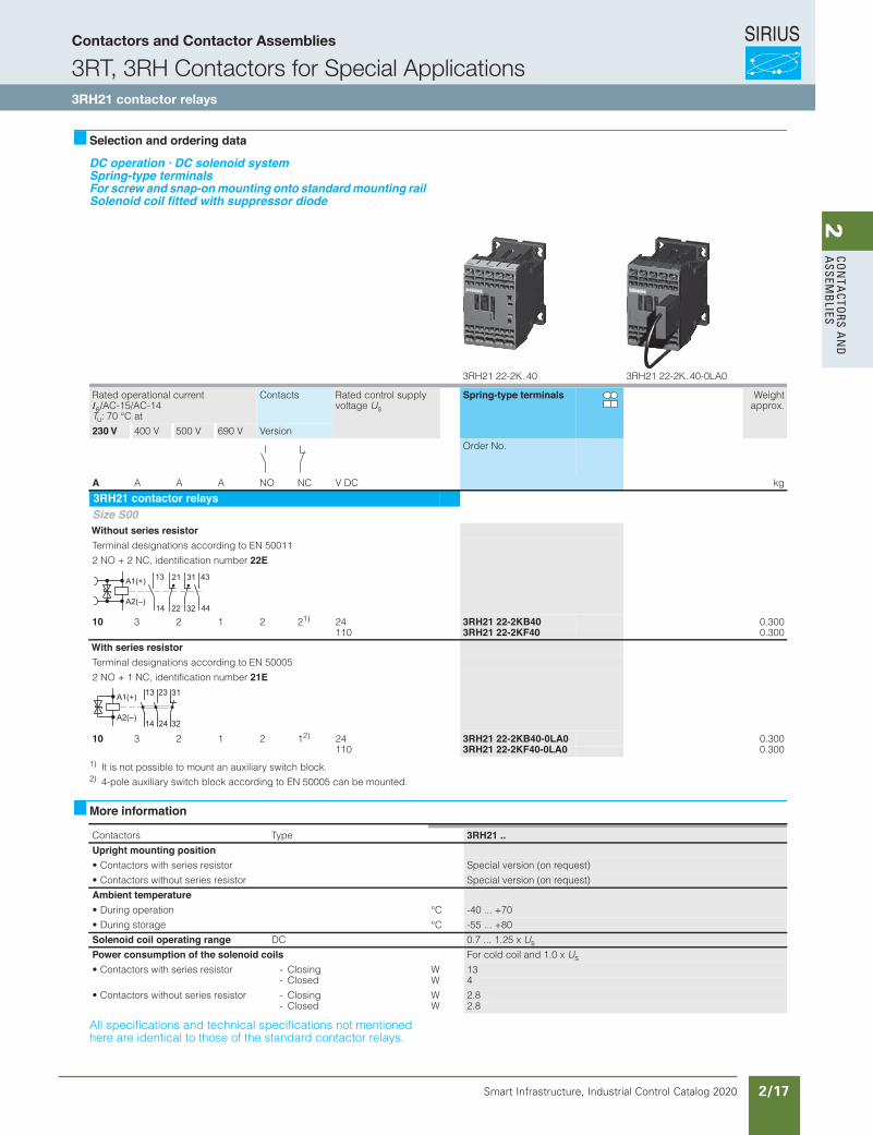
DC operation · DC solenoid systemSpring-type terminalsFor screw and snap-onmounting onto standardmounting railSolenoid coil fitted with suppressor diode
1) It is not possible to mount an auxiliary switch block.2) 4-pole auxiliary switch block according to EN 50005 can be mounted.
More information
All specifications and technical specifications not mentioned here are identical to those of the standard contactor relays.
3RH21 22-2K . 40 3RH21 22-2K . 40-0LA0
Rated operational current Ie/AC-15/AC-14 Tu: 70 °C at
Contacts Rated control supply voltage Us
Spring-type terminals Weightapprox.
230 V 400 V 500 V 690 V Version
Order No.
A A A A NO NC V DC kg
3RH21 contactor relaysSize S00Without series resistorTerminal designations according to EN 50011
2 NO + 2 NC, identification number 22E
10 3 2 1 2 21) 24 3RH21 22-2KB40 0.300110 3RH21 22-2KF40 0.300
With series resistorTerminal designations according to EN 50005
2 NO + 1 NC, identification number 21E
10 3 2 1 2 12) 24 3RH21 22-2KB40-0LA0 0.300110 3RH21 22-2KF40-0LA0 0.300
A1(+)
A2(–)14
13
44
43
22
21
32
31
A1(+)
A2(–)32
31
24
23
14
13
epyTsrotcatnoC 3RH21 ..Upright mounting position• Contactors with series resistor Special version (on request)
• Contactors without series resistor Special version (on request)
Ambient temperatureC°noitarepo gniruD• -40 ... +70
C°egarots gniruD• -55 ... +80
Solenoid coil operating range DC 0.7 ... 1.25 x Us
Power consumption of the solenoid coils For cold coil and 1.0 x Us
WgnisolC-rotsiser seires htiw srotcatnoC• 13WdesolC- 4
WgnisolC-rotsiser seires tuohtiw srotcatnoC• 2.8WdesolC- 2.8
Us
LV1N_03_06.fm Page 54 Thursday, October 31, 2013 11:31 AM
Contactors and Contactor Assemblies
3RT, 3RH Contactors for Special Applications3RH21 contactor relays
SIRIUS
Smart Infrastructure, Industrial Control Catalog 2020 2/18
2Co
nta
Cto
rs a
nd
a
ssem
bli
es3RT, 3RH Contactors for Special Applications
Contactors with Extended Operating Range 0.7 ... 1.25 x , for Railway Applications
3RT20 motor contactors, 7.5 ... 25 HP
3/55SIRIUS Innovations Supplement 2012
3
Overview
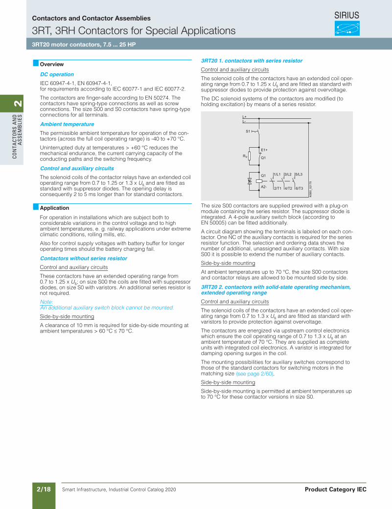
DC operationIEC 60947-4-1, EN 60947-4-1, for requirements according to IEC 60077-1 and IEC 60077-2.
The contactors are finger-safe according to EN 50274. The contactors have spring-type connections as well as screw connections. The size S00 and S0 contactors have spring-type connections for all terminals.
Ambient temperatureThe permissible ambient temperature for operation of the con-tactors (across the full coil operating range) is -40 to +70 °C.
Uninterrupted duty at temperatures > +60 °C reduces the mechanical endurance, the current carrying capacity of the conducting paths and the switching frequency.
Control and auxiliary circuitsThe solenoid coils of the contactor relays have an extended coil operating range from 0.7 to 1.25 or 1.3 x Us and are fitted as standard with suppressor diodes. The opening delay is consequently 2 to 5 ms longer than for standard contactors.
ApplicationFor operation in installations which are subject both to considerable variations in the control voltage and to high ambient temperatures, e. g. railway applications under extreme climatic conditions, rolling mills, etc.
Also for control supply voltages with battery buffer for longer operating times should the battery charging fail.
Contactors without series resistorControl and auxiliary circuits
These contactors have an extended operating range from 0.7 to 1.25 x Us; on size S00 the coils are fitted with suppressor diodes, on size S0 with varistors. An additional series resistor is not required.
Note:An additional auxiliary switch block cannot be mounted.
Side-by-side mounting
A clearance of 10 mm is required for side-by-side mounting at ambient temperatures > 60 °C ≤ 70 °C.
3RT20 1. contactors with series resistorControl and auxiliary circuits
The solenoid coils of the contactors have an extended coil oper-ating range from 0.7 to 1.25 x Us and are fitted as standard with suppressor diodes to provide protection against overvoltage.
The DC solenoid systems of the contactors are modified (to holding excitation) by means of a series resistor.
The size S00 contactors are supplied prewired with a plug-on module containing the series resistor. The suppressor diode is integrated. A 4-pole auxiliary switch block (according to EN 50005) can be fitted additionally.
A circuit diagram showing the terminals is labeled on each con-tactor. One NC of the auxiliary contacts is required for the series resistor function. The selection and ordering data shows the number of additional, unassigned auxiliary contacts. With size S00 it is possible to extend the number of auxiliary contacts.
Side-by-side mounting
At ambient temperatures up to 70 °C, the size S00 contactors and contactor relays are allowed to be mounted side by side.
3RT20 2. contactors with solid-state operating mechanism,extended operating rangeControl and auxiliary circuits
The solenoid coils of the contactors have an extended coil oper-ating range from 0.7 to 1.3 x Us and are fitted as standard with varistors to provide protection against overvoltage.
The contactors are energized via upstream control electronics which ensure the coil operating range of 0.7 to 1.3 x Us at an ambient temperature of 70 °C. They are supplied as complete units with integrated coil electronics. A varistor is integrated for damping opening surges in the coil.
The mounting possibilities for auxiliary switches correspond to those of the standard contactors for switching motors in the matching size (see page 3/6).
Side-by-side mounting
Side-by-side mounting is permitted at ambient temperatures up to 70 °C for these contactor versions in size S0.
6/T3
5/L3
4/T2
3/L2
2/T1
1/L1
E1+
Q1
Q1
A2-
NSB0_02178
R
S1
L-L+
v
Us
LV1N_03_06.fm Page 55 Thursday, October 31, 2013 11:31 AM
(see page 2/60).
Contactors and Contactor Assemblies
3RT, 3RH Contactors for Special Applications3RT20 motor contactors, 7.5 ... 25 HP
Product Category IEC
SIRIUS
Smart Infrastructure, Industrial Control Catalog 2020 2/19
2Co
nta
Ctors a
nd
a
ssemb
lies3RT, 3RH Contactors for Special Applications
Contactors with Extended Operating Range 0.7 ... 1.25 x , for Railway Applications
3RT20 motor contactors, 7.5 ... 25 HP
3/56 SIRIUS Innovations Supplement 2012 Illustrations are approximate
3
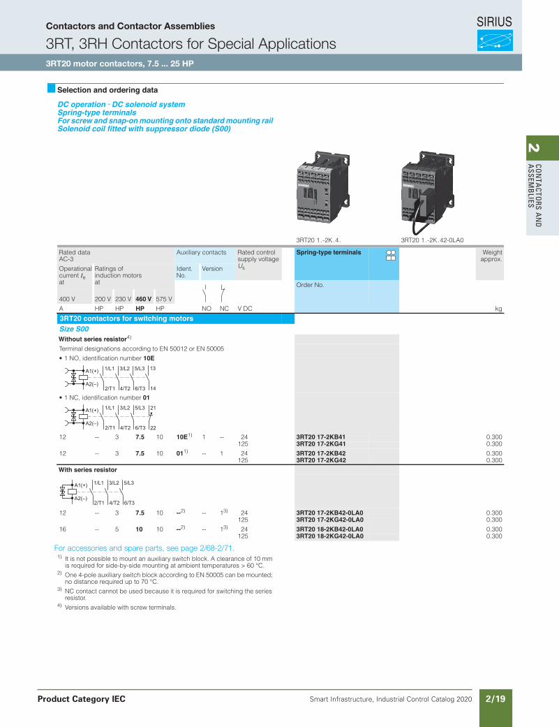
Selection and ordering data
DC operation · DC solenoid systemSpring-type terminalsFor screw and snap-onmounting onto standardmounting railSolenoid coil fitted with suppressor diode (S00)
For accessories and spare parts, see page 3/93.1) It is not possible to mount an auxiliary switch block. A clearance of 10 mm
is required for side-by-side mounting at ambient temperatures > 60 °C.2) One 4-pole auxiliary switch block according to EN 50005 can be mounted;
no distance required up to 70 °C.3) NC contact cannot be used because it is required for switching the series
resistor.4) Versions available with screw terminals.
3RT20 1 . -2K . 4 . 3RT20 1 . -2K . 42-0LA0
Rated data AC-3
Auxiliary contacts Rated control supply voltage Us
Spring-type terminals Weightapprox.
Operational current Ie at
Ratings of induction motors at
Ident. No.
Version
Order No.
400 V 200 V 230 V 460 V 575 V
A HP HP HP HP NO NC V DC kg
3RT20 contactors for switching motorsSize S00Without series resistor4)
Terminal designations according to EN 50012 or EN 50005
• 1 NO, identification number 10E
• 1 NC, identification number 01
12 -- 3 7.5 10 10E1) 1 -- 24 3RT20 17-2KB41 0.300125 3RT20 17-2KG41 0.300
12 -- 3 7.5 10 011) -- 1 24 3RT20 17-2KB42 0.300125 3RT20 17-2KG42 0.300
With series resistor
12 -- 3 7.5 10 --2) -- 13) 24 3RT20 17-2KB42-0LA0 0.300125 3RT20 17-2KG42-0LA0 0.300
16 -- 5 10 10 --2) -- 13) 24 3RT20 18-2KB42-0LA0 0.300125 3RT20 18-2KG42-0LA0 0.300
A1(+)
A2(–)14
13
2/T1
1/L1
4/T2
3/L2
6/T3
5/L3
A1(+)
A2(–)22
21
2/T1
1/L1
4/T2
3/L2
6/T3
5/L3
A1(+)
A2(–)2/T1
1/L1
4/T2
3/L2
6/T3
5/L3
Us
LV1N_03_06.fm Page 56 Thursday, October 31, 2013 11:31 AM
For accessories and spare parts, see page 2/68-2/71.
Contactors and Contactor Assemblies
3RT, 3RH Contactors for Special Applications3RT20 motor contactors, 7.5 ... 25 HP
Product Category IEC
SIRIUS
Smart Infrastructure, Industrial Control Catalog 2020 2/20
2Co
nta
Cto
rs a
nd
a
ssem
bli
es3RT, 3RH Contactors for Special Applications
Contactors with Extended Operating Range 0.7 ... 1.25 x , for Railway Applications
3RT20 motor contactors, 7.5 ... 25 HP
3/57SIRIUS Innovations Supplement 2012Illustrations are approximate
3
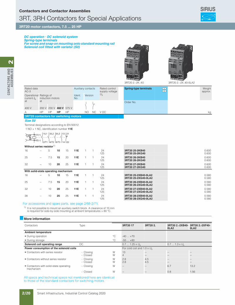
DC operation · DC solenoid systemSpring-type terminalsFor screw and snap-onmounting onto standardmounting railSolenoid coil fitted with varistor (S0)
For accessories and spare parts, see page 3/93.1) It is not possible to mount an auxiliary switch block. A clearance of 10 mm
is required for side-by-side mounting at ambient temperatures > 60 °C.
More information
All specs and technical specs not mentioned here are identical to those of the standard contactors for switching motors.
3RT20 2. -2K . 4 0 3RT20 2 . -2X . 40-0LA2
Rated data AC-3
Auxiliary contacts Rated control supply voltage Us
Spring-type terminals Weightapprox.
Operational current Ie at
Ratings of induction motors at
Ident. No.
Version
Order No.
400 V 200 V 230 V 460 V 575 V
A HP HP HP HP NO NC V DC kg
3RT20 contactors for switching motorsSize S0Terminal designations according to EN 50012
1 NO + 1 NC, identification number 11E
Without series resistor1)
16 -- 5 10 15 11E 1 1 24 3RT20 25-2KB40 0.600125 3RT20 25-2KG40 0.600
25 -- 7.5 15 20 11E 1 1 24 3RT20 26-2KB40 0.600125 3RT20 26-2KG40 0.600
32 -- 10 20 25 11E 1 1 24 3RT20 27-2KB40 0.600125 3RT20 27-2KG40 0.600
With solid-state operating mechanism16 -- 5 10 15 11E 1 1 24 3RT20 25-2XB40-0LA2 0.580
125 3RT20 25-2XG40-0LA2 0.580
25 -- 7.5 15 20 11E 1 1 24 3RT20 26-2XB40-0LA2 0.580125 3RT20 26-2XG40-0LA2 0.580
32 -- 10 20 25 11E 1 1 24 3RT20 27-2XB40-0LA2 0.580125 3RT20 27-2XG40-0LA2 0.580
38 -- 10 25 25 11E 1 1 24 3RT20 28-2XB40-0LA2 0.580125 3RT20 28-2XG40-0LA2 0.580
A1(+)
A2(–)22
21
14
13
2/T1
1/L1
4/T2
3/L2
6/T3
5/L3
epyTsrotcatnoC 3RT20 17 3RT20 2. 3RT20 2.-2XB40-0LA2
3RT20 2.-2XF40-0LA2
Ambient temperatureC°noitarepo gniruD• -40 ... +70
C°egarots gniruD• -55 ... +80
Solenoid coil operating range DC 0.7 ... 1.25 x Us 0.7 ... 1.3 x Us
Power consumption of the solenoid coils For cold coil and 1.0 x Us
• Contactors with series resistor - Closing W 13 -- -- --- Closed W 4 -- -- --
• Contactors without series resistor - Closing W 2.8 4.5 -- --- Closed W 2.8 4.5 -- --
• Contactors with solid-state operating mechanism
- Closing W -- -- 6.7 13.2
- Closed W -- -- 0.8 1.56
Us
LV1N_03_06.fm Page 57 Thursday, October 31, 2013 11:31 AM
For accessories and spare parts, see page 2/68-2/71.
Contactors and Contactor Assemblies
3RT, 3RH Contactors for Special Applications3RT20 motor contactors, 7.5 ... 25 HP
SIRIUS
Smart Infrastructure, Industrial Control Catalog 2020 2/21
2Co
nta
Ctors a
nd
a
ssemb
lies
Siemens / Industrial Controls Previous folio: IC10 2/15
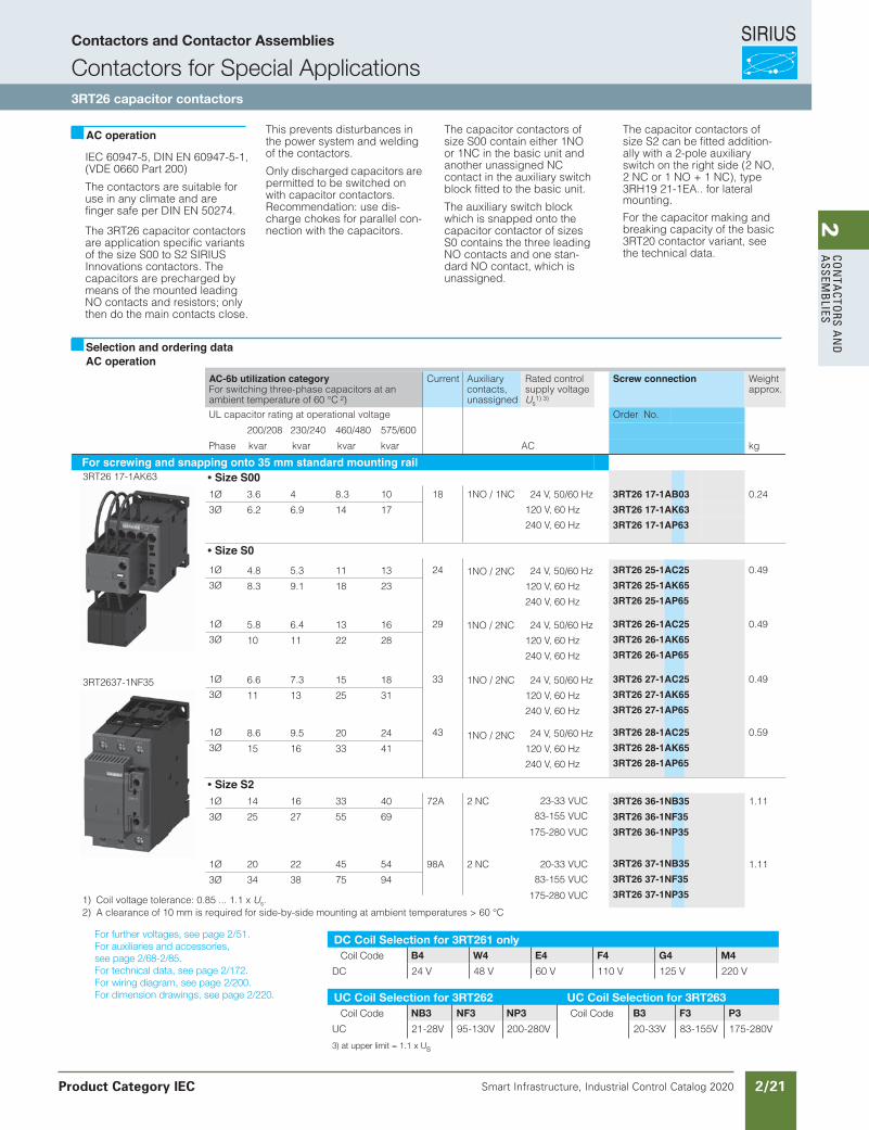
IEC 60947-5, DIN EN 60947-5-1,(VDE 0660 Part 200)
The contactors are suitable for use in any climate and are finger safe per DIN EN 50274.
The 3RT26 capacitor contactorsare application specific variants of the size S00 to S2 SIRIUS Innovations contactors. The capacitors are precharged by means of the mounted leading NO contacts and resistors; only then do the main contacts close.
This prevents disturbances in the power system and welding of the contactors.
Only discharged capacitors are permitted to be switched on with capacitor contactors. Recommendation: use dis-charge chokes for parallel con-nection with the capacitors.
The capacitor contactors of size S00 contain either 1NO or 1NC in the basic unit and another unassigned NC contact in the auxiliary switch block fitted to the basic unit.
The auxiliary switch block which is snapped onto thecapacitor contactor of sizes S0 contains the three leadingNO contacts and one stan-dard NO contact, which is unassigned.
The capacitor contactors of size S2 can be fitted addition-ally with a 2-pole auxiliary switch on the right side (2 NO, 2 NC or 1 NO + 1 NC), type 3RH19 21-1EA.. for lateral mounting.
For the capacitor making and breaking capacity of the basic 3RT20 contactor variant, see the technical data.
AC-6b utilization categoryFor switching three-phase capacitors at anambient temperature of 60 °C 2)
Current Auxiliarycontacts,unassigned
Rated controlsupply voltageUs
1) 3)
Screw connection Weightapprox.
UL capacitor rating at operational voltage Order No.
200/208 230/240 460/480 575/600
kvarPhase kvar kvar kvar AC kg
For screwing and snapping onto 35 mm standard mounting railSize S00
1Ø 18108.343.6
17146.96.2
13115.34.8
23189.18.3
24 V, 50/60 Hz 0.24
3Ø 120 V, 60 Hz
240 V, 60 Hz
24 V, 50/60 Hz
120 V, 60 Hz
240 V, 60 Hz
1Ø 24 3RT26 25-1AC25 0.49
3Ø 3RT26 25-1AK653RT26 25-1AP65
Size S21Ø 14 16 33 40 72A 2 NC
1NO / 1NC
1NO / 2NC
1NO / 2NC
1NO / 2NC
1NO / 2NC
1.11
3Ø 25 27 55 69
3RT26 37-1NB353RT26 37-1NF35 3RT26 37-1NP35
1Ø 20 22 45 54 98A 2 NC 20-33 VUC
83-155 VUC
175-280 VUC
23-33 VUC
83-155 VUC
175-280 VUC
1.11
3Ø 34 38 75 94
AC operation
Selection and ordering dataAC operation
3RT26 17-1AK63
3RT2637-1NF35
1) Coil voltage tolerance: 0.85 ... 1.1 x Us.2) A clearance of 10 mm is required for side-by-side mounting at ambient temperatures > 60 °C
3RT26 36-1NB353RT26 36-1NF353RT26 36-1NP35
3RT26 17-1AB033RT26 17-1AK633RT26 17-1AP63
Size S0
16136.45.8
28221110
24 V, 50/60 Hz
120 V, 60 Hz
240 V, 60 Hz
1Ø 29 3RT26 26-1AC25 0.49
3Ø 3RT26 26-1AK653RT26 26-1AP65
18157.36.6
31251311
24 V, 50/60 Hz
120 V, 60 Hz
240 V, 60 Hz
1Ø 33 3RT26 27-1AC25 0.49
3Ø 3RT26 27-1AK653RT26 27-1AP65
24209.58.6
41331615
24 V, 50/60 Hz
120 V, 60 Hz
240 V, 60 Hz
1Ø 43 3RT26 28-1AC25 0.59
3Ø 3RT26 28-1AK653RT26 28-1AP65
For further voltages, see page 2/51.For auxiliaries and accessories,see page 2/68-2/85.For technical data, see page 2/172.For wiring diagram, see page 2/200.For dimension drawings, see page 2/220.
DC Coil Selection for 3RT261 only Coil Code B4 W4 E4 F4 G4 M4
DC 24 V 48 V 60 V 110 V 125 V 220 V
UC Coil Selection for 3RT262 UC Coil Selection for 3RT263 Coil Code NB3 NF3 NP3 Coil Code B3 F3 P3
UC 21-28V 95-130V 200-280V 20-33V 83-155V 175-280V
3) at upper limit = 1.1 x Us
Contactors and Contactor Assemblies
Contactors for Special Applications3RT26 capacitor contactors
Product Category IEC
SIRIUS
Smart Infrastructure, Industrial Control Catalog 2020 2/22
2Co
nta
Cto
rs a
nd
a
ssem
bli
es
Siemens / Industrial Controls Previous folio: IC10 2/16
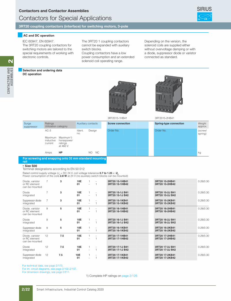
3RT2015-1HB41 3RT2015-2HB41
RatingsUtilization category
Auxiliary contactsSurgesuppressor
Spring-type connection Weight approx.
AC-3 Ident. no.
Design (screw/spring)
Order No. Order No.
Maximum inductive current
Maximum1)horsepower ratingsat 460 V
Amps HP NO NC kg
For screwing and snapping onto 35 mm standard mounting rail
Size S00Terminal designations according to EN 50 012Rated control supply voltage Us = DC 24 V, coil voltage tolerance 0.7 to 1.25 × UsPower consumption of the coils 2.8 W at 24 V (no auxiliary switch blocks can be mounted)
Diode, varistor 7 3 10E 1 – 0.28/0.30or RC element 01 – 1can be mounted
Diode 7 3 10E 1 – 0.28/0.30integrated 01 – 1
Suppressor diode 3 10E 1 – 0.28/0.30integrated 01 – 1
Diode, varistor 9 5 10E 1 – 0.28/0.30or RC element 01 – 1can be mounted
Diode 9 5 10E 1 – 0.28/0.30integrated 01 – 1
5 10E 1 – 0.28/0.30integrated 01 – 1
Diode, varistor 12 7.5 10E 1 – 0.28/0.30or RC element 01 – 1can be mounted
Diode 12 7.5 10E 1 – 0.28/0.30integrated 01 – 1
7.5 10E 1 – 0.28/0.30integrated 01 – 1
1) Complete HP ratings on page 2/89.
Selection and ordering dataDC operation
Screw connection
7
Suppressor diode 9
Suppressor diode 12
3RT20 15-1J B423RT20 15-1J B41
3RT20 15-1HB423RT20 15-1HB41 3RT20 15-2HB41
3RT20 15-2HB42
3RT20 15-2J B413RT20 15-2J B42
3RT20 15-2KB413RT20 15-2KB42
3RT20 16-2HB413RT20 16-2HB42
3RT20 16-2J B413RT20 16-2J B42
3RT20 16-2KB413RT20 16-2KB42
3RT20 17-2HB413RT20 17-2HB42
3RT20 17-2J B413RT20 17-2J B42
3RT20 17-2KB413RT20 17-2KB42
3RT20 16-1HB413RT20 16-1HB42
3RT20 16-1J B413RT20 16-1J B42
3RT20 16-1KB413RT20 16-1KB42
3RT20 15-1KB413RT20 15-1KB42
3RT20 17-1HB413RT20 17-1HB42
3RT20 17-1J B413RT20 17-1J B42
3RT20 17-1KB413RT20 17-1KB42
IEC 60947, EN 60947.The 3RT20 coupling contactors for switching motors are tailored to the special requirements of working with electronic controls.
AC and DC operation
The 3RT20 1 coupling contactors cannot be expanded with auxiliary switch blocks.Coupling contactors have a low power consumption and an extended solenoid coil operating range.
Depending on the version, the solenoid coils are supplied either without overvoltage damping or with a diode, suppressor diode or varistor connected as standard.
For technical data, see page 2/173.For int. circuit diagrams, see page 2/192-2/197.For dimension drawings, see page 2/211.
1) Complete HP ratings on page 2/126
Contactors and Contactor Assemblies
Contactors for Special Applications3RT20 coupling contactors (interface) for switching motors, 3-pole

SIRIUS
Smart Infrastructure, Industrial Control Catalog 2020 2/23
2Co
nta
Ctors a
nd
a
ssemb
lies3RT2015-1VB41 3RT2015-2VB41 3RT2024-1KB40
Surgesuppressor
RatingsUtilization category
Auxiliary contacts Spring-type connection Weight approx.
AC-3 Ident. no.
Design (screw/spring)
Order No. Order No.
Maximuminductivecurrent
Maximumhorsepowerratingsat 460 V
Amps HP NO NC kg
For screwing and snapping onto35 mm standard mounting rail Size S00Terminal designations according to EN 50 012Rated control supply voltage Us =DC 24 V, coil voltage tolerance 0.85 to 1.85 × UsPower consumption of the coils 1.6 W at 24 V (no auxiliary switch blocks can be mounted)
Diode, varistor 7 3 10E 1 – 3RT20 15-1MB41-0KT0 3RT20 15-2M B41-0KT0 0.28/0.30or RC element 01 – 1 3RT20 15-1MB42-0KT0 3RT20 15-2M B42-0KT0can be mounted
Diode 7 3 10E 1 – 0.28/0.30integrated 01 – 1
3 10E 1 – 0.28/0.30integrated 01 – 1
Diode, varistor 9 5 10E 1 – 3RT20 16-1MB41-0KT0 3RT20 16-2M B41-0KT0 0.28/0.30or RC element 01 – 1 3RT20 16-1MB42-0KT0 3RT20 16-2M B42-0KT0can be mounted
Diode 9 5 10E 1 – 0.28/0.30integrated 01 – 1
5 10E 1 – 0.28/0.30integrated 01 – 1
Diode, varistor 12 7.5 10E 1 – 3RT20 17-1MB41-0KT0 3RT20 17-2M B41-0KT0 0.28/0.30or RC element 01 – 1 3RT20 17-1MB42-0KT0 3RT20 17-2M B42-0KT0can be mounted
Diode 12 7.5 10E 1 – 0.28/0.30integrated 01 – 1
Suppressor diode 7.5 10E 1 – 0.28/0.30integrated 01 – 1
Size S0Rated control supply voltage Us = DC 24 V, coil voltage tolerance 0.7 to 1.25 × UsPower consumption of the coils 4.5 W at 24 V no auxiliary switch blocks can be mounted.
Varistorintegrated
12 7.5 11E 1 1 3RT20 24-1KB40 3RT20 24-2KB40 0.58/0.60
16 10 11E 1 1 3RT20 25-1KB40 3RT20 25-2KB40 0.58/0.60
25 15 11E 1 1 3RT20 26-1KB40 3RT20 26-2KB40 0.58/0.60
32 20 11E 1 1 3RT20 27-1KB40 3RT20 27-2KB40 0.58/0.60
Selection and ordering dataDC operation
Screw connection
3RT20 15-1VB413RT20 15-1VB42
3RT20 15-1SB423RT20 15-1SB41
3RT20 17-1SB42
3RT20 17-1VB413RT20 17-1VB42
3RT20 17-1SB413RT20 17-2SB423RT20 17-2SB41
3RT20 17-2VB42
3RT20 16-2SB42
3RT20 17-2VB41
3RT20 16-2SB41
3RT20 16-2VB423RT20 16-2VB41
3RT20 16-1VB423RT20 16-1VB41
3RT20 15-2VB413RT20 15-2VB42
3RT20 15-2SB413RT20 15-2SB42
3RT20 16-1SB413RT20 16-1SB42
12
Suppressor diode 9
Suppressor diode 7
Siemens / Industrial Controls Previous folio: IC10 2/17
For technical data, see page 2/173.For int. circuit diagrams, see page 2/192-2/197.For dimension drawings, see page 2/211.
Contactors and Contactor Assemblies
Contactors for Special Applications3RT20 coupling contactors (interface) for switching motors
SIRIUS
Smart Infrastructure, Industrial Control Catalog 2020 2/24
2Co
nta
Cto
rs a
nd
a
ssem
bli
es
Siemens / Industrial Controls Previous folio: IC10 2/18
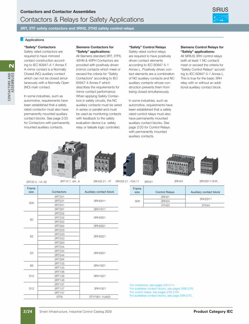
3RT20 2. -1A .00 3RT10 7. -6A ..6 3RH29 21. -1F 3RH29 21. -1DA 11 3RH21 3RH24 3RH2911-2HA..
Framesize Contactors Auxiliary contact block
S00
3RT2013RH29113RT231
3RT2513RT261 3RH1911
S0
3RT2023RH29213RT232
3RT2523RT262 3RH2921
S2
3RT203
3RH29213RT233 3RT2533RT263
S3
3RT204
3RH29213RT2343RT2443RT264
S63RT105
3RH19213RT145
S103RT106
3RH19213RT126 3RT146
S123RT107
3RH19213RT1273RT147
3TF6 3TY7561-1UA00
Framesize Control Relays Auxiliary contact block
S003RH21
3RH29113RH243TH20 3TX44
For contactors, see pages 2/8-2/11.For auxiliaries contact blocks, see pages 2/68-2/70.For control relays, see pages 2/52-2/54.For auxiliaries contact blocks, see page 2/68-2/70..
Applications
“Safety” ContactorsSafety rated contactors are required to have mirrored contact construction accord-ing to IEC 60947-4-1 Annex F. A mirror contact is a Normally Closed (NC) auxiliary contact which can not be closed simul-taneously with a Normally Open (NO) main contact.
In some industries, such as automotive, requirements have been established that a safety rated contactor must also have permanently mounted auxiliary contact blocks. See page 2/25 for Contactors with permanently mounted auxiliary contacts.
Siemens Contactors for“Safety” applications:All Siemens standard 3RT, 3TF6, 40HN & 40PH Contactors are provided with positively driven (mirror) contacts which meet or exceed the criteria for “SafetyContactors” according to IEC60947-4 Annex F which describes the requirements for mirror contact performance. When applying Safety Contac-tors in safety circuits, the NC auxiliary contacts must be wired in series or parallel and must be used as monitoring contacts with feedback to the safety evaluation device (i.e. safety relay or failsafe logic controller).
“Safety” Control RelaysSafety rated control relays are required to have positively driven contact elements according to IEC 60947-5-1 Annex L. Positively driven con-tact elements are a combination of NO auxiliary contacts and NC auxiliary contacts whose con-struction prevents them from being closed simultaneously.
In some industries, such as automotive, requirements have been established that a safety rated control relays must also have permanently mounted auxiliary contact blocks. See page 2/20 for Control Relays with permanently mounted auxiliary contacts.
Siemens Control Relays for“Safety” applications:All SIRIUS 3RH control relays(with at least 1 NC contact) meet or exceed the criteria for “Safety Control Relays” accord-ing to IEC 60947-5-1 Annex L. This is true for the basic 3RH relay with or without an addi-tional auxiliary contact block.
Contactors and Contactor Assemblies
Contactors & Relays for Safety Applications3RT, 3TF safety contactors and 3RH2, 3TH2 safety control relays
Product Category IEC
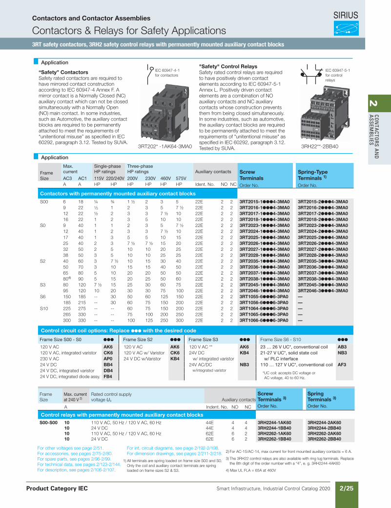
SIRIUS
Smart Infrastructure, Industrial Control Catalog 2020 2/25
2Co
nta
Ctors a
nd
a
ssemb
lies
Siemens / Industrial Controls Previous folio: IC10 2/70
“Safety” ContactorsSafety rated contactors are required tohave mirrored contact constructionaccording to IEC 60947-4 Annex F. Amirror contact is a Normally Closed (NC)auxiliary contact which can not be closedsimultaneously with a Normally Open(NO) main contact. In some industries,such as Automotive, the auxiliary contactblocks are required to be permanentlyattached to meet the requirements of“unitentional misuse” as specified in IEC60292, paragraph 3.12. Tested by SUVA.
"Safety" Control RelaysSafety rated control relays are requiredto have positively driven contactelements according to IEC 60947-5-1Annex L. Positively driven contactelements are a combination of NOauxiliary contacts and NC auxiliarycontacts whose construction preventsthem from being closed simultaneously.In some industries, such as automotive,the auxiliary contact blocks are requiredto be permanently attached to meet therequirements of "unitentional misuse" asspecified in IEC 60292, paragraph 3.12.Tested by SUVA.3RT202* -1AK64-3MA0 3RH22**-2BB40
IEC 60947-4-1for contactors
IEC 60947-5-1for controlrelays
Application
Application
FrameSize
Max.current
Single-phase HP ratings
Three-phaseHP ratings Auxiliary contacts Screw
TerminalsSpring-Type Terminals 1)AC3 AC1 115V 220/240V 200V 230V 460V 575V
A A HP HP HP HP HP HP Ident. No. NO NC Order No. Order No.
Contactors with permanently mounted auxiliary contact blocks
S00 6 18 ¼ ¾ 1 ½ 2 3 5 22E 2 2 3RT2015-14-3MA0 3RT2015-24-3MA09 22 1⁄3 1 2 3 5 7 ½ 22E 2 2 3RT2016-14-3MA0 3RT2016-24-3MA012 22 ½ 2 3 3 7 ½ 10 22E 2 2 3RT2017-14-3MA0 3RT2017-24-3MA016 22 1 2 3 5 10 10 22E 2 2 3RT2018-14-3MA0 3RT2018-24-3MA0
S0 9 40 1 1 2 3 5 7 ½ 22E 2 2 3RT2023-14-3MA0 3RT2023-24-3MA012 40 1 2 3 3 7 ½ 10 22E 2 2 3RT2024-14-3MA0 3RT2024-24-3MA017 40 1 3 5 5 10 15 22E 2 2 3RT2025-14-3MA0 3RT2025-24-3MA025 40 2 3 7 ½ 7 ½ 15 20 22E 2 2 3RT2026-14-3MA0 3RT2026-24-3MA032 50 2 5 10 10 20 25 22E 2 2 3RT2027-14-3MA0 3RT2027-24-3MA038 50 3 5 10 10 25 25 22E 2 2 3RT2028-14-3MA0 3RT2028-24-3MA0
S2 40 60 3 7 ½ 10 15 30 40 22E 2 2 3RT2035-14-3MA0 3RT2035-34-3MA050 70 3 10 15 15 40 50 22E 2 2 3RT2036-14-3MA0 3RT2036-34-3MA065 80 5 10 20 20 50 50 22E 2 2 3RT2037-14-3MA0 3RT2037-34-3MA0804) 90 5 15 20 25 50 60 22E 2 2 3RT2038-14-3MA0 3RT2038-34-3MA0
S3 80 120 7 ½ 15 25 30 60 75 22E 2 2 3RT2045-14-3MA0 3RT2045-34-3MA095 120 10 20 30 30 75 100 22E 2 2 3RT2046-14-3MA0 3RT2046-34-3MA0
S6 150 185 -- 30 50 60 125 150 22E 2 2 3RT1055-66-3PA0 —185 215 -- 30 60 75 150 200 22E 2 2 3RT1056-66-3PA0 —
S10 225 275 -- -- 60 75 150 200 22E 2 2 3RT1064-66-3PA0 —265 330 -- -- 75 100 200 250 22E 2 2 3RT1065-66-3PA0 —300 330 -- -- 100 125 250 300 22E 2 2 3RT1066-66-3PA0 —
Control circuit coil options: Replace with the desired code
Frame Size S00 - S0 Frame Size S2 Frame Size S3 Frame Size S6 - S10
120 V AC AK6 120 V AC AK6 120 V AC ** AK6 23 … 26 V UC*, conventional coil AB3120 V AC, integrated varistor CK6 120 V AC w/ Varistor CK6 24V DC KB4 21-27 V UC*, solid state coil NB3230 V AC AP0 24 V DC w/Varistor KB4 w/ integrated varistor w/ PLC interface24 V DC BB4 24V AC/DC NB3 110 … 127 V UC*, conventional coil AF324 V DC, integrated varistor DB4 w/integrated varistor
*UC coil: accepts DC voltage or AC voltage, 40 to 60 Hz.24 V DC, integrated diode assy. FB4
FrameSize
Max. currentat 240 V 2)
Rated control supplyvoltage Us Auxiliary contacts
Screw Terminals 3)
Spring Terminals 3)
A Indent. No. NO NC Order No. Order No.
Control relays with permanently mounted auxiliary contact blocksS00-S00 10
101010
110 V AC, 50 Hz / 120 V AC, 60 Hz24 V DC110 V AC, 50 Hz / 120 V AC, 60 Hz24 V DC
44E44E62E62E
4466
4422
3RH2244-1AK603RH2244-1BB403RH2262-1AK603RH2262-1BB40
3RH2244-2AK603RH2244-2BB403RH2262-2AK603RH2262-2BB40
For other voltages see page 2/51. For accessories, see pages 2/75-2/80.For spare parts, see pages 2/96-2/99.For technical data, see pages 2/123-2/144.For description, see pages 2/106-2/107.
For int. circuit diagrams, see page 2/192-2/198.For dimension drawings, see pages 2/211-2/218.
1) All terminals are spring loaded on frame size S00 and S0. Only the coil and auxiliary contact terminals are spring loaded on frame sizes S2 & S3.
2) For AC-15/AC-14, max current for front mounted auxiliary contacts = 6 A.
3) The 3RH22 control relays are also available with ring lug terminals. Replace the 8th digit of the order number with a “4”, e. g. 3RH2244-4AK60
4) Max UL FLA = 65A at 460V
Contactors and Contactor Assemblies
Contactors & Relays for Safety Applications3RT safety contactors, 3RH2 safety control relays with permanently mounted auxiliary contact blocks
Product Category IEC
Revised on 02/26/18
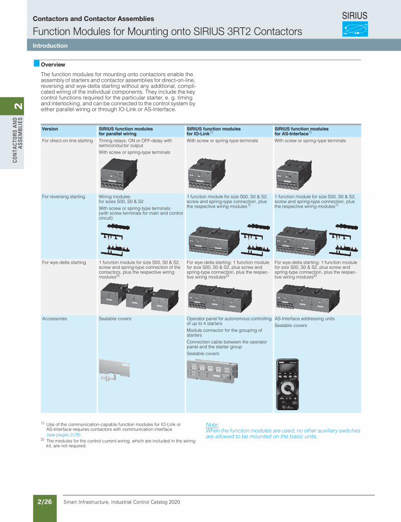
SIRIUS
Smart Infrastructure, Industrial Control Catalog 2020 2/26
2Co
nta
Cto
rs a
nd
a
ssem
bli
esFunction Modules for Mounting onto SIRIUS 3RT2 Contactors
Introduction
3/76 SIRIUS Innovations Supplement 2012
3
OverviewThe function modules for mounting onto contactors enable the assembly of starters and contactor assemblies for direct-on-line, reversing and wye-delta starting without any additional, compli-cated wiring of the individual components. They include the key control functions required for the particular starter, e. g. timing and interlocking, and can be connected to the control system by either parallel wiring or through IO-Link or AS-Interface.
1) Use of the communication-capable function modules for IO-Link or AS-Interface requires contactors with communication interface
2) The modules for the control current wiring, which are included in the wiring kit, are not required.
Note:When the function modules are used, no other auxiliary switches are allowed to be mounted on the basic units.
Version SIRIUS function modulesfor parallel wiring
SIRIUS function modulesfor IO-Link1)
SIRIUS function modulesfor AS-Interface1)
For direct-on-line starting Timing relays: ON or OFF-delay with semiconductor output
With screw or spring-type terminals
With screw or spring-type terminals With screw or spring-type terminals
For reversing starting Wiring modules for sizes S00, S0 & S2
With screw or spring-type terminals · (with screw terminals for main and control circuit)
1 function module for size S00, S0 & S2, screw and spring-type connection, plus the respective wiring modules1)
1 function module for size S00, S0 & S2, screw and spring-type connection, plus the respective wiring modules1)
For wye-delta starting 1 function module for size S00, S0 & S2, screw and spring-type connection of the contactors, plus the respective wiring modules2)
For wye-delta starting: 1 function module for size S00, S0 & S2, plus screw and spring-type connection, plus the respec-tive wiring modules2)
For wye-delta starting: 1 function module for size S00, S0 & S2, plus screw and spring-type connection, plus the respec-tive wiring modules2)
Accessories Sealable covers Operator panel for autonomous controlling of up to 4 starters
Module connector for the grouping of starters
Connection cable between the operator panel and the starter group
Sealable covers
AS-Interface addressing units
Sealable covers
LV1N_03_09.fm Page 76 Friday, October 18, 2013 6:47 PM
(see pages 2/28).
Contactors and Contactor Assemblies
Function Modules for Mounting onto SIRIUS 3RT2 ContactorsIntroduction
SIRIUS
Smart Infrastructure, Industrial Control Catalog 2020 2/27
2Co
nta
Ctors a
nd
a
ssemb
liesFunction Modules for Mounting onto SIRIUS 3RT2 Contactors
SIRIUS function modules
3/77SIRIUS Innovations Supplement 2012
3
OverviewSimply by being plugged in place, the SIRIUS function modules enable different functionalities required for the assembly of start-ers to be realized in the starter. The function modules and wiring kits help to reduce the wiring work within the starter practically to zero.
SIRIUS function modules for reversing startingThe wiring kits for reversing starters enable the cost-effective assembly of contactor assemblies. They can be used for all applications with reversing duty up to 50 HP.
SIRIUS function modules for wye-delta startingBoth interlocking and timing functions are required for the assembly of wye-delta starters. With the function modules for wye-delta starting and the matching link modules for the main circuit, these starters can be assembled easily and with abso-lutely no errors.
The entire sequence in the control circuit is integrated in the snap-on modules. This covers:• An adjustable wye time t from 0.5 to 60 s• A non-adjustable dead interval of 50 ms• Electrical contacting to the contactors by means of coil
pick-off (contact legs)• Feedback of the switching state at the contactor using a
mechanical switch position indicator (plunger)• Electrical interlocking between the contactors
These modules do not require their own terminals and can there-fore be used for contactors with both screw and spring-typeterminals in the S00, S0 and S2. To start the wye-delta starter, only the first of the three contactors (line contactor) is actuated. All other functions then take place inside the individual modules.
This also offers advantages if the timing function was previously implemented in a controller, as it again results in a significant reduction in the number of PLC outputs, the programming work and the wiring outlay.
The kits for the main circuit include the mechanical interlock, the star jumper, the wiring modules at the top and at the bottom, and the required connecting clips.
A protection circuit (varistor) is integrated in the basic module.
ApplicationThe snap-on function modules for direct-on-line starting are used above all for realizing timing functions independently of the control system.
With the OFF-delay variant of the timing relay it is possible for example for the fan motor for cooling a main drive to be switched off with a delay so that sufficient cooling after operation is guar-anteed even if the plant and its control system have already been switched off.
The ON-delay timing relays enable for example the time-delayed starting of several drives so that the summation starting current does not rise too high, which could result in voltage failure.
The function modules for wye-delta starting are mostly used where current-limiting measures for starting a drive are required, e.g. for large fans and ventilators, and a high level of availability is essential at the same time. This technology has been used with success for several decades and has the additional advan-tage of requiring relatively little know-how. Through the use of function modules, the assembly work with simple standard com-ponents is even easier and error-free.
BenefitsThe use of snap-on function modules for direct-on-line starting (timing relays) results in the following advantages:• Reduction of control current wiring• Prevention of wiring errors• Reduction of testing costs• Implementation of timing functions independently of the
control system• Less space required in the control cabinet compared to a
separate timing relay• No additive protection circuit required (varistor integrated)
The use of function modules for wye-delta starting results in the following advantages:• Operation solely through the line contactor A1/A2 – no further
wiring needed• Reduction of the control current wiring inside the contactor
assembly and to the higher-level control system where applicable
• Prevention of wiring errors• Reduction of testing costs• Integrated electrical interlocking saves costs and prevents
errors• Less space needed in the control cabinet compared to using
a separate timing relay• Adjustable starting in star mode from 0.5 to 60 s• Independent of the contactor's control supply voltage
(24 to 240 V AC/DC)• Varistor integrated – no additive protection circuit required• No control current wiring thanks to plug-in technology and
connecting cables• Mechanically coded assembly enables easy configuration
and reliable wiring• Fewer versions – one module kit for screw and spring-type
connection and for the two sizes S00 to S2• Mechanical interlocking (with wiring kit for the main circuit)
LV1N_03_09.fm Page 77 Friday, October 18, 2013 6:47 PM
SIRIUS function modules for direct-on-line startingThe electronic timing relays which can be mounted onto the contactor are available in these versions:• Sizes S00 and S0 for applications in the range from
24 to 240 V AC/DC (wide voltage range)• Size S2 for applications in either the range from 24 to
90 V AC/DC or 90 to 240 V AC/DC
Both the electrical and mechanical connection are made by simple snapping on and locking.
A protection circuit (varistor) is integrated in each module.
The electronic timing relay with semiconductor output uses two contact legs to actuate the contactor underneath by means of a semiconductor after the set time t has elapsed.
The switching state feedback is performed by a mechanical switching state indicator (plunger). In addition, the auxiliary switches in the contactors are freely accessible and can be used for feedbacks to the control system or for signal lamps.
A sealable cover is available to protect against careless adjustment of the set times.
For a detailed description see page 2/39.
Contactors and Contactor Assemblies
Function Modules for Mounting onto SIRIUS 3RT2 ContactorsSIRIUS function modules

SIRIUS
Smart Infrastructure, Industrial Control Catalog 2020 2/28
2Co
nta
Cto
rs a
nd
a
ssem
bli
es
Selection and ordering data
Frame Size
Amp Ratings
Single-phase HP ratings
Three-phaseHP ratings
Auxiliarycontacts
Screw Terminals 24 V DC coil
Spring-type Terminals 1) 24 V DC coil
Weightapprox.
AC3 AC1 115V 230V 208V 230V 460V 575V NO NC Order No. Order No. kg
3RT 3-pole Contactors
S00
7 18 0.25 0.75 1.5 2 3 51 0 3RT2015-1BB41-0CC0 3RT2015-2BB41-0CC0
0.28
0 1 3RT2015-1BB42-0CC0 3RT2015-2BB42-0CC0
9 22 0.33 1 2 3 5 7.51 0 3RT2016-1BB41-0CC0 3RT2016-2BB41-0CC00 1 3RT2016-1BB42-0CC0 3RT2016-2BB42-0CC0
12 22 0.5 2 3 3 7.5 101 0 3RT2017-1BB41-0CC0 3RT2017-2BB41-0CC00 1 3RT2017-1BB42-0CC0 3RT2017-2BB42-0CC0
16 22 1 2 3 5 10 101 0 3RT2018-1BB41-0CC0 3RT2018-2BB41-0CC00 1 3RT2018-1BB42-0CC0 3RT2018-2BB42-0CC0
S0
9 40 1 1 2 3 5 7.5 1 1 3RT2023-1BB40-0CC0 3RT2024-2BB40-0CC0
0.58
12 40 1 2 3 3 7.5 10 1 1 3RT2024-1BB40-0CC0 3RT2024-2BB40-0CC016 40 1 3 5 5 10 15 1 1 3RT2025-1BB40-0CC0 3RT2025-2BB40-0CC025 40 2 3 7.5 7.5 15 20 1 1 3RT2026-1BB40-0CC0 3RT2026-2BB40-0CC032 50 2 5 10 10 20 25 1 1 3RT2027-1BB40-0CC0 3RT2027-2BB40-0CC038 50 3 5 10 10 25 25 1 1 3RT2028-1BB40-0CC0 3RT2028-2BB40-0CC0
S2
40 60 3 7.5 10 15 30 40 1 1 3RT2035-1NB30-0CC0 3RT2035-3NB30-0CC0
1.122
50 70 3 10 15 15 40 50 1 1 3RT2036-1NB30-0CC0 3RT2036-3NB30-0CC0
65 80 5 10 20 20 50 50 1 1 3RT2037-1NB30-0CC0 3RT2037-3NB30-0CC0
80 90 5 15 20 25 50 60 1 1 3RT2038-1NB30-0CC0 3RT2038-3NB30-0CC0
3RT2018-1BB41-0CC0
• Ideal for diagnostics to the automation controller• Quickly locate and rectify faults• Configuration available in Step 7 and TIA Portal• Easy engineering of parameters• For DOL, reversing and wye delta starters up to 50 HP• Manual starter operation with optional operator panel
3RT2028-1BB40-0CC0
1) All terminals are spring loaded in sizes S00 and S0. For size S2, only the coil and aux contacts are spring loaded.
Communication capable contactors are ideal for starter feedback to the automation level. IO-Link starters in the cabinet save considerable wiring effort. AS-Interface is best suited for distributed systems.
For reversing contactors with communication capability, see pages 2/41-2/45For accessories, see page 2/29, 2/32, 2/36.For technical data, see page 2/33, 2/37, 2/38For description, see page 2/26.For further information on IO-Link and AS-Interface, see page 2/30-2/31 and 2/34-2/35.
• Reduces control wiring in the panel• Available for 24VDC control systems• Easily snap on IO-Link or AS-Interface modules onto contactors
3RT2038-1NB30-0CC0
Contactors and Contactor Assemblies
Contactors for Switching Motors3RT2 contactors, 3-pole – Communication Contactors
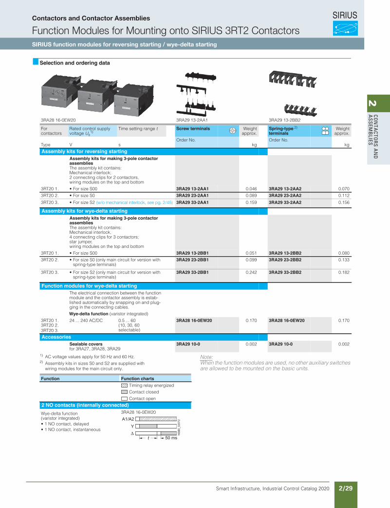
SIRIUS
Smart Infrastructure, Industrial Control Catalog 2020 2/29
2Co
nta
Ctors a
nd
a
ssemb
liesFunction Modules for Mounting onto SIRIUS 3RT2 Contactors
SIRIUS function modulesfor reversing starting / wye-delta starting
3/79SIRIUS Innovations Supplement 2012Illustrations are approximate
3
Selection and ordering data
1) AC voltage values apply for 50 Hz and 60 Hz.2) Assembly kits in sizes S0 and S2 are supplied with
wiring modules for the main circuit only.
Note:When the function modules are used, no other auxiliary switches are allowed to be mounted on the basic units.
2BB2-31 92AR31AA2-31 92AR302WE0-61 82AR3
For contactors
Rated control supply voltage Us
1) Time setting range t Screw terminals Weight
approx.Spring-typeterminals
Weightapprox.
sVepyTOrder No.
kgOrder No.
kg
Assembly kits for reversing startingAssembly kits for making 3-pole contactorassembliesThe assembly kit contains: Mechanical interlock; 2 connecting clips for 2 contactors, wiring modules on the top and bottom
3RT20 1 . • For size S00 3RA29 13-2AA1 0.046 3RA29 13-2AA2 0.070
3RT20 2 . • For size S0 3RA29 23-2AA1 0.089 3RA29 23-2AA2 0.112
Assembly kits for wye-delta startingAssembly kits for making 3-pole contactorassembliesThe assembly kit contains: Mechanical interlock, 4 connecting clips for 3 contactors; star jumper, wiring modules on the top and bottom
3RT20 1 . • For size S00 3RA29 13-2BB1 0.051 3RA29 13-2BB2 0.080
3RT20 2 . • For size S0 (only main circuit for version with spring-type terminals)
3RA29 23-2BB1 0.099 3RA29 23-2BB2 0.133
Function modules for wye-delta startingThe electrical connection between the function module and the contactor assembly is estab-lished automatically by snapping on and plug-ging in the connecting cables.
Wye-delta function (varistor integrated)
3RT20 1 . 3RT20 2 .3RT20 3.
24 ... 240 AC/DC 0.5 ... 60 (10, 30, 60 selectable)
3RA28 16-0EW20 0.170 3RA28 16-0EW20 0.170
AccessoriesSealable coversfor 3RA27, 3RA28, 3RA29
3RA29 10-0 0.002 3RA29 10-0 0.002
3RT20 3 . • For size S2 3RA29 33-2AA1 0.159 3RA29 33-2AA2 0.156
3RT20 3 . • For size S2 (only main circuit for version withspring-type terminals)
3RA29 33-2BB1 0.242 3RA29 33-2BB2 0.182
Function Function chartsTiming relay energized
Contact closed
Contact open
2 NO contacts (internally connected)Wye-delta function (varistor integrated)• 1 NO contact, delayed• 1 NO contact, instantaneous
3RA28 16-0EW20
50 ms
Y
A1/A2
NS
B0_
0207
2
t
LV1N_03_09.fm Page 79 Friday, October 18, 2013 6:47 PM
2)
(w/o mechanical interlock, see pg. 2/45)
Contactors and Contactor Assemblies
Function Modules for Mounting onto SIRIUS 3RT2 ContactorsSIRIUS function modules for reversing starting / wye-delta starting
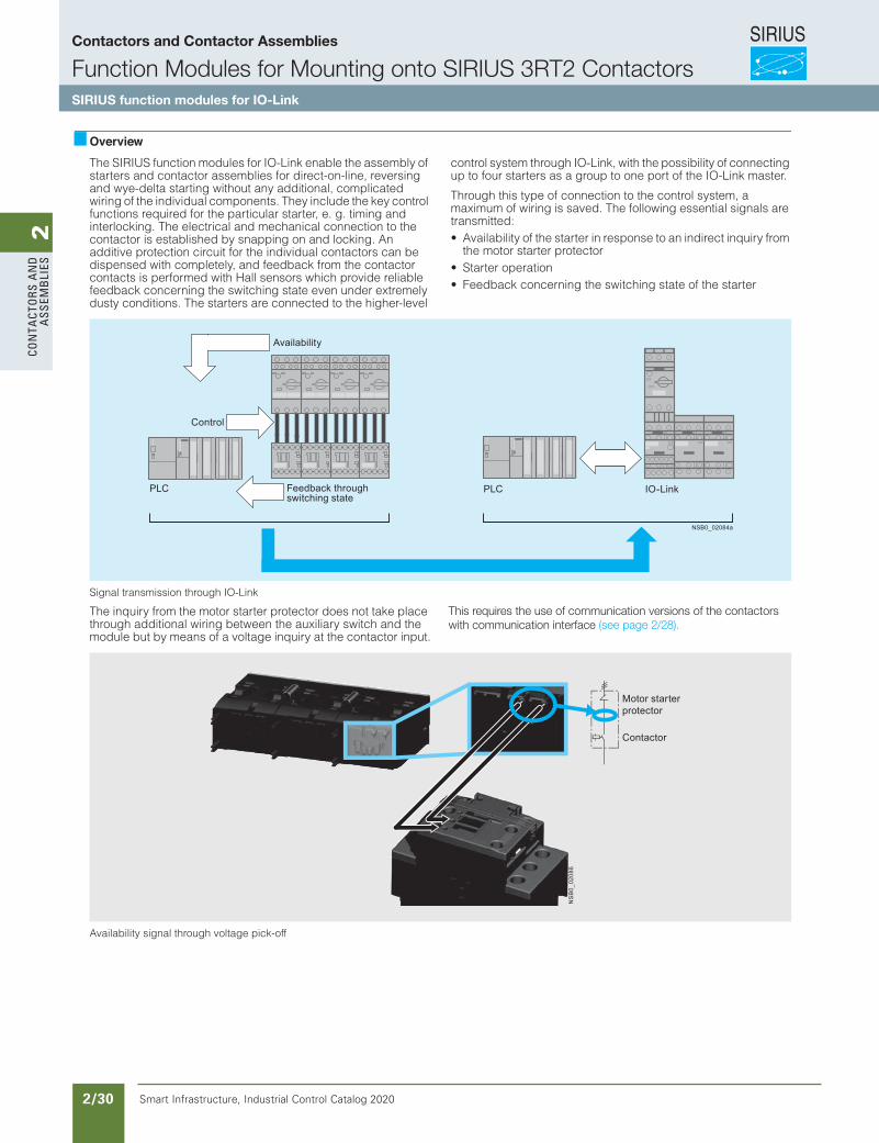
SIRIUS
Smart Infrastructure, Industrial Control Catalog 2020 2/30
2Co
nta
Cto
rs a
nd
a
ssem
bli
esFunction Modules for Mounting onto SIRIUS 3RT2 Contactors
SIRIUS function modules for IO-Link
3/81SIRIUS Innovations Supplement 2012
3
OverviewThe SIRIUS function modules for IO-Link enable the assembly of starters and contactor assemblies for direct-on-line, reversing and wye-delta starting without any additional, complicated wiring of the individual components. They include the key control functions required for the particular starter, e. g. timing and interlocking. The electrical and mechanical connection to the contactor is established by snapping on and locking. An additive protection circuit for the individual contactors can be dispensed with completely, and feedback from the contactor contacts is performed with Hall sensors which provide reliable feedback concerning the switching state even under extremely dusty conditions. The starters are connected to the higher-level
control system through IO-Link, with the possibility of connecting up to four starters as a group to one port of the IO-Link master.
Through this type of connection to the control system, a maximum of wiring is saved. The following essential signals are transmitted:• Availability of the starter in response to an indirect inquiry from
the motor starter protector• Starter operation• Feedback concerning the switching state of the starter
Signal transmission through IO-Link
The inquiry from the motor starter protector does not take place through additional wiring between the auxiliary switch and the module but by means of a voltage inquiry at the contactor input.
Availability signal through voltage pick-off
NSB0_02084a
Control
Availability
Feedback through switching state
PLC IO-LinkPLC
NS
B0_
0208
6
Motor starter protector
Contactor
LV1N_03_09.fm Page 81 Friday, October 18, 2013 6:47 PM
This requires the use of communication versions of the contactorswith communication interface (see page 2/28).
Contactors and Contactor Assemblies
Function Modules for Mounting onto SIRIUS 3RT2 ContactorsSIRIUS function modules for IO-Link
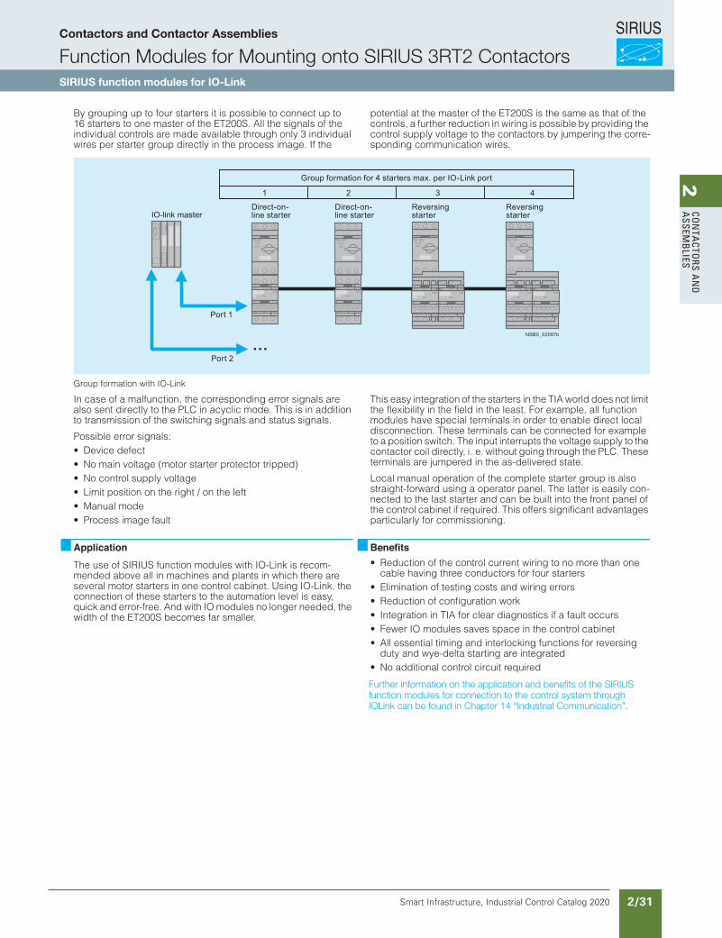
SIRIUS
Smart Infrastructure, Industrial Control Catalog 2020 2/31
2Co
nta
Ctors a
nd
a
ssemb
liesFunction Modules for Mounting onto SIRIUS 3RT2 Contactors
SIRIUS function modules for IO-Link
3/82 SIRIUS Innovations Supplement 2012
3
By grouping up to four starters it is possible to connect up to 16 starters to one master of the ET200S. All the signals of the individual controls are made available through only 3 individual wires per starter group directly in the process image. If the
potential at the master of the ET200S is the same as that of the controls, a further reduction in wiring is possible by providing the control supply voltage to the contactors by jumpering the corre-sponding communication wires.
Group formation with IO-Link
In case of a malfunction, the corresponding error signals are also sent directly to the PLC in acyclic mode. This is in addition to transmission of the switching signals and status signals.
Possible error signals:• Device defect• No main voltage (motor starter protector tripped)• No control supply voltage • Limit position on the right / on the left• Manual mode• Process image fault
This easy integration of the starters in the TIA world does not limit the flexibility in the field in the least. For example, all function modules have special terminals in order to enable direct local disconnection. These terminals can be connected for example to a position switch. The input interrupts the voltage supply to the contactor coil directly, i. e. without going through the PLC. These terminals are jumpered in the as-delivered state.
Local manual operation of the complete starter group is also straight-forward using a operator panel. The latter is easily con-nected to the last starter and can be built into the front panel of the control cabinet if required. This offers significant advantages particularly for commissioning.
ApplicationThe use of SIRIUS function modules with IO-Link is recom-mended above all in machines and plants in which there are several motor starters in one control cabinet. Using IO-Link, the connection of these starters to the automation level is easy, quick and error-free. And with IO modules no longer needed, the width of the ET200S becomes far smaller.
Benefits• Reduction of the control current wiring to no more than one
cable having three conductors for four starters• Elimination of testing costs and wiring errors• Reduction of configuration work• Integration in TIA for clear diagnostics if a fault occurs• Fewer IO modules saves space in the control cabinet• All essential timing and interlocking functions for reversing
duty and wye-delta starting are integrated• No additional control circuit required
Further information on the application and benefits of the SIRIUS function modules for connection to the control system through IO-Link can be found in Chapter 4 "Industrial Communication".
Reversing starter
Direct-on-line starter
Direct-on-line starter
Group formation for 4 starters max. per IO-Link port
Reversing starter
Port 1
Port 2
4321
... NSB0_02087b
LV1N_03_09.fm Page 82 Friday, October 18, 2013 6:47 PM
Further information on the application and benefits of the SIRIUSfunction modules for connection to the control system throughIOLink can be found in Chapter 14 “Industrial Communication”.
Contactors and Contactor Assemblies
Function Modules for Mounting onto SIRIUS 3RT2 ContactorsSIRIUS function modules for IO-Link
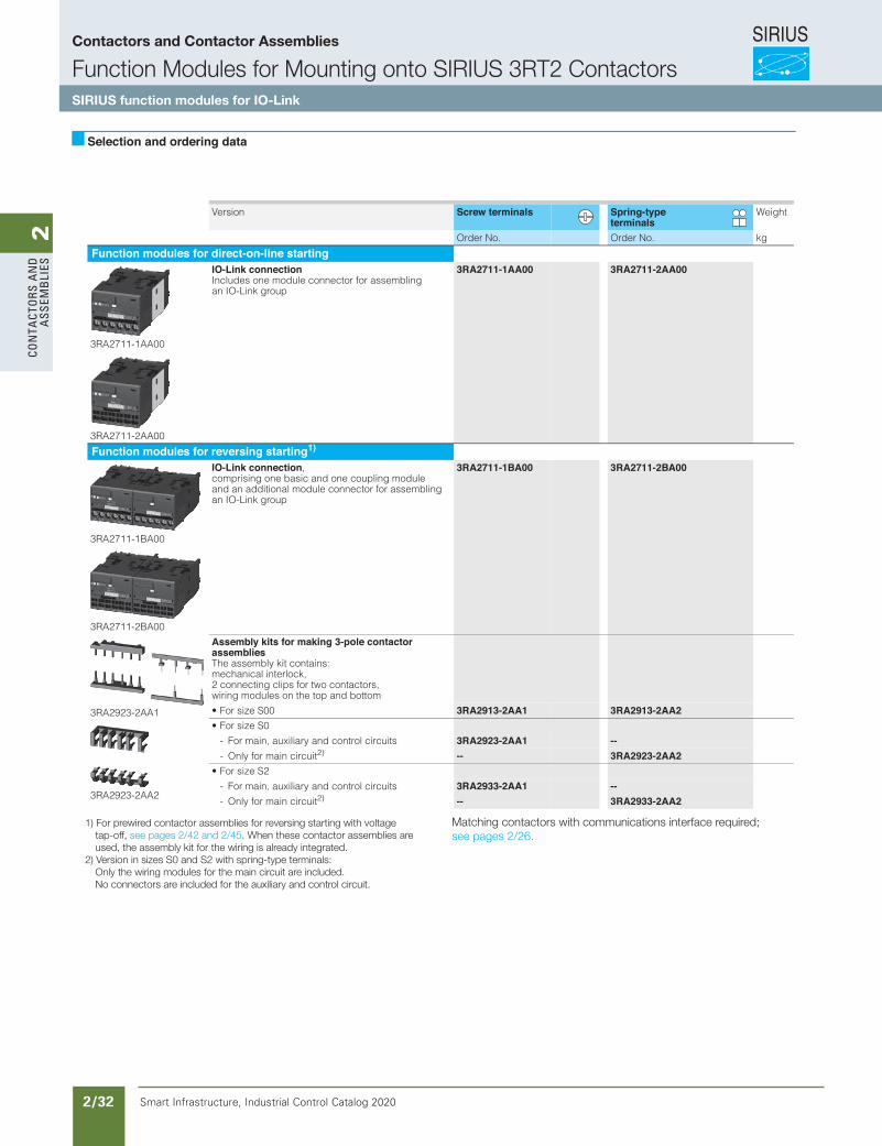
SIRIUS
Smart Infrastructure, Industrial Control Catalog 2020 2/32
2Co
nta
Cto
rs a
nd
a
ssem
bli
es
3/201Siemens IC 10 · 2015* You can order this quantity or a multiple thereof.Illustrations are approximate
Function ModulesSIRIUS 3RA27 Function Modules for IO-Link for Mounting on 3RT2 Contactors
For direct-on-line starting / for reversing starting / for wye-delta starting
3
Selection and ordering data
Version Screw terminals Spring-type terminals
Weight
Order No. Order No. kg
Function modules for direct-on-line starting
3RA2711-1AA00
3RA2711-2AA00
IO-Link connectionIncludes one module connector for assembling an IO-Link group
3RA2711-1AA00 3RA2711-2AA00
Function modules for reversing starting1)
3RA2711-1BA00
3RA2711-2BA00
IO-Link connection, comprising one basic and one coupling module and an additional module connector for assembling an IO-Link group
3RA2711-1BA00 3RA2711-2BA00
3RA2923-2AA1
3RA2923-2AA2
Assembly kits for making 3-pole contactor assembliesThe assembly kit contains: mechanical interlock, 2 connecting clips for two contactors, wiring modules on the top and bottom
• For size S00 3RA2913-2AA1 3RA2913-2AA2• For size S0
- For main, auxiliary and control circuits 3RA2923-2AA1 --- Only for main circuit2) -- 3RA2923-2AA2
• For size S2
- For main, auxiliary and control circuits 3RA2933-2AA1 --- Only for main circuit2) -- 3RA2933-2AA2
IC10_03_11.fm Page 201 Friday, April 17, 2015 3:15 PM
1) For prewired contactor assemblies for reversing starting with voltage tap-off, see pages 2/42 and 2/45. When these contactor assemblies areused, the assembly kit for the wiring is already integrated.
2) Version in sizes S0 and S2 with spring-type terminals: Only the wiring modules for the main circuit are included. No connectors are included for the auxiliary and control circuit.
Matching contactors with communications interface required; see pages 2/26.
Contactors and Contactor Assemblies
Function Modules for Mounting onto SIRIUS 3RT2 ContactorsSIRIUS function modules for IO-Link
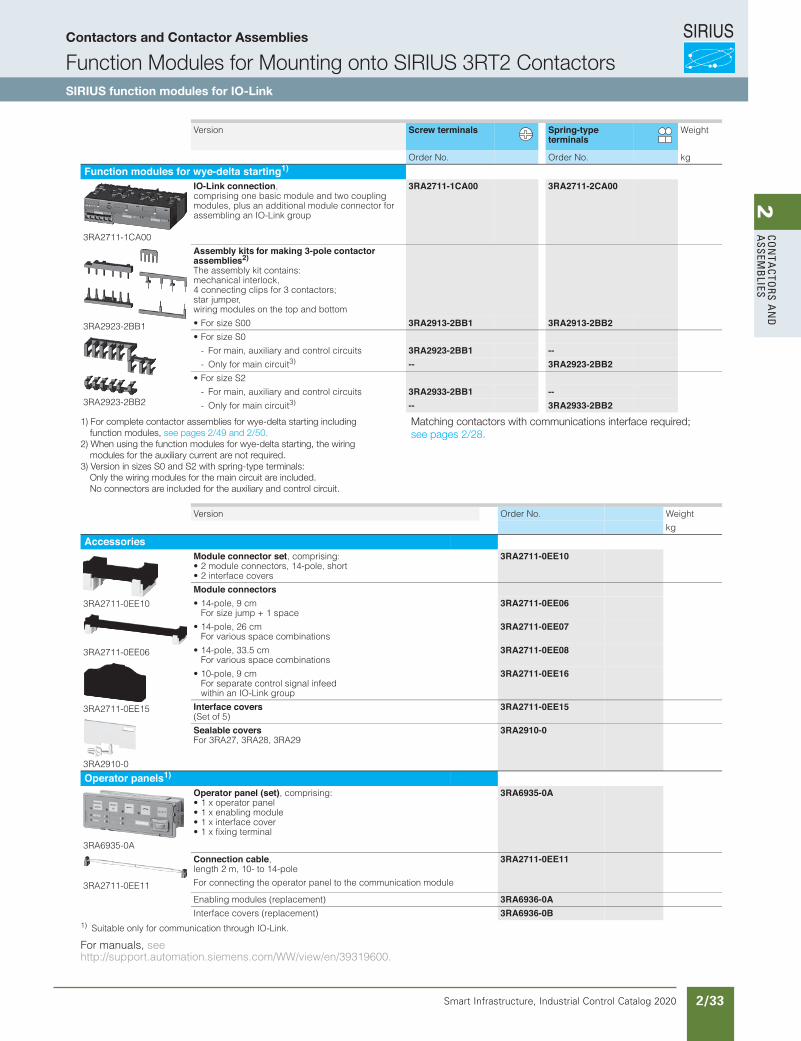
SIRIUS
Smart Infrastructure, Industrial Control Catalog 2020 2/33
2Co
nta
Ctors a
nd
a
ssemb
lies
3/202 Siemens IC 10 · 2015* You can order this quantity or a multiple thereof.
Illustrations are approximate
Function ModulesSIRIUS 3RA27 Function Modules for IO-Link for Mounting on 3RT2 Contactors
For direct-on-line starting / for reversing starting / for wye-delta starting
3
1) Suitable only for communication through IO-Link.
For manuals, see http://support.automation.siemens.com/WW/view/en/39319600.
Version Screw terminals Spring-type terminals
Weight
Order No. Order No. kg
Function modules for wye-delta starting1)
3RA2711-1CA00
IO-Link connection, comprising one basic module and two coupling modules, plus an additional module connector for assembling an IO-Link group
3RA2711-1CA00 3RA2711-2CA00
3RA2923-2BB1
3RA2923-2BB2
Assembly kits for making 3-pole contactor assemblies2)
The assembly kit contains: mechanical interlock, 4 connecting clips for 3 contactors; star jumper, wiring modules on the top and bottom
• For size S00 3RA2913-2BB1 3RA2913-2BB2• For size S0
- For main, auxiliary and control circuits 3RA2923-2BB1 --- Only for main circuit3) -- 3RA2923-2BB2
• For size S2
- For main, auxiliary and control circuits 3RA2933-2BB1 --- Only for main circuit3) -- 3RA2933-2BB2
Version Order No. Weight
kg
Accessories
3RA2711-0EE10
3RA2711-0EE06
3RA2711-0EE15
3RA2910-0
Module connector set, comprising:• 2 module connectors, 14-pole, short• 2 interface covers
3RA2711-0EE10
Module connectors• 14-pole, 9 cm
For size jump + 1 space3RA2711-0EE06
• 14-pole, 26 cm For various space combinations
3RA2711-0EE07
• 14-pole, 33.5 cm For various space combinations
3RA2711-0EE08
• 10-pole, 9 cm For separate control signal infeed within an IO-Link group
3RA2711-0EE16
Interface covers(Set of 5)
3RA2711-0EE15
Sealable covers For 3RA27, 3RA28, 3RA29
3RA2910-0
Operator panels1)
3RA6935-0A
Operator panel (set), comprising:• 1 x operator panel• 1 x enabling module• 1 x interface cover• 1 x fixing terminal
3RA6935-0A
3RA2711-0EE11
Connection cable, length 2 m, 10- to 14-pole
For connecting the operator panel to the communication module
3RA2711-0EE11
Enabling modules (replacement) 3RA6936-0AInterface covers (replacement) 3RA6936-0B
IC10_03_11.fm Page 202 Friday, April 17, 2015 3:15 PM
1) For complete contactor assemblies for wye-delta starting including function modules, see pages 2/49 and 2/50.
2) When using the function modules for wye-delta starting, the wiring modules for the auxiliary current are not required.
3) Version in sizes S0 and S2 with spring-type terminals: Only the wiring modules for the main circuit are included. No connectors are included for the auxiliary and control circuit.
Matching contactors with communications interface required; see pages 2/28.
Contactors and Contactor Assemblies
Function Modules for Mounting onto SIRIUS 3RT2 ContactorsSIRIUS function modules for IO-Link
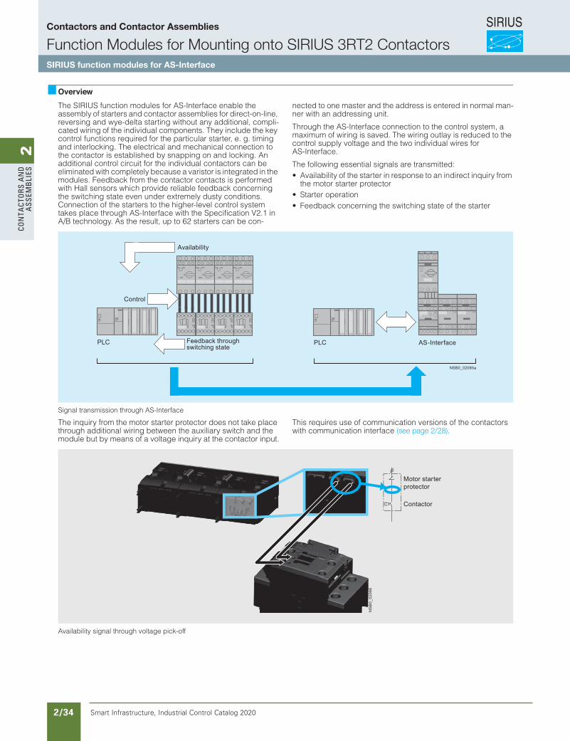
SIRIUS
Smart Infrastructure, Industrial Control Catalog 2020 2/34
2Co
nta
Cto
rs a
nd
a
ssem
bli
esFunction Modules for Mounting onto SIRIUS 3RT2 Contactors
SIRIUS function modules for AS-Interface
3/85SIRIUS Innovations Supplement 2012
3
OverviewThe SIRIUS function modules for AS-Interface enable the assembly of starters and contactor assemblies for direct-on-line, reversing and wye-delta starting without any additional, compli-cated wiring of the individual components. They include the key control functions required for the particular starter, e. g. timing and interlocking. The electrical and mechanical connection to the contactor is established by snapping on and locking. An additional control circuit for the individual contactors can be eliminated with completely because a varistor is integrated in the modules. Feedback from the contactor contacts is performed with Hall sensors which provide reliable feedback concerning the switching state even under extremely dusty conditions. Connection of the starters to the higher-level control system takes place through AS-Interface with the Specification V2.1 in A/B technology. As the result, up to 62 starters can be con-
nected to one master and the address is entered in normal man-ner with an addressing unit.
Through the AS-Interface connection to the control system, a maximum of wiring is saved. The wiring outlay is reduced to the control supply voltage and the two individual wires for AS-Interface.
The following essential signals are transmitted:• Availability of the starter in response to an indirect inquiry from
the motor starter protector• Starter operation• Feedback concerning the switching state of the starter
Signal transmission through AS-Interface
The inquiry from the motor starter protector does not take place through additional wiring between the auxiliary switch and the module but by means of a voltage inquiry at the contactor input.
This requires use of communication versions of the contactors with communication interface
Availability signal through voltage pick-off
NSB0_02085a
Control
Availability
Feedback through switching state
PLC AS-InterfacePLC
NS
B0_
0208
6
Motor starter protector
Contactor
LV1N_03_09.fm Page 85 Friday, October 18, 2013 6:47 PM
(see page 2/28).
Contactors and Contactor Assemblies
Function Modules for Mounting onto SIRIUS 3RT2 ContactorsSIRIUS function modules for AS-Interface
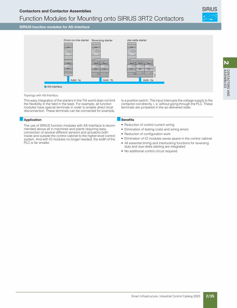
SIRIUS
Smart Infrastructure, Industrial Control Catalog 2020 2/35
2Co
nta
Ctors a
nd
a
ssemb
liesFunction Modules for Mounting onto SIRIUS 3RT2 Contactors
SIRIUS function modules for AS-Interface
3/86 SIRIUS Innovations Supplement 2012
3
Topology with AS-Interface
This easy integration of the starters in the TIA world does not limit the flexibility in the field in the least. For example, all function modules have special terminals in order to enable direct local disconnection. These terminals can be connected for example,
to a position switch. The input interrupts the voltage supply to the contactor coil directly, i. e. without going through the PLC. These terminals are jumpered in the as-delivered state.
ApplicationThe use of SIRIUS function modules with AS-Interface is recom-mended above all in machines and plants requiring easy connection of several different sensors and actuators both inside and outside the control cabinet to the higher-level control system. And with IO modules no longer needed, the width of the PLC is far smaller.
Benefits• Reduction of control current wiring• Elimination of testing costs and wiring errors• Reduction of configuration work• Elimination of IO modules saves space in the control cabinet• All essential timing and interlocking functions for reversing
duty and wye-delta starting are integrated• No additional control circuit required
NS
B0_
0208
8a
Direct-on-line starter Reversing starter star-delta starter
Addr. 1a Addr. 1b Addr. 2a
AS-Interface
LV1N_03_09.fm Page 86 Friday, October 18, 2013 6:47 PM
Contactors and Contactor Assemblies
Function Modules for Mounting onto SIRIUS 3RT2 ContactorsSIRIUS function modules for AS-Interface
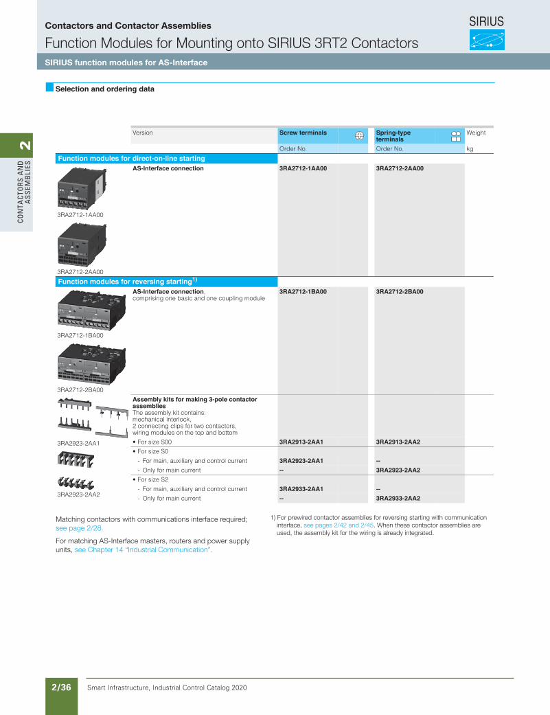
SIRIUS
Smart Infrastructure, Industrial Control Catalog 2020 2/36
2Co
nta
Cto
rs a
nd
a
ssem
bli
es
3/206 Siemens IC 10 · 2015* You can order this quantity or a multiple thereof.
Illustrations are approximate
Function ModulesSIRIUS 3RA27 Function Modules for AS-Interface for Mounting on 3RT2 Contactors
For direct-on-line starting / for reversing starting / for wye-delta starting
3
Selection and ordering data
Version Screw terminals Spring-type terminals
Weight
Order No. Order No. kg
Function modules for direct-on-line starting
3RA2712-1AA00
3RA2712-2AA00
AS-Interface connection 3RA2712-1AA00 3RA2712-2AA00
Function modules for reversing starting1)
3RA2712-1BA00
3RA2712-2BA00
AS-Interface connection, comprising one basic and one coupling module
3RA2712-1BA00 3RA2712-2BA00
3RA2923-2AA1
3RA2923-2AA2
Assembly kits for making 3-pole contactor assembliesThe assembly kit contains: mechanical interlock, 2 connecting clips for two contactors, wiring modules on the top and bottom
• For size S00 3RA2913-2AA1 3RA2913-2AA2• For size S0
- For main, auxiliary and control current 3RA2923-2AA1 --- Only for main current -- 3RA2923-2AA2
• For size S2
- For main, auxiliary and control current 3RA2933-2AA1 --- Only for main current -- 3RA2933-2AA2
IC10_03_11.fm Page 206 Friday, April 17, 2015 3:15 PM
1) For prewired contactor assemblies for reversing starting with communication interface, see pages 2/42 and 2/45. When these contactor assemblies are used, the assembly kit for the wiring is already integrated.
Matching contactors with communications interface required; see page 2/28.
For matching AS-Interface masters, routers and power supply units, see Chapter 14 “Industrial Communication”.
Contactors and Contactor Assemblies
Function Modules for Mounting onto SIRIUS 3RT2 ContactorsSIRIUS function modules for AS-Interface
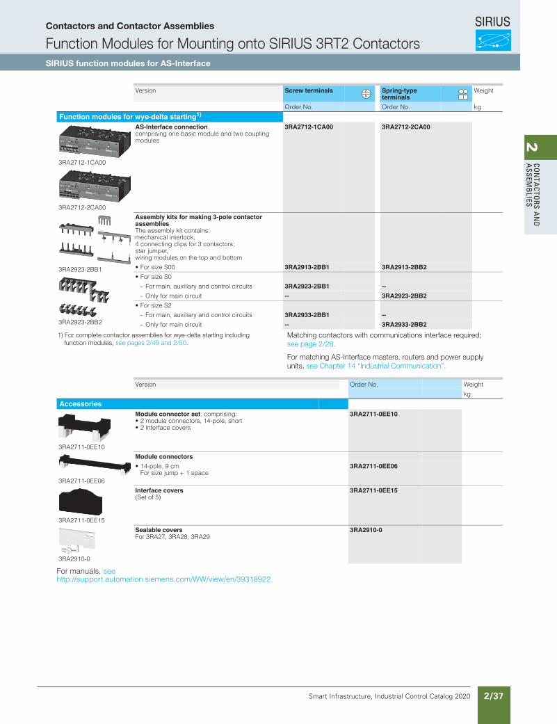
SIRIUS
Smart Infrastructure, Industrial Control Catalog 2020 2/37
2Co
nta
Ctors a
nd
a
ssemb
lies
3/207Siemens IC 10 · 2015* You can order this quantity or a multiple thereof.Illustrations are approximate
Function ModulesSIRIUS 3RA27 Function Modules for AS-Interface for Mounting on 3RT2 Contactors
For direct-on-line starting / for reversing starting / for wye-delta starting
3
For manuals, see http://support.automation.siemens.com/WW/view/en/39318922.
Version Screw terminals Spring-type terminals
Weight
Order No. Order No. kg
Function modules for wye-delta starting1)
3RA2712-1CA00
3RA2712-2CA00
AS-Interface connection, comprising one basic module and two coupling modules
3RA2712-1CA00 3RA2712-2CA00
3RA2923-2BB1
3RA2923-2BB2
Assembly kits for making 3-pole contactor assembliesThe assembly kit contains: mechanical interlock, 4 connecting clips for 3 contactors; star jumper, wiring modules on the top and bottom
• For size S00 3RA2913-2BB1 3RA2913-2BB2• For size S0
- For main, auxiliary and control circuits 3RA2923-2BB1 --- Only for main circuit -- 3RA2923-2BB2
• For size S2
- For main, auxiliary and control circuits 3RA2933-2BB1 --- Only for main circuit -- 3RA2933-2BB2
Version Order No. Weight
kg
Accessories
3RA2711-0EE10
Module connector set, comprising:• 2 module connectors, 14-pole, short• 2 interface covers
3RA2711-0EE10
3RA2711-0EE06
Module connectors• 14-pole, 9 cm
For size jump + 1 space3RA2711-0EE06
3RA2711-0EE15
Interface covers(Set of 5)
3RA2711-0EE15
3RA2910-0
Sealable covers For 3RA27, 3RA28, 3RA29
3RA2910-0
IC10_03_11.fm Page 207 Friday, April 17, 2015 3:15 PM
1) For complete contactor assemblies for wye-delta starting including function modules, see pages 2/49 and 2/50.
Matching contactors with communications interface required; see page 2/28.
For matching AS-Interface masters, routers and power supply units, see Chapter 14 “Industrial Communication”.
Contactors and Contactor Assemblies
Function Modules for Mounting onto SIRIUS 3RT2 ContactorsSIRIUS function modules for AS-Interface
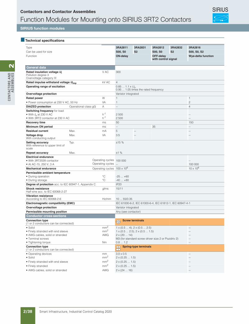
SIRIUS
Smart Infrastructure, Industrial Control Catalog 2020 2/38
2Co
nta
Cto
rs a
nd
a
ssem
bli
es
3/195Siemens IC 10 · 2015
Function ModulesSIRIUS 3RA28 Function Modules for Mounting on 3RT2 and 3RH21 Contactors
Introduction
3
Technical specifications
Type 3RA2811 3RA2831 3RA2812 3RA2832 3RA2816Can be used for size S00, S0 S2 S00, S0 S2 S00, S0, S2Function ON-delay OFF-delay
with control signalWye-delta function
General dataRated insulation voltage Ui Pollution degree 3 Overvoltage category III
V AC 300
Rated impulse withstand voltage Uimp kV AC 4
Operating range of excitation 0.85 ... 1.1 x Us, 0.95 ... 1.05 times the rated frequency
Overvoltage protection Varistor integrated
Rated power W 1 1
• Power consumption at 230 V AC, 50 Hz VA 1 2
DIAZED protection Operational class gG A -- 4
Switching frequency for load• With Ie hCA V 032 ta -1 2 500 --
hCA V 032 ta rotcatnoc 2TR3 htiW• -1 2 500 --
Recovery time ms 50 150
Minimum ON period ms -- 35 --
Residual current Max. mA 5 -- --
Voltage drop With conducting output
Max. VA 3.5 -- --
Setting accuracy With reference to upper limit of scale
Typ. ±15 %
Repeat accuracy Max. ±1 %
Electrical endurance• With 3RT2028 contactor Operating cycles 100 000 --• At AC-15, 250 V, 3 A Operating cycles -- 100 000
Mechanical endurance Operating cycles 100 x 106 10 x 106
Permissible ambient temperatureC°noitarepo gniruD• -25 ... +60C°egarots gniruD• -40 ... +80
Degree of protection acc. to IEC 60947-1, Appendix C IP20
Shock resistance Half-sine acc. to IEC 60068-2-27
g/ms 15/11
Vibration resistance mm/zH6-2-86006 CEI ot gnidroccA 10 ... 55/0.35
Electromagnetic compatibility (EMC) IEC 61000-6-2, IEC 61000-6-4, IEC 61812-1, IEC 60947-4-1
Overvoltage protection Varistor integrated
Permissible mounting position Any (see contactor)
Conductor cross-sectionsConnection type(1 or 2 conductors can be connected)
Screw terminals
mmdiloS• 2 1 x (0.5 ... 4), 2 x (0.5 ... 2.5) --mmeveels dne htiw dednarts yleniF• 2 1 x (0.5 ... 2.5), 2 x (0.5 ... 1.5) --
GWAdednarts ro dilos ,selbac GWA• 2 x (20 ... 14) --• Terminal screws M3 (for standard screw driver size 2 or Pozidriv 2) --
mNeuqrot gninethgiT• 0.8 ... 1.2 --
Connection type(1 or 2 conductors can be connected)
Spring-type terminals
mmsecived gnitarepO• 3.0 x 0.5 --mmdiloS• 2 2 x (0.25 ... 1.5) --
mmeveels dne htiw dednarts yleniF• 2 2 x (0.25 ... 1.5) --
mmdednarts yleniF• 2 2 x (0.25 ... 1.5) --
GWAdednarts ro dilos ,selbac GWA• 2 x (24 ... 16) --
© Siemens AG 2015
Contactors and Contactor Assemblies
Function Modules for Mounting onto SIRIUS 3RT2 ContactorsSIRIUS function modules
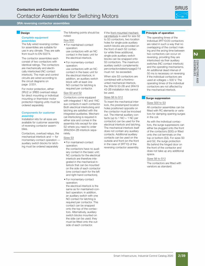
SIRIUS
Smart Infrastructure, Industrial Control Catalog 2020 2/39
2Co
nta
Ctors a
nd
a
ssemb
lies
The following points should be noted:
Size S00
• For maintained-contact operation: use contactors with an NC contact in the basic unit for the electrical interlock.
• For momentary-contact operation: use contactors with an NC contact in the basic unit for the electrical interlock; in addition, an auxiliary switch block with at least one NO contact for latching is required per contactor.
Size S0 and S2
Contactors come equipped with integrated 1 NO and 1NC aux contacts in each contactor. Both electrical interlocking and latching are satisfied with the integrated auxiliaries. Mechani-cal interlocking is required in either size and comes in the assembly kits except for size S2 where you need to order 3RA2934-2B interlock sepa-rately.
Sizes S3
• For maintained-contact operation: the contactors have no auxil-iary contact in the basic unit; NC contacts for the electrical interlock are therefore inte-grated in the mechanical in-terlock that can be mounted on the side of each contactor (one contact each for the left and right-hand contactors).
• For momentary-contact operation: the electrical interlock is the same as for maintained-con-tact operation; in addition, an auxiliary switch with one NO contact for latching is required per contactor. This contact can be snapped onto the top of the contac-tors. Alternatively, auxiliary switch blocks mounted on the side can be used; they must be fitted onto the out-side of each contactor.
Siemens / Industrial Controls Previous folio: IC10 2/71
Design
Complete equipmentassembliesThe fully wired reversing contac-tor assemblies are suitable for use in any climate. They are safe from touch to EN 50274.
The contactor assemblies each consist of two contactors with identical ratings. The contactors are mechanically and electri-cally interlocked (NC contact interlock). The main and control circuits are wired according to the circuit diagrams on page 2/201.
For motor protection, either 3RU2 or 3RB3 overload relays for direct mounting or individual mounting or thermistor motor protection tripping units must be ordered separately.
Components for customerassemblyInstallation kits for all sizes are available for customer assembly of reversing contactor assem-blies.
Contactors, overload relays, the mechanical interlock and — for momentary-contact operation — auxiliary switch blocks for latch-ing must be ordered separately
If the front-mounted mechani-cal interlock is used for size S2 to S3 contactors, two location holes for single-pole auxiliary switch blocks are provided on the front of each S2 contac-tor while three additional, single-pole auxiliary switch blocks can be snapped onto S3 contactors. The maximum auxiliary switch complements per contactor stated on page 2/14 must not be exceeded.
When size S3 contactors are combined with a frontmo-unted mechanical interlock, the 3RA19 33-2B and 3RA19 43-2B installation kits cannot be used.
Sizes S6 to S12
To insert the mechanical inter-lock, the prestamped location holes positioned opposite on the contactor must be knocked out. The internal auxiliary con-tacts (up to 1 NO + 1 NC per contactor) can be used for the electrical interlock and latching. The mechanical interlock itself does not contain any auxiliary contacts. Additional auxiliary contacts can be used on the outside and front (on the front in the case of 3RT10) of the reversing contactor assembly.
Principle of operation
The operating times of the individual 3RT10/20 contactors are rated in such a way that no overlapping of the contact mak-ing and the arcing time between two contactors can occur on reversing, providing they are interlocked via their auxiliary switches (NC contact interlock) and the operating mechanisms. An additional dead interval of 50 ms is necessary on reversing if the individual contactors are used at voltages > 500 V. The operating times of the individual contactors are not affected by the mechanical interlock.
Surge suppression
Sizes S00 to S3
All contactor assemblies can be fitted with RC elements or varis-tors for damping opening surges in the coil.
As with the individual contac-tors, the surge suppressors can either be plugged onto the front of the contactors (S00) or fitted onto the coil terminals on the top or bottom (S3). For sizes S0 and S2, the surge protection fits behind the hinged door on the front of the contactor and does not take up any additional space.
Sizes S6 to S12
The contactors are fitted with varistors as standard.
Contactors and Contactor Assemblies
Contactor Assemblies for Switching Motors3RA reversing contactor assemblies
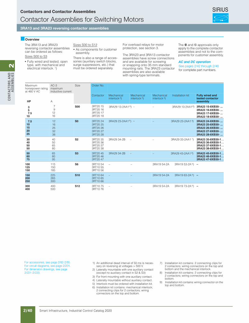
SIRIUS
Smart Infrastructure, Industrial Control Catalog 2020 2/40
2Co
nta
Cto
rs a
nd
a
ssem
bli
es
Siemens / Industrial Controls Previous folio: IC10 2/72
OverviewThe 3RA13 and 3RA23 reversing contactor assemblies can be ordered as follows:
Sizes S00 to S3
Fully wired and tested, open type, with mechanical and electrical interlock. 1)
Sizes S00 to S12As components for customer assembly.
There is also a range of acces-sories (auxiliary switch blocks, surge suppressors, etc.) that must be ordered separately.
The and approvals only apply to the complete contactor assemblies and not to the com-ponents for customer assembly.
AC and DC operation
Maximumhorsepower rating at 460 V AC
AC-3maximuminductive current
Size Order No.
HP A
Contactor Mechanicalinterlock 2)
Mechanicalinterlock 3)
Mechanicalinterlock 4)
Installation kit Fully wired and tested contactor assembly
S00 6 6)
S0
3RT20 153RT20 163RT20 173RT20 18
–
––
––
– 67.5
53
7.510
30 40 S2 3RT20 35 3RA29 34-2B 3RA29 33-2AA1 7) 3RA23 35-8XB30-1 . .40 63 02TR350 3RA23 36-8XB30-1 . .50 73 02TR365 3RA23 37-8XB30-1 . .50 83 02TR380 3RA23 38-8XB30-1 . .
50 65 S3 3RT20 45 3RA29 34-2B –– 3RA29 43-2AA1 8) 3RA23 45-8XB30-1 . .60 80 3RT20 46 3RA23 46-8XB30-1 . .75 95 3RT20 47 3RA23 47-8XB30-1 . .
100 115 S6 3RT10 54 – – 3RA19 54-2A 3RA19 53-2A 9) –125 55 01TR3051150 65 01TR3581
150 225 S10 3RT10 64 – – 3RA19 54-2A 3RA19 63-2A 9) –200 265 3RT10 65250 300 3RT10 66
300 400 S12 3RT10 75 – – 3RA19 54-2A 3RA19 73-2A 9) –400 67 01TR3005
1) An additional dead interval of 50 ms is neces-sary on reversing at voltages > 500 V.
2) Laterally mountable with one auxiliary contact
3) For front mounting with one auxiliary contact.4) Laterally mountable without auxiliary contact.5) Interlock must be ordered with installation kit.6) Installation kit contains: mechanical interlock;
2 connecting clips for 2 contactors; wiringconnectors on the top and bottom.
7) Installation kit contains: 2 connecting clips for 2 contactors; wiring connectors on the top and bottom and the mechanical interlock.
8) Installation kit contains: 2 connecting clips for 2 contactors; wiring connectors on the top and bottom.
9) Installation kit contains: wiring connector on the top and bottom.
For overload relays for motorprotection, see section 3.
The 3RA23 and 3RA13 contactor assemblies have screw connectionsand are available for screwingor snapping onto 35 mm standardmounting rails. The 3RA23 contactor assemblies are also available with spring-type terminals.
79
1216
3RA29 13-2AA1 ) 3RA29 13-2AA1 3RA23 15-8XB30- ... 3RA23 16-8XB30- ... 3RA23 17-8XB30- ... 3RA23 18-8XB30- ...
10152025
1216253238
3RT20 243RT20 253RT20 263RT20 273RT20 28
3RA29 23-2AA1 ) 6 3RA29 23-2AA1 ) 3RA23 24-8XB30- ... 3RA23 25-8XB30- ... 3RA23 26-8XB30- ... 3RA23 27-8XB30- ... 3RA23 28-8XB30- ...
(except no auxiliary contact in S2 & S3)
For accessories, see page 2/82-2/85.For circuit diagrams, see page 2/201.For dimension drawings, see page2/221-2/223.
See pages 2/42 through 2/46for complete part numbers.
Contactors and Contactor Assemblies
Contactor Assemblies for Switching Motors3RA13 and 3RA23 reversing contactor assemblies
Revised on 11/09/19 for new catalog
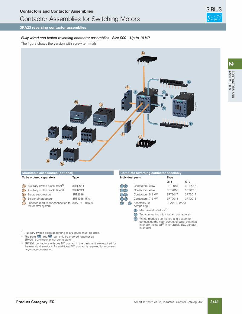
SIRIUS
Smart Infrastructure, Industrial Control Catalog 2020 2/41
2Co
nta
Ctors a
nd
a
ssemb
lies
Siemens / Industrial Controls Previous folio:
Contactors and Contactor Assemblies
Contactor Assemblies for Switching Motors3RA23 reversing contactor assemblies
Product Category IEC
3/157Siemens IC 10 · 2017
Reversing Contactor Assemblies
SIRIUS 3RA23 reversing contactor assemblies, up to 55 kW
3
Fully wired and tested reversing contactor assemblies · Size S00 · Up to 7.5 kW
The figure shows the version with screw terminals
1) Auxiliary switch block according to EN 50005 must be used.2) The parts and can only be ordered together as
3RA2912-2H mechanical connectors.3) 3RT201. contactors with one NC contact in the basic unit are required for
the electrical interlock. An additional NO contact is required for momen-tary-contact operation.
Mountable accessories (optional) Complete reversing contactor assemblyTo be ordered separately Type Individual parts Type
Q11 Q12
Auxiliary switch block, front1) 3RH2911 Contactors, 3 kW 3RT2015 3RT2015
Auxiliary switch block, lateral 3RH2921 Contactors, 4 kW 3RT2016 3RT2016
Surge suppressors 3RT2916 Contactors, 5.5 kW 3RT2017 3RT2017
Solder pin adapters 3RT1916-4KA1 Contactors, 7.5 kW 3RT2018 3RT2018
Function module for connection to the control system
3RA271.-1BA00 Assembly kit comprising:
3RA2913-2AA1
Mechanical interlock2)
Two connecting clips for two contactors2)
Wiring modules on the top and bottom for connecting the main current circuits, electrical interlock included3), interruptible (NC contact interlock)
89
9
7
1010
66
6
66
3
4
5
5
12
IC01
_006
21
6 21 7 21 8 21 9 2110 ...3 5
345
3 4
IC10_03_09.fm Page 157 Friday, June 23, 2017 3:43 PM
Fully wired and tested reversing contactor assemblies · Size S00 – Up to 10 HP
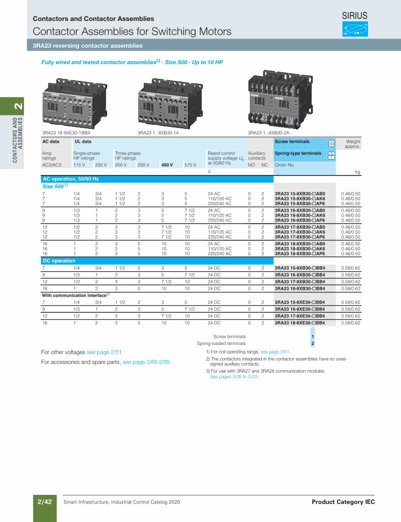
SIRIUS
Smart Infrastructure, Industrial Control Catalog 2020 2/42
2Co
nta
Cto
rs a
nd
a
ssem
bli
es3RA23, 3RA24 Contactor Assemblies
3RA23 Reversing Contactor Assemblies
3RA23 complete units, 3 ... 25 HP
3/31SIRIUS Innovations Supplement 2012Illustrations are approximate
3
Fully wired and tested contactor assemblies2) · Size S00 · Up to 10 HP
For other voltages see page 3/17.
For accessories and spare parts, see page 3/93.
1) For coil operating range, see page 3/17.2) The contactors integrated in the contactor assemblies have no unassigned
auxiliary contacts.3) For use with 3RA27 and 3RA28 communication modules. See Section 2
and also page 3/76.
. . A2-03BX8- . 1 32AR3. . A1-03BX8- . 1 32AR34BB 1-03EX8- 81 32AR3
AC data UL data Screw terminals Weightapprox.
Amp ratings
Single-phase HP ratings
Three-phase HP ratings
Rated control supply voltage Us at 50/60 Hz
Auxiliarycontacts
Spring-type terminals
AC2/AC3 115 V 230 V 200 V 230 V 460 V 575 V NO NC Order No.
gkV
AC operation, 50/60 HzSize S00 1)7 1/4 3/4 1 1/2 2 3 5 24 AC 0 2 3RA23 15-8XB30-@AB0 0.46/0.507 1/4 3/4 1 1/2 2 3 5 110/120 AC 0 2 3RA23 15-8XB30-@AK6 0.46/0.507 1/4 3/4 1 1/2 2 3 5 220/240 AC 0 2 3RA23 15-8XB30-@AP6 0.46/0.50
9 1/3 1 2 3 5 7 1/2 24 AC 0 2 3RA23 16-8XB30-@AB0 0.46/0.509 1/3 1 2 3 5 7 1/2 110/120 AC 0 2 3RA23 16-8XB30-@AK6 0.46/0.509 1/3 1 2 3 5 7 1/2 220/240 AC 0 2 3RA23 16-8XB30-@AP6 0.46/0.50
12 1/2 2 3 3 7 1/2 10 24 AC 0 2 3RA23 17-8XB30-@AB0 0.46/0.5012 1/2 2 3 3 7 1/2 10 110/120 AC 0 2 3RA23 17-8XB30-@AK6 0.46/0.5012 1/2 2 3 3 7 1/2 10 220/240 AC 0 2 3RA23 17-8XB30-@AP6 0.46/0.50
16 1 2 3 5 10 10 24 AC 0 2 3RA23 18-8XB30-@AB0 0.46/0.5016 1 2 3 5 10 10 110/120 AC 0 2 3RA23 18-8XB30-@AK6 0.46/0.5016 1 2 3 5 10 10 220/240 AC 0 2 3RA23 18-8XB30-@AP6 0.46/0.50
DC operation7 1/4 3/4 1 1/2 2 3 5 24 DC 0 2 3RA23 15-8XB30-@BB4 0.58/0.62
9 1/3 1 2 3 5 7 1/2 24 DC 0 2 3RA23 16-8XB30-@BB4 0.58/0.62
12 1/2 2 3 3 7 1/2 10 24 DC 0 2 3RA23 17-8XB30-@BB4 0.58/0.62
16 1 2 3 5 10 10 24 DC 0 2 3RA23 18-8XB30-@BB4 0.58/0.62
With communication interface3)
7 1/4 3/4 1 1/2 2 3 5 24 DC 0 2 3RA23 15-8XE30-@BB4 0.58/0.62
9 1/3 1 2 3 5 7 1/2 24 DC 0 2 3RA23 16-8XE30-@BB4 0.58/0.62
12 1/2 2 3 3 7 1/2 10 24 DC 0 2 3RA23 17-8XE30-@BB4 0.58/0.62
16 1 2 3 5 10 10 24 DC 0 2 3RA23 18-8XE30-@BB4 0.58/0.62
slanimret wercS 1
slanimret dedaol-gnirpS 2
LV1N_03_05.fm Page 31 Friday, October 18, 2013 3:24 PM
Siemens / Industrial Controls Previous folio:
For other voltages see page 2/51
For accessories and spare parts, see page 2/68-2/85.
1) For coil operating range, see page 2/51.
2) The contactors integrated in the contactor assemblies have no unas-signed auxiliary contacts.
3) For use with 3RA27 and 3RA28 communication modules. See pages 2/26 to 2/33.
Contactors and Contactor Assemblies
Contactor Assemblies for Switching Motors3RA23 reversing contactor assemblies
Product Category IEC
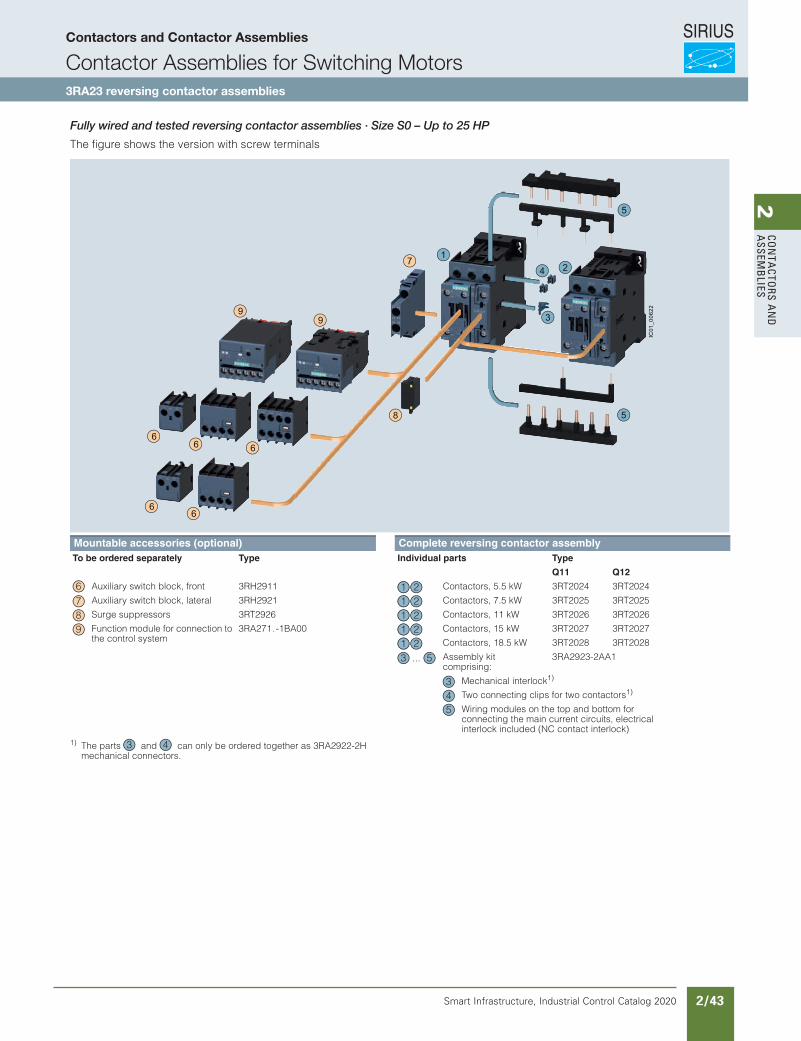
SIRIUS
Smart Infrastructure, Industrial Control Catalog 2020 2/43
2Co
nta
Ctors a
nd
a
ssemb
liesContactors and Contactor Assemblies
Contactor Assemblies for Switching Motors3RA23 reversing contactor assemblies
3/158 Siemens IC 10 · 2017
Reversing Contactor Assemblies
SIRIUS 3RA23 reversing contactor assemblies, up to 55 kW
3
Fully wired and tested reversing contactor assemblies · Size S0 · Up to 18.5 kW
The figure shows the version with screw terminals
1) The parts and can only be ordered together as 3RA2922-2H mechanical connectors.
Mountable accessories (optional) Complete reversing contactor assemblyTo be ordered separately Type Individual parts Type
Q11 Q12
Auxiliary switch block, front 3RH2911 Contactors, 5.5 kW 3RT2024 3RT2024
Auxiliary switch block, lateral 3RH2921 Contactors, 7.5 kW 3RT2025 3RT2025
Surge suppressors 3RT2926 Contactors, 11 kW 3RT2026 3RT2026
Function module for connection to the control system
3RA271.-1BA00 Contactors, 15 kW 3RT2027 3RT2027
Contactors, 18.5 kW 3RT2028 3RT2028
Assembly kit comprising:
3RA2923-2AA1
Mechanical interlock1)
Two connecting clips for two contactors1)
Wiring modules on the top and bottom forconnecting the main current circuits, electrical interlock included (NC contact interlock)
8
7
99
66 6
66
3
5
1
5
24
IC01
_006
22
6 21 7 21 8 21 9 21
21...3 5
345
3 4
IC10_03_09.fm Page 158 Friday, June 23, 2017 3:43 PM
Fully wired and tested reversing contactor assemblies · Size S0 – Up to 25 HP
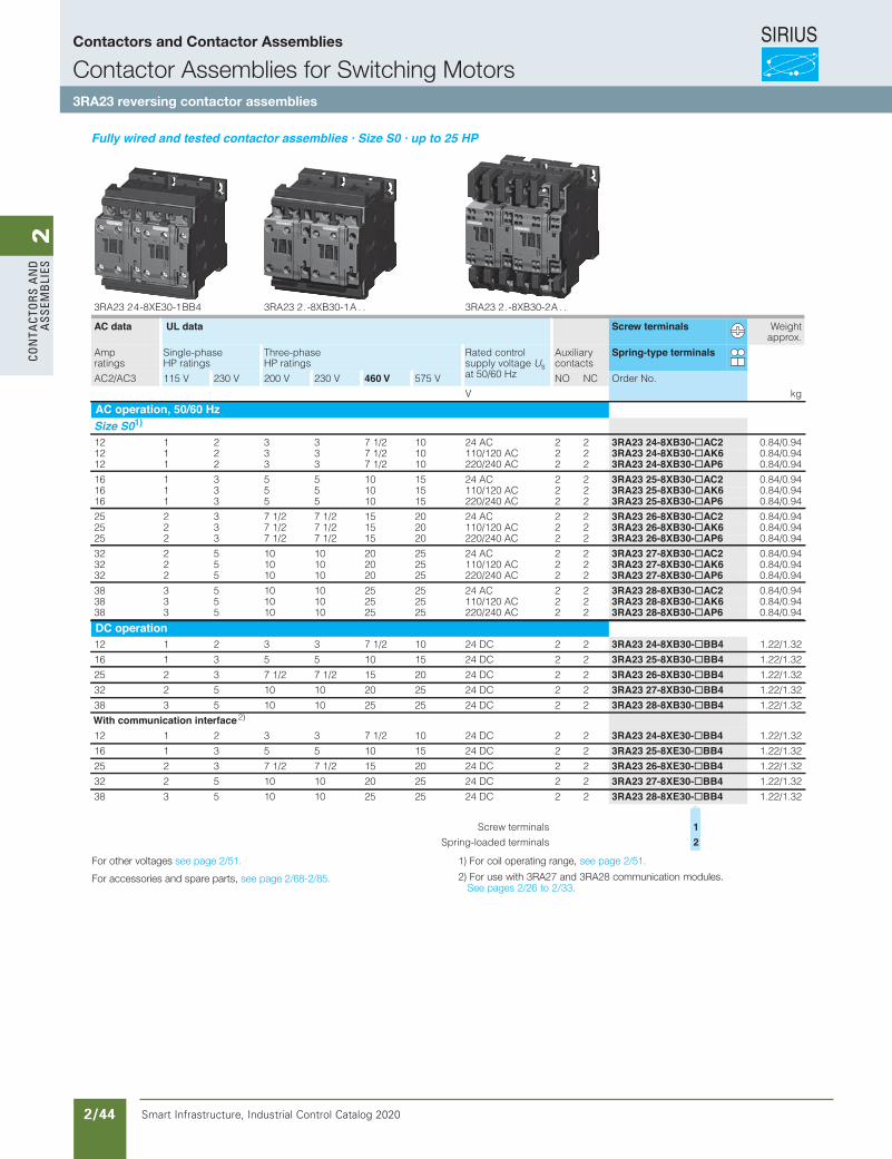
SIRIUS
Smart Infrastructure, Industrial Control Catalog 2020 2/44
2Co
nta
Cto
rs a
nd
a
ssem
bli
es3RA23, 3RA24 Contactor Assemblies
3RA23 Reversing Contactor Assemblies
3RA23 complete units, 3 ... 25 HP
3/33SIRIUS Innovations Supplement 2012Illustrations are approximate
3
Fully wired and tested contactor assemblies · Size S0 · up to 25 HP
For other voltages see page 3/17.
For accessories and spare parts, see page 3/93.
1) For coil operating range, see page 3/17.2) For use with 3RA27 and 3RA28 communication modules. See Section 2
and also page 3/76.
3RA23 2 4 -8XE30-1 BB4 3RA23 2 . -8XB30-1 A . . 3RA23 2 . -8XB30-2 A . .
AC data UL data Screw terminals Weightapprox.
Amp ratings
Single-phase HP ratings
Three-phase HP ratings
Rated control supply voltage Us at 50/60 Hz
Auxiliarycontacts
Spring-type terminals
AC2/AC3 115 V 230 V 200 V 230 V 460 V 575 V NO NC Order No.
gk V
AC operation, 50/60 HzSize S01)12 1 2 3 3 7 1/2 10 24 AC 2 2 3RA23 24-8XB30-@AC2 0.84/0.9412 1 2 3 3 7 1/2 10 110/120 AC 2 2 3RA23 24-8XB30-@AK6 0.84/0.9412 1 2 3 3 7 1/2 10 220/240 AC 2 2 3RA23 24-8XB30-@AP6 0.84/0.94
16 1 3 5 5 10 15 24 AC 2 2 3RA23 25-8XB30-@AC2 0.84/0.9416 1 3 5 5 10 15 110/120 AC 2 2 3RA23 25-8XB30-@AK6 0.84/0.9416 1 3 5 5 10 15 220/240 AC 2 2 3RA23 25-8XB30-@AP6 0.84/0.94
25 2 3 7 1/2 7 1/2 15 20 24 AC 2 2 3RA23 26-8XB30-@AC2 0.84/0.9425 2 3 7 1/2 7 1/2 15 20 110/120 AC 2 2 3RA23 26-8XB30-@AK6 0.84/0.9425 2 3 7 1/2 7 1/2 15 20 220/240 AC 2 2 3RA23 26-8XB30-@AP6 0.84/0.94
32 2 5 10 10 20 25 24 AC 2 2 3RA23 27-8XB30-@AC2 0.84/0.9432 2 5 10 10 20 25 110/120 AC 2 2 3RA23 27-8XB30-@AK6 0.84/0.9432 2 5 10 10 20 25 220/240 AC 2 2 3RA23 27-8XB30-@AP6 0.84/0.94
38 3 5 10 10 25 25 24 AC 2 2 3RA23 28-8XB30-@AC2 0.84/0.9438 3 5 10 10 25 25 110/120 AC 2 2 3RA23 28-8XB30-@AK6 0.84/0.9438 3 5 10 10 25 25 220/240 AC 2 2 3RA23 28-8XB30-@AP6 0.84/0.94
DC operation12 1 2 3 3 7 1/2 10 24 DC 2 2 3RA23 24-8XB30-@BB4 1.22/1.32
16 1 3 5 5 10 15 24 DC 2 2 3RA23 25-8XB30-@BB4 1.22/1.32
25 2 3 7 1/2 7 1/2 15 20 24 DC 2 2 3RA23 26-8XB30-@BB4 1.22/1.32
32 2 5 10 10 20 25 24 DC 2 2 3RA23 27-8XB30-@BB4 1.22/1.32
38 3 5 10 10 25 25 24 DC 2 2 3RA23 28-8XB30-@BB4 1.22/1.32
With communication interface 2)
12 1 2 3 3 7 1/2 10 24 DC 2 2 3RA23 24-8XE30-@BB4 1.22/1.32
16 1 3 5 5 10 15 24 DC 2 2 3RA23 25-8XE30-@BB4 1.22/1.32
25 2 3 7 1/2 7 1/2 15 20 24 DC 2 2 3RA23 26-8XE30-@BB4 1.22/1.32
32 2 5 10 10 20 25 24 DC 2 2 3RA23 27-8XE30-@BB4 1.22/1.32
38 3 5 10 10 25 25 24 DC 2 2 3RA23 28-8XE30-@BB4 1.22/1.32
slanimret wercS 1
slanimret dedaol-gnirpS 2
LV1N_03_05.fm Page 33 Friday, October 18, 2013 3:24 PM
For other voltages see page 2/51.
For accessories and spare parts, see page 2/68-2/85.
1) For coil operating range, see page 2/51.
2) For use with 3RA27 and 3RA28 communication modules. See pages 2/26 to 2/33.
Contactors and Contactor Assemblies
Contactor Assemblies for Switching Motors3RA23 reversing contactor assemblies
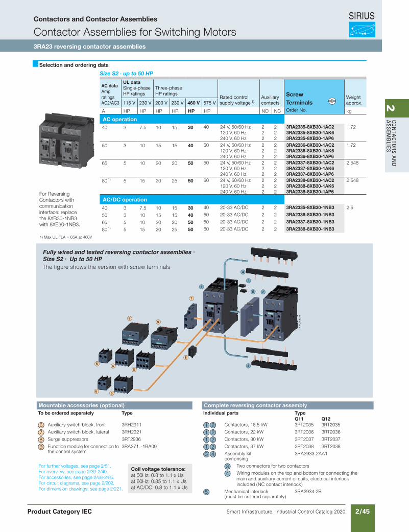
SIRIUS
Smart Infrastructure, Industrial Control Catalog 2020 2/45
2Co
nta
Ctors a
nd
a
ssemb
lies
Siemens / Industrial Controls Previous folio: IC10 2/19
Selection and ordering data
Mountable accessories (to be ordered separately): The fully wired and tested contactor assembly includes the following components:
The connecting leads are not shown.
Accessory Order No. Page
Mechanical interlock, mountable on the front 3RA19 24-1A
Auxiliary switch block, mountable on the front 3RH19 21-1CA..
Auxiliary switch block, laterally mountable 3RH19 21-1EA..
Surgesuppressor 3RT19 26-1....
3RT19 36-1....
Components Order No. PageK1 K2
Contactors, 20 HP 3RT10 33 3RT10 33
Contactors, 25 HP 3RT10 34 3RT10 34
Contactors, 30 HP 3RT10 35 3RT10 35
Contactors, 40 HP 3RT10 36 3RT10 36
Mechanical interlock, laterally mountable 3RA19 24-2B
Installation kit 3RA19 33-2A
The installation kit contains:
2 connecting clips for 2 contactors with a clearance of10 mm
Wiring connectors on the top and bottom for connecting the main conducting paths
12
14
15
16
1 2
1 2
1 2
1 2
4
65
5
6
Size S2 · up to 50 HP
AC dataAmpratingsAC2/AC3
UL dataSingle-phaseHP ratings
Three-phaseHP ratings
Rated controlsupply voltage 1)
Auxiliarycontacts
Screw Terminals
Weightapprox.115 V 230 V 200 V 230 V 460 V 575 V
A HP HP HP HP HP HP NO NC Order No. kg
AC operation40 3 7.5 10 15 30 40 24 V, 50/60 Hz
120 V, 60 Hz240 V, 60 Hz
222
222
3RA2335-8XB30-1AC23RA2335-8XB30-1AK63RA2335-8XB30-1AP6
1.72
50 3 10 15 15 40 50 24 V, 50/60 Hz120 V, 60 Hz240 V, 60 Hz
222
222
3RA2336-8XB30-1AC23RA2336-8XB30-1AK63RA2336-8XB30-1AP6
1.72
65 5 10 20 20 50 50 24 V, 50/60 Hz120 V, 60 Hz240 V, 60 Hz
222
222
3RA2337-8XB30-1AC23RA2337-8XB30-1AK63RA2337-8XB30-1AP6
2.548
80 1) 5 15 20 25 50 60 24 V, 50/60 Hz120 V, 60 Hz240 V, 60 Hz
222
222
3RA2338-8XB30-1AC23RA2338-8XB30-1AK63RA2338-8XB30-1AP6
2.548
AC/DC operation
40 3 7.5 10 15 30 40 20-33 AC/DC 2 2 3RA2335-8XB30-1NB3 2.5
50 3 10 15 15 40 50 20-33 AC/DC 2 2 3RA2336-8XB30-1NB3
65 5 10 20 20 50 50 20-33 AC/DC 2 2 3RA2337-8XB30-1NB3
80 1) 5 15 20 25 50 60 20-33 AC/DC 2 2 3RA2338-8XB30-1NB3
For Reversing Contactors with communication interface: replace the 8XB30-1NB3 with 8XE30-1NB3.
1) Max UL FLA = 65A at 460V
Contactors and Contactor Assemblies
Contactor Assemblies for Switching Motors3RA23 reversing contactor assemblies
Product Category IEC
3/159Siemens IC 10 · 2017
Reversing Contactor Assemblies
SIRIUS 3RA23 reversing contactor assemblies, up to 55 kW
3Mountable accessories (optional) Complete reversing contactor assembly
epyTstrap laudividnIepyTyletarapes deredro eb oTQ11 Q12
5302TR35302TR3Wk5.81 ,srotcatnoC1192HR3tnorf ,kcolb hctiws yrailixuA
6302TR36302TR3Wk22 ,srotcatnoC1292HR3laretal ,kcolb hctiws yrailixuA
7302TR37302TR3Wk03 ,srotcatnoC6392TR3srosserppus egruS
Function module for connection to the control system
8302TR38302TR3Wk73 ,srotcatnoC00AB1-.172AR3
Assembly kit comprising:
3RA2933-2AA1
Two connectors for two contactors
Wiring modules on the top and bottom for connecting the main and auxiliary current circuits, electrical interlock included (NC contact interlock)
Mechanical interlock(must be ordered separately)
3RA2934-2B
8
7
99
66
6
66
3
4
4
51
2
IC01_0
0623a
6 21 7 21 8 21 9 21
3 4
34
5
IC10_03_09.fm Page 159 Friday, June 23, 2017 3:43 PM
Fully wired and tested reversing contactor assemblies · Size S2 · Up to 50 HPThe figure shows the version with screw terminals
For further voltages, see page 2/51.For overview, see page 2/39-2/40.For accessories, see page 2/68-2/85.For circuit diagrams, see page 2/202.For dimension drawings, see page 2/221.
Coil voltage tolerance:at 50Hz: 0.8 to 1.1 x Usat 60Hz: 0.85 to 1.1 x Usat AC/DC: 0.8 to 1.1 x Us
Revised on 02/26/18
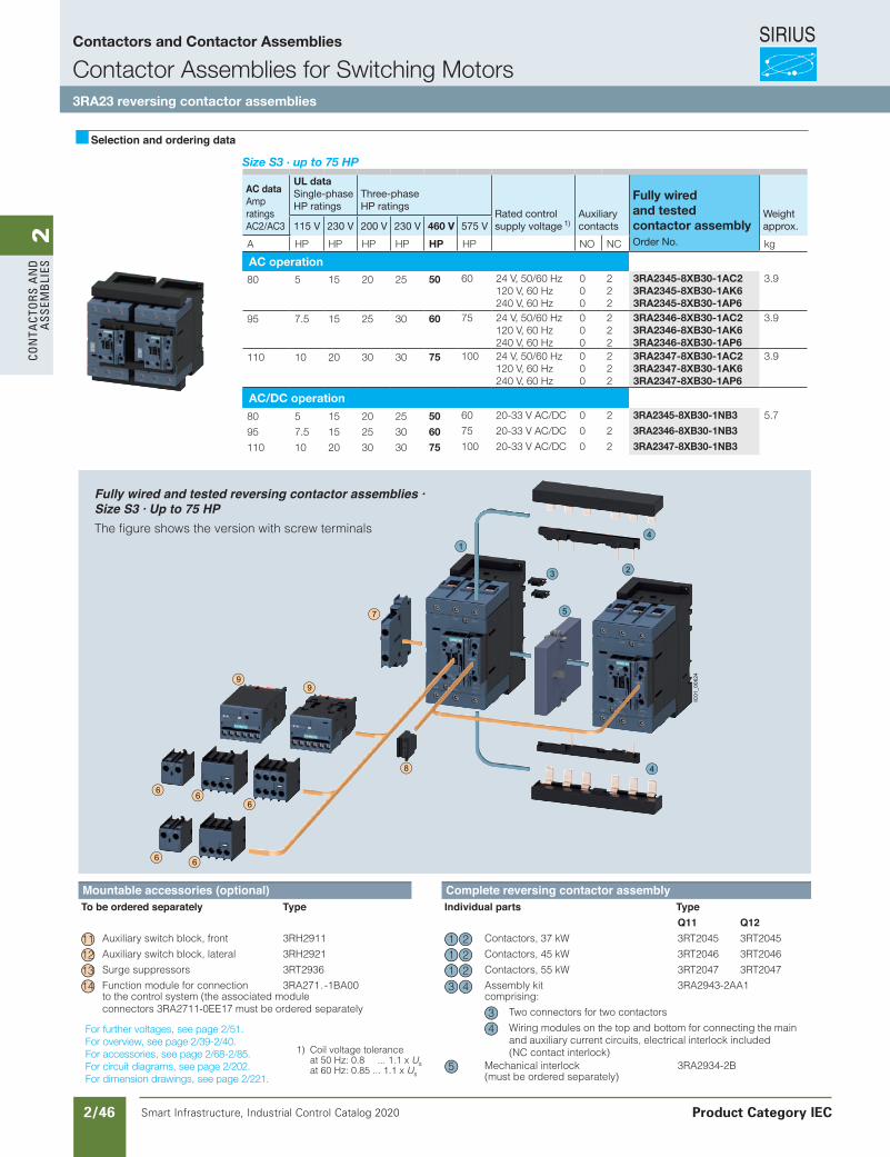
SIRIUS
Smart Infrastructure, Industrial Control Catalog 2020 2/46
2Co
nta
Cto
rs a
nd
a
ssem
bli
es
Siemens / Industrial Controls Previous folio: IC10 2/20
Contactors and Contactor Assemblies
Contactor Assemblies for Switching Motors3RA23 reversing contactor assemblies
Product Category IEC
Selection and ordering data
Mountable accessories (to be ordered separately): The fully wired and tested contactor assembly includes the following components:
The connecting leads are not shown.
egaP.oN redrOyrosseccA
Mechanical interlock, mountable on the front 3RA19 24-1A
Auxiliary switch block,mountable on the front 3RH19 21-1CA..
Auxiliary switch block,laterally mountable 3RH19 21-1EA..
Surge suppressor 3RT19 26-1....3RT19 36-1....
Components Order No. PageK1 K2
Contactors, 60 HP 3RT2045 3RT20453RT2046
3RT2047Contactors, 75 HP 3RT2046
Contactors, 75 HP 3RT2047
Mechanical interlock, laterally mountable 3RA19 24-2B
Installation kit 3RA19 43-2A
The installation kit contains:
2 connecting clips for 2 contactors with a clearance of10 mm
Wiring connectors on the top and bottom
12
14
15
16
1 2
1 2
1 2
4
5 6
5
61) Coil voltage tolerance
at 50 Hz: 0.8 ... 1.1 x Usat 60 Hz: 0.85 ... 1.1 x Us
Size S3 · up to 75 HP
AC dataAmpratingsAC2/AC3
UL dataSingle-phaseHP ratings
Three-phaseHP ratings
Rated controlsupply voltage 1)
Auxiliarycontacts
Fully wired and testedcontactor assembly
Weightapprox.115 V 230 V 200 V 230 V 460 V 575 V
A HP HP HP HP HP HP NO NC Order No. kg
AC operation80 5 15 20 25 50 60 24 V, 50/60 Hz
120 V, 60 Hz240 V, 60 Hz
000
222
3RA2345-8XB30-1AC23RA2345-8XB30-1AK63RA2345-8XB30-1AP6
3.9
95 7.5 15 25 30 60 75 24 V, 50/60 Hz120 V, 60 Hz240 V, 60 Hz
000
222
3RA2346-8XB30-1AC23RA2346-8XB30-1AK63RA2346-8XB30-1AP6
3.9
110 10 20 30 30 75 100 24 V, 50/60 Hz120 V, 60 Hz240 V, 60 Hz
000
222
3RA2347-8XB30-1AC23RA2347-8XB30-1AK63RA2347-8XB30-1AP6
3.9
AC/DC operation
80 5 15 20 25 50 60 20-33 V AC/DC 0 2 3RA2345-8XB30-1NB3 5.7
95 7.5 15 25 30 60 75 20-33 V AC/DC 0 2 3RA2346-8XB30-1NB3
110 10 20 30 30 75 100 20-33 V AC/DC 0 2 3RA2347-8XB30-1NB3
For further voltages, see page 2/51.For overview, see page 2/39-2/40.For accessories, see page 2/68-2/85.For circuit diagrams, see page 2/202.For dimension drawings, see page 2/221.
3/160 Siemens IC 10 · 2017
Reversing Contactor Assemblies
SIRIUS 3RA23 reversing contactor assemblies, up to 55 kW
3
Mountable accessories (optional) Complete reversing contactor assemblyepyTstrap laudividnIepyTyletarapes deredro eb oT
Q11 Q125402TR35402TR3Wk73 ,srotcatnoC1192HR3tnorf ,kcolb hctiws yrailixuA
6402TR36402TR3Wk54 ,srotcatnoC1292HR3laretal ,kcolb hctiws yrailixuA
7402TR37402TR3Wk55 ,srotcatnoC6392TR3srosserppus egruS
Function module for connection to the control system (the associated module connectors 3RA2711-0EE17 must be ordered separately
tik ylbmessA00AB1-.172AR3comprising:
3RA2943-2AA1
Two connectors for two contactors
Wiring modules on the top and bottom for connecting the main and auxiliary current circuits, electrical interlock included (NC contact interlock)
Mechanical interlock (must be ordered separately)
3RA2934-2B
8
7
99
66
6
66
3
4
4
5
1
2
IC01_0
0624
11 2112 2113 2114 3 4
34
5
IC10_03_09.fm Page 160 Friday, June 23, 2017 3:43 PM
Fully wired and tested reversing contactor assemblies · Size S3 · Up to 75 HPThe figure shows the version with screw terminals
Revised on 02/26/18
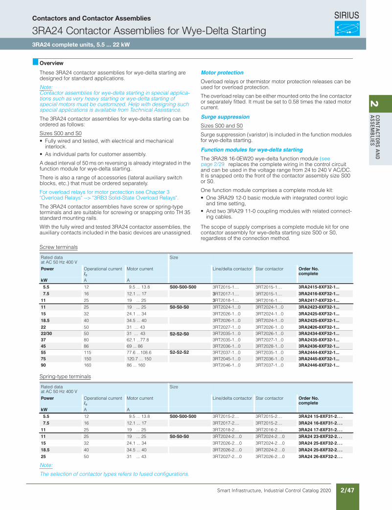
SIRIUS
Smart Infrastructure, Industrial Control Catalog 2020 2/47
2Co
nta
Ctors a
nd
a
ssemb
lies3RA23, 3RA24 Contactor Assemblies
3RA24 Contactor Assemblies for Wye-Delta Starting
3RA24 complete units, 5.5 ... 22 kW
3/36 SIRIUS Innovations Supplement 2012
3
OverviewThese 3RA24 contactor assemblies for wye-delta starting are designed for standard applications.
Note:Contactor assemblies for wye-delta starting in special applica-tions such as very heavy starting or wye-delta starting of special motors must be customized. Help with designing such special applications is available from Technical Assistance.
The 3RA24 contactor assemblies for wye-delta starting can be ordered as follows:
Sizes S00 and S0• Fully wired and tested, with electrical and mechanical
interlock.• As individual parts for customer assembly.
A dead interval of 50 ms on reversing is already integrated in the function module for wye-delta starting.
There is also a range of accessories (lateral auxiliary switch blocks, etc.) that must be ordered separately.
For overload relays for motor protection see Chapter 3 "Overload Relays" --> "3RB3 Solid-State Overload Relays".
The 3RA24 contactor assemblies have screw or spring-type terminals and are suitable for screwing or snapping onto TH 35 standard mounting rails.
With the fully wired and tested 3RA24 contactor assemblies, the auxiliary contacts included in the basic devices are unassigned.
Motor protectionOverload relays or thermistor motor protection releases can be used for overload protection.
The overload relay can be either mounted onto the line contactor or separately fitted. It must be set to 0.58 times the rated motor current.
Surge suppressionSizes S00 and S0
Surge suppression (varistor) is included in the function modules for wye-delta starting.
Function modules for wye-delta startingThe 3RA28 16-0EW20 wye-delta function module (see
replaces the complete wiring in the control circuit and can be used in the voltage range from 24 to 240 V AC/DC. It is snapped onto the front of the contactor assembly size S00 or S0.
One function module comprises a complete module kit:• One 3RA29 12-0 basic module with integrated control logic
and time setting,• And two 3RA29 11-0 coupling modules with related connect-
ing cables.
The scope of supply comprises a complete module kit for one contactor assembly for wye-delta starting size S00 or S0, regardless of the connection method.
Screw terminals
Spring-type terminals
Note:
The selection of contactor types refers to fused configurations.
Rated dataat AC 50 Hz 400 V
Size
Power Operational current Ie
Motor current Line/delta contactor Star contactor Order No.complete
kW A A
5.5 12 9.5 ... 13.8 S00-S00-S00 3RA2415-8XF32-1...7.5 16 12.1 ... 17 3 3RA2416-8XF32-1...
11 352 ... 9152 3RA2417-8XF32-1...11 25 19 ... 25 S0-S0-S0
S2-S2-S0
S2-S2-S2
3RT2024-1...0 3RT2024-1...0 3RA2423-8XF32-1...15 3RT2024-1...03RT2026-1...0
3RT2018-1....3RT2017-1....
3RT2015-1.... 3RT2015-1....
3RT2015-1....
3RT2016-1....
43 ... 1.4223 3RA2425-8XF32-1...18.5 40 34.5 ... 40 3RT2026-1...0 3RT2024-1...0 3RA2425-8XF32-1...22 3RT2026-1...03RT2027-1...034 ... 1305 3RA2426-8XF32-1...22/30 3RT2026-1...03RT2035-1...031 ... 43 50 3RA2434-8XF32-1...37 3RT2027-1...03RT2035-1...062.1 ...77.880 3RA2435-8XF32-1...45 3RT2028-1...03RT2036-1...069 ... 86 86 3RA2436-8XF32-1...55 3RT2035-1...03RT2037-1...077.6 ...108.6115 3RA2444-8XF32-1...75 3RT2036-1...0 3RT2045-1...0 120.7 ... 150 150 3RA2445-8XF32-1...90 3RT2037-1...0 3RT2046-1...0 86 ... 160 160 3RA2446-8XF32-1...
4
Rated dataat AC 50 Hz 400 V
Size
Power Operational current Ie
Motor current Line/delta contactor Star contactor Order No.complete
kW A A
5.5 12 9.5 ... 13.8 S00-S00-S00 3RT2015-2.... 3RT2015-2.... 3RA24 15-8XF31-2. . .7.5 16 12.1 ... 17 3RT2017-2.... 3RT2015-2.... 3RA24 16-8XF31-2. . .
11 3RT2016-2....3RT2018-2....52 ... 9152 3RA24 17-8XF31-2. . .11 25 19 ... 25 S0-S0-S0 3RT2024-2....0 3RT2024-2....0 3RA24 23-8XF32-2. . .15 3RT2024-2....03RT2026-2....043 ... 1.4223 3RA24 25-8XF32-2. . .18.5 40 34.5 ... 40 3RT2026-2....0 3RT2024-2....0 3RA24 25-8XF32-2. . .25 3RT2026-2....03RT2027-2....034 ... 1305 3RA24 26-8XF32-2. . .
LV1N_03_05.fm Page 36 Thursday, October 31, 2013 11:21 AM
page 2/29
Contactors and Contactor Assemblies
3RA24 Contactor Assemblies for Wye-Delta Starting3RA24 complete units, 5.5 ... 22 kW
Revised on 02/26/18
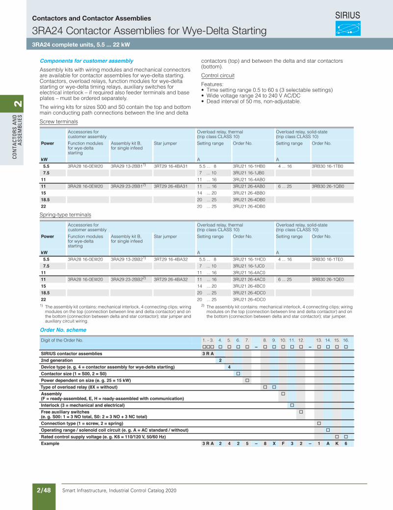
SIRIUS
Smart Infrastructure, Industrial Control Catalog 2020 2/48
2Co
nta
Cto
rs a
nd
a
ssem
bli
es3RA23, 3RA24 Contactor Assemblies
3RA24 Contactor Assemblies for Wye-Delta Starting
3RA24 complete units, 5.5 ... 22 kW
3/37SIRIUS Innovations Supplement 2012
3
Components for customer assemblyAssembly kits with wiring modules and mechanical connectors are available for contactor assemblies for wye-delta starting. Contactors, overload relays, function modules for wye-delta starting or wye-delta timing relays, auxiliary switches for electrical interlock – if required also feeder terminals and base plates – must be ordered separately.
The wiring kits for sizes S00 and S0 contain the top and bottom main conducting path connections between the line and delta
contactors (top) and between the delta and star contactors(bottom).
Control circuit
Features:• Time setting range 0.5 to 60 s (3 selectable settings)• Wide voltage range 24 to 240 V AC/DC• Dead interval of 50 ms, non-adjustable.
Screw terminals
Spring-type terminals
1) The assembly kit contains: mechanical interlock, 4 connecting clips; wiring modules on the top (connection between line and delta contactor) and on the bottom (connection between delta and star contactor); star jumper and auxiliary circuit wiring.
2) The assembly kit contains: mechanical interlock, 4 connecting clips; wiring modules on the top (connection between line and delta contactor) and on the bottom (connection between delta and star contactor); star jumper.
Order No. scheme
Note:
The Order No. scheme is presented here merely for information purposes and for better understanding of the logic behind the order numbers.
For your orders, please use the order numbers quote in the catalog in the Selection and ordering data.
Accessories for customer assembly
Overload relay, thermal (trip class CLASS 10)
Overload relay, solid-state (trip class CLASS 10)
Power Function modules for wye-delta starting
Assembly kit B, for single infeed
Star jumper Setting range Order No. Setting range Order No.
kW A A
5.5 3RA28 16-0EW20 3RA29 13-2BB11) 3RT29 16-4BA31 5.5 ... 8 3RU21 16-1HB0 4 ... 16 3RB30 16-1TB0
7.5 7 ... 10 3RU21 16-1JB0
11 11 ... 16 3RU21 16-4AB0
11 3RA28 16-0EW20 3RA29 23-2BB12) 3RT29 26-4BA31 11 ... 16 3RU21 26-4AB0 6 ... 25 3RB30 26-1QB0
15 14 ... 20 3RU21 26-4BB0
18.5 20 ... 25 3RU21 26-4DB0
22 20 ... 25 3RU21 26-4DB0
Accessories for customer assembly
Overload relay, thermal (trip class CLASS 10)
Overload relay, solid-state (trip class CLASS 10)
Power Function modules for wye-delta starting
Assembly kit B, for single infeed
Star jumper Setting range Order No. Setting range Order No.
kW A A
5.5 3RA28 16-0EW20 3RA29 13-2BB21) 3RT29 16-4BA32 5.5 ... 8 3RU21 16-1HC0 4 ... 16 3RB30 16-1TE0
7.5 7 ... 10 3RU21 16-1JC0
11 11 ... 16 3RU21 16-4AC0
11 3RA28 16-0EW20 3RA29 23-2BB22) 3RT29 26-4BA32 11 ... 16 3RU21 26-4AC0 6 ... 25 3RB30 26-1QE0
15 14 ... 20 3RU21 26-4BC0
18.5 20 ... 25 3RU21 26-4DC0
22 20 ... 25 3RU21 26-4DC0
Digit of the Order No. 1. - 3. 4. 5. 6. 7. 8. 9. 10. 11. 12. 13. 14. 15. 16.
@@@ @ @ @ @ – @ @ @ @ @ – @ @ @ @SIRIUS contactor assemblies 3 R A2nd generation 2Device type (e. g. 4 = contactor assembly for wye-delta starting) 4Contactor size (1 = S00, 2 = S0) @Power dependent on size (e. g. 25 = 15 kW) @Type of overload relay (8X = without) @ @Assembly(F = ready-assembled, E, H = ready-assembled with communication)
@
Interlock (3 = mechanical and electrical) @Free auxiliary switches(e. g. S00: 1 = 3 NO total, S0: 2 = 3 NO + 3 NC total)
@
Connection type (1 = screw, 2 = spring) @Operating range / solenoid coil circuit (e. g. A = AC standard / without) @Rated control supply voltage (e. g. K6 = 110/120 V, 50/60 Hz) @ @Example 3 R A 2 4 2 5 – 8 X F 3 2 – 1 A K 6
LV1N_03_05.fm Page 37 Thursday, October 31, 2013 11:21 AM
Contactors and Contactor Assemblies
3RA24 Contactor Assemblies for Wye-Delta Starting3RA24 complete units, 5.5 ... 22 kW
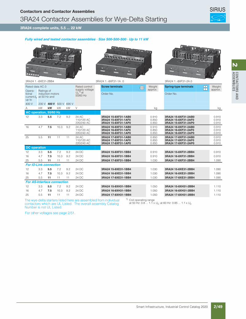
SIRIUS
Smart Infrastructure, Industrial Control Catalog 2020 2/49
2Co
nta
Ctors a
nd
a
ssemb
lies3RA23, 3RA24 Contactor Assemblies
3RA24 Contactor Assemblies for Wye-Delta Starting
3RA24 complete units, 5.5 ... 22 kW
3/39SIRIUS Innovations Supplement 2012Illustrations are approximate
3
Fully wired and tested contactor assemblies · Size S00-S00-S00 · Up to 11 kW
The wye-delta starters listed here are assembled from individual contactors which are UL Listed. The overall assembly Catalog Number is not UL Listed.
1) Coil operating range at 50 Hz: 0.8 ... 1.1 x Us; at 60 Hz: 0.85 ... 1.1 x Us.
0.A2-13FX8- . 1 42AR30 . A1-13FX8- . 1 42AR3 4BB2-13EX8- . 1 42AR3
Rated data AC-3 Rated control supply voltage Us
1) at 50/60 Hz
Screw terminals Weightapprox.
Spring-type terminals Weightapprox.Opera-
tional current Ie up to
Ratings of induction motors at 50 Hz and
Order No. Order No.
400 V 230 V 400 V 500 V 690 V
A kW kW kW kW V kg kg
AC operation, 50/60 Hz12 3.3 5.5 7.2 9.2 24 AC 3RA24 15-8XF31-1AB0 0.910 3RA24 15-8XF31-2AB0 0.910
110/120 AC 3RA24 15-8XF31-1AF0 0.850 3RA24 15-8XF31-2AF0 0.910220/240 AC 3RA24 15-8XF31-1AP0 0.850 3RA24 15-8XF31-2AP0 0.910
16 4.7 7.5 10.3 9.2 24 AC 3RA24 16-8XF31-1AB0 0.910 3RA24 16-8XF31-2AB0 0.910110/120 AC 3RA24 16-8XF31-1AF0 0.850 3RA24 16-8XF31-2AF0 0.910220/240 AC 3RA24 16-8XF31-1AP0 0.850 3RA24 16-8XF31-2AP0 0.910
25 5.5 11 11 11 24 AC 3RA24 17-8XF31-1AB0 0.850 3RA24 17-8XF31-2AB0 0.910110/120 AC 3RA24 17-8XF31-1AF0 0.850 3RA24 17-8XF31-2AF0 0.910220/240 AC 3RA24 17-8XF31-1AP0 0.850 3RA24 17-8XF31-2AP0 0.910
DC operation12 3.3 5.5 7.2 9.2 24 DC 3RA24 15-8XF31-1BB4 0.910 3RA24 15-8XF31-2BB4 0.910
16 4.7 7.5 10.3 9.2 24 DC 3RA24 16-8XF31-1BB4 0.910 3RA24 16-8XF31-2BB4 0.910
25 5.5 11 11 11 24 DC 3RA24 17-8XF31-1BB4 1.030 3RA24 17-8XF31-2BB4 1.090
For IO-Link connection12 3.3 5.5 7.2 9.2 24 DC 3RA24 15-8XE31-1BB4 1.030 3RA24 15-8XE31-2BB4 1.090
16 4.7 7.5 10.3 9.2 24 DC 3RA24 16-8XE31-1BB4 1.030 3RA24 16-8XE31-2BB4 1.090
25 5.5 11 11 11 24 DC 3RA24 17-8XE31-1BB4 1.030 3RA24 17-8XE31-2BB4 1.090
For AS-Interface connection12 3.3 5.5 7.2 9.2 24 DC 3RA24 15-8XH31-1BB4 1.050 3RA24 15-8XH31-2BB4 1.110
16 4.7 7.5 10.3 9.2 24 DC 3RA24 16-8XH31-1BB4 1.050 3RA24 16-8XH31-2BB4 1.110
25 5.5 11 11 11 24 DC 3RA24 17-8XH31-1BB4 1.050 3RA24 17-8XH31-2BB4 1.110
LV1N_03_05.fm Page 39 Thursday, October 31, 2013 11:21 AM
For other voltages see page 2/51.
Contactors and Contactor Assemblies
3RA24 Contactor Assemblies for Wye-Delta Starting3RA24 complete units, 5.5 ... 22 kW
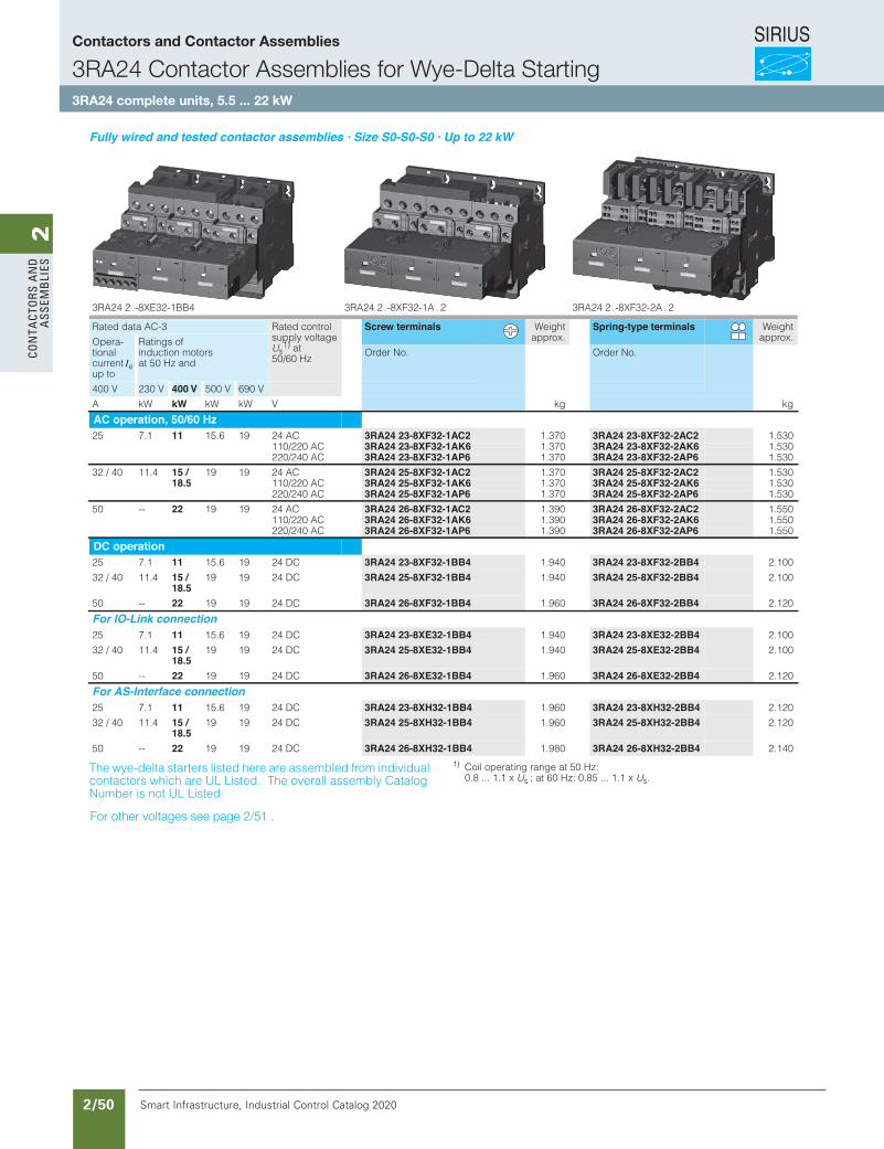
SIRIUS
Smart Infrastructure, Industrial Control Catalog 2020 2/50
2Co
nta
Cto
rs a
nd
a
ssem
bli
es3RA23, 3RA24 Contactor Assemblies
3RA24 Contactor Assemblies for Wye-Delta Starting
3RA24 complete units, 5.5 ... 22 kW
3/41SIRIUS Innovations Supplement 2012Illustrations are approximate
3
Fully wired and tested contactor assemblies · Size S0-S0-S0 · Up to 22 kW
The wye-delta starters listed here are assembled from individual contactors which are UL Listed. The overall assembly Catalog Number is not UL Listed.
1) Coil operating range at 50 Hz: 0.8 ... 1.1 x Us ; at 60 Hz: 0.85 ... 1.1 x Us.
2 . A2-23FX8- . 2 42AR32 . A1-23FX8- . 2 42AR34BB1-23EX8- . 2 42AR3
Rated data AC-3 Rated control supply voltage Us
1) at 50/60 Hz
Screw terminals Weightapprox.
Spring-type terminals Weightapprox.Opera-
tional current Ie up to
Ratings of induction motors at 50 Hz and
Order No. Order No.
400 V 230 V 400 V 500 V 690 V
A kW kW kW kW V kg kg
AC operation, 50/60 Hz25 7.1 11 15.6 19 24 AC 3RA24 23-8XF32-1AC2 1.370 3RA24 23-8XF32-2AC2 1.530
110/220 AC 3RA24 23-8XF32-1AK6 1.370 3RA24 23-8XF32-2AK6 1.530220/240 AC 3RA24 23-8XF32-1AP6 1.370 3RA24 23-8XF32-2AP6 1.530
32 / 40 11.4 15 /18.5
19 19 24 AC 3RA24 25-8XF32-1AC2 1.370 3RA24 25-8XF32-2AC2 1.530110/220 AC 3RA24 25-8XF32-1AK6 1.370 3RA24 25-8XF32-2AK6 1.530220/240 AC 3RA24 25-8XF32-1AP6 1.370 3RA24 25-8XF32-2AP6 1.530
50 -- 22 19 19 24 AC 3RA24 26-8XF32-1AC2 1.390 3RA24 26-8XF32-2AC2 1.550110/220 AC 3RA24 26-8XF32-1AK6 1.390 3RA24 26-8XF32-2AK6 1.550220/240 AC 3RA24 26-8XF32-1AP6 1.390 3RA24 26-8XF32-2AP6 1.550
DC operation25 7.1 11 15.6 19 24 DC 3RA24 23-8XF32-1BB4 1.940 3RA24 23-8XF32-2BB4 2.100
32 / 40 11.4 15 /18.5
19 19 24 DC 3RA24 25-8XF32-1BB4 1.940 3RA24 25-8XF32-2BB4 2.100
50 -- 22 19 19 24 DC 3RA24 26-8XF32-1BB4 1.960 3RA24 26-8XF32-2BB4 2.120
For IO-Link connection25 7.1 11 15.6 19 24 DC 3RA24 23-8XE32-1BB4 1.940 3RA24 23-8XE32-2BB4 2.100
32 / 40 11.4 15 /18.5
19 19 24 DC 3RA24 25-8XE32-1BB4 1.940 3RA24 25-8XE32-2BB4 2.100
50 -- 22 19 19 24 DC 3RA24 26-8XE32-1BB4 1.960 3RA24 26-8XE32-2BB4 2.120
For AS-Interface connection25 7.1 11 15.6 19 24 DC 3RA24 23-8XH32-1BB4 1.960 3RA24 23-8XH32-2BB4 2.120
32 / 40 11.4 15 /18.5
19 19 24 DC 3RA24 25-8XH32-1BB4 1.960 3RA24 25-8XH32-2BB4 2.120
50 -- 22 19 19 24 DC 3RA24 26-8XH32-1BB4 1.980 3RA24 26-8XH32-2BB4 2.140
LV1N_03_05.fm Page 41 Thursday, October 31, 2013 11:21 AM
For other voltages see page 2/51 .
Contactors and Contactor Assemblies
3RA24 Contactor Assemblies for Wye-Delta Starting3RA24 complete units, 5.5 ... 22 kW
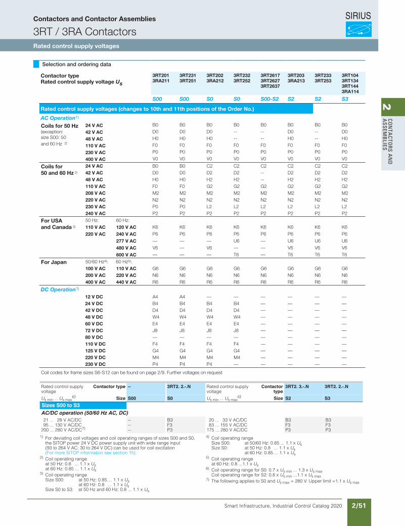
SIRIUS
Smart Infrastructure, Industrial Control Catalog 2020 2/51
2Co
nta
Ctors a
nd
a
ssemb
lies
Siemens / Industrial Controls Previous folio: IC10 2/23
Selection and ordering data
Contactor type Rated control supply voltage Us
3RT201 3RA211
3RT231 3RT251
3RT202 3RA212
3RT232 3RT252
3RT2617 3RT2627 3RT2637
3RT203 3RA213
3RT233 3RT253
3RT104 3RT134 3RT1443RA114
S00 S00 S0 S0 S00-S2 S2 S2 S3
Rated control supply voltages (changes to 10th and 11th positions of the Order No.)
AC Operation1)
Coils for 50 Hz (exception: size S00: 50 and 60 Hz 2)
24 V AC B0 B0 B0 B0 B0 B0 B0 B0
42 V AC D0 D0 D0 -- -- D0 -- D0
48 V AC H0 H0 H0 -- -- H0 -- H0
110 V AC F0 F0 F0 F0 F0 F0 F0 F0
230 V AC P0 P0 P0 P0 P0 P0 P0 P0
400 V AC V0 V0 V0 V0 V0 V0 V0 V0
Coils for 50 and 60 Hz 2)
24 V AC B0 B0 C2 C2 C2 C2 C2 C242 V AC D0 D0 D2 D2 -- D2 D2 D248 V AC H0 H0 H2 H2 -- H2 H2 H2110 V AC F0 F0 G2 G2 G2 G2 G2 G2208 V AC M2 M2 M2 M2 M2 M2 M2 M2220 V AC N2 N2 N2 N2 N2 N2 N2 N2230 V AC P0 P0 L2 L2 L2 L2 L2 L2240 V AC P2 P2 P2 P2 P2 P2 P2 P2
For USA and Canada 3)
50 Hz: 60 Hz:110 V AC 120 V AC K6 K6 K6 K6 K6 K6 K6 K6
220 V AC 240 V AC P6 P6 P6 P6 P6 P6 P6 P6
277 V AC — — — U6 — U6 U6 U6
480 V AC V6 — V6 — — V6 V6 V6
600 V AC — — — T6 — T6 T6 T6
For Japan 50/60 Hz4): 60 Hz5):100 V AC 110 V AC G6 G6 G6 G6 G6 G6 G6 G6200 V AC 220 V AC N6 N6 N6 N6 N6 N6 N6 N6400 V AC 440 V AC R6 R6 R6 R6 R6 R6 R6 R6
DC Operation1)
12 V DC A4 A4 — — — — — —24 V DC B4 B4 B4 B4 — — — —42 V DC D4 D4 D4 D4 — — — —48 V DC W4 W4 W4 W4 — — — —60 V DC E4 E4 E4 E4 — — — —72 V DC J8 J8 J8 J8 — — — —80 V DC — — — — — — — —110 V DC F4 F4 F4 F4 — — — —125 V DC G4 G4 G4 G4 — — — —220 V DC M4 M4 M4 M4 — — — —230 V DC P4 P4 P4 — — — — —
Coil codes for frame sizes S6-S12 can be found on page 2/9. Further voltages on request
3/50 Siemens IC 10 · 2015
Power Contactors for Switching Motors
SIRIUS 3RT20 contactors, 3-pole, up to 37 kW
3
Options
Rated control supply voltages, possible on request (change of the 10th and 11th digits of the Article No.)
1) For deviating coil voltages and coil operating ranges of sizes S00 and S0, the SITOP power 24 V DC power supply unit with wide range input (93 to 264 V AC; 30 to 264 V DC) can be used for coil excitation (For more SITOP information see section 15).
2) Coil operating range at 50 Hz: 0.8 ... 1.1 x Us at 60 Hz: 0.85 ... 1.1 x Us
3) Coil operating range Size S00: at 50 Hz: 0.85.... 1.1 x Us
at 60 Hz: 0.8 ... 1.1 x at 50 Hz and 60 Hz: 0.8 ... 1.1 x
Us Size S0 to S3: Us
4) Coil operating range Size S00: at 50/60 Hz: 0.85 ... 1.1 x Us Size S0: at 50 Hz: 0.8 ... 1.1 x Us
at 60 Hz: 0.85 ... 1.1 x Us5) Coil operating range
at 60 Hz: 0.8 ...1.1 x Us6) Coil operating range for S0: 0.7 x Us min ... 1.3 x Us max
Coil operating range for S2: 0.8 x Us min ...1.1 x Us max7) The following applies to S0 and Us max = 280 V: Upper limit =1.1 x Us max
Rated control supply voltage Us
Contactor type 3RT201 3RT202 3RT203 3RT231, 3RT251
3RT232, 3RT252
3RT233, 3RT253
Size S00 S0 S2 S00 S0 S2Sizes S00 to S2AC operation1)
Solenoid coils for 50 Hz (exception: Size S00: 50 and 60 Hz2))
24 V AC B0 B0 B0 B0 B0 B042 V AC D0 D0 D0 D0 -- --48 V AC H0 H0 H0 H0 -- --
110 V AC F0 F0 F0 F0 F0 F0230 V AC P0 P0 P0 P0 P0 P0240 V AC U0 U0 U0 -- -- --400 V AC V0 V0 V0 V0 V0 V0
Solenoid coils for 50 and 60 Hz2)
24 V AC B0 C2 C2 B0 C2 C242 V AC D0 D2 D2 D0 D2 D248 V AC H0 H2 H2 H0 H2 H2110 V AC F0 G2 G2 F0 G2 G2220 V AC N2 N2 N2 N2 N2 N2230 V AC P0 L2 L2 P0 L2 L2
Solenoid coils (for USA and Canada3))
50 Hz 60 Hz110 V AC 120 V AC K6 K6 K6 K6 K6 K6220 V AC 240 V AC P6 P6 P6 P6 P6 P6
Solenoid coils (for Japan)
50/60 Hz4) 60 Hz5)
100 V AC 110 V AC G6 G6 G6 G6 G6 G6200 V AC 220 V AC N6 N6 N6 N6 N6 N6400 V AC 440 V AC R6 R6 R6 R6 R6 R6
DC operation1)
12 V DC A4 A4 -- A4 A4 --24 V DC B4 B4 -- B4 B4 --42 V DC D4 D4 -- D4 D4 --48 V DC W4 W4 -- W4 W4 --60 V DC E4 E4 -- -- -- --
110 V DC F4 F4 -- F4 F4 --125 V DC G4 G4 -- G4 G4 --220 V DC M4 M4 -- M4 M4 --230 V DC P4 P4 -- P4 -- --
ExamplesAC operation 3RT2023-1AP00 Contactor with screw terminals; with solenoid coil for 50 Hz for rated control supply voltage 230 V AC
3RT2023-1AG20 Contactor with screw terminals; with solenoid coil for 50/60 Hz for rated control supply voltage 110 V AC
DC operation 3RT2025-2BB40 Contactor with spring-type terminals; for rated control supply voltage 24 V DC
3RT2025-2BG40 Contactor with spring-type terminals; for rated control supply voltage 125 V DC
Rated control supply voltage
Contactor type -- 3RT2. 2.-.N Rated control supply voltage
Contactortype
3RT2. 3.-.N
Us min ... Us max6) Size S00 S0 Us min ... Us max
6) Size S2Sizes S00 to S3AC/DC operation (50/60 Hz AC, DC)21 ... 28 V AC/DC -- B3 20 ... 33 V AC/DC B395 ... 130 V AC/DC -- F3 83 ... 155 V AC/DC F3
200 ... 280 V AC/DC7) -- P3 175 ... 280 V AC/DC P3
IC10_03_04.fm Page 50 Friday, April 17, 2015 3:43 PM
3RT2. 2.-.N
S3
B3F3P3
Contactors and Contactor Assemblies
3RT / 3RA ContactorsRated control supply voltages
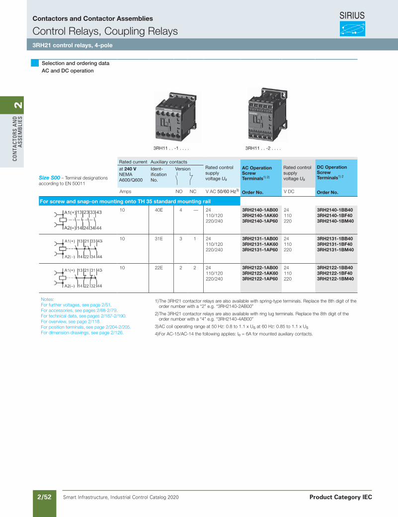
SIRIUS
Smart Infrastructure, Industrial Control Catalog 2020 2/52
2Co
nta
Cto
rs a
nd
a
ssem
bli
es
Siemens / Industrial Controls Previous folio: IC10 2/24 with new table
Selection and ordering data AC and DC operation
Size S00 – Terminal designations according to EN 50011
Rated current Auxiliary contacts Rated controlsupply voltage Us
AC OperationScrew Terminals1) 2)
Rated controlsupplyvoltage Us
DC OperationScrew Terminals1) 2
at 240 VNEMAA600/Q600
Ident-ificationNo.
Version
Amps NO NC V AC 50/60 Hz3) Order No. V DC Order No.
For screw and snap-on mounting onto TH 35 standard mounting rail
10 40E 4 — 24110/120220/240
3RH2140-1AB003RH2140-1AK603RH2140-1AP60
24110220
3RH2140-1BB403RH2140-1BF403RH2140-1BM40
10 31E 3 1 24110/120220/240
3RH2131-1AB003RH2131-1AK603RH2131-1AP60
24110220
3RH2131-1BB403RH2131-1BF403RH2131-1BM40
10 22E 2 2 24110/120220/240
3RH2122-1AB003RH2122-1AK603RH2122-1AP60
24110220
3RH2122-1BB403RH2122-1BF403RH2122-1BM40
Notes: For further voltages, see page 2/51.For accessories, see pages 2/68-2/79.For technical data, see pages 2/187-2/190.For overview, see page 2/118.For position terminals, see page 2/204-2/205.For dimension drawings, see page 2/126.
1) The 3RH21 contactor relays are also available with spring-type terminals. Replace the 8th digit of the order number with a “2” e.g. “3RH2140-2AB00”
2) The 3RH21 contactor relays are also available with ring lug terminals. Replace the 8th digit of the order number with a “4” e.g. “3RH2140-4AB00”
3) AC coil operating range at 50 Hz: 0.8 to 1.1 x Us at 60 Hz: 0.85 to 1.1 x Us
4) For AC-15/AC-14 the following applies: Ie = 6A for mounted auxiliary contacts.
3RH11 . . -1 . . . . 3RH11 . . -2 . . . .
Contactors and Contactor Assemblies
Control Relays, Coupling Relays3RH21 control relays, 4-pole
Product Category IEC
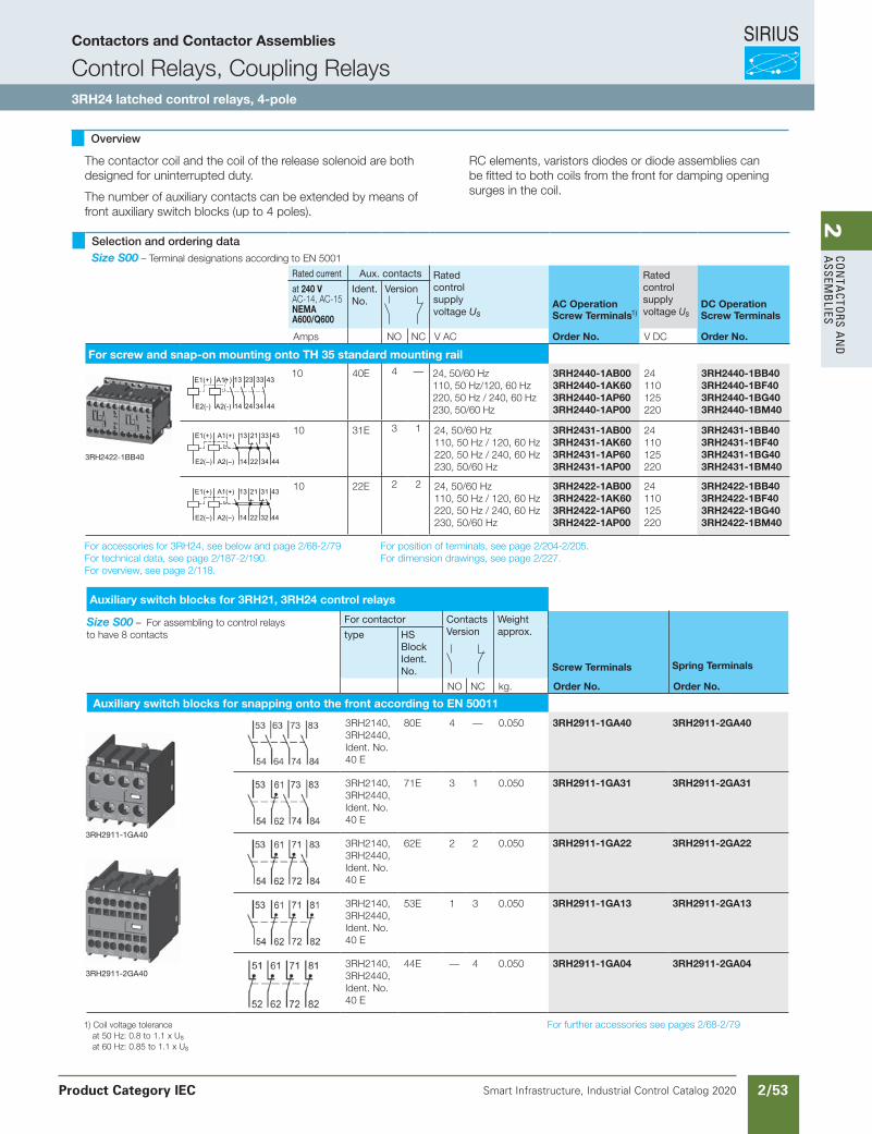
SIRIUS
Smart Infrastructure, Industrial Control Catalog 2020 2/53
2Co
nta
Ctors a
nd
a
ssemb
lies
Siemens / Industrial Controls Previous folio: New tables from excel
1) Coil voltage tolerance at 50 Hz: 0.8 to 1.1 x Usat 60 Hz: 0.85 to 1.1 x Us
For accessories for 3RH24, see below and page 2/68-2/79For technical data, see page 2/187-2/190.For overview, see page 2/118.
3RH2422-1BB40
Selection and ordering data Size S00 – Terminal designations according to EN 5001
Rated current Aux. contacts Rated controlsupply voltage Us
AC OperationScrew Terminals1)
Rated controlsupplyvoltage Us
DC OperationScrew Terminals
at 240 VAC-14, AC-15NEMAA600/Q600
Ident. No.
Version
Amps NO NC V AC Order No. V DC Order No.
For screw and snap-on mounting onto TH 35 standard mounting rail
10 40E 4 — 24, 50/60 Hz110, 50 Hz/120, 60 Hz220, 50 Hz / 240, 60 Hz230, 50/60 Hz
3RH2440-1AB003RH2440-1AK603RH2440-1AP603RH2440-1AP00
24110125220
3RH2440-1BB403RH2440-1BF403RH2440-1BG403RH2440-1BM40
10 31E 3 1 24, 50/60 Hz110, 50 Hz / 120, 60 Hz220, 50 Hz / 240, 60 Hz230, 50/60 Hz
3RH2431-1AB003RH2431-1AK603RH2431-1AP603RH2431-1AP00
24110125220
3RH2431-1BB403RH2431-1BF403RH2431-1BG403RH2431-1BM40
10 22E 2 2 24, 50/60 Hz110, 50 Hz / 120, 60 Hz220, 50 Hz / 240, 60 Hz230, 50/60 Hz
3RH2422-1AB003RH2422-1AK603RH2422-1AP603RH2422-1AP00
24110125220
3RH2422-1BB403RH2422-1BF403RH2422-1BG403RH2422-1BM40
Auxiliary switch blocks for 3RH21, 3RH24 control relays
Size S00 – For assembling to control relays to have 8 contacts
For contactor ContactsVersion
Weight approx.
Screw Terminals Spring Terminals
type HS Block Ident.No.
NO NC kg. Order No. Order No.
Auxiliary switch blocks for snapping onto the front according to EN 50011
3RH2140,3RH2440,Ident. No.40 E
80E 4 — 0.050 3RH2911-1GA40 3RH2911-2GA40
3RH2140,3RH2440,Ident. No.40 E
71E 3 1 0.050 3RH2911-1GA31 3RH2911-2GA31
3RH2140,3RH2440,Ident. No.40 E
62E 2 2 0.050 3RH2911-1GA22 3RH2911-2GA22
3RH2140,3RH2440,Ident. No.40 E
53E 1 3 0.050 3RH2911-1GA13 3RH2911-2GA13
3RH2140,3RH2440,Ident. No.40 E
44E — 4 0.050 3RH2911-1GA04 3RH2911-2GA04
3RH2911-1GA40
3RH2911-2GA40
E2(-)
E1(+)
A2(-)
)(A1+
14 24 34 44
43332313
E2(–)
E1(+)
22
21
44
43
34
33A1(+)
A2(–) 14
13
E2(–)
E1(+)
22
21
44
43
32
31A1(+)
A2(–) 14
13
The contactor coil and the coil of the release solenoid are both designed for uninterrupted duty.
The number of auxiliary contacts can be extended by means of front auxiliary switch blocks (up to 4 poles).
For position of terminals, see page 2/204-2/205.For dimension drawings, see page 2/227.
Overview
RC elements, varistors diodes or diode assemblies can be fitted to both coils from the front for damping opening surges in the coil.
For further accessories see pages 2/68-2/79
Contactors and Contactor Assemblies
Control Relays, Coupling Relays3RH24 latched control relays, 4-pole
Product Category IEC
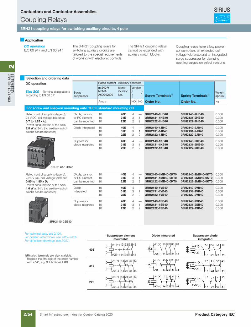
SIRIUS
Smart Infrastructure, Industrial Control Catalog 2020 2/54
2Co
nta
Cto
rs a
nd
a
ssem
bli
es
Siemens / Industrial Controls Previous folio: 2/27 with new tables
DC operationIEC 60 947 and EN 60 947
The 3RH21 coupling relays forswitching auxiliary circuits aretailored to the special requirements of working with electronic controls.
The 3RH21 coupling relays cannot be extended with auxiliary switch blocks.
Coupling relays have a low power consumption, an extended coil voltage tolerance and an integrated surge suppressor for damping opening surges on select versions
Selection and ordering data
DC operation
Size S00 – Terminal designations according to EN 50 011
Surgesuppressor
Rated current Auxiliary contacts
Screw Terminals1) Spring Terminals1)Weight approx.
at 240 VNEMAA600/Q600
Ident-ificationNo.
Version
Amps NO NC Order No. Order No. kg.
For screw and snap-on mounting onto TH 35 standard mounting rail
Rated control supply voltage Us = 24 V DC, coil voltage tolerance 0.7 to 1.25 x Us
Power consumption of the coils 2.8 W at 24 V (no auxiliary switch blocks can be mounted)
Diode, varistor,or RC elementcan be mounted
101010
40E31E22E
432
—12
3RH2140-1HB403RH2131-1HB403RH2122-1HB40
3RH2140-2HB403RH2131-2HB403RH2122-2HB40
0.3000.3000.300
Diode integrated 101010
40E31E22E
432
—12
3RH2140-1JB403RH2131-1JB403RH2122-1JB40
3RH2140-2JB403RH2131-2JB40 3RH2122-2JB40
0.3000.3000.300
Suppressor diode integrated
101010
40E31E22E
432
—12
3RH2140-1KB403RH2131-1KB403RH2122-1KB40
3RH2140-2KB40 3RH2131-2KB40 3RH2122-2KB40
0.3000.3000.300
Rated control supply voltage Us = 24 V DC, coil voltage tolerance 0.85 to 1.85 x Us
Power consumption of the coils 1.6 W at 24 V (no auxiliary switch blocks can be mounted)
Diode, varistor,or RC elementcan be mounted
101010
40E31E22E
432
—12
3RH2140-1MB40-0KT03RH2131-1MB40-0KT03RH2122-1MB40-0KT0
3RH2140-2MB40-0KT03RH2131-2MB40-0KT03RH2122-2MB40-0KT0
0.3000.3000.300
Diodeintegrated
101010
40E31E22E
432
—12
3RH2140-1VB403RH2131-1VB403RH2122-1VB40
3RH2140-2VB403RH2131-2VB403RH2122-2VB40
0.3000.3000.300
Suppressor diode integrated
101010
40E31E22E
432
—12
3RH2140-1SB403RH2131-1SB403RH2122-1SB40
3RH2140-2SB403RH2131-2SB403RH2122-2SB40
0.3000.3000.300
For technical data, see 2/191.For position of terminals, see 2/204-2/205.For dimension drawings, see 2/227.
1) Ring lug terminals are also available. Replace the 8th digit of the order number with a “4”, e.g. 3RH2140-4HB40
Suppressor element mountable
Diode integrated Suppressor diode integrated
40E
31E
22E
3RH2140-2SB40
3RH2140-1HB40
Contactors and Contactor Assemblies
Coupling Relays3RH21 coupling relays for switching auxiliary circuits, 4 pole
Product Category IEC
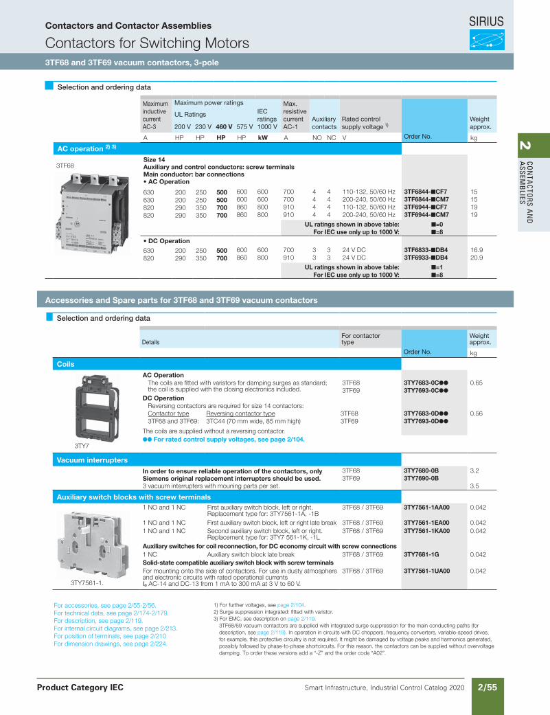
SIRIUS
Smart Infrastructure, Industrial Control Catalog 2020 2/55
2Co
nta
Ctors a
nd
a
ssemb
lies
Siemens / Industrial Controls Previous folio: IC10 2/28 new tables
Selection and ordering data
DetailsFor contactortype
Weightapprox.
Order No. kg
CoilsAC Operation
The coils are fitted with varistors for damping surges as standard; the coil is supplied with the closing electronics included.
3TF683TF69
3TY7683-0C
3TY7693-0C
0.65
DC OperationReversing contactors are required for size 14 contactors:Contactor type3TF68 and 3TF69:
Reversing contactor type3TC44 (70 mm wide, 85 mm high)
3TF683TF69
3TY7683-0D
3TY7693-0D
0.56
The coils are supplied without a reversing contactor. For rated control supply voltages, see page 2/104.
Vacuum interruptersIn order to ensure reliable operation of the contactors, only Siemens original replacement interrupters should be used. 3 vacuum interrupters with mouning parts per set.
3TF683TF69
3TY7680-0B3TY7690-0B
3.2
3.5
Auxiliary switch blocks with screw terminals1 NO and 1 NC First auxiliary switch block, left or right.
Replacement type for: 3TY7561-1A, -1B3TF68 / 3TF69 3TY7561-1AA00 0.042
1 NO and 1 NC First auxiliary switch block, left or right late break 3TF68 / 3TF69 3TY7561-1EA00 0.0421 NO and 1 NC Second auxiliary switch block, left or right.
Replacement type for: 3TY7 561-1K, -1L3TF68 / 3TF69 3TY7561-1KA00 0.042
Auxiliary switches for coil reconnection, for DC economy circuit with screw connections1 NC Auxiliary switch block late break 3TF68 / 3TF69 3TY7681-1G 0.042Solid-state compatible auxiliary switch block with screw terminalsFor mounting onto the side of contactors. For use in dusty atmosphereand electronic circuits with rated operational currentsIe AC-14 and DC-13 from 1 mA to 300 mA at 3 V to 60 V.
3TF68 / 3TF69 3TY7561-1UA00 0.042
For accessories, see page 2/55-2/56.For technical data, see page 2/174-2/179.For description, see page 2/119.For internal circuit diagrams, see page 2/213.For position of terminals, see page 2/210For dimension drawings, see page 2/224.
1) For further voltages, see page 2/104.2) Surge suppression integrated: fitted with varistor.3) For EMC, see description on page 2/119.
3TF68/69 vacuum contactors are supplied with integrated surge suppression for the main conducting paths (for description, see page 2/119). In operation in circuits with DC choppers, frequency converters, variable-speed drives, for example, this protective circuitry is not required. It might be damaged by voltage peaks and harmonics generated, possibly followed by phase-to-phase shortcircuits. For this reason. the contactors can be supplied without overvoltage damping. To order these versions add a “-Z” and the order code “A02”.
Selection and ordering data
MaximuminductivecurrentAC-3
Maximum power ratings Max.resistivecurrentAC-1
Auxiliarycontacts
Rated controlsupply voltage 1)
Weightapprox.
UL Ratings IECratings1000 V200 V 230 V 460 V 575 V
A HP HP HP HP kW A NO NC V Order No. kg
AC operation 2) 3)
3TF68Size 14Auxiliary and control conductors: screw terminalsMain conductor: bar connections• AC Operation
630630820820
200200290290
250250350350
500500700700
600600860860
600600800800
700700910910
4444
4444
110-132, 50/60 Hz200-240, 50/60 Hz110-132, 50/60 Hz200-240, 50/60 Hz
3TF6844-CF73TF6844-CM73TF6944-CF73TF6944-CM7
15151919
UL ratings shown in above table:For IEC use only up to 1000 V:
=0 =8
• DC Operation
630820
200290
250350
500700
600860
600800
700910
33
33
24 V DC24 V DC
3TF6833-DB43TF6933-DB4
16.920.9
UL ratings shown in above table:For IEC use only up to 1000 V:
=1 =8
3TY7561-1.
3TY7
Contactors and Contactor Assemblies
Contactors for Switching Motors3TF68 and 3TF69 vacuum contactors, 3-pole
Accessories and Spare parts for 3TF68 and 3TF69 vacuum contactors
Product Category IEC

SIRIUS
Smart Infrastructure, Industrial Control Catalog 2020 2/56
2Co
nta
Cto
rs a
nd
a
ssem
bli
es
For contactor Design Order No. Weight approx.
Size Type kg
Std.PackQty
Interface for control by PLC
Coil voltage tolerance: DC 17 V to 30 VPower consumption: 0.5 W at DC 24 VFitted with varistor
.7 traP ees ,atad lacinhcet roF
14 3TF68 and 3TF69
For snapping onto the side of auxiliary switch blocks, with surge suppression
for protection against inadvertent contact with the exposed busbar connections (DIN VDE 0106 Part 100)"
3TX7 090-0D 0.1
Terminal covers
(Order No. and price per set)14 3TF68 3TX7 686-0A 0.17 1 set =
2 units
1
3TF69 3TX7 696-0A
Link for paralleling (star jumper) · 3-pole, without terminal 1)
14 3TF68 3TX7 680-0D 0.26 1
Cover plate for paralleling link14 3TF68 A cover plate must be used in order to protect
against inadvertent contact (DIN VDE 0106 Part 100).
3TX7 680-0E 0.18 1
Box terminals for laminated copper bars
Without auxiliary conductor terminal
14 3TF68 With single covers for protection against inad-vertent contact (EN 50274)
3TX7 570-1E 0.6 1
With auxiliary conductor terminal
14 3TF69 Conductor cross-sections for auxiliary conduc-tors:
3TX7 690-1F 2.0 1
Solid: Finely strandedwith end sleeve: Solid or stranded: Tightening torque:
2 × (0.75 ... 2.5) mm2
2 × (0.5 ... 2.5) mm2
2 × (18 ... 12) AWG0.8 Nm ... 1.4 Nm(7 ... 12 lb.in)
Selection and ordering data
3TX7 686-0A
3TX7570-1E
For DC economy circuit; for lateral snapping onto auxiliary switches
The varistor is included in the scope of supply of the 3TF68 and 3TF69contactors with AC operation.
Includes the peak value of the alternating voltage on the DC side.
143TF68 and Rated control
supply voltage,V DC24 … 4848 … 127127 … 240
3TF69
3TX7 572-3G3TX7 572-3H3TX7 572-3J
0.09 10.09 10.09 1
3TX7 572-3G
3TX7 090-0D
3TX7 680-0D
1) The link for paralleling can be reduced by one pole.
Surge suppressors — Varistors
Contactors and Contactor Assemblies
Contactors for Switching MotorsAccessories and Spare parts for 3TF68 and 3TF69 vacuum contactors
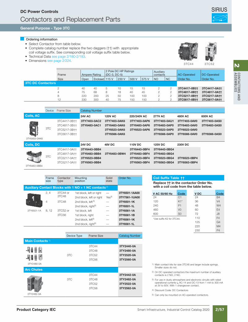
SIRIUS
Smart Infrastructure, Industrial Control Catalog 2020 2/57
2Co
nta
Ctors a
nd
a
ssemb
lies
Siemens / Industrial Controls Previous folio: IC10 2/29 w/ new tables
1) Main contact kits for size 3TC48 and larger include springs. Smaller sizes do not.
2) On DC operated contactors the maximum number of auxiliary contacts is 2 NO, 2 NC.
3) For use in dusty atmosphere and electronic circuits with rated operational currents Ie AC-14 and DC-13 from 1 mA to 300 mA at 3V to 60V. With 1 changeover contact.
4) Discount Code: DC Contactors
5) Can only be mounted on AC-operated contactors.
Frame Ampere Rating2 Pole DC HP Ratings (DC-3, DC-5)
Auxiliary contacts AC-Operated DC-Operated
Size Open Enclosed 115 V 230 V 500 V 575 V NO NC Order No. Order No.3TC DC Contactors
2 40 40 5 10 15 15 2 2 3TC4417–0B†† 3TC4417–0A††4 75 68 8 18 40 45 2 2 3TC4817–0B†† 3TC4817–0A††8 220 200 25 50 100 100 2 2 3TC5217–0B†† 3TC5217–0A††12 330 300 40 75 150 150 2 2 3TC5617–0B†† 3TC5617–0A††
Device Frame Size Catalog Number
Coils, AC 24V AC 120V AC 220/240V AC 277V AC 480V AC 600V AC
3TC
3TC4417-0B†† 3TY7403-0AC2 3TY7403-0AK6 3TY7403-0AP6 3TY7403-0AU1 3TY7403-0AV0 3TY7403-0AS0
3TC4817-0B†† 3TY6483-0AC1 3TY6483-0AK6 3TY6483-0AP6 3TY6483-0AP0 3TY6483-0AV0 3TY6483-0AS0
3TC5217-0B†† 3TY6523-0AK6 3TY6523-0AP6 3TY6523-0AP0 3TY6523-0AV0
3TC5617-0B†† 3TY6566-0AK6 3TY6566-0AP0 3TY6566-0AV0 3TY6566-0AS0
Coils, DC 24V DC 48V DC 110V DC 125V DC 230V DC
3TC
3TC4417-0A†† 3TY6443-0BB4 3TY6443-0BF4 3TY6443-0BG4
3TC4817-0A†† 3TY6483-0BB4 3TY6483-0BW4 3TY6483-0BF4 3TY6483-0BG4
3TC5217-0A†† 3TY6523-0BB4 3TY6523-0BF4 3TY6523-0BG4 3TY6523-0BP4
3TC5217-0A†† 3TY6563-0BB4 3TY6563-0BF4 3TY6563-0BG4 3TY6563-0BP4
3TY6483-0AK6
3TY6483-0BB4
Framesize
Contactortype
Mountingposition
Solidstate
Order No.
Auxiliary Contact Blocks with 1 NO + 1 NC contacts 2)
2, 4 3TC44 or3TC48
1st block, left or right — 3TY6501-1AA00
2nd block, left or right Yes3) 3TY7561-1UA00
4 3TC48 2nd block, left 5) — 3TY6501-1K
2nd block, right5) — 3TY6501-1L
8, 12 3TC52 or 1st block, left — 3TY6561-1A
3TC56 1st block, right — 3TY6561-1B
2nd block, left5) — 3TY6561-1K
2nd block, right5) — 3TY6561-1L
3TY6501-1A
Coil Suffix Table ††
Replace †† in the contactor Order No. with a coil code from the table below.
V AC 50/60 Hz Code V DC Code24 C1 24 B4120 K1* 36 V4240 P1 48 W4460 V0 60 E4600 S0 72 J8
*Use suffix K2 for 3TC44. 110 F4125 G4220 M4230 P4
Ordering information• Select Contactor from table below.• Complete catalog number replace the two daggers (††) with appropriate
coil voltage suffix. See corresponding coil voltage suffix table below.• Technical Data see page 2/180-2/183.• Dimensions see page 2/224.
Device Type Frame Size Catalog Number
Main Contacts 1)
3TC44 3TY2440-0A
3TC48 3TY2480-0A
3TC 3TC52 3TY2520-0A
3TC56 3TY2560-0A
Arc Chutes
3TC44 3TY2442-0A
3TC 3TC48 3TY2482-0A
3TC52 3TY2522-0A
3TC56 3TY2562-0A
3TY2480-0A
3TY2482-0A
3TC523TC44
DC Power Controls
Contactors and Replacement PartsGeneral Purpose - Type 3TC
Product Category IEC
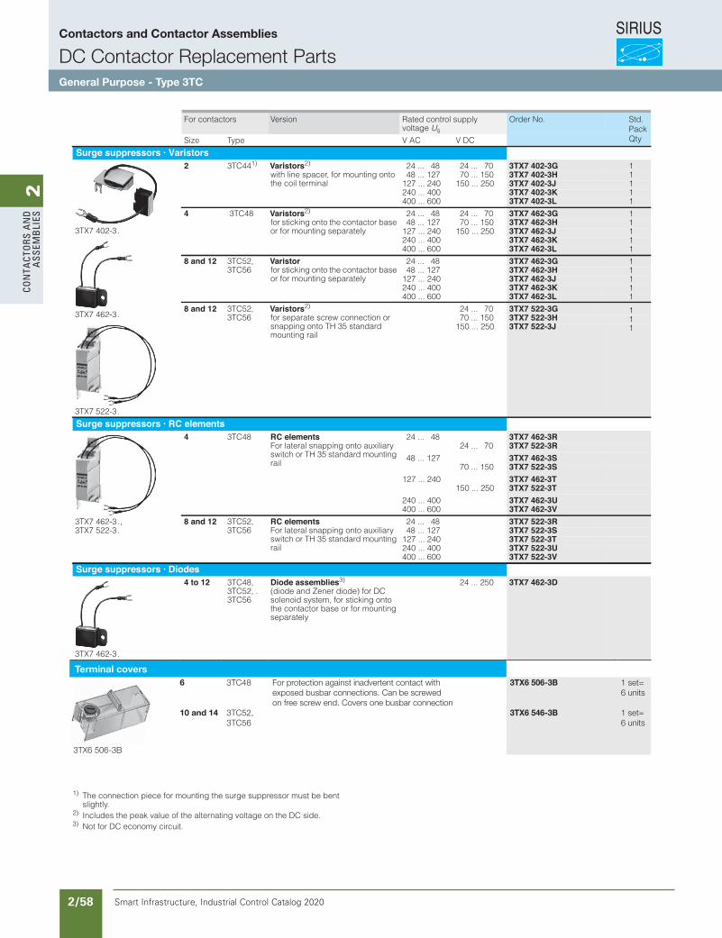
SIRIUS
Smart Infrastructure, Industrial Control Catalog 2020 2/58
2Co
nta
Cto
rs a
nd
a
ssem
bli
esContactors for Special Applications
Contactors for Switching DC Voltage3TC contactors,
1- and 2-pole, 32 ... 400 A
4/57Siemens IC 10 · 2012* You can order this quantity or a multiple thereof.Illustrations are approximate
4
1) The connection piece for mounting the surge suppressor must be bent slightly.
2) Includes the peak value of the alternating voltage on the DC side.3) Not for DC economy circuit.
For contactors Version Rated control supply voltage Us
Order No.
CD VCA VepyTeziS
Surge suppressors · Varistors
3TX7 402-3 .
3TX7 462-3 .
3TX7 522-3 .
2 3TC441) Varistors2) with line spacer, for mounting onto the coil terminal
24 ... 48 24 ... 70 3TX7 402-3G 48 ... 127 70 ... 150 3TX7 402-3H127 ... 240 150 ... 250 3TX7 402-3J240 ... 400 3TX7 402-3K400 ... 600 3TX7 402-3L
4 3TC48 Varistors2) for sticking onto the contactor base or for mounting separately
24 ... 48 24 ... 70 3TX7 462-3G 48 ... 127 70 ... 150 3TX7 462-3H127 ... 240 150 ... 250 3TX7 462-3J240 ... 400 3TX7 462-3K400 ... 600 3TX7 462-3L
8 and 12 3TC52, 3TC56
Varistor for sticking onto the contactor base or for mounting separately
24 ... 48 3TX7 462-3G 48 ... 127 3TX7 462-3H127 ... 240 3TX7 462-3J240 ... 400 3TX7 462-3K400 ... 600 3TX7 462-3L
8 and 12 3TC52, 3TC56
Varistors2) for separate screw connection or snapping onto TH 35 standard mounting rail
24 ... 70 3TX7 522-3G 70 ... 150 3TX7 522-3H150 ... 250 3TX7 522-3J
Surge suppressors · RC elements
3TX7 462-3 . , 3TX7 522-3 .
4 3TC48 RC elements For lateral snapping onto auxiliary switch or TH 35 standard mounting rail
24 ... 48 3TX7 462-3R 24 ... 70 3TX7 522-3R
48 ... 127 3TX7 462-3S 70 ... 150 3TX7 522-3S
127 ... 240 3TX7 462-3T 150 ... 250 3TX7 522-3T
240 ... 400 3TX7 462-3U400 ... 600 3TX7 462-3V
8 and 12 3TC52, 3TC56
RC elements For lateral snapping onto auxiliary switch or TH 35 standard mounting rail
24 ... 48 3TX7 522-3R 48 ... 127 3TX7 522-3S127 ... 240 3TX7 522-3T240 ... 400 3TX7 522-3U400 ... 600 3TX7 522-3V
Surge suppressors · Diodes
3TX7 462-3 .
4 to 12 3TC48, 3TC52, . 3TC56
Diode assemblies3) (diode and Zener diode) for DC solenoid system, for sticking onto the contactor base or for mounting separately
24 ... 250 3TX7 462-3D
IC10_04_03 ccorp.fm Page 57 Monday, September 16, 2013 11:37 AM
111111111111111
111
Std. PackQty
Terminal covers
3TX6 506-3B
6 3TC48 For protection against inadvertent contact withexposed busbar connections. Can be screwedon free screw end. Covers one busbar connection
3TX6 506-3B 1 set=6 units
10 and 14 3TC52,3TC56
3TX6 546-3B 1 set=6 units
Contactors and Contactor Assemblies
DC Contactor Replacement PartsGeneral Purpose - Type 3TC
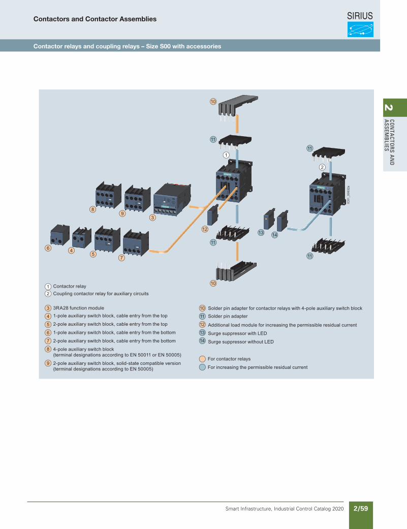
SIRIUS
Smart Infrastructure, Industrial Control Catalog 2020 2/59
2Co
nta
Ctors a
nd
a
ssemb
lies
5/4 Siemens IC 10 · 2018
Contactor Relays
SIRIUS 3RH2 contactor relays, 4- and 8-pole
5
Overview
Contactor relays, size S00, with accessories
11
11
10
2
1
3
89
45
12
116
7
10
11
13 14
3RA28 function module
Solder pin adapter
Coupling contactor relay for auxiliary circuitsContactor relay
1-pole auxiliary switch block, cable entry from the top
2-pole auxiliary switch block, cable entry from the top
1-pole auxiliary switch block, cable entry from the bottom
2-pole auxiliary switch block, cable entry from the bottom
4-pole auxiliary switch block(terminal designations according to EN 50011 or EN 50005)
2-pole auxiliary switch block, solid-state compatible version(terminal designations according to EN 50005)
Solder pin adapter for contactor relays with 4-pole auxiliary switch block
Additional load module for increasing the permissible residual current
Surge suppressor with LED
Surge suppressor without LED
12
3
4
5
6
7
8
9
10
12
11
13
14
For contactor relays
For increasing the permissible residual current
IC01
_006
32a
Contactors and Contactor Assemblies
Contactor relays and coupling relays – Size S00 with accessories
Revised on 02/26/18
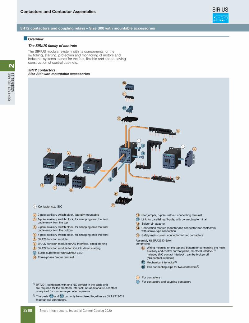
SIRIUS
Smart Infrastructure, Industrial Control Catalog 2020 2/60
2Co
nta
Cto
rs a
nd
a
ssem
bli
es
Siemens / Industrial Controls Previous folio: IC10 2/30
Contactors and Contactor Assemblies
3RT2 contactors and coupling relays – Size S00 with mountable accessories
3/7Siemens IC 10 · 2017
Power Contactors for Switching Motors
General data
3
Overview
The SIRIUS family of controls
The SIRIUS modular system with its components for the switching, starting, protection and monitoring of motors and industrial systems stands for the fast, flexible and space-saving construction of control cabinets.
3RT2 contactors Size S00 with mountable accessories
For accessories and spare parts, see pages 3/75 to 3/123.
10
11
12
16
13
14
13
16
15
18
17
1
1
2
9
34
5
67
8
Wiring modules on the top and bottom for connecting the main, auxiliary and control current paths, electrical interlock included (NC contact interlock), can be broken off (NC contact interlock)
Assembly kit 3RA2913-2AA1comprising:
Contactor size S00
For contactors For contactors and coupling contactors
Star jumper, 3-pole, without connecting terminalLink for paralleling, 3-pole, with connecting terminalSolder pin adapterConnection module (adapter and connector) for contactors with screw-type connectionSafety main current connector for two contactors
Mechanical interlocksTwo connecting clips for two contactors
The parts and can only be ordered together as 3RA2912-2H mechanical connectors.
2)
2)
1817
3RT201. contactors with one NC contact in the basic unit are required for the electrical interlock. An additional NO contact is required for momentary-contact operation.
1)
2-pole auxiliary switch block, laterally mountable1-pole auxiliary switch block, for snapping onto the frontcable entry from the top2-pole auxiliary switch block, for snapping onto the frontcable entry from the bottom4-pole auxiliary switch block, for snapping onto the front3RA28 function module3RA27 function module for AS-Interface, direct starting3RA27 function module for IO-Link, direct startingSurge suppressor with/without LEDThree-phase feeder terminal
4
23
5
12
16
11
10
89
76
1314
15
1
1718
IC01
_006
14
1)
2)
IC10_03_03.fm Page 7 Friday, June 23, 2017 3:30 PM
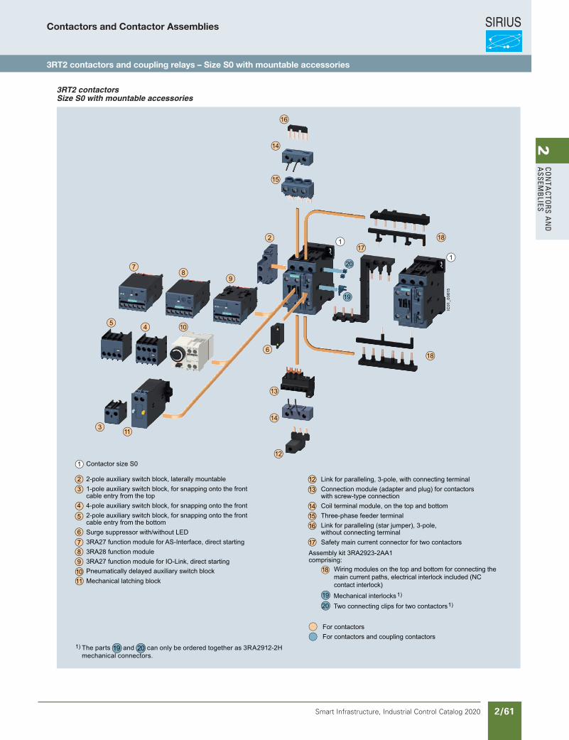
SIRIUS
Smart Infrastructure, Industrial Control Catalog 2020 2/61
2Co
nta
Ctors a
nd
a
ssemb
liesContactors and Contactor Assemblies
3RT2 contactors and coupling relays – Size S0 with mountable accessories
3/8 Siemens IC 10 · 2017
Power Contactors for Switching Motors
General data
3
3RT2 contactors Size S0 with mountable accessories
For accessories and spare parts, see pages 3/75 to 3/123.
2 18
15
16
14
1
1
3
5 10
11
4
14
18
13
12
6
87
9
17
20
19
1213
141516
17
18
1920
4
23
5
1110
876
9
1
Wiring modules on the top and bottom for connecting the main current paths, electrical interlock included (NC contact interlock)
Assembly kit 3RA2923-2AA1comprising:
Pneumatically delayed auxiliary switch blockMechanical latching block
2-pole auxiliary switch block, laterally mountable1-pole auxiliary switch block, for snapping onto the frontcable entry from the top4-pole auxiliary switch block, for snapping onto the front2-pole auxiliary switch block, for snapping onto the frontcable entry from the bottomSurge suppressor with/without LED3RA27 function module for AS-Interface, direct starting3RA28 function module3RA27 function module for IO-Link, direct starting
Link for paralleling, 3-pole, with connecting terminalConnection module (adapter and plug) for contactors with screw-type connectionCoil terminal module, on the top and bottomThree-phase feeder terminalLink for paralleling (star jumper), 3-pole,without connecting terminalSafety main current connector for two contactors
The parts and can only be ordered together as 3RA2912-2H mechanical connectors.
2019
For contactors For contactors and coupling contactors
Mechanical interlocksTwo connecting clips for two contactors
1)
1)
Contactor size S0
IC01
_006
15
1)
IC10_03_03.fm Page 8 Friday, June 23, 2017 3:30 PM
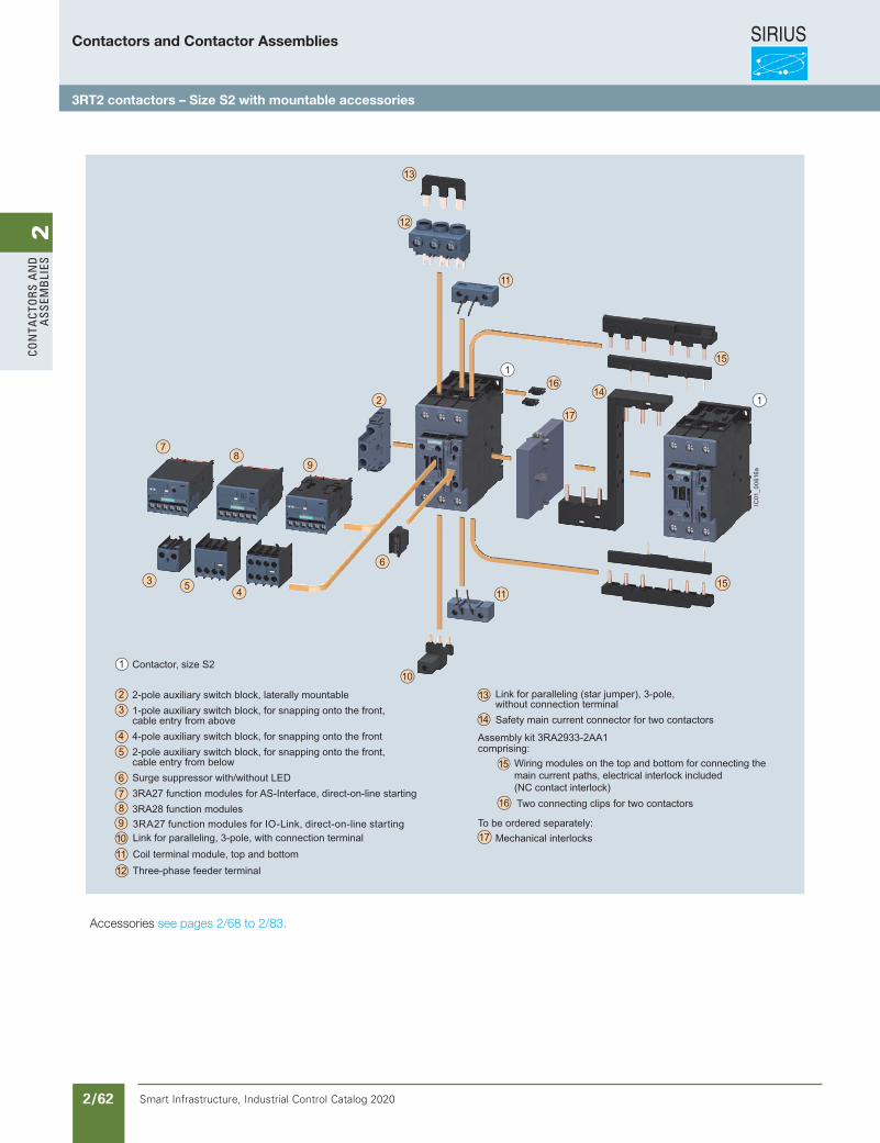
SIRIUS
Smart Infrastructure, Industrial Control Catalog 2020 2/62
2Co
nta
Cto
rs a
nd
a
ssem
bli
es
Siemens / Industrial Controls Previous folio: IC10 2/32
Accessories see pages 2/68 to 2/83.
3/9Siemens IC 10 · 2018
Power Contactors for Switching Motors
General data
3
3RT2 contactors Size S2 with mountable accessories
For accessories and spare parts, see pages 3/71 to 3/119.
87
9
11
13
15
2
12
141
1
17
16
3 5 4 1115
10
6
Wiring modules on the top and bottom for connecting the main current paths, electrical interlock included (NC contact interlock)
Assembly kit 3RA2933-2AA1comprising:
To be ordered separately:
Contactor, size S2 2-pole auxiliary switch block, laterally mountable1-pole auxiliary switch block, for snapping onto the front,cable entry from above4-pole auxiliary switch block, for snapping onto the front2-pole auxiliary switch block, for snapping onto the front,cable entry from belowSurge suppressor with/without LED3RA27 function modules for AS-Interface, direct-on-line starting3RA28 function modules
Link for paralleling (star jumper), 3-pole,without connection terminalSafety main current connector for two contactors
3RA27 function modules for IO-Link, direct-on-line startingLink for paralleling, 3-pole, with connection terminalCoil terminal module, top and bottomThree-phase feeder terminal
Mechanical interlocks
Two connecting clips for two contactors
4
23
5
1110
876
9
12
13
14
1
15
17
16
IC01
_006
16a
IC10_03_03.fm Page 9 Thursday, February 22, 2018 7:12 PM
Contactors and Contactor Assemblies
3RT2 contactors – Size S2 with mountable accessories
Revised on 02/26/18

SIRIUS
Smart Infrastructure, Industrial Control Catalog 2020 2/63
2Co
nta
Ctors a
nd
a
ssemb
lies
3/10 Siemens IC 10 · 2018
Power Contactors for Switching Motors
General data
3
3RT2 contactors Size S3 with mountable accessories
For accessories and spare parts, see pages 3/71 to 3/119.
87
9
11
13
2
12
1
1
16
15
3 54
11
14
14
10
6
Links for paralleling, 3-pole, with connection terminalCoil terminal module, top and bottomSingle-phase infeed terminals (3 units)Links for paralleling (star jumper), 3-polewithout connecting terminal
3RA27 function modules for IO-Link, direct-on-line starting
Contactor, size S3
2-pole auxiliary switch block, laterally mountable1-pole auxiliary switch block, for snapping onto the front,cable entry from above4-pole auxiliary switch block, for snapping onto the front2-pole auxiliary switch block, for snapping onto the front,cable entry from belowSurge suppressor with/without LED3RA27 function modules for AS-Interface, direct-on-line starting3RA28 function modules
Mechanical interlock
Two connectors for two contactors
1)Wiring modules on the top and bottom for connecting the main, auxiliary and control current paths, electrical interlock included, can be broken off (NC contact interlock)
Assembly kit 3RA2943-2AA1comprising:
To be ordered separately:
3RT201. contactors with one NC contact in the basic unitare required for the electrical interlock. An additional NO contact is required for momentary-contact operation.
14
16
15
4
23
5
1112
10
876
9
13
1IC
01_0
0617
a
1)
IC10_03_03.fm Page 10 Wednesday, February 28, 2018 12:12 PM
Motor Starters see Chapter 4 Combination Starters & Starters for group installation
Accessories see pages 2/68 to 2/83.
Contactors and Contactor Assemblies
3RT2 contactors – Size S3 with mountable accessories
Revised on 02/26/18
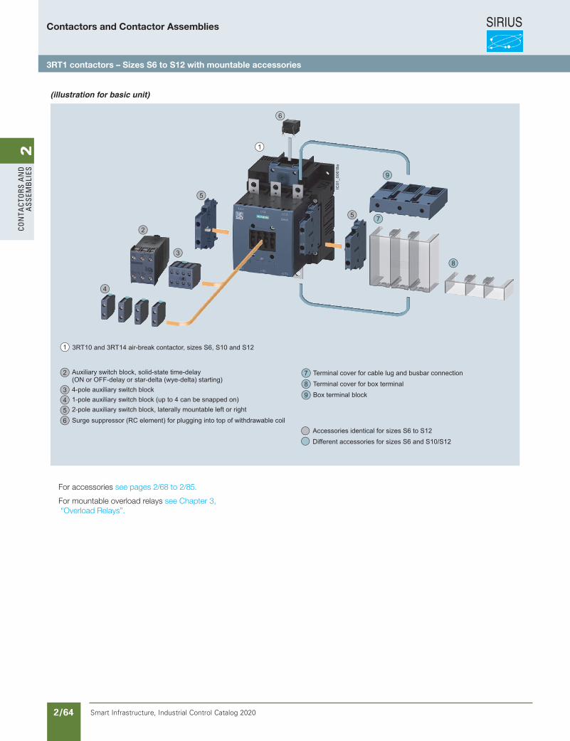
SIRIUS
Smart Infrastructure, Industrial Control Catalog 2020 2/64
2Co
nta
Cto
rs a
nd
a
ssem
bli
es
3/11Siemens IC 10 · 2018
Power Contactors for Switching Motors
General data
3
3RT1 contactors Sizes S6 to S12 with mountable accessories(illustration for basic unit)
For accessories and spare parts, see pages 3/71 to 3/119.
1
2
3
4
6
5
5
9
8
7
3RT10 and 3RT14 air-break contactor, sizes S6, S10 and S12
Auxiliary switch block, solid-state time-delay(ON or OFF-delay or star-delta (wye-delta) starting)4-pole auxiliary switch block1-pole auxiliary switch block (up to 4 can be snapped on)2-pole auxiliary switch block, laterally mountable left or rightSurge suppressor (RC element) for plugging into top of withdrawable coil
Terminal cover for cable lug and busbar connection Terminal cover for box terminalBox terminal block
Accessories identical for sizes S6 to S12Different accessories for sizes S6 and S10/S12
1
2
3456
987
IC01
_006
18a
IC10_03_03.fm Page 11 Thursday, February 22, 2018 7:12 PM
For accessories see pages 2/68 to 2/85.
For mountable overload relays see Chapter 3, “Overload Relays”.
Contactors and Contactor Assemblies
3RT1 contactors – Sizes S6 to S12 with mountable accessories
Revised on 02/26/18
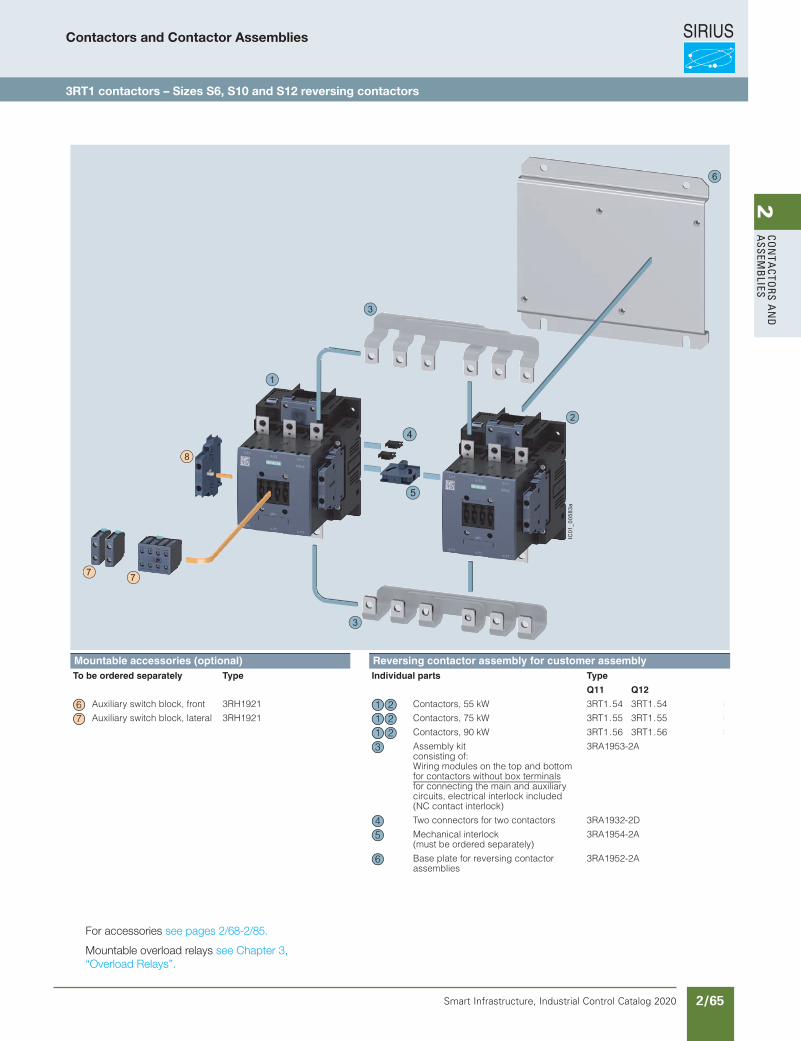
SIRIUS
Smart Infrastructure, Industrial Control Catalog 2020 2/65
2Co
nta
Ctors a
nd
a
ssemb
lies
Siemens / Industrial Controls Previous folio: IC10 2/34
For accessories see pages 2/68-2/85.
Mountable overload relays see Chapter 3, “Overload Relays”.
3/162 Siemens IC 10 · 2018
Reversing Contactor Assemblies
Reversing contactor assemblies consisting of SIRIUS 3RT1 contactors, up to 250 kW
3
Reversing contactor assemblies for customer assembly · Size S6 · Up to 90 kW
Mountable accessories (optional) Reversing contactor assembly for customer assemblyTo be ordered separately Type Page Individual parts Type Page
Q11 Q12
Auxiliary switch block, front 3RH1921 3/92 Contactors, 55 kW 3RT1.54 3RT1.54 3/66 ... 3/68
Auxiliary switch block, lateral 3RH1921 3/94 Contactors, 75 kW 3RT1.55 3RT1.55 3/66 ... 3/68
Contactors, 90 kW 3RT1.56 3RT1.56 3/66 ... 3/68
Assembly kitconsisting of:Wiring modules on the top and bottom for contactors without box terminalsfor connecting the main and auxiliary circuits, electrical interlock included (NC contact interlock)
3RA1953-2A 3/105
Two connectors for two contactors 3RA1932-2D 3/109
Mechanical interlock (must be ordered separately)
3RA1954-2A 3/109
Base plate for reversing contactor assemblies
3RA1952-2A 3/113
5
4
8
77
6
1
2
3
3
IC01
_005
83a
6 21 7 21
213
45
6
IC10_03_09.fm Page 162 Friday, April 27, 2018 1:36 PM
Contactors and Contactor Assemblies
3RT1 contactors – Sizes S6, S10 and S12 reversing contactors
Revised on 02/26/18
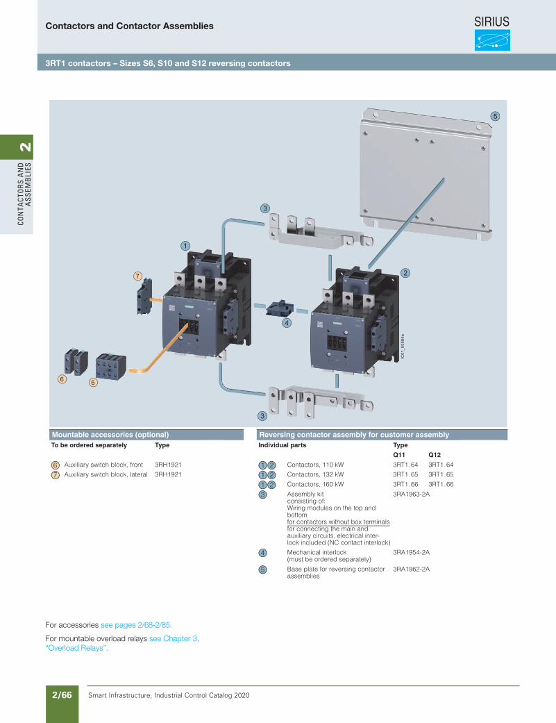
SIRIUS
Smart Infrastructure, Industrial Control Catalog 2020 2/66
2Co
nta
Cto
rs a
nd
a
ssem
bli
es
For accessories see pages 2/68-2/85.
For mountable overload relays see Chapter 3, “Overload Relays”.
Contactors and Contactor Assemblies
3RT1 contactors – Sizes S6, S10 and S12 reversing contactors
3/163Siemens IC 10 · 2018
Reversing Contactor Assemblies
Reversing contactor assemblies consisting of SIRIUS 3RT1 contactors, up to 250 kW
3
Reversing contactor assemblies for customer assembly · Size S10 · Up to 160 kW
Mountable accessories (optional) Reversing contactor assembly for customer assemblyTo be ordered separately Type Page Individual parts Type Page
Q11 Q12
Auxiliary switch block, front 3RH1921 3/92 Contactors, 110 kW 3RT1.64 3RT1.64 3/66 ... 3/68
Auxiliary switch block, lateral 3RH1921 3/94 Contactors, 132 kW 3RT1.65 3RT1.65 3/66 ... 3/68
Contactors, 160 kW 3RT1.66 3RT1.66 3/66 ... 3/68
Assembly kitconsisting of:Wiring modules on the top and bottom for contactors without box terminalsfor connecting the main and auxiliary circuits, electrical inter-lock included (NC contact interlock)
3RA1963-2A 3/105
Mechanical interlock (must be ordered separately)
3RA1954-2A 3/109
Base plate for reversing contactor assemblies
3RA1962-2A 3/113
7
5
2
3
3
1
66
IC01
_005
84a
4
6 21 7 21
213
4
5
IC10_03_09.fm Page 163 Friday, April 27, 2018 1:36 PM
Revised on 02/26/18
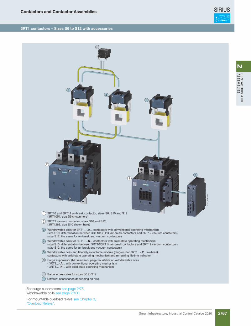
SIRIUS
Smart Infrastructure, Industrial Control Catalog 2020 2/67
2Co
nta
Ctors a
nd
a
ssemb
lies
For surge suppressors see page 2/75, withdrawable coils see page 2/100.
For mountable overload relays see Chapter 3, “Overload Relays”.
Contactors and Contactor Assemblies
3RT1 contactors – Sizes S6 to S12 with accessories
3/13Siemens IC 10 · 2018
Power Contactors for Switching Motors
General data
3
3RT1 contactors Sizes S6 to S12 with mountable accessories
For accessories and spare parts for• 3RT10 and 3RT14 contactors, see pages 3/71 to 3/119• 3RT12 vacuum contactors, see pages 3/132 to 3/135
5
34
5
6
1
2
(3RT1054, size S6 shown here)
(3RT1266, size S10 shown here)
Same accessories for sizes S6 to S12Different accessories depending on size
Withdrawable coils for 3RT1...-.A... contactors with conventional operating mechanism (size S10: differentiation between 3RT10/3RT14 air-break contactors and 3RT12 vacuum contactors)(size S12: the same for air-break and vacuum contactors)Withdrawable coils for 3RT1...-.N... contactors with solid-state operating mechanism. (size S10: differentiation between 3RT10/3RT14 air-break contactors and 3RT12 vacuum contactors)(size S12: the same for air-break and vacuum contactors)Withdrawable coils and laterally mountable module (plug-on) for 3RT1...-.P... air-breakcontactors with solid-state operating mechanism and remaining lifetime indicatorSurge suppressor (RC element), plug-mountable on withdrawable coils • 3RT1...-.A... with conventional operating mechanism• 3RT1...-.N... with solid-state operating mechanism
3RT12 vacuum contactor, sizes S10 and S12
3RT10 and 3RT14 air-break contactor, sizes S6, S10 and S121
2
3
4
5
6
IC01
_006
20a
IC10_03_03.fm Page 13 Thu rsday, February 22, 2018 7:12 PM
Revised on 02/26/18
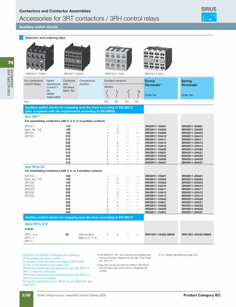
SIRIUS
Smart Infrastructure, Industrial Control Catalog 2020 2/68
2Co
nta
Cto
rs a
nd
a
ssem
bli
es
Siemens / Industrial Controls Previous folio: IC10 2/35
EN50005 and EN50012 designate the markingsof the auxiliary terminal numbers.For position of the terminals see pages 2/204-2/208.For int. circuit diagrams see page 2/192.3RH29 aux blocks are not intended for use with 3RT1 or 3RH1 contactors and relays.3RH19 aux blocks are not intended for use with 3RT2 or 3RH2 contactors and relays.For auxiliary switch blocks for 3RH2140 and 3RH2440 see page 2/53.
Selection and ordering data
For contactors/control relays
RatedoperationalCurrent 3)
6A NEMA A600/Q600
ContactorwithHS blockIdent. No.
Connectionsposition
Auxiliary contacts Screw Terminals1)
Spring Terminals1)
Version
Order No. Order No.
Type NO NC NO NC
Auxiliary switch blocks for snapping onto the front according to EN 50012(also compliant with the requirements according to EN 50005)
Size S00 2)
For assembling contactors with 2, 3, 4, or 5 auxiliary contacts
3RT201.,Ident. No. 10E3RT231.3RT251.
11E12E13E21E21E22E23E31E31E32E41E41E
———111122233
123—123— 12— 1
———— ————————
————————————
3RH2911-1HA013RH2911-1HA023RH2911-1HA033RH2911-1HA103RH2911-1HA113RH2911-1HA123RH2911-1HA133RH2911-1HA203RH2911-1HA213RH2911-1HA22 3RH2911-1HA303RH2911-1HA31
3RH2911-2HA013RH2911-2HA023RH2911-2HA033RH2911-2HA103RH2911-2HA113RH2911-2HA123RH2911-2HA133RH2911-2HA203RH2911-2HA213RH2911-2HA223RH2911-2HA303RH2911-2HA31
Size S0 to S3For assembling contactors with 3, 4, or 5 auxiliary contacts
3RT202. ,Ident. No. 11E3RT232.3RT252.3RT203.3RT233.3RT235.
12E13E14E21E22E23E24E31E32E33E41E42E
———111122233
123—123—12—1
————————————
————————————
3RH2911-1HA013RH2911-1HA023RH2911-1HA033RH2911-1HA103RH2911-1HA113RH2911-1HA123RH2911-1HA133RH2911-1HA203RH2911-1HA213RH2911-1HA223RH2911-1HA303RH2911-1HA31
3RH2911-2HA013RH2911-2HA023RH2911-2HA033RH2911-2HA103RH2911-2HA113RH2911-2HA123RH2911-2HA133RH2911-2HA203RH2911-2HA213RH2911-2HA223RH2911-2HA303RH2911-2HA31
Auxiliary switch blocks for snapping onto the front according to EN 50012
Sizes S6 to S12
4-pole
3RT1. 4 to 3RT1. 7,3RT11.
22 (with locationdigits 5, 6, 7, 8)
2 2 — — 3RH1921-1XA22-0MA0 3RH1921-2XA22-0MA0
1) The 3RH2911-.HA.. aux. switches are available with ring-lug terminals. Replace the 8th digit of the Order No. with a “4”.
2) Size S00 can be mounted according to EN 50012 only on basic units which have no integrated NC contact.
3) UL ratings: See appendix page 19/7
3RH2911-1HA01 3RH2911-2HA01 3RH19 21-1HA. . 3RH19 21-2HA . .
Contactors and Contactor Assemblies
Accessories for 3RT contactors / 3RH control relaysAuxiliary switch blocks
Product Category IEC
Revised on 09/07/19for new catalog
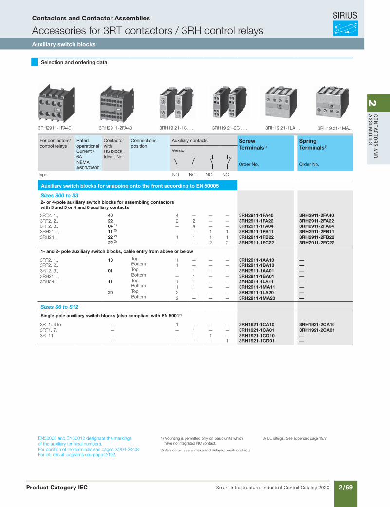
SIRIUS
Smart Infrastructure, Industrial Control Catalog 2020 2/69
2Co
nta
Ctors a
nd
a
ssemb
lies
Siemens / Industrial Controls Previous folio: IC10 2/36
EN50005 and EN50012 designate the markingsof the auxiliary terminal numbers.For position of the terminals see pages 2/204-2/208.For int. circuit diagrams see page 2/192.
Selection and ordering data
For contactors/control relays
RatedoperationalCurrent 3)
6A NEMA A600/Q600
ContactorwithHS blockIdent. No.
Connectionsposition
Auxiliary contacts Screw Terminals1)
Spring Terminals1)
Version
Order No. Order No.
Type NO NC NO NC
Auxiliary switch blocks for snapping onto the front according to EN 50005
Sizes S00 to S32- or 4-pole auxiliary switch blocks for assembling contactors with 3 and 5 or 4 and 6 auxiliary contacts
3RT2. 1.,3RT2. 2.,3RT2. 3.,3RH21 ..,3RH24 ..
402204 1)
11 2)
22 2)
22 2)
42——1—
—24—1—
———112
———112
3RH2911-1FA403RH2911-1FA223RH2911-1FA043RH2911-1FB113RH2911-1FB223RH2911-1FC22
3RH2911-2FA403RH2911-2FA223RH2911-2FA043RH2911-2FB113RH2911-2FB223RH2911-2FC22
1- and 2- pole auxiliary switch blocks, cable entry from above or below
3RT2. 1.,3RT2. 2.,3RT2. 3.,3RH21 ..,3RH24 ..
10
01
11
20
TopBottomTopBottomTopBottomTopBottom
11——1122
——1111——
————————
————————
3RH2911-1AA103RH2911-1BA103RH2911-1AA013RH2911-1BA013RH2911-1LA113RH2911-1MA113RH2911-1LA203RH2911-1MA20
————————
Sizes S6 to S12
Single-pole auxiliary switch blocks (also compliant with EN 50012)
3RT1. 4 to3RT1. 7,3RT11
————
1———
—1——
——1—
———1
3RH1921-1CA103RH1921-1CA013RH1921-1CD103RH1921-1CD01
3RH1921-2CA103RH1921-2CA01——
1) Mounting is permitted only on basic units which have no integrated NC contact.
2) Version with early make and delayed break contacts
3) UL ratings: See appendix page 19/7
3RH2911-1FA40 3RH2911-2FA40 3RH19 21-2C . . .3RH19 21-1C. . . 3RH19 21-1LA . . 3RH19 21-1MA..
Contactors and Contactor Assemblies
Accessories for 3RT contactors / 3RH control relaysAuxiliary switch blocks
Product Category IEC
UPDATE on 09/07/19
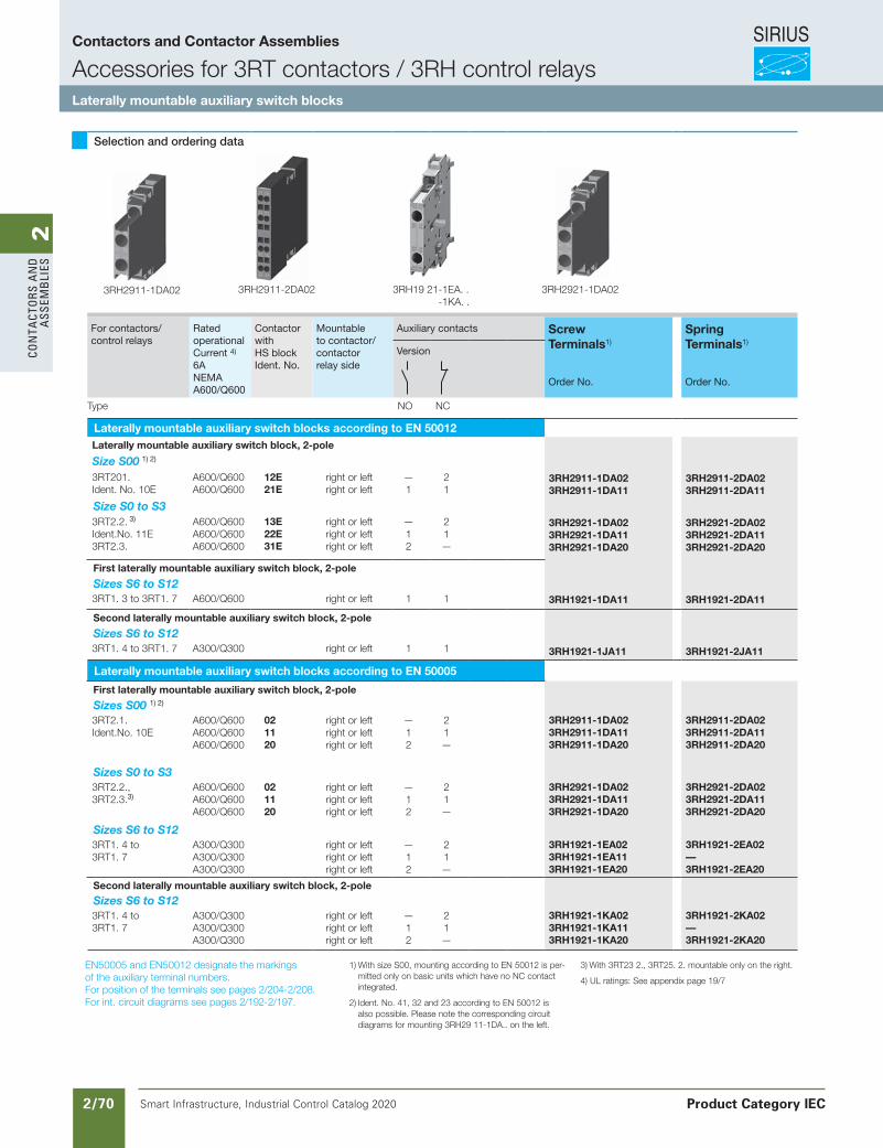
SIRIUS
Smart Infrastructure, Industrial Control Catalog 2020 2/70
2Co
nta
Cto
rs a
nd
a
ssem
bli
es
Siemens / Industrial Controls Previous folio: IC10 2/37
Selection and ordering data
For contactors/control relays
RatedoperationalCurrent 4)
6A NEMA A600/Q600
ContactorwithHS blockIdent. No.
Mountableto contactor/contactorrelay side
Auxiliary contacts Screw Terminals1)
Spring Terminals1)
Version
Order No. Order No.
Type NO NC
Laterally mountable auxiliary switch blocks according to EN 50012Laterally mountable auxiliary switch block, 2-pole
Size S00 1) 2)
3RT201.Ident. No. 10E
A600/Q600 A600/Q600
12E21E
right or left right or left
—1
21
3RH2911-1DA023RH2911-1DA11
3RH2911-2DA023RH2911-2DA11
Size S0 to S33RT2.2. 3)
Ident.No. 11E3RT2.3.
A600/Q600A600/Q600A600/Q600
13E22E31E
right or left right or left right or left
—12
21—
3RH2921-1DA023RH2921-1DA113RH2921-1DA20
3RH2921-2DA023RH2921-2DA113RH2921-2DA20
First laterally mountable auxiliary switch block, 2-pole
Sizes S6 to S12 3RT1. 3 to 3RT1. 7 A600/Q600 right or left 1 1 3RH1921-1DA11 3RH1921-2DA11
Second laterally mountable auxiliary switch block, 2-pole
Sizes S6 to S123RT1. 4 to 3RT1. 7 A300/Q300 right or left 1 1 3RH1921-1JA11 3RH1921-2JA11
Laterally mountable auxiliary switch blocks according to EN 50005
First laterally mountable auxiliary switch block, 2-pole
Sizes S00 1) 2)
3RT2.1.Ident.No. 10E
A600/Q600A600/Q600A600/Q600
021120
right or leftright or leftright or left
—12
21—
3RH2911-1DA023RH2911-1DA113RH2911-1DA20
3RH2911-2DA023RH2911-2DA113RH2911-2DA20
Sizes S0 to S3 3RT2.2.,3RT2.3.3)
A600/Q600A600/Q600A600/Q600
021120
right or leftright or leftright or left
—12
21—
3RH2921-1DA023RH2921-1DA113RH2921-1DA20
3RH2921-2DA023RH2921-2DA113RH2921-2DA20
Sizes S6 to S123RT1. 4 to3RT1. 7
A300/Q300 A300/Q300 A300/Q300
right or leftright or leftright or left
—12
21—
3RH1921-1EA023RH1921-1EA113RH1921-1EA20
3RH1921-2EA02—3RH1921-2EA20
Second laterally mountable auxiliary switch block, 2-pole
Sizes S6 to S123RT1. 4 to3RT1. 7
A300/Q300 A300/Q300 A300/Q300
right or leftright or leftright or left
—12
21—
3RH1921-1KA023RH1921-1KA113RH1921-1KA20
3RH1921-2KA02—3RH1921-2KA20
3RH2911-1DA02 3RH2911-2DA02 3RH19 21-1EA. . -1KA. .
3RH2921-1DA02
EN50005 and EN50012 designate the markingsof the auxiliary terminal numbers.For position of the terminals see pages 2/204-2/208.For int. circuit diagrams see pages 2/192-2/197.
1) With size S00, mounting according to EN 50012 is per-mitted only on basic units which have no NC contact integrated.
2) Ident. No. 41, 32 and 23 according to EN 50012 is also possible. Please note the corresponding circuit diagrams for mounting 3RH29 11-1DA.. on the left.
3) With 3RT23 2., 3RT25. 2. mountable only on the right.
4) UL ratings: See appendix page 19/7
Contactors and Contactor Assemblies
Accessories for 3RT contactors / 3RH control relaysLaterally mountable auxiliary switch blocks
Product Category IEC
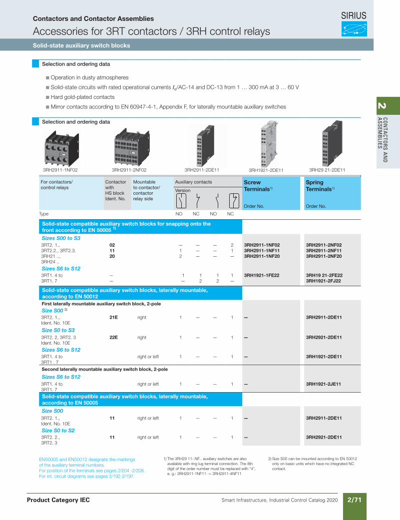
SIRIUS
Smart Infrastructure, Industrial Control Catalog 2020 2/71
2Co
nta
Ctors a
nd
a
ssemb
lies
Siemens / Industrial Controls Previous folio: Siemens / Industrial Controls Previous folio: IC10 2/38
EN50005 and EN50012 designate the markings of the auxiliary terminal numbers.For position of the terminals see pages 2/204 -2/208.For int. circuit diagrams see pages 2/192-2/197.
Selection and ordering data
Operation in dusty atmospheres
Solid-state circuits with rated operational currents Ie/AC-14 and DC-13 from 1 … 300 mA at 3 … 60 V
Hard gold-plated contacts
Mirror contacts according to EN 60947-4-1, Appendix F, for laterally mountable auxiliary switches
Selection and ordering data
For contactors/control relays
ContactorwithHS blockIdent. No.
Mountableto contactor/contactorrelay side
Auxiliary contacts Screw Terminals1)
Spring Terminals1)
Version
Order No. Order No.
Type NO NC NO NC
Solid-state compatible auxiliary switch blocks for snapping onto the front according to EN 50005 1)
Sizes S00 to S33RT2. 1.,3RT2.2., 3RT2.3.3RH21 ..,3RH24 ..
021120
—12
———
———
21—
3RH2911-1NF023RH2911-1NF113RH2911-1NF20
3RH2911-2NF023RH2911-2NF113RH2911-2NF20
Sizes S6 to S123RT1. 4 to3RT1. 7
— —
1 —
1 2
1 2
1 —
3RH1921-1FE22 3RH19 21-2FE22 3RH1921-2FJ22
Solid-state compatible auxiliary switch blocks, laterally mountable,according to EN 50012First laterally mountable auxiliary switch block, 2-pole
Size S00 2)
3RT2. 1.,Ident. No. 10E
21E right 1 — — 1 — 3RH2911-2DE11
Size S0 to S33RT2. 2, 3RT2. 3Ident. No. 10E
22E right 1 — — 1 — 3RH2921-2DE11
Sizes S6 to S123RT1. 4 to3RT1 . 7
right or left 1 — — 1 — 3RH1921-2DE11
Second laterally mountable auxiliary switch block, 2-pole
Sizes S6 to S123RT1. 4 to3RT1. 7
right or left 1 — — 1 — 3RH1921-2JE11
Solid-state compatible auxiliary switch blocks, laterally mountable,according to EN 50005
Size S003RT2. 1.,Ident. No. 10E
11 right or left 1 — — 1 — 3RH2911-2DE11
Size S0 to S23RT2. 2.,3RT2. 3
11 right or left 1 — — 1 — 3RH2921-2DE11
1) The 3RH29 11-.NF.. auxiliary switches are also available with ring lug terminal connection. The 8th digit of the order number must be replaced with “4”, e. g.: 3RH2911-1NF11 -> 3RH2911-4NF11
2) Size S00 can be mounted according to EN 50012 only on basic units which have no integrated NC contact.
3RH2911-1NF02 3RH2911-2NF02 3RH1921-2DE113RH2911-2DE11 3RH29 21-2DE11
Contactors and Contactor Assemblies
Accessories for 3RT contactors / 3RH control relaysSolid-state auxiliary switch blocks
Product Category IEC
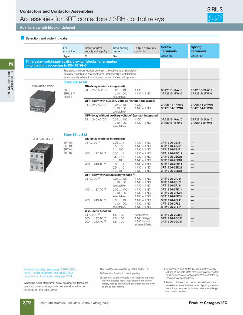
SIRIUS
Smart Infrastructure, Industrial Control Catalog 2020 2/72
2Co
nta
Cto
rs a
nd
a
ssem
bli
es
Siemens / Industrial Controls Previous folio: Siemens / Industrial Controls Previous folio: IC10 2/39
Selection and ordering data
Forcontactors
Rated controlsupply voltage Us 1)
Time settingrange t
Output / auxiliarycontacts
Screw Terminals
Spring Terminals
Type V Sec Order No. Order No.
Time-delay, solid-state auxiliary switch blocks for snappingonto the front according to DIN 46199-5
The electrical connection between the solid-state time-delayauxiliary switch and the contactor underneath is establishedautomatically when it is snapped on and locked into place.
Sizes S00 to S33RA2813-1AW10 ON-delay (varistor integrated)
3RT2.,3RH21 2)
3RH24
24 … 240 AC/DC 0.05 … 100(1, 10, 100,selectable)
1 CO1 NO + 1 NC
3RA2813-1AW103RA2813-1FW10
3RA2813-2AW103RA2813-2FW10
OFF-delay with auxiliary voltage (varistor integrated)24 … 240 AC/DC 0.05 … 100
(1, 10, 100,selectable)
1 CO1 NO + 1 NC
3RA28 14-1AW103RA28 14-1FW10
3RA28 14-2AW103RA28 14-2FW10
OFF-delay without auxiliary voltage3) (varistor integrated)24 … 240 AC/DC 0.05 … 100
(1, 10, 100,selectable)
1 CO1 NO + 1 NC
3RA2815-1AW103RA2815-1FW10
3RA2815-2AW103RA2815-2FW10
Sizes S6 to S123RT1926-2FJ11 ON-delay (varistor integrated)
3RT10,3RT13,3RT14,3RT15
24 AC/DC 4) 0.05 … 10.5 … 105 … 100
1 NO + 1 NC1 NO + 1 NC1 NO + 1 NC
3RT19 26-2EJ113RT19 26-2EJ213RT19 26-2EJ31
———
100 … 127 AC 4) 0.05 … 10.5 … 105 … 100
1 NO + 1 NC1 NO + 1 NC1 NO + 1 NC
3RT19 26-2EC113RT19 26-2EC213RT19 26-2EC31
———
200 … 240 AC 4) 0.05 … 10.5 … 105 … 100
1 NO + 1 NC1 NO + 1 NC1 NO + 1 NC
3RT19 26-2ED113RT19 26-2ED213RT19 26-2ED31
———
OFF-delay without auxiliary voltage 5)
24 AC/DC 4) 0.05 … 100(1, 10, 100,selectable)
1 NO + 1 NC1 NO + 1 NC1 NO + 1 NC
3RT19 26-2FJ113RT19 26-2FJ213RT19 26-2FJ31
———
100 … 127 AC 4) 0.05 … 100(1, 10, 100,selectable)
1 NO + 1 NC1 NO + 1 NC1 NO + 1 NC
3RT19 26-2FK113RT19 26-2FK213RT19 26-2FK31
———
200 … 240 AC 4) 0.05 … 100(1, 10, 100,selectable)
1 NO + 1 NC1 NO + 1 NC1 NO + 1 NC
3RT19 26-2FL113RT19 26-2FL213RT19 26-2FL31
———
WYE-delta function24 AC/DC 4)
100 … 127 AC 4)
200 … 240 AC 4)
1.5 … 301.5 … 301.5 … 30
each have:1 NO delayed1 NO instantinterval 50ms
3RT19 26-2GJ513RT19 26-2GC513RT19 26-2GD51
———
For technical data, see pages 2/184-2/185.For int. circuit diagrams, see page 2/200.For position of terminals, see page 2/208.
When the solid-state time-delay auxiliary switches are used, no other auxiliary switches are allowed to be mounted on the basic units.
1) AC voltage values apply for 50 Hz and 60 Hz.
2) Cannot be fitted onto coupling relays.
3) Setting of output contacts in as-supplied state not defined (bistable relay). Application of the control supply voltage once results in contact change-over to the correct setting.
4) Terminals A1 and A2 for the rated control supply voltage of the solid-state time-delay auxiliary switch must be connected to the associated contactor by means of connecting leads.
5) Position of the output contacts not defined in the as-delivered state (bistable relay). Applying the con-trol voltage once results in the contacts switching to the correct position.
Contactors and Contactor Assemblies
Accessories for 3RT contactors / 3RH control relaysAuxiliary switch blocks, delayed
Product Category IEC
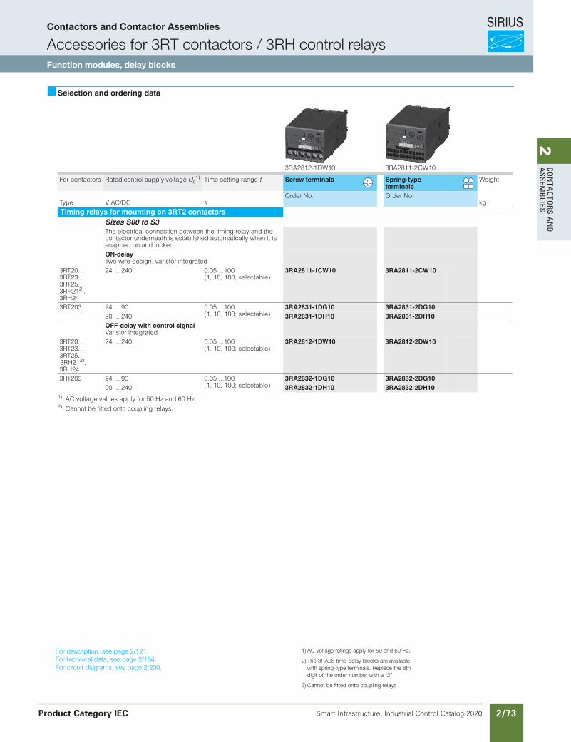
SIRIUS
Smart Infrastructure, Industrial Control Catalog 2020 2/73
2Co
nta
Ctors a
nd
a
ssemb
lies
Siemens / Industrial Controls Previous folio: IC10 2/40
3/70 Siemens IC 10 · 2015* You can order this quantity or a multiple thereof.
Illustrations are approximate
Power Contactors for Switching MotorsAccessories for 3RT2 Contactors
Delay and latching blocks
3
Selection and ordering data
1) AC voltage values apply for 50 Hz and 60 Hz.2) Cannot be fitted onto coupling relays.
For technical specifications, see page 3/54.
3RA2812-1DW10 3RA2811-2CW10
For contactors Rated control supply voltage Us1) Time setting range t Screw terminals Spring-type
terminalsWeight
sCD/CA VepyTOrder No. Order No.
kg
Timing relays for mounting on 3RT2 contactors Sizes S00 to S3The electrical connection between the timing relay and the contactor underneath is established automatically when it is snapped on and locked.ON-delayTwo-wire design, varistor integrated
3RT20.., 3RT23.., 3RT25.., 3RH212), 3RH24
001... 50.0042 ... 42(1, 10, 100; selectable)
3RA2811-1CW10 3RA2811-2CW10
001... 50.009 ... 42.302TR3(1, 10, 100; selectable)
3RA2831-1DG10 3RA2831-2DG1090 ... 240 3RA2831-1DH10 3RA2831-2DH10OFF-delay with control signalVaristor integrated
3RT20.., 3RT23.., 3RT25.., 3RH212), 3RH24
001... 50.0042 ... 42(1, 10, 100; selectable)
3RA2812-1DW10 3RA2812-2DW10
001... 50.009 ... 42.302TR3(1, 10, 100; selectable)
3RA2832-1DG10 3RA2832-2DG1090 ... 240 3RA2832-1DH10 3RA2832-2DH10
For contactors Rated control supply voltage Us
Time setting range t Screw terminals Weight
sVepyTOrder No.
kg
OFF-delay devices Sizes S00 to S2For contactors with DC operationNon-adjustable delay time
3RT2916-2B.01
3RT201.-1BF4., 3RT202.-1BF4., 3RT203.-1NF3., 3RH2.. . -1BF40
110 AC/DC
110 DC
S00: > 0,1S0: > 0,08S2: > 0,25
3RT2916-2BK01
3RT201.-1BM4./1BP4., 3RT202.-1BM4./1BP4.,3RT203.-1NP3., 3RH2. . . -1BM40/1BP40
220/230 AC/DC
220/230 DC
S00: > 0,5S0: > 0,3S2: > 0,8
3RT2916-2BL01
3RT201.-1BB4.,3RT202.-1BB4.,3RT203.-1NB3.,3RH2.. .-1BB40
24 DC S00: > 0,2S0: > 0,1S2: > 0,1
3RT2916-2BE01
Mechanical latching blocks Size S0
3RT2926-3A.31
For snapping onto the front of contactorsThe contactor remains in the energized state after a voltage failure
-- CD/CA 42.202TR3 3RT2926-3AB31110 AC/DC -- 3RT2926-3AF31230 AC/DC -- 3RT2926-3AP31
IC10_03_05.fm Page 70 Saturday, April 18, 2015 9:22 PM
For description, see page 2/121.For technical data, see page 2/184.For circuit diagrams, see page 2/200.
1) AC voltage ratings apply for 50 and 60 Hz.
2) The 3RA28 time-delay blocks are available with spring-type terminals. Replace the 8th digit of the order number with a “2”.
3) Cannot be fitted onto coupling relays
Contactors and Contactor Assemblies
Accessories for 3RT contactors / 3RH control relaysFunction modules, delay blocks
Product Category IEC
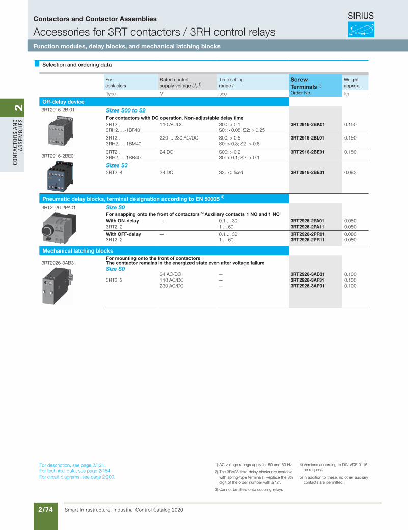
SIRIUS
Smart Infrastructure, Industrial Control Catalog 2020 2/74
2Co
nta
Cto
rs a
nd
a
ssem
bli
es
Selection and ordering data
Forcontactors
Rated controlsupply voltage Us 1)
Time settingrange t
Screw Terminals 2)
Weightapprox.
Type V sec Order No. kg
Off-delay device3RT2916-2B.01 Sizes S00 to S2
For contactors with DC operation. Non-adjustable delay time3RT2., 3RH2. . .-1BF40
110 AC/DC S00: > 0.1S0: > 0.08; S2: > 0.25
3RT2916-2BK01 0.150
3RT2., 3RH2. . .-1BM40
220 ... 230 AC/DC S00: > 0.5S0: > 0.3; S2: > 0.8
3RT2916-2BL01 0.150
3RT2916-2BE013RT2., 3RH2. . .-1BB40
24 DC S00: > 0.2S0: > 0.1; S2: > 0.1
3RT2916-2BE01 0.150
Sizes S33RT2. 4 24 DC S3: 70 fixed 3RT2916-2BE01 0.093
Pneumatic delay blocks, terminal designation according to EN 50005 4)
3RT2926-2PA01 Size S0For snapping onto the front of contactors 5) Auxiliary contacts 1 NO and 1 NCWith ON-delay3RT2. 2
— 0.1 ... 301 ... 60
3RT2926-2PA013RT2926-2PA11
0.0800.080
With OFF-delay3RT2. 2
— 0.1 ... 301 ... 60
3RT2926-2PR013RT2926-2PR11
0.0800.080
Mechanical latching blocks
3RT2926-3AB31For mounting onto the front of contactorsThe contactor remains in the energized state even after voltage failureSize S0 3RT2. 2
24 AC/DC 110 AC/DC230 AC/DC
———
3RT2926-3AB313RT2926-3AF313RT2926-3AP31
0.1000.1000.100
For description, see page 2/121.For technical data, see page 2/184.For circuit diagrams, see page 2/200.
1) AC voltage ratings apply for 50 and 60 Hz.
2) The 3RA28 time-delay blocks are available with spring-type terminals. Replace the 8th digit of the order number with a “2”.
3) Cannot be fitted onto coupling relays
4) Versions according to DIN VDE 0116 on request.
5) In addition to these, no other auxiliary contacts are permitted.
Contactors and Contactor Assemblies
Accessories for 3RT contactors / 3RH control relaysFunction modules, delay blocks, and mechanical latching blocks

SIRIUS
Smart Infrastructure, Industrial Control Catalog 2020 2/75
2Co
nta
Ctors a
nd
a
ssemb
lies
3/71Siemens IC 10 · 2015* You can order this quantity or a multiple thereof.Illustrations are approximate
Power Contactors for Switching MotorsAccessories for 3RT2 Contactors
Surge suppressors
3
Selection and ordering data
1) Can be used for AC operation for 50/60 Hz. Please inquire about further voltages.
For contactors
Version Rated control supply voltage Us1) Order No. Weight
AC operation DC operation
CD VCA VepyT kg
Surge suppressors without LED (also for spring-type terminals) Size S00
3RT2916-1B.00
For plugging onto the front side of the contactors (with and without auxiliary switch block)
3RT2.1, 3RH2.
Varistors 24 ... 48 24 ... 70 3RT2916-1BB0048 ... 127 70 ... 150 3RT2916-1BC00
127 ... 240 150 ... 250 3RT2916-1BD00240 ... 400 -- 3RT2916-1BE00400 ... 600 -- 3RT2916-1BF00
3RT2.1, 3RH2.
RC elements 24 ... 48 24 ... 70 3RT2916-1CB0048 ... 127 70 ... 150 3RT2916-1CC00
127 ... 240 150 ... 250 3RT2916-1CD00240 ... 400 -- 3RT2916-1CE00400 ... 600 -- 3RT2916-1CF00
3RT2.1, 3RH2.
Noise suppression diodes -- 12 ... 250 3RT2916-1DG00
3RT2.1, 3RH2.
Diode assemblies (diode and Zener diode) for DC operation
-- 12 ... 250 3RT2916-1EH00
Size S0
3RT2926-1E.00
For plugging onto the front side of the contactors (prior to mounting of the auxiliary switch block)
3RT2.2 Varistors 24 ... 48 24 ... 70 3RT2926-1BB0048 ... 127 70 ... 150 3RT2926-1BC00
127 ... 240 150 ... 250 3RT2926-1BD00240 ... 400 -- 3RT2926-1BE00400 ... 600 -- 3RT2926-1BF00
3RT2.2 RC elements 24 ... 48 24 ... 70 3RT2926-1CB0048 ... 127 70 ... 150 3RT2926-1CC00
127 ... 240 150 ... 250 3RT2926-1CD00240 ... 400 -- 3RT2926-1CE00400 ... 600 -- 3RT2926-1CF00
3RT2.2 Diode assembly for DC operation
-- 24 3RT2926-1ER00-- 30 ... 250 3RT2926-1ES00
Size S2 and S3
3RT2936-1B.00
3RT2936-1E.00
For plugging onto the front side of the contactors (prior to mounting of the auxiliary switch block)
3RT2.3. Varistors 24 ... 48 24 ... 70 3RT2936-1BB0048 ... 127 70 ... 150 3RT2936-1BC00
127 ... 240 150 ... 250 3RT2936-1BD00240 ... 400 -- 3RT2936-1BE00400 ... 600 -- 3RT2936-1BF00
3RT2.3. RC elements 24 ... 48 24 ... 70 3RT2936-1CB0048 ... 127 70 ... 150 3RT2936-1CC00
127 ... 240 150 ... 250 3RT2936-1CD00240 ... 400 -- 3RT2936-1CE00400 ... 600 -- 3RT2936-1CF00
3RT2.3. Diode assembly for DC operation
-- 24 3RT2936-1ER00-- 30 ... 250 3RT2936-1ES00
IC10_03_05.fm Page 71 Saturday, April 18, 2015 9:22 PM
Contactors and Contactor Assemblies
Accessories for 3RT contactors / 3RH control relaysSurge suppressors
Product Category IEC
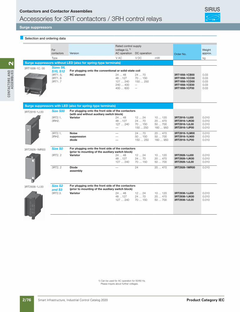
SIRIUS
Smart Infrastructure, Industrial Control Catalog 2020 2/76
2Co
nta
Cto
rs a
nd
a
ssem
bli
es
Selection and ordering data
Forcontactors Version
Rated control supply
Order No.
Weightapprox.
voltage Us 1)
AC operation DC operation
Type V AC V DC mW kg
Surge suppressors without LED (also for spring-type terminals)
3RT1936-1C. 00 Sizes S6, S10, S12 For plugging onto the conventional or solid-state coil3RT1. 5,3RT1. 6 3RT1. 7
RC element 24 … 4848 …127127 … 240240 … 400400 … 600
24 … 7070 … 150150 … 250——
3RT1956-1CB003RT1956-1CC003RT1956-1CD003RT1956-1CE003RT1956-1CF00
0.030.030.030.030.03
Surge suppressors with LED (also for spring-type terminals)
3RT2916-1J.00 Size S00 For plugging onto the front side of the contactors (with and without auxiliary switch block)
3RT2.1,3RH2.
Varistor 24 … 4848 …127127 … 240—
12 … 2424 … 7070 … 150150 ... 250
10 … 12020 … 47050 … 700160 … 950
3RT2916-1JJ003RT2916-1JK003RT2916-1JL003RT2916-1JP00
0.0100.0100.0100.010
3RT2.1,3RH2.
Noisesuppressiondiode
———
24 … 7050 … 150150 … 250
20 … 47050 … 700160 … 950
3RT2916-1LM003RT2916-1LN003RT2916-1LP00
0.0100.0100.010
3RT2926-1MR00 Size S0 For plugging onto the front side of the contactors (prior to mounting of the auxiliary switch block)
3RT2. 2 Varistor 24 … 4848 …127127 … 240
12 … 2424 … 7070 … 150
10 … 12020 … 47050 … 700
3RT2926-1JJ003RT2926-1JK003RT2926-1JL00
0.0100.0100.010
3RT2. 2 Diodeassembly
— 24 20 … 470 3RT2926-1MR00 0.010
3RT2936-1J.00 Size S2 and S3
For plugging onto the front side of the contactors(prior to mounting of the auxiliary switch block)
3RT2.3. Varistor 24 … 4848 …127127 … 240
12 … 2424 … 7070 … 150
10 … 12020 … 47050 … 700
3RT2936-1JJ003RT2936-1JK003RT2936-1JL00
0.0100.0100.010
1) Can be used for AC operation for 50/60 Hz. Please inquire about further voltages.
Siemens / Industrial Controls Previous folio: IC10 2/42
Contactors and Contactor Assemblies
Accessories for 3RT contactors / 3RH control relaysSurge suppressors
Product Category IEC
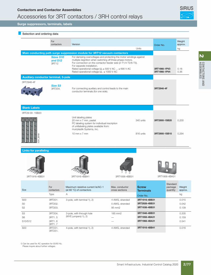
SIRIUS
Smart Infrastructure, Industrial Control Catalog 2020 2/77
2Co
nta
Ctors a
nd
a
ssemb
lies
Selection and ordering data
Forcontactors Version Order No.
Weightapprox.
Units kg
Main conducting path surge suppression module for 3RT12 vacuum contactorsSizes S10 and S12 3RT12
For damping overvoltages and protecting the motor windings against multiple reignition when switching off three-phase motors.For connection on the contactor feeder side (2-T1/4-T2/6-T3). For separate installation.Rated operational voltage Ue ≥ 500 V AC ... ≤ 690 V ACRated operational voltage Ue ≤ 1000 V AC
3RT1966-1PV33RT1966-1PV4
0.180.36
Auxiliary conductor terminal, 3-pole
3RT2946-4FSize S33RT204. For connecting auxiliary and control leads to the main
conductor terminals (for one side).3RT2946-4F
Blank Labels
3RT29 00- 1SB20
Unit labeling plates20 mm x 7 mm, pastel PC labeling system for individual inscriptionof unitlabeling plates available from:murrplastik Systems, Inc.
340 units 3RT2900-1SB20 0.200
10 mm x 7 mm 816 units 3RT2900-1SB10 0.294
Links for paralleling
Forcontactors
Maximum resistive current Ie/AC-1(at 60 °C) of contactors
Max. conductorcross sections
Screw Terminals
Standardpackagequantity
Weightapprox.Size
Type A Order No. kg
S00 3RT201. 3-pole, with terminal 1), 2) 4 AWG, stranded 3RT1916-4BB31 0.015
S0 3RT202. 0 AWG, stranded 3RT2926-4BB31 0.042
S2 3RT203. 95 mm2 3RT1936-4BB31 0.139
S3 3RT204. 3-pole, with through hole (WYE jumpers) 1), 2)
185 mm2 3RT1946-4BB31 0.205
S6 3RT1. 5 — 3RT1956-4BA31 0.159
S10/S12 3RT1. 63RT1. 7
— 3RT1966-4BA31 0.541
S00 3RT231. 3RT251.
4-pole, with terminal 1), 2) 4 AWG, stranded 3RT1916-4BB41 0.016
1) Can be used for AC operation for 50/60 Hz. Please inquire about further voltages.
IC01
_001
81
3RT1916-4BB31 3RT1936-4BB313RT1916-4BB41 3RT1956-4BA31
Contactors and Contactor Assemblies
Accessories for 3RT contactors / 3RH control relaysSurge suppressors, terminals, labels
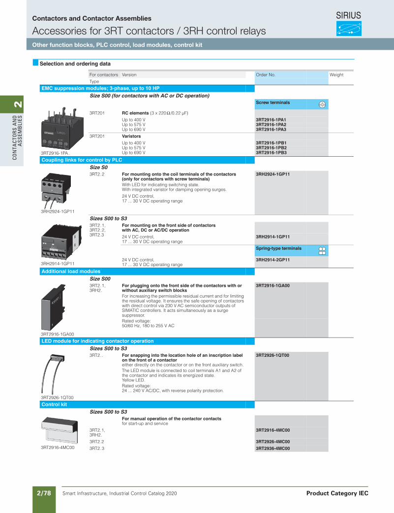
SIRIUS
Smart Infrastructure, Industrial Control Catalog 2020 2/78
2Co
nta
Cto
rs a
nd
a
ssem
bli
es
Siemens / Industrial Controls Previous folio:IC10 2/43
3/73Siemens IC 10 · 2015* You can order this quantity or a multiple thereof.Illustrations are approximate
Power Contactors for Switching MotorsAccessories for 3RT2 Contactors
Other function blocks
3
Selection and ordering data
For contactors Version Order No. Weight
Type
EMC suppression modules; 3-phase, up to 10 HP Size S00 (for contactors with AC or DC operation)
3RT2916-1PA.
Screw terminals
3RT201 RC elements (3 x 220 Ω /0.22 µF)
Up to 400 V 3RT2916-1PA1Up to 575 V 3RT2916-1PA2Up to 690 V 3RT2916-1PA3
3RT201 VaristorsUp to 400 V 3RT2916-1PB1Up to 575 V 3RT2916-1PB2Up to 690 V 3RT2916-1PB3
Coupling links for control by PLC Size S0
3RH2924-1GP11
3RT2. 2 For mounting onto the coil terminals of the contactors (only for contactors with screw terminals)With LED for indicating switching state. With integrated varistor for damping opening surges.
24 V DC control, 17 ... 30 V DC operating range
3RH2924-1GP11
Sizes S00 to S3
3RH2914-1GP11
3RT2.1, 3RT2.2, 3RT2.3
For mounting on the front side of contactors with AC, DC or AC/DC operation24 V DC control, 17 ... 30 V DC operating range
3RH2914-1GP11
Spring-type terminals
24 V DC control, 17 ... 30 V DC operating range
3RH2914-2GP11
Additional load modules Size S00
3RT2916-1GA00
3RT2.1, 3RH2.
For plugging onto the front side of the contactors with or without auxiliary switch blocksFor increasing the permissible residual current and for limiting the residual voltage. It ensures the safe opening of contactors with direct control via 230 V AC semiconductor outputs of SIMATIC controllers. It acts simultaneously as a surge suppressor.
3RT2916-1GA00
Rated voltage: 50/60 Hz, 180 to 255 V AC
LED module for indicating contactor operation Sizes S00 to S3
3RT2926-1QT00
3RT2.. For snapping into the location hole of an inscription label on the front of a contactor either directly on the contactor or on the front auxiliary switch.The LED module is connected to coil terminals A1 and A2 of the contactor and indicates its energized state. Yellow LED.Rated voltage: 24 ... 240 V AC/DC, with reverse polarity protection.
3RT2926-1QT00
Control kit Sizes S00 to S3
3RT2916-4MC00
For manual operation of the contactor contacts for start-up and service
3RT2.1, 3RH2.
3RT2916-4MC00
3RT2.2 3RT2926-4MC003RT2. 3 3RT2936-4MC00
IC10_03_05.fm Page 73 Sat urday, April 18, 2015 9:22 PM
Contactors and Contactor Assemblies
Accessories for 3RT contactors / 3RH control relaysOther function blocks, PLC control, load modules, control kit
Product Category IEC
Revised on 02/26/18

SIRIUS
Smart Infrastructure, Industrial Control Catalog 2020 2/79
2Co
nta
Ctors a
nd
a
ssemb
lies
Siemens / Industrial Controls Previous folio: IC10 2/44
3/74 Siemens IC 10 · 2015* You can order this quantity or a multiple thereof.
Illustrations are approximate
Power Contactors for Switching MotorsAccessories for 3RT2 Contactors
Terminals, covers, adapters, connectors
3
Selection and ordering data
Technical specifications for connection modules, see page 3/56. 1) Exception: contactors and contactor relays with auxiliary switch block
mounted onto the front.
For contactors Version Order No. Weight
Type
Sealable covers Sizes S00 to S3
3RT2916-4MA10
3RT2.1, 3RT2.2, 3RT2.3, 3RT2.4,3RH2.1)
Sealable covers for preventing manual operation
(Not suitable for coupling relays)
3RT2916-4MA10
Connection modules for contactors with screw terminals Sizes S00 and S0
3RT1926-4RD01
Adapters for contactorsAmbient temperature Tu max = 60 °C
Screw terminals
3RT2 .1, 3RH2.
Size S00, rated operational current Ie at AC-3/400 V: 20 A
3RT1916-4RD01
3RT2. 2 Size S0, rated operational current Ie at AC-3/400 V: 25 A
3RT1926-4RD01
3RT1900-4RE01
3RT2 .1, 3RT2.2, 3RH2.
Plugs for contactorsSize S00, S0
3RT1900-4RE01
Terminal covers for contactors with box terminals Size S2
3RT2936-4EA2
Covers for box terminals3RT203 For 3-pole contactors 3RT2936-4EA23RT233, 3RT253
For 4-pole contactors (see Chapter 4) 3RT2936-4EA4
Coil connection modules Sizes S0 and S2
3RT2926-4RA11
3RT2926-4RA12
3RT2.2, 3RT2.3
Connection from top 3RT2926-4RA11Connection from below 3RT2926-4RB11Connection diagonally 3RT2926-4RC11
Spring-type terminals
3RT2.2 Connection from top 3RT2926-4RA12Connection from below 3RT2926-4RB12
Covers for contactors with ring cable lug connections Size S00
Ring terminal lug connec-tions
3RT2916-4EA13
3RT2.1, 3RH2
Covers for ring terminal lug connectionsSingle covers
3RT2916-4EA13
Size S0
3RT2926-4EB13
3RT2. 2 Covers for ring terminal lug connectionsSet for one device, comprising 4 single covers: - 2 x 3RT2926-4EB13- 2 x 3RV2928-4AA00
3RT2926-4EB13
IC10_03_05.fm Page 74 Sat urday, April 18, 2015 9:22 PM
1) Exception: contactors and contactor relays with auxiliary switch block mounted onto the front.
Contactors and Contactor Assemblies
Accessories for 3RT contactors / 3RH control relaysTerminals, covers, adapters, connectors
Product Category IEC
Revised on 02/26/18
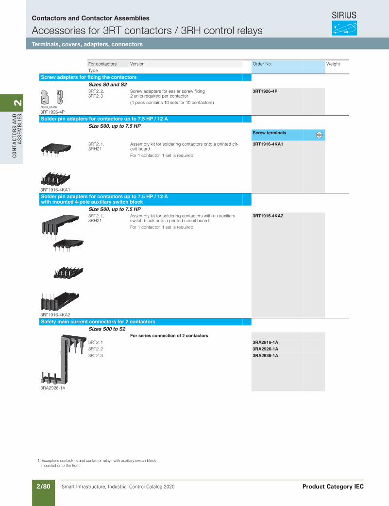
SIRIUS
Smart Infrastructure, Industrial Control Catalog 2020 2/80
2Co
nta
Cto
rs a
nd
a
ssem
bli
es
Siemens / Industrial Controls Previous folio: IC10 2/45
3/75Siemens IC 10 · 2015* You can order this quantity or a multiple thereof.Illustrations are approximate
Power Contactors for Switching MotorsAccessories for 3RT2 Contactors
Terminals, covers, adapters, connectors
3
For contactors Version Order No. Weight
Type
Screw adapters for fixing the contactors Sizes S0 and S2
3RT1926-4P
3RT2.2, 3RT2.3
Screw adapters for easier screw fixing 2 units required per contactor
(1 pack contains 10 sets for 10 contactors)
3RT1926-4P
Solder pin adapters for contactors up to 7.5 HP / 12 A Size S00, up to 7.5 HP
Screw terminals
3RT1916-4KA1
3RT2.1, 3RH21
Assembly kit for soldering contactors onto a printed cir-cuit board.
For 1 contactor, 1 set is required.
3RT1916-4KA1
Solder pin adapters for contactors up to 7.5 HP / 12 A with mounted 4-pole auxiliary switch block
Size S00, up to 7.5 HP
3RT1916-4KA2
3RT2.1, 3RH21
Assembly kit for soldering contactors with an auxiliary switch block onto a printed circuit board.
For 1 contactor, 1 set is required.
3RT1916-4KA2
Safety main current connectors for 2 contactors Sizes S00 to S2
3RA2926-1A
For series connection of 2 contactors3RT2 .1 3RA2916-1A3RT2. 2 3RA2926-1A3RT2.3 3RA2936-1A
NSB0_01470
IC10_03_05.fm Page 75 Saturday, April 18, 2015 9:22 PM
1) Exception: contactors and contactor relays with auxiliary switch block mounted onto the front.
Contactors and Contactor Assemblies
Accessories for 3RT contactors / 3RH control relaysTerminals, covers, adapters, connectors
Product Category IEC
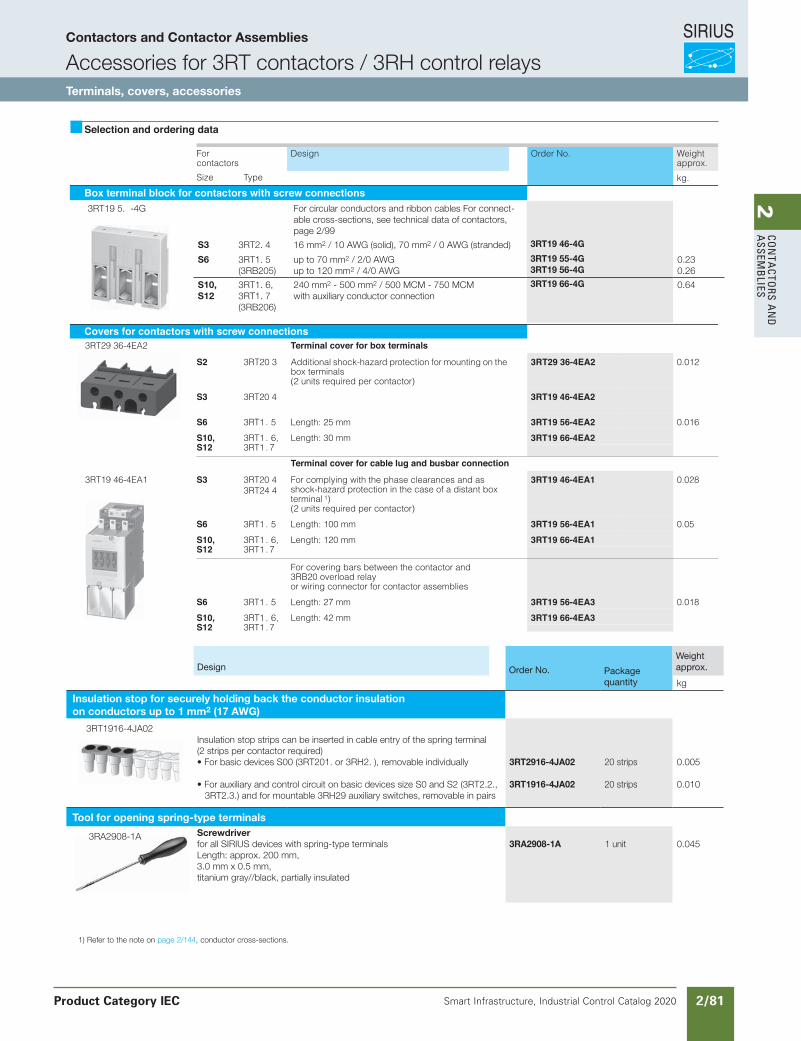
SIRIUS
Smart Infrastructure, Industrial Control Catalog 2020 2/81
2Co
nta
Ctors a
nd
a
ssemb
lies
Selection and ordering data
Forcontactors
Design Order No. Weight approx.
kg.Size Type
Box terminal block for contactors with screw connections
Covers for contactors with screw connectionsTerminal cover for box terminals
S2 3RT20 3 Additional shock-hazard protection for mounting on the box terminals(2 units required per contactor)
3RT29 36-4EA2 0.012
S3 3RT20 4 3RT19 46-4EA2
S6 3RT1 . 5 Length: 25 mm 3RT19 56-4EA2 0.016
S10, 3RT1 . 6, Length: 30 mm 3RT19 66-4EA2S12 3RT1 . 7
Terminal cover for cable lug and busbar connection
S3 3RT20 43RT24 4
For complying with the phase clearances and as shock-hazard protection in the case of a distant box terminal 1)(2 units required per contactor)
3RT19 46-4EA1 0.028
S6 3RT1 . 5 Length: 100 mm 3RT19 56-4EA1 0.05
S10, 3RT1 . 6, Length: 120 mm 3RT19 66-4EA1S12 3RT1 . 7
For covering bars between the contactor and 3RB20 overload relayor wiring connector for contactor assemblies
S6 3RT1 . 5 Length: 27 mm 3RT19 56-4EA3 0.018
S10, 3RT1 . 6, Length: 42 mm 3RT19 66-4EA3S12 3RT1 . 7
3RT29 36-4EA2
3RT19 46-4EA1
Siemens / Industrial Controls Previous folio: IC10 2/46
Design Order No. Packagequantity
Weightapprox.
kg
Insulation stop for securely holding back the conductor insulationon conductors up to 1 mm2 (17 AWG)
3RT1916-4JA02Insulation stop strips can be inserted in cable entry of the spring terminal(2 strips per contactor required)• For basic devices S00 (3RT201. or 3RH2. ), removable individually
• For auxiliary and control circuit on basic devices size S0 and S2 (3RT2.2., 3RT2.3.) and for mountable 3RH29 auxiliary switches, removable in pairs
3RT2916-4JA02
3RT1916-4JA02
20 strips
20 strips
0.005
0.010
Tool for opening spring-type terminals
3RA2908-1A Screwdriverfor all SIRIUS devices with spring-type terminalsLength: approx. 200 mm,3.0 mm x 0.5 mm,titanium gray//black, partially insulated
3RA2908-1A 1 unit 0.045
1) Refer to the note on page 2/144, conductor cross-sections.
3RT19 5. -4G For circular conductors and ribbon cables For connect-able cross-sections, see technical data of contactors, page 2/99
S3 3RT2. 4 16 mm2 / 10 AWG (solid), 70 mm2 / 0 AWG (stranded) 3RT19 46-4G
S6 3RT1. 5(3RB205)
up to 70 mm2 / 2/0 AWGup to 120 mm2 / 4/0 AWG
3RT19 55-4G3RT19 56-4G
0.230.26
S10,S12
3RT1. 6,3RT1. 7(3RB206)
240 mm2 - 500 mm2 / 500 MCM - 750 MCMwith auxiliary conductor connection
3RT19 66-4G 0.64
Contactors and Contactor Assemblies
Accessories for 3RT contactors / 3RH control relaysTerminals, covers, accessories
Product Category IEC
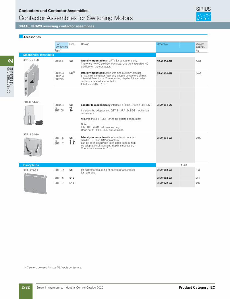
SIRIUS
Smart Infrastructure, Industrial Control Catalog 2020 2/82
2Co
nta
Cto
rs a
nd
a
ssem
bli
es
Siemens / Industrial Controls Previous folio: IC10 2/47
Accessories
For Size Design Order No. Weight approx.contactors
Type kg
Mechanical interlocks
laterally mountable each with one auxiliary contact(1 NC) per contactor (can only couple contactors of max.
auxiliary on the contactor.There are no NC auxiliary contacts. Use the integrated NC
contactor has to be adapted.)Interlock width: 10 mm
3RT204,3RT234,3RT245
S3 3RA2934-2B 0.05
laterally mountable for 3RT2 S2 contactors only.3RT2.3 S2 3RA2934-2B 0.04
3RT204to3RT105
S3toS6
adapter to mechanically interlock a 3RT204 with a 3RT105
includes the adapter and QTY 2 - 3RA1942-2G mechanical connectors
requires the 3RA1954 - 2A to be ordered separately
Note:Fits 3RT104 AC coil versions only.Does not fit 3RT104 DC coil versions.
3RA1954-2G
laterally mountable without auxiliary contacts; size S6, S10 and S12 contactors can be interlocked with each other as required; no adaptation of mounting depth is necessary. Contactor clearance 10 mm.
3RT1. 5to3RT1. 7
S6,S10,S12
3RA1954-2A 0.02
Baseplates 1 unit
3RT10 5 S6 for customer mounting of contactor assembliesfor reversing
3RA1952-2A 1.3
3RT1. 6 S10 3RA1962-2A 2.4
3RT1. 7 S12 3RA1972-2A 2.6
3RA19 24-2B
3RA19 54-2G
3RA19 54-2A
3RA1972-2A
1) Can also be used for size S3 4-pole contactors.
1 level different size. The mounting depth of the smaller
1)
Contactors and Contactor Assemblies
Contactor Assemblies for Switching Motors3RA13, 3RA23 reversing contactor assemblies
Product Category IEC
Revised on 12/27/18
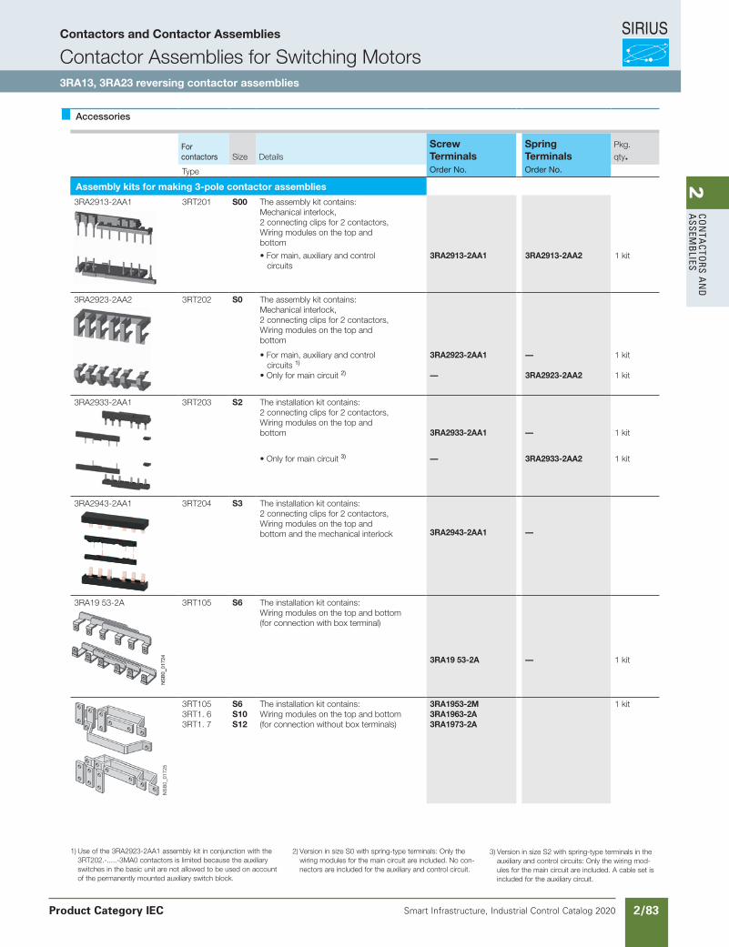
SIRIUS
Smart Infrastructure, Industrial Control Catalog 2020 2/83
2Co
nta
Ctors a
nd
a
ssemb
lies
Siemens / Industrial Controls Previous folio: IC10 2/48
Accessories
Forcontactors Size Details
Screw Terminals
Spring Terminals
Pkg.qty.
Type Order No. Order No.
Assembly kits for making 3-pole contactor assemblies
3RA2913-2AA1 3RT201 S00 The assembly kit contains:Mechanical interlock,2 connecting clips for 2 contactors,Wiring modules on the top andbottom
• For main, auxiliary and control circuits
3RA2913-2AA1 3RA2913-2AA2 1 kit
3RA2923-2AA2 3RT202 S0 The assembly kit contains:Mechanical interlock,2 connecting clips for 2 contactors,Wiring modules on the top andbottom
• For main, auxiliary and control circuits 1)
• Only for main circuit 2)
3RA2923-2AA1
—
—
3RA2923-2AA2
1 kit
1 kit
3RA2933-2AA1 3RT203 S2 The installation kit contains:2 connecting clips for 2 contactors,Wiring modules on the top andbottom 3RA2933-2AA1 — 1 kit
• Only for main circuit 3) — 3RA2933-2AA2 1 kit
3RA2943-2AA1 3RT204 S3 The installation kit contains:2 connecting clips for 2 contactors,Wiring modules on the top andbottom and the mechanical interlock 3RA2943-2AA1 —
3RA19 53-2A 3RT105 S6 The installation kit contains:Wiring modules on the top and bottom(for connection with box terminal)
3RA19 53-2A — 1 kit
3RT1053RT1. 63RT1. 7
S6S10S12
The installation kit contains:Wiring modules on the top and bottom(for connection without box terminals)
3RA1953-2M3RA1963-2A3RA1973-2A
1 kit
1) Use of the 3RA2923-2AA1 assembly kit in conjunction with the 3RT202.-.....-3MA0 contactors is limited because the auxiliary switches in the basic unit are not allowed to be used on account of the permanently mounted auxiliary switch block.
2) Version in size S0 with spring-type terminals: Only the wiring modules for the main circuit are included. No con-nectors are included for the auxiliary and control circuit.
3) Version in size S2 with spring-type terminals in the auxiliary and control circuits: Only the wiring mod-ules for the main circuit are included. A cable set is included for the auxiliary circuit.
Contactors and Contactor Assemblies
Contactor Assemblies for Switching Motors3RA13, 3RA23 reversing contactor assemblies
Product Category IEC
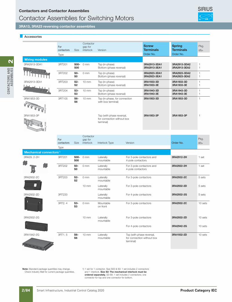
SIRIUS
Smart Infrastructure, Industrial Control Catalog 2020 2/84
2Co
nta
Cto
rs a
nd
a
ssem
bli
es
Siemens / Industrial Controls Previous folio: IC10 2/49
Accessories
Forcontactors Size
Contactorgap forinterlock Version
Screw Terminals
Spring Terminals
Pkg.qty.
Type Order No. Order No.
Wiring modules
3RA2913-3DA1 3RT201 S00-S00
0 mm Top (in-phase)Bottom (phase reversal)
3RA2913-3DA13RA2913-3EA1
3RA2913-3DA23RA2913-3EA2
11
3RT202 S0-S0
0 mm Top (in-phase)Bottom (phase reversal)
3RA2923-3DA13RA2923-3EA1
3RA2923-3DA23RA2923-3EA2
11
3RA2913-3EA1 3RT203 S2-S2
10 mm Top (in-phase)Bottom (phase reversal)
3RA1933-3D3RA1933-3E
3RA1933-3D3RA1933-3E
11
3RT204 S3-S3
10 mm Top (in-phase)Bottom (phase reversal)
3RA1943-3D3RA1943-3E
3RA1943-3D3RA1943-3E
11
3RA1953-3D 3RT105 S6-S6
10 mm Top (in-phase, for connectionwith box terminal)
3RA1953-3D 3RA1953-3D 1
3RA1953-3P Top (with phase reversal,for connection without boxterminal)
3RA1953-3P 3RA1953-3P 1
Forcontactors Size
Contactorgap forinterlock Interlock Type Version Order No.
Pkg.qty.
Type
Mechanical connectors1)
3RA29. 2-2H 3RT201 S00-S00
0 mm Laterallymountable
For 3-pole contactors and 4-pole contactors
3RA2912-2H 1 set
3RT202 S0-S0
0 mm Laterallymountable
For 3-pole contactors and 4-pole contactors
3RA2922-2H 1 set
3RA2932-2C 3RT203 S2-S2
0 mm Laterallymountable
For 3-pole contactors 3RA2932-2C 5 sets
10 mm Laterally mountable
For 3-pole contactors 3RA2932-2D 5 sets
3RA2932-2D 3RT233 Laterallymountable
For 4-pole contactors 3RA2932-2G 5 sets
3RT2. 4 S3-S3
0 mm Mountableon front
For 3-pole contactors 3RA2932-2C 10 sets
3RA2932-2G 10 mm Laterally mountable
For 3-pole contactors 3RA2932-2D 10 sets
For 4-pole contactors 3RA2942-2G 10 sets
3RA1942-2G 3RT1. 5 S6-S6
10 mm Laterally mountable
Top (with phase reversal,for connection without boxterminal)
3RA1932-2D 10 sets
Note: Standard package quantities may change. Check Industry Mall for current package quantities.
1) 1 set for 1 contactor. Size S00 & S0: 1 set includes 2 connectors and 1 interlock. Size S2: The mechanical interlock must be ordered separately. S3-S6: 1 set includes 2 connectors; one connector for top and one connector for bottom.
Contactors and Contactor Assemblies
Contactor Assemblies for Switching Motors3RA13, 3RA23 reversing contactor assemblies
Product Category IEC
Revised on 02/26/18
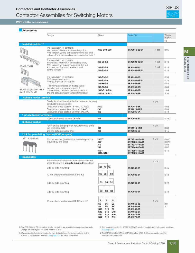
SIRIUS
Smart Infrastructure, Industrial Control Catalog 2020 2/85
2Co
nta
Ctors a
nd
a
ssemb
lies
Siemens / Industrial Controls Previous folio: IC10 2/50
Accessories
Design Sizes Order No. Weight approx.kg
Installation kits The installation kit contains:Mechanical interlock, 4 connecting clips, WYE jumper, Wiring connectors on the top and bottom,- For main, auxiliary, and control circuits 3)
S00-S00-S00 3RA2913-2BB1 0.05
The installation kit contains:mechanical interlock, 4 connecting clips, WYE jumper, wiring connectors on the top and bottom - For main, auxiliary, and control circuits 3)
S0-S0-S0 3RA2923-2BB1 0.10
The installation kit contains:WYE jumper on the topWiring jumper on the bottom
(The wiring connector on the top is not included in the scope of supply. A double infeed between the line contactor and the delta contactor is recommended.)
S2-S2-S0 3RA2933-2C 0.16S2-S2-S2 3RA2933-2BB1 0.16
S3-S3-S2 3RA2943-2C 0.33S3-S3-S3 3RA2943-2BB1 0.16S6-S6-S6 3RA1953-2B 0.85
S6-S6-S6 3RA1953-2N 0.60S10-S10-S10 3RA1963-2B 1.80S12-S12-S12 3RA1973-2B 2.20
3-phase feeder terminalFeeder terminal block for the line contactor for large conductor cross-sections
1 unit
Conductor cross-section: 6 mm2, 10 AWG S00 3RA2913-3K 0.02Conductor cross-section: 16 mm2, 6 AWG S0 3RV2925-5AB 0.04Conductor cross-section: 70 mm2, 2/0 AWG S2 3RV2935-5A 0.10
1-phase feeder terminalsConductor cross-section: 95 mm2 S3 3RA2943-3L 0.280
3-phase busbarFor in-phase bridging of all input terminals of the 1 unitline contactor (K1) S0 3RV1915-1AB 0.03and the delta contactor (K3) S2 3RV2935-5E 0.15
Link for paralleling, 3-pole (WYE jumpers)
Without terminal (the links for paralleling can be reduced by one pole)
S001) 3RT1916-4BA31 0.010S01) 3RT1926-4BA31 0.020S2 3RT1936-4BA31 0.02S3 3RT1946-4BA31 0.02
S6 4) 3RT1956-4BA31 0.15S10, S12 4) 3RT1966-4BA31
BaseplatesFor customer assembly of WYE-delta contactor assemblies with a laterally mounted time-delay
1 unit
Side-by-side mounting 3RA2932-2F 0.45
10 mm clearance between K3 and K2 3RA2932-2F 0.48
Side-by-side mounting
Side-by-side mounting
3RA2942-2F 0.72
0.72
10 mm clearance between K1, K3 and K2 1 unitS6 S6 S3 3RA1952-2E 2.0S6 S6 S6 3RA1952-2F 2.1S10 S10 S6 3RA1962-2ES10 S10 S10 3RA1962-2FS12 S12 S10 3RA1972-2ES12 S12 S12 3RA1972-2F
3RT19 26-4BA31
S2 S2 S0
S2 S2 S2
S3 S3
3RA2942-2FS3 S3 S3
S2
S. S. S.
1) 2)
1 set
1 set
1 set
1 unit
3RA19 53-2B
3RA19 53-2N, 3RA19 63-2B, 3RA19 73-2B
1) Size S00, S0 and S2 installation kits for paralleling are available in spring-type terminals. Change the last digit of the order number to a “2”.
2) When using the function modules for wye-delta starting, the wiring modules for the auxiliary current are not required. See page 2/47 for more information.
3) Also requires quantity (1) 3RA2816-0EW20 function module set for all control functions. See page 2/47.
4) The 3RT19 56-4EA1 (S6) or 3RT19 66-4EA1 (S10, S12) cover can be used for shock-hazard protection.
Contactors and Contactor Assemblies
Contactor Assemblies for Switching MotorsWYE-delta accessories
Revised on 02/26/18
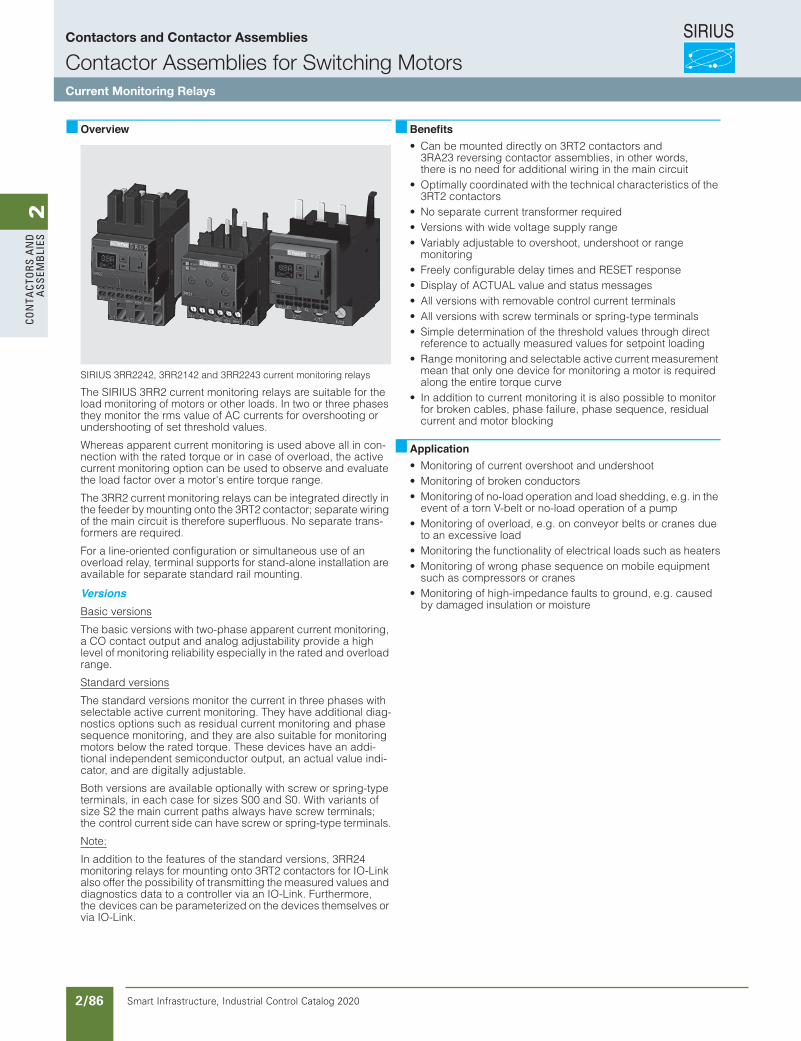
SIRIUS
Smart Infrastructure, Industrial Control Catalog 2020 2/86
2Co
nta
Cto
rs a
nd
a
ssem
bli
es
10/79Siemens IC 10 · 2015
RelaysSIRIUS 3RR21, 3RR22 Monitoring Relays for Mounting onto 3RT2 Contactors
Current and active current monitoring
10
Overview
SIRIUS 3RR2242, 3RR2142 and 3RR2243 current monitoring relays
The SIRIUS 3RR2 current monitoring relays are suitable for the load monitoring of motors or other loads. In two or three phases they monitor the rms value of AC currents for overshooting or undershooting of set threshold values.
Whereas apparent current monitoring is used above all in con-nection with the rated torque or in case of overload, the active current monitoring option can be used to observe and evaluate the load factor over a motor's entire torque range.
The 3RR2 current monitoring relays can be integrated directly in the feeder by mounting onto the 3RT2 contactor; separate wiring of the main circuit is therefore superfluous. No separate trans-formers are required.
For a line-oriented configuration or simultaneous use of an overload relay, terminal supports for stand-alone installation are available for separate standard rail mounting.
VersionsBasic versions
The basic versions with two-phase apparent current monitoring, a CO contact output and analog adjustability provide a high level of monitoring reliability especially in the rated and overload range.
Standard versions
The standard versions monitor the current in three phases with selectable active current monitoring. They have additional diag-nostics options such as residual current monitoring and phase sequence monitoring, and they are also suitable for monitoring motors below the rated torque. These devices have an addi-tional independent semiconductor output, an actual value indi-cator, and are digitally adjustable.
Both versions are available optionally with screw or spring-type terminals, in each case for sizes S00 and S0. With variants of size S2 the main current paths always have screw terminals; the control current side can have screw or spring-type terminals.
Note:
In addition to the features of the standard versions, 3RR24 monitoring relays for mounting onto 3RT2 contactors for IO-Link also offer the possibility of transmitting the measured values and diagnostics data to a controller via an IO-Link. Furthermore, the devices can be parameterized on the devices themselves or via IO-Link.
Benefits• Can be mounted directly on 3RT2 contactors and
3RA23 reversing contactor assemblies, in other words, there is no need for additional wiring in the main circuit
• Optimally coordinated with the technical characteristics of the 3RT2 contactors
• No separate current transformer required• Versions with wide voltage supply range• Variably adjustable to overshoot, undershoot or range
monitoring• Freely configurable delay times and RESET response• Display of ACTUAL value and status messages• All versions with removable control current terminals• All versions with screw terminals or spring-type terminals• Simple determination of the threshold values through direct
reference to actually measured values for setpoint loading• Range monitoring and selectable active current measurement
mean that only one device for monitoring a motor is required along the entire torque curve
• In addition to current monitoring it is also possible to monitor for broken cables, phase failure, phase sequence, residual current and motor blocking
Application• Monitoring of current overshoot and undershoot• Monitoring of broken conductors• Monitoring of no-load operation and load shedding, e.g. in the
event of a torn V-belt or no-load operation of a pump• Monitoring of overload, e.g. on conveyor belts or cranes due
to an excessive load• Monitoring the functionality of electrical loads such as heaters• Monitoring of wrong phase sequence on mobile equipment
such as compressors or cranes• Monitoring of high-impedance faults to ground, e.g. caused
by damaged insulation or moisture
IC10_10_06.fm Page 79 Sunday, April 19, 2015 11:57 AM
Contactors and Contactor Assemblies
Contactor Assemblies for Switching MotorsCurrent Monitoring Relays
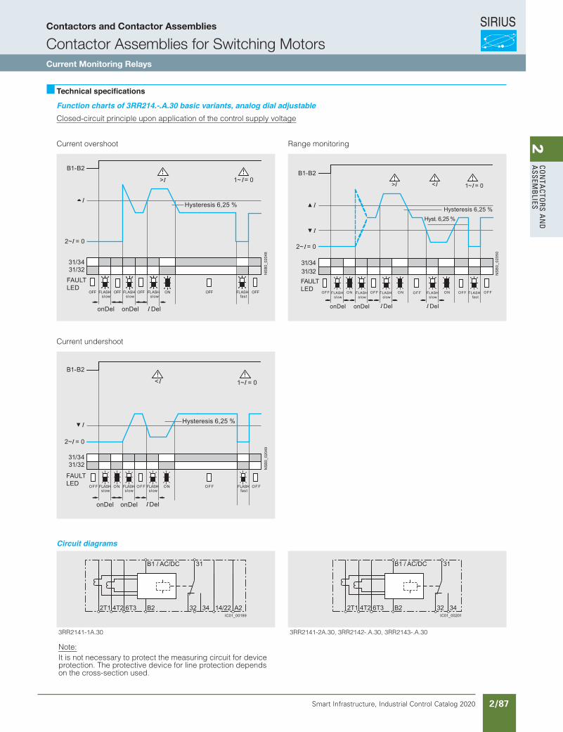
SIRIUS
Smart Infrastructure, Industrial Control Catalog 2020 2/87
2Co
nta
Ctors a
nd
a
ssemb
lies
10/80 Siemens IC 10 · 2015
RelaysSIRIUS 3RR21, 3RR22 Monitoring Relays for Mounting onto 3RT2 Contactors
Current and active current monitoring
10
Technical specifications
Function charts of 3RR214.-.A.30 basic variants, analog dial adjustableClosed-circuit principle upon application of the control supply voltage
Current overshoot
Current undershoot
Range monitoring
1~ = 0>
2~ = 0
Hysteresis 6,25 %
OFF FLASHslow
FLASHslow
FLASHslow
OFF ONOFF
FAULTLED
onDel onDel Del
OFF FLASHfast
OFF
B1-B2
NS
B0_
0204
831/3431/32
< 1~ = 0
NS
B0_
0204
9
Hysteresis 6,25 %
FAULTLED
2~ = 0
B1-B2
31/3431/32
OFF FLASHslow
FLASHslow
FLASHslow
OFF FFONONO FLASHfast
OFF
onDel onDel Del
> < 1~ = 0
2~ = 0
B1-B2
31/3431/32
OFF FLASHslow
FLASHslow
FLASHslow
OFF NONO OFF FLASHslow
ON FLASHfast
OFFOFF
onDel onDel Del Del
Hysteresis 6,25 %Hyst. 6,25 %
FAULTLED
NS
B0_
0205
0
IC10_10_06.fm Page 80 Sunday, April 19, 2015 11:57 AM
Circuit diagrams
03.A.-3412RR3 ,03.A.-2412RR3 ,03.A2-1412RR303.A1-1412RR3
Note:It is not necessary to protect the measuring circuit for device protection. The protective device for line protection depends on the cross-section used.
B1 / AC/DC 31
2T1 4T2 6T3 B2 32 34 14/22 A2IC01_00199
B1 / AC/DC 31
2T1 4T2 6T3 B2 32 34IC01_00201
Contactors and Contactor Assemblies
Contactor Assemblies for Switching MotorsCurrent Monitoring Relays
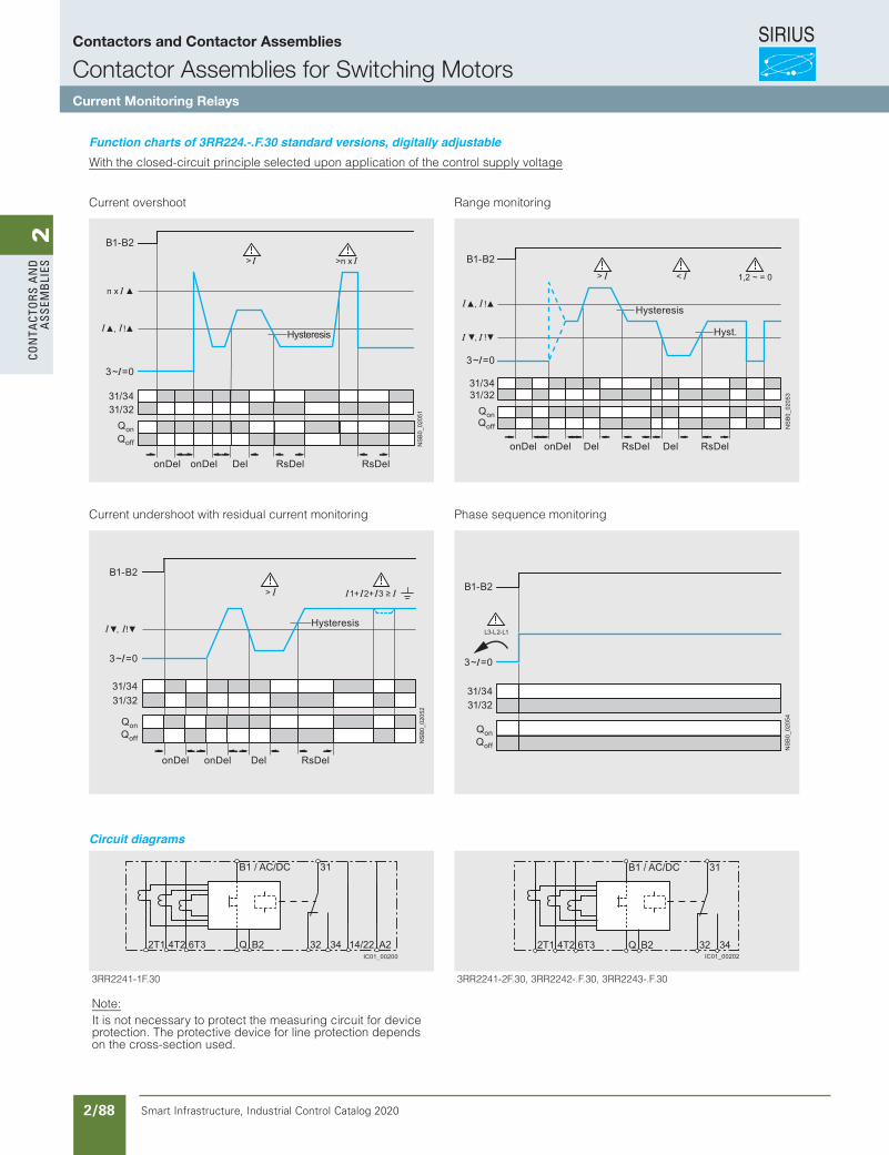
SIRIUS
Smart Infrastructure, Industrial Control Catalog 2020 2/88
2Co
nta
Cto
rs a
nd
a
ssem
bli
es
10/81Siemens IC 10 · 2015
RelaysSIRIUS 3RR21, 3RR22 Monitoring Relays for Mounting onto 3RT2 Contactors
Current and active current monitoring
10
Function charts of 3RR224.-.F.30 standard versions, digitally adjustableWith the closed-circuit principle selected upon application of the control supply voltage
Current overshoot
Current undershoot with residual current monitoring
Range monitoring
Phase sequence monitoring
> >n x
NS
B0_
0205
1
3~ = 0
Hysteresis
onDel onDel Del RsDel RsDel
QonQoff
n x
B1-B2
, !
31/3431/32
> 1+ 2+ 3 ≥
NS
B0_
0205
2
3~ = 0
QonQoff
Hysteresis
B1-B2
, !
31/3431/32
onDel onDel Del RsDel
> < 1,2 ~ = 0
NS
B0_
0205
3
B1-B2
, !
, !
3~ = 0
QonQoff
Hysteresis
Hyst.
31/3431/32
onDel onDel Del DelRsDel RsDel
1L-2L-3L
QonQoff
3~ = 0
NS
B0_
0205
4
B1-B2
31/3431/32
IC10_10_06.fm Page 81 Sunday, April 19, 2015 11:57 AM
Circuit diagrams
03.F.-3422RR3 ,03.F.-2422RR3 ,03.F2-1422RR303.F1-1422RR3
Note:It is not necessary to protect the measuring circuit for device protection. The protective device for line protection depends on the cross-section used.
B1 / AC/DC 31
43233T62T41T2 2A2BQ 14/22IC01_00200
B1 / AC/DC 31
43233T62T41T2 Q B2IC01_00202
Contactors and Contactor Assemblies
Contactor Assemblies for Switching MotorsCurrent Monitoring Relays
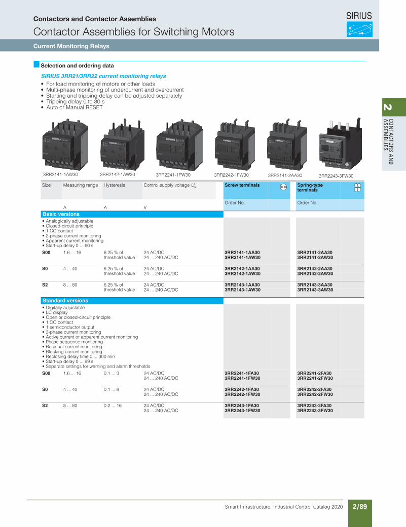
SIRIUS
Smart Infrastructure, Industrial Control Catalog 2020 2/89
2Co
nta
Ctors a
nd
a
ssemb
lies
10/83Siemens IC 10 · 2015* You can order this quantity or a multiple thereof.Illustrations are approximate
RelaysSIRIUS 3RR21, 3RR22 Monitoring Relays for Mounting onto 3RT2 Contactors
Current and active current monitoring
10
Selection and ordering data
SIRIUS 3RR21/3RR22 current monitoring relays• For load monitoring of motors or other loads• Multi-phase monitoring of undercurrent and overcurrent• Starting and tripping delay can be adjusted separately• Tripping delay 0 to 30 s• Auto or Manual RESET
Size Measuring range Hysteresis Control supply voltage Us Screw terminals Spring-type terminals
A A VOrder No. Order No.
Basic versions• Analogically adjustable• Closed-circuit principle• 1 CO contact• 2-phase current monitoring• Apparent current monitoring• Start-up delay 0 ... 60 s
S00 1.6 ... 16 6.25 % of threshold value
24 AC/DC 3RR2141-1AA30 3RR2141-2AA3024 ... 240 AC/DC 3RR2141-1AW30 3RR2141-2AW30
S0 4 ... 40 6.25 % of threshold value
24 AC/DC 3RR2142-1AA30 3RR2142-2AA3024 ... 240 AC/DC 3RR2142-1AW30 3RR2142-2AW30
S2 8 ... 80 6.25 % of threshold value
24 AC/DC 3RR2143-1AA30 3RR2143-3AA3024 ... 240 AC/DC 3RR2143-1AW30 3RR2143-3AW30
Standard versions• Digitally adjustable• LC display• Open or closed-circuit principle• 1 CO contact• 1 semiconductor output• 3-phase current monitoring• Active current or apparent current monitoring• Phase sequence monitoring• Residual current monitoring• Blocking current monitoring• Reclosing delay time 0 ... 300 min• Start-up delay 0 ... 99 s• Separate settings for warning and alarm thresholds
S00 1.6 ... 16 0.1 ... 3 24 AC/DC 3RR2241-1FA30 3RR2241-2FA3024 ... 240 AC/DC 3RR2241-1FW30 3RR2241-2FW30
S0 4 ... 40 0.1 ... 8 24 AC/DC 3RR2242-1FA30 3RR2242-2FA3024 ... 240 AC/DC 3RR2242-1FW30 3RR2242-2FW30
S2 8 ... 80 0.2 ... 16 24 AC/DC 3RR2243-1FA30 3RR2243-3FA3024 ... 240 AC/DC 3RR2243-1FW30 3RR2243-3FW30
3RR2141-1AW30 3RR2142-1AW30 3RR2241-1FW30 3RR2242-1FW30 3RR2141-2AA30 3RR2243-3FW30
IC10_10_06.fm Page 83 Sunday, April 19, 2015 11:57 AM
Contactors and Contactor Assemblies
Contactor Assemblies for Switching MotorsCurrent Monitoring Relays
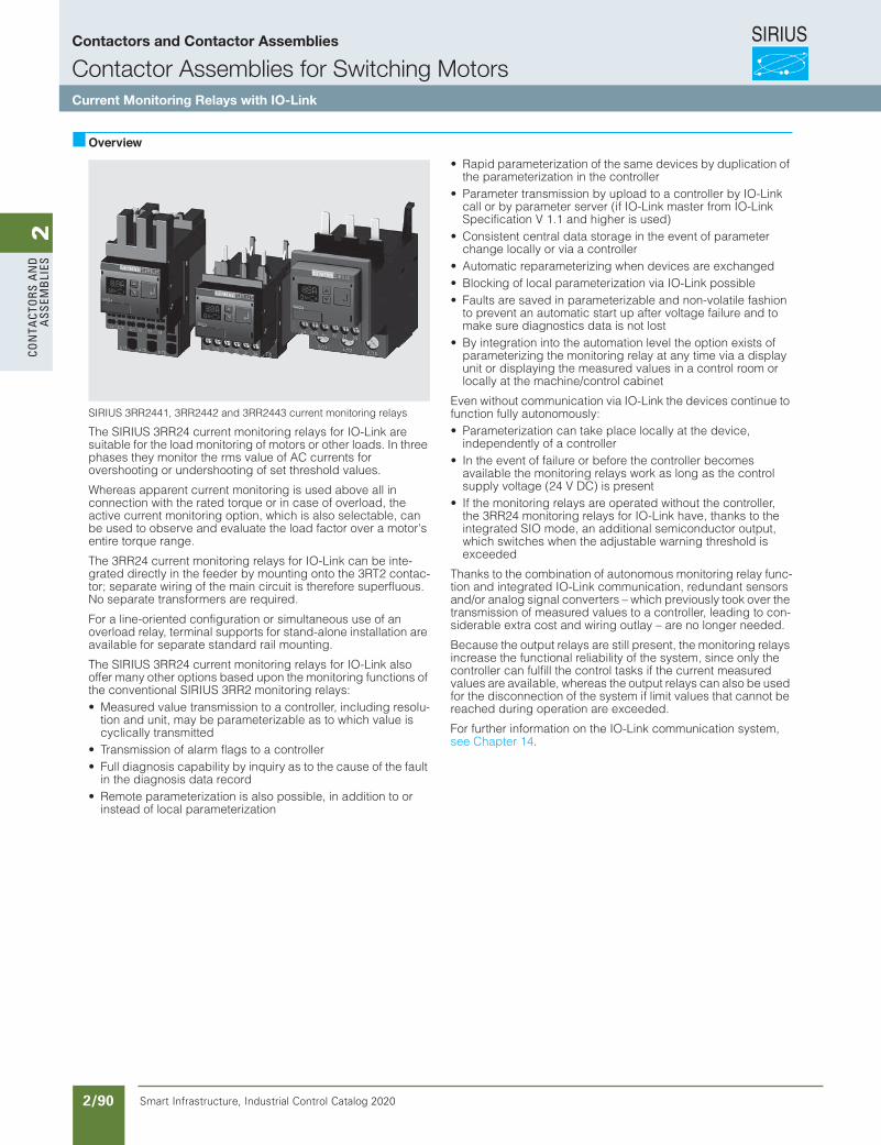
SIRIUS
Smart Infrastructure, Industrial Control Catalog 2020 2/90
2Co
nta
Cto
rs a
nd
a
ssem
bli
es
10/89Siemens IC 10 · 2015
RelaysSIRIUS 3RR24 Monitoring Relays for Mounting onto 3RT2 Contactors for IO-Link
Current and active current monitoring
10
Overview
SIRIUS 3RR2441, 3RR2442 and 3RR2443 current monitoring relays
The SIRIUS 3RR24 current monitoring relays for IO-Link are suitable for the load monitoring of motors or other loads. In three phases they monitor the rms value of AC currents for overshooting or undershooting of set threshold values.
Whereas apparent current monitoring is used above all in connection with the rated torque or in case of overload, the active current monitoring option, which is also selectable, can be used to observe and evaluate the load factor over a motor's entire torque range.
The 3RR24 current monitoring relays for IO-Link can be inte-grated directly in the feeder by mounting onto the 3RT2 contac-tor; separate wiring of the main circuit is therefore superfluous. No separate transformers are required.
For a line-oriented configuration or simultaneous use of an overload relay, terminal supports for stand-alone installation are available for separate standard rail mounting.
The SIRIUS 3RR24 current monitoring relays for IO-Link also offer many other options based upon the monitoring functions of the conventional SIRIUS 3RR2 monitoring relays:• Measured value transmission to a controller, including resolu-
tion and unit, may be parameterizable as to which value is cyclically transmitted
• Transmission of alarm flags to a controller• Full diagnosis capability by inquiry as to the cause of the fault
in the diagnosis data record• Remote parameterization is also possible, in addition to or
instead of local parameterization
• Rapid parameterization of the same devices by duplication of the parameterization in the controller
• Parameter transmission by upload to a controller by IO-Link call or by parameter server (if IO-Link master from IO-Link Specification V 1.1 and higher is used)
• Consistent central data storage in the event of parameter change locally or via a controller
• Automatic reparameterizing when devices are exchanged• Blocking of local parameterization via IO-Link possible• Faults are saved in parameterizable and non-volatile fashion
to prevent an automatic start up after voltage failure and to make sure diagnostics data is not lost
• By integration into the automation level the option exists of parameterizing the monitoring relay at any time via a display unit or displaying the measured values in a control room or locally at the machine/control cabinet
Even without communication via IO-Link the devices continue to function fully autonomously:• Parameterization can take place locally at the device,
independently of a controller• In the event of failure or before the controller becomes
available the monitoring relays work as long as the control supply voltage (24 V DC) is present
• If the monitoring relays are operated without the controller, the 3RR24 monitoring relays for IO-Link have, thanks to the integrated SIO mode, an additional semiconductor output, which switches when the adjustable warning threshold is exceeded
Thanks to the combination of autonomous monitoring relay func-tion and integrated IO-Link communication, redundant sensors and/or analog signal converters – which previously took over the transmission of measured values to a controller, leading to con-siderable extra cost and wiring outlay – are no longer needed.
Because the output relays are still present, the monitoring relays increase the functional reliability of the system, since only the controller can fulfill the control tasks if the current measured values are available, whereas the output relays can also be used for the disconnection of the system if limit values that cannot be reached during operation are exceeded.
For further information on the IO-Link communication system, see Chapter 14.
IC10_10_07.fm Page 89 Sunday, April 19, 2015 12:26 PM
Contactors and Contactor Assemblies
Contactor Assemblies for Switching MotorsCurrent Monitoring Relays with IO-Link
SIRIUS
Smart Infrastructure, Industrial Control Catalog 2020 2/91
2Co
nta
Ctors a
nd
a
ssemb
lies
10/90 Siemens IC 10 · 2015
RelaysSIRIUS 3RR24 Monitoring Relays for Mounting onto 3RT2 Contactors for IO-Link
Current and active current monitoring
10
Benefits• Can be mounted directly on 3RT2 contactors and
3RA23 reversing contactor assemblies, in other words, there is no need for additional wiring in the main circuit
• Optimally coordinated with the technical characteristics of the 3RT2 contactors
• No separate current transformer required• Variably adjustable to overshoot, undershoot or range
monitoring• Freely configurable delay times and RESET response• Display of ACTUAL value and status messages• All versions with removable control current terminals• All versions with screw or spring-type terminals• Simple determination of the threshold values through direct
reference to actually measured values for setpoint loading• Range monitoring and selectable active current measurement
mean that only one device for monitoring a motor is required along the entire torque curve
• In addition to current monitoring it is also possible to monitor for current unbalance, broken cables, phase failure, phase sequence, residual current and motor blocking
• Integrated counter for operating cycles and operating hours to support requirements-based maintenance of the monitored machine or application
• Simple cyclical transmission of the current measured values, relay switching states and events to a controller
• Remote parameterization• Automatic reparameterizing when devices are exchanged• Simple duplication of identical or similar parameterizations• Reduction of control current wiring• Elimination of testing costs and wiring errors• Reduction of configuration work• Integration in TIA means clear diagnostics if a fault occurs• Cost saving and space saving in control cabinet due to the
elimination of AI and IO modules as well as analog signal converters and duplicated sensors
Application• Monitoring of current overshoot and undershoot• Monitoring of broken conductors• Monitoring of no-load operation and load shedding, e.g. in the
event of a torn V-belt or no-load operation of a pump• Monitoring of overload, e.g. on pumps due to a dirty filter
system• Monitoring the functionality of electrical loads such as heaters• Monitoring of wrong phase sequence on mobile equipment
such as compressors or cranes• Monitoring of high-impedance faults to ground, e.g. caused
by damaged insulation or moisture
The use of SIRIUS monitoring relays for IO-Link is particularly recommended for machines and plant in which these relays, in addition to their monitoring function, are to be connected to the automation level for the rapid, simple and fault-free provision of the current measured values and/or for remote parameterization.
The monitoring relays can either relieve the controller of monitor-ing tasks or, as a second monitoring entity in parallel to and independent of the controller, increase the reliability in the process or in the system. In addition, the elimination of AI and IO modules allows the width of the controller to be reduced despite significantly expanded functionality.
IC10_10_07.fm Page 90 Sunday, April 19, 2015 12:26 PM
Contactors and Contactor Assemblies
Contactor Assemblies for Switching MotorsCurrent Monitoring Relays with IO-Link
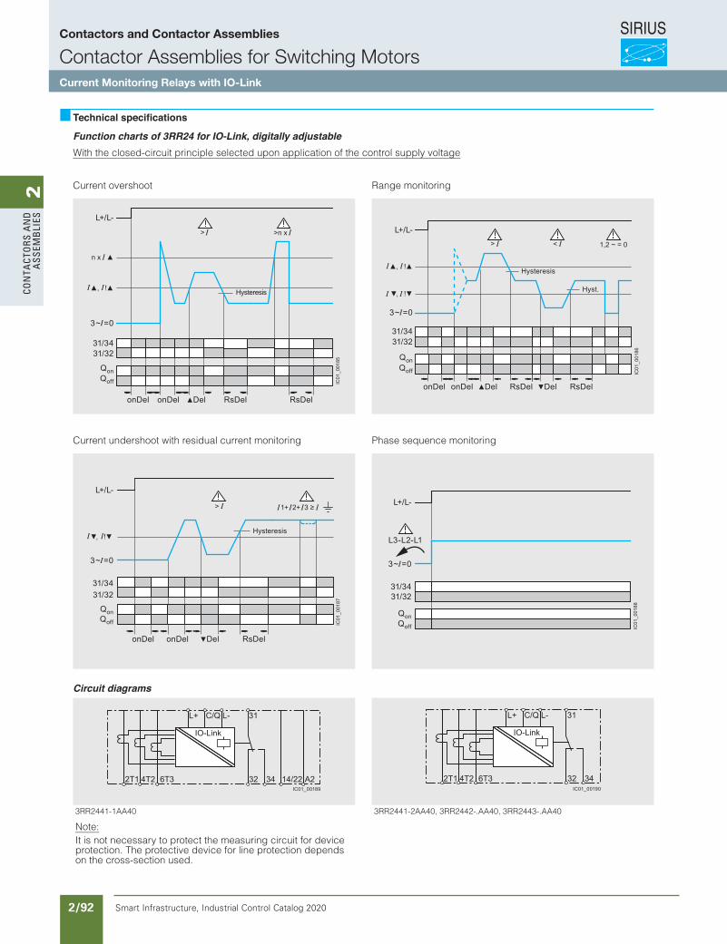
SIRIUS
Smart Infrastructure, Industrial Control Catalog 2020 2/92
2Co
nta
Cto
rs a
nd
a
ssem
bli
es
10/91Siemens IC 10 · 2015
RelaysSIRIUS 3RR24 Monitoring Relays for Mounting onto 3RT2 Contactors for IO-Link
Current and active current monitoring
10
Technical specifications
Function charts of 3RR24 for IO-Link, digitally adjustableWith the closed-circuit principle selected upon application of the control supply voltage
Current overshoot
Current undershoot with residual current monitoring
Range monitoring
Phase sequence monitoring
Circuit diagrams
Hysteresis
onDel onDel Del RsDel RsDel
QonQoff
n x
L+/L-
, !
31/3431/32
>n x >
3~ = 0IC
01_0
0185
QonQoff
Hysteresis
L+/L-
, !
31/3431/32
onDel onDel Del RsDel
3~ = 0
> 1+ 2+ 3 ≥
IC01
_001
87
QonQoff
Hysteresis
Hyst.
31/3431/32
onDel onDel Del DelRsDel RsDel
IC01
_001
86
L+/L-
, !
, !
3~ = 0
> < 1,2 ~ = 0
QonQoff
3~ = 0
IC01
_001
88
L+/L-
31/34
L3-L2-L1
31/32
04AA.-3442RR3 ,04AA.-2442RR3 ,04AA2-1442RR304AA1-1442RR3
Note:It is not necessary to protect the measuring circuit for device protection. The protective device for line protection depends on the cross-section used.
IC01_00189
IO-Link
326T34T22T1
31L-C/QL+
34 A214/22IC01_00190
326T34T22T1
31L-C/QL+
34
IO-Link
IC10_10_07.fm Page 91 Sunday, April 19, 2015 12:26 PM
Contactors and Contactor Assemblies
Contactor Assemblies for Switching MotorsCurrent Monitoring Relays with IO-Link
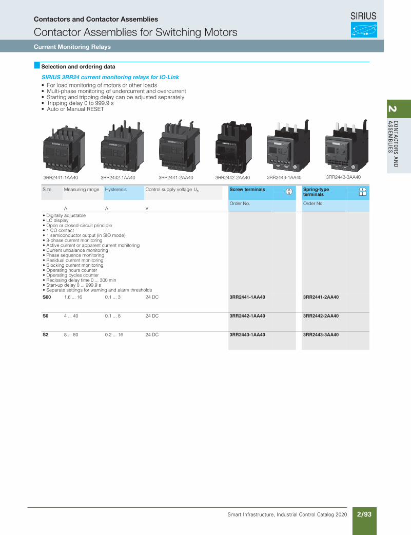
SIRIUS
Smart Infrastructure, Industrial Control Catalog 2020 2/93
2Co
nta
Ctors a
nd
a
ssemb
lies
10/92 Siemens IC 10 · 2015* You can order this quantity or a multiple thereof.
Illustrations are approximate
RelaysSIRIUS 3RR24 Monitoring Relays for Mounting onto 3RT2 Contactors for IO-Link
Current and active current monitoring
10
Selection and ordering data
SIRIUS 3RR24 current monitoring relays for IO-Link• For load monitoring of motors or other loads• Multi-phase monitoring of undercurrent and overcurrent• Starting and tripping delay can be adjusted separately• Tripping delay 0 to 999.9 s• Auto or Manual RESET
Size Measuring range Hysteresis Control supply voltage Us Screw terminals Spring-type terminals
A A VOrder No. Order No.
• Digitally adjustable• LC display• Open or closed-circuit principle• 1 CO contact• 1 semiconductor output (in SIO mode)• 3-phase current monitoring• Active current or apparent current monitoring• Current unbalance monitoring• Phase sequence monitoring• Residual current monitoring• Blocking current monitoring• Operating hours counter• Operating cycles counter• Reclosing delay time 0 ... 300 min• Start-up delay 0 ... 999.9 s• Separate settings for warning and alarm thresholds
S00 1.6 ... 16 0.1 ... 3 24 DC 3RR2441-1AA40 3RR2441-2AA40
S0 4 ... 40 0.1 ... 8 24 DC 3RR2442-1AA40 3RR2442-2AA40
S2 8 ... 80 0.2 ... 16 24 DC 3RR2443-1AA40 3RR2443-3AA40
3RR2441-1AA40 3RR2442-1AA40 3RR2441-2AA40 3RR2442-2AA40 3RR2443-1AA40 3RR2443-3AA40
IC10_10_07.fm Page 92 Sunday, April 19, 2015 12:26 PM
Contactors and Contactor Assemblies
Contactor Assemblies for Switching MotorsCurrent Monitoring Relays
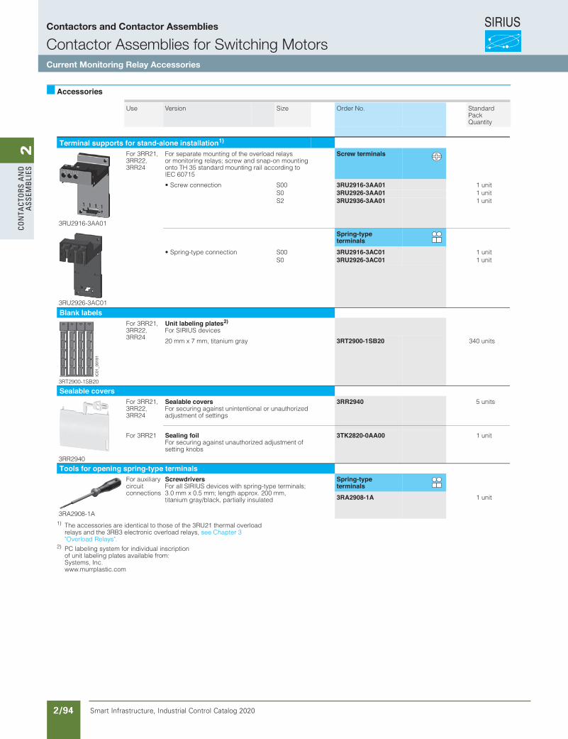
SIRIUS
Smart Infrastructure, Industrial Control Catalog 2020 2/94
2Co
nta
Cto
rs a
nd
a
ssem
bli
es
10/84 Siemens IC 10 · 2015* You can order this quantity or a multiple thereof.
Illustrations are approximate
RelaysSIRIUS 3RR21, 3RR22 Monitoring Relays for Mounting onto 3RT2 Contactors
Current and active current monitoring
10
Accessories
1) The accessories are identical to those of the 3RU21 thermal overload relays and the 3RB3 electronic overload relays, see Chapter 3 "Overload Relays".
2) PC labeling system for individual inscriptionof unit labeling plates available from:Systems, Inc. www.murrplastic.com
Use Version Size Order No. StandardPackQuantity
Terminal supports for stand-alone installation1)
3RU2916-3AA01
For 3RR21, 3RR22,3RR24
For separate mounting of the overload relays or monitoring relays; screw and snap-on mounting onto TH 35 standard mounting rail according to IEC 60715
Screw terminals
• Screw connection S00 3RU2916-3AA01 1 unitS0 3RU2926-3AA01 1 unitS2 3RU2936-3AA01 1 unit
3RU2926-3AC01
Spring-type terminals
• Spring-type connection S00 3RU2916-3AC01 1 unitS0 3RU2926-3AC01 1 unit
Blank labels
3RT2900-1SB20
For 3RR21, 3RR22,3RR24
Unit labeling plates2)
For SIRIUS devices
yarg muinatit ,mm 7 x mm 02 3RT2900-1SB20 340 units
Sealable covers
3RR2940
For 3RR21, 3RR22,3RR24
Sealable coversFor securing against unintentional or unauthorized adjustment of settings
3RR2940 5 units
For 3RR21 Sealing foilFor securing against unauthorized adjustment of setting knobs
3TK2820-0AA00 1 unit
Tools for opening spring-type terminals
3RA2908-1A
For auxiliary circuit connections
Screwdrivers For all SIRIUS devices with spring-type terminals; 3.0 mm x 0.5 mm; length approx. 200 mm, titanium gray/black, partially insulated
Spring-type terminals3RA2908-1A 1 unit
IC01_00181
IC10_10_06.fm Page 84 Sunday, April 19, 2015 11:57 AM
Contactors and Contactor Assemblies
Contactor Assemblies for Switching MotorsCurrent Monitoring Relay Accessories
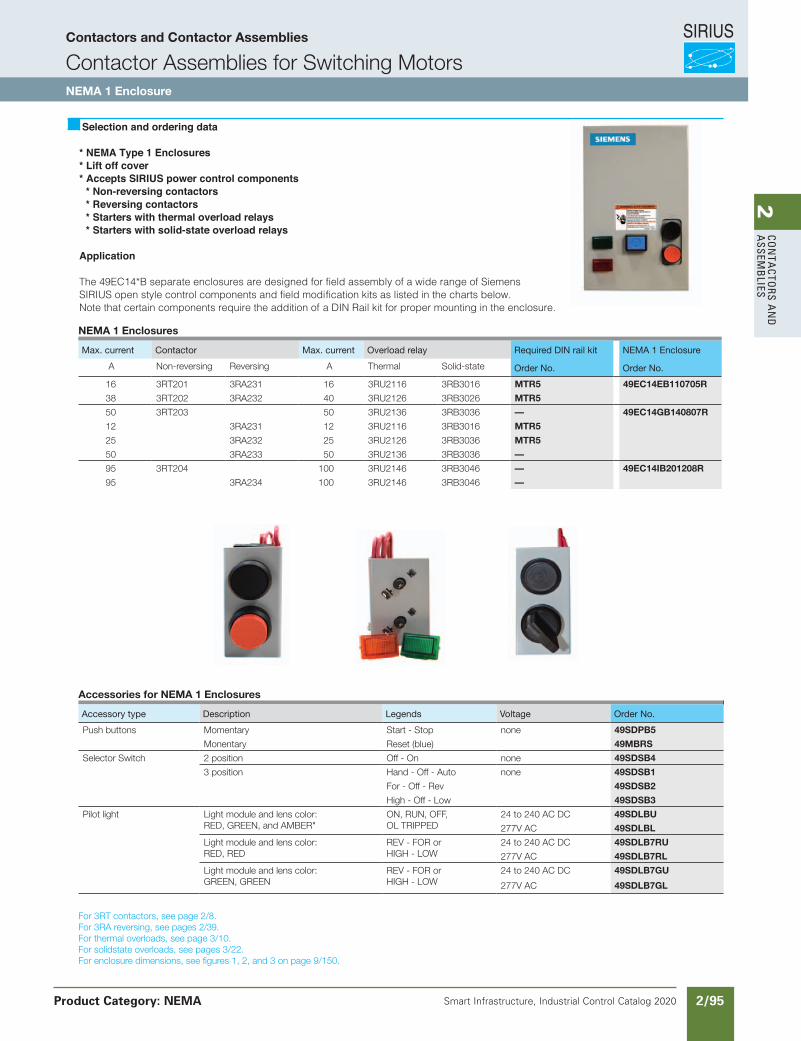
SIRIUS
Smart Infrastructure, Industrial Control Catalog 2020 2/95
2Co
nta
Ctors a
nd
a
ssemb
lies
Siemens / Industrial Controls Previous folio: IC10 2/51
Accessories for NEMA 1 Enclosures
Accessory type Description Marking Voltage Order No.
Push buttonStart-stop 49SBPB5Reset (blue) 49MBRS
Selector switch
2 position Off-on 49SBSB4Hand-off-auto 49SBSB1
3 position For-off-rev 49SBSB2High-off-low 49SBSB3
Pilot light Lens colors: red, green,amber
Legends: ON, RUN,OFF, OL TRIPPED,FORWARD,REVERSE, LOWHIGH
24 V AC120 V AC208, 240, 277 V AC480 V AC600 V AC
49SBLBJ49SBLBF49SBLBG49SBLBH49SBLBE
Selection and ordering data
* NEMA Type 1 Enclosures* Lift off cover* Accepts SIRIUS power control components
* Non-reversing contactors* Reversing contactors* Starters with thermal overload relays* Starters with solid-state overload relays
Application
The 49EC14*B separate enclosures are designed for field assembly of a wide range of Siemens SIRIUS open style control components and field modification kits as listed in the charts below.Note that certain components require the addition of a DIN Rail kit for proper mounting in the enclosure.
49EC14EB110705R
49SBPB5
49SBSB1
49SBLBF
For 3RT contactors, see page 2/8.For 3RA reversing, see pages 2/39.For thermal overloads, see page 3/10.For solidstate overloads, see pages 3/22.For enclosure dimensions, see figures 1, 2, and 3 on page 9/150.
NEMA 1 Enclosures
Max. current Contactor Max. current Overload relay Required DIN rail kit NEMA 1 Enclosure
A Non-reversing Reversing A Thermal Solid-state Order No. Order No.
16 3RT201 3RA231 16 3RU2116 3RB3016 MTR5 49EC14EB110705R
38 3RT202 3RA232 40 3RU2126 3RB3026 MTR5
50 3RT203 50 3RU2136 3RB3036 — 49EC14GB140807R
12 3RA231 12 3RU2116 3RB3016 MTR5
25 3RA232 25 3RU2126 3RB3036 MTR5
50 3RA233 50 3RU2136 3RB3036 —
95 3RT204 100 3RU2146 3RB3046 — 49EC14IB201208R
95 3RA234 100 3RU2146 3RB3046 —
Accessories for NEMA 1 Enclosures
Accessory type Description Legends Voltage Order No.
Push buttons Momentary Start - Stop none 49SDPB5
Monentary Reset (blue) 49MBRS
Selector Switch 2 position Off - On none 49SDSB4
3 position Hand - Off - Auto none 49SDSB1
For - Off - Rev 49SDSB2
High - Off - Low 49SDSB3
Pilot light Light module and lens color:RED, GREEN, and AMBER"
ON, RUN, OFF, OL TRIPPED
24 to 240 AC DC 49SDLBU
277V AC 49SDLBL
Light module and lens color: RED, RED
REV - FOR or HIGH - LOW
24 to 240 AC DC 49SDLB7RU
277V AC 49SDLB7RL
Light module and lens color: GREEN, GREEN
REV - FOR or HIGH - LOW
24 to 240 AC DC 49SDLB7GU
277V AC 49SDLB7GL
I think the Section 3 links were wrong
Contactors and Contactor Assemblies
Contactor Assemblies for Switching MotorsNEMA 1 Enclosure
Product Category: NEMA
Revised on 05/08/18

SIRIUS
Smart Infrastructure, Industrial Control Catalog 2020 2/96
2Co
nta
Cto
rs a
nd
a
ssem
bli
es
Siemens / Industrial Controls Previous folio: IC10 2/53
Accessories and Spare PartsFor 3RT2, 3RH2 Contactors and Contactor Relays
Spare parts for 3RT2 contactors
3/110 SIRIUS Innovations Supplement 2012 Illustrations are approximate
3
Selection and ordering data
For screw, spring-type and ring lug terminal connection
3RT29 24-5A . 01
For contactors Rated control supply voltage Us Order No. Weightapprox.
Size Type 50 Hz 50/60 Hz 60 Hz
V V V kg
Solenoid coils •AC operationS0 3RT20 23,
3RT20 24, 3RT20 25
24 -- -- 3RT29 24-5AB01 0.10042 -- -- 3RT29 24-5AD01 0.100
48 -- -- 3RT29 24-5AH01 0.100110 -- -- 3RT29 24-5AF01 0.100
230 -- -- 3RT29 24-5AP01 0.100400 -- -- 3RT29 24-5AV01 0.100
-- 24 -- 3RT29 24-5AC21 0.100-- 42 -- 3RT29 24-5AD21 0.100
-- 48 -- 3RT29 24-5AH21 0.100-- 110 -- 3RT29 24-5AG21 0.100
-- 220 -- 3RT29 24-5AN21 0.100-- 230 -- 3RT29 24-5AL21 0.100
110 -- 120 3RT29 24-5AK61 0.100220 -- 240 3RT29 24-5AP61 0.100
-- 100 110 3RT29 24-5AG61 0.100-- 200 220 3RT29 24-5AN61 0.100
-- 400 440 3RT29 24-5AR61 0.100
S0 3RT20 26 , 3RT20 27, 3RT20 28
3RT23 2 5, 3RT23 26, 3RT23 27
3RT25 2 6
24 -- -- 3RT29 26-5AB01 0.10042 -- -- 3RT29 26-5AD01 0.100
48 -- -- 3RT29 26-5AH01 0.100110 -- -- 3RT29 26-5AF01 0.100
230 -- -- 3RT29 26-5AP01 0.100400 -- -- 3RT29 26-5AV01 0.100
-- 24 -- 3RT29 26-5AC21 0.100-- 42 -- 3RT29 26-5AD21 0.100
-- 48 -- 3RT29 26-5AH21 0.100-- 110 -- 3RT29 26-5AG21 0.100-- 208 -- 3RT29 26-5AM21 0.100
-- 220 -- 3RT29 26-5AN21 0.100-- 230 -- 3RT29 26-5AL21 0.100
110 -- 120 3RT29 26-5AK61 0.100220 -- 240 3RT29 26-5AP61 0.100
-- 100 110 3RT29 26-5AG61 0.100-- 200 220 3RT29 26-5AN61 0.100
-- 400 440 3RT29 26-5AR61 0.100
500 -- 3RT29 26-5AQ21 0.100
277 3RT29 26-5AU61 0.100
480 3RT29 26-5AV61 0.100
600 3RT29 26-5AT61 0.100
LV1N_03_10.fm Page 110 Wednesday, October 30, 2013 3:55 PM
Note:Contactors with AC and AC/DC coils have different depths. It is only possible to replace the coils on AC contactors with AC coils, and on AC/DC contactors with AC/DC coils. It is not possible to replace the coils on DC contactors in the S0 frame.
Contactors and Contactor Assemblies
3RT ContactorsSpare parts for 3RT2 contactors
Product Category IEC
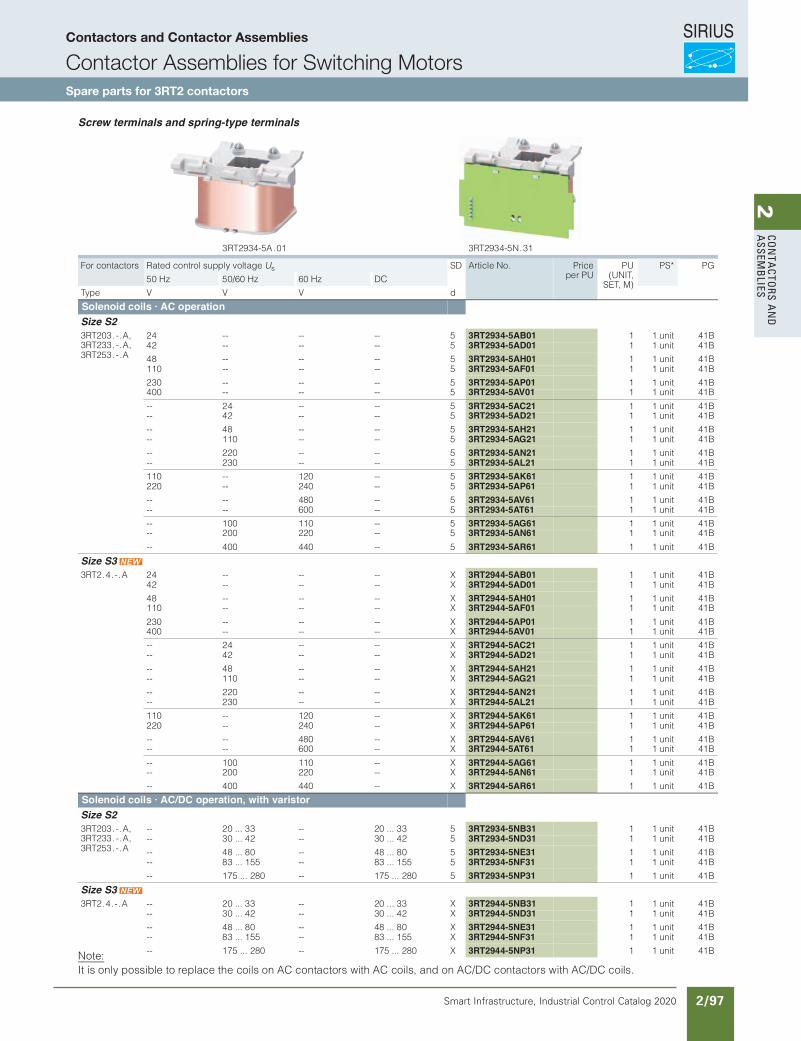
SIRIUS
Smart Infrastructure, Industrial Control Catalog 2020 2/97
2Co
nta
Ctors a
nd
a
ssemb
lies
3/121Siemens IC 10 · 2017* You can order this quantity or a multiple thereof.Illustrations are approximate.
Power Contactors for Switching MotorsAccessories and Spare Parts for SIRIUS 3RT Contactors and SIRIUS 3RH2 Contactor Relays
Spare Parts
Solenoid coils
3
Screw terminals and spring-type terminals
Note:It is only possible to replace the coils on AC contactors with AC coils, and on AC/DC contactors with AC/DC coils.
3RT2934-5A.01
3RT2934-5N.31
For contactors Rated control supply voltage Us SD Article No. Priceper PU
PU(UNIT,
SET, M)
PS* PG
50 Hz 50/60 Hz 60 Hz DC
dVVVepyT
Solenoid coils · AC operation Size S2 3RT203.-.A, 3RT233.-.A, 3RT253.-.A
24 -- -- -- 5 3RT2934-5AB01 1 1 unit 41B42 -- -- -- 5 3RT2934-5AD01 1 1 unit 41B
48 -- -- -- 5 3RT2934-5AH01 1 1 unit 41B110 -- -- -- 5 3RT2934-5AF01 1 1 unit 41B
230 -- -- -- 5 3RT2934-5AP01 1 1 unit 41B400 -- -- -- 5 3RT2934-5AV01 1 1 unit 41B
-- 24 -- -- 5 3RT2934-5AC21 1 1 unit 41B-- 42 -- -- 5 3RT2934-5AD21 1 1 unit 41B
-- 48 -- -- 5 3RT2934-5AH21 1 1 unit 41B-- 110 -- -- 5 3RT2934-5AG21 1 1 unit 41B
-- 220 -- -- 5 3RT2934-5AN21 1 1 unit 41B-- 230 -- -- 5 3RT2934-5AL21 1 1 unit 41B
110 -- 120 -- 5 3RT2934-5AK61 1 1 unit 41B220 -- 240 -- 5 3RT2934-5AP61 1 1 unit 41B
-- -- 480 -- 5 3RT2934-5AV61 1 1 unit 41B-- -- 600 -- 5 3RT2934-5AT61 1 1 unit 41B
-- 100 110 -- 5 3RT2934-5AG61 1 1 unit 41B-- 200 220 -- 5 3RT2934-5AN61 1 1 unit 41B
-- 400 440 -- 5 3RT2934-5AR61 1 1 unit 41B
Size S3 3RT2.4.-.A 24 -- -- -- X 3RT2944-5AB01 1 1 unit 41B
42 -- -- -- X 3RT2944-5AD01 1 1 unit 41B
48 -- -- -- X 3RT2944-5AH01 1 1 unit 41B110 -- -- -- X 3RT2944-5AF01 1 1 unit 41B
230 -- -- -- X 3RT2944-5AP01 1 1 unit 41B400 -- -- -- X 3RT2944-5AV01 1 1 unit 41B
-- 24 -- -- X 3RT2944-5AC21 1 1 unit 41B-- 42 -- -- X 3RT2944-5AD21 1 1 unit 41B
-- 48 -- -- X 3RT2944-5AH21 1 1 unit 41B-- 110 -- -- X 3RT2944-5AG21 1 1 unit 41B
-- 220 -- -- X 3RT2944-5AN21 1 1 unit 41B-- 230 -- -- X 3RT2944-5AL21 1 1 unit 41B
110 -- 120 -- X 3RT2944-5AK61 1 1 unit 41B220 -- 240 -- X 3RT2944-5AP61 1 1 unit 41B
-- -- 480 -- X 3RT2944-5AV61 1 1 unit 41B-- -- 600 -- X 3RT2944-5AT61 1 1 unit 41B
-- 100 110 -- X 3RT2944-5AG61 1 1 unit 41B-- 200 220 -- X 3RT2944-5AN61 1 1 unit 41B
-- 400 440 -- X 3RT2944-5AR61 1 1 unit 41B
Solenoid coils · AC/DC operation, with varistorSize S2 3RT203.-.A, 3RT233.-.A, 3RT253.-.A
-- 20 ... 33 -- 20 ... 33 5 3RT2934-5NB31 1 1 unit 41B-- 30 ... 42 -- 30 ... 42 5 3RT2934-5ND31 1 1 unit 41B
-- 48 ... 80 -- 48 ... 80 5 3RT2934-5NE31 1 1 unit 41B-- 83 ... 155 -- 83 ... 155 5 3RT2934-5NF31 1 1 unit 41B
-- 175 ... 280 -- 175 ... 280 5 3RT2934-5NP31 1 1 unit 41B
Size S3 3RT2.4.-.A -- 20 ... 33 -- 20 ... 33 X 3RT2944-5NB31 1 1 unit 41B
-- 30 ... 42 -- 30 ... 42 X 3RT2944-5ND31 1 1 unit 41B
-- 48 ... 80 -- 48 ... 80 X 3RT2944-5NE31 1 1 unit 41B-- 83 ... 155 -- 83 ... 155 X 3RT2944-5NF31 1 1 unit 41B
-- 175 ... 280 -- 175 ... 280 X 3RT2944-5NP31 1 1 unit 41B
© Siemens AG 2016
Contactors and Contactor Assemblies
Contactor Assemblies for Switching MotorsSpare parts for 3RT2 contactors
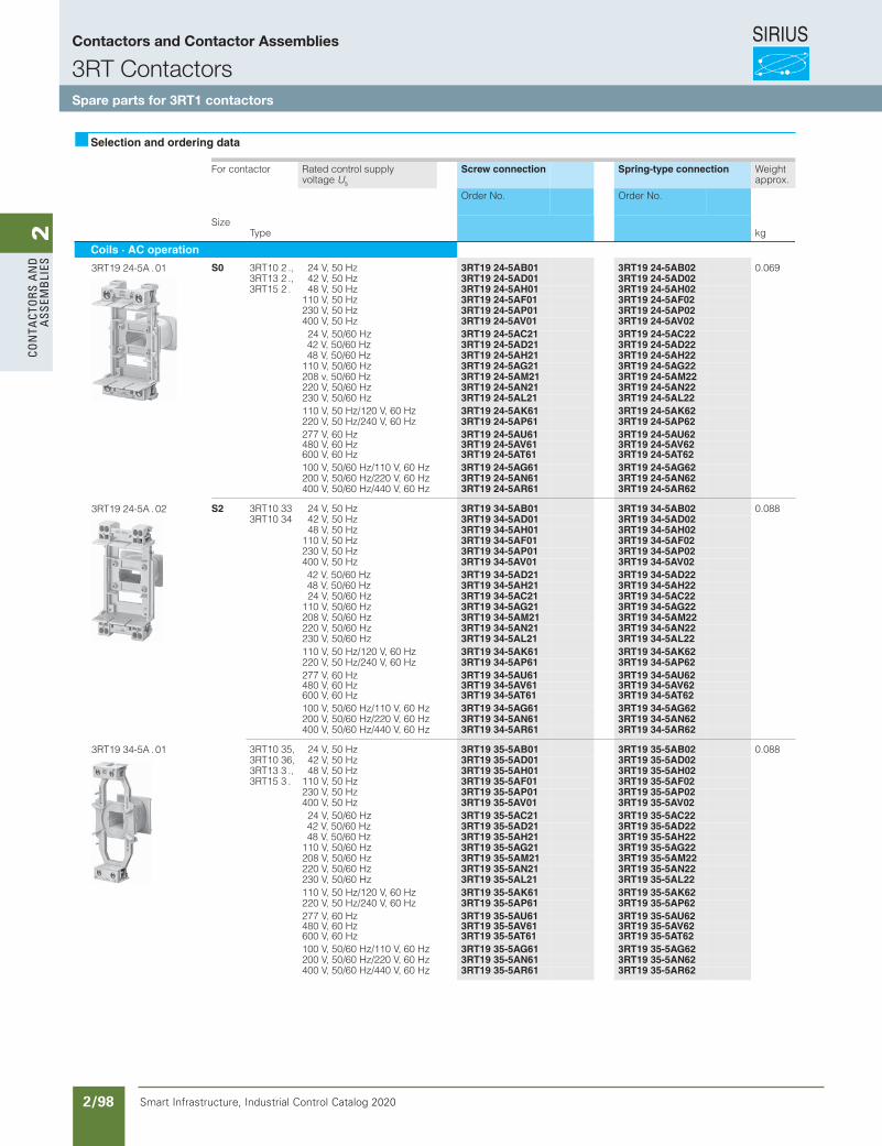
SIRIUS
Smart Infrastructure, Industrial Control Catalog 2020 2/98
2Co
nta
Cto
rs a
nd
a
ssem
bli
es
Siemens / Industrial Controls Previous folio: IC10 2/54
Selection and ordering data
For contactor Rated control supplyvoltage Us
Screw connection Spring-type connection Weightapprox.
Order No. Order No.
SizeType kg
Coils · AC operation
S0 3RT10 2 ., 24 V, 50 Hz 3RT19 24-5AB01 3RT19 24-5AB02 0.0693RT13 2 ., 42 V, 50 Hz 3RT19 24-5AD01 3RT19 24-5AD023RT15 2 . 48 V, 50 Hz 3RT19 24-5AH01 3RT19 24-5AH02
110 V, 50 Hz 3RT19 24-5AF01 3RT19 24-5AF02230 V, 50 Hz 3RT19 24-5AP01 3RT19 24-5AP02400 V, 50 Hz 3RT19 24-5AV01 3RT19 24-5AV0224 V, 50/60 Hz 3RT19 24-5AC21 3RT19 24-5AC2242 V, 50/60 Hz 3RT19 24-5AD21 3RT19 24-5AD2248 V, 50/60 Hz 3RT19 24-5AH21 3RT19 24-5AH22
110 V, 50/60 Hz 3RT19 24-5AG21 3RT19 24-5AG22208 v, 50/60 Hz 3RT19 24-5AM21 3RT19 24-5AM22220 V, 50/60 Hz 3RT19 24-5AN21 3RT19 24-5AN22230 V, 50/60 Hz 3RT19 24-5AL21 3RT19 24-5AL22110 V, 50 Hz/120 V, 60 Hz 3RT19 24-5AK61 3RT19 24-5AK62220 V, 50 Hz/240 V, 60 Hz 3RT19 24-5AP61 3RT19 24-5AP62277 V, 60 Hz 3RT19 24-5AU61 3RT19 24-5AU62480 V, 60 Hz 3RT19 24-5AV61 3RT19 24-5AV62600 V, 60 Hz 3RT19 24-5AT61 3RT19 24-5AT62100 V, 50/60 Hz/110 V, 60 Hz 3RT19 24-5AG61 3RT19 24-5AG62200 V, 50/60 Hz/220 V, 60 Hz 3RT19 24-5AN61 3RT19 24-5AN62400 V, 50/60 Hz/440 V, 60 Hz 3RT19 24-5AR61 3RT19 24-5AR62
S2 3RT10 33 24 V, 50 Hz 3RT19 34-5AB01 3RT19 34-5AB02 0.0883RT10 34 42 V, 50 Hz 3RT19 34-5AD01 3RT19 34-5AD02
48 V, 50 Hz 3RT19 34-5AH01 3RT19 34-5AH02110 V, 50 Hz 3RT19 34-5AF01 3RT19 34-5AF02230 V, 50 Hz 3RT19 34-5AP01 3RT19 34-5AP02400 V, 50 Hz 3RT19 34-5AV01 3RT19 34-5AV0242 V, 50/60 Hz 3RT19 34-5AD21 3RT19 34-5AD2248 V, 50/60 Hz 3RT19 34-5AH21 3RT19 34-5AH2224 V, 50/60 Hz 3RT19 34-5AC21 3RT19 34-5AC22
110 V, 50/60 Hz 3RT19 34-5AG21 3RT19 34-5AG22208 V, 50/60 Hz 3RT19 34-5AM21 3RT19 34-5AM22220 V, 50/60 Hz 3RT19 34-5AN21 3RT19 34-5AN22230 V, 50/60 Hz 3RT19 34-5AL21 3RT19 34-5AL22110 V, 50 Hz/120 V, 60 Hz 3RT19 34-5AK61 3RT19 34-5AK62220 V, 50 Hz/240 V, 60 Hz 3RT19 34-5AP61 3RT19 34-5AP62277 V, 60 Hz 3RT19 34-5AU61 3RT19 34-5AU62480 V, 60 Hz 3RT19 34-5AV61 3RT19 34-5AV62600 V, 60 Hz 3RT19 34-5AT61 3RT19 34-5AT62100 V, 50/60 Hz/110 V, 60 Hz 3RT19 34-5AG61 3RT19 34-5AG62200 V, 50/60 Hz/220 V, 60 Hz 3RT19 34-5AN61 3RT19 34-5AN62400 V, 50/60 Hz/440 V, 60 Hz 3RT19 34-5AR61 3RT19 34-5AR62
3RT10 35, 24 V, 50 Hz 3RT19 35-5AB01 3RT19 35-5AB02 0.0883RT10 36, 42 V, 50 Hz 3RT19 35-5AD01 3RT19 35-5AD023RT13 3 ., 48 V, 50 Hz 3RT19 35-5AH01 3RT19 35-5AH023RT15 3 . 110 V, 50 Hz 3RT19 35-5AF01 3RT19 35-5AF02
230 V, 50 Hz 3RT19 35-5AP01 3RT19 35-5AP02400 V, 50 Hz 3RT19 35-5AV01 3RT19 35-5AV0224 V, 50/60 Hz 3RT19 35-5AC21 3RT19 35-5AC2242 V, 50/60 Hz 3RT19 35-5AD21 3RT19 35-5AD2248 V, 50/60 Hz 3RT19 35-5AH21 3RT19 35-5AH22
110 V, 50/60 Hz 3RT19 35-5AG21 3RT19 35-5AG22208 V, 50/60 Hz 3RT19 35-5AM21 3RT19 35-5AM22220 V, 50/60 Hz 3RT19 35-5AN21 3RT19 35-5AN22230 V, 50/60 Hz 3RT19 35-5AL21 3RT19 35-5AL22110 V, 50 Hz/120 V, 60 Hz 3RT19 35-5AK61 3RT19 35-5AK62220 V, 50 Hz/240 V, 60 Hz 3RT19 35-5AP61 3RT19 35-5AP62277 V, 60 Hz 3RT19 35-5AU61 3RT19 35-5AU62480 V, 60 Hz 3RT19 35-5AV61 3RT19 35-5AV62600 V, 60 Hz 3RT19 35-5AT61 3RT19 35-5AT62100 V, 50/60 Hz/110 V, 60 Hz 3RT19 35-5AG61 3RT19 35-5AG62200 V, 50/60 Hz/220 V, 60 Hz 3RT19 35-5AN61 3RT19 35-5AN62400 V, 50/60 Hz/440 V, 60 Hz 3RT19 35-5AR61 3RT19 35-5AR62
3RT19 24-5A . 01
3RT19 24-5A . 02
3RT19 34-5A . 01
Contactors and Contactor Assemblies
3RT ContactorsSpare parts for 3RT1 contactors
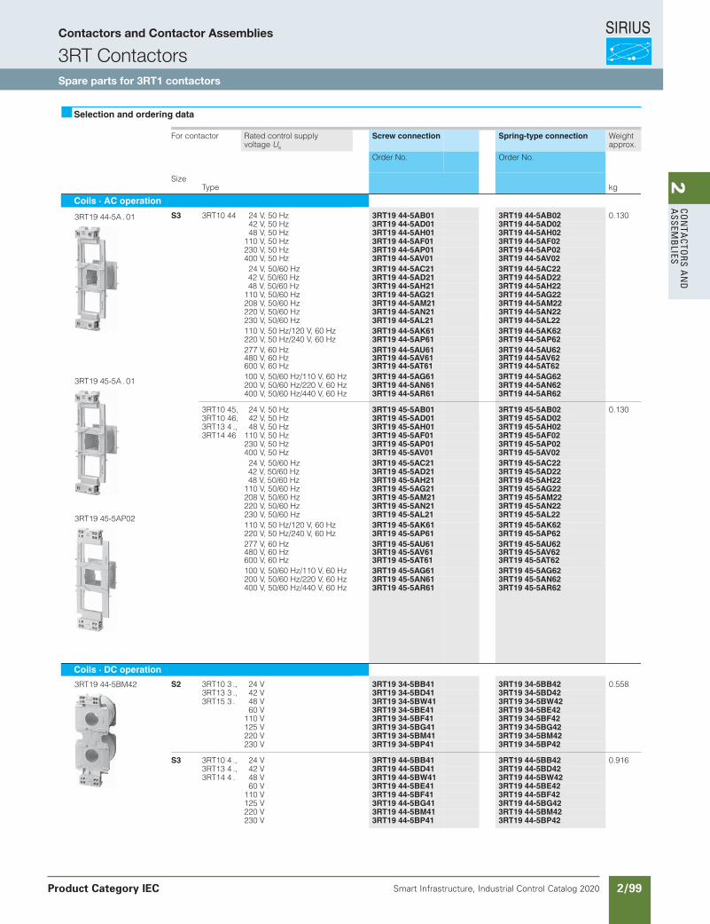
SIRIUS
Smart Infrastructure, Industrial Control Catalog 2020 2/99
2Co
nta
Ctors a
nd
a
ssemb
lies
Siemens / Industrial Controls Previous folio:IC10 2/55
Selection and ordering data
For contactor Rated control supply voltage Us
Screw connection Spring-type connection Weight approx.
Order No. Order No.
SizeType kg
Coils · AC operation
S3 3RT10 44 24 V, 50 Hz 3RT19 44-5AB01 3RT19 44-5AB02 0.13042 V, 50 Hz 3RT19 44-5AD01 3RT19 44-5AD0248 V, 50 Hz 3RT19 44-5AH01 3RT19 44-5AH02
110 V, 50 Hz 3RT19 44-5AF01 3RT19 44-5AF02230 V, 50 Hz 3RT19 44-5AP01 3RT19 44-5AP02400 V, 50 Hz 3RT19 44-5AV01 3RT19 44-5AV0224 V, 50/60 Hz 3RT19 44-5AC21 3RT19 44-5AC2242 V, 50/60 Hz 3RT19 44-5AD21 3RT19 44-5AD2248 V, 50/60 Hz 3RT19 44-5AH21 3RT19 44-5AH22
110 V, 50/60 Hz 3RT19 44-5AG21 3RT19 44-5AG22208 V, 50/60 Hz 3RT19 44-5AM21 3RT19 44-5AM22220 V, 50/60 Hz 3RT19 44-5AN21 3RT19 44-5AN22230 V, 50/60 Hz 3RT19 44-5AL21 3RT19 44-5AL22110 V, 50 Hz/120 V, 60 Hz 3RT19 44-5AK61 3RT19 44-5AK62220 V, 50 Hz/240 V, 60 Hz 3RT19 44-5AP61 3RT19 44-5AP62277 V, 60 Hz 3RT19 44-5AU61 3RT19 44-5AU62480 V, 60 Hz 3RT19 44-5AV61 3RT19 44-5AV62600 V, 60 Hz 3RT19 44-5AT61 3RT19 44-5AT62100 V, 50/60 Hz/110 V, 60 Hz 3RT19 44-5AG61 3RT19 44-5AG62200 V, 50/60 Hz/220 V, 60 Hz 3RT19 44-5AN61 3RT19 44-5AN62400 V, 50/60 Hz/440 V, 60 Hz 3RT19 44-5AR61 3RT19 44-5AR62
3RT10 45, 24 V, 50 Hz 3RT19 45-5AB01 3RT19 45-5AB02 0.1303RT10 46, 42 V, 50 Hz 3RT19 45-5AD01 3RT19 45-5AD023RT13 4 ., 48 V, 50 Hz 3RT19 45-5AH01 3RT19 45-5AH023RT14 46 110 V, 50 Hz 3RT19 45-5AF01 3RT19 45-5AF02
230 V, 50 Hz 3RT19 45-5AP01 3RT19 45-5AP02400 V, 50 Hz 3RT19 45-5AV01 3RT19 45-5AV0224 V, 50/60 Hz 3RT19 45-5AC21 3RT19 45-5AC2242 V, 50/60 Hz 3RT19 45-5AD21 3RT19 45-5AD2248 V, 50/60 Hz 3RT19 45-5AH21 3RT19 45-5AH22
110 V, 50/60 Hz 3RT19 45-5AG21 3RT19 45-5AG22208 V, 50/60 Hz 3RT19 45-5AM21 3RT19 45-5AM22220 V, 50/60 Hz 3RT19 45-5AN21 3RT19 45-5AN22230 V, 50/60 Hz 3RT19 45-5AL21 3RT19 45-5AL22110 V, 50 Hz/120 V, 60 Hz 3RT19 45-5AK61 3RT19 45-5AK62220 V, 50 Hz/240 V, 60 Hz 3RT19 45-5AP61 3RT19 45-5AP62277 V, 60 Hz 3RT19 45-5AU61 3RT19 45-5AU62480 V, 60 Hz 3RT19 45-5AV61 3RT19 45-5AV62600 V, 60 Hz 3RT19 45-5AT61 3RT19 45-5AT62100 V, 50/60 Hz/110 V, 60 Hz 3RT19 45-5AG61 3RT19 45-5AG62200 V, 50/60 Hz/220 V, 60 Hz 3RT19 45-5AN61 3RT19 45-5AN62400 V, 50/60 Hz/440 V, 60 Hz 3RT19 45-5AR61 3RT19 45-5AR62
Coils · DC operation
S2 3RT10 3 .,3RT13 3 .,3RT15 3 .
24 V 3RT19 34-5BB41 3RT19 34-5BB42 0.55842 V 3RT19 34-5BD41 3RT19 34-5BD4248 V 3RT19 34-5BW41 3RT19 34-5BW4260 V 3RT19 34-5BE41 3RT19 34-5BE42
110 V 3RT19 34-5BF41 3RT19 34-5BF42125 V 3RT19 34-5BG41 3RT19 34-5BG42220 V 3RT19 34-5BM41 3RT19 34-5BM42230 V 3RT19 34-5BP41 3RT19 34-5BP42
S3 3RT10 4 .,3RT13 4 .,3RT14 4 .
24 V 3RT19 44-5BB41 3RT19 44-5BB42 0.91642 V 3RT19 44-5BD41 3RT19 44-5BD4248 V 3RT19 44-5BW41 3RT19 44-5BW4260 V 3RT19 44-5BE41 3RT19 44-5BE42
110 V 3RT19 44-5BF41 3RT19 44-5BF42125 V 3RT19 44-5BG41 3RT19 44-5BG42220 V 3RT19 44-5BM41 3RT19 44-5BM42230 V 3RT19 44-5BP41 3RT19 44-5BP42
3RT19 44-5A . 01
3RT19 45-5A . 01
3RT19 45-5AP02
3RT19 44-5BM42
Contactors and Contactor Assemblies
3RT ContactorsSpare parts for 3RT1 contactors
Product Category IEC
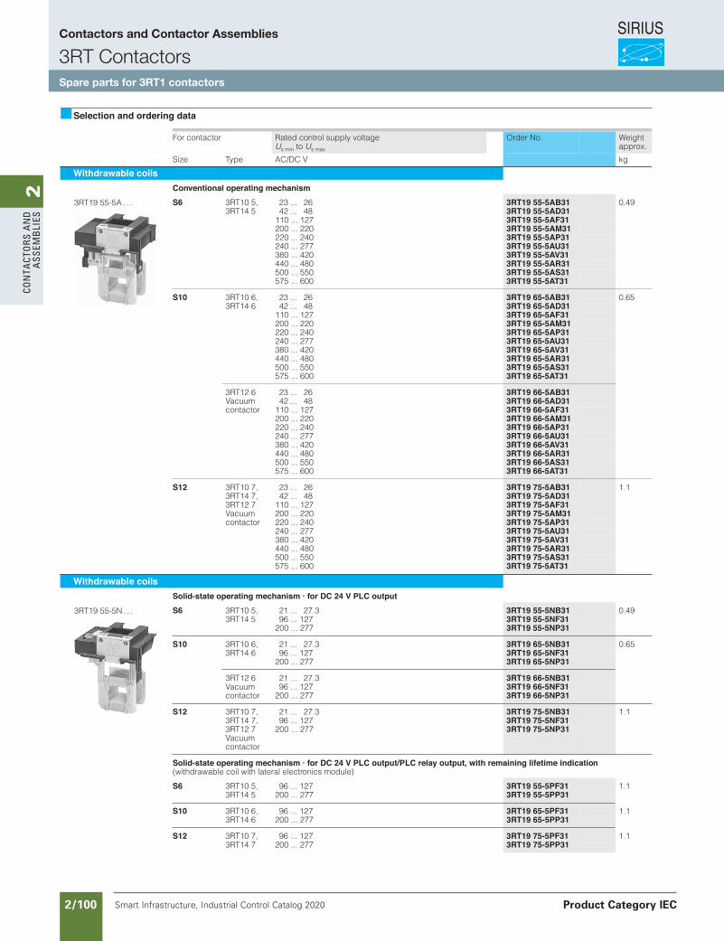
SIRIUS
Smart Infrastructure, Industrial Control Catalog 2020 2/100
2Co
nta
Cto
rs a
nd
a
ssem
bli
es
Siemens / Industrial Controls Previous folio: IC10 2/56
Selection and ordering data
For contactor Rated control supply voltage Us min to Us max
Order No. Weight approx.
Size Type AC/DC V kg
Withdrawable coilsConventional operating mechanism
S6 3RT10 5, 23 ... 26 3RT19 55-5AB31 0.493RT14 5 42 ... 48 3RT19 55-5AD31
110 ... 127 3RT19 55-5AF31200 ... 220 3RT19 55-5AM31220 ... 240 3RT19 55-5AP31240 ... 277 3RT19 55-5AU31380 ... 420 3RT19 55-5AV31440 ... 480 3RT19 55-5AR31500 ... 550 3RT19 55-5AS31575 ... 600 3RT19 55-5AT31
S10 3RT10 6, 23 ... 26 3RT19 65-5AB31 0.653RT14 6 42 ... 48 3RT19 65-5AD31
110 ... 127 3RT19 65-5AF31200 ... 220 3RT19 65-5AM31220 ... 240 3RT19 65-5AP31240 ... 277 3RT19 65-5AU31380 ... 420 3RT19 65-5AV31440 ... 480 3RT19 65-5AR31500 ... 550 3RT19 65-5AS31575 ... 600 3RT19 65-5AT31
3RT12 6 23 ... 26 3RT19 66-5AB31Vacuum contactor
42 ... 48 3RT19 66-5AD31110 ... 127 3RT19 66-5AF31200 ... 220 3RT19 66-5AM31220 ... 240 3RT19 66-5AP31240 ... 277 3RT19 66-5AU31380 ... 420 3RT19 66-5AV31440 ... 480 3RT19 66-5AR31500 ... 550 3RT19 66-5AS31575 ... 600 3RT19 66-5AT31
S12 3RT10 7, 23 ... 26 3RT19 75-5AB31 1.13RT14 7, 42 ... 48 3RT19 75-5AD313RT12 7 110 ... 127 3RT19 75-5AF31Vacuum contactor
200 ... 220 3RT19 75-5AM31220 ... 240 3RT19 75-5AP31240 ... 277 3RT19 75-5AU31380 ... 420 3RT19 75-5AV31440 ... 480 3RT19 75-5AR31500 ... 550 3RT19 75-5AS31575 ... 600 3RT19 75-5AT31
3RT19 55-5A . . .
Withdrawable coilsSolid-state operating mechanism · for DC 24 V PLC output
S6 3RT10 5, 21 ... 27.3 3RT19 55-5NB31 0.493RT14 5 96 ... 127 3RT19 55-5NF31
200 ... 277 3RT19 55-5NP31
S10 3RT10 6, 21 ... 27.3 3RT19 65-5NB31 0.653RT14 6 96 ... 127 3RT19 65-5NF31
200 ... 277 3RT19 65-5NP31
3RT12 6Vacuum contactor
21 ... 27.3 3RT19 66-5NB3196 ... 127 3RT19 66-5NF31
200 ... 277 3RT19 66-5NP31
S12 3RT10 7, 21 ... 27.3 3RT19 75-5NB31 1.13RT14 7, 96 ... 127 3RT19 75-5NF313RT12 7Vacuum contactor
200 ... 277 3RT19 75-5NP31
Solid-state operating mechanism · for DC 24 V PLC output/PLC relay output, with remaining lifetime indication(withdrawable coil with lateral electronics module)
S6 3RT10 5, 96 ... 127 3RT19 55-5PF31 1.13RT14 5 200 ... 277 3RT19 55-5PP31
S10 3RT10 6, 96 ... 127 3RT19 65-5PF31 1.13RT14 6 200 ... 277 3RT19 65-5PP31
S12 3RT10 7, 96 ... 127 3RT19 75-5PF31 1.13RT14 7 200 ... 277 3RT19 75-5PP31
3RT19 55-5N . . .
Contactors and Contactor Assemblies
3RT ContactorsSpare parts for 3RT1 contactors
Product Category IEC
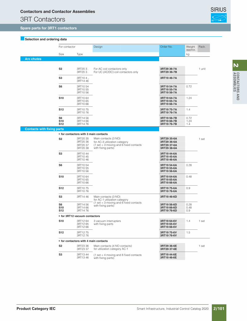
SIRIUS
Smart Infrastructure, Industrial Control Catalog 2020 2/101
2Co
nta
Ctors a
nd
a
ssemb
lies
Siemens / Industrial Controls Previous folio: IC10 2/58
Selection and ordering data
For contactor Design Order No. Weight approx.
Pack.
Size Type kg
Arc chutes
S2 3RT20 3 . For AC coil contactors only 3RT29 36-7A3RT20 3 . For UC (AC/DC) coil contactors only 3RT29 36-7B
1 unit
S3 3RT10 4 .,3RT14 46
3RT19 46-7A
S6 3RT10 54 3RT19 54-7A 0.723RT10 55 3RT19 55-7A3RT10 56 3RT19 56-7A
S10 3RT10 64 3RT19 64-7A 1.243RT10 65 3RT19 65-7A3RT10 66 3RT19 66-7A
S12 3RT10 75 3RT19 75-7A 1.43RT10 76 3RT19 76-7A
S6 3RT14 56 3RT19 56-7B 0.72S10 3RT14 66 3RT19 66-7B 1.24S12 3RT14 76 3RT19 76-7B 1.4
Contacts with fixing partsfor contactors with 3 main contacts
S2 3RT20 353RT20 36 for AC-3 utilization category
(1 set = 3 moving and 6 fixed contactswith fixing parts)
3RT29 35-6A 1 set
Discount Code: Replacement Parts
3RT20 37 3RT29 37-6A3RT20 38 3RT29 38-6A
S3 3RT10 44 3RT19 44-6A3RT10 45 3RT19 45-6A3RT10 46 3RT19 46-6A
S6 3RT10 54 3RT19 54-6A 0.283RT10 55 3RT19 55-6A3RT10 56 3RT19 56-6A
S10 3RT10 64 3RT19 64-6A 0.483RT10 65 3RT19 65-6A3RT10 66 3RT19 66-6A
S12 3RT10 75 3RT19 75-6A 0.93RT10 76 3RT19 76-6A
S3 3RT14 46 Main contacts (3 NO)for AC-1 utilization category(1 set = 3 moving and 6 fixed contactswith fixing parts)
3RT19 46-6D
S6 3RT14 56 3RT19 56-6D 0.28S10 3RT14 66 3RT19 66-6D 0.48S12 3RT14 76 3RT19 76-6D 0.9
for 3RT12 vacuum contactors
S10 3RT12 64 3 vacuum interrupterswith fixing parts
3RT19 64-6V 1.4 1 set3RT12 65 3RT19 65-6V3RT12 66 3RT19 66-6V
S12 3RT12 75 3RT19 75-6V 1.53RT12 76 3RT19 76-6V
for contactors with 4 main contacts
S2 3RT23 36 Main contacts (4 NO contacts)for utilization category AC-1
(1 set = 4 moving and 8 fixed contactswith fixing parts)
3RT29 36-6E3RT23 37 3RT29 37-6E
1 set
S3 3RT13 44 3RT19 44-6E3RT13 46 3RT19 46-6E
Main contacts (3 NO)3RT29 36-6A
Contactors and Contactor Assemblies
3RT ContactorsSpare parts for 3RT1 contactors
Product Category IEC
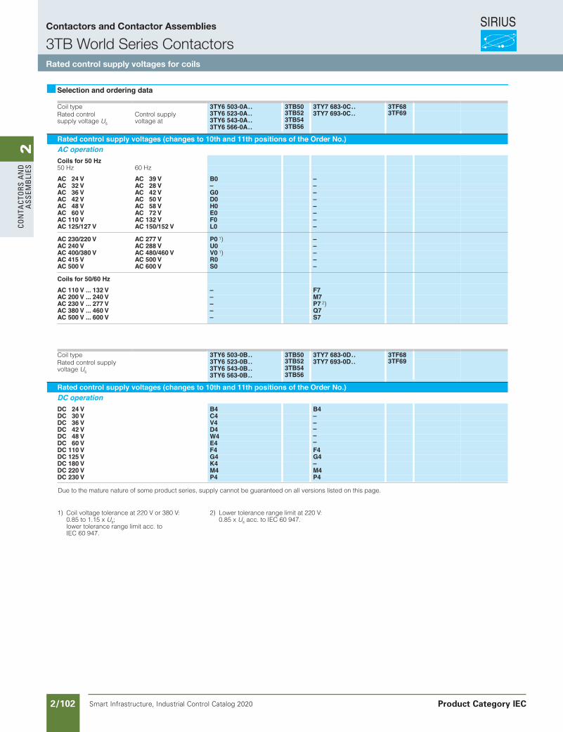
SIRIUS
Smart Infrastructure, Industrial Control Catalog 2020 2/102
2Co
nta
Cto
rs a
nd
a
ssem
bli
es
Siemens / Industrial Controls Previous folio: IC10 2/61
Contactors and Contactor Assemblies
3T Contactors
Rated control supply voltagesfor coils
Coil type
3TY6 503-0A.. 3TY6 523-0A.. 3TY6 543-0A.. 3TY6 566-0A..
3TB50 3TY7 683-0C.. 3TY7 693-0C..
3TF68
Rated control supply voltage
U
s
Control supply voltage at
3TB523TB543TB56
3TF69
Rated control supply voltages (changes to 10th and 11th positions of the Order No.)
AC operation
Coils for 50 Hz
50 Hz 60 Hz
AC 24 V AC 39 V B0 –AC 32 V AC 28 V – –AC 36 V AC 42 V G0 –AC 42 V AC 50 V D0 –AC 48 V AC 58 V H0 –AC 60 V AC 72 V E0 –AC 110 V AC 132 V F0 –AC 125/127 V AC 150/152 V L0 –
AC 230/220 V AC 277 V P0
1
)
–AC 240 V AC 288 V U0 –AC 400/380 V AC 480/460 V V0
1
)
–AC 415 V AC 500 V R0 –AC 500 V AC 600 V S0 –
Coils for 50/60 Hz
AC 110 V ... 132 V – F7AC 200 V ... 240 V – M7AC 230 V ... 277 V – P7
2
)
AC 380 V ... 460 V – Q7AC 500 V ... 600 V – S7
Coil type
3TY6 503-0B.. 3TY6 523-0B.. 3TY6 543-0B.. 3TY6 563-0B..
3TB50 3TY7 683-0D.. 3TY7 693-0D..
3TF68
Rated control supply voltage
U
s
3TB523TB543TB56
3TF69
Rated control supply voltages (changes to 10th and 11th positions of the Order No.)
DC operation
DC 24 V B4 B4DC 30 V C4 –DC 36 V V4 –DC 42 V D4DC 48 V W4DC 60 V E4DC 110 V F4 F4DC 125 V G4 G4DC 180 V K4 –DC 220 V M4 M4DC 230 V P4 P4
Selection and ordering data
1) Coil voltage tolerance at 220 V or 380
Due to the mature nature of some product series, supply cannot be guaranteed on all versions listed on this page.
V:0.85 to 1.15 x Us;lower tolerance range limit acc. to IEC 60 947.
2) Lower tolerance range limit at 220 V:0.85 x Us acc. to IEC 60 947.
–––
Contactors and Contactor Assemblies
3TB World Series ContactorsRated control supply voltages for coils
Product Category IEC
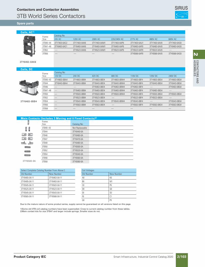
SIRIUS
Smart Infrastructure, Industrial Control Catalog 2020 2/103
2Co
nta
Ctors a
nd
a
ssemb
lies
Siemens / Industrial Controls Previous folio: IC10 2/62
Frame CatalogNo
Size 24VAC 120VAC 208VAC 220/240VAC 277VAC 480VAC 600VAC
3TB40–44 3TY7403-0AC2 3TY7403-0AK6 3TY7403-0AM1 3TY7403-0AP6 3TY7403-0AU1 3TY7403-0AV0 3TY7403-0AS0
3TB47–48 3TY6483-0AC1 3TY6483-0AK6 3TY6483-0AM1 3TY6483-0AP6 3TY6483-0AP0 3TY6483-0AV0 3TY6483-0AS0
3TB52 — 3TY6523-0AK6 3TY6523-0AM1 3TY6523-0AP6 3TY6523-0AP0 3TY6523-0AV0 —
3TB56 — — — — 3TY6566-0AP0 3TY6566-0AV0 3TY6566-0AS0
Frame CatalogNo
Size 12VDC 24VDC 42VDC 48VDC 110VDC 125VDC 240VDC
3TB40–43 3TY4803-0BA4 3TY4803-0BB4 3TY4803-0BD4 3TY4803-0BW4 3TY4803-0BF4 3TY4803-0BG4 3TY4803-0BQ4
3TB44 3TY6443-0BA4 3TY6443-0BB4 3TY6443-0BD4 3TY6443-0BW4 3TY6443-0BF4 3TY6443-0BG4 3TY6443-0BQ4
3TB46 — — 3TY6463-0BD4 3TY6463-0BW4 3TY6463-0BF4 — 3TY6463-0BQ4
3TB47–48 — 3TY6483-0BB4 3TY6483-0BD4 3TY6483-0BW4 3TY6483-0BF4 3TY6483-0BG4 —
3TB50 — 3TY6503-0BB4 3TY6503-0BD4 3TY6503-0BW4 3TY6503-0BF4 3TY6503-0BG4 3TY6503-0BQ4
3TB52 — 3TY6523-0BB4 3TY6523-0BD4 — 3TY6523-0BF4 3TY6523-0BG4 —
3TB54 — 3TY6543-0BB4 3TY6543-0BD4 3TY6543-0BW4 3TY6543-0BF4 — 3TY6543-0BQ4
3TB56 — 3TY6563-0BB4 3TY6563-0BD4 — 3TY6563-0BF4 3TY6563-0BG4 3TY6563-0BQ4
3TB58 — — — — — — — obsolete
Due to the mature nature of some product series, supply cannot be guaranteed on all versions listed on this page.
1)Some old 3TB coil catalog numbers have been superceded. Cross to current catalog number from these tables.2)Main contact kits for size 3TB47 and larger include springs. Smaller sizes do not.
3tY6483-0bb4
Coils, AC1)
3tY6463-0aK6
Coils, DC
SelectCompleteCatalogNumberFromAbove 1)
OldNumber NewNumber
3TY6465-0A†† 3TY6463-0A††
3TY6485-0A†† 3TY6483-0A††
3TY6505-0A†† 3TY6503-0A††
3TY6525-0A†† 3TY6523-0A††
3TY6545-0A†† 3TY6543-0A††
3TY6565-0A†† 3TY6566-0A††
Main Contacts (Includes 3 Moving and 6 Fixed Contacts)2)
Frame Size CatalogNo
3TB40–43 NotReplaceable
3TB44 3TY6440-0A
3TB46 3TY6460-0A
3TB47 3TY6470-0A
3TB48 3TY6480-0A
3TB50 3TY6500-0A
3TB52 3TY6520-0A
3TB54 3TY6540-0A
3TB56 3TY6560-0A
3TB58 3TY6580-0A3TY6500-0A
CoilVoltages
OldNumber NewNumber
A8 K6
B8 M1
C8 P6
D8 Q0
E8 S0
F8 C1
G8 P0
Contactors and Contactor Assemblies
3TB World Series ContactorsSpare parts
Product Category IEC
Page will mess up if shifted left to right
2Co
nta
Ctors a
nd
a
ssemb
lies
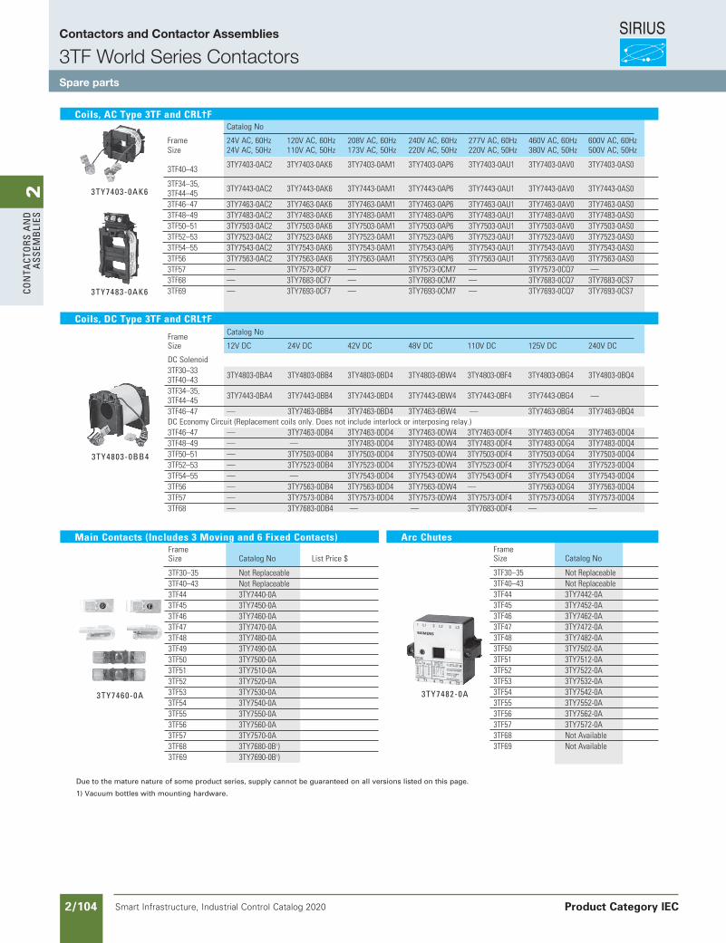
SIRIUS
Smart Infrastructure, Industrial Control Catalog 2020 2/104
2Co
nta
Cto
rs a
nd
a
ssem
bli
es
Frame
CatalogNo
Size 12VDC 24VDC 42VDC 48VDC 110VDC 125VDC 240VDC
DCSolenoid 3TF30–33 3TY4803-0BA4 3TY4803-0BB4 3TY4803-0BD4 3TY4803-0BW4 3TY4803-0BF4 3TY4803-0BG4 3TY4803-0BQ4 3TF40–43 3TF34–35, 3TY7443-0BA4 3TY7443-0BB4 3TY7443-0BD4 3TY7443-0BW4 3TY7443-0BF4 3TY7443-0BG4 — 3TF44–45 3TF46–47 — 3TY7463-0BB4 3TY7463-0BD4 3TY7463-0BW4 — 3TY7463-0BG4 3TY7463-0BQ4 DCEconomyCircuit(Replacementcoilsonly.Doesnotincludeinterlockorinterposingrelay.) 3TF46–47 — 3TY7463-0DB4 3TY7463-0DD4 3TY7463-0DW4 3TY7463-0DF4 3TY7463-0DG4 3TY7463-0DQ4 3TF48–49 — — 3TY7483-0DD4 3TY7483-0DW4 3TY7483-0DF4 3TY7483-0DG4 3TY7483-0DQ4 3TF50–51 — 3TY7503-0DB4 3TY7503-0DD4 3TY7503-0DW4 3TY7503-0DF4 3TY7503-0DG4 3TY7503-0DQ4 3TF52–53 — 3TY7523-0DB4 3TY7523-0DD4 3TY7523-0DW4 3TY7523-0DF4 3TY7523-0DG4 3TY7523-0DQ4 3TF54–55 — — 3TY7543-0DD4 3TY7543-0DW4 3TY7543-0DF4 3TY7543-0DG4 3TY7543-0DQ4 3TF56 — 3TY7563-0DB4 3TY7563-0DD4 3TY7563-0DW4 — 3TY7563-0DG4 3TY7563-0DQ4 3TF57 — 3TY7573-0DB4 3TY7573-0DD4 3TY7573-0DW4 3TY7573-0DF4 3TY7573-0DG4 3TY7573-0DQ4 3TF68 — 3TY7683-0DB4 — — 3TY7683-0DF4 — —
CatalogNo
Frame 24VAC,60Hz 120VAC,60Hz 208VAC,60Hz 240VAC,60Hz 277VAC,60Hz 460VAC,60Hz 600VAC,60Hz Size 24VAC,50Hz 110VAC,50Hz 173VAC,50Hz 220VAC,50Hz 220VAC,50Hz 380VAC,50Hz 500VAC,50Hz 3TF30–33 3TY7403-0AC2 3TY7403-0AK6 3TY7403-0AM1 3TY7403-0AP6 3TY7403-0AU1 3TY7403-0AV0 3TY7403-0AS0 3TF40–43
3TF34–35, 3TY7443-0AC2 3TY7443-0AK6 3TY7443-0AM1 3TY7443-0AP6 3TY7443-0AU1 3TY7443-0AV0 3TY7443-0AS0 3TF44–45 3TF46–47 3TY7463-0AC2 3TY7463-0AK6 3TY7463-0AM1 3TY7463-0AP6 3TY7463-0AU1 3TY7463-0AV0 3TY7463-0AS0 3TF48–49 3TY7483-0AC2 3TY7483-0AK6 3TY7483-0AM1 3TY7483-0AP6 3TY7483-0AU1 3TY7483-0AV0 3TY7483-0AS0 3TF50–51 3TY7503-0AC2 3TY7503-0AK6 3TY7503-0AM1 3TY7503-0AP6 3TY7503-0AU1 3TY7503-0AV0 3TY7503-0AS0 3TF52–53 3TY7523-0AC2 3TY7523-0AK6 3TY7523-0AM1 3TY7523-0AP6 3TY7523-0AU1 3TY7523-0AV0 3TY7523-0AS0 3TF54–55 3TY7543-0AC2 3TY7543-0AK6 3TY7543-0AM1 3TY7543-0AP6 3TY7543-0AU1 3TY7543-0AV0 3TY7543-0AS0 3TF56 3TY7563-0AC2 3TY7563-0AK6 3TY7563-0AM1 3TY7563-0AP6 3TY7563-0AU1 3TY7563-0AV0 3TY7563-0AS0 3TF57 — 3TY7573-0CF7 — 3TY7573-0CM7 — 3TY7573-0CQ7 — 3TF68 — 3TY7683-0CF7 — 3TY7683-0CM7 — 3TY7683-0CQ7 3TY7683-0CS7 3TF69 — 3TY7693-0CF7 — 3TY7693-0CM7 — 3TY7693-0CQ7 3TY7693-0CS7
Coils, AC Type 3TF and CRL†F
3tY7403-0aK6
3tY7483-0aK6
Due to the mature nature of some product series, supply cannot be guaranteed on all versions listed on this page.
1) Vacuum bottles with mounting hardware.
Main Contacts (Includes 3 Moving and 6 Fixed Contacts) Frame Size CatalogNo ListPrice$
3TF30–35 NotReplaceable 3TF40–43 NotReplaceable 3TF44 3TY7440-0A 3TF45 3TY7450-0A 3TF46 3TY7460-0A 3TF47 3TY7470-0A 3TF48 3TY7480-0A 3TF49 3TY7490-0A 3TF50 3TY7500-0A 3TF51 3TY7510-0A 3TF52 3TY7520-0A 3TF53 3TY7530-0A 3TF54 3TY7540-0A 3TF55 3TY7550-0A 3TF56 3TY7560-0A 3TF57 3TY7570-0A 3TF68 3TY7680-0B1) 3TF69 3TY7690-0B1)
3tY7460-0a
Arc Chutes Frame Size CatalogNo
3TF30–35 NotReplaceable 3TF40–43 NotReplaceable 3TF44 3TY7442-0A 3TF45 3TY7452-0A 3TF46 3TY7462-0A 3TF47 3TY7472-0A 3TF48 3TY7482-0A 3TF50 3TY7502-0A 3TF51 3TY7512-0A 3TF52 3TY7522-0A 3TF53 3TY7532-0A 3TF54 3TY7542-0A 3TF55 3TY7552-0A 3TF56 3TY7562-0A 3TF57 3TY7572-0A 3TF68 NotAvailable 3TF69 NotAvailable
3tY7482-0a
Coils, DC Type 3TF and CRL†F
3tY4803-0bb4
Siemens / Industrial Controls Previous folio: IC10 2/63
Page will mess up if shifted left to right
Contactors and Contactor Assemblies
3TF World Series ContactorsSpare parts
Product Category IEC
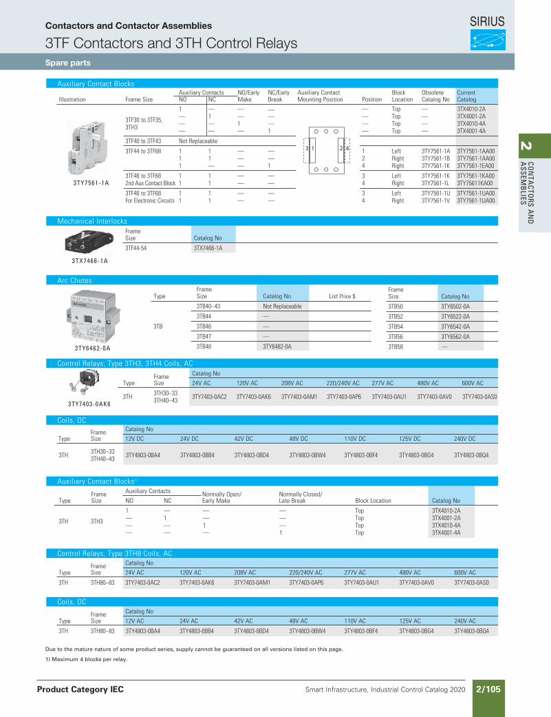
SIRIUS
Smart Infrastructure, Industrial Control Catalog 2020 2/105
2Co
nta
Ctors a
nd
a
ssemb
lies
Siemens / Industrial Controls Previous folio: IC10 2/64
AuxiliaryContactBlocks AuxiliaryContacts NO/Early NC/Early AuxiliaryContact Block Obsolete Current
Illustration FrameSize NO NC Make Break MountingPosition Position Location CatalogNo Catalog
1 — — — — Top — 3TX4010-2A 3TF30to3TF35, — 1 — — — Top — 3TX4001-2A 3TH3 — — 1 — — Top — 3TX4010-4A — — — 1 — Top — 3TX4001-4A
3TF40to3TF43 NotReplaceable
3TF44to3TF68 1 1 — — 1 Left 3TY7561-1A 3TY7561-1AA00 1 1 — — 2 Right 3TY7561-1B 3TY7561-1AA00 1 — — 1 4 Right 3TY7561-1K 3TY7561-1EA00
3TF46to3TF68 1 1 — — 3 Left 3TY7561-1K 3TY7561-1KA00 2ndAuxContactBlock 1 1 — — 4 Right 3TY7561-1L 3TY75611KA00
3TF46to3TF68 1 1 — — 3 Left 3TY7561-1U 3TY7561-1UA00 ForElectronicCircuits 1 1 — — 4 Right 3TY7561-1V 3TY7561-1UA00
3 1 2 4
3tY7561-1a
MechanicalInterlocks Frame Size CatalogNo
3TF44-54 3TX7466-1A
Frame Size CatalogNo
3TB50 3TY6502-0A
3TB52 3TY6522-0A
3TB54 3TY6542-0A
3TB56 3TY6562-0A
3TB58 —
Frame Type Size CatalogNo ListPrice$
3TB40–43 NotReplaceable
3TB44 —
3TB 3TB46 —
3TB47 —
3TB48 3TY6482-0A
ArcChutes
3tY6462-0a
Frame CatalogNo
Type Size 24VAC 120VAC 208VAC 220/240VAC 277VAC 480VAC 600VAC
3TH 3TH30–33 3TY7403-0AC2 3TY7403-0AK6 3TY7403-0AM1 3TY7403-0AP6 3TY7403-0AU1 3TY7403-0AV0 3TY7403-0AS0 3TH40–433tY7403-0aK6
ControlRelays,Type3TH3,3TH4Coils,AC
Frame CatalogNo
Type Size 12VDC 24VDC 42VDC 48VDC 110VDC 125VDC 240VDC
3TH 3TH30–33 3TY4803-0BA4 3TY4803-0BB4 3TY4803-0BD4 3TY4803-0BW4 3TY4803-0BF4 3TY4803-0BG4 3TY4803-0BQ4 3TH40–43
Coils,DC
Frame CatalogNo List
Type Size 24VAC 120VAC 208VAC 220/240VAC 277VAC 480VAC 600VAC Price$
3TH 3TH80–83 3TY7403-0AC2 3TY7403-0AK6 3TY7403-0AM1 3TY7403-0AP6 3TY7403-0AU1 3TY7403-0AV0 3TY7403-0AS0
Frame CatalogNo List
Type Size 12VAC 24VAC 42VAC 48VAC 110VAC 125VAC 240VAC Price$
3TH 3TH80–83 3TY4803-0BA4 3TY4803-0BB4 3TY4803-0BD4 3TY4803-0BW4 3TY4803-0BF4 3TY4803-0BG4 3TY4803-0BQ4
AuxiliaryContactBlocks1)
Frame AuxiliaryContacts NormallyOpen/ NormallyClosed/ Type Size NO NC EarlyMake LateBreak BlockLocation CatalogNo
1 — — — Top 3TX4010-2A3TH 3TH3 — 1 — — Top 3TX4001-2A — — 1 — Top 3TX4010-4A — — — 1 Top 3TX4001-4A
Coils,DC
ControlRelays,Type3TH8Coils,AC
Due to the mature nature of some product series, supply cannot be guaranteed on all versions listed on this page.
1) Maximum 4 blocks per relay.
Page will mess up if shifted left to right
3tX7466-1a
Contactors and Contactor Assemblies
3TF Contactors and 3TH Control RelaysSpare parts
Product Category IEC
2Co
nta
Ctors a
nd
a
ssemb
lies
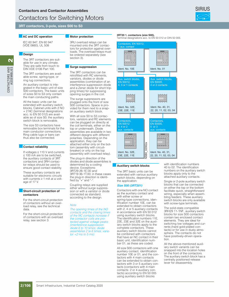
SIRIUS
Smart Infrastructure, Industrial Control Catalog 2020 2/106
2Co
nta
Cto
rs a
nd
a
ssem
bli
es
Siemens / Industrial Controls Previous folio: IC10 2/65
IEC 60 947, EN 60 947 (VDE 0660), UL 508
The 3RT contactors are suit-able for use in any climate. They are safe from touch to DIN VDE 0106 Part 100.
The 3RT contactors are avail-able screw, spring-type, or ring lug connections. An auxiliary contact is inte-grated in the basic unit of size S00 contactors. The basic units of sizes S0 to S3 only contain the main conducting paths.
All the basic units can be extended with auxiliary switch blocks. Cabinet units with 2 NO + 2 NC (terminal designations acc. to EN 50 012) are avail-able as of size S0; the auxiliary switch block is removable.
The size S3 contactors have removable box terminals for the main conductor connections. Ring cable lugs or bars can thus also be connected.
If voltages ≤ 110 V and currents ≤ 100 mA are to be switched, the auxiliary contacts of 3RTcontactors and 3RH contac-tor relays should be used to ensure good contact stability.
These auxiliary contacts are suitable for electronic circuits with currents ≥ 1 mA at a volt-age of 17 V.
For the short-circuit protection of contactors without an over-load relay, see the technical data.
For the short-circuit protection of contactors with an overload relay, see section 3.
3RU overload relays can be mounted onto the 3RT contac-tors for protection against over-loads. The overload relays must be ordered separately (see section 3).
The 3RT contactors can be retrofitted with RC elements, varistors, diodes or diode assemblies (combination of an interference suppression diode and a Zener diode for short trip-ping times) for suppressing opening surges in the coil.
The surge suppressors are plugged onto the front of size S00 contactors. Space is pro-vided for them next to a snap-on auxiliary switch block.
With all size S0 to S3 contac-tors, varistors and RC elements can be plugged on directly at the coil terminals, either on the top or underneath. Diode assemblies are available in two different designs with different polarities. Depending on the application, they can be attached either only on the bot-tom (assembly with circuit-breaker) or only on the top (assembly with overload relay).
The plug-in direction of the diodes and diode assemblies is determined by a coding device. Exceptions: 3RT29 26-1E.00 and 3RT19 36-1T.00; in these cases the plug-in direction is identi-fied by "+" and "–".
Coupling relays are supplied either without surge suppres-sion or with a varistor or diode connected as standard, according to the design.
NoteThe opening times of the NO contacts and the closing times of the NC contacts increase if the contactor coils are pro-tected against voltage peaks (interference suppression diode 6 to 10 times; diode assemblies 2 to 6 times; varis-tor +2 ms to 5 ms).
The 3RT basic units can be extended with various auxiliary switch blocks, depending on the application:
Size S00 (3RT201)Contactors with one NO contact as the auxiliary contact and with either screw or spring-type connections, iden-tification number 10E, can be extended to obtain contactors with 2, 4 or 5 auxiliary contacts in accordance with EN 50 012 using auxiliary switch blocks. The identification numbers 11E, 22E, 23E and 32E on the auxil-iary switch blocks apply to the complete contactors. These auxiliary switch blocks cannot be combined with contactors that have an NC contact in their basic unit, identification num-ber 01, as these are coded.
All size S00 contactors with one auxiliary contact, identification number 10E or 01, and the con-tactors with 4 main contacts can be extended to obtain con-tactors with 3 or 5 auxiliary con-tacts (contactors with 4 main contacts: 2 or 4 auxiliary con-tacts) according to EN 50 005 using auxiliary switch blocks
with identification numbers 40 to 02. The identification numbers on the auxiliary switch blocks apply only to the attached auxiliary contacts.
Single or 2-pole auxiliary switch blocks that can be connected on either the top or the bottom facilitate quick, straightforward wiring, especially when assem-bling feeders. These auxiliary switch blocks are only available with screw-type terminals.
The solid-state compatible 3RH29 11-1NF.. auxiliary switch blocks for size S00 contactors contain two enclosed contact elements. They are ideal for switching low voltages and cur-rents (hard gold-plated con-tacts) or for use in dusty atmo-sphere. The contacts do not have positively-driven opera-tion.
All the above-mentioned auxil-iary switch variants can be snapped into the location holes on the front of the contactors. The auxiliary switch block has a centrally positioned release lever for disassembly.
AC and DC operation
Design
Contact reliability
Short-circuit protection of contactors
Motor protection
Surge suppression
3RT20 1. contactors (size S00), Terminal designations acc. to EN 50 012 or DIN 50 005.
Auxiliary switch blocks
NS
B0_
0206
2a
Contactors, EN 50012, 1 aux. contact
Ident. No. 01Ident. No. 10E
Ident. No. 32E, 23E, 22E, 11E
Aux. switch blocks,EN 50012,4, 3 or 1 contacts
Ident. No. 40, 31, 22, 20, 11, 02, 03, 04
Aux. switch blocks,EN 50005,4 or 2 contacts
Ident. No. 32E, 23E, 22E, 11E
Contactors,EN 500125, 4 or 2aux. contacts
Ident. No. 40, 31, 22, 20, 11, 02, 03, 04
Contactors,EN 50005,5 or 3 aux. contacts
Contactors and Contactor Assemblies
Contactors for Switching Motors3RT contactors, 3-pole, sizes S00 to S3
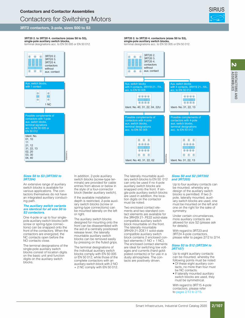
SIRIUS
Smart Infrastructure, Industrial Control Catalog 2020 2/107
2Co
nta
Ctors a
nd
a
ssemb
lies
Siemens / Industrial Controls Previous folio: IC10 2/66
Sizes S0 to S3 (3RT202 to 3RT204)An extensive range of auxiliary switch blocks is available for various applications. The con-tactors themselves do not have an integrated auxiliary conduct-ing path.
The auxiliary switch variants are identical for all size S0 to S3 contactors.One 4-pole or up to four single-pole auxiliary switch blocks (with screw or spring-type connec-tions) can be snapped onto the front of the contactors. When the contactors are energized, the NC contacts open before the NO contacts close.
The terminal designations of the single-pole auxiliary switch blocks consist of location digits on the basic unit and function digits on the auxiliary switch blocks.
In addition, 2-pole auxiliary switch blocks (screw-type ter-minals) are provided for cable entries from above or below in the style of a four-connector block (feeder auxiliary switch).
If the available installation depth is restricted, 2-pole auxil-iary switch blocks (screw or spring-type connections) can be mounted laterally on the left or right.
The auxiliary switch blocks designed for mounting onto the front can be disassembled with the aid of a centrally positioned release lever; the laterally mountable auxiliary switch blocks can be removed easily by pressing on the fluted grips.
The terminal designations of the individual auxiliary switch blocks comply with EN 50 005 or EN 50 012, while those of the complete contactors with an auxiliary switch block with 2 NO + 2 NC comply with EN 50 012.
The laterally mountable auxil-iary switch blocks to EN 50 012 can only be used if no 4-pole auxiliary switch blocks are snapped onto the front. If sin-gle-pole auxiliary switch blocks are used in addition, the loca-tion digits on the contactor must be noted.
Two enclosed contact ele-ments and two standard con-tact elements are available for the 3RH29 21-.FE22 solid-state compatible auxiliary switch block mountable on the front. The laterally mountable 3RH29 21-2DE11 solid-state compatible auxiliary switch block contains 2 enclosed con-tact elements (1 NO + 1 NC). The enclosed contact elements are ideal for switching low volt-ages and currents (hard gold-plated contacts) or for use in a dusty atmosphere. The con-tacts are positively driven.
Sizes S0 and S2 (3RT202 and 3RT203)Up to four auxiliary contacts can be mounted, whereby any design of the auxiliary switch blocks is permitted. If two 2-pole, laterally mounted, auxil-iary switch blocks are used, one must be mounted on the left and one on the right for the sake of symmetry.
Under certain circumstances, more auxiliary contacts are allowed for size S2 (please ask for details).
With regard to 3RT23 and 3RT24 4-pole contactors, please refer to pages 2/12 to 2/14.
Sizes S3 to S12 (3RT204 to 3RT107)Up to eight auxiliary contacts can be mounted, whereby the following points must be noted:• Of these eight auxiliary con-
tacts, no more than four must be NC contacts.
• If laterally mounted auxiliary switch blocks are used, they must be symmetrical.
With regard to 3RT15 4-pole contactors, please refer
3RT20 2. to 3RT20 4. contactors (sizes S0 to S3), single-pole auxiliary switch blocks, terminal designations acc. to EN 50 005 or EN 50 012.
3RT20 2. to 3RT20 4. contactors (sizes S0 to S3), single-pole auxiliary switch blocks, terminal designations acc. to EN 50 005 or EN 50 012.
1 NC
to pages 2/13 to 2/15.
Contactors and Contactor Assemblies
Contactors for Switching Motors3RT2 contactors, 3-pole, sizes S00 to S3
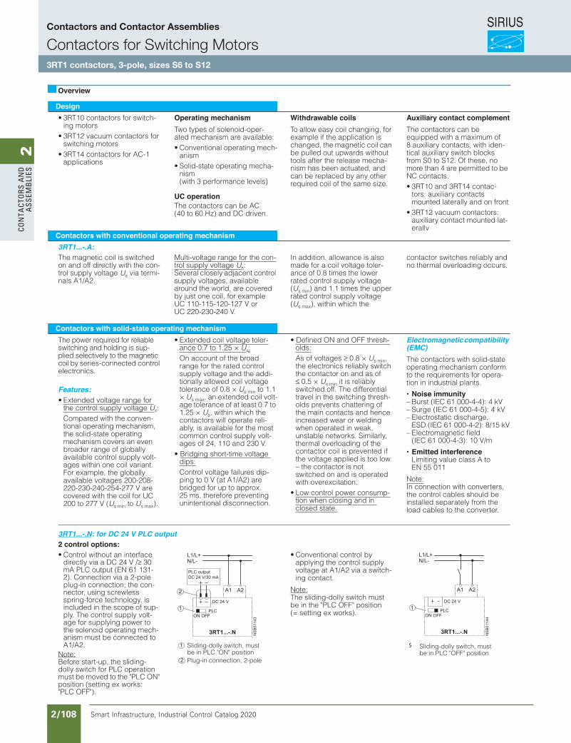
SIRIUS
Smart Infrastructure, Industrial Control Catalog 2020 2/108
2Co
nta
Cto
rs a
nd
a
ssem
bli
es
Siemens / Industrial Controls Previous folio: IC10 2/67
Design• 3RT10 contactors for switch-
ing motors• 3RT12 vacuum contactors for
switching motors• 3RT14 contactors for AC-1
applications
Operating mechanismTwo types of solenoid-oper-ated mechanism are available:• Conventional operating mech-
anism• Solid-state operating mecha-
nism(with 3 performance levels)
UC operationThe contactors can be AC (40 to 60 Hz) and DC driven.
Withdrawable coilsTo allow easy coil changing, for example if the application is changed, the magnetic coil can be pulled out upwards without tools after the release mecha-nism has been actuated, and can be replaced by any other required coil of the same size.
Auxiliary contact complementThe contactors can be equipped with a maximum of 8 auxiliary contacts, with iden-tical auxiliary switch blocks from S0 to S12. Of these, no more than 4 are permitted to be NC contacts.• 3RT10 and 3RT14 contac-
tors: auxiliary contacts mounted laterally and on front
• 3RT12 vacuum contactors: auxiliary contact mounted lat-erally
Contactors with conventional operating mechanism3RT1...-.A:The magnetic coil is switched on and off directly with the con-trol supply voltage Us via termi-nals A1/A2.
Multi-voltage range for the con-trol supply voltage Us:Several closely adjacent control supply voltages, available around the world, are covered by just one coil, for example UC 110-115-120-127 V or UC 220-230-240 V.
In addition, allowance is also made for a coil voltage toler-ance of 0.8 times the lower rated control supply voltage (Us min) and 1.1 times the upper rated control supply voltage (Us max), within which the
contactor switches reliably and no thermal overloading occurs.
Contactors with solid-state operating mechanismThe power required for reliable switching and holding is sup-plied selectively to the magnetic coil by series-connected control electronics.
Features:• Extended voltage range for
the control supply voltage Us:Compared with the conven-tional operating mechanism, the solid-state operating mechanism covers an even broader range of globally available control supply volt-ages within one coil variant. For example, the globally available voltages 200-208-220-230-240-254-277 V are covered with the coil for UC 200 to 277 V (Us min to Us max).
• Extended coil voltage toler-ance 0.7 to 1.25 × Us:On account of the broad range for the rated control supply voltage and the addi-tionally allowed coil voltage tolerance of 0.8 × Us min to 1.1 × Us max, an extended coil volt-age tolerance of at least 0.7 to 1.25 × Us, within which the contactors will operate reli-ably, is available for the most common control supply volt-ages of 24, 110 and 230 V.
• Bridging short-time voltage dips:Control voltage failures dip-ping to 0 V (at A1/A2) are bridged for up to approx. 25 ms, therefore preventing unintentional disconnection.
• Defined ON and OFF thresh-olds:As of voltages ≥ 0.8 × Us min,the electronics reliably switch the contactor on and as of ≤ 0.5 × Us min it is reliably switched off. The differential travel in the switching thresh-olds prevents chattering of the main contacts and hence increased wear or welding when operated in weak, unstable networks. Similarly, thermal overloading of the contactor coil is prevented if the voltage applied is too low – the contactor is not switched on and is operated with overexcitation.
• Low control power consump-tion when closing and in closed state.
Electromagnetic compatibility (EMC)The contactors with solid-state operating mechanism conform to the requirements for opera-tion in industrial plants.
• Noise immunity– Burst (IEC 61 000-4-4): 4 kV– Surge (IEC 61 000-4-5): 4 kV– Electrostatic discharge,
ESD (IEC 61 000-4-2): 8/15 kV– Electromagnetic field
(IEC 61 000-4-3): 10 V/m
• Emitted interferenceLimiting value class A to EN 55 011
Note:In connection with converters, the control cables should be installed separately from the load cables to the converter.
3RT1...-.N: for DC 24 V PLC output2 control options:• Control without an interface
directly via a DC 24 V /≥ 30mA PLC output (EN 61 131-2). Connection via a 2-pole plug-in connection; the con-nector, using screwless spring-force technology, is included in the scope of sup-ply. The control supply volt-age for supplying power to the solenoid operating mech-anism must be connected to A1/A2.
Note:Before start-up, the sliding-dolly switch for PLC operation must be moved to the "PLC ON" position (setting ex works: "PLC OFF").
• Conventional control by applying the control supply voltage at A1/A2 via a switch-ing contact.
Note:The sliding-dolly switch must be in the "PLC OFF" position (= setting ex works).
Overview
Sliding-dolly switch, must be in PLC "ON" positionPlug-in connection, 2-pole
Sliding-dolly switch, must be in PLC "OFF" position
$
Contactors and Contactor Assemblies
Contactors for Switching Motors3RT1 contactors, 3-pole, sizes S6 to S12
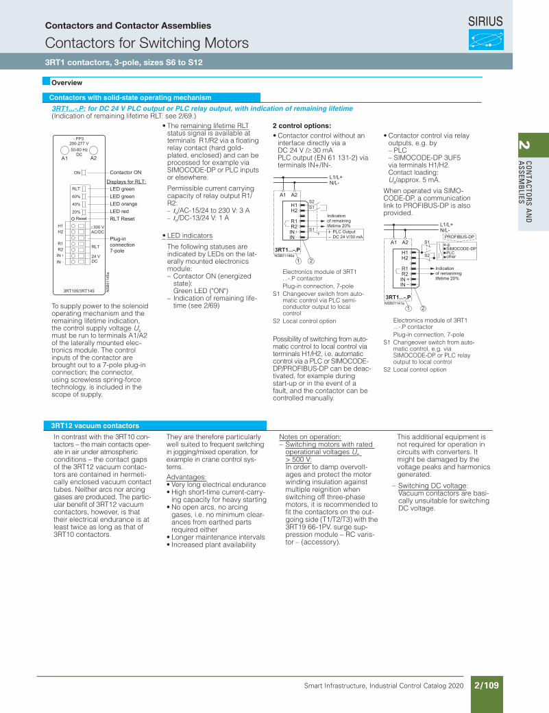
SIRIUS
Smart Infrastructure, Industrial Control Catalog 2020 2/109
2Co
nta
Ctors a
nd
a
ssemb
lies
Contactors with solid-state operating mechanism
3RT1...-.P: for DC 24 V PLC output or PLC relay output, with indication of remaining lifetime(Indication of remaining lifetime RLT: see 2/69.)
• The remaining lifetime RLTstatus signal is available at terminals R1/R2 via a floating relay contact (hard gold-plated, enclosed) and can be processed for example via SIMOCODE-DP or PLC inputs or elsewhere.
Permissible current carrying capacity of relay output R1/R2:– Ie/AC-15/24 to 230 V: 3 A– Ie/DC-13/24 V: 1 A
• LED indicators
The following statuses are indicated by LEDs on the lat-erally mounted electronics module:– Contactor ON (energized
state):Green LED ("ON")
– Indication of remaining life-time (see 2/69)
2 control options:
To supply power to the solenoid operating mechanism and the remaining lifetime indication, the control supply voltage Usmust be run to terminals A1/A2 of the laterally mounted elec-tronics module. The control inputs of the contactor are brought out to a 7-pole plug-in connection; the connector, using screwless spring-force technology, is included in the scope of supply.
• Contactor control without an interface directly via a DC 24 V /≥ 30 mA PLC output (EN 61 131-2) via terminals IN+/IN-.
Possibility of switching from auto-matic control to local control via terminals H1/H2, i.e. automatic control via a PLC or SIMOCODE-DP/PROFIBUS-DP can be deac-tivated, for example during start-up or in the event of a fault, and the contactor can be controlled manually.
• Contactor control via relay outputs, e.g. by – PLC– SIMOCODE-DP 3UF5 via terminals H1/H2. Contact loading: Us/approx. 5 mA.
When operated via SIMO-CODE-DP, a communication link to PROFIBUS-DP is also provided.
3RT1...-.Q: communication-capable with integrated AS-Interface and indication of remaining lifetime
To supply power to the solenoid operating mechanism and the remaining lifetime indication, the control supply voltage Usmust be run to terminals A1/A2 of the laterally mounted elec-tronics module. The contactor itself is controlled via the inte-grated AS-Interface.
Inputs and outputs are brought out to a 10-pole plug-in connec-tion; the connectors (6-pole for external connection and 4-pole for an AS-Interface) using screwless spring-force technol-ogy, are included in the scope of supply.
• LED indicators:
The following statuses are indicated by LEDs on the lat-erally mounted electronics module:– Contactor ON (energized
state):Green LED ("ON")
– Automatic/local control: Green LED ("AUTO")
– Bus status: Green/red dual LED ("AS-i")
– Remaining lifetime RLT (see separate description 2/16)
• AS-Interface address jack "ADDR":
The contactor address can be assigned in the built-in state.
Control circuit:
• Contactor control through AS-Interface via terminals AS-i+/AS-i–. Terminals AS-i+ and AS-i– are each brought out twice to a 4-pole connec-tor separate from the other control inputs and are jum-pered.
Advantages:– The AS-Interface cable is
not interrupted when the connector is removed
– The contactor remains capable of operation via the local control inputs via its own 6-pole connector.
• Control signals via AS-i:– Contactor ON/OFF
• Status signals via AS-i:– Contactor ON/OFF– Automatic/local control– Remaining lifetime RLT– Signal via free input, e.g.
overload relay tripped.
Possibility of switching from automatic control to to local control via terminals H1/H2/H3, i.e. automatic control via AS-Interface can be deactivated, for example during start-up up or in the event of a fault, and the contactor can be controlled manually.
Overview
Electronics module of 3RT1 ...-.P contactorPlug-in connection, 7-pole
S1 Changeover switch from auto-matic control via PLC semi-conductor output to local control
S2 Local control option Electronics module of 3RT1 ...-.P contactorPlug-in connection, 7-pole
S1 Changeover switch from auto-matic control, e.g. via SIMOCODE-DP or PLC relay output to local control
S2 Local control option
Electronics module of 3RT1 ...-.Q contactorPlug-in connection, 6-polePlug-in connection, 4-pole
S1 Changeover switch from auto-matic control, e.g. via AS-Interface, to local control· S1 open: automatic mode
S2 Local control option
$
%
&
Siemens / Industrial Controls Previous folio: IC10 2/68
Contactors for Switching Motors
Contactors and Contactor Assemblies
3RT1 contactors, 3-pole, sizes S6 to S12
Actuator-Sensor-Interface
Technical data
I/O configuration (hex) ID code (hex)
7 F
Power supply
V 26.5 to 31.6 (in accordance with AS-Interface specification)
AS-Interface current input
mA max. 20
Contact loading at SF1/2
mA 3 to 6
Watchdog function
(disconnection of outputs in event of AS-Interface fault) Built-in
Indication
During operation, the LEDs on the contactor indicate the states shown opposite.
Diagnosing the contactors using the application program
• Inputs • Outputs
Input signals Device status Output signals Device status
DI0 "ready" 0 Device not ready/manual operation DO0 "running" 0 Contactor off1 Device ready/automatic operation 1 Contactor on
DI1 "running" 0 Contactor off DO1 0 –1 Contactor on 1 –
DI2 "remaining lifetime" 0 Remaining lifetime RLT > 20 % DO2 0 –1 Remaining lifetime RLT
≤
20 % 1 –DI3 "free input" 0 No input signal at SF1/2 DO3 0 –
1 Input signal at SF1/2 1 –
Indication of remaining lifetime (RLT)
Main contactor contacts are wearing parts and must be replaced in good time when they reach the end of their ser-vice life. The degree of erosion of the contact material and hence the electrical endurance (= number of make-break oper-ations) varies, depending on the loading, utilization category, duty type etc. Routine inspec-tions/visual checks by mainte-nance staff are needed in order to determine the state of the main contacts. The "remaining lifetime indication" facility takes over this task. This does not comprise counting the make-break
operations – these offer no information about contact wear – but instead entails determin-ing and evaluating the actual progress of erosion of each of the three main contacts by electronic means; the results are stored, and a warning is issued when specified limits are reached. Even if the control supply voltage at A1/A2 fails, the stored data is not lost. After the main contacts are replaced, measurement of the remaining lifetime must be reset with the "RESET" button (hold down the RESET button for approx. 2 sec. with a ball-point pen or similar tool).
Advantages:• Signalling via a relay contact
or AS-i when a remaining life-time of 20 % is reached, i. e. when the contact material is 80 % worn.
• Additional visual indication of various levels of erosion via LEDs on the laterally mounted electronics modules when a remaining lifetime of 60 % (green), 40 % (orange) and 20 % (red) is reached.
• Advice to change contacts at the appropriate time.
• Optimum utilization of the contact material.
• Visual inspection of the condi-tion of contacts no longer necessary.
• Reduction of ongoing operat-ing costs.
• Optimum planning of mainte-nance measures.
• Avoidance of unforeseen plant stoppages.
3RT12 vacuum contactors
In contrast with the 3RT10 con-tactors – the main contacts oper-ate in air under atmospheric conditions – the contact gaps of the 3RT12 vacuum contac-tors are contained in hermeti-cally enclosed vacuum contact tubes. Neither arcs nor arcing gases are produced. The partic-ular benefit of 3RT12 vacuum contactors, however, is that their electrical endurance is at least twice as long as that of 3RT10 contactors.
They are therefore particularly well suited to frequent switching in jogging/mixed operation, for example in crane control sys-tems.Advantages:• Very long electrical endurance• High short-time current-carry-
ing capacity for heavy starting• No open arcs, no arcing
gases, i.e. no minimum clear-ances from earthed parts required either
• Longer maintenance intervals• Increased plant availability
Notes on operation:– Switching motors with rated
operational voltages
U
e
> 500 V:In order to damp overvolt-ages and protect the motor winding insulation against multiple reignition when switching off three-phase motors, it is recommended to fit the contactors on the out-going side (T1/T2/T3) with the 3RT19 66-1PV. surge sup-pression module – RC varis-tor – (accessory).
This additional equipment is not required for operation in circuits with converters. It might be damaged by the voltage peaks and harmonics generated.
– Switching DC voltage:Vacuum contactors are basi-cally unsuitable for switching DC voltage.
Overview
LED Statuses Status description
AS-Interface ON ON Flashing Flashing
Station address 0No AS-Interface communicationAS-Interface communication OK
greenredyellow
Contactors and Contactor Assemblies
Contactors for Switching Motors3RT1 contactors, 3-pole, sizes S6 to S12
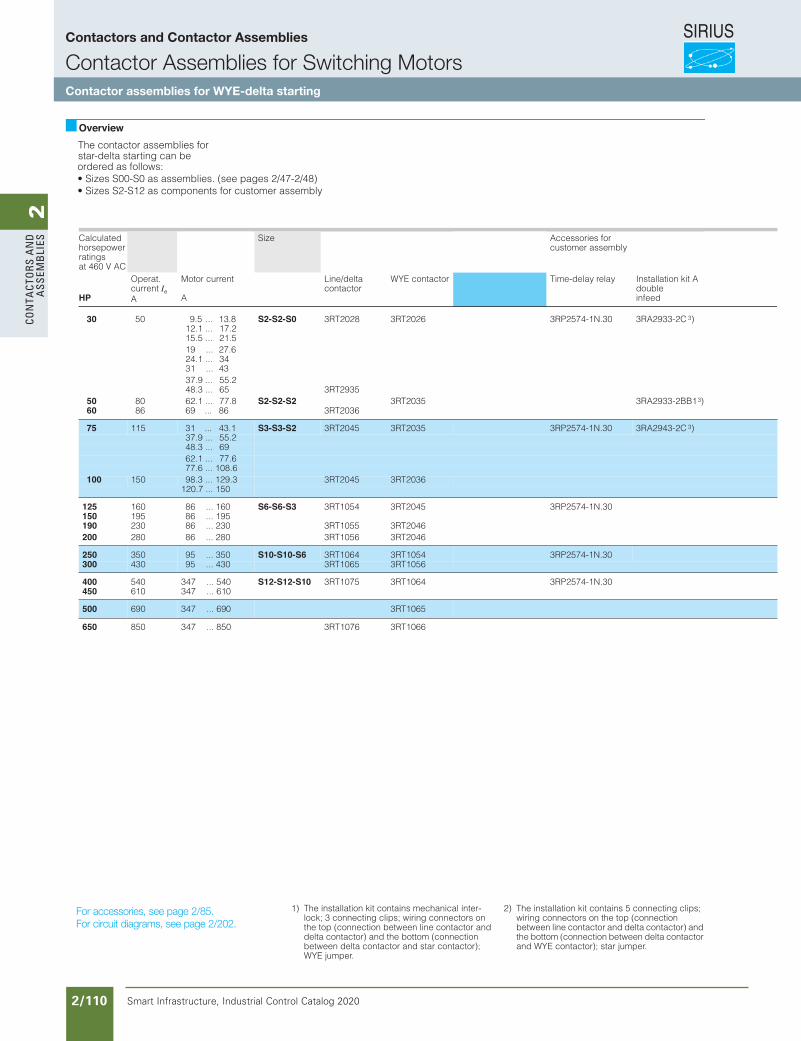
SIRIUS
Smart Infrastructure, Industrial Control Catalog 2020 2/110
2Co
nta
Cto
rs a
nd
a
ssem
bli
es
Siemens / Industrial Controls Previous folio: IC10 2/74
OverviewThe contactor assemblies for star-delta starting can be ordered as follows:• Sizes S00-S0 as assemblies. (see pages 2/47-2/48)• Sizes S2-S12 as components for customer assembly
Calculated horsepowerratingsat 460 V AC
Size Accessories for customer assembly
HP
Operat. current IeA
Motor current
A
Line/delta contactor
WYE contactor Time-delay relay Installation kit A doubleinfeed
30 50 9.5 ... 13.8 S2-S2-S0 3RT2028 3RT2026 3RP2574-1N.30 3RA2933-2C 3)12.1 ... 17.215.5 ... 21.519 ... 27.624.1 ... 3431 ... 4337.9 ... 55.248.3 ... 65 3RT2935
50 80 62.1 ... 77.8 S2-S2-S2 3RT2035 3RA2933-2BB13)60 86 69 ... 86 3RT2036
75 115 31 ... 43.1 S3-S3-S2 3RT2045 3RT2035 3RP2574-1N.30 3RA2943-2C 3)37.9 ... 55.248.3 ... 6962.1 ... 77.677.6 ... 108.6
100 150 98.3 ... 129.3 3RT2045 3RT2036120.7 ... 150
125 160 86 ... 160 S6-S6-S3 3RT1054 3RT2045 3RP2574-1N.30150 195 86 ... 195190 230 86 ... 230 3RT1055 3RT2046200 280 86 ... 280 3RT1056 3RT2046
250 350 95 ... 350 S10-S10-S6 3RT1064 3RT1054 3RP2574-1N.30300 430 95 ... 430 3RT1065 3RT1056
400 540 347 ... 540 S12-S12-S10 3RT1075 3RT1064 3RP2574-1N.30450 610 347 ... 610
500 690 347 ... 690 3RT1065
650 850 347 ... 850 3RT1076 3RT1066
For accessories, see page 2/50.For circuit diagrams, see page 2/162.
1) The installation kit contains mechanical inter-lock; 3 connecting clips; wiring connectors on the top (connection between line contactor and delta contactor) and the bottom (connection between delta contactor and star contactor); WYE jumper.
2) The installation kit contains 5 connecting clips; wiring connectors on the top (connection between line contactor and delta contactor) and the bottom (connection between delta contactor and WYE contactor); star jumper.
For accessories, see page 2/85.For circuit diagrams, see page 2/202.
Contactors and Contactor Assemblies
Contactor Assemblies for Switching MotorsContactor assemblies for WYE-delta starting
Revised on 02/26/18
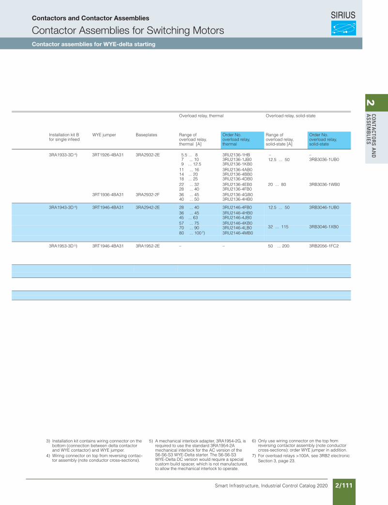
SIRIUS
Smart Infrastructure, Industrial Control Catalog 2020 2/111
2Co
nta
Ctors a
nd
a
ssemb
lies
Siemens / Industrial Controls Previous folio: IC10 2/75
3) Installation kit contains wiring connector on the bottom (connection between delta contactor and WYE contactor) and WYE jumper.
4) Wiring connector on top from reversing contac-tor assembly (note conductor cross-sections).
5) A mechanical interlock adapter, 3RA1954-2G, is required to use the standard 3RA1954-2A mechanical interlock for the AC version of the S6-S6-S3 WYE-Delta starter. The S6-S6-S3 WYE-Delta DC version would require a special custom build spacer, which is not manufactured,to allow the mechanical interlock to operate.
6) Only use wiring connector on the top fr
7) For overload relays >100A, see 3RB2 electronic Section 3, page 23.
om reversing contactor assembly (note conductor cross-sections); order WYE jumper in addition.
Overload relay, thermal Overload relay, solid-state
Installation kit B for single infeed
WYE jumper Baseplates Range of overload relay, thermal [A]
Order No. overload relay, thermal
Range of overload relay, solid-state [A]
Order No. overload relay, solid-state
3RA1933-3D 4) 3RT1926-4BA31 3RA2932-2E 5.5 ... 8 3RU2136-1HB ––7 ... 10 3RU2136-1JB0 3RB3036-1UB09 ... 12.5 3RU2136-1KB0
11 ... 16 3RU2136-4AB014 ... 20 3RU2136-4BB018 ... 25 3RU2136-4DB022 ... 32 3RU2136-4EB0 20 ... 80
12.5 ... 50
3RB3036-1WB028 ... 40 3RU2136-4FB0
3RT1936-4BA31 3RA2932-2F 36 ... 45 3RU2136-4GB040 ... 50 3RU2136-4HB0
3RA1943-3D 4) 3RT1946-4BA31 3RA2942-2E 12.5 ... 50 3RB3046-1UB028 ... 40 3RU2146-4FB036 ... 45 3RU2146-4HB045 ... 63 3RU2146-4JB0
32 ... 115 3RB3046-1XB057 ... 75 3RU2146-4KB070 ... 90 3RU2146-4LB080 ... 100 3RU2146-4MB0
3RA1953-3D 5) 3RT1946-4BA31 3RA1952-2E – – 50 ... 200 3RB2056-1FC2
7)
Contactors and Contactor Assemblies
Contactor Assemblies for Switching MotorsContactor assemblies for WYE-delta starting
Revised on 12/27/18

SIRIUS
Smart Infrastructure, Industrial Control Catalog 2020 2/112
2Co
nta
Cto
rs a
nd
a
ssem
bli
es
Siemens / Industrial Controls Previous folio: IC10 2/73
WYE-delta starting can only be used either if the motor normally operates in a d (delta) connec-tion or starts softly or if the load torque during * starting is low and does not increase sharply. On the *step the motors can carry approximately 50% (class KL 16) or 30% (class KL 10) of their rated torque; the starting torque is approximately 1/3 of that during direct on-line start-ing. The starting current is approximately 2 to 2.7 times the rated motor current.
The changeover from * to dmust not be effected until the motor has run up to rated speed. Drives which require this changeover to be performed earlier are unsuitable for WYE-delta starting.
The ratings given in the above table are only applicable to mo-tors with a starting current ratio of IA ≤8.4 × IN and using either a 3RT19 16-2G or 3RT19 26-2G solid-state time-delay auxiliary switch block with a WYE-delta function or a 3RP1574 WYE-delta time-delay relay with a dead interval of approximately 50 ms on reversing.For the circuit diagrams for the main and control circuits, see page 2/161. The size selected for the installation kits for WYE-delta starting is determined by the line contactor.
Components for customer as-semblyInstallation kits with wiring con-nectors and, if necessary, mechanical connectors are available for contactor assem-blies for WYE-delta starting. Contactors, overload relays, star-delta time-delay relays and auxiliary switches for the elec-trical interlock – if required also feeder terminals, mechanical interlocks 1) and baseplates – must be ordered separately.The wiring installation kits for sizes S00 and S0 contain the top and bottom main conduct-ing path connections between the line and delta contactors (top) and between the delta and WYE contactors (bottom).In the case of sizes S2 to S12 only the bottom main conduct-ing path connection between the delta and WYE contactors is included in the wiring connec-tor, owing to the larger conduc-tor cross-section at the infeed.
Motor protection
Overload relays or thermistor motor protection tripping units can be used for overload pro-tection.The overload relay can be ei-ther mounted onto the line con-tactor or separately fitted. It must be set to 0.58 times the rated motor current.
Sizes S00 to S3
All contactor assemblies can be fitted with RC elements, varistors or diode assemblies for damping opening surges in the coil.
As with the individual contac-tors, the surge suppressors can either be plugged onto the top of the contactors (S00) or fitted onto the coil terminals on the top or bottom (S0 to S3).
Sizes S6 to S12
The contactors are fitted with varistors as standard.
Application Design
Surge suppression
1) Exception:The mechanical interlock between the delta and WYE contactors is included in the installation kit for size S00 contactor assemblies.
Contactors and Contactor Assemblies
Contactor Assemblies for Switching MotorsContactor assemblies for WYE-delta starting
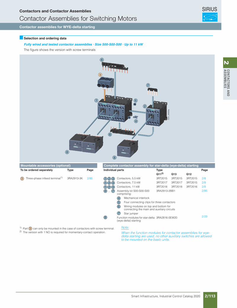
SIRIUS
Smart Infrastructure, Industrial Control Catalog 2020 2/113
2Co
nta
Ctors a
nd
a
ssemb
lies
Siemens / Industrial Controls Previous folio: IC10 2/76
3RA23, 3RA24 Contactor Assemblies3RA24 Contactor Assemblies for Wye-Delta Starting
3RA24 complete units, 5.5 ... 22 kW
3/38 SIRIUS Innovations Supplement 2012
3
Selection and ordering data
Fully wired and tested contactor assemblies · Size S00-S00-S00 · Up to 11 kWThe figure shows the version with screw terminals
1) Use version with 1 NO.2) Use version with 1 NC.3) Part can only be mounted with contactors with screw terminal.
Note:
When the function modules for contactor assemblies for wye-delta starting are used, no other auxiliary switches are allowed to be mounted on the basic units.
Mountable accessories Fully wired and tested contactor assembliesegaP.oNredrOstraplaudividnIegaP.oNredrOstraplaudividnI
Q111) Q132) Q122)
Three-phase feeder terminal3) 3RA29 13-3K 4 Contactor, 5.5 kW 3RT20 15 3RT20 15 3RT20 15
Contactor, 7.5 kW 3RT20 17 3RT20 17 3RT20 15
Contactor, 11 kW 3RT20 18 3RT20 18 3RT20 16
Assembly kit comprising
3RA29 13-2BB1
Mechanical interlock
4 connecting clipsWiring modules on the top and bottom for connecting the main current paths
Function modules for wye-delta starting
3RA28 16-0EW20
NSB0_02066a
3
4
5
6
6
7
1
2
1 2 3
1 2 3
1 2 3
4 5 6
4
56
7
LV1N_03_05.fm Page 38 Friday, October 18, 2013 3:24 PM
16
16
16
Contactors and Contactor Assemblies
Contactor Assemblies for Switching MotorsContactor assemblies for WYE-delta starting
3/167Siemens IC 10 · 2018
Contactor Assemblies for Star-Delta (Wye-Delta) Starting
SIRIUS 3RA24 contactor assemblies for star-delta (wye-delta) starting, up to 90 kW
3
Fully wired and tested contactor assemblies for star-delta (wye-delta) starting · Size S00-S00-S00 · Up to 11 kW
The figure shows the version with screw terminals
1) Part can only be mounted in the case of contactors with screw terminal.2) The version with 1 NO is required for momentary-contact operation.
Complete contactor assemblies for star-delta (wye-delta) starting see page 3/174.
Mountable accessories (optional) Complete contactor assembly for star-delta (wye-delta) startingTo be ordered separately Type Page Individual parts Type Page
Q112) Q13 Q12
Three-phase infeed terminal1) 3RA2913-3K 3/110 Contactors, 5.5 kW 3RT2015 3RT2015 3RT2015 3/50, 3/57
Contactors, 7.5 kW 3RT2017 3RT2017 3RT2015 3/50, 3/57
Contactors, 11 kW 3RT2018 3RT2018 3RT2016 3/50, 3/57
Assembly kit S00-S00-S00 comprising:
3RA2913-2BB1 3/106
Mechanical interlock
Four connecting clips for three contactors
Wiring modules on top and bottom for connecting the main and auxiliary circuits
Star jumper
Function modules for star-delta (wye-delta) starting
3RA2816-0EW20 3/101
9
4
5
7
6
6
8
8
2
1
IC01
_006
25a
9 1 2 31 2 31 2 3
...4 7
456
78
9
3RA23, 3RA24 Contactor Assemblies3RA24 Contactor Assemblies for Wye-Delta Starting
3RA24 complete units, 5.5 ... 22 kW
3/38 SIRIUS Innovations Supplement 2012
3
Selection and ordering data
Fully wired and tested contactor assemblies · Size S00-S00-S00 · Up to 11 kWThe figure shows the version with screw terminals
1) Use version with 1 NO.2) Use version with 1 NC.3) Part can only be mounted with contactors with screw terminal.
Note:
When the function modules for contactor assemblies for wye-delta starting are used, no other auxiliary switches are allowed to be mounted on the basic units.
Mountable accessories Fully wired and tested contactor assembliesegaP.oNredrOstraplaudividnIegaP.oNredrOstraplaudividnI
Q111) Q132) Q122)
Three-phase feeder terminal3) 3RA29 13-3K 4 Contactor, 5.5 kW 3RT20 15 3RT20 15 3RT20 15
Contactor, 7.5 kW 3RT20 17 3RT20 17 3RT20 15
Contactor, 11 kW 3RT20 18 3RT20 18 3RT20 16
Assembly kit comprising
3RA29 13-2BB1
Mechanical interlock
4 connecting clipsWiring modules on the top and bottom for connecting the main current paths
Function modules for wye-delta starting
3RA28 16-0EW20
NSB0_02066a
3
4
5
6
6
7
1
2
1 2 3
1 2 3
1 2 3
4 5 6
4
56
7
LV1N_03_05.fm Page 38 Friday, October 18, 2013 3:24 PM
16
16
16
2/85 2/8 2/8 2/8 2/85
2/29
Revised on 02/26/18
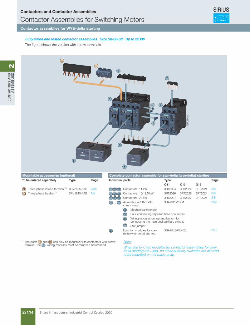
SIRIUS
Smart Infrastructure, Industrial Control Catalog 2020 2/114
2Co
nta
Cto
rs a
nd
a
ssem
bli
es
3/168 Siemens IC 10 · 2018
Contactor Assemblies for Star-Delta (Wye-Delta) Starting
SIRIUS 3RA24 contactor assemblies for star-delta (wye-delta) starting, up to 90 kW
3
Fully wired and tested contactor assemblies for star-delta (wye-delta) starting · Size S0-S0-S0 · Up to 22 kW
The figure shows the version with screw terminals
1) The parts and can only be mounted with contactors with screw terminal, the wiring modules must be removed beforehand.
Complete contactor assemblies for star-delta (wye-delta) starting see page 3/175.
Mountable accessories (optional) Complete contactor assembly for star-delta (wye-delta) startingTo be ordered separately Type Page Individual parts Type Page
Q11 Q13 Q12
Three-phase infeed terminal1) 3RV2925-5AB 3/110 Contactors, 11 kW 3RT2024 3RT2024 3RT2024 3/51, 3/61
Three-phase busbar1) 3RV1915-1AB 3/110 Contactors, 15/18.5 kW 3RT2026 3RT2026 3RT2024 3/51, 3/61
Contactors, 22 kW 3RT2027 3RT2027 3RT2026 3/51, 3/61
Assembly kit S0-S0-S0 comprising:
3RA2923-2BB1 3/106
Mechanical interlock
Four connecting clips for three contactors
Wiring modules on top and bottom for connecting the main and auxiliary circuits
Star jumper
Function modules for star-delta (wye-delta) starting
3RA2816-0EW20 3/101
5
4
9
10
7
6
6
8
8
2
1
IC01
_006
26a
9 1 2 310 1 2 3
1 2 3...4 7
456
7
8
9 106
IC10_03_10.fm Page 168 Wednesday, February 28, 2018 3:29 PM
3RA23, 3RA24 Contactor Assemblies3RA24 Contactor Assemblies for Wye-Delta Starting
3RA24 complete units, 5.5 ... 22 kW
3/40 SIRIUS Innovations Supplement 2012
3
Fully wired and tested contactor assemblies · Size S0-S0-S0 · Up to 22 kWThe figure shows the version with screw terminals
1) The parts and can only be mounted with contactors with screw terminal.
Note:
When the function modules for contactor assemblies for wye-delta starting are used, no other auxiliary switches are allowed to be mounted on the basic units.
Mountable accessories Fully wired and tested contactor assembliesegaP.oNredrOstraplaudividnIegaP.oNredrOstraplaudividnI
Q11 Q13 Q12Three-phase feeder terminal1) 3RV29 25-5AB 3/43 Contactor, 11 kW
Contactors, 15/18.5 kW3RT20 243RT20 26
3RT20 243RT20 26
3RT20 243RT20 24
3/103/10Three-phase busbar1) 3RV19 15-1AB 3/43
Contactor, 22 kW 3RT20 27 3RT20 27 3RT20 26 3/10
Assembly kit 3RA29 23-2BB1 3/43
The assembly kit contains:Mechanical interlock
Connecting clipsWiring modules on the top and bottom for connecting the main current paths
Function modules for wye-delta starting
3RA28 16-0EW20 3/44
2
1
7
6
6
5
4
3
NSB0_02067b
1 2 3
1 2 3
1 2 3
4 5 6
4
56
7
LV1N_03_05.fm Page 40 Friday, October 18, 2013 3:24 PM
17
16
16
17
16 17
Siemens / Industrial Controls Previous folio: IC10 2/77
2/8 2/8 2/8 2/85
2/29
2/851/8
Contactors and Contactor Assemblies
Contactor Assemblies for Switching MotorsContactor assemblies for WYE-delta starting
3RA23, 3RA24 Contactor Assemblies3RA24 Contactor Assemblies for Wye-Delta Starting
3RA24 complete units, 5.5 ... 22 kW
3/40 SIRIUS Innovations Supplement 2012
3
Fully wired and tested contactor assemblies · Size S0-S0-S0 · Up to 22 kWThe figure shows the version with screw terminals
1) The parts and can only be mounted with contactors with screw terminal.
Note:
When the function modules for contactor assemblies for wye-delta starting are used, no other auxiliary switches are allowed to be mounted on the basic units.
Mountable accessories Fully wired and tested contactor assembliesegaP.oNredrOstraplaudividnIegaP.oNredrOstraplaudividnI
Q11 Q13 Q12Three-phase feeder terminal1) 3RV29 25-5AB 3/43 Contactor, 11 kW
Contactors, 15/18.5 kW3RT20 243RT20 26
3RT20 243RT20 26
3RT20 243RT20 24
3/103/10Three-phase busbar1) 3RV19 15-1AB 3/43
Contactor, 22 kW 3RT20 27 3RT20 27 3RT20 26 3/10
Assembly kit 3RA29 23-2BB1 3/43
The assembly kit contains:Mechanical interlock
Connecting clipsWiring modules on the top and bottom for connecting the main current paths
Function modules for wye-delta starting
3RA28 16-0EW20 3/44
2
1
7
6
6
5
4
3
NSB0_02067b
1 2 3
1 2 3
1 2 3
4 5 6
4
56
7
LV1N_03_05.fm Page 40 Friday, October 18, 2013 3:24 PM
17
16
16
17
16 17
Revised on 02/26/18
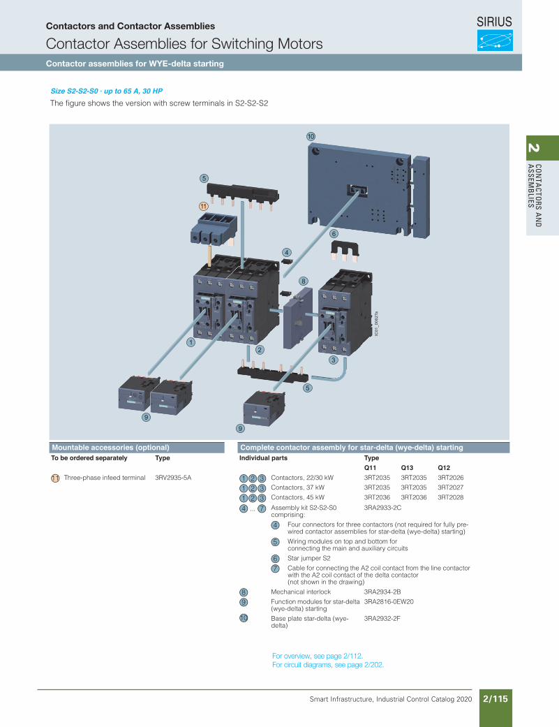
SIRIUS
Smart Infrastructure, Industrial Control Catalog 2020 2/115
2Co
nta
Ctors a
nd
a
ssemb
lies
Siemens / Industrial Controls Previous folio: IC10 2/78
Selection and ordering data
Size S2-S2-S0 · up to 65 A, 30 HP
Components to be ordered separately:
The connecting leads are not shown.
Accessory Order No. Page
Mechanical interlock, laterally mountable,depth must be adapted K3: 1.5 mm; K2: 0 mm 3RA19 24-2B
Solid-state time-delay auxiliary switch block, mountable on the front 3RT19 26-2G...
Auxiliary switch block,laterally mountable 3RH19 21-1EA..
Surge suppressor 3RT19 26-1....3RT19 36-1....
3-phase feeder terminal 3RV19 35-5A
3-phase busbar 3RV19 35-1A
Push-in lug 2) for time-delay relay for screw mounting 3RP19 03 Sec.11
Components Order No. PageK1 K3 K2
Contactors,50/60 A, 30 HP 3RT20 35 3RT20 35 3RT2026
Time-delay relay,laterally mountable 3RP1574-1N.30 Sec. 11
Auxiliary switch block with one unassignedNO contact 3RH19 21-1CA10
Auxiliary switch block for local control2 units 3RH19 21-1CA013 units 3RH19 21-1CA10
Baseplate 3RA19 32-2E
Installation kit 3RA19 33-2C
The installation kit contains the WYE jumper on the top and the wiring jumper on the bottom for connecting the main conducting paths.
4
7
15
16
17
18
19
1 2 3
8
10
11
6
9
1) Not included in scope of supply of complete contactor assemblies; available as accessory.
2) Possible in principle.If a solid-state time-delay auxiliary switch block is mounted onto the front of K3, an ordinary auxiliary switch block can only be mounted onto the side.
Links at bottom may be wrongRefer to IC German catalog I think
3/169Siemens IC 10 · 2018
Contactor Assemblies for Star-Delta (Wye-Delta) Starting
SIRIUS 3RA24 contactor assemblies for star-delta (wye-delta) starting, up to 90 kW
3
Fully wired and tested contactor assemblies for star-delta (wye-delta) starting · Size S2-S2-S01) · Up to 45 kW and S2-S2-S2 · 55 kWThe figure shows the version with screw terminals in S2-S2-S2
1) Complete contactor assembly for star-delta (wye-delta) starting in size S2-S2-S0 (not shown): The 3RA2933-2C assembly kit is to be used here, see page 3/106.
Complete contactor assemblies for star-delta (wye-delta) starting see page 3/176.
Mountable accessories (optional) Complete contactor assembly for star-delta (wye-delta) startingegaPepyTstrap laudividnIegaPepyTyletarapes deredro eb oT
Q11 Q13 Q12Three-phase infeed terminal 3RV2935-5A 3/110 Contactors, 22/30 kW 3RT2035 3RT2035 3RT2026 3/53, 3/62
Contactors, 37 kW 3RT2035 3RT2035 3RT2027 3/53, 3/62
Contactors, 45 kW 3RT2036 3RT2036 3RT2028 3/53, 3/62
Assembly kit S2-S2-S0comprising:
3RA2933-2C 3/106
Four connectors for three contactors (not required for fully pre-wired contactor assemblies for star-delta (wye-delta) starting)
Wiring modules on top and bottom for connecting the main and auxiliary circuits
Star jumper S2
Cable for connecting the A2 coil contact from the line contactor with the A2 coil contact of the delta contactor (not shown in the drawing)
Mechanical interlock 3RA2934-2B 3/109
Function modules for star-delta (wye-delta) starting
3RA2816-0EW20 3/101
Base plate star-delta (wye-delta)
3RA2932-2F 3/113
11
5
10
8
6
12
3
4
9
9
5
IC01_0
0627a
11 1 2 31 2 31 2 3
...4 7
4
5
67
89
10
IC10_03_10.fm Page 169 Wednesday, February 28, 2018 3:29 PM
3/169Siemens IC 10 · 2018
Contactor Assemblies for Star-Delta (Wye-Delta) Starting
SIRIUS 3RA24 contactor assemblies for star-delta (wye-delta) starting, up to 90 kW
3
Fully wired and tested contactor assemblies for star-delta (wye-delta) starting · Size S2-S2-S01) · Up to 45 kW and S2-S2-S2 · 55 kW
The figure shows the version with screw terminals in S2-S2-S2
1) Complete contactor assembly for star-delta (wye-delta) starting in size S2-S2-S0 (not shown): The 3RA2933-2C assembly kit is to be used here, see page 3/106.
Complete contactor assemblies for star-delta (wye-delta) starting see page 3/176.
Mountable accessories (optional) Complete contactor assembly for star-delta (wye-delta) startingTo be ordered separately Type Page Individual parts Type Page
Q11 Q13 Q12
Three-phase infeed terminal 3RV2935-5A 3/110 Contactors, 22/30 kW 3RT2035 3RT2035 3RT2026 3/53, 3/62
Contactors, 37 kW 3RT2035 3RT2035 3RT2027 3/53, 3/62
Contactors, 45 kW 3RT2036 3RT2036 3RT2028 3/53, 3/62
Contactors, 55 kW 3RT2037 3RT2037 3RT2035 3/53, 3/62
Assembly kit S2-S2-S2comprising:
3RA2933-2BB1 3/106
Four connectors for three contactors (not required for fully pre-wired contactor assemblies for star-delta (wye-delta) starting)
Wiring modules on top and bottom for connecting the main and auxiliary circuits
Star jumper S2
Cable for connecting the A2 coil contact from the line contactor with the A2 coil contact of the delta contactor (not shown in the drawing)
Mechanical interlock 3RA2934-2B 3/109
Function modules for star-delta (wye-delta) starting
3RA2816-0EW20 3/101
Base plate star-delta (wye-delta)
3RA2932-2F 3/113
11
5
10
8
6
12
3
4
9
9
5
IC01
_006
27a
11 1 2 31 2 31 2 31 2 3
...4 7
4
5
67
89
10
IC10_03_10.fm Page 169 Wednesday, February 28, 2018 3:29 PM
For overview, see page 2/112.For circuit diagrams, see page 2/202.
Contactors and Contactor Assemblies
Contactor Assemblies for Switching MotorsContactor assemblies for WYE-delta starting
Revised on 02/26/18
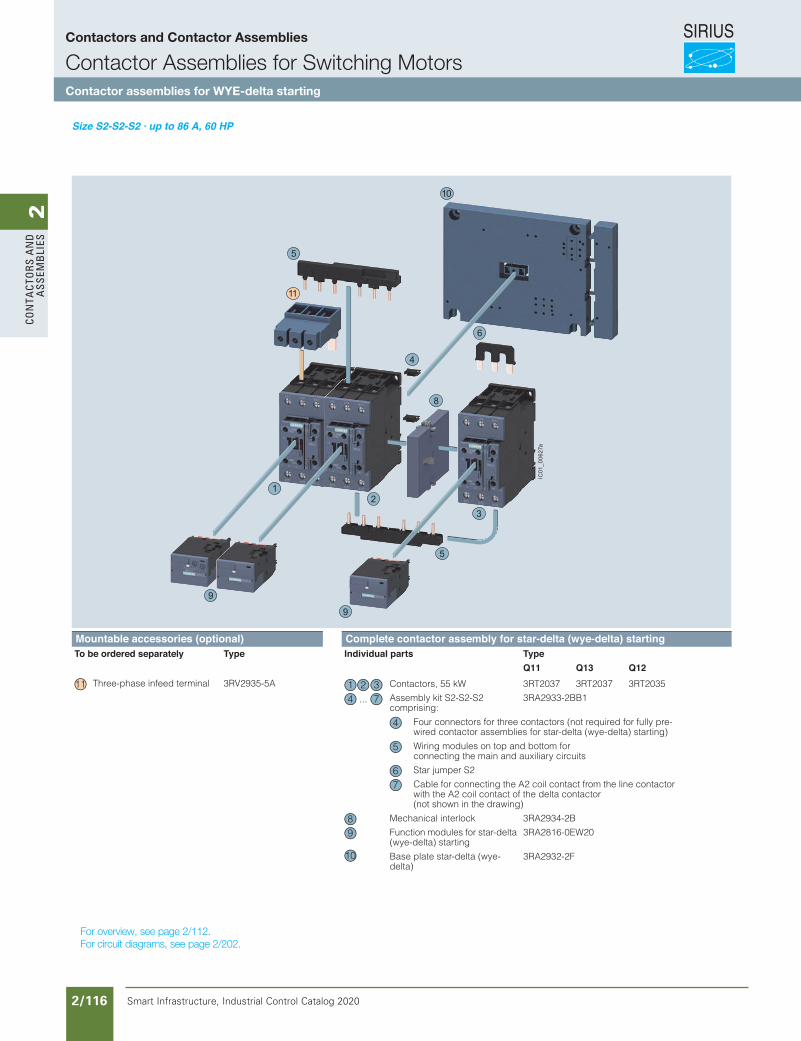
SIRIUS
Smart Infrastructure, Industrial Control Catalog 2020 2/116
2Co
nta
Cto
rs a
nd
a
ssem
bli
es
Siemens / Industrial Controls Previous folio: IC10 2/79
Selection and ordering data
Size S2-S2-S2 · up to 86 A, 60 HP
Components to be ordered separately:
The connecting leads are not shown.
Accessory Order No. Page
Mechanical interlock, lateral3RA19 24-2BSolid-state time-delay auxiliary switch block, mountable on the front 3RT19 26-2G...Mechanical interlock,mountable on the front 3RA19 24-1AAuxiliary switch block,
91HR3laretal 21-1EA..Surge suppressor 3RT19 26-1....
3RT19 36-1....3-phase feeder terminal 3RV19 35-5A3-phase busbar 3RV19 35-1APush-in lug 2) for time-delay relayfor screw mounting 3RP19 03
Components Order No. PageK1 K3 K2
Contactors,
80 A, 50 HP 3RT20 35 3RT20 35 3RT2034 Contactors,
86 A, 60 HP 3RT20 36 3RT20 36 3RT2034 Time-delay relay,lateral 3RP1574-1N.30Auxiliary switch block with one unassignedNO contact 3RH19 21-1CA10Auxiliary switch block for local control2 units 3RH19 21-1CA013 units 3RH19 21-1CA10Baseplate 3RA19 32-2FInstallation kit 3RA19 33-2BThe installation kit contains the WYE jumper on top and the wiring jumper on bottom for connecting the mainconducting paths.
47
12
15
16
171819
1 2 3
1 2 3
8
9
10
11
6
1) Not included in scope of supply of complete contactor assemblies; available as accessory.
2) Possible in principle. If a solid-state time-delay auxiliary switch block is mounted onto the front of K3, a standard auxiliary switch block can only be mounted onto the side.
Links at bottom may be wrongRefer to IC German catalog I think
For overview, see page 2/112.For circuit diagrams, see page 2/202.
Contactors and Contactor Assemblies
Contactor Assemblies for Switching MotorsContactor assemblies for WYE-delta starting
3/169Siemens IC 10 · 2018
Contactor Assemblies for Star-Delta (Wye-Delta) Starting
SIRIUS 3RA24 contactor assemblies for star-delta (wye-delta) starting, up to 90 kW
3
Fully wired and tested contactor assemblies for star-delta (wye-delta) starting · Size S2-S2-S01) · Up to 45 kW and S2-S2-S2 · 55 kWThe figure shows the version with screw terminals in S2-S2-S2
1) Complete contactor assembly for star-delta (wye-delta) starting in size S2-S2-S0 (not shown): The 3RA2933-2C assembly kit is to be used here, see page 3/106.
Complete contactor assemblies for star-delta (wye-delta) starting see page 3/176.
Mountable accessories (optional) Complete contactor assembly for star-delta (wye-delta) startingegaPepyTstrap laudividnIegaPepyTyletarapes deredro eb oT
Q11 Q13 Q12Three-phase infeed terminal 3RV2935-5A 3/110 Contactors, 55 kW 3RT2037 3RT2037 3RT2035 3/53, 3/62
Assembly kit S2-S2-S2comprising:
3RA2933-2BB1 3/106
Four connectors for three contactors (not required for fully pre-wired contactor assemblies for star-delta (wye-delta) starting)
Wiring modules on top and bottom for connecting the main and auxiliary circuits
Star jumper S2
Cable for connecting the A2 coil contact from the line contactor with the A2 coil contact of the delta contactor (not shown in the drawing)
Mechanical interlock 3RA2934-2B 3/109
Function modules for star-delta (wye-delta) starting
3RA2816-0EW20 3/101
Base plate star-delta (wye-delta)
3RA2932-2F 3/113
11
5
10
8
6
12
3
4
9
9
5
IC01_0
0627a
11 1 2 3...4 7
4
5
67
89
10
IC10_03_10.fm Page 169 Wednesday, February 28, 2018 3:29 PM
Revised on 02/26/18
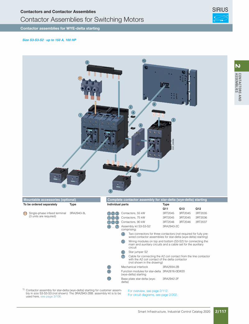
SIRIUS
Smart Infrastructure, Industrial Control Catalog 2020 2/117
2Co
nta
Ctors a
nd
a
ssemb
lies
3/170 Siemens IC 10 · 2018
Contactor Assemblies for Star-Delta (Wye-Delta) Starting
SIRIUS 3RA24 contactor assemblies for star-delta (wye-delta) starting, up to 90 kW
3
Fully wired and tested contactor assemblies for star-delta (wye-delta) starting · Size S3-S3-S21) · Up to 90 kW
1) Contactor assembly for star-delta (wye-delta) starting for customer assem-bly in size S3-S3-S3 (not shown): The 3RA2943-2BB. assembly kit is to be used here, see page 3/106.
Complete contactor assemblies for star-delta (wye-delta) starting see page 3/177.
Mountable accessories (optional) Complete contactor assembly for star-delta (wye-delta) startingTo be ordered separately Type Page Individual parts Type Page
Q11 Q13 Q12
Single-phase infeed terminal 3RA2943-3L 3/110 Contactors, 55 kW 3RT2045 3RT2045 3RT2035 3/54, 3/62(3 units are required) Contactors, 75 kW 3RT2045 3RT2045 3RT2036 3/54, 3/62
Contactors, 90 kW 3RT2046 3RT2046 3RT2037 3/54, 3/62
Assembly kit S3-S3-S2comprising:
3RA2943-2C 3/106
Two connectors for three contactors (not required for fully pre-wired contactor assemblies for star-delta (wye-delta) starting)
Wiring modules on top and bottom (S3-S2) for connecting the main and auxiliary circuits and a cable set for the auxiliary circuit
Star jumper S2
Cable for connecting the A2 coil contact from the line contactor with the A2 coil contact of the delta contactor (not shown in the drawing)
Mechanical interlock 3RA2934-2B 3/109
Function modules for star-delta (wye-delta) starting
3RA2816-0EW20 3/101
Base plate star-delta (wye-delta)
3RA2942-2F 3/113
11
5
10
8
6
1
2
3
4
5
9
9
IC01
_006
28b
11 1 2 31 2 31 2 3
...4 7
4
5
67
89
10
IC10_03_10.fm Page 170 Wednesday, April 11, 2018 8:17 PM
For overview, see page 2/112.For circuit diagrams, see page 2/202.
Siemens / Industrial Controls Previous folio: IC10 2/80
Selection and ordering data
Size S3-S3-S2 · up to 150 A, 100 HP
Components to be ordered separately:
The connecting leads are not shown.
Accessory Order No. Page
Mechanical interlock, lateral, depth must be adapted K3: 0 mm; K2: 27.5 mm 3RA19 24-2BSolid-state time-delay auxilary switch block, mountable on the front 3RT19 26-2G...Auxiliary switch block, lateral3RH1921-1EA..Surge suppressor 3RT19 . 6-1....Push-in lug 2) for time-delay relayfor screw mounting 3RP19 03
Components Order No. PageK1 K3 K2
Contactors,
115 A, 75 HP 3RT20 45 3RT20 45 3RT2035Contactors,
150 A, 100 HP 3RT20 45 3RT10 45 3RT2036Time-delay relay, lateral 3RP15 74-1N.30Auxiliary switch block with one unassignedNO contact 3RH19 21-1CA10Auxiliary switch block for local control2 units 3RH19 21-1CA013 units 3RH19 21-1CA10Baseplate 3RA19 42-2EInstallation kit 3RA19 43-2C
The installation kit contains the WYE jumper on the top and the wir-ing jumper on the bottom for connecting the main conducting
4
7
151619
1 2 3
1 2 3
8
9
10
116
1) Not included in scope of supply of the completecontactor assemblies; available as an accessory.
2) Possible in principle.If a solid-state time-delay aux-iliary switch block is mounted onto the front of K3, a standard auxiliary switch block can only be mounted onto the side.
Links at bottom may be wrongRefer to IC German catalog I think
Contactors and Contactor Assemblies
Contactor Assemblies for Switching MotorsContactor assemblies for WYE-delta starting
Revised on 02/26/18
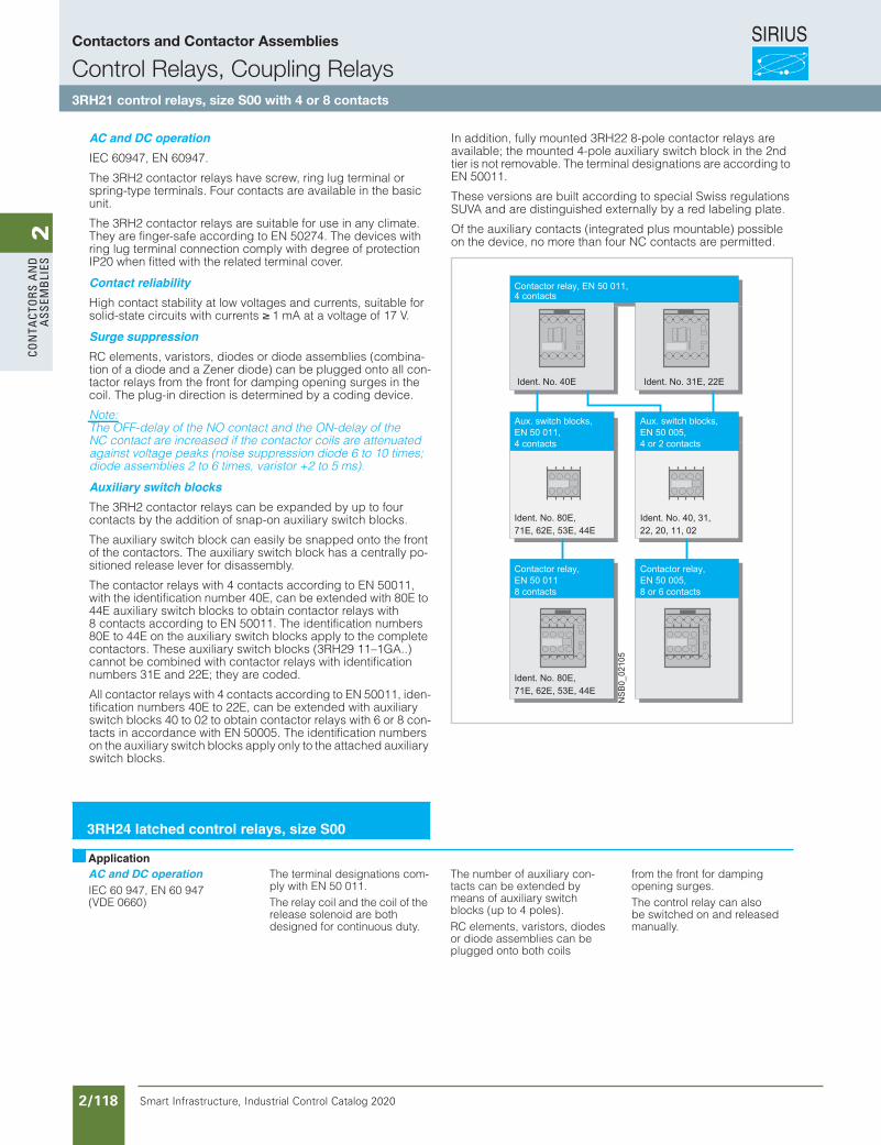
SIRIUS
Smart Infrastructure, Industrial Control Catalog 2020 2/118
2Co
nta
Cto
rs a
nd
a
ssem
bli
es
Siemens / Industrial Controls Previous folio: IC10 2/81
AC and DC operationIEC 60 947, EN 60 947(VDE 0660)
DesignThe 3RH21 control relays are suitable for use in any climate. They are safe from touch to DIN VDE 0106 Part 100.The 3RH21 control relays have screw, spring style or ring lug connections. Four contacts are available in the basic unit.
Contact reliabilityHigh contact stability at low voltages and currents, suitable for electronic circuits with currents ≥ 1 mA at a voltage of 17 V.
Auxiliary switch blocksThe 3RH21 control relays can be expanded by up to four con-tacts by the addition of mount-able auxiliary switch blocks.The auxiliary switch block can easily be snapped onto the front of the relays. The auxiliary switch block has a centrally positioned release lever for dis-assembly.The control relays with 4 con-tacts in accordance with EN 50 011, with the identifica-tion number 40E, can be extended with 80E to 44E auxi-liary switch blocks to obtain control relays with 8 contacts in accordance with EN 50 011. The identification numbers 80E to 44E on the auxiliary switch blocks apply to the complete relays (see illustration along-side).
These auxiliary switch blocks (3RH29 11-1GA ..) cannot be combined with control relays with identification numbers 31E and 22E; they are coded.All control relays with 4 con-tacts in accordance with EN 50 011, identification num-bers 40E to 22E, can be extended with auxiliary switch blocks 40 to 02 to obtain control relays with 6 or 8 contacts in accordance with EN 50 005. The identification numbers on the auxiliary switch blocks apply only to the attached auxil-iary switch blocks.
Surge suppressionRC elements, varistors, diodes or diode assemblies (combina-tion of a diode and a Zener diode) can be plugged onto all control relays from the front for damping opening surges in the coil. The plug-in direction is determined by a coding device.
NoteThe opening times of the NO contacts and the closing times of the NC contacts increase if the relay coils are protected against voltage peaks (sup-pression diode 6 to 10 times, diode assemblies 2 to 6 times, varistor +2 ms to 5 ms).
Application
HilfsschützeDIN EN50 005,8 oder 6 Kontakte
76000B
SN
Ident. No. 31E, 22EIdent. No. 40E
Ident. No. 80E,71E, 62E, 53E, 44E
Aux. switch blocks,4 contacts
Ident. No. 40, 31,22, 20, 11, 02
Aux. switch blocks,4 or 2 contacts
Ident. No. 80E,71E, 62E, 53E, 44E
Control relay, y ,EN 50 0118 contacts
Ident. No. 40, 31, 22, 20, 11, 02
Control relay,EN 50 005,8 or 6 contacts
Control relay, EN 50 011,4 contacts
3RH2. contactor relays acc. to EN 50 011 and EN 50 005
Overview
AC and DC operationIEC 60 947, EN 60 947(VDE 0660)
The terminal designations com-ply with EN 50 011.The relay coil and the coil of the release solenoid are both designed for continuous duty.
The number of auxiliary con-tacts can be extended by means of auxiliary switch blocks (up to 4 poles).RC elements, varistors, diodes or diode assemblies can be plugged onto both coils
from the front for damping opening surges.The control relay can also be switched on and released manually.
3RH24 latched control relays, size S00
Application
3RH Contactor Relays
3RH2 contactor relays, 4- and 8-pole
3/59SIRIUS Innovations Supplement 2012
3
AC and DC operationIEC 60947, EN 60947.
The 3RH2 contactor relays have screw, ring lug terminal or spring-type terminals. Four contacts are available in the basic unit.
The 3RH2 contactor relays are suitable for use in any climate. They are finger-safe according to EN 50274. The devices with ring lug terminal connection comply with degree of protection IP20 when fitted with the related terminal cover.
Contact reliabilityHigh contact stability at low voltages and currents, suitable for solid-state circuits with currents ≥ 1 mA at a voltage of 17 V.
Surge suppressionRC elements, varistors, diodes or diode assemblies (combina-tion of a diode and a Zener diode) can be plugged onto all con-tactor relays from the front for damping opening surges in the coil. The plug-in direction is determined by a coding device.
Note:The OFF-delay of the NO contact and the ON-delay of the NC contact are increased if the contactor coils are attenuated against voltage peaks (noise suppression diode 6 to 10 times; diode assemblies 2 to 6 times, varistor +2 to 5 ms).
Auxiliary switch blocksThe 3RH2 contactor relays can be expanded by up to four contacts by the addition of snap-on auxiliary switch blocks.
The auxiliary switch block can easily be snapped onto the front of the contactors. The auxiliary switch block has a centrally po-sitioned release lever for disassembly.
The contactor relays with 4 contacts according to EN 50011, with the identification number 40E, can be extended with 80E to 44E auxiliary switch blocks to obtain contactor relays with 8 contacts according to EN 50011. The identification numbers 80E to 44E on the auxiliary switch blocks apply to the complete contactors. These auxiliary switch blocks (3RH29 11–1GA..) cannot be combined with contactor relays with identification numbers 31E and 22E; they are coded.
All contactor relays with 4 contacts according to EN 50011, iden-tification numbers 40E to 22E, can be extended with auxiliary switch blocks 40 to 02 to obtain contactor relays with 6 or 8 con-tacts in accordance with EN 50005. The identification numbers on the auxiliary switch blocks apply only to the attached auxiliary switch blocks.
In addition, fully mounted 3RH22 8-pole contactor relays are available; the mounted 4-pole auxiliary switch block in the 2nd tier is not removable. The terminal designations are according to EN 50011.
These versions are built according to special Swiss regulations SUVA and are distinguished externally by a red labeling plate.
Of the auxiliary contacts (integrated plus mountable) possible on the device, no more than four NC contacts are permitted.
Order No. scheme
Note:
The Order No. scheme is presented here merely for information purposes and for better understanding of the logic behind the order numbers.
For your orders, please use the order numbers quote in the catalog in the Selection and ordering data.
Hilfsschütze DIN EN50 005,8 oder 6 Kontakte
NS
B0_
0210
5
Ident. No. 31E, 22EIdent. No. 40E
Ident. No. 80E,71E, 62E, 53E, 44E
Aux. switch blocks,EN 50 011,4 contacts
Ident. No. 40, 31, 22, 20, 11, 02
Aux. switch blocks,EN 50 005,4 or 2 contacts
Ident. No. 80E, 71E, 62E, 53E, 44E
Contactor relay,EN 50 0118 contacts
Contactor relay,EN 50 005,8 or 6 contacts
Contactor relay, EN 50 011,4 contacts
Digit of the Order No. 1st - 3rd
4th 5th 6th 7th 8th 9th 10th 11th 12th
13th 14th 15th 16th
@@@ @ @ @ @ – @ @ @ @ @ – @ @ @ @SIRIUS contactor relays 3 R H2nd generation 2Device type (e. g. 1 = 4-pole contactor relay, 3 = 8-pole contactor relay) @Number of NO contacts (e. g. 2 = 2 NO) @Number of NC contacts (e. g. 2 = 2 NC) @Connection type (1 = screw, 2 = spring, 4 = ring lug) @Operating range / solenoid coil circuit (e. g. A = AC standard / without) @Rated control supply voltage (e. g. K6 = 110/120 V, 50/60 Hz ) @ @No significance @Special version @ @ @ @Example 3 R H 2 1 2 2 – 1 A K 6 0
LV1N_03_07.fm Page 59 Wednesday, October 30, 2013 4:34 PM
Contactors and Contactor Assemblies
Control Relays, Coupling Relays3RH21 control relays, size S00 with 4 or 8 contacts
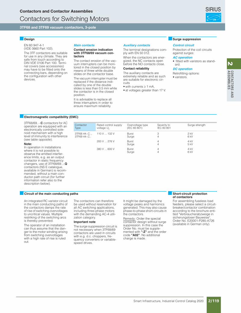
SIRIUS
Smart Infrastructure, Industrial Control Catalog 2020 2/119
2Co
nta
Ctors a
nd
a
ssemb
lies
Siemens / Industrial Controls Previous folio: IC10 2/82
Contactors and Contactor Assemblies
EN 60 947-4-1 (VDE 0660 Part 102).The 3TF contactors are suitable for use in any climate. They are safe from touch according to DIN VDE 0106 Part 100. Termi-nal covers (see accessories) may have to be fitted onto the connecting bars, depending on the configuration with other devices.
Main contactsContact erosion indication with 3TF68/69 vacuum con-tactorsThe contact erosion of the vac-uum interrupters can be moni-tored in the closed position by means of three white double slides on the contactor base.The vacuum interrupter must be replaced if the distance indi-cated by one of the double slides is less than 0.5 mm while the contactor is in the closed position.It is advisable to replace all three interrupters in order to ensure maximum reliability.
Auxiliary contactsThe terminal designations com-ply with EN 50 012.When the contactors are ener-gized, the NC contacts open before the NO contacts close.Contact reliabilityThe auxiliary contacts are extremely reliable and as such are suitable for electronic cir-cuits• with currents 1 mA,• at voltages greater than 17 V.
Control circuitProtection of the coil circuits against surges:AC operation• fitted with varistors as stand-
ard.DC operationRetrofitting options:• varistors.
3TF68/69..-.C contactors for AC operation are equipped with an electronically controlled sole-noid mechanism with a high level of immunity to interference (see table opposite).Note:In operation in installations where it is not possible to observe the emitted interfer-ence limits, e.g. as an output contactor in static frequency changers, use of 3TF68/69..-.Qcontactors (NS E catalogue, available in German) is recom-mended, without a main con-ductor path circuit (for further information refer also to the description below).
An integrated RC varistor circuit in the main conducting paths of the contactors damps the rate of rise of switching overvoltages to uncritical values. Multiple restriking of the switching arcs is thereby prevented.The operator of an installation can thus assume that the dan-ger to the motor winding arising from switching overvoltages with a high rate of rise is ruled out.
The contactors can therefore be used without reservation for all AC switching applications, including three-phase motors with the demanding AC-4 utili-zation category.Important noteThe surge suppression circuit is not necessary when 3TF68/69 contactors are used in circuits with e.g. d.c. choppers, fre-quency converters or variable-speed drives.
It might be damaged by the voltage peaks and harmonics generated. This may also cause phase-to-phase short-circuits in the contactors.Remedy: Order the special contactor design without surge suppression. In this case the Order No. must be supple-mented with "-Z" and the order code "A02". No additional charge is made.
For assembling fuseless load feeders, please select a circuit-breaker/contactor combination according to the brochure enti-tled "Verbraucherabzweige in sicherungsloser Bauweise", Order No. E20001-P285-A726 (available in German only).
Design Surge suppression
Electromagnetic compatibility (EMC)
ContactorType
Rated control supply voltage Us
Overvoltage type(IEC 60 801)
Severity toIEC 60 801
Surge strength
3TF68 44-.C..,3TF69 44-.C..
110 V ... 132 V BurstSurge
34
2 kV6 kV
200 V ... 276 V BurstSurge
44
4 kV5 kV
380 V ... 600 V BurstSurge
44
4 kV6 kV
Circuit of the main conducting paths Short-circuit protectionof contactors
Contactors and Contactor Assemblies
Contactors for Switching Motors3TF68 and 3TF69 vacuum contactors, 3-pole
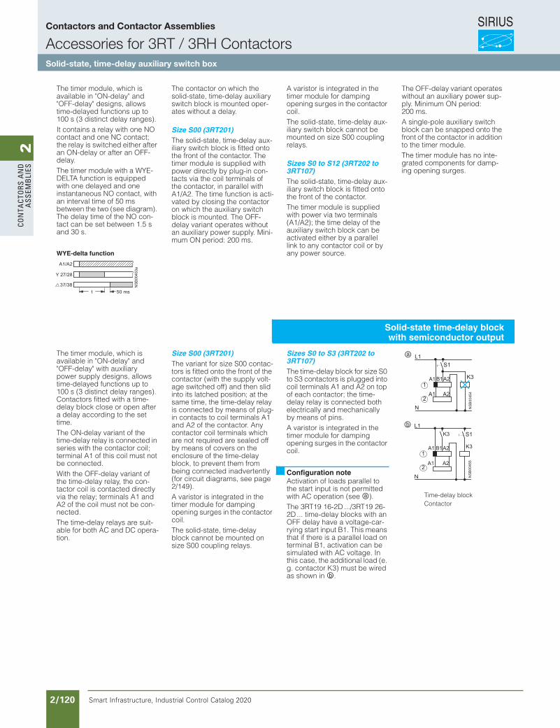
SIRIUS
Smart Infrastructure, Industrial Control Catalog 2020 2/120
2Co
nta
Cto
rs a
nd
a
ssem
bli
es
Siemens / Industrial Controls Previous folio: IC10 2/83
The timer module, which is available in "ON-delay" and "OFF-delay" designs, allows time-delayed functions up to 100 s (3 distinct delay ranges).It contains a relay with one NO contact and one NC contact; the relay is switched either after an ON-delay or after an OFF-delay.The timer module with a WYE-DELTA function is equipped with one delayed and one instantaneous NO contact, with an interval time of 50 ms between the two (see diagram). The delay time of the NO con-tact can be set between 1.5 s and 30 s.
WYE-delta function
The contactor on which the solid-state, time-delay auxiliary switch block is mounted oper-ates without a delay.
Size S00 (3RT201)The solid-state, time-delay aux-iliary switch block is fitted onto the front of the contactor. The timer module is supplied with power directly by plug-in con-tacts via the coil terminals of the contactor, in parallel with A1/A2. The time function is acti-vated by closing the contactor on which the auxiliary switch block is mounted. The OFF-delay variant operates without an auxiliary power supply. Mini-mum ON period: 200 ms.
A varistor is integrated in the timer module for damping opening surges in the contactor coil.The solid-state, time-delay aux-iliary switch block cannot be mounted on size S00 coupling relays.
Sizes S0 to S12 (3RT202 to 3RT107)The solid-state, time-delay aux-iliary switch block is fitted onto the front of the contactor.The timer module is supplied with power via two terminals (A1/A2); the time delay of the auxiliary switch block can be activated either by a parallel link to any contactor coil or by any power source.
The OFF-delay variant operates without an auxiliary power sup-ply. Minimum ON period: 200 ms.A single-pole auxiliary switch block can be snapped onto the front of the contactor in addition to the timer module.The timer module has no inte-grated components for damp-ing opening surges.
The timer module, which is available in "ON-delay" and "OFF-delay" with auxiliary power supply designs, allows time-delayed functions up to 100 s (3 distinct delay ranges). Contactors fitted with a time-delay block close or open after a delay according to the set time.The ON-delay variant of the time-delay relay is connected in series with the contactor coil; terminal A1 of this coil must not be connected.With the OFF-delay variant of the time-delay relay, the con-tactor coil is contacted directly via the relay; terminals A1 and A2 of the coil must not be con-nected.The time-delay relays are suit-able for both AC and DC opera-tion.
Size S00 (3RT201)The variant for size S00 contac-tors is fitted onto the front of the contactor (with the supply volt-age switched off) and then slid into its latched position; at the same time, the time-delay relay is connected by means of plug-in contacts to coil terminals A1 and A2 of the contactor. Any contactor coil terminals which are not required are sealed off by means of covers on the enclosure of the time-delay block, to prevent them from being connected inadvertently (for circuit diagrams, see page 2/149).A varistor is integrated in the timer module for damping opening surges in the contactor coil.The solid-state, time-delay block cannot be mounted on size S00 coupling relays.
Sizes S0 to S3 (3RT202 to 3RT107)The time-delay block for size S0 to S3 contactors is plugged into coil terminals A1 and A2 on top of each contactor; the time-delay relay is connected both electrically and mechanically by means of pins.A varistor is integrated in the timer module for damping opening surges in the contactor coil.
Activation of loads parallel to the start input is not permitted with AC operation (see #).The 3RT19 16-2D .../3RT19 26-2D ... time-delay blocks with an OFF delay have a voltage-car-rying start input B1. This means that if there is a parallel load on terminal B1, activation can be simulated with AC voltage. In this case, the additional load (e. g. contactor K3) must be wired as shown in $.
Configuration note
Time-delay blockContactor
#
$
Solid-state time-delay blockwith semiconductor output
Contactors and Contactor Assemblies
Accessories for 3RT / 3RH ContactorsSolid-state, time-delay auxiliary switch box
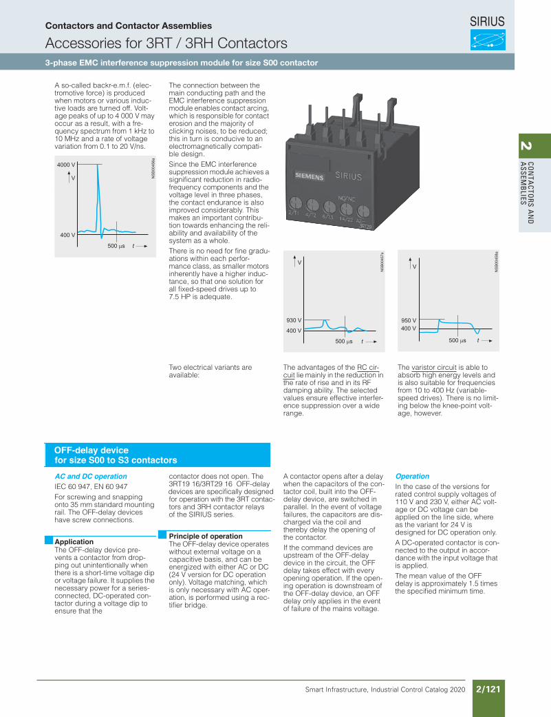
SIRIUS
Smart Infrastructure, Industrial Control Catalog 2020 2/121
2Co
nta
Ctors a
nd
a
ssemb
lies
Siemens / Industrial Controls Previous folio: IC10 2/84
A so-called backr-e.m.f. (elec-tromotive force) is produced when motors or various induc-tive loads are turned off. Volt-age peaks of up to 4 000 V may occur as a result, with a fre-quency spectrum from 1 kHz to 10 MHz and a rate of voltage variation from 0.1 to 20 V/ns.
Capacitive input to various ana-log and digital signals makes it necessary to suppress interfer-ence in the load circuit.
The connection between the main conducting path and the EMC interference suppression module enables contact arcing, which is responsible for contact erosion and the majority of clicking noises, to be reduced; this in turn is conducive to an electromagnetically compati-ble design.Since the EMC interference suppression module achieves a significant reduction in radio-frequency components and the voltage level in three phases, the contact endurance is also improved considerably. This makes an important contribu-tion towards enhancing the reli-ability and availability of the system as a whole.There is no need for fine gradu-ations within each perfor-mance class, as smaller motors inherently have a higher induc-tance, so that one solution for all fixed-speed drives up to 7.5 HP is adequate.
Two electrical variants are available:
The advantages of the RC cir-cuit lie mainly in the reduction in the rate of rise and in its RF damping ability. The selected values ensure effective interfer-ence suppression over a wide range.
The varistor circuit is able to absorb high energy levels and is also suitable for frequencies from 10 to 400 Hz (variable-speed drives). There is no limit-ing below the knee-point volt-age, however.
AC and DC operationIEC 60 947, EN 60 947For screwing and snapping onto 35 mm standard mounting rail. The OFF-delay devices have screw connections.
The OFF-delay device pre-vents a contactor from drop-ping out unintentionally when there is a short-time voltage dip or voltage failure. It supplies the necessary power for a series-connected, DC-operated con-tactor during a voltage dip to ensure that the
contactor does not open. The 3RT19 16/3RT29 16 OFF-delay
devices are specifically designedfor operation with the 3RT contac-tors and 3RH contactor relays of the SIRIUS series.
The OFF-delay device operates without external voltage on a capacitive basis, and can be energized with either AC or DC (24 V version for DC operation only). Voltage matching, which is only necessary with AC oper-ation, is performed using a rec-tifier bridge.
A contactor opens after a delay when the capacitors of the con-tactor coil, built into the OFF-delay device, are switched in parallel. In the event of voltage failures, the capacitors are dis-charged via the coil and thereby delay the opening of the contactor.If the command devices are upstream of the OFF-delay device in the circuit, the OFF delay takes effect with every opening operation. If the open-ing operation is downstream of the OFF-delay device, an OFF delay only applies in the event of failure of the mains voltage.
OperationIn the case of the versions for rated control supply voltages of 110 V and 230 V, either AC volt-age or DC voltage can be applied on the line side, where as the variant for 24 V is designed for DC operation only.A DC-operated contactor is con-nected to the output in accor-dance with the input voltage that is applied.The mean value of the OFF delay is approximately 1.5 times the specified minimum time.
OFF-delay devicefor size S00 to S3 contactors
ApplicationPrinciple of operation
Contactors and Contactor Assemblies
Accessories for 3RT / 3RH Contactors3-phase EMC interference suppression module for size S00 contactor
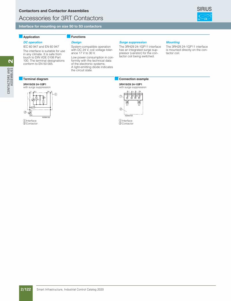
SIRIUS
Smart Infrastructure, Industrial Control Catalog 2020 2/122
2Co
nta
Cto
rs a
nd
a
ssem
bli
es
Siemens / Industrial Controls Previous folio: IC10 2/85
DC operationIEC 60 947 and EN 60 947The interface is suitable for use in any climate. It is safe from touch to DIN VDE 0106 Part 100. The terminal designations conform to EN 50 005.
DesignSystem-compatible operation with DC 24 V, coil voltage toler-ance 17 V to 30 V.Low power consumption in con-formity with the technical data of the electronic systems. A light-emitting diode indicates the circuit state.
Surge suppressionThe 3RH29 24-1GP11 interface has an integrated surge sup-pressor (varistor) for the con-tactor coil being switched.
MountingThe 3RH29 24-1GP11 interface is mounted directly on the con-tactor coil.
3RH19/29 24-1GP11with surge suppression
3RH19/29 24-1GP11with surge suppression
InterfaceContactor
InterfaceContactor
Application Functions
Terminal diagram Connection example
Contactors and Contactor Assemblies
Accessories for 3RT ContactorsInterface for mounting on size S0 to S3 contactors
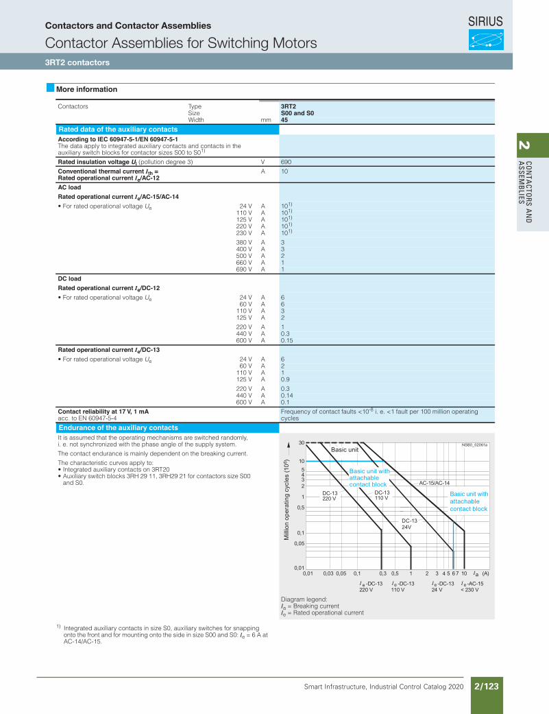
SIRIUS
Smart Infrastructure, Industrial Control Catalog 2020 2/123
2Co
nta
Ctors a
nd
a
ssemb
lies3RT Power Contactors for Switching Motors
3RT20 contactors, 3-pole, 3 ... 25 HP
3/18 SIRIUS Innovations Supplement 2012
3
More information
1) Integrated auxiliary contacts in size S0, auxiliary switches for snapping onto the front and for mounting onto the side in size S00 and S0: Ie = 6 A at AC-14/AC-15.
epyTsrotcatnoC 3RT2Size S00 and S0Width mm 45
Rated data of the auxiliary contactsAccording to IEC 60947-5-1/EN 60947-5-1The data apply to integrated auxiliary contacts and contacts in the auxiliary switch blocks for contactor sizes S00 to S01)
Rated insulation voltage Ui V)3 eerged noitullop( 690
Conventional thermal current Ith =Rated operational current Ie/AC-12
A 10
AC loadRated operational current Ie/AC-15/AC-14• For rated operational voltage Ue 24 V A 101)
110 V A 101)
125 V A 101)
220 V A 101)
230 V A 101)
380 V A 3400 V A 3500 V A 2660 V A 1690 V A 1
DC loadRated operational current Ie/DC-12• For rated operational voltage Ue 24 V A 6
60 V A 6110 V A 3125 V A 2
220 V A 1440 V A 0.3600 V A 0.15
Rated operational current Ie/DC-13• For rated operational voltage Ue 24 V A 6
60 V A 2110 V A 1125 V A 0.9
220 V A 0.3440 V A 0.14600 V A 0.1
Contact reliability at 17 V, 1 mA acc. to EN 60947-5-4
Frequency of contact faults <10-8 i. e. <1 fault per 100 million operating cycles
Endurance of the auxiliary contactsIt is assumed that the operating mechanisms are switched randomly, i. e. not synchronized with the phase angle of the supply system.
The contact endurance is mainly dependent on the breaking current.
The characteristic curves apply to:• Integrated auxiliary contacts on 3RT20• Auxiliary switch blocks 3RH 29 11, 3RH29 21 for contactors size S00
and S0.
Diagram legend: Ia = Breaking current Ie = Rated operational current
I
NSB0_02061a
III I
LV1N_03_04.fm Page 18 Wednesday, October 30, 2013 4:07 PM
Siemens / Industrial Controls Previous folio: IC10 2/86
Contactors and Contactor Assemblies
Contactor Assemblies for Switching Motors3RT2 contactors
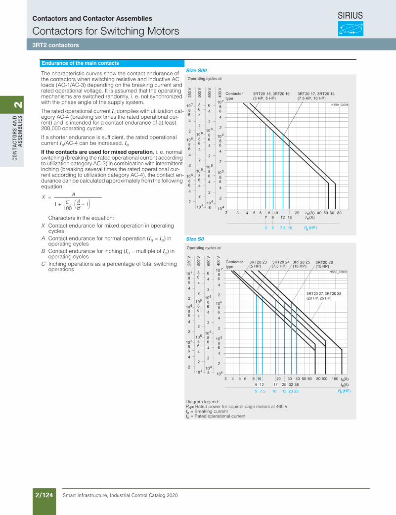
SIRIUS
Smart Infrastructure, Industrial Control Catalog 2020 2/124
2Co
nta
Cto
rs a
nd
a
ssem
bli
es
Siemens / Industrial Controls Previous folio: IC10 2/87
3RT Power Contactors for Switching Motors
3RT20 contactors, 3-pole, 3 ... 25 HP
3/19SIRIUS Innovations Supplement 2012
3
Endurance of the main contacts
The characteristic curves show the contact endurance of the contactors when switching resistive and inductive AC loads (AC-1/AC-3) depending on the breaking current and rated operational voltage. It is assumed that the operating mechanisms are switched randomly, i. e. not synchronized with the phase angle of the supply system.
The rated operational current Ie complies with utilization cat-egory AC-4 (breaking six times the rated operational cur-rent) and is intended for a contact endurance of at least 200,000 operating cycles.
If a shorter endurance is sufficient, the rated operational current Ie/AC-4 can be increased. IeIf the contacts are used for mixed operation, i. e. normal switching (breaking the rated operational current according to utilization category AC-3) in combination with intermittent inching (breaking several times the rated operational cur-rent according to utilization category AC-4), the contact en-durance can be calculated approximately from the following equation:
Characters in the equation:X Contact endurance for mixed operation in operating
cyclesA Contact endurance for normal operation (Ia = Ie) in
operating cyclesB Contact endurance for inching (Ia = multiple of Ie) in
operating cyclesC Inching operations as a percentage of total switching
operations
Size S00
Size S0
Diagram legend: PN= Rated power for squirrel-cage motors at 460 V Ia = Breaking current Ie = Rated operational current
NSB0_02059
7.5
(7.5 HP, 10 HP)
10
10864
2
10864
2
10864
2
10
7
6
5
4
64
2
10864
2
10864
2
108
6
5
4
864
2
10864
2
10864
2
10
6
5
4
10864
2
10864
2
10864
2
7
6
5
2 3 4 5 8 10 20 50 60 809 12
40
5
(A)a(A)e
P (HP)N
7
3
6
3RT20 15, 3RT20 16(3 HP, 5 HP)
3RT20 17, 3RT20 18690
V
500
V
230
V
400
V16
Operating cycles at
Contactor type
NSB0_02060
12 17
3RT20 24
25
3RT20 25 3RT20 26
15 PN
(15 HP)
10 20 30 40 50 60 80 100 (A)a
e(A)(HP)
3 4 5 6 89
5
3RT20 23(5 HP)
10864
2
10864
2
10864
2
7
6
5
4
64
2
10864
2
10864
2
108
6
5
4
864
2
10864
2
10864
2
10
6
5
4
10864
2
10864
2
10864
2
7
6
5
690
V
500
V
230
V
400
V
10
32 38
20
150
7.5 10 25
(7.5 HP) (10 HP)
3RT20 27, 3RT20 28(20 HP, 25 HP)
LV1N_03_04.fm Page 19 Wednesday, October 30, 2013 4:07 PM
Contactors and Contactor Assemblies
Contactors for Switching Motors3RT2 contactors
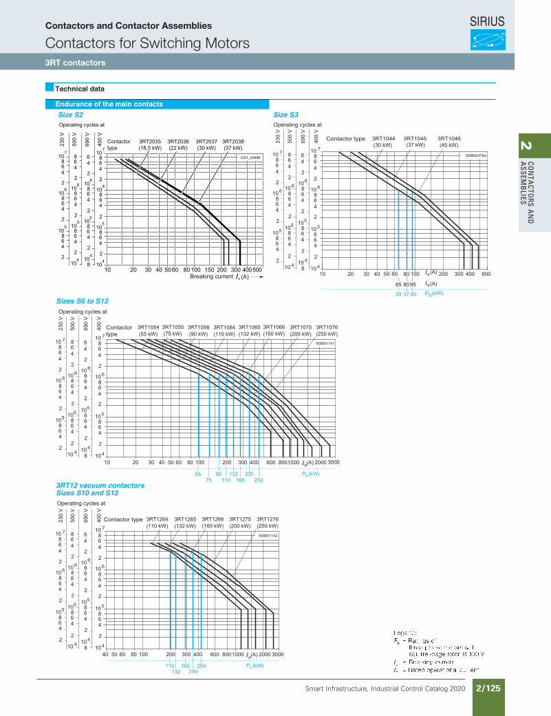
SIRIUS
Smart Infrastructure, Industrial Control Catalog 2020 2/125
2Co
nta
Ctors a
nd
a
ssemb
lies
Siemens / Industrial Controls Previous folio: IC10 2/88
3RT1 contactors
Endurance of the main contacts
Technical data
Size S2
Sizes S6 to S12
3RT12 vacuum contactorsSizes S10 and S12
Size S3
II
10080605040a (A)
Contactor type
Operating cycles at
Breaking current
3RT2038(37 kW)
IC01_00456
10
2
10864
2
10864
2
10864
6
7
2
10864
2
10864
2
64
4
6
2
10864
2
10864
2
864
4
6
2
10864
2
10864
2
10864
6
7
1010
55
55
8
690
V
500
V
230
V
400
V
4
3RT2035(18,5 kW)
3RT2036(22 kW)
3RT2037(30 kW)
400500300200150302010
Contactors and Contactor Assemblies
Contactors for Switching Motors3RT contactors

SIRIUS
Smart Infrastructure, Industrial Control Catalog 2020 2/126
2Co
nta
Cto
rs a
nd
a
ssem
bli
es3RT Power Contactors for Switching Motors
3RT20 contactors, 3-pole, 3 ... 25 HP
3/27SIRIUS Innovations Supplement 2012
3
1) For more information about short-circuit values, e. g. for protection against short-circuit currents, see UL reports (http://support.automation.siemens.com) for the individual devices.
2) Values for RK5 fuses on request.3) Values on request.
epyTsrotcatnoC 3RT20 15 3RT20 16 3RT20 17 3RT20 18Size S00 S00 S00 S00
mmhtdiW 45 45 45 45s and u rated dataRated insulation voltage V AC 600
Uninterrupted current, at 40 °C • Open and enclosed A 20
Maximum horsepower ratings (s and u approved values)
• Rated power for induction motors at 60 Hz
At 200 V hp 1.5 2 3 3230 V hp 2 3 3 5460 V hp 3 5 7.5 10575 V hp 5 7.5 10 10
Short-circuit protection1) At 600 V kA 5 5 5 5(contactor or overload relay) • Fuse CLASS J2) A 40 40 40 40
• Circuit breakers with overload protection according to UL 489
A 50 50 50 50
• Combination motor controllers type E according to UL 508
--3) --3) --3) --3)
NEMA/EEMAC ratingsNEMA/EEMAC size -- 0
AnepO-tnerruc detpurretninU• -- 18AdesolcnE- -- 18
• Rated power for induction motors at 60 Hz
At 200 V hp -- 3230 V hp -- 3460 V hp -- 5575 V hp -- 5
Overload relays • Type 3RU21 1 / 3RB30 1Aegnar gnitteS• 0.11 ... 16 / 0.1 ... 16
epyTsrotcatnoC 3RT20 23 3RT20 24 3RT20 25 3RT20 26 3RT20 27 3RT20 28Size S0 S0 S0 S0 S0 S0
mmhtdiW 45 45 45 45 45 45s and u rated dataRated insulation voltage V AC 600 600
Uninterrupted current, at 40 °C • Open and enclosed A 35 42
Maximum horsepower ratings (s and u approved values)
• Rated power for induction motors at 60 Hz
At 200 V hp 2 3 5 7.5 10 10230 V hp 3 3 5 7.5 10 10460 V hp 5 7.5 10 15 20 25575 V hp 7.5 10 15 20 25 25
Short-circuit protection1) At 600 V kA 5 5 5 5 5 5(contactor or overload relay) • Fuse CLASS J2) A 45 45 45 70 110 110
• Circuit breakers with overload protection according to UL 489
A 70 70 70 100 100 100
• Combination motor controllers type E according to UL 508
epyTV 084 tA- 3RV20 2A --kA --3)
epyTV 006 tA- 3RV20 2A --kA --3)
NEMA/EEMAC ratingsNEMA/EEMAC size --
AnepO-tnerruc detpurretninU• --AdesolcnE- --
• Rated power for induction motors at 60 Hz
At 200 V hp --230 V hp --460 V hp --575 V hp --
Overload relays • Type 3RU21 2 / 3RB30 2Aegnar gnitteS• 1.8 ... 40 / 0.1 ... 40
LV1N_03_04.fm Page 27 Friday, October 18, 2013 3:57 PM
1
2727
7.57.51010
Contactors and Contactor Assemblies
Contactors for Switching Motors3RT2 contactors
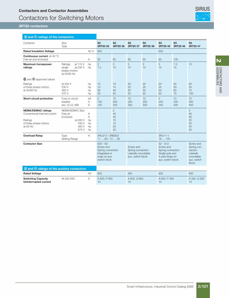
SIRIUS
Smart Infrastructure, Industrial Control Catalog 2020 2/127
2Co
nta
Ctors a
nd
a
ssemb
lies
Siemens / Industrial Controls Previous folio: IC10 2/89
and ratings of the contactors
Contactor Size Type
S2 3RT20 35
S2 3RT20 36
S2 3RT20 37
S2 3RT20 38
S3 3RT20 45
S3 3RT20 46
S3 3RT20 47
Rated Insulation Voltage AC V 600 600
Continuous current, at 40 °CFree air and enclosed A 55 60 80 90 90 105
Maximum horsepower ratings
Ratings at 115 V single at 230 V phase motors at 50/60 Hz
hp hp
3 7.5
3 10
5 10
5 15
5 15
7.5 15
10 -
and approved values
Ratings of three-phase motors at 50/60 Hz
at 200 V 230 V 460 V 575 V
hp hp hp hp
10 15 30 40
15 15 40 50
20 20 50 50
20 25 50 60
20 25 50 60
25 30 60 75
30 30 75 100
Short-circuit protection Fuse or circuit-breaker acc. to UL 489
kA A A
5 150 150
10 200 200
10 250 200
10 250 200
5 250 250
10 300 300
10 350 400
NEMA/EEMAC ratingsConventional thermal current Ratings of three-phase motors at 60 Hz
NEMA/EEMAC Size Free air Enclosed at 200 V 230 V 460 V 575 V
A A hp hp hp hp
- - - - - -
2 45 45 10 15 25 25
- - - - - -
- - - - - - -
3 90 90 25 30 50 50
Overload Relay Type Setting Range
A 3RU213 / 3RB303 11 … 80 / 12 … 80
3RU11 4 18 … 100
Contactor Size S00 - S0 Screw and Spring connection Integrated or snap-on aux. switch block
Screw and Spring connection Laterally mountable aux. switch block
S2 - S12 Screw and Spring connection Single pole and 4-pole Snap-on aux. switch block
Screw and Spring con-nection Laterally mountable aux. switch block
and ratings of the auxilary contactors
Rated Voltage AC 600 600 600 600
Switching CapacityUninterrupted current
At 240 VAC A A 600, P 60010
A 600, Q 60010
A 600, P 30010
A 300, Q 30010
Contactors and Contactor Assemblies
Contactors for Switching Motors3RT20 contactors
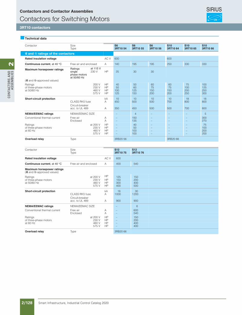
SIRIUS
Smart Infrastructure, Industrial Control Catalog 2020 2/128
2Co
nta
Cto
rs a
nd
a
ssem
bli
es
Siemens / Industrial Controls Previous folio: IC10 2/90
eziSrotcatnoCType
S63RT10 54
S63RT10 55
S63RT10 56
S103RT10 64
S103RT10 65
S103RT10 66
s and u ratings of the contactors
Rated insulation voltage AC V 600 600
Continuous current, at 40 °C Free air and enclosed A 140 195 195 250 330 330
Maximum horsepower ratings Ratingssinglephase motorsat 50/60 Hz
HP 25 30 30
(s and u-approved values)PHV 002sgnitaR 40 50 60 60 75 100PHV 032srotom esahp-eerht fo 50 60 75 75 100 125PHV 064zH 06/05 ta 100 125 150 150 200 250
575 V HP 125 150 200 200 250 300
Short-circuit protection kA 10 10 10 10 18 18CLASS RK5 fuse A 450 500 500 700 800 800Circuit-breakeracc. to UL 489 A 350 450 500 500 700 800
NEMA/EEMAC ratings NEMA/EEMAC SIZE – 4 – – – 5Conventional thermal current Free air A – 150 – – – 300
Enclosed A – 135 – – – 270PHV 002 tasgnitaR – 40 – – – 75PHV 032srotom esahp-eerht fo – 50 – – – 100PHV 064zH 06 ta – 100 – – – 200
575 V HP – 100 – – – 200
Overload relay Type 3RB20 56 3RB20 66
eziSrotcatnoCType
S123RT10 75
S123RT10 76
Rated insulation voltage AC V 600
Continuous current, at 40 °C Free air and enclosed A 400 540
Maximum horsepower ratings(s and u-approved values)
V 002 tasgnitaR HP 125 150PHV 032srotom esahp-eerht fo 150 200PHV 064zH 06/05 ta 300 400
575 V HP 400 500
Short-circuit protection kA 18 30CLASS RK5 fuse A 1000 1200Circuit-breaker acc. to UL 489 A 900 900
NEMA/EEMAC ratings NEMA/EEMAC SIZE – 6Conventional thermal current Free air A – 600
Enclosed A – 540
PHV 002 tasgnitaR – 150PHV 032srotom esahp-eerht fo – 200PHV 064zH 06 ta – 400
575 V HP – 400
Overload relay Type 3RB20 66
Technical data
at 115 V230 V
Contactors and Contactor Assemblies
Contactors for Switching Motors3RT10 contactors
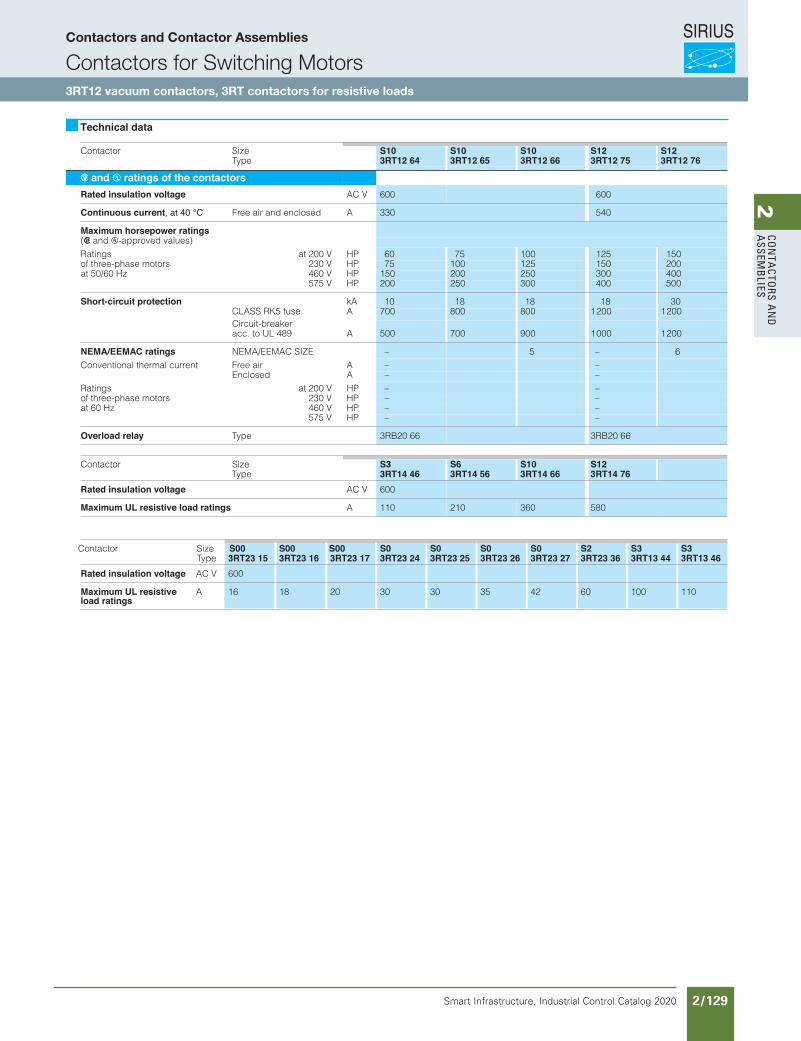
SIRIUS
Smart Infrastructure, Industrial Control Catalog 2020 2/129
2Co
nta
Ctors a
nd
a
ssemb
lies
eziSrotcatnoCType
S103RT12 64
S103RT12 65
S103RT12 66
S123RT12 75
S123RT12 76
s and u ratings of the contactorsRated insulation voltage AC V 600 600
Continuous current, at 40 °C Free air and enclosed A 330 540
Maximum horsepower ratings(s and u-approved values)
PHV 002 tasgnitaR 60 75 100 125 150PHV 032srotom esahp-eerht fo 75 100 125 150 200PHV 064zH 06/05 ta 150 200 250 300 400
575 V HP 200 250 300 400 500
Short-circuit protection kA 10 18 18 18 30CLASS RK5 fuse A 700 800 800 1200 1200Circuit-breaker acc. to UL 489 A 500 700 900 1000 1200
NEMA/EEMAC ratings NEMA/EEMAC SIZE – 5 – 6Conventional thermal current Free air A – –
Enclosed A – –PHV 002 tasgnitaR – –PHV 032srotom esahp-eerht fo – –PHV 064zH 06 ta – –
575 V HP – –
Overload relay Type 3RB20 66 3RB20 66
eziSrotcatnoCType
S33RT14 46
S63RT14 56
S103RT14 66
S123RT14 76
Rated insulation voltage AC V 600
Maximum UL resistive load ratings A 110 210 360 580
SizerotcatnoCType
S03RT23 24
S03RT23 25
S03RT23 26
S03RT23 27
S23RT23 36
S33RT13 44
S33RT13 46
Rated insulation voltage AC V
Maximum UL resistiveload ratings
A 30
3RT23 17
20
3RT23 16
18
3RT23 15600
16 30 35 42 60 100 110
Technical data
S00 S00 S00
Siemens / Industrial Controls Previous folio: IC10 2/91
Contactors and Contactor Assemblies
Contactors for Switching Motors3RT12 vacuum contactors, 3RT contactors for resistive loads
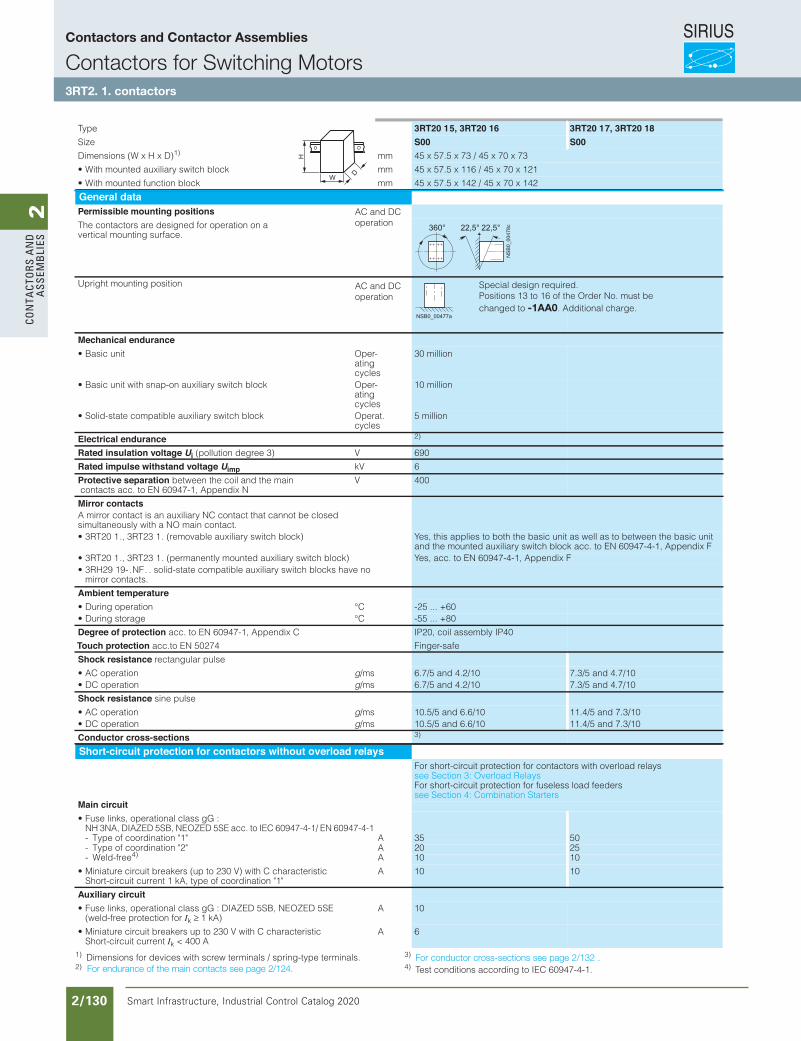
SIRIUS
Smart Infrastructure, Industrial Control Catalog 2020 2/130
2Co
nta
Cto
rs a
nd
a
ssem
bli
es3RT Power Contactors for Switching Motors
3RT20 contactors, 3-pole, 3 ... 25 HP
3/20 SIRIUS Innovations Supplement 2012
3
1) Dimensions for devices with screw terminals / spring-type terminals.2)
3) 4) Test conditions according to IEC 60947-4-1.
Type 3RT20 15, 3RT20 16 3RT20 17, 3RT20 18Size S00 S00Dimensions (W x H x D)1) mm 45 x 57.5 x 73 / 45 x 70 x 73
mmkcolb hctiws yrailixua detnuom htiW• 45 x 57.5 x 116 / 45 x 70 x 121
mmkcolb noitcnuf detnuom htiW• 45 x 57.5 x 142 / 45 x 70 x 142
General dataPermissible mounting positionsThe contactors are designed for operation on a vertical mounting surface.
Upright mounting position
Mechanical endurance-repOtinu cisaB•
ating cycles
30 million
-repOkcolb hctiws yrailixua no-pans htiw tinu cisaB•ating cycles
10 million
• Solid-state compatible auxiliary switch block Operat. cycles
5 million
Electrical endurance 2)
Rated insulation voltage Ui V)3 eerged noitullop( 690
Rated impulse withstand voltage Uimp kV 6
Protective separation between the coil and the main contacts acc. to EN 60947-1, Appendix N
V 400
Mirror contactsA mirror contact is an auxiliary NC contact that cannot be closed simultaneously with a NO main contact.• 3RT20 1 ., 3RT23 1 . (removable auxiliary switch block) Yes, this applies to both the basic unit as well as to between the basic unit
and the mounted auxiliary switch block acc. to EN 60947-4-1, Appendix F• 3RT20 1 ., 3RT23 1 . (permanently mounted auxiliary switch block) Yes, acc. to EN 60947-4-1, Appendix F• 3RH29 19- . NF . . solid-state compatible auxiliary switch blocks have no
mirror contacts.
Ambient temperatureC°noitarepo gniruD• -25 ... +60C°egarots gniruD• -55 ... +80
Degree of protection acc. to EN 60947-1, Appendix C
Touch protection acc.to EN 50274
IP20, coil assembly IP40
Finger-safe
Shock resistance rectangular pulse
• AC operation g/ms 6.7/5 and 4.2/10 7.3/5 and 4.7/10• DC operation g/ms 6.7/5 and 4.2/10 7.3/5 and 4.7/10
Shock resistance sine pulse
• AC operation g/ms 10.5/5 and 6.6/10 11.4/5 and 7.3/10• DC operation g/ms 10.5/5 and 6.6/10 11.4/5 and 7.3/10
Conductor cross-sections 3)
Short-circuit protection for contactors without overload relaysFor short-circuit protection for contactors with overload relays see Section 3: Overload RelaysFor short-circuit protection for fuseless load feeders see Section 4: Combination Starters
Main circuit• Fuse links, operational class gG :
NH 3NA, DIAZED 5SB, NEOZED 5SE acc. to IEC 60947-4-1/ EN 60947-4-1A"1" noitanidrooc fo epyT- 35 50A"2" noitanidrooc fo epyT- 20 25
- Weld-free4) A 10 10
• Miniature circuit breakers (up to 230 V) with C characteristicShort-circuit current 1 kA, type of coordination "1"
A 10 10
Auxiliary circuit • Fuse links, operational class gG : DIAZED 5SB, NEOZED 5SE
(weld-free protection for Ik ≥ 1 kA) A 10
• Miniature circuit breakers up to 230 V with C characteristic Short-circuit current Ik < 400 A
A 6
W
H
D
360° 22,5°22,5°
NSB0_00478c
NSB0_00477a
LV1N_03_04.fm Page 20 Friday, October 18, 2013 3:57 PM
Special design required.Positions 13 to 16 of the Order No. must be changed to -1AA0. Additional charge.
AC and DC operation
AC and DC operation
Siemens / Industrial Controls Previous folio: IC10 2/92
For endurance of the main contacts see page 2/124.For conductor cross-sections see page 2/132 .
Contactors and Contactor Assemblies
Contactors for Switching Motors3RT2. 1. contactors
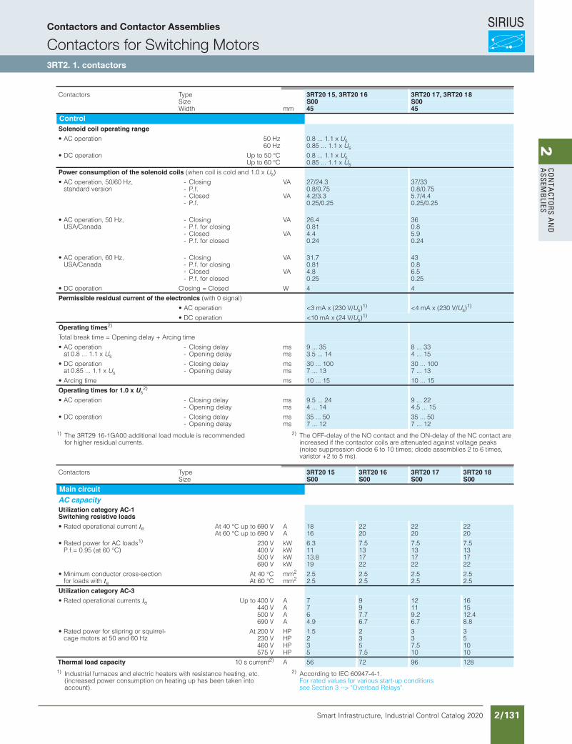
SIRIUS
Smart Infrastructure, Industrial Control Catalog 2020 2/131
2Co
nta
Ctors a
nd
a
ssemb
lies3RT Power Contactors for Switching Motors
3RT20 contactors, 3-pole, 3 ... 25 HP
3/21SIRIUS Innovations Supplement 2012
3
1) The 3RT29 16-1GA00 additional load module is recommended for higher residual currents.
2) The OFF-delay of the NO contact and the ON-delay of the NC contact are increased if the contactor coils are attenuated against voltage peaks (noise suppression diode 6 to 10 times; diode assemblies 2 to 6 times, varistor +2 to 5 ms).
1) Industrial furnaces and electric heaters with resistance heating, etc. (increased power consumption on heating up has been taken into account).
2) According to IEC 60947-4-1. For rated values for various start-up conditions see Section 3 --> "Overload Relays".
epyTsrotcatnoC 3RT20 15, 3RT20 16 3RT20 17, 3RT20 18Size S00 S00
mmhtdiW 45 45ControlSolenoid coil operating range
zH 05noitarepo CA• 0.8 ... 1.1 x Us60 Hz 0.85 ... 1.1 x Us
C° 05 ot pUnoitarepo CD• 0.8 ... 1.1 x UsUp to 60 °C 0.85 ... 1.1 x Us
Power consumption of the solenoid coils (when coil is cold and 1.0 x Us)
• AC operation, 50/60 Hz, standard version
AVgnisolC- 27/24.3 37/33- P.f. 0.8/0.75 0.8/0.75
AVdesolC- 4.2/3.3 5.7/4.4- P.f. 0.25/0.25 0.25/0.25
• AC operation, 50 Hz, USA/Canada
AVgnisolC- 26.4 36- P.f. for closing 0.81 0.8
AVdesolC- 4.4 5.9- P.f. for closed 0.24 0.24
• AC operation, 60 Hz, USA/Canada
AVgnisolC- 31.7 43- P.f. for closing 0.81 0.8
AVdesolC- 4.8 6.5- P.f. for closed 0.25 0.25
WdesolC = gnisolCnoitarepo CD• 4 4
Permissible residual current of the electronics (with 0 signal)
• AC operation <3 mA x (230 V/Us)1) <4 mA x (230 V/Us)
1)
• DC operation <10 mA x (24 V/Us)1)
Operating times2)
Total break time = Opening delay + Arcing time
• AC operation at 0.8 ... 1.1 x Us
- Closing delay ms 9 ... 35 8 ... 33- Opening delay ms 3.5 ... 14 4 ... 15
• DC operation at 0.85 ... 1.1 x Us
- Closing delay ms 30 ... 100 30 ... 100- Opening delay ms 7 ... 13 7 ... 13
smemit gnicrA• 10 ... 15 10 ... 15
Operating times for 1.0 x Us2)
smyaled gnisolC-noitarepo CA• 9.5 ... 24 9 ... 22- Opening delay ms 4 ... 14 4.5 ... 15
smyaled gnisolC-noitarepo CD• 35 ... 50 35 ... 50- Opening delay ms 7 ... 12 7 ... 12
epyTsrotcatnoC 3RT20 15 3RT20 16 3RT20 17 3RT20 18Size S00 S00 S00 S00
Main circuitAC capacityUtilization category AC-1Switching resistive loads
• Rated operational current Ie At 40 °C up to 690 V A 18 22 22 22At 60 °C up to 690 V A 16 20 20 20
• Rated power for AC loads1) P.f.= 0.95 (at 60 °C)
230 V kW 6.3 7.5 7.5 7.5400 V kW 11 13 13 13500 V kW 13.8 17 17 17690 V kW 19 22 22 22
• Minimum conductor cross-section for loads with Ie
At 40 °C mm2 2.5 2.5 2.5 2.5At 60 °C mm2 2.5 2.5 2.5 2.5
Utilization category AC-3• Rated operational currents Ie Up to 400 V A 7 9 12 16
440 V A 7 9 11 15500 V A 6 7.7 9.2 12.4690 V A 4.9 6.7 6.7 8.8
• Rated power for slipring or squirrel-cage motors at 50 and 60 Hz
At 200 V HP 1.5 2 3 3230 V HP 2 3 3 5460 V HP 3 5 7.5 10575 V HP 5 7.5 10 10
Thermal load capacity 10 s current2) A 56 72 96 128
LV1N_03_04.fm Page 21 Friday, October 18, 2013 3:57 PM
Siemens / Industrial Controls Previous folio: IC10 2/93
Contactors and Contactor Assemblies
Contactors for Switching Motors3RT2. 1. contactors
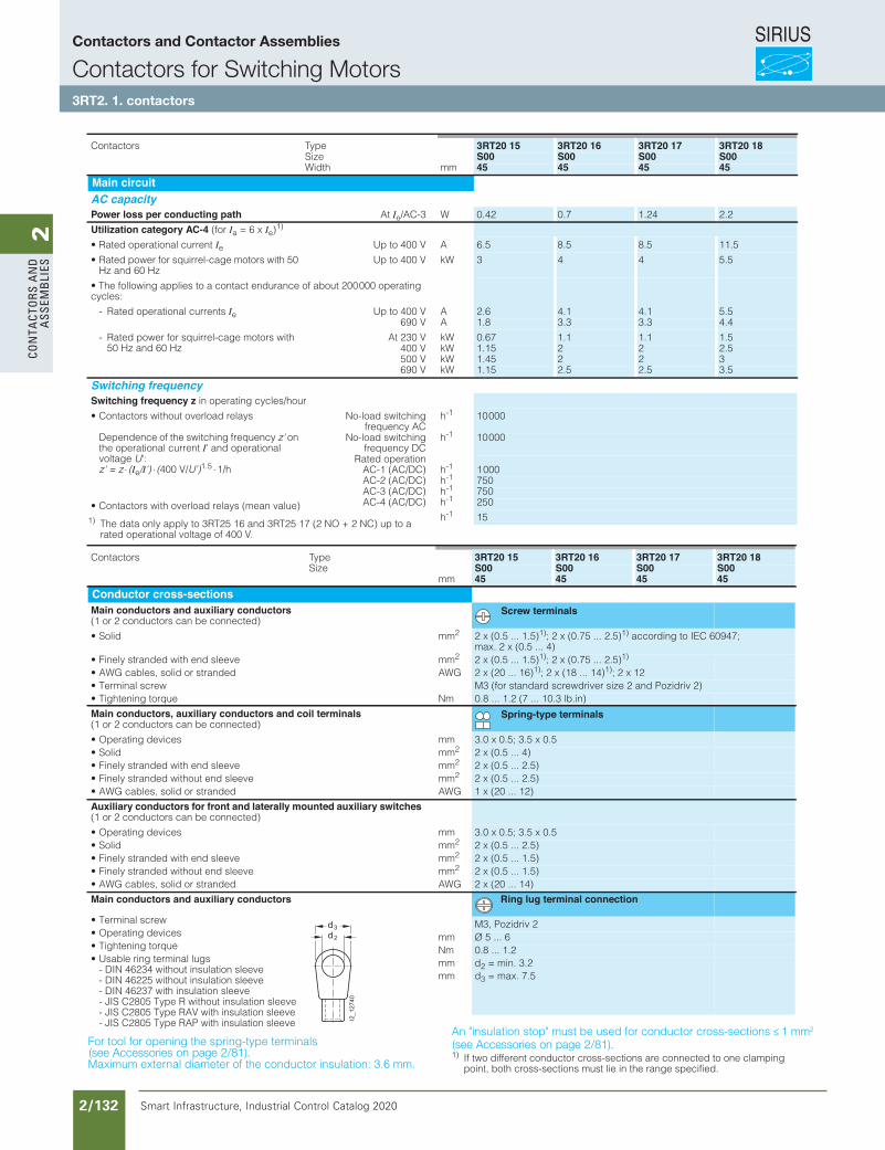
SIRIUS
Smart Infrastructure, Industrial Control Catalog 2020 2/132
2Co
nta
Cto
rs a
nd
a
ssem
bli
es3RT Power Contactors for Switching Motors
3RT20 contactors, 3-pole, 3 ... 25 HP
3/22 SIRIUS Innovations Supplement 2012
3
1) The data only apply to 3RT25 16 and 3RT25 17 (2 NO + 2 NC) up to a rated operational voltage of 400 V.
For tool for opening the spring-type terminals
Maximum external diameter of the conductor insulation: 3.6 mm.
An "insulation stop" must be used for conductor cross-sections ≤ 1 mm²
1) If two different conductor cross-sections are connected to one clamping point, both cross-sections must lie in the range specified.
epyTsrotcatnoC 3RT20 15 3RT20 16 3RT20 17 3RT20 18Size S00 S00 S00 S00
mmhtdiW 45 45 45 45Main circuitAC capacityPower loss per conducting path At Ie/AC-3 W 0.42 0.7 1.24 2.2
Utilization category AC-4 (for Ia = 6 x Ie)1)
• Rated operational current Ie Up to 400 V A 6.5 8.5 8.5 11.5
• Rated power for squirrel-cage motors with 50 Hz and 60 Hz
Up to 400 V kW 3 4 4 5.5
• The following applies to a contact endurance of about 200 000 operating cycles:
- Rated operational currents Ie Up to 400 V A 2.6 4.1 4.1 5.5690 V A 1.8 3.3 3.3 4.4
- Rated power for squirrel-cage motors with 50 Hz and 60 Hz
At 230 V kW 0.67 1.1 1.1 1.5400 V kW 1.15 2 2 2.5500 V kW 1.45 2 2 3690 V kW 1.15 2.5 2.5 3.5
Switching frequencySwitching frequency z in operating cycles/hour
• Contactors without overload relays
Dependence of the switching frequency z' on the operational current I' and operational voltage U':z' = z ⋅ ⋅ ⋅(Ie/I') (400 V/U')1.5 1/h
No-load switchingfrequency AC
h-1 10 000
No-load switchingfrequency DC
h-1 10 000
Rated operationAC-1 (AC/DC) h-1 1 000AC-2 (AC/DC) h-1 750AC-3 (AC/DC) h-1 750AC-4 (AC/DC) h-1 250
h)eulav naem( syaler daolrevo htiw srotcatnoC•
-1 15
epyTsrotcatnoC 3RT20 15 3RT20 16 3RT20 17 3RT20 18Size S00 S00 S00 S00
mm 45 45 45 45Conductor cross-sectionsMain conductors and auxiliary conductors(1 or 2 conductors can be connected)
Screw terminals
mmdiloS• 2 2 x (0.5 ... 1.5)1); 2 x (0.75 ... 2.5)1) according to IEC 60947; max. 2 x (0.5 ... 4)
mmeveels dne htiw dednarts yleniF• 2 2 x (0.5 ... 1.5)1); 2 x (0.75 ... 2.5)1)
GWAdednarts ro dilos ,selbac GWA• 2 x (20 ... 16)1); 2 x (18 ... 14)1); 2 x 12• Terminal screw M3 (for standard screwdriver size 2 and Pozidriv 2)
mNeuqrot gninethgiT• 0.8 ... 1.2 (7 ... 10.3 lb.in)
Main conductors, auxiliary conductors and coil terminals(1 or 2 conductors can be connected)
Spring-type terminals
mmsecived gnitarepO• 3.0 x 0.5; 3.5 x 0.5mmdiloS• 2 2 x (0.5 ... 4)mmeveels dne htiw dednarts yleniF• 2 2 x (0.5 ... 2.5)mmeveels dne tuohtiw dednarts yleniF• 2 2 x (0.5 ... 2.5)
GWAdednarts ro dilos ,selbac GWA• 1 x (20 ... 12)
Auxiliary conductors for front and laterally mounted auxiliary switches(1 or 2 conductors can be connected)
mmsecived gnitarepO• 3.0 x 0.5; 3.5 x 0.5mmdiloS• 2 2 x (0.5 ... 2.5)mmeveels dne htiw dednarts yleniF• 2 2 x (0.5 ... 1.5)mmeveels dne tuohtiw dednarts yleniF• 2 2 x (0.5 ... 1.5)
GWAdednarts ro dilos ,selbac GWA• 2 x (20 ... 14)
Main conductors and auxiliary conductors Ring lug terminal connection
• Terminal screw M3, Pozidriv 2mmsecived gnitarepO• Ø 5 ... 6mNeuqrot gninethgiT• 0.8 ... 1.2
• Usable ring terminal lugs - DIN 46234 without insulation sleeve - DIN 46225 without insulation sleeve - DIN 46237 with insulation sleeve - JIS C2805 Type R without insulation sleeve - JIS C2805 Type RAV with insulation sleeve - JIS C2805 Type RAP with insulation sleeve
mmmm
d2 = min. 3.2d3 = max. 7.5
I2_12740
d 2
d3
LV1N_03_04.fm Page 22 Friday, October 18, 2013 3:57 PM
≤ ×
≥
∅
Siemens / Industrial Controls Previous folio: IC10 2/94
(see Accessories on page 2/81).(see Accessories on page 2/81).
Contactors and Contactor Assemblies
Contactors for Switching Motors3RT2. 1. contactors
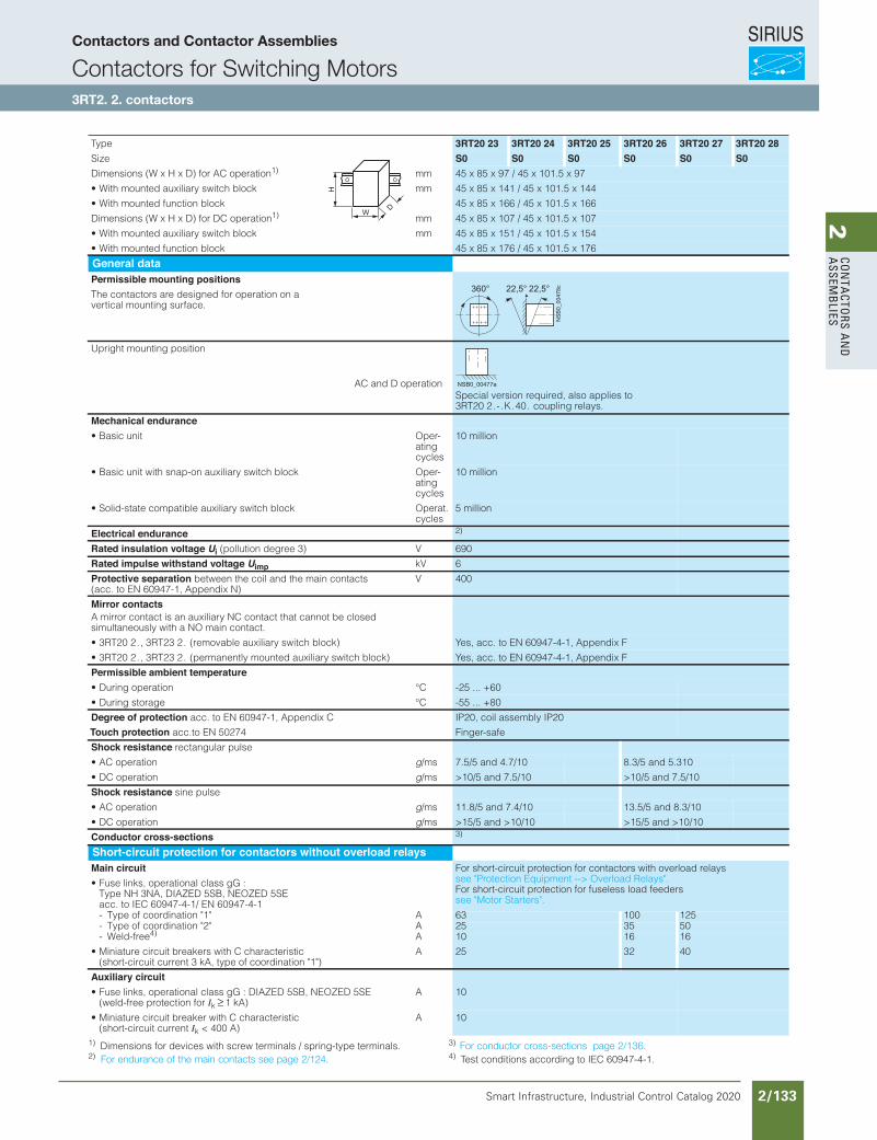
SIRIUS
Smart Infrastructure, Industrial Control Catalog 2020 2/133
2Co
nta
Ctors a
nd
a
ssemb
lies
Siemens / Industrial Controls Previous folio: IC10 2/96
1) Dimensions for devices with screw terminals / spring-type terminals.2)
3) 4) Test conditions according to IEC 60947-4-1.
Type 3RT20 23 3RT20 24 3RT20 25 3RT20 26 3RT20 27 3RT20 28Size S0 S0 S0 S0 S0 S0Dimensions (W x H x D) for AC operation1) mm 45 x 85 x 97 / 45 x 101.5 x 97
mmkcolb hctiws yrailixua detnuom htiW• 45 x 85 x 141 / 45 x 101.5 x 144
• With mounted function block 45 x 85 x 166 / 45 x 101.5 x 166
Dimensions (W x H x D) for DC operation1) mm 45 x 85 x 107 / 45 x 101.5 x 107
mmkcolb hctiws yrailixua detnuom htiW• 45 x 85 x 151 / 45 x 101.5 x 154
• With mounted function block 45 x 85 x 176 / 45 x 101.5 x 176
General dataPermissible mounting positionsThe contactors are designed for operation on a vertical mounting surface.
Upright mounting position
Special version required, also applies to AC and D operation
3RT20 2 . - . K . 40 . coupling relays.
Mechanical endurance-repOtinu cisaB•
ating cycles
10 million
-repOkcolb hctiws yrailixua no-pans htiw tinu cisaB•ating cycles
10 million
• Solid-state compatible auxiliary switch block Operat. cycles
5 million
Electrical endurance 2)
Rated insulation voltage Ui V)3 eerged noitullop( 690
Rated impulse withstand voltage Uimp kV 6
Protective separation between the coil and the main contacts (acc. to EN 60947-1, Appendix N)
V 400
Mirror contactsA mirror contact is an auxiliary NC contact that cannot be closed simultaneously with a NO main contact.
• 3RT20 2 . , 3RT23 2 . (removable auxiliary switch block) Yes, acc. to EN 60947-4-1, Appendix F
• 3RT20 2 . , 3RT23 2 . (permanently mounted auxiliary switch block) Yes, acc. to EN 60947-4-1, Appendix F
Permissible ambient temperatureC°noitarepo gniruD• -25 ... +60
C°egarots gniruD• -55 ... +80
Degree of protection acc. to EN 60947-1, Appendix C
Touch protection acc.to EN 50274
IP20, coil assembly IP20
Finger-safe
Shock resistance rectangular pulse
• AC operation g/ms 7.5/5 and 4.7/10 8.3/5 and 5.310
• DC operation g/ms >10/5 and 7.5/10 >10/5 and 7.5/10
Shock resistance sine pulse
• AC operation g/ms 11.8/5 and 7.4/10 13.5/5 and 8.3/10
• DC operation g/ms >15/5 and >10/10 >15/5 and >10/10
Conductor cross-sections 3)
Short-circuit protection for contactors without overload relaysMain circuit For short-circuit protection for contactors with overload relays
see "Protection Equipment --> Overload Relays". For short-circuit protection for fuseless load feeders see "Motor Starters".
• Fuse links, operational class gG : Type NH 3NA, DIAZED 5SB, NEOZED 5SEacc. to IEC 60947-4-1/ EN 60947-4-1
A"1" noitanidrooc fo epyT- 63 100 125A"2" noitanidrooc fo epyT- 25 35 50
- Weld-free4) A 10 16 16
• Miniature circuit breakers with C characteristic (short-circuit current 3 kA, type of coordination "1")
A 25 32 40
Auxiliary circuit • Fuse links, operational class gG : DIAZED 5SB, NEOZED 5SE
(weld-free protection for Ik ≥ 1 kA) A 10
• Miniature circuit breaker with C characteristic (short-circuit current Ik < 400 A)
A 10
W
H
D
360° 22,5°22,5°
NSB0_00478c
NSB0_00477a
For conductor cross-sections page 2/136.For endurance of the main contacts see page 2/124.
Contactors and Contactor Assemblies
Contactors for Switching Motors3RT2. 2. contactors
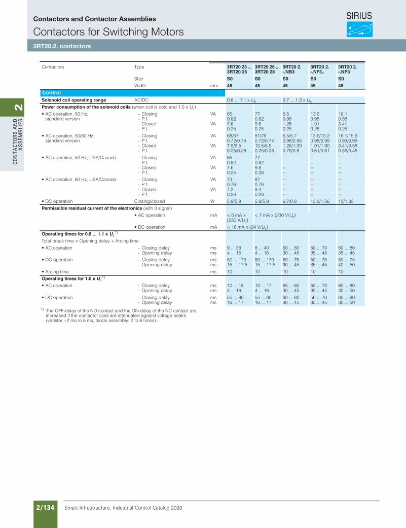
SIRIUS
Smart Infrastructure, Industrial Control Catalog 2020 2/134
2Co
nta
Cto
rs a
nd
a
ssem
bli
es
Siemens / Industrial Controls Previous folio: IC10 2/97
3RT Power Contactors for Switching Motors
3RT20 contactors, 3-pole, 3 ... 25 HP
3/24 SIRIUS Innovations Supplement 2012
3
1) The OFF-delay of the NO contact and the ON-delay of the NC contact are increased if the contactor coils are attenuated against voltage peaks (varistor +2 ms to 5 ms, diode assembly: 2 to 6 times).
epyTsrotcatnoC 3RT20 23 ...3RT20 25
3RT20 26 ...3RT20 28
3RT20 2.-.NB3
3RT20 2.-.NF3..
3RT20 2.-.NP3
Size S0 S0 S0 S0 S0mmhtdiW 45 45 45 45 45
ControlSolenoid coil operating range AC/DC 0.8 ... 1.1 x Us 0.7 ... 1.3 x Us
Power consumption of the solenoid coils (when coil is cold and 1.0 x Us)
• AC operation, 50 Hz, standard version
AVgnisolC- 65 77 6.5 13.6 16.1- P.f. 0.82 0.82 0.98 0.98 0.98
AVdesolC- 7.6 9.8 1.26 1.91 3.41- P.f. 0.25 0.25 0.25 0.25 0.25
• AC operation, 50/60 Hz, standard version
AVgnisolC- 68/67 81/79 6.5/5.7 13.6/13.2 16.1/15.9- P.f. 0.72/0.74 0.72/0.74 0.98/0.96 0.98/0.99 0.99/0.99
AVdesolC- 7.9/6.5 10.5/8.5 1.26/1.30 1.91/1.90 3.41/3.58- P.f. 0.25/0.28 0.25/0.28 0.78/0.8 0.61/0.61 0.36/0.45
AVgnisolC-adanaC/ASU ,zH 05 ,noitarepo CA• 65 77 -- -- --- P.f. 0.82 0.82 -- -- --
AVdesolC- 7.6 9.8 -- -- --- P.f. 0.25 0.28 -- -- --
AVgnisolC-adanaC/ASU ,zH 06 ,noitarepo CA• 73 87 -- -- --- P.f. 0.76 0.76 -- -- --
AVdesolC- 7.2 9.4 -- -- --- P.f. 0.28 0.28 -- -- --
Wdesolc/gnisolCnoitarepo CD• 5.9/5.9 5.9/5.9 6.7/0.8 13.2/1.56 15/1.83
Permissible residual current of the electronics (with 0 signal)
• AC operation mA < 6 mA x (230 V/Us)
< 7 mA x (230 V/Us)
• DC operation mA < 16 mA x (24 V/Us)
Operating times for 0.8 ... 1.1 x Us1)
Total break time = Opening delay + Arcing time
smyaled gnisolC-noitarepo CA• 9 ... 38 8 ... 40 60 ... 80 50 ... 70 60 ... 80- Opening delay ms 4 ... 16 4 ... 16 30 ... 45 35 ... 45 35 ... 45
smyaled gnisolC-noitarepo CD• 50 ... 170 50 ... 170 60 ... 75 50 ... 70 50 ... 75- Opening delay ms 15 ... 17.5 15 ... 17.5 30 ... 45 35 ... 45 40 ... 50
smemit gnicrA• 10 10 10 10 10
Operating times for 1.0 x Us1)
smyaled gnisolC-noitarepo CA• 10 ... 18 10 ... 17 65 ... 80 50 ... 70 60 ... 80- Opening delay ms 4 ... 16 4 ... 16 30 ... 45 35 ... 45 30 ... 50
smyaled gnisolC-noitarepo CD• 55 ... 80 55 ... 80 60 ... 80 56 ... 70 60 ... 80- Opening delay ms 16 ... 17 16 ... 17 30 ... 45 35 ... 45 30 ... 50
LV1N_03_04.fm Page 24 Friday, October 18, 2013 3:57 PM
Contactors and Contactor Assemblies
Contactors for Switching Motors3RT20.2. contactors
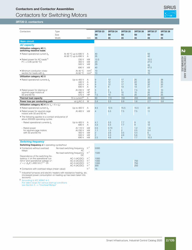
SIRIUS
Smart Infrastructure, Industrial Control Catalog 2020 2/135
2Co
nta
Ctors a
nd
a
ssemb
lies
Siemens / Industrial Controls Previous folio: IC10 2/98
3RT Power Contactors for Switching Motors
3RT20 contactors, 3-pole, 3 ... 25 HP
3/25SIRIUS Innovations Supplement 2012
3
1) Industrial furnaces and electric heaters with resistance heating, etc. (increased power consumption on heating up has been taken into account).
2) According to IEC 60947-4-1.For rated values for various start-up conditions see Section 3 --> "Overload Relays" .
epyTsrotcatnoC 3RT20 23 3RT20 24 3RT20 25 3RT20 26 3RT20 27 3RT20 28eziS S0 S0 S0 S0 S0 S0
mmhtdiW 45 45 45 45 45 45Main circuitAC capacityUtilization category AC-1,switching resistive loads
• Rated operational current Ie At 40 °C up to 690 V A 40 50AV 096 ot pu C° 06 tA 35 42
• Rated power for AC loads1)
P.f. = 0.95 (at 60 °C)230 V kW 13.3 15.5400 V kW 23 27.5500 V kW 29 35690 V kW 40 47.5
• Minimum conductor cross-section for loads with Ie
At 40 °C mm2 10 10At 60 °C mm2 10 10
Utilization category AC-3• Rated operational currents Ie Up to 400 V A 9 12 17 25 32 38
440 V A 9 12 17 22 32 35500 V A 9 12 17 18 32 32690 V A 9 9 13 13 21 21
• Rated power for slipring or squirrel-cage motors at 50 and 60 Hz
At 230 V HP 3 3 5 7.5 10 10460 V HP 5 7.5 10 15 20 25575 V HP 7.5 10 15 20 25 25
Thermal load capacity 10 s current2) A 80 110 150 200 260 300
Power loss per conducting path at Ie/AC-3 W 0.4 0.5 0.9 1.6 2.7 3.8
Utilization category AC-4 (for Ia = 6 x Ie)
• Rated operational current Ie Up to 400 V A 8.5 12.5 15.5 15.5 22
• Rated power for squirrel-cage motors with 50 and 60 Hz
At 400 V kW 4 5.5 7.5 7.5 11
• The following applies to a contact endurance of about 200 000 operating cycles:
- Rated operational currents Ie Up to 400 V A 4.1 5.5 7.7 9 12690 V A 3.3 5.5 7.7 9 12
- Rated power for squirrel-cage motors with 50 and 60 Hz
At 110 V kW 0.5 0.73 1 1.2 1.6At 230 V kW 1.1 1.5 2 2.5 3.4
400 V kW 2 2.6 3.5 4.4 6500 V kW 2 3.3 4.6 5.6 7.5690 V kW 2.5 4.6 6 7.7 10.3
Switching frequencySwitching frequency z in operating cycles/hour
• Contactors without overload relays
Dependence of the switching fre-quency z' on the operational cur-rent I’ and operational voltage U’:z’ = z ⋅ (Ie/I’) ⋅(400 V/U’)1.5 ⋅1/h
No-load switching frequencyAC
h-1 5 000
No-load switching frequencyDC
h-1 1 500
AC-1 (AC/DC) h-1 1 000AC-2 (AC/DC) h-1 1 000 750AC-3 (AC/DC) h-1 1 000 750AC-4 (AC/DC) h-1 300 250
• Contactors with overload relays (mean value) h-1 15
LV1N_03_04.fm Page 25 Friday, October 18, 2013 3:57 PM
Contactors and Contactor Assemblies
Contactors for Switching Motors3RT20 2. contactors
Revised on 10/11/17
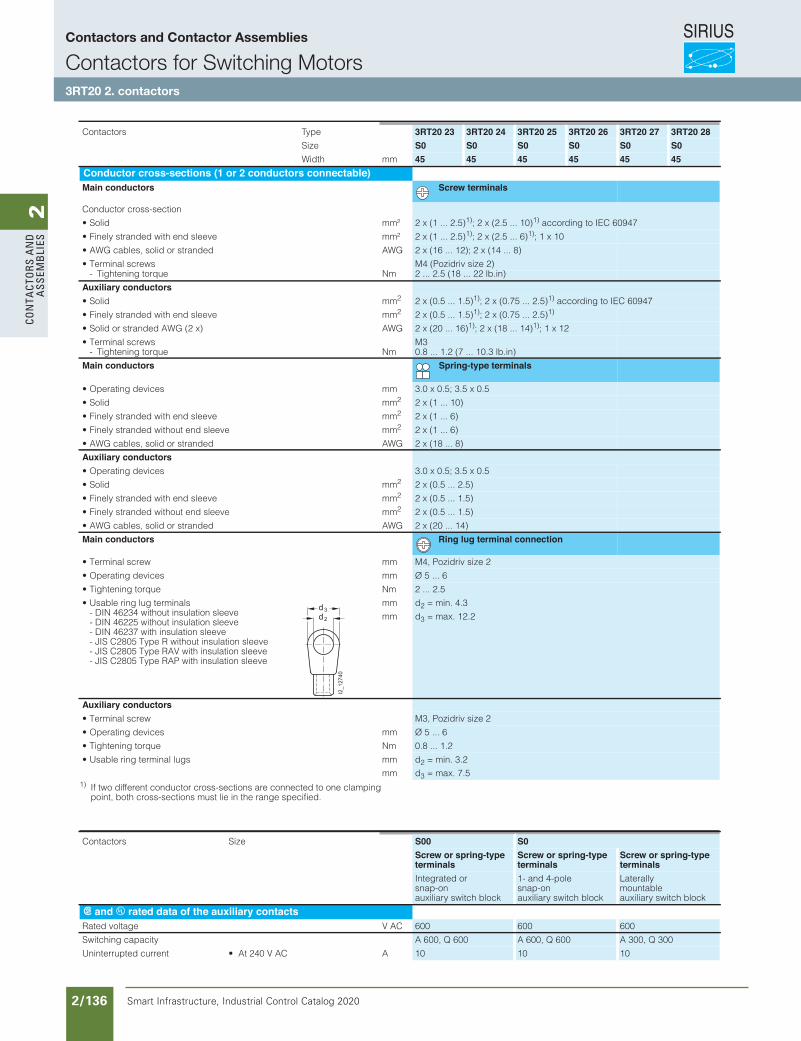
SIRIUS
Smart Infrastructure, Industrial Control Catalog 2020 2/136
2Co
nta
Cto
rs a
nd
a
ssem
bli
es
Siemens / Industrial Controls Previous folio: IC10 2/99
3RT Power Contactors for Switching Motors
3RT20 contactors, 3-pole, 3 ... 25 HP
3/26 SIRIUS Innovations Supplement 2012
3
1) If two different conductor cross-sections are connected to one clamping point, both cross-sections must lie in the range specified.
epyTsrotcatnoC 3RT20 23 3RT20 24 3RT20 25 3RT20 26 3RT20 27 3RT20 28Size S0 S0 S0 S0 S0 S0Width mm 45 45 45 45 45 45
Conductor cross-sections (1 or 2 conductors connectable)Main conductors Screw terminals
Conductor cross-section
²mmdiloS• 2 x (1 ... 2.5)1); 2 x (2.5 ... 10)1) according to IEC 60947
²mmeveels dne htiw dednarts yleniF• 2 x (1 ... 2.5)1); 2 x (2.5 ... 6)1); 1 x 10
GWAdednarts ro dilos ,selbac GWA• 2 x (16 ... 12); 2 x (14 ... 8)
• Terminal screws M4 (Pozidriv size 2)mNeuqrot gninethgiT- 2 ... 2.5 (18 ... 22 lb.in)
Auxiliary conductorsmmdiloS• 2 2 x (0.5 ... 1.5)1); 2 x (0.75 ... 2.5)1) according to IEC 60947
mmeveels dne htiw dednarts yleniF• 2 2 x (0.5 ... 1.5)1); 2 x (0.75 ... 2.5)1)
GWA)x 2( GWA dednarts ro diloS• 2 x (20 ... 16)1); 2 x (18 ... 14)1); 1 x 12
• Terminal screws M3mNeuqrot gninethgiT- 0.8 ... 1.2 (7 ... 10.3 lb.in)
Main conductors Spring-type terminals
mmsecived gnitarepO• 3.0 x 0.5; 3.5 x 0.5
mmdiloS• 2 2 x (1 ... 10)
mmeveels dne htiw dednarts yleniF• 2 2 x (1 ... 6)
mmeveels dne tuohtiw dednarts yleniF• 2 2 x (1 ... 6)
GWAdednarts ro dilos ,selbac GWA• 2 x (18 ... 8)
Auxiliary conductors• Operating devices 3.0 x 0.5; 3.5 x 0.5
mmdiloS• 2 2 x (0.5 ... 2.5)
mmeveels dne htiw dednarts yleniF• 2 2 x (0.5 ... 1.5)
mmeveels dne tuohtiw dednarts yleniF• 2 2 x (0.5 ... 1.5)
GWAdednarts ro dilos ,selbac GWA• 2 x (20 ... 14)
Main conductors Ring lug terminal connection
mmwercs lanimreT• M4, Pozidriv size 2
mmsecived gnitarepO• Ø 5 ... 6
mNeuqrot gninethgiT• 2 ... 2.5
• Usable ring lug terminals - DIN 46234 without insulation sleeve - DIN 46225 without insulation sleeve - DIN 46237 with insulation sleeve - JIS C2805 Type R without insulation sleeve - JIS C2805 Type RAV with insulation sleeve - JIS C2805 Type RAP with insulation sleeve
mm
mm
d2 = min. 4.3
d3 = max. 12.2
Auxiliary conductors• Terminal screw M3, Pozidriv size 2
mmsecived gnitarepO• Ø 5 ... 6
mNeuqrot gninethgiT• 0.8 ... 1.2
mmsgul lanimret gnir elbasU•
mm
d2 = min. 3.2
d3 = max. 7.5
I2_12740
d 2
d3
eziSsrotcatnoC S00 S0Screw or spring-typeterminals
Screw or spring-typeterminals
Screw or spring-typeterminals
Integrated or snap-on auxiliary switch block
1- and 4-pole snap-on auxiliary switch block
Laterally mountable auxiliary switch block
s and u rated data of the auxiliary contactsCA Vegatlov detaR 600 600 600
Switching capacity A 600, Q 600 A 600, Q 600 A 300, Q 300
ACA V 042 tA •tnerruc detpurretninU 10 10 10
LV1N_03_04.fm Page 26 Friday, October 18, 2013 3:57 PM
Contactors and Contactor Assemblies
Contactors for Switching Motors3RT20 2. contactors
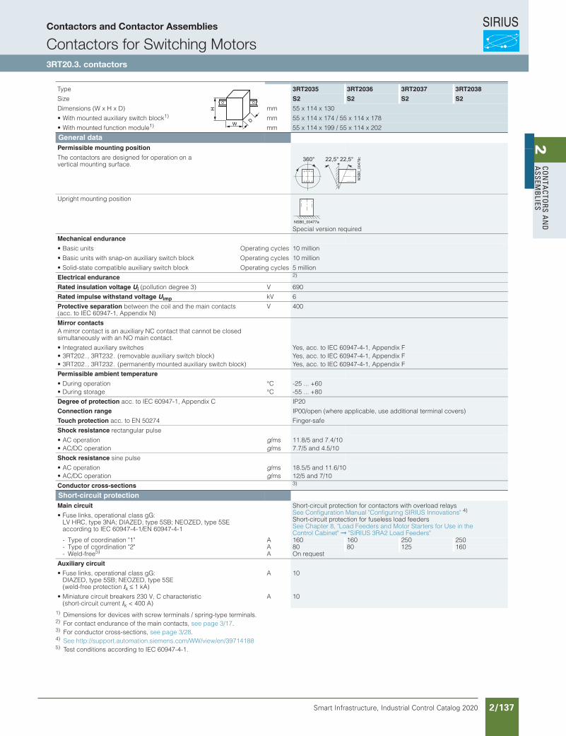
SIRIUS
Smart Infrastructure, Industrial Control Catalog 2020 2/137
2Co
nta
Ctors a
nd
a
ssemb
lies
3/29Siemens IC 10 · 2015
Power Contactors for Switching Motors
SIRIUS 3RT20 contactors, 3-pole, up to 37 kW
3
1) Dimensions for devices with screw terminals / spring-type terminals.2) For contact endurance of the main contacts, see page 3/17.3) For conductor cross-sections, see page 3/28.4) See http://support.automation.siemens.com/WW/view/en/397141885) Test conditions according to IEC 60947-4-1.
Type 3RT2035 3RT2036 3RT2037 3RT2038
Size S2 S2 S2 S2
Dimensions (W x H x D) mm 55 x 114 x 130• With mounted auxiliary switch block1) mm 55 x 114 x 174 / 55 x 114 x 178• With mounted function module1) mm 55 x 114 x 199 / 55 x 114 x 202
General data Permissible mounting position
The contactors are designed for operation on a vertical mounting surface.
Upright mounting position
Special version requiredMechanical endurance
• Basic units Operating cycles 10 million• Basic units with snap-on auxiliary switch block Operating cycles 10 million• Solid-state compatible auxiliary switch block Operating cycles 5 millionElectrical endurance 2) Rated insulation voltage Ui (pollution degree 3) V 690Rated impulse withstand voltage Uimp kV 6Protective separation between the coil and the main contacts (acc. to IEC 60947-1, Appendix N)
V 400
Mirror contactsA mirror contact is an auxiliary NC contact that cannot be closed simultaneously with an NO main contact.• Integrated auxiliary switches Yes, acc. to IEC 60947-4-1, Appendix F• 3RT202., 3RT232. (removable auxiliary switch block) Yes, acc. to IEC 60947-4-1, Appendix F• 3RT202., 3RT232. (permanently mounted auxiliary switch block) Yes, acc. to IEC 60947-4-1, Appendix FPermissible ambient temperature
• During operation °C -25 ... +60• During storage °C -55 ... +80Degree of protection acc. to IEC 60947-1, Appendix CConnection range
Touch protection acc. to EN 50274
IP20IP00/open (where applicable, use additional terminal covers)Finger-safe
Shock resistance rectangular pulse• AC operation g/ms 11.8/5 and 7.4/10• AC/DC operation g/ms 7.7/5 and 4.5/10Shock resistance sine pulse• AC operation g/ms 18.5/5 and 11.6/10• AC/DC operation g/ms 12/5 and 7/10Conductor cross-sections 3)
Short-circuit protectionMain circuit Short-circuit protection for contactors with overload relays
See Configuration Manual "Configuring SIRIUS Innovations" 4) Short-circuit protection for fuseless load feeders See Chapter 8, "Load Feeders and Motor Starters for Use in the Control Cabinet" "SIRIUS 3RA2 Load Feeders"
• Fuse links, operational class gG: LV HRC, type 3NA; DIAZED, type 5SB; NEOZED, type 5SE according to IEC 60947-4-1/EN 60947-4-1
- Type of coordination "1" A 160 160 250 250- Type of coordination "2" A 80 80 125 160- Weld-free5) A On request
Auxiliary circuit
• Fuse links, operational class gG: DIAZED, type 5SB; NEOZED, type 5SE (weld-free protection Ik ≤ 1 kA)
A 10
• Miniature circuit breakers 230 V, C characteristic (short-circuit current Ik < 400 A)
A 10
W
H
D
360° 22,5°22,5°
NS
B0_
0047
8c
NSB0_00477a
© Siemens AG 2015
Siemens / Industrial Controls Previous folio: IC10 2/100
Contactors and Contactor Assemblies
Contactors for Switching Motors3RT20.3. contactors
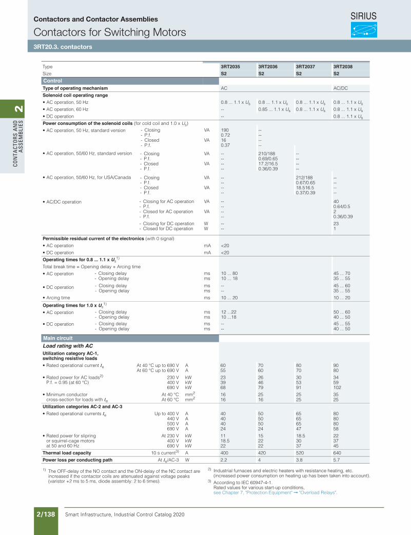
SIRIUS
Smart Infrastructure, Industrial Control Catalog 2020 2/138
2Co
nta
Cto
rs a
nd
a
ssem
bli
es
3/30 Siemens IC 10 · 2015
Power Contactors for Switching Motors
SIRIUS 3RT20 contactors, 3-pole, up to 37 kW
3
1) The OFF-delay of the NO contact and the ON-delay of the NC contact are increased if the contactor coils are attenuated against voltage peaks (varistor +2 ms to 5 ms, diode assembly: 2 to 6 times).
Type 3RT2035 3RT2036 3RT2037 3RT2038Size S2 S2 S2 S2ControlType of operating mechanism AC AC/DC
Solenoid coil operating range• AC operation, 50 Hz 0.8 ... 1.1 x Us 0.8 ... 1.1 x Us 0.8 ... 1.1 x Us 0.8 ... 1.1 x Us
• AC operation, 60 Hz -- 0.85 ... 1.1 x Us 0.8 ... 1.1 x Us 0.8 ... 1.1 x Us
• DC operation -- 0.8 ... 1.1 x Us
Power consumption of the solenoid coils (for cold coil and 1.0 x Us)
• AC operation, 50 Hz, standard version AVgnisolC- 190 --- P.f. 0.72 --
AVdesolC- 16 --- P.f. 0.37 --
• AC operation, 50/60 Hz, standard version AVgnisolC- -- 210/188 --- P.f. -- 0.69/0.65 --
AVdesolC- -- 17.2/16.5 --- P.f. -- 0.36/0.39 --
• AC operation, 50/60 Hz, for USA/Canada AVgnisolC- -- 212/188 --- P.f. -- 0.67/0.65 --
AVdesolC- -- 18.516.5 --- P.f. -- 0.37/0.39 --
• AC/DC operation AVnoitarepo CA rof gnisolC- -- 40- P.f. -- 0.64/0.5
AVnoitarepo CA rof desolC- -- 2- P.f. -- 0.36/0.39
Wnoitarepo CD rof gnisolC- -- 23Wnoitarepo CD rof desolC- -- 1
Permissible residual current of the electronics (with 0 signal)
Amnoitarepo CA• <20
Amnoitarepo CD• <20
Operating times for 0.8 ... 1.1 x Us1)
Total break time = Opening delay + Arcing time
• AC operation smyaled gnisolC- 10 ... 80 45 ... 70smyaled gninepO- 10 ... 18 35 ... 55
• DC operation smyaled gnisolC- -- 45 ... 60smyaled gninepO- -- 35 ... 55
smemit gnicrA• 10 ... 20 10 ... 20
Operating times for 1.0 x Us1)
• AC operation smyaled gnisolC- 12 ...22 50 ... 60smyaled gninepO- 10 ...18 40 ... 50
• DC operation smyaled gnisolC- -- 45 ... 55smyaled gninepO- -- 40 ... 50
© Siemens AG 2015
Main circuitLoad rating with ACUtilization category AC-1, switching resistive loads
• Rated operational current Ie At 40 °C up to 690 V A 60 70 80 90AV 096 ot pu C° 06 tA 55 60 70 80
• Rated power for AC loads2)
P.f. = 0.95 (at 60 °C)230 V kW 23 26 30 34400 V kW 39 46 53 59690 V kW 68 79 91 102
• Minimum conductor cross-section for loads with Ie
At 40 °C mm2 16 25 25 35At 60 °C mm2 16 16 25 25
Utilization categories AC-2 and AC-3• Rated operational currents Ie Up to 400 V A 40 50 65 80
440 V A 40 50 65 80500 V A 40 50 65 80690 V A 24 24 47 58
• Rated power for slipring or squirrel-cage motors at 50 and 60 Hz
At 230 V kW 11 15 18.5 22400 V kW 18.5 22 30 37690 V kW 22 22 37 45
Thermal load capacity 10 s current3) A 400 420 520 640
Power loss per conducting path At Ie/AC-3 W 2.2 4 3.8 5.7
2) Industrial furnaces and electric heaters with resistance heating, etc. (increased power consumption on heating up has been taken into account).
3) According to IEC 60947-4-1. Rated values for various start-up conditions, see Chapter 7, "Protection Equipment" "Overload Relays".
Siemens / Industrial Controls Previous folio: IC10 2/101
Contactors and Contactor Assemblies
Contactors for Switching Motors3RT20.3. contactors
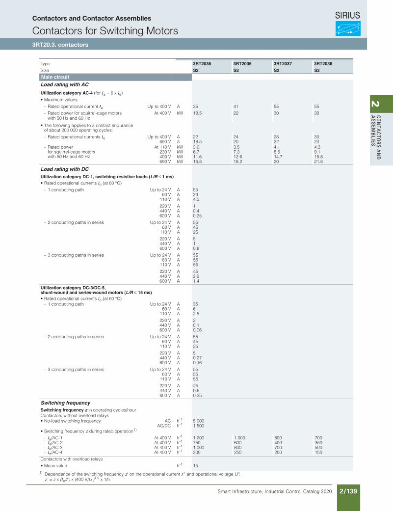
SIRIUS
Smart Infrastructure, Industrial Control Catalog 2020 2/139
2Co
nta
Ctors a
nd
a
ssemb
lies
3/31Siemens IC 10 · 2015
Power Contactors for Switching Motors
SIRIUS 3RT20 contactors, 3-pole, up to 37 kW
3
Type 3RT2035 3RT2036 3RT2037 3RT2038Size S2 S2 S2 S2Main circuitLoad rating with ACUtilization category AC-4 (for Ia = 6 x Ie)
• Maximum values:
- Rated operational current Ie Up to 400 V A 35 41 55 55
- Rated power for squirrel-cage motors with 50 Hz and 60 Hz
At 400 V kW 18.5 22 30 30
• The following applies to a contact endurance of about 200 000 operating cycles:
- Rated operational currents Ie Up to 400 V A 22 24 28 30690 V A 18.5 20 22 24
- Rated power for squirrel-cage motors with 50 Hz and 60 Hz
At 110 V kW 3.2 3.5 4.1 4.3230 V kW 6.7 7.3 8.5 9.1400 V kW 11.6 12.6 14.7 15.8690 V kW 16.8 18.2 20 21.8
© Siemens AG 2015
1) Dependence of the switching frequency z’ on the operational current I’ and operational voltage U’: z’ = z x (Ie/I’) x (400 V/U’)1.5 x 1/h
Load rating with DCUtilization category DC-1, switching resistive loads (L/R ≤ 1 ms)• Rated operational currents Ie (at 60 °C)
AV 42 ot pUhtap gnitcudnoc 1- 5560 V A 23
110 V A 4.5
220 V A 1440 V A 0.4600 V A 0.25
AV 42 ot pUseires ni shtap gnitcudnoc 2- 5560 V A 45
110 V A 25
220 V A 5440 V A 1600 V A 0.8
AV 42 ot pUseires ni shtap gnitcudnoc 3- 5560 V A 55
110 V A 55
220 V A 45440 V A 2.9600 V A 1.4
Utilization category DC-3/DC-5, shunt-wound and series-wound motors (L/R ≤ 15 ms)• Rated operational currents Ie (at 60 °C)
AV 42 ot pUhtap gnitcudnoc 1- 3560 V A 6
110 V A 2.5
220 V A 2440 V A 0.1600 V A 0.06
AV 42 ot pUseires ni shtap gnitcudnoc 2- 5560 V A 45
110 V A 25
220 V A 5440 V A 0.27600 V A 0.16
AV 42 ot pUseires ni shtap gnitcudnoc 3- 5560 V A 55
110 V A 55
220 V A 25440 V A 0.6600 V A 0.35
Switching frequencySwitching frequency z in operating cycles/hourContactors without overload relays
hCAycneuqerf gnihctiws daol-oN• -1 5 000AC/DC h-1 1 500
• Switching frequency z during rated operation1)
- Ie hV 004 tA1-CA/ -1 1 200 1 000 800 700- Ie hV 004 tA2-CA/ -1 750 600 400 350- Ie hV 004 tA3-CA/ -1 1 000 800 700 500- Ie hV 004 tA4-CA/ -1 300 250 200 150
Contactors with overload relays
heulav naeM• -1 15
Siemens / Industrial Controls Previous folio: IC10 2/102
Contactors and Contactor Assemblies
Contactors for Switching Motors3RT20.3. contactors
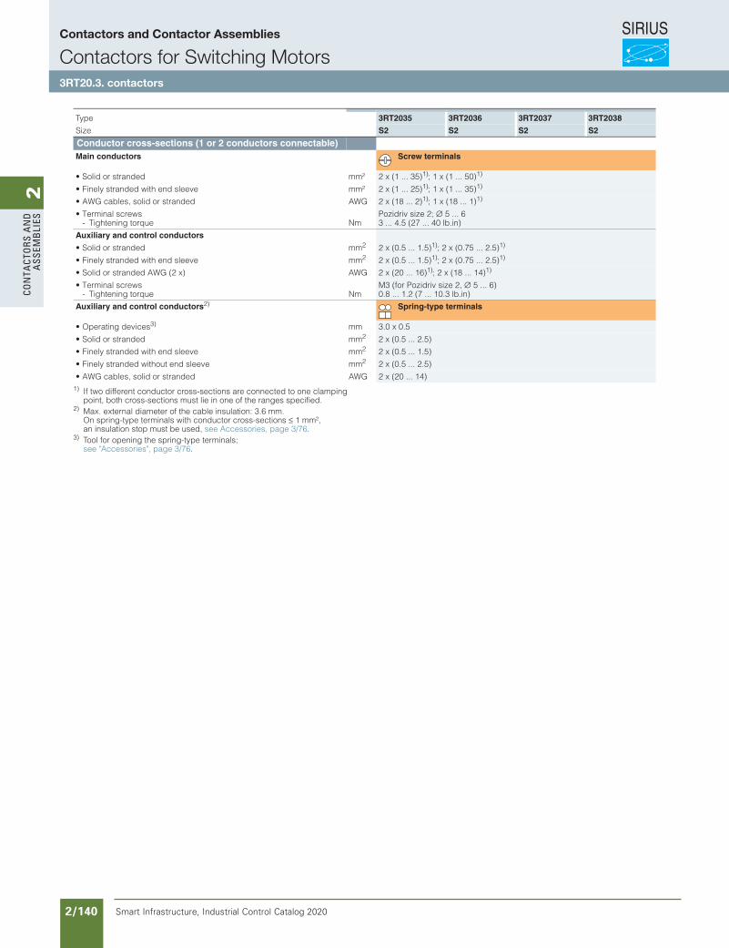
SIRIUS
Smart Infrastructure, Industrial Control Catalog 2020 2/140
2Co
nta
Cto
rs a
nd
a
ssem
bli
es
Siemens / Industrial Controls Previous folio: IC10 2/103
3/33Siemens IC 10 · 2015
Power Contactors for Switching Motors
SIRIUS 3RT20 contactors, 3-pole, up to 37 kW
3
1) If two different conductor cross-sections are connected to one clamping point, both cross-sections must lie in one of the ranges specified.
2) Max. external diameter of the cable insulation: 3.6 mm. On spring-type terminals with conductor cross-sections ≤ 1 mm², an insulation stop must be used, see Accessories, page 3/76.
3) Tool for opening the spring-type terminals; see "Accessories", page 3/76.
Data for North America
1) For more information about short-circuit values, e.g. for protection against short-circuit currents, see the UL reports on the individual devices, www.siemens.com/sirius/manuals.For the dimensioning of load feeders, see also the Configuration Manual "Configuring SIRIUS Innovations for UL", http://support.automation.siemens.com/WW/view/en/53433538.
2) Values for RK5 fuses on request.
Type 3RT2035 3RT2036 3RT2037 3RT2038
Size S2 S2 S2 S2
Conductor cross-sections (1 or 2 conductors connectable) Main conductors Screw terminals
• Solid or stranded mm² 2 x (1 ... 35)1); 1 x (1 ... 50)1)
• Finely stranded with end sleeve mm² 2 x (1 ... 25)1); 1 x (1 ... 35)1)
• AWG cables, solid or stranded AWG 2 x (18 ... 2)1); 1 x (18 ... 1)1)
• Terminal screws Pozidriv size 2; ∅ 5 ... 6- Tightening torque Nm 3 ... 4.5 (27 ... 40 lb.in)
Auxiliary and control conductors
• Solid or stranded mm2 2 x (0.5 ... 1.5)1); 2 x (0.75 ... 2.5)1)
• Finely stranded with end sleeve mm2 2 x (0.5 ... 1.5)1); 2 x (0.75 ... 2.5)1)
• Solid or stranded AWG (2 x) AWG 2 x (20 ... 16)1); 2 x (18 ... 14)1)
• Terminal screws M3 (for Pozidriv size 2, ∅ 5 ... 6)- Tightening torque Nm 0.8 ... 1.2 (7 ... 10.3 lb.in)
Auxiliary and control conductors2) Spring-type terminals
• Operating devices3) mm 3.0 x 0.5• Solid or stranded mm2 2 x (0.5 ... 2.5)• Finely stranded with end sleeve mm2 2 x (0.5 ... 1.5)• Finely stranded without end sleeve mm2 2 x (0.5 ... 2.5)• AWG cables, solid or stranded AWG 2 x (20 ... 14)
Type 3RT2015 3RT2016 3RT2017 3RT2018
Size S00 S00 S00 S00
s and u rated dataRated insulation voltage V AC 600Uninterrupted current, at 40 °C, open and enclosed A 20Maximum horsepower ratings (from s and u approved values)• Rated power for three-phase motors
at 60 HzAt 200 V hp 1.5 2 3 3
230 V hp 2 3 3 5460 V hp 3 5 7.5 10575 V hp 5 7.5 10 10
Short-circuit protection1)
(contactor or overload relay)At 600 V kA 5
• Fuse CLASS J2) A 40• Circuit breakers with overload protection
acc. to UL 489A 50
• Combination motor controllers type E according to UL 508 and UL 60947-4-1
Values on request.
Overload relays
• Type 3RU211 / 3RB301• Setting range A 0.11 ... 16 / 0.1 ... 16
© Siemens AG 2015
Contactors and Contactor Assemblies
Contactors for Switching Motors3RT20.3. contactors
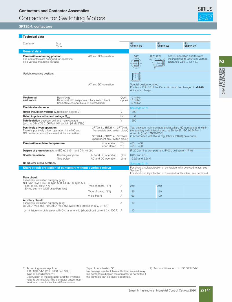
SIRIUS
Smart Infrastructure, Industrial Control Catalog 2020 2/141
2Co
nta
Ctors a
nd
a
ssemb
lies
SIRIUSContactors and Contactor Assemblies
Contactors for Switching Motors
3RT10 4. contactors
Contactor SizeType
S33RT20 45
S33RT20 46
S33RT20 47
General dataPermissible mounting positionThe contactors are designed for operationon a vertical mounting surface.
AC and DC operation
Upright mounting position:
AC and DC operation Special design required.Positions 13 to 16 of the Order No. must be changed to -1AA0.Additional charge.
Mechanical Basic units Oper. 10 millionendurance Basic unit with snap-on auxiliary switch block cycles 10 million
Solid-state compatible aux. switch block 5 million
Electrical enduranceRated insulation voltage Ui (pollution degree 3) V 1000
Rated impulse withstand voltage Uimp kV 6
Safe isolation between coil and main contacts(acc. to DIN VDE 0106 Part 101 and A1 [draft 2/89])
V 690
Positively driven operationThere is positively driven operation if the NC and NO contacts cannot be closed at the same time
3RT20 4 ., 3RT23 4 ., 3RT24 5 .(removable aux. switch block)
3RT20 4 ., 3RT23 4 ., 3RT24 5 .(permanent aux. switch block)
Yes, between main contacts and auxiliary NC contacts and within the auxiliary switch blocks acc. to ZH 1/457, IEC 60 947-4-1, Annex H (draft 17B/996/DC) in accordance with Swiss regulations (SUVA) on request.
Permissible ambient temperature in operationwhen stored
°C°C
–25 ... +60–55 ... +80
Degree of protection acc. to IEC 60 947-1 and DIN 40 050 IP 20 (terminal compartment IP 00), coil system IP 40
Shock resistance Rectangular pulse AC and DC operation g/ms 6.8/5 and 4/10Sine pulse AC and DC operation g/ms 10.6/5 and 6.2/10
Conductor cross-sections
Short-circuit protection of contactors without overload relays For short-circuit protection of contactors with overload relays, see Section 3.For short-circuit protection of fuseless load feeders, see Section 4.
Main circuitFuse links, utilization category gL/gGNH Type 3NA, DIAZED Type 5SB, NEOZED Type 5SE– acc. to IEC 60 947-4/
EN 60 947-4-4 (VDE 0660 Part 102)Type of coord. "1" 1) A 250 250
Type of coord. "2" 1) A 125 160
Weld-free 2) A 63 100
Auxiliary circuitFuse links, utilization category gL/gG DIAZED Type 5SB, NEOZED Type 5SE (weld-free protection at Ik 1 kA)
A 10
or miniature circuit-breaker with C-characteristic (short-circuit current Ik < 400 A) A 10
Technical data
For DC operation and forward inclination up to 22.5°: coil voltage tolerance 0.85 ... 1.1 x Us
1) According to excerpt fromIEC 60 947-4-1 (VDE 0660 Part 102):Type of coordination "1":Destruction of the contactor and the overload relay is permissible. The contactor and/or over-load relay must be replaced if necessary.
Type of coordination "2":No damage can be tolerated to the overload relay, but contact welding on the contactor is permitted if the contacts can be easily separated.
2) Test conditions acc. to IEC 60 947-4-1.
Siemens / Industrial Controls Previous folio: IC10 2/104
See page 2/125.
See page 2/144.
Contactors and Contactor Assemblies
Contactors for Switching Motors3RT20.4. contactors
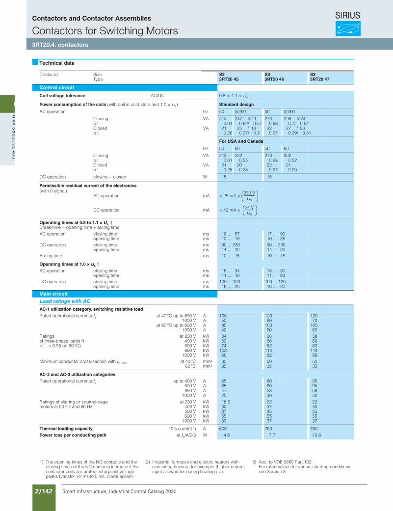
SIRIUS
Smart Infrastructure, Industrial Control Catalog 2020 2/142
2Co
nta
Cto
rs a
nd
a
ssem
bli
es
Contactor SizeType
S33RT20 45
S33RT20 46
S33RT20 47
Control circuitCoil voltage tolerance AC/DC 0.8 to 1.1 × Us
Power consumption of the coils (with coil in cold state and 1.0 × Us) Standard designzHnoitarepo CA 50 50/60 50 50/60
Closingp.f.Closedp.f.
VA
VA
2180.61
210.26
247 /2110.62/ 0.57
25 / 180.27/ 0.3
2700.68
220.27
298 /2740.7/ 0.62
27 / 200.29/ 0.31
For USA and CanadaHz 50 60 50 60
Closingp.f.Closedp.f.
VA
VA
2180.61
210.26
2320.55
200.28
2700.68
220.27
3000.52
210.29
Wdesolc = gnisolcnoitarepo CD 15 15
Permissible residual current of the electronics(with 0 signal)
Amnoitarepo CA < 25 mA ×
Amnoitarepo CD < 43 mA ×
Operating times at 0.8 to 1.1 × Us1)
Break-time = opening time + arcing timeAC operation closing time
opening timemsms
16 ... 5710 ... 19
17 ... 9010 ... 25
DC operation closing timeopening time
msms
90 ... 23014 ... 20
90 ... 23014 ... 20
smemit gnicrA 10 ... 15 10 ... 15
Operating times at 1.0 × Us1)
AC operation closing timeopening time
msms
18 ... 3411 ... 18
18 ... 3011 ... 23
DC operation closing timeopening time
msms
100 ... 12016 ... 20
100 ... 12016 ... 20
Main circuitLoad ratings with ACAC-1 utilization category, switching resistive loadRated operational currents Ie at 40 °C up to 690 V
1000 Vat 60 °C up to 690 V
1000 V
AAAA
100509040
12060
10050
12070
10060
Ratingsof three-phase loads 2)p.f. = 0.95 (at 60 °C)
at 230 V400 V500 V690 V
1000 V
kWkWkWkWkW
345974
10266
386682
11482
386682
11498
Minimum conductor cross-section with Ie load at 40 °C60 °C
mm2
mm23535
5035
5035
AC-2 and AC-3 utilization categoriesRated operational currents Ie up to 400 V
500 V690 V
1000 V
AAAA
65654725
80805830
95955830
Ratings of slipring or squirrel-cage motors at 50 Hz and 60 Hz
at 230 V400 V500 V690 V
1000 V
kWkWkWkWkW
18.530375530
2237455537
2245555537
Thermal loading capacity 10 s current 3) A 600 760 760Power loss per conducting path at Ie/AC-3 W 4.6 7.7 10.8
Technical data
230 VUs
-----------
24 VUs
---------
1) The opening times of the NO contacts and the closing times of the NC contacts increase if the contactor coils are protected against voltage peaks (varistor +2 ms to 5 ms, diode assem-blies 2 to 6 times).
2) Industrial furnaces and electric heaters with resistance heating, for example (higher current input allowed for during heating up).
3) Acc. to VDE 0660 Part 102.For rated values for various starting conditions,see Section 3.
Siemens / Industrial Controls Previous folio: IC10 2/105
Contactors and Contactor Assemblies
Contactors for Switching Motors3RT20.4. contactors
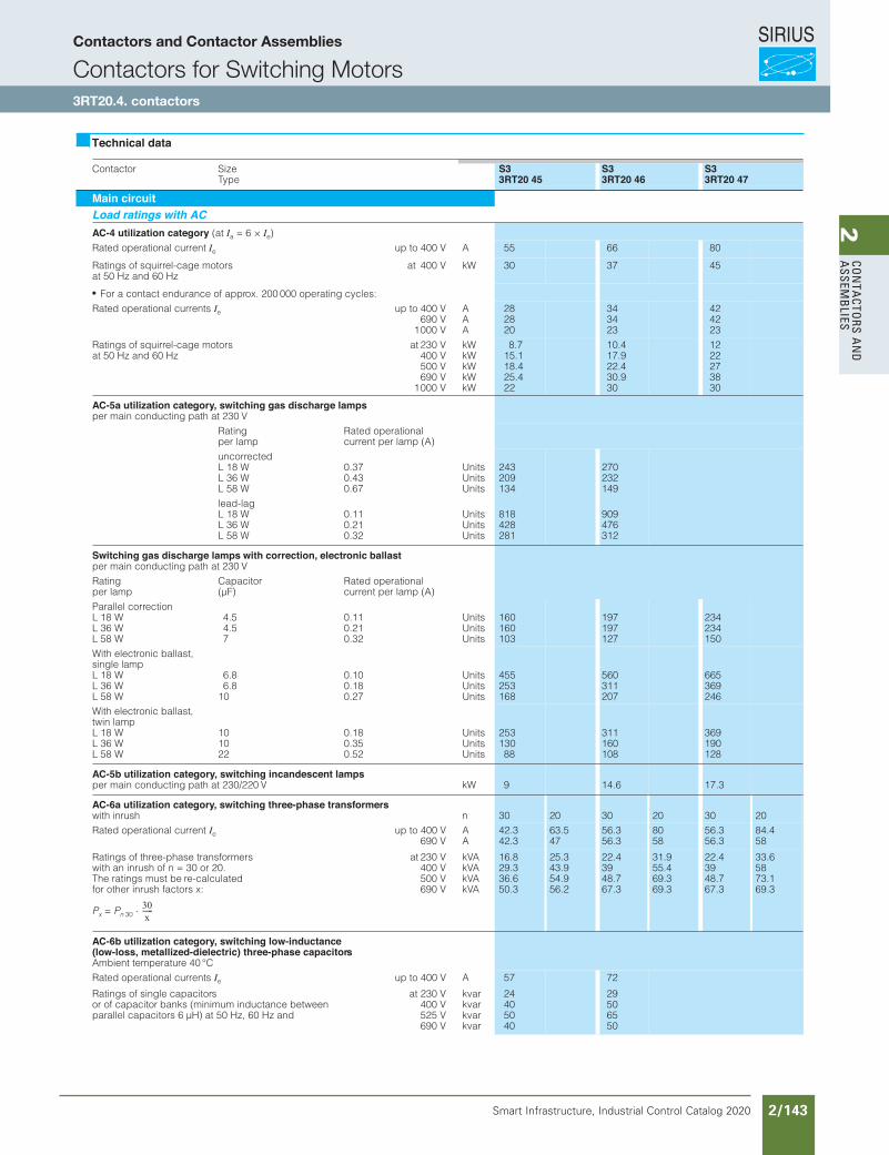
SIRIUS
Smart Infrastructure, Industrial Control Catalog 2020 2/143
2Co
nta
Ctors a
nd
a
ssemb
lies
SIRIUSContactors and Contactor Assemblies
Contactors for Switching Motors
3RT10 4. contactors
Contactor SizeType
S33RT20 45
S33RT20 46
S33RT20 47
Main circuitLoad ratings with ACAC-4 utilization category (at Ia = 6 × Ie)Rated operational current Ie up to 400 V A 55 66 80
Ratings of squirrel-cage motors at 50 Hz and 60 Hz
at 400 V kW 30 37 45
For a contact endurance of approx. 200 000 operating cycles:Rated operational currents Ie up to 400 V
690 V1000 V
AAA
282820
343423
424223
Ratings of squirrel-cage motors at 50 Hz and 60 Hz
at 230 V400 V500 V690 V
1000 V
kWkWkWkWkW
8.715.118.425.422
10.417.922.430.930
1222273830
AC-5a utilization category, switching gas discharge lampsper main conducting path at 230 V
Ratingper lamp
Rated operationalcurrent per lamp (A)
uncorrectedL 18 WL 36 WL 58 W
0.370.430.67
UnitsUnitsUnits
243209134
270232149
lead-lagL 18 WL 36 WL 58 W
0.110.210.32
UnitsUnitsUnits
818428281
909476312
Switching gas discharge lamps with correction, electronic ballastper main conducting path at 230 VRatingper lamp
Capacitor(µF)
Rated operationalcurrent per lamp (A)
Parallel correctionL 18 WL 36 WL 58 W
4.54.57
0.110.210.32
UnitsUnitsUnits
160160103
197197127
234234150
With electronic ballast, single lampL 18 WL 36 WL 58 W
6.86.8
10
0.100.180.27
UnitsUnitsUnits
455253168
560311207
665369246
With electronic ballast,twin lampL 18 WL 36 WL 58 W
101022
0.180.350.52
UnitsUnitsUnits
25313088
311160108
369190128
AC-5b utilization category, switching incandescent lampsper main conducting path at 230/220 V kW 9 14.6 17.3
AC-6a utilization category, switching three-phase transformerswith inrush n 30 20 30 20 30 20Rated operational current Ie up to 400 V
690 VAA
42.342.3
63.547
56.356.3
8058
56.356.3
84.458
Ratings of three-phase transformerswith an inrush of n = 30 or 20.The ratings must be re-calculatedfor other inrush factors x:
Px = Pn 30
at 230 V400 V500 V690 V
kVAkVAkVAkVA
16.829.336.650.3
25.343.954.956.2
22.43948.767.3
31.955.469.369.3
22.43948.767.3
33.65873.169.3
AC-6b utilization category, switching low-inductance(low-loss, metallized-dielectric) three-phase capacitorsAmbient temperature 40 °CRated operational currents Ie up to 400 V A 57 72
Ratings of single capacitorsor of capacitor banks (minimum inductance between parallel capacitors 6 µH) at 50 Hz, 60 Hz and
at 230 V400 V525 V690 V
kvarkvarkvarkvar
24405040
29506550
Technical data
Siemens / Industrial Controls Previous folio: IC10 2/106
Contactors and Contactor Assemblies
Contactors for Switching Motors3RT20.4. contactors
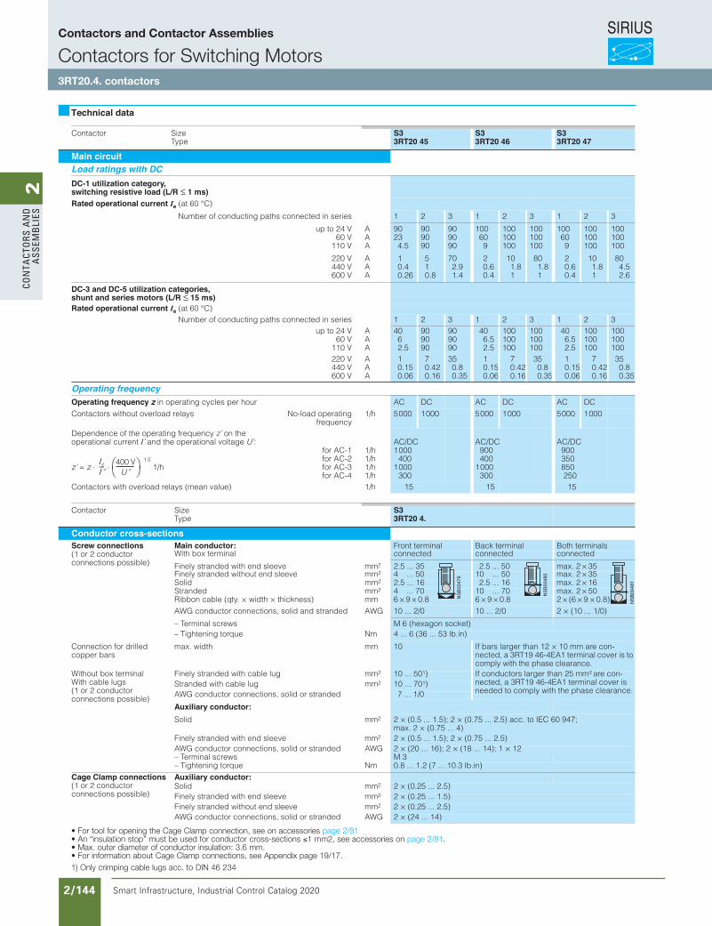
SIRIUS
Smart Infrastructure, Industrial Control Catalog 2020 2/144
2Co
nta
Cto
rs a
nd
a
ssem
bli
es
Contactor SizeType
S33RT20 45
S33RT20 46
S33RT20 47
Main circuitLoad ratings with DCDC-1 utilization category,switching resistive load (L/R ≤ 1 ms)Rated operational current Ie (at 60 °C)
Number of conducting paths connected in series 1 2 3 1 2 3 1 2 3
up to 24 V60 V
110 V
AAA
90234.5
909090
909090
100609
100100100
100100100
100609
100100100
100100100
220 V440 V600 V
AAA
10.40.26
510.8
702.91.4
20.60.4
101.81
801.81
20.60.4
101.81
804.52.6
DC-3 and DC-5 utilization categories,shunt and series motors (L/R ≤ 15 ms)Rated operational current Ie (at 60 °C)
Number of conducting paths connected in series 1 2 3 1 2 3 1 2 3up to 24 V
60 V110 V
AAA
4062.5
909090
909090
406.52.5
100100100
100100100
406.52.5
100100100
100100100
220 V440 V600 V
AAA
10.150.06
70.420.16
350.80.35
10.150.06
70.420.16
350.80.35
10.150.06
70.420.16
350.80.35
Operating frequencyOperating frequency z in operating cycles per hour AC DC AC DC AC DCContactors without overload gnitarepo daol-oNsyaler
frequency1/h 5000 1000 5000 1000 5000 1000
Dependence of the operating frequency z’ on the operational current I’ and the operational voltage U’:
z’ = z ⋅ ⋅1.5
1/h
for AC-1for AC-2for AC-3for AC-4
1/h1/h1/h1/h
AC/DC1000
4001000
300
AC/DC900400
1000300
AC/DC900350850 250
Contactors with overload h/1)eulav naem( syaler 15 15 15
Contactor SizeType
S33RT20 4.
Conductor cross-sectionsScrew connections(1 or 2 conductorconnections possible)
Main conductor: Front terminal Back terminal Both terminalsWith box terminal connected connected connected
Finely stranded with end sleeve mm2 2.5 ... 35 2.5 ... 50 max. 2 × 35Finely stranded without end sleeve mm2 4 ... 50 10 ... 50 max. 2 × 35
mmdiloS 2 2.5 ... 16 2.5 ... 16 max. 2 × 16mmdednartS 2 4 ... 70 10 ... 70 max. 2 × 50
Ribbon cable (qty. × width × thickness) mm 6 × 9 × 0.8 6 × 9 × 0.8 2 × (6 × 9 × 0.8)AWG conductor connections, solid and stranded AWG 10 ... 2/0 10 ... 2/0 2 × (10 ... 1/0)
– Terminal screws M 6 (hexagon socket)mNeuqrot gninethgiT – 4 ... 6 (36 ... 53 lb.in)
Connection for drilled copper bars
mmhtdiw .xam 10 If bars larger than 12 × 10 mm are con-nected, a 3RT19 46-4EA1 terminal cover is to comply with the phase clearance.
Without box terminalWith cable lugs(1 or 2 conductorconnections possible)
mmgul elbac htiw dednarts yleniF 2 10 ... 501) If conductors larger than 25 mm2 are con-nected, a 3RT19 46-4EA1 terminal cover is needed to comply with the phase clearance.
mmgul elbac htiw dednartS 2 10 ... 701)AWG conductor connections, solid or stranded 7 ... 1/0
Auxiliary conductor:mmdiloS 2 2 × (0.5 ... 1.5); 2 × (0.75 ... 2.5) acc. to IEC 60 947;
max. 2 × (0.75 ... 4)Finely stranded with end sleeve mm2 2 × (0.5 ... 1.5); 2 × (0.75 ... 2.5)AWG conductor connections, solid or stranded AWG 2 × (20 ... 16); 2 × (18 ... 14); 1 × 12– Terminal screws M 3
mNeuqrot gninethgiT – 0.8 ... 1.2 (7 ... 10.3 lb.in)
Cage Clamp connections(1 or 2 conductorconnections possible)
Auxiliary conductor:mmdiloS 2 2 × (0.25 ... 2.5)
Finely stranded with end sleeve mm2 2 × (0.25 ... 1.5)Finely stranded without end sleeve mm2 2 × (0.25 ... 2.5)AWG conductor connections, solid or stranded AWG 2 × (24 ... 14)
For tool for opening the Cage Clamp connection, see accessories on page 2/46.An "insulation stop" must be used for conductor cross-sections ≤ 1 mm2, see accessories on page 2/46.Max. outer diameter of conductor insulation: 3.6 mm.For information about Cage Clamp connections, see Appendix page 19/17.
Technical data
IeI ′---- 400 V
U ′----------
1) Only crimping cable lugs acc. to DIN 46 234
Siemens / Industrial Controls Previous folio: IC10 2/107
• For tool for opening the Cage Clamp connection, see on accessories page 2/81• An “insulation stop” must be used for conductor cross-sections ≤1 mm2, see accessories on page 2/81. • Max. outer diameter of conductor insulation: 3.6 mm.• For information about Cage Clamp connections, see Appendix page 19/17.1) Only crimping cable lugs acc. to DIN 46 234
Contactors and Contactor Assemblies
Contactors for Switching Motors3RT20.4. contactors
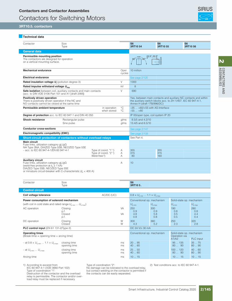
SIRIUS
Smart Infrastructure, Industrial Control Catalog 2020 2/145
2Co
nta
Ctors a
nd
a
ssemb
lies
Contactor SizeType
S63RT10 54
S63RT10 55
S63RT10 56
General data
Permissible mounting positionThe contactors are designed for operation on a vertical mounting surface.
Mechanical endurance Oper. cycles
10 million
Electrical endurance
Rated insulation voltage Ui (pollution degree 3) V 1000
Rated impulse withstand voltage Uimp kV 8
Safe isolation between coil, auxiliary contacts and main contacts(acc. to DIN VDE 0106 Part 101 and A1 [draft 2/89])
V 690
Positively driven operationThere is positively driven operation if the NC and NO contacts cannot be closed at the same time
Yes, between main contacts and auxiliary NC contacts and within the auxiliary switch blocks acc. to ZH 1/457, IEC 60 947-4-1, Annex H (draft 17B/996/DC)
Permissible ambient temperature in operationwhen stored
°C°C
–25 ... +60/+55 with AS-Interface–55 ... +80
Degree of protection acc. to IEC 60 947-1 and DIN 40 050 IP 00/open type, coil system IP 20
Shock resistance Rectangular pulse g/ms 8.5/5 and 4.2/10Sine pulse g/ms 13.4/5 and 6.5/10
Conductor cross-sections
Electromagnetic compatibility (EMC)
Short-circuit protection of contactors without overload relays See Part 4.
Main circuitFuse links, utilization category gL/gGNH Type 3NA, DIAZED Type 5SB, NEOZED Type 5SE– acc. to IEC 60 947-4-1/EN 60 947-4-1 Type of coord. "1" 1) A 355 355
Type of coord. "2" 1) A 315 315Weld-free 2) A 80 160
Auxiliary circuitFuse links, utilization category gL/gG (weld-free protection at Ik 1 kA)DIAZED Type 5SB, NEOZED Type 5SE
A 10
or miniature circuit-breaker with C-characteristic (Ik < 400 A)
Contactor SizeType
S63RT10 5 .
Control circuit
Coil voltage tolerance AC/DC (UC) 0.8 × Us min ... 1.1 × Us max
Power consumption of solenoid mechanism Conventional op. mechanism Solid-state op. mechanism(with coil in cold state and rated range Us min ... Us max) Us min Us max Us min Us max
AC operation Closingp.f. Closedp.f.
VA
VA
2500.94.80.8
3000.95.80.8
1900.83.50.5
2800.84.40.4
DC operation ClosingClosed
WW
3004.3
3605.2
2502.3
3202.8
PLC control input (EN 61 131-2/Type 2) DC 24 V/ 30 mA
Operating times Conventional op. mechanism Solid-state op. mechanism(Break-time = opening time + arcing time) Operation via
A1/A2 PLC input– at 0.8 × Us min ... 1.1 × Us max closing time
opening timemsms
20 ... 9540 ... 60
95 ... 13580 ... 90
35 ... 7580 ... 90
– at Us min ... Us max closing timeopening time
msms
25 ... 5040 ... 60
100 ... 12080 ... 90
40 ... 6080 ... 90
Arcing time ms 10 ... 15 10 ... 15 10 ... 15
Technical data
1) According to excerpt fromIEC 60 947-4-1 (VDE 0660 Part 102):Type of coordination "1":Destruction of the contactor and the overload relay is permissible. The contactor and/or over-load relay must be replaced if necessary.
Type of coordination "2":No damage can be tolerated to the overload relay, but contact welding on the contactor is permitted if the contacts can be easily separated.
2) Test conditions acc. to IEC 60 947-4-1.
Siemens / Industrial Controls Previous folio: IC10 2/108
See page 2/125
See page 2/147
See page 2/108
Contactors and Contactor Assemblies
Contactors for Switching Motors3RT10.5. contactors
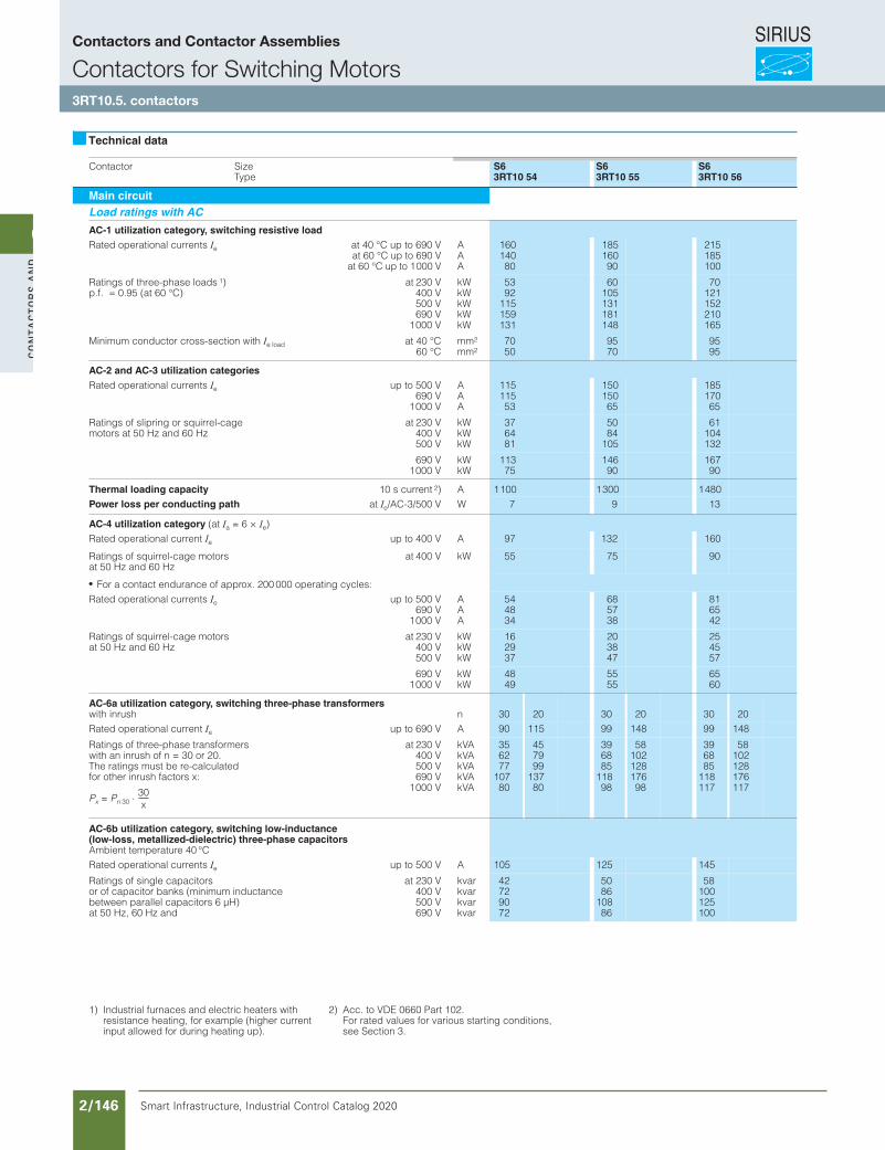
SIRIUS
Smart Infrastructure, Industrial Control Catalog 2020 2/146
2Co
nta
Cto
rs a
nd
a
ssem
bli
es
eziSrotcatnoCType
S63RT10 54
S63RT10 55
S63RT10 56
Main circuitLoad ratings with AC
AC-1 utilization category, switching resistive loadRated operational currents Ie at 40 °C up to 690 V
at 60 °C up to 690 Vat 60 °C up to 1000 V
AAA
16014080
18516090
215185100
Ratings of three-phase loads 1)p.f. = 0.95 (at 60 °C)
at 230 V400 V500 V690 V
1000 V
kWkWkWkWkW
5392
115159131
60105131181148
70121152210165
Minimum conductor cross-section with Ie load at 40 °C60 °C
mm2
mm27050
9570
9595
AC-2 and AC-3 utilization categoriesRated operational currents Ie up to 500 V
690 V1000 V
AAA
11511553
15015065
18517065
Ratings of slipring or squirrel-cage motors at 50 Hz and 60 Hz
at 230 V400 V500 V
kWkWkW
376481
5084
105
61104132
690 V1000 V
kWkW
11375
14690
16790
Thermal loading capacity 10 s current 2) A 1100 1300 1480Power loss per conducting path at Ie/AC-3/500 V W 7 9 13
AC-4 utilization category (at Ia = 6 × Ie)Rated operational current Ie up to 400 V A 97 132 160
Ratings of squirrel-cage motors at 50 Hz and 60 Hz
at 400 V kW 55 75 90
For a contact endurance of approx. 200 000 operating cycles:Rated operational currents Ie up to 500 V
690 V1000 V
AAA
544834
685738
816542
Ratings of squirrel-cage motors at 50 Hz and 60 Hz
at 230 V400 V500 V
kWkWkW
162937
203847
254557
690 V1000 V
kWkW
4849
5555
6560
AC-6a utilization category, switching three-phase transformerswith inrush n 30 20 30 20 30 20Rated operational current Ie up to 690 V A 90 115 99 148 99 148
Ratings of three-phase transformerswith an inrush of n = 30 or 20.The ratings must be re-calculatedfor other inrush factors x:
Px = Pn 30 ⋅
at 230 V400 V500 V690 V
1000 V
kVAkVAkVAkVAkVA
356277
10780
457999
13780
396885
11898
5810212817698
396885
118117
58102128176117
AC-6b utilization category, switching low-inductance(low-loss, metallized-dielectric) three-phase capacitorsAmbient temperature 40 °CRated operational currents Ie up to 500 V A 105 125 145
Ratings of single capacitorsor of capacitor banks (minimum inductance between parallel capacitors 6 µH)at 50 Hz, 60 Hz and
at 230 V400 V500 V690 V
kvarkvarkvarkvar
42729072
5086
10886
58100125100
Technical data
30x
------
1) Industrial furnaces and electric heaters with resistance heating, for example (higher current input allowed for during heating up).
2) Acc. to VDE 0660 Part 102.For rated values for various starting conditions, see Section 3.
Siemens / Industrial Controls Previous folio: IC10 2/109
Contactors and Contactor Assemblies
Contactors for Switching Motors3RT10.5. contactors

SIRIUS
Smart Infrastructure, Industrial Control Catalog 2020 2/147
2Co
nta
Ctors a
nd
a
ssemb
lies
SIRIUSContactors and Contactor Assemblies
Contactors for Switching Motors
3RT10 5. contactors
Contactor SizeType
S63RT10 54
S63RT10 55
S63RT10 56
Main circuitLoad ratings with DCDC-1 utilization category,switching resistive load (L/R 1 ms)Rated operational current Ie (at 60 °C)
Number of conducting paths connected in series 1 2 3
up to 24 V60 V
110 V
AAA
16016018
160160160
160160160
220 V440 V600 V
AAA
3.40.80.5
203.21.6
1601.40.75
DC-3 and DC-5 utilization categories,shunt and series motors (L/R 15 ms)Rated operational current Ie (at 60 °C)
Number of conducting paths connected in series 1 2 3
up to 24 V60 V
110 V
AAA
1607.52.5
160160160
160160160
220 V440 V600 V
AAA
0.60.170.12
2.50.650.37
16011.54
Operating frequencyOperating frequency z in operating cycles per hourContactors without overload relays No-load operating
frequency1/h 2000 2000
Dependence of the operating frequency z’ on the operational current I’ and the operational voltage U’:
z’ = z1.5
1/h
for AC-1for AC-2for AC-3for AC-4
1/h1/h1/h1/h
800400
1000130
800300750130
Contactors with overload relays (mean value) 1/h 60 60
Contactor SizeType
S63RT10 5.
Conductor cross-sectionsScrew connections Main conductor: Front terminal Back terminal Both terminals
with 3RT19 55-4G box terminal (75 HP) connected connected connected
finely stranded with end sleeve mm2 16 ... 70 16 ... 70 max. 1 × 50, 1 × 70Finely stranded without end sleeve mm2 16 ... 70 16 ... 70 max. 1 × 50, 1 × 70Stranded mm2 16 ... 70 16 ... 70 max. 2 × 70AWG conductor connections, solid/stranded 6 ... 2/0 6 ... 2/0 max. 2 × 1/0Ribbon cable (qty. x width × thickness) mm
mmmin. 3 × 9 × 0.8max. 6 × 15.5 × 0.8
min. 3 × 9 × 0.8max. 6 × 15.5 × 0.8 max. 2 × (6 × 15,5 × 0.8)
with 3RT19 56-4G box terminal
Finely stranded with end sleeve mm2 16 ... 120 16 ... 120 max. 1 × 95, 1 × 120Finely stranded without end sleeve mm2 16 ... 120 16 ... 120 max. 1 × 95, 1 × 120Stranded mm2 16 ... 120 16 ... 120 max. 2 × 120AWG conductor connections, solid/stranded 6 ... 250 kcmil 6 ... 250 kcmil max. 2 × 3/0Ribbon cable (qty. × width × thickness) mm
mmmin. 3 × 9 × 0.8max. 10 × 15.5 × 0.8
min. 3 × 9 × 0.8max. 10 × 15.5 × 0.8 max. 2 × (10 × 15.5 × 0.8)
– Terminal screws M 10 (hexagon socket, A/F4)– Tightening torque Nm 10 ... 12 (90 ... 110 lb.in)
Without box terminal/busbar connection
Finely stranded with cable lug mm2 16 ... 95 If cable lugs acc. to DIN 46 235 are connected, as of a conductor cross-section of 95 mm2 a3RT19 56-4EA1 terminal cover is necessary to comply with the phase clearance.
Stranded with cable lug mm2 25 ... 120
AWG conductor connections, solid or stranded AWG 4 ... 250 kcmilConnecting bar (max. width) mm 17– Terminal screws M 8 × 25 (A/F 13)– Tightening torque Nm 10 ... 14 (89 ... 124 lb.in)
Auxiliary conductor:Solid mm2 2 × (0.5 ...1.5); 2 × (0.75 ... 2.5) acc. to IEC 60 947;
max. 2 × (0.75 ... 4)Finely stranded with end sleeve mm2 2 × (0.5 ... 1.5); 2 × (0.75 ... 2.5)AWG conductor connections, solid or stranded AWG 2 × (18 ... 14)– Terminal screws M 3 (PZ 2)– Tightening torque Nm 0.8 ... 1.2 (7 ... 10.3 lb.in)
Technical data
400 VU
⋅ ⋅ II′---- ′----------
≤
≤
Siemens / Industrial Controls Previous folio: IC10 2/110
Contactors and Contactor Assemblies
Contactors for Switching Motors
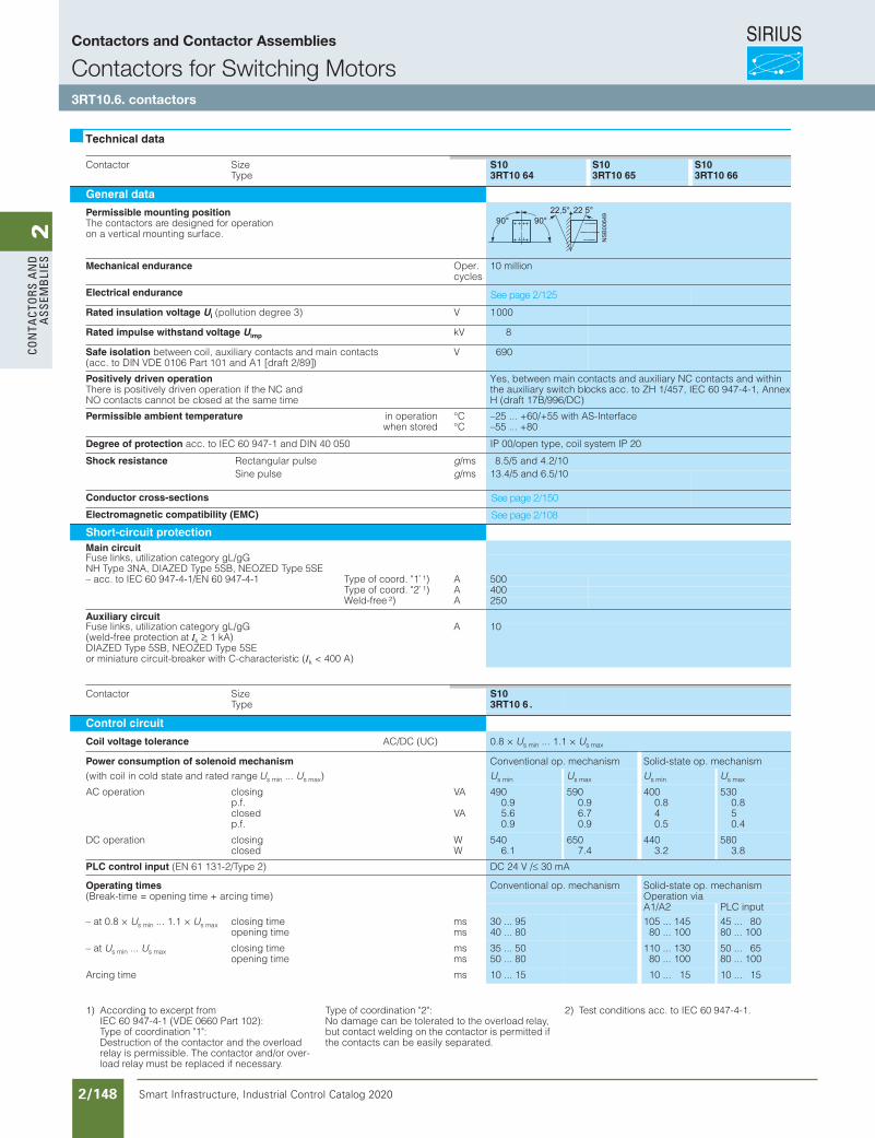
SIRIUS
Smart Infrastructure, Industrial Control Catalog 2020 2/148
2Co
nta
Cto
rs a
nd
a
ssem
bli
es
Contactors and Contactor Assemblies
Contactor SizeType
S103RT10 64
S103RT10 65
S103RT10 66
General data
Permissible mounting positionThe contactors are designed for operationon a vertical mounting surface.
Mechanical endurance Oper. cycles
10 million
Electrical endurance
Rated insulation voltage Ui (pollution degree 3) V 1000
Rated impulse withstand voltage Uimp kV 8
Safe isolation between coil, auxiliary contacts and main contacts(acc. to DIN VDE 0106 Part 101 and A1 [draft 2/89])
V 690
Positively driven operationThere is positively driven operation if the NC and NO contacts cannot be closed at the same time
Yes, between main contacts and auxiliary NC contacts and within the auxiliary switch blocks acc. to ZH 1/457, IEC 60 947-4-1, Annex H (draft 17B/996/DC)
Permissible ambient temperature in operationwhen stored
°C°C
–25 ... +60/+55 with AS-Interface–55 ... +80
Degree of protection acc. to IEC 60 947-1 and DIN 40 050 IP 00/open type, coil system IP 20
Shock resistance Rectangular pulse g/ms 8.5/5 and 4.2/10Sine pulse g/ms 13.4/5 and 6.5/10
Conductor cross-sections
Electromagnetic compatibility (EMC)
Short-circuit protectionMain circuitFuse links, utilization category gL/gGNH Type 3NA, DIAZED Type 5SB, NEOZED Type 5SE– acc. to IEC 60 947-4-1/EN 60 947-4-1 Type of coord. "1" 1) A 500
Type of coord. "2" 1) A 400Weld-free 2) A 250
Auxiliary circuitFuse links, utilization category gL/gG A 10(weld-free protection at Ik 1 kA)DIAZED Type 5SB, NEOZED Type 5SEor miniature circuit-breaker with C-characteristic (Ik < 400 A)
Contactor SizeType
S103RT10 6 .
Control circuit
Coil voltage tolerance AC/DC (UC) 0.8 × Us min ... 1.1 × Us max
Power consumption of solenoid mechanism Conventional op. mechanism Solid-state op. mechanism(with coil in cold state and rated range Us min ... Us max) Us min Us max Us min Us max
AC operation closingp.f. closedp.f.
VA
VA
4900.95.60.9
5900.96.70.9
4000.840.5
5300.850.4
DC operation closingclosed
WW
5406.1
6507.4
4403.2
5803.8
PLC control input (EN 61 131-2/Type 2) DC 24 V / 30 mA
Operating times Conventional op. mechanism Solid-state op. mechanism(Break-time = opening time + arcing time) Operation via
A1/A2 PLC input– at 0.8 × Us min ... 1.1 × Us max closing time
opening timemsms
30 ... 9540 ... 80
105 ... 14580 ... 100
45 ... 8080 ... 100
– at Us min ... Us max closing timeopening time
msms
35 ... 5050 ... 80
110 ... 13080 ... 100
50 ... 6580 ... 100
Arcing time ms 10 ... 15 10 ... 15 10 ... 15
Technical data
1) According to excerpt fromIEC 60 947-4-1 (VDE 0660 Part 102):Type of coordination "1":Destruction of the contactor and the overload relay is permissible. The contactor and/or over-load relay must be replaced if necessary.
Type of coordination "2":No damage can be tolerated to the overload relay, but contact welding on the contactor is permitted if the contacts can be easily separated.
2) Test conditions acc. to IEC 60 947-4-1.
Siemens / Industrial Controls Previous folio: IC10 2/111
See page 2/125
See page 2/150
See page 2/108
Contactors and Contactor Assemblies
Contactors for Switching Motors3RT10.6. contactors
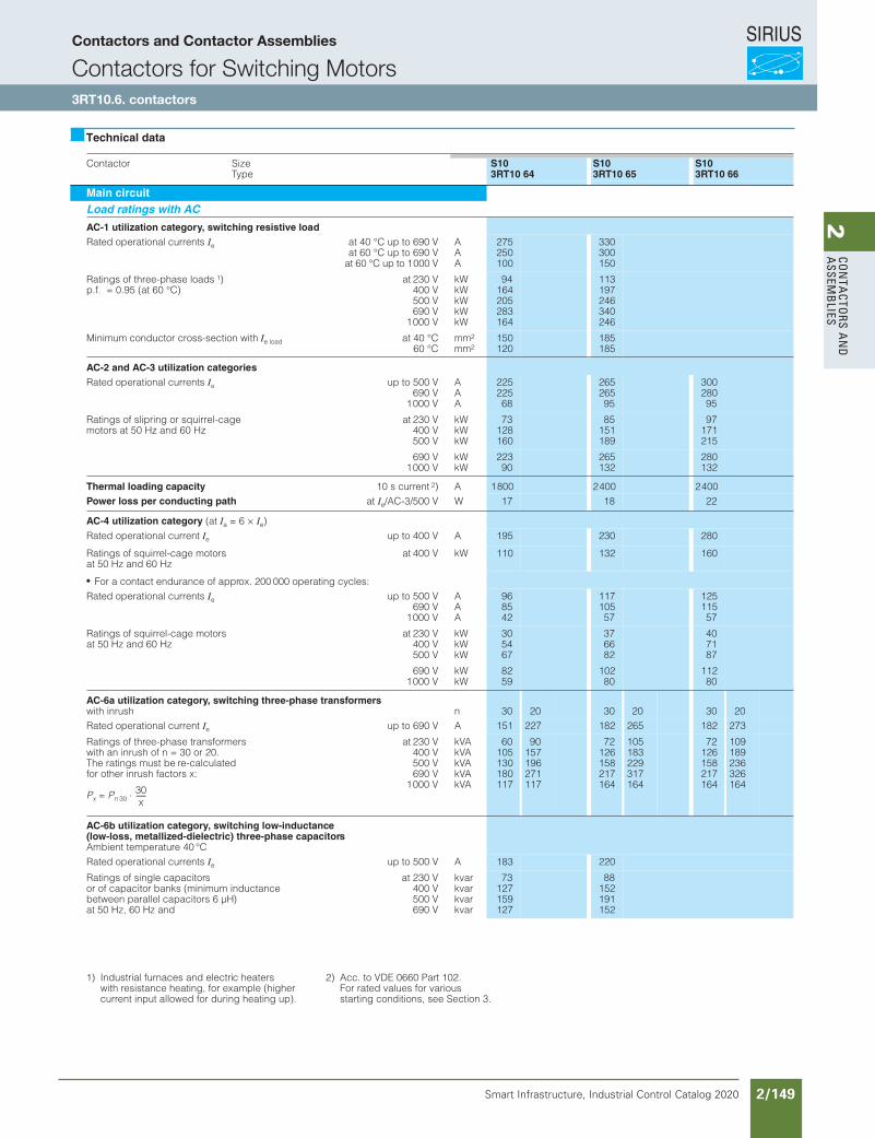
SIRIUS
Smart Infrastructure, Industrial Control Catalog 2020 2/149
2Co
nta
Ctors a
nd
a
ssemb
lies
Contactor SizeType
S103RT10 64
S103RT10 65
S103RT10 66
Main circuitLoad ratings with AC
AC-1 utilization category, switching resistive loadRated operational currents Ie at 40 °C up to 690 V
at 60 °C up to 690 Vat 60 °C up to 1000 V
AAA
275250100
330300150
Ratings of three-phase loads 1)p.f. = 0.95 (at 60 °C)
at 230 V400 V500 V690 V
1000 V
kWkWkWkWkW
94164205283164
113197246340246
Minimum conductor cross-section with Ie load at 40 °C60 °C
mm2
mm2150120
185185
AC-2 and AC-3 utilization categoriesRated operational currents Ie up to 500 V
690 V1000 V
AAA
22522568
26526595
30028095
Ratings of slipring or squirrel-cage motors at 50 Hz and 60 Hz
at 230 V400 V500 V
kWkWkW
73128160
85151189
97171215
690 V1000 V
kWkW
22390
265132
280132
Thermal loading capacity 10 s current 2) A 1800 2400 2400Power loss per conducting path at Ie/AC-3/500 V W 17 18 22
AC-4 utilization category (at Ia = 6 × Ie)Rated operational current Ie up to 400 V A 195 230 280
Ratings of squirrel-cage motors at 50 Hz and 60 Hz
at 400 V kW 110 132 160
For a contact endurance of approx. 200 000 operating cycles:Rated operational currents Ie up to 500 V
690 V1000 V
AAA
968542
11710557
12511557
Ratings of squirrel-cage motors at 50 Hz and 60 Hz
at 230 V400 V500 V
kWkWkW
305467
376682
407187
690 V1000 V
kWkW
8259
10280
11280
AC-6a utilization category, switching three-phase transformerswith inrush n 30 20 30 20 30 20Rated operational current Ie up to 690 V A 151 227 182 265 182 273
Ratings of three-phase transformerswith an inrush of n = 30 or 20.The ratings must be re-calculatedfor other inrush factors x:
Px = Pn 30
at 230 V400 V500 V690 V
1000 V
kVAkVAkVAkVAkVA
60105130180117
90157196271117
72126158217164
105183229317164
72126158217164
109189236326164
AC-6b utilization category, switching low-inductance(low-loss, metallized-dielectric) three-phase capacitorsAmbient temperature 40 °CRated operational currents Ie up to 500 V A 183 220
Ratings of single capacitorsor of capacitor banks (minimum inductance between parallel capacitors 6 µH)at 50 Hz, 60 Hz and
at 230 V400 V500 V690 V
kvarkvarkvarkvar
73127159127
88152191152
Technical data
30x
------
1) Industrial furnaces and electric heaters with resistance heating, for example (highercurrent input allowed for during heating up).
2) Acc. to VDE 0660 Part 102.For rated values for various starting conditions, see Section 3.
Siemens / Industrial Controls Previous folio: IC10 2/112
Contactors and Contactor Assemblies
Contactors for Switching Motors3RT10.6. contactors
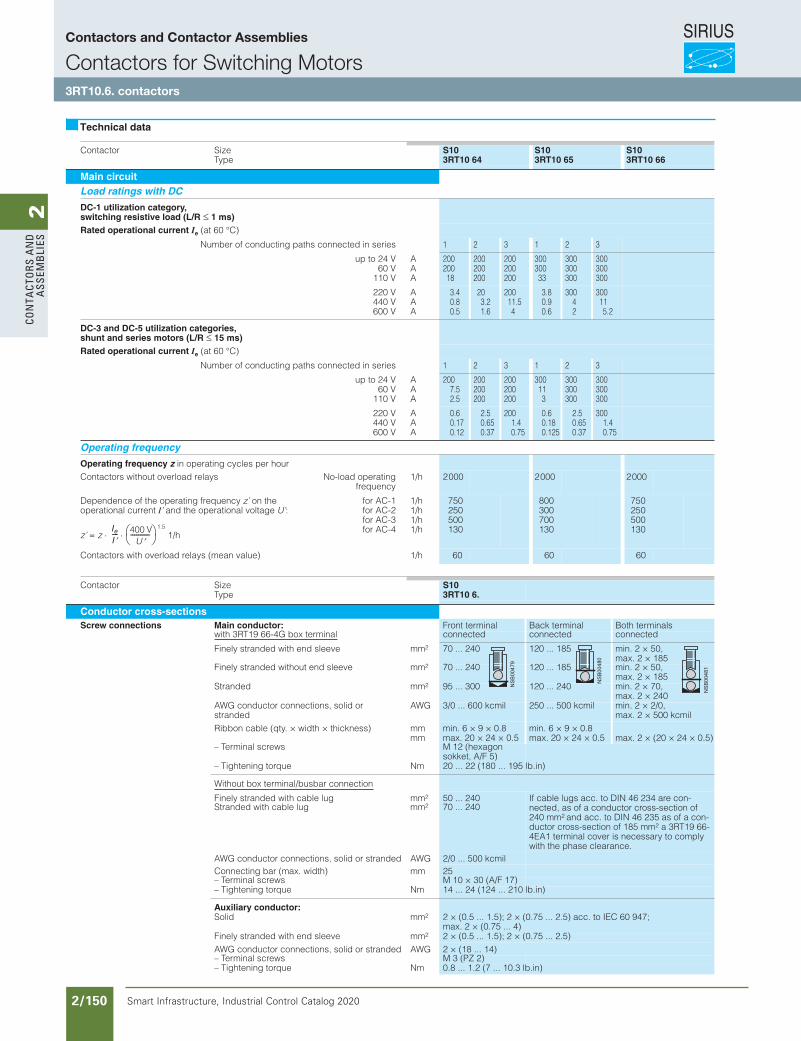
SIRIUS
Smart Infrastructure, Industrial Control Catalog 2020 2/150
2Co
nta
Cto
rs a
nd
a
ssem
bli
es
Contactor SizeType
S10 3R T10 64
S10 3R T10 65
S10 3R T10 66
Main circuit Load ratings with DC
DC-1 utilization categor y, sw itching resistive load (L/R 1 ms) Rated operational current Ie (at 60 °C)
Number of conducting paths connected in series 1 2 3 1 2 3
up to 24 V60 V
110 V
AAA
20020018
200200200
200200200
30030033
300300300
300300300
220 V440 V600 V
AAA
3.40.80.5
203.21.6
20011.54
3.80.90.6
30042
300115.2
DC-3 and DC-5 utilization categories, shunt and series motor s (L/R 15 ms) Rated operational current Ie (at 60 °C)
Number of conducting paths connected in series 1 2 3 1 2 3
up to 24 V60 V
110 V
AAA
2007.52.5
200200200
200200200
300113
300300300
300300300
220 V440 V600 V
AAA
0.60.170.12
2.50.650.37
2001.40.75
0.60.180.125
2.50.650.37
3001.40.75
Operating frequency
Operating frequen cy z in operating cycles per hourContactors without overload relays No-load operating
frequency1/h 2000 2000 2000
Dependence of the operating frequency z’ on the operational current I’ and the operational voltage U’:
z’ = z1.5
1/h
for AC-1for AC-2for AC-3for AC-4
1/h1/h1/h1/h
750250500130
800300700130
750250500130
Contactors with overload relays (mean value) 1/h 60 60 60
Contactor SizeType
S103RT10 6.
Conductor cross-sectionsScrew connections Main conductor: Front terminal Back terminal Both terminals
with 3RT19 66-4G box terminal connected connected connected
Finely stranded with end sleeve mm2 70 ... 240 120 ... 185 min. 2 × 50,max. 2 × 185
Finely stranded without end sleeve mm2 70 ... 240 120 ... 185 min. 2 × 50,max. 2 × 185
Stranded mm2 95 ... 300 120 ... 240 min. 2 × 70,max. 2 × 240
AWG conductor connections, solid or stranded
AWG 3/0 ... 600 kcmil 250 ... 500 kcmil min. 2 × 2/0,max. 2 × 500 kcmil
Ribbon cable (qty. × width × thickness) mmmm
min. 6 × 9 × 0.8max. 20 × 24 × 0.5
min. 6 × 9 × 0.8max. 20 × 24 × 0.5 max. 2 × (20 × 24 × 0.5)
– Terminal screws M 12 (hexagon sokket, A/F 5)
– Tightening torque Nm 20 ... 22 (180 ... 195 lb.in)
Without box terminal/busbar connection
Finely stranded with cable lug mm2 50 ... 240 If cable lugs acc. to DIN 46 234 are con-nected, as of a conductor cross-section of 240 mm2 and acc. to DIN 46 235 as of a con-ductor cross-section of 185 mm2 a 3RT19 66-4EA1 terminal cover is necessary to comply with the phase clearance.
Stranded with cable lug mm2 70 ... 240
AWG conductor connections, solid or stranded AWG 2/0 ... 500 kcmilConnecting bar (max. width) mm 25– Terminal screws M 10 × 30 (A/F 17)– Tightening torque Nm 14 ... 24 (124 ... 210 lb.in)
Auxiliary conductor:Solid mm2 2 × (0.5 ... 1.5); 2 × (0.75 ... 2.5) acc. to IEC 60 947;
max. 2 × (0.75 ... 4)Finely stranded with end sleeve mm2 2 × (0.5 ... 1.5); 2 × (0.75 ... 2.5)AWG conductor connections, solid or stranded AWG 2 × (18 ... 14)– Terminal screws M 3 (PZ 2)– Tightening torque Nm 0.8 ... 1.2 (7 ... 10.3 lb.in)
Technical data
IeI---- 400 V
U----------
Siemens / Industrial Controls Previous folio: IC10 2/113
Contactors and Contactor Assemblies
Contactors for Switching Motors3RT10.6. contactors
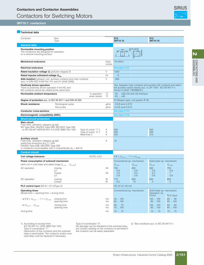
SIRIUS
Smart Infrastructure, Industrial Control Catalog 2020 2/151
2Co
nta
Ctors a
nd
a
ssemb
lies
Contactor SizeType
S123RT10 75
S123RT10 76
General data
Permissible mounting positionThe contactors are designed for operationon a vertical mounting surface.
Mechanical endurance Oper. cycles
10 million
Electrical endurance
Rated insulation voltage Ui (pollution degree 3) V 1000
Rated impulse withstand voltage Uimp kV 8
Safe isolation between coil, auxiliary contacts and main contacts(acc. to DIN VDE 0106 Part 101 and A1 [draft 2/89])
V 690
Positively driven operationThere is positively driven operation if the NC and NO contacts cannot be closed at the same time
Yes, between main contacts and auxiliary NC contacts and within the auxiliary switch blocks acc. to ZH 1/457, IEC 60 947-4-1, Annex H (draft 17B/996/DC)
Permissible ambient temperature in operationwhen stored
°C°C
–25 ... +60/+55 with AS-Interface–55 ... +80
Degree of protection acc. to IEC 60 947-1 and DIN 40 050 IP 00/open type, coil system IP 20
Shock resistance Rectangular pulse g/ms 8.5/5 and 4.2/10Sine pulse g/ms 13.4/5 and 6.5/10
Conductor cross-sections
Electromagnetic compatibility (EMC)
Short-circuit protectionMain circuitFuse links, utilization category gL/gGNH Type 3NA, DIAZED Type 5SB, NEOZED Type 5SE– to IEC 60 947-4/EN 60 947-4-4 (VDE 0660 Part 102) Type of coord. "1" 1) A 630 630
Type of coord. "2" 1) A 500 500Weld-free 2) A 250 315
Auxiliary circuitFuse links, utilization category gL/gG A 10(weld-free protection at Ik 1 kA)DIAZED Type 5SB, NEOZED Type 5SEor miniature circuit-breaker with C-characteristic (Ik < 400 A)
Control circuit
Coil voltage tolerance AC/DC (UC) 0.8 × Us min ... 1.1 × Us max
Power consumption of solenoid mechanism Conventional op. mechanism Solid-state op. mechanism(with coil in cold state and rated range Us min ... Us max) Us min Us max Us min Us max
AC operation closingp.f. closedp.f.
VA
VA
7000.97.60.9
8300.99.20.9
5600.85.40.8
7500.870.8
DC operation closingclosed
WW
7708.5
92010
6004
8005
PLC control input (EN 61 131-2/Type 2) DC 24 V/ 30 mA
Operating times Conventional op. mechanism Solid-state op. mechanism(Break-time = opening time + arcing time) Operation via
A1/A2 PLC input– at 0.8 × Us min ... 1.1 × Us max closing time
opening timemsms
45 ... 10060 ... 100
120 ... 15080 ... 100
60 ... 9080 ... 100
– at Us min ... Us max closing timeopening time
msms
50 ... 7070 ... 100
125 ... 15080 ... 100
65 ... 8080 ... 100
Arcing time ms 10 ... 15 10 ... 15 10 ... 15
Technical data
1) According to excerpt fromIEC 60 947-4-1 (VDE 0660 Part 102):Type of coordination "1":Destruction of the contactor and the overload relay is permissible. The contactor and/or over-load relay must be replaced if necessary.
Type of coordination "2":No damage can be tolerated to the overload relay,but contact welding on the contactor is permitted ifthe contacts can be easily separated.
2) Test conditions acc. to IEC 60 947-4-1.
Siemens / Industrial Controls Previous folio: IC10 2/114
See page 2/125
See page 2/153
See page 2/108
Contactors and Contactor Assemblies
Contactors for Switching Motors3RT10.7. contactors
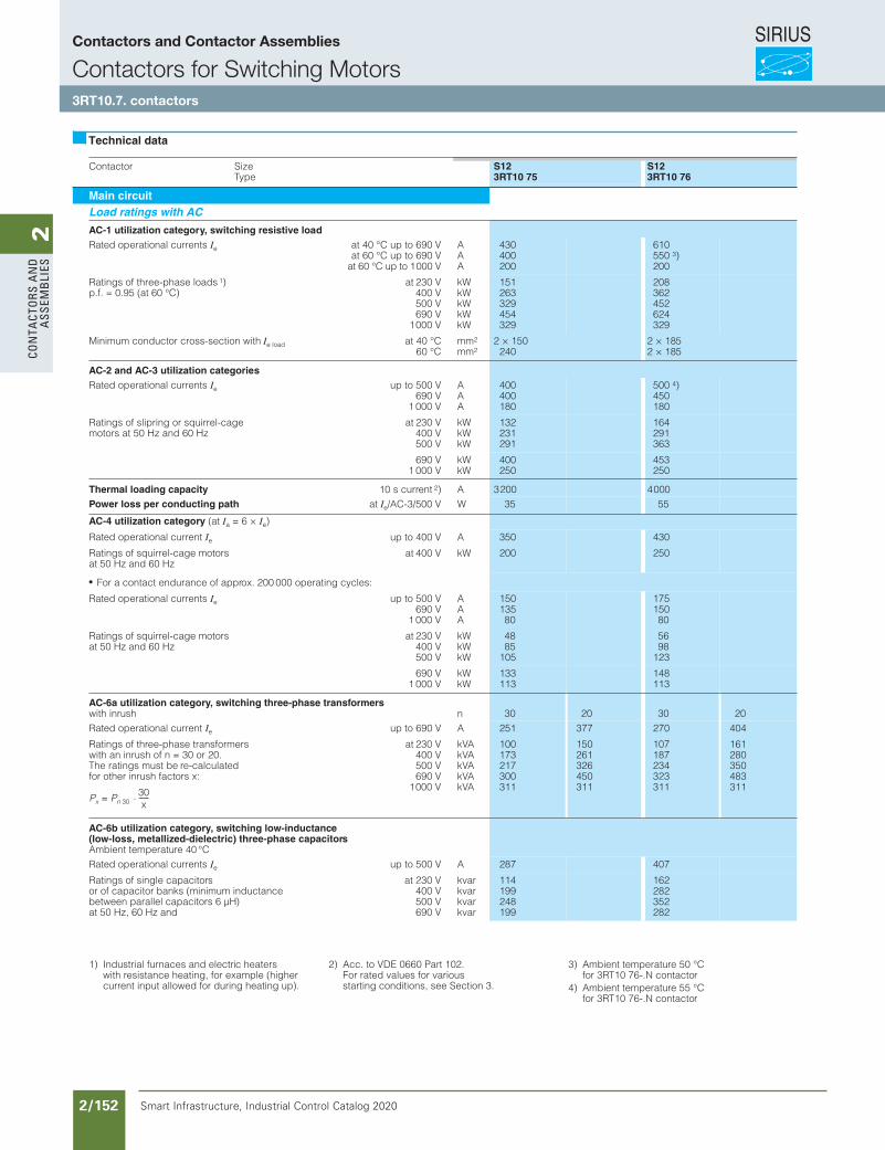
SIRIUS
Smart Infrastructure, Industrial Control Catalog 2020 2/152
2Co
nta
Cto
rs a
nd
a
ssem
bli
es
Contactor SizeType
S123RT10 75
S123RT10 76
Main circuitLoad ratings with AC
AC-1 utilization category, switching resistive loadRated operational currents Ie at 40 °C up to 690 V
at 60 °C up to 690 Vat 60 °C up to 1000 V
AAA
430400200
610550 3)200
Ratings of three-phase loads 1)p.f. = 0.95 (at 60 °C)
at 230 V400 V500 V690 V
1000 V
kWkWkWkWkW
151263329454329
208362452624329
Minimum conductor cross-section with Ie load at 40 °C60 °C
mm2
mm22 × 150
2402 × 1852 × 185
AC-2 and AC-3 utilization categoriesRated operational currents Ie up to 500 V
690 V1 000 V
AAA
400400180
500 4)450180
Ratings of slipring or squirrel-cage motors at 50 Hz and 60 Hz
at 230 V400 V500 V
kWkWkW
132231291
164291363
690 V1 000 V
kWkW
400250
453250
Thermal loading capacity 10 s current 2) A 3200 4000Power loss per conducting path at Ie/AC-3/500 V W 35 55
AC-4 utilization category (at Ia = 6 × Ie)Rated operational current Ie up to 400 V A 350 430
Ratings of squirrel-cage motors at 50 Hz and 60 Hz
at 400 V kW 200 250
For a contact endurance of approx. 200 000 operating cycles:
Rated operational currents Ie up to 500 V690 V
1 000 V
AAA
15013580
17515080
Ratings of squirrel-cage motors at 50 Hz and 60 Hz
at 230 V400 V500 V
kWkWkW
4885
105
5698
123
690 V1 000 V
kWkW
133113
148113
AC-6a utilization category, switching three-phase transformerswith inrush n 30 20 30 20Rated operational current Ie up to 690 V A 251 377 270 404
Ratings of three-phase transformerswith an inrush of n = 30 or 20.The ratings must be re-calculatedfor other inrush factors x:
at 230 V400 V500 V690 V
1000 V
kVAkVAkVAkVAkVA
100173217300311
150261326450311
107187234323311
161280350483311
AC-6b utilization category, switching low-inductance(low-loss, metallized-dielectric) three-phase capacitorsAmbient temperature 40 °CRated operational currents Ie up to 500 V A 287 407
Ratings of single capacitorsor of capacitor banks (minimum inductance between parallel capacitors 6 µH)at 50 Hz, 60 Hz and
at 230 V400 V500 V690 V
kvarkvarkvarkvar
114199248199
162282352282
Technical data
1) Industrial furnaces and electric heaters with resistance heating, for example (highercurrent input allowed for during heating up).
2) Acc. to VDE 0660 Part 102.For rated values for various starting conditions, see Section 3.
3) Ambient temperature 50 °C for 3RT10 76-.N contactor
4) Ambient temperature 55 °C for 3RT10 76-.N contactor
Siemens / Industrial Controls Previous folio: IC10 2/115
Contactors and Contactor Assemblies
Contactors for Switching Motors3RT10.7. contactors
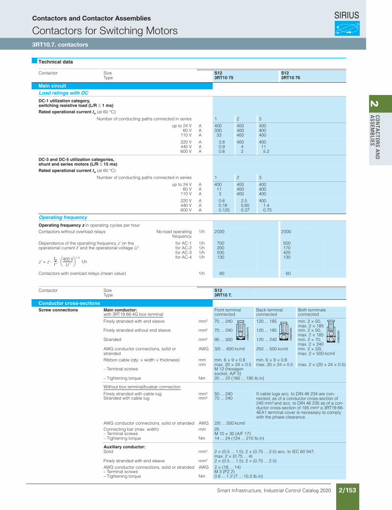
SIRIUS
Smart Infrastructure, Industrial Control Catalog 2020 2/153
2Co
nta
Ctors a
nd
a
ssemb
lies
Contactors for Switching MotorsSIRIUSContactors and Contactor Assemblies
3RT10 7. contactors
Contactor SizeType
S123RT10 75
S123RT10 76
Main circuitLoad ratings with DC
DC-1 utilization category,switching resistive load (L/R 1 ms)Rated operational current Ie (at 60 °C)
Number of conducting paths connected in series 1 2 3
up to 24 V60 V
110 V
AAA
40033033
400400400
400400400
220 V440 V600 V
AAA
3.80.90.6
40042
400115.2
DC-3 and DC-5 utilization categories,shunt and series motors (L/R 15 ms)Rated operational current Ie (at 60 °C)
Number of conducting paths connected in series 1 2 3
up to 24 V60 V
110 V
AAA
400113
400400400
400400400
220 V440 V600 V
AAA
0.60.180.125
2.50.650.37
4001.40.75
Operating frequency
Operating frequency z in operating cycles per hourContactors without overload relays No-load operating
frequency1/h 2000 2000
Dependence of the operating frequency z’ on the operational current I’ and the operational voltage U’:
z’ = z1.5
1/h
for AC-1for AC-2for AC-3for AC-4
1/h1/h1/h1/h
700200500130
500170420130
Contactors with overload relays (mean value) 1/h 60 60
Contactor SizeType
S123RT10 7.
Conductor cross-sectionsScrew connections Main conductor: Front terminal Back terminal Both terminals
with 3RT19 66-4G box terminal connected connected connected
Finely stranded with end sleeve mm2 70 ... 240 120 ... 185 min. 2 × 50,max. 2 × 185
Finely stranded without end sleeve mm2 70 ... 240 120 ... 185 min. 2 × 50,max. 2 × 185
Stranded mm2 95 ... 300 120 ... 240 min. 2 × 70,max. 2 × 240
AWG conductor connections, solid or stranded
AWG 3/0 ... 600 kcmil 250 ... 500 kcmil min. 2 × 2/0,max. 2 × 500 kcmil
Ribbon cable (qty. × width × thickness) mmmm
min. 6 × 9 × 0.8max. 20 × 24 × 0.5
min. 6 × 9 × 0.8max. 20 × 24 × 0.5 max. 2 × (20 × 24 × 0.5)
– Terminal screws M 12 (hexagon socket, A/F 5)
– Tightening torque Nm 20 ... 22 (180 ... 195 lb.in)
Without box terminal/busbar connection
Finely stranded with cable lug mm2 50 ... 240 If cable lugs acc. to DIN 46 234 are con-nected, as of a conductor cross-section of 240 mm2 and acc. to DIN 46 235 as of a con-ductor cross-section of 185 mm2 a 3RT19 66-4EA1 terminal cover is necessary to comply with the phase clearance.
Stranded with cable lug mm2 70 ... 240
AWG conductor connections, solid or stranded AWG 2/0 ... 500 kcmilConnecting bar (max. width) mm 25– Terminal screws M 10 × 30 (A/F 17)– Tightening torque Nm 14 ... 24 (124 ... 210 lb.in)
Auxiliary conductor:Solid mm2 2 × (0.5 ... 1.5); 2 × (0.75 ... 2.5) acc. to IEC 60 947;
max. 2 × (0.75 ... 4)Finely stranded with end sleeve mm2 2 × (0.5 ... 1.5); 2 × (0.75 ... 2.5)AWG conductor connections, solid or stranded AWG 2 × (18 ... 14)– Terminal screws M 3 (PZ 2)– Tightening torque Nm 0.8 ... 1.2 (7 ... 10.3 lb.in)
Technical data
IeI---- 400 V
U----------
Siemens / Industrial Controls Previous folio: IC10 2/116
Contactors and Contactor Assemblies
Contactors for Switching Motors3RT10.7. contactors
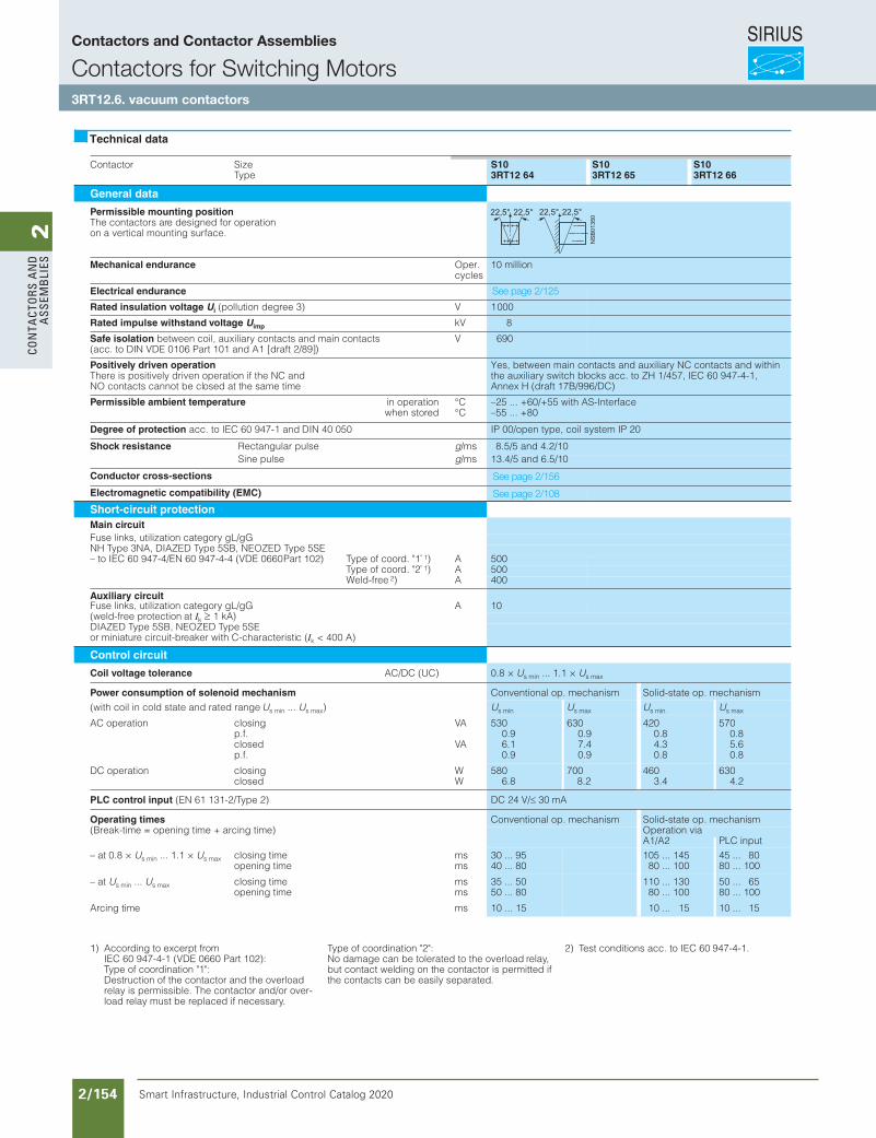
SIRIUS
Smart Infrastructure, Industrial Control Catalog 2020 2/154
2Co
nta
Cto
rs a
nd
a
ssem
bli
es
Contactor SizeType
S103RT12 64
S103RT12 65
S103RT12 66
General data
Permissible mounting positionThe contactors are designed for operationon a vertical mounting surface.
Mechanical endurance Oper. cycles
10 million
Electrical endurance
Rated insulation voltage Ui (pollution degree 3) V 1000
Rated impulse withstand voltage Uimp kV 8
Safe isolation between coil, auxiliary contacts and main contacts(acc. to DIN VDE 0106 Part 101 and A1 [draft 2/89])
V 690
Positively driven operationThere is positively driven operation if the NC and NO contacts cannot be closed at the same time
Yes, between main contacts and auxiliary NC contacts and within the auxiliary switch blocks acc. to ZH 1/457, IEC 60 947-4-1, Annex H (draft 17B/996/DC)
Permissible ambient temperature in operationwhen stored
°C°C
–25 ... +60/+55 with AS-Interface–55 ... +80
Degree of protection acc. to IEC 60 947-1 and DIN 40 050 IP 00/open type, coil system IP 20
Shock resistance Rectangular pulse g/ms 8.5/5 and 4.2/10Sine pulse g/ms 13.4/5 and 6.5/10
Conductor cross-sections
Electromagnetic compatibility (EMC)
Short-circuit protection Main circuitFuse links, utilization category gL/gGNH Type 3NA, DIAZED Type 5SB, NEOZED Type 5SE– to IEC 60 947-4/EN 60 947-4-4 (VDE 0660Part 102) Type of coord. "1" 1) A 500
Type of coord. "2" 1) A 500Weld-free 2) A 400
Auxiliary circuitFuse links, utilization category gL/gG A 10(weld-free protection at Ik 1 kA)DIAZED Type 5SB, NEOZED Type 5SEor miniature circuit-breaker with C-characteristic (Ik < 400 A)
Control circuit
Coil voltage tolerance AC/DC (UC) 0.8 × Us min ... 1.1 × Us max
Power consumption of solenoid mechanism Conventional op. mechanism Solid-state op. mechanism(with coil in cold state and rated range Us min ... Us max) Us min Us max Us min Us max
AC operation closingp.f. closedp.f.
VA
VA
5300.96.10.9
6300.97.40.9
4200.84.30.8
5700.85.60.8
DC operation closingclosed
WW
5806.8
7008.2
4603.4
6304.2
PLC control input (EN 61 131-2/Type 2) DC 24 V/ 30 mA
Operating times Conventional op. mechanism Solid-state op. mechanism(Break-time = opening time + arcing time) Operation via
A1/A2 PLC input– at 0.8 × Us min ... 1.1 × Us max closing time
opening timemsms
30 ... 9540 ... 80
105 ... 14580 ... 100
45 ... 8080 ... 100
– at Us min ... Us max closing timeopening time
msms
35 ... 5050 ... 80
110 ... 13080 ... 100
50 ... 6580 ... 100
Arcing time ms 10 ... 15 10 ... 15 10 ... 15
Technical data
1) According to excerpt fromIEC 60 947-4-1 (VDE 0660 Part 102):Type of coordination "1":Destruction of the contactor and the overload relay is permissible. The contactor and/or over-load relay must be replaced if necessary.
Type of coordination "2":No damage can be tolerated to the overload relay,but contact welding on the contactor is permitted ifthe contacts can be easily separated.
2) Test conditions acc. to IEC 60 947-4-1.
Siemens / Industrial Controls Previous folio: IC10 2/117
See page 2/125
See page 2/156
See page 2/108
Contactors and Contactor Assemblies
Contactors for Switching Motors3RT12.6. vacuum contactors
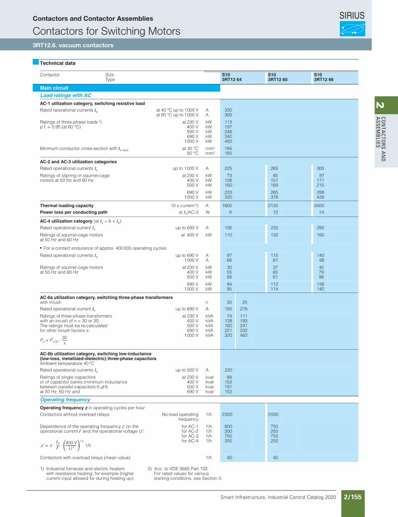
SIRIUS
Smart Infrastructure, Industrial Control Catalog 2020 2/155
2Co
nta
Ctors a
nd
a
ssemb
lies
Contactor SizeType
S103RT12 64
S103RT12 65
S103RT12 66
Main circuitLoad ratings with AC
AC-1 utilization category, switching resistive loadRated operational currents Ie at 40 °C up to 1000 V
at 60 °C up to 1000 VAA
330300
Ratings of three-phase loads 1)p.f. = 0.95 (at 60 °C)
at 230 V400 V500 V690 V
1000 V
kWkWkWkWkW
113197246340492
Minimum conductor cross-section with Ie load at 40 °C60 °C
mm2
mm2185185
AC-2 and AC-3 utilization categoriesRated operational currents Ie up to 1000 V A 225 265 300
Ratings of slipring or squirrel-cage motors at 50 Hz and 60 Hz
at 230 V400 V500 V
kWkWkW
73128160
85151189
97171215
690 V1000 V
kWkW
223320
265378
288428
Thermal loading capacity 10 s current 2) A 1800 2120 2400Power loss per conducting path at Ie/AC-3 W 9 12 14
AC-4 utilization category (at Ia = 6 × Ie)Rated operational current Ie up to 690 V A 195 230 280
Ratings of squirrel-cage motors at 50 Hz and 60 Hz
at 400 V kW 110 132 160
For a contact endurance of approx. 400 000 operating cycles:
Rated operational currents Ie up to 690 V1000 V
AA
9768
11581
14098
Ratings of squirrel-cage motors at 50 Hz and 60 Hz
at 230 V400 V500 V
kWkWkW
305568
376581
457998
690 V1000 V
kWkW
9495
112114
138140
AC-6a utilization category, switching three-phase transformerswith inrush n 30 20Rated operational current Ie up to 690 V A 185 278
Ratings of three-phase transformerswith an inrush of n = 30 or 20.The ratings must be re-calculatedfor other inrush factors x:
at 230 V400 V500 V690 V
1000 V
kVAkVAkVAkVAkVA
74128160221320
111193241332482
AC-6b utilization category, switching low-inductance(low-loss, metallized-dielectric) three-phase capacitorsAmbient temperature 40 °CRated operational currents Ie up to 500 V A 220
Ratings of single capacitorsor of capacitor banks (minimum inductance between parallel capacitors 6 µH)at 50 Hz, 60 Hz and
at 230 V400 V500 V690 V
kvarkvarkvarkvar
88152191152
Operating frequency
Operating frequency z in operating cycles per hourContactors without overload relays No-load operating
frequency1/h 2000 2000
Dependence of the operating frequency z’ on the operational current I’ and the operational voltage U’:
for AC-1for AC-2for AC-3for AC-4
1/h1/h1/h1/h
800300750250
750250750250
Contactors with overload relays (mean value) 1/h 60 60
Technical data
1) Industrial furnaces and electric heaters with resistance heating, for example (highercurrent input allowed for during heating up).
2) Acc. to VDE 0660 Part 102.For rated values for various starting conditions, see Section 3.
Siemens / Industrial Controls Previous folio: IC10 2/118
Contactors and Contactor Assemblies
Contactors for Switching Motors3RT12.6. vacuum contactors
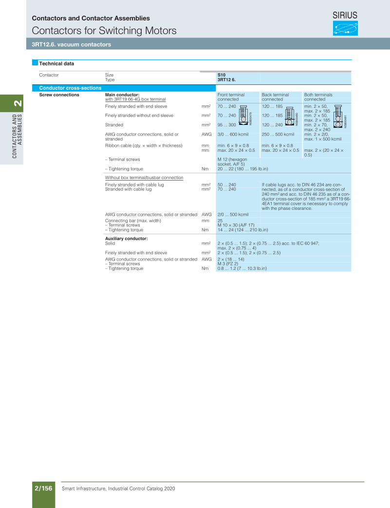
SIRIUS
Smart Infrastructure, Industrial Control Catalog 2020 2/156
2Co
nta
Cto
rs a
nd
a
ssem
bli
es
SIRIUSContactors and Contactor Assemblies
Contactors for Switching Motors
3RT12 6. vacuum contactors
Contactor SizeType
S103RT12 6.
Conductor cross-sectionsScrew connections Main conductor: Front terminal Back terminal Both terminals
with 3RT19 66-4G box terminal connected connected connected
Finely stranded with end sleeve mm2 70 ... 240 120 ... 185 min. 2 × 50,max. 2 × 185
Finely stranded without end sleeve mm2 70 ... 240 120 ... 185 min. 2 × 50,max. 2 × 185
Stranded mm2 95 ... 300 120 ... 240 min. 2 × 70,max. 2 × 240
AWG conductor connections, solid or stranded
AWG 3/0 ... 600 kcmil 250 ... 500 kcmil min. 2 × 2/0,max. 1 × 500 kcmil
Ribbon cable (qty. × width × thickness) mmmm
min. 6 × 9 × 0.8max. 20 × 24 × 0.5
min. 6 × 9 × 0.8max. 20 × 24 × 0.5 max. 2 × (20 × 24 ×
0.5)– Terminal screws M 12 (hexagon
socket, A/F 5)– Tightening torque Nm 20 ... 22 (180 ... 195 lb.in)
Without box terminal/busbar connection
Finely stranded with cable lug mm2 50 ... 240 If cable lugs acc. to DIN 46 234 are con-nected, as of a conductor cross-section of 240 mm2 and acc. to DIN 46 235 as of a con-ductor cross-section of 185 mm2 a 3RT19 66-4EA1 terminal cover is necessary to comply with the phase clearance.
Stranded with cable lug mm2 70 ... 240
AWG conductor connections, solid or stranded AWG 2/0 ... 500 kcmilConnecting bar (max. width) mm 25– Terminal screws M 10 × 30 (A/F 17)– Tightening torque Nm 14 ... 24 (124 ... 210 lb.in)
Auxiliary conductor:Solid mm2 2 × (0.5 ... 1.5); 2 × (0.75 ... 2.5) acc. to IEC 60 947;
max. 2 × (0.75 ... 4)Finely stranded with end sleeve mm2 2 × (0.5 ... 1.5); 2 × (0.75 ... 2.5)AWG conductor connections, solid or stranded AWG 2 × (18 ... 14)– Terminal screws M 3 (PZ 2)– Tightening torque Nm 0.8 ... 1.2 (7 ... 10.3 lb.in)
Technical data
Siemens / Industrial Controls Previous folio: IC10 2/119
Contactors and Contactor Assemblies
Contactors for Switching Motors3RT12.6. vacuum contactors
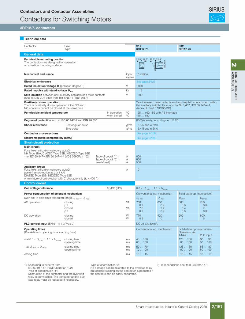
SIRIUS
Smart Infrastructure, Industrial Control Catalog 2020 2/157
2Co
nta
Ctors a
nd
a
ssemb
lies
Contactor SizeType
S123RT12 75
S123RT12 76
General data
Permissible mounting positionThe contactors are designed for operationon a vertical mounting surface.
Mechanical endurance Oper. cycles
10 million
Electrical endurance
Rated insulation voltage Ui (pollution degree 3) V 1000
Rated impulse withstand voltage Uimp kV 8
Safe isolation between coil, auxiliary contacts and main contacts(acc. to DIN VDE 0106 Part 101 and A1 [draft 2/89])
V 690
Positively driven operationThere is positively driven operation if the NC and NO contacts cannot be closed at the same time
Yes, between main contacts and auxiliary NC contacts and within the auxiliary switch blocks acc. to ZH 1/457, IEC 60 947-4-1, Annex H (draft 17B/996/DC)
Permissible ambient temperature in operationwhen stored
°C°C
–25 ... +60/+55 with AS-Interface–55 ... +80
Degree of protection acc. to IEC 60 947-1 and DIN 40 050 IP 00/open type, coil system IP 20
Shock resistance Rectangular pulse g/ms 8.5/5 and 4.2/10Sine pulse g/ms 13.4/5 and 6.5/10
Conductor cross-sections
Electromagnetic compatibility (EMC)
Short-circuit protectionMain circuitFuse links, utilization category gL/gGNH Type 3NA, DIAZED Type 5SB, NEOZED Type 5SE– to IEC 60 947-4/EN 60 947-4-4 (VDE 0660Part 102) Type of coord. "1" 1) A 800
Type of coord. "2" 1) A 800Weld-free 2) A 500
Auxiliary circuitFuse links, utilization category gL/gG A 10(weld-free protection at Ik 1 kA)DIAZED Type 5SB, NEOZED Type 5SEor miniature circuit-breaker with C-characteristic (Ik < 400 A)
Control circuit
Coil voltage tolerance AC/DC (UC) 0.8 × Us min ... 1.1 × Us max
Power consumption of solenoid mechanism Conventional op. mechanism Solid-state op. mechanism(with coil in cold state and rated range Us min ... Us max) Us min Us max Us min Us max
AC operation closingp.f. closedp.f.
VA
VA
7000.97.60.9
8300.99.20.9
5600.85.40.8
7500.870.8
DC operation closingclosed
WW
7708.5
92010
6004
8005
PLC control input (EN 61 131-2/Type 2) DC 24 V/ 30 mA
Operating times Conventional op. mechanism Solid-state op. mechanism(Break-time = opening time + arcing time) Operation via
A1/A2 PLC input– at 0.8 × Us min ... 1.1 × Us max closing time
opening timemsms
45 ... 10060 ... 100
120 ... 15080 ... 100
60 ... 9080 ... 100
– at Us min ... Us max closing timeopening time
msms
50 ... 7070 ... 100
125 ... 15080 ... 100
65 ... 8080 ... 100
Arcing time ms 10 ... 15 10 ... 15 10 ... 15
Technical data
1) According to excerpt fromIEC 60 947-4-1 (VDE 0660 Part 102):Type of coordination "1":Destruction of the contactor and the overload relay is permissible. The contactor and/or over-load relay must be replaced if necessary.
Type of coordination "2":No damage can be tolerated to the overload relay,but contact welding on the contactor is permitted ifthe contacts can be easily separated.
2) Test conditions acc. to IEC 60 947-4-1.
Siemens / Industrial Controls Previous folio: IC10 2/120
See page 2/125
See page 2/159
See page 2/108
Contactors and Contactor Assemblies
Contactors for Switching Motors3RT12.7. contactors
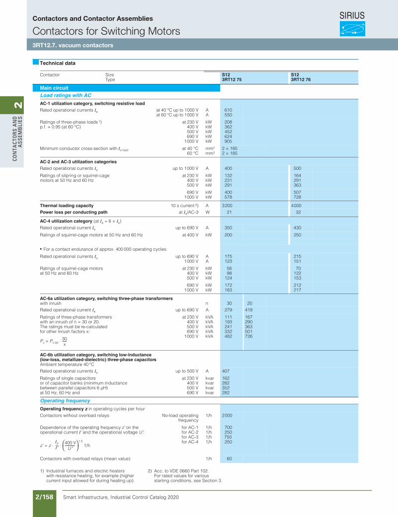
SIRIUS
Smart Infrastructure, Industrial Control Catalog 2020 2/158
2Co
nta
Cto
rs a
nd
a
ssem
bli
es
Contactor SizeType
S123RT12 75
S123RT12 76
Main circuitLoad ratings with AC
AC-1 utilization category, switching resistive loadRated operational currents Ie at 40 °C up to 1000 V
at 60 °C up to 1000 VAA
610550
Ratings of three-phase loads 1)p.f. = 0.95 (at 60 °C)
at 230 V400 V500 V690 V
1000 V
kWkWkWkWkW
208362452624905
Minimum conductor cross-section with Ie load at 40 °C60 °C
mm2
mm22 × 1852 × 185
AC-2 and AC-3 utilization categoriesRated operational currents Ie up to 1000 V A 400 500
Ratings of slipring or squirrel-cage motors at 50 Hz and 60 Hz
at 230 V400 V500 V
kWkWkW
132231291
164291363
690 V1000 V
kWkW
400578
507728
Thermal loading capacity 10 s current 2) A 3200 4000Power loss per conducting path at Ie/AC-3 W 21 32
AC-4 utilization category (at Ia = 6 × Ie)Rated operational current Ie up to 690 V A 350 430
Ratings of squirrel-cage motors at 50 Hz and 60 Hz at 400 V kW 200 250
For a contact endurance of approx. 400 000 operating cycles:
Rated operational currents Ie up to 690 V1000 V
AA
175123
215151
Ratings of squirrel-cage motors at 50 Hz and 60 Hz
at 230 V400 V500 V
kWkWkW
5698
124
70122153
690 V1000 V
kWkW
172183
212217
AC-6a utilization category, switching three-phase transformerswith inrush n 30 20Rated operational current Ie up to 690 V A 279 419
Ratings of three-phase transformerswith an inrush of n = 30 or 20.The ratings must be re-calculatedfor other inrush factors x:
at 230 V400 V500 V690 V
1000 V
kVAkVAkVAkVAkVA
111193241332482
167290363501726
AC-6b utilization category, switching low-inductance(low-loss, metallized-dielectric) three-phase capacitorsAmbient temperature 40 °CRated operational currents Ie up to 500 V A 407
Ratings of single capacitorsor of capacitor banks (minimum inductance between parallel capacitors 6 µH)at 50 Hz, 60 Hz and
at 230 V400 V500 V690 V
kvarkvarkvarkvar
162282352282
Operating frequency
Operating frequency z in operating cycles per hourContactors without overload relays No-load operating
frequency1/h 2000
Dependence of the operating frequency z’ on the operational current I’ and the operational voltage U’:
for AC-1for AC-2for AC-3for AC-4
1/h1/h1/h1/h
700250750250
Contactors with overload relays (mean value) 1/h 60
Technical data
1) Industrial furnaces and electric heaters with resistance heating, for example (highercurrent input allowed for during heating up).
2) Acc. to VDE 0660 Part 102.For rated values for various starting conditions, see Section 3.
Siemens / Industrial Controls Previous folio: IC10 2/121
Contactors and Contactor Assemblies
Contactors for Switching Motors3RT12.7. vacuum contactors
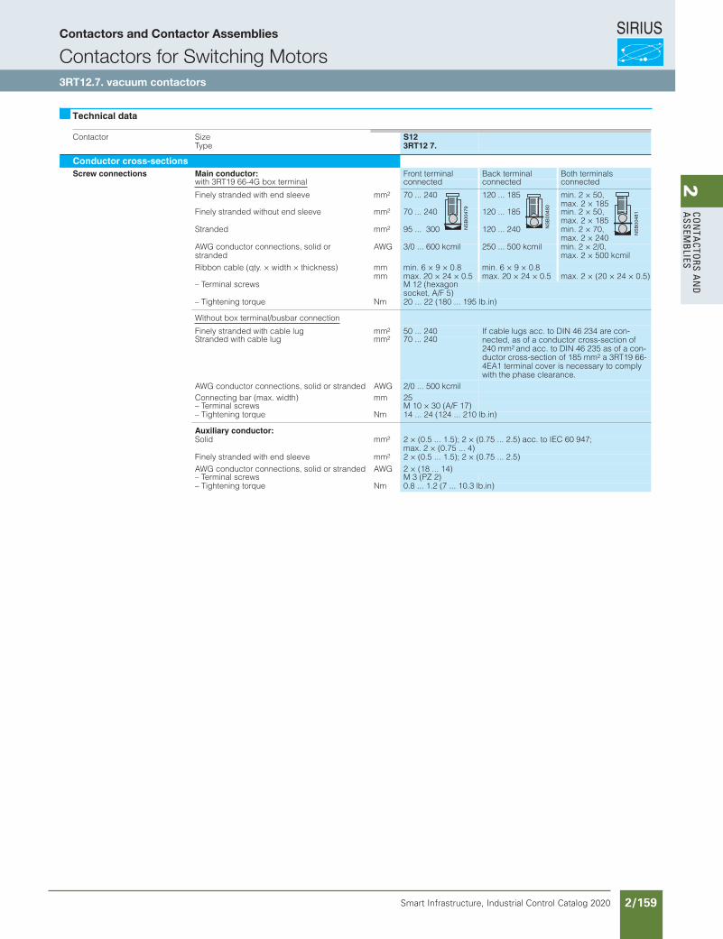
SIRIUS
Smart Infrastructure, Industrial Control Catalog 2020 2/159
2Co
nta
Ctors a
nd
a
ssemb
lies
Contactors for Switching MotorsSIRIUSContactors and Contactor Assemblies
3RT12 7. vacuum contactors
Contactor SizeType
S123RT12 7.
Conductor cross-sectionsScrew connections Main conductor: Front terminal Back terminal Both terminals
with 3RT19 66-4G box terminal connected connected connected
Finely stranded with end sleeve mm2 70 ... 240 120 ... 185 min. 2 × 50,max. 2 × 185
Finely stranded without end sleeve mm2 70 ... 240 120 ... 185 min. 2 × 50,max. 2 × 185
Stranded mm2 95 ... 300 120 ... 240 min. 2 × 70,max. 2 × 240
AWG conductor connections, solid or stranded
AWG 3/0 ... 600 kcmil 250 ... 500 kcmil min. 2 × 2/0,max. 2 × 500 kcmil
Ribbon cable (qty. × width × thickness) mmmm
min. 6 × 9 × 0.8max. 20 × 24 × 0.5
min. 6 × 9 × 0.8max. 20 × 24 × 0.5 max. 2 × (20 × 24 × 0.5)
– Terminal screws M 12 (hexagon socket, A/F 5)
– Tightening torque Nm 20 ... 22 (180 ... 195 lb.in)
Without box terminal/busbar connection
Finely stranded with cable lug mm2 50 ... 240 If cable lugs acc. to DIN 46 234 are con-nected, as of a conductor cross-section of 240 mm2 and acc. to DIN 46 235 as of a con-ductor cross-section of 185 mm2 a 3RT19 66-4EA1 terminal cover is necessary to comply with the phase clearance.
Stranded with cable lug mm2 70 ... 240
AWG conductor connections, solid or stranded AWG 2/0 ... 500 kcmilConnecting bar (max. width) mm 25– Terminal screws M 10 × 30 (A/F 17)– Tightening torque Nm 14 ... 24 (124 ... 210 lb.in)
Auxiliary conductor:Solid mm2 2 × (0.5 ... 1.5); 2 × (0.75 ... 2.5) acc. to IEC 60 947;
max. 2 × (0.75 ... 4)Finely stranded with end sleeve mm2 2 × (0.5 ... 1.5); 2 × (0.75 ... 2.5)AWG conductor connections, solid or stranded AWG 2 × (18 ... 14)– Terminal screws M 3 (PZ 2)– Tightening torque Nm 0.8 ... 1.2 (7 ... 10.3 lb.in)
Technical data
Siemens / Industrial Controls Previous folio: IC10 2/122
Contactors and Contactor Assemblies
Contactors for Switching Motors3RT12.7. vacuum contactors
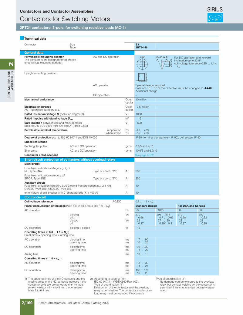
SIRIUS
Smart Infrastructure, Industrial Control Catalog 2020 2/160
2Co
nta
Cto
rs a
nd
a
ssem
bli
es
Contactors and Contactor Assemblies
Contactor SizeType
S33RT24 46
General dataPermissible mounting positionThe contactors are designed for operationon a vertical mounting surface.
AC and DC operation
Upright mounting position:
AC operation Special design required.Positions 13 ... 16 of the Order No. must be changed to -1AA0.Additional charge.
DC operation –
Mechanical endurance Oper. 10 millioncycles
Electrical endurance Oper. 0.5 millionAC-1 utilization category at Ie cycles
Rated insulation voltage Ui (pollution degree 3) V 1000
Rated impulse withstand voltage Uimp kV 6
Safe isolation between coil and main contacts(acc. to DIN VDE 0106 Part 101 and A1 [draft 2/89])
V 690
Permissible ambient temperature in operationwhen stored
°C°C
–25 ... +60–55 ... +80
Degree of protection acc. to IEC 60 947-1 and DIN 40 050 IP 20 (terminal compartment IP 00), coil system IP 40
Shock resistanceRectangular pulse AC and DC operation g/ms 6.8/5 and 4/10
Sine pulse AC and DC operation g/ms 10.6/5 and 6.2/10
Conductor cross-sectionsShort-circuit protection of contactors without overload relaysMain circuitFuse links, utilization category gL/gGNH, Type 3NA Type of coord. "1" 2) A 250
Fuse links, utilization category gRSITOR, Type 3NE Type of coord. "2" 2) A 250
Auxiliary circuitFuse links, utilization category gL/gG (weld-free protection at Ik 1 kA)DIAZED Type 5SB, NEOZED Type 5SE
A 10
or miniature circuit-breaker with C-characteristic (Ik < 400 A) A 10
Control circuitCoil voltage tolerance AC/DC 0.8 ... 1.1 × Us
Power consumption of the coils (with coil in cold state and 1.0 × Us) Standard design For USA and CanadaAC operation Hz 50 50/60 50 60
closingp.f. closedp.f.
VA
VA
2700.68
220.27
298 /2740.7 / 0.62
27 / 200.29/ 0.31
2700.68
220.27
3000.52
210.29
DC operation closing = closed W 15
Operating times at 0.8 ... 1.1 × Us1)
Break-time = opening time + arcing time
AC operation closing timeopening time
msms
17 ... 9010 ... 25
DC operation closing timeopening time
msms
90 ... 23014 ... 20
Arcing time ms 10 ... 15
Operating times at 1.0 × Us1)
AC operation closing timeopening time
msms
18 ... 3011 ... 23
DC operation closing timeopening time
msms
100 ... 12016 ... 20
Technical data
For DC operation and forward inclination up to 22.5°:coil voltage tolerance 0.85 ... 1.1 ×
Us
1) The opening times of the NO contacts and the closing times of the NC contacts increase if the contactor coils are protected against voltage peaks: varistor +2 ms to 5 ms, diode assem-blies 2 to 6 times.
2) According to excerpt fromIEC 60 947-4-1 (VDE 0660 Part 102):Type of coordination "1":Destruction of the contactor and the overload relay is permissible. The contactor and/or over-load relay must be replaced if necessary.
Type of coordination "2":No damage can be tolerated to the overload relay, but contact welding on the contactor is permitted if the contacts can be easily sepa-rated.
Siemens / Industrial Controls Previous folio: IC10 2/123
See page 2/162
Contactors and Contactor Assemblies
Contactors for Switching Motors3RT24 contactors, 3-pole, for switching resistive loads (AC-1)
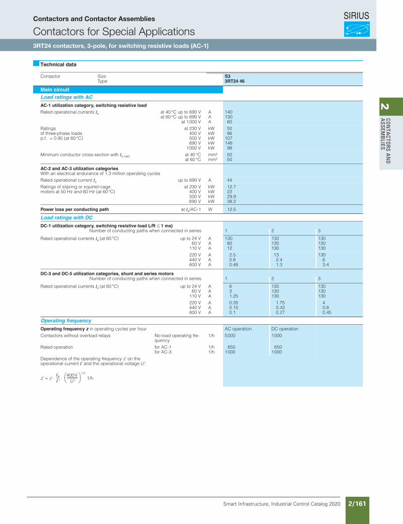
SIRIUS
Smart Infrastructure, Industrial Control Catalog 2020 2/161
2Co
nta
Ctors a
nd
a
ssemb
liesContactors and Contactor Assemblies
Contactors for Special Applications3RT14 contactors, 3-pole,
for switching resistive loads (AC-1)
Contactor Size Ty pe
S33RT24 46
Main circuitLoad ratings with ACAC-1 utilization category, switching resistive loadRated op erational curren ts Ie at 40 °C up to 690 V
at 60 °C up to 690 V at 1 000 V
A A A
140 130 60
Rating s of th re e-phase loads p.f. = 0.95 (at 60 °C)
at 230 V 400 V 500 V 690 V
1 000 V
kW kW kW kW kW
50 86
107 148 98
Minimum conductor cr oss-section with Ie load at 40 °C at 60 °C
mm 2
mm 2 50 50
AC-2 and AC-3 utilization categoriesWith an electrical endurance of 1.3 million operating cycle s Rated op erational curren t Ie up to 690 V A 44 Ratings of slipring or squirr el -cage motors at 50 Hz and 60 Hz (at 60 °C)
at 230 V 400 V 500 V 690 V
kW kW kW kW
12. 7 22 29. 9 38. 2
Power loss per conducting path at Ie /AC-1 W 12. 5
Load ratings with DCDC-1 utilization category, switching resistive load L/R 1 ms)
Nu mber of conducting paths when connected in series 1 2 3
Rated op erational curren ts Ie (at 60 °C) up to 24 V 60 V
110 V
A A A
130 80 12
130 130 130
13 0 13 0 13 0
220 V 440 V 600 V
A A A
2. 5 0. 8 0. 48
13 2.4 1.3
13 0 6 3.4
DC-3 and DC-5 utilization categories, shunt and series motorsNu mber of conducting paths when connected in series 1 2 3
Rated op erational curren ts Ie (at 60 °C) up to 24 V 60 V
110 V
A A A
6 3 1. 25
130 130 130
13 0 13 0 13 0
220 V 440 V 600 V
A A A
0. 35 0. 15 0. 1
1.7 5 0.4 2 0.2 7
4 0.8 0.4 5
Operating frequencyOperating frequency z in op erating cycles pe r hour AC operation DC operation Contactors without overl oad re lays No-load operating fr e-
quency 1/ h 50 00 10 00
Rated op eratio n f or AC-1 for AC-3
1/ h 1/ h
65 0 10 00
65 0 10 00
Dependence of the operating fr equency z’ on the operational current I’ an d the operational voltage U’ :
z’ = z 1. 5
1/ h
Technical data
Ie
I---- 400 V
U ---------- -
Siemens / Industrial Controls Previous folio: IC10 2/124
Contactors and Contactor Assemblies
Contactors for Special Applications3RT24 contactors, 3-pole, for switching resistive loads (AC-1)
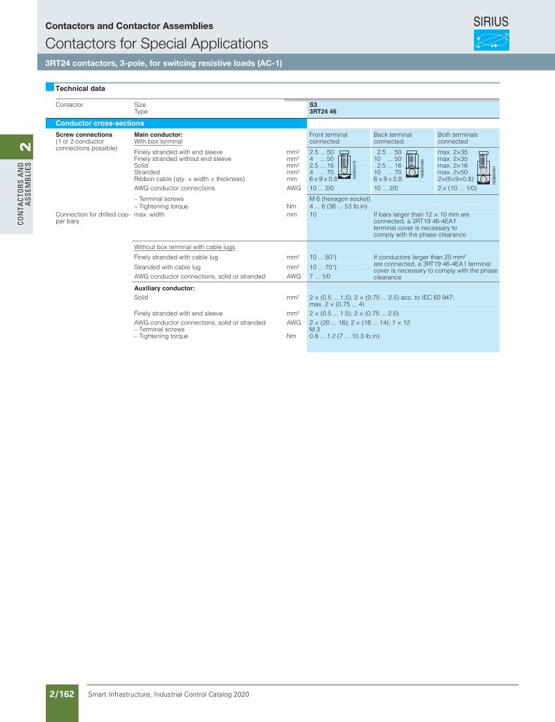
SIRIUS
Smart Infrastructure, Industrial Control Catalog 2020 2/162
2Co
nta
Cto
rs a
nd
a
ssem
bli
es
T24 46
Siemens / Industrial Controls Previous folio: IC10 2/125
Contactors and Contactor Assemblies
Contactors for Special Applications3RT24 contactors, 3-pole, for switcing resistive loads (AC-1)
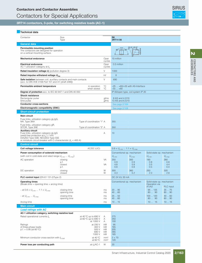
SIRIUS
Smart Infrastructure, Industrial Control Catalog 2020 2/163
2Co
nta
Ctors a
nd
a
ssemb
lies
Siemens / Industrial Controls Previous folio: IC10 2/126
Contactor SizeType
S63RT14 56
General dataPermissible mounting positionThe contactors are designed for operationon a vertical mounting surface.
Mechanical endurance Oper.cycles
10 million
Electrical enduranceAC-1 utilization category at Ie
Oper.cycles
0.5 million
Rated insulation voltage Ui (pollution degree 3) V 1000
Rated impulse withstand voltage Uimp kV 8
Safe isolation between coil, auxiliary contacts and main contacts(acc. to DIN VDE 0106 Part 101 and A1 [draft 2/89])
V 690
Permissible ambient temperature in operationwhen stored
°C°C
–25 ... +60/+55 with AS-Interface–55 ... +80
Degree of protection acc. to IEC 60 947-1 and DIN 40 050 IP 00/open type, coil system IP 20
Shock resistanceRectangular pulse g/ms 8.5/5 and 4.2/10Sine pulse g/ms 13.4/5 and 6.5/10Conductor cross-sectionsElectromagnetic compatibility (EMC)Short-circuit protectionMain circuitFuse links, utilization category gL/gG,NH, Type 3NA Type of coordination "1" A 355Fuse links, utilization category gR,SITOR, Type 3NE Type of coordination "2" A 350Auxiliary circuitFuse links, utilization category gL/gG(weld-free protection at Ik 1 kA)DIAZED Type 5SB, NEOZED Type 5SEor miniature circuit-breaker with C-characteristic (Ik < 400 A)
A 10
Control circuitCoil voltage tolerance AC/DC (UC) 0.8 × Us min ... 1.1 × Us max
Power consumption of solenoid mechanism Conventional op. mechanism Solid-state op. mechanism(with coil in cold state and rated range Us min ... Us max) Us min Us max Us min Us max
AC operation closingp.f. closedp.f.
VA
VA
2500.94.80.8
3000.95.80.8
1900.83.50.5
2800.84.40.4
DC operation closingclosed
WW
3004.3
3605.2
2502.3
3202.8
PLC control input (EN 61 131-2/Type 2) DC 24 V/ 30 mA
Operating times Conventional op. mechanism Solid-state op. mechanism(Break-time = opening time + arcing time) Operation via
A1/A2 PLC input– at 0.8 × Us min ... 1.1 × Us max closing time
opening timemsms
20 ... 9540 ... 60
95 ... 13580 ... 90
35 ... 7580 ... 90
– at Us min ... Us max closing timeopening time
msms
25 ... 5040 ... 60
100 ... 12080 ... 90
40 ... 6080 ... 90
Arcing time ms 10 ... 15 10 ... 15 10 ... 15
Main circuitLoad ratings with ACAC-1 utilization category, switching resistive loadRated operational currents Ie at 40 °C up to 690 V
at 60 °C up to 690 Vat 1000 V
AAA
275250100
Ratingsof three-phase loadsp.f. = 0.95 (at 60 °C)
at 230 V400 V500 V690 V
1000 V
kWkWkWkWkW
95165205285165
Minimum conductor cross-section with Ie load at 40 °Cat 60 °C
mm2
mm22 × 70120
Power loss per conducting path at Ie/AC-1 W 20
Technical data
See page 2/164
See page 2/108
Contactors and Contactor Assemblies
Contactors for Special Applications3RT14 contactors, 3-pole, for switching resistive loads (AC-1)
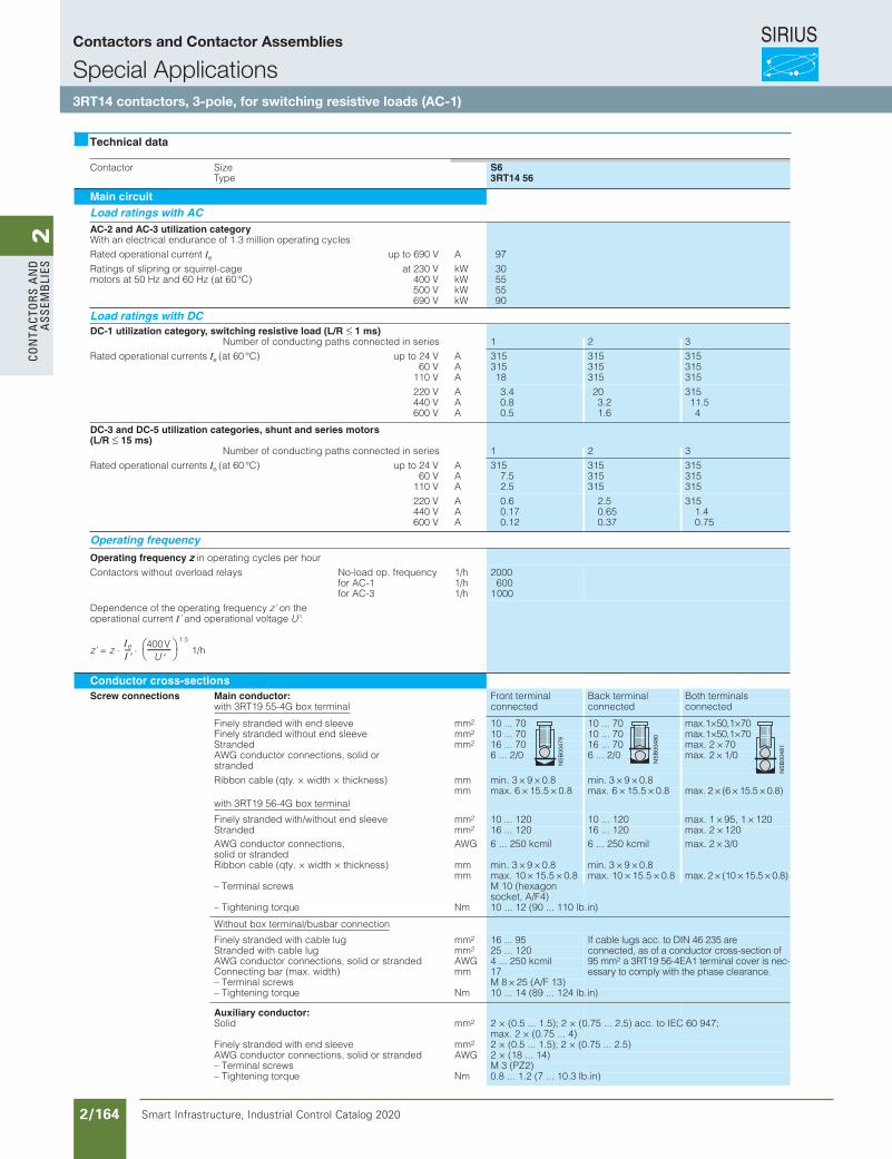
SIRIUS
Smart Infrastructure, Industrial Control Catalog 2020 2/164
2Co
nta
Cto
rs a
nd
a
ssem
bli
es
Siemens / Industrial Controls Previous folio: IC10 2/127
Contactors and Contactor Assemblies
Special Applications3RT14 contactors, 3-pole, for switching resistive loads (AC-1)
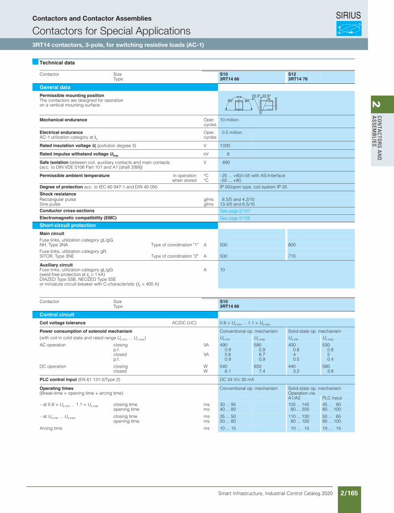
SIRIUS
Smart Infrastructure, Industrial Control Catalog 2020 2/165
2Co
nta
Ctors a
nd
a
ssemb
liesContactors and Contactor Assemblies
Contactors for Special Applications3RT14 contactors, 3-pole,
for switching resistive loads (AC-1)
Contactor SizeType
S103RT14 66
S123RT14 76
General data
Permissible mounting positionThe contactors are designed for operationon a vertical mounting surface.
Mechanical endurance Oper.cycles
10 million
Electrical enduranceAC-1 utilization category at Ie
Oper.cycles
0.5 million
Rated insulation voltage Ui (pollution degree 3) V 1000
Rated impulse withstand voltage Uimp kV 8
Safe isolation between coil, auxiliary contacts and main contacts(acc. to DIN VDE 0106 Part 101 and A1 [draft 2/89])
V 690
Permissible ambient temperature in operationwhen stored
°C°C
–25 ... +60/+55 with AS-Interface–55 ... +80
Degree of protection acc. to IEC 60 947-1 and DIN 40 050 IP 00/open type, coil system IP 20
Shock resistanceRectangular pulse g/ms 8.5/5 and 4.2/10Sine pulse g/ms 13.4/5 and 6.5/10Conductor cross-sections
Electromagnetic compatibility (EMC)
Short-circuit protection
Main circuitFuse links, utilization category gL/gG,NH, Type 3NA Type of coordination "1" A 500 800Fuse links, utilization category gR,SITOR, Type 3NE Type of coordination "2" A 500 710
Auxiliary circuitFuse links, utilization category gL/gG(weld-free protection at Ik 1 kA)DIAZED Type 5SB, NEOZED Type 5SEor miniature circuit-breaker with C-characteristic (Ik < 400 A)
A 10
Contactor SizeType
S103RT14 66
Control circuit
Coil voltage tolerance AC/DC (UC) 0.8 × Us min ... 1.1 × Us max
Power consumption of solenoid mechanism Conventional op. mechanism Solid-state op. mechanism(with coil in cold state and rated range Us min ... Us max) Us min Us max Us min Us max
AC operation closingp.f. closedp.f.
VA
VA
4900.95.60.9
5900.96.70.9
4000.840.5
5300.850.4
DC operation closingclosed
WW
5406.1
6507.4
4403.2
5803.8
PLC control input (EN 61 131-2/Type 2) DC 24 V/ 30 mA
Operating times Conventional op. mechanism Solid-state op. mechanism(Break-time = opening time + arcing time) Operation via
A1/A2 PLC input– at 0.8 × Us min ... 1.1 × Us max closing time
opening timemsms
30 ... 9540 ... 80
105 ... 14580 ... 200
45 ... 8080 ... 100
– at Us min ... Us max closing timeopening time
msms
35 ... 5050 ... 80
110 ... 13080 ... 100
50 ... 6580 ... 100
Arcing time ms 10 ... 15 10 ... 15 10 ... 15
Technical data
Siemens / Industrial Controls Previous folio: IC10 2/128
See page 2/167
See page 2/108
Contactors and Contactor Assemblies
Contactors for Special Applications3RT14 contactors, 3-pole, for switching resistive loads (AC-1)
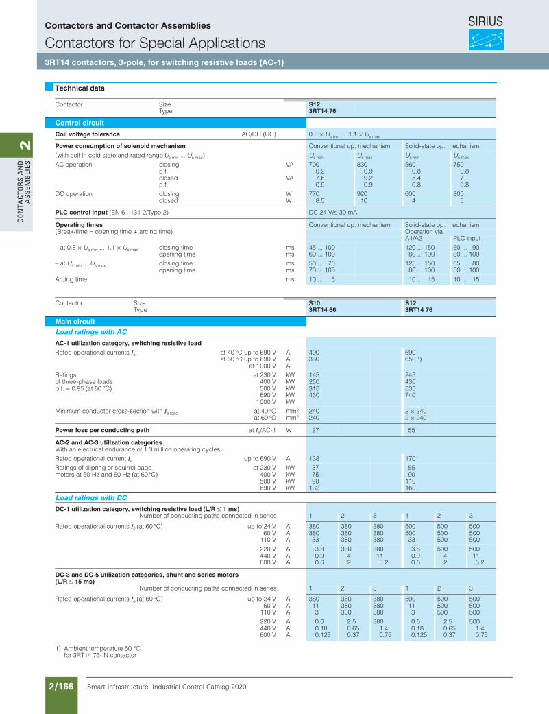
SIRIUS
Smart Infrastructure, Industrial Control Catalog 2020 2/166
2Co
nta
Cto
rs a
nd
a
ssem
bli
es
Siemens / Industrial Controls Previous folio: IC10 2/129
Contactors and Contactor Assemblies
Contactors for Special Applications3RT14 contactors, 3-pole, for switching resistive loads (AC-1)
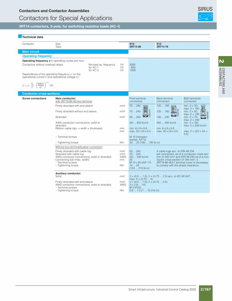
SIRIUS
Smart Infrastructure, Industrial Control Catalog 2020 2/167
2Co
nta
Ctors a
nd
a
ssemb
lies
Siemens / Industrial Controls Previous folio: IC10 2/130
Contactors and Contactor Assemblies
Contactors for Special Applications3RT14 contactors, 3-pole, for switching resistive loads (AC-1)
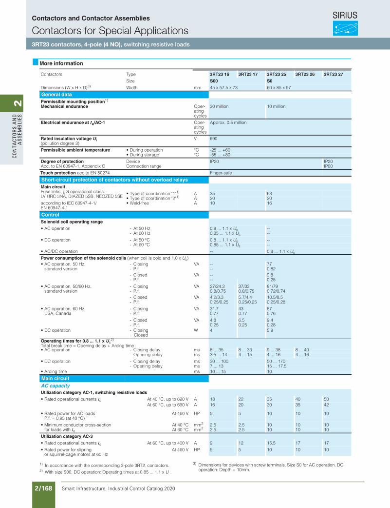
SIRIUS
Smart Infrastructure, Industrial Control Catalog 2020 2/168
2Co
nta
Cto
rs a
nd
a
ssem
bli
es3RT, 3RH Contactors for Special Applications
3RT23 Contactors for Switching Resistive Loads (AC-1)
4-pole, 4 NO, 18 ... 42 A
3/48 SIRIUS Innovations Supplement 2012
3
More information
1) In accordance with the corresponding 3-pole 3RT2. contactors.2) With size S00, DC operation: Operating times at 0.85 ... 1.1 x U
s
.
3) Dimensions for devices with screw terminals. Size S0 for AC operation. DC operation: Depth + 10mm.
epyTsrotcatnoC 3RT23 16 3RT23 17 3RT23 25 3RT23 26 3RT23 27Size S00 S0
Dimensions (W x H x D)3) mmhtdiW 45 x 57.5 x 73 60 x 85 x 97
General dataPermissible mounting position1)
Mechanical endurance Oper-ating cycles
30 million 10 million
Electrical endurance at Ie/AC-1 Oper-ating cycles
Approx. 0.5 million
Rated insulation voltage Ui(pollution degree 3)
V 690
Permissible ambient temperature • During operation °C -25 ... +60• During storage °C -55 ... +80
Degree of protection Acc. to EN 60947-1, Appendix C
DeviceConnection range
IP20 IP20IP00
Touch protection acc.to EN 50274 Finger-safe
Short-circuit protection of contactors without overload relaysMain circuit Fuse links, gG operational class: LV HRC 3NA, DIAZED 5SB, NEOZED 5SE
• Type of coordination "1"1) A 35 63• Type of coordination "2"1) A 20 20
according to IEC 60947-4-1/EN 60947-4-1
Aeerf-dleW• 10 16
ControlSolenoid coil operating range
zH 05 tA-noitarepo CA• 0.8 ... 1.1 x Us --- At 60 Hz 0.85 ... 1.1 x Us --
C° 05 tA-noitarepo CD• 0.8 ... 1.1 x Us --- At 60 °C 0.85 ... 1.1 x Us --
• AC/DC operation -- 0.8 ... 1.1 x Us
Power consumption of the solenoid coils (when coil is cold and 1.0 x Us) • AC operation, 50 Hz,
standard versionAVgnisolC- -- 77
- P.f. -- 0.82AVdesolC- -- 9.8
- P.f. -- 0.25
• AC operation, 50/60 Hz, standard version
AVgnisolC- 27/24.3 37/33 81/79- P.f. 0.8/0.75 0.8/0.75 0.72/0.74
AVdesolC- 4.2/3.3 5.7/4.4 10.5/8.5- P.f. 0.25/0.25 0.25/0.25 0.25/0.28
• AC operation, 60 Hz, USA, Canada
AVgnisolC- 31.7 43 87- P.f. 0.77 0.77 0.76
AVdesolC- 4.8 6.5 9.4- P.f. 0.25 0.25 0.28
gnisolC-noitarepo CD•= Closed
W 4 5.9
Operating times for 0.8 ... 1.1 x Us2)
Total break time = Opening delay + Arcing timesmyaled gnisolC-noitarepo CA• 8 ... 35 8 ... 33 9 ... 38 8 ... 40
- Opening delay ms 3.5 ... 14 4 ... 15 4 ... 16 4 ... 16
smyaled gnisolC-noitarepo CD• 30 ... 100 50 ... 170- Opening delay ms 7 ... 13 15 ... 17.5
smemit gnicrA• 10 ... 15 10
Main circuitAC capacityUtilization category AC-1, switching resistive loads
• Rated operational currents Ie At 40 °C, up to 690 V A 18 22 35 40 50
• Rated power for AC loadsP.f. = 0.95 (at 40 °C)
At 460 V HP 5 5 10 10 10
• Minimum conductor cross-section for loads with Ie
At 40 °C mm2 2.5 2.5 10 10 10At 60 °C mm2 2.5 2.5 10 10 10
Utilization category AC-3
• Rated operational currents Ie AV 004 ot pu ,C° 06 tA 9 12 15.5 17 17
• Rated power for slipring or squirrel-cage motors at 60 Hz
At 460 V HP 5 5 10 10 10
LV1N_03_06.fm Page 48 Wednesday, October 30, 2013 4:51 PM
At 60 °C, up to 690 V A 16 20 30 35 42
Siemens / Industrial Controls Previous folio: IC10 2/131
Contactors and Contactor Assemblies
Contactors for Special Applications3RT23 contactors, 4-pole (4 NO), switching resistive loads
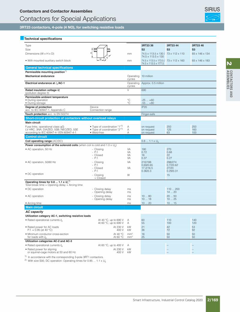
SIRIUS
Smart Infrastructure, Industrial Control Catalog 2020 2/169
2Co
nta
Ctors a
nd
a
ssemb
lies
Siemens / Industrial Controls Previous folio: IC10 2/132
Contactors for Special Applications
SIRIUS 3RT13 contactors for resistive loads(AC-1), 4-pole, 4 NO, 60 ... 140 A
4
Overview
StandardsIEC 60947-1, EN 60947-1, IEC 60947-4-1, EN 60947-4-1, IEC 60947-5-1, EN 60947-5-1 (auxiliary switches)
The contactors are suitable for use in any climate. They are fin-ger-safe according to EN 50274.
The accessories for the 3-pole 3RT10 contactors can also be used for the 4-pole versions.
The contactors are suitable for switching mixed loads in distribu-tion systems (e.g. for supplying heaters, lamps, motors, PC power supply units) with p.f. > 0.8 according to IEC 60947-4-1, test conditions for utilization category AC-1.
Technical specifications
1) In accordance with the corresponding 3-pole 3RT1 contactors.2) With size S00, DC operation: Operating times for 0.85 ... 1.1 x Us
Type 3RT23 36 3RT23 44 3RT23 46Size S2 S3 S3
mm)D x H x W( snoisnemiD 73 x 112 x 110 93 x 146 x 134
mmkcolb hctiws yrailixua detnuom htiW• 73 x 112 x 160 93 x 146 x 183
General technical specificationsPermissible mounting position1)
Mechanical endurance gnitarepO cycles
10 million
Electrical endurance at Ie/AC-1 gnitarepO cycles
Approx. 0.5 million
Rated insulation voltage Ui (pollution degree 3)
V 690
Permissible ambient temperatureC°noitarepo gniruD• -25 ... +60C°egarots gniruD• -55 ... +80
Degree of protection acc. to IEC 60947-1, Appendix C
DeviceConnection range
IP20
Touch protection acc. to EN 50274 Finger-safe
Short-circuit protection of contactors without overload relaysMain circuitFuse links, operational class gG: LV HRC, 3NA; DIAZED, 5SB; NEOZED, 5SE according to IEC 60947-4-1/EN 60947-4-1
• Type of coordination "1"1) A on request 250 250• Type of coordination "2"1) A on request 125 160• Weld-free A on request 63 100
Control circuitCoil operating range (AC/DC) 0.8 ... 1.1 x Us
Power consumption of the solenoid coils (when coil is cold and 1.0 x Us)
AVgnisolC-zH 05 ,noitarepo CA• 190 270AV.f.P- 0.72 0.68
- Closed VA 16 22AV.f.P- 0.37 0.27
AVgnisolC-zH 06/05 ,noitarepo CA• 210/188 298/274- P.f. 0.69/0.65 0.72/0.62- Closed VA 17.2/16.5 27/20- P.f. 0.36/0.3 0.29/0.31
• DC operation - Closing = Closed
W 15
Operating times for 0.8 ... 1.1 x Us2)
Total break time = Opening delay + Arcing time
smyaled gnisolC-noitarepo CD• 110 ... 200- Opening delay ms 14 ... 20
smyaled gnisolC-noitarepo CA• 10 ... 80 20 ... 50- Opening delay ms 10 ... 18 10 ... 25
smemit gnicrA• 10 ... 20 10 ... 15
Main circuitAC capacityUtilization category AC-1, switching resistive loads
• Rated operational currents Ie At 40 °C, up to 690 V A 60 110 140At 60 °C, up to 690 V A 55 100 120
• Rated power for AC loadsP.f. = 0.95 (at 40 °C)
At 230 V kW 21 42 53400 V kW 36 72 92
• Minimum conductor cross-section for loads with Ie
At 40 °C mm² 16 50 50At 60 °C mm² 25 50 50
Utilization categories AC-2 and AC-3
• Rated operational currents Ie At 60 °C, up to 400 V A -- --
• Rated power for slipring or squirrel-cage motors at 50 and 60 Hz
At 230 V kW -- --400 V kW -- --
W
H
D
IC10_04_03 ccorp.fm Page 15 Thursday, October 31, 2013 10:49 PM
74.5 x 113.5 x 130 / 74.5 x 113.5 x 130
74.5 x 113.5 x 173.5 / 74.5 x 113.5 x 177.5
Contactors and Contactor Assemblies
Contactors for Special Applications3RT23 contactors, 4-pole (4 NO), for switching resistive loads
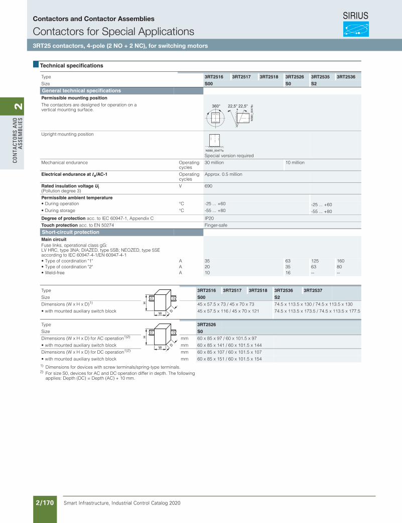
SIRIUS
Smart Infrastructure, Industrial Control Catalog 2020 2/170
2Co
nta
Cto
rs a
nd
a
ssem
bli
es
Siemens / Industrial Controls Previous folio: IC10 2/133
4/34 Siemens IC 10 · 2015
Contactors for Special Applications
SIRIUS 3RT25 contactors, 4-pole, 2 NO + 2 NC, 4 ... 22 kW
4
Overview
Standards
IEC 60947-1, EN 60947-1, IEC 60947-4-1, EN 60947-4-1, IEC 60947-5-1, EN 60947-5-1 (auxiliary switches)
The contactors are suitable for use in any climate. They are finger-safe according to EN 50274.
The accessories for the 3-pole 3RT20 contactors can also be used for the 4-pole versions.
With sizes S0 and S2, two auxiliary contacts 1 NO + 1 NC are included in the basic version.
Mountable auxiliary contacts
Size S00 to S2
Four additional auxiliary contacts, including no more than 2 NC.
Application
The contactors are suitable:• For changing the polarity of hoisting gear motors• For switching two separate loads
Note:
Single device for pole reversal; not suitable for reversing duty. 3RT25 contactors are not suitable for switching a load between two current sources.
For a general description of sizes S00 to S2, see Chapter 3, "Power contactors for switching motors" "SIRIUS 3RT20 contactors, 3-pole, up to 37 kW".
Technical specifications
1) Dimensions for devices with screw terminals/spring-type terminals.2) For size S0, devices for AC and DC operation differ in depth. The following
applies: Depth (DC) = Depth (AC) + 10 mm.
Type 3RT2516 3RT2517 3RT2518 3RT2526 3RT2535 3RT2536
Size S00 S0 S2
General technical specificationsPermissible mounting position
The contactors are designed for operation on a vertical mounting surface.
Upright mounting position
Special version requiredMechanical endurance Operating
cycles30 million 10 million
Electrical endurance at Ie/AC-1 Operating cycles
Approx. 0.5 million
Rated insulation voltage Ui(Pollution degree 3)
V 690
Permissible ambient temperature• During operation °C -25 ... +60 -25 ... +60• During storage °C -55 ... +80 -55 ... +80Degree of protection acc. to IEC 60947-1, Appendix C IP20Touch protection acc. to EN 50274 Finger-safe
Short-circuit protectionMain circuitFuse links, operational class gG: LV HRC, type 3NA; DIAZED, type 5SB; NEOZED, type 5SE according to IEC 60947-4-1/EN 60947-4-1• Type of coordination "1" A 35 63 125 160• Type of coordination "2" A 20 35 63 80• Weld-free A 10 16 -- --
360° 22,5°22,5°
NS
B0_
0047
8c
NSB0_00477a
Type 3RT2516 3RT2517 3RT2518 3RT2536 3RT2537
Size S00 S2
Dimensions (W x H x D)1) 45 x 57.5 x 73 / 45 x 70 x 73 74.5 x 113.5 x 130 / 74.5 x 113.5 x 130• with mounted auxiliary switch block 45 x 57.5 x 116 / 45 x 70 x 121 74.5 x 113.5 x 173.5 / 74.5 x 113.5 x 177.5
Type 3RT2526
Size S0
Dimensions (W x H x D) for AC operation1)2) mm 60 x 85 x 97 / 60 x 101.5 x 97• with mounted auxiliary switch block mm 60 x 85 x 141 / 60 x 101.5 x 144Dimensions (W x H x D) for DC operation1)2) mm 60 x 85 x 107 / 60 x 101.5 x 107• with mounted auxiliary switch block mm 60 x 85 x 151 / 60 x 101.5 x 154
W
H
D
W
H
D
© Siemens AG 2015
Contactors and Contactor Assemblies
Contactors for Special Applications3RT25 contactors, 4-pole (2 NO + 2 NC), for switching motors
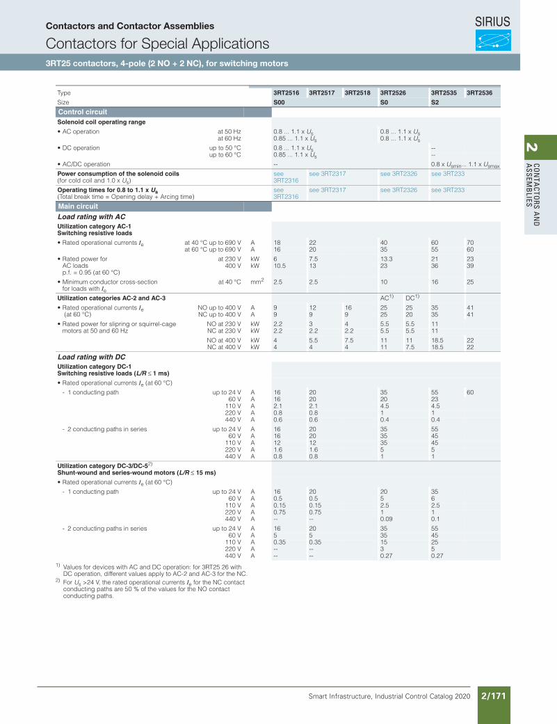
SIRIUS
Smart Infrastructure, Industrial Control Catalog 2020 2/171
2Co
nta
Ctors a
nd
a
ssemb
lies
Siemens / Industrial Controls Previous folio: IC10 2/134
4/35Siemens IC 10 · 2015
Contactors for Special Applications
SIRIUS 3RT25 contactors, 4-pole, 2 NO + 2 NC, 4 ... 22 kW
4
1) Values for devices with AC and DC operation: for 3RT25 26 with DC operation, different values apply to AC-2 and AC-3 for the NC.
2) For Us >24 V, the rated operational currents Ie for the NC contact conducting paths are 50 % of the values for the NO contact conducting paths.
Type 3RT2516 3RT2517 3RT2518 3RT2526 3RT2535 3RT2536
Size S00 S0 S2
Control circuitSolenoid coil operating range
• AC operation at 50 Hz 0.8 ... 1.1 x Us 0.8 ... 1.1 x Usat 60 Hz 0.85 ... 1.1 x Us 0.8 ... 1.1 x Us
• DC operation up to 50 °C 0.8 ... 1.1 x Us0.85 ... 1.1 x Us
--up to 60 °C --
• AC/DC operation -- 0.8 x Usmin... 1.1 x Usmax
Power consumption of the solenoid coils (for cold coil and 1.0 x Us)
see 3RT2316
see 3RT2317 see 3RT2326 see 3RT233
Operating times for 0.8 to 1.1 x Us (Total break time = Opening delay + Arcing time)
see 3RT2316
see 3RT2317 see 3RT2326 see 3RT233
Main circuitLoad rating with ACUtilization category AC-1Switching resistive loads
• Rated operational currents Ie at 40 °C up to 690 V A 18 22 40 60 70at 60 °C up to 690 V A 16 20 35 55 60
• Rated power for AC loads p.f. = 0.95 (at 60 °C)
at 230 V kW 6 7.5 13.3 21 23400 V kW 10.5 13 23 36 39
• Minimum conductor cross-section for loads with Ie
at 40 °C mm2 2.5 2.5 10 16 25
Utilization categories AC-2 and AC-3 AC1) DC1)
• Rated operational currents Ie (at 60 °C)
NO up to 400 V A 9 12 16 25 25 35 41NC up to 400 V A 9 9 9 25 20 35 41
• Rated power for slipring or squirrel-cage motors at 50 and 60 Hz
NO at 230 V kW 2.2 3 4 5.5 5.5 11NC at 230 V kW 2.2 2.2 2.2 5.5 5.5 11NO at 400 V kW 4 5.5 7.5 11 11 18.5 22NC at 400 V kW 4 4 4 11 7.5 18.5 22
Load rating with DCUtilization category DC-1Switching resistive loads (L/R ≤ 1 ms)
• Rated operational currents Ie (at 60 °C)- 1 conducting path up to 24 V A 16 20 35 55 60
60 V A 16 20 20 23110 V A 2.1 2.1 4.5 4.5220 V A 0.8 0.8 1 1440 V A 0.6 0.6 0.4 0.4
- 2 conducting paths in series up to 24 V A 16 20 35 5560 V A 16 20 35 45
110 V A 12 12 35 45220 V A 1.6 1.6 5 5440 V A 0.8 0.8 1 1
Utilization category DC-3/DC-52) Shunt-wound and series-wound motors (L/R ≤ 15 ms)
• Rated operational currents Ie (at 60 °C)- 1 conducting path up to 24 V A 16 20 20 35
60 V A 0.5 0.5 5 6110 V A 0.15 0.15 2.5 2.5220 V A 0.75 0.75 1 1440 V A -- -- 0.09 0.1
- 2 conducting paths in series up to 24 V A 16 20 35 5560 V A 5 5 35 45
110 V A 0.35 0.35 15 25220 V A -- -- 3 5440 V A -- -- 0.27 0.27
© Siemens AG 2015
Contactors and Contactor Assemblies
Contactors for Special Applications3RT25 contactors, 4-pole (2 NO + 2 NC), for switching motors
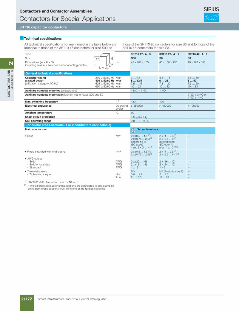
SIRIUS
Smart Infrastructure, Industrial Control Catalog 2020 2/172
2Co
nta
Cto
rs a
nd
a
ssem
bli
es
Siemens / Industrial Controls Previous folio: IC10 2/135
Contactors for Special Applications
4/35Siemens IC 10 · 2012
SIRIUS 3RT16 capacitor contactors,12.5 ... 50 kvar
4
Overview
StandardsIEC 60947-1, EN 60947-1, IEC 60947-4-1, EN 60947-4-1, IEC 60947-5-1, EN 60947-5-1 (auxiliary switches)
The contactors are suitable for use in any climate. They are fin-ger-safe according to EN 50274.
FunctionThe 3RT16 capacitor contactors are special versions of the 3RT10 contactors size S00 to S3. The capacitors are precharged by means of the mounted leading NO contacts and resistors; only then do the main contacts close.
This prevents disturbances in the network and welding of the contactors.
Only discharged capacitors are permitted to be switched on with capacitor contactors.
For the capacitor switching capacity of the basic 3RT10 contac-tor version.
Auxiliary switchesThe auxiliary switch block which is snapped onto the capacitor contactor contains the three leading NO contacts and in the case of S00 one standard NC contact and in the case of S0 and S3 one standard NO contact, which is unassigned. Size S00 also contains another unassigned NO contact in the basic unit.
In addition, a 2-pole auxiliary switch block can be mounted lat-erally on the 3RT16 47 capacitor contactors (2 NO, 2 NC or 1 NO + 1 NC versions); type 3RH19 21-1EA . . . The fitting of aux-iliary switches for 3RT16 17 and 3RT16 27 is not expandable.
Technical specificationsAll technical specifications not mentioned in the table below are identical to those of the 3RT10 17 contactors for size S00, to
those of the 3RT10 26 contactors for size S0 and to those of the 3RT10 45 contactors for size S3. .
1) 3RV19 25-5AB feeder terminal for 16 mm².2) If two different conductor cross-sections are connected to one clamping
point, both cross-sections must lie in one of the ranges specified.
Type 3RT16 17-.A. .3 3RT16 27-.A. .1 3RT16 47-.A. .1Size S00 S0 S3Dimensions (W x H x D) including auxiliary switches and connecting cables
mm 45 x 101 x 105 45 x 100 x 130 70 x 167 x 183
General technical specificationsCapacitor ratingat rated power (utilization category AC-6b)
230 V, 50/60 Hz kvar 3 … 7.5 3.5 … 15 3.5 … 30400 V, 50/60 Hz kvar 5 … 12.5 6 … 25 5 … 50525 V, 50/60 Hz kvar 7.5 … 15 7.8 … 30 7.5 … 60690 V, 50/60 Hz kvar 10 … 21 10 … 42 10 … 84
Auxiliary contacts mounted (unassigned) 1 NO + 1 NC 1 NO
Auxiliary contacts mountable (lateral), not for sizes S00 and S0 -- 2 NC + 2 NO or 1 NO + 1 NC
Max. switching frequency h-1 180 100
Electrical endurance Operating cycles
> 250 000 > 150 000 > 100 000
Ambient temperature °C 60
Short-circuit protection 1.6 ... 2.2 x IeCoil operating range 0.8 … 1.1 x Us
Conductor cross-sections (1 or 2 conductors connectable)Main conductors Screw terminals
²mmdiloS• 2 x (0.5 ... 1.5)2); 2 x (0.75 ... 2.5)2) according to IEC 60947; max. 2 x (1 ... 4)2)
2 x (1 ... 2.5)2); 2 x (2.5 ... 6)2) according to IEC 60947; max. 1 x 10 1)2)
--
²mmeveels dne htiw dednarts yleniF• 2 x (0.5 ... 1.5)2); 2 x (0.75 ... 2.5)2)
2 x (1 ... 2.5)2); 2 x (2.5 ... 6) 1)2)
--
• AWG cablesGWAdiloS- 2 x (20 ... 16) 2 x (16 ... 12) --GWAdednarts ro diloS- 2 x (18 ... 14) 2 x (14 ... 10) --GWAdednartS- 1 x 12 1 x 8 --
swercs lanimreT• M3 M4 (Pozidriv size 2) --mNeuqrot gninethgiT-
lb.in0.8 ... 1.2 7 ... 10.3
2 ... 2.5 18 ... 22
----
W
H
D
IC10_04_03 ccorp.fm Page 35 Wednesday, October 30, 2013 8:46 PM
Contactors and Contactor Assemblies
Contactors for Special Applications3RT16 capacitor contactors
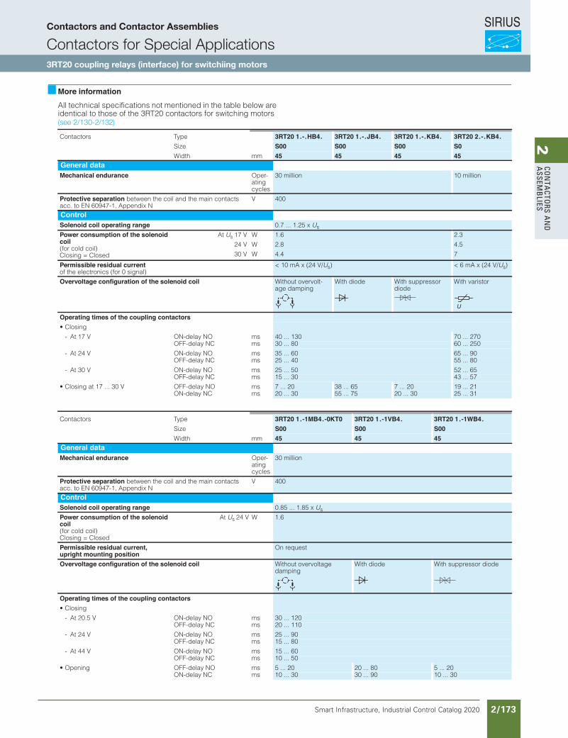
SIRIUS
Smart Infrastructure, Industrial Control Catalog 2020 2/173
2Co
nta
Ctors a
nd
a
ssemb
lies
Siemens / Industrial Controls Previous folio: IC10 2/136
3RT Coupling Contactors
3RT20 coupling contactors (interface),for switching motors, 3-pole, 3 ... 20 HP
3/75SIRIUS Innovations Supplement 2012
3
More informationAll technical specifications not mentioned in the table below are identical to those of the 3RT20 contactors for switching motors
epyTsrotcatnoC 3RT20 1.-.HB4. 3RT20 1.-.JB4. 3RT20 1.-.KB4. 3RT20 2.-.KB4.Size S00 S00 S00 S0Width mm 45 45 45 45
General dataMechanical endurance Oper-
ating cycles
30 million 10 million
Protective separation between the coil and the main contacts acc. to EN 60947-1, Appendix N
V 400
ControlSolenoid coil operating range 0.7 ... 1.25 x Us
Power consumption of the solenoidcoil (for cold coil) Closing = Closed
At Us 17 V W 1.6 2.3
24 V W 2.8 4.5
30 V W 4.4 7
Permissible residual currentof the electronics (for 0 signal)
< 10 mA x (24 V/Us) < 6 mA x (24 V/Us)
Overvoltage configuration of the solenoid coil Without overvolt-age damping
With diode
With suppressor diode
With varistor
Operating times of the coupling contactors• Closing
smON yaled-NOV 71 tA- 40 ... 130 70 ... 270OFF-delay NC ms 30 ... 80 60 ... 250
smON yaled-NOV 42 tA- 35 ... 60 65 ... 90OFF-delay NC ms 25 ... 40 55 ... 80
smON yaled-NOV 03 tA- 25 ... 50 52 ... 65OFF-delay NC ms 15 ... 30 43 ... 57
• Closing at 17 ... 30 V OFF-delay NO ms 7 ... 20 38 ... 65 7 ... 20 19 ... 21ON-delay NC ms 20 ... 30 55 ... 75 20 ... 30 25 ... 31
epyTsrotcatnoC 3RT20 1.-1MB4.-0KT0 3RT20 1.-1VB4. 3RT20 1.-1WB4.Size S00 S00 S00Width mm 45 45 45
General dataMechanical endurance Oper-
ating cycles
30 million
Protective separation between the coil and the main contacts acc. to EN 60947-1, Appendix N
V 400
ControlSolenoid coil operating range 0.85 ... 1.85 x Us
Power consumption of the solenoidcoil (for cold coil) Closing = Closed
At Us 24 V W 1.6
Permissible residual current, upright mounting position
On request
Overvoltage configuration of the solenoid coil Without overvoltage damping
With diode
With suppressor diode
Operating times of the coupling contactors
• Closing
smON yaled-NOV 5.02 tA- 30 ... 120OFF-delay NC ms 20 ... 110
smON yaled-NOV 42 tA- 25 ... 90OFF-delay NC ms 15 ... 80
smON yaled-NOV 44 tA- 15 ... 60smCN yaled-FFO 10 ... 50
smON yaled-FFOgninepO• 5 ... 20 20 ... 80 5 ... 20ON-delay NC ms 10 ... 30 30 ... 90 10 ... 30
LV1N_03_08.fm Page 75 Wednesday, October 30, 2013 4:39 PM
(see 2/130-2/132)
Contactors and Contactor Assemblies
Contactors for Special Applications3RT20 coupling relays (interface) for switchiing motors
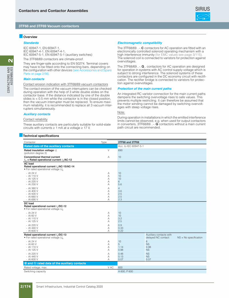
SIRIUS
Smart Infrastructure, Industrial Control Catalog 2020 2/174
2Co
nta
Cto
rs a
nd
a
ssem
bli
es
Siemens / Industrial Controls Previous folio: IC10 2/137
Power Contactors for Switching Motors
3TF6 vacuum contactors,3-pole, 335 ... 450 kW
3/112 Siemens IC 10 · 2012
3
Overview
StandardsIEC 60947-1, EN 60947-1, IEC 60947-4-1, EN 60947-4-1, IEC 60947-5-1, EN 60947-5-1 (auxiliary switches)The 3TF68/69 contactors are climate-proof.They are finger-safe according to EN 50274. Terminal covers may have to be fitted onto the connecting bars, depending on the configuration with other devices (see Accessories and Spare
Main contactsContact erosion indication with 3TF68/69 vacuum contactorsThe contact erosion of the vacuum interrupters can be checked during operation with the help of 3 white double slides on the contactor base. If the distance indicated by one of the double slides is < 0.5 mm while the contactor is in the closed position, then the vacuum interrupter must be replaced. To ensure maxi-mum reliability, it is recommended to replace all 3 vacuum inter-rupters simultaneously.
Auxiliary contactsContact reliability
These auxiliary contacts are particularly suitable for solid-state circuits with currents ≥ 1 mA at a voltage ≥ 17 V.
Electromagnetic compatibilityThe 3TF68/69 . . - . C contactors for AC operation are fitted with an electronically controlled solenoid operating mechanism with a high interference immunity (for EMC values see page 3/115). The solenoid coil is connected to varistors for protection against overvoltages.
The 3TF68/69 . . - . Q .. contactors for AC operation are designed for operation in systems with AC control supply voltage which is subject to strong interference. The solenoid systems of these contactors are configured in the DC economy circuit with rectifi-cation. The rectifier bridge is connected to varistors for protec-tion against overvoltages.
Protection of the main current pathsAn integrated RC varistor connection for the main current paths dampens the switching overvoltage rises to safe values. This prevents multiple restricting. It can therefore be assumed that the motor winding cannot be damaged by switching overvolt-ages with steep voltage rises.
Note:
During operation in installations in which the emitted interference limits cannot be observed, e.g. when used for output contactors in converters, 3TF68/69 . . - . Q contactors without a main current path circuit are recommended.
Technical specifications
epyTrotcatnoC 3TF68 and 3TF69Rated data of the auxiliary contacts Acc. to IEC 60947-5-1
Rated insulation voltage Ui (pollution degree 3)
V 690
Conventional thermal currentIth = Rated operational current Ie/AC-12
A 10
AC load Rated operational current Ie/AC-15/AC-14• For rated operational voltage Ue
AV 42 tA- 10AV 011 tA- 10AV 521 tA- 10AV 022 tA- 6AV 032 tA- 5.6
AV 083 tA- 4AV 004 tA- 3.6AV 005 tA- 2.5AV 066 tA- 2.5AV 096 tA- 2.3
DC load Rated operational current Ie/DC-12 • For rated operational voltage Ue
AV 42 tA- 10AV 06 tA- 10AV 011 tA- 3.2AV 521 tA- 2.5
AV 022 tA- 0.9AV 044 tA- 0.33AV 006 tA- 0.22
Rated operational current Ie/DC-13 • For rated operational voltage Ue
AV 42 tA- 10AV 06 tA- 5AV 011 tA- 1.14AV 521 tA- 0.98
AV 022 tA- 0.48AV 044 tA- 0.13AV 006 tA- 0.07
s and u rated data of the auxiliary contactsCA V.xam ,egatlov detaR 600
Switching capacity A 600, P 600
IC10_03_08.fm Page 112 Wednesday, October 30, 2013 8:38 PM
Auxiliary contacts with delayed NC contact: NS = No specification
6NS0.98NS
NSNS0.07
Parts on page 2/56).
Contactors and Contactor Assemblies
3TF68 and 3TF69 Vacuum contactors
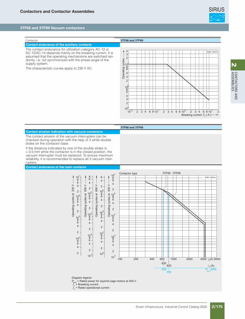
SIRIUS
Smart Infrastructure, Industrial Control Catalog 2020 2/175
2Co
nta
Ctors a
nd
a
ssemb
lies
Siemens / Industrial Controls Previous folio: IC10 2/138
Power Contactors for Switching Motors
3/113Siemens IC 10 · 2012
3TF6 vacuum contactors,3-pole, 335 ... 450 kW
3
Contactor 3TF68 and 3TF69Contact endurance of the auxiliary contactsThe contact endurance for utilization category AC-12 or AC-15/AC-14 depends mainly on the breaking current. It is assumed that the operating mechanisms are switched ran-domly, i.e. not synchronized with the phase angle of the supply system.The characteristic curves apply to 230 V AC.
432
1086432
1086432
10
7
6
5
10 2 3 4 6 8 10 2 3 4 6 8 10 2 3 4 6 8 10 2-2 101-
( A )a
NSB0_00651b
Ope
ratin
g cy
cles
Breaking current
3TF68 and 3TF69Contact erosion indication with vacuum contactorsThe contact erosion of the vacuum interrupters can be checked during operation with the help of 3 white double slides on the contactor base.If the distance indicated by one of the double slides is < 0.5 mm while the contactor is in the closed position, the vacuum interrupter must be replaced. To ensure maximum reliability, it is recommended to replace all 3 vacuum inter-rupters.Contact endurance of the main contacts
Ope
ratin
g cy
cles
at
Contactor type
Ope
ratin
g cy
cles
at
Ope
ratin
g cy
cles
at
Ope
ratin
g cy
cles
at
Prated
Diagram legend:Prated = Rated power for squirrel-cage motors at 400 V a = Breaking current e = Rated operational current
NSB0_00654a
3TF68 3TF6910864
2
10864
2
10864
2
10864
2
10
7
6
5
4
3
64
2
10864
2
10864
2
10864
2
10
6
5
4
3
864
2
10864
2
10864
2
10864
2
10
6
5
4
3
10864
2
10864
2
10864
2
10864
2
7
6
5
4
230
V
500
V
690
V
400
V
0004004002 20000001001 600635
335450
)A(028(kW)
e
6000(A)a
IC10_03_08.fm Page 113 Wednesday, October 30, 2013 8:38 PM
Contactors and Contactor Assemblies
3TF68 and 3TF69 Vacuum contactors
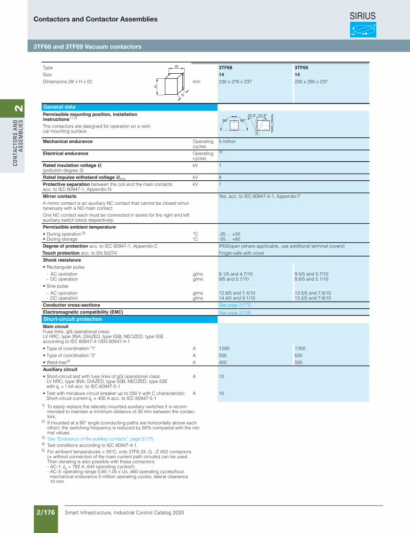
SIRIUS
Smart Infrastructure, Industrial Control Catalog 2020 2/176
2Co
nta
Cto
rs a
nd
a
ssem
bli
es
Siemens / Industrial Controls Previous folio: IC10 2/139
Power Contactors for Switching Motors
3TF6 vacuum contactors,3-pole, 335 ... 450 kW
3/114 Siemens IC 10 · 2012
3
1) To easily replace the laterally mounted auxiliary switches it is recom-mended to maintain a minimum distance of 30 mm between the contac-tors.
2) If mounted at a 90° angle (conducting paths are horizontally above each other), the switching frequency is reduced by 80% compared with the nor-mal values.
3) 4) Test conditions according to IEC 60947-4-1.
Type 3TF68 3TF69Size 14 14
mm)D x H x W( snoisnemiD 230 x 276 x 237 230 x 295 x 237
General dataPermissible mounting position, installationinstructions1) 2)
5)
The contactors are designed for operation on a verti-cal mounting surface.
Mechanical endurance Operating cycles
5 million
Electrical endurance Operating cycles
3)
Rated insulation voltage Ui (pollution degree 3)
kV 1
Rated impulse withstand voltage Uimp Vk 8
Protective separation between the coil and the main contacts acc. to IEC 60947-1, Appendix N
kV 1
Mirror contactsA mirror contact is an auxiliary NC contact that cannot be closed simul-taneously with a NO main contact.
One NC contact each must be connected in series for the right and left auxiliary switch block respectively.
Yes, acc. to IEC 60947-4-1, Appendix F
Permissible ambient temperatureC°noitarepo gniruD• -25 ... +55C°egarots gniruD• -55 ... +80
Degree of protection acc. to IEC 60947-1, Appendix C
Touch protection acc. to EN 50274
IP00/open (where applicable, use additional terminal covers)
Finger-safe with cover
Shock resistance
• Rectangular pulse
- AC operation g/ms 8.1/5 and 4.7/10 9.5/5 and 5.7/10- DC operation g/ms 9/5 and 5.7/10 8.6/5 and 5.1/10
• Sine pulse
- AC operation g/ms 12.8/5 and 7.4/10 13.5/5 and 7.8/10- DC operation g/ms 14.4/5 and 9.1/10 13.5/5 and 7.8/10
Conductor cross-sectionsElectromagnetic compatibility (EMC)Short-circuit protectionMain circuit Fuse links, gG operational class: LV HRC, type 3NA; DIAZED, type 5SB; NEOZED, type 5SE according to IEC 60947-4-1/EN 60947-4-1
A"1" noitanidrooc fo epyT• 1 000 1 250
A"2" noitanidrooc fo epyT• 500 630
• Weld-free4) A 400 500
Auxiliary circuit• Short-circuit test with fuse links of gG operational class:
LV HRC, type 3NA; DIAZED, type 5SB; NEOZED, type 5SE with Ik =1 kA acc. to IEC 60947-5-1
A 10
• Test with miniature circuit breaker up to 230 V with C characteristic: Short-circuit current Ik = 400 A acc. to IEC 60947-5-1
A 10
NSB0_00649a22,5° 22,5°
90°90°
IC10_03_08.fm Page 114 Wednesday, October 30, 2013 8:38 PM
5) For ambient temperatures > 55°C, only 3TF6.33-.Q..-Z A02 contactors (= without connection of the main current path circuits) can be used. Then derating is also possible with these contactors: - AC-1: Ie = 782 A, 644 operating cycles/h; - AC-3: operating range 0.85-1.05 x Us, 460 operating cycles/hour, mechanical endurance 5 million operating cycles, lateral clearance
10 mm
See page 2/179.
See page 2/108.
See “Endurance of the auxillary contacts”, page 2/175.
Contactors and Contactor Assemblies
3TF68 and 3TF69 Vacuum contactors
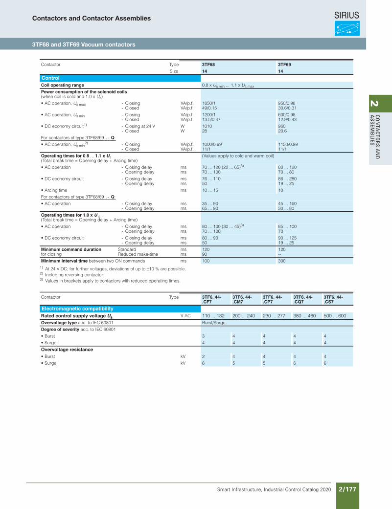
SIRIUS
Smart Infrastructure, Industrial Control Catalog 2020 2/177
2Co
nta
Ctors a
nd
a
ssemb
lies
Siemens / Industrial Controls Previous folio: IC10 2/140
Power Contactors for Switching Motors
3/115Siemens IC 10 · 2012
3TF6 vacuum contactors,3-pole, 335 ... 450 kW
3
1) At 24 V DC; for further voltages, deviations of up to ±10 % are possible.2) Including reversing contactor.3) Values in brackets apply to contactors with reduced operating times.
epyTrotcatnoC 3TF68 3TF69Size 14 14
ControlCoil operating range 0.8 x Us min ... 1.1 x Us max
Power consumption of the solenoid coils (when coil is cold and 1.0 x Us)
• AC operation, Us max - Closing VA/p.f. 1850/1 950/0.98- Closed VA/p.f. 49/0.15 30.6/0.31
• AC operation, Us min - Closing VA/p.f. 1200/1 600/0.98- Closed VA/p.f. 13.5/0.47 12.9/0.43
• DC economy circuit1) - Closing at 24 V W 1010 960- Closed W 28 20.6
For contactors of type 3TF68/69 . . - . Q:
• AC operation, Us min2) - Closing VA/p.f. 1000/0.99 1150/0.99
- Closed VA/p.f. 11/1 11/1
Operating times for 0.8 ... 1.1 x Us(Total break time = Opening delay + Arcing time)
(Values apply to cold and warm coil)
smyaled gnisolC-noitarepo CA• 70 ... 120 (22 ... 65)3) 80 ... 120- Opening delay ms 70 ... 100 70 ... 80
• DC economy circuit - Closing delay ms 76 ... 110 86 ... 280- Opening delay ms 50 19 ... 25
smemit gnicrA• 10 ... 15 10
For contactors of type 3TF68/69 . . - . Q:
smyaled gnisolC-noitarepo CA• 35 ... 90 45 ... 160- Opening delay ms 65 ... 90 30 ... 80
Operating times for 1.0 x U s (Total break time = Opening delay + Arcing time)
smyaled gnisolC-noitarepo CA• 80 ... 100 (30 ... 45)3) 85 ... 100- Opening delay ms 70 ... 100 70
• DC economy circuit - Closing delay ms 80 ... 90 90 ... 125- Opening delay ms 50 19 ... 25
Minimum command duration for closing
smdradnatS 120 120Reduced make-time ms 90 --
Minimum interval time between two ON commands ms 100 300
epyT rotcatnoC 3TF6. 44-.CF7
3TF6. 44-.CM7
3TF6. 44-.CP7
3TF6. 44-.CQ7
3TF6. 44-.CS7
Electromagnetic compatibilityRated control supply voltage Us V AC 110 ... 132 200 ... 240 230 ... 277 380 ... 460 500 ... 600Overvoltage type acc. to IEC 60801 Burst/Surge
Degree of severity acc. to IEC 60801
• Burst 3 4 4 4 4
• Surge 4 4 4 4 4
Overvoltage resistanceVktsruB• 2 4 4 4 4
VkegruS• 6 5 5 6 6
IC10_03_08.fm Page 115 Wednesday, October 30, 2013 8:38 PM
Contactors and Contactor Assemblies
3TF68 and 3TF69 Vacuum contactors
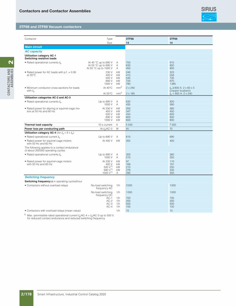
SIRIUS
Smart Infrastructure, Industrial Control Catalog 2020 2/178
2Co
nta
Cto
rs a
nd
a
ssem
bli
es
Siemens / Industrial Controls Previous folio: Siemens / Industrial Controls Previous folio: IC10 2/141
Power Contactors for Switching Motors
3TF6 vacuum contactors,3-pole, 335 ... 450 kW
3/116 Siemens IC 10 · 2012
3
1) Max. permissible rated operational current Ie/AC-4 = Ie/AC-3 up to 500 V, for reduced contact endurance and reduced switching frequency.
epyTrotcatnoC 3TF68 3TF69Size 14 14
Main circuitAC capacityUtilization category AC-1Switching resistive loads
• Rated operational currents Ie At 40 °C up to 690 V A 700 910At 55 °C up to 690 V A 630 850
At 55 °C up to 1000 V A 450 800
• Rated power for AC loads with p.f. = 0.95 at 55°C
230 V kW 240 323400 V kW 415 558500 V kW 545 735690 V kW 720 970
1000 V kW 780 1 385
• Minimum conductor cross-sections for loads with Ie
At 40°C mm2 2 x 240 Ie ≥ 800 A: 2 x 60 x 5 (copper busbars)
At 55°C mm2 2 x 185 Ie < 800 A: 2 x 240
Utilization categories AC-2 and AC-3• Rated operational currents Ie Up to 690 V A 630 820
1000 V A 435 580
• Rated power for slipring or squirrel-cage mo-tors at 50 Hz and 60 Hz
At 230 V kW 200 260400 V kW 347 450500 V kW 434 600690 V kW 600 800
1000 V kW 600 800
Utilization category AC-4 (for Ia = 6 x Ie)
• Rated operational current Ie Up to 690 V A 610 690
• Rated power for squirrel-cage motors with 50 Hz and 60 Hz
At 400 V kW 355 400
The following applies to a contact endurance of about 200 000 operating cycles:
• Rated operational currents Ie Up to 690 V A 300 3601000 V A 210 250
• Rated power for squirrel-cage motors with 50 Hz and 60 Hz
At 230 V kW 97 110400 V kW 168 191
500 V1) kW 210 250690 V1) kW 278 335
1000 V1) A 290 350
Switching frequencySwitching frequency z in operating cycles/hour
• Contactors without overload relays No-load switchingfrequency AC
1/h 2 000 1 000
No-load switchingfrequency DC
1/h 1 000 1 000
AC-1 1/h 700 700AC-2 1/h 200 200AC-3 1/h 500 500AC-4 1/h 150 150
h/1)eulav naem( syaler daolrevo htiw srotcatnoC• 15 15
IC10_03_08.fm Page 116 Wednesday, October 30, 2013 8:38 PM
Thermal load capacity 10 s current A 5 040 7 000
Power loss per conducting path At Ie/AC-3 W 45 70
Contactors and Contactor Assemblies
3TF68 and 3TF69 Vacuum contactors
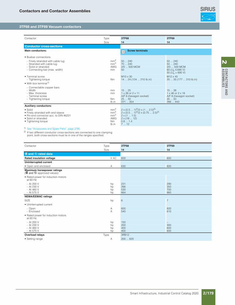
SIRIUS
Smart Infrastructure, Industrial Control Catalog 2020 2/179
2Co
nta
Ctors a
nd
a
ssemb
lies
Siemens / Industrial Controls Previous folio: IC10 2/142
Power Contactors for Switching Motors
3/117Siemens IC 10 · 2012
3TF6 vacuum contactors,3-pole, 335 ... 450 kW
3
1) 2) If two different conductor cross-sections are connected to one clamping
point, both cross-sections must lie in one of the ranges specified.
epyTrotcatnoC 3TF68 3TF69Size 14 14
Conductor cross-sectionsMain conductors: Screw terminals
• Busbar connections
mmgul elbac htiw dednarts yleniF- 2 50 ... 240 50 ... 240 mmgul elbac htiw dednartS- 2 70 ... 240 50 ... 240
GWA dednarts ro diloS- 2/0 ... 500 MCM 2/0 ... 500 MCMmm)htdiw .xam( rab gnitcennoC- 50 60 (Ue ≤ 690 V)
50 (Ue > 690 V)
• Terminal screw M10 x 30 M12 x 40mNeuqrot gninethgiT- 14 ... 24 (124 ... 210 lb.in) 20 ... 35 (177 ... 310 lb.in)
• With box terminal1)
- Connectable copper barsmm htdiW- 15 ... 25 15 ... 38mmssenkciht .xaM- 1 x 26 or 2 x 11 1 x 46 or 2 x 18
wercs lanimreT- A/F 6 (hexagon socket) A/F 8 (hexagon socket)mNeuqrot gninethgiT-
lb.in25 ... 40 221 ... 354
35 ... 50 266 ... 443
Auxiliary conductors:mmdiloS• 2 2 x (0.5 ... 1)2)/2 x (1 ... 2.5)2)
mmeveels dne htiw dednarts yleniF• 2 2 x (0.5 ... 1)2)/2 x (0.75 ... 2.5)2)
mm13264 NID ot .cca rotcennoc dne-niP• 2 2 x (1 ... 1.5)GWAdednarts ro diloS• 2 x (18 ... 12)
mNeuqrot gninethgiT•lb.in
0.8 ... 1.4 7 ... 12
epyTrotcatnoC 3TF68 3TF69Size 14 14
s and u rated dataRated insulation voltage V AC 600 600
Uninterrupted currentAdesolcne dna nepO• 630 820
Maximum horsepower ratings (s and u approved values)
• Rated power for induction motors at 60 Hz
phV 002 tA- 231 290phV 032 tA- 266 350phV 064 tA- 530 700phV 575 tA- 664 860
NEMA/EEMAC ratingsphEZIS 6 7
• Uninterrupted current
AnepO- 600 820AdesolcnE- 540 810
• Rated power for induction motors at 60 Hz
phV 002 tA- 150 --phV 032 tA- 200 300phV 064 tA- 400 600phV 575 tA- 400 600
Overload relays Type 3RB12 .
Aegnar gnitteS• 200 ... 820
IC10_03_08.fm Page 117 Wednesday, October 30, 2013 8:38 PM
See “Accessories and Spare Parts”, page 2/56.
Contactors and Contactor Assemblies
3TF68 and 3TF69 Vacuum contactors
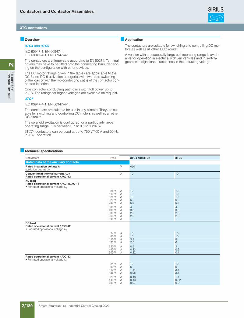
SIRIUS
Smart Infrastructure, Industrial Control Catalog 2020 2/180
2Co
nta
Cto
rs a
nd
a
ssem
bli
es
Siemens / Industrial Controls Previous folio: IC10 2/143
Contactors for Special ApplicationsContactors for Switching DC Voltage3TC contactors,1- and 2-pole, 32 ... 400 A
4/50 Siemens IC 10 · 2012
4
Overview
3TC4 and 3TC5IEC 60947-1, EN 60947-1, IEC 60947-4-1, EN 60947-4-1
The contactors are finger-safe according to EN 50274. Terminal covers may have to be fitted onto the connecting bars, depend-ing on the configuration with other devices.
The DC motor ratings given in the tables are applicable to the DC-3 and DC-5 utilization categories with two-pole switching of the load or with the two conducting paths of the contactor con-nected in series.
One contactor conducting path can switch full power up to 220 V. The ratings for higher voltages are available on request.
3TC7IEC 60947-4-1, EN 60947-4-1.
The contactors are suitable for use in any climate. They are suit-able for switching and controlling DC motors as well as all other DC circuits.
The solenoid excitation is configured for a particularly large operating range. It is between 0.7 or 0.8 to 1.2x Us.
3TC74 contactors can be used at up to 750 V/400 A and 50 Hz in AC-1 operation.
ApplicationThe contactors are suitable for switching and controlling DC mo-tors as well as all other DC circuits.
A version with an especially large coil operating range is avail-able for operation in electrically driven vehicles and in switch-gears with significant fluctuations in the actuating voltage
.
Technical specifications
epyTsrotcatnoC 3TC4 and 3TC7 3TC5Rated data of the auxiliary contactsRated insulation voltage Ui(pollution degree 3)
V 690
Conventional thermal current Ith =Rated operational current Ie/AC-12
A 10 10
AC load Rated operational current Ie/AC-15/AC-14• For rated operational voltage Ue
24 V A 10 10110 V A 10 10125 V A 10 10220 V A 6 6230 V A 5.6 5.6
380 V A 4 4400 V A 3.6 3.6500 V A 2.5 2.5660 V A 2.5 2.5690 V A -- --
DC load Rated operational current Ie/DC-12 • For rated operational voltage Ue
24 V A 10 1060 V A 10 10
110 V A 3.2 8125 V A 2.5 6
220 V A 0.9 2440 V A 0.33 0.6600 V A 0.22 0.4
Rated operational current Ie/DC-13 • For rated operational voltage Ue
24 V A 10 1060 V A 5 5
110 V A 1.14 2.4125 V A 0.98 2.1
220 V A 0.48 1.1440 V A 0.13 0.32600 V A 0.07 0.21
IC10_04_03 ccorp.fm Page 50 Wednesday, October 30, 2013 9:05 PM
Contactors and Contactor Assemblies
3TC contactors
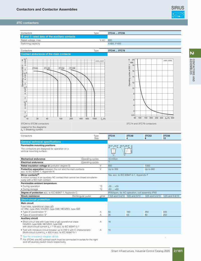
SIRIUS
Smart Infrastructure, Industrial Control Catalog 2020 2/181
2Co
nta
Ctors a
nd
a
ssemb
lies
Siemens / Industrial Controls Previous folio: IC10 2/144
Contactors for Special ApplicationsContactors for Switching DC Voltage
4/51Siemens IC 10 · 2012
3TC contactors,1- and 2-pole, 32 ... 400 A
4
1) See the endurance diagram above. 2) For 3TC44, one NC contact each must be connected in series for the right
and left auxiliary switch block respectively.
.
epyTsrotcatnoC 3TC44 ... 3TC56s and u rated data of the auxiliary contacts
CA V.xam ,egatlov detaR 600
Switching capacity A 600, P 600
epyTsrotcatnoC 3TC44 ... 3TC78Contact endurance of the main contacts
3TC44 to 3TC56 contactors 3TC74 and 3TC78 contactors
Legend for the diagrams:Ia = Breaking current
NSB0_00655
7
6
5
4
3
3TC44 3TC48 3TC52 3TC56
1010
20 40 100 200 400 600 1000 a (A)
6
2
4
108
6
2
4
108
6
2
4
108
6
2
4
108
Ope
ratin
g cy
cles
at 5
00 V
NSB0_0065620
18
12
16
4
6
8
2
50 100 150 200 250 300 400
14
(A)a
10
0,5
Ope
ratin
g cy
cles
at 5
00 V
Mill.
epyTsrotcatnoC 3TC44 3TC48 3TC52 3TC56Size 2 4 8 12
General technical specificationsPermissible mounting positionsThe contactors are designed for operation on a vertical mounting surface.
Mechanical endurance Operating cycles 10 million
Electrical endurance Operating cycles 1)
Rated insulation voltage Ui V)3 eerged noitullop( 800 1 000
Protective separation between the coil and the main contacts acc. to IEC 60947-1, Appendix N
V Up to 300 Up to 660
Mirror contacts2)A mirror contact is an auxiliary NC contact that cannot be closed simultane-ously with a NO main contact.
Yes, acc. to IEC 60947-4-1, Appendix F
Permissible ambient temperatureC°noitarepo gniruD• -25 ... +55C°egarots gniruD• -50 ... +80
Degree of protection acc. to IEC 60947-1, Appendix C IP00/open, for AC operation, coil assembly IP40
Shock resistance Rectangular pulse g/ms 7.5/5 and 3.4/10 10/5 and 5/10 12/5 and 5.5/10 12/5 and 5.6/10
Short-circuit protectionMain circuitFuse links, operational class gG: LV HRC, type 3NA; DIAZED, type 5SB; NEOZED, type 5SE
A"1" noitanidrooc fo epyT• 50 160 250 400A"2" noitanidrooc fo epyT• 35 63 80 250
Auxiliary circuit• Short-circuit test with fuse links of gG operational class:
DIAZED, type 5SB; NEOZED, type 5SE with short-circuit current Ik = 1 kA acc. to IEC 60947-5-1
A 16
• Test with miniature circuit breaker up to 230 V with C characteristic: Short-circuit current Ik = 400 A acc. to IEC 60947-5-1
A 10
22,5°22,5° 22,5°22,5°
NS
B0_
0065
0c
IC10_04_03 ccorp.fm Page 51 Wednesday, October 30, 2013 9:05 PM
≤ ×
≥
∅
Contactors and Contactor Assemblies
3TC contactors
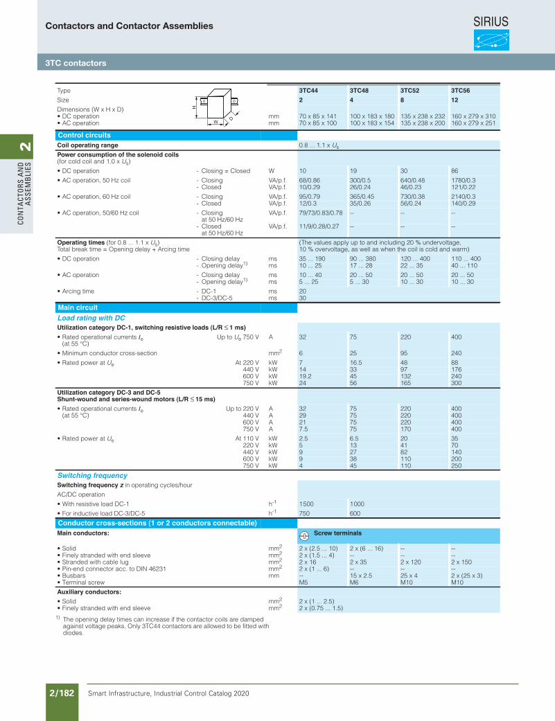
SIRIUS
Smart Infrastructure, Industrial Control Catalog 2020 2/182
2Co
nta
Cto
rs a
nd
a
ssem
bli
es
Siemens / Industrial Controls Previous folio: IC10 2/145
Contactors for Special ApplicationsContactors for Switching DC Voltage3TC contactors,1- and 2-pole, 32 ... 400 A
4/52 Siemens IC 10 · 2012
4
1) The opening delay times can increase if the contactor coils are damped against voltage peaks. Only 3TC44 contactors are allowed to be fitted with diodes.
Type 3TC44 3TC48 3TC52 3TC56Size 2 4 8 12Dimensions (W x H x D)
mmnoitarepo CD• 70 x 85 x 141 100 x 183 x 180 135 x 238 x 232 160 x 279 x 310mmnoitarepo CA• 70 x 85 x 100 100 x 183 x 154 135 x 238 x 200 160 x 279 x 251
Control circuitsCoil operating range 0.8 ... 1.1 x Us
Power consumption of the solenoid coils(for cold coil and 1.0 x Us)
WdesolC = gnisolC-noitarepo CD• 10 19 30 86
.f.p/AVgnisolC-lioc zH 05 ,noitarepo CA• 68/0.86 300/0.5 640/0.48 1780/0.3- Closed VA/p.f. 10/0.29 26/0.24 46/0.23 121/0.22
.f.p/AVgnisolC-lioc zH 06 ,noitarepo CA• 95/0.79 365/0.45 730/0.38 2140/0.3- Closed VA/p.f. 12/0.3 35/0.26 56/0.24 140/0.29
• AC operation, 50/60 Hz coil - Closing at 50 Hz/60 Hz
VA/p.f. 79/73/0.83/0.78 -- -- --
- Closed at 50 Hz/60 Hz
VA/p.f. 11/9/0.28/0.27 -- -- --
Operating times (for 0.8 ... 1.1 x Us)Total break time = Opening delay + Arcing time
(The values apply up to and including 20 % undervoltage, 10 % overvoltage, as well as when the coil is cold and warm)
smyaled gnisolC-noitarepo CD• 35 ... 190 90 ... 380 120 ... 400 110 ... 400- Opening delay1) ms 10 ... 25 17 ... 28 22 ... 35 40 ... 110
smyaled gnisolC-noitarepo CA• 10 ... 40 20 ... 50 20 ... 50 20 ... 50- Opening delay1) ms 5 ... 25 5 ... 30 10 ... 30 10 ... 30
sm1-CD-emit gnicrA• 20- DC-3/DC-5 ms 30
Main circuitLoad rating with DCUtilization category DC-1, switching resistive loads (L/R ≤ 1 ms)• Rated operational currents Ie
(at 55 °C)Up to Ue 750 V A 32 75 220 400
mmnoitces-ssorc rotcudnoc muminiM• 2 6 25 95 240
• Rated power at Ue At 220 V kW 7 16.5 48 88440 V kW 14 33 97 176600 V kW 19.2 45 132 240750 V kW 24 56 165 300
Utilization category DC-3 and DC-5Shunt-wound and series-wound motors (L/R ≤ 15 ms)• Rated operational currents Ie
(at 55 °C)Up to 220 V A 32 75 220 400
440 V A 29 75 220 400600 V A 21 75 220 400750 V A 7.5 75 170 400
• Rated power at Ue At 110 V kW 2.5 6.5 20 35220 V kW 5 13 41 70440 V kW 9 27 82 140600 V kW 9 38 110 200750 V kW 4 45 110 250
Switching frequencySwitching frequency z in operating cycles/hour AC/DC operation
h1-CD daol evitsiser htiW• -1 1 500 1 000
h5-CD/3-CD daol evitcudni roF• -1 750 600
Conductor cross-sections (1 or 2 conductors connectable)Main conductors: Screw terminals
mmdiloS• 2 2 x (2.5 ... 10) 2 x (6 ... 16) -- --mmeveels dne htiw dednarts yleniF• 2 2 x (1.5 ... 4) -- -- --mmgul elbac htiw dednartS• 2 2 x 16 2 x 35 2 x 120 2 x 150 mm13264 NID ot .cca rotcennoc dne-niP• 2 2 x (1 ... 6) -- -- --mmsrabsuB• -- 15 x 2.5 25 x 4 2 x (25 x 3)
wercs lanimreT• M5 M6 M10 M10
Auxiliary conductors: mmdiloS• 2 2 x (1 ... 2.5) mmeveels dne htiw dednarts yleniF• 2 2 x (0.75 ... 1.5)
W
H
D
IC10_04_03 ccorp.fm Page 52 Wednesday, October 30, 2013 9:05 PM
Contactors and Contactor Assemblies
3TC contactors
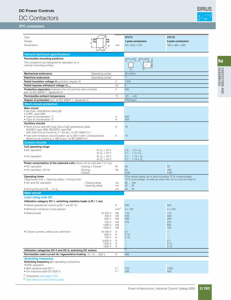
SIRIUS
Smart Infrastructure, Industrial Control Catalog 2020 2/183
2Co
nta
Ctors a
nd
a
ssemb
lies
Siemens / Industrial Controls Previous folio: IC10 2/146
Contactors for Special ApplicationsContactors for Switching DC Voltage
4/53Siemens IC 10 · 2012
3TC contactors,1- and 2-pole, 32 ... 400 A
4
1) Endurance 2) See Selection and ordering data.
.
Type
3TC74 3TC78Design 1-pole contactors 2-pole contactors
mmsnoisnemiD 78 x 352 x 276 160 x 366 x 290
General technical specificationsPermissible mounting positionsThe contactors are designed for operation on a vertical mounting surface.
Mechanical endurance Operating cycles 30 million
Electrical endurance Operating cycles 1)
Rated insulation voltage Ui V)3 eerged noitullop( 1 500
Rated impulse withstand voltage Uimp kV 8
Protective separation between the coil and the main contacts acc. to IEC 60947-1, Appendix N
V 630
Permissible ambient temperature °C -25 ... +55
Degree of protection acc. to IEC 60947-1, Appendix C IP00/open
Short-circuit protectionMain circuitFuse links, operational class gG: LV HRC, type 3NA
A"1" noitanidrooc fo epyT• 630A"2" noitanidrooc fo epyT• 500
Auxiliary circuits• Short-circuit test with fuse links of gG operational class:
DIAZED, type 5SB; NEOZED, type 5SE with short-circuit current Ik = 1 kA acc. to IEC 60947-5-1
A 16
• Test with miniature circuit breaker up to 230 V with C characteristic: Short-circuit current Ik = 400 A acc. to IEC 60947-5-1
A 10
Control circuitsCoil operating range
tAnoitarepo CD• Uc = 24 V 0.8 ... 1.2 x UsAt Uc > 24 V 0.7 ... 1.2 x Us
tAnoitarepo CA• Uc = 24 V 0.7 ... 1.15 x UsAt Uc > 24 V 0.7 ... 1.14 x Us
Power consumption of the solenoid coils (when coil is cold and 1.0 x Us)WdesolC = gnisolC noitarepo CD• 46 92
,gnisolCzH 05 ,noitarepo CA•Closed
VA 80 0.95
160 0.95
Operating times (The values apply up to and including 15 % undervoltage, 10 % overvoltage, as well as when the coil is cold and warm)(Total break time = Opening delay + Arcing time)
smyaled gnisolC-noitarepo CD dna CA• 60 ... 100- Opening delay ms 20 ... 35
• Arcing time at 0.06 ... 4 x Ie ms 40 ... 70
Main circuitLoad rating with DCUtilization category DC-1, switching resistive loads (L/R ≤ 1 ms)• Rated operational current Ie A)C° 55 ta( 1-CD/ 500 500
mmnoitces-ssorc rotcudnoc muminiM• 2 2 x 150 2 x 150
WkV 022 tA rewop detaR• 110 110440 V kW 220 220600 V kW 300 300750 V kW 375 375
1200 V kW — 6001500 V kW — 750
AV 044 tAnoitcnitxe cra tuohtiw ,stnerruc lacitirC• ≤ 7 —600 V A ≤ 13 —750 V A ≤ 15 —
≤ 800 V A — ≤ 71200 V A — ≤ 131500 V A — ≤ 15
Utilization categories DC-3 and DC-5, switching DC motors 2)
Permissible rated current for regenerative braking At 110 ... 600 V A 400
Switching frequencySwitching frequency z in operating cycles/hourAC/DC operation
h1-CD daol evitsiser htiW• -1 750 1 000h5-CD/3-CD daol evitcudni roF• -1 500 500
W
H
D
22,5°22,5° 22,5°22,5°
NSB0_00650c
IC10_04_03 ccorp.fm Page 53 Wednesday, October 30, 2013 9:05 PM
≤ ×
≥
∅
see page 2/181..
DC Power Controls
DC Contactors3TC contactors
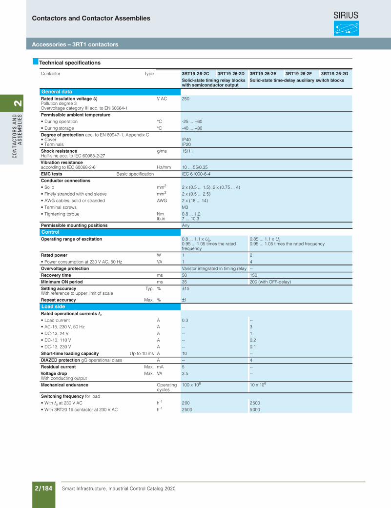
SIRIUS
Smart Infrastructure, Industrial Control Catalog 2020 2/184
2Co
nta
Cto
rs a
nd
a
ssem
bli
es
Siemens / Industrial Controls Previous folio: IC10 2/149
Power Contactors for Switching MotorsAccessories for 3RT1 Contactors
General data
3/94 Siemens IC 10 · 2012
3
Technical specifications
epyTrotcatnoC 3RT19 2 6-2C 3RT19 26-2D 3RT19 26-2E 3RT19 26-2F 3RT19 26-2G Solid-state timing relay blocks
with semiconductor outputSolid-state time-delay auxiliary switch blocks
General dataRated insulation voltage UiPollution degree 3Overvoltage category III acc. to EN 60664-1
V AC 250
Permissible ambient temperatureC°noitarepo gniruD• -25 ... +60
C°egarots gniruD• -40 ... +80
Degree of protection acc. to EN 60947-1, Appendix C• Cover IP40• Terminals IP20
Shock resistanceHalf-sine acc. to IEC 60068-2-27
g/ms 15/11
Vibration resistance mm/zH6-2-86006 CEI ot gnidrocca 10 ... 55/0.35
EMC tests Basic specification IEC 61000-6-4
Conductor connectionsmmdiloS• 2 2 x (0.5 ... 1.5), 2 x (0.75 ... 4)
mmeveels dne htiw dednarts yleniF• 2 2 x (0.5 ... 2.5)
GWAdednarts ro dilos ,selbac GWA• 2 x (18 ... 14)
• Terminal screws M3
mNeuqrot gninethgiT•lb.in
0.8 ... 1.27 ... 10.3
Permissible mounting positions Any
ControlOperating range of excitation 0.8 ... 1.1 x Us,
0.95 ... 1.05 times the rated frequency
0.85 ... 1.1 x Us, 0.95 ... 1.05 times the rated frequency
Rated power W 1 2
• Power consumption at 230 V AC, 50 Hz VA 1 4
Overvoltage protection Varistor integrated in timing relay --
Recovery time ms 50 150
Minimum ON period ms 35 200 (with OFF-delay)
Setting accuracy With reference to upper limit of scale
Typ. % ±15
Repeat accuracy Max. % ±1
Load sideRated operational currents Ie
ALoad current• 0.3 --AzH 05 ,V 032 ,51-CA• -- 3
AV 42 ,31-CD• -- 1
AV 011 ,31-CD• -- 0.2
AV 032 ,31-CD• -- 0.1
Short-time loading capacity Up to 10 ms A 10 --
DIAZED protection gG operational class A -- 4
Residual current Max. mA 5 --
Voltage drop With conducting output
Max. VA 3.5 --
Mechanical endurance Operating cycles
100 x 106 10 x 106
Switching frequency for load
• With Ie hCA V 032 ta -1 2 00 2 500
• With 3RT20 16 contactor at 230 V AC h-1 2 500 5 000
IC10_03_07.fm Page 94 Wednesday, October 30, 2013 8:20 PM
Contactors and Contactor Assemblies
Accessories – 3RT1 contactors
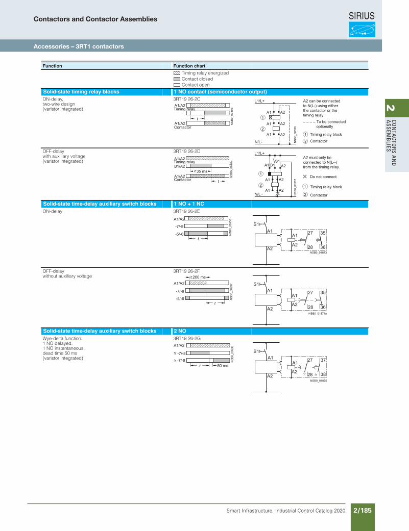
SIRIUS
Smart Infrastructure, Industrial Control Catalog 2020 2/185
2Co
nta
Ctors a
nd
a
ssemb
lies
Siemens / Industrial Controls Previous folio: IC10 2/150
Power Contactors for Switching MotorsAccessories for 3RT1 Contactors
3/95Siemens IC 10 · 2012
General data
3
Function Function chartTiming relay energizedContact closedContact open
Solid-state timing relay blocks 1 NO contact (semiconductor output)ON-delay, two-wire design (varistor integrated)
3RT19 26-2C
OFF-delay with auxiliary voltage (varistor integrated)
3RT19 26-2D
Solid-state time-delay auxiliary switch blocks 1 NO + 1 NCE2-62 91TR3yaled-NO
OFF-delay without auxiliary voltage
3RT19 26-2F
Solid-state time-delay auxiliary switch blocks 2 NOWye-delta function: 1 NO delayed, 1 NO instantaneous, dead time 50 ms(varistor integrated)
3RT19 26-2G
t
Contactor
Timing relay
NS
B0_
0939
a
A1/A2
A1/A22
1A1
A1
A1
A2
A2
A2
L1/L+
N/L- 2
1
A2 can be connected to N(L-) using either the contactor or the timing relay.
– – – – To be connected optionally
Timing relay block
ContactorNS
B0_
0055
6
t
>35 msB1/A2
A1/A2
A1/A2
NS
B0_
0940
a
Contactor
Timing relay
2
1
2
1
Contactor
Timing relay block
Do not connect
A2 must only be connected to N(L--) from the timing relay.
A1
A1
A2
A2
B1A1 A2S1
L1/L+
NS
B0_
0055
7
N/L
t-5/-6
-7/-8
A1/A2
NS
B0_
0093
6
NSB0_01873
A1 27
A2 28 36
35
A1/A2
>200 ms
-5/-6
-7/-8
NS
B0_
0093
7
t
NSB0_01874a
A1 27
A2 28 36
35
50 ms-7/-8
Y -7/-8
A1/A2
NS
B0_
0093
8
t27A1
A2 28 38
37
NSB0_01875
IC10_03_07.fm Page 95 Wednesday, October 30, 2013 8:20 PM
Contactors and Contactor Assemblies
Accessories – 3RT1 contactors
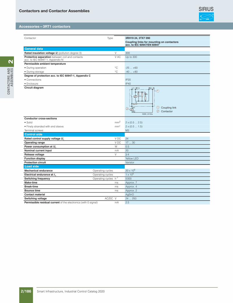
SIRIUS
Smart Infrastructure, Industrial Control Catalog 2020 2/186
2Co
nta
Cto
rs a
nd
a
ssem
bli
es
Siemens / Industrial Controls Previous folio: IC10 2/151
Power Contactors for Switching MotorsAccessories for 3RT1 Contactors
General data
3/96 Siemens IC 10 · 2012
3
epyTrotcatnoC 3RH19 24, 3TX7 090 Coupling links for mounting on contactors
acc. to IEC 60947/EN 60947General dataRated insulation voltage Ui V)3 eerged noitullop( 300
Protective separation between coil and contacts acc. to IEC 60947-1, Appendix N
V AC Up to 300
Permissible ambient temperatureC°noitarepo gniruD• -25 ... +60
C°egarots gniruD• -40 ... +80
Degree of protection acc. to IEC 60947-1, Appendix C• Connections IP20
• Enclosure IP40
Circuit diagram
Conductor cross-sectionsmmdiloS• 2 2 x (0.5 ... 2.5)
²mmeveels dne htiw dednarts yleniF• 2 x (0.5 ... 1.5)
Terminal screws M3
Control sideRated control supply voltage Us V DC 24
Operating range V DC 17 ... 30
Power consumption at Us W 0.5
Nominal current input mA 20
Release voltage V ≥ 4
Function display Yellow LED
Protection circuit Varistor
Load sideMechanical endurance Operating cycles 20 x 106
Electrical endurance at Ie Operating cycles 1 x 10⁵
Switching frequency Operating cycles h-1 5 000
Make-time ms Approx. 7
Break-time ms Approx. 4
Bounce time ms Approx. 2
Contact material AgSnO
Switching voltage AC/DC V 24 ... 250
Permissible residual current of the electronics (with 0 signal) mA 2.5
NSB0_00182a
L1 B2-B1+
A1
N
A22
1
Coupling linkContactor
12
IC10_03_07.fm Page 96 Wednesday, October 30, 2013 8:20 PM
Contactors and Contactor Assemblies
Accessories — 3RT1 contactors
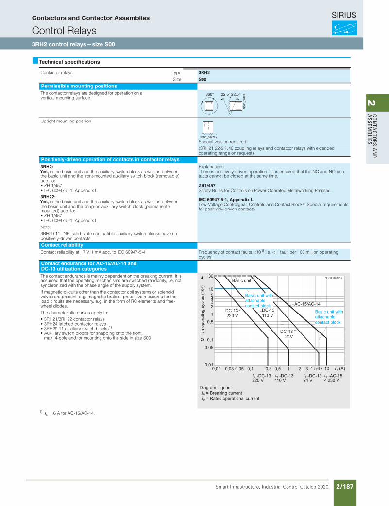
SIRIUS
Smart Infrastructure, Industrial Control Catalog 2020 2/187
2Co
nta
Ctors a
nd
a
ssemb
lies
Siemens / Industrial Controls Previous folio: IC10 2/152
Contactor Relays
SIRIUS 3RH2 contactor relays,4- and 8-pole
5/6 Siemens IC 10 · 2012
5
Technical specifications
1) Ie = 6 A for AC-15/AC-14.
epyTsyaler rotcatnoC 3RH2Size S00
Permissible mounting positionsThe contactor relays are designed for operation on a vertical mounting surface.
Upright mounting position
Special version required(3RH21 22-2K . 40 coupling relays and contactor relays with extended operating range on request)
Positively-driven operation of contacts in contactor relays3RH2: Explanations:Yes, in the basic unit and the auxiliary switch block as well as between the basic unit and the front-mounted auxiliary switch block (removable) acc. to:• ZH 1/457• IEC 60947-5-1, Appendix L
There is positively-driven operation if it is ensured that the NC and NO con-tacts cannot be closed at the same time.
ZH1/457Safety Rules for Controls on Power-Operated Metalworking Presses.
IEC 60947-5-1, Appendix LLow-Voltage Controlgear, Controls and Contact Blocks. Special requirements for positively-driven contacts
3RH22:Yes, in the basic unit and the auxiliary switch block as well as between the basic unit and the snap-on auxiliary switch block (permanently mounted) acc. to:• ZH 1/457• IEC 60947-5-1, Appendix L
Note:
3RH29 11- . NF . solid-state compatible auxiliary switch blocks have no positively-driven contacts.
Contact reliabilityContact reliability at 17 V, 1 mA acc. to IEC 60947-5-4 Frequency of contact faults <10-8 i.e. < 1 fault per 100 million operating
cycles
Contact endurance for AC-15/AC-14 andDC-13 utilization categoriesThe contact endurance is mainly dependent on the breaking current. It is assumed that the operating mechanisms are switched randomly, i.e. not synchronized with the phase angle of the supply system.
If magnetic circuits other than the contactor coil systems or solenoid valves are present, e.g. magnetic brakes, protective measures for the load circuits are necessary, e.g. in the form of RC elements and free-wheel diodes.
The characteristic curves apply to:
• 3RH21/3RH22 contactor relays• 3RH24 latched contactor relays• 3RH29 11 auxiliary switch blocks1)
• Auxiliary switch blocks for snapping onto the front, max. 4-pole and for mounting onto the side in size S00
360° 22,5°22,5°
NS
B0_
0047
8c
NSB0_00477a
(A)0,01
0,01 0,03 0,05 0,1 0,3 0,5 1 2 3
0,05
0,1
0,5
1
2345
10
30
DC-13220 V
NSB0_02061a
4 5 6 7 10
DC-13110 V
DC-1324V
110 V-DC-13
220 V-DC-13
24 V-DC-13eee
< 230 V-AC-15e
a
Basic unit
Basic unit with attachable contact block
Basic unit with attachable contact block
Mill
ion
oper
atin
g cy
cles
(106 )
Diagram legend: a = Breaking current e = Rated operational current
AC-15/AC-14
IC10_05_03 ccorp.fm Page 6 Wednesday, October 30, 2013 9:29 PM
Contactors and Contactor Assemblies
Control Relays3RH2 control relays — size S00
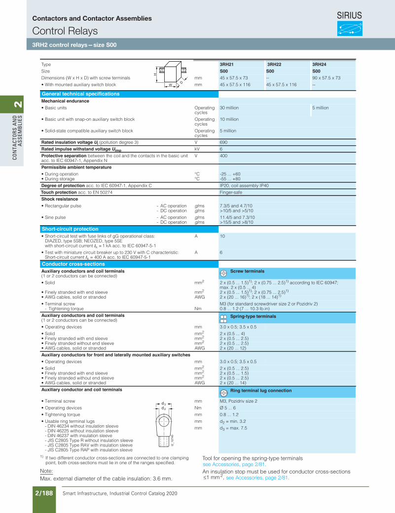
SIRIUS
Smart Infrastructure, Industrial Control Catalog 2020 2/188
2Co
nta
Cto
rs a
nd
a
ssem
bli
es
Siemens / Industrial Controls Previous folio: IC10 2/153
Contactor Relays
5/7Siemens IC 10 · 2012
SIRIUS 3RH2 contactor relays,4- and 8-pole
5
1) If two different conductor cross-sections are connected to one clamping point, both cross-sections must lie in one of the ranges specified.
Note:Max. external diameter of the cable insulation: 3.6 mm.
Tool for opening the spring-type terminals
An insulation stop must be used for conductor cross-sections ≤1 mm2,
Type 3RH21 3RH22 3RH24Size S00 S00 S00
mmslanimret wercs htiw )D x H x W( snoisnemiD 45 x 57.5 x 73 -- 90 x 57.5 x 73
mmkcolb hctiws yrailixua detnuom htiW• 45 x 57.5 x 116 45 x 57.5 x 116 --
General technical specificationsMechanical endurance
gnitarepOstinu cisaB•cycles
30 million 5 million
gnitarepOkcolb hctiws yrailixua no-pans htiw tinu cisaB•cycles
10 million
gnitarepOkcolb hctiws yrailixua elbitapmoc etats-diloS•cycles
5 million
Rated insulation voltage Ui V)3 eerged noitullop( 690
Rated impulse withstand voltage Uimp kV 6
Protective separation between the coil and the contacts in the basic unitacc. to IEC 60947-1, Appendix N
V 400
Permissible ambient temperatureC°noitarepo gniruD• -25 ... +60C°egarots gniruD• -55 ... +80
Degree of protection acc. to IEC 60947-1, Appendix C IP20, coil assembly IP40
Touch protection acc. to EN 50274 Finger-safe
Shock resistancenoitarepo CA-eslup ralugnatceR• g/ms 7.3/5 and 4.7/10
- DC operation g/ms >10/5 and >5/10
noitarepo CA-eslup eniS• g/ms 11.4/5 and 7.3/10- DC operation g/ms >15/5 and >8/10
Short-circuit protection• Short-circuit test with fuse links of gG operational class:
DIAZED, type 5SB; NEOZED, type 5SE with short-circuit current Ik = 1 kA acc. to IEC 60947-5-1
A 10
• Test with miniature circuit breaker up to 230 V with C characteristic: Short-circuit current Ik = 400 A acc. to IEC 60947-5-1
A 6
Conductor cross-sectionsAuxiliary conductors and coil terminals(1 or 2 conductors can be connected)
Screw terminals
mmdiloS• 2 2 x (0.5 ... 1.5)1); 2 x (0.75 ... 2.5)1) according to IEC 60947; max. 2 x (0.5 ... 4)
mmeveels dne htiw dednarts yleniF• 2 2 x (0.5 ... 1.5)1); 2 x (0.75 ... 2.5)1)
GWAdednarts ro dilos ,selbac GWA• 2 x (20 ... 16)1); 2 x (18 ... 14)1)
• Terminal screw M3 (for standard screwdriver size 2 or Pozidriv 2)mNeuqrot gninethgiT- 0.8 ... 1.2 (7 ... 10.3 lb.in)
Auxiliary conductors and coil terminals(1 or 2 conductors can be connected)
Spring-type terminals
mmsecived gnitarepO• 3.0 x 0.5; 3.5 x 0.5
mmdiloS• 2 2 x (0.5 ... 4)mmeveels dne htiw dednarts yleniF• 2 2 x (0.5 ... 2.5)mmeveels dne tuohtiw dednarts yleniF• 2 2 x (0.5 ... 2.5)
GWAdednarts ro dilos ,selbac GWA• 2 x (20 ... 12)
Auxiliary conductors for front and laterally mounted auxiliary switchesmmsecived gnitarepO• 3.0 x 0.5; 3.5 x 0.5
mmdiloS• 2 2 x (0.5 ... 2.5)mmeveels dne htiw dednarts yleniF• 2 2 x (0.5 ... 1.5)mmeveels dne tuohtiw dednarts yleniF• 2 2 x (0.5 ... 2.5)
GWAdednarts ro dilos ,selbac GWA• 2 x (20 ... 14)
Auxiliary conductor and coil terminals Ring terminal lug connection
mmwercs lanimreT• M3, Pozidriv size 2
mNsecived gnitarepO• Ø 5 ... 6
mmeuqrot gninethgiT• 0.8 ... 1.2
• Usable ring terminal lugs - DIN 46234 without insulation sleeve - DIN 46225 without insulation sleeve - DIN 46237 with insulation sleeve - JIS C2805 Type R without insulation sleeve - JIS C2805 Type RAV with insulation sleeve - JIS C2805 Type RAP with insulation sleeve
mm
mm
d2 = min. 3.2
d3 = max. 7.5
W
H
D
I2_12740
d 2
d3
IC10_05_03 ccorp.fm Page 7 Wednesday, October 30, 2013 9:29 PM
see Accessories, page 2/81.
see Accessories, page 2/81.
Contactors and Contactor Assemblies
Control Relays3RH2 control relays — size S00
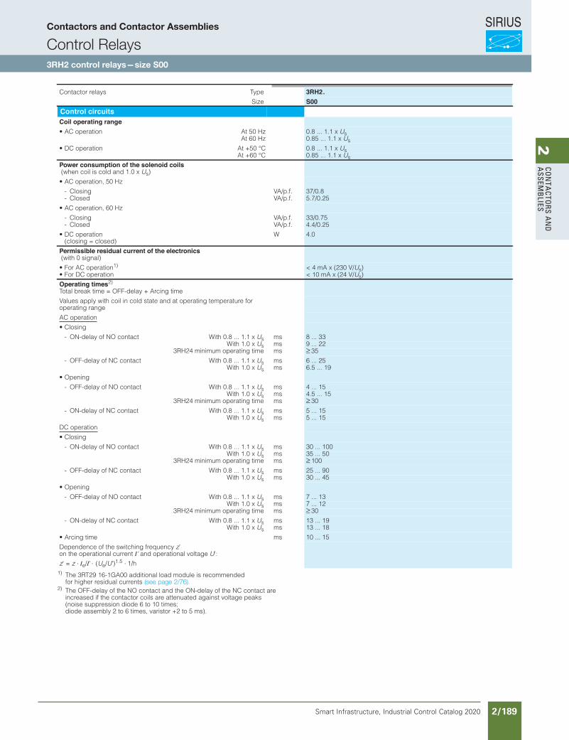
SIRIUS
Smart Infrastructure, Industrial Control Catalog 2020 2/189
2Co
nta
Ctors a
nd
a
ssemb
lies
Siemens / Industrial Controls Previous folio: IC10 2/154
Contactor Relays
SIRIUS 3RH2 contactor relays,4- and 8-pole
5/8 Siemens IC 10 · 2012
5
1) The 3RT29 16-1GA00 additional load module is recommended for higher residual currents
2) The OFF-delay of the NO contact and the ON-delay of the NC contact are increased if the contactor coils are attenuated against voltage peaks (noise suppression diode 6 to 10 times; diode assembly 2 to 6 times, varistor +2 to 5 ms).
epyTsyaler rotcatnoC 3RH2.Size S00
Control circuitsCoil operating range
zH 05 tAnoitarepo CA• 0.8 ... 1.1 x UsAt 60 Hz 0.85 ... 1.1 x Us
C° 05+ tAnoitarepo CD• 0.8 ... 1.1 x UsAt +60 °C 0.85 ... 1.1 x Us
Power consumption of the solenoid coils (when coil is cold and 1.0 x Us)
• AC operation, 50 Hz
.f.p/AVgnisolC- 37/0.8
.f.p/AVdesolC- 5.7/0.25
• AC operation, 60 Hz
.f.p/AVgnisolC- 33/0.75
.f.p/AVdesolC- 4.4/0.25
• DC operation (closing = closed)
W 4.0
Permissible residual current of the electronics (with 0 signal)
• For AC operation1) < 4 mA x (230 V/Us)• For DC operation < 10 mA x (24 V/Us)
Operating times2)
Total break time = OFF-delay + Arcing time
Values apply with coil in cold state and at operating temperature for operating range
AC operation
• Closing
x 1.1 ... 8.0 htiWtcatnoc ON fo yaled-NO- Us ms 8 ... 33With 1.0 x Us ms 9 ... 22
3RH24 minimum operating time ms ≥ 35
x 1.1 ... 8.0 htiWtcatnoc CN fo yaled-FFO- Us ms 6 ... 25With 1.0 x Us ms 6.5 ... 19
• Opening
x 1.1 ... 8.0 htiWtcatnoc ON fo yaled-FFO- Us ms 4 ... 15With 1.0 x Us ms 4.5 ... 15
3RH24 minimum operating time ms ≥ 30
x 1.1 ... 8.0 htiWtcatnoc CN fo yaled-NO- Us ms 5 ... 15With 1.0 x Us ms 5 ... 15
DC operation
• Closing
x 1.1 ... 8.0 htiWtcatnoc ON fo yaled-NO- Us ms 30 ... 100With 1.0 x Us ms 35 ... 50
3RH24 minimum operating time ms ≥ 100
x 1.1 ... 8.0 htiWtcatnoc CN fo yaled-FFO- Us ms 25 ... 90With 1.0 x Us ms 30 ... 45
• Opening
x 1.1 ... 8.0 htiWtcatnoc ON fo yaled-FFO- Us ms 7 ... 13With 1.0 x Us ms 7 ... 12
3RH24 minimum operating time ms ≥ 30
x 1.1 ... 8.0 htiWtcatnoc CN fo yaled-NO- Us ms 13 ... 19With 1.0 x Us ms 13 ... 18
smemit gnicrA• 10 ... 15
Dependence of the switching frequency z' on the operational current I' and operational voltage U':
z' = z ⋅⋅ ⋅Ie/I' (Ue/U')1.5 1/h
IC10_05_03 ccorp.fm Page 8 Wednesday, October 30, 2013 9:29 PM
(see page 2/76).
Contactors and Contactor Assemblies
Control Relays3RH2 control relays — size S00
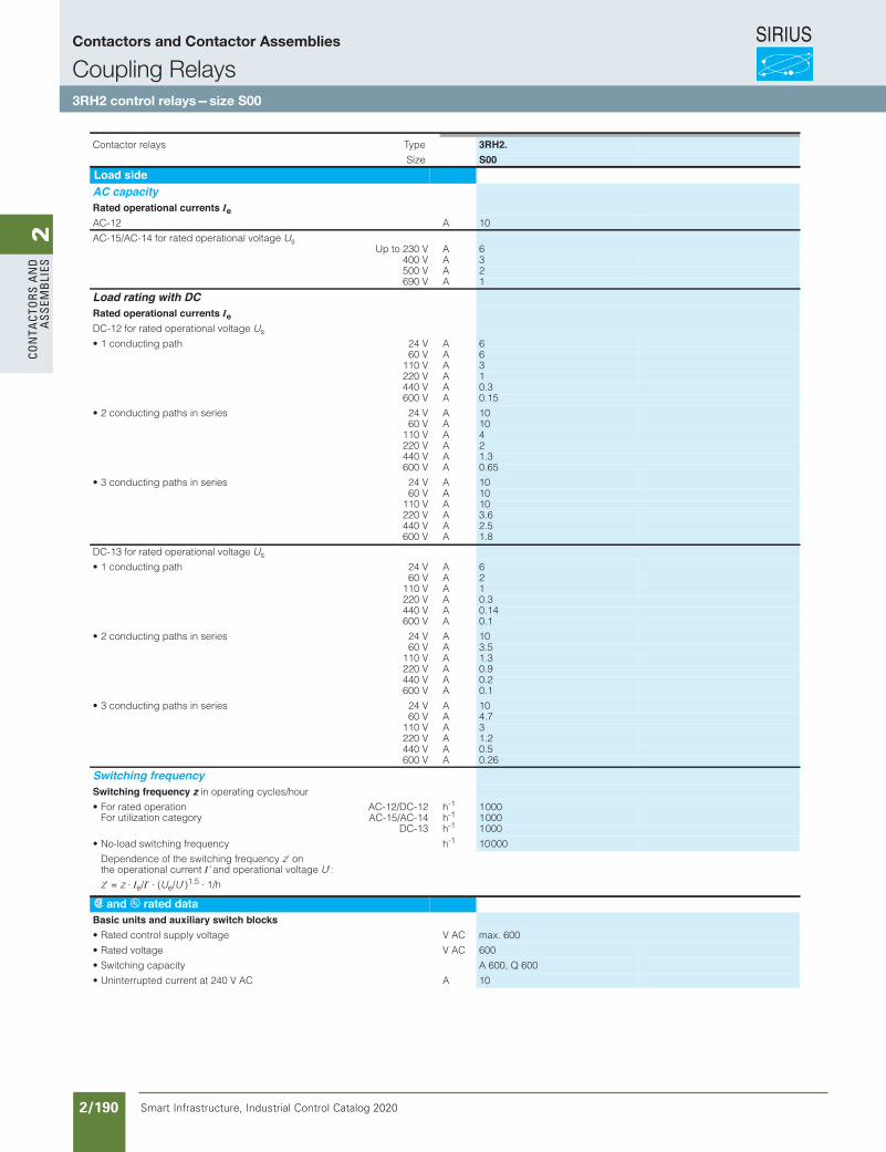
SIRIUS
Smart Infrastructure, Industrial Control Catalog 2020 2/190
2Co
nta
Cto
rs a
nd
a
ssem
bli
es
Siemens / Industrial Controls Previous folio: IC10 2/155
Contactor Relays
5/9Siemens IC 10 · 2012
SIRIUS 3RH2 contactor relays,4- and 8-pole
5
epyTsyaler rotcatnoC 3RH2.Size S00
Load sideAC capacityRated operational currents IeAC-12 A 10
AC-15/AC-14 for rated operational voltage UsUp to 230 V A 6
400 V A 3500 V A 2690 V A 1
Load rating with DCRated operational currents IeDC-12 for rated operational voltage Us
AV 42htap gnitcudnoc 1• 660 V A 6
110 V A 3220 V A 1440 V A 0.3600 V A 0.15
AV 42seires ni shtap gnitcudnoc 2• 1060 V A 10
110 V A 4220 V A 2440 V A 1.3600 V A 0.65
AV 42seires ni shtap gnitcudnoc 3• 1060 V A 10
110 V A 10220 V A 3.6440 V A 2.5600 V A 1.8
DC-13 for rated operational voltage Us
AV 42htap gnitcudnoc 1• 660 V A 2
110 V A 1220 V A 0.3440 V A 0.14600 V A 0.1
AV 42seires ni shtap gnitcudnoc 2• 1060 V A 3.5
110 V A 1.3220 V A 0.9440 V A 0.2600 V A 0.1
AV 42seires ni shtap gnitcudnoc 3• 1060 V A 4.7
110 V A 3220 V A 1.2440 V A 0.5600 V A 0.26
Switching frequencySwitching frequency z in operating cycles/hour
• For rated operation For utilization category
AC-12/DC-12 h-1 1 000AC-15/AC-14 h-1 1 000
DC-13 h-1 1 000
hycneuqerf gnihctiws daol-oN• -1 10 000
Dependence of the switching frequency z' on the operational current I' and operational voltage U':
z' = z ⋅ Ie/I' ⋅ (Ue/U')1.5 ⋅ 1/h
s and u rated dataBasic units and auxiliary switch blocks
CA Vegatlov ylppus lortnoc detaR• max. 600
CA Vegatlov detaR• 600
• Switching capacity A 600, Q 600
ACA V 042 ta tnerruc detpurretninU• 10
IC10_05_03 ccorp.fm Page 9 Wednesday, October 30, 2013 9:29 PM
Contactors and Contactor Assemblies
Coupling Relays3RH2 control relays — size S00
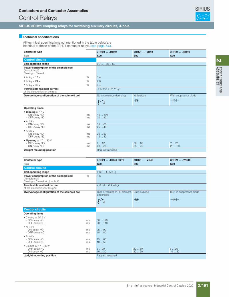
SIRIUS
Smart Infrastructure, Industrial Control Catalog 2020 2/191
2Co
nta
Ctors a
nd
a
ssemb
liesContactor Relays
Coupling RelaysSIRIUS 3RH21 coupling relaysfor switching auxiliary circuits, 4-pole
5/32 Siemens IC 10 · 2012
5
Technical specificationsAll technical specifications not mentioned in the table below are identical to those of the 3RH21 contactor relays (see page 5/6).
Contactor type 3RH21 . . - . HB40 3RH21 . . - . JB40 3RH21 . . - . KB40Size S00 S00 S00Control circuitsCoil operating range 0.7 ... 1.85 x Us
Power consumption of the solenoid coil (for cold coil) Closing = Closed
• At Us WV 71 = 1.4
• At Us WV 42 = 2.8
• At Us WV 03 = 4.4
Permissible residual currentof the electronics for 0 signal
< 10 mA x (24 V/Us)
Overvoltage configuration of the solenoid coil No overvoltage damping With diode With suppressor diode
Operating times• Closing at 17 V
smON yaled-NO- 40 ... 130smCN yaled-FFO- 30 ... 80
• At 24 VsmON yaled-NO- 35 ... 60smCN yaled-FFO- 25 ... 40
• At 30 VsmON yaled-NO- 25 ... 50smCN yaled-FFO- 15 ... 30
• Opening at 17 ... 30 VsmON yaled-FFO- 7 ... 20 38 ... 65 7 ... 20smCN yaled-NO- 20 ... 30 55 ... 75 20 ... 30
Upright mounting position Request required
Contactor type 3RH21 . . - . MB40-0KT0 3RH21 . . - . VB40 3RH21 . . - . WB40Size S00 S00 S00Control circuitsCoil operating range 0.85 ... 1.85 x Us
Power consumption of the solenoid coil (for cold coil) Closing = Closed at Us = 24 V
W 1.6
Permissible residual currentof the electronics for 0 signal
< 8 mA x (24 V/Us)
Overvoltage configuration of the solenoid coil Diode, varistor or RC element, attachable
Built-in diode Built-in suppressor diode
IC10_05_03 ccorp.fm Page 32 Wednesday, October 30, 2013 9:43 PM
Control circuitsOperating times• Closing at 20.5 V
smON yaled-NO- 30 ... 120smCN yaled-FFO- 20 ... 110
• At 24 VsmON yaled-NO- 25 ... 90smCN yaled-FFO- 15 ... 80
• At 44 VsmON yaled-NO- 15 ... 60smCN yaled-FFO- 10 ... 50
• Closing at 17 ... 30 VsmON yaled-FFO- 5 ... 20 20 ... 80 5 ... 20smCN yaled-NO- 10 ... 30 30 ... 90 10 ... 30
Upright mounting position Request required
Contactors and Contactor Assemblies
Control RelaysSIRIUS 3RH21 coupling relays for switching auxiliary circuits, 4-pole
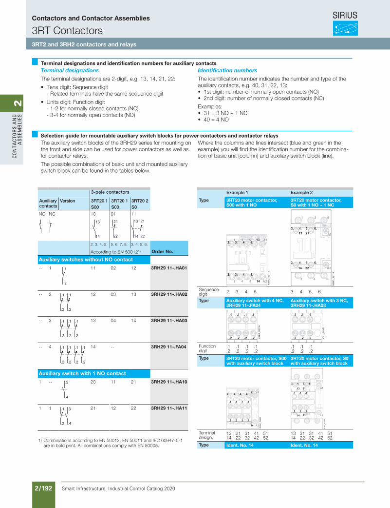
SIRIUS
Smart Infrastructure, Industrial Control Catalog 2020 2/192
2Co
nta
Cto
rs a
nd
a
ssem
bli
es
3-pole contactors
Auxiliary contacts
Version 3RT20 1 3RT20 1 3RT20 2S00 S00 S0
NO NC 10 01 11
IC01
_001
22
14
13
IC01
_001
23
22
21
14
13
NS
B0_
0053
4a
22
21
2. 3. 4. 5. 5. 6. 7. 8. 3. 4. 5. 6.
According to EN 500121) Order No.
Auxiliary switches without NO contact
-- 1
.2
.1
NS
B0_
0212
4 11 02 12 3RH29 11-.HA01
-- 2
NS
B0_
0212
5
.2
.1
.2
.1 12 03 13 3RH29 11-.HA02
-- 3
NS
B0_
0212
6
.2
.1
.2
.1
.2
.1 13 04 14 3RH29 11-.HA03
-- 4
NS
B0_
0214
2
.2
.1
.2
.1
.2
.1
.2
.1 14 -- 3RH29 11-.FA04
Auxiliary switch with 1 NO contact
1 --
.4
.3
NS
B0_
0212
7 20 11 21 3RH29 11-.HA10
1 1
.4
.3
NS
B0_
0212
8
.2
.1 21 12 22 3RH29 11-.HA11
Example 1 Example 2
Type 3RT20 motor contactor, S00 with 1 NO
3RT20 motor contactor, S0 with 1 NO + 1 NC
SIRIUS
NS
B0
_0
2112
A11353
A214642
1
5.4.3.2.
5.4.3.2.
NS
B0
_0
2114
53
A2
A121
642
2214
13
1
SIRIUS
6.5.4.3.
6.5.4.3.
Sequence digit 2. 3. 4. 5. 3. 4. 5. 6.
Type Auxiliary switch with 4 NC,3RH29 11-.FA04
Auxiliary switch with 3 NC,3RH29 11-.HA03
NS
B0
_0
2116
.2.2.2.2
.1.1.1.1
IC01
_0
0131
.2.2.2
.1.1.1
Function digit
.1 .1 .1 .1
.2 .2 .2 .2.1 .1 .1.2 .2 .2
Type 3RT20 motor contactor, S00 with auxiliary switch block
3RT20 motor contactor, S0with auxiliary switch block
NS
B0
_0
212
0
.2.2.2.2
SIRIUS
.1.1.1.1
A1135.4.3.
A214
2.
IC01
_0
013
2
SIRIUS
A2
A1
.2.2.2
6.5.
2214
2113
4.3.
.1.1.1
Terminal design.
13 21 31 41 5114 22 32 42 52
13 21 31 41 5114 22 32 42 52
Type Ident. No. 14 Ident. No. 14
Terminal designations and identification numbers for auxiliary contactsTerminal designations
The terminal designations are 2-digit, e.g. 13, 14, 21, 22:
• Tens digit: Sequence digit - Related terminals have the same sequence digit
• Units digit: Function digit - 1-2 for normally closed contacts (NC) - 3-4 for normally open contacts (NO)
Identification numbers
The identification number indicates the number and type of the auxiliary contacts, e.g. 40, 31, 22, 13:• 1st digit: number of normally open contacts (NO)• 2nd digit: number of normally closed contacts (NC)
Examples:• 31 = 3 NO + 1 NC• 40 = 4 NO
Selection guide for mountable auxiliary switch blocks for power contactors and contactor relaysThe auxiliary switch blocks of the 3RH29 series for mounting on the front and side can be used for power contactors as well as for contactor relays.
The possible combinations of basic unit and mounted auxiliary switch block can be found in the tables below.
Where the columns and lines intersect (blue and green in the example) you will find the identification number for the combina-tion of basic unit (column) and auxiliary switch block (line).
1) Combinations according to EN 50012, EN 50011 and IEC 60947-5-1 are in bold print. All combinations comply with EN 50005.
Contactors and Contactor Assemblies
3RT Contactors3RT2 and 3RH2 contactors and relays
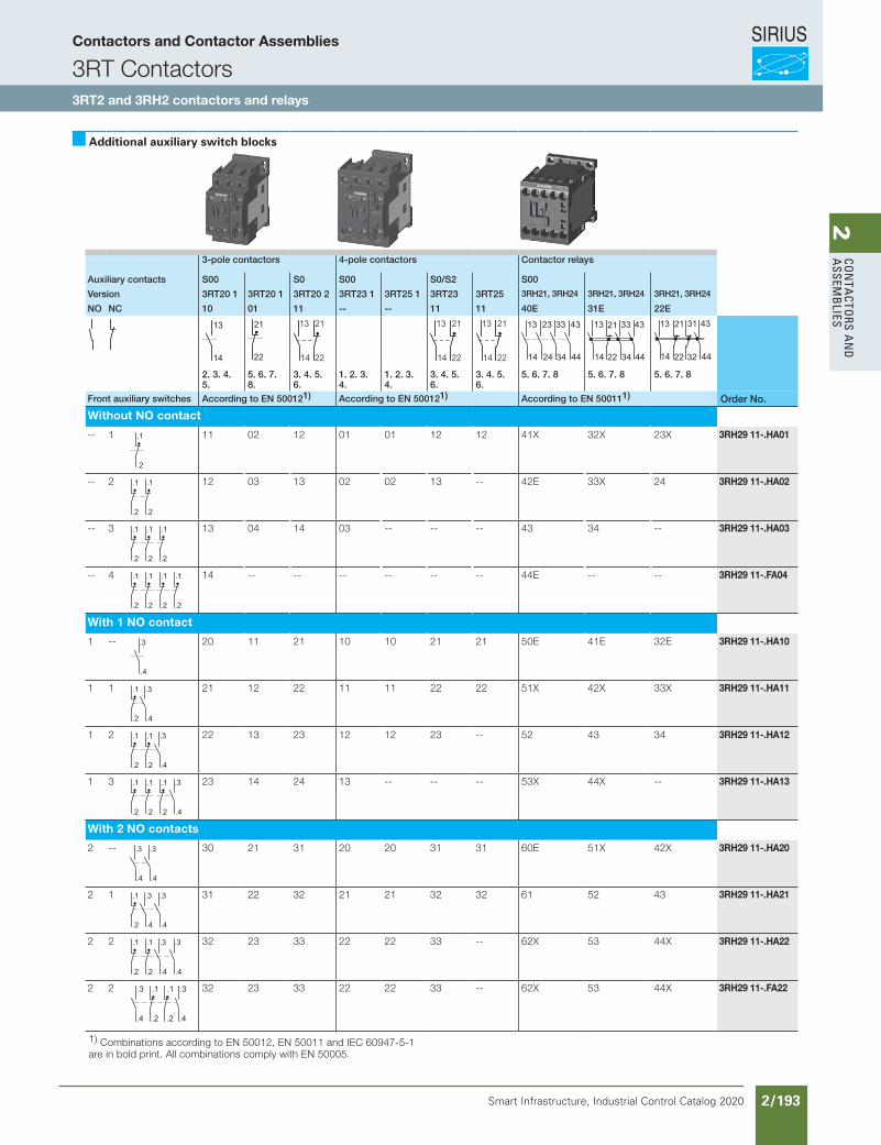
SIRIUS
Smart Infrastructure, Industrial Control Catalog 2020 2/193
2Co
nta
Ctors a
nd
a
ssemb
lies
Additional auxiliary switch blocks
3-pole contactors 4-pole contactors Contactor relays
Auxiliary contacts S00 S0 S00 S0/S2 S00
Version 3RT20 1 3RT20 1 3RT20 2 3RT23 1 3RT25 1 3RT23 3RT25 3RH21, 3RH24 3RH21, 3RH24 3RH21, 3RH24
NO NC 10 01 11 -- -- 11 11 40E 31E 22E
IC01
_001
22
14
13
IC01
_001
23
22
21
14
13N
SB
0_00
534a
22
21
14
13
NS
B0_
0053
4a
22
21
14
13
NS
B0_
0053
4a
22
21
IC01
_001
24
14
13
24
23
34
33
44
43
IC01
_001
25
14
13
22 34
33
44
4321
IC01
_001
26
14
13
44
43
32
31
22
21
2. 3. 4. 5.
5. 6. 7. 8.
3. 4. 5. 6.
1. 2. 3. 4.
1. 2. 3. 4.
3. 4. 5. 6.
3. 4. 5. 6.
5. 6. 7. 8 5. 6. 7. 8 5. 6. 7. 8
Front auxiliary switches According to EN 500121) According to EN 500121) According to EN 500111) Order No.
Without NO contact
-- 1
.2
.1
NS
B0_
0212
4 11 02 12 01 01 12 12 41X 32X 23X 3RH29 11-.HA01
-- 2
NS
B0_
0212
5
.2
.1
.2
.1 12 03 13 02 02 13 -- 42E 33X 24 3RH29 11-.HA02
-- 3
NS
B0_
0212
6
.2
.1
.2
.1
.2
.1 13 04 14 03 -- -- -- 43 34 -- 3RH29 11-.HA03
-- 4
NS
B0_
0214
2
.2
.1
.2
.1
.2
.1
.2
.1 14 -- -- -- -- -- -- 44E -- -- 3RH29 11-.FA04
With 1 NO contact
1 --
.4
.3
NS
B0_
0212
7 20 11 21 10 10 21 21 50E 41E 32E 3RH29 11-.HA10
1 1
.4
.3
NS
B0_
0212
8
.2
.1 21 12 22 11 11 22 22 51X 42X 33X 3RH29 11-.HA11
1 2
.4
.3
NS
B0_
0212
9
.2
.1
.2
.1 22 13 23 12 12 23 -- 52 43 34 3RH29 11-.HA12
1 3
.4
.3
NS
B0_
0213
0
.2
.1
.2
.1
.2
.1 23 14 24 13 -- -- -- 53X 44X -- 3RH29 11-.HA13
With 2 NO contacts
2 --
.4
.3
.4
.3
NS
B0_
0213
1 30 21 31 20 20 31 31 60E 51X 42X 3RH29 11-.HA20
2 1
.4
.3
.4
.3
NS
B0_
0213
2
.2
.1 31 22 32 21 21 32 32 61 52 43 3RH29 11-.HA21
2 2
.4
.3
.4
.3
NS
B0_
0213
3
.2
.1
.2
.1 32 23 33 22 22 33 -- 62X 53 44X 3RH29 11-.HA22
2 2
.2
.1
NS
B0_
0222
1
.2
.1
.4
.3
.4
.3 32 23 33 22 22 33 -- 62X 53 44X 3RH29 11-.FA22
1) Combinations according to EN 50012, EN 50011 and IEC 60947-5-1 are in bold print. All combinations comply with EN 50005.
Contactors and Contactor Assemblies
3RT Contactors3RT2 and 3RH2 contactors and relays
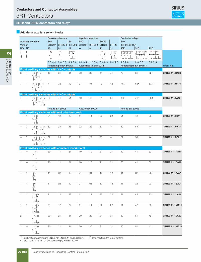
SIRIUS
Smart Infrastructure, Industrial Control Catalog 2020 2/194
2Co
nta
Cto
rs a
nd
a
ssem
bli
es
Additional auxillary switch blocks
3-pole contactors 4-pole contactors Contactor relaysAuxiliary contacts S00 S0 S00 S0/S2 S00Version 3RT20 1 3RT20 1 3RT20 2 3RT23 1 3RT25 1 3RT23 3RT25 3RH21, 3RH24NO NC 10 01 11 -- -- 11 11 40E 31E 22E
IC01
_001
22
14
13
IC01
_001
23
22
21
14
13
NS
B0_
0053
4a
22
21
14
13
NS
B0_
0053
4a
22
21
14
13
NS
B0_
0053
4a
22
21
IC01
_001
24
14
13
24
23
34
33
44
43
IC01
_001
25
14
13
22 34
33
44
4321
IC01
_001
26
14
13
44
43
32
31
22
21
2. 3. 4. 5. 5. 6. 7. 8. 3. 4. 5. 6. 1. 2. 3. 4. 1. 2. 3. 4. 3. 4. 5. 6. 3. 4. 5. 6. 5. 6. 7. 8 5. 6. 7. 8 5. 6. 7. 8
According to EN 500121) According to EN 500121) According to EN 500111) Order No.
Front auxiliary switches with 3 NO contacts3 --
.4
.3
.4
.3
.4
.3
NS
B0_
0213
4 40 31 41 30 30 41 41 70 61 52 3RH29 11-.HA30
3 1
.4
.3
.4
.3
.4
.3
NS
B0_
0213
5
.2
.1 41 32 42 31 31 42 42 71X 62X 53X 3RH29 11-.HA31
Front auxiliary switches with 4 NO contacts4 --
.4
.3
.4
.3
.4
.3
.4
.3
NS
B0_
0214
3 50 41 51 40 40 51 51 80E 71X 62X 3RH29 11-.FA40
Acc. to EN 50005 Acc. to EN 50005 Acc. to EN 50005
Front auxiliary switches with make-before-break-- 1
.6
.5
NS
B0_
0214
4
.8
.7 21 12 22 11 11 22 22 51 42 33 3RH29 11-.FB11
-- 2
.8
.7
NS
B0_
0214
5
.6
.5
.2
.1
.4
.3 32 23 33 22 22 33 -- 62 53 44 3RH29 11-.FB22
-- 3
.6
.5
NS
B0_
0214
6
.6
.5
.8
.7
.8
.7 32 23 33 22 22 33 -- 62 53 44 3RH29 11-.FC22
Front auxiliary switches with complete inscription2)
1 --
74
73
IC01
_001
27
20 11 21 10 10 21 21 50 41 32 3RH29 11-1AA10
1 --
74
73
IC01
_001
27
20 11 21 10 10 21 21 50 41 32 3RH29 11-1BA10
-- 1
72
71
IC01
_001
28
11 02 12 01 01 12 12 41 32 23 3RH29 11-1AA01
-- 1
72
71
IC01
_001
28
11 02 12 01 01 12 12 41 32 23 3RH29 11-1BA01
1 1
NS
B0_
0215
0
82
81
74
73 21 12 22 11 11 22 22 51 42 33 3RH29 11-1LA11
1 1
NS
B0_
0215
0
82
81
74
73 21 12 22 11 11 22 22 51 42 33 3RH29 11-1MA11
2 --
NS
B0_
0215
1
74
73
84
83 30 21 31 20 20 31 31 60 51 42 3RH29 11-1LA20
2 --
NS
B0_
0215
1
74
73
84
83 30 21 31 20 20 31 31 60 51 42 3RH29 11-1MA20
1) Combinations according to EN 50012, EN 50011 and IEC 60947-5-1 are in bold print. All combinations comply with EN 50005.
2) Terminals from the top or bottom.
Contactors and Contactor Assemblies
3RT Contactors3RT2 and 3RH2 contactors and relays
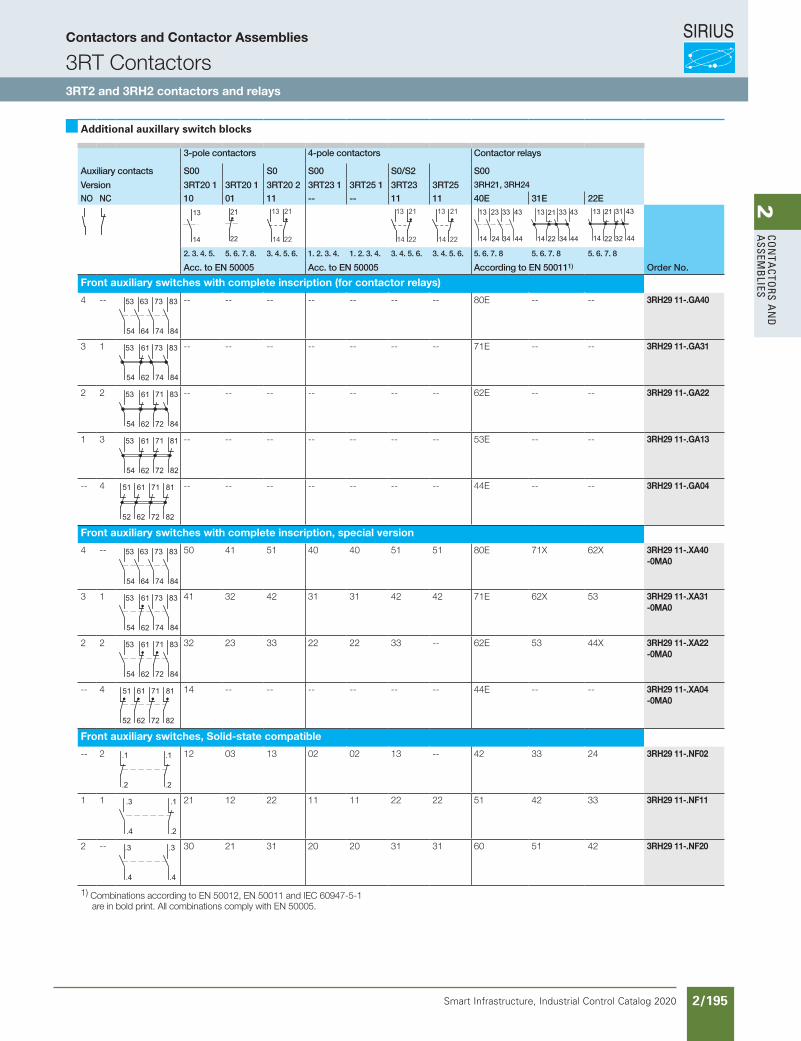
SIRIUS
Smart Infrastructure, Industrial Control Catalog 2020 2/195
2Co
nta
Ctors a
nd
a
ssemb
lies
Additional auxillary switch blocks
3-pole contactors 4-pole contactors Contactor relays
Auxiliary contacts S00 S0 S00 S0/S2 S00
Version 3RT20 1 3RT20 1 3RT20 2 3RT23 1 3RT25 1 3RT23 3RT25 3RH21, 3RH24
NO NC 10 01 11 -- -- 11 11 40E 31E 22EIC
01_0
0122
14
13
IC01
_001
2322
21
14
13
NS
B0_
0053
4a
22
21
14
13
NS
B0_
0053
4a
22
21
14
13
NS
B0_
0053
4a
22
21
IC01
_001
24
14
13
24
23
34
33
44
43
IC01
_001
25
14
13
22 34
33
44
4321
IC01
_001
26
14
13
44
43
32
31
22
21
2. 3. 4. 5. 5. 6. 7. 8. 3. 4. 5. 6. 1. 2. 3. 4. 1. 2. 3. 4. 3. 4. 5. 6. 3. 4. 5. 6. 5. 6. 7. 8 5. 6. 7. 8 5. 6. 7. 8
Acc. to EN 50005 Acc. to EN 50005 According to EN 500111) Order No.
Front auxiliary switches with complete inscription (for contactor relays)
4 --
54
53
64
63
74
73
84
83
NS
B0_
0215
6-- -- -- -- -- -- -- 80E -- -- 3RH29 11-.GA40
3 1
54
53
74
73
84
83
NS
B0_
0215
5a
62
61 -- -- -- -- -- -- -- 71E -- -- 3RH29 11-.GA31
2 2
54
53
72
71
84
83
NS
B0_
0215
4a
62
61 -- -- -- -- -- -- -- 62E -- -- 3RH29 11-.GA22
1 3
54
53
72
71
82
81
NS
B0_
0215
3a
62
61 -- -- -- -- -- -- -- 53E -- -- 3RH29 11-.GA13
-- 4
NS
B0_
0215
2a
52
51
62
61
72
71
82
81 -- -- -- -- -- -- -- 44E -- -- 3RH29 11-.GA04
Front auxiliary switches with complete inscription, special version
4 --
54
53
64
63
74
73
84
83
ic01
_001
47
50 41 51 40 40 51 51 80E 71X 62X 3RH29 11-.XA40-0MA0
3 1
54
53
74
73
84
83
ic01
_001
46
62
61 41 32 42 31 31 42 42 71E 62X 53 3RH29 11-.XA31-0MA0
2 2
54
53
72
71
84
83
ic01
_001
45
62
61 32 23 33 22 22 33 -- 62E 53 44X 3RH29 11-.XA22-0MA0
-- 4
ic01
_001
43
52
51
62
61
72
71
82
81 14 -- -- -- -- -- -- 44E -- -- 3RH29 11-.XA04-0MA0
Front auxiliary switches, Solid-state compatible
-- 2
IC01
_001
33
.2
.1
.2
.1 12 03 13 02 02 13 -- 42 33 24 3RH29 11-.NF02
1 1
NS
B0_
0214
7
.2
.1
.4
.3 21 12 22 11 11 22 22 51 42 33 3RH29 11-.NF11
2 --
.4
.3
.4
.3
IC01
_001
34
30 21 31 20 20 31 31 60 51 42 3RH29 11-.NF20
1) Combinations according to EN 50012, EN 50011 and IEC 60947-5-1 are in bold print. All combinations comply with EN 50005.
Contactors and Contactor Assemblies
3RT Contactors3RT2 and 3RH2 contactors and relays
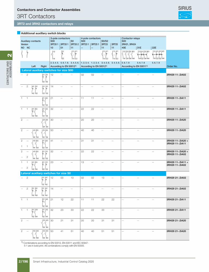
SIRIUS
Smart Infrastructure, Industrial Control Catalog 2020 2/196
2Co
nta
Cto
rs a
nd
a
ssem
bli
es
Additional auxillary switch blocks
3-pole contactors 4-pole contactors Contactor relaysAuxiliary contacts S00 S0 S00 S0/S2 S00Version 3RT20 1 3RT20 1 3RT20 2 3RT23 1 3RT25 1 3RT23 3RT25 3RH21, 3RH24NO NC 10 01 11 -- -- 11 11 40E 31E 22E
IC01
_001
22
14
13
IC01
_001
23
22
21
14
13
NS
B0_
0053
4a
22
21
14
13
NS
B0_
0053
4a
22
21
14
13
NS
B0_
0053
4a
22
21
IC01
_001
24
14
13
24
23
34
33
44
43
IC01
_001
25
14
13
22 34
33
44
4321
IC01
_001
26
14
13
44
43
32
31
22
21
2. 3. 4. 5. 5. 6. 7. 8. 3. 4. 5. 6. 1. 2. 3. 4. 1. 2. 3. 4. 3. 4. 5. 6. 3. 4. 5. 6. 5. 6. 7. 8 5. 6. 7. 8 5. 6. 7. 8
Left Right According to EN 500121) According to EN 500121) According to EN 500111) Order No.
Lateral auxiliary switches for size S00
-- 2
Anbaulinks
Anbaurechts
NS
B0_
0213
6
42
41
52
51
22
21
32
31 12 -- -- 02 02 -- -- -- -- -- 3RH29 11-.DA02
-- 2
Anbaulinks
Anbaurechts
NS
B0_
0213
6
42
41
52
51
22
21
32
31
Anbaulinks
Anbaurechts
NS
B0_
0213
6
42
41
52
51
22
21
32
31 14 -- -- -- -- -- -- -- -- -- 3RH29 11-.DA02
1 1
Anbaulinks
Anbaurechts
NS
B0_
0213
7
42
41
22
21
34
33
54
53 21 -- -- 11 11 -- -- -- -- -- 3RH29 11-.DA11
1 1
Anbaulinks
Anbaurechts
NS
B0_
0213
7
42
41
22
21
34
33
54
53
Anbaulinks
Anbaurechts
NS
B0_
0213
7
42
41
22
21
34
33
54
53 32 -- -- 22 22 -- -- -- -- -- 3RH29 11-.DA11
2 --
Anbaulinks
Anbaurechts
NS
B0_
0213
8
44
43
24
23
34
33
54
53 30 -- -- 20 20 -- -- -- -- -- 3RH29 11-.DA20
2 --
Anbaulinks
Anbaurechts
NS
B0_
0213
8
44
43
24
23
34
33
54
53
Anbaulinks
Anbaurechts
NS
B0_
0213
8
44
43
24
23
34
33
54
53 50 -- -- 40 40 -- -- -- -- -- 3RH29 11-.DA20
2
1
--
1
Anbaulinks
Anbaurechts
NS
B0_
0213
8
44
43
24
23
34
33
54
53
Anbaulinks
Anbaurechts
NS
B0_
0213
7
42
41
22
21
34
33
54
53 41 -- -- 31 31 -- -- -- -- -- 3RH29 11-.DA20 +3RH29 11-.DA11
2
--
--
2
Anbaulinks
Anbaurechts
NS
B0_
0213
8
44
43
24
23
34
33
54
53
Anbaulinks
Anbaurechts
NS
B0_
0213
6
42
41
52
51
22
21
32
31 32 -- -- 22 22 -- -- -- -- -- 3RH29 11-.DA20 +3RH29 11-.DA02
1
--
1
2
Anbaulinks
Anbaurechts
NS
B0_
0213
7
42
41
22
21
34
33
54
53
Anbaulinks
Anbaurechts
NS
B0_
0213
6
42
41
52
51
22
21
32
31 23 -- -- 13 -- -- -- -- -- -- 3RH29 11-.DA11 +3RH29 11-.DA02
Lateral auxiliary switches for size S0
-- 2
Anbaulinks
Anbaurechts
NS
B0_
0213
9
52
51
62
61
32
31
42
41 12 03 13 02 02 13 -- -- -- -- 3RH29 21-.DA02
-- 2
Anbaulinks
Anbaurechts
NS
B0_
0213
9
52
51
62
61
32
31
42
41
Anbaulinks
Anbaurechts
NS
B0_
0213
9
52
51
62
61
32
31
42
41 14 -- -- -- -- -- -- -- -- -- 3RH29 21-.DA02
1 1
Anbaulinks
Anbaurechts
NS
B0_
0214
0
52
51
64
63
32
31
44
43 21 12 22 11 11 22 22 -- -- -- 3RH29 21-.DA11
1 1
Anbaulinks
Anbaurechts
NS
B0_
0214
0
52
51
64
63
32
31
44
43
Anbaulinks
Anbaurechts
NS
B0_
0214
0
52
51
64
63
32
31
44
43 32 23 33 22 22 33 -- -- -- -- 3RH29 21-.DA11
2 --
Anbaulinks
Anbaurechts
NS
B0_
0214
1
54
53
64
63
34
33
44
43 30 21 31 20 20 31 31 -- -- -- 3RH29 21-.DA20
2 --
Anbaulinks
Anbaurechts
NS
B0_
0214
1
54
53
64
63
34
33
44
43
Anbaulinks
Anbaurechts
NS
B0_
0214
1
54
53
64
63
34
33
44
43 50 41 51 40 40 51 51 -- -- -- 3RH29 21-.DA20
1) Combinations according to EN 50012, EN 50011 and IEC 60947-5-1 are in bold print. All combinations comply with EN 50005.
Contactors and Contactor Assemblies
3RT Contactors3RT2 and 3RH2 contactors and relays
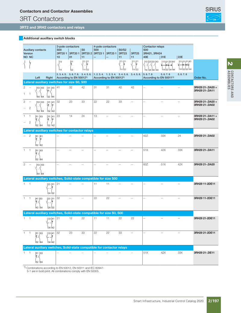
SIRIUS
Smart Infrastructure, Industrial Control Catalog 2020 2/197
2Co
nta
Ctors a
nd
a
ssemb
lies
Additional auxillary switch blocks
3-pole contactors 4-pole contactors Contactor relaysAuxiliary contacts S00 S0 S00 S0/S2 S00Version 3RT20 1 3RT20 1 3RT20 2 3RT23 1 3RT25 1 3RT23 3RT25 3RH21, 3RH24NO NC 10 01 11 -- -- 11 11 40E 31E 22E
IC01
_001
22
14
13
IC01
_001
23
22
21
14
13
NS
B0_
0053
4a
22
21
14
13
NS
B0_
0053
4a
22
21
14
13
NS
B0_
0053
4a
22
21
IC01
_001
24
14
13
24
23
34
33
44
43
IC01
_001
25
14
13
22 34
33
44
4321
IC01
_001
26
14
13
44
43
32
31
22
21
2. 3. 4. 5. 5. 6. 7. 8. 3. 4. 5. 6. 1. 2. 3. 4. 1. 2. 3. 4. 3. 4. 5. 6. 3. 4. 5. 6. 5. 6. 7. 8 5. 6. 7. 8 5. 6. 7. 8Left Right According to EN 500121) According to EN 500121) According to EN 500111) Order No.
Lateral auxiliary switches for size S0, S00
2
1
--
1
Anbaulinks
Anbaurechts
NS
B0_
0214
1
54
53
64
63
34
33
44
43
Anbaulinks
Anbaurechts
NS
B0_
0214
0
52
51
64
63
32
31
44
43 41 32 42 31 31 42 42 -- -- -- 3RH29 21-.DA20 +3RH29 21-.DA11
2
--
--
2
Anbaulinks
Anbaurechts
NS
B0_
0214
1
54
53
64
63
34
33
44
43
Anbaulinks
Anbaurechts
NS
B0_
0213
9
52
51
62
61
32
31
42
41 32 23 33 22 22 33 -- -- -- -- 3RH29 21-.DA20 +3RH29 21-.DA02
1
--
1
2
Anbaulinks
Anbaurechts
NS
B0_
0214
0
52
51
64
63
42
41
34
33
Anbaulinks
Anbaurechts
NS
B0_
0213
9
52
51
62
61
32
31
42
41 23 14 24 13 -- -- -- -- -- -- 3RH29 21-.DA11 +3RH29 21-.DA02
Lateral auxiliary switches for contactor relays
-- 2
Anbaulinks
Anbaurechts
NS
B0_
0213
9
52
51
62
61
32
31
42
41 -- -- -- -- -- -- -- 42Z 33X 24 3RH29 21-.DA02
1 1
Anbaulinks
Anbaurechts
NS
B0_
0214
0
52
51
64
63
32
31
44
43 -- -- -- -- -- -- -- 51X 42X 33X 3RH29 21-.DA11
2 --
Anbaulinks
Anbaurechts
NS
B0_
0214
1
54
53
64
63
34
33
44
43-- -- -- -- -- -- -- 60Z 51X 42X 3RH29 21-.DA20
Lateral auxiliary switches, Solid-state compatible for size S00
1 1
Anbaulinks
Anbaurechts
NS
B0_
0213
7
42
41
32
31
24
23
54
53 21 -- -- 11 11 -- -- -- -- -- 3RH29 11-2DE11
1 1
Anbaulinks
Anbaurechts
NS
B0_
0213
7
42
41
32
31
24
23
54
53
Anbaulinks
Anbaurechts
NS
B0_
0213
7
42
41
32
31
24
23
54
53 32 -- -- 22 22 -- -- -- -- -- 3RH29 11-2DE11
Lateral auxiliary switches, Solid-state compatible for size S0, S00
1 1
Anbaulinks
Anbaurechts
NS
B0_
0214
0
52
51
64
63
42
41
34
33 21 12 22 11 11 22 22 -- -- -- 3RH29 21-2DE11
1 1
Anbaulinks
Anbaurechts
NS
B0_
0214
0
52
51
64
63
42
41
34
33
Anbaulinks
Anbaurechts
NS
B0_
0214
0
52
51
64
63
42
41
34
33 32 23 33 22 22 33 -- -- -- -- 3RH29 21-2DE11
Lateral auxiliary switches, Solid-state compatible for contactor relays
1 1
Anbaulinks
Anbaurechts
NS
B0_
0214
0
52
51
64
63
42
41
34
33 -- -- -- -- -- -- -- 51X 42X 33X 3RH29 21-.DE11
1) Combinations according to EN 50012, EN 50011 and IEC 60947-5-1 are in bold print. All combinations comply with EN 50005.
Contactors and Contactor Assemblies
3RT Contactors3RT2 and 3RH2 contactors and relays
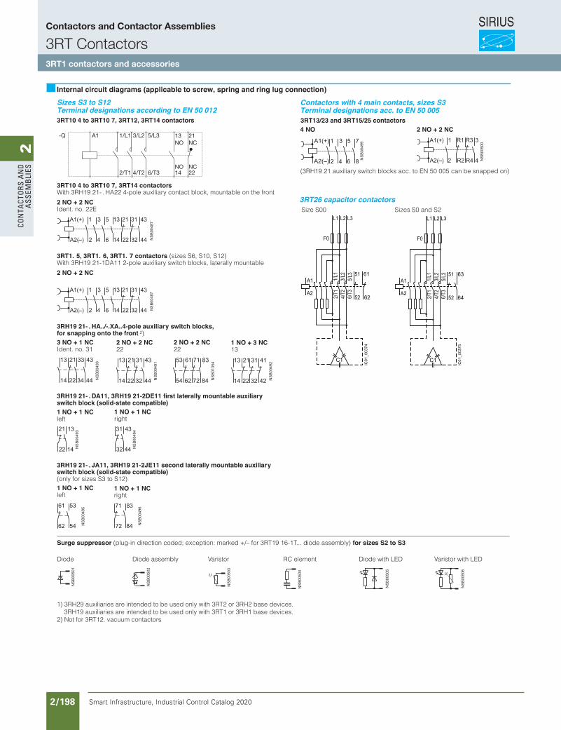
SIRIUS
Smart Infrastructure, Industrial Control Catalog 2020 2/198
2Co
nta
Cto
rs a
nd
a
ssem
bli
es
Sizes S3 to S12Terminal designations according to EN 50 0123RT10 4 to 3RT10 7, 3RT12, 3RT14 contactors
3RT10 4 to 3RT10 7, 3RT14 contactorsWith 3RH19 21- . HA22 4-pole auxiliary contact block, mountable on the front
2 NO + 2 NCIdent. no. 22E
3RT1. 5, 3RT1. 6, 3RT1. 7 contactors (sizes S6, S10, S12) With 3RH19 21-1DA11 2-pole auxiliary switch blocks, laterally mountable
2 NO + 2 NC
3RH19 21- . HA../-.XA..4-pole auxiliary switch blocks, for snapping onto the front 2)3 NO + 1 NCIdent. no. 31
3RH19 21- . DA11, 3RH19 21-2DE11 first laterally mountable auxiliary switch block (solid-state compatible)1 NO + 1 NCleft
3RH19 21- . JA11, 3RH19 21-2JE11 second laterally mountable auxiliary switch block (solid-state compatible)(only for sizes S3 to S12)1 NO + 1 NCleft
Surge suppressor (plug-in direction coded; exception: marked +/– for 3RT19 16-1T... diode assembly) for sizes S2 to S3
Diode Diode assembly Varistor RC element Diode with LED Varistor with LED
Internal circuit diagrams (applicable to screw, spring and ring lug connection)
2 NO + 2 NC22
1 NO + 3 NC13
2 NO + 2 NC22
1 NO + 1 NCright
1 NO + 1 NCright
Contactors with 4 main contacts, sizes S3Terminal designations acc. to EN 50 0053RT13/23 and 3RT15/25 contactors
CN 2 + ON 2ON 4
(3RH19 21 auxiliary switch blocks acc. to EN 50 005 can be snapped on)
1) 3RH29 auxiliaries are intended to be used only with 3RT2 or 3RH2 base devices. 3RH19 auxiliaries are intended to be used only with 3RT1 or 3RH1 base devices. 2) Not for 3RT12. vacuum contactors
3RT26 capacitor contactors Size S00 Sizes S0 and S2
A1-Q 13 21
14 22
NO NC
NO NC
1/L1 3/L2 5/L3
2/T1 4/T2 6/T3
52
51
6/T3
4/T2
2/T1
5/L3
1/L1
3/L2
C1
A2
F0
IC01
_003
74
A1
L3L2L1
62
61
52
51
6/T3
4/T2
2/T1
5/L3
1/L1
3/L2
C1
A2
F0
IC01
_003
75
A1
L3L2L1
64
63
Siemens / Industrial Controls Previous folio: IC10 2/156
Contactors and Contactor Assemblies
3RT Contactors3RT1 contactors and accessories
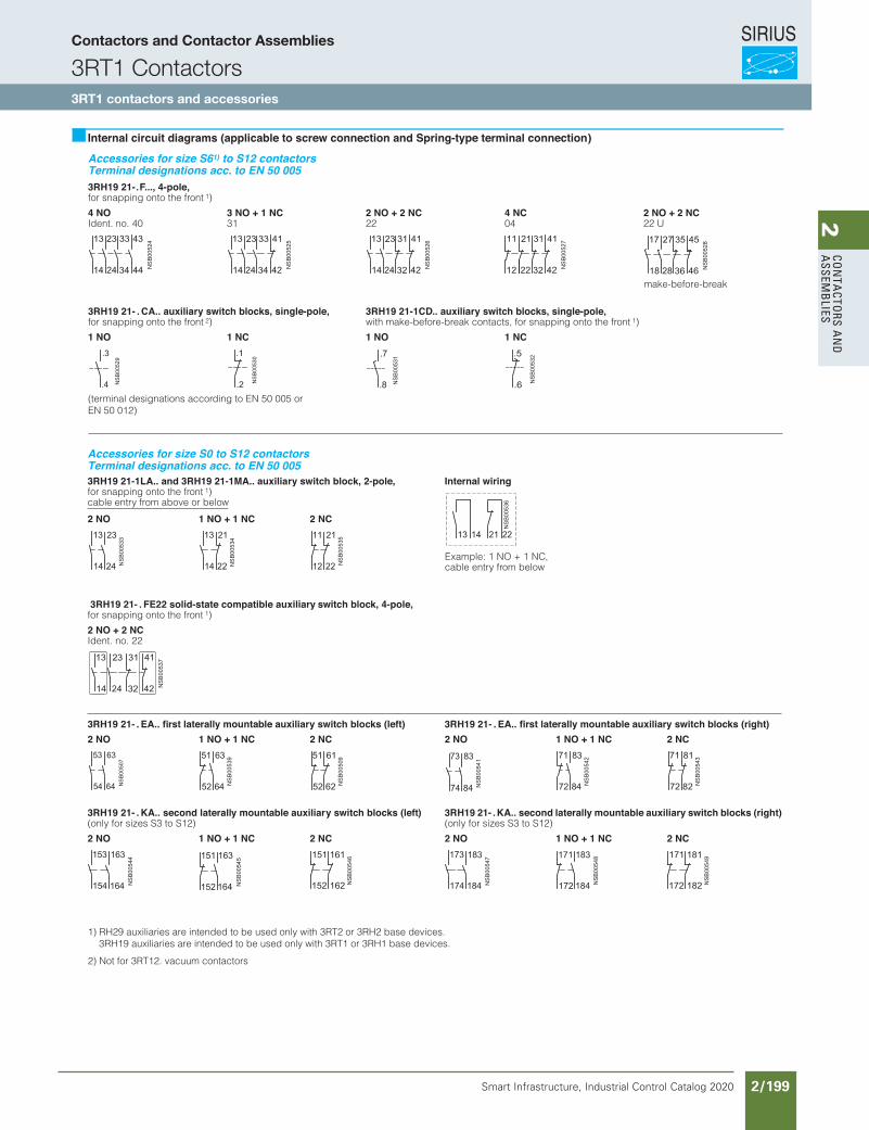
SIRIUS
Smart Infrastructure, Industrial Control Catalog 2020 2/199
2Co
nta
Ctors a
nd
a
ssemb
lies
Accessories for size S61) to S12 contactors Terminal designations acc. to EN 50 0053RH19 21-.F..., 4-pole,for snapping onto the front 1)
4 NOIdent. no. 40
3 NO + 1 NC31
2 NO + 2 NC22
4 NC04
2 NO + 2 NC22 U
3RH19 21- . CA.. auxiliary switch blocks, single-pole,for snapping onto the front 2)
3RH19 21-1CD.. auxiliary switch blocks, single-pole,with make-before-break contacts, for snapping onto the front 1)
CN 1ON 1CN 1ON 1
(terminal designations according to EN 50 005 orEN 50 012)
Internal circuit diagrams (applicable to screw connection and Spring-type terminal connection)
make-before-break
1) RH29 auxiliaries are intended to be used only with 3RT2 or 3RH2 base devices. 3RH19 auxiliaries are intended to be used only with 3RT1 or 3RH1 base devices.
2) Not for 3RT12. vacuum contactors
Accessories for size S0 to S12 contactors Terminal designations acc. to EN 50 0053RH19 21-1LA.. and 3RH19 21-1MA.. auxiliary switch block, 2-pole,for snapping onto the front 1)cable entry from above or below
Internal wiring
2 NO 1 NO + 1 NC 2 NC
3RH19 21- . FE22 solid-state compatible auxiliary switch block, 4-pole,for snapping onto the front 1)
2 NO + 2 NCIdent. no. 22
3RH19 21- . EA.. first laterally mountable auxiliary switch blocks (left) 3RH19 21- . EA.. first laterally mountable auxiliary switch blocks (right)CN 2CN 1 + ON 1ON 2CN 2CN 1 + ON 1ON 2
3RH19 21- . KA.. second laterally mountable auxiliary switch blocks (left)(only for sizes S3 to S12)
3RH19 21- .KA.. second laterally mountable auxiliary switch blocks (right)(only for sizes S3 to S12)
CN 2CN 1 + ON 1ON 2CN 2CN 1 + ON 1ON 2
Example: 1 NO + 1 NC,cable entry from below
Siemens / Industrial Controls Previous folio: IC10 2/157
Contactors and Contactor Assemblies
3RT1 Contactors3RT1 contactors and accessories
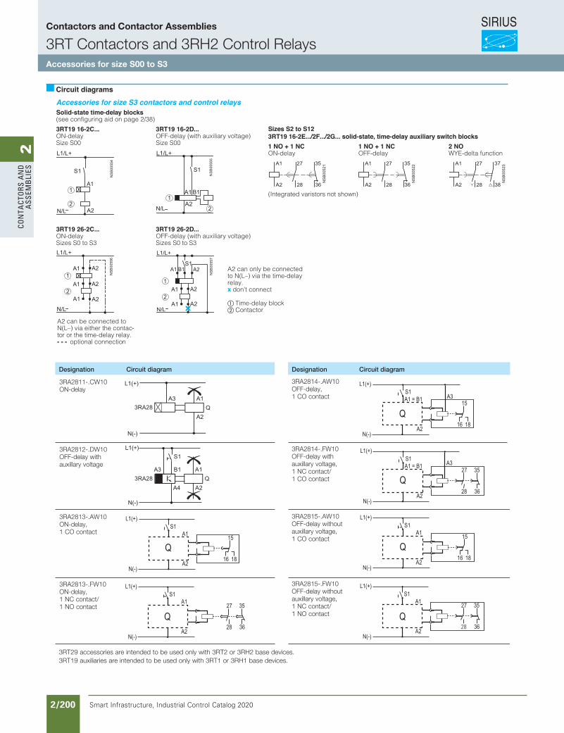
SIRIUS
Smart Infrastructure, Industrial Control Catalog 2020 2/200
2Co
nta
Cto
rs a
nd
a
ssem
bli
es
Siemens / Industrial Controls Previous folio: IC10 2/160
Solid-state time-delay blocks(see configuring aid on page 2/38)
3RT19 16-2C...ON-delaySize S00
3RT19 26-2C...ON-delaySizes S0 to S3
Circuit diagrams
3RT19 16-2D...OFF-delay (with auxiliary voltage)Size S00
A2 can be connected to N(L–) via either the contac-tor or the time-delay relay.- - - optional connection
3RT19 26-2D...OFF-delay (with auxiliary voltage)Sizes S0 to S3
A2 can only be connected to N(L–) via the time-delay relay. don’t connect
Time-delay blockContactor
Sizes S2 to S123RT19 16-2E.../2F.../2G... solid-state, time-delay auxiliary switch blocks1 NO + 1 NCON-delay
1 NO + 1 NCOFF-delay
2 NOWYE-delta function
(Integrated varistors not shown)
Accessories for size S3 contactors and control relays
x
Designation Circuit diagram
3RA2811-.CW10ON-delay
3RA2814-.AW10OFF-delay,1 CO contact
3RA2812-.DW10 OFF-delay with auxillary voltage
3RA2814-.FW10OFF-delay with auxillary voltage, 1 NC contact/ 1 CO contact
3RA2813-.AW10ON-delay, 1 CO contact
3RA2815-.AW10OFF-delay without auxillary voltage, 1 CO contact
3RA2813-.FW10ON-delay, 1 NC contact/1 NO contact
3RA2815-.FW10OFF-delay without auxillary voltage, 1 NC contact/1 NO contact
3RT29 accessories are intended to be used only with 3RT2 or 3RH2 base devices. 3RT19 auxiliaries are intended to be used only with 3RT1 or 3RH1 base devices.
Designation Circuit diagram
Q
L1(+)
N(-)
S1
A2
A1
16 18
15
Q
L1(+)
N(-)
S1
A2
A1
3628
27 35
Q
L1(+)
N(-)
S1A3
A2
A1 = B1
16 18
15
Q
S1L1(+)
N(-)
A3
A2
A1 = B1
3628
27 35
L1(+)
N(-)
S1
A2
A1
16 18
15
Q
L1(+)
N(-)
S1
A2
A1
3628
27 35
Q
Contactors and Contactor Assemblies
3RT Contactors and 3RH2 Control RelaysAccessories for size S00 to S3
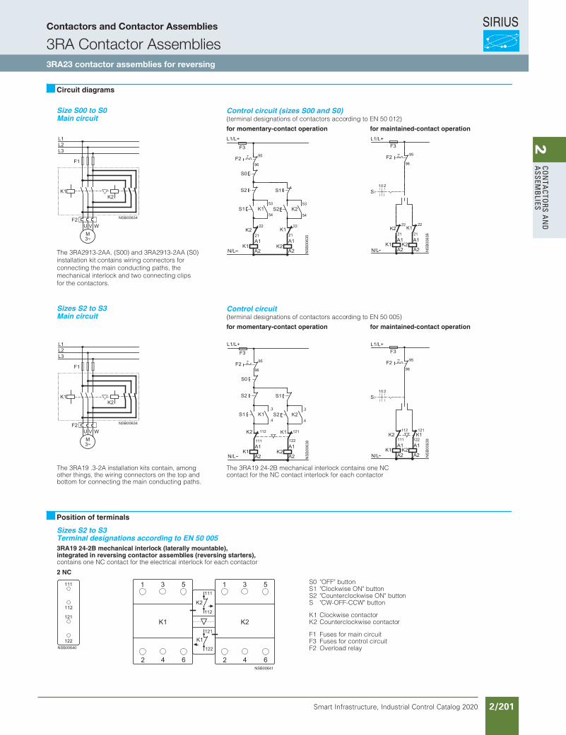
SIRIUS
Smart Infrastructure, Industrial Control Catalog 2020 2/201
2Co
nta
Ctors a
nd
a
ssemb
lies
Size S00 to S0Main circuit
Control circuit (sizes S00 and S0)(terminal designations of contactors according to EN 50 012)
for momentary-contact operation for maintained-contact operation
The 3RA2913-2AA. (S00) and 3RA2913-2AA (S0) installation kit contains wiring connectors forconnecting the main conducting paths, themechanical interlock and two connecting clipsfor the contactors.
Sizes S2 to S3Main circuit
Control circuit (terminal designations of contactors according to EN 50 005)
for momentary-contact operation for maintained-contact operation
The 3RA19 .3-2A installation kits contain, amongother things, the wiring connectors on the top and bottom for connecting the main conducting paths.
The 3RA19 24-2B mechanical interlock contains one NCcontact for the NC contact interlock for each contactor
Sizes S2 to S3Terminal designations according to EN 50 0053RA19 24-2B mechanical interlock (laterally mountable),integrated in reversing contactor assemblies (reversing starters), contains one NC contact for the electrical interlock for each contactor
2 NC
Circuit diagrams
Position of terminals
S0 "OFF" buttonS1 "Clockwise ON" buttonS2 "Counterclockwise ON" buttonS "CW-OFF-CCW" button
K1 Clockwise contactorK2 Counterclockwise contactor
F1 Fuses for main circuitF3 Fuses for control circuitF2 Overload relay
Siemens / Industrial Controls Previous folio: IC10 2/161
Contactors and Contactor Assemblies
3RA Contactor Assemblies3RA23 contactor assemblies for reversing
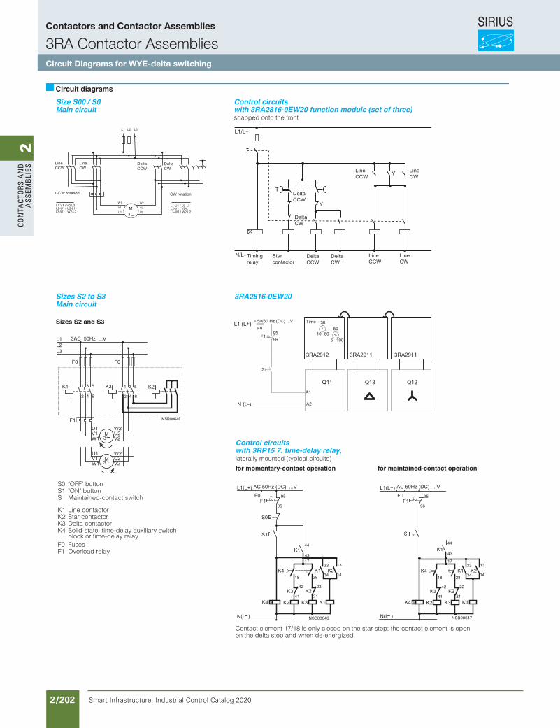
SIRIUS
Smart Infrastructure, Industrial Control Catalog 2020 2/202
2Co
nta
Cto
rs a
nd
a
ssem
bli
es
Siemens / Industrial Controls Previous folio: IC10 2/162
snapped onto the front
Sizes S2 and S3
S0 "OFF" buttonS1 "ON" buttonS Maintained-contact switch
K1 Line contactorK2 Star contactorK3 Delta contactorK4 Solid-state, time-delay auxiliary switch
block or time-delay relayF0 FusesF1 Overload relay
Circuit diagrams
laterally mounted (typical circuits)
for momentary-contact operation for maintained-contact operation
Contact element 17/18 is only closed on the star step; the contact element is openon the delta step and when de-energized.
s
%
Size S00 / S0Main circuit
Control circuitswith 3RA2816-0EW20 function module (set of three)
Sizes S2 to S3 3RA2816-0EW20Main circuit
Control circuitswith 3RP15 7. time-delay relay,
Contactors and Contactor Assemblies
3RA Contactor AssembliesCircuit Diagrams for WYE-delta switching
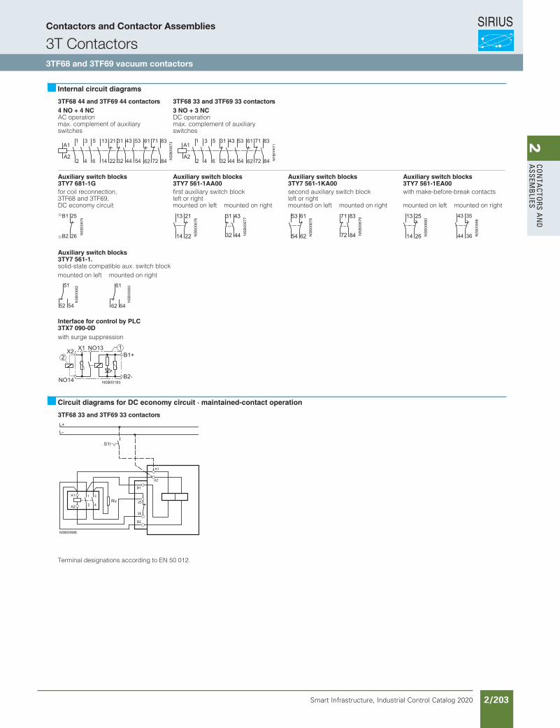
SIRIUS
Smart Infrastructure, Industrial Control Catalog 2020 2/203
2Co
nta
Ctors a
nd
a
ssemb
lies
Siemens / Industrial Controls Previous folio: IC10 2/163
3TF68 44 and 3TF69 44 contactors 3TF68 33 and 3TF69 33 contactors4 NO + 4 NCAC operationmax. complement of auxiliary switches
3 NO + 3 NCDC operationmax. complement of auxiliary switches
Auxiliary switch blocks 3TY7 681-1G
Auxiliary switch blocks 3TY7 561-1AA00
Auxiliary switch blocks 3TY7 561-1KA00
Auxiliary switch blocks 3TY7 561-1EA00
for coil reconnection,3TF68 and 3TF69,DC economy circuit
first auxiliary switch blockleft or rightmounted on left mounted on right
second auxiliary switch blockleft or rightmounted on left mounted on right
with make-before-break contacts
mounted on left mounted on right
Auxiliary switch blocks 3TY7 561-1.solid-state compatible aux. switch blockmounted on left mounted on right
Interface for control by PLC3TX7 090-0Dwith surge suppression
3TF68 33 and 3TF69 33 contactors
Internal circuit diagrams
Circuit diagrams for DC economy circuit · maintained-contact operation
Terminal designations according to EN 50 012.
Contactors and Contactor Assemblies
3T Contactors3TF68 and 3TF69 vacuum contactors
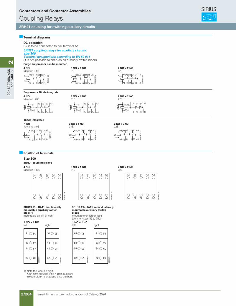
SIRIUS
Smart Infrastructure, Industrial Control Catalog 2020 2/204
2Co
nta
Cto
rs a
nd
a
ssem
bli
es
Siemens / Industrial Controls Previous folio: IC10 2/165
DC operationL+ is to be connected to coil terminal A1.
(it is not possible to snap on an auxiliary switch block)Surge suppressor can be mounted4 NOIdent no.: 40E
3 NO + 1 NC31E
2 NO + 2 NC22E
Suppressor Diode integrate4 NOIdent no.:40E
3 NO + 1 NC31E
2 NO + 2 NC22E
Size S003RH21 coupling relays4 NOIdent no.: 40E
3 NO + 1 NC31E
2 NO + 2 NC22E
Terminal diagrams
Position of terminals
3RH19 21- . DA11 first laterally mountable auxiliary switch block 1)mountable on left or right
3RH19 21- . JA11 second laterally mountable auxiliary switch block 1)mountable on left or right(only for sizes S3 to S12)
1 NO + 1 NCleft right
1 NO + 1 NCleft right
1) Note the location digit. Can only be used if no 4-pole auxiliary switch block is snapped onto the front.
A1(+)
A2(–)14
13
24
23
34
33
44
43 A1(+)
A2(–)14
13
22 34
33
44
4321 A1(+)
A2(–)14
13
44
43
32
31
22
21
Diode integrated4 NOIdent no.:40E
3 NO + 1 NC31E
2 NO + 2 NC22E
3RH21 coupling relays for auxiliary circuits, size S00Terminal designations according to EN 50 011
Contactors and Contactor Assemblies
Coupling Relays3RH21 coupling for switcing auxillary circuits
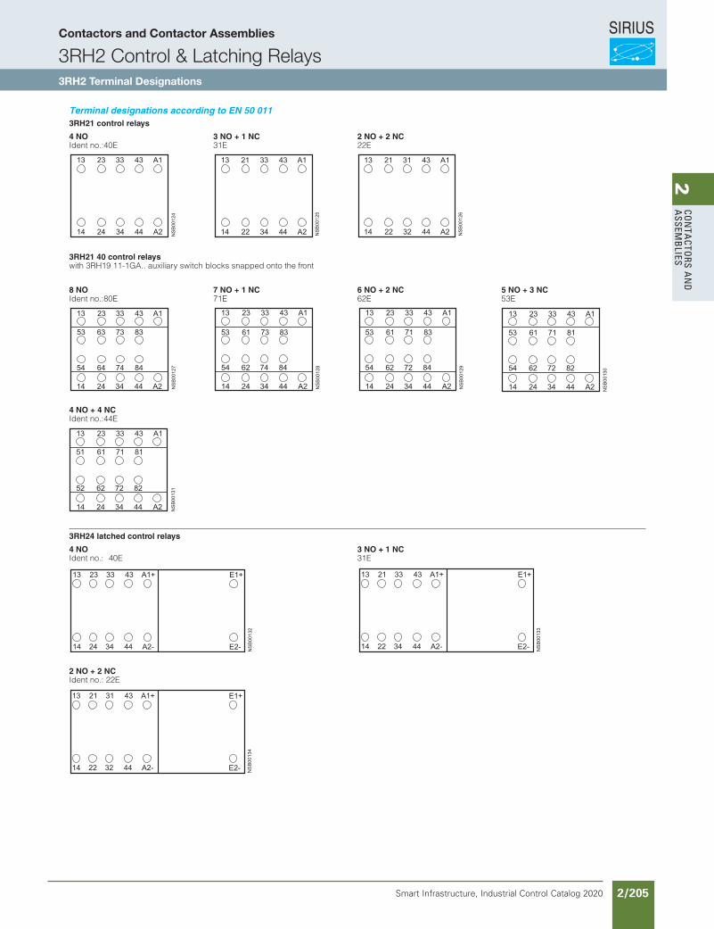
SIRIUS
Smart Infrastructure, Industrial Control Catalog 2020 2/205
2Co
nta
Ctors a
nd
a
ssemb
lies
Siemens / Industrial Controls Previous folio: IC10 2/171
Terminal designations according to EN 50 0113RH21 control relays
4 NOIdent no.:40E
3 NO + 1 NC31E
2 NO + 2 NC22E
3RH21 40 control relayswith 3RH19 11-1GA.. auxiliary switch blocks snapped onto the front
8 NOIdent no.:80E
7 NO + 1 NC71E
6 NO + 2 NC62E
5 NO + 3 NC53E
4 NO + 4 NCIdent no.:44E
3RH24 latched control relays
4 NOIdent no.: 40E
3 NO + 1 NC31E
2 NO + 2 NCIdent no.: 22E
Contactors and Contactor Assemblies
3RH2 Control & Latching Relays3RH2 Terminal Designations
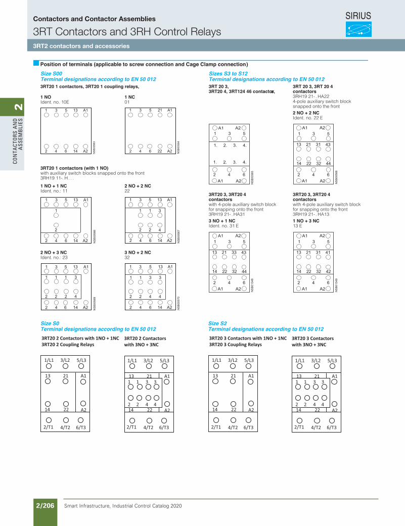
SIRIUS
Smart Infrastructure, Industrial Control Catalog 2020 2/206
2Co
nta
Cto
rs a
nd
a
ssem
bli
es
Siemens / Industrial Controls Previous folio: IC10 2/166
3RT20 1 contactors, 3RT20 1 coupling relays, 3RT 20 3, 3RT20 4, 3RT124 46 contactors,
3RT 20 3, 3RT 20 4contactors3RH19 21- . HA22 4-pole auxiliary switch block snapped onto the front
1 NO Ident. no. 10E
1 NC01
2 NO + 2 NCIdent. no. 22 E
3RT20 1 contactors (with 1 NO)with auxiliary switch blocks snapped onto the front3RH19 11-. H . . .
3RT20 3, 3RT20 4 contactorswith 4-pole auxiliary switch block for snapping onto the front 3RH19 21- . HA31
3RT20 3, 3RT20 4 contactorswith 4-pole auxiliary switch block for snapping onto the front 3RH19 21- . HA13
1 NO + 1 NCIdent. no.: 11
2 NO + 2 NC22
3 NO + 1 NCIdent. no. 31 E
1 NO + 3 NC13 E
Position of terminals (applicable to screw connection and Cage Clamp connection)
2 NO + 3 NCIdent. no.: 23
3 NO + 2 NC32
1/L1 3/L2 5/L3
A12113
2/T1 4/T2 6/T3
A214 22
3RT20 2 Contactors with 1NO + 1NC3RT20 2 Coupling Relays
A12113
A214 22
3RT20 2 Contactorswith 3NO + 3NC
1 1 3 3
2 2 4 4
2/T1 4/T2 6/T3
1/L1 3/L2 5/L3
Size S00Terminal designations according to EN 50 012
Size S0Terminal designations according to EN 50 012
1/L1 3/L2 5/L3
A12113
2/T1 4/T2 6/T3
A214 22
3RT20 3 Contactors with 1NO + 1NC3RT20 3 Coupling Relays
A12113
A214 22
3RT20 3 Contactorswith 3NO + 3NC
1 1 3 3
2 2 4 4
2/T1 4/T2 6/T3
1/L1 3/L2 5/L3
Size S2Terminal designations according to EN 50 012
Sizes S3 to S12Terminal designations according to EN 50 012
Contactors and Contactor Assemblies
3RT Contactors and 3RH Control Relays3RT2 contactors and accessories
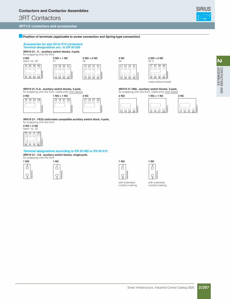
SIRIUS
Smart Infrastructure, Industrial Control Catalog 2020 2/207
2Co
nta
Ctors a
nd
a
ssemb
lies
Siemens / Industrial Controls Previous folio: IC10 2/168
Accessories for size S3 to S12 contactors Terminal designations acc. to EN 50 0053RH19 21- . F... auxiliary switch blocks, 4-pole,for snapping onto the front4 NOIdent. no. 40
3 NO + 1 NC31
2 NO + 2 NC22
4 NC04
2 NO + 2 NC22 U
3RH19 21-1LA.. auxiliary switch blocks, 2-pole, for snapping onto the front, cable entry from above
3RH19 21-1MA.. auxiliary switch blocks, 2-pole, for snapping onto the front, cable entry from below
2 NO 1 NO + 1 NC 2 NC 2 NO 1 NO + 1 NC 2 NC
3RH19 21- . FE22 solid-state compatible auxiliary switch block, 4-pole,for snapping onto the front2 NO + 2 NCIdent. no. 22
Terminal designations according to EN 50 005 or EN 50 0123RH19 21- . CA.. auxiliary switch blocks, single-pole,for snapping onto the front1 NO 1 NC 1 NO 1 NC
with extended contact-making
with extended contact-making
Position of terminals (applicable to screw connection and Spring-type connection)
make-before-break
Contactors and Contactor Assemblies
3RT Contactors3RT1/2 contactors and accessories
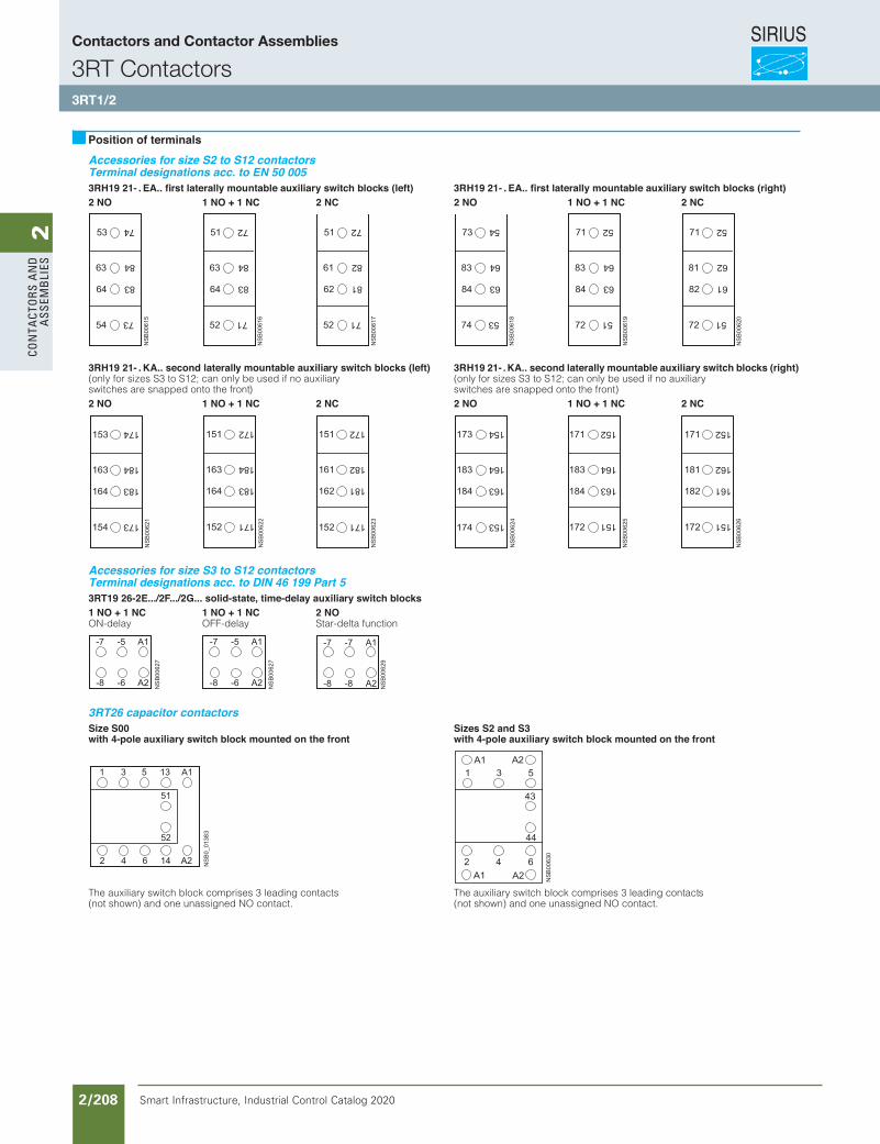
SIRIUS
Smart Infrastructure, Industrial Control Catalog 2020 2/208
2Co
nta
Cto
rs a
nd
a
ssem
bli
es
Accessories for size S2 to S12 contactors Terminal designations acc. to EN 50 0053RH19 21- . EA.. first laterally mountable auxiliary switch blocks (left) 3RH19 21- . EA.. first laterally mountable auxiliary switch blocks (right)2 NO 1 NO + 1 NC 2 NC 2 NO 1 NO + 1 NC 2 NC
3RH19 21- . KA.. second laterally mountable auxiliary switch blocks (left)(only for sizes S3 to S12; can only be used if no auxiliaryswitches are snapped onto the front)
3RH19 21- .KA.. second laterally mountable auxiliary switch blocks (right)(only for sizes S3 to S12; can only be used if no auxiliaryswitches are snapped onto the front)
2 NO 1 NO + 1 NC 2 NC 2 NO 1 NO + 1 NC 2 NC
Accessories for size S3 to S12 contactors Terminal designations acc. to DIN 46 199 Part 53RT19 26-2E.../2F.../2G... solid-state, time-delay auxiliary switch blocks1 NO + 1 NCON-delay
1 NO + 1 NCOFF-delay
2 NOStar-delta function
3RT26 capacitor contactorsSize S00with 4-pole auxiliary switch block mounted on the front
Sizes S2 and S3with 4-pole auxiliary switch block mounted on the front
The auxiliary switch block comprises 3 leading contacts(not shown) and one unassigned NO contact.
The auxiliary switch block comprises 3 leading contacts(not shown) and one unassigned NO contact.
Position of terminals
Contactors and Contactor Assemblies
3RT Contactors3RT1/2
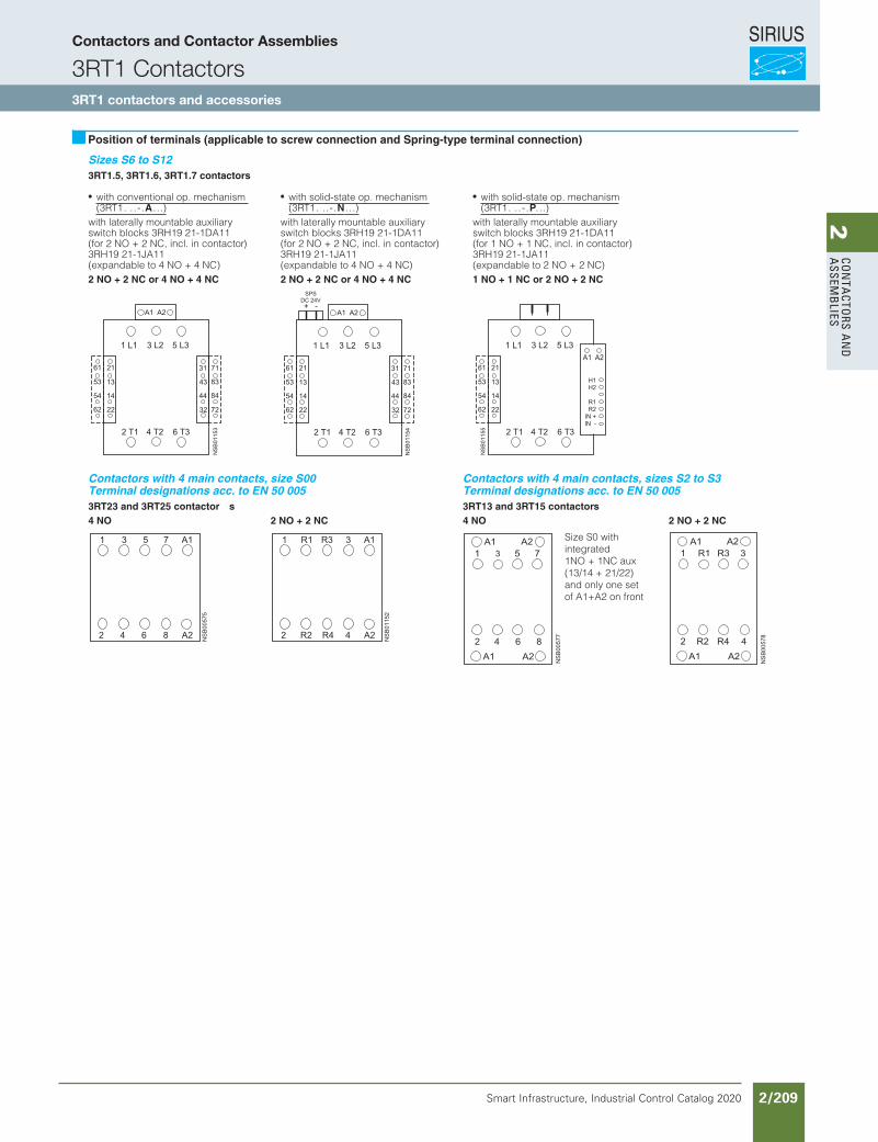
SIRIUS
Smart Infrastructure, Industrial Control Catalog 2020 2/209
2Co
nta
Ctors a
nd
a
ssemb
lies
Sizes S6 to S123RT1.5, 3RT1.6, 3RT1.7 contactors
with conventional op. mechanism (3RT1. ..-.A . . .)
with solid-state op. mechanism (3RT1. ..-.N . . .)
with solid-state op. mechanism(3RT1. ..-.P. . .)
with laterally mountable auxiliary switch blocks 3RH19 21-1DA11 (for 2 NO + 2 NC, incl. in contactor)3RH19 21-1JA11 (expandable to 4 NO + 4 NC)
with laterally mountable auxiliary switch blocks 3RH19 21-1DA11 (for 2 NO + 2 NC, incl. in contactor)3RH19 21-1JA11 (expandable to 4 NO + 4 NC)
with laterally mountable auxiliary switch blocks 3RH19 21-1DA11 (for 1 NO + 1 NC, incl. in contactor)3RH19 21-1JA11 (expandable to 2 NO + 2 NC)
2 NO + 2 NC or 4 NO + 4 NC 2 NO + 2 NC or 4 NO + 4 NC 1 NO + 1 NC or 2 NO + 2 NC
Contactors with 4 main contacts, size S00Terminal designations acc. to EN 50 005
Contactors with 4 main contacts, sizes S2 to S3Terminal designations acc. to EN 50 005
3RT23 and 3RT25 contactor s 3RT13 and 3RT15 contactors4 NO 2 NO + 2 NC 4 NO 2 NO + 2 NC
Position of terminals (applicable to screw connection and Spring-type terminal connection)
Size S0 withintegrated 1NO + 1NC aux(13/14 + 21/22)and only one set of A1+A2 on front
Contactors and Contactor Assemblies
3RT1 Contactors3RT1 contactors and accessories
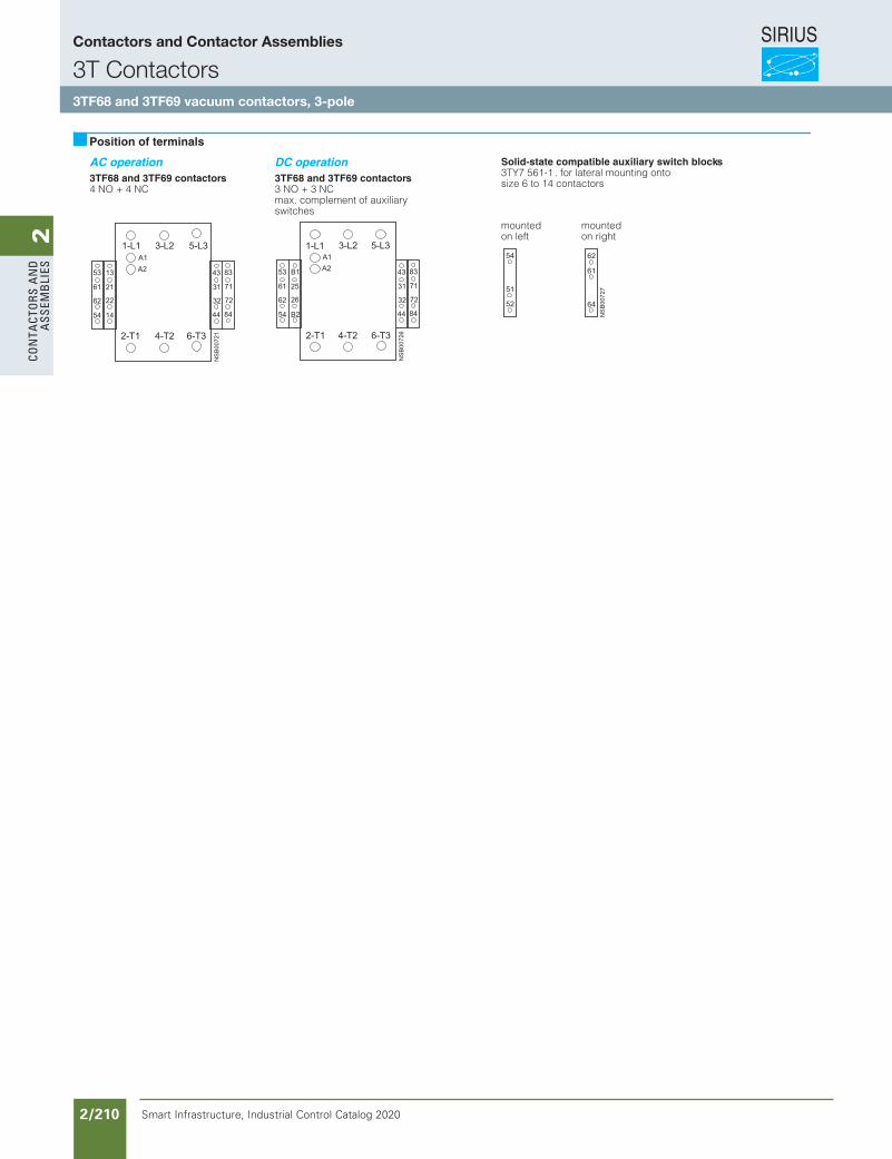
SIRIUS
Smart Infrastructure, Industrial Control Catalog 2020 2/210
2Co
nta
Cto
rs a
nd
a
ssem
bli
es
AC operation DC operation Solid-state compatible auxiliary switch blocks3TY7 561-1 . for lateral mounting onto size 6 to 14 contactors 3TF68 and 3TF69 contactors
4 NO + 4 NC3TF68 and 3TF69 contactors3 NO + 3 NCmax. complement of auxiliary switches
mounted mountedon left on right
Position of terminals
Contactors and Contactor Assemblies
3T Contactors3TF68 and 3TF69 vacuum contactors, 3-pole
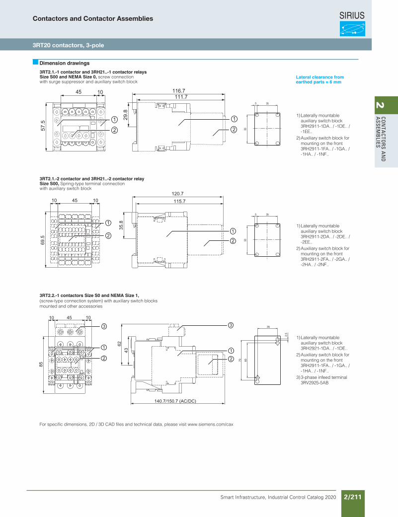
SIRIUS
Smart Infrastructure, Industrial Control Catalog 2020 2/211
2Co
nta
Ctors a
nd
a
ssemb
lies
3RT2.1.-1 contactor and 3RH21..-1 contactor relaysSize S00 and NEMA Size 0, screw connectionwith surge suppressor and auxiliary switch block
3RT2.1.-2 contactor and 3RH21..-2 contactor relaySize S00, Spring-type terminal connectionwith auxiliary switch block
3RT2.2.-1 contactors Size S0 and NEMA Size 1, (screw-type connection system) with auxiliary switch blocksmounted and other accessories
For specific dimensions, 2D / 3D CAD files and technical data, please visit www.siemens.com/cax
Dimension drawings
50
355
1) Laterally mountable auxiliary switch block 3RH2911-1DA.. / -1DE.. / -1EE..2) Auxiliary switch block for mounting on the front 3RH2911-1FA.. / -1GA.. / -1HA.. / -1NF..
50
355
1) Laterally mountable auxiliary switch block 3RH2911-2DA.. / -2DE.. / -2EE..2) Auxiliary switch block for mounting on the front 3RH2911-2FA.. / -2GA.. / -2HA.. / -2NF..
1) Laterally mountable auxiliary switch block 3RH2921-1DA.. / -1DE..2) Auxiliary switch block for mounting on the front 3RH2911-1FA.. / -1GA.. / -1HA.. / -1NF..3) 3-phase infeed terminal 3RV2925-5AB
Lateral clearance fromearthed parts = 6 mm
Contactors and Contactor Assemblies
3RT20 contactors, 3-pole
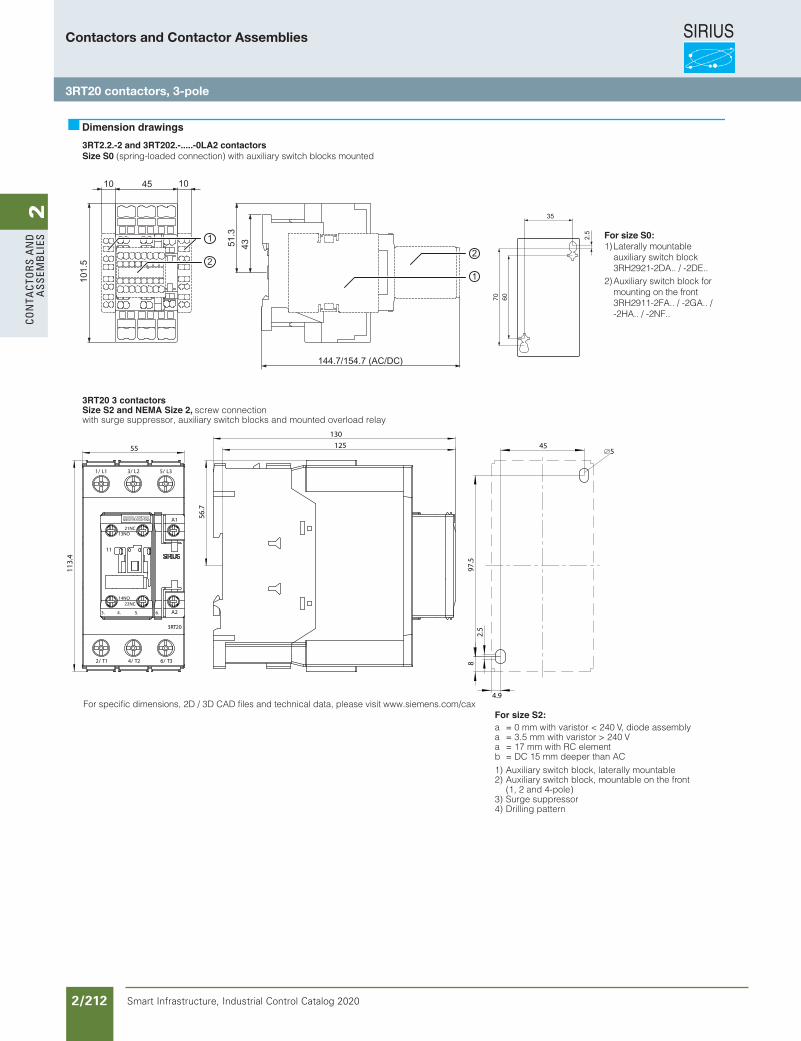
SIRIUS
Smart Infrastructure, Industrial Control Catalog 2020 2/212
2Co
nta
Cto
rs a
nd
a
ssem
bli
es
3RT2.2.-2 and 3RT202.-.....-0LA2 contactorsSize S0 (spring-loaded connection) with auxiliary switch blocks mounted
3RT20 3 contactorsSize S2 and NEMA Size 2, screw connectionwith surge suppressor, auxiliary switch blocks and mounted overload relay
Dimension drawings
For size S2:a = 0 mm with varistor < 240 V, diode assemblya = 3.5 mm with varistor > 240 Va = 17 mm with RC elementb = DC 15 mm deeper than AC1) Auxiliary switch block, laterally mountable2) Auxiliary switch block, mountable on the front
(1, 2 and 4-pole)3) Surge suppressor4) Drilling pattern
For size S0:1) Laterally mountable auxiliary switch block 3RH2921-2DA.. / -2DE..2) Auxiliary switch block for mounting on the front 3RH2911-2FA.. / -2GA.. / -2HA.. / -2NF..
For specific dimensions, 2D / 3D CAD files and technical data, please visit www.siemens.com/cax
1/ L1 3/ L2 5/ L3
6/ T34/ T22/ T1
3RT20
A1
A2
21NC
22NC
13NO
14NO
11
3. 4. 5. 6.
55
113.
4
130
125
56.7
45
97.5
2.5
8
5
4.9
Contactors and Contactor Assemblies
3RT20 contactors, 3-pole
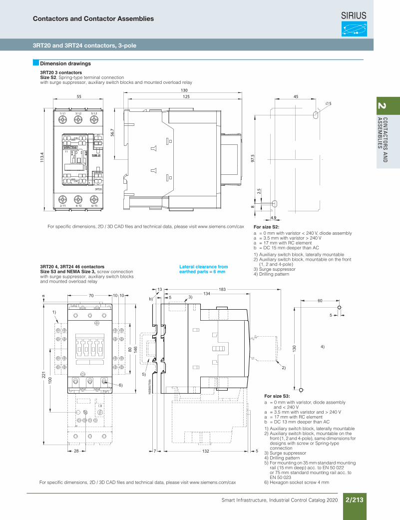
SIRIUS
Smart Infrastructure, Industrial Control Catalog 2020 2/213
2Co
nta
Ctors a
nd
a
ssemb
lies
3RT20 3 contactorsSize S2, Spring-type terminal connection with surge suppressor, auxiliary switch blocks and mounted overload relay
3RT20 4, 3RT24 46 contactorsSize S3 and NEMA Size 3, screw connectionwith surge suppressor, auxiliary switch blocksand mounted overload relay
Lateral clearance fromearthed parts = 6 mm
Dimension drawings
For size S3:a = 0 mm with varistor, diode assembly
and < 240 Va = 3.5 mm with varistor and > 240 Va = 17 mm with RC elementb = DC 13 mm deeper than AC
1) Auxiliary switch block, laterally mountable2) Auxiliary switch block, mountable on the
front (1, 2 and 4-pole), same dimensions for designs with screw or Spring-typeconnection
3) Surge suppressor4) Drilling pattern5) For mounting on 35 mm standard mounting
rail (15 mm deep) acc. to EN 50 022or 75 mm standard mounting rail acc. toEN 50 023
6) Hexagon socket screw 4 mmFor specific dimensions, 2D / 3D CAD files and technical data, please visit www.siemens.com/cax
For size S2:a = 0 mm with varistor < 240 V, diode assemblya = 3.5 mm with varistor > 240 Va = 17 mm with RC elementb = DC 15 mm deeper than AC1) Auxiliary switch block, laterally mountable2) Auxiliary switch block, mountable on the front
(1, 2 and 4-pole)3) Surge suppressor4) Drilling pattern
For specific dimensions, 2D / 3D CAD files and technical data, please visit www.siemens.com/cax
1/ L1 3/ L2 5/ L3
6/ T34/ T22/ T1
3RT20
A1
A2
21NC
22NC
13NO
14NO
11
3. 4. 5. 6.
55
113.
4
130
125
56.7
45
97.5
2.5
8
5
4.9
Contactors and Contactor Assemblies
3RT20 and 3RT24 contactors, 3-pole
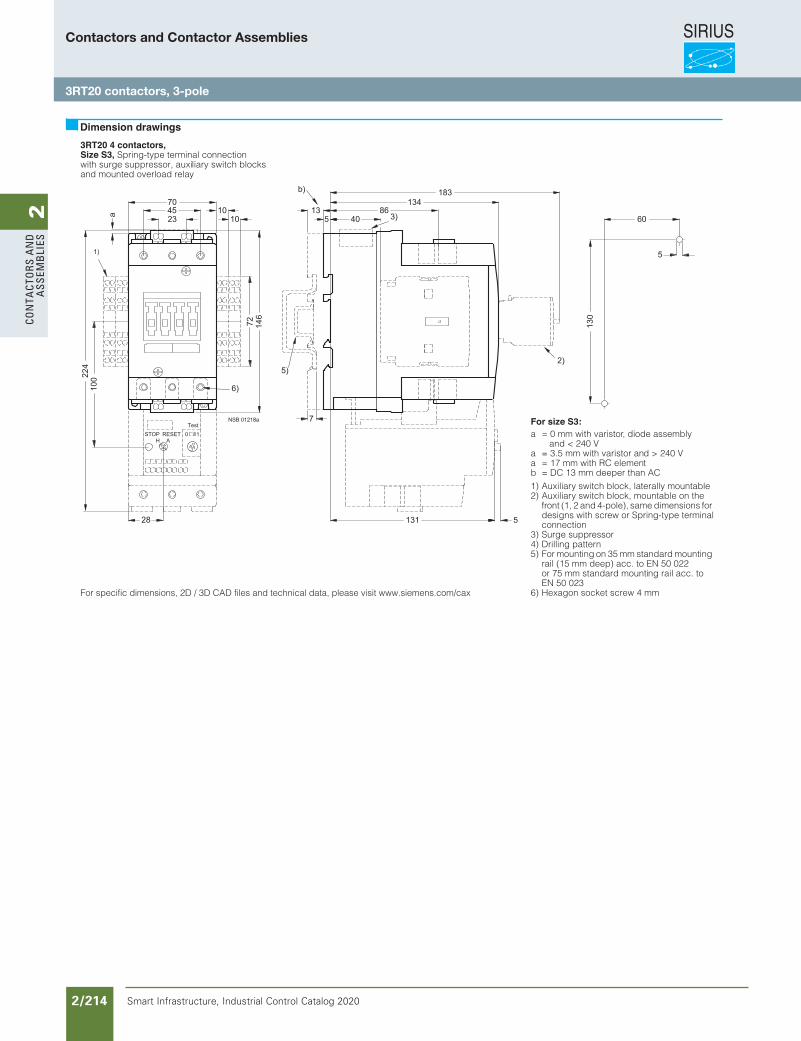
SIRIUS
Smart Infrastructure, Industrial Control Catalog 2020 2/214
2Co
nta
Cto
rs a
nd
a
ssem
bli
es
3RT20 4 contactors,Size S3, Spring-type terminal connectionwith surge suppressor, auxiliary switch blocksand mounted overload relay
Dimension drawings
For size S3:a = 0 mm with varistor, diode assembly
and < 240 Va = 3.5 mm with varistor and > 240 Va = 17 mm with RC elementb = DC 13 mm deeper than AC1) Auxiliary switch block, laterally mountable2) Auxiliary switch block, mountable on the
front (1, 2 and 4-pole), same dimensions for designs with screw or Spring-type terminalconnection
3) Surge suppressor4) Drilling pattern5) For mounting on 35 mm standard mounting
rail (15 mm deep) acc. to EN 50 022or 75 mm standard mounting rail acc. toEN 50 023
6) Hexagon socket screw 4 mmFor specific dimensions, 2D / 3D CAD files and technical data, please visit www.siemens.com/cax
Contactors and Contactor Assemblies
3RT20 contactors, 3-pole
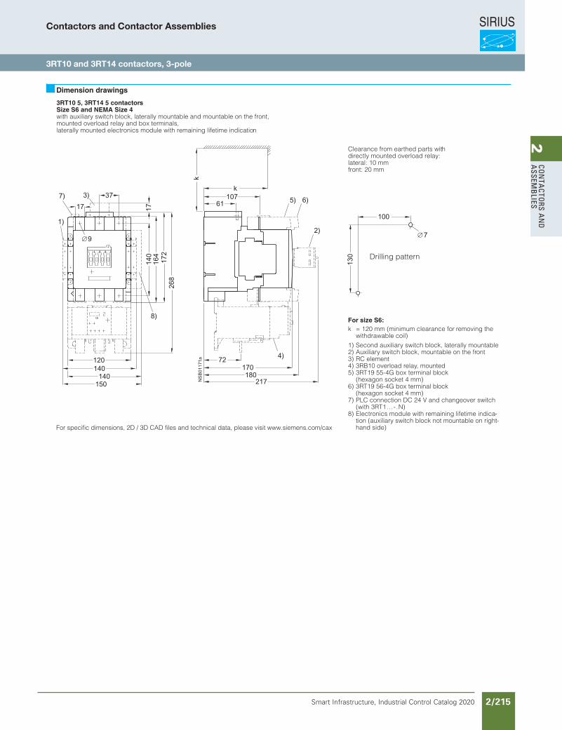
SIRIUS
Smart Infrastructure, Industrial Control Catalog 2020 2/215
2Co
nta
Ctors a
nd
a
ssemb
lies
3RT10 5, 3RT14 5 contactorsSize S6 and NEMA Size 4with auxiliary switch block, laterally mountable and mountable on the front,mounted overload relay and box terminals,laterally mounted electronics module with remaining lifetime indication
Clearance from earthed parts withdirectly mounted overload relay:lateral: 10 mmfront: 20 mm
Dimension drawings
For size S6:k = 120 mm (minimum clearance for removing the
withdrawable coil)1) Second auxiliary switch block, laterally mountable2) Auxiliary switch block, mountable on the front3) RC element4) 3RB10 overload relay, mounted5) 3RT19 55-4G box terminal block
(hexagon socket 4 mm)6) 3RT19 56-4G box terminal block
(hexagon socket 4 mm)7) PLC connection DC 24 V and changeover switch
(with 3RT1...-.N)8) Electronics module with remaining lifetime indica-
tion (auxiliary switch block not mountable on right-hand side)
Drilling pattern
For specific dimensions, 2D / 3D CAD files and technical data, please visit www.siemens.com/cax
Contactors and Contactor Assemblies
3RT10 and 3RT14 contactors, 3-pole
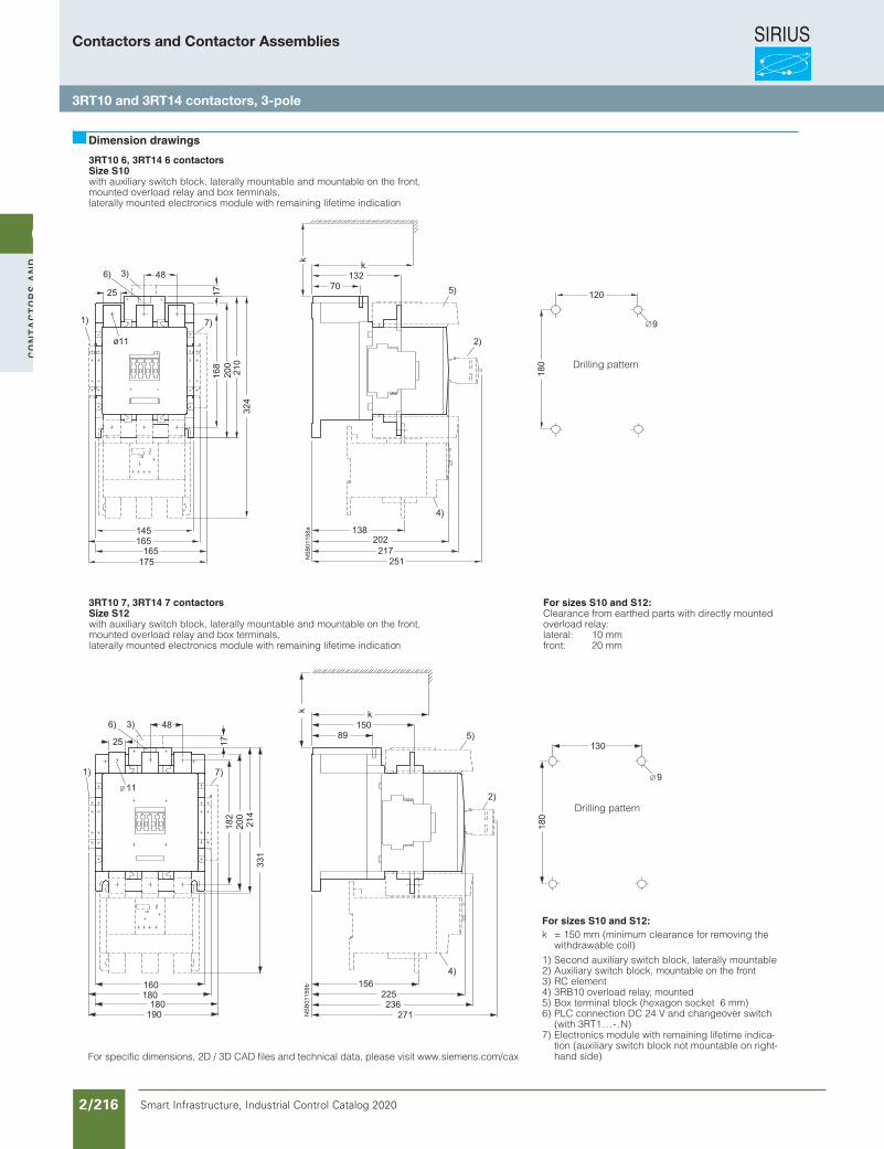
SIRIUS
Smart Infrastructure, Industrial Control Catalog 2020 2/216
2Co
nta
Cto
rs a
nd
a
ssem
bli
es
3RT10 6, 3RT14 6 contactorsSize S10with auxiliary switch block, laterally mountable and mountable on the front,mounted overload relay and box terminals,laterally mounted electronics module with remaining lifetime indication
3RT10 7, 3RT14 7 contactorsSize S12with auxiliary switch block, laterally mountable and mountable on the front,mounted overload relay and box terminals,laterally mounted electronics module with remaining lifetime indication
For sizes S10 and S12:Clearance from earthed parts with directly mounted overload relay:lateral: 10 mmfront: 20 mm
Dimension drawings
Drilling pattern
For sizes S10 and S12:k = 150 mm (minimum clearance for removing the
withdrawable coil)1) Second auxiliary switch block, laterally mountable2) Auxiliary switch block, mountable on the front3) RC element4) 3RB10 overload relay, mounted5) Box terminal block (hexagon socket 6 mm)6) PLC connection DC 24 V and changeover switch
(with 3RT1...-.N)7) Electronics module with remaining lifetime indica-
tion (auxiliary switch block not mountable on right-hand side)
Drilling pattern
For specific dimensions, 2D / 3D CAD files and technical data, please visit www.siemens.com/cax
Contactors and Contactor Assemblies
3RT10 and 3RT14 contactors, 3-pole
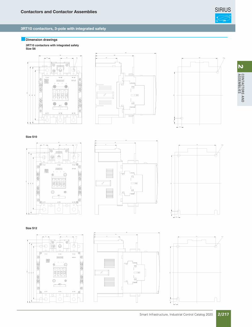
SIRIUS
Smart Infrastructure, Industrial Control Catalog 2020 2/217
2Co
nta
Ctors a
nd
a
ssemb
liesContactors and Contactor Assemblies
3RT10 contactors, 3-pole with integrated safety
3RT10 contactors with integrated safetySize S6
Dimension drawings
Size S10
Size S12
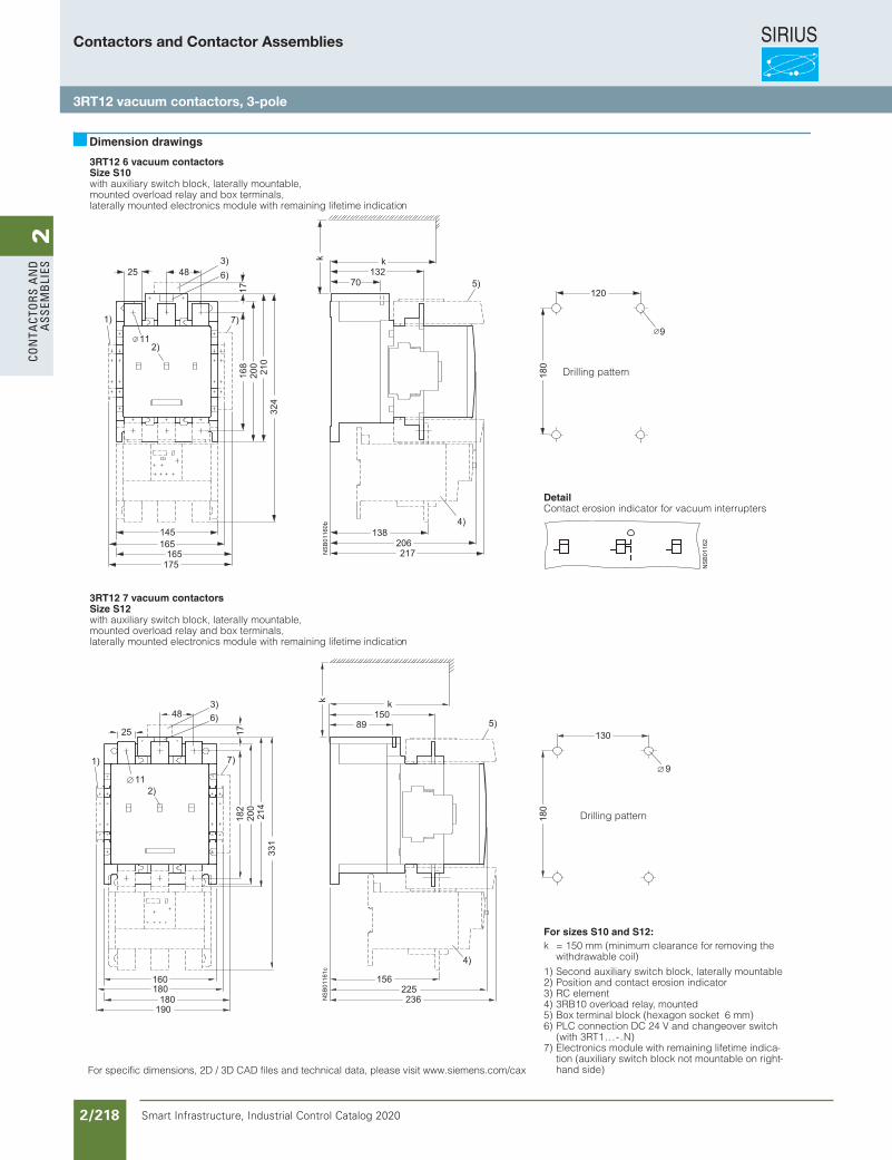
SIRIUS
Smart Infrastructure, Industrial Control Catalog 2020 2/218
2Co
nta
Cto
rs a
nd
a
ssem
bli
es
3RT12 6 vacuum contactorsSize S10with auxiliary switch block, laterally mountable,mounted overload relay and box terminals,laterally mounted electronics module with remaining lifetime indication
3RT12 7 vacuum contactorsSize S12with auxiliary switch block, laterally mountable,mounted overload relay and box terminals,laterally mounted electronics module with remaining lifetime indication
Dimension drawings
DetailContact erosion indicator for vacuum interrupters
Drilling pattern
For sizes S10 and S12:k = 150 mm (minimum clearance for removing the
withdrawable coil)1) Second auxiliary switch block, laterally mountable2) Position and contact erosion indicator3) RC element 4) 3RB10 overload relay, mounted5) Box terminal block (hexagon socket 6 mm)6) PLC connection DC 24 V and changeover switch
(with 3RT1...-.N)7) Electronics module with remaining lifetime indica-
tion (auxiliary switch block not mountable on right-hand side)
Drilling pattern
For specific dimensions, 2D / 3D CAD files and technical data, please visit www.siemens.com/cax
Contactors and Contactor Assemblies
3RT12 vacuum contactors, 3-pole
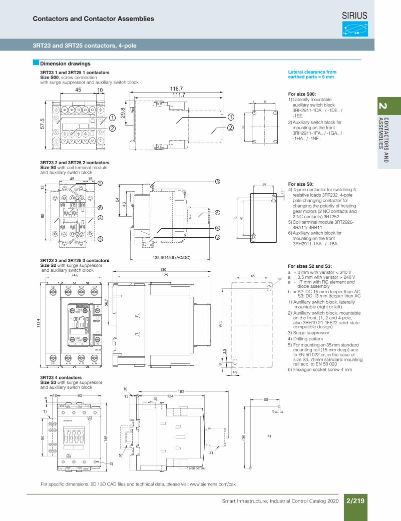
SIRIUS
Smart Infrastructure, Industrial Control Catalog 2020 2/219
2Co
nta
Ctors a
nd
a
ssemb
lies
3RT23 1 and 3RT25 1 contactorsSize S00, screw connectionwith surge suppressor and auxiliary switch block
3RT23 2 and 3RT25 2 contactorsSize S0 with coil terminal module and auxiliary switch block
3RT23 3 and 3RT25 3 contactorssSize S2 with surge suppressor and auxiliary switch block
For sizes S2 and S3:a = 0 mm with varistor < 240 Va = 3.5 mm with varistor > 240 Va = 17 mm with RC element and
diode assemblyb = S2: DC 15 mm deeper than AC
S3: DC 13 mm deeper than AC1) Auxiliary switch block, laterally
mountable (right or left)2) Auxiliary switch block, mountable
on the front, (1, 2 and 4-pole, also 3RH19 21-1FE22 solid-state compatible design)
3) Surge suppressor4) Drilling pattern5) For mounting on 35 mm standard
mounting rail (15 mm deep) acc. to EN 50 022 or, in the case of size S3, 75mm standard mountingrail acc. to EN 50 023
6) Hexagon socket screw 4 mm
3RT23 4 contactors Size S3 with surge suppressor and auxiliary switch block
Dimension drawings
For specific dimensions, 2D / 3D CAD files and technical data, please visit www.siemens.com/cax
50
355
For size S00:1) Laterally mountable auxiliary switch block 3RH2911-1DA.. / -1DE.. / -1EE..2) Auxiliary switch block for mounting on the front 3RH2911-1FA.. / -1GA.. / -1HA.. / -1NF..
For size S0:4) 4-pole contactor for switching 4 resistive loads 3RT232. 4-pole pole-changing contactor for changing the polarity of hoisting gear motors (2 NO contacts and 2 NC contacts) 3RT252.5) Coil terminal module 3RT2926- 4RA11/-4RB116) Auxiliary switch block for mounting on the front 3RH2911-1AA.. / -1BA
Lateral clearance fromearthed parts = 6 mm
3/ L2 5/ L3 7/ L4
8/ T46/ T34/ T2
3RT23
A1
A2
21NC
22NC
13NO
14NO
11
3. 4. 5. 6.
1/L1
2/T1
74.6
113.
4
125
130
56.7
45
97.5
2.5
8
5
4.9
Contactors and Contactor Assemblies
3RT23 and 3RT25 contactors, 4-pole
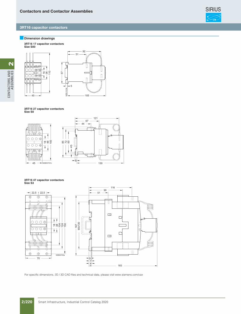
SIRIUS
Smart Infrastructure, Industrial Control Catalog 2020 2/220
2Co
nta
Cto
rs a
nd
a
ssem
bli
es
3RT16 17 capacitor contactorsSize S00
3RT16 27 capacitor contactorsSize S0
3RT16 47 capacitor contactorsSize S3
Dimension drawings
For specific dimensions, 2D / 3D CAD files and technical data, please visit www.siemens.com/cax
Contactors and Contactor Assemblies
3RT16 capacitor contactors
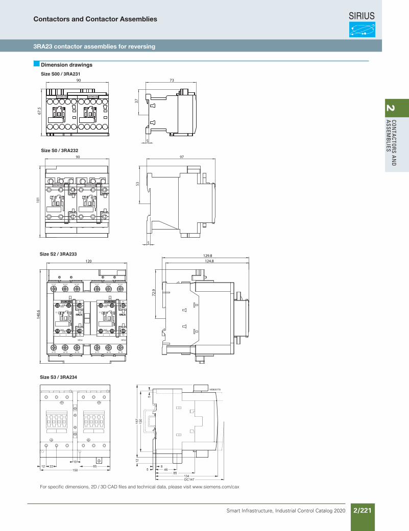
SIRIUS
Smart Infrastructure, Industrial Control Catalog 2020 2/221
2Co
nta
Ctors a
nd
a
ssemb
lies
Size S00 / 3RA231
Size S0 / 3RA232
Size S2 / 3RA233
Size S3 / 3RA234
Dimension drawings
For specific dimensions, 2D / 3D CAD files and technical data, please visit www.siemens.com/cax
90
67.5
5
73
37
90
101
5
97
53
1/ L1 3/ L2 5/ L3
6/ T34/ T22/ T1
3RT20
A1
A2
21NC
22NC
13NO
14NO
11
3. 4. 5. 6.
120
140.6
1/ L1 3/ L2 5/ L3
6/ T34/ T22/ T1
3RT20
A1
A2
21NC
22NC
13NO
14NO
11
3. 4. 5. 6.
124.8129.8
72.9
Contactors and Contactor Assemblies
3RA23 contactor assemblies for reversing
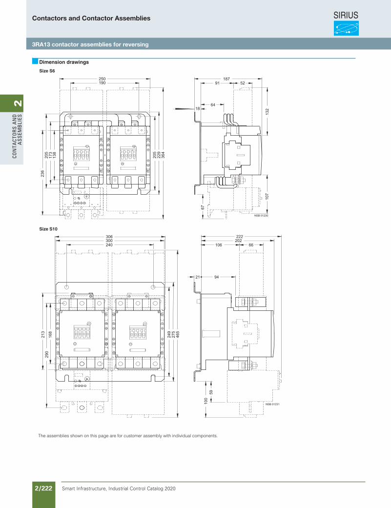
SIRIUS
Smart Infrastructure, Industrial Control Catalog 2020 2/222
2Co
nta
Cto
rs a
nd
a
ssem
bli
es
Size S6
Size S10
Dimension drawings
The assemblies shown on this page are for customer assembly with individual components.
Contactors and Contactor Assemblies
3RA13 contactor assemblies for reversing
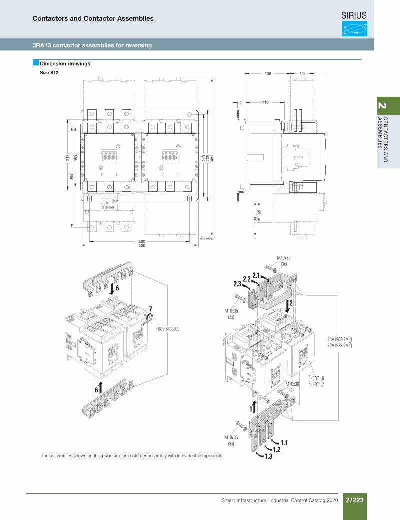
SIRIUS
Smart Infrastructure, Industrial Control Catalog 2020 2/223
2Co
nta
Ctors a
nd
a
ssemb
lies
RA-00944
6
6
7
3RA1953-2A
7201
0-A
R
3RA1963-2A 1)3RA1973-2A 2)
a72010-AR
2
2.3 2.2 2.1
1
M10x35(3x)
1.31.2
1.1
M10x35(3x)
M10x30(3x)
M10x30(3x)
1) 3RT1.62) 3RT1.7
Size S12
Dimension drawings
The assemblies shown on this page are for customer assembly with individual components.
Contactors and Contactor Assemblies
3RA13 contactor assemblies for reversing
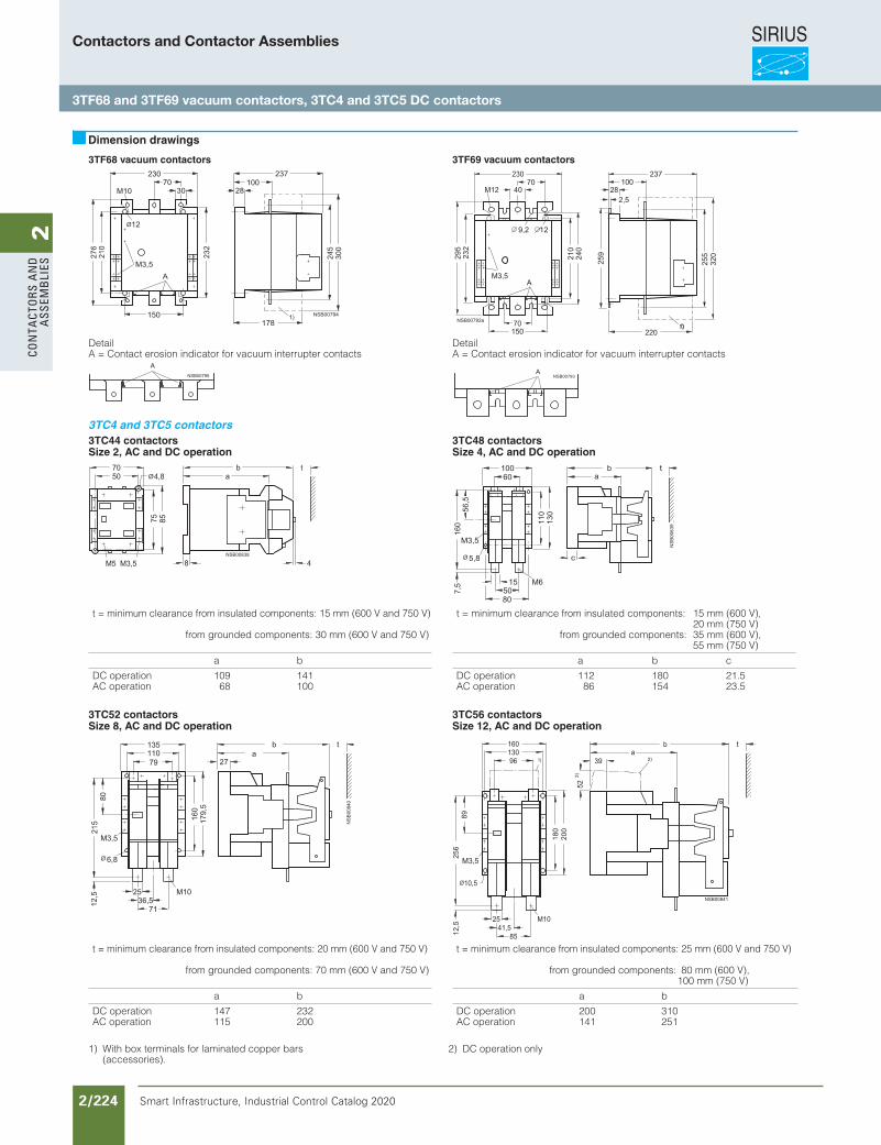
SIRIUS
Smart Infrastructure, Industrial Control Catalog 2020 2/224
2Co
nta
Cto
rs a
nd
a
ssem
bli
es
3TF68 vacuum contactors 3TF69 vacuum contactors
DetailA = Contact erosion indicator for vacuum interrupter contacts
DetailA = Contact erosion indicator for vacuum interrupter contacts
3TC4 and 3TC5 contactors3TC44 contactorsSize 2, AC and DC operation
3TC48 contactorsSize 4, AC and DC operation
3TC52 contactorsSize 8, AC and DC operation
3TC56 contactorsSize 12, AC and DC operation
Dimension drawings
t = minimum clearance from insulated components: 15 mm (600 V and 750 V)
from grounded components: 30 mm (600 V and 750 V)
a b
DC operationAC operation
10968
141100
t = minimum clearance from insulated components: 15 mm (600 V),20 mm (750 V)
from grounded components: 35 mm (600 V),55 mm (750 V)
a b c
DC operationAC operation
11286
180154
21.523.5
2
2
t = minimum clearance from insulated components: 20 mm (600 V and 750 V)
from grounded components: 70 mm (600 V and 750 V)
a b
DC operationAC operation
147115
232200
t = minimum clearance from insulated components: 25 mm (600 V and 750 V)
from grounded components: 80 mm (600 V),100 mm (750 V)
a b
DC operationAC operation
200141
310251
1) With box terminals for laminated copper bars (accessories).
2) DC operation only
Contactors and Contactor Assemblies
3TF68 and 3TF69 vacuum contactors, 3TC4 and 3TC5 DC contactors
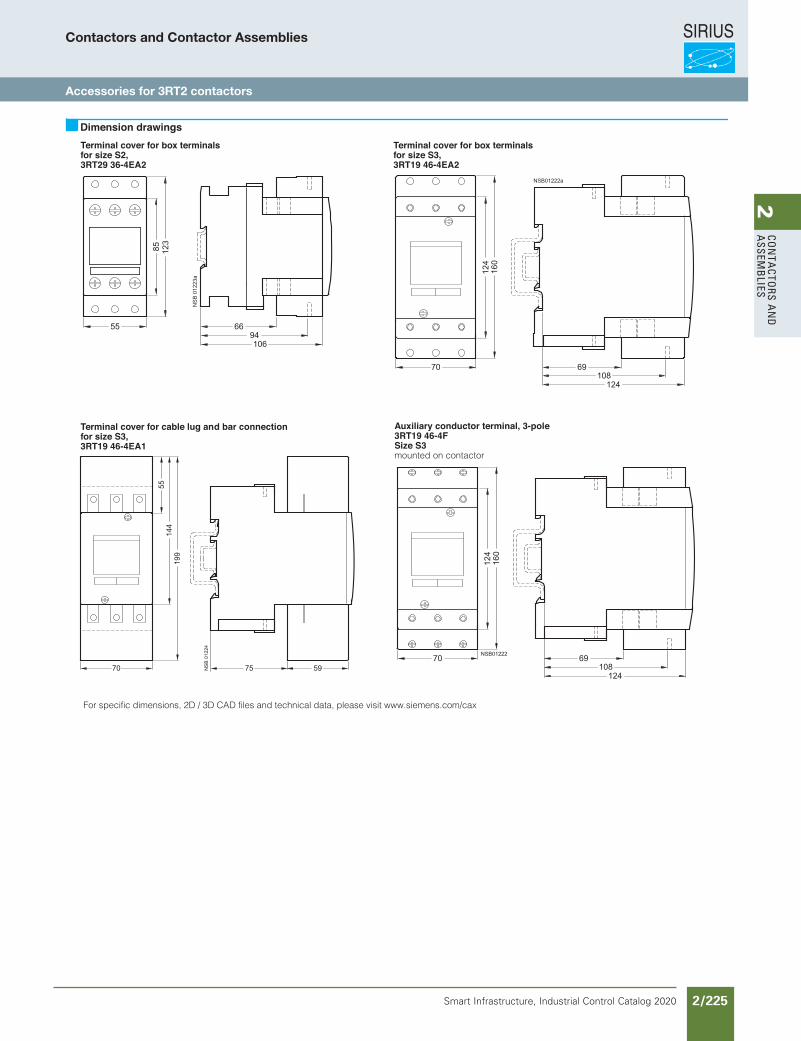
SIRIUS
Smart Infrastructure, Industrial Control Catalog 2020 2/225
2Co
nta
Ctors a
nd
a
ssemb
lies
Terminal cover for box terminals for size S2, 3RT29 36-4EA2
Terminal cover for box terminals for size S3, 3RT19 46-4EA2
Terminal cover for cable lug and bar connection for size S3, 3RT19 46-4EA1
Dimension drawings
Auxiliary conductor terminal, 3-pole3RT19 46-4FSize S3mounted on contactor
For specific dimensions, 2D / 3D CAD files and technical data, please visit www.siemens.com/cax
Contactors and Contactor Assemblies
Accessories for 3RT2 contactors
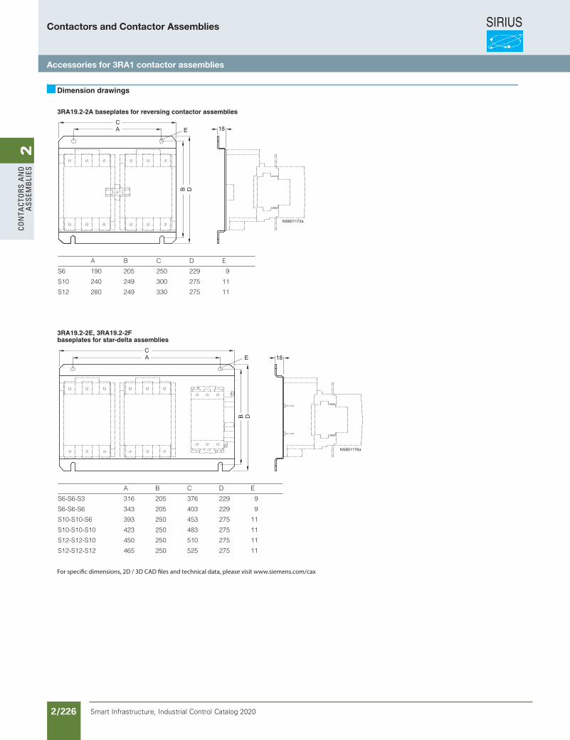
SIRIUS
Smart Infrastructure, Industrial Control Catalog 2020 2/226
2Co
nta
Cto
rs a
nd
a
ssem
bli
es
3RA19.2-2A baseplates for reversing contactor assemblies
3RA19.2-2E, 3RA19.2-2Fbaseplates for star-delta assemblies
Dimension drawings
A B C D E
S6 190 205 250 229 9
S10 240 249 300 275 11
S12 280 249 330 275 11
A B C D E
S6-S6-S3 316 205 376 229 9
S6-S6-S6 343 205 403 229 9
S10-S10-S6 393 250 453 275 11
S10-S10-S10 423 250 483 275 11
S12-S12-S10 450 250 510 275 11
S12-S12-S12 465 250 525 275 11
For specic dimensions, 2D / 3D CAD les and technical data, please visit www.siemens.com/cax
Contactors and Contactor Assemblies
Accessories for 3RA1 contactor assemblies
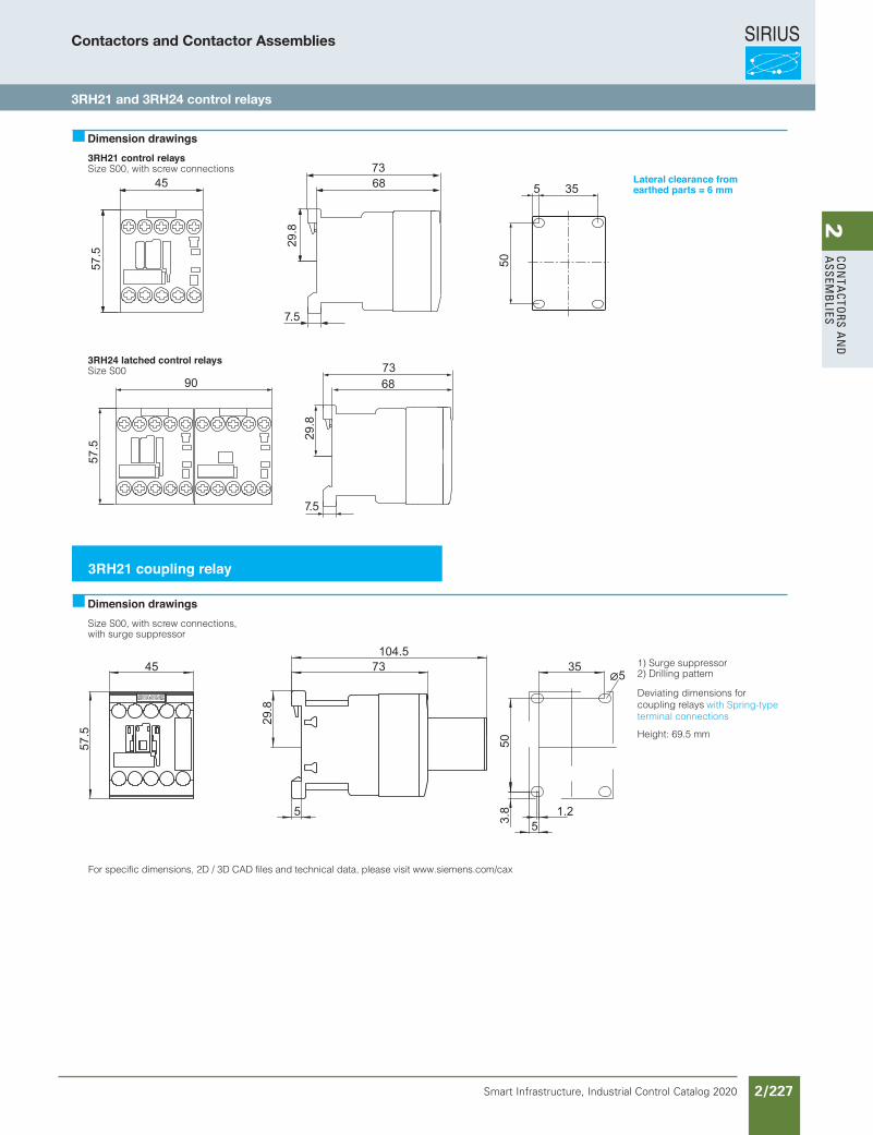
SIRIUS
Smart Infrastructure, Industrial Control Catalog 2020 2/227
2Co
nta
Ctors a
nd
a
ssemb
lies
3RH21 control relaysSize S00, with screw connections
3RH24 latched control relaysSize S00
Size S00, with screw connections,with surge suppressor
1) Surge suppressor2) Drilling pattern
Deviating dimensions forcoupling relays
Height: 69.5 mm
Dimension drawings
s
Dimension drawings
For specific dimensions, 2D / 3D CAD files and technical data, please visit www.siemens.com/cax
50
355
45
57.5
29.8
5
35
50
5
3.8 1.2
5
7390
73
68
7.5
73104.5
29.8
57.5
Lateral clearance fromearthed parts = 6 mm
3RH21 coupling relay
terminal connections with Spring-type
Contactors and Contactor Assemblies
3RH21 and 3RH24 control relays
SIRIUS
Smart Infrastructure, Industrial Control Catalog 2020 2/228
2Co
nta
Cto
rs a
nd
a
ssem
bli
esContactors and Contactor Assemblies
Notes