configuring panasonic ns1000 2 - psn-web.net
TRANSCRIPT
Setup Reference guide for KX-NS1000
Version 4.22 Firmware
“iHub” SIP Trunk service
(with Built-in Router)
Version 1.0(PSCEU) 29.October, 2015
2
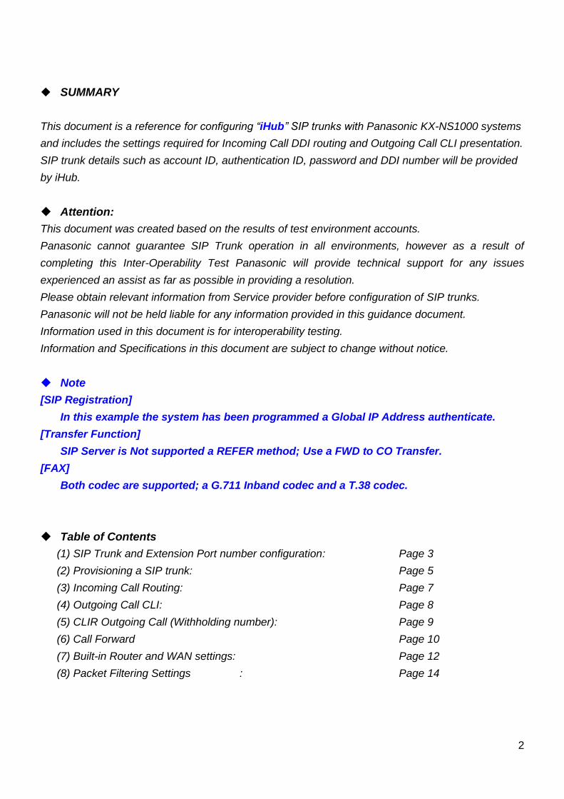
SUMMARY
This document is a reference for configuring “iHub” SIP trunks with Panasonic KX-NS1000 systems
and includes the settings required for Incoming Call DDI routing and Outgoing Call CLI presentation.
SIP trunk details such as account ID, authentication ID, password and DDI number will be provided
by iHub.
Attention:
This document was created based on the results of test environment accounts.
Panasonic cannot guarantee SIP Trunk operation in all environments, however as a result of
completing this Inter-Operability Test Panasonic will provide technical support for any issues
experienced an assist as far as possible in providing a resolution.
Please obtain relevant information from Service provider before configuration of SIP trunks.
Panasonic will not be held liable for any information provided in this guidance document.
Information used in this document is for interoperability testing.
Information and Specifications in this document are subject to change without notice.
Note
[SIP Registration]
In this example the system has been programmed a Global IP Address authenticate.
[Transfer Function]
SIP Server is Not supported a REFER method; Use a FWD to CO Transfer.
[FAX]
Both codec are supported; a G.711 Inband codec and a T.38 codec.
Table of Contents
(1) SIP Trunk and Extension Port number configuration: Page 3
(2) Provisioning a SIP trunk: Page 5
(3) Incoming Call Routing: Page 7
(4) Outgoing Call CLI: Page 8
(5) CLIR Outgoing Call (Withholding number): Page 9
(6) Call Forward Page 10
(7) Built-in Router and WAN settings: Page 12
(8) Packet Filtering Settings : Page 14
3
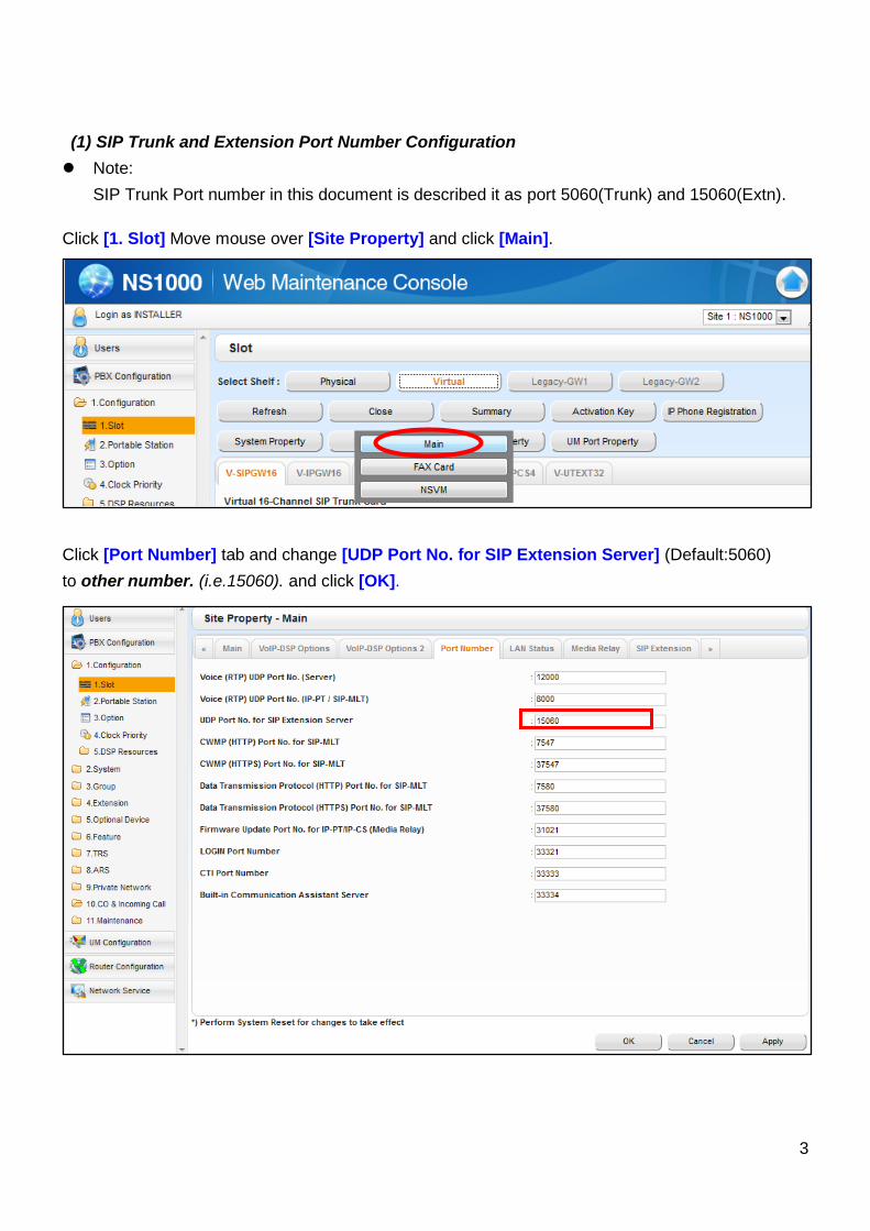
(1) SIP Trunk and Extension Port Number Configuration
Note:
SIP Trunk Port number in this document is described it as port 5060(Trunk) and 15060(Extn).
Click [1. Slot] Move mouse over [Site Property] and click [Main].
Click [Port Number] tab and change [UDP Port No. for SIP Extension Server] (Default:5060)
to other number. (i.e.15060). and click [OK].
4
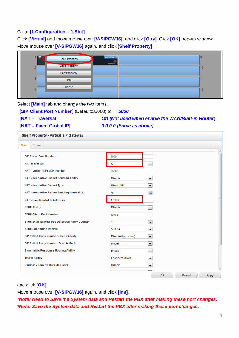
Go to [1.Configuration – 1.Slot]
Click [Virtual] and move mouse over [V-SIPGW16], and click [Ous]. Click [OK] pop-up window.
Move mouse over [V-SIPGW16] again, and click [Shelf Property].
Select [Main] tab and change the two items.
[SIP Client Port Number] (Default:35060) to 5060
[NAT – Traversal] Off (Not used when enable the WAN/Built-in Router)
[NAT – Fixed Global IP] 0.0.0.0 (Same as above)
and click [OK].
Move mouse over [V-SIPGW16] again, and click [Ins].
*Note: Need to Save the System data and Restart the PBX after making these port changes.
*Note: Save the System data and Restart the PBX after making these port changes.
5
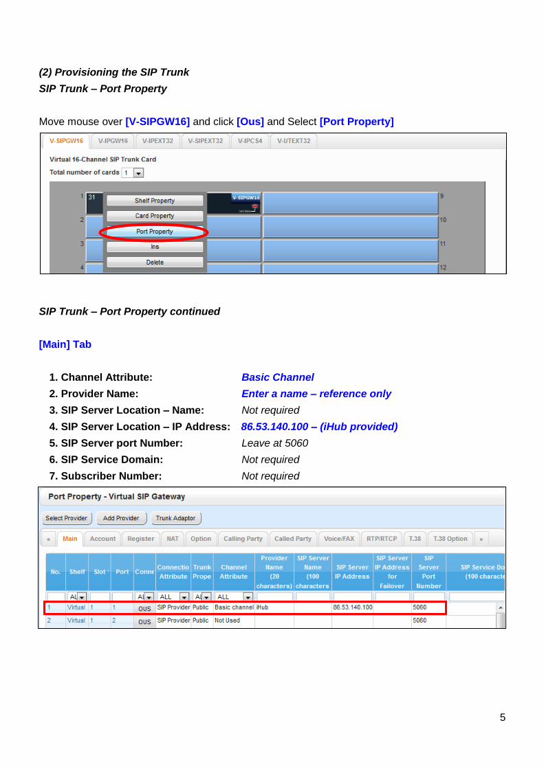
(2) Provisioning the SIP Trunk
SIP Trunk – Port Property
Move mouse over [V-SIPGW16] and click [Ous] and Select [Port Property]
SIP Trunk – Port Property continued
[Main] Tab
1. Channel Attribute: Basic Channel
2. Provider Name: Enter a name – reference only
3. SIP Server Location – Name: Not required
4. SIP Server Location – IP Address: 86.53.140.100 – (iHub provided)
5. SIP Server port Number: Leave at 5060
6. SIP Service Domain: Not required
7. Subscriber Number: Not required
6
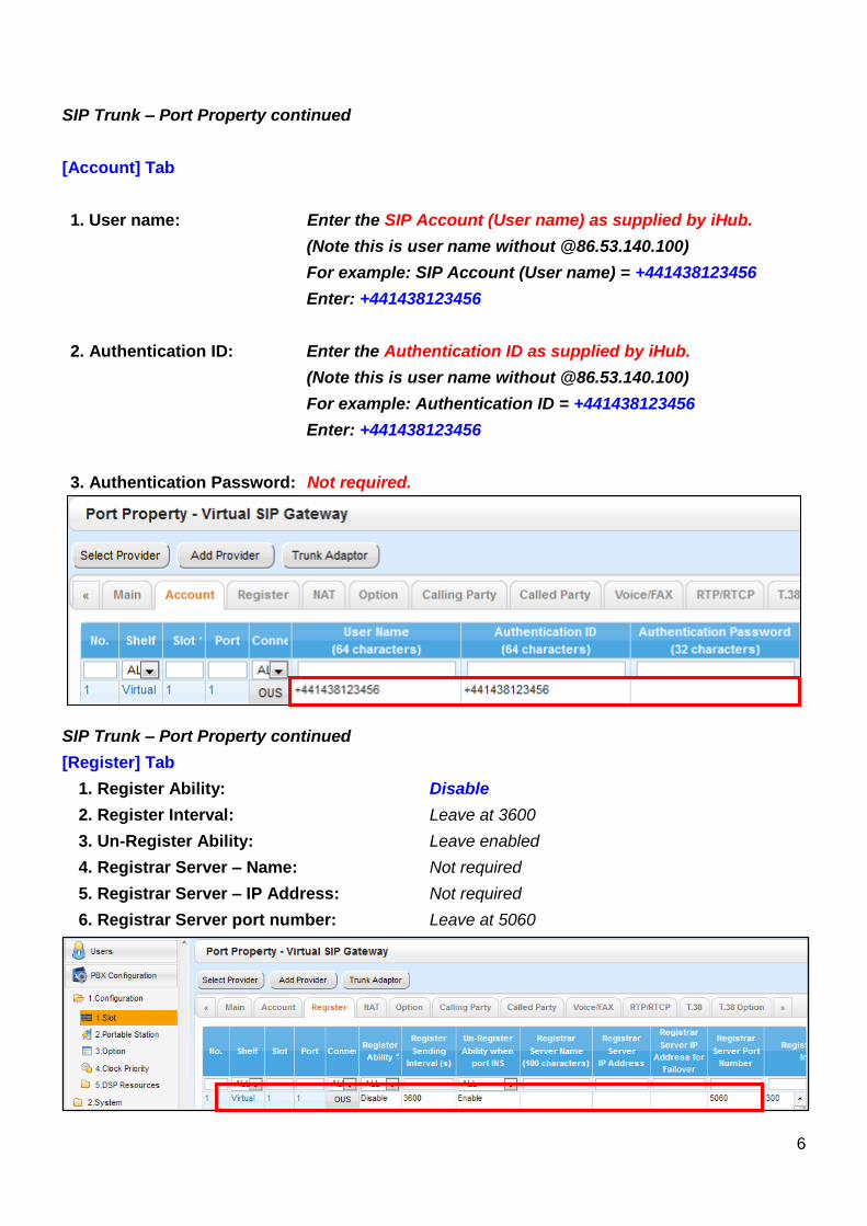
SIP Trunk – Port Property continued
[Account] Tab
1. User name: Enter the SIP Account (User name) as supplied by iHub.
(Note this is user name without @86.53.140.100)
For example: SIP Account (User name) = +441438123456
Enter: +441438123456
2. Authentication ID: Enter the Authentication ID as supplied by iHub.
(Note this is user name without @86.53.140.100)
For example: Authentication ID = +441438123456
Enter: +441438123456
3. Authentication Password: Not required.
SIP Trunk – Port Property continued
[Register] Tab
1. Register Ability: Disable
2. Register Interval: Leave at 3600
3. Un-Register Ability: Leave enabled
4. Registrar Server – Name: Not required
5. Registrar Server – IP Address: Not required
6. Registrar Server port number: Leave at 5060
7
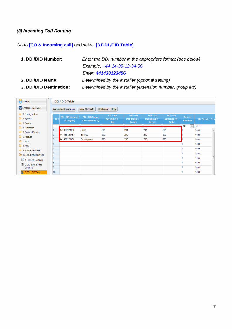
(3) Incoming Call Routing
Go to [CO & Incoming call] and select [3.DDI /DID Table]
1. DDI/DID Number: Enter the DDI number in the appropriate format (see below)
Example: +44-14-38-12-34-56
Enter: 441438123456
2. DDI/DID Name: Determined by the installer (optional setting)
3. DDI/DID Destination: Determined by the installer (extension number, group etc)
8
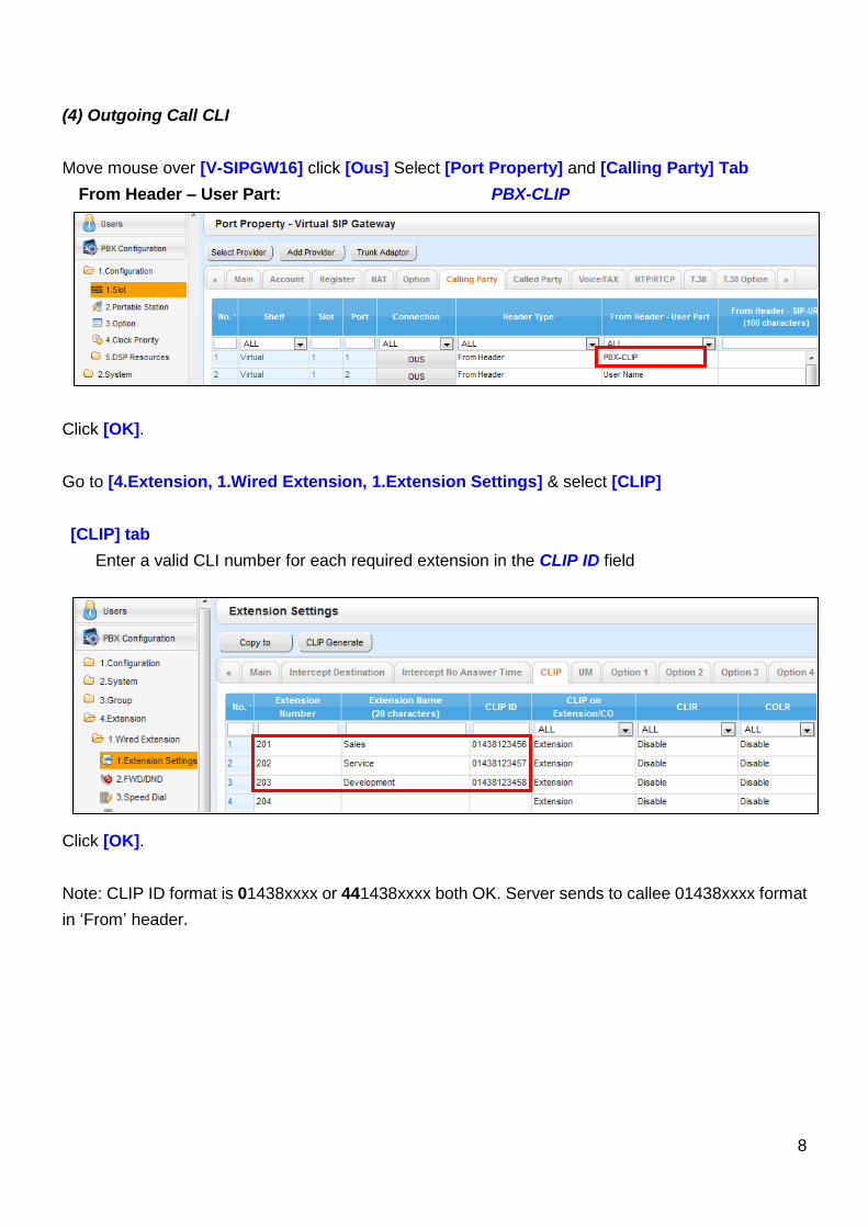
(4) Outgoing Call CLI
Move mouse over [V-SIPGW16] click [Ous] Select [Port Property] and [Calling Party] Tab
From Header – User Part: PBX-CLIP
Click [OK].
Go to [4.Extension, 1.Wired Extension, 1.Extension Settings] & select [CLIP]
[CLIP] tab
Enter a valid CLI number for each required extension in the CLIP ID field
Click [OK].
Note: CLIP ID format is 01438xxxx or 441438xxxx both OK. Server sends to callee 01438xxxx format
in ‘From’ header.
9
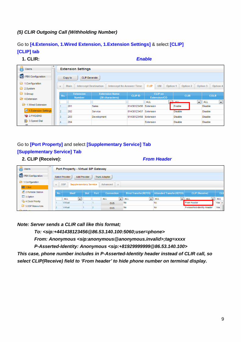
(5) CLIR Outgoing Call (Withholding Number)
Go to [4.Extension, 1.Wired Extension, 1.Extension Settings] & select [CLIP]
[CLIP] tab
1. CLIR: Enable
Go to [Port Property] and select [Supplementary Service] Tab
[Supplementary Service] Tab
2. CLIP (Receive): From Header
Note: Server sends a CLIR call like this format;
To: <sip:[email protected]:5060;user=phone>
From: Anonymous <sip:[email protected]>;tag=xxxx
P-Asserted-Identity: Anonymous <sip:[email protected]>
This case, phone number includes in P-Asserted-Identity header instead of CLIR call, so
select CLIP(Receive) field to ‘From header’ to hide phone number on terminal display.
10
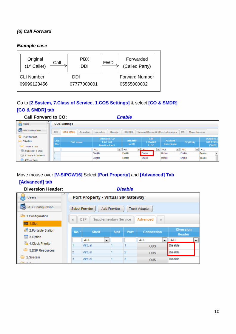
(6) Call Forward
Example case
Go to [2.System, 7.Class of Service, 1.COS Settings] & select [CO & SMDR]
[CO & SMDR] tab
Call Forward to CO: Enable
Move mouse over [V-SIPGW16] Select [Port Property] and [Advanced] Tab
[Advanced] tab
Diversion Header: Disable
Call FWD
CLI Number DDI Forward Number
09999123456 07777000001 05555000002
Original
(1st Caller)
PBX
DDI
Forwarded
(Called Party)
11
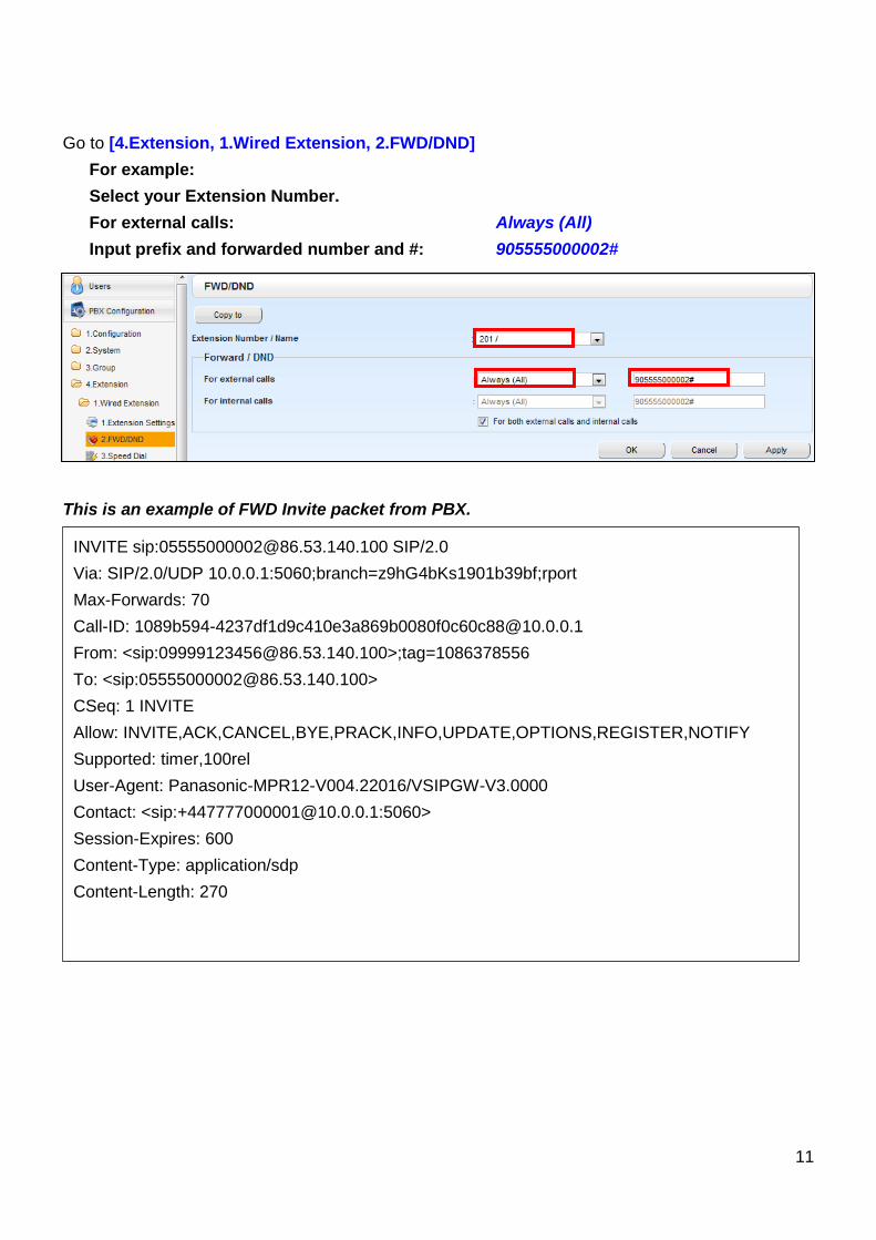
INVITE sip:[email protected] SIP/2.0
Via: SIP/2.0/UDP 10.0.0.1:5060;branch=z9hG4bKs1901b39bf;rport
Max-Forwards: 70
Call-ID: [email protected]
From: <sip:[email protected]>;tag=1086378556
To: <sip:[email protected]>
CSeq: 1 INVITE
Allow: INVITE,ACK,CANCEL,BYE,PRACK,INFO,UPDATE,OPTIONS,REGISTER,NOTIFY
Supported: timer,100rel
User-Agent: Panasonic-MPR12-V004.22016/VSIPGW-V3.0000
Contact: <sip:[email protected]:5060>
Session-Expires: 600
Content-Type: application/sdp
Content-Length: 270
Go to [4.Extension, 1.Wired Extension, 2.FWD/DND]
For example:
Select your Extension Number.
For external calls: Always (All)
Input prefix and forwarded number and #: 905555000002#
This is an example of FWD Invite packet from PBX.
12
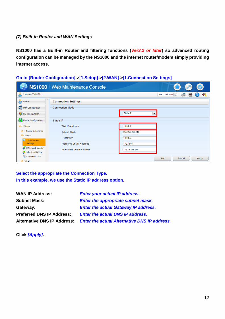
(7) Built-in Router and WAN Settings
NS1000 has a Built-in Router and filtering functions (Ver3.2 or later) so advanced routing
configuration can be managed by the NS1000 and the internet router/modem simply providing
internet access.
Go to [Router Configuration]->[1.Setup]->[2.WAN]->[1.Connection Settings]
Select the appropriate the Connection Type.
In this example, we use the Static IP address option.
WAN IP Address: Enter your actual IP address.
Subnet Mask: Enter the appropriate subnet mask.
Gateway: Enter the actual Gateway IP address.
Preferred DNS IP Address: Enter the actual DNS IP address.
Alternative DNS IP Address: Enter the actual Alternative DNS IP address.
Click [Apply].
13
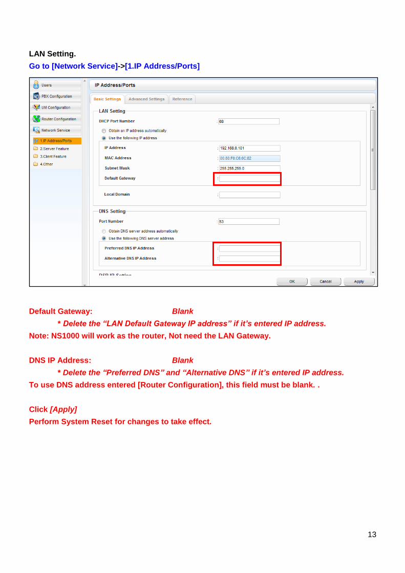
LAN Setting.
Go to [Network Service]->[1.IP Address/Ports]
Default Gateway: Blank
* Delete the “LAN Default Gateway IP address” if it’s entered IP address.
Note: NS1000 will work as the router, Not need the LAN Gateway.
DNS IP Address: Blank
* Delete the “Preferred DNS” and “Alternative DNS” if it’s entered IP address.
To use DNS address entered [Router Configuration], this field must be blank. .
Click [Apply]
Perform System Reset for changes to take effect.
14
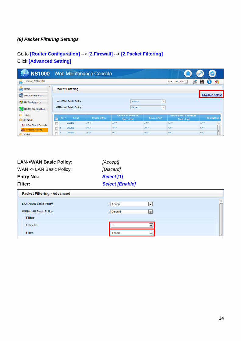
(8) Packet Filtering Settings
Go to [Router Configuration] --> [2.Firewall] --> [2.Packet Filtering]
Click [Advanced Setting]
LAN->WAN Basic Policy: [Accept]
WAN -> LAN Basic Policy: [Discard]
Entry No.: Select [1]
Filter: Select [Enable]
15
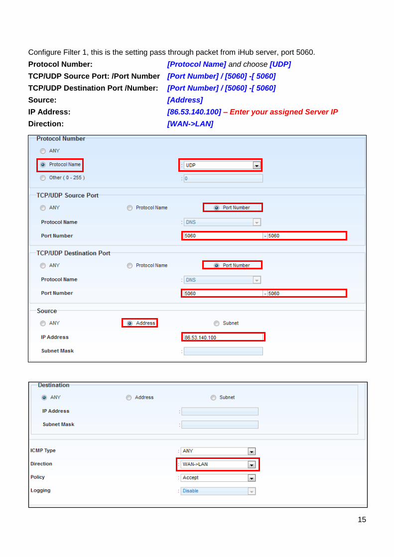
Configure Filter 1, this is the setting pass through packet from iHub server, port 5060.
Protocol Number: [Protocol Name] and choose [UDP]
TCP/UDP Source Port: /Port Number [Port Number] / [5060] -[ 5060]
TCP/UDP Destination Port /Number: [Port Number] / [5060] -[ 5060]
Source: [Address]
IP Address: [86.53.140.100] – Enter your assigned Server IP
Direction: [WAN->LAN]
16
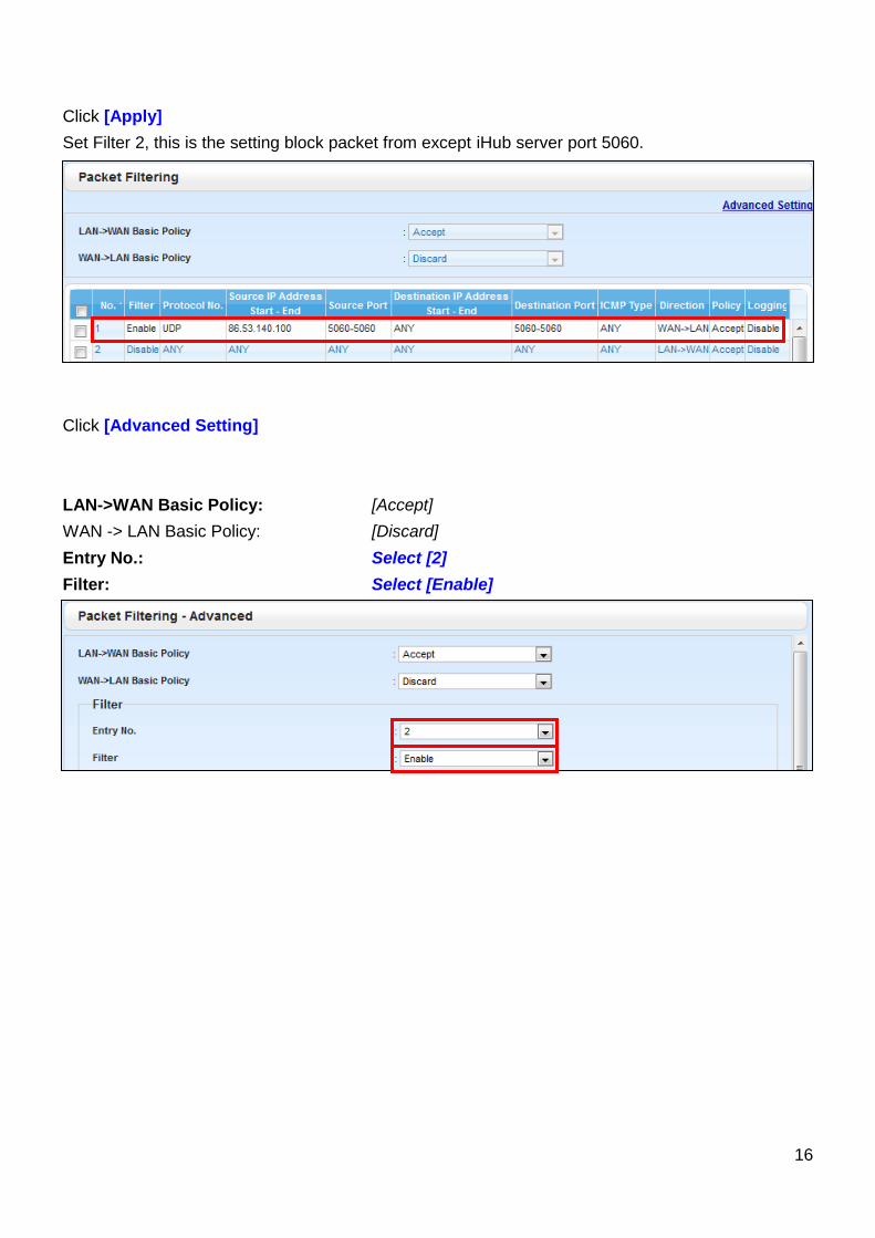
Click [Apply]
Set Filter 2, this is the setting block packet from except iHub server port 5060.
Click [Advanced Setting]
LAN->WAN Basic Policy: [Accept]
WAN -> LAN Basic Policy: [Discard]
Entry No.: Select [2]
Filter: Select [Enable]
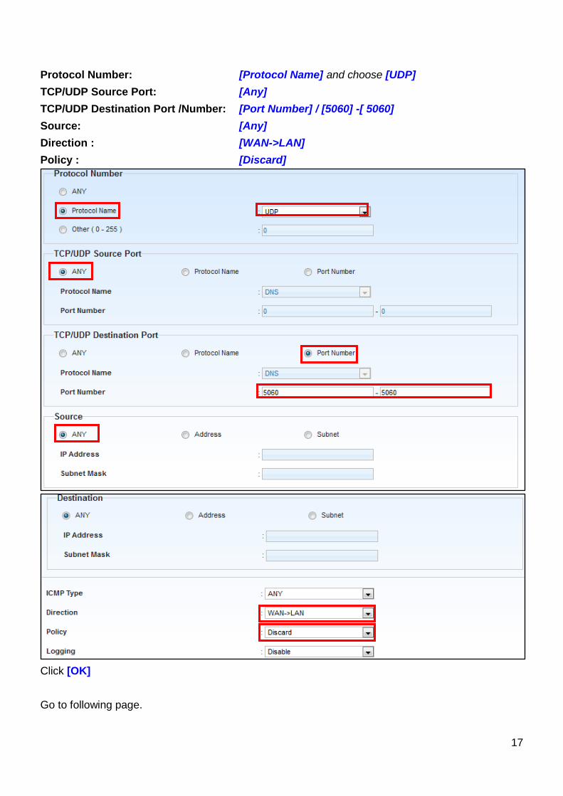
17
Protocol Number: [Protocol Name] and choose [UDP]
TCP/UDP Source Port: [Any]
TCP/UDP Destination Port /Number: [Port Number] / [5060] -[ 5060]
Source: [Any]
Direction : [WAN->LAN]
Policy : [Discard]
Click [OK]
Go to following page.
18
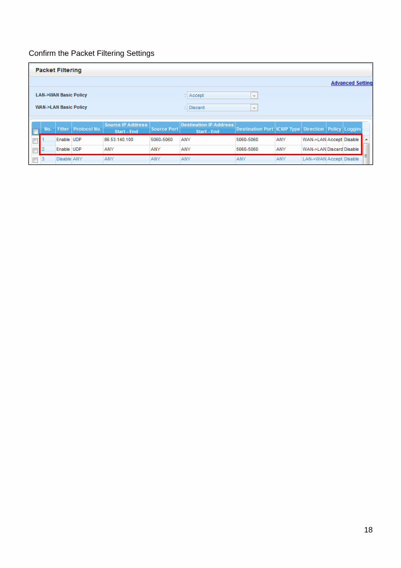
Confirm the Packet Filtering Settings