conductors and electrical connections - "modular electronics
TRANSCRIPT
Modular Electronics Learning (ModEL)project
v1 1 0 dc 12
v2 2 1 dc 15
r1 2 3 4700
r2 3 0 7100
.end
* SPICE ckt
V = I R
.dc v1 12 12 1
.print dc v(2,3)
.print dc i(v2)
Conductors and Electrical Connections
c© 2017-2022 by Tony R. Kuphaldt – under the terms and conditions of theCreative Commons Attribution 4.0 International Public License
Last update = 15 March 2022
This is a copyrighted work, but licensed under the Creative Commons Attribution 4.0 InternationalPublic License. A copy of this license is found in the last Appendix of this document. Alternatively,you may visit http://creativecommons.org/licenses/by/4.0/ or send a letter to CreativeCommons: 171 Second Street, Suite 300, San Francisco, California, 94105, USA. The terms andconditions of this license allow for free copying, distribution, and/or modification of all licensedworks by the general public.

ii

Contents
1 Introduction 3
2 Simplified Tutorial 5
3 Full Tutorial 73.1 Making and breaking connections . . . . . . . . . . . . . . . . . . . . . . . . . . . . . 93.2 Connection resistance . . . . . . . . . . . . . . . . . . . . . . . . . . . . . . . . . . . 103.3 Wire size and type . . . . . . . . . . . . . . . . . . . . . . . . . . . . . . . . . . . . . 133.4 Permanent connections . . . . . . . . . . . . . . . . . . . . . . . . . . . . . . . . . . . 15
3.4.1 Mechanical splicing . . . . . . . . . . . . . . . . . . . . . . . . . . . . . . . . . 163.4.2 Wire nuts . . . . . . . . . . . . . . . . . . . . . . . . . . . . . . . . . . . . . . 183.4.3 Solder . . . . . . . . . . . . . . . . . . . . . . . . . . . . . . . . . . . . . . . . 193.4.4 Wire wrap . . . . . . . . . . . . . . . . . . . . . . . . . . . . . . . . . . . . . . 243.4.5 Compression connectors . . . . . . . . . . . . . . . . . . . . . . . . . . . . . . 253.4.6 Terminal blocks . . . . . . . . . . . . . . . . . . . . . . . . . . . . . . . . . . . 28
3.5 Temporary connections . . . . . . . . . . . . . . . . . . . . . . . . . . . . . . . . . . 333.5.1 Alligator clips . . . . . . . . . . . . . . . . . . . . . . . . . . . . . . . . . . . . 343.5.2 Solderless breadboards . . . . . . . . . . . . . . . . . . . . . . . . . . . . . . . 353.5.3 Plugs and sockets . . . . . . . . . . . . . . . . . . . . . . . . . . . . . . . . . . 363.5.4 Banana plugs and jacks . . . . . . . . . . . . . . . . . . . . . . . . . . . . . . 39
4 Derivations and Technical References 414.1 Derivation of electron drift velocity . . . . . . . . . . . . . . . . . . . . . . . . . . . . 424.2 Table of specific resistance values . . . . . . . . . . . . . . . . . . . . . . . . . . . . . 44
5 Animations 455.1 Using a soldering iron . . . . . . . . . . . . . . . . . . . . . . . . . . . . . . . . . . . 46
6 Questions 816.1 Conceptual reasoning . . . . . . . . . . . . . . . . . . . . . . . . . . . . . . . . . . . . 85
6.1.1 Reading outline and reflections . . . . . . . . . . . . . . . . . . . . . . . . . . 866.1.2 Foundational concepts . . . . . . . . . . . . . . . . . . . . . . . . . . . . . . . 876.1.3 Switch contact size . . . . . . . . . . . . . . . . . . . . . . . . . . . . . . . . . 886.1.4 Why use gold plating? . . . . . . . . . . . . . . . . . . . . . . . . . . . . . . . 89
iii

CONTENTS 1
6.1.5 Diagnostic thermal imaging . . . . . . . . . . . . . . . . . . . . . . . . . . . . 906.1.6 Soldering iron usage . . . . . . . . . . . . . . . . . . . . . . . . . . . . . . . . 916.1.7 Battery-lamp-switch circuit on a solderless breadboard . . . . . . . . . . . . . 92
6.2 Quantitative reasoning . . . . . . . . . . . . . . . . . . . . . . . . . . . . . . . . . . . 936.2.1 Miscellaneous physical constants . . . . . . . . . . . . . . . . . . . . . . . . . 946.2.2 Introduction to spreadsheets . . . . . . . . . . . . . . . . . . . . . . . . . . . 956.2.3 Power losses over wires . . . . . . . . . . . . . . . . . . . . . . . . . . . . . . . 986.2.4 Siemens model 3AP1/2 high-voltage circuit breaker . . . . . . . . . . . . . . 1006.2.5 Resistance of copper busbar . . . . . . . . . . . . . . . . . . . . . . . . . . . . 101
6.3 Diagnostic reasoning . . . . . . . . . . . . . . . . . . . . . . . . . . . . . . . . . . . . 1026.3.1 Testing for a broken connection . . . . . . . . . . . . . . . . . . . . . . . . . . 1036.3.2 Improper breadboard use . . . . . . . . . . . . . . . . . . . . . . . . . . . . . 106
A Problem-Solving Strategies 109
B Instructional philosophy 111
C Tools used 117
D Creative Commons License 121
E References 129
F Version history 131
Index 132

2 CONTENTS

Chapter 1
Introduction
An essential step in constructing any electrical circuit is to make connections between componentterminals (i.e. the metal tabs on components) and wires (i.e. conductors used to convey electricalcharge carriers from one circuit component to another). A variety of methods exist to do this, eachwith its own set of advantages and disadvantages. This module describes many of these methodsand seeks to explain why each method works as it does.
Important concepts related to electrical connections includes the motion of charge carriersthrough conductors, switch action, wire resistance, opens versus shorts, wire gauge and area,safety standards, Joule’s Law, solid versus stranded wire, wire splicing, soldering, plugs andjacks, and printed circuit boards.
Here are some good questions to ask of yourself while studying this subject:
• What universal properties do all “sound” electrical connections share?
• What factors determine the end-to-end electrical resistance of a wire?
• What determines the current-carrying capacity of a wire?
• What type of wire must be used with compression-style connectors, and why?
• How come there are so many different ways to connect wires together?
• How is wire size measured?
• How do solid and stranded wire types compare with each other?
• Why do metal wires offer resistance to the flow of electric charge carriers?
• Why does air and other gases offer great resistance to the flow of electric charge carriers?
• What are the advantages and disadvantages of various connection methods?
• How do terminal blocks function?
• How does solder work to form an electrical connection between conductors?
3

4 CHAPTER 1. INTRODUCTION
• What is a printed circuit board (PCB) and how do they work?
• How are electrical connections made between components using a solderless breadboard?
• What are some of the limitations of a solderless breadboard?
Chapter 2
Simplified Tutorial
Electric circuits are formed by connecting wires and components with each other in specificconfigurations. Effective electrical connections are reliable and of low resistance to minimize energydissipation and excessive heating as charge carriers pass through. Electrical connections are made bybringing the surfaces of electrical conductors into tight physical contact with each other. The idealelectrical connection has maximum area of contact with minimum length, for minimum resistance.
Electrically conductive materials are rated for their resistive properties by a quantity calledspecific resistance. All other factors being equal, a material having less specific resistance will be abetter conductor of electricity than a material having more specific resistance.
End-to-end conductor resistance is a function of cross-sectional area, length, and specificresistance. The cross-sectional area of a wire may be expressed by a wire gauge number (withsmaller numbers representing larger-area wire) or alternatively by units of area (e.g. circular mils).The ampacity of a wire is the maximum continuous current it may carry without exceeding prescribedtemperature limits.
Wire is manufactured in both solid and stranded forms, with stranded having superior flexibility.
Permanent electrical connections may be formed in several different ways:
• Wire splices (twisting wire-ends together)
• Wire nuts (a device used to augment a pigtail splice)
• Wire wrap (thin-gauge wire wrapped around square metal pegs)
• Compression connectors (thin-gauge flat metal wrapped and compressed onto a wire’s end)
• Terminal blocks (screw- or spring-fastened clamp onto a wire’s end)
• Solder (low-temperature welding of two or more wires)
A popular format for the construction of low-power circuits is the printed circuit board (PCB)which uses conductive copper pathways laid onto an insulating fiberglass substrate, componentstypically attached to those copper traces by soldering.
5

6 CHAPTER 2. SIMPLIFIED TUTORIAL
Several methods also exist to temporarily form electrical connections:
• Alligator clips (spring-loaded clamps)
• Solderless breadboards (plastic boards with tiny spring-clips for insertion of terminals)
• Plugs and sockets
Chapter 3
Full Tutorial
All atoms contains even smaller bits of matter called particles. Some of these particles possess anelectrical charge, which means they experience a force when exposed to an electric field. Electrically-charged subatomic particles are found in two fundamental types: some of them negative and otherspositive.
Electricity is the study of mobile electric charges, and the exchange of energy by those movingcharges. Some substances easily permit electric charges to move within them, and we refer to thesesubstances as conductors of electricity. Other substances lack mobile electric charges, and we callthese substances insulators of electricity. The degree to which electric charges are impeded frommoving within a substance is called electrical resistance.
The amount of energy either gained or lost by a mobile charge between two different locations iscalled voltage, and is measured in the unit of the Volt (one Volt being equal to one Joule of energyper Coulomb1 of electric charges). The rate of motion for electric charges through a conductor iscalled current, and is measured in the unit of the Ampere (one Ampere being equal to one Coulombof electric charges passing by a point per second of time).
Metals are the most common group of conductors used to construct electric circuits, becausethe molecular structure of any metal is such that the outer-most electrons of its constituent atomsare free to leave those atoms and drift in the space between adjacent atoms. This makes electronsthe predominant form of charge carrier2 within metals, because these negatively-charged electronsare free to move within the solid volume of the metal. Within some non-metallic conductors, suchas liquids, both negatively charged electrons and positively charged atomic nuclei are free to driftthrough the bulk of the material which means there are two types of charge carriers (drifting inopposite directions when exposed to an electric field).
The particular type(s) of charge carrier(s) within any particular conductor is usually of littleimportance in the construction of an electric circuit. What matters for the existence of a complete
1A “Coulomb” is a rather large number of electric charges: 6.2415 × 10¹⁸ to be exact.2A charge carrier is any bit of mobile matter possessing a net electrical charge. Electrically charged subatomic
particles are charge carriers if they exist in a state where they may move when exposed to an electric field. Muchlarger pieces of matter may also serve as charge carriers if possessing a net electrical charge and free to move, suchas a whole atom or molecule that is either missing electrons or in possession of extra electrons and in a liquid orgaseous state. Even macroscopic objects may serve as charge carriers provided they meet the criteria of possessing anet electrical charge as well as mobility. For example, a latex balloon that is rubbed against a wool shirt to give it anelectrical charge is technically a charge carrier if it is then set aloft to float in a direction directed by an electric field!
7

8 CHAPTER 3. FULL TUTORIAL
circuit3 is that the conductive path is unbroken by any insulating gaps; i.e. a circuit demands acontinuous path exist to support charge carrier motion.
3A circuit is defined as a loop through which charge carriers may travel endlessly.

3.1. MAKING AND BREAKING CONNECTIONS 9
3.1 Making and breaking connections
The act of joining two or more conductors together so as to form a continuous path for chargecarrier motion between them is called making an electrical connection. In essence, this consists ofbringing the conductive materials together in direct contact with each other, so that no air gapsexist between. Air, like most gases at room temperature and atmospheric pressure, is an electricalinsulator. The electrically charged particles within each molecule of air are opposite in charge andequal in number so that each air molecule has zero net electrical charge. Unlike metals, where theconstituent atoms and molecules are packed closely together and electrons may freely drift between,the molecules comprising gases are spaced far apart from each other and their electrons are rathertightly bound to the nuclei. Therefore, any air gap between metallic conductors will serve as animpassable4 chasm preventing charge carrier motion.
For example, an electrical connection may be made between two metal wires by simply touchingthe bare metal ends of each wire together. Once direct metal-to-metal contact is made between thetwo wires, electrons from one wire may cross over into the metal of the other wire. Separating thosetwo metal wires creates an insulating air gap between them once more, thus breaking the connection.This is precisely how an electrical switch functions: a pair of metal “contact points” are broughtinto direct contact with each other to “close” or “make” or “short” the switch, and then separatedfrom each other to “open” or “break” the switch.
Open switch
wire wire wire wire
Closed (shorted) switch
A B BA
"Open" = points A and B are electrically isolated "Shorted" = points A and B are electrically commonand therefore no current may pass between them and therefore no voltage may exist between them
Electrical connections may also be made and broken between conductors of different substancesby direct physical contact and separation, respectively, between those substances. For example, anelectrical connection may be made between a metal wire and a body of saltwater by immersingthe wire’s end in the saltwater. Removing the wire from the water breaks the electrical connectionbetween them.
Likewise, substances other than air may separate two conductors from having direct contactwith each other. Some electrical switches, for example, designed for high-power applications usecontact points immersed in non-conductive oil which is a more effective5 electrical insulator thanair. Electrical connections between two pieces of metal may become broken by the accumulation ofinsulating corrosion6 on the metal surfaces, which is a common way that electrical connections fail.
4It should be noted that air may become ionized and therefore electrically conductive, but only by vastly elevatingits temperature and/or exposing it to intense electric fields.
5These electrical oils have a greater breakdown voltage than air, which means a stronger electrical field is requiredto ionize the oil molecules and thus render it conductive than for air.
6“Corrosion” is a general term describing any product of chemical reaction between the substrate metal and itsenvironment.
10 CHAPTER 3. FULL TUTORIAL
3.2 Connection resistance
The amount of contact area between two connected conductors is an important factor influencingthe electrical resistance of that connection. To understand why this is, it is necessary to explore thenature of electrical resistance within a conductor. As stated previously, conductors are substancespossessing mobile electric charges within their structure. The plain fact that the charges are mobile,however, does not mean they are free to move without impediment at all. The bulk of an electricalconductor is not a wide-open conduit for charge carriers to flow as one might suspect, but moreof an obstacle course in which the charge carriers frequently collide with stationary atoms as theymove through the conductor.
When a moving charge carrier collides with a stationary atom within the volume of a conductivesubstance, the kinetic energy of that charge carrier becomes translated into vibratory motion of theatom (i.e. the temperature7 of the solid increases). Thus, charge carrier collisions result in energybeing dissipated in the form of heat. This is why metal wires become warmer when conductingelectric current. After each collision robs a charge carrier of kinetic energy, it begins to pick upvelocity again until it collides with another atom within the conductor.
As charge carriers move at higher velocity, their collisions become more violent, dissipatinggreater levels of energy per collision. Therefore, the amount of voltage drop (i.e. energy lost percharge carrier) along a conductor’s length increases as a function of current. This phenomenon iscodified as Ohm’s Law, where voltage (V ) is equal to the product of current (I) and resistance (R):V = IR.
Suppose we pass a given amount of current through a conductor that is twice as long as before,but with all other characteristics (e.g. metal type, temperature, cross-sectional area) remaining thesame. Those charge carriers will now encounter on average twice as many collisions as before becausethe “obstacle course” is now twice as long, and therefore each charge carrier will lose twice as muchenergy as it did traversing the shorter conductor. This means that the voltage drop will be doublebetween the ends of a conductor that is twice as long, all other factors being equal. Stated moresimply: resistance is directly proportional to length.
Suppose now we modify the conductor so that it has the same length as before, but twice thecross-sectional area (i.e. a wider conductor). Widening the conductor will have the effect of slowingdown the charge carriers’ drift velocity8 for any given amount of current, just as water in a river slowswhenever the river’s dimensions widen or deepen. Slower drift velocity means less violent collisions,which translates into less energy loss per collision. Thus, a conductor with twice the cross-sectionalarea will generate half the voltage drop from end to end as before. Stated more simply: resistance
is inversely proportional to cross-sectional area.
At first it may seem as though length and area are characteristics of the conductors themselvesand not the connections between them. However, connections definitely have their own length andarea: if an intermediate material is used to join two other conductors together, that intermediatepiece’s length contributes to the connection’s resistance. Likewise, the contact area between twoconductors represents the aperture through which charge carriers must pass from one conductor to
7Temperature is really just the random motion of atoms and molecules within a substance. The greater a sample’stemperature, the faster its constituent atoms are moving!
8It is interesting to note that the drift velocity of electrons within a metal conductor is quite slow. To see amathematical exploration of electron drift velocity, refer to page 42 of the Derivations and Technical Referencessection 4.1.
3.2. CONNECTION RESISTANCE 11
the other, and so the amount of area shared between two conductors in contact with each other alsocontributes to the resistance of that connection.
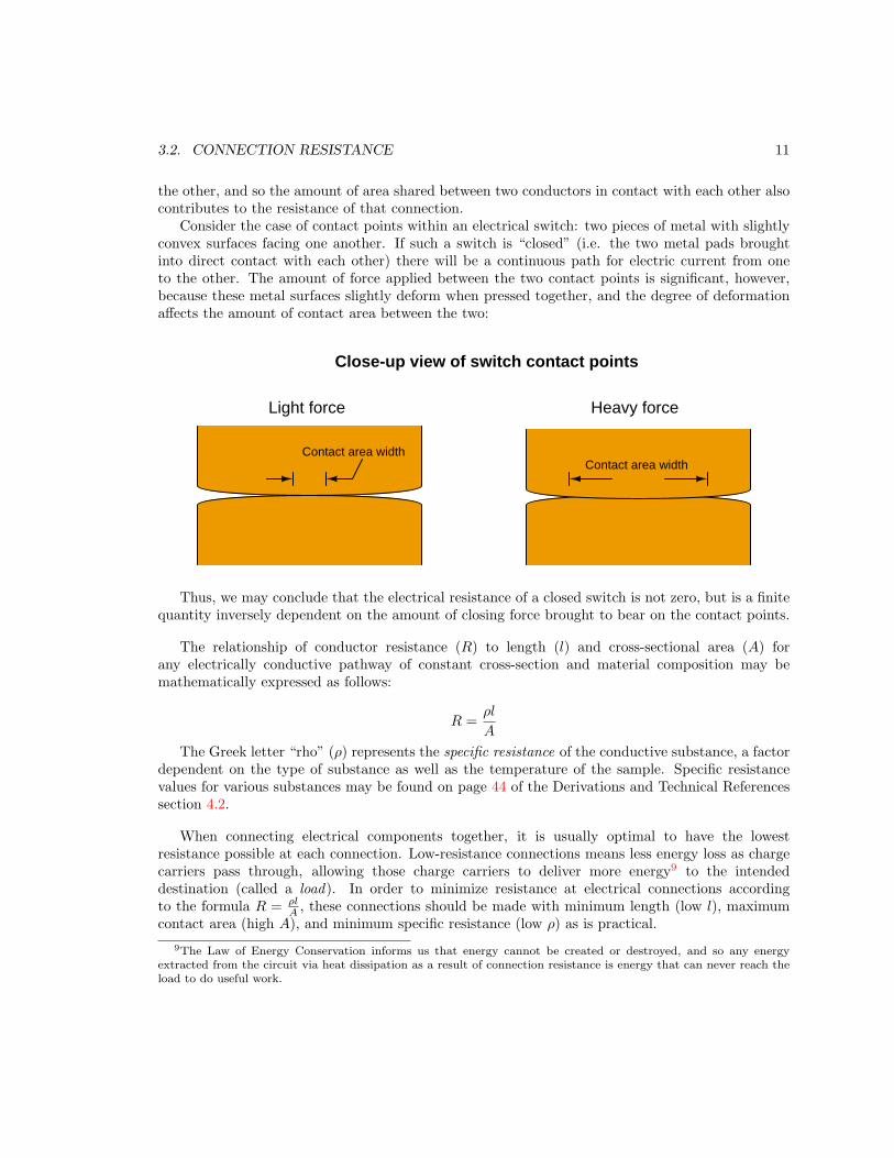
Consider the case of contact points within an electrical switch: two pieces of metal with slightlyconvex surfaces facing one another. If such a switch is “closed” (i.e. the two metal pads broughtinto direct contact with each other) there will be a continuous path for electric current from oneto the other. The amount of force applied between the two contact points is significant, however,because these metal surfaces slightly deform when pressed together, and the degree of deformationaffects the amount of contact area between the two:
Close-up view of switch contact points
Light force Heavy force
Contact area widthContact area width
Thus, we may conclude that the electrical resistance of a closed switch is not zero, but is a finitequantity inversely dependent on the amount of closing force brought to bear on the contact points.
The relationship of conductor resistance (R) to length (l) and cross-sectional area (A) forany electrically conductive pathway of constant cross-section and material composition may bemathematically expressed as follows:
R =ρl
A
The Greek letter “rho” (ρ) represents the specific resistance of the conductive substance, a factordependent on the type of substance as well as the temperature of the sample. Specific resistancevalues for various substances may be found on page 44 of the Derivations and Technical Referencessection 4.2.
When connecting electrical components together, it is usually optimal to have the lowestresistance possible at each connection. Low-resistance connections means less energy loss as chargecarriers pass through, allowing those charge carriers to deliver more energy9 to the intendeddestination (called a load). In order to minimize resistance at electrical connections accordingto the formula R = ρl
A, these connections should be made with minimum length (low l), maximum
contact area (high A), and minimum specific resistance (low ρ) as is practical.
9The Law of Energy Conservation informs us that energy cannot be created or destroyed, and so any energyextracted from the circuit via heat dissipation as a result of connection resistance is energy that can never reach theload to do useful work.

12 CHAPTER 3. FULL TUTORIAL
Bear these factors in mind as we explore the various techniques of making electrical connections.When assessing the integrity of an electrical connection (i.e. minimal electrical resistance R), thesefactors all play significant roles. Choosing the best connection type to use in any circumstance isa matter of assessing how well these factors will be optimized for that application, as well as otherfactors such as cost and convenience.
3.3. WIRE SIZE AND TYPE 13
3.3 Wire size and type
Metal wires intended for use as electrical conductors are rated according to their cross-sectionalarea. The common electrical wire sizing system used within the United States is the American Wire
Gauge (AWG), which is a number inversely proportional10 to the wire’s cross-sectional area. Forexample, a #10 AWG wire has a greater diameter and thus greater cross-sectional area than a #14AWG wire. Other gauge systems exist for expressing wire size, including the British Standard Wire
Gauge (SWG) used for electrical wire in Canada and England and the Steel Music Wire Gauge usedto measure steel string sizes for musical instruments.
Very large electrical wires use an altogether different method of sizing called circular mils. A“mil” is 1
1000of an inch, and a circular mil is the area of a wire with a circular cross-section having a
diameter of 1 mil (0.001 inch). Since circular mils are fundamentally an expression of two-dimensionalarea rather than one-dimensional distance, the relationship between wire diameter in mils and wirearea in circular mils is quadratic:
A = d2
Where,A = Wire cross-sectional area in circular milsd = Wire diameter in linear mils
For example, a round wire having a diameter of 0.75 inch could be expressed as having a diameterof 750 mils, and an area of 562,500 circular mils. In order to more conveniently express large numbervalues commonly associated with circular mil area figures, the Roman numeral “M” (representingone thousand) is often used in a manner not unlike the metric prefix “kilo” (k). So, a wire size of562,500 circular mils would be more commonly expressed as 562.5 MCM, where “MCM” stands for“thousands of circular mils”.
As previously explained, the cross-sectional area of a wire inversely affects its electrical resistance:the more area a conductor has, the less resistance it will exhibit for any given length and materialtype following the formula R = ρl
A. Conductors of low resistance are generally desirable because
they convey charge carriers with a minimum of energy loss (i.e. voltage drop) which allows fordelivery of more energy to the load(s) and less energy dissipated in the form of heat along theconductors. Conductor heating is also a safety concern, as wires may become hot enough to melttheir insulation, and/or ignite nearby flammable materials. The ampacity of a wire is the maximumamount of current a wire can handle without exceeding safe temperature limits.
10“Gauge” scales tend to exhibit this inverse proportionality. The gauge scale used to rate thickness of sheet metalis like this, with larger gauge numbers representing thinner sheet. Shotgun barrel diameter is also expressed by aninverse gauge scale: a 20 gauge shotgun has a smaller barrel diameter than a 12 gauge shotgun.

14 CHAPTER 3. FULL TUTORIAL
A wire’s ampacity is fundamentally a function of three factors: (1) the rate of heat dissipated bythe electric current passing through that wire based on wire resistance (by Joule’s Law P = I2R),(2) the wire’s ability to shed heat to the surrounding environment, and (3) the high-temperaturelimit of the wire’s insulation. Heat dissipation, of course, is directly related to the amount of currentand the wire’s resistance which is a function of gauge (cross-sectional area) and the type of metal(e.g. copper versus aluminum). Heat shedding is related to the outer surface area of the insulatedconductor as well as the material(s) it contacts. For this reason, wires buried in earth or suspendedalone in open air have greater ampacity ratings than wires bundled together in an enclosed raceway(e.g. conduit, wire duct). This means wire ampacity varies with the manner in which it is installedas well as its structure and composition.
Electrical safety standards documents contain conservatively-rated ampacity values for variouswire sizes, insulation types, and arrangements. In the United States, the National Fire ProtectionAssociation (NFPA) is well-respected for its electrical safety standards, including NFPA 70 (National
Electrical Code, or NEC ) and NFPA 79 (Electrical Standard for Industrial Machinery). Article 310of the National Electrical Code (“Conductors for General Wiring”) specifies wire ampacities forresidential, commercial, and industrial power distribution systems. Chapter 12 within the NFPA 79standard (“Conductors, Cables, and Flexible Cords”) specifies wire ampacities for electrical wiringwithin industrial machinery.
Conductors used for small electrical and electronic projects are typically much smaller (i.e. higherAmerican Wire Gauge number) than those specified in Article 310 of the National Electrical Codebecause the NEC focuses on facility power wiring. NFPA 79, with its focus on the internal wiringof machinery, specifies characteristics of wires over a wider range than the NEC. The followingtable summarizes some of the NFPA 79 specifications for smaller-gauge single copper conductors,assuming single conductors in free air attaining a temperature of no more than 60 oC:
AWG size Cross-sectional area Resistance per 1000 ft Ampacity
24 gauge – – – – – – – – 2 Amperes
22 gauge 0.324 mm2 17.2 Ω @ 25 oC 3 Amperes
20 gauge 0.519 mm2 10.7 Ω @ 25 oC 5 Amperes
18 gauge 0.823 mm2 6.77 Ω @ 25 oC 7 Amperes
16 gauge 1.31 mm2 4.26 Ω @ 25 oC 10 Amperes
14 gauge 2.08 mm2 2.68 Ω @ 25 oC 15 Amperes
12 gauge 3.31 mm2 1.68 Ω @ 25 oC 20 Amperes
10 gauge 5.261 mm2 1.060 Ω @ 25 oC 30 Amperes
3.4. PERMANENT CONNECTIONS 15
The resistance of copper wire at room temperature may be approximated based on the gauge ofthe wire using the following formula:
R1000ft = e0.232G−2.32
Where,
R1000ft = Approximate wire resistance in Ohms per 1000 feet of wire length
G = American Wire Gauge (AWG) number of the wire
#10 AWG copper wire exhibits approximately 1 Ohm of electrical resistance per 1000 feet oflength at room temperature. Increasing the gauge number by 3 approximately doubles a conductor’sresistance.
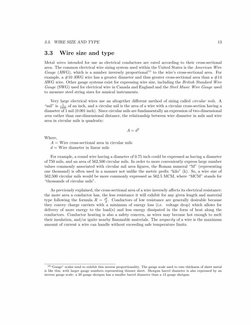
Wires may be constructed of solid wire, or alternatively as bundles of smaller solid strands. Solidwire is less expensive to manufacture, but is rather stiff and will break if repeatedly bent. Strandedwire costs more to manufacture, but is much more flexible. Comparative end-views of each wiretype are shown in the following illustration:
Solid wire Stranded wire
The degree of flexibility for any given gauge of wire depends on the size of the individual strands:the smaller (finer) the strands, the more flexible the wire. Gauge and circular mil sizing of strandedelectrical wire is based on total cross-sectional area. Thus, a #10 AWG stranded wire will havethe exact same cross-sectional area, and therefore the same electrical resistance per unit length, asa #10 AWG solid wire made of the same metal even though the #10 AWG stranded wire will beslightly larger in diameter than a #10 AWG solid wire.
The choice of solid versus stranded electrical wire is an important factor when selecting anappropriate connection type. Some connections only work well with solid wire, and others only withstranded. Some connection types work equally well with either solid or stranded wire.
3.4 Permanent connections
Electrical connections are formed by bringing conductive materials in direct physical contact witheach other. Tight solid-to-solid contact is essential in order that there be no air between theconductive surfaces, since air is electrically insulating under most conditions. The ideal electricalconnection has maximum contact area.
Some electrical connections are intended to be permanent, or at least potentially permanent evenif it is possible to intentionally break the connection. The following subsections describe various waysto permanently connect electrical conductors to each other.
16 CHAPTER 3. FULL TUTORIAL
3.4.1 Mechanical splicing
Solid wire is stiff enough that two or more pieces may be twisted together to form a permanentelectrical connection. The twisted form provides both a large contact area between the conductorsto ensure low resistance as well as mechanical strength to resist disconnection by stress or vibration.
A splice may be thought of as a knot, except for electrical wire instead of rope or string. Splicesgenerally do not work well for stranded wire, as the wire is too flexible to maintain its twisted shapewhen subjected to mechanical stress.
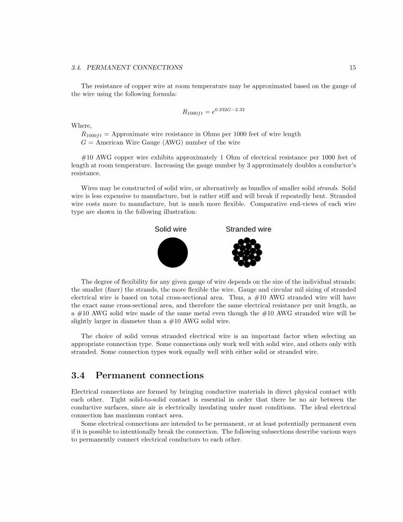
A type of wire splice developed during the era of the telegraph, intended to provide both robustmechanical and electrical connectivity is the Western Union splice. This splice is illustrated here inthree steps:
The design of this particular splice is such that any external tension applied to it brings the twomutually-coiled conductors in closer contact with each other.
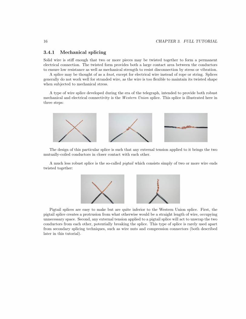
A much less robust splice is the so-called pigtail which consists simply of two or more wire endstwisted together:
Pigtail splices are easy to make but are quite inferior to the Western Union splice. First, thepigtail splice creates a protrusion from what otherwise would be a straight length of wire, occupyingunnecessary space. Second, any external tension applied to a pigtail splice will act to unwrap the twoconductors from each other, potentially breaking the splice. This type of splice is rarely used apartfrom secondary splicing techniques, such as wire nuts and compression connectors (both describedlater in this tutorial).
3.4. PERMANENT CONNECTIONS 17
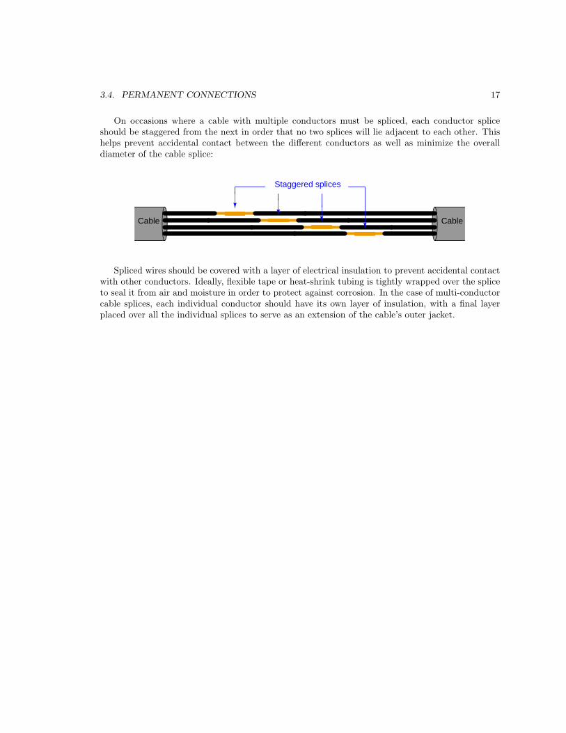
On occasions where a cable with multiple conductors must be spliced, each conductor spliceshould be staggered from the next in order that no two splices will lie adjacent to each other. Thishelps prevent accidental contact between the different conductors as well as minimize the overalldiameter of the cable splice:
Cable Cable
Staggered splices
Spliced wires should be covered with a layer of electrical insulation to prevent accidental contactwith other conductors. Ideally, flexible tape or heat-shrink tubing is tightly wrapped over the spliceto seal it from air and moisture in order to protect against corrosion. In the case of multi-conductorcable splices, each individual conductor should have its own layer of insulation, with a final layerplaced over all the individual splices to serve as an extension of the cable’s outer jacket.
18 CHAPTER 3. FULL TUTORIAL
3.4.2 Wire nuts
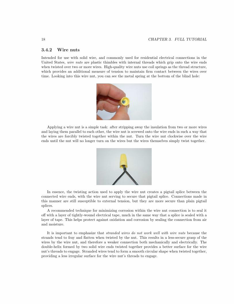
Intended for use with solid wire, and commonly used for residential electrical connections in theUnited States, wire nuts are plastic thimbles with internal threads which grip onto the wire endswhen twisted over two or more wires. High-quality wire nuts use coil springs as the thread structure,which provides an additional measure of tension to maintain firm contact between the wires overtime. Looking into this wire nut, you can see the metal spring at the bottom of the blind hole:
Applying a wire nut is a simple task: after stripping away the insulation from two or more wiresand laying them parallel to each other, the wire nut is screwed onto the wire ends in such a way thatthe wires are forcibly twisted together within the nut. Turn the wire nut clockwise over the wireends until the nut will no longer turn on the wires but the wires themselves simply twist together.
In essence, the twisting action used to apply the wire nut creates a pigtail splice between theconnected wire ends, with the wire nut serving to secure that pigtail splice. Connections made inthis manner are still susceptible to external tension, but they are more secure than plain pigtailsplices.
A recommended technique for minimizing corrosion within the wire nut connection is to seal itoff with a layer of tightly-wound electrical tape, much in the same way that a splice is sealed with alayer of tape. This helps protect against oxidation and corrosion by sealing the connection from airand moisture.
It is important to emphasize that stranded wires do not work well with wire nuts because thestrands tend to fray and flatten when twisted by the nut. This results in a less-secure grasp of thewires by the wire nut, and therefore a weaker connection both mechanically and electrically. Thedouble-helix formed by two solid wire ends twisted together provides a better surface for the wirenut’s threads to engage. Stranded wires tend to form a smooth circular shape when twisted together,providing a less irregular surface for the wire nut’s threads to engage.
3.4. PERMANENT CONNECTIONS 19
3.4.3 Solder
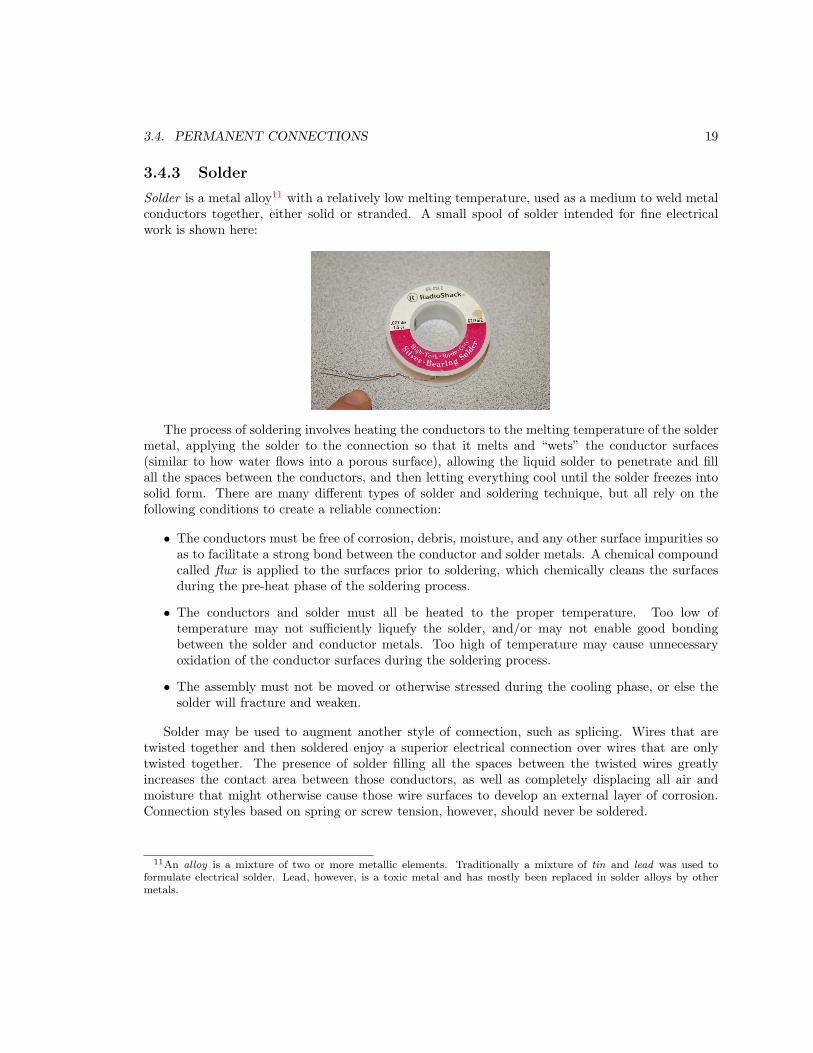
Solder is a metal alloy11 with a relatively low melting temperature, used as a medium to weld metalconductors together, either solid or stranded. A small spool of solder intended for fine electricalwork is shown here:
The process of soldering involves heating the conductors to the melting temperature of the soldermetal, applying the solder to the connection so that it melts and “wets” the conductor surfaces(similar to how water flows into a porous surface), allowing the liquid solder to penetrate and fillall the spaces between the conductors, and then letting everything cool until the solder freezes intosolid form. There are many different types of solder and soldering technique, but all rely on thefollowing conditions to create a reliable connection:
• The conductors must be free of corrosion, debris, moisture, and any other surface impurities soas to facilitate a strong bond between the conductor and solder metals. A chemical compoundcalled flux is applied to the surfaces prior to soldering, which chemically cleans the surfacesduring the pre-heat phase of the soldering process.
• The conductors and solder must all be heated to the proper temperature. Too low oftemperature may not sufficiently liquefy the solder, and/or may not enable good bondingbetween the solder and conductor metals. Too high of temperature may cause unnecessaryoxidation of the conductor surfaces during the soldering process.
• The assembly must not be moved or otherwise stressed during the cooling phase, or else thesolder will fracture and weaken.
Solder may be used to augment another style of connection, such as splicing. Wires that aretwisted together and then soldered enjoy a superior electrical connection over wires that are onlytwisted together. The presence of solder filling all the spaces between the twisted wires greatlyincreases the contact area between those conductors, as well as completely displacing all air andmoisture that might otherwise cause those wire surfaces to develop an external layer of corrosion.Connection styles based on spring or screw tension, however, should never be soldered.
11An alloy is a mixture of two or more metallic elements. Traditionally a mixture of tin and lead was used toformulate electrical solder. Lead, however, is a toxic metal and has mostly been replaced in solder alloys by othermetals.
20 CHAPTER 3. FULL TUTORIAL
A photograph showing a pigtail splice augmented with solder appears here:
It should be clear from this photograph how the solder has filled the spaces between the twotwisted wire ends, thereby greatly increasing the amount of surface area connecting the two wirestogether. The metallic bonding between the copper wire and the solder alloy also greatly strengthensthe splice and prevents corrosion by positively displacing all air and moisture from reaching thecopper wire surfaces.
Soldering does not produce as strong a bond as welding (where the substrate metals are heatedto the point of liquification and subsequent fusion), and so care should be taken to not stress thesoldered connection any more than necessary. Ideally, a mechanical connection between conductorsis formed prior to the application of solder, so that the solder need not bear all mechanical stressplaced upon the connection. The example of the pigtail splice shown previously fulfills this criterion:the twisting of the two copper wires provides substantial mechanical integrity even without the solderin place.
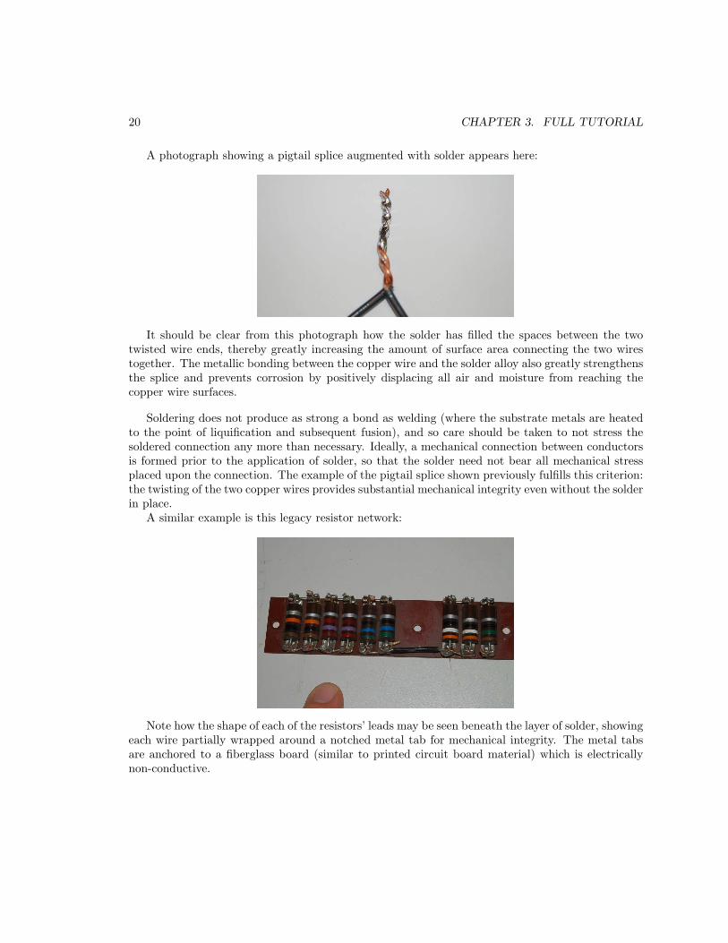
A similar example is this legacy resistor network:
Note how the shape of each of the resistors’ leads may be seen beneath the layer of solder, showingeach wire partially wrapped around a notched metal tab for mechanical integrity. The metal tabsare anchored to a fiberglass board (similar to printed circuit board material) which is electricallynon-conductive.

3.4. PERMANENT CONNECTIONS 21
Printed Circuit Boards, or PCBs, use solder as the sole form of attachment between conductorsand components. The board itself is formed of layered fiberglass12, with conductive copper metaltraces laid down on the fiberglass surface in lieu of wires. Components connect to these traces bythe strength of solder joints between the component terminals and traces.
A front and back view of a simple PCB is shown here, using through-hole components where thecomponent wire leads are pushed through pre-drilled holes aligned with the copper traces. Solderapplied to each of these protruding leads bonds it to the respective copper trace, providing both anelectrical connection to the trace and a mechanical connection to the board:
PCBs begin as a fiberglass board with either one or both sides13 covered entirely by a sheet14
of copper. Traces are formed by selectively etching away all the unwanted copper using a powerfulliquid solvent such as hydrochloric acid or ammonium persulfate15, the placement of each desiredtrace marked by a substance which displaces acid and leaves the underlying copper untouched. Thelayout of traces on a PCB design is a process which may be done manually as in the case of the PCBshown above (as evidenced by the hand-drawn traces), or done using computer drafting software.Computer-based PCB design is highly recommended over “hand” layout, and is not complicated foranyone already accustomed to two-dimensional drafting (CAD) software such as AutoCAD.
12A very common fiberglass-based material for PCB construction is called FR4. It has a very high dielectricbreakdown strength of approximately 39 kilovolts per millimeter, with good mechanical properties as well.
13This is true for single-layer and double-layer boards. PCBs having more than two layers of tracing are comprisedof multiple boards individually etched and then layered together to make the final product.
14The thickness of this copper layer is typically measured in ounces of copper per square foot, with “1 ounce”
layering being very common.15This process obviously produces hazardous waste consisting of spent solvent and dissolved copper metal. In the
interest of minimizing the environmental impact of your PCB designs, I recommend laying out your PCBs so as toeliminate as little copper as possible. Unless constrained by other design criteria, make your traces wide to keep asmuch copper on the board as possible.

22 CHAPTER 3. FULL TUTORIAL
The simple hand-laid PCB shown previously consists of nothing but bare copper traces laidon fiberglass substrate. Most professional-quality PCBs come complete with additional layersof tinning on all traces (solder plating designed to minimize corrosion), soldermask (a syntheticcompound designed to displace molten solder) covering all the areas that should not be soldered,and silkscreening (ink used to create text and graphic labels on the board useful for assembly andtroubleshooting). A final layer of conformal coating may be applied to a PCB after all componentsand connecting wires are soldered in place, the purpose of which is to seal everything from exposureto air or moisture for superior resistance to corrosion.
A comparison of two PCBs is shown here, the one on the left consisting of just FR4 fiberglasswith tinned copper traces, and the one on the right also having a green layer of soldermask andlighter-colored silkscreened text:
The use of different-diameter holes and different-width traces is clearly evident on this PCB. Holediameter is important for a good fit with through-hole component leads and external connectingwires. The size of the copper “pad” surrounding a PCB hole determines the bonding strength ofthat pad to the fiberglass substrate, which is important for resisting stress from the wire soldered tothat hole. For maximum pad strength, double-layer PCBs may be used with pads on both sides ofthe board for each hole. PCBs manufactured in a professional “board shop” may have the interiorcircumference of the holes plated as well to form a continuous metal structure from one side of theboard to the other at each hole.
Note the six large holes on each of the PCBs previously shown: these are placed for the purposeof screws used to anchor the PCB to some other framework.
Trace width and trace thickness are additional parameters important to PCB design, togetherdetermining the effective cross-sectional area of each trace and therefore the current-carrying abilityof each trace (analogous to the gauge of an electrical wire). For standard 1-ounce copper laying,a surface trace 0.010 inch in width (10 “mils” or 10 “thou”) will have a resistivity of 0.052 Ohmsper linear inch, and should be sufficient to carry 1 Ampere of continuous current with a 10 degreesCelsius rise in temperature over ambient air. Traces between layers of fiberglass on a multi-layerPCB will have less ampacity than their surface counterparts because their ability to shed heat ismore limited.
Resistance decreases proportionately to trace width and trace thickness. For example, a trace 20mils in width for 1 ounce copper thickness will have half the resistivity of a 10-mil trace: 0.026 Ohmsper linear inch instead of 0.052 Ohms per inch. A trace with the same width (10 mils) but twice thethickness (2 ounce copper) will also have 0.026 Ohms per linear inch. Ampacity (current-carrying
3.4. PERMANENT CONNECTIONS 23
capacity) also scales with trace thickness, but not linearly because power dissipation is proportionalto the square of current in accordance with Joule’s Law (P = I2R). This means a trace four times
as thick is necessary to double ampacity for any given width. The relationship between trace widthand ampacity is even more complicated because a wider trace has less resistance and greater surfacearea to dissipate heat.
The need for more compact circuitry and smaller components led to the development of surface-
mount devices (SMDs) where no holes are drilled in the PCB, but instead each component isequipped with conductive tabs which are soldered directly to copper “pads” provided on the sameside of the PCB.
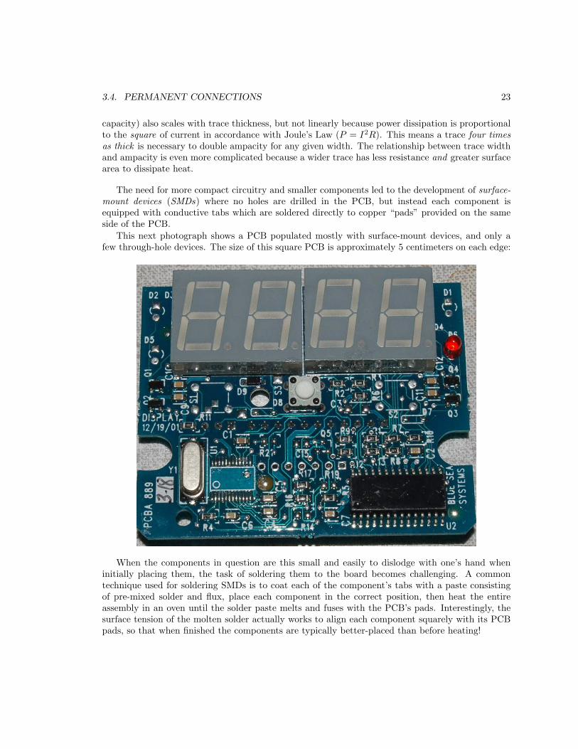
This next photograph shows a PCB populated mostly with surface-mount devices, and only afew through-hole devices. The size of this square PCB is approximately 5 centimeters on each edge:
When the components in question are this small and easily to dislodge with one’s hand wheninitially placing them, the task of soldering them to the board becomes challenging. A commontechnique used for soldering SMDs is to coat each of the component’s tabs with a paste consistingof pre-mixed solder and flux, place each component in the correct position, then heat the entireassembly in an oven until the solder paste melts and fuses with the PCB’s pads. Interestingly, thesurface tension of the molten solder actually works to align each component squarely with its PCBpads, so that when finished the components are typically better-placed than before heating!
24 CHAPTER 3. FULL TUTORIAL
3.4.4 Wire wrap
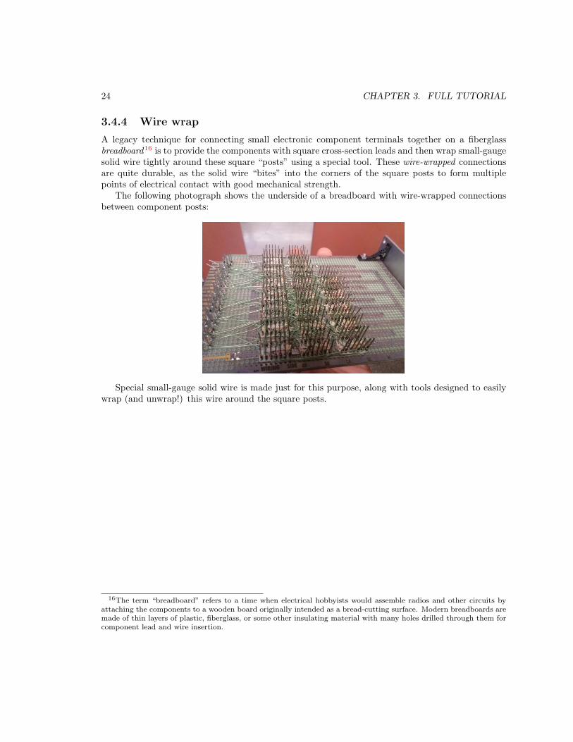
A legacy technique for connecting small electronic component terminals together on a fiberglassbreadboard16 is to provide the components with square cross-section leads and then wrap small-gaugesolid wire tightly around these square “posts” using a special tool. These wire-wrapped connectionsare quite durable, as the solid wire “bites” into the corners of the square posts to form multiplepoints of electrical contact with good mechanical strength.
The following photograph shows the underside of a breadboard with wire-wrapped connectionsbetween component posts:
Special small-gauge solid wire is made just for this purpose, along with tools designed to easilywrap (and unwrap!) this wire around the square posts.
16The term “breadboard” refers to a time when electrical hobbyists would assemble radios and other circuits byattaching the components to a wooden board originally intended as a bread-cutting surface. Modern breadboards aremade of thin layers of plastic, fiberglass, or some other insulating material with many holes drilled through them forcomponent lead and wire insertion.
3.4. PERMANENT CONNECTIONS 25
3.4.5 Compression connectors
A hollow metal barrel designed to be crushed around the ends of one or more wires is called acompression connector. These devices are intended to be used with stranded wire only! Strandedwire easily deforms to fit the exact shape of the compressed barrel, but solid wire does not. Theresult of trying to use solid wire with a compression connector is relatively low contact surface areabetween the wire and the connector barrel. This offers greater electrical resistance and reducedmechanical integrity over time as the connector experiences stress: over time the solid wire willbecome loose within the connector barrel, and may detach completely.
Similarly, compression-style connectors should never be applied to the end of a tinned wire (i.e. astranded wire that has been bonded with solder), because the soft-metal solder alloy will “cold-flow”over time with the force of the terminal’s compression and eventually loosen. Generally speaking,solder-tinned stranded wire should never be connected to any terminal of any type using physicalcompression.
Special crimping tools exist to compress these connectors around stranded wire ends. General-purpose pliers should never be used to crimp these connectors, as they do not provide the correctcrimping shape and will therefore result in a poor connection.
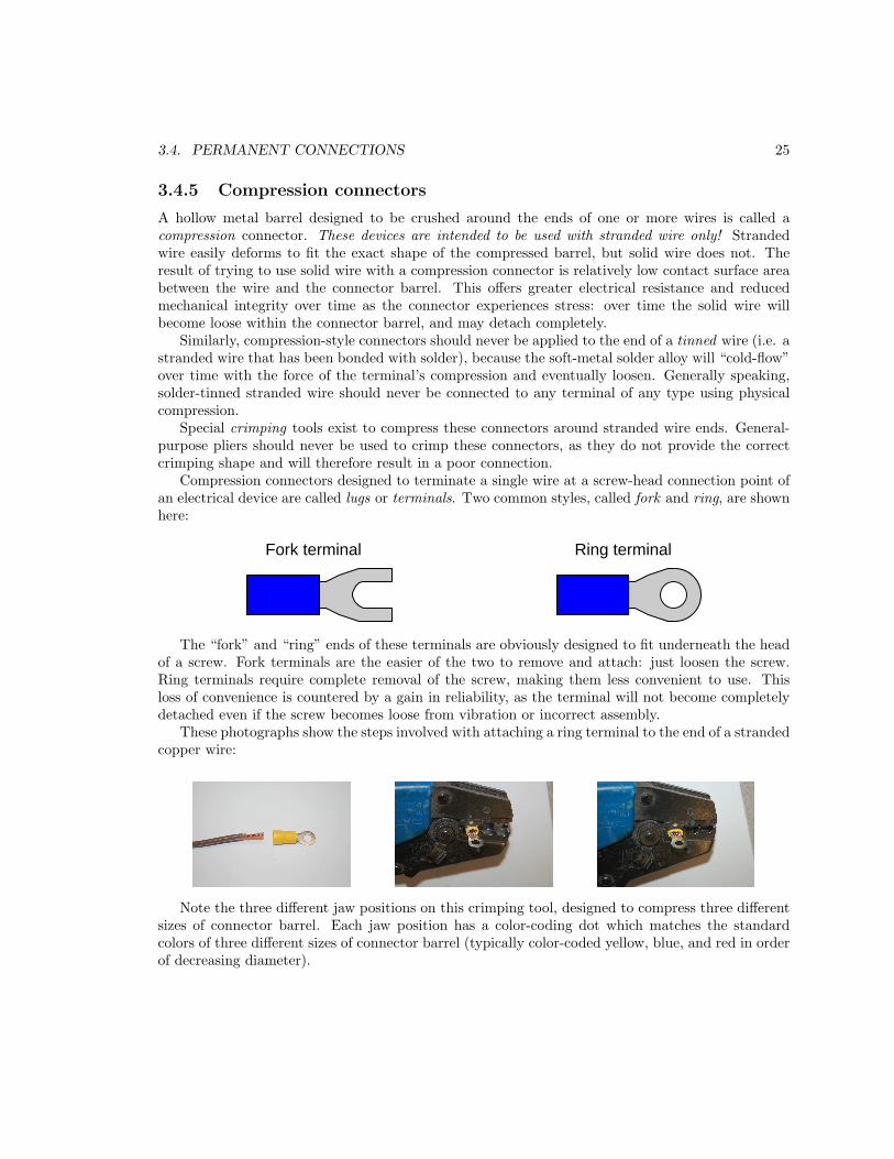
Compression connectors designed to terminate a single wire at a screw-head connection point ofan electrical device are called lugs or terminals. Two common styles, called fork and ring, are shownhere:
Fork terminal Ring terminal
The “fork” and “ring” ends of these terminals are obviously designed to fit underneath the headof a screw. Fork terminals are the easier of the two to remove and attach: just loosen the screw.Ring terminals require complete removal of the screw, making them less convenient to use. Thisloss of convenience is countered by a gain in reliability, as the terminal will not become completelydetached even if the screw becomes loose from vibration or incorrect assembly.
These photographs show the steps involved with attaching a ring terminal to the end of a strandedcopper wire:
Note the three different jaw positions on this crimping tool, designed to compress three differentsizes of connector barrel. Each jaw position has a color-coding dot which matches the standardcolors of three different sizes of connector barrel (typically color-coded yellow, blue, and red in orderof decreasing diameter).
26 CHAPTER 3. FULL TUTORIAL
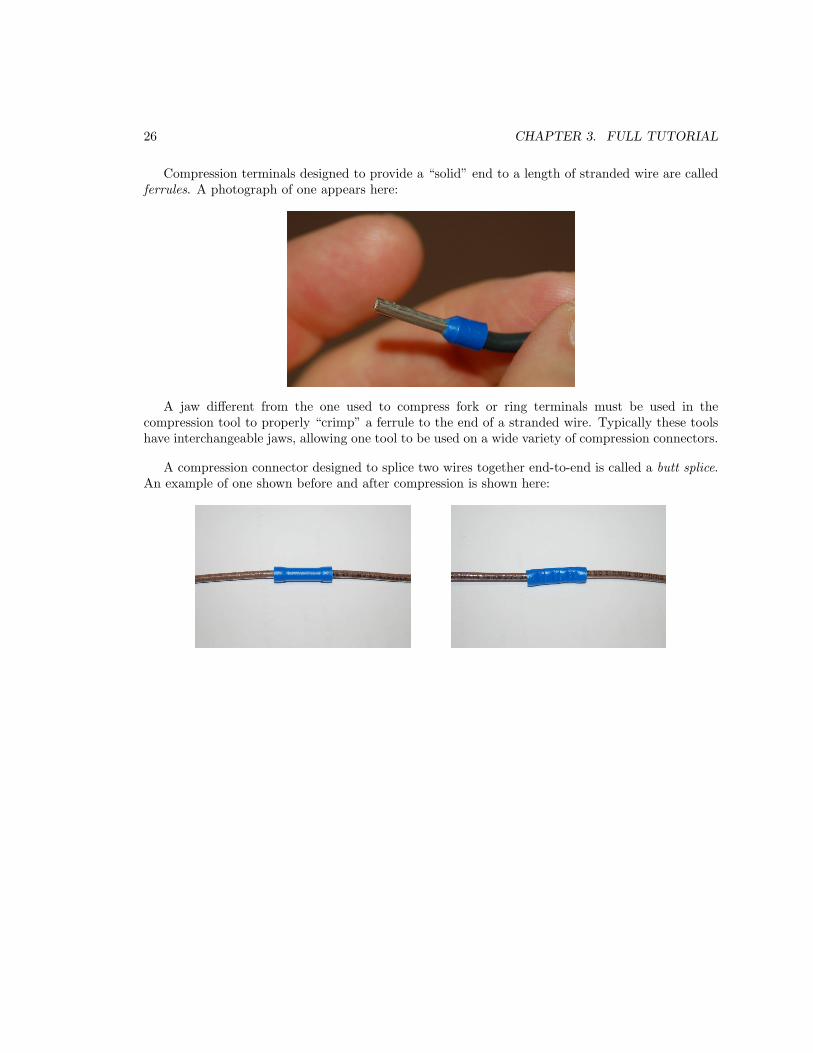
Compression terminals designed to provide a “solid” end to a length of stranded wire are calledferrules. A photograph of one appears here:
A jaw different from the one used to compress fork or ring terminals must be used in thecompression tool to properly “crimp” a ferrule to the end of a stranded wire. Typically these toolshave interchangeable jaws, allowing one tool to be used on a wide variety of compression connectors.
A compression connector designed to splice two wires together end-to-end is called a butt splice.An example of one shown before and after compression is shown here:

3.4. PERMANENT CONNECTIONS 27
Another popular form of compression connector is the spade terminal, manufactured in maleand female forms. Photographs of a male/female spade connector pair appear here (without wires),disconnected on the left and connected on the right:
The male spade connector terminates as a flat piece of metal, which fits alongside the female spadeconnector and is held in place by the tension of the female spade’s curled edges. Spade connectorsfacilitate temporary connections between wires, even though the spade connectors themselves remainpermanently compressed on the ends of their respective wires. Many electrical components areterminated by male spade ends, allowing female-terminated wires to be easily connected anddisconnected.
Aside from butt splices and ring, fork, spade, and ferrule compression terminals, a wide array ofcompression-style connectors are available for terminating multi-conductor cables. Coaxial cables –consisting of a center conductor surrounded by insulation, which in turn is surrounded by a braidedor foil-type outer conductor – may be terminated using special compression-style connectors suitedfor the specific cable size. Flat communication cable such as Category-5 and Category-6 (used forEthernet computer networks) also have special connectors which attach to the cable’s end by meansof compression. Most professional-grade crimping tools provide special jaws for crimping all of theseconnector types.
28 CHAPTER 3. FULL TUTORIAL
3.4.6 Terminal blocks
A very common connection style for industrial electrical circuits is the terminal block, comprised ofa “block” of insulating material (usually plastic) containing short metal strips with screws or springclips at each end for attaching wires.
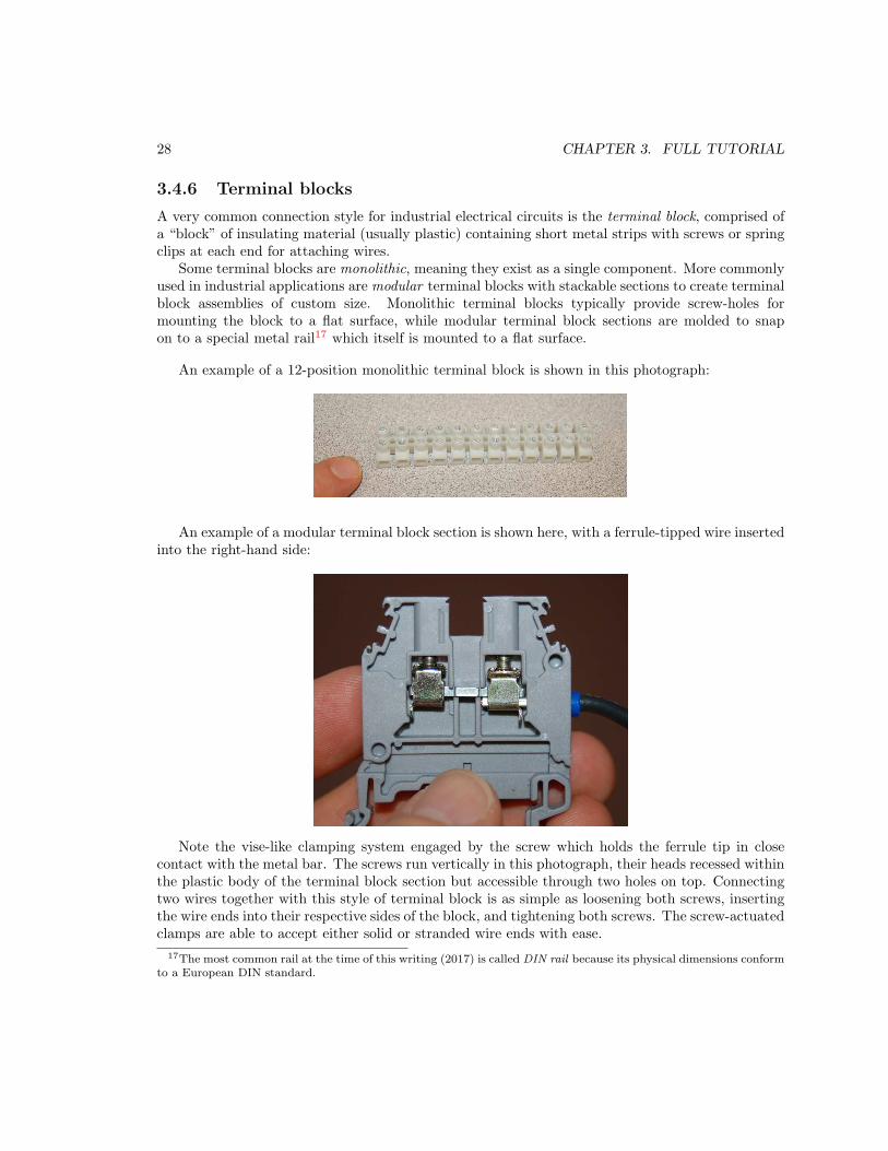
Some terminal blocks are monolithic, meaning they exist as a single component. More commonlyused in industrial applications are modular terminal blocks with stackable sections to create terminalblock assemblies of custom size. Monolithic terminal blocks typically provide screw-holes formounting the block to a flat surface, while modular terminal block sections are molded to snapon to a special metal rail17 which itself is mounted to a flat surface.
An example of a 12-position monolithic terminal block is shown in this photograph:
An example of a modular terminal block section is shown here, with a ferrule-tipped wire insertedinto the right-hand side:
Note the vise-like clamping system engaged by the screw which holds the ferrule tip in closecontact with the metal bar. The screws run vertically in this photograph, their heads recessed withinthe plastic body of the terminal block section but accessible through two holes on top. Connectingtwo wires together with this style of terminal block is as simple as loosening both screws, insertingthe wire ends into their respective sides of the block, and tightening both screws. The screw-actuatedclamps are able to accept either solid or stranded wire ends with ease.
17The most common rail at the time of this writing (2017) is called DIN rail because its physical dimensions conformto a European DIN standard.
3.4. PERMANENT CONNECTIONS 29
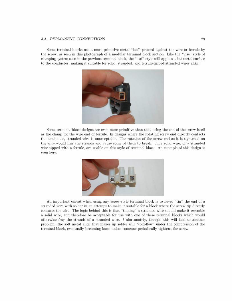
Some terminal blocks use a more primitive metal “leaf” pressed against the wire or ferrule bythe screw, as seen in this photograph of a modular terminal block section. Like the “vise” style ofclamping system seen in the previous terminal block, the “leaf” style still applies a flat metal surfaceto the conductor, making it suitable for solid, stranded, and ferrule-tipped stranded wires alike:
Some terminal block designs are even more primitive than this, using the end of the screw itselfas the clamp for the wire end or ferrule. In designs where the rotating screw end directly contactsthe conductor, stranded wire is unacceptable. The rotation of the screw end as it is tightened onthe wire would fray the strands and cause some of them to break. Only solid wire, or a strandedwire tipped with a ferrule, are usable on this style of terminal block. An example of this design isseen here:
An important caveat when using any screw-style terminal block is to never “tin” the end of astranded wire with solder in an attempt to make it suitable for a block where the screw tip directlycontacts the wire. The logic behind this is that “tinning” a stranded wire should make it resemblea solid wire, and therefore be acceptable for use with one of these terminal blocks which wouldotherwise fray the strands of a stranded wire. Unfortunately, though, this will lead to anotherproblem: the soft metal alloy that makes up solder will “cold-flow” under the compression of theterminal block, eventually becoming loose unless someone periodically tightens the screw.
30 CHAPTER 3. FULL TUTORIAL
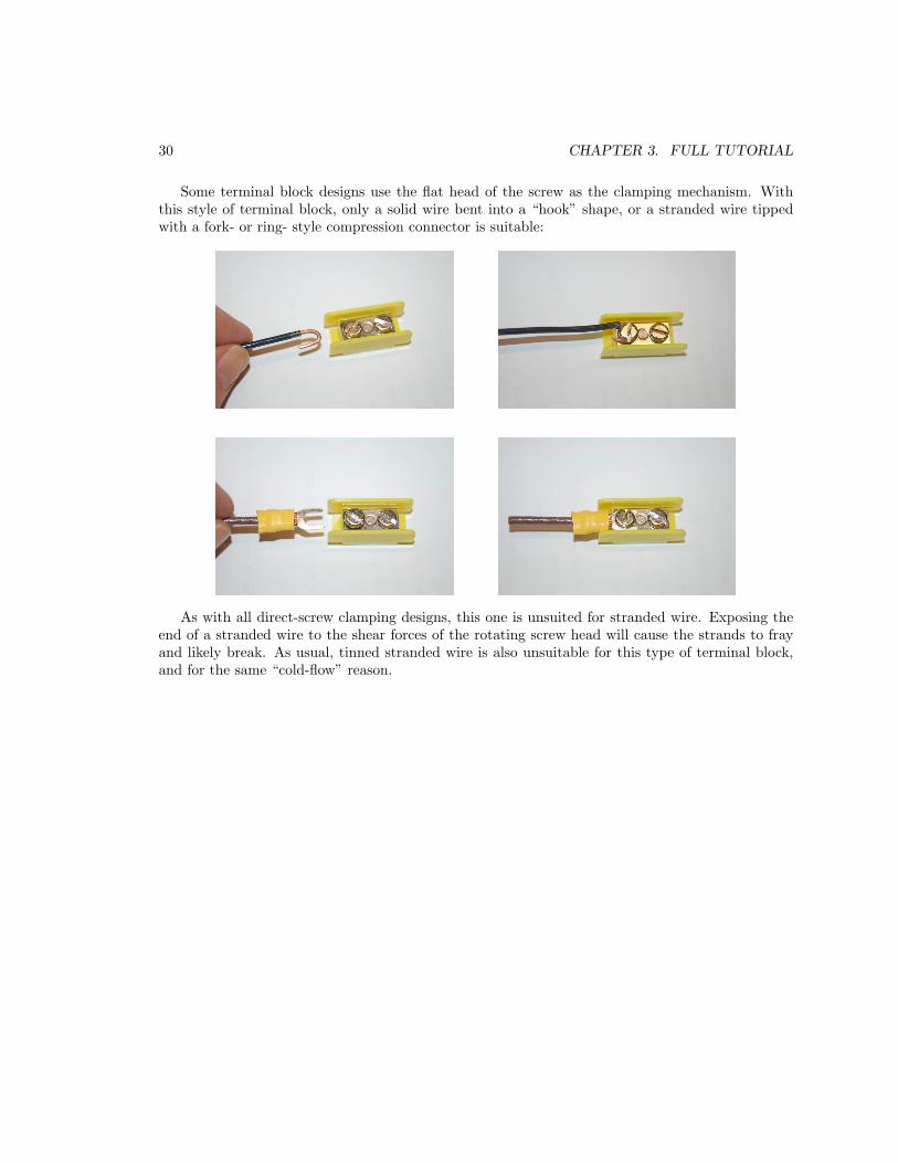
Some terminal block designs use the flat head of the screw as the clamping mechanism. Withthis style of terminal block, only a solid wire bent into a “hook” shape, or a stranded wire tippedwith a fork- or ring- style compression connector is suitable:
As with all direct-screw clamping designs, this one is unsuited for stranded wire. Exposing theend of a stranded wire to the shear forces of the rotating screw head will cause the strands to frayand likely break. As usual, tinned stranded wire is also unsuitable for this type of terminal block,and for the same “cold-flow” reason.
3.4. PERMANENT CONNECTIONS 31
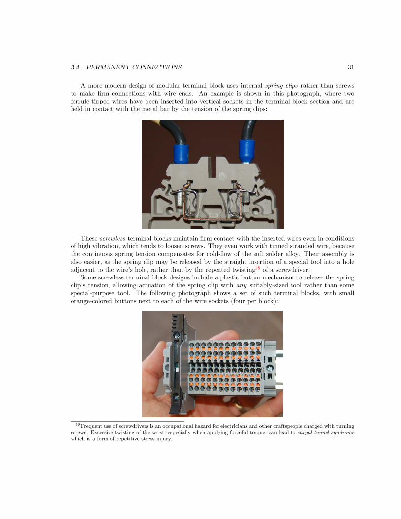
A more modern design of modular terminal block uses internal spring clips rather than screwsto make firm connections with wire ends. An example is shown in this photograph, where twoferrule-tipped wires have been inserted into vertical sockets in the terminal block section and areheld in contact with the metal bar by the tension of the spring clips:
These screwless terminal blocks maintain firm contact with the inserted wires even in conditionsof high vibration, which tends to loosen screws. They even work with tinned stranded wire, becausethe continuous spring tension compensates for cold-flow of the soft solder alloy. Their assembly isalso easier, as the spring clip may be released by the straight insertion of a special tool into a holeadjacent to the wire’s hole, rather than by the repeated twisting18 of a screwdriver.
Some screwless terminal block designs include a plastic button mechanism to release the springclip’s tension, allowing actuation of the spring clip with any suitably-sized tool rather than somespecial-purpose tool. The following photograph shows a set of such terminal blocks, with smallorange-colored buttons next to each of the wire sockets (four per block):
18Frequent use of screwdrivers is an occupational hazard for electricians and other craftspeople charged with turningscrews. Excessive twisting of the wrist, especially when applying forceful torque, can lead to carpal tunnel syndrome
which is a form of repetitive stress injury.

32 CHAPTER 3. FULL TUTORIAL
A feature of some modular terminal blocks is to ability to accept pre-manufactured jumpers
forcing a set of adjacent terminals to be electrically common to each other. The following photographshows a modular terminal block with two yellow-colored jumpers installed. The left-hand jumperconnects nine terminal block sections together, while the right-hand jumper connects three together:
All terminal blocks, regardless of style, are rated according to the size of wire (or compressionterminal) they may accept, as well as by maximum current (through any terminal) and maximumvoltage (between adjacent terminals). If the maximum current rating is exceeded for too long ofa time period, the terminal block will overheat due to the energy dissipated by the high rate ofcharge carrier motion through the small resistance of the terminal block metal and the connectionresistance between the terminal block and the wire ends. If the maximum voltage rating is exceeded,the plastic (or other insulating material separating adjacent blocks) may break down and begin toconduct current.

3.5. TEMPORARY CONNECTIONS 33
3.5 Temporary connections
Electrical connections exist where conductive materials come into direct physical contact with eachother. Tight solid-to-solid contact is essential for a sound electrical connection in order to eliminateair between the conductive surfaces, since air is electrically insulating under most conditions. Theideal electrical connection has maximum contact area.
Some electrical connections are intended to be temporary, either for the purpose of convenientconnection and disconnection of permanent fixtures, or for the construction of a prototype circuitwhich will be dismantled later. A common design technique for maintaining firm physical contactin a temporary electrical connection is to use a mechanical spring to hold the conductors together.The following subsections describe various spring-based means of temporarily connecting electricalconductors to each other.

34 CHAPTER 3. FULL TUTORIAL
3.5.1 Alligator clips
An alligator clip is a spring-actuated metal jaw used to grab and hold on to a conductive object,attached to the end of a connecting wire. A photograph of a single alligator clip (with no connectingwire) is shown here, its spring-loaded jaw being held open by the squeezing force of my fingers:
Lengths of wire with an alligator clip on either end are often referred to as jumper wires.
The following photograph shows a yellow-colored jumper wire temporarily “jumpering” two screwterminals together on an industrial relay. The alligator clip jaws are shrouded under yellow rubberguards, to help avoid unwanted electrical contact with nearby conductors:
Alligator-clip style jumper wires are perhaps the easiest method of connection for constructingvery simple circuits, and are often used by beginning students of electricity and electronics.
3.5. TEMPORARY CONNECTIONS 35
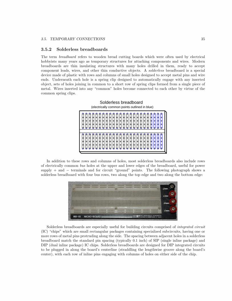
3.5.2 Solderless breadboards
The term breadboard refers to wooden bread cutting boards which were often used by electricalhobbyists many years ago as temporary structures for attaching components and wires. Modernbreadboards are thin insulating structures with many holes drilled in them, ready to acceptcomponent leads, wires, and other thin conductive objects. A solderless breadboard is a specialdevice made of plastic with rows and columns of small holes designed to accept metal pins and wireends. Underneath each hole is a spring clip designed to automatically engage with any insertedobject, sets of holes joining in common to a short row of spring clips formed from a single piece ofmetal. Wires inserted into any “common” holes become connected to each other by virtue of thecommon spring clips.
Solderless breadboard(electrically common points outlined in blue)
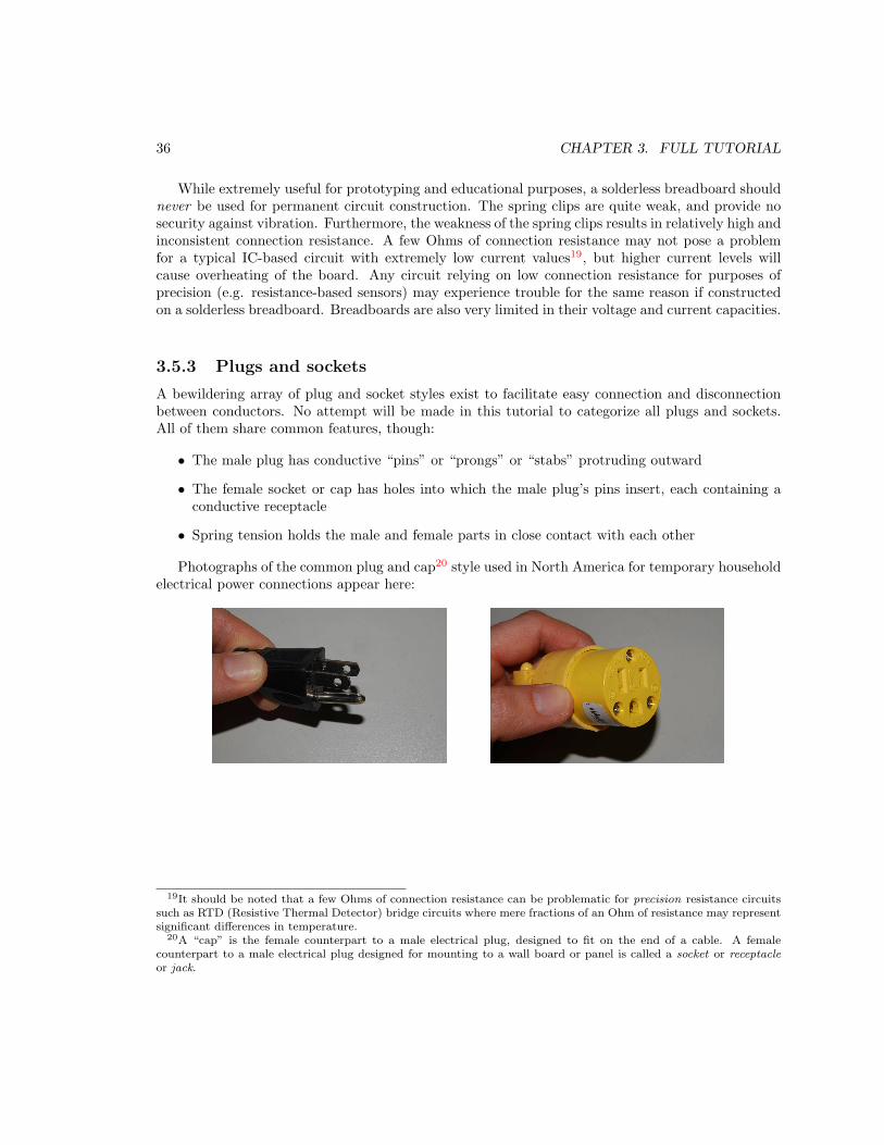
In addition to these rows and columns of holes, most solderless breadboards also include rowsof electrically common bus holes at the upper and lower edges of the breadboard, useful for powersupply + and − terminals and for circuit “ground” points. The following photograph shows asolderless breadboard with four bus rows, two along the top edge and two along the bottom edge:
Solderless breadboards are especially useful for building circuits comprised of integrated circuit
(IC) “chips” which are small rectangular packages containing specialized subcircuits, having one ormore rows of metal pins protruding along the side. The spacing between adjacent holes in a solderlessbreadboard match the standard pin spacing (typically 0.1 inch) of SIP (single inline package) andDIP (dual inline package) IC chips. Solderless breadboards are designed for DIP integrated circuitsto be plugged in along the board’s centerline (straddling the lengthwise groove along the board’scenter), with each row of inline pins engaging with columns of holes on either side of the chip.
36 CHAPTER 3. FULL TUTORIAL
While extremely useful for prototyping and educational purposes, a solderless breadboard shouldnever be used for permanent circuit construction. The spring clips are quite weak, and provide nosecurity against vibration. Furthermore, the weakness of the spring clips results in relatively high andinconsistent connection resistance. A few Ohms of connection resistance may not pose a problemfor a typical IC-based circuit with extremely low current values19, but higher current levels willcause overheating of the board. Any circuit relying on low connection resistance for purposes ofprecision (e.g. resistance-based sensors) may experience trouble for the same reason if constructedon a solderless breadboard. Breadboards are also very limited in their voltage and current capacities.
3.5.3 Plugs and sockets
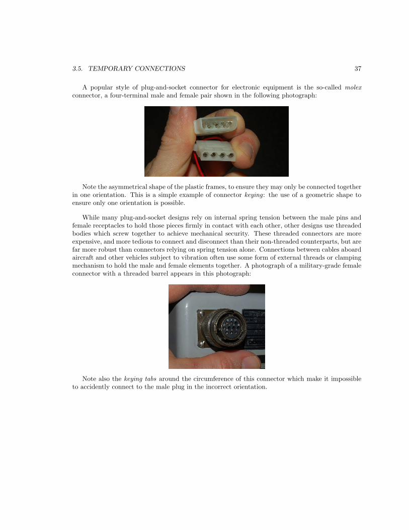
A bewildering array of plug and socket styles exist to facilitate easy connection and disconnectionbetween conductors. No attempt will be made in this tutorial to categorize all plugs and sockets.All of them share common features, though:
• The male plug has conductive “pins” or “prongs” or “stabs” protruding outward
• The female socket or cap has holes into which the male plug’s pins insert, each containing aconductive receptacle
• Spring tension holds the male and female parts in close contact with each other
Photographs of the common plug and cap20 style used in North America for temporary householdelectrical power connections appear here:
19It should be noted that a few Ohms of connection resistance can be problematic for precision resistance circuitssuch as RTD (Resistive Thermal Detector) bridge circuits where mere fractions of an Ohm of resistance may representsignificant differences in temperature.
20A “cap” is the female counterpart to a male electrical plug, designed to fit on the end of a cable. A femalecounterpart to a male electrical plug designed for mounting to a wall board or panel is called a socket or receptacle
or jack.
3.5. TEMPORARY CONNECTIONS 37
A popular style of plug-and-socket connector for electronic equipment is the so-called molex
connector, a four-terminal male and female pair shown in the following photograph:
Note the asymmetrical shape of the plastic frames, to ensure they may only be connected togetherin one orientation. This is a simple example of connector keying : the use of a geometric shape toensure only one orientation is possible.
While many plug-and-socket designs rely on internal spring tension between the male pins andfemale receptacles to hold those pieces firmly in contact with each other, other designs use threadedbodies which screw together to achieve mechanical security. These threaded connectors are moreexpensive, and more tedious to connect and disconnect than their non-threaded counterparts, but arefar more robust than connectors relying on spring tension alone. Connections between cables aboardaircraft and other vehicles subject to vibration often use some form of external threads or clampingmechanism to hold the male and female elements together. A photograph of a military-grade femaleconnector with a threaded barrel appears in this photograph:
Note also the keying tabs around the circumference of this connector which make it impossibleto accidently connect to the male plug in the incorrect orientation.

38 CHAPTER 3. FULL TUTORIAL
Circular connectors with simpler securing and keying mechanisms are commonplace on industrialproximity switches, an example of which is shown here:
3.5. TEMPORARY CONNECTIONS 39
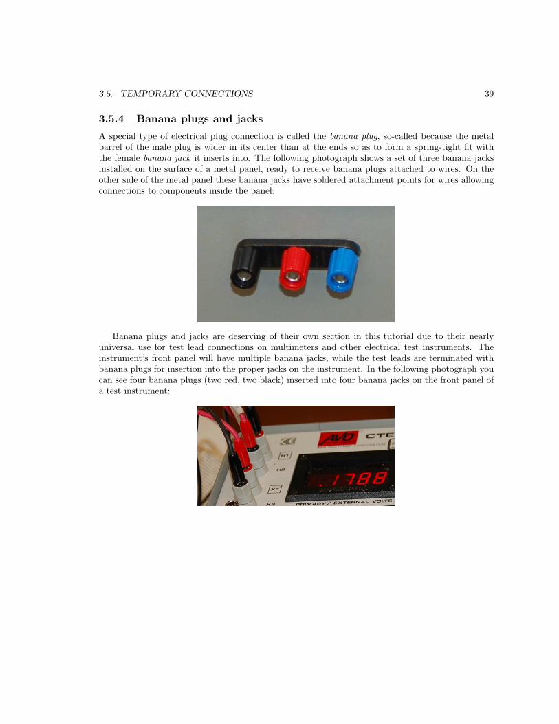
3.5.4 Banana plugs and jacks
A special type of electrical plug connection is called the banana plug, so-called because the metalbarrel of the male plug is wider in its center than at the ends so as to form a spring-tight fit withthe female banana jack it inserts into. The following photograph shows a set of three banana jacksinstalled on the surface of a metal panel, ready to receive banana plugs attached to wires. On theother side of the metal panel these banana jacks have soldered attachment points for wires allowingconnections to components inside the panel:
Banana plugs and jacks are deserving of their own section in this tutorial due to their nearlyuniversal use for test lead connections on multimeters and other electrical test instruments. Theinstrument’s front panel will have multiple banana jacks, while the test leads are terminated withbanana plugs for insertion into the proper jacks on the instrument. In the following photograph youcan see four banana plugs (two red, two black) inserted into four banana jacks on the front panel ofa test instrument:
40 CHAPTER 3. FULL TUTORIAL
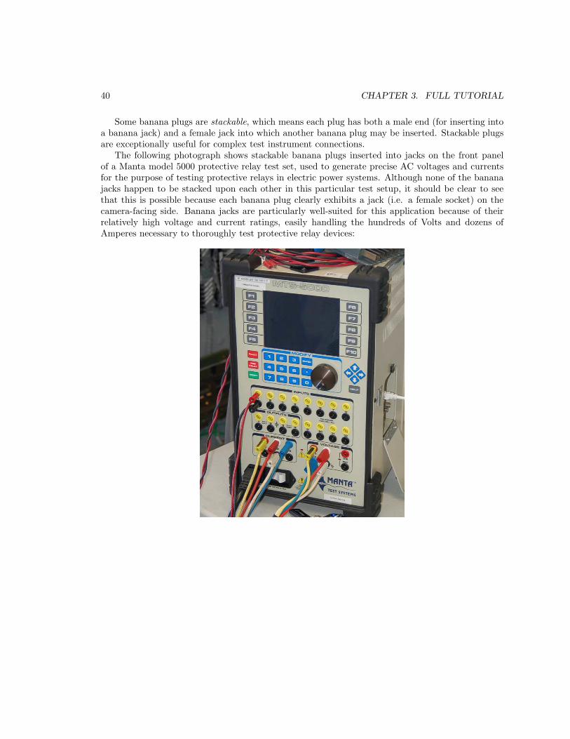
Some banana plugs are stackable, which means each plug has both a male end (for inserting intoa banana jack) and a female jack into which another banana plug may be inserted. Stackable plugsare exceptionally useful for complex test instrument connections.
The following photograph shows stackable banana plugs inserted into jacks on the front panelof a Manta model 5000 protective relay test set, used to generate precise AC voltages and currentsfor the purpose of testing protective relays in electric power systems. Although none of the bananajacks happen to be stacked upon each other in this particular test setup, it should be clear to seethat this is possible because each banana plug clearly exhibits a jack (i.e. a female socket) on thecamera-facing side. Banana jacks are particularly well-suited for this application because of theirrelatively high voltage and current ratings, easily handling the hundreds of Volts and dozens ofAmperes necessary to thoroughly test protective relay devices:
Chapter 4
Derivations and TechnicalReferences
This chapter is where you will find mathematical derivations too detailed to include in the tutorial,and/or tables and other technical reference material.
41
42 CHAPTER 4. DERIVATIONS AND TECHNICAL REFERENCES
4.1 Derivation of electron drift velocity
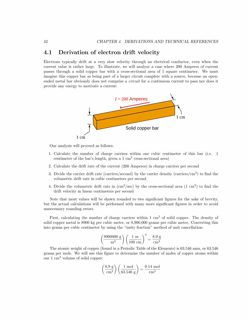
Electrons typically drift at a very slow velocity through an electrical conductor, even when thecurrent value is rather large. To illustrate, we will analyze a case where 200 Amperes of currentpasses through a solid copper bar with a cross-sectional area of 1 square centimeter. We mustimagine this copper bar as being part of a larger circuit complete with a source, because an open-ended metal bar obviously does not comprise a circuit for a continuous current to pass nor does itprovide any energy to motivate a current:
Solid copper bar
I = 200 Amperes
1 cm
1 cm
Our analysis will proceed as follows:
1. Calculate the number of charge carriers within one cubic centimeter of this bar (i.e. 1centimeter of the bar’s length, given a 1 cm2 cross-sectional area)
2. Calculate the drift rate of the current (200 Amperes) in charge carriers per second
3. Divide the carrier drift rate (carriers/second) by the carrier density (carriers/cm3) to find thevolumetric drift rate in cubic centimeters per second
4. Divide the volumetric drift rate in (cm3/sec) by the cross-sectional area (1 cm3) to find thedrift velocity in linear centimeters per second
Note that most values will be shown rounded to two significant figures for the sake of brevity,but the actual calculations will be performed with many more significant figures in order to avoidunnecessary rounding errors.
First, calculating the number of charge carriers within 1 cm3 of solid copper. The density ofsolid copper metal is 8900 kg per cubic meter, or 8,900,000 grams per cubic meter. Converting thisinto grams per cubic centimeter by using the “unity fraction” method of unit cancellation:
(
8900000 g
m3
)(
1 m
100 cm
)3
=8.9 g
cm3
The atomic weight of copper (found in a Periodic Table of the Elements) is 63.546 amu, or 63.546grams per mole. We will use this figure to determine the number of moles of copper atoms withinour 1 cm3 volume of solid copper:
(
8.9 g
cm3
)(
1 mol
63.546 g
)
=0.14 mol
cm3
4.1. DERIVATION OF ELECTRON DRIFT VELOCITY 43
1 mole of anything is 6.022 × 10²³ units, so we may calculate the number of individual copperatoms in our 1 cm3 sample by multiplying 0.14 moles by this number:
(
0.14 mol
cm3
)(
6.022 × 10²³ atoms
mol
)
=8.4 × 10²² atoms
cm3
Each copper atom possesses one “free” electron in its valence shell, which means our 1 cm3
sample of the copper bar contains 8.4 × 10²² free charges (electrons).
One Ampere of electric current is equal to 6.2 × 10¹⁸ individual charges passing by per secondof time. 200 Amperes of current is therefore equal to:
(
200 A
1
)(
6.2 × 10¹⁸ electrons / sec
1 A
)
=1.2 × 10²¹ electrons
sec
Dividing this electron flow rate by the volumetric density of electrons within copper will yield avolumetric flow rate in cubic centimeters’ worth of electrons per second:
1.2 × 10²¹ electrons / sec
8.4 × 10²² electrons / cm3
=0.015 cm3
sec
Dividing this volumetric charge flow rate by the bar’s cross-sectional area yields the linear driftvelocity in centimeters per second:
0.015 cm3 / sec
1 cm2=
0.015 cm
secConverting into centimeters per minute:
(
0.015 cm
sec
)(
60 sec
1 min
)
=0.88 cm
min
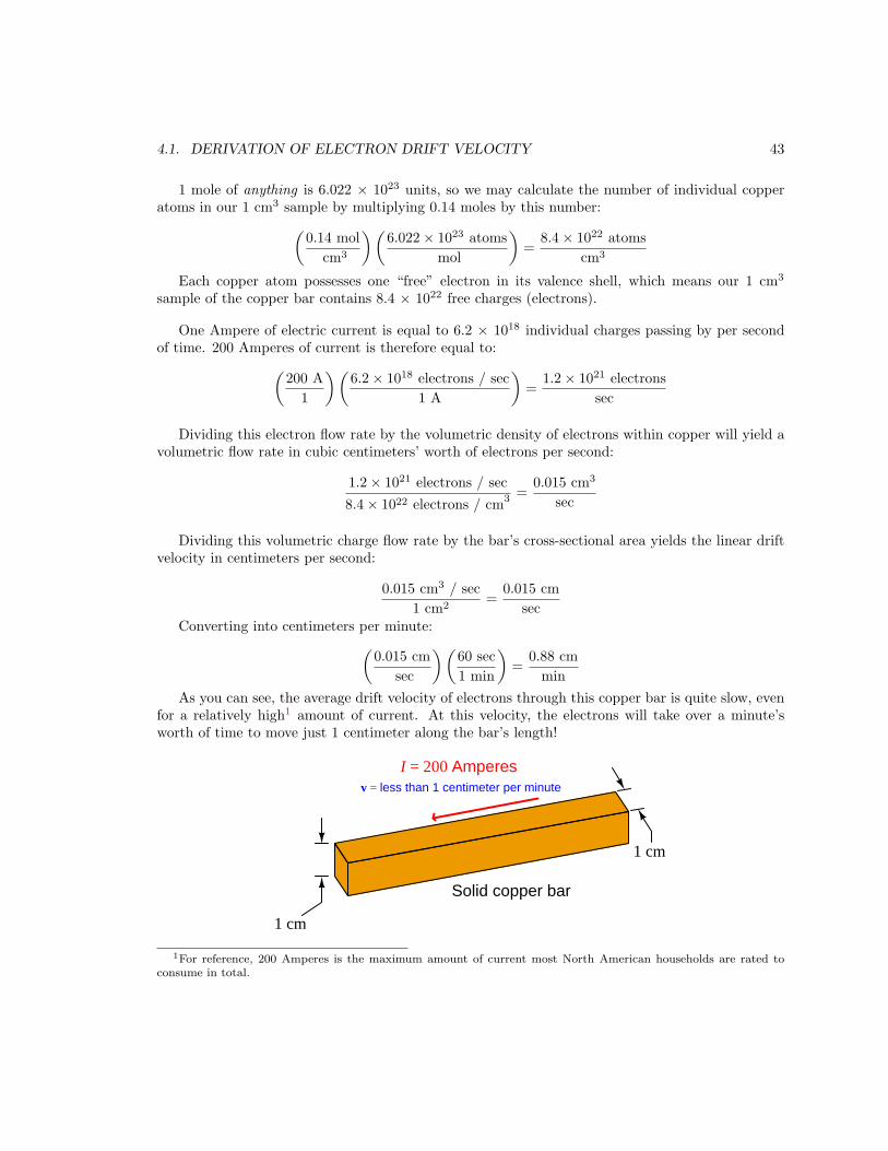
As you can see, the average drift velocity of electrons through this copper bar is quite slow, evenfor a relatively high1 amount of current. At this velocity, the electrons will take over a minute’sworth of time to move just 1 centimeter along the bar’s length!
Solid copper bar
I = 200 Amperes
1 cm
1 cm
v = less than 1 centimeter per minute
1For reference, 200 Amperes is the maximum amount of current most North American households are rated toconsume in total.

44 CHAPTER 4. DERIVATIONS AND TECHNICAL REFERENCES
4.2 Table of specific resistance values
Note: this table2 assumes a substance temperature of 20 degrees Celsius. Order is from least resistive(top) to most resistive (bottom).
Substance Element or Alloy Ohm-cmil/ft microOhm-cm
Silver Element 9.540 1.586
Copper Element 10.09 1.678
Gold Element 13.5 2.24
Aluminum Element 15.97 2.655
Molybdenum Element 31 5.2
Tungsten Element 34.0 5.65
Zinc Element 35.59 5.916
Nickel Element 41.1 6.84
Iron Element 58.4 9.71
Platinum Element 63.8 10.6
Tin Element 66.2 11.0
Lead Element 124.20 20.648
Steel (99.5% iron, 0.5% carbon) Alloy 100 16.62
Antimony Element 235 39.0
Titanium Element 253 42.0
Constantan Alloy 272.97 45.38
Manganin Alloy 290 48.21
Nichrome V Alloy 650 108.1
Nichrome Alloy 675 112.2
2Values of microOhm-centimeters for elements taken from the CRC Handbook of Chemistry and Physics, 64th
edition (page F-125, “Electrical Resistivity and Temperature Coefficients of Elements”) and then converted intoOhm-cmil/ft using exact conversion factors (e.g. 2.54 centimeters per inch, 12 inches per foot, 1000 mil per inch, 4
π
circular units per square unit).

Chapter 5
Animations
Some concepts are much easier to grasp when seen in action. A simple yet effective form of animationsuitable to an electronic document such as this is a “flip-book” animation where a set of pages in thedocument show successive frames of a simple animation. Such “flip-book” animations are designedto be viewed by paging forward (and/or back) with the document-reading software application,watching it frame-by-frame. Unlike video which may be difficult to pause at certain moments,“flip-book” animations lend themselves very well to individual frame viewing.
45

46 CHAPTER 5. ANIMATIONS
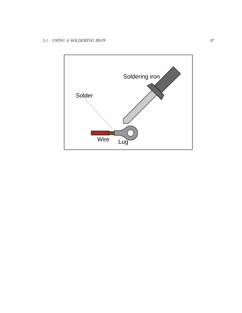
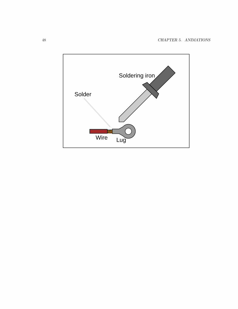
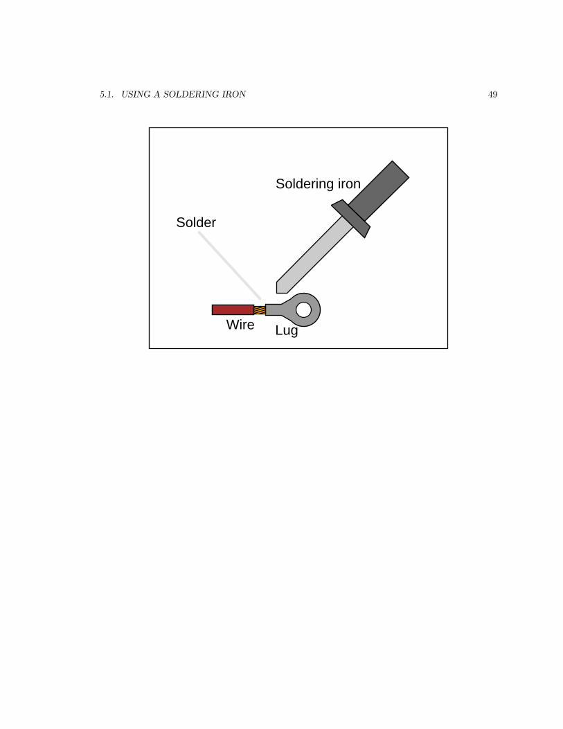
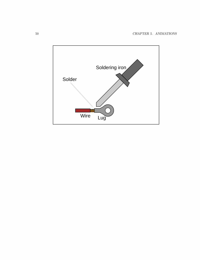
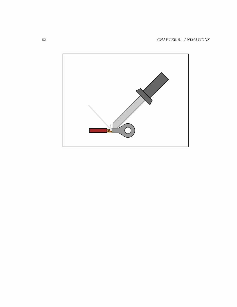
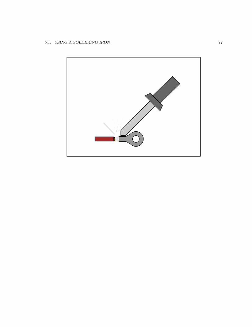
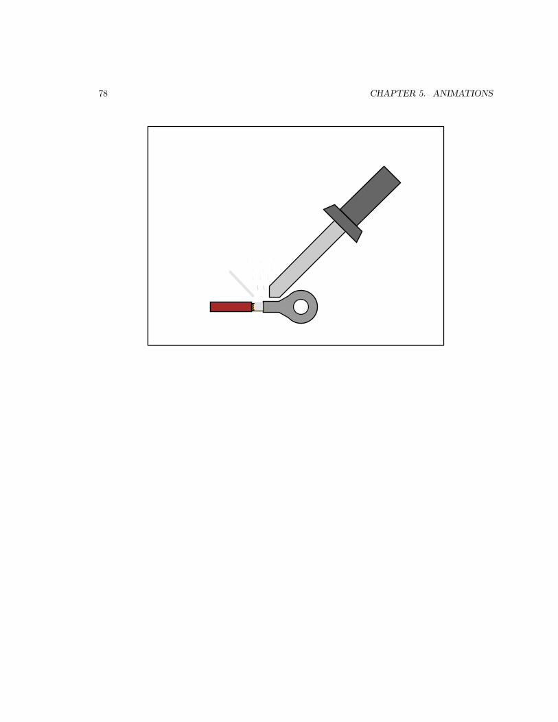
5.1 Using a soldering iron
This animation shows the proper usage of a soldering iron to solder a wire to a lug-style connector.Note how heat from the soldering iron tip is applied to the connector (lug) itself, and not to thesolder. This ensures the connector’s metal will be at full temperature necessary for good bondingbetween the metal and the solder.
5.1. USING A SOLDERING IRON 47
Soldering iron
Solder
LugWire
48 CHAPTER 5. ANIMATIONS
Soldering iron
Solder
LugWire
5.1. USING A SOLDERING IRON 49
Soldering iron
Solder
LugWire
50 CHAPTER 5. ANIMATIONS
Soldering iron
Solder
LugWire

5.1. USING A SOLDERING IRON 51
Soldering iron
Solder
LugWire

52 CHAPTER 5. ANIMATIONS
Soldering iron
Solder
LugWire

5.1. USING A SOLDERING IRON 53
Soldering iron
Solder
LugWire

54 CHAPTER 5. ANIMATIONS
Soldering iron
Solder
LugWire

5.1. USING A SOLDERING IRON 55
Soldering iron
Solder
LugWire

56 CHAPTER 5. ANIMATIONS
Soldering iron
Solder
LugWire

5.1. USING A SOLDERING IRON 57

58 CHAPTER 5. ANIMATIONS

5.1. USING A SOLDERING IRON 59

60 CHAPTER 5. ANIMATIONS

5.1. USING A SOLDERING IRON 61
62 CHAPTER 5. ANIMATIONS

5.1. USING A SOLDERING IRON 63

64 CHAPTER 5. ANIMATIONS

5.1. USING A SOLDERING IRON 65

66 CHAPTER 5. ANIMATIONS

5.1. USING A SOLDERING IRON 67

68 CHAPTER 5. ANIMATIONS

5.1. USING A SOLDERING IRON 69

70 CHAPTER 5. ANIMATIONS

5.1. USING A SOLDERING IRON 71

72 CHAPTER 5. ANIMATIONS

5.1. USING A SOLDERING IRON 73

74 CHAPTER 5. ANIMATIONS

5.1. USING A SOLDERING IRON 75

76 CHAPTER 5. ANIMATIONS
5.1. USING A SOLDERING IRON 77
78 CHAPTER 5. ANIMATIONS

5.1. USING A SOLDERING IRON 79

80 CHAPTER 5. ANIMATIONS
Chapter 6
Questions
This learning module, along with all others in the ModEL collection, is designed to be used in aninverted instructional environment where students independently read1 the tutorials and attemptto answer questions on their own prior to the instructor’s interaction with them. In place oflecture2, the instructor engages with students in Socratic-style dialogue, probing and challengingtheir understanding of the subject matter through inquiry.
Answers are not provided for questions within this chapter, and this is by design. Solved problemsmay be found in the Tutorial and Derivation chapters, instead. The goal here is independence, andthis requires students to be challenged in ways where others cannot think for them. Rememberthat you always have the tools of experimentation and computer simulation (e.g. SPICE) to exploreconcepts!
The following lists contain ideas for Socratic-style questions and challenges. Upon inspection,one will notice a strong theme of metacognition within these statements: they are designed to fostera regular habit of examining one’s own thoughts as a means toward clearer thinking. As such thesesample questions are useful both for instructor-led discussions as well as for self-study.
1Technical reading is an essential academic skill for any technical practitioner to possess for the simple reasonthat the most comprehensive, accurate, and useful information to be found for developing technical competence is intextual form. Technical careers in general are characterized by the need for continuous learning to remain currentwith standards and technology, and therefore any technical practitioner who cannot read well is handicapped intheir professional development. An excellent resource for educators on improving students’ reading prowess throughintentional effort and strategy is the book textitReading For Understanding – How Reading Apprenticeship ImprovesDisciplinary Learning in Secondary and College Classrooms by Ruth Schoenbach, Cynthia Greenleaf, and LynnMurphy.
2Lecture is popular as a teaching method because it is easy to implement: any reasonably articulate subject matterexpert can talk to students, even with little preparation. However, it is also quite problematic. A good lecture alwaysmakes complicated concepts seem easier than they are, which is bad for students because it instills a false sense ofconfidence in their own understanding; reading and re-articulation requires more cognitive effort and serves to verifycomprehension. A culture of teaching-by-lecture fosters a debilitating dependence upon direct personal instruction,whereas the challenges of modern life demand independent and critical thought made possible only by gatheringinformation and perspectives from afar. Information presented in a lecture is ephemeral, easily lost to failures ofmemory and dictation; text is forever, and may be referenced at any time.
81

82 CHAPTER 6. QUESTIONS
General challenges following tutorial reading
• Summarize as much of the text as you can in one paragraph of your own words. A helpfulstrategy is to explain ideas as you would for an intelligent child: as simple as you can withoutcompromising too much accuracy.
• Simplify a particular section of the text, for example a paragraph or even a single sentence, soas to capture the same fundamental idea in fewer words.
• Where did the text make the most sense to you? What was it about the text’s presentationthat made it clear?
• Identify where it might be easy for someone to misunderstand the text, and explain why youthink it could be confusing.
• Identify any new concept(s) presented in the text, and explain in your own words.
• Identify any familiar concept(s) such as physical laws or principles applied or referenced in thetext.
• Devise a proof of concept experiment demonstrating an important principle, physical law, ortechnical innovation represented in the text.
• Devise an experiment to disprove a plausible misconception.
• Did the text reveal any misconceptions you might have harbored? If so, describe themisconception(s) and the reason(s) why you now know them to be incorrect.
• Describe any useful problem-solving strategies applied in the text.
• Devise a question of your own to challenge a reader’s comprehension of the text.

83
General follow-up challenges for assigned problems
• Identify where any fundamental laws or principles apply to the solution of this problem,especially before applying any mathematical techniques.
• Devise a thought experiment to explore the characteristics of the problem scenario, applyingknown laws and principles to mentally model its behavior.
• Describe in detail your own strategy for solving this problem. How did you identify andorganized the given information? Did you sketch any diagrams to help frame the problem?
• Is there more than one way to solve this problem? Which method seems best to you?
• Show the work you did in solving this problem, even if the solution is incomplete or incorrect.
• What would you say was the most challenging part of this problem, and why was it so?
• Was any important information missing from the problem which you had to research or recall?
• Was there any extraneous information presented within this problem? If so, what was it andwhy did it not matter?
• Examine someone else’s solution to identify where they applied fundamental laws or principles.
• Simplify the problem from its given form and show how to solve this simpler version of it.Examples include eliminating certain variables or conditions, altering values to simpler (usuallywhole) numbers, applying a limiting case (i.e. altering a variable to some extreme or ultimatevalue).
• For quantitative problems, identify the real-world meaning of all intermediate calculations:their units of measurement, where they fit into the scenario at hand. Annotate any diagramsor illustrations with these calculated values.
• For quantitative problems, try approaching it qualitatively instead, thinking in terms of“increase” and “decrease” rather than definite values.
• For qualitative problems, try approaching it quantitatively instead, proposing simple numericalvalues for the variables.
• Were there any assumptions you made while solving this problem? Would your solution changeif one of those assumptions were altered?
• Identify where it would be easy for someone to go astray in attempting to solve this problem.
• Formulate your own problem based on what you learned solving this one.
General follow-up challenges for experiments or projects
• In what way(s) was this experiment or project easy to complete?
• Identify some of the challenges you faced in completing this experiment or project.

84 CHAPTER 6. QUESTIONS
• Show how thorough documentation assisted in the completion of this experiment or project.
• Which fundamental laws or principles are key to this system’s function?
• Identify any way(s) in which one might obtain false or otherwise misleading measurementsfrom test equipment in this system.
• What will happen if (component X) fails (open/shorted/etc.)?
• What would have to occur to make this system unsafe?

6.1. CONCEPTUAL REASONING 85
6.1 Conceptual reasoning
These questions are designed to stimulate your analytic and synthetic thinking3. In a Socraticdiscussion with your instructor, the goal is for these questions to prompt an extended dialoguewhere assumptions are revealed, conclusions are tested, and understanding is sharpened. Yourinstructor may also pose additional questions based on those assigned, in order to further probe andrefine your conceptual understanding.
Questions that follow are presented to challenge and probe your understanding of various conceptspresented in the tutorial. These questions are intended to serve as a guide for the Socratic dialoguebetween yourself and the instructor. Your instructor’s task is to ensure you have a sound grasp ofthese concepts, and the questions contained in this document are merely a means to this end. Yourinstructor may, at his or her discretion, alter or substitute questions for the benefit of tailoring thediscussion to each student’s needs. The only absolute requirement is that each student is challengedand assessed at a level equal to or greater than that represented by the documented questions.
It is far more important that you convey your reasoning than it is to simply convey a correctanswer. For this reason, you should refrain from researching other information sources to answerquestions. What matters here is that you are doing the thinking. If the answer is incorrect, yourinstructor will work with you to correct it through proper reasoning. A correct answer without anadequate explanation of how you derived that answer is unacceptable, as it does not aid the learningor assessment process.
You will note a conspicuous lack of answers given for these conceptual questions. Unlike standardtextbooks where answers to every other question are given somewhere toward the back of the book,here in these learning modules students must rely on other means to check their work. The best wayby far is to debate the answers with fellow students and also with the instructor during the Socraticdialogue sessions intended to be used with these learning modules. Reasoning through challengingquestions with other people is an excellent tool for developing strong reasoning skills.
Another means of checking your conceptual answers, where applicable, is to use circuit simulationsoftware to explore the effects of changes made to circuits. For example, if one of these conceptualquestions challenges you to predict the effects of altering some component parameter in a circuit,you may check the validity of your work by simulating that same parameter change within softwareand seeing if the results agree.
3Analytical thinking involves the “disassembly” of an idea into its constituent parts, analogous to dissection.Synthetic thinking involves the “assembly” of a new idea comprised of multiple concepts, analogous to construction.Both activities are high-level cognitive skills, extremely important for effective problem-solving, necessitating frequentchallenge and regular practice to fully develop.

86 CHAPTER 6. QUESTIONS
6.1.1 Reading outline and reflections
“Reading maketh a full man; conference a ready man; and writing an exact man” – Francis Bacon
Francis Bacon’s advice is a blueprint for effective education: reading provides the learner withknowledge, writing focuses the learner’s thoughts, and critical dialogue equips the learner toconfidently communicate and apply their learning. Independent acquisition and application ofknowledge is a powerful skill, well worth the effort to cultivate. To this end, students shouldread these educational resources closely, write their own outline and reflections on the reading, anddiscuss in detail their findings with classmates and instructor(s). You should be able to do all of thefollowing after reading any instructional text:
√Briefly OUTLINE THE TEXT, as though you were writing a detailed Table of Contents. Feel
free to rearrange the order if it makes more sense that way. Prepare to articulate these points indetail and to answer questions from your classmates and instructor. Outlining is a good self-test ofthorough reading because you cannot outline what you have not read or do not comprehend.
√Demonstrate ACTIVE READING STRATEGIES, including verbalizing your impressions as
you read, simplifying long passages to convey the same ideas using fewer words, annotating textand illustrations with your own interpretations, working through mathematical examples shown inthe text, cross-referencing passages with relevant illustrations and/or other passages, identifyingproblem-solving strategies applied by the author, etc. Technical reading is a special case of problem-solving, and so these strategies work precisely because they help solve any problem: paying attentionto your own thoughts (metacognition), eliminating unnecessary complexities, identifying what makessense, paying close attention to details, drawing connections between separated facts, and notingthe successful strategies of others.
√Identify IMPORTANT THEMES, especially GENERAL LAWS and PRINCIPLES, expounded
in the text and express them in the simplest of terms as though you were teaching an intelligentchild. This emphasizes connections between related topics and develops your ability to communicatecomplex ideas to anyone.
√Form YOUR OWN QUESTIONS based on the reading, and then pose them to your instructor
and classmates for their consideration. Anticipate both correct and incorrect answers, the incorrectanswer(s) assuming one or more plausible misconceptions. This helps you view the subject fromdifferent perspectives to grasp it more fully.
√Devise EXPERIMENTS to test claims presented in the reading, or to disprove misconceptions.
Predict possible outcomes of these experiments, and evaluate their meanings: what result(s) wouldconfirm, and what would constitute disproof? Running mental simulations and evaluating results isessential to scientific and diagnostic reasoning.
√Specifically identify any points you found CONFUSING. The reason for doing this is to help
diagnose misconceptions and overcome barriers to learning.

6.1. CONCEPTUAL REASONING 87
6.1.2 Foundational concepts
Correct analysis and diagnosis of electric circuits begins with a proper understanding of some basicconcepts. The following is a list of some important concepts referenced in this module’s full tutorial.Define each of them in your own words, and be prepared to illustrate each of these concepts with adescription of a practical example and/or a live demonstration.
Energy
Conservation of Energy
Conductors versus Insulators
Voltage
Resistance
Current
Open
Short
Switch
Ohm’s Law
Specific resistance
Electrical load

88 CHAPTER 6. QUESTIONS
Wire gauge
Mil
Ampacity
Solid versus Stranded wire
Soldering
6.1.3 Switch contact size
Electrical switches use pairs of metal contact points to open and close an electrical connection. Inthe “open” position the points are separated from each other, usually by an air gap. In the “closed”position the points are pressed together in firm contact with one another.
Does the maximum current rating of an electrical switch matter in its open or closed state?
Does the maximum voltage rating of an electrical switch matter in its open or closed state?
All other factors being equal, do you suppose a switch rated for a high amount of electricalcurrent would have larger or smaller or the same size contact points as a switch rated for a lowamount of current? Explain your answer in detail.
Challenges
• What design factors other than contact point size might be optimized for a switch intendedfor high-current applications?
• Suppose we needed a switch for a high voltage application rather than high current. Whatdesign factors might be altered to achieve this goal?

6.1. CONCEPTUAL REASONING 89
6.1.4 Why use gold plating?
High-quality electrical connectors are often plated with a thin layer of gold metal, which is obviouslyexpensive. Consulting a table of specific resistance values, we see that gold is actually a less effectiveconductor than copper, so why would anyone bother plating a copper wire or connector with gold?
Note: a table of specific resistance values for common metal types is found on page 44 of section4.2 for your reference.
Challenges
• Contact points for heavy-duty electrical switches are often plated with silver rather than gold.Why do you suppose silver is the better metal for this application?
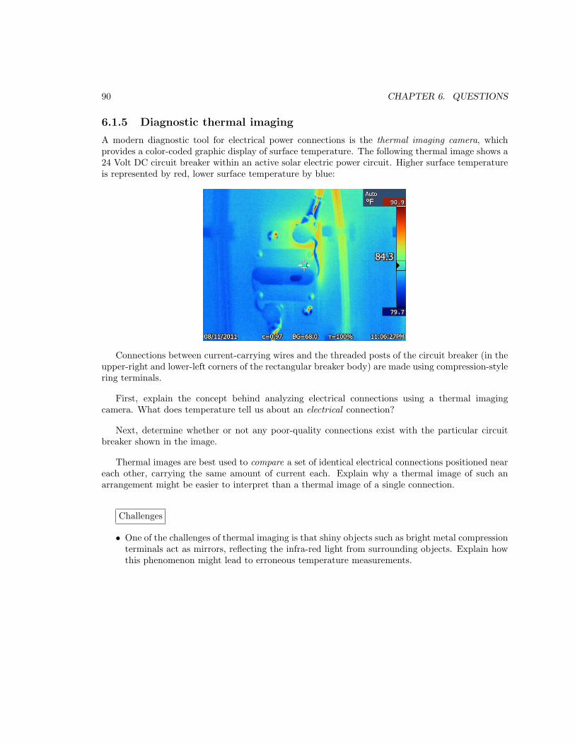
90 CHAPTER 6. QUESTIONS
6.1.5 Diagnostic thermal imaging
A modern diagnostic tool for electrical power connections is the thermal imaging camera, whichprovides a color-coded graphic display of surface temperature. The following thermal image shows a24 Volt DC circuit breaker within an active solar electric power circuit. Higher surface temperatureis represented by red, lower surface temperature by blue:
Connections between current-carrying wires and the threaded posts of the circuit breaker (in theupper-right and lower-left corners of the rectangular breaker body) are made using compression-stylering terminals.
First, explain the concept behind analyzing electrical connections using a thermal imagingcamera. What does temperature tell us about an electrical connection?
Next, determine whether or not any poor-quality connections exist with the particular circuitbreaker shown in the image.
Thermal images are best used to compare a set of identical electrical connections positioned neareach other, carrying the same amount of current each. Explain why a thermal image of such anarrangement might be easier to interpret than a thermal image of a single connection.
Challenges
• One of the challenges of thermal imaging is that shiny objects such as bright metal compressionterminals act as mirrors, reflecting the infra-red light from surrounding objects. Explain howthis phenomenon might lead to erroneous temperature measurements.
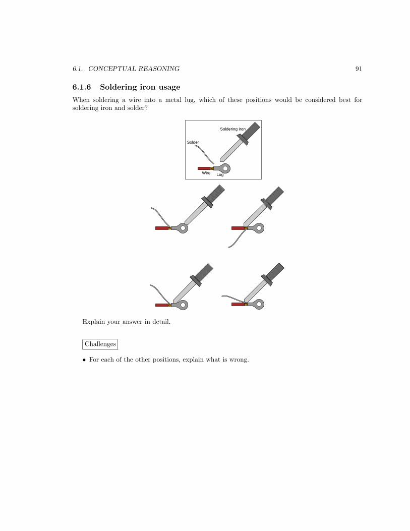
6.1. CONCEPTUAL REASONING 91
6.1.6 Soldering iron usage
When soldering a wire into a metal lug, which of these positions would be considered best forsoldering iron and solder?
Soldering iron
Solder
LugWire
Explain your answer in detail.
Challenges
• For each of the other positions, explain what is wrong.

92 CHAPTER 6. QUESTIONS
6.1.7 Battery-lamp-switch circuit on a solderless breadboard
Show how to build a simple circuit consisting of a battery, a lamp, and a switch, mounting the lampand switch on a solderless breadboard (also known as a proto-board):
+-
BatteryLamp Switch
Challenges
• As versatile as solderless breadboards are, they definitely have limitations. Identify a few.

6.2. QUANTITATIVE REASONING 93
6.2 Quantitative reasoning
These questions are designed to stimulate your computational thinking. In a Socratic discussion withyour instructor, the goal is for these questions to reveal your mathematical approach(es) to problem-solving so that good technique and sound reasoning may be reinforced. Your instructor may also poseadditional questions based on those assigned, in order to observe your problem-solving firsthand.
Mental arithmetic and estimations are strongly encouraged for all calculations, because withoutthese abilities you will be unable to readily detect errors caused by calculator misuse (e.g. keystrokeerrors).
You will note a conspicuous lack of answers given for these quantitative questions. Unlikestandard textbooks where answers to every other question are given somewhere toward the backof the book, here in these learning modules students must rely on other means to check their work.My advice is to use circuit simulation software such as SPICE to check the correctness of quantitativeanswers. Refer to those learning modules within this collection focusing on SPICE to see workedexamples which you may use directly as practice problems for your own study, and/or as templatesyou may modify to run your own analyses and generate your own practice problems.
Completely worked example problems found in the Tutorial may also serve as “test cases4” forgaining proficiency in the use of circuit simulation software, and then once that proficiency is gainedyou will never need to rely5 on an answer key!
4In other words, set up the circuit simulation software to analyze the same circuit examples found in the Tutorial.If the simulated results match the answers shown in the Tutorial, it confirms the simulation has properly run. Ifthe simulated results disagree with the Tutorial’s answers, something has been set up incorrectly in the simulationsoftware. Using every Tutorial as practice in this way will quickly develop proficiency in the use of circuit simulationsoftware.
5This approach is perfectly in keeping with the instructional philosophy of these learning modules: teaching students
to be self-sufficient thinkers. Answer keys can be useful, but it is even more useful to your long-term success to havea set of tools on hand for checking your own work, because once you have left school and are on your own, there willno longer be “answer keys” available for the problems you will have to solve.

94 CHAPTER 6. QUESTIONS
6.2.1 Miscellaneous physical constants
Note: constants shown in bold type are exact, not approximations. Values inside of parentheses showone standard deviation (σ) of uncertainty in the final digits: for example, Avogadro’s number givenas 6.02214179(30) × 1023 means the center value (6.02214179×10²³) plus or minus 0.00000030×10²³.
Avogadro’s number (NA) = 6.02214179(30) × 1023 per mole (mol−1)
Boltzmann’s constant (k) = 1.3806504(24) × 10−23 Joules per Kelvin (J/K)
Electronic charge (e) = 1.602176487(40) × 10−19 Coulomb (C)
Faraday constant (F ) = 9.64853399(24) × 104 Coulombs per mole (C/mol)
Magnetic permeability of free space (µ0) = 1.25663706212(19) × 10−6 Henrys per meter (H/m)
Electric permittivity of free space (ǫ0) = 8.8541878128(13) × 10−12 Farads per meter (F/m)
Characteristic impedance of free space (Z0) = 376.730313668(57) Ohms (Ω)
Gravitational constant (G) = 6.67428(67) × 10−11 cubic meters per kilogram-seconds squared(m3/kg-s2)
Molar gas constant (R) = 8.314472(15) Joules per mole-Kelvin (J/mol-K) = 0.08205746(14) liters-atmospheres per mole-Kelvin
Planck constant (h) = 6.62606896(33) × 10−34 joule-seconds (J-s)
Stefan-Boltzmann constant (σ) = 5.670400(40) × 10−8 Watts per square meter-Kelvin4 (W/m2·K4)
Speed of light in a vacuum (c) = 299792458 meters per second (m/s) = 186282.4 miles persecond (mi/s)
Note: All constants taken from NIST data “Fundamental Physical Constants – Extensive Listing”,from http://physics.nist.gov/constants, National Institute of Standards and Technology(NIST), 2006; with the exception of the permeability of free space which was taken from NIST’s2018 CODATA recommended values database.

6.2. QUANTITATIVE REASONING 95
6.2.2 Introduction to spreadsheets
A powerful computational tool you are encouraged to use in your work is a spreadsheet. Availableon most personal computers (e.g. Microsoft Excel), spreadsheet software performs numericalcalculations based on number values and formulae entered into cells of a grid. This grid istypically arranged as lettered columns and numbered rows, with each cell of the grid identifiedby its column/row coordinates (e.g. cell B3, cell A8). Each cell may contain a string of text, anumber value, or a mathematical formula. The spreadsheet automatically updates the results of allmathematical formulae whenever the entered number values are changed. This means it is possibleto set up a spreadsheet to perform a series of calculations on entered data, and those calculationswill be re-done by the computer any time the data points are edited in any way.
For example, the following spreadsheet calculates average speed based on entered values ofdistance traveled and time elapsed:
1
2
3
4
5
A B C
Distance traveled
Time elapsed
Kilometers
Hours
Average speed km/h
D
46.9
1.18
= B1 / B2
Text labels contained in cells A1 through A3 and cells C1 through C3 exist solely for readabilityand are not involved in any calculations. Cell B1 contains a sample distance value while cell B2contains a sample time value. The formula for computing speed is contained in cell B3. Note howthis formula begins with an “equals” symbol (=), references the values for distance and speed bylettered column and numbered row coordinates (B1 and B2), and uses a forward slash symbol fordivision (/). The coordinates B1 and B2 function as variables6 would in an algebraic formula.
When this spreadsheet is executed, the numerical value 39.74576 will appear in cell B3 ratherthan the formula = B1 / B2, because 39.74576 is the computed speed value given 46.9 kilometerstraveled over a period of 1.18 hours. If a different numerical value for distance is entered into cellB1 or a different value for time is entered into cell B2, cell B3’s value will automatically update. Allyou need to do is set up the given values and any formulae into the spreadsheet, and the computerwill do all the calculations for you.
Cell B3 may be referenced by other formulae in the spreadsheet if desired, since it is a variablejust like the given values contained in B1 and B2. This means it is possible to set up an entire chainof calculations, one dependent on the result of another, in order to arrive at a final value. Thearrangement of the given data and formulae need not follow any pattern on the grid, which meansyou may place them anywhere.
6Spreadsheets may also provide means to attach text labels to cells for use as variable names (Microsoft Excelsimply calls these labels “names”), but for simple spreadsheets such as those shown here it’s usually easier just to usethe standard coordinate naming for each cell.

96 CHAPTER 6. QUESTIONS
Common7 arithmetic operations available for your use in a spreadsheet include the following:
• Addition (+)
• Subtraction (-)
• Multiplication (*)
• Division (/)
• Powers (^)
• Square roots (sqrt())
• Logarithms (ln() , log10())
Parentheses may be used to ensure8 proper order of operations within a complex formula.Consider this example of a spreadsheet implementing the quadratic formula, used to solve for rootsof a polynomial expression in the form of ax2 + bx + c:
x =−b ±
√b2 − 4ac
2a
1
2
3
4
5
A B
5
-2
x_1
x_2
a =
b =
c =
9
= (-B4 - sqrt((B4^2) - (4*B3*B5))) / (2*B3)
= (-B4 + sqrt((B4^2) - (4*B3*B5))) / (2*B3)
This example is configured to compute roots9 of the polynomial 9x2 + 5x− 2 because the valuesof 9, 5, and −2 have been inserted into cells B3, B4, and B5, respectively. Once this spreadsheet hasbeen built, though, it may be used to calculate the roots of any second-degree polynomial expressionsimply by entering the new a, b, and c coefficients into cells B3 through B5. The numerical valuesappearing in cells B1 and B2 will be automatically updated by the computer immediately followingany changes made to the coefficients.
7Modern spreadsheet software offers a bewildering array of mathematical functions you may use in yourcomputations. I recommend you consult the documentation for your particular spreadsheet for information onoperations other than those listed here.
8Spreadsheet programs, like text-based programming languages, are designed to follow standard order of operationsby default. However, my personal preference is to use parentheses even where strictly unnecessary just to make itclear to any other person viewing the formula what the intended order of operations is.
9Reviewing some algebra here, a root is a value for x that yields an overall value of zero for the polynomial. Forthis polynomial (9x
2 +5x−2) the two roots happen to be x = 0.269381 and x = −0.82494, with these values displayedin cells B1 and B2, respectively upon execution of the spreadsheet.
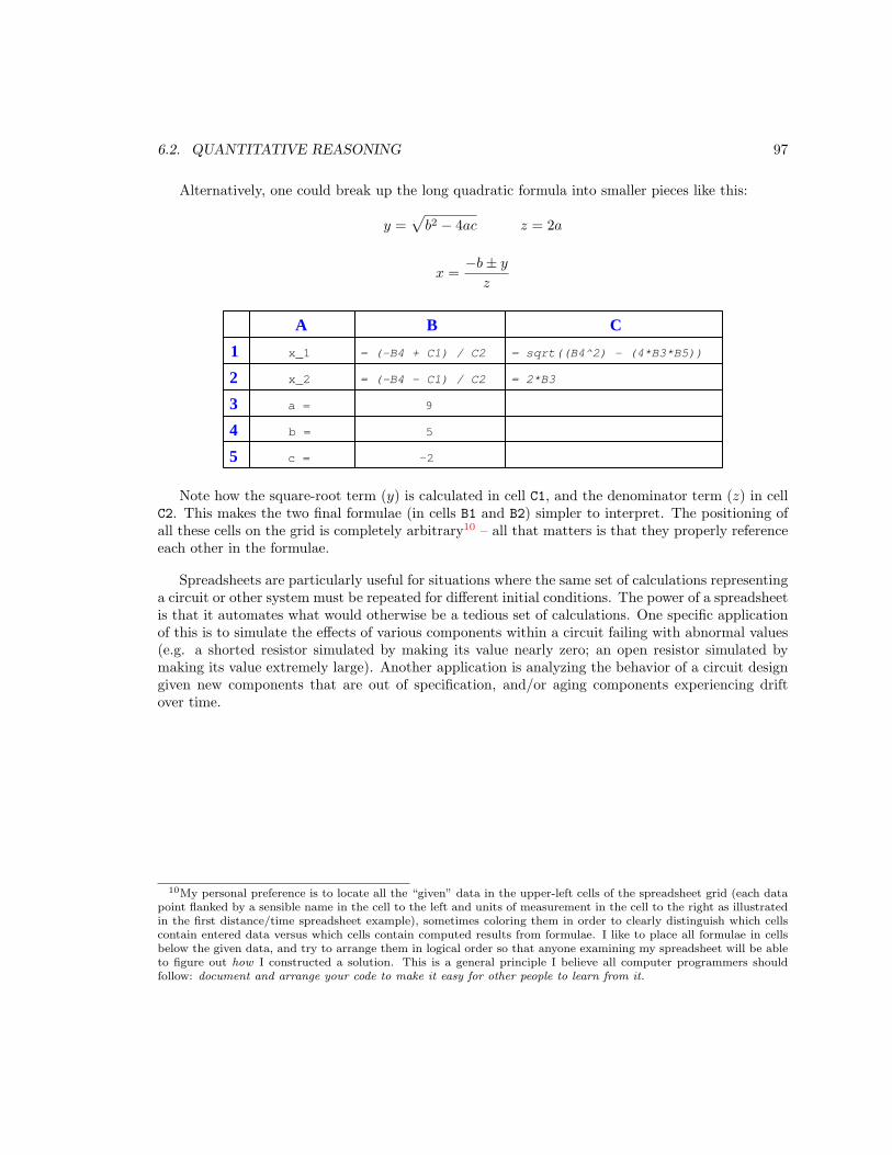
6.2. QUANTITATIVE REASONING 97
Alternatively, one could break up the long quadratic formula into smaller pieces like this:
y =√
b2 − 4ac z = 2a
x =−b ± y
z
1
2
3
4
5
A B
5
-2
x_1
x_2
a =
b =
c =
9
C
= sqrt((B4^2) - (4*B3*B5))
= 2*B3
= (-B4 + C1) / C2
= (-B4 - C1) / C2
Note how the square-root term (y) is calculated in cell C1, and the denominator term (z) in cellC2. This makes the two final formulae (in cells B1 and B2) simpler to interpret. The positioning ofall these cells on the grid is completely arbitrary10 – all that matters is that they properly referenceeach other in the formulae.
Spreadsheets are particularly useful for situations where the same set of calculations representinga circuit or other system must be repeated for different initial conditions. The power of a spreadsheetis that it automates what would otherwise be a tedious set of calculations. One specific applicationof this is to simulate the effects of various components within a circuit failing with abnormal values(e.g. a shorted resistor simulated by making its value nearly zero; an open resistor simulated bymaking its value extremely large). Another application is analyzing the behavior of a circuit designgiven new components that are out of specification, and/or aging components experiencing driftover time.
10My personal preference is to locate all the “given” data in the upper-left cells of the spreadsheet grid (each datapoint flanked by a sensible name in the cell to the left and units of measurement in the cell to the right as illustratedin the first distance/time spreadsheet example), sometimes coloring them in order to clearly distinguish which cellscontain entered data versus which cells contain computed results from formulae. I like to place all formulae in cellsbelow the given data, and try to arrange them in logical order so that anyone examining my spreadsheet will be ableto figure out how I constructed a solution. This is a general principle I believe all computer programmers shouldfollow: document and arrange your code to make it easy for other people to learn from it.
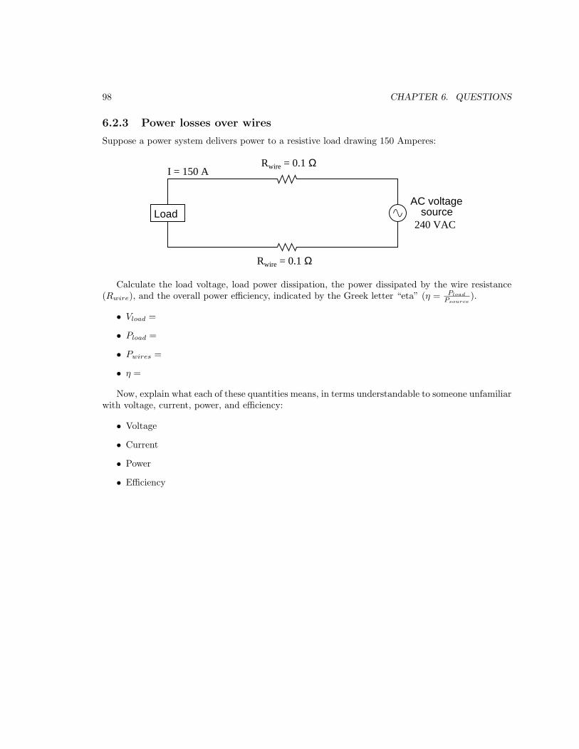
98 CHAPTER 6. QUESTIONS
6.2.3 Power losses over wires
Suppose a power system delivers power to a resistive load drawing 150 Amperes:
AC voltagesource
240 VAC
Rwire = 0.1 Ω
Rwire = 0.1 Ω
Load
I = 150 A
Calculate the load voltage, load power dissipation, the power dissipated by the wire resistance(Rwire), and the overall power efficiency, indicated by the Greek letter “eta” (η = Pload
Psource
).
• Vload =
• Pload =
• Pwires =
• η =
Now, explain what each of these quantities means, in terms understandable to someone unfamiliarwith voltage, current, power, and efficiency:
• Voltage
• Current
• Power
• Efficiency
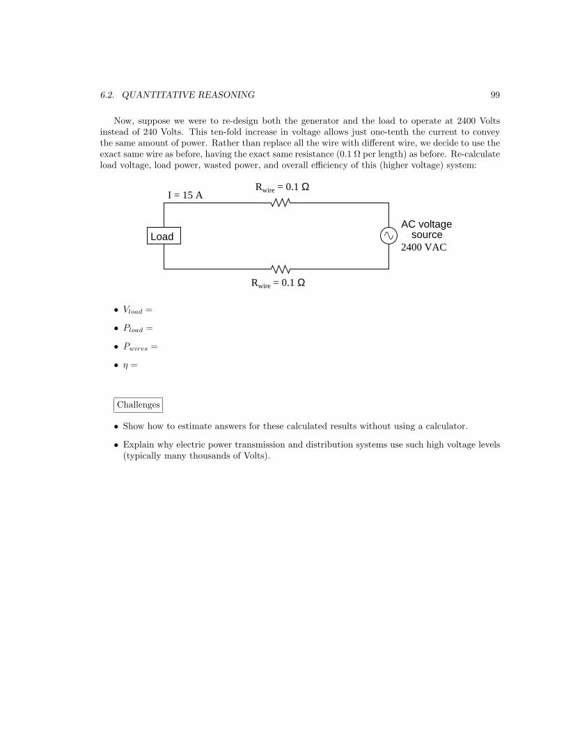
6.2. QUANTITATIVE REASONING 99
Now, suppose we were to re-design both the generator and the load to operate at 2400 Voltsinstead of 240 Volts. This ten-fold increase in voltage allows just one-tenth the current to conveythe same amount of power. Rather than replace all the wire with different wire, we decide to use theexact same wire as before, having the exact same resistance (0.1 Ω per length) as before. Re-calculateload voltage, load power, wasted power, and overall efficiency of this (higher voltage) system:
AC voltagesource
Rwire = 0.1 Ω
Rwire = 0.1 Ω
Load2400 VAC
I = 15 A
• Vload =
• Pload =
• Pwires =
• η =
Challenges
• Show how to estimate answers for these calculated results without using a calculator.
• Explain why electric power transmission and distribution systems use such high voltage levels(typically many thousands of Volts).

100 CHAPTER 6. QUESTIONS
6.2.4 Siemens model 3AP1/2 high-voltage circuit breaker
According to a technical brochure for the model 3AP1/2 high-voltage circuit breaker manufacturedby Siemens, for use as a switch in electrical power substations, the 550 kilo-Volt (550 kV) model hasthe following current ratings:
• Rated normal current = 5,000 Amperes
• Rated peak withstand current = 170,000 Amperes
• Rated maximum breaking current = 63,000 Amperes
• Rated maximum making current = 170,000 Amperes
The “normal” and “peak withstand” ratings refer to a condition when the unit is in its closed
state. However, the other two ratings refer to the circuit breaker transitioning between states,“breaking” referring to the transition from closed to open, and “making” referring to the transitionfrom open to closed.
Calculate how much greater the “making” current rating is than the “breaking” current rating,and then hypothesize why the “making” rating is greater than the “breaking” rating.
Challenges
• As you can see, the values of current a power-system circuit breaker must manage are quitelarge. If the normal amount of current for a circuit breaker such as this is 5,000 Amperes,what sort of abnormal condition do you suppose would create a current over ten times largerthan this, which the circuit breaker would have to be able to reliably interrupt by opening?
• High-voltage circuit breakers such as this model often are filled with a special gas called SF6
(sulfur hexafluoride). Why do you suppose a special gas-fill is needed, rather than have theelectrical contacts operate in plain air?
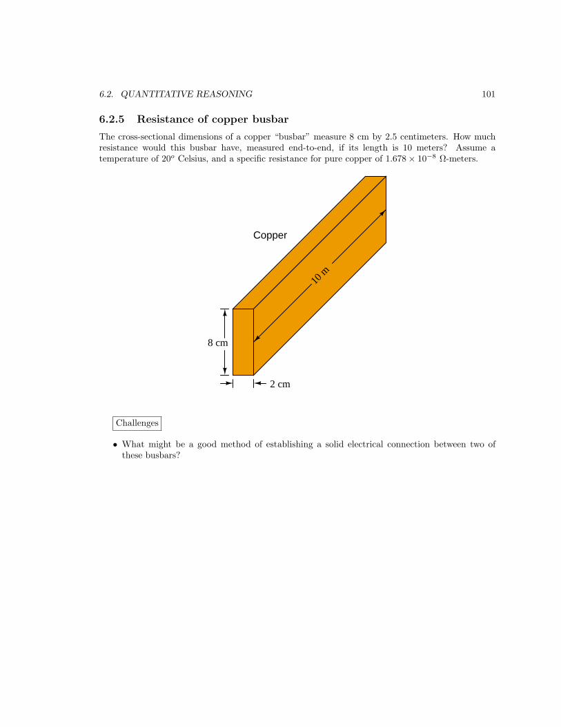
6.2. QUANTITATIVE REASONING 101
6.2.5 Resistance of copper busbar
The cross-sectional dimensions of a copper “busbar” measure 8 cm by 2.5 centimeters. How muchresistance would this busbar have, measured end-to-end, if its length is 10 meters? Assume atemperature of 20o Celsius, and a specific resistance for pure copper of 1.678 × 10⁻⁸ Ω-meters.
8 cm
2 cm
10 m
Copper
Challenges
• What might be a good method of establishing a solid electrical connection between two ofthese busbars?
102 CHAPTER 6. QUESTIONS
6.3 Diagnostic reasoning
These questions are designed to stimulate your deductive and inductive thinking, where you mustapply general principles to specific scenarios (deductive) and also derive conclusions about the failedcircuit from specific details (inductive). In a Socratic discussion with your instructor, the goal is forthese questions to reinforce your recall and use of general circuit principles and also challenge yourability to integrate multiple symptoms into a sensible explanation of what’s wrong in a circuit. Yourinstructor may also pose additional questions based on those assigned, in order to further challengeand sharpen your diagnostic abilities.
As always, your goal is to fully explain your analysis of each problem. Simply obtaining acorrect answer is not good enough – you must also demonstrate sound reasoning in order tosuccessfully complete the assignment. Your instructor’s responsibility is to probe and challengeyour understanding of the relevant principles and analytical processes in order to ensure you have astrong foundation upon which to build further understanding.
You will note a conspicuous lack of answers given for these diagnostic questions. Unlike standardtextbooks where answers to every other question are given somewhere toward the back of the book,here in these learning modules students must rely on other means to check their work. The best wayby far is to debate the answers with fellow students and also with the instructor during the Socraticdialogue sessions intended to be used with these learning modules. Reasoning through challengingquestions with other people is an excellent tool for developing strong reasoning skills.
Another means of checking your diagnostic answers, where applicable, is to use circuit simulationsoftware to explore the effects of faults placed in circuits. For example, if one of these diagnosticquestions requires that you predict the effect of an open or a short in a circuit, you may check thevalidity of your work by simulating that same fault (substituting a very high resistance in place ofthat component for an open, and substituting a very low resistance for a short) within software andseeing if the results agree.
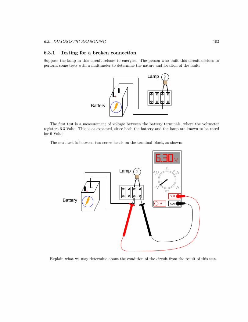
6.3. DIAGNOSTIC REASONING 103
6.3.1 Testing for a broken connection
Suppose the lamp in this circuit refuses to energize. The person who built this circuit decides toperform some tests with a multimeter to determine the nature and location of the fault:
+-
Battery
Lamp
The first test is a measurement of voltage between the battery terminals, where the voltmeterregisters 6.3 Volts. This is as expected, since both the battery and the lamp are known to be ratedfor 6 Volts.
The next test is between two screw-heads on the terminal block, as shown:
+-
Battery
Lamp
COMA
V
V A
AOFF
Explain what we may determine about the condition of the circuit from the result of this test.
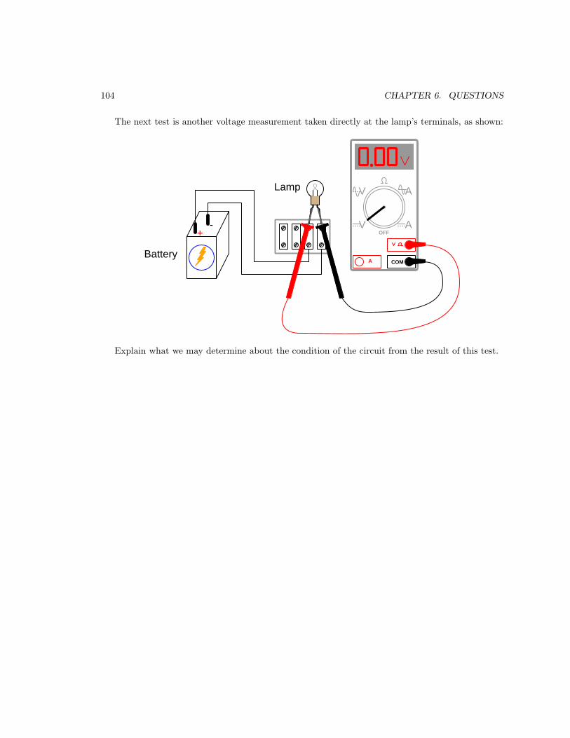
104 CHAPTER 6. QUESTIONS
The next test is another voltage measurement taken directly at the lamp’s terminals, as shown:
+-
Battery
Lamp
COMA
V
V A
AOFF
Explain what we may determine about the condition of the circuit from the result of this test.
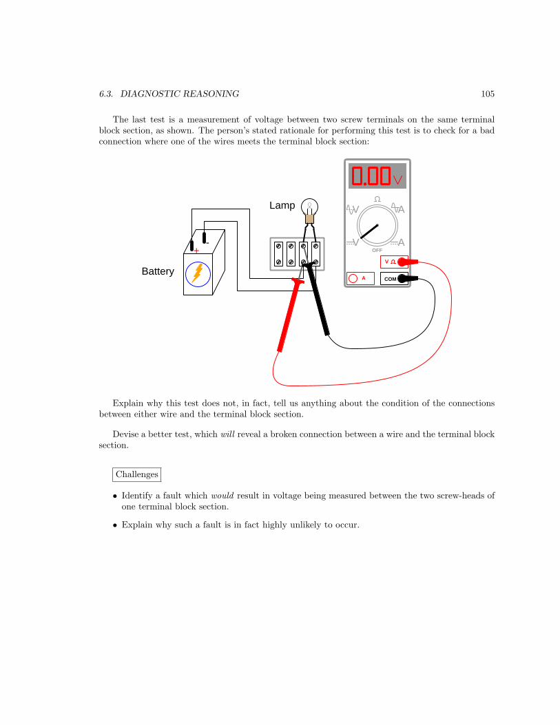
6.3. DIAGNOSTIC REASONING 105
The last test is a measurement of voltage between two screw terminals on the same terminalblock section, as shown. The person’s stated rationale for performing this test is to check for a badconnection where one of the wires meets the terminal block section:
+-
Battery
Lamp
COMA
V
V A
AOFF
Explain why this test does not, in fact, tell us anything about the condition of the connectionsbetween either wire and the terminal block section.
Devise a better test, which will reveal a broken connection between a wire and the terminal blocksection.
Challenges
• Identify a fault which would result in voltage being measured between the two screw-heads ofone terminal block section.
• Explain why such a fault is in fact highly unlikely to occur.
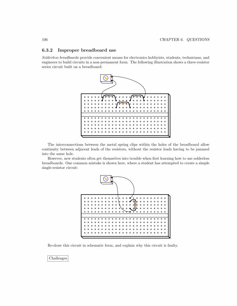
106 CHAPTER 6. QUESTIONS
6.3.2 Improper breadboard use
Solderless breadboards provide convenient means for electronics hobbyists, students, technicians, andengineers to build circuits in a non-permanent form. The following illustration shows a three-resistorseries circuit built on a breadboard:
+-
The interconnections between the metal spring clips within the holes of the breadboard allowcontinuity between adjacent leads of the resistors, without the resistor leads having to be jammedinto the same hole.
However, new students often get themselves into trouble when first learning how to use solderlessbreadboards. One common mistake is shown here, where a student has attempted to create a simplesingle-resistor circuit:
+-
Re-draw this circuit in schematic form, and explain why this circuit is faulty.
Challenges

6.3. DIAGNOSTIC REASONING 107
• Explain what might happen if a large battery or high-current power supply were powering thisshort circuit.
• Show how the single-resistor circuit should have been built on the breadboard so as to avoida problem.

108 CHAPTER 6. QUESTIONS
Appendix A
Problem-Solving Strategies
The ability to solve complex problems is arguably one of the most valuable skills one can possess,and this skill is particularly important in any science-based discipline.
• Study principles, not procedures. Don’t be satisfied with merely knowing how to computesolutions – learn why those solutions work.
• Identify what it is you need to solve, identify all relevant data, identify all units of measurement,identify any general principles or formulae linking the given information to the solution, andthen identify any “missing pieces” to a solution. Annotate all diagrams with this data.
• Sketch a diagram to help visualize the problem. When building a real system, always devisea plan for that system and analyze its function before constructing it.
• Follow the units of measurement and meaning of every calculation. If you are ever performingmathematical calculations as part of a problem-solving procedure, and you find yourself unableto apply each and every intermediate result to some aspect of the problem, it means youdon’t understand what you are doing. Properly done, every mathematical result should havepractical meaning for the problem, and not just be an abstract number. You should be able toidentify the proper units of measurement for each and every calculated result, and show wherethat result fits into the problem.
• Perform “thought experiments” to explore the effects of different conditions for theoreticalproblems. When troubleshooting real systems, perform diagnostic tests rather than visuallyinspecting for faults, the best diagnostic test being the one giving you the most informationabout the nature and/or location of the fault with the fewest steps.
• Simplify the problem until the solution becomes obvious, and then use that obvious case as amodel to follow in solving the more complex version of the problem.
• Check for exceptions to see if your solution is incorrect or incomplete. A good solution willwork for all known conditions and criteria. A good example of this is the process of testingscientific hypotheses: the task of a scientist is not to find support for a new idea, but ratherto challenge that new idea to see if it holds up under a battery of tests. The philosophical
109

110 APPENDIX A. PROBLEM-SOLVING STRATEGIES
principle of reductio ad absurdum (i.e. disproving a general idea by finding a specific casewhere it fails) is useful here.
• Work “backward” from a hypothetical solution to a new set of given conditions.
• Add quantities to problems that are qualitative in nature, because sometimes a little mathhelps illuminate the scenario.
• Sketch graphs illustrating how variables relate to each other. These may be quantitative (i.e.with realistic number values) or qualitative (i.e. simply showing increases and decreases).
• Treat quantitative problems as qualitative in order to discern the relative magnitudes and/ordirections of change of the relevant variables. For example, try determining what happens if acertain variable were to increase or decrease before attempting to precisely calculate quantities:how will each of the dependent variables respond, by increasing, decreasing, or remaining thesame as before?
• Consider limiting cases. This works especially well for qualitative problems where you need todetermine which direction a variable will change. Take the given condition and magnify thatcondition to an extreme degree as a way of simplifying the direction of the system’s response.
• Check your work. This means regularly testing your conclusions to see if they make sense.This does not mean repeating the same steps originally used to obtain the conclusion(s), butrather to use some other means to check validity. Simply repeating procedures often leads torepeating the same errors if any were made, which is why alternative paths are better.

Appendix B
Instructional philosophy
“The unexamined circuit is not worth energizing” – Socrates (if he had taught electricity)
These learning modules, although useful for self-study, were designed to be used in a formallearning environment where a subject-matter expert challenges students to digest the content andexercise their critical thinking abilities in the answering of questions and in the construction andtesting of working circuits.
The following principles inform the instructional and assessment philosophies embodied in theselearning modules:
• The first goal of education is to enhance clear and independent thought, in order thatevery student reach their fullest potential in a highly complex and inter-dependent world.Robust reasoning is always more important than particulars of any subject matter, becauseits application is universal.
• Literacy is fundamental to independent learning and thought because text continues to be themost efficient way to communicate complex ideas over space and time. Those who cannot readwith ease are limited in their ability to acquire knowledge and perspective.
• Articulate communication is fundamental to work that is complex and interdisciplinary.
• Faulty assumptions and poor reasoning are best corrected through challenge, not presentation.The rhetorical technique of reductio ad absurdum (disproving an assertion by exposing anabsurdity) works well to discipline student’s minds, not only to correct the problem at handbut also to learn how to detect and correct future errors.
• Important principles should be repeatedly explored and widely applied throughout a courseof study, not only to reinforce their importance and help ensure their mastery, but also toshowcase the interconnectedness and utility of knowledge.
111
112 APPENDIX B. INSTRUCTIONAL PHILOSOPHY
These learning modules were expressly designed to be used in an “inverted” teachingenvironment1 where students first read the introductory and tutorial chapters on their own, thenindividually attempt to answer the questions and construct working circuits according to theexperiment and project guidelines. The instructor never lectures, but instead meets regularlywith each individual student to review their progress, answer questions, identify misconceptions,and challenge the student to new depths of understanding through further questioning. Regularmeetings between instructor and student should resemble a Socratic2 dialogue, where questionsserve as scalpels to dissect topics and expose assumptions. The student passes each module onlyafter consistently demonstrating their ability to logically analyze and correctly apply all majorconcepts in each question or project/experiment. The instructor must be vigilant in probing eachstudent’s understanding to ensure they are truly reasoning and not just memorizing. This is why“Challenge” points appear throughout, as prompts for students to think deeper about topics and asstarting points for instructor queries. Sometimes these challenge points require additional knowledgethat hasn’t been covered in the series to answer in full. This is okay, as the major purpose of theChallenges is to stimulate analysis and synthesis on the part of each student.
The instructor must possess enough mastery of the subject matter and awareness of students’reasoning to generate their own follow-up questions to practically any student response. Evencompletely correct answers given by the student should be challenged by the instructor for thepurpose of having students practice articulating their thoughts and defending their reasoning.Conceptual errors committed by the student should be exposed and corrected not by directinstruction, but rather by reducing the errors to an absurdity3 through well-chosen questions andthought experiments posed by the instructor. Becoming proficient at this style of instruction requirestime and dedication, but the positive effects on critical thinking for both student and instructor arespectacular.
An inspection of these learning modules reveals certain unique characteristics. One of these isa bias toward thorough explanations in the tutorial chapters. Without a live instructor to explainconcepts and applications to students, the text itself must fulfill this role. This philosophy results inlengthier explanations than what you might typically find in a textbook, each step of the reasoningprocess fully explained, including footnotes addressing common questions and concerns studentsraise while learning these concepts. Each tutorial seeks to not only explain each major conceptin sufficient detail, but also to explain the logic of each concept and how each may be developed
1In a traditional teaching environment, students first encounter new information via lecture from an expert, andthen independently apply that information via homework. In an “inverted” course of study, students first encounternew information via homework, and then independently apply that information under the scrutiny of an expert. Theexpert’s role in lecture is to simply explain, but the expert’s role in an inverted session is to challenge, critique, andif necessary explain where gaps in understanding still exist.
2Socrates is a figure in ancient Greek philosophy famous for his unflinching style of questioning. Although heauthored no texts, he appears as a character in Plato’s many writings. The essence of Socratic philosophy is toleave no question unexamined and no point of view unchallenged. While purists may argue a topic such as electriccircuits is too narrow for a true Socratic-style dialogue, I would argue that the essential thought processes involvedwith scientific reasoning on any topic are not far removed from the Socratic ideal, and that students of electricity andelectronics would do very well to challenge assumptions, pose thought experiments, identify fallacies, and otherwiseemploy the arsenal of critical thinking skills modeled by Socrates.
3This rhetorical technique is known by the Latin phrase reductio ad absurdum. The concept is to expose errors bycounter-example, since only one solid counter-example is necessary to disprove a universal claim. As an example ofthis, consider the common misconception among beginning students of electricity that voltage cannot exist withoutcurrent. One way to apply reductio ad absurdum to this statement is to ask how much current passes through afully-charged battery connected to nothing (i.e. a clear example of voltage existing without current).

113
from “first principles”. Again, this reflects the goal of developing clear and independent thought instudents’ minds, by showing how clear and logical thought was used to forge each concept. Studentsbenefit from witnessing a model of clear thinking in action, and these tutorials strive to be just that.
Another characteristic of these learning modules is a lack of step-by-step instructions in theProject and Experiment chapters. Unlike many modern workbooks and laboratory guides wherestep-by-step instructions are prescribed for each experiment, these modules take the approach thatstudents must learn to closely read the tutorials and apply their own reasoning to identify theappropriate experimental steps. Sometimes these steps are plainly declared in the text, just not asa set of enumerated points. At other times certain steps are implied, an example being assumedcompetence in test equipment use where the student should not need to be told again how to usetheir multimeter because that was thoroughly explained in previous lessons. In some circumstancesno steps are given at all, leaving the entire procedure up to the student.
This lack of prescription is not a flaw, but rather a feature. Close reading and clear thinking arefoundational principles of this learning series, and in keeping with this philosophy all activities aredesigned to require those behaviors. Some students may find the lack of prescription frustrating,because it demands more from them than what their previous educational experiences required. Thisfrustration should be interpreted as an unfamiliarity with autonomous thinking, a problem whichmust be corrected if the student is ever to become a self-directed learner and effective problem-solver.Ultimately, the need for students to read closely and think clearly is more important both in thenear-term and far-term than any specific facet of the subject matter at hand. If a student takeslonger than expected to complete a module because they are forced to outline, digest, and reasonon their own, so be it. The future gains enjoyed by developing this mental discipline will be wellworth the additional effort and delay.
Another feature of these learning modules is that they do not treat topics in isolation. Rather,important concepts are introduced early in the series, and appear repeatedly as stepping-stonestoward other concepts in subsequent modules. This helps to avoid the “compartmentalization”of knowledge, demonstrating the inter-connectedness of concepts and simultaneously reinforcingthem. Each module is fairly complete in itself, reserving the beginning of its tutorial to a review offoundational concepts.
This methodology of assigning text-based modules to students for digestion and then usingSocratic dialogue to assess progress and hone students’ thinking was developed over a period ofseveral years by the author with his Electronics and Instrumentation students at the two-year collegelevel. While decidedly unconventional and sometimes even unsettling for students accustomed toa more passive lecture environment, this instructional philosophy has proven its ability to conveyconceptual mastery, foster careful analysis, and enhance employability so much better than lecturethat the author refuses to ever teach by lecture again.
Problems which often go undiagnosed in a lecture environment are laid bare in this “inverted”format where students must articulate and logically defend their reasoning. This, too, may beunsettling for students accustomed to lecture sessions where the instructor cannot tell for sure whocomprehends and who does not, and this vulnerability necessitates sensitivity on the part of the“inverted” session instructor in order that students never feel discouraged by having their errorsexposed. Everyone makes mistakes from time to time, and learning is a lifelong process! Part ofthe instructor’s job is to build a culture of learning among the students where errors are not seen asshameful, but rather as opportunities for progress.

114 APPENDIX B. INSTRUCTIONAL PHILOSOPHY
To this end, instructors managing courses based on these modules should adhere to the followingprinciples:
• Student questions are always welcome and demand thorough, honest answers. The only typeof question an instructor should refuse to answer is one the student should be able to easilyanswer on their own. Remember, the fundamental goal of education is for each student to learn
to think clearly and independently. This requires hard work on the part of the student, whichno instructor should ever circumvent. Anything done to bypass the student’s responsibility todo that hard work ultimately limits that student’s potential and thereby does real harm.
• It is not only permissible, but encouraged, to answer a student’s question by asking questionsin return, these follow-up questions designed to guide the student to reach a correct answerthrough their own reasoning.
• All student answers demand to be challenged by the instructor and/or by other students.This includes both correct and incorrect answers – the goal is to practice the articulation anddefense of one’s own reasoning.
• No reading assignment is deemed complete unless and until the student demonstrates theirability to accurately summarize the major points in their own terms. Recitation of the originaltext is unacceptable. This is why every module contains an “Outline and reflections” questionas well as a “Foundational concepts” question in the Conceptual reasoning section, to promptreflective reading.
• No assigned question is deemed answered unless and until the student demonstrates theirability to consistently and correctly apply the concepts to variations of that question. This iswhy module questions typically contain multiple “Challenges” suggesting different applicationsof the concept(s) as well as variations on the same theme(s). Instructors are encouraged todevise as many of their own “Challenges” as they are able, in order to have a multitude ofways ready to probe students’ understanding.
• No assigned experiment or project is deemed complete unless and until the studentdemonstrates the task in action. If this cannot be done “live” before the instructor, video-recordings showing the demonstration are acceptable. All relevant safety precautions must befollowed, all test equipment must be used correctly, and the student must be able to properlyexplain all results. The student must also successfully answer all Challenges presented by theinstructor for that experiment or project.

115
Students learning from these modules would do well to abide by the following principles:
• No text should be considered fully and adequately read unless and until you can express everyidea in your own words, using your own examples.
• You should always articulate your thoughts as you read the text, noting points of agreement,confusion, and epiphanies. Feel free to print the text on paper and then write your notes inthe margins. Alternatively, keep a journal for your own reflections as you read. This is trulya helpful tool when digesting complicated concepts.
• Never take the easy path of highlighting or underlining important text. Instead, summarize
and/or comment on the text using your own words. This actively engages your mind, allowingyou to more clearly perceive points of confusion or misunderstanding on your own.
• A very helpful strategy when learning new concepts is to place yourself in the role of a teacher,if only as a mental exercise. Either explain what you have recently learned to someone else,or at least imagine yourself explaining what you have learned to someone else. The simple actof having to articulate new knowledge and skill forces you to take on a different perspective,and will help reveal weaknesses in your understanding.
• Perform each and every mathematical calculation and thought experiment shown in the texton your own, referring back to the text to see that your results agree. This may seem trivialand unnecessary, but it is critically important to ensuring you actually understand what ispresented, especially when the concepts at hand are complicated and easy to misunderstand.Apply this same strategy to become proficient in the use of circuit simulation software, checkingto see if your simulated results agree with the results shown in the text.
• Above all, recognize that learning is hard work, and that a certain level of frustration isunavoidable. There are times when you will struggle to grasp some of these concepts, and thatstruggle is a natural thing. Take heart that it will yield with persistent and varied4 effort, andnever give up!
Students interested in using these modules for self-study will also find them beneficial, althoughthe onus of responsibility for thoroughly reading and answering questions will of course lie withthat individual alone. If a qualified instructor is not available to challenge students, a workablealternative is for students to form study groups where they challenge5 one another.
To high standards of education,
Tony R. Kuphaldt
4As the old saying goes, “Insanity is trying the same thing over and over again, expecting different results.” Ifyou find yourself stumped by something in the text, you should attempt a different approach. Alter the thoughtexperiment, change the mathematical parameters, do whatever you can to see the problem in a slightly different light,and then the solution will often present itself more readily.
5Avoid the temptation to simply share answers with study partners, as this is really counter-productive to learning.Always bear in mind that the answer to any question is far less important in the long run than the method(s) used toobtain that answer. The goal of education is to empower one’s life through the improvement of clear and independentthought, literacy, expression, and various practical skills.

116 APPENDIX B. INSTRUCTIONAL PHILOSOPHY

Appendix C
Tools used
I am indebted to the developers of many open-source software applications in the creation of theselearning modules. The following is a list of these applications with some commentary on each.
You will notice a theme common to many of these applications: a bias toward code. AlthoughI am by no means an expert programmer in any computer language, I understand and appreciatethe flexibility offered by code-based applications where the user (you) enters commands into a plainASCII text file, which the software then reads and processes to create the final output. Code-basedcomputer applications are by their very nature extensible, while WYSIWYG (What You See Is WhatYou Get) applications are generally limited to whatever user interface the developer makes for you.
The GNU/Linux computer operating system
There is so much to be said about Linus Torvalds’ Linux and Richard Stallman’s GNU
project. First, to credit just these two individuals is to fail to do justice to the mob ofpassionate volunteers who contributed to make this amazing software a reality. I firstlearned of Linux back in 1996, and have been using this operating system on my personalcomputers almost exclusively since then. It is free, it is completely configurable, and itpermits the continued use of highly efficient Unix applications and scripting languages(e.g. shell scripts, Makefiles, sed, awk) developed over many decades. Linux not onlyprovided me with a powerful computing platform, but its open design served to inspiremy life’s work of creating open-source educational resources.
Bram Moolenaar’s Vim text editor
Writing code for any code-based computer application requires a text editor, which maybe thought of as a word processor strictly limited to outputting plain-ASCII text files.Many good text editors exist, and one’s choice of text editor seems to be a deeply personalmatter within the programming world. I prefer Vim because it operates very similarly tovi which is ubiquitous on Unix/Linux operating systems, and because it may be entirelyoperated via keyboard (i.e. no mouse required) which makes it fast to use.
117
118 APPENDIX C. TOOLS USED
Donald Knuth’s TEX typesetting system
Developed in the late 1970’s and early 1980’s by computer scientist extraordinaire DonaldKnuth to typeset his multi-volume magnum opus The Art of Computer Programming,this software allows the production of formatted text for screen-viewing or paper printing,all by writing plain-text code to describe how the formatted text is supposed to appear.TEX is not just a markup language for documents, but it is also a Turing-completeprogramming language in and of itself, allowing useful algorithms to be created to controlthe production of documents. Simply put, TEX is a programmer’s approach to word
processing. Since TEX is controlled by code written in a plain-text file, this meansanyone may read that plain-text file to see exactly how the document was created. Thisopenness afforded by the code-based nature of TEX makes it relatively easy to learn howother people have created their own TEX documents. By contrast, examining a beautifuldocument created in a conventional WYSIWYG word processor such as Microsoft Wordsuggests nothing to the reader about how that document was created, or what the usermight do to create something similar. As Mr. Knuth himself once quipped, conventionalword processing applications should be called WYSIAYG (What You See Is All YouGet).
Leslie Lamport’s LATEX extensions to TEX
Like all true programming languages, TEX is inherently extensible. So, years after therelease of TEX to the public, Leslie Lamport decided to create a massive extensionallowing easier compilation of book-length documents. The result was LATEX, whichis the markup language used to create all ModEL module documents. You could saythat TEX is to LATEX as C is to C++. This means it is permissible to use any and all TEXcommands within LATEX source code, and it all still works. Some of the features offeredby LATEX that would be challenging to implement in TEX include automatic index andtable-of-content creation.
Tim Edwards’ Xcircuit drafting program
This wonderful program is what I use to create all the schematic diagrams andillustrations (but not photographic images or mathematical plots) throughout the ModELproject. It natively outputs PostScript format which is a true vector graphic format (thisis why the images do not pixellate when you zoom in for a closer view), and it is so simpleto use that I have never had to read the manual! Object libraries are easy to create forXcircuit, being plain-text files using PostScript programming conventions. Over theyears I have collected a large set of object libraries useful for drawing electrical andelectronic schematics, pictorial diagrams, and other technical illustrations.

119
Gimp graphic image manipulation program
Essentially an open-source clone of Adobe’s PhotoShop, I use Gimp to resize, crop, andconvert file formats for all of the photographic images appearing in the ModEL modules.Although Gimp does offer its own scripting language (called Script-Fu), I have neverhad occasion to use it. Thus, my utilization of Gimp to merely crop, resize, and convertgraphic images is akin to using a sword to slice bread.
SPICE circuit simulation program
SPICE is to circuit analysis as TEX is to document creation: it is a form of markuplanguage designed to describe a certain object to be processed in plain-ASCII text.When the plain-text “source file” is compiled by the software, it outputs the final result.More modern circuit analysis tools certainly exist, but I prefer SPICE for the followingreasons: it is free, it is fast, it is reliable, and it is a fantastic tool for teaching students ofelectricity and electronics how to write simple code. I happen to use rather old versions ofSPICE, version 2g6 being my “go to” application when I only require text-based output.NGSPICE (version 26), which is based on Berkeley SPICE version 3f5, is used when Irequire graphical output for such things as time-domain waveforms and Bode plots. Inall SPICE example netlists I strive to use coding conventions compatible with all SPICEversions.
Andrew D. Hwang’s ePiX mathematical visualization programming library
This amazing project is a C++ library you may link to any C/C++ code for the purposeof generating PostScript graphic images of mathematical functions. As a completelyfree and open-source project, it does all the plotting I would otherwise use a ComputerAlgebra System (CAS) such as Mathematica or Maple to do. It should be said thatePiX is not a Computer Algebra System like Mathematica or Maple, but merely amathematical visualization tool. In other words, it won’t determine integrals for you(you’ll have to implement that in your own C/C++ code!), but it can graph the results, andit does so beautifully. What I really admire about ePiX is that it is a C++ programminglibrary, which means it builds on the existing power and toolset available with thatprogramming language. Mr. Hwang could have probably developed his own stand-aloneapplication for mathematical plotting, but by creating a C++ library to do the same thinghe accomplished something much greater.

120 APPENDIX C. TOOLS USED
gnuplot mathematical visualization software
Another open-source tool for mathematical visualization is gnuplot. Interestingly, thistool is not part of Richard Stallman’s GNU project, its name being a coincidence. Forthis reason the authors prefer “gnu” not be capitalized at all to avoid confusion. This isa much “lighter-weight” alternative to a spreadsheet for plotting tabular data, and thefact that it easily outputs directly to an X11 console or a file in a number of differentgraphical formats (including PostScript) is very helpful. I typically set my gnuplot
output format to default (X11 on my Linux PC) for quick viewing while I’m developinga visualization, then switch to PostScript file export once the visual is ready to include inthe document(s) I’m writing. As with my use of Gimp to do rudimentary image editing,my use of gnuplot only scratches the surface of its capabilities, but the important pointsare that it’s free and that it works well.
Python programming language
Both Python and C++ find extensive use in these modules as instructional aids andexercises, but I’m listing Python here as a tool for myself because I use it almost dailyas a calculator. If you open a Python interpreter console and type from math import
* you can type mathematical expressions and have it return results just as you wouldon a hand calculator. Complex-number (i.e. phasor) arithmetic is similarly supportedif you include the complex-math library (from cmath import *). Examples of this areshown in the Programming References chapter (if included) in each module. Of course,being a fully-featured programming language, Python also supports conditionals, loops,and other structures useful for calculation of quantities. Also, running in a consoleenvironment where all entries and returned values show as text in a chronologically-ordered list makes it easy to copy-and-paste those calculations to document exactly howthey were performed.

Appendix D
Creative Commons License
Creative Commons Attribution 4.0 International Public License
By exercising the Licensed Rights (defined below), You accept and agree to be bound by the termsand conditions of this Creative Commons Attribution 4.0 International Public License (“PublicLicense”). To the extent this Public License may be interpreted as a contract, You are granted theLicensed Rights in consideration of Your acceptance of these terms and conditions, and the Licensorgrants You such rights in consideration of benefits the Licensor receives from making the LicensedMaterial available under these terms and conditions.
Section 1 – Definitions.
a. Adapted Material means material subject to Copyright and Similar Rights that is derivedfrom or based upon the Licensed Material and in which the Licensed Material is translated, altered,arranged, transformed, or otherwise modified in a manner requiring permission under the Copyrightand Similar Rights held by the Licensor. For purposes of this Public License, where the LicensedMaterial is a musical work, performance, or sound recording, Adapted Material is always producedwhere the Licensed Material is synched in timed relation with a moving image.
b. Adapter’s License means the license You apply to Your Copyright and Similar Rights inYour contributions to Adapted Material in accordance with the terms and conditions of this PublicLicense.
c. Copyright and Similar Rights means copyright and/or similar rights closely related tocopyright including, without limitation, performance, broadcast, sound recording, and Sui GenerisDatabase Rights, without regard to how the rights are labeled or categorized. For purposes of thisPublic License, the rights specified in Section 2(b)(1)-(2) are not Copyright and Similar Rights.
d. Effective Technological Measures means those measures that, in the absence of properauthority, may not be circumvented under laws fulfilling obligations under Article 11 of the WIPOCopyright Treaty adopted on December 20, 1996, and/or similar international agreements.
e. Exceptions and Limitations means fair use, fair dealing, and/or any other exception or
121

122 APPENDIX D. CREATIVE COMMONS LICENSE
limitation to Copyright and Similar Rights that applies to Your use of the Licensed Material.
f. Licensed Material means the artistic or literary work, database, or other material to whichthe Licensor applied this Public License.
g. Licensed Rights means the rights granted to You subject to the terms and conditions ofthis Public License, which are limited to all Copyright and Similar Rights that apply to Your use ofthe Licensed Material and that the Licensor has authority to license.
h. Licensor means the individual(s) or entity(ies) granting rights under this Public License.
i. Share means to provide material to the public by any means or process that requirespermission under the Licensed Rights, such as reproduction, public display, public performance,distribution, dissemination, communication, or importation, and to make material available to thepublic including in ways that members of the public may access the material from a place and at atime individually chosen by them.
j. Sui Generis Database Rights means rights other than copyright resulting from Directive96/9/EC of the European Parliament and of the Council of 11 March 1996 on the legal protectionof databases, as amended and/or succeeded, as well as other essentially equivalent rights anywherein the world.
k. You means the individual or entity exercising the Licensed Rights under this Public License.Your has a corresponding meaning.
Section 2 – Scope.
a. License grant.
1. Subject to the terms and conditions of this Public License, the Licensor hereby grants You aworldwide, royalty-free, non-sublicensable, non-exclusive, irrevocable license to exercise the LicensedRights in the Licensed Material to:
A. reproduce and Share the Licensed Material, in whole or in part; and
B. produce, reproduce, and Share Adapted Material.
2. Exceptions and Limitations. For the avoidance of doubt, where Exceptions and Limitationsapply to Your use, this Public License does not apply, and You do not need to comply with its termsand conditions.
3. Term. The term of this Public License is specified in Section 6(a).
4. Media and formats; technical modifications allowed. The Licensor authorizes You to exercisethe Licensed Rights in all media and formats whether now known or hereafter created, and to maketechnical modifications necessary to do so. The Licensor waives and/or agrees not to assert any rightor authority to forbid You from making technical modifications necessary to exercise the LicensedRights, including technical modifications necessary to circumvent Effective Technological Measures.

123
For purposes of this Public License, simply making modifications authorized by this Section 2(a)(4)never produces Adapted Material.
5. Downstream recipients.
A. Offer from the Licensor – Licensed Material. Every recipient of the Licensed Materialautomatically receives an offer from the Licensor to exercise the Licensed Rights under the termsand conditions of this Public License.
B. No downstream restrictions. You may not offer or impose any additional or different termsor conditions on, or apply any Effective Technological Measures to, the Licensed Material if doingso restricts exercise of the Licensed Rights by any recipient of the Licensed Material.
6. No endorsement. Nothing in this Public License constitutes or may be construed as permissionto assert or imply that You are, or that Your use of the Licensed Material is, connected with,or sponsored, endorsed, or granted official status by, the Licensor or others designated to receiveattribution as provided in Section 3(a)(1)(A)(i).
b. Other rights.
1. Moral rights, such as the right of integrity, are not licensed under this Public License, norare publicity, privacy, and/or other similar personality rights; however, to the extent possible, theLicensor waives and/or agrees not to assert any such rights held by the Licensor to the limited extentnecessary to allow You to exercise the Licensed Rights, but not otherwise.
2. Patent and trademark rights are not licensed under this Public License.
3. To the extent possible, the Licensor waives any right to collect royalties from You for theexercise of the Licensed Rights, whether directly or through a collecting society under any voluntaryor waivable statutory or compulsory licensing scheme. In all other cases the Licensor expresslyreserves any right to collect such royalties.
Section 3 – License Conditions.
Your exercise of the Licensed Rights is expressly made subject to the following conditions.
a. Attribution.
1. If You Share the Licensed Material (including in modified form), You must:
A. retain the following if it is supplied by the Licensor with the Licensed Material:
i. identification of the creator(s) of the Licensed Material and any others designated to receiveattribution, in any reasonable manner requested by the Licensor (including by pseudonym ifdesignated);
ii. a copyright notice;

124 APPENDIX D. CREATIVE COMMONS LICENSE
iii. a notice that refers to this Public License;
iv. a notice that refers to the disclaimer of warranties;
v. a URI or hyperlink to the Licensed Material to the extent reasonably practicable;
B. indicate if You modified the Licensed Material and retain an indication of any previousmodifications; and
C. indicate the Licensed Material is licensed under this Public License, and include the text of,or the URI or hyperlink to, this Public License.
2. You may satisfy the conditions in Section 3(a)(1) in any reasonable manner based on themedium, means, and context in which You Share the Licensed Material. For example, it may bereasonable to satisfy the conditions by providing a URI or hyperlink to a resource that includes therequired information.
3. If requested by the Licensor, You must remove any of the information required by Section3(a)(1)(A) to the extent reasonably practicable.
4. If You Share Adapted Material You produce, the Adapter’s License You apply must notprevent recipients of the Adapted Material from complying with this Public License.
Section 4 – Sui Generis Database Rights.
Where the Licensed Rights include Sui Generis Database Rights that apply to Your use of theLicensed Material:
a. for the avoidance of doubt, Section 2(a)(1) grants You the right to extract, reuse, reproduce,and Share all or a substantial portion of the contents of the database;
b. if You include all or a substantial portion of the database contents in a database in whichYou have Sui Generis Database Rights, then the database in which You have Sui Generis DatabaseRights (but not its individual contents) is Adapted Material; and
c. You must comply with the conditions in Section 3(a) if You Share all or a substantial portionof the contents of the database.
For the avoidance of doubt, this Section 4 supplements and does not replace Your obligationsunder this Public License where the Licensed Rights include other Copyright and Similar Rights.
Section 5 – Disclaimer of Warranties and Limitation of Liability.
a. Unless otherwise separately undertaken by the Licensor, to the extent possible, the Licensoroffers the Licensed Material as-is and as-available, and makes no representations or warranties ofany kind concerning the Licensed Material, whether express, implied, statutory, or other. Thisincludes, without limitation, warranties of title, merchantability, fitness for a particular purpose,non-infringement, absence of latent or other defects, accuracy, or the presence or absence of errors,

125
whether or not known or discoverable. Where disclaimers of warranties are not allowed in full or inpart, this disclaimer may not apply to You.
b. To the extent possible, in no event will the Licensor be liable to You on any legal theory(including, without limitation, negligence) or otherwise for any direct, special, indirect, incidental,consequential, punitive, exemplary, or other losses, costs, expenses, or damages arising out of thisPublic License or use of the Licensed Material, even if the Licensor has been advised of the possibilityof such losses, costs, expenses, or damages. Where a limitation of liability is not allowed in full orin part, this limitation may not apply to You.
c. The disclaimer of warranties and limitation of liability provided above shall be interpreted ina manner that, to the extent possible, most closely approximates an absolute disclaimer and waiverof all liability.
Section 6 – Term and Termination.
a. This Public License applies for the term of the Copyright and Similar Rights licensed here.However, if You fail to comply with this Public License, then Your rights under this Public Licenseterminate automatically.
b. Where Your right to use the Licensed Material has terminated under Section 6(a), it reinstates:
1. automatically as of the date the violation is cured, provided it is cured within 30 days of Yourdiscovery of the violation; or
2. upon express reinstatement by the Licensor.
For the avoidance of doubt, this Section 6(b) does not affect any right the Licensor may have toseek remedies for Your violations of this Public License.
c. For the avoidance of doubt, the Licensor may also offer the Licensed Material under separateterms or conditions or stop distributing the Licensed Material at any time; however, doing so willnot terminate this Public License.
d. Sections 1, 5, 6, 7, and 8 survive termination of this Public License.
Section 7 – Other Terms and Conditions.
a. The Licensor shall not be bound by any additional or different terms or conditionscommunicated by You unless expressly agreed.
b. Any arrangements, understandings, or agreements regarding the Licensed Material not statedherein are separate from and independent of the terms and conditions of this Public License.
Section 8 – Interpretation.
a. For the avoidance of doubt, this Public License does not, and shall not be interpreted to,reduce, limit, restrict, or impose conditions on any use of the Licensed Material that could lawfully

126 APPENDIX D. CREATIVE COMMONS LICENSE
be made without permission under this Public License.
b. To the extent possible, if any provision of this Public License is deemed unenforceable, it shallbe automatically reformed to the minimum extent necessary to make it enforceable. If the provisioncannot be reformed, it shall be severed from this Public License without affecting the enforceabilityof the remaining terms and conditions.
c. No term or condition of this Public License will be waived and no failure to comply consentedto unless expressly agreed to by the Licensor.
d. Nothing in this Public License constitutes or may be interpreted as a limitation upon, orwaiver of, any privileges and immunities that apply to the Licensor or You, including from the legalprocesses of any jurisdiction or authority.

127
Creative Commons is not a party to its public licenses. Notwithstanding, Creative Commonsmay elect to apply one of its public licenses to material it publishes and in those instances willbe considered the “Licensor.” Except for the limited purpose of indicating that material is sharedunder a Creative Commons public license or as otherwise permitted by the Creative Commonspolicies published at creativecommons.org/policies, Creative Commons does not authorize theuse of the trademark “Creative Commons” or any other trademark or logo of Creative Commonswithout its prior written consent including, without limitation, in connection with any unauthorizedmodifications to any of its public licenses or any other arrangements, understandings, or agreementsconcerning use of licensed material. For the avoidance of doubt, this paragraph does not form partof the public licenses.
Creative Commons may be contacted at creativecommons.org.

128 APPENDIX D. CREATIVE COMMONS LICENSE

Appendix E
References
“High-Voltage Circuit-Breakers 3AP1/2 72.5 kV up to 550 kV”, Order number E50001-U113-A165-V3-7600, Siemens, Berlin.
NFPA 79 Electrical Standard for Industrial Machinery 2007 Edition, National Fire ProtectionAssociation, Quincy, MA, 2006.
129

130 APPENDIX E. REFERENCES

Appendix F
Version history
This is a list showing all significant additions, corrections, and other edits made to this learningmodule. Each entry is referenced by calendar date in reverse chronological order (newest versionfirst), which appears on the front cover of every learning module for easy reference. Any contributorsto this open-source document are listed here as well.
15 March 2022 – added comments about solder-tinned wire ends “cold-flowing” under mechanicalcompression. Also, relocated the “Solder” subsection to an earlier part of the Tutorial, so that itprecedes the subsection on terminal blocks where these new comments are found.
4 February 2022 – added some challenges in various questions to have students demonstratestrategies for checking their work.
18 July 2021 – added foundational concept review to the “Power losses over wires” QuantitativeReasoning question.
1 June 2021 – minor additions to the beginning of the “Permanent Connections” and “TemporaryConnections” sections of the Tutorial.
8 May 2021 – commented out or deleted empty chapters.
2 February 2021 – minor edits.
14 September 2020 – added “soldering” to the list of Foundational concepts.
8 September 2020 – minor edits to the Introduction chapter.
29 August 2020 – significantly edited the Introduction chapter to make it more suitable as apre-study guide and to provide cues useful to instructors leading “inverted” teaching sessions.
14 April 2020 – added some questions.
14 February 2020 – added ampacity figures from NFPA 79 standard.
131

132 APPENDIX F. VERSION HISTORY
2 February 2020 – minor typographical error correction.
20 October 2019 – added an animation showing the proper use of a soldering iron to attach a wireto a lug.
August 2018 – added more photographs to the tutorial, especially of plug and socket connectors,and of terminal blocks. Also, made minor edits to Introduction chapter.
May 2018 – minor edit to “parallel” illustration, annotating connected points as electrically commonto each other, not just equipotential to each other. Minor edit to open vs. shorted switch illustration,relating open with electrical isolation (no current) and relating shorted with electrical commonality(no voltage).
2017 – document first created.

Index
ρ, specific resistance, 11
Adding quantities to a qualitative problem, 110Alligator clip, 34Alloy, 19American Wire Gauge, 13, 14Ampacity, 5, 13, 23Ampere, 7Annotating diagrams, 109Atom, 7AutoCAD, 21AWG, 13, 14
Breadboard, 24, 35Breakdown voltage, 9Breaking a connection, 9Butt splice, 26
CAD, 21Cap, 36Category-5 cable, 27Category-6 cable, 27Charge carrier, 7Checking for exceptions, 110Checking your work, 110Circuit, 8Circular mils, 13Close, 9CM, 13Coaxial cable, 27Code, computer, 117Cold-flow, 25, 29–31Compression connector, 25Conductors, 7Conservation of Energy, 11Corrosion, 9, 17–20Coulomb, 7
Crimping tool, 25Current, 7
Dimensional analysis, 109DIN rail, 28DIP, 35Dual inline package, 35
Edwards, Tim, 118Electric field, 7Electrical resistance, 7Electrically common points, 9Electrically isolated points, 9Electricity, 7
Ferrule, 26, 28Fiberglass, 20, 24Flux, soldering, 19, 23Fork terminal, 25FR4, 21
Gauge, wire, 5, 13Graph values to solve a problem, 110Greenleaf, Cynthia, 81
How to teach with these modules, 112Hwang, Andrew D., 119
IC, 35Identify given data, 109Identify relevant principles, 109Instructions for projects and experiments, 113Insulators, 7Integrated circuit, 35Intermediate results, 109Inverted instruction, 112Ionization, 9
133

134 INDEX
Jack, 36Joule’s Law, 14, 23Jumper wire, 34Jumper, terminal block, 32
Keying, 37Knuth, Donald, 118
Lamport, Leslie, 118Lead, 19Limiting cases, 110Load, 11
Making a connection, 9Manta 5000 protective relay test set, 40MCM, 13Metacognition, 86Mil, 13Modular terminal block, 28Mole, 42Monolithic terminal block, 28Moolenaar, Bram, 117Murphy, Lynn, 81
National Electrical Code, 14NEC, 14Negative charge, 7NFPA 70, 14NFPA 79, 14
Ohm’s Law, 10Open, 9Open-source, 117
Particle, 7PCB, 5, 21Periodic Table of the Elements, 42Pigtail splice, 16, 20Plug, 36Positive charge, 7Printed Circuit Board, 5, 21Problem-solving: annotate diagrams, 109Problem-solving: check for exceptions, 110Problem-solving: checking work, 110Problem-solving: dimensional analysis, 109Problem-solving: graph values, 110Problem-solving: identify given data, 109
Problem-solving: identify relevant principles, 109Problem-solving: interpret intermediate results,
109Problem-solving: limiting cases, 110Problem-solving: qualitative to quantitative, 110Problem-solving: quantitative to qualitative, 110Problem-solving: reductio ad absurdum, 110Problem-solving: simplify the system, 109Problem-solving: thought experiment, 109Problem-solving: track units of measurement,
109Problem-solving: visually represent the system,
109Problem-solving: work in reverse, 110
Qualitatively approaching a quantitativeproblem, 110
Reading Apprenticeship, 81Receptacle, 36Reductio ad absurdum, 110–112Relay, 34Resistance, 7Resistive Thermal Detector, 36Ring terminal, 25RTD, 36
Schoenbach, Ruth, 81Scientific method, 86Screwless terminal block, 31Short, 9Silkscreen, 22Simplifying a system, 109Single inline package, 35SIP, 35SMD, 23Socket, 36Socrates, 111Socratic dialogue, 112Solder, 19Soldering flux, 19, 23Solderless breadboard, 35Soldermask, 22Solid wire, 15Spade terminal, 27Specific resistance, 5, 11

INDEX 135
SPICE, 81Splice, 16Splice, pigtail, 16, 20Splice, Western Union, 16Spring, 33Stallman, Richard, 117Stranded wire, 15Surface-mount devices, 23Switch, 9
Tab, keying, 37Temperature, 10Terminal block, 28Terminal block, screwless, 31Thought experiment, 109Through-hole components, 21Tin, 19Tinning, 22Tool, crimping, 25Torvalds, Linus, 117
Units of measurement, 109
Visualizing a system, 109Volt, 7Voltage, 7
Western Union splice, 16Wire nut, 18Wire wrap, 24Work in reverse to solve a problem, 110WYSIWYG, 117, 118