concrete repair with realkalisation and the management thereof
TRANSCRIPT
CONCRETE REPAIR WITH REALKALISATION AND THE MANAGEMENT THEREOF
by
WA MUZEMBA TSHIBANGU
A THESIS SUBMITTED TO THE FACULTY OF ENGINEERING FOR PARTIAL FULFILMENT OF THE REQUIREMENTS FOR THE DEGREE
MAGISTER INGENERIAE
in
ENGINEERING MANAGEMENT
at the
RAND AFRIKAANS UNIVERSITY
SUPERVISOR: Mr J. PRETORIUS
JUNE 1998
DEDICATION
To my wife JoeIle,
my children Kenny, Dan and Sarah.
For all your support during my studies. This thesis is dedicated to you for your love and confidence in me.
Anselme WM Tshibangu
i
ACKNOWLEDGEMENT
This thesis was made possible through the contributions and support of a number of people.
The encouragement and initial orientation of Prof. Pieter van der Merwe, Dean of the Faculty of Engineering at Rand Afrikaans University, is highly acknowledged.
The advises, guidance, patience, support, encouragement of Mr Johann Pretorius, my supervisor, are gratefully acknowledged and appreciated.
The academic support and background gained through lectures willingly given by Prof. L. Pretorius, Head of Department of Mechanical and Manufacturing Engineering at Rand Afrikaans University, Dr. Wessels, Mr. D. Kruger, Department of Civil Engineering, R.A.U., and occasional and visiting lecturers, are gratefully appreciated.
The logistic support of MM Louison Kabamba and K.T. Khally is acknowledged.
I am especially grateful to my wife, my mother, my brothers, my parents-in-law and all my friends for their support and encouragement during my studies.
Many thanks to God for making everything possible.
ii
TABLE OF CONTENTS
DEDICATION ACKNOWLEDGEMENT TABLE OF CONTENTS LIST OF FIGURES LIST OF TABLES
SYNOPSIS PART I CHAPTER 1 : INTRODUCTION
ii iii
xii
1 1 2
1.1 General remarks 2
1 . 2 Purpose of the study 2
1.3 Scope of the study 3
CHAPTER 2 : CONCRETE AND PROTECTIVE COATINGS MATERIALS USED AND CHARACTERISTICS 5
2.1 Concrete 5 2.1.1 General remarks 5 2.1.2 Constituents of concrete, structure and
chemistry of concrete 6 2.1.2.1 The composite 6 2.1.2.2 Aggregate phase 7 2.1.2.3 Hydrated cement matrix 9 2.1.2.4 Pores and voids 11 2.1.2.5 The states of water in hydrated cement paste 12
2.1.3 Admixtures for concrete 14 2.1.3.1 Accelerators 14 2.1.3.2 Retarders 15 2.1.3.3 Air entraining agents 15 2.1.3.4 Plasticisers or workability aids 16 2.1.3.5 Superplasticisers 16 2.1.3.6 Pulverised Fuel Ash (PFA) 17 2.1.3.7 Condensate Silica Fume (CSF) 18 2.1.3.8 Nonchloride admixtures 18 2.1.3.9 Corrosion inhibiting admixtures 18 2.1.3.10 Dampproofing and waterproofing admixtures 19 2.1.3.11 Bonding aids 20
2.2 Protective coatings 21 2.2.1 Research trends of concrete polymer composites 21
iii
2.2.2 Chemistry of polymeric building materials 21 2.2.3 Reactions producing polymers 22 2.2.4 Polymer structures 23 2.2.4.1 Linear polymers 23 2.2.4.2 Branched polymers 23 2..2.5 Polymers properties 24 2.2.5.1 Bonding and response to temperature 24 2.2.5.2 Actions of solvents 24 2.2.5.3 Crystallinity in polymers 25 2.2.5.4 Molecular weight of polymers 25 2.2.5.5 Polymer solubility and solutions 25 2.2.5.6 Glass transition 25 2.2.5.7 Mechanical properties of polymers 26 2.2.5.8 Application of polymers 26 2.2.6 Types of polymers 27 2.2.6.1 Thermoplastic polymers 27 2.2.6.2. Thermosetting polymers 27 2.2.7 Organic polymers 28
2.3 Principal resins used as protective coatings 28 2.3.1 General considerations 28 2.3.2 Types of coatings 29 2.3.2.1 Epoxyde resins 29 2.3.2.2 Polyurethane resins 29 2.3.2.3 Polyesters 30 2.3.2.4 Acrylic resins 30
2.4 Polymerized concrete 31
CHAPTER 3 DETERIORATION PROCESSES OF CONCRETE AND FACTORS CONTROLLING THE DETERIORATION OF CONCRETE 33
3.1 General considerations 33
3.2 Durability of concrete 33 3.2.1 Factors affecting the durability 34 3.2.1.1 Construction practices 35 3.2.1.2 Design 36 3.2.1.3 Material characteristics 37 3.2.1.4 Exposure conditions 37
3.3 Permeability of concrete 38 3.4 Carbonation of concrete 39 3.4.1 Decisive parameters 43 3.4.2 Effects of carbonation 44
iv
3.5 Chemical aggression to concrete 45 3.5.1 Alkali-Aggregate Reaction (AAR) 46 3.5.1.1 Alkalis in cement and concrete 46 3.5.1.2 Alkali-Aggregate Reactions (AAR) 47
3.6 Corrosion of steel in concrete 48 3.6.1 General remarks 48 3.6.2 Corrosion process 49 3.6.3 Corrosion in cracks region 51
3.4 Physical aggression to concrete 53
CHAPTER 4: PLANNING AND INVESTIGATION OF CAUSES AND EH.E,CTS OF CONCRETE DEGRADATION 55
4.1 General remarks 55
4.2 Defects and causes in various types 55 4.2.1 Architectural concrete 55 4.2.2 Formed concrete 56 4.2.3 Surface defects in flatwork 57 4.2.4 Cracks in concrete 58 4.2.4.1 Crazing 59 4.2.4.2 D-cracking 59 4.2.4.3 Cracks caused by stress concentration 59 4.2.4.4 Random cracks 60
4.3 Condition survey 62
4.4. Planning an investigation
62 4.4.1
Overall Plan
63 4.4.1.1
Initial General Phase
63 4.4.1.2
Detailed phase
64
CHAPTER 5: INVESTIGATION AND DIAGNOSIS OF DEFECTS IN CONCRETE STRUCTURES
66
5.1 General 66
5.2 Non-Destructive Testing 67 5.2.1 Visual inspection 68 5.2.2 Sounding test 69 5.2.3 Covermeter survey 69 5.2.4 Carbonation depth 70 5.2.5 Non-destructive methods for
reinforcement corrosion 71
5.2.5.1 Half-potential method 71 5.2.5.2 Procedures 72
CHAPTER 6: REPAIR PROGRAMME 74
6.1 General remarks 74
6.2 Selection of repair materials and methods 75 6.3 Preparation of project plans and specifications 77
6.4 Substrate preparation 79 6.4.1 Concrete removal 79 6.4.1.1 Blasting methods 80 6.4.1.2 Cutting methods 80 6.4.1.3 Impacting methods 80 6.4.1.4 Presplitting methods 80 6.4.1.5 Spalling methods 81 6.4.2 Surface preparation 81 6.4.2.1 Chemical cleaning 82 6.4.2.2 Mechanical cleaning 82 6.4.2.3 Blast cleaning 82 6.4.3 Reinforcement preparation 83
CHAPTER 7: ELECTROCHEMICAL REALKALISATION, A REVOLUTIONARY CONCRETE REHABILITATION TECHNIQUE 85
7.1 Background 85
7.2 Introduction 85
7.3 Definition 86
7.4 Purpose of the realkalisation 86
7.5 Principle and description of the realkalisation treatment 87
7.5.1 Preparation prior to realkalisation 87 7.5.2 The realkalisation process, step by step 88 7.5.2.1 Rebar connections 88 7.5.2.2. Installation of the anode system 88 7.5.2.3 The electrolyte 89 7.5.2.4 Basic process 90 7.5.3 Monitoring and control of the process 91 7.5.4 Dismantling 92 7.5.5 Advantages 93
vi
7.5.6 Effects of realkalisation on leaching, durability and carbonation 93
7.5.6.1 Leaching of alkalis 94 7.5.6.2 Durability of coatings 94 7.5.6.3 Penetration of realkalisation and 95
its effect on carbonation
CHAPTER 8: MANAGEMENT OF A RELKALISATION PROJECT, Case study of the Rand Afrikaans University 96
8.1 General remarks 96
I Backgroung in project management 96 8.2 Initiation phase of a project 96 8.2.1 Introduction 96 8.2.1.1 Definitions 96 8.2.1.2 Why project management 96 8.2.2 Project initiation - 98 8.2..2.1 Project selection 98 8.2.2.2 Criteria for project selection models 98 8.2.2.3 The nature of project selection models 98 8.2.2.4 Types of project selection models 99 8.2.2.5 Base for selection 100 8.2.2.6 Project proposal 100 8.2.3 Project manager 101 8.2.4 Project organization 102 8.2.4.1 Types of organizations 102 8.2.4.2 Chosing an organization form 102 8.2.4.3 Human factors and the project team 103 8.2.5 Project plan 103 8.2.6 Negotiation and conflict resolution 104 8.2.6.1 Partnering 104 8.2.6.2 Chartering 104 8.2.6.3 Conflict and the project life 105
8.3 Project implementation 106 8.3.1 Budgeting and cost estimation 106 8.3.1.1 Introduction 106 8.3.1.2 Estimating project budgets 106 8.3.1.3 Budget request 108 8.3.1.4 Activity budgeting vs Program budgeting 108 8.3.1.5 Improving the process of cost estimation 109 8.3.2 Scheduling 110 8.3.2.1 Introduction 110 8.3.2.2 Network tecniques PERT and CPM 110 8.3.2.3 Gantt chart 112 8.3.2.4 Extensions of PERT 113
vii
8.3.2.5 Other methods 113 8.3.3 Resource allocation 114 8.3.3.1 Introduction 114 8.3.3.2 The critical path method 114 8.3.3.3 The resource allocation problem 115 8.3.3.4 Multiproject scheduling and resource allocation 118 8.3.4 monitoring and information systems 120 8.3.4.1 Introduction 120 8.3.4.2 The planning-monitoring-controlling cycle 120 8.3.4.3 Information needs and the reprting process 121 8.3.4.4 The earned chart value 121 8.3.4.5 Cost/schedule control system criteria (C/SCSC) 122 8.3.4.6 Computerized PMTS 122 8.3.5 Project control 123 8.3.5.1 Introduction 123 8.3.5.2 The fundamental purposes of control 123 8.3.5.3 Tree types of control processes 124 8.3.5.4 Control as a function of mangement 126 8.3.5.5 Balance in control system 126 8.3.5.6 Control of creative activities 126 8.3.5.7 Control of change 126
8.4 Project termination 127 8.4.1 Project auditing 127 8.4.1.1 Introduction 127 8.4.1.2 Purposes of evaluation 127 8.4.1.3 The project audit 128 8.4.1.4 Constructions and use of the audit report 129 8.4.1.5 The project audit life cycle 130 8.4.1.6 Some essential of an audit/evaluation 130 8.4.2 Project termination 130 8.4.2.1 The varieties of project termination 131 8.4.2.2 When to terminate a project 132 8.4.2.3 The termination process 133 8.4.2.4 The final report, a project history 133 8.4.2 Multicultural, environmental and unsolved issues 134 8.4.3.1 Introduction 134 8.4.3.2 Problems of cultural differences 134 8.4.3.3 Impact of institutional environments 134 8.4.3.4 Multicultural, communication and managerial
Behaviour 135 8.4.3.5 Three critical, unsolved problems 135 8.4.3.6 Disputes 136
II Realkalisation management: case study of The Rand Afrikaans University 136
8.5 Historic of the university buildings 136
8.6 Project initiation 137 8.6.1 Field assessment to quantify damage 138 8.6.2 Considerations after site
inspection and testing 139 8.6.3 Alternative options 139 8.6.4 Choosing a repair strategy 140 8.6.5 Feasibilities issues 146
8.7 Cost of realkalisation 147
8.8 Definition of the project 149 8.8.1 Project specification 149 8.8.2 Implications of the project 150 8.8.3 Constraints on the project 150 8.8.4 Project proposal 151
8.9 Quality Assurance (QA) and Quality Control (QC) during a realkalisation treatment 151
8.10 Tendering and Contract 152 8.10.1 Tendering 152 8.10.2 Contract documents 153 8.10.3 Planning scheduling 154
8.11 Reakalisation project implementation 154 8.11.1 Installation design 154 8.11.2 Survey 155 8.11.3 Preparation prior to installation 156 8.11.4 Installation and treatment 156 8.11.4.1 Installation 156 8.11.4.2 Treatment and monitoring 157 8.11.4.3 Contract supervision 158
8.12 Realkalisation project termination 159 8.12.1 Dismantling 159 8.12.2 Project auditing 159 8.12.3 Post-treatment analysis and maintenance 159
CHAPTER 9: CONCLUSIONS 160
REFERENCES 163 ANNEXES 16 7
ix
LIST OF FIGURES
Figure 2.1 Polished section from a concrete specimen 7 Figure 2.2 Diagrammatic representation of the transition zone 8 Figure 2.3 Diagrammatic representation
of bleeding in concrete 9 Figure 2.4 Rate of hydration of the cement compounds 10 Figure 2.5 Simplified model of paste structure 12 Figure 2.6 Model of a well-hydrated cement paste 13 Figure 2.7 Types of water associated with Ca-Si hydrate 14 Figure 2.8 Influence of Aluminate/Sulfate on cement pastes 16 Figure 2.9 Flocculated cements particles in Portland cement 17 Figure 2.10 Role of the molecular structure in polymer science 22 Figure 2.11 Representation of different types of coatings 31 Figure 3.1 Typical cracking map for normal concrete 36 Figure 3.2 Schematic representation of carbonation process 39 Figure 3.3 Schematic representation of oven-dried partly
carbonated concrete 41 Figure 3.4 Schematic representation of water saturated
partly carbonated concrete 41 Figure 3.5 Schematic representation partly carbonated
concrete, dried at normal RH 41 Figure 3.6 Description of water permeability test 43
Figure 3.7 Evolution of the structure of cement pastes 44 Figure 3.8 Assessment of concrete quality 45 Figure 3.9 Progress of carbonation with time of exposure 46 Figure 3.10 Dependence of atmospheric corrosion rate
on moisture 49 Figure 3.11 Corrosion process on the surface of steel 50 Figure 3.12 Factors controlling rate of corrosion
of steel in concrete 51 Figure 3.13 Termination of corrosion process due to crack 52 Figure 3.14 Diagrammatic representation of
cracking-corrosion-cracking cycles in concrete 52 Figure 3.15 Expansion and cracking of concrete due to
Corrosion of the embedded steel 53 Figure 3.16 Description of the corrosion process in two
identical concretes 53 Figure 4.1 Chart showing causes of cracking in concrete 59 Figure 4.2 Schematic description of the corrosion process 60 Figure 4.3 Schematic presentation of damage to concrete
cover due to the formation of rust 61
Figure 4.4
Figure 4.5
Figure 5.1 Figure 5.2
Figure 5.3
Figure 5.4 Figure 6.1
Figure 6.2 Figure 6.3
Figure 7.1 Figure 8.1 Figure 8.2
Figure 8.3
Figure 8.4
Schematic description of types of damages to concrete cover due the formation of rust as the function of the position of the reinforcing steel 61 Stages in investigation of a concrete reinforced structure 65 Subsurface radar 67 Resistivity measurement using non-damaging Four-probe technique 68 Schematic diagram of equipment for half-cell potential tests 72 Half-cell potential measurement 73 RAU concrete repair pilot project, disposition of test panels 77 Schematic description of steps in repair operation 79 Schematic description of the cross-section of repaired section 80 Principle of the realkalisation 87 Schematic description of cathodic protection 144 Migration of ions in protection cathodically protected reinforced concrete 144 Electrical circuit in impressed current cathodic protection 145 Schematic description of the corrosion process 148
xi
LIST OF TABLES
Table 2.1 Table 3.1 Table 4.1
Table 5.1 Table 8.1
Bond energy 24 Carbonation rate vs relative humidity 42 Contributors to surface blemishes in formated concrete 57 Indicators used for carbonation depth measurement 70 Principles of protection and repair of damage by reinforcement corosion 141
xii
SYNOPSIS
Maintaining and repairing building stock, repair and replacement of the infrastructure, has been a facet of the European building industry for more than 50 years. Deterioration of structures to a level that renders them unusable is a more recent occurrence in South Africa.
World-wide changes in the proportion of construction expenditure on new construction and repair and refurbishing of existing structures has occurred only the last two decades. Today, nearly 50 % of such expenditure is on repair and renovation in comparison to proportions of 30 % of previous years. Projections indicate that this trend will continue at least to the next coming century. 1171 Such a substantial proportion of construction expenditure must be expected to influence the market for repair materials, specialized techniques and services. Therefore, a good understanding of the all range of modern concrete repair materials, associated techniques and services as well as latest developments in concrete rehabilitation technology is a prerequisite for designers and users of concrete structures.
The following pages attempt to present the basic background of modern concrete repair approaches with regard to the intended use of building structures. They will also deal with the management of a repair project with realkalisation as a remediation strategy. The present condition of the Rand Afrikaans University main campus buildings will serve as a case study model.
1
PART I
CHAPTER 1
INTRODUCTION
1.1 GENERAL REMARKS
The important aspect in concrete repair is to establish the nature and severity of the service environment, to properly asses how much degradation has occurred, and to reasonably estimate the intended service life of a particular building structure. From these factors, and knowing relationships of environmental influences on construction materials and procedures, criteria for selection of materials and techniques can be developed in order to give repair operations a reasonable probability of success.
Today's designers must make material selection from a perpetual increasing variety of new building products and materials. Materials properties must be systematically analyzed to arrive at the most appropriate use and application in repair and refurbishment. The prospective user of these materials coming from a myriad of products available, must have a good knowledge of which materials and associated repair techniques are the most suitably qualified for an intended use. This can be achieved on the basis of performance specifications and testing, from which he can obtain information on physical criteria that are important and crucial in any particular case. Eventually, an adequate selection of the best repair materials and techniques can be carried out easily.
1.2 PURPOSE OF THE STUDY
Previous works on the repair of concrete structures have been done by many researchers. These studies provide a wide range of information on the concrete itself as well as on the repair techniques appropriate for various specific cases and circumstances.
The purpose of this study is to provide, specially for owners and users of concrete building structures, a certain background on the concrete and its associated degradation problems and mechanisms, and to give, in a further stage, an effective approach for the selection of repair materials that can be used successfully in association with suitable repair methods and strategies.
The classification of repair materials and methods is generally done on the basis of various aspects commonly considered during engineering approaches. Amongst these aspects are the ease of application, the cost, the durability, the available labour skills, the equipment, and so on. Data on the service life of repair materials are essential for
2
effective selection, use and maintenance, and also for assessment of the performance as a function of cost and thereby to enable the selection of the most economically attractive option.
1.3 SCOPE OF THE STUDY
In a first instance, the present study deals mainly with concrete, deterioration of concrete structures, repair strategies, materials and methods. Practical information on the management of a repair project is provided further. A particular attention is given to problems arising in the use of concrete, the suitability of materials, the conditions under which concrete may deteriorate, and the precautionary or remedial measures that can be employed at a reasonable cost. The study consists of nine chapters.
An introductory approach of the main topic of the study is made in the first chapter. This chapter includes a general remarks section, an outline of the purpose of the study and short additional comments on the scope of the study.
Theory of the "concrete", its main constituents and the protective materials commonly used to prevent its deterioration are the main subject of the second chapter. Besides giving a brief summary on the composition and the workability of the concrete, this part of the study prepares the reader for a better understanding of diverse phenomena related to the concrete degradation process and the various means that are used for its protection, specially polymer resins.
Factors that contribute to the degradation of concrete are examined in the third chapter. In this chapter the author tries to outline the behaviour of concrete under various environmental conditions. The factors controlling the deterioration process of concrete structures are only considered for common concrete buildings and structures. Other civil structures such as factories, dams, and marine constructions are not considered here because being beyond the scope of this study.
Planning and investigation of causes and effects of concrete degradation are addressed in the fourth chapter. A large description of evaluation methods used for planning and investigation is given in this chapter. Besides that, the required equipment and expertise are also outlined.
A short description of the ways of diagnosing defects in concrete structures is made in the fifth chapter of this study. Provision is also made on how information derived from investigation can be utilized to seleCt appropriate repair materials and methods. Finally, different methods used for the investigation of concrete defects, specially non-destructive methods, are shortly described
The basic principles of a repair program concerning concrete structures suffering from surface damages due to the corrosion of the reinforcing steel are set out in chapter 6. This chapter gives not only the principles of a repair operation but also additional details on the most effective way to conduct the selection of a repair
3
strategy and its associated techniques. A description of the way to prepare a repair project plan after selecting repair materials and techniques is also provided. The preparation of the substrate before carrying out a repair operation is also part of this chapter.
Electrochemical realkalisation of concrete as a means of rehabilitation of building structures is largely discussed in the seventh chapter. Being a recent repair technique in the building repair business, this method's economic and aesthetic aspects are analyzed and compared to traditionally used methods, in order to determine whether or not this technique adds value to those conventionally known before. Further in the chapter, on the basis of experiments conducted in Finland, technical comments are made on the monitoring of realkalised structures as well as on the effectiveness of the realkalisation process itself.
Each concrete building owner should be familiar with repair projects related to concrete. Evaluation of the condition of concrete structures should be done on a regular basis. The maintenance of structures and the cost incurred by such activity are discussed as a repair project management case in chapter 8. Life-cycle costs of a building structure service are also analyzed in this chapter. To render things more realistic, the present condition of the main campus buildings of the Rand Afrikaans University has been taken as a live example.
At a last stage and as general conclusions to this study, recommendations are made to the Rand Afrikaans University about repair strategies, materials and techniques that are suitable for the presently under execution infrastructures rehabilitation around the university and for any future repair project that will involve the existing building structures.
4
CHAPTER 2
CONCRETE & PROTECTIVE COATINGS,
MATERIALS USED AND CHARACTERISTICS
2.1 CONCRETE
2.1. 1 General remarks
Concrete has the largest production of all man-made materials. It is estimated that a ton of concrete is produced annually for every human being on earth. Concrete possesses many advantages over other materials, including low cost, general availability of raw materials for its production, adaptability, low energy requirement, the ability to be utilized under different environmental conditions, and a capacity to be incorporated into various waste materials and industrial by-products.
Concrete is the best of materials, it is the worst of materials. It is the material used with beauty and flare in the Union Building, Pretoria. It is also the material used for the construction of most of the Rand Afrikaans University buildings. It has mundane and spectacular uses. Some examples of its use are still in existence after a thousand years; some of its recent application have deteriorated rapidly and have had to be demolished for many reasons including lack of maintenance, inappropriate workmanship and materials used, severe environmental conditions etc. However it becomes evident that in the foreseeable future, concrete will continue to be the dominant material in construction.
Although good concrete should have excellent durability, the fact that billions of money are spent annually over the world on repairs is evidence that there are still many unresolved problems associated with its use, namely, design and detailing, mismatch of materials used in repair, workmanship, and its ability to withstand undue exposure to abnormally aggressive environments.
Concrete is one of the most versatile of construction materials. It presents many faces to the public and is perceived in many ways in the modern world. Many of its applications are in combination with steel reinforcement and in this sense any examination of its performance is a tale of the two materials.
Steel and concrete are complementary in several areas of their properties. Steel is strong in tension but, when used in the form of rod reinforcement, is not able to resist
5
large compressive loads because of buckling instability. Concrete is weak in tension but strong in compression. Its mass provides stability against buckling failure of contained reinforcement by preventing any lateral movement of these bars.
Unprotected steel is subject to corrosion under normal atmospheric exposure but, to a certain extent, concrete is superficially and chemically stable under these conditions. Concrete has an alkaline pH. This alkalinity of concrete provides a passive environment where steel is less likely to corrode. Steel and concrete possess similar coefficients of thermal expansion and so when they are combined they do not exert undue strains on one another when subject to wide temperature extremes.
2.1.2 Constituents of concrete, structure ancichemistry of concrete
About concrete, G. Somerville said one day: "Both good and bad concrete are made from the same materials ".
Concrete starts to exist as a fluid mixture of manufactured and natural ingredients, some of which take part in a chemical reaction to produce the hardened stone-like product. Therefore concrete is a synthetic stone produced when cement is mixed with a fine aggregate (sand), a coarse aggregate (gravel or crushed stone), and water. In South Africa, usually Portland cements used.
The intended use of concrete dictates the proportioning of the main ingredients and the choice of the cement type and particle size gradations. Graded aggregates act as filler whereas admixtures act to modify some of the properties of the concrete in the fluid or hardened states.
The cement may be Portland cement or a mixture of Portland cement and other hydraulic cements or pozzolanic materials such as fly ash, blast- furnace slag or microsilica. The chemistry of concrete is primarily related to the chemical and mineral reactions that progress during the hardening of concrete. This also includes the interactions that chemical and mineral admixtures have on the plastic and hardened states of the concrete.
The properties of concrete originate from its internal structure, and modifications of these properties result from changes occurring within the structure. Therefore, an understanding of the elements of concrete structure is essential for appreciation of the structure and property relationships.
2.1.2.1 The composite
Macrostructure of the concrete is the gross structure of a material that is visible to the naked human eye. In the macrostructure of concrete two phases are readily distinguished: aggregates of varying shapes and size, and the binding medium, which consists of an incoherent mass of the hydrated cement paste ( see Figure 2.1) [37] .
6
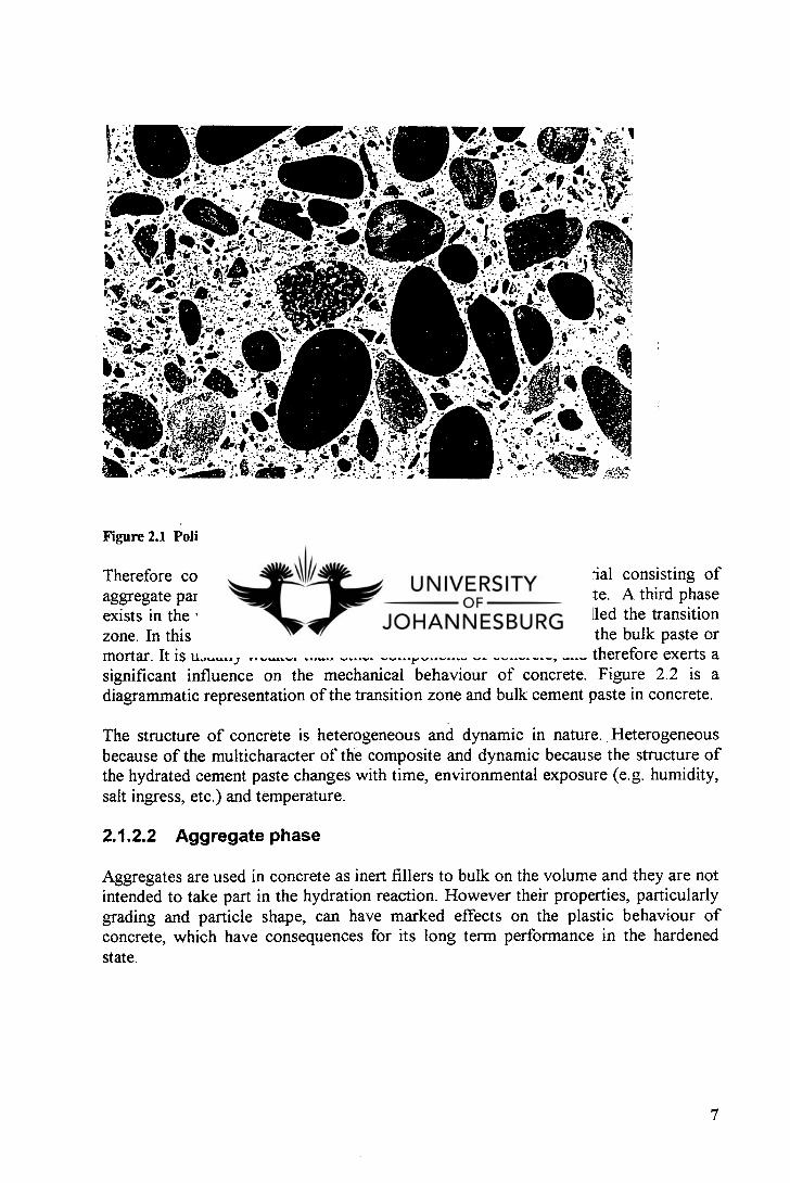
Figure 2.1 Polished section from a concrete specimen. [37]
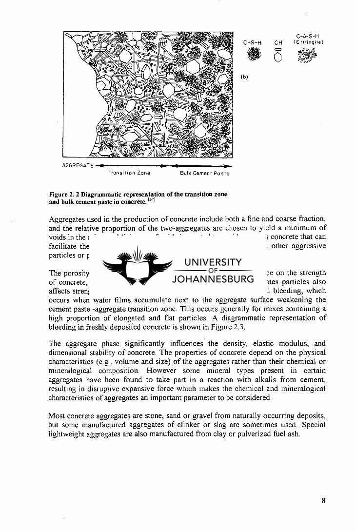
Therefore concrete may be considered to be a two phase material consisting of aggregate particles dispersed in a matrix of the hydrated cement paste. A third phase exists in the vicinity of large aggregates particles. This phase is called the transition zone. In this zone the hydrated cement paste is very different from the bulk paste or mortar. It is usually weaker than other components of concrete, and therefore exerts a significant influence on the mechanical behaviour of concrete. Figure 2.2 is a diagrammatic representation of the transition zone and bulk cement paste in concrete.
The structure of concrete is heterogeneous and dynamic in nature. Heterogeneous because of the multicharacter of the composite and dynamic because the structure of the hydrated cement paste changes with time, environmental exposure (e.g. humidity, salt ingress, etc.) and temperature.
2.1.2.2 Aggregate phase
Aggregates are used in concrete as inert fillers to bulk on the volume and they are not intended to take part in the hydration reaction. However their properties, particularly grading and particle shape, can have marked effects on the plastic behaviour of concrete, which have consequences for its long term performance in the hardened state.
7
C-S-H CH
O
C-A-S-H ( E t ring it e )
(b)
AGGREGATE —NI
)1•■•••1(
Transition Zone
Bulk Cement Paste
Figure 2. 2 Diagrammatic representation of the transition zone and bulk cement paste in concrete. (37)
Aggregates used in the production of concrete include both a fine and coarse fraction, and the relative proportion of the two-aggregates are chosen to yield a minimum of voids in the mixture. Minimum of voids is wanted to avoid a porous concrete that can facilitate the ingress of damaging moisture, gases, chemicals and other aggressive particles or products.
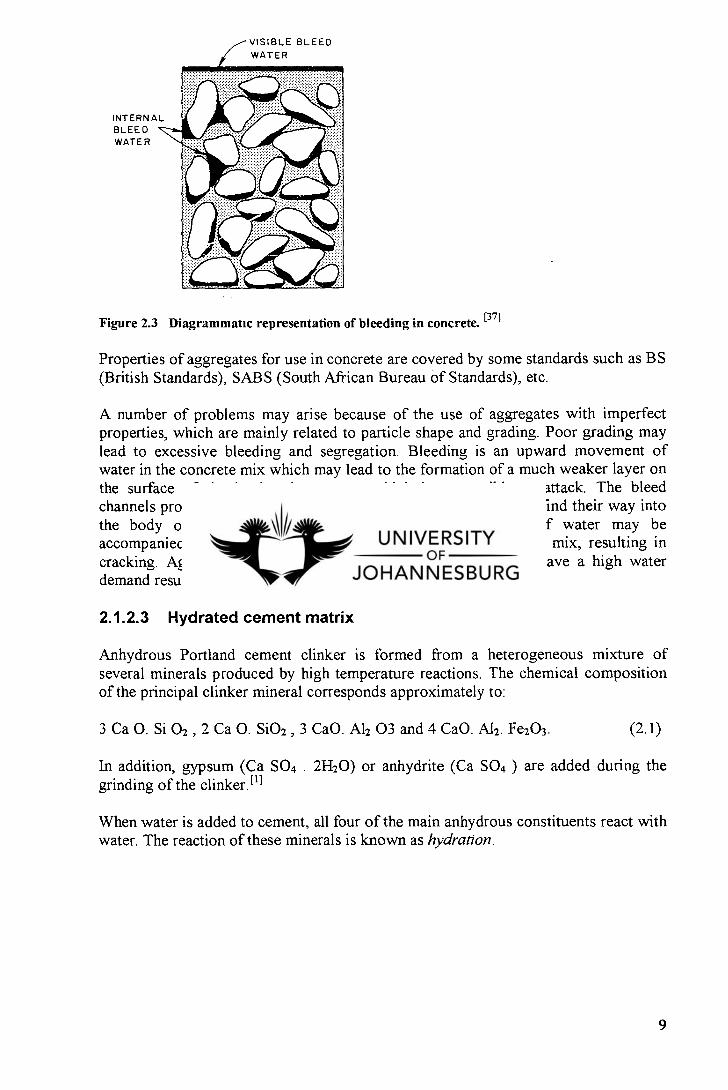
The porosity and friability of aggregates will have a direct influence on the strength of concrete, whereas the shape and texture of the coarse aggregates particles also affects strength indirectly through a phenomenon known as internal bleeding, which occurs when water films accumulate next to the aggregate surface weakening the cement paste -aggregate transition zone. This occurs generally for mixes containing a high proportion of elongated and flat particles. A diagrammatic representation of bleeding in freshly deposited concrete is shown in Figure 2.3.
The aggregate phase significantly influences the density, elastic modulus, and dimensional stability of concrete. The properties of concrete depend on the physical characteristics (e.g., volume and size) of the aggregates rather than their chemical or mineralogical composition. However some mineral types present in certain aggregates have been found to take part in a reaction with alkalis from cement, resulting in disruptive expansive force which makes the chemical and mineralogical characteristics of aggregates an important parameter to be considered.
Most concrete aggregates are stone, sand or gravel from naturally occurring deposits, but some manufactured aggregates of clinker or slag are sometimes used. Special lightweight aggregates are also manufactured from clay or pulverized fuel ash.
8
INTERNAL BLEED WATER
VISIBLE BLEED WATER
Figure 2.3 Diagrammatic representation of bleeding in concrete. [371
Properties of aggregates for use in concrete are covered by some standards such as BS (British Standards), SAGS (South African Bureau of Standards), etc.
A number of problems may arise because of the use of aggregates with imperfect properties, which are mainly related to particle shape and grading. Poor grading may lead to excessive bleeding and segregation. Bleeding is an upward movement of water in the concrete mix which may lead to the formation of a much weaker layer on the surface of the hardened concrete, which is susceptible to attack. The bleed channels provide a passage way by which aggressive agencies can find their way into the body of the hardened concrete. The upward bleeding of water may be accompanied by downward movement of other ingredients of the mix, resulting in cracking. Aggregate which contain an excess of fine materials have a high water demand resulting in a less durable concrete.
2.1.2.3 Hydrated cement matrix
Anhydrous Portland cement clinker is formed from a heterogeneous mixture of several minerals produced by high temperature reactions. The chemical composition of the principal clinker mineral corresponds approximately to:
3 Ca 0. Si 02 , 2 Ca 0. Si02 , 3 CaO. Al e 03 and 4 CaO. Al2. Fe203. (2.1)
In addition, gypsum (Ca SO4 . 21420) or anhydrite (Ca SO 4 ) are added during the grinding of the clinker.t i l
When water is added to cement, all four of the main anhydrous constituents react with water. The reaction of these minerals is known as hydration.
9

20 40 60
Time (days)
80 100
FR 80
0
2 60 -o _c
0 2
60 80 100
100
Alite
Ferrite
Belite
80
0
aR
60
40
rn 0 20
20 40 0
Time (days)
Figure 2. 4 Rate of hydration of the cement compounds: (a) in pure compounds.
(b) in a Type I cement paste. [39j
The initial hydration reactions that occur involve the solubilization of the 3 CaO . A1203 and calcium sulphate, during which the liquid phase gets rapidly saturated with various ionic species. combination between Ca 2+ , S042", Al' and OH- occur within a few minutes of hydration producing needle-shaped crystals of calcium sulfoaluminate hydrate (ettringite). (11 This is followed by the appearance of large prismatic crystals of calcium hydroxide and the formation of very small fibrous crystals of calcium silicate hydrate which begin to occupy the formerly held by water and the dissolving cement particles. 141
Hydration of cement compound is exothermic. Rates of hydration reaction are shown in the Figure 2.4. The most important solid in hydrated cement paste is calcium silicate hydrate gel. ASTM Type I is the cement most commonly used in general construction where no special properties are needed or specified.
(CaO . Si02 . H2O) a non stoichiometric material which makes up 50 % to 60 % of the solids in a completely hydrated Portland cement paste.E 11 This gel determines the properties of the paste. Its strength is attributed chiefly to the degree of polymerization and accompanying van der Waals forces which are intramolecular forces.
Other components of the paste include unhydrated cement grains, calcium sulfoaluminates, and the large hexagonal prism crystals of calcium hydroxide. Due to
10
the lower surface area, their contribution to strength is limited. The presence of a considerable amount of calcium hydroxide in the hydrated paste has an adverse effect on chemical durability to acidic solutions because calcium hydroxide is more readily soluble than calcium silicate hydrate gel.
Depending on the degree of hydration, some unhydrated cement grains may be found in the hydrated paste long after the initial rate of hydration has slowed down. With the progress of hydration, the grains tend to dissolve and to be assimilated into paste system. Figure 2.6 is a model of hydrated Portland cement paste which shows the relationships between the various components of the hydrated paste.
2.1.2.4 Pores and voids
The hydrated paste, in addition to the solids described above, contains a variety of voids or pores which exert an important influence on the properties of concrete. The smallest pores are the interlayer spaces within the C-S-H structure. These pores are said to occupy 28 % of the total volume of the hydrated paste.
The total volume of paste pores increases with the progress of the hydration. The void size of the interlayer pores is too small to have an adverse effect on the strength and permeability of the concrete paste. However, water in these pores can be held by hydrogen bonding, and its removal under certain conditions may contribute to drying shrinkage and creep.
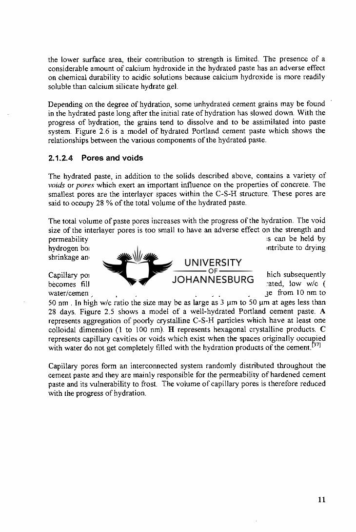
Capillary pores represent the space originally occupied by water which subsequently becomes filled by the solid hydration products. In well-hydrated, low w/c ( water/cement) ratio pastes, the size of the capillary pores may range from 10 nm to 50 nm . In high w/c ratio the size may be as large as 3µm to 50 p.m at ages less than 28 days. Figure 2.5 shows a model of a well-hydrated Portland cement paste. A represents aggregation of poorly crystalline C-S-H particles which have at least one colloidal dimension (1 to 100 nm). H represents hexagonal crystalline products. C represents capillary cavities or voids which exist when the spaces originally occupied with water do not get completely filled with the hydration products of the cement. (371
Capillary pores form an interconnected system randomly distributed throughout the cement paste and they are mainly responsible for the permeability of hardened cement paste and its vulnerability to frost. The volume of capillary pores is therefore reduced with the progress of hydration.
11
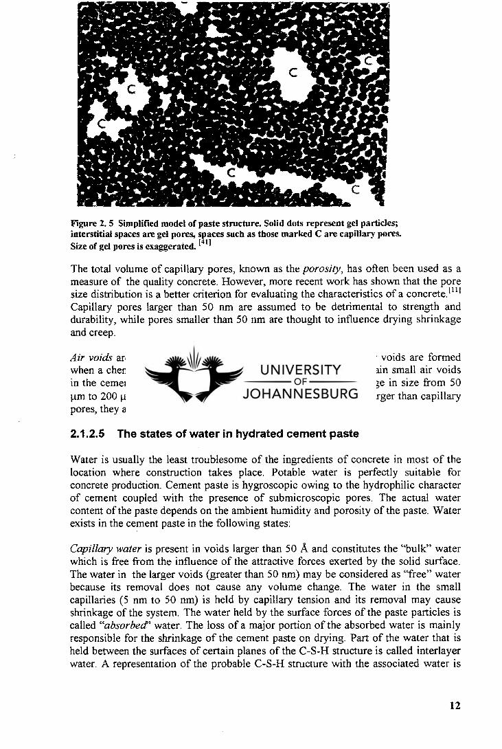
Figure 2. 5 Simplified model of paste structure. Solid dots represent gel particles; interstitial spaces are gel pores, spaces such as those marked C are capillary pores. Size of gel pores is exaggerated. [411
The total volume of capillary pores, known as the porosity, has often been used as a measure of the quality concrete. However, more recent work has shown that the pore size distribution is a better criterion for evaluating the characteristics of a concrete. 1111 Capillary pores larger than 50 nm are assumed to be detrimental to strength and durability, while pores smaller than 50 nm are thought to influence drying shrinkage and creep.
Air voids are of two types, entrapped and entrained. Entrained air voids are formed when a chemical admixture is added to concrete to purposely entrain small air voids in the cement paste. They are generally spherical and usually range in size from 50 p.m to 200 p.m Entrapped air voids in the cement paste are much larger than capillary pores, they adversely affect strength and impermeability.
2.1.2.5 The states of water in hydrated cement paste
Water is usually the least troublesome of the ingredients of concrete in most of the location where construction takes place. Potable water is perfectly suitable for concrete production. Cement paste is hygroscopic owing to the hydrophilic character of cement coupled with the presence of submicroscopic pores. The actual water content of the paste depends on the ambient humidity and porosity of the paste. Water exists in the cement paste in the following states:
Capillary water is present in voids larger than 50 A and constitutes the "bulk" water which is free from the influence of the attractive forces exerted by the solid surface. The water in the larger voids (greater than 50 nm) may be considered as "free" water because its removal does not cause any volume change. The water in the small capillaries (5 nm to 50 nm) is held by capillary tension and its removal may cause shrinkage of the system. The water held by the surface forces of the paste particles is called "absorbed" water. The loss of a major portion of the absorbed water is mainly responsible for the shrinkage of the cement paste on drying. Part of the water that is held between the surfaces of certain planes of the C-S-H structure is called interlayer water. A representation of the probable C-S-H structure with the associated water is
12
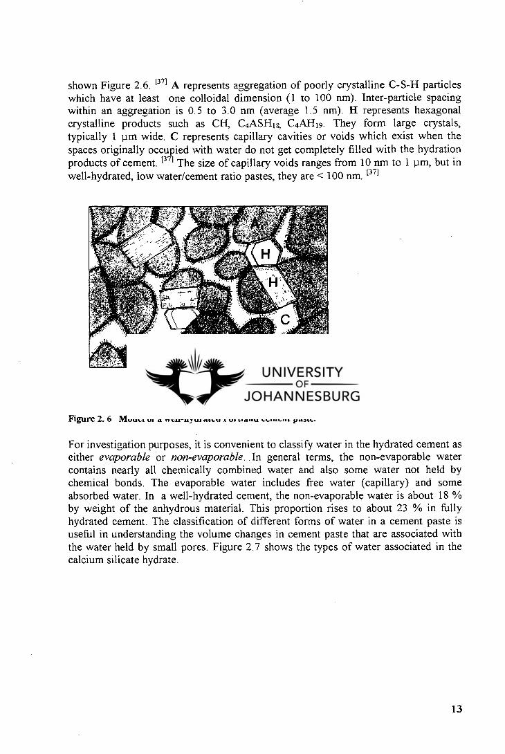
shown Figure 2.6. [37] A represents aggregation of poorly crystalline C-S-H particles which have at least one colloidal dimension (1 to 100 nm). Inter-particle spacing within an aggregation is 0.5 to 3.0 nm (average 1.5 nm). H represents hexagonal crystalline products such as CH, C4ASH18. C 4AH 1 9. They form large crystals, typically 1 pm wide. C represents capillary cavities or voids which exist when the spaces originally occupied with water do not get completely filled with the hydration products of cement. [37] The size of capillary voids ranges from 10 nm to 1 pm, but in well-hydrated, low water/cement ratio pastes, they are < 100 nm. [371
I p,m
Figure 2. 6 Model of a well-hydrated Portland cement paste. 1371
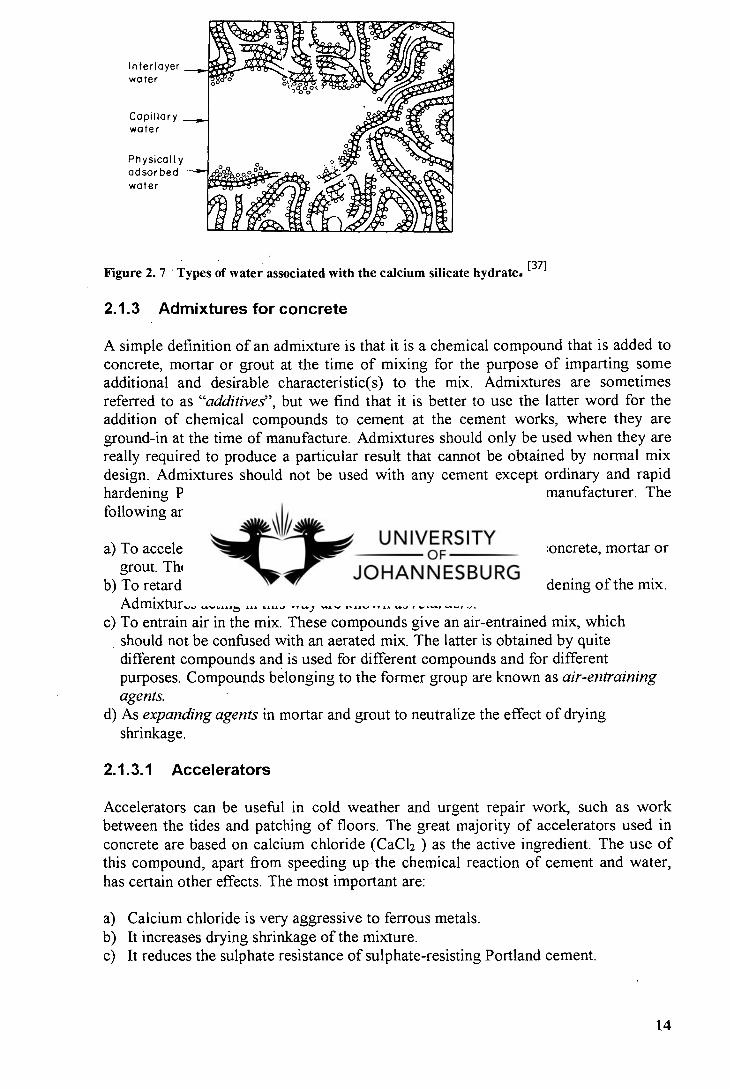
For investigation purposes, it is convenient to classify water in the hydrated cement as either evaporable or non-evaporable. In general terms, the non-evaporable water contains nearly all chemically combined water and also some water not held by chemical bonds. The evaporable water includes free water (capillary) and some absorbed water. In a well-hydrated cement, the non-evaporable water is about 18 % by weight of the anhydrous material. This proportion rises to about 23 % in fully hydrated cement. The classification of different forms of water in a cement paste is useful in understanding the volume changes in cement paste that are associated with the water held by small pores. Figure 2.7 shows the types of water associated in the calcium silicate hydrate.
13
Interlayer
water
Capillary water
Physically adsorbed
water
Figure 2. 7 Types of water associated with the calcium silicate hydrate. [37]
2.1.3 Admixtures for concrete
A simple definition of an admixture is that it is a chemical compound that is added to concrete, mortar or grout at the time of mixing for the purpose of imparting some additional and desirable characteristic(s) to the mix. Admixtures are sometimes referred to as "additives", but we find that it is better to use the latter word for the addition of chemical compounds to cement at the cement works, where they are ground-in at the time of manufacture. Admixtures should only be used when they are really required to produce a particular result that cannot be obtained by normal mix design. Admixtures should not be used with any cement except ordinary and rapid hardening Portland cement without the approval of the cement manufacturer. The following are the main purposes for which admixtures are used:
To accelerate the setting of the cement and the hardening of the concrete, mortar or grout. These compounds are known as accelerators. To retard the setting of the cement and slow down the rate of hardening of the mix. Admixtures acting in this way are known as retarders. To entrain air in the mix. These compounds give an air-entrained mix, which should not be confused with an aerated mix. The latter is obtained by quite different compounds and is used for different compounds and for different purposes. Compounds belonging to the former group are known as air-entraining agents. As expanding agents in mortar and grout to neutralize the effect of drying shrinkage.
2.1.3.1 Accelerators
Accelerators can be useful in cold weather and urgent repair work, such as work between the tides and patching of floors. The great majority of accelerators used in concrete are based on calcium chloride (CaCl2 ) as the active ingredient. The use of this compound, apart from speeding up the chemical reaction of cement and water, has certain other effects. The most important are:
Calcium chloride is very aggressive to ferrous metals. It increases drying shrinkage of the mixture. It reduces the sulphate resistance of sulphate-resisting Portland cement.
14
Because of the serious disadvantage of CaC1 2 mentioned above, considerable efforts have been made to find a satisfactory substitute as the basis for accelerators. Only two compound seem to have met a limited degree of success. These are calcium format and sodium carbonate. The use of heated concrete or the application of heat to concrete after casting is the most effective and satisfactory method of speeding up the setting and hardening of Portland cement.
2.1.3.2 Retarders
There are two main uses for retarders. One is as an integral part of a mortar or grout or concrete mix when it is required to extend the setting time of the cement and reduce the rate of hardening of the concrete. The other is when the retarder is used on formwork to retard the setting or hardening of the surface when the formwork is removed. Retarders are usually sugars and similar compounds, but borax is also used.
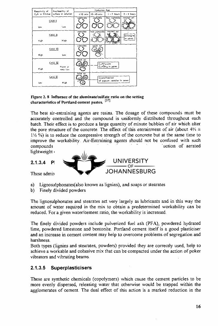
The reaction between retarders and Portland cement is a very complicated one. It is affected by the chemical composition of the cement and the temperature of the concrete as it is maturing. Therefore the period of retardation can only be estimated approximately and accurate reproduction of results is difficult and requires considerable experience. The influence of the aluminate/sulfate ratio in the solution phase on the setting characteristics of Portland cement pastes is depicted in Figure 2.8.
2.1.3.3 Air-entraining agents
Air-Entrained concrete is used for roads and external pavings, to resist the disintegrating effects of frost and de-icing salts. Air-Entraining agents, however, can be useful for concrete repair work and for mortar used on repairs to structures on very exposed sites as well as marine structures.
Beside providing concrete with resistance against frost action, these compounds impart other beneficial characteristics to the mix. These are:
They help to reduce, and may, in favourable circumstances, eliminate plastic cracking. They help to reduce a tendency to water scour on the surface of fair-faced concrete and reduce segregation. They improve workability.
15
Reactivity of
C,A in Clinker
Availability of
sulfate in solution
Hydration Age
<10 min 1 0 - 45 min 1 - 2 hours 2 - 4 hours
CASE I
workable
DO workable
(1.0)
00 less workable
W normal set
Low Low
CASE a
workable
D O
less workable
.
% --
normal set
' .3. a - it.4, .. Ettringite
, pores High High
CASE 111
workable quick set
.-1• de High Low
CASE 12
flash set
:19 J C.AHn, and
in pores None or High very low
~ C.ASHi.
CASEY
rafse set
Crystallization needles in pores
Low High of gypsum
Figure 2. 8 Influence of the aluminate/sulfate ratio on the setting characteristics of Portland cement pastes. [371
The best air-entraining agents are resins. The dosage of these compounds must be accurately controlled and the compound is uniformly distributed throughout each batch. Their effect is to produce a large quantity of minute bubbles of air which alter the pore structure of the concrete. The effect of this entrainment of air (about 4 1/2 ± 1 1/2 %) is to reduce the compressive strength of the concrete but at the same time to improve the workability. Air-Entraining agents should not be confused with such compounds as aluminium powder that is used for the production of aerated lightweight concrete.
2.1.3.4 Plasticisers or workability aids
These admixtures can be divided into two main types, namely:
Lignosulphonates(also known as lignins), and soaps or stearates Finely divided powders
The lignosulphonates and stearates act very largely as lubricants and in this way the amount of water required in the mix to obtain a predetermined workability can be reduced. For a given water/cement ratio, the workability is increased.
The finely divided powders include pulverized fuel ash (PFA), powdered hydrated lime, powdered limestone and bentonite. Portland cement itself is a good plasticiser and an increase in cement content may help to overcome problems of segregation and harshness. Both types (lignins and stearates, powders) provided they are correctly used, help to achieve a workable and cohesive mix that can be compacted under the action of poker vibrators and vibrating beams.
2.1.3.5 Superplasticisers
These are synthetic chemicals (copolymers) which cause the cement particles to be more evenly dispersed, releasing water that otherwise would be trapped within the agglomerates of cement. The dual effect of this action is a marked reduction in the
16
water content required to achieve the desire workability, and more rapid hydration of the cement particles. Superplasticisers are distinct from the normal workability aids. They can be used for two purposes:
To produce concrete having a virtually collapse slump i.e. a flowable concrete To produce a concrete with normal workability but with a very low water/cement ratio, resulting in a high strength concrete.
Superplasticisers can be used to reduce water content by up to 30 %. Consequently, a more dense and impermeable concrete, with a greatly reduced potential for shrinkage and cracking than normal concrete, is obtained. These characteristics of superplasticised concrete ensure that the ingress of damaging moisture, gases, and chemicals is greatly retarded, and the protective alkaline environment endures for longer periods. Figure 2.9 is a photomicrograph showing the effects of superplasticizers in a cemen-water suspension.
The various types of superplasticisers in use are :
Group 1: Sulphonated melamine formaldehyde. Group 2 : Naphthalene sulphonated formaldehyde condensate. Group 3 : Modified ligno-sulphonates.
(a)
(b)
Figure 2. 9 Photomicrograph of flocculated cement particles in Portland cement-water suspension. (a) with no admixture present; (b ) after it is dispersed with the addition of a superplasticizing admixture. (371
2.1.3.6 Pulverized Fuel Ash (PFA)
PFA is a very fine powder produced from coal burning power stations and having a specific surface similar to that of ordinary Portland cement, namely about 340 m 2/kg. The specific gravity of PFA is appreciably low : 1.9 - 2.3, while of cement is about
17
3.12. PFA are oxides of silicon, iron and aluminium, together with some carbon and sulphur.
2.1.3.7 Condensate Silica Fume (CSF)
CSF is a waste of ferrosilicon industry in the form of an extremely greyish powder. It consists of 88 % - 98 % silicon with very small percentages (usually a maximum of 2 % each) of carbon, ferric oxide, aluminium oxide (alumina) and oxides of sodium, potassium and magnesium. Its specific surface is many times that of ordinary Portland cement. It is normally used with a lingosulphonate plasticizer or superplasticizer. It has been shown that the use of silicafume (8 % to 10 % by weight of cement in the mix) in conjunction with a superplasticizer can accelerate strength development to offset the retarding effect of low temperature.
2.1.3.8 Non -chloride admixtures
The use of calcium chloride as an accelerator to offset the effects of cold weather has been widely cited as one of the chief sources of reinforcement corrosion. The use of accelerators that are not based on chlorides reduce the serious risk of reinforcement corrosion by maintaining the chloride ion threshold above which corrosion does not occur. A number of organic and inorganic salts, including formates, thiosulfates, alkali sulfates, nitrites, nitrates, and thiocyanate are currently marketed. Although these admixtures satisfy the requirement of being nonchlorides, some are reported to produce corrosion.
2.1.3.9 Corrosion inhibiting admixtures
The protection offered to the reinforcement by the highly alkaline concrete may be increased by the use of corrosion inhibiting admixtures. A corrosion inhibiting admixture is a chemical compound which, when added in small concentrations to concrete or mortar, effectively checks or retards corrosion.
These admixtures can be into three broad classes, namely anodic, cathodic or mixed, depending on whether they interfere with the corrosion reaction preferentially at the anodic or cathodic sites or whether both are involved.
Anodic inhibitors are materials which function as inhibitors due to their ability to accept electrons. They exert their action by stifling the reaction at the anode. The most widely used anodic inhibitors include calcium and sodium nitrite, sodium benzoate, and sodium chromate. One of the serious drawbacks in the use of anodic inhibitors is that the admixtures are effective in maintaining passivity only if present in sufficiently high concentrations.
Cathodic inhibitors act either by slowing the cathodic reaction or by selectively precipitating at cathodic sites. Materials in this group are strong proton acceptors and their action, in contrast to anodic inhibitors, is usually indirect. Commonly used
18
cathodic inhibitor materials are bases such as Na2CO3 or NI-1 40H which increase the pH of the medium and thereby also decrease the solubility of the ferrous ion.
Mixed inhibitors are materials that may simultaneously affect both anodic and cathodic processes. A mixed inhibitor is usual more desirable because its effect is all encompassing, covering corrosion resulting from chloride attack as well as that due to microcells on the metal surface.
2.1.3.10 Dampproofing and waterproofing admixtures
Water penetrates concrete under conditions of pressure or by absorption. In the former, water under pressure and in contact with one surface of the concrete is forced through channels which interconnect the two faces of concrete. In the latter, the passage of moisture through concrete occurs merely by capillary action. Evaporation from faces exposed to unsaturated air, and the constant replenishment of moisture from surfaces in contact with water, result in a flow of moisture through the concrete. Integral waterproofing admixtures are often used to restrict or reduce the rate of transport of moisture.
An integral waterproofing admixture is a powder, liquid, or suspension which, when mixed with fresh concrete, results in the reduction in the permeability of cured concrete, and/or imparts a water repellency or hydrophobic property to the hardened concrete. Admixtures that reduce the permeability of concrete termed "waterproofing", are effective in reducing the transport of moisture under pressure; whereas materials that impart water repellency termed "dampproofing", may reduce moisture migration by capillary action. Most dampproofing admixtures are ineffective in reducing water passage under a positive hydrostatic head.
More recently, a waterproofing admixture called Hydrophobic Blocking Ingredient (HBI) based on two principal components - reactive aliphahtic fatty acids and an aqueous emulsion of polymers and aromatic globules has been introduced to USA.
During mixing, reaction of the fatty acids with the initial hydration products creates a water and moisture repelling lining on the capillaries and concrete surfaces. This component increases the contact angle to well above 90°, and resulting force at the entrance of the. capillary pores and microcracks act to keep water out.
The formulators of HBI claim that this admixture was designed to deal with the problem of water penetration, on the belief that water transport mechanisms and chemical reactions were fundamental to concrete durability. The claim that it is not permeability, but sorptivity, or capillary suction, that is the primary mechanism of water and salt penetration under conditions of wetting and drying, or partial immersion.
19
Both dampproofing and waterproofing admixtures increase resistance to water penetration, either by acting as pore fillers or by creating a hydrophobic coating within the pores, or by combining both effects.
Normally concrete "wets" because the pressure needed for wetting is low due the surface tension forces which pull the water into the pores. When waterproofing admixtures such as stereates are used, insoluble calcium stearate produced by the reaction of the soap with Ca(OH)2 coats the surface of the pore. Similarly, wax or bituminous emulsions on contact with cement pores and capillaries form an hydrophobic coating. The end result is that the hydrophobic coating causes a reversed angle of contact so that the surface tension force now push the water out of the pore.
Ca(OH)2 + RCOOH --=Ca-COOK" + H2O
(2.2) Stearate Insoluble admixture calcium
stearate
The principle of the HBI system is to exclude water and moisture along with any dissolved salts or other aggressive solutes. Each component of the admixtures has a distinct action.
2.1.3.11 Bonding aids
More than 50 years ago, certain polymers, either on their own or mixed with cement, have been increasingly used to improve bonding between hardened concrete and newly placed cement-based materials such as concrete and mortar. In general one uses polyvinyl acetate (PVA), styrene-butadiene rubber (SBR) and acrylics.
It is essential to obtain the best possible bond at the interface between existing concrete and mortar or concrete used for repair, and prior to the introduction of polymer bonding aids. It must be appreciated that the bond at the interface between the concrete and the repair material is likely to be subjected to considerable stress arising from changes in moisture content, freeze-thaw, a wide temperature range, as well as the force of gravity and some times vibration.
Two tests for the effectiveness of the bond are the Slant Shear Test (BS 6319, Part 4 and ASTM C 882-78) and the pull-off test for which there is no UK standard. The former can only be applied in laboratory whereas the latter can be applied both in the laboratory and on site.
The effect of weathering on the bond is obviously of great importance, and until laboratory specimens prepared for the Slant Shear Test have been exposed to the weather for long periods, the effect of weathering can only be tested by pull-off tests on site.
20
Philip H. Perkins says that when properly used, SBR/cement slurry helps to mitigate the inevitable effects of variation in workmanship and site conditions, and thus improve the bond. 111
The vast majority of concrete repairs involve the placing of new concrete or mortar around cleaned reinforcement. A trend in repair techniques is the use of concrete-polymer composites. For instance, the high pH of SBR/cement slurry (about 12.0) helps considerably to ensure passivation of rebars. However, before any repair action to be undertaken, the all history of the concrete must be known accurately.
2.2 PROTECTIVE COATINGS
2.2.1 Research trends of concrete-polymer composites
Concrete-polymer composites have been developed lately and are used in place of conventional cement and concretes, including mortar by virtue of their excellent characteristics.
Early deterioration of cement concrete structures have created many problems, and plant-precast productions of concrete members are becoming popular in stead of field casting. Actually, field casting of concrete structure in many countries becomes difficult and more difficult due to not only its poor durability, but also high labour and transportation cost. Therefore, the emerging need is to develop new materials in place of conventional concretes 1161 . That is the reason why polymer composite products have been developed in 1 970s and continue to be developed over the world and. in South Africa.
The mechanical properties of polymers can greatly enhanced by incorporating fillers and/or fibres into the resin formulations. Therefore, for structural application, such composite materials should: (181
consist of two or more phases, each with their own physical and mechanical characteristics.
be manufactured by combining the separate phases such that the dispersion of material in the other achieves optimum properties of the resulting material;
have enhanced properties compared with those of the individual components.
2.2.2 Chemistry of polymeric building materials
The word "polymer" comes from the Greek words" many membered". It could be applied to any large molecule which is formed from a relatively large number of smaller units. However, it is commonly restricted to materials in which the units are held together by covalent bonding, i.e., shared electrons. This class of materials
21
Molecular structure Processing prolerties
Material roperties
Applications
Production
possess many interesting and useful properties which are completely different from those of the more traditional engineering materials.
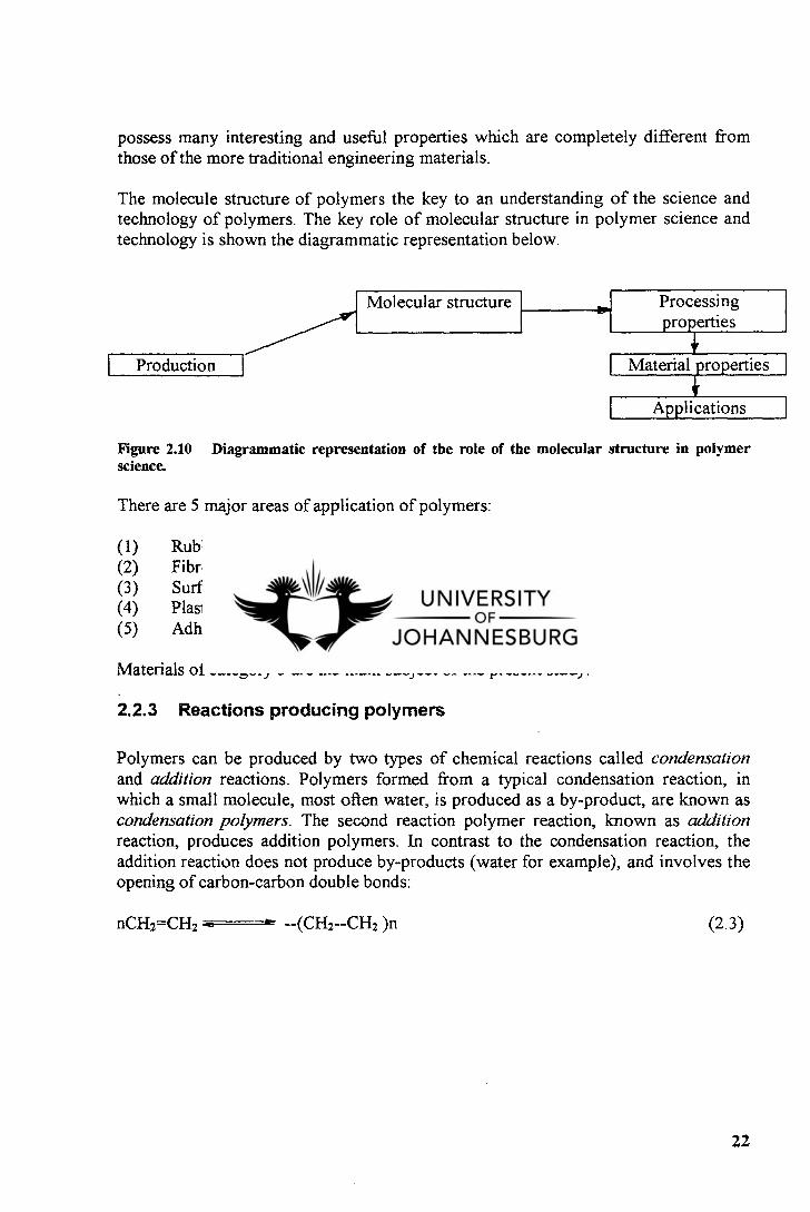
The molecule structure of polymers the key to an understanding of the science and technology of polymers. The key role of molecular structure in polymer science and technology is shown the diagrammatic representation below.
Figure 2.10 Diagrammatic representation of the role of the molecular structure in polymer science.
There are 5 major areas of application of polymers:
Rubbers and elastomers Fibres Surfaces finishes and protective coating Plastics Adhesives and sealants
Materials of category 3 are the main subject of the present study.
2.2.3 Reactions producing polymers
Polymers can be produced by two types of chemical reactions called condensation and addition reactions. Polymers formed from a typical condensation reaction, in which a small molecule, most often water, is produced as a by-product, are known as condensation polymers. The second reaction polymer reaction, known as addition reaction, produces addition polymers. In contrast to the condensation reaction, the addition reaction does not produce by-products (water for example), and involves the opening of carbon-carbon double bonds:
nCH2=CH2 I (CH2--CH2 )n (2.3)
22
2.2.4 Polymer structure
Polymerization of monomeric units produces homopolymers that are either linear, branched, or cross-linked, depending on the number of functionalities of the monomers and the method of polymerization.
Most linear homopolymers are obtained by addition polymerization or polycondensation of difunctional monomers (A and B). Branched polymers result when a small quantity of trifunctional monomers is mixed with difunctional monomers or when branches made from B monomers are grafted onto a linear backbone obtained from A monomer units, thus generating a graft copolymer.i l l
2.2.4.1 Linear polymers
Homopolymers
Homopolymers are formed when a pure monomer polymerizes by an addition reaction. The repeating unit in the polymer chain is the pure monomer.
Random Copolymers
Random copolymers are synthesized when a mixture of two difunctional monomer, A and B, are made to react.
Block Copolymers
Under certain conditions two or more monomers can be polymerized in such a manner that long blocks of each monomer are combined in a single chain.
2.2.4.2 Branched polymers
If trifunctional or higher units are introduced either intentionally or through side reactions at random points along linear chains, branched molecules result. Branching has a significant influence on the properties of polymers such as modulus and chemical resistance. Two subgroups are recognised: - graft
- cross-linked polymers.
a) Graft Polymers
Under specialized conditions, branches of monomer B may be grafted to a backbone of linear A polymer. This structure is known as a graft copolymer.
23
b) Cross-linked polymers
The chain of linear and most branched polymers have finite length and molecular weight. In contrast, cross-linked polymers possess interconnected chains, which result in a three dimensional network of essentially infinite molecular weight.
2.2.5 Polymer properties
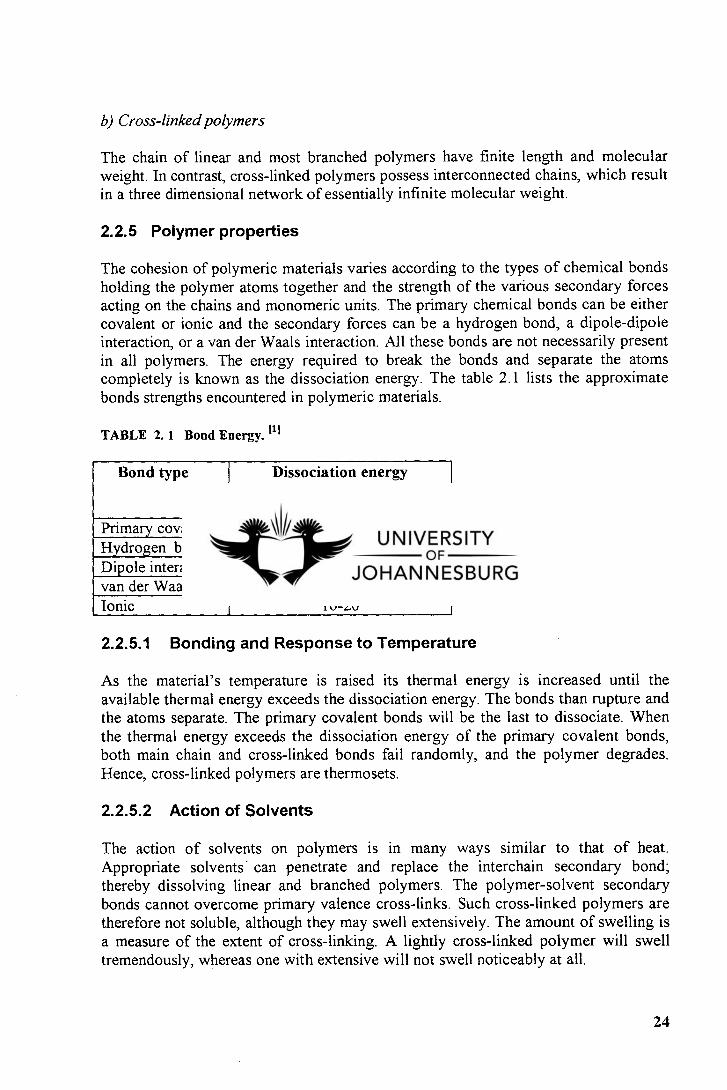
The cohesion of polymeric materials varies according to the types of chemical bonds holding the polymer atoms together and the strength of the various secondary forces acting on the chains and monomeric units. The primary chemical bonds can be either covalent or ionic and the secondary forces can be a hydrogen bond, a dipole-dipole interaction, or a van der Waals interaction. All these bonds are not necessarily present in all polymers. The energy required to break the bonds and separate the atoms completely is known as the dissociation energy. The table 2.1 lists the approximate bonds strengths encountered in polymeric materials.
TABLE 2. 1 Bond Energy.
Bond type Dissociation energy kcallmole
Primary covalent 50-200 Hydrogen bond 3-7 Dipole interaction 1.5-3 van der Waals 0.2-2 Ionic 10-20
2.2.5.1 Bonding and Response to Temperature
As the material's temperature is raised its thermal energy is increased until the available thermal energy exceeds the dissociation energy. The bonds than rupture and the atoms separate. The primary covalent bonds will be the last to dissociate. When the thermal energy exceeds the dissociation energy of the primary covalent bonds, both main chain and cross-linked bonds fail randomly, and the polymer degrades. Hence, cross-linked polymers are thermosets.
2.2.5.2 Action of Solvents
The action of solvents on polymers is in many ways similar to that of heat. Appropriate solvents - can penetrate and replace the interchain secondary bond; thereby dissolving linear and branched polymers. The polymer-solvent secondary bonds cannot overcome primary valence cross-links. Such cross-linked polymers are therefore not soluble, although they may swell extensively. The amount of swelling is a measure of the extent of cross-linking. A lightly cross-linked polymer will swell tremendously, whereas one with extensive will not swell noticeably at all.
24
2.2.5.3 Crystallinity in polymers
It has been shown by X-rays studies that the bulk polymers have regions where the polymer chains pack into a regular crystal lattice due to an ordered, regular chain structure, and other areas where the irregular chain structure interferes with the arrangement of the main chains in a regular lattice. The presence of crystalline material in polymers strongly influences their properties, particularly the mechanical properties. Crystallinity can significantly increase the strength and rigidity of a polymer.
2.2.5.4 Molecular Weight of Polymers
All polymers consist of molecules with a distribution of chain lengths. It is therefore necessary to characterize the entire distribution quantitatively or at least to define and measure average chain lengths or molecular weights for these materials as many important properties of the polymer depend on these quantities.
2.2.5.5 Polymer Solubility and Solutions
Two factors relating to polymer solubility are of general interest to materials scientists and engineers:
Which solvents will attack which polymers How does the polymer-solvent interaction influence the solution properties
Some rules for polymer solubility are as follows :
Polar solvents will tend to dissolve polar polymers. Non-polar solvents will do the same with non-polar polymers. In a given solvent, at a particular temperature, the solubility of a polymer will decrease with increasing molecular weight. Crosslinking eliminates solubility. The rate of polymer solubility increases with short branches, which have looser main chain structure, allowing the solvent molecules to penetrate more easily, and decreases with longer branches, because the entanglement of these branches makes it harder for individual molecules to separate. Crystallinity : the solvent cannot penetrate crystalline regions and therefore solubilization will take a considerably longer time.
2.2.5.6 Glass Transition Temperature
Polymers exhibit two different types of mechanical behaviour. Some are hard, rigid, and plastic at room temperature, while others are soft, flexible, rubbery materials. There is some temperature or narrow range of temperature below which a polymer is in a glassy state and above which it is rubbery. This temperature is known as the glass
25
transition temperature Tg. The Tg is a characteristic of a particular polymer, and varies with microstructure, type of side groups, and molecular mass.
2.2.5.7 Mechanical Properties of Polymers
Polymers like natural and synthetic rubbers possess some interesting, unique, and useful mechanical properties. For example, no other materials are capable of reversible extensions to strains of 600 % to 700 %. The mechanical properties commonly used are:
Modulus of Elasticity. Visco-elasticity.
2.2.5.8 Applications of Polymers
In building construction the application of polymers can be classified in various ways:
Non-structural polymers. Structural and semi-structural polymers. Auxiliaries to other materials.
The first group constitutes, by far, the greatest volume and number of different uses. Auxiliaries include adhesive, sealants, and decorative and protective coatings
a) Adhesives
Many of the polymers used for adhesives are the same as those used in other applications. An adhesive is a substance capable of holding materials together by surface attachment.
Adhesion results from:
mechanical bonding between the adhesive and adherend. chemical forces, either primary, covalent bonds or polar forces between the two.
In general, the properties of the adhesive polymer determine the properties of the adhesive joint, i.e., the bond can be no stronger than the glue line. There are three general categories of adhesives used in construction applications: solvent based, latex, and reactive.
b) Sealants
Sealants are synthetic, elastomeric polymers that are used to plug or close an opening in a structure (joint) in order to keep out water and cold air, as well as to retain
26
warmth. They provide material continuity between building elements while the joint changes in dimension as it opens in winter and closes in summer.
c) Coatings
A coating may be described as a material which forms a continuous membrane when applied to a substrate. Coatings are used for a variety of protection and refurbishment applications such as protection against chemical attack, wear, and damage by freeze/thaw action.
2.2.6 Types of polymers
The distinction between types of polymers is based on their reaction to heating and cooling.
2.2.6.1 Thermoplastic polymers
In a thermoplastic polymer the log-chain molecules are held together by relatively weak van der Waals forces, but the chemical bond along the chain is extremely strong.r 181 Thermoplastic polymers soften upon heating, and can be made to flow when a stress is applied. When cooled again, they reversibly regain their solid or rubbery nature. Continued heating of thermoplastics will lead ultimately to degradation, but they will generally soften at temperatures below their degradation point.
Thermoplastic materials have a semi-crystalline ordered structure or an amorphous random structure. Polypropylene, Nylon 66 and polycarbonate are examples of amorphous thermoplastic polymers. (181
2.2.6.2 Thermosetting polymers
Thermosetting polymers are formed in a two-stage chemical reaction. Firstly, a substance consisting of a series of long-chain polymerized molecules, similar to those in thermoplastics, is produced; then the chains become cross-linked. As the cross-linking is by strong chemical bonds, thermosetting polymers are rigid materials and their mechanical properties are affected by heat.I 181
Thermosetting polymers are materials which can be heated to the point where they would soften and made to flow under stress. However, they do not revert to the original solid state as the heating causes the material to undergo a curing reaction. Further heating ultimately leads only to degradation without softening and flow. The principal thermosetting polymers which are used in composites in construction are polyesters, epoxies and phenolics.
27
2.2.7 Organic polymers
Organic polymers are complex chemical compounds derived mainly from the petro-chemical industry. These materials are often referred to as "resins", and the principal resins used in the construction industry are epoxide, polyurethane, polyester, acrylic, polyvinyl acetate, and styrene-butadiene.
Under the particular condition of curing, which in some cases requires hardeners or accelerators, the resins form long molecular chains in three dimensions, which can result in an extremely strong and stable material.
It is convenient to divide these materials into 2 main categories, namely:
coatings in which the formulated compound is used alone. mortars and concretes in which the resin is mixed with aggregates and sometimes cement.
It is quite common to find that several types of polymer are used in combination in order to obtain the optimum results.
For coating used for the protection of concrete and to reduce permeability, epoxies, polyurethanes and acrylics are mostly used. For use in mortars and concretes, acrylics and styrene-butadiene compounds are used successfully. Polyvinyl acetate (PVA) is used as a bonding agent for floors screeds and topping to increase adhesion with the base concrete. It is also used in cement mortar mixes to improve certain characteristics of the mortar and bond with the substrate. Polyester resins are used in cement-based proprietary floor toppings.
2.3 PRINCIPAL RESINS USED AS PROTECTIVE COATINGS
2.3.1 General considerations
The principal resins used in the construction industry are epoxyde, polyurethane, polyester, acrylic, polyvinyl acetate, and styrene-butadiene. When considering a coating for concrete, the specifier or buyer must take into account the properties of the concrete and location of the area to be coated in the structure. The properties of concrete which affect the successful application and performance of a coating are:
Porosity. Moisture content . Presence of contaminants on the surface.
The factors due to location of the concrete in the structure that need to be considered include:
Continuous or intermittent exposure of the coating to moisture.
28
The degree of wear encountered in service. The temperature fluctuations to which it will be subjected.
Each coating possesses unique application characteristics which influence the quality of the film formed. Thus it is important that the items given below should be checked with the manufacturer prior to use.
Climatic conditions. Concrete temperature. Moisture content of surface. The thickness and number of required coats. Coverage rate.
2.3.2 Types of coatings
Many different wall and floor coatings are available and exhibit varying degrees of chemical resistance, physical durability, and ease of application. Some of the major characteristics of these product are discussed below.
2.3.2.1 Epoxy resins
Proprietary products are generally two-package systems composed of epoxy resin (which may contain plasticizers, reactive diluents, extender resins, and fillers), and a curing agent. Some formulations are 100 % solids and others are solvent based systems. Common curing agents suitable for room temperature curing are amine adducts, polyamides, polysulfides, and tertiary amines. The coating properties depend on the amount of curing agent used.
Epoxy coatings have excellent chemical resistance to most chemicals. They have a some what better alkali resistance than acid resistance and bond well to concrete. The coatings are resilient and abrasion resistant. Disadvantage associated with certain epoxies is that they age to brittle materials which cannot accommodate substrate movement. Intercoat adhesion is difficult once previously applied coats are cured, curing agents may cause dermatitis and they will chalk badly when exposed to sunlight (UV rays). Fibre-reinforced epoxy coatings may be used on concrete that may undergo thermal movement
2.3.2.2 Polyurethanes
Polyurethanes, like epoxide resins, are also products of the petrochemical. They are very durable in external conditions and retain their gloss well. Polyurethanes can be specially formulated to meet specific site requirements. One characteristic of particular importance is that they will cure in temperatures appreciably below 0 °C, whereas epoxide cannot be relied upon to continue to gain in strength cure when the temperature falls to 5 °C and below. They can combined with epoxies and will
29
withstand relatively high temperatures as well as sudden changes in temperature, i.e. thermal shock.
2.3.2.3 Polyester resins
Unsaturated polyester resins are formed by the polycondensation of polyhydric alcohols with unsaturated dicarboxylic acids and anhydrides. They are usually solid at ambient temperatures and can be supplied in powdered or granulated form, or, more commonly, as liquid solutions in monomers, i.e.: styrene monomer. To prevent uncontrolled or premature polymerization, inhibitors are usually added, at parts per million level. The most common types of inhibitor are substituted hydroquinone derivatives.
The curing of polyester resin solutions in monomers is effected by the use of catalysts (i.e. organic peroxides), the reaction being initiated by accelerators (various amines and organo-metal) or by heat, UV radiation or combinations of these.
A polyester resin system is either a solid resin, which may in addition contain catalyts or a resin solution, possibly including accelerators, fillers, pigments, plasticisers, thixotropes and other additives. Fillers and pigments are generally inert, with little effect on hazards.
The combination of polyester resin and glass -fibre mat produces an incredibly versatile material - strong, durable weatherproof, waterproof, non-rusting, easily moulded to virtually any shape, highly adhesive to a wide range of materials, and capable of making structures of almost size. There are numerous instances where GRP (Glassfibre Reinforced Plastic) can be used as viable alternative to traditional materials such as steel or wood, and in many cases GRP is more appropriate choice.
Polyester resin can also be used alone, or with fillers, to make castings which accurately reproduce the finest detail of the mould. It can be mixed with metal powders to create realistic imitation metal castings. The finished item, can be sawn, drilled or polished and used as viable alternative
2.3.2.4 Acrylic resins
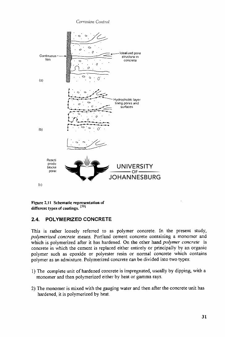
Acrylic resin systems form high strength materials. In general acrylic resins are based on monomers of very low viscosity or blends of monomers with methyl metacrylate monomer, the most commonly used. Because of the very low viscosity of the uncured acrylic resins, very high filler loadings are possible, so that the mortars tend to exhibit less shrinkage than mortars based on unsaturated polyester resins. [42 Acrylic based on monomers such as 2-ethyhexacrylate produce mortars with significantly lower modulus which are, therefore, able to absorb the stresses due to their inherent shrinkage without causing bond failure with the concrete subtrate. [421 Figure 2.11 is a schematic description of different types of coatings.
30
-
0
Continuous---f• film
. 0
Idealized pore structure in
concrete
0
. • 0 •
. . o
(a)
. 0 0
Hydrophobic layer
o •c, • lining pores and
0 surfaces
•
0
Reaction product ( blocking
pores
Corrosion Control
Figure 2.11 Schematic representation of different types of coatings. [39]
2.4. POLYMERIZED CONCRETE
This is rather loosely referred to as polymer concrete. In the present study, polymerized concrete means. Portland cement concrete containing a monomer and which is polymerized after it has hardened. On the other hand polymer concrete is concrete in which the cement is replaced either entirely or principally by an organic polymer such as epoxide or polyester resin or normal concrete which contains polymer as an admixture. Polymerized concrete can be divided into two types:
The complete unit of hardened concrete is impregnated, usually by dipping, with a monomer and then polymerized either by heat or gamma rays.
The monomer is mixed with the gauging water and then after the concrete unit has hardened, it is polymerized by heat.
31
Claims made for polymerized concrete include the following :
A considerable increase, up to 4 times, in the compressive and tensile strength. The resistance to chemical attack and the effects of freeze-thaw are greatly increased. Absorption and permeability are greatly reduced.
The process of producing polymerized concrete is complicated and expensive and so far it appears to have been used only on a small scale in selected locations for long term test purposes.
32
CHAPTER 3
DETERIORATION PROCESSES OF CONCRETE AND FACTORS CONTROLLING THE DETERIORATION
OF CONCRETE
3.1 GENERAL CONSIDERATIONS
This chapter intends to consider the most important factors that can cause deterioration of concrete and reinforced concrete structures. Only two basic types of materials will be considered, namely the concrete itself and the metal which is usually used in conjunction with it.
Basically, deterioration can be due to chemical attack on or between the various materials of which the structure is built, or physical deterioration arising from climatic changes, abrasion, damage from high velocity water, fire, impact, explosion, foundation failure or overloading. In résumé, degradation can result from either the environment to which the concrete is exposed, for example frost damage, or from internal causes within the concrete, as in alkali-aggregate reaction. It is necessary to distinguish between degradation of the concrete itself and loss of protection and subsequent corrosion of the reinforcing or pre-stressing steel contained within it."' It is also essential to understand how these various causes are likely to reveal themselves, so that a realistic assessment of the overall cause(s) can be made and a proper diagnosis be given. In essence we will make a review of the following:
Durability, permeability and carbonation of concrete. Chemical aggression to concrete. Corrosion of metals in concrete. Physical aggression to concrete.
Nathan Johnson said: " There is nothing which more truly leads to a knowledge of how to make enduring concrete than a proper study of disintegration."
3.2 DURABILITY OF CONCRETE
Durability is defined as the capability of maintaining the serviceability of a product, component, assembly, or construction over a period time which must be at least the required lifetime. Serviceability refers to the capability of the structure to perform the functions for which it was designed and constructed while exposed to a specific environment. The structure should, therefore, be able to resist or withstand for its service life all the intended loads and environment conditions without excessive deterioration, wear, or failure. Thus, durability in a broadest sense will depend on the nature of the concrete and the aggressiveness of the in-service environment. However, many structures do not have a well-defined lifetime, and in such cases the durability should be such that the structure remains serviceable more or less indefinitely, given reasonable maintenance. 1181
33
The rate of most degradation processes is controlled by the rate at which moisture, air or other aggressive agents can penetrate the concrete
Larry Masters said: "No material is itself durable or non-durable; it is the interaction of the material with its in-service environment that determines its durability."
The requirement of good quality concrete and the provision of adequate reinforcement cover is of fundamental importance to the specification of durable concrete. Low permeability is identified as being the key to durable concrete and is governed by water/cement ratio, cement content, curing, and the degree of compaction obtained. Cover to reinforcement is usually specified in relation to condition of exposure.
The importance of exposure conditions in the design of durable concrete and durable structures is reflected in the manner in which it dictates requirements in the codes of practice. The provision of durability consists mainly of a prescription of maintaining the required margins and factors with time. In practice, the engineer will attempt to assess the aggressiveness of a given environment towards the concrete, or to design protection for it, so that the rate of change of concrete properties is negligible.
Concrete will not deteriorate if the specifications covering its production are correct and followed. Therefore, when a concrete does deteriorate, either the specifications were improper or they were violated. An improper specification often results when the specifier makes an imperfect choice in matching concrete selected for use in a given environment and how these control the needed levels of properties of concrete. When these levels are known, specifications may be prepared to produce a concrete that will interact with the effects of the environment and will not deteriorate.
The four main methods that ensure adequate durability of concrete in service are as follows:
Compliance with current standards of good practice during construction. The use of new and improved materials and innovative construction systems designed for increased durability at competitive cost.
Provision of protection to existing undamaged structures against adverse environments. Use of materials and procedures that incorporate the best, available standards of good practice in repair, replacement, and subsequent protection of already damaged structures.
3.2.1 Factors affecting the durability
No single parameter controls the durability of concrete. Rather, there are a number of contributing factors which affect its durability. These factors can be grouped under four main categories, namely, construction practices, design, material characteristics, and exposure conditions. The distress and defects that result from the effects of these factors are often the initiation point of deterioration.
34
3.2.1.1 Construction practices
Improper procedures or carelessness during any phase of the construction operation results in concrete of inferior quality. Poor transportation, placing, finishing techniques, and inadequate curing conditions are included in this group. Subgrade settlement due to insufficient compaction of the base, movement of poorly constructed formwork, and inadequate vibration of placed concrete, results in cracks in the hardened concrete. Cracking due to localised settlement of the subgrade occurs if there are soft pockets in the subgrade on which the concrete is placed or if there are pockets under the building paper. Proper compaction of the subgrade, elimination of air pockets in the building paper and a delay in the final finishing are preventive measures that could be taken to reduce the occurrence of this problem.
Cracking results from the movement of formwork during the period when the concrete begins to stiffen to the time it has fully set. The cracks are usually internal and are not visible by surface inspection. Consequently, they are potential localisations where deterioration can originate. Water pockets can form in the crack promoting corrosion of reinforcement and spalling of the surface due to freeze-thaw action. Preventive measures include the use of robust forms with much reduced absorption and swelling capacity, and the monitoring of the permissible rate of rise of the concrete level in the forms.
Poorly vibrated concrete in subsequent pours of a vertical member often produces cold joints and honeycombed concrete due to the lack of consolidation and marriage of the two concretes. Cracking of concrete due to vibrations, which take place during the setting process, is a common occurrence. The source of vibration may be delayed vibration, transmission of vibration along the reinforcement, or accidental impact of equipment.
After initial placement, vibration, and finishing, concrete has a tendency to continue to consolidate or settle. Since the surface hardens first, if such settlement is locally restrained by reinforcing steel, or formwork, voids or cracking adjacent to restraining element will occur. Where the reinforcement consists of a heavy mat of closely spaced bars instead of surface cracks, a face of separation could occur and is potentially dangerous as it could lead to damage resulting from freeze-thaw cycles or corrosion of reinforcement. Use of a reasonably plastic mix, proper vibratory compaction, delayed finishing, and commencing curing operation as soon as concrete placement is completed, are beneficial measures.
The use of excessively wet mixes of high slump concrete or retempering with water on the job results in the production of a weak concrete surface that is prone to dusting.
Dusting refers to a phenomenon where a soft, powdery concrete surface, which is easily marred or dusted away, is produced under adverse conditions. It is caused by excessive bleeding of the mix, troweling too soon, allowing the surface to dry too rapidly without curing, and the reaction of carbon dioxide with the freshly placed concrete. High w/c ratio produces bleeding and segregation of the mix, increasing the overall porosity of the concrete. Consequently, the concrete is rendered more vulnerable to the ingress of moisture and aggressive chemicals.
Poor finishing practice is responsible for dusting, cracking, and formation of blisters. In
35
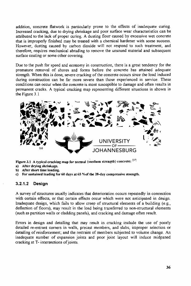
(a) (b) (c)
1? 07 141, 44. J1' — 1,74 12::11, A
A 41bA lk A -
addition, concrete flatwork is particularly prone to the effects of inadequate curing. Increased cracking, due to drying shrinkage and poor surface wear characteristics can be attributed to the lack of proper curing. A dusting floor caused by excessive wet concrete that is improperly finished may be treated with a chemical hardener with some success. However, dusting caused by carbon dioxide will not respond to such treatment, and therefore, requires mechanical abrading to remove the unsound material and subsequent surface coating or some other covering.
Due to the push for speed and economy in construction, there is a great tendency for the premature removal of shores and forms before the concrete has attained adequate strength. When this is done, severe cracking of the concrete occurs since the load induced during construction can be far more severe than those experienced in service. These conditions can occur when the concrete is most susceptible to damage and often results in permanent cracks. A typical cracking map representing different situations is shown in the Figure 3.1
Figure 3.1 A typical cracking map for normal (medium strength) concrete: [37] After drying shrinkage. After short time loading. For sustained loading for 60 days at 65 %of the 28-day compressive strength.
3.2.1.2 Design
A survey of structures usually indicates that deterioration occurs repeatedly in connection with certain effects, or that certain effects occur which were not anticipated in design. Inadequate design, which fails to allow creep of structural elements of a building (e.g., deflection of floors), may result in the load being transferred to non-structural elements (such as partition walls or cladding panels), and cracking and damage often result.
Errors in design and detailing that may result in cracking include the use of poorly detailed re-entrant corners in walls, precast members, and slabs; improper selection or detailing of reinforcement; and the restraint of members subjected to volume change. An inadequate number of expansion joints and poor joint layout will induce midpaned cracking at T- intersections of joints.
36
Design should include the provision of desired concrete quality to resist the adverse effects produced by in-service exposure conditions. Thus, the designer or specifier needs to be better informed on the particular characteristics of the given environment so that a proper choice in matching the concrete selected with the characteristics of the environment can be made.
3.2.1.3 Material characteristics
The quality of concrete with respect to durability is measured in terms of permeability. This property of hardened concrete is governed by the pore system and is basic to its ability to resist chemical attacks by external sources (e.g., acids, carbon dioxide, and sulphates), from within the concrete e.g., alkali-aggregate reactivity (AAR) and unsound cement), and other environmentally induced distress related to moisture ingress (e.g., freeze-thaw cycling, leaching). Permeability is affected by the following :
Quality of cement and aggregate. water/cement ratio and degree of hydration. Effectiveness of compaction. Extent of curing. Presence or absence of cracks.
The reactions which affect the durability of concrete can be broadly grouped into two types of reactions: - surface reactions
- reactions occurring in the body of the concrete
The attack of the surface which destroys the external microstructure of concrete and mortar is usually due to the detrimental effects of aggressive solutions. The attack from the interior can be caused by freeze-thaw cycles, and aggregates which undergo a severe expansion reaction with cement. An internal attack can also occur if the cement is of inferior quality or contains an excess of calcium oxide or magnesium oxide.
Physical phenomena affecting durability include wear of the concrete surface due to abrasion, erosion, cavitation, and impact stresses due to shock waves. The ability of the concrete to resist such forces depends on the quality of the concrete. High density, high strength concrete with low porosity and permeability values will resist these physical phenomena and show little distress for many years. Such concrete, however, must be well-designed, properly mixed and placed, adequately compacted, and well-cured if it is to be embodied with desired characteristics that are suitable for the in-service conditions.
3.2.1.4 Exposure conditions
Exposure conditions can range from the sheltered office building to the hot, arid, salt laden environment in the Middle East, or the rapid freeze-thaw cycling of temperature climates. Whatever the in-service conditions are, the designer and specifier must acquaint themselves with factors influencing the given environment; and only then design a concrete to meet those demands or take measures to protect the concrete from the aggressive conditions.
37
Having designed the concrete, the specifier should then institute proper quality control procedures to ensure that the placed concrete will represent the specified features.
3.3 PERMEABILITY OF CONCRETE
Permeability refers to the capability of a material to transmit liquids or vapours. For durability, it is accepted that concrete should possess low permeability. Unfortunately it has been found impossible so far to set limits for permeability which can be subjected to practical tests.E 41 Permeability should not be confused with absorption.
Hardened cement paste and concrete contain pores of varying types and size. Therefore the transport of materials through concrete can be considered as a particular case of the more general phenomenon of flow through a porous medium. The rate of flow will not depend simply on the porosity, but on the degree of continuity of the pores. [181 The term permeability is often loosely used to describe this general property. Therefore, as said before, the permeability of a concrete is not a simple function of its porosity but depends on the size, distribution and continuity of the pores . The flow processes depend on the degree of saturation of the cement paste or concrete as illustrated through the process described below and which represents the various stages of flow through an idealized single pore with a neck at each end: 1181
Stage a: At very low humidities, the moisture is in the vapour state and is adsorbed on to the dry surfaces of the paste.
Stage b: As the humidity increases, the adsorption becomes complete, and flow then takes place as direct vapour movement through the pore due to a pressure or concentration gradient, in the manner of inert gas.
Stage c: The humidity is sufficient for water to condense in the restricted part of the pore. The path for vapour transfer is shortened and thus the rate of movement increased.
Stage d: The condensed water zones extend with rising humidity and the flow is augmented by transfer in the adsorbed layers.
Stage e: Straightforward liquid flow under a pressure gradient eventually occurs, initially in the incompletely saturated state.
Stage f: In addition, movement of ions or dissolved gases will occur through saturated pores under a concentration gradient.
The size of capillary pores in concrete is about 1.3 Rm, and the gel pores are very much smaller. The volume of pores space in concrete, as distinct from its permeability, is measured by absorption, and the two quantities are not necessarily related. Permeability tests measure the rate at which a gas or liquid passes right through the test specimen under an applied head. Concrete possesses a pore structure and in this respect is different to metals. The capillary pore structure allows water under pressure to pass slowly through the concrete, but the rate of flow through dense, good quality concrete is extremely slow.
38
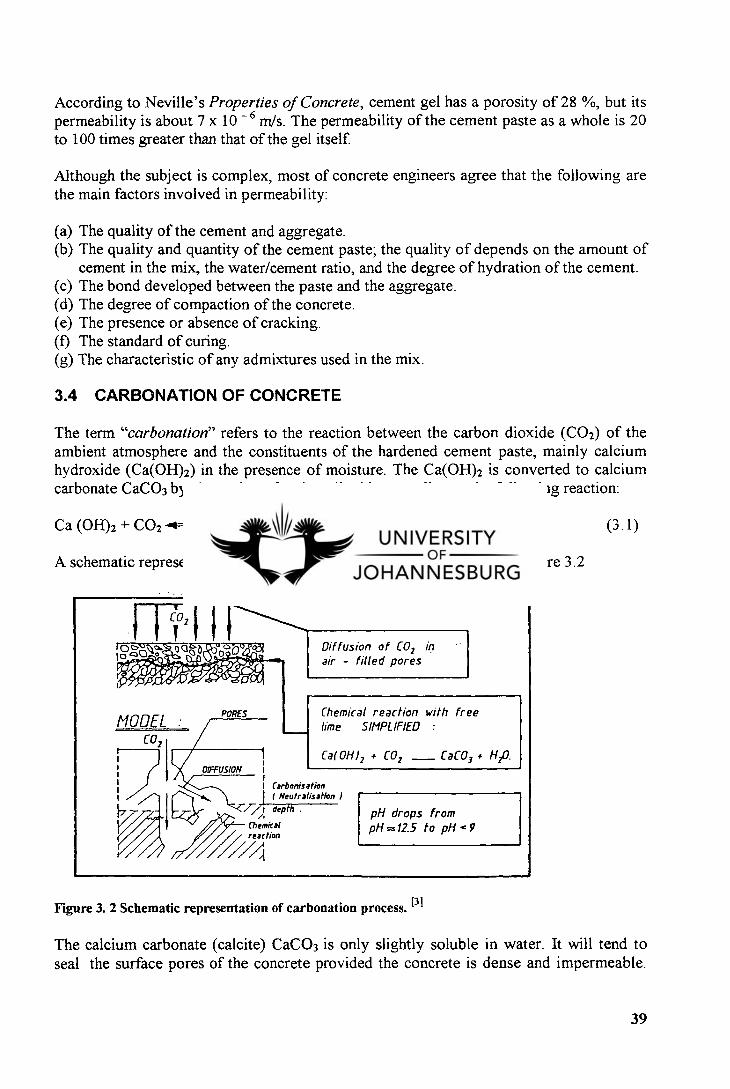
Chemical reaction with free lime SIMPLIFIED : MODEL
co,
PORES
Diffusion of CO2 in air - filled pores
I 0 c>x) b o o
Cat OH1 2 CO2 CaCO3 • H20. OIFFUSION
I Carbonisation
1
( Neutralisation
/7 depth .
Chemical / reaction
pH drops from pH =12.5 to pH .e 9
According to Neville's Properties of Concrete, cement gel has a porosity of 28 %, but its permeability is about 7 x 10 -6 m/s. The permeability of the cement paste as a whole is 20 to 100 times greater than that of the gel itself.
Although the subject is complex, most of concrete engineers agree that the following are the main factors involved in permeability:
The quality of the cement and aggregate. The quality and quantity of the cement paste; the quality of depends on the amount of cement in the mix, the water/cement ratio, and the degree of hydration of the cement. The bond developed between the paste and the aggregate. The degree of compaction of the concrete. The presence or absence of cracking. The standard of curing. The characteristic of any admixtures used in the mix.
3.4 CARBONATION OF CONCRETE
The term "carbonation" refers to the reaction between the carbon dioxide (CO 2) of the ambient atmosphere and the constituents of the hardened cement paste, mainly calcium hydroxide (Ca(OH)2) in the presence of moisture. The Ca(OH) 2 is converted to calcium carbonate CaCO3 by absorption of carbon dioxide according to the following reaction:
Ca (OH)2 + CO2 + H2O (3.1)
A schematic representation of the carbonation process is shown in the Figure 3.2
Figure 3. 2 Schematic representation of carbonation process. [31
The calcium carbonate (calcite) CaCO3 is only slightly soluble in water. It will tend to seal the surface pores of the concrete provided the concrete is dense and impermeable.
39
Other cement compounds are carbonated to hemi-carboaluminate (4CaO.A1203 .1/2 CO2. 81{20).
The reaction may occur in three phases. In the first phase, CO2 diffuses inwards. In the second phase, CO2 reacts with H2O molecules, and in the third phase, the resultant carbonic acids react with the alkaline components of the concrete. Carbonation penetrates beyond the exposed surface of concrete very slowly as moisture released by the above reaction diffuses out to preserve hygral equilibrium between the atmosphere and the interior of the concrete.I I I
The rate of carbonation is defined by the formula:
c = k ff (3.2)
where c = depth of carbonation in inches k = constant T = time in years
The importance of carbonation lies in its effects on the properties of the concrete and on the protection afforded by the concrete against corrosion of reinforcements. The pH of the pore water is generally between 12.5 and 13.5 but if due to carbonation, it is lowered to 9.0 and below, corrosion of the reinforcement may occur because the alkalinity is no longer capable of maintaining the passivating oxide film. The subsequent access of the electrolyte causes electrochemical processes in the steel to begin. Concrete which has a pH value below 9 is usually categorized as carbonated concrete.t 11 Therefore the depth of carbonation is an important factor in the protection of reinforcement. The deeper the carbonation, the greater the risk of corrosion of the steel.
It was assumed before that as only the calcium hydroxide produced by the hydration of alite and belite reacted with the carbon dioxide to form calcium carbonate. Consequently it was thought that hardened cement pastes containing blast-furnace slag were more resistant to carbonation. 131
However it has been shown that substantially all the constituents of the cement are subject to ultimate carbonation and the complete conversion of the hydrated cement is chemically possible even at the low carbon dioxide concentrations present in normal outdoor atmospheres.t 31 In recent years therefore, it has become the practice also to include in the term "carbonation " the reaction between oxides of sulphur (SO 2 and SO3 ) and the calcium dioxide.
It is important to notice that there is a large difference between rate of diffusion of CO2 in air and diffusion of CO2 in water (in water = t 10 4 times lower). [61 The penetration of CO2 in concrete will be determined by the form of the pore structure i.e. whether the pores of concrete are waterfilled or not. If the pores are dry (Figure 3.3) CO2 diffuses inwardly but carbonation does not occur because of lack of water or moisture (case of oven-dried concrete). [31
40
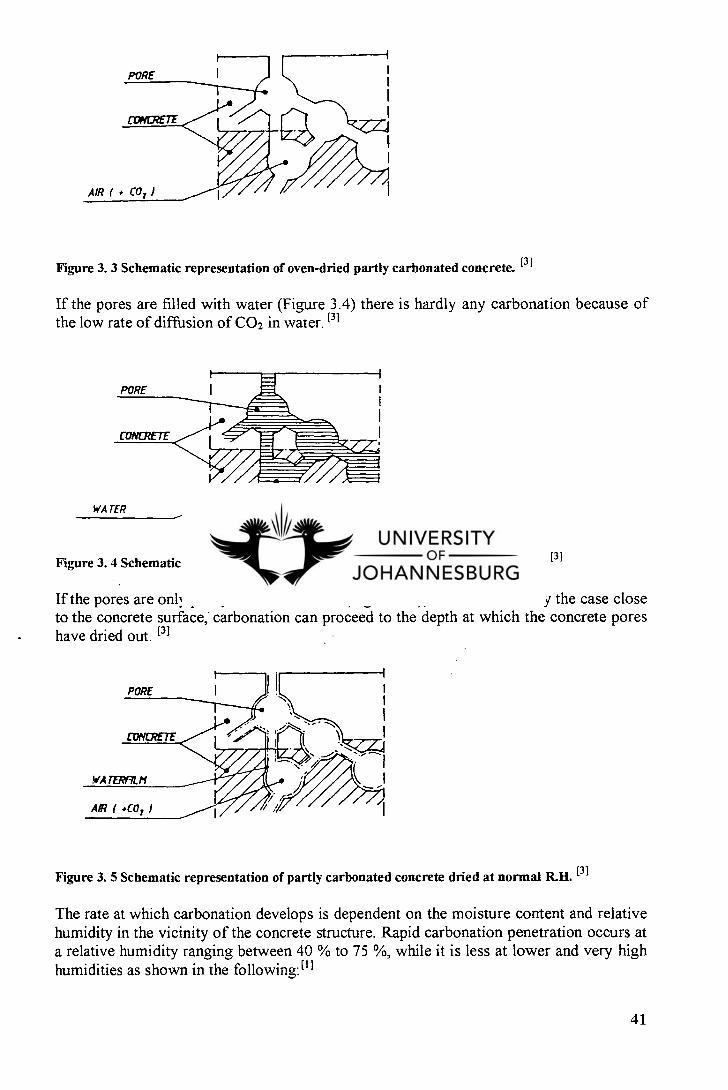
Figure 3. 3 Schematic representation of oven-dried partly carbonated concrete. i31
If the pores are filled with water (Figure 3.4) there is hardly any carbonation because of the low rate of diffusion of CO2 in water. [31
Figure 3. 4 Schematic representation of water saturated partly carbonated concrete. PI
If the pores are only partly filled with water (Figure 3.5), which is normally the case close to the concrete surface, carbonation can proceed to the depth at which the concrete pores have dried out. [31
Figure 3. 5 Schematic representation of partly carbonated concrete dried at normal R.H. [31
The rate at which carbonation develops is dependent on the moisture content and relative humidity in the vicinity of the concrete structure. Rapid carbonation penetration occurs at a relative humidity ranging between 40 % to 75 %, while it is less at lower and very high humidities as shown in the following: [11
41
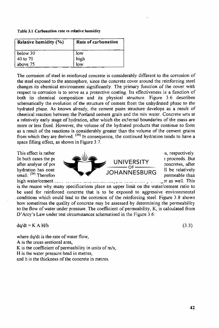
Table 3.1 Carbonation rate vs relative humidity
Relative humidity (%) Rate of carbonation
below 30 40 to 70 above 75
low high low
The corrosion of steel in reinforced concrete is considerably different to the corrosion of the steel exposed to the atmosphere, since the concrete cover around the reinforcing steel changes its chemical environment significantly. The primary function of the cover with respect to corrosion is to serve as a protective coating. Its effectiveness is a function of both its chemical composition and its physical structure. Figure 3.6 describes schematically the evolution of the structure of cement from the unhydrated phase to the hydrated phase. As known already, the cement paste structure develops as a result of chemical reaction between the Portland cement grain and the mix water. Concrete sets at a relatively early stage of hydration, after which the ex5ernal boundaries of the mass are more or less fixed. However, the volume of the hydrated products that continue to form as a result of the reactions is considerably greater than the volume of the cement grains from which they are derived. [391 In consequence, the continued hydration tends to have a space filling effect, as shown in Figure 3.7.
This effect is rather different for pastes of low and high water/cement ratios, respectively. In both cases the porosity of the cement continues to decrease as hydration proceeds. But after analyse of pores, it has been noticed that in low water/cement ratio concretes, after hydration has continued for some reasonable time, the total porosity will be relatively small. [391 Therefore, low water/cement ratio concrete is intrinsically less permeable than high water/cement ratio concrete and, incidentally, is considerably stronger as well. This is the reason why many specifications place an upper limit on the water/cement ratio to be used for reinforced concrete that is to be exposed to aggressive environmental conditions which could lead to the corrosion of the reinforcing steel. Figure 3.8 shows how sometimes the quality of concrete may be assessed by determining the permeability to the flow of water under pressure. The coefficient of permeability, K, is calculated from D'Arcy's Law under test circumstances schematised in the Figure 3.6:
dq/dt = K A H/h (3.3)
where dq/dt is the rate of water flow, A is the cross-sectional area, K is the coefficient of permeability in units of m/s, H is the water pressure head in metres, and h is the thickness of the concrete in metres.
42
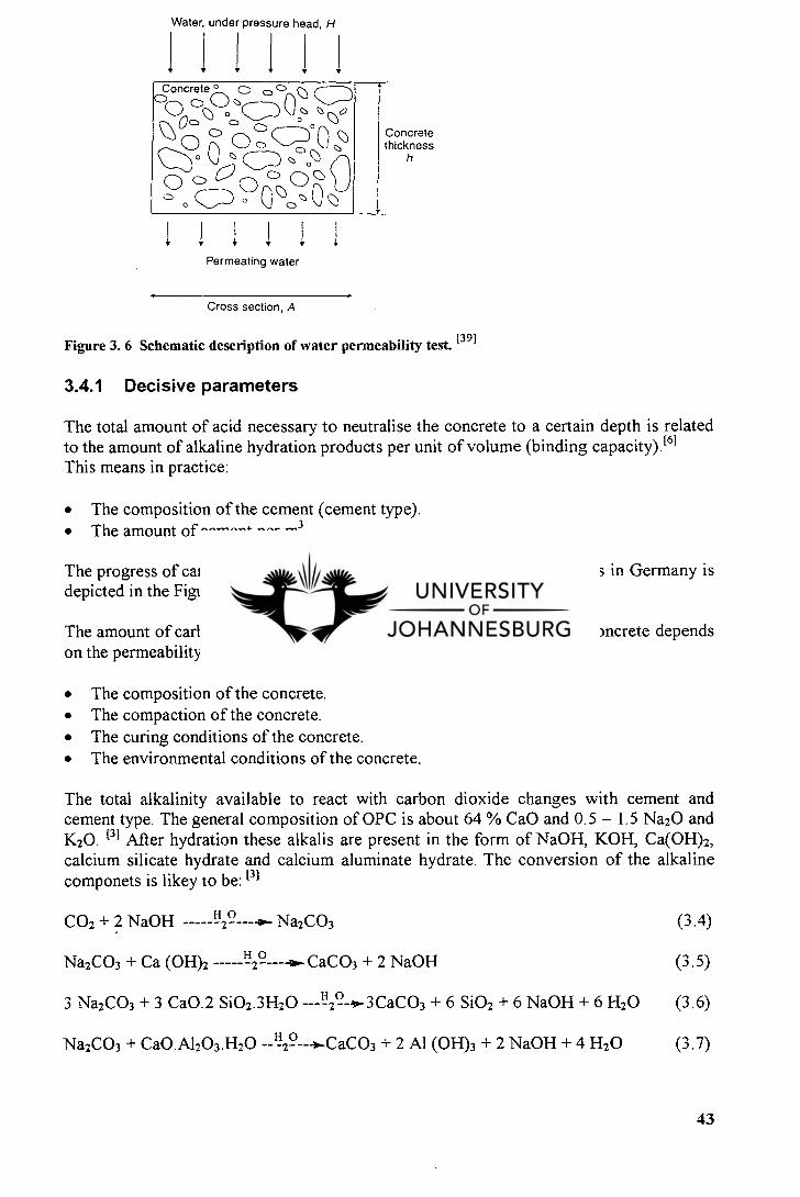
Water, under pressure head, H
it
Concrete ° O CD (1' ,
°
1-
,&) 0(Th
C/D 0 0 0 U c,°00
rN.c
Concrete thickness
h
Permeating water
Cross section, A
Figure 3. 6 Schematic description of water permeability test. [39]
3.4.1 Decisive parameters
The total amount of acid necessary to neutralise the concrete to a certain depth is related to the amount of alkaline hydration products per unit of volume (binding capacity). (61 This means in practice:
The composition of the cement (cement type). The amount of cement per m 3 .
The progress of carbonation with time exposure under different conditions in Germany is depicted in the Figure 3.9.
The amount of carbon dioxide that will diffuse per unit of time into the concrete depends on the permeability of the concrete to CO2) (61 This means in practice :
The composition of the concrete. The compaction of the concrete. The curing conditions of the concrete. The environmental conditions of the concrete.
The total alkalinity available to react with carbon dioxide changes with cement and cement type. The general composition of OPC is about 64 % CaO and 0.5 - 1.5 Na20 and K20. i31 After hydration these alkalis are present in the form of NaOH, KOH, Ca(OH) 2, calcium silicate hydrate and calcium aluminate hydrate. The conversion of the alkaline componets is likey to be: 131
CO2 + 2 NaOH H2 0 -91••• Na2 CO3 (3.4)
Na2 CO3 + Ca (OH)2 H 2— 0
— --11.-CaCO3 + 2 NaOH (3.5)
3 Na2 CO3 + 3 CaO.2 Si02.3H20 -- 1:129-1-3CaCO3 + 6 Si02 + 6 NaOH + 6 H2 O (3.6)
Na2CO3 + CaO.A1203.H20 -- 112 -9-4-CaCO3 + 2 Al (OH) 3 + 2 NaOH + 4 H2 O (3.7)
43
Un hydrated
Cement grains
Water
Hydrated
Hydation products
Capillary pores
Cement grains
The binding capacity for CO 2 (ceterum paribus) will be proportionate to the amount of alkaline components in the cement.E 31
High w/c ratio (a 0.70)
Low w/c ratio (a 0.40)
Figure 3.7 Schematic description of the evolution of the structure of cement pastes of low and high water/cement ratio. [39]
3.4.2 Effects of carbonation
The principal effects of carbonation of concrete are:
A large increase in irreversible shrinkage when the concrete is exposed to intermediate relative humidities. Under normal conditions carbonation is slow, but over a long period may cause shrinkage, additional to drying shrinkage which can have serious effects. Warping of components and crazing of concrete surfaces have been attributed to this cause.
Improved volume stability, except in cases where the concrete is cured by steam at high pressure.
In the case of concretes made with ordinary or rapid-hardening Portland cement, a considerably increased compressive strength.
A drastic reduction in the protection provided against corrosion of steel reinforcement
In regard to (iv) it has been reported that steel in a highly alkaline environment, i.e. in the presence of a sufficiently high concentration of hydroxyl ions, does not corrode. It is believed that this passivity is due to the formation of a protective film of gamma ferric oxide on the surface of the steel. As long as this protective film is maintained by a sufficiently high pH and is not disrupted by aggressive substances, complete protection of
44
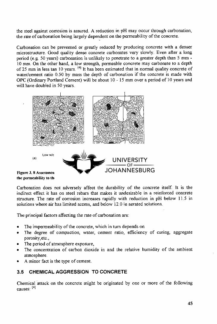
the steel against corrosion is assured. A reduction in pH may occur through carbonation, the rate of carbonation being largely dependent on the permeability of the concrete.
Carbonation can be prevented or greatly reduced by producing concrete with a denser microstructure. Good quality dense concrete carbonates very slowly. Even after a long period (e.g. 50 years) carbonation is unlikely to penetrate to a greater depth than 5 mm -10 mm. On the other hand, a low strength, permeable concrete may carbonate to a depth of 25 mm in less tan 10 years. 141 It has been estimated that in normal quality concrete of water/cement ratio 0.50 by mass the depth of carbonation if the concrete is made with OPC (Ordinary Portland Cement) will be about 10 - 15 mm over a period of 10 years and will have doubled in 50 years.
gq,-.6.'-giq,:.0' II , i egq.-<",— ojzcs g-0,4s)L y-....-o 0 1
lad° 4(3:' a? b--. .; f 101069,,00 :Ai opp,.,
ft) c= , 4 at) „I/ V. s 1cl eapf,'"c7 moo. ,,,,,,l) ‘ a a°'-,ST,-° Oiqqo c°°4 ''=/.
„p gi-1- ,?' IV' -8,,g)60c, opop p,..1=20 • • f i7 '4/A(7 Q 011D 2.):070 ,011 ,4 f,d2,g 8fic,=-,,,,p,,,,.
0 c1=A= OP.,a°'---s-PA.0 _... 0 oa.e..:,A A c'c,-,,c-, ,,,,,--, ,_' =,,,---'”
Low w/c ratio (:---: 0.40) (a) (b)
High w/c ratio (L-- 0.70)
Figure 3. 8 Assessment of concrete quality by the determination of the permeability to the flow of water under pressure. [39)
Carbonation does not adversely affect the durability of the concrete itself. It is the indirect effect it has on steel rebars that makes it undesirable in a reinforced concrete structure. The rate of corrosion increases rapidly with reduction in pH below 11.5 in solutions where air has limited access, and below 12.0 in aerated solutions.
The principal factors affecting the rate of carbonation are:
The impermeability of the concrete, which in turn depends on The degree of compaction, water, cement ratio, efficiency of curing, aggregate porosity,etc., The period of atmosphere exposure, The concentration of carbon dioxide in and the relative humidity of the ambient atmosphere. A minor fact is the type of cement.
3.5 CHEMICAL AGGRESSION TO CONCRETE
Chemical attack on the concrete might be originated by one or more of the following causes: tai
45
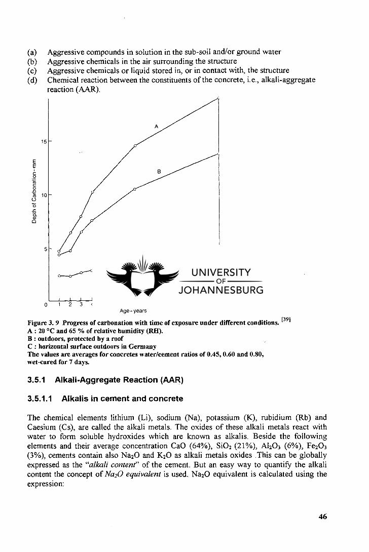
Aggressive compounds in solution in the sub-soil and/or ground water Aggressive chemicals in the air surrounding the structure Aggressive chemicals or liquid stored in, or in contact with, the structure Chemical reaction between the constituents of the concrete, i.e., alkali-aggregate reaction (AAR).
15
10
5
Dep
th of C
arb
onat
ion
- m
m
I 0 1 2 3 4
8 Age- years
Figure 3. 9 Progress of carbonation with time of exposure under different conditions. 1391 A : 20 °C and 65 % of relative humidity (RH). B : outdoors, protected by a roof C : horizontal surface outdoors in Germany The values are averages for concretes water/cement ratios of 0.45, 0.60 and 0.80, wet-cured for 7 days.
3.5.1 Alkali-Aggregate Reaction (AAR)
3.5.1.1 Alkalis in cement and concrete
The chemical elements lithium (Li), sodium (Na), potassium (K), rubidium (Rb) and Caesium (Cs), are called the alkali metals. The oxides of these alkali metals react with water to form soluble hydroxides which are known as alkalis. Beside the following elements and their average concentration CaO (64%), Si0 2 (21%), A1203 (6%), Fe203 (3%), cements contain also Na20 and K 20 as alkali metals oxides .This can be globally expressed as the "alkali content" of the cement. But an easy way to quantify the alkali content the concept of Na20 equivalent is used. Na20 equivalent is calculated using the expression:
46
Na20 equivalent(%) = Na20 (%) + (62.0/94.2) x K20 (%) = Na20 (%) + 0.658 x K20(%) (3.8)
When water is added to cement, the sodium and potassium oxides react with the water, releasing the alkalis sodium hydroxide and potassium hydroxide into the cement paste.
The "alkali content" of concrete can be expressed in the same way as that of cement by using the Na20 equivalent, but the contribution of alkali from any cement replacement materials or additives, as well as alkali from the cement, must be taken into account (Concrete Society, 1987). 151
There is one further difference: while the alkali content of cement is expressed as a percentage by mass, the alkali content of concrete is conventionally expressed as a mass per unit volume (kg/m3). The cement content of concrete is also expressed as mass per unit volume (kg/m3). Therefore the alkali content of the concrete can be readily calculated from the expression: [51
Na20 equivalent of concrete (kg/m 3) = Na20 equivalent of cement (%) x 1/100 x cement content of concrete (kg/m 3) (3.9)
3.5.1.2 Alkali-aggregate reaction (AAR)
The reaction called Alkali-aggregate reaction occurs in concrete when alkalis from the cement, or from an external source, react with certain aggregates to form products that are deteriorous in some way to the concrete. Four forms of alkali-aggregate reaction have been recognized .They are: 151
alkali-silca reaction, alkali-silicate reaction, alkali-carbonate reaction and other alkali-aggregate reactions.
Alkali-silica reaction
Alkali-silica reaction occurs in concrete when alkalis from the cement, or from an external source, react with free silica present in certain aggregates to form alkali-silica gel. The alkali-silica gel has the property of attacking in water and expanding. [51 This expansion can cause the aggregate particles and the concrete to crack, and ultimately can damage the concrete.
When concrete has become damaged by the alkali-silica reaction, the characteristic feature it display is a network of cracks, which on the surface of the concrete produce a crazed pattern referred to as "map-cracking". [5] Sometimes, but not always, white alkali-silica gel can be seen emanating from the cracks, but in dry weather this often dries to a white powder.
47
Alkali-silicate reaction
The alkali-silicate reaction is the same as the alkali-silica reaction except that in this case the reactive constituent in the aggregate is not free silica but silica present in the combined form of phyllosilicates(e.g. chlorite, vermiculite, mica.E 51
Alkali -carbonate reaction
The alkali-carbonate reaction occurs in concrete when alkalis from the cement, or from an external source, react with certain dolomitic limestones containing clay. The alkalis react with the mineral dolomite [CaMg(CO 3 )2], causing it to break down into brucite [Mg(OH)2] and calcite (CaCO 3), in a reaction that is called "dedolomitization" and which is represented by the following equation: [5]
CaMg(CO3)2 + 2NaOH Dolomite Alkali
Mg(OH)2 + CaCO3 + Na2CO3 (3.10) Brucite Calcite
N.B. This chemical equation can also be written with potassium in place of sodium.
Other alkali-aggregate reactions
Beside the three reactions described above, other alkali-aggregate reactions can also occur in concrete when the cement is wetted, because of the high reactivity of the alkalis sodium hydroxide and potassium hydroxide. In Trinidad recently a concrete wall had to be demolished because of unacceptable blemishes caused by alkalis from the cement reacting with a brown organic-iron complex present as a coating on the aggregate. The reaction product formed an oily brown deposit on the surface of the wal1. 151 This could not happened if a locally low-alkali cement had been used instead of the imported high-alkali cement.
3.6 CORROSION OF STEEL IN CONCRETE
3.6.1 General remarks
The corrosion of steel in concrete proceeds by means of an electrochemical mechanism which involves both microcell and macrocell corrosion. The corrosion reaction is therefore electrochemical and creates measurable electrical potentials. A microcell is developed when anodic and cathodic regions are formed alternately along the surface of the same reinforcement bar in very close proximity to each other. Only the mixed corrosion potentials of the innumerable anodes and cathodes can be measured in this case. In a macrocell, separate anodic and cathodic regions are formed some distance apart, and both the anodic and cathodic potentials can be measured.E 101 Macrocell corrosion is likely to play an important role in reinforcement corrosion. The large dimensions of concrete structures and local differences in exposure conditions will undoubtedly promote differential electrochemical behaviour in the embedded steel. This is accompanied by potential differences along the reinforcement which in turn result in galvanic interaction on large scale. The overall result is that part of the steel reinforcement will suffer an accelerated corrosion attack, which often leads to premature failure. [ 101
48
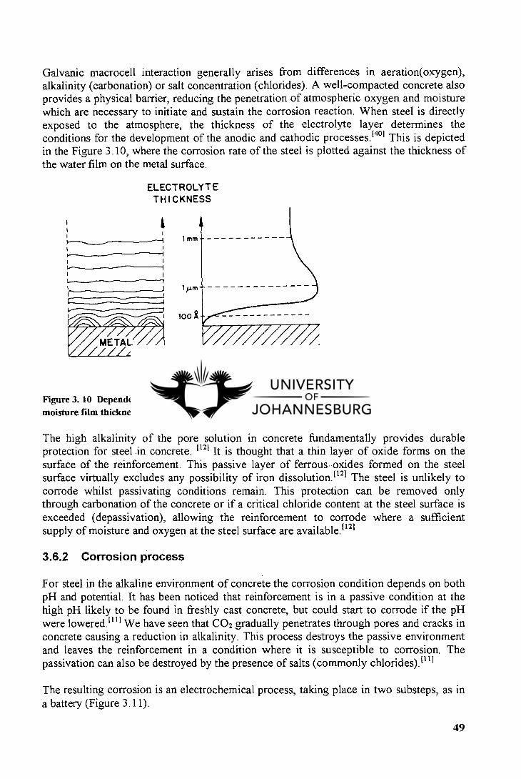
1 mm I
J
100
Galvanic macrocell interaction generally arises from differences in aeration(oxygen), alkalinity (carbonation) or salt concentration (chlorides). A well-compacted concrete also provides a physical barrier, reducing the penetration of atmospheric oxygen and moisture which are necessary to initiate and sustain the corrosion reaction. When steel is directly exposed to the atmosphere, the thickness of the electrolyte layer determines the conditions for the development of the anodic and cathodic processes.E 401 This is depicted in the Figure 3.10, where the corrosion rate of the steel is plotted against the thickness of the water film on the metal surface.
ELECTROLYTE THICKNESS
CORROSION RATE
Figure 3. 10 Dependence of atmospheric corrosion rate on moisture film thickness on the metal surface. 1401
The high alkalinity of the pore solution in concrete fundamentally provides durable protection for steel .in concrete. 1121 It is thought that a thin layer of oxide forms on the surface of the reinforcement. This passive layer of ferrous oxides formed on the steel surface virtually excludes any possibility of iron dissolution. 1121 The steel is unlikely to corrode whilst passivating conditions remain. This protection can be removed only through carbonation of the concrete or if a critical chloride content at the steel surface is exceeded (depassivation), allowing the reinforcement to corrode where a sufficient supply of moisture and oxygen at the steel surface are available. 1121
3.6.2 Corrosion process
For steel in the alkaline environment of concrete the corrosion condition depends on both pH and potential. It has been noticed that reinforcement is in a passive condition at the high pH likely to be found in freshly cast concrete, but could start to corrode if the pH were lowered. [111 We have seen that CO2 gradually penetrates through pores and cracks in concrete causing a reduction in alkalinity. This process destroys the passive environment and leaves the reinforcement in a condition where it is susceptible to corrosion. The passivation can also be destroyed by the presence of salts (commonly chlorides). [111
The resulting corrosion is an electrochemical process, taking place in two substeps, as in a battery (Figure 3.11).
49
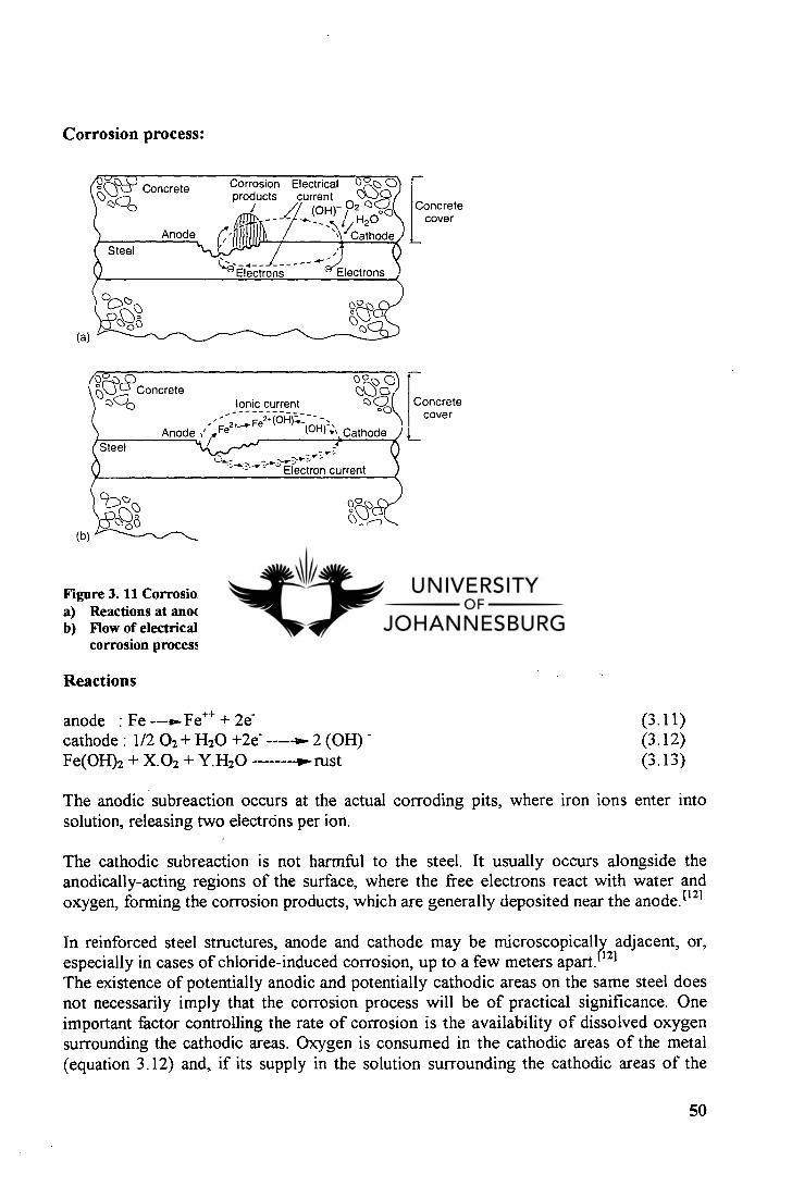
Concrete cover
Corrosion Electrical products current e,
- ■-)2 / (OH) / / / H 0
- - ''Ca2thode
0 ihJliih
• Concrete 000
I .
Anode
Steel
FNO 0 OQ
Ionic current 0G ---- oo
Anode Fe2 *(0 F1 )■-- - - (OH)1; , Cathode
(b)
(a)
Concrete cover
Corrosion process:
--- Electrons Electrons
Figure 3. 11 Corrosion processes on the surface of steel: 1391 Reactions at anodic and cathodic sites and electric current loop. Flow of electrical charge in the electric current loop during the corrosion process.
Reactions
anode : Fe ---,-Fe ÷± + 2e- cathode : 1/2 02 + H2O +2e- 2 (OH) - Fe(OH)2 + X.02 + Y.H20 -••• rust
(3.11) (3.12) (3.13)
The anodic subreaction occurs at the actual corroding pits, where iron ions enter into solution, releasing two electrons per ion.
The cathodic subreaction is not harmful to the steel. It usually occurs alongside the anodically-acting regions of the surface, where the free electrons react with water and oxygen, forming the corrosion products, which are generally deposited near the anode. (121
In reinforced steel structures, anode and cathode may be microscopically adjacent, or, especially in cases of chloride-induced corrosion, up to a few meters apart. [12]
The existence of potentially anodic and potentially cathodic areas on the same steel does not necessarily imply that the corrosion process will be of practical significance. One important factor controlling the rate of corrosion is the availability of dissolved oxygen surrounding the cathodic areas. Oxygen is consumed in the cathodic areas of the metal (equation 3.12) and, if its supply in the solution surrounding the cathodic areas of the
50
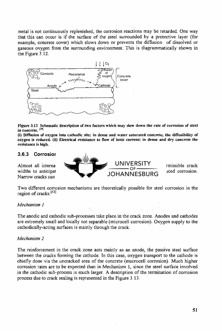
metal is not continuously replenished, the corrosion reactions may be retarded. One way that this can occur is if the surface of the steel surrounded by a protective layer (for example, concrete cover) which slows down or prevents the diffusion of dissolved or gaseous oxygen from the surrounding environment. This is diagrammatically shown in the Figure 3.12.
1 I 02
Concrete cover
Figure 3.12 Schematic description of two factors which may slow down the rate of corrosion of steel in concrete. [39] (i) Diffusion of oxygen into cathodic site: in dense and water saturated concrete, the diffusibility of oxygen is reduced. (ii) Electrical resistance to flow of ionic current: in dense and dry concrete the resistance is high.
3.6.3 Corrosion in cracks region
Almost all international codes of reinforced concrete design relate permissible crack widths to anticipated exposure conditions in order to avoid crack induced corrosion. Narrow cracks can be obtained by reduction of the concrete cover. 161
Two different corrosion mechanisms are theoretically possible for steel corrosion in the region of cracks: 1121
Mechanism 1
The anodic and cathodic sub-processes take place in the crack zone. Anodes and cathodes are extremely small and locally not separable (microcell corrosion). Oxygen supply to the cathodically-acting surfaces is mainly through the crack.
Mechanism 2
The reinforcement in the crack zone acts mainly as an anode, the passive steel surface between the cracks forming the cathode. In this case, oxygen transport to the cathode is chiefly done via the uncracked area of the concrete (macrocell corrosion). Much higher corrosion rates are to be expected than in Mechanism 1, since the steel surface involved in the cathodic sub-process is much larger. A description of the termination of corrosion process due to crack sealing is represented in the Figure 3.13.
51
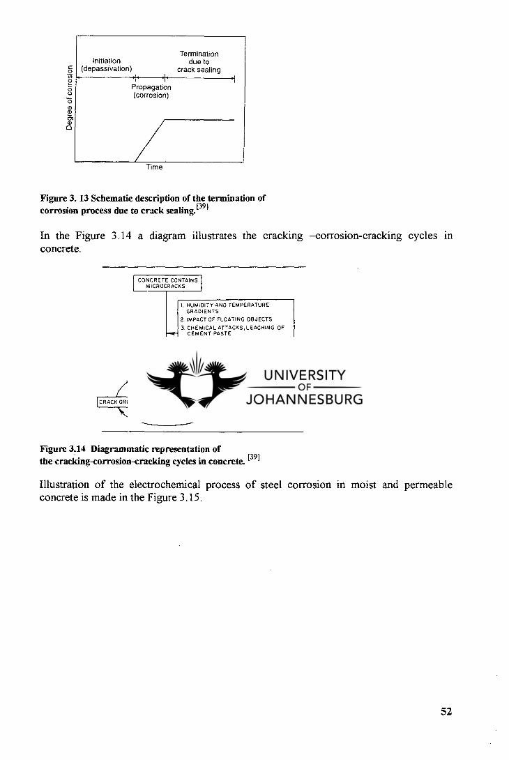
Termination Initiation
due to . (depassivation)
crack sealing
Propagation (corrosion)
Time
Figure 3. 13 Schematic description of the termination of corrosion process due to crack sealing. (39]
In the Figure 3.14 a diagram illustrates the cracking —corrosion-cracking cycles in concrete.
CONCRETE CONTAINS MICROCRACKS
I. HUMIDITY AND TEMPERATURE GRADIENTS
IMPACT OF FLOATING OBJECTS
CHEMICAL ATTACKS,LEACHING OF CEMENT PASTE FREEZE-THAW ATTACK,OVERLOAOS, AND OTHER FACTORS INCREASING THE PERMEABILITY OF CONCRETE
SEAWATER AND AIR HIGHLY PERMEABLE
CONCRETE
CRACK GROWTH
CORROSION OF EMBEDDED STEEL
the cracking-corrosion-cracking cycles in concrete. [39]
Illustration of the electrochemical process of steel corrosion in moist and permeable concrete is made in the Figure 3.15.
Cl)
C 0
. 0
0 a) rn a) a
Figure 3.14 Diagrammatic representation of
52
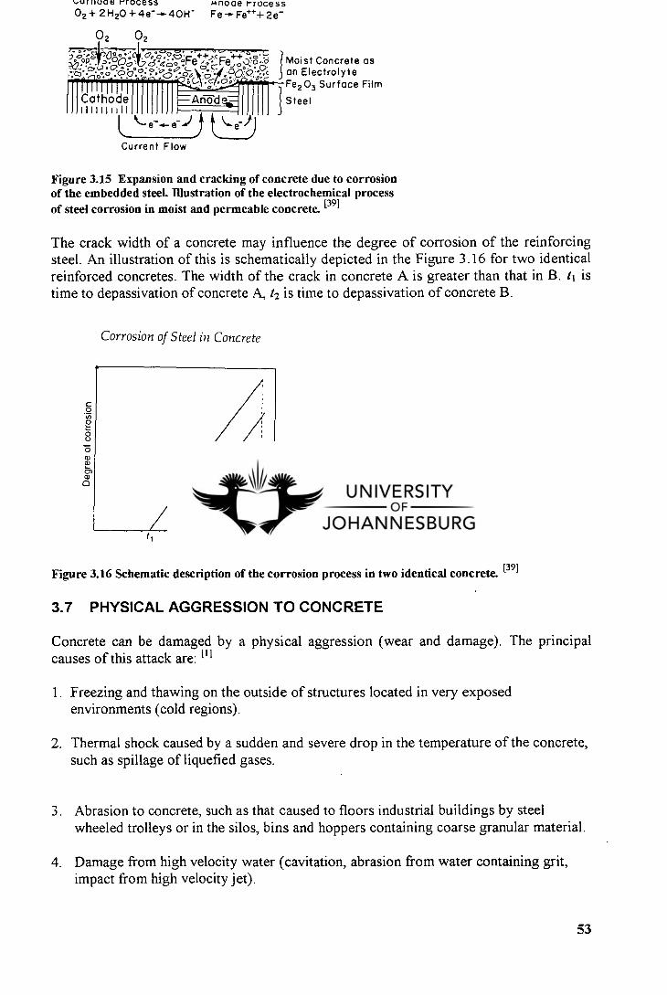
Deg
r ee
of c
orr
osio
n
lol.111100e rrOCeSS unoae rrocess 02+ 2F120 +4e- -► 40H -
Fe -0- Fe+++ 2e-
0 2 02
,7 .c3 • • • ..0 .c30 . • • 0 • fc..1.c....o,;21:41**1...--Fe203 Surface Film
v9.°05° .. 0o0° , 3e 4L. • -6° -7,-,-/.90. an Electrolyte --- 0.... „,e„p-++,:,.---„,,,) ,t Moist Concrete as
.•:„,..3. (2. •.. . 0:0 .c. -.9.L- \sy.:;•0:--9*.• 4
Cathode 111111 i H
e- ■))
Current Flow
Figure 3.15 Expansion and cracking of concrete due to corrosion of the embedded steeL Illustration of the electrochemical process of steel corrosion in moist and permeable concrete. [39]
The crack width of a concrete may influence the degree of corrosion of the reinforcing steel. An illustration of this is schematically depicted in the Figure 3.16 for two identical reinforced concretes. The width of the crack in concrete A is greater than that in B. ti is time to depassivation of concrete A, t 2 is time to depassivation of concrete B.
Corrosion of Steel in Concrete
Figure 3.16 Schematic description of the corrosion process in two identical concrete. [39]
3.7 PHYSICAL AGGRESSION TO CONCRETE
Concrete can be damaged by a physical aggression (wear and damage). The principal causes of this attack are: (11
Freezing and thawing on the outside of structures located in very exposed environments (cold regions).
Thermal shock caused by a sudden and severe drop in the temperature of the concrete, such as spillage of liquefied gases.
Abrasion to concrete, such as that caused to floors industrial buildings by steel wheeled trolleys or in the silos, bins and hoppers containing coarse granular material.
Damage from high velocity water (cavitation, abrasion from water containing grit, impact from high velocity jet).
53
Steel
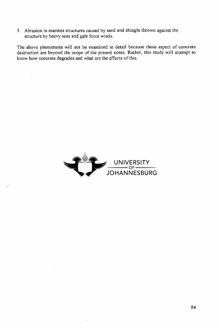
5. Abrasion in marines structures caused by sand and shingle thrown against the structure by heavy seas and gale force winds.
The above phenomena will not be examined in detail because these aspect of concrete destruction are beyond the scope of the present notes. Rather, this study will attempt to know how concrete degrades and what are the effects of this.
54
CHAPTER 4
PLANNING AND INVESTIGATION OF CAUSES AND EFFECTS OF CONCRETE DEGRADATION
4.1 GENERAL REMARKS
The repair program is the step that comes after assessment of the causes of concrete deterioration. Factors which greatly influence the type of repair technique and material to be used are the type of deterioration, extent of damage, and the cause of deterioration. Thus, it is important to identify the kind of deterioration before deciding on how best to conduct the repair program.
However, the most difficult and important step of the repair process is the determination of the cause of degradation. It is not possible to evaluate the need for repair or to select a repair procedure and materials with assurance of satisfactory results unless the cause is understood. With concrete, often the specific cause cannot be identified, either because there is insufficient data to determine the origin of the trouble or because there are several
factors involved simultaneously.
4.2 DEFECTS AND CAUSES OF DEFECTS IN VARIOUS TYPES OF CONCRETE
This paragraph discusses about some common concrete problems that can be identified visually. It will also suggest some plausible explanation for the occurrence of these defects. The various defects can be grouped into two categories :
Defects observed in different concretes. Defects occurring in various concrete structures.
4.2.1 Architectural concrete
Architectural concrete may be defined as concrete which will be permanently exposed to view and which therefore requires special care in the selection of the concrete materials, forming, placing, and finishing to obtain to the desired architectural appearance.' ?1
The primary general factors which can singly, or in combination, cause blemishes are:i l l
General work conditions ( poor access, restricted openings, etc.). The concrete mix ( too dry or wet mixes). Placement techniques ( segregation of mix). Compaction effect ( mismatch of vibrator and mix consistence). Forms ( robustness, absorbency ).
The Table 4.1 summarizes the primary and secondary causes of surface blemishes and lists a variety of factors influencing the origin of blemishes. Typical blemishes which
55
produce an aesthetically poor surface appearance include the following: hydration, discoloration, efflorescence, weathering, honeycombing, blowholes, grout loss, scouring, crazing, form scabbing, and scaling.
Colour variation in the matrix is due to differences in the colours of the different brands of cement, differences in aggregates, or improper finishing and curing techniques. Drying discoloration is the variation in the shade of concrete occurring after removal of the forms. Weathering of architectural concrete is usually observed as an irregular discoloration by disposition of foreign matter or due to an external chemical reaction. Blow holes are small regular or irregular individual cavities normally not exceeding 15 mm diameter. Sand textured areas devoid of cement form when there is grout loss from the mix. In the same way scouring produces washed out channels in the surface with exposed sand or stone particles. 111
4.2.2 Formed Concrete
The actual trend in construction structures, is to leave concrete as the finish surface. Therefore appearance becomes a very important aspect, particularly for vertical surfaces which are usually formed and unfortunately prone to defects. Many kinds of defects occur in formed concrete such as :
- honeycombing : is a surface condition of irregular voids that results when the mortar does not effectively fill the spaces in between the aggregate during vibration. It occurs because the concrete mix is undersanded and/or placing conditions and techniques are poor. [il
discoloration: is the variation of colour over the surface because of differences in the brand of cement, excessive application of release agent, change in type of release agent, non uniform absorbency of unsealed form board, incomplete mixing, etc. E'• 8 ' 91
- subsidence cracking: occurs when concrete settles after or near initial set and concrete is not able to accommodate the stress due to the high degree of cohesion in the mix.t 11
sand streaking or scouring: irregular eroded areas and channels with exposed stone and sand particles. It is the result of using an excessively wet, lean concrete mix, placing at too low temperature could also produce this effect.
- aggregate transparency: consists of a generally mottled appearance of dark areas of similar size and shape to the coarse aggregate. It is usually caused when the formwork is not rigid enough, when gap graded mixes with low sand content is used, or excessive external vibration has been used during placing. 111
- efflorescence: consists of white deposits and stains found on concrete. The deposits result from the migration of salts ( derived from the cements or alkalis in the ground) in solution from the interior of the concrete or brick to the surface where they crystallize. 111
56
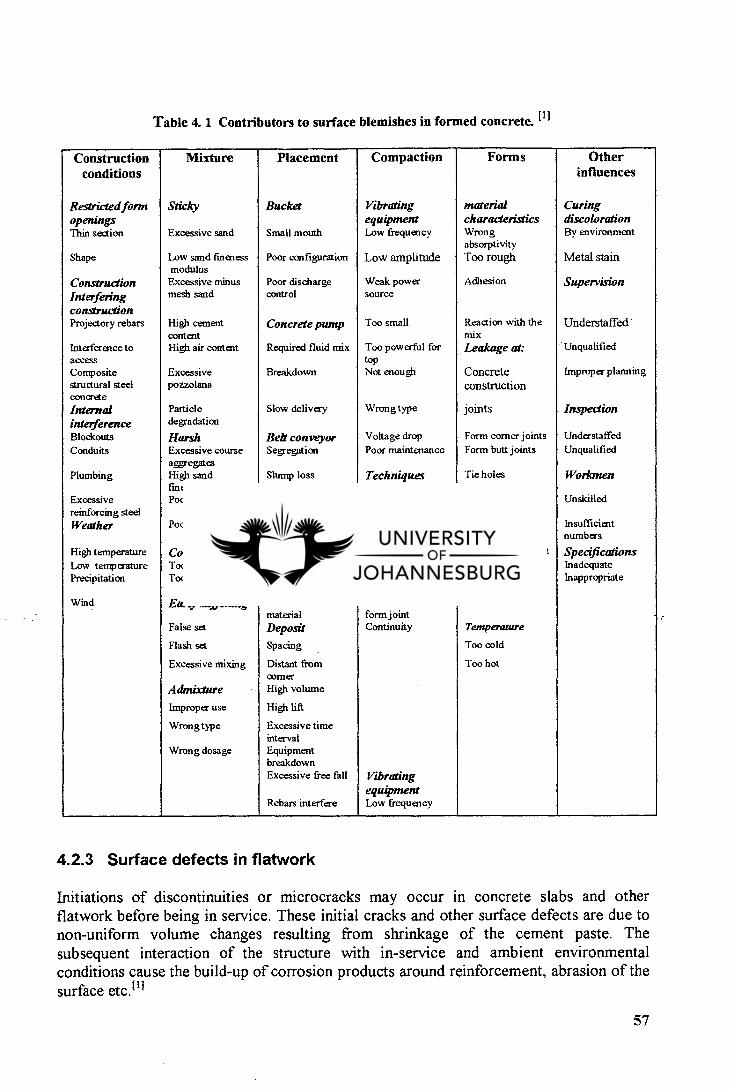
Table 4. 1 Contributors to surface blemishes in formed concrete. 111
Construction conditions
Mixture Placement Compaction Forms Other influences
Restricted form Sticky Bucket Vibrating material Curing openings equipment characteristics discoloration Thin section Excessive sand Small mouth Low frequency Wrong
absorptivity By environment
Shape Low sand fineness modulus
Poor configuration Low amplitude Too rough Metal stain
Construction Excessive minus Poor discharge Weak power Adhesion Supervision Interfering construction
mesh sand control source
Projedory rebars High cement content
Concrete pump Too small Reaction with the mix
Understaffed
Interference to access
High air content Required fluid mix Too powerful for top
Leakage at: . Unqualified
Composite structural steel concrete
Excessive pozzolana
Breakdown Not enough Concrete construction
Improper planning
Internal interference
Particle degradation
Slow delivery Wrong type joints Inspection
Blockouts Harsh Belt conveyor Voltage drop Form comer joints Understaffed
Conduits Excessive course aggregates
Segregation Poor maintenance Form butt joints Unqualified
Plumbing High sand fineness modulus
Slump loss Techniques Tie holes Workmen
Excessive reinforcing steel
Poor grading Mortar loss Vibration too brief
Release agent Unskilled
Weather Poor particle shape Hopper/drop chute
Poor manipulation Unsuitable type Insufficient numbers
High temperature Consistency Omitted Spacing too brief Chemistry of agent Specifications Low temperature Too high Too small Not deep enough Friction with mix Inadequate Precipitation Too low Insufficient
number Head partially immersed
Applied too thick Inappropriate
Wind Early stiffening Unsuitable material
Placed too close to form joint
Not cured •
False set Deposit Continuity Temperature
Flash set Spacing Too cold
Excessive mixing Distant from comer
Too hot
Admixture High volume
Improper use High Lift
Wrong type Excessive time interval
Wrong dosage Equipment breakdown Excessive free fall Vibrating
equipment Rebars interfere Low frequency
4.2.3 Surface defects in flatwork
Initiations of discontinuities or microcracks may occur in concrete slabs and other flatwork before being in service. These initial cracks and other surface defects are due to non-uniform volume changes resulting from shrinkage of the cement paste. The subsequent interaction of the structure with in-service and ambient environmental conditions cause the build-up of corrosion products around reinforcement, abrasion of the surface etc. 111
57
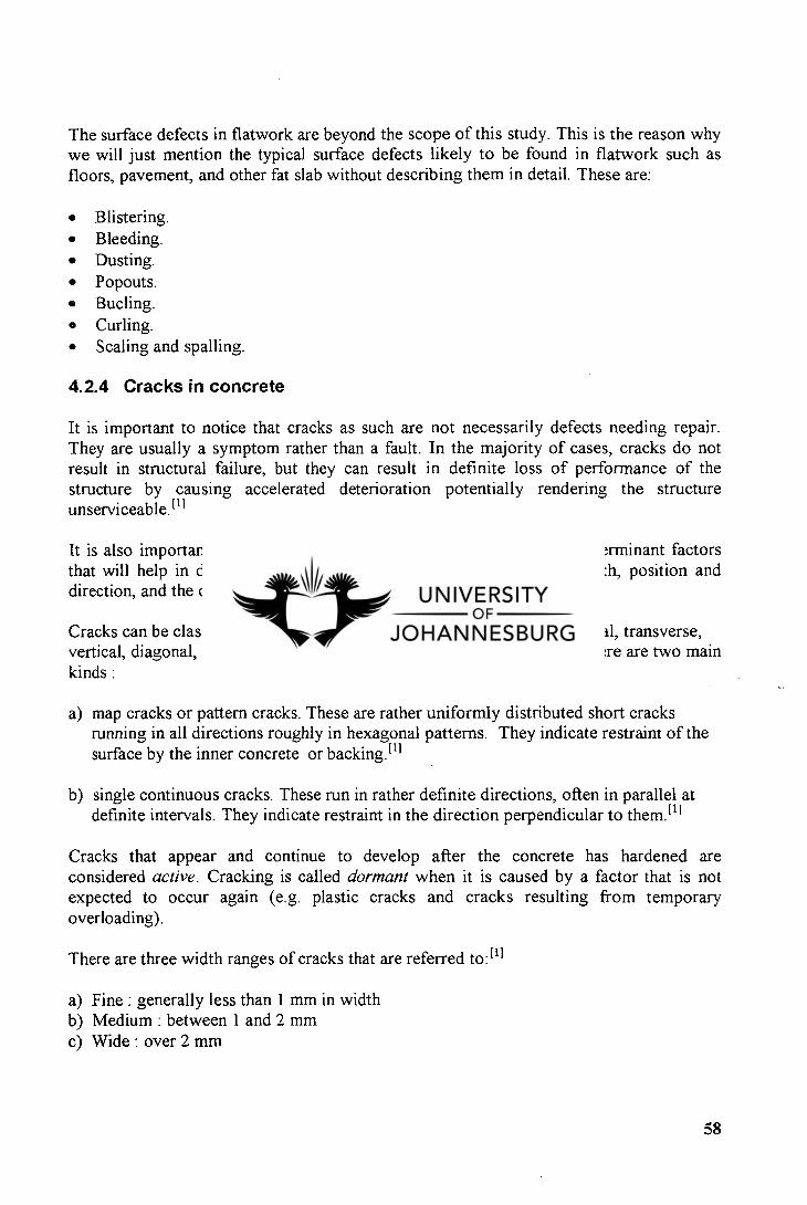
The surface defects in flatwork are beyond the scope of this study. This is the reason why we will just mention the typical surface defects likely to be found in flatwork such as floors, pavement, and other fat slab without describing them in detail. These are:
Blistering. Bleeding. Dusting. Popouts. Bucling. Curling. Scaling and spalling.
4.2.4 Cracks in concrete
It is important to notice that cracks as such are not necessarily defects needing repair. They are usually a symptom rather than a fault. In the majority of cases, cracks do not result in structural failure, but they can result in definite loss of performance of the structure by causing accelerated deterioration potentially rendering the structure unserviceable. [1]
It is also important to determine the cause of the cracks. The most determinant factors that will help in deciding what actions should be taken are cracks width, position and direction, and the degree of exposure.
Cracks can be classified by direction, width and depth, namely longitudinal, transverse, vertical, diagonal, and random. with regard to direction at the surface. There are two main kinds :
map cracks or pattern cracks. These are rather uniformly distributed short cracks running in all directions roughly in hexagonal patterns. They indicate restraint of the surface by the inner concrete or backing. 111
single continuous cracks. These run in rather definite directions, often in parallel at definite intervals. They indicate restraint in the direction perpendicular to them.E l i
Cracks that appear and continue to develop after the concrete has hardened are considered active. Cracking is called dormant when it is caused by a factor that is not expected to occur again (e.g. plastic cracks and cracks resulting from temporary overloading).
There are three width ranges of cracks that are referred to: 111
Fine : generally less than 1 mm in width Medium : between 1 and 2 mm Wide : over 2 mm
58
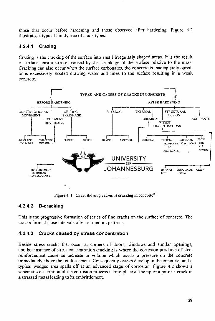
BEFORE HARDENING
those that occur before hardening and those observed after hardening. Figure 4.2 illustrates a typical family tree of crack types.
4.2.4.1 Crazing
Crazing is the cracking of the surface into small irregularly shaped areas. It is the result of surface tensile stresses caused by the shrinkage of the surface relative to the mass. Cracking can also occur when the surface carbonates, the concrete is inadequately cured, or is excessively floated drawing water and fines to the surface resulting in a weak concrete.
TYPES AND CAUSES OF CRACKS IN CONCRETE-7
AFTER HARDENING
CONSTRUCTIONAL SETTING PHYSICAL THERMAL STRUCTURAL MOVEMENT
SETTLEMENT SHRINKAGE.
SHRINKAGE CHEMICAL
CONCENTRATIONS
DESIGN ACCIDENTS
STRESS
1
SUBGRADE MOVEMENT
FORMWORK MOVEMENT
PLASTIC DRYING
SHRINKAGE SHRINKAGE
DRYING
SHRINKAGE
1 1 MOISTURE
MOVEMENTS
INTERNAL THERMAL EXTERNAL
TEMPERATURE PROPERTIES VIBRATIONS
STRESSES OF
AGGREGATE'.
FROST
AND ICE
ACTION
I I i I I REINFORCEMENT AGGREGATE RAPID SLOWER CEMENT REACTIVE FOREIGN REINFORCE STRUCTURAL CREEP OR SIMILAR STAGE COMPOSI AGGRE BODIES MENT FORM
CONSTRUCTIONS TION AND GATES AND RUST CARBONATION
Figure 4. 1 Chart showing causes of cracking in concrete ill
4.2.4.2 D-cracking
This is the progressive formation of series of fine cracks on the surface of concrete. The cracks form at close intervals often of random patterns.
4.2.4.3 Cracks caused by stress concentration
Beside stress cracks that occur at corners of doors, windows and similar openings, another instance of stress concentration cracking is where the corrosion products of steel reinforcement cause an increase in volume which exerts a pressure on the concrete immediately above the reinforcement. Consequently cracks develop in the concrete, and a typical wedged area spalls off at an advanced stage of corrosion. Figure 4.2 shows a schematic description of the corrosion process taking place at the tip of a pit or a crack in a stressed metal leading to its embrittlement.
59
Metal surface
Stressed tip
Metal surface
// 1-1+
\
CY-
Stressed tip (a)
(b)
Figure 4. 2 Schematic description of the corrosion process. [39] Stress corrosion cracking. Hydrogen embrittlement
4.2.4.4 Random cracks
Cracks, deep or wide occurring solely or in group can be induced by any of the several factors that cause cracking including improper jointing or unstable subgrade. the rapid drop in temperature ( e.g. a hot day followed by a cold night) is also a way of producing such cracks.
The pattern of the cracking, its location, the depth and width of cracks, the presence of foreign material on the cracked surfaces, and differences in elevation of two contiguous cracked concrete masses are factors that help to determine what cause the cracks to form.
In general, the volume of rust produced in a corrosion reaction is at least twice the volume of the steel that is dissolved. 1391 Thus, rust formation involves a substantial volume increase. Since most of the rust is confined within the concrete immediately surrounding the reinforcing steel, its formation generates expansive stresses within the concrete which can lead to cracking of the cover. Longitudinal cracks, spalling and delamination often take place. The damage to the concrete cover due to the formation of rust is schematically represented in the Figures 4.3 and 4.4.
60
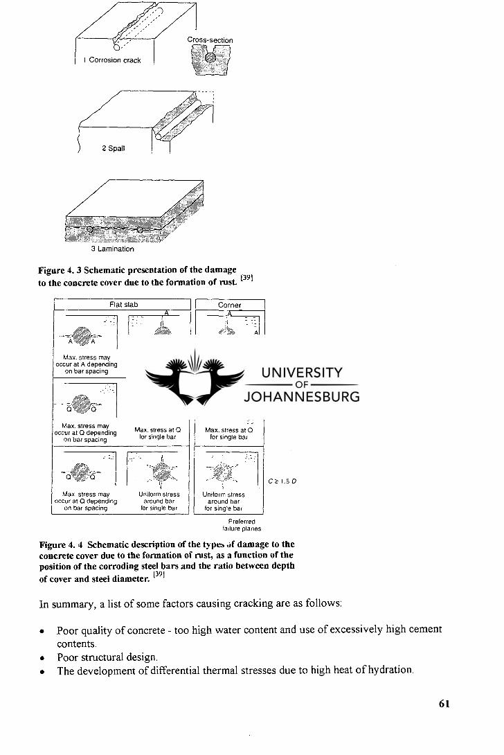
Ardir Cross-section
I Corrosion crack
3 Lamination
to the concrete cover due to the formation of rust. [39]
Flat slab Corner
/c. . ' ---r---//i / - - -
Max. stress may occur at A depending
on bar spacing
V7 '
Max. stress at A for single bar
:.,;',',!---=----- ---- 4,
Max. stress at A for single bar
"/7..A•
0 .• /„./0
Max. stress may occur at ()depending
on bar spacing
• 0 ''77' 1 0
Max. stress at 0 for single bar
: / i•-..,-/ -
'-.':•;.W -6- • •
Max. stress at 0 for single bar
—Ey/ "--
Max. stress may occur at 0 depending
on bar spacing
it. '
,, ,:tz , '",-,... i1 1
Uniform stress around bar
for single bar
,...- .:•,;.1t.%-%-t.,
Uniform stress around bar
for single bar
Preferred failure planes
Figure 4. 4 Schematic description of the types if damage to the concrete cover due to the formation of rust, as a function of the position of the corroding steel bars and the ratio between depth of cover and steel diameter. [391
In summary, a list of some factors causing cracking are as follows:
Poor quality of concrete - too high water content and use of excessively high cement contents. Poor structural design. The development of differential thermal stresses due to high heat of hydration.
Figure 4. 3 Schematic presentation of the damage
C _C 0.5 0
C=0.5÷1.50
C> 1.5
61
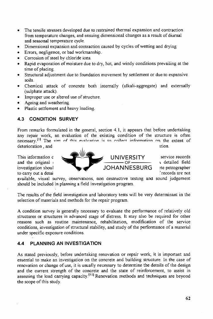
The tensile stresses developed due to restrained thermal expansion and contraction from temperature changes, and ensuing dimensional changes as a result of diurnal and seasonal temperature cycle. Dimensional expansion and contraction caused by cycles of wetting and drying Errors, negligence, or bad workmanship. Corrosion of steel by chloride ions. Rapid evaporation of moisture due to dry, hot, and windy conditions prevailing at the time of placing. Structural adjustment due to foundation movement by settlement or due to expansive soils. Chemical attack of concrete both internally (alkali-aggregate) and externally (sulphate attack). Improper use or altered use of structure. Ageing and weathering. Plastic settlement and heavy loading.
4.3 CONDITION SURVEY
From remarks formulated in the general, section 4.1, it appears that before undertaking any repair work, an evaluation of the existing condition of the structure is often necessary.E l l The aim of this evaluation is to collect information on the extent of deterioration , and to determine the cause and significance of this deterioration.
This information can only be obtained through a systematic review of service records and the original design and construction details of the structure. A detailed field investigation should be planned. Sometimes, it takes a chemist and concrete petrographer to carry out a detailed investigation to identify the type of deterioration. If records are not available, visual survey, observations, non destructive testing and sound judgement should be included in planning a field investigation program.
The results of the field investigation and laboratory tests will be very determinant in the selection of materials and methods for the repair program.
A condition survey is generally necessary to evaluate the performance of relatively old structures or structures in advanced stage of distress. It may also be required for other reasons such as routine maintenance, rehabilitation, modification of the service conditions, investigation of structural stability, and study of the performance of a material under specific exposure conditions.
4.4 PLANNING AN INVESTIGATION
As stated previously, before undertaking renovation or repair work, it is important and essential to make an investigation on the concrete and building structure. In the case of renovation or change of use, it is usually necessary to determine the details of the design and the current strength of the concrete and the state of reinforcement, to assist in assessing the load carrying capacity.E i n Renovation methods and techniques are beyond the scope of this study.
62
In the present study we focus mainly on repair aspect, i.e. the case of structures where some form of deterioration has taken place and which demand restoration. For all these cases, the causes of deterioration must be established so that appropriate remedial and protective work can be designed and specified.
The most common reasons for carrying out appraisals or assessment of structures are the following: [13,14]
Some form of deterioration is apparent, e.g. cracking, spalling, staining, loss of surface There is apparent structural weakness or distress. Evidence of this would be shown by large deflections, cracking or spalling. A change of use of the structure is being considered. The structure has been generally or locally damaged by an accidental loading such as impact, explosion, fire, earthquake or settlement. The structure is changing ownership. A defect is suspected in the structure. The appraisal forms part of the routine maintenance programme.
In the following sections, comments will be made on some condition survey methods. Although there are several existing methods, the comments will be limited only to those that have been used for the R.A.0 Concrete Pilot Project.
4.4.1 Overall Plan
The appraisal or assessment of a concrete structure involves some form of survey. The aim of this is to provide sufficient information to allow a realistic assessment of the structure to be carried out. The individual activities and techniques used in the survey will be different depending on the type of assessment required but, in most cases, the overall plan will be the same. There will be an initial phase when general dimensions and global properties are determined, and a later phase when particular locations are examined in greater detail. These principal stages in the investigation of a concrete structure are illustrated for condition assessment in Figure 4.5. 111
4.4.1.1 Initial General Phase
The first objective in most investigations is to gather readily available information on the structure through an initial walk inspection which provides the opportunity to make initial assessments of the structural form and to take general note of the locations of any deterioration. 1111 All potential problems related to access to critical locations and other specific aspects should be noted at this stage in order to take relevant dispositions for later stages of the survey.
In a second stage of the survey, the attempt will consist in finding existing records of the structure such as drawings or any other valuable information. Other possible sources of information are given in an appendix to a report by the Institution of Structural Engineers. [11, 15] Recorded details must be subject to checks at site, because there may be discrepancies between what is shown on drawings and what was actually constructed.
63
4.4.1.2 Detailed Phase
This phase comes after the preliminary walk-over survey and the search for existing records. During this phase, individual activities will differ depending on whether an assessment of structural capacity or condition is being undertaken.
The provision of access requires consideration early in the planning phase. The form of access should be such that it provides a suitable and safe platform for the planned activities and equipment, and permits the surveyors/inspectors to obtain a close view of critical areas of the structure.i' l l Most of the time ladders and lightweight scaffold towers will be found to be suitable and helpful. Other means such as scissor lifts, satellite towers and cherry-pickers may also be used but sometimes they can be expensive although they may worth it for difficult locations. At R.A.U., the use of scaffolds was the most common.
Samples can be taken from a structure and further tested in order to be able to estimate the overall mean value of some properties such as strength, cover to reinforcement, carbonation depth, chloride content, etc.. The number of samples to be taken must be assessed at the planning stage. Statistical methods may be useful for that.
Several factors make the investigation of reinforced concrete structures particularly challenging. Among these are: 1111
A reinforced member derives its strength from both the reinforcement and the concrete. Workmanship during the construction phase as well as the maintenance history of a member may influence the strength developed by this latter. Concrete as a material has a wide strength range. The strength properties of concrete are time-related. Attack by external agencies or internal chemical process may result in substantial strength reductions.
64
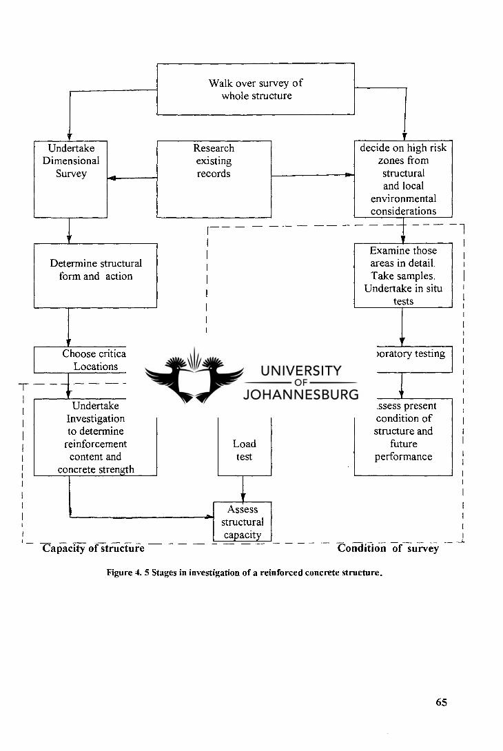
Walk over survey of whole structure
Undertake Research decide on high risk Dimensional existing zones from
Survey records structural and local
environmental considerations
Determine structural form and action
Examine those areas in detail. Take samples.
Undertake in situ tests
fi Choose critical Laboratory testing
Locations
Undertake Investigation to determine
Assess present condition of structure and
reinforcement Load future content and
concrete strength test performance
I Assess structural capacity
Capacity of structure Condition of survey
Figure 4. 5 Stages in investigation of a reinforced concrete structure.
65
CHAPTER 5
INVESTIGATION AND DIAGNOSIS OF DEFECTS IN CONCRETE STRUCTURES
5.1 GENERAL
Investigation of defects in reinforced concrete structures is a very important stage in the process preceding concrete rehabilitation. In general this job must be done by a qualified engineer. The essential object during such an investigation is the ability to recognise at an early stage the likely causes of the defects. From that, the investigation will be directed accordingly. Possibility of structural weakness must draw a particular attention.
In practice, inspection of reinforced concrete structures should be carried out regularly and an adequate decision should be taken on what remedial work, if any, should be carried out.
The course which has to be followed when dealing with inspection of reinforced structures is the following :
Investigation (preliminary and detailed). Diagnosis (based on the results of the investigation). Preparation of report, and when required, preparation of specification and contract documents for remedial. [41
This can be taken as a general guide to good practice. The form that the investigation takes will clearly depend on the type of structure and its conditions.
Failures and defects in concrete structures can be placed in five categories: [41
Structural deficiency resulting from such causes as error in design, errors in construction, impact, explosions, and change of use resulting in higher loading than was allowed for in the original design. Fire damage. This can result in some weakening of parts of the structure, as well as physical damage to columns, beams, slabs, etc. Deterioration due to poor quality concrete, inadequate cover to reinforcement, the presence of chlorides and/or sulphates in the concrete. External chemical attack on the concrete and/or reinforcement. Physical damage caused by the use to which the structure or part has been put or subjected to, such as abrasion of a floor slab in a factory, or abrasion of marine structures by sand and shingle.
Investigation activities usually involve testing of the existing structures. There are, essentially, two types of testing:
66
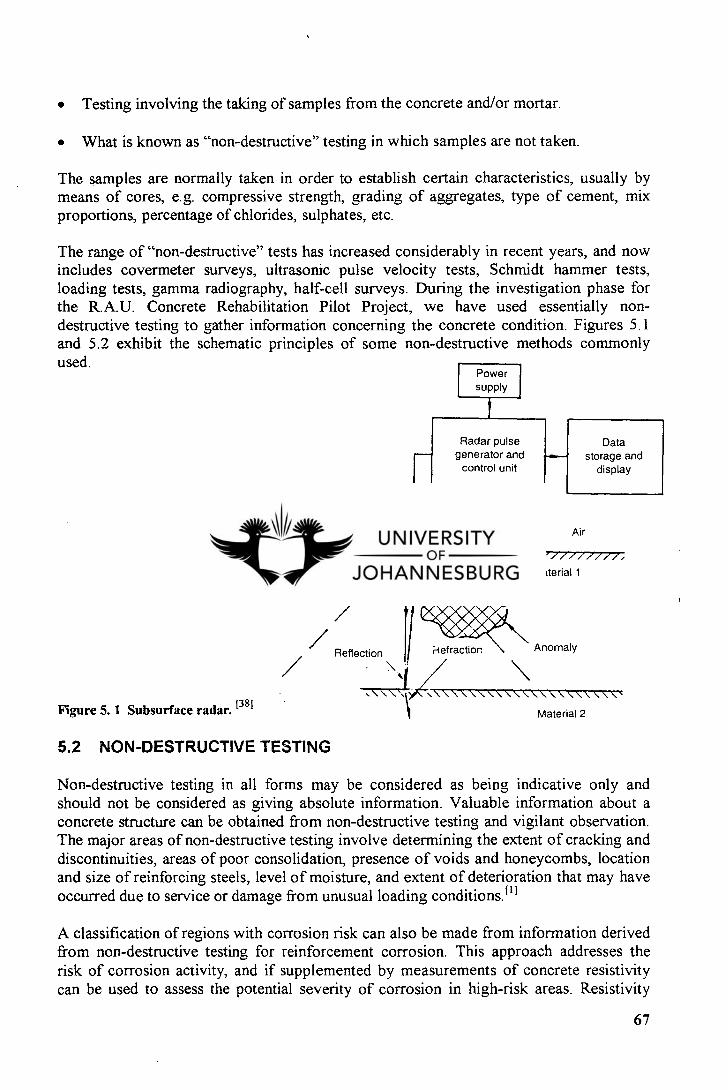
Power supply
Radar pulse generator and
control unit
Data storage and
display
Transmitter Receiver
Scan Air
/77,-/-zrz/z/-/-7z/z77777,
Material 1
Reflection
kr
-refraction \ Anomaly /
Testing involving the taking of samples from the concrete and/or mortar.
What is known as "non-destructive" testing in which samples are not taken.
The samples are normally taken in order to establish certain characteristics, usually by means of cores, e.g. compressive strength, grading of aggregates, type of cement, mix proportions, percentage of chlorides, sulphates, etc.
The range of "non-destructive" tests has increased considerably in recent years, and now includes covermeter surveys, ultrasonic pulse velocity tests, Schmidt hammer tests, loading tests, gamma radiography, half-cell surveys. During the investigation phase for the R.A.U. Concrete Rehabilitation Pilot Project, we have used essentially non-destructive testing to gather information concerning the concrete condition. Figures 5.1 and 5.2 exhibit the schematic principles of some non-destructive methods commonly used.
Figure 5. 1 Subsurface radar. [381 Material 2
5.2 NON-DESTRUCTIVE TESTING
Non-destructive testing in all forms may be considered as being indicative only and should not be considered as giving absolute information. Valuable information about a concrete structure can be obtained from non-destructive testing and vigilant observation. The major areas of non-destructive testing involve determining the extent of cracking and discontinuities, areas of poor consolidation, presence of voids and honeycombs, location and size of reinforcing steels, level of moisture, and extent of deterioration that may have occurred due to service or damage from unusual loading conditions. 111
A classification of regions with corrosion risk can also be made from information derived from non-destructive testing for reinforcement corrosion. This approach addresses the risk of corrosion activity, and if supplemented by measurements of concrete resistivity can be used to assess the potential severity of corrosion in high-risk areas. Resistivity
67
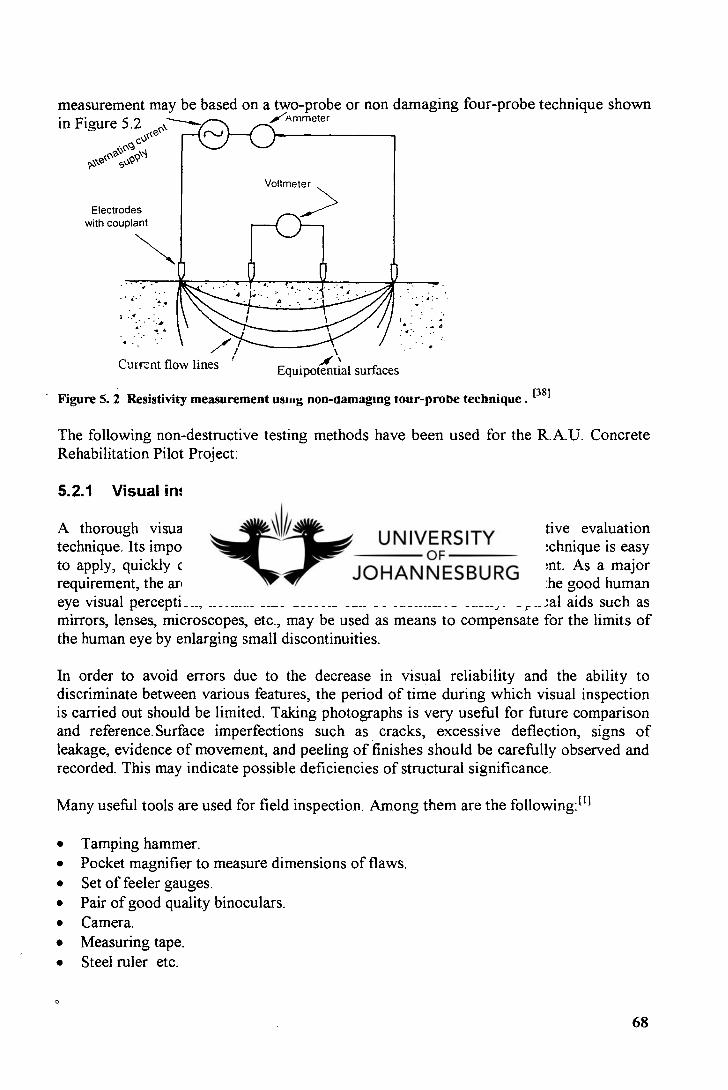
measurement may be based on a two-probe or non damaging four-probe technique shown in Figure 5.2 ctiat`C--—
,A'Ammeter
0. c. \s4
s‘PC
Electrodes with couplant
Currcnt flow lines Equipotential surfaces
Figure 5.2 Resistivity measurement USIng non-namaging Tour-prone technique . [381
The following non-destructive testing methods have been used for the R.A.U. Concrete Rehabilitation Pilot Project:
5.2.1 Visual inspection
A thorough visual inspection is the simplest form of non-destructive evaluation technique. Its importance should not be underestimated. This evaluation technique is easy to apply, quickly carried out, economic, requires no expensive equipment. As a major requirement, the area of inspection must be adequately illuminated. With the good human eye visual perception, normal size defects can be identified easily. Optical aids such as mirrors, lenses, microscopes, etc., may be used as means to compensate for the limits of the human eye by enlarging small discontinuities.
In order to avoid errors due to the decrease in visual reliability and the ability to discriminate between various features, the period of time during which visual inspection is carried out should be limited. Taking photographs is very useful for future comparison and reference. Surface imperfections such as cracks, excessive deflection, signs of leakage, evidence of movement, and peeling of finishes should be carefully observed and recorded. This may indicate possible deficiencies of structural significance.
Many useful tools are used for field inspection. Among them are the following:I l l
Tamping hammer. Pocket magnifier to measure dimensions of flaws. Set of feeler gauges. Pair of good quality binoculars. Camera. Measuring tape. Steel ruler etc.
0
68
5.2.2 Sounding test
The sounding test is a sound based test that may help in assessing concrete strength and investigating the likely presence of cracks voids in the concrete. It is carried out with the Schmidt Rebound Hammer or simply the Impact Hammer. This device measures the hardness of a concrete surface by rebound principle. The. test is based on the principle that the extent of rebound of an elastic mass depends on the hardness of the surface against which the mass strikes. The Impact Hammer is essentially made of a spring controlled hammer mass that slides on a plunger. A cylindrical casing houses the system.
The test is sensitive to local variation in the concrete quality: for instance, the presence of a large piece of aggregate under the plunger would result in an unusually high recording number. Conversely, the presence of a void would show a very low result. For this reason, in most structures, it has been suggested that at least 16 readings be taken in a square foot area.
Even though the Impact hammer provides a quick, inexpensive means of checking relative quality of concrete, it has several limitations. the following is a list of the factors which affect the results of Impact Hammer tests:
Smoothness of the concrete surface. Age and type of concrete. Surface and internal moisture condition of the concrete. Type of coarse aggregate. Carbonation of concrete surface.
However, the method is quite useful for determining the uniformity of the concrete quality in a structure and comparing two areas with similar types of concrete.
5.2.3 Covermeter survey
Electromagnetic covermeter survey is a testing method enabling to assess the thickness of concrete cover over the reinforcement. Electromagnetic covermeter surveys can under favourable conditions be considered as accurate on an average site, within ± 5 mm. Inadequate cover to reinforcing steel is one of the primary causes of- corrosion of reinforcing and subsequent deterioration of the concrete. Therefore, measurement of cover during a condition survey is essential to establish the adequacy of protection to steel.
Devices used for cover measuring are known as pachometers or covermeters. Apart their primary purpose of cover measuring, these devices can also be used to identify the locations of embedded rebars to avoid cutting them during core drilling operation. Hand held devices are the more in use, comparing to automated devices mounted on wheels and used for rapid measurement on large areas. For the R.A.U. Concrete Rehabilitation Pilot Project, we have used a Swiss made hand held covermeter.
69
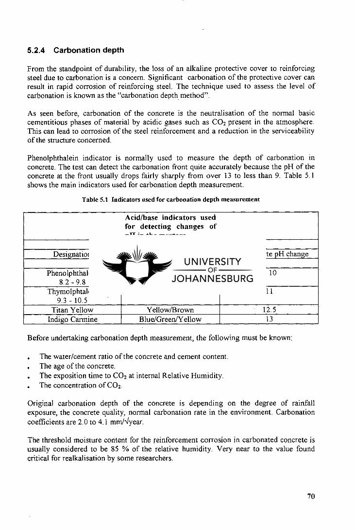
5.2.4 Carbonation depth
From the standpoint of durability, the loss of an alkaline protective cover to reinforcing steel due to carbonation is a concern. Significant carbonation of the protective cover can result in rapid corrosion of reinforcing steel. The technique used to assess the level of carbonation is known as the "carbonation depth method".
As seen before, carbonation of the concrete is the neutralisation of the normal basic cementitious phases of material by acidic gases such as CO2 present in the atmosphere. This can lead to corrosion of the steel reinforcement and a reduction in the serviceability of the structure concerned.
Phenolphthalein indicator is normally used to measure the depth of carbonation in concrete. The test can detect the carbonation front quite accurately because the pH of the concrete at the front usually drops fairly sharply from over 13 to less than 9. Table 5.1 shows the main indicators used for carbonation depth measurement.
Table 5.1 Indicators used for carbonation depth measurement
Acid/base indicators used for detecting changes of pH in the mortars
Designation Colour change Approximate pH change
Phenolphthalein 8.2 - 9.8
Colourless/Pink < 10
Thymolphtalein 9.3 - 10.5
Colourless/Blue 11
Titan Yellow Yellow/Brown 12.5 Indigo Carmine Blue/Green/Yellow 13
Before undertaking carbonation depth measurement, the following must be known:
The water/cement ratio of the concrete and cement content. The age of the concrete. The exposition time to CO2 at internal Relative Humidity. The concentration of CO2.
Original carbonation depth of the concrete is depending on the degree of rainfall exposure, the concrete quality, normal carbonation rate in the environment. Carbonation coefficients are 2.0 to 4.1 mm/'year.
The threshold moisture content for the reinforcement corrosion in carbonated concrete is usually considered to be 85 % of the relative humidity. Very near to the value found critical for realkalisation by some researchers.
70
Petrography (optical microscopy) can be made as a complement to carbonation depth determination by using the pH indicator phenolphthalein in order to confirm the phenolphthalein results.
5.2.5 Non-destructive method for reinforcement corrosion
Assessment of the risk and extent of corrosion of embedded steel forms a major area of concern, and is particularly important in relation to maintenance and repair programmes. Corrosion of embedded reinforcement or prestressing steel is widely recognized as the principal mechanism of deterioration of structural concrete.
Testing for corrosion risk and steel embedded in concrete may be considered under three categories:
Tests to assess the protection provided by the surrounding concrete Tests to assess the electrical or electrochemical characteristics of the steel and concrete combination. Tests to identify the extent to which corrosion has progressed, from the effects of the corrosion products upon magnetic, ultrasonic, impact and similar responses.
Tests within the first category include measurement of cover thickness, surface zone permeability, carbonation depth and chloride concentrations. Tests within category 3 are at the laboratory development stage. Tests within category 2 form the essential part of non-destructive survey for reinforcement corrosion.
As seen before, steel corrosion is an electrochemical process involving the establishment of corroding and passive sites on the metal surface, leading to the development of regions of differing electrical potential and resulting in current flow within the concrete.
The location of existing corrosion sites can be made by measuring the magnitude of corrosion currents. Predictions of future corrosion failure can be made, provided that the prevailing ambient conditions remain constant.
Two principal electrical test methods are in use: Half potential and resistivity. We describe below the half-cell potential only because used during R.A.U. Concrete Rehabilitation Pilot Project and because the resistivity test (Figure 5.2) is just a supplement method of measurement to half-cell potential measurements in regions shown to be at risk from corrosion. It will provide information about its likely severity.
5.2.5.1 Half-cell potential method
The process of corrosion causes electrical potentials to be generated and the half cell provide a method of detecting and categorizing these electrical potentials. The equipment and method are described in some standards, namely in ASTM C 876.
It consists of measurement of the potential Ec of embedded reinforcing bars relative to a reference half-cell placed on the concrete surface. Cu/SO4 or Ag/AgC1 cells are typically
71
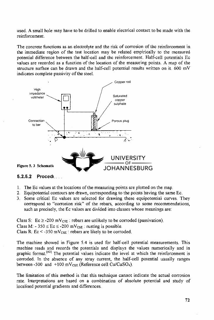
High impedance voltmeter
Connection to bar
Saturated copper
sulphate
Porous plug
Copper rod
Reinforcing bar
Figure 5. 3 Schematic diagram of equipment for half-cell potential tests. 1381
used. A small hole may have to be drilled to enable electrical contact to be made with the reinforcement.
The concrete functions as an electrolyte and the risk of corrosion of the reinforcement in the immediate region of the test location may be related empirically to the measured potential difference between the half-cell and the reinforcement. Half-cell potentials Ec values are recorded as a function of the location of the measuring points. A map of the structure surface can be drawn and the half-cell potential results written on it. 600 mV indicates complete passivity of the steel.
5.2.5.2 Procedures
The Ec values at the locations of the measuring points are plotted on the map. Equipotential contours are drawn, corresponding to the points having the same Ec. Some critical Ec values are selected for drawing these equipotential curves. They correspond to "corrosion risk" of the rebars, according to some recommendations, such as precisely, the Ec values are divided into classes whose meanings are:
Class S: Ec -200 mVcsE : rebars are unlikely to be corroded (passivation). Class M: - 350 Ec 5 -200 mVcsE : rusting is possible. Class R: Ec < -350 mVcsE : rebars are likely to be corroded.
The machine showed in Figure 5.4 is used for half-cell potential measurements. This machine reads and records the potentials and displays the values numerically and in graphic format. 1421 The potential values indicate the level at which the reinforcement is corroded. In the absence of any stray current, the half-cell potential usually ranges between -500 and +100 mVcsE (Reference cell Cu/CuSO4).
The limitation of this method is that this technique cannot indicate the actual corrosion rate. Interpretations are based on a combination of absolute potential and study of localised potential gradients and differences.
72
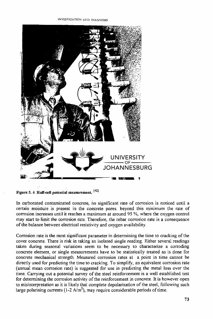
INVESTIGATION AND DIAGNOSIS
Figure 5.4 Half-cell potential measurement. (421
In carbonated contaminated concrete, no significant rate of corrosion is noticed until a certain moisture is present in the concrete pores. beyond this minimum the rate of corrosion increases until it reaches a maximum at around 95 %, where the oxygen control may start to limit the corrosion rate. Therefore, the rebar corrosion rate is a consequence of the balance between electrical resistivity and oxygen availability.
Corrosion rate is the most significant parameter in determining the time to cracking of the cover concrete. There is risk in taking an isolated single reading. Either several readings taken during seasonal variations seem to be necessary to characterize a corroding concrete element, or single measurements have to be statistically treated as is done for concrete mechanical strength. Measured corrosion rates at a point in time cannot be directly used for predicting the time to cracking. To simplify, an equivalent corrosion rate (annual mean corrosion rate) is suggested for use in predicting the metal loss over the time. Carrying out a potential survey of the steel reinforcement is a well established test for determining the corrosion activity of the reinforcement in concrete. It is however open to misinterpretation as it is likely that complete depolarisation of the steel, following such large polarising currents (1-2 A/m 2), may require considerable periods of time.
73
CHAPTER 6
REPAIR PROGRAMME
6.1 GENERAL REMARKS
Repair actions correct existing deterioration or distress of a structural, serviceability, or aesthetic nature, accomplishing restoration of structural integrity, serviceability, or adjusting cosmetic defects. Structural repair restores concrete to a more pleasing lost sectional or monolithic properties to damaged concrete members while serviceability repairs restore concrete surfaces to a satisfactory operational standard.t 21
The selection of a repair method is the crucial step in the rehabilitation of a structure. It is often a difficult process which involves consideration of a large number of factors, some of which are technical, some economic, and others which are purely practical. Other factors which need to be taken in account are:P i]
Cause of damage and the results of the preliminary assessments Future life requirement of the structure. The overall quantity of repairs and the size of individual repairs. Access. Requirement for continued use of the structure during repair and the time available for repair. Relative costs. Client requirements including future maintenance and economic considerations.
Serviceable concrete repairs can result only from a correct choice of method and the careful performance of techniques. A wrong or an ineffective repair, coupled with poor workmanship, lead to inferior quality repair. Proper materials selection and surface preparation are essential to high quality, durable, and functional repair. Materials selected for use in concrete repair must meet specification requirements for the particular application or intended use. Manufacturer's recommendations must be considered during the preparation and the use of these materials. mixing, proportioning, and handling must be in accordance with the highest standards of workmanship. Once the cause of degradation in a structure has been diagnosed, the selection of appropriate materials and removal and repair should be based on the following considerations: [2]
Adjustments or modifications required to remedy the cause of the damage prior the repair. Restriction of access to the structure, weight restrictions on equipment, weather, and operational schedule on the structure. Advantages and disadvantages of making permanent vs temporary repairs. The availability of repair materials and methods, and the possibility of using them for the particular repair. The choice of the most economically viable materials and methods which will also reproduce a satisfactory job. Restrictions to noise, dust, vibration, and exhaust fumes.
74
7. Method of disposal of watery waste.
Common techniques used in repair and renovation include:
Sprayed concrete. Breaking out and recasting of individual members or regions of structures. Patch repair Crack injection.
6.2 SELECTION OF REPAIR MATERIALS AND METHODS
The unlimited selection of repair products available on the market makes choosing the right one for a specific repair work important. The service life of a repaired area will depend on the exposure to which it will be subjected. Furthermore, the location of the problem will determine, to a large degree, the product for best results. For instance, one material used to repair a honeycombed area on a vertical surface may be a bad choice for a scaled floor.
The choice of the repair material to be used will depend not only on the particular nature of the problem but also on the function of the structure, the availability of equipment and skilled manpower, the relative importance of appearance, and of course the funds available for the repair. below is a list of the more frequently used repair materials:t 171
Acrylic-modified mortars. Elastic sealants. Epoxies. Expanding mortars. Flexible epoxy resins. Latex-modified compounds. Portland cement concrete, grout, or mortar. Quick-setting materials.
For active cracks, for replacement of expansion joints, or for use between any two surfaces that are subject to movement, elastic sealants are recommended.
Quick-setting materials, usually referred to as water plugs, wet plugs, or hydraulic cements, are useful where water is coming from a hole under pressure. They set and harden rapidly.
Latex-modified concrete possesses good adhesive properties and high compressive and tensile strength. It is reasonably flexible, has a low water-absorption factor, and is durable. It is recommended for the repair of concrete roads, bridges, and heavy-duty floors.
Portland cement has several advantages as a repair material for deep repairs. It has the same thermal qualities as the concrete to which it is being bonded. Other advantages are that Portland cement is well known and understood. It is widely available and reasonably low in cost.
75
Portland cement grout is generally used where the opening to be repaired is small, and where shrinkage can be tolerated. It is usually pumped under pressure into these openings, for best results. However an epoxy injection can be preferred if the repair is important.
Portland cement mortar may be used for various repairs. It is not recommended for very shallow problems because it will usually not stand up well. All mortar repairs should be at least 40 mm deep and never feather-edged. The sides of the repair area should be vertical to the full depth of the patch. 1171 The preparation of the repair area is similar to the concrete repair area preparation, i.e., saturation with water in order to prevent absorption of the water from the fresh patch, application of a bonding agent, and while the bonding agent is still tacky, compaction of the stiff mortar into place. The patch must be covered with a wet burlap and kept moist for at least 3 days. 1171 When the repair to be made is an important part of the structure epoxies should be seriously considered.
Epoxies are generally a two-component system, producing a 100 percent solid, modified epoxy resin which is injected into cracks. The product is self bonding. The process may be more expensive than others not only because of the cost of the material but also because of the method of application. A big advantage in the epoxy systems, as with magnesium phosphate cements, is the ability of these repair products to be applied in temperatures below freezing. 1171 Some epoxies can be applied on moist, wet, and dry surfaces. They harden rapidly and have used successfully underwater in the repair of dams. However, the use epoxy products may require the employment of skilled manpower familiar with the various products, the proper preparation of the problem surface, and the correct method of application. Caution must be taken during application in order to avoid health danger subsequent to the use of epoxies.
Latex and acrylic-modified cement mortar are the more conventional patching materials. They are less expensive than epoxy materials. When added with a synthetic latex, they are excellent products that perform well and easy to apply. They are more flexible and durable, and will resist freeze/thaw cycles better than the conventional patch. They are not resistant to chemicals as epoxy-based' materials and are suitable when such deteriorating forces are not involved.
The choice of a specific repair material or method will be finally done when the engineer in charge of the matter will assess the amplitude of concrete deterioration and match it with the availability and the cost of existing materials on the market. Other considerations such as aesthetic aspect after repair may be taken into account.
Many repair materials do not match the colour of the surrounding existing concrete. If a mortar or concrete patch is used, with the same cement as the original mix, there probably will be a difference in colour, but the patched area will match the unpatched area in time. Slight differences in colour may be of little concern for some repair problems such as highways or bridges for instance. Therefore it will be more important in some areas to select the most durable and suitable repair material needed than to be concerned with the aesthetic aspect such as difference in colour.
76
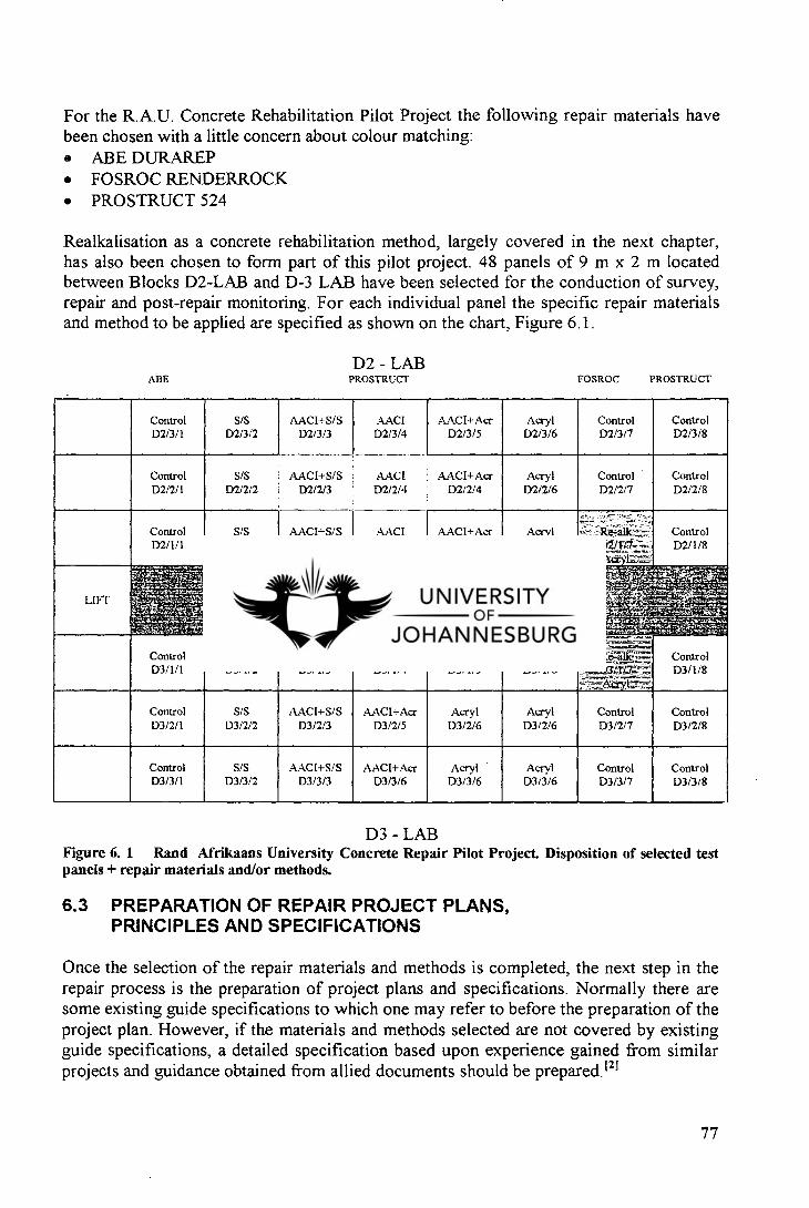
For the R.A.U. Concrete Rehabilitation Pilot Project the following repair materials have been chosen with a little concern about colour matching:
ABE DURAREP FOSROC RENDERROCK PROSTRUCT 524
Realkalisation as a concrete rehabilitation method, largely covered in the next chapter, has also been chosen to form part of this pilot project. 48 panels of 9 m x 2 m located between Blocks D2-LAB and D-3 LAB have been selected for the conduction of survey, repair and post-repair monitoring. For each individual panel the specific repair materials and method to be applied are specified as shown on the chart, Figure 6.1.
D2 - LAB ABE
PROSTRUCT
FOSROC PROSTRUCT
Control D2/3/1
S/S D2/3/2
AAC1+S/S D2/3/3
AACI D2/3/4
AACI+ Acr D2/3/5
Acryl D2/3/6
Control 1)2/3/7
Control D2/3/8
Control D2/2/1
S/S AACI+S/S D2/2/2 D2/2/3
AACI AACI+Acr D2/2/4 D2/2/4
Acryl D2/2/6
Control D2/2/7
Control D2/2/8
Control D2/1/1
S/S D2/1/2
AACI+S/S D2/1/3
AACI D2/1/4
AACI+Acr D2/1/5
Acryl D2/1/6
a Control D2/1/8
LIFT
Control D3/1/1
S/S D3/1/2
AACI+S/S D3/1/3
AACI D3/1/4
AAC I+ Acr D3/1/5
Acryl D3/1/6
Control D3/1/8
Control D3/2/1
S/S D3/2/2
AACI+S/S D3/2/3
AACI+Acr D3/2/5
Acryl D3/2/6
Acryl 133/2/6
Control D3/2/7
Control D3/2/8
Control D3/3/1
S/S D3/3/2
AACI+S/S D3/3/3
AACI+Acr D3/3/6
Acryl D3/3/6
Acryl D3/3/6
Control D3/3/7
Control 1)3/3/8
D3 - LAB Figure 6. 1 Rand Afrikaans University Concrete Repair Pilot Project. Disposition of selected test panels + repair materials and/or methods.
6.3 PREPARATION OF REPAIR PROJECT PLANS, PRINCIPLES AND SPECIFICATIONS
Once the selection of the repair materials and methods is completed, the next step in the repair process is the preparation of project plans and specifications. Normally there are some existing guide specifications to which one may refer to before the preparation of the project plan. However, if the materials and methods selected are not covered by existing guide specifications, a detailed specification based upon experience gained from similar projects and guidance obtained from allied documents should be prepared.t 21
77
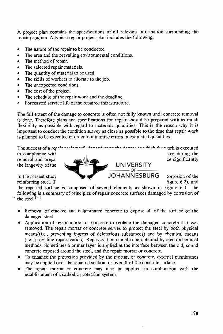
A project plan contains the specifications of all relevant information surrounding the repair program. A typical repair project plan includes the following:
The nature of the repair to be conducted. The area and the prevailing environmental conditions. The method of repair. The selected repair materials. The quantity of material to be used. The skills of workers to allocate to the job. The unexpected conditions. The cost of the project. The schedule of the repair work and the deadline. Forecasted service life of the repaired infrastructure.
The full extent of the damage to concrete is often not fully known until concrete removal is done. Therefore plans and specifications for repair should be prepared with as much flexibility as possible with regard to materials quantities. This is the reason why it is important to conduct the condition survey as close as possible to the time that repair work is planned to be executed in order to minimize errors in estimated quantities.
The success of a repair project will depend upon the degree to which the work is executed in compliance with plans and specifications. Therefore care must be taken during the removal and preparation phases of a repair job because that can influence significantly the longevity of the repair, regardless of the materials or techniques used.
In the present study the main concern is concrete surfaces suffering from corrosion of the reinforcing steel. The repair of such structures consists of several steps (Figure 6.2), and the repaired surface is composed of several elements as shown in Figure 6.3. The following is a summary of principles of repair concrete surfaces damaged by corrosion of the steel: 1391
4) Removal of cracked and delaminated concrete to expose all of the surface of the damaged steel. Application of repair mortar or concrete to replace the damaged concrete that was removed. The repair mortar or concrete serves to protect the steel by both physical means((i.e., preventing ingress of deleterious substances) and by chemical means (i.e., providing repassivation). Repassivation can also be obtained by electrochemical methods. Sometimes a primer layer is applied at the interface between the old, sound concrete exposed around the steel, and the repair mortar or concrete. To enhance the protection provided by the mortar, or concrete, external membranes may be applied over the repaired section, or overall of the concrete surface.
4) The repair mortar or concrete may also be applied in combination with the establishment of a cathodic protection system.
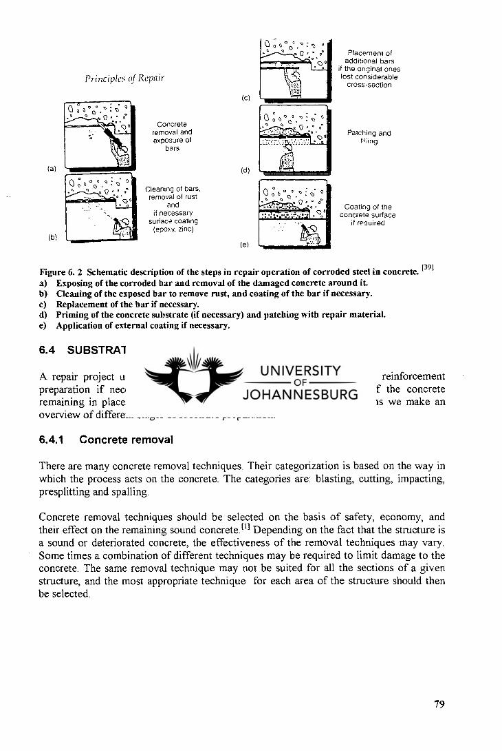
Principles of Repair
Concrete removal and exposure of
bars
Cleaning of bars, removal of rust
and if necessary
surface coating (epoxy. zinc)
(c)
(d)
(e)
0 0° t `V° °
(a)
(b)
0 . 0 ° ° ° Placement of
additional bars if the original ones lost considerable
cross-section
Patching and
Coating of the concrete surface
if required
Figure 6. 2 Schematic description of the steps in repair operation of corroded steel in concrete. (391 Exposing of the corroded bar and removal of the damaged concrete around it. Cleaning of the exposed bar to remove rust, and coating of the bar if necessary. Replacement of the bar if necessary. Priming of the concrete substrate (if necessary) and patching with repair material. Application of external coating if necessary.
6.4 SUBSTRATE PREPARATION
A repair project usually involves the removal of deteriorated concrete, reinforcement preparation if necessary, scarification, and cleaning of the surface of the concrete remaining in place, prior to any repair activity. in the following sections we make an overview of different stages of substrate preparation.
6.4.1 Concrete removal
There are many concrete removal techniques. Their categorization is based on the way in which the process acts on the concrete. The categories are: blasting, cutting, impacting, presplitting and spalling.
Concrete removal techniques should be selected on the basis of safety, economy, and their effect on the remaining sound concrete.t l i Depending on the fact that the structure is a sound or deteriorated concrete, the effectiveness of the removal techniques may vary. Some times a combination of different techniques may be required to limit damage to the concrete. The same removal technique may not be suited for all the sections of a given structure, and the most appropriate technique for each area of the structure should then be selected.
79
Levelling mortar
.---- Anti-carbonation coat
Anti-corrosion primer
Bond coat Rebar
Repair mortar
Substrate concrete
Repair and Rehabilitation
Figure 6. 3 Schematic description of the cross section of repaired section. [39]
6.4.1.1 Blasting method
The blasting methods involve the use of a vigorously expanding gas confined inside a series of boreholes to produce controlled fracture. Some of the methods are explosive blasting, high pressure, carbon dioxide blasting, and acetylene-air rock breaker. 111 For explosive blasting, selection of proper charge weight, borehole diameter, and borehole spacing for a repair project depends on the location of the structure, acceptable degree of vibration and damage, and the quantity and quality of concrete to be removed. (11
6.4.1.2 Cutting methods
Cutting methods generally employ mechanical diamond saw cutting, intense heat from powder torch thermal lance, electric arc equipment, and high pressure water jets to cut around the perimeter of concrete sections to allow their removal. [11 The method is slow and costly. Its application is restricted for use with other methods to improve crack control and over breakage. Advantages of the method include well-defined limits for concrete removal, relatively small and easily handled concrete debris, and simplicity of operation.
6.4.1.3 Impacting methods
Impacting methods use equipment including machines that produce a repeated striking of the concrete surface causing fractionating and spalling of the concrete. Current used equipment are hand-held and vehicle mounted concrete breakers or the widely known jackhammer. This equipment is highly productive. However, the high cyclic impact energy delivered to the structure by the breaker generates vibrations that may damage the remaining concrete, and thus affect the integrity of the structure.P 1
6.4.1.4 Presplitting methods
Presplitting methods include splitters, water pulse devices„ and expansive agents. Wedge devices, water pressure pulses, or expansive chemicals are placed in boreholes made at intervals along a predetermined line to induce a crack plane to allow for concrete removal. [t]
80
6.4.1.5 Spalling methods
Spalling methods are chiefly used as secondary means of removal of concrete. The method employs mechanical devices that generates tensile stresses large enough to remove small pieces of concrete, and are more applicable to shallow removal of small volumes of concrete. 111
6.4.2 Surface preparation
Surface preparation is among the critical factors in the performance of a repair material. The quality of a repair depends on the effort expended in surface preparation, regardless of the nature or quality of the repair material. Surface preparation starts just after the removal of deteriorated concrete and proceeds through the steps taken to prepare surfaces when little or no concrete is removed. The objective being to provide a dry, even, level surface, free of dirt, oil, and grease. The final condition of the concrete after surface preparation depends at a certain level on the type of repair to be undertaken.
For reinforced concrete, repairs must include proper preparation of the reinforcing steel to ensure good bond development with the replacement concrete so that the desired behaviour in the structure is obtained . Surface preparation does not only imply the removal of extraneous loose material from the substrate surface, but also the removal of reaction products like laitance that cover the surface. The removal of surface contaminants allows primers, and the repair materials themselves, to have intimate contact with the substrate 111 . Increasing of the surface area is achieved by the increasing of the roughness of the surface that provide more points for increased anchorage of the repair material.
It is a trend during present times to use organic materials for concrete repair. When such types of materials have to be utilised, the prepared concrete should be saturated, the surface dry to prevent rapid loss of water from the repair material to the substrate so that shrinkage and cracking is prevented and maximum adhesion achieved (for resin-based materials). The presence of moisture may also lead to a poor bond.
To ensure efficiency of the repair it is recommended that all damaged concrete should be removed during the surface preparation phase. However, it is not always possible to determine when all such material has been removed because the zones of damaged or deteriorated concrete are not well defined. Therefore, the best action is to continue to remove material until aggregate particles are being broken, rather than simply pried loose from the matrix (11 . If damaged concrete has been removed from a structure by rigorous methods, such as impacting or splitting, it should be further prepared using a secondary method, such as wet sandblasting or high pressure water jetting, to remove any damaged surface material.
In order to choose the best removal method, or combination of methods, the following safety, environmental, and job related information should be obtained: i l l
81
Job location: is it inside a building?
Are there restrictions to noise, dust, vibration, exhaust fumes, and disposal of watery waste? If the work is to be done on elevated decks, are there any weight restrictions on equipment? What thickness of concrete or coating has to be removed? What is the condition of the concrete? If it sound concrete, what is the estimated compressive strength? Is there reinforcing steel close to the surface? What kind of new surface will be applied, and what thickness? Does an existing coating have to be remove? If so, what kind of coating is it?
The following methods are commonly used for surface preparation:
6.4.2.1 Chemical cleaning
The chemical cleaning is required for concrete that has been contaminated with oil, grease, or dirt. Many chemical products are available for this work. However, care must be exercised to avoid residues after the cleaning process. Vigorous scrubbing and thorough rinsing with water will often required. Solvents must be avoided because they will dissolve the contaminate and carry it deeper into the concrete.
6.4.2.2 Mechanical cleaning
Mechanical cleaning is made rotary or impact type devices. Rotary equipment includes rotary discs and grinders and are used for relatively low compressive strength concrete. Impact tools are equipment such as bush hammer , scabblers, and needle guns. They are effective in the sense that they can remove several millimetres of surface. Impact tools pulverize the concrete and can cause fracturing of lower levels. Therefore, other means such as water jetting or wet sandblasting may be used for final cleaning of the concrete.
Scarifying machines applying a rotating circular cutting wheel to the concrete surface are also used. These machines are effective on old floors and will successfully remove old paint or curing compounds. However, they are relatively expensive and require skilled operators. I l l
6.4.2.3 Blast cleaning
Blast cleaning includes:
Abrasive wet and dry cleaning. Shotblasting. Water jet cleaning.
1. Sandblasting
82
Sandblasting machines use compressed air to eject a high speed stream of sand or other abrasive from a nozzle. Dust is a problem in the dry method of sandblasting. Because of the dust and associated health problems, dry sandblasting is sparingly used now Pi . The use of non-silica abrasives may reduce potential health hazard.
Shotblasting
In shotblasting machines, a metallic abrasive (steel shot) is used to scour the concrete surface. A pneumatically driven vacuum system collects dust and the shot, separating and recycling the usable shot and removing the dust through a filtering system. 111
Waterblasting
Waterblasting consists of directing a high velocity, high pressure, water jet to the concrete surface through a special designed nozzle which travels transversely along a boom, sweeping back and forth across the concrete surface as the equipment incrementally advances. (11
Advantages of the method are as follows:i l l
No dust is produced and noise is minimal. There are no mechanical vibrations that might cause structural damage. The machine selectively removes deteriorated concrete and leaves good concrete intact. Rebars are not damaged as they might be by scarifiers or scabblers. Removal of deteriorated concrete is faster than by conventional methods such as jack hammers.
6.4.3 Reinforcement preparation
The repair programme of a reinforced concrete should include the preparation and if necessary the repair of steel reinforcement. This stage comes after concrete removal, inspection of the steel, and cleaning of the rebars. Should reinforcing bars are found damaged, a repair project of the damaged steel must be considered and carried out.
The present study does not have the intention of treating the rebars reparation because this is beyond the scope of the study. However, we have judged necessary to dwell on the preparation of the reinforcing bars.
During the removal of concrete surrounding the steel care should be exercised to avoid the damage of sound concrete at the periphery of the damaged area. Therefore the use of light instruments is recommended. The use of a covermeter will facilitate the location of the steel and determine their depth in the concrete.
When more than half of the perimeter of the bar has been exposed during the removal of deteriorated concrete, then removal should continue until a clear space of 6.25 mm ( 1/4") behind the reinforcing steel, plus the size of the maximum size aggregate is obtained.t 1 ' If less than half of the perimeter of a bar is exposed after concrete removal, the bar should
83
be inspected, cleaned as necessary, and repairs may then proceed without further concrete removal. However, if inspection indicates that a bar or bars must be replaced, concrete must be removed to give the clear space indicated above.E l l
Inspection is conducted in order to determine whether the reinforcing steel is capable of performing according to the intended design of the structure. If the cross sectional area of a bar has been significantly reduced by corrosion, the steel may have to be replaced. (191
If during inspection it is found that the reinforcing bars do not need replacing, they should however be cleaned of all rust, scale, and foreign matter before the fresh concrete is placed. Depending on the area of the rebars, brushing, abrasive blasting or other methods may be used for reinforcement preparation. An alternative method of cleaning the steel is high pressure water jet cleaning. The disadvantage of the latter method is that it provides oxygen and water necessary to initiate corrosion of the cleaned steel. Coating the rebar with an alkaline cement slurry or an epoxy coating may reduce the potential for the steel to rust between the time it is cleaned and the time the fresh replacement concrete is placed.
Recently, a new concrete repair method that is not requiring necessarily demolition of the structural concrete has been developed for curing carbonated embedded concrete. This method called Electrochemical Realkalisation is largely covered in the next chapter.
84
PART II
CHAPTER 7
ELECTROCHEMICAL REALKALISATION, A REVOLUTIONARY CONCRETE REHABILITATION TECHNIQUE
7.1 BACKGROUND
The electrochemical technique known as realkalisation was totally unknown prior its development by Norwegian Concrete Technologies a.s., now styled simply NCT who started to commercialise the method in 1988 (then under the name of Norssk Overflateteknikk a.s.[NOT]). [221 In 1995 the Oslo based company NCT was acquired by FOSROC, a UK based company who specialises in concrete repair materials. This acquisition represents an important addition to FOSROC's existing concrete repair range, which already includes Renderoc repair mortars and fluid micro-concretes, and Dekguard high performance protective and decorative coatings.
7.2 INTRODUCTION
The Rand Afrikaans University (RAU) decided during 1996 to conduct a pilot project for the rehabilitation of its building structures. This pilot project consisted of testing various concrete repair materials and techniques, with a selection to be made ultimately according to the performance of each material or method. Repair materials included the most recently known repair mortars available on the south african market. Traditionally known repair techniques (e.g. patching repair) as well as recent technologies such as the electrochemical realkalisation had been also selected as part of the project.
In order to make a comparative assessment between the traditional repair methods and the electrochemical realkalisation of concrete, the repair programme of the RAU Concrete Rehabilitation Pilot Project had selected 48 testing panels to be treated with different products and methods. Among them, two panels, D2/1/7 and D3/1/7, shown in the Figure 6.1, had been selected for the realkalisation test. However, the carbonation depth measurements and subsequent electro-potential measurements taken by the contractor appointed by RAU in July 1997, showed that there was not enough carbonation depth and therefore not enough reinforcement corrosion to necessitate the realkalisation of the 2 selected panels. The realkalisation treatment is normally recommended for carbonation depths beyond values of 25 mm. The average of recorded carbonation depths on panels D2/1/7 and D3/1/7 was less than 10mm. But the covermeter survey .conducted by myself on AUgust 14, 1997 for the panel D2/1/7 and on September 2, 1997 for the panel D3/1/7, revealed as it is shown on report charts N° 1 & 2 in annexe, that the concrete cover was largely sufficient for a successful realkalisation treatment.
85
The minimum concrete cover required for realkalisation being 10 mm. The average concete cover recorded was about 30 mm.
7.3 DEFINITION
As stated before, concrete may suffer from the classic effects of carbonation, whereby the passive oxide layer surrounding the steel reinforcement is being broken down by carbonic acid, resulting in the formation of an expansive steel rust and ultimate spalling of the concrete. In the first step, preliminary testing will identify the range of reasons for the apparent rapid on-set of carbonation that includes low cover on the steel reinforcement, poor quality concrete and high permeability. The recommended method to halt ongoing and prevent future reinforcement corrosion in carbonated concrete is a non-destructive electrochemical treatment called realkalisation.
Electrochemical realkalisation is a recently developed rehabilitation technique for reinforced concrete where carbonation has penetrated beyond the depth of cover. It is a temporary treatment which re-establishes high alkalinity around the steel reinforcement by promoting the production of hydroxyl ions at the steel cathode and inward migration of alkali ions from an external electrolyte. [22] The alkalinity of the cover concrete is further enhanced by absorption and diffusion of the alkaline electrolyte.
7.4 PURPOSE OF THE REALKALISATION
Realkalisation is aimed at raising the pH of carbonated concrete to levels at which corrosion cannot take place, while simultaneously passivating the embedded reinforcing steel. Realkalisation provides a means to increase the pH of the carbonated concrete initially to more than 12, which favours passivation, with a final value greater than 10.5, which is sufficient to maintain passivity of the reinforcement. [241 Alkaline substances are transported into the carbonated zone from a temporary anodic source under the influence of an electric field.
Therefore realkalisation is used mainly to:
Halt corrosion of steel reinforcement. Reinstate protective alkalinity in concrete.
The process enables the treatment of large areas as a whole instead of a treatment in isolated patches as is the case for traditional patching repairs. Versatile applications include the following:
High-rise buildings. Soffits. Balconies. Bridges. Water towers. Car parks.
86
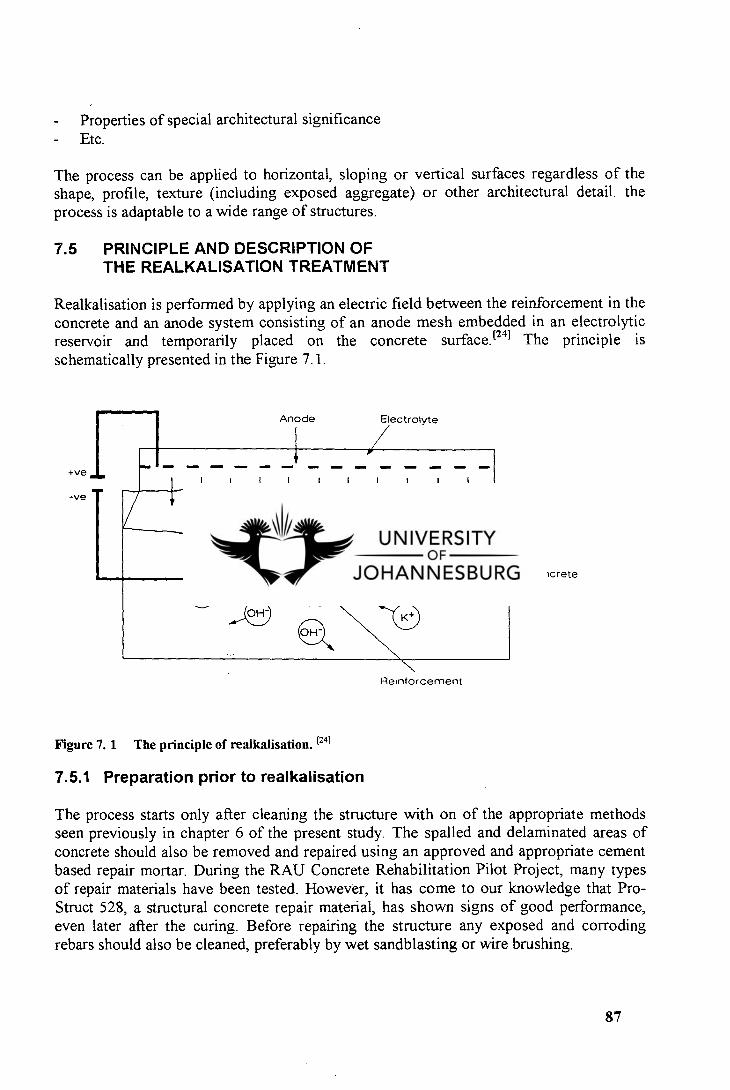
Anode Electrolyte
N=4, IMIM MEM
Nat CO3 . NaHCO3
OH"
- Properties of special architectural significance - Etc.
The process can be applied to horizontal, sloping or vertical surfaces regardless of the shape, profile, texture (including exposed aggregate) or other architectural detail. the process is adaptable to a wide range of structures.
7.5 PRINCIPLE AND DESCRIPTION OF THE REALKALISATION TREATMENT
Realkalisation is performed by applying an electric field between the reinforcement in the concrete and an anode system consisting of an anode mesh embedded in an electrolytic reservoir and temporarily placed on the concrete surface.E 241 The principle is schematically presented in the Figure 7.1.
Reinforcement
+v.
-ye
Concrete
Figure 7. 1 The principle of realkalisation. [241
7.5.1 Preparation prior to realkalisation
The process starts only after cleaning the structure with on of the appropriate methods seen previously in chapter 6 of the present study. The spalled and delaminated areas of concrete should also be removed and repaired using an approved and appropriate cement based repair mortar. During the RAU Concrete Rehabilitation Pilot Project, many types of repair materials have been tested. However, it has come to our knowledge that Pro-Struct 528, a structural concrete repair material, has shown signs of good performance, even later after the curing. Before repairing the structure any exposed and corroding rebars should also be cleaned, preferably by wet sandblasting or wire brushing.
87
Concrete surface coatings should be removed prior to realkalisation since coatings may increase the treatment time or limit the effect of the treatment. If for any reason the removal of the surface finish must be avoided, a realkalisation trial is required to establish necessary treatment time. 1241
7.5.2 The realkalisation process, step by step
Realkalisation can be performed under all weather conditions as long as the electrolyte does not freeze.t241 FOSROC NCT recommends his advice before starting the realkalisation of pre-stressed and post-tensioned structures and any concrete with unusual characteristics. The reason being that even though realkalisation is suitable for most types of reinforced concrete, it is not necessarily a panacea.
7.5.2.1 Rebar connections
Drilling is conducted into the concrete to reach the reinforcing steel to which a wire connection is attached. This reinforcing steel will become ultimately the cathode during the process. The number of rebar connections depends on rebar continuity. FOSROC recommends at least one for each 50 m 2 . The continuity is determined by means of resistance measurements carried out during installation. The resistance between two rebars connection points should ideally be less than 1 ohm but up to 10 ohms is generally acceptable. [24]
7.5.2.2 Installation of the anode system
The anode system consists of an anode mesh embedded in an electrolytic reservoir on the concrete surface.. The purpose of the electrolyte is to conduct electricity and to provide alkalis to the carbonated concrete. The reservoir keeps the electrolyte in contact with the concrete surface and the anode mesh. Electrolyte may be sprayed-on cellulose fibre, felt cloth or coffer tanks.
Softwood timber battens are fixed to the concrete surface with non metallic fixings. These wooden battens act as spacers between the concrete and the mesh in order to avoid short circuits. Than the cellulose fibre and the electrolyte are sprayed on the concrete surface using an appropriate equipment. This is done in order to maintain continuity between the anode mesh and the concrete surface. A layer of approximately 25 mm thick is built up before the whole area to be treated. During treatment, regular wettings is required. The same equipment used at the beginning of the treatment will be required again. Once the mesh is fixed to the timber battens a final layer of about 25 mm thick poultice is applied and the mesh is then wired up to carry a positive current. It becomes the anode during the process.
Felt cloth may be used for decks in two layers rolled onto the concrete surface with the anode mesh placed between them. Constant wetting will be required when felt cloth is used.
88
Coffer tanks may also be used during the installation of the anode system. These tanks consist of plastic sheets with sealing edge strips of compressible expanded plastic and with built-in anode. They may be fastened directly to the concrete surface and filled with electrolyte. Coffer tanks are particularly suitable for the treatment of smaller, separated areas, provided that the concrete surface is relatively smooth and even. Coffer tanks may be topped up during treatment if required.t 241
As realkalisation is an electrochemical method, rebar continuity is vital. Prior the application of the cellulose material, felt cloth, or coffer tanks, a test should be performed to establish both the size and the continuity of the steel within each area to be treated.
After installation of the anode mesh and once the cathode and the electrolyte are in place, the process may start, by applying an electrical current between the cathode and the anode. The anode mesh may be either in titanium or mild steel. The latter acts as a sacrificial anode and is disposed of after the process, whilst the former can provide greater treatment usage but at greater initial cost.
During realkalisation, the anode reaction is forced to take place on the anode mesh temporarily placed in the electrolytic reservoir on the concrete surface while the cathode reaction now takes place over the entire reinforcement surface. The anode is considered to be the harmful part and the cathode as the protective part
7.5.2.3 The electrolyte
Generally, the alkaline solution is made by adding sodium carbonate to water under continuous mixing. To get the correct concentration recommended by FOSROC, 110 grams of Sodium Carbonate, of the commercial grade known as light soda ash, is added per litre of water. This will produce approximately 1 molar Sodium Carbonate solution. A lower concentration may be used when considered satisfactory with regard to the extent of carbonation into the concrete.
If realkalisation by electrolysis alone is required, the Sodium Carbonate solution is sometimes exchanged with potable water to which 2 to 10 grams of Calcium Hydroxide per litre of water are added. 24i
Alternative materials such as Calcium Hydroxyde solution, Lithium Carbonate or Borate solution, or Potassium Carbonate may be used. The use of these materials may require a formal approval of a qualified realkalisation Engineer. Full laboratory tests may be required prior selection of an electrolyte.
In this study it is assumed that the electrolyte is a Sodium Carbonate solution because being the most used for the over 200 realkalisation projects conducted world-wide. It will also be considered that the anode mesh is embedded in cellulose fibre.
89
7.5.2.4 Basic process
Both leads, i.e. the cathode (-) and the anode mesh (+) are then simply connected to a transformer rectifier to provide a DC voltage of approximately 240 A per hour of current based on current density of around 3A per m 2 of steel surface area.t 251
The passage of current, besides the passivating effect, also causes the pH of carbonated concrete to rise from around 9,5 to values at which passivity is easily maintained. This pH will reach the value of 12 in the event of use of Sodium Carbonate. [23) The pH increase results from the introduction of extraneous alkali from the external electrolyte into the carbonated zone. As a result of the passage of the current, at least four superimposed mechanisms may occur:
Electrolysis. Electro-osmosis. Diffusion. Capillary absorption.
Firstly, water is electrolysed at the reinforcement, producing hydroxyl ions, which restore the passive oxide layer surrounding the steel, which was previously broken down by the effects of carbonation. As the treatment continues these negative ions are repelled away from the steel thereby widening the protective oxide layer.
Electrolysis results in the generation of very high pH values on and immediately around the steel due to the formation of an hydroxide of the main alkali metal contained in the electrolyte, i.e. Sodium Hydroxide for our study. This is caused by the electrical neutralisation of incoming alkali metal and alkali earth metal ions at the reinforcing steel cathode and the immediate subsequent reaction of the metal so produced with water may be summarised as follows, when Sodium Carbonate is used as electrolyte:
2 Na + + H2 (7.1) Ca + 21120 Ca(OH)2 + H2 (7.2)
Therefore the pH increases at the reinforcement. This is important both in realkalisation and in Chloride extraction, by contributing to the overall reduction of Cl/OH ratio desired. The potential difference also causes electromigration of negative ions (Chloride, Hydroxide) away from the reinforcement and positive ions (Sodium, Potassium, etc.) towards the reinforcement, the latter being the primary objective in Chloride extraction.
In other words, during the electrolysis mechanism, the polarity between reinforcement and anode is such that through a combination of mechanisms hydroxyl ions are generated around the reinforcement and the pH is subsequently enhanced. A second mechanism called electro-osmosis mechanism, or in other words electrically- induced liquid movement into the concrete, is also proposed as a contributing mechanism during realkalisation, but the extent of that contribution remains unclear.t 271 During the
90
occurrence of this mechanism, the positive ions, i.e. Sodium if the electrolyte is the Sodium Carbonate, are transported into the concrete pore structure.
Electro-osmosis results in the external electrolyte (Sodium Carbonate solution) being bodily transported into the concrete. This is thought to be due to part of the so called electric double layer adsorbed on carbonated pore surfaces, and which is electrically charged, being attracted towards the oppositely charged electrode. 1281 This slippage causes the free pore water to be pulled along simultaneously, to create an effect which may be thought of as a suction which greatly augments the capillary absorption.
The electrolyte (Sodium Carbonate solution or another) is also moved into the concrete pores through a combination of electro-osmosis and probably a third mechanism known as capillary or natural absorption.
Current-independent diffusion may also contribute to the transportation of the electrolyte through the concrete pores. This is known as the fourth contributing mechanism during the realkalisation process.
Except for very porous concretes, capillary absorption and diffusion are not important as mechanisms. Penetration into typical concretes due to capillary absorption and/or diffusion, is usually no more than a few millimetres in a normal realkalisation period of about three to four days. 1231
Which mechanism is dominant in a particular case is dependent on factors such as: 123 i
Concrete porosity. Extent of carbonation Extent of chloride contamination (if any). Type of cement. Type of aggregate. Voltage gradient applied.
Therefore installations need to be dimensioned to the work with regard to the above mentioned factors for the highest efficiency.
7.5.3 Monitoring and control of the process
FOSROC NCT recommends the anode system to be kept moist at all times during treatment. This is achieved by wetting the anode system as appropriate. The process is monitored by means of current and voltage readings, and, if necessary, adjusted to maintain 1 A/m2 of concrete surface. 1261 The Norcure RD2 units provide easy current control and process monitoring.E 241 These units are computer controlled rectifiers associated with software, with as main function the regulation of the supply of current. Norcure RD2 units are also programmed to draw attention to any malfunctions should they ever occur. 1241
91
40
Companies such as Martech Ltd, or Draper & Penhall and Associates have developed computer software systems that monitor and control the supply of current required, advising of changes in voltage, resistance and indicating potential faults in the circuit so that remedial actions can be taken. The system can also switch itself off should a fault requires such action or in fact simply when the treatment has attained the required amp hours. These computer monitoring systems provide accurate assessment 24 hours a day of how the treatment is progressing.
When the system is switched on for each treatment area the resistance is much dependant on the level of carbonation of the concrete, since the greater the carbonation between the anode and the cathode, the higher the resistance.
As the electrolysis and the electro-osmosis take place, the resistance to the flow of electrical current between the anode and the cathode drops until a point is reached where the resistance effectively flattens out. The current density is maintained constant so that the computer monitoring system can only adjust the voltage at the required value. In fact unless the fibre surrounding the anode is kept wet with further Sodium Carbonate, the resistance can rise again as the carbonated concrete absorbs so much of the electrolyte.
The real advantage of the computer is that the resistance curve can be monitored constantly to consider whether rewetting is required or if the resistance curve flattens off for a period of time, whether to consider turning off the process.
FOSROC recommends that cores be drilled at the previously marked test locations, after a few days of treatment. The cores will then undergo phenolphthalein test in order to determine the carbonation front and therefore, the extent of realkalisation. The treatment should continue until the alkalinity of the cover zone has been re-established. This can be determined by quantitative chemical analysis for sodium levels and testing with phenolphthalein solution.E291
7.5.4 Dismantling
When the carbonated concrete has been satisfactorily realkalised, the treatment is terminated. The treated structure is cleaned of all the fibre, mesh, battens and electrical wiring. It is then left for up to a week to allow the electrolyte to redistribute and for any salts to appear at the surface. The salt may then be removed by dry grit blasting to provide a suitable surface for further coatings. Further, dust samples are taken to check the increase in the sodium content of the concrete, whilst further phenolphthalein testing shows that the previously carbonated concrete is now restored to its highly alkaline state, especially that surrounding the steel.
92
7.5.5 Advantages
The fact that realkalisation treats the causes of corrosion in-depth by treating the afflicted concrete and steel (not merely the superficial symptoms) results in considerable advantage over both conventional repair techniques and cathodic protection schemes. The main advantages of the realkalisation process may be listed as follows:
The cause of corrosion is addressed and removed, not merely the symptoms. Steel reinforcement is passivated throughout, not just in isolated areas Vastly reduced concrete break-out resulting in
. major time-savings,
less noise, dust and environmental pollution,
no need for expensive structural support,
little chance of inducing micro-cracks during extensive break-out.
Architectural and exposed aggregate finishes can be maintained. Little chance of inducing micro-cracks during extensive break-out No need for permanent electronic monitoring. Fixed prices can be offered. A variety of anode systems for various structures and conditions are available.
From the above mentioned advantages, it could be perceived that the realkalisation treatment is the ideal solution to any concrete problem arising from carbonation of the reinforcing steel. But the process is still recent and previously realkalised structures are still under monitoring in order to assess the real effectiveness of the treatment.
7.5.6 Effects of realkalisation on leaching, durability, and carbonation
Electrochemical realkalisation is a relatively new repair method without a long track record at least as far as the durability of the treatment is concerned. However, the short term effects of the method have been examined widely in several research laboratories, which have provided plenty of essential facts for understanding the behaviour of realkalisation. [30]
Among all different research works done on the realkalisation we found that trials carried out by J.S. Mattila, M.J. Pentti and T.A. Raiski in Finland in 1991 were interesting in this sense that they revealed relevant results concerning leaching of alkalis, durability, and penetration of alkalis.t 291 Sodium Carbonate has been used as electrolyte. Various panels including coated, uncoated, treated, untreated, good quality, and porous specimen panels have been used during the study. After testing them, the following conclusions have been drawn:
93
7.5.6.1 Leaching of alkalis
Leaching of alkalis was examined by measuring at intervals the sodium concentration of the concrete at a depth range of 0 to 15 mm in uncoated specimens during an accelerated weathering test. Changes in sodium concentration in the depth range of 0 to 15 mm have been noticed and plotted. On the basis of the measurements it can be stated that alkali concentration may be lowered by intense weather exposure (cyclic wetting and drying) The effect of leaching will probably be limited to near the surface. Deeper in the concrete the alkali concentration may even increase due to moisture transportation, although this could not be confirmed by measurements. However, it is probable that the alkali concentration can be lowered due to leaching in normal climate exposure, although the leaching will affect primarily the zone near the surface. It can be concluded that corrosion protection in realkalised concrete may be endangered due to leaching in low cover areas (cover < 5 to 10 mm) in structures where weather exposure is intense.
7.5.6.2 Durability of coatings
The behaviour of the coatings was observed by bond strength measurements and by monitoring visual changes in the coating films. As for the leaching test, the bond strength measurements were performed four times during the weathering test. Realkalised and untreated specimens were used during the test.
It is known from experience that the moisture content in the concrete will affect the bond strength of all kinds of coatings. That is the reason why the moisture content in the concrete was approximately equalised by adjusting the conditions to 30 °C and RH 40 % in the test chamber one week before each test.
At the beginning of accelerated weathering exposure test the bond strengths increased in all the coatings. Therefore it may be concluded that realkalisation would be at least not disastrous for coating adhesion. Later in the test the bond strengths started to decrease. But the bond strength was not clearly stronger in realkalised specimens than in untreated ones. Only specimen coated with a non-alkali resistant binder performed less well because the bond strength in the realkalised specimens with non-alkali coating were systematically weaker than in the untreated ones. In addition, the bond strength decreased in time more seriously in the realkalised specimens than in the untreated ones.
On the basis of the accelerated weathering test it may be concluded that realkalisation would not adversely affect the durability of alkali resistant organic or inorganic coatings. For other coatings, realkalisation might restrict the service life of coatings on realkalised surfaces in comparison with normal concrete surfaces because of the weakness of the bonding strength. Therefore care must be exercised when opting for protecting with coating a recently realkalised structure.
94
7.5.6.3 Penetration of realkalisation and its effect on carbonation
The penetration of realkalisation into carbonated concrete was examined by measuring the sodium concentration of samples taken from different depths in the concrete and by investigating changes of the pH-profile in the specimens due to the further carbonation.
On the basis of the measurements it can be seen that in porous concrete, where carbonation has penetrated fairly deeply, realkalisation can also penetrate deeply in three days treatment, which is the time assumed to be normal for a realkalisation treatment. The effect of carbonation will be fairly limited to the carbonated zone. It can also be confirmed from experiences that the realkalisation will neither accelerate nor reduce the carbonation rate. The same experiences revealed also that in good quality concrete, where the carbonation depth was much smaller, the sodium concentration in the zone of 0 to 15 mm remained much lower after three days of normal treatment. Sodium concentration can be increased by continuing the treatment for up to 6 days.
The fact that the realkalisation does not really penetrate into uncarbonated concrete and does not retard the carbonation rate means that further carbonation may endanger the corrosion protection of the rebars behind the carbonation front. On the basis of this it may be further concluded that realkalisation can not be used as a preventive measure too early, when the carbonation front is still proceeding quite rapidly, at least not when the test treatment durations are followed. This means that realkalisation should not be recommended for relatively new structures where carbonation is still progressing fairly rapidly.
95
CHAPTER 8
MANAGEMENT OF A REALKALISATION PROJECT
Case study of the Rand Afrikaans University
8.1 GENERAL REMARKS
This chapter will treat the building structures situation of the Rand Afrikaans University as a management case study of an electrochemical realkalisation project. In order to render the reader familiar with project management terms and prepare him for a better understanding of the case study itself, the first part of this chapter will address project management and associated phases, definitions and vocabulary. Project initiation, project implementation and project termination which are the three main phase of project life will be analysed successively.
I. BACKGROUND IN PROJECT MANAGEMENT
The management of a project includes three main phases, namely the initiation phase, the implementation phase and the termination phase. The following sections examine each one of these three stages.
8.2 INITIATION PHASE OF A PROJECT
8.2.1 Introduction
8.2.1.1 Definitions
Program : A program is an exceptionally large, long-range objective that is broken down into a set of projects.
Project : A project is a specific, finite task to be accomplished and which must be seen as a unit. Project is further divided into tasks, which are, in turn, split into work packages that are themselves composed of work units.
Attributes characterising a project
Purpose : well defined set of desired end results. Life cycle: beginning, middle, end. Interdependencies: interaction with other projects carried out simultaneously. Uniqueness: every project has some elements that are unique. Conflict: for resources and personnel.
96
8.2.1.2 Why project management
The basic purpose for initiating a project is to accomplish some goals and focus the responsibility and the authority for the attainment of these goals in a timely and economically acceptable manner. During the project's life cycle (stages on the path from origin to completion), the project is born, a manager is selected, the project team and initial resources assembled, and the work program is organized. The basic to successful project management is the ability to recognize where it is needed and where it is not.
The following must be well defined to ensure that a project is successfully managed:
Scope: picture of the project, objectives, time, money, etc. Unfamiliarity: lack of familiarity or lack of precedent usually leads to disagreement or uncertainty as to how the undertaking should be managed. Complexity: degree of interdependence among tasks is a decisive criterion because it can affect cost or timing. Stake: the company's stake in the outcome of the undertaking is a final criterion that may tip the scales in favour of project management.
Special sources of trouble
Organizational uncertainties. Unusual decision pressures. Vulnerability to top-management mistakes.
The executive actions required to avoid trouble are:
1. Define the objective, by defining the management's intent in undertaking the project, outlining the scope of the project, and describing the end results of the project.
2. Establish a project organization. Basic steps to be followed are:
Appointment of an experienced manager to run the project full time. Organization of the project management in terms of responsibilities. Assignment of a limited number of staff to the project. Maintenance of a balance of power between the functional heads and the Project Manager.
3. Install project controls over time, cost, and quality.
Time may be controlled by drawing up a list of all the tasks to be carried out by each department involved in the project. The PM discusses each of these lists with the respective departmental supervisors in detail in order to establish the sequence in the project in relation to other departments. Each department should estimate the time
97
required for each of its project activities. Once the overall schedule is established, review meeting should be held to check progress against schedule.
The main steps for cost control are:
Break the comprehensive cost summary into work packages. Devise commitment reports for technical decision makers. Act on early, approximate report data. Concentrate talent on major problems and opportunities
The quality control comprises :
Defining performance criteria. Expressing the project objection in terms of quality standards. Monitoring progress toward these standards.
8.2.2 Project initiation
8.2.2.1 Project selection
Project selection is the process of evaluating individual projects or groups of projects, and then choosing to implement some set of them so that the objectives of the organization will be achieved. The same systematic process can be applied to any area of the organization's business in which choices must be made between competing alternatives. The PM needs to know the goals of the project in order to perform effectively.
The techniques used for selecting a project are called decision-aiding models. The process of carrying away the unwanted reality from the bones of a problem is called modelling the problem. The idealized version of the problem that results is called model. The model represents the problem's structure and its form. Models can be iconic, analogic, verbal, diagrammatic, graphic, flow graph or network, or symbolic.
8.2.2.2 Criteria for project selection models
The following criteria, defined by Souder are the most important :
Realism. Capability. Flexibility. Ease of use. Cost. Easy computerisation.
98
8.2.2.3 The nature of project selection models
The two basic types of selection models are:
Numeric models. Nonnumeric models.
Measured criteria may be subjective or objective. Two critically important facts to keep in mind are:
Models do not make decision, people do. All models are only partial representations of the reality they are meant to reflect .
Models are helpful to assist Project Managers in making project selection decisions. The choice between two or more alternative courses of action requires reference to some objective(s) and the choice is thus made in accord with some, possibly subjective model. Elements of the list should be weighted. Each item is added to the list because it represents a contribution to the success of the organization, but each item does not make an equal contribution. The weights reflect the different degree of contribution of each element in the set of goals. If the estimated level of goals achievement is sufficiently large, the project is then selected. If not it is rejected. Generally the information required to evaluate a project can be listed under : Production, Marketing, Financial, Personnel, Administrative etc. Critical values must be attributed to those of the factors which may have thresholds. It is important to note that all the factors are not at the same level of generality.
8.2.2.4 Types of project selection models.
Nonnumeric models
The following are commonly used :
The sacred cow. The operating necessity. The competitive necessity. The product line extension. Comparative benefit models.
One of the several techniques used for ordering projects is the Q-sort method.
Numeric models
Profit/profitability is commonly used as the sole measure of acceptability. The following critical measures are used :
99
Pay back period. Average Rate of Return. Discounted Cash Flow. Internal Rate of Return. Profitability Index. Other profitability models
Scoring is also used in numeric models. The common measures are :
Unweighted 0-1 Factor Model. Unweighted Factor Scoring Model. Weighted Factor Scoring model. Constrained weighted Factor Scoring Model. Dean and Nishry's Model
The description of each one of the above model is beyond the scope of this study. The reader may find relevant explanations in specialised books.
Choosing a project selection model depends on the philosophy and wishes of management but weighted scoring models are the most used. A certain analysis under high uncertainty must be made through :
Risk analysis method. General simulation analysis.
8.2.2.5 Base for selection
The use of either scoring models or profit/profitability models assume that the decision-making procedure takes place in a reasonably rational organizational environment. Such is not always the case. In some organizations, project selection seems to be the result of political process, and sometimes involving questionable ethics.
Three special problems affecting the data used in project selection are:
Accounting data. Measurements: subjective, objective, qualitative, quantitative, reliable, unreliable, valid, unvalid. Technological shock
8.2.2.6 Project Proposal
The project proposal is a set of documents submitted for evaluation of a project. It contains a short summary statement covering the fundamental nature of the proposal as well as the general benefits expected. The project proposal should be accompanied by a cover letter and should deal with the following:
100
The nature of the technical problem and the approach used. The plan for implementing the project. The plan for logistic support and administration of the project. A description of the proposing to do the work and its past experience in similar work.
The project proposal in brief contains :
The technical approach of the problem. The implementation plan. The plan for logistic support + administration. The past experience of the proposing group.
8.2.3 Project Manager
Depending on the organization, project management calls for the appointment of one person, the Project Manager who has the responsibility for the detailed planning, co-ordination, and ultimate outcome of the project. The Project Manager (PM) is supplied with a team (project team members) from various functional departments involved in the project and who report directly to him. The PM's responsibility and authority are inter-functional within the limits of the project.
After evaluation and selection of a project and before any progress, a Project Manager must be appointed. The PM will take responsibility for planning, implementing and completing the project.
The first set of the Project Manager's tasks include the following:
To prepare preliminary budget and schedule. To help select people to serve on the project team. To get to know client requirements. To make sure that the proper facilities are available. To ensure that supplies required in the project life cycle are available. To take care of details necessary to the project progress.
Communication must be facilitated between the PM and all parties involved in the project. Meetings and briefings are necessary . The difference between a PM and a functional manager is that the latter uses the analytical approach when he is involved with his charge whereas the PM uses the systems approach.
The Project Manager's responsibilities fall into three areas, namely:
Responsibility to the parent organization. Responsibility to the project. Responsibility to the project team members.
The demands on the Project Manager include:
101
Acquiring adequate resources. Acquiring and motivating personnel. Dealing with obstacles. Making project goal trade-offs. Handling failure and risk of failure. Communicating with all parties. Negotiating
The most popular attributes, skills and qualities in selecting project managers are:
Strong technical background. Hand-nosed manager. Mature individual. Currently available.Good relations with senior executives. Ability to keep the project team happy ,etc.
The major categories of skills required for a PM are:
Credibility ( technical and administrative ). Sensitivity ( political, social and technical). Leadership. Ability to handle stress
8.2.4 Project organization
Project organization is the interface between the project and the parent organization.
8.2.4.1 Types of organizations
The main types of organizations are:
Functional organization. Pure project organization. Matrix organization. Mixed organizational systems.
8.2.4.2 Choosing an organizational form
The choice is determined by the situation. Some principles to be considered are:
Nature of the potential project. Characteristics of the various organizational options. Advantages and desadvantages of each. Cultural preferences of the parent organizations.
102
One performing the choice of a final organization form one must make the best compromise possible between the above principles.
The following people are more critical to the project's success :
Senior project team. People with whom the PM will require continuous or close communication. People with rare skills necessary to project success.
8.2.4.3 Human factors and the project team
Beside meeting schedule, cost goals, and performance, there is also a human problem which can occur during the management of a project. The PM has to motivate project team members. Recognition, achievement, work, responsibility, advancement and learning are among strong motivators, according to F. Herzberg The use of a participative management is also motivating. This kind of management can be accomplished by M.B.O. (management by objectives).The PM will have also to handle conflicts. Sources of conflicts are : priorities, procedures, schedules, techniques, labour, responsibility, etc..
8.2.5 Project planning
Project Planning considers how to plan the work of the project and to examine how the project plan impacts on the structure of the project team as well as on the parent organization. The purpose of planning is to facilitate later accomplishment of a project.
Planning may be illustrated by the following phases:
Definition phase: the problem is defined in a "Requirements Document". Analysis: produce the functional specifications, "deliverables". Design phase: a system is proposed to solve the problem. Programming phase: bring the system into being. System test phase: test all the system. Acceptance phase: the customer tests the system for acceptance and payment. Operation phase: installation and use.
The general process can be broken as follows:
Preliminary co-ordination Detailed description of various tasks. Deriving the project budget. Deriving the project schedule. Precise description of all project status reports. Plan for project termination.
A project plan generally contains the following elements : overview, objectives, general
103
approach, contractual aspects, schedules, resources, personnel, evaluation methods, potential problems, etc. The process of integrating technical disciplines to achieve customer's objectives and/or integrating the project into customer's system is called "Systems Integration" and is concerned with 3 major objectives, namely, performance, effectiveness and cost.
Strategic factors associated with success in implementation projects are project mission, top management support, project schedule or plan, client consultation, personnel, technical tasks, client acceptance, communication, trouble shooting.
Work Breakdown Structure (WBS) and linear responsibility charts can be used to picture a project subdivided into hierarchical units of tasks, subtasks, work packages, etc. Sometimes a verbal responsibility chart may be developed to reorganize the distribution system. The most difficult aspect of implementing the project plan is the co-ordination of the various elements of the project in order to meet the overall and joint goals of performance, schedule and budget.
The process and the fact of this co-ordination is called interface management. A tool particularly helpful in identifying potential interface and co-ordination problems is called TREND (Transformed Relationships Evolved from Network Data) which is an organization chart overlay, based on differences in status or prestige level, task dependence and uncertainty.
8.2.6. Negotiation and conflict resolution
Negotiation, according to Wall, is the process through which two or more parties seek an acceptable rate of exchange for items they own or control. Cohen defines negotiation as being a field of knowledge and endeavour that focus on gaining the favour of people from whom we want things.
Three situations arising during projects and that call for the highest level of negotiating skill of the Project Manage are :
The use of subcontractors. The development of the project's mission statement. The management of changes in deliverables and/or priorities.
Methods used to transform the traditional adversarial atmosphere in a co-operation and mutual helpfulness one, are partnering and chatering
8.2.6.1 Partnering
Partnering is a method of transforming contractual relationships into a cohesive co-operative project team with a single set of goals and established procedures for resolving disputes in a timely and effective manner. The condition for that being that both parties must agree on a joint evaluation of the project progress and method for resolving any
104
problem or disagreement, an acceptance of a goal for continuous improvement (Total Quality Management ) for the joint project, and a continuous support for the process of partnering from senior management of both parties.
8.2.6.2 Chartering
Chartering is the fact of producing a project charter which is a written agreement between the Project Manager, senior management, and the functional managers who are committing resources and/or people to the project. Chartering member team must commit to meet the design intent, complete the contract without need of litigation, and finish the project on schedule. Changes of project have impact on specifications of the deliverables, the schedule and the budget. Changes of project may result from :
Error in the initial assessment and in the choice of the proper goal for the project. Technological uncertainty. New technology allowing faster and cheaper solution. Client/user or project team needs new knowledge about the nature of the project deliverable. New government law.
8.2.6.3 Conflict and the project life cycle
Certain patterns of conflict are associated with the periods in the life of the project. Four main stages of the project life are :
Project formation (Conceptualisation). Build-up (Planning). Main program (Execution). Phase-out (Termination).
Three categories of conflicts that may arise during the life of a project are:
Conflicts over differing goals. Conflicts over uncertainty about authority. Conflicts between personalities
Three primary sources of conflicts are:
Project team. Client. Functional and senior manager
Critical issues in the project formation stages are delimiting technical objectives, getting management commitment, setting the project's relative priority, and selecting the project organizational structure. The total level of conflict is highest during the project build-up
105
stage. Scheduling and technical are most frequent and serious in the project build-up and main program stages, and scheduling conflicts in particular during the phase-out stage. Project negotiation requirements are that conflicts must be settled without permanent damage. The methodology must foster and the solution must satisfy both individuals' and the organization's needs.
The "principled negotiation" technique developed by Fisher and Ury is defined by four points, namely:
Separate the people from the problem. Focus on interests. Before trying to reach agreement, invent options for mutual gain. Insist on using objective criteria.
8.3 PROJECT IMPLEMENTATION
8.3.1 Budgeting and cost estimation
8.3.1.1 Introduction.
Before implementing a project the PM should obtain resources to do the work, through a project budget. A budget is a plan for allocating resources and the allocation of scarce resources to the various endeavours of an organization is the act of budgeting. Budget has some constraints and the degree to which the different activities of an organization are fully supported by an allocation of resources is one measure of the importance placed on the outcome of the activity.
A budget serves as a standard for comparison, a baseline from which to measure the difference between the actual and planned uses of resources. Deviations from planned usage of resources can be checked against the progress of the project, and exception reports can be generated if resource expenditures are not consistent with accomplishments and so, some corrective actions can be taken.
Budgets are important in the management process. Without budget, the management may misinterpret the true state of affairs. Data must be collected and reported in a timely manner to avoid lost of the value of budget in identifying and reporting current problems or anticipating upcoming problems. This reporting process must be carefully designed and controlled in order to avoid the data to be sent to the wrong person or the reports to take a long time to be processed through the system.
8.3.1.2 Estimating project budgets
Developing a budget demands to forecast what resources are required for the project as well as required quantity of each, the exact time when they will be needed and how much they will cost. Although forecasts have some uncertainty, some forecasts have less
106

uncertainty than others. It has been found that project budgets are stable over time when measured as a percent of the total allocation to R&D (Research and Development), from parent firm, though within the project, the budget may be reallocated among activities.
The situation is not different for other kinds of projects. For long-term projects, the forecast resource usage may be altered by the availability of alternate or new materials, machinery, or personnel. So the longer the project life, the less the P.M. can trust that traditional methods and costs will be relevant. The P.M. must be aware of both the resource requirements and the specific time pattern of resource usage.
Every expenditure must be identified with a specific project task and with its associated milestone. There are two fundamentally different strategies for data gathering, top-down and bottom-up.
Top-down budgeting
Top-down budgeting is a strategy based on collecting the judgements and experiences of top and middle managers, and available past data concerning similar activities. After estimating these cost by the above mentioned level management, the estimates are then given to lower-level managers, who are expected to make the breakdown into budget estimates for the specific tasks and work packages that comprise the subprojects. The process continues to the lower level.
In this budgeting process, lower-level managers will argue for more funds if they judge insufficient the budget allocation granted to them. Otherwise they will feel forced to accept what they perceive to be insufficient allocation to achieve the objectives to which they must commit. The advantage of the top-down process is that aggregate budgets can often be developed quite accurately.
Bottom-up budgeting.
Bottom-up budgeting is a process in which elemental tasks, their schedules and their individual budget are constructed again following the WBS. People doing the work are consulted regarding times and budgets for the tasks to assure the best level of accuracy. Estimates are initially made in terms of resources (e.g. labour hours, materials, etc.) and the later converted to equivalent money. Standard analytic tools (learning curve analysis) and work sampling are often employed where appropriate to improve the estimates.
The resulting task budgets are aggregated to give the total directs costs of the projects. Addition of indirect costs and general and administrative (G & A), project reserve for contingencies and profit figure gives the final project budget. Bottom-up budgets are generally more accurate in the detailed tasks but it is critical that all elements be included. It is difficult to develop a complete list of tasks when constructing that list from the bottom-up than from the top-down.
107
Advantages of the bottom-up process are those generally associated with participative management. But this process is rare because seen by senior managers as a risky.
8.3.1.3 Budget request process
The budget process often starts with an invitation from top management for each division to submit a budget request for the coming year. The invitation flows through departments, sections etc. and from below the requests are aggregated and flow up to top management. As the budget requests are passed back up the organization, they are carefully inspected for conformity to guidelines. If they do not conform, they are adjusted often with little or no consultation with the originating units.
The Project Manager's budget request is expected to conform to policy. So the Project Manager's channels of communication must be sensitive enough to receive policy signals even in the event that a communicative superior blocks those signals.
8.3.1.4 Activity budgeting vs Program budgeting
Another facet of a budget is the degree to which it is activity-oriented or program oriented. The traditional organizational budget is activity-oriented. Individual expenses are classified and assigned to basic budget lines (materials, personnel, labour costs, etc.). These expense lines are gathered by section, department, division etc.
A program-oriented project budget is divided by task and expected time of expenditure. Program budgeting is the generic name given to a budgeting system that aggregates income and expenditures across programs (projects).
There are 2 special forms of program budgeting:
Planning-Programming - Budgeting Systems ( PPBS ). Zero-Base- Budgeting ( ZBB )
Both forms of program budgeting are not widely used today. PPBS was developed in the late 1960's through then Secretary of Defense Robert Mc Namara's efforts to deal rationally with the budget of the DOD (Department of Defence).t 431 PPBS is basically a program budgeting (and planning) system oriented to identifying, planning, and controlling projects that will maximize achievement of the organization's long-run goals. The objective is fund those projects that really bring the greatest progress toward organizational goals for the least cost.
Four major steps are followed in this budgeting program:
Identification of goals and objectives for each major area of activity. Analysis of the programs proposed to attain organizational objectives.(Long-term and Short-term programs are considered). Estimation of total costs for each project, including indirect costs.
108
4. Final analysis of the alternative project and sets of projects in terms of expected costs, expected benefits, and expected project lives.
ZBB came into favor in the 1970's as a reaction to the automatic budget increment given year after year to government agencies. The goals of ZBB was to link the level of funding directly to the achievements associated with specific programs. The philosophy of ZBB is that the fundamental desirability of ever program should be reviewed and justified each year before the program receives any funding at all. The ZBB procedure is to describe each project/program, evaluate each one and rank them in terms of cost-benefit or some other appropriate measure. Funds will then be allocated in accordance with this ranking.
As PPBS is associated with Robert Mc Namara, ZBB is associated with President Jimmy Carter who employed ZBB as governor of Georgia and promised (threatened) to do so as president.t431 ZBB is not applied to projects that are clearly successful or are obvious failures, but to projects that cannot be identified as belonging to either group.
8.3.1.5. Improving the process of cost estimation
Generally it is the job of the PM to generate a description of the work to be done on the project in sufficient detail that the estimation can know what cost data must be collected. Help from experts in the functional areas is frequent for complex projects. Two different ways to deal with the chance events that occur on every project are:
Make an allowance for contingencies (usually 5 to 10 % of the estimated cost). The forecaster selects most likely optimistic and pessimistic estimates.
Estimating direct costs can be done on a form that lists the level of resource needs and when each resource will be needed and notes if it is available (or will be available at the appropriate time). Generally overheads costs do not appear in such a form. The PM should take the learning curve into account when estimating costs. Changes in resource prices can produce errors in cost estimates. The solution is to increase all cost estimates by some fixed percentage. Improvements can be done on a project cost estimate by taking in account the fact that the prices of different inputs often change at very different rates. The PM has to use different inflators for each of several different classes of labor or types of commodities.
It is important to note that every project needs an allowance of contingencies to deal with the unpredicted.There are 2 generic types of estimation error:
Random error in which overestimates and underestimates are equally likely. Bias, which is systematic error.The chance of over and under estimates are not equally likely.
Two simple statistical measures are used:
• The Mean Absolute Deviation MAD = I A (t) - F (t) I / n (8.1)
109
MAD is the arithmetic average of the absolute values of the differences between the actual value A (t) and the estimates or forecast for that period F (t), where n is the number of differences.
• The Tracking Signal TS which measures the estimator's bias.
8.3.2 Scheduling
8.3.2. 1 Introduction
A schedule is the conversion of a project action plan into an operating timetable. It serves as a fundamental basis for monitoring and controlling project activities and, taken together with the plan and budget, is probably the major tool for the management of projects. Not all project activities need to be scheduled at the same level of detail. There may be several schedules: the master schedule, the development and testing schedule, the assembly schedule, and so on. These schedules are typically based on the previously determined action plan and/or work breakdown structure (WBS). A schedule for each major task level in the WBS is recommendable.
Dates and time allotments for the work packages must be in precise agreement with those set forth in the project master schedule. The work units that aggregate into work packages must also be in agreement with the times in the master schedule. These times are control points for the PM. The basic approach of all scheduling techniques is to form an actual or implied network of activity and event relationships that graphically portrays the sequential relations between the tasks in a project. Preceding and following tasks are then clearly identified, in time as well as function.
8.3.2. 2 Network techniques : PERT and CPM
The most common approach to project scheduling is the use of network techniques such as PERT (Program Evaluation and Review Technique) and CPM (Critical Path Method). The PERT was developed by the US Navy in co-operation with Booz-Alen Hamilton and the Lockeed Corporation in the Polaris missile/submarine project in 1958. The CPM was developed by Dupont, Inc., during the same time period.
Initially, PERT has been used for R & D projects. CPM was designed for construction projects. The two methods are quite similar and are often combined. Therefore in the present study the term PERT / CPM will be used whenever the distinction is not important. Originally PERT was used to aid in determining the probability that a project could be completed by some given date. CPM was designed to control both the time and costs aspects of a project, in particular, time/cost trade off. Both techniques identified a project critical path whose activities could not be delayed, and also indicated slack activities that could be somewhat delayed without lengthening the project completion time. Generally critical activities constitute about 10% of the total activities.
110
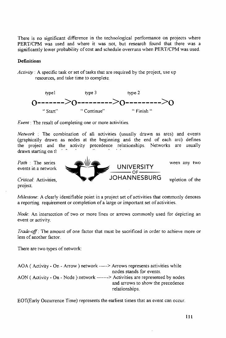
There is no significant difference in the technological performance on projects where PERT/CPM was used and where it was not, but research found that there was a significantly lower probability of cost and schedule overruns when PERT/CPM was used.
Definitions
Activity : A specific task or set of tasks that are required by the project, use up resources, and take time to complete.
typel type 3 type 2
O >0 >0 >0 " Start"
" Continue" " Finish "
Event: The result of completing one or more activities.
Network : The combination of all activities (usually drawn as arcs) and events (graphically drawn as nodes at the beginning and the end of each arc) defines the project and the activity precedence relationships. Networks are usually drawn starting on the left and proceeding to the right.
Path : The series of connected activities (or intermediate events) between any two events in a network.
Critical: Activities, events, or paths which, if delayed, will delay the completion of the project.
Milestone: A clearly identifiable point in a project set of activities that commonly denotes a reporting requirement or completion of a large or important set of activities.
Node: An intersection of two or more lines or arrows commonly used for depicting an event or activity.
Trade-off : The amount of one factor that must be sacrificed in order to achieve more or less of another factor.
There are two types of network:
AOA ( Activity - On - Arrow ) network
> Arrows represents activities while nodes stands for events.
> Activities are represented by nodes and arrows to show the precedence relationships.
AON ( Activity - On - Node ) network
EOT(Early Occurrence Time) represents the earliest times that an event can occur.
111
Calculating Activity Times
From data such as optimistic time, most likely time, pessimistic time, it is possible to calculate the expected time (based on the fact that this time follows a beta statistical distribution) the variance as well as the standard deviation.
Critical Path and Time
By proceeding to calculate the EOT of each node beginning at the start, we are actually finding the critical path and time to each of the nodes in the network. Most of the time the PM will employ the "as-soon-as-possible" approach to scheduling tasks (early start) but there are situations where other approaches will sometimes be used. For example the simultaneous start, where all resources are launched and the beginning or the simultaneous finish, where a facility can be moved to its next location once the tasks are finished.
A reason for using an " as-late-as possible " approach is that it delays the use of resources as much as possible, thereby optimizing the cash flow of the project, but again at some risk of delay.
EST which is the earliest starting time is equal to the EOT for the event from which the activity emanates.
LST is the latest starting time.
The difference between the LST and the EST for an activity is called its slack or float. It is obvious that all activities on the critical path have zero slack. They cannot be delayed without making the project late. To find the slack for any activity or the LOT (Last occurrence Time) one makes a backward pass (right to left) through the network just as we made a forward pass (left to right) to find the critical path and time and the EOTs for all events (which are also the ESTs for successor activities). It is conventional to calculate the slack for any activity as if it was the only activity in the path.
Uncertainty of Project Completion Time
The P.M. should try to determine the probability that a project will be completed by the suggested deadline, or find the completion time associated with a predetermined level of risk.
8.3.2.3 Gantt chart
One of the oldest and still one of the most useful method of presenting scientifically information is the Gantt chart, developed around 1917 by Henry L. Gantt. The Gantt chart is particularly effective and easy to read, easy to construct and can be helpful in expediting, sequencing, and reallocating resources among tasks. That is why the Gantt chart is the most popular method for displaying a project schedule. One of the
112
disadvantages of the Gantt chart is that it is not indicating clearly task precedence and dependencies.
8.3.2.4 Extensions of PERT
GERT
The Graphical Evaluation and Review Technique (GERT) is a network model developed to deal with more complex modelling situations. GERT combines signal flow graph theory, probabilistic network PERT/CPM, and decision trees all in a single framework. Its components consist of logical nodes and directed arcs (or branches) with 2 parameters, the probability that a given arc is taken (or "realized") and the distribution function describing the time required by the activity.
Difference between GERT and PERT/CPM.
GERT
Branching from a node is probabilistic Various possible probability distributions for time estimates Flexibility in node realization Looping back to earlier events is acceptable Difficult to use as a control tool Arcs may represent time, cost, reliability etc....
PERT/CPM
Branching from a node is deterministic Only the beta distribution for time estimates No flexibility in node realization Looping back is not allowed
Easy to use for control Arcs represent time only
Pritsker conducted some work and found a modelling package called Q-GERT which simulates queues, or waiting lines, in the network. [431 There are other extensions of PERT that have some features similar to GERT and Q-GERT, e.g. VERT, but GERT seems to be the most widely used extension.
8.3. 2.5 Other methods
Other methods can be used for project scheduling such as the one developed by the Goddard Space Flight Center in three phases, and the one in use by the Department of General Services and called PMIS (Project Management Information System).
Bubshait and Selen worked on the use of project management techniques. Digman and Green have developed a useful framework for evaluating the various planning and control techniques. The PM should opt for the simplest method sufficient to the needs of the project and its parent firm.
113
8.3.3 Resource allocation
8.3.3.1 Introduction
After looking at allocation of time among project tasks (scheduling), next is to consider the allocation of physical resources. The subject relates directly to the matter of the scheduling because altering schedules can alter the need for the resources and the timing of resources needs. The approaches employed to solve allocation problems include the Critical Path Method (CPM) and several other well known techniques.
8.3.3.2 The Critical Path Method
In CPM, two activity times and two costs are specified, if appropriate, for each activity. This first time/cost combination is called normal and the second set is referred to as crash. Normal times are "normal" in the same sense as the m time estimate of the three times used in PERT. Crash times result from a attempt to expedite the activity by the application of additional resources, e.g., overtime, special equipment, additional staff and material, etc.
It is common standard practice with PERT/CPM to estimate activity times under the assumption of resource loading that are normal. There must have been some decision about what resources would be devoted to each task, but much of the decision-making is practice, relegated to the common methods of standard practice and rules of thumb which are sufficient for estimating the source needs for normal progress. However a careful planning is critical when attempting to expedite (crash) a project. Crash plans that appear feasible when considered activity by activity may incorporate impossible assumptions about resource availability.
Use of the three probabilistic time estimates of PERT may reduce chance that crashing will be needed because they include uncertainties that are sometimes ignored when making deterministic time estimates. If deterministic time estimates are used, and if project deadlines are first, there is a high likelihood that it will be necessary to crash the last few activities in most projects.
If we define a cost/time slope as follows:
Crash cost - normal cost slope = (which is the cost per day of crashing a project ) (8.2)
Crash time - normal time
The slope is negative, indicating that as the time required for a project or task is decreased, the cost is increased.
Crashing a project results in a change of the technology with which something is done. At certain times, crashing may involve a relatively simple decision to increase groups of
114
resources already being used. In some cases technology cannot be changed, and task duration is fixed.
Changes in technology tend to produce not only discontinuities in outcomes, but they tend also to produce discontinuities in cost. As the technology is changed to speed a project, the cost curve relating input costs to time is apt to jump as we move from less to more sophisticated production systems. To use CPM , the PM has to develop a table or a graph of the cost of a project as a function of the project's various possible completion dates. This can be obtained by either of two approaches:
Start with the normal schedule for all project activities, and then crash selected activities, one at a time, to decrease project duration at the minimum additional. Start with an all-crash schedule, compute its cost, and "relax" activities one time at time. It is obvious that the activities relaxed first should be those that do not extend the completion date of the project.- that is, those not on the critical path.
Then it is possible to draw a time/cost curve. Starting at the right, the more the curve of cost per unit of duration gets steeper and steeper the more the project duration is reduced. Such kind of charts (curves) are useful to the PM in exercising control over project duration and cost. They are particularly helpful in dealing with senior managers who may argue for early project completion dates with little understanding of the costs involved. Similarly, such data are of great benefit when clients plead for early delivery. It is important to note that indirect costs are often altered when a project is crashed. It is advisable for the PM to ignore overhead cost over which he/she has no control.
If a project has a penalty clause making the organization liable for late delivery, the cost/duration trade off curve contains the information the PM needs to know in order to determine whether crashing the project or paying the penalty is the more economic course of action.
8.3.3.3 The resource allocation problem.
The present study will not refer to resource usage simply as "costs" but refers also to individual types of labor, specific facilities, kinds of materials, individual pieces of equipment, and other discrete inputs that are relevant to an individual project and are limited in availability.
The relationship between progress, time, and resource availability/usage is the major focus. Schedules should be evaluated not merely in terms of meeting project milestones, but also in terms of the timing and use of scarce resources. A fundamental measure of the PM's success in project management is the skill with which the trade-offs among performance, time, and cost are managed. The extreme points of the relationship between time use and resource use are:
- Time Limited: The project must be finished by a certain time, using as few resources as possible. But it is time, not resource usage, that is critical.
115
- Resource Limited: The project must be finished as soon as possible, but without exceeding some specific level of resource usage or some general resource constraint.
The points between these two extremes represent time/resource-use trade-offs.They specify the times achievable at various resources levels. Equivalently, they specify the resources associated with various completion times. The range of time or resource variability is limited.
If all three variables, time, cost, specifications are fixed, the system is "over determined". One or more tasks in a project may be "system constrained". A system-constrained task requires a fixed amount of time and known quantities of resources. No trade-offs are possible when dealing with a system- constrained task or project. More important is to make sure that the required resources are available when needed.
Resource loading
Resource loading describes the amounts of individual resources an existing job requires during specific time periods. It is also a step in attempting to reduce excessive demands on certain resources, regardless the specific technique used to reduce the demands. The PERT diagram, if modified to illustrate slacks, will be helpful for resource levelling. A Gantt chart could be also adapted.
Resource levelling
Resource levelling aims to minimize the period-by-period variations in the resource loading by shifting tasks within their slack allowances. The purpose is to create a smoother distribution of resource usage. The advantages of smoothening resource usage that the PM can arrange to have the resource available when needed, can have the supplier furnish constant amounts, and can arrange a backup supplier if advisable.
Another implication is that when resources are levelled, the associated costs tend to be levelled. Resource levelling is a procedure that can be used for almost all projects, whether or not resources are constrained. Depending on the size of the network, resource levelling can be done manually or by computer package.
Constrained resource scheduling
There are two fundamental approaches to constrained allocation problems, heuristics and optimization models .
Heuristic approaches employ rules of thumb that have been found to work reasonably well in similar situations. They seek better solutions. Optimization approaches seek the best solutions but far more limited in their ability to handle complex situations and large problems.
116
a) Heuristic methods.
Heuristics approaches to constrained resources scheduling problems are widely in use because they are the only feasible methods of attacking the large, non-linear, complex problems that tend to occur in project management environment and also because the schedules generated by this methods are good for most projects. In a period when the available supply of a resource is exceeded, the heuristic examines the tasks in the period and allocates the scarce resource to them sequentially, according to some priority rules which are mainly:
As Soon as Possible : The default rule for scheduling. This provides the general solution for critical path and time.
As Late as Possible : All activities are scheduled as late as possible without delaying the project. The usual purpose of this heuristic is to defer cash out flows as late as possible.
Shortest Task First : Tasks are ordered in terms of duration, with the shortest first. This rule in general maximizes the number of tasks that can be completed by a system during some time period.
Most Resources First : Activities are ordered by use of specific resource, with the largest user heading the list, because the more important tasks usually place a higher demand on scarce resources.
- Minimum Slack first : This heuristic orders activities by the amount of slack, least slack going first. It is common, when using this rules, to break ties by using the shortest-task-first rule.
Most Critical Followers: Tasks are arranged by number of critical activities following them. The ones with the greatest number of critical followers go first.
Most Successors : Same as the previous rule, except that all followers, not merely critical ones, are counted.
Experiments by Fendley revealed that the minimum slack rule was the best or near-best quite often and rarely caused poor performance. The heuristic procedure just described is probably the most common. There are, however, other heuristic procedures that work in a similar manner. One works in reverse and schedules jobs from the end of the project instead of from its beginning. Activities that just precede the project finish are scheduled to be completed just barely within their latest finish times. Other heuristics use the branch and bound approach. They generate a wide range of solutions, discard those that are not feasible and others that are feasible with poor solutions. Another heuristic procedure for levelling resource loads is based on the concept of minimizing the sum of the squares of resource requirements in each period. This approach, called Burgess's Method, was applied by Woodworth and Willie to a multiproject situation involving a number of
117
resources. The method was applied to each resource sequentially starting with the most critical resource first.
b) Optimizing methods
The methods to find an optimal solution to the constrained resource scheduling problem fall into two categories, mathematical programming (linear programming) and enumeration
Linear programming (LP) is usually not feasible for reasonably large projects where there may be a dozen resources and thousands of activities. Advanced in LP techniques now allow LP to be used on large constrained resource scheduling problems.
In the late 1960s and early 1970s, limited enumeration techniques were applied to the constrained resource problem with more success. Tree search and branch and bound methods were devised to handle up to 5 resources and perhaps 200 activities. Recent approaches have combined programming and enumeration methods.
8.3.3.4 Multiproject scheduling and resource allocation
Scheduling and allocating resources to multiple projects, as is the case for the RAU Concrete Rehabilitation Project, is much more complex than for the single-project case. The most common approach is to treat the such projects as if they were each element of a single large project. Another way of dealing with the problem is to consider all projects as completely independent.
In a multiproject, each project has its own set of activities, due dates, and resource requirements. Penalties for not meeting time, cost and performance goals for the several projects may differ. A multiproject problem involves determining how to allocate resources to, and set a completion time for, anew project that is added to an existing set of ongoing projects. This requires the development of an efficient, dynamic multiproject scheduling system.
Three important parameters affected by the project scheduling are:
Schedule slippage: is the time past a project's due date or delivery date when the project is completed. It may result in penalty costs. It may also cause other projects to slip.
Resource utilization : A resource allocation system that smooths out the peaks and valleys of rescue usage is ideal but it is extremely difficult to attain while maintaining scheduled performance because all the projects in a multiproject organization are competing for the same scare resources.
118
3. In - process inventory concerns the amount of work waiting to be processed because there is a shortage of some resource(s).
Fendley found that when a new project is added to a multiproject system the amount of slippage is related to the average resource load factor. The load factor is the average resource requirement during a set time period divided by resource availability for that time period. Analysis of resources loads is important in determining the amount of slippage to expect when adding projects. There are various types of multiproject scheduling and resource allocation techniques such as:
Mathematical programming which can be used to obtain optimal schedule to certain types of multiproject scheduling problems.
Heuristic techniques on which have been focused major efforts in attacking the resources constrained multiproject scheduling problem because the difficulties with the analytical formulation of realistic problems.
These additional heuristic for resource allocation have been developed and are commercially available for computer:
Resource Scheduling Method. Minimum Late Finish Time. Greatest Resource Demand
A multiproject scheduling heuristic
If an entire network is decomposed into subnetwork, we have the equivalent of the multiproject problem where each of the projects (subnetworks) is linked to processor and successor projects (other subnetworks). In this case the predecessor/successor relationships depend on the technology of the parent project. Before undertaking the allocation of resources it is proper to consider the quantity of resources available allocation. Excluding activities that have been completed in previous periods, every activity planed by the project is in one of four states: ongoing, stopping, waiting and technologically able to start or waiting and technologically unable to start.
Ongoing activities are labelled us "resource users". Stopping are " resource contributors"
- Waiting and able to start are "resource demanders"
If the PM uses up the resources before all critical activities are scheduled, we can adopt one or two subheuristics
1 Borrow resources from currently active , but non critical tasks. 2. Deschedule a currently active ,non critical taste .
119
In both cases, some resources will be for use on critical tasks.
8.3.4 Monitoring and Information Systems
8.3.4.1 Introduction
Monitoring is collecting, recording, and reporting information concerning any and all aspects of project performance that the P.M or others in the organisation wish to know Monitoring as an activity, should be kept distinct from controlling . Controlling activity uses the date supplied by monitoring to bring actual performance into approximate congruence with planed performance. Monitoring should also be kept distinct from evaluation(through which judgements are made about the project is completed.
8.3.4.2 The planning - monitoring - controlling cycle
The key things to be planned ,monitored, and controlled are time (schedule), cost (budget), and performance (specifications).
Planning - monitoring - controlling cycle is continuously in process until the project is completed.
Designing the monitoring system
The first step is to identify the key factors to be controlled and the source of items to be monitored by the project action plan. Monitoring system follows and should concentrate on measuring various facets of output rather than intensity of activity. The measurement of project performance usually poses most difficult than gathering problems.
How to collect data
It is necessary to define precisely what pieces of information should be gather and when the collected data take one of the following forms:
Frequency counts. Raw members. Subjective numeric ratings. Indicators. Verbal measures.
After data collection has been completed reports on project progress should be generated project status reports, time/cost reports, various reports. Causes and effects should be identified and trends noted. Plans, charts and tables should be updated on a timely basis. The purpose of the monitoring system is to gather and report data. The purpose of the control system is to act on the data and to aid the project controller. It is helpful for the monitor to carry out some data analysis .
120
8.3.4.3 Information needs and the reporting process
The monitoring system ought to be constructed so that it addresses every level of management, but reports need not be of the same depth or at the frequency for each level. Lower level personnel have a need for detailed information about individual tasks and the factors affecting such tasks. Reports should be available in time to be used for project control. The timing reports should generally correspond to the timing of project milestones. Project reports may not be issued periodically excepting progress reports for senior management.
Report- types
The three distinct types of reports are:
Routine (issued on regular basis). Exception (directly oriented to the project management decision and they may be issued when a decision is made on an exception basis). Special analysis ( used to disseminate the results of special studies conducted as part of the project or as a response to special problems during the project.)
Meetings
A few rules can help project meetings to be pleasant:
Use meetings for making group decisions or getting input for important problems. Have preset starting and stopping times as well as a written agenda. Be prepared. Minutes must be distributed as soon as possible after the meeting. Avoid attributing remarks or viewpoints to individuals in the minutes. Avoid overly formal rules of procedure. In case of crisis, call a meeting to deal with that issue only.
Common reporting problems
There are three common difficulties in the design of project reports:
There is usually too much detail, both in the reports and in the input being solicited from workers. Poor interface between the project information system and the parent firm's information system. Poor correspondence between the planning and the monitoring.
8.3.4.4 The earned chart value
Monitoring of performance for the entire project is important. Individual task performance must be monitored carefully because the timing and co-ordination between
121
individual tasks is important. One way of measuring overall performance is by using an aggregate performance measure called earned value. Three variances can be identified on the earned value chart.
The time variance = difference in the time scheduled for the work that has been performed (STWP) and the actual time used to perform it (ATWP).
- The cost or spending variance = the difference between the amount of money budgeted for the work that has been performed (BCWP) to date and the actual cost of that work (ACWP)
- The schedule variance = the difference between the budgeted cost of the work performed (BCWP) to date and the cost of the work scheduled to be performed to date (BCWS).
When the project is behind schedule as is the case of the realkalisation project at Rand Afrikaans University, the variances are negative.
8.3.4.5 Cost/Schedule Control System Criteria (C/SCSC)
C/SCSC was developed by the US Department of Defence in the late 1960s and is generally required for defence projects. It is an extension of earned value analysis. The approach emphasizes the need to relate the realities of time, cost, and performance with the project's master plan which must be kept up to date.
Milestone - reporting
These types-of reports show project status at specific time. They serve to keep all parties up to date on.what has been accomplished.
8.3.4.6 Computerized PMIS (Project Management Information Systems)
These systems are certainly efficient, but they can be misused or inappropriately applied. The most common error of this type is managing the PMIS rather than the project itself.
Thamhain described it in the form of the following list:
Computer paralysis. - PMIS verification.
Information overload. Project isolation.
- Computer dependence. PMIS misdirection.
The PMIS have a wide of capabilities which can be helpful for Project Managers. Project Managers' preferred PMIS features are:
122
- Friendliness, - Schedules, - Calendars,
Budgets, - Reports, with graphics,
Networks charts, - Migration, - Integration.
The five areas of internal PMTS capabilities are
Project Planning. Resource Management. Tracking / Monitoring. Report generation. Decision making.
8.3.5. Project control
8.3.5.1 Introduction
Control is the last element in the implementation cycle of planning-monitoring-controlling. Information is selected about system performance, compared with the desired (or planned) level and action taken if actual and desired performance differ enough that the Project Manager wishes to decrease the difference.
In essence, control is the act of reducing the difference between plan and reality. Control is focused on the three elements of a project, namely performance, cost and time. The process of controlling a project defines what points in the project should be controlled, how it will be measured, how much deviation from plan will be tolerated before to act, what kinds of interventions should be used, and how to spot and correct deviations before they occur.
8.3.5.2 The fundamental purposes of control
The two fundamental objectives of control are :
The regulation of results through the alteration of activities. The stewardship of organizational assets.
Physical asset control
Requires control of the use of physical assets. It is concerned with asset maintenance (preventive or corrective) as is the case for RAU buildings . The timing of maintenance or replacement as well as the quality of maintenance are also among the issues. Physically inventory (of equipment or material), must also be controlled.
123
Human resource control
Human resources must be controlled. Such devices for the measurement of human resource conservation as :
Einployee appraisals. Personnel performance indices. Screening methods for appointments, promotion, and retention are not particularly satisfactory devices for ensuring that the conservation function is being properly handled.
Financial resource control.
Capital investment controls work to conserve the organization's assets by insisting that certain conditions be met before capital can be expended, and those same conditions usually regulate the use of capital to achieve the organization goal of a high return on investments. It is difficult to separate the control mechanisms aimed at conservation of financial resources from those focused on regulating resource use. The techniques of financial control, both conservation and regulation include current asset controls and project budgets as well as investment controls.
8.3.5.3 Three types of control processes
a) Cybernetic control
Also known as steering control, cybernetic control is characterized by its automatic operation. It is essentially constituted by inputs, process, outputs (and sensors for measurement of outputs), comparator, effector and decision maker. A cybernetic control system that acts to reduce deviations from standard is called a negative feedback loop.
There are three types of cybernetic control systems:
A first-order control system. A second order control system. A third order control system.
The information requirements of a cybernetic control are:
The characteristics of an output (interim output or final output) which must be controlled. Standard must be set for each characteristic. Sensors must be built to measure the characteristics at desired level of precision. Measurements must be transformed into a signal that can be compared to a standard signal. The difference between the two is sent to a decision maker.
124
The signal is transmitted to the effector to cause the system to react in order to counter act the deviation from standard.
Go/No-go controls
Go/No-go controls take the form of testing to see if some specific precondition has been met. For many facets of performance, it is sufficient to know that the predetermined specifications for project output have been met. It is also true for cost and time. Judgement is required in the use of go/no-go controls.
The project plan, budget, and schedule are control documents, so the PM has a pre-designed control system complete with pre-specified milestones as control checkpoints contrary to cybernetic controls which are automatic, go/no-go controls operate only when and if the controller uses them. In many cases go/no-go controls functions periodically, at regular, pre-set intervals. Advantage associated to go/no-go controls is that with them it is easy to administer a control system whereas the disadvantage is that there is an allowance of errors to be compounded before to be detected. Therefore controls should be linked to the actual plans and the occurrence of real events, not simply to the calendar. The PM should establish an early warning system in order to expose potential problems. The most information required to operate go/no-go project control are contained in the project proposal, plans, specifications, schedules and budgets. Milestones are the key events that serve as a focus for ongoing control activity and they are the project's deliverable in the form of in-process output or final output.
Postcontrol
PostcOntrols (also known as post performance controls or post project controls) are applied after the fact. Postcontrol is applied through a formal document with four distinct sections:
The project objectives. Milestones, checkpoints, and budgets. The final report on project results. Recommendations for performance and process improvement.
Some useful control tools are:
Trend projection charts.
Actual progress Budgeted cost Critical ration = X (8.3)
Scheduled progress Actual cost Control charts.
125
8.3.5. 4 Control as a function of management
Control is a necessary and inherent part of life in any organization. It must be taken as a tool assuring the maintenance of ethical goal-directed behavior. Control does indicate the direction toward which the motivated person should move.
Three responses to the goal-directedness of control systems are:
Active and positive participation and goal seeking. Passive participation in order to avoid loss. Active and negative participation and resistance.
8.3.5. 5 Balance in control system
When developing a control system, it is important that the system be well balanced. A balanced control system is cost-effective, well geared for the best results sought, and not overdone. The most important principle to achieve a balanced control system is the need to tie controls directly to project objectives. Control should also be closely and directly related to specific performance outcomes. Constructing a balanced system must be done when control systems are designed . The work planned will also to be controlled.
8.3. 5.6 Control of creative activities
This type of control deals particularly with controlling research and development projects, design projects and similar processes that depend ultimately on the creativity of individuals and teams.
Three general approaches must be adopted by the PM in order to control creative projects:
Progress review. Personnel reassignment. Control of input resources.
8.3.5.7 Control of change
Changes result from three basic causes, namely the uncertainty about the technology, the increase in the knowledge base of the client/user and the modification of rules applying to the process of carrying out the project or to its output. The most common changes, however, are due to the natural tendency of the client and project team members to try to improve the product or service. The purpose of the formal change control system is to:
Review all requested changes to the project. Identify all task impacts. Translate the impacts into project performance, cost and schedule. Evaluate the benefits and costs of the requested changes.
126
Identify alternative changes that might accomplish the same ends. Accept or reject the requested changes. Communicate the changes to all concerned parties. Ensure that the changes are implemented properly. Prepare months reports summarizing all changes to the date and their project impacts.
To establish an effective change control procedure some guidelines must be followed:
Description of how requests for a change will be introduced and processed. Any change in a project will be in the form of a change order. Changes must be approved. The PM must be consulted on all desired changes prior to the preparation and approval of the change order. Once the change order has been completed and approved, the project master plan should be amended to reflect the change and the change order becomes a part of the master plan.
The next phase after implementing a project and which is also the last stage in a project life cycle is the project termination. The next section examines how to terminate a project.
8.4 PROJECT TERMINATION
8.4.1 Project auditing
8.4.1.1 Introduction
Postcontrol tries to capture the essence of project success and failures so that future projects can benefit from past experiences. Understanding past experiences requires evaluation. One of the evaluation process is called project auditing. Project evaluation appraises the progress and performance of a project compared to that project's planned progress and performance or compared to the progress and performance of other, similar projects. The evaluation also supports management decisions required for the project. Therefore the evaluation must be presented in such a way that all pertinent data have been considered.
8.4.1.2 Purposes of evaluation
The primary purpose of evaluation is to aid in achieving the project's goals and contribution to the parent's organization's goals. All the facets of the project must be studied in order to identify and understand the project's strengths and weaknesses. It is the equivalent of application of TQM to project management.
Identification of goals of a project is easy. It requires only a careful reading of the project proposal and a close examination of any documentation that indicates why the project
127
was selected and undertaken. Immediately following the project description is a section headed "reason for interest" which is a statement of the project's direct goal. If this section does not exist a few interviews with the individuals in charge of making decision about projects will help to expose the direct goals sought by the firm.
Identification of ancillary goals is a difficult and politically delicate task. Ancillary goals are usually not overtly identified . For the most part, they are "hidden" by accident, not by purpose. Finding them requires deductive reasoning. A well advised P.M has to take a keen interest in finding ancillary goals of a project he has to request that evaluations include ancillary goals of the parent organization's if not those of individuals.
8.4.1.3 The project audit
The project audit is a thorough examination of the management of project, its methodology and procedures, its records, its properties its budgets and expenditures and its degree of completion. It may deal with a project as a whole , or only with a part of the project.
The formal report may be presented in various formats, but should , at a minimum, contain comments on the points.
Current status of the project. Future status. Status of crucial tasks. Risk assessment. Information pertinent to other projects. Limitations of the audit.
Project audit is not a financial audit. The processes are similar but the outputs are quite different. A financial audit has a limited scope whereas a project is far broader in scope and may deal with the project as a whole or any components of the project. Project audit is not also a traditional management audit. Management audits are primarily aimed at ensuring that the organization's management systems are in place and operation. The project audit studies the financial, managerial, and technical aspects of the project as an integrated set applied to a specific project in a specific organizational environment .
Depth of the audit
Time and money are two of the most common limits on the depth of investigation and level of detail presented in the audit report. Some costs are associated with the audit/ evaluation process. The Depth of the investigation may vary depending on circumstances and needs unique to each project.
Three levels of audit are generally recognized:
128
1. The general audit (normally most constrained by time and resources and is usually a brief review of the project).
2 The detailed audit is conducted when a flow-up to the general audit is required. 3. Technical audit is normally carried out by a qualified technician under the direct
guidance of the project auditor. It is usually the most detailed.
Timing of the audit
The timing will depend on the circumstances of a particular project. The first audits are usually done early in the project's life and are focused on the technical issues in order to make sure that key technical problems have been solved or are under competent attack. As the project develops, technical issues are less likely to be matters of concern. Conformity to the schedule and budget becomes the primary interest. Management issues are major matters of interest for audits made late in the project's life. Post project audits are conducted as a legal necessity because the client specified such an audit in the contract. It is also a major part of the managerial feedback to the parent organization. A post project audit is needed to account for all project property and expenditures.
8.4.1. 4 Constructions and use of the audit report
It is useful to establish a general format to which all audit reports must conform. Significant deviations of actual from predict results should be highlighted and explained in a set of footnotes or comments. Negative comments about individuals or groups associated with the project should be avoided. The report must be written in a clear, professional, unemotional style and restrict its content to information and issues that are relevant to the project. The following items cover the minimum information that should be contained in the audit report:
Introduction Current status : should include - cost (direct charges).Overheads cost data should be
presented in an additional set of tables, schedule, progress, quality.
Future project status Critical management Risk analysis Caveats, limitations, and assumptions
Responsibilities of the Project Auditor/Evaluator
The auditor should tell the truth. He must also approach the audit in an objective and ethical manner and assume responsibility for what is included and excluded from consideration in the report.
Walker and Bracey suggest the following steps for carrying out an audit: [431
129
Assemble a small team of experienced experts. Familiarize the team with the requirements of the project. Audit the project on site. After completion, debrief the project management. Produce a written report according to a prespecified format. Distribute the report to the PM and project team for their response. Follow up to see if the recommendations have been implemented
8.4.1.5 The project audit life cycle
The audit should be considered as a formal document required by contract with the client. The life cycle of an audit is composed of an orderly progression of well-defined events:
Project Audit Initiation. Project Baseline Definition. Establishing an Audit Database. Preliminary Analysis of the Project. Audit Report Preparation. Project Audit Termination
8.4.1.6 Some essential of an audit/evaluation
For an audit/evaluation to be conducted with skill and precision, for it to be credible and generally acceptable to senior management, to the project team, and to the client, several conditions must be met:
The audit/evaluation team must be properly selected. All records and files must be accessible. The contact with project team members must be preserved
8.4.1.6 Measurement
The measurement of a project is not an easy issue to deal with. Criteria and scoring procedures should be decided at the start of the project. After measuring the project comes the termination phase.
8.4.2. Project termination
Project termination is the stage during which the signing and acceptance procedures must take place. In other words, at this stage, all parties involved in the project must ensure that the final output is as specified and have a point at which the project is declared completed.
130
8.4.2.1 The varieties of project termination
A project can be said to be terminated:
When work on the substance of the project has ceased or slowed to the point that further progress on the is no longer possible. When the project has been indefinitely delayed. When its resources have been deployed to other projects. When project personnel (especially the PM) becomes a personae non gratae with senior management and in the company lunchroom.
There are four fundamental different ways to close out a project :
By extinction. By addition. By integration. By starvation.
Termination by extinction
The project is stopped. It may end because it has been successful and achieved its goals. It may also be stopped because it is unsuccessful or has been superseded or it will cost too much and take too long to get the desired performance. Termination by murder may also be a case of termination (political assassination, accidental projecticide, etc.).
When a project terminates, all activity on its substance ceases. Arrangements must be made in order to release project team members and to reassign them to other activities if they remain in the parent firm. The property, equipment and materials belonging to the project must be disbursed and a final report, also known as the project history must be prepared.
Termination by addition
In-house projects are carried out by the project team for use in the parent organization. If a project output is a major success, it may be terminated by institutionalising it as a formal part of the parent organization. In the case of termination by addition, as in the case of termination by extinction the project ceases to exist. Project personnel, property, and equipment are often simply transferred from the dying project to the newly born division.
Termination by integration
This kind of termination is the most common way of dealing with successful projects, and the most complex. The property, equipment, material, personnel, and functions of the project are distributed among the existing elements of the parent organization. The more
131
important aspects of the transition from project to integrated operation that must be considered when the project functions are distributed, are the following:
Personnel : Where will the project team go? Will it remain a team? etc. Manufacturing : Is training complete? Are input materials and the required facilities available? Accounting/Finance : Have the project accounts been closed and audited? Engineering : Are all drawings complete and on file? Information systems/software. Marketing : Is the sales department aware of the change? Purchasing, Distribution, Legal; etc... Are all these and other functional areas aware of the change?
Termination by starvation
It is more a "slow starvation by budget decrement" than a project termination by itself. In effect, the project is terminated, but the project still exists as a legal entity complete with sufficient staff to maintain some sort of presence such as a secretary who issues a project "no-progress" report each year.
8.4 2.2 When to terminate a project
Buell developed a list of some questions which must be asked before terminating a project. [431 This list is not reproduced in this study but can be found in specialised books. This list can help senior management to take decision about the life of the project.
Dean reports that the probabilities of technical and/or commercial failure are the two most important reasons for terminating projects.t 431
Balachandra and Raelin performed a discriminant analysis on 23 factors involved in terminating projects, not as a decision model, but as a way of highlighting the various factors involved and their relevance to the termination problem, as related to projects in general. [431 Some critical success factors had been selected by Pinto and Slevin. In order of importance, there are: [431
Project mission. Top management support. Project schedule / plan. Client consultation. Personnel. Technical tasks. Client acceptance. Monitoring and feedback. Communication. Troubleshooting
132
These success-related factors can be used as termination decision models. There are also relatively few fundamental reasons why some projects fail to produce satisfactory answers to Buell's questions. Among them we find mainly the followings:
A project organization is not required. Insufficient support from senior management. Naming the wrong person as Project Manager. Poor planning.
8.4.2. 3 The termination process
This process has two distinct parts : The decision (whether or not to terminate a project). The implementation of the decision (execution).
The decision
Two categories pertain to this process: There are models that base the decision on the degree to which the project qualifies against a set of factors associated with successful or failed projects.
There are models that base the decision on the degree to which the project meets the goals and objectives set for it.
Balachandra and Raelin state that project selection models are not appropriate for the project termination decision. For them, data requirements for selection models are too large and costly. They also argue that the evaluation of factors in project selection models may change during the life cycle of the project.
Shafer and Mantel have developed a project termination decision support system (DDS) available on Lotus 1-2-3 and using a constrained weighted factor scoring model. [431
The implementation process
Once taken, the decision to terminate a project must be implemented. The termination can be planned or be a simple hatchet job. The implementation process is a complex process. Special termination managers are sometimes useful in completing the long and involved process of shutting down a project. Some suggestions have been made but are very difficult to be followed in case of termination by murder.
8.4.2.4 The final report, a project history
The project final report incorporates the process knowledge gained from the project. The elements that should be covered in the final report are:
133
Project performance. Administrative performance. Organizational structure. Project and administrative teams. Techniques and project management.
These comments are made in order to preserve project records.
8.4.3 Multicultural, environmental and unsolved issues
8.4.3.1 Introduction
Projects are conducted in different environments, namely, economic, political, legal and socio-technical environments. The PM has to deal with all these environments in order to manage and reduce conflict between the parties involved in the project, i.e., project team, client, senior management, public, etc. The problems are greater if the parties-at-interest represent different nations, industries, and firms.
8.4.3.2 Problems of cultural differences
Culture refers to the entire way of life for a group of people. It encompasses every aspect of living and has four elements that are common to all cultures:
Technology (tools, materials in use). Institutions (structure of the society). Language (means of communication and expression). Arts (aesthetic values of a culture)
Culture and project
Philosophy of staffing projects varies greatly in different cultures.
Microcultures and project
The term microculture is used to differentiate "corporate cultures" from the broader national or regional cultures. Microcultures vary from industry to industry and from firm to firm just as cultures do from nation to nation. The impact of interindustry, interfirm and intrafirm microcultural diversity on the PM is very significant.
8.4.3.3 Impact of institutional environments
The environment of a system is defined as everything outside the system that receive system outputs from it or delivers inputs to it.
134
Socio-economic environment
The PM must deal with the socio-economic environment of where the project is conducted (governmental regulations about, safety use of people, profits regulations, etc).
Legal environment
Regulated by laws which are a product of the history of a nation. Law results to attempt to reduce conflict by a regularised procedure. Law is constantly changing. The project must evolve together with the law.
The business cycle as an environment
The PM must aware of the general level of business conditions in the nation hosting the project. Different perceptions about the level of prosperity or recession differ from region to region and will be reflected in positive or negative attitudes toward investment, and employment.
Technological environment
The ability to complete a project with success is often dependent on the Project Manager's ability to plan the project in such a way as to be compatible with the technology available in the host nation.
Other environmental factors
Political uncertainty, rampant inflation, governmental bureaucracy, local contractor politics and so on are also some environmental issues that should be in the focus of the PM at any stage during the evolution of the project.
8.4.3.4 Multicultural communication and managerial behaviour
These aspects of the environment where the project are conducted include the following:
The language in use in the environment (easy of communication). The structure and style of communications. The managerial and personal behaviours of the PM (guaranty of success).
8.4.3.5 Three critical, unsolved problems
In general, there are always three critical unsolved problems when conducting a project. These are:
The ability of Project Managers to learn from the experiences of others. The ability to manage conflict. The consideration of project management as a career.
135
8.4.3.6 Disputes
Disputes include disagreement between the concerned parties in the project and are due either to the way requirements or obligations have been achieved after the operational phase of the project. A good PM should plan and forecast all these kinds of issues during the initiation phase (Planning) of the project so that he can handle them easily when they arise.
During the progress of the contract issues inevitably arise over which the contractor and the Engineer have differing points of view. Such difficulties may take the form of circumstances which the contractor regards as disruptive and not necessarily foreseeable, or requirements for additional work, or delays due to operations outside of the direct control of the contractor, or disputes over the standard of work being produced.
Those responsible for supervision have to decide whether or not a contractor's requests for additional payment or for an extended time for completion are reasonable within the terms of the contract. As all these issues have been planned during the planning phase of the project, the way to handle them should be not frustrating for any party. Both parties must be prepared to agree that it is desirable to minimize areas of disputes.
An open and constructive approach toward the settlement of differences requires that both parties should be experienced engineers, confident of what they are doing and enjoying the confidence of their superiors. An excessive reliance on correspondence in disputes generally indicates that theparties are more interested in establishing their own positions than in seeking agreement.I i51
II. REAKALISATION MANAGEMENT: CASE STUDY OF THE RAND AFRIKAANS UNIVERSITY
The first part of this chapter addressed the project management life cycle, principles and related definitions and terminology. This second part will attempt to examine the real situation of RAU concrete infrastructures and deal with the realkalisation project in a case study. The purpose is to help the university management in their decision making on whether or not an electrochemical realkalisation has to be considered as a radical solution for those part of the building infrastrutures that are suffering from severe reinforcement corrosion.
8.5 HISTORIC OF THE UNIVERSITY BUILDINGS
The main campus buildings of the Rand Afrikaans University in Johannesburg have been constructed during the 1970s. In terms of today value, the capital worth was in the order of R 1 billion. The project was designed and constructed over a period of five years.t 311 During the design phase, off-shutter concrete was selected because it was believed at that time to be maintenance free and virtually ever-lasting.
136
Considering the fact that university buildings are normally expected to last for hundreds of years, the decision to use off-shutter concrete on such a scale as durable and maintenance free material was perhaps not based on the correct information.t 321 Now, more than 80 000 m2 of exposed off-shutter concrete is found on the campus, due to the design decision of using of-shutter concrete panels. 1311 Shortly after completion, corrosion problems related primarily to spalling of concrete in certain parapet walls started manifesting itself and the problem has accelerated over the last decade. Therefore, the aesthetic appearance of the university buildings is being threatened while user safety and some possible minor structural problems are becoming a concern to the university authorities.
The main problem is that owners of concrete structures such as the RAU complex are often under the impression that concrete is a maintenance free building material and, therefore virtually no maintenance is done during the initial life of the structure. Unfortunately, due to insufficient planning, wrong evaluation factors, bad workmanship, inadequate quality control and lack of maintenance, a high percentage of concrete structures showed signs of damage within the first few years of service and maintenance due to corrosion of the reinforcing steel, becomes necessary.
8.6 RAU PROJECT INITIATION
As stated above, at the initial design of RAU, the concrete used was considered "maintenance free". Therefore very little time and money were spent on the maintenance of external facade of the building during the life of the structure. Soon, inadequate concrete cover exposed itself through cracking, leaching of corrosion products and spalling.
Spalling of concrete on high locations, non-aesthetic appearance of cracks and unsightly leaching eventually gave rise to concern and it became clear for the university authorities that a full maintenance and repair management program should to be implemented. This resulted in the initiative taken by Mr J.C.J. to Wet, Senior Director of Projects at RAU tocall for an in-depth investigation into the problem, with supporting rehabilitation recommendations to be presented to the university authorities. For this preliminary investigation, both internal and external consultants have been appointed.
As external consultants, Draper Penhall & Associates, corrosion specialists, conducted an intensive and comprehensive investigation in 1994 including the following :
Stray Current Survey. Covermeter Survey. Carbonation depths Chloride and Sulphate Ions Profiles. Electro-potential Mapping.
BKS Incorporated, a consulting company conducted a theoretical study in 1995 with some relevant recommendations made on how surface inspection, testing and cleaning, repair and protection should be carried out in order to ensure successful results.
137
Professor M.G. Alexander, Department of Civil Engineering, University of Cape Town, had also been approached by RAU to provide an independent and preliminary assessment of the durability state of the main buildings on campus. His final report, isssued on October 22, 1996 contains a practical approach to the problem solution.
Internal investigations include works and investigations conducted by done by Mr D. Kruger, Professor P.C. Pretorius and final year civil engineering students.
Many means, methods and equipment were used by these different consultants to assess the problem before releasing information and recommendations to the university authorities. The next section explains how to conduct an investigation of a building structure when reinforcement corrosion is involved.
8.6.1 Field assessment to quantify damage
The assessment of any concrete structure involves two phases. The first stage is a preliminary investigation to determine whether the damage requires repair. If it is concluded that repair is needed, a second stage consisting of an extensive investigation should be launched. The results of this investigation should provide the information required for chossing the repair strategy and the details of the repair programme. An initial survey when corrosion of steel reinforcing is suspected should include the following steps: [391
Visual inspection and sounding tests (hammer-tapping, etc.) to determine damage: any rust strains, cracks and delamination should be noted. Crack width of any visible cracks should be recorded. Determination of cover thickness, location of the steel and concrete quality. Non-destructive test methods should be used (equipment includes covermeter survey and Schmidt hammer). Determination of the depth of carbonation by phenolphthalein test of cover pieces of concrete broken from the surface. Measurement of the Chloride content in cores or pieces of concrete broken from the surface, or pieces of concrete drilled from the structure.
The more extensive survey which may follow if required should include the following steps: [39]
Mapping of potentials, using half-cell techniques. Mapping areas of delamination and of damaged concrete, by means of ultrasonic testing or chain-drag. Determination of the electrical resistance of the concrete. Measuring surface properties of the concrete by surface absorption techniques or similar tests, and determining the strength of drilled concrete cores. Detailed study of depth of carbonation and of Chloride ingress profiles by testing of drilled cores.
138
Evaluation the nature of the cracks and of their width and changes of width with time, to resolve whether they are "live" or in other words cracks induced by thermal and loading effects, which are still active. Assessment of the structural conditions by full-scale loading tests in which the deflections under load are measured. Destructive tests to assess the reduction of the cross-section area of the steel. Etc.
8.6.2 Considerations after site inspection and testing
Preliminary investigations conducted by different consultants appointed by the Rand Afrikaans University had identified a potential corrosion problem on most of the campus buildings.
The testing carried out include both hammer sounding tests, phenolphthalein tests and covermeter surveys to respectively identify pores and voids, determine the depth of carbonation and measure the concrete cover. It quickly became evident that structures were suffering essentially from the effects of carbonation. It appeared also that the carbonation front, in some places, had advanced relatively quickly over the last two decades, causing corrosion of the first layer of steel. Its advancement can be supposed to have evolved further into the denser cementitious material. From all the investigation works, the surface defects could be categorised into the following four groups:
Spalled or delaminated areas due to corrosion, including unacceptable previously prepared areas Corroded steel without spalling Carbonated areas without cracking or spalling Contaminated surfaces by algae growth, dust and general pollution sediments.
After carrying out site inspection and evaluating measurements taken, all the commissioned consultants were unanimous, indicating that two factors need to receive attention the case of reinforcement corrosion of the university's buildings:
A sound alkali environment must be ensured for the enveloped reinforcement.
Preventive techniques need to be taken to obviate the condition deteriration or progressing to the extent that further areas of corrosion become manifest in time.
8.6.3 Alternative options
As for any project involving repair or protection of a structure, it is important first to have a proper consideration of its structural and material condition. Derived information may facilitate the prediction of the future condition of the structure and therefore enable the selection of an effective remedial strategy.
139
The primary factors are normally the question of the target lifetime over which acceptable, safe performance of the structure is required, and the largely economic question of whether this is to be achieved by regular repetitive repairs (e.g. regular patching repairs), or by a higher performance initial repair method with a substantially lower level of subsequent attention. The choice for reinforcement corrosion problems typically lies between methods used either singly or in combination.
A number of repair options may be open to any consultant. The following four alternative options may be taken in consideration in the case of RAU concrete deterioration problem:
Option A: Potentially extensive traditional patch repairs, coupled with steel replacement if required.
Option B: Limited repair and coating systems.
Option C: Limited patch repairs coupled with some form of cathodic protection.
Option D: Limited repair and realkalisation of the structures.
8.6.4 Choosing a repair strategy
The next step once the alternative options are laid down is to choose an effective and definitive repair strategy before starting to implement the project repair. To generate a means of selecting repair strategies scientifically, the European Standard for Protection and Repair of Concrete (ESPRC) has a section dealing with "principles" of repair, in which the primary deterioration causes are identified, covering damage to the concrete and separately the reinforcement. (27] The principles of protection and repair are then defined for each form of deterioration or damage, and the available methods of repair are defined in turn for each principle. The operations and materials issues then follow accordingly. This approach is illustrated in Table 8.1, which shows the principles and associated methods for dealing with reinforcement corrosion. [27]
Faced with a problem involving corrosion in concrete, an owner would, by following the ESPRC principles, assess the structure, available options, and user requirements, and be able then to select possible repair methods from each appropriate principle.t 271 The owner needs therefore to examine each option and determine from technical advantages and inconveniences which option is possibly suitable to be implemented with the funds available.
140
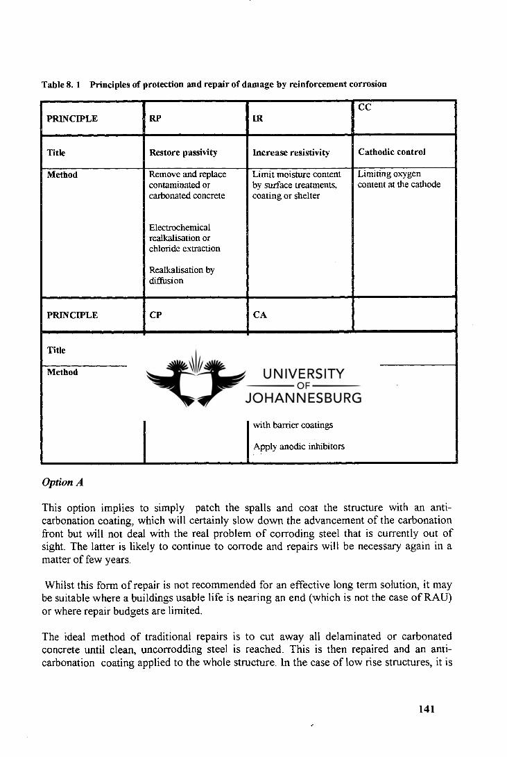
Table 8. 1 Principles of protection and repair of damage by reinforcement corrosion
PRINCIPLE RP IR CC
Title Restore passivity Increase resistivity Cathodic control
Method Remove and replace contaminated or carbonated concrete
Electrochemical realkalisation or chloride extraction
Realkalisation by diffusion
Limit moisture content by surface treatments, coating or shelter
Limiting oxygen content at the cathode
PRINCIPLE CP CA
Title Cathodic protection Control anodic areas
Method Provide electric current to maintain reinforcement at negative potential
Coat reinforcement with coatings containing active pigments
Paint reinforcement with barrier coatings
Apply anodic inhibitors
Option A
This option implies to simply patch the spalls and coat the structure with an anti-carbonation coating, which will certainly slow down the advancement of the carbonation front but will not deal with the real problem of corroding steel that is currently out of sight. The latter is likely to continue to corrode and repairs will be necessary again in a matter of few years.
Whilst this form of repair is not recommended for an effective long term solution, it may be suitable where a buildings usable life is nearing an end (which is not the case of RAU) or where repair budgets are limited.
The ideal method of traditional repairs is to cut away all delaminated or carbonated concrete until clean, uncorrodding steel is reached. This is then repaired and an anti- carbonation coating applied to the whole structure. In the case of low rise structures, it is
141
a relatively easy exercise for the owner's agent to assess the likely extent of such repairs whilst preparing his tender documentation. In addition, by choosing this option, one should be aware of the building occupation during the work in order to avoid disruption of the routine business of the premise by noise, dust, etc. Two critical issues in conventional concrete repair are that the repair is fundamentally dependent on:
The extent and rigour of concrete removal. Reinforcement cleaning.
The likely cost of works pertaining to the conventional repair option is extremely difficult to assess at a tender stage due to the fact that the real condition of the concert is only known after the breaking-out phase.
Option B
Concrete is exposed to many environmental conditions against which it require protection. Among the less aggressive of these is the atmospheric carbonation. When concrete cures, approximately 25 percent of water is retained as water of crystallisation and 15 percent as gel. Capillary pores are formed during evaporation of the remaining 60 percent and eventually the 15 percent gel water. [42] Concrete is strongly alkaline, and as such it is susceptible to attack from acid reagents. The capillary pores allow carbon dioxide and other gases to diffuse into the concrete and dissolve in the pore water to fprm acidic solutions and produce carbonation of the concrete. This produces carbonic acid which reacts with the free lime in to form calcium carbonate. This leads to a gradual fall in pH. Once carbonation reaches the reinforcement, depassivation of the steel results in corrosion and spalling when oxygen and water are present.
Coatings may be applied to concrete to arrest the carbonation process. These are known as anti-carbonation coatings and are normally based on chlorinated rubber, polyurethane resins or acrylic emulsions. 1421 Although they are principally designed to prevent diffusion of carbon dioxide and oxygen in the concrete, the coatings will also limit or prevent penetration of chlorides in solution.
By choosing option B as the repair strategy, RAU management will face the problem of aesthetic aspect of the buildings. The university is likely to become a multicoloured as this remedial solution demands preliminary limited patch repairs of the damaged concrete, and the protective coating has to be applied only on the repaired areas. Extending the coating protection to the whole concrete structure will certainly be costly but will not surely halt the problem because, as stated before, spalling is not a reliable indicator of the extent of damage due to reinforcement corrosion. Some areas presumed to be good and already coated may reveal later that corrosion was already existing during the application of the protective coating.
Anti-carbonation coatings may be effectively used to resist carbonation and general atmospheric deterioration of reinforced concrete. In cases where the level of carbonation has led to localised depassivation and corrosion of the reinforcing steel, application of the
142
coatings will limit the ingress of oxygen, carbon dioxide, and moisture, and reduce deterioration of the structure to a certain level. Where corrosion and spalling are more widespread, however, using an anti-carbonation coating will be satisfactory. The only realistic solution in this situation is to strip the concrete to behind the reinforcement and reinstate with a cement-based repair material. This freshly placed mortar may then be coated preventively.
The volume of the repair must be considered when taking the decision of opting for limited patch repairs combined with coating systems. This will certainly help to avoid excessive cost that could be avoided by opting for another alternative. Technical aspects such as ease of the procedure, time, noise, equipment and workmanship must also be considered. Therefore option B is as risky as option A and should be recommended for areas that are not suffering from confirmed reinforcement corrosion.
Option C
Cathodic protection, if applied properly, can prevent corrosion of steel in concrete, and stop corrosion that already in progress. It accomplishes this by making the steel reinforcing bar a cathode and by use of an external anode, as shown schematically in Figure 8.1. Electrons are supplied to the reinforcing bar from the anode, through the ionically conductive concrete. The current supplied should be sufficiently high so that all local cells are inhibited and the steel surface becomes anodic. Figure 8.2 is an illustration of the migration of ions in cathodically protected reinforced concrete.
The external current can be supplied by'connecting the steel to a metal which is higher in the electrochemical series (e.g. zinc). [391 It serves as the anode relative to the cathodic steel. In this method the anode gradually dissolves as it oxidizes and supplies electrons to the cathodic steel. Therefore this type of cathodic protection is referred to as "sacrificial protection:. The anode is called a "sacrificial anode".
An alternative metod for cathodic protection is based on supplying electrons to the reinforcing steel from an external electrical power source. The electrical power is fed into an inert material which serves as the anode and is placed on the concrete surface. This method is referred to as "impressed current cathodic protection". Figure 8.3 shows the electrical circuit in such a case, The anode is frequently called "fixed anode".
A sacrificial anode can be particularly effective in submerged structures where the concrete is wet and the resistivity is low. The relatively small potential difference of two metals is sufficient to render cathodic protection effective. [391
In structures exposed to the atmosphere, the electrical resistance is usually higher and therefore a greater potential difference is required. This can be more readily achieved by impressed current anodic protection. [391
143
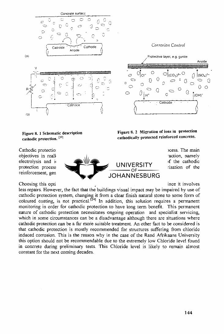
— —
I ' .•-__2 ;71
,-----_-, ,----,
,--- • • ,..,
Cathode
)b ) cJ
0 1(co 3 ) 2- ° 0 I (so 4) 2-
0 o
0 `) 0o(1) 0 Co
o 0 - 0 n t (OH)
(a)
Concrete surface
(
0
Corrosion Control Cathode - Cathode
Anode
Protective layer, e.g. gunite
Anode
V
iiiiiaiiisiioi./Z7 / ,00,7
Figure 8. 1 Schematic description cathodic protection. [391
Figure 8. 2 Migration of ions in protection cathodically protected reinforced concrete.
Cathodic protection for concrete is a permanent, lower current density process. The main objectives in realkalisation and other processes such as chloride extraction, namely electrolysis and ionic movement, are the minor, secondary effects of the cathodic protection process in concrete, where the primary purpose is polarisation of the reinforcement, generally measured as "shift" or "decay".
Choosing this option would obviously be better than the first solution since it involves less repairs. However, the fact that the buildings visual impact may be impaired by use of cathodic protection system, changing it from a clear finish natural stone to some form of coloured coating, is not practical. (241 In addition, this solution requires a permanent monitoring in order for cathodic protection to have long term benefit. This permanent nature of cathodic protection necessitates ongoing operation and specialist servicing, which in some circumstances can be a disadvantage although there are situations where cathodic protection can be a far more suitable treatment. An other fact to be considered is that cathodic protection is mostly recommended for structures suffering from chloride induced corrosion. This is the reason why in the case of the Rand Afrikaans University this option should not be recommendable due to the extremely low Chloride level found in concrete during preliminary tests. This Chloride level is likely to remain almost constant for the next coming decades.
144
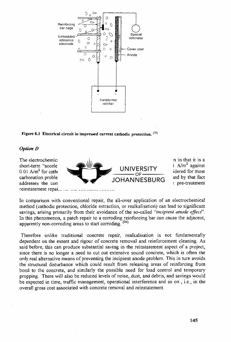
Embedded reference electrode
Reinforcing bar cage
Special voltmeter
Cover coat
Anode
Figure 8.3 Electrical circuit in impressed current cathodic protection. [391
Option D
The electrochemical realkalisation process differs from cathodic protection in that it is a short-term "accelerated" treatment operating at higher current density (1 A/m 2 against 0.01 A/m2 for cathodic protection). Realkalisation can in principle be considered for most carbonation problems. Since realkalisation is an electrochemical method and by that fact addresses the corrosion mechanism, its success does not rely on the pre-treatment reinstatement repairs for the corrosion control.
In comparison with conventional repair, the all-over application of an electrochemical method (cathodic protection, chloride extraction, or realkalisation) can lead to significant savings, arising primarily from their avoidance of the so-called "incipient anode effect". In this phenomenon, a patch repair to a corroding reinforcing bar can cause the adjacent, apparently non-corroding areas to start corroding. [26]
Therefore unlike traditional concrete repair, realkalisation is not fundamentally dependent on the extent and rigour of concrete removal and reinforcement cleaning. As said before, this can produce substantial saving in the reinstatement aspect of a project, since there is no longer a need to cut out extensive sound concrete, which is often the only real alternative means of preventing the incipient anode problem. This in turn avoids the structural disturbance which could result from releasing areas of reinforcing from bond to the concrete, and similarly the possible need for load control and temporary propping. There will also be reduced levels of noise, dust, and debris, and savings would be expected in time, traffic management, operational interference and so on , i.e., in the overall gross cost associated with concrete removal and reinstatement.
145
In addition, once carbonation has extended up to and beyond the steel reinforcement, and the passive layer is broken down, the steel reinforcement will begin to form an extensive rust, which will eventually spall the concrete cover. Without regular maintenance this can at the end cause considerable disruption and potential danger in the university environment. Unfortunately as concrete is not homogeneous, the advancement of the carbonation front towards the steel is relatively hard to predict without the regular monitoring of the whole structure through, for example half cell potential mapping. And on the other hand, those areas that have spalled are not necessary representative of the whole problem. It may be that the spalled areas only represent a n-th part of the total surface area of concrete that has corroding steel beneath, currently beyond the naked eye but still representing potential further spalls.
The owner is often therefore faced with a difficult decision to make as how best to repair the structure with the available funds. Therefore, if one considers traditional methods of concrete patch repairs of carbonated structure, it becomes readily apparent that in many cases, an electrochemical realkalisation treatment is an economic solution that provides a long term answer to the problem of reinforcement decay. However, the clear evidence of corrosion control is far more complicated to gather and, mainly for this reason, is more limited, but growing. For example, ongoing electrochemical post-treatment monitoring by Taywood Engineering in Australia has shown reduced activity of the reinforcement passivation after three years.t 271 Thus the selection of an electrochemical realkalisation must be considered with its perceived level of risk in comparison with the main alternatives, primarily traditional concrete repair and cathodic protection, each of which has its own level of risk. This risk element would be manifested as future costs of repeated patch repair, servicing computer systems, possible re-application of realkalisation, or coating maintenance. In overall terms it appears that realkalisation can offer some saving over conventional patching, and the possible attraction of not being permanently installed as for cathodic protection.
8.6.5 Feasibility issues
Now that the electrochemical realkalisation has been chosen as part of the remedial method, it becomes evident that we should examine the feasibility of the project. This includes the possible influence on concrete bond strength to plain reinforcement, whether there is a potential risk of alkali-silica reaction or not, and where there is prestressed steel (pre or post-tensioned). As alkali silica reaction can be provoked in some conditions but not in others, it was found that it is possible to suppress this problem by tailoring the extraction electrolyte with Lithium Borate additions.t 271 The issue with prestressed steel concerns the risks of hydrogen embrittlement and findings are varied. Where ducting is present, the ducting is significantly deeper than reinforcement, and steels are cold-drawn and not alloyed with chromium, risks are substantially reduced. As with any electrochemical of prestressed structures, particularly close attention to uniformity of current distribution and it subsequent control are required.
146
8.7 COST OF REALKALISATION
The first question one should ask after opting for an electrochemical realkalisation as a means to halt ongoing corrosion is what is going to be the cost? The answer is difficult to express in terms of money value because some benefits from the realkalisation treatment cannot be evaluated in figures value.
According to experience of specialists like Draper Penhall & Associated the cost of an electrochemical realkalisation treatment may be of R 1000/m 2 for small areas. It has been noticed that for small areas the specific consumption of electrolyte per square meter is about 20 litres. The cost of electrolyte such as Sodium Carbonate solution being of R 50 per litre. In order to find an approximate cost for realkalisation, it must be added to the electrolyte cost of R 1000/m2 the cost of breaking out of damaged concrete and the cost of preliminary patch repairs.
When big areas are concerned the figure of R 1000/m 2 will not apply because experience has shown that in such events the specific consumption of electrolyte is less than 20 litres/m2 . The frequent rewetting of the cellulose fibre with a recycled solution is the main contributor to this saving. In addition, big areas do not necessitate extensive concrete removal when prepared to a realkalisation treatment. Therefore for big areas a fixed price of less than R 1000/m 2 may be afforded. One of the ways to assess the cost of realkalisation comparatively to traditional concrete repair methods is to consider the life-cycle cost of repairs conducted on a structure.
The cost of corrosion protection in a concrete structure is a combination of initial, maintenance, and repair costs occurring within the projected service life of the structure. Maintenance and repair costs are generally higher than the initial costs of corrosion protection system. However, frequently only the initial costs are considered, and as a result the total cost may be higher.t 391
The use of Net Present Value (NPV) analysis can be used to estimate the present cost of a future repair. For example: for a repair that occurs in year n, the NPV is defined as:
NPV = Cost x (1=D)" (8.4)
where Cost is the price for the repair and D is the discount rate or the interest rate less the inflation rate.
The total life-cycle costs of a structure is therefore the initial cost plus the sum of the NPV of all future costs. As the discount rate increases, the cost of future repairs Iis less significant. Thus, a lowering of the discount rate results in an increase in the NPV of future repairs.
To compare the cost of an electrochemical realkalisation with the cost of rehabilitation of a structure using traditional methods, one must calculate the NPV of the future repairs and maintenance actions over a certain period. These costs will be then compared to the
147
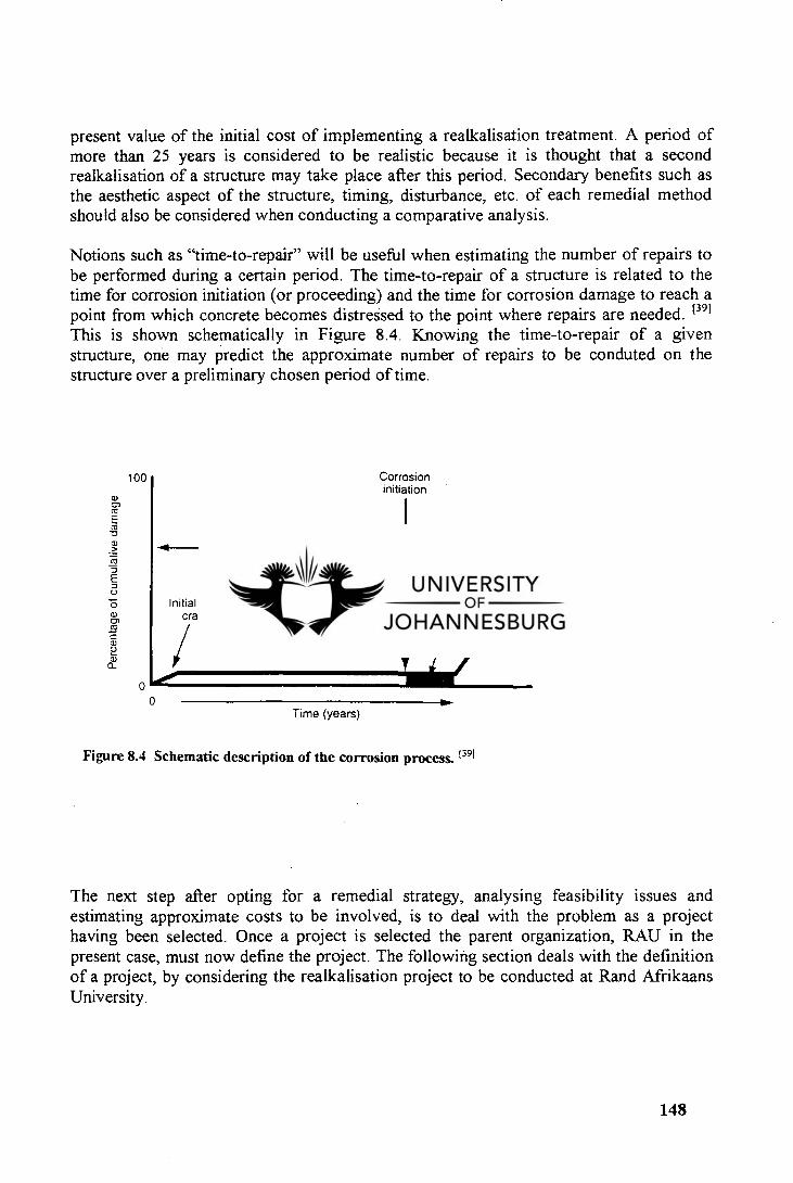
0
Per
c ent
age
of c
umu
lativ
e da
mag
e
100 Corrosion initiation
Corrosion
Corrosion products build-up
Major damage
Diffusion period
Initial cracks and crack repair
present value of the initial cost of implementing a realkalisation treatment. A period of more than 25 years is considered to be realistic because it is thought that a second realkalisation of a structure may take place after this period. Secondary benefits such as the aesthetic aspect of the structure, timing, disturbance, etc. of each remedial method should also be considered when conducting a comparative analysis.
Notions such as "time-to-repair" will be useful when estimating the number of repairs to be performed during a certain period. The time-to-repair of a structure is related to the time for corrosion initiation (or proceeding) and the time for corrosion damage to reach a point from which concrete becomes distreSsed to the point where repairs are needed. [39]
This is shown schematically in Figure 8.4. Knowing the time-to-repair of a given structure, one may predict the approximate number of repairs to be conduted on the structure over a preliminary chosen period of time.
Time (years)
Figure 8.4 Schematic description of the corrosion process. t39I
The next step after opting for a remedial strategy, analysing feasibility issues and estimating approximate costs to be involved, is to deal with the problem as a project having been selected. Once a project is selected the parent organization, RAU in the present case, must now define the project. The following section deals with the definition of a project, by considering the realkalisation project to be conducted at Rand Afrikaans University.
148
8.8 DEFINITION OF THE PROJECT
8.8.1 Project specification
The project specification is a description of the project so that all interested parties know what is planned and what the outcome should be. A project specification should include the following: [331
The title of the project. The scope. The objectives. Any conditions under which the project is to be carried out Priority. Authority.
In the following sections attempt is to define in the case of RAU project what should be the content of each one of the above aspects of a project specification.
Title
The title of the project may be the following in the situation of RAU:
"Electrochemical realkalisation of the Rand Afrikaans University's building suffering from deep corrosion of the reinforcing steel".
Scope
In its initial phase the project will be limited to those areas that have revealed a deep corrosion of rebars with an average carbonation depth higher than 20 mm (e.g. Kruisig building). This limitation is made according to the allocated funds and in order to avoid potential and imminent disaster of these buildings.
Objectives
The objectives of the RAU realkalisation project are in three-fold :
To passivate all areas already suffering from corrosion of reinforcing steel. To prevent any further advancement of carbonation front.
To maintain the expected service life of the university buildings achievable without changing neither their aesthetic aspect nor their structural strength.
Conditions
The project including all the preliminary break-out and repairs, must be carried out with minimum disturbance for the occupants of concerned buildings. If possible repair works
149
may take place and be completed totally during vacation leave, for example during Christmas holidays.
Priority
The present realkalisation project must take priority over all other repair projects around the university, except those that directly threaten the structural strength of university structures. However, other small projects involving repair works such as simple patch repairs which are not demanding big amounts to be spent, may take place simultaneously.
Authority
The authorisation for the project should be stated by Rand Afrikaans University management and the authority of people working on the project should be defined. In this specific case, instead of giving to one person sole responsibility for planning and executing the work, a team of people must be appointed and the authority for particular part defined. The authority for making decisions at different stages is defined at the start.
8.8.2 Implications of the project
Implications of the project include the benefits expected from the project and the cost thereof. In the specific case of RAU, benefits may be expressed in terms of service life, safety and aesthetic aspect of the university buildings. The cost of the project will be examined in the section 8.7 of this study.
8.8.3 Constraints on the project
Constraints on a project are the factors that restrict what can be done in the project. Typical constraints may come from deadlines to be met or the level of funding to be rose or other forms of resource available, e.g. people, equipment, etc. The university should identify all constraints that may slow down or simply stop the project. RAU realkalisation project is now beyond the schedule because too much time has been spent by the university to identify which repair mortar was suitable for repair around the university. This should have been done during the initiation phase of the project, i.e., during preliminary and secondary investigations called by the RAU management.
8.8.4 Project proposal
The project proposal is the document that brings together all the information about the project so that it can be accessed by other people. [331 The proposal must include the project specification, the cost, the justification, any constraints, and a project plan. The preparation of the latter has been discussed in the section 6.3 of the present study. Project activities, milestones, Gantt charts, critical path analysis have to be defined and analysed in the project plan. The first part of this chapter has dealt largely with all these notions.
150
8.9 QUALITY ASSURANCE (QA) AND QUALITY CONTROL (QC) DURING A REALKALISATION TREATMENT
In South Africa, Quality Assurance is defined in SABS 0157 (ISO 9002) as: "all those planned and systematic actions that are necessary to provide confidence in the achievement of the required quality". Unfortunately, all too often, the necessary systematic actions do not include Quality Control or "hands-on". The common belief is that, provided the QA documentation looks good, all is in order. It is only when a problem arises that it is realised that the necessary QC records in fact do not exist. [34]
Quality must be agreed and quantified before starting the project. Quality Assurance can be controlled from inside or outside of the project. External and internal inspection points should be implemented to warrant the quality. External points are those required by the law and internal points ensure that quality standards remain acceptable. In other words QC is the "hands-on" activity of confirming. that the applied treatment meets the specification requirements and QA is a surveillance and documentation checking procedure. The correct implementation of QC and QA activities decreases the likelihood of a failure, and provides the following:
Traceability : in the event of failure, enables the cause or causes to be identified.
Record keeping : identification of the relevant information recorded in a concise manner : Material batch records, ambient conditions, concrete repair, surface and substrate preparation, records of specific tests and measurements, etc.
Method statement : details each activity to carried out during the job. Each activity should be supported by a detailed procedure for that activity.
Witness and hold points : Before commencing any work a witness and hold point should be drawn up by, the contractor in consultation with the client's engineer. This schedule should detail the inspection requirements of each activity, listing whether it is a witness or hold point, and defining the responsibilities of the various parties at each stage of the work.
Quality plans : All requirements, from preparation and job activities to final inspection and acceptance /rejection, can be summarised in a quality plan which tabulates the activity, acceptance criteria, additional criteria and witness and hold point responsibilities.
Inspection and methods : includes typical activities that should be inspected must be listed and the standard test methods adopted defined.
151
Data books : On completion of the job, the contractor should provide the client's engineer with a data book containing all the relevant quality and records pertaining to the works.
8.10 TENDERING AND CONTRACT
At this stage the project has been selected, defined. Implications and other coditions have been analysed. Quality standards and performance have also been defined and fixed. The next step consists of finding the "best" contractor to whom the project may be given for excution. The process of looking for and selecting the contractor is called tendering.
8.10.1 Tendering
Consists of producing documents which summarizes the output from the conceptual phase of the project. this document must contain the following:
An introductory overview of the project. The overall quantified objectives and purpose of the project. The deliverables ( requirements in terms of output and quality). The probable project limitations (time, money, people, materials. etc.). The project constraints. The required timing for the project, etc.
This document must be widely spread by the Client ( RAU in this case) in order to get many propositions from probable contractors.
Following the tendering is the evaluation which is a stage during which tenders from different contractors are examined, analysed and evaluated according to criteria defined by the tenderer himself. After evaluation, the project is awarded to the contractor who met closely the requirements of the tender.
Although it is possible to nominate specific subcontractors for specialist work it is generally regarded as advisable to avoid doing this since it can cause complications in administering a contract, in the event of a nominated sub-contractor defaulting or causing delay in some way. [35] Nevertheless there are items where the Client will wish to restrict the choices made by a main contractor.
8.10.2 Contract documents
Contract documents consist of drawings, a specification of the project, conditions of contract and bills of quantities. It is also becoming general practice to issue bending schedules to tenderers, which has the effect of giving them the status of part of contract documents since they then become information on which the contractor bases his tender. [35]
152
Drawings are the primary vehicle for a designer to communicate his intentions to the people. it is important that the impression they give is clear unambiguous and yields the required information without prolonged searches.
For drafting specification clauses two distinctive approaches can be made. The method of working or a description of the required end product. Contractors prefer the latter "performance" type of specification because it leaves them freedom of choice in their way of working. A "method " specification does not of itself guarantee the quality of the end product, since it is quite possible to do a job the right way but badly.E 351 A performance specification is appropriate when the objectives can be clearly defined. The weakness of a performance specification occurs where it may be extremely difficult to describe a standard of quality - like a concrete surface.
Conditions of a contract are generally regulated by laws from the government or from the institution that controls civil engineering works (e.g. The Institution of Civil Engineers). However when third parties are involved in a contract, it becomes necessary to include additional conditions to meet their requirements.
Bills of quantities are documents containing quantities of various resources used during a project. These documents are established in conformity of the principle of the " Standard measurement for civil engineering quantities " which is based on the initial premise that every item relates to completed work and includes all materials, labour, plant and other cost involved.
A full set of contract documents normally includes the following items:
Instructions for tendering Location and brief description of the works Collusive tendering certificates Form of the tender Forms of bond Conditions of contract
- General conditions of contract Special; conditions of contract
- Variation of contract price - Noise control - Traffic control
Diversion of public utilities Special requirements in relation to:
Central electricity board - Area authorities, etc.
List of drawings Specification
Reference to standard specification - Additional and revised clauses
Bills of quantities
153
Preambles Bills General Summary
8.10. 3 Planning scheduling
The scheduling of resources must be done during the initiation phase of the project. A document known as the project schedule contains the following
A synopsis of the project (why the project was conceived). Functional project maps (showing contractors and sub-contractors involved in the development of the project). The necessary conditions for success project maps (what, why, when). Critical monitoring points (and actions to be taken if any of them fail to be met). Gantt charts, resources usage histograms for human and material resources. Financial reports of overall cost broken down by sub-project with cash flows. Explanations where necessary of how activities will be done, the contract itself ready for signing.
8.11 REA LKALISATION PROJECT IMPLEMENTATION
8.11.1 Installation design
After the initial structural assessment, selection of repair strategy, feasibility appraisal and definition of the project, the treatment configuration and layout must be planned. Configurations include using sprayed fibre electrolytes or liquid electrolyte tanks. The layout of treatment zones is based on reinforcement density, likely operating currents, and structure geometry. [261 Practical considerations of access/configuration can also prevail in unusual circumstances. From this follows choice of materials, anode type, electrolyte, and control facilities. Areas where cover concrete has already spalled or delaminated must be repaired in advance, since electrical shorts to the reinforcement must be avoided. The process parameters and performance criteria need to be set. The post-application treatment such as coating application must also be identified.
As for any properly executed traditional repair or cathodic project there are many design and specification issues that need to be addressed:
Current provision and uniformity. Reinforcement connections and their distribution. Cabling and power supplies. Monitoring and control. Documentation.
An appropriate system for managing before, during and after the treatment should also be considered.
154
8.11.2 Survey
Following installation design, the physical implementation of the project must realised. However, it is always recommended to carry out structural and condition test as close as possible of the beginning of the remedial repairs in order to work with recent information giving the real condition of the structure. This the reason why we include in the present section at this stage.
Survey includes the determination of :
The cause or origin of the problem (concrete deterioration). The extent of the problem. The concrete cover. Cracks, spalls, delamination and other effects. The location of metallic features.
Concerning the cause of the problem at RAU, it has been found from previous works that most serious concrete deterioration is due to carbonation-induced corrosion of the reinforcing steel. (311 Carbonation front measured by phenolphthalein method, are found to be in the order of 20 mm while almost 60 % of the measured reinforcing steel cover was found to be less than 20 mm. These two factors have led to cracking and spalling prevailing on most external facades where sufficient moisture is present to drive the corrosion reactions. Algae and fungal growth are also found on certain shaded areas exposed to moisture on a regular basis.
It also has been found that corrosive problems are concentrated at areas where low quality concrete is evident. Where signs of inadequate compaction, honeycombing or low cement content were visible, carbonation was found to depths of up to 45 mm due to poor quality of concrete.
The extent of the problem were determined by means of complete surveys of all concrete facades of the university, using the following survey techniques:
Stray current survey. Electro-potential mapping. Covermeter survey. Carbonation depth survey. Chemical analysis. Visual inspection. Audio-testing (steel hammer and tapping device).
The cost of using all these techniques is obviously a big concern because including the cost of erecting scaffolding and other access systems, the cost of using specialised and sophisticated instruments and products, and the cost of employing high calibre skilled people and engineers.
155
8.11.3 Preparation prior to installation
The key points during this stage include the following:
The removal of all cracked and spalled concrete. The establishment of a full rebar continuity. The establishment of a sufficient concrete cover. The insulation or removal of metallic features. The patch repair of all cracks, spalls, delaminations etc.
8.11.4 Installation and treatment
8.11.4.1 Installation
Installation for realkalisation includes :
The anode system installation. The connection of leads to the metal mesh. The installation of electrolyte circuit and reservoirs.
The anode system as said previously consists of a steel mesh embedded in an alkaline reservoir temporarily applied on the concrete surface. Choice may be made between two types of anode system, a mild steel mesh or titanium mesh. The steel mesh has the following as advantages:
Low cost. Disposable. Easy installation. Eliminates chlorine production.
Among disadvantages related to the steel mesh, the following may be retained:
- Rust staining. May require replacement mid-project
Electro-catalysed titanium mesh has the following advantages:
Practically inert. No rust staining. Will not require replacement mid-project. Can often be reused.
Disadvantages associated to the use of a titanium mesh are:
Higher initial cost. Surface etching possible.
156
- Chlorine release.
When the mesh is in place, a specially formulated cellulose fibre is sprayed directly onto the concrete surface together with a liquid electrolyte. The cellulose fibre acts as a reservoir for the electrolyte, which is an alkaline solution. Depending on the site characteristics a choice is possible between various electrolytes such as sodium carbonate, tap water, calcium hydroxyde solution, lithium carbonate or borate solution, etc. Three types of reservoirs are commonly used, namely sprayed-on cellulose fibre, coffer tanks, and felt cloth. The anode system may be applied to all types of concrete surfaces: horizontal, inclined or vertical, regardless of shape, profile surface condition or architectural detail.
8.11.4.2 Treatment and monitoring
The treatment during an electrochemical realkalisation process includes the following:
Connection of leads to a rectifier. Adjustment and regulation of current flow. Checking of voltage and current flow. Regular rewetting Analysis of concrete samples.
Leads to the rebars are connected to the negative pole of an AC/DC rectifier. Leads to the anode mesh are connected to the positive pole. A voltage is applied and adjusted to give a current flow of approximately 1 A per m 2 . The rectifier automatically adjust the voltage to maintain the required current output. Voltage and current flow are checked regularly and fresh electrolyte sprayed onto the fibre reservoir when necessary. Concrete cores may be obtained and examined on site using the pH indicator phenolphthalein to determine when carbonated concrete is sufficiently realkalised. The treatment takes typically less than one week depending on the surface and the extent of carbonation. Monitoring of the treatment may also be performed by computer systems as described in the section 7.5.3 of the present study.
To keep the project on track, the contractor has to develop a list of events which, when monitored, would give him an instant indication of whether the project is about to run into trouble with its constraints. These events include the control of the following :
Cost control: overtime hours expected on specified activities, material cost expected. Scheduling control: material arrival dates, time expected for each specified activity, a selection of milestone nodes on the critical path and their completion dates. Production control: manpower prestation, productivity, reliability of equipment. resources control: effective allocation of people, material and equipment on each activity.
157
8.11.4.3 Contract supervision
Normally an Engineer's representative is appointed in order to supervise the work on the site. It is important that he should have a clear understanding of what is expected in this role. The realkalisation project at RAU being a substantially-sized contract, we think that it should involve a residents engineer's staff of Section Engineers, Assistant Engineers and Inspectors.
Resident Engineer's duties
The objective of the Resident Engineer and his staff should be to ensure that the works are completed in accordance with the contract documents, and to keep the Engineer fully informed on all relevant matters. [351 Their basic terms of reference are the specification, contract drawings, conditions of contract and bill of quantities.
Safety
One area of potential confusion on civil engineering sites is the question of responsibilities regarding safety. under the civil engineering contract between the contractor and the employer, responsibility for the safety of all operations on the site rests with the contractor. [35
Site meeting
The Resident Engineer should call and take minutes of site meetings at regular intervals. The general purpose of such site meetings is to provide a regular opportunity for the contractor and for the contractor and the engineer to monitor jointly the progress of the project, and record items of contractual importance or interest.
Approvals
On commencing the works the contractor is require to produce a programme setting out the sequence in which he intends to tackle the work and giving sufficient details to enable the Engineer to make a reasonable assessment of whether it is in fact an appropriate sequence of operations compatible with related job requirements and that can reasonably be achieved within the contract period.
8.12 REALKALISATION PROJECT TERMINATION
8.12.1 Dismantling
Dismantling is the step coming after the treatment has been declared completed according resistance curve monitoring and chemical testing of cores. The main actions during the dismantling operation can be summarized as follows:
• AC/DC convertor is switched off.
158
All leads are disconnected. The anode system is removed. The surface is cleaned. The structure is left to dry.
Once the treatment is completed the rectifier is switched off . cables dismantled, and the anode system removed. The concrete surface is washed with generally high pressure warm water and left to dry before application of a protective coating if defined during the design phase of the project. It is interesting to note that due to the high hydroxyl content around the steel and the possible conversion of the sodium carbonate into sodium bi-carbonate with time, the concrete surface does not necessarily warrant the use of an anti-carbonation coating, since sodium bi-carbonate has a high pH value, above at least the point at which passive oxides around the steel begin to break down. L 251
8.12.2 Project auditing
This process includes the following:
Final quality checks. Testing of finished product. External inspection. Timing achieved. Expended budget, etc.
At this stage RAU may appoint external auditors/consultant in order to evaluate if the output of the project really meets its requirements.
8.12.3 Post -treatment analysis and maintenance
After dismantling of all the system installed for electrochemical realkalisation, the treated concrete needs to be analysed in order to determine the effect of the treatment. This carried using the following tests:
pH indicator phenolphthalein. Sodium and Potassium analysis if a quantitative value is required. Chlorine analysis.
On structures in severe environments, it is recommended to install reference electrodes (e.g. Norcure reference electrodes) to monitor the stability of the treated concrete. [231 The precaution of providing surface coatings against re-carbonation may also be considered as a means to maintain the infrastructure in good environmental conditions. However, the concrete surface should be allowed to dry and a compatible material must be chosen.t 241
159
CHAPTER 9
CONCLUSIONS
The current study is subdivided into two main parts. The first part addresses concrete as a building material widely used in the civil construction. Its composition, characteristics and the various ways for its protection are the main topics discussed early in the study. Immediately after the introductory part, analysis of deterioration processes of concrete and means of investigation causes and effects of concrete degradation follow. Condition survey, diagnosis of defects in concrete structures and related methods and equipment are finally examined in the first part of the study. The main objective of such an approach is to provide for any building structure owner sufficient knowledge and background that may be helpful in drawing up an effective repair programme for a concrete structure suffering from any form of degradation.
When a building owner reaches the stage of establishing a repair programme for its asset, two important decisions must be taken. Firstly, selection of an appropriate repair method must be made in accordance with the level of damage encountered in the structure. Secondly, suitable repair materials must be determined and used in this particular circumstance in order to warrant success of the repair operation and ultimately halt the deterioration progress.
Several alternative options have to be considered. The first approach may be oriented towards traditional repair methods involving a thorough break-out of deteriorated concrete, followed by patch repairs with materials selected among a wide varied range of existing and approved repair materials. A second alternative may be to opt for an electrochemical treatment consisting of a cathodic protection, a desalination or a realkalisation, depending on the causes of the damage, the extent of the problem, and other constraints such as aesthetic aspect of the building, available funds, expected remaining service life, availability of technologies and skills, etc.
As a case study, the second part of the present study examines the problem that the Rand Afrikaans University management is facing in what is considered to be an early degradation of most of main campus buildings just after 20 years of service life. After investigation by both internally and externally appointed consultants, it was noticed that the main causes of structure degradation at RAU may be subdivided in four main groups. The university management should address each group separately and find specific and unique solution suitable for each group
Spalling and delamination due to an advanced corrosion of concrete reinforcing steel is among the main causes of RAU buildings degradation. To halt this ongoing corrosion and reinstate the alkalinity of concrete which is the condition for the reinforcement to be in a passive medium that can prevent any corrosion, the electrochemical realkalisation seems to be one of the repair strategies that should be considered. The prevailing conditions and
160
the compliance with the expected service life of the buildings which is of hundreds of years should be both considered during the decision phase.
This is the reason why the second part of the study is mainly dedicated to the electrochemical realkalisation as a project to be managed by the Rand Afrikaans University in the near future. Preliminary survey and testing have been already conducted by both internal and external consultants. The choice of this method as the remedial strategy is dictated by the present condition of the main building structures as well as by selection criteria suggested by the European Standard for Protection and Repair of Concrete.
After a theoretical, economical and environmental analysis, it has been advocated for the Rand Afrikaans University's concrete problem an electrochemical realkalisation treatment combined with small patch repairs. The reason is that the use of realkalisation combined with limited patch repairs has many chances to provide as for other many cases around the world, a cost effective, long term repair solution on these RAU particular structures, especially when one considers the other, perhaps non-building problems of structure borne noise pollution and disruption levels in a fully occupied, restricted site such as the Rand Afrikaans University.
In most cases the method competes well in terms of cost with both traditional repair techniques and cathodic protection. Nevertheless there are limitations to the cost-effectiveness of the method, the general rule being to treat the affected structure at as early a stage of damage development as possible. Vastly reduced concrete break-out means that fixed prices can be offered.
However, it remains obvious that for areas that do not present any structural danger for the university environment, traditional patch repair methods should be considered and largely used, as long as the selected repair materials may comply with the technical and economical considerations and the aesthetic aspect of buildings as a whole. Colour matching between old and new concrete should be a great concern for building as universities for this reason that they are called to be a motif of pride, not only locally but world-wide. The cathodic protection could also be a competitive alternative but it is not favoured because of its almost permanent nature necessitating ongoing operation and specialist servicing.
The pending question regarding electrochemical realkalisation is the durability of concrete after treatment. For that it is said that there is no substitute for experience. The more projects involving realkalisation will receive subsequent checks, preferably by independent organisations, the more rapidly confidence can grow.
There are some concerns that, with widely-spaced reinforcement, "blind spots" could be created between bars which, with time, could lead to redistribution of alkali, possibly influencing corrosion conditions. Data from closely monitored trials, however, is encouraging [27] .
161
According to many researches, there is also evidence emerging that the Sodium Carbonate product formed when used as electrolyte in a realkalisation treatment, is stable and that no significant loss of Sodium has been found even after five years. [271 Whilst such technical assessments continue, the precaution of providing surface coatings against re-carbonation may still be considered.
162
REFERENCES
1
Noel P. Mailvaganam, "Repair and protection of concrete structures", Institute for Research in Construction, National Research Council of Canada, Ottawa, Ontario. CRC Press, Bocaraton Ann Arbor, London, 1992.
ACI Publication SP - 19, cited by N.P. Mailvaganam in "repair and protection of concrete structures".
3 G.J. Verbeck, "Carbonation of hydrated Portland Cement", ASTM Special Technical Publication, N° 235, 1958.
4. Philip H. Perkins, "Repair, protection and waterproofing of concrete structures", Elsevier applied science publishers Ltd, 1986.
5 Grahm West, "Alkali-aggregate reactions in concrete roads and bridges", Thomas Telford Publications, 1996.
Y. Ohno, S. Praparntanatorn & K. Suzuki, "Influence of cracking and water cement ratio on macrocell corrosion of steel in concrete", published in "Corrosion of reinforcement in concrete constructions"
Kinnear, R.G., "Concrete surface blemishes", Cement and Concrete Association Rep., Slough, UK, 1979.
Shilstone, J.M., "Surface blemishes on formed concrete", Concrete construction, 23, 735, 1979.
Anon, "Identification and control of consolidation related defects in formed concrete", Rep. N° ACI 309 2R - 82, Concr. Int., 982.
J. Gulikers and E. Schlangen, Delft University of technology, Netherlands, "Numerical analysis of galvanic interaction in reinforcement corrosion", published in "Corrosion of reinforcement in concrete construction".
Ted Kay, "Assessment and Renovation of concrete structures", Concrete design and construction series, Longman Group UK Limited, 1992.
M. Raupach, Bauingenieur Sozietat Aachen, Germany, published in "Corrosion of steel in the area of cracks in concrete", Corrosion of reinforcement in concrete constructions.
163
ACI Committee 437, "Strength evaluation of existing concrete buildings, American Concrete Institute, Detroit, 1985.
Menzies J.B., "Load testing of concrete building structures", The structural engineers, 54 A (12), 1978.
Institution of Structural Engineers, London, "Appraisal of existing structures", 1980.
K. S. Yeon, K.W. Kim, J.D. Choi and K. S. Kim, Department of agricultural engineering, Kangwon National University, Chunchon, Korea, "Research trends of concrete polymer composites in Korea", Polymers in concrete, proceedings of the second East Asia symposium on polymers in concrete, College of engineering, Nihon University, Koriyama, Japan, May 11-13, E & FN Spon, 1997.
John C. Ropke, "Concrete problems, causes and cures", Mac Graw-Hill Inc., 1982.
P.L. Domone, "Construction materials, their nature and behaviour", Part three, "Concrete", edited by J.M. Illston, Consultant and Professor Emeritus, University of Hertford, 1994.
CSA Technical Committee on Repair of Concrete Buildings, Draft 1, 1989.
J.T. Grundy, "Construction Technology, volume 2", published by Edward Arnold, a division of Hodder Headline PLC, London, 1979.
Rilem Report 14, 'Durability design of concrete structures", edited by A. Sarja and E. Vesikari, Technical Research Centre of Finland, Esppoo, Finland, 1996.
G. Sergi, R.J. Walker and C.L. Page, " Mechanisms and criteria for the realkalisation of concrete", Department of civil engineering, Aston University, Aston Triangle, Birmingham B4 7 ET, UK, 1996.
John B. Miller, International Technology Manager, " Electrochemical concrete repair", NCT, Construction Repair, December 1995.
"Norcure Realkalisation", a FOSROC's brochure, 1996.
Nigel Cox, "Realkalisation of precast panels for British Telecom, outlines the development of a repair strategy at a British Telecom Plc central telephone exchange, using the Norcure method and yellow pages", Construction Repair, July/August 1995.
164
26. FOSROC's brochure, "Norcure realkalisation", brochure 1994.
27 David Pocok, Taywood Engineering Ltd, "Chloride extraction and realkalisation, six years on", Corrosion and Protection of reinforced concrete Conference, Dubai, 10 - 11 October 1994.
"Realkalisation, case study : apartment building in Blindernoveien", Construction Repair, November/December 1995.
Gun E. Nustad and Moira Decter, " Desalination and realkalisation, the mechanisms and the advantages of electrochemical repair".
J.S. Mattila, M.J Pentti and T.A Raiski, " Durability of electrochemically realkalised concrete structures", Tampere University of Technology, Structural Engineering, Finland 1991.
Deon Kruger and Prof. Piet Pretorius, Department of civil engineering, Rand Afrikaans University, "Rehabilitation of concrete : the owners dilemma", Johannesburg, RSA, March 1996
P.0 Pretorius and D.J. Penhall, " durability aspects related to off-shutter concrete at Rand Afrikaans University: A case study ", 23 January 1995.
Gail Freeman, Bell and James Balkwill, "Management in Engineering", Prentice-Hall International UK (Ltd), 1993.
Colin E. Alvey, Corrosion Advisory Technical Services, " Quality Assurance and Quality while applying protective coatings", Mechanical Technology, December 1996.
E. Pennells, " Concrete Bridge Designer's Manual", Whitefriars Press Ltd, London and Tonbridge, 1981.
Sidney Mindess and J. Francis Young, "Concrete", Prentice-Hall, Inc., Englewood Cliffs, NJ 07632, 1981.
P. Kumar Metha and Paulo J.M. Monteiro, "Concrete, structure, properties and materials", second edition, Prentice-Hall, Inc., Englewoods Cliffs, NJ 07632, 1981.
"Prediction of concrete durability", Proceedings of STATS 21st anniversary conference, edited by J. Glanville and A. Neville, E & FN SPON, Chapman & Hall, London 1997.
165
Arnon Bentur, Sydney Diamond and Neal S. Berke, "Steel corrosion in concrete, fundamentals and civil engineering practice", E & FN SPON, St Edmunds press, Great Britain, 1997.
"Corrosion of reinforcement in concrete", edited by C.L. Page, K.W.J. Treadaway and P.B. Bamforth, Papers presented at the third international symposium on "corrosion of reinforcement in concrete construction, held at Belfry Hotel, Wishaw, Warwickshire, UK, 21-24 May 1990.
A.M. Neville, "Properties of concrete, fourth and final edition", John Wiley & Sons, New York, 1997.
R.T.L. Allen and S.C. Edwards, "The repair of concrete structures", Blackie & Son Ltd, 1987.
Jack R. Meredith and Samuel J. Mantel Jr, "Project management, a managerial approach", third edition, John Wiley & Sons. Inc., USA, 1995.
166
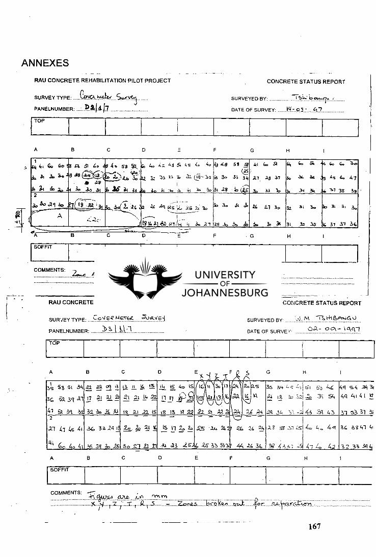
167
M "Th14-16FrrsiG SURVEYED BY:
oc\ - lggl DATE OF SURVEY.
A B C D X "T" F s G
H
A B C E F H
SURVEY TYPE: CcV cQ 14€1-C=4
PANELNUMBER: 3 I 10
5oo..ve-1
1 , 38 'a-3 5 1 3iI
36 02 3ct xi
Z.
17
22 2.9 .'I
21 '.-1 21
I;
521
II 14,
21 14 22-
1 1-i
11
15
11
40 iS
2 IG 111
l c I
3z.\1 11
t ' i:,
•
4 '9.0\2,5
I 4 a v q
35
;'. ,' I
34
18
--;-. -"--_, 61 .S3 46
--- :•2 .;:.' 54
4c1 54 3ii
4c1 Lti 4 i It_
4/ Ea Yi 2 3; A Al is li .21 is 1_13 is ri 2.2 Z2 l'i A2 A a.14 2-6 ;24 .2-1 34 .--: -.114 --.1 4 3 31 .53 31 & 2 - - - - - --1- - -
X-1 41 4s 41 3.6 32. 24 IS 2-,0 .2z. 21 14, Is 11 20 ti ZS ' 2.4 2427 :26 26 .`24 :L? . _y: -.51 L. i, o 42. a‘ 33 41 41
Lii too 44, 4i _65 3c1 25 30 2.1 /1 11 A4 as -a 64 xS 33 3117 44 .,.6 a, w 4:7, 4.3 -'..S 47 .Z, 4,2 3 2 31 -3e? Le
"(IA rn
t. . i • _5 N2,5 17C0kz2-A cria 4r Yria.Tn
COMMENTS: --7
SURVEY TYPE: e$‘0t- hufs.d S,AA-
DATE OF SURVEY:
SURVEYED BY: t can.
IU 03 -
RAU CONCRETE REHABILITATION PILOT PROJECT
ANNEXES
RAU CONCRETE REHABILITATION PILOT PROJECT
PANELNUMBER: Dal& 17
F B C D H A G
F H B C D G 4fF
A
1 A in Go Go
3,, A 32. 26'8
.ia 31 6, • 0 2.
a a 61 40 ag
. , AS
AV
4 30 3,5 oil
4e 58 *I,
1.4 ,...2. 2).tir, t„tz
i2 le II 3•1 .
as Z. 4.7.. AS 5, 45 4. 40
32 33 33 i a ( 19 'Is
zu a. 3i .1.. 13. ;i So ::.
43 49
i3 3.
31 28
58
3;
52
(4.5
34
(c
41
.7.7
,
66
2.5
:53
SI
37
3.
64
&
-;
C.
3/'
34
Si 46
36
34 36
6.
145
-.1
6.
6..
38
3.
47
3" 2
jo 40 .19 ID I8 -09.1 1 L ,.tc ja
-
____ -24 Aci azs ;.;., „Ya• xi -3. ■•
32. 30
29 .10
44
.3,
'3'
ci,
.14
So
4-1
3,
30
31
3z
3;
3i
3:, Is
34
3.7
3i
37
&
36
----- A >,
4...2.z_. ,----... 1
1816,21.30 al.ii.: i, .3. 2.1
TOP
CONCRETE STATUS REPORT
CONCRETE STATUS REPORT
TOP
SOFFIT