comply with asme code during early design stages
TRANSCRIPT
H&rr
Comply with ASME
Code During Early
Design Stages
Compliance with
the ASME Code
during the thermal
design phase
assures that the
final sheUranMube
heat-exchanger
design is accurate
and minimizes lost
time and labor
for making
revisions later.
'. -',:K,iGabriel Aiiriqlesr ,
The classical division between
thermal design engineers and
mechanical design engineers is
becoming blurred. Tools are
now available that enable the design en
gineer to perform an integrated ther
mal/mechanical design calculation.
Traditionally, the process engineer
'would design the heat exchanger to
.meet process requirements and then
transfer the basic exchanger geometry
. ; to a mechanical engineer for detailed
,;•. mechanical design. The mechanical en
gineer would apply construction code
: 'rules, such as those established by
;;ASME and, by the Tubular Exchanger
; Manufacturers Association (TEMA),
.: • and check for overstress conditions
,;;)Caused by., thermal and other stresses
(longitudinal, compressive, etc.). In
. many cases, a change was initiated by
the mechanical engineer that would af
fect the thermal design. If the mechani
cal; engineer recognized this, the change
. would be sent back to the process engi-
; neer for review. This "work-in-
prdgress'rb transfer would be repeated
r..^several times, wasting time and money
3H.ca?Twith each transfer.
^kra • With;; recent improvements in com--^puterized design tools, we now have the
ability to ,do a "once-through" thermal
and mechanical design, resulting in sig
nificant cost savings. A project engineer
with the appropriate tools can now over
see the design process from thermal de
sign to mechanical-design without cost-
.... ly.JbackVand-forth. movement of data.
; v^Y-This procedure can-also, be extended to
vendors, thereby saving a significant
amount of time sending, receiving,
checking, and re-sending design data.
Shell-and-tube
equipment design
A successful shell-and-tube heat-ex
changer design includes many aspects:
thermal design, mechanical design, ex
ternal piping loads, seismic loads, wind
loads, support design, cost estimation,
drawing generation, and so on. The
ASME Code (as well as other construc
tion codes, such as AD-Merkblatter
[Germany], Code Francais de Construc
tion des Appareils a Pression (CODAP)
[France], and BS 5500 [U.K.]) plays an
important role in the completion of
many of these analyses.
Many studies have been conducted
on the thermal optimization of heat ex
changers. For instance, Steinmeyer sug
gests that there are over 500 publica
tions on the subject of heat-exchanger
optimization (1). However, true opti
mization not only encompasses the ther
mal design portion, but also mechanical
design. In selecting an optimum heat-
exchanger design for a particular ser
vice, many issues need to be considered,
including the following.
Geometry. The best configuration
for a given process is sometimes diffi
cult to select. For example, a distillation
column reboiler can have either forced
circulation (using a pump) or natural
circulation (where the fluid density is
the driving force), and within these two
categories, the reboiler can be horizon-
CHEMICAL ENGINEERING PROGRESS • JUNE 1998 • 45
ENERGY TRANSFER/CONVERSION
tal or vertical, with or without a re
movable bundle, and so on.
Vessel shapes also contribute sig
nificantly to the cost of the unit. In
general, flat components (e.g., a flat
head) will be several times thicker
than curved ones (e.g., a formed
head). Therefore, unless there are
reasons to specify flat components
(such as for easier access to inter
nals), it is always better to specify
curved ones (2).
Maintenance. It is important to
consider cost reductions throughout
the life of the equipment. For exam
ple, ease of maintenance is very im
portant in high-fouling environ
ments where frequent cleaning is re
quired. Fouling can often be mini
mized by maintaining high fluid ve
locities and avoiding stagnant fluid
regimes. Other considerations in
clude the selection of the most ap
propriate method for cleaning
(chemical or mechanical, off-line or
on-line, etc.) and establishing
whether the tube bundle needs to be
removed to be properly cleaned (3).
Vibration. Vibration or excessive
velocity can occur even in an ex
changer that has been designed for
optimum operation and maintain
ability. In many cases, the type of
baffling or baffle spacing (or both),
tube layout, or tube dimensions may
have to be modified to avoid these
problems. For example, using more
longitudinal flow will decrease fluid
velocities and reduce the probability
of vibration. These changes require
redesigning the unit to establish the
optimum process design that also
avoids these problems.
Erosion-corrosion. Erosion-cor
rosion can decrease the equipment's
operational life. One method to
avoid excessive erosion is to main
tain fluid velocities below an allow
able maximum. Erosion effects are
also important in corrosion chem
istry. Changes in oxygen concentra
tion, as well as the destruction of
protective layers, are other conse
quences of erosion attack (4).
Suitable materials of construction
and protective covers can be select
ed to minimize corrosion attack and
reduce costs. For example, cost sav
ings of over 50% have been realized
using alloy-clad materials rather
than solid alloys (5). In addition,
care should be taken to avoid exces
sive thermal stresses caused by
welding metals with different ther
mal expansion coefficients.
Mechanical design —
the ASME Code
The ASME Code was established
by the American Society of Me
chanical Engineers at the turn of the
century to standardize boiler design
because of frequent boiler explo
sions. The current edition is the
1995 ASME Boiler and Pressure
Vessel Code. The section of interest
to shell-and-tube heat-exchanger de
signers is Section VIII, Rules for
Construction of Pressure Vessels,
Division 1. This is the primary stan
dard used for vessel mechanical de
sign in the United States.
What can go wrong?
Performing mechanical design
independently from thermal design
can result in an exchanger that does
not perform as expected. Two main
types of problems can occur:
• changes initiated by mechani
cal design that require adjustment to
thermal design; and
• mechanical design criteria that
can significantly increase cost.
Changes that
require more changes
Changes made by the mechanical
designer that necessitate thermal de
sign adjustments include:
1. Tubes that will not fit into the
stated diameter. This can occur be
cause (a) a minimum tolerance is re
quired for mechanical construction
(for example, for TEMA T or S rear
head types), (b) a high tubeside de
sign pressure reduces the available
outer tube limit (OTL) calculated
during the thermal design, (c) the
inside diameter was used for ther
mal design but an outside diameter
criterion had to be used for mechan
ical design due to the product form
(e.g., pipe vs. plate), or (d) the out
side diameter was used for thermal
design and the resulting wall thick
ness calculated in the mechanical
design reduces the number of tubes
that will fit in the shell.
2. Additional tube supports added
to stiffen the rear end of bundles
with floating heads or U-tubes (6).
3. Shellside nozzles that are
moved due to construction require
ments, such as mechanical rein
forcement rules, hub flanges clear
ances, etc.
4. Mechanical design changes,
such as a different exchanger type,
different materials, closer baffle
spacing, or different tube dimen
sions, to accommodate the differen
tial expansion of the shell and tubes
in fixed-tubesheet exchangers.
5. Mechanical design changes to
reduce excessive thermal stresses in
one component due to the large tem
perature gradients, for example, the
tubesheet in multipass units.
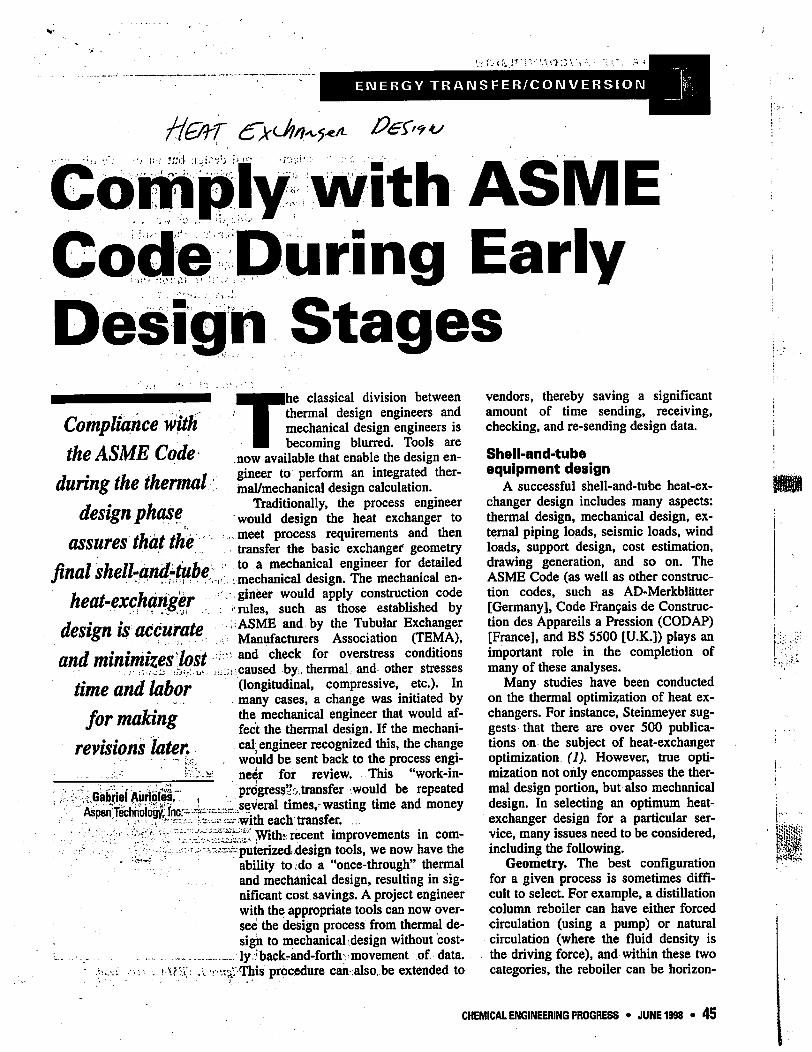
Tubes will not fit — TEMA T
or S rear head. If the tubeside or
shellside pressure is such that the in
side floating head is relatively thick,
the tube bundle will not fit in the
original outside diameter (Figure 1).
Floating Head
Shell Cover
I Figure I. TEMA T rear head.
46 • JUNE 1998 • CHEMICAL ENGINEERING PROGRESS
Y <•» n 75 W 3
This . occurs because the floating
head design is very sensitive to
pressure, as it is subject to both in
ternal arid external pressure loads.
Tubes will not fit — O.D. vs.
I.D. If the product form is pipe but
the unit was thermally designed to
use plate, the number of tubes may
not fit. The mechanical portion of
the design software will calculate
the required wall thickness. If this
wall thickness is significant and the
design proceeds inward from the
outside diameter, the resulting in
side diameter may not be large
enough to contain the required inter
nals. This problem can also happen
if the thermal design is based on the
vessel outside diameter. The channel
(tube) side may also control the tube
layout, particularly when the pres
sure differential between the tube-
side and the shellside is consider
able. Special tubesheet construction,
such as stub ends for butt welds,
will add additional clearance that
can also reduce the. area available
for tubes.
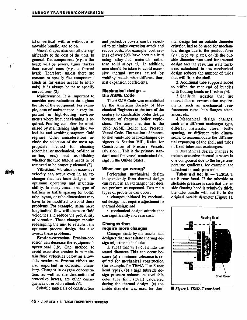
Additional tube supports. In
typical removable-bundle designs,
the tubes need to be rigid enough to
avoid sagging. One way to stiffen
the bundle is to add support plates
near the rear head of a floating head
or U-tube exchanger (Figure 2). In
some instances, these additional
supports render the tube surface par
tially ineffective in this area. The
Boating Head
Shell
Support Plate
Shell Cover
I Figure 2. TEMA S rear head with support plate.
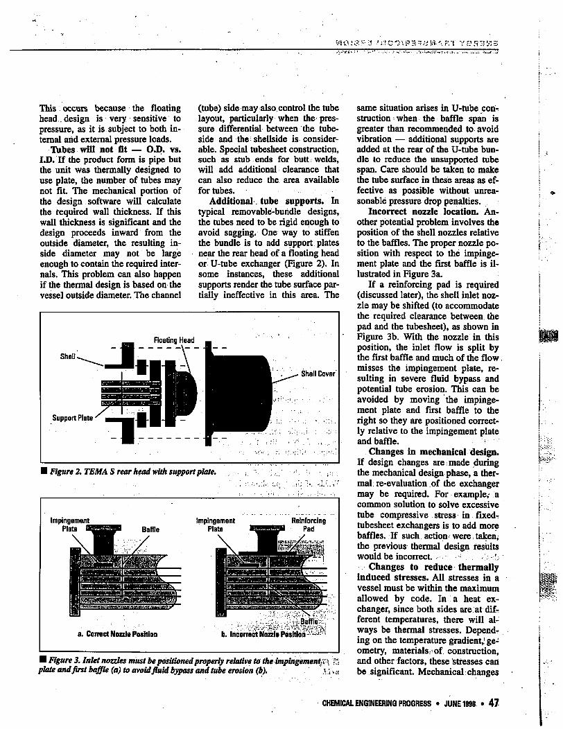
■ Figure 3. Inlet nozzles must be positioned properly relative to the impingement;<\ :.'. plate and first baffle (a) to avoid fluid bypass and tube erosion (b). '.VI. a
same situation arises in U-tube. con-!
struction •■ when the baffle span is
greater than recommended to avoid
vibration — additional supports are
added at the rear of the U-tube bun
dle to reduce the unsupported tube
span. Care should be taken to make
the tube surface in these areas as ef
fective as possible without unrea
sonable pressure drop penalties.
Incorrect nozzle location. An
other potential problem involves the
position of the shell nozzles relative
to the baffles. The proper nozzle po
sition with respect to the impinge
ment plate and the first baffle is il
lustrated in Figure 3a.
If a reinforcing pad is required
(discussed later), the shell inlet noz
zle may be shifted (to accommodate
the required clearance between the
pad and the tubesheet), as shown in
Figure 3b. With the nozzle in this
position, the inlet flow is split by
the first baffle and much of the flow.
misses the impingement plate, re
sulting in severe fluid bypass and
potential tube erosion. This can be
avoided by moving the impinge
ment plate and first baffle to the
right so they are positioned correct
ly relative to the impingement plate
and baffle. *
Changes in mechanical design.
If design changes are made during
the mechanical design phase, a ther
mal re-evaluation of the exchanger
may be required. For example,- a
common solution to solve excessive
tube compressive stress in fixed-?
tubesheet exchangers is to add more
baffles. If such action- were. taken,
the previous thermal design results
would be incorrect. ■••■•' : :>
Changes to reduce thermally
induced stresses. All stresses in a
vessel must be within the maximum
allowed by code. In a heat ex
changer, since both sides are at dif
ferent temperatures, there will al
ways be thermal stresses. Depend
ing on the temperature gradient,9 ge
ometry, materials: of construction,
and other factors, these stresses can
be significant. Mechanical changes
CHEMICAL ENGINEERING PROGRESS • JUNE 1998 • 47
ENERGY TRANSFER/CONVERSION
designed to reduce thermally in
duced stresses can severely impact
thermal performance.
In the simplest case, an expan
sion joint needs to be added to a
fixed-tubesheet exchanger to absorb
the excessive thermal stresses. If the
stresses are still too high after
adding an expansion joint, a change
in geometry is required.
A floating head or U-tube con
struction may be acceptable if a
fixed-tubesheet unit cannot be used.
Exchanger designs that serve dual
purposes can sometimes be used.
For example, if a fixed-tubesheet
kettle is going to be used and the
stress analysis recommends an ex
pansion joint, the kettle itself can
serve as an expansion joint. Clearly,
dual-purpose construction lowers
capital costs.
Excessive thermal stresses can
also occur in multitube exchangers
where the tubesheet is subject to
large temperature gradients from
pass to pass. In these cases, proper
gasket selection is important to
avoid potential leakage due to metal
distortion.
Mechanical criteria
that affect cost
Mechanical design criteria that
can significantly affect the cost of
an exchanger include:
1. Equipment designed under
"lethal service" Code rules (7).
2. Special materials of construc
tion or construction features re
quired to accommodate very low or
very high design temperatures.
3. Supports that need to be re
designed because of excessive shell
or head buckling due to support
loads.
Lethal service. If a vessel's con
tents could kill, it is the user's re
sponsibility to provide a safe design.
The ASME Code provides rules to
make vessels safer under the label
"lethal service."
Although many substances are
harmful if allowed to escape the ves
sel boundaries, the Code defines
lethal substances as poisonous gases
or liquids that are dangerous to life
when inhaled {e.g., hydrocyanic
acid, carbonyl chloride, cyanogen,
xylyl bromide, and others (8)). How
ever, many other processes could
easily qualify as lethal if somehow
the vessel contents were allowed to
escape. The decision then becomes
one of added cost vs. additional safe
ty features. The equipment user has
the responsibility of labeling the
equipment as "lethal service."
Lethal service designs have the
following requirements:
• vessel butt welds must be fully
radiographed;
• body flanges must be of the
hub type;
• carbon steel material must be
post-weld heat-treated; and
• additional rules concerning
tubes and product forms (such as
seamless rather than welded tubes
[the latter require further testing])
must be adhered to.
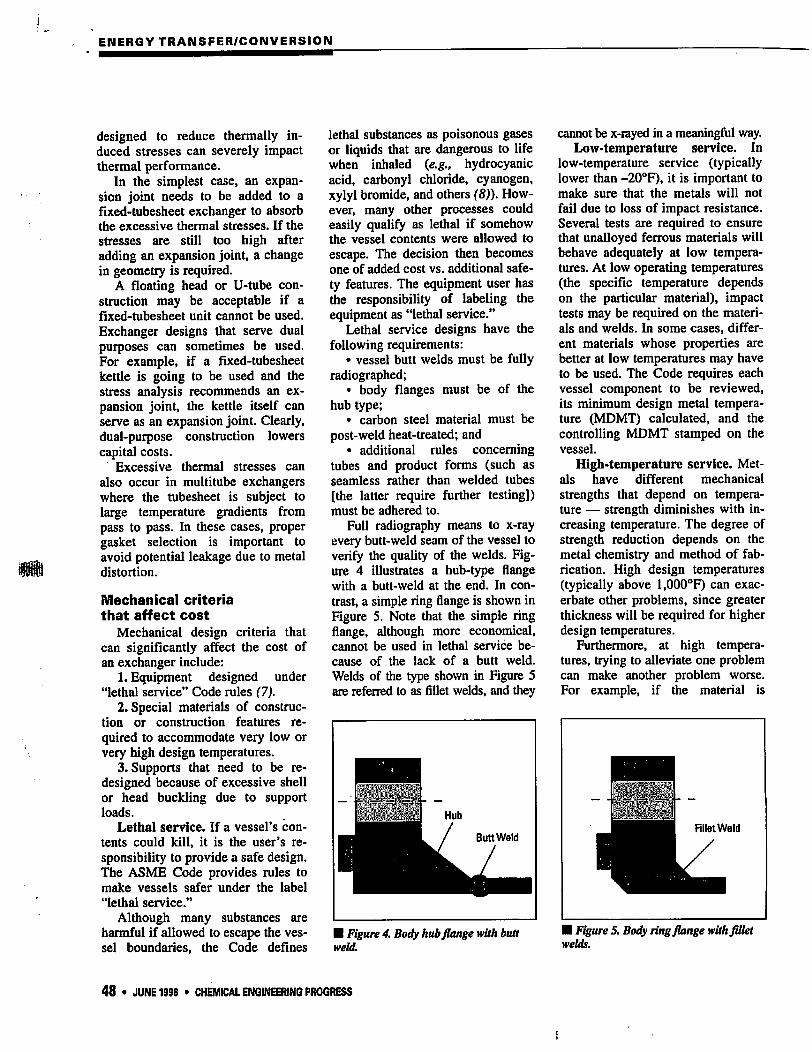
Full radiography means to x-ray
every butt-weld seam of the vessel to
verify the quality of the welds. Fig
ure 4 illustrates a hub-type flange
with a butt-weld at the end. In con
trast, a simple ring flange is shown in
Figure 5. Note that the simple ring
flange, although more economical,
cannot be used in lethal service be
cause of the lack of a butt weld.
Welds of the type shown in Figure 5
are referred to as fillet welds, and they
cannot be x-rayed in a meaningful way.
Low-temperature service. In
low-temperature service (typically
lower than -20°F), it is important to
make sure that the metals will not
fail due to loss of impact resistance.
Several tests are required to ensure
that unalloyed ferrous materials will
behave adequately at low tempera
tures. At low operating temperatures
(the specific temperature depends
on the particular material), impact
tests may be required on the materi
als and welds. In some cases, differ
ent materials whose properties are
better at low temperatures may have
to be used. The Code requires each
vessel component to be reviewed,
its minimum design metal tempera
ture (MDMT) calculated, and the
controlling MDMT stamped on the
vessel.
High-temperature service. Met
als have different mechanical
strengths that depend on tempera
ture — strength diminishes with in
creasing temperature. The degree of
strength reduction depends on the
metal chemistry and method of fab
rication. High design temperatures
(typically above l,000°F) can exac
erbate other problems, since greater
thickness will be required for higher
design temperatures.
Furthermore, at high tempera
tures, trying to alleviate one problem
can make another problem worse.
For example, if the material is
■ Figure 4. Body hub flange with butt
weld.
■ Figure 5. Body ring flange with fillet
welds.
48 • JUNE 1998 • CHEMICAL ENGINEERING PROGRESS
.'? Vi/.'. "ft f OA3V13
changed from standard-grade stain
less steel to L-grade to avoid sensi
tized welds (welds with chromium-
depleted areas subject to attack by
strong acids), the vessel material
maximum design temperature de
creases from l,500°F (815°C) to
800°F (427°C) (9), which could
make the material unsuitable for the
original service.
Shell or head buckling due to
support loads. Horizontal or verti
cal supports impose loads on the
walls to which they are attached. Ad
ditional metal, in the form of rein
forcing pads, is sometimes required
to reduce excessive support loads.
Support location will also impact ad
jacent components, such as formed
heads. It may be desirable to move
the supports to a better location. In
vertical vessels, if an expansion joint
is present, the support location is im
portant in order to avoid overstress-
ing the expansion joint/shell/tubes
assembly.
Reducing capital costs
Three examples illustrate steps
that can be taken to minimize capi
tal costs.
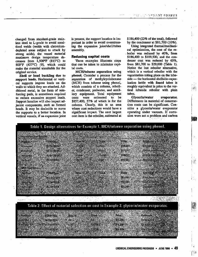
MCH/toluene separation using
phenol. Consider a process for the
separation of methylcyclohexane
(MCH) from toluene using phenol,
which consists of a column, reboil-
er, condenser, preheater, and auxil
iary equipment. Total equipment
costs were estimated to be
$857,400, 57% of which is for the
column. Clearly, this is an area
where cost reductions would have a
significant impact. The next largest
cost item is the reboiler, estimated at
$186,400 (22% of the total), followed
by the condenser at $81^700 (10%).
Using integrated thermal/mechani
cal optimization, the cost of the re-
. boiler was reduced by 40%, from
$186,400 to $109,500, and the con
denser cost was reduced by 65%,
from $81,700 to $29,000 (Table 1).
Notice the last reboiler alternative,
which is a vertical reboiler with the
vaporization taking place on the tube-
side — the horizontal shellside-vapor-
ization kettle with finned tubes is
roughly equivalent in price to the ver
tical tubeside reboiler with plain
tubes.
Glycerin/water evaporator.
Differences in material of construc
tion costs can be significant. Con
sider a glycerin/water evaporator
operating under vacuum. If corro
sion were not a problem and carbon
Table 1. Design alternatives for Example 1, MCH/toluene separation using phenol.
Table 2. Effect of material selection on cost in Example 2, glycerin/water evaporator.
!RrIce
:j&^'■■■::i:m^-:^ ; mm ..[^^^^^^tti
CHEMICAL ENGINEERING PROGRESS • JUNE 1998 • 49
ENERGY TRANSFER/CONVERSION
Conclusion
With the advancement of inte
grated tools, the project engineer
can now design shell-and-tube heat
exchangers from beginning to end,
including fabrication drawings. The
advantages of this once-through ap
proach are significant:
• reduced costs because of an
optimized thermal and mechanical
design;
• reduced costs as a result of ap
plying ASME rules early in the pro
ject and minimizing rework later;
• reduced costs associated with
shorter project completion times;
and
• improved cost projections re
sulting from the simulation of
equipment fabrication.
steel could be used on the process
side, the equipment cost would be
60% less than if the unit were built
of the recommended Type 316L
stainless steel. If the process side of
the exchanger were classified as
lethal service, the increase in cost to
meet the more-stringent construc
tion criteria would be 15%; addi
tional costs would be incurred if the
whole unit were to be classified as
lethal service (Table 2).
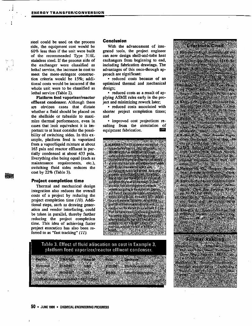
Platform feed vaporizer/reactor
effluent condenser. Although there
are obvious cases that dictate
whether a fluid should be placed on
the shellside or tubeside to maxi
mize thermal performance, even in
cases that look equivalent it is im
portant to at least consider the possi
bility of switching sides. In this ex
ample, platform feed is vaporized
from a vapor/liquid mixture at about
165 psia and reactor effluent is par
tially condensed at about 433 psia.
Everything else being equal (such as
maintenance requirements, etc.),
switching fluid sides reduces the
cost by 22% (Table 3).
Project completion time
Thermal and mechanical design
integration also reduces the overall
costs of a project by reducing the
project completion time (10). Addi
tional steps, such as drawing gener
ation and vendor interfacing, could
be taken in parallel, thereby further
reducing the project completion
time. This idea of achieving faster
project execution has also been re
ferred to as "fast tracking" (II).
Table 3. Effect of fluid allocation on cost in Example 3,
platform feed vaporizer/reactor effluent condenser.
'. Steel-: fpt'.'-teoiroBlon' -. Proleclibn,".
■ :40Ht4;tliny:W96);::.;>ri'.^. :6. RuBtpv:«,. i.V "Jleal..7ynnBfer. ibp
. C«sfc; ̂ eofip^Ill^PiiBB^irc Vessels.
■ ■fW9?5)V;-'?' ■-■1.:..v.. :V-' ■■'.' -■ ■ 8. l*iristtB.b^]QV^I):,; .^Ptessuie Veasels:-:, Ttajtai,; beBlgh^tiesiflcajip'n^.; ̂ tfeni.
sten. .MlBUijuls-. Etor ||etter; Krt
ir <* S^iej 93i(
lftiq^j^JGi^iJ^JpSimiit/BxihariBr
#-y, :: .
,-■■■■.■■ V^*-"-;i:-- ■■■'■■■■;--1 ■'■■■;--!. ■■
50 • JUNE 1998 • CHEMICAL ENGINEERING PROGRESS