comparative study of low rise, mid rise and high rise steel
TRANSCRIPT
ISSN(Online): 2319-8753 ISSN (Print): 2347-6710
International Journal of Innovative Research in Science, Engineering and Technology
(A High Impact Factor, Monthly, Peer Reviewed Journal)
Visit: www.ijirset.com
Vol. 7, Issue 7, July 2018
Copyright to IJIRSET DOI:10.15680/IJIRSET.2018.70707053 7925
Comparative Study of Low Rise, Mid Rise and High Rise Steel Structure as per is Code and
Other Code.
Gourav Tamboli1, Prof. Vellal. P.N2, Prof Atul Pujari2 M.E 4th Semester (Structure), Department of Civil Engineering, K.J College of Engineering Research and
Management, Pune, Maharashtra, India1
Department of Civil Engineering, K.J College of Engineering Research and Management, Pune, Maharashtra, India2
ABSTRACT: In this project we compare Comparative Study of Low Rise (g+5)e, Mid Rise(g+10) and High Rise (g+15) Structure as per Is Code and Other Code.In Reinforced building, frames are major partssince it opposes Shear force, Bending moment, torsion and furthermore subjected to variety of loads in which seismic loads are dominating. Developing nations like India we need to adopt some standards. The BIS recommended IS 456:2000 and IS 1893(Part-1)2002 likewise European standard recommended EC2 and EC8 for Design of concrete structures and Design of earthquake resistant structures respectively. An attempt is made to compare Indian standard and Euro standard in "ETABS 2016"Seismic plays gigantic part on life and property since the impact on structures is colossal, so it's essential to design the structures in the most ideal approach to withstand these impacts. Different seismic codes determines distinctive parameters so than clearly it's performance differs as per different codes. Hence, it is important to do a comparison in order to assess which building performs better'. In this project we compare Comparative Study of Low Rise(g+5)e, Mid Rise(g+10) and High Rise (g+15) Structure as per Is Code and Other Code.Two different famous structural building codes have been adopted. Those are the Indian Standards and European Standards. In R.C. buildings, frames are considered as main structural elements, which resist shear, moment and torsion effectively. These frames be subjected to variety of loads, where lateral loads are always predominant. Infrastructures of Gulf countries are always notable as they mainly follow EURO standards for construction development. In view of the demand of such code of practice across the developing countries like India, an attempt is made to compare EURO standards with Indian standards under Seismic Forces. KEYWORDS: Allowable Stress Design, Factor of Safety, Limit State Method, Load and Resistance, Factor Design Method, Serviceability Limit State, Ultimate Limit State
I. INTRODUCTION In India the standard for RC buildings were presented in 1953, which was additionally revised and executed with the course of time. For Earthquake load, Indian Bureau Standard has recommended the criteria for earthquake resist design of structures in 1983. This paper incorporated the IS 456:2000: Code of Practice for Plain and Reinforced Concrete and IS 1983(Part-1):2002: Criteria for Earthquake Resistant Design of Structures. In the present situation there is a requirement for convergence of design philosophies to bring out structures with uniform danger of collapse and least level of harm or damage and need to look at the expected seismic performance of building designed on various codes. Indian codes are adequate for design but there are different parameters in some global norms which are not adopted in Indian code, so to improve our design there is requirement for selection
ISSN(Online): 2319-8753 ISSN (Print): 2347-6710
International Journal of Innovative Research in Science, Engineering and Technology
(A High Impact Factor, Monthly, Peer Reviewed Journal)
Visit: www.ijirset.com
Vol. 7, Issue 7, July 2018
Copyright to IJIRSET DOI:10.15680/IJIRSET.2018.70707053 7926
for the best practice of design. codes, under both static and dynamic forces in most reliable software tool “ETABS”.The developing nations like India it is desirable to adopt the standard like Euro standard. Comparison work is carried out by considering the design standards from both IS and Euro. The Indian Construction is often guided by steel, cement as the prime material of construction. Cement requires a healthy partnership with aggregates and steel to form the structural element called concrete [1]. Steel, on the other hand has an advantage of partnering with concrete and also can go alone as an individual structural element. In order to reap the advantages of steel the whole supply chain needs to be in place. Use of steel as a preferred material for Design Engineers can be increased if the design codes are modified, updated with the scientific researches , user friendly etc [2]. The design Engineers will then be inclined in deciding on using steel. This will increase the consumption in the country. IS-800, the code for general structural steel design which was published in 1984 reaffirmed in 1991 was much outdated with outdated philosophy. The working stress method or the Allowable stress method was prepared long back. In the meantime the methodology of design of steel structures had undergone major changes due to two decades of research and the state-of-the-art practiced all over the world. Since an outdated code would be detrimental to the very purpose of the code of practice itself, the basic code for design of steel structures needed updating using recent research findings and practices in developed countries [4]. Thus, the code was revised under the supervision of expert committee constituted. Almost all advanced countries are now taking advantage of efficient code stipulations, and the current practice all over the world is based on either Limit State Method (LSM) or Load and Resistance Factor Design (LRFD) method. Since LSM has become the design philosophy in most of the international design standards due to its rationality and consequent economy achieved in design, it was felt that IS: 800 should also be modified to LSM while maintaining Allowable Stress Design (ASD) as a transition alternative. This would also help the designers to understand both the design methods and utilize the most advantageous one. Even in USA, the codes on design ofsteel structures, still maintain a dual standards approach, viz.
A. OBJECTIVES
1) The research work was performed using ETABS 2016 software, the analysis is done under static and dynamic loads on structure using Indian and Euro code of standards for Low Rise(g+5)e, Mid Rise(g+10) and High Rise (g+15) Structure as per Is Code and Other Code
2) Despite the design principles and standards contained in both codes IS and Euro standards codes are same, but they vary in configuration, design criteria, detailing and also different seismic factors that governs the design strengths on the structure. The investigation focuses on the factors which contribute to the poor performance of structure during earthquake.
3) To do the static and dynamic analysis on Low Rise(g+5)e, Mid Rise(g+10) and High Rise (g+15) Structure as per Is Code and Other Code, building using Indian and Euro code of standards.
4) To compare the design standards in view of strength of building. 5) To study the performance of building in view of two codes of standards and to measures which building
performs better. 6) To give comparison with the parameters like: Displacement, Base shear, Story displacement, Story drift, Time
period, Shear force, Bending moments and Area of steel required.
II. LITERATURE SURVEY
1. Vinit Dhanvijay1, Prof. Deepa Telang2, Vikrant Nair3” Comparative Study of Different Codes in Seismic Assessment” International Research Journal of Engineering and Technology (IRJET) e-ISSN: 2395 -0056 Volume: 02 Issue: 04 | July-2015 www.irjet.net p-ISSN: 2395-0072
From this Paper I refer- This study focuses on comparison of International standards. The chosen standards are Eurocode, IBC (American Society of civil Engineers) and Indian code i.e. IS 1893:2002. The study also helps in understanding the main
ISSN(Online): 2319-8753 ISSN (Print): 2347-6710
International Journal of Innovative Research in Science, Engineering and Technology
(A High Impact Factor, Monthly, Peer Reviewed Journal)
Visit: www.ijirset.com
Vol. 7, Issue 7, July 2018
Copyright to IJIRSET DOI:10.15680/IJIRSET.2018.70707053 7927
contributing factors which lead to poor performance of Structure during the earthquake, so as to achieve their adequate safe behavior under future earthquakes. The structure analysed is symmetrical, G+5, Special RC moment-resting frame (SMRF). Modelling of the structure is done as per staad pro. V8i software. Time period of the structure in both the direction is taken from the software and as per the three standards three models are made. The Lateral seismic forces are calculated manually. The Lateral seismic forces are calculated per floor as per different codes in X and Z direction and are applied to the Centre of gravity of the structure. The analytical results of the model buildings are then represented graphically and in tabular form, it is compared and analysed taking note of any significant differences. This study focuses on exploring variations in the results obtained using the three codes i.e. Eurocode, IBC (ASCE) and Indian code. A comparative analysis is performed in terms of Base shear, Displacement, Axial load, Moments in Y and Z direction for selected columns and also comparing Displacement, Axial load, Moments in Y and Z direction Floor wise of different codes for same selected columns. Accompanied by comparative analysis of Displacement, shear Y, Torsion and Moment Z of selected beams on each floor for different international codes.
2. Dr.T.Muralidhara Rao1, S.S.Phani2 “A CRITICAL COMPARATIVE STUDY OF IS:800-2007ANDIS:800-1984” 2016.
From this Paper I refer- Now-a-days, the whole world is changing over to limit state method since it is more rational. The latest version of the Code of Practice for general construction in steel IS: 800-2007 is based on Limit State Method of design. The design concept is totally changed in comparison to earlier code IS 800:1984 which is based on Elastic method. In view of this, an effort has been made to high light the critical comparison between the important clauses of IS:800-2007 and IS:800-1984. At a glance, the present study will provide the readers a quick and clear idea about the changes in the corresponding clauses of old(IS:800-1984) and new (IS:800-2007) codes of practice.
3. SaiKiran Gone, KailashRao, Pradeep Kumar RamancharlaInternational Journal of Civil, Architectural, Structural and Construction Engineering 2016
From this Paper I refer- Abstract—In recent years, the introduction of Pre Engineered Building (PEB) concept in the design of structures has helped in optimizing design. The adoptability of PEB in the place of Conventional Steel Building (CSB) design concept resulted in many advantages, including economy and easier fabrication. In this study, an industrial structure (Ware House) is analyzed and designed according to the Indian standards, IS 800-1984, IS 800-2007 and also by referring MBMA-96 and AISC-89. In this study, a structure with length 187m,width 40m,with clear height 8m and having R-Slope 1:10,isconsidered to carry out analysis& design for 2D frames (End frame, frame without crane and frame with 3 module cranes). The economy of the structure is discussed in terms of its weight comparison, between Indian codes (IS800-1984, IS800-2007) & American code (MBMA-96), & between Indian codes (IS800-1984, IS800-2007).
4. Midhun B Sankar, Priya A Jacob “Comparison of Design Standards for Steel Railway Bridges” Midhun B Sankar, Priya A Jacob / International Journal of Engineering Research and Applications (IJERA) ISSN: 2248-9622 www.ijera.com Vol. 3, Issue 2, March -April 2013, pp.1131-1138
From this Paper I refer- The popularity of steel bridges is increasing in the modern era because of its unmatchable advantages. Engineers are using various national codes to achieve an optimum design. Some of the Asian countries are using their own codes and also American and other country code provisions to achieve better economy and better standards. In this regard the comparison of design codes is relevant. Comparison of code provisions for design of steel bridges enables us to know which country spends more money to meet their design standards also which country imposes maximum safety standards. In this paper design of steel bridge based on Indian and European standards are done and the results are compared. This study is concentrated on the total deflection and weight of the steel girder by varying the grade of steel, panel aspect ratio, web slenderness ratio. Based on the design results, conclusions are arrived at to know the behavior of plate girder bridges when designed using Indian and European standards.
ISSN(Online): 2319-8753 ISSN (Print): 2347-6710
International Journal of Innovative Research in Science, Engineering and Technology
(A High Impact Factor, Monthly, Peer Reviewed Journal)
Visit: www.ijirset.com
Vol. 7, Issue 7, July 2018
Copyright to IJIRSET DOI:10.15680/IJIRSET.2018.70707053 7928
5. M. Ameerutheen1, Sri. Aravindan “Study Of Stresses On Composite Girder Bridge Over Square And Skew Span” International Journal Of Civil Engineering And Technology (Ijciet) Issn 0976 – 6308 (Print) Issn 0976 – 6316(Online) Volume 5, Issue 2, February (2014), Pp. 88-96
From this Paper I refer- Generally a bridge is defined as a structure spanning a river, road, valley, depression or any other type of obstruction with a purpose to provide through passage of communication. This project is taken to study the stresses on the two lane solid slab and on beam and slab arrangement (composite) on various skew angles by imposing a load of 1t/sq.m and compare the results to study the characteristics of skew deck and also to investigate the skew effect if the bridge is subjected to IRC loading. The following analysis are going to be made using the software STAAD-PRO. 1. The effect of stresses in Solid slab & Composite Bridge Deck slab- comparative study 2. The effect of Skew angle in Composite Bridge. 3. To find out the Critical section where skew angle has to be considered for design
6. M.G.Kalyanshetti, G.S. Mirajkar “Comparison Between Conventional Steel Structures And Tubular Steel Structures” M.G.Kalyanshetti, G.S. Mirajkar / International Journal of Engineering Research and Applications (IJERA) ISSN: 2248-9622 www.ijera.com Vol. 2, Issue 6, November- December 2012, pp.1460-1464
From this Paper I refer- Most of the steel structures are builted-up with conventional sections of steels which are designed and constructed by conventional methods. This leads to heavy or uneconomical structures. Tubular steel sections are the best replacements to the conventional ones with their useful and comparatively better properties. It is obvious that due to the profile of the tube section, dead weight is likely to be reduced for many structural members .which derives overall economy. This study is regarding the economy, load carrying capacity of all structural members and their corresponding safety measures. Economy is the main objective of this study involving comparison of conventional sectioned structures with tubular sectioned structure for given requirements. For study purpose superstructure-part of an industrial building is considered and comparison is made. Study reveals that,upto 40 to 50% saving in cost is achieved by using tubular sections
7. Adithya. M1, Swathi rani K.S2, Shruthi H K3, Dr. Ramesh B.R “Study On Effective Bracing Systems for High Rise Steel Structures” SSRG International Journal of Civil Engineering (SSRG-IJCE) – volume 2 Issue 2 February 2015 ISSN: 2348
From this Paper I refer- The resistance to the lateral loads from wind or from an earthquake is the reason for the evolution of various structural systems. Bracing system is one such structural system which forms an integral part of the frame. Such a structure has to be analyzed before arriving at the best type or effective arrangement of bracing. This project is about the efficiency of using different types of bracings and with different steel profiles for bracing members for multi-storey steel frames. ETABS software is used to obtain the design of frames and bracing systems with the least weight and appropriate steel section selection for beams, columns and bracing members from the standard set of steel sections. A three dimensional structure is taken with 4 horizontal bays of width 4 meters, and 20 stories is taken with storey height of 3m. The beams and columns are designed to withstand dead and live load only. Wind load and Earthquake loads are taken by bracings. The bracings are provided only on the peripheral columns. Maximum of 4 bracings are used in a storey for economic purposes. In this study, an attempt has been made to study the effects of various types of bracing systems, its position in the building and cost of the bracing system with respect to minimum drift index and inter storey drift.
ISSN(Online): 2319-8753 ISSN (Print): 2347-6710
International Journal of Innovative Research in Science, Engineering and Technology
(A High Impact Factor, Monthly, Peer Reviewed Journal)
Visit: www.ijirset.com
Vol. 7, Issue 7, July 2018
Copyright to IJIRSET DOI:10.15680/IJIRSET.2018.70707053 7929
8. S.Jagadesh kannan#1, V.Vanitha*2, “Comparison of Various Types of Roofs in PEB” International Journal of Engineering Trends and Technology (IJETT) – Volume 22 Number 8-April 2015
From this Paper I refer- Pre Engineered Building systems have become a great alternative to conventional steel buildings due to its advantages like faster construction, easy fabrication and economy. In this contest more researches on pre engineering buildings (PEB) are being done to make it more efficient. In this paper Pre Engineered Buildings (PEB) with different roof shapes such as Curved, Pitched & Mono slope have been compared. The study involves an industrial building of length 77.5m and width 25m, with different shapes of roof system. Analysis and design are done using STAAD PRO V8i and results are compared, to understand the behaviour of different roof shapes of Pre Engineered Building.
9. Abhishek Sanjay Mahajan1, Laxman G. Kalurkar “PERFORMANCE ANALYSIS OF RCC AND STEEL CONCRETE COMPOSITE STRUCTURE UNDER SEISMIC EFFECT”IJRET: International Journal of Research in Engineering and Technology eISSN: 2319-1163 | pISSN: 2321-7308
From this Paper I refer- The RCC Structure is no longer suitable because of increased dead load, span rejection and less stiffness .The structural engineers are trying to use different materials for most efficient design solution .There is great potential for increasing volume of steel in construction .The percentage of steel can be increased with the use of steel-concrete composite sections. The paper presents the effect of FEC (Fully Encased Composite) on a G+ 20 storey special moment frame .In this paper two different structures are considered for the comparison under seismic analysis. The linear static analysis and nonlinear static analysis i.e. “Pushover analysis” are done for G+20 storey structure. The building is analyzed and design for seismic loading by using ETAB software. The unique method of pushover analysis is followed with the help of FEMA 36 specifications and for hinge formation ATC40 is considered. Results are compared for the Base shear, Modal time period, Storey displacement and storey drift for both structures. As the composite is having more lateral stiffness, the results of time period and storey displacement shows the significant variation. While analyzing for “Non-linear static analysis the performance point for the FEC is significantly much more as compared to the RCC model.
10. Yoshiaki Okui, (2011) “Recent Topics of Japanese Design Codes for Steel and Composite Bridges”. From this Paper I refer-
This paper gives an overview of Japanese design codes for steel and composite bridges are given. Also some important topics discussed in Standard Specifications for Steel and Composite Structures published by JSCE are introduced. The positive bending moment capacity of composite steel girders is examined through parametric study employing elasto-plastic finite displacement analyses. The effects of initial bending moment in un shored construction on the bending moment capacity and on the web slenderness limit for section classification are investigated. Observations made during the numerical study indicate that the non compact web slenderness limits in conventional design standards, which are based on tests of steel I-sections, are conservative for composite sections. Many sections, which are classified as slender by current specifications, demonstrate sufficient flexural capacity as non compact. The conventional web slenderness limits for non compact sections, which are independent of initial bending moment, seem to be inappropriate for composite girders. The initial bending moment, which is firstly applied to steel section only in un shored construction, has considerable effect on the non compact web slenderness limits. The web slenderness limits for compact and non compact sections are proposed on the basis of the parametric study.
III. METHODOLOGY OF WORK The current research is to compare the performance of 3D strengthened structure under both static and dynamic strategies. Modeling and research are done in ETABS. The structure is analysed under static and dynamic load cases. Different seismic codes specifies different parameters so than clearly it's performance also varies. Thus it is important to do a relative report in order to conclude which building performs better. Results are organized by tables and relating graphs are plotted.
ISSN(Online): 2319-8753 ISSN (Print): 2347-6710
International Journal of Innovative Research in Science, Engineering and Technology
(A High Impact Factor, Monthly, Peer Reviewed Journal)
Visit: www.ijirset.com
Vol. 7, Issue 7, July 2018
Copyright to IJIRSET DOI:10.15680/IJIRSET.2018.70707053 7930
3.1 Factors Affecting the Lateral Seismic Forces The total design lateral force acting at the base of the structure is depends on: 1.Time Period: The structure should be intended to oppose seismic forces acting up on structure. The fundamental natural period of structure is dependent on height, type of structural member, material property. The empirical formula as per codes is given below: Fundamental natural period: i) According to IS 1893 (Part-I) 2002
1) With Infill: Ta = 0.09 * h/√(d ) 2) Without Infill: Ta = 0.075*h ^0.75 for RC frame Buildings.
ii) According to BS EN 1998-1:2004 1) Ta = 0.075*h ^0.75 for RC outline. 2) Ta = 0.085*h ^0.75 for RC outline Buildings. 3) Ta = 0.050*h ^0.75 for every single other structure.
2. Zone Factor: Zone factors are derived on the basis of intensity of earthquakes in various zones. IS code characterized in view service life of structure. IS code has 4 zones from low to very severe seismic intensity with factors 0.10, 0.16, 0.24 and 0.36 for zones II, III, IV and V respectively. Where as in case of Euro code factors are based on peak ground acceleration (ag) from 0.02 to 0.18 3.Importance factor :Importance factor are introduced to represent level of significance for different structure. It relies upon the functional use and utilization of the structure in view of seismic constraints adopted. Also it depends upon theutilization of structure, risk factor, notable historic significance, number of occupants resides etc. In this case as per codes the importance factor is taken as 1.2 for both Indian and Euro codes, Since it’s occupancy capacity of structure is high. i.e. 30 storey building. 4.Seismic Weight: In case of seismic design dead loads and partial proportions of live loads are considered along with the seismic forces are taken in to account for seismic design of structure. The static design load combination for gravity loadings is given by IS 456:2000 and Eurocode2 are w = 1.5gk + 1.5qk w = 1.35gk + 1.5qk Where: gk and qk are dead loads and imposed loads respectively. 1.5 and 1.35 are partial safety factors for loads for IS 456:2000 and Eurocode2 respectively. 5.Ductility Class: IS 1893:2002 (Part 1) specified the RC frame ductility as Ordinary Moment Resisting Frames (OMRF) and Special Moment Resisting Frames (SMRF) with factors 3 and 5 respectively. In case of Euro code 8 (EN 1998-1) specified the building ductility as Ductile Class Low (DCL), Ductile Class Medium (DCM) and Ductile Class High (DCH) with ductility factors 1.5, 3.9 and 5.85 respectively 6. Response Reduction Factor: Response reduction factor is the factor which reduces the actual base shear that would be generated, if the building were remain elastic and responded to a design basis earthquake, to get a design lateral force. According to IS codes the response reduction factors are 3 and 5 for OMRF and SMRF respectively. According to EN 1998 response reduction factors are1.5, 3.9, and 5.85 for DCL, DCM and DCH classes respectively. 7. Base Shear Calculation: The procedure to compute the base shear of the structure according to IS 1893 (Part 1): 2002, and BS EN 1998-1: 2004 are as follows. IS 1893 (Part-1): 2002 a) VB = Ah *W According to Clause 7.5.3 of IS 1893 (Part 1):2002 b) Ah = (Z/2* I/R* Sa/g) According to Clause 6.4.2 of IS 1893 (Part 1):2002 c) For various kind of soil, Sa/g value is calculated according to Clause 6.4.5 of IS 1893 (Part1):2002 BS EN 1998-1: 2004 The seismic base shear force Fb, is given by: Fb = Sd (T1) .m. λ
ISSN(Online): 2319-8753 ISSN (Print): 2347-6710
International Journal of Innovative Research in Science, Engineering and Technology
(A High Impact Factor, Monthly, Peer Reviewed Journal)
Visit: www.ijirset.com
Vol. 7, Issue 7, July 2018
Copyright to IJIRSET DOI:10.15680/IJIRSET.2018.70707053 7931
Where, T1 is time period, Sd is ordinate at T1, m is mass of building and λ is correction factor. According to Clause 4.3.3.2.2 (1) of BS EN 1998 Where Design Spectrum Sd(T1)shall be characterized from the following cases: 0 ≤ T ≤ TB Sd(T1) = ag. S [2/3+ T/TB (2.5/q - 2/3)] according to Clause 3.2.2.5 of BS EN 1998 TB ≤ T ≤ TC: Sd(T1) = ag .S(2.5/q) according to Clause 3.2.2.5 of BS EN 1998 TC ≤ T ≤ TD: Sd(T1) = ag. S (2.5/q) . (TC/T ) >/b ag. According to Clause 3.2.2.5 of BS EN 1998 TD ≤ T: Sd (T1) = ag. S.( 2.5/q ) (TC.TD)/(T^2) ) . >/b ag. According to Clause 3.2.2.5 of BS EN 1998 3.2 Modeling in ETABS ETABS is highly effective and reliable software developed by Computers and Structures Incorporation, USA, which is used for professional use in analysing and developing the models and components. It is easy, simple to use and compare and time saving software tool. 1. Materials Used: Concrete: M 25 Grade of concrete for Slabs, M 30 Grade of concrete for Beams, M 40 Grade of concrete for Columns and Shear walls
1) Concrete density is taken as 25 KN/m3 as per IS 456:2000 clause 19.2.1 and 24 KN/m3 as per EN 1991-1-1:2002:Annex A: Table A-1.
2) Poisson’s ratio is taken as 0.2 as per both respective codes. 3) Modulus of elasticity for IS model is computed as per IS 456:2000 clause 6.2.3.1 is: E = 5000 4) Modulus of elasticity for EC model is taken from EN 1992-1: 2004 Table 3.1 5) Steel: Fe 500 HYSD bars for bending reinforcement, Fe 415 HYSD bars for shear reinforcement. 6) Walls: Poro-therm Blocks with density 6.8 KN/m3 – 7.68 KN/m3
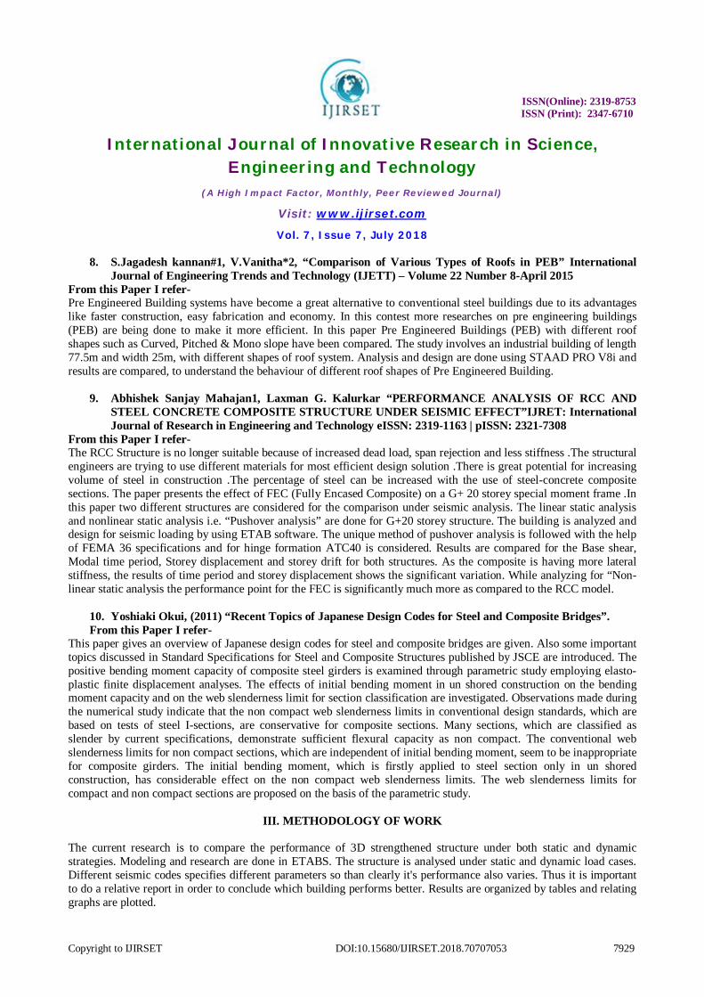
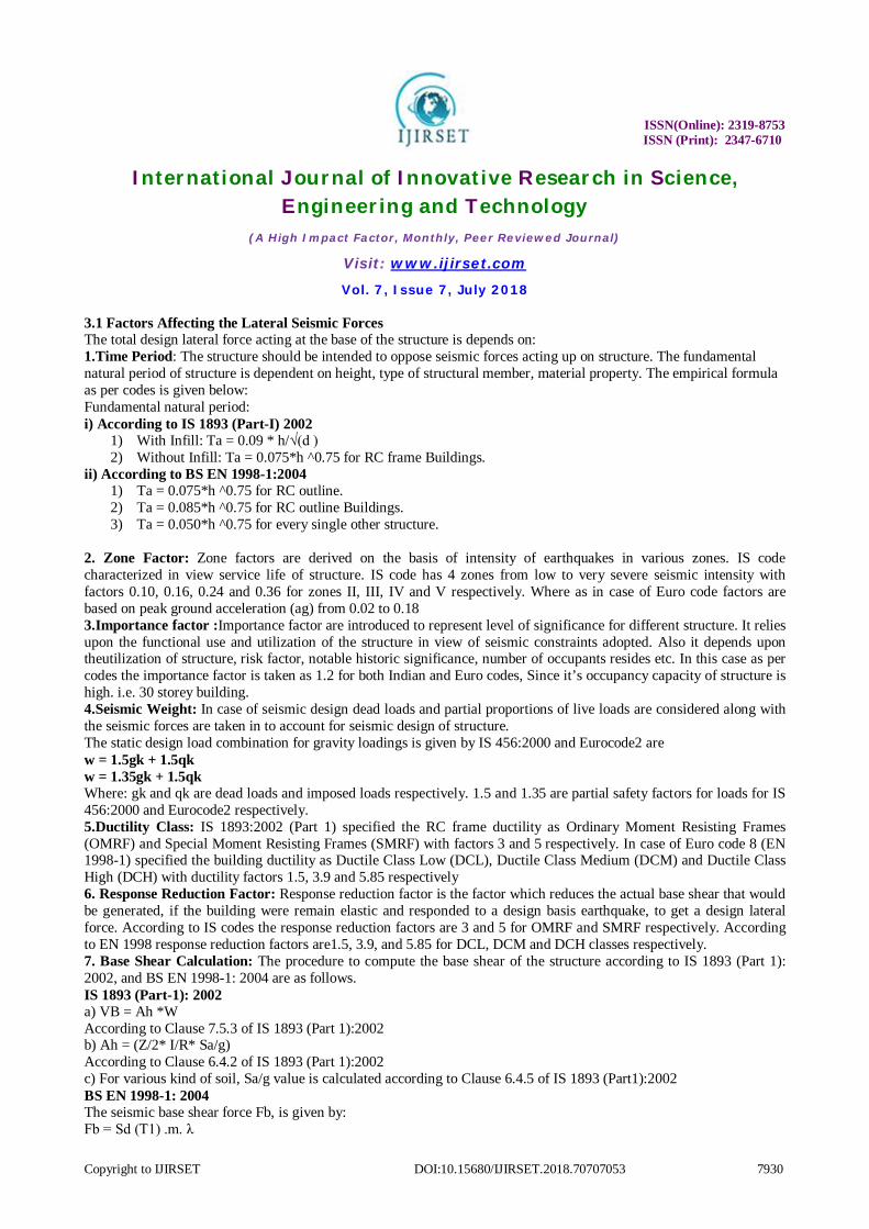
2. Defined Frame sections, Slab sections and Wall sections in High Rise (g+15)
Fig 1-D View of the 15-storeys Rectangular-shape building
Fig 2-D View of the 15-storeys L-shape building
ISSN(Online): 2319-8753 ISSN (Print): 2347-6710
International Journal of Innovative Research in Science, Engineering and Technology
(A High Impact Factor, Monthly, Peer Reviewed Journal)
Visit: www.ijirset.com
Vol. 7, Issue 7, July 2018
Copyright to IJIRSET DOI:10.15680/IJIRSET.2018.70707053 7932
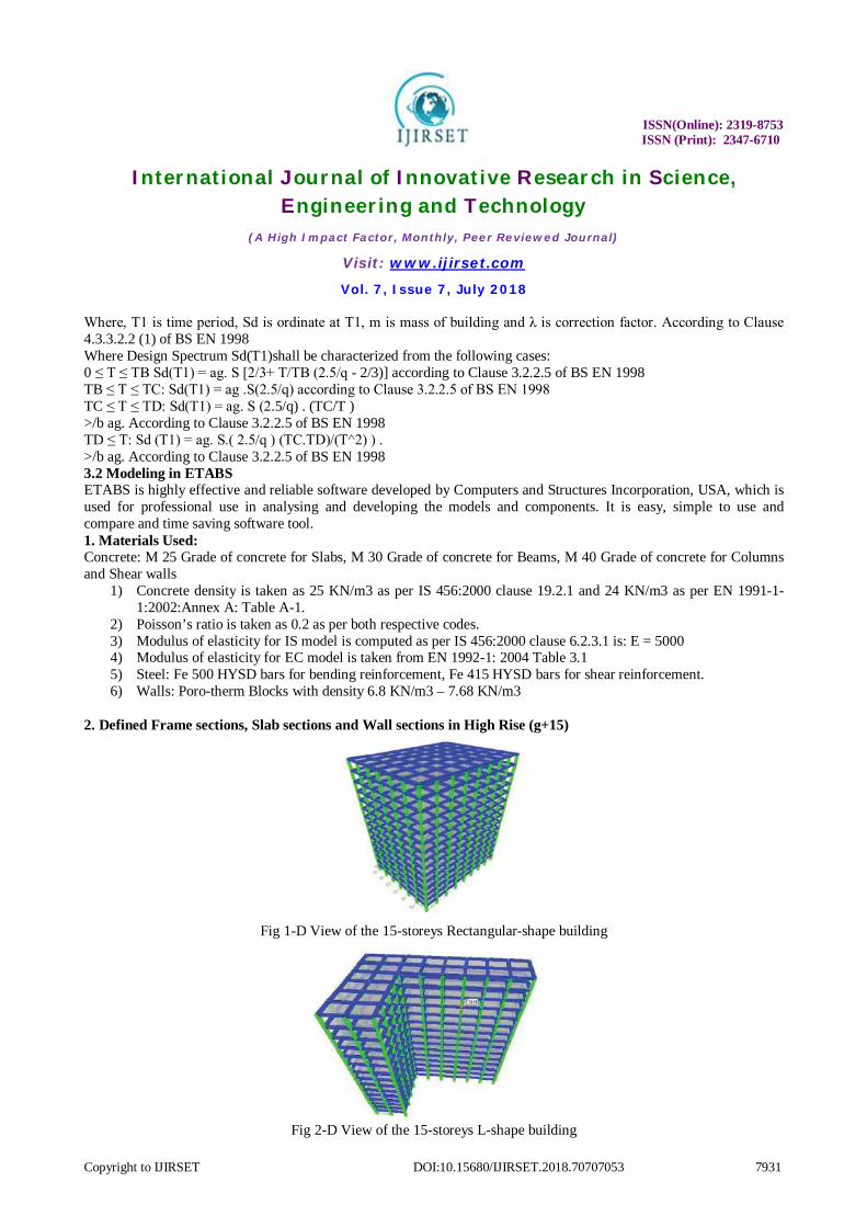
Fig 3-D View of the 15-storeys I-shape building
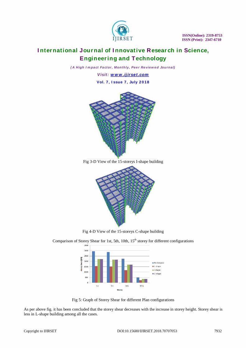
Fig 4-D View of the 15-storeys C-shape building
Comparison of Storey Shear for 1st, 5th, 10th, 15th storey for different configurations
Fig 5: Graph of Storey Shear for different Plan configurations
As per above fig. it has been concluded that the storey shear decreases with the increase in storey height. Storey shear is less in L-shape building among all the cases.
ISSN(Online): 2319-8753 ISSN (Print): 2347-6710
International Journal of Innovative Research in Science, Engineering and Technology
(A High Impact Factor, Monthly, Peer Reviewed Journal)
Visit: www.ijirset.com
Vol. 7, Issue 7, July 2018
Copyright to IJIRSET DOI:10.15680/IJIRSET.2018.70707053 7933
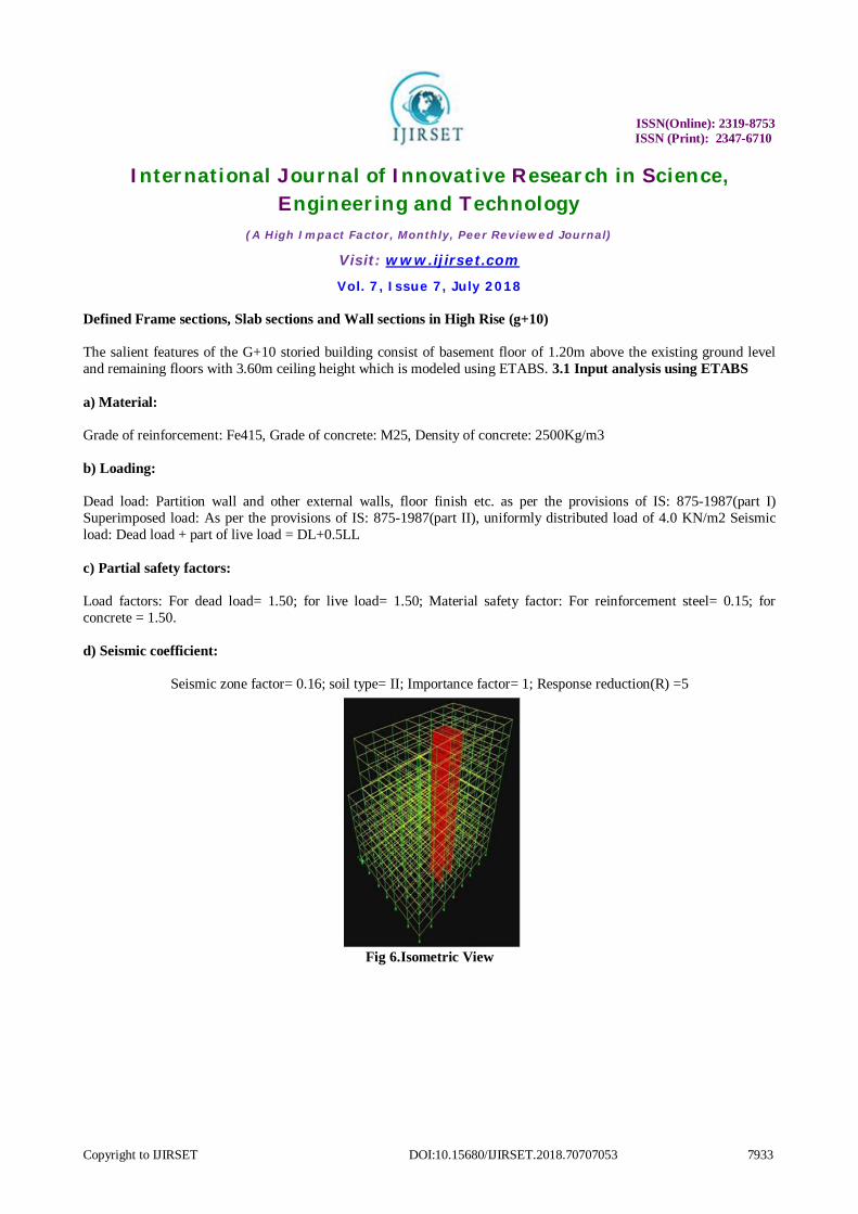
Defined Frame sections, Slab sections and Wall sections in High Rise (g+10) The salient features of the G+10 storied building consist of basement floor of 1.20m above the existing ground level and remaining floors with 3.60m ceiling height which is modeled using ETABS. 3.1 Input analysis using ETABS a) Material: Grade of reinforcement: Fe415, Grade of concrete: M25, Density of concrete: 2500Kg/m3 b) Loading: Dead load: Partition wall and other external walls, floor finish etc. as per the provisions of IS: 875-1987(part I) Superimposed load: As per the provisions of IS: 875-1987(part II), uniformly distributed load of 4.0 KN/m2 Seismic load: Dead load + part of live load = DL+0.5LL c) Partial safety factors: Load factors: For dead load= 1.50; for live load= 1.50; Material safety factor: For reinforcement steel= 0.15; for concrete = 1.50. d) Seismic coefficient:
Seismic zone factor= 0.16; soil type= II; Importance factor= 1; Response reduction(R) =5
Fig 6.Isometric View
ISSN(Online): 2319-8753 ISSN (Print): 2347-6710
International Journal of Innovative Research in Science, Engineering and Technology
(A High Impact Factor, Monthly, Peer Reviewed Journal)
Visit: www.ijirset.com
Vol. 7, Issue 7, July 2018
Copyright to IJIRSET DOI:10.15680/IJIRSET.2018.70707053 7934
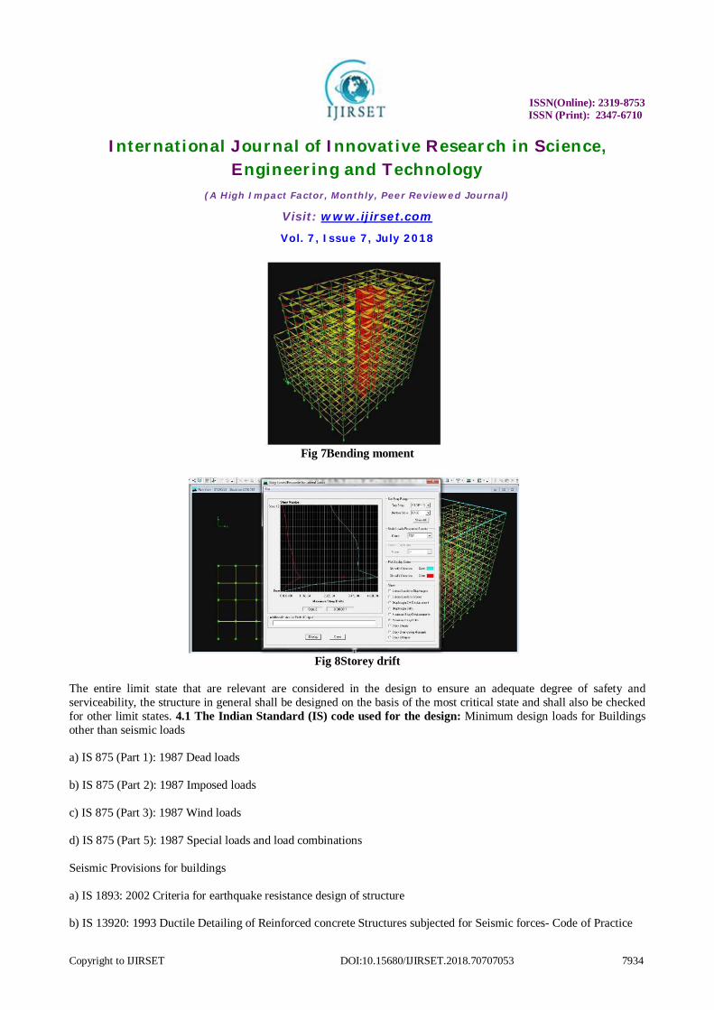
Fig 7Bending moment
Fig 8Storey drift
The entire limit state that are relevant are considered in the design to ensure an adequate degree of safety and serviceability, the structure in general shall be designed on the basis of the most critical state and shall also be checked for other limit states. 4.1 The Indian Standard (IS) code used for the design: Minimum design loads for Buildings other than seismic loads a) IS 875 (Part 1): 1987 Dead loads b) IS 875 (Part 2): 1987 Imposed loads c) IS 875 (Part 3): 1987 Wind loads d) IS 875 (Part 5): 1987 Special loads and load combinations Seismic Provisions for buildings a) IS 1893: 2002 Criteria for earthquake resistance design of structure b) IS 13920: 1993 Ductile Detailing of Reinforced concrete Structures subjected for Seismic forces- Code of Practice

ISSN(Online): 2319-8753 ISSN (Print): 2347-6710
International Journal of Innovative Research in Science, Engineering and Technology
(A High Impact Factor, Monthly, Peer Reviewed Journal)
Visit: www.ijirset.com
Vol. 7, Issue 7, July 2018
Copyright to IJIRSET DOI:10.15680/IJIRSET.2018.70707053 7935
Building code requirements for Structural Concrete: a) IS 456: 2000 Plain and Reinforced Concrete - Code of practice b) SP 16: Structural use of concrete. Design charts for singly reinforced beams, doubly reinforced beams and columns. c) SP 34: Handbook on Concrete Reinforcement & Detailing. Defined Frame sections, Slab sections and Wall sections in High Rise (g+5) To achieve the objectives of the study that is to analyze and design commercial building using ETABS and by manual method, which meets the basic requirements such as safety, durability, economy, aesthetic appearance, feasibility, practicability and acceptability. It has been proposed to follow the following methodology.
1) Site survey 2) Soil investigation 3) Structural planning 4) Analysis and design in ETABS 5) Verification by manual method 6) Detailing
Surveying is a basic tool for a Civil engineering science. Before any civil engineering work has to start, surveying has to be done and then we must prepare a plan or map of the area showing topographical details related to design of structure etc. Good planning and management of a geotechnical site investigation is the key to obtaining sufficient site information for designing a structure in a timely manner and with minimum cost for the effort needed. The engineering properties of soil like water content, density and SBC are calculated by conducting tests in laboratory. The structural plan is prepared using auto cad. The center line diagram is prepared and imported to ETAB model, and the following step by step procedures are followed: Step - 1: Defining of property Select define menu > material properties. Add new material in the defining material property the concrete of M25 and steel of grade Fe415. For our work the size of structural components (beams, columns, and slabs) are taken as per the requirement.
Table -1: Beam details
Table -2: Column details
Column No. Size Column 1 230x450mm Column 2 230x600mm Column 3 230x750mm
Beam No. Size Beam 1 230x450mm Beam 2 230x600mm Beam 3 230x750mm
ISSN(Online): 2319-8753 ISSN (Print): 2347-6710
International Journal of Innovative Research in Science, Engineering and Technology
(A High Impact Factor, Monthly, Peer Reviewed Journal)
Visit: www.ijirset.com
Vol. 7, Issue 7, July 2018
Copyright to IJIRSET DOI:10.15680/IJIRSET.2018.70707053 7936
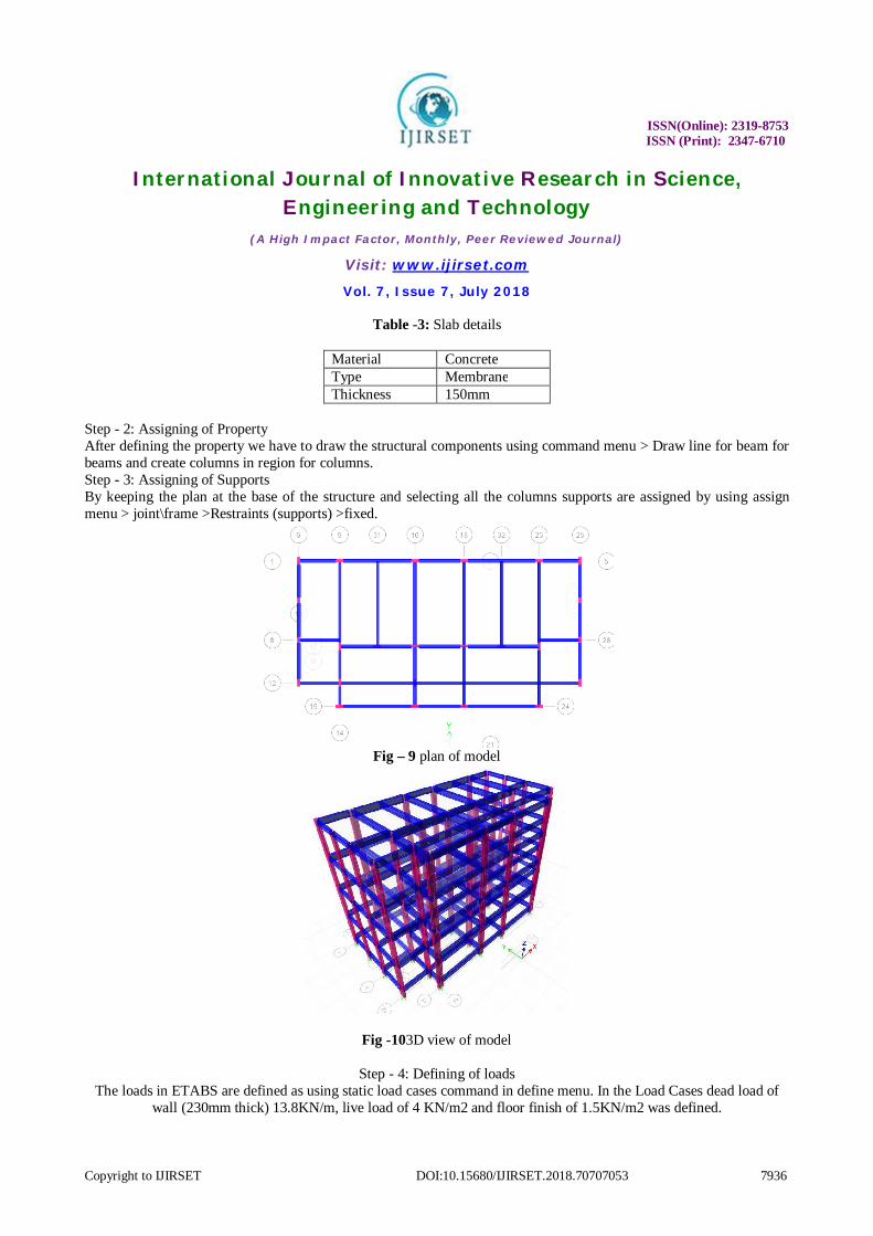
Table -3: Slab details
Material Concrete Type Membrane Thickness 150mm
Step - 2: Assigning of Property After defining the property we have to draw the structural components using command menu > Draw line for beam for beams and create columns in region for columns. Step - 3: Assigning of Supports By keeping the plan at the base of the structure and selecting all the columns supports are assigned by using assign menu > joint\frame >Restraints (supports) >fixed.
Fig – 9 plan of model
Fig -103D view of model
Step - 4: Defining of loads The loads in ETABS are defined as using static load cases command in define menu. In the Load Cases dead load of
wall (230mm thick) 13.8KN/m, live load of 4 KN/m2 and floor finish of 1.5KN/m2 was defined.
ISSN(Online): 2319-8753 ISSN (Print): 2347-6710
International Journal of Innovative Research in Science, Engineering and Technology
(A High Impact Factor, Monthly, Peer Reviewed Journal)
Visit: www.ijirset.com
Vol. 7, Issue 7, July 2018
Copyright to IJIRSET DOI:10.15680/IJIRSET.2018.70707053 7937
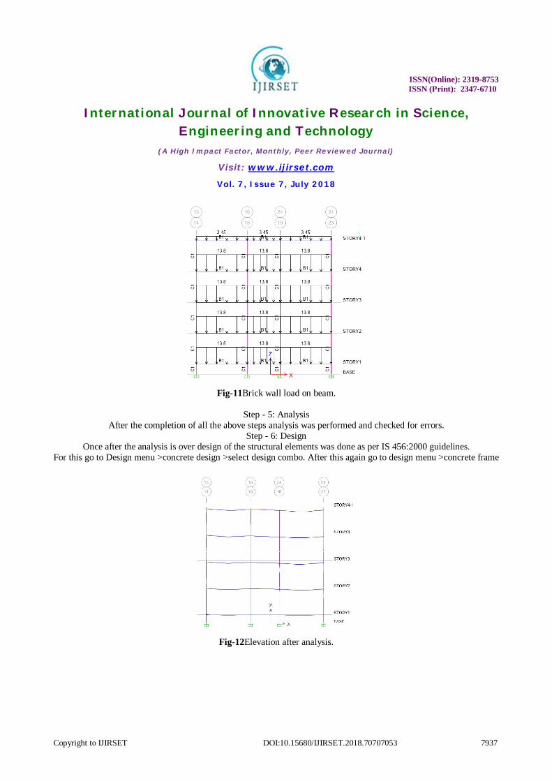
Fig-11Brick wall load on beam.
Step - 5: Analysis
After the completion of all the above steps analysis was performed and checked for errors. Step - 6: Design
Once after the analysis is over design of the structural elements was done as per IS 456:2000 guidelines. For this go to Design menu >concrete design >select design combo. After this again go to design menu >concrete frame
Fig-12Elevation after analysis.
ISSN(Online): 2319-8753 ISSN (Print): 2347-6710
International Journal of Innovative Research in Science, Engineering and Technology
(A High Impact Factor, Monthly, Peer Reviewed Journal)
Visit: www.ijirset.com
Vol. 7, Issue 7, July 2018
Copyright to IJIRSET DOI:10.15680/IJIRSET.2018.70707053 7938
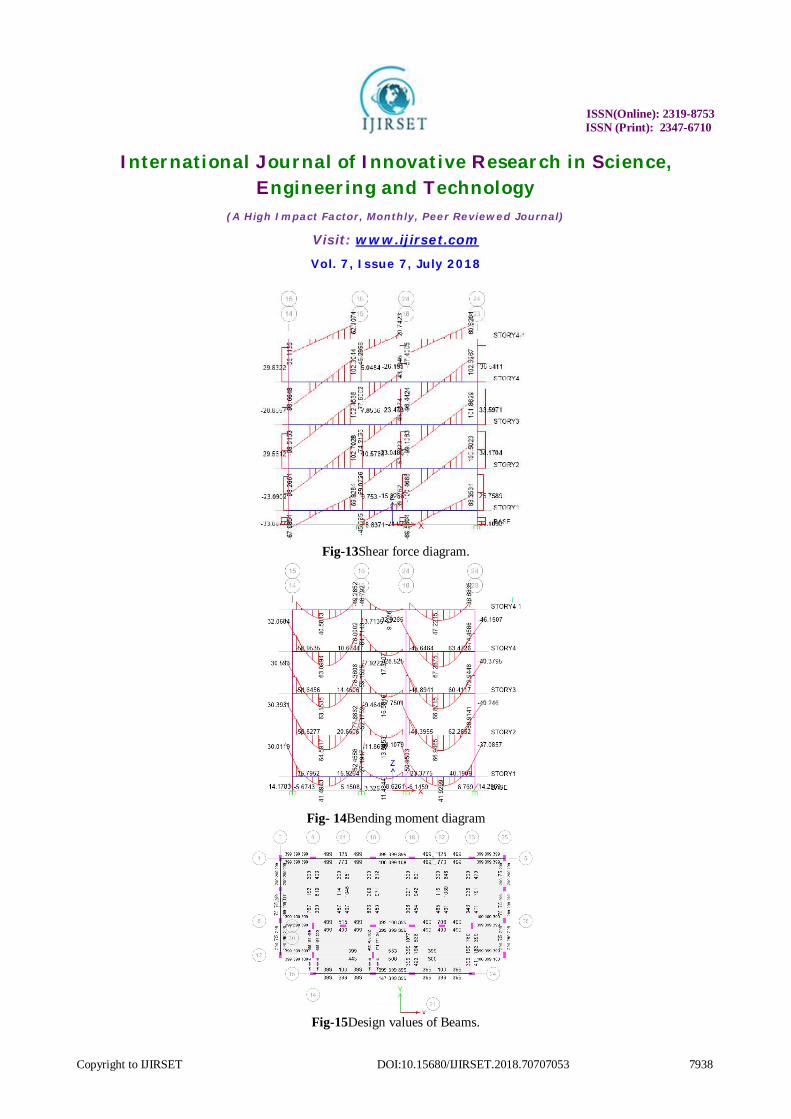
Fig-13Shear force diagram.
Fig- 14Bending moment diagram
Fig-15Design values of Beams.
ISSN(Online): 2319-8753 ISSN (Print): 2347-6710
International Journal of Innovative Research in Science, Engineering and Technology
(A High Impact Factor, Monthly, Peer Reviewed Journal)
Visit: www.ijirset.com
Vol. 7, Issue 7, July 2018
Copyright to IJIRSET DOI:10.15680/IJIRSET.2018.70707053 7939
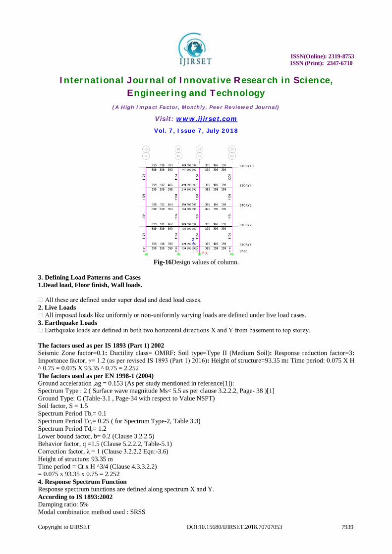
Fig-16Design values of column.
3. Defining Load Patterns and Cases 1.Dead load, Floor finish, Wall loads.
All these are defined under super dead and dead load cases. 2. Live Loads
All imposed loads like uniformly or non-uniformly varying loads are defined under live load cases. 3. Earthquake Loads
Earthquake loads are defined in both two horizontal directions X and Y from basement to top storey. The factors used as per IS 1893 (Part 1) 2002 Seismic Zone factor=0.1: Ductility class= OMRF: Soil type=Type II (Medium Soil): Response reduction factor=3: Importance factor, γ= 1.2 (as per revised IS 1893 (Part 1) 2016): Height of structure=93.35 m: Time period: 0.075 X H ^ 0.75 = 0.075 X 93.35 ^ 0.75 = 2.252 The factors used as per EN 1998-1 (2004) Ground acceleration ,ag = 0.153 (As per study mentioned in reference[1]): Spectrum Type : 2 ( Surface wave magnitude Ms< 5.5 as per clause 3.2.2.2, Page- 38 )[1] Ground Type: C (Table-3.1 , Page-34 with respect to Value NSPT) Soil factor, S = 1.5 Spectrum Period Tb,= 0.1 Spectrum Period Tc,= 0.25 ( for Spectrum Type-2, Table 3.3) Spectrum Period Td,= 1.2 Lower bound factor, b= 0.2 (Clause 3.2.2.5) Behavior factor, q =1.5 (Clause 5.2.2.2, Table-5.1) Correction factor, λ = 1 (Clause 3.2.2.2 Eqn:-3.6) Height of structure: 93.35 m Time period = Ct x H ^3/4 (Clause 4.3.3.2.2) = 0.075 x 93.35 x 0.75 = 2.252 4. Response Spectrum Function Response spectrum functions are defined along spectrum X and Y. According to IS 1893:2002 Damping ratio: 5% Modal combination method used : SRSS
ISSN(Online): 2319-8753 ISSN (Print): 2347-6710
International Journal of Innovative Research in Science, Engineering and Technology
(A High Impact Factor, Monthly, Peer Reviewed Journal)
Visit: www.ijirset.com
Vol. 7, Issue 7, July 2018
Copyright to IJIRSET DOI:10.15680/IJIRSET.2018.70707053 7940
Scale Factor = I .g/2R = 1.2 (9.81/(2 x 3 ) = 1.962 ( Rescaling has done to match spectral base shear with static base shear up to 90%) According to EN 1998-1:2004 Type of response spectrum: Horizontal Ground acceleration, ag/g = γ. agR = 1.2 x 0.153 = 0.184 (Clause 3.2.2.2,Page-37) Damping ratio: 5 % Modal combination method used : SRSS Scale Factor = 9.81m/sec2 or 9806.65 mm/ sec2( Rescaling has done to match with spectral base shear with static base shear up to 90%) 5. Assignment of loads :Live loads, Wall load, Finishes, Fill as per plan layout with reference to IS 875 (Part-1) 6. Defined :Mass Source, Diaphragms, Load combinations and Live load reduction factors 7. Design of structural elements: Beams, columns, walls and slabs are designed as per preferences of codes. i) IS 456:2000: Plain and Reinforced concrete code of practice ii) EN 1992-1-1 (2004): Design of concrete structures – Part 1-1: General rules and rules for buildings
IV. RESULT AND DISCUSSION
4.1 Static Analysis Results
Table-5 :Bending Moments for selected beams
Bending 05th Floor (Low Rise) 10th Floor(High Rise )
15th Floor (Mid Rise)
Moment, KN.m
Beam ID IS EC IS EC IS EC
B164(200X 113.4 98.33 108.9 95.76 100.1 88.24 850)M30
B368(200X 219.5 196.85 220.0 199.9 158.3 144.8 850)M30
B505(200X 231.9 211.0 317.0 291.3 243.6 221.4 650)M30
B294(200X 541.28 487.9 539.0 488.6 385.9 348.4 850)M30
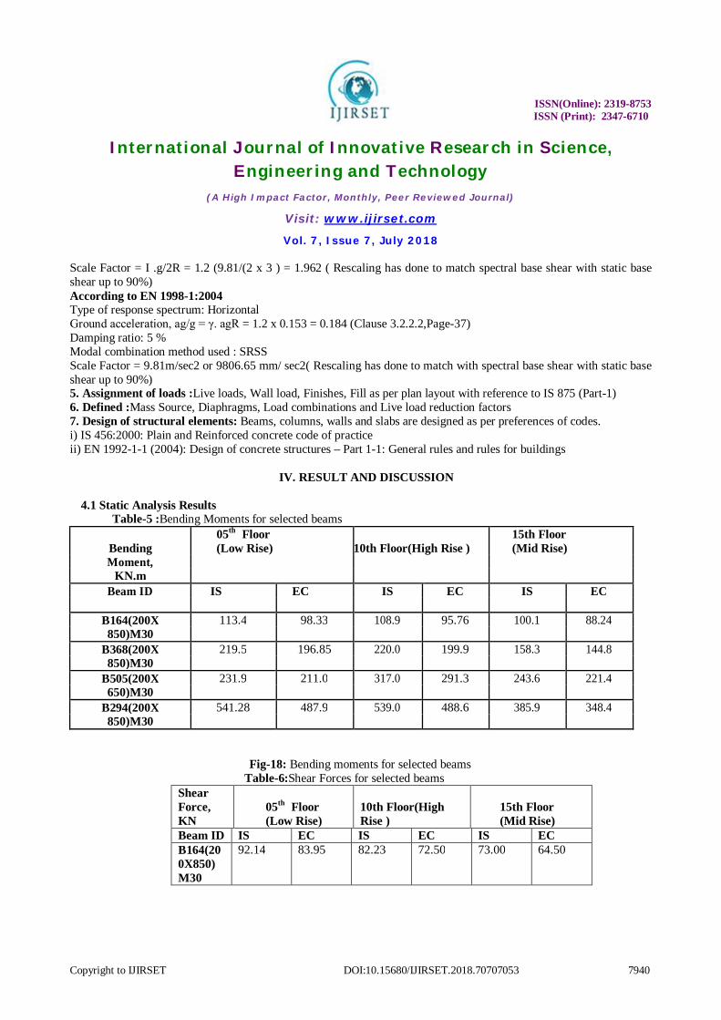
Fig-18: Bending moments for selected beams Table-6:Shear Forces for selected beams
Shear Force, KN
05th Floor (Low Rise)
10th Floor(High Rise )
15th Floor (Mid Rise)
Beam ID IS EC IS EC IS EC B164(200X850)M30
92.14 83.95 82.23 72.50 73.00 64.50
ISSN(Online): 2319-8753 ISSN (Print): 2347-6710
International Journal of Innovative Research in Science, Engineering and Technology
(A High Impact Factor, Monthly, Peer Reviewed Journal)
Visit: www.ijirset.com
Vol. 7, Issue 7, July 2018
Copyright to IJIRSET DOI:10.15680/IJIRSET.2018.70707053 7941
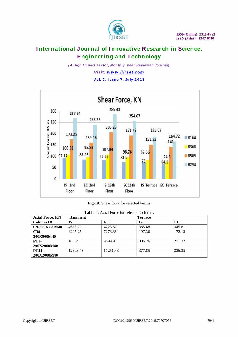
Fig-19: Shear force for selected beams
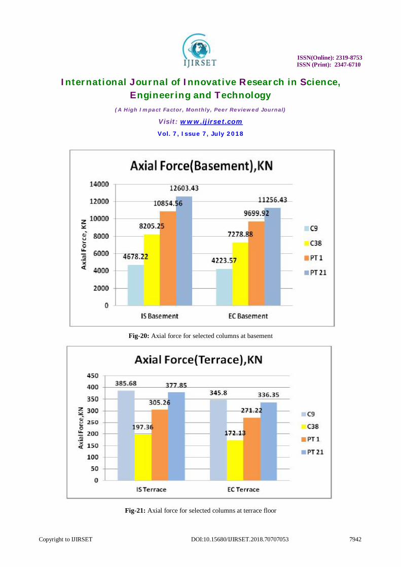
Table-4: Axial Force for selected Columns
Axial Force, KN Basement Terrace Column ID IS EC IS EC C9-200X750M40 4678.22 4223.57 385.68 345.8 C38-300X900M40
8205.25 7278.88 197.36 172.13
PT1-200X2000M40
10854.56 9699.92 305.26 271.22
PT21-200X2000M40
12603.43 11256.43 377.85 336.35
ISSN(Online): 2319-8753 ISSN (Print): 2347-6710
International Journal of Innovative Research in Science, Engineering and Technology
(A High Impact Factor, Monthly, Peer Reviewed Journal)
Visit: www.ijirset.com
Vol. 7, Issue 7, July 2018
Copyright to IJIRSET DOI:10.15680/IJIRSET.2018.70707053 7942
Fig-20: Axial force for selected columns at basement
Fig-21: Axial force for selected columns at terrace floor
ISSN(Online): 2319-8753 ISSN (Print): 2347-6710
International Journal of Innovative Research in Science, Engineering and Technology
(A High Impact Factor, Monthly, Peer Reviewed Journal)
Visit: www.ijirset.com
Vol. 7, Issue 7, July 2018
Copyright to IJIRSET DOI:10.15680/IJIRSET.2018.70707053 7943
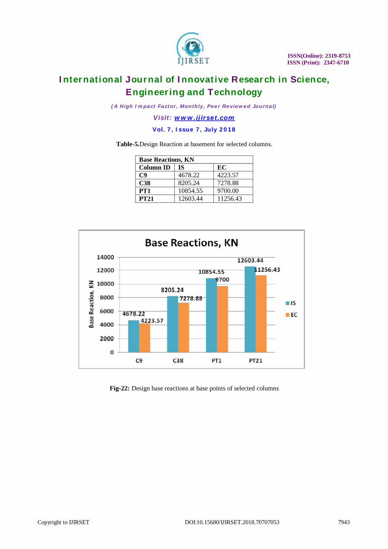
Table-5.Design Reaction at basement for selected columns.
Base Reactions, KN Column ID IS EC C9 4678.22 4223.57 C38 8205.24 7278.88 PT1 10854.55 9700.00 PT21 12603.44 11256.43
Fig-22: Design base reactions at base points of selected columns
ISSN(Online): 2319-8753 ISSN (Print): 2347-6710
International Journal of Innovative Research in Science, Engineering and Technology
(A High Impact Factor, Monthly, Peer Reviewed Journal)
Visit: www.ijirset.com
Vol. 7, Issue 7, July 2018
Copyright to IJIRSET DOI:10.15680/IJIRSET.2018.70707053 7944
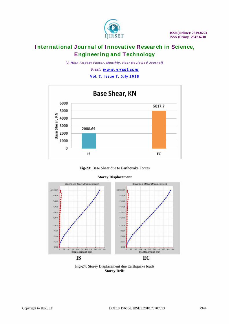
Fig-23: Base Shear due to Earthquake Forces
Storey Displacement
Fig-24: Storey Displacement due Earthquake loads
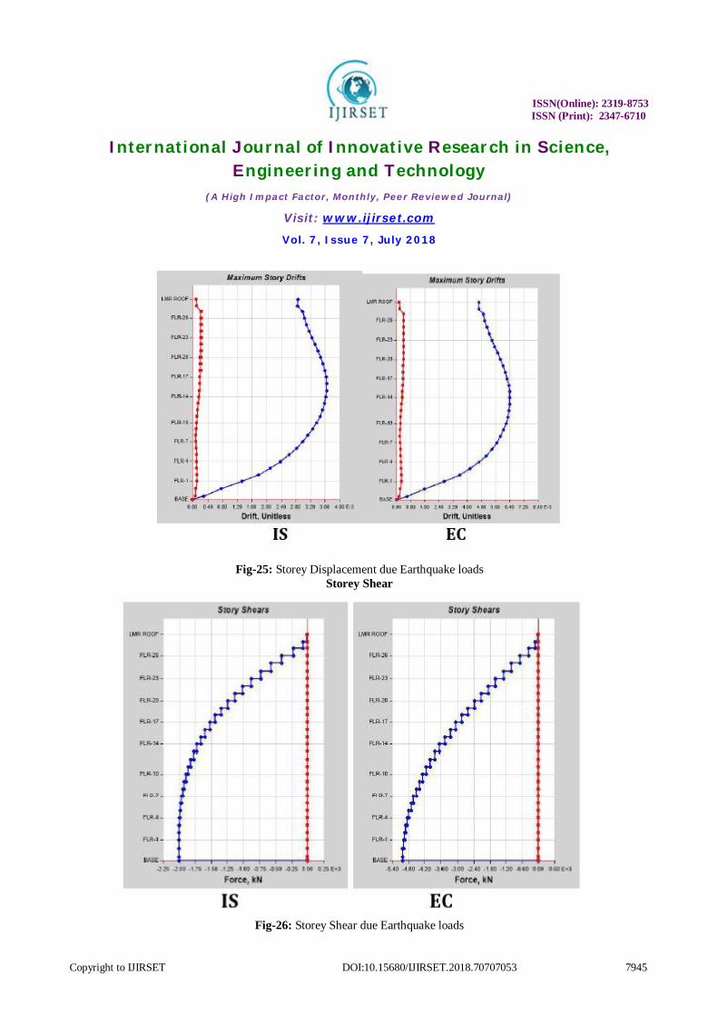
Storey Drift
ISSN(Online): 2319-8753 ISSN (Print): 2347-6710
International Journal of Innovative Research in Science, Engineering and Technology
(A High Impact Factor, Monthly, Peer Reviewed Journal)
Visit: www.ijirset.com
Vol. 7, Issue 7, July 2018
Copyright to IJIRSET DOI:10.15680/IJIRSET.2018.70707053 7945
Fig-25: Storey Displacement due Earthquake loads Storey Shear
Fig-26: Storey Shear due Earthquake loads
ISSN(Online): 2319-8753 ISSN (Print): 2347-6710
International Journal of Innovative Research in Science, Engineering and Technology
(A High Impact Factor, Monthly, Peer Reviewed Journal)
Visit: www.ijirset.com
Vol. 7, Issue 7, July 2018
Copyright to IJIRSET DOI:10.15680/IJIRSET.2018.70707053 7946
V. CONCLUSION
From the consideration of all the above points we conclude that
1. Static Analysis: In this project we compare Comparative Study of Low Rise(g+5)e, Mid Rise(g+10) and High Rise (g+15) Structure as per Is Code and Other Code Due to varied partial safety factors for dead and live loads and unit weight of concrete as indicated in both IS andEC codes, there are numerous variations in design parameters like Bending moment, Shear force, Axial force and Base design reactions. •Bending moment, Shear force, Axial forces and Base design are reduced in Euro code based design values by 8-13% •Storey displacement is decreased by 22.5% for static loads
2. Dynamic Analysis: Design base shear calculated according to EC 8 is higher than IS 1893 by up to 60% on account of high values of response reduction factors specified by IS code. •Due to higher design base shear, the storey displacement at top and storey drifts are high for Euro code based design, but these parameters are within the safe confinements specified by the codes. •Percentage of steel for column as per Euro standards is relatively lower. It’s because of higher values of modulus of elasticity of concrete specified by Euro code2 due to this the ductility of columns are enhanced by the concrete and axial force is less comparing to IS values because of low partial factor of safety for the dead loads. •The minimum and maximum percentage of reinforcement for columns as per IS is 0.8% and 6% respectively, where as per EC 2 is 0.2 % and 4%. So, this also makes impact while giving minimum reinforcement.
REFERENCES [1] Vinit Dhanvijay1, Prof. Deepa Telang2, Vikrant Nair3” Comparative Study of Different Codes in Seismic Assessment” International Research Journal of Engineering and Technology (IRJET) e-ISSN: 2395 -0056 Volume: 02 Issue: 04 | July-2015 www.irjet.net p-ISSN: 2395-0072 [2] Dr.T.Muralidhara Rao1, S.S.Phani2 “A CRITICAL COMPARATIVE STUDY OF IS:800-2007ANDIS:800-1984” 2016. [3] SaiKiran Gone, KailashRao, Pradeep Kumar RamancharlaInternational Journal of Civil, Architectural, Structural and Construction Engineering 2016 [4] Midhun B Sankar, Priya A Jacob “Comparison of Design Standards for Steel Railway Bridges” Midhun B Sankar, Priya A Jacob / International Journal of Engineering Research and Applications (IJERA) ISSN: 2248-9622 www.ijera.com Vol. 3, Issue 2, March -April 2013, pp.1131-1138 [5] M. Ameerutheen1, Sri. Aravindan “Study Of Stresses On Composite Girder Bridge Over Square And Skew Span” International Journal Of Civil Engineering And Technology (Ijciet) Issn 0976 – 6308 (Print) Issn 0976 – 6316(Online) Volume 5, Issue 2, February (2014), Pp. 88-96. [6] M.G.Kalyanshetti, G.S. Mirajkar “Comparison Between Conventional Steel Structures And Tubular Steel Structures” M.G.Kalyanshetti, G.S. Mirajkar / International Journal of Engineering Research and Applications (IJERA) ISSN: 2248-9622 www.ijera.com Vol. 2, Issue 6, November- December 2012, pp.1460-1464 [7] Adithya. M1, Swathi rani K.S2, Shruthi H K3, Dr. Ramesh B.R “Study On Effective Bracing Systems for High Rise Steel Structures” SSRG International Journal of Civil Engineering (SSRG-IJCE) – volume 2 Issue 2 February 2015 ISSN: 2348. [8] S.Jagadesh kannan#1, V.Vanitha*2, “Comparison of Various Types of Roofs in PEB” International Journal of Engineering Trends and Technology (IJETT) – Volume 22 Number 8-April 2015 [9] Abhishek Sanjay Mahajan1, Laxman G. Kalurkar “PERFORMANCE ANALYSIS OF RCC AND STEEL CONCRETE COMPOSITE STRUCTURE UNDER SEISMIC EFFECT”IJRET: International Journal of Research in Engineering and Technology eISSN: 2319-1163 | pISSN: 2321-7308 [10] Dr. N. Subramanian, (2008). “Code Of Practice On Steel Structures” -A Review Of IS 800: 2007, Civil Engineering and Construction Journal. [11] Mr. ArijitGuha, Mr. M MGhosh , (2008). “IS: 800 - Indian Code of Practice for Construction in Steel and its Comparison with International Codes”, Institute for Steel Development & Growth (INSDAG). [12] M. Krishnamoorthy, D.Tensing , (2008). “Design of Compression members based on IS 800-2007 and IS 800-1984- Comparison”, Journal of Information Knowledge and Research in civil engineering. [13] F. Faluyi , and C. Arum, (2012). “Design Optimization of Plate Girder Using Generalized Reduced Gradient and Constrained Artificial Bee Colony Algorithms”, International Journal of Emerging Technology and Advanced Engineering. [14] R. Abspoel, (2009). “Optimizing plate girder design”, Nordic steel construction conference. [15] ArijitGuha and Dr.T.K. Bandyopandhya (2004), “Structural Member Design Based on Draft IS: 800 (Limit State Method), Insdag’s steel journal”, Institute for steel development & Growth, Jan 2004, Volume5. [16] Akira Takaue, (2010).”Applied design codes on long-span bridge projects in Asia”, IABSE-JSCE Joint Conference on Advances in Bridge Engineering-II, August 8-10, Dhaka, Bangladesh. [17] Subramanian, N (2008). Design of Steel Structures, Oxford University Press, New Delhi. [18] IS 800:2007 (2007).“Indian standard code of practice for General Construction in Steel”, Bureau of Indian Standards, New Delhi.