company #1 • tooling checklist listed before work instructions
TRANSCRIPT
Highlighted Features – Company #1
Tooling checklist listed before work instructions to preempt operators & machinist to setup in advance.
Sections isolated distinctively and color coded.
Standard product information & description header on each page of the document.
Critical product characteristics highlighted & noted.
Images work well as a visual aid in conjunction with listed work instructions.
Easy to fill out inspection record. Record captures important criteria for product verification & validation.
Instructions are concise.

Product A Inspection Record
Specification Measurement Tol Min Max Actual Pass/Fail
1 Engraving legible Pass/Fail
2 Shape/appearance Pass/Fail
3 Free of voids & blowholes Pass/Fail
4 Free of debris inside and out Pass/Fail
5 Free of burrs Pass/Fail
6 Proper linear cure Pass/Fail
7 Proper container label Pass/Fail
8 Dimension 22 Tolerance +/- 2 20 24
9 (3) flatness +/- 1.5mm Pass/Fail
10 Dimension 81.3 Tolerance +/- 2 79.3 83.3
11 Part bagged #XXXXX Pass/Fail
12 Correct color #ZZZZZ Pass/Fail
13 Non-Texture area present at zone G2 (on print) Pass/Fail
14 Good plastic fill at cores Pass/Fail
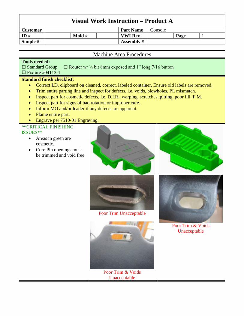
Visual Work Instruction – Product A
Customer Part Name Console
ID # Mold # VWI Rev Page 1
Simple # Assembly #
Machine Area Procedures
Tools needed:
Standard Group Router w/ ¼ bit 8mm exposed and 1” long 7/16 button
Fixture #04113-1
Standard finish checklist:
Correct I.D. clipboard on cleaned, correct, labeled container. Ensure old labels are removed.
Trim entire parting line and inspect for defects, i.e. voids, blowholes, PL mismatch.
Inspect part for cosmetic defects, i.e. D.I.R., warping, scratches, pitting, poor fill, F.M.
Inspect part for signs of bad rotation or improper cure.
Inform MO and/or leader if any defects are apparent.
Flame entire part.
Engrave per 7510-01 Engraving.
**CRITICAL FINISHING
ISSUES**
Areas in green are
cosmetic.
Core Pin openings must
be trimmed and void free
Poor Trim Unacceptable
Poor Trim & Voids
Unacceptable
Poor Trim & Voids
Unacceptable
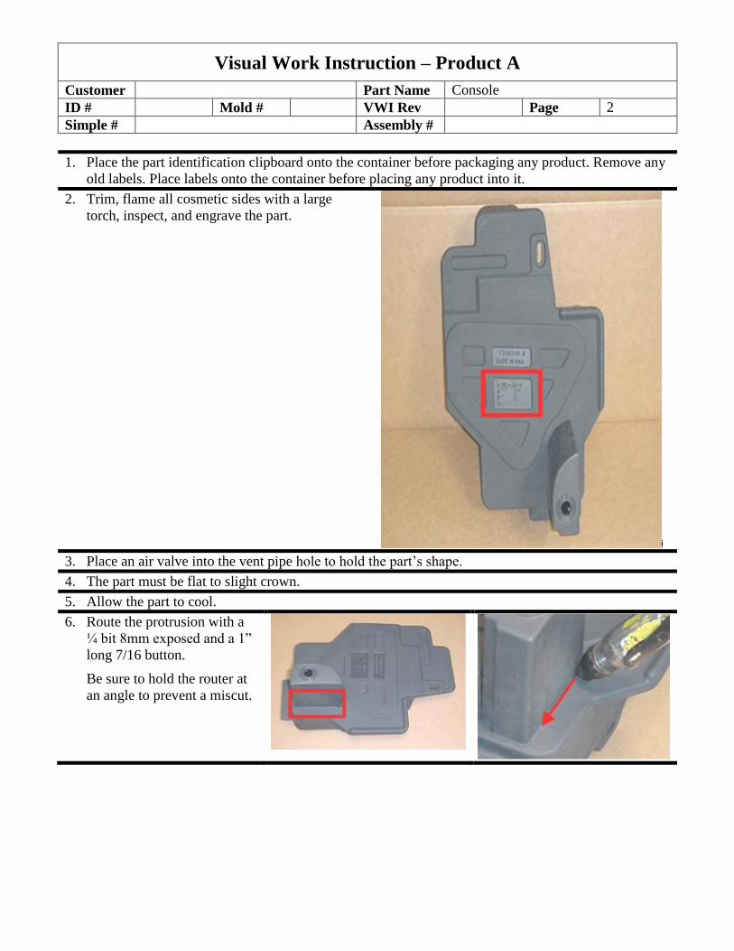
Visual Work Instruction – Product A
Customer Part Name Console
ID # Mold # VWI Rev Page 2
Simple # Assembly #
1. Place the part identification clipboard onto the container before packaging any product. Remove any
old labels. Place labels onto the container before placing any product into it.
2. Trim, flame all cosmetic sides with a large
torch, inspect, and engrave the part.
3. Place an air valve into the vent pipe hole to hold the part’s shape.
4. The part must be flat to slight crown.
5. Allow the part to cool.
6. Route the protrusion with a
¼ bit 8mm exposed and a 1”
long 7/16 button.
Be sure to hold the router at
an angle to prevent a miscut.

Visual Work Instruction – Product A
Customer Part Name Console
ID # Mold # VWI Rev Page 3
Simple # Assembly #
7. Clamp fixture #04113-1 onto the part, in order
shown.
Route the opening with a ¼ bit 8mm exposed
and a 1” long 7/16 button.
8. Deburr, clean, flame, and inspect the part. Thoroughly remove any debris from the part.
PACKAGING INSTRUCTIONS
Place the part into a bag #XXXXX.
Place (30) parts – (6) pieces per layer, (5) layers per contico, with cardboard divider
#YYYYY between layers – into a contico and label for shipping. Pack as shown in picture.

Product B Inspection Record
Specification Measurement Tol Min Max Actual Pass/Fail
1 No evidence of bad rotation Pass/Fail
2 Proper cure (X-Link) Pass/Fail
3 Free of burrs, voids, and blowholes Pass/Fail
4 Parting line trim smooth- no over trim scrapes Pass/Fail
5 Appearance of cosmetic areas, shown in v.w.i. Very
cosmetic in areas shown in green. Pass/Fail
6 Engraving legible Pass/Fail
7 (2) Molded Hole sizes. 8.0mm Tolerance +/.5 7.5 8.5
8 C/L to C/L molded Holes.156.0mm Tolerance +/-1.0 155 157
9 Rectangular section height. print (d4) 40.mm Tolerance +/-1.0 39 41
10 Correct packaging-Each part in bag. #XXXXX Pass/Fail
11 Package label blue in color Pass/Fail
12 Vent pipe not through inside wall Pass/Fail
13 36mm hole in round end Tolerance +/- 0.8 35.2 36.8
14 Correct part number marked with white marker Pass/Fail
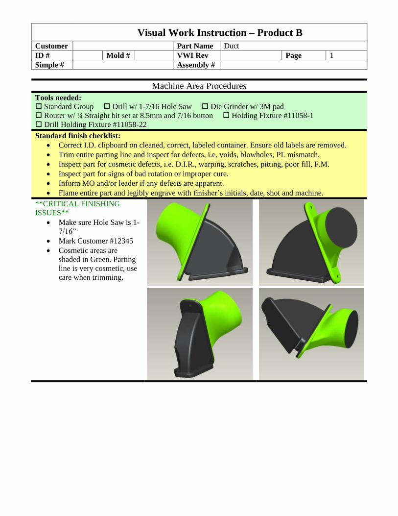
Visual Work Instruction – Product B
Customer Part Name Duct
ID # Mold # VWI Rev Page 1
Simple # Assembly #
Machine Area Procedures
Tools needed:
Standard Group Drill w/ 1-7/16 Hole Saw Die Grinder w/ 3M pad
Router w/ ¼ Straight bit set at 8.5mm and 7/16 button Holding Fixture #11058-1
Drill Holding Fixture #11058-22
Standard finish checklist:
Correct I.D. clipboard on cleaned, correct, labeled container. Ensure old labels are removed.
Trim entire parting line and inspect for defects, i.e. voids, blowholes, PL mismatch.
Inspect part for cosmetic defects, i.e. D.I.R., warping, scratches, pitting, poor fill, F.M.
Inspect part for signs of bad rotation or improper cure.
Inform MO and/or leader if any defects are apparent.
Flame entire part and legibly engrave with finisher’s initials, date, shot and machine.
**CRITICAL FINISHING
ISSUES**
Make sure Hole Saw is 1-
7/16”
Mark Customer #12345
Cosmetic areas are
shaded in Green. Parting
line is very cosmetic, use
care when trimming.
Visual Work Instruction – Product B
Customer Part Name Duct
ID # Mold # VWI Rev Page 2
Simple # Assembly #
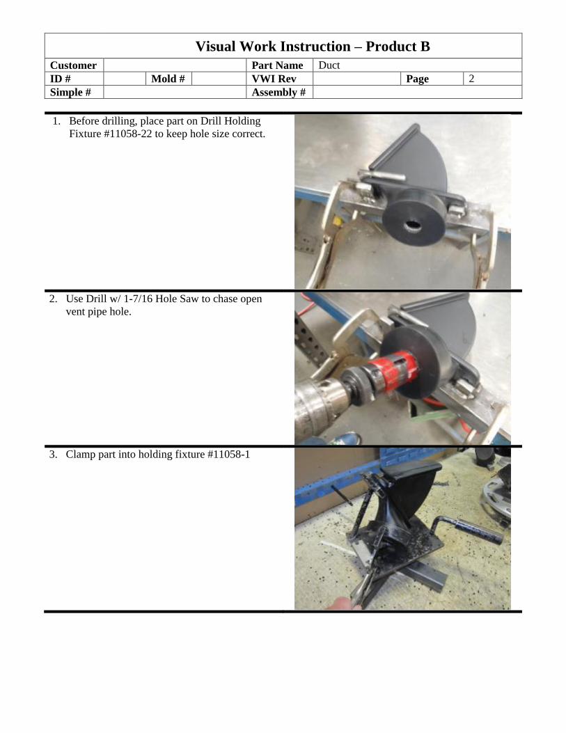
1. Before drilling, place part on Drill Holding
Fixture #11058-22 to keep hole size correct.
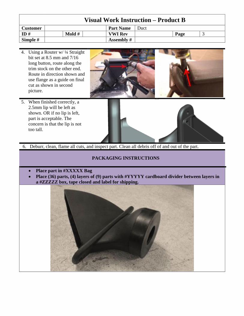
2. Use Drill w/ 1-7/16 Hole Saw to chase open
vent pipe hole.
3. Clamp part into holding fixture #11058-1
Visual Work Instruction – Product B
Customer Part Name Duct
ID # Mold # VWI Rev Page 3
Simple # Assembly #
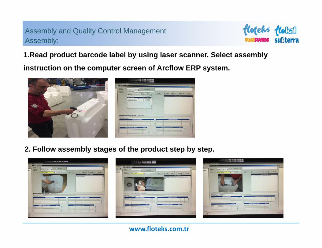
4. Using a Router w/ ¼ Straight
bit set at 8.5 mm and 7/16
long button, route along the
trim stock on the other end.
Route in direction shown and
use flange as a guide on final
cut as shown in second
picture.
5. When finished correctly, a
2.5mm lip will be left as
shown. OR if no lip is left,
part is acceptable. The
concern is that the lip is not
too tall.
6. Deburr, clean, flame all cuts, and inspect part. Clean all debris off of and out of the part.
PACKAGING INSTRUCTIONS
Place part in #XXXXX Bag
Place (36) parts, (4) layers of (9) parts with #YYYYY cardboard divider between layers in
a #ZZZZZ box, tape closed and label for shipping.

Highlighted Features – Company #2
Well‐structured and organized part processing system.
Parts are stationed by QC cell with individual barcodes to track each part throughout the process described.
Work instructions embedded into ERP system to streamline product manufacturing.
Images work well as a visual aid in conjunction with listed work instructions. Larger focus on visual instructions than written.
Instructions are concise.
www.floteks.com.tr
Assembly and Quality Control ManagementAssembly:
1.Read product barcode label by using laser scanner. Select assembly
instruction on the computer screen of Arcflow ERP system.
2. Follow assembly stages of the product step by step.
www.floteks.com.tr
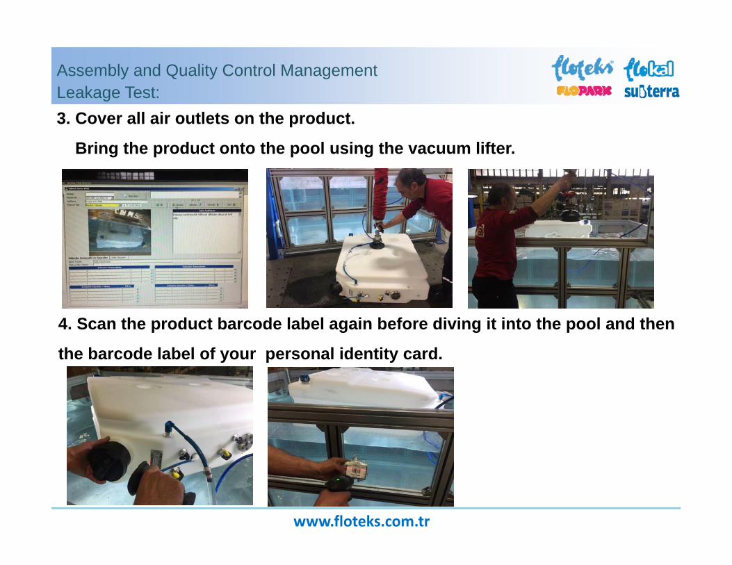
Assembly and Quality Control ManagementLeakage Test:3. Cover all air outlets on the product.
Bring the product onto the pool using the vacuum lifter.
4. Scan the product barcode label again before diving it into the pool and then
the barcode label of your personal identity card.

www.floteks.com.tr
Assembly and Quality Control ManagementLeakage Test:
5. Push start button to pressurise the tank under water. If there is no bubble
evolving within 18 seconds under 300mbar, push OK button and complete the test.
6. Barcode writer creates label automatically according to the test
result. Stick leakproof label ( OK ) onto product.
www.floteks.com.tr
Assembly and Quality Control ManagementFinal Control:
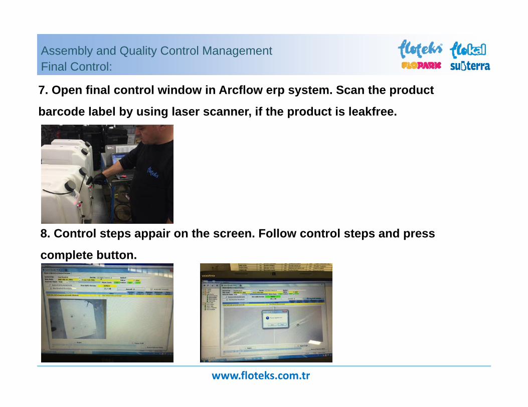
7. Open final control window in Arcflow erp system. Scan the product
barcode label by using laser scanner, if the product is leakfree.
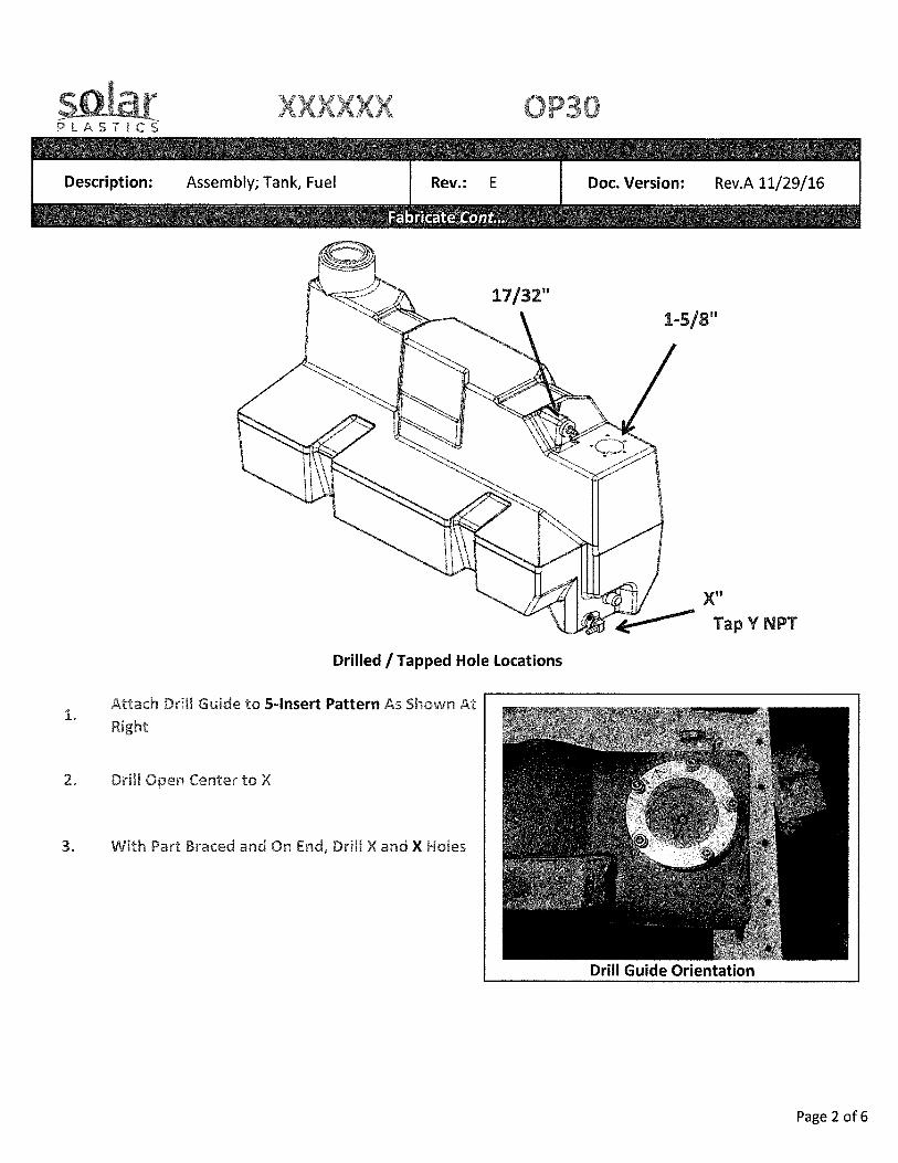
8. Control steps appair on the screen. Follow control steps and press
complete button.

Highlighted Features – Company #3
• Rotational molding parameters specified with molded hardware
components listed.
• Tooling checklist listed before work instructions to preempt operators & machinist to setup in advance.
• Standard product image shown on mostly every page throughout
the document.
• Standard product information & description header on each page of the document.
• Document name & revision level stated.
• Flow-chart to identify part processing steps throughout
manufacturing cycle.
• Sections isolated distinctively.
• Images work well as a visual aid in conjunction with listed work instructions. Larger focus on visual instructions than written.
• Images captioned briefly.
• Instructions are concise.

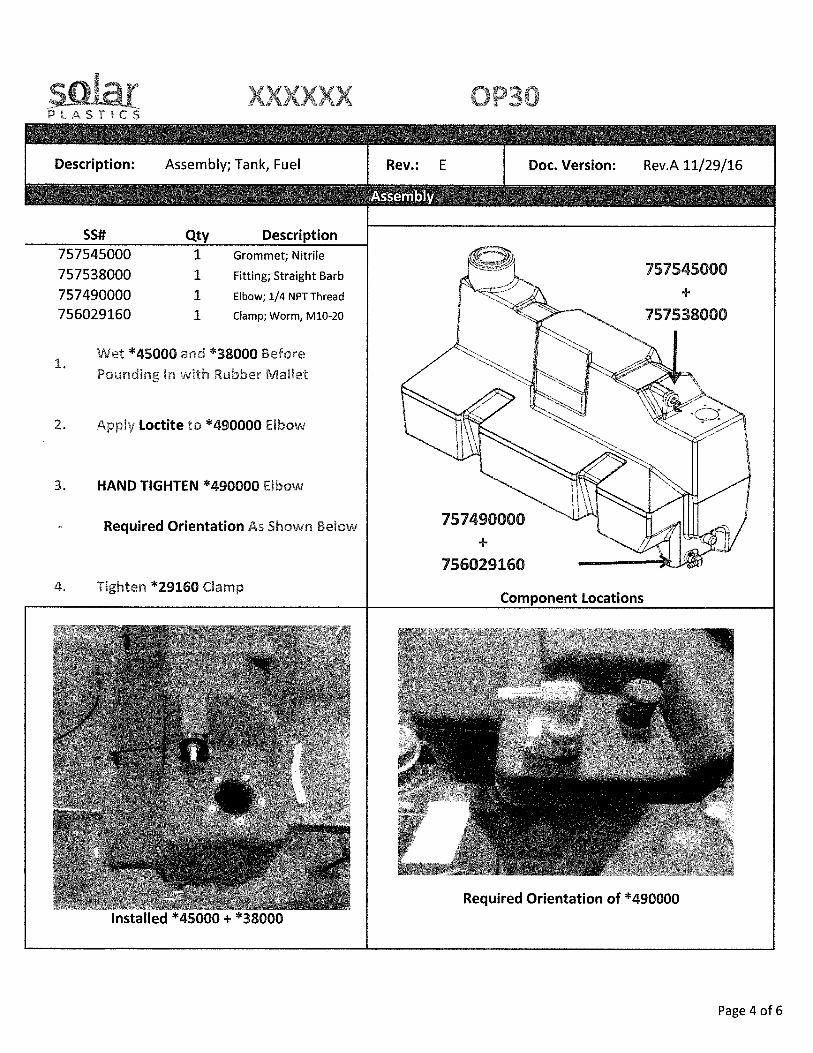
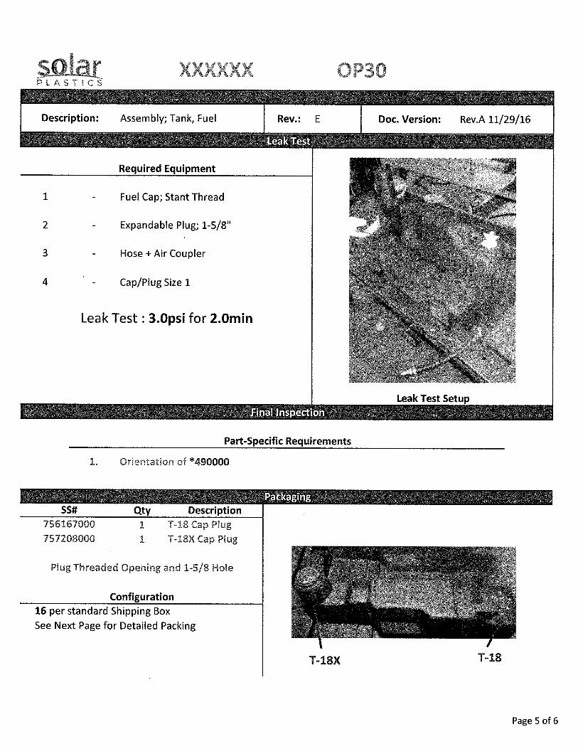

Highlighted Features – Company #4
• Coversheet details all prerequisite information & documents for product manufacturing.
• Hyperlinks to other pertinent documents for processing.
• Rotational molding parameters specified.
• Images work well as a visual aid in conjunction with listed work instructions. Larger focus on visual instructions than written. Multiple images to capture one instruction.
• Forewarning at footnote location of each page of the document. Helps alleviate obsolete instructions.
• Document name & revision level stated.
• Revision log to ascertain latest instructions are described.
• Instructions are concise.
• Effective use of cooling fixtures.
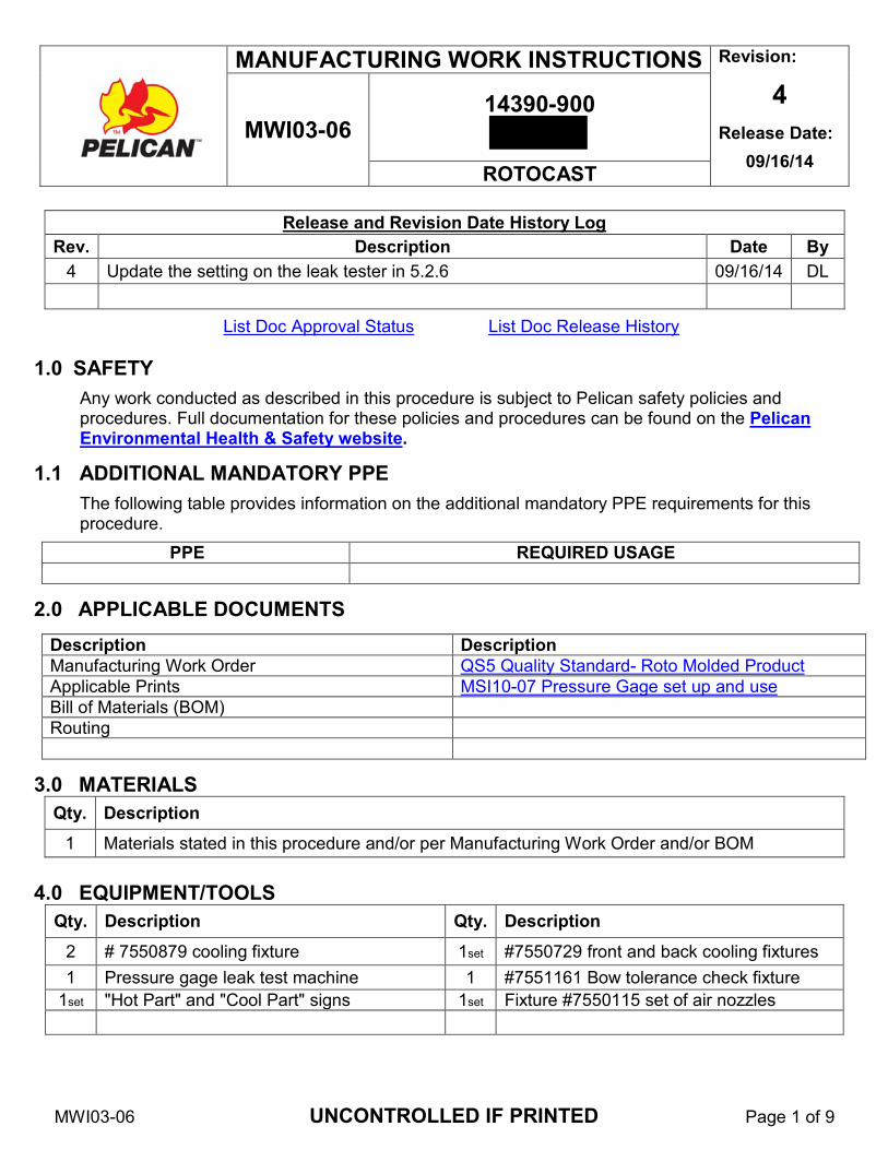
MWI03-06 UNCONTROLLED IF PRINTED Page 1 of 9
MANUFACTURING WORK INSTRUCTIONS Revision:
4 Release Date:
09/16/14 MWI03-06
14390-900
ROTOCAST
Release and Revision Date History Log
Rev. Description Date By 4 Update the setting on the leak tester in 5.2.6 09/16/14 DL
List Doc Approval Status List Doc Release History
1.0 SAFETY
Any work conducted as described in this procedure is subject to Pelican safety policies and procedures. Full documentation for these policies and procedures can be found on the Pelican Environmental Health & Safety website.
1.1 ADDITIONAL MANDATORY PPE
The following table provides information on the additional mandatory PPE requirements for this procedure.
PPE REQUIRED USAGE
2.0 APPLICABLE DOCUMENTS
Description Description Manufacturing Work Order QS5 Quality Standard- Roto Molded Product
Applicable Prints MSI10-07 Pressure Gage set up and use
Bill of Materials (BOM)
Routing
3.0 MATERIALS Qty. Description
1 Materials stated in this procedure and/or per Manufacturing Work Order and/or BOM
4.0 EQUIPMENT/TOOLS Qty. Description Qty. Description
2 # 7550879 cooling fixture 1set #7550729 front and back cooling fixtures 1 Pressure gage leak test machine 1 #7551161 Bow tolerance check fixture
1set "Hot Part" and "Cool Part" signs 1set Fixture #7550115 set of air nozzles
MWI03-06 UNCONTROLLED IF PRINTED Page 2 of 9
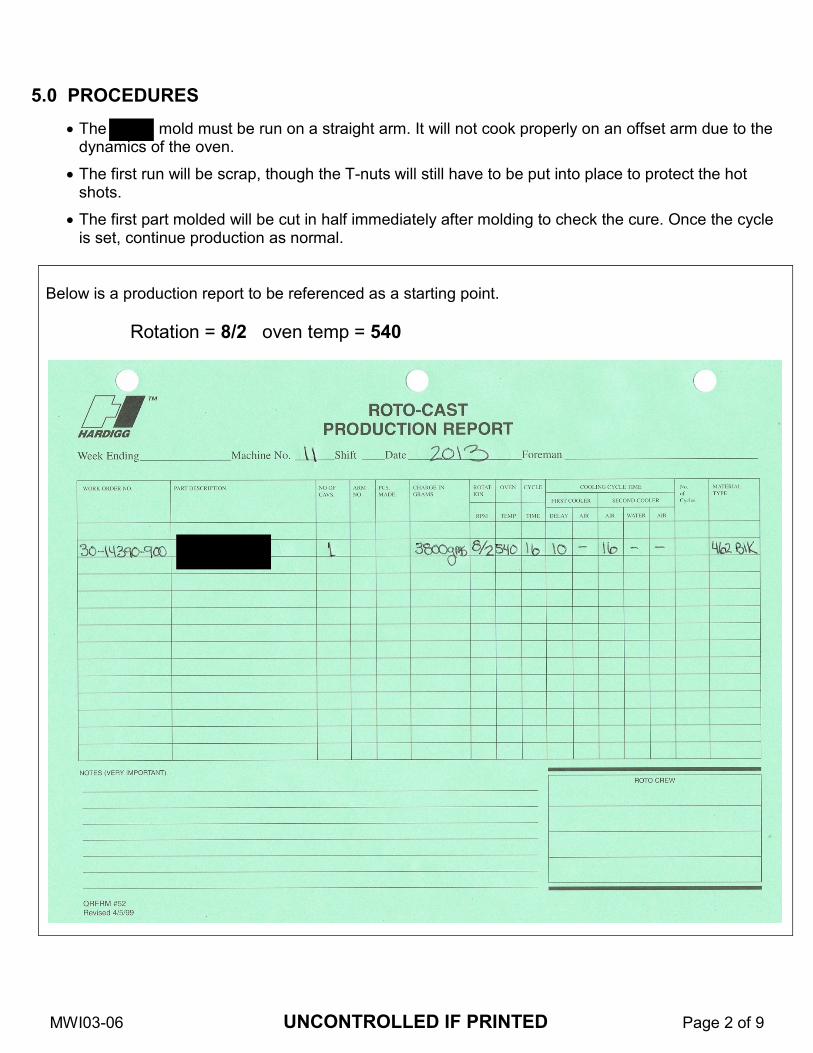
5.0 PROCEDURES
• The mold must be run on a straight arm. It will not cook properly on an offset arm due to the dynamics of the oven.
• The first run will be scrap, though the T-nuts will still have to be put into place to protect the hot shots.
• The first part molded will be cut in half immediately after molding to check the cure. Once the cycle is set, continue production as normal.
Below is a production report to be referenced as a starting point. Rotation = 8/2 oven temp = 540

MWI03-06 UNCONTROLLED IF PRINTED Page 3 of 9
5.1 MOLDING
5.1.1Disconnect the vortex from the mold.
5.1.2 Remove the front and rear covers and place them onto the cover table.
5.1.3 Remove the top section and place it onto
the cover table.
5.1.4 Remove the plug from the side of the mold.
MWI03-06 UNCONTROLLED IF PRINTED Page 4 of 9
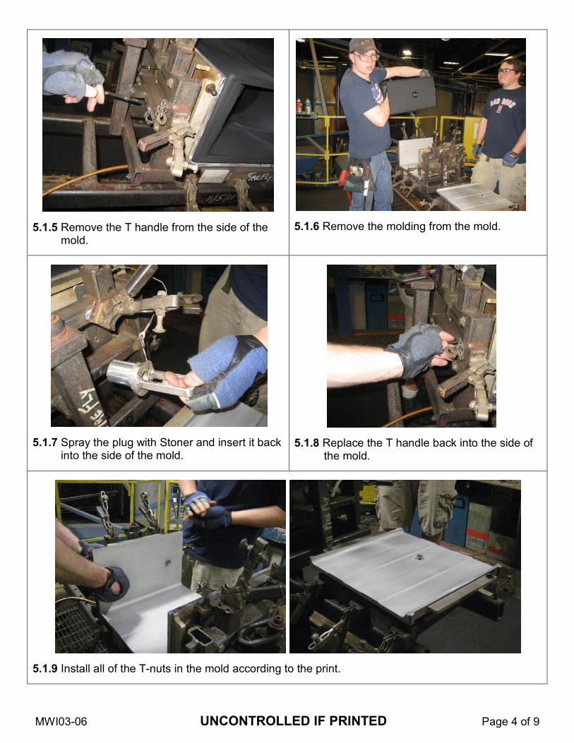
5.1.5 Remove the T handle from the side of the
mold.
5.1.6 Remove the molding from the mold.
5.1.7 Spray the plug with Stoner and insert it back
into the side of the mold.
5.1.8 Replace the T handle back into the side of
the mold.
5.1.9 Install all of the T-nuts in the mold according to the print.
MWI03-06 UNCONTROLLED IF PRINTED Page 5 of 9
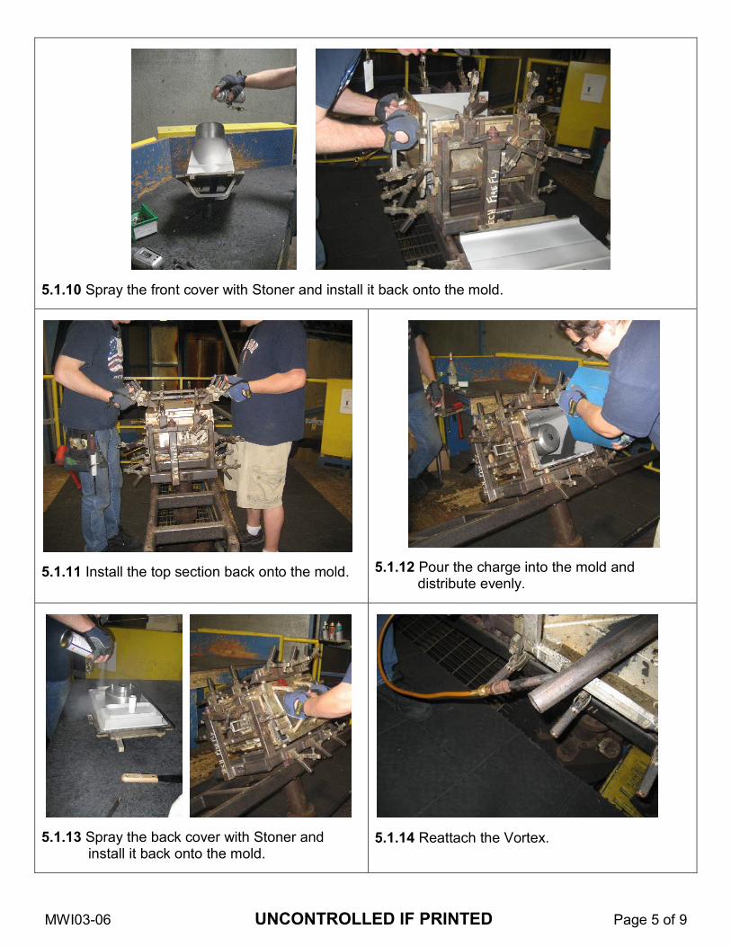
5.1.10 Spray the front cover with Stoner and install it back onto the mold.
5.1.11 Install the top section back onto the mold.
5.1.12 Pour the charge into the mold and
distribute evenly.
5.1.13 Spray the back cover with Stoner and
install it back onto the mold.
5.1.14 Reattach the Vortex.
MWI03-06 UNCONTROLLED IF PRINTED Page 6 of 9
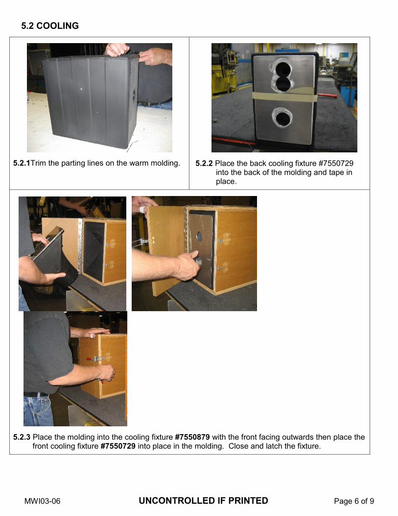
5.2 COOLING
5.2.1Trim the parting lines on the warm molding.
5.2.2 Place the back cooling fixture #7550729 into the back of the molding and tape in place.
5.2.3 Place the molding into the cooling fixture #7550879 with the front facing outwards then place the front cooling fixture #7550729 into place in the molding. Close and latch the fixture.
MWI03-06 UNCONTROLLED IF PRINTED Page 7 of 9
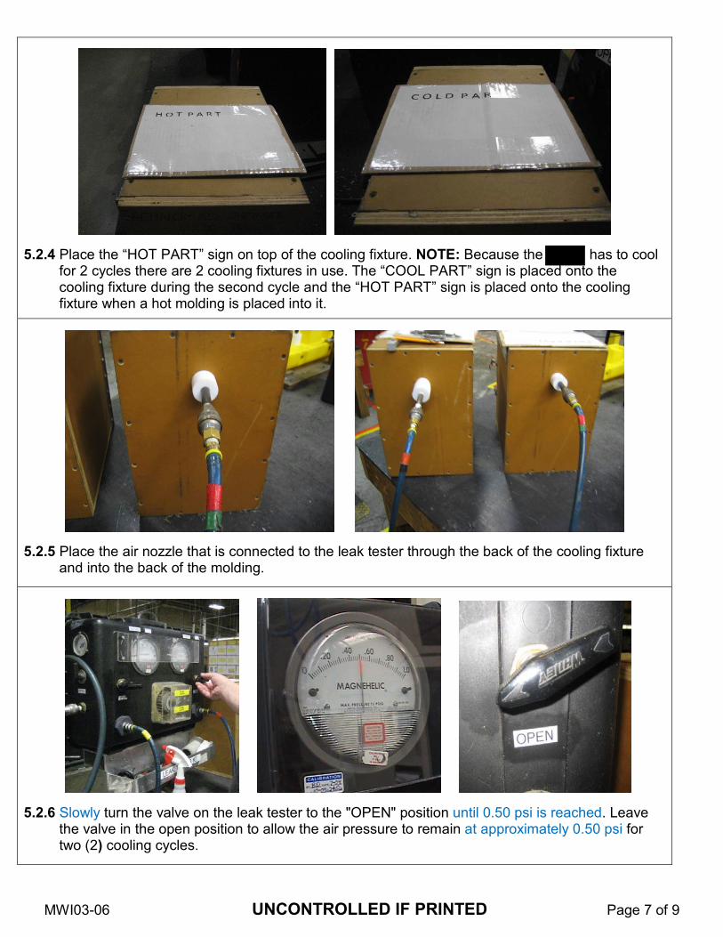
5.2.4 Place the “HOT PART” sign on top of the cooling fixture. NOTE: Because the has to cool
for 2 cycles there are 2 cooling fixtures in use. The “COOL PART” sign is placed onto the cooling fixture during the second cycle and the “HOT PART” sign is placed onto the cooling fixture when a hot molding is placed into it.
5.2.5 Place the air nozzle that is connected to the leak tester through the back of the cooling fixture
and into the back of the molding.
5.2.6 Slowly turn the valve on the leak tester to the "OPEN" position until 0.50 psi is reached. Leave
the valve in the open position to allow the air pressure to remain at approximately 0.50 psi for two (2) cooling cycles.
MWI03-06 UNCONTROLLED IF PRINTED Page 8 of 9
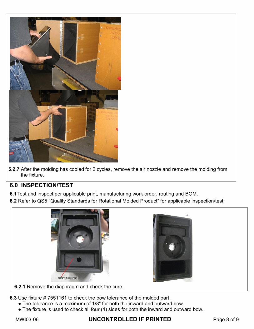
6.0 INSPECTION/TEST
6.1Test and inspect per applicable print, manufacturing work order, routing and BOM.
6.2 Refer to QS5 "Quality Standards for Rotational Molded Product” for applicable inspection/test.
6.2.1 Remove the diaphragm and check the cure.
6.3 Use fixture # 7551161 to check the bow tolerance of the molded part. ● The tolerance is a maximum of 1/8" for both the inward and outward bow. ● The fixture is used to check all four (4) sides for both the inward and outward bow.
5.2.7 After the molding has cooled for 2 cycles, remove the air nozzle and remove the molding from
the fixture.
MWI03-06 UNCONTROLLED IF PRINTED Page 9 of 9
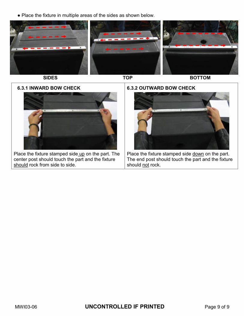
● Place the fixture in multiple areas of the sides as shown below.
SIDES TOP BOTTOM
6.3.1 INWARD BOW CHECK
Place the fixture stamped side up on the part. The center post should touch the part and the fixture should rock from side to side.
6.3.2 OUTWARD BOW CHECK
Place the fixture stamped side down on the part. The end post should touch the part and the fixture should not rock.
MWI03-110 UNCONTROLLED IF PRINTED Page 1 of 5
MANUFACTURING WORK INSTRUCTIONS Revision:
1 Release Date:
11/11/15 MWI03-110
13886-400 TANK
ROTOCAST
Release and Revision Date History Log Rev. Description Date By
1 Initial Release 11/11/15 DL
List Doc Approval Status List Doc Release History
1.0 SAFETY
Any work conducted as described in this procedure is subject to Pelican safety policies and procedures. Full documentation for these policies and procedures can be found on the Pelican Environmental Health & Safety website.
1.1 ADDITIONAL MANDATORY PPE
The following table provides information on the additional mandatory PPE requirements for this procedure.
PPE REQUIRED USAGE
2.0 APPLICABLE DOCUMENTS
Description Description Manufacturing Work Order QS5 Quality Standard- Roto Molded Product Applicable Prints Bill of Materials (BOM) Routing
3.0 MATERIALS
Materials stated in this procedure and/or per Manufacturing Work Order and/or BOM
4.0 EQUIPMENT/TOOLS
Qty. Description Qty. Description Basic Rotocast tool set up

MWI03-110 UNCONTROLLED IF PRINTED Page 2 of 5
5.0 PROCEDURES
5.1 MOLDING
5.1.1. Below is a production report to be referenced as a starting point.
Rotation = 6/1 Oven temp = 535 Cycle = 25
MWI03-110 UNCONTROLLED IF PRINTED Page 3 of 5
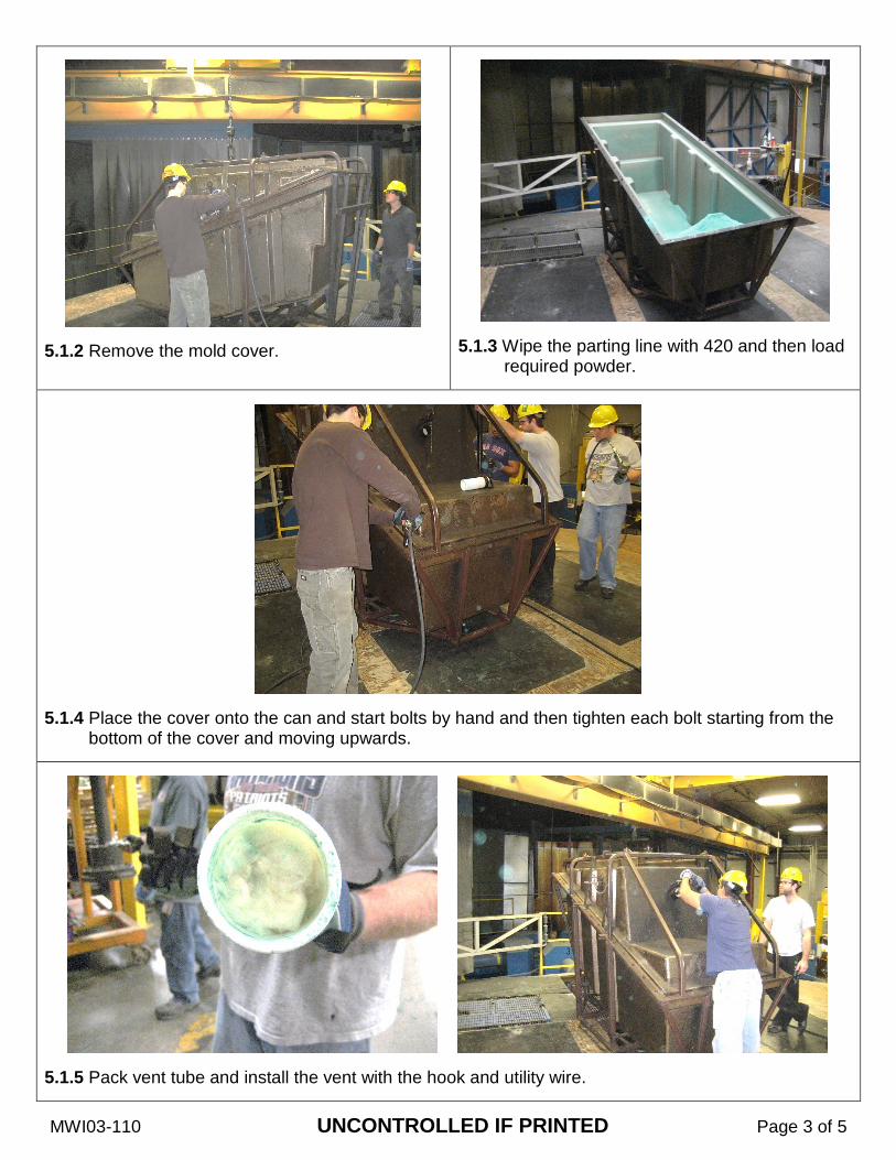
5.1.2 Remove the mold cover.
5.1.3 Wipe the parting line with 420 and then load
required powder.
5.1.4 Place the cover onto the can and start bolts by hand and then tighten each bolt starting from the
bottom of the cover and moving upwards.
5.1.5 Pack vent tube and install the vent with the hook and utility wire.

MWI03-110 UNCONTROLLED IF PRINTED Page 4 of 5
5.1.6 Remove the two plugs (one on each side of the cover) and wipe with 420. Fill the plug installation holes with insulation and install the plugs.
5.1.7 NOTE: After first molding, if part was sticking, apply TRA 420 to a clean rag and wipe the inside
walls of the mold.
5.2 DE-MOLDING
5.2.1 Remove the bolts from the cover of the mold. Lift the cover and molding off/out of the can.
MWI03-110 UNCONTROLLED IF PRINTED Page 5 of 5
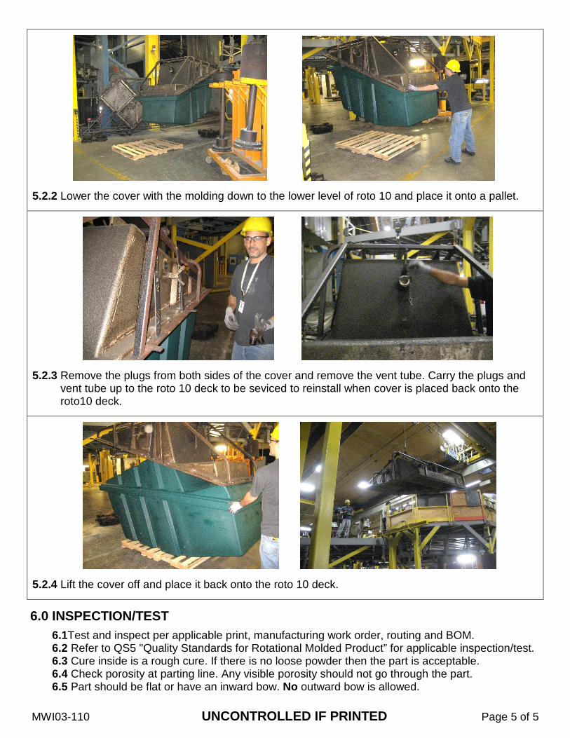
5.2.2 Lower the cover with the molding down to the lower level of roto 10 and place it onto a pallet.
5.2.3 Remove the plugs from both sides of the cover and remove the vent tube. Carry the plugs and
vent tube up to the roto 10 deck to be seviced to reinstall when cover is placed back onto the roto10 deck.
5.2.4 Lift the cover off and place it back onto the roto 10 deck.
6.0 INSPECTION/TEST
6.1Test and inspect per applicable print, manufacturing work order, routing and BOM. 6.2 Refer to QS5 "Quality Standards for Rotational Molded Product” for applicable inspection/test. 6.3 Cure inside is a rough cure. If there is no loose powder then the part is acceptable. 6.4 Check porosity at parting line. Any visible porosity should not go through the part. 6.5 Part should be flat or have an inward bow. No outward bow is allowed.

Highlighted Features – Company #5
• Purpose & intended user of document stated clearly.
• Tooling & equipment checklist listed before work instructions to preempt operators & machinist to setup in advance.
• Table of contents included for easier navigation throughout the
document.
• Revision log to ascertain latest instructions are described.
• Critical instructions are noted separately from main
instructions body.
• Images work well as a visual aid in conjunction with listed work instructions. Larger focus on visual instructions than written.
• Inspection chart captures important criteria for product
verification & validation. Specifies extent of defects
permissible.
• Well organized & detailed inspection report document.
• References other pertinent documents.
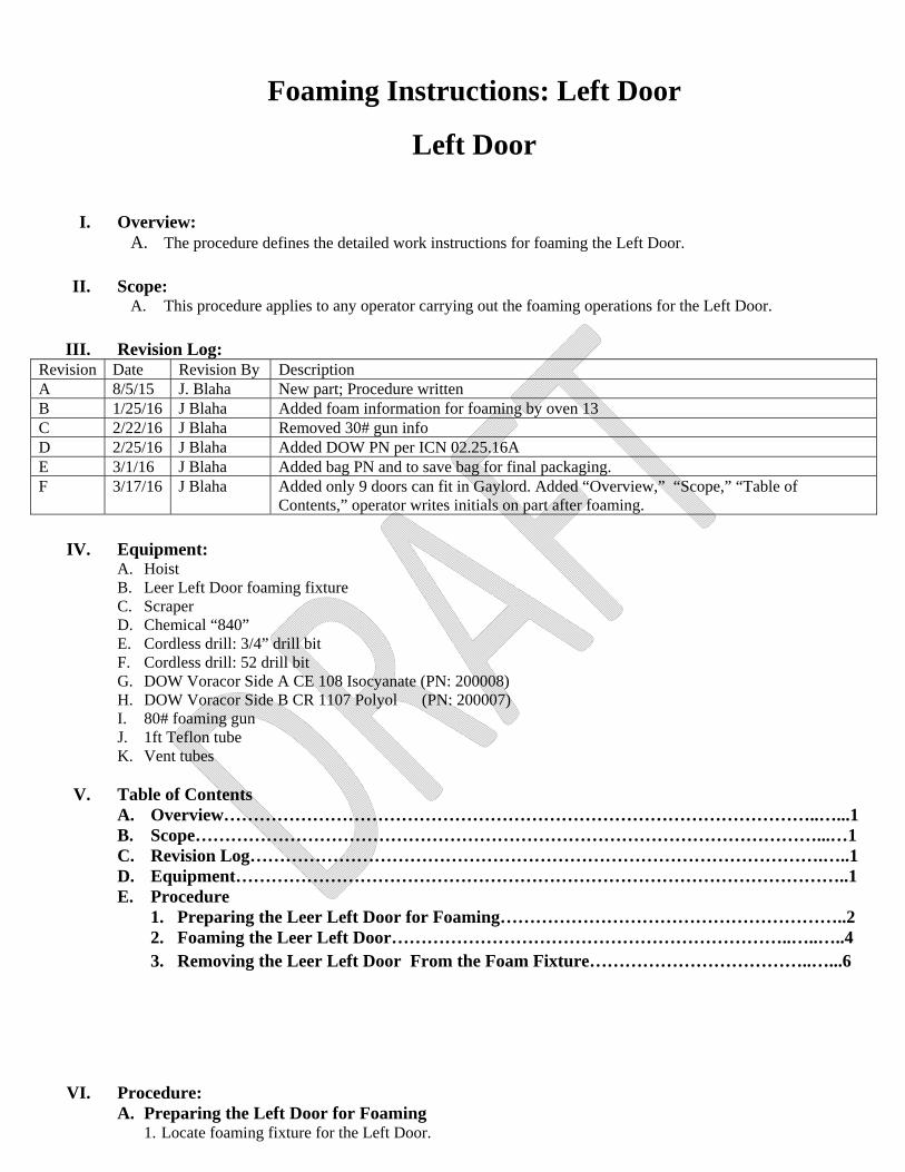
Foaming Instructions: Left Door
Left Door
I. Overview: A. The procedure defines the detailed work instructions for foaming the Left Door.
II. Scope:
A. This procedure applies to any operator carrying out the foaming operations for the Left Door.
III. Revision Log:
Revision Date Revision By Description A 8/5/15 J. Blaha New part; Procedure written B 1/25/16 J Blaha Added foam information for foaming by oven 13 C 2/22/16 J Blaha Removed 30# gun info D 2/25/16 J Blaha Added DOW PN per ICN 02.25.16A E 3/1/16 J Blaha Added bag PN and to save bag for final packaging. F 3/17/16 J Blaha Added only 9 doors can fit in Gaylord. Added “Overview,” “Scope,” “Table of
Contents,” operator writes initials on part after foaming.
IV. Equipment:
A. Hoist B. Leer Left Door foaming fixture C. Scraper D. Chemical “840” E. Cordless drill: 3/4” drill bit F. Cordless drill: 52 drill bit G. DOW Voracor Side A CE 108 Isocyanate (PN: 200008) H. DOW Voracor Side B CR 1107 Polyol (PN: 200007) I. 80# foaming gun J. 1ft Teflon tube K. Vent tubes
V. Table of Contents A. Overview………………………………………………………………………………………..…...1 B. Scope……………………………………………………………………………………………...…1 C. Revision Log…………………………………………………………………………………….…..1 D. Equipment…………………………………………………………………………………………..1 E. Procedure
1. Preparing the Leer Left Door for Foaming…………………………………………………..2 2. Foaming the Leer Left Door…………………………………………………………..…..…..4 3. Removing the Leer Left Door From the Foam Fixture………………………………..…...6
VI. Procedure: A. Preparing the Left Door for Foaming
1. Locate foaming fixture for the Left Door.

2. Use a scraper to remove excess flash from the foaming fixture.
NOTE: The surface of the foaming fixture should be smooth and free of debris.
3. Obtain the Left Door from the Gaylord from the oven.
4. Remove the plastic bag (PN: BEL2453). NOTE: Save this bag as it will be used in the final packaging of the door.
5. Use a ¾” drill bit to drill out the 2 vent holes on the bottom of the door.
6. Trim the flash off of the 2 vent holes located in the bottom of the door.
7. Use a 52 drill bit to drill 6 vent holes along the bottom edge of the door.
8. Spray all holes with chemical “840.”
9. Place the Left Door, face down, inside the foaming fixture.
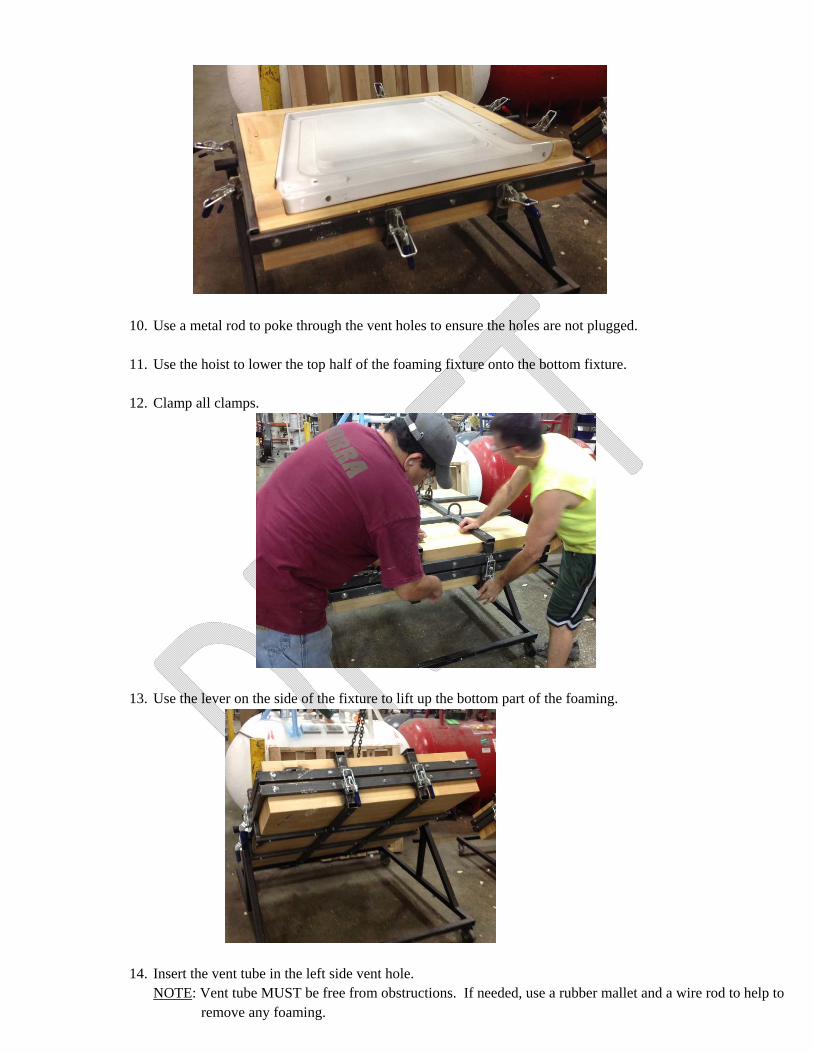
10. Use a metal rod to poke through the vent holes to ensure the holes are not plugged.
11. Use the hoist to lower the top half of the foaming fixture onto the bottom fixture. 12. Clamp all clamps.
13. Use the lever on the side of the fixture to lift up the bottom part of the foaming.
14. Insert the vent tube in the left side vent hole.
NOTE: Vent tube MUST be free from obstructions. If needed, use a rubber mallet and a wire rod to help to remove any foaming.
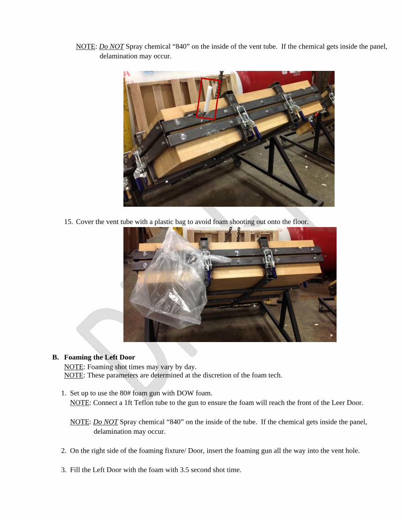
NOTE: Do NOT Spray chemical “840” on the inside of the vent tube. If the chemical gets inside the panel,
delamination may occur.
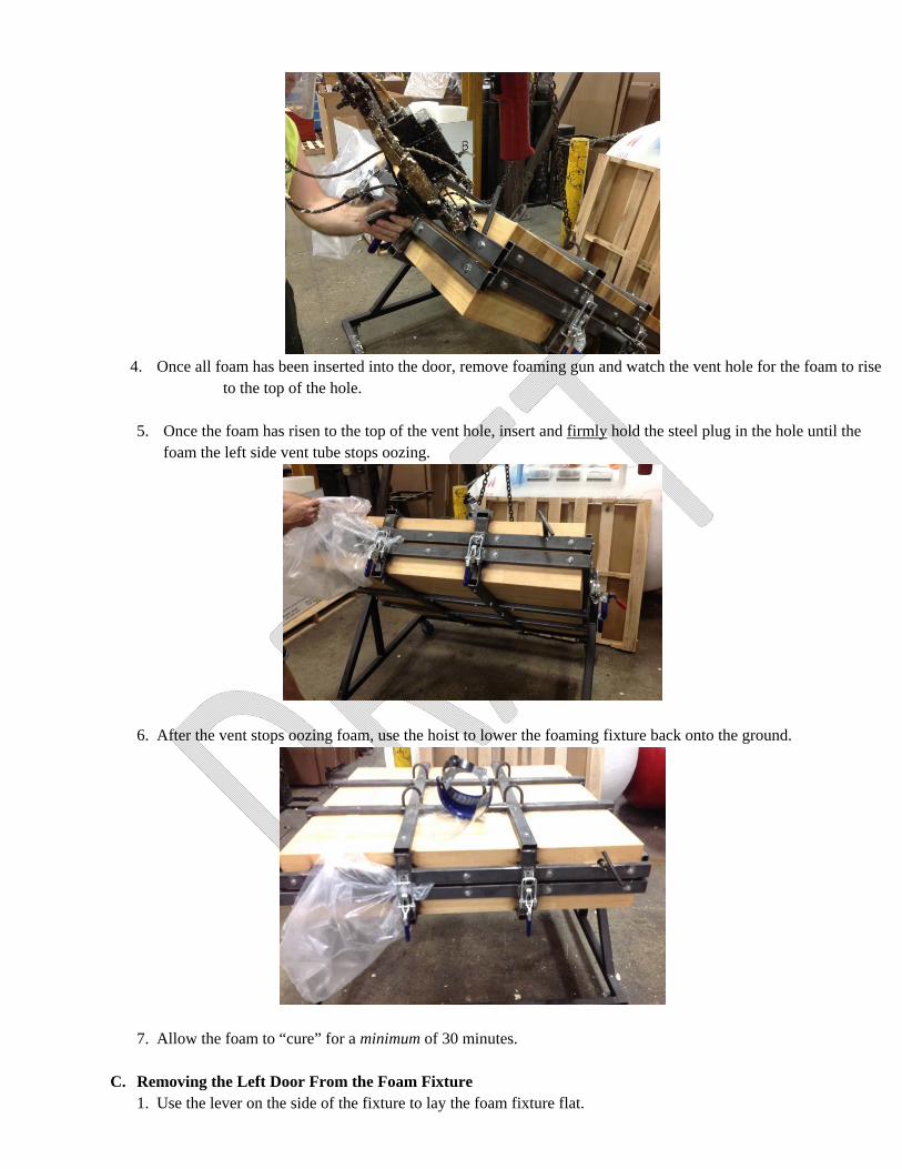
15. Cover the vent tube with a plastic bag to avoid foam shooting out onto the floor.
B. Foaming the Left Door NOTE: Foaming shot times may vary by day. NOTE: These parameters are determined at the discretion of the foam tech.
1. Set up to use the 80# foam gun with DOW foam. NOTE: Connect a 1ft Teflon tube to the gun to ensure the foam will reach the front of the Leer Door. NOTE: Do NOT Spray chemical “840” on the inside of the tube. If the chemical gets inside the panel,
delamination may occur.
2. On the right side of the foaming fixture/ Door, insert the foaming gun all the way into the vent hole.
3. Fill the Left Door with the foam with 3.5 second shot time.
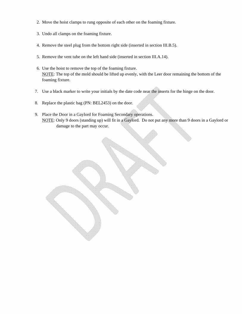
4. Once all foam has been inserted into the door, remove foaming gun and watch the vent hole for the foam to rise
to the top of the hole.
5. Once the foam has risen to the top of the vent hole, insert and firmly hold the steel plug in the hole until the foam the left side vent tube stops oozing.
6. After the vent stops oozing foam, use the hoist to lower the foaming fixture back onto the ground.
7. Allow the foam to “cure” for a minimum of 30 minutes.
C. Removing the Left Door From the Foam Fixture 1. Use the lever on the side of the fixture to lay the foam fixture flat.
2. Move the hoist clamps to rung opposite of each other on the foaming fixture.
3. Undo all clamps on the foaming fixture.
4. Remove the steel plug from the bottom right side (inserted in section III.B.5).
5. Remove the vent tube on the left hand side (inserted in section III.A.14).
6. Use the hoist to remove the top of the foaming fixture.
NOTE: The top of the mold should be lifted up evenly, with the Leer door remaining the bottom of the foaming fixture.
7. Use a black marker to write your initials by the date code near the inserts for the hinge on the door.
8. Replace the plastic bag (PN: BEL2453) on the door.
9. Place the Door in a Gaylord for Foaming Secondary operations.
NOTE: Only 9 doors (standing up) will fit in a Gaylord. Do not put any more than 9 doors in a Gaylord or damage to the part may occur.

Page 1
Foaming Secondary Instructions:
Left Door I. Overview
A. This procedure defines the detailed secondary work instructions for the Left Door (PN: 1241002).
II. Scope A. This procedure applies to any operator carrying out the secondary procedure for the Left Door.
III. Revision Log: Revision Date Revision By Description A 8/17/15 J. Blaha New part; Procedure written B 2/5/16 J Blaha Update quality specs per: Rev 3 (25-Sep-2015) C 2/23/16 J Blaha Updated packaging per ICN 10.28.15 D 2/24/16 J Blaha Clarified to patch holes only along parting lines, not foaming vent holes E 2/25/16 J Blaha Added 2 white plugs (CAB2684) to procedure; missing info from initial run.
Added plugs and handle check fixture to FIP. F 3/17/16 J Blaha Added bag PN and replace if necessary for final packaging. Added pics for packaging and
unacceptable flash and contamination/porosity. Added Operators initials by date code.G 6/7/16 J Blaha Changed to paint pen to identify defects, instead of blue tape (doesn’t stick well). Changed
checking gasket channel with straight edge to using the Gasket Channel Flatness Fixture. Changed Gaylord from PN: Gregaylordbx to PN: 760012 per ICN 5.25.16.
IV. Equipment:
A. Gaylord box (PN: 760012) B. Bubble Wrap (PN: Polbubblewrap) C. Knife D. Trimming Tool E. Water F. Mr. Clean G. Sponge
H. Cool temperature patcher I. Air hose J. Straight edge K. Panel Gasket Channel Check Fixture L. (2) Heyco 2684 White Plug (PN: CAB2684) M. 36 x 42 Skid
V. Table of Contents
A. Overview………………………………………………………………….………………………….1 B. Scope………………………………………………………………………………………………….1 C. Revision Log………………………………………………………………………………………….1 D. Equipment……………………………………………………………………………………………1 E. Table of Contents…………………………………………………………………………………….1 F. Procedure
1. Trimming and Inserting Plugs in the Left Door………….…………………………2 2. Performing the Final Inspection……………………………….…………………………..3 3. Packaging the Left Door……………………………………...………………………6
G. Attachments………………………………………………………………………………………….7 H. References……………………………………………………………………………………………7
Page 2
VI. Procedure: A. Trimming and Inserting Plugs in the Left Door
NOTE: Use paint pen to identify defects. Do not use a permanent marker to identify foam voids or other defects. The marker is time-consuming to remove and if left long enough on the part will permanently leach into the plastic.
1. Place bubble wrap on the table top to prevent any scratches on the Door while trimming.
2. Obtain a Left Door from the Gaylord from foaming.
3. Remove the bag (PN: BEL2453) from the Door. NOTE: Save this bag as it will be used in the final packaging of the door.
4. Use a trimmer/knife to remove excess flash from the Door.
NOTE: All surfaces of the door should be smooth.
5. Use a trimmer/knife to remove exposed foam from the Door. NOTE: There should be no foam exposed to the outside of the door.
6. Patch any holes along the parting lines using poly with a cool temperature patcher to avoid leaving burn
marks on the door. NOTE: All patched surfaces should be smooth. NOTE: The foaming vent holes on the bottom of the door do not need to be patched; only holes along the
parting lines.
7. Attempt to buff out any scratches/gouges/scuffs on the front of the door that can be seen from less than 2 feet away.
8. Use Mr. Clean/water mix and a sponge to thoroughly clean the door.
9. Use the air hose to blow out any debris from grooves.
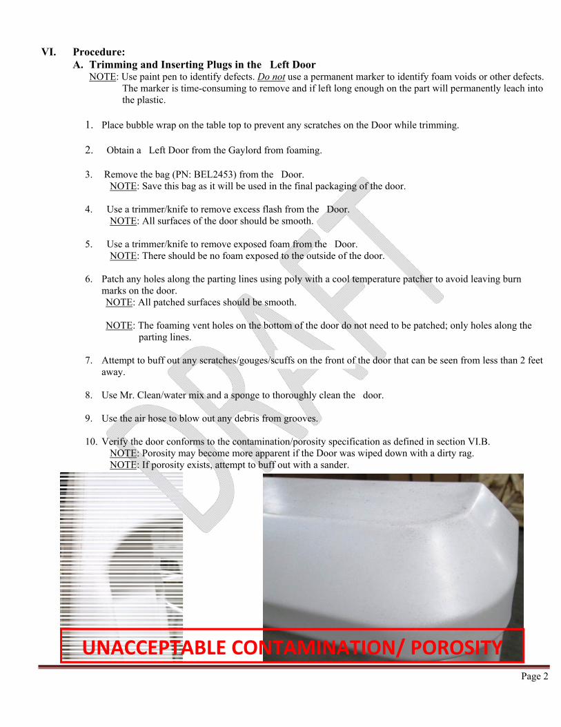
10. Verify the door conforms to the contamination/porosity specification as defined in section VI.B. NOTE: Porosity may become more apparent if the Door was wiped down with a dirty rag. NOTE: If porosity exists, attempt to buff out with a sander.
UNACCEPTABLE CONTAMINATION/ POROSITY

Page 3
11. In the vent hole on the bottom right side of the door, insert one Heyco 2684 White Plug (PN: CAB2684).
12. In the vent hole on the bottom left side of the door, insert one Heyco 2684 White Plug (PN: CAB2684).
13. Using a black marker, write your initials by the date code by the inserts for the hinge on the door.
B. Performing the Final Inspection NOTE: Inspect all items 100% unless otherwise noted.
1. Verify the door has no dirt or finger prints.
2. Verify the door is the color white.
3. Ensure all excess foam has been removed from the door.
4. Verify all flash has been removed on the entire Panel.
5. Use the table below to verify the door conforms to the specifications. NOTE: A surface includes the front and hinge side of the part and the outer sides. NOTE: B surface includes the top and back of the door. NOTE: C surface includes the bottom of the door.
UNACCEPTABLE FLASH
CAB2684
Page 4
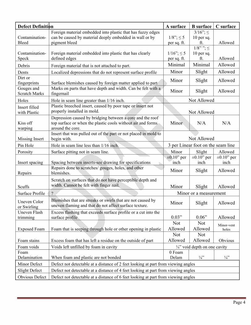
Defect Definition A surface B surface C surface
Contamination-Bleed
Foreign material embedded into plastic that has fuzzy edges can be caused by material deeply embedded in wall or by pigment bleed
1/8”; ≤ 5 per sq. ft.
3/16”; ≤ 10 per sq.
ft. Allowed
Contamination-Speck
Foreign material embedded into plastic that has clearly defined edges
1/16”; ≤ 5 per sq. ft.
1/8” ”; ≤ 10 per sq.
ft. Allowed
Debris Foreign material that is not attached to part. Minimal Minimal Allowed
Dents Localized depressions that do not represent surface profile Minor Slight Allowed Dirt or fingerprints Surface blemishes caused by foreign matter applied to part Minor Slight Allowed
Gouges and Scratch Marks
Marks on parts that have depth and width. Can be felt with a fingernail Minor Slight Allowed
Holes Hole in seam line greater than 1/16 inch. Not Allowed
Insert filled with Plastic
Plastic breeched insert, caused by poor tape or insert not properly installed in mold. Not Allowed
Kiss off warping
Depression caused by bridging between a core and the roof top surface or when the plastic cools without air and forms around the core.
Minor N/A N/A
Missing Insert Insert that was pulled out of the part or not placed in mold to begin with. Not Allowed
Pin Hole Hole in seam line less than 1/16 inch. 3 per Linear foot on the seam line Porosity Surface pitting not in seam line. Minor Slight Allowed
Insert spacing Spacing between inserts-see drawing for specifications ±0.10” per
inch ±0.10” per
inch ±0.10” per
inch
Repairs Repairs done to scratches/ gouges, holes, and other blemishes. Minor Slight Allowed
Scuffs
Scratch on surfaces that do not have perceptible depth and width. Cannot be felt with finger nail. Minor Slight Allowed
Surface Profile ? Minor or a measurement
Uneven Color or Swirling
Blemishes that are streaks or swirls that are not caused by uneven flaming and that do not affect surface texture. Minor Slight Allowed
Uneven Flash trimming
Excess flashing that exceeds surface profile or a cut into the surface profile 0.03” 0.06” Allowed
Exposed Foam Foam that is seeping through hole or other opening in plastic Not
Allowed Not
Allowed Minor-vent
holes
Foam stains Excess foam that has left a residue on the outside of part Not
Allowed Not
Allowed Obvious
Foam voids Voids left unfilled by foam in cavity ¼” void depth on one cavity Foam Delamination When foam and plastic are not bonded
0 Foam Delam ¼” ¼”
Minor Defect Defect not detectable at a distance of 2 feet looking at part from viewing angles
Slight Defect Defect not detectable at a distance of 4 feet looking at part from viewing angles
Obvious Defect Defect not detectable at a distance of 6 feet looking at part from viewing angles
Page 5
6. Verify there is zero foam delamination on surface A. NOTE: Delamination is when the plastic detaches from the foam, creating a bubble between the two surfaces.
This can be detected when you press on the part and feel a void between the plastic and the foam.
NOTE: A surface includes the front and hinge side of the part and the outer sides.
7. Verify there is no more than ¼” delamination present on Surfaces B and C. NOTE: Delamination is when the plastic detaches from the foam, creating a bubble between the two surfaces.
This can be detected when you press on the part and feel a void between the plastic and the foam.
NOTE: B surface includes the top and back of the door. NOTE: C surface includes the bottom of the door.
8. Verify the door conforms to the contamination/porosity specification.
NOTE: A surface (top and sides): specks- ≤ 1/16” & ≤ 5 specks per sq. ft.; porosity- not detectable at a distance of 2 feet looking at part from viewing angles.
NOTE: B surface (bell and back): specks- ≤ 1/8” & 10 specks per sq. ft.; porosity- not detectable at a distance
of 4 feet looking at part from viewing angles. NOTE: C surface (bottom): Allowed as long as it does not disrupt the function of the door. NOTE: Porosity may become more apparent if the door was wiped down with a dirty rag.
9. Verify the flatness of the hinge area on the door is a maximum of 1/8” (0.125”).
NOTE: Use a straight edge and a drill bit as a feeler gauge.
10. Verify the hinge area to the gasket area has a difference of no more than 1/16” (0.06”). NOTE: Use a straight edge and a drill bit as a feeler gauge.
11. Verify the flatness of the gasket area on the door is a maximum of 1/8” (0.120”).
NOTE: Use the large Panel Gasket Channel Check Fixture and a drill bit as a feeler gauge.
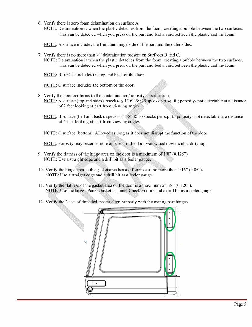
12. Verify the 2 sets of threaded inserts align properly with the mating part hinges.
Page 6
13. Verify there are 2 white plug caps in the vent holes on the both the right and left side on the bottom of the door.
14. Use the metal door handle to check the fit/alignment of the handles to the door.
NOTE: Check once per shift. 15. Record results on the Door FIP form.
C. Packaging the Left Door
1. Place a clean and empty Gaylord (PN: 760012) on a 36 x 42 skid.
2. Replace the plastic bag (PN: BEL2453) over the Door. NOTE: Replace the bag if there are many holes present.
3. Place the door in Gaylord (PN: 760012) for shipping. NOTE: 9 doors will fit in 1 Gaylord.
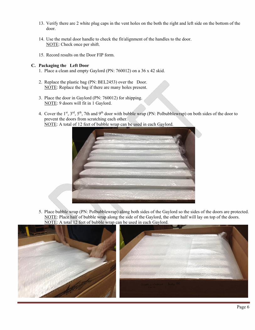
4. Cover the 1st, 3rd, 5th, 7th and 9th door with bubble wrap (PN: Polbubblewrap) on both sides of the door to prevent the doors from scratching each other. NOTE: A total of 12 feet of bubble wrap can be used in each Gaylord.
5. Place bubble wrap (PN: Polbubblewrap) along both sides of the Gaylord so the sides of the doors are protected. NOTE: Place half of bubble wrap along the side of the Gaylord, the other half will lay on top of the doors. NOTE: A total 12 feet of bubble wrap can be used in each Gaylord.
Page 7
6. Use parts of an empty cardboard box to create a top to help keep the doors clean.
7. Report finished Gaylord in EPICOR, reporting the exact number of Left Doors the Gaylord contains.
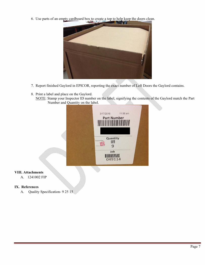
8. Print a label and place on the Gaylord. NOTE: Stamp your Inspector ID number on the label, signifying the contents of the Gaylord match the Part
Number and Quantity on the label.
VIII. Attachments A. 1241002 FIP
IX. References
A. Quality Specification- 9 25 15
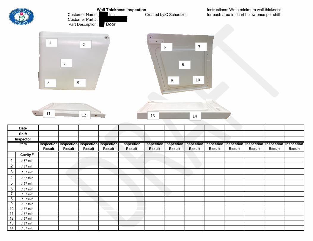
Customer Name: Inc Created by:C SchaetzerCustomer Part #:Part Description: Door
Inspection Inspection Inspection Inspection Inspection Inspection Inspection Inspection Inspection Inspection Inspection Inspection InspectionResult Result Result Result Result Result Result Result Result Result Result Result Result
Cavity #1 .187 mIn
2 .187 mIn
3 .187 mIn
4 .187 mIn
5 .187 mIn
6 .187 mIn7 .187 mIn8 .187 mIn9 .187 mIn
10 .187 mIn11 .187 mIn12 .187 mIn13 .187 mIn14 .187 mIn
Item
Instructions: Write minimum wall thickness for each area in chart below once per shift.
DateShift
Inspector
Wall Thickness Inspection
1 2
4 5
3
6 7
8
9 10
13 1411 12
Customer Name: ,IncCustomer Part #:Part Description: Left Hand Door
Inspection Inspec.Inspection Inspection Inspection Inspection Inspection Inspection Inspection Inspection Inspection Inspection Inspection InspectionMethod Freq. Result Result Result Result Result Result Result Result Result Result Result Result
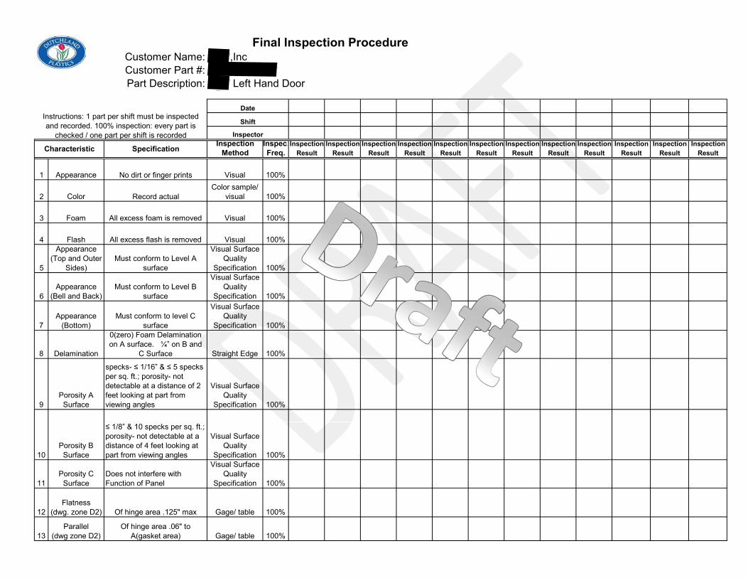
1 Appearance No dirt or finger prints Visual 100%
2 Color Record actualColor sample/
visual 100%
3 Foam All excess foam is removed Visual 100%
4 Flash All excess flash is removed Visual 100%
5
Appearance (Top and Outer
Sides)Must conform to Level A
surface
Visual Surface Quality
Specification 100%
6Appearance
(Bell and Back)Must conform to Level B
surface
Visual Surface Quality
Specification 100%
7Appearance
(Bottom)Must conform to level C
surface
Visual Surface Quality
Specification 100%
8 Delamination
0(zero) Foam Delamination on A surface. ¼” on B and
C Surface Straight Edge 100%
9Porosity A
Surface
specks- ≤ 1/16” & ≤ 5 specks per sq. ft.; porosity- not detectable at a distance of 2 feet looking at part from viewing angles
Visual Surface Quality
Specification 100%
10Porosity B
Surface
≤ 1/8” & 10 specks per sq. ft.; porosity- not detectable at a distance of 4 feet looking at part from viewing angles
Visual Surface Quality
Specification 100%
11Porosity C
SurfaceDoes not interfere with Function of Panel
Visual Surface Quality
Specification 100%
12Flatness
(dwg. zone D2) Of hinge area .125" max Gage/ table 100%
13Parallel
(dwg zone D2)Of hinge area .06" to
A(gasket area) Gage/ table 100%
Final Inspection Procedure
Characteristic Specification
Instructions: 1 part per shift must be inspected and recorded. 100% inspection: every part is
checked / one part per shift is recorded
Date
Shift
Inspector
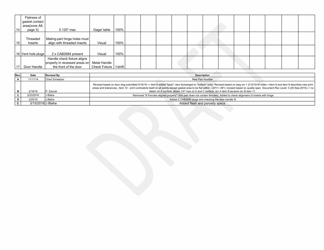
14
Flatness of gasket contact area(zone A8,
page 3) 0.120" max Gage/ table 100%
15Threaded
InsertsMating-part hinge holes must
align with threaded inserts Visual 100%
16 Vent hole plugs 2 x CAB2684 present Visual 100%
17 Door Handle
Handle check fixture aligns properly in recessed areas on
the front of the doorMetal Handle Check Fixture 1/shift
Rev. Date Revised ByA 11/11/14 Chad Schaetzer
B 2/18/16 P. ZaczykC 2/23/2016 J BlahaD 2/25/16 J BlahaE 3/15/2016 J Blaha
Added 2 CAB2684 plugs and checking the door handle fitRemoved "8 Ferrules aligned properly" (this part does not contain ferrules). Added to check alignment of inserts with hinge
Added flash and porosity specs
DescriptionNew Part Number
Revised based on door dwg submitted 5/18/15--> item 5 added "back"; item 6(changed to "bottom" only). Revised based on dwg rev 1 2/12/16 M miller-->item 8 and item 9 describes new print areas and tolerances.; Item 10 - print contradicts itself on all points except gasket area to be flat within .120"(+-.06"); revised based on quality spec Document Rev Level: 3 (25-Sep-2015)--> no
delam on A surface; delam 1/4" max on b and C surface; rev A item 9 became rev B item 11.

LEFT HAND DOOR WEIGHT: 23 # TOTAL (2 different materials) MOLD NUMBER: LEER1241002
COLOR JERR9354158 Untreated White: 17.25# JERR9354ADH158 Treated White: 5.75# INSERTS: (6) 1/4"-20 BRASS HEX (MAS1020614)
(1) 5/16”-18 BRASS HEX (MAS1020615) WALL THICKNESS REFERENCE: .187” Settings: PRODUCTION:
Different material suppliers have us listing the material by A or B and not part number.
TRIMMING OPERATIONS: Use paint pen to identify defects. Do not use a permanent marker to identify defects. The marker is time-
consuming to remove and if left long enough on the part will permanently leach into the plastic.
Trim seamlines, watching for holes. Be careful to not inadvertently scratch or gouge the part. Date code in marker by inserts for hinge on door.
Put door in bag BEL2453 to prevent against scrapes and gouges. This bag will follow the part all the
way to packaging operations. Place in cooling fixture for one round. Make sure the door is in the bag before putting it in the cooling
fixture.
Part needs to be foam filled.
UNACCEPTABLE CONTAMINATION/POROSITY
UNACCEPTABLE FLASH

Revision: Date: Revision By: Description: A 08.04.15 T. Brill New B 8.12.15 T Mentink Updated with new Jerico Material C 2/26/16 J Blaha Added date code location, use of BEL2453. Removed need to upkeep date wheel. D 3/15/16 J Blaha Added pictures of unacceptable flash, contamination/porosity E 6/6/16 J Blaha Changed to paint pen to identify defects, instead of blue tape (doesn’t stick well). F 9/2/16 J Blaha Changed “Secondary” heading to “Trimming Operations” to clarify Trimmer’s
responsibility
Highlighted Features – Company #6
• Rotational molding parameters specified with product bill of
materials listed.
• Coversheet details all prerequisite information & documents for product manufacturing.
• Tooling & equipment checklist listed before work instructions to preempt operators & machinist to setup in advance.
• Images work well as a visual aid in conjunction with listed work instructions. Larger focus on visual instructions than written. Multiple images to capture one instruction.
• Subsection for inspection checks within each instruction.
• Instructions are concise.
• Instructions document template remains consistent for processing of different parts. Template captures all necessary stages of manufacturing.

ROTATIONAL MOLDING INC. Date:
Customer & Part Specifications: Material Specifications:Customer: Shot Weight: Lbs.
Part Name: Material / Color:RMI Part No: Mixture: Grams / Lbs
Customer Part No: Dry Blend (Vendor):Drawing No: Pigment (Number & Vendor):Wall Thkns: Inch Compounded (Vendor):
Finished Wt: Lbs. RMI Pigment I.D. No:
Bill of Materials:
123456789
1011121314151617181920
Tooling Mold Info:Tooling Mold Vendor: Single Cavity x Qty Molds Supplied:
Aluminum x Double Cavity I.D. on Mold:Fabricated Steel / S.S.T. Multiple Parts Additional Parts:
Primary Production Specifications: Secondary Production Specifications:Machine Used: Rotation Ratio: Trimming
Part Loading/Arm: Major (Arm) 8 Hand Routing / Drilling# of Operators: Minor (Plate) 2 CNC Machining
Load/Unload Time: min AssemblyOven Cycle Time: min Cleaning
Oven Temperature: F Mold Release Used: Flamingair Yes x Material Handlingwater No Finished Goods Handlingair Cooling Jig Used: Leak Test
Yes Taping Off HolesArm Type: No x Packaging Foaming:
Standard Arm Q.C. Inspection at Machine: Boxing: Density (Lbs)Offset Arm x Yes Bagging: Amt. (sec.)
Single Frame No x Other: Pallet Time (mins.)
Packaging: Pallet (Qty / Pallet): Note:Box (Qty / Box):Other (Explain):
Qty
12
6010
10
1
Labo
r Tim
e in
Min
utes
Cooling Cycle Time:
3
30
Description Part Number
PRODUCT SPECIFICATION SHEET
02-600155
Vendor
700.0
Sulphate Return Tank Config. A700.00
LLDPE / Natural02B02120
45
370
Secondary procedure labor times are based on two employees per part.
6058
20
600
This Part has two
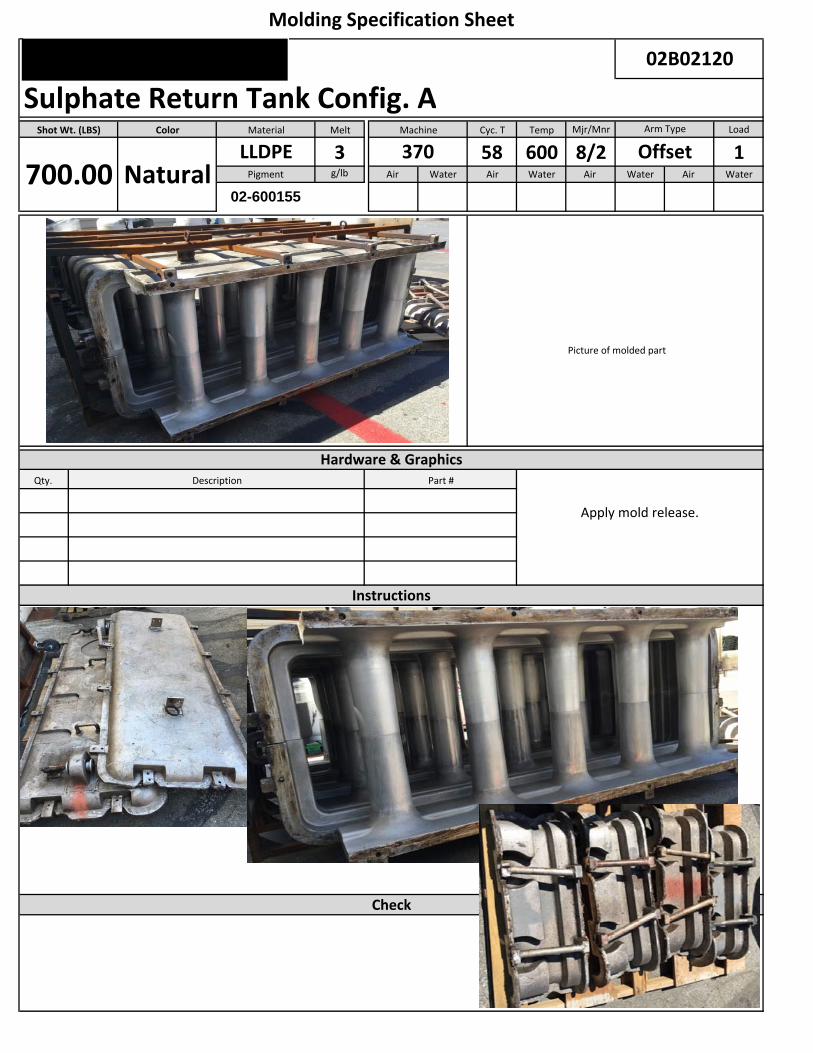
Melt Cyc. T Temp Mjr/Mnr Load
3 58 600 8/2 1g/lb Air Water Air Water Air Water Air Water
Picture of mold Picture of molded part
Qty.
Check
Part #
Instructions
OffsetPigment
02-600155
Description
Hardware & Graphics
700.00 NaturalLLDPE 370
Apply mold release.
Molding Specification Sheet
02B02120
Sulphate Return Tank Config. AShot Wt. (LBS) Color Material Machine Arm Type
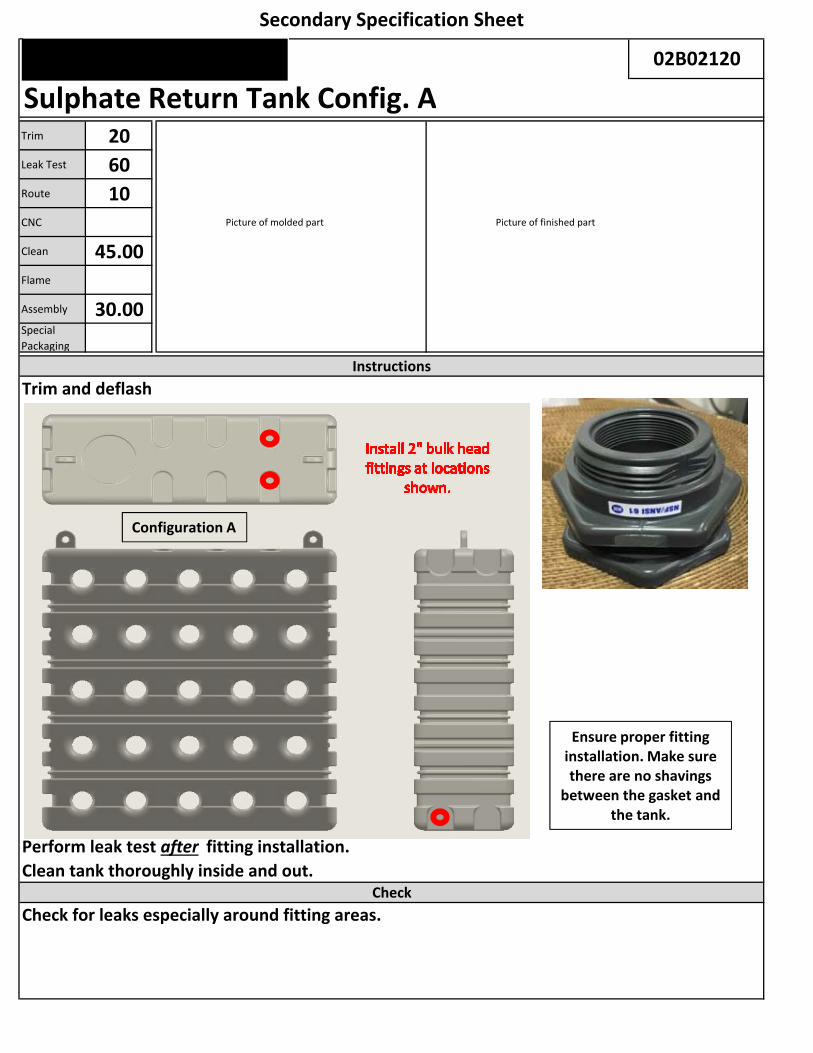
Trim 20Leak Test 60Route 10CNC Picture of molded part Picture of finished part
Clean 45.00Flame
Assembly 30.00Special
Packaging
Trim and deflash
Perform leak test after fitting installation.Clean tank thoroughly inside and out.
Check for leaks especially around fitting areas.
Secondary Specification Sheet
Check
Instructions
Sulphate Return Tank Config. A02B02120
Configuration A
Ensure proper fitting installation. Make sure there are no shavings
between the gasket and the tank.

Melt Trim Clean Leak T. Route
3 20 45 60 10g/lb CNC Flame Asmby Spc Pckg
30
Note: Images do not include fittings.
Quality Control
Sulphate Return Tank Config. A02B02120
Shrink wrap parts individually.
Make sure tanks do not contain any shavings from trimming and routing.
Make sure tanks are leak free.
Color Material Wall Thickness
Notes
Natural
Shot Wt. (LBS)
700.00LLDPE
Pigment
02‐600155
ROTATIONAL MOLDING INC. Date:
Customer & Part Specifications: Material Specifications:Customer: Shot Weight: Lbs.
Part Name: Material / Color:RMI Part No: Mixture: Grams / Lbs
Customer Part No: Dry Blend (Vendor):Drawing No: Pigment (Number & Vendor):Wall Thkns: Inch Compounded (Vendor):
Finished Wt: Lbs. RMI Pigment I.D. No:
Bill of Materials:
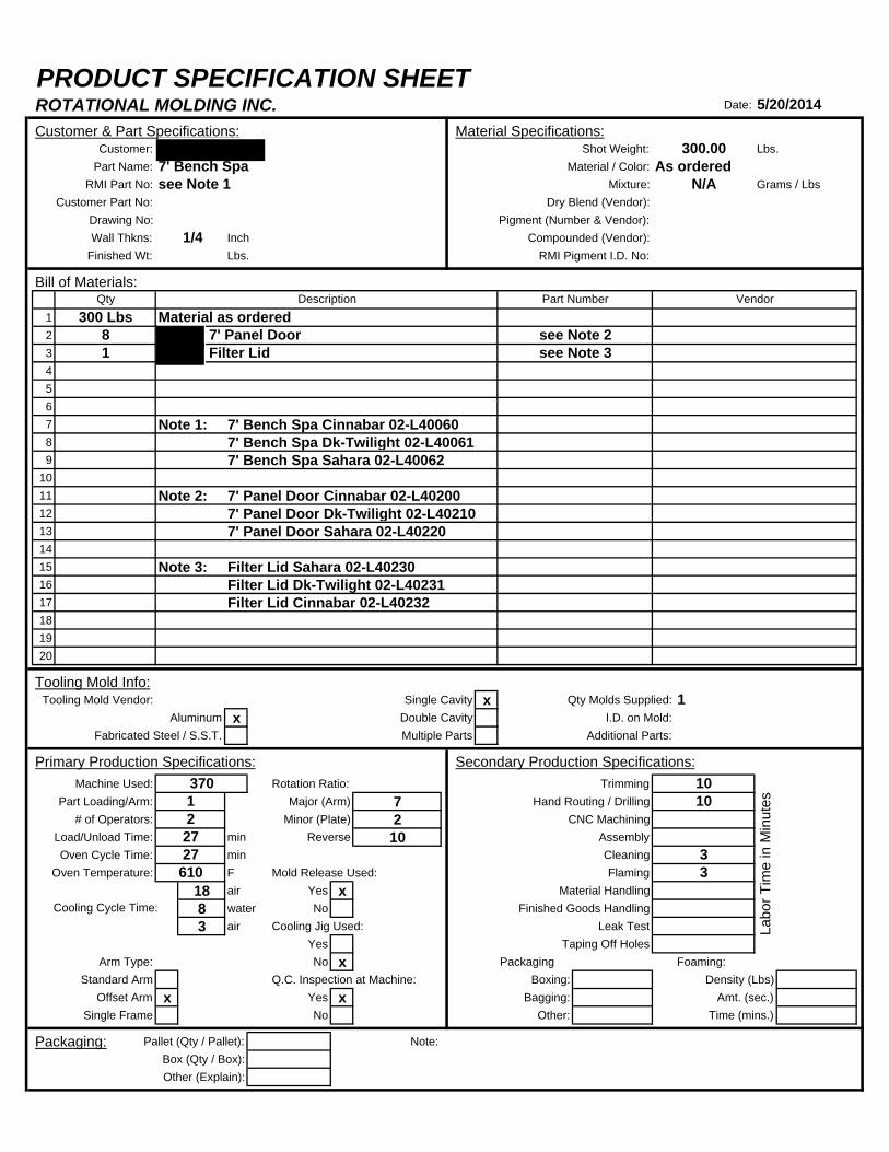
1234567 Note 1: 7' Bench Spa Cinnabar 02-L400608 7' Bench Spa Dk-Twilight 02-L400619 7' Bench Spa Sahara 02-L40062
1011 Note 2: 7' Panel Door Cinnabar 02-L4020012 7' Panel Door Dk-Twilight 02-L4021013 7' Panel Door Sahara 02-L402201415 Note 3: Filter Lid Sahara 02-L4023016 Filter Lid Dk-Twilight 02-L4023117 Filter Lid Cinnabar 02-L40232181920
Tooling Mold Info:Tooling Mold Vendor: Single Cavity x Qty Molds Supplied:
Aluminum x Double Cavity I.D. on Mold:Fabricated Steel / S.S.T. Multiple Parts Additional Parts:
Primary Production Specifications: Secondary Production Specifications:Machine Used: Rotation Ratio: Trimming
Part Loading/Arm: Major (Arm) 7 Hand Routing / Drilling# of Operators: Minor (Plate) 2 CNC Machining
Load/Unload Time: min Reverse 10 AssemblyOven Cycle Time: min Cleaning
Oven Temperature: F Mold Release Used: Flaming18 air Yes x Material Handling8 water No Finished Goods Handling3 air Cooling Jig Used: Leak Test
Yes Taping Off HolesArm Type: No x Packaging Foaming:
Standard Arm Q.C. Inspection at Machine: Boxing: Density (Lbs)Offset Arm x Yes x Bagging: Amt. (sec.)
Single Frame No Other: Time (mins.)
Packaging: Pallet (Qty / Pallet): Note:Box (Qty / Box):Other (Explain):
Description
8 7' Panel Door see Note 21 Filter Lid see Note 3
PRODUCT SPECIFICATION SHEET
1/4
7' Bench Spa
5/20/2014
As ordered300.00
N/Asee Note 1
10
VendorPart NumberMaterial as ordered
2727
12
370
Cooling Cycle Time:
610
Labo
r Tim
e in
Min
utes
33
10
1
Qty300 Lbs
Melt Cyc. T Temp Mjr/Mnr Load
27 610 7/2 1g/lb Air Water Air Water Air Water Air Water
18 8 3
Pic of mold Pic of Raw Part
Qty.
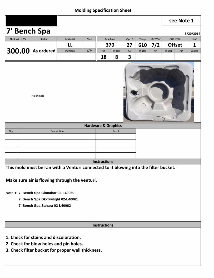
This mold must be ran with a Venturi connected to it blowing into the filter bucket.
Make sure air is flowing through the venturi.
Note 1: 7' Bench Spa Cinnabar 02-L40060
7' Bench Spa Dk-Twilight 02-L40061
7' Bench Spa Sahara 02-L40062
1. Check for stains and discoloration.2. Check for blow holes and pin holes.3. Check filter bucket for proper wall thickness.
Shot Wt. (LBS) Color Material Machine
Molding Specification Sheet
see Note 1
7' Bench Spa 5/20/2014
As orderedLL 370 Offset
Arm Type
Pigment
Instructions
Instructions
Description Part #
Hardware & Graphics
300.00
Trim XLeak Test
Route XCNC Picture of molded part Picture of finished part
Clean XFlame XAssembly
Special
Packaging
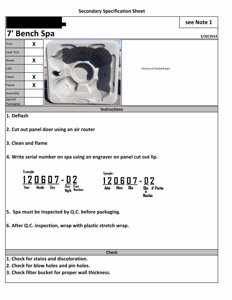
1. Deflash
2. Cut out panel door using an air router
3. Clean and flame
4. Write serial number on spa using an engraver on panel cut out lip.
5. Spa must be inspected by Q.C. before packaging.
6. After Q.C. inspection, wrap with plastic stretch wrap.
1. Check for stains and discoloration.2. Check for blow holes and pin holes.3. Check filter bucket for proper wall thickness.
Secondary Specification Sheet
Check
Instructions
7' Bench Spa 5/20/2014
see Note 1

Melt Trim Clean Leak T. Route
X X Xg/lb CNC Flame Asmby Spc Pckg
X
1. Use Q.C. inspection form.
1/4
Notes
As ordered
Shot Wt.
300.00LL
Pigment
Color Material Wall Thickness
Quality Control
7' Bench Spa 5/20/2014
see Note 1

Melt Cyc. T Temp Mjr/Mnr Load
5 16 500 8:2 2g/lb Air Water Air Water Air Water Air Water
1:1 12 3 1
Pic of Raw Part
Qty.
12
Instruction
Description Part #
Ins Hex Blind Brass 10-24 3/8 X 1/2 02-557100
Inserts can be BRASS, ALUMINUM or STAINLESS STEEL. 10-
24 treads and be a minimum of 1/4 inch deep.
Molding Specification Sheet
Tank 970244 8/14/2012
Shot Wt. Color Material Machine Arm Type
Hardware & Graphics
7 Dark
Blue
LL 190 StraightPigment
x2699

Trim XLeak Test XRoute XCNC Picture of finished part
Clean XFlame XAssembly
Special
Packaging
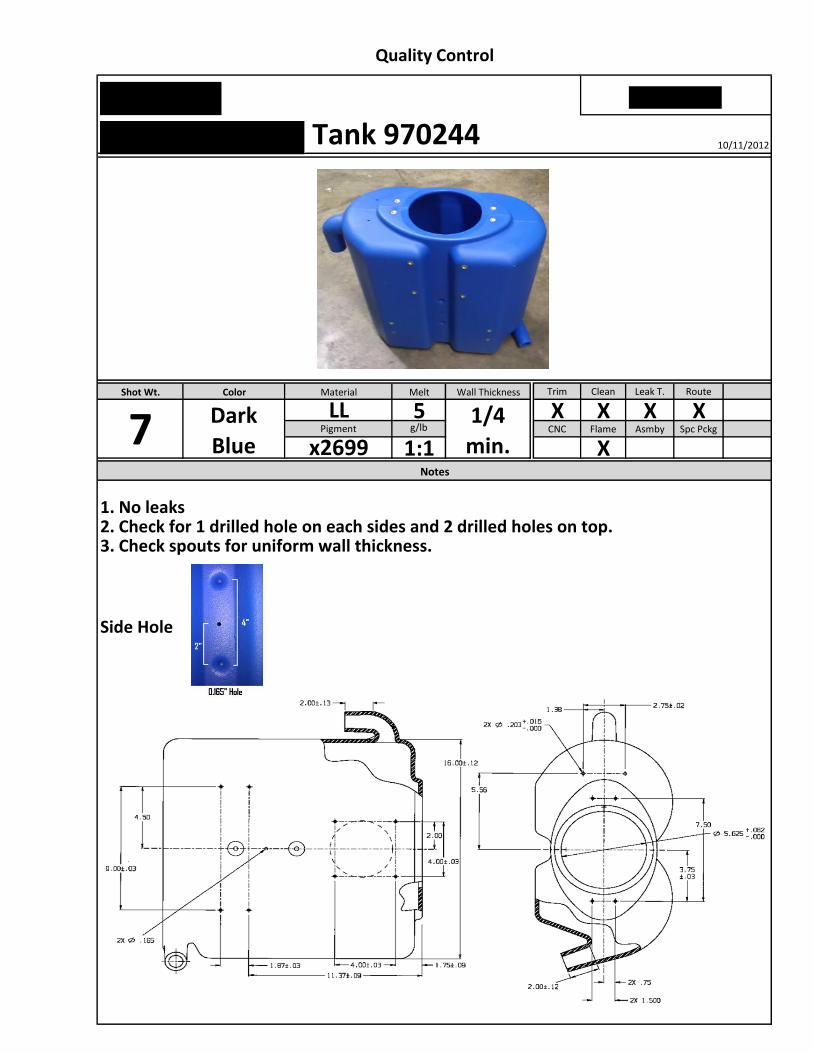
1. Leak test 4. Drill a 0.168" hole between the 2. Use trimming fixture to route large hole and two dents. drill two 3/64" holes.
3. Using a bandsaw, cut 1/2" off both spouts.
5. Repeat STEP 4 for the other side.
1. No leaks
2. Check for 1 drilled hole on each sides and 2 drilled holes on top.
3. Check spouts for uniform wall thickness.
Secondary Specification Sheet
Check
Instruction
Tank 970244 10/11/2012
02-S90100
Melt Trim Clean Leak T. Route
5 X X X Xg/lb CNC Flame Asmby Spc Pckg
1:1 X
1. No leaks2. Check for 1 drilled hole on each sides and 2 drilled holes on top.3. Check spouts for uniform wall thickness.
Side Hole
Color Material Wall Thickness
1/4
min.Notes
Dark
Blue
Shot Wt.
7LL
Pigment
x2699
Quality Control
Tank 970244 10/11/2012
Highlighted Features – Company #7
• Rotational molding parameters specified with product bill of
materials listed.
• Document revision level stated.
• Coversheet details all prerequisite information & documents for product manufacturing.
• Emphasizes key characteristics to process job – does not
include extraneous information
lbs.
1st 2nd 3rd 1st 2nd 3rd Arm Plate Rev 1st Stage 2nd Stage Water
lbs. gms. lbs.
A B Cin.
# Qty # Qty1 62 73 84 95 10
1 42 53 6
1 162 173 184 195 206 217 228 239 24
10 2511 2612 2713 2814 2915 30
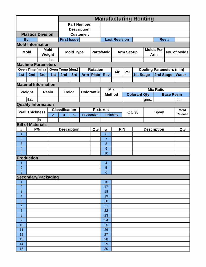
Rev #
Manufacturing RoutingPart Number:Description:
No. of Molds
Plastics Division Customer:By: First Issue Last Revision
Mold Information
Mold Mold Weight Mold Type Parts/Mold Arm Set-up Molds Per
Arm
Machine ParametersOven Time (min.) Oven Temp (deg.) Rotation Air PSI Cooling Parameters (min)
Material Information
Weight Resin Color Colorant # Mix Method
Mix RatioColorant Qty Base Resin
Quality Information
Wall Thickness Classification Fixtures QC % Spray Mold ReleaseProduction Finishing
Bill of MaterialsP/N Description P/N Description
Production
Secondary/Packaging
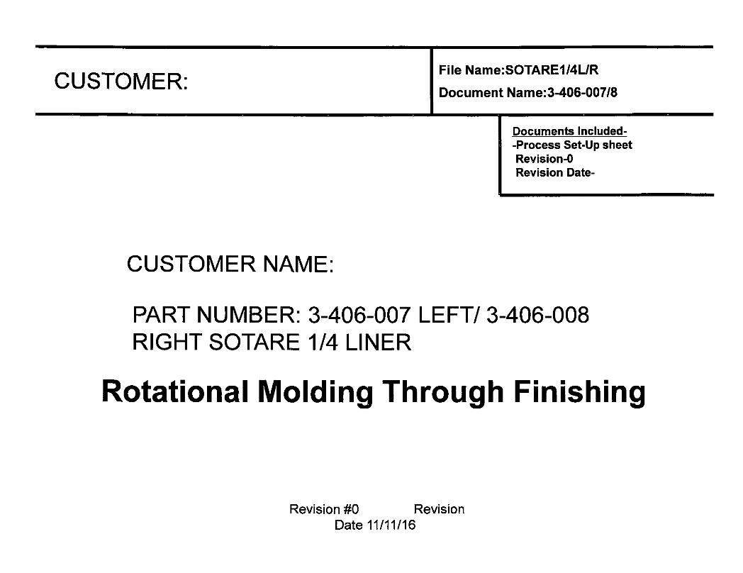
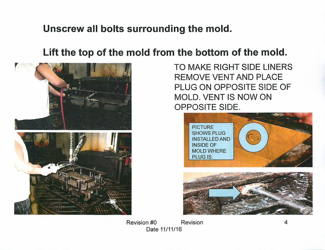
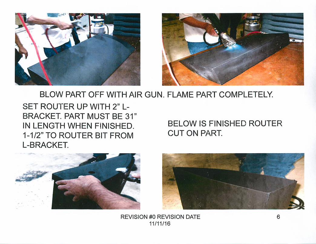
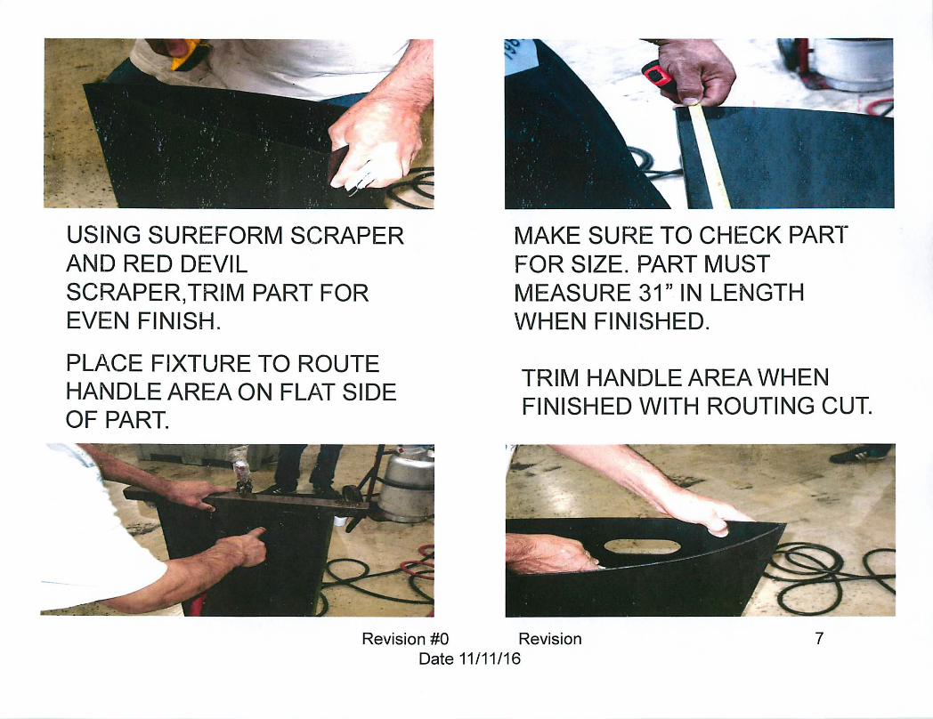
Highlighted Features – Company #8
• Document name & revision level stated.
• Part molding characteristics stated.
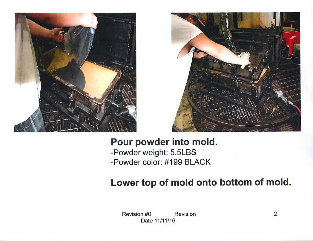
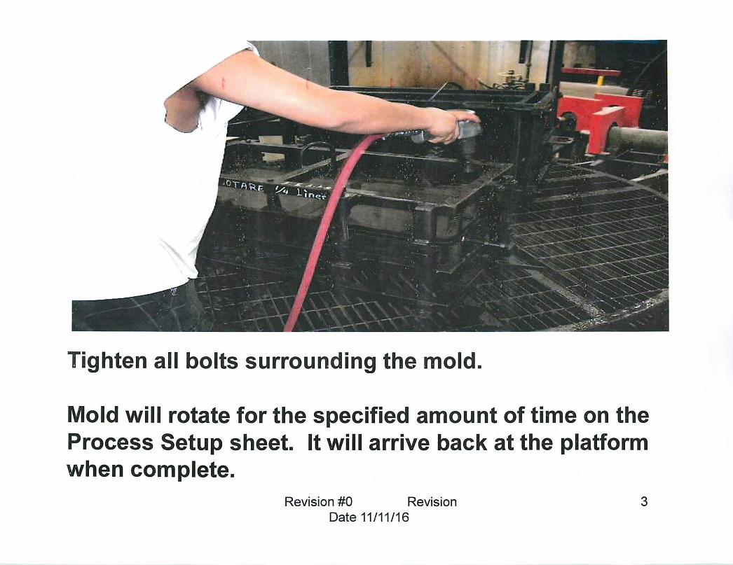
• Images work well as a visual aid in conjunction with listed work instructions.
• Instructions in large font and capitalized.
• Instructions are concise.


Highlighted Features – Company #9
• Rotational molding parameters specified.
• Instructions document template remains consistent for processing of different parts. Template captures all necessary stages of manufacturing.
• Tooling checklist listed before work instructions to preempt operators & machinist to setup in advance.
• Images work well as a visual aid in conjunction with listed work instructions. Larger focus on visual instructions than written.
• English/Spanish translation
• Standard product information & description header on each page of the document.
• Document name & revision level stated.
• Revision log to ascertain latest instructions are described.
• Critical instructions are noted separately from main
instructions body.
• Instructions are concise.

QUALITY INSPECTION
REQUIREMENTS
Copy of QIR-0889SAMPLE
Rev E
#
1
2
3
4
5
6
7
8
Todas las partes aprovadas deben ser marcadas con
el numero del inspector y enviadas al departamento
de 5 axis.
All accepted parts should be marked with the
inspector number and released to the 5 axis
department.
COLOR 500° - 560°
18
Verify that we used 100 lbs of LD in the high
intesity mixer to blend the powder..
11.5 lbs
2013-050
P/N
PART NAME Tank; vacuum 5 gallon
Para la maquina #4 asegurese que los parametros
IRT han sido programados correctamente.
After removing the part from the mold place the
sockets in the bottom of the part.
Despues de sacar la pieza del molde coloque los
sockets a la base de la pieza.
For machine #4, check that the IRT parameters
are set correctly
IRT COOLER (°F)
15 - 17
REVISION
APPROX IRT PARAMETERS (MACHINE 4 ONLY)PRODUCT CHARACTERISTICS
CUSTOMER
LD
Y- DC-60-309-009 / G- DC-80-309
ABC yellow/ Gray DC-80-309
620° - 650°
DYE
E
ABC
602-105 390°
OVEN TEMP (°F)
Asegurese que esta usando el metodo correcto para
mezclar el polvo y el color
SpanishEnglish
MINIMUM TEMP (°F)
17
THERMAL INDEX (°F) 290°
FERRY MACHINE APROX PARAMETERS
OVEN TIME (MIN)
OVEN TIME (MIN)
Asegurese que los graficos estan buenos y en la
posicion correcta segun las marcas en el molde.
MATERIAL
PART WEIGHT
FIXTURES COOLING TIME (MIN)
OVEN TEMP (°F)
Verify the graphic location with marks in the
mold. Check the quality of the graphic.
INSPECTION REQUIREMENTS
Check that the wall thickness is 0.300 or greaterAsegurese que el grosor de las paredes es 0.300 o
mas
Verifique que el peso que esta usando es 11.5 libras.
BEFORE MOLDINGDegrease inserts prior to use (if applicable)
Clean parting line; all leftover material to be removed
Check mold surface for damage
Clean vent tube(s)
Check that correct shot weight and color are used
Check that mold is closed properly and completely
AFTER MOLDINGCheck part for material containation, scratches, or blemishes
Check parting line for excessive flash
Check parting line for blowholes
Check part for warpage, especially on flat surfaces
Check that part is cured properly
If part is acceptable, mark with appropriate shift/shot/day numbers
Revise que la pieza no tenga contaminacion, rayones o golpes.
Revise que las orillas no esten demasiado gruesas.
Revise que las orillas no tengan huecos.
Revise que la pieza no este doblada, especialmente en las areas planas.
Asegurese que la pieza esta cocinada completamente.
Marque la pieza con el apropiado numero de turno/vuelta/dia.
Desengrase los inserts antes de usarlos ( si la pieza lleva tuercas)
Limpie los bordes del molde; remuevba todo el material sobrante del molde.
Revise que la superficie del molde no tenga daños.
Limpie los tubos de ventilacion.
Asegurese que esta usando el peso y el color correcto.
Asegurese que el molde esta cerrado completamente.
Rout a 1 inch hole on top of the part, to check if
the part is properly cured inside.
Corte un hoyo de 1 pulgada en sima de la pieza, para
comprobar si la pieza se cura adecuadamente
dentro.
Check that the correct shot weight of 11.5 lbs. is
being used.
1 of 4

QUALITY INSPECTION
REQUIREMENTS
Copy of QIR-0889SAMPLE
Rev E
1
2
3
4 Using a 1/8 radius cutter with a 1/2" bearing, make the radius on the lip as shown during the 5 axis cycle.
Check the opening with the ABC checking fixture CF-602-105 as shown in pic 1. The ID should be 10.70. Make sure the lip is even all around the
part as shown in pic 2.
Tool Used: 1/4 Onsrud
Place the part into the 5axis fixture as shown.
PART NUMBER 602-105PART NAME: ABC
Put the top fixture in the part as shown to make sure the part is sitting in place. Clamp the part when it is in place to start the 5 axis program.
5 AXIS INSTRUCTIONS
1 2Lip
2 of 4
QUALITY INSPECTION
REQUIREMENTS
Copy of QIR-0889SAMPLE
Rev E
#
1
2
3
4
Spanish
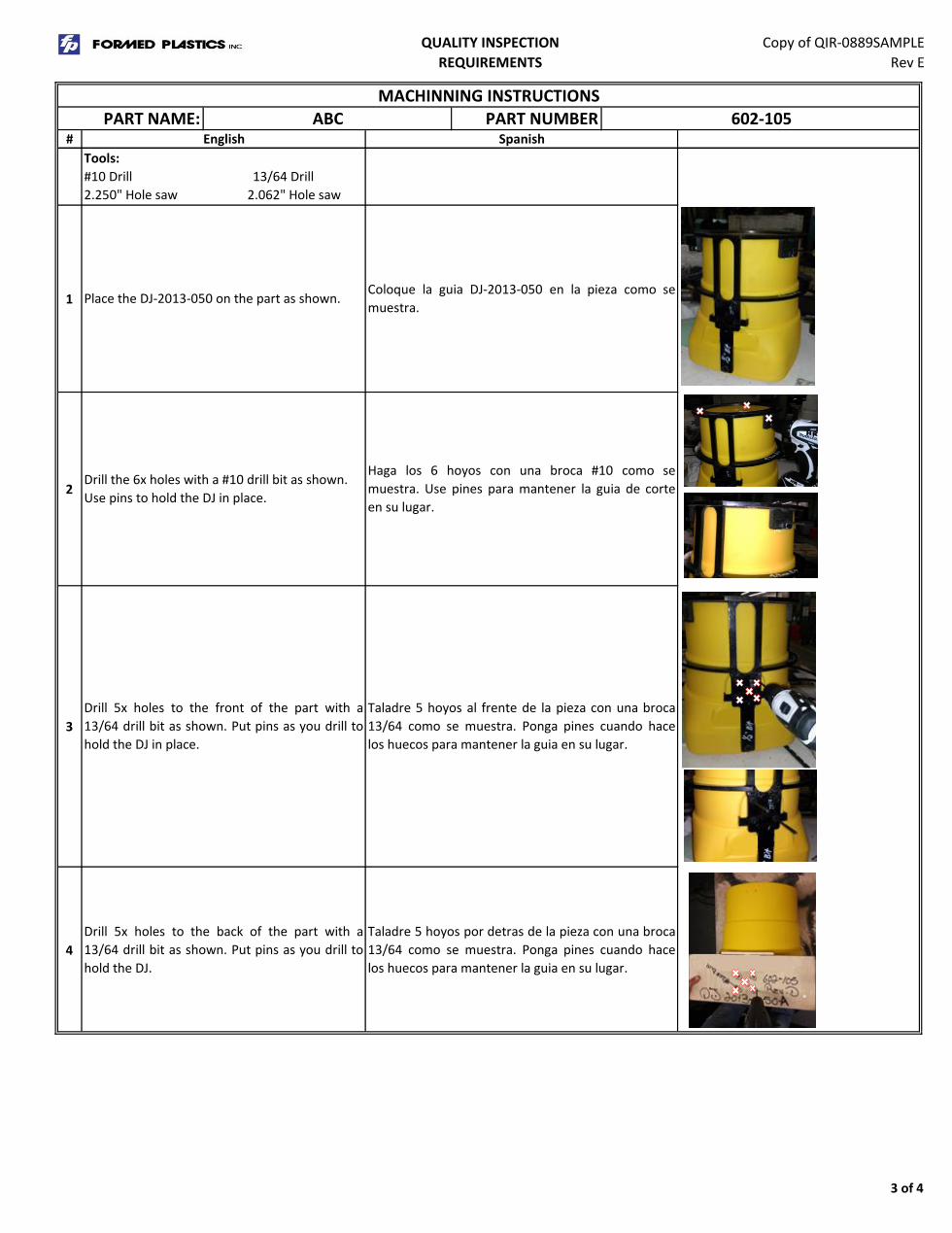
Place the DJ-2013-050 on the part as shown.Coloque la guia DJ-2013-050 en la pieza como se
muestra.
Drill 5x holes to the front of the part with a
13/64 drill bit as shown. Put pins as you drill to
hold the DJ in place.
Taladre 5 hoyos al frente de la pieza con una broca
13/64 como se muestra. Ponga pines cuando hace
los huecos para mantener la guia en su lugar.
Drill 5x holes to the back of the part with a
13/64 drill bit as shown. Put pins as you drill to
hold the DJ.
Taladre 5 hoyos por detras de la pieza con una broca
13/64 como se muestra. Ponga pines cuando hace
los huecos para mantener la guia en su lugar.
Drill the 6x holes with a #10 drill bit as shown.
Use pins to hold the DJ in place.
Haga los 6 hoyos con una broca #10 como se
muestra. Use pines para mantener la guia de corte
en su lugar.
Tools:
#10 Drill 13/64 Drill
2.250" Hole saw 2.062" Hole saw
English
MACHINNING INSTRUCTIONS
PART NAME: ABC PART NUMBER 602-105
3 of 4

QUALITY INSPECTION
REQUIREMENTS
Copy of QIR-0889SAMPLE
Rev E
5
6
7
8
9
10
Rev Initial
B GC
C GC
D JT
E JT5/14/2016 ADDED GRAY COLOR TO QIR
NOTE: Use labels provided by the office on all
boxes we send out. If you dont have the labels,
see the office manager.
NOTA: Utilice etiquetas proporcionadas por la
oficina, en todas las cajas que enviamos. Si usted no
tiene, vea el manger de la officina.
Drill one hole with a 1/2" dril bit as shown.Haga un hoyo con una broca de 1/2" como se
muestra.
Make the front hole using a 2.250 +/- .015 hole
saw as shown.
Haga el hoyo del frente con una cortadora de 2.250
+/- .015 como se muestra.
Make the back hole using a 2.062 +/- .015 hole
saw as shown.
Haga el hoyo de atras con una cortadora de 2.062 +/-
.015 como se muestra.
Inspect the part before putting the part in a 197
cartonEmpaque una pieza en una caja 197.
A 1/14/2014
Date Changes
Scrape the part and clean with type wash. Pula la pieza y limpiela con Type wash.
4/23/2016 Updated photo for step 8 to more recent one
6/30/2015 Changed the revision of the part from C to E.
AL
7/2/2014 Changed the part weight from 12.0 lbs to 11.5 lbs.
Created
4 of 4