combination alarm zone valve box - nfpa 99 specification
TRANSCRIPT
SSB-825-014107 9515 10.01
Page 1 of 824 May 2021
COM
BIN
ATI
ON
A
LARM
ZVB
BeaconMedæs • 1059 Paragon Way, Rock Hill, SC 29730 • Phone: (803) 817-5600 • Fax: (803) 817-5750 • www.beaconmedaes.com
Combination Alarm Zone Valve Box - NFPA 99
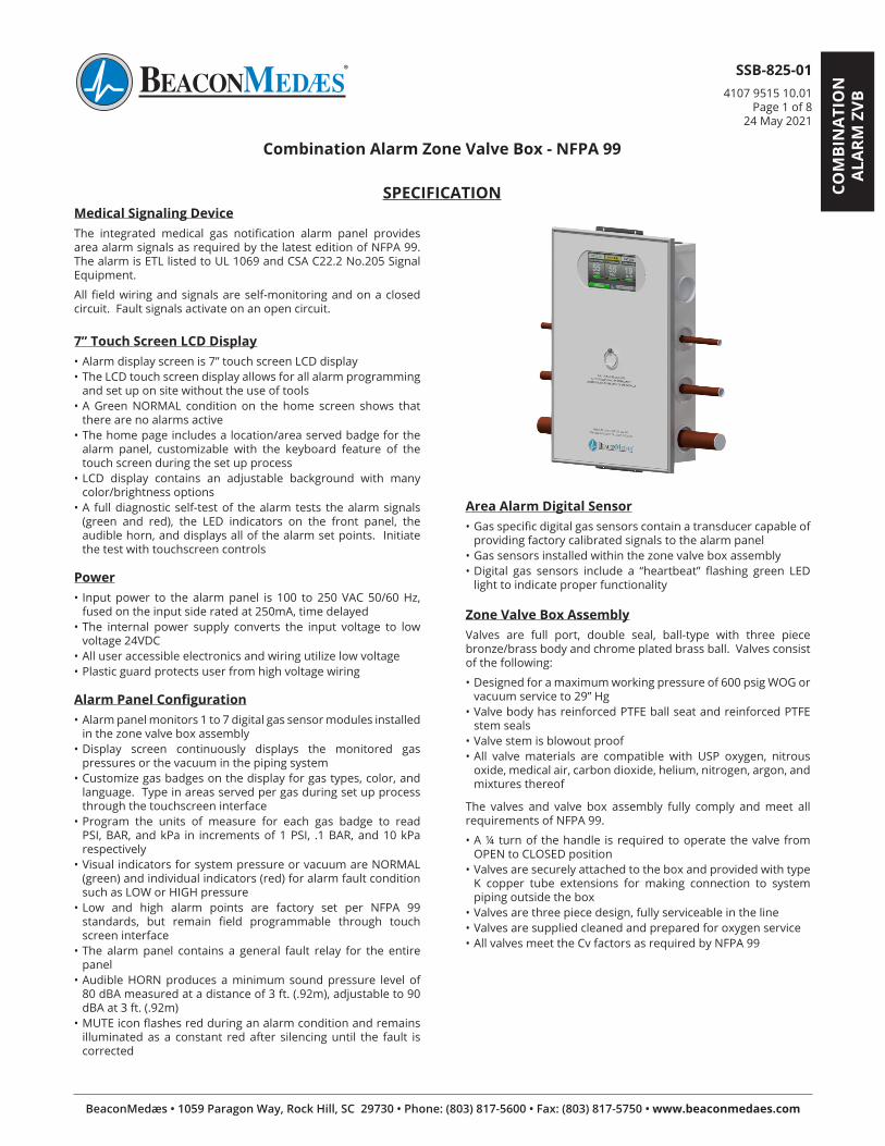
SPECIFICATIONMedical Signaling DeviceThe integrated medical gas notification alarm panel provides area alarm signals as required by the latest edition of NFPA 99. The alarm is ETL listed to UL 1069 and CSA C22.2 No.205 Signal Equipment.
All field wiring and signals are self-monitoring and on a closed circuit. Fault signals activate on an open circuit.
7” Touch Screen LCD Display• Alarm display screen is 7” touch screen LCD display• The LCD touch screen display allows for all alarm programming
and set up on site without the use of tools• A Green NORMAL condition on the home screen shows that
there are no alarms active• The home page includes a location/area served badge for the
alarm panel, customizable with the keyboard feature of the touch screen during the set up process
• LCD display contains an adjustable background with many color/brightness options
• A full diagnostic self-test of the alarm tests the alarm signals (green and red), the LED indicators on the front panel, the audible horn, and displays all of the alarm set points. Initiate the test with touchscreen controls
Power• Input power to the alarm panel is 100 to 250 VAC 50/60 Hz,
fused on the input side rated at 250mA, time delayed• The internal power supply converts the input voltage to low
voltage 24VDC• All user accessible electronics and wiring utilize low voltage• Plastic guard protects user from high voltage wiring
Alarm Panel Configuration• Alarm panel monitors 1 to 7 digital gas sensor modules installed
in the zone valve box assembly• Display screen continuously displays the monitored gas
pressures or the vacuum in the piping system• Customize gas badges on the display for gas types, color, and
language. Type in areas served per gas during set up process through the touchscreen interface
• Program the units of measure for each gas badge to read PSI, BAR, and kPa in increments of 1 PSI, .1 BAR, and 10 kPa respectively
• Visual indicators for system pressure or vacuum are NORMAL (green) and individual indicators (red) for alarm fault condition such as LOW or HIGH pressure
• Low and high alarm points are factory set per NFPA 99 standards, but remain field programmable through touch screen interface
• The alarm panel contains a general fault relay for the entire panel
• Audible HORN produces a minimum sound pressure level of 80 dBA measured at a distance of 3 ft. (.92m), adjustable to 90 dBA at 3 ft. (.92m)
• MUTE icon flashes red during an alarm condition and remains illuminated as a constant red after silencing until the fault is corrected
Area Alarm Digital Sensor• Gas specific digital gas sensors contain a transducer capable of
providing factory calibrated signals to the alarm panel• Gas sensors installed within the zone valve box assembly• Digital gas sensors include a “heartbeat” flashing green LED
light to indicate proper functionality
Zone Valve Box AssemblyValves are full port, double seal, ball-type with three piece bronze/brass body and chrome plated brass ball. Valves consist of the following:
• Designed for a maximum working pressure of 600 psig WOG or vacuum service to 29” Hg
• Valve body has reinforced PTFE ball seat and reinforced PTFE stem seals
• Valve stem is blowout proof• All valve materials are compatible with USP oxygen, nitrous
oxide, medical air, carbon dioxide, helium, nitrogen, argon, and mixtures thereof
The valves and valve box assembly fully comply and meet all requirements of NFPA 99.
• A ¼ turn of the handle is required to operate the valve from OPEN to CLOSED position
• Valves are securely attached to the box and provided with type K copper tube extensions for making connection to system piping outside the box
• Valves are three piece design, fully serviceable in the line• Valves are supplied cleaned and prepared for oxygen service• All valves meet the Cv factors as required by NFPA 99
SSB-825-014107 9515 10.01
Page 2 of 824 May 2021
Zone Box DoorThe zone valve box assembly has an opaque door with pull ring
• In an emergency, the door will SNAP OUT by pulling the pull ring forward without exposing sharp edges
• Zone Valve Box door is treated with Biomaster*• The assembly door has a label that reads:
- CAUTION -CLOSE VALVES ONLY IN EMERGENCY
Compliance• Ball valves conform to MSS SP-110• The Type K copper tube extensions conform to ASTM B88, UNS
No. C12200, and H58 temper• Complete valve assembly (valve and tube extensions) cleaned
for oxygen service per CGA Pamphlet G-4.1• The gauges conform to ANSI B40.1• The zone valves and box assembly meet all requirements of
NFPA 99 and CAN/CSA Z7396.1-09
Transport and StorageDuring transport and storage, do not exceed an ambient temperature range of 0°F to 130°F (-18°C to 55°C), a relative humidity range of 10% to 85% with non-condensation, and an atmospheric pressure range of 950 hPa (millibar) to 1050 hPa (millibar).
* Biomaster is an additive tested successfully to ISO 22196:2011 standards and shown to reduce Staphylococcus aureus by ≥ 99.90% and Escherichia coli by ≥ 99.91%.
All valve assemblies have a total of three 1/8” NPT ports with pipe plugs.
• One port is used as a provision for connection of a gauge, located on the terminal outlet side of the valve to register pipeline pressure or vacuum
• A second port, also located on the terminal outlet side of the valve, can accept a DISS connection of a gas sensor
• A third port is located upstream of the valve and can be used either for a DISS connection of a gas sensor, or for purging during the brazing process
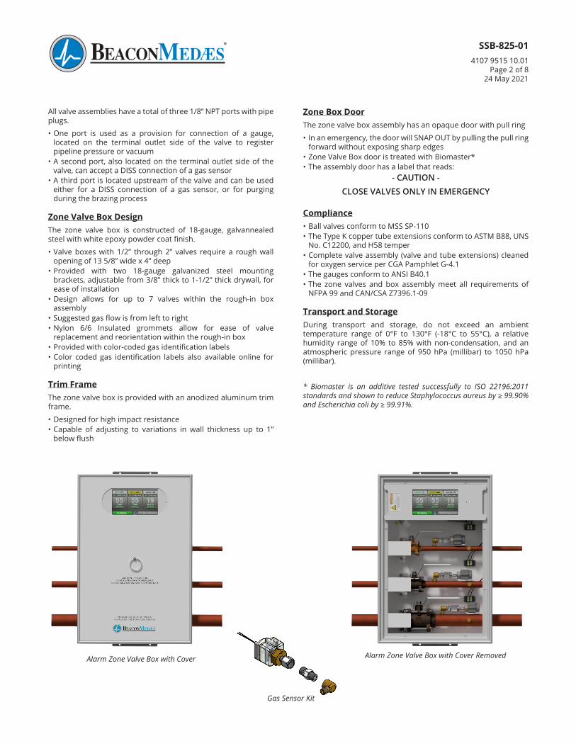
Zone Valve Box DesignThe zone valve box is constructed of 18-gauge, galvannealed steel with white epoxy powder coat finish.
• Valve boxes with 1/2” through 2” valves require a rough wall opening of 13 5/8” wide x 4” deep
• Provided with two 18-gauge galvanized steel mounting brackets, adjustable from 3/8” thick to 1-1/2” thick drywall, for ease of installation
• Design allows for up to 7 valves within the rough-in box assembly
• Suggested gas flow is from left to right• Nylon 6/6 Insulated grommets allow for ease of valve
replacement and reorientation within the rough-in box• Provided with color-coded gas identification labels• Color coded gas identification labels also available online for
printing
Trim FrameThe zone valve box is provided with an anodized aluminum trim frame.
• Designed for high impact resistance• Capable of adjusting to variations in wall thickness up to 1”
below flush
Alarm Zone Valve Box with Cover Alarm Zone Valve Box with Cover Removed
Gas Sensor Kit
SSB-825-014107 9515 10.01
Page 3 of 824 May 2021
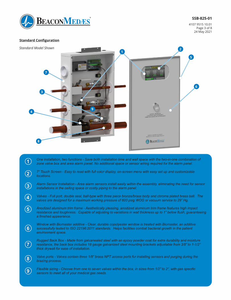
Standard Configuration
1 One installation, two functions - Save both installation time and wall space with the two-in-one combination of zone valve box and area alarm panel. No additional space or sensor wiring required for the alarm panel.
2 7” Touch Screen - Easy to read with full color display, on-screen menu with easy set up and customizable locations.
3 Alarm Sensor Installation - Area alarm sensors install easily within the assembly, eliminating the need for sensor installations in the ceiling space or costly piping to the alarm panel.
Valves - Full port, double seal, ball-type with three piece bronze/brass body and chrome plated brass ball. The valves are designed for a maximum working pressure of 600 psig WOG or vacuum service to 29” Hg.
Anodized aluminum trim frame - Aesthetically pleasing, anodized aluminum trim frame features high impact resistance and toughness. Capable of adjusting to variations in wall thickness up to 1” below flush, guaranteeing a finished appearance.
6Window with Biomaster additive - Clear, durable copolyester window is treated with Biomaster, an additive successfully tested to ISO 22196:2011 standards. Helps facilities combat bacterial growth in the patient environment space.
7Rugged Back Box - Made from galvanealed steel with an epoxy powder coat for extra durability and moisture resistance, the back box includes 18 gauge galvanized steel mounting brackets adjustable from 3/8” to 1-1/2” thick drywall for ease of installation.
8 Valve ports - Valves contain three 1/8” brass NPT access ports for installing sensors and purging during the brazing process.
9 Flexible sizing - Choose from one to seven valves within the box, in sizes from 1/2” to 2”, with gas specific sensors to meet all of your medical gas needs.
5
4
Standard Model Shown1
9
5
8
4
36
2
7
SSB-825-014107 9515 10.01
Page 4 of 824 May 2021
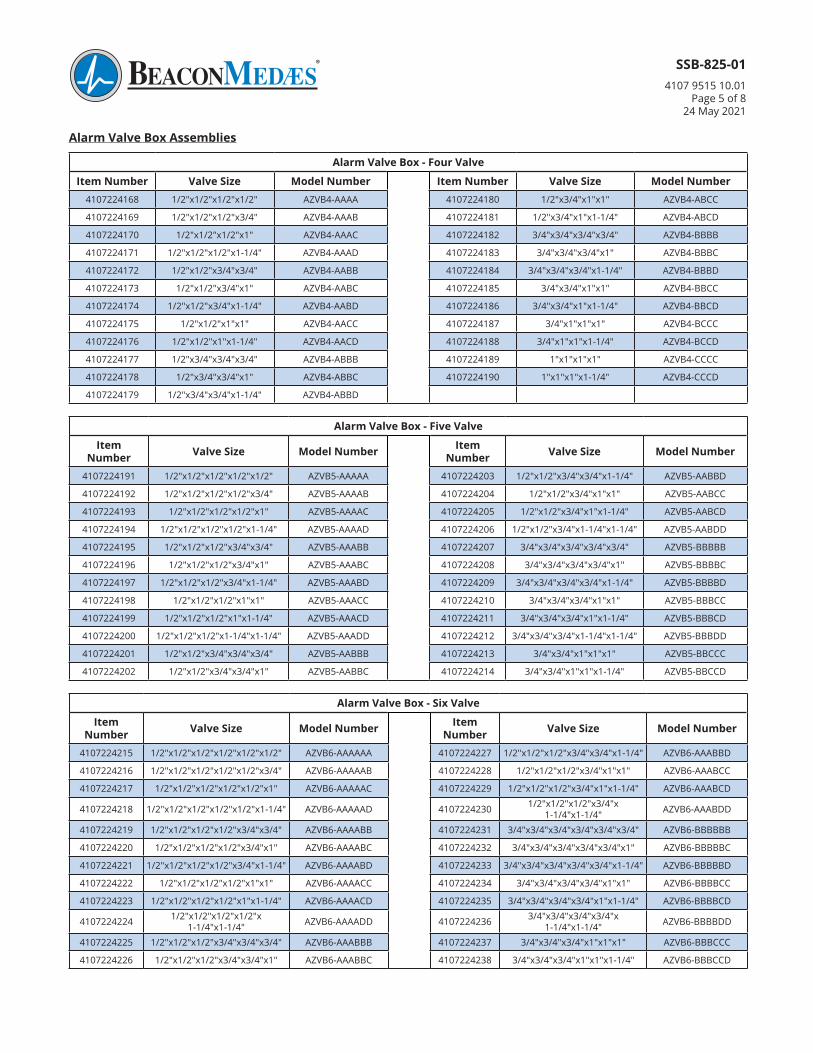
Alarm Valve Box - Single Valve
Item Number Valve Size Model Number Item Number Valve Size Model Number4107224111 1/2” AZVB1-A 4107224114 1-1/4” AZVB1-D
4107224112 3/4” AZVB1-B 4107224115 1-1/2” AZVB1-E
4107224113 1” AZVB1-C 4107224116 2” AZVB1-F
Alarm Valve Box AssembliesAn alarm valve box assembly includes the zone valve box assembly, the alarm screen and power supply. Individual gas specific sensors to be ordered separately. Part numbers for the sensors follow the alarm valve box assemblies.
Alarm Valve Box - Two Valve
Item Number Valve Size Model Number Item Number Valve Size Model Number4107224117 1/2"x1/2" AZVB2-AA 4107224127* 3/4"x2" AZVB2-BF
4107224118 1/2"x3/4" AZVB2-AB 4107224128 1"x1" AZVB2-CC
4107224119 1/2"x1" AZVB2-AC 4107224129 1"x1-1/4" AZVB2-CD
4107224120 1/2"x1-1/4" AZVB2-AD 4107224130 1"x1-1/2" AZVB2-CE
4107224121 1/2"x1-1/2" AZVB2-AE 4107224131* 1"x2" AZVB2-CF
4107224122 1/2"x2" AZVB2-AF 4107224132 1-1/4"x1-1/4" AZVB2-DD
4107224123 3/4"x3/4" AZVB2-BB 4107224133* 1-1/4"x1-1/2" AZVB2-DE
4107224124 3/4"x1" AZVB2-BC 4107224134* 1-1/4"x2" AZVB2-DF
4107224125 3/4"x1-1/4" AZVB2-BD 4107224135* 1-1/2"x1-1/2" AZVB2-EE
4107224126 3/4"x1-1/2" AZVB2-BE 4107224136* 1-1/2"x2" AZVB2-EF
Alarm Valve Box - Three Valve
Item Number Valve Size Model Number Item Number Valve Size Model Number4107224137 1/2"x1/2"x1/2" AZVB3-AAA 4107224153 3/4"x3/4"x1" AZVB3-BBC
4107224138 1/2"x1/2"x3/4" AZVB3-AAB 4107224154 3/4"x3/4"x1-1/4" AZVB3-BBD
4107224139 1/2"x1/2"x1" AZVB3-AAC 4107224155 3/4"x3/4"x1-1/2" AZVB3-BBE
4107224140 1/2"x1/2"x1-1/4" AZVB3-AAD 4107224156* 3/4"x3/4"x2" AZVB3-BBF
4107224141 1/2"x1/2"x1-1/2" AZVB3-AAE 4107224157 3/4"x1"x1" AZVB3-BCC
4107224142 1/2"x1/2"x2" AZVB3-AAF 4107224158 3/4"x1"x1-1/4" AZVB3-BCD
4107224143 1/2"x3/4"x3/4" AZVB3-ABB 4107224159 3/4"x1"x1-1/2" AZVB3-BCE
4107224144 1/2"x3/4"x1" AZVB3-ABC 4107224160* 3/4"x1"x2" AZVB3-BCF
4107224145 1/2"x3/4"x1-1/4" AZVB3-ABD 4107224161 3/4"x1"x1-1/2" AZVB3-BDE
4107224146 1/2"x3/4"x1-1/2" AZVB3-ABE 4107224162 1"x1"x1" AZVB3-CCC
4107224147* 1/2"x3/4"x2" AZVB3-ABF 4107224163 1"x1"x1-1/4" AZVB3-CCD
4107224148 1/2"x1"x1" AZVB3-ACC 4107224164 1"x1"x1-1/2" AZVB3-CCE
4107224149 1/2"x1"x1-1/4" AZVB3-ACD 4107224165* 1"x1"x2" AZVB3-CCF
4107224150 1/2"x1"x1-1/2" AZVB3-ACE 4107224166* 1"x1-1/4"x1-1/2" AZVB3-CDE
4107224151* 1/2"x1"x2" AZVB3-ACF 4107224167* 1"x1-1/4"x2" AZVB3-CDF
4107224152 3/4"x3/4"x3/4" AZVB3-BBB
NOTE:
Part numbers with "*" require a larger back box than standard. Please see Dimension Drawings on page 8, "AZVB Valve with Larger Back Box" section for dimensions on these part numbers.
SSB-825-014107 9515 10.01
Page 5 of 824 May 2021
Alarm Valve Box Assemblies
Alarm Valve Box - Four Valve
Item Number Valve Size Model Number Item Number Valve Size Model Number4107224168 1/2"x1/2"x1/2"x1/2" AZVB4-AAAA 4107224180 1/2"x3/4"x1"x1" AZVB4-ABCC
4107224169 1/2"x1/2"x1/2"x3/4" AZVB4-AAAB 4107224181 1/2"x3/4"x1"x1-1/4" AZVB4-ABCD
4107224170 1/2"x1/2"x1/2"x1" AZVB4-AAAC 4107224182 3/4"x3/4"x3/4"x3/4" AZVB4-BBBB
4107224171 1/2"x1/2"x1/2"x1-1/4" AZVB4-AAAD 4107224183 3/4"x3/4"x3/4"x1" AZVB4-BBBC
4107224172 1/2"x1/2"x3/4"x3/4" AZVB4-AABB 4107224184 3/4"x3/4"x3/4"x1-1/4" AZVB4-BBBD
4107224173 1/2"x1/2"x3/4"x1" AZVB4-AABC 4107224185 3/4"x3/4"x1"x1" AZVB4-BBCC
4107224174 1/2"x1/2"x3/4"x1-1/4" AZVB4-AABD 4107224186 3/4"x3/4"x1"x1-1/4" AZVB4-BBCD
4107224175 1/2"x1/2"x1"x1" AZVB4-AACC 4107224187 3/4"x1"x1"x1" AZVB4-BCCC
4107224176 1/2"x1/2"x1"x1-1/4" AZVB4-AACD 4107224188 3/4"x1"x1"x1-1/4" AZVB4-BCCD
4107224177 1/2"x3/4"x3/4"x3/4" AZVB4-ABBB 4107224189 1"x1"x1"x1" AZVB4-CCCC
4107224178 1/2"x3/4"x3/4"x1" AZVB4-ABBC 4107224190 1"x1"x1"x1-1/4" AZVB4-CCCD
4107224179 1/2"x3/4"x3/4"x1-1/4" AZVB4-ABBD
Alarm Valve Box - Five Valve
Item Number Valve Size Model Number Item
Number Valve Size Model Number
4107224191 1/2"x1/2"x1/2"x1/2"x1/2" AZVB5-AAAAA 4107224203 1/2"x1/2"x3/4"x3/4"x1-1/4" AZVB5-AABBD
4107224192 1/2"x1/2"x1/2"x1/2"x3/4" AZVB5-AAAAB 4107224204 1/2"x1/2"x3/4"x1"x1" AZVB5-AABCC
4107224193 1/2"x1/2"x1/2"x1/2"x1" AZVB5-AAAAC 4107224205 1/2"x1/2"x3/4"x1"x1-1/4" AZVB5-AABCD
4107224194 1/2"x1/2"x1/2"x1/2"x1-1/4" AZVB5-AAAAD 4107224206 1/2"x1/2"x3/4"x1-1/4"x1-1/4" AZVB5-AABDD
4107224195 1/2"x1/2"x1/2"x3/4"x3/4" AZVB5-AAABB 4107224207 3/4"x3/4"x3/4"x3/4"x3/4" AZVB5-BBBBB
4107224196 1/2"x1/2"x1/2"x3/4"x1" AZVB5-AAABC 4107224208 3/4"x3/4"x3/4"x3/4"x1" AZVB5-BBBBC
4107224197 1/2"x1/2"x1/2"x3/4"x1-1/4" AZVB5-AAABD 4107224209 3/4"x3/4"x3/4"x3/4"x1-1/4" AZVB5-BBBBD
4107224198 1/2"x1/2"x1/2"x1"x1" AZVB5-AAACC 4107224210 3/4"x3/4"x3/4"x1"x1" AZVB5-BBBCC
4107224199 1/2"x1/2"x1/2"x1"x1-1/4" AZVB5-AAACD 4107224211 3/4"x3/4"x3/4"x1"x1-1/4" AZVB5-BBBCD
4107224200 1/2"x1/2"x1/2"x1-1/4"x1-1/4" AZVB5-AAADD 4107224212 3/4"x3/4"x3/4"x1-1/4"x1-1/4" AZVB5-BBBDD
4107224201 1/2"x1/2"x3/4"x3/4"x3/4" AZVB5-AABBB 4107224213 3/4"x3/4"x1"x1"x1" AZVB5-BBCCC
4107224202 1/2"x1/2"x3/4"x3/4"x1" AZVB5-AABBC 4107224214 3/4"x3/4"x1"x1"x1-1/4" AZVB5-BBCCD
Alarm Valve Box - Six Valve
Item Number Valve Size Model Number Item
Number Valve Size Model Number
4107224215 1/2"x1/2"x1/2"x1/2"x1/2"x1/2" AZVB6-AAAAAA 4107224227 1/2"x1/2"x1/2"x3/4"x3/4"x1-1/4" AZVB6-AAABBD
4107224216 1/2"x1/2"x1/2"x1/2"x1/2"x3/4" AZVB6-AAAAAB 4107224228 1/2"x1/2"x1/2"x3/4"x1"x1" AZVB6-AAABCC
4107224217 1/2"x1/2"x1/2"x1/2"x1/2"x1" AZVB6-AAAAAC 4107224229 1/2"x1/2"x1/2"x3/4"x1"x1-1/4" AZVB6-AAABCD
4107224218 1/2"x1/2"x1/2"x1/2"x1/2"x1-1/4" AZVB6-AAAAAD 4107224230 1/2"x1/2"x1/2"x3/4"x1-1/4"x1-1/4" AZVB6-AAABDD
4107224219 1/2"x1/2"x1/2"x1/2"x3/4"x3/4" AZVB6-AAAABB 4107224231 3/4"x3/4"x3/4"x3/4"x3/4"x3/4" AZVB6-BBBBBB
4107224220 1/2"x1/2"x1/2"x1/2"x3/4"x1" AZVB6-AAAABC 4107224232 3/4"x3/4"x3/4"x3/4"x3/4"x1" AZVB6-BBBBBC
4107224221 1/2"x1/2"x1/2"x1/2"x3/4"x1-1/4" AZVB6-AAAABD 4107224233 3/4"x3/4"x3/4"x3/4"x3/4"x1-1/4" AZVB6-BBBBBD
4107224222 1/2"x1/2"x1/2"x1/2"x1"x1" AZVB6-AAAACC 4107224234 3/4"x3/4"x3/4"x3/4"x1"x1" AZVB6-BBBBCC
4107224223 1/2"x1/2"x1/2"x1/2"x1"x1-1/4" AZVB6-AAAACD 4107224235 3/4"x3/4"x3/4"x3/4"x1"x1-1/4" AZVB6-BBBBCD
4107224224 1/2"x1/2"x1/2"x1/2"x1-1/4"x1-1/4" AZVB6-AAAADD 4107224236 3/4"x3/4"x3/4"x3/4"x
1-1/4"x1-1/4" AZVB6-BBBBDD
4107224225 1/2"x1/2"x1/2"x3/4"x3/4"x3/4" AZVB6-AAABBB 4107224237 3/4"x3/4"x3/4"x1"x1"x1" AZVB6-BBBCCC
4107224226 1/2"x1/2"x1/2"x3/4"x3/4"x1" AZVB6-AAABBC 4107224238 3/4"x3/4"x3/4"x1"x1"x1-1/4" AZVB6-BBBCCD
SSB-825-014107 9515 10.01
Page 6 of 824 May 2021
Alarm Valve Box Assemblies
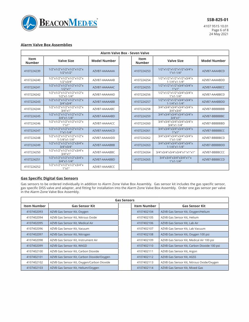
Alarm Valve Box - Seven Valve
Item Number Valve Size Model Number Item
Number Valve Size Model Number
4107224239 1/2"x1/2"x1/2"x1/2"x1/2"x1/2"x1/2" AZVB7-AAAAAAA 4107224253 1/2"x1/2"x1/2"x1/2"x3/4"x
1"x1-1/4" AZVB7-AAAABCD
4107224240 1/2"x1/2"x1/2"x1/2"x1/2"x1/2"x3/4" AZVB7-AAAAAAB 4107224254 1/2"x1/2"x1/2"x1/2"x3/4"x
1-1/4"x1-1/4" AZVB7-AAAABDD
4107224241 1/2"x1/2"x1/2"x1/2"x1/2"x1/2"x1" AZVB7-AAAAAAC 4107224255 1/2"x1/2"x1/2"x3/4"x3/4"x
1"x1" AZVB7-AAABBCC
4107224242 1/2"x1/2"x1/2"x1/2"x1/2"x1/2"x1-1/4" AZVB7-AAAAAAD 4107224256 1/2"x1/2"x1/2"x3/4"x3/4"x
1"x1-1/4" AZVB7-AAABBCD
4107224243 1/2"x1/2"x1/2"x1/2"x1/2"x3/4"x3/4" AZVB7-AAAAABB 4107224257 1/2"x1/2"x1/2"x3/4"x3/4"x
1-1/4"x1-1/4" AZVB7-AAABBDD
4107224244 1/2"x1/2"x1/2"x1/2"x1/2"x3/4"x1" AZVB7-AAAAABC 4107224258 3/4"x3/4"x3/4"x3/4"x3/4"x
3/4"x3/4" AZVB7-BBBBBBB
4107224245 1/2"x1/2"x1/2"x1/2"x1/2"x3/4"x1-1/4" AZVB7-AAAAABD 4107224259 3/4"x3/4"x3/4"x3/4"x3/4"x
3/4"x1" AZVB7-BBBBBBC
4107224246 1/2"x1/2"x1/2"x1/2"x1/2"x1"x1" AZVB7-AAAAACC 4107224260 3/4"x3/4"x3/4"x3/4"x3/4"x
3/4"x1-1/4" AZVB7-BBBBBBD
4107224247 1/2"x1/2"x1/2"x1/2"x1/2"x1"x1-1/4" AZVB7-AAAAACD 4107224261 3/4"x3/4"x3/4"x3/4"x3/4"x
1"x1" AZVB7-BBBBBCC
4107224248 1/2"x1/2"x1/2"x1/2"x1/2"x1-1/4"x1-1/4" AZVB7-AAAAADD 4107224262 3/4"x3/4"x3/4"x3/4"x3/4"x
1"x1-1/4" AZVB7-BBBBBCD
4107224249 1/2"x1/2"x1/2"x1/2"x3/4"x3/4"x3/4" AZVB7-AAAABBB 4107224263 3/4"x3/4"x3/4"x3/4"x3/4"x
1-1/4"x1-1/4" AZVB7-BBBBBDD
4107224250 1/2"x1/2"x1/2"x1/2"x3/4"x3/4"x1" AZVB7-AAAABBC 4107224264 3/4"x3/4"x3/4"x3/4"x1"x1"x1" AZVB7-BBBBCCC
4107224251 1/2"x1/2"x1/2"x1/2"x3/4"x3/4"x1-1/4" AZVB7-AAAABBD 4107224265 3/4"x3/4"x3/4"x3/4"x1"x
1"x1-1/4" AZVB7-BBBBCCD
4107224252 1/2"x1/2"x1/2"x1/2"x3/4"x1"x1" AZVB7-AAAABCC
Gas Sensors
Item Number Gas Sensor Kit Item Number Gas Sensor Kit
4107402093 AZVB Gas Sensor Kit, Oxygen 4107402104 AZVB Gas Sensor Kit, Oxygen/Helium
4107402094 AZVB Gas Sensor Kit, Nitrous Oxide 4107402105 AZVB Gas Sensor Kit, Helium
4107402095 AZVB Gas Sensor Kit, Medical Air 4107402106 AZVB Gas Sensor Kit, Lab Air
4107402096 AZVB Gas Sensor Kit, Vacuum 4107402107 AZVB Gas Sensor Kit, Lab Vacuum
4107402097 AZVB Gas Sensor Kit, Nitrogen 4107402108 AZVB Gas Sensor Kit, Oxygen 100 psi
4107402098 AZVB Gas Sensor Kit, Instrument Air 4107402109 AZVB Gas Sensor Kit, Medical Air 100 psi
4107402099 AZVB Gas Sensor Kit, WAGD 4107402110 AZVB Gas Sensor Kit, Carbon Dioxide 100 psi
4107402100 AZVB Gas Sensor Kit, Carbon Dioxide 4107402111 AZVB Gas Sensor Kit, Argon
4107402101 AZVB Gas Sensor Kit, Carbon Dioxide/Oxygen 4107402112 AZVB Gas Sensor Kit, AGSS
4107402102 AZVB Gas Sensor Kit, Oxygen/Carbon Dioxide 4107402113 AZVB Gas Sensor Kit, Nitrous Oxide/Oxygen
4107402103 AZVB Gas Sensor Kit, Helium/Oxygen 4107402114 AZVB Gas Sensor Kit, Mixed Gas
Gas Specific Digital Gas SensorsGas sensors to be ordered individually in addition to Alarm Zone Valve Box Assembly. Gas sensor kit includes the gas specific sensor, gas specific DISS valve and adapter, and fitting for installation into the Alarm Zone Valve Box Assembly. Order one gas sensor per valve in the Alarm Zone Valve Box Assembly.
SSB-825-014107 9515 10.01
Page 7 of 824 May 2021
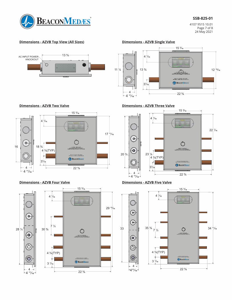
1358
AC INPUT POWERKNOCKOUT
4
41116
111 4
2258
3716
1358
15316
121516
4116
Dimensions - AZVB Top View (All Sizes) Dimensions - AZVB Single Valve
15 3/16
13 5/8
37/16
12 15/1611 1/4
4 11/164 22 5/8
4 1/1613 5/8AC INPUT POWER KNOCKOUT
4
41116
2034
3716
2318
15316
22716
4116
434 (TYP)
2258
4
41116
2034
3716
2318
15316
22716
4116
434 (TYP)
2258
4
41116
16
3716
1838
15316
171116
4116
434 (TYP)
2258
Dimensions - AZVB Three ValveDimensions - AZVB Two Valve
15 3/16
18 3/8
37/16
17 11/16
16
4 11/164 22 5/8
4 1/16
15 3/16
22 7/16
20 3/4
4 11/164 22 5/8
4 1/16
4 3/4(TYP)
37/16
4 3/4(TYP)23 1/8
4
41116
15316
341116
4116
33
2258
3716
434 (TYP)
3538
712
4
41116
15316
341116
4116
33
2258
3716
434 (TYP)
3538
712
4
41116
15316
291516
4116
434 (TYP)
3716
281 4 3058
2258
712
4
41116
15316
291516
4116
434 (TYP)
3716
281 4 3058
2258
712
Dimensions - AZVB Five ValveDimensions - AZVB Four Valve
15 3/16
35 3/8
3 7/16
33
422 5/8
4 1/16
15 3/16
30 5/8
3 7/16
29 15/16
28 1/4
4 11/164
22 5/8
4 1/16
4
41116
15316
341116
4116
33
2258
3716
434 (TYP)
3538
712
7 1/2
4 3/4(TYP)
411/16
7 1/2
4 3/4(TYP)
34 11/16
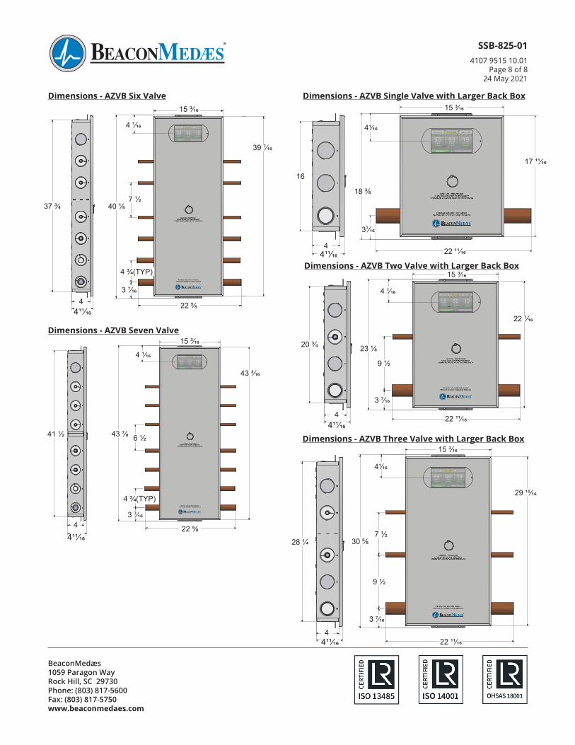
BeaconMedæs 1059 Paragon Way Rock Hill, SC 29730 Phone: (803) 817-5600 Fax: (803) 817-5750 www.beaconmedaes.com
SSB-825-014107 9515 10.01
Page 8 of 824 May 2021
4
41116
15316
39716
4116
3716
434 (TYP)
712
2258
4018373
4
4
41116
15316
39716
4116
3716
434 (TYP)
712
2258
4018373
4
4
41116
15316
39716
4116
3716
434 (TYP)
712
2258
4018373
4
Dimensions - AZVB Six Valve15 3/16
40 1/8
3 7/16
39 7/16
37 3/4
4 22 5/8
4 1/16
411/16
4 3/4(TYP)
7 1/2
4
41116
15316
43316
4116
2258
434 (TYP)
3716
612
4378411
2
4
41116
15316
43316
4116
2258
434 (TYP)
3716
612
4378411
2
Dimensions - AZVB Seven Valve15 3/16
43 7/8
3 7/16
43 3/16
41 1/2
4 22 5/8
4 1/16
4 3/4(TYP)
411/16
6 1/2
4
41116
16
3716
1838
15316
171116
4116
221116
Dimensions - AZVB Single Valve with Larger Back Box15 3/16
18 3/8
37/16
17 11/16
411/164
22 11/16
16
41/16
4
41116
2034
3716
2318
15316
22716
4116
912
221116
4
41116
2034
3716
2318
15316
22716
4116
912
221116
Dimensions - AZVB Two Valve with Larger Back Box
3 7/16
4
15 3/16
23 1/8
22 7/16
20 3/4
22 11/16
4 1/16
411/16
9 1/2
4
41116
15316
291516
4116
912
221116
3716
3058281 4
712
4
41116
15316
291516
4116
912
221116
3716
3058281 4
712
Dimensions - AZVB Three Valve with Larger Back Box15 3/16
28 1/4 30 5/8
29 15/16
22 11/16
41/16
3 7/16
4411/16
9 1/2
7 1/2