coins operated pizza vending machine
TRANSCRIPT
Palestine Polytechnic University
College of Engineering and Technology
Electrical Engineering Department
Title
Coins Operated Pizza Vending Machine
Project Team
Mohammad Shahateet Abed-Alrahem Khalifa
Ahmad Mahfouz
Project Supervisor
Dr. Raed Amro .
Hebron – Palestine
2019-2020
2
Abstract:
Pizza is the fastest food ordered and Due to the small number of pizza restaurants
and Most people don't know how make it and the high demand on it by people. So, we
decided to design and implement an automatic machine with dimensions (3m
long,1.5m width) , make to produce pizza with high quality without waiting in markets .
The prototype contains a six main parts: Coins Detector, Refrigerator ,sauce
distribution, Cheese distribution ,Vegetable distribution and Baking stage, with
experiments as follows. is Activated the Coins Detector by pay 5 (₪), then the dough
piece from the conveyor belt inside the refrigerator is download to the main conveyor
belt , and adding the materials (sauce, vegetables and cheese) to the dough piece, , and
finally the entry the piece pizza into the oven For 10 minutes . Already A Pizza has
been produced.
The advantages of using this machine are for save the man power, money and time,
this machine is located in public places.
الملخص
البيتزا هي من أسرع األطعمة التي يتم طلبها في األسواق وبسبب قلة عدد مطاعم البيتزا و معظم
الناس ال يعرفون كيف يصنعها والطلب الكبير عليها من قبل الناس . لذلك ، قررنا تصميم وتنفيذ
ماكينة أوتوماتيكية بأبعاد )3 م طوالً ، 1.5 م عرض( إلنتاج البيتزا بجودة عالية دون االنتظار في
األسواق .
يحتوي النموذج األولي الذي تم تصنيعه على ستة أجزاء رئيسية: كاشف العمالت ، ثالجة , توزيع
الصلصة , توزيع خضروات ، توزيع جبنة وفرن. تم إجراء التجارب على النحو التالي ، يتم تفعيل
كاشف العمالت بواسطة قطعة معدنية من صنف 5 شيكل ، ثم يتم أنزال قطعة العجينة من السير
الناقل الذي بداخل الثالجة الى السير الناقل الرئيسي ، وبعدها يتم أضافة الصلصة ، الخضروات و
الجبنة ، واخيرا يتم دخول قطعة البيتزا الى الفرن لمدة 10 دقائق وبعدها ينتج لنا قطعة بيتزا جاهزة
لألكل ، بالفعل تم إنتاج بيتزا .
مزايا أستخدام هذه الماكينة هي لتوفير الطاقة البشرية )األيدي العاملة ( والمال والوقت ، ويقع هذا
الجهاز في األماكن العامة .

3
إهداء
القلب إلى... وسلم عليه هللا صلى املصطفى الحبيب... االول املعلم إلى
باملعاناة تلذذت من... مضت التي املراحل بكل بجانبي كانت التي الحنون
أن علمني من إلى ..الحبيبات أمهاتنا إلى... دربي لتنير تحترق شمعة وكانت
علمني من إلى.. اليمنى يدي إلى.. بخطوة ميل االلف ابدأ وكيف اقف
ينابيع من رووني من إلى.. األجالء آبائنا إلى... ترقباني وعيناه الصعود
اإليمان بشجرة وأظلوني املعرفة منهل إلى بيدي أخذو الذين إلى.. الفضيلة
سندا كانوا من إلى.. حرفا وعلمني بيدي أمسك من إلى.. األعزاء أهلنا إلى...
.. لي
.. واملعرفة العلم طريق إلى بإرشادي الفضل لهم من الى
.رائد عمرو الفاضل الدكتور إلى
. املعرفة محبي كل إلى
. األوفياء أصدقائنا إلى... قلبي فوسعهم ذكرهم عن السطور ضاقت من إلى
.البواسل أسرانا إلى... غيرهم حرية أجل من بحرياتهم ضحوا من إلى
. األبرار شهدائنا إلى ... منا أكرم هم من إلى
كل إلى.. فنائه حتى وأبوابه بمقاعده جمعني الذي املكان هذا أنس ى ولن
األعوام هذه طوال احتضنتني من إلى فلسطين بوليتكنك جامعة إلى.. جزء
.. الحبيبة فلسطين إلى...
.. هذا علمنا نهدي
4
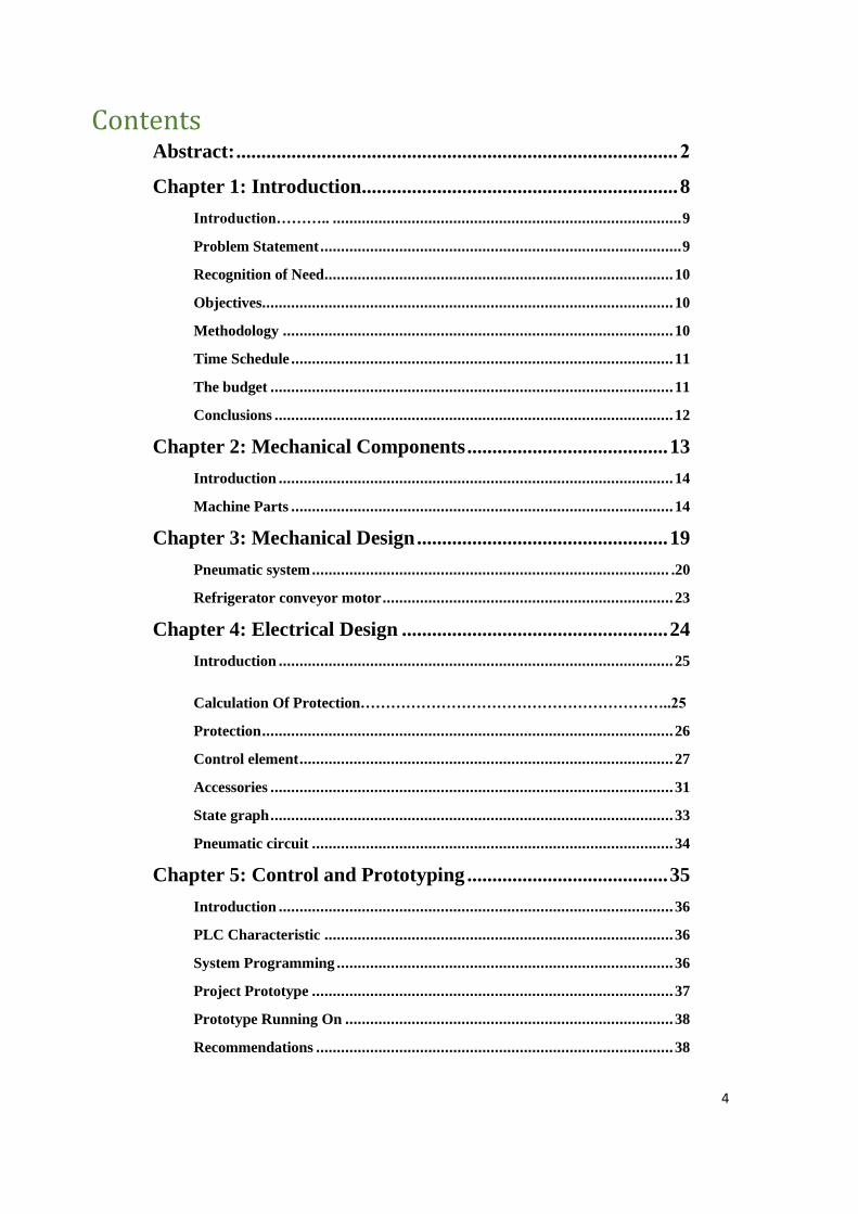
Contents Abstract: ........................................................................................ 2
Chapter 1: Introduction ............................................................... 8
Introduction……….. .................................................................................... 9
Problem Statement ....................................................................................... 9
Recognition of Need .................................................................................... 10
Objectives................................................................................................... 10
Methodology .............................................................................................. 10
Time Schedule ............................................................................................ 11
The budget ................................................................................................. 11
Conclusions ................................................................................................ 12
Chapter 2: Mechanical Components ........................................ 13
Introduction ............................................................................................... 14
Machine Parts ............................................................................................ 14
Chapter 3: Mechanical Design .................................................. 19
Pneumatic system ...................................................................................... .20
Refrigerator conveyor motor ...................................................................... 23
Chapter 4: Electrical Design ..................................................... 24
Introduction ............................................................................................... 25
Calculation Of Protection……………………………………………………..25
Protection ................................................................................................... 26
Control element .......................................................................................... 27
Accessories ................................................................................................. 31
State graph ................................................................................................. 33
Pneumatic circuit ....................................................................................... 34
Chapter 5: Control and Prototyping ........................................ 35
Introduction ............................................................................................... 36
PLC Characteristic .................................................................................... 36
System Programming ................................................................................. 36
Project Prototype ....................................................................................... 37
Prototype Running On ............................................................................... 38
Recommendations ...................................................................................... 38

5
Chapter 6: Manual User ............................................................ 39
System basics .............................................................................................. 40
Main features ............................................................................................. 40
Operation and setting ................................................................................. 40
Check and maintenance ............................................................................. 40
Safety ......................................................................................................... 41
Electrical circuit ......................................................................................... 41
Appendix ..................................................................................... 45
Referance ..................................................................................... 74
6
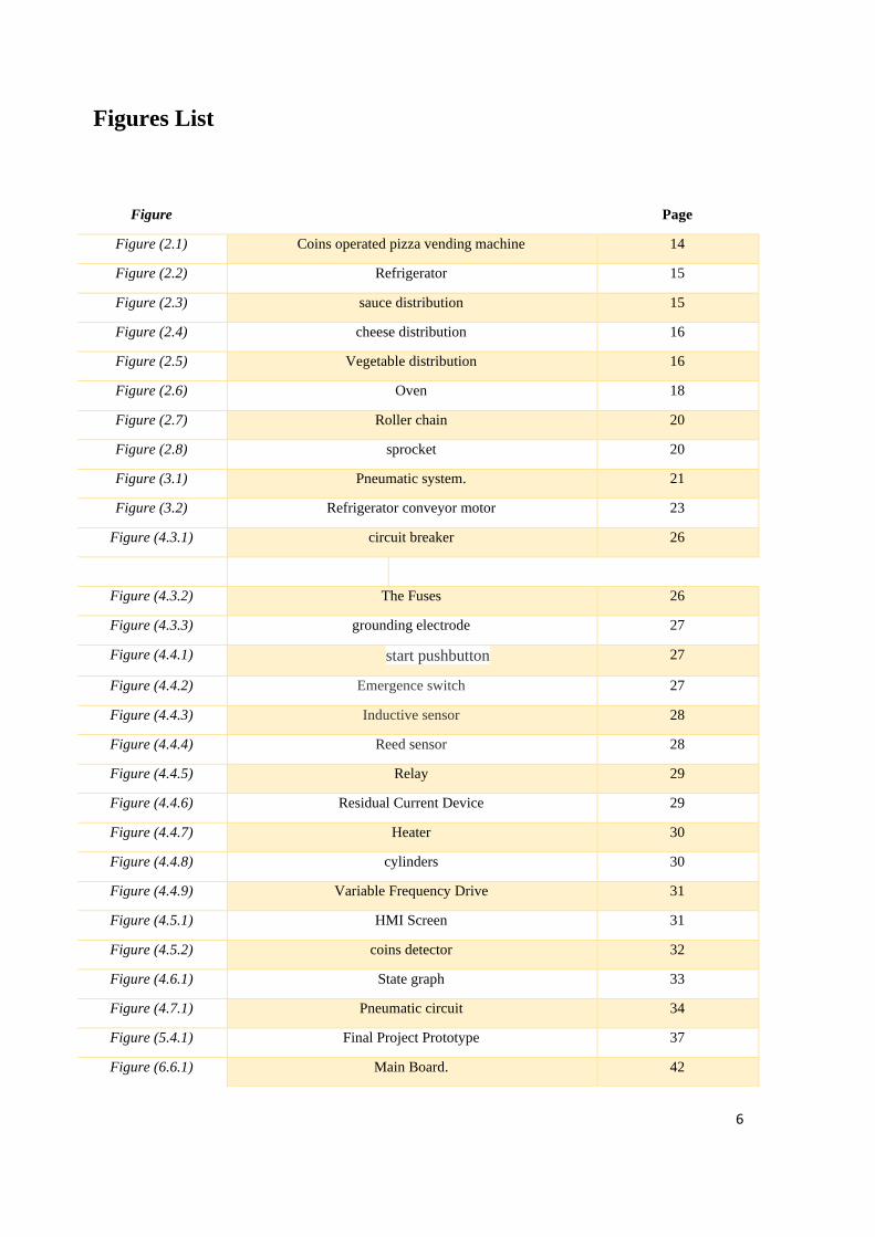
Figures List
Figure Page
Figure (2.1) Coins operated pizza vending machine 14
Figure (2.2) Refrigerator 15
Figure (2.3) sauce distribution 15
Figure (2.4) cheese distribution 16
Figure (2.5) Vegetable distribution 16
Figure (2.6) Oven 18
Figure (2.7) Roller chain 20
Figure (2.8) sprocket 20
Figure (3.1) Pneumatic system. 21
Figure (3.2) Refrigerator conveyor motor 23
Figure (4.3.1) circuit breaker 26
Figure (4.3.2) The Fuses 26
Figure (4.3.3) grounding electrode 27
Figure (4.4.1) start pushbutton 27
Figure (4.4.2) Emergence switch 27
Figure (4.4.3) Inductive sensor 28
Figure (4.4.4) Reed sensor 28
Figure (4.4.5) Relay 29
Figure (4.4.6) Residual Current Device 29
Figure (4.4.7) Heater 30
Figure (4.4.8) cylinders 30
Figure (4.4.9) Variable Frequency Drive 31
Figure (4.5.1) HMI Screen 31
Figure (4.5.2) coins detector 32
Figure (4.6.1) State graph 33
Figure (4.7.1) Pneumatic circuit 34
Figure (5.4.1) Final Project Prototype 37
Figure (6.6.1) Main Board. 42
7
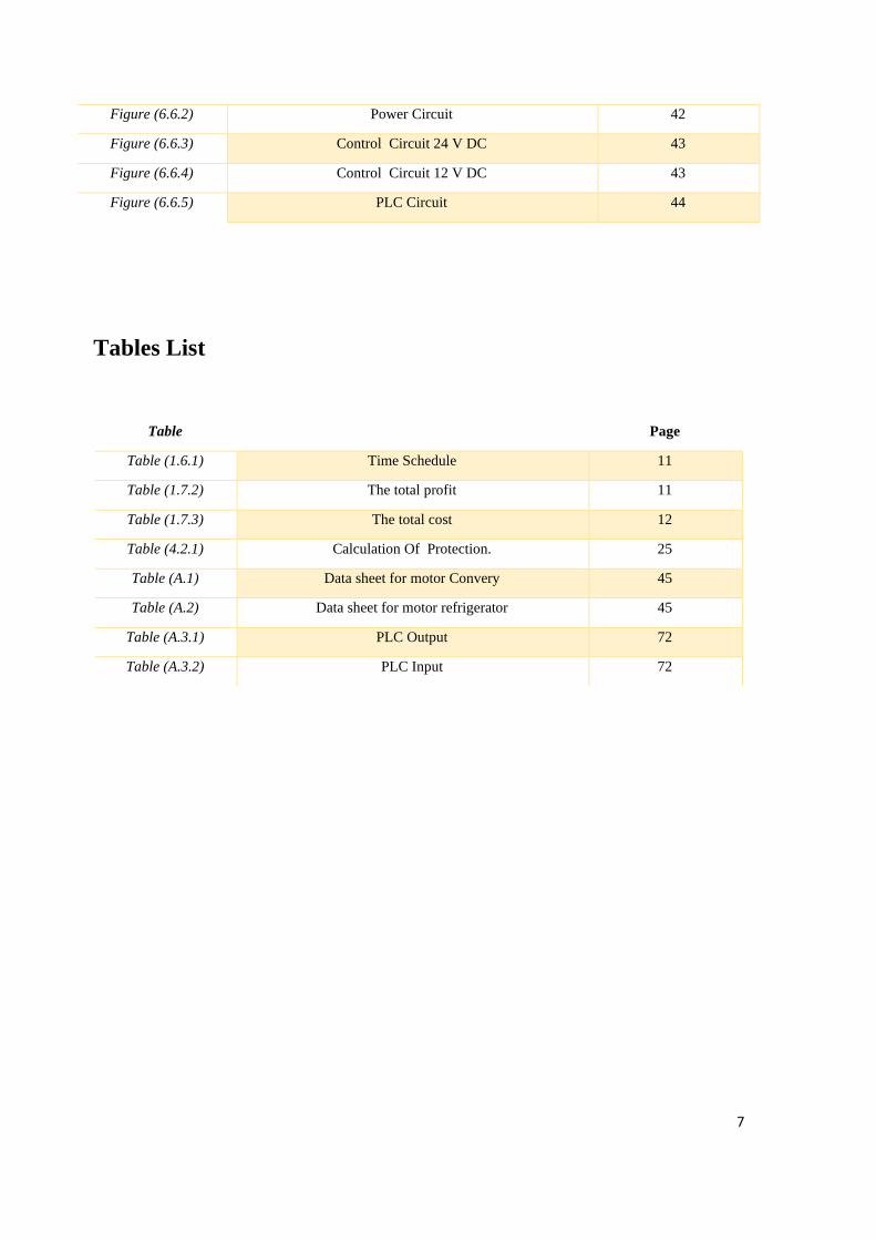
Tables List
Figure (6.6.2) Power Circuit 42
Figure (6.6.3) Control Circuit 24 V DC 43
Figure (6.6.4) Control Circuit 12 V DC 43
Figure (6.6.5) PLC Circuit 44
Table Page
Table (1.6.1) Time Schedule 11
Table (1.7.2) The total profit 11
Table (1.7.3) The total cost 12
Table (4.2.1) Calculation Of Protection. 25
Table (A.1) Data sheet for motor Convery 45
Table (A.2) Data sheet for motor refrigerator 45
Table (A.3.1) PLC Output 72
Table (A.3.2) PLC Input 72
8
1
Chapter 1: Introduction
1.1 Introduction
1.2 Problem Statement
1.3 Recognition of Need
1.4 Objectives
1.5 Methodology
1.6 Time Schedule
1.7 The budget
1.8 Conclusions
9
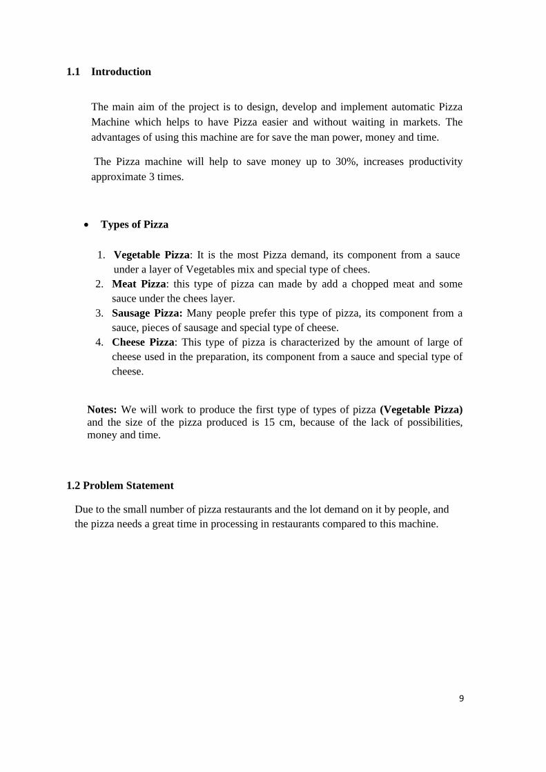
1.1 Introduction
The main aim of the project is to design, develop and implement automatic Pizza
Machine which helps to have Pizza easier and without waiting in markets. The
advantages of using this machine are for save the man power, money and time.
The Pizza machine will help to save money up to 30%, increases productivity
approximate 3 times.
• Types of Pizza
1. Vegetable Pizza: It is the most Pizza demand, its component from a sauce
under a layer of Vegetables mix and special type of chees.
2. Meat Pizza: this type of pizza can made by add a chopped meat and some
sauce under the chees layer.
3. Sausage Pizza: Many people prefer this type of pizza, its component from a
sauce, pieces of sausage and special type of cheese.
4. Cheese Pizza: This type of pizza is characterized by the amount of large of
cheese used in the preparation, its component from a sauce and special type of
cheese.
Notes: We will work to produce the first type of types of pizza (Vegetable Pizza)
and the size of the pizza produced is 15 cm, because of the lack of possibilities,
money and time.
1.2 Problem Statement
Due to the small number of pizza restaurants and the lot demand on it by people, and
the pizza needs a great time in processing in restaurants compared to this machine.

10
1.3 Recognition of Need
Notice that, the local market needs the machines product fast food such as pizza for
save money and time.
• High specifications for local product.
• A good price for local market.
• A Mechanical electrical system without using a human hand.
• Support the national economy.
1.4 Objectives
The actual targets of this research were set as follows:
• Design and implementation of a control system for the automatic pizza machine. • Make machine structure simple.
• Produce more than a piece of dough at the same time.
• Produce a multi types of pizza on the same line.
• Design a prototype for machine.
1.5 Methodology
• Study the machine in the global market and compare it to the cost of producing
a machine here in Palestine.
• Create a model using computer.
• Simulate the project and get the outcomes.
• Create a real model and producing pizza.
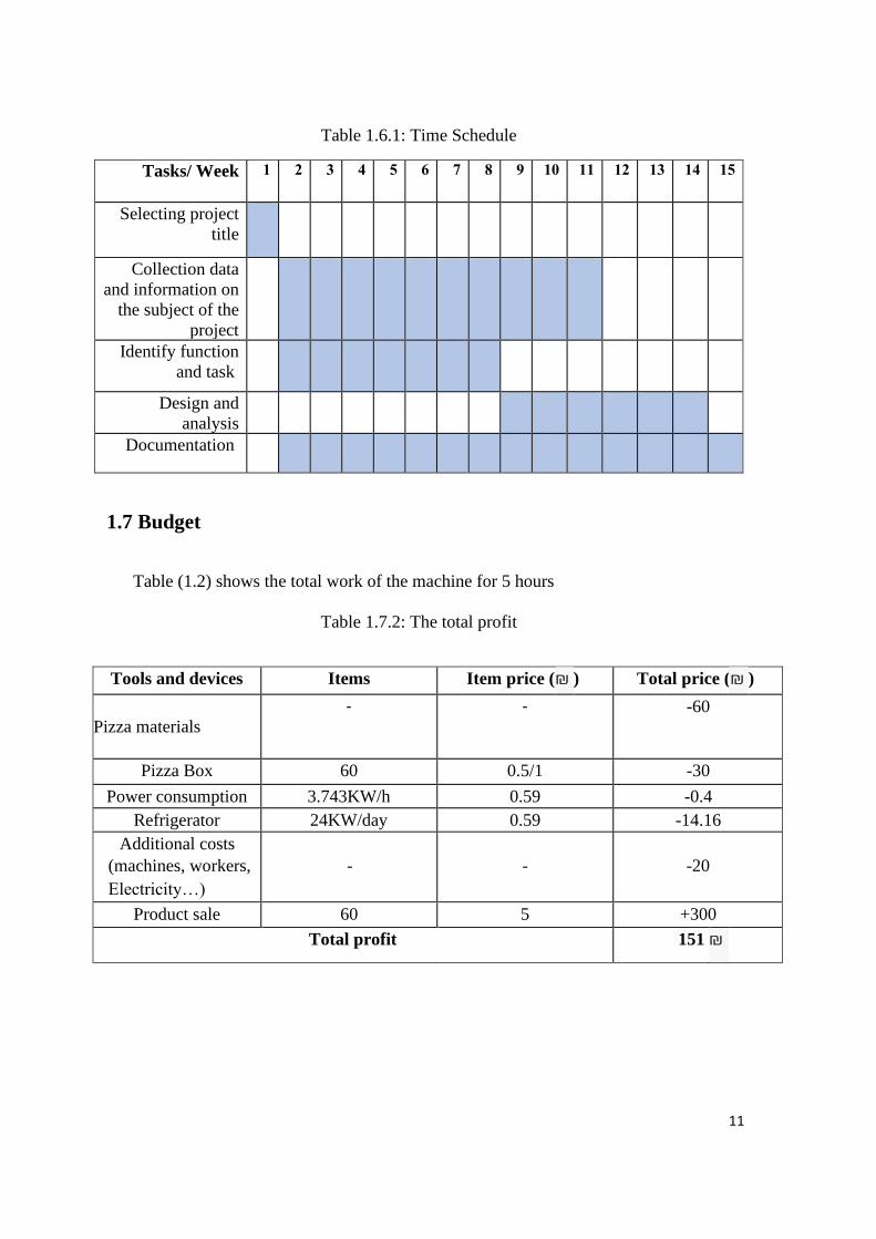
1.6 Time Schedule
The following time table shows the project work divided in fifteen weeks of the as
following.
11
Table 1.6.1: Time Schedule
15 14 13 12 11 10 9 8 7 6 5 4 3 2 1 Tasks/ Week
Selecting project
title
Collection data
and information on
the subject of the
project Identify function
and task
Design and
analysis Documentation
1.7 Budget
Table (1.2) shows the total work of the machine for 5 hours
Table 1.7.2: The total profit
Tools and devices Items Item price ( ₪ ) Total price ( ₪ )
Pizza materials
- - -60
Pizza Box 60 0.5/1 -30
Power consumption 3.743KW/h 0.59 -0.4
Refrigerator 24KW/day 0.59 -14.16
Additional costs
(machines, workers,
Electricity…)
-
-
-20
Product sale 60 5 +300
Total profit 151 ₪
12
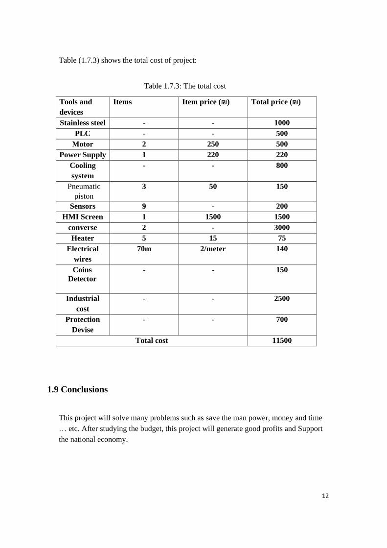
Table (1.7.3) shows the total cost of project:
Table 1.7.3: The total cost
Tools and
devices
Items Item price (₪) Total price (₪)
Stainless steel - - 1000
PLC - - 500
Motor 2 250 500
Power Supply 1 220 220
Cooling
system
- - 800
Pneumatic
piston
3 50 150
Sensors 9 - 200
HMI Screen 1 1500 1500
converse 2 - 3000
Heater 5 15 75
Electrical
wires
70m 2/meter 140
Coins
Detector
- - 150
Industrial
cost
- - 2500
Protection
Devise
- - 700
Total cost 11500
1.9 Conclusions
This project will solve many problems such as save the man power, money and time
… etc. After studying the budget, this project will generate good profits and Support
the national economy.
13
2
Chapter 2: Mechanical Components
1. Introduction.
2. Machine Parts.
14
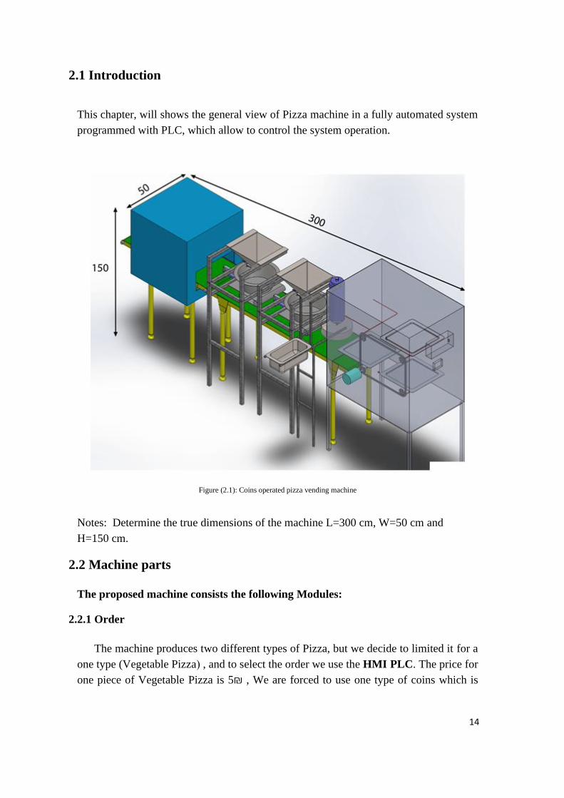
2.1 Introduction
This chapter, will shows the general view of Pizza machine in a fully automated system
programmed with PLC, which allow to control the system operation.
Figure (2.1): Coins operated pizza vending machine
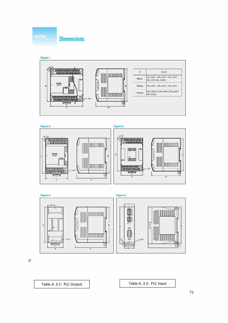
Notes: Determine the true dimensions of the machine L=300 cm, W=50 cm and
H=150 cm.
2.2 Machine parts
The proposed machine consists the following Modules:
2.2.1 Order
The machine produces two different types of Pizza, but we decide to limited it for a
one type (Vegetable Pizza ( , and to select the order we use the HMI PLC. The price for
one piece of Vegetable Pizza is 5 ₪ , We are forced to use one type of coins which is
15
5₪, the consumer has a free choice to use single conins of type 5₪ or to use a conis of
type 5₪ twiced.
Key word: ₪ the shekel symbol.
Notes: We will work to produce the first type of types of pizza (Vegetable Pizza)
because of the lack of possibilities, money and time.
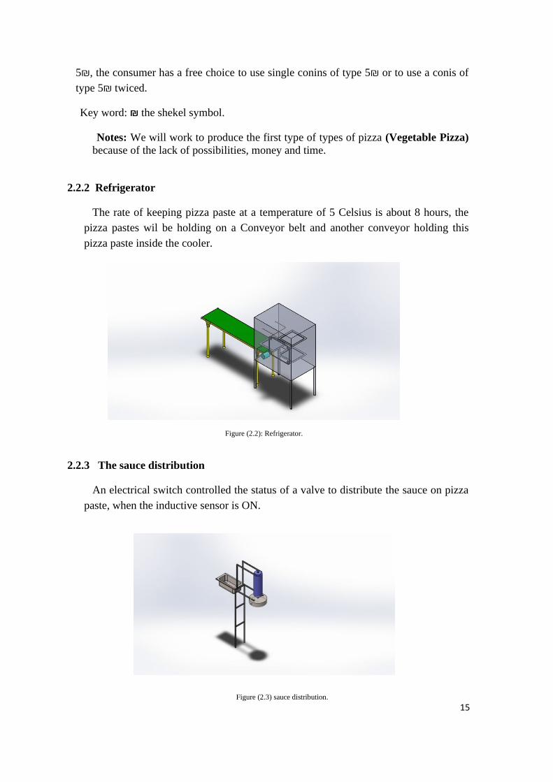
2.2.2 Refrigerator
The rate of keeping pizza paste at a temperature of 5 Celsius is about 8 hours, the
pizza pastes wil be holding on a Conveyor belt and another conveyor holding this
pizza paste inside the cooler.
2.2.3 The sauce distribution
An electrical switch controlled the status of a valve to distribute the sauce on pizza
paste, when the inductive sensor is ON.
Figure (2.2): Refrigerator.
.
Figure (2.3.1): sauce distribution.
.
Figure (2.3) sauce distribution.
.
16
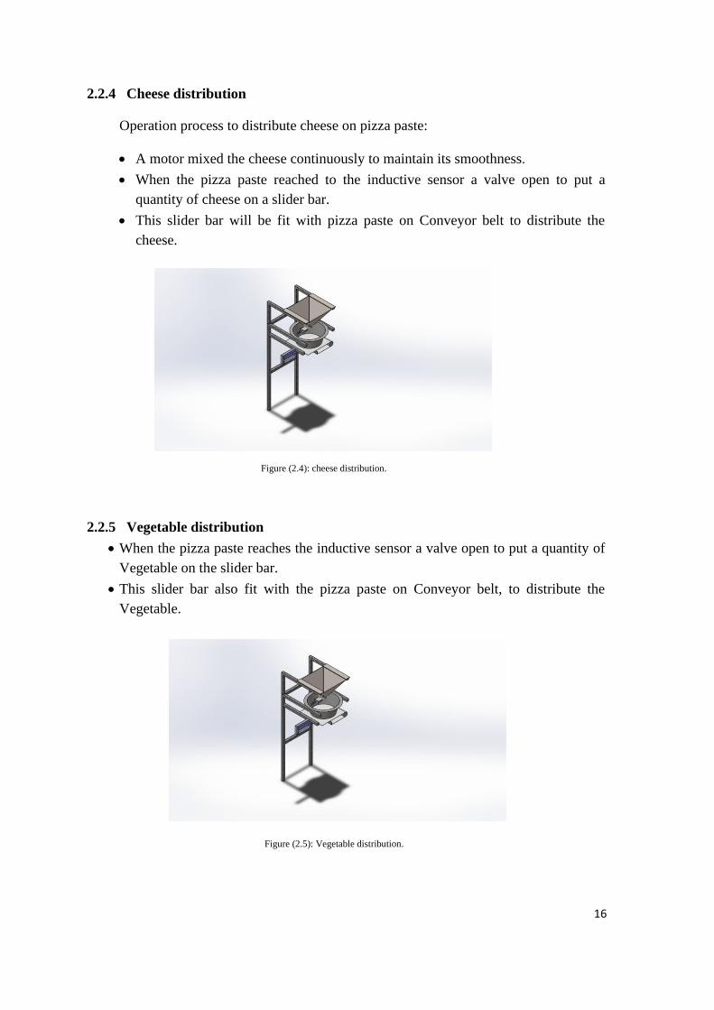
2.2.4 Cheese distribution
Operation process to distribute cheese on pizza paste:
• A motor mixed the cheese continuously to maintain its smoothness .
• When the pizza paste reached to the inductive sensor a valve open to put a
quantity of cheese on a slider bar.
• This slider bar will be fit with pizza paste on Conveyor belt to distribute the
cheese.
2.2.5 Vegetable distribution
• When the pizza paste reaches the inductive sensor a valve open to put a quantity of
Vegetable on the slider bar.
• This slider bar also fit with the pizza paste on Conveyor belt, to distribute the
Vegetable.
Figure (2.4): cheese distribution.
.
Figure (2.5): Vegetable distribution.
.
17
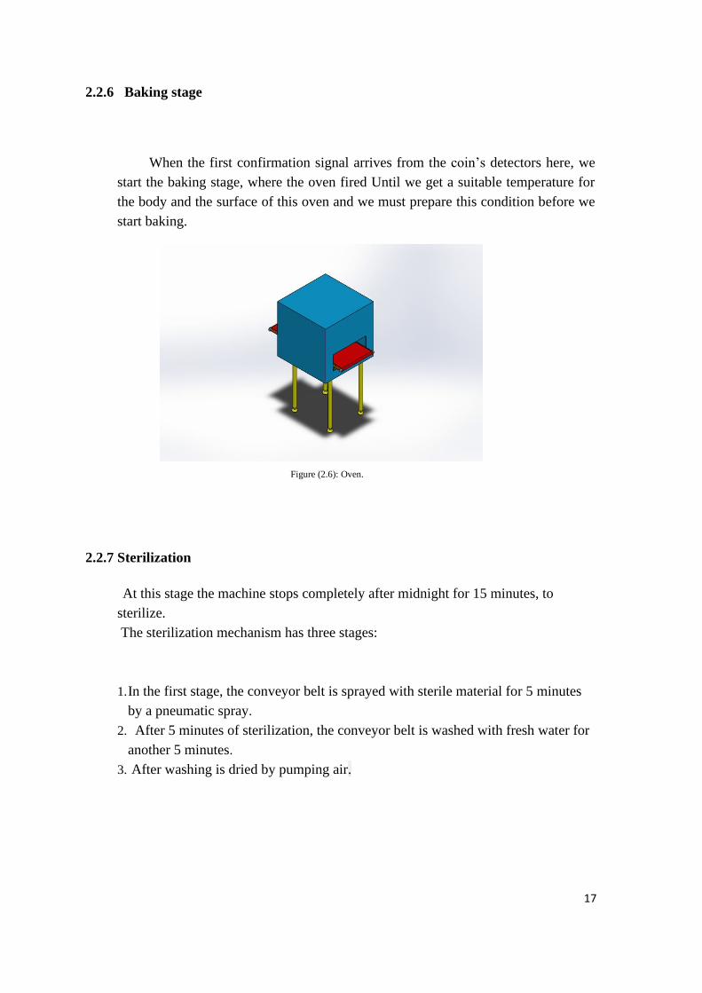
2.2.6 Baking stage
When the first confirmation signal arrives from the coin’s detectors here, we
start the baking stage, where the oven fired Until we get a suitable temperature for
the body and the surface of this oven and we must prepare this condition before we
start baking.
2.2.7 Sterilization
At this stage the machine stops completely after midnight for 15 minutes, to
sterilize.
The sterilization mechanism has three stages:
1. In the first stage, the conveyor belt is sprayed with sterile material for 5 minutes
by a pneumatic spray.
2. After 5 minutes of sterilization, the conveyor belt is washed with fresh water for
another 5 minutes.
3. After washing is dried by pumping air.
Figure (2.6): Oven.
.
18
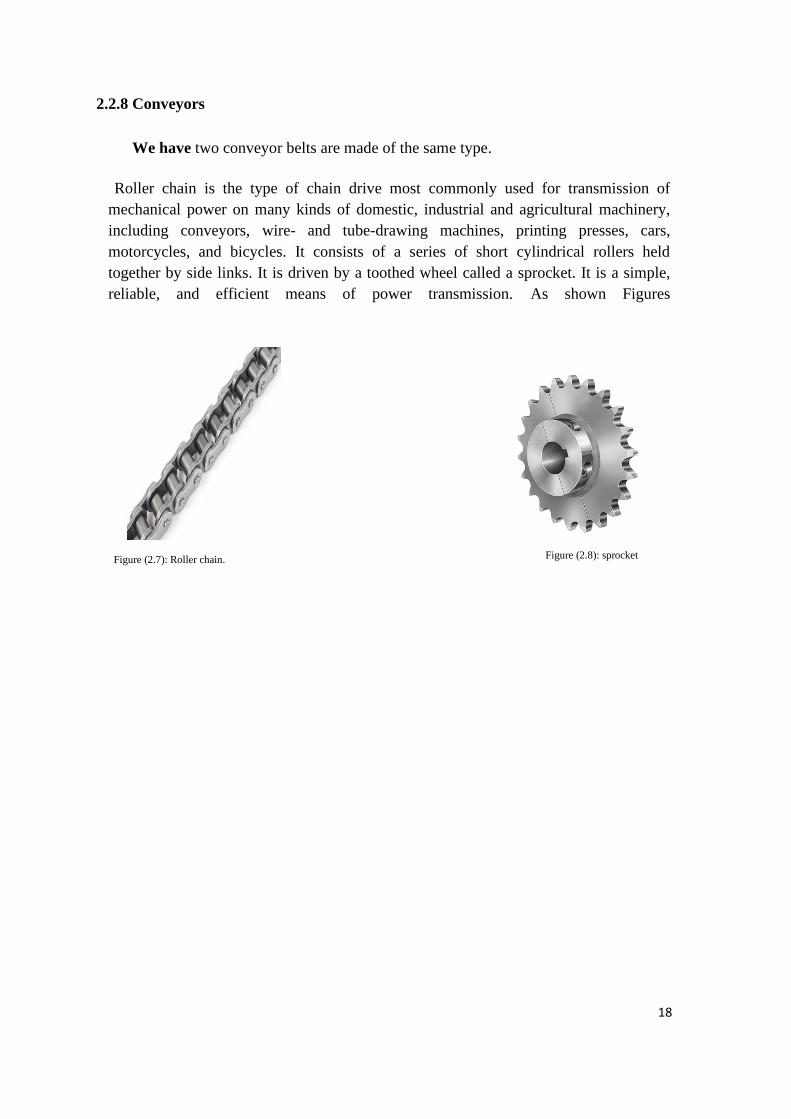
2.2.8 Conveyors
We have two conveyor belts are made of the same type.
Roller chain is the type of chain drive most commonly used for transmission of
mechanical power on many kinds of domestic, industrial and agricultural machinery,
including conveyors, wire- and tube-drawing machines, printing presses, cars,
motorcycles, and bicycles. It consists of a series of short cylindrical rollers held
together by side links. It is driven by a toothed wheel called a sprocket. It is a simple,
reliable, and efficient means of power transmission. As shown Figures
Figure (2.7): Roller chain.
.
Figure (2.8): sprocket
.
19
3
Chapter 3: Mechanical Design
3.1 Pneumatic system.
3.2 Refrigerator conveyor motor.
20
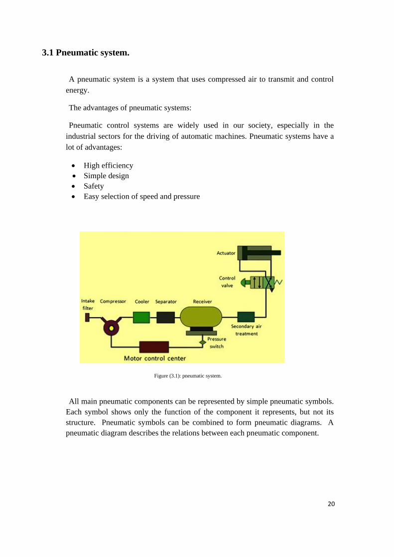
3.1 Pneumatic system.
A pneumatic system is a system that uses compressed air to transmit and control
energy.
The advantages of pneumatic systems:
Pneumatic control systems are widely used in our society, especially in the
industrial sectors for the driving of automatic machines. Pneumatic systems have a
lot of advantages:
• High efficiency
• Simple design
• Safety
• Easy selection of speed and pressure
All main pneumatic components can be represented by simple pneumatic symbols.
Each symbol shows only the function of the component it represents, but not its
structure. Pneumatic symbols can be combined to form pneumatic diagrams. A
pneumatic diagram describes the relations between each pneumatic component.
Figure (3.1): pneumatic system.
.

21
Equation 1
Equation 2
Equation 3
Equation 4
Cylinder calculation
The diminution of flexing piston is calculated by the following equations:
F=P *A
Where
• F: force(N).
• P: pressure(bar)=0.5N/ 𝑚𝑚2.
• A: cross section area of the piston rod.
According to newton second low, the force can be calculated by the following
equations:
F=M*G
Where
• M: mass of prism (kg).
• G: Acceleration of gravity (m/ 𝑠2).
Mass of object can be calculated by the following equation:
M=P*V
Where
• p: Aluminum density =2700 Kg\𝑚2
• V: volume of pec
The volume of pec can be calculated by the following equation:
V=x*y*z
=0.00004 𝑚2

22
Equation 5
Equation 6
Equation 7
Equation 8
Equation 9
M=p*v
=2700*00004
=0.108kg
F=m*g
=0.108*9.8
=1.058 N
A= f
𝑝 =
1.058N
0.5= 2.1𝑚𝑚2
The piston diameter can be calculated by the following equation:
A=π
4*𝑑2
d=A∗U
π =2.69mm
The volume of pec can be calculated by the following equation:
V= 𝜋
4 *𝑑2*h
=568. 𝑚𝑚303
Where
• h: length of pec =10 cm.
• d: diameter.
23
Equation 10
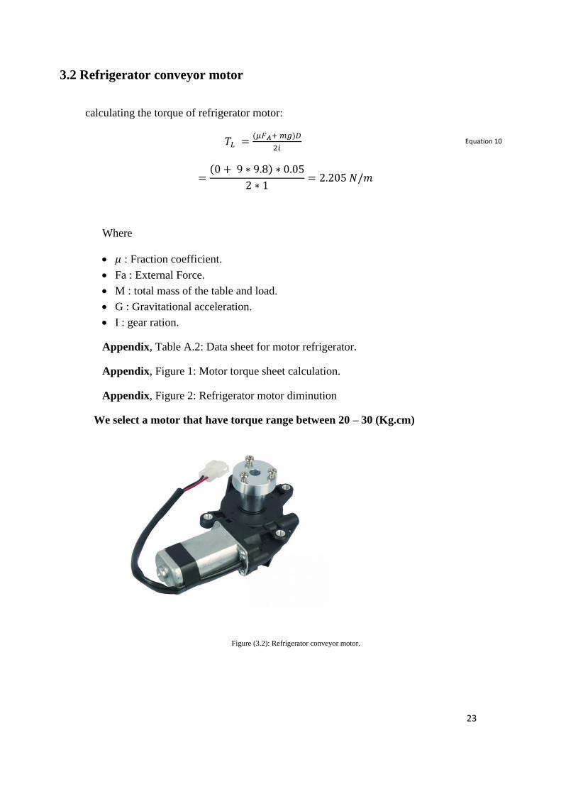
3.2 Refrigerator conveyor motor
calculating the torque of refrigerator motor:
𝑇𝐿 =(𝜇𝐹𝐴+ 𝑚𝑔)𝐷
2𝑖
=(0 + 9 ∗ 9.8) ∗ 0.05
2 ∗ 1= 2.205 𝑁/𝑚
Where
• 𝜇 : Fraction coefficient.
• Fa : External Force.
• M : total mass of the table and load.
• G : Gravitational acceleration.
• I : gear ration.
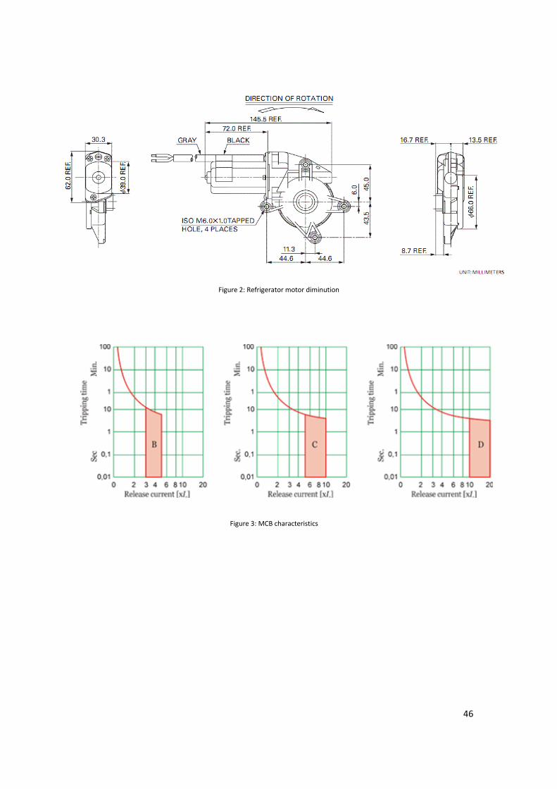
Appendix, Table A.2: Data sheet for motor refrigerator.
Appendix, Figure 1: Motor torque sheet calculation.
Appendix, Figure 2: Refrigerator motor diminution
We select a motor that have torque range between 20 – 30 (Kg.cm)
Figure (3.2): Refrigerator conveyor motor.
.
24
4
Chapter 4: Electrical Design
4.1 Introduction.
4.2 Calculation Of Protection.
4.3 Protection.
4.4 Control element.
4.5 Accessories.
4.6 State graph.
4.7 Pneumatic circuit.
25
Equation 11
Equation 12
4.1 Introduction
This chapter contains the electrical component specifications (motor, sensor,
overload, etc.), power and control circuit which will be used in our project.
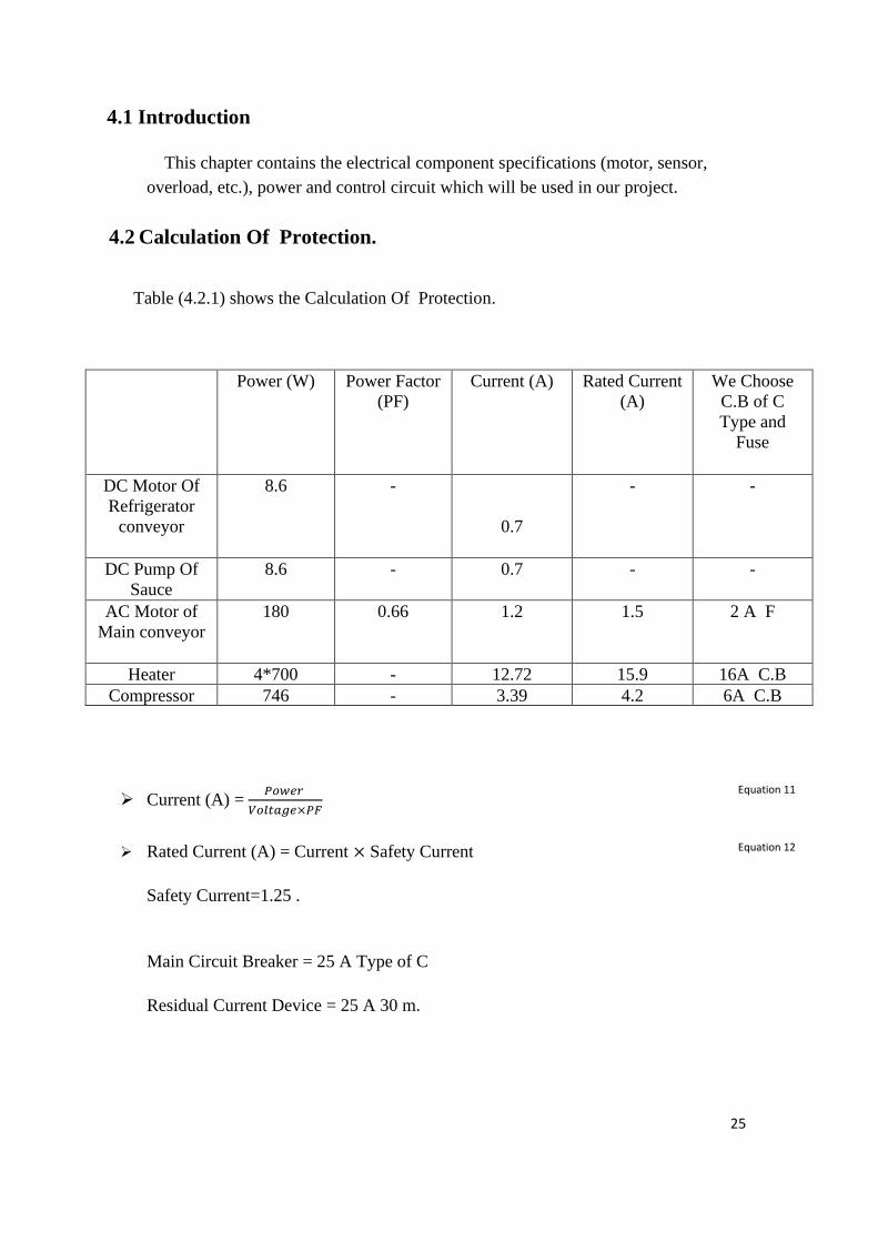
4.2 Calculation Of Protection.
Table (4.2.1) shows the Calculation Of Protection.
Power (W) Power Factor
(PF)
Current (A) Rated Current
(A)
We Choose
C.B of C
Type and
Fuse
DC Motor Of
Refrigerator
conveyor
8.6 -
0.7
- -
DC Pump Of
Sauce
8.6 - 0.7 - -
AC Motor of
Main conveyor
180 0.66 1.2 1.5 2 A F
Heater 4*700 - 12.72 15.9 16A C.B
Compressor 746 - 3.39 4.2 6A C.B
➢ Current (A) = 𝑃𝑜𝑤𝑒𝑟
𝑉𝑜𝑙𝑡𝑎𝑔𝑒×𝑃𝐹
➢ Rated Current (A) = Current × Safety Current
Safety Current=1.25 .
Main Circuit Breaker = 25 A Type of C
Residual Current Device = 25 A 30 m.
26
4.3 Protection
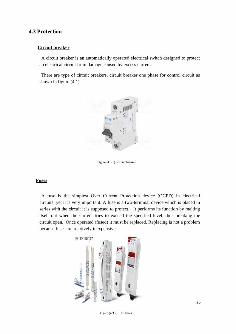
Circuit breaker
A circuit breaker is an automatically operated electrical switch designed to protect
an electrical circuit from damage caused by excess current.
There are type of circuit breakers, circuit breaker one phase for control circuit as
shown in figure (4.1).
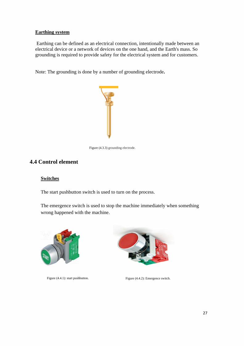
Fuses
A fuse is the simplest Over Current Protection device (OCPD) in electrical
circuits, yet it is very important. A fuse is a two-terminal device which is placed in
series with the circuit it is supposed to protect. It performs its function by melting
itself out when the current tries to exceed the specified level, thus breaking the
circuit open. Once operated (fused) it must be replaced. Replacing is not a problem
because fuses are relatively inexpensive.
Figure (4.3.1): circuit breaker.
Figure (4.3.2): The Fuses.
27
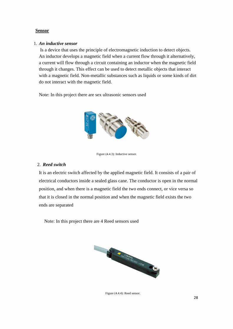
Earthing system
Earthing can be defined as an electrical connection, intentionally made between an
electrical device or a network of devices on the one hand, and the Earth's mass. So
grounding is required to provide safety for the electrical system and for customers.
Note: The grounding is done by a number of grounding electrode.
4.4 Control element
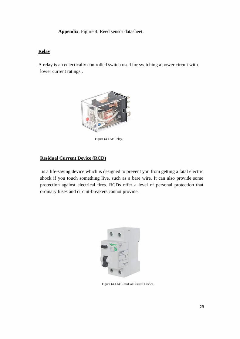
Switches
The start pushbutton switch is used to turn on the process.
The emergence switch is used to stop the machine immediately when something
wrong happened with the machine.
Figure (4.3.3) grounding electrode.
Figure (4.4.1): start pushbutton.
breaker.
Figure (4.4.2): Emergence switch.
breaker.
28
Sensor
1. An inductive sensor
Is a device that uses the principle of electromagnetic induction to detect objects.
An inductor develops a magnetic field when a current flow through it alternatively,
a current will flow through a circuit containing an inductor when the magnetic field
through it changes. This effect can be used to detect metallic objects that interact
with a magnetic field. Non-metallic substances such as liquids or some kinds of dirt
do not interact with the magnetic field.
Note: In this project there are sex ultrasonic sensors used
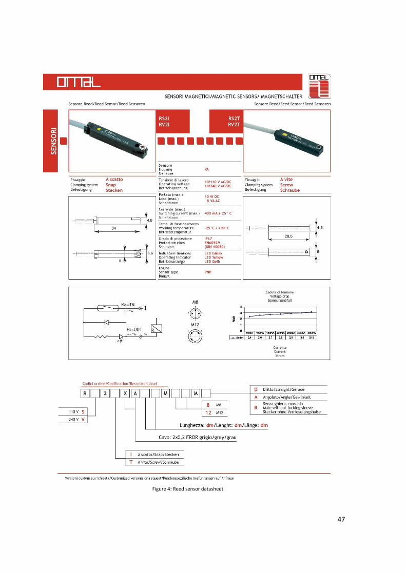
2. Reed switch
It is an electric switch affected by the applied magnetic field. It consists of a pair of
electrical conductors inside a sealed glass cane. The conductor is open in the normal
position, and when there is a magnetic field the two ends connect, or vice versa so
that it is closed in the normal position and when the magnetic field exists the two
ends are separated
Note: In this project there are 4 Reed sensors used
Figure (4.4.3): Inductive sensor.
breaker.
Figure (4.4.4): Reed sensor.
breaker.
29
Appendix, Figure 4: Reed sensor datasheet.
Relay
A relay is an eclectically controlled switch used for switching a power circuit with
lower current ratings .
Residual Current Device (RCD)
is a life-saving device which is designed to prevent you from getting a fatal electric
shock if you touch something live, such as a bare wire. It can also provide some
protection against electrical fires. RCDs offer a level of personal protection that
ordinary fuses and circuit-breakers cannot provide.
Figure (4.4.5): Relay.
Figure (4.4.6): Residual Current Device.
30
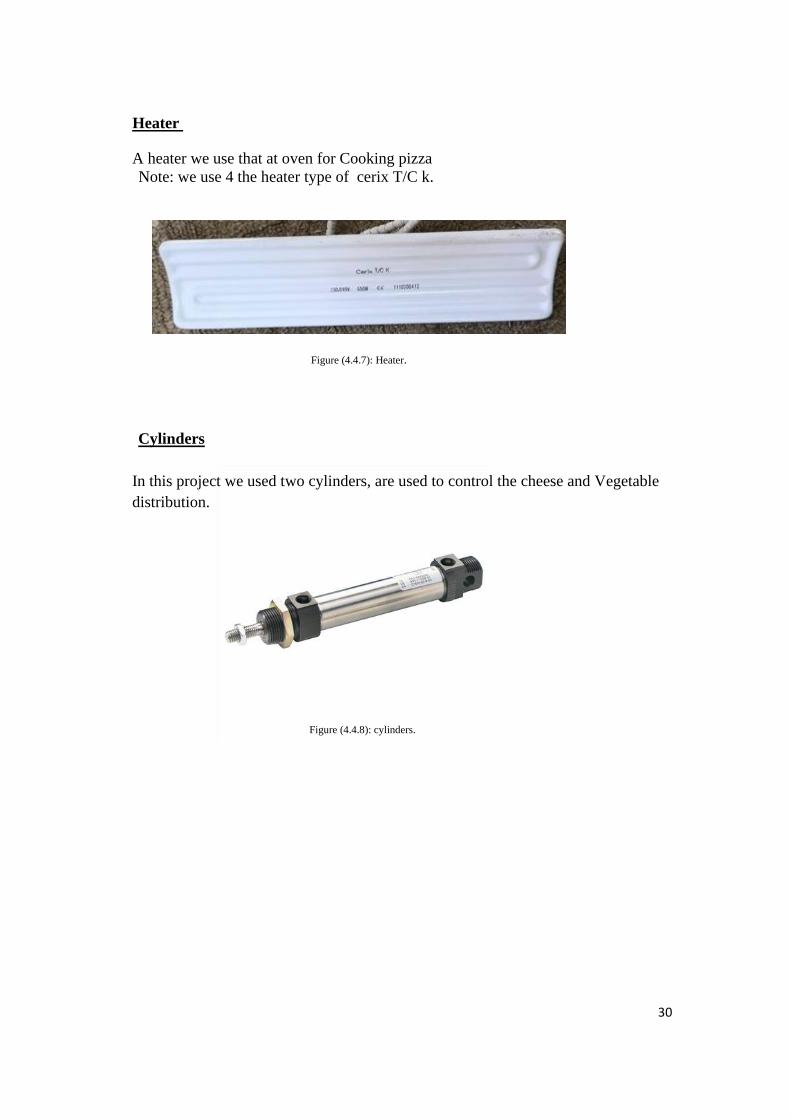
Heater
A heater we use that at oven for Cooking pizza
Note: we use 4 the heater type of cerix T/C k.
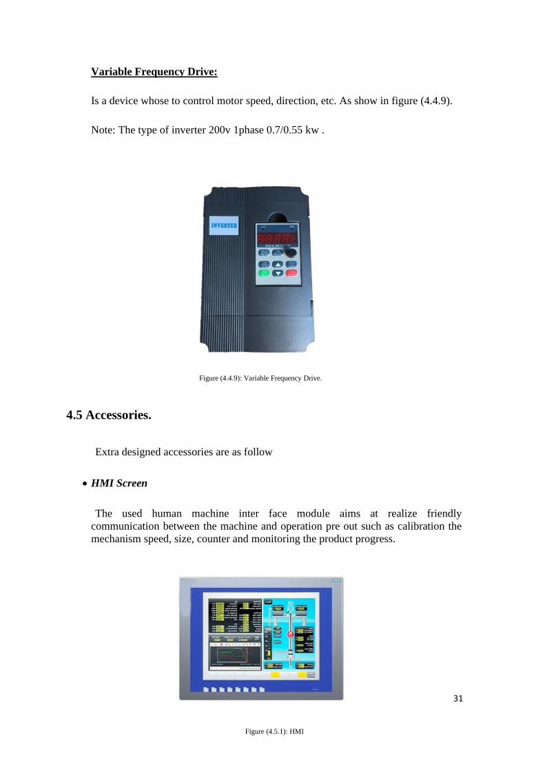
Cylinders
In this project we used two cylinders, are used to control the cheese and Vegetable
distribution.
Figure (4.4.8): cylinders.
Figure (4.4.7): Heater.
31
Variable Frequency Drive:
Is a device whose to control motor speed, direction, etc. As show in figure (4.4.9).
Note: The type of inverter 200v 1phase 0.7/0.55 kw .
Figure (4.4.9): Variable Frequency Drive.
4.5 Accessories.
Extra designed accessories are as follow
• HMI Screen
The used human machine inter face module aims at realize friendly
communication between the machine and operation pre out such as calibration the
mechanism speed, size, counter and monitoring the product progress.
Figure (4.5.1): HMI
Screen.
32
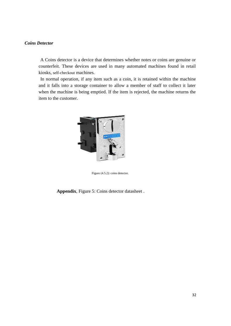
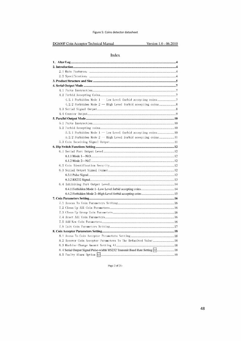
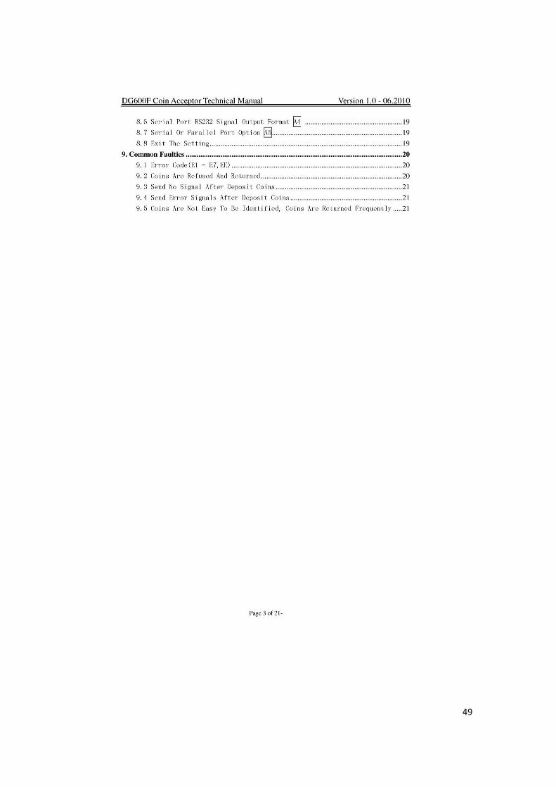
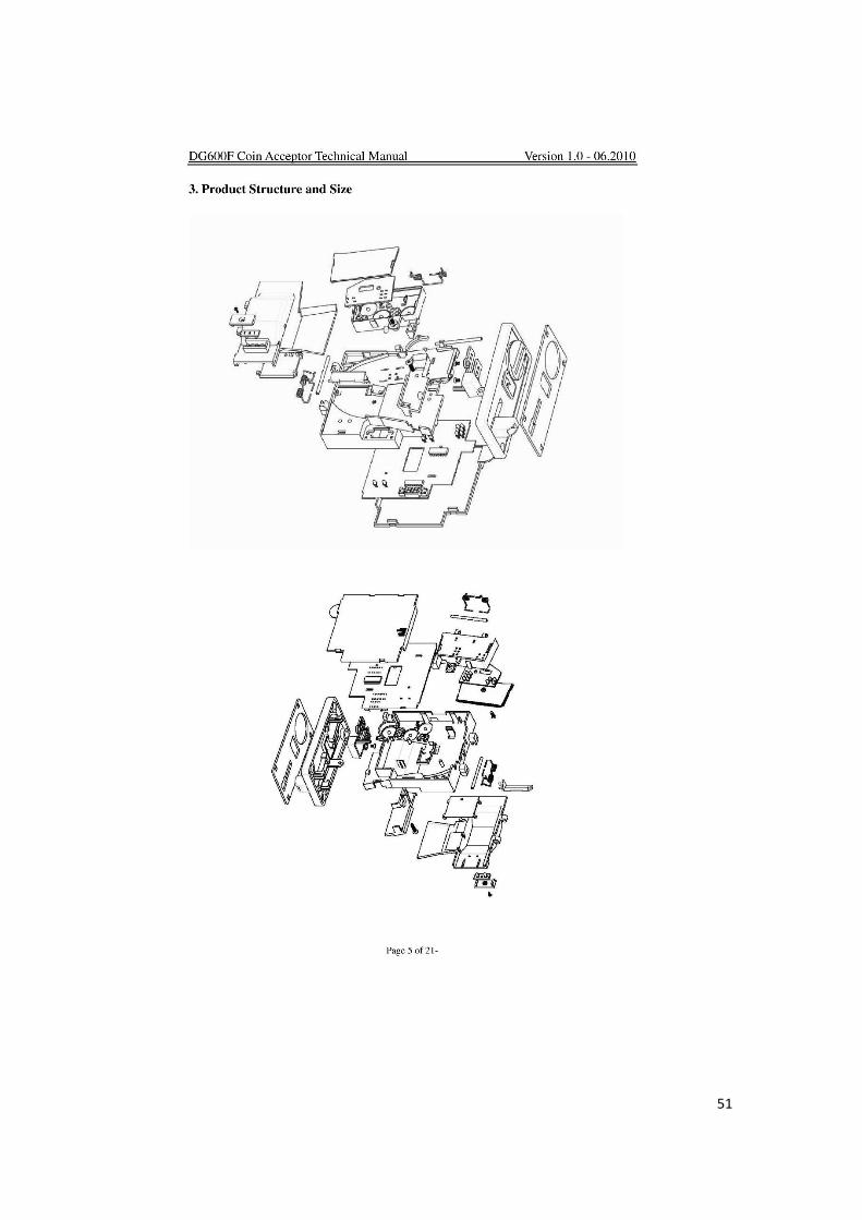
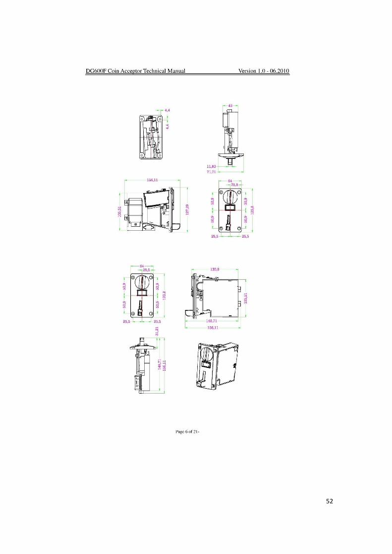
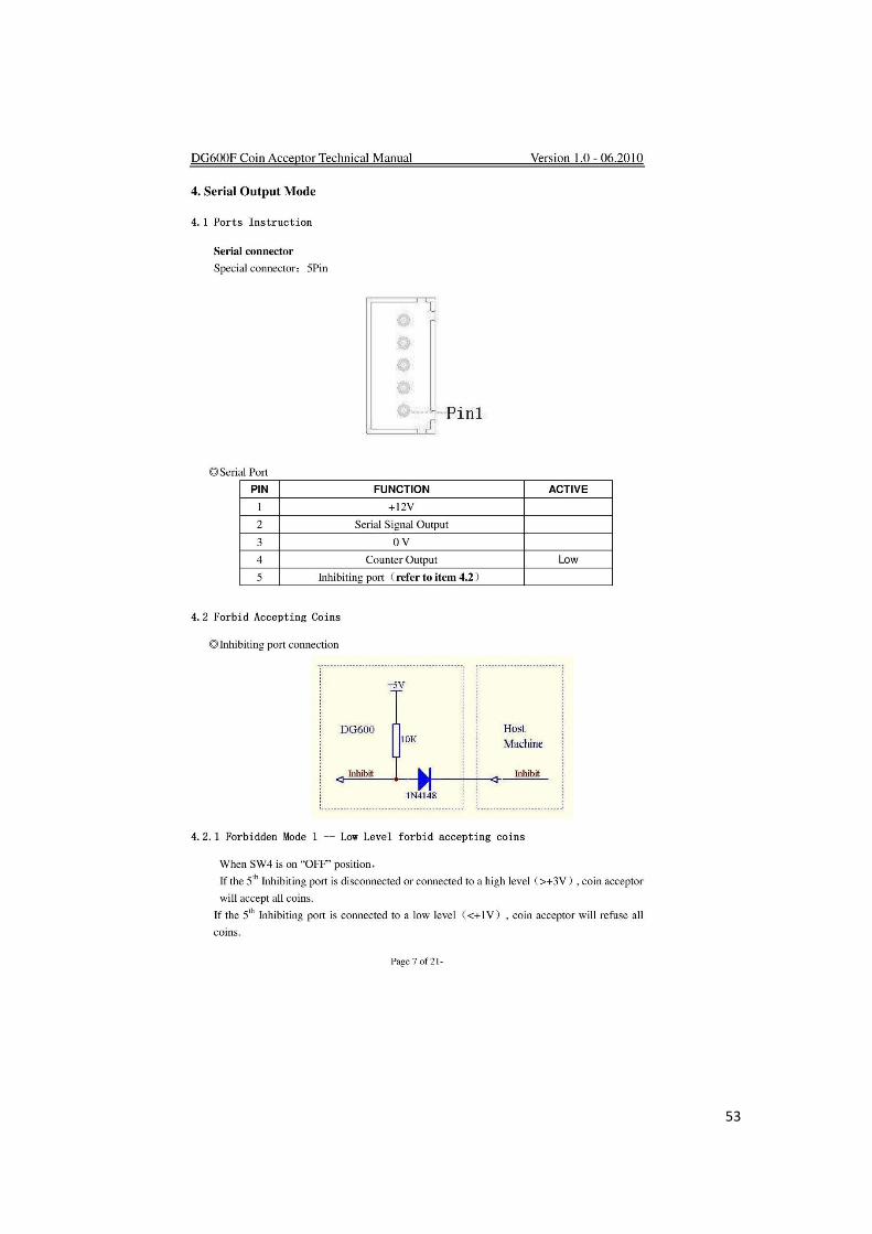
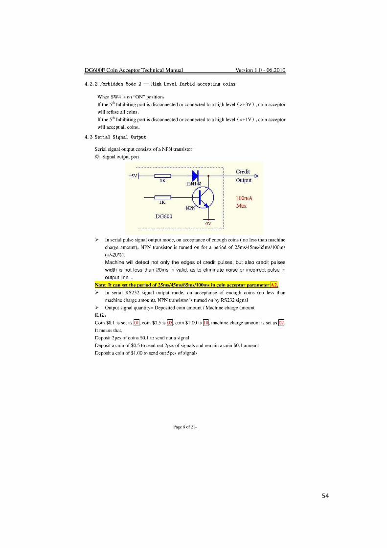
Coins Detector
A Coins detector is a device that determines whether notes or coins are genuine or
counterfeit. These devices are used in many automated machines found in retail
kiosks, self-checkout machines.
In normal operation, if any item such as a coin, it is retained within the machine
and it falls into a storage container to allow a member of staff to collect it later
when the machine is being emptied. If the item is rejected, the machine returns the
item to the customer.
Figure (4.5.2): coins detector.
Appendix, Figure 5: Coins detector datasheet .
33
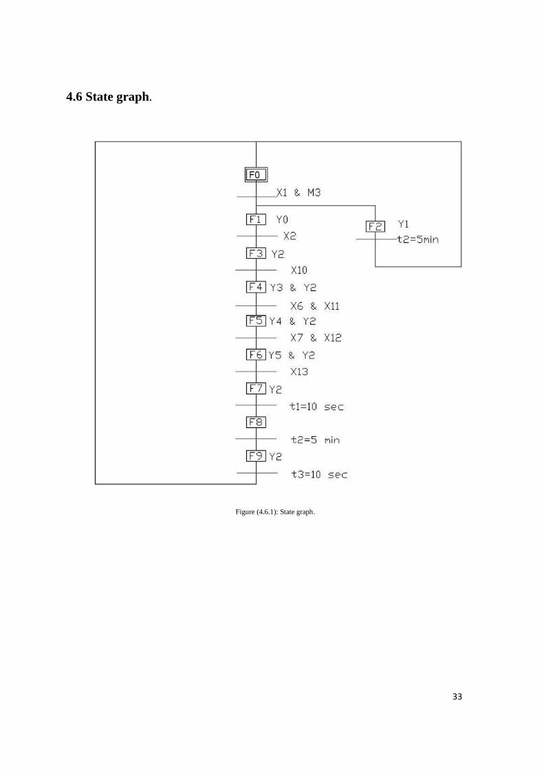
4.6 State graph.
Figure (4.6.1): State graph.
34
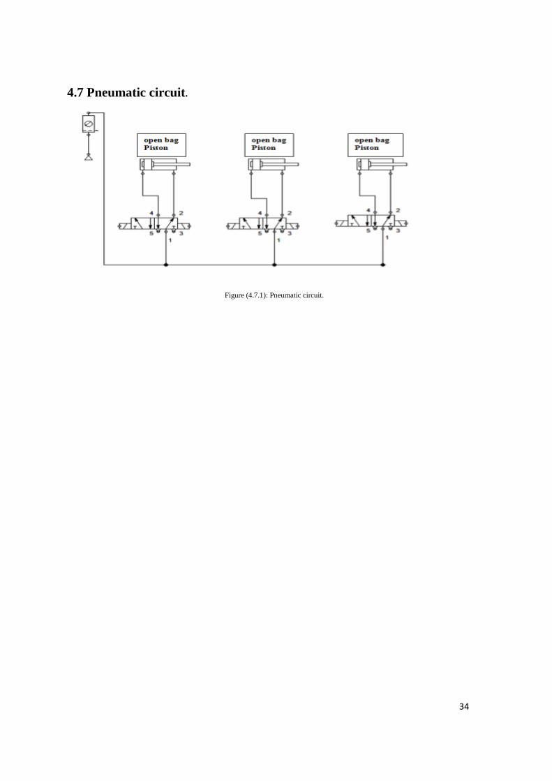
4.7 Pneumatic circuit.
Figure (4.7.1): Pneumatic circuit.
35
5
Chapter 5: Control and Prototyping
5.1 Introduction
5.2 PLC Characteristic
5.3 System Programming
5.4 Project Prototype
5.5 Prototype Running On
5.6 Recommendations
36
5.1 Introduction
As mentioned, the operation of Pizza Machine will be full automated in serial orders by
using PLC (programming logic controller). This program added some specifications
like automated running and occupational safety. This chapter provides experimental
result and, some recommendations from the work team for this project.
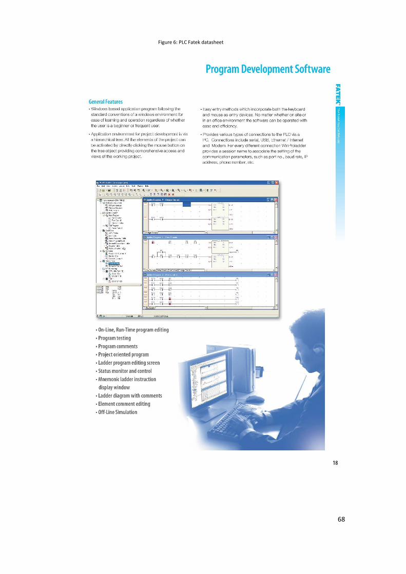
5.2 PLC Characteristic
Programmable Logic Controller (PLC) is a digital computer used for automation of
electromechanical process, such as control of machinery on factory assembly lines,
PLCs are used in many industries and machine. Unlike general-purpose computers, the
PLC is designed for multiple inputs and output arrangements. extended temperature
ranges, immunity to electrical noise, and resistance to vibration and impact. Programs
to control machine operation are typically stored in battery backed up or non- volatile
memory.
A PLC is an example of a hard-real time system since output results must be produced
in response to input conditions within a limited time otherwise unintended operation
will result. In our controlling design it is desirable to use a PLC with 13 input and 11
outputs mention, it can be operated on 24 volts. The used PLC is Fatek base controller
24VDC with 13 inputs and 9 outputs.
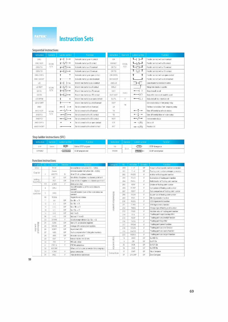
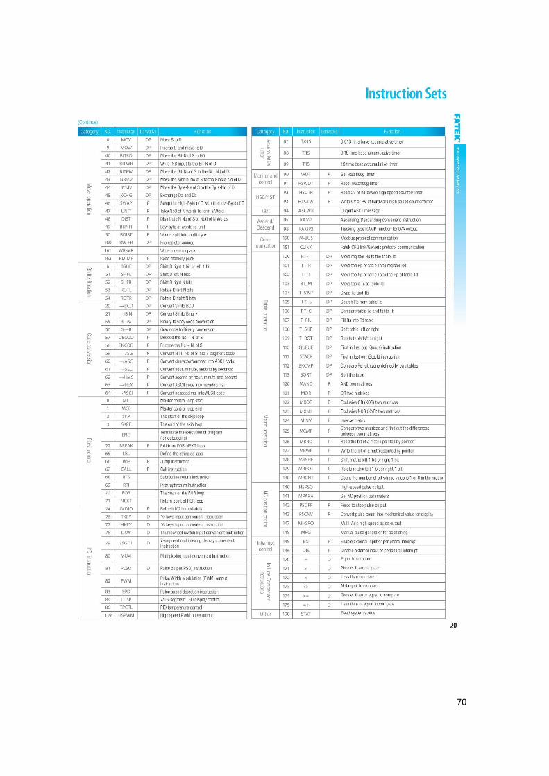
Appendix, Figure 6: PLC Fatek datasheet.
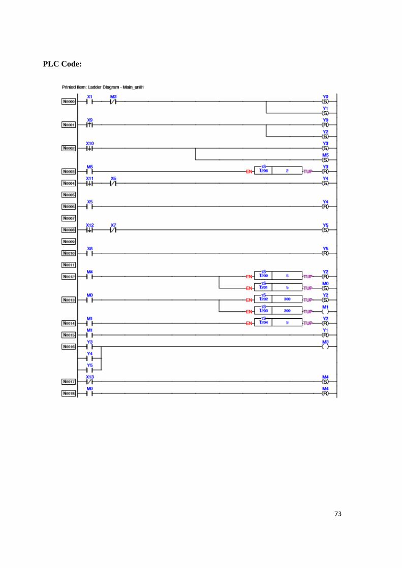
5.3 System Programming
The program of the system has been done of three stages: define outputs and inputs of
the system with symbols, programmatic expression for system parts and movements by
SFC, transfer SFC to Ladder program
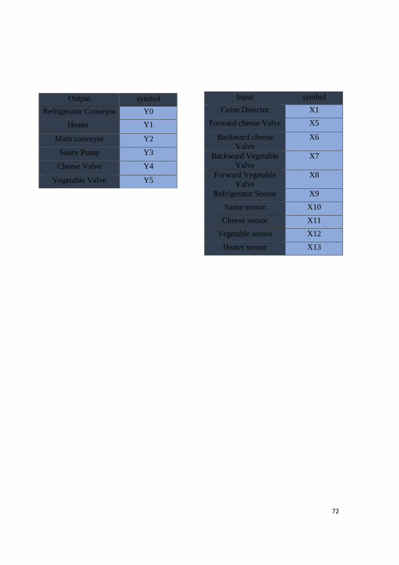
1. Inputs and outputs definition
(sensors) (Appendix, table A.3.2). And outputs (motors, cylinders) (Appendix, table
A.3.1).
2. Building SFC
Coordinate movement of system parts sequentially by SFC
3. Ladder program
After making SFC, transfers it to ladder program then upload the code to PLC
37
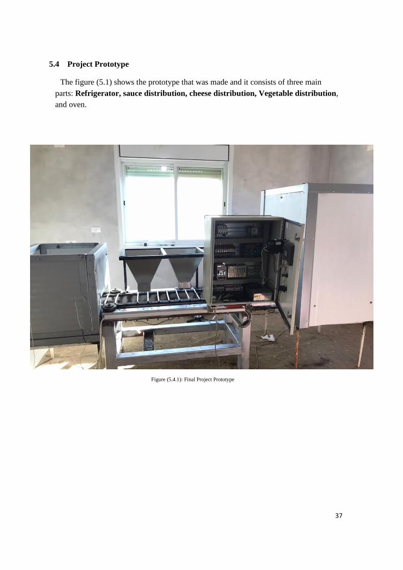
5.4 Project Prototype
The figure (5.1) shows the prototype that was made and it consists of three main
parts: Refrigerator, sauce distribution, cheese distribution, Vegetable distribution,
and oven.
Figure (5.4.1): Final Project Prototype
38
5.5 Prototype Running On
The process begins when the Coins Detector is activated by pay 5 (₪) ,Then
activates the sensor of the refrigerator then the Come down the piece of dough
from the refrigerator goes down to the conveyor and when the piece of dough
arrives at the sauce sensor will be placed the sauce , as well the cheese and
vegetables ,and When the piece of dough reaches the entrance to the oven, the
sensor activates and run a timer for 3 seconds to ensure that the piece reaches the
middle of the oven, the cooking timer will start after 3 seconds finished, for
another 5 minutes in this time the Convery will stopped, after the cooking time
finished the timer count 3 second then the machine turned off.
5.6 Recommendations
1. Study the possibility of producing more than one type of pizza.
2. Study the possibility of Packaging pizza by this machine.
Improve the project through of decrease or increase the materials of pizza.
39
6
Chapter 6: Manual User
6.1 System basics.
6.2 Main features.
6.3 Operation and setting.
6.4 Check and maintenance.
6.5 Safety.
6.6 Electrical circuit.
40
6.1 System basics
This system is designed to produce pizza cooked with dimensions of L=300, W=50,
H=150 cm, suitable for the markets local and global.
6.2 Main features
1) medium size, heavy weight.
2) fully automatic system.
3) mass production line with short time.
4) easy installation.
5) easy maintenance.
6.3 Operation and setting
1. make sure that the electric current reaches the production line, refrigerator and
motor.
2. make sure that the controller (PLC) is working through the exist of power light.
3. make sure that the materials are Existing in distribution tanks are sufficient for
production (sauce, cheese and distribution).
4. Pay 10 ₪ to start the process of the system, then the system will run
automatically from A to Z.
5. To stop the process at any time press "stop" button.
6. If any danger or unnormal states happened, press "emergency" button
immediately to move the system to the most safety conditions.
7. If the process stopped for any reason press "Run" button to complete the
operation from the stop point.
6.4 Check and maintenance
1. If any motor stops working, check the overload circuit breaker. If the cutter is
disconnected, disconnect the power supply from the motor and look for the load
and fix it then reconnect the power and start working.
2. In the case of giving the appropriate pressure for the valve, check the selector and
if there is no problem in it make sure of work the air compressor.
3. When making sure all electrical parts are working and there is no electrical fault,
but the system does not work when you paying 10 (₪) in coins detector , make
sure the controller (PLC) electrical connections (Power / Input / Output) If there is
no defect, the problem is in the programming of the plc, so reprogram the plc the
code.
41
6.5 Safety
1. Do not use flammable gasses such as anesthetic gas ,oxygen or hydrogen ,or
flammable liquid such as ethanol ,near the system because there is danger of
explosion.
2. Make sure that the electrical source is proportional to the electrical
characteristics of the production line
3. When maintaining or changing the used parts make sure that their characteristics
appropriate to the original parts of the system and take down the cutter.
4. Replace damaged electrical cables with electrical cables with the same
characteristics for fear of electric shock.
5. Keep the production line away from any water source, especially the control
panel because the system does not have a protection system against water, there
is a risk of electric shock when exposed to water.
6. If any problem is observed during the operation or scan, stop the process
immediately and turn off the system
7. Before cleaning the system, turn it off and remove the power cable from the
plug to avoid electric shock
8. To avoid damage to the system or electrical failure, do not remove the cable
from the plug until the system is turned off
42
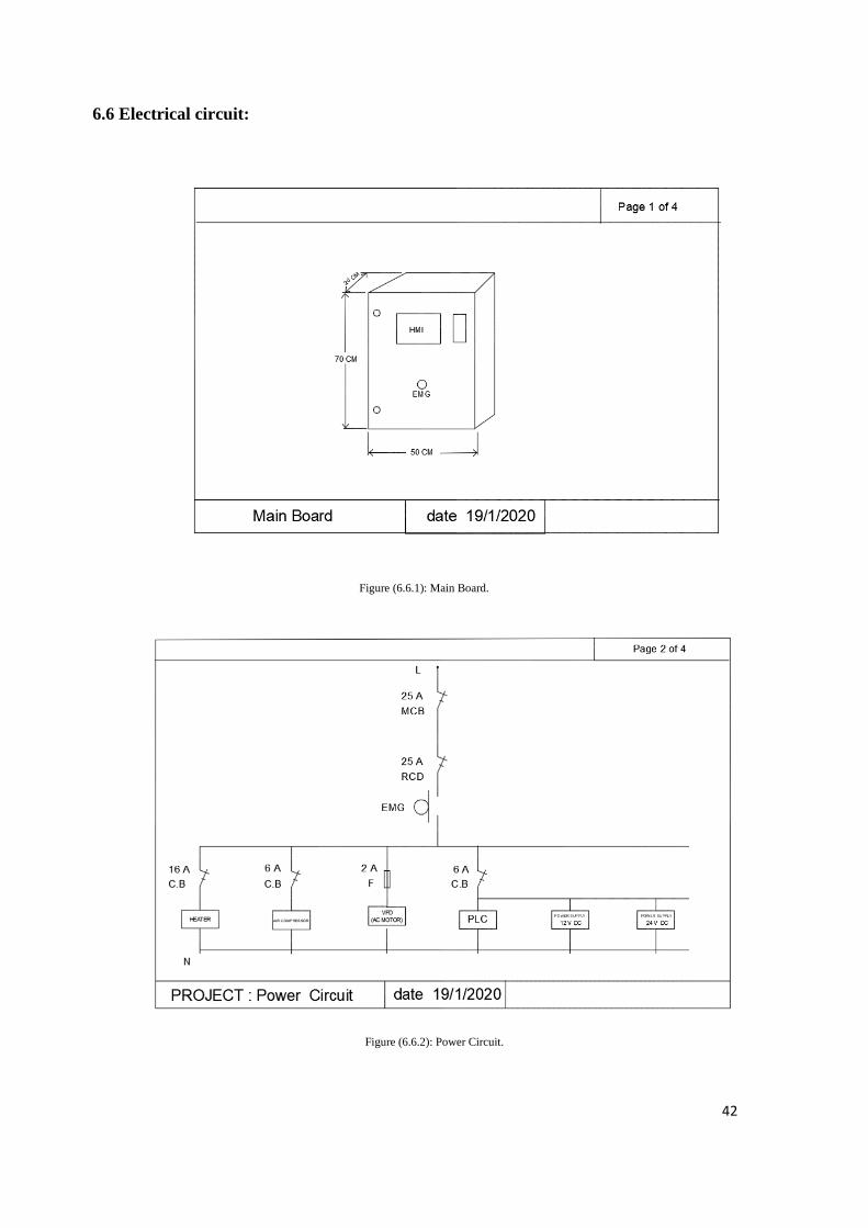
6.6 Electrical circuit:
Figure (6.6.1): Main Board.
Figure (6.6.2): Power Circuit.
43
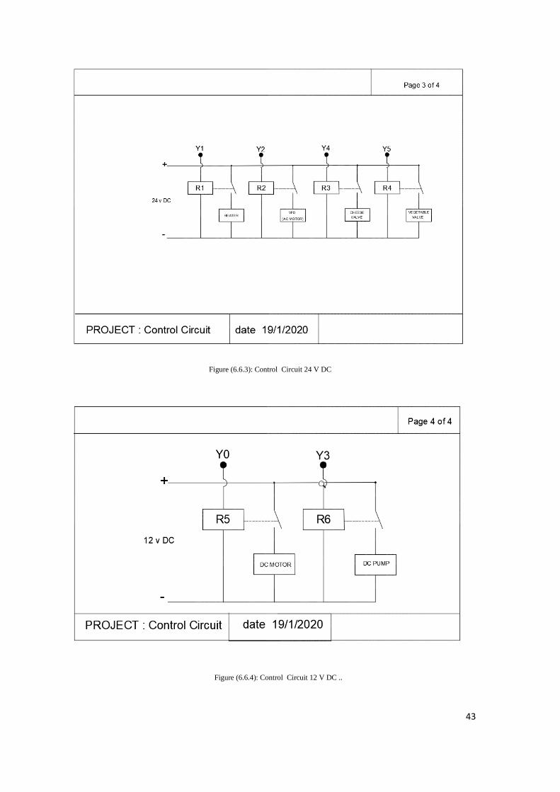
Figure (6.6.3): Control Circuit 24 V DC
Figure (6.6.4): Control Circuit 12 V DC ..
44
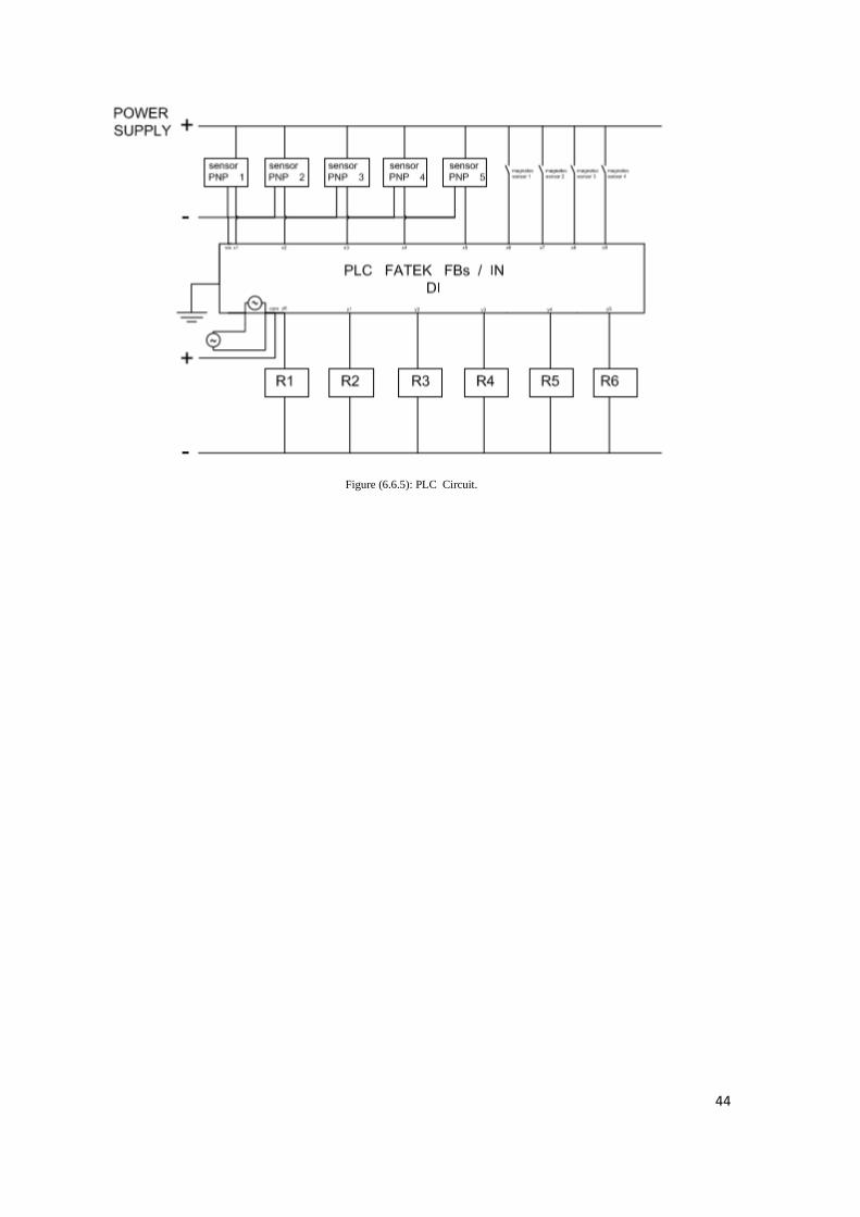
Figure (6.6.5): PLC Circuit.
45
Appendix
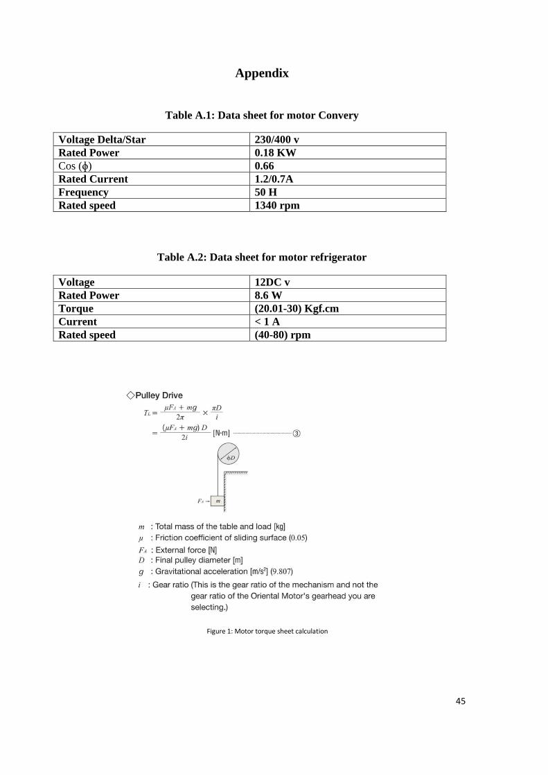
Table A.1: Data sheet for motor Convery
Voltage Delta/Star 230/400 v
Rated Power 0.18 KW
Cos (ɸ) 0.66
Rated Current 1.2/0.7A
Frequency 50 H
Rated speed 1340 rpm
Table A.2: Data sheet for motor refrigerator
Voltage 12DC v
Rated Power 8.6 W
Torque (20.01-30) Kgf.cm
Current < 1 A
Rated speed (40-80) rpm
Figure 1: Motor torque sheet calculation
46
Figure 2: Refrigerator motor diminution
Figure 3: MCB characteristics
47
Figure 4: Reed sensor datasheet
48
Figure 5: Coins detector datasheet
49

50
51
52
53
54
55
56
57
58

59
60

61
62

63
64
65
66
67
68
Figure 6: PLC Fatek datasheet
69
70
71
Table A. 3.1: PLC Output Table A. 3.2: PLC Input
72
Input symbol
Coins Detector X1
Forward cheese Valve X5
Backward cheese
Valve
X6
Backward Vegetable
Valve
X7
Forward Vegetable
Valve
X8
Refrigerator Sensor X9
Sause sensor X10
Cheese sensor X11
Vegetable sensor X12
Heater sensor X13
Output symbol
Refrigerator Conveyor Y0
Heater Y1
Main conveyor Y2
Sauce Pump Y3
Cheese Valve Y4
Vegetable Valve Y5
73
PLC Code:
74
Reference
[1] E. N. A. AlShemmary, L. M. Kadhom, and W. J. J. E. P. Al-Fahham, "Information
technology and stand-alone solar systems in tertiary institutions," vol. 36, pp. 369-
379, 2013.
[2] Budynas, Richard, Nisbett, and Keith, Shigley's Mechanical Engineering Design 9th
Edition. 2010.
[3] C. M. Franck, "HVDC circuit breakers: A review identifying future research needs,"
IEEE transactions on power delivery, vol. 26, no. 2, pp. 998-1007, 2011.
[4] J. Hernández, J. De la Cruz, and B. J. E. P. S. R. Ogayar, "Electrical protection for
the grid-interconnection of photovoltaic-distributed generation," vol. 89, pp. 85-99,
2012.
[5] A. Parr, "Hydraulics and Pneumatics A Technician's and Engineer's Guide," 2011.
[6] D. Paul, "Light rail transit DC traction power system surge overvoltage protection,"
IEEE Transactions on Industry Applications, vol. 38, no. 1, pp. 21-28, 2002.
[7] T. Takashima, J. Yamaguchi, K. Otani, T. Oozeki, K. Kato, and M. Ishida,
"Experimental studies of fault location in PV module strings," Solar Energy
Materials and Solar Cells, vol. 93, no. 6-7, pp. 1079-1082, 2009.
[8] L. Tianze, L. Hengwei, J. Chuan, H. Luan, and Z. Xia, "Application and design of
solar photovoltaic system," in Journal of Physics: Conference Series, 2011, vol.
276, no. 1, p. 012175: IOP Publishing.
[9] A. Wright and C. Christopoulos, "Electrical Power System Protection."
[10] Afer, P. T. Pvb. Terentii Aphri Poetae Comici Lepidissimi. Andria. Eunuchus.
Heautontimorumenos. Adelphi. Phormio. Ecyra. Schurerius.
[11] Pedersen, S. L., Hansen, J. M., & Ambrósio, J. A. (2004). A roller chain drive model
including contact with guide-bars. Multibody system dynamics, 12(3), 285-301.
[12] Brennan, P. V. (1993). Residual current device with high immunity to nuisance tripping. IEE Proceedings G (Circuits, Devices and Systems), 140(2), 140-144.