clutches need attention - the automotive technician
TRANSCRIPT

Brake and clutch
Cooling systems Diesel servicing
4WD focus
Volvo Strange speedo
Jaguar Dodgy module
Mercedes Blank display
Peugeot Freaky fan
Tech
Spotlight
problem solving page 26
‘s a fact Join TaT today
Visit: www.tat.net.au
The Automotive Technician
The Automotive Technician
LandCruiser Hard starter
Issue 58, 2017
www.tat.net.au
Clutches need
attention
BMW Blown cooler
Like us on Facebook

Join Capricorn today. 1800 560 554 | [email protected] | capricorn.coop
For the best interests of our members
Shares are issued by Capricorn Society Limited (ACN 008 347 313). No offer of shares is made in this advertisement. An offer of shares will only made in, or accompanied by, Capricorn’s Prospectus and any supplementary prospectus which is available on request or may be viewed at capricorn.coop under “Corporate Documents.” Before making any decision to apply for shares you should consider the Prospectus and any supplementary prospectus. Any application for shares must be made on the application form in or accompanying the Prospectus.
Together, we’re stronger.For over 40 years Capricorn Members have been sharing in the benefits.Make buying parts easier, earn exclusive reward points and experience the benefits of being a shareholder in Australia’s oldest and largest automotive parts buying cooperative.
The Automotive Technician 3
PublisherThe Automotive Technician Pty LtdABN 27 121 589 80230 Dale StreetBROOKVALE NSW 2100Ph: 1300 828 000(in Australia)or + 61 2 9907 1332Fax: 1300 828 100All communications to:[email protected] boardGeoff MuttonJeff SmitJanene ChampionTechnical editorJeff SmitSub-editorCameron McGavinGeneral managerGeoff MuttonScan Data directorRod MaherTechnical researchDeyan BarrieTaT’s a fact traffic managerAlex CowieTaTassist moderatorScott Thomas
Technical contributorsBrendan SorensenLarry Carley (USA)Frank Massey (UK)Dan Sullivan (USA)Clinton Brett (Diesel do)Allan Gray (Terrain Tamer)Jack StepanianSam NazarianJason SmithTaTassist teamBrendan SorensenClinton BrettSideth ChivMaurice DonovanGil SherAnthony TyddWayne BroadyJason SmithMarty HosieJack Stepanian TaT technical assistanceTim MarshGary HomanPeter HindsGraham PattersonAllen ChamberlainSimon ForseyColumnistsJulian Hentze (USA)Geoff Mutton (TaT Biz)
Advertising inquiriesJanene [email protected] 226 77003 5862 3090 Graphic designRussell Jones Graphic Design [email protected] 0411 817 012 www.rjgd.com.auPrintingMcPherson’s Printing Group76 Nelson St, Maryborough VIC 3465www.mcphersonsprinting.com.auAffiliated associationsVASA – [email protected] – [email protected] Society Alliance Supplier
The Automotive Technician Pty Ltd publishes, in print and on its website, technical advice, case studies and items contributed by its members and readers for the purpose of educating technicians and preparing them for a rewarding aftermarket future.
All advices are given in good faith, and are based on actual workshop repairs.No guarantee is given, nor any liability accepted in respect to any published advice.
The Automotive Technician Pty Ltd is not responsible for the accuracy of any information contained in material submitted by contributors or other third parties and published either in print or in digital format online and accepts no liability in relation to such materials or their content.
Newsworthy articles or comments are welcomed, and should be submitted to the technical editor.
All material appearing in The Automotive Technician is copyright.
Reproduction in whole or in part is illegal without prior written consent from the Editorial board.
TaT SD (Scan Data), TaT programs and TaT reviews are exclusive resources to financial members of the TaT network.
All are strictly copyright and must not be published, copied or shared in any manner outside the TaT membership.
All advertisers agree to indemnify the publisher for all damages or liabilities arising from their published or unpublished material.
THE TAT TEAM
CONTENTS - The Automotive Technician - Issue 58, August 2017
• TaT’s a fact • TaTassist • TaT share • TaT train • Tat Biz • TaT SD (Scan Data)
• TaT programs • TaT reviews • TaT check • TaT find
are all trade names ofThe Automotive Technician Pty Ltd
Reversing the polarity of a DC motor
6 Maurice Donovan
10 Frank Massey
8 Brendan Sorensen
20 Dan Sullivan16 Jason Smith
24 Rod Maher 35 Sam and Jack
44 Clinton Brett36 Allan Gray
A funny thing happened on the way to my laptop
14 Larry Carley
Understanding vacuum
Future of DPF servicing
Tripping the cold fantastic
The Automotive Technician is a member of the Circulations Audit Board.
Audit period 1st October 2016 to 31st March 2017Average net distribution 9948.
Nissan Tiida idle relearn
The forecast is hot for cooling systems
P0089 – Fuel-pressure regulator performance outside parameters
Cooling-system problems
The day we gatecrashed Rod Maher’s workshop
Join Capricorn today. 1800 560 554 | [email protected] | capricorn.coop
For the best interests of our members
Shares are issued by Capricorn Society Limited (ACN 008 347 313). No offer of shares is made in this advertisement. An offer of shares will only made in, or accompanied by, Capricorn’s Prospectus and any supplementary prospectus which is available on request or may be viewed at capricorn.coop under “Corporate Documents.” Before making any decision to apply for shares you should consider the Prospectus and any supplementary prospectus. Any application for shares must be made on the application form in or accompanying the Prospectus.
Together, we’re stronger.For over 40 years Capricorn Members have been sharing in the benefits.Make buying parts easier, earn exclusive reward points and experience the benefits of being a shareholder in Australia’s oldest and largest automotive parts buying cooperative.
The Automotive Technician 4
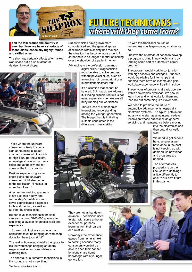
If all the talk around the country is even half true, we have a shortage of technicians, especially highly trained
and skilled ones.The shortage certainly affects aftermarket workshops but it also a factor for dealership workshops.
That’s where the unaware consumer is likely to spot a sign announcing a labour-charge increase into the mid-to-high $100-per-hour realm, a now-typical rate in our major cities and at the low end for some of the luxury brands.Besides experiencing some chest pains, the unaware consumer might also come to the realisation: ‘That’s a lot more than I earn.’A technician wielding spanners is not paid that hourly rate — the shop’s cashflow must cover sophisticated diagnostic tools and training, as well as all other business costs.But top-level technicians in the field can earn around $100,000 a year after achieving a level of diagnostic skills and experience. So we could logically conclude that applicants must be banging on workshop doors for these jobs, right?The reality, however, is totally the opposite. It’s the workshops banging on doors, eagerly seeking out candidates at an alarming rate.The shortfall of automotive technicians in this country is not a new thing.
But as vehicles have grown more computerised and the general appeal of all trades within society has reduced, the situation has become more urgent. A career path is no longer a matter of looking over the shoulder of a patient mentor. Advancing in the profession demands
digital skills. A diagnostician must be able to solve puzzles without physical clues, such as an engine not running right or an intermittent electrical fault.It’s a situation that cannot be ignored. But how do we address it? Finding suitable recruits is not easy, especially when we are all busy running our workshops.There’s less of a mechanical interest and understanding among the younger generation. The biggest hurdle in finding suitable candidates is the difference in basic skills.
They are not as hands-on anymore. Technicians used to start with some at-home experience, perhaps learning from their parent or a relative. Nowadays the experience gained from home is next to nothing because many consumers wouldn’t be able to open their bonnet, let alone share some knowledge with a younger generation.
So with this traditional source of technicians now largely gone, what do we do?I believe the aftermarket needs to develop a program to bring in new technicians by forming some sort of automotive-career program.The program would work in conjunction with high schools and colleges. Students would be eligible for internships that enabled them have an income and gain workplace experience while still in school. These types of programs already operate within dealerships overseas. We should learn how and what works for them and then roll out something like it over here.We need to promote the future of automotive advancements, especially electronic systems. The typical path in our industry is to start as a maintenance-level technician whose duties include general servicing and maintenance before moving
into the electronics and then onto diagnostic work.We need to get serious here. Whatever we have done in the past is not keeping up with demand, so new ideas and programs are needed. The aftermarket’s prosperity is on the line, so let’s do things a little differently to ensure our own future in this game.
FUTURE TECHNICIANS –where will they come from?
with Jeff Smit
The Automotive Technician 5
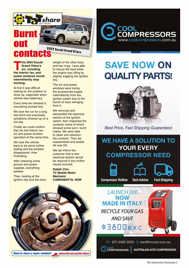
This 2003 Suzuki Grand Vitara’s a/c, including
the interior fan, and power windows would intermittently stop working.At first it was difficult waiting for the problem to show up, especially when vehicle was stationary. Every time we checked it, everything worked fine. We took the car for a long test drive and eventually symptoms showed up on a hot day. Finally we could confirm that we lost interior fan, a/c and power-window operation at the same time.We took the vehicle back to do some further testing and the problem disappeared. How frustrating. After checking some ground and power supplies, everything passed. Then, looking at the ignition key and the extra
weight of the other keys and key rings, I was able to induce the fault while the engine was idling by slightly wiggling the ignition key.The a/c and power windows were losing the accessories supply intermittently from the ignition switch due to the bunch of keys swinging from it. We removed and dismantled the electrical section of the ignition switch, then inspected the contacts, some of which showed some worn, burnt marks. We were able to clean and retention the contacts. Then we reassembled and tested. All was OK.We did inform the customer that a new electrical section would be required if any further issues occured.Sideth ChivTC Mobile Motor MechanicCABRAMATTA, NSW
2003 Suzuki Grand Vitara
Burnt -out contacts
Want to share a repair solution? www.tat.net.au/tat-share

The Automotive Technician 6
We all know just how much we can learn from each other. So a few of us who make up the TaT technical-advisory
team thought it would be cool to visit Grafton on the NSW north coast. It’s on NSW’s tourist strip, so why wouldn’t we want to visit such as fabulous place? More pertinently, it’s where where TaT director and TaT Scan Data founder Rod Maher lives and works, so we could take the opportunity to pop into his workshop.
Rod is the proud owner of more than 25 scan tools, plus every other imaginable automotive tool you can imagine. His shop is a very tidy three-bay workshop and we spent the whole day exploring all the cool things he has there. All of us left with a shopping list of goodies we now want to buy. Be warned, you cannot visit Rod’s shop without suffering from the sin of covetousness.We started our morning exploring some deeper insights into some more advanced settings of the Pico scope. Our visit would have been worth every cent it cost us to travel to Grafton if this had been the only thing we learnt. Rod’s knowledge and wisdom are gold and he is extremely gifted in how he communicates.Many of us lack an understanding of the Pico buffer setting, and none of us knew about the Pico scope rapid-trigger setting. Later in the day we covered exhaust-pressure diagnostics using the program Rod wrote for detecting misfires. We also road-tested some of the many scan tools he has in his shop. One I was particularly impressed with was a PC-based scan tool called ATS EScan with Sharp Shooter Technology (ESN2000). At about $US1000, I’ve realised I now must have one, which is a bugger because I did not want to add any more aftermarket scan tools to my must-buy list.The ATS EScan does something no other diagnostic tool does – it analyses raw OBD-II data to provide you with special calculation and evaluation tests that help you diagnose the vehicle quicker. The ATS scan tool can calculate and display catalyst efficiency, tell you if the air/fuel ratio is correct and if the mass-airflow (MAF) sensor is working properly.
The ATS EScan can also display fuel-trim charts at different engine speeds and calculate volumetric efficiency. It also translates Mode 6 data to simple English.We also test-drove The Foxwell scan tool that both Jason Smith and Rod have been talking about. It is a nice tool, capable of merging interactive live-sensor graphs for easy and
intuitive diagnosis. It also has scan-data alerts that warn the user when data exceeds range limits. Rod offered me the chance to take his tool home and play with it. I was tempted but I knew if I liked the tool I would want to buy one. The chances of that were high, so I chose not to risk the temptation.
We were all impressed with Rod’s Coda Shock Absorber Tester, which can test the shocks and print out cool reports. There’s no need for an expensive drive-on tester – simply bounce the car manually and the Coda Shock Absorber Tester box independently reports. All four shock absorbers can be tested and the results downloaded to a PC via the USB lead. The PC software displays a detailed trend graph of the full shock motion and rebound. A colour-coded pass or fail status is clearly displayed and can be printed out for the customer.
We covered so much and picked up a bucketloads of priceless knowledge but all too quickly the day was over and we were back on the road heading home, finding that it can be hard to shut off your mind when it is so full information. We had a great day, Rod. Thanks for allowing us to come and gatecrash your shop.
The day we
gatecrashed Rod
Maher’s workshop Maurice Donovan
The Automotive Technician 7

The Automotive Technician 8
The engine cooling system has had its fair share of nips and tucks over
the last few decades but the principal behind it is a simple one and stays the same – keeping the engine within a certain temperature range and providing heating for cabin occupants.Progress in cooling systems, as with most vehicle systems these days, is being pushed by emissions and efficiency. Several tweaks to age-old components have played a part in the modern vehicle being more powerful, using less fuel and having cleaner emissions than its predecessors.We are a long way from the days of air cooling and now seeing computer-controlled versions of well-established cooling components, including electronically assisted thermostats, pulse-width-modulated fans and electric water pumps to name a few. With these components come new fault codes and new ways to diagnose cooling systems.
Why are there wires going to the thermostat?Electronically-assisted thermostats have been around for decades now and their operating principle is still very much the same as their earlier, mechanical ancestors. The main drawcards of electrical control over the thermostat are increased power and improved emissions. In a perfect world the optimum combustion process in a passenger car occurs at about 110°C. With mechanical thermostats a middle ground must be struck and their rated opening temperature can open much lower than 110°C to allow a ‘buffer’ for high-load situations.Electronically assisted thermostats have the advantage of being able to offer a much higher opening temperature. These thermostats can remain closed as high as 110°C – at this point they will open unassisted as the wax pellet melts, just the same as a regular thermostat. This creates the ideal temperature environment for emissions and efficiency.The computer uses preset maps and watches several parameters – including engine load, vehicle and engine speed, coolant and intake air temperature – to operate the heating element and quickly open the thermostat further. This offers a rapid increase in cooling and drops the engine below 110°C.
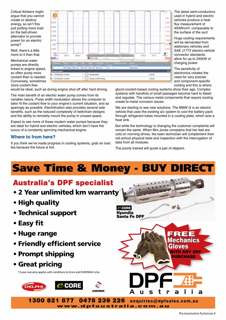
The lower temperature is ideal for making power, allowing ignition timing to be advanced closer to optimal without increasing knock. For this reason, the heating element is most often operated under high-load conditions to increase cooling.The heating element will also be operated, even at low load, if the coolant temperature rises above 113°C to combat overheating.The graph on this page – a simulated map that controls the thermostat heating element – shows what the computer is thinking (pic 1). The coolant temperature is lowered
as vehicle load and speed increases.
Check its pulse!From belt-driven fans to low/high staged relays, we now commonly see vehicles with pulse-width-modulated cooling fans. Pulse width modulation ticks all the efficiency and NVH (noise, vibrations, harshness) boxes for manufacturers.
The benefits of precise fan-speed control are obvious but often the speed range is not infinite. It is quite common to have preset stages of fan operation, loosely evidenced by only a handful of speeds being available when bi-directionally controlling fans through a scan tool. Understand that engineers have worked long and hard to perfect these speed stages to provide a balance between effective cooling, energy efficiency and driver comfort.
Under certain conditions a 64 per cent duty cycle may be ideal for cooling but 61 per cent may be a better option due to the noise and vibration of a particular fan assembly.With a 10.61 per cent duty cycle (blue) commanded by the computer, this small cooling fan draws only 300 milliamps (red) (pic 2).For testing purposes, if no scan tool bi-directional tests are
available, the old theory of increasing load to get the fans on high still holds true, so set the a/c to max and turn on as many loads as possible.With a rise in commanded duty cycle to 38.55 per cent (blue), fan current increases to 814 milliamps (red) (pic 3).
Go with the flowThe theory for going electric with water pumps seems logical – old mechanical-driven pumps, after all, rob precious power and economy.
1
2
by Brendan Sorensen
The forecast is hot for cooling systems
The Automotive Technician 9
Critical thinkers might argue that you cannot create or destroy energy, so isn’t this just putting more load on the belt-driven alternator to provide power for an electric pump? Well, there’s a little more to it than that.Mechanical water pumps are directly linked to engine speed, so often pump more coolant than is needed. Conversely, sometimes more coolant flow would be ideal, such as during engine shut-off after hard driving.The main benefit of an electric water pump comes from its variable nature. Pulse width modulation allows the computer to tailor fit the coolant flow to your engine’s current situation, and as sparingly as possible. Electrification also provides several side benefits, such as the reduced complexity of belt/chain designs and the ability to remotely mount the pump in unused space.Expect to see more of these modern water pumps because they are ideal for hybrid and electric vehicles, which don’t have the luxury of a constantly spinning mechanical engine.
Where to from here?If you think we’ve made progress in cooling systems, grab an iced tea because the future is hot.
The latest semi-conductors used in hybrid and electric vehicles produce a heat flux measurement of 400W/cm², comparable to the surface of the sun!Huge cooling requirements will be demanded from stationary vehicles and SAE J1772 electric-vehicle connector standards allow for up to 240kW of charging power.The sensitivity of electronics creates the need for very precise and component-specific cooling and this is where
glycol-coolant-based cooling systems show their age. Complex systems with handfuls of small passages become hard to bleed and regulate. The various metal components that require cooling create bi-metal corrosion issues.We are starting to see new solutions. The BMW i3 is an electric vehicle that uses the existing a/c system to cool the battery pack through refrigerant tubes mounted in a cooling plate, which acts a heat sink.But while the technology is changing the customer complaints will remain the same. When Mrs Jones complains that her feet are cold on morning drives, the keen technician will complement their old-school physical tests and inspection with the interrogation of data from all modules. The poorly trained will quote a pair of slippers.
3
1300 821 877 0478 239 226 [email protected]
Save Time & Money - BUY DIRECT
*2 year warranty applies with conditions to Ecore and EUROMAX only.
Hyundia Santa Fe DPF
Australia’s DPF specialist• 2 Year unlimited km warranty
• High quality
• Technical support
• Easy fit
• Huge range
• Friendly efficient service
• Prompt shipping
• Great pricing
*
FREE Mechanics Gloves WITH ANY DPF PURCHASE
The Automotive Technician 10
Future of DPF servicingby Frank
Massey
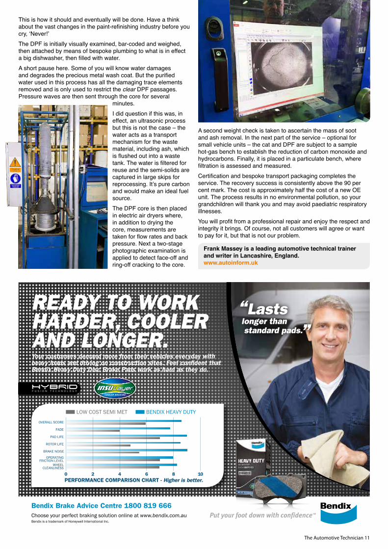
In two months, as this was written, my tenure in the motor industry will reach 49 years. I would like to think I have evolved and kept up with technology, which has allowed
me to provide a professional service and enjoy customer respect and integrity. My focus has been on the technical challenge, with my son David managing the commercial responsibilities.
This creates a wide role for me when it comes to developing our training programme, internal research and development, as well as our technical and legal compliance.My chosen subject is diesel servicing and repairs, specifically particulate filtration and emissions control. It’s a subject we have been passionate and vocal about for several years. It gives me no pleasure or satisfaction to see predictions of the demise of diesel-powered vehicles.The future, and the changes our political lords and masters have in mind, are now clear and we have a short timeline to get our house in order. My intention is to advise, help and warn what will happen if we all continue to fudge diesel particulate filter (DPF) repairs as we currently do.Upwards of 90 per cent of independent garages will fall into this category. So how do we service and recover diesel particulate filters, or how should we? The choices are very simple.
1. Replace with a new original-equipment (OE) filter.2. Replace with a non-OE filter.3. Clean and service off the vehicle in factory-controlled
conditions.4. Clean and service off the vehicle in house.5. Clean and service on the vehicle.6. Remove the filtration system from the vehicle.
Here is the problem – we, as professional repairers, are legally and financially responsible, and exposed, for the advice and decisions we make, even if the customer agrees and/or instructs us to take a certain course of action.
Clear legislation is in place for the performance and fitment of diesel-emission systems. Vehicle taxation is based on specific emission levels agreed with the manufacturers. I’m sure I don’t need to mention the VW Audi Group but I will bet their corporate accountants have regrets. How long do you think it will be before the government beancounters look at us? Let’s not fool ourselves. Enforcement will take the effect of stringent fines.So what are we doing wrong? Pretty much everything.Please remember my words – help, advice and not critique.We are breaking the law when we remove legally compliant systems. British MOT examiners will lose their licence by passing unauthorised emission-system modifications. You will become the first unpaid enforcers.We are further breaking the law when we pollute the water course by power cleaning or rinsing out cleaning agents into the drains. Utility companies have the powers to set huge fines and often do.
We are also in breach of the Clean Air Act when we use cleaning agents that require the engine to be running and emit all of the contaminants back into the environment.It’s quite possible at this point some of you will want to rip the pages out of this magazine and find an alternative use for them. But please reconsider. We are slowly killing ourselves.As an industry we need to get together, think ahead of the curve and get our house and processes in order.I recently visited Ceramex in Slough, Buckinghamshire, in the UK. Before some of you suspect a paid endorsement here, I even paid my own travel expenses. I have been aware of several companies offering off-vehicle cleaning, pressure washing, thermal cleaning in an oven and ultrasonic treatments. My problem has always related to the following questions. Are the catalytic converter and DPF still fully functional and durable
when refitted? How can we protect ourselves from future premature failure due to other indirect causes?
And can we provide certification of test results? Here is my opinion about how we should address the blocked/cleaning DPF problem. Many of you will not agree. I don’t care.
The Automotive Technician 11
This is how it should and eventually will be done. Have a think about the vast changes in the paint-refinishing industry before you cry, ‘Never!’The DPF is initially visually examined, bar-coded and weighed, then attached by means of bespoke plumbing to what is in effect a big dishwasher, then filled with water.A short pause here. Some of you will know water damages and degrades the precious metal wash coat. But the purified water used in this process has all the damaging trace elements removed and is only used to restrict the clear DPF passages. Pressure waves are then sent through the core for several
minutes. I did question if this was, in effect, an ultrasonic process but this is not the case – the water acts as a transport mechanism for the waste material, including ash, which is flushed out into a waste tank. The water is filtered for reuse and the semi-solids are captured in large skips for reprocessing. It’s pure carbon and would make an ideal fuel source.The DPF core is then placed in electric air dryers where, in addition to drying the core, measurements are taken for flow rates and back pressure. Next a two-stage photographic examination is applied to detect face-off and ring-off cracking to the core.
A second weight check is taken to ascertain the mass of soot and ash removal. In the next part of the service – optional for small vehicle units – the cat and DPF are subject to a sample hot-gas bench to establish the reduction of carbon monoxide and hydrocarbons. Finally, it is placed in a particulate bench, where filtration is assessed and measured.Certification and bespoke transport packaging completes the service. The recovery success is consistently above the 90 per cent mark. The cost is approximately half the cost of a new OE unit. The process results in no environmental pollution, so your grandchildren will thank you and may avoid paediatric respiratory illnesses.You will profit from a professional repair and enjoy the respect and integrity it brings. Of course, not all customers will agree or want to pay for it, but that is not our problem.
Frank Massey is a leading automotive technical trainer and writer in Lancashire, England.www.autoinform.uk
Bendix Brake Advice Centre 1800 819 666Choose your perfect braking solution online at www.bendix.com.auBendix is a trademark of Honeywell International Inc.
Put your foot down with confidence™
Your customers demand more from their vehicles everyday with heavy loads and driving on construction sites. Feel confident that Bendix Heavy Duty Disc Brake Pads work as hard as they do.
Lastslonger than standard pads.
“ “ready to work harder, cooLerand Longer.
LOW COST SEMI MET
PERFORMANCE COMPARISON CHART - Higher is better.0 2 4 6 8 10
WHEELCLEANLINESS
OPERATINGFRICTION LEVEL
BRAKE NOISE
ROTOR LIFE
PAD LIFE
FADE
OVERALL SCORE
BENDIX HEAVY DUTY
The Automotive Technician 12
Tales like this one bring shame on the auto repair trade.
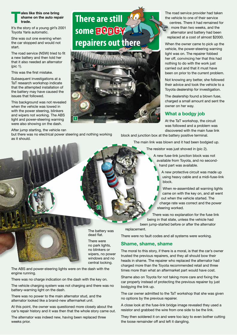
It’s the story of a young girl’s 2001 Toyota Yaris automatic.She was out one evening when the car stopped and would not start.The road service (NSW) tried to fit a new battery and then told her that it also needed an alternator (pic 1).This was the first mistake.Subsequent investigations at a TaT research workshop indicate that the attempted installation of the battery may have caused the issues that followed.This background was not revealed when the vehicle was towed in with the power steering, blinkers and wipers not working. The ABS light and power-steering warning were also showing on the dash.After jump starting, the vehicle ran but there was no electrical power steering and nothing working as it should.
The battery was dead flat. There were no park lights, no blinkers or wipers, no power windows and no central locking.
The ABS and power-steering lights were on the dash with the engine running.There was no charge indication on the dash with the key on.The vehicle charging system was not charging and there was no battery-warning light on the dash.There was no power to the main alternator stud, and the alternator looked like a brand-new aftermarket unit.At this point, the owner was questioned more closely about the car’s repair history and it was then that the whole story came out. The alternator was indeed new, having been replaced three weeks prior.
The road service provider had taken the vehicle to one of their service
centres. There it had remained for more than two weeks, and the alternator and battery had been
replaced at a cost of almost $2000.
When the owner came to pick up the vehicle, the power-steering warning light was on. The repairer fobbed her off, convincing her that this had nothing to do with the work just carried out and that it must have been on prior to the current problem.
Not knowing any better, she followed their advice and took the vehicle to a Toyota dealership for investigation.
The dealership found a blown fuse, charged a small amount and sent the owner on her way.
What a bodgy jobAt the TaT workshop, the circuit was followed and a problem was discovered with the main fuse link
block and junction box at the battery positive terminal.
The main link was blown and it had been bodgied up.
The resistor was just shoved in (pic 2).
A new fuse-link junction block was not available from Toyota, and no second-
hand part was available.
A new protective circuit was made up using heavy cable and a midi-fuse-link block.
When re-assembled all warning lights came on with the key on, and all went
out when the vehicle started. The charge rate was correct and the power
steering worked.
There was no explanation for the fuse link being in that state, unless the vehicle had
been jump-started before or after the alternator replacement.
There were no fault codes and all systems were working.
Shame, shame, shameThe moral to this story, if there is a moral, is that the car’s owner trusted the previous repairers, and they all should bow their heads in shame. The repairer who replaced the alternator had charged more than the Toyota recommended retail and three times more than what an aftermarket part would have cost.
Shame also on Toyota for not taking more care and fixing the car properly instead of protecting the previous repairer by just bodgying the link up.
The car owner admitted to the TaT workshop that she was given no options by the previous repairer.
A close look at the fuse-link bridge image revealed they used a resistor and grabbed the wire from one side to be the link.
They then soldered it on and were too lazy to even bother cutting the loose remainder off and left it dangling.
There are still some bodgy repairers out there
1
2

The Automotive Technician 13
BRILLIANT.
Intelligent solution: Timing Belt KITs from INA.Our Timing Belt KITs are the first choice for regular maintenance of the timing drive, since they contain all components required for OEM-quality repairs. INA, a renowned product brand of Schaeffler, offers tailor-made KITs for almost every vehicle, with the option of an included water pump.
www.schaeffler-aftermarket.com.au
Installation guides, product information and more garage knowledge:www.repxpert.com
The Automotive Technician 14
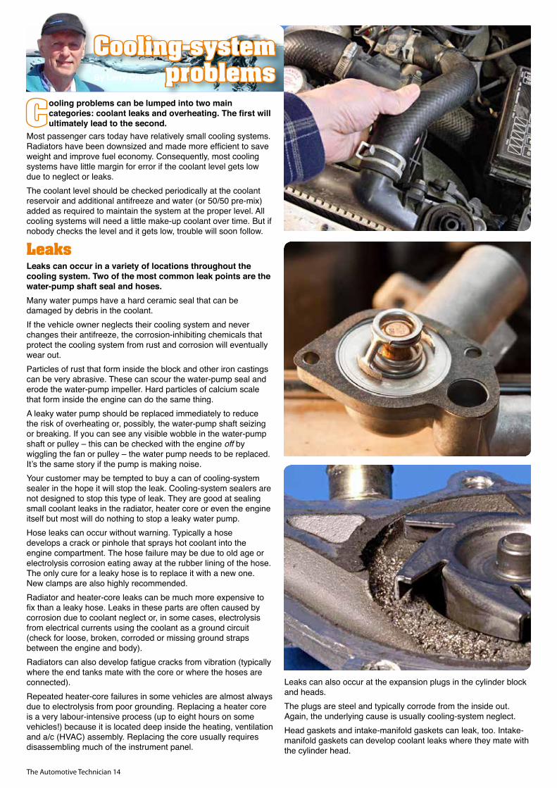
ooling problems can be lumped into two main categories: coolant leaks and overheating. The first will ultimately lead to the second.
Most passenger cars today have relatively small cooling systems. Radiators have been downsized and made more efficient to save weight and improve fuel economy. Consequently, most cooling systems have little margin for error if the coolant level gets low due to neglect or leaks.The coolant level should be checked periodically at the coolant reservoir and additional antifreeze and water (or 50/50 pre-mix) added as required to maintain the system at the proper level. All cooling systems will need a little make-up coolant over time. But if nobody checks the level and it gets low, trouble will soon follow.
LeaksLeaks can occur in a variety of locations throughout the cooling system. Two of the most common leak points are the water-pump shaft seal and hoses. Many water pumps have a hard ceramic seal that can be damaged by debris in the coolant. If the vehicle owner neglects their cooling system and never changes their antifreeze, the corrosion-inhibiting chemicals that protect the cooling system from rust and corrosion will eventually wear out.Particles of rust that form inside the block and other iron castings can be very abrasive. These can scour the water-pump seal and erode the water-pump impeller. Hard particles of calcium scale that form inside the engine can do the same thing.A leaky water pump should be replaced immediately to reduce the risk of overheating or, possibly, the water-pump shaft seizing or breaking. If you can see any visible wobble in the water-pump shaft or pulley – this can be checked with the engine off by wiggling the fan or pulley – the water pump needs to be replaced. It’s the same story if the pump is making noise.Your customer may be tempted to buy a can of cooling-system sealer in the hope it will stop the leak. Cooling-system sealers are not designed to stop this type of leak. They are good at sealing small coolant leaks in the radiator, heater core or even the engine itself but most will do nothing to stop a leaky water pump.Hose leaks can occur without warning. Typically a hose develops a crack or pinhole that sprays hot coolant into the engine compartment. The hose failure may be due to old age or electrolysis corrosion eating away at the rubber lining of the hose. The only cure for a leaky hose is to replace it with a new one. New clamps are also highly recommended.Radiator and heater-core leaks can be much more expensive to fix than a leaky hose. Leaks in these parts are often caused by corrosion due to coolant neglect or, in some cases, electrolysis from electrical currents using the coolant as a ground circuit (check for loose, broken, corroded or missing ground straps between the engine and body). Radiators can also develop fatigue cracks from vibration (typically where the end tanks mate with the core or where the hoses are connected). Repeated heater-core failures in some vehicles are almost always due to electrolysis from poor grounding. Replacing a heater core is a very labour-intensive process (up to eight hours on some vehicles!) because it is located deep inside the heating, ventilation and a/c (HVAC) assembly. Replacing the core usually requires disassembling much of the instrument panel.
Leaks can also occur at the expansion plugs in the cylinder block and heads. The plugs are steel and typically corrode from the inside out. Again, the underlying cause is usually cooling-system neglect.Head gaskets and intake-manifold gaskets can leak, too. Intake-manifold gaskets can develop coolant leaks where they mate with the cylinder head.
Cooling-system problemsBy Larry Carley

The Automotive Technician 15
Larry Carley is a noted automotive technical writer, editor and author in Illinois, USA. www.AA1Car.com www.CarleySoftware.com
Some late-model GM and Ford engines with plastic intake manifolds develop leaks from galvanic corrosion and erosion of the plastic at the coolant ports.If an engine is overheating with no visible coolant leaks it’s probably a bad head gasket or a cracked cylinder head. Pressure- testing the system will tell you if the system can hold pressure internally. If the pressure reading drops you have a leak. Chemical test strips can also be used to detect combustion gases in the coolant if you need an alternative method of diagnosing a bad head gasket. The presence of coolant in the crankcase would be another indicator.The radiator cap or coolant-reservoir cap should also be pressure tested if it is spring-loaded and holds pressure. If the cap can’t hold its rated pressure, your customer needs a new cap.
Other causes of overheatingA thermostat that fails to open or is stuck shut is another common cause of overheating. The thermostat (usually located on top of the engine in a housing that connects to the upper radiator hose) should remain closed while a cold engine is warming up, then cycle open and shut to maintain a normal operating temperature. If the upper radiator hose does not feel warm or hot after the engine has been running for several minutes, a bad thermostat is the likely culprit. You can also use a non-contact infrared thermometer to measure the temperature at which the thermostat opens. Aim the infrared thermometer at the thermostat housing and upper radiator hose to monitor the temperature.On some late-model vehicles an electronic thermostat is used to more closely control engine temperature. The powertrain control module (PCM) monitors the temperature of the coolant via the coolant sensor and cycles the thermostat as needed to control the coolant temperature.
If a thermostat fails to close and remains open the engine will never reach normal operating temperature and the engine-control system will never go into closed loop. This will hurt fuel economy and emissions. An operating temperature that is too low will also increase combustion blowby and cylinder wear.Other causes of overheating can be a slipping fan clutch (on vehicles with mechanical belt-driven fans) or a faulty electrical-fan circuit. The average service life of a fan clutch is about the same as the water pump, so if the pump has reached the end of the road replace the clutch, too.Electric fans on most late-model vehicles are controlled by the PCM via a power relay or fan-control module. The electric fan usually comes on when the a/c is on to increase airflow through the condenser, and it may come on intermittently depending on driving conditions. If the fan fails to come on when extra cooling is needed the engine may run hot and overheat.Another often overlooked cause of overheating is a severe exhaust restriction (clogged converter, pinched exhaust pipe or restricted muffler). Severe backpressure will back heat up into the engine. Check the intake-vacuum reading if you suspect an exhaust restriction. An unusually low reading will tell you there is a problem.Finally, if an engine is running hot and there are no apparent problems with the cooling system, coolant level, cooling fan, radiator, thermostat or water pump, check the vehicle for a dragging brake or a slipping automatic transmission or clutch.
rt
rt br
bl sw
ws
ws
(bl)
(br)
rt br el
el
gnbrogbl
rsgnw
s
gnog
rsgr
rt
ogbr
bl ws
ws
ws
vivi
vi
gn
bl
blw
srs w
sw
s
sw sw sw
swbl
ws
rt
ws
bl rt
bl gn rt
gn rt ws
rt sw g
e
og og rt
brog w
s
br rt
gnbr
gn
br w
s
sw b
l
sw
sw og g
n
blblge
og
br g
e
el
elw
s
ws
ws
ws
ws
sw sw
rsrs
gngn
el
swsw
rt
rt
ge
gege ge
vi vi
brgr
el
swel
gn
elelel
rs
rs
el
el
elrt
rt
rtrt rt
rt
A AC B
B
8 3 11 15
16 1
7
5A A A AA
D A30
D
20A
18D
27D
3A
13A
2A
BB
BA
C30
C29
AA
BA
A B A B
C24
C25
C21
C20
6 10 B A75
C16
C17
C18
C19
C28
AA
AB
1A
8
10
1012
119
7 5
86
11
1
B2
2
2B
60A
X28-II
2 395 68
10 10
95 6
C26
C27
B5
B15
B14
B4
C22
C23
1
3
2 1
D19
D26
5 4 6
D29
D22
14A
9 10 122 6A A A A A
17D
1B
7,5A 20A
60A
X28-II
70A
X28-II
sw ws ws ws
sw gn sw sw sw swgn
10a11asw
2
3
br
40 30 2A(3) 4B(9)2B(7) 6A(2) 6A(3)27
2A(1) 2A(2) 5A(1)5B(2) 11 1
=LHD =LHD =LHD
60 59
5862
61
4kB
3hB
4hB
1fB
2dA
3dA
3015
31
B161 X1
FS
A176
M7
M105 M126 M99
A63
B170 B53
A35
K208
K12K12-I
B24M6-II M6-I
K12-II
F15
M100M101 B37
M51
B191B102
S6
A11
K13K17F20
X28-I
F4
K79
F20F19
A5R4
CAN-H
CAN-L
CAN-L
CAN-H
EP10EP5 EP5EP4
EP9 EP10 EP8EP8
S292
H22
Y11
Try Autodata now at
www.autodata-group.com
Home Technical Information Estimate Calculator
User_123456
Land Rover
Range Rover Evoque
Change brakes
Settings Support
Change Vehicle
Log outNew arrivals for September
Technical specifi cationn
Electric parking braken
Repair timesn
Jacking pointsn
Jacking points
© Copyright and database rights: Autodata Limited 1974-2015Terms and conditions | Copyright Notice | Application Status
AD109893 ©
4x4
AD109893 ©
4x4
Home Technical Information Estimate Calculator
User_123456
Ford
Fiesta
Service Schedule
Settings Support
Change Vehicle
Log outNew arrivals for September
© Copyright and database rights: Autodata Limited 1974-2015Terms and conditions | Copyright Notice | Application Status
With convenience checks - customer options
12500 miles 12 months
Air conditioning check (hrs): 0.20h
Air conditioning deodoriser (hrs): 0.10h
Choose additional service:Back
Every 24 months regardless of miles/km
Every 120 months regardless of miles/km
Every 150000 miles or 120 months
Total time - 1.30 hrs Select all
Renew allCabin fi lter, odour (if fi tted)
VEHICLE ON FLOOR
VEHICLE FULLY RAISED
VEHICLE HALF RAISED
ENGINE BAY OPERATIONS
FINAL ITEMS CHECK
Important
More information
Optional upgrade of odour fi lter to odour fi lter plus
AD115724
1
2
3
4 RHD
AD128165
1
2
3
4 LHD
© Copyright and database rights: Autodata Limited 1974-2015Terms and conditions | Copyright Notice | Application Status
Home Technical information Estimate calculator
User_123456
Ford
All modelsSystem circuit diagram
SE16ADT
Fiesta
Wiring diagram
Settings Support
Change vehicle
Log outNew Arrivals for September
sw w
s
ws
sw
ws
sw
bl g
e
sw
bl sw w
s
sw r
t
sw g
e
sw b
l
gn r
t
sw r
t
vi r
t
vi r
t
sw r
t
vi ge r
t
ws
rt
rt rs hgn
sw r
t
gn s
w
gn r
t
gn g
e
rt b
l
gr g
e
gr vi sw ws
rt gn gr b
l
rs gn o
g
rs s
w
bl g
e
gn w
s
gnrt b
l
rt b
l
rt b
l
rt b
l
rt b
l
rt b
l
rt b
l
rt b
l
gnsw
gn w
s
bl r
t
vi bl s
w
ws
ws
hgn
sw
gn r
t
bl w
s
rt b
l
rt b
l
rt b
l
hgn
sw
rt w
s
rsgersgeblws
sw
gn w
s
rs b
l
bl g
e
gn r
t
gn r
t
ge g
n
ws
gn sw g
e
bl hgn
ge r
t
rt s
w
br ws
sw
ws
sw
w w
ge g
n
rt ge hgn
rt
bl w
s
rt b
l
bl r
t
ge sw b
l
ws
vi rt sw ge ws
sw
gr b
l
gr g
n
bl g
e
hgn
gn r
t
ws
bl
sw r
t
ws
sw
sw g
e
sw
sw sw
rs b
l
sw w
s
sw w
s
rt s
w
rt s
w
5
8
A
A
1
B
B B B B B B B B B
5
B
4
B
3
B
2
4 5 1 6 2
2 2
3
15 14 13 12
26 25 24 23 20 7 22 24 23 21 16 12
B
11 11 1 6 5
B
19
B
13 22 31 2114
18 7
B
A A A A A A A A
A A A A E
8
E
1
1 1
2
E EE
816
E
9
D
19
D
27
D
13
D
28
D
24
D
6 3
3
3
4 1
2 5
20
A
19
A
30
A
29
A
17
B
B
2
A
A B D DAAA
A
4 3 21A
6
1 2
2
21
1
1
1
1
8
13
2
3
E
12
E
15
E
22 10
E
4
C ECC
C
1
22
D
23
D
14
D
21
E
14
E
15
B
20
B
16
A
27
A
17
A
A
28
A
A35
3
3
2
1
4
3
2
1
4
3
2
2 22 21
4
4 23
5 1 1
3
5
2
3
2
1
1 1 1 1
2 3 3 2 1
11
3 4
5
3
2
22
1
1
14
2
1
2
24
3
3
114
25
D
4
5
4
4 8
8
7
7
4
18
E E
19
15 13 7
9
E
6
6 102
2
3
5
8
54
6
6 5
E C C C C C
10
D
4 7
BA A
9 8
A
rt s
w
2
C
13
C
2
3
16
C
(MT
)(M
T)
A180 A35
B138 A177
B132 B54Y68 Y28
K22K46
K303
A5
H63H25
S13
A162
S216 S253 S249
H44
S159S28
B33
R5-I R5-II R5-III R5-IV
Y3-I Y3-II Y3-III Y3-IV
Y141 B25 B31 B24
B186 B105 B149 B30
Y84-I Y84-IIS104 S330
G1 A63 X1
A70
Y117
B134
1 - Fuse box/relay plate, engine bay 1 More
Home Technical Information Estimate Calculator
User_123456
Ford
Fiesta
VIN plate location
Settings Support
Change Vehicle
Log outNew arrivals for September
© Copyright and database rights: Autodata Limited 1974-2015Terms and conditions | Copyright Notice | Application Status
AD133607 ©
XXXXXX
XXXXXXXXXXXXXXXX
XXXXX
XXXXX
XXXXX
XXXXXXXXX
VIN:G H5J82G2Z4SVIN:GH5J82G2Z4S
Home Technical Information Estimate Calculator
User_123456
Ford
Fiesta
Timing belt
Settings Support
Change Vehicle
Log outNew arrivals for September
<< HIDE
Important note Close all
© Copyright and database rights: Autodata Limited 1974-2015Terms and conditions | Copyright Notice | Application Status
Replacement Intervals
With convinience checks - customer options
Timing Belt - Renew
Every 150000 miles or 120 months
Auxiliary Drive Belts(s) - Renew Every 150000 miles or 120 months
Without convinience checks - customer options
Timing Belt - Renew
Every 150000 miles or 120 months
Auxiliary Drive Belts(s) - Renew Every 150000 miles or 120 months
Timing Belt Tensioner - Renew Every 150000 miles or 120 months
Auxiliary Drive Belt (s) - Renew
Important Note
Timing belt replacement intervals quotes by the manufacturer should be regarded as the maximum. Due to variations in vehicle usage and operating conditions the belt may need to be replaced earlier than specifi ed.
If there is any doubt as to the serviceability of the belt and its associated components, they should be replaced.
It is important that you consider the items listed in the section below and discuss them with your customer. More information
CACA
T
(15 Nm)
12
15
(15 Nm)15
4
14
2
(10 Nm)
(10 Nm)
13
11
10
3
14
AB1155582
AB1155582
AB1155582
AB1155582
Untitled-1 1 22/02/2017 09:21:20
The Automotive Technician 16
T his is a quick story revisiting the subject of Nissan idle-relearn situations, in particular for the Tiida and X-Trail, and how you can perform the idle relearn a bit easier.
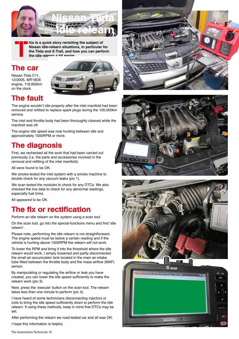
The carNissan Tiida C11, 12/2005, MR18DE engine, 118,850km on the clock.
The faultThe engine wouldn’t idle properly after the inlet manifold had been removed and refitted to replace spark plugs during the 100,000km service.The inlet and throttle body had been thoroughly cleaned while the manifold was off.The engine idle speed was now hunting between idle and approximately 1500RPM or more.
The diagnosisFirst, we rechecked all the work that had been carried out previously (i.e. the parts and accessories involved in the removal and refitting of the inlet manifold). All were found to be OK.We smoke-tested the inlet system with a smoke machine to double check for any vacuum leaks (pic 1).We scan tested the modules to check for any DTCs. We also checked the live data to check for any abnormal readings, especially fuel trims. All appeared to be OK.
The fix or rectificationPerform an idle relearn on the system using a scan tool.On the scan tool, go into the special-functions menu and find ‘idle relearn’.Please note, performing the idle relearn is not straightforward. The engine speed must be below a certain reading and if the vehicle is hunting above 1500RPM the relearn will not work.To lower the RPM and bring it into the threshold where the idle relearn would work, I simply loosened and partly disconnected the small air-accumulator tank located in the main air-intake tube fitted between the throttle body and the mass-airflow (MAF) sensor. By manipulating or regulating the airflow or leak you have created, you can lower the idle speed sufficiently to make the relearn work (pic 3).Next, press the ‘execute’ button on the scan tool. The relearn takes less than one minute to perform (pic 4).I have heard of some technicians disconnecting injectors or coils to bring the idle speed sufficiently down to perform the idle relearn. If using these methods, keep in mind that DTCs may be set. After performing the relearn we road-tested car and all was OK.I hope this information is helpful.
Nissan Tiida idle relearnby Jason
Smith

The Automotive Technician 17
Begin searching now:www.gatescatalogue.com.au
IDENTIFY THE RIGHT PART QUICKLY, EASILY AND ACCURATELY
Gates is excited to launch an innovative and user-friendly online catalogue in the automotive aftermarket. Featuring three ways to find the product you’re after, this is the easiest and fastest way to find the part you need. Search results feature: product images, diagrams, resources, videos, product specifications and more.
Jump online and experience the future.
THE PARTS WORLD AT YOUR FINGER TIPS
CATALOGUE APPAVAILABLE FOR DOWNLOAD
The Automotive Technician 18
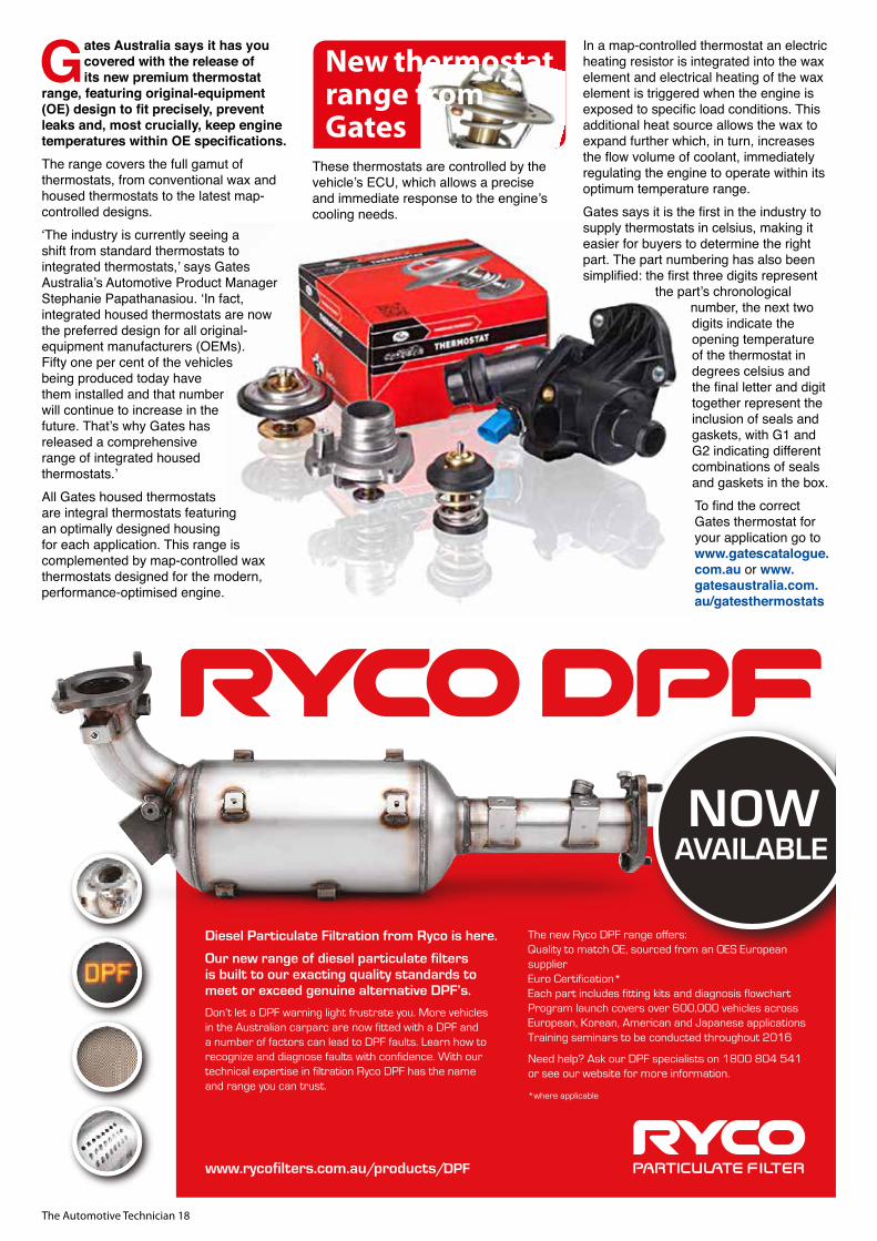
Gates Australia says it has you covered with the release of its new premium thermostat
range, featuring original-equipment (OE) design to fit precisely, prevent leaks and, most crucially, keep engine temperatures within OE specifications.The range covers the full gamut of thermostats, from conventional wax and housed thermostats to the latest map-controlled designs.‘The industry is currently seeing a shift from standard thermostats to integrated thermostats,’ says Gates Australia’s Automotive Product Manager Stephanie Papathanasiou. ‘In fact, integrated housed thermostats are now the preferred design for all original-equipment manufacturers (OEMs). Fifty one per cent of the vehicles being produced today have them installed and that number will continue to increase in the future. That’s why Gates has released a comprehensive range of integrated housed thermostats.’All Gates housed thermostats are integral thermostats featuring an optimally designed housing for each application. This range is complemented by map-controlled wax thermostats designed for the modern, performance-optimised engine.
These thermostats are controlled by the vehicle’s ECU, which allows a precise and immediate response to the engine’s cooling needs.
In a map-controlled thermostat an electric heating resistor is integrated into the wax element and electrical heating of the wax element is triggered when the engine is exposed to specific load conditions. This additional heat source allows the wax to expand further which, in turn, increases the flow volume of coolant, immediately regulating the engine to operate within its optimum temperature range.Gates says it is the first in the industry to supply thermostats in celsius, making it easier for buyers to determine the right part. The part numbering has also been simplified: the first three digits represent
the part’s chronological number, the next two digits indicate the opening temperature of the thermostat in degrees celsius and the final letter and digit together represent the inclusion of seals and gaskets, with G1 and G2 indicating different combinations of seals and gaskets in the box.To find the correct Gates thermostat for your application go to www.gatescatalogue.com.au or www.gatesaustralia.com.au/gatesthermostats
New thermostat range from Gates
NOWAVAILABLE
The new Ryco DPF range offers:✓ Quality to match OE, sourced from an OES European
supplier✓ Euro Certification* ✓ Each part includes fitting kits and diagnosis flowchart✓ Program launch covers over 600,000 vehicles across
European, Korean, American and Japanese applications✓ Training seminars to be conducted throughout 2016
Need help? Ask our DPF specialists on 1800 804 541or see our website for more information.
*where applicable
Diesel Particulate Filtration from Ryco is here.
Our new range of diesel particulate filtersis built to our exacting quality standards to meet or exceed genuine alternative DPF’s.
Don’t let a DPF warning light frustrate you. More vehicles in the Australian carparc are now fitted with a DPF anda number of factors can lead to DPF faults. Learn how to recognize and diagnose faults with confidence. With our technical expertise in filtration Ryco DPF has the name and range you can trust.
www.rycofilters.com.au/products/DPF
C
M
Y
CM
MY
CY
CMY
K
DPF V4.pdf 1 13/7/17 11:30 am

NGK Spark Plugs Australia
WARNING! DON’T PUT METAL WHERE
IT DOESN’T BELONG
NGK Glow Plugs are at the forefront of technological innovations. Our innovative ceramic technology is setting new industry standards. In fact many automotive manufacturers are specifying ceramic plugs as OE fitment. In these cases replacement with metal plugs can cause a reduction in performance and in extreme cases, permanent engine damage. Don’t risk your reputation, choose the correct NGK Glow Plug for the engine and ignite with ease.
For correct fitment please visit ngk.com.au
Seriously, it did. I was returning home from somewhere, trying to get the finishing touches to the article I was originally writing for this issue clear in my mind, when I
heard a little chime go off in my 2011 Dodge Grand Caravan. After a short search I found the check-engine light (CEL) shining on the instrument panel, in the uppermost right corner, under the steering wheel and under my hand, cleverly hidden by an engineer who obviously wasn’t very bright.I’ve questioned the thought process that resulted in the CEL being placed in the most out-of-the-way location possible rather than in the dead center of the cluster, in plain view of even the most inattentive driver. But that’s not the point of this column. We can blather on about the ingenuity of engineers later on. Rather, this column is about the diagnostic process that resulted from the codes my van suddenly developed.I haven’t fixed the problem, by the way, but I thought this would be an interesting way to discuss two diagnostic processes – the ideal method and the practical (profitable) method.I’ve always understood the impossibility of needing to instantaneously get something right, right now. Customers aren’t always patient and their expectations can be unrealistic to the point of being absurd. As technicians, we can struggle with the need to do some pretty complicated things quickly while knowing with absolute certainty that the outcome will be the best one possible.Generally, this is not possible. There will always be doubts, hopes, fears and concerns that the actual result will be the right one and that we didn’t miss something. That’s why I stress the need to sort out the problem of billing for diagnostic time and not apologising for it or short-changing yourself. In this case, I’m the customer. I can’t afford to take the vehicle to the dealer and, with few exceptions, I can get the wrenches in the right place most of the time. Besides, how can I claim to be a mechanic if I don’t have busted knuckles and greasy fingernails?Here’s where I am. The transmission has started to stop shifting out of low gear. The first indication came when my wife and son drove the vehicle. They tried to explain to me what happened but from their telling the van was on fire, the engine was belching smoke and gremlins were beating on the roof. However, there was no mention of the CEL and absolutely nothing they said immediately pointed to it being stuck in low gear. They talked about RPM, speed, noises and other characteristics of a no-shift scenario but never a simple and concise, ‘It won’t shift out of low gear’. I won’t go into the argument that ensued with my wife when I tried to explain the relationship of the CEL to logged codes!So the codes are P0750 and P0882 – Shift solenoid A malfunction and TCM (transmission control module) power input signal low respectively. Given the self-destruction of the transmission my family reported, these codes seem logical. The P0750 showed up first – I cleared it and then cleaned the connections on the valve-body connector. When I drove the vehicle again the problem had gone away but, because I’m the customer and the tech, I could afford to not be concerned with getting it right straight away. Good thing, too, because the issue came back, this time with the P0882 code. I didn’t rip things apart and swap solenoids but knew the connection to the valve body wasn’t responsible.
I thought about the P0882 voltage code (hey, OBD2 guys, it’s voltage, not power) and remembered that I had torn up the entire power distribution while looking for another issue earlier on, so I was concerned I’d made a mistake there and was responsible for this fault. I haven’t actually found the problem yet; it’s intermittent and I can reset things by starting and restarting the van. It’s not associated with heat or cold, and if I start out using the manual-shift mode the problem doesn’t appear. It hasn’t happened in the middle of a trip, and the van doesn’t really suffer anything other than low speed and high RPM.
So here’s how I start:
A. The system works perfectly when it works, so nothing has catastrophically failed. When a failure happens it’s instant and absolute, like opening a switch.
B. The problem cycles with the van start, so it would seem to point to a software/TCM problem. However, there’s also a relay switching the TCM and the P0882 code suggests it could be to blame. I’ll test it when I can figure out which relay it is because the stupid laser-etched cover for the fuse and relay panel is utterly unreadable.
C. Low voltage to the TCM could cause a cascade failure at the valve assembly. But a shorted solenoid cycling with heat could cause a low resistance -> high amperage -> low voltage condition. The P0750 showed up a few days before the P0882.
D. This all happened after I changed the alternator for a P0560 (low voltage plus battery light). That fault has passed but did it/could it be related? I doubt it but this is often where, in my experience, people will try to create a relationship where none exists and get off track.
E. I have the AllData DIY but even these documents are only marginally helpful. I still have no real idea how the system is supposed to work correctly.
Here’s what I plan to do first. When I find the relay I’m going to load-test the supply voltage and – assuming it passes – I’ll jump 30-87 with a wire, take the contacts out of the picture and see what happens. Why not simply change the relay? Because a new relay would still require extra work determining if it was the coil or contacts. A jumper will eliminate that confusion. If the fault disappears when hardwired I can rule out everything beyond the relay. If the fault returns I know that it wasn’t the relay at all. Thankfully, I have the time to do things this way.
Is this all possible with a paying customer? Can you tell somebody that you’re going to do all of these hopeful tests and wait out an intermittent problem, spending hours working on a car that might not fail again for days? How do you bill for this? Can the owner take off of work and spend $50 for petrol driving in circles when in truth that’s really what needs to be done? Of course not. What, then, do we do if the goal is to get it right? I honestly don’t know because a good, sound and effective diagnostic process cannot always be the best for customer relations. Does the customer want to wait until it’s really fixed or take a hopeful repair and deal with a comeback? Can they stomach the upfront ordeal and live long and prosper in a fully functional vehicle, or would they rather take the quicker, cheaper way out and gamble on the possibility of things going bad again?
The Automotive Technician 20
by Dan Sullivan
A funny thing happened on the way to my laptop…

The Automotive Technician 21
What about you? Assuming this is a new problem for you, what is your method? Ideally you work through to the correct conclusion and bill for the total time, regardless of the expense. This way you learn, you improve and your times get shorter. Your confidence builds, your clue bag gets a little fuller and your understanding of the system improves. But can you trust that the customer will be willing to pay the freight without anger and frustration? Ill will and a bad reputation are killers but, in the end, what will be more destructive – a big bill or a bad job?
How are your gut and your self-respect affected here?From my position as a teacher, I can only advise on the harsh realities of needing to learn from correct diagnosis. I will maintain to my deathbed that the only electrical-system learning that can ever occur occurs during a legitimate diagnostic process. How you, a working technician, will balance the need to understand the system with the need to keep customers is not my concern here. My point is no-one benefits from a dishonest relationship, one where the customer grows to expect electrical perfection because we imply it’s possible when we know it isn’t. When you say ‘G’day’ to me I assume you’ve said it because you meant it. Failing to say ‘I don’t know’ when it’s the only honest answer is not a good start to the day, especially when it’s often honestly the only thing you do know.
Dan Sullivan is a noted electrical diagnostics trainer in North Carolina, USAwww.brighterideas.com
Top Gun says its automotive leads, coils and componentry
range delivers quality with a bang.Top Gun is a leading Austalian supplier of automotive ignition leads, coils and componentry, and has provided quality products to the aftermarket for more than 20 years.Top Gun ignition-lead kits are available for key applications, including Japanese, Korean, European and Australian vehicles. The company says they are manufactured from the very best materials to the most exact tolerances.The Top Gun range also includes premium ignition coils. Where applicable, Top Gun’s standard 5mm and 7mm multi-
valve ignition-lead kits include spark plug and distributor/coil boots designed to deliver original factory-fitted quality.
Top Gun says its history, experience and reputation ensure it leads the market with range, quality, high performance and perfect fit.
When you need quality ignition leads, coils and componentry, think of Top Gun.
To find out more about your local stockist, see a catalogue or access detailed product information, call 03 8369 1300 www.topgunignition.com.au.
Ignition leads with proven reliability
A TRIP FOR YOURSELF & 3 MATESTO MELBOURNE CUP CARNIVAL
ENTRY IS EASY!To be in the running and to win this fantastic prize, register your purchase
of any EXEDY Clutch Kit via the Purchase Registration link at
www.exedy.com.au
PRIZE INCLUDESFlights, Accommodation and Tickets to Melbourne Cup for you & 3 mates.
Valid for all products registered from June 1 2017 till August 31 2017. Full terms & conditions at www.exedy.com.au/trade-experience. NSW Permit No. LTPS/17/14376 ACT Permit No. TP 17/00969
Photo: Nicole Akeroyd

The Automotive Technician 22
THE FIRST LINE OF DEFENCE FOR YOUR
DIESEL ENGINE
www.direction-plus.com
Reduce wear & tear and avoid repair costs that can exceed $10,000
95% water separation and superior particle removal
Ability to separate emulsified water from ULSD
Clear water drainage bowl to easily identify removed water
Keeps critical engine components clean
No filter bypass - contaminated fuel will not be sent to the fuel system even when the filter is blocked
DIESEL FUEL PRE-FILTER KIT
Prevents oil & soot contamination entering the clean air intake
Excellent protection for turbocharger
Minimises oil consumption
Prevents oil buildup in intercoolers
Regulates crankcase pressure
Keeps critical engine components clean
Reduces exhaust smoke & odours
Saves you money
PROVENT® OIL SEPARATOR KIT
The Automotive Technician 23
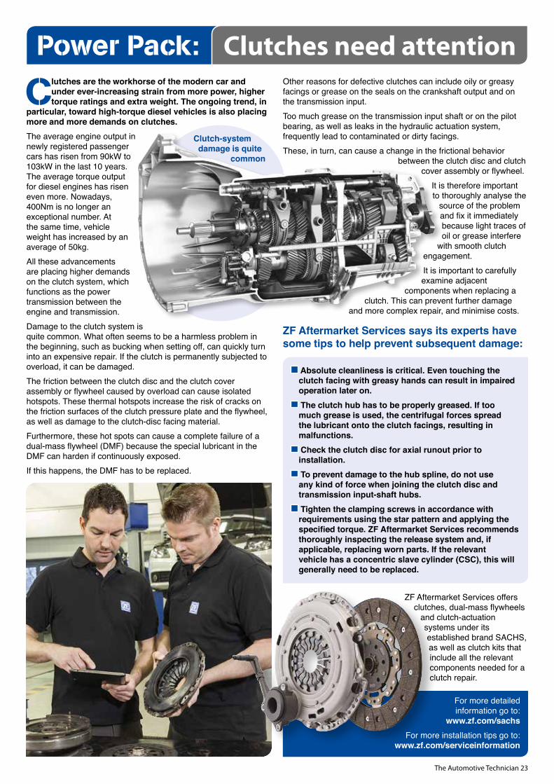
Clutches are the workhorse of the modern car and under ever-increasing strain from more power, higher torque ratings and extra weight. The ongoing trend, in
particular, toward high-torque diesel vehicles is also placing more and more demands on clutches.The average engine output in newly registered passenger cars has risen from 90kW to 103kW in the last 10 years. The average torque output for diesel engines has risen even more. Nowadays, 400Nm is no longer an exceptional number. At the same time, vehicle weight has increased by an average of 50kg.All these advancements are placing higher demands on the clutch system, which functions as the power transmission between the engine and transmission.Damage to the clutch system is quite common. What often seems to be a harmless problem in the beginning, such as bucking when setting off, can quickly turn into an expensive repair. If the clutch is permanently subjected to overload, it can be damaged. The friction between the clutch disc and the clutch cover assembly or flywheel caused by overload can cause isolated hotspots. These thermal hotspots increase the risk of cracks on the friction surfaces of the clutch pressure plate and the flywheel, as well as damage to the clutch-disc facing material. Furthermore, these hot spots can cause a complete failure of a dual-mass flywheel (DMF) because the special lubricant in the DMF can harden if continuously exposed. If this happens, the DMF has to be replaced.
Other reasons for defective clutches can include oily or greasy facings or grease on the seals on the crankshaft output and on the transmission input. Too much grease on the transmission input shaft or on the pilot bearing, as well as leaks in the hydraulic actuation system, frequently lead to contaminated or dirty facings. These, in turn, can cause a change in the frictional behavior
between the clutch disc and clutch cover assembly or flywheel.
It is therefore important to thoroughly analyse the
source of the problem and fix it immediately because light traces of oil or grease interfere
with smooth clutch engagement.It is important to carefully examine adjacent
components when replacing a clutch. This can prevent further damage
and more complex repair, and minimise costs.
ZF Aftermarket Services says its experts have some tips to help prevent subsequent damage:
Absolute cleanliness is critical. Even touching the clutch facing with greasy hands can result in impaired operation later on. The clutch hub has to be properly greased. If too much grease is used, the centrifugal forces spread the lubricant onto the clutch facings, resulting in malfunctions. Check the clutch disc for axial runout prior to installation. To prevent damage to the hub spline, do not use any kind of force when joining the clutch disc and transmission input-shaft hubs. Tighten the clamping screws in accordance with requirements using the star pattern and applying the specified torque. ZF Aftermarket Services recommends thoroughly inspecting the release system and, if applicable, replacing worn parts. If the relevant vehicle has a concentric slave cylinder (CSC), this will generally need to be replaced.
ZF Aftermarket Services offers clutches, dual-mass flywheels
and clutch-actuation systems under its established brand SACHS, as well as clutch kits that include all the relevant components needed for a clutch repair.
For more detailed information go to:
www.zf.com/sachsFor more installation tips go to:
www.zf.com/serviceinformation
Power Pack: Clutches need attention
Clutch-system damage is quite
common
The Automotive Technician 24
I ’ve often wondered why many technicians don’t use vacuum gauges. It’s strange that this tool tends to get skipped over so much considering how simple it is to use and how it gives such good insight into the condition of an engine.
I use my vacuum gauge occasionally but probably not as much as I should. That may be partly due to the increased use of my scan tool and transducers but I know I still should use the vacuum gauge more than I do. Perhaps we all just need a reminder about how good they really are for diagnosing mechanical conditions.
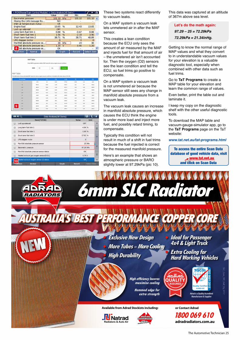
To see an animated vacuum gauge that displays various engine conditions at idle, raised RPM and snap-throttle, go to the TaT Programs page of the TaT website www.tat.net.au/tat-programs.html and download the vacuum-gauge-simulator app.A scan tool can be another way to check engine vacuum. This can only be done on vehicles with speed-density fuel systems or, in other words, if they have a manifold absolute pressure (MAP) sensor.Next time you have your scan tool connected to a vehicle with a MAP sensor, take a quick look at the live-data values for barometric pressure (BARO) and MAP at idle. If you are at sea level the value for BARO will be somewhere near 101kPa and the MAP around 30kPa with the engine at idle and no load. Subtracting MAP from BARO will give you the engine vacuum. Then you just need to convert that kilopascals value to a unit of measurement that we are all more familiar with.
Here’s a live data example (pic 8):101.10 – 30 = 71.1kPa.71.1kPa = 20.99inHg.
If your workshop is at sea level and you see a MAP value of 30kPa at idle, you will now know the engine has excellent intake manifold vacuum of roughly 21inHg.Check out the shortened example of the MAP table that is available to all TaT members on the TaT Programs page (pic 9). This example table has been generated for sea level at 101kP and shows expected MAP values under various intake-vacuum measurements.Where could this be handy? Looking at the BARO, MAP and fuel-trim values is one of my first checks when doing driveability diagnostics. I know my BARO never changes very much and only the MAP will change depending on engine vacuum. I only need to learn the acceptable number range for MAP at my altitude and I will know what the engine vacuum is without even pulling out my vacuum gauge.If I have a vehicle in the workshop running poorly and at idle the MAP values are high 30s or close to 40kPa, the idle speed may be a little higher and timing may be retarded. I will grab the smoke tester first because there is a good chance I have a vacuum leak.While we are on the subject of vacuum leaks, there are two main types of fuelling systems – mass airflow (MAF) and MAP, or speed density.
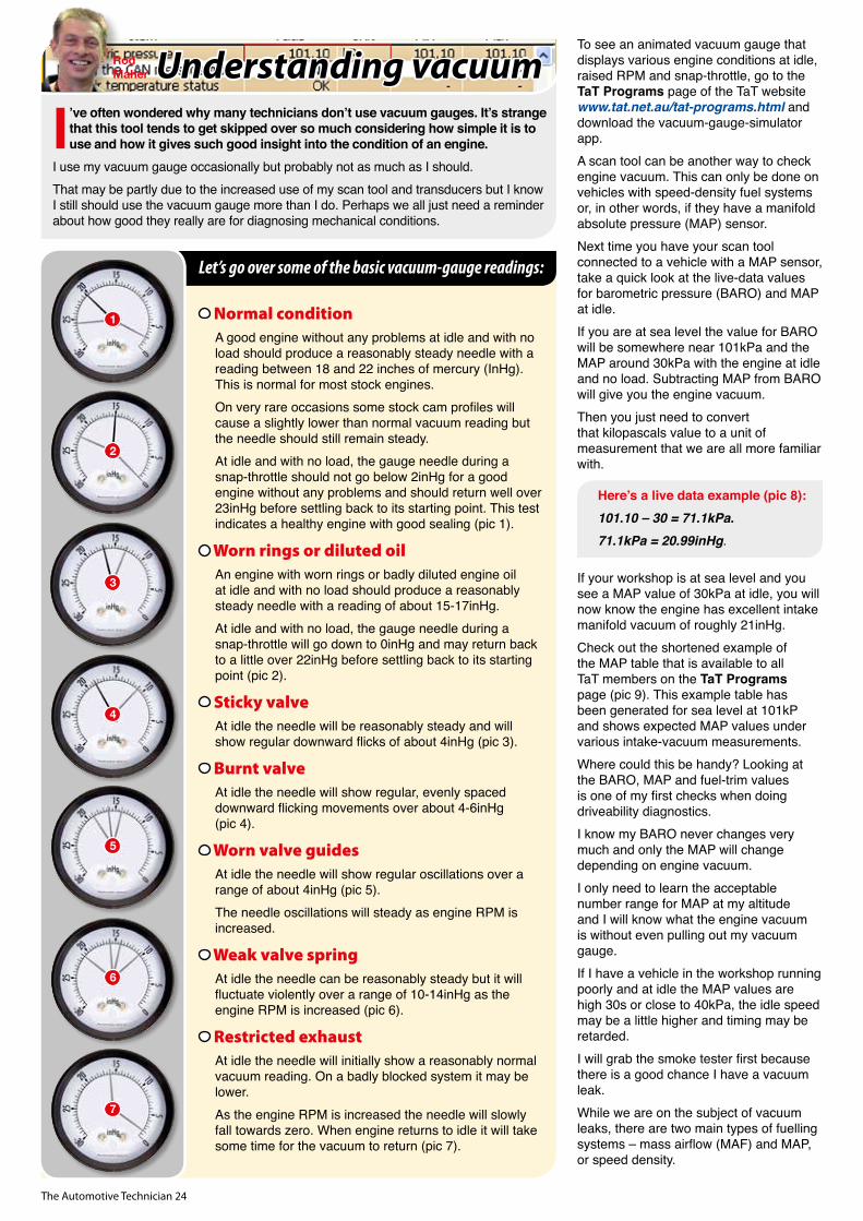
Normal conditionA good engine without any problems at idle and with no load should produce a reasonably steady needle with a reading between 18 and 22 inches of mercury (InHg). This is normal for most stock engines. On very rare occasions some stock cam profiles will cause a slightly lower than normal vacuum reading but the needle should still remain steady.At idle and with no load, the gauge needle during a snap-throttle should not go below 2inHg for a good engine without any problems and should return well over 23inHg before settling back to its starting point. This test indicates a healthy engine with good sealing (pic 1).
Worn rings or diluted oilAn engine with worn rings or badly diluted engine oil at idle and with no load should produce a reasonably steady needle with a reading of about 15-17inHg.At idle and with no load, the gauge needle during a snap-throttle will go down to 0inHg and may return back to a little over 22inHg before settling back to its starting point (pic 2).
Sticky valveAt idle the needle will be reasonably steady and will show regular downward flicks of about 4inHg (pic 3).
Burnt valveAt idle the needle will show regular, evenly spaced downward flicking movements over about 4-6inHg (pic 4).
Worn valve guidesAt idle the needle will show regular oscillations over a range of about 4inHg (pic 5). The needle oscillations will steady as engine RPM is increased.
Weak valve springAt idle the needle can be reasonably steady but it will fluctuate violently over a range of 10-14inHg as the engine RPM is increased (pic 6).
Restricted exhaustAt idle the needle will initially show a reasonably normal vacuum reading. On a badly blocked system it may be lower.As the engine RPM is increased the needle will slowly fall towards zero. When engine returns to idle it will take some time for the vacuum to return (pic 7).
Understanding vacuumRod Maher
1
2
3
4
5
6
7
Let’s go over some of the basic vacuum-gauge readings:
The Automotive Technician 25
These two systems react differently to vacuum leaks.On a MAF system a vacuum leak lets unmetered air in after the MAF sensor. This creates a lean condition because the ECU only sees the amount of air measured by the MAF and injects fuel for that amount of air – the unmetered air isn’t accounted for. Then the oxygen (O2) sensors see the lean condition and tell the ECU, so fuel trims go positive to compensate.On a MAP system a vacuum leak is not unmetered air because the MAP sensor still sees any change in manifold absolute pressure from a vacuum leak. The vacuum leak causes an increase in manifold absolute pressure, which causes the ECU think the engine is under more load and inject more fuel, and possibly retard timing, to compensate. Typically this condition will not result in much of a shift in fuel trims because the fuel injected is correct for the measured manifold pressure.Here’s an example that shows an atmospheric pressure or BARO slightly lower at 97.29kPa (pic 10).
This data was captured at an altitude of 367m above sea level.
Let’s do the math again:97.29 – 25 = 72.29kPa72.29kPa = 21.34inHg.
Getting to know the normal range of MAP values and what they convert to in understandable vacuum values for your elevation is a valuable diagnostic tool, especially when combined with other data such as fuel trims. Go to TaT Programs to create a MAP table for your elevation and learn the common range of values. Even better, print the table out and laminate it. I keep my copy on the diagnostic shelf with the other useful diagnostic tools.To download the MAP table and vacuum-gauge-simulator app, go to the TaT Programs page on the TaT website:www.tat.net.au/tat-programs.html
8
9
10
To access the entire Scan Data database of good vehicle data, visit
www.tat.net.au and click on Scan Data
6mm SLC RadiatorAUSTRALIA’S BEST PERFORMANCE COPPER CORE
Quality CertifiedAU602-QC
ISO 9001:2015
Exclusive New DesignMore Tubes = More Cooling High Durability
Ideal for Passenger 4x4 & Light TruckExtra Cooling for Hard Working Vehicles
Adrad is a Quality Accredited Manufacturer & Supplier
SLC_Core_TAT_Half_Pg_0717
®
Available from Adrad Stockists including: or Contact Adrad
1800 069 610adradradiators.com.au
High efficiency louvres maximise cooling
Hemmed edge for extra strength
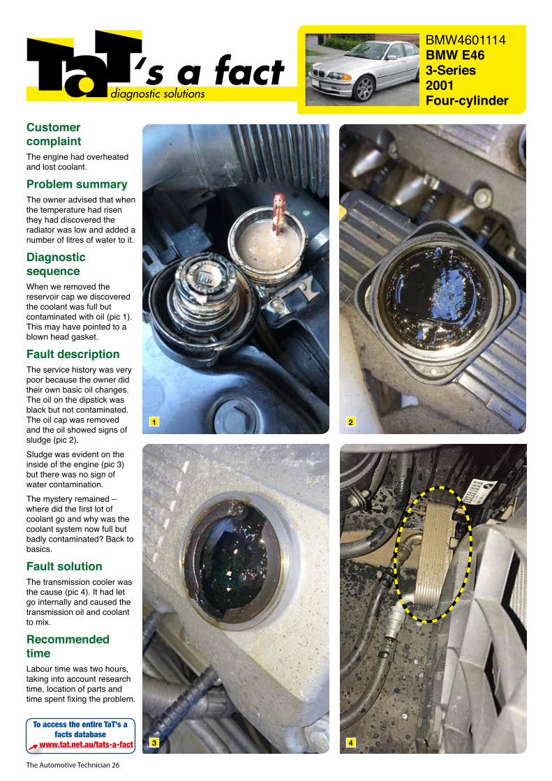
The Automotive Technician 26
BMW4601114BMW E46 3-Series2001Four-cylinder
‘s a factdiagnostic solutions
Customer complaintThe engine had overheated and lost coolant.
Problem summaryThe owner advised that when the temperature had risen they had discovered the radiator was low and added a number of litres of water to it.
Diagnostic sequenceWhen we removed the reservoir cap we discovered the coolant was full but contaminated with oil (pic 1). This may have pointed to a blown head gasket.
Fault descriptionThe service history was very poor because the owner did their own basic oil changes. The oil on the dipstick was black but not contaminated. The oil cap was removed and the oil showed signs of sludge (pic 2).Sludge was evident on the inside of the engine (pic 3) but there was no sign of water contamination.The mystery remained – where did the first lot of coolant go and why was the coolant system now full but badly contaminated? Back to basics.
Fault solutionThe transmission cooler was the cause (pic 4). It had let go internally and caused the transmission oil and coolant to mix.
Recommended timeLabour time was two hours, taking into account research time, location of parts and time spent fixing the problem.
To access the entire TaT’s a facts database
www.tat.net.au/tats-a-fact
1
3
2
4
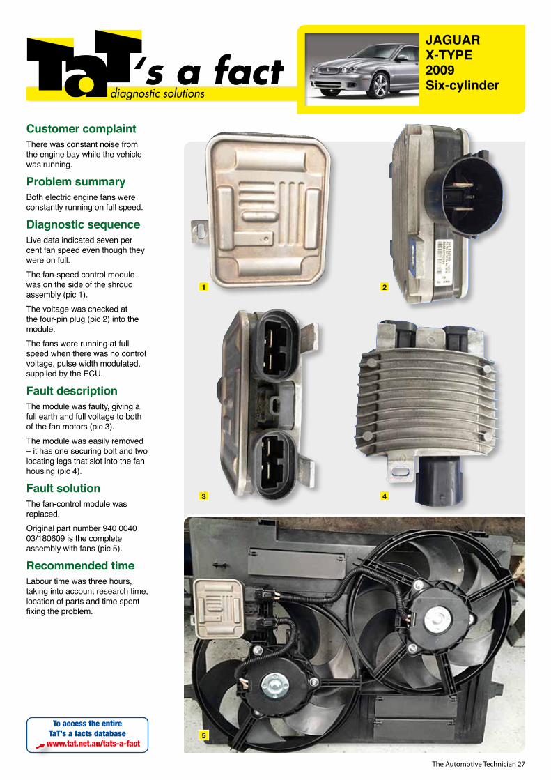
The Automotive Technician 27
JAGUAR X-TYPE2009Six-cylinder‘s a fact
diagnostic solutions
Customer complaintThere was constant noise from the engine bay while the vehicle was running.
Problem summaryBoth electric engine fans were constantly running on full speed.
Diagnostic sequenceLive data indicated seven per cent fan speed even though they were on full. The fan-speed control module was on the side of the shroud assembly (pic 1).The voltage was checked at the four-pin plug (pic 2) into the module. The fans were running at full speed when there was no control voltage, pulse width modulated, supplied by the ECU.
Fault descriptionThe module was faulty, giving a full earth and full voltage to both of the fan motors (pic 3).The module was easily removed – it has one securing bolt and two locating legs that slot into the fan housing (pic 4).
Fault solutionThe fan-control module was replaced. Original part number 940 0040 03/180609 is the complete assembly with fans (pic 5).
Recommended timeLabour time was three hours, taking into account research time, location of parts and time spent fixing the problem.
To access the entire TaT’s a facts database
www.tat.net.au/tats-a-fact
2
4
1
3
5
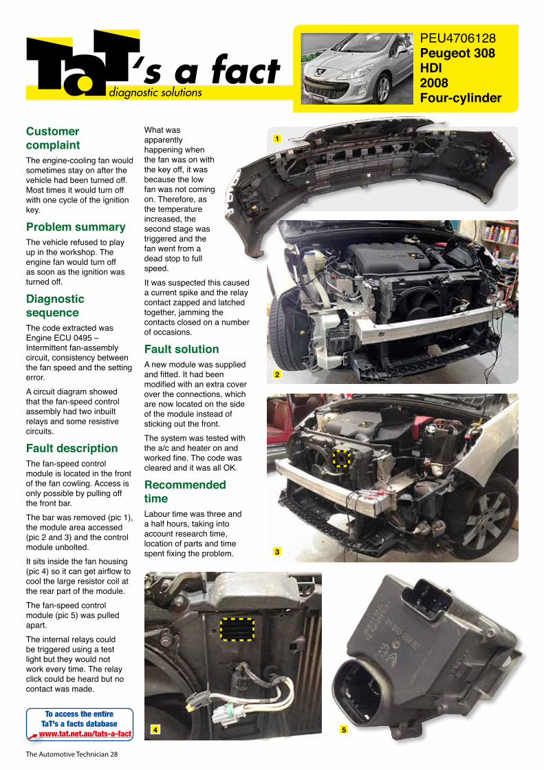
The Automotive Technician 28
PEU4706128Peugeot 308 HDI2008Four-cylinder
‘s a factdiagnostic solutions
Customer complaintThe engine-cooling fan would sometimes stay on after the vehicle had been turned off. Most times it would turn off with one cycle of the ignition key.
Problem summaryThe vehicle refused to play up in the workshop. The engine fan would turn off as soon as the ignition was turned off.
Diagnostic sequenceThe code extracted was Engine ECU 0495 – Intermittent fan-assembly circuit, consistency between the fan speed and the setting error.A circuit diagram showed that the fan-speed control assembly had two inbuilt relays and some resistive circuits.
Fault descriptionThe fan-speed control module is located in the front of the fan cowling. Access is only possible by pulling off the front bar.The bar was removed (pic 1), the module area accessed (pic 2 and 3) and the control module unbolted. It sits inside the fan housing (pic 4) so it can get airflow to cool the large resistor coil at the rear part of the module.The fan-speed control module (pic 5) was pulled apart. The internal relays could be triggered using a test light but they would not work every time. The relay click could be heard but no contact was made.
What was apparently happening when the fan was on with the key off, it was because the low fan was not coming on. Therefore, as the temperature increased, the second stage was triggered and the fan went from a dead stop to full speed.It was suspected this caused a current spike and the relay contact zapped and latched together, jamming the contacts closed on a number of occasions.
Fault solutionA new module was supplied and fitted. It had been modified with an extra cover over the connections, which are now located on the side of the module instead of sticking out the front.The system was tested with the a/c and heater on and worked fine. The code was cleared and it was all OK.
Recommended timeLabour time was three and a half hours, taking into account research time, location of parts and time spent fixing the problem.
To access the entire TaT’s a facts database
www.tat.net.au/tats-a-fact
2
1
3
4 5
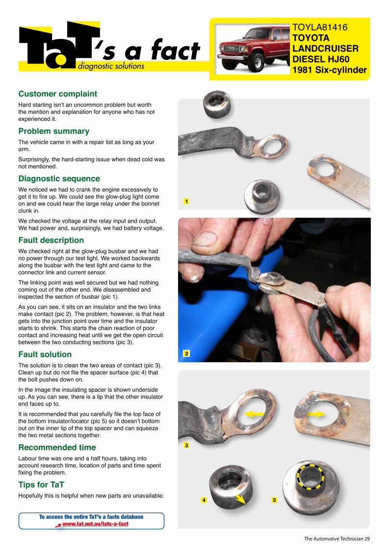
The Automotive Technician 29
TOYLA81416TOYOTALANDCRUISERDIESEL HJ601981 Six-cylinder
‘s a factdiagnostic solutions
Customer complaintHard starting isn’t an uncommon problem but worth the mention and explanation for anyone who has not experienced it.
Problem summaryThe vehicle came in with a repair list as long as your arm.Surprisingly, the hard-starting issue when dead cold was not mentioned.
Diagnostic sequenceWe noticed we had to crank the engine excessively to get it to fire up. We could see the glow-plug light come on and we could hear the large relay under the bonnet clunk in.We checked the voltage at the relay input and output. We had power and, surprisingly, we had battery voltage.
Fault descriptionWe checked right at the glow-plug busbar and we had no power through our test light. We worked backwards along the busbar with the test light and came to the connector link and current sensor.The linking point was well secured but we had nothing coming out of the other end. We disassembled and inspected the section of busbar (pic 1).As you can see, it sits on an insulator and the two links make contact (pic 2). The problem, however, is that heat gets into the junction point over time and the insulator starts to shrink. This starts the chain reaction of poor contact and increasing heat until we get the open circuit between the two conducting sections (pic 3).
Fault solutionThe solution is to clean the two areas of contact (pic 3). Clean up but do not file the spacer surface (pic 4) that the bolt pushes down on.In the image the insulating spacer is shown underside up. As you can see, there is a lip that the other insulator end faces up to.It is recommended that you carefully file the top face of the bottom insulator/locator (pic 5) so it doesn’t bottom out on the inner lip of the top spacer and can squeeze the two metal sections together.
Recommended timeLabour time was one and a half hours, taking into account research time, location of parts and time spent fixing the problem.
Tips for TaTHopefully this is helpful when new parts are unavailable.
To access the entire TaT’s a facts databasewww.tat.net.au/tats-a-fact
1
2
4 5
3
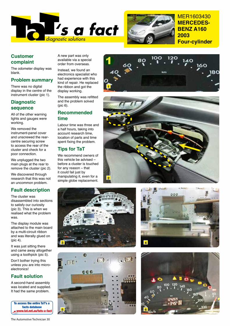
The Automotive Technician 30
MER1603430MERCEDES-BENZ A1602003Four-cylinder
‘s a factdiagnostic solutions
Customer complaintThe odometer display was blank.
Problem summaryThere was no digital display in the centre of the instrument cluster (pic 1).
Diagnostic sequenceAll of the other warning lights and gauges were working.We removed the instrument-panel cover and unscrewed the rear-centre securing screw to access the rear of the cluster and check for a poor connection.We unplugged the two main plugs at the rear to remove the cluster (pic 2).We discovered through research that this was not an uncommon problem.
Fault descriptionThe cluster was disassembled into sections to satisfy our curiosity (pic 3). This is when we realised what the problem was.The display module was attached to the main board by a multi-circuit ribbon and was literally glued on (pic 4).It was just sitting there and came away altogether using a toothpick (pic 5).Don’t bother trying this unless you are into micro-electronics!
Fault solutionA second-hand assembly was located and supplied. It had the same problem.
A new part was only available via a special order from overseas.Instead, we found an electronics specialist who had experience with this kind of repair. He replaced the ribbon and got the display working.The assembly was refitted and the problem solved (pic 6).
Recommended timeLabour time was three and a half hours, taking into account research time, location of parts and time spent fixing the problem.
Tips for TaTWe recommend owners of this vehicle be advised – before a cluster is touched for any reason – that it could fail just by manipulating it, even for a simple globe replacement.
To access the entire TaT’s a facts database
www.tat.net.au/tats-a-fact
1
2
3
5
4
6
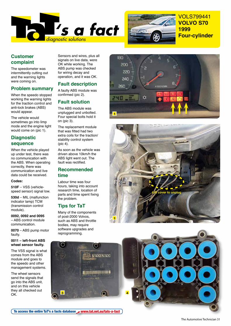
The Automotive Technician 31
VOLS799441VOLVO S701999Four-cylinder‘s a fact
diagnostic solutions
Customer complaintThe speedometer was intermittently cutting out and the warning lights were coming on.
Problem summaryWhen the speedo stopped working the warning lights for the traction control and anti-lock brakes (ABS) would appear.The vehicle would sometimes go into limp mode and the engine light would come on (pic 1).
Diagnostic sequenceWhen the vehicle played up under test, there was no communication with the ABS. When operating correctly, there was communication and live data could be received.Codes:510F – VSS (vehicle-speed sensor) signal low.530d – MIL (malfunction indicator lamp) TCM (transmission control module).0092, 0092 and 0095 – ABS control module communication.0070 – ABS pump motor faulty.0011 – left-front ABS wheel sensor faulty.The VSS signal is what comes from the ABS module and goes to the speedo and other management systems.The wheel sensors send the signals that go into the ABS unit, and on this vehicle they all checked out OK.
Sensors and wires, plus all signals on live data, were OK while working. The ABS pump was checked for wiring decay and operation, and it was OK.
Fault descriptionA faulty ABS module was confirmed (pic 2).
Fault solutionThe ABS module was unplugged and unbolted. Four special bolts hold it on (pic 3).The replacement module that was fitted had two extra coils for the traction/stability control system (pic 4).As soon as the vehicle was driven above 10km/h the ABS light went out. The fault was rectified.
Recommended timeLabour time was four hours, taking into account research time, location of parts and time spent fixing the problem.
Tips for TaTMany of the components of post-2000 Volvos, such as ABS and throttle bodies, may require software upgrades and reprogramming.
To access the entire TaT’s a facts database www.tat.net.au/tats-a-fact
1
1
3 4
Lift cover to unplug

The Automotive Technician 32
The Automotive Technician 33
W ith later and later model vehicles now finding their way into aftermarket workshops, technicians
need to learn to slow down.Why? Because the correct diagnosis is best outcome. Our trade has always faced time constraints, sometimes from customers, sometimes even from the boss. In the past, when vehicles were much simpler, time was not as important as it is today.Then it took 15 minutes to diagnose a problem and three hours to fix it. Now it takes three hours to diagnose and 15 minutes to fix. This means we need a totally different approach to these jobs.As technicians we need time to make a proper diagnosis. Time to think, plan, analyse and test. Without these deliberate steps, mistakes get made.
Don’t be rushed into a job or diagnosis by a
customer, it will only lead to unnecessary purchases and wasted time. Your customer won’t be
happy when that occurs, either.
When it comes to solving problem vehicles and diagnosing
issues, the top tech tip is to slow down. Not only will slowing down allow you to think with more clarity, it will also allow you to consider other options. Often slowing down means speeding up.Talk to your team, access networks, forums and take time to research and analyse the problem. You are much more likely to get the right answers.Next time you feel yourself rushing, slow down. The correct diagnosis is really what
matters, not what the clock says.
TOPTECH TIP
The right diagnosis is the best outcome
SLOW DOWN
FROM THE RACE TRACK TO THE ROAD...
www.envirotek.net.au | 1300 584 665 |

The Automotive Technician 34
aad.com.auVICTORIADerrimut (03) 8369 1400Nunawading (03) 8878 2290
SOUTH AUSTRALIAWelland (08) 8346 7066
NEW SOUTH WALESYagoona (02) 9791 8000Yennora (02) 9892 2166Girraween (02) 9688 4400
QUEENSLANDWillawong (07) 3859 2860Brendale (07) 3881 1692WESTERN AUSTRALIAWelshpool (08) 6454 9405
C O O L I N G P R O D U C T S
WE STOCK THE COOLEST BRANDS
AAD offer a complete range of Automotive Cooling
Components.
RadiatorsA/C CondensersWater PumpsThermostats & Housings Radiator Caps
Hose & ClampsWater OutletsThermo Fan Switches Thermatic FansFan & Drive Belts
Fan ClutchesTemperature SensorsTransmission Oil CoolersCoolantElectric Booster Pumps
ALWAYS COOL...
AAD Cooling AD 2016.indd 1 17/07/2017 1:59:17 PM
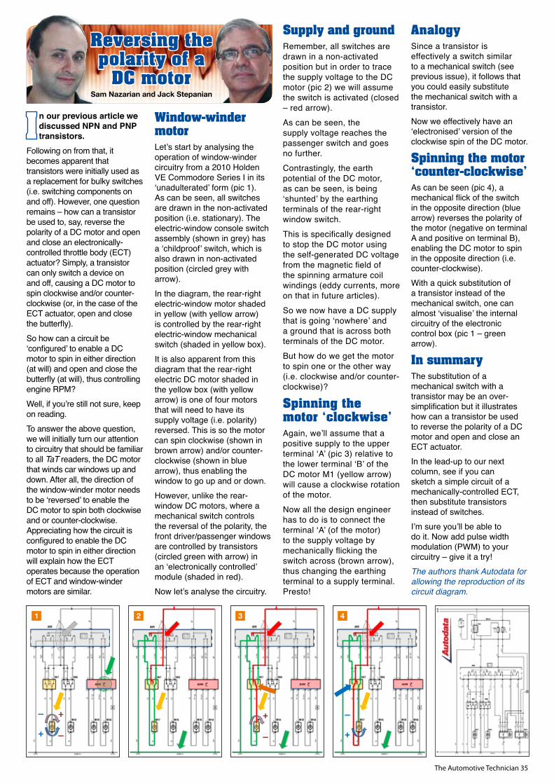
The Automotive Technician 35
n our previous article we discussed NPN and PNP transistors.
Following on from that, it becomes apparent that transistors were initially used as a replacement for bulky switches (i.e. switching components on and off). However, one question remains – how can a transistor be used to, say, reverse the polarity of a DC motor and open and close an electronically-controlled throttle body (ECT) actuator? Simply, a transistor can only switch a device on and off, causing a DC motor to spin clockwise and/or counter-clockwise (or, in the case of the ECT actuator, open and close the butterfly). So how can a circuit be ‘configured’ to enable a DC motor to spin in either direction (at will) and open and close the butterfly (at will), thus controlling engine RPM?Well, if you’re still not sure, keep on reading. To answer the above question, we will initially turn our attention to circuitry that should be familiar to all TaT readers, the DC motor that winds car windows up and down. After all, the direction of the window-winder motor needs to be ‘reversed’ to enable the DC motor to spin both clockwise and or counter-clockwise. Appreciating how the circuit is configured to enable the DC motor to spin in either direction will explain how the ECT operates because the operation of ECT and window-winder motors are similar.
Window-winder motorLet’s start by analysing the operation of window-winder circuitry from a 2010 Holden VE Commodore Series I in its ‘unadulterated’ form (pic 1). As can be seen, all switches are drawn in the non-activated position (i.e. stationary). The electric-window console switch assembly (shown in grey) has a ‘childproof’ switch, which is also drawn in non-activated position (circled grey with arrow). In the diagram, the rear-right electric-window motor shaded in yellow (with yellow arrow) is controlled by the rear-right electric-window mechanical switch (shaded in yellow box).It is also apparent from this diagram that the rear-right electric DC motor shaded in the yellow box (with yellow arrow) is one of four motors that will need to have its supply voltage (i.e. polarity) reversed. This is so the motor can spin clockwise (shown in brown arrow) and/or counter-clockwise (shown in blue arrow), thus enabling the window to go up and or down.However, unlike the rear-window DC motors, where a mechanical switch controls the reversal of the polarity, the front driver/passenger windows are controlled by transistors (circled green with arrow) in an ‘electronically controlled’ module (shaded in red).Now let’s analyse the circuitry.
Supply and groundRemember, all switches are drawn in a non-activated position but in order to trace the supply voltage to the DC motor (pic 2) we will assume the switch is activated (closed – red arrow). As can be seen, the supply voltage reaches the passenger switch and goes no further. Contrastingly, the earth potential of the DC motor, as can be seen, is being ‘shunted’ by the earthing terminals of the rear-right window switch. This is specifically designed to stop the DC motor using the self-generated DC voltage from the magnetic field of the spinning armature coil windings (eddy currents, more on that in future articles). So we now have a DC supply that is going ‘nowhere’ and a ground that is across both terminals of the DC motor. But how do we get the motor to spin one or the other way (i.e. clockwise and/or counter-clockwise)?
Spinning the motor ‘clockwise’Again, we’ll assume that a positive supply to the upper terminal ‘A’ (pic 3) relative to the lower terminal ‘B’ of the DC motor M1 (yellow arrow) will cause a clockwise rotation of the motor. Now all the design engineer has to do is to connect the terminal ‘A’ (of the motor) to the supply voltage by mechanically flicking the switch across (brown arrow), thus changing the earthing terminal to a supply terminal. Presto!
AnalogySince a transistor is effectively a switch similar to a mechanical switch (see previous issue), it follows that you could easily substitute the mechanical switch with a transistor. Now we effectively have an ‘electronised’ version of the clockwise spin of the DC motor.
Spinning the motor ‘counter-clockwise’As can be seen (pic 4), a mechanical flick of the switch in the opposite direction (blue arrow) reverses the polarity of the motor (negative on terminal A and positive on terminal B), enabling the DC motor to spin in the opposite direction (i.e. counter-clockwise). With a quick substitution of a transistor instead of the mechanical switch, one can almost ‘visualise’ the internal circuitry of the electronic control box (pic 1 – green arrow).
In summaryThe substitution of a mechanical switch with a transistor may be an over-simplification but it illustrates how can a transistor be used to reverse the polarity of a DC motor and open and close an ECT actuator.In the lead-up to our next column, see if you can sketch a simple circuit of a mechanically-controlled ECT, then substitute transistors instead of switches. I’m sure you’ll be able to do it. Now add pulse width modulation (PWM) to your circuitry – give it a try!The authors thank Autodata for allowing the reproduction of its circuit diagram.
Sam Nazarian and Jack Stepanian
Reversing the polarity of a
DC motor
-
+ _
_
+
-
-
+ _
-
_
+
1 2 3 4
aad.com.auVICTORIADerrimut (03) 8369 1400Nunawading (03) 8878 2290
SOUTH AUSTRALIAWelland (08) 8346 7066
NEW SOUTH WALESYagoona (02) 9791 8000Yennora (02) 9892 2166Girraween (02) 9688 4400
QUEENSLANDWillawong (07) 3859 2860Brendale (07) 3881 1692WESTERN AUSTRALIAWelshpool (08) 6454 9405
C O O L I N G P R O D U C T S
WE STOCK THE COOLEST BRANDS
AAD offer a complete range of Automotive Cooling
Components.
RadiatorsA/C CondensersWater PumpsThermostats & Housings Radiator Caps
Hose & ClampsWater OutletsThermo Fan Switches Thermatic FansFan & Drive Belts
Fan ClutchesTemperature SensorsTransmission Oil CoolersCoolantElectric Booster Pumps
ALWAYS COOL...
AAD Cooling AD 2016.indd 1 17/07/2017 1:59:17 PM
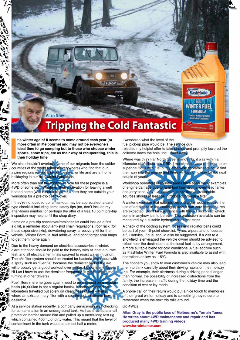
The Automotive Technician 36
Tripping the Cold FantasticAllan Gray
It’s winter again! It seems to come around each year (or more often in Melbourne) and may not be everyone’s ideal time to go camping but to those who choose winter sports, snow trips, etc as their way of recuperating, this is their holiday time.
We also shouldn’t overlook some of our migrants from the colder countries of the world (almost everywhere) who find that our alpine regions remind them of their earlier life and are at home holidaying in our mild winter conditions. More often than not the chosen vehicle for these people is a 4WD of some sort. Whatever their motivation for leaving a well heated home (with electric blankets), here they are outside your workshop for a pre-trip check over.If they’re not queued up, a mail-out may be appreciated, a card type checklist including some safety tips (no, don’t include my after-hours number) or perhaps the offer of a free 10 point pre-trip inspection may help to fill the shop diary. Items on a pre-trip checkover/reminder list could include a first aid kit, a reminder about anti-skid chain regulations, roof rack (for those expensive skis), dewatering spray, a recovery kit for the vehicle, ‘Winter Formula’ fuel additive, and don’t forget area maps to get them home again.Due to the heavy demand on electrical accessories in winter, extra attention should be paid to the battery with at least a hi-rate test, and all electrical terminals sprayed to resist water intrusion. The a/c filter system should be treated for bacteria and odour with a spray such as ‘Glen 20’ because the demister part of the a/c will probably get a good workout over winter. I know in my Toyota Hi-Lux I have to use the demister frequently (it might be just me fuming at other drivers).Fuel filters (here he goes again) need to be changed on a regular basis (40,000km is not a regular basis). It doesn’t depend on kilometers travelled but solely on cleanliness of fuel – that’s where an extra primary filter with a see-through sediment bowl is desirable.At a service station recently, a company serviceman was checking for contamination in an underground tank. He had erected a small protection barrier around him and pulled up a meter-long test rig which contained 400mL of dirty water. This meant that the level of contaminant in the tank would be almost half a meter.
I wondered what the level of the fuel pick-up pipe would be. The service guy rejected my helpful offer to take photos and promptly lowered the collector down the hole until I went away.Where was this? Far North Queensland? No, it was within a kilometer of Melbourne’s CBD. I mention this as a reminder to be super cautious with fuel purity otherwise contaminants could find their way into the engine and there will be no holiday for the next couple of years!Workshop operators in country areas have seen many examples of engine damage due to farm fuel from drums, overhead tanks and jerry cans. Any fuel added to tanks from questionable sources should at least be introduced through a filter.A winter excursion that extends beyond a day would require the use of antifreeze in the cooling system if sub-zero temperatures are expected. Don’t take a chance with this – I reckon I’d whack some in anyhow just to be sure. The protection available can be measured by a suitable hydrometer or test strips.A check of the cooling system, hoses and radiator belts could be part of your 10-point checklist. Tyres, wipers and, of course, a full service, if due, should also be suggested. If a visit to a snowfield is envisaged the vehicle owner should be advised to refuel near the destination as the local fuel is, by arrangement, a more suitable blend for cold conditions. A fuel additive such as Flashlube Winter Fuel Formula is also available to assist with operations as low as -15ºC.The concern you show to your customer’s vehicle may also lead them to think carefully about their driving habits on their holiday trip. For example, their alertness during a driving period longer than normal, the possibility of increased distractions from the family, the increase in traffic during the holiday time and the condition of wet or icy roads. A phone call on their return would put a nice touch to memories of their great winter holiday and is something they’re sure to remember when the next trip rolls around. Go 4WDs!Allan Gray is the public face of Melbourne’s Terrain Tamer. He writes about 4WD maintenance and repair and has produced many 4WD training videoswww.terraintamer.com
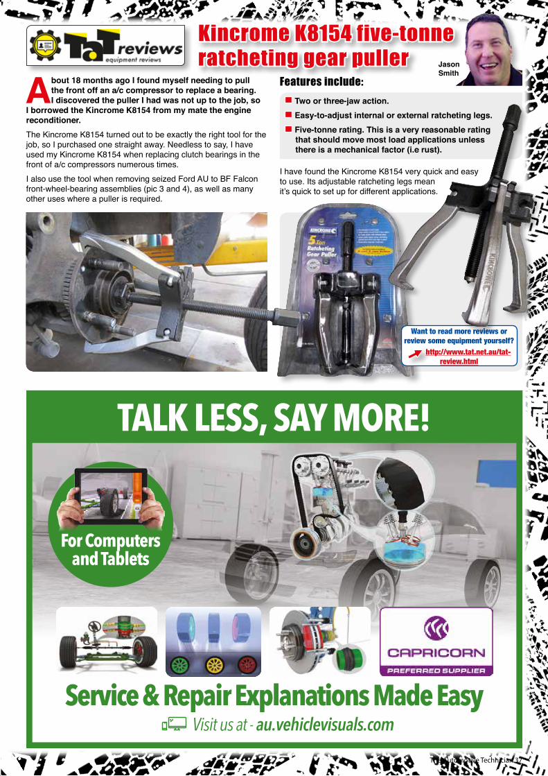
The Automotive Technician 37
About 18 months ago I found myself needing to pull the front off an a/c compressor to replace a bearing. I discovered the puller I had was not up to the job, so
I borrowed the Kincrome K8154 from my mate the engine reconditioner.The Kincrome K8154 turned out to be exactly the right tool for the job, so I purchased one straight away. Needless to say, I have used my Kincrome K8154 when replacing clutch bearings in the front of a/c compressors numerous times. I also use the tool when removing seized Ford AU to BF Falcon front-wheel-bearing assemblies (pic 3 and 4), as well as many other uses where a puller is required.
Features include:
Two or three-jaw action. Easy-to-adjust internal or external ratcheting legs. Five-tonne rating. This is a very reasonable rating that should move most load applications unless there is a mechanical factor (i.e rust).
I have found the Kincrome K8154 very quick and easy to use. Its adjustable ratcheting legs mean it’s quick to set up for different applications.
Kincrome K8154 five-tonne ratcheting gear puller Jason
Smith
Want to read more reviews or review some equipment yourself?
http://www.tat.net.au/tat-review.html
TALK LESS, SAY MORE!
Service & Repair Explanations Made Easy
For Computers and Tablets
Visit us at - au.vehiclevisuals.com
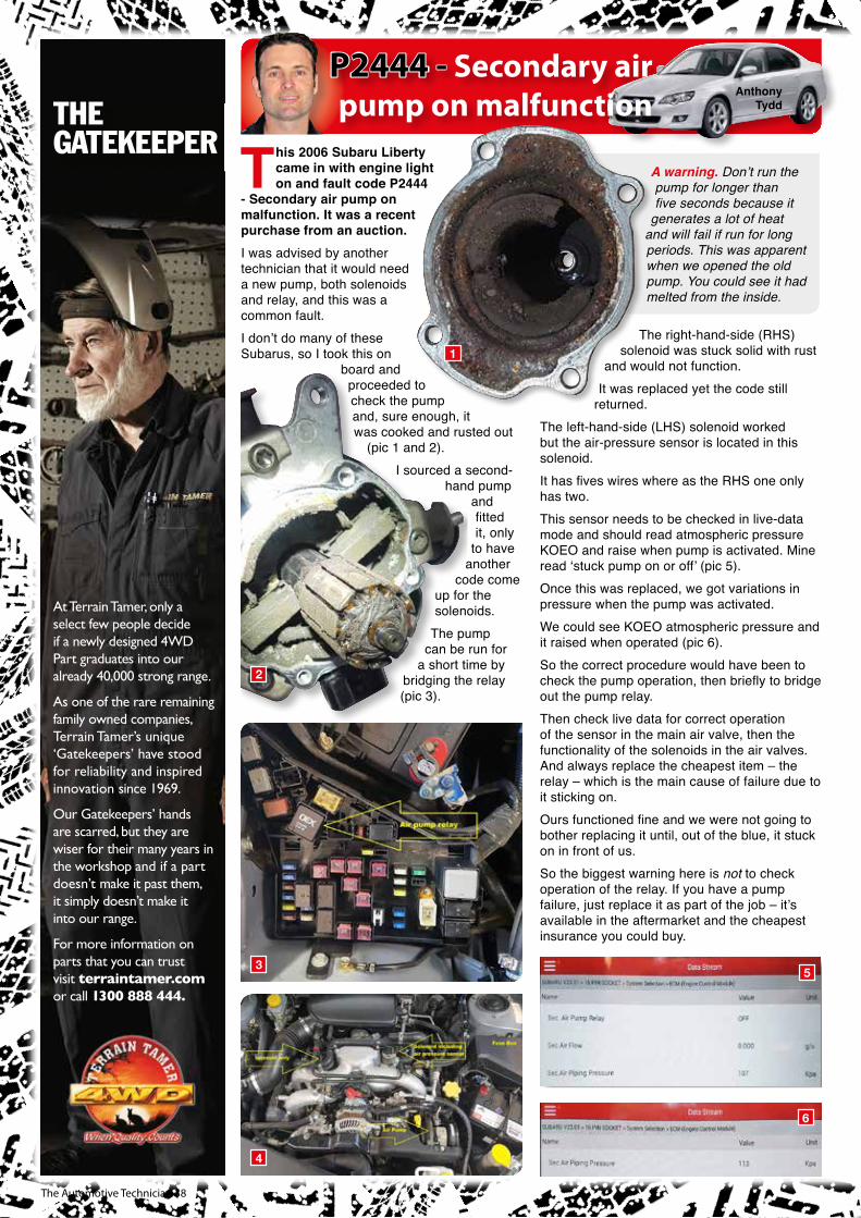
The Automotive Technician 38
This 2006 Subaru Liberty came in with engine light on and fault code P2444
- Secondary air pump on malfunction. It was a recent purchase from an auction.I was advised by another technician that it would need a new pump, both solenoids and relay, and this was a common fault.I don’t do many of these Subarus, so I took this on
board and proceeded to check the pump and, sure enough, it was cooked and rusted out
(pic 1 and 2).I sourced a second-
hand pump and fitted it, only
to have another
code come up for the solenoids.
The pump can be run for
a short time by bridging the relay (pic 3).
A warning. Don’t run the pump for longer than five seconds because it
generates a lot of heat and will fail if run for long periods. This was apparent when we opened the old pump. You could see it had melted from the inside.
The right-hand-side (RHS) solenoid was stuck solid with rust
and would not function. It was replaced yet the code still
returned.The left-hand-side (LHS) solenoid worked but the air-pressure sensor is located in this solenoid. It has fives wires where as the RHS one only has two.This sensor needs to be checked in live-data mode and should read atmospheric pressure KOEO and raise when pump is activated. Mine read ‘stuck pump on or off’ (pic 5).Once this was replaced, we got variations in pressure when the pump was activated. We could see KOEO atmospheric pressure and it raised when operated (pic 6).So the correct procedure would have been to check the pump operation, then briefly to bridge out the pump relay. Then check live data for correct operation of the sensor in the main air valve, then the functionality of the solenoids in the air valves. And always replace the cheapest item – the relay – which is the main cause of failure due to it sticking on.Ours functioned fine and we were not going to bother replacing it until, out of the blue, it stuck on in front of us.So the biggest warning here is not to check operation of the relay. If you have a pump failure, just replace it as part of the job – it’s available in the aftermarket and the cheapest insurance you could buy.
2
3
4
5
6
P2444 - Secondary air pump on malfunction
1
Anthony TyddTHE
GATEKEEPER
At Terrain Tamer, only a select few people decide if a newly designed 4WD Part graduates into our already 40,000 strong range.
As one of the rare remaining family owned companies, Terrain Tamer’s unique ‘Gatekeepers’ have stood for reliability and inspired innovation since 1969.
Our Gatekeepers’ hands are scarred, but they are wiser for their many years in the workshop and if a part doesn’t make it past them, it simply doesn’t make it into our range.
For more information on parts that you can trust visit terraintamer.com or call 1300 888 444.

The Automotive Technician 39
MTQ2004_MTQ_TAT Advert_MTQ Gold Service (Print File).indd 1 31/05/2017 10:32:13 AM
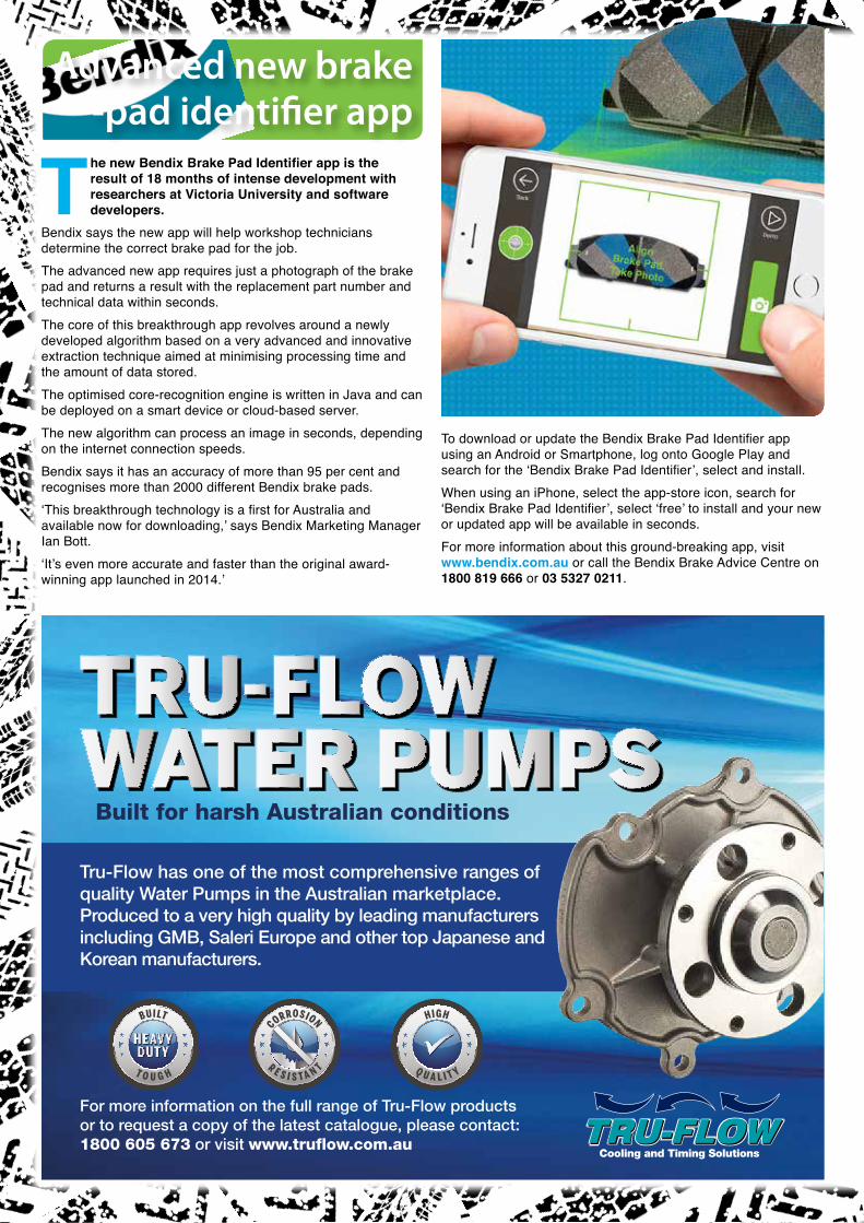
The Automotive Technician 40
The new Bendix Brake Pad Identifier app is the result of 18 months of intense development with researchers at Victoria University and software developers.
Bendix says the new app will help workshop technicians determine the correct brake pad for the job.The advanced new app requires just a photograph of the brake pad and returns a result with the replacement part number and technical data within seconds.The core of this breakthrough app revolves around a newly developed algorithm based on a very advanced and innovative extraction technique aimed at minimising processing time and the amount of data stored. The optimised core-recognition engine is written in Java and can be deployed on a smart device or cloud-based server. The new algorithm can process an image in seconds, depending on the internet connection speeds. Bendix says it has an accuracy of more than 95 per cent and recognises more than 2000 different Bendix brake pads.‘This breakthrough technology is a first for Australia and available now for downloading,’ says Bendix Marketing Manager Ian Bott. ‘It’s even more accurate and faster than the original award-winning app launched in 2014.’
To download or update the Bendix Brake Pad Identifier app using an Android or Smartphone, log onto Google Play and search for the ‘Bendix Brake Pad Identifier’, select and install. When using an iPhone, select the app-store icon, search for ‘Bendix Brake Pad Identifier’, select ‘free’ to install and your new or updated app will be available in seconds.For more information about this ground-breaking app, visit www.bendix.com.au or call the Bendix Brake Advice Centre on 1800 819 666 or 03 5327 0211.
Advanced new brake -pad identifier app
Cooling and Timing Solutions
BUILT
T O U G H
CORROSION
R E S I S T A N
T
HIGH
Q U A L I T Y
BUILT
T O U G H
CORROSION
R E S I S T A N
T
HIGH
Q U A L I T Y
BUILT
T O U G H
CORROSION
R E S I S T A N
T
HIGH
Q U A L I T Y
Tru-Flow has one of the most comprehensive ranges of quality Water Pumps in the Australian marketplace. Produced to a very high quality by leading manufacturers including GMB, Saleri Europe and other top Japanese and Korean manufacturers.
For more information on the full range of Tru-Flow products or to request a copy of the latest catalogue, please contact: 1800 605 673 or visit www.truflow.com.au
Built for harsh Australian conditions
The Automotive Technician 41
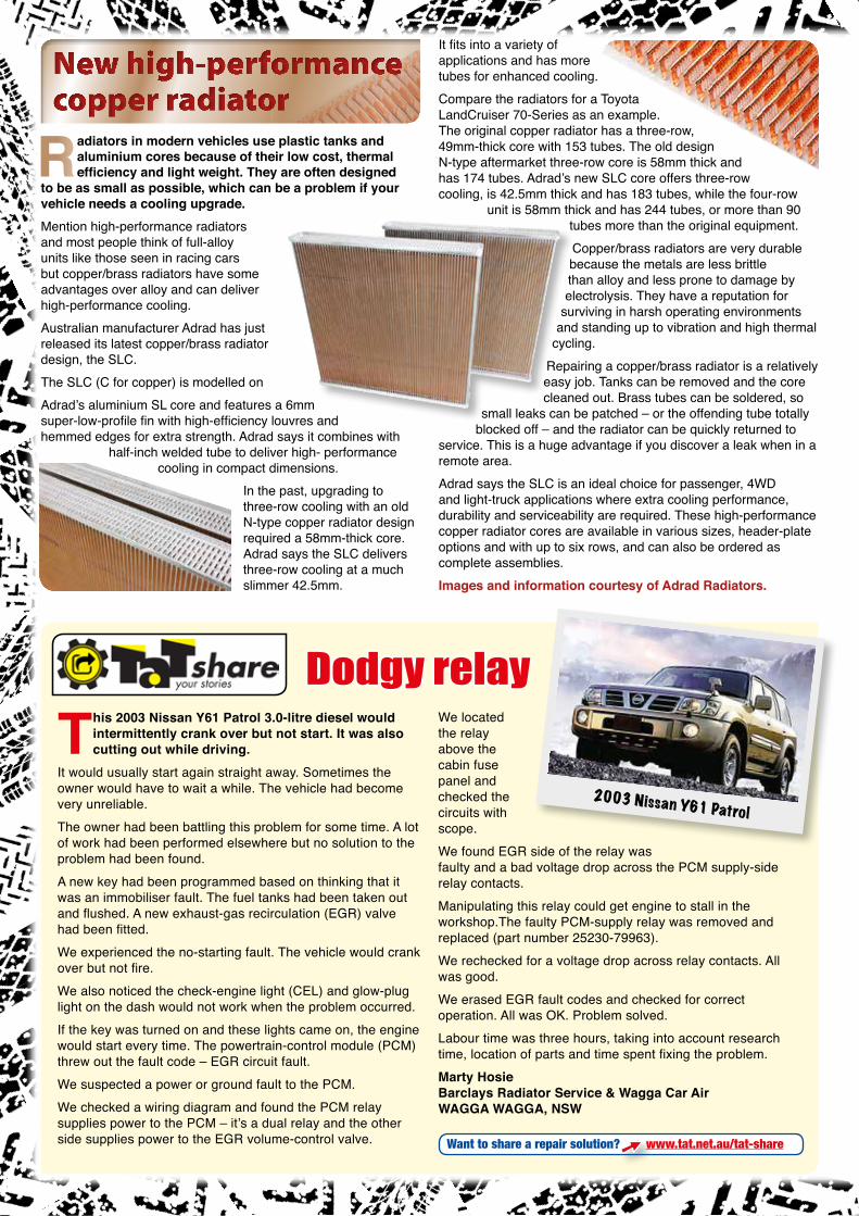
The Automotive Technician 42
Radiators in modern vehicles use plastic tanks and aluminium cores because of their low cost, thermal efficiency and light weight. They are often designed
to be as small as possible, which can be a problem if your vehicle needs a cooling upgrade.Mention high-performance radiators and most people think of full-alloy units like those seen in racing cars but copper/brass radiators have some advantages over alloy and can deliver high-performance cooling.Australian manufacturer Adrad has just released its latest copper/brass radiator design, the SLC.The SLC (C for copper) is modelled onAdrad’s aluminium SL core and features a 6mm super-low-profile fin with high-efficiency louvres and hemmed edges for extra strength. Adrad says it combines with
half-inch welded tube to deliver high- performance cooling in compact dimensions.
In the past, upgrading to three-row cooling with an old N-type copper radiator design required a 58mm-thick core. Adrad says the SLC delivers three-row cooling at a much slimmer 42.5mm.
It fits into a variety of applications and has more tubes for enhanced cooling.Compare the radiators for a Toyota LandCruiser 70-Series as an example. The original copper radiator has a three-row, 49mm-thick core with 153 tubes. The old design N-type aftermarket three-row core is 58mm thick and has 174 tubes. Adrad’s new SLC core offers three-row cooling, is 42.5mm thick and has 183 tubes, while the four-row
unit is 58mm thick and has 244 tubes, or more than 90 tubes more than the original equipment.Copper/brass radiators are very durable because the metals are less brittle than alloy and less prone to damage by electrolysis. They have a reputation for
surviving in harsh operating environments and standing up to vibration and high thermal
cycling.Repairing a copper/brass radiator is a relatively easy job. Tanks can be removed and the core cleaned out. Brass tubes can be soldered, so
small leaks can be patched – or the offending tube totally blocked off – and the radiator can be quickly returned to
service. This is a huge advantage if you discover a leak when in a remote area.Adrad says the SLC is an ideal choice for passenger, 4WD and light-truck applications where extra cooling performance, durability and serviceability are required. These high-performance copper radiator cores are available in various sizes, header-plate options and with up to six rows, and can also be ordered as complete assemblies.Images and information courtesy of Adrad Radiators.
New high-performance copper radiator
This 2003 Nissan Y61 Patrol 3.0-litre diesel would intermittently crank over but not start. It was also cutting out while driving.
It would usually start again straight away. Sometimes the owner would have to wait a while. The vehicle had become very unreliable.The owner had been battling this problem for some time. A lot of work had been performed elsewhere but no solution to the problem had been found. A new key had been programmed based on thinking that it was an immobiliser fault. The fuel tanks had been taken out and flushed. A new exhaust-gas recirculation (EGR) valve had been fitted.We experienced the no-starting fault. The vehicle would crank over but not fire. We also noticed the check-engine light (CEL) and glow-plug light on the dash would not work when the problem occurred. If the key was turned on and these lights came on, the engine would start every time. The powertrain-control module (PCM) threw out the fault code – EGR circuit fault. We suspected a power or ground fault to the PCM. We checked a wiring diagram and found the PCM relay supplies power to the PCM – it’s a dual relay and the other side supplies power to the EGR volume-control valve.
We located the relay above the cabin fuse panel and checked the circuits with scope. We found EGR side of the relay was faulty and a bad voltage drop across the PCM supply-side relay contacts. Manipulating this relay could get engine to stall in the workshop.The faulty PCM-supply relay was removed and replaced (part number 25230-79963). We rechecked for a voltage drop across relay contacts. All was good. We erased EGR fault codes and checked for correct operation. All was OK. Problem solved.Labour time was three hours, taking into account research time, location of parts and time spent fixing the problem.Marty HosieBarclays Radiator Service & Wagga Car AirWAGGA WAGGA, NSW
2003 Nissan Y61 Patrol
Dodgy relay
Want to share a repair solution? www.tat.net.au/tat-share
The Automotive Technician 43
STOPThat’s what we do Best
Available from all leading Auto parts stores
The Kangaroo Paw ventilation design is a series of 144 diamond and tear-drop pillars (or columns) instead of the generic continuous straight or curved vane designs. The freedom of movement and greater surface area for cooling air to pass through the Kangaroo Paw pillars increases cooling efficiency by up to 20% when compared to standard disc rotors.
“Better cooling means faster recovery for your brake system.”
In addition to more efficient cooling the Kangaroo Paw pillars provide a unique structural support for the disc
rotor friction surfaces enabling better high load stability to guard against disc rotor distortion known to cause vibration in the steering wheel or brake pedal.
This is achieved by careful distribution of the pillars to key areas within the disc ventilation passage.
The heat capacity of the Kangaroo Paw disc rotor is calculated to provide efficient braking under extreme conditions while preventing brake fade. Heat capacity and efficient cooling work in harmony to receive and process out the heaviest of brake loads to achieve fast recovery of the brake system to maximise safety for the next time when you apply the brake pedal.
TAT_2017_July_issue.indd 1 5/07/2017 3:13:31 PM

The Automotive Technician 44
If you attended this year’s Australian Auto Aftermarket Expo (AAAE) and sat in on the Diesel Opportunities
seminar – I was one of the speakers, along with Andrew from Diesel Tech and Clint from Automate – you will remember this fault code (pic 1). This a favorite of mine because more than 20 different failures that I’m aware of can cause it to show up in a common-rail diesel.
One of the key problems with diagnosing these easy faults is the inability of the scan tool to communicate with the vehicle or the many different descriptions that different tools display for this fault code. Some of the most expensive scan tools will not diagnose this fault without you doing the diagnosis.This is where some mechanics can come unstuck. If you think a scan tool is going to instantly tell you what component has failed, you’re not just beginning to think like your customer but lowering your standards. You must continue to keep yourself up to date attending training courses, teaching yourself and learning from others who know diesel. One often forgotten key factor is the common-rail engine remains a combustion engine with pistons, valves, an intake and exhaust, just like a diesel engine of 80 years ago. All they’ve done is change how the fuel and air enters the engine.What do you do if there is not a fault code present? Well, they’re not always necessary. They can not just be very misleading but impact on valuable thought patterns. But the scan tool has many valuable benefits, including the data, actuator activation, reset, adaptation of components (electrical and mechanical) and some scan tools have a scope function. If they don’t, then I’m sure you’ve got one stashed away. If not, you better get yourself one.The most common component replaced on many diesels when surging, loss of power, stalling or even fuel-economy symptoms occur is the suction-control valve (SCV). Most of the time it isn’t the SCV that is actually failing and, if you think back to one of our previous articles about the SCV, you will take this advice seriously.
In this issue I’m going to show you how to diagnose one of multiple failures that brings on the P0089 code in the Mazda BT-50 (pic 2) and Ford Ranger (pic 3) fitted with the 2.2-litre four cylinder and 3.2-litre five-cylinder turbodiesel engines. The vehicle owner has a complaint of poor performance, the engine light is on (code P0089) yet the vehicle starts and idles OK.
The actual failing component is the breakage of one of three plunger springs located with the Siemens/Continental high-pressure pump (pic 4, pic 5 disassembled).
These springs enable tension to seat the plunger hard against the ecentric cam, which rotates as it is driven by the timing belt or chain. This allows a full plunger stroke to take place, therefore creating enough rail pressure to maintain stable delivery of pressure to the electronic operating injectors that are injecting fuel at the correct time into each cylinder.Let’s begin with connecting some clear line to a separate fuel supply (pic 6). Why use clear line when diagnosing diesel fuel-system faults? Many who have attended my training or have called me for Diesel Help know the answer to this. Clear fuel line enables you to see if air bubbles are present. Air within the diesel fuel system is one of its greatest enemies. Most vehicles run black hoses and tubing, so you cannot see what is going on inside. Even if they do have clear low-pressure lines they are often old and faded, making it difficult to see what’s going on.Many ask me this question – if there was a leak and air was entering the system, wouldn’t you have an external leak? Well, often you don’t. On many occasions when there is a leak on the low-pressure side (between the high-pressure pump and the fuel tank), the suction of the fuel created from the internal transfer/feed pump of the high-pressure common-rail diesel (CRD) pump does not allow for an external leak – this is why you can run a separate fuel
supply. If it was under pressure, such as when an electric pump is fitted in line on the low-pressure side then, yes, an external leak could occur.
Or fuel could leak externally within the high-pressure pump – often this does not cause a fault but just leaks
fuel all over the engine.Have a think about this. If the vehicle is stationary overnight or for several hours
and a pin hole is present on the low-pressure side, what happens to the diesel within the fuel system? I’m not
going to give it all away. You’ll have to attend one of my courses to find out more.I have seen diesel leak from the low-pressure system from the fuel-filter drain tap or the water sensor itself. Because it is a reservoir and the drain tap is at the bottom, the leaks occur under the weight of the fuel. Yes, if you’ve just read this sentence, the drain-tap O-ring can be a great source of the air entering, and often gets overlooked for replacement during services.Why run the separate fuel supply? It’s simple. The time saved concentrating on one of the two systems can eliminate hours of wasted diagnostics time. Just because this registers as a high-pressure fault doesn’t mean it is not a failure of the low-pressure side.Often with this vehicle, the scan tool will display P0089 – Fuel-pressure regulator performance outside parameters.
P0089 – Fuel-pressure regulator performance outside parameters
Clinton Brett
1
2
3
4
5
6
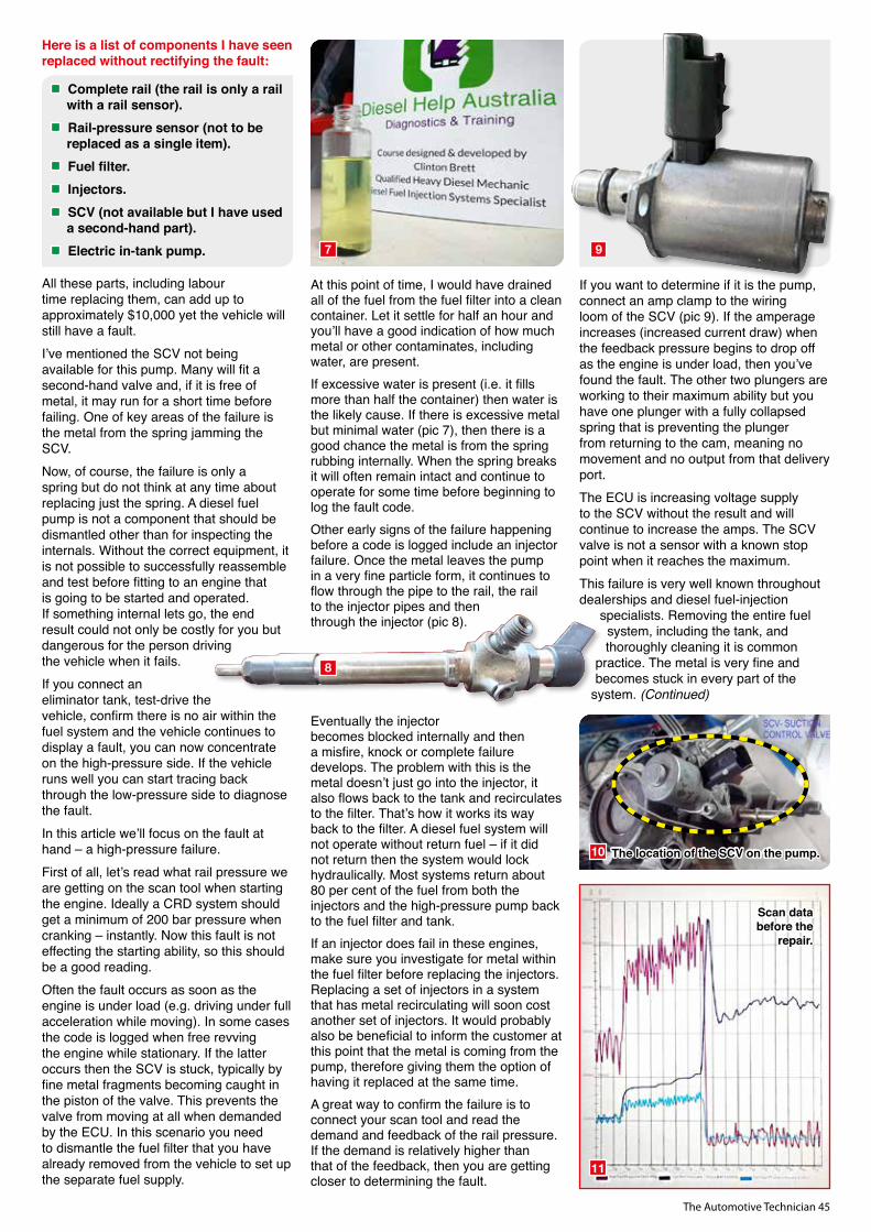
The Automotive Technician 45
Here is a list of components I have seen replaced without rectifying the fault:
Complete rail (the rail is only a rail with a rail sensor).
Rail-pressure sensor (not to be replaced as a single item).
Fuel filter. Injectors. SCV (not available but I have used a second-hand part).
Electric in-tank pump.
All these parts, including labour time replacing them, can add up to approximately $10,000 yet the vehicle will still have a fault.I’ve mentioned the SCV not being available for this pump. Many will fit a second-hand valve and, if it is free of metal, it may run for a short time before failing. One of key areas of the failure is the metal from the spring jamming the SCV.Now, of course, the failure is only a spring but do not think at any time about replacing just the spring. A diesel fuel pump is not a component that should be dismantled other than for inspecting the internals. Without the correct equipment, it is not possible to successfully reassemble and test before fitting to an engine that is going to be started and operated. If something internal lets go, the end result could not only be costly for you but dangerous for the person driving the vehicle when it fails.If you connect an eliminator tank, test-drive the vehicle, confirm there is no air within the fuel system and the vehicle continues to display a fault, you can now concentrate on the high-pressure side. If the vehicle runs well you can start tracing back through the low-pressure side to diagnose the fault.In this article we’ll focus on the fault at hand – a high-pressure failure.First of all, let’s read what rail pressure we are getting on the scan tool when starting the engine. Ideally a CRD system should get a minimum of 200 bar pressure when cranking – instantly. Now this fault is not effecting the starting ability, so this should be a good reading.Often the fault occurs as soon as the engine is under load (e.g. driving under full acceleration while moving). In some cases the code is logged when free revving the engine while stationary. If the latter occurs then the SCV is stuck, typically by fine metal fragments becoming caught in the piston of the valve. This prevents the valve from moving at all when demanded by the ECU. In this scenario you need to dismantle the fuel filter that you have already removed from the vehicle to set up the separate fuel supply.
At this point of time, I would have drained all of the fuel from the fuel filter into a clean container. Let it settle for half an hour and you’ll have a good indication of how much metal or other contaminates, including water, are present.If excessive water is present (i.e. it fills more than half the container) then water is the likely cause. If there is excessive metal but minimal water (pic 7), then there is a good chance the metal is from the spring rubbing internally. When the spring breaks it will often remain intact and continue to operate for some time before beginning to log the fault code.Other early signs of the failure happening before a code is logged include an injector failure. Once the metal leaves the pump in a very fine particle form, it continues to flow through the pipe to the rail, the rail to the injector pipes and then through the injector (pic 8).
Eventually the injector becomes blocked internally and then a misfire, knock or complete failure develops. The problem with this is the metal doesn’t just go into the injector, it also flows back to the tank and recirculates to the filter. That’s how it works its way back to the filter. A diesel fuel system will not operate without return fuel – if it did not return then the system would lock hydraulically. Most systems return about 80 per cent of the fuel from both the injectors and the high-pressure pump back to the fuel filter and tank.If an injector does fail in these engines, make sure you investigate for metal within the fuel filter before replacing the injectors. Replacing a set of injectors in a system that has metal recirculating will soon cost another set of injectors. It would probably also be beneficial to inform the customer at this point that the metal is coming from the pump, therefore giving them the option of having it replaced at the same time.A great way to confirm the failure is to connect your scan tool and read the demand and feedback of the rail pressure. If the demand is relatively higher than that of the feedback, then you are getting closer to determining the fault.
If you want to determine if it is the pump, connect an amp clamp to the wiring loom of the SCV (pic 9). If the amperage increases (increased current draw) when the feedback pressure begins to drop off as the engine is under load, then you’ve found the fault. The other two plungers are working to their maximum ability but you have one plunger with a fully collapsed spring that is preventing the plunger from returning to the cam, meaning no movement and no output from that delivery port. The ECU is increasing voltage supply to the SCV without the result and will continue to increase the amps. The SCV valve is not a sensor with a known stop point when it reaches the maximum.This failure is very well known throughout dealerships and diesel fuel-injection
specialists. Removing the entire fuel system, including the tank, and thoroughly cleaning it is common
practice. The metal is very fine and becomes stuck in every part of the
system. (Continued)
7 9
8
10
11
The location of the SCV on the pump.
Scan databefore the
repair.

The Automotive Technician 46
(Continued) At any given time metal may dislodge and flow to another injector, causing a failure. I have been involved with a lot of diagnostic work on these vehicles and anywhere from 40,000km up to 150,000km seems to be the average life of this pump.
Would I recommend replacing the injectors at the same time if the pump has a broken spring? Yes, but only if you have removed and tested them to find out if they are damaged or not.
It is best you have your injectors tested by a diesel fuel-injection specialist that has an actual test bench for CRD injectors. This will help determine all the internal settings are correct. Knowing the spring has broken means there will be metal up in the tiny nooks and crannies of the high-pressure system that will eventually become stuck elsewhere.
How do you determine the spring is broken once you have removed the pump? See pictures 13 to 15 to determine what component you are looking to remove.
It’s really simple to dismantle this section of the pump. There are three to remove and, don’t worry, the spring is not under much tension, so it’s not going to fly out at high speed and take your eye out.
Clinton Brett is a leading diagnostic diesel trainer. For courses and more information visit www.dieseldoat.com
Bad scan prior to replacement.
Good scan following repair.
The high-pressure fuel pump.
The dismantled plunger assembly…
… which reveals the broken spring.Good scan following replacement.
12a
13
14
15
12b
12c
Mackay Consolidated Industries Pty. Ltd. ABN 72 006 962 401 260 Chesterville Road (PO Box 1113) Moorabbin Victoria 3189 Australia
1300 020 374 www.mackayrubber.com.au
Since 1932 Mackay has provided quality cooling solutions for both original equipment manufacturers and the aftermarket.
Mackay is at the leading edge of research and development, determined to continuously improve the performance and reliability of our products.
Our products are engineered and manufactured to meet the most demanding specifications.
With 5000 Coolant Hoses in our range, you can rely on MACKAY
MOuLDED HOSE
HEATER TAPS
FLEXIBLE HOSE
Z HOSE
UNIVERSAL HOSE BENDS
BLANKING CAPS
HEATER HOSE BULK PACKS
COOLING SOLUTIONSPERFORMANCE RELIABILITY
Online catalogue Searchwww.mackayrubber.com.au/content/online-catalogue-search/
100% Australian owned company since 1932hsy autoparts is an importer and distributer of OEM (original equipment manufacturers), genuine and aftermarket spare parts to suit: AUDI, BMW, VW Mercedes, Saab, Skoda, Smart, Mini, Peugeot and Volvo. With branches all over Australia we are just a short delivery away.
C
M
Y
CM
MY
CY
CMY
K
pp 11 Hsy hph June 2017 RJ Approved.pdf 1 13/07/2017 2:58 PM

The Automotive Technician 47
Mackay Consolidated Industries Pty. Ltd. ABN 72 006 962 401 260 Chesterville Road (PO Box 1113) Moorabbin Victoria 3189 Australia
1300 020 374 www.mackayrubber.com.au
Since 1932 Mackay has provided quality cooling solutions for both original equipment manufacturers and the aftermarket.
Mackay is at the leading edge of research and development, determined to continuously improve the performance and reliability of our products.
Our products are engineered and manufactured to meet the most demanding specifications.
With 5000 Coolant Hoses in our range, you can rely on MACKAY
MOuLDED HOSE
HEATER TAPS
FLEXIBLE HOSE
Z HOSE
UNIVERSAL HOSE BENDS
BLANKING CAPS
HEATER HOSE BULK PACKS
COOLING SOLUTIONSPERFORMANCE RELIABILITY
Online catalogue Searchwww.mackayrubber.com.au/content/online-catalogue-search/
100% Australian owned company since 1932
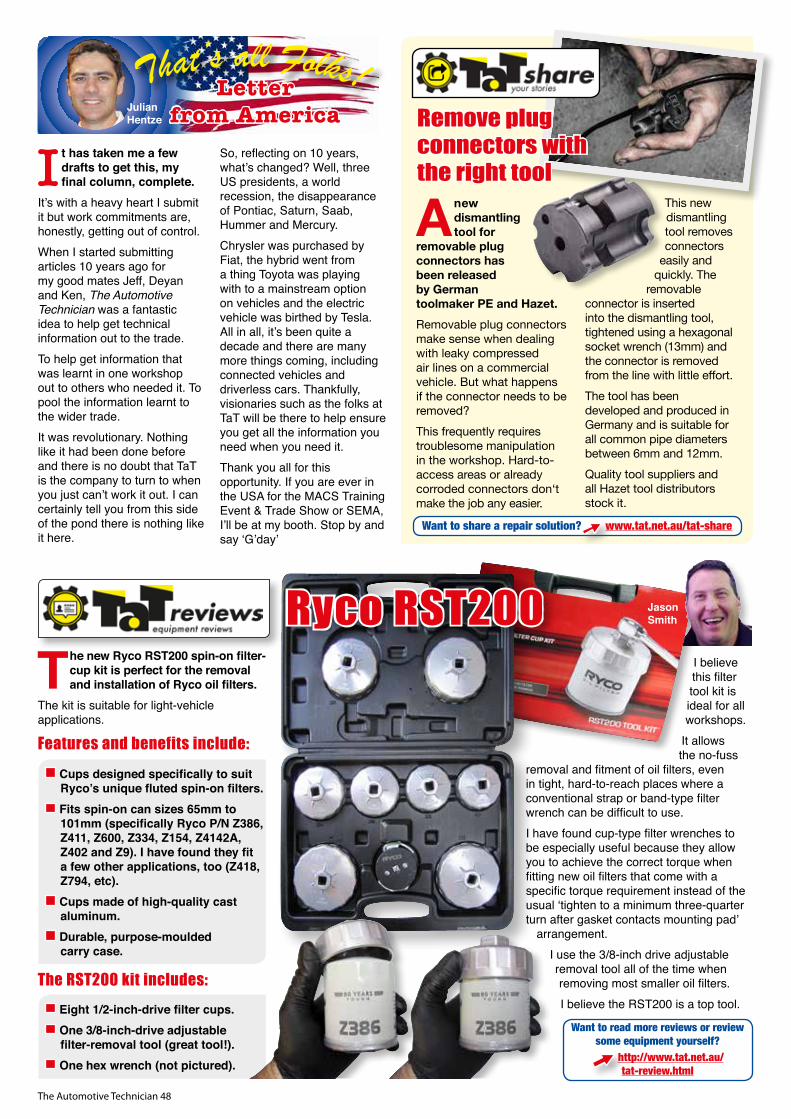
The Automotive Technician 48
I t has taken me a few drafts to get this, my final column, complete.
It’s with a heavy heart I submit it but work commitments are, honestly, getting out of control. When I started submitting articles 10 years ago for my good mates Jeff, Deyan and Ken, The Automotive Technician was a fantastic idea to help get technical information out to the trade. To help get information that was learnt in one workshop out to others who needed it. To pool the information learnt to the wider trade. It was revolutionary. Nothing like it had been done before and there is no doubt that TaT is the company to turn to when you just can’t work it out. I can certainly tell you from this side of the pond there is nothing like it here.
So, reflecting on 10 years, what’s changed? Well, three US presidents, a world recession, the disappearance of Pontiac, Saturn, Saab, Hummer and Mercury. Chrysler was purchased by Fiat, the hybrid went from a thing Toyota was playing with to a mainstream option on vehicles and the electric vehicle was birthed by Tesla. All in all, it’s been quite a decade and there are many more things coming, including connected vehicles and driverless cars. Thankfully, visionaries such as the folks at TaT will be there to help ensure you get all the information you need when you need it.Thank you all for this opportunity. If you are ever in the USA for the MACS Training Event & Trade Show or SEMA, I’ll be at my booth. Stop by and say ‘G’day’
Julian Hentze
Letterfrom America
The new Ryco RST200 spin-on filter-cup kit is perfect for the removal and installation of Ryco oil filters.
The kit is suitable for light-vehicle applications.
Features and benefits include:
Cups designed specifically to suit Ryco’s unique fluted spin-on filters.
Fits spin-on can sizes 65mm to 101mm (specifically Ryco P/N Z386, Z411, Z600, Z334, Z154, Z4142A, Z402 and Z9). I have found they fit a few other applications, too (Z418, Z794, etc).
Cups made of high-quality cast aluminum.
Durable, purpose-moulded carry case.
The RST200 kit includes:
Eight 1/2-inch-drive filter cups. One 3/8-inch-drive adjustable filter-removal tool (great tool!).
One hex wrench (not pictured).
I believe this filter tool kit is ideal for all workshops.
It allows the no-fuss
removal and fitment of oil filters, even in tight, hard-to-reach places where a conventional strap or band-type filter wrench can be difficult to use.I have found cup-type filter wrenches to be especially useful because they allow you to achieve the correct torque when fitting new oil filters that come with a specific torque requirement instead of the usual ‘tighten to a minimum three-quarter turn after gasket contacts mounting pad’
arrangement.I use the 3/8-inch drive adjustable removal tool all of the time when removing most smaller oil filters.I believe the RST200 is a top tool.
Want to read more reviews or review some equipment yourself?
http://www.tat.net.au/tat-review.html
Jason SmithRyco RST200
A new dismantling tool for
removable plug connectors has been released by German toolmaker PE and Hazet.Removable plug connectors make sense when dealing with leaky compressed air lines on a commercial vehicle. But what happens if the connector needs to be removed? This frequently requires troublesome manipulation in the workshop. Hard-to- access areas or already corroded connectors don‘t make the job any easier.
This new dismantling tool removes connectors
easily and quickly. The
removable connector is inserted into the dismantling tool, tightened using a hexagonal socket wrench (13mm) and the connector is removed from the line with little effort.The tool has been developed and produced in Germany and is suitable for all common pipe diameters between 6mm and 12mm.Quality tool suppliers and all Hazet tool distributors stock it.
Remove plug connectors with the right tool
Want to share a repair solution? www.tat.net.au/tat-share
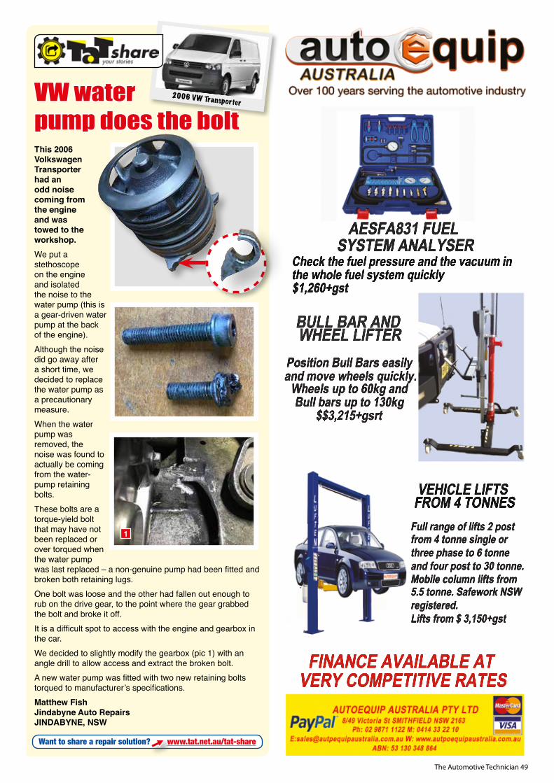
The Automotive Technician 49
This 2006 Volkswagen Transporter had an odd noise coming from the engine and was towed to the workshop.We put a stethoscope on the engine and isolated the noise to the water pump (this is a gear-driven water pump at the back of the engine). Although the noise did go away after a short time, we decided to replace the water pump as a precautionary measure.When the water pump was removed, the noise was found to actually be coming from the water-pump retaining bolts. These bolts are a torque-yield bolt that may have not been replaced or over torqued when the water pump was last replaced – a non-genuine pump had been fitted and broken both retaining lugs. One bolt was loose and the other had fallen out enough to rub on the drive gear, to the point where the gear grabbed the bolt and broke it off. It is a difficult spot to access with the engine and gearbox in the car. We decided to slightly modify the gearbox (pic 1) with an angle drill to allow access and extract the broken bolt. A new water pump was fitted with two new retaining bolts torqued to manufacturer’s specifications.Matthew FishJindabyne Auto RepairsJINDABYNE, NSW
2006 VW TransporterVW water pump does the bolt
1
Want to share a repair solution? www.tat.net.au/tat-share

The Automotive Technician 50
PH 1300 BURSON (1300 28 77 66)
trust your equipment!
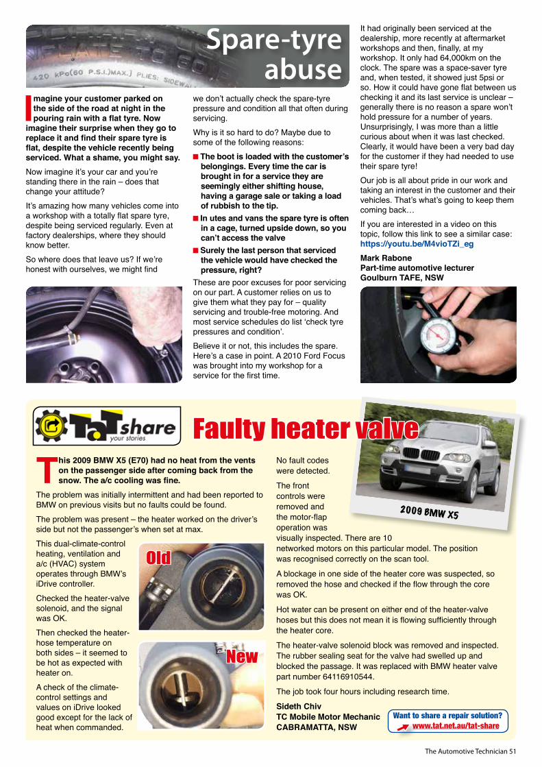
The Automotive Technician 51
This 2009 BMW X5 (E70) had no heat from the vents on the passenger side after coming back from the snow. The a/c cooling was fine.
The problem was initially intermittent and had been reported to BMW on previous visits but no faults could be found.The problem was present – the heater worked on the driver’s side but not the passenger’s when set at max. This dual-climate-control heating, ventilation and a/c (HVAC) system operates through BMW’s iDrive controller. Checked the heater-valve solenoid, and the signal was OK.Then checked the heater-hose temperature on both sides – it seemed to be hot as expected with heater on.A check of the climate-control settings and values on iDrive looked good except for the lack of heat when commanded.
No fault codes were detected.
The front controls were removed and the motor-flap operation was visually inspected. There are 10 networked motors on this particular model. The position was recognised correctly on the scan tool.
A blockage in one side of the heater core was suspected, so removed the hose and checked if the flow through the core was OK.
Hot water can be present on either end of the heater-valve hoses but this does not mean it is flowing sufficiently through the heater core.
The heater-valve solenoid block was removed and inspected. The rubber sealing seat for the valve had swelled up and blocked the passage. It was replaced with BMW heater valve part number 64116910544.
The job took four hours including research time.
Sideth ChivTC Mobile Motor MechanicCABRAMATTA, NSW
2009 BMW X5
Faulty heater valve
Want to share a repair solution? www.tat.net.au/tat-share
Old
New
PH 1300 BURSON (1300 28 77 66)
trust your equipment!
Imagine your customer parked on the side of the road at night in the pouring rain with a flat tyre. Now
imagine their surprise when they go to replace it and find their spare tyre is flat, despite the vehicle recently being serviced. What a shame, you might say.Now imagine it’s your car and you’re standing there in the rain – does that change your attitude?It’s amazing how many vehicles come into a workshop with a totally flat spare tyre, despite being serviced regularly. Even at factory dealerships, where they should know better.So where does that leave us? If we’re honest with ourselves, we might find
we don’t actually check the spare-tyre pressure and condition all that often during servicing. Why is it so hard to do? Maybe due to some of the following reasons:
The boot is loaded with the customer’s belongings. Every time the car is brought in for a service they are seemingly either shifting house, having a garage sale or taking a load of rubbish to the tip.
In utes and vans the spare tyre is often in a cage, turned upside down, so you can’t access the valve
Surely the last person that serviced the vehicle would have checked the pressure, right?
These are poor excuses for poor servicing on our part. A customer relies on us to give them what they pay for – quality servicing and trouble-free motoring. And most service schedules do list ‘check tyre pressures and condition’. Believe it or not, this includes the spare. Here’s a case in point. A 2010 Ford Focus was brought into my workshop for a service for the first time.
It had originally been serviced at the dealership, more recently at aftermarket workshops and then, finally, at my workshop. It only had 64,000km on the clock. The spare was a space-saver tyre and, when tested, it showed just 5psi or so. How it could have gone flat between us checking it and its last service is unclear – generally there is no reason a spare won’t hold pressure for a number of years. Unsurprisingly, I was more than a little curious about when it was last checked. Clearly, it would have been a very bad day for the customer if they had needed to use their spare tyre!Our job is all about pride in our work and taking an interest in the customer and their vehicles. That’s what’s going to keep them coming back…If you are interested in a video on this topic, follow this link to see a similar case: https://youtu.be/M4vioTZi_egMark RabonePart-time automotive lecturerGoulburn TAFE, NSW
Spare-tyre abuse
The Automotive Technician 52
Diagnostics and aftermarket training
Clinton Brett brings more than 20 years of experience to diesel fuel injection. A fifth-generation mechanic, Clinton diagnoses diesel faults around the world by phone, email or video link and conducts live common-rail diesel diagnostics training courses for all automotive repairers and the fleet-servicing industry.
Here is his current course program: All training sessions include dinner, booklet and three months trial to Diesel Help phone assistance. Prices quoted are per person and all courses are limited to 15 attendees.
Tues 15 August – North Metropolitan TAFE, Corner Eddie Barron Dve and Lloyd St, Midland, WA
Wed 16 August – South Metropolitan TAFE, Oats and Banks St, Carlisle, WA
Thurs 17 August – South Regional TAFE, Robertson Dve, Bunbury, WA
Tues 5 September – Canberra TAFE, 81 Mildura St, Fyshwick, ACT
Wed 6 September – Nth Sydney Institute, 205 Peats Ferry Rd, Hornsby, NSWThurs 7 September – St George College, Cnr President Ave and Princes Hwy, Kogarah, NSWTues 12 September – TAFE SA, 137 Days Rd, Regency Park, SAWed 13 September – Bosch, 1555 Centre Rd, Clayton, VIC
Tues 10 October – North Coast TAFE, 1 Clarence St Grafton, NSWWed 11 October – TAFE NSW, Beardy St, Armidale, NSWThurs 12 October – TAFE New England, 13 Janison St, Tamworth, NSWDates and locations are subject to change. Check the AutoPartners website and book early.
Dates and locations are subject to change. Check the www.dieseldoat.com website and book early.More information: www.dieseldoat.com [email protected] Clinton Brett 0432 738 003
Course: CRDFS1.0: Six hours of diesel-fuel-systems training. ‘The real on-vehicle diagnostic experience.’Sat 19 August – Anthony’s Car and Head Service, Bega, NSWSat 26 August – Scott Doneys Autos, Sydney, NSWSat 2nd September – Wildcat Diesel Pty Ltd, Adelaide, SA, Sat 9th September – Future Auto North Lakes, Brisbane, QLDMon 11th and Tue 12th September – TAS TAFE, Hobart, TASSat 16th September – TAS TAFE, Burnie, TASMon 18th and Tue 19th September – TAS TAFE, Launceston, TASMon 23rd and Tue 24th October – QLD TAFE, Gold Coast, QLD
Course: CRDFS2.0: Three hours of air intake, EGR, VGT turbo and emissions.
‘Not just about fuel’ diagnostics training.Tue 23rd August – Barrie Auto Electrics, Hornsby, Sydney, NSWWed 13th September – TAS TAFE, Hobart, TASThu 14th September – TAS TAFE, Burnie, TASWed 20th September – TAS TAFE, Launceston, TASWed 25th October – QLD TAFE, Gold Coast, QLD
Auto Partners free trade nightsThe AutoPartners free trade night includes presentations from top automotive brands, together with a presentation from TaT head trainer Jeff Smit on the mechanics of diagnostics. This is a whole new presentation on the logical mechanical process of diagnostics. Those who attend will gain a great deal of information that will be useful in their in future diagnostics.
Call to make a booking on: 1300 650 048 or visit: www.autopartners.com.au
A technical training session with TaT head trainer Jeff Smit has been built into the forthcoming series of
Capricorn Gala Dinners and Tradeshows.Jeff Smit will present a practical and topical training session on the mechanics of diagnostics.
The 1.5 hour training session will be run immediately prior to the tradeshow, which is followed by the dinner.
These training sessions are run in a relaxed environment and are great warm-up to the trade show. Capricorn members should contact their area manager for bookings.
SA – 2nd SeptemberNSW – 16th SeptemberNZ – 7th OctoberWA – 28th OctoberVIC – 11th NovemberQLD – 18th November
Training with dinner
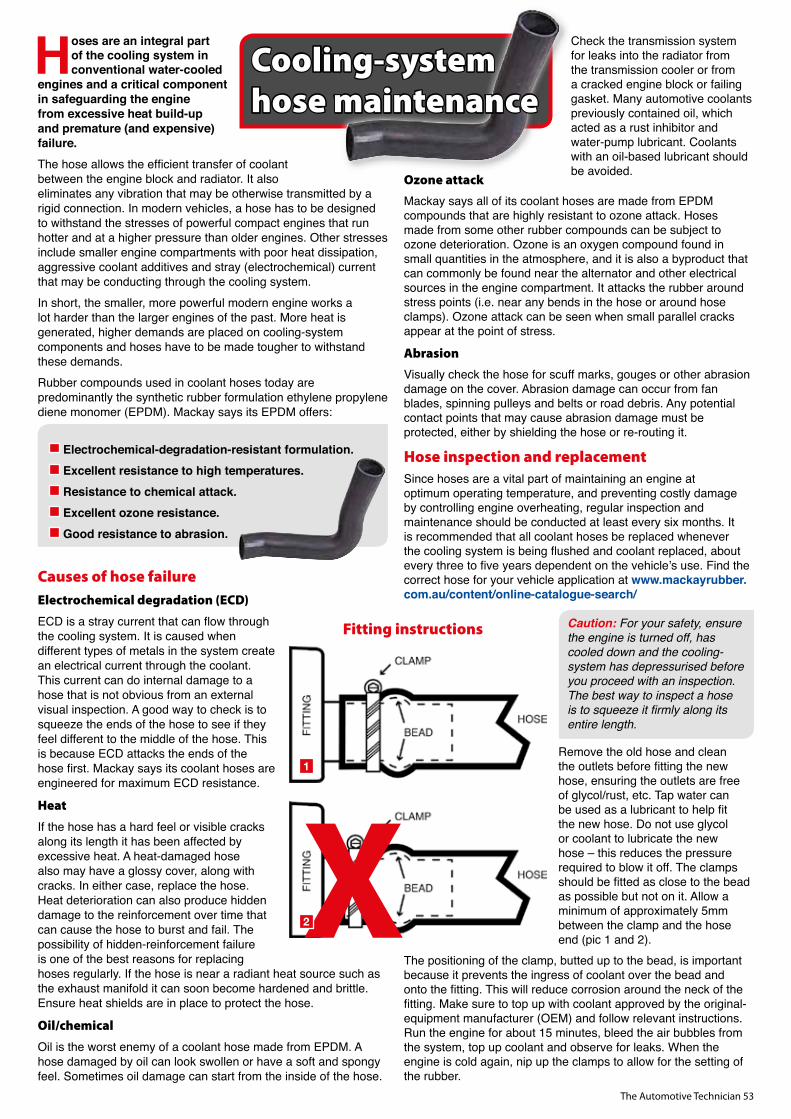
The Automotive Technician 53
Hoses are an integral part of the cooling system in conventional water-cooled
engines and a critical component in safeguarding the engine from excessive heat build-up and premature (and expensive) failure.The hose allows the efficient transfer of coolant between the engine block and radiator. It also eliminates any vibration that may be otherwise transmitted by a rigid connection. In modern vehicles, a hose has to be designed to withstand the stresses of powerful compact engines that run hotter and at a higher pressure than older engines. Other stresses include smaller engine compartments with poor heat dissipation, aggressive coolant additives and stray (electrochemical) current that may be conducting through the cooling system.In short, the smaller, more powerful modern engine works a lot harder than the larger engines of the past. More heat is generated, higher demands are placed on cooling-system components and hoses have to be made tougher to withstand these demands.Rubber compounds used in coolant hoses today are predominantly the synthetic rubber formulation ethylene propylene diene monomer (EPDM). Mackay says its EPDM offers:
Electrochemical-degradation-resistant formulation. Excellent resistance to high temperatures. Resistance to chemical attack. Excellent ozone resistance. Good resistance to abrasion.
Causes of hose failure
Electrochemical degradation (ECD)
ECD is a stray current that can flow through the cooling system. It is caused when different types of metals in the system create an electrical current through the coolant. This current can do internal damage to a hose that is not obvious from an external visual inspection. A good way to check is to squeeze the ends of the hose to see if they feel different to the middle of the hose. This is because ECD attacks the ends of the hose first. Mackay says its coolant hoses are engineered for maximum ECD resistance.
Heat
If the hose has a hard feel or visible cracks along its length it has been affected by excessive heat. A heat-damaged hose also may have a glossy cover, along with cracks. In either case, replace the hose. Heat deterioration can also produce hidden damage to the reinforcement over time that can cause the hose to burst and fail. The possibility of hidden-reinforcement failure is one of the best reasons for replacing hoses regularly. If the hose is near a radiant heat source such as the exhaust manifold it can soon become hardened and brittle. Ensure heat shields are in place to protect the hose.
Oil/chemical
Oil is the worst enemy of a coolant hose made from EPDM. A hose damaged by oil can look swollen or have a soft and spongy feel. Sometimes oil damage can start from the inside of the hose.
Check the transmission system for leaks into the radi ator from the transmission cooler or from a cracked engine block or failing gasket. Many automotive coolants previously contained oil, which acted as a rust inhibitor and water-pump lubricant. Coolants with an oil-based lubricant should be avoided.
Ozone attackMackay says all of its coolant hoses are made from EPDM compounds that are highly resistant to ozone attack. Hoses made from some other rubber compounds can be subject to ozone deterioration. Ozone is an oxygen compound found in small quantities in the atmosphere, and it is also a byproduct that can commonly be found near the alternator and other electrical sources in the engine compartment. It attacks the rubber around stress points (i.e. near any bends in the hose or around hose clamps). Ozone attack can be seen when small parallel cracks appear at the point of stress.
AbrasionVisually check the hose for scuff marks, gouges or other abrasion damage on the cover. Abrasion damage can occur from fan blades, spinning pulleys and belts or road debris. Any potential contact points that may cause abrasion damage must be protected, either by shielding the hose or re-routing it.
Hose inspection and replacementSince hoses are a vital part of maintaining an engine at optimum operating temperature, and preventing costly damage by controlling engine overheating, regular inspection and maintenance should be con ducted at least every six months. It is recommended that all coolant hoses be replaced whenever the cooling system is being flushed and coolant replaced, about every three to five years dependent on the vehicle’s use. Find the correct hose for your vehicle application at www.mackayrubber.com.au/content/online-catalogue-search/
Caution: For your safety, ensure the engine is turned off, has cooled down and the cooling-system has depressurised before you proceed with an inspection. The best way to inspect a hose is to squeeze it firmly along its entire length.
Remove the old hose and clean the outlets before fitting the new hose, ensuring the outlets are free of glycol/rust, etc. Tap water can be used as a lubricant to help fit the new hose. Do not use glycol or coolant to lubricate the new hose – this reduces the pressure required to blow it off. The clamps should be fitted as close to the bead as possible but not on it. Allow a minimum of approximately 5mm between the clamp and the hose end (pic 1 and 2).
The positioning of the clamp, butted up to the bead, is important because it prevents the ingress of coolant over the bead and onto the fitting. This will reduce corrosion around the neck of the fitting. Make sure to top up with coolant approved by the original-equipment manufacturer (OEM) and follow relevant instructions. Run the engine for about 15 minutes, bleed the air bubbles from the system, top up coolant and observe for leaks. When the engine is cold again, nip up the clamps to allow for the setting of the rubber.
Cooling-system hose maintenance
X1
2
Fitting instructions
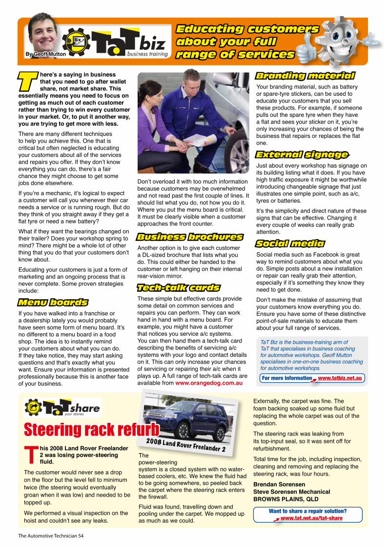
The Automotive Technician 54
T here’s a saying in business that you need to go after wallet share, not market share. This
essentially means you need to focus on getting as much out of each customer rather than trying to win every customer in your market. Or, to put it another way, you are trying to get more with less.There are many different techniques to help you achieve this. One that is critical but often neglected is educating your customers about all of the services and repairs you offer. If they don’t know everything you can do, there’s a fair chance they might choose to get some jobs done elsewhere.If you’re a mechanic, it’s logical to expect a customer will call you whenever their car needs a service or is running rough. But do they think of you straight away if they get a flat tyre or need a new battery?What if they want the bearings changed on their trailer? Does your workshop spring to mind? There might be a whole lot of other thing that you do that your customers don’t know about.Educating your customers is just a form of marketing and an ongoing process that is never complete. Some proven strategies include:
Menu boardsIf you have walked into a franchise or a dealership lately you would probably have seen some form of menu board. It’s no different to a menu board in a food shop. The idea is to instantly remind your customers about what you can do. If they take notice, they may start asking questions and that’s exactly what you want. Ensure your information is presented professionally because this is another face of your business.
Don’t overload it with too much information because customers may be overwhelmed and not read past the first couple of lines. It should list what you do, not how you do it. Where you put the menu board is critical. It must be clearly visible when a customer approaches the front counter.
Business brochuresAnother option is to give each customer a DL-sized brochure that lists what you do. This could either be handed to the customer or left hanging on their internal rear-vision mirror.
Tech-talk cardsThese simple but effective cards provide some detail on common services and repairs you can perform. They can work hand in hand with a menu board. For example, you might have a customer that notices you service a/c systems. You can then hand them a tech-talk card describing the benefits of servicing a/c systems with your logo and contact details on it. This can only increase your chances of servicing or repairing their a/c when it plays up. A full range of tech-talk cards are available from www.orangedog.com.au
Branding materialYour branding material, such as battery or spare-tyre stickers, can be used to educate your customers that you sell these products. For example, if someone pulls out the spare tyre when they have a flat and sees your sticker on it, you’re only increasing your chances of being the business that repairs or replaces the flat one.
External signageJust about every workshop has signage on its building listing what it does. If you have high traffic exposure it might be worthwhile introducing changeable signage that just illustrates one simple point, such as a/c, tyres or batteries. It’s the simplicity and direct nature of these signs that can be effective. Changing it every couple of weeks can really grab attention.
Social mediaSocial media such as Facebook is great way to remind customers about what you do. Simple posts about a new installation or repair can really grab their attention, especially if it’s something they know they need to get done.Don’t make the mistake of assuming that your customers know everything you do. Ensure you have some of these distinctive point-of-sale materials to educate them about your full range of services.
For more information www.tatbiz.net.au
TaT Biz is the business-training arm of TaT that specialises in business coaching for automotive workshops. Geoff Mutton specialises in one-on-one business coaching for automotive workshops.
By Geoff Mutton
Educating customers about your full range of services
This 2008 Land Rover Freelander 2 was losing power-steering fluid.
The customer would never see a drop on the floor but the level fell to minimum twice (the steering would eventually groan when it was low) and needed to be topped up.
We performed a visual inspection on the hoist and couldn’t see any leaks.
The power-steering system is a closed system with no water-based coolers, etc. We knew the fluid had to be going somewhere, so peeled back the carpet where the steering rack enters the firewall.Fluid was found, travelling down and pooling under the carpet. We mopped up as much as we could.
Externally, the carpet was fine. The foam backing soaked up some fluid but replacing the whole carpet was out of the question.
The steering rack was leaking from its top-input seal, so it was sent off for refurbishment.
Total time for the job, including inspection, cleaning and removing and replacing the steering rack, was four hours.
Brendan SorensenSteve Sorensen MechanicalBROWNS PLAINS, QLD
2008 Land Rover Freelander 2
Steering rack refurb
Want to share a repair solution?www.tat.net.au/tat-share
The Automotive Technician 55
The standard in Auto Parts
• Steering & Suspension
• Radiators, Condensers
• Water Pumps, Coolant
• Power Steering
• Hydraulics
• Disc Pads & Shoes
• Disc Rotors & Drums
• Clutch Components
• Driveline
The Brand ThatDELIVERS
www.protexparts.com.auReseller Enquiries: (03) 8369 1300
RANGE • QUALITY • TECHNOLOGY • INNOVATION
protex general 2017.indd 1 16/02/2017 1:29:00 PM

C O M P L E T E S O L U T I O N S
Complete Ignition Solutions from the world’s largest ignition
component manufacturer.
All NGK ignition components are designed specifically to suit
individual engine applications and are manufactured to match
or exceed original equipment specifications.
DON’T COMPROMISE ON QUALITY, RELY ON NGK. ngk.com.auNGK Spark Plugs Australia
NGK002817_NGK_AusWorkshopManager_Jul/Aug_297x210mm_FINAL.indd 1 21/6/17 11:18 am