cldfnd 210-451 - official cert guide
TRANSCRIPT
ptg17120290
ptg17120290
Cisco Press800 East 96th Street
Indianapolis, IN 46240
CCNA CloudCLDFND 210-451
Official Cert Guide
GUSTAVO A. A. SANTANA, CCIE No. 8806
ptg17120290
CCNA Cloud CLDFND 210-451 Official Cert GuideGustavo A. A. Santana
Copyright© 2016 Pearson Education, Inc.
Published by:Cisco Press800 East 96th Street Indianapolis, IN 46240 USA
All rights reserved. No part of this book may be reproduced or transmitted in any form or by any means, electronic or mechanical, including photocopying, recording, or by any information storage and retrieval system, without written permission from the publisher, except for the inclusion of brief quotations in a review.
Printed in the United States of America
First Printing April 2016
Library of Congress Control Number: 2015957536
ISBN-13: 978-1-58714-700-5
ISBN-10: 1-58714-7009
Warning and DisclaimerThis book is designed to provide information about the CCNA Cloud CLDFND 210-451 exam. Every effort has been made to make this book as complete and as accurate as possible, but no warranty or fitness is implied.
The information is provided on an “as is” basis. The author, Cisco Press, and Cisco Systems, Inc. shall have neither liability nor responsibility to any person or entity with respect to any loss or damages arising from the information contained in this book or from the use of the discs or programs that may accompany it.
The opinions expressed in this book belong to the author and are not necessarily those of Cisco Systems, Inc.
Trademark AcknowledgmentsAll terms mentioned in this book that are known to be trademarks or service marks have been appropriately capitalized. Cisco Press or Cisco Systems, Inc. cannot attest to the accuracy of this information. Use of a term in this book should not be regarded as affecting the validity of any trademark or service mark.
Publisher: Paul Boger Associate Publisher: Dave Dusthimer
Business Operation Manager, Cisco Press: Jan Cornelssen Acquisitions Editor: Denise Lincoln
Managing Editor: Sandra Schroeder Development Editor: Ellie Bru
Project Editor: Mandie Frank Copy Editor: Bill McManus
Technical Editors: Fernando de Almeida, Adilson Silva Editorial Assistant: Vanessa Evans
Designer: Mark Shirar Composition: Trina Wurst
Senior Indexer: Cheryl Lenser Proofreader: The Wordsmithery LLC
ii CCNA Cloud CLDFND 210-451 Official Cert Guide
ptg17120290
Figure AttributionsFigure 4-15: “airplane cockpit” [92430886] © Sergey Bogdanov
Figure 5-1: “Процессор” [77587032]© Bashkirov, “Some module DDR RAM memory computer on white background” [77697137] © peuceta, “HDD on whitre” [75921949] © Natalia Merzlyakova, “con-nectivity problem concept with lan cable & network card” [54429846] © Bacho Foto
Figure 8-1: “Stack of DDR RAM sticks on isolated background” [57415022] © finallast, “Computer hard drives stack” [73144222] © destina, “data center” [54917331] © kubais
Figure 8-11: “disco duro” [38666746] © estionx, “Connectors cable ATA and IDE interface for com-puter” [53636918] © dmitrydesigner
Figure 8-12: “Harddisk drive, close up image of device” [68745710] © charcomphoto, “SATA cable” [8713125] © Vladimir Agapov
Figure 14-5: “Auto parts store. Automotive basket shop” [64856957] © Oleksandr Delyk, “Red body car” [60704600] © Cla78, “Red roadster” [62654792] © Vladimir Kramin
Special SalesFor information about buying this title in bulk quantities, or for special sales opportunities (which may include electronic versions; custom cover designs; and content particular to your business, training goals, marketing focus, or branding interests), please contact our corporate sales department at [email protected] or (800) 382-3419.
For government sales inquiries, please contact [email protected].
For questions about sales outside the United States, please contact [email protected].
Feedback InformationAt Cisco Press, our goal is to create in-depth technical books of the highest quality and value. Each book is crafted with care and precision, undergoing rigorous development that involves the unique expertise of members from the professional technical community.
Readers’ feedback is a natural continuation of this process. If you have any comments regarding how we could improve the quality of this book, or otherwise alter it to better suit your needs, you can contact us through email at [email protected]. Please make sure to include the book title and ISBN in your message.
We greatly appreciate your assistance.
iii
ptg17120290
About the AuthorGustavo A. A. Santana, CCIE No. 8806, is the author of Data Center Virtualization
Fundamentals (CiscoPress, 2013) and a Cisco Technical Solutions Architect working in enterprise and service provider data center projects that require a greater integration among multiple technology areas such as networking, application optimization, storage, and servers.
With more than 18 years of experience in the data center industry, Gustavo has led and coordinated a team of specialized Cisco engineers in Brazil. A true believer of education as a technology catalyst, he has also dedicated himself to the technical development of many IT professionals from customer, partner, and strategic alliance organizations. In addition to holding three CCIE certifications (Data Center, Storage Networking, and Routing & Switching), Gustavo is an SNIA Certified Storage Networking Expert (SCSN-E). A frequent speaker at Cisco Live and data center industry events, he holds a degree in computer engineering from Instituto Tecnológico de Aeronáutica (ITA-Brazil) and an MBA in strategic IT management from Fundação Getúlio Vargas (FGV-Brazil). Gustavo maintains a personal blog in which he discusses topics related to data center vir-tualization technologies at http://gustavoaasantana.net.
About the Technical ReviewersFernando de Almeida, CCIE No. 8831 (R&S and SP), has more than 18 years of experi-ence in telecommunications and networking. Fernando joined Cisco in 2000 as a TAC engineer and moved on to other functions in Advanced Services, focusing on service providers and enterprise customers. He has had active participation in design and imple-mentation of the biggest service providers in Latin America, in technologies such as MPLS, TE, VPLS, QoS, and BGP, and has worked as a Solutions Architect for the big-gest banks in Brazil, integrating key environments, such as core wide-area networks, data center networks, network security, and wireless networks. He has been a speaker at vari-ous network conferences (including Cisco Live), and he is currently involved in Internet of Things projects, mainly in Smart Grid. Before joining Cisco, Fernando worked as a pre-sales engineer and instructor at Nortel. He graduated with an electrical engineering degree and an MBA in IT management from Universidade de São Paulo.
Adilson Silva, CCIE No. 30110, is a Cisco Technical Solutions Architect at Cisco Systems involved in public and hybrid cloud Cisco architectures as well as cloud man-aged services solutions through Cisco partners. Adilson’s expertise includes data center virtualization, routing and switching, hypervisor solutions, and hybrid cloud using Cisco Intercloud Fabric solutions for business as well as for providers including Cisco Powered partners, Cisco Cloud Architecture for Microsoft, and OpenStack, which includes Cisco Metapod solutions for private customer clouds.
During his more than 14 years of experience in the networking industry, Adilson spent his last 7 years at Cisco Systems. In the last 3 years he has covered Cloud & Managed Services for the whole of the Latin America region.
In addition to holding his CCIE certification (Routing & Switching), Adilson holds a degree in science computing from Estácio University (Brazil) and an MBA in communica-tion services from Universidade Federal Fluminense (UFF-Brazil).
iv CCNA Cloud CLDFND 210-451 Official Cert Guide
ptg17120290
v
DedicationsThis book is dedicated to my wife and true love, Carlene. Besides being my unconditional supporter, she is also my co-author on two wonderful long-term projects: our daughters Carolina and Cecília. I wholeheartedly dedicate this writing to both of them, too.
I also dedicate this publication to my parents, Honorio and Cleia, who have taught me that one can only learn by being fearless and humble.
Finally, this book is dedicated to every person who is (or once was) a CCNA candidate. Your passion, commitment, and integrity are the strong threads that wove our connected world together.
ptg17120290
vi CCNA Cloud CLDFND 210-451 Official Cert Guide
AcknowledgmentsAlthough the cover of this book exhibits a single author, the many months of writing would be fruitless without the support of an entire network of relatives, friends, and professionals who are acknowledged here.
First, I would like to thank my sister Raquel and brother André for the family support during this book writing.
I would also like to express my gratitude to my friend and trusted advisor Alexandre M. S. P. Moraes, who has always shared with me his invaluable insights and experiences as a technical author.
Many thanks to Andrey Lee for the wonderful illustrations in Chapters 1 and 14.
Sincere thanks to my manager, Renier Souza, for actively helping me coordinate my pro-fessional life and this writing.
My thanks to the technical reviewers Adilson Silva and Fernando Almeida for their outstanding contributions and focus to make this work more effective for its targeted readership.
A personal thanks to the data center tiger team at Cisco Brazil, which has always served as my treasured “brain trust” for best practices and innovative ideas.
I am also very grateful to Simon Richards, Gordon Hirst, and all professionals behind Cisco Demo Cloud (dCloud), which was an inestimable tool for this book development.
Thanks to all the Pearson production team, especially Ellie Bru, Mandie Frank, and Bill McManus who helped me to create the final version of this book.
I will always be grateful to Mary Beth Ray and Anand Sundaram for giving me the unique opportunity of becoming a Cisco Press author back in 2012.
A very special thank you goes to Denise Lincoln, for trusting me with the honor of writ-ing this book and for the amazing support during its development.
ptg17120290
vii
Contents at a Glance
Introduction xxi
Part I Cloud Concepts
Chapter 1 What Is Cloud Computing? 3
Chapter 2 Cloud Shapes: Service Models 29
Part II Cloud Deployments
Chapter 3 Cloud Heights: Deployment Models 57
Chapter 4 Behind the Curtain 87
Part III Server Virtualization for Cloud
Chapter 5 Server Virtualization 119
Chapter 6 Infrastructure Virtualization 149
Chapter 7 Virtual Networking Services and Application Containers 187
Part IV Cloud Storage
Chapter 8 Block Storage Technologies 221
Chapter 9 File Storage Technologies 265
Part V Architectures for Cloud
Chapter 10 Network Architectures for the Data Center: Unified Fabric 301
Chapter 11 Network Architectures for the Data Center: SDN and ACI 363
Chapter 12 Unified Computing 407
Chapter 13 Cisco Cloud Infrastructure Portfolio 457
Chapter 14 Integrated Infrastructures 493
Chapter 15 Final Preparation 517
Glossary 523
Appendix A Answers to Pre-Assessments and Quizzes 539
Appendix B Memory Tables 543
Appendix C Answers to Memory Tables 561
Index 578
Appendix D Study Planner CD
ptg17120290
viii CCNA Cloud CLDFND 210-451 Official Cert Guide
ContentsIntroduction xxi
Part I Cloud Concepts
Chapter 1 What Is Cloud Computing? 3
“Do I Know This Already?” Quiz 3
Foundation Topics 7
Welcome to the Cloud Hype 7
Historical Steps Toward Cloud Computing 9
The Many Definitions of Cloud Computing 11
The Data Center 12
Common Cloud Characteristics 14
On-Demand Self-Service 14
Rapid Elasticity 16
Resource Pooling 17
Measured Service 19
Broad Network Access 20
Multi-tenancy 21
Classifying Clouds 22
Around the Corner: Agile, Cloud-Scale Applications, and DevOps 24
Further Reading 26
Exam Preparation Tasks 27
Review All the Key Topics 27
Complete the Tables and Lists from Memory 27
Define Key Terms 27
Chapter 2 Cloud Shapes: Service Models 29
“Do I Know This Already?” Quiz 29
Foundation Topics 32
Service Providers and Information Technology 32
Service-Level Agreement 34
Cloud Providers 34
Infrastructure as a Service 36
Regions and Availability Zones 38
IaaS Example: Amazon Web Services 39
Platform as a Service 43
PaaS Example: Microsoft Azure 45
Software as a Service 49
SaaS Examples 50
Around the Corner: Anything as a Service 52
Further Reading 53
ptg17120290
ix
Exam Preparation Tasks 54
Review All the Key Topics 54
Complete the Tables and Lists from Memory 54
Define Key Terms 54
Part II Cloud Deployments
Chapter 3 Cloud Heights: Deployment Models 57
“Do I Know This Already?” Quiz 57
Foundation Topics 61
Public Clouds 61
Risks and Challenges 62
Security 62
Control 63
Cost 64
Private Clouds 65
Community Clouds 67
Hybrid Clouds 69
Cisco Intercloud 70
Cisco Intercloud Fabric 73
Intercloud Fabric Architecture 74
Intercloud Fabric Services 76
Intercloud Fabric Use Cases 83
Around the Corner: Private Cloud as a Service 83
Further Reading 83
Exam Preparation Tasks 84
Review All the Key Topics 84
Complete the Tables and Lists from Memory 84
Define Key Terms 84
Chapter 4 Behind the Curtain 87
“Do I Know This Already?” Quiz 87
Foundation Topics 89
Cloud Computing Architecture 89
Cloud Portal 90
Cloud Orchestrator 94
Cloud Meter 97
Cloud Infrastructure: Journey to the Cloud 99
Consolidation 100
Virtualization 102
Standardization 103
ptg17120290
x CCNA Cloud CLDFND 210-451 Official Cert Guide
Automation 103
Orchestration 104
Application Programming Interfaces 105
CLI vs API 106
RESTful APIs 111
Around the Corner: OpenStack 115
Further Reading 116
Exam Preparation Tasks 117
Review All the Key Topics 117
Complete the Tables and Lists from Memory 117
Define Key Terms 117
Part III Server Virtualization for Cloud
Chapter 5 Server Virtualization 119
“Do I Know This Already?” Quiz 119
Foundation Topics 122
Introduction to Servers and Operating Systems 122
What Is a Server? 122
Server Operating Systems 124
Server Virtualization History 125
Mainframe Virtualization 126
Virtualization on x86 127
Server Virtualization Definitions 128
Hypervisor 129
Hypervisor Types 130
Virtual Machines 130
Virtual Machine Manager 132
Hypervisor Architectures 132
VMware vSphere 133
Microsoft Hyper-V 133
Linux Kernel-based Virtual Machine 134
Multi-Hypervisor Environments 135
Server Virtualization Features 136
Virtual Machine High Availability 136
Virtual Machine Live Migration 137
Resource Load Balancing 140
Virtual Machine Fault Tolerance 140
Other Interesting Features 141
ptg17120290
xi
Cloud Computing and Server Virtualization 142
Self-Service on Demand 142
Resource Pooling 143
Elasticity 144
Around the Corner: Linux Containers and Docker 144
Further Reading 145
Exam Preparation Tasks 146
Review All Key Topics 146
Complete the Tables and Lists from Memory 146
Define Key Terms 146
Chapter 6 Infrastructure Virtualization 149
“Do I Know This Already?” Quiz 149
Foundation Topics 152
Virtual Machines and Networking 152
An Abstraction for Virtual Machine Traffic Management 152
The Virtual Switch 154
Distributed Virtual Switch 157
Virtual Networking on Other Hypervisors 158
Networking Challenges in Server Virtualization Environments 159
Cisco Nexus 1000V 161
Cisco Nexus 1000V Advanced Features 166
Cisco Nexus 1000V: A Multi-Hypervisor Platform 168
Virtual eXtensible LAN 171
VXLAN in Action 173
How Does VXLAN Solve VLAN Challenges? 177
Standard VXLAN Deployment in Cisco Nexus 1000V 177
VXLAN Gateways 180
Around the Corner: Unicast-Based VXLAN 181
Further Reading 184
Exam Preparation Tasks 185
Review All the Key Topics 185
Complete the Tables and Lists from Memory 185
Define Key Terms 185
Chapter 7 Virtual Networking Services and Application Containers 187
“Do I Know This Already?” Quiz 187
Foundation Topics 190
Virtual Networking Services 190
Service Insertion in Physical Networks 190
ptg17120290
xii CCNA Cloud CLDFND 210-451 Official Cert Guide
Virtual Services Data Path 192
Cisco Virtual Security Gateway 193
Cisco Adaptive Security Virtual Appliance 197
Cisco Cloud Services Router 1000V 199
Citrix NetScaler 1000V 201
Cisco Virtual Wide Area Application Services 205
vPath Service Chains 208
Virtual Application Containers 210
Around the Corner: Service Insertion Innovations 217
Further Reading 218
Exam Preparation Tasks 219
Review All the Key Topics 219
Complete the Tables and Lists from Memory 219
Define Key Terms 219
Part IV Cloud Storage
Chapter 8 Block Storage Technologies 221
“Do I Know This Already?” Quiz 221
Foundation Topics 224
What Is Data Storage? 224
Hard Disk Drives 225
RAID Levels 226
Disk Controllers and Disk Arrays 228
Volumes 231
Accessing Blocks 233
Advanced Technology Attachment 234
Small Computer Systems Interface 235
Fibre Channel Basics 237
Fibre Channel Topologies 238
Fibre Channel Addresses 239
Fibre Channel Flow Control 241
Fibre Channel Processes 241
Fabric Shortest Path First 243
Fibre Channel Logins 245
Zoning 246
SAN Designs 247
Virtual SANs 250
VSAN Definitions 251
VSAN Trunking 253
ptg17120290
xiii
Zoning and VSANs 254
VSAN Use Cases 255
Internet SCSI 256
Cloud Computing and SANs 258
Block Storage for Cloud Infrastructure 258
Block Storage as a Service 259
Around the Corner: Solid-State Drives 260
Further Reading 261
Exam Preparation Tasks 262
Review All the Key Topics 262
Complete the Tables and Lists from Memory 262
Define Key Terms 263
Chapter 9 File Storage Technologies 265
“Do I Know This Already?” Quiz 265
Foundation Topics 268
What Is a File? 268
File Locations 269
Main Differences Between Block and File Technologies 270
Building a File System 271
File Namespace 272
Linux File Naming Rules 272
Windows File Naming Rules 273
Volume Formatting 274
Extended Filesystems 274
FAT and NTFS 278
Permissions 281
Linux Permissions 281
NTFS Permissions 282
Accessing Remote Files 285
Network File System 286
Common NFS Client Operations 287
Common NFS NAS Operations 289
Server Message Block 289
Common SMB Client Operations 292
Common SMB NAS Operations 292
Other File Access Protocols 293
Cloud Computing and File Storage 294
File Storage for Cloud Infrastructure 294
ptg17120290
xiv CCNA Cloud CLDFND 210-451 Official Cert Guide
File Hosting 294
OpenStack Manila 295
Around the Corner: Object Storage 297
Further Reading 298
Exam Preparation Tasks 299
Review All the Key Topics 299
Complete the Tables and Lists from Memory 299
Define Key Terms 299
Part V Architectures for Cloud
Chapter 10 Network Architectures for the Data Center: Unified Fabric 301
“Do I Know This Already?” Quiz 301
Foundation Topics 304
Attributes of Data Center Networks 304
The Three-Tier Design 305
Device Virtualization 307
Why Use VDCs? 309
Creating VDCs 310
Allocating Resources to VDCs 312
Virtual PortChannels 313
Link Aggregation 315
Creating vPCs 317
Adding vPCs to the Three-Tier Design 319
Fabric Extenders 320
Top-of-Rack Designs 320
End-of-Row and Middle-of-Row Designs 321
Enter the Nexus 2000 322
High-available Fabric Extender Topologies 325
Overlay Transport Virtualization 326
Layer 2 Extension Challenges 327
I Want My OTV! 329
Configuring OTV 332
OTV Site Designs 335
I/O Consolidation 336
Data Center Bridging 338
Priority-based Flow Control 338
Enhanced Transmission Selection 339
Data Center Bridging Exchange 340
Fibre Channel over Ethernet 341
FCoE Definitions 341
ptg17120290
xv
Deploying I/O Consolidation 343
I/O Consolidation Designs 346
FabricPath 349
Address Learning with FabricPath 351
Configuring FabricPath 352
FabricPath and Spanning Tree Protocol 354
Introduction to Spine-Leaf Topologies 356
Around the Corner: VXLAN Fabrics 358
Further Reading 360
Exam Preparation Tasks 361
Review All the Key Topics 361
Complete the Tables and Lists from Memory 361
Define Key Terms 361
Chapter 11 Network Architectures for the Data Center: SDN and ACI 363
“Do I Know This Already?” Quiz 363
Foundation Topics 366
Cloud Computing and Traditional Data Center Networks 366
The Opposite of Software-Defined Networking 367
Network Programmability 369
Network Management Systems 369
Automated Networks 370
Programmable Networks 371
SDN Approaches 374
Separation of the Control and Data Planes 375
The OpenFlow Protocol 376
OpenDaylight 378
Software-based Virtual Overlays 381
Application Centric Infrastructure 382
Problems Not Addressed by SDN 382
ACI Architecture 383
ACI Policy Model 385
Concerning EPGs 388
Concerning Contracts 389
Cisco APIC 391
Fabric Management 392
Integration 394
Visibility 395
A Peek into ACI’s Data Plane 396
Integration with Virtual Machine Managers 398
ptg17120290
xvi CCNA Cloud CLDFND 210-451 Official Cert Guide
Around the Corner: OpenStack Neutron 399
Further Reading 403
Exam Preparation Tasks 404
Review All the Key Topics 404
Complete the Tables and Lists from Memory 404
Define Key Terms 404
Chapter 12 Unified Computing 407
“Do I Know This Already?” Quiz 407
Foundation Topics 410
Physical Servers in a Virtual World 410
X86 Microarchitecture 411
Physical Server Formats 413
Server Provisioning Challenges 414
Infrastructure Preparation 415
Pre-Operating System Installation Operations 417
Introducing the Cisco Unified Computing System 418
UCS Fabric Interconnects 419
UCS Manager 424
UCS B-Series 426
UCS C-Series 430
UCS Virtual Interface Cards 432
UCS Server Identity 436
Building a Service Profile 437
Policies 442
Cloning 443
Pools 444
Templates 445
UCS Central 449
Cloud Computing and UCS 451
Around the Corner: OpenStack Ironic 453
Further Reading 453
Exam Preparation Tasks 454
Review All the Key Topics 454
Complete the Tables and Lists from Memory 454
Define Key Terms 454
Chapter 13 Cisco Cloud Infrastructure Portfolio 457
“Do I Know This Already?” Quiz 457
Foundation Topics 460

ptg17120290
xvii
Cisco MDS 9000 Series Multilayer Directors and Fabric Switches 460
Cisco Nexus Data Center Switches 462
Cisco Nexus 1000V Series Switches 462
Cisco Nexus 1100 Cloud Services Platforms 463
Cisco Nexus 2000 Series Fabric Extenders 464
Cisco Nexus 3000 Series Switches 466
Cisco Nexus 5000 Series Switches 469
Cisco Nexus 7000 Series Switches 471
Cisco Nexus 9000 Series Switches 475
Cisco Prime Data Center Network Manager 478
Cisco Unified Computing System 479
Cisco UCS 6200 and 6300 Series Fabric Interconnects 480
Cisco UCS 5100 Series Blade Server Chassis 481
Cisco UCS 2200 Series Fabric Extenders 481
Cisco UCS B-Series Blade Servers 482
Cisco UCS C-Series Rack Servers 482
Cisco UCS Invicta 483
Cisco UCS M-Series Modular Servers 484
Cisco Virtual Networking Services 486
Cisco Adaptive Security Virtual Appliance 486
Cisco Cloud Services Router 1000V 487
Citrix NetScaler 1000V 488
Cisco Virtual Wide-Area Application Services 489
Virtual Security Gateway 490
Exam Preparation Tasks 491
Review All the Key Topics 491
Complete the Tables and Lists from Memory 491
Define Key Terms 491
Chapter 14 Integrated Infrastructures 493
“Do I Know This Already?” Quiz 493
Foundation Topics 497
Modular Data Centers 497
Pool of Devices 497
Custom PODs vs. Integrated Infrastructures 501
FlexPod 503
Vblock 506
VSPEX 508
UCS Integrated Infrastructure for Red Hat OpenStack 510

ptg17120290
xviii CCNA Cloud CLDFND 210-451 Official Cert Guide
Around the Corner: Hyperconvergence 510
Further Reading 512
Before We Go 512
Exam Preparation Tasks 514
Review All the Key Topics 514
Define Key Terms 514
Chapter 15 Final Preparation 517
Tools for Final Preparation 517
Pearson Cert Practice Test Engine and Questions 517
Companion Website 517
Pearson IT Certification Practice Test Engine and Questions 518
Install the Software 518
Activate and Download the Practice Exam 519
Activating Other Exams 520
Assessing Exam Readiness 520
Premium Edition eBook and Practice Tests 520
Premium Edition 520
The Cisco Learning Network 520
Memory Tables 521
Chapter-Ending Review Tools 521
Suggested Plan for Final Review/Study 521
Using the Exam Engine 522
Summary 522
Glossary 523
Appendix A Answers to Pre-Assessments and Quizzes 539
Appendix B Memory Tables 543
Appendix C Answers to Memory Tables 561
Index 578
Appendix D Study Planner CD
ptg17120290
xix
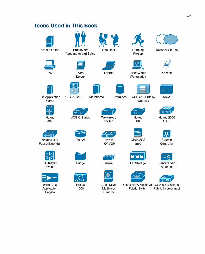
Icons Used in This Book
Employee/Accounting and Sales
Branch Office End User RunningPerson
Network Clouds
WebServer
PC Laptop CiscoWorksWorkstation
Newton
MainframeFile ApplicationServer
Database UCS 5108 BladeChassis
UCS C-SeriesNexus7000
WorkgroupSwitch
Nexus5000
Nexus 200010GE
10GE
Nexus 2000Fabric Extender
Router Nexus1KV VSM
Cisco ASA5500
SystemController
MultilayerSwitch
Bridge Firewall FC Storage Server LoadBalancer
Wide AreaApplication
Engine
Nexus1000
Cisco MDS MultilayerDirector
Cisco MDS MultilayerFabric Switch
UCS 6200 SeriesFabric Interconnect
MUX10GE/FCoE
ptg17120290
xx CCNA Cloud CLDFND 210-451 Official Cert Guide
Command Syntax ConventionsThe conventions used to present command syntax in this book are the same conventions used in the IOS Command Reference. The Command Reference describes these conven-tions as follows:
■ Boldface indicates commands and keywords that are entered literally as shown. In actual configuration examples and output (not general command syntax), boldface indicates commands that are manually input by the user (such as a show command).
■ Italic indicates arguments for which you supply actual values.
■ Vertical bars (|) separate alternative, mutually exclusive elements.
■ Square brackets ([ ]) indicate an optional element.
■ Braces ({ }) indicate a required choice.
■ Braces within brackets ([{ }]) indicate a required choice within an optional element.
ptg17120290
xxi
IntroductionWorking as an information technology professional for many years, I have pursued a con-siderable number of certifications. However, I have always reserved a special place in my heart for my first one: Cisco Certified Network Associate (CCNA).
Back in 1999, I was thrilled to discover that having obtained this certification was going to radically change my career for the better. Undoubtedly, I was being recognized by the market as a tested network professional, and better job opportunities immediately started to appear.
What surprised me the most was that the CCNA certification did not dwell too much on products. Instead, it focused on foundational networking concepts, which I still use today on a daily basis. Smartly, Cisco had already realized that technologies may quickly change, but concepts remain consistent throughout the years, like genes that are passed through uncountable generations of life forms.
Fast forwarding 17 years, the world has turned its attention to cloud computing and all the promises it holds to make IT easy and flexible. But contrarily to the late 1990s, the explosion of information and opinions that currently floods on the Internet causes more confusion than enlightenment in professionals interested in understanding any IT related topic with reasonable depth.
Bringing method and objectivity to such potential chaos, Cisco has launched a brand-new, associate-level certification: CCNA Cloud. And fortunately, the invitation to write this book has given me not only the opportunity to systematically explore cloud computing, but also the personal satisfaction of positively contributing to my favorite certification.
Goals and MethodsObviously, the primary objective of this book is to help you pass the CCNA Cloud CLDFND 210-451 Exam. However, as previously mentioned, it is also designed to facili-tate your learning of foundational concepts underlying cloud computing that will carry over into your professional job experience; this book is not intended to be an exercise in rote memorization of terms and technologies.
With the intention of giving you a holistic view of cloud computing and a more reward-ing learning experience, the order in which I present the material is designed to provide a logical progression of explanations from basic concepts to complex architectures. Notwithstanding, if you are interested in covering specific gaps in your preparation for the exam, you can also read the chapters out of the proposed sequence.
Each chapter roughly follows this structure:
■ A description of the business and technological context of the explained technology, approach, or architecture.
■ An explanation of the challenges addressed by such technology, approach, or architecture.
■ A detailed analysis that immerses the reader in the main topic of the chapter, including its characteristics, possibilities, results, and consequences.
ptg17120290
xxii CCNA Cloud CLDFND 210-451 Official Cert Guide
■ A thorough explanation of how this technology, approach, or architecture is applicable to real-world cloud computing environments.
■ A section called “Around the Corner” that points out related topics, trends, and technol-ogies that you are not specifically required to know for the CCNA Cloud CLDFND 210-451 exam, but are very important for your knowledge as a cloud computing professional.
Who Should Read This Book?CCNA Cloud certification candidates are the target audience for this book . However, it is also designed to offer a proper introduction to fundamental concepts and technologies for engineers, architects, developers, analysts, and students that are interested in cloud computing.
Strategies for Exam PreparationWhether you want to read the book in sequence or pick specific chapters to cover knowl-edge gaps, I recommend that you include the following guidelines in your study for the CCNA Cloud CLDFND 210-451 exam each time you start a chapter:
■ Answer the “Do I Know This Already?” quiz questions to assess your expertise in the chapter topic.
■ Check the results in Appendix A, “Answers to the Pre-Assessments and Quizzes.”
■ Based on your results, read the Foundation Topics sections, giving special attention to the sections corresponding to the questions you have not answered correctly.
■ After the first reading, try to complete the memory tables and define the key terms from the chapter, and verify the results in the appendices. If you make a mistake in a table entry or the definition of a key term, review the related section.
Remember: discovering gaps in your preparation for the exam is as important as address-ing them.
Additionally, you can use Appendix D, “Study Planner,” to control the pace of your study during the first reading of this certification guide as whole. In this appendix, you can establish goal dates to read the contents of each chapter and reserve time to test what you have learned through practice tests generated from the Pearson Cert Practice Test engine.
How This Book Is OrganizedIn times where blog posts and tweets provide disconnected pieces of information, this book intends to serve a complete learning experience, where order and consistency between chapters do matter.
For such purpose, Chapters 1 through 15 cover the following topics:
■ Chapter 1, “What Is Cloud Computing?”—Unfortunately, massive hype surround-ing cloud computing in the past several years has resulted in more distraction than certainty for the majority of IT professionals. With lots of different vendors claiming that cloud environments can only exist via their products, many fundamental aspects of cloud computing have been simply glossed over or, even worse, undiscovered.
ptg17120290
xxiii
Peeling away these marketing layers, this chapter focuses on the history of cloud com-puting, from its humble beginnings to its widespread adoption during this decade. As a theoretical foundation, it explores NIST’s definition of cloud computing and the essen-tial common characteristics of cloud computing environments.
■ Chapter 2, “Cloud Shapes: Service Models”— Besides using services from established cloud providers such as Amazon Web Services (AWS) and Microsoft Azure, IT depart-ments are becoming true cloud service providers within their own organizations. This chapter examines the implications of this responsibility, analyzing the well-known cloud service models (Infrastructure as a Service [IaaS], Platform as a Service [PaaS], and Software as a Service [SaaS]). To put such concepts into practice, all service models are explained through illustrative real-world examples.
■ Chapter 3, “Cloud Heights: Deployment Models”—An organization may choose to build a cloud environment for its own exclusive use or choose to share another cloud environment with one or many other companies. This chapter describes the main characteristics of private, community, public, and hybrid clouds while also discussing the reasons for choosing each of these deployment models. Additionally, it dedicates special focus to the benefits of the Cisco Intercloud strategy, and presents the main characteristics of the Cisco Intercloud Fabric solution.
■ Chapter 4, “Behind the Curtain”—Building on the conceptual basis provided in the previous three chapters, this chapter introduces you to the most important implemen-tation and operation challenges of a cloud computing environment. The chapter pres-ents the main software and hardware components of a cloud project, the data center journey into a cloud-based architecture, and essential requirements such as application programming interfaces (APIs).
After reading this chapter, you will be fully prepared to clearly understand how each of the technologies explained in the subsequent chapters fit into cloud computing deployments.
■ Chapter 5, “Server Virtualization”—The exploration of cloud computing infrastruc-ture begins in earnest with this chapter, which analyzes server virtualization as a major enabling technology of cloud computing environments. After quickly addressing the origins and main features of server virtualization, the chapter explains how it differs from cloud computing and, most importantly, what must be done to adapt server virtu-alization environments to the automation required by cloud computing environments.
■ Chapter 6, “Infrastructure Virtualization”—Data exchange is essential to any application, regardless of whether it belongs to a server virtualization environment. Nevertheless, connectivity presents particular challenges when virtual machines must communicate with each other and with the outside world. On the other hand, cloud networking faces additional constraints because standardization and automation have become required design factors in such projects. This chapter presents the main prin-ciples of and new technologies for virtual and cloud networking through practical examples and clear explanations.
■ Chapter 7, “Virtual Networking Services and Application Containers”—As virtual and cloud networking have evolved, networking services that used to be deployed only as physical appliances can now be ported into virtual machines. These virtual networking services leverage the advantages of server virtualization environments to offer benefits that

ptg17120290
xxiv CCNA Cloud CLDFND 210-451 Official Cert Guide
were unimaginable with their physical counterparts. Besides exploring these services using real-world examples, this chapter also addresses the concept of application containers, which can be used to secure tenants within a cloud computing environment.
■ Chapter 8, “Block Storage Technologies”—Data processing, transmission, and stor-age technologies have always been intertwined in computer science: any change to one technology will always produce effects on the other two. Consequently, storage tech-nologies have evolved to keep pace with the liberal use of virtual servers and virtual networks in cloud computing.
This chapter explores block storage provisioning concepts and the most widely used technologies within such context, such as SAN and disk arrays.
■ Chapter 9, “File Storage Technologies”—Files are arguably the most popular method of data storage due to their simplicity and scale. This chapter explores concepts and technologies that support file systems for cloud computing, such as NAS and file shar-ing protocols.
■ Chapter 10, “Network Architectures for the Data Center: Unified Fabric”—In the late 2000s, Cisco introduced numerous innovations to data center networking through its Unified Fabric architecture. This chapter focuses on the most impactful of these modernizations, including device virtualization (VDCs and their relationship to VLANs and VRF instances), virtual PortChannels, Fabric Extenders, Overlay Transport Virtualization (OTV), and Layer 2 Multipathing with FabricPath.
■ Chapter 11, “Network Architectures for the Data Center: SDN and ACI”—Cloud networking requires a robust physical infrastructure with intrinsic support for dynamic and scalable designs. This chapter explains two cutting-edge architectures for data center networks: Software-Defined Networking (SDN) and Cisco Application Centric Infrastructure (ACI).
■ Chapter 12: “Unified Computing”—Although many IT professionals may view servers as self-sufficient devices within a data center, Cisco Unified Computing System (UCS) encompasses technologies that closely interact with all architectures presented in the previous chapters. This chapter introduces the main components of Cisco UCS and explains why this solution was designed from the ground up to be the best server archi-tecture for cloud computing environments.
■ Chapter 13, “Cisco Cloud Infrastructure Portfolio”—This chapter briefly describes the Cisco products that are used to build optimal cloud computing infrastructures. It is designed to provide a quick reference guide of the ever-evolving family of Cisco prod-ucts and to materialize the theoretical concepts explained in the previous chapters.
■ Chapter 14: “Integrated Infrastructures”—Cloud computing environments require levels of speed and elasticity that have challenged how data centers are designed and expanded. Using the concept of pool of devices (POD), multiple companies have formed alliances to provide standardized integrated platforms that include server, net-working, storage, and virtualization software as a predictable cloud module. This chap-ter explains the advantages of such an approach and explores the main similarities and differences between FlexPod (Cisco and NetApp), Vblock (VCE), VSPEX (EMC), and UCSO (Cisco and Red Hat).

ptg17120290
xxv
■ Chapter 15: “Final Preparation”— Considering you have learned the content explained in the certification guide, this chapter includes guidelines and tips that are intended to support your study until you take your exam.
Certification Exam Topics and This BookAlthough this certification guide covers all topics from the CCNA Cloud CLDFND 210-451 Exam, it does not follow the exact order of the exam blueprint published by Cisco. Instead, the chapter sequence is purposely designed to enhance your learning through a gradual progression of concepts.
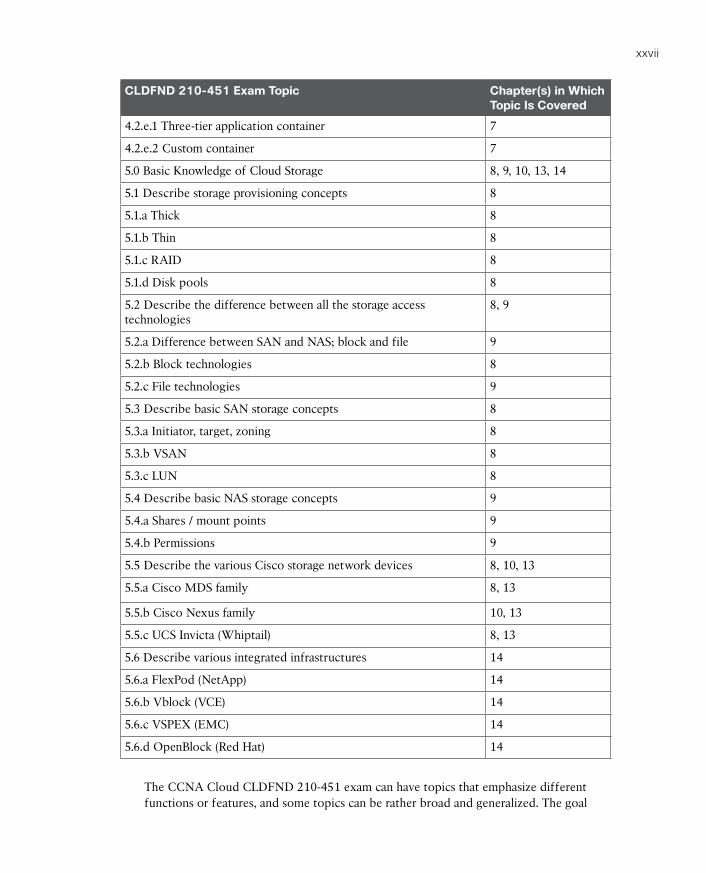
Table I-1 lists each exam topic in the blueprint along with a reference to the book chapter that covers the topic.
Table I-1 CLDFND Exam 210-451 Topics and Chapter References
CLDFND 210-451 Exam Topic Chapter(s) in Which Topic Is Covered
1.0 Cloud Characteristics and Models 1, 2
1.1 Describe common cloud characteristics 1
1.1.a On-demand self-service 1
1.1.b Elasticity 1
1.1.c Resource pooling 1
1.1.d Metered service 1
1.1.e Ubiquitous network access (smartphone, tablet, mobility) 1
1.1.f Multi-tenancy 1
1.2 Describe Cloud Service Models 2
1.2.a Infrastructure as a Service (IaaS) 2
1.2.b Software as a Service (SaaS) 2
1.2.c Platform as a Service (PaaS) 2
2.0 Cloud Deployment 3
2.1 Describe cloud deployment models 3
2.1.a Public 3
2.1.b Private 3
2.1.c Community 3
2.1.d Hybrid 3
2.2 Describe the Components of the Cisco Intercloud Solution 3
2.2.a Describe the benefits of Cisco Intercloud 3
2.2.b Describe Cisco Intercloud Fabric Services 3

ptg17120290
xxvi CCNA Cloud CLDFND 210-451 Official Cert Guide
CLDFND 210-451 Exam Topic Chapter(s) in Which Topic Is Covered
3.0 Basic Knowledge of Cloud Compute 5, 12, 13
3.1 Identify key features of Cisco UCS 12, 13
3.1.a Cisco UCS Manager 12
3.1.b Cisco UCS Central 12
3.1.c B-Series 12, 13
3.1.d C-Series 12, 13
3.1.e Server identity (profiles, templates, pools) 12
3.2 Describe Server Virtualization 5
3.2.a Basic knowledge of different OS and hypervisors 5
4.0 Basic Knowledge of Cloud Networking 6, 7, 10, 11, 13
4.1 Describe network architectures for the data center 10, 11, 13
4.1.a Cisco Unified Fabric 10, 13
4.1.a.1 Describe the Cisco nexus product family 10, 13
4.1.a.2 Describe device virtualization 10
4.1.b SDN 11
4.1.b.1 Separation of control and data 11
4.1.b.2 Programmability 11
4.1.b.3 Basic understanding of Open Daylight 11
4.1.c ACI 11
4.1.c.1 Describe how ACI solves the problem not addressed by SDN 11
4.1.c.2 Describe benefits of leaf/spine architecture 10
4.1.c.3 Describe the role of APIC Controller 11
4.2 Describe Infrastructure Virtualization 6, 7, 13
4.2.a Difference between vSwitch and DVS 6
4.2.b Cisco Nexus 1000V components 6, 13
4.2.b.1 VSM 6, 13
4.2.b.2 VEM 6, 13
4.2.b.3 VSM appliance 6, 13
4.2.c Difference between VLAN and VXLAN 6
4.2.d Virtual networking services 7
4.2.e Define Virtual Application Containers 7
ptg17120290
xxvii
CLDFND 210-451 Exam Topic Chapter(s) in Which Topic Is Covered
4.2.e.1 Three-tier application container 7
4.2.e.2 Custom container 7
5.0 Basic Knowledge of Cloud Storage 8, 9, 10, 13, 14
5.1 Describe storage provisioning concepts 8
5.1.a Thick 8
5.1.b Thin 8
5.1.c RAID 8
5.1.d Disk pools 8
5.2 Describe the difference between all the storage access technologies
8, 9
5.2.a Difference between SAN and NAS; block and file 9
5.2.b Block technologies 8
5.2.c File technologies 9
5.3 Describe basic SAN storage concepts 8
5.3.a Initiator, target, zoning 8
5.3.b VSAN 8
5.3.c LUN 8
5.4 Describe basic NAS storage concepts 9
5.4.a Shares / mount points 9
5.4.b Permissions 9
5.5 Describe the various Cisco storage network devices 8, 10, 13
5.5.a Cisco MDS family 8, 13
5.5.b Cisco Nexus family 10, 13
5.5.c UCS Invicta (Whiptail) 8, 13
5.6 Describe various integrated infrastructures 14
5.6.a FlexPod (NetApp) 14
5.6.b Vblock (VCE) 14
5.6.c VSPEX (EMC) 14
5.6.d OpenBlock (Red Hat) 14
The CCNA Cloud CLDFND 210-451 exam can have topics that emphasize different functions or features, and some topics can be rather broad and generalized. The goal
ptg17120290
xxviii CCNA Cloud CLDFND 210-451 Official Cert Guide
of this book is to provide the most comprehensive coverage to ensure that you are well prepared for the exam. Although some chapters might not address specific exam topics, they provide a foundation that is necessary for a clear understanding of important top-ics. Your short-term goal might be to pass this exam, but your long-term goal should be to become a qualified cloud professional.
It is also important to understand that this book is a “static” reference, whereas the exam topics are dynamic. Cisco can and does change the topics covered on certification exams often.
This exam guide should not be your only reference when preparing for the certifica-tion exam. You can find a wealth of information available at Cisco.com that covers each topic in great detail. If you think that you need more detailed information on a specific topic, read the Cisco documentation that focuses on that topic.
Taking the CCNA CLDFND 210-451 ExamAs with any Cisco certification exam, you should strive to be thoroughly prepared before taking the exam. There is no way to determine exactly what questions are on the exam, so the best way to prepare is to have a good working knowledge of all subjects covered on the exam. Schedule yourself for the exam and be sure to be rested and ready to focus when taking the exam.
The best place to find out about the latest available Cisco training and certifications is under the Training & Events section at Cisco.com.
Tracking Your StatusYou can track your certification progress by checking http://www.cisco.com/go/certifications/login. You must create an account the first time you log in to the site.
Cisco Certifications in the Real WorldCisco is one of the most widely recognized names in the IT industry. Cisco Certified cloud specialists bring quite a bit of knowledge to the table because of their deep under-standing of cloud technologies, standards, and designs. This is why the Cisco certifica-tion carries such high respect in the marketplace. Cisco certifications demonstrate to potential employers and contract holders a certain professionalism, expertise, and dedi-cation required to complete a difficult goal. If Cisco certifications were easy to obtain, everyone would have them.
Exam RegistrationThe CCNA Cloud CLDFND 210-451 exam is a computer-based exam, with around 55 to 65 multiple-choice, fill-in-the-blank, list-in-order, and simulation-based questions. You can take the exam at any Pearson VUE (http://www.pearsonvue.com) testing center.

ptg17120290
xxix
According to Cisco, the exam should last about 90 minutes. Be aware that when you register for the exam, you might be instructed to allocate an amount of time to take the exam that is longer than the testing time indicated by the testing software when you begin. The additional time is for you to get settled in and to take the tutorial about the test engine.
Companion WebsiteRegister this book to get access to the Pearson IT Certification test engine and other study materials plus additional bonus content. Check this site regularly for new and updated postings written by the author that provide further insight into the more troublesome top-ics on the exam. Be sure to check the box that you would like to hear from us to receive updates and exclusive discounts on future editions of this product or related products.
To access this companion website, follow the steps below:
Step 1 Go to www.pearsonITcertification.com/register and log in or create a new account.
Step 2 Enter the ISBN: 9781587147005
Step 3 Answer the challenge question as proof of purchase.
Step 4 Click on the “Access Bonus Content” link in the Registered Products section of your account page, to be taken to the page where your downloadable content is available.
Please note that many of our companion content files can be very large, especially image and video files.
If you are unable to locate the files for this title by following the steps at left, please visit www.pearsonITcertification.com/contact and select the “Site Problems/ Comments” option. Our customer service representatives will assist you.
Pearson IT Certification Practice Test Engine and Questions
The companion website includes the Pearson IT Certification Practice Test engine—software that displays and grades a set of exam-realistic multiple-choice questions. Using the Pearson IT Certification Practice Test engine, you can either study by going through the questions in Study Mode, or take a simulated exam that mimics real exam conditions. You can also serve up questions in a Flash Card Mode, which will display just the question and no answers, chal-lenging you to state the answer in your own words before checking the actual answers to verify your work.
The installation process requires two major steps: installing the software and then activat-ing the exam. The website has a recent copy of the Pearson IT Certification Practice Test engine. The practice exam (the database of exam questions) is not on this site.
ptg17120290
xxx CCNA Cloud CLDFND 210-451 Official Cert Guide
NOTE: The cardboard case in the back of this book includes a piece of paper. The paper lists the activation code for the practice exam associated with this book. Do not lose the activation code. On the opposite side of the paper from the activation code is a unique, one-time-use coupon code for the purchase of the Premium Edition eBook and Practice Test.
Install the SoftwareThe Pearson IT Certification Practice Test is a Windows-only desktop application. You can run it on a Mac using a Windows virtual machine, but it was built specifically for the PC platform. The minimum system requirements are as follows:
■ Windows 10, Windows 8.1, or Windows 7
■ Microsoft .NET Framework 4.0 Client
■ Pentium-class 1GHz processor (or equivalent)
■ 512MB RAM
■ 650MB disk space plus 50MB for each downloaded practice exam
■ Access to the Internet to register and download exam databases
The software installation process is routine as compared with other software installation pro-cesses. If you have already installed the Pearson IT Certification Practice Test software from another Pearson product, there is no need for you to reinstall the software. Simply launch the software on your desktop and proceed to activate the practice exam from this book by using the activation code included in the access code card sleeve in the back of the book.
The following steps outline the installation process:
Step 1 Download the exam practice test engine from the companion site.
Step 2 Respond to windows prompts as with any typical software installation process.
The installation process will give you the option to activate your exam with the activa-tion code supplied on the paper in the cardboard sleeve. This process requires that you establish a Pearson website login. You need this login to activate the exam, so please do register when prompted. If you already have a Pearson website login, there is no need to register again. Just use your existing login.
Activate and Download the Practice ExamOnce the exam engine is installed, you should then activate the exam associated with this book (if you did not do so during the installation process) as follows:
Step 1 Start the Pearson IT Certification Practice Test software from the Windows Start menu or from your desktop shortcut icon.
Step 2 To activate and download the exam associated with this book, from the My Products or Tools tab, click the Activate Exam button.
ptg17120290
xxxi
Step 3 At the next screen, enter the activation key from paper inside the cardboard sleeve in the back of the book. Once entered, click the Activate button.
Step 4 The activation process will download the practice exam. Click Next, and then click Finish.
When the activation process completes, the My Products tab should list your new exam. If you do not see the exam, make sure that you have selected the My Products tab on the menu. At this point, the software and practice exam are ready to use. Simply select the exam and click the Open Exam button.
To update a particular exam you have already activated and downloaded, display the Tools tab and click the Update Products button. Updating your exams will ensure that you have the latest changes and updates to the exam data.
If you want to check for updates to the Pearson Cert Practice Test exam engine software, display the Tools tab and click the Update Application button. You can then ensure that you are running the latest version of the software engine.
Activating Other ExamsThe exam software installation process, and the registration process, has to happen only once. Then, for each new exam, only a few steps are required. For instance, if you buy another Pearson IT Certification Cert Guide, extract the activation code from the card-board sleeve in the back of that book; you do not even need the exam engine at this point. From there, all you have to do is start the exam engine (if not still up and running) and perform Steps 2 through 4 from the previous list.
Assessing Exam ReadinessExam candidates never really know whether they are adequately prepared for the exam until they have completed about 30% of the questions. At that point, if you are not prepared, it is too late. The best way to determine your readiness is to work through the “Do I Know This Already?” quizzes at the beginning of each chapter and review the foundation and key topics presented in each chapter. It is best to work your way through the entire book unless you can complete each subject without having to do any research or look up any answers.
Premium Edition eBook and Practice TestsThis book also includes an exclusive offer for 70% off the Premium Edition eBook and Practice Tests edition of this title. Please see the coupon code included with the card-board sleeve for information on how to purchase the Premium Edition.
ptg17120290
This chapter covers the following topics:
■ Welcome to the Cloud Hype
■ Historical Steps Toward Cloud Computing
■ The Many Definitions of Cloud Computing
■ The Data Center
■ Common Cloud Characteristics
■ Classifying Clouds
This chapter covers the following exam objectives:
■ 1.1 Describe common cloud characteristics■ 1.1.a On-demand self service■ 1.1.b Elasticity■ 1.1.c Resource pooling■ 1.1.d Metered service■ 1.1.e Ubiquitous network access (smartphone, tablet, mobility)■ 1.1.f Multi-tenancy
ptg17120290
CHAPTER 1
What Is Cloud Computing?Not too long ago (2011), many technology enthusiasts were predicting that cloud computing would address all information technology challenges. And rather loudly, they had already declared the cloud as the decade’s panacea.
Although I had been led astray earlier in my career by hyperbolic statements predicting the revolutionary impact of one technology or another on the future of IT, it was hard not to be impressed by all the promises associated with cloud computing: agility, simplicity, efficiency, and control. It just seemed the perfect fit for the exceedingly complex world of IT, especially in my area of specialization: data centers.
But like other seasoned IT professionals, I now have a healthy level of skepticism and thus have braced myself for the front of “cloud computing” offerings from literally thousands of manufacturers, vendors, integrators, and service providers. Many of these companies have latched onto the cloud movement in hope of rebranding their standard products and services with the new and hot “cloud” moniker…and many of their customers are buying into the hype.
Thankfully, within a relatively short time, informed CIOs and IT managers realized that cloud computing is not a miraculous product, solution, or technology but rather a model that enables them to exploit computing resources in a new and cost-efficient manner. And through the efforts of organizations such as the U.S. National Institute of Standards and Technologies (NIST), cloud computing has been appropriately defined as a new access
model for IT, created to solve problems that are ingrained in the manual operations that still creep IT departments from myriad organizations in the world.
The CLDFND exam requires knowledge about the common characteristics of cloud computing as defined by NIST: on-demand self-service, rapid elasticity, resource pooling, broad network access, and measured service. It also demands understanding about a subtopic of resource pooling, multi-tenancy, and its importance to cloud implementations. To help you master these concepts, this chapter contextualizes the perception of cloud computing during its hype in the late 2000s, presents some of the historical milestones in the evolution of computing toward cloud computing, and explains each one of the cloud essential characteristics using real examples and concepts picked from the daily routine of an IT professional.
“Do I Know This Already?” QuizThe “Do I Know This Already?” quiz allows you to assess whether you should read this entire chapter thoroughly or jump to the “Exam Preparation Tasks” section. If you are in doubt about your answers to these questions or your own assessment of your knowledge of the topics, read the entire chapter. Table 1-1 lists the major headings in this chapter and their corresponding “Do I Know This Already?” quiz questions. You can find the answers in Appendix A, “Answers to Pre-Assessments and Quizzes.”
ptg17120290
4 CCNA Cloud CLDFND 210-451 Official Cert Guide
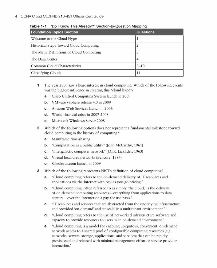
Table 1-1 “Do I Know This Already?” Section-to-Question Mapping
Foundation Topics Section Questions
Welcome to the Cloud Hype 1
Historical Steps Toward Cloud Computing 2
The Many Definitions of Cloud Computing 3
The Data Center 4
Common Cloud Characteristics 5–10
Classifying Clouds 11
1. The year 2009 saw a huge interest in cloud computing. Which of the following events was the biggest influence in creating this “cloud hype”?
a. Cisco Unified Computing System launch in 2009
b. VMware vSphere release 4.0 in 2009
c. Amazon Web Services launch in 2006
d. World financial crisis in 2007-2008
e. Microsoft Windows Server 2008
2. Which of the following options does not represent a fundamental milestone toward cloud computing in the history of computing?
a. Mainframe time-sharing
b. “Computation as a public utility” (John McCarthy, 1961)
c. “Intergalactic computer network” (J.C.R. Licklider, 1963)
d. Virtual local-area networks (Bellcore, 1984)
e. Salesforce.com launch in 2009
3. Which of the following represents NIST’s definition of cloud computing?
a. “Cloud computing refers to the on-demand delivery of IT resources and applications via the Internet with pay-as-you-go pricing.”
b. “Cloud computing, often referred to as simply ‘the cloud,’ is the delivery of on-demand computing resources—everything from applications to data centers—over the Internet on a pay for use basis.”
c. “IT resources and services that are abstracted from the underlying infrastructure and provided ‘on-demand’ and ‘at scale’ in a multitenant environment.”
d. “Cloud computing refers to the use of networked infrastructure software and capacity to provide resources to users in an on-demand environment.”
e. “Cloud computing is a model for enabling ubiquitous, convenient, on-demand network access to a shared pool of configurable computing resources (e.g., networks, servers, storage, applications, and services) that can be rapidly provisioned and released with minimal management effort or service provider interaction.”
ptg17120290
1
Chapter 1: What Is Cloud Computing? 5
4. Which of the following are data center resources that can be offered through cloud computing? (Choose all that apply.)
a. Building
b. Server
c. Raised floor
d. Cooling system
e. Data storage
f. Network bandwidth
g. Server cabinets
5. Which of the following tools gives cloud end users access to request resources?
a. Service catalog in web portal
b. Mailer group
c. 1-800 telephone number
d. None; requests are always delegated to the IT department
e. SLA
6. Which of the following options characterizes elasticity according to the NIST definition of cloud computing?
a. Identical cloud resources are provisioned in different cloud computing environments.
b. Cloud computing resources can be expanded but never decreased.
c. Cloud capabilities can be scaled rapidly outward and inward according to demand.
d. Cloud resources are doubled after at least 24 hours.
e. The leasing period of a resource can be extended for free.
7. What option best defines the opposite of the NIST essential characteristic “resource pooling” for cloud computing?
a. Resource clusters
b. Sharing
c. Resources that can be easily reassigned
d. Grouping of similar resources
e. Silos
ptg17120290
6 CCNA Cloud CLDFND 210-451 Official Cert Guide
8. Which of the following options are direct benefits from the cloud computing measured service characteristic? (Choose all that apply.)
a. Automatic control
b. Elasticity
c. Resource optimization
d. Security
e. Risk management
f. Transparency between provider and consumer
9. Which of the following options represent devices that can utilize cloud resources? (Choose all that apply.)
a. Personal computer
b. Mobile phones
c. Tablets
d. Mainframe terminal
e. Offline laptop
10. What is a tenant in the context of cloud computing?
a. An organization
b. A single user account
c. Any application that requires isolation from other tenants
d. A department
e. A community of users
11. Which of the following options represent NIST methods of classifying cloud implementations? (Choose all that apply.)
a. Providers
b. Deployment models
c. OPEX and CAPEX
d. Service models
ptg17120290
1
Chapter 1: What Is Cloud Computing? 7
Foundation Topics
Welcome to the Cloud HypeIt has been a while since IT was considered just a boring subject restricted to water cooler conversations. As the 21st century welcomed a new generation unaware of a world without the Internet or mobile phones, IT naturally became an integral part of the strategy of business corporations and public sector companies. And with almost the totality of their transactions based on electronic data and applications, these organizations realized that the content of the data center has become much more valuable than all of their combined material assets.
At the time of this writing, IT bears a striking resemblance to the fashion industry, where inno-vative concepts and paradigm shifts are introduced to huge acclaim and are strongly promoted as the latest trend (even if they may appear unsuitable for present needs). Some of these campaigns are so overwhelming that they end up fomenting a period of hype in which many organizations include the technology du jour into their short-term IT plan (sometimes without having enough time to understand its true value to the company objectives).
Although the precise origins of the term cloud computing are fittingly nebulous, its hype certainly peaked around 2011, as Figure 1-1 demonstrates.
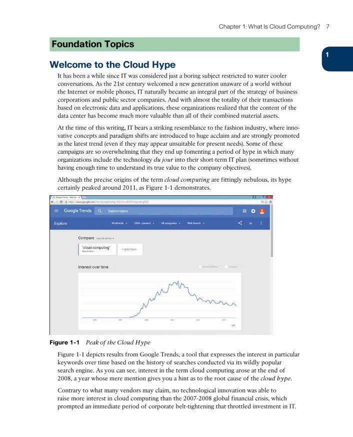
Figure 1-1 Peak of the Cloud Hype
Figure 1-1 depicts results from Google Trends, a tool that expresses the interest in particular keywords over time based on the history of searches conducted via its wildly popular search engine. As you can see, interest in the term cloud computing arose at the end of 2008, a year whose mere mention gives you a hint as to the root cause of the cloud hype.
Contrary to what many vendors may claim, no technological innovation was able to raise more interest in cloud computing than the 2007-2008 global financial crisis, which prompted an immediate period of corporate belt-tightening that throttled investment in IT.
ptg17120290
8 CCNA Cloud CLDFND 210-451 Official Cert Guide
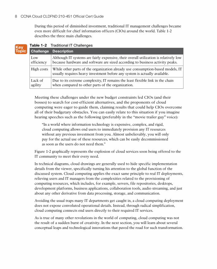
During this period of diminished investment, traditional IT management challenges became even more difficult for chief information officers (CIOs) around the world. Table 1-2 describes the three main challenges.
Table 1-2 Traditional IT Challenges
Challenge Description
Low efficiency
Although IT systems are fairly expensive, their overall utilization is relatively low because hardware and software are sized according to business activity peaks.
High costs While other parts of the organization already use consumption-based models, IT usually requires heavy investment before any system is actually available.
Lack of agility
Due to its extreme complexity, IT remains the least flexible link in the chain when compared to other parts of the organization.
Meeting these challenges under the new budget constraints led CIOs (and their bosses) to search for cost-efficient alternatives, and the proponents of cloud computing were eager to guide them, claiming results that could help CIOs overcome all of their budgetary obstacles. You can easily relate to this situation if you imagine hearing speeches such as the following (preferably in the “movie trailer guy” voice):
“In a world where information technology is expensive, complex, and rigid, cloud computing allows end users to immediately provision any IT resources without any previous investment from you. Almost unbelievably, you will only pay for the actual use of these resources, which can be easily decommissioned as soon as the users do not need them.”
Figure 1-2 graphically represents the explosion of cloud services soon being offered to the IT community to meet their every need.
In technical diagrams, cloud drawings are generally used to hide specific implementation details from the viewer, specifically turning his attention to the global function of the discussed system. Cloud computing applies the exact same principle to real IT deployments, relieving users and IT managers from the complexities related to the provisioning of computing resources, which includes, for example, servers, file repositories, desktops, development platforms, business applications, collaboration tools, audio streaming, and just about any other derivative from data processing, storage, and communication.
Avoiding the usual traps many IT departments get caught in, a cloud computing deployment does not expose convoluted operational details. Instead, through radical simplification, cloud computing connects end users directly to their required IT services.
As is true of many other revolutions in the world of computing, cloud computing was not the result of a sudden burst of creativity. In the next section, you will learn about several conceptual leaps and technological innovations that paved the road for such transformation.

ptg17120290
1
Chapter 1: What Is Cloud Computing? 9
Figure 1-2 Cloud Computing Proposition
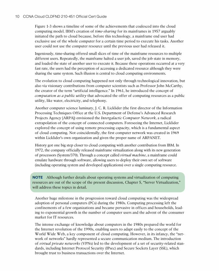
Historical Steps Toward Cloud ComputingUnbeknownst to many of its ardent devotees, some of the concepts that support cloud computing were developed more than 50 years ago, as Figure 1-3 illustrates.
MainframeTime-sharing
“Computation as a public utility” (John
McCarthy)
Virtual Machine(IBM)
1957
1961
World Wide Web(WWW) and
Virtual PrivateNetworks(VPNs)
Mid 90s
PersonalComputers
Early80s
1969
“Intergalactic ComputerNetwork” (J.C.R.
Licklider)
ARPANET
1963
1973
AmazonWeb Servicesis launched
2006
Salesforce.com islaunched
1999
1970s 1980s 1990s 2000s1950s 1960s
Figure 1-3 Computing Milestones Toward Cloud Computing
ptg17120290
10 CCNA Cloud CLDFND 210-451 Official Cert Guide
Figure 1-3 shows a timeline of some of the achievements that coalesced into the cloud computing model. IBM’s creation of time-sharing for its mainframes in 1957 arguably initiated the path to cloud because, before this technology, a mainframe end user had exclusive use of the whole computer for a certain time period to execute his tasks. Another user could not use the computer resource until the previous user had released it.
Ingeniously, time-sharing offered small slices of time of the mainframe resources to multiple different users. Repeatedly, the mainframe halted a user job, saved the job state in memory, and loaded the state of another user to execute it. Because these operations occurred at a very fast rate, the users had the perception of accessing a dedicated resource although they were sharing the same system. Such illusion is central to cloud computing environments.
The evolution to cloud computing happened not only through technological innovation, but also via visionary contributions from computer scientists such as Professor John McCarthy, the creator of the term “artificial intelligence.” In 1961, he introduced the concept of computation as a public utility that advocated the offer of computing resources as a public utility, like water, electricity, and telephony.
Another computer science luminary, J. C. R. Licklider (the first director of the Information Processing Techniques Office at the U.S. Department of Defense’s Advanced Research Projects Agency [ARPA]) envisioned the Intergalactic Computer Network , a radical extrapolation of the concept of connected computers. Foreseeing the Internet, Licklider explored the concept of using remote processing capacity, which is a fundamental aspect of cloud computing. Not coincidentally, the first computer network was created in 1969 within Licklider’s own organization and given the proper name of ARPANET .
History got one big step closer to cloud computing with another contribution from IBM. In 1972, the company officially released mainframe virtualization along with its new generation of processors (System/370). Through a concept called virtual machine , a mainframe could emulate hardware through software, allowing users to deploy their own set of software (including operating system and developed applications) over a single computing resource.
NOTE Although further details about operating systems and virtualization of computing resources are out of the scope of the present discussion, Chapter 5, “Server Virtualization,” will address these topics in detail.
Another huge milestone in the progression toward cloud computing was the widespread adoption of personal computers (PCs) during the 1980s. Computing processing left the confinements of a few organizations and became pervasive in offices and households, lead-ing to exponential growth in the number of computer users and the advent of the consumer market for IT resources.
The intense exchange of knowledge about computers in the 1980s prepared the world for the Internet revolution of the 1990s, enabling users to adapt easily to the concept of the World Wide Web, a key component of cloud computing. However, in its infancy, the “net-work of networks” hardly represented a secure communication medium. The introduction of virtual private networks (VPNs) led to the development of a set of security-related stan-dards, including Internet Protocol Security (IPsec) and Secure Sockets Layer (SSL) , which brought trust to business transactions over the Internet.
ptg17120290
1
Chapter 1: What Is Cloud Computing? 11
With these concepts in position, it was only a matter of time before a corporation combined them all to offer IT services via the Internet. It first happened in 1999, with the launch of Salesforce.com , a company that has specialized in offering customer relationship management (CRM) software as a service. In its proposal model, Salesforce.com customers do not have to use any special software or infrastructure to manage their respective data. Instead, the company provided this complete infrastructure, the only requirements for its users being a functional web browser and an Internet connection.
In 2003, Amazon (the world biggest Internet-based retailer) began to pursue a broader approach to offer IT services through the Internet, through an internal project that would originate Amazon Web Services (AWS) . Just like other retail companies, Amazon has its biggest sales peaks during Christmas seasons. Realizing that huge amounts of unused capacity exist in its data centers during all other periods of the year, Amazon’s internal project aimed to rent “pure” computing resources to remote users in an effort to monetize all that unused capacity. The release of the first AWS products occurred in 2006: Elastic Compute Cloud (EC2) and Simple Storage Service (S3) . These services, respectively, offer processing and storage services through the Internet, with very fast provisioning, scalable capabilities, and monthly payments according to resource usage.
Sensing an untapped opportunity, companies such as Rackspace and Terremark (a subsidiary of Verizon) followed suit and started offering services in a similar way to AWS. And a new market was born under the name of cloud computing.
The Many Definitions of Cloud ComputingAs I briefly mentioned in the section “Welcome to the Cloud Hype,” the huge interest in cloud computing also produced adverse effects for prospective users. For example, it spawned a huge number of vendors vying for their business who had neither the technology nor the expertise to offer anything similar to the services offered by Salesforce.com and Amazon. Consequently, many organizations interested in cloud computing instead found themselves in a fog of confusion and endless discussions about what exactly characterized a cloud computing service.
A quick search of the Internet demonstrates what prompted such bewilderment, as you behold proposed definitions for cloud computing such as the following:
“No matter which provider you choose, you’ll find that almost every cloud has these core characteristics: it’s virtual, it’s flexible and scalable, it’s open (or closed), it can be secure, it can be affordable, it can be secure AND affordable.”
“Cloud computing refers to the use of networked infrastructure software and capacity to provide resources to users in an on-demand environment.”
“Cloud computing refers to the on-demand delivery of IT resources and appli-cations via the Internet with pay-as-you-go pricing.”
Although these definitions may share some similarities, they subtly bend the term according to the offered solutions of each company. But with rapid maturation of cloud computing in recent years, it is fairly easy to point out examples that contradict these definitions, such as cloud computing services that can offer direct access to physical hardware or that are accessible from private networks instead of the Internet.
ptg17120290
12 CCNA Cloud CLDFND 210-451 Official Cert Guide
To dispel the confusion about what constitutes cloud computing, several standards organizations have devoted efforts to formally define and categorize cloud computing implementations. Officially launched in 2008, the U.S. National Institute of Standards and Technology (NIST) Cloud Computing Program (NCCP) has generated Special Publications (SPs) containing definitions, reference architectures, and classification criteria for cloud environments.
Though NIST created these standards to accelerate the adoption of cloud computing in the U.S. federal government, they constitute a crowning achievement in the theoretical study of this subject. For example, NIST Special Publication 800-145 (The NIST Definition of
Cloud Computing) states that
“Cloud computing is a model for enabling ubiquitous, convenient, on-demand network access to a shared pool of configurable computing resources (e.g., net-works, servers, storage, applications, and services) that can be rapidly provisioned and released with minimal management effort or service provider interaction.”
One important aspect of this definition is the fact that NIST characterizes cloud computing as an access model for computing resources rather than a technology. Besides that subtle but important distinction, SP 800-145 cites five essential characteristics that all cloud computing scenarios must share:
■ On-demand self-service
■ Rapid elasticity
■ Resource pooling
■ Measured service
■ Broad network access
Before we delve into each of these characteristics, allow me to describe the environment where computing resources are actually allocated and provisioned for cloud end users.
The Data CenterThe infrastructure that makes cloud computing possible is the data center. In summary, a data center is a special facility conceived to house, manage, and support critical computing resources for one or more organizations. A particularly complex entity, a typical data center encompasses special building structures, power backup structures, cooling systems, special-purpose rooms (entrance and telecommunications, for example), equipment cabinets, struc-tured cabling, network devices, storage systems, servers, data security systems, mainframes, application software, physical security devices, monitoring centers, and many other support systems. All these resources and their interaction are (locally or remotely) managed by spe-cialized personnel.
Figure 1-4 depicts the physical view of a data center.
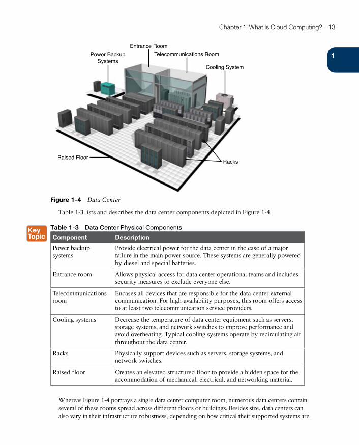
ptg17120290
1
Chapter 1: What Is Cloud Computing? 13
Power BackupSystems
Raised FloorRacks
Entrance Room
Cooling System
Telecommunications Room
Figure 1-4 Data Center
Table 1-3 lists and describes the data center components depicted in Figure 1-4.
Table 1-3 Data Center Physical Components
Component Description
Power backup systems
Provide electrical power for the data center in the case of a major failure in the main power source. These systems are generally powered by diesel and special batteries.
Entrance room Allows physical access for data center operational teams and includes security measures to exclude everyone else.
Telecommunications room
Encases all devices that are responsible for the data center external communication. For high-availability purposes, this room offers access to at least two telecommunication service providers.
Cooling systems Decrease the temperature of data center equipment such as servers, storage systems, and network switches to improve performance and avoid overheating. Typical cooling systems operate by recirculating air throughout the data center.
Racks Physically support devices such as servers, storage systems, and network switches.
Raised floor Creates an elevated structured floor to provide a hidden space for the accommodation of mechanical, electrical, and networking material.
Whereas Figure 1-4 portrays a single data center computer room, numerous data centers contain several of these rooms spread across different floors or buildings. Besides size, data centers can also vary in their infrastructure robustness, depending on how critical their supported systems are.
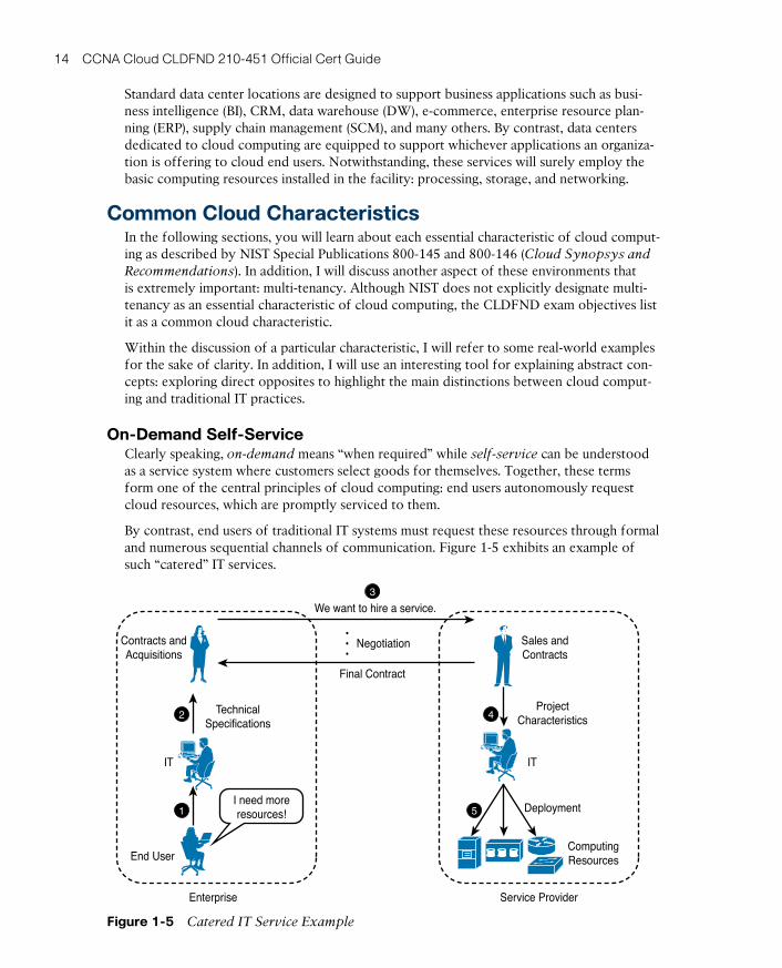
ptg17120290
14 CCNA Cloud CLDFND 210-451 Official Cert Guide
Standard data center locations are designed to support business applications such as busi-ness intelligence (BI), CRM, data warehouse (DW), e-commerce, enterprise resource plan-ning (ERP), supply chain management (SCM), and many others. By contrast, data centers dedicated to cloud computing are equipped to support whichever applications an organiza-tion is offering to cloud end users. Notwithstanding, these services will surely employ the basic computing resources installed in the facility: processing, storage, and networking.
Common Cloud CharacteristicsIn the following sections, you will learn about each essential characteristic of cloud comput-ing as described by NIST Special Publications 800-145 and 800-146 (Cloud Synopsys and Recommendations). In addition, I will discuss another aspect of these environments that is extremely important: multi-tenancy. Although NIST does not explicitly designate multi-tenancy as an essential characteristic of cloud computing, the CLDFND exam objectives list it as a common cloud characteristic.
Within the discussion of a particular characteristic, I will refer to some real-world examples for the sake of clarity. In addition, I will use an interesting tool for explaining abstract con-cepts: exploring direct opposites to highlight the main distinctions between cloud comput-ing and traditional IT practices.
On-Demand Self-ServiceClearly speaking, on-demand means “when required” while self-service can be understood as a service system where customers select goods for themselves. Together, these terms form one of the central principles of cloud computing: end users autonomously request cloud resources, which are promptly serviced to them.
By contrast, end users of traditional IT systems must request these resources through formal and numerous sequential channels of communication. Figure 1-5 exhibits an example of such “catered” IT services.
Contracts andAcquisitions
TechnicalSpecifications
End User
I need moreresources!
Enterprise Service Provider
ProjectCharacteristics
Deployment
ComputingResources
ITIT
Sales andContracts
Final Contract
We want to hire a service.
Negotiation•••
1
2
3
4
5
Figure 1-5 Catered IT Service Example
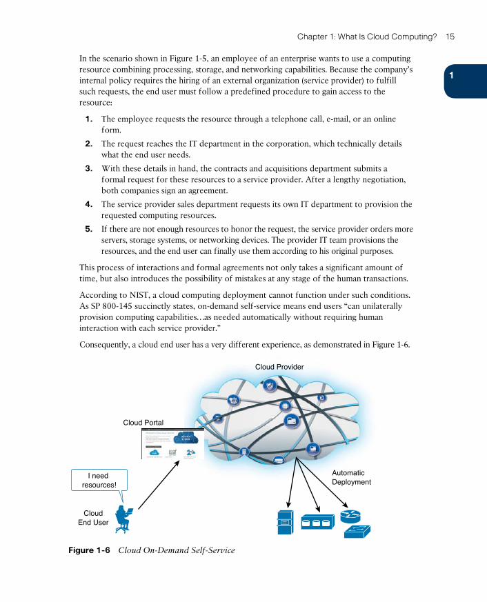
ptg17120290
1
Chapter 1: What Is Cloud Computing? 15
In the scenario shown in Figure 1-5, an employee of an enterprise wants to use a computing resource combining processing, storage, and networking capabilities. Because the company’s internal policy requires the hiring of an external organization (service provider) to fulfill such requests, the end user must follow a predefined procedure to gain access to the resource:
1. The employee requests the resource through a telephone call, e-mail, or an online form.
2. The request reaches the IT department in the corporation, which technically details what the end user needs.
3. With these details in hand, the contracts and acquisitions department submits a formal request for these resources to a service provider. After a lengthy negotiation, both companies sign an agreement.
4. The service provider sales department requests its own IT department to provision the requested computing resources.
5. If there are not enough resources to honor the request, the service provider orders more servers, storage systems, or networking devices. The provider IT team provisions the resources, and the end user can finally use them according to his original purposes.
This process of interactions and formal agreements not only takes a significant amount of time, but also introduces the possibility of mistakes at any stage of the human transactions.
According to NIST, a cloud computing deployment cannot function under such conditions. As SP 800-145 succinctly states, on-demand self-service means end users “can unilaterally provision computing capabilities…as needed automatically without requiring human interaction with each service provider.”
Consequently, a cloud end user has a very different experience, as demonstrated in Figure 1-6.
Cloud Provider
CloudEnd User
Cloud Portal
AutomaticDeployment
I need resources!
Figure 1-6 Cloud On-Demand Self-Service
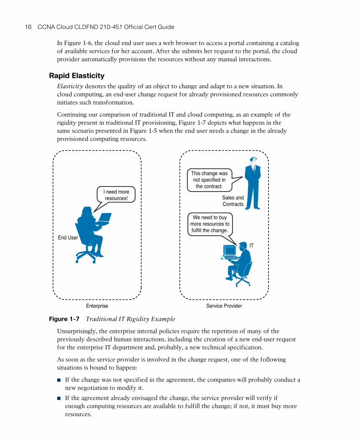
ptg17120290
16 CCNA Cloud CLDFND 210-451 Official Cert Guide
In Figure 1-6, the cloud end user uses a web browser to access a portal containing a catalog of available services for her account. After she submits her request to the portal, the cloud provider automatically provisions the resources without any manual interactions.
Rapid ElasticityElasticity denotes the quality of an object to change and adapt to a new situation. In cloud computing, an end-user change request for already provisioned resources commonly initiates such transformation.
Continuing our comparison of traditional IT and cloud computing, as an example of the rigidity present in traditional IT provisioning, Figure 1-7 depicts what happens in the same scenario presented in Figure 1-5 when the end user needs a change in the already provisioned computing resources.
End User
Enterprise
I need moreresources!
IT
Sales andContracts
Service Provider
We need to buymore resources tofulfill the change.
This change wasnot specified in
the contract.
Figure 1-7 Traditional IT Rigidity Example
Unsurprisingly, the enterprise internal policies require the repetition of many of the previously described human interactions, including the creation of a new end-user request for the enterprise IT department and, probably, a new technical specification.
As soon as the service provider is involved in the change request, one of the following situations is bound to happen:
■ If the change was not specified in the agreement, the companies will probably conduct a new negotiation to modify it.
■ If the agreement already envisaged the change, the service provider will verify if enough computing resources are available to fulfill the change; if not, it must buy more resources.
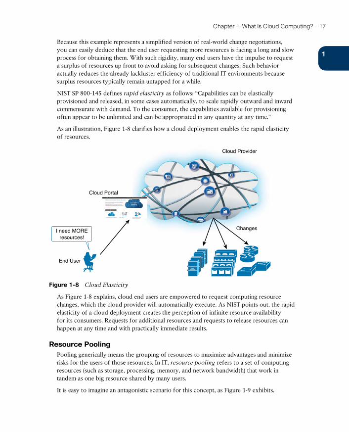
ptg17120290
1
Chapter 1: What Is Cloud Computing? 17
Because this example represents a simplified version of real-world change negotiations, you can easily deduce that the end user requesting more resources is facing a long and slow process for obtaining them. With such rigidity, many end users have the impulse to request a surplus of resources up front to avoid asking for subsequent changes. Such behavior actually reduces the already lackluster efficiency of traditional IT environments because surplus resources typically remain untapped for a while.
NIST SP 800-145 defines rapid elasticity as follows: “Capabilities can be elastically provisioned and released, in some cases automatically, to scale rapidly outward and inward commensurate with demand. To the consumer, the capabilities available for provisioning often appear to be unlimited and can be appropriated in any quantity at any time.”
As an illustration, Figure 1-8 clarifies how a cloud deployment enables the rapid elasticity of resources.
Cloud Provider
End User
Cloud Portal
ChangesI need MOREresources!
Figure 1-8 Cloud Elasticity
As Figure 1-8 explains, cloud end users are empowered to request computing resource changes, which the cloud provider will automatically execute. As NIST points out, the rapid elasticity of a cloud deployment creates the perception of infinite resource availability for its consumers. Requests for additional resources and requests to release resources can happen at any time and with practically immediate results.
Resource PoolingPooling generically means the grouping of resources to maximize advantages and minimize risks for the users of those resources. In IT, resource pooling refers to a set of computing resources (such as storage, processing, memory, and network bandwidth) that work in tandem as one big resource shared by many users.
It is easy to imagine an antagonistic scenario for this concept, as Figure 1-9 exhibits.
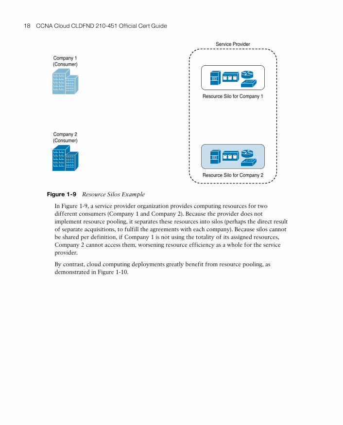
ptg17120290
18 CCNA Cloud CLDFND 210-451 Official Cert Guide
Resource Silo for Company 1
Resource Silo for Company 2
Service Provider
Company 1(Consumer)
Company 2(Consumer)
Figure 1-9 Resource Silos Example
In Figure 1-9, a service provider organization provides computing resources for two different consumers (Company 1 and Company 2). Because the provider does not implement resource pooling, it separates these resources into silos (perhaps the direct result of separate acquisitions, to fulfill the agreements with each company). Because silos cannot be shared per definition, if Company 1 is not using the totality of its assigned resources, Company 2 cannot access them, worsening resource efficiency as a whole for the service provider.
By contrast, cloud computing deployments greatly benefit from resource pooling, as demonstrated in Figure 1-10.
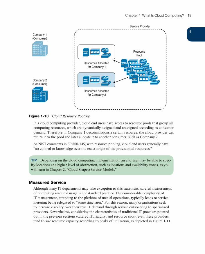
ptg17120290
1
Chapter 1: What Is Cloud Computing? 19
Resources Allocated for Company 1
ResourcePool
Resources Allocated for Company 2
Service Provider
Company 1(Consumer)
Company 2(Consumer)
Figure 1-10 Cloud Resource Pooling
In a cloud computing provider, cloud end users have access to resource pools that group all computing resources, which are dynamically assigned and reassigned according to consumer demand. Therefore, if Company 1 decommissions a certain resource, the cloud provider can return it to the pool and later allocate it to another consumer, such as Company 2.
As NIST comments in SP 800-145, with resource pooling, cloud end users generally have “no control or knowledge over the exact origin of the provisioned resources.”
TIP Depending on the cloud computing implementation, an end user may be able to spec-ify locations at a higher level of abstraction, such as locations and availability zones, as you will learn in Chapter 2, “Cloud Shapes: Service Models.”
Measured ServiceAlthough many IT departments may take exception to this statement, careful measurement of computing resource usage is not standard practice. The considerable complexity of IT management, attending to the plethora of menial operations, typically leads to service metering being relegated to “some time later.” For this reason, many organizations seek to increase visibility over their true IT demand through service outsourcing to specialized providers. Nevertheless, considering the characteristics of traditional IT practices pointed out in the previous sections (catered IT, rigidity, and resource silos), even these providers tend to size resource capacity according to peaks of utilization, as depicted in Figure 1-11.
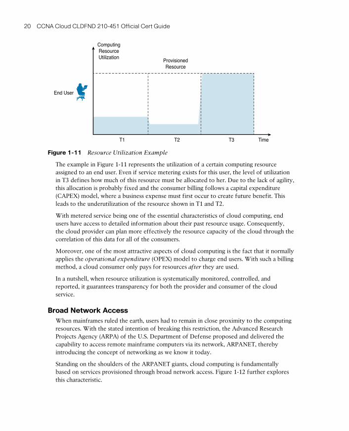
ptg17120290
20 CCNA Cloud CLDFND 210-451 Official Cert Guide
ComputingResourceUtilization
End User
T1 T2 T3 Time
ProvisionedResource
Figure 1-11 Resource Utilization Example
The example in Figure 1-11 represents the utilization of a certain computing resource assigned to an end user. Even if service metering exists for this user, the level of utilization in T3 defines how much of this resource must be allocated to her. Due to the lack of agility, this allocation is probably fixed and the consumer billing follows a capital expenditure (CAPEX) model, where a business expense must first occur to create future benefit. This leads to the underutilization of the resource shown in T1 and T2.
With metered service being one of the essential characteristics of cloud computing, end users have access to detailed information about their past resource usage. Consequently, the cloud provider can plan more effectively the resource capacity of the cloud through the correlation of this data for all of the consumers.
Moreover, one of the most attractive aspects of cloud computing is the fact that it normally applies the operational expenditure (OPEX) model to charge end users. With such a billing method, a cloud consumer only pays for resources after they are used.
In a nutshell, when resource utilization is systematically monitored, controlled, and reported, it guarantees transparency for both the provider and consumer of the cloud service.
Broad Network AccessWhen mainframes ruled the earth, users had to remain in close proximity to the computing resources. With the stated intention of breaking this restriction, the Advanced Research Projects Agency (ARPA) of the U.S. Department of Defense proposed and delivered the capability to access remote mainframe computers via its network, ARPANET , thereby introducing the concept of networking as we know it today.
Standing on the shoulders of the ARPANET giants, cloud computing is fundamentally based on services provisioned through broad network access. Figure 1-12 further explores this characteristic.
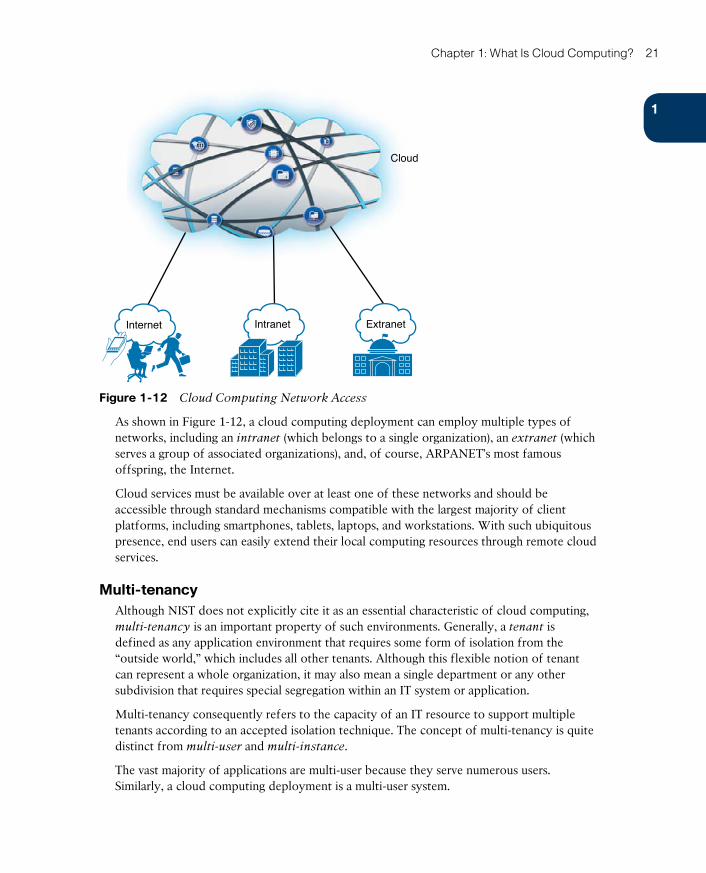
ptg17120290
1
Chapter 1: What Is Cloud Computing? 21
Cloud
Internet Intranet Extranet
Figure 1-12 Cloud Computing Network Access
As shown in Figure 1-12, a cloud computing deployment can employ multiple types of networks , including an intranet (which belongs to a single organization), an extranet (which serves a group of associated organizations), and, of course, ARPANET’s most famous offspring, the Internet.
Cloud services must be available over at least one of these networks and should be accessible through standard mechanisms compatible with the largest majority of client platforms, including smartphones, tablets, laptops, and workstations. With such ubiquitous presence, end users can easily extend their local computing resources through remote cloud services.
Multi-tenancyAlthough NIST does not explicitly cite it as an essential characteristic of cloud computing, multi-tenancy is an important property of such environments. Generally, a tenant is defined as any application environment that requires some form of isolation from the “outside world,” which includes all other tenants. Although this flexible notion of tenant can represent a whole organization, it may also mean a single department or any other subdivision that requires special segregation within an IT system or application.
Multi-tenancy consequently refers to the capacity of an IT resource to support multiple tenants according to an accepted isolation technique. The concept of multi-tenancy is quite distinct from multi-user and multi-instance.
The vast majority of applications are multi-user because they serve numerous users. Similarly, a cloud computing deployment is a multi-user system.
ptg17120290
22 CCNA Cloud CLDFND 210-451 Official Cert Guide
However, imagine that such deployment does not have any multi-tenant system or application within its structure. In such a scenario, the cloud architect may decide to design services that require new resource instances for each new user. Building such a cloud as a multi-instance system eventually will add complexity to its operations because upgrades and fixes will have to be applied to every resource instance. Moreover, each resource will have to be dedicated to a single application, decreasing efficiency of the cloud implementation.
On the other hand, cloud deployments greatly benefit from using multi-tenancy components because they can deploy a single instance of software or hardware to several different tenants. In this fashion, any change, upgrade, or tweak is immediately available to every tenant. As a drawback, all tenants may share the same fate in the case of a major system failure (which would not happen in a multi-instance system).
Undoubtedly, the reasonable balance between multi-instance and multi-tenant resources within a cloud project will dictate the efficiency and availability required by future consumers.
Classifying CloudsThe previous sections have discussed characteristics that all cloud computing deployments share, but these environments can differ wildly from each other. Such variation really blossomed during the cloud hype, where innovative services and security concerns opened up new opportunities.
Much like actual clouds, these models required a classification system to simplify their individual analysis. For tropospheric clouds, which reside in the lowest and thickest part of Earth’s atmosphere, nephologists have been using the classification system created by Luke Howard in 1802. In his book Modifications of Clouds , the British chemist and amateur meteorologist created an interesting taxonomy based on cloud shapes and heights, which the World Meteorological Organization (WMO) later extended. Figure 1-13 illustrates this system.
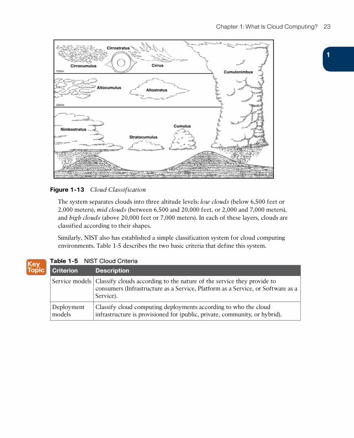
ptg17120290
1
Chapter 1: What Is Cloud Computing? 23
Cirrostratus
Cirrus
AltostratusAltocumulus
Nimbostratus
Stratocumulus
Cumulus
Cumulonimbus
Cirrocumulus7000m
2000m
Figure 1-13 Cloud Classification
The system separates clouds into three altitude levels: low clouds (below 6,500 feet or 2,000 meters), mid clouds (between 6,500 and 20,000 feet, or 2,000 and 7,000 meters), and high clouds (above 20,000 feet or 7,000 meters). In each of these layers, clouds are classified according to their shapes.
Similarly, NIST also has established a simple classification system for cloud computing environments. Table 1-5 describes the two basic criteria that define this system.
Table 1-5 NIST Cloud Criteria
Criterion Description
Service models Classify clouds according to the nature of the service they provide to consumers (Infrastructure as a Service, Platform as a Service, or Software as a Service).
Deployment models
Classify cloud computing deployments according to who the cloud infrastructure is provisioned for (public, private, community, or hybrid).

ptg17120290
24 CCNA Cloud CLDFND 210-451 Official Cert Guide
Complete analysis of all three service models will be provided in Chapter 2. Subsequently, Chapter 3, “Cloud Heights: Deployment Models,” will explore the four deployment models defined by NIST.
Around the Corner: Agile, Cloud-Scale Applications, and DevOps
Based on the fact that you’re reading this book, I’m guessing that you probably have an infrastructure background (networking, server, or storage) and want to expand your knowledge about cloud computing. Assuming that I am right, you likely will be surprised to discover that the benefits of cloud computing go way beyond providing a “smart data center” for traditional applications.
A data center exists to support critical applications, so it is only natural that the way software is developed affects this IT structure. Since the 1950s, software development has followed the principles of the waterfall model, which is a sequential design process with origins in project management procedures from other industries. Figure 1-14 captures the idea behind this approach.
Project Timeline
Design Build Test OperationAnalyze Plan
Figure 1-14 Waterfall Model
In a waterfall, water never goes upstream. Similarly, this software development model establishes phases for the whole project, where each phase only begins after the complete result from the previous phase is delivered. Table 1-6 provides an overview of the phases shown in Figure 1-14.
Table 1-6 Common Waterfall Phases
Phase Description
Analyze The user requirements are gathered and captured in a product requirement document, resulting in models, schema, and business rules.
Plan A project management strategy is developed to enumerate all resources required in the project.
Design The architecture of the software is detailed and the project is broken down into smaller pieces.
Build The software is developed, proved, and integrated. One important observation: software is usable only after this phase is complete.
Test The developed system is tested to demonstrate that it conforms to the requirements established in the first phase.
Operation Consists of the installation, migration, support, and maintenance of the complete system.

ptg17120290
1
Chapter 1: What Is Cloud Computing? 25
During a waterfall project timeline, user requirements of the software and design must remain constant because a simple scope change can force the project to return to the first phase (analysis).
Business applications such as ERP, CRM, and e-mail still use slight variations of the waterfall model in their development. All of these systems share some noticeable characteristics: they are designed to serve a well-known number of users, are based on a few software components, and will run over a considerably reliable infrastructure.
In the wake of the 2007-2008 global financial crisis, business organizations have gradually changed their perception of IT as a cost center to an enabler of new opportunities. With potential customers armed with always-online smartphones, tablets, and portable computers, an “app” released today may become the source of millions of dollars in the near future. In this landscape of smaller budgets and intense competition, application development cannot afford to spend the months (or even years) common in waterfall-based projects. A short time to market is crucial to gain the attention of this customer base, so software development must respond to a prototype request in a few days or weeks.
To fulfill such an aggressive schedule, a new software development model was required. With origins in the late 1990s, a new model dubbed Agile embodies the consolidation of many ideas focused on simplicity, close collaboration between development and business, continuous delivery of valuable software, constant change of requirements, and self-organizing teams. Figure 1-15 summarizes how these principles change software development.
Project Timeline
OperationAnalyze Plan
Design
Test
Build
OperationAnalyze Plan
Design
Test
Build
OperationAnalyze Plan
Design
Test
Build
Requirements Change Customer Turnover Technology Innovation
Figure 1-15 Agile Model
As you can see in Figure 1-15, the Agile model essentially shrinks the waterfall development cycle into faster rounds, which produce useful software code in fractions of the final product timeline. And if a company desires to develop an application prototype between Monday and Thursday, Agile can be the software development approach that can deliver this kind of result.
Architecturally speaking, these modern apps are very different from traditional applications. The main reason for this change is quite simple: if an app proves to be popular, its number of users may grow exponentially in a very short period. Consequently, these apps usually possess multiple small components that perform very specific functions and that can be rapidly scaled, in the case of sudden interest. And because cloud computing environments provide perfect conditions for scaling such apps, online gaming, video on demand, content delivery, instant messaging, and mobility applications are also referred to as cloud-scale apps .
ptg17120290
26 CCNA Cloud CLDFND 210-451 Official Cert Guide
But the modernization of software development does not stop at the point code is ready for production. Another movement called DevOps has enhanced application deployment through the expanded collaboration between the development staff and operations staff throughout all stages of the development lifecycle. With DevOps, rather than creating software and delivering it to the operations team, the development team works closely with operations to produce a much more efficient and reliable final product.
Further Reading■ Agile Alliance: https://www.agilealliance.org/agile101/what-is-agile/
■ Kim, Gene, Spafford, George, and Kevin Behr. The Phoenix Project: A Novel About IT,
DevOps, and Helping Your Business Win. IT Revolution Press, 2013.

ptg17120290
1
Chapter 1: What Is Cloud Computing? 27
Exam Preparation Tasks
Review All the Key TopicsReview the most important topics in this chapter, denoted with a Key Topic icon in the outer margin of the page. Table 1-7 lists a reference of these key topics and the page number on which each is found.
Table 1-7 Key Topics for Chapter 1
Key Topic Element Description Page Number
Table 1-2 Traditional IT challenges 8
Table 1-3 Data center physical components 13
Table 1-5 NIST cloud criteria 23
Complete the Tables and Lists from MemoryPrint a copy of Appendix B, “Memory Tables” (found on the CD), or at least the section for this chapter, and complete the tables and lists from memory. Appendix C, “Answers to Memory Tables,” also on the CD, includes completed tables and lists so that you can check your work.
Define Key TermsDefine the following key terms from this chapter, and check your answers in the glossary:
time-sharing, computation as a public utility, personal computer (PC), virtual private network (VPN), National Institute of Standards and Technologies (NIST), on-demand self-service, rapid elasticity, resource pooling, measured service, broad network access, multi-tenant

ptg17120290
This chapter covers the following topics:
■ Service Providers and Information Technology
■ Infrastructure as a Service
■ Platform as a Service
■ Software as a Service
This chapter covers the following exam objectives:
■ 1.2 Describe Cloud Service Models■ 1.2.a Infrastructure as a Service (IaaS)■ 1.2.b Software as a Service (SaaS)■ 1.2.c Platform as a Service (PaaS)
ptg17120290
CHAPTER 2
Cloud Shapes: Service ModelsAfter the mild sense of disappointment that followed its initial hype in the late 2000s, cloud computing began to morph into different shapes in a similar way as its atmospheric counter-parts. Currently, cloud services seem to be bound only by the creative limitations of provid-ers and their execution capacity, providing IT resources that range from simple processing capacity to fully provisioned applications at the click of a browser button.
To identify important aspects of cloud computing and to serve as a means for broad com-parisons of cloud services and deployment strategies, the National Institute of Standards and Technology (NIST) Special Publication 800-145, “The NIST Definition of Cloud Com-puting,” describes three service models that classify cloud services according to their flex-ibility and readiness to support consumer needs: Infrastructure as a Service (IaaS), Platform as a Service (PaaS), and Software as a Service (SaaS).
TIP Due to its initials, these service models are also known as IPS Stack .
The CLDFND exam requires that you understand these service models, so this chapter focuses on providing a detailed explanation of them, including basic concepts, applicability, benefits, and challenges. To illustrate specific aspects of each of these service models, the chapter also introduces some examples from well-known cloud providers. The chapter con-cludes with an overview of new hybrid models that are on the horizon.
“Do I Know This Already?” QuizThe “Do I Know This Already?” quiz allows you to assess whether you should read this entire chapter thoroughly or jump to the “Exam Preparation Tasks” section. If you are in doubt about your answers to these questions or your own assessment of your knowledge of the topics, read the entire chapter. Table 2-1 lists the major headings in this chapter and their corresponding “Do I Know This Already?” quiz questions. You can find the answers in Appendix A, “Answers to Pre-Assessments and Quizzes.”
Table 2-1 “Do I Know This Already?” Section-to-Question Mapping
Foundation Topics Section Questions
Service Providers and Information Technology 1
Infrastructure as a Service 2–4
Platform as a Service 5–7
Software as a Service 8–9
ptg17120290
30 CCNA Cloud CLDFND 210-451 Official Cert Guide
1. Which of the following represent key aspects of a service-level agreement between a data center service provider and a consumer? (Choose all that apply.)
a. Performance
b. Mean time to recover
c. Contract changes
d. Data handling
e. Uptime
2. Which of the following represents the service models described by NIST?
a. XaaS, PaaS, SaaS
b. SaaS, IaaS, PaaS
c. Private, public, hybrid
d. On-premise, off-premise, managed
e. EaaS, XaaS, IaaS
3. Which of the following are true about Infrastructure as a Service? (Choose all that apply.)
a. Most typical consumers are IT administrators.
b. Virtualization technologies are mandatory for the implementation of IaaS.
c. IaaS basically offers computing hardware for its consumers.
d. Among all service models, IaaS is the least flexible option.
4. Which of the following are correct about cloud regions and availability zones? (Choose all that apply.)
a. Regions represent data center installations from a cloud provider that can be used as options for the consumer resource deployment.
b. Availability zones represent data center installations from a cloud provider that can be used as options for the consumer resource deployment.
c. Regions are independent locations within a single data center facility.
d. Availability zones are independent locations within a single data center facility.
5. Which of the following are offered by the cloud provider in PaaS? (Choose all that apply.)
a. Application
b. Operating system
c. Computing hardware
d. Virtualization layer
e. Development tools
ptg17120290
2
Chapter 2: Cloud Shapes: Service Models 31
6. Which of the following represents the typical PaaS consumers?
a. IT administrators
b. Application end users
c. Application developers
d. Cloud brokers
7. Which of the following represents the typical SaaS consumers?
a. IT administrators
b. Application end users
c. Application developers
d. Cloud brokers
8. Which of the following must be provided by the consumer in SaaS?
a. Application
b. Operating system
c. Computing hardware
d. Virtualization layer
e. None of the above
9. Which of the following is correct about SaaS? (Choose all that apply.)
a. Among all cloud service models, SaaS requires less customization from a con-sumer standpoint.
b. SaaS provides full control over hardware for a cloud consumer.
c. SaaS has had the slowest adoption among all cloud service models.
d. SaaS providers may use PaaS resources for development and IaaS resources for production.

ptg17120290
32 CCNA Cloud CLDFND 210-451 Official Cert Guide
Foundation Topics
Service Providers and Information TechnologyA service provider (SP) is a company that offers specialized services to organizations. These services may include pretty much anything these corporations need to properly function (from toilet paper supply to business consulting). In the context of information technology, the term service provider applies to outsourced suppliers that can provide a set of tech-nologies to an organization during an agreed (and compensated) period of time.
Since the dawn of computing, corporations have been hiring service providers for several different reasons, such as to reduce CAPEX, to sharpen business focus, or simply because they lacked the capacity to internally support an IT system. And although there are service providers that can provide services covering the entirety of IT systems, most organizations typically work with a mix of in-house environments and outsourced systems hired from highly specialized SPs.
Figure 2-1 portrays a scenario with some specialized service providers.
Storage Service Provider
PrimaryData Center
Managed ServiceProvider
Data Center ServiceProvider
Application ServiceProvider
TelecommunicationsService ProviderComputer Service
Provider
SecondaryData Center
Internet ServiceProvider
Network Service Provider
Figure 2-1 Specialized Service Providers Supporting a Single Corporation
The service providers supporting the company represented in Figure 2-1 are described in Table 2-2.
Table 2-2 Specialized Service Providers
Type Description
Application service pro-vider (ASP)
Offers software services (applications) to customers through a computer net-work such as the Internet. An ASP normally hosts, owns, operates, and main-tains the same software that would be installed locally in the customer and customizes the service according to the customer needs.

ptg17120290
2
Chapter 2: Cloud Shapes: Service Models 33
Type Description
Computer ser-vice provider (CSP)
Provides and supports a complete computer system, which includes hardware, software, communication systems, and power backup. This service provider is more common in mainframe-based environments.
Data center service pro-vider (DCSP)
Offers all technologies, facility components, and activities related to the oper-ation of a data center. A data center service may include computing, storage, and networking, among other offers. Common options are hosting (customer leases hardware that the ISP has acquired) and colocation (customer acquires hardware and leases a server cabinet in the ISP data center).
Internet ser-vice provider (ISP)
Provides services for accessing the Internet, offering options such as Internet transit and domain name registration.
Managed ser-vice provider (MSP)
Remotely controls components of the IT infrastructure of a customer, which may include desktops, critical applications, networks, or even every IT sys-tem. The latter situation is commonly called full IT outsourcing .
Network ser-vice provider (NSP)
Offers data communication services to its customers through a shared “back-bone” network. These services generally include a committed bandwidth for each site and, optionally, Internet access.
Storage ser-vice provider (SSP)
Provides computer storage capacity and data management services (such as backup) at a customer site or remotely, using its data center facilities. Figure 2-1 depicts a local SSP service.
Telecommuni-cations service provider (TSP)
Offers long distance communication resources for traditional telephony and data leased lines between customer premises or between a customer premises and an NSP (which is known as last mile link ).
Throughout the many decades of relationships between service providers and their custom-ers, many SPs have bundled services to both simplify service contracts and leverage the synergy between technologies (such as a network and Internet access, for example). And unsurprisingly, the world has witnessed a consolidation trend among IT service providers since the early 2000s.
As academic and consulting studies have discussed extensively, there is not a unique and definitive answer to the question “should my company outsource IT system X?” In fact, the number of factors that must be considered essentially dictates the complexity of such deci-sion. Notwithstanding, one important aspect that must be taken into account is how critical
to the business the IT system in consideration is. Because noncritical systems do not have any impact on the competitiveness of a company, they are usually the ideal candidates for outsourcing, as long as the pricing makes sense for the customer’s budget.
To summarize why this discussion has endured for a very long time, I will simply paraphrase a teacher of mine who joked that, each year, one-third of companies outsource their IT, 33.3% bring their systems back to the company premises (in a process called insourcing ), and the remaining organizations decide not to change their outsourcing policy (for at least a year).
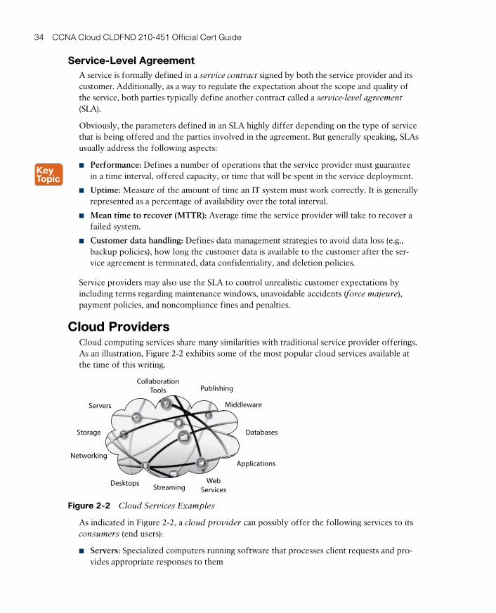
ptg17120290
34 CCNA Cloud CLDFND 210-451 Official Cert Guide
Service-Level AgreementA service is formally defined in a service contract signed by both the service provider and its customer. Additionally, as a way to regulate the expectation about the scope and quality of the service, both parties typically define another contract called a service-level agreement
(SLA).
Obviously, the parameters defined in an SLA highly differ depending on the type of service that is being offered and the parties involved in the agreement. But generally speaking, SLAs usually address the following aspects:
■ Performance: Defines a number of operations that the service provider must guarantee in a time interval, offered capacity, or time that will be spent in the service deployment.
■ Uptime: Measure of the amount of time an IT system must work correctly. It is generally represented as a percentage of availability over the total interval.
■ Mean time to recover (MTTR): Average time the service provider will take to recover a failed system.
■ Customer data handling: Defines data management strategies to avoid data loss (e.g., backup policies), how long the customer data is available to the customer after the ser-vice agreement is terminated, data confidentiality, and deletion policies.
Service providers may also use the SLA to control unrealistic customer expectations by including terms regarding maintenance windows, unavoidable accidents (force majeure), payment policies, and noncompliance fines and penalties.
Cloud ProvidersCloud computing services share many similarities with traditional service provider offerings. As an illustration, Figure 2-2 exhibits some of the most popular cloud services available at the time of this writing.
CollaborationTools Publishing
Middleware
Databases
Applications
WebServicesStreamingDesktops
Networking
Storage
Servers
Figure 2-2 Cloud Services Examples
As indicated in Figure 2-2, a cloud provider can possibly offer the following services to its consumers (end users):
■ Servers: Specialized computers running software that processes client requests and pro-vides appropriate responses to them
ptg17120290
2
Chapter 2: Cloud Shapes: Service Models 35
■ Storage: Capability to store consumer data for a certain period of time
■ Networking: Connectivity between cloud elements and external resources, domain name registration, and IP addressing, among others
■ Desktops: Computers to be used for traditional end-user applications
■ Middleware: Supplementary software, including libraries, programming language inter-preters, database services, user authentication services, account management, and so forth
■ Applications: Software created to achieve objectives of an end user
■ Collaboration tools: Applications that are especially designed to optimize the joint work among different people
■ Publishing: Applications that facilitate the publication of texts such as blogs on the Internet
■ Databases: Organized collection of data that can be queried by other applications
■ Streaming: Media, such as audio and video, that is delivered to end users as a constant flow of data and is generally rendered by a desktop application
■ Web services: Standardized methods of communication between two systems over an IP network
Potentially, this list may encompass all IT services available from service providers. Nev-ertheless, as you have learned in Chapter 1, “What Is Cloud Computing?”, some common parameters defined in traditional SLAs may collide with the essential characteristics of cloud computing. In that chapter, I have juxtaposed opposite characteristics from traditional SP practices such as catered services, rigidity, silos, and overprovisioning to further highlight the NIST definitions for cloud services.
Over time, cloud providers started to attract interest from corporations that desired more dynamic services and less complex hiring procedures. However, all cloud computing companies still constitute SPs, sharing many concerns and responsibilities with these long-established providers. And for such reason, a certain service provider mentality is very welcome in cloud deployments, regardless of whether they are strictly internal or not.
Because Internet access is sometimes all you need to deploy external cloud resources, many companies started to deal with a menace called shadow IT . In these relatively new scenari-os, cloud services are hired by employees without approval from the organization, exposing the whole company to uncontrolled risks. As a reaction, an IT department may either act as a cloud broker , intermediating cloud service hiring on behalf of the employees and accord-ing to predefined compliance policies, or become a cloud provider itself for its internal customers. In the latter case, a private cloud can offer the same level of service of external cloud providers without their associated risks for the business.
NOTE Cloud deployment models such as private cloud will be fully discussed in Chapter 3, “Cloud Heights: Deployment Models.”
To categorize the benefits and issues related to cloud services and help IT decision makers that are dealing with such projects, NIST has released Special Publication 800-146, “Cloud
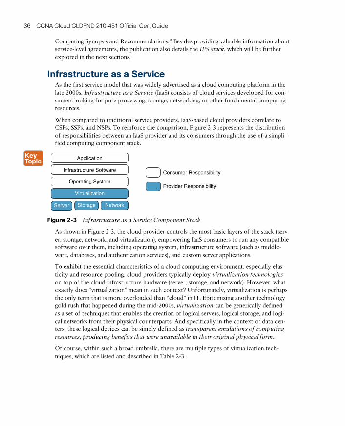
ptg17120290
36 CCNA Cloud CLDFND 210-451 Official Cert Guide
Computing Synopsis and Recommendations.” Besides providing valuable information about service-level agreements, the publication also details the IPS stack, which will be further explored in the next sections.
Infrastructure as a ServiceAs the first service model that was widely advertised as a cloud computing platform in the late 2000s, Infrastructure as a Service (IaaS) consists of cloud services developed for con-sumers looking for pure processing, storage, networking, or other fundamental computing resources.
When compared to traditional service providers, IaaS-based cloud providers correlate to CSPs, SSPs, and NSPs. To reinforce the comparison, Figure 2-3 represents the distribution of responsibilities between an IaaS provider and its consumers through the use of a simpli-fied computing component stack.
Application
Server Storage Network
Virtualization
Operating System
Infrastructure Software Consumer Responsibility
Provider Responsibility
Figure 2-3 Infrastructure as a Service Component Stack
As shown in Figure 2-3, the cloud provider controls the most basic layers of the stack (serv-er, storage, network, and virtualization), empowering IaaS consumers to run any compatible software over them, including operating system, infrastructure software (such as middle-ware, databases, and authentication services), and custom server applications.
To exhibit the essential characteristics of a cloud computing environment, especially elas-ticity and resource pooling, cloud providers typically deploy virtualization technologies on top of the cloud infrastructure hardware (server, storage, and network). However, what exactly does “virtualization” mean in such context? Unfortunately, virtualization is perhaps the only term that is more overloaded than “cloud” in IT. Epitomizing another technology gold rush that happened during the mid-2000s, virtualization can be generically defined as a set of techniques that enables the creation of logical servers, logical storage, and logi-cal networks from their physical counterparts. And specifically in the context of data cen-ters, these logical devices can be simply defined as transparent emulations of computing
resources, producing benefits that were unavailable in their original physical form.
Of course, within such a broad umbrella, there are multiple types of virtualization tech-niques, which are listed and described in Table 2-3.
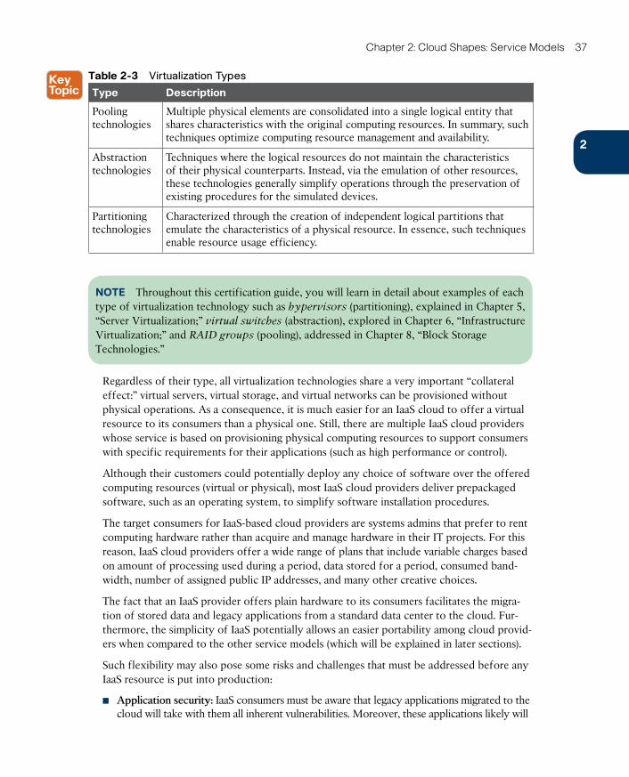
ptg17120290
2
Chapter 2: Cloud Shapes: Service Models 37
Table 2-3 Virtualization Types
Type Description
Pooling technologies
Multiple physical elements are consolidated into a single logical entity that shares characteristics with the original computing resources. In summary, such techniques optimize computing resource management and availability.
Abstraction technologies
Techniques where the logical resources do not maintain the characteristics of their physical counterparts. Instead, via the emulation of other resources, these technologies generally simplify operations through the preservation of existing procedures for the simulated devices.
Partitioning technologies
Characterized through the creation of independent logical partitions that emulate the characteristics of a physical resource. In essence, such techniques enable resource usage efficiency.
NOTE Throughout this certification guide, you will learn in detail about examples of each type of virtualization technology such as hypervisors (partitioning), explained in Chapter 5, “Server Virtualization;” virtual switches (abstraction), explored in Chapter 6, “Infrastructure Virtualization;” and RAID groups (pooling), addressed in Chapter 8, “Block Storage Technologies.”
Regardless of their type, all virtualization technologies share a very important “collateral effect:” virtual servers, virtual storage, and virtual networks can be provisioned without physical operations. As a consequence, it is much easier for an IaaS cloud to offer a virtual resource to its consumers than a physical one. Still, there are multiple IaaS cloud providers whose service is based on provisioning physical computing resources to support consumers with specific requirements for their applications (such as high performance or control).
Although their customers could potentially deploy any choice of software over the offered computing resources (virtual or physical), most IaaS cloud providers deliver prepackaged software, such as an operating system, to simplify software installation procedures.
The target consumers for IaaS-based cloud providers are systems admins that prefer to rent computing hardware rather than acquire and manage hardware in their IT projects. For this reason, IaaS cloud providers offer a wide range of plans that include variable charges based on amount of processing used during a period, data stored for a period, consumed band-width, number of assigned public IP addresses, and many other creative choices.
The fact that an IaaS provider offers plain hardware to its consumers facilitates the migra-tion of stored data and legacy applications from a standard data center to the cloud. Fur-thermore, the simplicity of IaaS potentially allows an easier portability among cloud provid-ers when compared to the other service models (which will be explained in later sections).
Such flexibility may also pose some risks and challenges that must be addressed before any IaaS resource is put into production:
■ Application security: IaaS consumers must be aware that legacy applications migrated to the cloud will take with them all inherent vulnerabilities. Moreover, these applications likely will
ptg17120290
38 CCNA Cloud CLDFND 210-451 Official Cert Guide
be exposed to a less secure environment when compared to the native protection of a com-pany-owned data center. For this reason, many cloud providers offer add-on security services that can be combined (with an associated fee) to the consumer-provisioned resources.
■ Noisy and suspect neighbors: Due to its native multitenant infrastructure, SPs of IaaS clouds deploying partitioning virtualization technologies may contractually disavow any liability for harm that a tenant suffers as a result of the operations of other tenants sharing hardware components … or worse, harm that a tenant suffers from data theft or denial-of-service attacks because of intentional tampering from other tenants. To miti-gate such risks, many IaaS cloud providers offer dedicated hardware for a single tenant, though at a premium charge.
Directly competing with hardware manufacturers, IaaS cloud providers initially gained the most traction among small businesses and midsized companies. Through the gradual addi-tion of security features, these providers have slowly attracted the attention of enterprise corporations and public sector organizations.
Regions and Availability ZonesAlthough it is not considered one of the essential characteristics of cloud computing, non-localization of resources is very commonly associated with these environments. Hence, it is common to assume that a cloud consumer “does not care” from where its service is being provisioned: what matters is the service itself.
Notwithstanding, with more responsibilities on their shoulders when compared to consum-ers of other service models, IaaS cloud tenants may not want to risk loss of application availability if all of its resources are provisioned in the same failure domain, which can be understood as the area of a data center facility that can be impacted during a major system malfunction. Consequently, knowing where a resource is located is an advantage for most consumers with critical applications.
IaaS cloud providers have supported such a requirement through localization services known as regions and availability zones. Originally created by Amazon Web Services (AWS, discussed in the next section), and afterward adopted by other cloud providers under different names, both concepts are represented in Figure 2-4.
Figure 2-4 depicts a global cloud provider with four regions (US, Latin America, Europe, and Asia), which correspond to the choices of data center facilities from which a cloud con-sumer resource can be provisioned. Characteristics such as Internet latency and application user locations may help the cloud consumer choose a region.
NOTE A cloud provider can also create exclusive regions for specific customers to fulfill specific security or compliance requirements.
Each region may contain multiple availability zones, which are basically independent failure domains (or subfacilities) within a single region. Consequently, any disruption in an avail-ability zone should not impact the availability zone or zones. Through this arrangement, a consumer can access IaaS resources from two availability zones within a region of the consumer’s preference and use cheaper connectivity with lower latency when compared to cloud resources installed in two different regions.
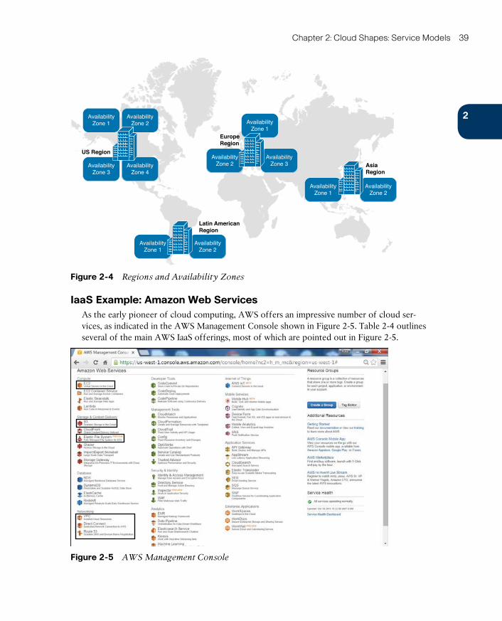
ptg17120290
2
Chapter 2: Cloud Shapes: Service Models 39
US Region
Latin AmericanRegion
AsiaRegion
EuropeRegion
AvailabilityZone 1
AvailabilityZone 2
AvailabilityZone 1
AvailabilityZone 1
AvailabilityZone 1
AvailabilityZone 2
AvailabilityZone 2
AvailabilityZone 2
AvailabilityZone 3
AvailabilityZone 3Availability
Zone 4
Figure 2-4 Regions and Availability Zones
IaaS Example: Amazon Web ServicesAs the early pioneer of cloud computing, AWS offers an impressive number of cloud ser-vices, as indicated in the AWS Management Console shown in Figure 2-5. Table 2-4 outlines several of the main AWS IaaS offerings, most of which are pointed out in Figure 2-5.
Figure 2-5 AWS Management Console
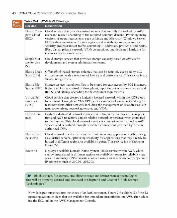
ptg17120290
40 CCNA Cloud CLDFND 210-451 Official Cert Guide
Table 2-4 AWS IaaS Offerings
Service Description
Elastic Com-pute Cloud (EC2)
Cloud service that provides virtual servers that are fully controlled by AWS users and resized according to the required compute demand. Providing many versions of operating systems, such as Linux and Microsoft Windows Server, EC2 enables robustness through regions and availability zones, as well as security groups (rules of traffic containing IP addresses, protocols, and ports), IPsec virtual private network (VPN) connections, and dedicated hardware for instances from a single tenant.
Simple Stor-age Service (S3)
Cloud storage service that provides storage capacity based on objects for development and system administration teams.
Elastic Block Store (EBS)
Offers block-based storage volumes that can be remotely accessed by EC2 virtual servers, with a selection of latency and performance. This service is not shown in Figure 2-5.
Elastic File System (EFS)
Storage service that allows files to be stored for easy access by EC2 instances. It also enables the control of throughput, input/output operations per second (IOPS), and latency, according to the consumer requirements.
Virtual Pri-vate Cloud (VPC)
Cloud service that creates a logically isolated network within the AWS cloud for a tenant. Through an AWS VPC, a user can control virtual networking for resources from other services, including the management of IP addresses, sub-nets, route tables, network gateways, and VPNs.
Direct Con-nect
Enables a dedicated network connection between the premises of a corpora-tion and AWS to achieve a more reliable network experience when compared to the Internet. This cloud network service is compatible with all other AWS services and is enabled through dedicated connections provided by Amazon-authorized TSPs.
Elastic Load Balancing
Cloud network service that can distribute incoming application traffic among EC2 virtual servers, optimizing reliability for applications that may already be hosted in different regions or availability zones. This service is not shown in Figure 2-5.
Route 53 Deploys a scalable Domain Name System (DNS) service within AWS, which can be instantiated in different regions or availability zones for reliability rea-sons. In summary, DNS translates domain names such as www.company.com to IP addresses such as 200.201.202.203.
TIP Block storage, file storage, and object storage are distinct storage technologies that will be properly defined and discussed in Chapter 8 and Chapter 9, “File Storage Technologies.”
Now, let’s put ourselves into the shoes of an IaaS consumer. Figure 2-6 exhibits 5 of the 22 operating system choices that are available for immediate instantiation on AWS after select-ing the EC2 link in the AWS Management Console.
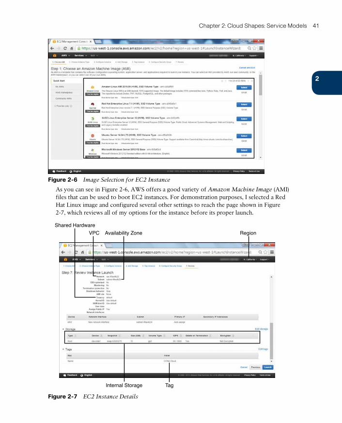
ptg17120290
2
Chapter 2: Cloud Shapes: Service Models 41
Figure 2-6 Image Selection for EC2 Instance
As you can see in Figure 2-6, AWS offers a good variety of Amazon Machine Image (AMI) files that can be used to boot EC2 instances. For demonstration purposes, I selected a Red Hat Linux image and configured several other settings to reach the page shown in Figure 2-7, which reviews all of my options for the instance before its proper launch.
VPC Availability Zone
Shared Hardware
Internal Storage Tag
Region
Figure 2-7 EC2 Instance Details
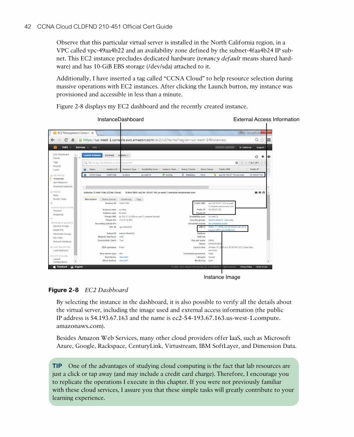
ptg17120290
42 CCNA Cloud CLDFND 210-451 Official Cert Guide
Observe that this particular virtual server is installed in the North California region, in a VPC called vpc-49aa4b22 and an availability zone defined by the subnet-4faa4b24 IP sub-net. This EC2 instance precludes dedicated hardware (tenancy default means shared hard-ware) and has 10-GiB EBS storage (/dev/sda) attached to it.
Additionally, I have inserted a tag called “CCNA Cloud” to help resource selection during massive operations with EC2 instances. After clicking the Launch button, my instance was provisioned and accessible in less than a minute.
Figure 2-8 displays my EC2 dashboard and the recently created instance.
External Access Information
Instance Image
InstanceDashboard
Figure 2-8 EC2 Dashboard
By selecting the instance in the dashboard, it is also possible to verify all the details about the virtual server, including the image used and external access information (the public IP address is 54.193.67.163 and the name is ec2-54-193.67.163.us-west-1.compute.amazonaws.com).
Besides Amazon Web Services, many other cloud providers offer IaaS, such as Microsoft Azure, Google, Rackspace, CenturyLink, Virtustream, IBM SoftLayer, and Dimension Data.
TIP One of the advantages of studying cloud computing is the fact that lab resources are just a click or tap away (and may include a credit card charge). Therefore, I encourage you to replicate the operations I execute in this chapter. If you were not previously familiar with these cloud services, I assure you that these simple tasks will greatly contribute to your learning experience.
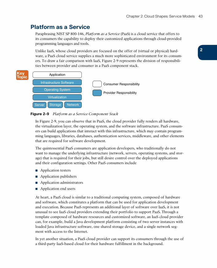
ptg17120290
2
Chapter 2: Cloud Shapes: Service Models 43
Platform as a ServiceParaphrasing NIST SP 800-146, Platform as a Service (PaaS) is a cloud service that offers to its consumers the capability to deploy their customized applications through cloud-provided programming languages and tools.
Unlike IaaS, whose cloud providers are focused on the offer of (virtual or physical) hard-ware, a PaaS cloud service supplies a much more sophisticated environment for its consum-ers. To draw a fair comparison with IaaS, Figure 2-9 represents the division of responsibili-ties between provider and consumer in a PaaS component stack.
Application
Server Storage Network
Virtualization
Operating System
Infrastructure Software Consumer Responsibility
Provider Responsibility
Figure 2-9 Platform as a Service Component Stack
In Figure 2-9, you can observe that in PaaS, the cloud provider fully renders all hardware, the virtualization layer, the operating system, and the software infrastructure. PaaS consum-ers can build applications that interact with this infrastructure, which may contain program-ming languages, libraries, databases, authentication services, middleware, and other elements that are required for software development.
The quintessential PaaS consumers are application developers, who traditionally do not want to manage the underlying infrastructure (network, servers, operating systems, and stor-age) that is required for their jobs, but still desire control over the deployed applications and their configuration settings. Other PaaS consumers include
■ Application testers
■ Application publishers
■ Application administrators
■ Application end users
At heart, a PaaS cloud is similar to a traditional computing system, composed of hardware and software, which constitutes a platform that can be used for application development and execution. Because PaaS represents an additional layer of software over IaaS, it is not unusual to see IaaS cloud providers extending their portfolio to support PaaS. Through a template composed of hardware resources and customized software, an IaaS cloud provider can, for example, build a Java development platform consisting of two server instances with loaded Java infrastructure software, one shared storage device, and a single network seg-ment with access to the Internet.
In yet another situation, a PaaS cloud provider can support its consumers through the use of a third-party IaaS-based cloud for their hardware fulfillment in the background.
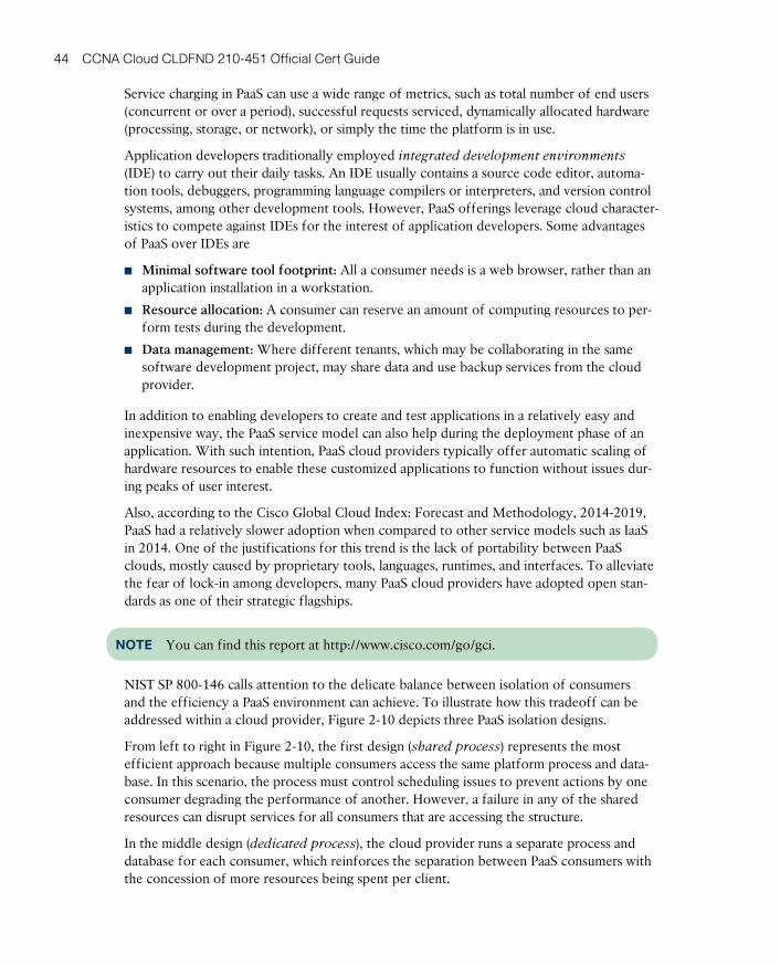
ptg17120290
44 CCNA Cloud CLDFND 210-451 Official Cert Guide
Service charging in PaaS can use a wide range of metrics, such as total number of end users (concurrent or over a period), successful requests serviced, dynamically allocated hardware (processing, storage, or network), or simply the time the platform is in use.
Application developers traditionally employed integrated development environments
(IDE) to carry out their daily tasks. An IDE usually contains a source code editor, automa-tion tools, debuggers, programming language compilers or interpreters, and version control systems, among other development tools. However, PaaS offerings leverage cloud character-istics to compete against IDEs for the interest of application developers. Some advantages of PaaS over IDEs are
■ Minimal software tool footprint: All a consumer needs is a web browser, rather than an application installation in a workstation.
■ Resource allocation: A consumer can reserve an amount of computing resources to per-form tests during the development.
■ Data management: Where different tenants, which may be collaborating in the same software development project, may share data and use backup services from the cloud provider.
In addition to enabling developers to create and test applications in a relatively easy and inexpensive way, the PaaS service model can also help during the deployment phase of an application. With such intention, PaaS cloud providers typically offer automatic scaling of hardware resources to enable these customized applications to function without issues dur-ing peaks of user interest.
Also, according to the Cisco Global Cloud Index: Forecast and Methodology, 2014-2019, PaaS had a relatively slower adoption when compared to other service models such as IaaS in 2014. One of the justifications for this trend is the lack of portability between PaaS clouds, mostly caused by proprietary tools, languages, runtimes, and interfaces. To alleviate the fear of lock-in among developers, many PaaS cloud providers have adopted open stan-dards as one of their strategic flagships.
NOTE You can find this report at http://www.cisco.com/go/gci.
NIST SP 800-146 calls attention to the delicate balance between isolation of consumers and the efficiency a PaaS environment can achieve. To illustrate how this tradeoff can be addressed within a cloud provider, Figure 2-10 depicts three PaaS isolation designs.
From left to right in Figure 2-10, the first design (shared process ) represents the most efficient approach because multiple consumers access the same platform process and data-base. In this scenario, the process must control scheduling issues to prevent actions by one consumer degrading the performance of another. However, a failure in any of the shared resources can disrupt services for all consumers that are accessing the structure.
In the middle design (dedicated process ), the cloud provider runs a separate process and database for each consumer, which reinforces the separation between PaaS consumers with the concession of more resources being spent per client.
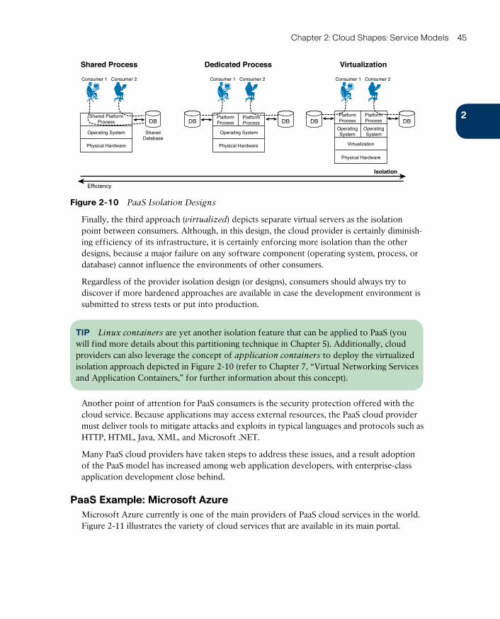
ptg17120290
2
Chapter 2: Cloud Shapes: Service Models 45
Shared Process VirtualizationDedicated Process
DB DB DB DB
Consumer 1 Consumer 2 Consumer 1 Consumer 2 Consumer 1 Consumer 2
Shared PlatformProcess
Physical Hardware
SharedDatabase
Operating System
Efficiency
Physical Hardware
Operating System
PlatformProcess
PlatformProcess
Physical Hardware
Virtualization
OperatingSystem
OperatingSystem
PlatformProcess
PlatformProcess
Isolation
DB
Figure 2-10 PaaS Isolation Designs
Finally, the third approach (virtualized ) depicts separate virtual servers as the isolation point between consumers. Although, in this design, the cloud provider is certainly diminish-ing efficiency of its infrastructure, it is certainly enforcing more isolation than the other designs, because a major failure on any software component (operating system, process, or database) cannot influence the environments of other consumers.
Regardless of the provider isolation design (or designs), consumers should always try to discover if more hardened approaches are available in case the development environment is submitted to stress tests or put into production.
TIP Linux containers are yet another isolation feature that can be applied to PaaS (you will find more details about this partitioning technique in Chapter 5). Additionally, cloud providers can also leverage the concept of application containers to deploy the virtualized isolation approach depicted in Figure 2-10 (refer to Chapter 7, “Virtual Networking Services and Application Containers,” for further information about this concept).
Another point of attention for PaaS consumers is the security protection offered with the cloud service. Because applications may access external resources, the PaaS cloud provider must deliver tools to mitigate attacks and exploits in typical languages and protocols such as HTTP, HTML, Java, XML, and Microsoft .NET.
Many PaaS cloud providers have taken steps to address these issues, and a result adoption of the PaaS model has increased among web application developers, with enterprise-class application development close behind.
PaaS Example: Microsoft AzureMicrosoft Azure currently is one of the main providers of PaaS cloud services in the world. Figure 2-11 illustrates the variety of cloud services that are available in its main portal.

ptg17120290
46 CCNA Cloud CLDFND 210-451 Official Cert Guide
Cloud Services
Figure 2-11 Microsoft Azure Portal
Besides PaaS, Microsoft Azure also supplies IaaS cloud services, including virtual machines (with Windows and other operating systems), data services (including SQL databases and other options of data storage), and virtual networks that allow cloud services to connect to each other and to a customer premises.
Aligning the expertise from the large community of Microsoft developers with its own innovation drive, Microsoft Azure offers a wide range of application development environ-ments.
After selecting Web Apps in the portal shown in Figure 2-11, an extensive list of develop-ment platforms becomes available, as Figure 2-12 displays.
For purposes of demonstration, at the wizard step shown in Figure 2-12, I chose to deploy an ASP.NET environment, which is essentially a Microsoft-developed open source web application framework for dynamic web sites, which may include web applications and web services. Figure 2-13 depicts my site settings for this new service.
Having chosen the suggestive name of ccnacloud for my application environment and the region where I want this service to be deployed (West US), I have concluded the settings for the service. Please observe that I could also have created a new App Service plan to enable automatic scaling in this ASP.NET environment.
Some seconds after I clicked the check symbol, the new provisioned service was available in my Azure console, as shown in Figure 2-14.
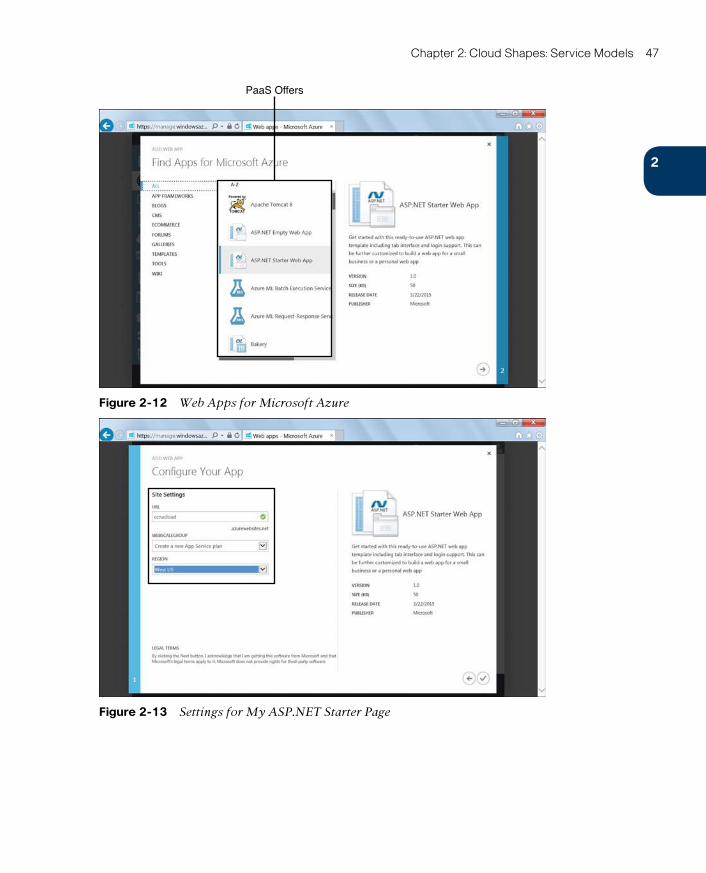
ptg17120290
2
Chapter 2: Cloud Shapes: Service Models 47
PaaS Offers
Figure 2-12 Web Apps for Microsoft Azure
Figure 2-13 Settings for My ASP.NET Starter Page
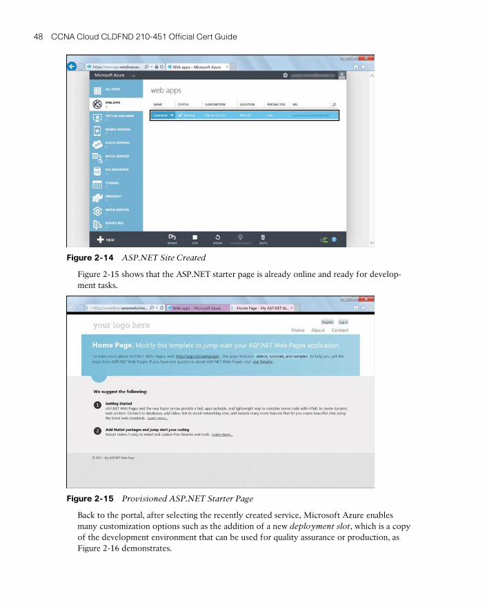
ptg17120290
48 CCNA Cloud CLDFND 210-451 Official Cert Guide
Figure 2-14 ASP.NET Site Created
Figure 2-15 shows that the ASP.NET starter page is already online and ready for develop-ment tasks.
Figure 2-15 Provisioned ASP.NET Starter Page
Back to the portal, after selecting the recently created service, Microsoft Azure enables many customization options such as the addition of a new deployment slot, which is a copy of the development environment that can be used for quality assurance or production, as Figure 2-16 demonstrates.
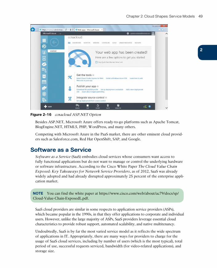
ptg17120290
2
Chapter 2: Cloud Shapes: Service Models 49
Figure 2-16 ccnacloud ASP.NET Option
Besides ASP.NET, Microsoft Azure offers ready-to-go platforms such as Apache Tomcat, BlogEngine.NET, HTML5, PHP, WordPress, and many others.
Competing with Microsoft Azure in the PaaS market, there are other eminent cloud provid-ers such as Salesforce.com, Red Hat OpenShift, SAP, and Google.
Software as a ServiceSoftware as a Service (SaaS) embodies cloud services whose consumers want access to fully functional applications but do not want to manage or control the underlying hardware or software infrastructure. According to the Cisco White Paper The Cloud Value Chain
Exposed: Key Takeaways for Network Service Providers, as of 2012, SaaS was already widely adopted and had already disrupted approximately 25 percent of the enterprise appli-cation market.
NOTE You can find the white paper at https://www.cisco.com/web/about/ac79/docs/sp/Cloud-Value-Chain-ExposedL.pdf.
SaaS cloud providers are similar in some respects to application service providers (ASPs), which became popular in the 1990s, in that they offer applications to corporate and individual users. However, unlike the large majority of ASPs, SaaS providers leverage essential cloud characteristics to provide robust support, automated scalability, and native multitenancy.
Undoubtedly, SaaS is by far the most varied service model as it reflects the wide spectrum of applications in IT. Appropriately, there are many ways for providers to charge for the usage of SaaS cloud services, including by number of users (which is the most typical), total period of use, successful requests serviced, bandwidth (for video-related applications), and storage size.
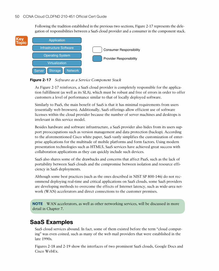
ptg17120290
50 CCNA Cloud CLDFND 210-451 Official Cert Guide
Following the tradition established in the previous two sections, Figure 2-17 represents the dele-gation of responsibilities between a SaaS cloud provider and a consumer in the component stack.
Application
Server Storage Network
Virtualization
Operating System
Infrastructure SoftwareConsumer Responsibility
Provider Responsibility
Figure 2-17 Software as a Service Component Stack
As Figure 2-17 reinforces, a SaaS cloud provider is completely responsible for the applica-tion fulfillment (as well as its SLA), which must be robust and free of errors in order to offer customers a level of performance similar to that of locally deployed software.
Similarly to PaaS, the main benefit of SaaS is that it has minimal requirements from users (essentially web browsers). Additionally, SaaS offerings allow efficient use of software licenses within the cloud provider because the number of server machines and desktops is irrelevant in this service model.
Besides hardware and software infrastructure, a SaaS provider also hides from its users sup-port preoccupations such as version management and data protection (backup). According to the aforementioned Cisco white paper, SaaS vastly simplifies the customization of enter-prise applications for the multitude of mobile platforms and form factors. Using modern presentation technologies such as HTML5, SaaS services have achieved great success with collaboration applications as they can quickly include such devices.
SaaS also shares some of the drawbacks and concerns that affect PaaS, such as the lack of portability between SaaS clouds and the compromise between isolation and resource effi-ciency in SaaS deployments.
Although some best practices (such as the ones described in NIST SP 800-146) do not rec-ommend deploying real-time and critical applications on SaaS clouds, some SaaS providers are developing methods to overcome the effects of Internet latency, such as wide-area net-work (WAN) accelerators and direct connections to the customer premises.
NOTE WAN accelerators, as well as other networking services, will be discussed in more detail in Chapter 7.
SaaS ExamplesSaaS cloud services abound. In fact, some of them existed before the term “cloud comput-ing” was even coined, such as many of the web mail providers that were established in the late 1990s.
Figures 2-18 and 2-19 show the interfaces of two prominent SaaS clouds, Google Docs and Cisco WebEx.
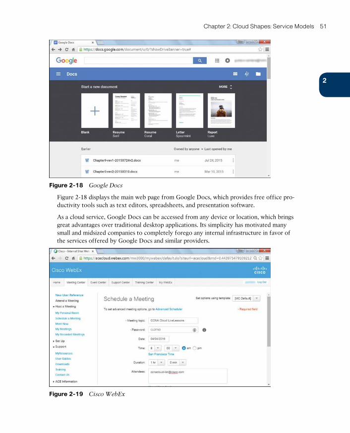
ptg17120290
2
Chapter 2: Cloud Shapes: Service Models 51
Figure 2-18 Google Docs
Figure 2-18 displays the main web page from Google Docs, which provides free office pro-ductivity tools such as text editors, spreadsheets, and presentation software.
As a cloud service, Google Docs can be accessed from any device or location, which brings great advantages over traditional desktop applications. Its simplicity has motivated many small and midsized companies to completely forego any internal infrastructure in favor of the services offered by Google Docs and similar providers.
Figure 2-19 Cisco WebEx
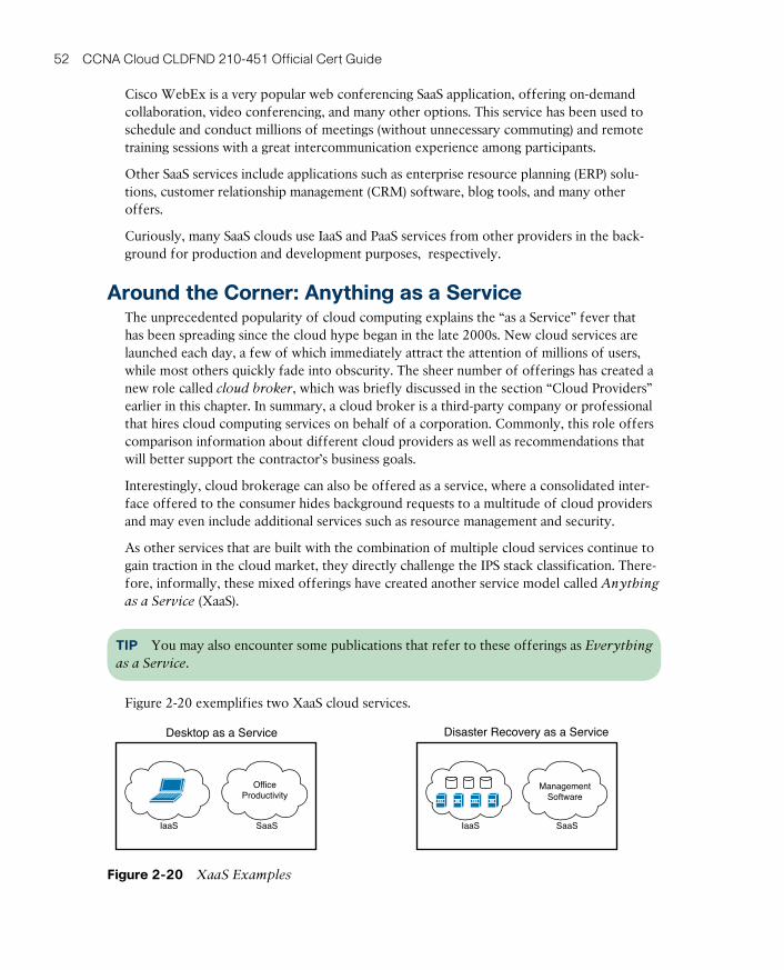
ptg17120290
52 CCNA Cloud CLDFND 210-451 Official Cert Guide
Cisco WebEx is a very popular web conferencing SaaS application, offering on-demand collaboration, video conferencing, and many other options. This service has been used to schedule and conduct millions of meetings (without unnecessary commuting) and remote training sessions with a great intercommunication experience among participants.
Other SaaS services include applications such as enterprise resource planning (ERP) solu-tions, customer relationship management (CRM) software, blog tools, and many other offers.
Curiously, many SaaS clouds use IaaS and PaaS services from other providers in the back-ground for production and development purposes, respectively.
Around the Corner: Anything as a ServiceThe unprecedented popularity of cloud computing explains the “as a Service” fever that has been spreading since the cloud hype began in the late 2000s. New cloud services are launched each day, a few of which immediately attract the attention of millions of users, while most others quickly fade into obscurity. The sheer number of offerings has created a new role called cloud broker, which was briefly discussed in the section “Cloud Providers” earlier in this chapter. In summary, a cloud broker is a third-party company or professional that hires cloud computing services on behalf of a corporation. Commonly, this role offers comparison information about different cloud providers as well as recommendations that will better support the contractor’s business goals.
Interestingly, cloud brokerage can also be offered as a service, where a consolidated inter-face offered to the consumer hides background requests to a multitude of cloud providers and may even include additional services such as resource management and security.
As other services that are built with the combination of multiple cloud services continue to gain traction in the cloud market, they directly challenge the IPS stack classification. There-fore, informally, these mixed offerings have created another service model called Anything
as a Service (XaaS).
TIP You may also encounter some publications that refer to these offerings as Everything
as a Service.
Figure 2-20 exemplifies two XaaS cloud services.
Desktop as a Service Disaster Recovery as a Service
IaaS SaaS
OfficeProductivity
IaaS SaaS
ManagementSoftware
Figure 2-20 XaaS Examples
ptg17120290
2
Chapter 2: Cloud Shapes: Service Models 53
The first example is called Desktop as a Service (DaaS) , where the cloud consumer requests a remotely accessible personal computer to carry out standard PC functions (such as web browsing, document editing, and application execution). A DaaS provider can offer the service through the combination of a computing instance provisioned via an IaaS cloud and desktop software provisioned by one or more SaaS providers.
Figure 2-20 depicts another XaaS offering called Disaster Recovery as a Service (DRaaS) , which enables companies to hire a backup data center (to store data, run applications, and receive end-user requests) in case they do not want, or simply cannot afford, the investment necessary to build their own data center. In these scenarios, a SaaS provider can manage resources in the customer data center as well as servers and storage deployed in an IaaS cloud (owned by the same provider or another provider).
Other XaaS offerings include
■ Backup as a Service (BaaS) : SaaS-provided backup software that can transparently use storage from an IaaS cloud.
■ IP Telephony as a Service (IPTaaS) : IP telephony control software is coordinated through a SaaS cloud, while signaling servers are scaled in an IaaS cloud. Additionally, the provider may offer a SaaS service to support IP telephony application development.
■ VPN as a Service (VPNaaS) : Allows users to control bandwidth scaling and the deploy-ment of features on their VPNs, including monitoring and security services. These modi-fications can be simultaneously supported by SaaS-based management software and IaaS-provided virtual servers deployed inside the customer premises.
Further Reading■ “Want to hear Cisco’s POV on the top 5 questions about the Future of Cloud?” (Cisco
Blog): http://blogs.cisco.com/tag/xaas

ptg17120290
54 CCNA Cloud CLDFND 210-451 Official Cert Guide
Exam Preparation Tasks
Review All the Key TopicsReview the most important topics in this chapter, denoted with a Key Topic icon in the outer margin of the page. Table 2-5 lists a reference of these key topics and the page num-ber on which each is found.
Table 2-5 Key Topics for Chapter 2
Key Topic Element Description Page Number
Table 2-2 Specialized service providers 32
List SLA common aspects 34
Figure 2-3 Infrastructure as a Service component stack 36
Table 2-3 Virtualization types 37
Table 2-4 AWS IaaS offerings 40
Figure 2-9 Platform as a Service component stack 43
Figure 2-17 Software as a Service component stack 50
Complete the Tables and Lists from MemoryPrint a copy of Appendix B, “Memory Tables” (found on the CD), or at least the section for this chapter, and complete the tables and lists from memory. Appendix C, “Answers to Memory Tables,” also on the CD, includes completed tables and lists so that you can check your work.
Define Key TermsDefine the following key terms from this chapter, and check your answers in the glossary:
service provider, service-level agreement (SLA), Infrastructure as a Service (IaaS), virtualiza-tion, region, availability zone, Platform as a Service (PaaS), integrated development environ-ment (IDE), Software as a Service (SaaS), cloud broker, Anything as a Service (XaaS)

ptg17120290
ptg17120290
This chapter covers the following topics:
■ Public Clouds
■ Risks and Challenges
■ Private Clouds
■ Community Clouds
■ Hybrid Clouds
■ Cisco Intercloud
■ Cisco Intercloud Fabric
This chapter covers the following exam objectives:
■ 2.1 Describe Cloud Deployment Models■ 2.1.a Public■ 2.1.b Private■ 2.1.c Community■ 2.1.d Hybrid
■ 2.2 Describe the Components of the Cisco Intercloud Solution■ 2.2.a Describe the benefi ts of Cisco Intercloud■ 2.2.b Describe Cisco Intercloud Fabric Services
ptg17120290
CHAPTER 3
Cloud Heights: Deployment ModelsAs an information technology access model, cloud computing is certainly more malleable than most computer technologies. In addition to having the flexibility to support diverse service models (IaaS, PaaS, SaaS, XaaS), cloud computing enables designers of IT system environments to respond to the skepticism and insecurity of prospective consumers by tai-loring their environments to meet the consumers’ needs.
Like their atmospheric analogs, clouds can be “closer” or “farther” from their users through different deployment models . In summary, this classification (which is independent to service model categorization) imposes usage restrictions in a cloud computing scenario to address vulnerabilities caused by resource sharing and infrastructure implementations that do not satisfy compliance standards.
There are four cloud deployment models: public, private, community, and hybrid. An orga-nization needs to consider the benefits and drawbacks of each deployment model before choosing to implement any of them. After all, the diversity of current service offerings poses additional challenges for customers that desire to avoid provider or technology lock-in. Addressing such challenges, Cisco and an entire ecosystem of partners have brought to reality the concept of the Intercloud, through an open and simple foundation technology called Cisco Intercloud Fabric.
The CLDFND exam requires candidates to have basic knowledge about these four deploy-ment models, Cisco Intercloud, and Cisco Intercloud Fabric. To familiarize you with each, this chapter portrays a journey multiple organizations have taken in their cloud adoption process. Duly, it demonstrates how the hindrances of each deployment model have led to the development of new models, in a progression that outlines the rich landscape of cloud service offerings that we contemplate today.
“Do I Know This Already?” QuizThe “Do I Know This Already?” quiz allows you to assess whether you should read this entire chapter thoroughly or jump to the “Exam Preparation Tasks” section. If you are in doubt about your answers to these questions or your own assessment of your knowledge of the topics, read the entire chapter. Table 3-1 lists the major headings in this chapter and their corresponding “Do I Know This Already?” quiz questions. You can find the answers in Appendix A, “Answers to Pre-Assessments and Quizzes.”
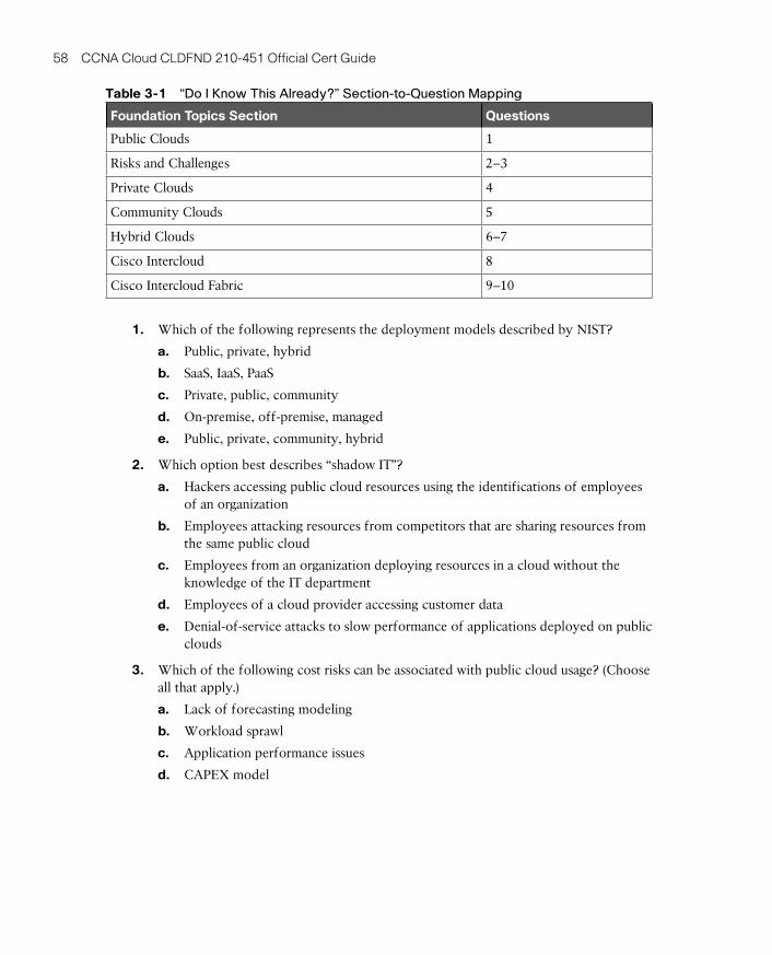
ptg17120290
58 CCNA Cloud CLDFND 210-451 Official Cert Guide
Table 3-1 “Do I Know This Already?” Section-to-Question Mapping
Foundation Topics Section Questions
Public Clouds 1
Risks and Challenges 2–3
Private Clouds 4
Community Clouds 5
Hybrid Clouds 6–7
Cisco Intercloud 8
Cisco Intercloud Fabric 9–10
1. Which of the following represents the deployment models described by NIST?
a. Public, private, hybrid
b. SaaS, IaaS, PaaS
c. Private, public, community
d. On-premise, off-premise, managed
e. Public, private, community, hybrid
2. Which option best describes “shadow IT”?
a. Hackers accessing public cloud resources using the identifications of employees of an organization
b. Employees attacking resources from competitors that are sharing resources from the same public cloud
c. Employees from an organization deploying resources in a cloud without the knowledge of the IT department
d. Employees of a cloud provider accessing customer data
e. Denial-of-service attacks to slow performance of applications deployed on public clouds
3. Which of the following cost risks can be associated with public cloud usage? (Choose all that apply.)
a. Lack of forecasting modeling
b. Workload sprawl
c. Application performance issues
d. CAPEX model
ptg17120290
3
Chapter 3: Cloud Heights: Deployment Models 59
4. According to NIST, what is the definition of private cloud?
a. A cloud deployment provisioned for exclusive use by a single organization
b. A cloud deployment managed by a single organization
c. A computing deployment located inside a single organization’s data center
d. A cloud computing deployment managed and used by a single organization
e. A cloud computing deployment managed, used by a single organization and also located at the same organization’s data center
5. Which of the following options contains only regulatory compliance standards?
a. PCI DSS, FISMA, NIST
b. HIPAA, PCI DSS, SOX
c. IEEE, IETF, ANSI
d. ANSI, FedRAMP, Basel
e. SOX, Intercloud, HIPAA
6. What is “cloud bursting”?
a. A cloud deployment exhausts its infrastructure resources.
b. An organization can provision public cloud services to use during periods of stress of its internal IT resources.
c. Two public cloud providers work in conjunction to load balance requests from a consumer.
d. A private cloud can transform physical workloads into virtual workloads.
7. Which of the following represent challenges of hybrid cloud implementations? (Choose all that apply.)
a. Inconsistent cloud architectures
b. Incompatible networking and security policies
c. Lack of encryption standards
d. Requirement for application reconfiguration when an application is migrated from one cloud to another
e. Few service offerings
8. Which of the following are considered components of the Cisco Intercloud? (Choose all that apply.)
a. Private clouds
b. Public clouds
c. Cisco Powered Partner Clouds
d. Cisco Intercloud Services
ptg17120290
60 CCNA Cloud CLDFND 210-451 Official Cert Guide
9. Which of the following is correct about Cisco Intercloud Fabric? (Choose all that apply.)
a. It is agnostic to server virtualization technology.
b. It provides encryption only for traffic that is traversing the Internet.
c. It does not allow migration of workloads toward a private cloud.
d. It has business and provider complementary solutions.
10. Which of the following is not considered a service of Cisco Intercloud Fabric?
a. VM portability
b. Hybrid cloud management and visibility
c. Cloud networking
d. Community cloud
e. Cloud security
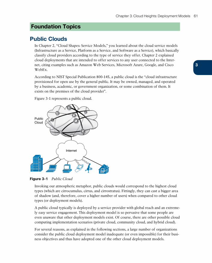
ptg17120290
3
Chapter 3: Cloud Heights: Deployment Models 61
Foundation Topics
Public CloudsIn Chapter 2, “Cloud Shapes: Service Models,” you learned about the cloud service models (Infrastructure as a Service, Platform as a Service, and Software as a Service), which basically classify cloud providers according to the type of service they offer. Chapter 2 explained cloud deployments that are intended to offer services to any user connected to the Inter-net, citing examples such as Amazon Web Services, Microsoft Azure, Google, and Cisco WebEx.
According to NIST Special Publication 800-145, a public cloud is the “cloud infrastructure provisioned for open use by the general public. It may be owned, managed, and operated by a business, academic, or government organization, or some combination of them. It exists on the premises of the cloud provider”.
Figure 3-1 represents a public cloud.
PublicCloud
Internet
Figure 3-1 Public Cloud
Invoking our atmospheric metaphor, public clouds would correspond to the highest cloud types (which are cirrocumulus, cirrus, and cirrostratus). Fittingly, they can cast a bigger area of shadow (and, therefore, cover a higher number of users) when compared to other cloud types (or deployment models).
A public cloud typically is deployed by a service provider with global reach and an extreme-ly easy service engagement. This deployment model is so pervasive that some people are even unaware that other deployment models exist. Of course, there are other possible cloud computing implementation scenarios (private cloud, community cloud, and hybrid cloud).
For several reasons, as explained in the following sections, a large number of organizations consider the public cloud deployment model inadequate (or even impossible) for their busi-ness objectives and thus have adopted one of the other cloud deployment models.

ptg17120290
62 CCNA Cloud CLDFND 210-451 Official Cert Guide
Risks and ChallengesPublic clouds perfectly embodied the advantages of cloud computing during its late-2000s hype. But paradoxically, the broad exposure of public clouds has discouraged some compa-nies from seizing these benefits due to many risks that are intrinsic to the deployment model.
To better explain such risks (and operational challenges), allow me to propose a role-playing game for you: in the next three sections, you will be the Chief Information Officer (CIO) of a fast-growing company that is on the verge of adopting cloud services to increase IT agility. To safely promote the cloud revolution in the organization, you decided to hire a consult-ing firm to accurately assess the risks involved with embracing a public cloud. An experi-enced consultant from the firm is ready to present his assessment to your team through three distinct categories: security, control, and cost risks.
SecurityProbably the most visceral reaction toward public clouds comes from potential consumers who are worried about the inherent vulnerabilities of such environments. As CIO, you are all too aware of this preoccupation because many company systems have suffered attacks during the last year, making security the highest priority in IT in the current fiscal period. The company CEO has put it in blunt terms: “I do not want to lose more money due to lack of preparation against these hacker punks!”
Aware of this situation, the consultant presents the slide depicted in Figure 3-2 to your team to outline the security risks and challenges that your company may encounter if it decides to use public cloud services.
PublicCloud
Account or TrafficHijacking
MaliciousInsiders
Cloud PortalInsecure Interfaces
Your Company
Data Loss
Data Breaches
End User
ShadowIT
Figure 3-2 Public Cloud Security Challenges
Table 3-2 summarizes the risks explained by the consultant.
Table 3-2 Public Cloud Security Risks
Risk Description
Data loss In the case of an outage or major hardware failure in the cloud deployment, cor-porate data may be completely lost.
Data breaches
Sensitive company data may be accessed within the cloud provider or via Inter-net attacks.
Malicious insiders
Although they deploy highly automated environments, cloud providers still have to rely on employees, who are subject to human motivations and malfeasances.
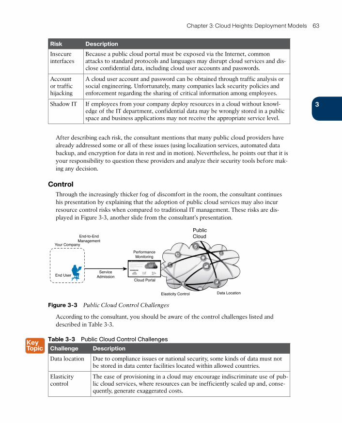
ptg17120290
3
Chapter 3: Cloud Heights: Deployment Models 63
Risk Description
Insecure interfaces
Because a public cloud portal must be exposed via the Internet, common attacks to standard protocols and languages may disrupt cloud services and dis-close confidential data, including cloud user accounts and passwords.
Account or traffic hijacking
A cloud user account and password can be obtained through traffic analysis or social engineering. Unfortunately, many companies lack security policies and enforcement regarding the sharing of critical information among employees.
Shadow IT If employees from your company deploy resources in a cloud without knowl-edge of the IT department, confidential data may be wrongly stored in a public space and business applications may not receive the appropriate service level.
After describing each risk, the consultant mentions that many public cloud providers have already addressed some or all of these issues (using localization services, automated data backup, and encryption for data in rest and in motion). Nevertheless, he points out that it is your responsibility to question these providers and analyze their security tools before mak-ing any decision.
ControlThrough the increasingly thicker fog of discomfort in the room, the consultant continues his presentation by explaining that the adoption of public cloud services may also incur resource control risks when compared to traditional IT management. These risks are dis-played in Figure 3-3, another slide from the consultant’s presentation.
PublicCloudEnd-to-End
Management
ServiceAdmission
PerformanceMonitoring
Cloud Portal
Elasticity Control
Your Company
Data Location
End User
Figure 3-3 Public Cloud Control Challenges
According to the consultant, you should be aware of the control challenges listed and described in Table 3-3.
Table 3-3 Public Cloud Control Challenges
Challenge Description
Data location Due to compliance issues or national security, some kinds of data must not be stored in data center facilities located within allowed countries.
Elasticity control
The ease of provisioning in a cloud may encourage indiscriminate use of pub-lic cloud services, where resources can be inefficiently scaled up and, conse-quently, generate exaggerated costs.
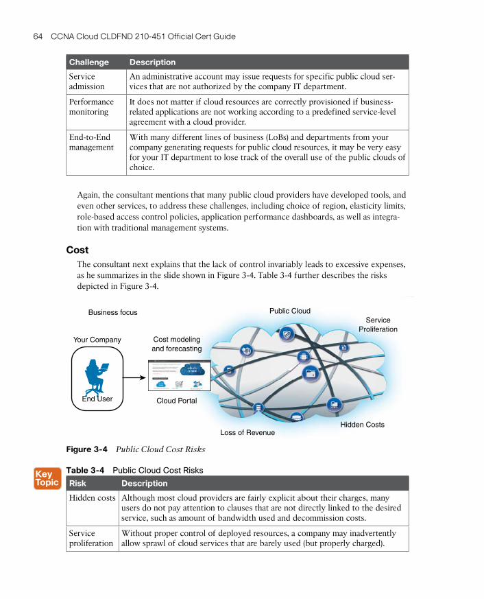
ptg17120290
64 CCNA Cloud CLDFND 210-451 Official Cert Guide
Challenge Description
Service admission
An administrative account may issue requests for specific public cloud ser-vices that are not authorized by the company IT department.
Performance monitoring
It does not matter if cloud resources are correctly provisioned if business-related applications are not working according to a predefined service-level agreement with a cloud provider.
End-to-End management
With many different lines of business (LoBs) and departments from your company generating requests for public cloud resources, it may be very easy for your IT department to lose track of the overall use of the public clouds of choice.
Again, the consultant mentions that many public cloud providers have developed tools, and even other services, to address these challenges, including choice of region, elasticity limits, role-based access control policies, application performance dashboards, as well as integra-tion with traditional management systems.
CostThe consultant next explains that the lack of control invariably leads to excessive expenses, as he summarizes in the slide shown in Figure 3-4. Table 3-4 further describes the risks depicted in Figure 3-4.
Business focus
Your Company
End User
Cost modelingand forecasting
Cloud Portal
Public CloudService
Proliferation
Hidden CostsLoss of Revenue
Figure 3-4 Public Cloud Cost Risks
Table 3-4 Public Cloud Cost Risks
Risk Description
Hidden costs Although most cloud providers are fairly explicit about their charges, many users do not pay attention to clauses that are not directly linked to the desired service, such as amount of bandwidth used and decommission costs.
Service proliferation
Without proper control of deployed resources, a company may inadvertently allow sprawl of cloud services that are barely used (but properly charged).
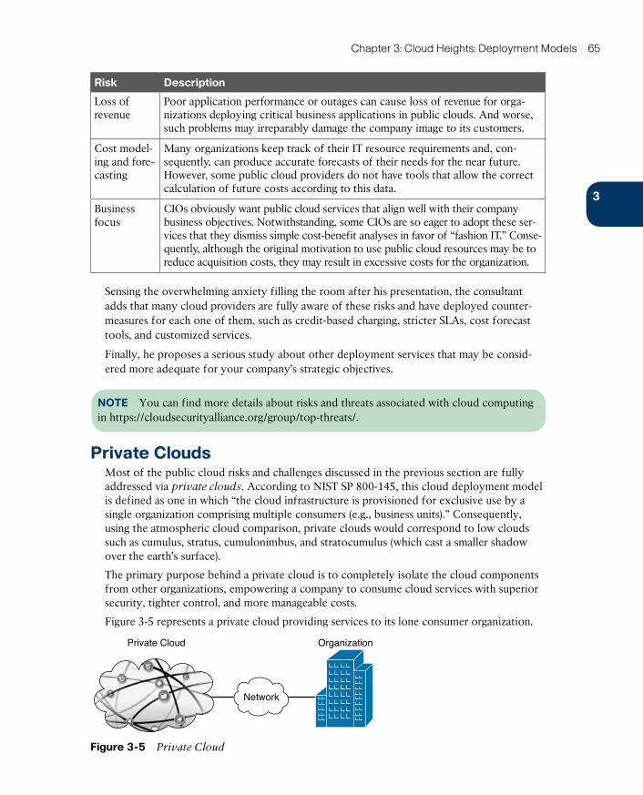
ptg17120290
3
Chapter 3: Cloud Heights: Deployment Models 65
Risk Description
Loss of revenue
Poor application performance or outages can cause loss of revenue for orga-nizations deploying critical business applications in public clouds. And worse, such problems may irreparably damage the company image to its customers.
Cost model-ing and fore-casting
Many organizations keep track of their IT resource requirements and, con-sequently, can produce accurate forecasts of their needs for the near future. However, some public cloud providers do not have tools that allow the correct calculation of future costs according to this data.
Business focus
CIOs obviously want public cloud services that align well with their company business objectives. Notwithstanding, some CIOs are so eager to adopt these ser-vices that they dismiss simple cost-benefit analyses in favor of “fashion IT.” Conse-quently, although the original motivation to use public cloud resources may be to reduce acquisition costs, they may result in excessive costs for the organization.
Sensing the overwhelming anxiety filling the room after his presentation, the consultant adds that many cloud providers are fully aware of these risks and have deployed counter-measures for each one of them, such as credit-based charging, stricter SLAs, cost forecast tools, and customized services.
Finally, he proposes a serious study about other deployment services that may be consid-ered more adequate for your company’s strategic objectives.
NOTE You can find more details about risks and threats associated with cloud computing in https://cloudsecurityalliance.org/group/top-threats/.
Private CloudsMost of the public cloud risks and challenges discussed in the previous section are fully addressed via private clouds. According to NIST SP 800-145, this cloud deployment model is defined as one in which “the cloud infrastructure is provisioned for exclusive use by a single organization comprising multiple consumers (e.g., business units).” Consequently, using the atmospheric cloud comparison, private clouds would correspond to low clouds such as cumulus, stratus, cumulonimbus, and stratocumulus (which cast a smaller shadow over the earth’s surface).
The primary purpose behind a private cloud is to completely isolate the cloud components from other organizations, empowering a company to consume cloud services with superior security, tighter control, and more manageable costs.
Figure 3-5 represents a private cloud providing services to its lone consumer organization.
Private Cloud Organization
Network
Figure 3-5 Private Cloud
ptg17120290
66 CCNA Cloud CLDFND 210-451 Official Cert Guide
As Figure 3-5 depicts , private cloud resources simply are not available for public use. In general, the employees of the served organization receive (or reuse) credentials to request cloud resources. And, of course, these services are provided according to the essential cloud characteristics (on-demand self-service, elasticity, resource pooling, broad network access, and metering) that were extensively discussed in Chapter 1, “What Is Cloud Computing?”
The large majority of organizations that deploy a private cloud designate internal employees to design, build, and support the company’s private cloud. Therefore, the private cloud is usually (but not always) implemented on premises, meaning in a location that belongs to the corporation. Unfortunately, as I have witnessed many times, such projects may eventual-ly become overwhelming to an already overloaded IT department. And, as you have learned in Chapter 2, a cloud computing implementation demands a certain level of service provider competence that many organizations may simply lack.
Hence, alternatively, a private cloud consumer may hire a third-party company to fully manage the cloud deployment. Moreover, a private cloud does not have to be provisioned within a facility owned by the organization. In fact, as the NIST definition of private cloud states, it “may be owned, managed, and operated by the organization, a third party, or some combination of them, and it may exist on or off premises.” What really differentiates a pri-vate cloud from other deployment models in NIST’s definition is that the private cloud is restricted to use by a single corporation.
Interestingly, Amazon Web Services and other public cloud providers can deploy a service called Virtual Private Cloud (VPC) , which emulates a private cloud within a public cloud environment. Commonly used in IaaS, a VPC isolates resources for a cloud tenant from other users through a private IP subnet and a network segment.
VPCs may potentially entail the security, control, and cost risks that a private cloud project is primarily trying to avoid. In summation, the decision to use a VPC (rather than a proper private cloud) depends on the hardware and software isolation services the public provider can offer, which will dictate how secure, manageable, and cost-effective this virtual con-struct actually is.
But as Thomas Aquinas has presumably said, every choice is a renunciation. Likewise, an organization must accept a compromise when it opts for the safeness of a private cloud instead of the flexibility of the public cloud.
In a nutshell, the following public cloud benefits may be lessened (or even eliminated) in private cloud deployments:
■ Broad network access: To achieve the highest level of network isolation, an organization usually deploys private connections between internal users and private cloud resources. Depending on how much such resources scale, this private connection may quickly become a bottleneck.
■ OPEX model: In most private cloud projects, all resources must be acquired before the cloud can be used, reinstating the CAPEX model in this deployment model.
■ Elasticity: The CAPEX model inherently defines an upper limit for scalability of private cloud resources. Consequently, whoever is managing the private cloud must maintain systematic monitoring of the resource usage in the infrastructure.
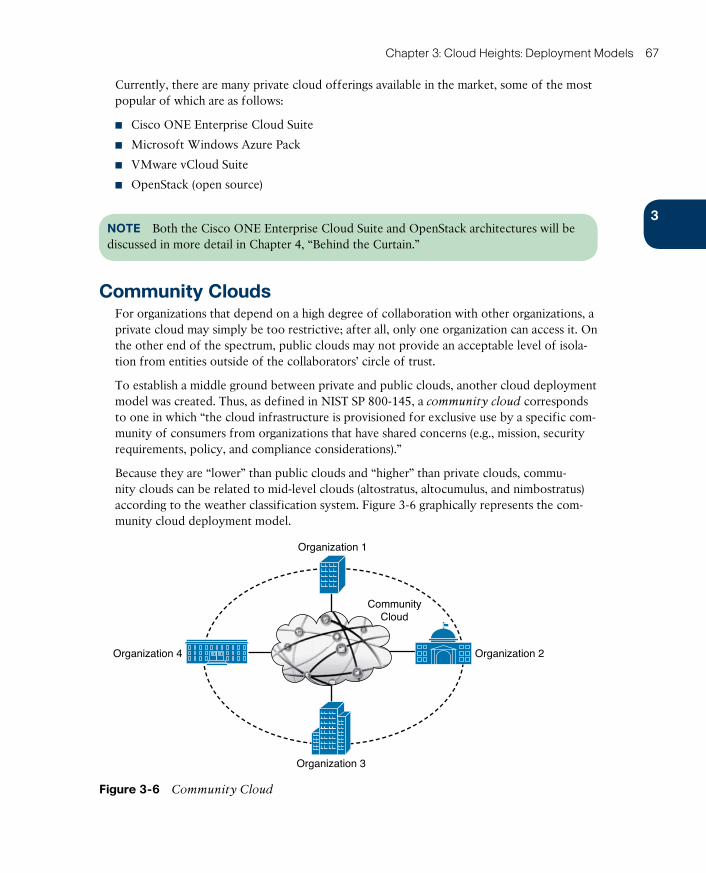
ptg17120290
3
Chapter 3: Cloud Heights: Deployment Models 67
Currently, there are many private cloud offerings available in the market, some of the most popular of which are as follows:
■ Cisco ONE Enterprise Cloud Suite
■ Microsoft Windows Azure Pack
■ VMware vCloud Suite
■ OpenStack (open source)
NOTE Both the Cisco ONE Enterprise Cloud Suite and OpenStack architectures will be discussed in more detail in Chapter 4, “Behind the Curtain.”
Community CloudsFor organizations that depend on a high degree of collaboration with other organizations, a private cloud may simply be too restrictive; after all, only one organization can access it. On the other end of the spectrum, public clouds may not provide an acceptable level of isola-tion from entities outside of the collaborators’ circle of trust.
To establish a middle ground between private and public clouds, another cloud deployment model was created. Thus, as defined in NIST SP 800-145, a community cloud corresponds to one in which “the cloud infrastructure is provisioned for exclusive use by a specific com-munity of consumers from organizations that have shared concerns (e.g., mission, security requirements, policy, and compliance considerations).”
Because they are “lower” than public clouds and “higher” than private clouds, commu-nity clouds can be related to mid-level clouds (altostratus, altocumulus, and nimbostratus) according to the weather classification system. Figure 3-6 graphically represents the com-munity cloud deployment model.
Organization 1
Organization 2
Organization 3
Organization 4
CommunityCloud
Figure 3-6 Community Cloud
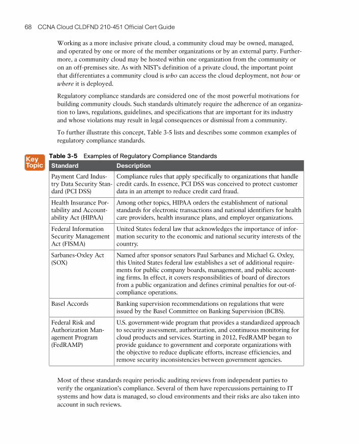
ptg17120290
68 CCNA Cloud CLDFND 210-451 Official Cert Guide
Working as a more inclusive private cloud, a community cloud may be owned, managed, and operated by one or more of the member organizations or by an external party. Further-more, a community cloud may be hosted within one organization from the community or on an off-premises site. As with NIST’s definition of a private cloud, the important point that differentiates a community cloud is who can access the cloud deployment, not how or where it is deployed.
Regulatory compliance standards are considered one of the most powerful motivations for building community clouds. Such standards ultimately require the adherence of an organiza-tion to laws, regulations, guidelines, and specifications that are important for its industry and whose violations may result in legal consequences or dismissal from a community.
To further illustrate this concept, Table 3-5 lists and describes some common examples of regulatory compliance standards.
Table 3-5 Examples of Regulatory Compliance Standards
Standard Description
Payment Card Indus-try Data Security Stan-dard (PCI DSS)
Compliance rules that apply specifically to organizations that handle credit cards. In essence, PCI DSS was conceived to protect customer data in an attempt to reduce credit card fraud.
Health Insurance Por-tability and Account-ability Act (HIPAA)
Among other topics, HIPAA orders the establishment of national standards for electronic transactions and national identifiers for health care providers, health insurance plans, and employer organizations.
Federal Information Security Management Act (FISMA)
United States federal law that acknowledges the importance of infor-mation security to the economic and national security interests of the country.
Sarbanes-Oxley Act (SOX)
Named after sponsor senators Paul Sarbanes and Michael G. Oxley, this United States federal law establishes a set of additional require-ments for public company boards, management, and public account-ing firms. In effect, it covers responsibilities of board of directors from a public organization and defines criminal penalties for out-of-compliance operations.
Basel Accords Banking supervision recommendations on regulations that were issued by the Basel Committee on Banking Supervision (BCBS).
Federal Risk and Authorization Man-agement Program (FedRAMP)
U.S. government-wide program that provides a standardized approach to security assessment, authorization, and continuous monitoring for cloud products and services. Starting in 2012, FedRAMP began to provide guidance to government and corporate organizations with the objective to reduce duplicate efforts, increase efficiencies, and remove security inconsistencies between government agencies.
Most of these standards require periodic auditing reviews from independent parties to verify the organization’s compliance. Several of them have repercussions pertaining to IT systems and how data is managed, so cloud environments and their risks are also taken into account in such reviews.
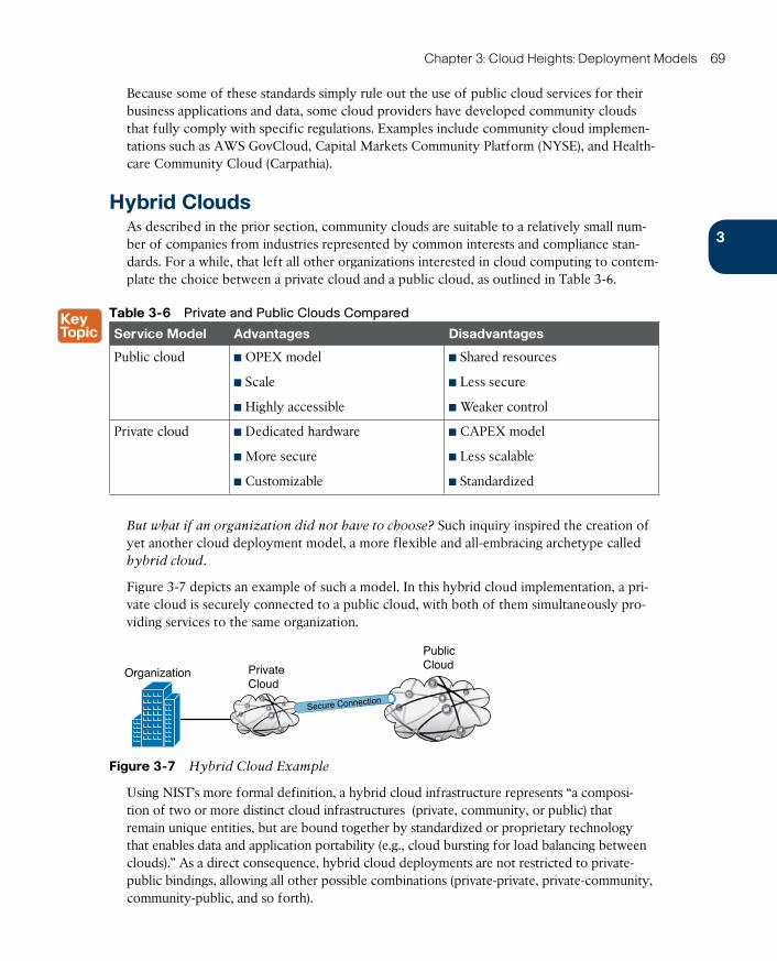
ptg17120290
3
Chapter 3: Cloud Heights: Deployment Models 69
Because some of these standards simply rule out the use of public cloud services for their business applications and data, some cloud providers have developed community clouds that fully comply with specific regulations. Examples include community cloud implemen-tations such as AWS GovCloud, Capital Markets Community Platform (NYSE), and Health-care Community Cloud (Carpathia).
Hybrid CloudsAs described in the prior section, community clouds are suitable to a relatively small num-ber of companies from industries represented by common interests and compliance stan-dards. For a while, that left all other organizations interested in cloud computing to contem-plate the choice between a private cloud and a public cloud, as outlined in Table 3-6.
Table 3-6 Private and Public Clouds Compared
Service Model Advantages Disadvantages
Public cloud ■ OPEX model
■ Scale
■ Highly accessible
■ Shared resources
■ Less secure
■ Weaker control
Private cloud ■ Dedicated hardware
■ More secure
■ Customizable
■ CAPEX model
■ Less scalable
■ Standardized
But what if an organization did not have to choose? Such inquiry inspired the creation of yet another cloud deployment model, a more flexible and all-embracing archetype called hybrid cloud.
Figure 3-7 depicts an example of such a model. In this hybrid cloud implementation, a pri-vate cloud is securely connected to a public cloud, with both of them simultaneously pro-viding services to the same organization.
Organization PrivateCloud
PublicCloud
Secure Connection
Figure 3-7 Hybrid Cloud Example
Using NIST’s more formal definition, a hybrid cloud infrastructure represents “a composi-tion of two or more distinct cloud infrastructures (private, community, or public) that remain unique entities, but are bound together by standardized or proprietary technology that enables data and application portability (e.g., cloud bursting for load balancing between clouds).” As a direct consequence, hybrid cloud deployments are not restricted to private-public bindings, allowing all other possible combinations (private-private, private-community, community-public, and so forth).

ptg17120290
70 CCNA Cloud CLDFND 210-451 Official Cert Guide
TIP Because they cover both high and low altitudes, cumulonimbus with anvil top clouds
would be the atmospheric analog of hybrid clouds.
Using a hybrid cloud, a consumer can decide to provision application resources in the pub-lic cloud during periods of stress in the private cloud or even relocate some internal work-loads to the public part of the hybrid cloud. Both situations define a hybrid cloud feature that is commonly referred as cloud bursting .
Undoubtedly, hybrid clouds enable organizations to seize the best features of each deploy-ment model. For example, an employee can use a private cloud to deploy fixed workloads (and consequently leverage the control, security, and data sovereignty from this structure) while implementing elastic workloads in the public cloud to benefit from its OPEX charging model, provisioning speed, and superior scalability.
Due to its considerable flexibility, the hybrid cloud deployment model has gained a lot of attention from enterprise and public corporations. As reported in the Cisco document Cisco
Intercloud Fabric: Hybrid Cloud with Choice, Consistency, Control and Compliance, according to the results of Forrester Consulting research commissioned by Cisco in 2012, 76 percent of the 69 IT decision makers surveyed planned to implement hybrid clouds, using IaaS to complement on-premises servers and storage and burst peak workloads, among other use cases.
Nevertheless, as seasoned network engineers can attest, a harsher reality underlies any initia-tive that intends to bring two different structures together. Basically, the main challenges faced in hybrid cloud deployments originate from disparate technologies and standards that are used in each of the linked cloud deployments. More specifically, hybrid clouds may fail to integrate infrastructures with distinct
■ Security architectures
■ Encryption algorithms
■ Networking technologies
■ Application characteristics
■ Visibility methods and tools
Fortunately, a very well-known networking company rose to the challenge of integrating heterogeneous cloud deployments in a concept that parallels the foundation of the Internet.
Cisco IntercloudCloud adoption certainly isn’t the only technological dilemma IT departments of the world confront on a daily basis. Many CIOs have been challenged to quickly support business objectives through new concepts such as
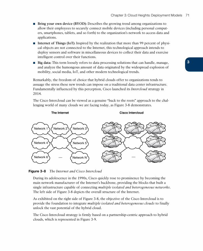
ptg17120290
3
Chapter 3: Cloud Heights: Deployment Models 71
■ Bring your own device (BYOD): Describes the growing trend among organizations to allow their employees to securely connect mobile devices (including personal comput-ers, smartphones, tablets, and so forth) to the organization’s network to access data and applications.
■ Internet of Things (IoT): Inspired by the realization that more than 99 percent of physi-cal objects are not connected to the Internet, this technological approach intends to deploy sensors and software in miscellaneous devices to collect their data and exercise intelligent control over their functions.
■ Big data: This term loosely refers to data processing solutions that can handle, manage, and analyze the humongous amount of data originated by the widespread explosion of mobility, social media, IoT, and other modern technological trends.
Remarkably, the freedom of choice that hybrid clouds offer to organizations tends to assuage the stress these new trends can impose on a traditional data center infrastructure. Fundamentally influenced by this perception, Cisco launched its Intercloud strategy in 2014.
The Cisco Intercloud can be viewed as a genuine “back to the roots” approach to the chal-lenging world of many clouds we are facing today, as Figure 3-8 demonstrates.
...
The Internet Cisco Intercloud
Network 1
Network 6
Network 3
Network N...
Network 2
Network 4 Network 5
Figure 3-8 The Internet and Cisco Intercloud
During its adolescence in the 1990s, Cisco quickly rose to prominence by becoming the main network manufacturer of the Internet’s backbone, providing the blocks that built a single infrastructure capable of connecting multiple isolated and heterogeneous networks. The left side of Figure 3-8 depicts the overall structure of the Internet.
As exhibited on the right side of Figure 3-8, the objective of the Cisco Intercloud is to provide the foundation to integrate multiple isolated and heterogeneous clouds to finally unlock the vast potential of the hybrid cloud.
The Cisco Intercloud strategy is firmly based on a partnership-centric approach to hybrid clouds, which is represented in Figure 3-9.
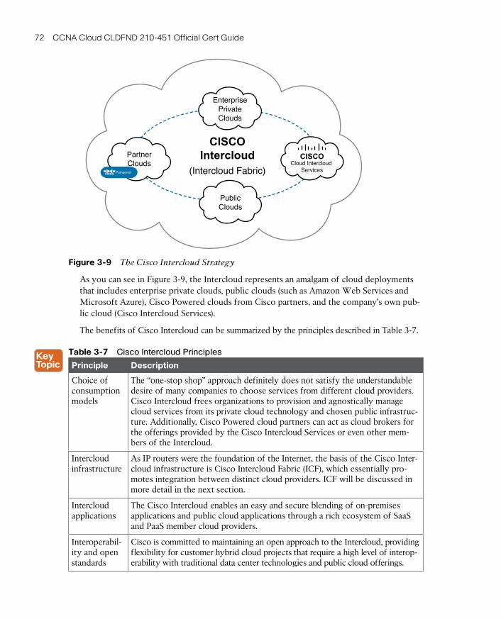
ptg17120290
72 CCNA Cloud CLDFND 210-451 Official Cert Guide
PublicClouds
PartnerClouds
CISCOCloud Intercloud
Services
EnterprisePrivateClouds
CISCOIntercloud
(Intercloud Fabric)CISCO Pampered
Figure 3-9 The Cisco Intercloud Strategy
As you can see in Figure 3-9, the Intercloud represents an amalgam of cloud deployments that includes enterprise private clouds, public clouds (such as Amazon Web Services and Microsoft Azure), Cisco Powered clouds from Cisco partners, and the company’s own pub-lic cloud (Cisco Intercloud Services).
The benefits of Cisco Intercloud can be summarized by the principles described in Table 3-7.
Table 3-7 Cisco Intercloud Principles
Principle Description
Choice of consumption models
The “one-stop shop” approach definitely does not satisfy the understandable desire of many companies to choose services from different cloud providers. Cisco Intercloud frees organizations to provision and agnostically manage cloud services from its private cloud technology and chosen public infrastruc-ture. Additionally, Cisco Powered cloud partners can act as cloud brokers for the offerings provided by the Cisco Intercloud Services or even other mem-bers of the Intercloud.
Intercloud infrastructure
As IP routers were the foundation of the Internet, the basis of the Cisco Inter-cloud infrastructure is Cisco Intercloud Fabric (ICF), which essentially pro-motes integration between distinct cloud providers. ICF will be discussed in more detail in the next section.
Intercloud applications
The Cisco Intercloud enables an easy and secure blending of on-premises applications and public cloud applications through a rich ecosystem of SaaS and PaaS member cloud providers.
Interoperabil-ity and open standards
Cisco is committed to maintaining an open approach to the Intercloud, providing flexibility for customer hybrid cloud projects that require a high level of interop-erability with traditional data center technologies and public cloud offerings.
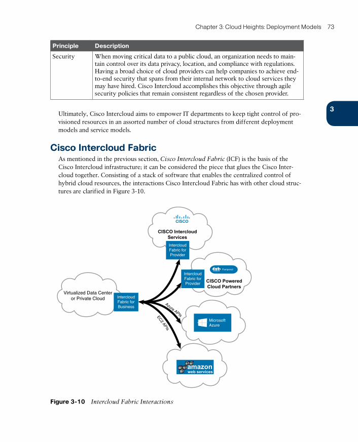
ptg17120290
3
Chapter 3: Cloud Heights: Deployment Models 73
Principle Description
Security When moving critical data to a public cloud, an organization needs to main-tain control over its data privacy, location, and compliance with regulations. Having a broad choice of cloud providers can help companies to achieve end-to-end security that spans from their internal network to cloud services they may have hired. Cisco Intercloud accomplishes this objective through agile security policies that remain consistent regardless of the chosen provider.
Ultimately, Cisco Intercloud aims to empower IT departments to keep tight control of pro-visioned resources in an assorted number of cloud structures from different deployment models and service models.
Cisco Intercloud FabricAs mentioned in the previous section, Cisco Intercloud Fabric (ICF) is the basis of the Cisco Intercloud infrastructure; it can be considered the piece that glues the Cisco Inter-cloud together. Consisting of a stack of software that enables the centralized control of hybrid cloud resources, the interactions Cisco Intercloud Fabric has with other cloud struc-tures are clarified in Figure 3-10.
Virtualized Data Centeror Private Cloud
Azure APIsEC2 APIs
IntercloudFabric forBusiness
IntercloudFabric forProvider
IntercloudFabric forProvider
CISCO
CISCO IntercloudServices
CISCO Pampered
CISCO PoweredCloud Partners
MicrosoftAzure
amazonweb services
Figure 3-10 Intercloud Fabric Interactions
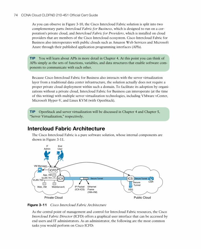
ptg17120290
74 CCNA Cloud CLDFND 210-451 Official Cert Guide
As you can observe in Figure 3-10, the Cisco Intercloud Fabric solution is split into two complementary parts: Intercloud Fabric for Business , which is designed to run on a cor-poration’s private cloud, and Intercloud Fabric for Providers , which is installed on cloud providers that are members of the Cisco Intercloud ecosystem. Cisco Intercloud Fabric for Business also interoperates with public clouds such as Amazon Web Services and Microsoft Azure through their published application programming interfaces (APIs).
TIP You will learn about APIs in more detail in Chapter 4. At this point you can think of APIs simply as the sets of functions, variables, and data structures that enable software com-ponents to communicate with each other.
Because Cisco Intercloud Fabric for Business also interacts with the server virtualization layer from a traditional data center infrastructure, the solution actually does not require a proper private cloud deployment within such a domain. To facilitate its adoption by organi-zations without a private cloud, Intercloud Fabric for Business can interoperate (at the time of this writing) with multiple server virtualization technologies, including VMware vCenter, Microsoft Hyper-V, and Linux KVM (with OpenStack).
TIP OpenStack and server virtualization will be discussed in Chapter 4 and Chapter 5, “Server Virtualization,” respectively.
Intercloud Fabric ArchitectureThe Cisco Intercloud Fabric is a pure software solution, whose internal components are shown in Figure 3-11.
ITAdmin
EndUser
VM Manager
IP Packet(ICX-ICS)
EthernetFrame(VM=VM)
Private Cloud Public Cloud
ICFD
App_VM
WebServerAWeb_VM
VLAN 701VLAN 702
VSG
CSRSecure Tunnel
ICS Secure TunnelICX Secure Tunnel
Figure 3-11 Cisco Intercloud Fabric Architecture
As the central point of management and control for Intercloud Fabric resources, the Cisco Intercloud Fabric Director (ICFD) offers a graphical user interface that can be accessed by end users and IT administrators. As an administrator, the following are the most common tasks you would perform on Cisco ICFD:
ptg17120290
3
Chapter 3: Cloud Heights: Deployment Models 75
■ Establish management connections to server virtualization control software (commonly called VM [virtual machine] managers) from your organization, to provide the raw prod-uct for cloud-bursting operations
■ Configure the secure connection between a public cloud and the enterprise private cloud
■ Add and manage end users
■ Configure policies that govern workload placement between the enterprise and each public cloud
■ Customize portal branding
■ Monitor hardware capacity and utilization per user
■ Create service catalogs to enable end users to provision and manage workloads in the cloud
■ Configure virtual server templates and images, as well as end users’ access to them
Another ICF component, the Cisco Intercloud Extender (ICX) , provides encryption for all data headed toward public clouds through a secure tunnel, which essentially encapsulates encrypted original Ethernet frames into IP packets. To ensure data confidentiality, ICX employs a protocol called Datagram Transport Layer Security (DTLS) , which supports 128- and 256-bit encryption algorithms.
To permit connectivity between resources distributed across distinct clouds, ICX must access virtual local-area networks (VLANs) in the private cloud through the connection with a virtual switch such as Cisco Nexus 1000V.
TIP Multiple virtual switches, including Cisco Nexus 1000V, will be described in further detail in Chapter 6, “Infrastructure Virtualization.”
Whereas ICX encrypts and encapsulates Ethernet frames exiting the private cloud toward the Internet, the Cisco Intercloud Switch (ICS) performs the reverse operations in the pro-vider cloud, decrypting traffic received from ICX and making decisions that are usually related to a physical switch (for example, sending a frame to a virtual machine). Further-more, ICS is also responsible for establishing internal DTLS secure tunnels to any public cloud resource managed by Intercloud Fabric, encrypting frames again before they are sent to such resources. With such arrangement, the Intercloud Fabric solution never exposes traffic in clear text out of the confinements of the private cloud.
As examples of ICF resources deployed in public clouds, the solution offers integrated security and routing services in public cloud providers through Virtual Security Gateway (VSG) and Cloud Service Router (CSR) , respectively. These services, along with all the com-ponents of a secure connection between a private cloud and a public cloud, can be moni-tored in ICFD, as Figure 3-12 delineates.
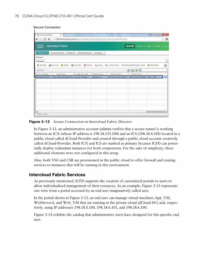
ptg17120290
76 CCNA Cloud CLDFND 210-451 Official Cert Guide
Secure Connection
Figure 3-12 Secure Connection in Intercloud Fabric Director
In Figure 3-12, an administrative account (admin) verifies that a secure tunnel is working between an ICX (whose IP address is 198.18.133.100) and an ICS (198.18.4.105) located in a public cloud called dCloud-Provider and created through a public cloud account creatively called dCloud-Provider. Both ICX and ICS are marked as primary because ICFD can poten-tially deploy redundant instances for both components. For the sake of simplicity, these additional elements were not configured in this setup.
Also, both VSG and CSR are provisioned in the public cloud to offer firewall and routing services to instances that will be running in this environment.
Intercloud Fabric ServicesAs previously mentioned, ICFD supports the creation of customized portals to users to allow individualized management of their resources. As an example, Figure 3-13 represents one view from a portal accessed by an end user imaginatively called user.
In the portal shown in Figure 3-13, an end user can manage virtual machines App_VM, WebServerA, and Web_VM that are running in the private cloud (dCloud-DC) and, respec-tively, using IP addresses 198.18.5.100, 198.18.6.101, and 198.18.6.100.
Figure 3-14 exhibits the catalog that administrative users have designed for this specific end user.
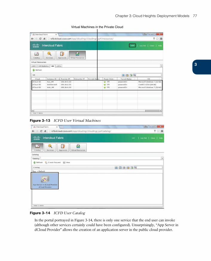
ptg17120290
3
Chapter 3: Cloud Heights: Deployment Models 77
Virtual Machines in the Private Cloud
Figure 3-13 ICFD User Virtual Machines
Figure 3-14 ICFD User Catalog
In the portal portrayed in Figure 3-14, there is only one service that the end user can invoke (although other services certainly could have been configured). Unsurprisingly, “App Server in dCloud Provider” allows the creation of an application server in the public cloud provider.
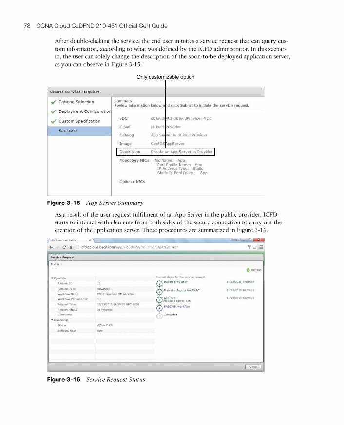
ptg17120290
78 CCNA Cloud CLDFND 210-451 Official Cert Guide
After double-clicking the service, the end user initiates a service request that can query cus-tom information, according to what was defined by the ICFD administrator. In this scenar-io, the user can solely change the description of the soon-to-be deployed application server, as you can observe in Figure 3-15.
Only customizable option
Figure 3-15 App Server Summary
As a result of the user request fulfilment of an App Server in the public provider, ICFD starts to interact with elements from both sides of the secure connection to carry out the creation of the application server. These procedures are summarized in Figure 3-16.
Figure 3-16 Service Request Status
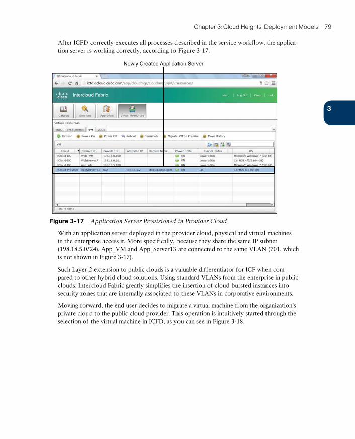
ptg17120290
3
Chapter 3: Cloud Heights: Deployment Models 79
After ICFD correctly executes all processes described in the service workflow, the applica-tion server is working correctly, according to Figure 3-17.
Newly Created Application Server
Figure 3-17 Application Server Provisioned in Provider Cloud
With an application server deployed in the provider cloud, physical and virtual machines in the enterprise access it. More specifically, because they share the same IP subnet (198.18.5.0/24), App_VM and App_Server13 are connected to the same VLAN (701, which is not shown in Figure 3-17).
Such Layer 2 extension to public clouds is a valuable differentiator for ICF when com-pared to other hybrid cloud solutions. Using standard VLANs from the enterprise in public clouds, Intercloud Fabric greatly simplifies the insertion of cloud-bursted instances into security zones that are internally associated to these VLANs in corporative environments.
Moving forward, the end user decides to migrate a virtual machine from the organization’s private cloud to the public cloud provider. This operation is intuitively started through the selection of the virtual machine in ICFD, as you can see in Figure 3-18.
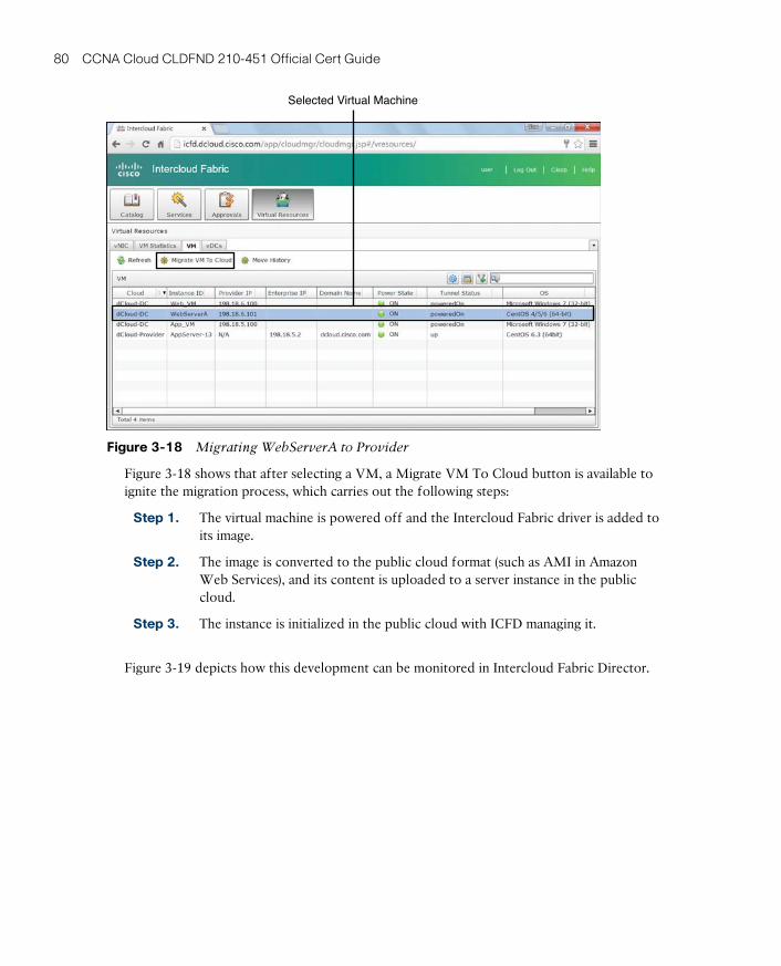
ptg17120290
80 CCNA Cloud CLDFND 210-451 Official Cert Guide
Selected Virtual Machine
Figure 3-18 Migrating WebServerA to Provider
Figure 3-18 shows that after selecting a VM, a Migrate VM To Cloud button is available to ignite the migration process, which carries out the following steps:
Step 1. The virtual machine is powered off and the Intercloud Fabric driver is added to its image.
Step 2. The image is converted to the public cloud format (such as AMI in Amazon Web Services), and its content is uploaded to a server instance in the public cloud.
Step 3. The instance is initialized in the public cloud with ICFD managing it.
Figure 3-19 depicts how this development can be monitored in Intercloud Fabric Director.
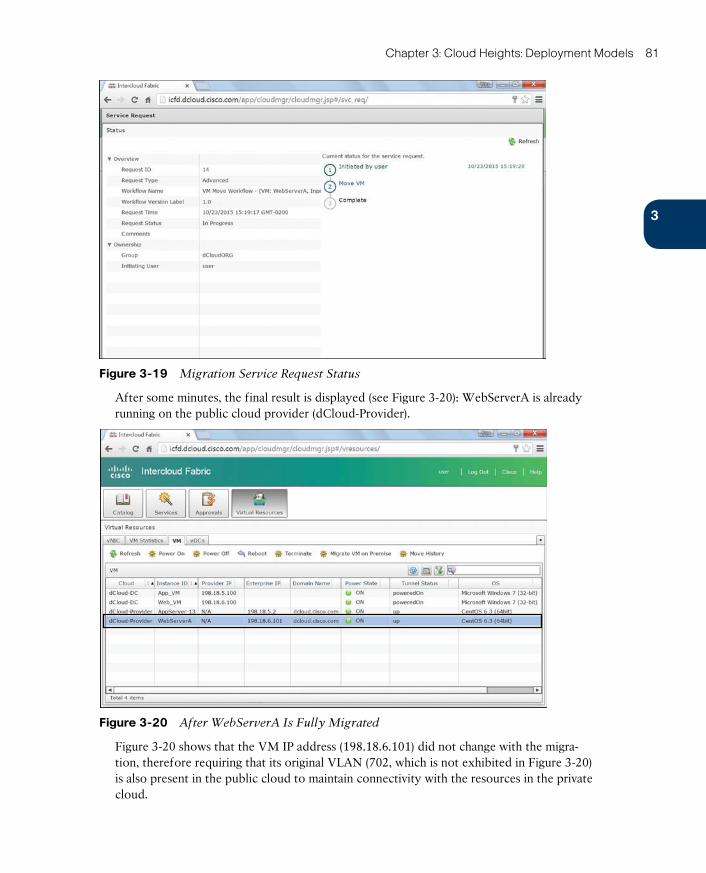
ptg17120290
3
Chapter 3: Cloud Heights: Deployment Models 81
Figure 3-19 Migration Service Request Status
After some minutes, the final result is displayed (see Figure 3-20): WebServerA is already running on the public cloud provider (dCloud-Provider).
Figure 3-20 After WebServerA Is Fully Migrated
Figure 3-20 shows that the VM IP address (198.18.6.101) did not change with the migra-tion, therefore requiring that its original VLAN (702, which is not exhibited in Figure 3-20) is also present in the public cloud to maintain connectivity with the resources in the private cloud.
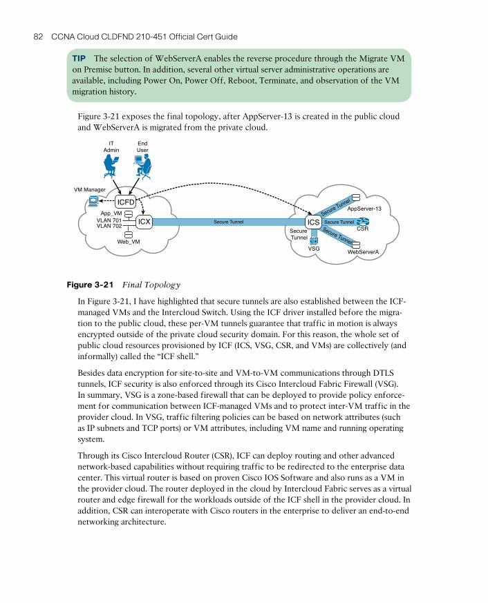
ptg17120290
82 CCNA Cloud CLDFND 210-451 Official Cert Guide
TIP The selection of WebServerA enables the reverse procedure through the Migrate VM on Premise button. In addition, several other virtual server administrative operations are available, including Power On, Power Off, Reboot, Terminate, and observation of the VM migration history.
Figure 3-21 exposes the final topology, after AppServer-13 is created in the public cloud and WebServerA is migrated from the private cloud.
ITAdmin
EndUser
VM Manager
ICFDApp_VM
Web_VM
VLAN 701VLAN 702
AppServer-13
WebServerAVSG
CSRSecure Tunnel
Secure Tunnel
Secure Tunnel
ICS Secure TunnelICX Secure Tunnel
Figure 3-21 Final Topology
In Figure 3-21, I have highlighted that secure tunnels are also established between the ICF-managed VMs and the Intercloud Switch. Using the ICF driver installed before the migra-tion to the public cloud, these per-VM tunnels guarantee that traffic in motion is always encrypted outside of the private cloud security domain. For this reason, the whole set of public cloud resources provisioned by ICF (ICS, VSG, CSR, and VMs) are collectively (and informally) called the “ICF shell.”
Besides data encryption for site-to-site and VM-to-VM communications through DTLS tunnels, ICF security is also enforced through its Cisco Intercloud Fabric Firewall (VSG). In summary, VSG is a zone-based firewall that can be deployed to provide policy enforce-ment for communication between ICF-managed VMs and to protect inter-VM traffic in the provider cloud. In VSG, traffic filtering policies can be based on network attributes (such as IP subnets and TCP ports) or VM attributes, including VM name and running operating system.
Through its Cisco Intercloud Router (CSR), ICF can deploy routing and other advanced network-based capabilities without requiring traffic to be redirected to the enterprise data center. This virtual router is based on proven Cisco IOS Software and also runs as a VM in the provider cloud. The router deployed in the cloud by Intercloud Fabric serves as a virtual router and edge firewall for the workloads outside of the ICF shell in the provider cloud. In addition, CSR can interoperate with Cisco routers in the enterprise to deliver an end-to-end networking architecture.
ptg17120290
3
Chapter 3: Cloud Heights: Deployment Models 83
TIP Both VSG and CSR 1000V will be discussed in more detail in Chapter 7, “Virtual Networking Services and Application Containers.”
Intercloud Fabric Use CasesAdditionally to cloud bursting, the safe and rich feature set of Cisco Intercloud Fabric has inspired a series of very interesting practical uses for this hybrid cloud architecture, such as:
■ Application development and test environments: ICF enables organizations to securely deploy temporary development environments in the public cloud. While test environ-ments can be easily cloned from this scenario, these organizations can also bring back the workloads to their private clouds as soon as they are ready for production.
■ Shadow IT control: The solution offers to employees a secure alternative to ad hoc pub-lic cloud provisioning, giving resource provisioning control back to the IT department.
Around the Corner: Private Cloud as a ServiceMany organizations have struggled to deploy private clouds, only to shelve the project before its completion or see it go untouched by internal users due to lack of business alignment or cloud-related expertise. In response, some pioneering cloud providers have stretched the loose definition of private cloud to encompass another type of cloud service called Private Cloud as a Service (PCaaS), where a cloud provider
■ Deploys an on-premises private cloud in an organization, using pretested automated operations
■ Operates, manages, and supports the private cloud
■ Charges the organization according to its use (OPEX)
Cisco offers PCaaS through the Cisco Metapod , an OpenStack-based solution that is remotely installed over standardized hardware and operated 24 hours a day, all year. Besides the extreme agility in the installation process, Cisco Metapod is a highly available private cloud with a prebuilt catalog for virtual servers and desktops. Additionally, it can integrate with most organizations’ directory services (using Lightweight Directory Access Protocol or Microsoft Active Directory) and provides full support for OpenStack and Amazon Web Service APIs.
Further Reading■ Cisco Metapod: http://www.cisco.com/go/metapod

ptg17120290
84 CCNA Cloud CLDFND 210-451 Official Cert Guide
Exam Preparation Tasks
Review All the Key TopicsReview the most important topics in this chapter, denoted with a Key Topic icon in the outer margin of the page. Table 3-8 lists a reference of these key topics and the page num-ber on which each is found.
Table 3-8 Key Topics for Chapter 3
Key Topic Element Description Page Number
Table 3-2 Public cloud security risks 62
Table 3-3 Public cloud control challenges 63
Table 3-4 Public cloud cost risks 64
Table 3-5 Examples of regulatory compliance standards 68
Table 3-6 Private and public clouds compared 69
Table 3-7 Cisco Intercloud principles 72
List Intercloud Fabric administrator tasks 75
Complete the Tables and Lists from MemoryPrint a copy of Appendix B, “Memory Tables” (found on the CD), or at least the section for this chapter, and complete the tables and lists from memory. Appendix C, “Memory Tables Answer Key,” also on the CD, includes completed tables and lists so that you can check your work.
Define Key TermsDefine the following key terms from this chapter, and check your answers in the glossary:
public cloud, line of business (LoB), private cloud, community cloud, regulatory compliance standards, hybrid cloud, cloud bursting, Cisco Intercloud, Cisco Intercloud Fabric, Inter-cloud Fabric Director (ICFD), Intercloud Extender (ICX), Intercloud Switch (ICS), Virtual Security Gateway (VSG), Cloud Services Router (CSR)

ptg17120290
ptg17120290
This chapter covers the following topics:
■ Cloud Computing Architecture
■ Cloud Infrastructure: Journey to the Cloud
■ Application Programming Interfaces
ptg17120290
CHAPTER 4
Behind the CurtainTaking a quick glance at our rearview mirror, up to this point in the book we have approached cloud computing from an external perspective, focusing on the relationship between cloud consumers and cloud resources. Throughout the previous three chapters, I have discussed the essential aspects that commonly characterize cloud computing environ-ments and explored different classifications according to the types of offered services and restrictions of use.
In this chapter, we shift gears to investigate how exactly a cloud deployment works. Here, you will learn about the components and concepts a cloud architect should master before effectively designing such an environment.
Although the CLDFND exam does not explicitly demand knowledge about the topics discussed in this chapter, I have written it strategically to bridge the gap between the lofty expectations of a cloud computing implementation and the realities of its operation on ser-vice providers, enterprise, and public organizations.
With such intention, the chapter covers the basic architecture of a cloud deployment and its main software functions; data center infrastructure evolution toward cloud computing; and the main methods of communication between all cloud elements. And to further assist you to successfully cross the chasm between a cloud user and a cloud professional, your reading experience will be broadened through real-world solutions and scenarios.
“Do I Know This Already?” QuizThe “Do I Know This Already?” quiz allows you to assess whether you should read this entire chapter thoroughly or jump to the “Exam Preparation Tasks” section. If you are in doubt about your answers to these questions or your own assessment of your knowledge of the topics, read the entire chapter. Table 4-1 lists the major headings in this chapter and their corresponding “Do I Know This Already?” quiz questions. You can find the answers in Appendix A, “Answers to Pre-Assessments and Quizzes.”
Table 4-1 “Do I Know This Already?” Section-to-Question Mapping
Foundation Topics Section Questions
Cloud Computing Architecture 1
Cloud Infrastructure: Journey to the Cloud 2
Application Programming Interfaces 3
ptg17120290
88 CCNA Cloud CLDFND 210-451 Official Cert Guide
1. Which of the following are components of the cloud software stack? (Choose all that apply.)
a. Virtualization software
b. Meter
c. Orchestrator
d. Portal
e. All software running within a data center that is hosting a cloud environment
2. Which of the following options summarizes the importance of standardization for cloud deployments?
a. Any cloud computing deployment requires a single vendor for all infrastructure components.
b. Virtualization solutions do not require standardization in cloud computing imple-mentations.
c. Cloud software stack solutions already provide standardization for cloud infra-structure.
d. Standardization of hardware, software, processes, and offerings facilitate automa-tion and increase predictability in a cloud computing deployment.
e. None, because cloud computing scenarios must always be ready for customiza-tion.
3. Which of the following are not characteristics of RESTful application programming interfaces? (Choose all that apply.)
a. Uses HTTP or HTTPS
b. Only supports XML data
c. Designed for web services
d. Follows a request-response model
e. Designed for human reading
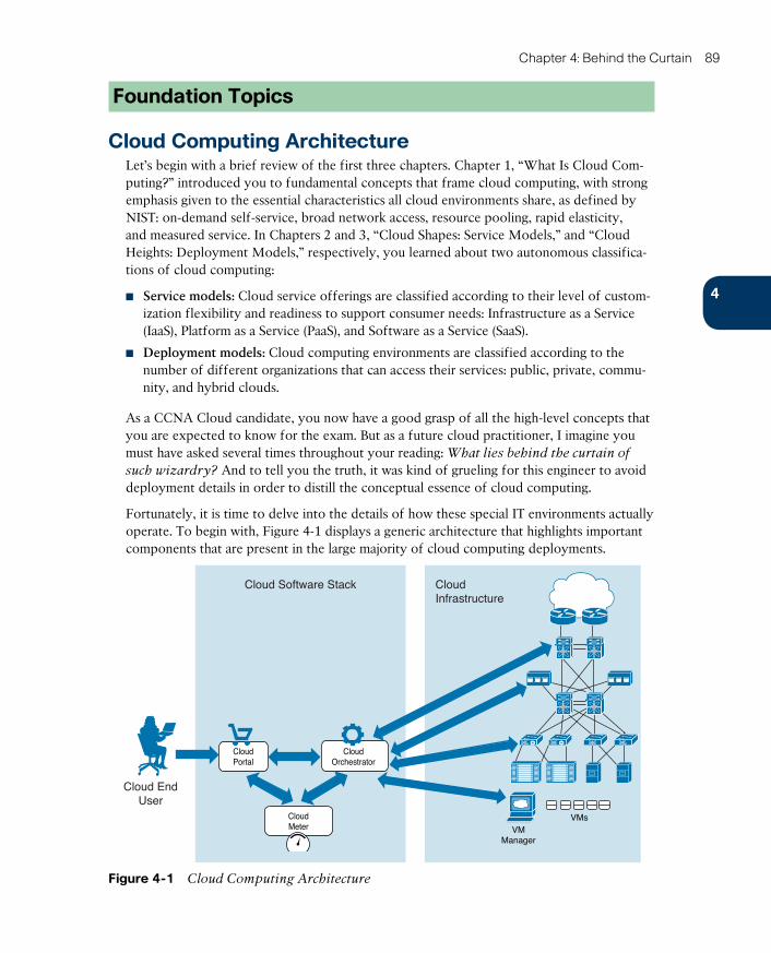
ptg17120290
4
Chapter 4: Behind the Curtain 89
Foundation Topics
Cloud Computing ArchitectureLet’s begin with a brief review of the first three chapters. Chapter 1, “What Is Cloud Com-puting?” introduced you to fundamental concepts that frame cloud computing, with strong emphasis given to the essential characteristics all cloud environments share, as defined by NIST: on-demand self-service, broad network access, resource pooling, rapid elasticity, and measured service. In Chapters 2 and 3, “Cloud Shapes: Service Models,” and “Cloud Heights: Deployment Models,” respectively, you learned about two autonomous classifica-tions of cloud computing:
■ Service models: Cloud service offerings are classified according to their level of custom-ization flexibility and readiness to support consumer needs: Infrastructure as a Service (IaaS), Platform as a Service (PaaS), and Software as a Service (SaaS).
■ Deployment models: Cloud computing environments are classified according to the number of different organizations that can access their services: public, private, commu-nity, and hybrid clouds.
As a CCNA Cloud candidate, you now have a good grasp of all the high-level concepts that you are expected to know for the exam. But as a future cloud practitioner, I imagine you must have asked several times throughout your reading: What lies behind the curtain of
such wizardry? And to tell you the truth, it was kind of grueling for this engineer to avoid deployment details in order to distill the conceptual essence of cloud computing.
Fortunately, it is time to delve into the details of how these special IT environments actually operate. To begin with, Figure 4-1 displays a generic architecture that highlights important components that are present in the large majority of cloud computing deployments.
VMManager
VMs
Cloud EndUser
Cloud Software Stack CloudInfrastructure
CloudPortal
CloudOrchestrator
CloudMeter
Figure 4-1 Cloud Computing Architecture

ptg17120290
90 CCNA Cloud CLDFND 210-451 Official Cert Guide
In Figure 4-1, the cloud elements are clearly separated into two groups: cloud software stack and cloud infrastructure. Such division is further described in Table 4-2.
Table 4-2 Cloud Component Classes
Class Description
Cloud software stack
Concerns integrated software modules that are developed to exclusively perform cloud-related operations, such as providing a service catalog to cloud consumers, provisioning requested resources, and keeping track of cloud resource usage
Cloud infrastructure Applies to all software and hardware that the cloud software stack orchestrates and that can also be used in non-cloud data center environ-ments
Whereas the components of the cloud software stack translate the consumer requests into infrastructure management operations, the cloud infrastructure elements embody the resources that will actually be used by the cloud consumers. As represented in Figure 4-1, the cloud infrastructure consists of network devices, storage systems, physical servers, virtual machines, security solutions, networking service appliances, and operating systems, among other solutions.
Because each of these infrastructure elements will be thoroughly explained in future chap-ters, the following sections describe the main components of the cloud software stack.
NOTE Across different cloud computing deployments, you will certainly find these ele-ments implemented in varied arrangements, such as services of monolithic applications or as integrated software modules from different vendors. The focus of this chapter is to intro-duce these elements as functions rather than as independent software pieces.
Cloud PortalMuch like an application on a personal computer, the cloud portal directly interacts with end users. Essentially, the portal publishes cloud service catalogs, wizards for guided user “shopping,” interactive forms, approval workflows, status updates, usage information, and billing balances.
Figure 4-2 depicts an example screenshot from the Cisco Prime Service Catalog (PSC) cloud portal, which is a software module that belongs to the Cisco ONE Enterprise Cloud Suite integrated cloud software stack. As indicated, the interface is presented to the user as a per-sonal IT as a Service (ITaaS) storefront.
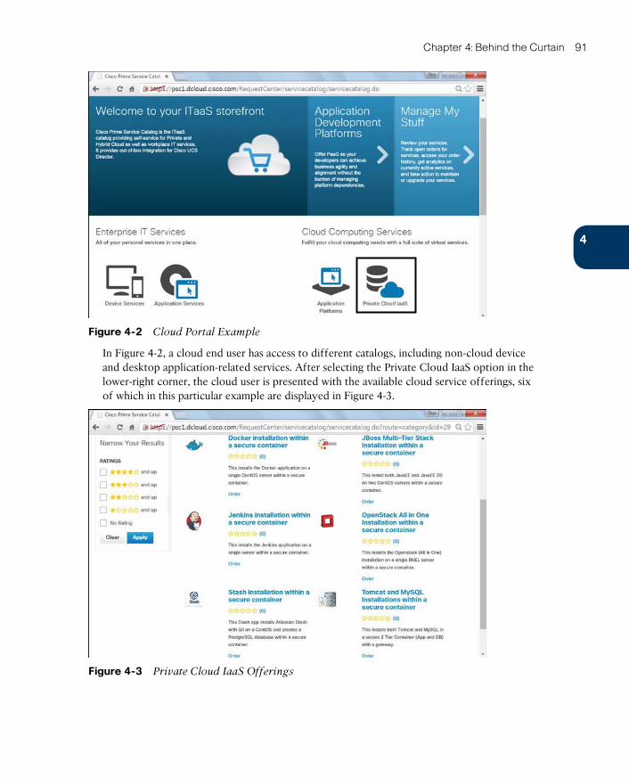
ptg17120290
4
Chapter 4: Behind the Curtain 91
Figure 4-2 Cloud Portal Example
In Figure 4-2, a cloud end user has access to different catalogs, including non-cloud device and desktop application-related services. After selecting the Private Cloud IaaS option in the lower-right corner, the cloud user is presented with the available cloud service offerings, six of which in this particular example are displayed in Figure 4-3.
Figure 4-3 Private Cloud IaaS Offerings
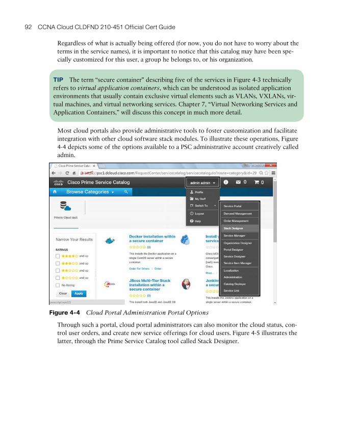
ptg17120290
92 CCNA Cloud CLDFND 210-451 Official Cert Guide
Regardless of what is actually being offered (for now, you do not have to worry about the terms in the service names), it is important to notice that this catalog may have been spe-cially customized for this user, a group he belongs to, or his organization.
TIP The term “secure container” describing five of the services in Figure 4-3 technically refers to virtual application containers , which can be understood as isolated application environments that usually contain exclusive virtual elements such as VLANs, VXLANs, vir-tual machines, and virtual networking services. Chapter 7, “Virtual Networking Services and Application Containers,” will discuss this concept in much more detail.
Most cloud portals also provide administrative tools to foster customization and facilitate integration with other cloud software stack modules. To illustrate these operations, Figure 4-4 depicts some of the options available to a PSC administrative account creatively called admin.
Figure 4-4 Cloud Portal Administration Portal Options
Through such a portal, cloud portal administrators can also monitor the cloud status, con-trol user orders, and create new service offerings for cloud users. Figure 4-5 illustrates the latter, through the Prime Service Catalog tool called Stack Designer.

ptg17120290
4
Chapter 4: Behind the Curtain 93
Figure 4-5 Prime Service Catalog Stack Designer
Figure 4-5 depicts the creation of a new service called “CCNA Cloud CLDFND Exam Simu-lator,” which contains two servers: an app server running the exam simulator, and a db serv-er containing multiple questions that can be summoned to compose an on-demand exam.
The PSC software stack designer uses templates with a varied number of elements (virtual machines, for example) to enable an easy assignment of applications to each catalog offer-ing. After the application is designed, it can be published to the cloud end users as Figure 4-6 shows.
Figure 4-6 Publishing a Service to All Users
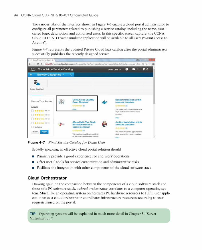
ptg17120290
94 CCNA Cloud CLDFND 210-451 Official Cert Guide
The various tabs of the interface shown in Figure 4-6 enable a cloud portal administrator to configure all parameters related to publishing a service catalog, including the name, asso-ciated logo, description, and authorized users. In this specific screen capture, the CCNA Cloud CLDFND Exam Simulator application will be available to all users (“Grant access to Anyone”).
Figure 4-7 represents the updated Private Cloud IaaS catalog after the portal administrator successfully publishes the recently designed service.
Figure 4-7 Final Service Catalog for Demo User
Broadly speaking, an effective cloud portal solution should
■ Primarily provide a good experience for end users’ operations
■ Offer useful tools for service customization and administrative tasks
■ Facilitate the integration with other components of the cloud software stack
Cloud OrchestratorDrawing again on the comparison between the components of a cloud software stack and those of a PC software stack, a cloud orchestrator correlates to a computer operating sys-tem. Much like an operating system orchestrates PC hardware resources to fulfill user appli-cation tasks, a cloud orchestrator coordinates infrastructure resources according to user requests issued on the portal.
TIP Operating systems will be explained in much more detail in Chapter 5, “Server Virtualization.”
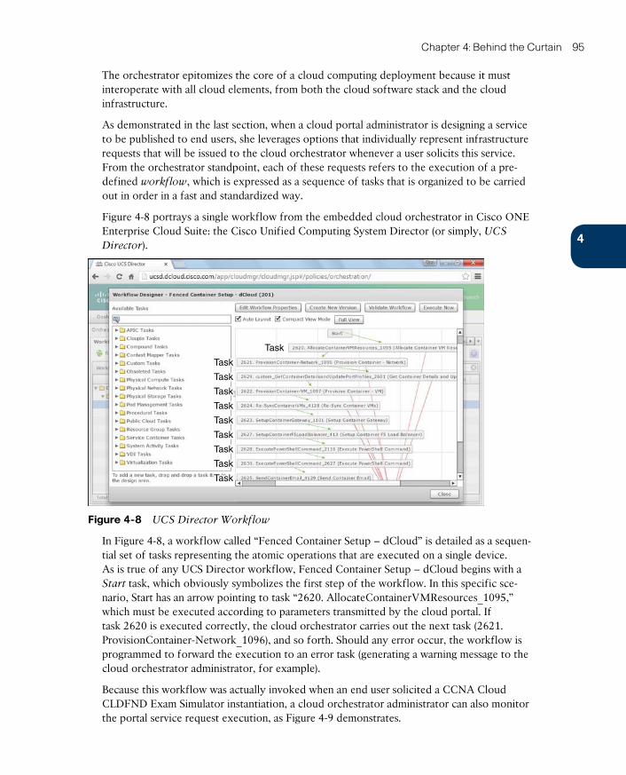
ptg17120290
4
Chapter 4: Behind the Curtain 95
The orchestrator epitomizes the core of a cloud computing deployment because it must interoperate with all cloud elements, from both the cloud software stack and the cloud infrastructure.
As demonstrated in the last section, when a cloud portal administrator is designing a service to be published to end users, she leverages options that individually represent infrastructure requests that will be issued to the cloud orchestrator whenever a user solicits this service. From the orchestrator standpoint, each of these requests refers to the execution of a pre-defined workflow , which is expressed as a sequence of tasks that is organized to be carried out in order in a fast and standardized way.
Figure 4-8 portrays a single workflow from the embedded cloud orchestrator in Cisco ONE Enterprise Cloud Suite: the Cisco Unified Computing System Director (or simply, UCS
Director).
Task
Task
Task
Task
Task
Task
Task
Task
Task
Task
Figure 4-8 UCS Director Workflow
In Figure 4-8, a workflow called “Fenced Container Setup – dCloud” is detailed as a sequen-tial set of tasks representing the atomic operations that are executed on a single device. As is true of any UCS Director workflow, Fenced Container Setup – dCloud begins with a Start task, which obviously symbolizes the first step of the workflow. In this specific sce-nario, Start has an arrow pointing to task “2620. AllocateContainerVMResources_1095,” which must be executed according to parameters transmitted by the cloud portal. If task 2620 is executed correctly, the cloud orchestrator carries out the next task (2621. ProvisionContainer-Network_1096), and so forth. Should any error occur, the workflow is programmed to forward the execution to an error task (generating a warning message to the cloud orchestrator administrator, for example).
Because this workflow was actually invoked when an end user solicited a CCNA Cloud CLDFND Exam Simulator instantiation, a cloud orchestrator administrator can also monitor the portal service request execution, as Figure 4-9 demonstrates.

ptg17120290
96 CCNA Cloud CLDFND 210-451 Official Cert Guide
Figure 4-9 Workflow Execution
To correctly execute a workflow, a cloud orchestrator must have information about the devices that are related to each workflow task. Using management connections for this endeavor, UCS Director also monitors resource usage and availability, greatly simplifying capacity planning of a cloud computing environment.
Figure 4-10 depicts a dashboard from UCS Director displaying device information, provi-sioned resources, and overall capacity for storage (na-edge1), servers (dCloud_UCSM), net-work (VSM), and server virtualization (dCloud_VC_55).
Figure 4-10 UCS Director Dashboard
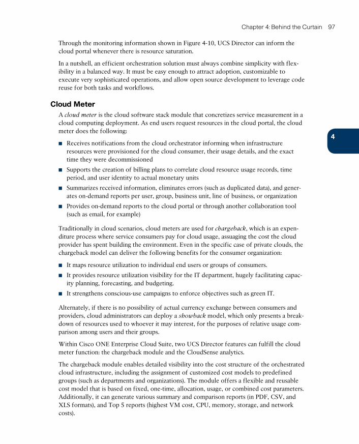
ptg17120290
4
Chapter 4: Behind the Curtain 97
Through the monitoring information shown in Figure 4-10, UCS Director can inform the cloud portal whenever there is resource saturation.
In a nutshell, an efficient orchestration solution must always combine simplicity with flex-ibility in a balanced way. It must be easy enough to attract adoption, customizable to execute very sophisticated operations, and allow open source development to leverage code reuse for both tasks and workflows.
Cloud MeterA cloud meter is the cloud software stack module that concretizes service measurement in a cloud computing deployment. As end users request resources in the cloud portal, the cloud meter does the following:
■ Receives notifications from the cloud orchestrator informing when infrastructure resources were provisioned for the cloud consumer, their usage details, and the exact time they were decommissioned
■ Supports the creation of billing plans to correlate cloud resource usage records, time period, and user identity to actual monetary units
■ Summarizes received information, eliminates errors (such as duplicated data), and gener-ates on-demand reports per user, group, business unit, line of business, or organization
■ Provides on-demand reports to the cloud portal or through another collaboration tool (such as email, for example)
Traditionally in cloud scenarios, cloud meters are used for chargeback , which is an expen-diture process where service consumers pay for cloud usage, assuaging the cost the cloud provider has spent building the environment. Even in the specific case of private clouds, the chargeback model can deliver the following benefits for the consumer organization:
■ It maps resource utilization to individual end users or groups of consumers.
■ It provides resource utilization visibility for the IT department, hugely facilitating capac-ity planning, forecasting, and budgeting.
■ It strengthens conscious-use campaigns to enforce objectives such as green IT.
Alternately, if there is no possibility of actual currency exchange between consumers and providers, cloud administrators can deploy a showback model, which only presents a break-down of resources used to whoever it may interest, for the purposes of relative usage com-parison among users and their groups.
Within Cisco ONE Enterprise Cloud Suite, two UCS Director features can fulfill the cloud meter function: the chargeback module and the CloudSense analytics.
The chargeback module enables detailed visibility into the cost structure of the orchestrated cloud infrastructure, including the assignment of customized cost models to predefined groups (such as departments and organizations). The module offers a flexible and reusable cost model that is based on fixed, one-time, allocation, usage, or combined cost parameters. Additionally, it can generate various summary and comparison reports (in PDF, CSV, and XLS formats), and Top 5 reports (highest VM cost, CPU, memory, storage, and network costs).
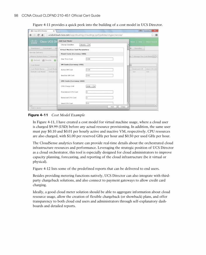
ptg17120290
98 CCNA Cloud CLDFND 210-451 Official Cert Guide
Figure 4-11 provides a quick peek into the building of a cost model in UCS Director.
Figure 4-11 Cost Model Example
In Figure 4-11, I have created a cost model for virtual machine usage, where a cloud user is charged $9.99 (USD) before any actual resource provisioning. In addition, the same user must pay $0.10 and $0.01 per hourly active and inactive VM, respectively. CPU resources are also charged, with $1.00 per reserved GHz per hour and $0.50 per used GHz per hour.
The CloudSense analytics feature can provide real-time details about the orchestrated cloud infrastructure resources and performance. Leveraging the strategic position of UCS Director as a cloud orchestrator, this tool is especially designed for cloud administrators to improve capacity planning, forecasting, and reporting of the cloud infrastructure (be it virtual or physical).
Figure 4-12 lists some of the predefined reports that can be delivered to end users.
Besides providing metering functions natively, UCS Director can also integrate with third-party chargeback solutions, and also connect to payment gateways to allow credit card charging.
Ideally, a good cloud meter solution should be able to aggregate information about cloud resource usage, allow the creation of flexible chargeback (or showback) plans, and offer transparency to both cloud end users and administrators through self-explanatory dash-boards and detailed reports.
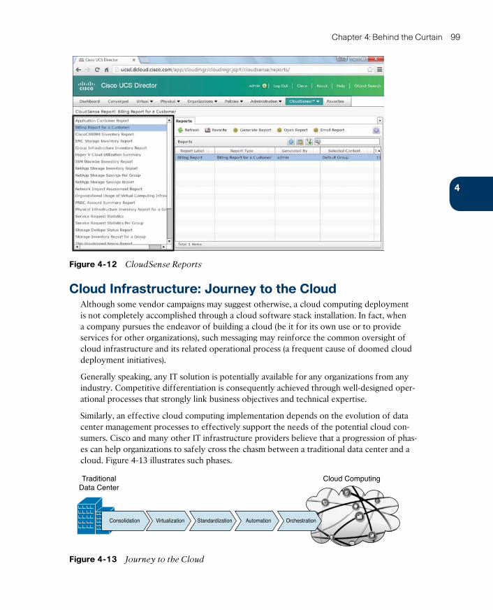
ptg17120290
4
Chapter 4: Behind the Curtain 99
Figure 4-12 CloudSense Reports
Cloud Infrastructure: Journey to the CloudAlthough some vendor campaigns may suggest otherwise, a cloud computing deployment is not completely accomplished through a cloud software stack installation. In fact, when a company pursues the endeavor of building a cloud (be it for its own use or to provide services for other organizations), such messaging may reinforce the common oversight of cloud infrastructure and its related operational process (a frequent cause of doomed cloud deployment initiatives).
Generally speaking, any IT solution is potentially available for any organizations from any industry. Competitive differentiation is consequently achieved through well-designed oper-ational processes that strongly link business objectives and technical expertise.
Similarly, an effective cloud computing implementation depends on the evolution of data center management processes to effectively support the needs of the potential cloud con-sumers. Cisco and many other IT infrastructure providers believe that a progression of phas-es can help organizations to safely cross the chasm between a traditional data center and a cloud. Figure 4-13 illustrates such phases.
Cloud ComputingTraditionalData Center
Consolidation Virtualization Standardization Automation Orchestration
Figure 4-13 Journey to the Cloud
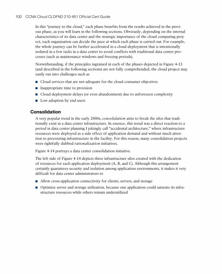
ptg17120290
100 CCNA Cloud CLDFND 210-451 Official Cert Guide
In this “journey to the cloud,” each phase benefits from the results achieved in the previ-ous phase, as you will learn in the following sections. Obviously, depending on the internal characteristics of its data center and the strategic importance of the cloud computing proj-ect, each organization can decide the pace at which each phase is carried out. For example, the whole journey can be further accelerated in a cloud deployment that is intentionally isolated in a few racks in a data center to avoid conflicts with traditional data center pro-cesses (such as maintenance windows and freezing periods).
Notwithstanding, if the principles ingrained in each of the phases depicted in Figure 4-13 (and described in the following sections) are not fully comprehended, the cloud project may easily run into challenges such as
■ Cloud services that are not adequate for the cloud consumer objectives
■ Inappropriate time to provision
■ Cloud deployment delays (or even abandonment) due to unforeseen complexity
■ Low adoption by end users
ConsolidationA very popular trend in the early 2000s, consolidation aims to break the silos that tradi-tionally exist in a data center infrastructure. In essence, this trend was a direct reaction to a period in data center planning I jokingly call “accidental architecture,” where infrastructure resources were deployed as a side effect of application demand and without much atten-tion to preexisting infrastructure in the facility. For this reason, many consolidation projects were rightfully dubbed rationalization initiatives.
Figure 4-14 portrays a data center consolidation initiative.
The left side of Figure 4-14 depicts three infrastructure silos created with the dedication of resources for each application deployment (A, B, and C). Although this arrangement certainly guarantees security and isolation among application environments, it makes it very difficult for data center administrators to
■ Allow cross-application connectivity for clients, servers, and storage
■ Optimize server and storage utilization, because one application could saturate its infra-structure resources while others remain underutilized
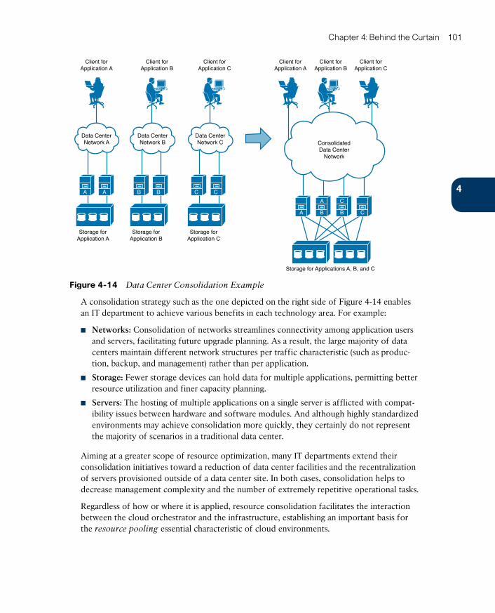
ptg17120290
4
Chapter 4: Behind the Curtain 101
Client forApplication A
Storage forApplication A
Storage forApplication B
Client forApplication B
Data CenterNetwork A
A A
Data CenterNetwork B
Storage forApplication C
Client forApplication C
Client forApplication A
Client forApplication B
Client forApplication C
Data CenterNetwork C Consolidated
Data CenterNetwork
Storage for Applications A, B, and C
B B C C
A B B
A C
C
Figure 4-14 Data Center Consolidation Example
A consolidation strategy such as the one depicted on the right side of Figure 4-14 enables an IT department to achieve various benefits in each technology area. For example:
■ Networks: Consolidation of networks streamlines connectivity among application users and servers, facilitating future upgrade planning. As a result, the large majority of data centers maintain different network structures per traffic characteristic (such as produc-tion, backup, and management) rather than per application.
■ Storage: Fewer storage devices can hold data for multiple applications, permitting better resource utilization and finer capacity planning.
■ Servers: The hosting of multiple applications on a single server is afflicted with compat-ibility issues between hardware and software modules. And although highly standardized environments may achieve consolidation more quickly, they certainly do not represent the majority of scenarios in a traditional data center.
Aiming at a greater scope of resource optimization, many IT departments extend their consolidation initiatives toward a reduction of data center facilities and the recentralization of servers provisioned outside of a data center site. In both cases, consolidation helps to decrease management complexity and the number of extremely repetitive operational tasks.
Regardless of how or where it is applied, resource consolidation facilitates the interaction between the cloud orchestrator and the infrastructure, establishing an important basis for the resource pooling essential characteristic of cloud environments.
ptg17120290
102 CCNA Cloud CLDFND 210-451 Official Cert Guide
VirtualizationAs discussed in Chapter 2, virtualization techniques generally allow the provisioning of logi-cal resources that offer considerable benefits when compared with their physical counter-parts.
Interestingly enough, many virtualization techniques are still extensively deployed to sup-port consolidation processes within data centers. For example:
■ Virtual local-area network (VLAN): Technique that isolates Ethernet traffic within a shared network structure, providing segmentation for hosts that should not directly com-municate with each other.
■ Storage volume: Allows storage capacity provisioning for a single application server inside of a high-capacity storage system.
■ Server virtualization: Permits the provisioning of multiple logical servers inside of a single physical machine.
Chapter 2 also explained a simple classification system that separates virtualization tech-niques into three types: partitioning, pooling, and abstraction. From an architectural standpoint, partitioning virtualization techniques enable even higher asset utilization through more sophisticated resource control techniques. In addition, these virtual resources can be combined into virtual data centers (vDCs) , which are potential infrastructure tem-plates for future cloud applications or tenants.
Pooling virtualization techniques also support consolidation projects through a greater reduction of management points and proper construction of resource pools. Among the examples of pooling technologies, I can highlight disk array virtualization (which allowed multiple storage devices to be managed as a single unit) and server clusters (which enabled multiple servers to deploy the same application for performance and high-availability pur-poses).
Abstraction virtualization technologies also help consolidation as they can change the nature of a physical device to a form that may be more familiar to a data center infrastruc-ture team. As an illustration, a virtual switch connecting virtual machines potentially can be managed using the same operational procedures used on a physical switch.
Invariably, all virtualization technologies provide a strong basis for cloud computing deployments through their added flexibility. Because virtual resources can be quickly pro-visioned without manual operations, it enormously amplifies the creation of offers in the cloud portal and simplifies the job of the cloud orchestrator.
NOTE You will have the opportunity to explore virtualization techniques and technolo-gies in much greater depth in subsequent chapters, including, for example, virtual machines (Chapter 5), virtual switches (Chapter 6, “Infrastructure Virtualization”), virtual network-ing services (Chapter 7), RAID, volumes (Chapter 8, “Block Storage Technologies”), virtual device contexts, virtual PortChannels, fabric extenders, Overlay Transport Virtualization, server I/O consolidation (Chapter 10, “Network Architectures for the Data Center: Unified Fabric”), and service profiles (Chapter 12, “Unified Computing”).
ptg17120290
4
Chapter 4: Behind the Curtain 103
StandardizationAlthough many organizations feel comfortable lingering in the virtualization phase, they are usually aware that more effort is required to complete the journey toward cloud computing. This awareness typically matures gradually as virtualization technologies naturally lead to overprovisioning and loss of control over the deployed (virtual) resources.
To properly assess the problem, try to picture the amount of development a cloud software stack solution would require if an organization tried to replicate the wild variations of “in the heat of the moment” provisioned infrastructure. In any complex project, excessive varia-tion counteracts replicability, predictability, scalability, and accountability. Henry Ford , a leader in 20th-century mass production, was very cognizant of that fact, as he succinctly stated to the customers of his automobile company: “You can have any color you like, as long as it is black.”
As a logical conclusion, to achieve replicability, predictability, scalability, and accountability—the essential characteristics of a well-oiled machine, be it a car or a cloud— production resourc-es must be standardized. Customization means complexity. Therefore, offering more custom options in a self-service cloud portal catalog means more workflows in the cloud orchestrators, more metering plans, and more effort spent overseeing the cloud infrastructure.
Besides simplifying the service offerings in a cloud, infrastructure standardization can also help to reduce development in the cloud software stack. Such an initiative can happen in multiple dimensions, such as
■ Uniformity of infrastructure vendor, models, and versions concerning storage, server, and network devices, virtualization software, operating systems, and platform software
■ Clear predefinition of resources (physical or virtual) to support user demands
■ Normalization of provisioning methods and configuration procedures
Undoubtedly, even without a proper cloud deployment, these different standardization endeavors will certainly drive a data center toward more effective control over deployed resources and troubleshooting processes.
NOTE Special attention to standardization process in data centers is given in Chapter 14, “Integrated Infrastructures,” where the concept of pool of devices (POD) is explored in detail.
AutomationThrough standardization initiatives in IT, an organization is preparing its operational teams to think massively rather than on a one-off basis. Notwithstanding, even in highly standard-ized environments, the staggering amount of coordinated infrastructure operations can eas-ily result in human-related mistakes.
Figure 4-15 exemplifies another complex system that is highly susceptible to operational missteps.
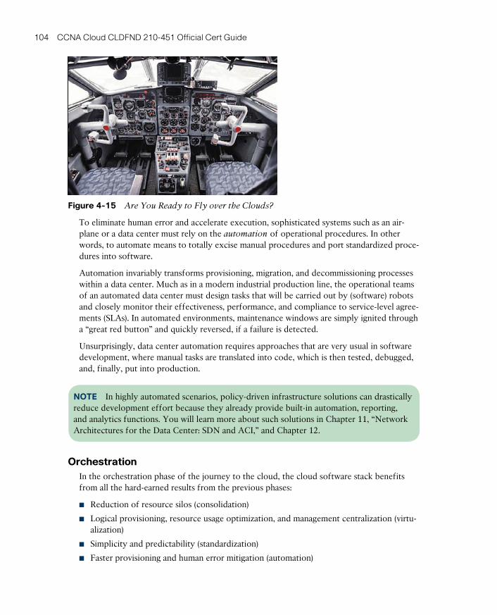
ptg17120290
104 CCNA Cloud CLDFND 210-451 Official Cert Guide
Figure 4-15 Are You Ready to Fly over the Clouds?
To eliminate human error and accelerate execution, sophisticated systems such as an air-plane or a data center must rely on the automation of operational procedures. In other words, to automate means to totally excise manual procedures and port standardized proce-dures into software.
Automation invariably transforms provisioning, migration, and decommissioning processes within a data center. Much as in a modern industrial production line, the operational teams of an automated data center must design tasks that will be carried out by (software) robots and closely monitor their effectiveness, performance, and compliance to service-level agree-ments (SLAs). In automated environments, maintenance windows are simply ignited through a “great red button” and quickly reversed, if a failure is detected.
Unsurprisingly, data center automation requires approaches that are very usual in software development, where manual tasks are translated into code, which is then tested, debugged, and, finally, put into production.
NOTE In highly automated scenarios, policy-driven infrastructure solutions can drastically reduce development effort because they already provide built-in automation, reporting, and analytics functions. You will learn more about such solutions in Chapter 11, “Network Architectures for the Data Center: SDN and ACI,” and Chapter 12.
OrchestrationIn the orchestration phase of the journey to the cloud, the cloud software stack benefits from all the hard-earned results from the previous phases:
■ Reduction of resource silos (consolidation)
■ Logical provisioning, resource usage optimization, and management centralization (virtu-alization)
■ Simplicity and predictability (standardization)
■ Faster provisioning and human error mitigation (automation)
ptg17120290
4
Chapter 4: Behind the Curtain 105
At this stage, silos between infrastructure and development are already broken. The cloud architect focuses his attention on services that should be offered in the portal catalog according to user requirements. With such defined purpose, the cloud orchestrator is pro-grammed to execute workflows over the automated infrastructure to fulfill the requested services.
A cloud metering plan also must be put in action, with an optional chargeback (or show-back) billing strategy aligned to business objectives. Additionally, as explained in Chapter 3, an organization handling the implementation of a cloud may also supplement its service catalog through the secure offering of resources from other clouds through the hybrid cloud deployment model.
Application Programming InterfacesIn the first half of this chapter, you have learned about the most important components in a cloud computing deployment, with special attention given to the functions of the cloud software stack and the evolution of data center infrastructure toward the cloud IT access model.
The efficiency of a cloud implementation depends on how well the cloud software stack components communicate with each other, the cloud infrastructure devices, and even with external clouds. Especially in the case of the cloud orchestrator, a varied spectrum of com-munication methods facilitates integration within the cloud.
In short, cloud software stack and infrastructure components commonly use the following intercommunication approaches:
■ Command-line interface (CLI): Developed for user interaction with mainframe terminals in the 1960s. A software component accepts commands via the CLI, processes them, and produces an appropriate output. Although original CLIs depended on serial data connec-tions, modern devices use Telnet or Secure Shell (SSH) sessions over an IP network.
■ Software development kit (SDK): Collection of tools, including code, examples, and documentation, that supports the creation of applications for a computer component. With an SDK, a developer can write applications using a programming language such as Java and Python.
■ Application programming interface (API): A set of functions, variables, and data struc-tures that enables software components to communicate with each other. Essentially, an API regulates how services from a computer system are exposed to applications in terms of operations, inputs, outputs, and data format.
Although the origin of APIs is associated with web services (which are basically applica-tions that can communicate through the World Wide Web), they have become a powerful alternative for cloud software integration because they decouple software implementation from its services, freeing developers to use their language of preference in their applications instead of being limited to the specific language used in an SDK.
More importantly, a well-designed API is a key tool for IT automation in general because it can hide the complexity of intricate operations through a simple API request.
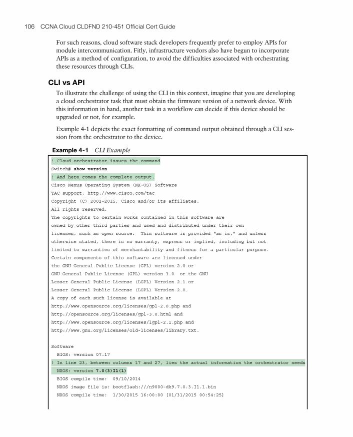
ptg17120290
106 CCNA Cloud CLDFND 210-451 Official Cert Guide
For such reasons, cloud software stack developers frequently prefer to employ APIs for module intercommunication. Fitly, infrastructure vendors also have begun to incorporate APIs as a method of configuration, to avoid the difficulties associated with orchestrating these resources through CLIs.
CLI vs APITo illustrate the challenge of using the CLI in this context, imagine that you are developing a cloud orchestrator task that must obtain the firmware version of a network device. With this information in hand, another task in a workflow can decide if this device should be upgraded or not, for example.
Example 4-1 depicts the exact formatting of command output obtained through a CLI ses-sion from the orchestrator to the device.
Example 4-1 CLI Example
! Cloud orchestrator issues the command
Switch# show version
! And here comes the complete output.
Cisco Nexus Operating System (NX-OS) Software
TAC support: http://www.cisco.com/tac
Copyright (C) 2002-2015, Cisco and/or its affiliates.
All rights reserved.
The copyrights to certain works contained in this software are
owned by other third parties and used and distributed under their own
licenses, such as open source. This software is provided "as is," and unless
otherwise stated, there is no warranty, express or implied, including but not
limited to warranties of merchantability and fitness for a particular purpose.
Certain components of this software are licensed under
the GNU General Public License (GPL) version 2.0 or
GNU General Public License (GPL) version 3.0 or the GNU
Lesser General Public License (LGPL) Version 2.1 or
Lesser General Public License (LGPL) Version 2.0.
A copy of each such license is available at
http://www.opensource.org/licenses/gpl-2.0.php and
http://opensource.org/licenses/gpl-3.0.html and
http://www.opensource.org/licenses/lgpl-2.1.php and
http://www.gnu.org/licenses/old-licenses/library.txt.
Software
BIOS: version 07.17
! In line 23, between columns 17 and 27, lies the actual information the orchestrator needs
NXOS: version 7.0(3)I1(1)
BIOS compile time: 09/10/2014
NXOS image file is: bootflash:///n9000-dk9.7.0.3.I1.1.bin
NXOS compile time: 1/30/2015 16:00:00 [01/31/2015 00:54:25]
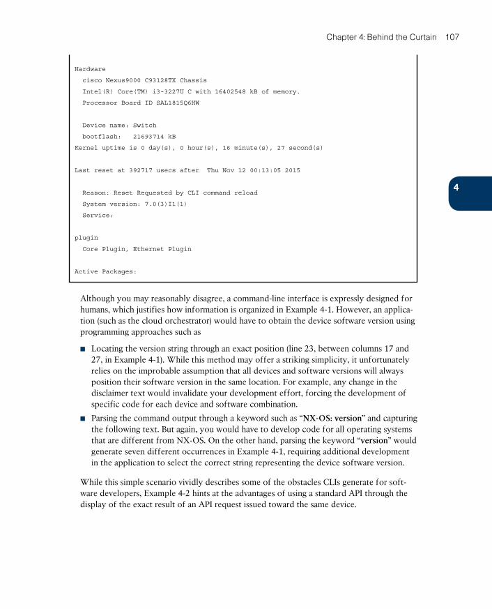
ptg17120290
4
Chapter 4: Behind the Curtain 107
Hardware
cisco Nexus9000 C93128TX Chassis
Intel(R) Core(TM) i3-3227U C with 16402548 kB of memory.
Processor Board ID SAL1815Q6HW
Device name: Switch
bootflash: 21693714 kB
Kernel uptime is 0 day(s), 0 hour(s), 16 minute(s), 27 second(s)
Last reset at 392717 usecs after Thu Nov 12 00:13:05 2015
Reason: Reset Requested by CLI command reload
System version: 7.0(3)I1(1)
Service:
plugin
Core Plugin, Ethernet Plugin
Active Packages:
Although you may reasonably disagree, a command-line interface is expressly designed for humans, which justifies how information is organized in Example 4-1. However, an applica-tion (such as the cloud orchestrator) would have to obtain the device software version using programming approaches such as
■ Locating the version string through an exact position (line 23, between columns 17 and 27, in Example 4-1). While this method may offer a striking simplicity, it unfortunately relies on the improbable assumption that all devices and software versions will always position their software version in the same location. For example, any change in the disclaimer text would invalidate your development effort, forcing the development of specific code for each device and software combination.
■ Parsing the command output through a keyword such as “NX-OS: version” and capturing the following text. But again, you would have to develop code for all operating systems that are different from NX-OS. On the other hand, parsing the keyword “version” would generate seven different occurrences in Example 4-1, requiring additional development in the application to select the correct string representing the device software version.
While this simple scenario vividly describes some of the obstacles CLIs generate for soft-ware developers, Example 4-2 hints at the advantages of using a standard API through the display of the exact result of an API request issued toward the same device.

ptg17120290
108 CCNA Cloud CLDFND 210-451 Official Cert Guide
Example 4-2 API Output
<?xml version="1.0"?>
<ins_api>
<type>cli_show</type>
<version>1.0</version>
<sid>eoc</sid>
<outputs>
<output>
<body>
<header_str>Cisco Nexus Operating System (NX-OS) Software
TAC support: http://www.cisco.com/tac
Copyright (C) 2002-2015, Cisco and/or its affiliates.
All rights reserved.
The copyrights to certain works contained in this software are
owned by other third parties and used and distributed under their own
licenses, such as open source. This software is provided "as is," and unless
otherwise stated, there is no warranty, express or implied, including but not
limited to warranties of merchantability and fitness for a particular purpose.
Certain components of this software are licensed under
the GNU General Public License (GPL) version 2.0 or
GNU General Public License (GPL) version 3.0 or the GNU
Lesser General Public License (LGPL) Version 2.1 or
Lesser General Public License (LGPL) Version 2.0.
A copy of each such license is available at
http://www.opensource.org/licenses/gpl-2.0.php and
http://opensource.org/licenses/gpl-3.0.html and
http://www.opensource.org/licenses/lgpl-2.1.php and
http://www.gnu.org/licenses/old-licenses/library.txt.
</header_str>
<bios_ver_str>07.17</bios_ver_str>
<kickstart_ver_str>7.0(3)I1(1)</kickstart_ver_str>
<bios_cmpl_time>09/10/2014</bios_cmpl_time>
<kick_file_name>bootflash:///n9000-dk9.7.0.3.I1.1.bin</kick_file_name>
<kick_cmpl_time> 1/30/2015 16:00:00</kick_cmpl_time>
<kick_tmstmp>01/31/2015 00:54:25</kick_tmstmp>
<chassis_id>Nexus9000 C93128TX Chassis</chassis_id>
<cpu_name>Intel(R) Core(TM) i3-3227U C</cpu_name>
<memory>16402548</memory>
<mem_type>kB</mem_type>
<proc_board_id>SAL1815Q6HW</proc_board_id>
<host_name>dcloud-n9k</host_name>
<bootflash_size>21693714</bootflash_size>
<kern_uptm_days>0</kern_uptm_days>
<kern_uptm_hrs>0</kern_uptm_hrs>
<kern_uptm_mins>44</kern_uptm_mins>
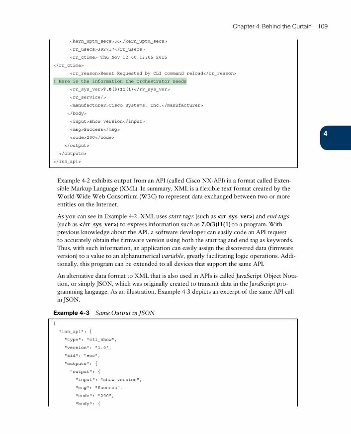
ptg17120290
4
Chapter 4: Behind the Curtain 109
<kern_uptm_secs>36</kern_uptm_secs>
<rr_usecs>392717</rr_usecs>
<rr_ctime> Thu Nov 12 00:13:05 2015
</rr_ctime>
<rr_reason>Reset Requested by CLI command reload</rr_reason>
! Here is the information the orchestrator needs
<rr_sys_ver>7.0(3)I1(1)</rr_sys_ver>
<rr_service/>
<manufacturer>Cisco Systems, Inc.</manufacturer>
</body>
<input>show version</input>
<msg>Success</msg>
<code>200</code>
</output>
</outputs>
</ins_api>
Example 4-2 exhibits output from an API (called Cisco NX-API) in a format called Exten-sible Markup Language (XML) . In summary, XML is a flexible text format created by the World Wide Web Consortium (W3C) to represent data exchanged between two or more entities on the Internet.
As you can see in Example 4-2, XML uses start tags (such as <rr_sys_ver>) and end tags (such as </rr_sys_ver>) to express information such as 7.0(3)I1(1) to a program. With previous knowledge about the API, a software developer can easily code an API request to accurately obtain the firmware version using both the start tag and end tag as keywords. Thus, with such information, an application can easily assign the discovered data (firmware version) to a value to an alphanumerical variable, greatly facilitating logic operations. Addi-tionally, this program can be extended to all devices that support the same API.
An alternative data format to XML that is also used in APIs is called JavaScript Object Nota-tion , or simply JSON, which was originally created to transmit data in the JavaScript pro-gramming language. As an illustration, Example 4-3 depicts an excerpt of the same API call in JSON.
Example 4-3 Same Output in JSON
{
"ins_api": {
"type": "cli_show",
"version": "1.0",
"sid": "eoc",
"outputs": {
"output": {
"input": "show version",
"msg": "Success",
"code": "200",
"body": {
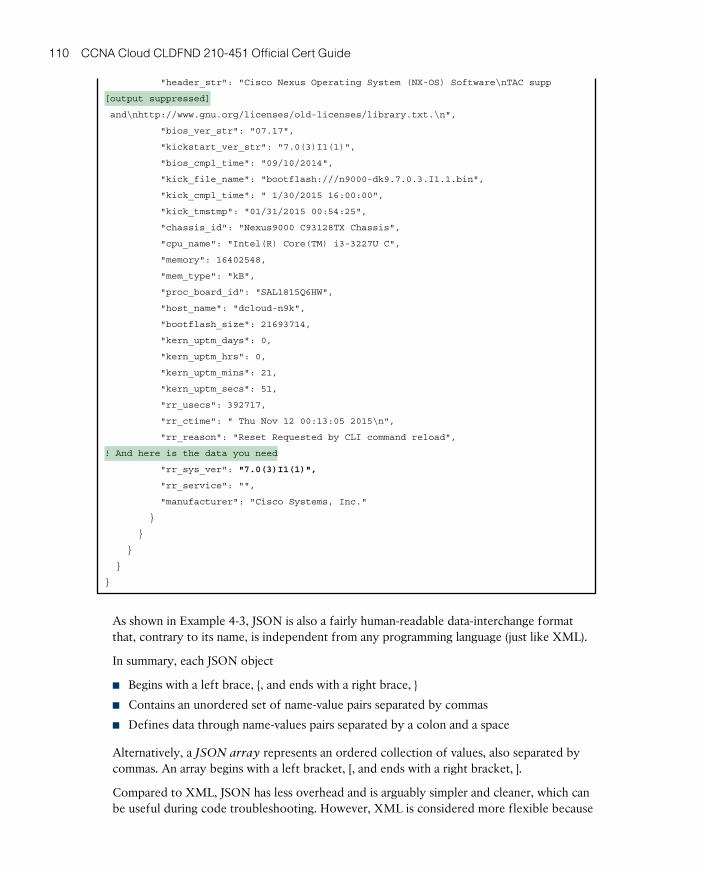
ptg17120290
110 CCNA Cloud CLDFND 210-451 Official Cert Guide
"header_str": "Cisco Nexus Operating System (NX-OS) Software\nTAC supp
[output suppressed]
and\nhttp://www.gnu.org/licenses/old-licenses/library.txt.\n",
"bios_ver_str": "07.17",
"kickstart_ver_str": "7.0(3)I1(1)",
"bios_cmpl_time": "09/10/2014",
"kick_file_name": "bootflash:///n9000-dk9.7.0.3.I1.1.bin",
"kick_cmpl_time": " 1/30/2015 16:00:00",
"kick_tmstmp": "01/31/2015 00:54:25",
"chassis_id": "Nexus9000 C93128TX Chassis",
"cpu_name": "Intel(R) Core(TM) i3-3227U C",
"memory": 16402548,
"mem_type": "kB",
"proc_board_id": "SAL1815Q6HW",
"host_name": "dcloud-n9k",
"bootflash_size": 21693714,
"kern_uptm_days": 0,
"kern_uptm_hrs": 0,
"kern_uptm_mins": 21,
"kern_uptm_secs": 51,
"rr_usecs": 392717,
"rr_ctime": " Thu Nov 12 00:13:05 2015\n",
"rr_reason": "Reset Requested by CLI command reload",
! And here is the data you need
"rr_sys_ver": "7.0(3)I1(1)",
"rr_service": "",
"manufacturer": "Cisco Systems, Inc."
}
}
}
}
}
As shown in Example 4-3, JSON is also a fairly human-readable data-interchange format that, contrary to its name, is independent from any programming language (just like XML).
In summary, each JSON object
■ Begins with a left brace, {, and ends with a right brace, }
■ Contains an unordered set of name-value pairs separated by commas
■ Defines data through name-values pairs separated by a colon and a space
Alternatively, a JSON array represents an ordered collection of values, also separated by commas. An array begins with a left bracket, [, and ends with a right bracket, ].
Compared to XML, JSON has less overhead and is arguably simpler and cleaner, which can be useful during code troubleshooting. However, XML is considered more flexible because
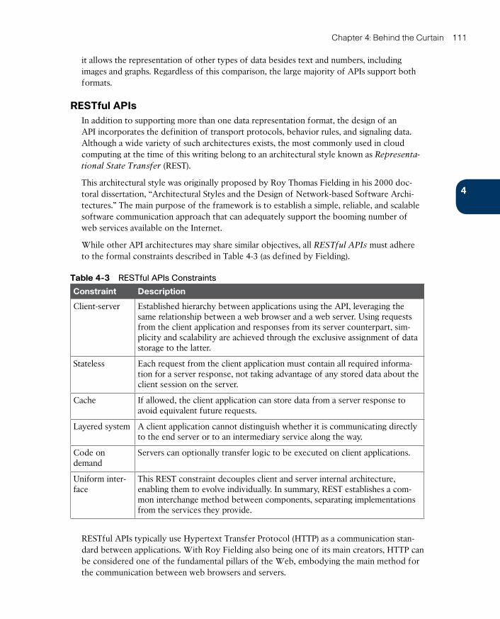
ptg17120290
4
Chapter 4: Behind the Curtain 111
it allows the representation of other types of data besides text and numbers, including images and graphs. Regardless of this comparison, the large majority of APIs support both formats.
RESTful APIsIn addition to supporting more than one data representation format, the design of an API incorporates the definition of transport protocols, behavior rules, and signaling data. Although a wide variety of such architectures exists, the most commonly used in cloud computing at the time of this writing belong to an architectural style known as Representa-
tional State Transfer (REST) .
This architectural style was originally proposed by Roy Thomas Fielding in his 2000 doc-toral dissertation, “Architectural Styles and the Design of Network-based Software Archi-tectures.” The main purpose of the framework is to establish a simple, reliable, and scalable software communication approach that can adequately support the booming number of web services available on the Internet.
While other API architectures may share similar objectives, all RESTful APIs must adhere to the formal constraints described in Table 4-3 (as defined by Fielding).
Table 4-3 RESTful APIs Constraints
Constraint Description
Client-server Established hierarchy between applications using the API, leveraging the same relationship between a web browser and a web server. Using requests from the client application and responses from its server counterpart, sim-plicity and scalability are achieved through the exclusive assignment of data storage to the latter.
Stateless Each request from the client application must contain all required informa-tion for a server response, not taking advantage of any stored data about the client session on the server.
Cache If allowed, the client application can store data from a server response to avoid equivalent future requests.
Layered system A client application cannot distinguish whether it is communicating directly to the end server or to an intermediary service along the way.
Code on demand
Servers can optionally transfer logic to be executed on client applications.
Uniform inter-face
This REST constraint decouples client and server internal architecture, enabling them to evolve individually. In summary, REST establishes a com-mon interchange method between components, separating implementations from the services they provide.
RESTful APIs typically use Hypertext Transfer Protocol (HTTP) as a communication stan-dard between applications. With Roy Fielding also being one of its main creators, HTTP can be considered one of the fundamental pillars of the Web, embodying the main method for the communication between web browsers and servers.
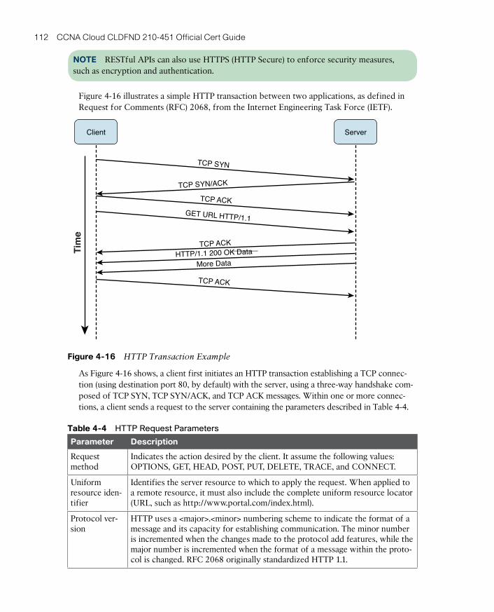
ptg17120290
112 CCNA Cloud CLDFND 210-451 Official Cert Guide
NOTE RESTful APIs can also use HTTPS (HTTP Secure) to enforce security measures, such as encryption and authentication.
Figure 4-16 illustrates a simple HTTP transaction between two applications, as defined in Request for Comments (RFC) 2068, from the Internet Engineering Task Force (IETF).
Client Server
Tim
e
TCP SYN
TCP SYN/ACK
TCP ACK
GET URL HTTP/1.1
TCP ACK
HTTP/1.1 200 OK Data
More Data
TCP ACK
Figure 4-16 HTTP Transaction Example
As Figure 4-16 shows, a client first initiates an HTTP transaction establishing a TCP connec-tion (using destination port 80, by default) with the server, using a three-way handshake com-posed of TCP SYN, TCP SYN/ACK, and TCP ACK messages. Within one or more connec-tions, a client sends a request to the server containing the parameters described in Table 4-4.
Table 4-4 HTTP Request Parameters
Parameter Description
Request method
Indicates the action desired by the client. It assume the following values: OPTIONS, GET, HEAD, POST, PUT, DELETE, TRACE, and CONNECT.
Uniform resource iden-tifier
Identifies the server resource to which to apply the request. When applied to a remote resource, it must also include the complete uniform resource locator (URL, such as http://www.portal.com/index.html).
Protocol ver-sion
HTTP uses a <major>.<minor> numbering scheme to indicate the format of a message and its capacity for establishing communication. The minor number is incremented when the changes made to the protocol add features, while the major number is incremented when the format of a message within the proto-col is changed. RFC 2068 originally standardized HTTP 1.1.
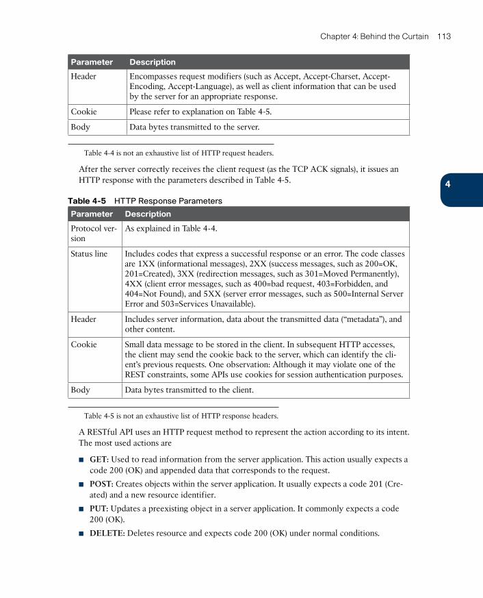
ptg17120290
4
Chapter 4: Behind the Curtain 113
Parameter Description
Header Encompasses request modifiers (such as Accept, Accept-Charset, Accept-Encoding, Accept-Language), as well as client information that can be used by the server for an appropriate response.
Cookie Please refer to explanation on Table 4-5.
Body Data bytes transmitted to the server.
Table 4-4 is not an exhaustive list of HTTP request headers.
After the server correctly receives the client request (as the TCP ACK signals), it issues an HTTP response with the parameters described in Table 4-5.
Table 4-5 HTTP Response Parameters
Parameter Description
Protocol ver-sion
As explained in Table 4-4.
Status line Includes codes that express a successful response or an error. The code classes are 1XX (informational messages), 2XX (success messages, such as 200=OK, 201=Created), 3XX (redirection messages, such as 301=Moved Permanently), 4XX (client error messages, such as 400=bad request, 403=Forbidden, and 404=Not Found), and 5XX (server error messages, such as 500=Internal Server Error and 503=Services Unavailable).
Header Includes server information, data about the transmitted data (“metadata”), and other content.
Cookie Small data message to be stored in the client. In subsequent HTTP accesses, the client may send the cookie back to the server, which can identify the cli-ent’s previous requests. One observation: Although it may violate one of the REST constraints, some APIs use cookies for session authentication purposes.
Body Data bytes transmitted to the client.
Table 4-5 is not an exhaustive list of HTTP response headers.
A RESTful API uses an HTTP request method to represent the action according to its intent. The most used actions are
■ GET: Used to read information from the server application. This action usually expects a code 200 (OK) and appended data that corresponds to the request.
■ POST: Creates objects within the server application. It usually expects a code 201 (Cre-ated) and a new resource identifier.
■ PUT: Updates a preexisting object in a server application. It commonly expects a code 200 (OK).
■ DELETE: Deletes resource and expects code 200 (OK) under normal conditions.
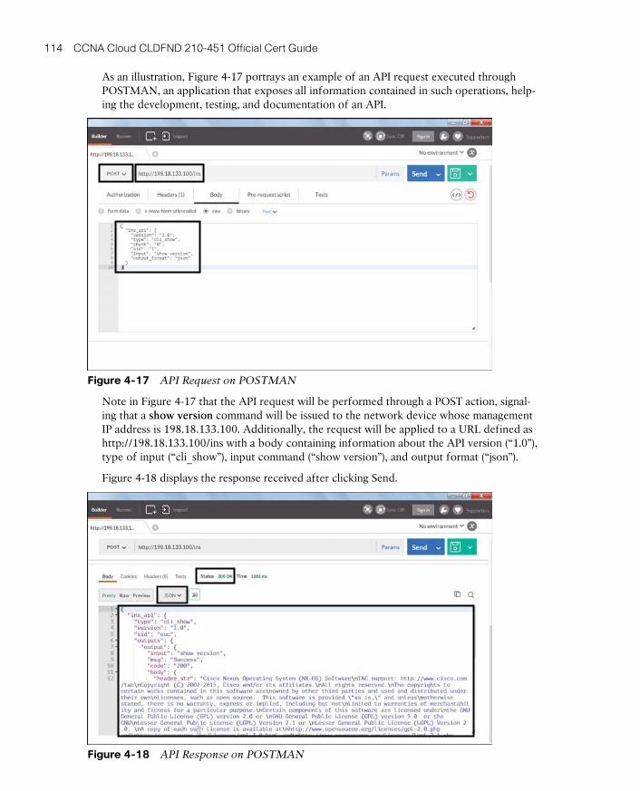
ptg17120290
114 CCNA Cloud CLDFND 210-451 Official Cert Guide
As an illustration, Figure 4-17 portrays an example of an API request executed through POSTMAN, an application that exposes all information contained in such operations, help-ing the development, testing, and documentation of an API.
Figure 4-17 API Request on POSTMAN
Note in Figure 4-17 that the API request will be performed through a POST action, signal-ing that a show version command will be issued to the network device whose management IP address is 198.18.133.100. Additionally, the request will be applied to a URL defined as http://198.18.133.100/ins with a body containing information about the API version (“1.0”), type of input (“cli_show”), input command (“show version”), and output format (“json”).
Figure 4-18 displays the response received after clicking Send.
Figure 4-18 API Response on POSTMAN
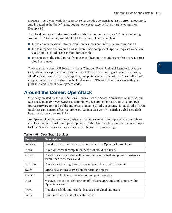
ptg17120290
4
Chapter 4: Behind the Curtain 115
In Figure 4-18, the network device response has a code 200, signaling that no error has occurred. And included in the “body” name, you can observe an excerpt from the same output from Example 4-3.
The cloud components discussed earlier in the chapter in the section “Cloud Computing Architecture” frequently use RESTful APIs in multiple ways, such as
■ In the communication between cloud orchestrator and infrastructure components
■ In the integration between cloud software stack components (portal requests workflow execution on cloud orchestration, for example)
■ In requests to the cloud portal from user applications (not end users) that are requesting cloud resources
There are many other API formats, such as Windows PowerShell and Remote Procedure Call, whose description is out of the scope of this chapter. But regardless of their origin, all APIs should aim for clarity, simplicity, completeness, and ease of use. Above all, an API designer must remember that, much like diamonds, APIs are forever (as soon as they are published and used in development code).
Around the Corner: OpenStackOriginally created by the U.S. National Aeronautics and Space Administration (NASA) and Rackspace in 2010, OpenStack is a community development initiative to develop open source software to build public and private scalable clouds. In essence, it is a cloud software stack that can control infrastructure resources in a data center through a web-based dash-board or via the OpenStack API.
An OpenStack implementation consists of the deployment of multiple services, which are developed in individual development projects. Table 4-6 describes some of the most popu-lar OpenStack services, as they are known at the time of this writing.
Table 4-6 OpenStack Services
Service Description
Keystone Provides identity services for all services in an OpenStack installation
Nova Provisions virtual compute on behalf of cloud end users
Glance Coordinates images that will be used to boot virtual and physical instances within the OpenStack cloud
Neutron Controls networking resources to support cloud service requests
Swift Offers data storage services in the form of objects
Cinder Provisions block-based storage for compute instances
Heat Manages the entire orchestration of infrastructure and applications within OpenStack clouds
Trove Provides scalable and reliable databases for cloud end users
Ironic Provisions bare-metal (physical) servers
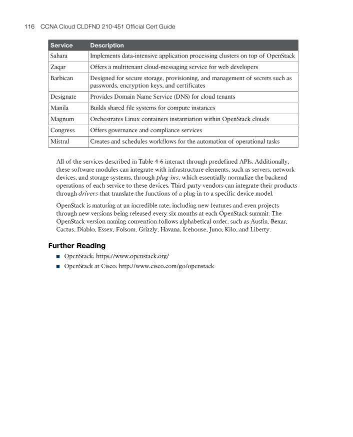
ptg17120290
116 CCNA Cloud CLDFND 210-451 Official Cert Guide
Service Description
Sahara Implements data-intensive application processing clusters on top of OpenStack
Zaqar Offers a multitenant cloud-messaging service for web developers
Barbican Designed for secure storage, provisioning, and management of secrets such as passwords, encryption keys, and certificates
Designate Provides Domain Name Service (DNS) for cloud tenants
Manila Builds shared file systems for compute instances
Magnum Orchestrates Linux containers instantiation within OpenStack clouds
Congress Offers governance and compliance services
Mistral Creates and schedules workflows for the automation of operational tasks
All of the services described in Table 4-6 interact through predefined APIs. Additionally, these software modules can integrate with infrastructure elements, such as servers, network devices, and storage systems, through plug-ins , which essentially normalize the backend operations of each service to these devices. Third-party vendors can integrate their products through drivers that translate the functions of a plug-in to a specific device model.
OpenStack is maturing at an incredible rate, including new features and even projects through new versions being released every six months at each OpenStack summit. The OpenStack version naming convention follows alphabetical order, such as Austin, Bexar, Cactus, Diablo, Essex, Folsom, Grizzly, Havana, Icehouse, Juno, Kilo, and Liberty.
Further Reading■ OpenStack: https://www.openstack.org/
■ OpenStack at Cisco: http://www.cisco.com/go/openstack
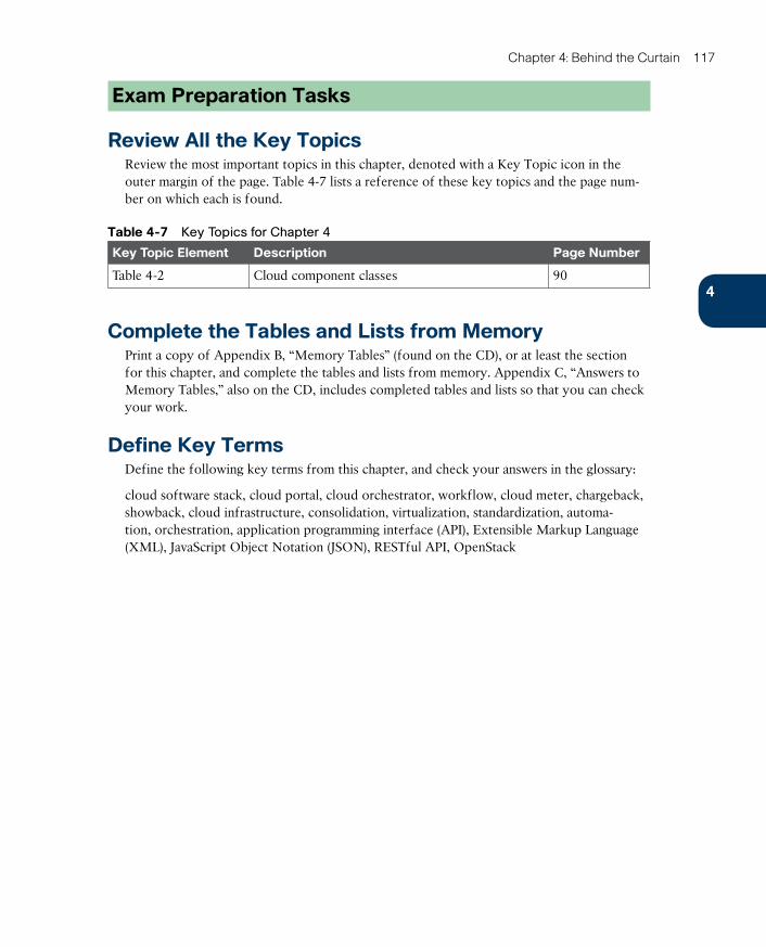
ptg17120290
4
Chapter 4: Behind the Curtain 117
Exam Preparation Tasks
Review All the Key TopicsReview the most important topics in this chapter, denoted with a Key Topic icon in the outer margin of the page. Table 4-7 lists a reference of these key topics and the page num-ber on which each is found.
Table 4-7 Key Topics for Chapter 4
Key Topic Element Description Page Number
Table 4-2 Cloud component classes 90
Complete the Tables and Lists from MemoryPrint a copy of Appendix B, “Memory Tables” (found on the CD), or at least the section for this chapter, and complete the tables and lists from memory. Appendix C, “Answers to Memory Tables,” also on the CD, includes completed tables and lists so that you can check your work.
Define Key TermsDefine the following key terms from this chapter, and check your answers in the glossary:
cloud software stack, cloud portal, cloud orchestrator, workflow, cloud meter, chargeback, showback, cloud infrastructure, consolidation, virtualization, standardization, automa-tion, orchestration, application programming interface (API), Extensible Markup Language (XML), JavaScript Object Notation (JSON), RESTful API, OpenStack
ptg17120290
This chapter covers the following topics:
■ Introduction to Servers and Operating Systems
■ Server Virtualization History
■ Server Virtualization Definitions
■ Hypervisor Architectures
■ Server Virtualization Features
■ Cloud Computing and Server Virtualization
This chapter covers the following exam objectives:
■ 3.2 Describe Server Virtualization
■ 3.2.a Basic knowledge of different OS and hypervisors

ptg17120290
CHAPTER 5
Server VirtualizationThroughout the history of computing, virtualization technologies have offered solutions to diverse problems such as hardware inefficiency and lack of support for legacy applications. More recently, the accelerated adoption of server virtualization on x86 platforms in the mid-2000s has clearly positioned such a trend as one of the most important components of modern data center architecture.
And without surprise, cloud computing significantly benefits from the agility and flexibil-ity virtualization brings to application server provisioning. Therefore, the CLDFND exam requires a basic knowledge of operating systems and hypervisors. Accordingly, this chapter covers these concepts as well as important definitions that establish the overall context of server virtualization.
This chapter also introduces the main components of server hardware and explores how some of the challenges of server hardware are solved through virtualization. Then, it addresses the most important concepts related to x86 server virtualization, introduces the most prominent hypervisor architectures available at the time of this writing, and identifies virtualization features that are particularly useful in cloud computing environments.
“Do I Know This Already?” QuizThe “Do I Know This Already?” quiz allows you to assess whether you should read this entire chapter thoroughly or jump to the “Exam Preparation Tasks” section. If you are in doubt about your answers to these questions or your own assessment of your knowledge of the topics, read the entire chapter. Table 5-1 lists the major headings in this chapter and their corresponding “Do I Know This Already?” quiz questions. You can find the answers in Appendix A, “Answers to Pre-Assessments and Quizzes.”
Table 5-1 “Do I Know This Already?” Section-to-Question Mapping
Foundation Topics Section Questions
Introduction to Servers and Operating Systems 1–2
Server Virtualization History 3–4
Server Virtualization Definitions 5–6
Hypervisor Architectures 7
Server Virtualization Features 8–9
Cloud Computing and Server Virtualization 10
ptg17120290
120 CCNA Cloud CLDFND 210-451 Official Cert Guide
1. Which of the following is not a server hardware component?
a. Storage controller
b. NIC
c. Operating system
d. CPU
e. RAM
2. Which of the following is not a server operating system?
a. Microsoft Windows Server
b. FreeBSD
c. Cisco IOS
d. Linux
3. Which of the following advantages were achieved through mainframe virtualization in the early 1970s? (Choose two.)
a. Performance increase
b. Legacy application support
c. Downsizing
d. User isolation
4. Which of the following is not an advantage from server virtualization on x86 servers? (Choose all that apply.)
a. Hardware efficiency
b. Network provisioning
c. Legacy application support
d. Management cost decrease
5. Which of the following are Type-1 hypervisors? (Choose all that apply.)
a. Linux KVM
b. Xen
c. Microsoft Hyper-V
d. VMware Workstation
6. Which of the following identify a hypervisor and its corresponding VM manager? (Choose all that apply.)
a. KVM and oVirt
b. vSphere and ESXi
c. Hyper-V and Hyper-V Manager
d. ESXi and vCenter
e. KVM and OpenStack Nova
ptg17120290
5
Chapter 5: Server Virtualization 121
7. Which of the following is not a virtual machine file?
a. Virtual disk
b. NVRAM
c. Swap memory
d. NFS
e. Log
8. Which of the following statements is false?
a. VM high availability enables the restarting of virtual machines that were running on hosts that failed.
b. Live migration is a disaster recovery feature that allows the migration of VMs after a physical server suffers a major hardware failure.
c. Resource load balancing allows automatic host selection when you are creating a virtual machine.
d. VM fault tolerance reserves double the resources a virtual machine requires.
9. In which of the following features is a disruption in associated virtual machines expected?
a. Fault tolerance
b. Live migration
c. High availability
d. Resource load balancing
10. Which of the following features enables cloud computing pooling characteristics?
a. Fault tolerance
b. Live migration
c. High availability
d. Resource load balancing

ptg17120290
122 CCNA Cloud CLDFND 210-451 Official Cert Guide
Foundation Topics
Introduction to Servers and Operating SystemsIn Chapter 2, “Cloud Shapes: Service Models,” you learned the different ways in which a cloud computing environment can offer services. Testing your memory further, a specific service model called Infrastructure as a Service (IaaS) provides server instances to end users, allowing them to potentially run any software on top of these structures.
This section revisits the formal definition of a server, aiming to provide you with a strong conceptual background before you delve into their positioning and challenges in cloud computing environments.
What Is a Server?Generically speaking, a server is a software component that can accept requests from mul-tiple clients, providing suitable responses after processing these requests or accessing other servers. This definition relates to the popular client/server application architecture, which eventually replaced the centralized architecture based on mainframes during the last two decades of the 20th century.
Although server software may run on desktop computers, its increasing relevance to busi-ness applications means that dedicated, specialized hardware is better suited to host these central application components. In the context of data center infrastructure, these custom-ized micro-computers running server software are also (confusingly) called servers.
Note As you advance in your study in cloud technologies, you will learn that distinct data center technology teams may use the exact same term for different subjects. Therefore, I highly recommend that you always try to discover the context of the discussion beforehand (for example, software or hardware, in the case of the word “server”). Except when noted, “server” in this chapter refers to the dedicated hardware that hosts server applications.
Data centers, be they for cloud deployments or not, are basically built for application host-ing and data storing. Suitably, data center architects may view servers as raw material that ultimately defines how a data center is designed and maintained. In fact, I know many com-panies that measure their data center agility according to the answer to the following ques-tion: How long does it take to provision an application server?
Of course, servers have different characteristics depending on the applications they are hosting. However, they all share the following basic components:
■ Central processing unit (CPU): Unquestionably the most important component of any computer, the CPU (aka processor) is responsible for the majority of processing jobs and calculations. The CPU is probably the server component that has experienced the fastest evolution.
■ Main memory: The CPU uses these fast, volatile storage areas to directly access data retrieved from files and programs that are being worked on. If you picture yourself as the CPU, the main memory would be your desk, stacking documents that you are working on
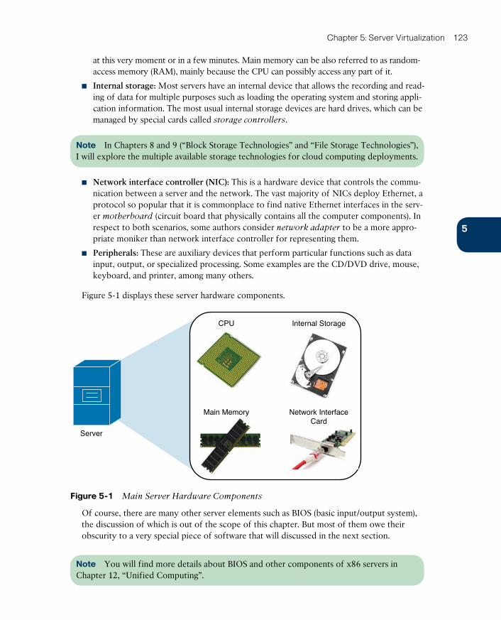
ptg17120290
5
Chapter 5: Server Virtualization 123
at this very moment or in a few minutes. Main memory can be also referred to as random-access memory (RAM) , mainly because the CPU can possibly access any part of it.
■ Internal storage: Most servers have an internal device that allows the recording and read-ing of data for multiple purposes such as loading the operating system and storing appli-cation information. The most usual internal storage devices are hard drives, which can be managed by special cards called storage controllers .
Note In Chapters 8 and 9 (“Block Storage Technologies” and “File Storage Technologies”), I will explore the multiple available storage technologies for cloud computing deployments.
■ Network interface controller (NIC): This is a hardware device that controls the commu-nication between a server and the network. The vast majority of NICs deploy Ethernet, a protocol so popular that it is commonplace to find native Ethernet interfaces in the serv-er motherboard (circuit board that physically contains all the computer components). In respect to both scenarios, some authors consider network adapter to be a more appro-priate moniker than network interface controller for representing them.
■ Peripherals: These are auxiliary devices that perform particular functions such as data input, output, or specialized processing. Some examples are the CD/DVD drive, mouse, keyboard, and printer, among many others.
Figure 5-1 displays these server hardware components.
Server
CPU Internal Storage
Main Memory Network InterfaceCard
Figure 5-1 Main Server Hardware Components
Of course, there are many other server elements such as BIOS (basic input/output system), the discussion of which is out of the scope of this chapter. But most of them owe their obscurity to a very special piece of software that will discussed in the next section.
Note You will find more details about BIOS and other components of x86 servers in Chapter 12, “Unified Computing”.

ptg17120290
124 CCNA Cloud CLDFND 210-451 Official Cert Guide
Server Operating SystemsAn operating system (or simply OS) can be defined as software that controls computer resources and provides common services for other computer programs that run “on top of it.” Consequently, the operating system is widely considered the most fundamental piece of software in a computer system.
Table 5-2 describes some of the most popular operating systems at the time of this writing.
Table 5-2 Operating Systems
Operating System Description
Microsoft Windows Most popular operating system for personal computers (PCs). Microsoft introduced Windows in 1985 as a graphical user interface (GUI) for the Microsoft Disk Operating System (MS-DOS). Today, Windows comprises a family of operating systems developed for myriad different computing devices ranging from smartphones to servers.
Linux First released in 1991 by software engineer Linus Torvalds, Linux is a Unix-based operating system developed and distributed as an open source software for PCs and server platforms. Nevertheless, companies such as Red Hat, Inc. also offer Linux (among open source solutions) as enterprise-ready products.
FreeBSD Free Berkeley Software Distribution (FreeBSD) is a Unix-like operating system developed at the University of California, Berkeley. This system is still popular among select server platforms.
Apple Mac OS Family of operating systems developed by Apple, Inc. for its Macintosh computers. Created In 1984, Mac OS was designed for these specialized workstations and was succeeded by Apple OS X (2001), which for the first time included a server version, and is now simply branded OS X.
Android Acquired in 2005 and currently developed by Google, Android is an OS based on Linux and, at the time of this writing, is the most popular operating system for mobile devices (smartphones and tablets).
Apple iOS Apple created this mobile operating system in 2007 for the iPhone but later extended its use to its line of tablets (iPad).
Cisco IOS Cisco IOS is considered the most popular network operating system in the world. It is supported on multiple Cisco routers and switches, among other network devices.
ChromeOS Google Inc. has developed this operating system to run on “netbooks,” which are lightweight and inexpensive computers that are uniquely built for web-based applications. Based on Linux, ChromeOS was first released in 2009 and currently supports Android applications as well.
The kernel (“core” in German) is the central part of an operating system. This program directly manages the computer hardware components, such as memory and CPU. The kernel

ptg17120290
5
Chapter 5: Server Virtualization 125
is also responsible for providing services to applications that need to access any hardware component, including NICs and internal storage.
Because it represents the most fundamental part of an operating system, the kernel is executed on a protected area of the main memory (kernel space ) to prevent problems other processes may cause. Therefore, non-kernel processes are executed in a memory area called user space.
As a visual aid, Figure 5-2 illustrates how an OS kernel relates to applications and the com-puter hardware.
Applications User Space
Kernel
CPU
Kernel Space
Hardware
DiskRAM NIC
Figure 5-2 Operating System Kernel
Operating systems can be categorized according to the distribution of their components between kernel space and user space. Hence, operating systems whose entire architecture resides in kernel space are called monolithic (for example, Linux and FreeBSD). By contrast, microkernel operating systems are considered more flexible because they consist of mul-tiple processes that are scattered across both kernel space and user space. Mac OS X and current Windows versions are examples of microkernel operating systems.
A server operating system is obviously focused on providing resources and services to applications running on server hardware. Such is the level of specialization of these OSs that many nonessential services, such as the GUI, may unceremoniously be disabled during nor-mal operations.
Server Virtualization HistoryContrary to a common misconception among many IT professionals, virtualization technol-ogies are not exclusive to servers or even cutting-edge 21st-century innovations.
As a generic term, virtualization can be defined as the transparent emulation of an IT resource to provide to its consumers benefits that were unavailable in its physical form. Thereupon, this concept may be embraced by many resources, such as network devices, storage arrays, or applications.
When virtualization was originally applied to computer systems, several advantages were achieved in two different platforms, as you will learn in the next sections.
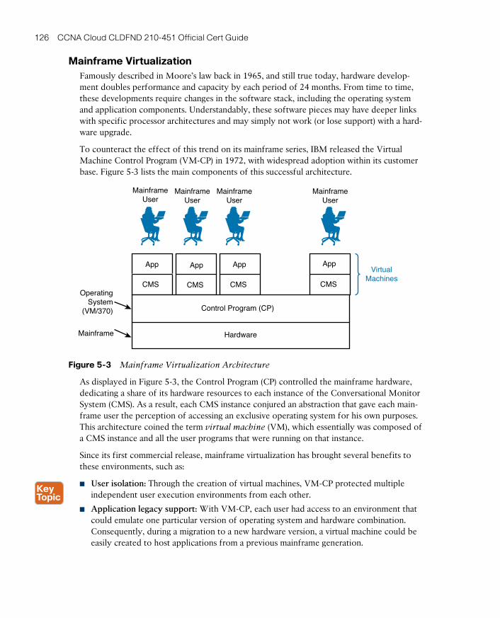
ptg17120290
126 CCNA Cloud CLDFND 210-451 Official Cert Guide
Mainframe VirtualizationFamously described in Moore’s law back in 1965, and still true today, hardware develop-ment doubles performance and capacity by each period of 24 months. From time to time, these developments require changes in the software stack, including the operating system and application components. Understandably, these software pieces may have deeper links with specific processor architectures and may simply not work (or lose support) with a hard-ware upgrade.
To counteract the effect of this trend on its mainframe series, IBM released the Virtual Machine Control Program (VM-CP) in 1972, with widespread adoption within its customer base. Figure 5-3 lists the main components of this successful architecture.
MainframeUser
MainframeUser
MainframeUser
MainframeUser
Mainframe
OperatingSystem
(VM/370)
CMS
App
CMS
App
CMS
App
CMS
App
Control Program (CP)
Hardware
VirtualMachines
Figure 5-3 Mainframe Virtualization Architecture
As displayed in Figure 5-3, the Control Program (CP) controlled the mainframe hardware, dedicating a share of its hardware resources to each instance of the Conversational Monitor System (CMS) . As a result, each CMS instance conjured an abstraction that gave each main-frame user the perception of accessing an exclusive operating system for his own purposes. This architecture coined the term virtual machine (VM) , which essentially was composed of a CMS instance and all the user programs that were running on that instance.
Since its first commercial release, mainframe virtualization has brought several benefits to these environments, such as:
■ User isolation: Through the creation of virtual machines, VM-CP protected multiple independent user execution environments from each other.
■ Application legacy support: With VM-CP, each user had access to an environment that could emulate one particular version of operating system and hardware combination. Consequently, during a migration to a new hardware version, a virtual machine could be easily created to host applications from a previous mainframe generation.
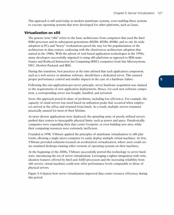
ptg17120290
5
Chapter 5: Server Virtualization 127
This approach is still used today in modern mainframe systems, even enabling these systems to execute operating systems that were developed for other platforms, such as Linux.
Virtualization on x86The generic term “x86” refers to the basic architecture from computers that used the Intel 8086 processor and its subsequent generations (80286, 80386, 80486, and so on). Its wide adoption in PCs and “heavy” workstations paved the way for the popularization of the architecture in data centers, coalescing with the client/server architecture adoption that started in the 1980s. With the advent of web-based application technologies in the 1990s, many developers successfully migrated to using x86 platforms as opposed to IBM main-frames and Reduced Instruction Set Computing (RISC) computers from Sun Microsystems, DEC, Hewlett-Packard, and IBM.
During this transition, best practices at the time advised that each application component, such as a web service or database software, should have a dedicated server. This ensured proper performance control and smaller impacts in the case of a hardware failure.
Following this one-application-per-server principle, server hardware acquisition was chained to the requirements of new application deployments. Hence, for each new software compo-nent, a corresponding server was bought, installed, and activated.
Soon, this approach posed its share of problems, including low efficiency. For example, the capacity of email servers was sized based on utilization peaks that occurred when employ-ees arrived at the office and returned from lunch. As a result, multiple servers remained practically unused for most of their lifetime.
As more diverse applications were deployed, the sprawling army of poorly utilized servers pushed data centers to inescapable physical limits, such as power and space. Paradoxically, companies were expanding their data center footprint, or even building new sites, while their computing resources were extremely inefficient.
Founded in 1998, VMware applied the principles of mainframe virtualization to x86 plat-forms, allowing a single micro-computer to easily deploy multiple virtual machines. At first, VMware provided solutions focused on workstation virtualization , where users could cre-ate emulated desktops running other versions of operating systems on their machines.
At the beginning of the 2000s, VMware successfully ported this technology to server hard-ware, introducing the era of server virtualization. Leveraging a tighter integration with virtu-alization features offered by Intel and AMD processors and the increasing reliability from x86 servers, virtual machines could now offer performance levels comparable to those of physical servers.
Figure 5-4 depicts how server virtualization improved data center resource efficiency during this period.
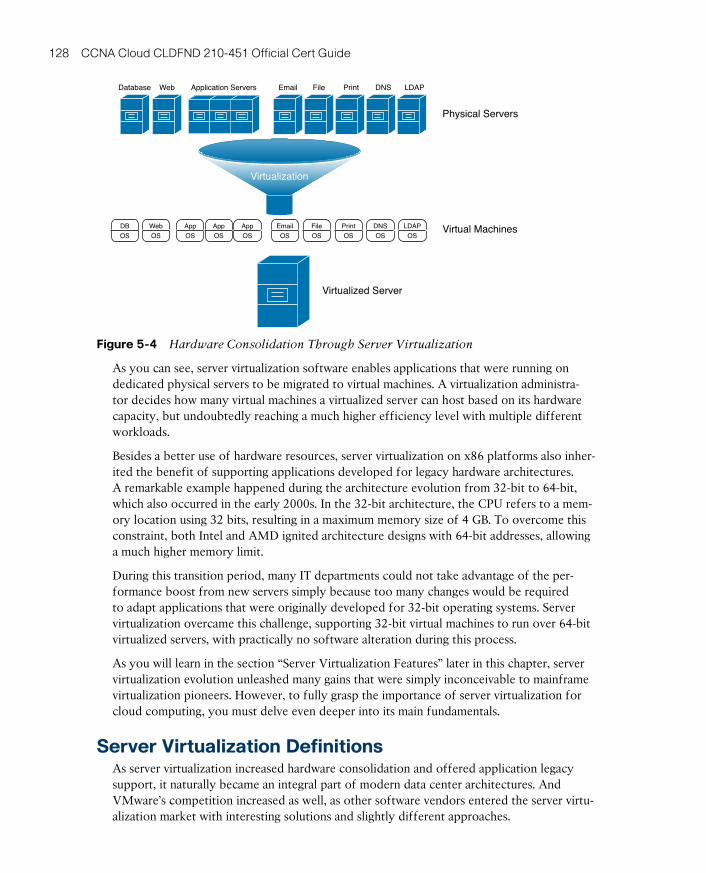
ptg17120290
128 CCNA Cloud CLDFND 210-451 Official Cert Guide
Physical Servers
Virtual Machines
Virtualized Server
Database Web Application Servers
Virtualization
DB
OS
LDAP
OS
DNS
OS
OS
File
OS
OS
App
OS
App
OS
App
OS
Web
OS
Email File Print DNS LDAP
Figure 5-4 Hardware Consolidation Through Server Virtualization
As you can see, server virtualization software enables applications that were running on dedicated physical servers to be migrated to virtual machines. A virtualization administra-tor decides how many virtual machines a virtualized server can host based on its hardware capacity, but undoubtedly reaching a much higher efficiency level with multiple different workloads.
Besides a better use of hardware resources, server virtualization on x86 platforms also inher-ited the benefit of supporting applications developed for legacy hardware architectures. A remarkable example happened during the architecture evolution from 32-bit to 64-bit, which also occurred in the early 2000s. In the 32-bit architecture, the CPU refers to a mem-ory location using 32 bits, resulting in a maximum memory size of 4 GB. To overcome this constraint, both Intel and AMD ignited architecture designs with 64-bit addresses, allowing a much higher memory limit.
During this transition period, many IT departments could not take advantage of the per-formance boost from new servers simply because too many changes would be required to adapt applications that were originally developed for 32-bit operating systems. Server virtualization overcame this challenge, supporting 32-bit virtual machines to run over 64-bit virtualized servers, with practically no software alteration during this process.
As you will learn in the section “Server Virtualization Features” later in this chapter, server virtualization evolution unleashed many gains that were simply inconceivable to mainframe virtualization pioneers. However, to fully grasp the importance of server virtualization for cloud computing, you must delve even deeper into its main fundamentals.
Server Virtualization DefinitionsAs server virtualization increased hardware consolidation and offered application legacy support, it naturally became an integral part of modern data center architectures. And VMware’s competition increased as well, as other software vendors entered the server virtu-alization market with interesting solutions and slightly different approaches.
ptg17120290
5
Chapter 5: Server Virtualization 129
To approach server virtualization as generically and vendor neutrally as possible, in the fol-lowing sections I will focus on the common concepts that bind all virtualization solutions and introduce hypervisor offerings from many different vendors.
HypervisorA hypervisor can be defined as a software component that can create emulated hardware (including CPU, memory, storage, networking, and peripherals, among other components) for the installation of a guest operating system . In the context of server technologies, a hypervisor is essentially a program that allows the creation of virtual servers.
Table 5-3 lists and describes the most commonly deployed hypervisors at the time of this writing.
Table 5-3 Commonly Deployed Hypervisors
Hypervisor Brief Description
VMware ESXi Derived from the VMware ESX software created in 2001, ESXi is the market-leading hypervisor as well as the basis for a suite of virtualization tools called VMware vSphere .
Microsoft Hyper-V Released alongside Windows Server 2008 and enhanced in version 2012, this hypervisor naturally provides a tighter integration with Windows environments.
Linux KVM The Kernel-based Virtual Machine (KVM) is an open source hypervisor that was integrated into the Linux kernel in 2007.
Red Hat Enterprise Virtualization (RHEV)
An enterprise version of Linux KVM, this solution also benefits from other open source virtualization tools such as oVirt.
Citrix XenServer A Citrix enterprise version of Xen, a hypervisor that was originally released in 2003 as a project from the University of Cambridge. Citrix XenServer continues to leverage open source development on Xen.
Oracle VM Also based on Xen, this hypervisor is specially customized to support Oracle applications.
VMware Workstation , VMware Player , and VMware Fusion
VMware Workstation allows the creation of multiple x86-based VMs over a desktop PC. VMware Player is its free version that only permits the creation of a single VM. VMware Fusion allows the same functionality for Apple Mac OS X users.
Microsoft Windows Virtual PC
Released in 2006, this virtualization software enables the creation of virtual desktops on a single Windows-based computer.
Oracle VM Virtual Box This virtualization product, originally released in 2007, also allows additional guest operating systems running over Linux, Mac OS X, and Windows, among other operating systems.
Parallels Desktop for Mac This was the first virtualization software released for Mac computers. Since 2007, this software permits the creation of virtual desktops running Windows, Linux, and Mac OS X.
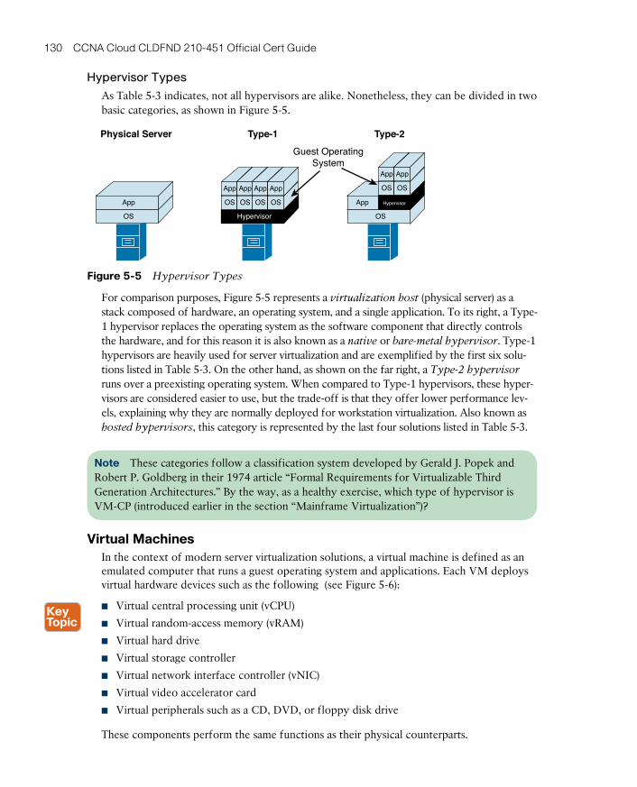
ptg17120290
130 CCNA Cloud CLDFND 210-451 Official Cert Guide
Hypervisor Types
As Table 5-3 indicates, not all hypervisors are alike. Nonetheless, they can be divided in two basic categories, as shown in Figure 5-5.
Physical Server Type-1 Type-2
Guest OperatingSystem
OS
App
Hypervisor
OS OS OS OS
App App App App OS OS
App App
OS
App Hypervisor
Figure 5-5 Hypervisor Types
For comparison purposes, Figure 5-5 represents a virtualization host (physical server) as a stack composed of hardware, an operating system, and a single application. To its right, a Type-1 hypervisor replaces the operating system as the software component that directly controls the hardware, and for this reason it is also known as a native or bare-metal hypervisor . Type-1 hypervisors are heavily used for server virtualization and are exemplified by the first six solu-tions listed in Table 5-3. On the other hand, as shown on the far right, a Type-2 hypervisor runs over a preexisting operating system. When compared to Type-1 hypervisors, these hyper-visors are considered easier to use, but the trade-off is that they offer lower performance lev-els, explaining why they are normally deployed for workstation virtualization. Also known as hosted hypervisors , this category is represented by the last four solutions listed in Table 5-3.
Note These categories follow a classification system developed by Gerald J. Popek and Robert P. Goldberg in their 1974 article “Formal Requirements for Virtualizable Third Generation Architectures.” By the way, as a healthy exercise, which type of hypervisor is VM-CP (introduced earlier in the section “Mainframe Virtualization”)?
Virtual MachinesIn the context of modern server virtualization solutions, a virtual machine is defined as an emulated computer that runs a guest operating system and applications. Each VM deploys virtual hardware devices such as the following (see Figure 5-6):
■ Virtual central processing unit (vCPU)
■ Virtual random-access memory (vRAM)
■ Virtual hard drive
■ Virtual storage controller
■ Virtual network interface controller (vNIC)
■ Virtual video accelerator card
■ Virtual peripherals such as a CD, DVD, or floppy disk drive
These components perform the same functions as their physical counterparts.
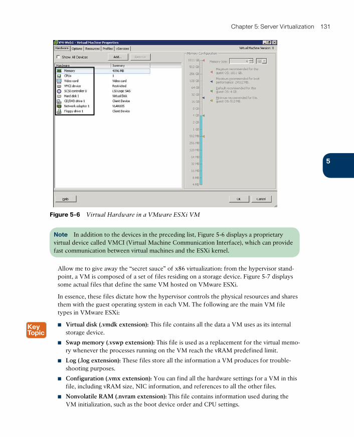
ptg17120290
5
Chapter 5: Server Virtualization 131
Figure 5-6 Virtual Hardware in a VMware ESXi VM
Note In addition to the devices in the preceding list, Figure 5-6 displays a proprietary virtual device called VMCI (Virtual Machine Communication Interface) , which can provide fast communication between virtual machines and the ESXi kernel.
Allow me to give away the “secret sauce” of x86 virtualization: from the hypervisor stand-point, a VM is composed of a set of files residing on a storage device. Figure 5-7 displays some actual files that define the same VM hosted on VMware ESXi.
In essence, these files dictate how the hypervisor controls the physical resources and shares them with the guest operating system in each VM. The following are the main VM file types in VMware ESXi:
■ Virtual disk (.vmdk extension): This file contains all the data a VM uses as its internal storage device.
■ Swap memory (.vswp extension): This file is used as a replacement for the virtual memo-ry whenever the processes running on the VM reach the vRAM predefined limit.
■ Log (.log extension): These files store all the information a VM produces for trouble-shooting purposes.
■ Configuration (.vmx extension): You can find all the hardware settings for a VM in this file, including vRAM size, NIC information, and references to all the other files.
■ Nonvolatile RAM (.nvram extension): This file contains information used during the VM initialization, such as the boot device order and CPU settings.
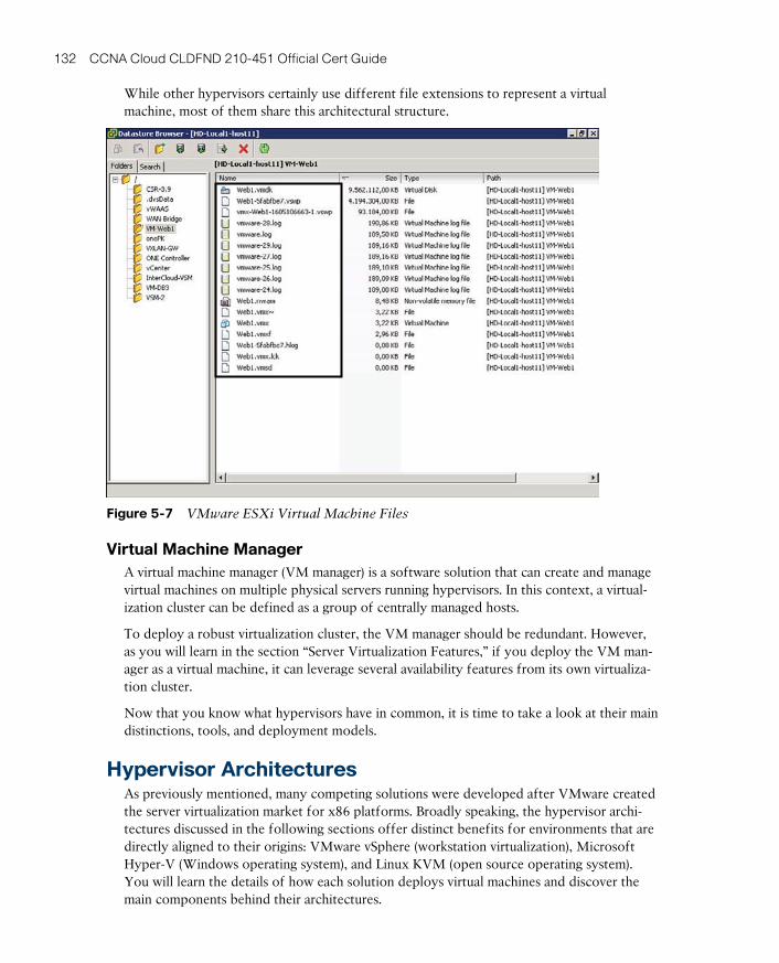
ptg17120290
132 CCNA Cloud CLDFND 210-451 Official Cert Guide
While other hypervisors certainly use different file extensions to represent a virtual machine, most of them share this architectural structure.
Figure 5-7 VMware ESXi Virtual Machine Files
Virtual Machine ManagerA virtual machine manager (VM manager) is a software solution that can create and manage virtual machines on multiple physical servers running hypervisors. In this context, a virtual-ization cluster can be defined as a group of centrally managed hosts.
To deploy a robust virtualization cluster, the VM manager should be redundant. However, as you will learn in the section “Server Virtualization Features,” if you deploy the VM man-ager as a virtual machine, it can leverage several availability features from its own virtualiza-tion cluster.
Now that you know what hypervisors have in common, it is time to take a look at their main distinctions, tools, and deployment models.
Hypervisor ArchitecturesAs previously mentioned, many competing solutions were developed after VMware created the server virtualization market for x86 platforms. Broadly speaking, the hypervisor archi-tectures discussed in the following sections offer distinct benefits for environments that are directly aligned to their origins: VMware vSphere (workstation virtualization), Microsoft Hyper-V (Windows operating system), and Linux KVM (open source operating system). You will learn the details of how each solution deploys virtual machines and discover the main components behind their architectures.

ptg17120290
5
Chapter 5: Server Virtualization 133
VMware vSphereVMware vSphere is the software suite comprising the VMware ESXi hypervisor and its asso-ciated tools. VMware developed vSphere for the purpose of creating and managing virtual servers. Continuing the basic structure started with VMware Infrastructure (VI), vSphere has maintained its position as the leading server virtualization architecture since its launch in 2009.
Figure 5-8 depicts the main components of the VMware vSphere architecture and how they interact with each other.
ESXI ESXI ESXI
App
OS
App
OS
App
OS
App
OS
App
OS
App
OS
vCenterVirtualMachinesvSphere Client
vSphere Client
VirtualizationAdmin or Web Client
Hosts
Figure 5-8 VMware vSphere Architecture
As Figure 5-8 demonstrates, a virtualization administrator uses vSphere Client, which is soft-ware available for Windows computers, to deploy multiple virtual machines on hosts with installed ESXi hypervisors. Nevertheless, the use of a VM manager enables multiple benefits besides the centralized creation of VMs, as you will learn in the upcoming section “Server Virtualization Features.” Originally built over a Windows-based server, VMware vCenter is the VM manager for the vSphere suite.
A VMware vSphere administrator can use a web browser to control VMware vCenter and, consequently, its associated virtualization cluster.
Note In VMware vSphere terminology, “cluster” refers to a set of hosts that share the same policies and feature settings. Therefore, a single vCenter instance can manage multiple clusters. However, for the sake of simplicity, this certification guide refers to a virtualization cluster as a single VM manager managing a set of hosts.
Microsoft Hyper-VMicrosoft, the leading personal computer operating system vendor, released its server vir-tualization offer in 2008. Hyper-V is a hypervisor enabled as a new Windows Server 2012 role, exactly as you would activate services such Active Directory or Terminal Services in this operating system. Figure 5-9 shows Hyper-V already installed and activated along with other roles in a Windows 2012 Server.
Your first impression might be that Hyper-V is a Type-2 hypervisor, but Hyper-V is indeed a Type-1 hypervisor because it has direct access to the server hardware. In fact, after the Hyper-V role is enabled on a Windows 2012 Server, the whole system requires a reboot so the original operating system instance can be transformed into a special virtual machine, formally called a parent partition . For obvious reasons, Hyper-V grants special privileges to this partition because it also deploys some functions that are shared by the hosted VMs.

ptg17120290
134 CCNA Cloud CLDFND 210-451 Official Cert Guide
Figure 5-9 Installed Hyper-V in a Windows 2012 Server
Although a virtualization administrator can use client software called Hyper-V Manager to create and manage VMs in a single Hyper-V host, System Center Virtual Machine Manager (SCVMM) is the architecture VM manager, extending server virtualization features to multi-ple hosts. Using the VMM Administrator Console, a virtualization administrator can control a Hyper-V virtualization cluster as depicted in Figure 5-10.
Windows Server 2012 withHyper-V Role
System Center VirtualMachine Manager
(SCVMM)
VMM Adminstrator
Console WindowsServer
App
OS
App
OS
App
OS
App
OS
App
OS
App
OS
VirtualMachines
Hyper-V Manager
VirtualizationAdmin
Hosts
WindowsServer
WindowsServer
Figure 5-10 Microsoft Hyper-V Architecture
Microsoft Hyper-V has increased its participation in the server virtualization market with each new version. Arguably, its adoption is strongly supported by the ubiquitous presence of the Windows operating system in server environments and its relative operational sim-plicity to Windows-trained professionals.
Linux Kernel-based Virtual MachineStanding on the shoulders of a giant called open source development, server virtualization was brought to Linux systems with the increasing adoption of this operating system in the

ptg17120290
5
Chapter 5: Server Virtualization 135
2000s. Kernel-based Virtual Machine (KVM) is arguably the most popular solution among several other Linux-based Type-1 hypervisors since its release in 2007.
As its name implies, this full virtualization solution is not executed as a user application but actually as a loadable kernel module called kvm.ko. This component was integrated in main-line Linux since version 2.6.20.
Both the open source community and vendors packaging Linux enterprise solutions have developed a great variety of methods to manage KVM virtual machines, including command-line interfaces (Linux shell), web interfaces, and client-based GUIs. Additionally, many VM managers were similarly created to manage KVM-based virtualization clusters. Among these are Red Hat Enterprise Virtualization (RHEV), oVirt, and OpenStack Nova. Figure 5-11 illus-trates how all of these components are integrated into a generic KVM architecture.
Web, Client,
or CLI
CLI, GUI
Hosts
Linux withKVM KernelModule
VirtualMachines
VirtualizationAdmin
Red HatEnterpriseVirtualization(RHEV)
oVirt
OpenStack Nova
... and manyothers Linux Linux Linux
App
OS
App
OS
App
OS
App
OS
App
OS
App
OS
Figure 5-11 Linux KVM Architecture
KVM has been adopted for various reasons, such as cost (it can be considered free, depend-ing on your version of Linux) and operational easiness to install in server environments where Linux expertise is available.
Note OpenStack Nova encompasses many functions that are beyond the scope of a VM manager. Thus, besides the creation and management of virtual machines (called “Nova instances”), Nova is considered the de facto orchestrator of most computer-related opera-tions in an OpenStack cloud, offering a set of APIs (including Amazon EC2 API) to auto-mate pools of computer resources from hypervisors such as Hyper-V, VM managers (such as VMware vCenter), and high-performance computing (HPC) clusters.
Multi-Hypervisor EnvironmentsWhile the three software solutions explained in the previous sections arguably represent the most widely adopted server virtualization architectures, they are not alone in this market. Some other hypervisors, such as Citrix XenServer, were briefly described in Table 5-3.
For obvious reasons, each solution presents its own specific advantages. Yet, some custom-ers do not want to be restricted to a single server virtualization architecture. Interestingly, during the past few years, I have observed an increasing number of customers deploying multi-hypervisor environments for various reasons. For example:

ptg17120290
136 CCNA Cloud CLDFND 210-451 Official Cert Guide
■ To decrease licensing costs
■ To avoid vendor lock-in
■ To leverage personnel’s specialized familiarity with a specific operating system
■ To deploy new projects such as cloud computing or virtual desktops
Server Virtualization FeaturesAs I briefly mentioned in the section “Virtualization on x86,” a server virtualization clus-ter can bring more benefits to data centers than simply creating and monitoring virtual machines on multiple hosts. With the objective of exploring these enhancements, the fol-lowing sections discuss this list of features (plus a few other interesting features):
■ Virtual machine high availability
■ Virtual machine live migration
■ Resource load balancing
■ Virtual machine fault tolerance
Undoubtedly, these features highlight the fact that VMs are software constructs that can be much more easily manipulated when compared to physical servers.
Allow me to suggest to you a small exercise: During the explanation of each feature, try to picture how it can help cloud computing environments. Later, in the section “Cloud Computing and Server Virtualization,” I will address these synergies so you can gauge your cloud design powers.
Virtual Machine High AvailabilityServer failures may happen at any time. To protect server systems from such events, applica-tion teams usually have to develop or acquire solutions that provide an adequate level of resiliency for these systems. These solutions are generically called cluster software and are usually bound to an operating system (e.g., Windows Server Failover Cluster) or a single application (e.g., Oracle Real Application Clusters).
With the considerable variety of operating systems and their hosted applications, the job of managing cluster software in pure physical server environments can become extremely diffi-cult. Notwithstanding, through virtualization clusters, hypervisors can actually provide high availability to virtual machines regardless of their application or operating system flavors.
Figure 5-12 details how selected virtual machines can be conveniently “resurrected” when-ever their host suffers a major hardware or hypervisor failure.
In the situation depicted on the left side of Figure 5-12, a virtualization cluster consists of three hosts (Host1, Host2, and Host3) with two virtual machines each. After Host1 experi-ences a major failure, both of its virtual machines are restarted on other hosts from the same cluster, as shown on the right. This automatic procedure is only possible because the affect-ed VMs’ files are stored on an external storage system (such as a disk array or network-attached storage) rather than a hard disk on Host1.
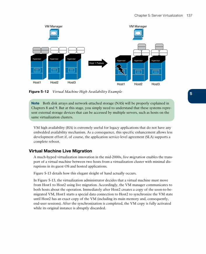
ptg17120290
5
Chapter 5: Server Virtualization 137
Host 1 Failure
VM Manager VM Manager
Hypervisor
Host1
Hypervisor
Host2
HypervisorHypervisorHypervisor Hypervisor
Host3 Host1 Host2 Host3
Figure 5-12 Virtual Machine High Availability Example
Note Both disk arrays and network-attached storage (NAS) will be properly explained in Chapters 8 and 9. But at this stage, you simply need to understand that these systems repre-sent external storage devices that can be accessed by multiple servers, such as hosts on the same virtualization clusters.
VM high availability (HA) is extremely useful for legacy applications that do not have any embedded availability mechanism. As a consequence, this specific enhancement allows less development effort if, of course, the application service-level agreement (SLA) supports a complete reboot.
Virtual Machine Live MigrationA much-hyped virtualization innovation in the mid-2000s, live migration enables the trans-port of a virtual machine between two hosts from a virtualization cluster with minimal dis-ruptions in its guest OS and hosted applications.
Figure 5-13 details how this elegant sleight of hand actually occurs.
In Figure 5-13, the virtualization administrator decides that a virtual machine must move from Host1 to Host2 using live migration. Accordingly, the VM manager communicates to both hosts about the operation. Immediately after Host2 creates a copy of the soon-to-be-migrated VM, Host1 starts a special data connection to Host2 to synchronize the VM state until Host2 has an exact copy of the VM (including its main memory and, consequently, end-user sessions). After the synchronization is completed, the VM copy is fully activated while its original instance is abruptly discarded.
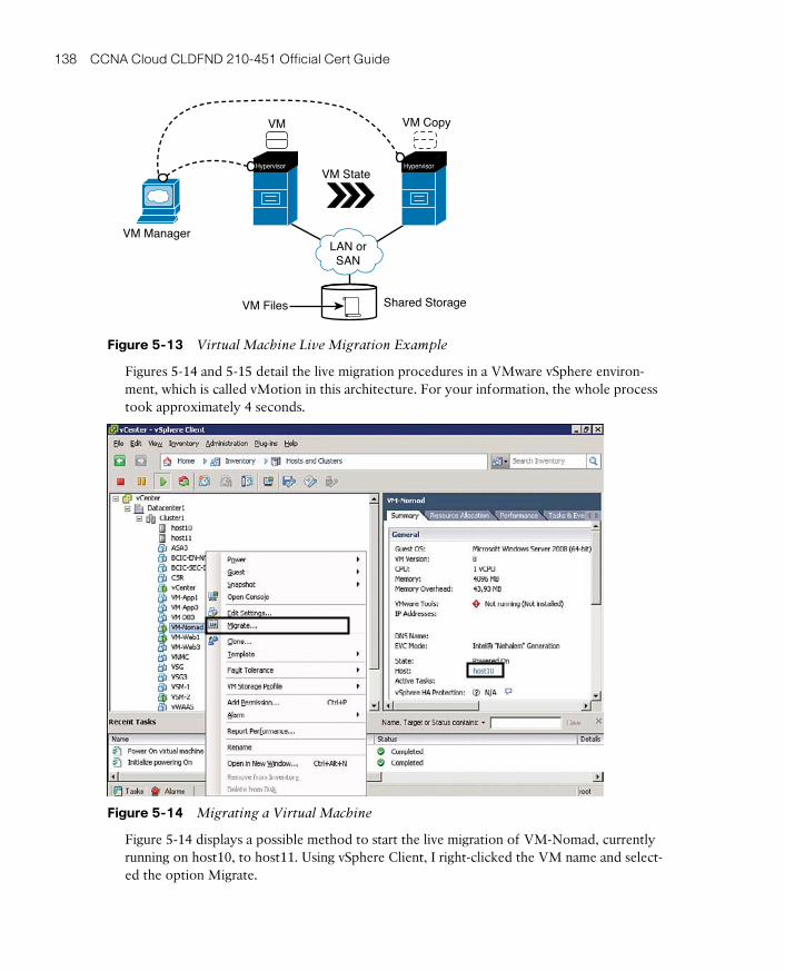
ptg17120290
138 CCNA Cloud CLDFND 210-451 Official Cert Guide
VM Files
VM Manager
VM State
VM VM Copy
Shared Storage
Hypervisor Hypervisor
LAN orSAN
Figure 5-13 Virtual Machine Live Migration Example
Figures 5-14 and 5-15 detail the live migration procedures in a VMware vSphere environ-ment, which is called vMotion in this architecture. For your information, the whole process took approximately 4 seconds.
Figure 5-14 Migrating a Virtual Machine
Figure 5-14 displays a possible method to start the live migration of VM-Nomad, currently running on host10, to host11. Using vSphere Client, I right-clicked the VM name and select-ed the option Migrate.
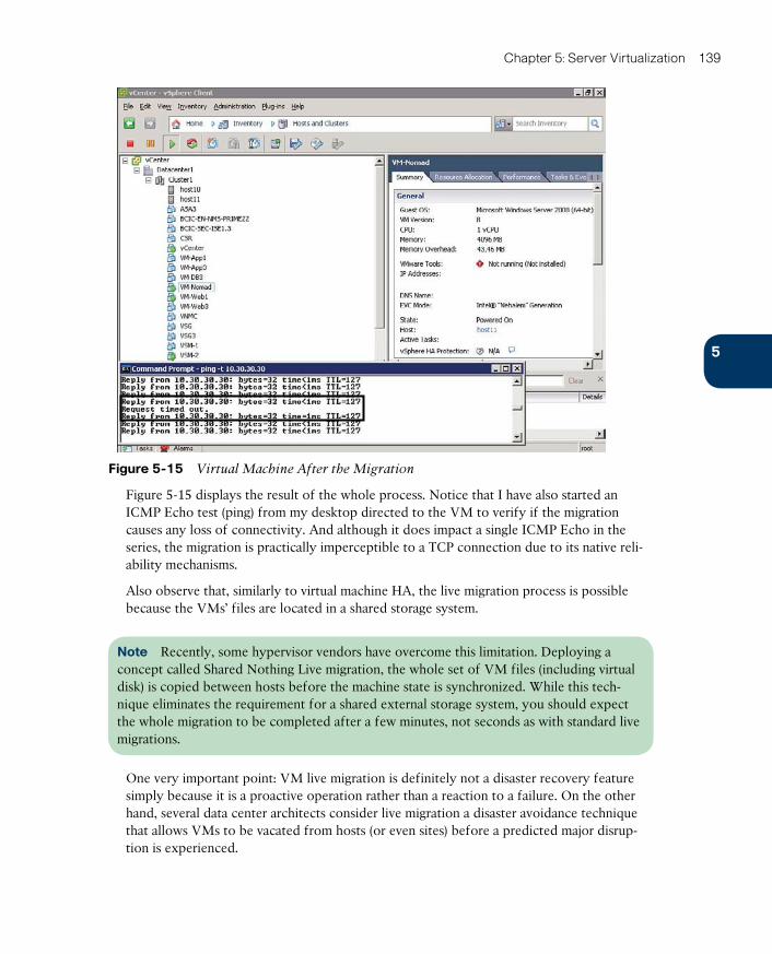
ptg17120290
5
Chapter 5: Server Virtualization 139
Figure 5-15 Virtual Machine After the Migration
Figure 5-15 displays the result of the whole process. Notice that I have also started an ICMP Echo test (ping) from my desktop directed to the VM to verify if the migration causes any loss of connectivity. And although it does impact a single ICMP Echo in the series, the migration is practically imperceptible to a TCP connection due to its native reli-ability mechanisms.
Also observe that, similarly to virtual machine HA, the live migration process is possible because the VMs’ files are located in a shared storage system.
Note Recently, some hypervisor vendors have overcome this limitation. Deploying a concept called Shared Nothing Live migration , the whole set of VM files (including virtual disk) is copied between hosts before the machine state is synchronized. While this tech-nique eliminates the requirement for a shared external storage system, you should expect the whole migration to be completed after a few minutes, not seconds as with standard live migrations.
One very important point: VM live migration is definitely not a disaster recovery feature simply because it is a proactive operation rather than a reaction to a failure. On the other hand, several data center architects consider live migration a disaster avoidance technique that allows VMs to be vacated from hosts (or even sites) before a predicted major disrup-tion is experienced.
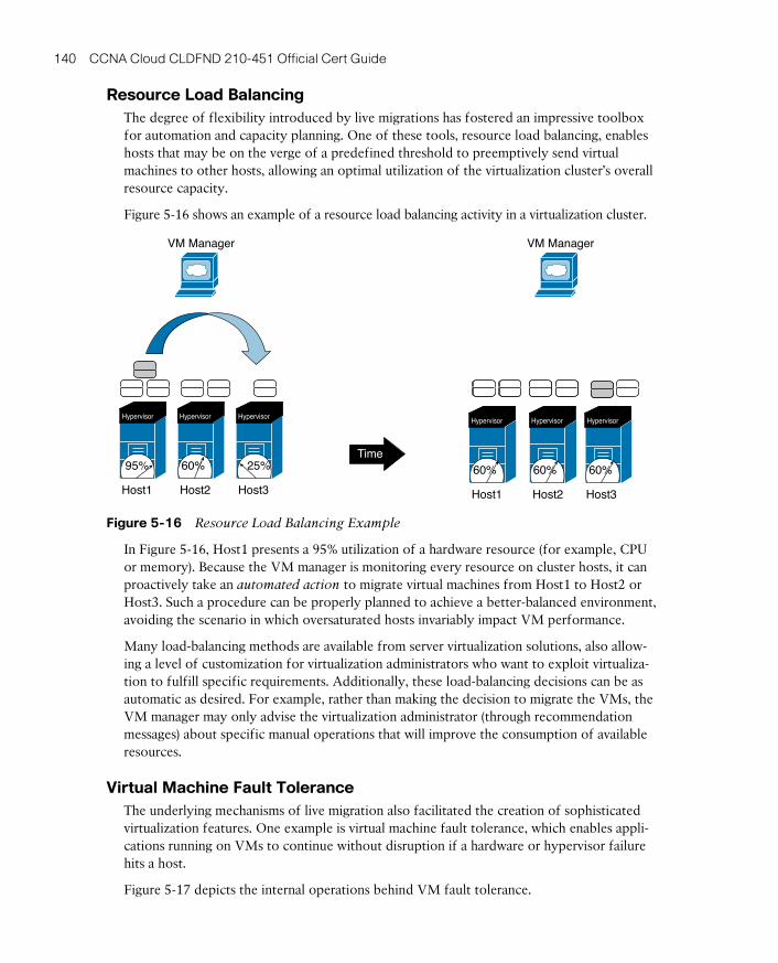
ptg17120290
140 CCNA Cloud CLDFND 210-451 Official Cert Guide
Resource Load BalancingThe degree of flexibility introduced by live migrations has fostered an impressive toolbox for automation and capacity planning. One of these tools, resource load balancing, enables hosts that may be on the verge of a predefined threshold to preemptively send virtual machines to other hosts, allowing an optimal utilization of the virtualization cluster’s overall resource capacity.
Figure 5-16 shows an example of a resource load balancing activity in a virtualization cluster.
Time
VM Manager VM Manager
Hypervisor
60%
Hypervisor
95% 25%
Host1 Host1Host2
Hypervisor
60%
Hypervisor
60%
Hypervisor
60%
Host2Host3 Host3
Hypervisor
Figure 5-16 Resource Load Balancing Example
In Figure 5-16, Host1 presents a 95% utilization of a hardware resource (for example, CPU or memory). Because the VM manager is monitoring every resource on cluster hosts, it can proactively take an automated action to migrate virtual machines from Host1 to Host2 or Host3. Such a procedure can be properly planned to achieve a better-balanced environment, avoiding the scenario in which oversaturated hosts invariably impact VM performance.
Many load-balancing methods are available from server virtualization solutions, also allow-ing a level of customization for virtualization administrators who want to exploit virtualiza-tion to fulfill specific requirements. Additionally, these load-balancing decisions can be as automatic as desired. For example, rather than making the decision to migrate the VMs, the VM manager may only advise the virtualization administrator (through recommendation messages) about specific manual operations that will improve the consumption of available resources.
Virtual Machine Fault ToleranceThe underlying mechanisms of live migration also facilitated the creation of sophisticated virtualization features. One example is virtual machine fault tolerance, which enables appli-cations running on VMs to continue without disruption if a hardware or hypervisor failure hits a host.
Figure 5-17 depicts the internal operations behind VM fault tolerance.
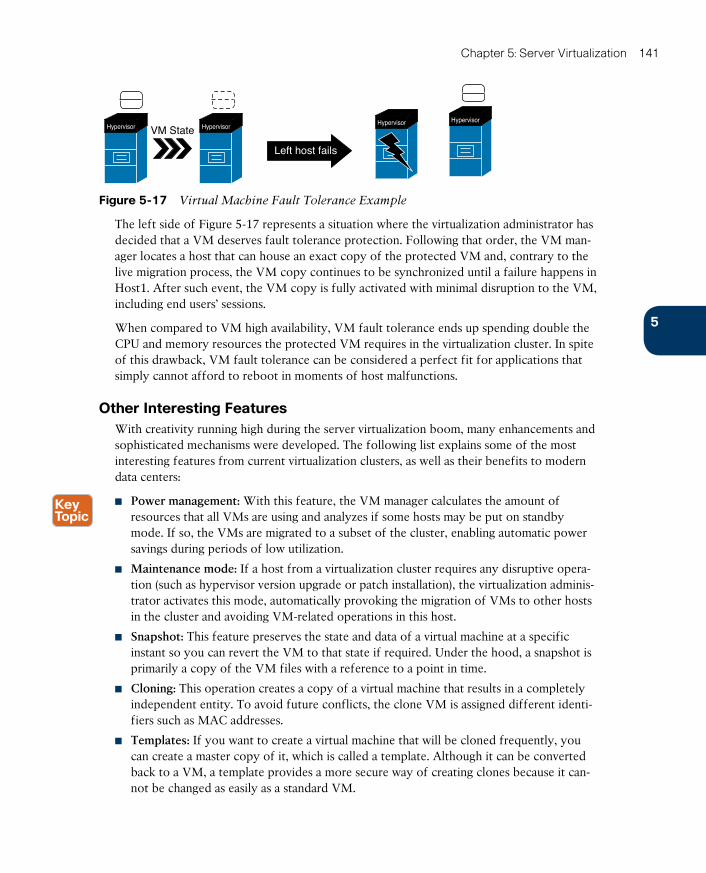
ptg17120290
5
Chapter 5: Server Virtualization 141
VM StateHypervisorHypervisor Hypervisor
Hypervisor
Left host fails
Figure 5-17 Virtual Machine Fault Tolerance Example
The left side of Figure 5-17 represents a situation where the virtualization administrator has decided that a VM deserves fault tolerance protection. Following that order, the VM man-ager locates a host that can house an exact copy of the protected VM and, contrary to the live migration process, the VM copy continues to be synchronized until a failure happens in Host1. After such event, the VM copy is fully activated with minimal disruption to the VM, including end users’ sessions.
When compared to VM high availability, VM fault tolerance ends up spending double the CPU and memory resources the protected VM requires in the virtualization cluster. In spite of this drawback, VM fault tolerance can be considered a perfect fit for applications that simply cannot afford to reboot in moments of host malfunctions.
Other Interesting FeaturesWith creativity running high during the server virtualization boom, many enhancements and sophisticated mechanisms were developed. The following list explains some of the most interesting features from current virtualization clusters, as well as their benefits to modern data centers:
■ Power management: With this feature, the VM manager calculates the amount of resources that all VMs are using and analyzes if some hosts may be put on standby mode. If so, the VMs are migrated to a subset of the cluster, enabling automatic power savings during periods of low utilization.
■ Maintenance mode: If a host from a virtualization cluster requires any disruptive opera-tion (such as hypervisor version upgrade or patch installation), the virtualization adminis-trator activates this mode, automatically provoking the migration of VMs to other hosts in the cluster and avoiding VM-related operations in this host.
■ Snapshot: This feature preserves the state and data of a virtual machine at a specific instant so you can revert the VM to that state if required. Under the hood, a snapshot is primarily a copy of the VM files with a reference to a point in time.
■ Cloning: This operation creates a copy of a virtual machine that results in a completely independent entity. To avoid future conflicts, the clone VM is assigned different identi-fiers such as MAC addresses.
■ Templates: If you want to create a virtual machine that will be cloned frequently, you can create a master copy of it, which is called a template. Although it can be converted back to a VM, a template provides a more secure way of creating clones because it can-not be changed as easily as a standard VM.

ptg17120290
142 CCNA Cloud CLDFND 210-451 Official Cert Guide
Undeniably, most of the features discussed in this section can help cloud comput-ing deployments achieve the characteristics described in Chapter 1, “What Is Cloud Computing?” And, as you will learn in the next section, these features have become an important foundation for these environments.
Cloud Computing and Server VirtualizationServer virtualization set such a firm foundation for cloud computing that many profession-als still embrace these concepts as being synonymous. This confusion is understandable because virtualization technology has surely decreased the number of physical operations that encumbered server provisioning in data centers.
But while virtual machines greatly facilitate application provisioning, a server virtualization cluster is definitely not a cloud. For sure, virtual machines are not the only resource end users expect from a cloud computing environment. And, as I have described in Chapter 1, a cloud can potentially offer physical resources, such as database servers, or networking assets, such as virtual private networks (VPNs).
With the objective of further exploring both the similarities and differences between server virtualization and cloud computing, the next three sections will review some essential cloud characteristics discussed in Chapter 1.
Self-Service on DemandSome VM managers offer embedded web portals for end users to easily provision and manage VMs. Consequently, these hypervisor architectures can express the self-service on demand characteristic through a very simple IaaS-based private cloud.
However, as I have personally observed in many customer deployments, some self-service portal implementations do not address other cloud essential characteristics, such as provi-sioning of physical resources and service metering. As a result, it is much more usual to find cloud deployments using additional software layers consisting of service catalog portal, infrastructure orchestration, and chargeback (or showback) solutions.
As a refresher from Chapter 4, “Behind the Curtain,” Figure 5-18 illustrates that a server vir-tualization cluster is just one of several infrastructure components orchestrated by a cloud software stack.
Figure 5-18 also highlights that end-user requests generate API calls (asking to create, read, update, or delete a resource) to the VM manager via a cloud orchestrator. With such an arrangement, metering is made possible through the collection of data from the VM man-ager. Therefore, a flexible and well-written VM manager API is certainly a requirement for the integration of hypervisor architectures and cloud orchestrators. And in a way to spare customization efforts on this integration, most server virtualization vendors have developed complementary cloud stack solutions.
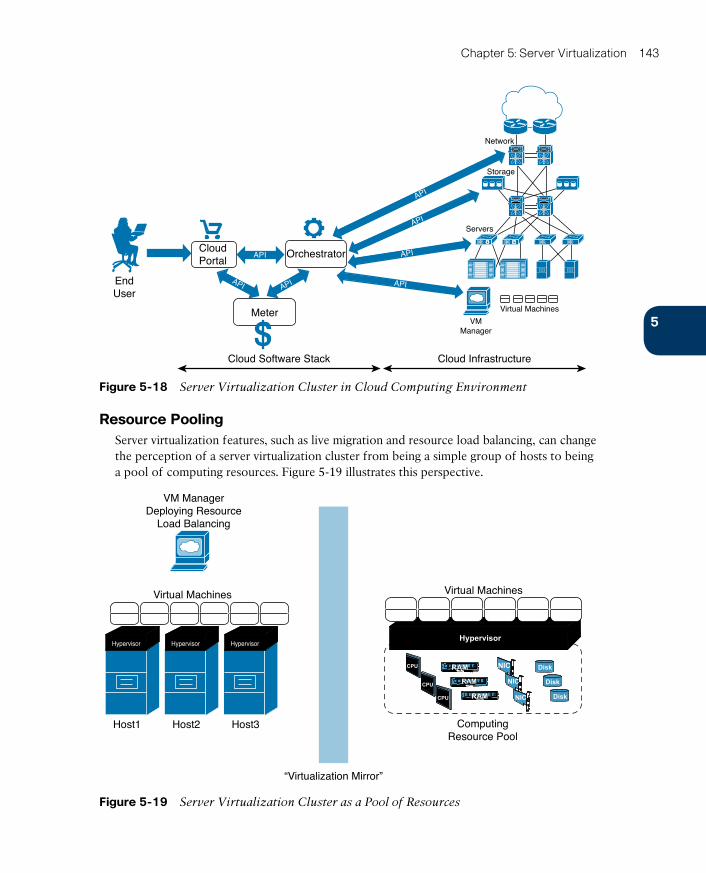
ptg17120290
5
Chapter 5: Server Virtualization 143
EndUser
CloudPortal
Orchestrator
Meter
Cloud Software Stack Cloud Infrastructure
Storage
Servers
Network
API
API API
API
API
API
API
Virtual Machines
VMManager$
Figure 5-18 Server Virtualization Cluster in Cloud Computing Environment
Resource PoolingServer virtualization features, such as live migration and resource load balancing, can change the perception of a server virtualization cluster from being a simple group of hosts to being a pool of computing resources. Figure 5-19 illustrates this perspective.
Disk
Disk
Disk
VM ManagerDeploying Resource
Load Balancing
Hypervisor
Host1
Hypervisor
Host2
Hypervisor
Host3
Virtual Machines Virtual Machines
ComputingResource Pool
NIC
NIC
NIC
RAM
RAM
RAM
Hypervisor
“Virtualization Mirror”
CPU
CPU
CPU
Figure 5-19 Server Virtualization Cluster as a Pool of Resources
ptg17120290
144 CCNA Cloud CLDFND 210-451 Official Cert Guide
Figure 5-19 displays a VM manager deploying resource load balancing on three hosts in virtu-alization clusters. In this environment, a cloud orchestrator does not have to define in which host a new VM will be instantiated simply because the VM manager already takes care of such details. Therefore, from the cloud software stack perspective (right of the “virtualization mir-ror”), the cluster is a big computing device aggregating a pool of resources (CPU, memory, I/O bandwidth, and storage, among others) from the cluster hosts.
On the other hand, if end-user requests have already exhausted one of the cluster resources, the cloud software stack should ideally detect such saturation and provision more physical devices (hosts or storage) into the virtualization cluster.
ElasticityBecause a virtual machine is essentially a set of software components, it can be scaled up according to application or end-user requirements. For example, if an application’s perfor-mance is being adversely affected by memory constraints from its virtual machine, a VM manager can increase its assigned vRAM without any serious disruption. And even if the resource cannot be tampered with without a reboot, virtualization features such as cloning and templates can scale out applications, providing more VMs as required.
Even so, to deploy such elasticity capability, a cloud architect should consider the additional use of performance monitoring solutions to monitor applications running on virtual machines. And as a general rule, these solutions are not part of a VM manager software package.
Around the Corner: Linux Containers and DockerIn this chapter, you have learned how virtual machines have revolutionized server and application provisioning in data centers during the first decade of this century. However, in certain situations an application development may not require some of the overhead related to a VM, such as
■ Emulation of hardware (for example, CPU, memory, NIC, and hard disk)
■ Execution (and management) of a separate operating system kernel
■ Initialization time, when compared to application provisioning over an already installed operating system
Linux Containers (LXC) offers a lightweight alternative to hypervisors, providing operating system–level virtualization instead. A single Linux server can run multiple isolated Linux sys-tems, called containers , using the combination of the following kernel security features:
■ Control groups (cgroups): Provide resource isolation to each container, dedicating CPU, memory, block I/O, and networking accordingly
■ Access control: Denies container access to unauthorized users
■ Namespaces: Isolate the application perspective of the operating system, offering distinct process trees, network connectivity, and user identifiers for each provisioned container
Because a container reuses libraries and processes from the original Linux installation, it will have a smaller size when compared with a virtual machine. Therefore, if your cloud environ-ment provisions Linux applications, containers are probably the fastest and most economical way to support such offerings. However, I highly recommend that you carefully analyze
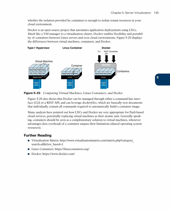
ptg17120290
5
Chapter 5: Server Virtualization 145
whether the isolation provided by containers is enough to isolate tenant resources in your cloud environment.
Docker is an open source project that automates application deployments using LXCs. Much like a VM manager to a virtualization cluster, Docker enables flexibility and portabil-ity of containers between Linux servers and even cloud environments. Figure 5-20 displays the differences between virtual machines, containers, and Docker.
Type-1 Hypervisor Linux Container Docker
DockerVirtual Machine
Container
Linux
App App App App
Hypervisor
OS OS OS OS
App App App AppContainers
Linux
App App App App
CLI RESTAPI
Dockerfiles
Figure 5-20 Comparing Virtual Machines, Linux Containers, and Docker
Figure 5-20 also shows that Docker can be managed through either a command-line inter-face (CLI) or a REST API, and can leverage dockerfiles , which are basically text documents that individually contain all commands required to automatically build a container image.
Many analysts have pointed out how LXCs and Docker are very appropriate for PaaS-based cloud services, potentially replacing virtual machines as their atomic unit. Generally speak-ing, containers should be seen as a complementary solution to virtual machines, whenever advantages (less overhead) of a container surpass their limitations (shared operating system resources).
Further Reading■ Virtualization Matrix: http://www.virtualizationmatrix.com/matrix.php?category_
search=all&free_based=1
■ Linux Containers: https://linuxcontainers.org/
■ Docker: https://www.docker.com/
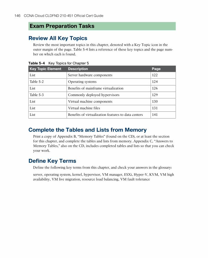
ptg17120290
146 CCNA Cloud CLDFND 210-451 Official Cert Guide
Exam Preparation Tasks
Review All Key TopicsReview the most important topics in this chapter, denoted with a Key Topic icon in the outer margin of the page. Table 5-4 lists a reference of these key topics and the page num-ber on which each is found.
Table 5-4 Key Topics for Chapter 5
Key Topic Element Description Page
List Server hardware components 122
Table 5-2 Operating systems 124
List Benefits of mainframe virtualization 126
Table 5-3 Commonly deployed hypervisors 129
List Virtual machine components 130
List Virtual machine files 131
List Benefits of virtualization features to data centers 141
Complete the Tables and Lists from MemoryPrint a copy of Appendix B, “Memory Tables” (found on the CD), or at least the section for this chapter, and complete the tables and lists from memory. Appendix C, “Answers to Memory Tables,” also on the CD, includes completed tables and lists so that you can check your work.
Define Key TermsDefine the following key terms from this chapter, and check your answers in the glossary:
server, operating system, kernel, hypervisor, VM manager, ESXi, Hyper-V, KVM, VM high availability, VM live migration, resource load balancing, VM fault tolerance

ptg17120290
ptg17120290
This chapter covers the following topics:
■ Virtual Machines and Networking
■ Cisco Nexus 1000V
■ Virtual eXtensible LAN
This chapter covers the following exam objectives:
■ 4.2 Describe Infrastructure Virtualization■ 4.2.a Difference between vSwitch and DVS■ 4.2.b Cisco Nexus 1000V components
■ 4.2.b.1 VSM■ 4.2.b.2 VEM■ 4.2.b.3 VSM appliance
■ 4.2.c Difference between VLAN and VXLAN
ptg17120290
CHAPTER 6
Infrastructure VirtualizationThe sole action of creating virtual servers is certainly not enough to provide applications to end users. In fact, these devices are expected to interact with their users, as well as other resources, making the subject of networking mandatory in any application-related conversa-tion. Many topics related to physical networks (such as VLANs, IP addresses, and routing) are naturally part of this discussion. Additionally, the popularization of server virtualization on x86 platforms has led to the development of other solutions to support the problem of virtual machine communication. An amalgamation of both old and new concepts has spawned a new and exciting branch of networking called virtual networking .
With server virtualization performing a fundamental role in cloud computing, virtual machine (VM) traffic management has fostered intense development during the past decade. Unsurprisingly, the CLDFND exam requires knowledge about the main funda-mentals of virtual networking in Cisco environments, such as both main variants of virtual switches (vSwitch and distributed virtual switch), multi-hypervisor virtual switching based on Cisco Nexus 1000V, and Virtual eXtensible LANs (VXLANs).
Fully addressing these points, this chapter investigates the motivations behind virtual net-working, compares multiple solutions for virtual machine communication, and describes how Cisco has approached this new data center knowledge area.
“Do I Know This Already?” QuizThe “Do I Know This Already?” quiz allows you to assess whether you should read this entire chapter thoroughly or jump to the “Exam Preparation Tasks” section. If you are in doubt about your answers to these questions or your own assessment of your knowledge of the topics, read the entire chapter. Table 6-1 lists the major headings in this chapter and their corresponding “Do I Know This Already?” quiz questions. You can find the answers in Appendix A, “Answers to Pre-Assessments and Quizzes.”
Table 6-1 “Do I Know This Already?” Section-to-Question Mapping
Foundation Topics Section Questions
Virtual Machines and Networking 1–3
Cisco Nexus 1000V 4–7
Virtual eXtensible LAN 8–10
1. Which of the following is not applicable to virtual switching in general?
a. Responsible for virtual machine Layer 2 connectivity
b. Can be configured per host, without the use of a VM manager
c. Does not allow live migration of VMs
d. Supports LACP
e. Can belong to more than one host
ptg17120290
150 CCNA Cloud CLDFND 210-451 Official Cert Guide
2. Which of the following are differences between the VMware vNetwork Standard Switch and the VMware vNetwork Distributed Switch? (Choose four.)
a. VMware vCenter requirement
b. Uplink Port Groups
c. Allows VMotion
d. Resides in more than one host
e. Permits Port Groups with distinct load balancing methods
f. Supports LACP
3. Which of the following virtual devices can be considered distributed virtual switches? (Choose three.)
a. VMware vSS
b. Open vSwitch
c. Microsoft Virtual Network Switch
d. Linux bridge
e. VMware vDS
f. Cisco Nexus 1000V
4. Which of the following are correct about Cisco Nexus 1000V Switch for VMware vSphere? (Choose four.)
a. The communication between the VSM and VEM requires Layer 3 connectivity.
b. The communication between the VSM and VEM requires Layer 2 connectivity.
c. The VEM runs inside the VMware vSphere kernel.
d. The VEM does not run inside the VMware vSphere kernel.
e. Cisco Nexus 1000V can coexist with other virtual switches in the same host.
f. Cisco Nexus 1000V cannot coexist with other virtual switches in the same host.
g. The communication between active and standby VSMs requires Layer 3 connec-tivity.
h. The communication between active and standby VSMs requires Layer 2 connec-tivity.
5. Which of the following are correct associations of Cisco Nexus 1000V interfaces and VMware vSphere interfaces? (Choose two.)
a. Ethernet and vnic
b. vEthernet and vmk
c. vEthernet and vmnic
d. Ethernet and vmnic
e. Ethernet and vmk
ptg17120290
6
Chapter 6: Infrastructure Virtualization 151
6. Which of the following is not a Cisco Nexus 1000V feature?
a. vTracker
b. PortChannel
c. DHCP server
d. Private VLAN
e. TrustSec
7. Which hypervisors support Cisco Nexus 1000V? (Choose three.)
a. Microsoft Hyper-V for Windows 2008
b. Microsoft Hyper-V for Windows 2012
c. VMware vSphere
d. Xen
e. KVM
8. Which protocols are used in the VXLAN encapsulation header? (Choose two.)
a. TCP
b. GRE
c. UDP
d. IP
9. Which of the following are advantages of VXLANs over VLANs? (Choose three.)
a. Avoids MAC address table overflow in physical switches
b. Offers easier provisioning of broadcast domains for virtual machines
c. Provides more segments
d. Use IP multicast
e. Deploys flood-based learning
10. Which of the following represent improvements of Cisco Nexus 1000V Enhanced VXLAN over standard VXLAN deployments? (Choose two.)
a. Uses less MAC addresses
b. Does not require IP multicast
c. Eliminates broadcast and unknown unicast frames
d. Eliminates flooding
ptg17120290
152 CCNA Cloud CLDFND 210-451 Official Cert Guide
Foundation Topics
Virtual Machines and NetworkingChapter 5, “Server Virtualization,” explored how mainframe virtualization was adapted for x86 platforms to conceive one of the most important atomic units of a modern data center: the virtual machine. In the same chapter, you also learned why server virtualization is a key component in cloud computing, offering native agility, standardization, mobility, and resilience to applications deployed in such environments. With this background, this sec-tion zooms in on a simple (but challenging) problem: How to control VM traffic inside of a hypervisor.
An Abstraction for Virtual Machine Traffic ManagementConsider the following philosophical question:
If a virtual machine cannot communicate with any other element, does it really
exist?
From a technical standpoint, a virtual server obviously consumes CPU cycles, accesses memory, and saves data. Nonetheless, if the main purpose of a VM is to provide services to other systems, it certainly cannot achieve that without data connectivity.
The emulation of network adapters within virtual machines presupposes that actual traffic is exchanged across this virtual interface, including IP packets encapsulated in Ethernet frames and all ancillary signaling messages (e.g., Address Resolution Protocol [ARP]). Consequently, during the intense development of server virtualization in the early 2000s, several solutions were proposed for the following so-called challenges of VM communication:
■ Challenge 1: Which software element should control the physical network adapter drive?
■ Challenge 2: How should communication occur between VMs and external resources such as physical servers and routers?
■ Challenge 3: How should VMs located in the same host be isolated from one another?
Depending on your level of server virtualization expertise, you likely already know the solu-tion for all of these challenges. Nonetheless, to fully appreciate the subtleties and elegance of modern virtual networking solutions, for the moment put yourself in the shoes of a virtualiza-tion vendor in the early 2000s. As a starting point for this discussion, consider Figure 6-1.
In Figure 6-1, the same virtualized host containing two virtual machines is represented twice. And as described in the preceding list of challenges, these VMs must talk to each other and to devices located beyond the access switch, in the data center network.
Additionally, Figure 6-1 introduces two ways of representing virtual machines and their hosts. Whereas the drawing on the left depicts VMs running over the hypervisor (which I call “server vision”), the drawing on the right positions VMs at the bottom, mimicking usual network topologies where physical servers are connected below communication devices (a “network vision”).

ptg17120290
6
Chapter 6: Infrastructure Virtualization 153
VM VM
Server Vision Network Vision
Data Center Network
App
OS
App
OS
Hypervisor
Virtual Machines
Virtualized Server Virtualized Server
Access Switch
?
NIC
App
OS
App
OS
Figure 6-1 Virtual Machine Networking Challenges
Although the two visions might seem very similar, I highly suggest you refrain from using the server vision for networking problems. Comparing both methods, the network vision allows a more detailed exploration of networking issues in complex environments. Thus, from now on, this certification guide will employ the latter method whenever virtual net-working is being discussed.
When addressing the first challenge, you will probably agree that standard VMs should not control the physical network adapter driver, not only to avoid becoming a bottleneck for VM traffic, but also to prevent other VMs from accessing this resource. As a consequence, most server virtualization vendors have decided that the hypervisor itself should control the physical network interface controller (NIC), sharing this resource with all hosted VMs.
Regarding the second challenge, try to picture how a hypervisor can use the physical NIC to forward VM data to the outside world. In this case, is it better to route (Layer 3) or bridge (Layer 2) the traffic? While routing certainly can offer better isolation to the hosted VMs, it invariably imposes operational complexities (such as subnet design and routing protocol implementation) that do not fit into most server virtualization deployments. Therefore, for the sake of simplicity, most virtual networking solutions are based on Layer 2 forwarding of Ethernet frames between VMs and the access switch.
Finally, addressing the third challenge, virtualization administrators expect to define which VMs, even running in the same hypervisor instance, should communicate with each other. As a direct result, most virtual networking solutions converged on the most traditional method of traffic isolation: the virtual local-area network (VLAN) .
A VLAN is formally defined as a broadcast domain in a single Ethernet switch or shared among connected switches. Whenever a switch port receives a broadcast Ethernet frame (destination MAC address is ffff.ffff.ffff), the Layer 2 device must forward this frame to all other interfaces that are defined in the same VLAN. In other words, if two hosts are connected to the same VLAN, they can exchange frames. If not, they are isolated until an external device (such as an IP router) connects them.
Taking all of these considerations into account, and adding the goals of simplicity and flex-ibility, the virtual switch has emerged as the most common virtual networking solution

ptg17120290
154 CCNA Cloud CLDFND 210-451 Official Cert Guide
among all hypervisors. To further delve into this software network device, the following sections explore its main characteristics, evolution, and variants.
The Virtual SwitchIn the early 2000s, VMware created the concept of the virtual switch (vSwitch), which is essentially a software abstraction where the hypervisor deploys a simplified version of a Layer 2 Ethernet switch to control virtual machine traffic. At the time of this writing, this specific networking element is officially known as VMware vNetwork Standard Switch (vSS) .
Note For the sake of simplicity, I will generically refer to a virtual network device that shares the characteristics presented in this section as a vSwitch, regardless of its hypervisor.
Figure 6-2 illustrates the forwarding principles behind a generic vSwitch.
AccessSwitch
Virtualized Server
Data CenterNetwork
vSwitchFrame
Frame
VM
VM
NIC
AppOS
vNlCAppOS
vNlC
Figure 6-2 Example of a vSwitch in Action
In a vSwitch, the physical NICs act as uplinks , conducting VM traffic beyond the access switch. As represented in Figure 6-2, a vSwitch can forward Ethernet frames from a virtual machine to the physical switch and vice versa. And because each VM emulates at least one NIC, real Ethernet frames traverse the virtual wire that exists between the virtual adapter and the virtual switch. After analyzing the destination MAC address in a frame, the vSwitch decides if it should send the frame to the physical NIC or to a VM whose virtual network adapter is connected to the same VLAN. In the latter situation, the data exchanged between two VMs in the same host only requires a memory-based operation.
Using VLAN tagging in its physical NICs, a vSwitch deploys more than one VLAN in these interfaces. Based on the 12-bit VLAN ID field defined in the IEEE 802.1Q standard, the vir-tual device can identify to which VLAN an incoming Ethernet frame belongs and also signal to the access switch the VLAN from an outgoing frame.
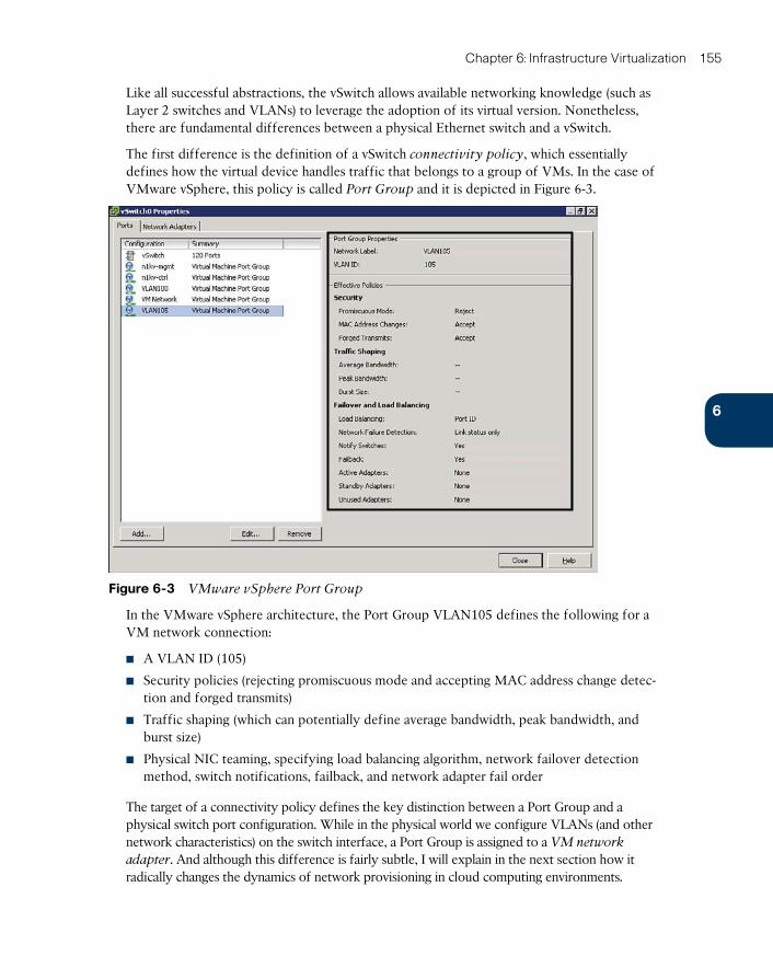
ptg17120290
6
Chapter 6: Infrastructure Virtualization 155
Like all successful abstractions, the vSwitch allows available networking knowledge (such as Layer 2 switches and VLANs) to leverage the adoption of its virtual version. Nonetheless, there are fundamental differences between a physical Ethernet switch and a vSwitch.
The first difference is the definition of a vSwitch connectivity policy , which essentially defines how the virtual device handles traffic that belongs to a group of VMs. In the case of VMware vSphere, this policy is called Port Group and it is depicted in Figure 6-3.
Figure 6-3 VMware vSphere Port Group
In the VMware vSphere architecture, the Port Group VLAN105 defines the following for a VM network connection:
■ A VLAN ID (105)
■ Security policies (rejecting promiscuous mode and accepting MAC address change detec-tion and forged transmits)
■ Traffic shaping (which can potentially define average bandwidth, peak bandwidth, and burst size)
■ Physical NIC teaming, specifying load balancing algorithm, network failover detection method, switch notifications, failback, and network adapter fail order
The target of a connectivity policy defines the key distinction between a Port Group and a physical switch port configuration. While in the physical world we configure VLANs (and other network characteristics) on the switch interface, a Port Group is assigned to a VM network
adapter. And although this difference is fairly subtle, I will explain in the next section how it radically changes the dynamics of network provisioning in cloud computing environments.
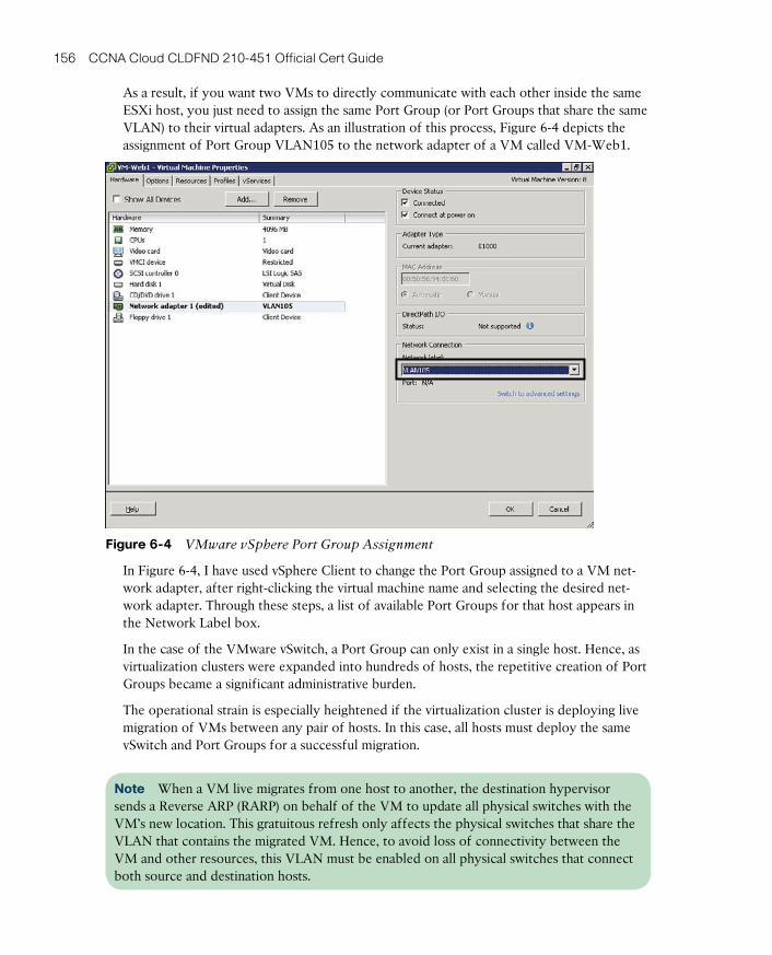
ptg17120290
156 CCNA Cloud CLDFND 210-451 Official Cert Guide
As a result, if you want two VMs to directly communicate with each other inside the same ESXi host, you just need to assign the same Port Group (or Port Groups that share the same VLAN) to their virtual adapters. As an illustration of this process, Figure 6-4 depicts the assignment of Port Group VLAN105 to the network adapter of a VM called VM-Web1.
Figure 6-4 VMware vSphere Port Group Assignment
In Figure 6-4, I have used vSphere Client to change the Port Group assigned to a VM net-work adapter, after right-clicking the virtual machine name and selecting the desired net-work adapter. Through these steps, a list of available Port Groups for that host appears in the Network Label box.
In the case of the VMware vSwitch, a Port Group can only exist in a single host. Hence, as virtualization clusters were expanded into hundreds of hosts, the repetitive creation of Port Groups became a significant administrative burden.
The operational strain is especially heightened if the virtualization cluster is deploying live migration of VMs between any pair of hosts. In this case, all hosts must deploy the same vSwitch and Port Groups for a successful migration.
Note When a VM live migrates from one host to another, the destination hypervisor sends a Reverse ARP (RARP) on behalf of the VM to update all physical switches with the VM’s new location. This gratuitous refresh only affects the physical switches that share the VLAN that contains the migrated VM. Hence, to avoid loss of connectivity between the VM and other resources, this VLAN must be enabled on all physical switches that connect both source and destination hosts.
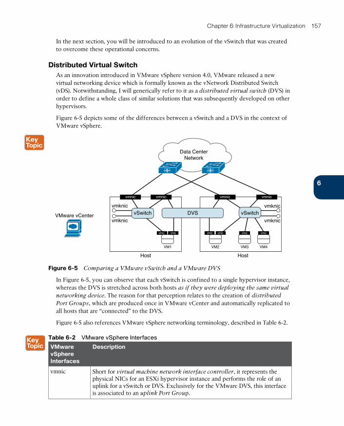
ptg17120290
6
Chapter 6: Infrastructure Virtualization 157
In the next section, you will be introduced to an evolution of the vSwitch that was created to overcome these operational concerns.
Distributed Virtual SwitchAs an innovation introduced in VMware vSphere version 4.0, VMware released a new virtual networking device which is formally known as the vNetwork Distributed Switch (vDS). Notwithstanding, I will generically refer to it as a distributed virtual switch (DVS) in order to define a whole class of similar solutions that was subsequently developed on other hypervisors.
Figure 6-5 depicts some of the differences between a vSwitch and a DVS in the context of VMware vSphere.
Data CenterNetwork
VMware vCenter
vmknic
vmknic
vnic vnic
vmnic vmnic
vSwitch
VM1
vmknic
vmknic
vnic vnic
vmnic vmnic
VM2 VM3 VM4
vnic vnic
vSwitch
Host Host
DVS
Figure 6-5 Comparing a VMware vSwitch and a VMware DVS
In Figure 6-5, you can observe that each vSwitch is confined to a single hypervisor instance, whereas the DVS is stretched across both hosts as if they were deploying the same virtual
networking device. The reason for that perception relates to the creation of distributed
Port Groups , which are produced once in VMware vCenter and automatically replicated to all hosts that are “connected” to the DVS.
Figure 6-5 also references VMware vSphere networking terminology, described in Table 6-2.
Table 6-2 VMware vSphere Interfaces
VMware vSphere Interfaces
Description
vmnic Short for virtual machine network interface controller , it represents the physical NICs for an ESXi hypervisor instance and performs the role of an uplink for a vSwitch or DVS. Exclusively for the VMware DVS, this interface is associated to an uplink Port Group.
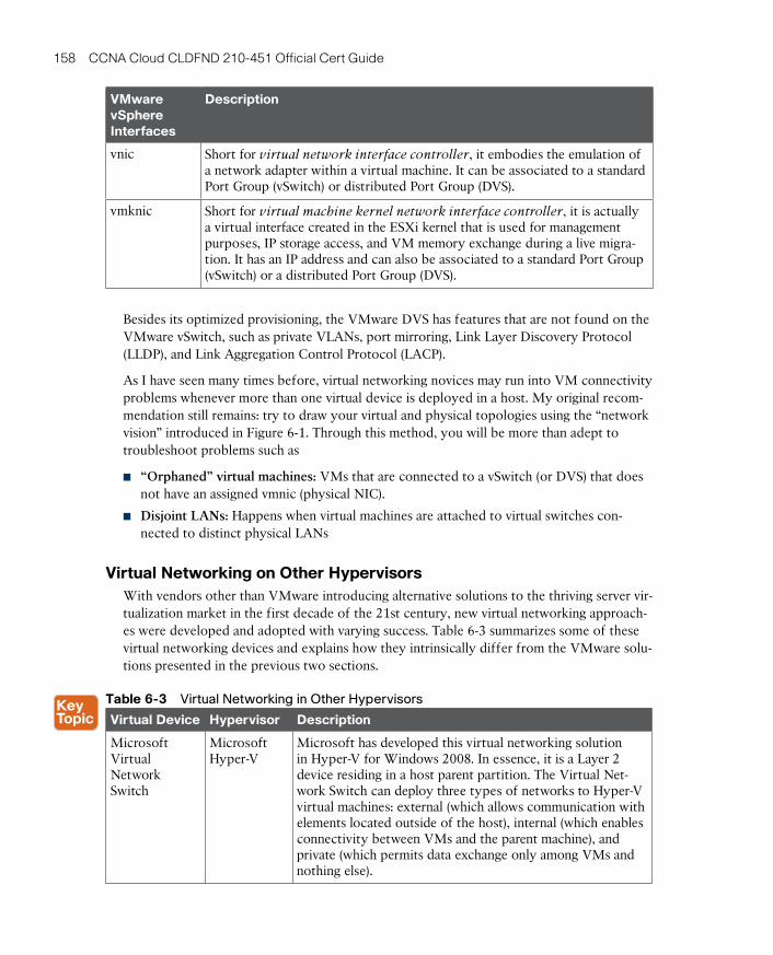
ptg17120290
158 CCNA Cloud CLDFND 210-451 Official Cert Guide
VMware vSphere Interfaces
Description
vnic Short for virtual network interface controller , it embodies the emulation of a network adapter within a virtual machine. It can be associated to a standard Port Group (vSwitch) or distributed Port Group (DVS).
vmknic Short for virtual machine kernel network interface controller , it is actually a virtual interface created in the ESXi kernel that is used for management purposes, IP storage access, and VM memory exchange during a live migra-tion. It has an IP address and can also be associated to a standard Port Group (vSwitch) or a distributed Port Group (DVS).
Besides its optimized provisioning, the VMware DVS has features that are not found on the VMware vSwitch, such as private VLANs, port mirroring, Link Layer Discovery Protocol (LLDP), and Link Aggregation Control Protocol (LACP).
As I have seen many times before, virtual networking novices may run into VM connectivity problems whenever more than one virtual device is deployed in a host. My original recom-mendation still remains: try to draw your virtual and physical topologies using the “network vision” introduced in Figure 6-1. Through this method, you will be more than adept to troubleshoot problems such as
■ “Orphaned” virtual machines: VMs that are connected to a vSwitch (or DVS) that does not have an assigned vmnic (physical NIC).
■ Disjoint LANs: Happens when virtual machines are attached to virtual switches con-nected to distinct physical LANs
Virtual Networking on Other HypervisorsWith vendors other than VMware introducing alternative solutions to the thriving server vir-tualization market in the first decade of the 21st century, new virtual networking approach-es were developed and adopted with varying success. Table 6-3 summarizes some of these virtual networking devices and explains how they intrinsically differ from the VMware solu-tions presented in the previous two sections.
Table 6-3 Virtual Networking in Other Hypervisors
Virtual Device Hypervisor Description
Microsoft Virtual Network Switch
Microsoft Hyper-V
Microsoft has developed this virtual networking solution in Hyper-V for Windows 2008. In essence, it is a Layer 2 device residing in a host parent partition. The Virtual Net-work Switch can deploy three types of networks to Hyper-V virtual machines: external (which allows communication with elements located outside of the host), internal (which enables connectivity between VMs and the parent machine), and private (which permits data exchange only among VMs and nothing else).
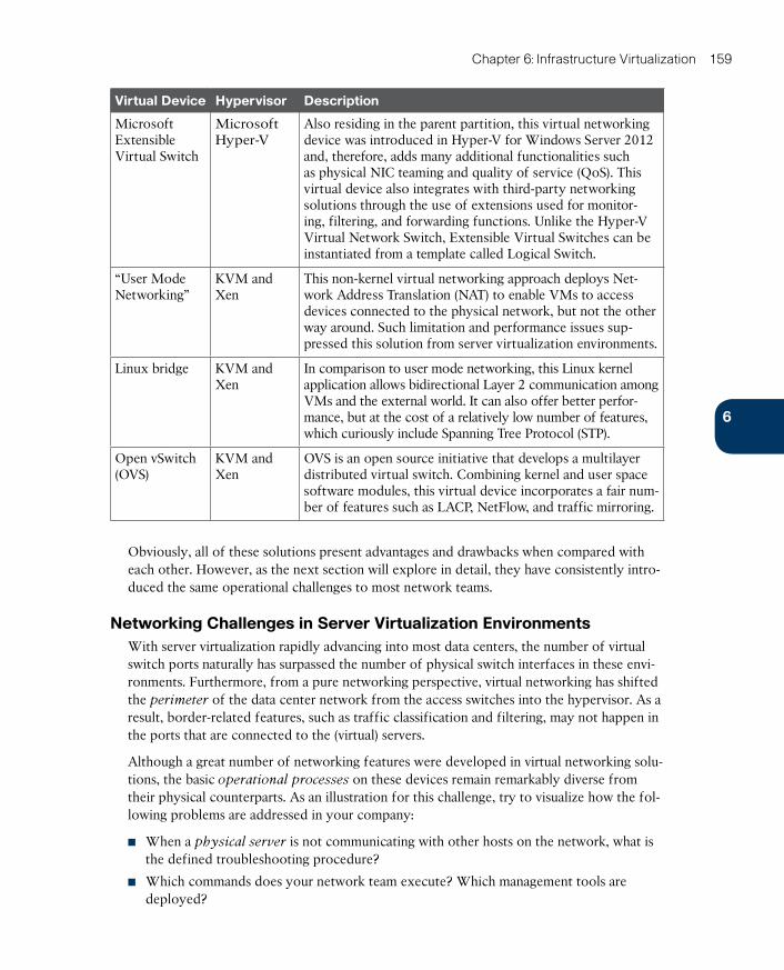
ptg17120290
6
Chapter 6: Infrastructure Virtualization 159
Virtual Device Hypervisor Description
Microsoft Extensible Virtual Switch
Microsoft Hyper-V
Also residing in the parent partition, this virtual networking device was introduced in Hyper-V for Windows Server 2012 and, therefore, adds many additional functionalities such as physical NIC teaming and quality of service (QoS). This virtual device also integrates with third-party networking solutions through the use of extensions used for monitor-ing, filtering, and forwarding functions. Unlike the Hyper-V Virtual Network Switch, Extensible Virtual Switches can be instantiated from a template called Logical Switch.
“User Mode Networking”
KVM and Xen
This non-kernel virtual networking approach deploys Net-work Address Translation (NAT) to enable VMs to access devices connected to the physical network, but not the other way around. Such limitation and performance issues sup-pressed this solution from server virtualization environments.
Linux bridge KVM and Xen
In comparison to user mode networking, this Linux kernel application allows bidirectional Layer 2 communication among VMs and the external world. It can also offer better perfor-mance, but at the cost of a relatively low number of features, which curiously include Spanning Tree Protocol (STP).
Open vSwitch (OVS)
KVM and Xen
OVS is an open source initiative that develops a multilayer distributed virtual switch. Combining kernel and user space software modules, this virtual device incorporates a fair num-ber of features such as LACP, NetFlow, and traffic mirroring.
Obviously, all of these solutions present advantages and drawbacks when compared with each other. However, as the next section will explore in detail, they have consistently intro-duced the same operational challenges to most network teams.
Networking Challenges in Server Virtualization EnvironmentsWith server virtualization rapidly advancing into most data centers, the number of virtual switch ports naturally has surpassed the number of physical switch interfaces in these envi-ronments. Furthermore, from a pure networking perspective, virtual networking has shifted the perimeter of the data center network from the access switches into the hypervisor. As a result, border-related features, such as traffic classification and filtering, may not happen in the ports that are connected to the (virtual) servers.
Although a great number of networking features were developed in virtual networking solu-tions, the basic operational processes on these devices remain remarkably diverse from their physical counterparts. As an illustration for this challenge, try to visualize how the fol-lowing problems are addressed in your company:
■ When a physical server is not communicating with other hosts on the network, what is the defined troubleshooting procedure?
■ Which commands does your network team execute? Which management tools are deployed?
ptg17120290
160 CCNA Cloud CLDFND 210-451 Official Cert Guide
Now consider what happens if a virtual machine runs into the same exact problem:
■ Are new troubleshooting procedures required?
■ Can your network team perform them with their current operational skills and manage-ment tools?
■ How can the network team know about a change in the virtual network?
As discussed in Chapter 4, “Behind the Curtain,” operational processes can certainly define whether a technology will be successfully adopted or not. And in my humble opinion, it really does not matter how innovative a solution is, if it does not fit into the operational procedures of a company IT department.
More specifically, the vast majority of virtual networking solutions discussed in the previous sections present the following difficulties to network teams and their operations:
■ No visibility: When there is a problem happening in the “virtual wire” that links a vir-tual machine to a virtual networking device, traditional management tools are useless to discover a root cause. Without proper access to the VM manager, a network administra-tor can only “ping” this VM and verify if its MAC address is detected on the physical switches.
■ VMs on wrong VLANs: Operational mistakes during the creation of virtual network-ing policies may provoke major problems in data center networks. For example, if a VM running a Dynamic Host Control Protocol (DHCP) server is incorrectly connected to a VLAN, it may assign incorrect IP addresses to other VMs and consequently stop all com-munication in that segment.
■ Illicit communication between VMs: A virtualization administrator may not be acute-ly aware of security policies that were defined and deployed in the physical network. As a consequence, VMs that should not communicate with each other may share a poten-tially dangerous network backdoor.
■ Distinct control policies: Besides filtering policies described in the previous item, QoS policies defined in the physical network may not be accordingly mapped to the virtual network. Therefore, noncritical traffic may exhaust resources (such as physical NIC bandwidth) from being available for critical traffic, resulting in poor application perfor-mance.
■ No virtualized DMZ: When companies must deploy demilitarized zones (DMZ) to con-trol incoming and outgoing traffic for select servers, server hardware consolidation may directly collide with such a security directive. I personally have seen many security teams struggling with this concept, most of which ended up deploying a separate virtualization cluster for these DMZ-connected VMs.
■ Increased complexity for multi-hypervisor environments: If a data center is using more than one hypervisor, the network team will probably face additional operational difficulties to find common features in distinct virtualization platforms.
In 2009, Cisco released an innovative (yet familiar) solution that addresses all of these operational challenges: a multi-hypervisor distributed virtual switch, further explored in the next section.
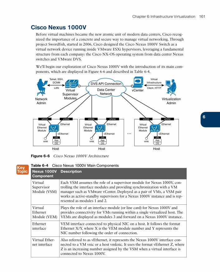
ptg17120290
6
Chapter 6: Infrastructure Virtualization 161
Cisco Nexus 1000VBefore virtual machines became the new atomic unit of modern data centers, Cisco recog-nized the importance of a concrete and secure way to manage virtual networking. Through project Swordfish, started in 2006, Cisco designed the Cisco Nexus 1000V Switch as a virtual network device running inside VMware ESXi hypervisors, leveraging a fundamental structure from each company: the Cisco NX-OS operating system from data center Nexus switches and VMware DVS.
We’ll begin our exploration of Cisco Nexus 1000V with the introduction of its main com-ponents, which are displayed in Figure 6-6 and described in Table 6-4.
vmic
AppOS
vnlc
vmnic
VirtualEthernetModule
vEthernet
Ethernet
AppOS
VirtualEthernetModule
vmk
vEthernet
Ethernet
vnlc
...
Host Host
vmnic
AppOS
VirtualEthernetModule
vmk
vEthernet
Ethernet
vnlc
Host
vmnic
LAN
NetworkAdmin
VirtualSupervisorModules
Telnet, SSH,DCNM
Client, HTTP
VirtualInfrastructure
vCenter
VirtualizationAdmin
DVS API Connection
Data CenterNetwork
vmnic vmnic vmnic
vmk
Figure 6-6 Cisco Nexus 1000V Architecture
Table 6-4 Cisco Nexus 1000V Main Components
Nexus 1000V Component
Description
Virtual Supervisor Module (VSM)
Each VSM assumes the role of a supervisor module for Nexus 1000V, con-trolling the interface modules and providing synchronization with a VM manager such as VMware vCenter. Deployed as a pair of VMs, a VSM pair works as active-standby supervisors for a Nexus 1000V instance and is rep-resented as modules 1 and 2.
Virtual Ethernet Module (VEM)
Plays the role of an interface module (or line card) for Nexus 1000V and provides connectivity for VMs running within a single virtualized host. The VEMs are displayed as modules 3 and forward on a Nexus 1000V instance.
Ethernet interface
VEM interface connected to physical NIC on a host. It follows the format Ethernet X/Y, where X is the VEM module number and Y represents the NIC number following the order of connection.
Virtual Ether-net interface
Also referred to as vEthernet, it represents the Nexus 1000V interface con-nected to a VM vnic or a host vmknic. It uses the format vEthernet Z, where Z is an increasing number assigned by the VSM when a virtual interface is connected to Nexus 1000V.

ptg17120290
162 CCNA Cloud CLDFND 210-451 Official Cert Guide
Note Virtual Services Appliances (VSAs) such as the Cisco Nexus 1110 Cloud Services Platforms can also host VSMs as a virtual service blade (VSB) . Unlike how VMs are man-aged, VSBs are managed through procedures and NX-OS commands that are familiar to net-work administrators and do not require access to the VM manager. For more information about Nexus 1110, please refer to Chapter 13, “Cisco Cloud Infrastructure Portfolio.”
From an architectural standpoint , Cisco Nexus 1000V mirrors the internal structure of a chassis switch such as the Cisco Nexus 9500. Functioning equivalently to these physical devices, the switch supervisor (the VSM, in the case of Nexus 1000V) offers administrative access and centrally controls all other switch components, including the Nexus 1000V Eth-ernet line cards (VEMs). This comparison is further explored in Figure 6-7 and described in the following list:
Nexus 9500
EthernetModules
…
RedundantSupervisors
ActiveVSM
StandbyVSM
Nexus 1000V
VEM
VEM
VEM
Data CenterNetwork
Figure 6-7 Comparing a Chassis Switch to Cisco Nexus 1000V
■ Each VEM forwards Ethernet frames that originate from or are destined to connected virtual machines.
■ The active VSM configures how the VEMs behave, defining VLANs, filters, and policies, among other functionalities. It also monitors these modules and their interfaces (Ethernet and vEthernet). Moreover, the standby VSM is constantly synchronizing with the active VSM through a shared VLAN. Should the latter fail for any reason, the standby VSM is always ready to assume the switch control operations.
■ The majority of chassis switches utilize fabric modules to forward traffic between inter-face line cards. Interestingly, the physical network plays the role of a fabric module in Cisco Nexus 1000V .
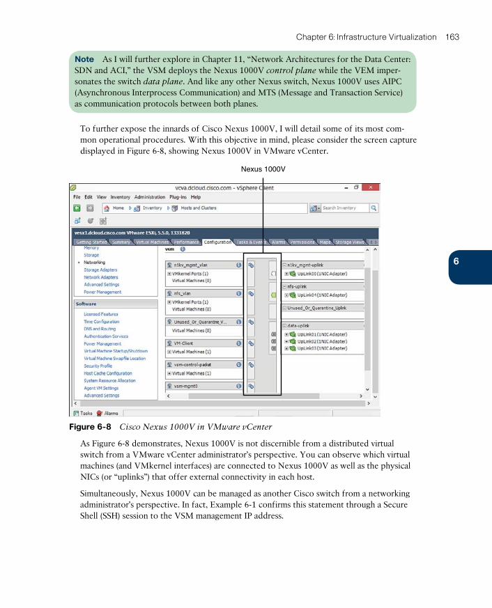
ptg17120290
6
Chapter 6: Infrastructure Virtualization 163
Note As I will further explore in Chapter 11, “Network Architectures for the Data Center: SDN and ACI,” the VSM deploys the Nexus 1000V control plane while the VEM imper-sonates the switch data plane. And like any other Nexus switch, Nexus 1000V uses AIPC (Asynchronous Interprocess Communication) and MTS (Message and Transaction Service) as communication protocols between both planes.
To further expose the innards of Cisco Nexus 1000V, I will detail some of its most com-mon operational procedures. With this objective in mind, please consider the screen capture displayed in Figure 6-8, showing Nexus 1000V in VMware vCenter.
Nexus 1000V
Figure 6-8 Cisco Nexus 1000V in VMware vCenter
As Figure 6-8 demonstrates, Nexus 1000V is not discernible from a distributed virtual switch from a VMware vCenter administrator’s perspective. You can observe which virtual machines (and VMkernel interfaces) are connected to Nexus 1000V as well as the physical NICs (or “uplinks”) that offer external connectivity in each host.
Simultaneously, Nexus 1000V can be managed as another Cisco switch from a networking administrator’s perspective. In fact, Example 6-1 confirms this statement through a Secure Shell (SSH) session to the VSM management IP address.
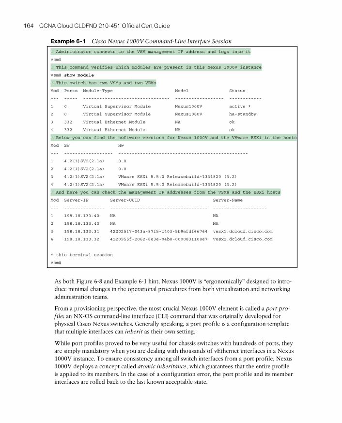
ptg17120290
164 CCNA Cloud CLDFND 210-451 Official Cert Guide
Example 6-1 Cisco Nexus 1000V Command-Line Interface Session
! Administrator connects to the VSM management IP address and logs into it
vsm#
! This command verifies which modules are present in this Nexus 1000V instance
vsm# show module
! This switch has two VSMs and two VEMs
Mod Ports Module-Type Model Status
--- ----- -------------------------------- ------------------ ------------
1 0 Virtual Supervisor Module Nexus1000V active *
2 0 Virtual Supervisor Module Nexus1000V ha-standby
3 332 Virtual Ethernet Module NA ok
4 332 Virtual Ethernet Module NA ok
! Below you can find the software versions for Nexus 1000V and the VMware ESXi in the hosts
Mod Sw Hw
--- ------------------ ------------------------------------------------
1 4.2(1)SV2(2.1a) 0.0
2 4.2(1)SV2(2.1a) 0.0
3 4.2(1)SV2(2.1a) VMware ESXi 5.5.0 Releasebuild-1331820 (3.2)
4 4.2(1)SV2(2.1a) VMware ESXi 5.5.0 Releasebuild-1331820 (3.2)
! And here you can check the management IP addresses from the VSMs and the ESXi hosts
Mod Server-IP Server-UUID Server-Name
--- --------------- ------------------------------------ --------------------
1 198.18.133.40 NA NA
2 198.18.133.40 NA NA
3 198.18.133.31 422025f7-043a-87f5-c403-5b9efdf66764 vesx1.dcloud.cisco.com
4 198.18.133.32 4220955f-2062-8e3e-04b8-0000831108e7 vesx2.dcloud.cisco.com
* this terminal session
vsm#
As both Figure 6-8 and Example 6-1 hint, Nexus 1000V is “ergonomically” designed to intro-duce minimal changes in the operational procedures from both virtualization and networking administration teams.
From a provisioning perspective, the most crucial Nexus 1000V element is called a port pro-
file: an NX-OS command-line interface (CLI) command that was originally developed for physical Cisco Nexus switches. Generally speaking, a port profile is a configuration template that multiple interfaces can inherit as their own setting.
While port profiles proved to be very useful for chassis switches with hundreds of ports, they are simply mandatory when you are dealing with thousands of vEthernet interfaces in a Nexus 1000V instance. To ensure consistency among all switch interfaces from a port profile, Nexus 1000V deploys a concept called atomic inheritance , which guarantees that the entire profile is applied to its members. In the case of a configuration error, the port profile and its member interfaces are rolled back to the last known acceptable state.
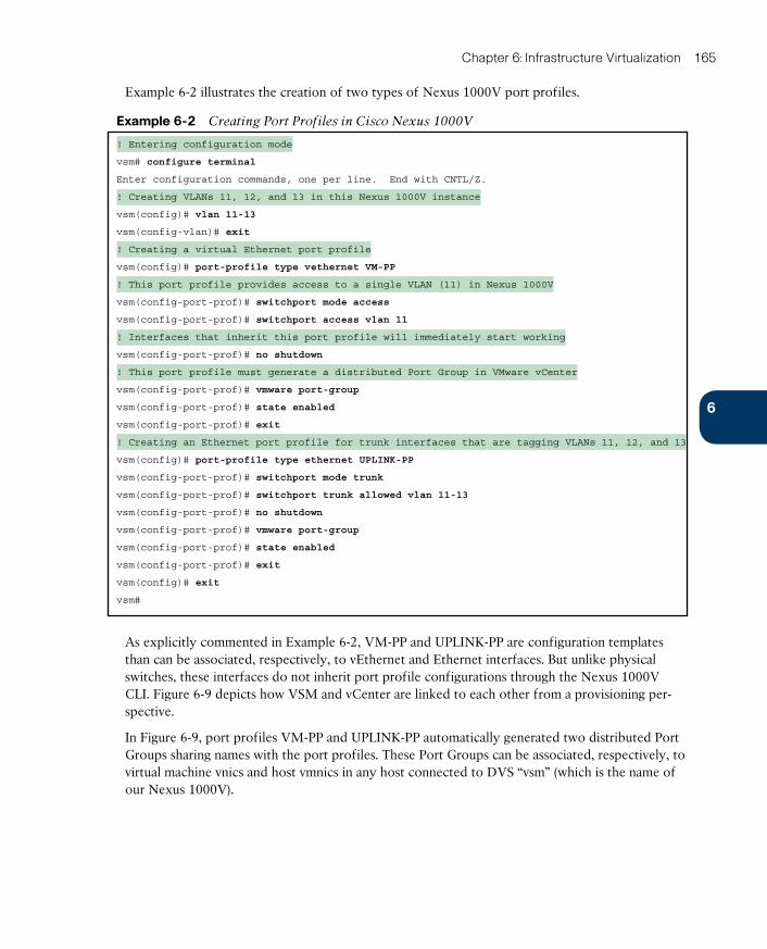
ptg17120290
6
Chapter 6: Infrastructure Virtualization 165
Example 6-2 illustrates the creation of two types of Nexus 1000V port profiles.
Example 6-2 Creating Port Profiles in Cisco Nexus 1000V
! Entering configuration mode
vsm# configure terminal
Enter configuration commands, one per line. End with CNTL/Z.
! Creating VLANs 11, 12, and 13 in this Nexus 1000V instance
vsm(config)# vlan 11-13
vsm(config-vlan)# exit
! Creating a virtual Ethernet port profile
vsm(config)# port-profile type vethernet VM-PP
! This port profile provides access to a single VLAN (11) in Nexus 1000V
vsm(config-port-prof)# switchport mode access
vsm(config-port-prof)# switchport access vlan 11
! Interfaces that inherit this port profile will immediately start working
vsm(config-port-prof)# no shutdown
! This port profile must generate a distributed Port Group in VMware vCenter
vsm(config-port-prof)# vmware port-group
vsm(config-port-prof)# state enabled
vsm(config-port-prof)# exit
! Creating an Ethernet port profile for trunk interfaces that are tagging VLANs 11, 12, and 13
vsm(config)# port-profile type ethernet UPLINK-PP
vsm(config-port-prof)# switchport mode trunk
vsm(config-port-prof)# switchport trunk allowed vlan 11-13
vsm(config-port-prof)# no shutdown
vsm(config-port-prof)# vmware port-group
vsm(config-port-prof)# state enabled
vsm(config-port-prof)# exit
vsm(config)# exit
vsm#
As explicitly commented in Example 6-2, VM-PP and UPLINK-PP are configuration templates than can be associated, respectively, to vEthernet and Ethernet interfaces. But unlike physical switches, these interfaces do not inherit port profile configurations through the Nexus 1000V CLI. Figure 6-9 depicts how VSM and vCenter are linked to each other from a provisioning per-spective.
In Figure 6-9, port profiles VM-PP and UPLINK-PP automatically generated two distributed Port Groups sharing names with the port profiles. These Port Groups can be associated, respectively, to virtual machine vnics and host vmnics in any host connected to DVS “vsm” (which is the name of our Nexus 1000V).
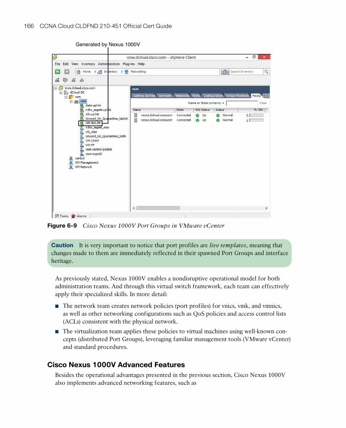
ptg17120290
166 CCNA Cloud CLDFND 210-451 Official Cert Guide
Generated by Nexus 1000V
Figure 6-9 Cisco Nexus 1000V Port Groups in VMware vCenter
Caution It is very important to notice that port profiles are live templates , meaning that changes made to them are immediately reflected in their spawned Port Groups and interface heritage.
As previously stated, Nexus 1000V enables a nondisruptive operational model for both administration teams. And through this virtual switch framework, each team can effectively apply their specialized skills. In more detail:
■ The network team creates network policies (port profiles) for vnics, vmk, and vmnics, as well as other networking configurations such as QoS policies and access control lists (ACLs) consistent with the physical network.
■ The virtualization team applies these policies to virtual machines using well-known con-cepts (distributed Port Groups), leveraging familiar management tools (VMware vCenter) and standard procedures.
Cisco Nexus 1000V Advanced FeaturesBesides the operational advantages presented in the previous section, Cisco Nexus 1000V also implements advanced networking features, such as
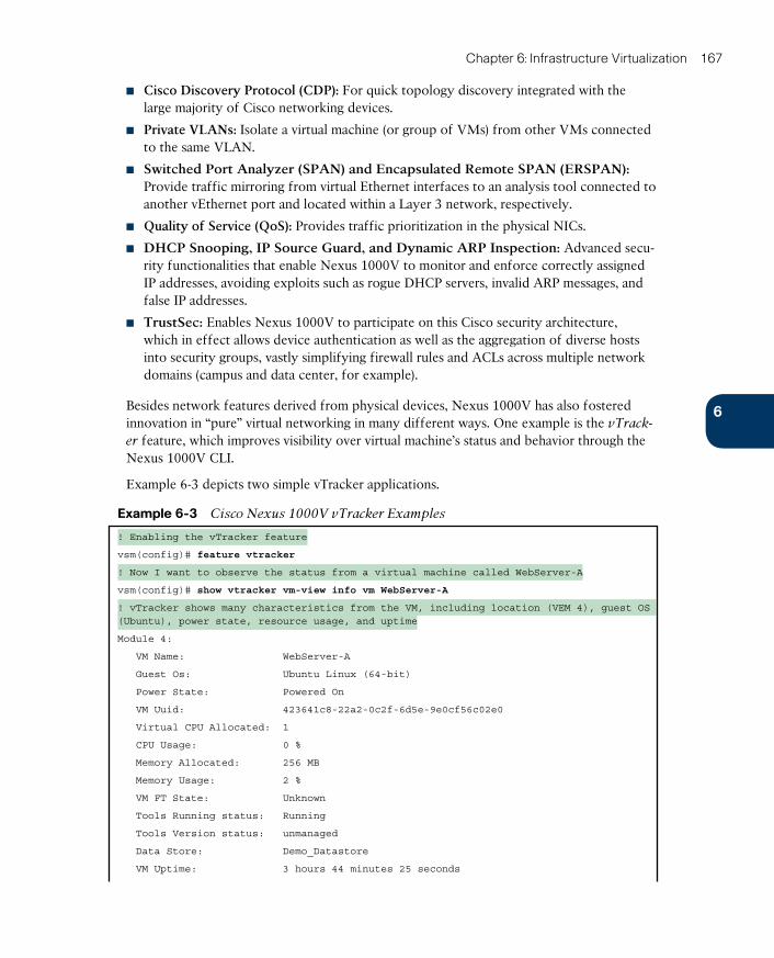
ptg17120290
6
Chapter 6: Infrastructure Virtualization 167
■ Cisco Discovery Protocol (CDP) : For quick topology discovery integrated with the large majority of Cisco networking devices.
■ Private VLANs: Isolate a virtual machine (or group of VMs) from other VMs connected to the same VLAN.
■ Switched Port Analyzer (SPAN) and Encapsulated Remote SPAN (ERSPAN) : Provide traffic mirroring from virtual Ethernet interfaces to an analysis tool connected to another vEthernet port and located within a Layer 3 network, respectively.
■ Quality of Service (QoS) : Provides traffic prioritization in the physical NICs.
■ DHCP Snooping , IP Source Guard , and Dynamic ARP Inspection : Advanced secu-rity functionalities that enable Nexus 1000V to monitor and enforce correctly assigned IP addresses, avoiding exploits such as rogue DHCP servers, invalid ARP messages, and false IP addresses.
■ TrustSec : Enables Nexus 1000V to participate on this Cisco security architecture, which in effect allows device authentication as well as the aggregation of diverse hosts into security groups, vastly simplifying firewall rules and ACLs across multiple network domains (campus and data center, for example).
Besides network features derived from physical devices, Nexus 1000V has also fostered innovation in “pure” virtual networking in many different ways. One example is the vTrack-
er feature , which improves visibility over virtual machine’s status and behavior through the Nexus 1000V CLI.
Example 6-3 depicts two simple vTracker applications.
Example 6-3 Cisco Nexus 1000V vTracker Examples
! Enabling the vTracker feature
vsm(config)# feature vtracker
! Now I want to observe the status from a virtual machine called WebServer-A
vsm(config)# show vtracker vm-view info vm WebServer-A
! vTracker shows many characteristics from the VM, including location (VEM 4), guest OS (Ubuntu), power state, resource usage, and uptime
Module 4:
VM Name: WebServer-A
Guest Os: Ubuntu Linux (64-bit)
Power State: Powered On
VM Uuid: 423641c8-22a2-0c2f-6d5e-9e0cf56c02e0
Virtual CPU Allocated: 1
CPU Usage: 0 %
Memory Allocated: 256 MB
Memory Usage: 2 %
VM FT State: Unknown
Tools Running status: Running
Tools Version status: unmanaged
Data Store: Demo_Datastore
VM Uptime: 3 hours 44 minutes 25 seconds
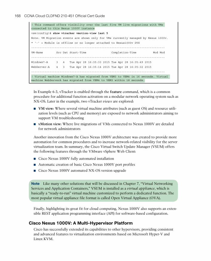
ptg17120290
168 CCNA Cloud CLDFND 210-451 Official Cert Guide
! This command offers visibility over the last five VM live migrations with VMs connected to this Nexus 1000V instance
vsm(config)# show vtracker vmotion-view last 5
Note: VM Migration events are shown only for VMs currently managed by Nexus 1000v.
* '-' = Module is offline or no longer attached to Nexus1000v DVS
--------------------------------------------------------------------------------
VM-Name Src Dst Start-Time Completion-Time Mod Mod
--------------------------------------------------------------------------------
Windows7-A 3 4 Tue Apr 28 16:35:33 2015 Tue Apr 28 16:35:49 2015
WebServer-A 4 3 Tue Apr 28 16:35:14 2015 Tue Apr 28 16:35:32 2015
--------------------------------------------------------------------------------
! Virtual machine Windows7-A has migrated from VEM3 to VEM4 in 16 seconds. Virtual machine WebServerA has migrated from VEM4 to VEM3 within 18 seconds.
In Example 6-3, vTracker is enabled through the feature command, which is a common procedure for additional function activation on a modular network operating system such as NX-OS. Later in the example, two vTracker views are explored:
■ VM view: Where several virtual machine attributes (such as guest OS) and resource utili-zation levels (such as CPU and memory) are exposed to network administrators aiming to support VM troubleshooting
■ vMotion view: Where live migrations of VMs connected to Nexus 1000V are detailed for network administrators
Another innovation from the Cisco Nexus 1000V architecture was created to provide more automation for common procedures and to increase network-related visibility for the server virtualization team. In summary, the Cisco Virtual Switch Update Manager (VSUM) offers the following features through the VMware vSphere Web Client:
■ Cisco Nexus 1000V fully automated installation
■ Automatic creation of basic Cisco Nexus 1000V port profiles
■ Cisco Nexus 1000V automated NX-OS version upgrade
Note Like many other solutions that will be discussed in Chapter 7, “Virtual Networking Services and Application Containers,” VSUM is installed as a virtual appliance , which is basically a “ready-to-run” virtual machine customized to perform a dedicated function. The most popular virtual appliance file format is called Open Virtual Appliance (OVA).
Finally, highlighting its great fit for cloud computing, Nexus 1000V also supports an exten-sible REST application programming interface (API) for software-based configuration.
Cisco Nexus 1000V: A Multi-Hypervisor Platform Cisco has successfully extended its capabilities to other hypervisors, providing consistent and advanced features to virtualization environments based on Microsoft Hyper-V and Linux KVM.

ptg17120290
6
Chapter 6: Infrastructure Virtualization 169
Figure 6-10 delineates the architecture of Nexus 1000V for Microsoft Hyper-V and Nexus 1000V for Linux KVM.
Nexus 1000V for KVMNexus 1000V forMicrosoft Hyper-V
VSMSCVMM
LinuxServers
with KVM
OpenStackNova andNeutron
VSM
WindowsServer
2012 withHyper-V
VFM
VFM
VFM...
DataCenter
Network
VFM
VFM
VFM...
DataCenter
Network
Figure 6-10 Cisco Nexus 1000V Multi-Hypervisor Architectures
As with the VMware vSphere version, in both cases the VSM continues to be intrinsically linked to a VM manager, which are Microsoft System Center Virtual Machine Manager (for Hyper-V) and OpenStack Nova (for Linux KVM). And similarly, the creation of port pro-files on Nexus 1000V automatically produces matching connectivity policies in both hyper-visors (more specifically, port classifications in Hyper-V and network profiles in KVM).
In addition to its astounding number of features, another advantage of adopting Nexus 1000V in multi-hypervisor environments is that it offers operational simplicity in such scenarios.
As an illustration, envision an OpenStack-based cloud computing scenario employing three hypervisors: VMware vSphere, Microsoft Hyper-V, and Linux KVM. A cloud architect should pick the most appropriate physical NIC high availability methods according to each adopted virtual networking device from the extensive list of currently available options for each virtual switch:
■ VMware vSphere vNetwork Standard Switch: Route based on originating virtual port ID, route based on source MAC hash, use explicit failover order, or route based on IP hash
■ VMware vSphere vNetwork Distributed Switch: Route based on originating virtual port ID, route based on source MAC hash, route based on physical NIC load, use explic-it failover order, or route based on IP hash
■ Microsoft Hyper-V Virtual Extensible Switch: Active-standby, all address hash, or port mode
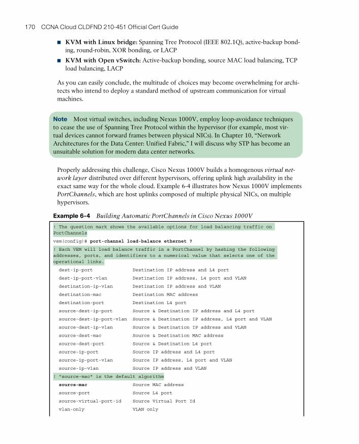
ptg17120290
170 CCNA Cloud CLDFND 210-451 Official Cert Guide
■ KVM with Linux bridge: Spanning Tree Protocol (IEEE 802.1Q), active-backup bond-ing, round-robin, XOR bonding, or LACP
■ KVM with Open vSwitch: Active-backup bonding, source MAC load balancing, TCP load balancing, LACP
As you can easily conclude, the multitude of choices may become overwhelming for archi-tects who intend to deploy a standard method of upstream communication for virtual machines.
Note Most virtual switches, including Nexus 1000V, employ loop-avoidance techniques to cease the use of Spanning Tree Protocol within the hypervisor (for example, most vir-tual devices cannot forward frames between physical NICs). In Chapter 10, “Network Architectures for the Data Center: Unified Fabric,” I will discuss why STP has become an unsuitable solution for modern data center networks.
Properly addressing this challenge, Cisco Nexus 1000V builds a homogenous virtual net-
work layer distributed over different hypervisors, offering uplink high availability in the exact same way for the whole cloud. Example 6-4 illustrates how Nexus 1000V implements PortChannels , which are host uplinks composed of multiple physical NICs, on multiple hypervisors.
Example 6-4 Building Automatic PortChannels in Cisco Nexus 1000V
! The question mark shows the available options for load balancing traffic on PortChannels
vsm(config)# port-channel load-balance ethernet ?
! Each VEM will load balance traffic in a PortChannel by hashing the following addresses, ports, and identifiers to a numerical value that selects one of the operational links.
dest-ip-port Destination IP address and L4 port
dest-ip-port-vlan Destination IP address, L4 port and VLAN
destination-ip-vlan Destination IP address and VLAN
destination-mac Destination MAC address
destination-port Destination L4 port
source-dest-ip-port Source & Destination IP address and L4 port
source-dest-ip-port-vlan Source & Destination IP address, L4 port and VLAN
source-dest-ip-vlan Source & Destination IP address and VLAN
source-dest-mac Source & Destination MAC address
source-dest-port Source & Destination L4 port
source-ip-port Source IP address and L4 port
source-ip-port-vlan Source IP address, L4 port and VLAN
source-ip-vlan Source IP address and VLAN
! "source-mac" is the default algorithm
source-mac Source MAC address
source-port Source L4 port
source-virtual-port-id Source Virtual Port Id
vlan-only VLAN only
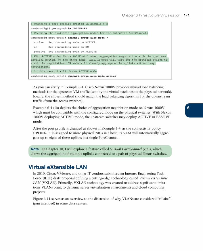
ptg17120290
6
Chapter 6: Infrastructure Virtualization 171
! Changing a port profile created in Example 6-2
vsm(config)# port-profile UPLINK-PP
! Checking the available aggregation modes for the automatic PortChannels
vsm(config-port-prof)# channel-group auto mode ?
active Set channeling mode to ACTIVE
on Set channeling mode to ON
passive Set channeling mode to PASSIVE
! With ACTIVE mode, Nexus 1000V will start aggregation negotiation with the upstream physical switch. On the other hand, PASSIVE mode will wait for the upstream switch to start the negotiation. ON mode will already aggregate the uplinks without any negotiation.
! In this case, I will choose ACTIVE mode
vsm(config-port-prof)# channel-group auto mode active
As you can verify in Example 6-4, Cisco Nexus 1000V provides myriad load balancing methods for the upstream VM traffic (sent by the virtual machines to the physical network). Ideally, the chosen method should match the load balancing algorithm for the downstream traffic (from the access switches).
Example 6-4 also depicts the choice of aggregation negotiation mode on Nexus 1000V, which must be compatible with the configured mode on the physical switches. With Nexus 1000V deploying ACTIVE mode, the upstream switches may deploy ACTIVE or PASSIVE mode.
After the port profile is changed as shown in Example 6-4, as the connectivity policy UPLINK-PP is assigned to more physical NICs in a host, its VEM will automatically aggre-gate up to eight of these uplinks in a single PortChannel.
Note In Chapter 10, I will explore a feature called Virtual PortChannel (vPC), which allows the aggregation of multiple uplinks connected to a pair of physical Nexus switches.
Virtual eXtensible LANIn 2010, Cisco, VMware, and other IT vendors submitted an Internet Engineering Task Force (IETF) draft proposal defining a cutting-edge technology called Virtual eXtensible
LAN (VXLAN) . Primarily, VXLAN technology was created to address significant limita-tions VLANs bring to dynamic server virtualization environments and cloud computing projects.
Figure 6-11 serves as an overview to the discussion of why VLANs are considered “villains” (pun intended) in some data centers.

ptg17120290
172 CCNA Cloud CLDFND 210-451 Official Cert Guide
Data Center Network
VLAN 10 VLAN 20
VLAN Provisioning
MAC Address TableDepletion
VLAN ID StarvationHost
Virtual Switch
NIC NIC
VLAN 10 VLAN 20
Host
Virtual Switch
NIC NIC
Figure 6-11 VLAN Challenges for Server Virtualization
VLAN provisioning in the physical network constitutes the first challenge for VMs using VLANs. In Figure 6-11, there are two hosts that may or may not belong to the same virtu-alization cluster. Imagine that each host is deploying VMs connected to two VLANs: 10 and 20. As you may easily infer, these VMs can communicate with their counterparts in the other host only if the network administration team has already configured both VLANs in every switch and possible connections between both hosts.
Obviously, this configuration procedure can become unbearably cumbersome and slow as the number of network devices increases. In addition, the potential live migration of VMs to any host in the data center severely aggravates the situation. The reason is that network administrators must enable these new VLANs in all switches and trunks of the data center network to avoid isolated VMs.
Caution Although I have seen it done in some data centers, I definitely do not recom-mend the pre-provisioning of all 4094 possible VLANs in every network trunk. Although it may apparently save time and effort, this “worst practice” may result in unwanted traffic in many ports of the network as well as STP scalability issues.
VLAN ID starvation is a second challenge that can become a growing preoccupation in cloud computing environments. Because a physical network can deploy only 4094 VLANs (1 to 4094 according to the IEEE 802.1Q standard) to isolate hosts, a cloud will eventually face an absolute limit if it is reserving one or more VLANs per tenant.
While not as noticeable as the previous challenges, MAC address table depletion is already a preoccupation for many network teams all over the world. In a standard Ethernet network, every switch ends up learning the MAC address of all VMs. Therefore, a relatively small
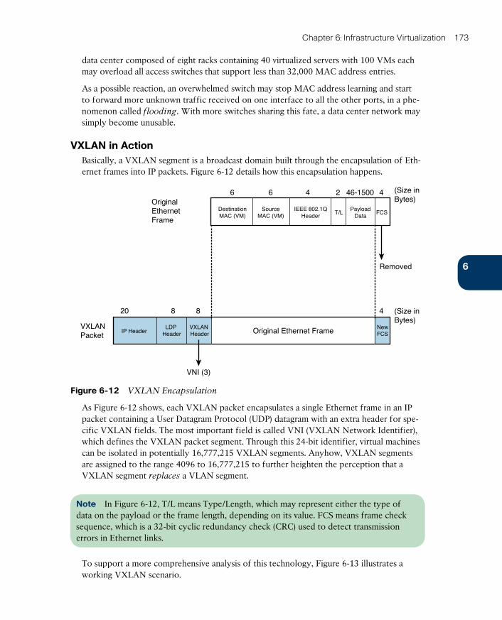
ptg17120290
6
Chapter 6: Infrastructure Virtualization 173
data center composed of eight racks containing 40 virtualized servers with 100 VMs each may overload all access switches that support less than 32,000 MAC address entries.
As a possible reaction, an overwhelmed switch may stop MAC address learning and start to forward more unknown traffic received on one interface to all the other ports, in a phe-nomenon called flooding . With more switches sharing this fate, a data center network may simply become unusable.
VXLAN in ActionBasically, a VXLAN segment is a broadcast domain built through the encapsulation of Eth-ernet frames into IP packets. Figure 6-12 details how this encapsulation happens.
OriginalEthernetFrame
VXLANPacket
6
8820
6 4 4
4
2 46-1500 (Size inBytes)
Removed
(Size inBytes)
VNI (3)
Original Ethernet FrameIP HeaderLDP
HeaderVXLAN Header
NewFCS
DestinationMAC (VM)
SourceMAC (VM)
IEEE 802.1QHeader
T/LPayload
DataFCS
Figure 6-12 VXLAN Encapsulation
As Figure 6-12 shows, each VXLAN packet encapsulates a single Ethernet frame in an IP packet containing a User Datagram Protocol (UDP) datagram with an extra header for spe-cific VXLAN fields. The most important field is called VNI (VXLAN Network Identifier), which defines the VXLAN packet segment. Through this 24-bit identifier, virtual machines can be isolated in potentially 16,777,215 VXLAN segments. Anyhow, VXLAN segments are assigned to the range 4096 to 16,777,215 to further heighten the perception that a VXLAN segment replaces a VLAN segment.
Note In Figure 6-12, T/L means Type/Length, which may represent either the type of data on the payload or the frame length, depending on its value. FCS means frame check sequence, which is a 32-bit cyclic redundancy check (CRC) used to detect transmission errors in Ethernet links.
To support a more comprehensive analysis of this technology, Figure 6-13 illustrates a working VXLAN scenario.
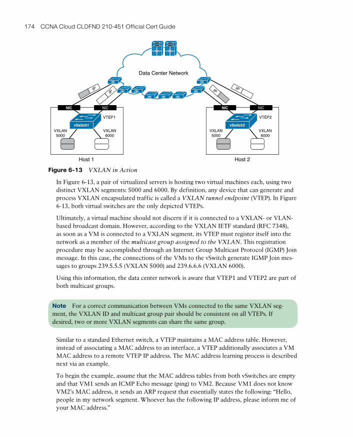
ptg17120290
174 CCNA Cloud CLDFND 210-451 Official Cert Guide
Data Center Network
VTEP1 VTEP2
Host 1
vSwitch1
NIC NIC
VXLAN5000
VXLAN6000
VXLAN5000
VXLAN6000
Host 2
vSwitch2
NIC NIC
IPIPIP
IP
Figure 6-13 VXLAN in Action
In Figure 6-13, a pair of virtualized servers is hosting two virtual machines each, using two distinct VXLAN segments: 5000 and 6000. By definition, any device that can generate and process VXLAN encapsulated traffic is called a VXLAN tunnel endpoint (VTEP) . In Figure 6-13, both virtual switches are the only depicted VTEPs.
Ultimately, a virtual machine should not discern if it is connected to a VXLAN- or VLAN-based broadcast domain. However, according to the VXLAN IETF standard (RFC 7348), as soon as a VM is connected to a VXLAN segment, its VTEP must register itself into the network as a member of the multicast group assigned to the VXLAN. This registration procedure may be accomplished through an Internet Group Multicast Protocol (IGMP) Join message. In this case, the connections of the VMs to the vSwitch generate IGMP Join mes-sages to groups 239.5.5.5 (VXLAN 5000) and 239.6.6.6 (VXLAN 6000).
Using this information, the data center network is aware that VTEP1 and VTEP2 are part of both multicast groups.
Note For a correct communication between VMs connected to the same VXLAN seg-ment, the VXLAN ID and multicast group pair should be consistent on all VTEPs. If desired, two or more VXLAN segments can share the same group.
Similar to a standard Ethernet switch, a VTEP maintains a MAC address table. However, instead of associating a MAC address to an interface, a VTEP additionally associates a VM MAC address to a remote VTEP IP address. The MAC address learning process is described next via an example.
To begin the example, assume that the MAC address tables from both vSwitches are empty and that VM1 sends an ICMP Echo message (ping) to VM2. Because VM1 does not know VM2’s MAC address, it sends an ARP request that essentially states the following: “Hello, people in my network segment. Whoever has the following IP address, please inform me of your MAC address.”
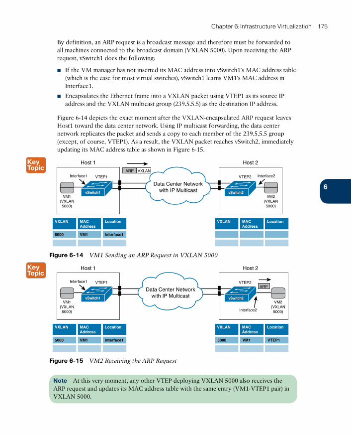
ptg17120290
6
Chapter 6: Infrastructure Virtualization 175
By definition, an ARP request is a broadcast message and therefore must be forwarded to all machines connected to the broadcast domain (VXLAN 5000). Upon receiving the ARP request, vSwitch1 does the following:
■ If the VM manager has not inserted its MAC address into vSwitch1’s MAC address table (which is the case for most virtual switches), vSwitch1 learns VM1’s MAC address in Interface1.
■ Encapsulates the Ethernet frame into a VXLAN packet using VTEP1 as its source IP address and the VXLAN multicast group (239.5.5.5) as the destination IP address.
Figure 6-14 depicts the exact moment after the VXLAN-encapsulated ARP request leaves Host1 toward the data center network. Using IP multicast forwarding, the data center network replicates the packet and sends a copy to each member of the 239.5.5.5 group (except, of course, VTEP1). As a result, the VXLAN packet reaches vSwitch2, immediately updating its MAC address table as shown in Figure 6-15.
VTEP1
Host 1
VM1(VXLAN5000)
Interface1ARP VXLAN
VXLAN
5000
MACAddress
VM1
Location
Interface1
vSwitch1
VTEP2
Host 2
VM2(VXLAN5000)
Interface2
VXLAN MACAddress
Location
vSwitch2
Data Center Networkwith IP Multicast
Figure 6-14 VM1 Sending an ARP Request in VXLAN 5000
VTEP1
Host 1
VM1(VXLAN5000)
Interface1
VXLAN
5000
MACAddress
VM1
Location
Interface1
vSwitch1
VTEP2
Host 2
VM2(VXLAN5000)Interface2
VXLAN MACAddress
Location
vSwitch2
Data Center Networkwith IP Multicast
ARP
5000 VM1 VTEP1
Figure 6-15 VM2 Receiving the ARP Request
Note At this very moment, any other VTEP deploying VXLAN 5000 also receives the ARP request and updates its MAC address table with the same entry (VM1-VTEP1 pair) in VXLAN 5000.
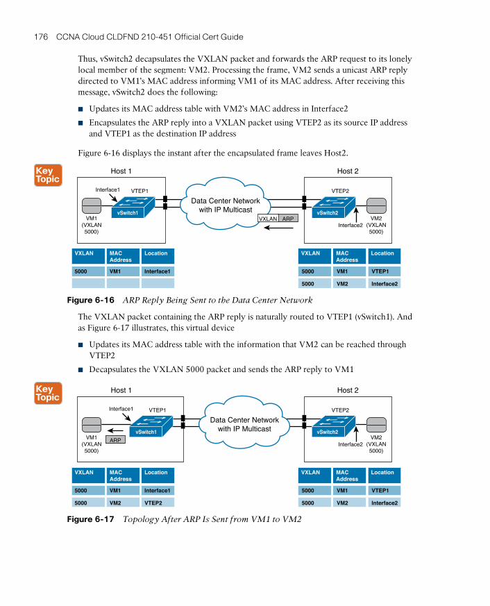
ptg17120290
176 CCNA Cloud CLDFND 210-451 Official Cert Guide
Thus, vSwitch2 decapsulates the VXLAN packet and forwards the ARP request to its lonely local member of the segment: VM2. Processing the frame, VM2 sends a unicast ARP reply directed to VM1’s MAC address informing VM1 of its MAC address. After receiving this message, vSwitch2 does the following:
■ Updates its MAC address table with VM2’s MAC address in Interface2
■ Encapsulates the ARP reply into a VXLAN packet using VTEP2 as its source IP address and VTEP1 as the destination IP address
Figure 6-16 displays the instant after the encapsulated frame leaves Host2.
VTEP1
Host 1
VM1(VXLAN5000)
Interface1
VXLAN
5000
MACAddress
VM1
Location
Interface1
vSwitch1
VTEP2
Host 2
VM2(VXLAN5000)
Interface2
VXLAN MACAddress
Location
vSwitch2
Data Center Networkwith IP Multicast
ARPVXLAN
5000 VM1 VTEP1
5000 VM2 Interface2
Figure 6-16 ARP Reply Being Sent to the Data Center Network
The VXLAN packet containing the ARP reply is naturally routed to VTEP1 (vSwitch1). And as Figure 6-17 illustrates, this virtual device
■ Updates its MAC address table with the information that VM2 can be reached through VTEP2
■ Decapsulates the VXLAN 5000 packet and sends the ARP reply to VM1
VTEP1
Host 1
VM1(VXLAN5000)
Interface1
VXLAN
5000
MACAddress
VM1
Location
Interface1
5000 VM2 VTEP2
vSwitch1
VTEP2
Host 2
VM2(VXLAN5000)
Interface2
VXLAN MACAddress
Location
vSwitch2
Data Center Networkwith IP Multicast
ARP
5000 VM1 VTEP1
5000 VM2 Interface2
Figure 6-17 Topology After ARP Is Sent from VM1 to VM2
ptg17120290
6
Chapter 6: Infrastructure Virtualization 177
From this moment on, both VMs can forward unicast Ethernet frames to each other with their associated VTEPs only exchanging unicast VXLAN packets.
The encapsulation of a frame into a multicast VXLAN packet, as depicted in Figure 6-14, also happens if VM1 sends an Ethernet frame destined to an unknown MAC address. Resulting in VXLAN flooding , this frame will also be sent to all VTEPs deploying VXLAN 5000.
Based on the IETF standard, VTEPs learn MAC addresses through the actual forwarding of multidestination traffic such as broadcast and unknown unicast frames. And if you are a sea-soned network professional, you can surely recognize that standard VXLAN employs the same learning mechanism from standard Ethernet switches.
How Does VXLAN Solve VLAN Challenges?As you can deduce from the example in the previous section, a VXLAN deployment has the following requirements for a data center network:
■ IP unicast routing and forwarding: To allow the exchange of VXLAN packets between VTEPs.
■ IP multicast routing and forwarding: To permit the transmission of broadcast frames and flooding within a VXLAN segment.
■ A maximum transmission unit (MTU) bigger than 1550 bytes: The additional 50 bytes are necessary to avoid fragmentation of VXLAN packets.
After these procedures are correctly implemented, virtual machines can be connected to multiple VXLANs without any additional physical network configuration. In that sense, this VXLAN characteristic overcomes the VLAN provisioning challenge.
Also, VTEPs can identify more than 16 million different Layer 2 segments using the same physical network infrastructure between the hosts. Consequently, VXLAN can effectively address the VLAN ID starvation challenge as well.
Lastly, physical switches do not learn the virtual machine MAC addresses because they are inside of VXLAN packets. From a Layer 2 perspective, only the VTEP MAC addresses are actually learned in the data center network, avoiding VLAN MAC address table depletion .
Standard VXLAN Deployment in Cisco Nexus 1000VCisco Nexus 1000V was one of the first products in the market to offer VXLAN capabili-ties for virtual machines. And in truly Cisco fashion, Nexus 1000V followed the original VXLAN IETF draft to enable the feature almost two years before the actual standard in 2014.
Since you are already familiar with Nexus 1000V configuration, Example 6-5 demonstrates how VXLANs are deployed in the virtual device.
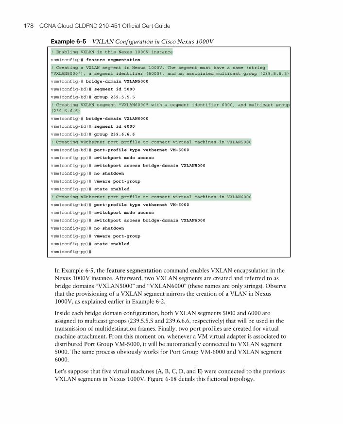
ptg17120290
178 CCNA Cloud CLDFND 210-451 Official Cert Guide
Example 6-5 VXLAN Configuration in Cisco Nexus 1000V
! Enabling VXLAN in this Nexus 1000V instance
vsm(config)# feature segmentation
! Creating a VXLAN segment in Nexus 1000V. The segment must have a name (string "VXLAN5000"), a segment identifier (5000), and an associated multicast group (239.5.5.5)
vsm(config)# bridge-domain VXLAN5000
vsm(config-bd)# segment id 5000
vsm(config-bd)# group 239.5.5.5
! Creating VXLAN segment "VXLAN6000" with a segment identifier 6000, and multicast group (239.6.6.6)
vsm(config)# bridge-domain VXLAN6000
vsm(config-bd)# segment id 6000
vsm(config-bd)# group 239.6.6.6
! Creating vEthernet port profile to connect virtual machines in VXLAN5000
vsm(config-bd)# port-profile type vethernet VM-5000
vsm(config-pp)# switchport mode access
vsm(config-pp)# switchport access bridge-domain VXLAN5000
vsm(config-pp)# no shutdown
vsm(config-pp)# vmware port-group
vsm(config-pp)# state enabled
! Creating vEthernet port profile to connect virtual machines in VXLAN6000
vsm(config-bd)# port-profile type vethernet VM-6000
vsm(config-pp)# switchport mode access
vsm(config-pp)# switchport access bridge-domain VXLAN6000
vsm(config-pp)# no shutdown
vsm(config-pp)# vmware port-group
vsm(config-pp)# state enabled
vsm(config-pp)#
In Example 6-5, the feature segmentation command enables VXLAN encapsulation in the Nexus 1000V instance. Afterward, two VXLAN segments are created and referred to as bridge domains “VXLAN5000” and “VXLAN6000” (these names are only strings). Observe that the provisioning of a VXLAN segment mirrors the creation of a VLAN in Nexus 1000V, as explained earlier in Example 6-2.
Inside each bridge domain configuration, both VXLAN segments 5000 and 6000 are assigned to multicast groups (239.5.5.5 and 239.6.6.6, respectively) that will be used in the transmission of multidestination frames. Finally, two port profiles are created for virtual machine attachment. From this moment on, whenever a VM virtual adapter is associated to distributed Port Group VM-5000, it will be automatically connected to VXLAN segment 5000. The same process obviously works for Port Group VM-6000 and VXLAN segment 6000.
Let’s suppose that five virtual machines (A, B, C, D, and E) were connected to the previous VXLAN segments in Nexus 1000V. Figure 6-18 details this fictional topology.
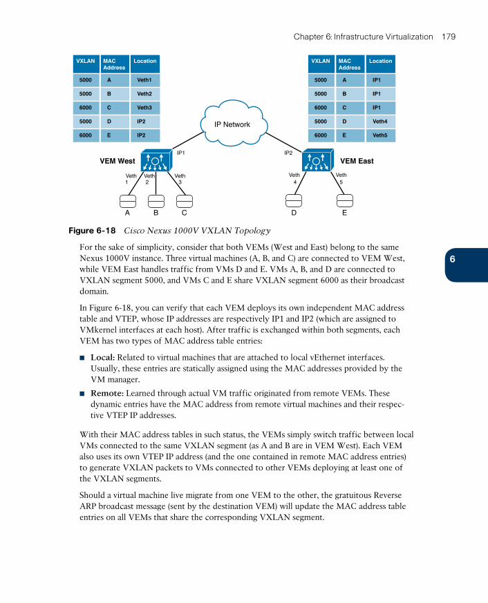
ptg17120290
6
Chapter 6: Infrastructure Virtualization 179
VXLAN MACAddress
Location
5000
5000
5000
6000
6000
Veth1
Veth2
IP2
Veth3
IP2
Location
IP1
IP1
Veth4
IP1
Veth5
A
B
D
C
E
VXLAN
5000
5000
5000
6000
6000
MACAddress
A
B
D
C
E
A B C
IP1 IP2
1 2 3 4 5Veth Veth Veth Veth Veth
VEM West VEM East
D E
IP Network
Figure 6-18 Cisco Nexus 1000V VXLAN Topology
For the sake of simplicity, consider that both VEMs (West and East) belong to the same Nexus 1000V instance. Three virtual machines (A, B, and C) are connected to VEM West, while VEM East handles traffic from VMs D and E. VMs A, B, and D are connected to VXLAN segment 5000, and VMs C and E share VXLAN segment 6000 as their broadcast domain.
In Figure 6-18, you can verify that each VEM deploys its own independent MAC address table and VTEP, whose IP addresses are respectively IP1 and IP2 (which are assigned to VMkernel interfaces at each host). After traffic is exchanged within both segments, each VEM has two types of MAC address table entries:
■ Local: Related to virtual machines that are attached to local vEthernet interfaces. Usually, these entries are statically assigned using the MAC addresses provided by the VM manager.
■ Remote: Learned through actual VM traffic originated from remote VEMs. These dynamic entries have the MAC address from remote virtual machines and their respec-tive VTEP IP addresses.
With their MAC address tables in such status, the VEMs simply switch traffic between local VMs connected to the same VXLAN segment (as A and B are in VEM West). Each VEM also uses its own VTEP IP address (and the one contained in remote MAC address entries) to generate VXLAN packets to VMs connected to other VEMs deploying at least one of the VXLAN segments.
Should a virtual machine live migrate from one VEM to the other, the gratuitous Reverse ARP broadcast message (sent by the destination VEM) will update the MAC address table entries on all VEMs that share the corresponding VXLAN segment.
ptg17120290
180 CCNA Cloud CLDFND 210-451 Official Cert Guide
Note If VEMs West and East belong to two distinct Nexus 1000V instances, their active VSMs must share the same segment identifiers and multicast groups for VXLAN segments 5000 and 6000. With this condition, VMs A, B, C, D, and E would follow the same previ-ously described behavior with one exception: at the time of this writing, it is not possible to live migrate a VM between hosts that are connected to different Nexus 1000V switches.
VXLAN GatewaysIn the prior few sections, I have shown how VXLANs can conveniently overcome VLAN shortcomings that afflict VM-to-VM communication. Intentionally, I have not addressed the extremely common situation where a VM connected to a VXLAN must communicate with a VLAN-attached physical server or the Internet.
Now that you have mastered the principles underlying VXLAN communication, you are ready to meet an important component of this protocol framework: the VXLAN gateway, a device that can connect VXLAN segments to standard VLANs. Some network devices can perform the role of a VXLAN gateway by assuming one of the following formats:
■ Virtual: A virtual machine provides the traffic interchange between VXLANs and VLANs.
■ Physical: A physical network device establishes this communication.
Generally speaking, virtual VXLAN gateways are suggested for environments that may not require an outstanding forwarding performance (for example, a single cloud tenant). Even so, being virtual machines, these gateways benefit from server virtualization natural scaling and replicability advantages. On the other hand, multitenant environments will most cer-tainly leverage the high performance provided by physical VXLAN gateways.
VXLAN gateways are also classified depending on how they handle interchanged traffic between a VXLAN and a VLAN. Therefore, according to the layers defined in the Open Systems Interconnection (OSI) model, these devices can be
■ Layer 2: Where the gateway bridges traffic between a VLAN and a VXLAN, forming a single broadcast domain within this VXLAN-VLAN pair.
■ Layer 3: Where the gateway routes traffic between VLANs and VXLANs. Most commonly, these devices become the default gateway for VXLAN-connected virtual machines. Some VXLAN Layer 3 gateways can also route traffic between different VXLAN segments.
The IP addressing design for VXLAN-based scenarios defines the required type of com-munication between VXLAN and VLANs. Notwithstanding, I have noticed that Layer 2 VXLAN gateways are more heavily used in data centers going through physical-to-virtual (P2V) migrations. In these scenarios, the network team is usually concerned with the main-tenance of connectivity during a migration process, where physical servers are being con-verted into VMs without any IP address change.
Figure 6-19 displays some examples of different VXLAN gateways from the Cisco Cloud Infrastructure portfolio, including devices from each combination available at the time of this writing.
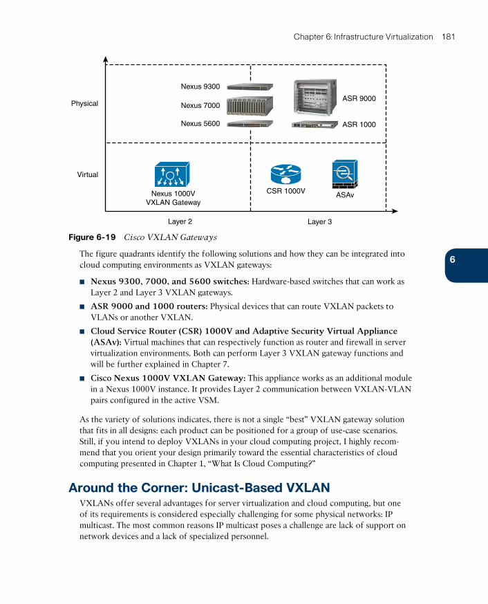
ptg17120290
6
Chapter 6: Infrastructure Virtualization 181
ASR 9000
ASR 1000
Nexus 9300
Nexus 7000
Nexus 5600
Nexus 1000VVXLAN Gateway
Physical
Virtual
ASAvCSR 1000V
Layer 2 Layer 3
Figure 6-19 Cisco VXLAN Gateways
The figure quadrants identify the following solutions and how they can be integrated into cloud computing environments as VXLAN gateways:
■ Nexus 9300 , 7000, and 5600 switches: Hardware-based switches that can work as Layer 2 and Layer 3 VXLAN gateways.
■ ASR 9000 and 1000 routers: Physical devices that can route VXLAN packets to VLANs or another VXLAN.
■ Cloud Service Router (CSR) 1000V and Adaptive Security Virtual Appliance (ASAv) : Virtual machines that can respectively function as router and firewall in server virtualization environments. Both can perform Layer 3 VXLAN gateway functions and will be further explained in Chapter 7.
■ Cisco Nexus 1000V VXLAN Gateway: This appliance works as an additional module in a Nexus 1000V instance. It provides Layer 2 communication between VXLAN-VLAN pairs configured in the active VSM.
As the variety of solutions indicates, there is not a single “best” VXLAN gateway solution that fits in all designs: each product can be positioned for a group of use-case scenarios. Still, if you intend to deploy VXLANs in your cloud computing project, I highly recom-mend that you orient your design primarily toward the essential characteristics of cloud computing presented in Chapter 1, “What Is Cloud Computing?”
Around the Corner: Unicast-Based VXLANVXLANs offer several advantages for server virtualization and cloud computing, but one of its requirements is considered especially challenging for some physical networks: IP multicast. The most common reasons IP multicast poses a challenge are lack of support on network devices and a lack of specialized personnel.

ptg17120290
182 CCNA Cloud CLDFND 210-451 Official Cert Guide
Perhaps more worrying than an IP multicast deployment is the fact that VTEPs rely on broadcast frames or flooding to learn MAC addresses. As can occur with VLANs in Ether-net networks, these multidestination datagrams can transform a set of VTEPs into a single failure domain, and easily produce undesired effects (for example, loops and MAC address flapping).
Aware of these obstacles, the networking industry has moved accordingly, and Cisco, along with other vendors, has developed VXLAN solutions that can avoid both prerequisites, IP multicast and MAC address learning through the data plane.
Without IP multicast, VTEPs must use other methods for MAC address learning. The meth-ods that Cisco has developed to counteract these challenges essentially can be classified into two main categories: controller-based methods and protocol-based methods.
Since 2013, Cisco Nexus 1000V offers a unicast-only VXLANs implementation called Enhanced VXLAN. In essence, this controller-based method uses the active VSM to distrib-ute MAC-VTEP entries to VEMs deploying VXLAN segments.
Figure 6-20 details the Enhanced VXLAN MAC address learning in Nexus 1000V.
VSMVSM
[A,VTEP3][A,VTEP3]
VEM 3[VTEP3]
VEM 3[VTEP3]
[A,V
TEP3]
A
MACAddress
vEth10
Location
A
MACAddress
vEth10
LocationMACAddress
Location
A
MACAddress
VTEP 3
Location
A
MACAddress
VTEP 3
LocationMACAddress
Location
VEP 4 VEP 5
A
Time
A
Figure 6-20 Enhanced VXLAN MAC Learning
As explained earlier in the section “Standard VXLAN Deployment in Cisco Nexus 1000V,” each VEM has a VTEP and deploys a separate MAC address table. The left side of Figure 6-20 displays the moment VM A is connected to VXLAN 10000 on VEM 3. As a conse-quence, the active VSM learns that the VM MAC address can be reached through the VEM VTEP. Acting as a MAC-VTEP entry distributor, the VSM populates the MAC address table on other VEMs, as shown on the right side of Figure 6-20.
Furthermore, Example 6-6 describes how exactly an Enhanced VXLAN is configured on Nexus 1000V.

ptg17120290
6
Chapter 6: Infrastructure Virtualization 183
Example 6-6 Enhanced VXLAN Deployment
! Creating an Enhanced VXLAN
vsm(config)# bridge-domain VXLAN10000
vsm(config-bd)# segment id 10000
vsm(config-bd)# segment mode unicast-only
! Creating a vEthernet port profile assigned to bridge domain "VXLAN10000"
vsm(config-bd)# port-profile type vethernet VM-10000
vsm(config-pp)# switchport mode access
vsm(config-pp)# switchport access bridge-domain VXLAN10000
vsm(config-pp)# no shutdown
vsm(config-pp)# vmware port-group
vsm(config-pp)# state enabled
vsm(config-pp)#
In Example 6-6, rather than defining a multicast group for the bridge domain, I have used the segment mode unicast-only command to create bridge domain “VXLAN10000.” After-ward, I have assigned the bridge domain to port profile VM-10000, auto-generating a con-nectivity policy (Port Group in VMware vSphere) that may be associated to virtual network adapters on VMs.
Note The same Nexus 1000V instance can simultaneously deploy standard and Enhanced VXLAN segments.
As an immediate effect from this method, the flooding of frames with unknown destination MAC addresses is no longer necessary. Because the VSM can distribute MAC addresses from an Enhanced VXLAN among all of its VEMs, there is full awareness of all MAC addresses in that segment—put simply, there are no unknown addresses.
Yet, broadcast messages are still necessary in IP-based communications within a VXLAN segment (for example, ARP messages). So how are broadcast frames forwarded in Enhanced VXLAN segments? The answer lies in Figure 6-21.
VSM
VEM 3(VTEP3)
Bro
adca
st VEM 4(VTEP4)
VEM 5(VTEP5)
VEM 3(VTEP3)
VEM 4(VTEP4)
VEM 5(VTEP5)
A vEth10
B VTEP4
C VTEP5
BA
MACAddress
Location
VSM
A vEth10
B VTEP4
C VTEP5
MACAddress
Location
Time
Broadcast
Broadcast
Figure 6-21 Enhanced VXLAN Head-End Replication
B C A C
ptg17120290
184 CCNA Cloud CLDFND 210-451 Official Cert Guide
On the left side of Figure 6-21, VM A sends a broadcast frame, which, of course, should be received by all other VMs connected to Enhanced VXLAN 10000. Because the active VSM has already populated the all VEMs’ MAC address tables, VEM 3 is aware of the vir-tual machines that are connected to the same VXLAN (VM B in VEM 4 and VM C in VEM 5). Thus, VEM 3 performs a head-end replication of the VXLAN packet that contains the broadcast frame, sending one copy to each VTEP registered in its MAC address table.
Note In the case of standard VXLAN, the multicast IP network takes care of the packet replication in the case of multidestination packets.
Controller-based unicast-only VXLANs are obviously limited to the controller domain. In the case of Nexus 1000V, an active VSM can populate only the MAC address tables of its administered VEMs. Under these circumstances, Cisco and other vendors have initiated some endeavors to standardize unicast-only VXLAN communication between independent VTEPs. Among many efforts, one is apparently becoming a de facto standard at the time of this writing: VXLAN Ethernet Virtual Private Network (EVPN).
The secret sauce of this technology is the use of Multiprotocol Border Gateway Protocol (MP-BGP) to exchange MAC-VTEP entries between multiple devices deploying VXLAN segments. With this approach, all VTEPs (physical or virtual) signal a new VXLAN-attached host through MP-BGP updates to other VTEPs.
In fairly large VXLAN networks, with multiple VTEPs, it may become extremely complex to manage the full-mesh set of MP-BGP connections between all VTEPs on a network. Instead, a BGP route reflector can be deployed as a central point of advertisement, where one MAC-VTEP update from a VXLAN segment that is sent to the route reflector will sub-sequently be forwarded to all other VTEPs deploying the same segment.
Further Reading■ Enhanced VXLAN on Cisco Nexus 1000V Switch for VMware vSphere Deployment
Guide: http://www.cisco.com/c/en/us/products/collateral/switches/nexus-7000-series-switches/guide_c07-728863.html
■ VXLAN DCI Using EVPN: http://tools.ietf.org/id/draft-boutros-l2vpn-vxlan-evpn-04.txt
■ Cisco Border Gateway Protocol Control Plane for Virtual Extensible LAN: http://www.cisco.com/c/en/us/products/collateral/switches/nexus-9000-series-switches/white-paper-c11-733737.html
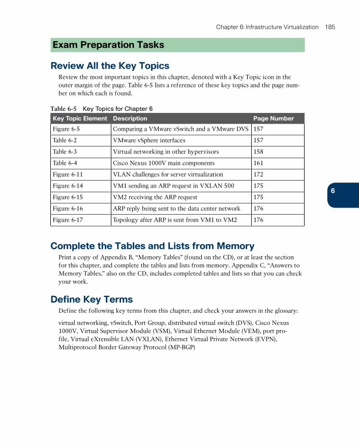
ptg17120290
6
Chapter 6: Infrastructure Virtualization 185
Exam Preparation Tasks
Review All the Key TopicsReview the most important topics in this chapter, denoted with a Key Topic icon in the outer margin of the page. Table 6-5 lists a reference of these key topics and the page num-ber on which each is found.
Table 6-5 Key Topics for Chapter 6
Key Topic Element Description Page Number
Figure 6-5 Comparing a VMware vSwitch and a VMware DVS 157
Table 6-2 VMware vSphere interfaces 157
Table 6-3 Virtual networking in other hypervisors 158
Table 6-4 Cisco Nexus 1000V main components 161
Figure 6-11 VLAN challenges for server virtualization 172
Figure 6-14 VM1 sending an ARP request in VXLAN 500 175
Figure 6-15 VM2 receiving the ARP request 175
Figure 6-16 ARP reply being sent to the data center network 176
Figure 6-17 Topology after ARP is sent from VM1 to VM2 176
Complete the Tables and Lists from MemoryPrint a copy of Appendix B, “Memory Tables” (found on the CD), or at least the section for this chapter, and complete the tables and lists from memory. Appendix C, “Answers to Memory Tables,” also on the CD, includes completed tables and lists so that you can check your work.
Define Key TermsDefine the following key terms from this chapter, and check your answers in the glossary:
virtual networking, vSwitch, Port Group, distributed virtual switch (DVS), Cisco Nexus 1000V, Virtual Supervisor Module (VSM), Virtual Ethernet Module (VEM), port pro-file, Virtual eXtensible LAN (VXLAN), Ethernet Virtual Private Network (EVPN), Multiprotocol Border Gateway Protocol (MP-BGP)

ptg17120290
This chapter covers the following topics:
■ Virtual Networking Services
■ Virtual Application Containers
This chapter covers the following exam objectives:
■ 4.2 Describe Infrastructure Virtualization
■ 4.2.d Virtual networking services
■ 4.2.e Defi ne Virtual Application Containers
■ 4.2.e.1 Three-tier application container
■ 4.2.e.2 Custom container

ptg17120290
CHAPTER 7
Virtual Networking Services and Application Containers
Although many data center professionals may regard networking solely as “data plumbing,” the importance of reliable information sharing continues to grow as IT establishes a stronger alignment with business.
More than ever, modern network devices can offer sophisticated functionalities with much more value to business than simply forwarding packets. In that sense, networking services
have established themselves as an integral part of data centers since the blooming of Inter-net commerce in the 1990s.
Inhabiting the gray area between applications and network, networking services can be defined as a set of repetitive operations normally carried out by application servers (or cli-ent devices) but actually implemented on specialized network devices. The most common data center networking services are firewalls, server load balancers, and WAN accelerators. And as server virtualization has evolved, many of these services have been packaged in vir-tual machines with comparable performance to some physical devices.
In Chapter 6, “Infrastructure Virtualization,” you learned the fundamental principles and were introduced to multiple solutions for virtual networking. One of the most innovative solutions, Cisco Nexus 1000V, represents the company approach to virtual machine traffic control with advanced features and remarkable consistency with physical network opera-tions. Today, this virtual switch provides a comprehensive framework for virtual network-
ing services both developed in-house and by third-party vendors.
The CLDFND exam requires awareness of the most common virtual networking services, including compute and edge firewalls, advanced routing, server load balancing, and WAN acceleration. This chapter first introduces these services, through real examples from the Cisco Nexus 1000V portfolio, and then turns its attention to virtual application containers, a concept that introduces standardization and consistency for cloud computing virtual net-works.
“Do I Know This Already?” QuizThe “Do I Know This Already?” quiz allows you to assess whether you should read this entire chapter thoroughly or jump to the “Exam Preparation Tasks” section. If you are in doubt about your answers to these questions or your own assessment of your knowledge of the topics, read the entire chapter. Table 7-1 lists the major headings in this chapter and their corresponding “Do I Know This Already?” quiz questions. You can find the answers in Appendix A, “Answers to Pre-Assessments and Quizzes.”
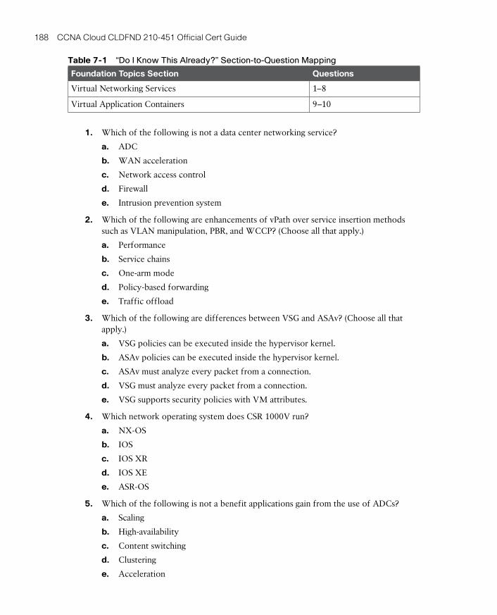
ptg17120290
188 CCNA Cloud CLDFND 210-451 Official Cert Guide
Table 7-1 “Do I Know This Already?” Section-to-Question Mapping
Foundation Topics Section Questions
Virtual Networking Services 1–8
Virtual Application Containers 9–10
1. Which of the following is not a data center networking service?
a. ADC
b. WAN acceleration
c. Network access control
d. Firewall
e. Intrusion prevention system
2. Which of the following are enhancements of vPath over service insertion methods such as VLAN manipulation, PBR, and WCCP? (Choose all that apply.)
a. Performance
b. Service chains
c. One-arm mode
d. Policy-based forwarding
e. Traffic offload
3. Which of the following are differences between VSG and ASAv? (Choose all that apply.)
a. VSG policies can be executed inside the hypervisor kernel.
b. ASAv policies can be executed inside the hypervisor kernel.
c. ASAv must analyze every packet from a connection.
d. VSG must analyze every packet from a connection.
e. VSG supports security policies with VM attributes.
4. Which network operating system does CSR 1000V run?
a. NX-OS
b. IOS
c. IOS XR
d. IOS XE
e. ASR-OS
5. Which of the following is not a benefit applications gain from the use of ADCs?
a. Scaling
b. High-availability
c. Content switching
d. Clustering
e. Acceleration
ptg171202907
Chapter 7: Virtual Networking Services and Application Containers 189
6. Which of the following are required configuration elements when deploying server load balancing in Citrix NetScaler 1000V? (Choose all that apply.)
a. Stickiness table
b. Virtual IP address
c. Monitor
d. Servers
e. DNS
7. Which of the following is not a WAN acceleration method available on vWAAS?
a. TFC
b. Windows printing AO
c. DRE
d. PLZ
e. TFO
8. Which of the following virtual networking services support vPath? (Choose all that apply.)
a. VSG
b. CSR 1000V
c. ASAv
d. vWAAS
e. NetScaler 1000V
9. Which of the following solutions are components of Cisco Virtual Application Cloud Segmentation? (Choose all that apply.)
a. Nexus 1000V
b. PNSC
c. UCS Director
d. CSM
e. VSG
f. CSR 1000V
10. Which of the following are differences between three-tier and custom virtual applica-tion containers? (Choose all that apply.)
a. Additional security zones
b. Zone-based firewall
c. Number of application tiers
d. Use of VXLAN
e. Number of segments
ptg17120290
190 CCNA Cloud CLDFND 210-451 Official Cert Guide
Foundation Topics
Virtual Networking ServicesThere are many ways to provide specialized services to applications. For example, one can install agents on application servers to achieve user session authorization or encryption according to a defined security policy. However, as the number of servers increases in a data center site (especially under the influence of server virtualization), such agents may eas-ily become an operational challenge.
If a specific service is based on open standards and requires exhaustive repetition of the same operations, a dedicated network device is probably the best way to perform that ser-vice. These specialized devices are generically called networking services.
Offering predictable performance for predefined operations, networking services are usu-ally deployed in a centralized position in a data center network while executing their func-tions transparently to both application servers and clients.
The most popular data center networking services are
■ Firewalls
■ Advanced routers
■ Server load balancers (SLBs) or application delivery controllers (ADCs)
■ Wide-area network (WAN) accelerators
Over the past two decades, networking services have been deployed in different formats, such as dedicated network appliances, hardware-based device insertion modules, or addi-tional features on a network operating system. But with the increasing adoption of server virtualization, many networking services started to be commercialized in a virtual format. Also labeled virtual networking services , the first virtual appliances were essentially a repackaging of physical appliances, with virtual machines hosting the exact same software that ran on physical networking services.
Nonetheless, new approaches were developed as more networking services leveraged the flexibility of virtual switching. Providing a firm architecture for virtual networking designs, Cisco Nexus 1000V has aggregated an enviable portfolio of virtual networking services, which will be discussed at length in the following sections.
But before you delve into these services, you must first be acquainted with some of the “old-school” techniques that are still used to insert networking services in physical struc-tures.
Service Insertion in Physical NetworksIf a networking service must be deployed for an application, the traffic exchanged between clients and servers must be guided to the network device implementing such service. As an illustration, Figure 7-1 depicts some of the most traditional solutions for traffic steering deployed in data center networks.
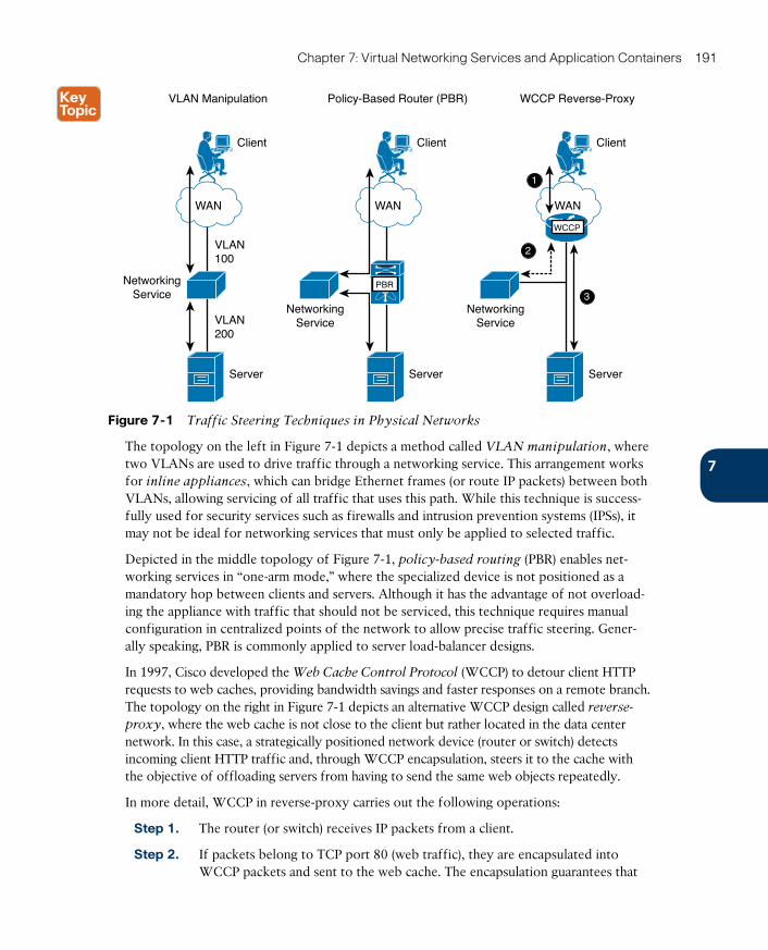
ptg171202907
Chapter 7: Virtual Networking Services and Application Containers 191
1
2
3
VLAN Manipulation
VLAN100
VLAN200
NetworkingService
Server
Client
WAN
Policy-Based Router (PBR)
NetworkingService
Server
Client
WAN
WCCP Reverse-Proxy
Server
Client
WAN
PBR
WCCP
NetworkingService
Figure 7-1 Traffic Steering Techniques in Physical Networks
The topology on the left in Figure 7-1 depicts a method called VLAN manipulation , where two VLANs are used to drive traffic through a networking service. This arrangement works for inline appliances , which can bridge Ethernet frames (or route IP packets) between both VLANs, allowing servicing of all traffic that uses this path. While this technique is success-fully used for security services such as firewalls and intrusion prevention systems (IPSs), it may not be ideal for networking services that must only be applied to selected traffic.
Depicted in the middle topology of Figure 7-1, policy-based routing (PBR) enables net-working services in “one-arm mode,” where the specialized device is not positioned as a mandatory hop between clients and servers. Although it has the advantage of not overload-ing the appliance with traffic that should not be serviced, this technique requires manual configuration in centralized points of the network to allow precise traffic steering. Gener-ally speaking, PBR is commonly applied to server load-balancer designs.
In 1997, Cisco developed the Web Cache Control Protocol (WCCP) to detour client HTTP requests to web caches, providing bandwidth savings and faster responses on a remote branch. The topology on the right in Figure 7-1 depicts an alternative WCCP design called reverse-
proxy , where the web cache is not close to the client but rather located in the data center network. In this case, a strategically positioned network device (router or switch) detects incoming client HTTP traffic and, through WCCP encapsulation, steers it to the cache with the objective of offloading servers from having to send the same web objects repeatedly.
In more detail, WCCP in reverse-proxy carries out the following operations:
Step 1. The router (or switch) receives IP packets from a client.
Step 2. If packets belong to TCP port 80 (web traffic), they are encapsulated into WCCP packets and sent to the web cache. The encapsulation guarantees that
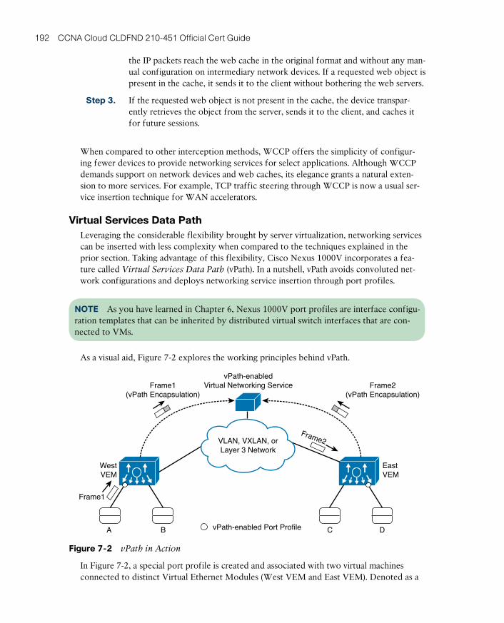
ptg17120290
192 CCNA Cloud CLDFND 210-451 Official Cert Guide
the IP packets reach the web cache in the original format and without any man-ual configuration on intermediary network devices. If a requested web object is present in the cache, it sends it to the client without bothering the web servers.
Step 3. If the requested web object is not present in the cache, the device transpar-ently retrieves the object from the server, sends it to the client, and caches it for future sessions.
When compared to other interception methods, WCCP offers the simplicity of configur-ing fewer devices to provide networking services for select applications. Although WCCP demands support on network devices and web caches, its elegance grants a natural exten-sion to more services. For example, TCP traffic steering through WCCP is now a usual ser-vice insertion technique for WAN accelerators.
Virtual Services Data PathLeveraging the considerable flexibility brought by server virtualization, networking services can be inserted with less complexity when compared to the techniques explained in the prior section. Taking advantage of this flexibility, Cisco Nexus 1000V incorporates a fea-ture called Virtual Services Data Path (vPath). In a nutshell, vPath avoids convoluted net-work configurations and deploys networking service insertion through port profiles.
NOTE As you have learned in Chapter 6, Nexus 1000V port profiles are interface configu-ration templates that can be inherited by distributed virtual switch interfaces that are con-nected to VMs.
As a visual aid, Figure 7-2 explores the working principles behind vPath.
EastVEM
WestVEM
vPath-enabled Port ProfileA C DB
Frame1
Frame2(vPath Encapsulation)
Frame1(vPath Encapsulation)
Frame2
vPath-enabledVirtual Networking Service
VLAN, VXLAN, orLayer 3 Network
Figure 7-2 vPath in Action
In Figure 7-2, a special port profile is created and associated with two virtual machines connected to distinct Virtual Ethernet Modules (West VEM and East VEM). Denoted as a

ptg171202907
Chapter 7: Virtual Networking Services and Application Containers 193
small circle, this port profile essentially signals to a VEM that frames to (or from) these vir-tual machines deserve distinctive traffic handling, rather than plain Layer 2 switching.
Afterward, the VEM encapsulates these frames into vPath packets destined to virtual net-working services that can be reached through a shared Layer 2 segment (VLAN or VXLAN) or a remote IP subnet.
Figure 7-2 depicts vPath steering two frames to a virtual networking service: Frame1 (sent by VM A) and Frame2 (destined to VM D). Depending on the virtual appliance specialized service, these packets are processed accordingly and sent back to the VEM connected to the virtual machine to continue their original path.
Similarly to WCCP, vPath employs encapsulation to simplify traffic interception configura-tions. But as an enhancement, vPath introduces the concept of forwarding policies , where a virtual machine attribute (such as associated port profile) takes precedence over its pure networking characteristics (such as VLAN or IP address) to define service insertion. Further-more, vPath enables virtual networking services to program Nexus 1000V VEMs to better serve target applications.
Knowing that examples speak much louder than abstractions, I will introduce a very illustra-tive vPath-enabled security service in the next section.
Cisco Virtual Security GatewayReleased in 2010, Cisco Virtual Security Gateway (VSG) brought the concept of a com-
pute firewall to virtual networks based on Cisco Nexus 1000V. With VSG, traffic between two virtual machines can be permitted or blocked within the hypervisor kernel or, more specifically, the Virtual Ethernet Module.
But first, allow me to present the components that comprise the VSG architecture:
■ Cisco Prime Network Services Controller (PNSC) : Deployed as a virtual machine, this software is responsible for the creation of security profiles, configuration of VSG (as well as other service devices), and the establishment of a multitenant hierarchy defined by tenants, virtual data centers (vDCs), virtual applications (vApps), and application tiers.
■ Cisco Virtual Security Gateway (VSG): This virtual appliance executes the rules defined in the PNSC security profiles on traffic from (or to) VMs that belong to a PNSC tenant, vDC, vApp, or tier.
■ Cisco Virtual Supervisor Module (VSM) : In the Nexus 1000V supervisor module, VSG reachability is configured and PNSC security profiles are inserted into vEthernet port profiles. And as explained in Chapter 6, these port profiles generate connectivity policies that can be associated to virtual machines and, thereafter, drive VEM behavior in order to correctly steer traffic to VSG.
■ VM Manager : Actively associates connectivity policies (Port Groups in the case of VMware vSphere) to a VM network adapter card.
As you may have already noticed, these components work collaboratively to deploy the concept of a compute firewall. Further detailing this service, Figure 7-3 examines a VSG scenario at the moment when a new connection reaches a Nexus 1000V instance.

ptg17120290
194 CCNA Cloud CLDFND 210-451 Official Cert Guide
PNSC VSM
VSG
VM Manager
Host1 Host2
WestVEM
A B
EastVEM
DC
“WEB-SP” “WEB-PP” Port Group“WEB-PP”Containing“WEB-SP”
Figure 7-3 VSG Ready to Process Traffic
The following is the complete provisioning process used to build the scenario depicted in Figure 7-3:
■ The security administrator creates a VSG security profile called “WEB-SP” in PNSC. This policy basically blocks all traffic except TCP connections whose destination port is 80 or 443.
■ The network administrator defines how the VEMs can reach VSG (VLAN, VXLAN, or IP address), creates a port profile called “WEB-PP,” and inserts security profile “WEB-SP” into this port profile.
■ The configuration of port profile “WEB-PP” automatically creates a connectivity policy (or Port Group in VMware-speak) in the VM manager. Thus, the virtualization adminis-trator assigns this policy to VM A, spawning vEthernet 10 in West VEM.
NOTE For the sake of simplicity and because it is a topic beyond the scope of this book, I will not represent how exactly each virtual networking service deploys high availability in the examples discussed in this chapter. Please refer to each vendor’s products documenta-tion for more detailed information.
This bucolic scene is disturbed with an HTTP connection sent toward VM A. Figure 7-4 shows what happens when the first packet of the connection reaches West VEM, regardless of its source (B, C, D, or an external host).
Figure 7-4 captures the instant when West VEM sends the connection’s first packet (encap-sulated in a vPath frame) after noticing that it was supposed to reach a “protected” interface (vEthernet 10).
As VSG receives the packet, it enforces security profile WEB-SP rules on it. Because the packet belongs to a TCP port 80 connection, it conforms to WEB-SP rules. Consequently, VSG resends the encapsulated packet back to the West VEM, as displayed in Figure 7-5.
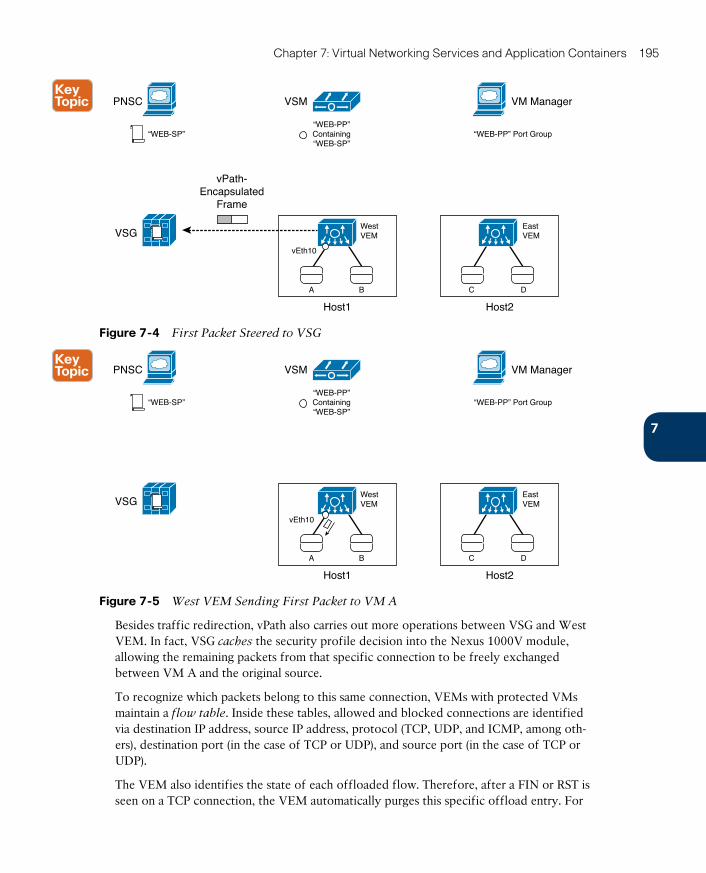
ptg171202907
Chapter 7: Virtual Networking Services and Application Containers 195
PNSC VSM
VSG
VM Manager
Host1 Host2
WestVEM
A B
EastVEM
vEth10
DC
“WEB-SP” “WEB-PP” Port Group“WEB-PP”Containing“WEB-SP”
vPath-Encapsulated
Frame
Figure 7-4 First Packet Steered to VSG
PNSC VSM
VSG
VM Manager
Host1 Host2
WestVEM
vEth10
A B
EastVEM
DC
“WEB-SP” “WEB-PP” Port Group“WEB-PP”Containing“WEB-SP”
Figure 7-5 West VEM Sending First Packet to VM A
Besides traffic redirection, vPath also carries out more operations between VSG and West VEM. In fact, VSG caches the security profile decision into the Nexus 1000V module, allowing the remaining packets from that specific connection to be freely exchanged between VM A and the original source.
To recognize which packets belong to this same connection, VEMs with protected VMs maintain a flow table . Inside these tables, allowed and blocked connections are identified via destination IP address, source IP address, protocol (TCP, UDP, and ICMP, among oth-ers), destination port (in the case of TCP or UDP), and source port (in the case of TCP or UDP).
The VEM also identifies the state of each offloaded flow. Therefore, after a FIN or RST is seen on a TCP connection, the VEM automatically purges this specific offload entry. For
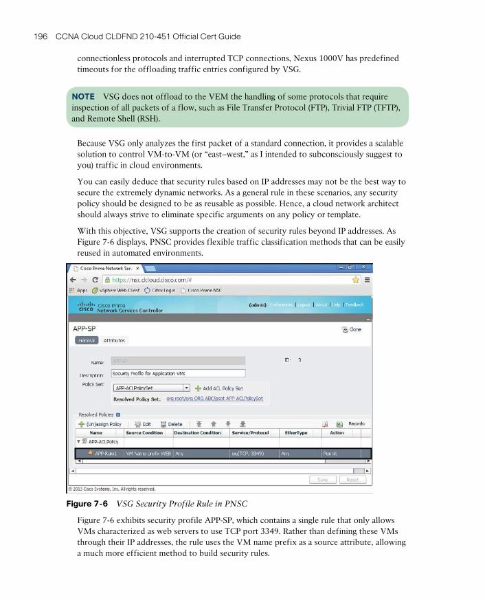
ptg17120290
196 CCNA Cloud CLDFND 210-451 Official Cert Guide
connectionless protocols and interrupted TCP connections, Nexus 1000V has predefined timeouts for the offloading traffic entries configured by VSG.
NOTE VSG does not offload to the VEM the handling of some protocols that require inspection of all packets of a flow, such as File Transfer Protocol (FTP), Trivial FTP (TFTP), and Remote Shell (RSH).
Because VSG only analyzes the first packet of a standard connection, it provides a scalable solution to control VM-to-VM (or “east–west,” as I intended to subconsciously suggest to you) traffic in cloud environments.
You can easily deduce that security rules based on IP addresses may not be the best way to secure the extremely dynamic networks. As a general rule in these scenarios, any security policy should be designed to be as reusable as possible. Hence, a cloud network architect should always strive to eliminate specific arguments on any policy or template.
With this objective, VSG supports the creation of security rules beyond IP addresses. As Figure 7-6 displays, PNSC provides flexible traffic classification methods that can be easily reused in automated environments.
Figure 7-6 VSG Security Profile Rule in PNSC
Figure 7-6 exhibits security profile APP-SP, which contains a single rule that only allows VMs characterized as web servers to use TCP port 3349. Rather than defining these VMs through their IP addresses, the rule uses the VM name prefix as a source attribute, allowing a much more efficient method to build security rules.
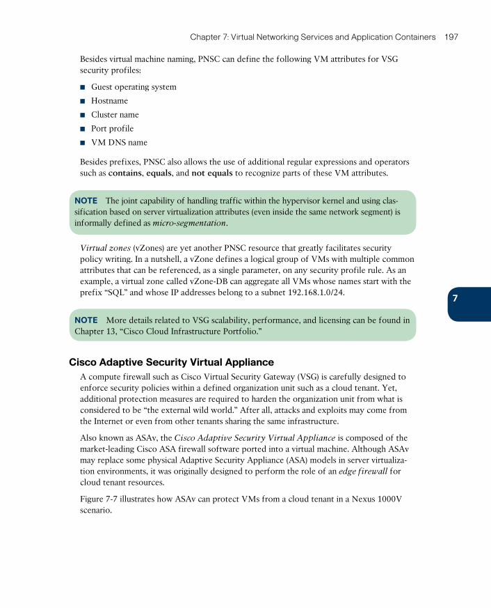
ptg171202907
Chapter 7: Virtual Networking Services and Application Containers 197
Besides virtual machine naming, PNSC can define the following VM attributes for VSG security profiles:
■ Guest operating system
■ Hostname
■ Cluster name
■ Port profile
■ VM DNS name
Besides prefixes, PNSC also allows the use of additional regular expressions and operators such as contains, equals, and not equals to recognize parts of these VM attributes.
NOTE The joint capability of handling traffic within the hypervisor kernel and using clas-sification based on server virtualization attributes (even inside the same network segment) is informally defined as micro-segmentation .
Virtual zones (vZones) are yet another PNSC resource that greatly facilitates security policy writing. In a nutshell, a vZone defines a logical group of VMs with multiple common attributes that can be referenced, as a single parameter, on any security profile rule. As an example, a virtual zone called vZone-DB can aggregate all VMs whose names start with the prefix “SQL” and whose IP addresses belong to a subnet 192.168.1.0/24.
NOTE More details related to VSG scalability, performance, and licensing can be found in Chapter 13, “Cisco Cloud Infrastructure Portfolio.”
Cisco Adaptive Security Virtual ApplianceA compute firewall such as Cisco Virtual Security Gateway (VSG) is carefully designed to enforce security policies within a defined organization unit such as a cloud tenant. Yet, additional protection measures are required to harden the organization unit from what is considered to be “the external wild world.” After all, attacks and exploits may come from the Internet or even from other tenants sharing the same infrastructure.
Also known as ASAv, the Cisco Adaptive Security Virtual Appliance is composed of the market-leading Cisco ASA firewall software ported into a virtual machine. Although ASAv may replace some physical Adaptive Security Appliance (ASA) models in server virtualiza-tion environments, it was originally designed to perform the role of an edge firewall for cloud tenant resources.
Figure 7-7 illustrates how ASAv can protect VMs from a cloud tenant in a Nexus 1000V scenario.

ptg17120290
198 CCNA Cloud CLDFND 210-451 Official Cert Guide
VLAN50
VLAN50
Trun
k
Trunk Trunk
Trunk
VLAN 50
VXLAN9000
VLAN50
VXLAN 9000
ASAv
ClientsClients
InternetInternet
A B C
Host2
EastVEM
C
VXLAN9000
VXLAN9000
VXLAN9000
ASAv
Host1
WestVEM
BA
Figure 7-7 ASAv Deployment Example
In both topologies in Figure 7-7, ASAv is protecting all virtual machines connected to VXLAN 9000 (VMs A, B, and C) from outside traffic coming through VLAN 50. Because edge firewalls must deploy Layers 4 to 7 security rules to avoid more sophisticated attacks, traffic is always steered to ASAv through VLAN (and VXLAN) manipulation. Routing IP packets between both inside and outside interfaces, ASAv can work as a default gateway for the protected VMs.
NOTE At the time of this writing, ASAv does not support vPath. For this reason, it depends on other traffic steering techniques, such as embodying the VMs default gateway, to enforce security policies on all traffic from a cloud tenant (or select resources from it).
The topology on the right side of Figure 7-7 hides the representation of Layer 2 switches and virtualization hosts to clarify the objective of an edge firewall such as ASAv. In my opinion, such “broadcast domain view” can be an excellent alternative to characterize secu-rity domains in virtual network topologies.
ASAv can deploy up to ten virtual interfaces and, for that reason, may also filter intra-tenant traffic and deploy virtual demilitarized zones (DMZs). Besides traffic filtering, ASAv also provides the following capabilities for cloud tenant resources:
■ Site-to-site virtual private networks (VPNs): Using IPsec, the edge firewall can securely connect external networks with compatible routers or firewalls.
■ Remote VPNs: This feature allows individual hosts deploying VPN software (such as Cisco AnyConnect) to remotely connect to ASAv as if they were located in a local
ptg171202907
Chapter 7: Virtual Networking Services and Application Containers 199
security zone. With this feature, IT administrators can perform maintenance operations on protected VMs, for example.
■ Network Address Translation (NAT) : ASAv can perform translation of private IP addresses to public IP addresses so internal VMs can be externally reached. This capabil-ity also allows the reuse of private IP subnets and addresses for multiple tenants.
■ Application inspection: Required for services that embed IP addressing information in user data or open secondary connections using dynamically assigned ports. Through this feature, ASAv performs deep packet analysis in protocols such as Domain Name Service (DNS), FTP, HTTP, Instant Messaging (IM), RSH, Session Initiation Protocol (SIP), SQL*Net, TFTP, among others.
■ Authentication, Authorization, and Accounting (AAA) : Set of services to identify ASAv administrators and application users, define what type of resources they can access, and register the procedures they have executed.
At the time of this writing, ASAv can be managed through the following tools and methods:
■ Command-line interface (CLI): This configuration method uses commands from the well-known ASA operating system.
■ Cisco Adaptive Security Device Manager (ASDM) : Graphical user interface that allows the easy creation of security rules and policies on a single ASAv instance. Its administra-tion can be also offered to tenants’ administrators, if desired.
■ Cisco Security Manager (CSM) : Management tool that allows security policy consisten-cy across multiple ASAv instances through object management, event monitoring, report and troubleshooting tools, image control, health, and performance monitoring. CSM can be managed through a GUI or a REST-based XML API.
■ Application programming interface (API): ASAv also provides an individual API based on RESTful principles. Ideal for cloud computing and other automated environments.
NOTE More details related to ASAv scalability, performance, and licensing can be found in Chapter 13.
Cisco Cloud Services Router 1000VThe vast majority of virtual switches only offer Layer 2 forwarding (bridging) between virtual machines and the physical network. Nevertheless, rather than limit Layer 3 forward-ing (routing) to occur exclusively from physical network devices, cloud tenants can benefit from the insertion of advanced routing functions closer to their virtual machines.
Cisco Cloud Services Router (CSR) 1000V expands Cisco’s initiative of building virtual appliances based on its most flexible and popular physical devices. More specifically, CSR 1000V runs Cisco IOS XE, a robust and complete variation of the most popular network operating system in the world.
Deploying CSR 1000V, cloud tenants can leverage advanced Layer 3 features such as
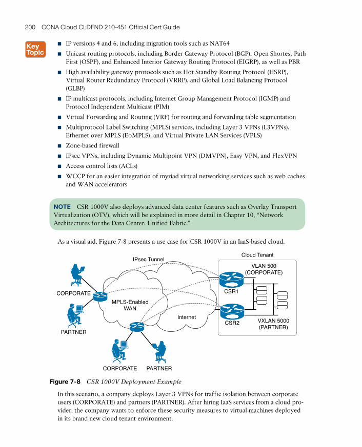
ptg17120290
200 CCNA Cloud CLDFND 210-451 Official Cert Guide
■ IP versions 4 and 6, including migration tools such as NAT64
■ Unicast routing protocols, including Border Gateway Protocol (BGP), Open Shortest Path First (OSPF), and Enhanced Interior Gateway Routing Protocol (EIGRP), as well as PBR
■ High availability gateway protocols such as Hot Standby Routing Protocol (HSRP), Virtual Router Redundancy Protocol (VRRP), and Global Load Balancing Protocol (GLBP)
■ IP multicast protocols, including Internet Group Management Protocol (IGMP) and Protocol Independent Multicast (PIM)
■ Virtual Forwarding and Routing (VRF) for routing and forwarding table segmentation
■ Multiprotocol Label Switching (MPLS) services, including Layer 3 VPNs (L3VPNs), Ethernet over MPLS (EoMPLS), and Virtual Private LAN Services (VPLS)
■ Zone-based firewall
■ IPsec VPNs, including Dynamic Multipoint VPN (DMVPN), Easy VPN, and FlexVPN
■ Access control lists (ACLs)
■ WCCP for an easier integration of myriad virtual networking services such as web caches and WAN accelerators
NOTE CSR 1000V also deploys advanced data center features such as Overlay Transport Virtualization (OTV), which will be explained in more detail in Chapter 10, “Network Architectures for the Data Center: Unified Fabric.”
As a visual aid, Figure 7-8 presents a use case for CSR 1000V in an IaaS-based cloud.
Internet
MPLS-EnabledWAN
VLAN 500(CORPORATE)
VXLAN 5000(PARTNER)
IPsec TunnelCloud Tenant
CORPORATE
CORPORATE
PARTNER
PARTNER
CSR2
CSR1
Figure 7-8 CSR 1000V Deployment Example
In this scenario, a company deploys Layer 3 VPNs for traffic isolation between corporate users (CORPORATE) and partners (PARTNER). After hiring IaaS services from a cloud pro-vider, the company wants to enforce these security measures to virtual machines deployed in its brand new cloud tenant environment.
ptg171202907
Chapter 7: Virtual Networking Services and Application Containers 201
As Figure 7-8 shows, two CSR 1000V instances are deployed inside the cloud tenant for redundancy purposes (ideally, each one of these virtual routers should be located in distinct hosts through anti-affinity rules defined in a virtualization cluster). CSR1 and CSR2 deploy HSRP to implement an “always active” default gateway for virtual machines. Moreover, these tenant-controlled routers provide route advertisement throughout the company WAN with OSPF. Security is further tightened with the use of IPsec tunnels providing encryption to all data exchanged between remote branches and the cloud tenant.
Deploying MPLS in these IOS-based virtual appliances, the cloud tenant has separate VMs assigned to CORPORATE and PARTNER VPNs, as long as they are connected, respective-ly, to VLAN 500 or VXLAN 5000. Consequently, desktops from end users connected to a VPN PARTNER can only access virtual machines that are connected to VXLAN 5000 in the cloud tenant.
NOTE At the time of this writing, CSR 1000V does not require vPath because it is usually positioned to deploy advanced routing features for all traffic exchanged between the cloud tenant domain and external networks.
The instantiation of an advanced router in a cloud tenant is such a compelling concept that public cloud providers, such as Amazon Web Services (AWS), are already offering CSR 1000V as an additional service for their customers.
CSR 1000V can be managed through the following methods:
■ CLI: Using Telnet or SSH, a network administrator can use the familiar commands from Cisco IOS. As a result, service providers and large enterprise networks can easily leverage CLI-based provisioning tools for CSR 1000V instances running on a cloud environment.
■ Cisco PNSC: This management tool can install and license CSR 1000V instances, as well as configure features according to their location within a created PNSC tenant hierarchy.
■ API: CSR 1000V additionally provides an API based on RESTful principles. It is ideal for cloud computing and other automated environments.
NOTE More details related to CSR 1000V scalability, performance, and licensing can be found in Chapter 13.
Citrix NetScaler 1000VWith the massive popularity of e-business applications in the late 1990s, data center archi-tects quickly realized that a web application running over a single server raises two immedi-ate risks:
■ Lackluster performance: Whenever the server hits a saturation point defined by its hardware-software combination
■ Poor availability: In the case of a major hardware or software failure

ptg17120290
202 CCNA Cloud CLDFND 210-451 Official Cert Guide
To mitigate these risks, Cisco created the concept of the server load balancer (SLB) appli-ance in 1998. In essence, an SLB is a network device that can receive end-user traffic and send it to a selected server according to a predefined load balancing policy.
Figure 7-9 displays the main components on a typical SLB deployment, described in the following list.
ApplicationUsers
SLB
StickinessTable
Monitor
Monitor
Monitor
Monitor
Monitor
Service A2
Service A3
Service B3
Service B4
Service B5
Server 1
Server 2
Server 3
Server 4
Server 5
Service A1
VIP
Client
Client 1
Server
Server 3
Client 2 Server 4
… …
Figure 7-9 SLB Basic Architecture
■ Servers: Basically the IP addresses from servers that will receive the connections dis-patched from the SLB.
■ Service: The IP address, port, and protocol combination used to route requests to a spe-cific load-balanced application server. A service is the logical representation of an appli-cation running on a server.
■ Monitors: Synthetic requests the SLB creates to check whether a service is available on a server. They can be as simple as an Internet Control Message Protocol (ICMP) Echo request or as sophisticated as a Hypertext Transfer Protocol (HTTP) GET operation bundled with a database query.
■ Virtual IP (VIP): An SLB internal IP address that is specifically used to receive end-user connections. This address is usually registered with DNS servers to be advertised to end users.
■ Virtual server: Combines a VIP, transport protocol (TCP or UDP), and port to which a client sends connection requests for a particular load-balanced application. It is associ-ated with a set of services to which the SLB will dispatch end-user connections.
ptg171202907
Chapter 7: Virtual Networking Services and Application Containers 203
■ Stickiness table: An optional SLB component that stores client information. The SLB uses this data to consistently forward end-user subsequent connections to the server that was selected during the first access, thus maintaining user session states inside the same server. Examples of stored client information are source IP address, HTTP cookies, and special strings excised from user data.
■ Load balancing algorithm: It is the configured method of user traffic distribution among the servers deploying the same application. A wide variety of algorithms are available today for these devices, including round robin, least connections, and hashing.
Generally speaking, an SLB provides server load balancing through the following process:
STEP 1. The SLB receives the client connection request in its VIP address, identifies the virtual server that will take care of the connection, and checks if the client is already in the stickiness table.
STEP 2. If the client information is not already present in the stickiness table, the SLB takes a look at the services associated with the virtual server and determines, through their monitor results, which real servers have the application healthily running at that moment.
STEP 3. Using the virtual server configured load balancing algorithm, the SLB selects the server that will receive the user connection.
STEP 4. The SLB saves the client and server information in the stickiness table and coordinates both ends of the connection until it eventually ends.
An interesting analogy for an SLB would be an airport control tower, which must identify the main characteristics of a landing airplane (user connection) before deciding which run-way (server) it can use. The control tower usually applies a predefined method (algorithm) to sequence the arriving planes and must already know (monitor) if a runway is in mainte-nance or not.
NOTE Please do not confuse the concept of a server load balancer with that of server
cluster software, which essentially allows servers to work in tandem, providing a scale-out solution for a specific application. Although SLBs may replace specific end-user distribution functions of clustering software, only the latter can manage user session synchronization among cluster members and provide shared access to stored data.
With widespread adoption in most data centers in the 2000s, SLBs were aptly renamed application delivery controllers (ADCs) as they expanded their capabilities with features such as the following:
■ Content switching: Server selection based on Layers 5 to 7 parameters from HTTP, FTP, RSTP, DNS, as well as user data.
■ Secure Sockets Layer (SSL) acceleration: Hardware-assisted encryption to offload secure web servers.

ptg17120290
204 CCNA Cloud CLDFND 210-451 Official Cert Guide
■ TCP connection reuse: Multiplexing of numerous TCP connections from clients to a small number of connections between the ADC and a server. This feature offloads web servers from the management of multiple TCP connections.
■ Object compression: Decreases bandwidth requirements with web objects being com-pressed in the ADC and, subsequently, delivered to the application clients employing decompression in their web browsers.
■ Web acceleration: Includes several distinct mechanisms whose objective is improving application response time for web applications.
■ Application firewall: Embedded analysis tools which prevent security breaches, data loss, and unauthorized customizations to web applications with sensitive business or cus-tomer information.
Similar to other networking services, ADCs were eventually introduced as virtual appliances targeting server virtualization and cloud deployments. In both contexts, this virtual network-ing service is generically used to increase capacity of applications when virtual machines are scaled out through cloning or template instantiation.
Citrix NetScaler (NS) 1000V embodies the packaging of Citrix NetScaler ADCs in virtual appliances. And as Figure 7-10 depicts, NetScaler 1000V provides vPath integration with virtual networks based on Nexus 1000V.
Host2
EastVEM
C
Internet
DataCenter
Network
Clients
Host2
EastVEM
vPath
vPathNS 1000V
Host1
WestVEM
A
Internet
DataCenter
Network
Clients
vPathNS 1000V
Host1
WestVEM
A B DC
Time
Figure 7-10 NetScaler 1000V Deployment Example
In the described scenario, a cloud tenant has already deployed two virtual machines (A and C) to host a web application. In the situation displayed on the left side of the figure,
ptg171202907
Chapter 7: Virtual Networking Services and Application Containers 205
NetScaler 1000V receives the requests from clients using a VIP address. As a consequence, the virtual ADC load balances the client connections between both VMs, providing more user capacity and availability for the application.
Because the company business department is foreseeing a sudden user interest during a future limited promotion, the cloud administration team decides to deploy two more virtual machines (B and D) for that period. The right side of the figure showcases this situation, where NetScaler 1000V is automatically configured to load balance client traffic to all VMs, doubling the user capacity of the application.
If you are wondering about the value vPath is adding to this scenario, first you have to understand a classic problem related to ADCs connected in one-arm mode: how to guaran-tee that response traffic from the servers reaches the ADC.
In Figure 7-10, when NetScaler 1000V sends the connection request to the virtual machine, by default, the client IP address is used as the connection source address. Therefore, the VM response has the client IP address as the destination. And because Nexus 1000V is a Layer 2 switch, it would naturally send the VM response to the VM default gateway, blind-ing the ADC from the server response. Besides, the connection would be instantly terminat-ed as soon as the client did not see the original destination IP address (VIP) at the response source IP address.
Traditionally, two methods are deployed in physical networks to solve this challenge, with variable benefits and drawbacks:
■ Source NAT: The ADC replaces the client IP address with an internal address (for example, the VIP), forcing the return traffic to be directed back to it. As a disadvantage, the application servers only detect the ADC as the origin for all connections and conse-quently lose track of the client accesses for monitoring and accountability purposes.
■ Policy-based routing: As previously explained in the section “Service Insertion in Physical Networks,” a network device may deploy this non-default method to route serv-er responses back to the ADC, demanding an exclusive IP subnet for the virtual service. However, this method is not possible in pure Layer 2 scenarios such as the one depicted in Figure 7-10.
Nexus 1000V and NetScaler 1000V can avoid this conundrum through vPath encapsulation. When this virtual ADC is assigned to a vPath-enabled port profile, Nexus 1000V can reg-ister load-balanced connections coming from NetScaler 1000V and automatically steer the return traffic to the ADC, avoiding the drawbacks from both source NAT and PBR.
NOTE More details related to Citrix NetScaler 1000V scalability, performance, and licens-ing can be found in Chapter 13.
Cisco Virtual Wide Area Application ServicesThe two main reasons why applications usually suffer from performance issues in wide-area networks are latency and bandwidth starvation:
ptg17120290
206 CCNA Cloud CLDFND 210-451 Official Cert Guide
■ Latency can be defined as the time spent to transmit any signal through a communica-tion channel. In any client/server application transaction, application response time can be roughly derived from the multiplication of the round-trip time (two times the latency) and the number of messages exchanged between client and server, with reception con-firmation. For example, if a server needs to send 1000 messages to a client and requires reception confirmation for each of them to send the next message, a latency of 1 mil-lisecond will result in 2 seconds for the whole transaction. On the other hand, with a latency of 100 milliseconds, the same transaction would need 3 minutes and 20 seconds (or 200 seconds) to finish.
TCP connections behave differently from the data exchange I just described. In summa-ry, TCP employs the concept of a transmission window , which represents the unidirec-tional amount of connection data that can be transmitted after a reception confirmation. In a TCP connection, the transmission window increases whenever the last transmitted data chunk is successfully transmitted. Nevertheless, most hosts present a transmission window size limitation of 64 KB, which may compromise TCP connections in high-latency links, regardless of their available bandwidth.
■ Because it defines how Internet access is usually billed, bandwidth starvation is argu-ably the most intuitive cause attributed to unsatisfactory application performance. For example, in a low-bandwidth WAN connection, traffic queuing in network devices increases, causing packet loss and retransmissions on TCP connections.
To support the consolidation process of servers in centralized data centers, a new network-ing service called WAN acceleration was conceived. In essence, WAN acceleration aims to transparently assuage the effect of latency and bandwidth saturation for applications tra-versing WAN links.
Cisco Wide Area Application Services (WAAS) epitomizes Cisco’s innovative and scalable WAN acceleration solution. WAAS is a symmetrical acceleration solution, demanding the deployment of an accelerator device at each end of a WAN link: one close to the client and another in the vicinity of the application server. With this arrangement, application connec-tions are intercepted by both WAAS devices, which in turn apply acceleration algorithms to decrease the application response time and increase the WAN link capacity.
In summary, Cisco WAAS offers the following acceleration algorithms:
■ TCP Flow Optimization (TFO) : Each WAAS device acts as a TCP proxy, providing local acknowledgements to the host that is closest to the device on behalf of the remote end. With this artifice, WAAS “fools” both client and server through the illusion that both are connected to the same LAN. Then, the devices deploy an optimized version of TCP between them to leverage the most from the WAN bandwidth for each connection.
■ Data Redundancy Elimination (DRE) : WAAS inspects TCP traffic to identify redundant data patterns at the byte level and quickly replace them with 6-byte signatures that are automatically indexed and recognized by both WAAS devices.
■ Persistent Lempel-Ziv (PLZ) : Standards-based compression that can be applied (in con-junction with DRE or not) to further reduce the amount of bandwidth consumed by a TCP flow.
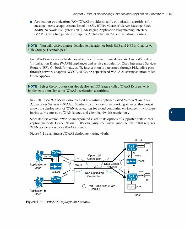
ptg171202907
Chapter 7: Virtual Networking Services and Application Containers 207
■ Application optimization (AO) : WAAS provides specific optimization algorithms for message-intensive applications based on SSL, HTTP, Microsoft Server Message Block (SMB), Network File System (NFS), Messaging Application Programming Interface (MAPI), Citrix Independent Computer Architecture (ICA), and Windows Printing.
NOTE You will receive a more detailed explanation of both SMB and NFS in Chapter 9, “File Storage Technologies.”
Full WAAS services can be deployed in two different physical formats: Cisco Wide Area Virtualization Engine (WAVE) appliances and service modules for Cisco Integrated Services Routers (ISR). On both formats, traffic interception is performed through PBR, inline pass-through network adapters, WCCP, ADCs, or a specialized WAAS clustering solution called Cisco AppNav.
NOTE Select Cisco routers can also deploy an IOS feature called WAAS Express, which implements a smaller set of WAAS acceleration algorithms.
In 2010, Cisco WAAS was also released as a virtual appliance called Virtual Wide Area
Application Services (vWAAS). Similarly to other virtual networking services, this format allows the deployment of WAN acceleration for cloud computing environments, which are intrinsically exposed to WAN latency and client bandwidth restrictions.
Since its first version, vWAAS incorporated vPath to its options of supported traffic inter-ception methods. Hence, Nexus 1000V can easily steer virtual machine traffic that requires WAN acceleration to a vWAAS instance.
Figure 7-11 examines a vWAAS deployment using vPath.
WAN Data CenterNetwork
OptimizedConnection
Non-OptimizedConnection
Port Profile with vPathto vWAAS
WCCP
WAAS
Host1
A
vPath
vWAAS
Application AUser
Application BUser Host2
B
vPath
vCM
Figure 7-11 vWAAS Deployment Scenario
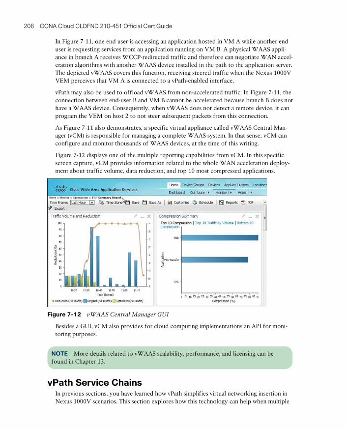
ptg17120290
208 CCNA Cloud CLDFND 210-451 Official Cert Guide
In Figure 7-11, one end user is accessing an application hosted in VM A while another end user is requesting services from an application running on VM B. A physical WAAS appli-ance in branch A receives WCCP-redirected traffic and therefore can negotiate WAN accel-eration algorithms with another WAAS device installed in the path to the application server. The depicted vWAAS covers this function, receiving steered traffic when the Nexus 1000V VEM perceives that VM A is connected to a vPath-enabled interface.
vPath may also be used to offload vWAAS from non-accelerated traffic. In Figure 7-11, the connection between end-user B and VM B cannot be accelerated because branch B does not have a WAAS device. Consequently, when vWAAS does not detect a remote device, it can program the VEM on host 2 to not steer subsequent packets from this connection.
As Figure 7-11 also demonstrates, a specific virtual appliance called vWAAS Central Man-ager (vCM) is responsible for managing a complete WAAS system. In that sense, vCM can configure and monitor thousands of WAAS devices, at the time of this writing.
Figure 7-12 displays one of the multiple reporting capabilities from vCM. In this specific screen capture, vCM provides information related to the whole WAN acceleration deploy-ment about traffic volume, data reduction, and top 10 most compressed applications.
Figure 7-12 vWAAS Central Manager GUI
Besides a GUI, vCM also provides for cloud computing implementations an API for moni-toring purposes.
NOTE More details related to vWAAS scalability, performance, and licensing can be found in Chapter 13.
vPath Service ChainsIn previous sections, you have learned how vPath simplifies virtual networking insertion in Nexus 1000V scenarios. This section explores how this technology can help when multiple
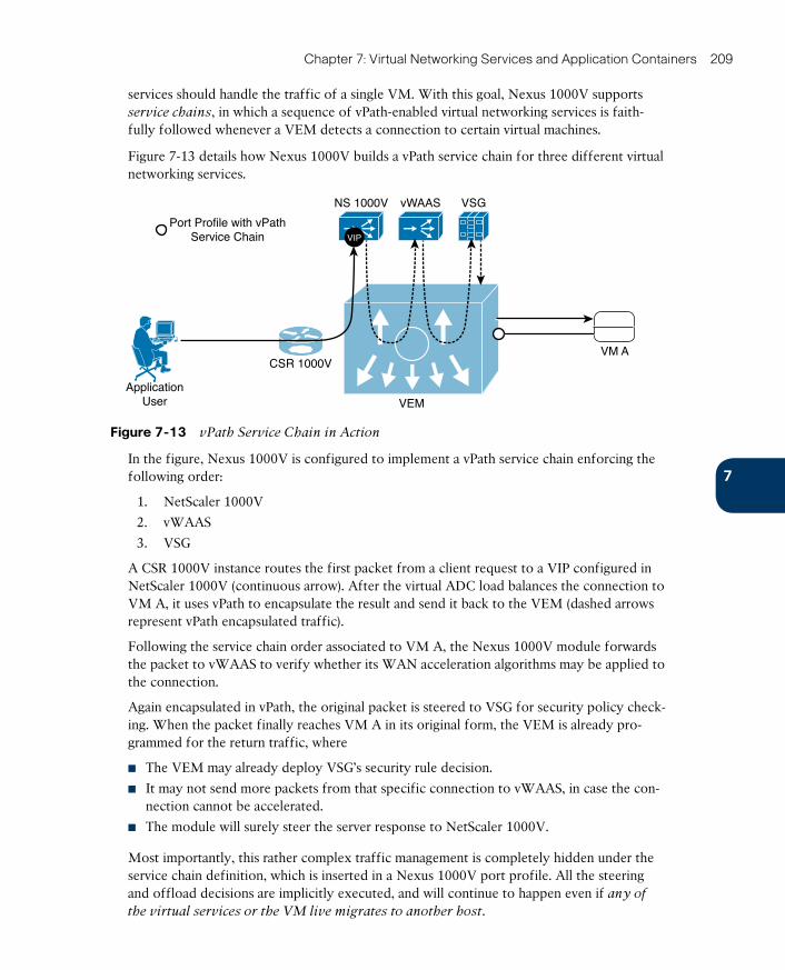
ptg171202907
Chapter 7: Virtual Networking Services and Application Containers 209
services should handle the traffic of a single VM. With this goal, Nexus 1000V supports service chains, in which a sequence of vPath-enabled virtual networking services is faith-fully followed whenever a VEM detects a connection to certain virtual machines.
Figure 7-13 details how Nexus 1000V builds a vPath service chain for three different virtual networking services.
VSGvWAASNS 1000V
Port Profile with vPathService Chain
ApplicationUser
VM A
VEM
CSR 1000V
VIP
Figure 7-13 vPath Service Chain in Action
In the figure, Nexus 1000V is configured to implement a vPath service chain enforcing the following order:
1. NetScaler 1000V
2. vWAAS
3. VSG
A CSR 1000V instance routes the first packet from a client request to a VIP configured in NetScaler 1000V (continuous arrow). After the virtual ADC load balances the connection to VM A, it uses vPath to encapsulate the result and send it back to the VEM (dashed arrows represent vPath encapsulated traffic).
Following the service chain order associated to VM A, the Nexus 1000V module forwards the packet to vWAAS to verify whether its WAN acceleration algorithms may be applied to the connection.
Again encapsulated in vPath, the original packet is steered to VSG for security policy check-ing. When the packet finally reaches VM A in its original form, the VEM is already pro-grammed for the return traffic, where
■ The VEM may already deploy VSG’s security rule decision.
■ It may not send more packets from that specific connection to vWAAS, in case the con-nection cannot be accelerated.
■ The module will surely steer the server response to NetScaler 1000V.
Most importantly, this rather complex traffic management is completely hidden under the service chain definition, which is inserted in a Nexus 1000V port profile. All the steering and offload decisions are implicitly executed, and will continue to happen even if any of
the virtual services or the VM live migrates to another host.
ptg17120290
210 CCNA Cloud CLDFND 210-451 Official Cert Guide
Fundamentally, a vPath service chain provides policy-defined service insertion for virtual machines. If desired, other port profiles may implement distinct service chains: for example, a second service chain may only include vWAAS and VSG services for select VMs.
vPath service chains make it extremely easy for clouds to employ virtual networking ser-vices as “add-ons” for each application tier on a cloud tenant.
In the case of a failure on any virtual networking service on the chain, Nexus 1000V detects the lack of connectivity probe (keepalive) responses from the failed service and no longer steers traffic to it. However, the configured fail-mode in such service will define how the entire service chain will behave:
■ Fail-mode close: If the virtual networking service fails or loses connectivity to Nexus 1000V, all port profiles associated with the service will drop every packet and the whole service chain will stop working.
■ Fail-mode open: If the virtual networking service fails or loses connectivity to Nexus 1000V, all port profiles associated with the service will perform frame forwarding as if the service is not included in the service chain.
Undoubtedly, because of its central position for vPath-enabled services, Nexus 1000V is the most important tool during troubleshooting processes involving service chains.
Virtual Application ContainersBusiness applications rely on servers, storage, and networking, which includes segment cre-ation and additional networking services (routing, security, and load balancing, among oth-ers). As a consequence, the application provisioning process is severely challenged with the complexity of installing, configuring, and licensing all of these components.
By definition, some level of application isolation is required in any multitenant domain, for multiple reasons, such as security, compliance, or service-level agreements (SLAs). As a simple example, you can imagine that in a service provider hosting applications for multiple customers, a single tenant may want to separate applications for internal employees from those for external partners.
With both situations in mind, data center architects embraced the concept of a network
container to speed up application provisioning and reinforce network isolation in multiten-ant environments. In summary, a network container can be defined as a set of networking services configured in a standardized manner.
During the 2000s, to avoid deploying dedicated network devices (switches, routers, fire-walls, and ADCs) for each tenant, most data center service providers built network contain-ers using a virtualization technique called device partitioning to better leverage the usage of networking resources. The following elements represent common network device partitions that were heavily used during that period:
■ Virtual Routing and Forwarding (VRF) instance : A routing instance that can coexist with several others in the same routing equipment. It is composed of independent rout-ing and forwarding tables, a set of interfaces, and optional routing protocols to exchange routing information with other peers.

ptg171202907
Chapter 7: Virtual Networking Services and Application Containers 211
■ Firewall context: An independent virtual firewall, with its own security policy, interfac-es, and administrators. From an administration perspective, deploying multiple contexts is similar to having multiple standalone devices. Cisco ASA supports multiple contexts deploying separate routing tables, firewall features, IPS, and management capabilities.
■ ADC context: An abstraction of an independent load balancer with its own interfaces, configuration, policies, and administrators. This technology was originally deployed in the former Cisco ADC solution called Application Control Engine (ACE).
Figure 7-14 illustrates four network container examples composed of network partitions and offered to tenants of a data center service provider.
BronzeNetwork
Container
GoldNetwork
Container
SilverNetwork
Container
DiamondNetwork
Container
PhysicalRouter
PhysicalFirewall
PhysicalADC
VRF VRF VRF VRF
FirewallContext
FirewallContext
FirewallContext
ADCContext
Tenant Application Tenant Application Tenant Application Tenant Application
ADCContext
ADCContext
ADCContext
Figure 7-14 Network Container Examples
In all four container options depicted in Figure 7-14, VRF instances provide Layer 3 servic-es to external networks, while both firewall and SLB contexts provide their specialized net-working services to one or more applications from a tenant. Using these virtual partitions, a service provider can logically provision selected networking services without undertaking the manual procedures that would be necessary if physical appliances were deployed.
As you previously learned in the section “Service Insertion in Physical Networks,” this scenario uses VLAN manipulation to insert services between clients and servers from an application. For this objective, an additional VLAN must be provisioned to connect two networking services (or one service to the application servers). Thus, the bronze, silver, gold, and diamond network containers, respectively, consume 2, 2, 3, and 5 VLANs from the 4094 that are available on a single service provider network infrastructure.
NOTE For service providers interested in developing such designs, Cisco offers an extremely useful standardization tool in the form of the Virtualized Multiservice Data Center (VMDC) reference architecture . VMDC essentially provides a framework for build-ing multitenant data centers with focus on the integration of networking, computing, server virtualization, security, load balancing, and system management.
ptg17120290
212 CCNA Cloud CLDFND 210-451 Official Cert Guide
Being also a multitenant environment, cloud computing recycles many principles and best practices learned from data center service providers. But with the benefits brought by server virtualization, cloud providers could evolve network containers into virtual application
containers through the addition of three new ingredients:
■ Virtual machines: The simplicity of VM provisioning allows virtual servers to be added to these templates.
■ VXLAN: Used to scale and facilitate network provisioning for tenants.
■ Virtual networking services: Can replace device partitions, decreasing cloud orchestra-tion operations with the physical network and expanding their capabilities to scale out (create more virtual appliances) and scale up (allocate more resources to a virtual appli-ance).
As discussed in Chapter 4, “Behind the Curtain,” standardization is a mandatory requirement for ease of automation. And for this reason, virtual application containers are considered a key element of cloud computing architecture.
Using its broad portfolio of virtual networking services, Cisco streamlined the creation of virtual application containers through a solution called Cisco Virtual Application Cloud
Segmentation (VACS) . This software package basically automates installation, licensing, and configuration of multiple virtual services to enable an easy and efficient setup of virtualized applications.
Cisco VACS provisions application environments through virtual application container
templates , which are used for the instantiation of identical virtual application containers. The solution architecture has three main software components:
■ Cisco Nexus 1000V: Provides network segmentation through VLAN and VXLANs, and offers vPath-based network insertion
■ Cisco PNSC: Controls the installation, licensing, and configuration of virtual networking services
■ Unified Computing System (UCS) Director: Cisco orchestration solution that provides the management interface to deploy, provision, and monitor the whole VACS solution
As Figure 7-15 demonstrates, VACS discharges the cloud orchestrator from executing repetitive (and strongly correlated) tasks to instantiate a virtual application container.
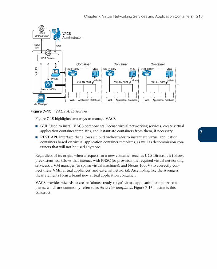
ptg171202907
Chapter 7: Virtual Networking Services and Application Containers 213
VACSAdministrator
GUIRESTAPI
VA
CS
VM Manager
Nexus 1000V
PNSC
UCS Director
CloudOrchestrator
ContainerCSR 1000V
vPathVXLAN 5003
VSG
Web Application Database
...
ContainerCSR 1000V
vPathVXLAN 5002
VSG
Web Application Database
ContainerCSR 1000V
vPathVXLAN 5001
VSG
Web Application Database
Figure 7-15 VACS Architecture
Figure 7-15 highlights two ways to manage VACS:
■ GUI: Used to install VACS components, license virtual networking services, create virtual application container templates, and instantiate containers from them, if necessary
■ REST API: Interface that allows a cloud orchestrator to instantiate virtual application containers based on virtual application container templates, as well as decommission con-tainers that will not be used anymore
Regardless of its origin, when a request for a new container reaches UCS Director, it follows preexistent workflows that interact with PNSC (to provision the required virtual networking services), a VM manager (to spawn virtual machines), and Nexus 1000V (to correctly con-nect these VMs, virtual appliances, and external networks). Assembling like the Avengers, these elements form a brand new virtual application container.
VACS provides wizards to create “almost-ready-to-go” virtual application container tem-plates, which are commonly referred as three-tier templates . Figure 7-16 illustrates this construct.
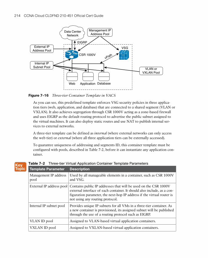
ptg17120290
214 CCNA Cloud CLDFND 210-451 Official Cert Guide
Data CenterNetwork
VSG
DatabaseApplicationWeb
CSR 1000V
EIGRP
vPath
Management IPAddress Pool
VLAN orVXLAN Pool
External IPAddress Pool
Internal IPSubnet Pool
Figure 7-16 Three-tier Container Template in VACS
As you can see, this predefined template enforces VSG security policies in three applica-tion tiers (web, application, and database) that are connected to a shared segment (VLAN or VXLAN). It also achieves segregation through CSR 1000V acting as a zone-based firewall and uses EIGRP as the default routing protocol to advertise the public subnet assigned to the virtual machines. It can also deploy static routes and use NAT to publish internal ser-vices to external networks.
A three-tier template can be defined as internal (where external networks can only access the web tier) or external (where all three application tiers can be externally accessed).
To guarantee uniqueness of addressing and segments ID, this container template must be configured with pools, described in Table 7-2, before it can instantiate any application con-tainer.
Table 7-2 Three-tier Virtual Application Container Template Parameters
Template Parameter Description
Management IP address pool
Used by all manageable elements in a container, such as CSR 1000V and VSG.
External IP address pool Contains public IP addresses that will be used on the CSR 1000V external interface of each container. It should also include, as a con-figuration parameter, the next-hop IP address if the virtual router is not using any routing protocol.
Internal IP subnet pool Provides unique IP subnets for all VMs in a three-tier container. As a new container is provisioned, its assigned subnet will be published through the use of a routing protocol such as EIGRP.
VLAN ID pool Assigned to VLAN-based virtual application containers.
VXLAN ID pool Assigned to VXLAN-based virtual application containers.
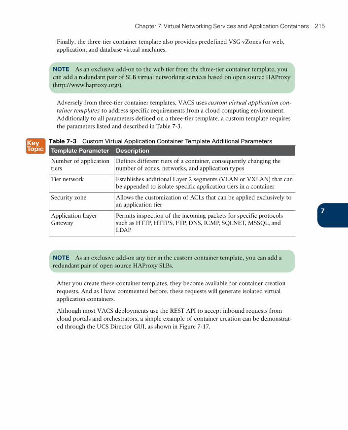
ptg171202907
Chapter 7: Virtual Networking Services and Application Containers 215
Finally, the three-tier container template also provides predefined VSG vZones for web, application, and database virtual machines.
NOTE As an exclusive add-on to the web tier from the three-tier container template, you can add a redundant pair of SLB virtual networking services based on open source HAProxy (http://www.haproxy.org/).
Adversely from three-tier container templates, VACS uses custom virtual application con-
tainer templates to address specific requirements from a cloud computing environment. Additionally to all parameters defined on a three-tier template, a custom template requires the parameters listed and described in Table 7-3.
Table 7-3 Custom Virtual Application Container Template Additional Parameters
Template Parameter Description
Number of application tiers
Defines different tiers of a container, consequently changing the number of zones, networks, and application types
Tier network Establishes additional Layer 2 segments (VLAN or VXLAN) that can be appended to isolate specific application tiers in a container
Security zone Allows the customization of ACLs that can be applied exclusively to an application tier
Application Layer Gateway
Permits inspection of the incoming packets for specific protocols such as HTTP, HTTPS, FTP, DNS, ICMP, SQLNET, MSSQL, and LDAP
NOTE As an exclusive add-on any tier in the custom container template, you can add a redundant pair of open source HAProxy SLBs.
After you create these container templates, they become available for container creation requests. And as I have commented before, these requests will generate isolated virtual application containers.
Although most VACS deployments use the REST API to accept inbound requests from cloud portals and orchestrators, a simple example of container creation can be demonstrat-ed through the UCS Director GUI, as shown in Figure 7-17.
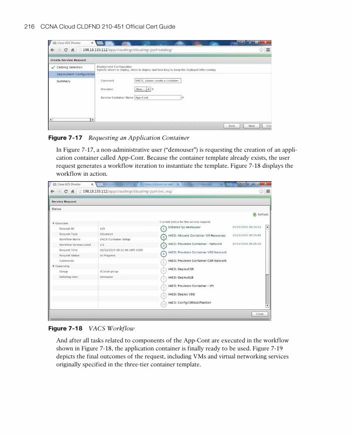
ptg17120290
216 CCNA Cloud CLDFND 210-451 Official Cert Guide
Figure 7-17 Requesting an Application Container
In Figure 7-17, a non-administrative user (“demouser”) is requesting the creation of an appli-cation container called App-Cont. Because the container template already exists, the user request generates a workflow iteration to instantiate the template. Figure 7-18 displays the workflow in action.
Figure 7-18 VACS Workflow
And after all tasks related to components of the App-Cont are executed in the workflow shown in Figure 7-18, the application container is finally ready to be used. Figure 7-19 depicts the final outcomes of the request, including VMs and virtual networking services originally specified in the three-tier container template.
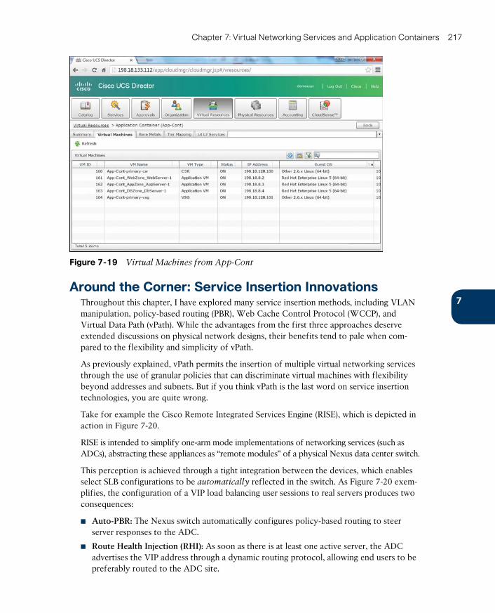
ptg171202907
Chapter 7: Virtual Networking Services and Application Containers 217
Figure 7-19 Virtual Machines from App-Cont
Around the Corner: Service Insertion InnovationsThroughout this chapter, I have explored many service insertion methods, including VLAN manipulation, policy-based routing (PBR), Web Cache Control Protocol (WCCP), and Virtual Data Path (vPath). While the advantages from the first three approaches deserve extended discussions on physical network designs, their benefits tend to pale when com-pared to the flexibility and simplicity of vPath.
As previously explained, vPath permits the insertion of multiple virtual networking services through the use of granular policies that can discriminate virtual machines with flexibility beyond addresses and subnets. But if you think vPath is the last word on service insertion technologies, you are quite wrong.
Take for example the Cisco Remote Integrated Services Engine (RISE) , which is depicted in action in Figure 7-20.
RISE is intended to simplify one-arm mode implementations of networking services (such as ADCs), abstracting these appliances as “remote modules” of a physical Nexus data center switch.
This perception is achieved through a tight integration between the devices, which enables select SLB configurations to be automatically reflected in the switch. As Figure 7-20 exem-plifies, the configuration of a VIP load balancing user sessions to real servers produces two consequences:
■ Auto-PBR: The Nexus switch automatically configures policy-based routing to steer server responses to the ADC.
■ Route Health Injection (RHI): As soon as there is at least one active server, the ADC advertises the VIP address through a dynamic routing protocol, allowing end users to be preferably routed to the ADC site.
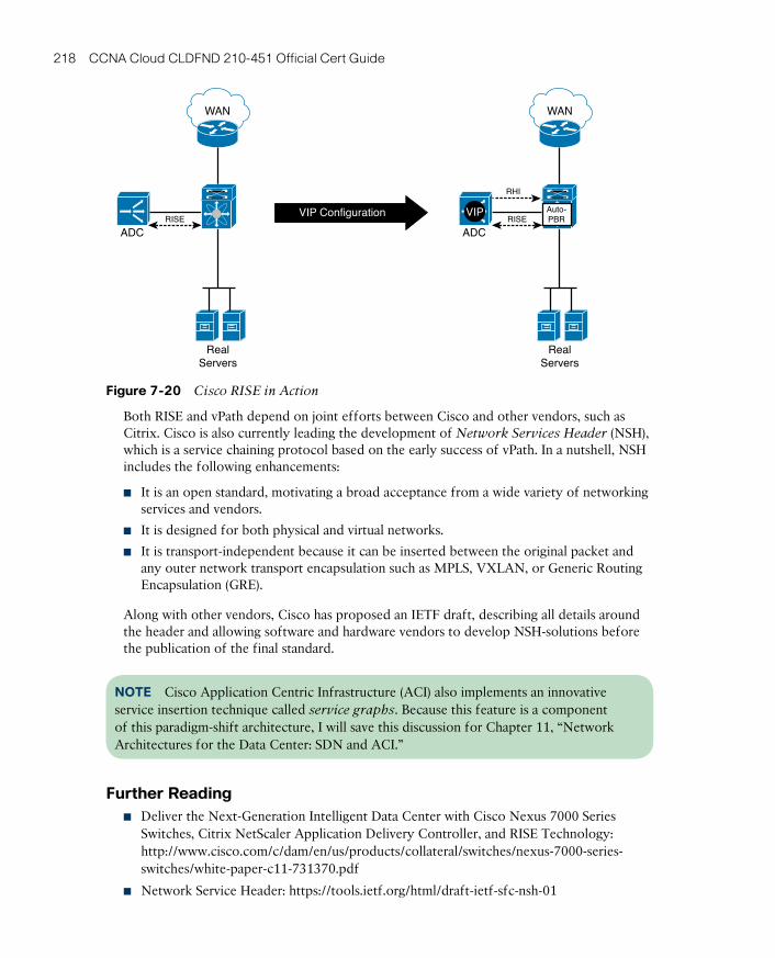
ptg17120290
218 CCNA Cloud CLDFND 210-451 Official Cert Guide
VIP Configuration
WAN WAN
RISE RISE
ADC ADC
VIP Auto-PBR
RHI
RealServers
RealServers
Figure 7-20 Cisco RISE in Action
Both RISE and vPath depend on joint efforts between Cisco and other vendors, such as Citrix. Cisco is also currently leading the development of Network Services Header (NSH) , which is a service chaining protocol based on the early success of vPath. In a nutshell, NSH includes the following enhancements:
■ It is an open standard, motivating a broad acceptance from a wide variety of networking services and vendors.
■ It is designed for both physical and virtual networks.
■ It is transport-independent because it can be inserted between the original packet and any outer network transport encapsulation such as MPLS, VXLAN, or Generic Routing Encapsulation (GRE).
Along with other vendors, Cisco has proposed an IETF draft, describing all details around the header and allowing software and hardware vendors to develop NSH-solutions before the publication of the final standard.
NOTE Cisco Application Centric Infrastructure (ACI) also implements an innovative service insertion technique called service graphs. Because this feature is a component of this paradigm-shift architecture, I will save this discussion for Chapter 11, “Network Architectures for the Data Center: SDN and ACI.”
Further Reading■ Deliver the Next-Generation Intelligent Data Center with Cisco Nexus 7000 Series
Switches, Citrix NetScaler Application Delivery Controller, and RISE Technology: http://www.cisco.com/c/dam/en/us/products/collateral/switches/nexus-7000-series-switches/white-paper-c11-731370.pdf
■ Network Service Header: https://tools.ietf.org/html/draft-ietf-sfc-nsh-01

ptg171202907
Chapter 7: Virtual Networking Services and Application Containers 219
Exam Preparation Tasks
Review All the Key TopicsReview the most important topics in this chapter, denoted with a Key Topic icon in the outer margin of the page. Table 7-4 lists a reference of these key topics and the page num-ber on which each is found.
Table 7-4 Key Topics for Chapter 7
Key Topic Element Description Page Number
Figure 7-1 Traffic steering techniques in physical networks 191
Figure 7-3 VSG ready to process traffic 194
Figure 7-4 First packet steered to VSG 195
Figure 7-5 West VEM sending first packet to VM A 195
List ASAv capabilities for cloud tenant resources 198
List CSR 1000V advanced Layer 3 features 200
List SLB configuration elements 202
List Cisco WAAS acceleration algorithms 206
Table 7-2 Three-tier virtual application container template parameters
214
Table 7-3 Custom virtual application container template addi-tional parameters
215
Complete the Tables and Lists from MemoryPrint a copy of Appendix B, “Memory Tables” (found on the CD), or at least the section for this chapter, and complete the tables and lists from memory. Appendix C, “Answers to Memory Tables,” also on the CD, includes completed tables and lists so that you can check your work.
Define Key TermsDefine the following key terms from this chapter, and check your answers in the glossary:
networking service, firewall, server load balancer (SLB), WAN acceleration, service inser-tion, policy-based routing (PBR), Web Cache Control Protocol (WCCP), virtual networking service, Virtual Data Path (vPath), Virtual Security Gateway (VSG), Adaptive Security Virtual Appliance (ASAv), Cloud Services Router (CSR) 1000V, NetScaler 1000V, Virtual Wide Area Application Services (vWAAS), Virtual Application Cloud Segmentation (VACS)
ptg17120290
This chapter covers the following topics:
■ What Is Data Storage?
■ Hard Disk Drives
■ RAID Levels
■ Disk Controllers and Disk Arrays
■ Volumes
■ Accessing Blocks
■ Fibre Channel Basics
■ SAN Designs
■ Virtual SANs
■ Internet SCSI
■ Cloud Computing and SANs
This chapter covers the following exam Objectives:
■ 5.1 Describe storage provisioning concepts■ 5.1.a Thick■ 5.1.b Thin■ 5.1.c RAID■ 5.1.d Disk pools
■ 5.2 Describe the difference between all the storage access technologies■ 5.2.b Block technologies
■ 5.3 Describe basic SAN storage concepts■ 5.3.a Initiator, target, zoning■ 5.3.b VSAN■ 5.3.c LUN
■ 5.5 Describe the various Cisco storage network devices■ 5.5.a Cisco MDS family■ 5.5.c UCS Invicta (Whiptail)
ptg17120290
CHAPTER 8
Block Storage TechnologiesThe capability to store data for later use is part of any computer system. However, how such systems write and read data in a storage device has been handled in many different ways since the beginning of computer science.
Obviously, cloud computing projects cannot avoid this topic. To actually provide self-catered services to end users, cloud architects must select a methodology to store applica-tion data that is both efficient and strikes a good balance between performance and cost. In some cases, data storage itself may be offered as a service, enabling consumers to use a cloud as their data repository.
Within such context, the CLDFND exam requires knowledge about the basic principles of block storage technologies, including provisioning concepts, storage devices, access meth-ods, and Cisco storage network devices. This chapter starts with the most basic of these principles by providing a formal definition of what constitutes storage. It then examines different types of storage devices, hard disk drives (and associated technologies), main block storage access methods, storage-area networks (SANs), and common SAN topologies. Finally, the chapter correlates these technologies to the current state of cloud computing, providing a clear application of these technologies to dynamic cloud environments.
“Do I Know This Already?” QuizThe “Do I Know This Already?” quiz allows you to assess whether you should read this entire chapter thoroughly or jump to the “Exam Preparation Tasks” section. If you are in doubt about your answers to these questions or your own assessment of your knowledge of the topics, read the entire chapter. Table 8-1 lists the major headings in this chapter and their corresponding “Do I Know This Already?” quiz questions. You can find the answers in Appendix A, “Answers to Pre-Assessments and Quizzes.”
Table 8-1 Do I Know This Already?” Section-to-Question Mapping
Foundation Topics Section Questions
What Is Data Storage? 1
Hard Disk Drives 2
RAID Levels 3
Disk Controllers and Disk Arrays 4
Volumes 5
Accessing Blocks 6
Fibre Channel Basics 7–8
SAN Designs 9
ptg17120290
222 CCNA Cloud CLDFND 210-451 Official Cert Guide
Foundation Topics Section Questions
Virtual SANs 10
Internet SCSI 11
Cloud Computing and SANs 12
1. Which of the following is a correct statement?
a. HDDs are considered primary storage.
b. DVD drives are considered secondary storage.
c. Tape libraries are considered tertiary storage.
d. RAM is not considered primary storage.
2. Which of the following represents data addressing in HDDs?
a. Bus/target/LUN
b. World Wide Name
c. Cylinder/head/sector
d. Domain/area/port
3. Which option describes an incorrect RAID level description?
a. RAID 0: Striping
b. RAID 1: Mirroring
c. RAID 6: Striping, double parity
d. RAID 10: Striping, multiple parity
4. Which of the following is not an array component?
a. SATA
b. Controller
c. JBOD
d. Disk enclosure
e. Access ports
5. Which of the following devices can potentially deploy volume thin provisioning? (Choose all that apply.)
a. JBOD
b. Storage array
c. Server
d. Dedicated appliance
e. HDD
6. Which of the following are block I/O access methods? (Choose all that apply.)
a. ATA
b. SCSI
c. SAN
d. NFS
e. SQL

ptg17120290
8
Chapter 8: Block Storage Technologies 223
7. Which of the following options is incorrect?
a. FC-0: Physical components
b. FC-1: Frame transmission and signaling
c. FC-3: Generic services
d. FC-4: ULP mapping
8. Which of the following is correct concerning Fibre Channel addressing?
a. WWNs are used for logical addressing.
b. FCIDs are used for physical addressing.
c. WWNs are used in Fibre Channel frames.
d. FSPF is used to exchange routes based on domain IDs.
e. FCIDs are assigned to N_Ports and F_Ports.
9. Which of the following is an accurate list of common SAN topologies?
a. Collapsed core, spine-leaf, core-aggregation-access
b. Collapsed core, spine-leaf, core-distribution-access
c. Collapsed core, core-edge, core-aggregation-access
d. Collapsed core, core-edge, edge-core-edge
e. Collapsed core, spine-leaf, edge-core-edge
10. Which of the following is not an advantage for the deployment of VSANs?
a. Interoperability
b. Multi-tenancy
c. Zoning replacement
d. Security
e. Isolation
11. Which of the following is incorrect about iSCSI?
a. Standardized in IETF RFC 3720.
b. Employs TCP connections to encapsulate SCSI traffic.
c. Employs TCP connections to encapsulate Fibre Channel frames.
d. Deployed by iSCSI initiators, iSCSI targets, and iSCSI gateways.
e. Initiators and targets are usually identified through IQN.
12. Which is the most popular block I/O access method for cloud offerings of Storage as a Service?
a. Fibre Channel
b. iSCSI
c. FCIP
d. iFCP
e. NFS

ptg17120290
224 CCNA Cloud CLDFND 210-451 Official Cert Guide
Foundation Topics
What Is Data Storage?Applications should be able to receive data from and provide data to end users. To support this capability, data centers must dedicate resources to hold application data effectively while supporting at least two basic input and output (I/O) operations: writing and reading.
In parallel to the evolution of computing, data storage technologies were developed to achieve these objectives, using multiple approaches. Storage devices are generally separated into the following three distinct classes, depending on their speed, endurance, and proxim-ity to a computer central processing unit (CPU):
■ Primary storage: The volatile storage mechanisms in this class can be directly accessed by the CPU, usually have small capacity, and are relatively faster than other storage technologies. Primary storage is also known to as main memory, which was referred in Chapter 5, “Server Virtualization.”
■ Secondary storage: The devices in this class require I/O channels to transport their data to the computer system processor because they are not directly accessible to the CPU. Secondary storage devices deploy nonvolatile data, have more storage capacity than pri-mary storage, provide longer access times, and are also known as auxiliary memory .
■ Tertiary storage: This class represents removable mass storage media whose data access time is much longer than secondary storage. These solutions are the most cost effective among all storage types, providing massive capacity for long-term periods.
Figure 8-1 exemplifies these classes of storage technologies.
Memory Modules
Hard Disk Drive
Capacity
Lat
ency
Tape Library
Figure 8-1 Storage Technology ClassificationPhoto Credits: finallast, destina, kubais

ptg17120290
8
Chapter 8: Block Storage Technologies 225
Figure 8-1 uses two parameters to characterize each technology: latency , which is the length of time it takes to retrieve saved data from a resource, and capacity , which represents the maximum amount of data a device can hold.
Random-access memory (RAM) provides a relatively low latency (from 8 to 30 nanosec-onds) and, for that reason, is the most common main memory device. RAM chips are com-posed of multiple simple structures that contain transistors and capacitor sets that can store a single bit. When compared to other storage technologies, these devices have relatively low capacity (tens of gigabytes at the time of this writing).
Because the energy stored in the RAM capacitors leaks, the stored information must be constantly refreshed, characterizing the most common type of memory used today: dynamic RAM (DRAM) . Represented in the bottom left of Figure 8-1, the DRAM chips (little black rectangle) are sustained by a physical structure that is commonly referred to as a memory module .
In the upper-right side of Figure 8-1, tertiary storage technologies are represented by a tape
library . This rather complex system comprises multiple tape drives, abundant tape car-tridges, barcode readers to identify these cartridges, and a robotic arm to load tapes to the drives after an I/O request is issued. Because of its myriad mechanical components, a tape library introduces a much longer latency (a few minutes) when compared to other storage technologies. Notwithstanding, a tape library provides an excellent method for long-term archiving because of its capacity, which is usually measured in exabytes (EB).
Depicted in the middle of Figure 8-1, hard disk drives (HDDs) epitomize the most com-monly used secondary storage technology today, offering latency of around 10 ms and capacity of a few terabytes per unit. These devices offer a great cost-benefit ratio when compared to RAM and tape libraries, while avoiding the volatile characteristics of the for-mer and the extreme latency of the latter.
The next section discusses hard disk drives, exploring the internal characteristics of this sea-soned technology.
Hard Disk DrivesHDDs are widely popular storage devices whose functionality is based on multiple platters (disks) spinning around a common axis at a constant speed. Electromagnetic movable heads, positioned above and below each disk, read (or write) data by moving over the surface of the platter either toward its center or toward its edge, depending on where the data is stored.
In these devices, data is stored in concentric sectors , which embody the atomic data units of a disk and accommodate 512 bytes each. A track is the set of all sectors that a single actua-tor head can access when maintaining its position while the platters spin. With around 1024 tracks on a single disk, all parallel tracks from the disks form a cylinder . As a result, each specific sector in an HDD is referenced through a three-part address composed of cylinder/
head/sector information.
Figure 8-2 illustrates how these components are arranged in a hard disk drive structure.
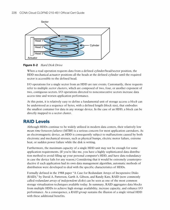
ptg17120290
226 CCNA Cloud CLDFND 210-451 Official Cert Guide
Actuator
Head 3
Head 2
Head 1
Sector
Cylinder
Figure 8-2 Hard Disk Drive
When a read operation requests data from a defined cylinder/head/sector position, the HDD mechanical actuator positions all the heads at the defined cylinder until the required sector is accessible to the defined head.
I/O operations for a single sector from an HDD are rare events. Customarily, these requests refer to multiple sector clusters , which are composed of two, four, or another exponent of two, contiguous sectors. I/O operations directed to nonconsecutive sectors increase data access time and worsen application performance.
At this point, it is relatively easy to define a fundamental unit of storage access: a block can be understood as a sequence of bytes, with a defined length (block size), that embodies the smallest container for data in any storage device. In the case of an HDD, a block can be directly mapped to a sector cluster.
RAID LevelsAlthough HDDs continue to be widely utilized in modern data centers, their relatively low mean time between failures (MTBF) is a serious concern for most application caretakers. As an electromagnetic device, an HDD is consequently subject to malfunctions caused by both electronic and mechanical stresses, such as physical bumps, electric motor failure, extreme heat, or sudden power failure while the disk is writing.
Furthermore, the maximum capacity of a single HDD unit may not be enough for some application requirements. (If you’re like me, you have a highly sophisticated data distribu-tion method to avoid filling up your personal computer’s HDD, and have data redundancy in case the device fails for any reason.) Considering that it would be extremely counterpro-ductive if each application had its own data management algorithm, automatic methods of distribution were developed to deal with the specific characteristics of HDDs.
Formally defined in the 1988 paper “A Case for Redundant Arrays of Inexpensive Disks (RAID),” by David A. Patterson, Garth A. Gibson, and Randy Katz, RAID (now commonly called redundant array of independent disks) can be seen as one of the most common storage virtualization techniques available today. In summary, RAID aggregates data blocks from multiple HDDs to achieve high storage availability, increase capacity, and enhance I/O performance. As a consequence, a RAID group sustains the illusion of a single virtual HDD with these additional benefits.

ptg17120290
8
Chapter 8: Block Storage Technologies 227
Figure 8-3 portrays some of the most popular RAID levels, where each one employs a dif-ferent block distribution scheme for the involved HDDs. Table 8-2 describes each one of these levels.
02468
13579
15
9
01234
Parity 6-8
Parity 3-5Parity 9-11
048
2
610
Parity 0-2
73
11
RAID 5
RAID 0 RAID 1
RAID 6
Parity 9-11
Parity 6-8
Parity 3-5
Parity 0-2
4
1085
116
2
9
130
7
01234
Figure 8-3 Select RAID Levels
Table 8-2 Select RAID Levels
Level Description
RAID 0 In this level, sequential blocks of data are written across multiple drives (called striping ). Figure 8-3 depicts a sequence of ten blocks (0 to 9) being striped between two HDDs, which is the minimum quantity of devices for RAID 0. The method does not provide any data redundancy, because a disk failure results in total data loss. However, when compared to a lonely disk drive with similar capac-ity, this RAID level improves I/O performance for one reason: it supports simulta-neous reads or writes on all drives.
RAID 1 Also known as mirroring , RAID 1 makes sure that every write operation at one device is duplicated to another device. If one of the disks fails, data can be com-pletely recovered from its mirrored pair. This level adds latency for write opera-tions, because they must occur twice. RAID 1 can use only half of the overall capacity of the RAID group.
RAID 5 A popular method, RAID 5 has better balance between capacity and I/O perfor-mance when compared with other RAID levels. In a nutshell, RAID 5 deploys data block striping over a group of HDDs (minimum of three) and builds additional parity blocks that can be used to recover an entire sequence of blocks in the absence of an entire drive. Unlike the other parity-based methods (such as RAID 3 and 4), RAID 5 evenly distributes the parity blocks among the HDDs, which enhances I/O performance because a block change only generates an additional operation in another disk (the one that contains the parity block).
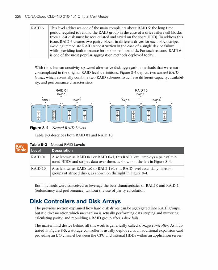
ptg17120290
228 CCNA Cloud CLDFND 210-451 Official Cert Guide
RAID 6 This level addresses one of the main complaints about RAID 5: the long time period required to rebuild the RAID group in the case of a drive failure (all blocks from a lost disk must be recalculated and saved on the spare HDD). To address this issue, RAID 6 creates two parity blocks in different drives for each block stripe, avoiding immediate RAID reconstruction in the case of a single device failure, while providing fault tolerance for one more failed disk. For such reasons, RAID 6 is one of the most popular aggregation methods deployed today.
With time, human creativity spawned alternative disk aggregation methods that were not contemplated in the original RAID level definitions. Figure 8-4 depicts two nested RAID
levels , which essentially combine two RAID schemes to achieve different capacity, availabil-ity, and performance characteristics.
0246
0246
0246
0246
1357
1357
1357
1357
RAID 10RAID 01
RAID 0
RAID 0
RAID 0
RAID 1
RAID 1 RAID 1
Figure 8-4 Nested RAID Levels
Table 8-3 describes both RAID 01 and RAID 10.
Table 8-3 Nested RAID Levels
Level Description
RAID 01 Also known as RAID 0/1 or RAID 0+1, this RAID level employs a pair of mir-rored HDDs and stripes data over them, as shown on the left in Figure 8-4.
RAID 10 Also known as RAID 1/0 or RAID 1+0, this RAID level essentially mirrors groups of striped disks, as shown on the right in Figure 8-4.
Both methods were conceived to leverage the best characteristics of RAID 0 and RAID 1 (redundancy and performance) without the use of parity calculation.
Disk Controllers and Disk ArraysThe previous section explained how hard disk drives can be aggregated into RAID groups, but it didn’t mention which mechanism is actually performing data striping and mirroring, calculating parity, and rebuilding a RAID group after a disk fails.
The mastermind device behind all this work is generically called storage controller. As illus-trated in Figure 8-5, a storage controller is usually deployed as an additional expansion card providing an I/O channel between the CPU and internal HDDs within an application server.
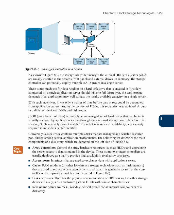
ptg17120290
8
Chapter 8: Block Storage Technologies 229
Server
InternalHDD
InternalHDD
InternalHDD
ExternalHDD
ExternalHDD
ExternalHDD
StorageController
CPU
Figure 8-5 Storage Controller in a Server
As shown in Figure 8-5, the storage controller manages the internal HDDs of a server (which are usually inserted in the server’s front panel) and external drives. In summary, the storage controller can potentially deploy multiple RAID groups in a single server.
There is not much use for data residing on a hard disk drive that is encased in (or solely connected to) a single application server should this one fail. Moreover, the data storage demands of an application may well surpass the locally available capacity on a single server.
With such incentives, it was only a matter of time before data at rest could be decoupled from application servers. And in the context of HDDs, this separation was achieved through two different devices: JBODs and disk arrays.
JBOD (just a bunch of disks) is basically an unmanaged set of hard drives that can be indi-vidually accessed by application servers through their internal storage controllers. For this reason, JBODs generally cannot match the level of management, availability, and capacity required in most data center facilities.
Conversely, a disk array contains multiples disks that are managed as a scalable resource pool shared among several application environments. The following list describes the main components of a disk array, which are depicted on the left side of Figure 8-6:
■ Array controllers: Control the array hardware resources (such as HDDs) and coordinate the server access to data contained in the device. These complex storage controllers are usually deployed as a pair to provide high availability to all array processes.
■ Access ports: Interfaces that are used to exchange data with application servers.
■ Cache: RAM modules (or other low-latency storage technology such as flash memory) that are used to reduce access latency for stored data. It is generally located at the con-troller or on expansion modules (not depicted in Figure 8-6).
■ Disk enclosures: Used for the physical accommodation of HDDs as well as other storage devices. Usually, a disk enclosure gathers HDDs with similar characteristics.
■ Redundant power sources: Provide electrical power for all internal components of a disk array.

ptg17120290
230 CCNA Cloud CLDFND 210-451 Official Cert Guide
ArrayControllers
Disk Array AccessPorts
Disk Array
Physical View Connectivity View
Redundant PowerSources
DiskEnclosure
HDD
Back-EndFront-End
HDDs
Controller
Controller
•••
Slo
t
Figure 8-6 Disk Array Components
The right side of Figure 8-6 visualizes the two types of disk array interconnections: front-
end (used for server access) and back-end (used for the internal disk connection to the array controller). Both types of connections support a great variety of communication protocols and physical media, as you will learn in future sections.
With their highly redundant architecture and management features, disk arrays have become the most familiar example of permanent storage in current data centers. At the time of this writing, the main disk array vendors are EMC Corporation, Hitachi Data Systems (HDS), IBM, and NetApp Inc.
Besides providing sheer storage capacity, disk arrays also offer advanced capabilities. One of them is called dynamic disk pool, which can overcome the following challenges of RAID technologies within disk arrays:
■ Same drive size: Regardless of chosen RAID level, the striping, mirroring, and parity cal-culation procedures require that all HDDs inside a RAID group share the same size. This characteristic can become operationally challenging as HDDs continue to evolve their internal storage capacity.
■ High rebuild time: Even with RAID 6, when a drive fails, the array controller must read every single block of the remaining drives before reconstructing the failed RAID group. This routine operation can consume a considerable chunk of time, depending on the number of RAID group members.
■ Low number of disks: Because of the previously described rebuild process, disk array vendors usually do not recommend that the number of RAID group members surpasses 15 to 20 disks (even though disk arrays may enclose hundreds of HDDs).
■ Need of hot spare units: It is a usual procedure to leave unused the HDDs that are ready to replace failed members of a RAID group. Because these hot spare drives are effectively used after a rebuilding process, they further reduce the disk array overall storage capacity.
The secret behind dynamic disk pools is pretty simple, as with most smartly conceived technologies: they still implement principles underlying RAID but in a much more granular
way. Within a pool, each drive is broken into smaller pieces deploying RAID levels, rather than using the whole HDD for that intent.
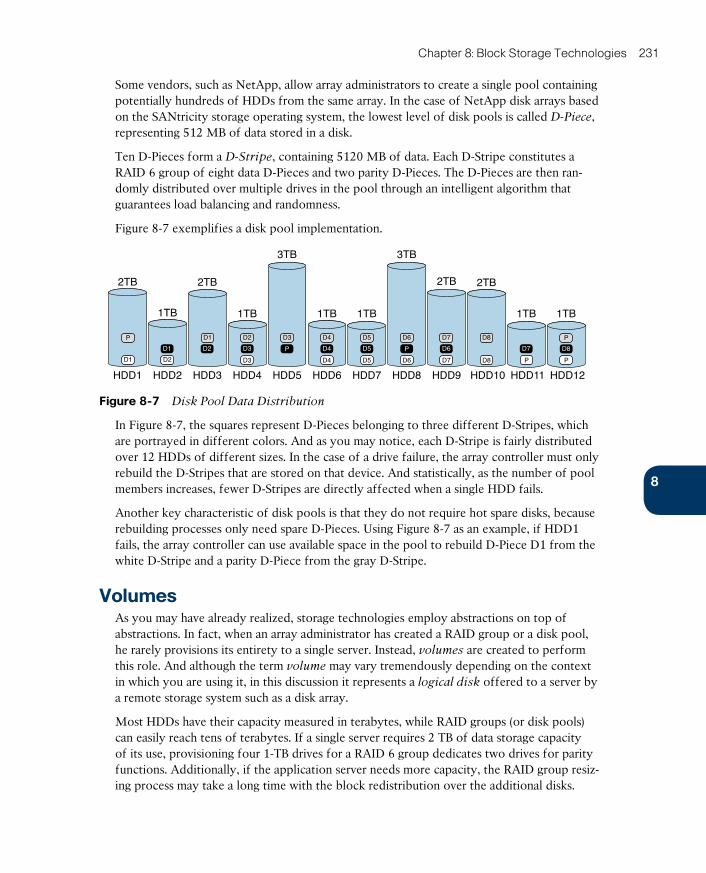
ptg17120290
8
Chapter 8: Block Storage Technologies 231
Some vendors, such as NetApp, allow array administrators to create a single pool containing potentially hundreds of HDDs from the same array. In the case of NetApp disk arrays based on the SANtricity storage operating system, the lowest level of disk pools is called D-Piece , representing 512 MB of data stored in a disk.
Ten D-Pieces form a D-Stripe , containing 5120 MB of data. Each D-Stripe constitutes a RAID 6 group of eight data D-Pieces and two parity D-Pieces. The D-Pieces are then ran-domly distributed over multiple drives in the pool through an intelligent algorithm that guarantees load balancing and randomness.
Figure 8-7 exemplifies a disk pool implementation.
P
D1
2TB
HDD1
D1
D2
2TB
HDD3
D8
D8
2TB
HDD10HDD2
1TB
D2
D1
HDD4
1TB
D2
D3
D3
HDD6
1TB
D4
D4
D4
HDD7
1TB
D5
D5
D5
HDD12
1TB
P
D8
P
HDD8
3TB
D6
D6
P
HDD5
3TB
D3
P
HDD9
2TB
D7
D6
D7
HDD11
1TB
P
D7
Figure 8-7 Disk Pool Data Distribution
In Figure 8-7, the squares represent D-Pieces belonging to three different D-Stripes, which are portrayed in different colors. And as you may notice, each D-Stripe is fairly distributed over 12 HDDs of different sizes. In the case of a drive failure, the array controller must only rebuild the D-Stripes that are stored on that device. And statistically, as the number of pool members increases, fewer D-Stripes are directly affected when a single HDD fails.
Another key characteristic of disk pools is that they do not require hot spare disks, because rebuilding processes only need spare D-Pieces. Using Figure 8-7 as an example, if HDD1 fails, the array controller can use available space in the pool to rebuild D-Piece D1 from the white D-Stripe and a parity D-Piece from the gray D-Stripe.
VolumesAs you may have already realized, storage technologies employ abstractions on top of abstractions. In fact, when an array administrator has created a RAID group or a disk pool, he rarely provisions its entirety to a single server. Instead, volumes are created to perform this role. And although the term volume may vary tremendously depending on the context in which you are using it, in this discussion it represents a logical disk offered to a server by a remote storage system such as a disk array.
Most HDDs have their capacity measured in terabytes, while RAID groups (or disk pools) can easily reach tens of terabytes. If a single server requires 2 TB of data storage capacity of its use, provisioning four 1-TB drives for a RAID 6 group dedicates two drives for parity functions. Additionally, if the application server needs more capacity, the RAID group resiz-ing process may take a long time with the block redistribution over the additional disks.
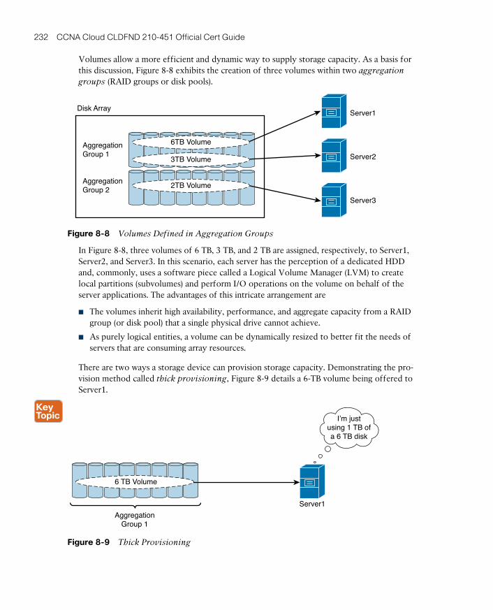
ptg17120290
232 CCNA Cloud CLDFND 210-451 Official Cert Guide
Volumes allow a more efficient and dynamic way to supply storage capacity. As a basis for this discussion, Figure 8-8 exhibits the creation of three volumes within two aggregation
groups (RAID groups or disk pools).
Server1
Server2
Server3
Disk Array
AggregationGroup 1
AggregationGroup 2
6TB Volume
3TB Volume
2TB Volume
Figure 8-8 Volumes Defined in Aggregation Groups
In Figure 8-8, three volumes of 6 TB, 3 TB, and 2 TB are assigned, respectively, to Server1, Server2, and Server3. In this scenario, each server has the perception of a dedicated HDD and, commonly, uses a software piece called a Logical Volume Manager (LVM) to create local partitions (subvolumes) and perform I/O operations on the volume on behalf of the server applications. The advantages of this intricate arrangement are
■ The volumes inherit high availability, performance, and aggregate capacity from a RAID group (or disk pool) that a single physical drive cannot achieve.
■ As purely logical entities, a volume can be dynamically resized to better fit the needs of servers that are consuming array resources.
There are two ways a storage device can provision storage capacity. Demonstrating the pro-vision method called thick provisioning , Figure 8-9 details a 6-TB volume being offered to Server1.
Figure 8-9 Thick Provisioning
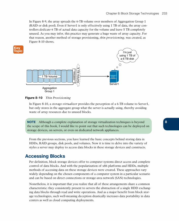
ptg17120290
8
Chapter 8: Block Storage Technologies 233
In Figure 8-9, the array spreads the 6-TB volume over members of Aggregation Group 1 (RAID or disk pool). Even if Server1 is only effectively using 1 TB of data, the array con-trollers dedicate 6 TB of actual data capacity for the volume and leave 5 TB completely unused. As you may infer, this practice may generate a huge waste of array capacity. For that reason, another method of storage provisioning, thin provisioning , was created, as Figure 8-10 shows.
Figure 8-10 Thin Provisioning
In Figure 8-10, a storage virtualizer provides the perception of a 6-TB volume to Server1, but only stores in the aggregate group what the server is actually using, thereby avoiding waste of array resources due to unused blocks.
NOTE Although a complete explanation of storage virtualization techniques is beyond the scope of this book, I would like to point out that such technologies can be deployed on storage devices, on servers, or even on dedicated network appliances.
From the previous sections, you have learned the basic concepts behind storing data in HDDs, RAID groups, disk pools, and volumes. Now it is time to delve into the variety of styles a server may deploy to access data blocks in these storage devices and constructs.
Accessing BlocksPer definition, block storage devices offer to computer systems direct access and complete control of data blocks. And with the popularization of x86 platforms and HDDs, multiple methods of accessing data on these storage devices were created. These approaches vary widely depending on the chosen components of a computer system in a particular scenario and can be based on direct connections or storage-area network (SAN) technologies.
Nonetheless, it is important that you realize that all of these arrangements share a common characteristic: they consistently present to servers the abstraction of a single HDD exchang-ing data blocks through read and write operations. And as a major benefit from block stor-age technologies, such well-meaning deception drastically increases data portability in data centers as well as cloud computing deployments.
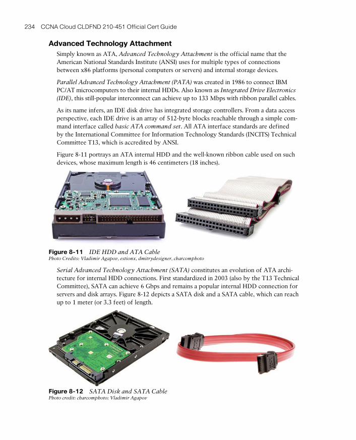
ptg17120290
234 CCNA Cloud CLDFND 210-451 Official Cert Guide
Advanced Technology AttachmentSimply known as ATA, Advanced Technology Attachment is the official name that the American National Standards Institute (ANSI) uses for multiple types of connections between x86 platforms (personal computers or servers) and internal storage devices.
Parallel Advanced Technology Attachment (PATA) was created in 1986 to connect IBM PC/AT microcomputers to their internal HDDs. Also known as Integrated Drive Electronics
(IDE) , this still-popular interconnect can achieve up to 133 Mbps with ribbon parallel cables.
As its name infers, an IDE disk drive has integrated storage controllers. From a data access perspective, each IDE drive is an array of 512-byte blocks reachable through a simple com-mand interface called basic ATA command set . All ATA interface standards are defined by the International Committee for Information Technology Standards (INCITS) Technical Committee T13, which is accredited by ANSI.
Figure 8-11 portrays an ATA internal HDD and the well-known ribbon cable used on such devices, whose maximum length is 46 centimeters (18 inches).
Figure 8-11 IDE HDD and ATA CablePhoto Credits: Vladimir Agapov, estionx, dmitrydesigner, charcomphoto
Serial Advanced Technology Attachment (SATA) constitutes an evolution of ATA archi-tecture for internal HDD connections. First standardized in 2003 (also by the T13 Technical Committee), SATA can achieve 6 Gbps and remains a popular internal HDD connection for servers and disk arrays. Figure 8-12 depicts a SATA disk and a SATA cable, which can reach up to 1 meter (or 3.3 feet) of length.
Figure 8-12 SATA Disk and SATA Cable Photo credit: charcomphoto; Vladimir Agapov
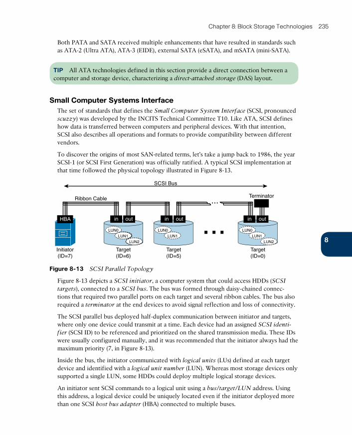
ptg17120290
8
Chapter 8: Block Storage Technologies 235
Both PATA and SATA received multiple enhancements that have resulted in standards such as ATA-2 (Ultra ATA), ATA-3 (EIDE), external SATA (eSATA), and mSATA (mini-SATA).
TIP All ATA technologies defined in this section provide a direct connection between a computer and storage device, characterizing a direct-attached storage (DAS) layout.
Small Computer Systems InterfaceThe set of standards that defines the Small Computer System Interface (SCSI, pronounced scuzzy) was developed by the INCITS Technical Committee T10. Like ATA, SCSI defines how data is transferred between computers and peripheral devices. With that intention, SCSI also describes all operations and formats to provide compatibility between different vendors.
To discover the origins of most SAN-related terms, let’s take a jump back to 1986, the year SCSI-1 (or SCSI First Generation) was officially ratified. A typical SCSI implementation at that time followed the physical topology illustrated in Figure 8-13.
SCSI Bus
Ribbon Cable
Initiator(ID=7)
Target(ID=6)
Target(ID=5)
Terminator...
HBA
LUN0
LUN1
LUN0
LUN1LUN2
Target(ID=0)
LUN0
LUN1LUN2
... outoutin outin in
Figure 8-13 SCSI Parallel Topology
Figure 8-13 depicts a SCSI initiator , a computer system that could access HDDs (SCSI
targets ), connected to a SCSI bus . The bus was formed through daisy-chained connec-tions that required two parallel ports on each target and several ribbon cables. The bus also required a terminator at the end devices to avoid signal reflection and loss of connectivity.
The SCSI parallel bus deployed half-duplex communication between initiator and targets, where only one device could transmit at a time. Each device had an assigned SCSI identi-
fier (SCSI ID) to be referenced and prioritized on the shared transmission media. These IDs were usually configured manually, and it was recommended that the initiator always had the maximum priority (7, in Figure 8-13).
Inside the bus, the initiator communicated with logical units (LUs) defined at each target device and identified with a logical unit number (LUN) . Whereas most storage devices only supported a single LUN, some HDDs could deploy multiple logical storage devices.
An initiator sent SCSI commands to a logical unit using a bus/target/LUN address. Using this address, a logical device could be uniquely located even if the initiator deployed more than one SCSI host bus adapter (HBA) connected to multiple buses.
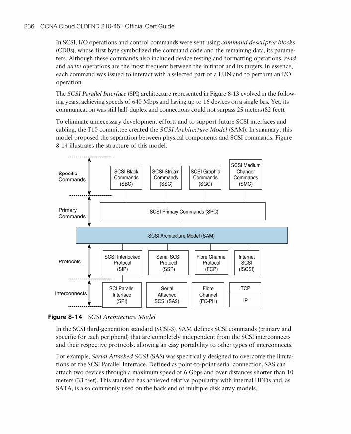
ptg17120290
236 CCNA Cloud CLDFND 210-451 Official Cert Guide
In SCSI, I/O operations and control commands were sent using command descriptor blocks (CDBs) , whose first byte symbolized the command code and the remaining data, its parame-ters. Although these commands also included device testing and formatting operations, read
and write operations are the most frequent between the initiator and its targets. In essence, each command was issued to interact with a selected part of a LUN and to perform an I/O operation.
The SCSI Parallel Interface (SPI) architecture represented in Figure 8-13 evolved in the follow-ing years, achieving speeds of 640 Mbps and having up to 16 devices on a single bus. Yet, its communication was still half-duplex and connections could not surpass 25 meters (82 feet).
To eliminate unnecessary development efforts and to support future SCSI interfaces and cabling, the T10 committee created the SCSI Architecture Model (SAM) . In summary, this model proposed the separation between physical components and SCSI commands. Figure 8-14 illustrates the structure of this model.
SpecificCommands
PrimaryCommands
Protocols
InterconnectsSCI Parallel
Interface(SPI)
FibreChannel(FC-PH)
TCP
IP
SCSI InterlockedProtocol
(SIP)
Serial SCSIProtocol(SSP)
Fibre ChannelProtocol(FCP)
SerialAttached
SCSI (SAS)
InternetSCSI
(ISCSI)
SCSI Primary Commands (SPC)
SCSI Architecture Model (SAM)
SCSI BlackCommands
(SBC)
SCSI StreamCommands
(SSC)
SCSI GraphicCommands
(SGC)
SCSI MediumChanger
Commands(SMC)
Figure 8-14 SCSI Architecture Model
In the SCSI third-generation standard (SCSI-3), SAM defines SCSI commands (primary and spe cific for each peripheral) that are completely independent from the SCSI interconnects and their respective protocols, allowing an easy portability to other types of interconnects.
For example, Serial Attached SCSI (SAS) was specifically designed to overcome the limita-tions of the SCSI Parallel Interface. Defined as point-to-point serial connection, SAS can attach two devices through a maximum speed of 6 Gbps and over distances shorter than 10 meters (33 feet). This standard has achieved relative popularity with internal HDDs and, as SATA, is also commonly used on the back end of multiple disk array models.
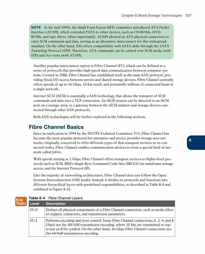
ptg17120290
8
Chapter 8: Block Storage Technologies 237
NOTE In the mid-1990s, the Small Form Factor (SFF) committee introduced ATA Packet
Interface (ATAPI) , which extended PATA to other devices, such as CD-ROMs, DVD-ROMs, and tape drives. More importantly, ATAPI allowed an ATA physical connection to carry SCSI commands and data, serving as an alternative interconnect for this widespread standard. On the other hand, SAS offers compatibility with SATA disks through the SATA
Tunneling Protocol (STP) . Therefore, ATA commands can be carried over SCSI media (with STP) and vice versa (with ATAPI).
Another popular interconnect option is Fibre Channel (FC) , which can be defined as a series of protocols that provides high-speed data communication between computer sys-tems. Created in 1988, Fibre Channel has established itself as the main SAN protocol, pro-viding block I/O access between servers and shared storage devices. Fibre Channel currently offers speeds of up to 16 Gbps, 10-km reach, and potentially millions of connected hosts in a single network.
Internet SCSI (iSCSI) is essentially a SAN technology that allows the transport of SCSI commands and data over a TCP connection. An iSCSI session can be directed to an iSCSI port on a storage array or a gateway between the iSCSI initiator and storage devices con-nected through other SAN protocols.
Both SAN technologies will be further explored in the following sections.
Fibre Channel BasicsSince its ratification in 1994 by the INCITS Technical Committee T11, Fibre Channel has become the most popular protocol for enterprise and service provider storage-area net-works. Originally conceived to offer different types of data transport services to its con-nected nodes, Fibre Channel enables communication devices to form a special kind of net-work called fabric .
With speeds starting at 1 Gbps, Fibre Channel offers transport services to higher-level pro-tocols such as SCSI, IBM’s Single-Byte Command Code Sets (SBCCS) for mainframe storage access, and the Internet Protocol (IP).
Like the majority of networking architectures, Fibre Channel does not follow the Open Systems Interconnection (OSI) model. Instead, it divides its protocols and functions into different hierarchical layers with predefined responsibilities, as described in Table 8-4 and exhibited in Figure 8-15.
Table 8-4 Fibre Channel Layers
Level Description
FC-0 Defines all physical components of a Fibre Channel connection, such as media (fiber or copper), connectors, and transmission parameters.
FC-1 Performs encoding and error control. Some Fibre Channel connections (1, 2, 4, and 8 Gbps) use the 8B/10B transmission encoding, where 10 bits are transmitted to rep-resent an 8-bit symbol. On the other hand, 16-Gbps Fibre Channel connections use the 64/66B transmission encoding.
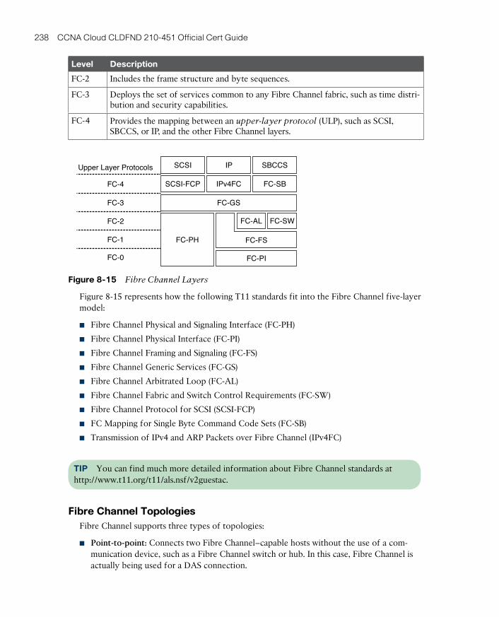
ptg17120290
238 CCNA Cloud CLDFND 210-451 Official Cert Guide
Level Description
FC-2 Includes the frame structure and byte sequences.
FC-3 Deploys the set of services common to any Fibre Channel fabric, such as time distri-bution and security capabilities.
FC-4 Provides the mapping between an upper-layer protocol (ULP), such as SCSI, SBCCS, or IP, and the other Fibre Channel layers.
Upper Layer Protocols
FC-4
FC-3
FC-2
FC-1
FC-0
SCSI
FC-PI
FC-SW
IP SBCCS
SCSI-FCP
FC-GS
FC-SB
FC-PH FC-FS
IPv4FC
FC-AL
Figure 8-15 Fibre Channel Layers
Figure 8-15 represents how the following T11 standards fit into the Fibre Channel five-layer model:
■ Fibre Channel Physical and Signaling Interface (FC-PH)
■ Fibre Channel Physical Interface (FC-PI)
■ Fibre Channel Framing and Signaling (FC-FS)
■ Fibre Channel Generic Services (FC-GS)
■ Fibre Channel Arbitrated Loop (FC-AL)
■ Fibre Channel Fabric and Switch Control Requirements (FC-SW)
■ Fibre Channel Protocol for SCSI (SCSI-FCP)
■ FC Mapping for Single Byte Command Code Sets (FC-SB)
■ Transmission of IPv4 and ARP Packets over Fibre Channel (IPv4FC)
TIP You can find much more detailed information about Fibre Channel standards at http://www.t11.org/t11/als.nsf/v2guestac.
Fibre Channel TopologiesFibre Channel supports three types of topologies:
■ Point-to-point: Connects two Fibre Channel–capable hosts without the use of a com-munication device, such as a Fibre Channel switch or hub. In this case, Fibre Channel is actually being used for a DAS connection.
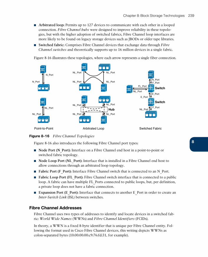
ptg17120290
8
Chapter 8: Block Storage Technologies 239
■ Arbitrated loop: Permits up to 127 devices to communicate with each other in a looped connection. Fibre Channel hubs were designed to improve reliability in these topolo-gies, but with the higher adoption of switched fabrics, Fibre Channel loop interfaces are more likely to be found on legacy storage devices such as JBODs or older tape libraries.
■ Switched fabric: Comprises Fibre Channel devices that exchange data through Fibre
Channel switches and theoretically supports up to 16 million devices in a single fabric.
Figure 8-16 illustrates these topologies, where each arrow represents a single fiber connection.
Arbitrated LoopPoint-to-Point Switched Fabric
Hub
NL_Port
NL_Port
NL_PortNL_Port
NL_Port
N_Port
N_Port
NL_Port NL_Port
E_PortE_Port
F_Port
FL_Port
NL_Port
N_Port
NL_Port
NL_Port
NL_Port
NL_Port
Switch
Switch
F_Port
Figure 8-16 Fibre Channel Topologies
Figure 8-16 also introduces the following Fibre Channel port types:
■ Node Port (N_Port): Interface on a Fibre Channel end host in a point-to-point or switched fabric topology.
■ Node Loop Port (NL_Port): Interface that is installed in a Fibre Channel end host to allow connections through an arbitrated loop topology.
■ Fabric Port (F_Port): Interface Fibre Channel switch that is connected to an N_Port.
■ Fabric Loop Port (FL_Port): Fibre Channel switch interface that is connected to a public loop. A fabric can have multiple FL_Ports connected to public loops, but, per definition, a private loop does not have a fabric connection.
■ Expansion Port (E_Port): Interface that connects to another E_Port in order to create an Inter-Switch Link (ISL) between switches.
Fibre Channel AddressesFibre Channel uses two types of addresses to identify and locate devices in a switched fab-ric: World Wide Names (WWNs) and Fibre Channel Identifiers (FCIDs).
In theory, a WWN is a fixed 8-byte identifier that is unique per Fibre Channel entity. Fol-lowing the format used in Cisco Fibre Channel devices, this writing depicts WWNs as colon-separated bytes (10:00:00:00:c9:76:fd:31, for example).
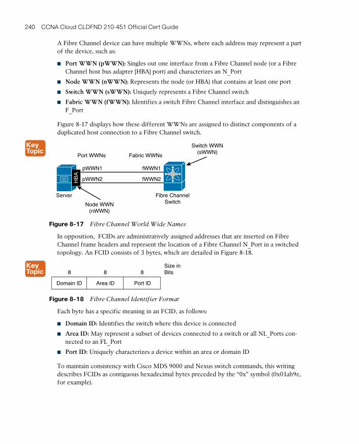
ptg17120290
240 CCNA Cloud CLDFND 210-451 Official Cert Guide
A Fibre Channel device can have multiple WWNs, where each address may represent a part of the device, such as:
■ Port WWN (pWWN): Singles out one interface from a Fibre Channel node (or a Fibre Channel host bus adapter [HBA] port) and characterizes an N_Port
■ Node WWN (nWWN): Represents the node (or HBA) that contains at least one port
■ Switch WWN (sWWN): Uniquely represents a Fibre Channel switch
■ Fabric WWN (fWWN): Identifies a switch Fibre Channel interface and distinguishes an F_Port
Figure 8-17 displays how these different WWNs are assigned to distinct components of a duplicated host connection to a Fibre Channel switch.
Server
pWWN1 fWWN1
fWWN2pWWN2
Node WWN(nWWN)
Switch WWN(sWWN)
Fibre ChannelSwitch
Port WWNs Fabric WWNs
HB
A
Figure 8-17 Fibre Channel World Wide Names
In opposition, FCIDs are administratively assigned addresses that are inserted on Fibre Channel frame headers and represent the location of a Fibre Channel N_Port in a switched topology. An FCID consists of 3 bytes, which are detailed in Figure 8-18.
Size inBits888
Domain ID Area ID Port ID
Figure 8-18 Fibre Channel Identifier Format
Each byte has a specific meaning in an FCID, as follows:
■ Domain ID: Identifies the switch where this device is connected
■ Area ID: May represent a subset of devices connected to a switch or all NL_Ports con-nected to an FL_Port
■ Port ID: Uniquely characterizes a device within an area or domain ID
To maintain consistency with Cisco MDS 9000 and Nexus switch commands, this writing describes FCIDs as contiguous hexadecimal bytes preceded by the “0x” symbol (0x01ab9e, for example).
ptg17120290
8
Chapter 8: Block Storage Technologies 241
TIP At this point, you may be tempted to make mental associations between WWNs, FCIDs, MAC addresses, and IP addresses. Although it is a strong temptation, I advise you avoid the urge for now. Fibre Channel is easier to learn when you clear your mind about other protocol stacks.
Fibre Channel Flow ControlAs part of a network architecture capable of providing lossless transport of data, a Fibre Channel device must determine whether there are enough resources to process a frame before receiving it. As a result, a flow control mechanism is needed to avoid frame discard-ing within a Fibre Channel fabric.
Fibre Channel deploys credit-based strategies to control data exchange between directly connected ports or between end nodes. In both scenarios, the receiving end is always in control, while the transmitter only sends a frame if it is sure that the receiver has available resources (buffers) to handle this frame.
Buffer-to-Buffer Credits (BB_Credits) are used to control frame transmission between directly connected ports (for example, N_Port to F_Port, N_Port to N_Port, or E_Port to E_Port). In essence, each port is aware of how many buffers are available to receive frames at the other end of the connection, only transmitting a frame if there is at least a single available buffer.
BB_Credit counters are usually configured with low two-digit values when both connected ports belong to the same data center. However, in data center interconnections over longer distances, a small number of BB_Credits may result in low performance. Such behavior can occur because the transmitting port sends as many frames as it can and then must wait for more BB_Credits from the receiving port to transmit again. The higher the latency on the interconnection, the longer the wait and the less traffic that traverses this link (regardless of its available bandwidth).
Distinctively, the End-to-End Credits (EE_Credits) flow control method regulates the trans-port of frames between source and destination N_Ports (such as an HBA and a disk array storage port). With a very similar mechanism to BB_Credits, this method allows a sender node to receive the delivery confirmation of frames from the receiver node.
Fibre Channel ProcessesThe Fibre Channel standards formally define a fabric as the “entity that interconnects vari-ous N_Ports attached to it and is capable of routing frames by using only the D_ID (destina-tion domain ID) informa tion in an FC-2 frame header.” The problem with this definition is that it does not really differentiate a fabric from a network.
However, as a recent trend, the networking industry has chosen the term fabric to represent a set of network devices that can somehow behave like one single device. And being the first architecture to use the term, Fibre Channel has influenced other networking technolo-gies (including Ethernet) to also use the term as they embody characteristics from Fibre Channel such as simplicity, reliability, flexibility, minimum operation overhead, and support of new applications without disruption.
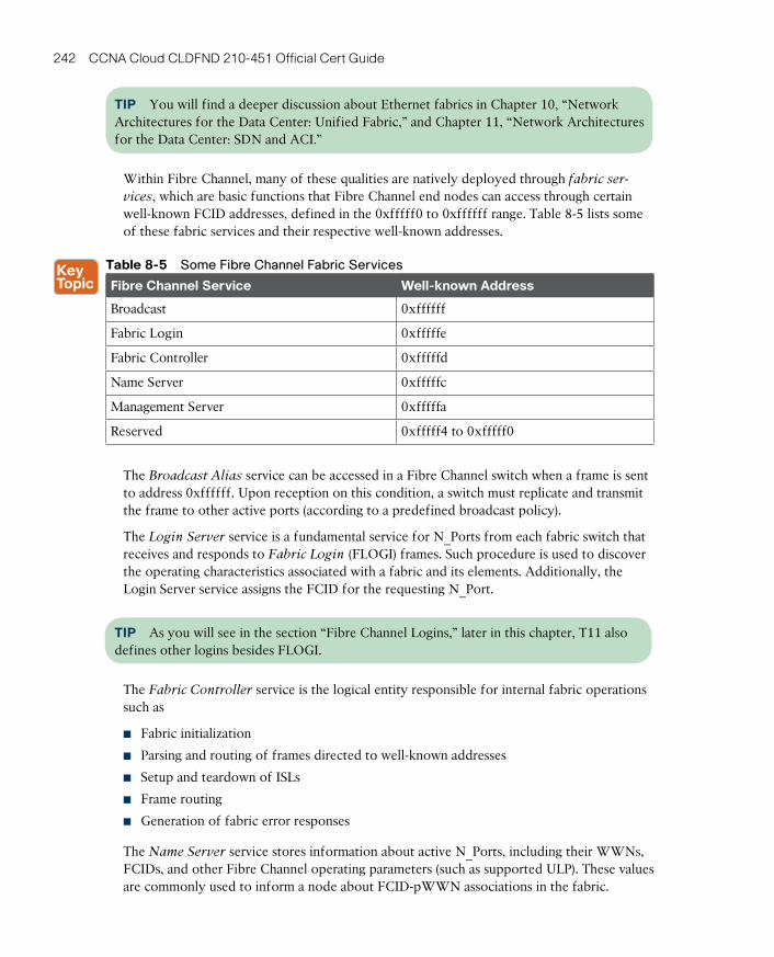
ptg17120290
242 CCNA Cloud CLDFND 210-451 Official Cert Guide
TIP You will find a deeper discussion about Ethernet fabrics in Chapter 10, “Network Architectures for the Data Center: Unified Fabric,” and Chapter 11, “Network Architectures for the Data Center: SDN and ACI.”
Within Fibre Channel, many of these qualities are natively deployed through fabric ser-
vices, which are basic functions that Fibre Channel end nodes can access through certain well-known FCID addresses, defined in the 0xfffff0 to 0xffffff range. Table 8-5 lists some of these fabric services and their respective well-known addresses.
Table 8-5 Some Fibre Channel Fabric Services
Fibre Channel Service Well-known Address
Broadcast 0xffffff
Fabric Login 0xfffffe
Fabric Controller 0xfffffd
Name Server 0xfffffc
Management Server 0xfffffa
Reserved 0xfffff4 to 0xfffff0
The Broadcast Alias service can be accessed in a Fibre Channel switch when a frame is sent to address 0xffffff. Upon reception on this condition, a switch must replicate and transmit the frame to other active ports (according to a predefined broadcast policy).
The Login Server service is a fundamental service for N_Ports from each fabric switch that receives and responds to Fabric Login (FLOGI) frames. Such procedure is used to discover the operating characteristics associated with a fabric and its elements. Additionally, the Login Server service assigns the FCID for the requesting N_Port.
TIP As you will see in the section “Fibre Channel Logins,” later in this chapter, T11 also defines other logins besides FLOGI.
The Fabric Controller service is the logical entity responsible for internal fabric operations such as
■ Fabric initialization
■ Parsing and routing of frames directed to well-known addresses
■ Setup and teardown of ISLs
■ Frame routing
■ Generation of fabric error responses
The Name Server service stores information about active N_Ports, including their WWNs, FCIDs, and other Fibre Channel operating parameters (such as supported ULP). These values are commonly used to inform a node about FCID-pWWN associations in the fabric.
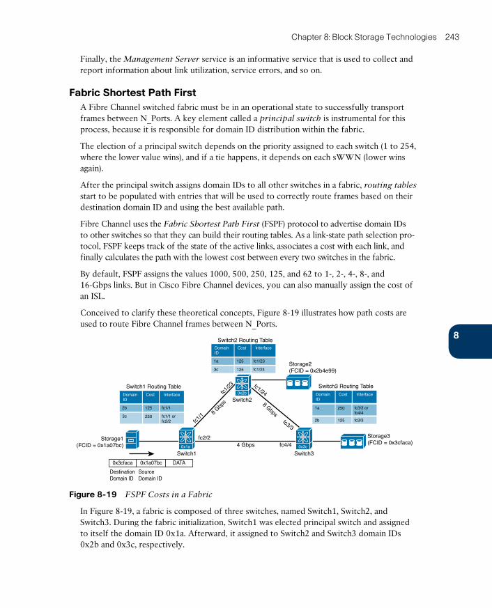
ptg17120290
8
Chapter 8: Block Storage Technologies 243
Finally, the Management Server service is an informative service that is used to collect and report information about link utilization, service errors, and so on.
Fabric Shortest Path FirstA Fibre Channel switched fabric must be in an operational state to successfully transport frames between N_Ports. A key element called a principal switch is instrumental for this process, because it is responsible for domain ID distribution within the fabric.
The election of a principal switch depends on the priority assigned to each switch (1 to 254, where the lower value wins), and if a tie happens, it depends on each sWWN (lower wins again).
After the principal switch assigns domain IDs to all other switches in a fabric, routing tables start to be populated with entries that will be used to correctly route frames based on their destination domain ID and using the best available path.
Fibre Channel uses the Fabric Shortest Path First (FSPF) protocol to advertise domain IDs to other switches so that they can build their routing tables. As a link-state path selection pro-tocol, FSPF keeps track of the state of the active links, associates a cost with each link, and finally calculates the path with the lowest cost between every two switches in the fabric.
By default, FSPF assigns the values 1000, 500, 250, 125, and 62 to 1-, 2-, 4-, 8-, and 16-Gbps links. But in Cisco Fibre Channel devices, you can also manually assign the cost of an ISL.
Conceived to clarify these theoretical concepts, Figure 8-19 illustrates how path costs are used to route Fibre Channel frames between N_Ports.
DATA0x3cfaca
DestinationDomain ID
0x1a07bc
SourceDomain ID
DomainID
InterfaceCost
1a 125
125
fc1/23
fc1/243c
Switch2 Routing Table
DomainID
InterfaceCost
2b 125
250
fc1/1
fc1/1 orfc2/2
3c
Switch1 Routing Table
Switch1
Switch2
Switch3
4 Gbps
8 Gbp
s 8 Gbpsfc3/3
fc1/24
fc1/1
fc1/2
3
fc4/4fc2/2
DomainID
InterfaceCost
2b 125 fc3/3
250 fc3/3 orfc4/4
1a
Switch3 Routing Table
Storage2(FCID = 0x2b4e99)
Storage3(FCID = 0x3cfaca)
Storage1(FCID = 0x1a07bc)
0x2b
0x1a 0x3c
Figure 8-19 FSPF Costs in a Fabric
In Figure 8-19, a fabric is composed of three switches, named Switch1, Switch2, and Switch3. During the fabric initialization, Switch1 was elected principal switch and assigned to itself the domain ID 0x1a. Afterward, it assigned to Switch2 and Switch3 domain IDs 0x2b and 0x3c, respectively.
ptg17120290
244 CCNA Cloud CLDFND 210-451 Official Cert Guide
Using FSPF, the switches exchange routes based on their own domain ID and build rout-
ing tables, shown in Figure 8-19. Also noticeable is the fact that the Fibre Channel initia-tor (Server1) and targets (Storage2 and Storage3) have already received FCIDs during their FLOGI process, and that the first byte on these addresses corresponds to the domain ID of their directly connected switch.
Therefore, to route frames between two Fibre Channel N_Ports, each switch observes the destination domain ID in each frame, performs a lookup in its routing table, and sends the frame to the outgoing interface pointed to in the route entry. This process is repeated until the frame reaches the switch that is directly connected to the destination N_Port.
TIP Figure 8-19 follows the interface naming process used in Cisco Fibre Channel switch-es, where the first number refers to the slot order and the second to the order of the inter-face in a module.
Notice in Figure 8-19 that there are two paths with an FSPF cost of 250 between Switch1 and Switch3. Thus, the frame sent from Server1 to Storage3 (represented in a very simplified format) may be forwarded to one of two interfaces on Switch1: fc1/1 or fc2/2.
According to the Fibre Channel standards, it is up to each manufacturer to decide how a switch forwards frames in the case of equal-cost paths. Cisco Fibre Channel switches can load-balance traffic on up to 16 equal-cost paths using one of the following behaviors:
■ Flow-based: Each pair of N_Ports only uses a single path (for example, traffic from Server1 to Storage3 will only use the path Switch1–Switch3). The path choice is based on a hash function over the source and destination FCIDs of each frame.
TIP A hash function is an operation that can map digital data of any size to digital data of fixed size. In the case of FSPF load-balancing, a hash function of the same arguments (des-tination and source FCIDs) will always result in the same path among all equal-cost shortest paths.
■ Exchange-based: Exchanges from each pair of N_Ports are load-balanced among all available paths. The path choice is based on a hash operation over the source and desti-nation FCIDs of each frame, plus a Fibre Channel header called Originator Exchange
Identifier (OX_ID) , which is unique for each SCSI I/O operation (read or write).
Because FSPF does not take into account the available bandwidth or utilization of the paths for route calculation, SAN administrators must carefully plan FSPF to consider failure sce-narios and to avoid traffic bottlenecks.
Unlike the topology shown in Figure 8-19, SAN administrators commonly deploy ISL redundancy between switches. However, these professionals still need to be aware that if an ISL changes its operational state, a general route recomputation can bring instability and traffic loss to a fabric.
To reduce these risks, using PortChannels is highly recommended because they can aggre-gate multiple ISLs into one logical connection (from the FSPF perspective).
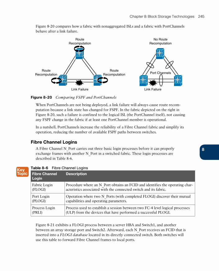
ptg17120290
8
Chapter 8: Block Storage Technologies 245
Figure 8-20 compares how a fabric with nonaggregated ISLs and a fabric with PortChannels behave after a link failure.
RouteRecomputation
Port Channels
No RouteRecomputation
RouteRecomputation
RouteRecomputation
Link Failure Link Failure
Figure 8-20 Comparing FSPF and PortChannels
When PortChannels are not being deployed, a link failure will always cause route recom-putation because a link state has changed for FSPF. In the fabric depicted on the right in Figure 8-20, such a failure is confined to the logical ISL (the PortChannel itself), not causing any FSPF change in the fabric if at least one PortChannel member is operational.
In a nutshell, PortChannels increase the reliability of a Fibre Channel fabric and simplify its operation, reducing the number of available FSPF paths between switches.
Fibre Channel LoginsA Fibre Channel N_Port carries out three basic login processes before it can properly exchange frames with another N_Port in a switched fabric. These login processes are described in Table 8-6.
Table 8-6 Fibre Channel Logins
Fibre Channel Login
Description
Fabric Login (FLOGI)
Procedure where an N_Port obtains an FCID and identifies the operating char-acteristics associated with the connected switch and its fabric.
Port Login (PLOGI)
Operation where two N_Ports (with completed FLOGI) discover their mutual capabilities and operating parameters.
Process Login (PRLI)
Process used to establish a session between two FC-4 level logical processes (ULP) from the devices that have performed a successful PLOGI.
Figure 8-21 exhibits a FLOGI process between a server HBA and Switch1, and another between an array storage port and Switch2. Afterward, each N_Port receives an FCID that is inserted into a FLOGI database located in its directly connected switch. Both switches will use this table to forward Fibre Channel frames to local ports.
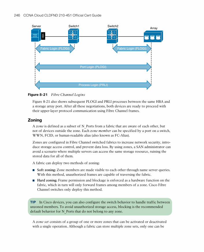
ptg17120290
246 CCNA Cloud CLDFND 210-451 Official Cert Guide
Port Login (PLOGI)
Fabric Login (FLOGI) Fabric Login (FLOGI)
Process Login (PRLI)
HB
A
Server Switch1 Switch2Array
Figure 8-21 Fibre Channel Logins
Figure 8-21 also shows subsequent PLOGI and PRLI processes between the same HBA and a storage array port. After all these negotiations, both devices are ready to proceed with their upper-layer protocol communication using Fibre Channel frames.
ZoningA zone is defined as a subset of N_Ports from a fabric that are aware of each other, but not of devices outside the zone. Each zone member can be specified by a port on a switch, WWN, FCID, or human-readable alias (also known as FC-Alias).
Zones are configured in Fibre Channel switched fabrics to increase network security, intro-duce storage access control, and prevent data loss. By using zones, a SAN administrator can avoid a scenario where multiple servers can access the same storage resource, ruining the stored data for all of them.
A fabric can deploy two methods of zoning:
■ Soft zoning: Zone members are made visible to each other through name server queries. With this method, unauthorized frames are capable of traversing the fabric.
■ Hard zoning: Frame permission and blockage is enforced as a hardware function on the fabric, which in turn will only forward frames among members of a zone. Cisco Fibre Channel switches only deploy this method.
TIP In Cisco devices, you can also configure the switch behavior to handle traffic between unzoned members. To avoid unauthorized storage access, blocking is the recommended default behavior for N_Ports that do not belong to any zone.
A zone set consists of a group of one or more zones that can be activated or deactivated with a single operation. Although a fabric can store multiple zone sets, only one can be
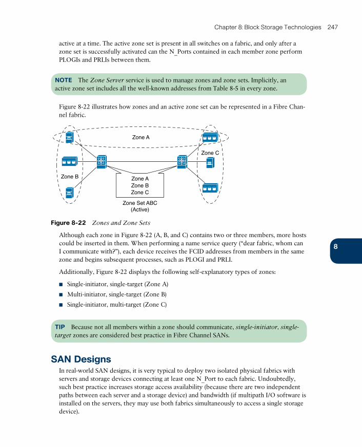
ptg17120290
8
Chapter 8: Block Storage Technologies 247
active at a time. The active zone set is present in all switches on a fabric, and only after a zone set is successfully activated can the N_Ports contained in each member zone perform PLOGIs and PRLIs between them.
NOTE The Zone Server service is used to manage zones and zone sets. Implicitly, an active zone set includes all the well-known addresses from Table 8-5 in every zone.
Figure 8-22 illustrates how zones and an active zone set can be represented in a Fibre Chan-nel fabric.
Zone Set ABC(Active)
Zone B
Zone A
Zone C
Zone AZone BZone C
Figure 8-22 Zones and Zone Sets
Although each zone in Figure 8-22 (A, B, and C) contains two or three members, more hosts could be inserted in them. When performing a name service query (“dear fabric, whom can I communicate with?”), each device receives the FCID addresses from members in the same zone and begins subsequent processes, such as PLOGI and PRLI.
Additionally, Figure 8-22 displays the following self-explanatory types of zones:
■ Single-initiator, single-target (Zone A)
■ Multi-initiator, single-target (Zone B)
■ Single-initiator, multi-target (Zone C)
TIP Because not all members within a zone should communicate, single-initiator, single-
target zones are considered best practice in Fibre Channel SANs.
SAN DesignsIn real-world SAN designs, it is very typical to deploy two isolated physical fabrics with servers and storage devices connecting at least one N_Port to each fabric. Undoubtedly, such best practice increases storage access availability (because there are two independent paths between each server and a storage device) and bandwidth (if multipath I/O software is installed on the servers, they may use both fabrics simultaneously to access a single storage device).
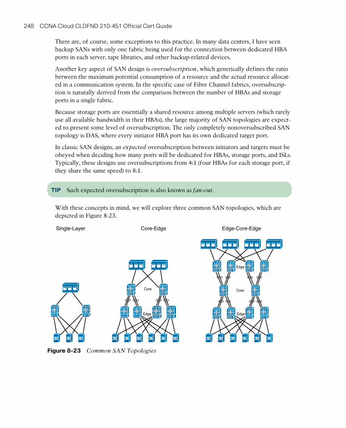
ptg17120290
248 CCNA Cloud CLDFND 210-451 Official Cert Guide
There are, of course, some exceptions to this practice. In many data centers, I have seen backup SANs with only one fabric being used for the connection between dedicated HBA ports in each server, tape libraries, and other backup-related devices.
Another key aspect of SAN design is oversubscription , which generically defines the ratio between the maximum potential consumption of a resource and the actual resource allocat-ed in a communication system. In the specific case of Fibre Channel fabrics, oversubscrip-tion is naturally derived from the comparison between the number of HBAs and storage ports in a single fabric.
Because storage ports are essentially a shared resource among multiple servers (which rarely use all available bandwidth in their HBAs), the large majority of SAN topologies are expect-ed to present some level of oversubscription. The only completely nonoversubscribed SAN topology is DAS, where every initiator HBA port has its own dedicated target port.
In classic SAN designs, an expected oversubscription between initiators and targets must be obeyed when deciding how many ports will be dedicated for HBAs, storage ports, and ISLs. Typically, these designs use oversubscriptions from 4:1 (four HBAs for each storage port, if they share the same speed) to 8:1.
TIP Such expected oversubscription is also known as fan-out .
With these concepts in mind, we will explore three common SAN topologies, which are depicted in Figure 8-23.
Single-Layer Core-Edge Edge-Core-Edge
Edge
Edge
CoreSAN A SAN B
SAN A SAN BSAN A SAN B
SAN A SAN A SAN B SAN BEdge
CoreSAN A SAN B
SAN A SAN B SAN A SAN BSAN ASAN A SAN B
Figure 8-23 Common SAN Topologies

ptg17120290
8
Chapter 8: Block Storage Technologies 249
The left side of Figure 8-23 represents the single-layer topology , where only one Fibre Channel switch is positioned between the server HBAs and the storage ports on disk arrays. The simplicity of this topology also limits its scalability to the maximum number of ports of a single Fibre Channel switch. For this reason, positioning Fibre Channel director-class
switches (or simply, directors) in this topology is usually better, because they can offer a larger number of ports when compared to fabric switches, as well as high availability on all of their internal components. This topology is also known as collapsed-core as a direct result of the highly popular process in the 2000s of consolidating multiple fabric switches into directors.
NOTE You will find more details about Cisco MDS 9000 fabric switches and directors in Chapter 13, “Cisco Cloud Infrastructure Portfolio.”
The center topology in Figure 8-23 depicts a very traditional topology called core-edge , where two layers of communication devices are positioned between initiators and targets. In this case, each layer is dedicated to the connection of a single type of device (servers on edge and storage devices on core). In core-edge topologies, the number of ISLs between both layers is defined according to the SAN expected oversubscription and available port speeds.
Also in core-edge designs, the number of ports on edge devices depends on the type of physical connection arrangement to the servers. In top-of-rack connections, where the serv-ers share the same rack with their access devices, fabric switches with less than 48 Fibre Channel ports are usually deployed. If end-of-row connections are used, directors are com-monly positioned to offer connection access to servers distributed across many racks.
Finally, the topology on the right in Figure 8-23 depicts the edge-core-edge topology , which is deployed in SANs that require thousands of ports in a single physical structure. In an edge-core-edge fabric, there are two kinds of edge switches: target edges and initiator edges. These switches are used, respectively, to connect to storage devices and to connect to servers. All traffic coalesces in the core switches, whose number of devices and deployed ISLs controls the SAN oversubscription.
As a way to transcend some scalability limits on Fibre Channel SANs, such as the number of domain IDs in a single fabric, it is possible to deploy a virtualization technique called N_Port Virtualization (NPV) . Running in NPV mode, a switch can emulate an N_Port con-nected to an upstream switch F_Port, which eliminates the need to deploy an ISL and the insertion of an additional domain ID in the fabric.
Figure 8-24 details the differences between a standard ISL and an NPV connection.
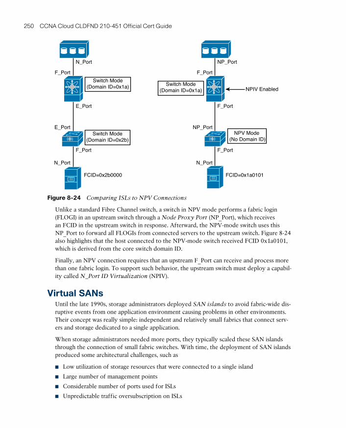
ptg17120290
250 CCNA Cloud CLDFND 210-451 Official Cert Guide
N_Port
N_Port
NP_Port
NP_Port
F_PortF_Port
E_Port
E_Port
N_Port
F_PortF_Port
F_Port
NPIV Enabled
FCID=0x1a0101FCID=0x2b0000
NPV Mode (No Domain ID)
Switch Mode(Domain ID=0x1a) Switch Mode
(Domain ID=0x1a)
Switch Mode(Domain ID=0x2b)
Figure 8-24 Comparing ISLs to NPV Connections
Unlike a standard Fibre Channel switch, a switch in NPV mode performs a fabric login (FLOGI) in an upstream switch through a Node Proxy Port (NP_Port) , which receives an FCID in the upstream switch in response. Afterward, the NPV-mode switch uses this NP_Port to forward all FLOGIs from connected servers to the upstream switch. Figure 8-24 also highlights that the host connected to the NPV-mode switch received FCID 0x1a0101, which is derived from the core switch domain ID.
Finally, an NPV connection requires that an upstream F_Port can receive and process more than one fabric login. To support such behavior, the upstream switch must deploy a capabil-ity called N_Port ID Virtualization (NPIV) .
Virtual SANsUntil the late 1990s, storage administrators deployed SAN islands to avoid fabric-wide dis-ruptive events from one application environment causing problems in other environments. Their concept was really simple: independent and relatively small fabrics that connect serv-ers and storage dedicated to a single application.
When storage administrators needed more ports, they typically scaled these SAN islands through the connection of small fabric switches. With time, the deployment of SAN islands produced some architectural challenges, such as
■ Low utilization of storage resources that were connected to a single island
■ Large number of management points
■ Considerable number of ports used for ISLs
■ Unpredictable traffic oversubscription on ISLs
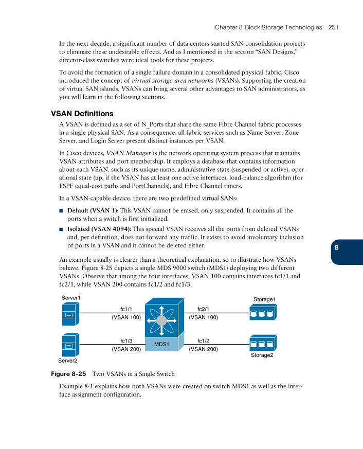
ptg17120290
8
Chapter 8: Block Storage Technologies 251
In the next decade, a significant number of data centers started SAN consolidation projects to eliminate these undesirable effects. And as I mentioned in the section “SAN Designs,” director-class switches were ideal tools for these projects.
To avoid the formation of a single failure domain in a consolidated physical fabric, Cisco introduced the concept of virtual storage-area networks (VSANs) . Supporting the creation of virtual SAN islands, VSANs can bring several other advantages to SAN administrators, as you will learn in the following sections.
VSAN DefinitionsA VSAN is defined as a set of N_Ports that share the same Fibre Channel fabric processes in a single physical SAN. As a consequence, all fabric services such as Name Server, Zone Server, and Login Server present distinct instances per VSAN.
In Cisco devices, VSAN Manager is the network operating system process that maintains VSAN attributes and port membership. It employs a database that contains information about each VSAN, such as its unique name, administrative state (suspended or active), oper-ational state (up, if the VSAN has at least one active interface), load-balance algorithm (for FSPF equal-cost paths and PortChannels), and Fibre Channel timers.
In a VSAN-capable device, there are two predefined virtual SANs:
■ Default (VSAN 1): This VSAN cannot be erased, only suspended. It contains all the ports when a switch is first initialized.
■ Isolated (VSAN 4094): This special VSAN receives all the ports from deleted VSANs and, per definition, does not forward any traffic. It exists to avoid involuntary inclusion of ports in a VSAN and it cannot be deleted either.
An example usually is clearer than a theoretical explanation, so to illustrate how VSANs behave, Figure 8-25 depicts a single MDS 9000 switch (MDS1) deploying two different VSANs. Observe that among the four interfaces, VSAN 100 contains interfaces fc1/1 and fc2/1, while VSAN 200 contains fc1/2 and fc1/3.
MDS1
Server1
fc1/1
(VSAN 100)
fc1/3
(VSAN 200)
fc2/1
(VSAN 100)
fc1/2
(VSAN 200)
Server2
Storage1
Storage2
Figure 8-25 Two VSANs in a Single Switch
Example 8-1 explains how both VSANs were created on switch MDS1 as well as the inter-face assignment configuration.
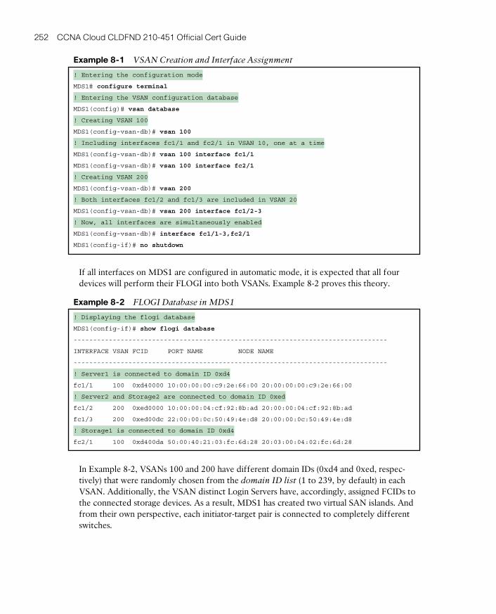
ptg17120290
252 CCNA Cloud CLDFND 210-451 Official Cert Guide
Example 8-1 VSAN Creation and Interface Assignment
! Entering the configuration mode
MDS1# configure terminal
! Entering the VSAN configuration database
MDS1(config)# vsan database
! Creating VSAN 100
MDS1(config-vsan-db)# vsan 100
! Including interfaces fc1/1 and fc2/1 in VSAN 10, one at a time
MDS1(config-vsan-db)# vsan 100 interface fc1/1
MDS1(config-vsan-db)# vsan 100 interface fc2/1
! Creating VSAN 200
MDS1(config-vsan-db)# vsan 200
! Both interfaces fc1/2 and fc1/3 are included in VSAN 20
MDS1(config-vsan-db)# vsan 200 interface fc1/2-3
! Now, all interfaces are simultaneously enabled
MDS1(config-vsan-db)# interface fc1/1-3,fc2/1
MDS1(config-if)# no shutdown
If all interfaces on MDS1 are configured in automatic mode, it is expected that all four devices will perform their FLOGI into both VSANs. Example 8-2 proves this theory.
Example 8-2 FLOGI Database in MDS1
! Displaying the flogi database
MDS1(config-if)# show flogi database
--------------------------------------------------------------------------------
INTERFACE VSAN FCID PORT NAME NODE NAME
--------------------------------------------------------------------------------
! Server1 is connected to domain ID 0xd4
fc1/1 100 0xd40000 10:00:00:00:c9:2e:66:00 20:00:00:00:c9:2e:66:00
! Server2 and Storage2 are connected to domain ID 0xed
fc1/2 200 0xed0000 10:00:00:04:cf:92:8b:ad 20:00:00:04:cf:92:8b:ad
fc1/3 200 0xed00dc 22:00:00:0c:50:49:4e:d8 20:00:00:0c:50:49:4e:d8
! Storage1 is connected to domain ID 0xd4
fc2/1 100 0xd400da 50:00:40:21:03:fc:6d:28 20:03:00:04:02:fc:6d:28
In Example 8-2, VSANs 100 and 200 have different domain IDs (0xd4 and 0xed, respec-tively) that were randomly chosen from the domain ID list (1 to 239, by default) in each VSAN. Additionally, the VSAN distinct Login Servers have, accordingly, assigned FCIDs to the connected storage devices. As a result, MDS1 has created two virtual SAN islands. And from their own perspective, each initiator-target pair is connected to completely different switches.
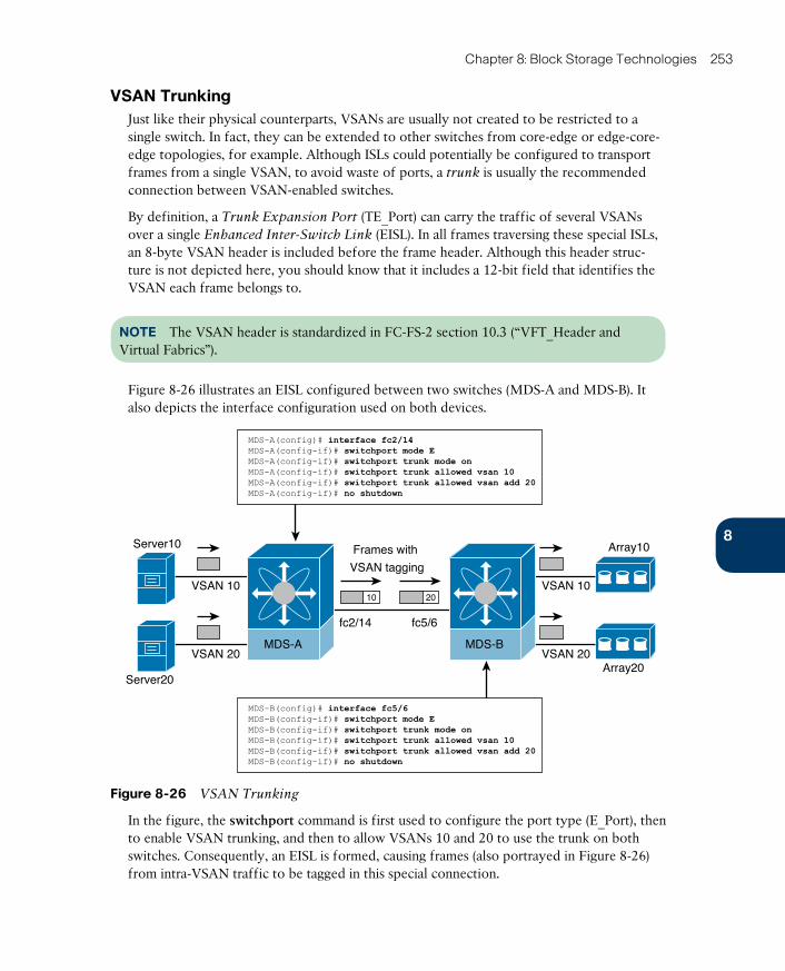
ptg17120290
8
Chapter 8: Block Storage Technologies 253
VSAN TrunkingJust like their physical counterparts, VSANs are usually not created to be restricted to a single switch. In fact, they can be extended to other switches from core-edge or edge-core-edge topologies, for example. Although ISLs could potentially be configured to transport frames from a single VSAN, to avoid waste of ports, a trunk is usually the recommended connection between VSAN-enabled switches.
By definition, a Trunk Expansion Port (TE_Port) can carry the traffic of several VSANs over a single Enhanced Inter-Switch Link (EISL) . In all frames traversing these special ISLs, an 8-byte VSAN header is included before the frame header. Although this header struc-ture is not depicted here, you should know that it includes a 12-bit field that identifies the VSAN each frame belongs to.
NOTE The VSAN header is standardized in FC-FS-2 section 10.3 (“VFT_Header and Virtual Fabrics”).
Figure 8-26 illustrates an EISL configured between two switches (MDS-A and MDS-B). It also depicts the interface configuration used on both devices.
Server10
VSAN 10
VSAN 20
VSAN 10
VSAN 20
fc2/14 fc5/6
Server20
Array10
Array20
MDS-BMDS-A
MDS-B(config)# interface fc5/6MDS-B(config-if)# switchport mode EMDS-B(config-if)# switchport trunk mode onMDS-B(config-if)# switchport trunk allowed vsan 10MDS-B(config-if)# switchport trunk allowed vsan add 20MDS-B(config-if)# no shutdown
MDS-A(config)# interface fc2/14MDS-A(config-if)# switchport mode EMDS-A(config-if)# switchport trunk mode onMDS-A(config-if)# switchport trunk allowed vsan 10MDS-A(config-if)# switchport trunk allowed vsan add 20MDS-A(config-if)# no shutdown
10 20
Frames with
VSAN tagging
Figure 8-26 VSAN Trunking
In the figure, the switchport command is first used to configure the port type (E_Port), then to enable VSAN trunking, and then to allow VSANs 10 and 20 to use the trunk on both switches. Consequently, an EISL is formed, causing frames (also portrayed in Figure 8-26) from intra-VSAN traffic to be tagged in this special connection.
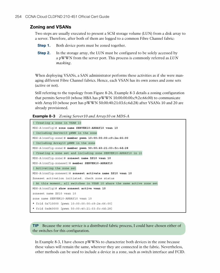
ptg17120290
254 CCNA Cloud CLDFND 210-451 Official Cert Guide
Zoning and VSANsTwo steps are usually executed to present a SCSI storage volume (LUN) from a disk array to a server. Therefore, after both of them are logged to a common Fibre Channel fabric:
Step 1. Both device ports must be zoned together.
Step 2. In the storage array, the LUN must be configured to be solely accessed by a pWWN from the server port. This process is commonly referred as LUN
masking .
When deploying VSANs, a SAN administrator performs these activities as if she were man-aging different Fibre Channel fabrics. Hence, each VSAN has its own zones and zone sets (active or not).
Still referring to the topology from Figure 8-26, Example 8-3 details a zoning configuration that permits Server10 (whose HBA has pWWN 10:00:00:00:c9:2e:66:00) to communicate with Array10 (whose port has pWWN 50:00:40:21:03:fc:6d:28) after VSANs 10 and 20 are already provisioned.
Example 8-3 Zoning Server10 and Array10 on MDS-A
! Creating a zone in VSAN 10
MDS-A(config)# zone name SERVER10-ARRAY10 vsan 10
! Including Server10 pWWN in the zone
MDS-A(config-zone)# member pwwn 10:00:00:00:c9:2e:66:00
! Including Array10 pWWN in the zone
MDS-A(config-zone)# member pwwn 50:00:40:21:03:fc:6d:28
! Creating a zone set and including zone SERVER10-ARRAY10 in it
MDS-A(config-zone)# zoneset name ZS10 vsan 10
MDS-A(config-zoneset)# member SERVER10-ARRAY10
! Activating the zone set
MDS-A(config-zoneset)# zoneset activate name ZS10 vsan 10
Zoneset activation initiated. check zone status
! At this moment, all switches in VSAN 10 share the same active zone set
MDS-A(config)# show zoneset active vsan 10
zoneset name ZS10 vsan 10
zone name SERVER10-ARRAY10 vsan 10
* fcid 0x710000 [pwwn 10:00:00:00:c9:2e:66:00]
* fcid 0xd40000 [pwwn 50:00:40:21:03:fc:6d:28]
TIP Because the zone service is a distributed fabric process, I could have chosen either of the switches for this configuration.
In Example 8-3, I have chosen pWWNs to characterize both devices in the zone because these values will remain the same, wherever they are connected in the fabric. Nevertheless, other methods can be used to include a device in a zone, such as switch interface and FCID.
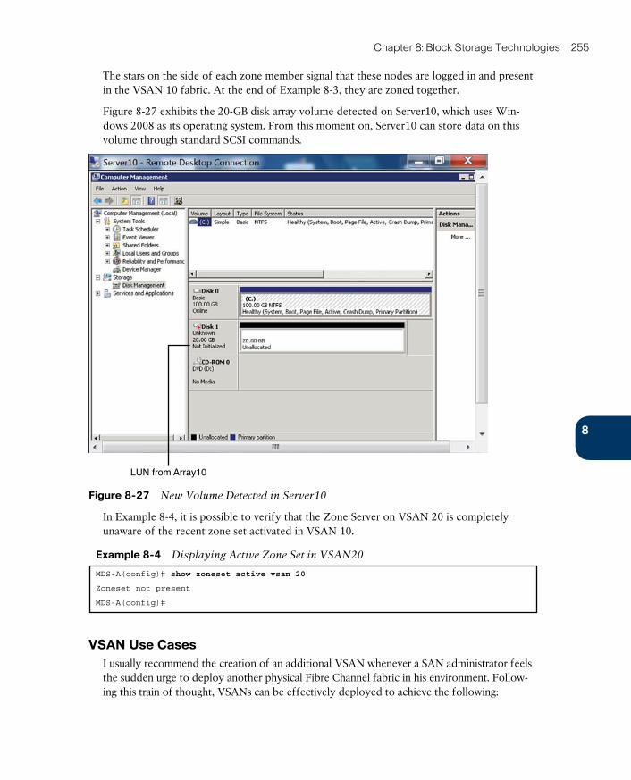
ptg17120290
8
Chapter 8: Block Storage Technologies 255
The stars on the side of each zone member signal that these nodes are logged in and present in the VSAN 10 fabric. At the end of Example 8-3, they are zoned together.
Figure 8-27 exhibits the 20-GB disk array volume detected on Server10, which uses Win-dows 2008 as its operating system. From this moment on, Server10 can store data on this volume through standard SCSI commands.
LUN from Array10
Figure 8-27 New Volume Detected in Server10
In Example 8-4, it is possible to verify that the Zone Server on VSAN 20 is completely unaware of the recent zone set activated in VSAN 10.
Example 8-4 Displaying Active Zone Set in VSAN20
MDS-A(config)# show zoneset active vsan 20
Zoneset not present
MDS-A(config)#
VSAN Use CasesI usually recommend the creation of an additional VSAN whenever a SAN administrator feels the sudden urge to deploy another physical Fibre Channel fabric in his environment. Follow-ing this train of thought, VSANs can be effectively deployed to achieve the following:

ptg17120290
256 CCNA Cloud CLDFND 210-451 Official Cert Guide
■ Consolidation: As previously mentioned, VSANs originally allowed many SAN islands to be put together within the same physical infrastructure.
■ Isolation: A VSAN basically creates an additional Fibre Channel fabric that does not interfere with environments that already exist. As a way to avoid investment in additional SAN switches, VSANs can be easily applied to support development, qualification, and production environments for the same application.
■ Multi-tenancy: Virtual SANs can easily build, on a shared infrastructure, separate fabric services and traffic segmentation for servers and storage devices that belong to different companies. Moreover, the management of all VSAN resources can be assigned to distinct tenant administrators through the use of Role-based Access Control (RBAC) features.
■ Interoperability: As one of the first Cisco innovations brought to a hardly open indus-try, MDS 9000 interoperability features enabled the integration of third-party switches through the use of additional VSANs. In essence, a VSAN in interoperability mode
emulates all the characteristics of a third-party device without compromising other envi-ronments.
NOTE A feature called Inter-VSAN Routing (IVR) can be used whenever two devices that belong to different VSANs must communicate with each other. In migration scenarios that use VSANs in interoperability mode, IVR is heavily used.
Certainly, this list is not an exhaustive exploration of VSAN applicability, as many more use cases were created to support specific requirements of many other customers. But funda-mentally, this virtualization technique drastically decreased SAN provisioning time as well as the number of unused ports during the endemic formation of physical SAN “archipelagos” in the 1990s.
Internet SCSIA joint initiative between Cisco and IBM, Internet SCSI (or simply iSCSI) was originally intended to port SCSI peripherals into the flourishing IP networks. Fostering convergence over a single network infrastructure, iSCSI connections can leverage an existent local-area network (LAN) (and potentially wide-area networks [WANs]) to establish block-based com-munications between servers and storage devices.
Standardized in the IETF RFC 3720 in 2004, iSCSI employs TCP connections to encapsulate SCSI traffic (and perform flow control). For that reason, iSCSI has consequently achieved great popularity as a quick-to-deploy alternative SAN technology.
As depicted in Figure 8-28, the main components of the iSCSI architecture are
■ iSCSI initiator: Server that originates an iSCSI connection to an iSCSI portal identi-fied by an IP address and a TCP destination port (default is 3260). An initiator usually employs a software client to establish a session and (optionally) an offload engine to unburden the CPU of the overhead associated with iSCSI or TCP processing. However, as computer processor speeds continue to abide by Moore’s law, the great majority of iSCSI implementations still rely on idle resources from the CPU and forego the optional offload engine.

ptg17120290
8
Chapter 8: Block Storage Technologies 257
TIP Fibre Channel HBAs relieve the server processor from all overhead related to SCSI and Fibre Channel communication.
■ iSCSI target: Storage device that provides LUN access through iSCSI. Generally speak-ing, these targets establish an iSCSI portal to which multiple iSCSI initiators may connect.
■ iSCSI gateway: Communication device that allows the communication between iSCSI initiators and targets connected to different SAN technologies. Select MDS 9000 switch-es and directors are capable of establishing portals for iSCSI initiators and initiators for Fibre Channel storage devices.
IP Network
iSCSIConnection
iSCSIConnection
iSCSI Initiator
iSCSI Gateway
Fibre ChannelTarget
Fibre ChannelSwitch
iSCSI Target
iSCSI Initiator
Figure 8-28 iSCSI Devices
NOTE Over the years, I have witnessed many discussions regarding the question of whether iSCSI requires a separate IP network. Excluding political and governance argu-ments, I would say that iSCSI traffic can be easily protected in modern data center networks through familiar network technologies such as VLANs and Quality of Service (QoS). In such scenarios, I would recommend having an exclusive VLAN connecting dedicated iSCSI inter-faces for both initiators and targets as a best practice, for two reasons: iSCSI initiators will not require additional host routes, and iSCSI traffic will be easily identified, by VLAN or IP subnet, for QoS purposes.
As an alternative to using IP addresses, devices at the end of an iSCSI connection can identify each other through specially defined naming schemes. The most commonly used structure is called an iSCSI Qualified Name (IQN) , which may have up to 255 bytes and is formed with the concatenation of the following elements:
■ Literal IQN: The prefix “iqn”
■ Date: The year and month
■ Reverse domain name: Where “company.com” becomes “com.company”
■ Optional colon and specific device name:
An example IQN name is “iqn.1993-11.com.disk-vendor:diskarrays.sn.45678.” If the iSCSI connection is using IQN-based authentication, the other host at the end of the connections must identify this exact string. Other, less common naming conventions for iSCSI are IEEE
Extended Unique Identifier (EUI) and T11 Network Address Authority (NAA).
ptg17120290
258 CCNA Cloud CLDFND 210-451 Official Cert Guide
Designed as an additional service for large iSCSI deployments, Internet Storage Name Ser-
vice (iSNS) enables automated discovery, management, and configuration of iSCSI devices. For this reason, iSNS is frequently compared to native Fibre Channel services such as Login Server and Name Server.
Although iSNS was standardized in 2005, the great majority of iSCSI implementations still depend on static portal definitions on initiators to establish iSCSI connections. As a conse-quence, iSCSI devices leverage high-availability mechanisms from both SCSI and IP proto-cols. For example:
■ Multipathing: Ideally, each initiator and target pair deploys more than one interface to establish two independent iSCSI connections between these entities. With such arrange-ment, an initiator software client may choose to forward iSCSI traffic to only one con-nection or load-balance storage access between them. In both cases, if a session fails for any reason, the remaining connection maintains LUN access to the iSCSI initiator.
■ Virtual Router Redundancy Protocol (VRRP) : This protocol can provide high availability for iSCSI portals created on multiple target (or gateway) ports. In these scenarios, iSCSI ini-tiators connect to a virtual IP address that is dynamically assigned to an interface deploying an iSCSI portal. In the case of a device (or port) failure, this special IP address is quickly reassigned to another device (or interface) and the iSCSI connection is reinitialized.
iSCSI initiators, targets, and gateways can also leverage security mechanisms from both IP and SCSI architectures, including access control lists (ACLs) and LUN masking for specific IP addresses, subnets, or IQNs. RFC 3720 additionally predicted exclusive security mea-sures for iSCSI, such as initiator identification through Challenge-Handshake Authentication Protocol (CHAP) and packet protection through Internet Protocol Security (IPSec).
Cloud Computing and SANsAs specialized environments built over standard data centers, cloud computing can certainly enjoy the same benefits from block-based storage and SANs. As you have learned in this chapter, these technologies greatly facilitate data portability because they obscure any dis-tinction between local hard disk drives and remote volumes, while leveraging all advantages from modern disk arrays.
Fundamentally, block storage technologies can serve two objectives in cloud computing scenarios:
■ Infrastructure: Where disk arrays and SAN devices are used to provide remote storage access to the systems supporting the cloud
■ Block Storage as a Service: Where volumes are offered as cloud tenant resources
This section explores each of these possibilities using concepts and technologies you are already familiar with.
Block Storage for Cloud InfrastructurePrimarily, a data center architect usually includes SAN deployments in a project to establish a transparent decoupling between application software and the data it accesses. Such an
ptg17120290
8
Chapter 8: Block Storage Technologies 259
approach greatly facilitates the replication of data and volume scaling up without unneces-sary hardware changes in the application servers.
Considering the specific requirements of a cloud computing infrastructure, SANs can offer additional interesting functions such as
■ SAN boot: Rather than using an internal HDD, a server can boot its operating system using a LUN on a remote storage device, simplifying hardware replacement if a critical component suffers any major malfunction. SAN boot is also a necessary step for the con-cept of stateless computing , where all server configurations (states) are not contained in the computer system. In this style of computing, a server is used exclusively as a process-ing resource.
■ Cluster storage: Computer clusters are composed of multiple server nodes controlled by cluster software and performing identical tasks to achieve high availability and, in some cases, higher performance. Most cluster technologies require that the multiple nodes access the same data set simultaneously, which can be easily achieved in SAN deployments.
■ Virtual machine datastores: Multiple virtualization hosts that run Type-1 hypervisors have access to the same volume storing VM files, thereby enabling server virtualization features such as VM high availability and live migration. This implementation can be con-sidered a specific, but extremely popular, subtype of cluster storage.
NOTE Most hypervisor architectures can perform VM storage live migration , which essentially allows the transfer of all files from virtual machines between two VM datastores without any loss of service.
Block Storage as a ServiceBesides consuming block-based storage for its own structural purposes, there is no techni-cal reason why a cloud computing environment cannot also provide these resources to end users. Therefore, through a Block Storage as a Service offering, a cloud tenant can request a volume to store data from applications deployed inside a cloud, or even to store data for external systems.
For public clouds, providing external access to automatically generated SCSI LUNs may be especially challenging due to the expected high latency of the Internet. Nevertheless, these volumes could potentially be provisioned for external servers that are sharing the same Fibre Channel SAN or Ethernet LAN (for iSCSI) with a private cloud.
In real-world scenarios, the most common Block Storage as a Service offerings today exist to create and attach volumes to Infrastructure as a Service (IaaS)-generated virtual machines. Several public cloud providers include this service in their portals, including Amazon Web Services through its Amazon Elastic Block Storage (EBS) and Microsoft Azure via its Azure Blob Storage.
OpenStack also offers a highly available component for Block Storage as a Service, named Cinder . Much like the services cited in the previous paragraph, Cinder is designed to allow Nova-instantiated virtual machines to access volumes dynamically provisioned on traditional block storage devices.
ptg17120290
260 CCNA Cloud CLDFND 210-451 Official Cert Guide
As explained, you should not consider Cinder as storage device emulation, simply because this OpenStack service does not actually receive or send application data directly from or to tenant VMs. In fact, Cinder provides an abstraction service that uses back-end storage drivers that enable several vendors to be controlled by an OpenStack cloud. In summary, OpenStack Cinder
■ Provides a volume to a single VM instance
■ Has an API to receive predefined end-user requests such as create volume and attach
volume working in tandem with OpenStack Nova
■ Selects the most appropriate storage device to deploy a volume
■ Sends requests to the underlying storage systems to create and manage volumes
■ Sends storage information (using iSCSI credentials) to Nova for session establishment
As a general comment, iSCSI is usually considered a better fit for Block Storage as a Service scenarios due to its flexibility of using software initiators in the virtual machines (as well as the amazing ubiquity of IP).
Around the Corner: Solid-State DrivesIt is not exactly news that hard disk drives are not the only available technology for second-ary storage functions, especially if you observe the huge gap of data access latency between main memory (30 to 60 nanoseconds) and HDDs (3,000,000 to 12,000,000 nanoseconds). And although that difference may be imperceptible to humans (the blink of an eye is on average 100,000,000 to 150,000,000 nanoseconds), it is certainly not for computers, where a single user request for a stored object may generate millions of individual I/O operations.
Dodging the electromechanical-related latencies of HDDs, solid-state drives (SSDs) were created several decades ago to better bridge the gap between primary and secondary stor-age, offering an access latency of less than 100 microseconds. SSDs share their origins with the widely popular USB flash drives, both being composed of the same integrated circuit assemblies that can persistently store data through power outages. For that reason, SSDs are also referred as flash drives by some vendors.
Perhaps to appeal to long-term HDD users, some vendors chose to market their SSD tech-nology as “solid-state disk.” Regardless of the motivation, this technical misstep is not total-ly without merit, because most SSDs share compatible interfaces with HDDs. Employing SATA and SAS connections, SSDs can easily replace other technologies in personal comput-ers, servers, and disk arrays.
Besides providing lower latency, SSDs are also more resistant to physical shock, produce less noise, and consume less power when compared to HDDs. And as the price difference with HDDs decreases, SSDs are increasingly becoming popular in application environments that require superior I/O performance. And once more, Cisco innovates modern data center architec-tures by positioning SSDs as part of the Unified Computing System (UCS) with UCS Invicta .
NOTE Cisco Unified Computing System will be explained in detail in Chapter 12, “Unified Computing.”
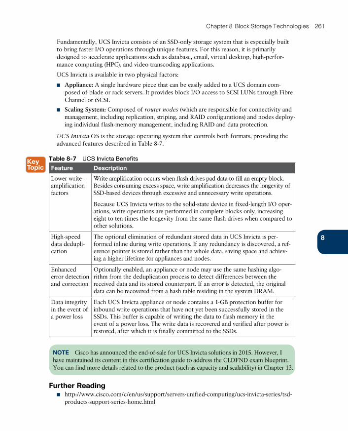
ptg17120290
8
Chapter 8: Block Storage Technologies 261
Fundamentally, UCS Invicta consists of an SSD-only storage system that is especially built to bring faster I/O operations through unique features. For this reason, it is primarily designed to accelerate applications such as database, email, virtual desktop, high-perfor-mance computing (HPC), and video transcoding applications.
UCS Invicta is available in two physical factors:
■ Appliance: A single hardware piece that can be easily added to a UCS domain com-posed of blade or rack servers. It provides block I/O access to SCSI LUNs through Fibre Channel or iSCSI.
■ Scaling System: Composed of router nodes (which are responsible for connectivity and management, including replication, striping, and RAID configurations) and nodes deploy-ing individual flash-memory management, including RAID and data protection.
UCS Invicta OS is the storage operating system that controls both formats, providing the advanced features described in Table 8-7.
Table 8-7 UCS Invicta Benefits
Feature Description
Lower write-amplification factors
Write amplification occurs when flash drives pad data to fill an empty block. Besides consuming excess space, write amplification decreases the longevity of SSD-based devices through excessive and unnecessary write operations.
Because UCS Invicta writes to the solid-state device in fixed-length I/O oper-ations, write operations are performed in complete blocks only, increasing eight to ten times the longevity from the same flash drives when compared to other solutions.
High-speed data dedupli-cation
The optional elimination of redundant stored data in UCS Invicta is per-formed inline during write operations. If any redundancy is discovered, a ref-erence pointer is stored rather than the whole data, saving space and achiev-ing a higher lifetime for appliances and nodes.
Enhanced error detection and correction
Optionally enabled, an appliance or node may use the same hashing algo-rithm from the deduplication process to detect differences between the received data and its stored counterpart. If an error is detected, the original data can be recovered from a hash table residing in the system DRAM.
Data integrity in the event of a power loss
Each UCS Invicta appliance or node contains a 1-GB protection buffer for inbound write operations that have not yet been successfully stored in the SSDs. This buffer is capable of writing the data to flash memory in the event of a power loss. The write data is recovered and verified after power is restored, after which it is finally committed to the SSDs.
NOTE Cisco has announced the end-of-sale for UCS Invicta solutions in 2015. However, I have maintained its content in this certification guide to address the CLDFND exam blueprint. You can find more details related to the product (such as capacity and scalability) in Chapter 13.
Further Reading■ http://www.cisco.com/c/en/us/support/servers-unified-computing/ucs-invicta-series/tsd-
products-support-series-home.html
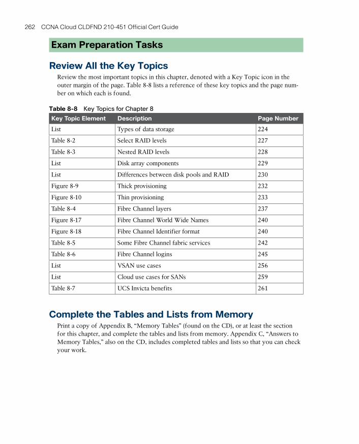
ptg17120290
262 CCNA Cloud CLDFND 210-451 Official Cert Guide
Exam Preparation Tasks
Review All the Key TopicsReview the most important topics in this chapter, denoted with a Key Topic icon in the outer margin of the page. Table 8-8 lists a reference of these key topics and the page num-ber on which each is found.
Table 8-8 Key Topics for Chapter 8
Key Topic Element Description Page Number
List Types of data storage 224
Table 8-2 Select RAID levels 227
Table 8-3 Nested RAID levels 228
List Disk array components 229
List Differences between disk pools and RAID 230
Figure 8-9 Thick provisioning 232
Figure 8-10 Thin provisioning 233
Table 8-4 Fibre Channel layers 237
Figure 8-17 Fibre Channel World Wide Names 240
Figure 8-18 Fibre Channel Identifier format 240
Table 8-5 Some Fibre Channel fabric services 242
Table 8-6 Fibre Channel logins 245
List VSAN use cases 256
List Cloud use cases for SANs 259
Table 8-7 UCS Invicta benefits 261
Complete the Tables and Lists from MemoryPrint a copy of Appendix B, “Memory Tables” (found on the CD), or at least the section for this chapter, and complete the tables and lists from memory. Appendix C, “Answers to Memory Tables,” also on the CD, includes completed tables and lists so that you can check your work.
ptg17120290
8
Chapter 8: Block Storage Technologies 263
Define Key TermsDefine the following key terms from this chapter, and check your answers in the glossary:
main memory, secondary memory, hard disk drive (HDD), redundant array of independent disks (RAID), disk controller, disk array, volume, block, Advanced Technology Attachment (ATA), Small Computer Systems Interface (SCSI), storage-area network (SAN), Fibre Chan-nel, World Wide Name (WWN), Fibre Channel Identifier (FCID), Fabric Shortest Path First (FSPF), Fabric Login (FLOGI), zone, zone set, virtual storage-area network (VSAN), VSAN trunking, Internet Small Computer Systems Interface (iSCSI), iSCSI Qualified Name (IQN), SAN boot, solid-state drive (SSD)
ptg17120290
This chapter covers the following topics:
■ What Is a File?
■ Building a File System
■ Accessing Remote Files
■ Cloud Computing and File Storage
This chapter covers the following exam subjects:
■ 5.2 Describe the difference between all the storage access technologies■ 5.2.a Difference between SAN and NAS; block and fi le■ 5.2.c File technologies
■ 5.4 Describe basic NAS storage concepts■ 5.4.a Shares / Mount Points■ 5.4.b Permissions
ptg17120290
CHAPTER 9
File Storage TechnologiesAs discussed in Chapter 8, “Block Storage Technologies,” after a block-based storage device or volume is provisioned to a server, the applications running on the computer system will dictate, from a byte level, exactly how data is written and read. However, the described pro-cedure is not the only way to store data for later use.
As a computer user, you are already familiar with the concept of using files to store your per-sonal data. This familiarity will help you understand why file systems are also a popular choice for saving information in modern data centers, including those that host cloud computing.
According to a 2012 report, International Data Corporation (IDC) estimated that file-based storage systems accounted for 65% of the overall disk capacity shipped that year. And with the advances of cloud computing, such technologies have grown in importance in the infra-structure that supports these environments.
The CLDFND exam requires knowledge of the basic principles behind file storage technol-ogies, clearly differentiating them from the block-based technologies explained in Chapter 8. With this objective in mind, this chapter presents the formal definition of a file, compar-ing this data-at-rest structure to other methods available today. The chapter then introduces the most common file locations and the main options to build a file system, including naming rules, format, and security. It also addresses the two methods of remote file access, explaining how files are usually shared among computers. Finally, the chapter correlates file storage technologies to cloud computing environments, focusing on how their flexibility may help these implementations.
“Do I Know This Already?” QuizThe “Do I Know This Already?” quiz allows you to assess whether you should read this entire chapter thoroughly or jump to the “Exam Preparation Tasks” section. If you are in doubt about your answers to these questions or your own assessment of your knowledge of the topics, read the entire chapter. Table 9-1 lists the major headings in this chapter and their corresponding “Do I Know This Already?” quiz questions. You can find the answers in Appendix A, “Answers to Pre-Assessments and Quizzes.”
Table 9-1 “Do I Know This Already?” Section-to-Question Mapping
Foundation Topics Section Questions
What Is a File? 1–2
Building a File System 3–5
Accessing Remote Files 6–8
Cloud Computing and File Storage 9–10
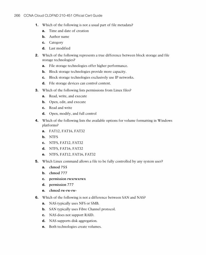
ptg17120290
266 CCNA Cloud CLDFND 210-451 Official Cert Guide
1. Which of the following is not a usual part of file metadata?
a. Time and date of creation
b. Author name
c. Category
d. Last modified
2. Which of the following represents a true difference between block storage and file storage technologies?
a. File storage technologies offer higher performance.
b. Block storage technologies provide more capacity.
c. Block storage technologies exclusively use IP networks.
d. File storage devices can control content.
3. Which of the following lists permissions from Linux files?
a. Read, write, and execute
b. Open, edit, and execute
c. Read and write
d. Open, modify, and full control
4. Which of the following lists the available options for volume formatting in Windows platforms?
a. FAT12, FAT16, FAT32
b. NTFS
c. NTFS, FAT12, FAT32
d. NTFS, FAT16, FAT32
e. NTFS, FAT12, FAT16, FAT32
5. Which Linux command allows a file to be fully controlled by any system user?
a. chmod 755
b. chmod 777
c. permission rwxrwxrwx
d. permission 777
e. chmod rw-rw-rw-
6. Which of the following is not a difference between SAN and NAS?
a. NAS typically uses NFS or SMB.
b. SAN typically uses Fibre Channel protocol.
c. NAS does not support RAID.
d. NAS supports disk aggregation.
e. Both technologies create volumes.
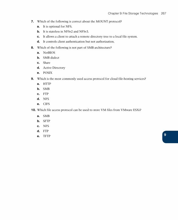
ptg17120290
9
Chapter 9: File Storage Technologies 267
7. Which of the following is correct about the MOUNT protocol?
a. It is optional for NFS.
b. It is stateless in NFSv2 and NFSv3.
c. It allows a client to attach a remote directory tree to a local file system.
d. It controls client authentication but not authorization.
8. Which of the following is not part of SMB architecture?
a. NetBIOS
b. SMB dialect
c. Share
d. Active Directory
e. POSIX
9. Which is the most commonly used access protocol for cloud file-hosting services?
a. HTTP
b. SMB
c. FTP
d. NFS
e. CIFS
10. Which file access protocol can be used to store VM files from VMware ESXi?
a. SMB
b. SFTP
c. NFS
d. FTP
e. TFTP
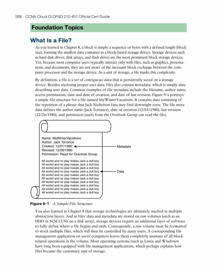
ptg17120290
268 CCNA Cloud CLDFND 210-451 Official Cert Guide
Foundation Topics
What Is a File?As you learned in Chapter 8, a block is simply a sequence of bytes with a defined length (block size), forming the smallest data container in a block-based storage device. Storage devices such as hard disk drives, disk arrays, and flash drives are the most prominent block storage devices. Yet, because most computer users typically interact only with files, such as graphics, presenta-tions, and documents, they are not aware of the incessant block exchange between the com-puter processor and the storage device. As a unit of storage, a file masks this complexity.
By definition, a file is a set of contiguous data that is persistently saved on a storage device. Besides enclosing proper user data, files also contain metadata , which is simply data describing user data. Common examples of file metadata include the filename, author name, access permissions, time and date of creation, and date of last revision. Figure 9-1 portrays a simple file structure for a file named MyWinterVacations. It contains data consisting of the repetition of a phrase that Jack Nicholson fans may find downright eerie. The file meta-data defines the author name (Jack Torrance), date of creation (12/01/1980), last revision (12/26/1980), and permission (users from the Overlook Group can read the file).
Name: MyWinterVacationsAuthor: Jack TorranceCreated: 12/01/1980Revised: 12/26/1980Permission: Read for Overlook Group
Metadata
All workd and no play makes Jack a dull boyAll workd and no play makes Jack a dull boyAll workd and no play makes Jack a dull boyAll workd and no play makes Jack a dull boyAll workd and no play makes Jack a dull boyAll workd and no play makes Jack a dull boyAll workd and no play makes Jack a dull boyAll workd and no play makes Jack a dull boyAll workd and no play makes Jack a dull boyAll workd and no play makes Jack a dull boy
Data
Figure 9-1 A Simple File Structure
You also learned in Chapter 8 that storage technologies are ultimately stacked in multiple abstraction layers. And as files’ data and metadata are stored on raw volumes (such as an HDD or SCSI LUNs on a disk array), storage devices require an additional layer of software to fully define where a file begins and ends. Consequently, a raw volume must be formatted to stock multiple files, which will then be controlled by many users. A corresponding file management application on users’ computers leaves them completely unaware of all block-related operations in the volume. Most operating systems (such as Linux and Windows) have long been equipped with file management applications, which perhaps explains how files became the customary unit of storage.

ptg17120290
9
Chapter 9: File Storage Technologies 269
File LocationsA user can access files located in different places, which are generically represented in Figure 9-2.
Local Network-AttachedStorage (NAS)
Sharing
NAS Disk Array
NAS-Head
NAS Head
Figure 9-2 File Location Options
First and most frequently, a user accesses local files when these data constructs are main-tained in a direct-attached storage (DAS) device. But rather curiously, when a server is using an external SCSI volume on a disk array, it is actually saving files locally. After all, from a file management perspective, the files are being processed in this server.
Already inadequate in data centers, the practice of storing files in local storage is becoming as unfashionable as shoulder pads. In any scenario, local files represent a single point of fail-ure, requiring individual backup procedures and manual operations to avoid data loss in the case of hardware failure.
File sharing allows users to access files located in other computers, through the use of a network infrastructure and a file access protocol. Although ad hoc file sharing may be attractive for environments with a low number of computers, it may easily become a man-agement nightmare for companies with thousands of systems. In these organizations, sea-soned IT administrators commonly preferred to store user files centrally in specialized com-puters called file servers . But as these servers had their capacity and robustness challenged with user file proliferation, they were gradually replaced with network-attached storage (NAS) devices . In essence, a NAS device is a specialized storage device with a large capacity that can serve files to a heterogeneous group of servers and personal computers.
A NAS may contain hundreds of hard disk drives and deploy aggregation technologies such as RAID and dynamic disk pools to increase access performance, data capacity, and file availability. But whereas disk arrays are connected to a storage-area network (SAN), a NAS formats volumes to handle files and exclusively communicate with clients through IP-based file sharing protocols such as Network File System (NFS) and Server Message Block (SMB).
From an architectural perspective, a NAS works as single point of arbitration to remote cli-ent systems, providing locks (to prevent other users from tampering with the files) and per-missions (to prevent unauthorized access to files). These devices are commercialized through various vendors, such as NetApp Inc. and EMC Corporation.
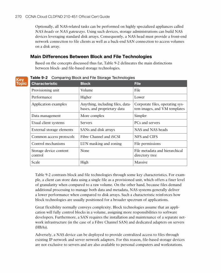
ptg17120290
270 CCNA Cloud CLDFND 210-451 Official Cert Guide
Optionally, all NAS-related tasks can be performed on highly specialized appliances called NAS heads or NAS gateways. Using such devices, storage administrations can build NAS devices leveraging standard disk arrays. Consequently, a NAS head must provide a front-end network connection to file clients as well as a back-end SAN connection to access volumes on a disk array.
Main Differences Between Block and File TechnologiesBased on the concepts discussed thus far, Table 9-2 delineates the main distinctions between block- and file-based storage technologies.
Table 9-2 Comparing Block and File Storage Technologies
Characteristic Block File
Provisioning unit Volume File
Performance Higher Lower
Application examples Anything, including files, data-bases, and proprietary data
Corporate files, operating sys-tem images, and VM templates
Data management More complex Simpler
Usual client systems Servers PCs and servers
External storage elements SANs and disk arrays NAS and NAS heads
Common access protocols Fibre Channel and iSCSI NFS and CIFS
Control mechanisms LUN masking and zoning File permissions
Storage device content control
None File metadata and hierarchical directory tree
Scale High Massive
Table 9-2 contrasts block and file technologies through some key characteristics. For exam-ple, a client can store data using a single file as a provisioned unit, which offers a finer level of granularity when compared to a raw volume. On the other hand, because files demand additional processing to manage both data and metadata, NAS systems generally deliver a lower performance when compared to disk arrays. Such a characteristic reinforces how block technologies are usually positioned for a broader spectrum of applications.
Great flexibility normally conveys complexity. Block technologies assume that an appli-cation will fully control blocks in a volume, assigning more responsibilities to software developers. Furthermore, a SAN requires the installation and maintenance of a separate net-work infrastructure (in the case of a Fibre Channel SAN) and dedicated adapters on servers (HBAs).
Adversely, a NAS device can be deployed to provide centralized access to files through existing IP network and server network adapters. For this reason, file-based storage devices are not exclusive to servers and are also available to personal computers and workstations.
ptg17120290
9
Chapter 9: File Storage Technologies 271
TIP NAS is discussed in more detail in the section “Accessing Remote Files” later in the chapter.
From a storage device administration standpoint, although a disk array controller can spawn volumes, it cannot control any data block contained within these constructs. Alternatively, file servers and NAS can control data format, metadata, client access, and many other inter-nal aspects of a formatted volume.
Lastly, file-based storage systems can scale massively when compared to block technologies, which usually follow the one-volume-per-server rule on SANs.
NOTE Considered a specific type of file, a database is a collection of highly organized information (records) that allows the retrieval and saving of select portions of data. The best analogy for a database is probably the telephone book, whose records have at least three types of data: name, address, and telephone number.
Database management systems (DBMSs) are generally composed of one or more database
servers controlling storage devices (where data is actually saved) and providing record access to other applications. The most popular DBMSs are Oracle Database and Microsoft SQL Server.
Building a File SystemA file system is defined as the methodology used for file management. Most computer sys-tems have at least one file system, and there are various cases where several of them can be deployed simultaneously on a single computer.
A file system offers a hierarchical structure designed to organize, name, store, retrieve, and update a set of files. The structure resembles an inverted tree composed of a root directory and subdirectories (branches) that can contain files and other directories. The uniqueness of a file is defined through its place in the directory structure, its name, and (optionally) a suf-fix defining which type of content the file encompasses.
A file system also characterizes file metadata such as length, time of creation, time of last change, name of user who created it, which group the user belongs to, device type, and many other details. Additionally, the design of a file system should answer questions such as
■ Which block-based structures are needed to store files’ and directories’ data and meta-data?
■ How can files be located in a block volume?
■ How should storage usage be optimized when dealing with files?
Although a detailed discussion of every characteristic of file systems is beyond the scope of this book, the next three sections will focus on some aspects that will help you understand basic file concepts. In these explanations, I will use as examples two of the most popular operating systems in servers today: Linux and Microsoft Windows.

ptg17120290
272 CCNA Cloud CLDFND 210-451 Official Cert Guide
File NamespaceA namespace is a set of symbols and rules that is used to organize different objects into a structure that assigns a distinct name to each object. Linux and Microsoft Windows deploy distinct hierarchical file namespaces, but both of them are based on the recursive logic of directories containing subdirectories and files forming a tree structure.
TIP In this discussion, it may be useful to think of a directory as a special file accommo-dating names and other information about its contained files.
Linux File Naming Rules
All Linux versions consider a pathname to be the concatenation of all the components (directory, subdirectories, and filename) that uniquely defines a file. However, depending on the version you choose, the limitation in the depth of the file tree may vary.
As an example, the Linux file root/private/curriculum.txt belongs to the directory private located in the root directory. Its name is defined as curriculum.txt, which signals to applica-tions that it is a text file.
Linux files are named through a combination of up to 255 characters, excluding reserved characters such as the forward slash (/), dollar sign ($), percent sign (%), brackets ([ and ]), less-than sign (<), greater-than sign (>), vertical bar (|), and ampersand (&).
TIP Filenames should also never begin with a hyphen (-). Linux allows the use of spe-cial characters such as period (.) for hidden files, underscore (_), and even blank spaces in filenames. Nonetheless, to use any forbidden characters and wildcards in a file name, you should escape the character by putting it in quote marks or use the backslash (\) symbol before it.
Example 9-1 introduces several Linux commands that reveal some concepts behind file and directory management.
Example 9-1 File and Directory Name Examples in Linux
! This command shows that the user is in the root of the file hierarchical tree
# pwd
/
! This command shows all the files and directories in the root directory
# ls
bin dev home lib lost+found mnt proc run srv tmp var
boot etc initrd.img lib64 media opt root sbin sys usr vmlinuz
! Let's create a directory
# mkdir private
! Going into the private directory
# cd private
# pwd
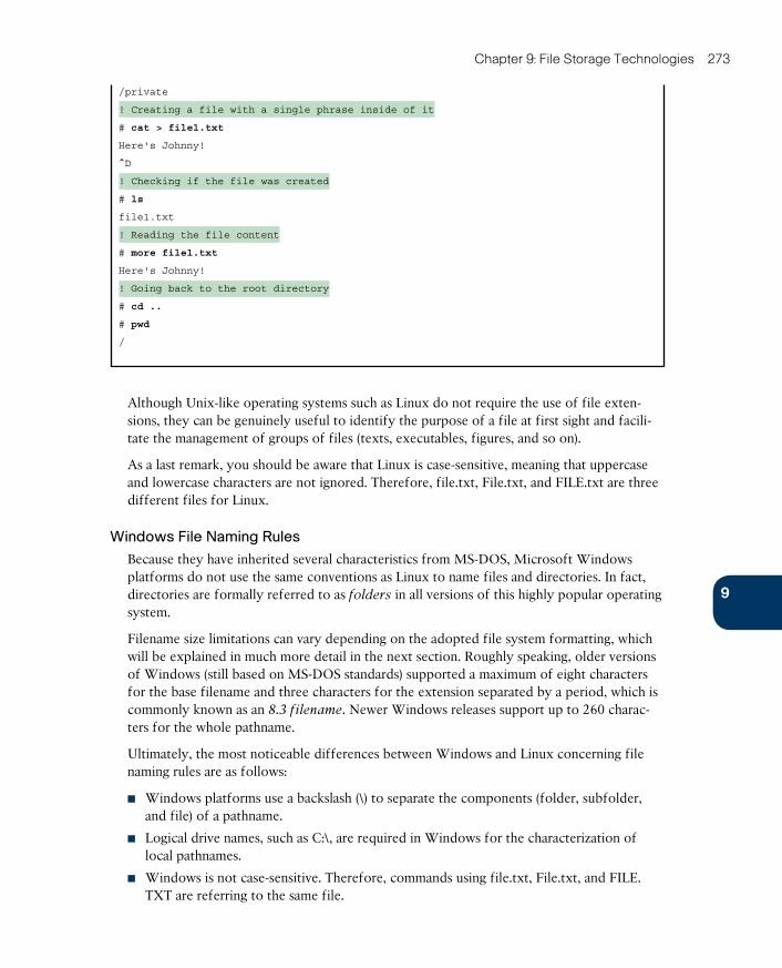
ptg17120290
9
Chapter 9: File Storage Technologies 273
/private
! Creating a file with a single phrase inside of it
# cat > file1.txt
Here's Johnny!
^D
! Checking if the file was created
# ls
file1.txt
! Reading the file content
# more file1.txt
Here's Johnny!
! Going back to the root directory
# cd ..
# pwd
/
Although Unix-like operating systems such as Linux do not require the use of file exten-sions, they can be genuinely useful to identify the purpose of a file at first sight and facili-tate the management of groups of files (texts, executables, figures, and so on).
As a last remark, you should be aware that Linux is case-sensitive, meaning that uppercase and lowercase characters are not ignored. Therefore, file.txt, File.txt, and FILE.txt are three different files for Linux.
Windows File Naming Rules
Because they have inherited several characteristics from MS-DOS, Microsoft Windows platforms do not use the same conventions as Linux to name files and directories. In fact, directories are formally referred to as folders in all versions of this highly popular operating system.
Filename size limitations can vary depending on the adopted file system formatting, which will be explained in much more detail in the next section. Roughly speaking, older versions of Windows (still based on MS-DOS standards) supported a maximum of eight characters for the base filename and three characters for the extension separated by a period, which is commonly known as an 8.3 filename . Newer Windows releases support up to 260 charac-ters for the whole pathname.
Ultimately, the most noticeable differences between Windows and Linux concerning file naming rules are as follows:
■ Windows platforms use a backslash (\) to separate the components (folder, subfolder, and file) of a pathname.
■ Logical drive names, such as C:\, are required in Windows for the characterization of local pathnames.
■ Windows is not case-sensitive. Therefore, commands using file.txt, File.txt, and FILE.TXT are referring to the same file.
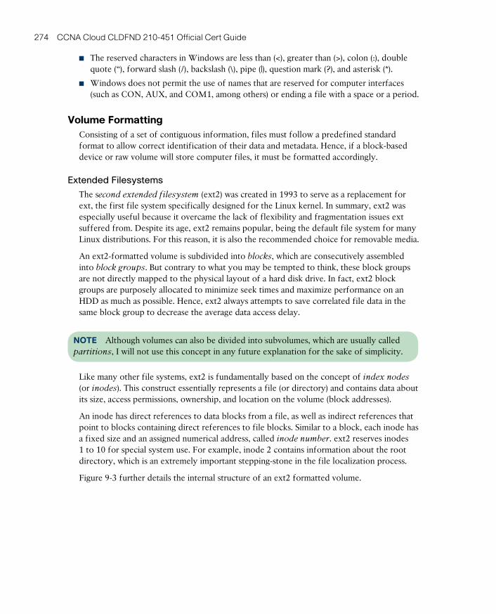
ptg17120290
274 CCNA Cloud CLDFND 210-451 Official Cert Guide
■ The reserved characters in Windows are less than (<), greater than (>), colon (:), double quote (“), forward slash (/), backslash (\), pipe (|), question mark (?), and asterisk (*).
■ Windows does not permit the use of names that are reserved for computer interfaces (such as CON, AUX, and COM1, among others) or ending a file with a space or a period.
Volume FormattingConsisting of a set of contiguous information, files must follow a predefined standard format to allow correct identification of their data and metadata. Hence, if a block-based device or raw volume will store computer files, it must be formatted accordingly.
Extended Filesystems
The second extended filesystem (ext2) was created in 1993 to serve as a replacement for ext, the first file system specifically designed for the Linux kernel. In summary, ext2 was especially useful because it overcame the lack of flexibility and fragmentation issues ext suffered from. Despite its age, ext2 remains popular, being the default file system for many Linux distributions. For this reason, it is also the recommended choice for removable media.
An ext2-formatted volume is subdivided into blocks , which are consecutively assembled into block groups . But contrary to what you may be tempted to think, these block groups are not directly mapped to the physical layout of a hard disk drive. In fact, ext2 block groups are purposely allocated to minimize seek times and maximize performance on an HDD as much as possible. Hence, ext2 always attempts to save correlated file data in the same block group to decrease the average data access delay.
NOTE Although volumes can also be divided into subvolumes, which are usually called partitions , I will not use this concept in any future explanation for the sake of simplicity.
Like many other file systems, ext2 is fundamentally based on the concept of index nodes (or inodes ). This construct essentially represents a file (or directory) and contains data about its size, access permissions, ownership, and location on the volume (block addresses).
An inode has direct references to data blocks from a file, as well as indirect references that point to blocks containing direct references to file blocks. Similar to a block, each inode has a fixed size and an assigned numerical address, called inode number . ext2 reserves inodes 1 to 10 for special system use. For example, inode 2 contains information about the root directory, which is an extremely important stepping-stone in the file localization process.
Figure 9-3 further details the internal structure of an ext2 formatted volume.
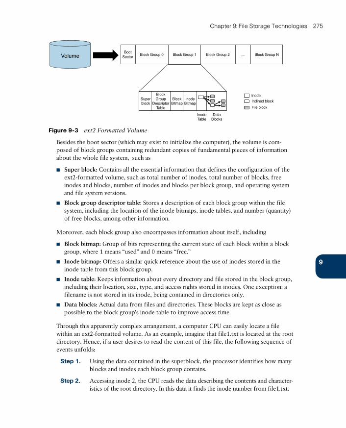
ptg17120290
9
Chapter 9: File Storage Technologies 275
BootSector Block Group 0 Block Group 2 Block Group NBlock Group 1 ...
Inode
InodeTable
Indirect block
DataBlocks
File block
InodeBitmap
Superblock
BlockGroup
DescriptorTable
BlockBitmap
Volume
Figure 9-3 ext2 Formatted Volume
Besides the boot sector (which may exist to initialize the computer), the volume is com-posed of block groups containing redundant copies of fundamental pieces of information about the whole file system, such as
■ Super block: Contains all the essential information that defines the configuration of the ext2-formatted volume, such as total number of inodes, total number of blocks, free inodes and blocks, number of inodes and blocks per block group, and operating system and file system versions.
■ Block group descriptor table: Stores a description of each block group within the file system, including the location of the inode bitmaps, inode tables, and number (quantity) of free blocks, among other information.
Moreover, each block group also encompasses information about itself, including
■ Block bitmap: Group of bits representing the current state of each block within a block group, where 1 means “used” and 0 means “free.”
■ Inode bitmap: Offers a similar quick reference about the use of inodes stored in the inode table from this block group.
■ Inode table: Keeps information about every directory and file stored in the block group, including their location, size, type, and access rights stored in inodes. One exception: a filename is not stored in its inode, being contained in directories only.
■ Data blocks: Actual data from files and directories. These blocks are kept as close as possible to the block group’s inode table to improve access time.
Through this apparently complex arrangement, a computer CPU can easily locate a file within an ext2-formatted volume. As an example, imagine that file1.txt is located at the root directory. Hence, if a user desires to read the content of this file, the following sequence of events unfolds:
Step 1. Using the data contained in the superblock, the processor identifies how many blocks and inodes each block group contains.
Step 2. Accessing inode 2, the CPU reads the data describing the contents and character-istics of the root directory. In this data it finds the inode number from file1.txt.
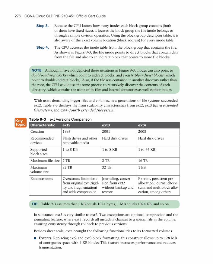
ptg17120290
276 CCNA Cloud CLDFND 210-451 Official Cert Guide
Step 3. Because the CPU knows how many inodes each block group contains (both of them have fixed sizes), it locates the block group the file inode belongs to through a simple division operation. Using the block group descriptor table, it is also aware of the exact volume location (block address) for every inode table.
Step 4. The CPU accesses the inode table from the block group that contains the file. As shown in Figure 9-3, the file inode points to direct blocks that contain data from the file and also to an indirect block that points to more file blocks.
NOTE Although I have not depicted these situations in Figure 9-3, inodes can also point to double-indirect blocks (which point to indirect blocks) and even triple-indirect blocks (which point to double-indirect blocks). Also, if the file was contained in another directory rather than the root, the CPU would use the same process to recursively discover the contents of each directory, which contains the name of its files and internal directories as well as their inodes.
With users demanding bigger files and volumes, new generations of file systems succeeded ext2. Table 9-3 displays the main scalability characteristics from ext2, ext3 (third extended
filesystem ), and ext4 (fourth extended filesystem ).
Table 9-3 ext Versions Comparison
Characteristic ext2 ext3 ext4
Creation 1993 2001 2008
Recommended devices
Flash drives and other removable media
Hard disk drives Hard disk drives
Supported block sizes
1 to 8 KB 1 to 8 KB 1 to 64 KB
Maximum file size 2 TB 2 TB 16 TB
Maximum volume size
32 TB 32 TB 1 EB
Enhancements Overcomes limitations from original ext (rigid-ity and fragmentation) and adds compression
Journaling, conver-sion from ext2 without backup and restore
Extents, persistent pre-allocation, journal check-sum, and multiblock allo-cation, among others
TIP Table 9-3 assumes that 1 KB equals 1024 bytes, 1 MB equals 1024 KB, and so on.
In substance, ext3 is very similar to ext2. Two exceptions are optional compression and the journaling feature, where ext3 records all metadata changes to a special file in the volume, ensuring consistency through rollback to previous versions.
Besides sheer scale, ext4 brought the following functionalities to its formatted volumes:
■ Extents: Replacing ext2 and ext3 block formatting, this construct allows up to 128 MB of contiguous space with 4-KB blocks. This feature increases performance and reduces fragmentation.
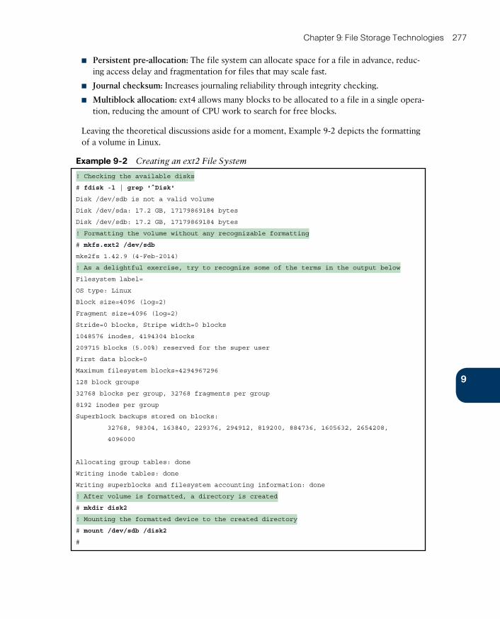
ptg17120290
9
Chapter 9: File Storage Technologies 277
■ Persistent pre-allocation: The file system can allocate space for a file in advance, reduc-ing access delay and fragmentation for files that may scale fast.
■ Journal checksum: Increases journaling reliability through integrity checking.
■ Multiblock allocation: ext4 allows many blocks to be allocated to a file in a single opera-tion, reducing the amount of CPU work to search for free blocks.
Leaving the theoretical discussions aside for a moment, Example 9-2 depicts the formatting of a volume in Linux.
Example 9-2 Creating an ext2 File System
! Checking the available disks
# fdisk -l | grep '^Disk'
Disk /dev/sdb is not a valid volume
Disk /dev/sda: 17.2 GB, 17179869184 bytes
Disk /dev/sdb: 17.2 GB, 17179869184 bytes
! Formatting the volume without any recognizable formatting
# mkfs.ext2 /dev/sdb
mke2fs 1.42.9 (4-Feb-2014)
! As a delightful exercise, try to recognize some of the terms in the output below
Filesystem label=
OS type: Linux
Block size=4096 (log=2)
Fragment size=4096 (log=2)
Stride=0 blocks, Stripe width=0 blocks
1048576 inodes, 4194304 blocks
209715 blocks (5.00%) reserved for the super user
First data block=0
Maximum filesystem blocks=4294967296
128 block groups
32768 blocks per group, 32768 fragments per group
8192 inodes per group
Superblock backups stored on blocks:
32768, 98304, 163840, 229376, 294912, 819200, 884736, 1605632, 2654208,
4096000
Allocating group tables: done
Writing inode tables: done
Writing superblocks and filesystem accounting information: done
! After volume is formatted, a directory is created
# mkdir disk2
! Mounting the formatted device to the created directory
# mount /dev/sdb /disk2
#
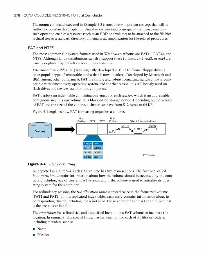
ptg17120290
278 CCNA Cloud CLDFND 210-451 Official Cert Guide
The mount command executed in Example 9-2 frames a very important concept that will be further explored in this chapter. In Unix-like systems (and consequently all Linux versions), such operation enables a resource (such as an HDD or a volume) to be attached to the file hier-archical tree as a standard directory, bringing great simplification for file-related procedures.
FAT and NTFS
The most common file system formats used in Windows platforms are FAT16, FAT32, and NTFS. Although Linux distributions can also support these formats, ext2, ext3, or ext4 are usually deployed by default on local Linux volumes.
File Allocation Table (FAT) was originally developed in 1977 to format floppy disks (a once popular type of removable media that is now obsolete). Developed by Microsoft and IBM (among other companies), FAT is a simple and robust formatting standard that is com-patible with almost every operating system, and for that reason, it is still heavily used on flash drives and devices used to boot computers.
FAT deploys an index table containing one entry for each cluster , which is an addressable contiguous area in a raw volume on a block-based storage device. Depending on the version of FAT and the size of the volume, a cluster can have from 512 bytes to 64 KB.
Figure 9-4 explains how FAT formatting organizes a volume.
BootPartition FAT1 FAT2 Other folders and all files
RootFolder
0x1111
0x2222
Cluster
0x3333
file2.txtVolume
0x1111
0x2222
0x2222
0x3333
0x3333
Last
Cluster Info
Figure 9-4 FAT Formatting
As depicted in Figure 9-4, each FAT volume has five main sections. The first one, called boot partition , contains information about how the volume should be accessed by the com-puter, including size of cluster, FAT version, and if the volume is used to initialize its oper-ating system for the computer.
For redundancy reasons, the file allocation table is stored twice in the formatted volume (FAT1 and FAT2). In this replicated index table, each entry contains information about its corresponding cluster, including if it is not used, the next cluster address for a file, and if it is the last cluster in a file.
The root folder has a fixed size and a specified location in a FAT volume to facilitate file location. In summary, this special folder has information for each of its files or folders, including metadata such as
■ Name
■ File size

ptg17120290
9
Chapter 9: File Storage Technologies 279
■ Creation time
■ Creation date
■ Last access date
■ Last modified time
■ Last modified date
■ Starting cluster address in the file allocation table
All files and other folders are stored in the remaining part of the volume. When files are being written in a FAT volume, the first free cluster is always used to store the next cor-responding chunk of data. For this reason, the more that a FAT volume is used, the greater the likelihood that files may suffer from fragmentation issues as they are distributed among clusters that are distant from each other. As a result of fragmented files, the overall file access delay tends to increase.
Through the starting cluster address contained in the root folder, a computer CPU has a starting point to locate cluster entries from subfolders in a recursive manner, until it reaches the file in the hierarchy tree. Afterward, it collects the file data simply by following the sequence of clusters defined in the file allocation table.
Figure 9-4 also depicts how a file named file2.txt located in the root folder is accessed inside of a FAT volume. In more detail:
Step 1. The CPU goes to the root folder and locates entry file2.txt and its starting clus-ter address (0x1111).
Step 2. After reading the cluster content, the CPU has the first data portion from the file.
Step 3. The CPU accesses the file allocation table entry for this cluster and discovers the address for the next cluster (0x2222). It then reads the cluster content to obtain the second part of the file.
Step 4. The CPU accesses the file allocation table again, which points to cluster 0x3333.
Step 5. After reading the cluster, the CPU recognizes the end of the file in the cluster file allocation table entry.
There are several variants of FAT, but the most popular ones are represented in Table 9-4.
Table 9-4 FAT Versions Comparison
Characteristic FAT12 FAT16 FAT32
First implementation 1980 1984 1996
Index table entry size 12 bits 16 bits 32 bits
Designed for Floppy disks HDDs HDDs
Supported cluster sizes 0.5 KB to 4 KB 2 KB to 32 KB 4 KB to 32 KB
Maximum file size 16 MB 2 GB (4 GB for some operating systems)
4 GB
Maximum volume size 16 MB 2 GB 2 TB
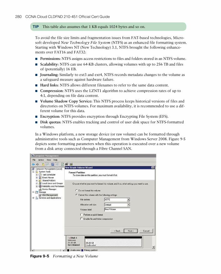
ptg17120290
280 CCNA Cloud CLDFND 210-451 Official Cert Guide
TIP This table also assumes that 1 KB equals 1024 bytes and so on.
To avoid the file size limits and fragmentation issues from FAT-based technologies, Micro-soft developed New Technology File System (NTFS) as an enhanced file formatting system. Starting with Windows NT (New Technology) 3.1, NTFS brought the following enhance-ments over FAT16 and FAT32:
■ Permissions: NTFS assigns access restrictions to files and folders stored in an NTFS volume.
■ Scalability: NTFS can use 64-KB clusters, allowing volumes with up to 256 TB and files of (potentially) 16 EB.
■ Journaling: Similarly to ext3 and ext4, NTFS records metadata changes to the volume as a safeguard measure against hardware failure.
■ Hard links: NTFS allows different filenames to refer to the same data content.
■ Compression: NTFS uses the LZNT1 algorithm to achieve compression rates of up to 4:1, depending on file data content.
■ Volume Shadow Copy Service: This NTFS process keeps historical versions of files and directories on NTFS volumes. For maximum availability, it is recommended to use a dif-ferent volume for this data.
■ Encryption: NTFS provides encryption through Encrypting File System (EFS).
■ Disk quotas: NTFS enables tracking and control of user disk space for NTFS-formatted volumes.
In a Windows platform, a new storage device (or raw volume) can be formatted through administrative tools such as Computer Management from Windows Server 2008. Figure 9-5 depicts some formatting parameters when this operation is executed over a new volume from a disk array connected through a Fibre Channel SAN.
Figure 9-5 Formatting a New Volume
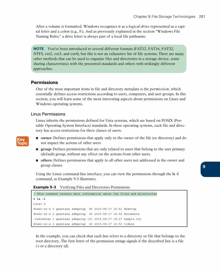
ptg17120290
9
Chapter 9: File Storage Technologies 281
After a volume is formatted, Windows recognizes it as a logical drive represented as a capi-tal letter and a colon (e.g., F:). And as previously explained in the section “Windows File Naming Rules,” a drive letter is always part of a local file pathname.
NOTE You’ve been introduced to several different formats (FAT12, FAT16, FAT32, NTFS, ext2, ext3, and ext4), but this is not an exhaustive list of file systems. There are many other methods that can be used to organize files and directories in a storage device, some sharing characteristics with the presented standards and others with strikingly different approaches.
PermissionsOne of the most important items in file and directory metadata is the permission, which essentially defines access restrictions according to users, computers, and user groups. In this section, you will learn some of the most interesting aspects about permissions on Linux and Windows operating systems.
Linux Permissions
Linux inherits the permissions defined for Unix systems, which are based on POSIX (Por-table Operating System Interface) standards. In these operating systems, each file and direc-tory has access restrictions for three classes of users:
■ owner: Defines permissions that apply only to the owner of the file (or directory) and do not impact the actions of other users
■ group: Defines permissions that are only related to users that belong to the user primary (default) group, without any effect on the actions from other users.
■ others: Defines permissions that apply to all other users not addressed in the owner and group classes
Using the Linux command-line interface, you can view the permissions through the ls -l command, as Example 9-3 illustrates.
Example 9-3 Verifying Files and Directories Permissions
! This command reveals more information about the files and directories
# ls –l
total 4
drwxr-xr-x 2 gsantana admgroup 80 2015-08-17 16:52 desktop
drwxr-xr-x 2 gsantana admgroup 40 2015-08-17 16:52 documents
-rwxrwxrwx 1 gsantana admgroup 131 2015-08-17 18:07 sample.txt
drwxr-xr-x 2 gsantana admgroup 40 2015-08-17 16:52 videos
In the example, you can check that each line refers to a directory or file that belongs to the root directory. The first letter of the permission strings signals if the described line is a file (-) or a directory (d).
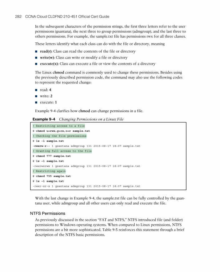
ptg17120290
282 CCNA Cloud CLDFND 210-451 Official Cert Guide
In the subsequent characters of the permission strings, the first three letters refer to the user permissions (gsantana), the next three to group permissions (admgroup), and the last three to others permissions. For example, the sample.txt file has permissions rwx for all three classes.
These letters identify what each class can do with the file or directory, meaning
■ read(r): Class can read the contents of the file or directory
■ write(w): Class can write or modify a file or directory
■ execute(x): Class can execute a file or view the contents of a directory
The Linux chmod command is commonly used to change these permissions. Besides using the previously described permission code, the command may also use the following codes to represent the requested change:
■ read: 4
■ write: 2
■ execute: 1
Example 9-4 clarifies how chmod can change permissions in a file.
Example 9-4 Changing Permissions on a Linux File
! Restricting access to a file
# chmod u=rwx,g=rx,o=r sample.txt
! Checking the file permissions
# ls -l sample.txt
-rwxrw-r-- 1 gsantana admgroup 131 2015-08-17 18:07 sample.txt
! Granting full access to the file
# chmod 777 sample.txt
# ls –l sample.txt
-rwxrwxrwx 1 gsantana admgroup 131 2015-08-17 18:07 sample.txt
! Restricting again
# chmod 755 sample.txt
# ls –l sample.txt
-rwxr-xr-x 1 gsantana admgroup 131 2015-08-17 18:07 sample.txt
With the last change in Example 9-4, the sample.txt file can be fully controlled by the gsan-tana user, while admgroup and all other users can only read and execute the file.
NTFS Permissions
As previously discussed in the section “FAT and NTFS,” NTFS introduced file (and folder) permissions to Windows operating systems. When compared to Linux permissions, NTFS permissions are a bit more sophisticated. Table 9-5 reinforces this statement through a brief description of the NTFS basic permissions.
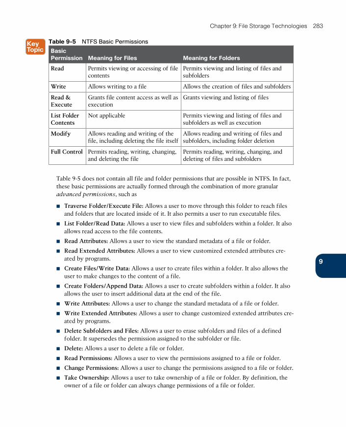
ptg17120290
9
Chapter 9: File Storage Technologies 283
Table 9-5 NTFS Basic Permissions
Basic Permission Meaning for Files Meaning for Folders
Read Permits viewing or accessing of file contents
Permits viewing and listing of files and subfolders
Write Allows writing to a file Allows the creation of files and subfolders
Read & Execute
Grants file content access as well as execution
Grants viewing and listing of files
List Folder Contents
Not applicable Permits viewing and listing of files and subfolders as well as execution
Modify Allows reading and writing of the file, including deleting the file itself
Allows reading and writing of files and subfolders, including folder deletion
Full Control Permits reading, writing, changing, and deleting the file
Permits reading, writing, changing, and deleting of files and subfolders
Table 9-5 does not contain all file and folder permissions that are possible in NTFS. In fact, these basic permissions are actually formed through the combination of more granular advanced permissions, such as
■ Traverse Folder/Execute File: Allows a user to move through this folder to reach files and folders that are located inside of it. It also permits a user to run executable files.
■ List Folder/Read Data: Allows a user to view files and subfolders within a folder. It also allows read access to the file contents.
■ Read Attributes: Allows a user to view the standard metadata of a file or folder.
■ Read Extended Attributes: Allows a user to view customized extended attributes cre-ated by programs.
■ Create Files/Write Data: Allows a user to create files within a folder. It also allows the user to make changes to the content of a file.
■ Create Folders/Append Data: Allows a user to create subfolders within a folder. It also allows the user to insert additional data at the end of the file.
■ Write Attributes: Allows a user to change the standard metadata of a file or folder.
■ Write Extended Attributes: Allows a user to change customized extended attributes cre-ated by programs.
■ Delete Subfolders and Files: Allows a user to erase subfolders and files of a defined folder. It supersedes the permission assigned to the subfolder or file.
■ Delete: Allows a user to delete a file or folder.
■ Read Permissions: Allows a user to view the permissions assigned to a file or folder.
■ Change Permissions: Allows a user to change the permissions assigned to a file or folder.
■ Take Ownership: Allows a user to take ownership of a file or folder. By definition, the owner of a file or folder can always change permissions of a file or folder.
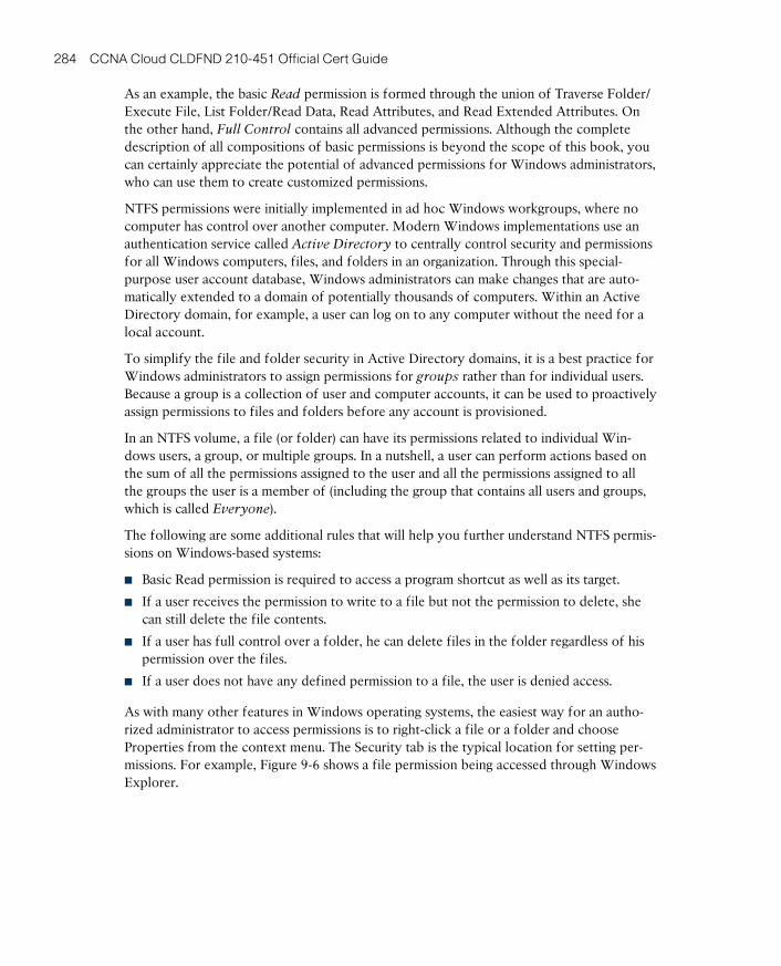
ptg17120290
284 CCNA Cloud CLDFND 210-451 Official Cert Guide
As an example, the basic Read permission is formed through the union of Traverse Folder/Execute File, List Folder/Read Data, Read Attributes, and Read Extended Attributes. On the other hand, Full Control contains all advanced permissions. Although the complete description of all compositions of basic permissions is beyond the scope of this book, you can certainly appreciate the potential of advanced permissions for Windows administrators, who can use them to create customized permissions.
NTFS permissions were initially implemented in ad hoc Windows workgroups, where no computer has control over another computer. Modern Windows implementations use an authentication service called Active Directory to centrally control security and permissions for all Windows computers, files, and folders in an organization. Through this special-purpose user account database, Windows administrators can make changes that are auto-matically extended to a domain of potentially thousands of computers. Within an Active Directory domain, for example, a user can log on to any computer without the need for a local account.
To simplify the file and folder security in Active Directory domains, it is a best practice for Windows administrators to assign permissions for groups rather than for individual users. Because a group is a collection of user and computer accounts, it can be used to proactively assign permissions to files and folders before any account is provisioned.
In an NTFS volume, a file (or folder) can have its permissions related to individual Win-dows users, a group, or multiple groups. In a nutshell, a user can perform actions based on the sum of all the permissions assigned to the user and all the permissions assigned to all the groups the user is a member of (including the group that contains all users and groups, which is called Everyone).
The following are some additional rules that will help you further understand NTFS permis-sions on Windows-based systems:
■ Basic Read permission is required to access a program shortcut as well as its target.
■ If a user receives the permission to write to a file but not the permission to delete, she can still delete the file contents.
■ If a user has full control over a folder, he can delete files in the folder regardless of his permission over the files.
■ If a user does not have any defined permission to a file, the user is denied access.
As with many other features in Windows operating systems, the easiest way for an autho-rized administrator to access permissions is to right-click a file or a folder and choose Properties from the context menu. The Security tab is the typical location for setting per-missions. For example, Figure 9-6 shows a file permission being accessed through Windows Explorer.
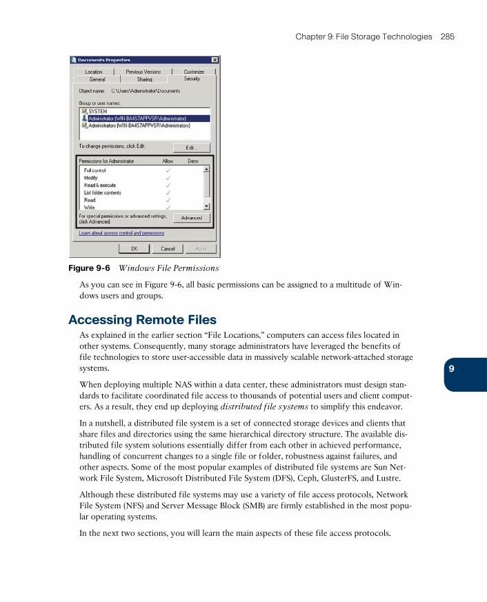
ptg17120290
9
Chapter 9: File Storage Technologies 285
Figure 9-6 Windows File Permissions
As you can see in Figure 9-6, all basic permissions can be assigned to a multitude of Win-dows users and groups.
Accessing Remote FilesAs explained in the earlier section “File Locations,” computers can access files located in other systems. Consequently, many storage administrators have leveraged the benefits of file technologies to store user-accessible data in massively scalable network-attached storage systems.
When deploying multiple NAS within a data center, these administrators must design stan-dards to facilitate coordinated file access to thousands of potential users and client comput-ers. As a result, they end up deploying distributed file systems to simplify this endeavor.
In a nutshell, a distributed file system is a set of connected storage devices and clients that share files and directories using the same hierarchical directory structure. The available dis-tributed file system solutions essentially differ from each other in achieved performance, handling of concurrent changes to a single file or folder, robustness against failures, and other aspects. Some of the most popular examples of distributed file systems are Sun Net-work File System, Microsoft Distributed File System (DFS), Ceph, GlusterFS, and Lustre.
Although these distributed file systems may use a variety of file access protocols, Network File System (NFS) and Server Message Block (SMB) are firmly established in the most popu-lar operating systems.
In the next two sections, you will learn the main aspects of these file access protocols.

ptg17120290
286 CCNA Cloud CLDFND 210-451 Official Cert Guide
Network File SystemAlthough its acronym is perhaps more commonly associated with the “Need for Speed” video game franchise, Network File System (NFS) is probably more entitled to it because of its age. Created by Sun Microsystems in 1984 for its Solaris operating system, NFS is still used by many other Unix-based operating systems, such as Linux and FreeBSD, as their native file access method.
Although its ease of use masks such complexity, NFS is characterized by a stack of proto-cols, as illustrated in Figure 9-7.
Layer 7 (Application)
Layer 6 (Presentation)
Layer 1 (Physical)
Layer 2 (Data Link)
Layer 3 (Network)
Layer 4 (Transport)
Layer 5 (Session)
NFS
XDR
Any
Any
IP
UCP or TCP
ONC RPC
Figure 9-7 Network File System Protocol Stack
Unlike SANs, file access protocols always use IP networks to establish a session between client and server. Hence, the Internet Protocol enables NFS to run over any type of media (Layer 1) or networking technology (Layer 2). Furthermore, depending on which NFS ver-sion you may be using, the transport of data between file client and server may use TCP or UDP. However, all the versions share the same Layer 5 and 6 protocols, which are
■ Open Network Computing Remote Procedure Call (ONC RPC) : Also known as Sun RPC, this Layer 5 protocol enables communication between different remote file access processes for NFS.
■ External Data Representation (XDR) : Also developed by Sun, XDR is a standardized data coding format that permits different computer systems to share data transmitted through NFS.
NFS, XDR, and ONC RPC are standardized by the Internet Engineering Task Force (IETF). Both XDR and ONC RPC have multiple releases that support all three NFS versions, as shown in Table 9-6.
Table 9-6 NFS Versions Comparison
Characteristic NFSv2 NFSv3 NFSv4
Standard RFC 1094 (March 1989)
RFC 1813 (June 1995)
RFC 3530 (December 2000)
Transport protocol UDP UDP or TCP TCP
XDR version RFC 1014 RFC 1014 RFC 1831
ONC RPC version RFC 1057 RFC 1057 RFC 1832
x86 architecture 32-bit 32- and 64-bit 32- and 64-bit
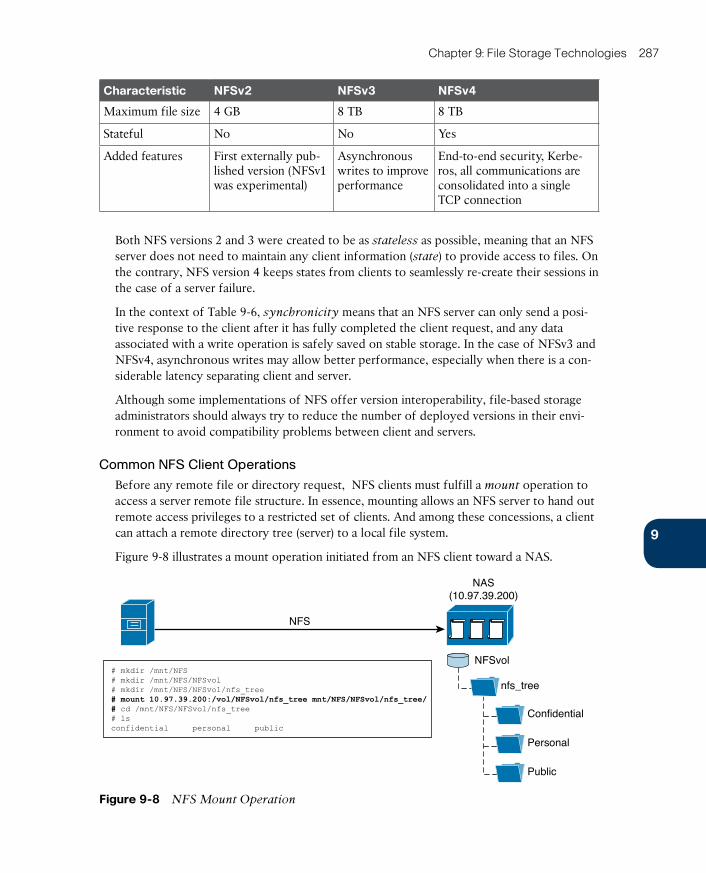
ptg17120290
9
Chapter 9: File Storage Technologies 287
Characteristic NFSv2 NFSv3 NFSv4
Maximum file size 4 GB 8 TB 8 TB
Stateful No No Yes
Added features First externally pub-lished version (NFSv1 was experimental)
Asynchronous writes to improve performance
End-to-end security, Kerbe-ros, all communications are consolidated into a single TCP connection
Both NFS versions 2 and 3 were created to be as stateless as possible, meaning that an NFS server does not need to maintain any client information (state ) to provide access to files. On the contrary, NFS version 4 keeps states from clients to seamlessly re-create their sessions in the case of a server failure.
In the context of Table 9-6, synchronicity means that an NFS server can only send a posi-tive response to the client after it has fully completed the client request, and any data associated with a write operation is safely saved on stable storage. In the case of NFSv3 and NFSv4, asynchronous writes may allow better performance, especially when there is a con-siderable latency separating client and server.
Although some implementations of NFS offer version interoperability, file-based storage administrators should always try to reduce the number of deployed versions in their envi-ronment to avoid compatibility problems between client and servers.
Common NFS Client Operations
Before any remote file or directory request, NFS clients must fulfill a mount operation to access a server remote file structure. In essence, mounting allows an NFS server to hand out remote access privileges to a restricted set of clients. And among these concessions, a client can attach a remote directory tree (server) to a local file system.
Figure 9-8 illustrates a mount operation initiated from an NFS client toward a NAS.
NAS(10.97.39.200)
NFS
NFSvol
nfs_tree
# mkdir /mnt/NFS# mkdir /mnt/NFS/NFSvol# mkdir /mnt/NFS/NFSvol/nfs_tree# mount 10.97.39.200:/vol/NFSvol/nfs_tree mnt/NFS/NFSvol/nfs_tree/# cd /mnt/NFS/NFSvol/nfs_tree# lsconfidential personal public
Confidential
Personal
Public
Figure 9-8 NFS Mount Operation
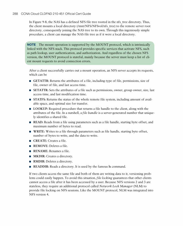
ptg17120290
288 CCNA Cloud CLDFND 210-451 Official Cert Guide
In Figure 9-8, the NAS has a defined NFS file tree rooted in the nfs_tree directory. Thus, the client mounts a local directory (/mnt/NFS/NFSvol/nfs_tree) to the remote server root directory, consequently joining the NAS tree to its own. Through this ingeniously simple procedure, a client can manage the NAS file tree as if it were a local directory.
NOTE The mount operation is supported by the MOUNT protocol, which is intrinsically linked with the NFS stack. This protocol provides specific services that activate NFS, such as path lookup, user authentication, and authorization. And regardless of the chosen NFS version, the MOUNT protocol is stateful, mainly because the server must keep a list of cli-ent mount requests to avoid connection errors.
After a client successfully carries out a mount operation, an NFS server accepts its requests, which can be
■ GETATTR: Returns the attributes of a file, including type of file, permissions, size of file, owner of file, and last access time.
■ SETATTR: Sets the attributes of a file such as permissions, owner, group owner, size, last access time, and last modification time.
■ STATFS: Returns the status of the whole remote file system, including amount of avail-able space, and optimal size for transfer.
■ LOOKUP: Required procedure that returns a file handle to the client, along with the attributes of the file. In a nutshell, a file handle is a server-generated number that unique-ly identifies a shared file.
■ READ: Reads from a file using parameters such as a file handle, starting byte offset, and maximum number of bytes to read.
■ WRITE: Writes to a file through parameters such as file handle, starting byte offset, number of bytes to write, and the data to write.
■ CREATE: Creates a file.
■ REMOVE: Deletes a file.
■ RENAME: Renames a file.
■ MKDIR: Creates a directory.
■ RMDIR: Deletes a directory.
■ READDIR: Reads a directory. It is used by the famous ls command.
If two clients access the same file and both of them are writing data to it, versioning prob-lems could easily happen. To avoid this situation, file locking guarantees that other clients cannot access a file after it has been accessed by a user. Because NFS versions 2 and 3 are stateless, they require an additional protocol called Network Lock Manager (NLM) to provide file locking on NFS sessions. Like the MOUNT protocol, NLM was integrated into NFS version 4.
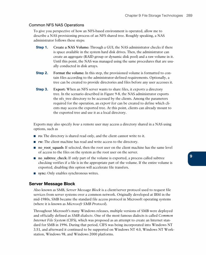
ptg17120290
9
Chapter 9: File Storage Technologies 289
Common NFS NAS Operations
To give you perspective of how an NFS-based environment is operated, allow me to describe a NAS provisioning process of an NFS shared tree. Roughly speaking, a NAS administrator follows these steps:
Step 1. Create a NAS Volume: Through a GUI, the NAS administrator checks if there is space available in the system hard disk drives. Then, the administrator can create an aggregate (RAID group or dynamic disk pool) and a raw volume in it. Until this point, the NAS was managed using the same procedures that are usu-ally conducted in disk arrays.
Step 2. Format the volume: In this step, the provisioned volume is formatted to con-tain files according to the administrator-defined requirements. Optionally, a tree can be created to provide directories and files before any user accesses it.
Step 3. Export: When an NFS server wants to share files, it exports a directory tree. In the scenario described in Figure 9-8, the NAS administrator exports the nfs_tree directory to be accessed by the clients. Among the parameters required for the operation, an export list can be created to define which cli-ents may access the exported tree. At this point, clients can already mount to the exported tree and use it as a local directory.
Exports may also specify how a remote user may access a directory shared in a NAS using options, such as
■ ro: The directory is shared read only, and the client cannot write to it.
■ rw: The client machine has read and write access to the directory.
■ no_root_squash: If selected, then the root user on the client machine has the same level of access to the files on the system as the root user on the server.
■ no_subtree_check: If only part of the volume is exported, a process called subtree checking verifies if a file is in the appropriate part of the volume. If the entire volume is exported, disabling this option will accelerate file transfers.
■ sync: Only enables synchronous writes.
Server Message BlockAlso known as SMB, Server Message Block is a client/server protocol used to request file services from server systems over a common network. Originally developed at IBM in the mid-1980s, SMB became the standard file access protocol in Microsoft operating systems (where it is known as Microsoft SMB Protocol).
Throughout Microsoft’s many Windows releases, multiple versions of SMB were deployed and officially defined as SMB dialects . One of the most famous dialects is called Common
Internet File System (CIFS) , which was proposed as an attempt to create an Internet stan-dard for SMB in 1996. During that period, CIFS was being incorporated into Windows NT 3.51, and afterward it continued to be supported on Windows NT 4.0, Windows NT Work-station, Windows 98, and Windows 2000 platforms.
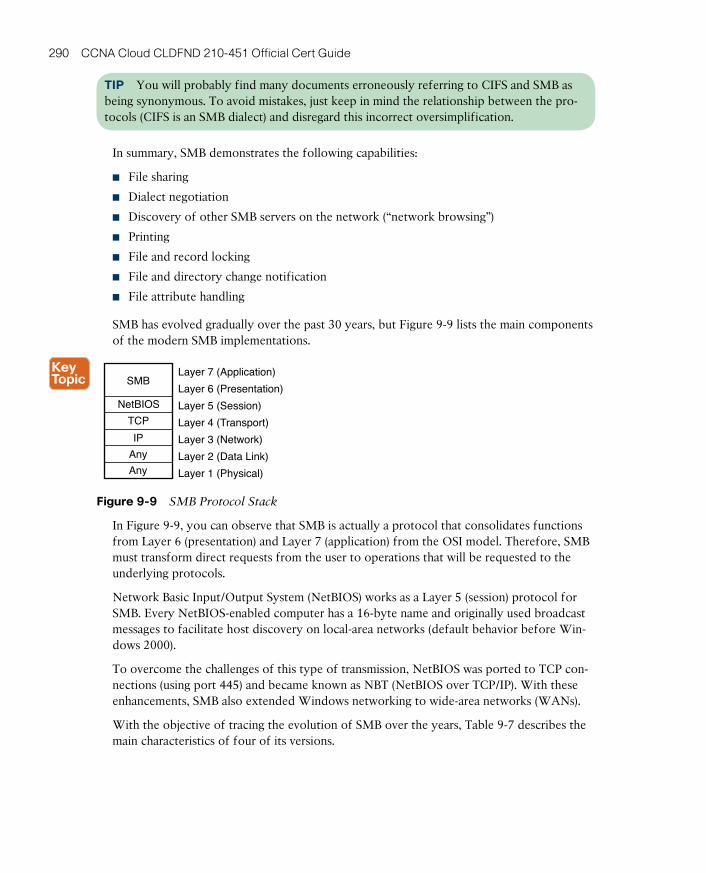
ptg17120290
290 CCNA Cloud CLDFND 210-451 Official Cert Guide
TIP You will probably find many documents erroneously referring to CIFS and SMB as being synonymous. To avoid mistakes, just keep in mind the relationship between the pro-tocols (CIFS is an SMB dialect) and disregard this incorrect oversimplification.
In summary, SMB demonstrates the following capabilities:
■ File sharing
■ Dialect negotiation
■ Discovery of other SMB servers on the network (“network browsing”)
■ Printing
■ File and record locking
■ File and directory change notification
■ File attribute handling
SMB has evolved gradually over the past 30 years, but Figure 9-9 lists the main components of the modern SMB implementations.
Layer 7 (Application)
Layer 6 (Presentation)
Layer 1 (Physical)
Layer 2 (Data Link)
Layer 3 (Network)
Layer 4 (Transport)
Layer 5 (Session)
SMB
Any
Any
IP
TCP
NetBIOS
Figure 9-9 SMB Protocol Stack
In Figure 9-9, you can observe that SMB is actually a protocol that consolidates functions from Layer 6 (presentation) and Layer 7 (application) from the OSI model. Therefore, SMB must transform direct requests from the user to operations that will be requested to the underlying protocols.
Network Basic Input/Output System (NetBIOS) works as a Layer 5 (session) protocol for SMB. Every NetBIOS-enabled computer has a 16-byte name and originally used broadcast messages to facilitate host discovery on local-area networks (default behavior before Win-dows 2000).
To overcome the challenges of this type of transmission, NetBIOS was ported to TCP con-nections (using port 445) and became known as NBT (NetBIOS over TCP/IP). With these enhancements, SMB also extended Windows networking to wide-area networks (WANs).
With the objective of tracing the evolution of SMB over the years, Table 9-7 describes the main characteristics of four of its versions.
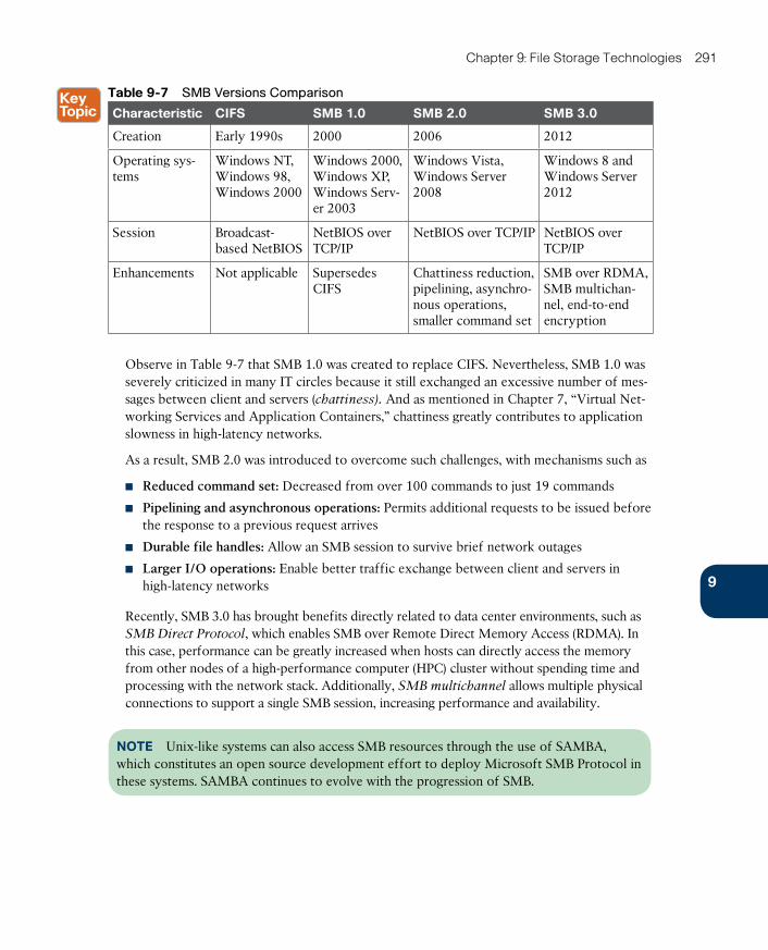
ptg17120290
9
Chapter 9: File Storage Technologies 291
Table 9-7 SMB Versions Comparison
Characteristic CIFS SMB 1.0 SMB 2.0 SMB 3.0
Creation Early 1990s 2000 2006 2012
Operating sys-tems
Windows NT, Windows 98, Windows 2000
Windows 2000, Windows XP, Windows Serv-er 2003
Windows Vista, Windows Server 2008
Windows 8 and Windows Server 2012
Session Broadcast-based NetBIOS
NetBIOS over TCP/IP
NetBIOS over TCP/IP NetBIOS over TCP/IP
Enhancements Not applicable Supersedes CIFS
Chattiness reduction, pipelining, asynchro-nous operations, smaller command set
SMB over RDMA, SMB multichan-nel, end-to-end encryption
Observe in Table 9-7 that SMB 1.0 was created to replace CIFS. Nevertheless, SMB 1.0 was severely criticized in many IT circles because it still exchanged an excessive number of mes-sages between client and servers (chattiness ). And as mentioned in Chapter 7, “Virtual Net-working Services and Application Containers,” chattiness greatly contributes to application slowness in high-latency networks.
As a result, SMB 2.0 was introduced to overcome such challenges, with mechanisms such as
■ Reduced command set: Decreased from over 100 commands to just 19 commands
■ Pipelining and asynchronous operations: Permits additional requests to be issued before the response to a previous request arrives
■ Durable file handles: Allow an SMB session to survive brief network outages
■ Larger I/O operations: Enable better traffic exchange between client and servers in high-latency networks
Recently, SMB 3.0 has brought benefits directly related to data center environments, such as SMB Direct Protocol , which enables SMB over Remote Direct Memory Access (RDMA). In this case, performance can be greatly increased when hosts can directly access the memory from other nodes of a high-performance computer (HPC) cluster without spending time and processing with the network stack. Additionally, SMB multichannel allows multiple physical connections to support a single SMB session, increasing performance and availability.
NOTE Unix-like systems can also access SMB resources through the use of SAMBA, which constitutes an open source development effort to deploy Microsoft SMB Protocol in these systems. SAMBA continues to evolve with the progression of SMB.

ptg17120290
292 CCNA Cloud CLDFND 210-451 Official Cert Guide
Common SMB Client Operations
An SMB client accesses remote files using the concept of shares , which are formally defined as files, folders, or even a whole logical drive that can be shared through SMB ses-sions. From a client perspective, there are multiple ways to access shared files and folders. Figure 9-10 exposes one of them.
Figure 9-10 Mapping a Local Drive to an SMB Share
In this scenario, a shared folder (ingeniously called Share) in the host 10.97.39.200 is mapped to the local drive Z: in my Windows workstation. The following steps illustrate what happens within this successful mapping:
Step 1. Client and server establish a NetBIOS session.
Step 2. Client and server negotiate Microsoft SMB protocol version and dialect.
Step 3. Client logs on to the server.
Step 4. Client connects to a share on the server.
Step 5. Client accesses the folder.
From this moment, whatever operations are performed on this drive will be reflected in the SMB, including opening a file, writing in a file, listing the content of a folder, and so on.
Common SMB NAS Operations
Generally speaking, any Windows-based computer can share files. However, as previously discussed in the section “File Locations,” a NAS can offer scalability, availability, and flex-ibility that may not be found even in specialized computers serving as file servers.
The following are some of the high-level procedures that must be carried out to offer file-based storage in a NAS through SMB:
ptg17120290
9
Chapter 9: File Storage Technologies 293
Step 1. Register the NAS to Active Directory: With this operation, the NAS adminis-trator inserts the system into an Active Directory domain, leveraging all users and groups that are already created in it. Furthermore, the NAS is added as a resource that can be discovered and mapped as a logical drive by Windows servers and desktops.
Step 2. Create the NAS volume: Through a GUI, the NAS administrator checks if there is available space in the system HDDs. Then, the administrator can create an aggregate (RAID group or dynamic disk pool) and a raw volume over it.
Step 3. Format the volume: In this case, the volume is formatted with NTFS to reflect the file security that is already implemented on Active Directory domains. Optionally, a folder tree can be created to provide files and folders to be accessed by users.
Step 4. Sharing: Finally, the tree is shared so that it can be accessed by the clients.
By definition, the security model of Microsoft SMB Protocol has two levels of security: user and share. While user-level authentication indicates which users and groups can access a share, as described in the section “NTFS Permissions,” share-level authentication indicates that access to a share must be controlled by a password that is exclusively assigned to it.
Most NAS systems can perform both types of authentication, leveraging their relationship with Active Directory.
Other File Access ProtocolsAlthough both NFS and SMB have software clients integrated into most operating systems, they are not the only available protocols to access and exchange files across a network. As an illustra-tion, here is a list of open protocols that can also perform this task for users and applications:
■ File Transfer Protocol (FTP) : Created at the dawn of the Internet (1971), FTP is an IETF-standardized file transfer protocol that runs over TCP using two different con-nections for control and data exchange between client and server. Secure File Transfer Protocol (SFTP) is a more robust version of the protocol that was launched in 2001 to improve security.
■ Trivial File Transfer Protocol (TFTP) : Protocol that requires a very simple client and is designed for boot and firmware loading during device initialization. Released in 1981, TFTP leverages UDP in the communication between client and server.
■ Secure Copy Protocol (SCP) : Network protocol that supports file transfers through an SSH (Secure Shell) connection in TCP port 22. SCP is generally installed by default in most Linux distributions.
■ Hypertext Transfer Protocol (HTTP) : As one of the pillars of the World Wide Web, HTTP was originally designed to transfer objects between web servers and browsers. HTTP Secure (HTTPS) provides secure access to web pages, while Web Distributed Authoring and Versioning (WebDAV) allows users to create, read, update, and delete documents in a web server.
■ Apple Filing Protocol (AFP) : Proprietary protocol that offers file services for Apple Mac operating systems. It was previously known as AppleTalk .
ptg17120290
294 CCNA Cloud CLDFND 210-451 Official Cert Guide
Cloud Computing and File StorageWith their basic concepts ingrained in the minds of every computer user, files and directo-ries certainly play a significant role in cloud computing. And, as this section explores, the relationship between file systems and cloud environments can be placed in two contexts: file storage as a part of the cloud infrastructure or file storage as an offer to cloud users. The section also explores OpenStack’s file service, which is called Manila.
File Storage for Cloud InfrastructureAs you learned in the section “Main Differences Between Block and File Technologies,” file-based storage devices present advantages over block-based storage devices, including massive scalability and active control over stored data. For elastic multi-tenant environ-ments, these characteristics are indeed a great fit.
One straightforward example is the use of NAS systems as shared storage for server virtu-
alization clusters. In these scenarios, hypervisors can use a distributed file system to store virtual machine files.
Naturally, each hypervisor vendor tends to favor its own choice of distributed file system to store VM files, but most vendors are flexible about this choice. For example, although VMware offers its vSphere Virtual Machine File System (VMFS) as the default for VMware ESXi implementations to format block-based volumes, such implementations may instead leverage NFS servers to store VM files.
Consistent with their Linux origins, Kernel-based Virtual Machine (KVM) and Xen clusters traditionally mount their VM files on NFS-based NAS devices or file servers. And as you may expect, Microsoft Hyper-V leverages SMB to access VM files to implement storage features from the latest versions from this protocol.
Considering the flexibility required in cloud computing scenarios, many storage administra-tors opt to deploy systems that can allow access through a diverse range of methods, includ-ing both block and file protocols. With such a hybrid storage device, NFS, SMB, and iSCSI can easily run over the same IP network infrastructure, thereby simplifying the installation of new physical servers.
Furthermore, as you will learn in Chapter 10, “Network Architectures for the Data Center: Unified Fabric,” a unified fabric supporting Fibre Channel over Ethernet (FCoE) can avoid the requirement of a separate network infrastructure to provide the exact behavior expect-ed from Fibre Channel SANs.
File HostingProviding external access to files is an extremely popular cloud service. In this case, files can be stored, read, updated, and deleted according to a predefined agreement. The service may involve charges related to storage usage or it may be free.
Your first encounter with the word “cloud” in the context of computing was likely associated with a popular file hosting service such as Google Drive, Box, Dropbox, and Apple iCloud, all of which provide capacity for users to store and read files. But beyond storing personal infor-mation, these providers also offer specialized file services such as the following:

ptg17120290
9
Chapter 9: File Storage Technologies 295
■ Backup: Provides automated copies for files stored in a personal computer as well as enterprise servers. Many cloud providers have developed enhancements that are usually offered as options, such as the type of backup (continuous, incremental), file synchroni-zation, scheduling, and bandwidth control.
■ Security: Offers secure storage through file encryption and typically includes options for users to use their own keys, replicate data in two different geographic regions, and manipulate myriad file and directory permissions.
■ Content Delivery Network (CDN): Through this service, data centers may save band-width resources and leverage the pervasive Internet presence of CDN service providers to optimally distribute content stored in files.
Regardless of the use case, most file services deployed on public clouds tend not to deploy NFS or SMB protocols, mainly because of the challenges they pose with the intrinsic laten-cy of the Internet. HTTP has quickly assumed leadership as the main file transfer protocol for cloud file projects, for reasons such as these:
■ HTTP does not suffer from the same chattiness issues as NFS and SMB.
■ HTTP offers acceptable security through HTTPS.
■ The overwhelming majority of computers and smart devices are equipped with a web browser.
■ Firewall rules generally allow HTTP sessions for web surfing, simplifying access to file hosting service providers.
OpenStack ManilaIntroduced in 2014, Manila is a project whose objective is to provide file-based storage for OpenStack clouds. Based on OpenStack Cinder (which was briefly discussed in Chapter 8), Manila primarily offers to Nova instances coordinated access to shared or distributed file systems.
The project is sponsored by NetApp, Mirantis, Red Hat, EMC, and IBM, and currently sup-ports file sharing through NFS and SMB (although more protocols are expected to follow in future releases). The main concepts behind OpenStack Manila are
■ Share: Instance of a shared file system with a defined access protocol, size, and an access list composed of share access rules.
■ Share access rules: Access-list entries that determine which client IP addresses are autho-rized to access one share.
■ Share network: Defines the network (Layer 2 domain) and subnet (Layer 3 addresses) through which the instances can access the share.
TIP Both subnet and network constructs belong to Neutron, an OpenStack project that will be further explained in Chapter 11, “Network Architectures for the Data Center: SDN and ACI.”
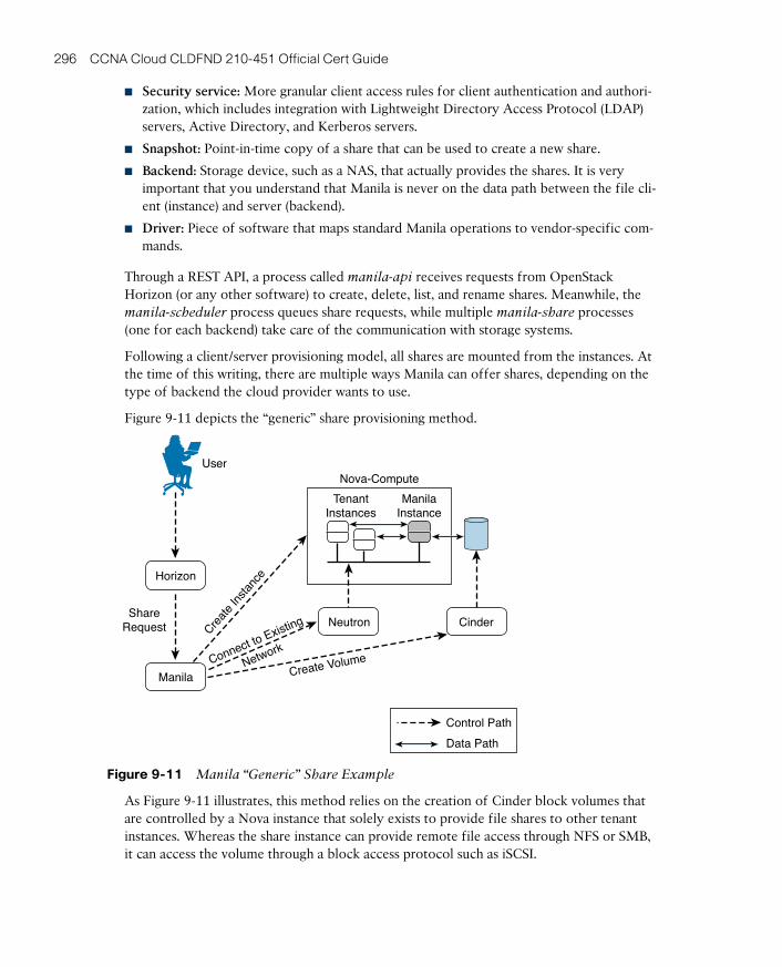
ptg17120290
296 CCNA Cloud CLDFND 210-451 Official Cert Guide
■ Security service: More granular client access rules for client authentication and authori-zation, which includes integration with Lightweight Directory Access Protocol (LDAP) servers, Active Directory, and Kerberos servers.
■ Snapshot: Point-in-time copy of a share that can be used to create a new share.
■ Backend: Storage device, such as a NAS, that actually provides the shares. It is very important that you understand that Manila is never on the data path between the file cli-ent (instance) and server (backend).
■ Driver: Piece of software that maps standard Manila operations to vendor-specific com-mands.
Through a REST API, a process called manila-api receives requests from OpenStack Horizon (or any other software) to create, delete, list, and rename shares. Meanwhile, the manila-scheduler process queues share requests, while multiple manila-share processes (one for each backend) take care of the communication with storage systems.
Following a client/server provisioning model, all shares are mounted from the instances. At the time of this writing, there are multiple ways Manila can offer shares, depending on the type of backend the cloud provider wants to use.
Figure 9-11 depicts the “generic” share provisioning method.
UserNova-Compute
TenantInstances
ManilaInstance
Create VolumeConnect to Existing
Network
Creat
e In
stanc
e
ShareRequest
Horizon
Manila
Neutron Cinder
Control Path
Data Path
Figure 9-11 Manila “Generic” Share Example
As Figure 9-11 illustrates, this method relies on the creation of Cinder block volumes that are controlled by a Nova instance that solely exists to provide file shares to other tenant instances. Whereas the share instance can provide remote file access through NFS or SMB, it can access the volume through a block access protocol such as iSCSI.

ptg17120290
9
Chapter 9: File Storage Technologies 297
On the other hand, Manila can also use third-party vendor drivers to allow the creation of shares on backend storage devices to provide file access to tenant instances. Figure 9-12 clarifies this method.
UserNova-Compute
TenantInstances
NASCreate File
Share
Connect to
Network
ShareRequest
Horizon
Manila
Neutron
Nova-Compute
TenantInstances
Figure 9-12 Manila Third-party Vendor Method Example
As shown in Figure 9-12, after Manila receives a request for another share, it instructs an integrated backend device (NAS) to create a new file system through a supported plug-in. Manila also requires the creation of a Neutron network that connects tenants to the newly created share in the NAS.
Around the Corner: Object StorageRisking an oversimplification, I would say that the choice between block- and file-based storage is guided by two factors: performance and scale. Nonetheless, new applications’ requirements are pushing the edge of this spectrum beyond the scale achieved by file sys-tems, and therefore, leaving further behind the strong consistency that block storage offers.
For this kind of application, a concept called object-based storage seems to be the strongest fit. In such context, an object is a construct that contains data, a globally unique identifier, and both a variable and a flexible amount of metadata. Unlike file systems, object stor-age does not possess a hierarchical structure of directories, because it employs only a flat namespace that contains all objects.
Object storage systems are intended to support massive amounts of unstructured data, and thus do not have to worry about abstractions such as aggregate groups and volumes. Gener-ally, these systems are built over x86 servers (referred to as nodes) rather than specialized equipment such as disk arrays or NAS devices. Hence, the internal storage from these serv-ers is used to store the objects, which are always replicated on other nodes to increase data availability. Moreover, scalability is achieved with the insertion of additional nodes.
Through the designed simplicity of object storage, these systems only provide an object after a request and only allow manipulation of the whole unit, never just a part of it. Only

ptg17120290
298 CCNA Cloud CLDFND 210-451 Official Cert Guide
applications that are mostly read-oriented, with minimal writes or incremental updates, are usually recommended to use object-based storage. Some examples are social networking, data backup, archival imaging, and multimedia applications.
The flexible metadata of objects enables some capabilities that are extremely hard to rep-licate in file systems. For example, an object allows the creation of custom metadata such as genre, data center site, tenant, publisher, and other details that may be limited only by your imagination. Because this metadata can be used in the distribution of objects across the nodes, the location of a single object beneath petabytes of information is drastically simpli-fied, even enabling the client to infer which nodes host the object.
Some of the prominent object storage solutions at the time of this writing are
■ Ceph : Open source software designed to present block, file, and object storage through an algorithm called CRUSH (Controlled Replication Under Scalable Hashing), which ensures that data is evenly distributed across the cluster. This system has self-healing capabilities that eliminate the possibility of a single point of failure, even after a hard-ware malfunction.
■ Amazon Simple Storage Service (S3) : Provides developers and IT teams with secure, durable, highly scalable object storage.
■ OpenStack Swift : Object store project that offers massive scale with a simple API. Some companies, such as SwiftStack, offer OpenStack Swift as an enterprise solution.
Due to their intensive use of APIs, these solutions generally employ HTTP as the object access protocol.
Further Reading■ Ceph: http://ceph.com/
■ Amazon S3: http://aws.amazon.com/s3/
■ OpenStack Swift: http://docs.openstack.org/developer/swift/
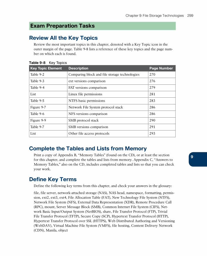
ptg17120290
9
Chapter 9: File Storage Technologies 299
Exam Preparation Tasks
Review All the Key TopicsReview the most important topics in this chapter, denoted with a Key Topic icon in the outer margin of the page. Table 9-8 lists a reference of these key topics and the page num-ber on which each is found.
Table 9-8 Key Topics
Key Topic Element Description Page Number
Table 9-2 Comparing block and file storage technologies 270
Table 9-3 ext versions comparison 276
Table 9-4 FAT versions comparison 279
List Linux file permissions 281
Table 9-5 NTFS basic permissions 283
Figure 9-7 Network File System protocol stack 286
Table 9-6 NFS versions comparison 286
Figure 9-9 SMB protocol stack 290
Table 9-7 SMB versions comparison 291
List Other file access protocols 293
Complete the Tables and Lists from MemoryPrint a copy of Appendix B, “Memory Tables” (found on the CD), or at least the section for this chapter, and complete the tables and lists from memory. Appendix C, “Answers to Memory Tables,” also on the CD, includes completed tables and lists so that you can check your work.
Define Key TermsDefine the following key terms from this chapter, and check your answers in the glossary:
file, file server, network-attached storage (NAS), NAS head, namespace, formatting, permis-sion, ext2, ext3, ext4, File Allocation Table (FAT), New Technology File System (NTFS), Network File System (NFS), External Data Representation (XDR), Remote Procedure Call (RPC), mount, Server Message Block (SMB), Common Internet File System (CIFS), Net-work Basic Input/Output System (NetBIOS), share, File Transfer Protocol (FTP), Trivial File Transfer Protocol (TFTP), Secure Copy (SCP), Hypertext Transfer Protocol (HTTP), Hypertext Transfer Protocol over SSL (HTTPS), Web Distributed Authoring and Versioning (WebDAV), Virtual Machine File System (VMFS), file hosting, Content Delivery Network (CDN), Manila, object

ptg17120290
This chapter covers the following topics:
■ Attributes of Data Center Networks
■ The Three-Tier Design
■ Device Virtualization
■ Virtual PortChannels
■ Fabric Extenders
■ Overlay Transport Virtualization
■ I/O Consolidation
■ FabricPath
This chapter covers the following exam objectives:
■ 4.1 Describe network architectures for the data center■ 4.1.a Cisco Unifi ed Fabric
■ 4.1.a.1 Describe the Cisco Nexus product family■ 4.1.a.2 Describe device virtualization
■ 4.1.c ACI■ 4.1.c.2 Describe benefi ts of leaf/spine architecture
ptg17120290
CHAPTER 10
Network Architectures for the Data Center: Unified Fabric
Thus far, you have learned important concepts regarding cloud infrastructure, including server virtualization and storage technologies. Throughout much of the discussion of these topics, the presence of the network that magically binds these elements together has been presumed without further comment. Chapter 6, “Infrastructure Virtualization,” and Chapter 7, “Virtual Networking Services and Application Containers,” briefly discussed the main aspects that drive physical network architectures in modern data centers, especially those that support cloud proj-ects. This chapter delves much deeper into the topic of network architectures for the data center.
As a direct result of the popularization of server virtualization in the mid 2000s, network designs have embraced profound architectural changes at breakneck speed. And with Cisco leading almost all of these significant shifts, its virtualization solutions were successfully incorporated into the foundations of data center infrastructure knowledge.
The CLDFND exam requires knowledge about three Cisco data center networking archi-tectures: Cisco Unified Fabric, Software-Defined Networking (SDN), and Cisco Application Centric Infrastructure (ACI). This chapter explores Cisco Unified Fabric, investigating the massive impact innovative features from the Nexus portfolio have on data center projects.
“Do I Know This Already?” QuizThe “Do I Know This Already?” quiz allows you to assess whether you should read this entire chapter thoroughly or jump to the “Exam Preparation Tasks” section. If you are in doubt about your answers to these questions or your own assessment of your knowledge of the topics, read the entire chapter. Table 10-1 lists the major headings in this chapter and their corresponding “Do I Know This Already?” quiz questions. You can find the answers in Appendix A, “Answers to Pre-Assessments and Quizzes.”
Table 10-1 “Do I Know This Already?” Section-to-Question Mapping
Foundation Topics Section Questions
Attributes of Data Center Networks 1
The Three-Tier Design 2–3
Device Virtualization 4
Virtual PortChannels 5
Fabric Extenders 6
Overlay Transport Virtualization 7
I/O Consolidation 8
FabricPath 9–10
ptg17120290
302 CCNA Cloud CLDFND 210-451 Official Cert Guide
1. Which of the following is not an expected quality of a data center network?
a. Availability
b. Scalability
c. Flexibility
d. User authentication
e. Manageability
2. Which of the following represent the main distinctions between data center and campus networks? (Choose all that apply.)
a. Campus networks follow three-tier designs with core, aggregation, and access layers.
b. Majority of traffic direction (east-west versus north-south).
c. Number of connections on a single host.
d. Data center networks generally are considered a more secure environment.
3. Which of the following does not represent a function of the aggregation layer on a three-tier data center network design?
a. Default gateway for the servers
b. Supports east-west traffic between servers connected to different access switches
c. Routing protocol peering with external networks
d. STP root
4. Which of the following is correct regarding virtual device contexts?
a. You cannot configure two VRF instances with the same name in two different VDCs.
b. With VDCs, a switch can deploy more than 4094 VLANs.
c. You can control the number of VLANs, VRF instances, and MAC addresses each VDC can have.
d. It is possible to allow traffic between two VDCs through the switch backplane.
e. VDCs are a scalable solution for multitenant data centers.
5. Which of the following is incorrect regarding virtual PortChannels?
a. They allow two switches to behave like a single device.
b. Although it is not a good practice, the peer-keepalive probes can traverse the peer trunk.
c. You can form a peer trunk with only one physical connection.
d. Primary and secondary roles must be established between the two switches.
e. Using vPC eliminates the need for STP.

ptg17120290
10
Chapter 10: Network Architectures for the Data Center: Unified Fabric 303
6. Which of the following is not correct regarding Fabric Extenders?
a. They cannot work without connecting to a parent switch.
b. They create logical interfaces in the parent switch.
c. They allow the connection of FCoE-enabled devices.
d. They allow the connection of STP-enabled devices.
e. They allow the connection of LACP-enabled devices.
7. Which of the following is incorrect regarding Overlay Transport Virtualization?
a. Allows VLAN extension between multiple sites
b. Can use multicast or unicast-only backbones between data center sites
c. Blocks broadcast traffic
d. Blocks STP
e. Blocks unknown unicast frames
8. Which of the following options are not required on Fibre Channel over Ether-net connections?
a. 10-Gigabit Ethernet or higher
b. Fiber connection
c. ETS
d. PFC
e. DCBX
9. Which protocol is responsible for both OTV and FabricPath MAC address updates?
a. Ethernet
b. OSPF opaque TLVs
c. IS-IS
d. MP-BGP
e. OTV and FabricPath do not share the same protocol for updates.
10. Which of the following is not an advantage of spine-leaf topologies over three-tier designs?
a. Bandwidth scalability
b. Simplicity
c. Flexibility
d. Rapid STP
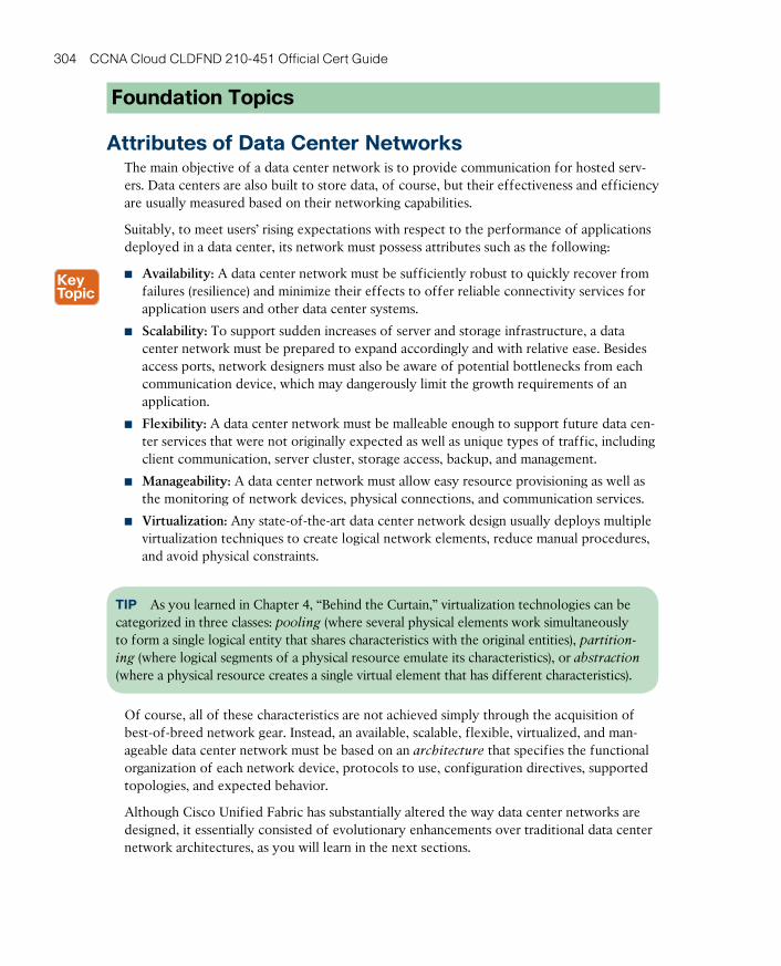
ptg17120290
304 CCNA Cloud CLDFND 210-451 Official Cert Guide
Foundation Topics
Attributes of Data Center NetworksThe main objective of a data center network is to provide communication for hosted serv-ers. Data centers are also built to store data, of course, but their effectiveness and efficiency are usually measured based on their networking capabilities.
Suitably, to meet users’ rising expectations with respect to the performance of applications deployed in a data center, its network must possess attributes such as the following:
■ Availability: A data center network must be sufficiently robust to quickly recover from failures (resilience) and minimize their effects to offer reliable connectivity services for application users and other data center systems.
■ Scalability: To support sudden increases of server and storage infrastructure, a data center network must be prepared to expand accordingly and with relative ease. Besides access ports, network designers must also be aware of potential bottlenecks from each communication device, which may dangerously limit the growth requirements of an application.
■ Flexibility: A data center network must be malleable enough to support future data cen-ter services that were not originally expected as well as unique types of traffic, including client communication, server cluster, storage access, backup, and management.
■ Manageability: A data center network must allow easy resource provisioning as well as the monitoring of network devices, physical connections, and communication services.
■ Virtualization: Any state-of-the-art data center network design usually deploys multiple virtualization techniques to create logical network elements, reduce manual procedures, and avoid physical constraints.
TIP As you learned in Chapter 4, “Behind the Curtain,” virtualization technologies can be categorized in three classes: pooling (where several physical elements work simultaneously to form a single logical entity that shares characteristics with the original entities), partition-
ing (where logical segments of a physical resource emulate its characteristics), or abstraction
(where a physical resource creates a single virtual element that has different characteristics).
Of course, all of these characteristics are not achieved simply through the acquisition of best-of-breed network gear. Instead, an available, scalable, flexible, virtualized, and man-ageable data center network must be based on an architecture that specifies the functional organization of each network device, protocols to use, configuration directives, supported topologies, and expected behavior.
Although Cisco Unified Fabric has substantially altered the way data center networks are designed, it essentially consisted of evolutionary enhancements over traditional data center network architectures, as you will learn in the next sections.
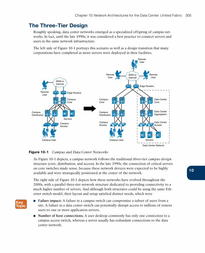
ptg17120290
10
Chapter 10: Network Architectures for the Data Center: Unified Fabric 305
The Three-Tier DesignRoughly speaking, data center networks emerged as a specialized offspring of campus net-works. In fact, until the late 1990s, it was considered a best practice to connect servers and users in the same network infrastructure.
The left side of Figure 10-1 portrays this scenario as well as a design transition that many corporations have completed as more servers were deployed in their facilities.
RemoteUser
Edge Routers
CampusCore
CampusCore
CampusAccess
CampusDistribution
Campus User
Servers
RemoteUser
RemoteUser
RemoteUser
Edge Routers
CampusDistribution
CampusAccess
Campus User
Data Center Network
Data CenterCore
Data CenterAggregation
Data CenterAccess
Servers
WAN orInternet
WAN orInternet
Figure 10-1 Campus and Data Center Networks
As Figure 10-1 depicts, a campus network follows the traditional three-tier campus design structure (core, distribution, and access). In the late 1990s, the connection of critical servers on core switches made sense, because these network devices were expected to be highly available and were strategically positioned at the center of the network.
The right side of Figure 10-1 depicts how these networks have evolved throughout the 2000s, with a parallel three-tier network structure dedicated to providing connectivity to a much higher number of servers. And although both structures could be using the same Eth-ernet switch model, their layout and setup satisfied distinct needs, which were
■ Failure impact: A failure in a campus switch can compromise a subset of users from a site. A failure in a data center switch can potentially disrupt access to millions of remote users to one or more application servers.
■ Number of host connections: A user desktop commonly has only one connection to a campus access switch, whereas a server usually has redundant connections to the data center network.
ptg17120290
306 CCNA Cloud CLDFND 210-451 Official Cert Guide
■ Traffic direction: Undoubtedly, traffic in a campus network mostly happens toward the core switches, directed to local servers or external networks. The same situation does not happen in data center networks because inter-server traffic (east-west) easily outweighs client-server traffic (north-south).
The core-aggregation-access topology is the accumulation of years of real-world expe-rience from data center network designers from different industries. Because such an approach brings modularity, flexibility, and resilience, it was considered during the 2000s the de facto best practice for multipurpose data center networks.
Similar to campus designs, each switch tier exists to offer different networking roles and functionalities. For example, the core tier primarily consolidates north-south traf-fic between the servers and the external networks. Commonly operating as pure Layer 3 devices, core switches also provide a highly scalable, flexible, and resilient structure that can offer connectivity between aggregation blocks (multiple pairs of aggregation switches) for scalable data centers.
The aggregation tier is originally designed to provide confluence for server VLANs, being their default gateway and forwarding east-west traffic between distinct pairs of access
switches. For these reasons, the aggregation tier is considered the best place in a data net-work to connect networking services, such as firewalls and server load balancers.
The access tier is ultimately responsible for server connection. With the highest number of ports among all tiers, these devices are configured with simplicity in mind. Consequently, access switches traditionally operate in Layer 2 only, offering communication between hosts that belong to the same IP subnet.
NOTE Many data centers deploy the three-tier design on their networks with slight modi-fications, such as collapsing core and aggregation switches in a single tier (small and midsize facilities) or providing routing solely in the core switches to allow an “any-VLAN-in-any-rack” strategy (service providers).
In 2008, Cisco released its Nexus Series switches , a specialized line of switches for data center networks. While, at first, they were positioned in traditional three-tier topologies, Nexus switches provided greater reliability and superior performance when compared to other Ethernet switches. Notwithstanding, these communication devices brought a series of innovative features conceived to overcome exclusive challenges of data centers, such as the following:
■ Virtual device contexts
■ Virtual PortChannels
■ Fabric Extenders
■ Overlay Transport Virtualization
■ I/O consolidation
■ FabricPath
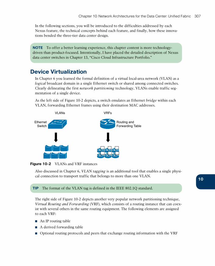
ptg17120290
10
Chapter 10: Network Architectures for the Data Center: Unified Fabric 307
In the following sections, you will be introduced to the difficulties addressed by each Nexus feature, the technical concepts behind each feature, and finally, how these innova-tions bended the three-tier data center design.
NOTE To offer a better learning experience, this chapter content is more technology-driven than product-focused. Intentionally, I have placed the detailed description of Nexus data center switches in Chapter 13, “Cisco Cloud Infrastructure Portfolio.”
Device VirtualizationIn Chapter 6 you learned the formal definition of a virtual local-area network (VLAN) as a logical broadcast domain in a single Ethernet switch or shared among connected switches. Clearly delineating the first network partitioning technology, VLANs enable traffic seg-mentation of a single device.
As the left side of Figure 10-2 depicts, a switch emulates an Ethernet bridge within each VLAN, forwarding Ethernet frames using their destination MAC addresses.
VLANs VRFs
EthernetSwitch
Routing andForwarding Table
Figure 10-2 VLANs and VRF instances
Also discussed in Chapter 6, VLAN tagging is an additional tool that enables a single physi-cal connection to transport traffic that belongs to more than one VLAN.
TIP The format of the VLAN tag is defined in the IEEE 802.1Q standard.
The right side of Figure 10-2 depicts another very popular network partitioning technique, Virtual Routing and Forwarding (VRF) , which consists of a routing instance that can coex-ist with several others in the same routing equipment. The following elements are assigned to each VRF:
■ An IP routing table
■ A derived forwarding table
■ Optional routing protocols and peers that exchange routing information with the VRF
ptg17120290
308 CCNA Cloud CLDFND 210-451 Official Cert Guide
Whereas VLANs deploy segmentation for Layer 2 traffic (Ethernet) and VRF instances do the same for Layer 3 traffic (IP), both technologies enable the provision of logical networks without the acquisition of new hardware. As a result, they have become fundamental build-ing blocks in any data center network project. Nonetheless, seasoned network designers are already used to the following limitations from these virtualization technologies:
■ According to the IEEE 802.1Q standards, a switch can only support a maximum of 4,094 VLANs (because VLAN identifiers must belong to the range 1–4094).
■ Within switches, these virtual elements may share processes and protocol instances. Hence, a problem on these shared resources may impact all VLANs or VRF instances.
■ VLANs and VRF instances do not support management partitioning. Therefore, adminis-trative access to the physical device can potentially affect many logical networks.
By all accounts, these challenges were addressed with a remarkable Nexus feature called virtual device context (VDC) . Essentially conceived to emulate Ethernet switches, VDCs allow data center network designers to achieve a higher level of consolidation and isolation that was not possible with other network partitioning technologies.
Cisco introduced VDCs in 2008 with its Nexus 7000 Series. Taking advantage of the NX-OS networking operating system architecture, a VDC can be understood as a logical partition of a physical switch with the following characteristics:
■ It can be managed by a completely distinct set of administrators.
■ It implements exclusive Layer 2–3 processes and protocol instances.
■ It does not allow the internal communication between hosts and devices connected to another VDC. If such traffic exchange is desired, an external connection must be built between both VDCs.
NOTE The later section “Overlay Transport Virtualization” presents a use case for the con-nection of VDCs created on the same physical switch.
VDCs envelop other network partitioning techniques such as VLANs and VRF instances, as illustrated in Figure 10-3.
Within a VDC, you can create VLANs and VRF instances through exactly the same proce-dures used in a physical switch. If two VLANs with the same identifier (100, for example) are configured on two different VDCs, they become distinct elements called bridge
domains in the physical switch perspective. In a similar fashion, if you configure VRF instances with the same name on different VDCs, NX-OS will see them as separate virtual elements.
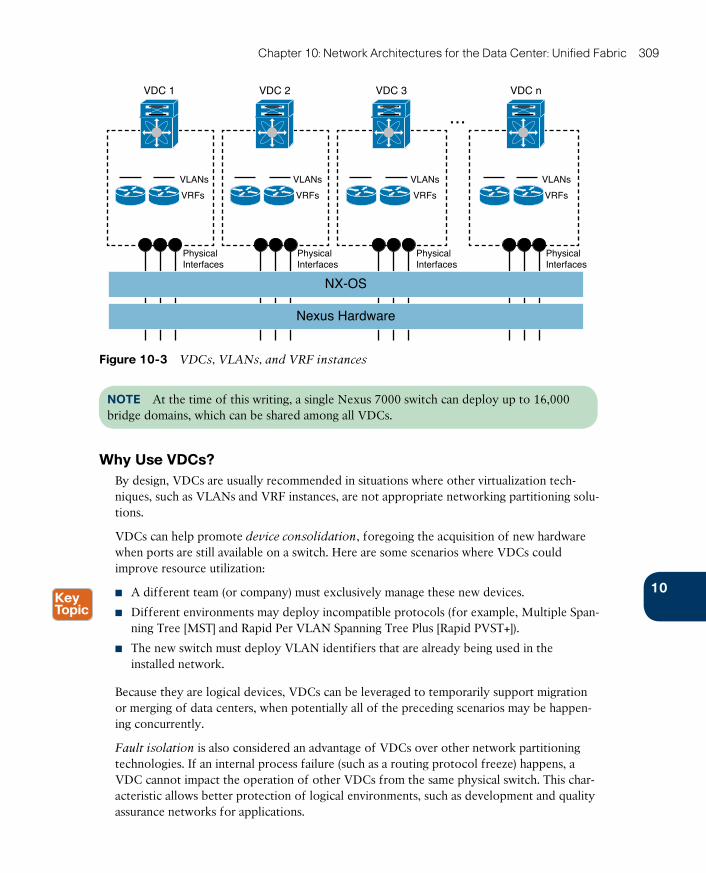
ptg17120290
10
Chapter 10: Network Architectures for the Data Center: Unified Fabric 309
VDC n
PhysicalInterfaces
PhysicalInterfaces
PhysicalInterfaces
PhysicalInterfaces
VDC 1
VLANs
VRFs
VDC 2 VDC 3
VLANs
VRFs
VLANs
VRFs
NX-OS
Nexus Hardware
...
VLANs
VRFs
Figure 10-3 VDCs, VLANs, and VRF instances
NOTE At the time of this writing, a single Nexus 7000 switch can deploy up to 16,000 bridge domains, which can be shared among all VDCs.
Why Use VDCs?By design, VDCs are usually recommended in situations where other virtualization tech-niques, such as VLANs and VRF instances, are not appropriate networking partitioning solu-tions.
VDCs can help promote device consolidation , foregoing the acquisition of new hardware when ports are still available on a switch. Here are some scenarios where VDCs could improve resource utilization:
■ A different team (or company) must exclusively manage these new devices.
■ Different environments may deploy incompatible protocols (for example, Multiple Span-ning Tree [MST] and Rapid Per VLAN Spanning Tree Plus [Rapid PVST+]).
■ The new switch must deploy VLAN identifiers that are already being used in the installed network.
Because they are logical devices, VDCs can be leveraged to temporarily support migration or merging of data centers, when potentially all of the preceding scenarios may be happen-ing concurrently.
Fault isolation is also considered an advantage of VDCs over other network partitioning technologies. If an internal process failure (such as a routing protocol freeze) happens, a VDC cannot impact the operation of other VDCs from the same physical switch. This char-acteristic allows better protection of logical environments, such as development and quality assurance networks for applications.

ptg17120290
310 CCNA Cloud CLDFND 210-451 Official Cert Guide
Additionally, VDCs allow the creation of logical demilitarized zones (DMZs) in a single physical switch. In such scenarios, VDCs can efficiently deploy virtual devices whose com-munication only happens through external firewalls and support security policies that require
■ A distinct team to manage the switches from each security zone.
■ A failure on a switch should not affect switches on different security zones.
Although VDCs are an amazing tool, each company should perform a thorough analysis before deciding if such virtualization technology is adequate to its security policies. As sup-port for this decision, VDCs have already achieved validation from several compliance orga-nizations, including NSS Labs for Payment Card Industry (PCI) Compliant Environments, U.S. Federal Information Processing Standards (FIPS) Publication 140-2, and Common Cri-teria Evaluation and Validation Scheme (Certification no. 10349).
Creating VDCsIn any Nexus switch, you are forced to use at least one virtual device context: the default
VDC . This context is automatically created during the switch boot and, if you are using a VDC-capable switch, is used to create other contexts.
To demonstrate this statement, I will create a new VDC named Switch2. Example 10-1 fur-ther details how interfaces can be allocated to a VDC and verifies such distribution.
Example 10-1 New VDC Creation
! Creating a VDC named Switch2
N7K(config)# vdc Switch2
Note: Creating VDC, one moment please ...
14:36:07 N7K %$ VDC-1 %$ %VDC_MGR-2-VDC_ONLINE: vdc 2 has come online
! Allocating interface Ethernet 10/10 to Switch2
N7K(config-vdc)# allocate interface ethernet 10/10
! I allocate the entire Ethernet 10/10 hardware port-group to this Switch2
Entire port-group is not present in the command. Missing ports will
be included automatically
Moving ports will cause all config associated to them in source vdc
to be removed. Are you sure you want to move the ports (y/n)? [yes] yes
! Verifying the new interface distribution among VDCs
N7K(config-vdc)# show vdc membership
vdc_id: 0 vdc_name: Unallocated interfaces:
vdc_id: 1 vdc_name: N7K interfaces:
Ethernet1/1 Ethernet1/2 Ethernet1/3
Ethernet1/4 Ethernet1/5 Ethernet1/6
[output suppressed]
Ethernet1/46 Ethernet1/47 Ethernet1/48
Ethernet10/1 Ethernet10/2 Ethernet10/3
Ethernet10/4 Ethernet10/5 Ethernet10/6
Ethernet10/7 Ethernet10/8 Ethernet10/9
Ethernet10/11 Ethernet10/13 Ethernet10/15
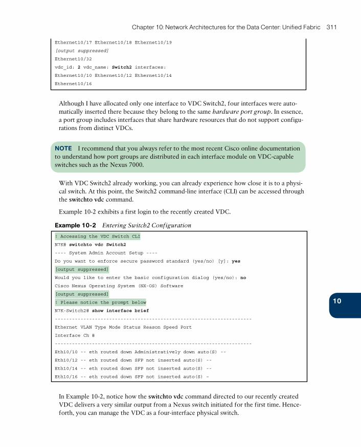
ptg17120290
10
Chapter 10: Network Architectures for the Data Center: Unified Fabric 311
Ethernet10/17 Ethernet10/18 Ethernet10/19
[output suppressed]
Ethernet10/32
vdc_id: 2 vdc_name: Switch2 interfaces:
Ethernet10/10 Ethernet10/12 Ethernet10/14
Ethernet10/16
Although I have allocated only one interface to VDC Switch2, four interfaces were auto-matically inserted there because they belong to the same hardware port group. In essence, a port group includes interfaces that share hardware resources that do not support configu-rations from distinct VDCs.
NOTE I recommend that you always refer to the most recent Cisco online documentation to understand how port groups are distributed in each interface module on VDC-capable switches such as the Nexus 7000.
With VDC Switch2 already working, you can already experience how close it is to a physi-cal switch. At this point, the Switch2 command-line interface (CLI) can be accessed through the switchto vdc command.
Example 10-2 exhibits a first login to the recently created VDC.
Example 10-2 Entering Switch2 Configuration
! Accessing the VDC Switch CLI
N7K# switchto vdc Switch2
---- System Admin Account Setup ----
Do you want to enforce secure password standard (yes/no) [y]: yes
[output suppressed]
Would you like to enter the basic configuration dialog (yes/no): no
Cisco Nexus Operating System (NX-OS) Software
[output suppressed]
! Please notice the prompt below
N7K-Switch2# show interface brief
---------------------------------------------------------------------
Ethernet VLAN Type Mode Status Reason Speed Port
Interface Ch #
---------------------------------------------------------------------
Eth10/10 -- eth routed down Administratively down auto(S) --
Eth10/12 -- eth routed down SFP not inserted auto(S) --
Eth10/14 -- eth routed down SFP not inserted auto(S) --
Eth10/16 -- eth routed down SFP not inserted auto(S) –
In Example 10-2, notice how the switchto vdc command directed to our recently created VDC delivers a very similar output from a Nexus switch initiated for the first time. Hence-forth, you can manage the VDC as a four-interface physical switch.
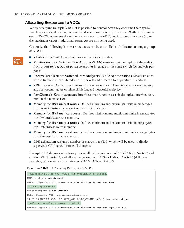
ptg17120290
312 CCNA Cloud CLDFND 210-451 Official Cert Guide
Allocating Resources to VDCsWhen deploying multiple VDCs, it is possible to control how they consume the physical switch resources, allocating minimum and maximum values for their use. With these param-eters, NX-OS guarantees the minimum resources to a VDC, but it can reclaim more (up to the maximum value) if additional resources are not being used.
Currently, the following hardware resources can be controlled and allocated among a group of VDCs:
■ VLANs: Broadcast domains within a virtual device context
■ Monitor sessions: Switched Port Analyzer (SPAN) sessions that can replicate the traffic from a port (or a group of ports) to another interface in the same switch for analysis pur-poses
■ Encapsulated Remote Switched Port Analyzer (ERSPAN) destinations: SPAN sessions whose traffic is encapsulated into IP packets and directed to a specified IP address.
■ VRF instances: As mentioned in an earlier section, these elements deploy virtual routing and forwarding tables within a single Layer 3 networking device.
■ PortChannels: Sets of aggregate interfaces that function as a single logical interface (cov-ered in the next section).
■ Memory for IPv4 unicast routes: Defines minimum and maximum limits in megabytes for Internet Protocol version 4 unicast route memory.
■ Memory for IPv4 multicast routes: Defines minimum and maximum limits in megabytes for IPv4 multicast route memory.
■ Memory for IPv6 unicast routes: Defines minimum and maximum limits in megabytes for IPv6 unicast route memory.
■ Memory for IPv6 multicast routes: Defines minimum and maximum limits in megabytes for IPv6 multicast route memory.
■ CPU utilization: Assigns a number of shares to a VDC, which will be used to divide supervisor CPU access among all contexts.
Example 10-3 demonstrates how you can allocate a minimum of 16 VLANs to Switch2 and another VDC, Switch3, and allocate a maximum of 4094 VLANs to Switch2 (if they are available, of course) and a maximum of 16 VLANs to Switch3.
Example 10-3 Allocating Resources to VDCs
! Allocating 16 to 4094 VLANs (if available) to Switch2
N7K (config)# vdc Switch2
N7K(config-vdc)# limit-resource vlan minimum 16 maximum 4094
! Creating a new VDC
N7K(config-vdc)# vdc Switch3
Note: Creating VDC, one moment please ...
14:53:33 N7K %$ VDC-1 %$ %VDC_MGR-2-VDC_ONLINE: vdc 3 has come online
! Allocating only 16 VLANs to Switch3
N7K(config-vdc)# limit-resource vlan minimum 16 maximum equal-to-min

ptg17120290
10
Chapter 10: Network Architectures for the Data Center: Unified Fabric 313
Instead of changing resource allocation in each VDC, it is also possible to configure resource templates that can be applied to multiple VDCs. Resource templates can be used to decrease the number of configuration operations and increase standardization.
NOTE Resource allocation configurations can be done in the default VDC or in an admin VDC , which is restricted to handling administrative tasks over the other VDCs and the physical hardware. Refer to Chapter 13 and the Cisco online documentation to verify whether your hardware and software combination supports admin VDCs.
Virtual PortChannelsAny communication media is susceptible to failures, be they caused by humans or a result of external events. Therefore, it is only natural that network designers would want to define redundant paths in critical networks.
However, in classical Ethernet networks, if two or more paths between two hosts are active at the same time, a deplorable effect known as loop can easily happen. As a visual aid, Fig-ure 10-4 details how a loop can be formed in an Ethernet switched network that receives a single broadcast frame.
Agg-1 Agg-2
BC
AS
T
BC
AS
T
BC
AS
TBCAST
BC
AS
T
22
4 4
1
BroadcastFrame
BCASTBCAST
3 3
Access
Figure 10-4 How to Generate a Loop in Your Home
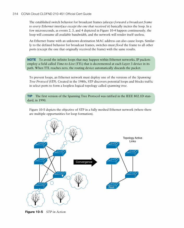
ptg17120290
314 CCNA Cloud CLDFND 210-451 Official Cert Guide
The established switch behavior for broadcast frames (always forward a broadcast frame
to every Ethernet interface except the one that received it) basically incites the loop. In a few microseconds, as events 2, 3, and 4 depicted in Figure 10-4 happen continuously, the loop will consume all available bandwidth, and the network will render itself useless.
An Ethernet frame with an unknown destination MAC address can also cause loops. Similar-ly to the defined behavior for broadcast frames, switches must flood the frame to all other ports (except the one that originally received the frame) with the same results.
NOTE To avoid the infinite loops that may happen within Ethernet networks, IP packets employ a field called Time-to-Live (TTL) that is decremented at each Layer 3 device in its path. When TTL reaches zero, the routing device automatically discards the packet.
To prevent loops, an Ethernet network must deploy one of the versions of the Spanning
Tree Protocol (STP) . Created in the 1980s, STP discovers potential loops and blocks traffic in select ports to form a loopless logical topology called spanning tree .
TIP The first version of the Spanning Tree Protocol was ratified in the IEEE 802.1D stan-dard, in 1990.
Figure 10-5 depicts the objective of STP in a fully meshed Ethernet network (where there are multiple opportunities for loop formation).
Convergence
Topology ActiveLinks
Root
Figure 10-5 STP in Action
ptg17120290
10
Chapter 10: Network Architectures for the Data Center: Unified Fabric 315
By definition, a spanning tree topology has a root bridge (or switch) from which the active paths are formed, and all other switches can have only one active connection toward the root.
When all Ethernet switches in a LAN deploy the same STP version, they exchange Bridge Protocol Data Unit (BPDU) frames in order to form a spanning tree. This process is called convergence , and it lasts until all switches agree on a single stable topology. Afterward, in case an active connection fails or another switch is connected to the topology, a new span-ning tree may be calculated and a recon vergence is expected.
A topology change in the spanning tree may represent tens of seconds without traffic in an Ethernet network. Knowing that this disruption is unbearable for most modern applications, Cisco and other switch manufacturers began to work on proprietary enhancements to STP. In 2004, these efforts coalesced in an evolution of STP called Rapid Spanning Tree Proto-
col (RSTP) and standardized as IEEE 802.1w.
Link AggregationRegardless of version, one of the most persistent challenges STP presents is the waste of physical connections between switches (also known as uplinks ). More specifically, in a traditional Ethernet network, it is expected that STP (or any of its later versions) will allow only one path toward the root, blocking every other redundant path. Without a doubt, this characteristic wastes bandwidth resources from ports and cabling that are already provi-sioned but only used in case of a failure.
Using existing processes and protocols to obtain a specific advantage, a company called Kalpana , which was later acquired by Cisco in 1994, created a virtualization technique to “fool” STP. In summary, EtherChannels provide link aggregation between two Ethernet devices as if they were connected with a single (logical) link.
To sustain the illusion of a single interface between two switches, each interface in an Ether-Channel group must share the same physical properties and configuration (such as speed, duplex, flow control, Layer 2 mode, native VLAN, and so on), and not flood unknown uni-cast frames or forward broadcast frames back to the channel.
With the intention to provide link aggregation interoperability between devices from differ-ent vendors, the IEEE 802.3ad standard was published in 2000. It was subsequently adopted by most Ethernet switch vendors.
Using link aggregation, STP detects a single logical interface, load balancing among the active physical links that are part of the channel. Figure 10-6 represents how STP aggregates links.
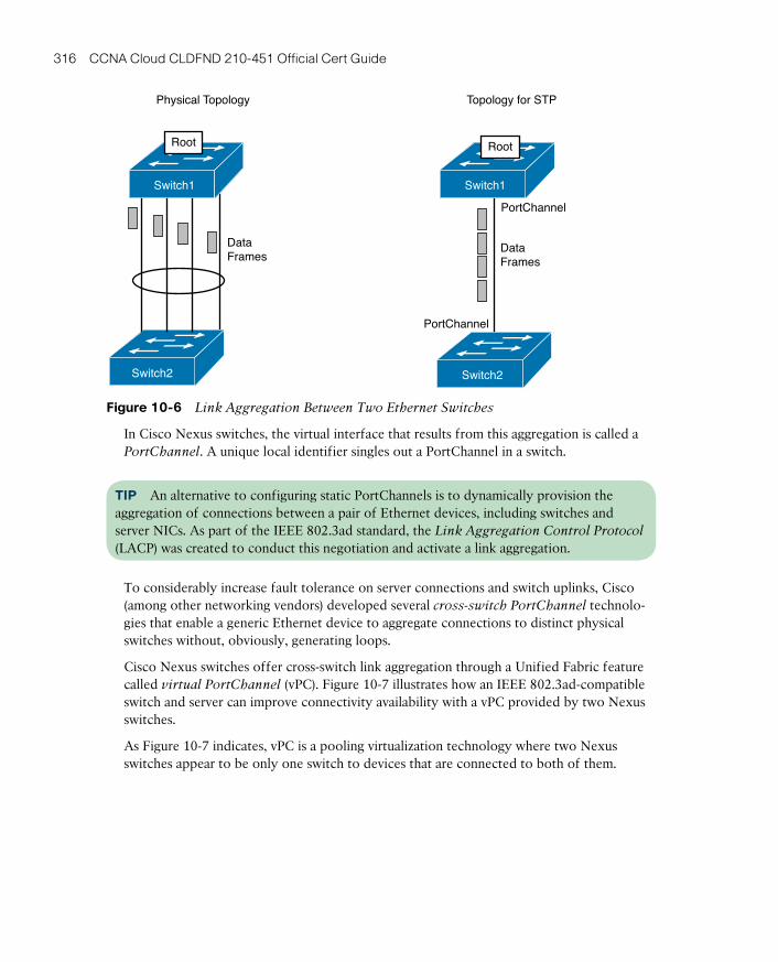
ptg17120290
316 CCNA Cloud CLDFND 210-451 Official Cert Guide
Physical Topology Topology for STP
DataFrames
Switch1
Switch2
Root
PortChannel
PortChannel
Switch2
DataFrames
Root
Switch1
Figure 10-6 Link Aggregation Between Two Ethernet Switches
In Cisco Nexus switches, the virtual interface that results from this aggregation is called a PortChannel . A unique local identifier singles out a PortChannel in a switch.
TIP An alternative to configuring static PortChannels is to dynamically provision the aggregation of connections between a pair of Ethernet devices, including switches and server NICs. As part of the IEEE 802.3ad standard, the Link Aggregation Control Protocol (LACP) was created to conduct this negotiation and activate a link aggregation.
To considerably increase fault tolerance on server connections and switch uplinks, Cisco (among other networking vendors) developed several cross-switch PortChannel technolo-gies that enable a generic Ethernet device to aggregate connections to distinct physical switches without, obviously, generating loops.
Cisco Nexus switches offer cross-switch link aggregation through a Unified Fabric feature called virtual PortChannel (vPC) . Figure 10-7 illustrates how an IEEE 802.3ad-compatible switch and server can improve connectivity availability with a vPC provided by two Nexus switches.
As Figure 10-7 indicates, vPC is a pooling virtualization technology where two Nexus switches appear to be only one switch to devices that are connected to both of them.

ptg17120290
10
Chapter 10: Network Architectures for the Data Center: Unified Fabric 317
Physical Topology Logical Topology
vPC 10 vPC 20 vPC 10 vPC 20
Figure 10-7 vPC in Action
Creating vPCsA virtual PortChannel consists of complementary configurations on a pair of Nexus switches. Figure 10-8 details the main elements that are part of these configurations, briefly described as follows:
vPC Domain
vPC Member vPC Member
vPC
vPC Peer-Keepalive Link
vPC Peer-Link
vPCPeer
vPCPeer
Figure 10-8 Virtual PortChannel Elements
■ vPC: The PortChannel between a device that deploys IEEE 802.3ad link aggregation and two identical Nexus switches.
■ vPC peer: A switch (or VDC) of a pair that is configured to implement vPCs.
■ vPC member port: An interface that belongs to a defined vPC in one of the vPC peers.
■ vPC domain: A unique identifier (per Layer 2 network) that defines the pair of switches that provides the vPC feature to another device. Each switch (or VDC) supports only one vPC domain.
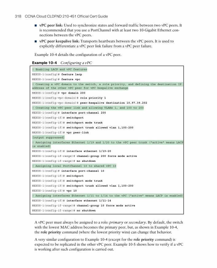
ptg17120290
318 CCNA Cloud CLDFND 210-451 Official Cert Guide
■ vPC peer link: Used to synchronize states and forward traffic between two vPC peers. It is recommended that you use a PortChannel with at least two 10-Gigabit Ethernet con-nections between the vPC peers.
■ vPC peer keepalive link: Transports heartbeats between the vPC peers. It is used to explicitly differentiate a vPC peer link failure from a vPC peer failure.
Example 10-4 details the configuration of a vPC peer.
Example 10-4 Configuring a vPC
! Enabling LACP and vPC features
NEXUS-1(config)# feature lacp
NEXUS-1(config)# feature vpc
! Creating a vPC domain to the switch, a role priority, and defining the destination IP address of the other vPC peer for vPC keepalive exchange
NEXUS-1(config)# vpc domain 200
NEXUS-1(config-vpc-domain)# role priority 1
NEXUS-1(config-vpc-domain)# peer-keepalive destination 10.97.39.202
! Creating the vPC peer link and allowing VLANs 1, and 100 to 200
NEXUS-1(config)# interface port-channel 200
NEXUS-1(config-if)# switchport
NEXUS-1(config-if)# switchport mode trunk
NEXUS-1(config-if)# switchport trunk allowed vlan 1,100-200
NEXUS-1(config-if)# vpc peer-link
[output suppressed]
! Assigning interfaces Ethernet 1/19 and 1/20 to the vPC peer trunk ("active" means LACP is enabled)
NEXUS-1(config-if)# interface ethernet 1/19-20
NEXUS-1(config-if-range)# channel-group 200 force mode active
NEXUS-1(config-if-range)# no shutdown
! Assigning local PortChannel 10 to shared vPC 10
NEXUS-1(config)# interface port-channel 10
NEXUS-1(config-if)# switchport
NEXUS-1(config-if)# switchport mode trunk
NEXUS-1(config-if)# switchport trunk allowed vlan 1,100-200
NEXUS-1(config-if)# vpc 10
! Assigning interfaces Ethernet 1/11 to 1/14 to the vPC ("active" means LACP is enabled)
NEXUS-1(config-if)# interface ethernet 1/11-14
NEXUS-1(config-if-range)# channel-group 10 force mode active
NEXUS-1(config-if-range)# no shutdown
A vPC peer must always be assigned to a role: primary or secondary. By default, the switch with the lowest MAC address becomes the primary peer, but, as shown in Example 10-4, the role priority command (where the lowest priority wins) can change that behavior.
A very similar configuration to Example 10-4 (except for the role priority command) is expected to be replicated in the other vPC peer. Example 10-5 shows how to verify if a vPC is working after such configuration is carried out.

ptg17120290
10
Chapter 10: Network Architectures for the Data Center: Unified Fabric 319
Example 10-5 vPC Verification
! Checking the status of every vPC configurations
NEXUS-2# show vpc brief
Legend:
(*) - local vPC is down, forwarding via vPC peer-link
vPC domain id : 200
! Both vPC members are successfully exchanging keepalives
Peer status : peer adjacency formed ok
vPC keep-alive status : peer is alive
! Mandatory parameters are OK
Configuration consistency status : success
Per-vlan consistency status : success
[output suppressed]
! The vPC peer-link is working
vPC Peer-link status
---------------------------------------------------------------------
id Port Status Active vlans
-- ---- ------ --------------------------------------------------
1 Po200 up 1
! And here is the successfully created vPC 10
vPC status
---------------------------------------------------------------------
id Port Status Consistency Reason Active vlans
-- ---- ------ ----------- ------ ------------
10 Po10 up success success 1
Adding vPCs to the Three-Tier DesignFigure 10-9 demonstrates how virtual PortChannels have enhanced three-tier topologies.
As the figure shows, although configuring vPCs is a relatively simple procedure, they sub-stantially increase the efficiency between the aggregation layer and the access layer with marginal changes. Additionally, the figure depicts double-sided vPCs between two pairs of vPC members.
When extended to connected servers, vPCs can also scale application bandwidth from its source and forego the use of nonstandard NIC teaming techniques (obviously, as long as the NICs or operating system supports IEEE 802.3ad).
Before we jump to the next Unified Fabric feature, note the following about vPC topologies:
■ STP continues to act behind the scenes as a safeguard mechanism should the vPC fail for any reason.
■ If two vPC members are deploying Layer 3 interfaces as the servers’ default gate-ways, both of them are capable of forwarding Layer 3 traffic.
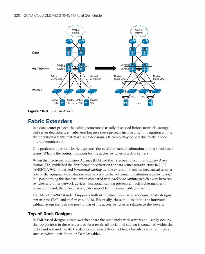
ptg17120290
320 CCNA Cloud CLDFND 210-451 Official Cert Guide
Layer 3
Layer 2
Core
Aggregation
Access
ActiveConnection
ActiveNIC
StandbyNIC
BlockedConnection
WAN orInternet
ActiveNIC
StandbyNIC
Layer 3
Layer 2
Double-Sided VPC
vPC vPC
Double-Sided VPC
WAN orInternet
Figure 10-9 vPC in Action
Fabric ExtendersIn a data center project, the cabling structure is usually discussed before network, storage, and server decisions are made. And because these projects involve a tight integration among the operational teams that make such decisions, efficiency may be lost due to their poor intercommunication.
One particular question clearly expresses the need for such collaboration among specialized teams: What is the optimal position for the access switches in a data center?
When the Electronic Industries Alliance (EIA) and the Telecommunications Industry Asso-ciation (TIA) published the first formal specification for data center infrastructure in 2005 (ANSI/TIA-942), it defined horizontal cabling as “the extension from the mechanical termina-tion of the equipment distribution area (servers) to the horizontal distribution area (switches).” Still paraphrasing the standard, when compared with backbone cabling (which exists between switches and other network devices), horizontal cabling presents a much higher number of connections and, therefore, has a greater impact for the entire cabling structure.
The ANSI/TIA-942 standard supports both of the most popular server connectivity designs: top-of-rack (ToR) and end-of-row (EoR). Essentially, these models define the horizontal cabling layout through the positioning of the access switches in relation to the servers.
Top-of-Rack DesignsIn ToR-based designs, access switches share the same racks with servers and usually occupy the top position in these structures. As a result, all horizontal cabling is contained within the racks (and not underneath the data center raised floor), adding a broader variety of media such as twisted-pair, fiber, or TwinAx cables.

ptg17120290
10
Chapter 10: Network Architectures for the Data Center: Unified Fabric 321
TIP TwinAx cables are cost-effective, direct-attached connections that eliminate the use of twisted-pair cables as well as optical transceivers. Because they are mostly used over short distances (less than 10 meters), TwinAx cables have become extremely popular for 10-Gigabit Ethernet connections in ToR designs.
To allow easier uplink upgrades, fiber is generally used in the redundant connections from the ToR switches to upper-layer devices such as the aggregation tier.
Figure 10-10 portrays a top-of-rack access network.
RaisedFloor
Servers Servers Servers Servers ServersServers
Figure 10-10 Top-of-Rack Topology
The ToR model offers the following benefits:
■ Savings in horizontal cabling (because cable length is reduced)
■ Preinstallation of fully populated server cabinets
■ Per-cabinet migration of connection technologies (Gigabit Ethernet to 10-Gigabit Ether-net, for example)
ToR switches usually have 24, 32, 48, or 96 Ethernet interfaces, and if a rack does not sup-port a considerable number of servers, switch interface use may become inefficient. There-fore, network and cabling designers must work in tandem with the facilities team, because power distribution and cooling capacity heavily influence the number of servers that can be installed in a rack.
A significant drawback of ToR designs relates to their high number of access switches. In a data center with thousands of server racks, operational procedures, such as the identifica-tion of interfaces and firmware upgrades, may become quite challenging.
End-of-Row and Middle-of-Row DesignsEoR designs enable the management of hundreds of server connections with a single pair of access switches. Generally speaking, these switches are modular chassis provisioned for hori-zontal cabling based on unshielded twisted-pair (UTP) connections.
Like the ToR design, the EoR model leverages multiple fiber connections to network upper-layer devices (usually aggregation switches).
Figure 10-11 illustrates an end-of-row access network, as well as an alternative topology called middle-of-row (MoR). Because the MoR design slightly decreases the average cable length to servers, it may be advantageous in a data center network with a higher number of server racks.

ptg17120290
322 CCNA Cloud CLDFND 210-451 Official Cert Guide
RaisedFloor
RaisedFloor
ServersServers
End-of-Row
Middle-of-Row
Servers Servers Servers Servers Servers
ServersServersServersServers Servers Servers
Servers
Figure 10-11 End-of-Row and Middle-of-Row Topologies
EoR and MoR topologies demonstrate more flexibility for server racks with a low port count. Because UTP can reach up to 100 meters, access switches can reach multiple racks in a row and, as a result, reduce the number of idle interfaces.
Nonetheless, cabling sprawl is a pointed disadvantage of EoR and MoR topologies when compared to ToR. In a data center, excessive horizontal cabling may produce undesirable effects such as
■ Difficult cable management, troubleshooting, and decommission
■ Blockage of air cooling (if it is installed beneath a raised access floor)
When data centers invest in structured cabling based on UTP connections, they conse-quently lose some of the flexibility to adopt new connectivity technologies that were not foreseen at project planning time. For this reason, EoR and MoR designs require serious attention to server connectivity trends to avoid prematurely obsolete facilities.
Enter the Nexus 2000Over the past few decades, I have noticed that ToR designs have started to usurp the supremacy of EoR (and MoR) topologies in brand new (greenfield) data center projects. Many reasons explain this movement:
■ Technology evolution has enabled more processing power in more compact servers.
■ Virtualization has led to more bandwidth per server.
■ Servers have adopted 10-Gbps connections.
Still, there was no consensus over the “best” design until 2009, which is when Cisco launched the Nexus 2000 Fabric Extender series. Unlike other Nexus switches, these devic-es are essentially remote linecards that are managed by a parent switch, such as multiple Nexus models or a UCS Fabric Interconnect.
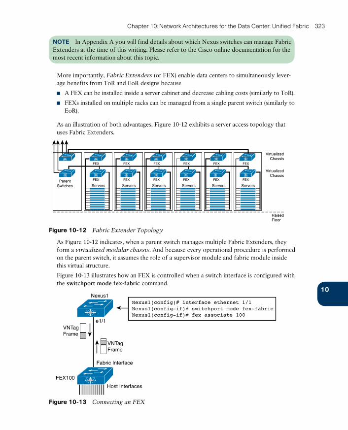
ptg17120290
10
Chapter 10: Network Architectures for the Data Center: Unified Fabric 323
NOTE In Appendix A you will find details about which Nexus switches can manage Fabric Extenders at the time of this writing. Please refer to the Cisco online documentation for the most recent information about this topic.
More importantly, Fabric Extenders (or FEX) enable data centers to simultaneously lever-age benefits from ToR and EoR designs because
■ A FEX can be installed inside a server cabinet and decrease cabling costs (similarly to ToR).
■ FEXs installed on multiple racks can be managed from a single parent switch (similarly to EoR).
As an illustration of both advantages, Figure 10-12 exhibits a server access topology that uses Fabric Extenders.
VirtualizedChassis
VirtualizedChassis
RaisedFloor
ParentSwitches
FEX
Servers
FEX
Servers
FEX
Servers
FEX
Servers
FEX
Servers
FEX
Servers
FEXFEX FEXFEXFEX FEX
Figure 10-12 Fabric Extender Topology
As Figure 10-12 indicates, when a parent switch manages multiple Fabric Extenders, they form a virtualized modular chassis . And because every operational procedure is performed on the parent switch, it assumes the role of a supervisor module and fabric module inside this virtual structure.
Figure 10-13 illustrates how an FEX is controlled when a switch interface is configured with the switchport mode fex-fabric command.
Nexus1
e1/1
VNTagFrame
Fabric Interface
Host Interfaces
FEX100
VNTagFrame
Nexus1(config)# interface ethernet 1/1Nexus1(config-if)# switchport mode fex-fabricNexus1(config-if)# fex associate 100
Figure 10-13 Connecting an FEX
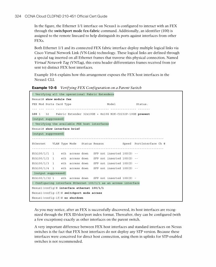
ptg17120290
324 CCNA Cloud CLDFND 210-451 Official Cert Guide
In the figure, the Ethernet 1/1 interface on Nexus1 is configured to interact with an FEX through the switchport mode fex-fabric command. Additionally, an identifier (100) is assigned to the remote linecard to help distinguish its ports against interfaces from other FEXs.
Both Ethernet 1/1 and its connected FEX fabric interface deploy multiple logical links via Cisco Virtual Network Link (VN-Link) technology. These logical links are defined through a special tag inserted on all Ethernet frames that traverse this physical connection. Named Virtual Network Tag (VNTag) , this extra header differentiates frames received from (or sent to) distinct FEX host interfaces.
Example 10-6 explains how this arrangement exposes the FEX host interfaces in the Nexus1 CLI.
Example 10-6 Verifying FEX Configuration on a Parent Switch
! Verifying all the operational Fabric Extenders
Nexus1# show module fex
FEX Mod Ports Card Type Model Status.
--- --- ----- ------------------------------- --------------- -------
100 1 32 Fabric Extender 32x10GE + 8x10G N2K-C2232P-10GE present
[output suppressed]
! Verifying the available FEX host interfaces
Nexus1# show interface brief
[output suppressed]
-----------------------------------------------------------------------------
Ethernet VLAN Type Mode Status Reason Speed PortInterface Ch #
-----------------------------------------------------------------------------
Eth100/1/1 1 eth access down SFP not inserted 10G(D) --
Eth100/1/2 1 eth access down SFP not inserted 10G(D) --
Eth100/1/3 1 eth access down SFP not inserted 10G(D) --
Eth100/1/4 1 eth access down SFP not inserted 10G(D) --
[output suppressed]
Eth100/1/32 1 eth access down SFP not inserted 10G(D) –
! Configuring interface Ethernet 100/1/1 as an access interface
Nexus1(config)# interface ethernet 100/1/1
Nexus1(config-if)# switchport mode access
Nexus1(config-if)# no shutdown
As you may notice, after an FEX is successfully discovered, its host interfaces are recog-nized through the FEX ID/slot/port index format. Thereafter, they can be configured (with a few exceptions) exactly as other interfaces on the parent switch.
A very important difference between FEX host interfaces and standard interfaces on Nexus switches is the fact that FEX host interfaces do not deploy any STP version. Because these interfaces were conceived for direct host connection, using them in uplinks for STP-enabled switches is not recommended.
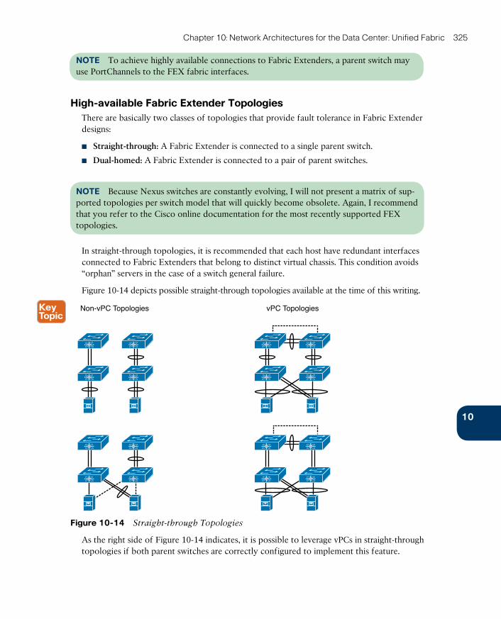
ptg17120290
10
Chapter 10: Network Architectures for the Data Center: Unified Fabric 325
NOTE To achieve highly available connections to Fabric Extenders, a parent switch may use PortChannels to the FEX fabric interfaces.
High-available Fabric Extender TopologiesThere are basically two classes of topologies that provide fault tolerance in Fabric Extender designs:
■ Straight-through: A Fabric Extender is connected to a single parent switch.
■ Dual-homed: A Fabric Extender is connected to a pair of parent switches.
NOTE Because Nexus switches are constantly evolving, I will not present a matrix of sup-ported topologies per switch model that will quickly become obsolete. Again, I recommend that you refer to the Cisco online documentation for the most recently supported FEX topologies.
In straight-through topologies, it is recommended that each host have redundant interfaces connected to Fabric Extenders that belong to distinct virtual chassis. This condition avoids “orphan” servers in the case of a switch general failure.
Figure 10-14 depicts possible straight-through topologies available at the time of this writing.
Non-vPC Topologies vPC Topologies
Figure 10-14 Straight-through Topologies
As the right side of Figure 10-14 indicates, it is possible to leverage vPCs in straight-through topologies if both parent switches are correctly configured to implement this feature.
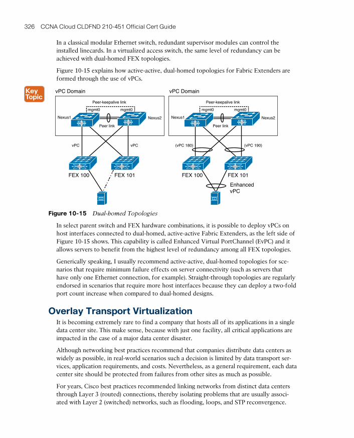
ptg17120290
326 CCNA Cloud CLDFND 210-451 Official Cert Guide
In a classical modular Ethernet switch, redundant supervisor modules can control the installed linecards. In a virtualized access switch, the same level of redundancy can be achieved with dual-homed FEX topologies.
Figure 10-15 explains how active-active, dual-homed topologies for Fabric Extenders are formed through the use of vPCs.
Peer link
Nexus1 Nexus2
Peer-keepalive link
vPC Domain
vPC vPC
vPC Domain
FEX 101
EnhancedvPC
FEX 100
(vPC 180) (vPC 190)
Peer link
Nexus1 Nexus2
Peer-keepalive link
mgmt0 mgmt0mgmt0 mgmt0
FEX 101FEX 100
Figure 10-15 Dual-homed Topologies
In select parent switch and FEX hardware combinations, it is possible to deploy vPCs on host interfaces connected to dual-homed, active-active Fabric Extenders, as the left side of Figure 10-15 shows. This capability is called Enhanced Virtual PortChannel (EvPC) and it allows servers to benefit from the highest level of redundancy among all FEX topologies.
Generically speaking, I usually recommend active-active, dual-homed topologies for sce-narios that require minimum failure effects on server connectivity (such as servers that have only one Ethernet connection, for example). Straight-through topologies are regularly endorsed in scenarios that require more host interfaces because they can deploy a two-fold port count increase when compared to dual-homed designs.
Overlay Transport VirtualizationIt is becoming extremely rare to find a company that hosts all of its applications in a single data center site. This make sense, because with just one facility, all critical applications are impacted in the case of a major data center disaster.
Although networking best practices recommend that companies distribute data centers as widely as possible, in real-world scenarios such a decision is limited by data transport ser-vices, application requirements, and costs. Nevertheless, as a general requirement, each data center site should be protected from failures from other sites as much as possible.
For years, Cisco best practices recommended linking networks from distinct data centers through Layer 3 (routed) connections, thereby isolating problems that are usually associ-ated with Layer 2 (switched) networks, such as flooding, loops, and STP reconvergence.

ptg17120290
10
Chapter 10: Network Architectures for the Data Center: Unified Fabric 327
However, some situations and application scenarios simply require that Layer 2 domains be extended over multiple data centers. For example:
■ Geographic cluster (geocluster): A set of servers (known as cluster nodes) that run the same application must be installed on at least two geographically separate sites to pro-vide a disaster recovery solution for critical applications.
■ Data center expansion: The integration of an extra data center facility may also require Layer 2 extensions between sites. This situation is very common when a data center has reached a physical limitation (such as power or space) and colocation service from an outsourcing data center is hired.
■ Server migration: Some applications do not support easy IP readdressing because these values are already embedded in their codes, or simply because it can generate pains-takingly complex operations. Consequently, during the migration between sites, some VLANs are expected to exist simultaneously in the original site and the destination site.
TIP The last bullet point refers to both physical and virtual server migrations.
Layer 2 Extension ChallengesThe problems Layer 2 extensions can present in data centers are not minor nuisances. Unfortunately, many data center network engineers have experienced incidents where extended broadcast domains disrupted applications in multiple sites at the same time.
Although IP communication absolutely requires flooding and broadcast to occur on Ether-net networks, these switch operations can become quite dangerous in data center intercon-
nections (DCIs) . If unknown unicast or broadcast frames are not somehow restrained, the Layer 2 extensions can easily form loops, threatening application availability on all con-nected facilities.
If you are wondering whether STP can help in these situations, here comes the biggest DCI dilemma: a spanning tree distributed over multiple sites also introduces formidable chal-lenges, including
■ Scalability: STP diameter is defined as the number of hops between two switches from a spanning tree. In data center interconnections, the STP diameter can easily surpass the IEEE-recommended value of 7, bringing unexpected results.
■ Isolation: When a spanning tree is extended to multiple sites, the root switch obviously will be contained in only one of them. If such device fails for any reason, all VLANs may be affected by an STP reconvergence. Consequently, traffic will be interrupted on all sites during the entire process.
■ Multihoming: Because STP elects a single path between the root and any other switch in the spanning tree, all DCI links between sites but one will not be used until a failure hap-pens.
Figure 10-16 represents the challenges caused by STP in a Layer 2 connection between two data center sites.
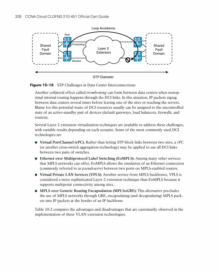
ptg17120290
328 CCNA Cloud CLDFND 210-451 Official Cert Guide
STP Diameter
Loop Avoidance
Forwarding
Blocked
Root
SharedFault
Domain
SharedFault
Domain
Layer 2 Extension
Figure 10-16 STP Challenges in Data Center Interconnections
Another collateral effect called tromboning can form between data centers when nonop-timal internal routing happens through the DCI links. In this situation, IP packets zigzag between data centers several times before leaving one of the sites or reaching the servers. Blame for this potential waste of DCI resources usually can be assigned to the uncontrolled state of an active-standby pair of devices (default gateways, load balancers, firewalls, and routers).
Several Layer 2 extension virtualization techniques are available to address these challenges, with variable results depending on each scenario. Some of the most commonly used DCI technologies are
■ Virtual PortChannel (vPC): Rather than letting STP block links between two sites, a vPC (or another cross-switch aggregation technology) may be applied to use all DCI links between two pairs of switches.
■ Ethernet over Multiprotocol Label Switching (EoMPLS) : Among many other services that MPLS networks can offer, EoMPLS allows the emulation of an Ethernet connection (commonly referred to as pseudowire) between two ports on MPLS-enabled routers.
■ Virtual Private LAN Services (VPLS) : Another service from MPLS backbones, VPLS is considered a more sophisticated Layer 2 extension technique than EoMPLS because it supports multipoint connectivity among sites.
■ MPLS over Generic Routing Encapsulation (MPLSoGRE) : This alternative precludes the use of MPLS networks through GRE, encapsulating (and decapsulating) MPLS pack-ets into IP packets at the border of an IP backbone.
Table 10-2 compares the advantages and disadvantages that are customarily observed in the implementation of these VLAN extension technologies.
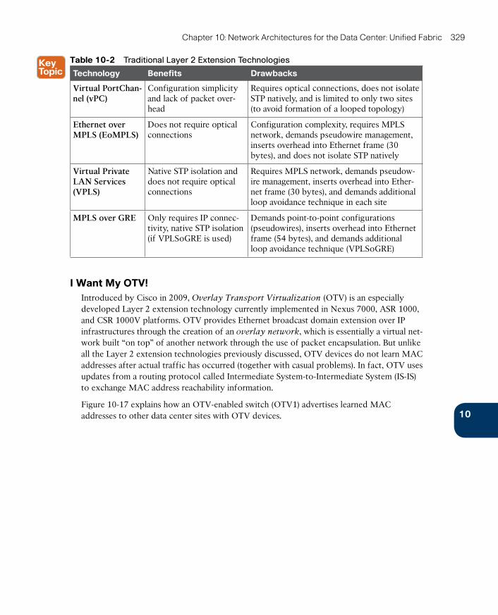
ptg17120290
10
Chapter 10: Network Architectures for the Data Center: Unified Fabric 329
Table 10-2 Traditional Layer 2 Extension Technologies
Technology Benefits Drawbacks
Virtual PortChan-nel (vPC)
Configuration simplicity and lack of packet over-head
Requires optical connections, does not isolate STP natively, and is limited to only two sites (to avoid formation of a looped topology)
Ethernet over MPLS (EoMPLS)
Does not require optical connections
Configuration complexity, requires MPLS network, demands pseudowire management, inserts overhead into Ethernet frame (30 bytes), and does not isolate STP natively
Virtual Private LAN Services (VPLS)
Native STP isolation and does not require optical connections
Requires MPLS network, demands pseudow-ire management, inserts overhead into Ether-net frame (30 bytes), and demands additional loop avoidance technique in each site
MPLS over GRE Only requires IP connec-tivity, native STP isolation (if VPLSoGRE is used)
Demands point-to-point configurations (pseudowires), inserts overhead into Ethernet frame (54 bytes), and demands additional loop avoidance technique (VPLSoGRE)
I Want My OTV!Introduced by Cisco in 2009, Overlay Transport Virtualization (OTV) is an especially developed Layer 2 extension technology currently implemented in Nexus 7000, ASR 1000, and CSR 1000V platforms. OTV provides Ethernet broadcast domain extension over IP infrastructures through the creation of an overlay network, which is essentially a virtual net-work built “on top” of another network through the use of packet encapsulation. But unlike all the Layer 2 extension technologies previously discussed, OTV devices do not learn MAC addresses after actual traffic has occurred (together with casual problems). In fact, OTV uses updates from a routing protocol called Intermediate System-to-Intermediate System (IS-IS) to exchange MAC address reachability information.
Figure 10-17 explains how an OTV-enabled switch (OTV1) advertises learned MAC addresses to other data center sites with OTV devices.
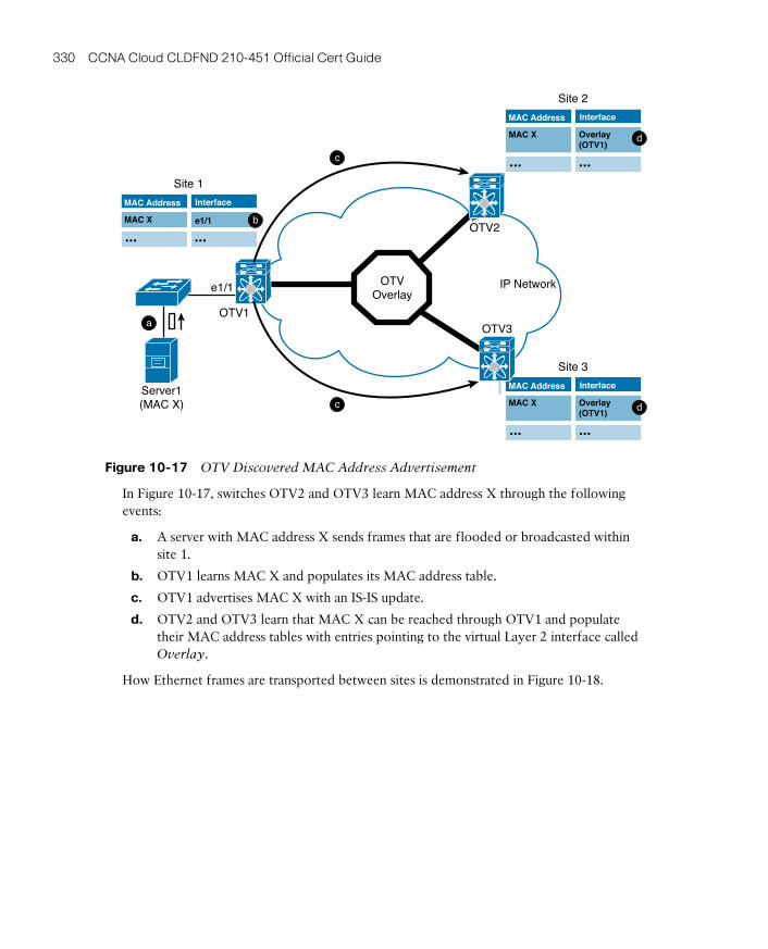
ptg17120290
330 CCNA Cloud CLDFND 210-451 Official Cert Guide
IP Network
Site 1
OTV1OTV3
OTV2
e1/1
Server1(MAC X)
InterfaceMAC Address
MAC X e1/1
......
Site 2
InterfaceMAC Address
MAC X Overlay(OTV1)
......
Site 3
InterfaceMAC Address
MAC X
......
OTVOverlay
Overlay(OTV1)
c
a
b
c d
d
Figure 10-17 OTV Discovered MAC Address Advertisement
In Figure 10-17, switches OTV2 and OTV3 learn MAC address X through the following events:
a. A server with MAC address X sends frames that are flooded or broadcasted within site 1.
b. OTV1 learns MAC X and populates its MAC address table.
c. OTV1 advertises MAC X with an IS-IS update.
d. OTV2 and OTV3 learn that MAC X can be reached through OTV1 and populate their MAC address tables with entries pointing to the virtual Layer 2 interface called Overlay.
How Ethernet frames are transported between sites is demonstrated in Figure 10-18.
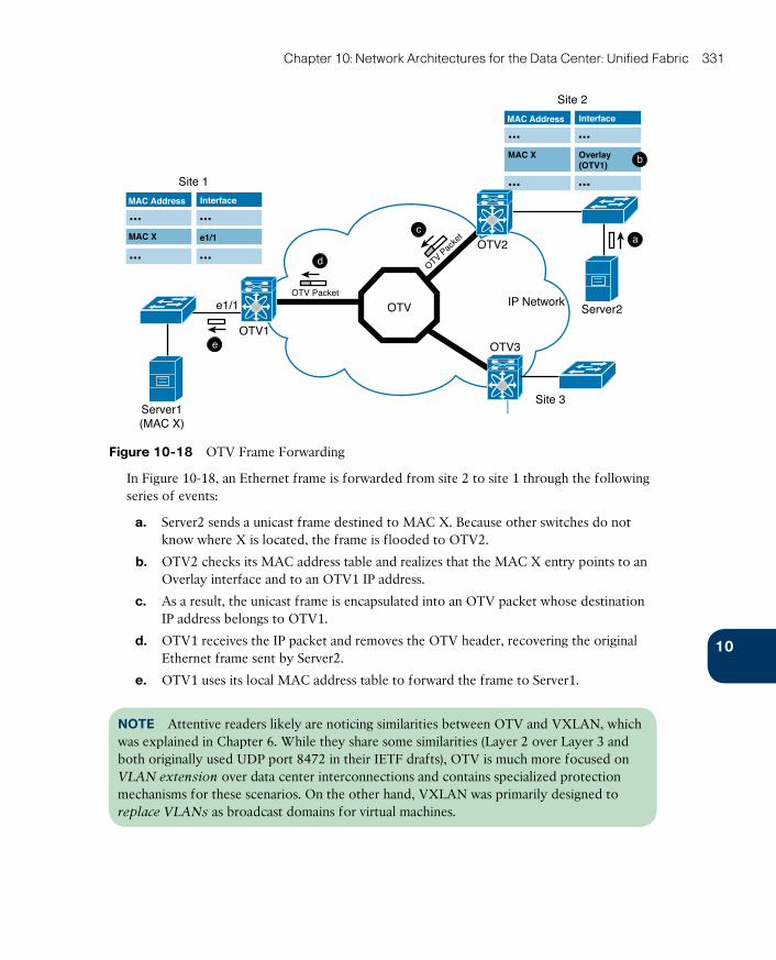
ptg17120290
10
Chapter 10: Network Architectures for the Data Center: Unified Fabric 331
IP Network
Site 1
OTV1OTV3
OTV2
e1/1OTV Packet
Server1(MAC X)
InterfaceMAC Address
MAC X e1/1
......
......
Site 3
Server2
OTV Pac
ket
OTV
c
d
e
a
Site 2
InterfaceMAC Address
......
......
bMAC X Overlay(OTV1)
Figure 10-18 OTV Frame Forwarding
In Figure 10-18, an Ethernet frame is forwarded from site 2 to site 1 through the following series of events:
a. Server2 sends a unicast frame destined to MAC X. Because other switches do not know where X is located, the frame is flooded to OTV2.
b. OTV2 checks its MAC address table and realizes that the MAC X entry points to an Overlay interface and to an OTV1 IP address.
c. As a result, the unicast frame is encapsulated into an OTV packet whose destination IP address belongs to OTV1.
d. OTV1 receives the IP packet and removes the OTV header, recovering the original Ethernet frame sent by Server2.
e. OTV1 uses its local MAC address table to forward the frame to Server1.
NOTE Attentive readers likely are noticing similarities between OTV and VXLAN, which was explained in Chapter 6. While they share some similarities (Layer 2 over Layer 3 and both originally used UDP port 8472 in their IETF drafts), OTV is much more focused on VLAN extension over data center interconnections and contains specialized protection mechanisms for these scenarios. On the other hand, VXLAN was primarily designed to replace VLANs as broadcast domains for virtual machines.
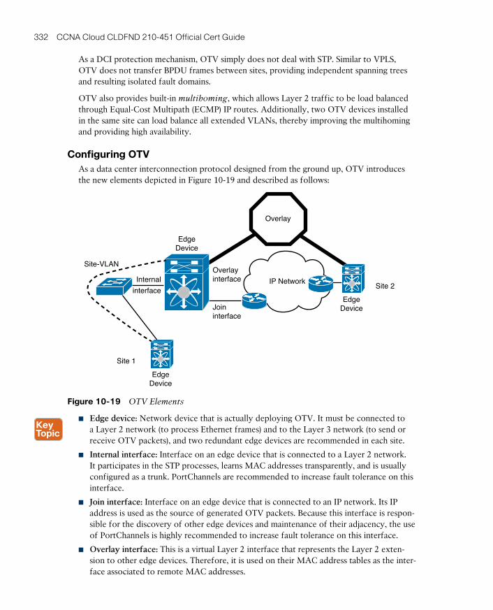
ptg17120290
332 CCNA Cloud CLDFND 210-451 Official Cert Guide
As a DCI protection mechanism, OTV simply does not deal with STP. Similar to VPLS, OTV does not transfer BPDU frames between sites, providing independent spanning trees and resulting isolated fault domains.
OTV also provides built-in multihoming, which allows Layer 2 traffic to be load balanced through Equal-Cost Multipath (ECMP) IP routes. Additionally, two OTV devices installed in the same site can load balance all extended VLANs, thereby improving the multihoming and providing high availability.
Configuring OTVAs a data center interconnection protocol designed from the ground up, OTV introduces the new elements depicted in Figure 10-19 and described as follows:
IP NetworkSite 2
Site 1
EdgeDevice
EdgeDevice
EdgeDevice
Joininterface
Internal
interface
Site-VLANOverlayinterface
Overlay
Figure 10-19 OTV Elements
■ Edge device: Network device that is actually deploying OTV. It must be connected to a Layer 2 network (to process Ethernet frames) and to the Layer 3 network (to send or receive OTV packets), and two redundant edge devices are recommended in each site.
■ Internal interface: Interface on an edge device that is connected to a Layer 2 network. It participates in the STP processes, learns MAC addresses transparently, and is usually configured as a trunk. PortChannels are recommended to increase fault tolerance on this interface.
■ Join interface: Interface on an edge device that is connected to an IP network. Its IP address is used as the source of generated OTV packets. Because this interface is respon-sible for the discovery of other edge devices and maintenance of their adjacency, the use of PortChannels is highly recommended to increase fault tolerance on this interface.
■ Overlay interface: This is a virtual Layer 2 interface that represents the Layer 2 exten-sion to other edge devices. Therefore, it is used on their MAC address tables as the inter-face associated to remote MAC addresses.
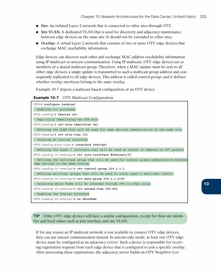
ptg17120290
10
Chapter 10: Network Architectures for the Data Center: Unified Fabric 333
■ Site: An isolated Layer 2 network that is connected to other sites through OTV.
■ Site VLAN: A dedicated VLAN that is used for discovery and adjacency maintenance between edge devices on the same site. It should not be extended to other sites.
■ Overlay: A virtual Layer 2 network that consists of two or more OTV edge devices that exchange MAC reachability information.
Edge devices can discover each other and exchange MAC address reachability information using IP multicast or unicast communication. Using IP multicast, OTV edge devices act as members of a shared multicast group. Therefore, when a MAC update must be sent to all other edge devices, a single update is transmitted to such a multicast group address and con-sequently replicated to all edge devices. This address is called control-group, and it defines whether overlay interfaces belong to the same overlay.
Example 10-7 depicts a multicast-based configuration of an OTV device.
Example 10-7 OTV Multicast Configuration
OTV1# configure terminal
! Enabling otv processes
OTV1(config)# feature otv
! Explicitly identifying the OTV site
OTV1(config)# otv site-identifier 0x1
! Defining the VLAN that will be used for edge devices communication in the same site
OTV1(config)# otv site-vlan 111
! Creating an overlay interface
OTV1(config-site-vlan)# interface Overlay1
! Defining the Layer 3 interface that will be used as source IP address on OTV packets
OTV1(config-if-overlay)# otv join-interface Ethernet1/27
! Defining the multicast group that will be used for control plane communication between edge devices in the same overlay
OTV1(config-if-overlay)# otv control-group 239.1.1.1
! Defining multicast groups that will be used to carry Layer 2 multicast traffic
OTV1(config-if-overlay)# otv data-group 232.1.1.0/28
! Declaring which VLANs will be extended through OTV to other sites
OTV1(config-if-overlay)# otv extend-vlan 300-400
! Enabling the Overlay interface
OTV1(config-if-overlay)# no shutdown
TIP Other OTV edge devices will have a similar configuration, except for their site identi-fier and local values such as join interface and site VLAN.
If for any reason an IP multicast network is not available to connect OTV edge devices, they can use unicast communication instead. In unicast-only mode, at least one OTV edge device must be configured as an adjacency server . Such a device is responsible for receiv-ing registration requests from each edge device that is configured to join a specific overlay. After processing these registrations, the adjacency server builds an OTV Neighbor List

ptg17120290
334 CCNA Cloud CLDFND 210-451 Official Cert Guide
(ONL) that is sent periodically to all other edge devices. From this list, each edge device can find all IP addresses necessary to generate OTV packets.
Example 10-8 contrasts a unicast-only OTV configuration against Example 10-7.
Example 10-8 OTV Unicast-only Configuration
! Enabling OTV and defining the site characteristics
OTV1(config)# feature otv
OTV1(config)# otv site-identifier 0x1
OTV1(config)# otv site-vlan 111
! Configuring interface Overlay1 (it should be the same on all sites)
OTV1(config-site-vlan)# interface overlay 1
OTV1(config-if-overlay)# otv join-interface Ethernet 1/27
! Enabling unicast-only communication
OTV1(config-if-overlay)# otv adjacency-server unicast-only
! Defining 10.12.1.1 as the Adjacency Server. Another IP address could
also be included in this command to define a secondary Adjacency
Server
OTV-DC2(config-if-overlay)# otv use-adjacency-server 10.12.1.1 unicast-only
! An OTV edge device performing the role of an adjacency server does not require the last command
TIP Other non-adjacency server OTV edge devices will have a similar configuration, except for their site identifier and specifics such as join interface and site VLAN.
Applicable to both multicast and unicast-only OTV scenarios, Example 10-9 exhibits how a network administrator can verify if OTV is correctly working.
Example 10-9 Checking OTV Status
! Verifying OTV adjacency status to other edge devices
OTV1# show otv adjacency detail
Overlay Adjacency database
! OTV1 has established an adjacency with OTV2
Overlay-Interface Overlay1 :
Hostname System-ID Dest Addr Up Time State
OTV2 0022.5579.f744 10.12.2.1 00:24:57 UP
! Verifying OTV-advertised MAC addresses
OTV1# show otv route
OTV Unicast MAC Routing Table For Overlay1
! OTV2 has advertised one MAC address through an IS-IS update
VLAN MAC-Address Metric Uptime Owner Next-hop(s)
---- -------------- ------ -------- --------- -----------
300 0050.568d.1105 1 00:38:01 site Ethernet2/19
300 0050.568d.391f 42 00:38:01 overlay OTV2
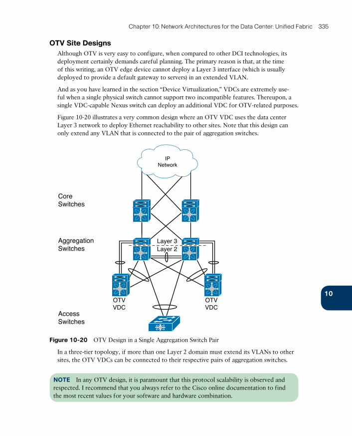
ptg17120290
10
Chapter 10: Network Architectures for the Data Center: Unified Fabric 335
OTV Site DesignsAlthough OTV is very easy to configure, when compared to other DCI technologies, its deployment certainly demands careful planning. The primary reason is that, at the time of this writing, an OTV edge device cannot deploy a Layer 3 interface (which is usually deployed to provide a default gateway to servers) in an extended VLAN.
And as you have learned in the section “Device Virtualization,” VDCs are extremely use-ful when a single physical switch cannot support two incompatible features. Thereupon, a single VDC-capable Nexus switch can deploy an additional VDC for OTV-related purposes.
Figure 10-20 illustrates a very common design where an OTV VDC uses the data center Layer 3 network to deploy Ethernet reachability to other sites. Note that this design can only extend any VLAN that is connected to the pair of aggregation switches.
CoreSwitches
AggregationSwitches
AccessSwitches
Layer 3Layer 2
IPNetwork
OTVVDC
OTVVDC
Figure 10-20 OTV Design in a Single Aggregation Switch Pair
In a three-tier topology, if more than one Layer 2 domain must extend its VLANs to other sites, the OTV VDCs can be connected to their respective pairs of aggregation switches.
NOTE In any OTV design, it is paramount that this protocol scalability is observed and respected. I recommend that you always refer to the Cisco online documentation to find the most recent values for your software and hardware combination.
ptg17120290
336 CCNA Cloud CLDFND 210-451 Official Cert Guide
I/O ConsolidationA server commonly requires different types of input/output (I/O) communications. Tradition-ally, these discrete traffic loads are characterized by separate physical connections, such as
■ Public interfaces: Responsible for receiving application client requests and giving corre-sponding responses.
■ Private interfaces: Used for internal communication between servers from the same cluster.
■ Management interfaces: Deployed to support server operations, such as software instal-lation, firmware upgrades, health monitoring, and so on.
■ Backup interfaces: Used to copy files, databases, or entire computer images to non-volatile media (such as magnetic tapes). Ethernet or Fibre Channel connections can be deployed for this traffic.
■ Storage access interfaces: Responsible for external storage access. Ethernet (for Internet Small Computer System Interface [iSCSI], Network File System [NFS], or Server Message Block [SMB]) or Fibre Channel is generally used on these connections.
Each server connection has three distinct elements: an adapter interface, a cable, and a net-
work device port. As a result, a server connection requires at least three harmonically coor-dinated procedures, which can be quite complex, error-prone, and slow.
Distinct connections also lead to the formation of “bandwidth islands” within each server. Hence, even if a connection is not using its available bandwidth, it cannot share resources with other interfaces that may be in need. And if a specific I/O type requires more band-width, additional physical connections will probably have to be provisioned.
All of these challenges are addressed through I/O consolidation solutions, whose concept is illustrated in Figure 10-21.
In such scenarios, multiple physical connections are reduced to only one (or two) on each server. I/O consolidation also enables an approach called “wire once and walk away,” which enables data centers to provision any type of I/O access to a server without additional physical operations.
Network convergence is a required step for I/O consolidation. Consequently, a converged
network (such as Cisco Unified Fabric) should possess sufficient resources to support all types of I/O traffic from its connected servers. A converged network should also allocate these resources fairly among these loads, creating a “virtual network” for each one of them.
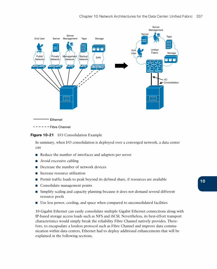
ptg17120290
10
Chapter 10: Network Architectures for the Data Center: Unified Fabric 337
EndUser
ServerManagement
I/OConsolidation
TapeTape
Server
Storage
Storage
ServerManagement
UnifiedFabric
Server
Ethernet
Fibre Channel
End User
BackupNetwork
SANManagementNetwork
PrivateNetwork
PublicNetwork
Figure 10-21 I/O Consolidation Example
In summary, when I/O consolidation is deployed over a converged network, a data center can
■ Reduce the number of interfaces and adapters per server
■ Avoid excessive cabling
■ Decrease the number of network devices
■ Increase resource utilization
■ Permit traffic loads to peak beyond its defined share, if resources are available
■ Consolidate management points
■ Simplify scaling and capacity planning because it does not demand several different resource pools
■ Use less power, cooling, and space when compared to unconsolidated facilities
10-Gigabit Ethernet can easily consolidate multiple Gigabit Ethernet connections along with IP-based storage access loads such as NFS and iSCSI. Nevertheless, its best-effort transport characteristics would simply break the reliability Fibre Channel natively provides. There-fore, to encapsulate a lossless protocol such as Fibre Channel and improve data commu-nication within data centers, Ethernet had to deploy additional enhancements that will be explained in the following sections.
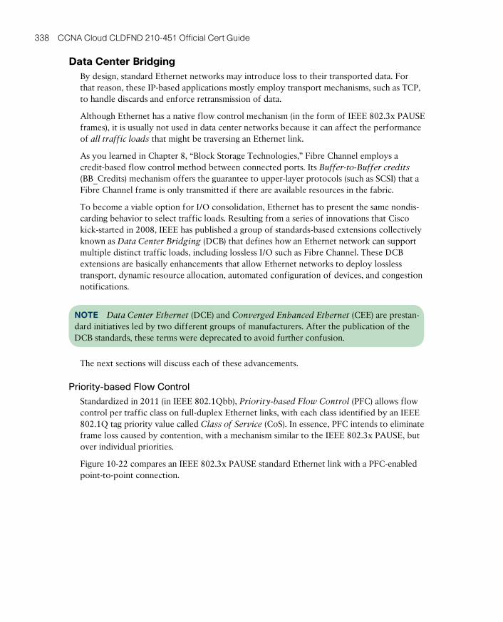
ptg17120290
338 CCNA Cloud CLDFND 210-451 Official Cert Guide
Data Center BridgingBy design, standard Ethernet networks may introduce loss to their transported data. For that reason, these IP-based applications mostly employ transport mechanisms, such as TCP, to handle discards and enforce retransmission of data.
Although Ethernet has a native flow control mechanism (in the form of IEEE 802.3x PAUSE frames), it is usually not used in data center networks because it can affect the performance of all traffic loads that might be traversing an Ethernet link.
As you learned in Chapter 8, “Block Storage Technologies,” Fibre Channel employs a credit-based flow control method between connected ports. Its Buffer-to-Buffer credits
(BB_Credits) mechanism offers the guarantee to upper-layer protocols (such as SCSI) that a Fibre Channel frame is only transmitted if there are available resources in the fabric.
To become a viable option for I/O consolidation, Ethernet has to present the same nondis-carding behavior to select traffic loads. Resulting from a series of innovations that Cisco kick-started in 2008, IEEE has published a group of standards-based extensions collectively known as Data Center Bridging (DCB) that defines how an Ethernet network can support multiple distinct traffic loads, including lossless I/O such as Fibre Channel. These DCB extensions are basically enhancements that allow Ethernet networks to deploy lossless transport, dynamic resource allocation, automated configuration of devices, and congestion notifications.
NOTE Data Center Ethernet (DCE) and Converged Enhanced Ethernet (CEE) are prestan-dard initiatives led by two different groups of manufacturers. After the publication of the DCB standards, these terms were deprecated to avoid further confusion.
The next sections will discuss each of these advancements.
Priority-based Flow Control
Standardized in 2011 (in IEEE 802.1Qbb), Priority-based Flow Control (PFC) allows flow control per traffic class on full-duplex Ethernet links, with each class identified by an IEEE 802.1Q tag priority value called Class of Service (CoS). In essence, PFC intends to eliminate frame loss caused by contention, with a mechanism similar to the IEEE 802.3x PAUSE, but over individual priorities.
Figure 10-22 compares an IEEE 802.3x PAUSE standard Ethernet link with a PFC-enabled point-to-point connection.
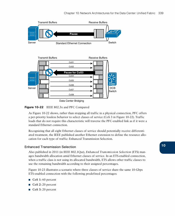
ptg17120290
10
Chapter 10: Network Architectures for the Data Center: Unified Fabric 339
Receive BuffersTransmit Buffers
Standard Ethernet ConnectionServer Switch
Receive BuffersTransmit Buffers
Data Center Bridging
Server DCBSwitch
CoS1
CoS2
CoS4
CoS5
CoS6
CoS7
CoS8
Pause
Pause for CoS3
Figure 10-22 IEEE 802.3x and PFC Compared
As Figure 10-22 shows, rather than stopping all traffic in a physical connection, PFC offers a per-priority lossless behavior to select classes of service (CoS 3 in Figure 10-22). Traffic loads that do not require this characteristic will traverse the PFC-enabled link as if it were a standard Ethernet connection.
Recognizing that all eight Ethernet classes of service should potentially receive differenti-ated treatment, the IEEE published another Ethernet extension to define the resource allo-cation for each type of traffic: Enhanced Transmission Selection.
Enhanced Transmission Selection
Also published in 2011 (in IEEE 802.1Qaz), Enhanced Transmission Selection (ETS) man-ages bandwidth allocation amid Ethernet classes of service. In an ETS-enabled connection, when a traffic class is not using its allocated bandwidth, ETS allows other traffic classes to use the remaining bandwidth according to their assigned percentages.
Figure 10-23 illustrates a scenario where three classes of service share the same 10-Gbps ETS-enabled connection with the following predefined percentages:
■ CoS 1: 60 percent
■ CoS 2: 20 percent
■ CoS 3: 20 percent
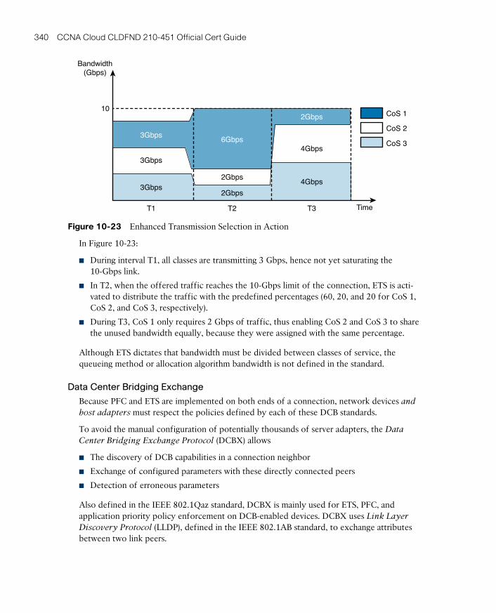
ptg17120290
340 CCNA Cloud CLDFND 210-451 Official Cert Guide
Bandwidth(Gbps)
3Gbps
3Gbps
3Gbps
6Gbps
2Gbps
2Gbps
2Gbps
4Gbps
4Gbps
CoS 1
CoS 3
CoS 2
10
T1 T2 T3 Time
Figure 10-23 Enhanced Transmission Selection in Action
In Figure 10-23:
■ During interval T1, all classes are transmitting 3 Gbps, hence not yet saturating the 10-Gbps link.
■ In T2, when the offered traffic reaches the 10-Gbps limit of the connection, ETS is acti-vated to distribute the traffic with the predefined percentages (60, 20, and 20 for CoS 1, CoS 2, and CoS 3, respectively).
■ During T3, CoS 1 only requires 2 Gbps of traffic, thus enabling CoS 2 and CoS 3 to share the unused bandwidth equally, because they were assigned with the same percentage.
Although ETS dictates that bandwidth must be divided between classes of service, the queueing method or allocation algorithm bandwidth is not defined in the standard.
Data Center Bridging Exchange
Because PFC and ETS are implemented on both ends of a connection, network devices and
host adapters must respect the policies defined by each of these DCB standards.
To avoid the manual configuration of potentially thousands of server adapters, the Data
Center Bridging Exchange Protocol (DCBX) allows
■ The discovery of DCB capabilities in a connection neighbor
■ Exchange of configured parameters with these directly connected peers
■ Detection of erroneous parameters
Also defined in the IEEE 802.1Qaz standard, DCBX is mainly used for ETS, PFC, and application priority policy enforcement on DCB-enabled devices. DCBX uses Link Layer
Discovery Protocol (LLDP), defined in the IEEE 802.1AB standard, to exchange attributes between two link peers.
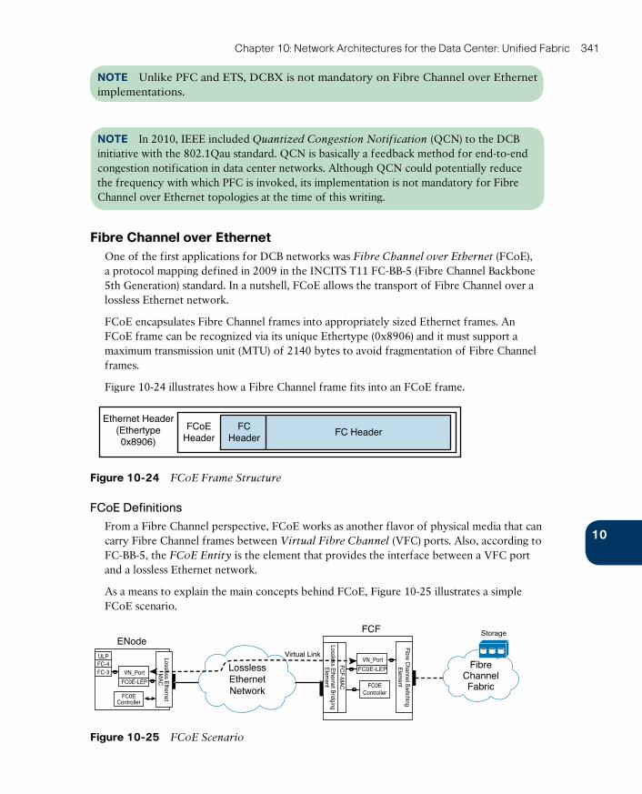
ptg17120290
10
Chapter 10: Network Architectures for the Data Center: Unified Fabric 341
NOTE Unlike PFC and ETS, DCBX is not mandatory on Fibre Channel over Ethernet implementations.
NOTE In 2010, IEEE included Quantized Congestion Notification (QCN) to the DCB initiative with the 802.1Qau standard. QCN is basically a feedback method for end-to-end congestion notification in data center networks. Although QCN could potentially reduce the frequency with which PFC is invoked, its implementation is not mandatory for Fibre Channel over Ethernet topologies at the time of this writing.
Fibre Channel over EthernetOne of the first applications for DCB networks was Fibre Channel over Ethernet (FCoE), a protocol mapping defined in 2009 in the INCITS T11 FC-BB-5 (Fibre Channel Backbone 5th Generation) standard. In a nutshell, FCoE allows the transport of Fibre Channel over a lossless Ethernet network.
FCoE encapsulates Fibre Channel frames into appropriately sized Ethernet frames. An FCoE frame can be recognized via its unique Ethertype (0x8906) and it must support a maximum transmission unit (MTU) of 2140 bytes to avoid fragmentation of Fibre Channel frames.
Figure 10-24 illustrates how a Fibre Channel frame fits into an FCoE frame.
Ethernet Header(Ethertype0x8906)
FCoEHeader
FC HeaderFC
Header
Figure 10-24 FCoE Frame Structure
FCoE Definitions
From a Fibre Channel perspective, FCoE works as another flavor of physical media that can carry Fibre Channel frames between Virtual Fibre Channel (VFC) ports. Also, according to FC-BB-5, the FCoE Entity is the element that provides the interface between a VFC port and a lossless Ethernet network.
As a means to explain the main concepts behind FCoE, Figure 10-25 illustrates a simple FCoE scenario.
LosslessEthernetNetwork
Virtual Link
Storage
FibreChannelFabric
ENodeULPFC-4FC-3 VN_Port
FC0E-LEP
FC0EController
Lossless Ethernet
MA
C
FCF
VN_Port
FC0E-LEP
FC0EController
Fibre Channel S
witching
Elem
ent
FCF-M
AC
Lossless Ethernet B
ridgingE
lement
Figure 10-25 FCoE Scenario
ptg17120290
342 CCNA Cloud CLDFND 210-451 Official Cert Guide
Figure 10-25 introduces some important FCoE terms:
■ FCoE Node (ENode): A Fibre Channel node that can transmit FCoE frames using one or more lossless Ethernet connections.
■ FCoE Controller: A functional entity that is coupled with a lossless Ethernet interface, creating and deleting VFC ports and FCoE link endpoints. It also performs the FCoE
Initialization Protocol (FIP) .
■ FCoE Forwarder (FCF): A Fibre Channel switching element that can forward FCoE frames across lossless Ethernet networks and that optionally includes a Fibre Channel fabric interface.
■ Lossless Ethernet Bridging Element: An Ethernet bridging function operating on an FCF.
■ FCoE Link End-Point (FCoE_LEP ): The data-forwarding component of an FCoE entity that handles FC frame encapsulation and decapsulation, and the exchange of encapsu-lated frames with another FCoE_LEP.
■ Virtual link: The logical link connecting two FCoE_LEPs.
■ VF_Port (Virtual F_Port) : An instance that communicates with one or more VN_Ports and that is dynamically instantiated on a successful completion of a FIP Fabric Login (FLOGI) exchange.
■ VN_Port (Virtual N_Port) : An instance that operates as an N_Port and is dynamically instantiated on successful completion of a FIP FLOGI exchange.
■ Fibre Channel Switching Element: A functional entity performing Fibre Channel switch-ing among E_Ports, F_Ports, VE_Ports, and VF_Ports on an FCF. Its behavior is specified in the FC-SW standard series.
Before any FCoE frame is effectively transported between VFC ports, each FCoE device must perform a procedure coordinated by the FCoE Initialization Protocol. FIP is used to perform the functions described in the following negotiation phases:
■ Phase 1. FIP VLAN discovery: Begins when an ENode sends a FIP VLAN request frame toward FCFs to discover FCoE-enabled VLANs. Each reachable FCF responds with a unicast FIP VLAN notification frame, stating a list of VLAN IDs that offer FCoE ser-vices.
■ Phase 2. FIP FCF discovery: This phase is performed independently in each discovered FCoE VLAN. It starts when FCFs periodically send multicast Discovery Advertisements to all ENodes announcing their FCoE capabilities (such as availability for Fabric LOGIn and FCoE MAC address assignment available methods). After selecting one FCF, the FCoE Controller of an ENode transmits to it a unicast Discovery Solicitation that shall be responded to with a unicast Discovery Advertisement.
■ Phase 3. FCoE virtual link instantiation: In this phase, the FCoE Controller of an ENode instantiates a VN_Port to a VF_Port located at the chosen FCF. The ENode indi-cates the FCoE MAC address assignment method it intends to use to exchange FCoE frames. Usually, as soon as the virtual link is established, FCoE frames are used to com-plete the Fibre Channel logins and start frame exchange.
ptg17120290
10
Chapter 10: Network Architectures for the Data Center: Unified Fabric 343
■ Phase 4. FCoE virtual link maintenance: In this final phase, each VF_Port transmits FIP keepalive frames to continuously verify the state of the virtual link. If a failure happens, the virtual interfaces are deinstantiated.
As described in phase 3 of the FIP process, the MAC address that is effectively used in the FCoE communication on a virtual link is assigned to the ENode. FC-BB-5 defines two meth-ods for this MAC address definition:
■ Server-Provided MAC Address (SPMA) : A MAC address that is assigned by an ENode
to one of its interfaces, and is not assigned to any other MAC within the same Ethernet VLAN.
■ Fabric-Provided MAC Address (FPMA) : A MAC address that is assigned by an FCF
to a single VN_Port at one ENode interface. A properly formed FPMA is one in which the 24 most significant bits correspond to the FC Mapped Address Prefix (FC-MAP) value, and the least significant 24 bits are mapped to the Fibre Channel Identifier (FCID) assigned to the VN_Port by an FCF. This process guarantees that FPMAs are unique within an FCoE fabric.
One example of FPMA can be illustrated when an FCF with an FC-MAP of 0x0efc00 assigns the FCID 0x100101 to a VN_Port in response to the ENode’s FIP FLOGI frame. Consequently, all FCoE frames from such a VFC port will use the FPMA 0efc.0010.0101.
Deploying I/O ConsolidationCisco shipped its first FCoE-capable switch (Nexus 5020) in 2008, before any of the previ-ously explained standards were even published. As part of its innovative approach, Cisco has leveraged its real-world experience to actively participate and lead both DCB and FCoE standardization initiatives.
Since then, the company has consolidated an enviable I/O portfolio with additional Nexus switches, Fabric Extenders, and directors. Concurrently, other manufacturers such as Emu-lex, QLogic, and Intel have launched server adapters that could fulfill the promise of cost-effective I/O consolidation with DCB and FCoE over 10-Gigabit Ethernet connections using fiber, short-reach twisted-pair, and TwinAx cables.
There are two ways to transform a server into an FCoE ENode: using an FCoE software
driver or through a specialized hardware-based adapter called a converged network adapter (CNA). At the time of this writing, the majority of Cisco FCoE deployments use CNAs.
A CNA combines the properties of an Ethernet network interface card (NIC) and a Fibre Channel host bus adapter (HBA) on a single adapter card. In fact, operating systems view the Ethernet and Fibre Channel components from a CNA as completely separate entities.
Figure 10-26 portrays an example of such a perspective, when a Windows-based server detects two Ethernet interfaces and two Fibre Channel ports on a dual-port CNA.
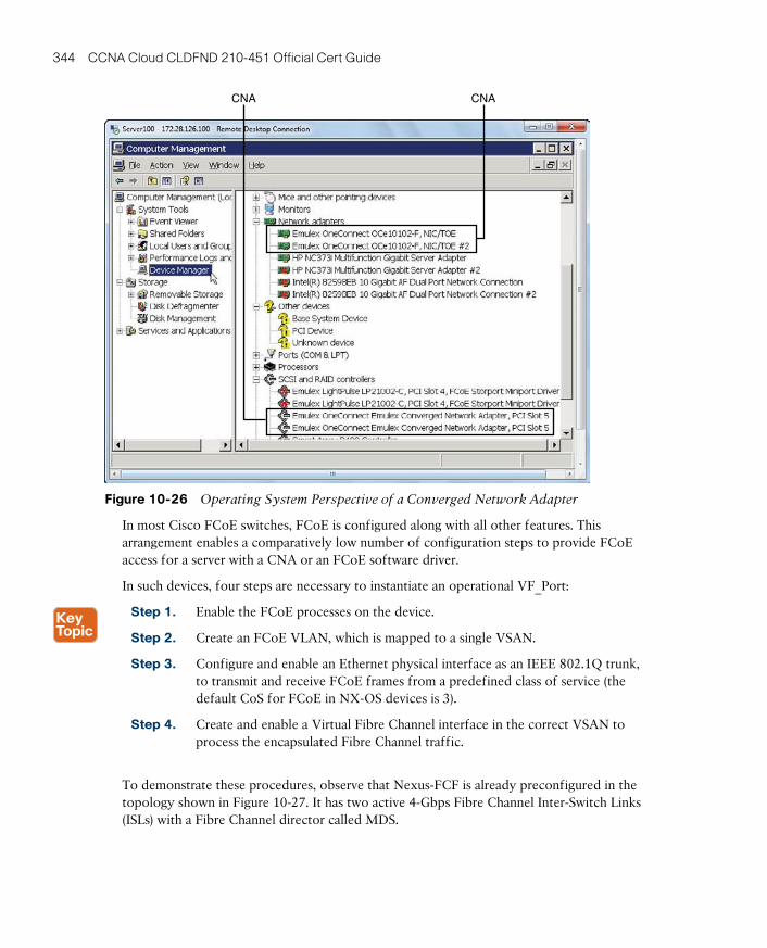
ptg17120290
344 CCNA Cloud CLDFND 210-451 Official Cert Guide
CNACNA
Figure 10-26 Operating System Perspective of a Converged Network Adapter
In most Cisco FCoE switches, FCoE is configured along with all other features. This arrangement enables a comparatively low number of configuration steps to provide FCoE access for a server with a CNA or an FCoE software driver.
In such devices, four steps are necessary to instantiate an operational VF_Port:
Step 1. Enable the FCoE processes on the device.
Step 2. Create an FCoE VLAN, which is mapped to a single VSAN.
Step 3. Configure and enable an Ethernet physical interface as an IEEE 802.1Q trunk, to transmit and receive FCoE frames from a predefined class of service (the default CoS for FCoE in NX-OS devices is 3).
Step 4. Create and enable a Virtual Fibre Channel interface in the correct VSAN to process the encapsulated Fibre Channel traffic.
To demonstrate these procedures, observe that Nexus-FCF is already preconfigured in the topology shown in Figure 10-27. It has two active 4-Gbps Fibre Channel Inter-Switch Links (ISLs) with a Fibre Channel director called MDS.
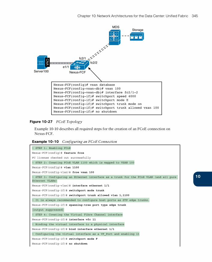
ptg17120290
10
Chapter 10: Network Architectures for the Data Center: Unified Fabric 345
Nexus-FCF(config)# vsan databaseNexus-FCF(config-vsan-db)# vsan 100Nexus-FCF(config-vsan-db)# interface fc2/1-2Nexus-FCF(config-if)# switchport speed 4000Nexus-FCF(config-if)# switchport mode ENexus-FCF(config-if)# switchport trunk mode onNexus-FCF(config-if)# switchport trunk allowed vsan 100Nexus-FCF(config-if)# no shutdown
Nexus-FCF
fc2/1
e1/1Server100
fc2/2
MDSStorage
CN
A
Figure 10-27 FCoE Topology
Example 10-10 describes all required steps for the creation of an FCoE connection on Nexus-FCF.
Example 10-10 Configuring an FCoE Connection
! STEP 1: Enabling FCoE
Nexus-FCF(config)# feature fcoe
FC license checked out successfully
! STEP 2: Creating FCoE VLAN 1100 which is mapped to VSAN 100
Nexus-FCF(config)# vlan 1100
Nexus-FCF(config-vlan)# fcoe vsan 100
! STEP 3: Configuring an Ethernet interface as a trunk for the FCoE VLAN (and all pure Ethernet VLANs)
Nexus-FCF(config-vlan)# interface ethernet 1/1
Nexus-FCF(config-if)# switchport mode trunk
Nexus-FCF(config-if)# switchport trunk allowed vlan 1,1100
! It is always recommended to configure host ports as STP edge trunks.
Nexus-FCF(config-if)# spanning-tree port type edge trunk
[output suppressed]
! STEP 4: Creating the Virtual Fibre Channel interface
Nexus-FCF(config-if)# interface vfc 11
! Binding the virtual interface to a physical interface
Nexus-FCF(config-if)# bind interface ethernet 1/1
! Configuring the virtual interface as a VF_Port and enabling it
Nexus-FCF(config-if)# switchport mode F
Nexus-FCF(config-if)# no shutdown
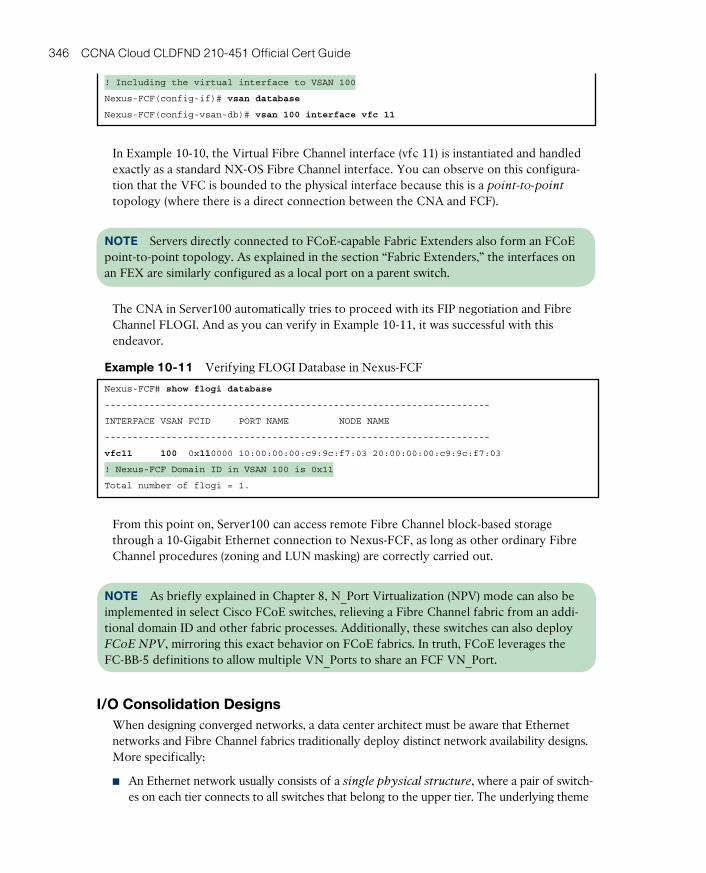
ptg17120290
346 CCNA Cloud CLDFND 210-451 Official Cert Guide
! Including the virtual interface to VSAN 100
Nexus-FCF(config-if)# vsan database
Nexus-FCF(config-vsan-db)# vsan 100 interface vfc 11
In Example 10-10, the Virtual Fibre Channel interface (vfc 11) is instantiated and handled exactly as a standard NX-OS Fibre Channel interface. You can observe on this configura-tion that the VFC is bounded to the physical interface because this is a point-to-point
topology (where there is a direct connection between the CNA and FCF).
NOTE Servers directly connected to FCoE-capable Fabric Extenders also form an FCoE point-to-point topology. As explained in the section “Fabric Extenders,” the interfaces on an FEX are similarly configured as a local port on a parent switch.
The CNA in Server100 automatically tries to proceed with its FIP negotiation and Fibre Channel FLOGI. And as you can verify in Example 10-11, it was successful with this endeavor.
Example 10-11 Verifying FLOGI Database in Nexus-FCF
Nexus-FCF# show flogi database
---------------------------------------------------------------------
INTERFACE VSAN FCID PORT NAME NODE NAME
---------------------------------------------------------------------
vfc11 100 0x110000 10:00:00:00:c9:9c:f7:03 20:00:00:00:c9:9c:f7:03
! Nexus-FCF Domain ID in VSAN 100 is 0x11
Total number of flogi = 1.
From this point on, Server100 can access remote Fibre Channel block-based storage through a 10-Gigabit Ethernet connection to Nexus-FCF, as long as other ordinary Fibre Channel procedures (zoning and LUN masking) are correctly carried out.
NOTE As briefly explained in Chapter 8, N_Port Virtualization (NPV) mode can also be implemented in select Cisco FCoE switches, relieving a Fibre Channel fabric from an addi-tional domain ID and other fabric processes. Additionally, these switches can also deploy FCoE NPV, mirroring this exact behavior on FCoE fabrics. In truth, FCoE leverages the FC-BB-5 definitions to allow multiple VN_Ports to share an FCF VN_Port.
I/O Consolidation DesignsWhen designing converged networks, a data center architect must be aware that Ethernet networks and Fibre Channel fabrics traditionally deploy distinct network availability designs. More specifically:
■ An Ethernet network usually consists of a single physical structure, where a pair of switch-es on each tier connects to all switches that belong to the upper tier. The underlying theme
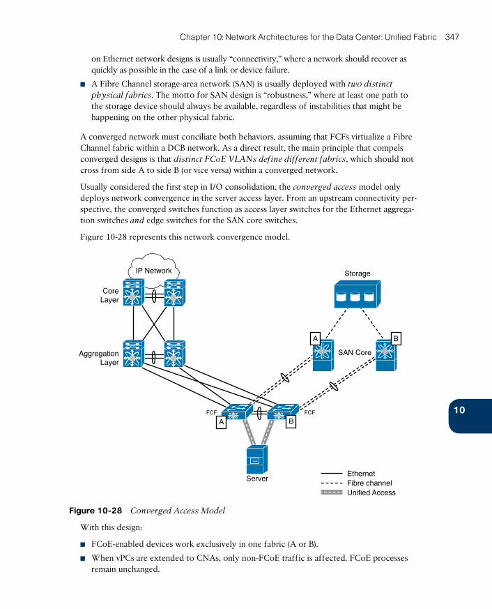
ptg17120290
10
Chapter 10: Network Architectures for the Data Center: Unified Fabric 347
on Ethernet network designs is usually “connectivity,” where a network should recover as quickly as possible in the case of a link or device failure.
■ A Fibre Channel storage-area network (SAN) is usually deployed with two distinct
physical fabrics. The motto for SAN design is “robustness,” where at least one path to the storage device should always be available, regardless of instabilities that might be happening on the other physical fabric.
A converged network must conciliate both behaviors, assuming that FCFs virtualize a Fibre Channel fabric within a DCB network. As a direct result, the main principle that compels converged designs is that distinct FCoE VLANs define different fabrics, which should not cross from side A to side B (or vice versa) within a converged network.
Usually considered the first step in I/O consolidation, the converged access model only deploys network convergence in the server access layer. From an upstream connectivity per-spective, the converged switches function as access layer switches for the Ethernet aggrega-tion switches and edge switches for the SAN core switches.
Figure 10-28 represents this network convergence model.
Storage
Server
FCF FCF
EthernetFibre channelUnified Access
SAN CoreAggregationLayer
CoreLayer
IP Network
BA
BA
Figure 10-28 Converged Access Model
With this design:
■ FCoE-enabled devices work exclusively in one fabric (A or B).
■ When vPCs are extended to CNAs, only non-FCoE traffic is affected. FCoE processes remain unchanged.
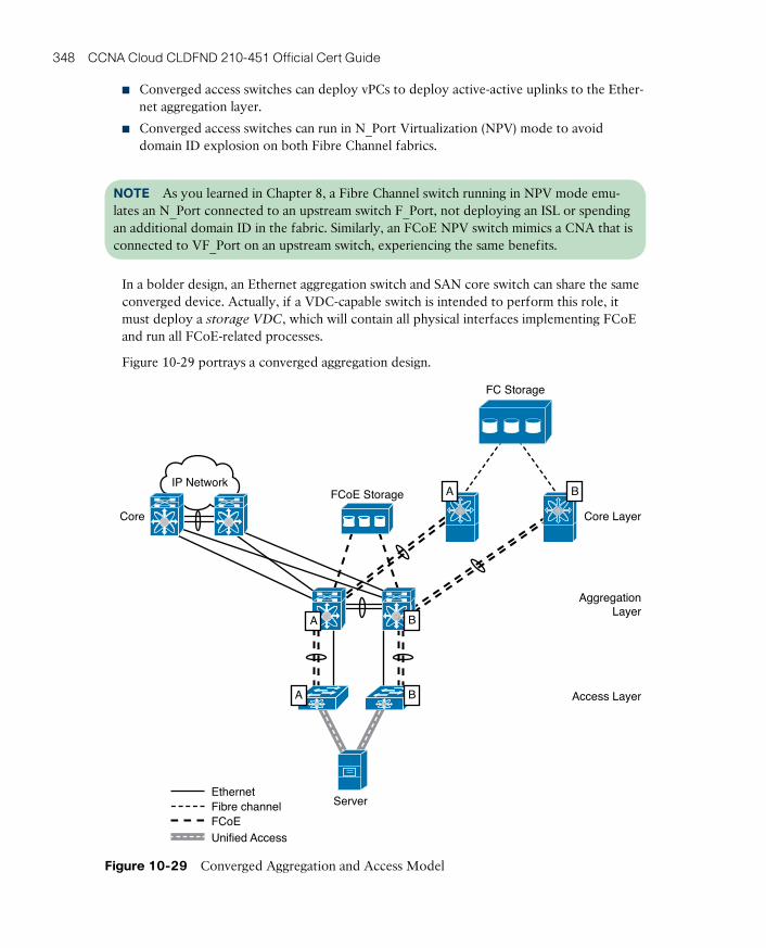
ptg17120290
348 CCNA Cloud CLDFND 210-451 Official Cert Guide
■ Converged access switches can deploy vPCs to deploy active-active uplinks to the Ether-net aggregation layer.
■ Converged access switches can run in N_Port Virtualization (NPV) mode to avoid domain ID explosion on both Fibre Channel fabrics.
NOTE As you learned in Chapter 8, a Fibre Channel switch running in NPV mode emu-lates an N_Port connected to an upstream switch F_Port, not deploying an ISL or spending an additional domain ID in the fabric. Similarly, an FCoE NPV switch mimics a CNA that is connected to VF_Port on an upstream switch, experiencing the same benefits.
In a bolder design, an Ethernet aggregation switch and SAN core switch can share the same converged device. Actually, if a VDC-capable switch is intended to perform this role, it must deploy a storage VDC, which will contain all physical interfaces implementing FCoE and run all FCoE-related processes.
Figure 10-29 portrays a converged aggregation design.
Server
AggregationLayer
Access Layer
Core LayerCore
IP NetworkFCoE Storage
A
FC Storage
EthernetFibre channelFCoE
A
BA
B
B
Unified Access
Figure 10-29 Converged Aggregation and Access Model

ptg17120290
10
Chapter 10: Network Architectures for the Data Center: Unified Fabric 349
Observe in Figure 10-29 the physical separation between FCoE ISLs and Ethernet uplinks. There are several reasons for deploying these separated switch connections:
■ The FCoE VLANs from Fabric A and Fabric B must remain on separate devices to deploy a Fibre Channel–equivalent network design.
■ Fibre Channel ISLs and Ethernet uplinks usually present much higher bandwidth utiliza-tion than server connections. Therefore, a hypothetical consolidation of these connec-tions will not bring significant savings in cabling.
■ SAN and LAN teams can deploy independent bandwidth capacity planning with separate ISLs and uplinks, respectively.
Additionally, this design allows
■ Converged access switches to deploy vPCs to deploy active-active uplinks to the Ether-net aggregation layer
■ Converged access switches to deploy FCoE NPV mode on their FCoE connections to the aggregation
■ Storage devices with FCoE access ports to connect directly to the converged aggregation
■ The converged aggregation switches to deploy FCoE ISLs to FCoE-capable SAN direc-tors to provide access to Fibre Channel SANs
Although FCoE ISLs and Ethernet uplinks are separated on this supported design, it does not mean that they must remain completely segmented in all possible designs. In fact, an interesting Unified Fabric that allows a full I/O consolidation scenario will be presented in the next section.
NOTE To isolate the operations between the networking and storage teams, all NX-OS devices can deploy Role-Based Access Control (RBAC) features, which can dedicate man-agement access to interfaces, VLANs, and commands to a single user or group of users. As an added separation technique, select Nexus switches can deploy a single storage VDC for all FCoE-related functions.
FabricPathOver the past several years, networking manufacturers and standards organizations have invested research and development time to retire STP from data center networks through a Layer 2 multipathing technology. The main idea behind this initiative is the possibility of using the advantages associated with Layer 3 routing (equal-cost multipath, flexible topolo-gies, and traffic control) while keeping the simplicity that Layer 2 switching offers to all kinds of traffic (unicast, multicast, and broadcast).
In 2010, Cisco launched FabricPath as the first commercially available Layer 2 multipath protocol. Like many other technologies discussed in this chapter, FabricPath uses encapsula-tion and decapsulation to forward Ethernet frames from one FabricPath switch to another (using up to 16 different paths).
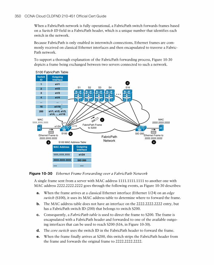
ptg17120290
350 CCNA Cloud CLDFND 210-451 Official Cert Guide
When a FabricPath network is fully operational, a FabricPath switch forwards frames based on a Switch ID field in a FabricPath header, which is a unique number that identifies each switch in the network.
Because FabricPath is only enabled in interswitch connections, Ethernet frames are com-monly received on classical Ethernet interfaces and then encapsulated to traverse a Fabric-Path network.
To support a thorough explanation of the FabricPath forwarding process, Figure 10-30 depicts a frame being exchanged between two servers connected to such a network.
MAC1111.1111.1111
S100 SID 200Ethernet Frame to2222.2222.2222
Ethernet Frame to2222.2222.2222
e1/16e1/24e1/1
FabricPathNetwork
MAC2222.2222.2222
S16
...
S100 FabricPath Table
1 e1/1
e1/1, e1/2, e1/3,e1/4, ..., e1/16
e1/22
e1/33
e1/44
e1/1616
200
... ...
FabricPath Frameto S200
SwitchID
OutgoingInterface
e1/3e1/4
e1/16
e1/1e1/2
S4S3S2S1
OutgoingInterface
MAC Address
2222.2222.2222 SID 200
......
e1/241111.1111.1111
d
e
c
b
a S100 MAC Address Table
Figure 10-30 Ethernet Frame Forwarding over a FabricPath Network
A single frame sent from a server with MAC address 1111.1111.1111 to another one with MAC address 2222.2222.2222 goes through the following events, as Figure 10-30 describes:
a. When the frame arrives at a classical Ethernet interface (Ethernet 1/24) on an edge
switch (S100), it uses its MAC address table to determine where to forward the frame.
b. The MAC address table does not have an interface on the 2222.2222.2222 entry, but has a FabricPath switch ID (200) that belongs to switch S200.
c. Consequently, a FabricPath table is used to direct the frame to S200. The frame is encapsulated with a FabricPath header and forwarded to one of the available outgo-ing interfaces that can be used to reach S200 (S16, in Figure 10-30).
d. The core switch uses the switch ID in the FabricPath header to forward the frame.
e. When the frame finally arrives at S200, this switch strips the FabricPath header from the frame and forwards the original frame to 2222.2222.2222.
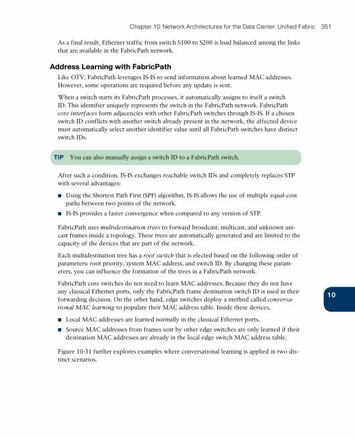
ptg17120290
10
Chapter 10: Network Architectures for the Data Center: Unified Fabric 351
As a final result, Ethernet traffic from switch S100 to S200 is load balanced among the links that are available in the FabricPath network.
Address Learning with FabricPathLike OTV, FabricPath leverages IS-IS to send information about learned MAC addresses. However, some operations are required before any update is sent.
When a switch starts its FabricPath processes, it automatically assigns to itself a switch ID. This identifier uniquely represents the switch in the FabricPath network. FabricPath core interfaces form adjacencies with other FabricPath switches through IS-IS. If a chosen switch ID conflicts with another switch already present in the network, the affected device must automatically select another identifier value until all FabricPath switches have distinct switch IDs.
TIP You can also manually assign a switch ID to a FabricPath switch.
After such a condition, IS-IS exchanges reachable switch IDs and completely replaces STP with several advantages:
■ Using the Shortest Path First (SPF) algorithm, IS-IS allows the use of multiple equal-cost paths between two points of the network.
■ IS-IS provides a faster convergence when compared to any version of STP.
FabricPath uses multidestination trees to forward broadcast, multicast, and unknown uni-cast frames inside a topology. These trees are automatically generated and are limited to the capacity of the devices that are part of the network.
Each multidestination tree has a root switch that is elected based on the following order of parameters: root priority, system MAC address, and switch ID. By changing these param-eters, you can influence the formation of the trees in a FabricPath network.
FabricPath core switches do not need to learn MAC addresses. Because they do not have any classical Ethernet ports, only the FabricPath frame destination switch ID is used in their forwarding decision. On the other hand, edge switches deploy a method called conversa-
tional MAC learning to populate their MAC address table. Inside these devices,
■ Local MAC addresses are learned normally in the classical Ethernet ports.
■ Source MAC addresses from frames sent by other edge switches are only learned if their destination MAC addresses are already in the local edge switch MAC address table.
Figure 10-31 further explores examples where conversational learning is applied in two dis-tinct scenarios.
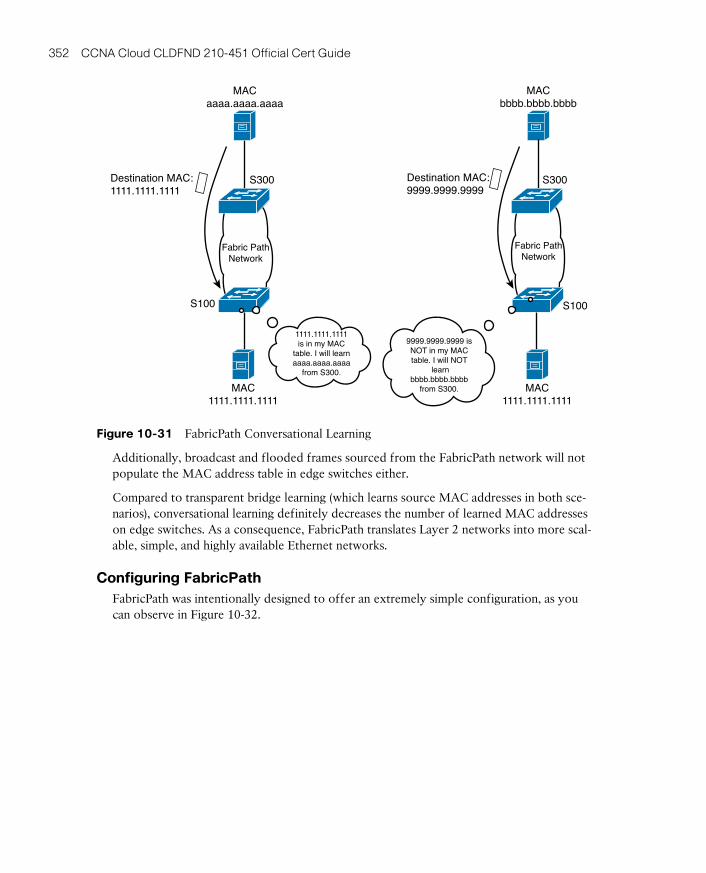
ptg17120290
352 CCNA Cloud CLDFND 210-451 Official Cert Guide
Destination MAC:1111.1111.1111
Destination MAC:9999.9999.9999
S300 S300
S100 S100
MAC1111.1111.1111
MACaaaa.aaaa.aaaa
MACbbbb.bbbb.bbbb
MAC1111.1111.1111
1111.1111.1111is in my MAC
table. I will learnaaaa.aaaa.aaaa
from S300.
9999.9999.9999 isNOT in my MACtable. I will NOT
learnbbbb.bbbb.bbbb
from S300.
Fabric PathNetwork
Fabric PathNetwork
Figure 10-31 FabricPath Conversational Learning
Additionally, broadcast and flooded frames sourced from the FabricPath network will not populate the MAC address table in edge switches either.
Compared to transparent bridge learning (which learns source MAC addresses in both sce-narios), conversational learning definitely decreases the number of learned MAC addresses on edge switches. As a consequence, FabricPath translates Layer 2 networks into more scal-able, simple, and highly available Ethernet networks.
Configuring FabricPathFabricPath was intentionally designed to offer an extremely simple configuration, as you can observe in Figure 10-32.

ptg17120290
10
Chapter 10: Network Architectures for the Data Center: Unified Fabric 353
e1/19
e1/20
e1/1-4
e1/12
MAC0050.568b.0020
MAC0050.568b.0025
e1/5-8
e1/19
e1/20
e1/15-18e1/11-14
FP2(config)# feature-set fabricpathFP2(config)# fabricpath switch-id 2FP2(config)# vlan 100FP2(config-vlan)# mode fabricpathFP2(config-vlan)# interface ethernet 1/15-20FP2(config-if-range)# switchport mode fabricpathFP2(config-if-range)# no shutdown
FP50(config)# install feature-set fabricpathFP50(config)# feature-set fabricpathFP50(config)# fabricpath switch-id 50FP50(config)# vlan 100FP50(config-vlan)# mode fabricpathFP50(config-vlan)# interface ethernet 1/1-8FP50(config-if-range)# switchport mode fabricpathFP50(config-if-range)# no shutdown
FP1(config)# feature-set fabricpathFP1(config)# fabricpath switch-id 1FP1(config)# vlan 100FP1(config-vlan)# mode fabricpathFP1(config-vlan)# interface ethernet 1/11-14, ethernet 1/19-20FP1(config-if-range)# switchport mode fabricpathFP1(config-if-range)# no shutdown
FP1
FP50
FP2
Figure 10-32 FabricPath Configuration Example
The figure portrays a sample topology deploying basic FabricPath configuration for switch-es FP1, FP2, and FP50. In summary, the configuration in each device requires the execution of the following steps:
Step 1. Install and enable the FabricPath feature set, which is essentially a set of pro-cesses. Because FP1 and FP2 are VDCs, the feature set installation must be executed in the admin VDC.
Step 2. Optionally, change the switch ID. This step is executed here to make the out-put clearer.
Step 3. Configure the VLANs that will be used on the FabricPath network (only VLAN 100, in our scenario).
Step 4. Include interfaces in the FabricPath network through the switchport mode fabricpath command.
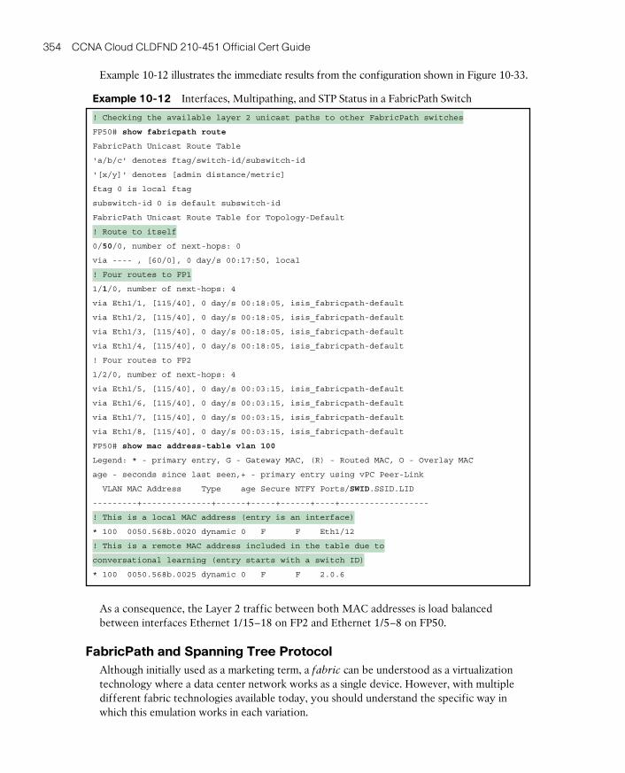
ptg17120290
354 CCNA Cloud CLDFND 210-451 Official Cert Guide
Example 10-12 illustrates the immediate results from the configuration shown in Figure 10-33.
Example 10-12 Interfaces, Multipathing, and STP Status in a FabricPath Switch
! Checking the available layer 2 unicast paths to other FabricPath switches
FP50# show fabricpath route
FabricPath Unicast Route Table
'a/b/c' denotes ftag/switch-id/subswitch-id
'[x/y]' denotes [admin distance/metric]
ftag 0 is local ftag
subswitch-id 0 is default subswitch-id
FabricPath Unicast Route Table for Topology-Default
! Route to itself
0/50/0, number of next-hops: 0
via ---- , [60/0], 0 day/s 00:17:50, local
! Four routes to FP1
1/1/0, number of next-hops: 4
via Eth1/1, [115/40], 0 day/s 00:18:05, isis_fabricpath-default
via Eth1/2, [115/40], 0 day/s 00:18:05, isis_fabricpath-default
via Eth1/3, [115/40], 0 day/s 00:18:05, isis_fabricpath-default
via Eth1/4, [115/40], 0 day/s 00:18:05, isis_fabricpath-default
! Four routes to FP2
1/2/0, number of next-hops: 4
via Eth1/5, [115/40], 0 day/s 00:03:15, isis_fabricpath-default
via Eth1/6, [115/40], 0 day/s 00:03:15, isis_fabricpath-default
via Eth1/7, [115/40], 0 day/s 00:03:15, isis_fabricpath-default
via Eth1/8, [115/40], 0 day/s 00:03:15, isis_fabricpath-default
FP50# show mac address-table vlan 100
Legend: * - primary entry, G - Gateway MAC, (R) - Routed MAC, O - Overlay MAC
age - seconds since last seen,+ - primary entry using vPC Peer-Link
VLAN MAC Address Type age Secure NTFY Ports/SWID.SSID.LID
---------+--------------+------+-----+------+----+------------------
! This is a local MAC address (entry is an interface)
* 100 0050.568b.0020 dynamic 0 F F Eth1/12
! This is a remote MAC address included in the table due to
conversational learning (entry starts with a switch ID)
* 100 0050.568b.0025 dynamic 0 F F 2.0.6
As a consequence, the Layer 2 traffic between both MAC addresses is load balanced between interfaces Ethernet 1/15–18 on FP2 and Ethernet 1/5–8 on FP50.
FabricPath and Spanning Tree ProtocolAlthough initially used as a marketing term, a fabric can be understood as a virtualization technology where a data center network works as a single device. However, with multiple different fabric technologies available today, you should understand the specific way in which this emulation works in each variation.

ptg17120290
10
Chapter 10: Network Architectures for the Data Center: Unified Fabric 355
In the case of FabricPath, the single-device virtualization is achieved in connections between FabricPath switches’ classical Ethernet interfaces and STP-based networks. In this situation, the FabricPath network appears as a single switch from an STP perspective to all external switches. Such a virtual STP bridge can be identified with the MAC address c84c.75fa.6000, which is included in all BPDUs sent to STP-based switches.
Figure 10-33 details how a FabricPath network is viewed from an STP-enabled switch per-spective.
Blockedby STP
Physical Topology Logical Topology
Spine1 Spine2
Leaf1 Leaf2
STP Switch
FabricPath Virtual STPBridge
(c84c.75fa.6000)
STP Root
Blockedby STP
STP Switch
Figure 10-33 FabricPath Network from an STP Device Perspective
As a way to avoid loops in the connection shown in Figure 10-33, you must guarantee that the FabricPath network is selected as the root for the connected STP network. Otherwise, FabricPath-enabled switches will automatically bring such STP-based connections down to avoid the danger of multiple active links to a single switch or classical Ethernet network. In this hypothetical situation, neither STP nor FabricPath would be able to identify a loop formed through these connections.
The virtual bridge is a convenient structure to understand how to build active-active paths for STP switches connected to a FabricPath network. Logically, a feature called virtual
PortChannel Plus (vPC+) allows an IEEE 802.3ad-compatible device to aggregate classical Ethernet links to a pair of FabricPath switches.
Figure 10-34 represents how a vPC+ can be built on the same topology shown in Figure 10-33, offering active-active connections to STP switches and servers that can deploy link aggregation. Figure 10-34 also depicts how both vPC peers are seen from a FabricPath switch standpoint.
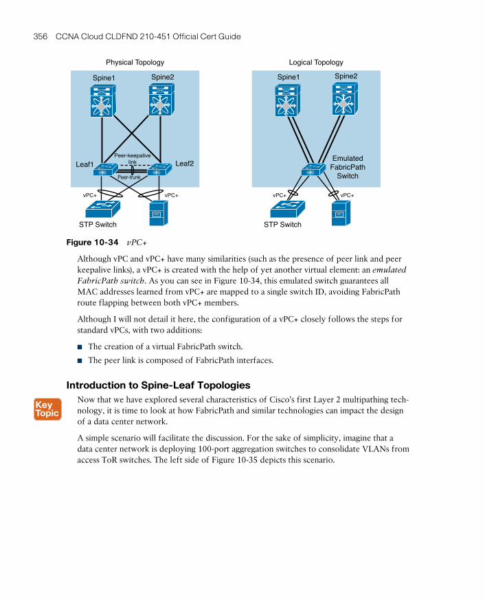
ptg17120290
356 CCNA Cloud CLDFND 210-451 Official Cert Guide
Physical Topology Logical Topology
EmulatedFabricPath
Switch
Spine1 Spine2
vPC+vPC+
STP Switch
Spine1 Spine2
Leaf1 Leaf2
STP Switch
vPC+
Peer-keepalivelink
Peer-trunk
vPC+
Figure 10-34 vPC+
Although vPC and vPC+ have many similarities (such as the presence of peer link and peer keepalive links), a vPC+ is created with the help of yet another virtual element: an emulated
FabricPath switch. As you can see in Figure 10-34, this emulated switch guarantees all MAC addresses learned from vPC+ are mapped to a single switch ID, avoiding FabricPath route flapping between both vPC+ members.
Although I will not detail it here, the configuration of a vPC+ closely follows the steps for standard vPCs, with two additions:
■ The creation of a virtual FabricPath switch.
■ The peer link is composed of FabricPath interfaces.
Introduction to Spine-Leaf TopologiesNow that we have explored several characteristics of Cisco’s first Layer 2 multipathing tech-nology, it is time to look at how FabricPath and similar technologies can impact the design of a data center network.
A simple scenario will facilitate the discussion. For the sake of simplicity, imagine that a data center network is deploying 100-port aggregation switches to consolidate VLANs from access ToR switches. The left side of Figure 10-35 depicts this scenario.

ptg17120290
10
Chapter 10: Network Architectures for the Data Center: Unified Fabric 357
Acc1
Acc2 Acc48
Acc47 Acc49
Acc50 Acc95 Acc96
WAN orInternet
Core1
Agg1(100 ports)
Agg2(100 ports)
Layer 2Domain
Layer 2Domain
Layer 2Domain
Core2
Acc1
Acc2 Acc96
Acc95
WAN orInternet
Core1
Agg1(100 ports)
Agg3(100 ports)
Agg2(100 ports)
Agg4(100 ports)
Core2
Figure 10-35 Scaling a Core-Aggregation-Access Network
Observe that the maximum number of access switches (96) corresponds to the number of remaining ports of the aggregation switches after accounting for the interfaces’ four dedi-cated connections to the core switches and the vPC peer link.
All was well in this network until the network administrators perceived a sudden growth in the east-west traffic. After some discussion, they decided that the number of uplinks of each access switch should be doubled.
The right side of Figure 10-35 illustrates the solution if the three-tier design is maintained. Because the data center network designers are still using 100-port aggregation switches, the number of access switches connected to a pair of aggregation switches decreases to 48. As a result, the network growth requires another pair of aggregation switches to maintain the original number of access switches.
Notwithstanding, you can notice a collateral effect: there are now two Layer 2 domains that cannot share any VLANs (due to the routed network between them). These separate domains surely bring operational complexity to server connection because it forbids the provisioning of a VLAN to all the racks in this facility.
The described situation has been challenging many data centers all over the world, which are forced to deal with Layer 2 domains and their exclusive VLANs. And although the con-nectivity problem could be solved if the Layer 3 border were dislocated to the core switch, all aggregation and access switches would be under the same failure domain and subjected to extremely dangerous STP reconvergences.
With the advent of Layer 2 multipathing, this problem is addressed through a spine-leaf topology, as Figure 10-36 details.
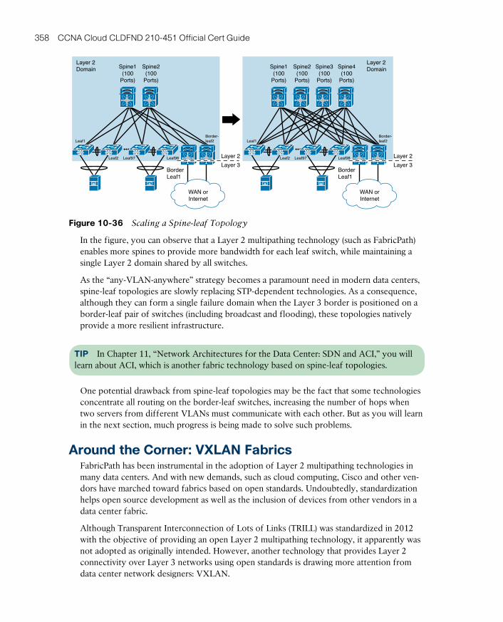
ptg17120290
358 CCNA Cloud CLDFND 210-451 Official Cert Guide
Spine1(100
Ports)
Layer 2Domain
BorderLeaf1
Leaf1Border-leaf2
Leaf2 Leaf97 Leaf98
Spine2(100
Ports)
WAN orInternet
Spine1(100
Ports)
Layer 2Domain
BorderLeaf1
Leaf1
Leaf2 Leaf97 Leaf98
Spine2(100
Ports)
Spine3(100
Ports)
Spine4(100
Ports)
WAN orInternet
Layer 2
Layer 3
Layer 2
Layer 3
Border-leaf2
Figure 10-36 Scaling a Spine-leaf Topology
In the figure, you can observe that a Layer 2 multipathing technology (such as FabricPath) enables more spines to provide more bandwidth for each leaf switch, while maintaining a single Layer 2 domain shared by all switches.
As the “any-VLAN-anywhere” strategy becomes a paramount need in modern data centers, spine-leaf topologies are slowly replacing STP-dependent technologies. As a consequence, although they can form a single failure domain when the Layer 3 border is positioned on a border-leaf pair of switches (including broadcast and flooding), these topologies natively provide a more resilient infrastructure.
TIP In Chapter 11, “Network Architectures for the Data Center: SDN and ACI,” you will learn about ACI, which is another fabric technology based on spine-leaf topologies.
One potential drawback from spine-leaf topologies may be the fact that some technologies concentrate all routing on the border-leaf switches, increasing the number of hops when two servers from different VLANs must communicate with each other. But as you will learn in the next section, much progress is being made to solve such problems.
Around the Corner: VXLAN FabricsFabricPath has been instrumental in the adoption of Layer 2 multipathing technologies in many data centers. And with new demands, such as cloud computing, Cisco and other ven-dors have marched toward fabrics based on open standards. Undoubtedly, standardization helps open source development as well as the inclusion of devices from other vendors in a data center fabric.
Although Transparent Interconnection of Lots of Links (TRILL) was standardized in 2012 with the objective of providing an open Layer 2 multipathing technology, it apparently was not adopted as originally intended. However, another technology that provides Layer 2 connectivity over Layer 3 networks using open standards is drawing more attention from data center network designers: VXLAN.
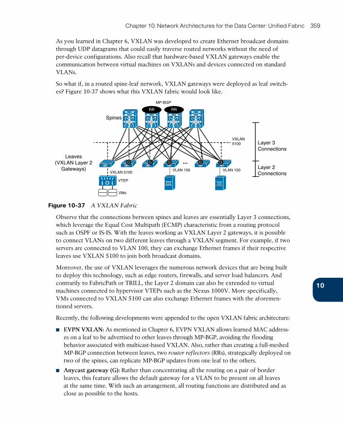
ptg17120290
10
Chapter 10: Network Architectures for the Data Center: Unified Fabric 359
As you learned in Chapter 6, VXLAN was developed to create Ethernet broadcast domains through UDP datagrams that could easily traverse routed networks without the need of per-device configurations. Also recall that hardware-based VXLAN gateways enable the communication between virtual machines on VXLANs and devices connected on standard VLANs.
So what if, in a routed spine-leaf network, VXLAN gateways were deployed as leaf switch-es? Figure 10-37 shows what this VXLAN fabric would look like.
Spines
Leaves(VXLAN Layer 2
Gateways)
VXLAN5100
VXLAN 5100 VLAN 100
Layer 3Connections
Layer 2Connections
VTEP
VMs
VLAN 100
MP-BGP
...
RR RR
GGGGG
Figure 10-37 A VXLAN Fabric
Observe that the connections between spines and leaves are essentially Layer 3 connections, which leverage the Equal Cost Multipath (ECMP) characteristic from a routing protocol such as OSPF or IS-IS. With the leaves working as VXLAN Layer 2 gateways, it is possible to connect VLANs on two different leaves through a VXLAN segment. For example, if two servers are connected to VLAN 100, they can exchange Ethernet frames if their respective leaves use VXLAN 5100 to join both broadcast domains.
Moreover, the use of VXLAN leverages the numerous network devices that are being built to deploy this technology, such as edge routers, firewalls, and server load balancers. And contrarily to FabricPath or TRILL, the Layer 2 domain can also be extended to virtual machines connected to hypervisor VTEPs such as the Nexus 1000V. More specifically, VMs connected to VXLAN 5100 can also exchange Ethernet frames with the aforemen-tioned servers.
Recently, the following developments were appended to the open VXLAN fabric architecture:
■ EVPN VXLAN : As mentioned in Chapter 6, EVPN VXLAN allows learned MAC address-es on a leaf to be advertised to other leaves through MP-BGP, avoiding the flooding behavior associated with multicast-based VXLAN. Also, rather than creating a full-meshed MP-BGP connection between leaves, two router reflectors (RRs), strategically deployed on two of the spines, can replicate MP-BGP updates from one leaf to the others.
■ Anycast gateway (G): Rather than concentrating all the routing on a pair of border leaves, this feature allows the default gateway for a VLAN to be present on all leaves at the same time. With such an arrangement, all routing functions are distributed and as close as possible to the hosts.
ptg17120290
360 CCNA Cloud CLDFND 210-451 Official Cert Guide
One possible drawback of this fabric design is the number of operations involved in build-ing the fabric basic infrastructure (Layer 3 links, routing protocol, MP-BGP, and router reflector), and provisioning and mapping the Layer 2 mechanisms (VLANs and VXLANs). Cisco has overcome this challenge through an orchestration solution called Virtual Topol-ogy System (VTS), which can coordinate the numerous operations involved in the creation of a virtual overlay in a VXLAN fabric.
Further Reading■ VXLAN Network with MP-BGP EVPN Control Plane: http://www.cisco.com/c/en/us/
products/collateral/switches/nexus-9000-series-switches/guide-c07-734107.html
■ VXLAN DCI Using EVPN: https://datatracker.ietf.org/doc/draft-boutros-l2vpn-vxlan-evpn/
■ Operation of Anycast Services (RFC 4786): https://tools.ietf.org/html/rfc4786

ptg17120290
10
Chapter 10: Network Architectures for the Data Center: Unified Fabric 361
Exam Preparation Tasks
Review All the Key TopicsReview the most important topics in this chapter, denoted with a Key Topic icon in the outer margin of the page. Table 10-3 lists a reference of these key topics and the page num-ber on which each is found.
Table 10-3 Key Topics for Chapter 10
Key Topic Element Description Page Number
List Attributes of data center networks 304
List Differences between campus and data center net-works
305
List VDC use cases 309
List VDC managed resources 312
List vPC elements 317
Figure 10-14 Straight-through topologies 325
Figure 10-15 Dual-homed topologies 326
List Layer 2 extension challenges 327
Table 10-2 Traditional Layer 2 extension technologies 329
List OTV elements 332
List FCoE configuration steps 344
Section Introduction to spine-leaf topologies 356
Complete the Tables and Lists from MemoryPrint a copy of Appendix B, “Memory Tables” (found on the CD), or at least the section for this chapter, and complete the tables and lists from memory. Appendix C, “Answers to Memory Tables,” also on the CD, includes completed tables and lists so that you can check your work.
Define Key TermsDefine the following key terms from this chapter, and check your answers in the glossary:
three-tier topology, core layer, aggregation layer, access layer, Unified Fabric, virtual device context (VDC), virtual PortChannel (vPC), Fabric Extender (FEX), Ethernet over MPLS (EoMPLS), Virtual Private LAN Service (VPLS), Overlay Transport Virtualization (OTV), I/O consolidation, Data Center Bridging (DCB), Fibre Channel over Ethernet (FCoE), FCoE Ini-tialization Protocol (FIP), FabricPath, fabric, spine-leaf
ptg17120290
This chapter covers the following topics:
■ Cloud Computing and Traditional Data Center Networks
■ The Opposite of Software-Defined Networking
■ Network Programmability
■ SDN Approaches
■ Application Centric Infrastructure
This chapter covers the following exam objectives:
■ 4.1 Describe network architectures for the data center■ 4.1.b SDN
■ 4.1.b.1 Separation of control and data■ 4.1.b.2 Programmability■ 4.1.b.3 Basic understanding of OpenDaylight
■ 4.1.c ACI■ 4.1.c.1 Describe how ACI solves the problem not addressed by SDN■ 4.1.c.3 Describe the role of the APIC Controller
ptg17120290
CHAPTER 11
Network Architectures for the Data Center: SDN and ACI
In Chapter 10, “Network Architectures for the Data Center: Unified Fabric,” you learned about a series of technological innovations that Cisco amalgamated into a highly success-ful data center network architecture: Cisco Unified Fabric. Although such architecture has become a primary driver for the evolution of numerous data centers worldwide, it is essen-tially based on concepts and abstractions that were conceived during the 1970s and 1980s, as the Internet was being formed.
During the last half of the 2000s, inspired by the noticeable differences between network-ing and other computer systems, a group of researchers began to question whether estab-lished networking practices were actually appropriate for the future of IT. Through creativ-ity and healthy naïveté, these researchers proposed many breakthrough new approaches to disrupt well-known network designs and best practices. These new approaches have been collectively given the umbrella term Software-Defined Networking (SDN).
As the world-leading networking manufacturer, Cisco has actively participated in develop-ing the large majority of these cutting-edge approaches, while also creating many others. Combining innovation and intimate knowledge about customer demands, Cisco conceived a revolutionary data center network architecture called Cisco Application Centric Infrastruc-ture (ACI). Specially designed for data centers involved in cloud computing and IT automa-tion, ACI addresses many challenges that were overlooked by earlier SDN approaches.
As mentioned in Chapter 10, the CLDFND exam requires knowledge about two other Cisco data center networking architectures besides Cisco Unified Fabric: Software-Defined Net-working and Cisco Application Centric Infrastructure. This chapter focuses on both, explor-ing the dramatic paradigm shifts they have caused in data center infrastructure and cloud computing projects.
“Do I Know This Already?” QuizThe “Do I Know This Already?” quiz allows you to assess whether you should read this entire chapter thoroughly or jump to the “Exam Preparation Tasks” section. If you are in doubt about your answers to these questions or your own assessment of your knowledge of the topics, read the entire chapter. Table 11-1 lists the major headings in this chapter and their corresponding “Do I Know This Already?” quiz questions. You can find the answers in Appendix A, “Answers to Pre-Assessments and Quizzes.”

ptg17120290
364 CCNA Cloud CLDFND 210-451 Official Cert Guide
Table 11-1 “Do I Know This Already?” Section-to-Question Mapping
Foundation Topics Section Questions
Cloud Computing and Traditional Data Center Networks 1
The Opposite of Software-Defined Networking 2
Network Programmability 3
SDN Approaches 4–6
Application Centric Infrastructure 7–10
1. Which of the following is not a challenge data center networks bring to cloud com-puting?
a. Scalability
b. Provisioning model
c. Resource decommission
d. VLAN ID depletion for tenant isolation
e. I/O consolidation
2. Which of the following options is not directly related to SDN?
a. “Clean Slate” program
b. OpenStack
c. Network programmability
d. Provisioning agility
3. Which of the following is not a generic network controller objective?
a. Exclusively deploy the control plane of a network
b. Network abstraction for simpler provisioning
c. Aggregation of device information
d. Single point of access for provisioning
4. Which of the following correctly define the network planes? (Choose all that apply.)
a. The data plane corresponds to all processes related to the transport of data pack-ets in a network device.
b. The control plane makes the decisions that the data plane carries out.
c. The data plane makes the decisions that the control plane carries out.
d. The control plane takes care of all communications between network devices in traditional networks.
e. The control plane is represented through software running on general-purpose CPUs, while the data plane is executed on specialized ASICs.
ptg17120290
11
Chapter 11: Network Architectures for the Data Center: SDN and ACI 365
5. Which of the following is not a valid action for an OpenFlow network device?
a. Send to SDN controller
b. Send to egress interface
c. Send to all ports except ingress
d. Check TCP flags
e. Send to input port
6. Which of the following is the main function of SAL in OpenDaylight?
a. Provide abstraction for southbound protocols
b. Directly configure OpenFlow compatible devices
c. Handle REST API calls
d. Clustering
e. GUI
7. Which of the following is not an ACI component?
a. Nexus 9000
b. APIC
c. AVS
d. Nexus 1000V
e. Partner ecosystem
8. Which of the following contains constructs that are not part of the ACI policy model?
a. Context, tenant, subnet
b. Broadcast domain, context, connectivity profile
c. Contract, filter, subject
d. Service chain, contract, EPG
9. Which of the following is not a function of APIC?
a. Control plane
b. Policy
c. GUI
d. Fabric management
e. API
10. Which of the following are benefits from Cisco Application Centric Infrastructure? (Choose all that apply)
a. Distributed default gateway
b. VM provisioning
c. Encapsulation normalization
d. Multi-hypervisor integration
e. Separation of control and data planes
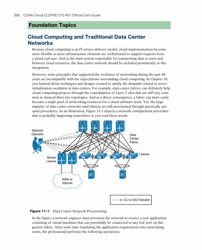
ptg17120290
366 CCNA Cloud CLDFND 210-451 Official Cert Guide
Foundation Topics
Cloud Computing and Traditional Data Center Networks
Because cloud computing is an IT service delivery model, cloud implementations become more flexible as more infrastructure elements are orchestrated to support requests from a cloud end user. And as the main system responsible for transporting data to users and between cloud resources, the data center network should be included prominently in this integration.
However, some principles that supported the evolution of networking during the past 40 years are incompatible with the expectations surrounding cloud computing. In Chapter 10, you learned about techniques and designs created to satisfy the demands related to server virtualization escalation in data centers. For example, data center fabrics can definitely help cloud computing projects through the consolidation of Layer 2 silos that are still very com-mon in classical three-tier topologies. And as a direct consequence, a fabric can more easily become a single pool of networking resources for a cloud software stack. Yet, the large majority of data center networks (and fabrics) are still provisioned through practically arti-sanal procedures. As an illustration, Figure 11-1 depicts a network configuration procedure that is probably happening somewhere as you read these words.
DataCenterFabric
BorderLeaves
Leaves
NetworkOperator
CLI or GUI Session
WAN orInternet
Figure 11-1 Data Center Network Provisioning
In the figure, a network engineer must provision the network to receive a new application consisting of virtual machines that can potentially be connected to any leaf port on this generic fabric. After some time translating the application requirements into networking terms, the professional performs the following operations:
ptg17120290
11
Chapter 11: Network Architectures for the Data Center: SDN and ACI 367
Step 1. Creates three VLANs in every switch.
Step 2. Adds these VLANs to every leaf access port.
Step 3. Configures a default gateway for each VLAN at some point of this network (border leaves in the case of Figure 11-1).
Because most network engineers still use command-line interface (CLI) sessions or a device graphical user interface (GUI) to fulfill these steps , their resulting configurations are gener-ally considered very error-prone and difficult to troubleshoot. And although some corpora-tions maintain detailed documentation about past and current network configurations, this practice is hardly the norm for the majority of data center networks.
This simple example should already reveal to you the great chasm that exists between resource provisioning for networks and resource provisioning for other technologies such as server virtualization. To make matters worse, I’m personally aware of many companies in which VLANs can be added (or removed) only during monthly maintenance windows, invari-ably making the network team the biggest contributor to application deployment delays.
As you can easily deduce, such manual operations are highly unsuitable for cloud comput-ing environments. For this reason alone, I completely understand why some cloud architects plan to pre-configure all 4094 available VLANs every port of a network, avoiding additional procedures during the provisioning of cloud resources. However, leveraging this design decision, these architects are disregarding important aspects such as
■ Flooding and broadcast traffic may severely impact all ports, inadvertently affecting other cloud tenants.
■ VLANs are not the only network consumable resource. Other configurations such as access-control lists (ACLs), firewall rules, and server load balancer services will still need provisioning as new tenants sign up for cloud services.
Whereas cloud computing environments may be prepared to welcome new tenants, they should also expect that any of them may discontinue cloud services at any time. And because the network resources for a tenant are essentially defined as a set of configuration lines spread over multiple devices, decommissioning is considered an almost insurmount-able obstacle in traditional networks. Consequently, even after tenants or applications are discontinued, their corresponding VLANs, routes, ACL entries, and firewall rules continue to clutter troubleshooting procedures forever.
With the popularization of cloud computing projects, and the increasing demand for auto-mation and standardization in data centers, networks began to be seriously reexamined within academic studies, service provider meetings, and boardrooms in light of the new SDN technologies.
The Opposite of Software-Defined NetworkingThe formal beginning of many SDN initiatives happened in 2006 with Stanford University’s Clean Slate Program , a collaborative research program intended to design the Internet as if it were being created anew while leveraging three decades of hindsight.
ptg17120290
368 CCNA Cloud CLDFND 210-451 Official Cert Guide
As clearly stated in its mission, Clean Slate did not outline a precise approach, a decision that enabled program participants to pursue extremely creative small projects and very inter-esting endeavors. And even after its deactivation in 2012, the project’s legacy is apparent today in the numerous network solutions being offered to support automation and cloud computing deployments in enterprise corporations and service providers.
Unsurprisingly, presenting a conclusive definition for SDN is quite difficult. This difficulty is compounded by the SDN marketing bandwagon. With huge interest in SDN turning into hype in the early 2010s, many vendors tried to associate SDN as closely as possible with their own approach. As an example, the following list paraphrases some definitions of SDN I have compiled after a quick web search:
■ “SDN is an approach to computer networking where IT administrators can manage net-works through the abstraction of lower-level functionalities.”
■ “SDN is an emerging architecture that can be translated into speed, manageability, cost reduction, and flexibility.”
■ “SDN enables network control to become directly programmable as the underlying infra-structure is abstracted for applications and network services.”
■ “SDN is the virtualization of network services in order to create a pool of data transport capacity, which can be flexibly provisioned and reutilized according to demand.”
As you can see from this small sampling, such definitions of SDN wildly vary from precise descriptions of specific technologies to very vague statements. In my humble opinion, the effort to propose a definitive conceptualization of SDN is futile simply because these new approaches are intended to break current paradigms and, consequently, are only bounded by creativity.
Because this chapter will explore SDN approaches that will contradict the statements made previously, allow me to introduce a definition for SDN in a different manner.
According to John Cleese (genius from legendary comedy troupe Monty Python and neu-ropsychological studies enthusiast), nobody really knows how creativity actually happens, but it is pretty clear how it does not. Furthermore, as Cleese jokes in his famous lectures about creativity and the human mind, a sculptor explained his method of creating beautiful elephant statues: simply remove from the stone what is not an elephant.
In a similar vein, allow me to propose the following question: what is the opposite of SDN
for you? Please give yourself some time for reflection before reading the next paragraph.
If you believe hardware-defined networking (HDN) is the correct answer, you are not alone. Respectfully, I do not agree with that answer, for what I think are some compelling reasons. Since the inception of the ARPANET in the late 1960s, networks have been based on devices composed of both hardware and software (network operating system), the lat-ter of which is as carefully designed and developed as other complex applications such as enterprise resource planning (ERP). In its current model, neither hardware nor software defines how a network behaves, but rather a higher layer of control called Homo sapiens
defines its behavior. Because this “layer” is directly involved in every single change on most networks, I believe human-defined networking genuinely represents what is not SDN. (But if you still prefer hardware-defined networking, at least we can agree on the same acronym.)
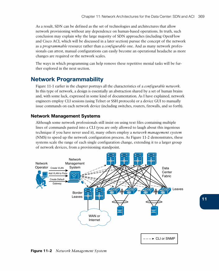
ptg17120290
11
Chapter 11: Network Architectures for the Data Center: SDN and ACI 369
As a result, SDN can be defined as the set of technologies and architectures that allow network provisioning without any dependence on human-based operations. In truth, such conclusion may explain why the large majority of SDN approaches (including OpenFlow and Cisco ACI, which will be discussed in a later section) pursue the concept of the network as a programmable resource rather than a configurable one. And as many network profes-sionals can attest, manual configurations can easily become an operational headache as more changes are required or the network scales.
The ways in which programming can help remove these repetitive menial tasks will be fur-ther explored in the next section.
Network ProgrammabilityFigure 11-1 earlier in the chapter portrays all the characteristics of a configurable network. In this type of network, a design is essentially an abstraction shared by a set of human brains and, with some luck, expressed in some kind of documentation. As I have explained, network engineers employ CLI sessions (using Telnet or SSH protocols) or a device GUI to manually issue commands on each network device (including switches, routers, firewalls, and so forth).
Network Management SystemsAlthough some network professionals still insist on using text files containing multiple lines of commands pasted into a CLI (you are only allowed to laugh about this ingenious technique if you have never used it), many others employ a network management system
(NMS) to speed up the network configuration process. As Figure 11-2 demonstrates, these systems scale the range of each single configuration change, extending it to a larger group of network devices, from a provisioning standpoint.
DataCenterFabric
BorderLeaves
Leaves
NetworkOperator
NetworkManagement
System
CLI or SNMP
WAN orInternet
Create VLAN
Add VLAN to Ports
Create Default
Gateway
Figure 11-2 Network Management System
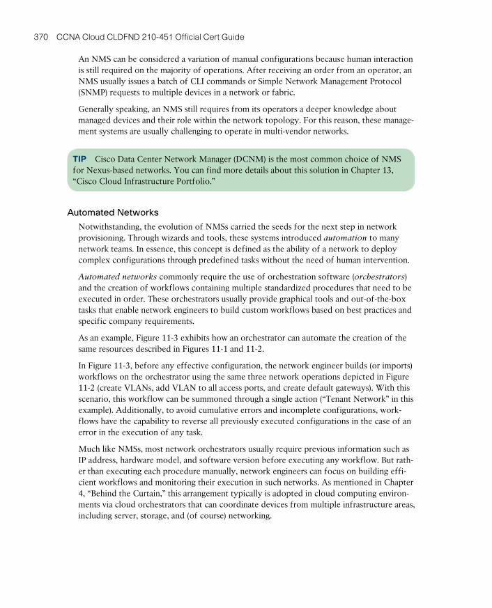
ptg17120290
370 CCNA Cloud CLDFND 210-451 Official Cert Guide
An NMS can be considered a variation of manual configurations because human interaction is still required on the majority of operations. After receiving an order from an operator, an NMS usually issues a batch of CLI commands or Simple Network Management Protocol (SNMP) requests to multiple devices in a network or fabric.
Generally speaking, an NMS still requires from its operators a deeper knowledge about managed devices and their role within the network topology. For this reason, these manage-ment systems are usually challenging to operate in multi-vendor networks.
TIP Cisco Data Center Network Manager (DCNM) is the most common choice of NMS for Nexus-based networks. You can find more details about this solution in Chapter 13, “Cisco Cloud Infrastructure Portfolio.”
Automated Networks
Notwithstanding, the evolution of NMSs carried the seeds for the next step in network provisioning. Through wizards and tools, these systems introduced automation to many network teams. In essence, this concept is defined as the ability of a network to deploy complex configurations through predefined tasks without the need of human intervention.
Automated networks commonly require the use of orchestration software (orchestrators ) and the creation of workflows containing multiple standardized procedures that need to be executed in order. These orchestrators usually provide graphical tools and out-of-the-box tasks that enable network engineers to build custom workflows based on best practices and specific company requirements.
As an example, Figure 11-3 exhibits how an orchestrator can automate the creation of the same resources described in Figures 11-1 and 11-2.
In Figure 11-3, before any effective configuration, the network engineer builds (or imports) workflows on the orchestrator using the same three network operations depicted in Figure 11-2 (create VLANs, add VLAN to all access ports, and create default gateways). With this scenario, this workflow can be summoned through a single action (“Tenant Network” in this example). Additionally, to avoid cumulative errors and incomplete configurations, work-flows have the capability to reverse all previously executed configurations in the case of an error in the execution of any task.
Much like NMSs, most network orchestrators usually require previous information such as IP address, hardware model, and software version before executing any workflow. But rath-er than executing each procedure manually, network engineers can focus on building effi-cient workflows and monitoring their execution in such networks. As mentioned in Chapter 4, “Behind the Curtain,” this arrangement typically is adopted in cloud computing environ-ments via cloud orchestrators that can coordinate devices from multiple infrastructure areas, including server, storage, and (of course) networking.
ptg17120290
11
Chapter 11: Network Architectures for the Data Center: SDN and ACI 371
DataCenterFabric
BorderLeaves
LeavesNetworkEngineer
CLI, SNMP, or API
WAN orInternet
Orchestrator
“Tenant Network” Workflow
CreateVLANs
StopCreateDefault
Gateways
AddVLANs
toPortsI summon the
“Tenant Network”Workflow
Figure 11-3 Network Automation
TIP Although its name may not advertise its cloud credentials, Cisco Unified Computing System (UCS) Director is one of the most complete cloud orchestrators available at the time of this writing. In addition to containing numerous predefined tasks for Cisco data center solutions, UCS Director provides out-of-the-box support for third-party devices and a graphical tool for workflow composing.
Even with the gradually increasing adoption of network automation, the flexibility auto-mated networks achieve still pales when compared with fully programmable resources, such as servers and microcomputers. To better explain this gap, let’s take a brief digression into the subject of software development.
Programmable NetworksA computer program (or application) can be defined as a sequence of instructions written to perform a specific task on a computer system. A software developer uses keywords and the syntax of a programming language to develop a source code. When executed, the code consumes computing resources to fulfill the original objective of the program.
Computer programmers increase the usefulness of their programs by making them compat-ible with a wide array of hardware platforms and operating systems. Suitably, programming languages are usually not concerned with the specific characteristics of a computer system. Instead, their functions are abstracted enough to allow a compiler or interpreter to translate them into machine language, which includes a CPU basic instruction set and memory man-agement.
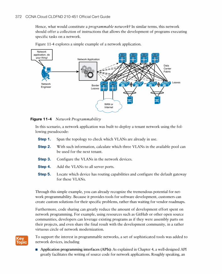
ptg17120290
372 CCNA Cloud CLDFND 210-451 Official Cert Guide
Hence, what would constitute a programmable network? In similar terms, this network should offer a collection of instructions that allows the development of programs executing specific tasks on a network.
Figure 11-4 explores a simple example of a network application.
DataCenterFabric
BorderLeaves
LeavesNetworkEngineer
WAN orInternet
Networkapplication, do
your thing!Network Application
Figure 11-4 Network Programmability
In this scenario, a network application was built to deploy a tenant network using the fol-lowing pseudocode:
Step 1. Span the topology to check which VLANs are already in use.
Step 2. With such information, calculate which three VLANs in the available pool can be used for the next tenant.
Step 3. Configure the VLANs in the network devices.
Step 4. Add the VLANs to all server ports.
Step 5. Locate which device has routing capabilities and configure the default gateway for these VLANs.
Through this simple example, you can already recognize the tremendous potential for net-work programmability. Because it provides tools for software development, customers can create custom solutions for their specific problems, rather than waiting for vendor roadmaps.
Furthermore, code sharing can greatly reduce the amount of development effort spent on network programming. For example, using resources such as GitHub or other open source communities, developers can leverage existing programs as if they were assembly parts on their projects, and even share the final result with the development community, in a rather virtuous circle of network modernization.
To support the interest in programmable networks, a set of sophisticated tools was added to network devices, including
■ Application programming interfaces (APIs): As explained in Chapter 4, a well-designed API greatly facilitates the writing of source code for network applications. Roughly speaking, an
ptg17120290
11
Chapter 11: Network Architectures for the Data Center: SDN and ACI 373
API offers an easy alternative for applications that would be forced to parse strings contain-ing outputs from a CLI session to gather information required for an algorithm decision.
■ Embedded programming languages: A network device can facilitate network application execution through a programming language interpreter running on its operating system. With such a feature, reactions can be performed as soon as a network event occurs. As an example, the Nexus 9000 switches possess a Python interpreter, Python being an extremely popular language among infrastructure developers due to its flexibility and easiness to learn.
■ Access to lower-level software: Most network operating systems depend on application-
specific integrated circuit (ASIC) firmware and operating systems such as Linux to coor-dinate their boot. Consequently, some developers are keenly interested in accessing these lower-level software pieces to achieve specific results, increase visibility over device infor-mation, and leverage open source code.
■ Application hosting: Rather than demanding external computers to run network pro-grams, network devices can offer computing resources for application hosting in the form of dedicated hardware modules or space in the their supervisor (running VMs or Linux containers). Moreover, these devices offer a highly strategic position for their hosted applications because they can gather data that may be impossible (or simply too expensive) for external computers to gather.
■ Configuration management software: This category of software includes open source configuration management utilities with a declarative language that describes the target state for an IT resource (a server, storage device, and, as you can guess, a network device). Arguably, the best known examples of configuration management software are Puppet, Chef, and Ansible. Cisco NX-OS supports many of these intent-based automation methods through embedded client software such as Puppet agent and Chef client (Ansible is agent-less), which allows provisioning, configuration, and management tasks from their server component (Puppet master, Chef server, or Ansible control nodes, respectively). Besides repetitive and error-prone configuration tasks involving VLANs, QoS, and ACLs, these tools are also used for network device PowerOn Auto Provisioning (POAP) , the automat-ed process of upgrading software images and installing configuration files on Cisco Nexus switches that are being deployed in the network for the first time.
■ Extensible Message and Presence Protocol (XMPP) : XMPP is open technology that is commonly used for instant messaging and presence. Through an embedded XMPP client, network devices can be easily integrated into an efficient message bus and, therefore, be configured as a group.
Although these tools can help turn networks into a programmatically consumable resource, their highly variable types of network topology and potential large number of devices bring an immense complexity to network application development. Moreover, devices usually perform different roles inside these topologies (core, aggregation, access, spine, and leaf, for example) and include a broad spectrum of networking services such as firewalls, server load balancers, and network analyzers.
Network controllers were created to facilitate the interaction with distinct topologies and network implementations. Basically, these controllers are responsible for the complete con-figuration of managed network devices, offering a simpler view of the whole network for application developers.

ptg17120290
374 CCNA Cloud CLDFND 210-451 Official Cert Guide
Figure 11-5 portrays the concept of a network controller in more detail.
DataCenterFabric
BorderLeaves
Leaves
NetworkEngineer
WAN orInternet
Networkapplication, do
your thing!Network Application
Northbound
NetworkController
Southbound
That was mucheasier!
Figure 11-5 Using a Network Controller
Acting as a point of aggregation for all communication with network programs and other applications (which are northbound from the controller), a network controller hides the network complexity from these software pieces. Meanwhile, all “low level” operations are executed through a variety of communication procedures with the controlled network devices (southbound from the controller).
Network controllers are not exactly a brand new concept. Besides being very popular for indoor wireless implementations, these controllers have been used as a central point of arbi-tration of WAN optimization features that leverage IP service-level agreement (SLA) traffic probes. Also, in an interesting way, one can argue that the Nexus 1000V Virtual Supervi-sor Module (VSM) also acts as a controller for the Virtual Ethernet Modules (VEMs), as explained in Chapter 6, “Infrastructure Virtualization.”
NOTE It is important that you understand the software components I have discussed in this section (NMS, orchestrator, network programs, and controllers) more as functions than products per se. Such advice will be useful for you in the future, as you get to know orches-tration solutions that have programmability features, network controllers with automation tools, and so forth.
SDN ApproachesEven through the great tornado of innovation in recent years, it is already possible to observe two SDN approaches that have generated more interest from companies looking for more dynamic data center networks:
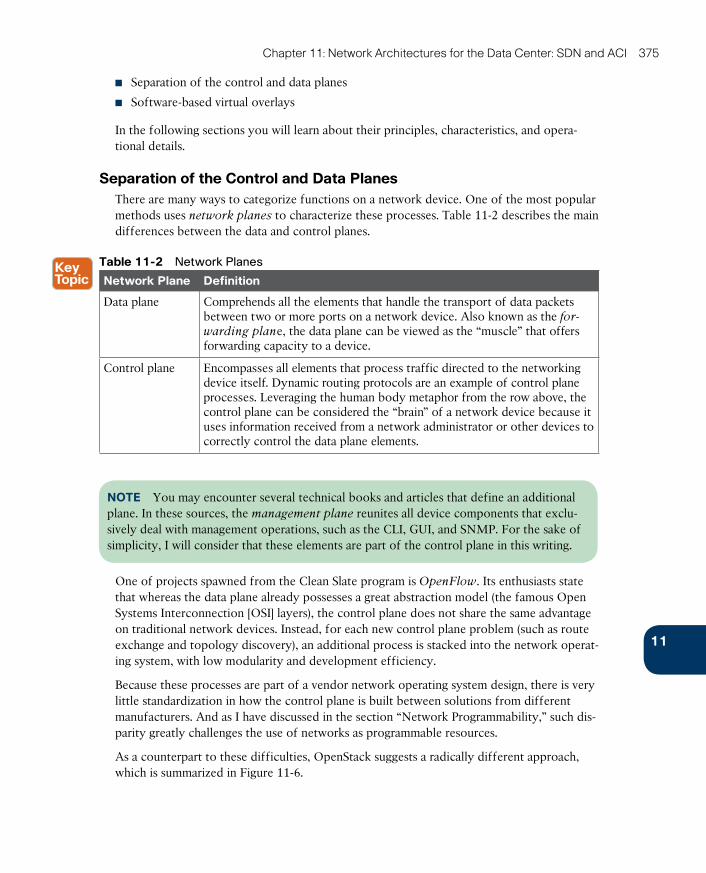
ptg17120290
11
Chapter 11: Network Architectures for the Data Center: SDN and ACI 375
■ Separation of the control and data planes
■ Software-based virtual overlays
In the following sections you will learn about their principles, characteristics, and opera-tional details.
Separation of the Control and Data PlanesThere are many ways to categorize functions on a network device. One of the most popular methods uses network planes to characterize these processes. Table 11-2 describes the main differences between the data and control planes.
Table 11-2 Network Planes
Network Plane Definition
Data plane Comprehends all the elements that handle the transport of data packets between two or more ports on a network device. Also known as the for-warding plane , the data plane can be viewed as the “muscle” that offers forwarding capacity to a device.
Control plane Encompasses all elements that process traffic directed to the networking device itself. Dynamic routing protocols are an example of control plane processes. Leveraging the human body metaphor from the row above, the control plane can be considered the “brain” of a network device because it uses information received from a network administrator or other devices to correctly control the data plane elements.
NOTE You may encounter several technical books and articles that define an additional plane. In these sources, the management plane reunites all device components that exclu-sively deal with management operations, such as the CLI, GUI, and SNMP. For the sake of simplicity, I will consider that these elements are part of the control plane in this writing.
One of projects spawned from the Clean Slate program is OpenFlow . Its enthusiasts state that whereas the data plane already possesses a great abstraction model (the famous Open Systems Interconnection [OSI] layers), the control plane does not share the same advantage on traditional network devices. Instead, for each new control plane problem (such as route exchange and topology discovery), an additional process is stacked into the network operat-ing system, with low modularity and development efficiency.
Because these processes are part of a vendor network operating system design, there is very little standardization in how the control plane is built between solutions from different manufacturers. And as I have discussed in the section “Network Programmability,” such dis-parity greatly challenges the use of networks as programmable resources.
As a counterpart to these difficulties, OpenStack suggests a radically different approach, which is summarized in Figure 11-6.
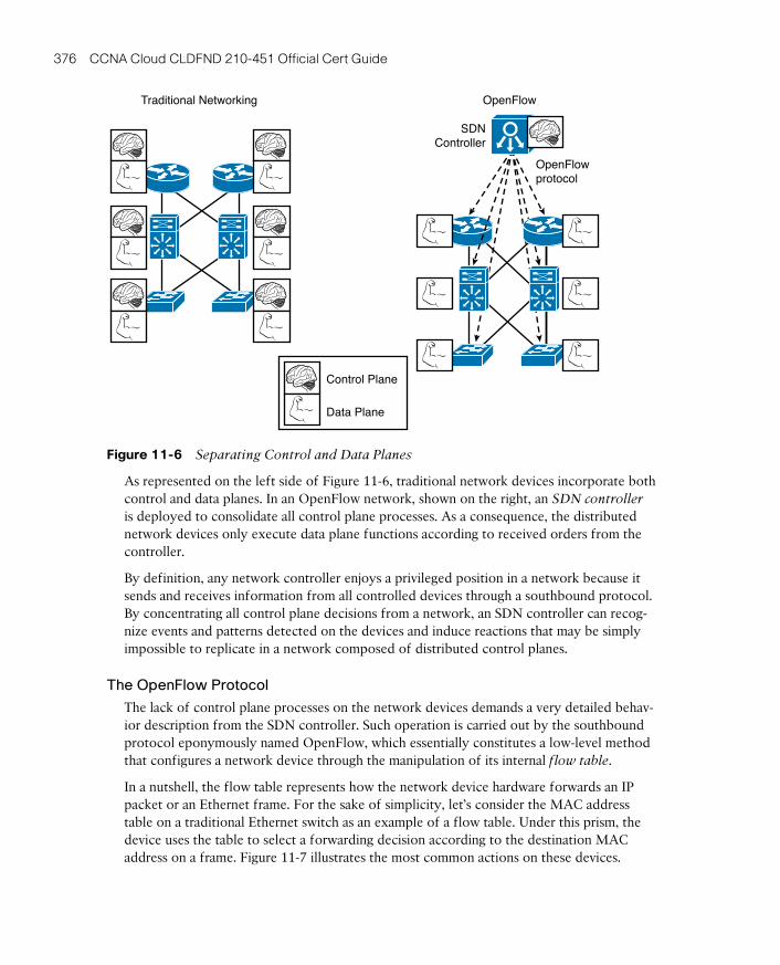
ptg17120290
376 CCNA Cloud CLDFND 210-451 Official Cert Guide
Traditional Networking OpenFlow
Control Plane
Data Plane
OpenFlowprotocol
SDNController
Figure 11-6 Separating Control and Data Planes
As represented on the left side of Figure 11-6, traditional network devices incorporate both control and data planes. In an OpenFlow network, shown on the right, an SDN controller is deployed to consolidate all control plane processes. As a consequence, the distributed network devices only execute data plane functions according to received orders from the controller.
By definition, any network controller enjoys a privileged position in a network because it sends and receives information from all controlled devices through a southbound protocol. By concentrating all control plane decisions from a network, an SDN controller can recog-nize events and patterns detected on the devices and induce reactions that may be simply impossible to replicate in a network composed of distributed control planes.
The OpenFlow Protocol
The lack of control plane processes on the network devices demands a very detailed behav-ior description from the SDN controller. Such operation is carried out by the southbound protocol eponymously named OpenFlow, which essentially constitutes a low-level method that configures a network device through the manipulation of its internal flow table.
In a nutshell, the flow table represents how the network device hardware forwards an IP packet or an Ethernet frame. For the sake of simplicity, let’s consider the MAC address table on a traditional Ethernet switch as an example of a flow table. Under this prism, the device uses the table to select a forwarding decision according to the destination MAC address on a frame. Figure 11-7 illustrates the most common actions on these devices.
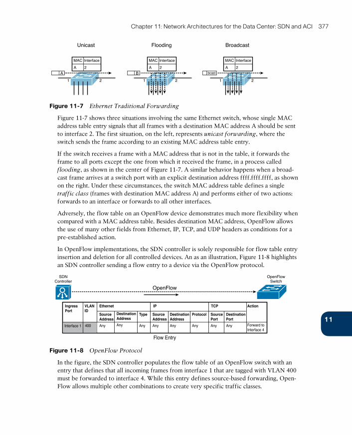
ptg17120290
11
Chapter 11: Network Architectures for the Data Center: SDN and ACI 377
Unicast
MAC Interface
2A
21
A
Flooding
21
MAC Interface
2AB
Broadcast
21
MAC Interface
2Abcast
Figure 11-7 Ethernet Traditional Forwarding
Figure 11-7 shows three situations involving the same Ethernet switch, whose single MAC address table entry signals that all frames with a destination MAC address A should be sent to interface 2. The first situation, on the left, represents unicast forwarding , where the switch sends the frame according to an existing MAC address table entry.
If the switch receives a frame with a MAC address that is not in the table, it forwards the frame to all ports except the one from which it received the frame, in a process called flooding , as shown in the center of Figure 11-7. A similar behavior happens when a broad-cast frame arrives at a switch port with an explicit destination address ffff.ffff.ffff, as shown on the right. Under these circumstances, the switch MAC address table defines a single traffic class (frames with destination MAC address A) and performs either of two actions: forwards to an interface or forwards to all other interfaces.
Adversely, the flow table on an OpenFlow device demonstrates much more flexibility when compared with a MAC address table. Besides destination MAC address, OpenFlow allows the use of many other fields from Ethernet, IP, TCP, and UDP headers as conditions for a pre-established action.
In OpenFlow implementations, the SDN controller is solely responsible for flow table entry insertion and deletion for all controlled devices. An as an illustration, Figure 11-8 highlights an SDN controller sending a flow entry to a device via the OpenFlow protocol.
OpenFlow
SDNController
OpenFlowSwitch
Flow Entry
IngressPort
ActionTCPIPEthernetVLANID
SourceAddress
Any Any Any Any Any Any Any Any
ProtocolTypeDestinationAddress
SourceAddress
DestinationAddress
DestinationPort
Forward toInterface 4
SourcePort
400Interface 1
Figure 11-8 OpenFlow Protocol
In the figure, the SDN controller populates the flow table of an OpenFlow switch with an entry that defines that all incoming frames from interface 1 that are tagged with VLAN 400 must be forwarded to interface 4. While this entry defines source-based forwarding, Open-Flow allows multiple other combinations to create very specific traffic classes.
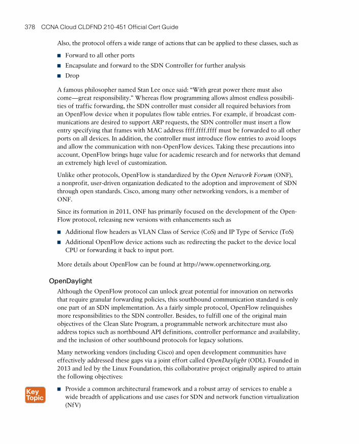
ptg17120290
378 CCNA Cloud CLDFND 210-451 Official Cert Guide
Also, the protocol offers a wide range of actions that can be applied to these classes, such as
■ Forward to all other ports
■ Encapsulate and forward to the SDN Controller for further analysis
■ Drop
A famous philosopher named Stan Lee once said: “With great power there must also come—great responsibility.” Whereas flow programming allows almost endless possibili-ties of traffic forwarding, the SDN controller must consider all required behaviors from an OpenFlow device when it populates flow table entries. For example, if broadcast com-munications are desired to support ARP requests, the SDN controller must insert a flow entry specifying that frames with MAC address ffff.ffff.ffff must be forwarded to all other ports on all devices. In addition, the controller must introduce flow entries to avoid loops and allow the communication with non-OpenFlow devices. Taking these precautions into account, OpenFlow brings huge value for academic research and for networks that demand an extremely high level of customization.
Unlike other protocols, OpenFlow is standardized by the Open Network Forum (ONF) , a nonprofit, user-driven organization dedicated to the adoption and improvement of SDN through open standards. Cisco, among many other networking vendors, is a member of ONF.
Since its formation in 2011, ONF has primarily focused on the development of the Open-Flow protocol, releasing new versions with enhancements such as
■ Additional flow headers as VLAN Class of Service (CoS) and IP Type of Service (ToS)
■ Additional OpenFlow device actions such as: redirecting the packet to the device local CPU or forwarding it back to input port.
More details about OpenFlow can be found at http://www.opennetworking.org.
OpenDaylight
Although the OpenFlow protocol can unlock great potential for innovation on networks that require granular forwarding policies, this southbound communication standard is only one part of an SDN implementation. As a fairly simple protocol, OpenFlow relinquishes more responsibilities to the SDN controller. Besides, to fulfill one of the original main objectives of the Clean Slate Program, a programmable network architecture must also address topics such as northbound API definitions, controller performance and availability, and the inclusion of other southbound protocols for legacy solutions.
Many networking vendors (including Cisco) and open development communities have effectively addressed these gaps via a joint effort called OpenDaylight (ODL). Founded in 2013 and led by the Linux Foundation, this collaborative project originally aspired to attain the following objectives:
■ Provide a common architectural framework and a robust array of services to enable a wide breadth of applications and use cases for SDN and network function virtualization (NfV)

ptg17120290
11
Chapter 11: Network Architectures for the Data Center: SDN and ACI 379
■ Offer an open, highly available, modular, extensible, scalable, and multiprotocol control-ler infrastructure built for SDN deployments on modern multivendor networks
■ Enable a service abstraction platform that allows the development of network applica-tions that can be ported to a wide array of network devices and southbound protocols
Figure 11-9 introduces the original structure of the OpenDaylight architecture.
OpenDaylight
Northbound Interfaces
Controller Platform
Southbound Interfaces andProtocols
Data Plane Elements (Routers,Physical and Virtual Switches)
UserInterfaces
Network Applications, Orchestrators, andServices (VTN, OpenStock Neutron, SDNI, ...)
SAL
REST API
OpenFlow Other StandardProtocols
Vendor-SpecificInterfaces
ExtensionsPlatform ServicesNetwork ServiceFunctions
Figure 11-9 OpenDaylight Architecture
From top to bottom, the architecture delineates how users and applications can interact with the OpenDaylight controller. Besides supporting a modular RESTful API and a default GUI (OpenDaylight User Experience [DLUX]), the ODL controller also communicates to applications through northbound interfaces such as these:
■ Virtual Tenant Network (VTN) coordinator : Application that builds virtual networks in ODL controllers
■ OpenStack Neutron : OpenStack networking project (discussed later in more detail in the section “Around the Corner: OpenStack Neutron”)
■ SDN Interface (SDNi) : OpenDaylight project that intends to enable inter-ODL control-ler communication
Inside the controller structure, a number of network and platform services process the northbound requests that were handed to the API layer. At the time of this writing, the ODL controller deploys a varied array of services, including topology manager, stats man-ager, switch manager, and host tracker.
The Service Abstraction Layer (SAL) exposes the network devices to the controller services just described, providing a uniform network abstraction to them. The SAL facilitates the implementation of many different southbound protocols, covering a wide range of network devices. Besides supporting OpenFlow, legacy network devices can also join an ODL imple-mentation through open protocols such as Network Configuration Protocol (NETCONF)
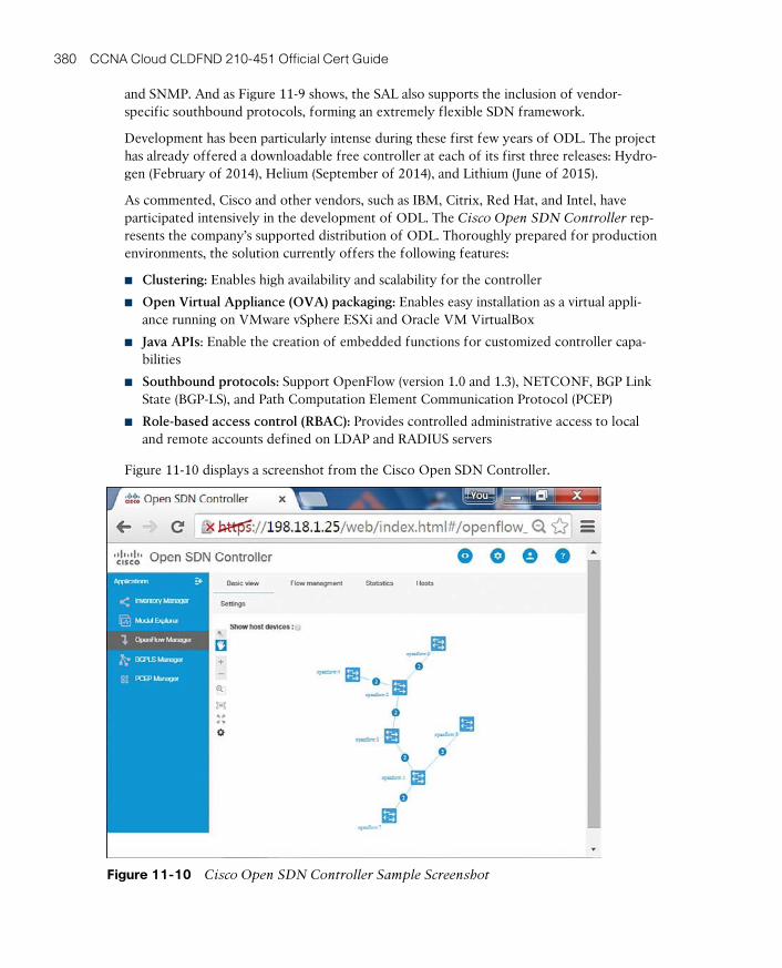
ptg17120290
380 CCNA Cloud CLDFND 210-451 Official Cert Guide
and SNMP. And as Figure 11-9 shows, the SAL also supports the inclusion of vendor-specific southbound protocols, forming an extremely flexible SDN framework.
Development has been particularly intense during these first few years of ODL. The project has already offered a downloadable free controller at each of its first three releases: Hydro-gen (February of 2014), Helium (September of 2014), and Lithium (June of 2015).
As commented, Cisco and other vendors, such as IBM, Citrix, Red Hat, and Intel, have participated intensively in the development of ODL. The Cisco Open SDN Controller rep-resents the company’s supported distribution of ODL. Thoroughly prepared for production environments, the solution currently offers the following features:
■ Clustering: Enables high availability and scalability for the controller
■ Open Virtual Appliance (OVA) packaging: Enables easy installation as a virtual appli-ance running on VMware vSphere ESXi and Oracle VM VirtualBox
■ Java APIs: Enable the creation of embedded functions for customized controller capa-bilities
■ Southbound protocols: Support OpenFlow (version 1.0 and 1.3), NETCONF, BGP Link State (BGP-LS), and Path Computation Element Communication Protocol (PCEP)
■ Role-based access control (RBAC): Provides controlled administrative access to local and remote accounts defined on LDAP and RADIUS servers
Figure 11-10 displays a screenshot from the Cisco Open SDN Controller.
Figure 11-10 Cisco Open SDN Controller Sample Screenshot
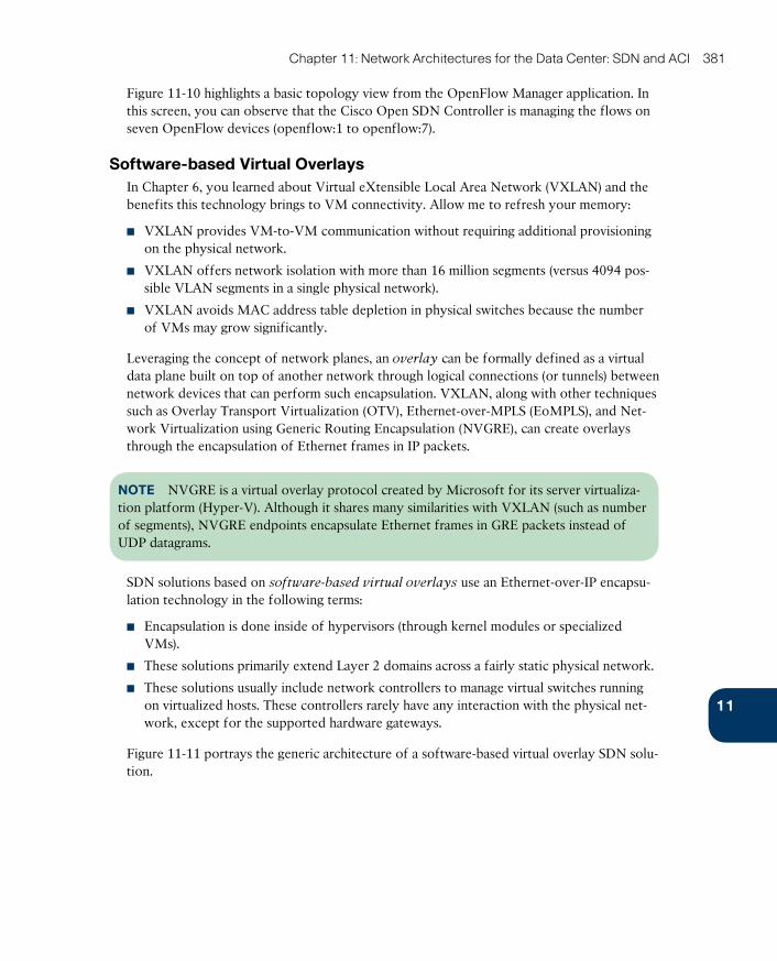
ptg17120290
11
Chapter 11: Network Architectures for the Data Center: SDN and ACI 381
Figure 11-10 highlights a basic topology view from the OpenFlow Manager application. In this screen, you can observe that the Cisco Open SDN Controller is managing the flows on seven OpenFlow devices (openflow:1 to openflow:7).
Software-based Virtual OverlaysIn Chapter 6, you learned about Virtual eXtensible Local Area Network (VXLAN) and the benefits this technology brings to VM connectivity. Allow me to refresh your memory:
■ VXLAN provides VM-to-VM communication without requiring additional provisioning on the physical network.
■ VXLAN offers network isolation with more than 16 million segments (versus 4094 pos-sible VLAN segments in a single physical network).
■ VXLAN avoids MAC address table depletion in physical switches because the number of VMs may grow significantly.
Leveraging the concept of network planes, an overlay can be formally defined as a virtual data plane built on top of another network through logical connections (or tunnels) between network devices that can perform such encapsulation. VXLAN, along with other techniques such as Overlay Transport Virtualization (OTV), Ethernet-over-MPLS (EoMPLS), and Net-work Virtualization using Generic Routing Encapsulation (NVGRE) , can create overlays through the encapsulation of Ethernet frames in IP packets.
NOTE NVGRE is a virtual overlay protocol created by Microsoft for its server virtualiza-tion platform (Hyper-V). Although it shares many similarities with VXLAN (such as number of segments), NVGRE endpoints encapsulate Ethernet frames in GRE packets instead of UDP datagrams.
SDN solutions based on software-based virtual overlays use an Ethernet-over-IP encapsu-lation technology in the following terms:
■ Encapsulation is done inside of hypervisors (through kernel modules or specialized VMs).
■ These solutions primarily extend Layer 2 domains across a fairly static physical network.
■ These solutions usually include network controllers to manage virtual switches running on virtualized hosts. These controllers rarely have any interaction with the physical net-work, except for the supported hardware gateways.
Figure 11-11 portrays the generic architecture of a software-based virtual overlay SDN solu-tion.

ptg17120290
382 CCNA Cloud CLDFND 210-451 Official Cert Guide
NetworkOverlay
Controller
Encapsulation Tunnels(Layer 2)
Data CenterNetwork
VLANs
VMs
VirtualSwitch
VMs
VirtualSwitch
Gateway
Figure 11-11 Software-based Virtual Overlay Architecture
Within such architecture, the controller creates virtual broadcast domains to connect VMs according to a request to the controller. The network overlay controller must also configure a physical gateway to provide external communication with servers and networking services connected to the physical network. Alternatively, it may create VMs that act as gateways to provide external communication to existing VLANs.
Besides providing Layer 2 connectivity for VMs, some software-based virtual overlay solu-tions also aggregate virtual networking services providing routing, firewalls, and server load balancing.
TIP In my opinion, the Cisco Virtual Application Cloud Segmentation (VACS) deploying VXLAN segments is the Cisco product that most closely approximates to software-based virtual overlay solutions. VACS was briefly discussed in Chapter 7, “Virtual Networking Services and Application Containers.”
Application Centric InfrastructureBesides supporting and leading many SDN initiatives, Cisco has used its considerable knowl-edge of customer challenges to create a revolutionary new SDN approach for agile data centers. But to fully express the impact Cisco Application Centric Infrastructure (ACI) can achieve in data center networking, I will first introduce some of the oversights and limita-tions from both SDN approaches discussed in the previous sections.
Problems Not Addressed by SDNThe first half of the 2010s has seen a wide variety of innovative approaches and sophisticat-ed technologies added to the SDN spectrum. Among these, OpenFlow and software-based network overlays are arguably the most widely known SDN approaches for data center net-works, so we will focus on some of the shortcomings they have encountered in real-world implementations.
The benefit of hindsight allows the observation of the following challenges encountered in OpenFlow implementations in data centers:
ptg17120290
11
Chapter 11: Network Architectures for the Data Center: SDN and ACI 383
■ Operational complexity: When compared to WANs, data center networks have more bandwidth resources, which significantly lessens the advantages of forwarding traffic through anything different than destination IP or MAC addresses. Consequently, the complexity associated with managing flow tables may not be justified in these relatively simple environments.
■ Scalability: Whereas most data center switches (including Nexus series) possess enough memory to store MAC address and ARP entries, OpenFlow-enabled switches typically leverage a special type of memory space called Ternary Content-Addressable Memory (TCAM) to deploy their flow table. Depending on the switches’ hardware architecture, the TCAM space can become quite limiting for large-scale OpenFlow deployments.
■ Reliability: OpenFlow follows an imperative model, where a network controller must state exactly how each managed object should perform each configuration change and must remain fully aware of the state of each controlled device. As a result, SDN control-lers may become seriously challenged as these networks scale, running into issues such as processing intensity and disruptive execution errors. And more importantly, the tight relationship between controller and network device can lead to calamitous events on an OpenFlow network, in the case of a complete failure on the controller.
Similarly, production implementations of software-based virtual overlays have faced some practical difficulties such as these:
■ Lack of visibility: These solutions commonly do not address the additional effort required to manage an underlying physical network infrastructure. And because manage-ment tools from the physical network cannot be applied to the encapsulated traffic, this SDN approach decreases mutual visibility between the physical and the virtual network teams, making troubleshooting even harder.
■ Limited applicability: Because they are intrinsically linked to the hypervisor architecture, software-based network overlay solutions usually cannot deploy network policies over bare-metal servers and VMs running on other hypervisors.
■ Scalability: The majority of these solutions recommend the use of software gateways running on a VM or server-based appliances, which are subject to bandwidth and packet processing limits. Additionally, packet replication used for broadcast and multicast traf-fic can be extremely taxing for servers deploying overlays.
Although these approaches deploy innovative methods to change provisioning processes, they are still deeply attached to network-centric entities such as flow table entries or broad-cast domains. Hence, they did not fully grasp the opportunity to radically rethink data cen-ter networks by focusing on their main objective: rapid and reusable connectivity for appli-cation deployment. In the following sections, you will learn how Cisco ACI has embraced this opportunity.
ACI ArchitectureDesigned to become the most effective SDN approach for modern data centers, the Cisco Application Centric Infrastructure has three main components, which are described in Table 11-3.
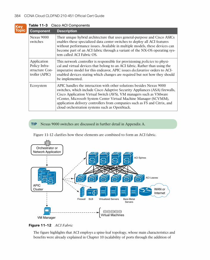
ptg17120290
384 CCNA Cloud CLDFND 210-451 Official Cert Guide
Table 11-3 Cisco ACI Components
Component Description
Nexus 9000 switches
Their unique hybrid architecture that uses general-purpose and Cisco ASICs enables these specialized data center switches to deploy all ACI features without performance issues. Available in multiple models, these devices can become part of an ACI fabric through a variant of the NX-OS operating sys-tem called ACI Fabric OS.
Application Policy Infra-structure Con-troller (APIC)
This network controller is responsible for provisioning policies to physi-cal and virtual devices that belong to an ACI fabric. Rather than using the imperative model for this endeavor, APIC issues declarative orders to ACI-enabled devices stating which changes are required but not how they should be implemented.
Ecosystem APIC handles the interaction with other solutions besides Nexus 9000 switches, which include Cisco Adaptive Security Appliances (ASA) firewalls, Cisco Application Virtual Switch (AVS), VM managers such as VMware vCenter, Microsoft System Center Virtual Machine Manager (SCVMM), application delivery controllers from companies such as F5 and Citrix, and cloud orchestration systems such as OpenStack.
TIP Nexus 9000 switches are discussed in further detail in Appendix A.
Figure 11-12 clarifies how these elements are combined to form an ACI fabric.
ACI Spines
Orchestrator orNetwork Application
ACI Leaves
VM Manager
ACIACI ACI ACI
ACI ACI ACI ACI ACI ACI
WAN orInternet
Virtual Machines
Virtualized ServersSLBFirewall Bare-MetalServers
APICCluster
ACI
APIC
ACI
APIC
ACI
APIC
Figure 11-12 ACI Fabric
The figure highlights that ACI employs a spine-leaf topology, whose main characteristics and benefits were already explained in Chapter 10 (scalability of ports through the addition of
ptg17120290
11
Chapter 11: Network Architectures for the Data Center: SDN and ACI 385
leaves and bandwidth scaling through the deployment of more spines). In particular, an ACI fabric must minimally deploy 40-Gigabit Ethernet connections between Nexus 9000 switches running in ACI mode.
A cluster of APIC controllers manages all switches in an ACI fabric and interacts with ecosys-tem components such as firewalls, application delivery controllers, and VM managers. Through a powerful GUI and a highly interoperable REST API, APIC centralizes connectivity-related requests that may come from administrative users and a wide range of network applications.
How exactly these elements are configured is perhaps the secret sauce of ACI, which I will share with you in the next few sections.
ACI Policy ModelIn a traditional network, application connectivity must be translated into multiple per-device and per-port configurations. Thus, these rather dispersed configurations chain together three characteristics that every endpoint has: identity (IP and MAC addresses), locale (port or VLAN), and traffic rules (IP subnet declared on an ACL, for example). And because these characteristics are so intertwined in traditional network abstractions, any change on one of them certainly requires modifications in at least another one.
As an illustration, imagine that a physical server is connected to an access port that belongs to VLAN 400 (locale). Due to this assignment, the server is probably included in a predefined IP subnet and is recognized through its IP and MAC addresses (identity) with its traffic being con-trolled by a security policy (such as ACL and firewall rules) referring to its IP address (traffic rule).
Now observe how the following hypothetical simple changes provoke subsequent adapta-tions in multiple points of the network:
■ What if you need to change the server IP address? You will probably have to change its port configuration as well as its associated security policies.
■ How do you move a device without changing its IP address? You will probably have to reconfigure the destination port to support this migration.
■ What if you need to move the server from a development to a production environ-ment? IP readdressing is possibly required as well as a connection to another port, and a reconfiguration of security rules for production traffic.
■ How do you apply the same security rules to devices located in different subnets? Most environments are able to duplicate the number of firewall rules and ACL entries to address this problem.
■ If an application is decommissioned, how do you update security rules? A thorough rule analysis is required to verify if an ACL entry or firewall rule deletion will disrupt other services that are sharing the same subnet with the components of the decommis-sioned application.
As an SDN approach, one of the ACI key differentiators is its connectivity policy model, which is cleverly designed to manage all aspects of a fabric through policies and objects. More specifically, APIC can faithfully represent an application network requirement through a simple text file, which can be easily replicated, decommissioned, and ported to another ACI fabric.
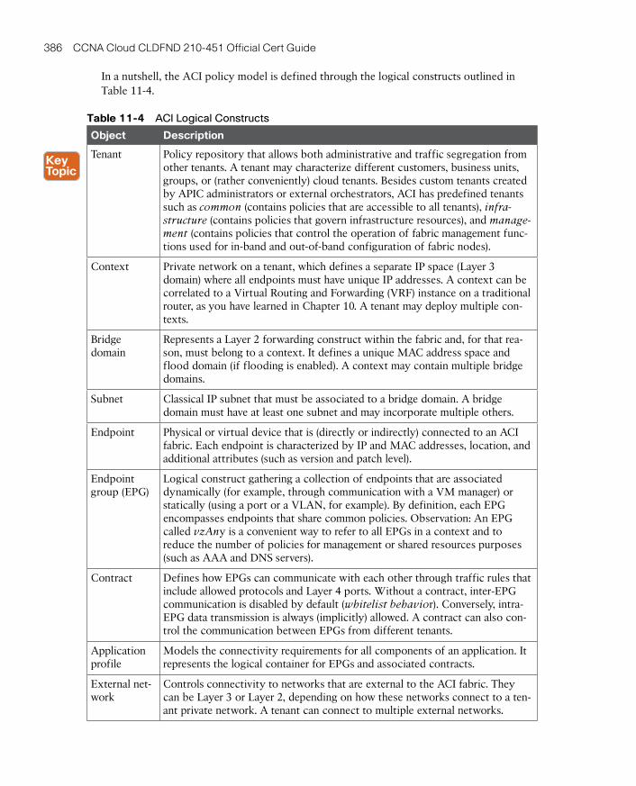
ptg17120290
386 CCNA Cloud CLDFND 210-451 Official Cert Guide
In a nutshell, the ACI policy model is defined through the logical constructs outlined in Table 11-4.
Table 11-4 ACI Logical Constructs
Object Description
Tenant Policy repository that allows both administrative and traffic segregation from other tenants. A tenant may characterize different customers, business units, groups, or (rather conveniently) cloud tenants. Besides custom tenants created by APIC administrators or external orchestrators, ACI has predefined tenants such as common (contains policies that are accessible to all tenants), infra-structure (contains policies that govern infrastructure resources), and manage-ment (contains policies that control the operation of fabric management func-tions used for in-band and out-of-band configuration of fabric nodes).
Context Private network on a tenant, which defines a separate IP space (Layer 3 domain) where all endpoints must have unique IP addresses. A context can be correlated to a Virtual Routing and Forwarding (VRF) instance on a traditional router, as you have learned in Chapter 10. A tenant may deploy multiple con-texts.
Bridge domain
Represents a Layer 2 forwarding construct within the fabric and, for that rea-son, must belong to a context. It defines a unique MAC address space and flood domain (if flooding is enabled). A context may contain multiple bridge domains.
Subnet Classical IP subnet that must be associated to a bridge domain. A bridge domain must have at least one subnet and may incorporate multiple others.
Endpoint Physical or virtual device that is (directly or indirectly) connected to an ACI fabric. Each endpoint is characterized by IP and MAC addresses, location, and additional attributes (such as version and patch level).
Endpoint group (EPG)
Logical construct gathering a collection of endpoints that are associated dynamically (for example, through communication with a VM manager) or statically (using a port or a VLAN, for example). By definition, each EPG encompasses endpoints that share common policies. Observation: An EPG called vzAny is a convenient way to refer to all EPGs in a context and to reduce the number of policies for management or shared resources purposes (such as AAA and DNS servers).
Contract Defines how EPGs can communicate with each other through traffic rules that include allowed protocols and Layer 4 ports. Without a contract, inter-EPG communication is disabled by default (whitelist behavior). Conversely, intra-EPG data transmission is always (implicitly) allowed. A contract can also con-trol the communication between EPGs from different tenants.
Application profile
Models the connectivity requirements for all components of an application. It represents the logical container for EPGs and associated contracts.
External net-work
Controls connectivity to networks that are external to the ACI fabric. They can be Layer 3 or Layer 2, depending on how these networks connect to a ten-ant private network. A tenant can connect to multiple external networks.

ptg17120290
11
Chapter 11: Network Architectures for the Data Center: SDN and ACI 387
NOTE In an ACI fabric, any leaf switch that provides connectivity to external devices such as edge routers and Data Center Interconnect (DCI) switches is commonly referred to as a border leaf. Depending on whether an external network is reachable through Layer 3 or Layer 2, the border leaf interface that is connected to such an external device is configured as a routed interface (with an optional routing protocol) or a bridged interface , respectively.
In Table 11-4, you may have noticed traces of a strict hierarchy between ACI logical con-structs. As a visual aid for you, Figure 11-13 addresses the ACI Management Information Tree (MIT) structure through a custom tenant example.
AppProfile1
Common Infrastructure Tenant2 … TenantN
Root
Management Tenant1
ExtEPG1
Contract1 Contract2 Contract3
EPG1 EPG2 EPG3
Context1
BridgeDomain1
Subnet1
Bridge Domain2
Subnet2
ExNetwork1
Figure 11-13 ACI Policy Model
In the figure, you can observe how an ACI fabric (henceforth referred to as root) is subdi-vided into many tenants, including the aforementioned common, infrastructure, and man-agement predefined tenants. Only Tenant1 is shown in full for purposes of discussion.
Tenant1 has an external network (ExtNetwork1) and a private network (Context1), the lat-ter of which contains two bridge domains (BridgeDomain1 and BridgeDomain2). Much like VLANs on traditional networks, each bridge domain defines a broadcast domain that may contain more than one subnet. As a consequence, a subnet aggregates endpoints that can directly exchange Ethernet frames, whereas inter-subnet communication requires routing from the fabric as well as default gateways for each subnet. In Figure 11-13, BridgeDomain1 and BridgeDomain2 contain a single subnet each (Subnet1 and Subnet2, respectively).
Further down the tree, Subnet1 accommodates a single endpoint group (EPG1) represent-ing a collection of endpoints that should be handled in the same way by the fabric. Subnet2 contains two EPGs (EPG2 and EPG3).
Finally, Figure 11-13 depicts an application profile (AppProfile1) encompassing all three EPGs and a fourth, special EPG (ExtEPG1), generated from ExtNetwork1 and representing a set of endpoints that is reachable through an external device. As an example, this EPG can speak for a specific IP subnet in a corporation WAN, or even the whole Internet.
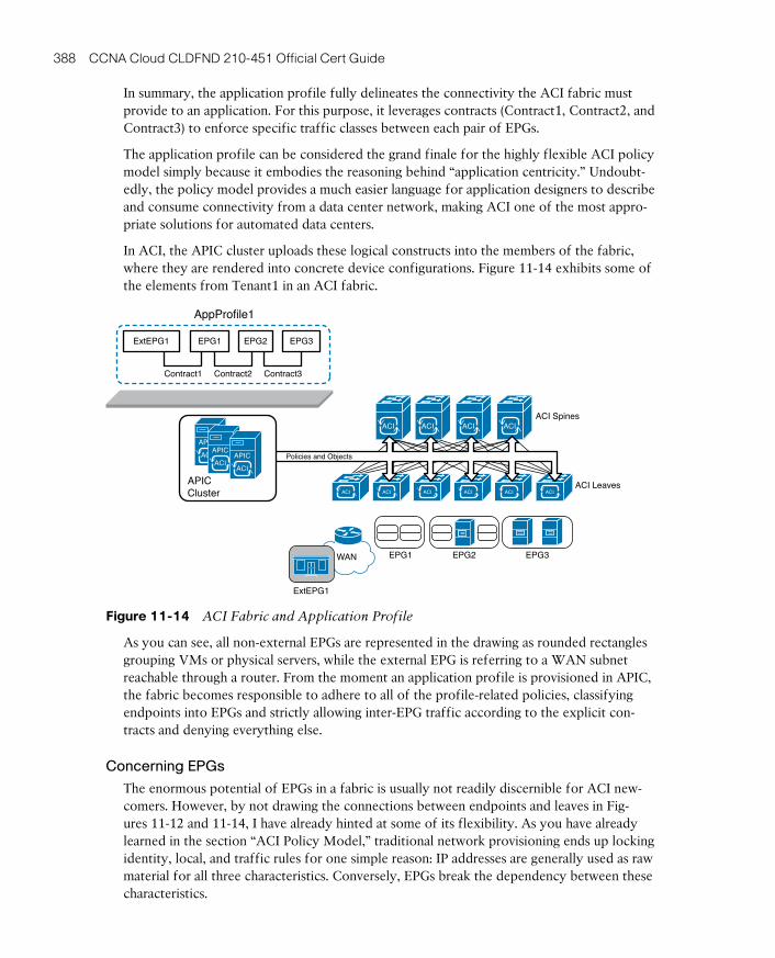
ptg17120290
388 CCNA Cloud CLDFND 210-451 Official Cert Guide
In summary, the application profile fully delineates the connectivity the ACI fabric must provide to an application. For this purpose, it leverages contracts (Contract1, Contract2, and Contract3) to enforce specific traffic classes between each pair of EPGs.
The application profile can be considered the grand finale for the highly flexible ACI policy model simply because it embodies the reasoning behind “application centricity.” Undoubt-edly, the policy model provides a much easier language for application designers to describe and consume connectivity from a data center network, making ACI one of the most appro-priate solutions for automated data centers.
In ACI, the APIC cluster uploads these logical constructs into the members of the fabric, where they are rendered into concrete device configurations. Figure 11-14 exhibits some of the elements from Tenant1 in an ACI fabric.
EPG3EPG1
AppProfile1
EPG2
ACI Spines
ACI Leaves
ACIACI ACI ACI
ACI ACI ACI ACI ACI ACI
WAN
ExtEPG1
Contract1 Contract2 Contract3
ExtEPG1 EPG1 EPG3EPG2
Policies and ObjectsACI
APIC
ACI
APIC
ACI
APIC
APICCluster
Figure 11-14 ACI Fabric and Application Profile
As you can see, all non-external EPGs are represented in the drawing as rounded rectangles grouping VMs or physical servers, while the external EPG is referring to a WAN subnet reachable through a router. From the moment an application profile is provisioned in APIC, the fabric becomes responsible to adhere to all of the profile-related policies, classifying endpoints into EPGs and strictly allowing inter-EPG traffic according to the explicit con-tracts and denying everything else.
Concerning EPGs
The enormous potential of EPGs in a fabric is usually not readily discernible for ACI new-comers. However, by not drawing the connections between endpoints and leaves in Fig-ures 11-12 and 11-14, I have already hinted at some of its flexibility. As you have already learned in the section “ACI Policy Model,” traditional network provisioning ends up locking identity, local, and traffic rules for one simple reason: IP addresses are generally used as raw material for all three characteristics. Conversely, EPGs break the dependency between these characteristics.

ptg17120290
11
Chapter 11: Network Architectures for the Data Center: SDN and ACI 389
By definition, an ACI fabric can identify physical and virtual endpoints regardless of their location in the fabric, therefore providing complete mobility for these devices. An EPG can accommodate endpoints through a multitude of methods, including
■ A VLAN identifier
■ A VXLAN identifier
■ A VMware DVS port group
■ A specific IP address or subnet
■ A specific DNS name or range
■ And most importantly, a combination of the listed parameters
Consequently, it is perfectly possible to separate endpoints that are sharing the same IP subnet in different EPGs. At the same time, the same EPG can group endpoints from differ-ent IP subnets. And as you will learn in the next section, because traffic policies are defined through contracts, they are no longer chained to endpoint identity or location.
Concerning Contracts
Although you have already learned the main objectives of a contract in an ACI fabric, I have not delved into its specifics yet. To begin with, an EPG can assume one of the following roles from a contract perspective:
■ Provider: The EPG offers the service described in the contract and, therefore, character-izes the destination endpoints for the traffic defined in the contract.
■ Consumer: The EPG represents the source endpoints for the traffic defined in the con-tract.
■ Both: Endpoints from both EPGs can communicate according to the traffic rules defined in the contract.
A contract is composed of multiple objects called subjects, which can be reused within the same tenant or among the whole fabric, if it belongs to the common tenant. A subject com-bines one or more rules, which are built with the following parameters:
■ Labels: Assign a name to the rule
■ Filter: Defines Layer 2, 3, and 4 fields, including Ethertype, IP protocol, and TCP port range
Figure 11-15 portrays a contract defined between two EPGs as well as the objects that com-prise it.
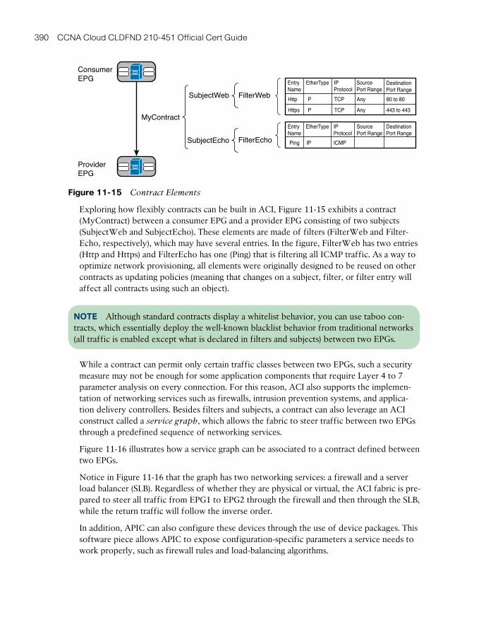
ptg17120290
390 CCNA Cloud CLDFND 210-451 Official Cert Guide
ConsumerEPG
MyContract
SubjectWeb
FilterEcho
FilterWeb
SubjectEcho
ProviderEPG
EntryName
Http
Https
80 to 80
443 to 443
Any
Any
TCP
TCP
P
P
IPProtocol
DestinationPort Range
SourcePort Range
EtherType
EntryName
Ping ICMPIP
IPProtocol
DestinationPort Range
SourcePort Range
EtherType
Figure 11-15 Contract Elements
Exploring how flexibly contracts can be built in ACI, Figure 11-15 exhibits a contract (MyContract) between a consumer EPG and a provider EPG consisting of two subjects (SubjectWeb and SubjectEcho). These elements are made of filters (FilterWeb and Filter-Echo, respectively), which may have several entries. In the figure, FilterWeb has two entries (Http and Https) and FilterEcho has one (Ping) that is filtering all ICMP traffic. As a way to optimize network provisioning, all elements were originally designed to be reused on other contracts as updating policies (meaning that changes on a subject, filter, or filter entry will affect all contracts using such an object).
NOTE Although standard contracts display a whitelist behavior, you can use taboo con-tracts, which essentially deploy the well-known blacklist behavior from traditional networks (all traffic is enabled except what is declared in filters and subjects) between two EPGs.
While a contract can permit only certain traffic classes between two EPGs, such a security measure may not be enough for some application components that require Layer 4 to 7 parameter analysis on every connection. For this reason, ACI also supports the implemen-tation of networking services such as firewalls, intrusion prevention systems, and applica-tion delivery controllers. Besides filters and subjects, a contract can also leverage an ACI construct called a service graph, which allows the fabric to steer traffic between two EPGs through a predefined sequence of networking services.
Figure 11-16 illustrates how a service graph can be associated to a contract defined between two EPGs.
Notice in Figure 11-16 that the graph has two networking services: a firewall and a server load balancer (SLB). Regardless of whether they are physical or virtual, the ACI fabric is pre-pared to steer all traffic from EPG1 to EPG2 through the firewall and then through the SLB, while the return traffic will follow the inverse order.
In addition, APIC can also configure these devices through the use of device packages. This software piece allows APIC to expose configuration-specific parameters a service needs to work properly, such as firewall rules and load-balancing algorithms.
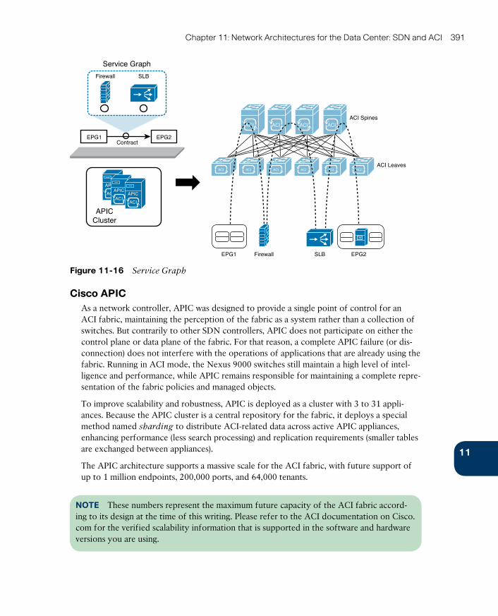
ptg17120290
11
Chapter 11: Network Architectures for the Data Center: SDN and ACI 391
Service Graph
ContractEPG1 EPG2
EPG2EPG1
SLB
SLB
Firewall
Firewall
ACI Spines
ACI Leaves
ACIACI ACI ACI
ACI ACI ACI ACI ACI ACI
APICCluster
ACI
APIC
ACI
APIC
ACI
APIC
Figure 11-16 Service Graph
Cisco APICAs a network controller, APIC was designed to provide a single point of control for an ACI fabric, maintaining the perception of the fabric as a system rather than a collection of switches. But contrarily to other SDN controllers, APIC does not participate on either the control plane or data plane of the fabric. For that reason, a complete APIC failure (or dis-connection) does not interfere with the operations of applications that are already using the fabric. Running in ACI mode, the Nexus 9000 switches still maintain a high level of intel-ligence and performance, while APIC remains responsible for maintaining a complete repre-sentation of the fabric policies and managed objects.
To improve scalability and robustness, APIC is deployed as a cluster with 3 to 31 appli-ances. Because the APIC cluster is a central repository for the fabric, it deploys a special method named sharding to distribute ACI-related data across active APIC appliances, enhancing performance (less search processing) and replication requirements (smaller tables are exchanged between appliances).
The APIC architecture supports a massive scale for the ACI fabric, with future support of up to 1 million endpoints, 200,000 ports, and 64,000 tenants.
NOTE These numbers represent the maximum future capacity of the ACI fabric accord-ing to its design at the time of this writing. Please refer to the ACI documentation on Cisco.com for the verified scalability information that is supported in the software and hardware versions you are using.
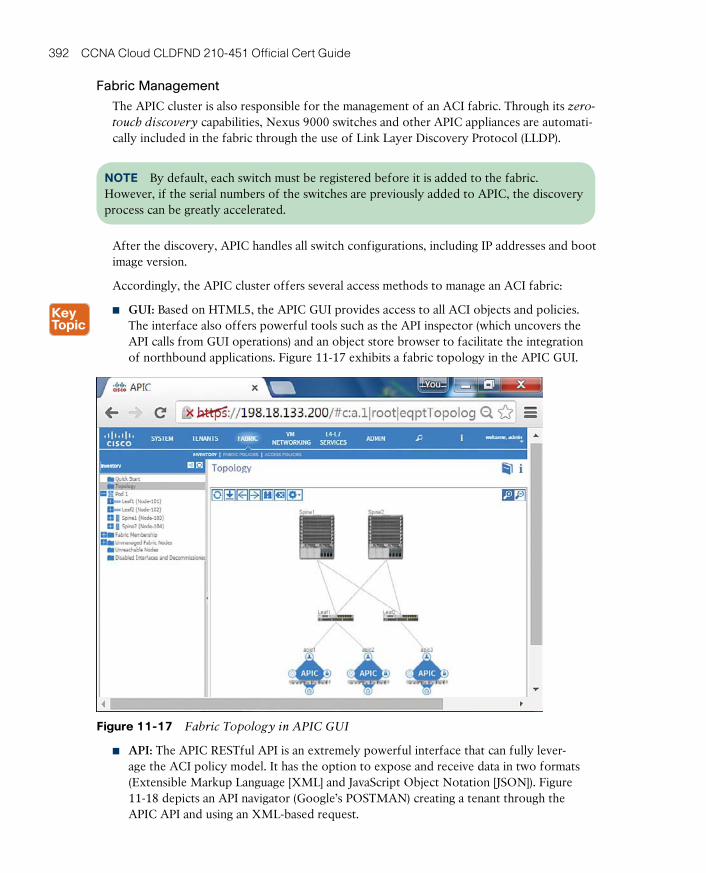
ptg17120290
392 CCNA Cloud CLDFND 210-451 Official Cert Guide
Fabric Management
The APIC cluster is also responsible for the management of an ACI fabric. Through its zero-
touch discovery capabilities, Nexus 9000 switches and other APIC appliances are automati-cally included in the fabric through the use of Link Layer Discovery Protocol (LLDP).
NOTE By default, each switch must be registered before it is added to the fabric. However, if the serial numbers of the switches are previously added to APIC, the discovery process can be greatly accelerated.
After the discovery, APIC handles all switch configurations, including IP addresses and boot image version.
Accordingly, the APIC cluster offers several access methods to manage an ACI fabric:
■ GUI: Based on HTML5, the APIC GUI provides access to all ACI objects and policies. The interface also offers powerful tools such as the API inspector (which uncovers the API calls from GUI operations) and an object store browser to facilitate the integration of northbound applications. Figure 11-17 exhibits a fabric topology in the APIC GUI.
Figure 11-17 Fabric Topology in APIC GUI
■ API: The APIC RESTful API is an extremely powerful interface that can fully lever-age the ACI policy model. It has the option to expose and receive data in two formats (Extensible Markup Language [XML] and JavaScript Object Notation [JSON]). Figure 11-18 depicts an API navigator (Google’s POSTMAN) creating a tenant through the APIC API and using an XML-based request.
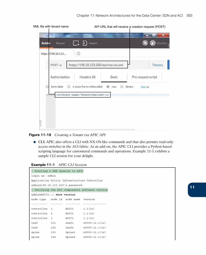
ptg17120290
11
Chapter 11: Network Architectures for the Data Center: SDN and ACI 393
XML file with tenant name API URL that will receive a creation request (POST)
Figure 11-18 Creating a Tenant via APIC API
■ CLI: APIC also offers a CLI with NX-OS-like commands and that also permits read-only access switches in the ACI fabric. As an add-on, the APIC CLI provides a Python-based scripting language for customized commands and operations. Example 11-1 exhibits a sample CLI session for your delight.
Example 11-1 APIC CLI Session
! Starting a SSH session to APIC
login as: admin
Application Policy Infrastructure Controller
[email protected]’s password:
! Verifying the ACI components software version
admin@APIC1:~> show version
node type node id node name version
---------- ------- --------- --------------
controller 1 APIC1 1.1(1r)
controller 2 APIC1 1.1(1r)
controller 3 APIC1 1.1(1r)
leaf 101 Leaf1 n9000-11.1(1r)
leaf 102 Leaf2 n9000-11.1(1r)
spine 103 Spine1 n9000-11.1(1r)
spine 104 Spine2 n9000-11.1(1r)

ptg17120290
394 CCNA Cloud CLDFND 210-451 Official Cert Guide
! Starting a session to a switch
admin@APIC1:~> attach Leaf1
# Executing command: ssh N9K-L1
Password:
Last login: Thu Sep 10 19:39:54 2015 from apic1
Cisco Nexus Operating System (NX-OS) Software
TAC support: http://www.cisco.com/tac
Copyright (c) 2002-2015, Cisco Systems, Inc. All rights reserved.
[output suppressed]
! Verifying interface status
Leaf1# show interface brief
--------------------------------------------------------------------------------
Port VRF Status IP Address Speed MTU
--------------------------------------------------------------------------------
mgmt0 -- down unknown 9000
--------------------------------------------------------------------------------
Ethernet VLAN Type Mode Status Reason Speed Port
Interface Ch#
--------------------------------------------------------------------------------
Eth1/1 0 eth trunk down sfp-missing 10G(D) --
Eth1/2 0 eth trunk down sfp-missing 10G(D) --
Eth1/3 0 eth trunk up none 10G(D) --
Eth1/4 0 eth trunk up none 10G(D) --
[output suppressed]
Leaf1#
All APIC access methods are subordinated to an RBAC feature that can assign read or write access to different managed objects (such as tenants, application profiles, and so on) through local or remote accounts in TACACS+, RADIUS, or LDAP servers.
Integration
Natively, APIC disposes of multiple integration methods to other elements in an ACI fabric. One of the most important is OpFlex , an open and extensible protocol designed to transfer object-based connectivity policies (in XML or JSON) between a network policy controller (APIC, for example) and other devices such as
■ Physical switches (leaves in an ACI fabric)
■ Virtual switches (virtual leaves in an ACI fabric)
■ Physical and virtual networking services (L4–L7 services in an ACI fabric)

ptg17120290
11
Chapter 11: Network Architectures for the Data Center: SDN and ACI 395
OpFlex uses remote procedure calls as well as secure communication channels such as SSL and TLS. With the launch of ACI, Cisco has submitted OpFlex as an IETF draft and also as a supported OpenDaylight southbound interface. Using OpFlex, third-party vendors can also develop device packages, as previously mentioned in the section “Concerning Con-tracts.”
APIC also integrates with VM managers such as VMware vCenter, Microsoft System Center VMM, and OpenStack Nova. These special connections allow APIC to access information about hypervisors and VMs, become aware of VM live migrations, and push connectivity policies to VMs.
Finally, the APIC open API and policy model allows an ACI fabric to be controlled and consumed by automation tools such as Puppet, cloud management platforms such as Win-dows Azure Pack and OpenStack, and many other orchestration tools.
Visibility
Almost as a collateral effect of being a central point of management of an ACI fabric, APIC offers great visibility to administration users and northbound applications. Through its observer process, APIC is capable of monitoring hardware and software states from all man-aged switches, as well as the operational state of protocols, performance data, events, faults, and statistical collections. In addition, APIC maintains an endpoint registry that allows the monitoring of endpoints (directly connected, connected to an FEX, intermediate switches, or virtual switches).
The controller also provides health scores, a terrific tool for troubleshooting. In effect, these scores consist of dashboards built through ACI information collected by APIC to rep-resent status elements such as
■ ACI fabric
■ Managed devices
■ Tenants
■ Application profiles
A health score aggregates data from state, drops, health score of dependent objects, latency, and remaining capacity through their faults and alerts. As an example of this monitoring tool, Figure 11-19 depicts the health score of a leaf switch.

ptg17120290
396 CCNA Cloud CLDFND 210-451 Official Cert Guide
Current Health Score and History
Figure 11-19 ACI Leaf Switch Health Score
A Peek into ACI’s Data PlaneFrom a data plane perspective, ACI is a VXLAN fabric with several enhancements and spe-cial characteristics to optimize its operations. In an ACI fabric, every switch is a VXLAN tunnel endpoint (VTEP), including both leaves and spines.
All connections between leaf and spine are routed (Layer 3), with APIC controlling the assignment of interface and VTEP addresses. A slightly modified version of IS-IS is respon-sible for advertising all VTEP addresses to all other switches in the fabric, leading to the creation of VXLAN tunnels between all VTEPs of the fabric.
TIP The elements described (Layer 3 connections and VTEPs) belong to the infrastructure context.
Endpoints are assigned to EPGs depending on parameters that define the latter, which can include static values (VLAN, IP address, and port), as well as information from a VM manager, DHCP requests, ARP requests, and real traffic. After associating an endpoint to an EPG, the discovering leaf sends its information to the spines, which perform the role of “endpoint directory” (spine proxy) in the ACI fabric.
Within the fabric, the location of an endpoint corresponds to the VTEP to which it is connected. By definition, the communication between two endpoints is encapsulated

ptg17120290
11
Chapter 11: Network Architectures for the Data Center: SDN and ACI 397
into VXLAN packets exchanged by their respective VTEPs. Nonetheless, these internal
VXLAN (iVXLAN) packets have special attributes that uniquely identify their source EPG. Additionally, the APIC-assigned VXLAN ID for each packet is correlated to a context (if the packet is routed) or to a bridge domain (if the packet is bridged).
To perform routing between two endpoints, ACI creates a distributed default gateway in each leaf with an administrator-configured IP address and an automatically assigned MAC address. Within such an arrangement, the ACI fabric always routes traffic destined to the default gateway MAC address and bridges traffic that is not destined for it.
By default, a unicast packet is normally forwarded between leaves through the APIC-assigned iVXLAN packets. As a result, ACI does not need to flood unknown unicast frames. If a leaf does not know the destination address on a packet, it will simply forward the packet to any proxy spine. Because the spines are aware of all endpoints, they can send the packet to the correct destination leaf, which in turn will locally cache the location (leaf VTEP) for the source endpoint.
TIP Flooding can be enabled on a bridge domain if such behavior is desired for any reason.
Multicast and broadcast frames are forwarded to all VTEPs that are locally connected to the multicast group or source endpoint bridge domain, respectively. However, ARP frames are handled a bit differently: the leaf uses the destination IP in the ARP header to locate the destination leaf and directs the packet solely to it, avoiding unnecessary traffic to other leaves.
Because internal forwarding uses iVXLAN packets, which already identify source and destination endpoints, the original encapsulation (IEEE 802.1Q VLAN ID, VXLAN ID, or NVGRE ID) can be discarded for ingress packets and added to outgoing packets, as Figure 11-20 demonstrates.
iVXLAN IP
iVXLAN IP NVGRE IP
vSwitch vSwitch
ACI Spines
ACI Leaves
ACIACI ACI ACI
ACI ACI ACI ACI ACI ACI
VTEP VTEP VTEP VTEP VTEP VTEP
Figure 11-20 Encapsulation Normalization
Through this unique normalization feature, the ACI fabric provides seamless communication between different hypervisors and physical servers. And much like the first Cisco routers pro-vided communication between different types of network protocols, an ACI fabric can become the ultimate gateway for environments that have heterogeneous Layer 2 encapsulations.
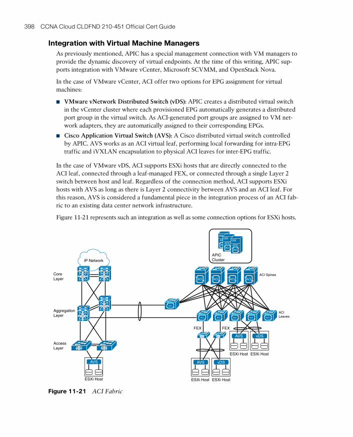
ptg17120290
398 CCNA Cloud CLDFND 210-451 Official Cert Guide
Integration with Virtual Machine ManagersAs previously mentioned, APIC has a special management connection with VM managers to provide the dynamic discovery of virtual endpoints. At the time of this writing, APIC sup-ports integration with VMware vCenter, Microsoft SCVMM, and OpenStack Nova.
In the case of VMware vCenter, ACI offer two options for EPG assignment for virtual machines:
■ VMware vNetwork Distributed Switch (vDS) : APIC creates a distributed virtual switch in the vCenter cluster where each provisioned EPG automatically generates a distributed port group in the virtual switch. As ACI-generated port groups are assigned to VM net-work adapters, they are automatically assigned to their corresponding EPGs.
■ Cisco Application Virtual Switch (AVS) : A Cisco distributed virtual switch controlled by APIC. AVS works as an ACI virtual leaf, performing local forwarding for intra-EPG traffic and iVXLAN encapsulation to physical ACI leaves for inter-EPG traffic.
In the case of VMware vDS, ACI supports ESXi hosts that are directly connected to the ACI leaf, connected through a leaf-managed FEX, or connected through a single Layer 2 switch between host and leaf. Regardless of the connection method, ACI supports ESXi hosts with AVS as long as there is Layer 2 connectivity between AVS and an ACI leaf. For this reason, AVS is considered a fundamental piece in the integration process of an ACI fab-ric to an existing data center network infrastructure.
Figure 11-21 represents such an integration as well as some connection options for ESXi hosts.
AggregationLayer
AccessLayer
Core Layer
FEX FEX
IP Network
ESXi Host ESXi Host
DVSvDS
ESXi Host
AVS
ESXi Host
vDS
ESXi Host
AVS
AVS
ACI Spines
ACILeaves
ACIACI ACI ACI
ACI ACI ACI ACI ACI
APICCluster
ACI
APIC
ACI
APIC
ACI
APIC
ACI
Figure 11-21 ACI Fabric
ptg17120290
11
Chapter 11: Network Architectures for the Data Center: SDN and ACI 399
TIP As a bonus, Figure 11-21 also demonstrates that ACI leaves can deploy virtual PortChannels (vPCs) to external devices.
Around the Corner: OpenStack NeutronNeutron is the OpenStack core project responsible for providing Network as a Service
(NaaS) in these environments. Formerly known as Quantum , Neutron offers an API that enables cloud tenants to build fairly sophisticated networking topologies for multitier appli-cations.
Innovation in Neutron is encouraged through API extensions and available plug-ins. These software elements allow open source development as well as integration of networking ven-dors to generate advanced policies (security, quality of service, monitoring, troubleshooting) and cloud networking services such as server load balancing (SLBaaS), firewalling (FWaaS), virtual private networking (VPNaaS), and data center interconnection (DCIaaS).
To build network topologies, OpenStack Neutron uses the following logical constructs:
■ Tenant network: Within an OpenStack project, this element offers Layer 2 connectiv-ity that is isolated to other projects. It may use a varied range of isolation technologies, including flat (all instances reside in the same network, which can be shared with the hosts), VLAN (use 802.1Q VLAN IDs), or overlay protocols such as VXLAN and GRE. OpenStack Neutron supports multiple projects and tenants having multiple private net-works and enables them to choose their own IP addressing scheme, even if they overlap with other projects or tenants.
■ Provider network: Created by the OpenStack administrator, this special network allows the communication of tenants to existing physical networks. It may use flat communica-tion (untagged) or VLAN (802.1Q tag).
■ Subnet: Range of IP addresses which is also known as IP Address Management (IPAM). Neutron provides subnets for both tenant and provider networks.
■ Port: Virtual network connection point for a single device, such as the virtual NIC of a Nova instance. It exposes configuration and monitoring state for Neutron as well as other OpenStack components.
■ Router: Optional component that forwards IP packets between distinct networks. It can also offer Layer 3 services such as Network Address Translation (NAT) and access to external networks such as the Internet.
■ Security group: Controls inbound and outbound traffic at the port level. It can be com-pared to access control lists in traditional network devices because it can specify type of traffic and direction. The default security group drops all ingress traffic and allows all egress traffic.
These Neutron constructs are usually exposed to cloud tenants as an API or options on the Horizon GUI. At heart, they represent abstractions for the tenants that hide how networks are actually implemented. For example, a tenant will probably not know if a requested network is isolated from other tenants through VLAN or VXLAN because this choice is part of the Neutron administrator duties. As a direct consequence, there are many ways to

ptg17120290
400 CCNA Cloud CLDFND 210-451 Official Cert Guide
provision networking resources for cloud tenants. One fairly typical deployment model is exposed in Figure 11-22.
External Network
Management Network
Data Network
API Network
NetworkNode
ComputeNodes
ControllerNodes
Nova Compute
Neutron Agent
Layer 3 andDHCP Agent
Layer 3 Agent
DHCP Agent
Metadata Agent
Nova Server
Neutron Server
Keystone Server
...
Internet
Figure 11-22 Typical Neutron Deployment
Figure 11-22 identifies some of the most common nodes (which in effect are servers run-ning OpenStack services):
■ Network node: Deploys Layer 3 services (routers), a DHCP server for address assign-ment, and metadata containing all information about provisioned networks, tenants, proj-ects, and IP addresses.
■ Compute node: Hosts Nova instances that use Neutron-provisioned networking resources.
■ Controller node: Runs core OpenStack services such as Nova and, of course, Neutron.
In the implementation depicted in Figure 11-22, while all core services receive API calls from the API network, they use the management network to control their corresponding agents in the compute and network nodes. Nova instances use the data network to exchange local traffic and access Layer 3 services in the controller node. Finally, the external network is used to allow these instances to access an outside network such as the Internet.
Whereas these networks commonly use statically provisioned VLANs in the physical net-work infrastructure, the data network usually carries VXLAN or GRE packets to segment traffic among Nova instances from different projects or tenants.
One of the main drawbacks from this model resides in the network node, whose perfor-mance can be seriously challenged with routing and frame encapsulation processes. This obstacle can be surmounted by installing on a Neutron agent plug-ins and drivers that allow API requests to be converted into configurations that are deployed on hardware-based net-work devices. While a plug-in represents a group of general functionalities, a driver contains the necessary code to allow plug-in functions in a specific technology or device.
Originally, Neutron had native plug-ins for Open vSwitch and Linux Bridge, because they are very common in OpenStack environments. However, these plug-ins were eventu-ally replaced by the Modular Layer 2 (ML2) plug-in, which essentially creates broadcast domains for Nova instances in generic Layer 2 devices.
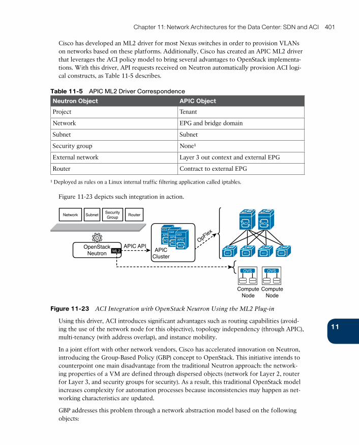
ptg17120290
11
Chapter 11: Network Architectures for the Data Center: SDN and ACI 401
Cisco has developed an ML2 driver for most Nexus switches in order to provision VLANs on networks based on these platforms. Additionally, Cisco has created an APIC ML2 driver that leverages the ACI policy model to bring several advantages to OpenStack implementa-tions. With this driver, API requests received on Neutron automatically provision ACI logi-cal constructs, as Table 11-5 describes.
Table 11-5 APIC ML2 Driver Correspondence
Neutron Object APIC Object
Project Tenant
Network EPG and bridge domain
Subnet Subnet
Security group None¹
External network Layer 3 out context and external EPG
Router Contract to external EPG
¹ Deployed as rules on a Linux internal traffic filtering application called iptables.
Figure 11-23 depicts such integration in action.
Network SubnetSecurityGroup
Router
OpFlex
APIC API
ComputeNode
OpenStackNeutron ML2 APIC
Cluster
ComputeNode
ACI
APIC
ACI
APIC
ACI
APIC
OVS OVS
ACI ACI
ACI ACI ACIACI
Figure 11-23 ACI Integration with OpenStack Neutron Using the ML2 Plug-in
Using this driver, ACI introduces significant advantages such as routing capabilities (avoid-ing the use of the network node for this objective), topology independency (through APIC), multi-tenancy (with address overlap), and instance mobility.
In a joint effort with other network vendors, Cisco has accelerated innovation on Neutron, introducing the Group-Based Policy (GBP) concept to OpenStack. This initiative intends to counterpoint one main disadvantage from the traditional Neutron approach: the network-ing properties of a VM are defined through dispersed objects (network for Layer 2, router for Layer 3, and security groups for security). As a result, this traditional OpenStack model increases complexity for automation processes because inconsistencies may happen as net-working characteristics are updated.
GBP addresses this problem through a network abstraction model based on the following objects:
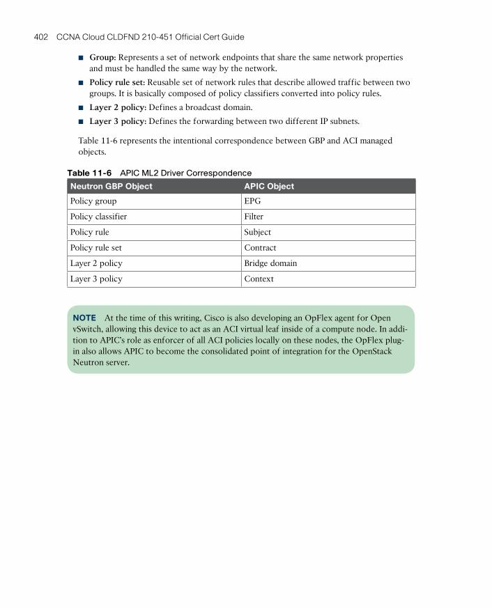
ptg17120290
402 CCNA Cloud CLDFND 210-451 Official Cert Guide
■ Group: Represents a set of network endpoints that share the same network properties and must be handled the same way by the network.
■ Policy rule set: Reusable set of network rules that describe allowed traffic between two groups. It is basically composed of policy classifiers converted into policy rules.
■ Layer 2 policy: Defines a broadcast domain.
■ Layer 3 policy: Defines the forwarding between two different IP subnets.
Table 11-6 represents the intentional correspondence between GBP and ACI managed objects.
Table 11-6 APIC ML2 Driver Correspondence
Neutron GBP Object APIC Object
Policy group EPG
Policy classifier Filter
Policy rule Subject
Policy rule set Contract
Layer 2 policy Bridge domain
Layer 3 policy Context
NOTE At the time of this writing, Cisco is also developing an OpFlex agent for Open vSwitch, allowing this device to act as an ACI virtual leaf inside of a compute node. In addi-tion to APIC’s role as enforcer of all ACI policies locally on these nodes, the OpFlex plug-in also allows APIC to become the consolidated point of integration for the OpenStack Neutron server.

ptg17120290
11
Chapter 11: Network Architectures for the Data Center: SDN and ACI 403
Figure 11-24 represents this integration scenario.
OpFlex
APIC API
ComputeNode
OpenStackNeutron
PolicyRule Set
PolicyRule Set
PolicyRule Set
Group1 Group2 Group3 Group3
GBP
APICCluster
ComputeNode
ACI
APIC
ACI
APIC
ACI
APIC
OVS OVS
ACI ACI
ACI ACI ACIACI
Figure 11-24 ACI Integration with OpenStack Neutron and Open vSwitch OpFlex Agent
Further Reading■ OpenStack Networking Guide, “Overview and Components”: http://docs.openstack.org/
networking-guide/intro_os_networking_overview.html
■ Installing the Cisco APIC OpenStack Driver: http://www.cisco.com/c/en/us/td/docs/switches/datacenter/aci/apic/sw/1-x/api/openstack/b_Cisco_APIC_OpenStack_Driver_Install_Guide.html
■ Group-Based Policy for OpenStack: https://wiki.openstack.org/w/images/a/aa/Group-BasedPolicyWhitePaper_v3.pdf
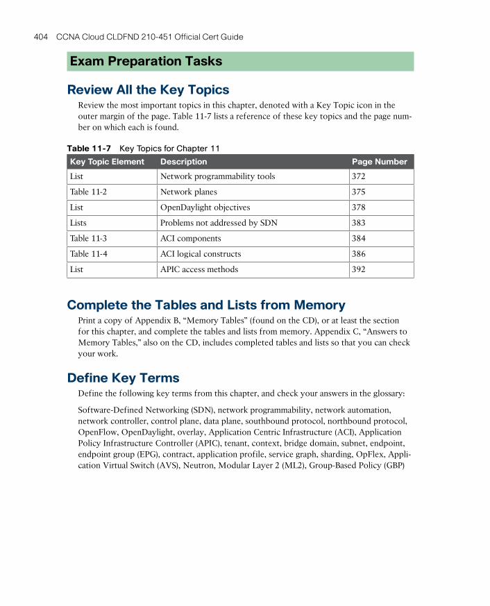
ptg17120290
404 CCNA Cloud CLDFND 210-451 Official Cert Guide
Exam Preparation Tasks
Review All the Key TopicsReview the most important topics in this chapter, denoted with a Key Topic icon in the outer margin of the page. Table 11-7 lists a reference of these key topics and the page num-ber on which each is found.
Table 11-7 Key Topics for Chapter 11
Key Topic Element Description Page Number
List Network programmability tools 372
Table 11-2 Network planes 375
List OpenDaylight objectives 378
Lists Problems not addressed by SDN 383
Table 11-3 ACI components 384
Table 11-4 ACI logical constructs 386
List APIC access methods 392
Complete the Tables and Lists from MemoryPrint a copy of Appendix B, “Memory Tables” (found on the CD), or at least the section for this chapter, and complete the tables and lists from memory. Appendix C, “Answers to Memory Tables,” also on the CD, includes completed tables and lists so that you can check your work.
Define Key TermsDefine the following key terms from this chapter, and check your answers in the glossary:
Software-Defined Networking (SDN), network programmability, network automation, network controller, control plane, data plane, southbound protocol, northbound protocol, OpenFlow, OpenDaylight, overlay, Application Centric Infrastructure (ACI), Application Policy Infrastructure Controller (APIC), tenant, context, bridge domain, subnet, endpoint, endpoint group (EPG), contract, application profile, service graph, sharding, OpFlex, Appli-cation Virtual Switch (AVS), Neutron, Modular Layer 2 (ML2), Group-Based Policy (GBP)

ptg17120290

ptg17120290
This chapter covers the following topics:
■ Physical Servers in a Virtual World
■ Server Provisioning Challenges
■ Introducing the Cisco Unified Computing System
■ UCS Server Identity
■ UCS Central
■ Cloud Computing and UCS
This chapter covers the following exam objectives:
■ 3.1 Identify key features of Cisco UCS
■ 3.1.a Cisco UCS Manager■ 3.1.b Cisco UCS Central■ 3.1.c B-Series■ 3.1.d C-Series■ 3.1.e Server identity (profi les, templates, pools)

ptg17120290
CHAPTER 12
Unified ComputingThroughout Chapters 4 to 11, you have learned important concepts about cloud comput-ing infrastructure, focusing on server virtualization, storage, and networking technologies. I deliberately delayed the discussion of physical servers until this chapter for one very impor-tant reason: understanding these fundamental concepts is a prerequisite to assessing the innovative impact of unified computing.
When Cisco launched the Unified Computing System (UCS) in 2009, many pundits ques-tioned why the company decided to enter the increasingly commoditized x86 server mar-ket. Such questions clearly didn’t take into consideration the massive number of operational challenges that physical server provisioning has posed for many years. And, as you will learn in this chapter, most of these difficulties are essentially linked to inefficient interactions among procedures from the server teams and other technology areas within data centers.
Because the CLDFND exam demands knowledge about the key features of the Cisco Uni-fied Computing System, this chapter examines such aspects, outlining hardware compo-nents, management software (such as UCS Manager and UCS Central), and its policy model, which truly justifies why Cisco UCS is considered the most suitable computing platform for cloud computing environments.
“Do I Know This Already?” QuizThe “Do I Know This Already?” quiz allows you to assess whether you should read this entire chapter thoroughly or jump to the “Exam Preparation Tasks” section. If you are in doubt about your answers to these questions or your own assessment of your knowledge of the topics, read the entire chapter. Table 12-1 lists the major headings in this chapter and their corresponding “Do I Know This Already?” quiz questions. You can find the answers in Appendix A, “Answers to Pre-Assessments and Quizzes.”
Table 12-1 “Do I Know This Already?” Section-to-Question Mapping
Foundation Topics Section Questions
Physical Servers in a Virtual World 1
Server Provisioning Challenges 2
Introducing the Cisco Unified Computing System 3–5
UCS Server Identity 6–8
UCS Central 9
Cloud Computing and UCS 10
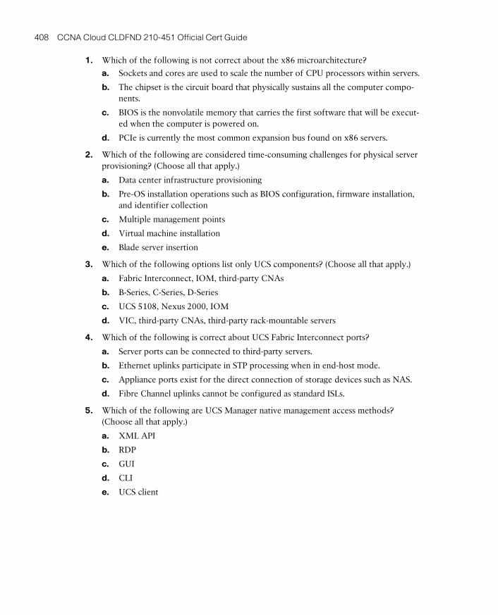
ptg17120290
408 CCNA Cloud CLDFND 210-451 Official Cert Guide
1. Which of the following is not correct about the x86 microarchitecture?
a. Sockets and cores are used to scale the number of CPU processors within servers.
b. The chipset is the circuit board that physically sustains all the computer compo-nents.
c. BIOS is the nonvolatile memory that carries the first software that will be execut-ed when the computer is powered on.
d. PCIe is currently the most common expansion bus found on x86 servers.
2. Which of the following are considered time-consuming challenges for physical server provisioning? (Choose all that apply.)
a. Data center infrastructure provisioning
b. Pre-OS installation operations such as BIOS configuration, firmware installation, and identifier collection
c. Multiple management points
d. Virtual machine installation
e. Blade server insertion
3. Which of the following options list only UCS components? (Choose all that apply.)
a. Fabric Interconnect, IOM, third-party CNAs
b. B-Series, C-Series, D-Series
c. UCS 5108, Nexus 2000, IOM
d. VIC, third-party CNAs, third-party rack-mountable servers
4. Which of the following is correct about UCS Fabric Interconnect ports?
a. Server ports can be connected to third-party servers.
b. Ethernet uplinks participate in STP processing when in end-host mode.
c. Appliance ports exist for the direct connection of storage devices such as NAS.
d. Fibre Channel uplinks cannot be configured as standard ISLs.
5. Which of the following are UCS Manager native management access methods? (Choose all that apply.)
a. XML API
b. RDP
c. GUI
d. CLI
e. UCS client
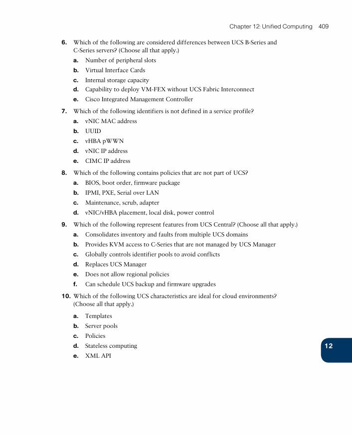
ptg17120290
12
Chapter 12: Unified Computing 409
6. Which of the following are considered differences between UCS B-Series and C-Series servers? (Choose all that apply.)
a. Number of peripheral slots
b. Virtual Interface Cards
c. Internal storage capacity
d. Capability to deploy VM-FEX without UCS Fabric Interconnect
e. Cisco Integrated Management Controller
7. Which of the following identifiers is not defined in a service profile?
a. vNIC MAC address
b. UUID
c. vHBA pWWN
d. vNIC IP address
e. CIMC IP address
8. Which of the following contains policies that are not part of UCS?
a. BIOS, boot order, firmware package
b. IPMI, PXE, Serial over LAN
c. Maintenance, scrub, adapter
d. vNIC/vHBA placement, local disk, power control
9. Which of the following represent features from UCS Central? (Choose all that apply.)
a. Consolidates inventory and faults from multiple UCS domains
b. Provides KVM access to C-Series that are not managed by UCS Manager
c. Globally controls identifier pools to avoid conflicts
d. Replaces UCS Manager
e. Does not allow regional policies
f. Can schedule UCS backup and firmware upgrades
10. Which of the following UCS characteristics are ideal for cloud environments? (Choose all that apply.)
a. Templates
b. Server pools
c. Policies
d. Stateless computing
e. XML API
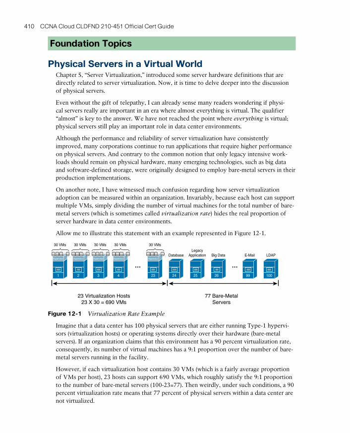
ptg17120290
410 CCNA Cloud CLDFND 210-451 Official Cert Guide
Foundation Topics
Physical Servers in a Virtual WorldChapter 5, “Server Virtualization,” introduced some server hardware definitions that are directly related to server virtualization. Now, it is time to delve deeper into the discussion of physical servers.
Even without the gift of telepathy, I can already sense many readers wondering if physi-cal servers really are important in an era where almost everything is virtual. The qualifier “almost” is key to the answer. We have not reached the point where everything is virtual; physical servers still play an important role in data center environments.
Although the performance and reliability of server virtualization have consistently improved, many corporations continue to run applications that require higher performance on physical servers. And contrary to the common notion that only legacy intensive work-loads should remain on physical hardware, many emerging technologies, such as big data and software-defined storage, were originally designed to employ bare-metal servers in their production implementations.
On another note, I have witnessed much confusion regarding how server virtualization adoption can be measured within an organization. Invariably, because each host can support multiple VMs, simply dividing the number of virtual machines for the total number of bare-metal servers (which is sometimes called virtualization rate) hides the real proportion of server hardware in data center environments.
Allow me to illustrate this statement with an example represented in Figure 12-1.
Hypervisor
1
30 VMs
…
Hypervisor
2
30 VMs
…
Hypervisor
3
30 VMs
…
Hypervisor
4
30 VMs
…
Hypervisor
23
30 VMs
…
24
Database
25
LegacyApplication
26
Big Data
99
100
LDAP
… …
23 Virtualization Hosts23 X 30 = 690 VMs
77 Bare-MetalServers
Figure 12-1 Virtualization Rate Example
Imagine that a data center has 100 physical servers that are either running Type-1 hypervi-sors (virtualization hosts) or operating systems directly over their hardware (bare-metal servers). If an organization claims that this environment has a 90 percent virtualization rate, consequently, its number of virtual machines has a 9:1 proportion over the number of bare-metal servers running in the facility.
However, if each virtualization host contains 30 VMs (which is a fairly average proportion of VMs per host), 23 hosts can support 690 VMs, which roughly satisfy the 9:1 proportion to the number of bare-metal servers (100-23=77). Then weirdly, under such conditions, a 90 percent virtualization rate means that 77 percent of physical servers within a data center are not virtualized.
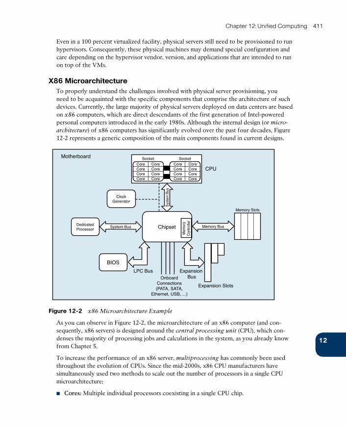
ptg17120290
12
Chapter 12: Unified Computing 411
Even in a 100 percent virtualized facility, physical servers still need to be provisioned to run hypervisors. Consequently, these physical machines may demand special configuration and care depending on the hypervisor vendor, version, and applications that are intended to run on top of the VMs.
X86 MicroarchitectureTo properly understand the challenges involved with physical server provisioning, you need to be acquainted with the specific components that comprise the architecture of such devices. Currently, the large majority of physical servers deployed on data centers are based on x86 computers, which are direct descendants of the first generation of Intel-powered personal computers introduced in the early 1980s. Although the internal design (or micro-
architecture ) of x86 computers has significantly evolved over the past four decades, Figure 12-2 represents a generic composition of the main components found in current designs.
Motherboard
CPU
Memory Slots
ClockGenerator
Expansion Slots
Expansion Bus
LPC BusOnboard
Connections(PATA, SATA,
Ethernet, USB, ...)
DedicatedProcessor
BIOS
Sys
tem
Bus
Memory BusSystem Bus Chipset
Mem
ory
Con
trolle
r
SocketCore CoreCore CoreCore CoreCore Core
SocketCore CoreCore CoreCore CoreCore Core
Figure 12-2 x86 Microarchitecture Example
As you can observe in Figure 12-2, the microarchitecture of an x86 computer (and con-sequently, x86 servers) is designed around the central processing unit (CPU) , which con-denses the majority of processing jobs and calculations in the system, as you already know from Chapter 5.
To increase the performance of an x86 server, multiprocessing has commonly been used throughout the evolution of CPUs. Since the mid-2000s, x86 CPU manufacturers have simultaneously used two methods to scale out the number of processors in a single CPU microarchitecture:
■ Cores: Multiple individual processors coexisting in a single CPU chip.
ptg17120290
412 CCNA Cloud CLDFND 210-451 Official Cert Guide
■ Sockets: Physical connectors that allow the insertion of multiple CPU chips on a single computer. These chips are usually interconnected through a proprietary high-bandwidth data connection.
With tens of processors available for parallel use in a single x86 server, it is up to the appli-cations, operating system, and hypervisor vendors to employ these resources to the benefit of their users.
A chipset is the computer element that is responsible for the data exchange between the CPU and practically all other components of an x86 server. Because it is usually designed to support a specific generation of CPUs, this circuit may also integrate other elements such as memory controllers (as shown in Figure 12-2), peripherals, and onboard connections such as LAN on Motherboard (LoM) Ethernet ports, Universal Serial Bus (USB) connections, and storage controllers for PATA and SATA disks.
Connected to the chipset, you can also find the clock generator , which provides a timing signal for the synchronization of operations between two or more components from the microarchitecture.
A memory controller is a specialized circuit concerned with how data is inserted into and retrieved from memory modules (containing multiple random-access memory [RAM] chips) that are physically inserted into their corresponding slots. To perform this function, the memory controller applies an exclusive clock signal to the memory chips to synchro-nize their data exchange. Single Data Rate (SDR) RAM chips can provide only one data exchange during a memory clock cycle, whereas Double Data Rate (DDR) chips can provide two data exchanges at each clock cycle.
NOTE As a consequence of the evolution of the processors, memory controllers are com-monly integrated into the CPU structure to accelerate the access to RAM memory.
Generally speaking, a bus refers to any medium that supports data transfer among compo-nents of an x86 computer. Figure 12-2 shows three types of buses:
■ Memory bus: Connects the memory to its controller
■ System bus: Provides higher-speed chipset connections to the CPU or to a dedicated processor (which may assist the CPU in the execution of a specific function such as graphics, encryption, or I/O control)
■ Expansion bus: Interconnects adapters and peripherals that can be added to the system via the expansion slots
Currently, the standard internal peripheral connection found on the large majority of x86 servers is PCI Express (PCIe) , which avoids the communication limitations of parallel con-nections such as Industry Standard Architecture (ISA) and Peripheral Component Inter-connect (PCI). PCIe leverages dedicated pairs of unidirectional connections to peripherals known as lanes . A PCIe device deploys a group of lanes (1, 2, 4, 8, or 16) to transfer data within a computer. Each PCIe connection is defined through an x prefix and the corre-sponding number of lanes (for example, an x2 PCIe connection employs two lanes).
ptg17120290
12
Chapter 12: Unified Computing 413
TIP Interestingly, PCIe uses networking principles that employ transaction, data link, and physical layers defined according to PCI Special Interest Group (PCI-SIG) standards. Additionally, PCIe can virtualize network adapters through the single-root I/O virtualization (SR-IOV), which allows a single PCIe I/O peripheral to emulate multiple “lightweight” instanc-es. Nonetheless, because these virtual adapters cannot be configured exactly as their physical counterparts, SR-IOV requires special support from the operating system or hypervisor.
Figure 12-2 also depicts the basic input/output system (BIOS) , which consists of non-volatile memory that stores the very first application that should be executed when the computer is powered on. In summary, the BIOS software checks the health of all computer hardware components and loads the operating system afterward. The BIOS software nor-mally provides a simple user interface that allows the configuration of several options (such as boot device order and CPU settings), and it is usually connected to the chipset through a connection known as low pin count (LPC) bus (corresponding to “LPC Bus” in Figure 12-2).
Lastly, the motherboard consists of a circuit panel that physically sustains all the computer components described in this section, providing appropriate connection slots for each one of them.
Physical Server Formats
During the Internet boom in the 1990s, the x86 architecture became the leading server computing architecture, replacing mainframe and RISC servers through added RAS features whose objective was to achieve
■ Reliability: Consistently producing trusted results with acceptable performance
■ Availability: Presenting extremely low downtime per year
■ Serviceability: Requiring simple and fast operations to recover from a failure
As a result, x86 servers gained strategic importance in most IT departments. More recently, the evolving demands in data center facilities have led to the commercialization of servers in different formats.
Figure 12-3 exhibits the most popular server formats.
The format of a tower server , represented on the left side of Figure 12-3, is very similar to that of a PC workstation. Because tower servers tend to waste space in dense environments, they are rarely found in data centers today. However, tower servers are still pretty common in remote branches and remote environments, where they are usually installed on a table or directly on the floor.
Depicted in the middle of Figure 12-2, rack-mountable servers are computers that are spe-cially designed to be stacked into 19-inch-wide server cabinets. Because each of these inde-pendent devices occupies one to eight rack units (where each RU is 1.075 inches or 44.45 mm high), a standard cabinet usually houses from 4 to 44 rack-mountable servers.

ptg17120290
414 CCNA Cloud CLDFND 210-451 Official Cert Guide
Tower Rack-Mountable
Server Cabinet(Rack)
Blade Chassis
MezzanineCard
Blade Server
Blade Server
SLO
T
Figure 12-3 Server Formats
An even denser server format, blade servers are exhibited on the right of Figure 12-2. Their popularization increased in the late 2000s, when a large number of data center sites were having trouble physically accommodating more server hardware in the same available space. Although their specifications vary from manufacturer to manufacturer, a blade server is actually a highly compacted x86 machine that is inserted into one or more slots on a blade chassis . A single blade chassis occupies from 6 to 10 RUs in a server cabinet and contains from 4 to 16 blade servers.
To further optimize the size of blade servers, most blade chassis offer infrastructure elements that are shared among all internal servers, such as power sources, management modules, Ether-net, and Fibre Channel switches. The connections between these switches and the I/O adapt-ers on blade servers are implemented through short-distance internal electrical media specified in IEEE 802.3ap, IEEE 802.3ba, and the ANSI T11 FC-PI family of standards.
The blade server I/O adapters commonly follow a special physical design called mezzanine , mainly because they resemble a theater balcony as they are mounted over the blade server motherboard. However, when compared to their rack-mountable counterparts, blade servers support fewer adapters.
As a direct consequence of their higher server density, new blade server deployments demand special attention from a power and cooling distribution perspective.
Server Provisioning ChallengesBefore cloud computing, an informal way to compare the efficiency of data center facili-ties was to measure how fast one site could fully provision a physical server. Because the process of readying a server for production use involves multiple interdependent tasks from different technology areas, it was not uncommon to expect to spend a couple of weeks (or even months) to ready the server to receive its first user request.
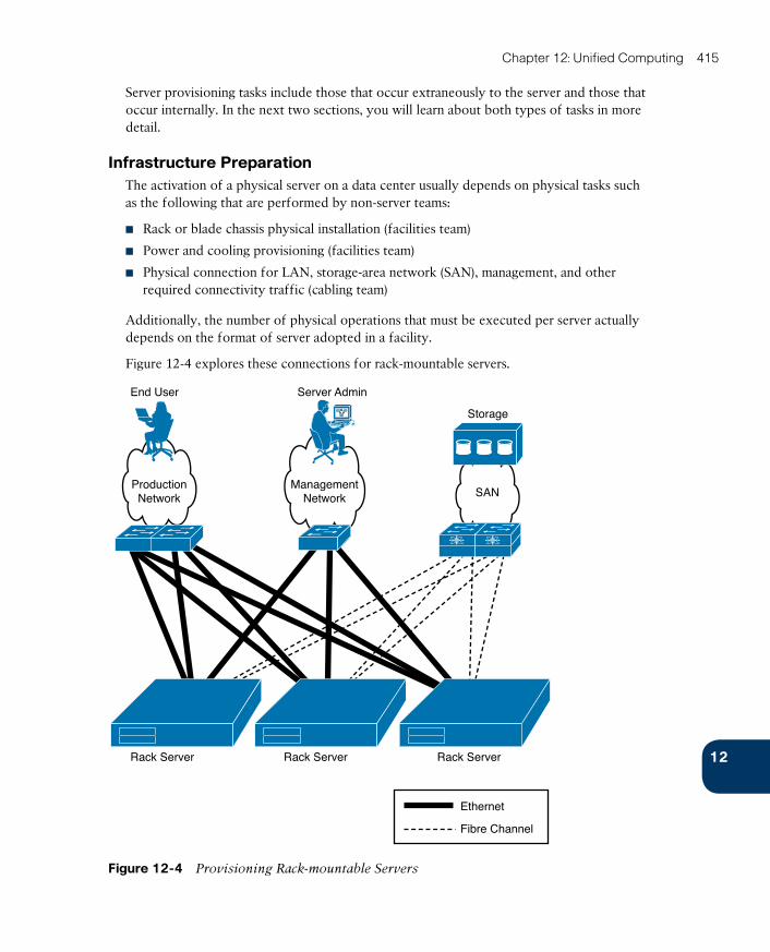
ptg17120290
12
Chapter 12: Unified Computing 415
Server provisioning tasks include those that occur extraneously to the server and those that occur internally. In the next two sections, you will learn about both types of tasks in more detail.
Infrastructure PreparationThe activation of a physical server on a data center usually depends on physical tasks such as the following that are performed by non-server teams:
■ Rack or blade chassis physical installation (facilities team)
■ Power and cooling provisioning (facilities team)
■ Physical connection for LAN, storage-area network (SAN), management, and other required connectivity traffic (cabling team)
Additionally, the number of physical operations that must be executed per server actually depends on the format of server adopted in a facility.
Figure 12-4 explores these connections for rack-mountable servers .
Storage
Server AdminEnd User
Rack Server Rack Server Rack Server
ManagementNetwork
ProductionNetwork SAN
Ethernet
Fibre Channel
Figure 12-4 Provisioning Rack-mountable Servers
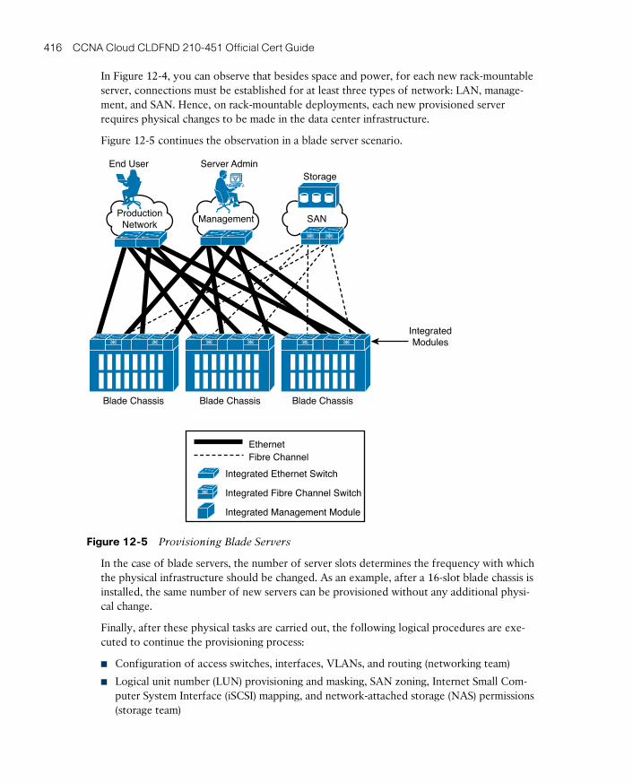
ptg17120290
416 CCNA Cloud CLDFND 210-451 Official Cert Guide
In Figure 12-4, you can observe that besides space and power, for each new rack-mountable server, connections must be established for at least three types of network: LAN, manage-ment, and SAN. Hence, on rack-mountable deployments, each new provisioned server requires physical changes to be made in the data center infrastructure.
Figure 12-5 continues the observation in a blade server scenario.
End UserStorage
SANManagement
Server Admin
Blade Chassis Blade Chassis Blade Chassis
IntegratedModules
ProductionNetwork
EthernetFibre Channel
Integrated Ethernet Switch
Integrated Fibre Channel Switch
Integrated Management Module
Figure 12-5 Provisioning Blade Servers
In the case of blade servers, the number of server slots determines the frequency with which the physical infrastructure should be changed. As an example, after a 16-slot blade chassis is installed, the same number of new servers can be provisioned without any additional physi-cal change.
Finally, after these physical tasks are carried out, the following logical procedures are exe-cuted to continue the provisioning process:
■ Configuration of access switches, interfaces, VLANs, and routing (networking team)
■ Logical unit number (LUN) provisioning and masking, SAN zoning, Internet Small Com-puter System Interface (iSCSI) mapping, and network-attached storage (NAS) permissions (storage team)

ptg17120290
12
Chapter 12: Unified Computing 417
Unfortunately, a lot of these activities can only happen after the server hardware is physi-cally located in the data center, or at least not before some of the hardware’s identity is obtained, including World Wide Names (WWNs), MAC address (for licensing purposes in some scenarios), or Universally Unique Identifier (UUID), which is a 128-bit value that basi-cally guarantees uniqueness across space and time without requiring a central registration process. For example, a host bus adapter (HBA) will only access Fibre Channel storage after its port WWN (pWWN) is included in the SAN active zone set.
Pre-Operating System Installation OperationsApart from all the infrastructure operations described in the previous section, the server team must still execute a considerable number of procedures before an operating system (or Type-1 hypervisor) can be properly installed on a server. The primary purpose of such tasks typically is to harmonize the soon-to-be installed software version with the server hardware, and, in general, these tasks are accomplished through the BIOS user interface.
Table 12-2 lists some of the pre-OS settings that are usually configured on x86 servers, regardless of their format.
Table 12-2 Pre-OS Installation Settings
Server Component
Common Settings
CPU Performance features (such as Intel Turbo Boost), scaling technologies (Intel Hyper-Threading [Intel HT] and Intel Core Multi-Processing [CMP]), vir-tualization enhancements (including Intel Virtualization Technology [Intel VT]), among many others
Memory Caching, mirroring, power saving mode, and so forth
HDD RAID group configuration and data erasing
Network inter-face controller (NIC)
Failover configuration and firmware update
HBA Multipath configuration and firmware update
Boot order Defines a list of devices (such as DVD drive, internal storage, SAN, among many others) that will be used to access the server boot image
After this minimal set of parameters is set on an x86 server, an operating system (or hypervi-sor) can finally be installed, licensed, and customized on such a server.
Then, at last, an application (or virtual machines) can be installed over this elaborate struc-ture. But again, some of these software activation tasks, especially licensing, require previ-ous knowledge of a server identifier such as the UUID or an adapter MAC address.
With all these operations and dependencies, you can see that spending a few weeks on server provisioning is not as far-fetched as it may have seemed initially.
ptg17120290
418 CCNA Cloud CLDFND 210-451 Official Cert Guide
Introducing the Cisco Unified Computing SystemThe complexity and consequent plodding pace related to traditional server provisioning obviously collide with the objectives of data center automation and, worryingly, the essen-tial characteristics of cloud computing. And even if a cloud is exclusively providing IaaS through virtual machines, its elasticity can be seriously challenged if more virtualized hosts cannot be quickly provisioned during periods of peak utilization.
Realizing that cloud computing demanded a new method of server provisioning, Cisco seized the opportunity to rethink physical servers with a fresh start. In 2009, the outcome of this radical redesign was expressed as the Cisco Unified Computing System (UCS).
Broadly speaking, UCS relies on a technology trend that you have already encountered sev-eral times in this book: the consolidation of management points. Some examples for this trend are
■ Disk arrays: Hundreds of disks are centrally managed through redundant array controllers.
■ Fabric Extenders: Tens of Fabric Extenders relinquish their management to one or two parent switches.
■ Network controller: The complexity behind managing multiple networking devices is hidden via this network application.
Although the introduction of blade servers was a giant step on the path to server manage-ment consolidation, UCS takes it much farther through the unification of different tech-nologies that exist to support server provisioning, including networking, storage, and server virtualization. Besides management centralization, UCS also provides I/O flexibility and virtualization performance enhancements through many innovations that were discussed in Chapter 10, “Network Architectures for the Data Center: Unified Fabric.”
Figure 12-6 outlines the main elements that comprise the UCS architecture.
A UCS domain is typically delimited by a pair of UCS Fabric Interconnects (although some rare implementations employ a single Fabric Interconnect). Through embedded software called UCS Manager, such devices simultaneously control all other elements in a domain, including UCS blade chassis, Fabric Extenders (FEXs), and UCS servers (including some of their internal components). Although they act as an active-standby pair for all manage-ment purposes, the Fabric Interconnects deploy active-active redundancy for all networking functions of a UCS domain, be they external to the domain (Ethernet and Fibre Channel) or internal (unified I/O to the servers and virtual networking using Cisco Virtual Interface
Cards [VICs]).
From an architectural perspective, the physical addition of a UCS Blade Server Chassis (con-taining UCS B-Series Blade Servers) or a Fabric Extender (connected to UCS C-Series rack-mountable switches) does not necessitate physical changes in the data center infrastructure. Therefore, after a pair of Fabric Interconnects is correctly connected to all external net-works (which are represented by the production, management, and SAN in Figure 12-6), the number of servers supported on a single UCS domain will dictate the need of infrastructure changes through another pair of Fabric Interconnects.
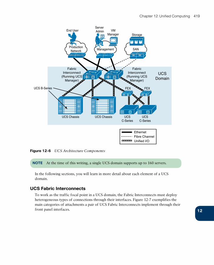
ptg17120290
12
Chapter 12: Unified Computing 419
End UserStorage
Server Admin VM
Manager
ManagementProduction
Network
UCS B-Series
UCS Chassis UCS Chassis UCSC-Series
UCSC-Series
UCSDomain
FabricInterconnect
(Running UCSManager)
FabricInterconnect
(Running UCSManager)
FEX FEX
SAN
Unified I/OFibre ChannelEthernet
Figure 12-6 UCS Architecture Components
NOTE At the time of this writing, a single UCS domain supports up to 160 servers.
In the following sections, you will learn in more detail about each element of a UCS domain.
UCS Fabric InterconnectsTo work as the traffic focal point in a UCS domain, the Fabric Interconnects must deploy heterogeneous types of connections through their interfaces. Figure 12-7 exemplifies the main categories of attachments a pair of UCS Fabric Interconnects implement through their front panel interfaces.
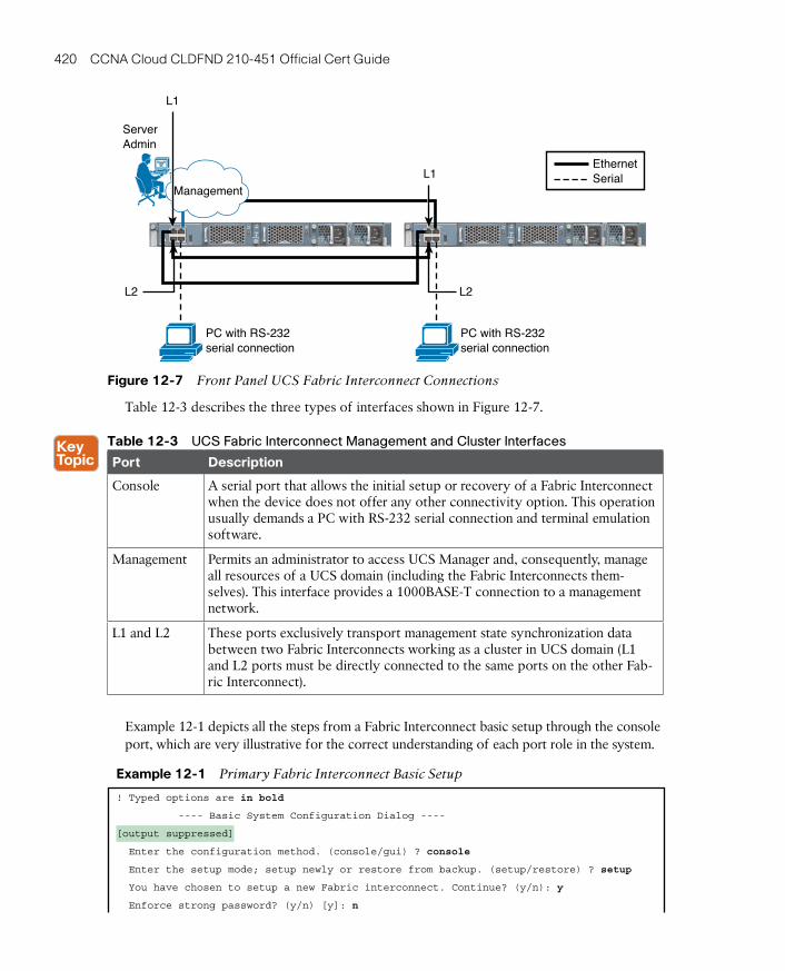
ptg17120290
420 CCNA Cloud CLDFND 210-451 Official Cert Guide
PC with RS-232serial connection
PC with RS-232serial connection
EthernetSerial
Management
ServerAdmin
L1
L1
L2L2
Figure 12-7 Front Panel UCS Fabric Interconnect Connections
Table 12-3 describes the three types of interfaces shown in Figure 12-7.
Table 12-3 UCS Fabric Interconnect Management and Cluster Interfaces
Port Description
Console A serial port that allows the initial setup or recovery of a Fabric Interconnect when the device does not offer any other connectivity option. This operation usually demands a PC with RS-232 serial connection and terminal emulation software.
Management Permits an administrator to access UCS Manager and, consequently, manage all resources of a UCS domain (including the Fabric Interconnects them-selves). This interface provides a 1000BASE-T connection to a management network.
L1 and L2 These ports exclusively transport management state synchronization data between two Fabric Interconnects working as a cluster in UCS domain (L1 and L2 ports must be directly connected to the same ports on the other Fab-ric Interconnect).
Example 12-1 depicts all the steps from a Fabric Interconnect basic setup through the console port, which are very illustrative for the correct understanding of each port role in the system.
Example 12-1 Primary Fabric Interconnect Basic Setup
! Typed options are in bold
---- Basic System Configuration Dialog ----
[output suppressed]
Enter the configuration method. (console/gui) ? console
Enter the setup mode; setup newly or restore from backup. (setup/restore) ? setup
You have chosen to setup a new Fabric interconnect. Continue? (y/n): y
Enforce strong password? (y/n) [y]: n
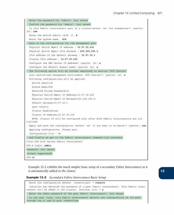
ptg17120290
12
Chapter 12: Unified Computing 421
Enter the password for "admin": [not shown]
Confirm the password for "admin": [not shown]
Is this Fabric interconnect part of a cluster(select 'no' for standalone)? (yes/no) [n]: yes
Enter the switch fabric (A/B) []: A
Enter the system name: UCS
! Here is the configuration for the management port
Physical Switch Mgmt0 IP address : 10.97.39.236
Physical Switch Mgmt0 IPv4 netmask : 255.255.255.0
IPv4 address of the default gateway : 10.97.39.1
Cluster IPv4 address : 10.97.39.235
Configure the DNS Server IP address? (yes/no) [n]: n
Configure the default domain name? (yes/no) [n]: n
! The following option will be further explained in section "UCS Central"
Join centralized management environment (UCS Central)? (yes/no) [n]: n
Following configurations will be applied:
Switch Fabric=A
System Name=UCS
Enforced Strong Password=no
Physical Switch Mgmt0 IP Address=10.97.39.236
Physical Switch Mgmt0 IP Netmask=255.255.255.0
Default Gateway=10.97.39.1
Ipv6 value=0
Cluster Enabled=yes
Cluster IP Address=10.97.39.235
NOTE: Cluster IP will be configured only after both Fabric Interconnects are ini-tialized
Apply and save the configuration (select 'no' if you want to re-enter)? (yes/no): yes
Applying configuration. Please wait.
Configuration file - Ok
! And finally we get to the Fabric Interconnect command-line interface
Cisco UCS 6200 Series Fabric Interconnect
UCS-A login: admin
Password: [not shown]
[output suppressed]
UCS-A#
Example 12-2 exhibits the much simpler basic setup of a secondary Fabric Interconnect as it is automatically added to the cluster.
Example 12-2 Secondary Fabric Interconnect Basic Setup
Enter the configuration method. (console/gui) ? console
Installer has detected the presence of a peer Fabric interconnect. This Fabric inter-connect will be added to the cluster. Continue (y/n) ? y
Enter the admin password of the peer Fabric interconnect: [not shown]
! In the next lines, this Fabric Interconnect detects the configuration of its peer through the L1 and L2 port connections
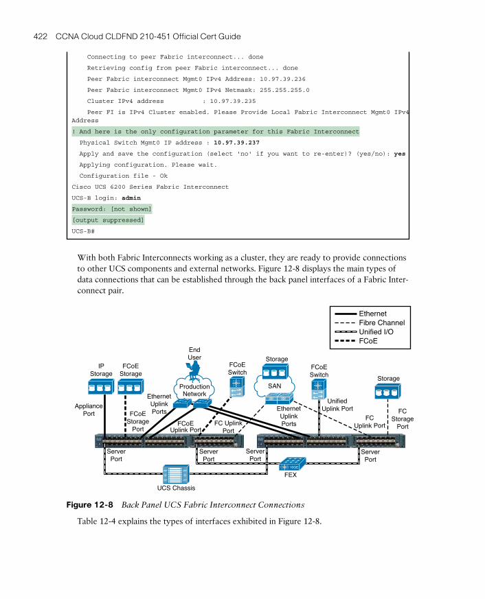
ptg17120290
422 CCNA Cloud CLDFND 210-451 Official Cert Guide
Connecting to peer Fabric interconnect... done
Retrieving config from peer Fabric interconnect... done
Peer Fabric interconnect Mgmt0 IPv4 Address: 10.97.39.236
Peer Fabric interconnect Mgmt0 IPv4 Netmask: 255.255.255.0
Cluster IPv4 address : 10.97.39.235
Peer FI is IPv4 Cluster enabled. Please Provide Local Fabric Interconnect Mgmt0 IPv4 Address
! And here is the only configuration parameter for this Fabric Interconnect
Physical Switch Mgmt0 IP address : 10.97.39.237
Apply and save the configuration (select 'no' if you want to re-enter)? (yes/no): yes
Applying configuration. Please wait.
Configuration file - Ok
Cisco UCS 6200 Series Fabric Interconnect
UCS-B login: admin
Password: [not shown]
[output suppressed]
UCS-B#
With both Fabric Interconnects working as a cluster, they are ready to provide connections to other UCS components and external networks. Figure 12-8 displays the main types of data connections that can be established through the back panel interfaces of a Fabric Inter-connect pair.
AppliancePort FC
StoragePort
FCUplink PortFC Uplink
PortFCoE
Uplink Port
FCoEStorage
Port
UnifiedUplink PortEthernet
UplinkPorts
EthernetUplinkPorts
EthernetFibre ChannelUnified I/OFCoE
SAN
ServerPort
ServerPort
ServerPort
ServerPort
FEX
FCoESwitch
IPStorage
UCS Chassis
FCoEStorage
Storage
Storage
10GE
ProductionNetwork
EndUser
FCoESwitch
Figure 12-8 Back Panel UCS Fabric Interconnect Connections
Table 12-4 explains the types of interfaces exhibited in Figure 12-8.

ptg17120290
12
Chapter 12: Unified Computing 423
Table 12-4 UCS Fabric Interconnect Data Interfaces
Port Description
Server These ports must be exclusively connected to the I/O Modules (IOMs) on a UCS Blade Server Chassis for B-Series servers, Fabric Extender connected to C-Series server, or even directly to a C-Series server.
Ethernet uplink Used to connect servers in a UCS domain to a standard Ethernet-based net-work. They may also be part of a PortChannel defined on the same Fabric Interconnect.
Fibre Channel uplink
These ports enable servers in a UCS domain to access networked storage devices that are connected to a Fibre Channel SAN. They can also be part of a Fibre Channel PortChannel with other Fibre Channel interfaces on the same Fabric Interconnect.
FCoE uplink Used to carry storage-only FCoE traffic from the Fabric Interconnect to an upstream FCoE-capable switch. They may also be members of an FCoE uplink PortChannel defined on the same Fabric Interconnect.
Unified uplink FCoE uplink port that can carry both Ethernet and FCoE-encapsulated Fibre Channel traffic simultaneously. They can also be part of a Unified uplink PortChannel with similar ports on the same Fabric Interconnect.
Appliance Permits the connection of directly attached NFS or iSCSI storage devices. If supported on the storage appliance, these interfaces also support aggre-gation through a PortChannel.
Fibre Channel storage
Permits the direct connection of a Fibre Channel storage array.
FCoE storage Allows the direct connection of an FCoE-based storage array.
SPAN Destina-tion
These ports are connected to traffic analyzers and are used to transmit mirrored traffic from any of the other port types described on this table. These ports must share the same mode (Ethernet or Fibre Channel) as the SPAN source interfaces (not depicted in Figure 12-8).
NOTE Without loss of generality, this section uses the UCS 6248UP as an example of a Fabric Interconnect. This device can apply the Unified Port concept , where the same inter-face may be configured in either Ethernet mode or Fibre Channel mode. Because there are other Fabric Interconnect models available in the Cisco UCS portfolio (including UCS-Mini, whose Fabric Interconnect is located inside of a UCS Blade Server Chassis), I will address their specific characteristics in Chapter 13, “Cisco Cloud Infrastructure Portfolio.”
From a Fibre Channel data plane standpoint, each Fabric Interconnect can assume one of the following two modes:
■ Switch mode: The Fabric Interconnect runs as a traditional Fibre Channel switch, deploy-ing Inter-Switch Links (ISLs) to other switches or directors. Only this mode enables direct connections to Fibre Channel or FCoE storage devices.
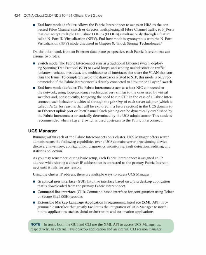
ptg17120290
424 CCNA Cloud CLDFND 210-451 Official Cert Guide
■ End-host mode (default): Allows the Fabric Interconnect to act as an HBA to the con-nected Fibre Channel switch or director, multiplexing all Fibre Channel traffic to F_Ports that can accept multiple FIP Fabric LOGIns (FLOGIs) simultaneously through a feature called N_Port ID Virtualization (NPIV). End-host mode is synonymous with the N_Port Virtualization (NPV) mode discussed in Chapter 8, “Block Storage Technologies.”
On the other hand, from an Ethernet data plane perspective, each Fabric Interconnect can assume two roles:
■ Switch mode: The Fabric Interconnect runs as a traditional Ethernet switch, deploy-ing Spanning Tree Protocol (STP) to avoid loops, and sending multidestination traffic (unknown unicast, broadcast, and multicast) to all interfaces that share the VLAN that con-tains the frame. To completely avoid the drawbacks related to STP, this mode is only rec-ommended if the Fabric Interconnect is directly connected to a router or a Layer 3 switch.
■ End-host mode (default): The Fabric Interconnect acts as a host NIC connected to the network, using loop-avoidance techniques very similar to the ones used by virtual switches and, consequently, foregoing the need to run STP. In the case of a Fabric Inter-connect, such behavior is achieved through the pinning of each server adapter (which is called vNICs for reasons that will be explored in a future section) in the UCS domain to an Ethernet uplink port or PortChannel. Such pinning can be dynamically established by the Fabric Interconnect or statically determined by the UCS administrator. This mode is recommended when a Layer 2 switch is used upstream to the Fabric Interconnect.
UCS ManagerRunning within each of the Fabric Interconnects on a cluster, UCS Manager offers server administrators the following capabilities over a UCS domain: server provisioning, device discovery, inventory, configuration, diagnostics, monitoring, fault detection, auditing, and statistics collection.
As you may remember, during basic setup, each Fabric Interconnect is assigned an IP address while sharing a cluster IP address that is entrusted to the primary Fabric Intercon-nect until it fails for any reason.
Using the cluster IP address, there are multiple ways to access UCS Manager:
■ Graphical user interface (GUI): Intuitive interface based on a Java desktop application that is downloaded from the primary Fabric Interconnect
■ Command-line interface (CLI): Command-based interface for configuration using Telnet or Secure Shell (SSH) sessions
■ Extensible Markup Language Application Programming Interface (XML API): Pro-grammable interface that greatly facilitates the integration of UCS Manager to north-bound applications such as cloud orchestrators and automation applications
NOTE In truth, both the GUI and CLI use the XML API to access UCS Manager as, respectively, an external Java desktop application and an internal CLI session manager.
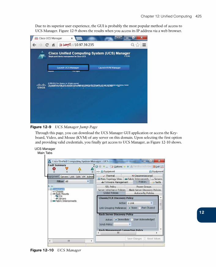
ptg17120290
12
Chapter 12: Unified Computing 425
Due to its superior user experience, the GUI is probably the most popular method of access to UCS Manager. Figure 12-9 shows the results when you access its IP address via a web browser.
Figure 12-9 UCS Manager Jump Page
Through this page, you can download the UCS Manager GUI application or access the Key-board, Video, and Mouse (KVM) of any server on this domain. Upon selecting the first option and providing valid credentials, you finally get access to UCS Manager, as Figure 12-10 shows.
UCS ManagerMain Tabs
Figure 12-10 UCS Manager
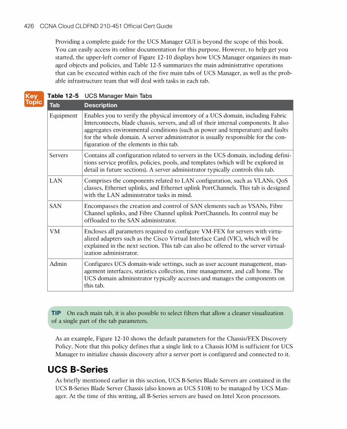
ptg17120290
426 CCNA Cloud CLDFND 210-451 Official Cert Guide
Providing a complete guide for the UCS Manager GUI is beyond the scope of this book. You can easily access its online documentation for this purpose. However, to help get you started, the upper-left corner of Figure 12-10 displays how UCS Manager organizes its man-aged objects and policies, and Table 12-5 summarizes the main administrative operations that can be executed within each of the five main tabs of UCS Manager, as well as the prob-able infrastructure team that will deal with tasks in each tab.
Table 12-5 UCS Manager Main Tabs
Tab Description
Equipment Enables you to verify the physical inventory of a UCS domain, including Fabric Interconnects, blade chassis, servers, and all of their internal components. It also aggregates environmental conditions (such as power and temperature) and faults for the whole domain. A server administrator is usually responsible for the con-figuration of the elements in this tab.
Servers Contains all configuration related to servers in the UCS domain, including defini-tions service profiles, policies, pools, and templates (which will be explored in detail in future sections). A server administrator typically controls this tab.
LAN Comprises the components related to LAN configuration, such as VLANs, QoS classes, Ethernet uplinks, and Ethernet uplink PortChannels. This tab is designed with the LAN administrator tasks in mind.
SAN Encompasses the creation and control of SAN elements such as VSANs, Fibre Channel uplinks, and Fibre Channel uplink PortChannels. Its control may be offloaded to the SAN administrator.
VM Encloses all parameters required to configure VM-FEX for servers with virtu-alized adapters such as the Cisco Virtual Interface Card (VIC), which will be explained in the next section. This tab can also be offered to the server virtual-ization administrator.
Admin Configures UCS domain-wide settings, such as user account management, man-agement interfaces, statistics collection, time management, and call home. The UCS domain administrator typically accesses and manages the components on this tab.
TIP On each main tab, it is also possible to select filters that allow a cleaner visualization of a single part of the tab parameters.
As an example, Figure 12-10 shows the default parameters for the Chassis/FEX Discovery Policy. Note that this policy defines that a single link to a Chassis IOM is sufficient for UCS Manager to initialize chassis discovery after a server port is configured and connected to it.
UCS B-SeriesAs briefly mentioned earlier in this section, UCS B-Series Blade Servers are contained in the UCS B-Series Blade Server Chassis (also known as UCS 5108) to be managed by UCS Man-ager. At the time of this writing, all B-Series servers are based on Intel Xeon processors.

ptg17120290
12
Chapter 12: Unified Computing 427
The external connectivity of the UCS B-Series Blade Chassis is represented in Figure 12-11.
Unified I/O
Fabric Interconnect
UCS2204XP
(IOM)
UCS 5108(Back)
UCS 5108(Back)
Fabric Interconnect Fabric Interconnect
UCS2208XP
(IOM)
Fabric Interconnect
Figure 12-11 UCS 5108 External Connectivity
As you can observe in Figure 12-11, a UCS 5108 chassis supports two IOM models, which, at the time of this writing, are UCS 2204XP and 2208XP. Whereas the former allows up to four 10-Gbps connections to a single Fabric Interconnect, the latter supports eight of these connections, offering 80 Gbps of bandwidth to each IOM, and consequently 160 Gbps for the entire chassis.
TIP By design, you cannot connect an IOM to both Fabric Interconnects.
At heart, these modules are Fabric Extenders whose fabric interfaces are connected to a Fabric Interconnect (performing the role of a parent switch) while their host interfaces are connected to the B-Series I/O adapters through internal electrical chassis connections. Consequently, and in harmony with the UCS consolidation principles, all server ports in a domain are connected to logical interfaces that are called virtual Ethernet (vEthernet) and are dynamically instantiated at each Fabric Interconnect.
After a sufficient number of server ports on a Fabric Interconnect are configured and con-nected to an IOM (according to the Chassis/FEX Discovery Policy shown previously in Fig-ure 12-10), UCS Manager starts to catalog and control the chassis, IOM, blade servers, and their internal components.
Figure 12-12 depicts the UCS Manager Equipment tab after the discovery process has ended.
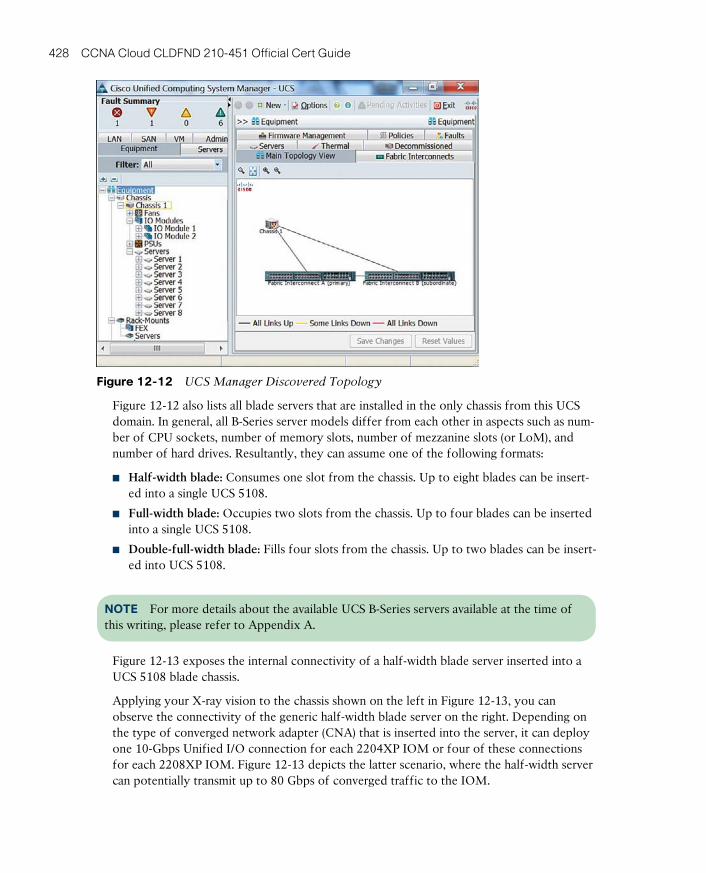
ptg17120290
428 CCNA Cloud CLDFND 210-451 Official Cert Guide
Figure 12-12 UCS Manager Discovered Topology
Figure 12-12 also lists all blade servers that are installed in the only chassis from this UCS domain. In general, all B-Series server models differ from each other in aspects such as num-ber of CPU sockets, number of memory slots, number of mezzanine slots (or LoM), and number of hard drives. Resultantly, they can assume one of the following formats:
■ Half-width blade: Consumes one slot from the chassis. Up to eight blades can be insert-ed into a single UCS 5108.
■ Full-width blade: Occupies two slots from the chassis. Up to four blades can be inserted into a single UCS 5108.
■ Double-full-width blade: Fills four slots from the chassis. Up to two blades can be insert-ed into UCS 5108.
NOTE For more details about the available UCS B-Series servers available at the time of this writing, please refer to Appendix A.
Figure 12-13 exposes the internal connectivity of a half-width blade server inserted into a UCS 5108 blade chassis.
Applying your X-ray vision to the chassis shown on the left in Figure 12-13, you can observe the connectivity of the generic half-width blade server on the right. Depending on the type of converged network adapter (CNA) that is inserted into the server, it can deploy one 10-Gbps Unified I/O connection for each 2204XP IOM or four of these connections for each 2208XP IOM. Figure 12-13 depicts the latter scenario, where the half-width server can potentially transmit up to 80 Gbps of converged traffic to the IOM.
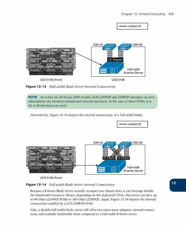
ptg17120290
12
Chapter 12: Unified Computing 429
Unified I/O
UCS 5108UCS 5108 (Front)
IOM (A) IOM (B)
Half-widthB-series Server
I/O Adapter
Figure 12-13 Half-width Blade Server Internal Connectivity
NOTE As is true for all Nexus 2000 models, both 2204XP and 2208XP introduce an over-subscription rate between internal and external interfaces. In the case of these IOMs, it is 4:1 if all interfaces are used.
Alternatively, Figure 12-14 depicts the internal connectivity of a full-width blade.
Unified I/O
UCS 5108 (Front)
IOM (A) IOM (B)
Half-widthB-series Server
I/O Adapter I/O Adapter
Figure 12-14 Full-width Blade Server Internal Connectivity
Because a B-Series Blade Server actually occupies two chassis slots, it can leverage double the bandwidth resources. Hence, depending on the deployed CNAs, this server can have up to 40 Gbps (2204XP IOM) or 160 Gbps (2208XP). Again, Figure 12-14 depicts the internal connections enabled by a UCS 2208XP IOM.
Fitly, a double-full-width blade server will offer two times more adapters, internal connec-tions, and available bandwidth when compared to a full-width B-Series server.

ptg17120290
430 CCNA Cloud CLDFND 210-451 Official Cert Guide
UCS C-SeriesThe Cisco UCS C-Series servers are rack-mountable devices that can be added to a UCS domain. Besides having a different format from the UCS B-Series, UCS C-Series servers dif-fer in the following ways as well:
■ They can work as an independent server.
■ They support more PCIe devices.
■ They can hold more internal storage (HDD or SSD).
From a hardware capacity angle, UCS C-Series servers roughly follow their blade counter-parts, offering corresponding models that also vary in number of CPU sockets, number of memory slots, number of PCIe slots, and type and number of hard drives. Accordingly, to accommodate these varying specifications, UCS C-Series servers are presented in models with 1, 2, and 4 rack units (RU).
NOTE Again, if you are looking for specific details about the UCS C-Series server models available at the time of this writing, please refer to Chapter 13.
Figure 12-15 demonstrates how a UCS C-Series server can be deployed and managed.
Unified I/O
UCS C-Series
UCS C-Series
Single Connect
Fabric Interconnect Fabric Interconnect
Direct Connect
UCS C-Series
Standalone
Fabric Interconnect Fabric Interconnect
Figure 12-15 UCS C-Series Connectivity Options
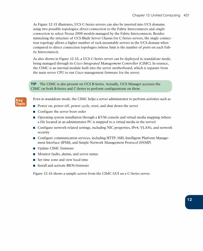
ptg17120290
12
Chapter 12: Unified Computing 431
As Figure 12-15 illustrates, UCS C-Series servers can also be inserted into UCS domains using two possible topologies: direct connection to the Fabric Interconnects and single
connection to select Nexus 2000 models managed by the Fabric Interconnects. Besides mimicking the structure of UCS Blade Server Chassis for C-Series servers, the single connec-tion topology allows a higher number of rack-mountable servers in the UCS domain when compared to direct connection topologies (whose limit is the number of ports on each Fab-ric Interconnect).
As also shown in Figure 12-15, a UCS C-Series server can be deployed in standalone mode, being managed through its Cisco Integrated Management Controller (CIMC) . In essence, the CIMC is an internal module built into the server motherboard, which is separate from the main server CPU to run Cisco management firmware for the server.
TIP The CIMC is also present on UCS B-Series. Actually, UCS Manager accesses the CIMC on both B-Series and C-Series to perform configurations on them.
Even in standalone mode, the CIMC helps a server administrator to perform activities such as
■ Power on, pow er off, power cycle, reset, and shut down the server
■ Configure the server boot order
■ Operating system installation through a KVM console and virtual media mapping (where a file located at an administrator PC is mapped to a virtual media in the server)
■ Configure network-related settings, including NIC properties, IPv4, VLANs, and network security
■ Configure communication services, including HTTP, SSH, Intelligent Platform Manage-ment Interface (IPMI), and Simple Network Management Protocol (SNMP)
■ Update CIMC firmware
■ Monitor faults, alarms, and server status
■ Set time zone and view local time
■ Install and activate BIOS firmware
Figure 12-16 shows a sample screen from the CIMC GUI on a C-Series server.
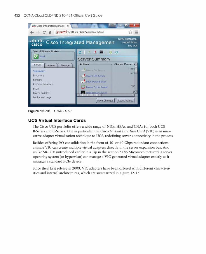
ptg17120290
432 CCNA Cloud CLDFND 210-451 Official Cert Guide
Figure 12-16 CIMC GUI
UCS Virtual Interface CardsThe Cisco UCS portfolio offers a wide range of NICs, HBAs, and CNAs for both UCS B-Series and C-Series. One in particular, the Cisco Virtual Interface Card (VIC) is an inno-vative adapter virtualization technique to UCS, redefining server connectivity in the process.
Besides offering I/O consolidation in the form of 10- or 40-Gbps redundant connections, a single VIC can create multiple virtual adapters directly in the server expansion bus. And unlike SR-IOV (introduced earlier in a Tip in the section “X86 Microarchitecture”), a server operating system (or hypervisor) can manage a VIC-generated virtual adapter exactly as it manages a standard PCIe device.
Since their first release in 2009, VIC adapters have been offered with different characteri-stics and internal architectures, which are summarized in Figure 12-17.
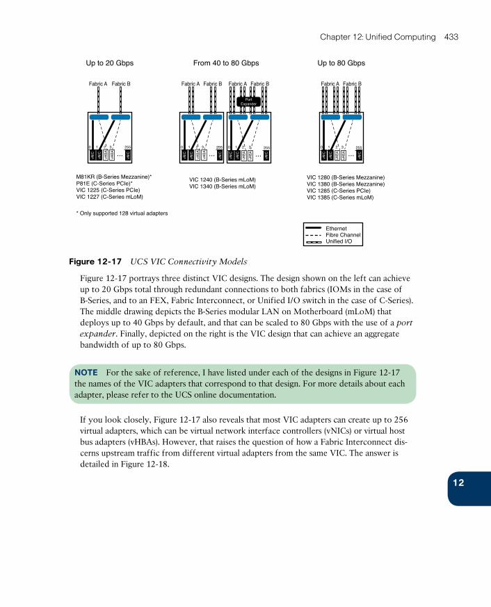
ptg17120290
12
Chapter 12: Unified Computing 433
From 40 to 80 GbpsUp to 20 Gbps
Fabric A Fabric B
2550 1 2 3 0 1 2 3 0 1 2 3 0 1 2 3
...
vNIC
vNIC
vNIC
vHB
A
vHB
A
Up to 80 Gbps
Fabric A Fabric B
255
...
M81KR (B-Series Mezzanine)*P81E (C-Series PCIe)*VIC 1225 (C-Series PCIe)VIC 1227 (C-Series mLoM)
VIC 1280 (B-Series Mezzanine)VIC 1380 (B-Series Mezzanine)VIC 1285 (C-Series PCIe)VIC 1385 (C-Series mLoM)
Fabric A Fabric B Fabric A Fabric B
255
...255
...
PortExpander
VIC 1240 (B-Series mLoM)VIC 1340 (B-Series mLoM)
* Only supported 128 virtual adapters
Ethernet
Unified I/OFibre Channel
vNIC
vNIC
vNIC
vHB
A
vHB
A
vNIC
vNIC
vNIC
vHB
A
vHB
A
vNIC
vNIC
vNIC
vHB
A
vHB
A
Figure 12-17 UCS VIC Connectivity Models
Figure 12-17 portrays three distinct VIC designs. The design shown on the left can achieve up to 20 Gbps total through redundant connections to both fabrics (IOMs in the case of B-Series, and to an FEX, Fabric Interconnect, or Unified I/O switch in the case of C-Series). The middle drawing depicts the B-Series modular LAN on Motherboard (mLoM) that deploys up to 40 Gbps by default, and that can be scaled to 80 Gbps with the use of a port
expander. Finally, depicted on the right is the VIC design that can achieve an aggregate bandwidth of up to 80 Gbps.
NOTE For the sake of reference, I have listed under each of the designs in Figure 12-17 the names of the VIC adapters that correspond to that design. For more details about each adapter, please refer to the UCS online documentation.
If you look closely, Figure 12-17 also reveals that most VIC adapters can create up to 256 virtual adapters, which can be virtual network interface controllers (vNICs) or virtual host bus adapters (vHBAs). However, that raises the question of how a Fabric Interconnect dis-cerns upstream traffic from different virtual adapters from the same VIC. The answer is detailed in Figure 12-18.

ptg17120290
434 CCNA Cloud CLDFND 210-451 Official Cert Guide
vEthernetfor VNTag
vEthernetfor VNTag
FabricInterconnect A
FabricInterconnect B
VNTag
UCS Blade Chassis
IOMA
IOMB
Adapter withoutI/O Virtualization
Adapter with I/OVirtualization
Unified I/O
FabricInterconnect A
FabricInterconnect B
VNTag
UCS Blade Chassis
IOMB
Blade Server
No VNTag
IOMA
CNA
Blade Server
VNTag VIC
Figure 12-18 Comparing a Non-virtualized NIC with VIC
As you can observe on the left side of Figure 12-18, a UCS B-Series server equipped with a non-virtualized adapter sends a standard Ethernet frame to the chassis IOM. As a legitimate Fabric Extender, the IOM inserts a VNTag into the frame before forwarding it to the Fabric Interconnect. A virtual interface (vEthernet, as I have previously commented) is automati-cally instantiated on the Fabric Interconnect to receive traffic (marked with the specific VNTag) from the adapter interface.
On the right side of Figure 12-18, the server VIC actually imposes the VNTag in the upstream Ethernet frames to permit the differentiation of traffic from distinct vNICs on the Fabric Interconnect. In this case, the IOM only forwards the tagged frames to the uplinks. Because the VIC is actually performing the role of a Fabric Extender, the creation of static virtual adapters within a UCS domain is called Adapter Fabric Extender (Adapter FEX) .
Furthermore, UCS Fabric Interconnect can also generate dynamic vNICs (DvNICs) on VIC adapters for a special virtual networking technology called Virtual Machine Fabric Extend-
er (VM-FEX) . Similarly to standard Fabric Extenders, VM-FEX consolidates the networking infrastructure, enabling configuration, management, and monitoring of virtual and physical connectivity in the same device.
In a server virtualization environment with VM-FEX
■ Each virtual machine has a dedicated virtual Ethernet interface on the Fabric Intercon-nect.
■ All virtual machine traffic is sent straight to this interface on the Fabric Interconnect.
■ Software-based switching can be eliminated because the parent switch will handle all VM-related traffic.
Figure 12-19 represents the VM-FEX architecture.
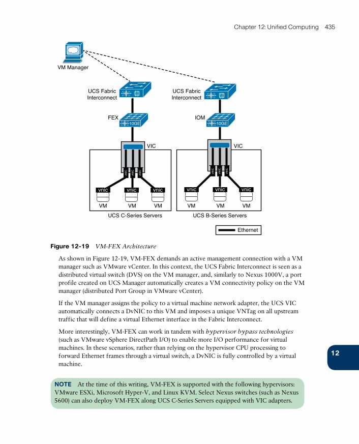
ptg17120290
12
Chapter 12: Unified Computing 435
UCS FabricInterconnect
UCS C-Series Servers UCS B-Series Servers
FEX IOM
UCS FabricInterconnect
10GE
VIC
VM VM VM
vnic vnic
vNIC
vNIC
vNIC
vnic
VM VM VM
VIC
vNIC
vNIC
vNIC
vnic vnic vnic
10GE
Ethernet
VM Manager
Figure 12-19 VM-FEX Architecture
As shown in Figure 12-19, VM-FEX demands an active management connection with a VM manager such as VMware vCenter. In this context, the UCS Fabric Interconnect is seen as a distributed virtual switch (DVS) on the VM manager, and, similarly to Nexus 1000V, a port profile created on UCS Manager automatically creates a VM connectivity policy on the VM manager (distributed Port Group in VMware vCenter).
If the VM manager assigns the policy to a virtual machine network adapter, the UCS VIC automatically connects a DvNIC to this VM and imposes a unique VNTag on all upstream traffic that will define a virtual Ethernet interface in the Fabric Interconnect.
More interestingly, VM-FEX can work in tandem with hypervisor bypass technologies (such as VMware vSphere DirectPath I/O) to enable more I/O performance for virtual machines. In these scenarios, rather than relying on the hypervisor CPU processing to forward Ethernet frames through a virtual switch, a DvNIC is fully controlled by a virtual machine.
NOTE At the time of this writing, VM-FEX is supported with the following hypervisors: VMware ESXi, Microsoft Hyper-V, and Linux KVM. Select Nexus switches (such as Nexus 5600) can also deploy VM-FEX along UCS C-Series Servers equipped with VIC adapters.
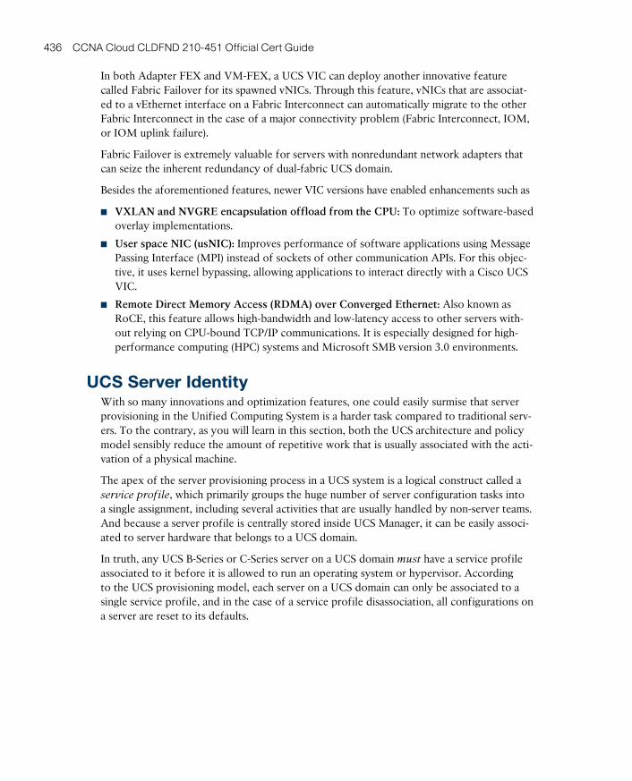
ptg17120290
436 CCNA Cloud CLDFND 210-451 Official Cert Guide
In both Adapter FEX and VM-FEX, a UCS VIC can deploy another innovative feature called Fabric Failover for its spawned vNICs. Through this feature, vNICs that are associat-ed to a vEthernet interface on a Fabric Interconnect can automatically migrate to the other Fabric Interconnect in the case of a major connectivity problem (Fabric Interconnect, IOM, or IOM uplink failure).
Fabric Failover is extremely valuable for servers with nonredundant network adapters that can seize the inherent redundancy of dual-fabric UCS domain.
Besides the aforementioned features, newer VIC versions have enabled enhancements such as
■ VXLAN and NVGRE encapsulation offload from the CPU: To optimize software-based overlay implementations.
■ User space NIC (usNIC): Improves performance of software applications using Message Passing Interface (MPI) instead of sockets of other communication APIs. For this objec-tive, it uses kernel bypassing, allowing applications to interact directly with a Cisco UCS VIC.
■ Remote Direct Memory Access (RDMA) over Converged Ethernet: Also known as RoCE, this feature allows high-bandwidth and low-latency access to other servers with-out relying on CPU-bound TCP/IP communications. It is especially designed for high-performance computing (HPC) systems and Microsoft SMB version 3.0 environments.
UCS Server IdentityWith so many innovations and optimization features, one could easily surmise that server provisioning in the Unified Computing System is a harder task compared to traditional serv-ers. To the contrary, as you will learn in this section, both the UCS architecture and policy model sensibly reduce the amount of repetitive work that is usually associated with the acti-vation of a physical machine.
The apex of the server provisioning process in a UCS system is a logical construct called a service profile, which primarily groups the huge number of server configuration tasks into a single assignment, including several activities that are usually handled by non-server teams. And because a server profile is centrally stored inside UCS Manager, it can be easily associ-ated to server hardware that belongs to a UCS domain.
In truth, any UCS B-Series or C-Series server on a UCS domain must have a service profile associated to it before it is allowed to run an operating system or hypervisor. According to the UCS provisioning model, each server on a UCS domain can only be associated to a single service profile, and in the case of a service profile disassociation, all configurations on a server are reset to its defaults.
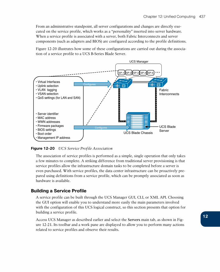
ptg17120290
12
Chapter 12: Unified Computing 437
From an administrative standpoint, all server configurations and changes are directly exe-cuted on the service profile, which works as a “personality” inserted into server hardware. When a service profile is associated with a server, both Fabric Interconnects and server components (such as adapters and BIOS) are configured according to the profile definitions.
Figure 12-20 illustrates how some of these configurations are carried out during the associa-tion of a service profile to a UCS B-Series Blade Server.
UCS BladeServer
UCS Blade Chassis
FabricInterconnects
UCS Blade Chassis
UCS Manager
SP-1 SP-2 SP-3 SP-4 SP-5 ...
• Virtual Interfaces • Uplink selection• VLAN tagging• VSAN selection• QoS settings (for LAN and SAN)
• Server identifier• MAC address• WWN addresses• Firmware packages• BIOS settings• Boot order• Management IP address
Configures
Configures
Figure 12-20 UCS Service Profile Association
The association of service profiles is performed as a simple, single operation that only takes a few minutes to complete. A striking difference from traditional server provisioning is that service profiles allow the infrastructure domain tasks to be completed before a server is even purchased. With service profiles, the data center infrastructure can be proactively pre-pared using definitions from a service profile, which can be promptly associated as soon as hardware is available.
Building a Service ProfileA service profile can be built through the UCS Manager GUI, CLI, or XML API. Choosing the GUI option will enable you to understand more easily the main parameters involved with the configuration of this UCS logical construct, so this section presents that option for building a service profile.
Access UCS Manager as described earlier and select the Servers main tab, as shown in Fig-ure 12-21. Its toolbar and a work pane are displayed to allow you to perform many actions related to service profiles and observe their results.
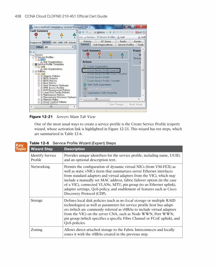
ptg17120290
438 CCNA Cloud CLDFND 210-451 Official Cert Guide
Figure 12-21 Servers Main Tab View
One of the most usual ways to create a service profile is the Create Service Profile (expert) wizard, whose activation link is highlighted in Figure 12-21. This wizard has ten steps, which are summarized in Table 12-6.
Table 12-6 Service Profile Wizard (Expert) Steps
Wizard Step Description
Identify Service Profile
Provides unique identifiers for the service profile, including name, UUID, and an optional description text.
Networking Permits the configuration of dynamic virtual NICs (from VM-FEX) as well as static vNICs (term that summarizes server Ethernet interfaces from standard adapters and virtual adapters from the VIC), which may include a manually set MAC address, fabric failover option (in the case of a VIC), connected VLANs, MTU, pin group (to an Ethernet uplink), adapter settings, QoS policy, and enablement of features such as Cisco Discovery Protocol (CDP).
Storage Defines local disk policies (such as no local storage or multiple RAID technologies) as well as parameters for service profile host bus adapt-ers (which are commonly referred as vHBAs to include virtual adapters from the VIC) on the server CNA, such as Node WWN, Port WWN, pin group (which specifies a specific Fibre Channel or FCoE uplink), and QoS policies.
Zoning Allows direct-attached storage to the Fabric Interconnects and locally zones it with the vHBAs created in the previous step.
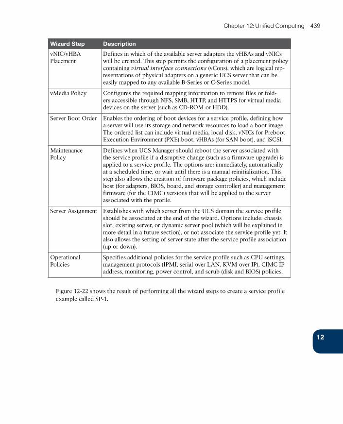
ptg17120290
12
Chapter 12: Unified Computing 439
Wizard Step Description
vNIC/vHBA Placement
Defines in which of the available server adapters the vHBAs and vNICs will be created. This step permits the configuration of a placement policy containing virtual interface connections (vCons), which are logical rep-resentations of physical adapters on a generic UCS server that can be easily mapped to any available B-Series or C-Series model.
vMedia Policy Configures the required mapping information to remote files or fold-ers accessible through NFS, SMB, HTTP, and HTTPS for virtual media devices on the server (such as CD-ROM or HDD).
Server Boot Order Enables the ordering of boot devices for a service profile, defining how a server will use its storage and network resources to load a boot image. The ordered list can include virtual media, local disk, vNICs for Preboot Execution Environment (PXE) boot, vHBAs (for SAN boot), and iSCSI.
Maintenance Policy
Defines when UCS Manager should reboot the server associated with the service profile if a disruptive change (such as a firmware upgrade) is applied to a service profile. The options are: immediately, automatically at a scheduled time, or wait until there is a manual reinitialization. This step also allows the creation of firmware package policies, which include host (for adapters, BIOS, board, and storage controller) and management firmware (for the CIMC) versions that will be applied to the server associated with the profile.
Server Assignment Establishes with which server from the UCS domain the service profile should be associated at the end of the wizard. Options include: chassis slot, existing server, or dynamic server pool (which will be explained in more detail in a future section), or not associate the service profile yet. It also allows the setting of server state after the service profile association (up or down).
Operational Policies
Specifies additional policies for the service profile such as CPU settings, management protocols (IPMI, serial over LAN, KVM over IP), CIMC IP address, monitoring, power control, and scrub (disk and BIOS) policies.
Figure 12-22 shows the result of performing all the wizard steps to create a service profile example called SP-1.
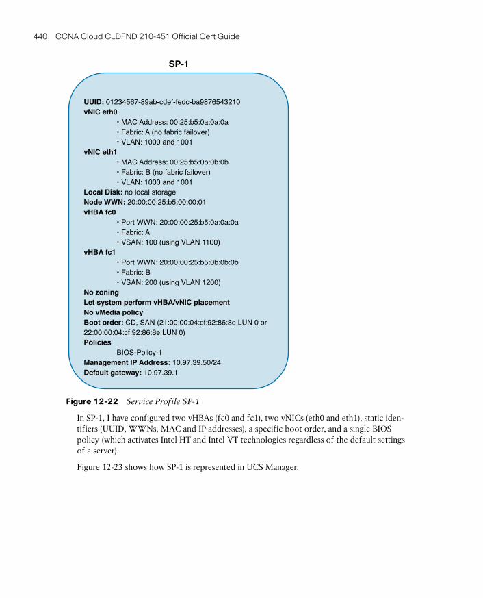
ptg17120290
440 CCNA Cloud CLDFND 210-451 Official Cert Guide
UUID: 01234567-89ab-cdef-fedc-ba9876543210vNIC eth0 • MAC Address: 00:25:b5:0a:0a:0a • Fabric: A (no fabric failover) • VLAN: 1000 and 1001vNIC eth1 • MAC Address: 00:25:b5:0b:0b:0b • Fabric: B (no fabric failover) • VLAN: 1000 and 1001Local Disk: no local storageNode WWN: 20:00:00:25:b5:00:00:01vHBA fc0 • Port WWN: 20:00:00:25:b5:0a:0a:0a • Fabric: A • VSAN: 100 (using VLAN 1100)vHBA fc1 • Port WWN: 20:00:00:25:b5:0b:0b:0b • Fabric: B • VSAN: 200 (using VLAN 1200)No zoningLet system perform vHBA/vNIC placementNo vMedia policyBoot order: CD, SAN (21:00:00:04:cf:92:86:8e LUN 0 or22:00:00:04:cf:92:86:8e LUN 0)Policies BIOS-Policy-1Management IP Address: 10.97.39.50/24Default gateway: 10.97.39.1
SP-1
Figure 12-22 Service Profile SP-1
In SP-1, I have configured two vHBAs (fc0 and fc1), two vNICs (eth0 and eth1), static iden-tifiers (UUID, WWNs, MAC and IP addresses), a specific boot order, and a single BIOS policy (which activates Intel HT and Intel VT technologies regardless of the default settings of a server).
Figure 12-23 shows how SP-1 is represented in UCS Manager.
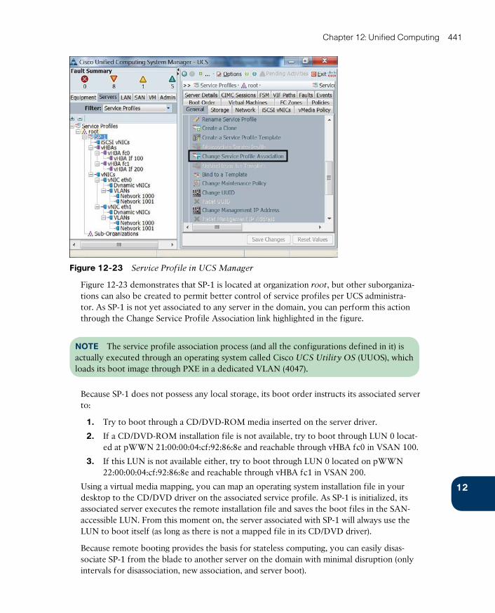
ptg17120290
12
Chapter 12: Unified Computing 441
Figure 12-23 Service Profile in UCS Manager
Figure 12-23 demonstrates that SP-1 is located at organization root, but other suborganiza-tions can also be created to permit better control of service profiles per UCS administra-tor. As SP-1 is not yet associated to any server in the domain, you can perform this action through the Change Service Profile Association link highlighted in the figure.
NOTE The service profile association process (and all the configurations defined in it) is actually executed through an operating system called Cisco UCS Utility OS (UUOS) , which loads its boot image through PXE in a dedicated VLAN (4047).
Because SP-1 does not possess any local storage, its boot order instructs its associated server to:
1. Try to boot through a CD/DVD-ROM media inserted on the server driver.
2. If a CD/DVD-ROM installation file is not available, try to boot through LUN 0 locat-ed at pWWN 21:00:00:04:cf:92:86:8e and reachable through vHBA fc0 in VSAN 100.
3. If this LUN is not available either, try to boot through LUN 0 located on pWWN 22:00:00:04:cf:92:86:8e and reachable through vHBA fc1 in VSAN 200.
Using a virtual media mapping, you can map an operating system installation file in your desktop to the CD/DVD driver on the associated service profile. As SP-1 is initialized, its associated server executes the remote installation file and saves the boot files in the SAN-accessible LUN. From this moment on, the server associated with SP-1 will always use the LUN to boot itself (as long as there is not a mapped file in its CD/DVD driver).
Because remote booting provides the basis for stateless computing, you can easily disas-sociate SP-1 from the blade to another server on the domain with minimal disruption (only intervals for disassociation, new association, and server boot).
ptg17120290
442 CCNA Cloud CLDFND 210-451 Official Cert Guide
Multiple use cases can be applied for stateless computing on UCS, including server realloca-tion after major hardware failures or hardware resource exhaustion.
PoliciesCisco UCS leverages policies to reinforce standardization and avoid the mind-numbing rep-etition of tasks that is usually associated with traditional server provisioning. In a nutshell, a UCS policy defines how UCS components behave in specific situations. In the context of service profiles, UCS policies enclose a set of configurations that can be shared among mul-tiple profiles.
In SP-1, I have configured a single policy, BIOS-Policy-1, that essentially enforces the acti-vation of features from Intel processors that optimize virtualization hosts (Intel HT and VT). Because BIOS-Policy-1 is a reusable policy, it can greatly simplify the creation of new service profiles. As an example, other Create Service Profile (expert) wizard interactions can easily refer to the aforementioned policies to define service profiles with the same proces-sor settings.
Understandably, the complete list of UCS policies is more than enough to fill an entire pub-lication and thus is beyond the scope of this writing. To give you a sampling, allow me to present select UCS policies that can be useful to streamline and standardize the creation of service profiles:
■ Adapter policy: Regulates how an adapter handles traffic and acts in a host. It may include queue configuration parameters, performance enhancements, and failover behav-ior (in the case of vNICs generated on VICs).
■ BIOS policy: As previously commented, a BIOS policy automates the configuration of BIOS settings for a server or group of servers. It includes general settings (such as reboot on BIOS settings change and quiet boot), processor configurations (such as the afore-mentioned Intel HT and VT), Intel Directed IO, RAS memory, serial port, USB, PCI con-figuration, additional boot options, and other server management details.
■ Boot policy: Defines the boot order for a server or group of servers. It may include local boot devices (such as a local disk or CD-ROM) or remote boot devices (including SAN or LAN via PXE).
■ Local disk configuration policy: Configures local hard disk drives on a server through its storage controller. It can assign the following modes to local disks: no local stor-age, RAID 0 Striped, RAID 1 Mirrored, any configuration (does not change the current configuration on the server local disk), no RAID, RAID 5 Striped Parity, RAID 6 Striped Dual Parity, RAID 10 Mirrored and Striped, among others.
■ Power control policy: Establishes priorities for blade servers in a UCS domain. If all blades are active and reach a predefined power cap, service profiles with higher priority will take precedence over service profiles with lower priority.
■ Scrub policy: Determines what happens to local data and to the BIOS settings on a server when it is disassociated from this service profile. In summary, if Disk Scrub is enabled, all data on any local drives is destroyed (otherwise it is preserved). On the other hand, if BIOS Scrub is enabled, it erases all BIOS settings for the server and resets them to the BIOS defaults for that server type and vendor.

ptg17120290
12
Chapter 12: Unified Computing 443
■ Serial over LAN policy: Controls how the input and output of a UCS serial port can be redirected to an SSH session. It includes Serial over LAN state enablement and speed in bauds.
Besides facilitating server provisioning, UCS policies also enable the efficient management of servers that are already activated. Because policies are “live” objects on a UCS domain, a change on any of them may be automatically replicated to all service profiles that are using such a policy (depending on their configured maintenance policy).
CloningService profile cloning severely decreases the number of tasks to create service profiles. In UCS Manager, after selecting a service profile, the Create a Clone link (also shown in Figure 12-22) will only request a profile name before creating an approximated copy of this service profile.
Generally, a service profile clone usually requires additional changes before it can be associ-ated to a UCS blade or rack-mount server. To fully understand this statement, please review Figure 12-24, which compares the configurations of SP-1 and its clone, SP-1-Clone.
UUID: 01234567-89ab-cdef-fedc-ba9876543210vNIC eth0 • MAC Address: 00:25:b5:0a:0a:0a • Fabric: A (no fabric failover) • VLAN: 1000 and 1001vNIC eth1 • MAC Address: 00:25:b5:0b:0b:0b • Fabric: B (no fabric failover) • VLAN: 1000 and 1001Local Disk: no local storageNode WWN: 20:00:00:25:b5:00:00:01vHBA fc0 • Port WWN: 20:00:00:25:b5:0a:0a:0a • Fabric: A • VSAN: 100 (using VLAN 1100)vHBA fc1 • Port WWN: 20:00:00:25:b5:0b:0b:0b • Fabric: B • VSAN: 200 (using VLAN 1200)No zoningLet system perform vHBA/vNIC placementNo vMedia policyBoot order: CD, SAN (21:00:00:04:cf:92:86:8e LUN 0 or22:00:00:04:cf:92:86:8e LUN 0)Policies BIOS-Policy-1Management IP Address: 10.97.39.50/24Default gateway: 10.97.39.1
SP-1
UUID: (hardware default)vNIC eth0 • MAC Address: (hardware default) • Fabric: A (no fabric failover) • VLAN: 1000 and 1001vNIC eth1 • MAC Address: (hardware default) • Fabric: B (no fabric failover) • VLAN: 1000 and 1001Local Disk: no local storageNode WWN: (pool derived)vHBA fc0 • Port WWN: (hardware default) • Fabric: A • VSAN: 100 (using VLAN 1100)vHBA fc1 • Port WWN: (hardware default) • Fabric: B • VSAN: 200 (using VLAN 1200)No zoningLet system perform vHBA/vNIC placementNo vMedia policyBoot order: CD, SAN (21:00:00:04:cf:92:86:8e LUN 0 or22:00:00:04:cf:92:86:8e LUN 0)Policies BIOS-Policy-1Management IP Address: (pool derived)Default gateway: (pool derived)
SP-1-Clone
Cloning
Figure 12-24 Cloning a Service Profile
In Figure 12-24, observe that whereas the cloning procedure reuses all configurations and policies from its parent service profile, it obviously cannot replicate SP-1’s unique identi-fiers (UUID, WWNs, MACs, and management IP address). As a consequence, UCS Manager derives most identifiers for service profile clones from the server hardware.
When such action is not possible, UCS Manager picks the identifiers from default pools, the subject of the next section.
ptg17120290
444 CCNA Cloud CLDFND 210-451 Official Cert Guide
PoolsThe allocation of unique identifiers to assorted service profiles can be automated through the use of pools. In general, UCS identity pools are defined as collections of physical or logical identities that can be assigned to UCS domain resources.
As a clarification of this concept in UCS, I have created the following pools (with 31 identi-fiers each):
■ UUID-Pool: UUIDs from 01234567-89AB-CDEF-0000-000000000001 to 01234567-89AB-CDEF-0000-00000000001F
■ MAC-Pool-A: MAC addresses from 0025.b500.0a01 to 0025.b500.0a1f
■ MAC-Pool-B: MAC addresses from 0025.b500.0b01 to 0025.b500.0b1f
■ nWWN-Pool: Node WWNs from 20:00:00:25:b5:00:01:01 to 20:00:00:25:b5:00:01:1f
■ pWWN-Pool-A: Port WWNs from 20:00:00:25:b5:00:0a:01 to 20:00:00:25:b5:00:0a:1f
■ pWWN-Pool-B: Port WWNs from 20:00:00:25:b5:00:0b:01 to 20:00:00:25:b5:00:0b:1f
■ Management IP Pool: IP addresses from 10.97.39.81 to 10.97.39.122 (with mask 255.255.255.0 and default gateway 10.97.39.1)
The configuration of pools is distributed across the UCS Manager GUI main tabs. Thus, I created the aforementioned pools on the Servers (UUID-Pool), SAN (nWWN-Pool, pWWN-Pool-A, and pWWN-Pool-B), and LAN (MAC-Pool-A, MAC-Pool-B, and Manage-ment IP Pool) main tabs.
When a UCS administrator applies these logical constructs to a service profile instead of manually assigning identifiers, UCS Manager automatically chooses one of the avail-able addresses for this profile, relieving the administrator from the menial tasks related to address management.
When all of these pools are referred in SP-1-Clone, this service profile will use the values shown in Figure 12-25.
TIP By default, UCS Manager uses descending order to distribute the elements of a pool.
Pools are not restricted to identifiers in a UCS domain. A server pool can be defined as a dynamic selection of servers from a UCS domain that share common characteristics (such as minimum memory size or local storage characteristics) or are manually grouped together. Using server pools, UCS Manager can automatically associate a service profile to a server that meets predefined specifications using a server pool policy qualification.
Besides memory type and storage configuration, these policies can qualify servers according to their adapter type, chassis location, CPU characteristics (cores, type, and configuration), and server model.
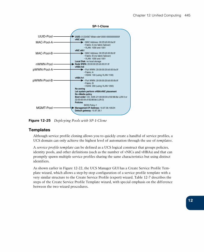
ptg17120290
12
Chapter 12: Unified Computing 445
UUID: 01234567-89ab-cdef-0000-00000000000fvNIC eth0 • MAC Address: 00:25:b5:00:0a:0f • Fabric: A (no fabric failover) • VLAN: 1000 and 1001vNIC eth1 • MAC Address: 00:25:b5:00:0b:0f • Fabric: B (no fabric failover) • VLAN: 1000 and 1001Local Disk: no local storageNode WWN: 20:00:00:25:b5:00:01:0fvHBA fc0 • Port WWN: 20:00:00:25:b5:00:0a:0f • Fabric: A • VSAN: 100 (using VLAN 1100)vHBA fc1 • Port WWN: 20:00:00:25:b5:00:0b:0f • Fabric: B • VSAN: 200 (using VLAN 1200)No zoningLet system perform vHBA/vNIC placementNo vMedia policyBoot order: CD, SAN (21:00:00:04:cf:92:86:8e LUN 0 or22:00:00:04:cf:92:86:8e LUN 0)Policies BIOS-Policy-1Management IP Address: 10.97.39.105/24Default gateway: 10.97.39.1
SP-1-Clone
UUID-Pool
MAC-Pool-A
MAC-Pool-B
nWWN-Pool
pWWN-Pool-A
pWWN-Pool-B
MGMT-Pool
Figure 12-25 Deploying Pools with SP-1-Clone
TemplatesAlthough service profile cloning allows you to quickly create a handful of service profiles, a UCS domain can only achieve the highest level of automation through the use of templates.
A service profile template can be defined as a UCS logical construct that groups policies, identity pools, and other definitions (such as the number of vNICs and vHBAs) and that can promptly spawn multiple service profiles sharing the same characteristics but using distinct identifiers.
As shown earlier in Figure 12-22, the UCS Manager GUI has a Create Service Profile Tem-plate wizard, which allows a step-by-step configuration of a service profile template with a very similar structure to the Create Service Profile (expert) wizard. Table 12-7 describes the steps of the Create Service Profile Template wizard, with special emphasis on the difference between the two wizard procedures.
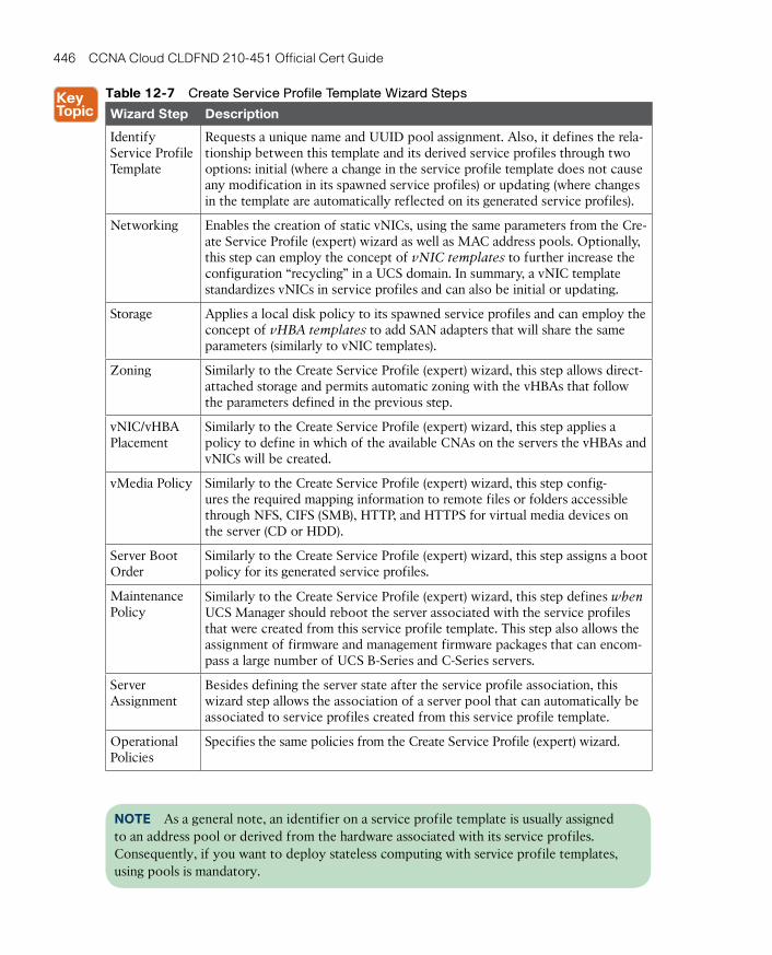
ptg17120290
446 CCNA Cloud CLDFND 210-451 Official Cert Guide
Table 12-7 Create Service Profile Template Wizard Steps
Wizard Step Description
Identify Service Profile Template
Requests a unique name and UUID pool assignment. Also, it defines the rela-tionship between this template and its derived service profiles through two options: initial (where a change in the service profile template does not cause any modification in its spawned service profiles) or updating (where changes in the template are automatically reflected on its generated service profiles).
Networking Enables the creation of static vNICs, using the same parameters from the Cre-ate Service Profile (expert) wizard as well as MAC address pools. Optionally, this step can employ the concept of vNIC templates to further increase the configuration “recycling” in a UCS domain. In summary, a vNIC template standardizes vNICs in service profiles and can also be initial or updating.
Storage Applies a local disk policy to its spawned service profiles and can employ the concept of vHBA templates to add SAN adapters that will share the same parameters (similarly to vNIC templates).
Zoning Similarly to the Create Service Profile (expert) wizard, this step allows direct-attached storage and permits automatic zoning with the vHBAs that follow the parameters defined in the previous step.
vNIC/vHBA Placement
Similarly to the Create Service Profile (expert) wizard, this step applies a policy to define in which of the available CNAs on the servers the vHBAs and vNICs will be created.
vMedia Policy Similarly to the Create Service Profile (expert) wizard, this step config-ures the required mapping information to remote files or folders accessible through NFS, CIFS (SMB), HTTP, and HTTPS for virtual media devices on the server (CD or HDD).
Server Boot Order
Similarly to the Create Service Profile (expert) wizard, this step assigns a boot policy for its generated service profiles.
Maintenance Policy
Similarly to the Create Service Profile (expert) wizard, this step defines when UCS Manager should reboot the server associated with the service profiles that were created from this service profile template. This step also allows the assignment of firmware and management firmware packages that can encom-pass a large number of UCS B-Series and C-Series servers.
Server Assignment
Besides defining the server state after the service profile association, this wizard step allows the association of a server pool that can automatically be associated to service profiles created from this service profile template.
Operational Policies
Specifies the same policies from the Create Service Profile (expert) wizard.
NOTE As a general note, an identifier on a service profile template is usually assigned to an address pool or derived from the hardware associated with its service profiles. Consequently, if you want to deploy stateless computing with service profile templates, using pools is mandatory.
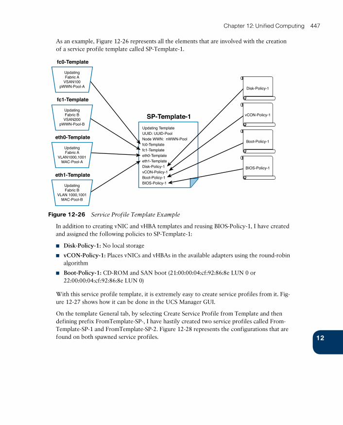
ptg17120290
12
Chapter 12: Unified Computing 447
As an example, Figure 12-26 represents all the elements that are involved with the creation of a service profile template called SP-Template-1.
SP-Template-1
Updating TemplateUUID: UUID-PoolNode WWN: nWWN-Poolfc0-Templatefc1-Templateeth0-Templateeth1-TemplateDisk-Policy-1vCON-Policy-1Boot-Policy-1BIOS-Policy-1
Disk-Policy-1
vCON-Policy-1
Boot-Policy-1
BIOS-Policy-1
UpdatingFabric A
VSAN100pWWN-Pool-A
fc0-Template
UpdatingFabric B
VSAN200pWWN-Pool-B
fc1-Template
UpdatingFabric A
VLAN1000,1001MAC-Pool-A
eth0-Template
UpdatingFabric B
VLAN 1000,1001MAC-Pool-B
eth1-Template
Figure 12-26 Service Profile Template Example
In addition to creating vNIC and vHBA templates and reusing BIOS-Policy-1, I have created and assigned the following policies to SP-Template-1:
■ Disk-Policy-1: No local storage
■ vCON-Policy-1: Places vNICs and vHBAs in the available adapters using the round-robin algorithm
■ Boot-Policy-1: CD-ROM and SAN boot (21:00:00:04:cf:92:86:8e LUN 0 or 22:00:00:04:cf:92:86:8e LUN 0)
With this service profile template, it is extremely easy to create service profiles from it. Fig-ure 12-27 shows how it can be done in the UCS Manager GUI.
On the template General tab, by selecting Create Service Profile from Template and then defining prefix FromTemplate-SP-, I have hastily created two service profiles called From-Template-SP-1 and FromTemplate-SP-2. Figure 12-28 represents the configurations that are found on both spawned service profiles.

ptg17120290
448 CCNA Cloud CLDFND 210-451 Official Cert Guide
Figure 12-27 SP-Template-1 in UCS Manager
UUID: 01234567-89ab-cdef-0000-00000000001fvNIC eth0 • MAC Address: 00:25:b5:00:0a:1f • Fabric: A (no fabric failover) • VLAN: 1000 and 1001vNIC eth1 • MAC Address: 00:25:b5:00:0b:1f • Fabric: B (no fabric failover) • VLAN: 1000 and 1001Local Disk: no local storageNode WWN: 20:00:00:25:b5:00:01:1fvHBA fc0 • Port WWN: 20:00:00:25:b5:00:0a:1f • Fabric: A • VSAN: 100 (using VLAN 1100)vHBA fc1 • Port WWN: 20:00:00:25:b5:00:0b:1f • Fabric: B • VSAN: 200 (using VLAN 1200)No zoningLet system perform vHBA/vNIC placementNo vMedia policyBoot order: CD, SAN (21:00:00:04:cf:92:86:8e LUN 0 or21:00:00:04:cf:92:86:8e LUN 0)Policies Disk-Policy-1, vCon-Policy-1, Boot-Policy-1, BIOS-Policy-1Management IP Address: 10.97.39.104/24Default gateway: 10.97.39.1
FromTemplate-SP-1
UUID: 01234567-89ab-cdef-0000-00000000000evNIC eth0 • MAC Address: 00:25:b5:00:0a:0e • Fabric: A (no fabric failover) • VLAN: 1000 and 1001vNIC eth1 • MAC Address: 00:25:b5:00:0b:0e • Fabric: B (no fabric failover) • VLAN: 1000 and 1001Local Disk: no local storageNode WWN: 20:00:00:25:b5:00:01:0evHBA fc0 • Port WWN: 20:00:00:25:b5:00:0a:0e • Fabric: A • VSAN: 100 (using VLAN 1100)vHBA fc1 • Port WWN: 20:00:00:25:b5:00:0b:0e • Fabric: B • VSAN: 200 (using VLAN 1200)No zoningLet system perform vHBA/vNIC placementNo vMedia policyBoot order: CD, SAN (21:00:00:04:cf:92:86:8e LUN 0 or21:00:00:04:cf:92:86:8e LUN 0)Policies Disk-Policy-1, vCon-Policy-1, Boot-Policy-1, BIOS-Policy-1Management IP Address: 10.97.39.104/24Default gateway: 10.97.39.1
FromTemplate-SP-2
SP-Template-1
Figure 12-28 Service Profiles Created from a Service Profile Template
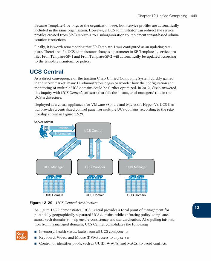
ptg17120290
12
Chapter 12: Unified Computing 449
Because Template-1 belongs to the organization root, both service profiles are automatically included in the same organization. However, a UCS administrator can redirect the service profiles created from SP-Template-1 to a suborganization to implement tenant-based admin-istration restrictions.
Finally, it is worth remembering that SP-Template-1 was configured as an updating tem-plate. Therefore, if a UCS administrator changes a parameter in SP-Template-1, service pro-files FromTemplate-SP-1 and FromTemplate-SP-2 will automatically be updated according to the template maintenance policy.
UCS CentralAs a direct consequence of the traction Cisco Unified Computing System quickly gained in the server market, many IT administrators began to wonder how the configuration and monitoring of multiple UCS domains could be further optimized. In 2012, Cisco answered this inquiry with UCS Central, software that fills the “manager of managers” role in the UCS architecture.
Deployed as a virtual appliance (for VMware vSphere and Microsoft Hyper-V), UCS Cen-tral provides a centralized control panel for multiple UCS domains, according to the rela-tionship shown in Figure 12-29.
UCS Manager
Policies
Server Admin
UCS Domain UCS Domain UCS Domain
Policies
Policies
Informatio
n
InformationPolicies
Information
Information
UCS Central
UCS ManagerUCS Manager
Figure 12-29 UCS Central Architecture
As Figure 12-29 demonstrates, UCS Central provides a focal point of management for potentially geographically separated UCS domains, while enforcing policy compliance across such domains to help ensure consistency and standardization. Also pulling informa-tion from its managed domains, UCS Central consolidates the following:
■ Inventory, health status, faults from all UCS components
■ Keyboard, Video, and Mouse (KVM) access to any server
■ Control of identifier pools, such as UUID, WWNs, and MACs, to avoid conflicts
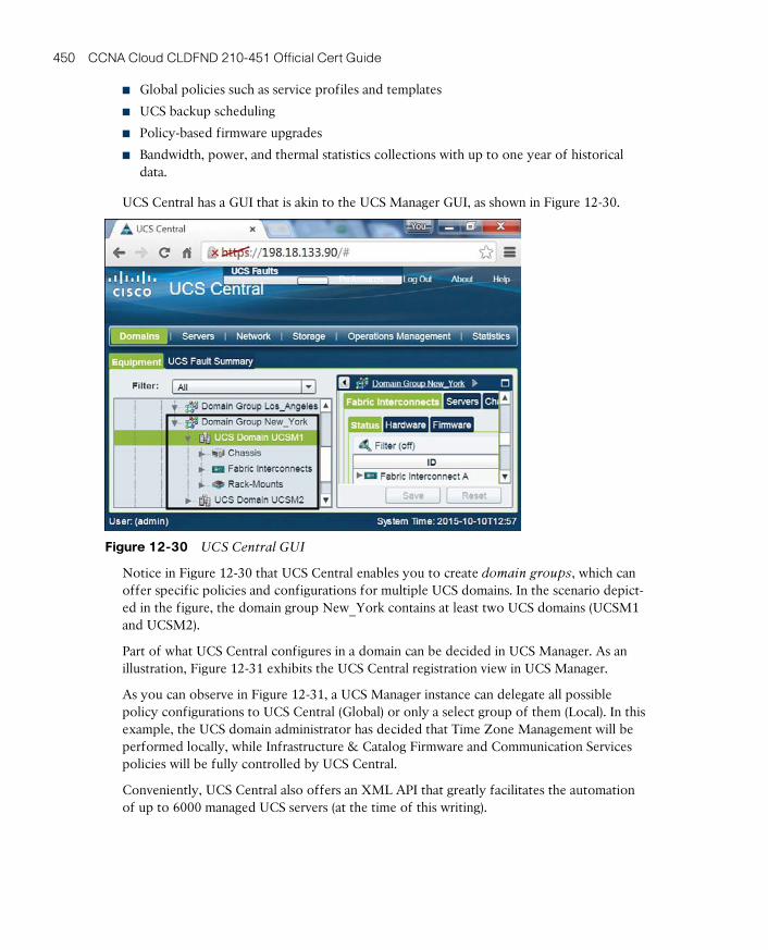
ptg17120290
450 CCNA Cloud CLDFND 210-451 Official Cert Guide
■ Global policies such as service profiles and templates
■ UCS backup scheduling
■ Policy-based firmware upgrades
■ Bandwidth, power, and thermal statistics collections with up to one year of historical data.
UCS Central has a GUI that is akin to the UCS Manager GUI, as shown in Figure 12-30.
Figure 12-30 UCS Central GUI
Notice in Figure 12-30 that UCS Central enables you to create domain groups , which can offer specific policies and configurations for multiple UCS domains. In the scenario depict-ed in the figure, the domain group New_York contains at least two UCS domains (UCSM1 and UCSM2).
Part of what UCS Central configures in a domain can be decided in UCS Manager. As an illustration, Figure 12-31 exhibits the UCS Central registration view in UCS Manager.
As you can observe in Figure 12-31, a UCS Manager instance can delegate all possible policy configurations to UCS Central (Global) or only a select group of them (Local). In this example, the UCS domain administrator has decided that Time Zone Management will be performed locally, while Infrastructure & Catalog Firmware and Communication Services
policies will be fully controlled by UCS Central.
Conveniently, UCS Central also offers an XML API that greatly facilitates the automation of up to 6000 managed UCS servers (at the time of this writing).
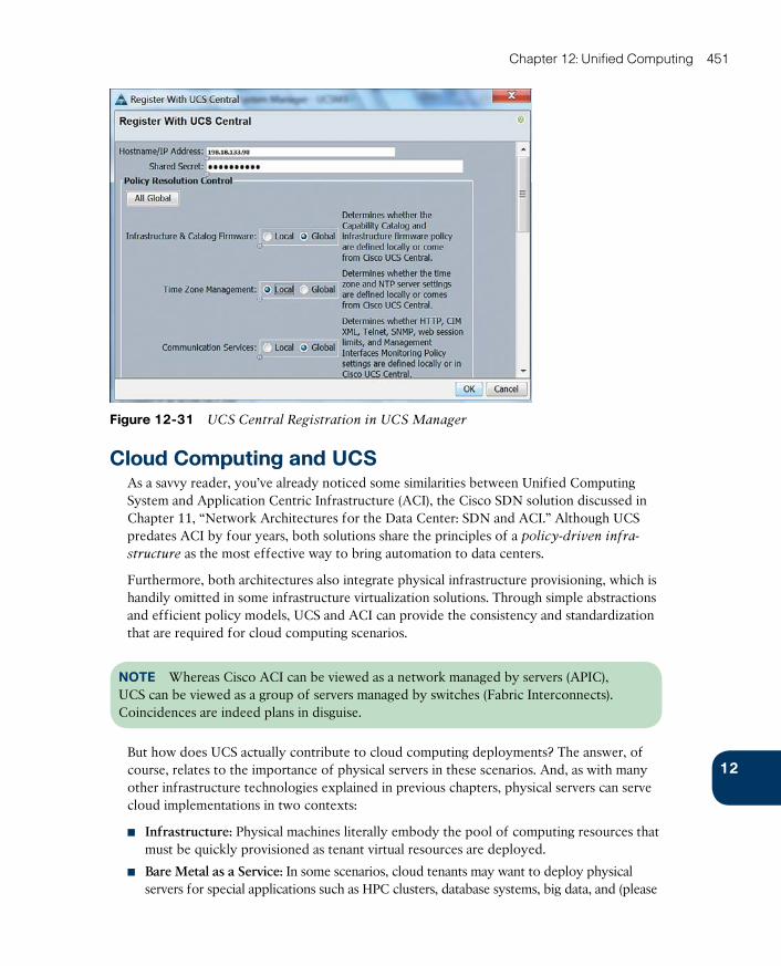
ptg17120290
12
Chapter 12: Unified Computing 451
Figure 12-31 UCS Central Registration in UCS Manager
Cloud Computing and UCSAs a savvy reader, you’ve already noticed some similarities between Unified Computing System and Application Centric Infrastructure (ACI), the Cisco SDN solution discussed in Chapter 11, “Network Architectures for the Data Center: SDN and ACI.” Although UCS predates ACI by four years, both solutions share the principles of a policy-driven infra-
structure as the most effective way to bring automation to data centers.
Furthermore, both architectures also integrate physical infrastructure provisioning, which is handily omitted in some infrastructure virtualization solutions. Through simple abstractions and efficient policy models, UCS and ACI can provide the consistency and standardization that are required for cloud computing scenarios.
NOTE Whereas Cisco ACI can be viewed as a network managed by servers (APIC), UCS can be viewed as a group of servers managed by switches (Fabric Interconnects). Coincidences are indeed plans in disguise.
But how does UCS actually contribute to cloud computing deployments? The answer, of course, relates to the importance of physical servers in these scenarios. And, as with many other infrastructure technologies explained in previous chapters, physical servers can serve cloud implementations in two contexts:
■ Infrastructure: Physical machines literally embody the pool of computing resources that must be quickly provisioned as tenant virtual resources are deployed.
■ Bare Metal as a Service: In some scenarios, cloud tenants may want to deploy physical servers for special applications such as HPC clusters, database systems, big data, and (please
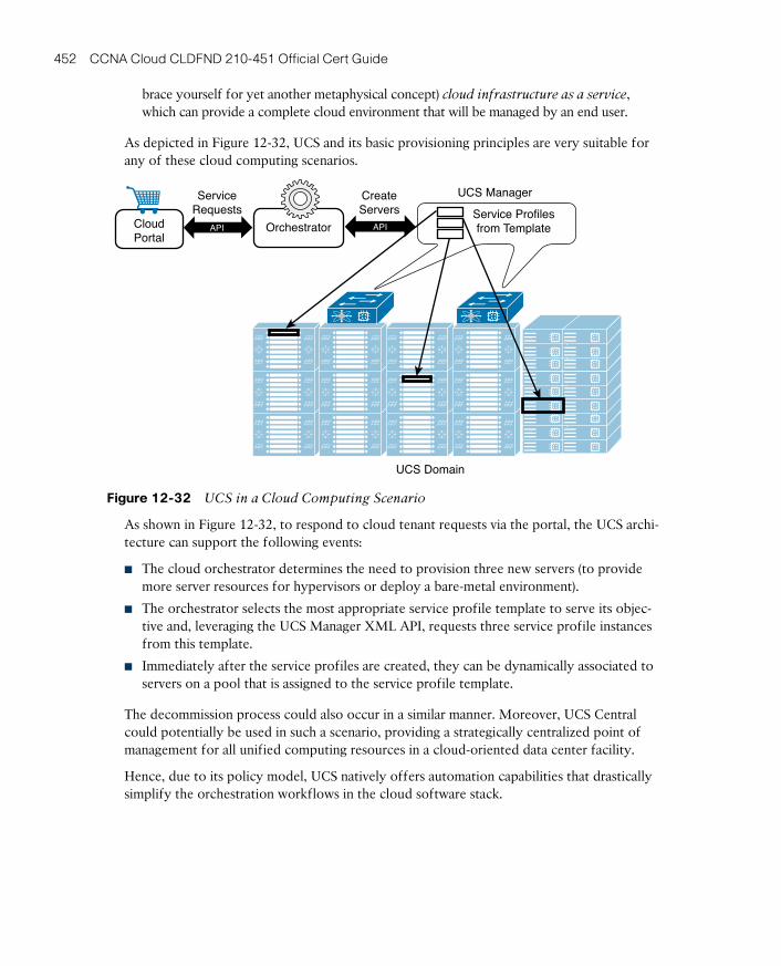
ptg17120290
452 CCNA Cloud CLDFND 210-451 Official Cert Guide
brace yourself for yet another metaphysical concept) cloud infrastructure as a service, which can provide a complete cloud environment that will be managed by an end user.
As depicted in Figure 12-32, UCS and its basic provisioning principles are very suitable for any of these cloud computing scenarios.
CloudPortal
Orchestrator
UCS Manager
UCS Domain
Service Profilesfrom Template
CreateServers
ServiceRequests
APIAPI
Figure 12-32 UCS in a Cloud Computing Scenario
As shown in Figure 12-32, to respond to cloud tenant requests via the portal, the UCS archi-tecture can support the following events:
■ The cloud orchestrator determines the need to provision three new servers (to provide more server resources for hypervisors or deploy a bare-metal environment).
■ The orchestrator selects the most appropriate service profile template to serve its objec-tive and, leveraging the UCS Manager XML API, requests three service profile instances from this template.
■ Immediately after the service profiles are created, they can be dynamically associated to servers on a pool that is assigned to the service profile template.
The decommission process could also occur in a similar manner. Moreover, UCS Central could potentially be used in such a scenario, providing a strategically centralized point of management for all unified computing resources in a cloud-oriented data center facility.
Hence, due to its policy model, UCS natively offers automation capabilities that drastically simplify the orchestration workflows in the cloud software stack.
ptg17120290
12
Chapter 12: Unified Computing 453
Around the Corner: OpenStack IronicThe OpenStack Ironic project intends to provision physical hardware as opposed to virtual machines. With its goal of replacing all bare-metal drivers that were originally developed for the Nova project, Ironic can be understood as a physical machine manager on OpenStack implementations.
Named Ironic as a double-meaning pun (iron as a metal and the irony that OpenStack was very focused on virtual machines), the project uses open protocols such as PXE, Dynamic Host Configuration Protocol (DHCP), Network Bootstrap Program (NBP), Trivial FTP (TFTP), and IPMI to control hardware resources. However, it also supports the development of vendor-specific drivers to incorporate specific features from server architectures such as Cisco UCS.
Because Cisco has been extremely participative in the integration of its products to the OpenStack project, UCS already offers the following integrations for Ironic deployments:
■ Ironic can boot a Glance image onto a UCS Manager-managed bare-metal server through PXE.
■ An OpenStack cloud can power on and off a server within a UCS domain without relying on IPMI.
■ The capability to report hardware statistics to Ceilometer, which is the OpenStack mod-ule responsible for metering and monitoring.
Just like Nova, Ironic must interact with various OpenStack services such as Glance, Neu-tron, Cinder, and others to access the resources required to automatically provision a bare-metal machine instance.
Further Reading■ OpenStack Ironic: https://wiki.openstack.org/wiki/Ironic
■ OpenStack Ironic integration with Cisco UCS B/C-Series servers: https://github.com/CiscoUcs/Ironic-UCS
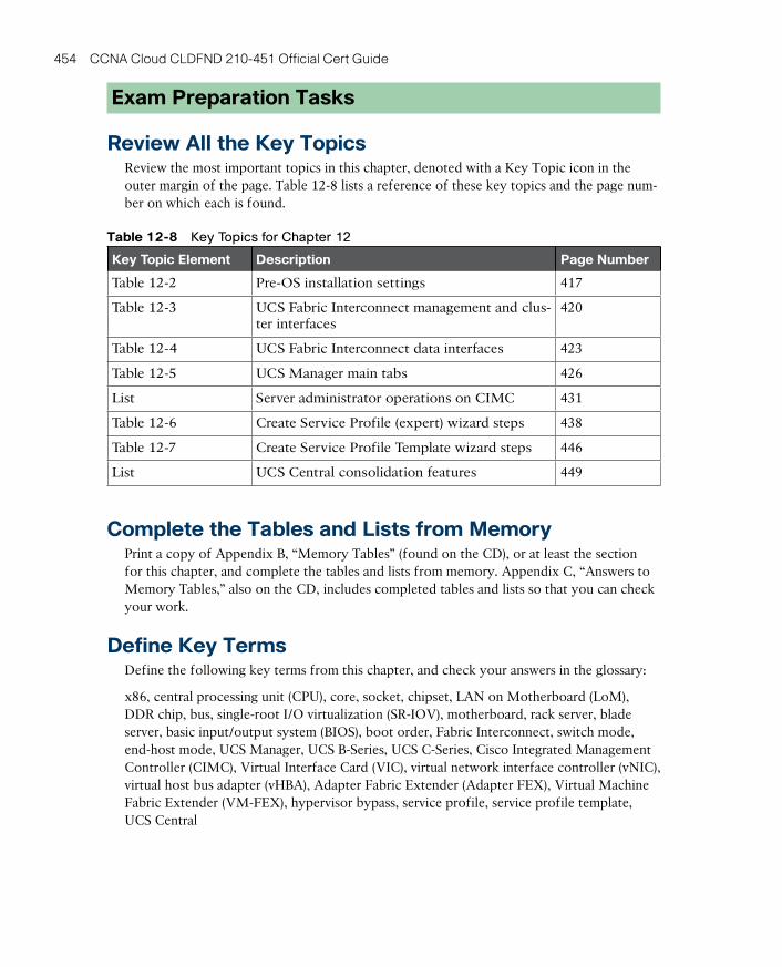
ptg17120290
454 CCNA Cloud CLDFND 210-451 Official Cert Guide
Exam Preparation Tasks
Review All the Key TopicsReview the most important topics in this chapter, denoted with a Key Topic icon in the outer margin of the page. Table 12-8 lists a reference of these key topics and the page num-ber on which each is found.
Table 12-8 Key Topics for Chapter 12
Key Topic Element Description Page Number
Table 12-2 Pre-OS installation settings 417
Table 12-3 UCS Fabric Interconnect management and clus-ter interfaces
420
Table 12-4 UCS Fabric Interconnect data interfaces 423
Table 12-5 UCS Manager main tabs 426
List Server administrator operations on CIMC 431
Table 12-6 Create Service Profile (expert) wizard steps 438
Table 12-7 Create Service Profile Template wizard steps 446
List UCS Central consolidation features 449
Complete the Tables and Lists from MemoryPrint a copy of Appendix B, “Memory Tables” (found on the CD), or at least the section for this chapter, and complete the tables and lists from memory. Appendix C, “Answers to Memory Tables,” also on the CD, includes completed tables and lists so that you can check your work.
Define Key TermsDefine the following key terms from this chapter, and check your answers in the glossary:
x86, central processing unit (CPU), core, socket, chipset, LAN on Motherboard (LoM), DDR chip, bus, single-root I/O virtualization (SR-IOV), motherboard, rack server, blade server, basic input/output system (BIOS), boot order, Fabric Interconnect, switch mode, end-host mode, UCS Manager, UCS B-Series, UCS C-Series, Cisco Integrated Management Controller (CIMC), Virtual Interface Card (VIC), virtual network interface controller (vNIC), virtual host bus adapter (vHBA), Adapter Fabric Extender (Adapter FEX), Virtual Machine Fabric Extender (VM-FEX), hypervisor bypass, service profile, service profile template, UCS Central

ptg17120290
ptg17120290
This chapter covers the following topics:
■ Cisco MDS 9000 Series Multilayer Directors and Fabric Switches
■ Cisco Nexus Data Center Switches
■ Cisco Prime Data Center Network Manager
■ Cisco Unified Computing System
■ Cisco Virtual Networking Services
This chapter covers the following exam objectives:
■ 3.1 Identify key features of Cisco UCS■ 3.1.c B-Series■ 3.1.d C-Series
■ 4.1 Describe network architectures for the data center■ 4.1.a Cisco Unifi ed Fabric
■ 4.1.a.1 Describe the Cisco Nexus product family
■ 4.2 Describe Infrastructure Virtualization■ 4.2.b Cisco Nexus 1000V components
■ 4.2.b.1 VSM■ 4.2.b.2 VEM■ 4.2.b.3 VSM appliance
■ 5.5 Describe the various Cisco storage network devices
■ 5.5.a Cisco MDS family■ 5.5.b Cisco Nexus family■ 5.5.c UCS Invicta

ptg17120290
CHAPTER 13
Cisco Cloud Infrastructure PortfolioAccording to the Synergy Research Group¹, Cisco is one of the world leading companies in cloud infrastructure equipment at the time of this writing. Such accomplishment epitomizes the great commitment the company has demonstrated with its customers in their journey to cloud computing.
The Cisco cloud infrastructure portfolio encompasses an impressive number of flexible solu-tions that can be easily orchestrated and integrated into a wide variety of cloud architectures. The purpose of this chapter is to provide a brief description of each solution from this portfo-lio, including format options, scalability numbers, and performance metrics when available.
Because Cisco designs its cloud infrastructure solutions with the future in mind, this portfo-lio has changed throughout the years. For this reason, this chapter offers a snapshot of its products at the time of this writing. In fact, you can really imagine it as a “family portrait,” which is a little bit different depending on the year it is taken.
The primary objective of this chapter is to provide you valuable information about these solutions that the previous chapters did not directly address but that you are required to know for the CLDFND exam.
For more details about each solution from this portfolio, I highly recommend that you refer to the Cisco online product documentation.
“Do I Know This Already?” QuizThe “Do I Know This Already?” quiz allows you to assess whether you should read this entire chapter thoroughly or jump to the “Exam Preparation Tasks” section. If you are in doubt about your answers to these questions or your own assessment of your knowledge of the topics, read the entire chapter. Table 13-1 lists the major headings in this chapter and their corresponding “Do I Know This Already?” quiz questions. You can find the answers in Appendix A, “Answers to the Pre-Assessments and Quizzes.”
Table 13-1 “Do I Know This Already?” Section-to-Question Mapping
Foundation Topics Section Questions
Cisco MDS 9000 Series Multilayer Directors and Fabric Switches 1–2
Cisco Nexus Data Center Switches 3–6
Cisco Prime Data Center Network Manager 7
Cisco Unified Computing System 8–9
Cisco Virtual Networking Services 10
¹ https://www.srgresearch.com/articles/cisco-maintains-lead-public-cloud-infrastructure-while-hp-leads-private
ptg17120290
458 CCNA Cloud CLDFND 210-451 Official Cert Guide
1. Which of the following options represent differences between Cisco MDS 9700 Series Multilayer Directors and Cisco MDS 9300, 9200, and 9100 series? (Choose all that apply.)
a. Redundant power sources
b. Redundant supervisor modules
c. Redundant fabric modules
d. I/O modules
e. VSANs
2. Which of the following are features included in the Cisco Prime DCNM Server license for the Cisco MDS 9000 Series? (Choose all that apply.)
a. DCNM-SAN management
b. Historical performance
c. Inter-VSAN Routing
d. Multifabric management
e. VSAN
3. Which of the following features is not exclusive to the Cisco Nexus 1000V Advanced Edition?
a. Dynamic ARP inspection
b. Cisco TrustSec Security Groups
c. Private VLAN
d. Virtual Security Gateway
e. IP Source Guard
4. Which feature of the Cisco Nexus 3500 is designed to support high-frequency trading applications?
a. VXLAN
b. Algo Boost
c. Virtual PortChannel
d. Enhanced Layer 3
e. Priority Flow Control
5. Which of the following represent differences between Cisco Nexus 7000 and 7700 switches? (Choose all that apply.)
a. F-Series modules
b. M-Series modules
c. Bandwidth per slot
d. Data Center Interconnection technologies such as OTV
e. Layer 3 routing

ptg17120290
13
Chapter 13: Cisco Cloud Infrastructure Portfolio 459
6. Which of the following Cisco Nexus 9000 Series Switches does not support NX-OS mode?
a. Nexus 9504
b. Nexus 93128TX
c. Nexus 9516
d. Nexus 9336PQ
e. Nexus 9332PQ
7. Which of the following options does not represent a feature of Cisco Prime Data Center Network Manager?
a. REST API
b. Cable management
c. Device image management
d. UCS Fabric Interconnect visualization
e. ACI management
8. Which of the following options represent fabric extenders that are compatible with UCS? (Choose all that apply.)
a. 2204XP
b. 2208XP
c. Nexus 2232PP
d. Nexus 2248TP
e. Nexus 2224TP
9. Which of the following represent components of UCS Invicta? (Choose all that apply.)
a. C3124SA
b. Storage blade
c. Scaling System Router
d. UCS Fabric Interconnect
e. Scaling System Node
10. Which of the following features are deployed by Cisco ASAv? (Choose all that apply.)
a. Remote-access VPN
b. Stateful firewall rules
c. IPsec VPN
d. WCCP
e. vPath
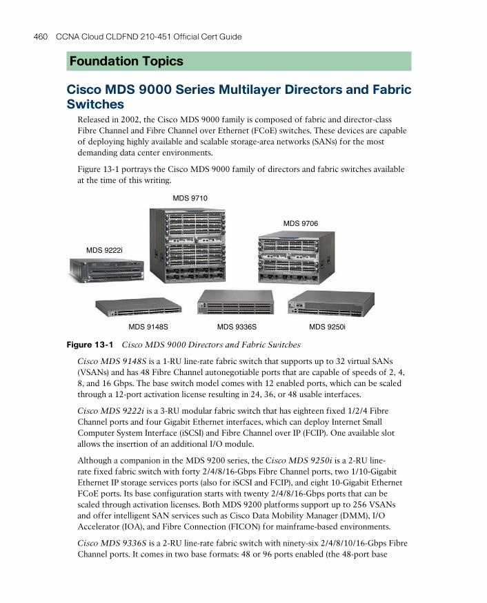
ptg17120290
460 CCNA Cloud CLDFND 210-451 Official Cert Guide
Foundation Topics
Cisco MDS 9000 Series Multilayer Directors and Fabric Switches
Released in 2002, the Cisco MDS 9000 family is composed of fabric and director-class Fibre Channel and Fibre Channel over Ethernet (FCoE) switches. These devices are capable of deploying highly available and scalable storage-area networks (SANs) for the most demanding data center environments.
Figure 13-1 portrays the Cisco MDS 9000 family of directors and fabric switches available at the time of this writing.
MDS 9222i
MDS 9710
MDS 9706
MDS 9336S MDS 9250iMDS 9148S
Figure 13-1 Cisco MDS 9000 Directors and Fabric Switches
Cisco MDS 9148S is a 1-RU line-rate fabric switch that supports up to 32 virtual SANs (VSANs) and has 48 Fibre Channel autonegotiable ports that are capable of speeds of 2, 4, 8, and 16 Gbps. The base switch model comes with 12 enabled ports, which can be scaled through a 12-port activation license resulting in 24, 36, or 48 usable interfaces.
Cisco MDS 9222i is a 3-RU modular fabric switch that has eighteen fixed 1/2/4 Fibre Channel ports and four Gigabit Ethernet interfaces, which can deploy Internet Small Computer System Interface (iSCSI) and Fibre Channel over IP (FCIP). One available slot allows the insertion of an additional I/O module.
Although a companion in the MDS 9200 series, the Cisco MDS 9250i is a 2-RU line-rate fixed fabric switch with forty 2/4/8/16-Gbps Fibre Channel ports, two 1/10-Gigabit Ethernet IP storage services ports (also for iSCSI and FCIP), and eight 10-Gigabit Ethernet FCoE ports. Its base configuration starts with twenty 2/4/8/16-Gbps ports that can be scaled through activation licenses. Both MDS 9200 platforms support up to 256 VSANs and offer intelligent SAN services such as Cisco Data Mobility Manager (DMM), I/O Accelerator (IOA), and Fibre Connection (FICON) for mainframe-based environments.
Cisco MDS 9336S is a 2-RU line-rate fabric switch with ninety-six 2/4/8/10/16-Gbps Fibre Channel ports. It comes in two base formats: 48 or 96 ports enabled (the 48-port base
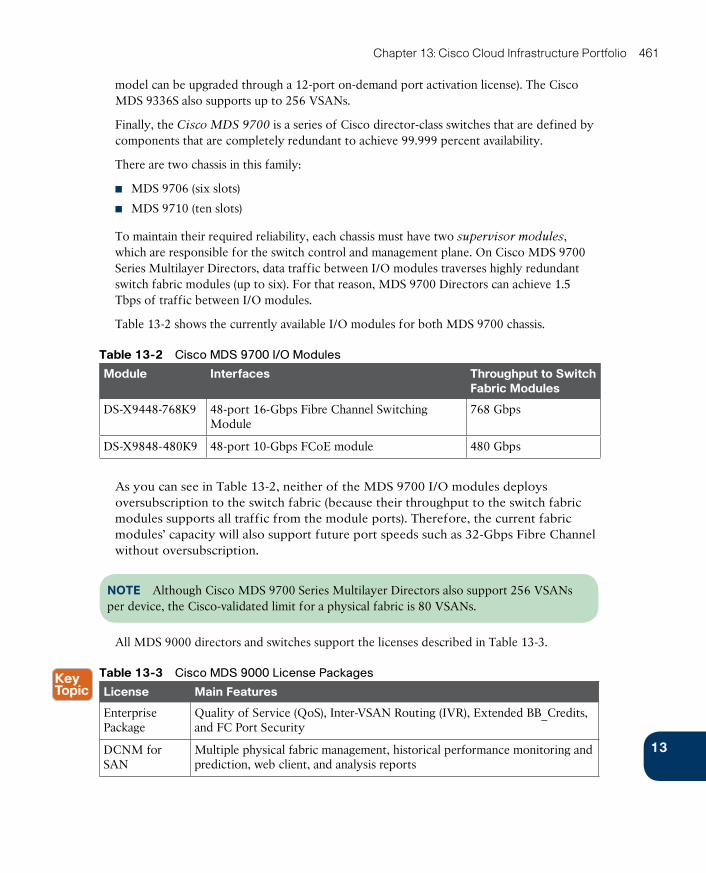
ptg17120290
13
Chapter 13: Cisco Cloud Infrastructure Portfolio 461
model can be upgraded through a 12-port on-demand port activation license). The Cisco MDS 9336S also supports up to 256 VSANs.
Finally, the Cisco MDS 9700 is a series of Cisco director-class switches that are defined by components that are completely redundant to achieve 99.999 percent availability.
There are two chassis in this family:
■ MDS 9706 (six slots)
■ MDS 9710 (ten slots)
To maintain their required reliability, each chassis must have two supervisor modules , which are responsible for the switch control and management plane. On Cisco MDS 9700 Series Multilayer Directors, data traffic between I/O modules traverses highly redundant switch fabric modules (up to six). For that reason, MDS 9700 Directors can achieve 1.5 Tbps of traffic between I/O modules.
Table 13-2 shows the currently available I/O modules for both MDS 9700 chassis.
Table 13-2 Cisco MDS 9700 I/O Modules
Module Interfaces Throughput to Switch Fabric Modules
DS-X9448-768K9 48-port 16-Gbps Fibre Channel Switching Module
768 Gbps
DS-X9848-480K9 48-port 10-Gbps FCoE module 480 Gbps
As you can see in Table 13-2, neither of the MDS 9700 I/O modules deploys oversubscription to the switch fabric (because their throughput to the switch fabric modules supports all traffic from the module ports). Therefore, the current fabric modules’ capacity will also support future port speeds such as 32-Gbps Fibre Channel without oversubscription.
NOTE Although Cisco MDS 9700 Series Multilayer Directors also support 256 VSANs per device, the Cisco-validated limit for a physical fabric is 80 VSANs.
All MDS 9000 directors and switches support the licenses described in Table 13-3.
Table 13-3 Cisco MDS 9000 License Packages
License Main Features
Enterprise Package
Quality of Service (QoS), Inter-VSAN Routing (IVR), Extended BB_Credits, and FC Port Security
DCNM for SAN
Multiple physical fabric management, historical performance monitoring and prediction, web client, and analysis reports

ptg17120290
462 CCNA Cloud CLDFND 210-451 Official Cert Guide
You can find more information about Cisco MDS 9000 directors and switches at http://www.cisco.com/go/mds.
Cisco Nexus Data Center SwitchesIn 2008, Cisco launched its family of specialized data center switches. Since then, the Cisco Nexus Data Center Switches have established their leadership in corporate and service provider data centers of varied sizes and characteristics.
Deploying the same modular network operating system (Cisco NX-OS), the various families of data center switches brought to data centers innovations such as
■ Management of multi-hypervisor virtual networks
■ Unified Fabric with Data Center Bridging (DCB) and FCoE
■ Fabric Extenders
■ Virtual device contexts (VDCs)
■ Virtual PortChannels (vPCs)
■ Layer 2 multipathing with FabricPath
■ Intelligent virtual switching
■ Algo Boost technology for ultra-low-latency applications
■ Application Centric Infrastructure (ACI)
Cisco Nexus 1000V Series SwitchesCisco Nexus 1000V Series Switches are Layer 2 distributed virtual switches for server virtualization and cloud environments. These “software switches” control virtual machine connectivity as faithfully as a “hardware switch” provides Ethernet switching for physical servers.
As Cisco NX-OS-based devices, the Cisco Nexus 1000V Series Switches bring multiple access, security, and extensibility features to multi-hypervisor environments. Such similarity allows the great majority of customer processes and tools (such as the command-line interface [CLI], Simple Network Management Protocol [SNMP], NetFlow, and Encapsulated Remote Switched Port Analyzer [ERSPAN]) to be applied to both physical and virtual networking infrastructures.
Two basic components form a Cisco Nexus 1000V instance:
■ Virtual Ethernet Module (VEM) : Runs as part of the hypervisor kernel, replacing its native connectivity model. It deploys the data plane component of Nexus 1000V, performing Layer 2 switching, among other NX-OS advanced features (such as PortChannels, QoS, private VLANs, and access control lists [ACLs]).
■ Virtual Supervisor Module (VSM) : Coordinates multiple virtual Ethernet modules, providing the control and management plane for Nexus 1000V. Dynamically linked with VM managers (such as VMware vCenter, Microsoft System Center Virtual Machine Manager, or OpenStack Nova), VSM allows the creation of port profiles that will be exported to these managers as standard connectivity policies (to be executed by the VEMs).
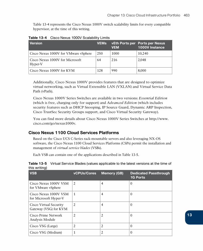
ptg17120290
13
Chapter 13: Cisco Cloud Infrastructure Portfolio 463
Table 13-4 represents the Cisco Nexus 1000V switch scalability limits for every compatible hypervisor, at the time of this writing.
Table 13-4 Cisco Nexus 1000V Scalability Limits
Version VEMs vEth Ports per VEM
Ports per Nexus 1000V Instance
Cisco Nexus 1000V for VMware vSphere 250 1000 10,240
Cisco Nexus 1000V for Microsoft Hyper-V
64 216 2,048
Cisco Nexus 1000V for KVM 128 990 8,000
Additionally, Cisco Nexus 1000V provides features that are designed to optimize virtual networking, such as Virtual Extensible LAN (VXLAN) and Virtual Service Data Path (vPath).
Cisco Nexus 1000V Series Switches are available in two versions: Essential Edition
(which is free, charging only for support) and Advanced Edition (which includes security features such as DHCP Snooping, IP Source Guard, Dynamic ARP Inspection, Cisco TrustSec Security Groups support, and Cisco Virtual Security Gateway).
You can find more details about Cisco Nexus 1000V Series Switches at http://www.cisco.com/go/nexus1000v.
Cisco Nexus 1100 Cloud Services PlatformsBased on the Cisco UCS C-Series rack-mountable servers and also leveraging NX-OS software, the Cisco Nexus 1100 Cloud Services Platforms (CSPs) permit the installation and management of virtual service blades (VSBs).
Each VSB can contain one of the applications described in Table 13-5.
Table 13-5 Virtual Service Blades (values applicable to the latest versions at the time of
this writing)
VSB vCPUs/Cores Memory (GB) Dedicated Passthrough 1G Ports
Cisco Nexus 1000V VSM for VMware vSphere
2 4 0
Cisco Nexus 1000V VSM for Microsoft Hyper-V
1 4 0
Cisco Virtual Security Gateway (VSG) for KVM
2 4 0
Cisco Prime Network Analysis Module
2 2 0
Cisco VSG (Large) 2 2 0
Cisco VSG (Medium) 1 2 0
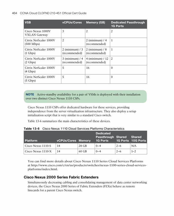
ptg17120290
464 CCNA Cloud CLDFND 210-451 Official Cert Guide
VSB vCPUs/Cores Memory (GB) Dedicated Passthrough 1G Ports
Cisco Nexus 1000V VXLAN Gateway
3 2 2
Citrix NetScaler 1000V (500 Mbps)
2 2 (minimum) / 4 (recommended)
1
Citrix NetScaler 1000V (1 Gbps)
2 (minimum) / 3 (recommended)
2 (minimum) / 8 (recommended)
1
Citrix NetScaler 1000V (2 Gbps)
3 (minimum) / 4 (recommended)
4 (minimum) / 12 (recommended)
2
Citrix NetScaler 1000V (4 Gbps)
5 16 0
Citrix NetScaler 1000V (5 Gbps)
5 16 0
NOTE Active-standby availability for a pair of VSMs is deployed with their installation over two distinct Cisco Nexus 1110 CSPs.
Cisco Nexus 1110 CSPs offer dedicated hardware for these services, providing independence from the server virtualization infrastructure. They also deploy a setup initialization script that is very similar to a standard Cisco switch.
Table 13-6 summarizes the main characteristics of these devices.
Table 13-6 Cisco Nexus 1110 Cloud Services Platforms Characteristics
Platform vCPUs/Cores Memory
Dedicated Passthrough 1G Ports
Shared 1G Ports
Shared 10G Ports
Cisco Nexus 1110-S 14 28 GB 0–4 2–6 N/A
Cisco Nexus 1110-X 14 60 GB 0–4 2–6 1–2
You can find more details about Cisco Nexus 1110 Series Cloud Services Platforms at http://www.cisco.com/c/en/us/products/switches/nexus-1100-series-cloud-services-platforms/index.html.
Cisco Nexus 2000 Series Fabric ExtendersSimultaneously decreasing cabling and consolidating management of data center networking devices, the Cisco Nexus 2000 Series of Fabric Extenders (FEXs) behave as remote linecards for a parent Cisco Nexus switch.

ptg17120290
13
Chapter 13: Cisco Cloud Infrastructure Portfolio 465
Because of their simplicity, network operational teams can deploy Nexus 2000 Series Fabric Extenders within server cabinets (similarly to top-of-rack switches) with a small space and power footprint (from 80 W to 350 W in 1 RU).
Figure 13-2 portrays some of the Nexus 2000 devices that are available at the time of this writing.
Nexus 2232PPNexus 2232TQ
Nexus 2348TQNexus 2248TP
Nexus 2232TM-E
Nexus 2224TPNexus 2348UPQ
Figure 13-2 Cisco Nexus 2000 Series Fabric Extenders
Table 13-7 outlines the main characteristics of these models.
Table 13-7 Cisco Nexus 2000 Series Models
ModelHost Interfaces Fabric
InterfacesOversubscription Performance
Nexus 2224TP Twenty-four 100BASE-T/1000BASE-T
Two 10-Gigabit Ethernet (SFP+)
1.2:1 88 Gbps or 65 Mpps3
Nexus 2248TP Forty-eight 100/1000BASE-T
Four 10-Gigabit Ethernet (SFP+)
1.2:1 176 Gbps or 131 Mpps
Nexus 2248TP-E
Forty-eight 100/1000BASE-T
Four 10-Gigabit Ethernet (SFP+)
1.2:1 176 Gbps or 131 Mpps
Nexus 2232PP Thirty-two 1/10 Gigabit Ethernet (SFP/SFP+)
Eight 10-Gigabit Ethernet (SFP+)
4:1 800 Gbps or 595 Mpps
Nexus 2232TM
Thirty-two 1000BASE-T/10GBASE-T
Eight 10-Gigabit Ethernet (SFP+)
4:1 800 Gbps or 595 Mpps
Nexus 2232TM-E
Thirty-two 1000BASE-T/10GBASE-T
Eight 10-Gigabit Ethernet (SFP+)
4:1 800 Gbps or 595 Mpps
Nexus 2232TQ Thirty-two 100BASE-T/1000BASE-T/10GBASE-T
Four 40-Gigabit Ethernet (QSFP+)¹
2:1 960 Gbps or 1440 Mpps

ptg17120290
466 CCNA Cloud CLDFND 210-451 Official Cert Guide
ModelHost Interfaces Fabric
InterfacesOversubscription Performance
Nexus 2348PQ Forty-eight 1/10-Gigabit Ethernet (SFP/SFP+)
Four 40-Gigabit Ethernet (QSFP+)¹
3:1 1280 Gbps or 952 Mpps
Nexus 2348TQ Forty-eight 100BASE-T/1000BASE-T/10GBASE-T
Six 40-Gigabit Ethernet (QSFP+)¹
2:1 1440 Gbps or 2160 Mpps
Nexus 2348UPQ²
Forty-eight 1/10-Gigabit Ethernet
Six 40-Gigabit Ethernet (QSFP+)¹
2:1 1440 Gbps or 2160 Mpps
1. Each port can be converted into four 10-Gigabit Ethernet ports through a breakout cable.2. Hardware support of Unified Ports, which are interfaces that can provide Ethernet (1/10 Gbps with FCoE) or Fibre Channel (8/4/2/1 Gbps) according to the inserted transceiver.3. Mpps = megapackets per second.
Both Nexus 2248TP-E and Nexus 2232TM-E differ from their respective “non-E” models mainly through bigger shared buffers, which benefit applications such as large-volume data-bases, distributed storage, and video editing.
Besides Twinax copper cables and standard 10-Gigabit Ethernet transceivers, Nexus 2000 models also deploy cost-effective Fabric Extender Transceivers (FETs) that can reach up to 100 meters of fiber to connect to the parent switch.
The Cisco family of Fabric Extenders is further extended with the Cisco Nexus B22 Blade Fabric Extenders for HP BladeSystem c3000 and c7000 enclosures (B22HP), Fujitsu PRIMERGY BX400 and BX9000 enclosure (B22F), and Dell PowerEdge M1000e. All models have 16 host interfaces (10GBASE-KR) for internal blade server connectivity and eight 10-Gigabit Ethernet SFP+ fabric interfaces.
The Cisco Nexus 2000 Series Fabric Extenders support the following platforms as parent switches: Cisco Nexus 5000, Nexus 7000, and Nexus 9000. Please refer to the Cisco.com documentation for specific details about the features supported by each parent switch and FEX combination.
You can find more details about Cisco Nexus 2000 Series Fabric Extenders at http://www.cisco.com/go/nexus2000.
Cisco Nexus 3000 Series SwitchesCisco originally designed Cisco Nexus 3000 Series Switches to provide ultra-low-latency switching to high-frequency trading (HFT) and high-performance computing (HPC) environments. With a small footprint of 1 RU and a distinctive “switch-on-a-chip” architecture, these NX-OS devices are capable of providing wire-rate Layer 2 and 3 switching.
Figure 13-3 shows some of the Nexus 3000 Series models that are available at the time of this writing. Table 13-8 describes their main characteristics.
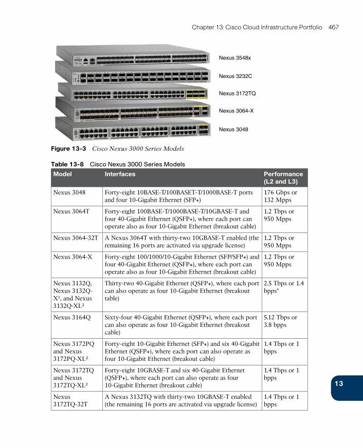
ptg17120290
13
Chapter 13: Cisco Cloud Infrastructure Portfolio 467
Nexus 3232C
Nexus 3548x
Nexus 3172TQ
Nexus 3064-X
Nexus 3048
Figure 13-3 Cisco Nexus 3000 Series Models
Table 13-8 Cisco Nexus 3000 Series Models
Model Interfaces Performance (L2 and L3)
Nexus 3048 Forty-eight 10BASE-T/100BASET-T/1000BASE-T ports and four 10-Gigabit Ethernet (SFP+)
176 Gbps or 132 Mpps
Nexus 3064T Forty-eight 100BASE-T/1000BASE-T/10GBASE-T and four 40-Gigabit Ethernet (QSFP+), where each port can operate also as four 10-Gigabit Ethernet (breakout cable)
1.2 Tbps or 950 Mpps
Nexus 3064-32T A Nexus 3064T with thirty-two 10GBASE-T enabled (the remaining 16 ports are activated via upgrade license)
1.2 Tbps or 950 Mpps
Nexus 3064-X Forty-eight 100/1000/10-Gigabit Ethernet (SFP/SFP+) and four 40-Gigabit Ethernet (QSFP+), where each port can operate also as four 10-Gigabit Ethernet (breakout cable)
1.2 Tbps or 950 Mpps
Nexus 3132Q, Nexus 3132Q-X¹, and Nexus 3132Q-XL²
Thirty-two 40-Gigabit Ethernet (QSFP+), where each port can also operate as four 10-Gigabit Ethernet (breakout table)
2.5 Tbps or 1.4 bpps4
Nexus 3164Q Sixty-four 40-Gigabit Ethernet (QSFP+), where each port can also operate as four 10-Gigabit Ethernet (breakout cable)
5.12 Tbps or 3.8 bpps
Nexus 3172PQ and Nexus 3172PQ-XL²
Forty-eight 10-Gigabit Ethernet (SFP+) and six 40-Gigabit Ethernet (QSFP+), where each port can also operate as four 10-Gigabit Ethernet (breakout cable)
1.4 Tbps or 1 bpps
Nexus 3172TQ and Nexus 3172TQ-XL²
Forty-eight 10GBASE-T and six 40-Gigabit Ethernet (QSFP+), where each port can also operate as four 10-Gigabit Ethernet (breakout cable)
1.4 Tbps or 1 bpps
Nexus 3172TQ-32T
A Nexus 3132TQ with thirty-two 10GBASE-T enabled (the remaining 16 ports are activated via upgrade license)
1.4 Tbps or 1 bpps
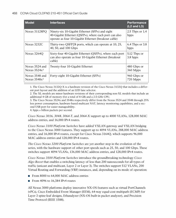
ptg17120290
468 CCNA Cloud CLDFND 210-451 Official Cert Guide
Model Interfaces Performance (L2 and L3)
Nexus 31128PQ Ninety-six 10-Gigabit Ethernet (SFP+) and eight 40-Gigabit Ethernet (QSFP+), where each port can also operate as four 10-Gigabit Ethernet (breakout cable)
2.5 Tbps or 1.4 bpps
Nexus 3232C Thirty-two QSFP28 ports, which can operate at 10, 25, 40, 50, and 100 Gbps
6.4 Tbps or 3.8 bpps
Nexus 3264Q Sixty-four 40-Gigabit Ethernet (QSFP+), where each port can also operate as four 10-Gigabit Ethernet (breakout cable)
5.12 Tbps or 3.8 bpps
Nexus 3524 and Nexus 3524x³
Twenty-four 10-Gigabit Ethernet 480 Gbps or 360 Mpps
Nexus 3548 and Nexus 3548x³
Forty-eight 10-Gigabit Ethernet (SFP+) 960 Gbps or 720 Mpps
1. The Cisco Nexus 3132Q-X is a hardware revision of the Cisco Nexus 3132Q that includes a differ-ent port layout and the addition of an LED lane selector.2. The XL models are minor hardware revisions of their corresponding non-XL models that include an additional 4 GB of memory (for a total of 8 GB) and a 2.5-GHz CPU.3. The Cisco Nexus 3524x and 3548x respectively differ from the Nexus 3524 and 3548 through 25% less power consumption, hardware-based multicast NAT, latency monitoring capabilities, and a sec-ond USB port for easier manageability.4. bpps = billion packets per second.
Cisco Nexus 3016, 3048, 3064-T, and 3064-X support up to 4000 VLANs, 128,000 MAC address entries, and 16,000 IPv4 routes.
Cisco Nexus 3100 Platform Switches have added VXLAN gateway and VXLAN bridging to the Cisco Nexus 3000 features. They support up to 4094 VLANs, 288,000 MAC address entries, and 16,000 IPv4 routes, except for Cisco Nexus 3164Q, which supports 96,000 MAC address entries and 128,000 IPv4 routes.
The Cisco Nexus 3200 Platform Switches are yet another step in the evolution of the series, with the hardware support of other port speeds such as 25, 50, and 100 Gbps. These switches support 4094 VLANs, 136,000 MAC address entries, and 128,000 IPv4 routes.
Cisco Nexus 3500 Platform Switches introduce the groundbreaking technology Cisco Algo Boost that enables a switching latency of less than 200 nanoseconds for all types of traffic (unicast and multicast, Layer 2 or Layer 3). The switches support 512 VLANs, 200 Virtual Routing and Forwarding (VRF) instances, and, depending on its mode of operation:
■ From 8000 to 64,000 MAC address entries
■ From 4096 to 16,384 IPv4 routes
All Nexus 3000 platforms deploy innovative NX-OS features such as virtual PortChannels (vPCs), Cisco Embedded Event Manager (EEM), 64-way equal-cost multipath (ECMP) for Layer 3 spine-leaf designs, Ethanalyzer (NX-OS built-in packet analyzer), and Precision Time Protocol (IEEE 1588).

ptg17120290
13
Chapter 13: Cisco Cloud Infrastructure Portfolio 469
Additionally, through the Enhanced Layer 3 license, the Cisco Nexus 3000 can implement full Open Shortest Path First (OSPF), Enhanced Interior Gateway Routing Protocol (EIGRP), Border Gateway Protocol (BGP), VRF Lite, and VXLAN gateway and bridging.
You can find more details about Cisco Nexus 3000 Series Switches at http://www.cisco.com/go/nexus3000.
Cisco Nexus 5000 Series SwitchesThe Cisco Nexus 5000 Series Switches are arguably the most flexible platforms within the Cisco Data Center switching portfolio. Figure 13-4 portrays some of the Nexus 5000 models currently offered at the time of this writing.
Nexus 5624Q
Nexus 5696Q
Nexus 5672UP
Nexus 5596T
Figure 13-4 Cisco Nexus 5000 Series Switches
The Cisco Nexus 5500 Platform Switches introduced innovations in data center networks such as FabricPath, VM-FEX, and Unified Ports , which are interfaces that can provide Ethernet (1/10 Gbps with FCoE) or Fibre Channel (1/2/4/8 Gbps) according to the inserted transceiver. Unified Ports enable flexibility and an easier migration from Fibre Channel to FCoE networks.
The Cisco Nexus 5600 Platform Switches improved the series flexibility with integrated Layer 3 forwarding, new features such as VXLAN (gateway, bridging, and routing), higher scalability, and advanced programmability tools such as NX-API.
Table 13-9 describes the main characteristics of the Cisco Nexus 5000 Series Switches models.
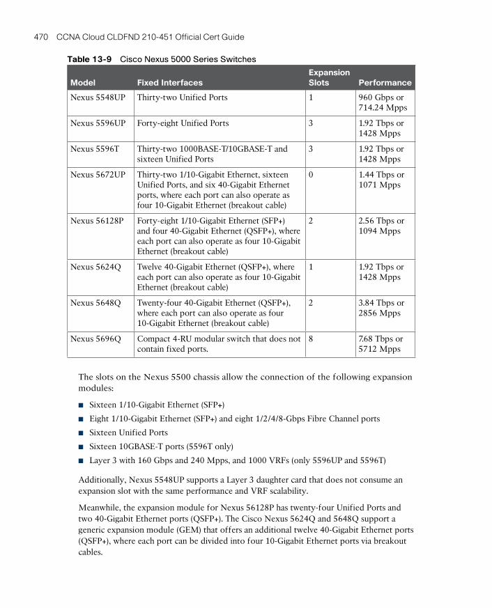
ptg17120290
470 CCNA Cloud CLDFND 210-451 Official Cert Guide
Table 13-9 Cisco Nexus 5000 Series Switches
Model Fixed InterfacesExpansion Slots Performance
Nexus 5548UP Thirty-two Unified Ports 1 960 Gbps or 714.24 Mpps
Nexus 5596UP Forty-eight Unified Ports 3 1.92 Tbps or 1428 Mpps
Nexus 5596T Thirty-two 1000BASE-T/10GBASE-T and sixteen Unified Ports
3 1.92 Tbps or 1428 Mpps
Nexus 5672UP Thirty-two 1/10-Gigabit Ethernet, sixteen Unified Ports, and six 40-Gigabit Ethernet ports, where each port can also operate as four 10-Gigabit Ethernet (breakout cable)
0 1.44 Tbps or 1071 Mpps
Nexus 56128P Forty-eight 1/10-Gigabit Ethernet (SFP+) and four 40-Gigabit Ethernet (QSFP+), where each port can also operate as four 10-Gigabit Ethernet (breakout cable)
2 2.56 Tbps or 1094 Mpps
Nexus 5624Q Twelve 40-Gigabit Ethernet (QSFP+), where each port can also operate as four 10-Gigabit Ethernet (breakout cable)
1 1.92 Tbps or 1428 Mpps
Nexus 5648Q Twenty-four 40-Gigabit Ethernet (QSFP+), where each port can also operate as four 10-Gigabit Ethernet (breakout cable)
2 3.84 Tbps or 2856 Mpps
Nexus 5696Q Compact 4-RU modular switch that does not contain fixed ports.
8 7.68 Tbps or 5712 Mpps
The slots on the Nexus 5500 chassis allow the connection of the following expansion modules:
■ Sixteen 1/10-Gigabit Ethernet (SFP+)
■ Eight 1/10-Gigabit Ethernet (SFP+) and eight 1/2/4/8-Gbps Fibre Channel ports
■ Sixteen Unified Ports
■ Sixteen 10GBASE-T ports (5596T only)
■ Layer 3 with 160 Gbps and 240 Mpps, and 1000 VRFs (only 5596UP and 5596T)
Additionally, Nexus 5548UP supports a Layer 3 daughter card that does not consume an expansion slot with the same performance and VRF scalability.
Meanwhile, the expansion module for Nexus 56128P has twenty-four Unified Ports and two 40-Gigabit Ethernet ports (QSFP+). The Cisco Nexus 5624Q and 5648Q support a generic expansion module (GEM) that offers an additional twelve 40-Gigabit Ethernet ports (QSFP+), where each port can be divided into four 10-Gigabit Ethernet ports via breakout cables.
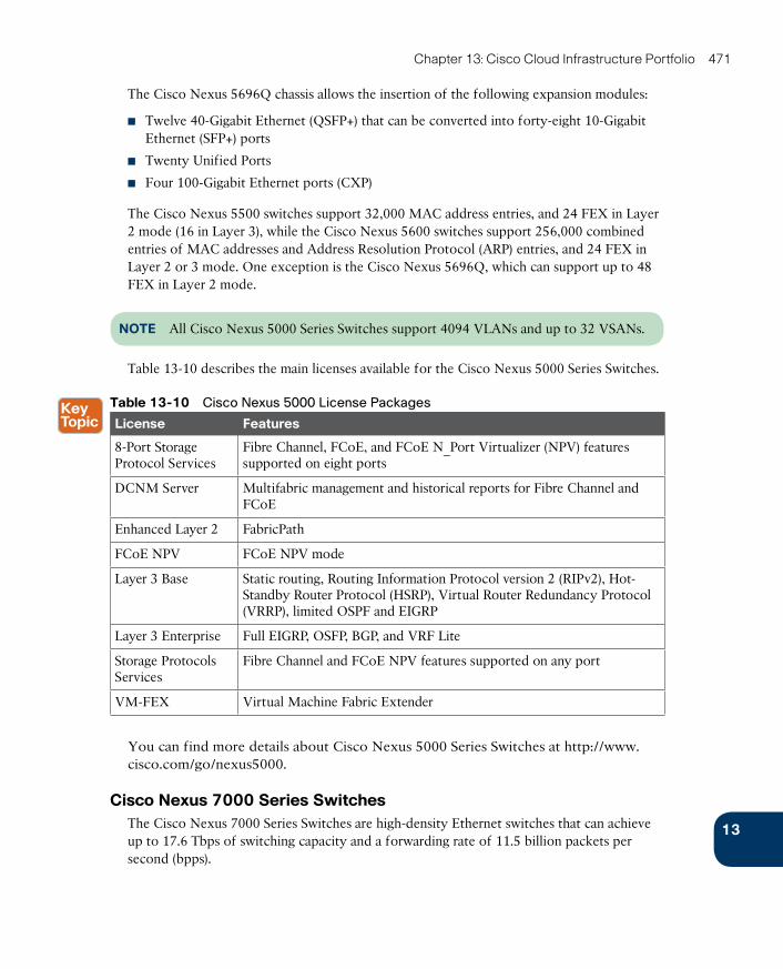
ptg17120290
13
Chapter 13: Cisco Cloud Infrastructure Portfolio 471
The Cisco Nexus 5696Q chassis allows the insertion of the following expansion modules:
■ Twelve 40-Gigabit Ethernet (QSFP+) that can be converted into forty-eight 10-Gigabit Ethernet (SFP+) ports
■ Twenty Unified Ports
■ Four 100-Gigabit Ethernet ports (CXP)
The Cisco Nexus 5500 switches support 32,000 MAC address entries, and 24 FEX in Layer 2 mode (16 in Layer 3), while the Cisco Nexus 5600 switches support 256,000 combined entries of MAC addresses and Address Resolution Protocol (ARP) entries, and 24 FEX in Layer 2 or 3 mode. One exception is the Cisco Nexus 5696Q, which can support up to 48 FEX in Layer 2 mode.
NOTE All Cisco Nexus 5000 Series Switches support 4094 VLANs and up to 32 VSANs.
Table 13-10 describes the main licenses available for the Cisco Nexus 5000 Series Switches.
Table 13-10 Cisco Nexus 5000 License Packages
License Features
8-Port Storage Protocol Services
Fibre Channel, FCoE, and FCoE N_Port Virtualizer (NPV) features supported on eight ports
DCNM Server Multifabric management and historical reports for Fibre Channel and FCoE
Enhanced Layer 2 FabricPath
FCoE NPV FCoE NPV mode
Layer 3 Base Static routing, Routing Information Protocol version 2 (RIPv2), Hot-Standby Router Protocol (HSRP), Virtual Router Redundancy Protocol (VRRP), limited OSPF and EIGRP
Layer 3 Enterprise Full EIGRP, OSFP, BGP, and VRF Lite
Storage Protocols Services
Fibre Channel and FCoE NPV features supported on any port
VM-FEX Virtual Machine Fabric Extender
You can find more details about Cisco Nexus 5000 Series Switches at http://www.cisco.com/go/nexus5000.
Cisco Nexus 7000 Series SwitchesThe Cisco Nexus 7000 Series Switches are high-density Ethernet switches that can achieve up to 17.6 Tbps of switching capacity and a forwarding rate of 11.5 billion packets per second (bpps).
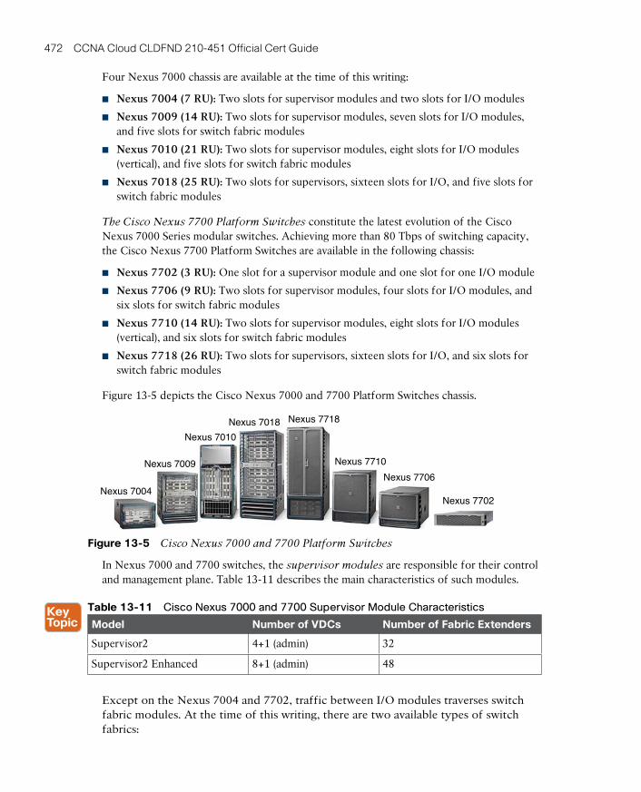
ptg17120290
472 CCNA Cloud CLDFND 210-451 Official Cert Guide
Four Nexus 7000 chassis are available at the time of this writing:
■ Nexus 7004 (7 RU): Two slots for supervisor modules and two slots for I/O modules
■ Nexus 7009 (14 RU): Two slots for supervisor modules, seven slots for I/O modules, and five slots for switch fabric modules
■ Nexus 7010 (21 RU): Two slots for supervisor modules, eight slots for I/O modules (vertical), and five slots for switch fabric modules
■ Nexus 7018 (25 RU): Two slots for supervisors, sixteen slots for I/O, and five slots for switch fabric modules
The Cisco Nexus 7700 Platform Switches constitute the latest evolution of the Cisco Nexus 7000 Series modular switches. Achieving more than 80 Tbps of switching capacity, the Cisco Nexus 7700 Platform Switches are available in the following chassis:
■ Nexus 7702 (3 RU): One slot for a supervisor module and one slot for one I/O module
■ Nexus 7706 (9 RU): Two slots for supervisor modules, four slots for I/O modules, and six slots for switch fabric modules
■ Nexus 7710 (14 RU): Two slots for supervisor modules, eight slots for I/O modules (vertical), and six slots for switch fabric modules
■ Nexus 7718 (26 RU): Two slots for supervisors, sixteen slots for I/O, and six slots for switch fabric modules
Figure 13-5 depicts the Cisco Nexus 7000 and 7700 Platform Switches chassis.
Nexus 7004
Nexus 7009
Nexus 7010
Nexus 7018 Nexus 7718
Nexus 7710
Nexus 7706
Nexus 7702
Figure 13-5 Cisco Nexus 7000 and 7700 Platform Switches
In Nexus 7000 and 7700 switches, the supervisor modules are responsible for their control and management plane. Table 13-11 describes the main characteristics of such modules.
Table 13-11 Cisco Nexus 7000 and 7700 Supervisor Module Characteristics
Model Number of VDCs Number of Fabric Extenders
Supervisor2 4+1 (admin) 32
Supervisor2 Enhanced 8+1 (admin) 48
Except on the Nexus 7004 and 7702, traffic between I/O modules traverses switch fabric modules. At the time of this writing, there are two available types of switch fabrics:
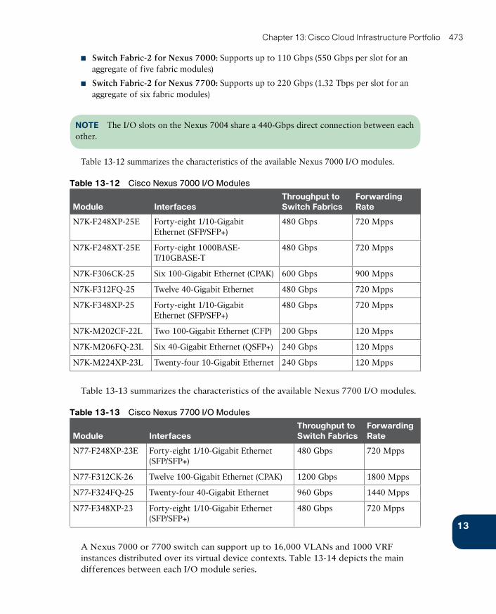
ptg17120290
13
Chapter 13: Cisco Cloud Infrastructure Portfolio 473
■ Switch Fabric-2 for Nexus 7000: Supports up to 110 Gbps (550 Gbps per slot for an aggregate of five fabric modules)
■ Switch Fabric-2 for Nexus 7700: Supports up to 220 Gbps (1.32 Tbps per slot for an aggregate of six fabric modules)
NOTE The I/O slots on the Nexus 7004 share a 440-Gbps direct connection between each other.
Table 13-12 summarizes the characteristics of the available Nexus 7000 I/O modules.
Table 13-12 Cisco Nexus 7000 I/O Modules
Module InterfacesThroughput to Switch Fabrics
Forwarding Rate
N7K-F248XP-25E Forty-eight 1/10-Gigabit Ethernet (SFP/SFP+)
480 Gbps 720 Mpps
N7K-F248XT-25E Forty-eight 1000BASE-T/10GBASE-T
480 Gbps 720 Mpps
N7K-F306CK-25 Six 100-Gigabit Ethernet (CPAK) 600 Gbps 900 Mpps
N7K-F312FQ-25 Twelve 40-Gigabit Ethernet 480 Gbps 720 Mpps
N7K-F348XP-25 Forty-eight 1/10-Gigabit Ethernet (SFP/SFP+)
480 Gbps 720 Mpps
N7K-M202CF-22L Two 100-Gigabit Ethernet (CFP) 200 Gbps 120 Mpps
N7K-M206FQ-23L Six 40-Gigabit Ethernet (QSFP+) 240 Gbps 120 Mpps
N7K-M224XP-23L Twenty-four 10-Gigabit Ethernet 240 Gbps 120 Mpps
Table 13-13 summarizes the characteristics of the available Nexus 7700 I/O modules.
Table 13-13 Cisco Nexus 7700 I/O Modules
Module InterfacesThroughput to Switch Fabrics
Forwarding Rate
N77-F248XP-23E Forty-eight 1/10-Gigabit Ethernet (SFP/SFP+)
480 Gbps 720 Mpps
N77-F312CK-26 Twelve 100-Gigabit Ethernet (CPAK) 1200 Gbps 1800 Mpps
N77-F324FQ-25 Twenty-four 40-Gigabit Ethernet 960 Gbps 1440 Mpps
N77-F348XP-23 Forty-eight 1/10-Gigabit Ethernet (SFP/SFP+)
480 Gbps 720 Mpps
A Nexus 7000 or 7700 switch can support up to 16,000 VLANs and 1000 VRF instances distributed over its virtual device contexts. Table 13-14 depicts the main differences between each I/O module series.

ptg17120290
474 CCNA Cloud CLDFND 210-451 Official Cert Guide
Table 13-14 Cisco Nexus 7000 and 7700 I/O Modules
Module Series MAC Address Entries IPv4 Routes
FCoE-capable
VXLAN-capable
F2-Series Up to 196,608 (depending on VLAN allocation on ports)
32,768 Yes No
F3-Series 64,000 64,000 Yes Yes
M2-Series 128,000 128,000 (1 million in XL mode) No No
NOTE Although FCoE-enabled Nexus 7000 Series Switches support more VSANs per switch, the Cisco-verified limit for a physical fabric is 80 VSANs.
Table 13-15 describes the main licenses available for the Cisco Nexus 7000 and 7700 Platform Switches.
Table 13-15 Cisco Nexus 7000 and 7700 License Packages
License Main Features
Enterprise Services Package
OSPF, BGP, IS-IS, Policy-Based Routing, Generic Routing Encapsulation (GRE), Protocol Independent Multicast (PIM), Multicast Source Discovery Protocol (MSDP), EIGRP, VXLAN, and BGP eVPN control plane
Advanced Services Packages
Virtual device contexts (VDCs)
VDC Licenses Increments four VDC licenses that allow Supervisor 2 Enhanced module to support eight VDCs
Transport Services Package
Overlay Transport Virtualization (OTV) and Locator/ID Separation Protocol (LISP)
Scalable Services Package Enables all XL-capable modules to operate in XL mode
Enhanced Layer 2 Package
Enables FabricPath on F2- and F3-Series modules, Remote Integrated Service Engine (RISE), and Intelligent Traffic Director (ITD)
MPLS Services Package Enables Multiprotocol Label Switching (MPLS), Layer 3 Virtual Private Network (VPN), Ethernet over MPLS (EoMPLS), and Virtual Private LAN Services (VPLS)
FCoE License Enables Fibre Channel over Ethernet on an F-Series module
Storage Enterprise Package
Enables Inter-VSAN Routing (IVR), IVR Network Address Translation (NAT), VSAN access control, and Fabric Binding for open systems
You can find more details about Cisco Nexus 7000 Series Switches at http://www.cisco.com/go/nexus7000.
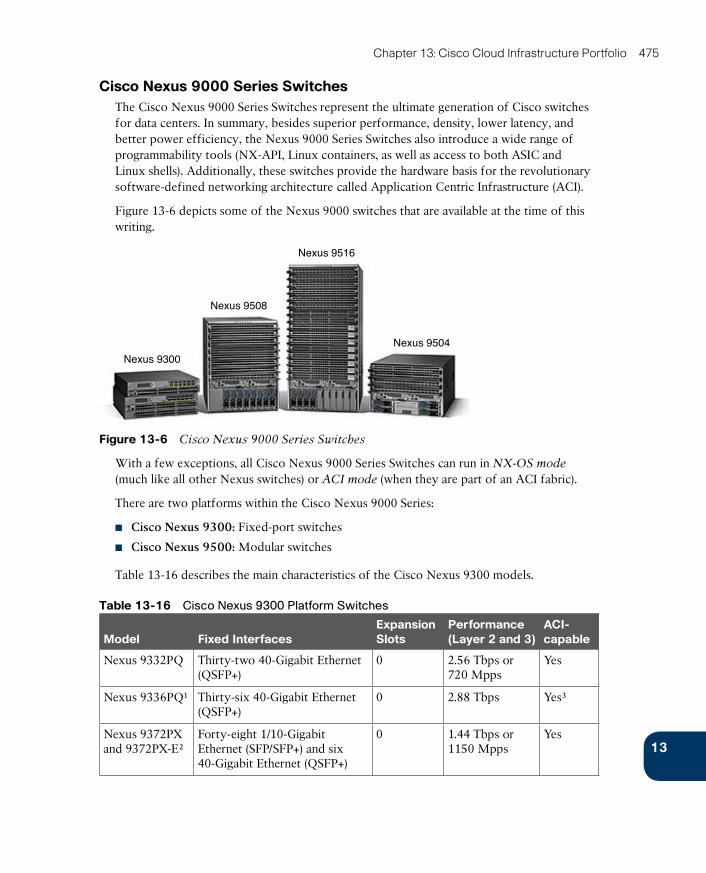
ptg17120290
13
Chapter 13: Cisco Cloud Infrastructure Portfolio 475
Cisco Nexus 9000 Series SwitchesThe Cisco Nexus 9000 Series Switches represent the ultimate generation of Cisco switches for data centers. In summary, besides superior performance, density, lower latency, and better power efficiency, the Nexus 9000 Series Switches also introduce a wide range of programmability tools (NX-API, Linux containers, as well as access to both ASIC and Linux shells). Additionally, these switches provide the hardware basis for the revolutionary software-defined networking architecture called Application Centric Infrastructure (ACI) .
Figure 13-6 depicts some of the Nexus 9000 switches that are available at the time of this writing.
Nexus 9300
Nexus 9508
Nexus 9516
Nexus 9504
Figure 13-6 Cisco Nexus 9000 Series Switches
With a few exceptions, all Cisco Nexus 9000 Series Switches can run in NX-OS mode
(much like all other Nexus switches) or ACI mode (when they are part of an ACI fabric).
There are two platforms within the Cisco Nexus 9000 Series:
■ Cisco Nexus 9300: Fixed-port switches
■ Cisco Nexus 9500: Modular switches
Table 13-16 describes the main characteristics of the Cisco Nexus 9300 models.
Table 13-16 Cisco Nexus 9300 Platform Switches
Model Fixed InterfacesExpansion Slots
Performance (Layer 2 and 3)
ACI-capable
Nexus 9332PQ Thirty-two 40-Gigabit Ethernet (QSFP+)
0 2.56 Tbps or 720 Mpps
Yes
Nexus 9336PQ¹ Thirty-six 40-Gigabit Ethernet (QSFP+)
0 2.88 Tbps Yes³
Nexus 9372PX and 9372PX-E²
Forty-eight 1/10-Gigabit Ethernet (SFP/SFP+) and six 40-Gigabit Ethernet (QSFP+)
0 1.44 Tbps or 1150 Mpps
Yes
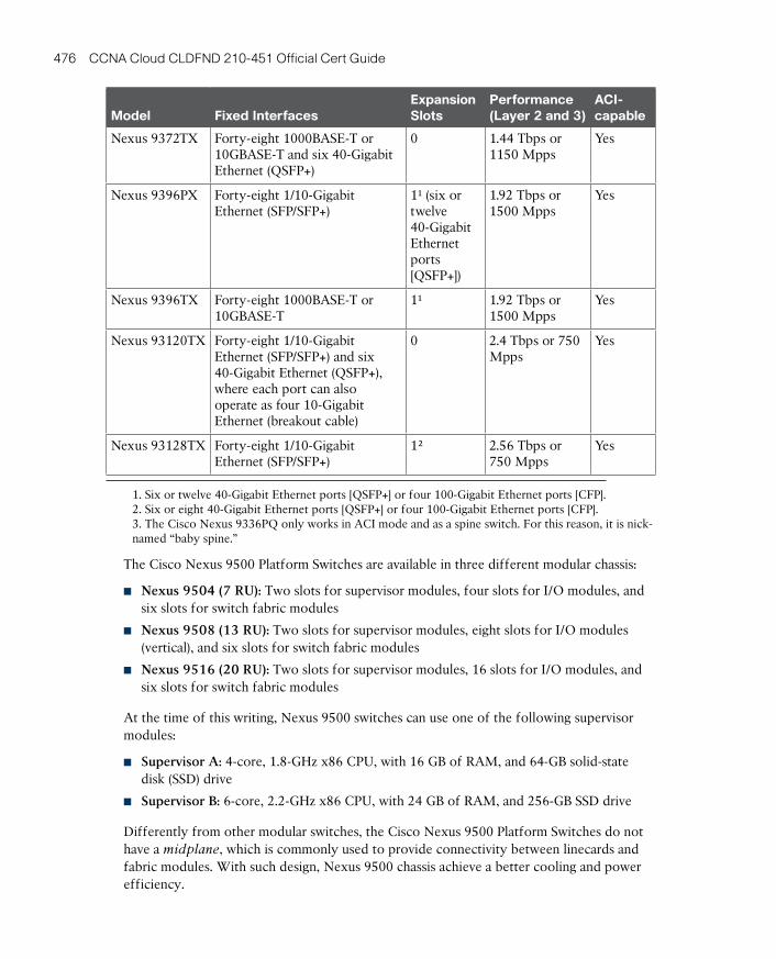
ptg17120290
476 CCNA Cloud CLDFND 210-451 Official Cert Guide
Model Fixed InterfacesExpansion Slots
Performance (Layer 2 and 3)
ACI-capable
Nexus 9372TX Forty-eight 1000BASE-T or 10GBASE-T and six 40-Gigabit Ethernet (QSFP+)
0 1.44 Tbps or 1150 Mpps
Yes
Nexus 9396PX Forty-eight 1/10-Gigabit Ethernet (SFP/SFP+)
1¹ (six or twelve 40-Gigabit Ethernet ports [QSFP+])
1.92 Tbps or 1500 Mpps
Yes
Nexus 9396TX Forty-eight 1000BASE-T or 10GBASE-T
1¹ 1.92 Tbps or 1500 Mpps
Yes
Nexus 93120TX Forty-eight 1/10-Gigabit Ethernet (SFP/SFP+) and six 40-Gigabit Ethernet (QSFP+), where each port can also operate as four 10-Gigabit Ethernet (breakout cable)
0 2.4 Tbps or 750 Mpps
Yes
Nexus 93128TX Forty-eight 1/10-Gigabit Ethernet (SFP/SFP+)
1² 2.56 Tbps or 750 Mpps
Yes
1. Six or twelve 40-Gigabit Ethernet ports [QSFP+] or four 100-Gigabit Ethernet ports [CFP].2. Six or eight 40-Gigabit Ethernet ports [QSFP+] or four 100-Gigabit Ethernet ports [CFP].3. The Cisco Nexus 9336PQ only works in ACI mode and as a spine switch. For this reason, it is nick-named “baby spine.”
The Cisco Nexus 9500 Platform Switches are available in three different modular chassis:
■ Nexus 9504 (7 RU): Two slots for supervisor modules, four slots for I/O modules, and six slots for switch fabric modules
■ Nexus 9508 (13 RU): Two slots for supervisor modules, eight slots for I/O modules (vertical), and six slots for switch fabric modules
■ Nexus 9516 (20 RU): Two slots for supervisor modules, 16 slots for I/O modules, and six slots for switch fabric modules
At the time of this writing, Nexus 9500 switches can use one of the following supervisor modules :
■ Supervisor A: 4-core, 1.8-GHz x86 CPU, with 16 GB of RAM, and 64-GB solid-state disk (SSD) drive
■ Supervisor B: 6-core, 2.2-GHz x86 CPU, with 24 GB of RAM, and 256-GB SSD drive
Differently from other modular switches, the Cisco Nexus 9500 Platform Switches do not have a midplane , which is commonly used to provide connectivity between linecards and fabric modules. With such design, Nexus 9500 chassis achieve a better cooling and power efficiency.
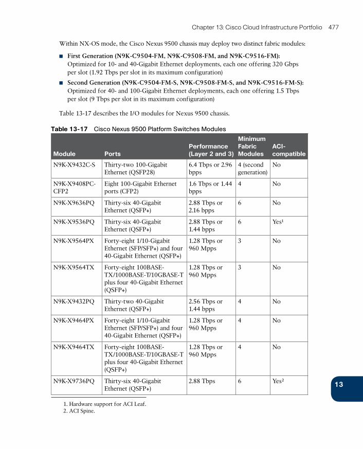
ptg17120290
13
Chapter 13: Cisco Cloud Infrastructure Portfolio 477
Within NX-OS mode, the Cisco Nexus 9500 chassis may deploy two distinct fabric modules:
■ First Generation (N9K-C9504-FM, N9K-C9508-FM, and N9K-C9516-FM): Optimized for 10- and 40-Gigabit Ethernet deployments, each one offering 320 Gbps per slot (1.92 Tbps per slot in its maximum configuration)
■ Second Generation (N9K-C9504-FM-S, N9K-C9508-FM-S, and N9K-C9516-FM-S): Optimized for 40- and 100-Gigabit Ethernet deployments, each one offering 1.5 Tbps per slot (9 Tbps per slot in its maximum configuration)
Table 13-17 describes the I/O modules for Nexus 9500 chassis.
Table 13-17 Cisco Nexus 9500 Platform Switches Modules
Module PortsPerformance (Layer 2 and 3)
Minimum Fabric Modules
ACI-compatible
N9K-X9432C-S Thirty-two 100-Gigabit Ethernet (QSFP28)
6.4 Tbps or 2.96 bpps
4 (second generation)
No
N9K-X9408PC-CFP2
Eight 100-Gigabit Ethernet ports (CFP2)
1.6 Tbps or 1.44 bpps
4 No
N9K-X9636PQ Thirty-six 40-Gigabit Ethernet (QSFP+)
2.88 Tbps or 2.16 bpps
6 No
N9K-X9536PQ Thirty-six 40-Gigabit Ethernet (QSFP+)
2.88 Tbps or 1.44 bpps
6 Yes¹
N9K-X9564PX Forty-eight 1/10-Gigabit Ethernet (SFP/SFP+) and four 40-Gigabit Ethernet (QSFP+)
1.28 Tbps or 960 Mpps
3 No
N9K-X9564TX Forty-eight 100BASE-TX/1000BASE-T/10GBASE-T plus four 40-Gigabit Ethernet (QSFP+)
1.28 Tbps or 960 Mpps
3 No
N9K-X9432PQ Thirty-two 40-Gigabit Ethernet (QSFP+)
2.56 Tbps or 1.44 bpps
4 No
N9K-X9464PX Forty-eight 1/10-Gigabit Ethernet (SFP/SFP+) and four 40-Gigabit Ethernet (QSFP+)
1.28 Tbps or 960 Mpps
4 No
N9K-X9464TX Forty-eight 100BASE-TX/1000BASE-T/10GBASE-T plus four 40-Gigabit Ethernet (QSFP+)
1.28 Tbps or 960 Mpps
4 No
N9K-X9736PQ Thirty-six 40-Gigabit Ethernet (QSFP+)
2.88 Tbps 6 Yes²
1. Hardware support for ACI Leaf.2. ACI Spine.
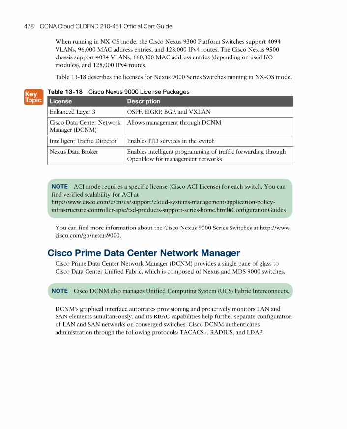
ptg17120290
478 CCNA Cloud CLDFND 210-451 Official Cert Guide
When running in NX-OS mode, the Cisco Nexus 9300 Platform Switches support 4094 VLANs, 96,000 MAC address entries, and 128,000 IPv4 routes. The Cisco Nexus 9500 chassis support 4094 VLANs, 160,000 MAC address entries (depending on used I/O modules), and 128,000 IPv4 routes.
Table 13-18 describes the licenses for Nexus 9000 Series Switches running in NX-OS mode.
Table 13-18 Cisco Nexus 9000 License Packages
License Description
Enhanced Layer 3 OSPF, EIGRP, BGP, and VXLAN
Cisco Data Center Network Manager (DCNM)
Allows management through DCNM
Intelligent Traffic Director Enables ITD services in the switch
Nexus Data Broker Enables intelligent programming of traffic forwarding through OpenFlow for management networks
NOTE ACI mode requires a specific license (Cisco ACI License) for each switch. You can find verified scalability for ACI athttp://www.cisco.com/c/en/us/support/cloud-systems-management/application-policy-infrastructure-controller-apic/tsd-products-support-series-home.html#ConfigurationGuides
You can find more information about the Cisco Nexus 9000 Series Switches at http://www.cisco.com/go/nexus9000.
Cisco Prime Data Center Network ManagerCisco Prime Data Center Network Manager (DCNM) provides a single pane of glass to Cisco Data Center Unified Fabric, which is composed of Nexus and MDS 9000 switches.
NOTE Cisco DCNM also manages Unified Computing System (UCS) Fabric Interconnects.
DCNM’s graphical interface automates provisioning and proactively monitors LAN and SAN elements simultaneously, and its RBAC capabilities help further separate configuration of LAN and SAN networks on converged switches. Cisco DCNM authenticates administration through the following protocols: TACACS+, RADIUS, and LDAP.

ptg17120290
13
Chapter 13: Cisco Cloud Infrastructure Portfolio 479
Distinct LAN and SAN Java clients provide advanced monitoring and provisioning capabilities, while a web dashboard offers health and performance monitoring of a data center fabric. This dashboard allows network and storage administrators to quickly troubleshoot health and performance across the entire range of Cisco NX-OS devices.
Additionally, Cisco DCNM deploys the following features:
■ Cable plan management
■ Automated discovery and topology views
■ Event management and forwarding
■ Web templates
■ Performance and capacity planning
■ Virtual machine path analysis for LAN and SAN
■ Standard and customized reports
■ Configuration and change management
■ Device image management
■ RESTful API
■ VXLAN fabric management
■ Orchestration support (OpenStack, Cisco UCS Director, and VMware vCloud Director)
This management solution can be deployed in Windows and Linux, or as a virtual service blade on Nexus 1100 Cloud Services Platforms. More Cisco DCNM servers can be added to a cluster to follow the growth of a network.
You can find more information about DCNM at http://www.cisco.com/go/dcnm.
Cisco Unified Computing SystemBy design, Cisco Unified Computing System (UCS) consolidates high-performance Intel-based servers, high-speed networking, storage access, and server virtualization into an integrated infrastructure.
With fewer points of managements than similar server solutions, UCS drastically reduces the amount of time dedicated to physical server provisioning and enables bare-metal installations to achieve a similar performance level of server virtualization environments.
Figure 13-7 portrays the main components of Cisco Unified Computing System.
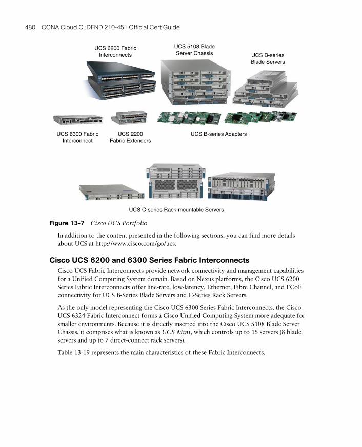
ptg17120290
480 CCNA Cloud CLDFND 210-451 Official Cert Guide
UCS 6200 FabricInterconnects
UCS 5108 BladeServer Chassis UCS B-series
Blade Servers
UCS 6300 FabricInterconnect
UCS 2200Fabric Extenders
UCS B-series Adapters
UCS C-series Rack-mountable Servers
Figure 13-7 Cisco UCS Portfolio
In addition to the content presented in the following sections, you can find more details about UCS at http://www.cisco.com/go/ucs.
Cisco UCS 6200 and 6300 Series Fabric InterconnectsCisco UCS Fabric Interconnects provide network connectivity and management capabilities for a Unified Computing System domain. Based on Nexus platforms, the Cisco UCS 6200 Series Fabric Interconnects offer line-rate, low-latency, Ethernet, Fibre Channel, and FCoE connectivity for UCS B-Series Blade Servers and C-Series Rack Servers.
As the only model representing the Cisco UCS 6300 Series Fabric Interconnects, the Cisco UCS 6324 Fabric Interconnect forms a Cisco Unified Computing System more adequate for smaller environments. Because it is directly inserted into the Cisco UCS 5108 Blade Server Chassis, it comprises what is known as UCS Mini , which controls up to 15 servers (8 blade servers and up to 7 direct-connect rack servers).
Table 13-19 represents the main characteristics of these Fabric Interconnects.
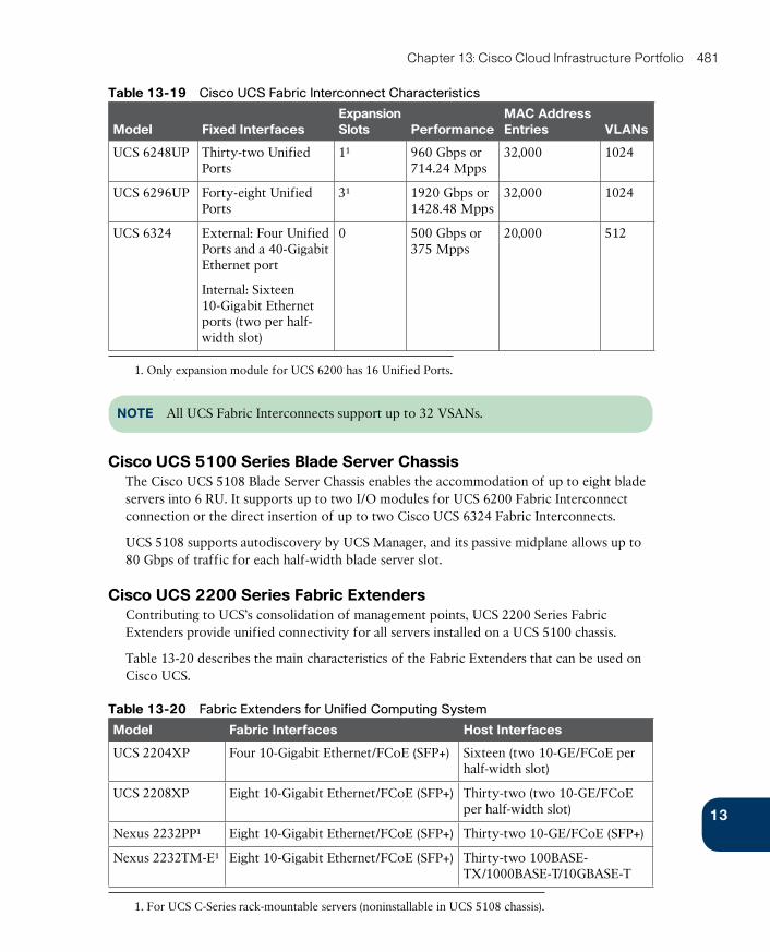
ptg17120290
13
Chapter 13: Cisco Cloud Infrastructure Portfolio 481
Table 13-19 Cisco UCS Fabric Interconnect Characteristics
Model Fixed InterfacesExpansion Slots Performance
MAC Address Entries VLANs
UCS 6248UP Thirty-two Unified Ports
1¹ 960 Gbps or 714.24 Mpps
32,000 1024
UCS 6296UP Forty-eight Unified Ports
3¹ 1920 Gbps or 1428.48 Mpps
32,000 1024
UCS 6324 External: Four Unified Ports and a 40-Gigabit Ethernet port
Internal: Sixteen 10-Gigabit Ethernet ports (two per half-width slot)
0 500 Gbps or 375 Mpps
20,000 512
1. Only expansion module for UCS 6200 has 16 Unified Ports.
NOTE All UCS Fabric Interconnects support up to 32 VSANs.
Cisco UCS 5100 Series Blade Server ChassisThe Cisco UCS 5108 Blade Server Chassis enables the accommodation of up to eight blade servers into 6 RU. It supports up to two I/O modules for UCS 6200 Fabric Interconnect connection or the direct insertion of up to two Cisco UCS 6324 Fabric Interconnects.
UCS 5108 supports autodiscovery by UCS Manager, and its passive midplane allows up to 80 Gbps of traffic for each half-width blade server slot.
Cisco UCS 2200 Series Fabric ExtendersContributing to UCS’s consolidation of management points, UCS 2200 Series Fabric Extenders provide unified connectivity for all servers installed on a UCS 5100 chassis.
Table 13-20 describes the main characteristics of the Fabric Extenders that can be used on Cisco UCS.
Table 13-20 Fabric Extenders for Unified Computing System
Model Fabric Interfaces Host Interfaces
UCS 2204XP Four 10-Gigabit Ethernet/FCoE (SFP+) Sixteen (two 10-GE/FCoE per half-width slot)
UCS 2208XP Eight 10-Gigabit Ethernet/FCoE (SFP+) Thirty-two (two 10-GE/FCoE per half-width slot)
Nexus 2232PP¹ Eight 10-Gigabit Ethernet/FCoE (SFP+) Thirty-two 10-GE/FCoE (SFP+)
Nexus 2232TM-E¹ Eight 10-Gigabit Ethernet/FCoE (SFP+) Thirty-two 100BASE-TX/1000BASE-T/10GBASE-T
1. For UCS C-Series rack-mountable servers (noninstallable in UCS 5108 chassis).
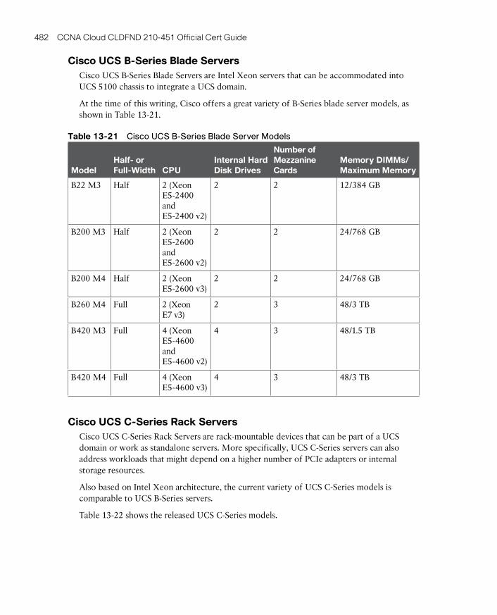
ptg17120290
482 CCNA Cloud CLDFND 210-451 Official Cert Guide
Cisco UCS B-Series Blade ServersCisco UCS B-Series Blade Servers are Intel Xeon servers that can be accommodated into UCS 5100 chassis to integrate a UCS domain.
At the time of this writing, Cisco offers a great variety of B-Series blade server models, as shown in Table 13-21.
Table 13-21 Cisco UCS B-Series Blade Server Models
ModelHalf- or Full-Width CPU
Internal Hard Disk Drives
Number of Mezzanine Cards
Memory DIMMs/Maximum Memory
B22 M3 Half 2 (Xeon E5-2400 and E5-2400 v2)
2 2 12/384 GB
B200 M3 Half 2 (Xeon E5-2600 and E5-2600 v2)
2 2 24/768 GB
B200 M4 Half 2 (Xeon E5-2600 v3)
2 2 24/768 GB
B260 M4 Full 2 (Xeon E7 v3)
2 3 48/3 TB
B420 M3 Full 4 (Xeon E5-4600 and E5-4600 v2)
4 3 48/1.5 TB
B420 M4 Full 4 (Xeon E5-4600 v3)
4 3 48/3 TB
Cisco UCS C-Series Rack ServersCisco UCS C-Series Rack Servers are rack-mountable devices that can be part of a UCS domain or work as standalone servers. More specifically, UCS C-Series servers can also address workloads that might depend on a higher number of PCIe adapters or internal storage resources.
Also based on Intel Xeon architecture, the current variety of UCS C-Series models is comparable to UCS B-Series servers.
Table 13-22 shows the released UCS C-Series models.
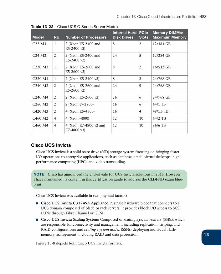
ptg17120290
13
Chapter 13: Cisco Cloud Infrastructure Portfolio 483
Table 13-22 Cisco UCS C-Series Server Models
Model RU Number of ProcessorsInternal Hard Disk Drives
PCIe Slots
Memory DIMMs/Maximum Memory
C22 M3 1 2 (Xeon E5-2400 and E5-2400 v2)
8 2 12/384 GB
C24 M3 2 2 (Xeon E5-2400 and E5-2400 v2)
24 5 12/384 GB
C220 M3 1 2 (Xeon E5-2600 and E5-2600 v2)
8 2 16/512 GB
C220 M4 1 2 (Xeon E5-2400 v3) 8 2 24/768 GB
C240 M3 2 2 (Xeon E5-2600 and E5-2600 v2)
24 5 24/768 GB
C240 M4 2 2 (Xeon E5-2600 v3) 26 6 24/768 GB
C260 M2 2 2 (Xeon e7-2800) 16 6 64/1 TB
C420 M3 2 4 (Xeon E5-4600) 16 4 48/1.5 TB
C460 M2 4 4 (Xeon-4800) 12 10 64/2 TB
C460 M4 4 4 (Xeon E7-4800 v2 and E7-4800 v3)
12 10 96/6 TB
Cisco UCS InvictaCisco UCS Invicta is a solid-state drive (SSD) storage system focusing on bringing faster I/O operations to enterprise applications, such as database, email, virtual desktops, high-performance computing (HPC), and video transcoding.
NOTE Cisco has announced the end-of-sale for UCS Invicta solutions in 2015. However, I have maintained its content in this certification guide to address the CLDFND exam blue-print.
Cisco UCS Invicta was available in two physical factors:
■ Cisco UCS Invicta C3124SA Appliance: A single hardware piece that connects to a UCS domain composed of blade or rack servers. It provides block I/O access to SCSI LUNs through Fibre Channel or iSCSI.
■ Cisco UCS Invicta Scaling System: Composed of scaling system routers (SSRs) , which are responsible for connectivity and management, including replication, striping, and RAID configurations; and scaling system nodes (SSNs) deploying individual flash-memory management, including RAID and data protection.
Figure 13-8 depicts both Cisco UCS Invicta formats.
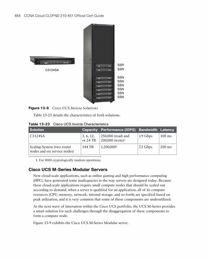
ptg17120290
484 CCNA Cloud CLDFND 210-451 Official Cert Guide
C3124SA
SSRSSR
SSNSSNSSNSSNSSNSSN
Figure 13-8 Cisco UCS Invicta Solutions
Table 13-23 details the characteristics of both solutions.
Table 13-23 Cisco UCS Invicta Characteristics
Solution Capacity Performance (IOPS) Bandwidth Latency
C3124SA 3, 6, 12, or 24 TB
250,000 (read) and 200,000 (write)¹
1.9 Gbps 100 ms
Scaling System (two router nodes and six service nodes)
144 TB 1,200,000¹ 7.2 Gbps 200 ms
1. For 4000 cryptologically random operations.
Cisco UCS M-Series Modular ServersNew cloud-scale applications, such as online gaming and high performance computing (HPC), have generated some inadequacies in the way servers are designed today. Because these cloud-scale applications require small compute nodes that should be scaled out according to demand, when a server is qualified for an application, all of its compute resources (CPU, memory, network, internal storage, and so forth) are specified based on peak utilization, and it is very common that some of these components are underutilized.
As the next wave of innovation within the Cisco UCS portfolio, the UCS M-Series provides a smart solution for such challenges through the disaggregation of these components to form a compute node.
Figure 13-9 exhibits the Cisco UCS M-Series Modular server.
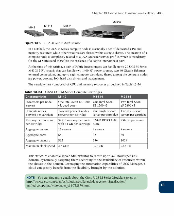
ptg17120290
13
Chapter 13: Cisco Cloud Infrastructure Portfolio 485
M142 M1414 M2814M4308
Figure 13-9 UCS M-Series Architecture
In a nutshell, the UCS M-Series compute node is essentially a set of dedicated CPU and memory resources while other resources are shared within a single chassis. The creation of a compute node is completely related to a UCS Manager service profile, which is mandatory for the M-Series (and therefore the presence of a Fabric Interconnect pair).
At the time of this writing, a pair of Fabric Interconnects can handle up to 20 UCS M-Series M4308 2-RU chassis that can handle two 1400-W power sources, two 40-Gigabit Ethernet external connections, and up to eight compute cartridges. Shared among the compute nodes are power, cooling, I/O, hard disk drives, and management.
The cartridges are composed of CPU and memory resources as outlined in Table 13-24.
Table 13-24 Cisco UCS M-Series Compute Cartridges
Characteristic M142 M1414 M2814
Processors per node (server)
One Intel Xeon E3-1200 v3, quad core
One Intel Xeon E3-1200 v3
Two Intel Xeon e5-2600 v3
Compute nodes (servers) per cartridge
Two independent nodes (servers) per cartridge
One single-socket server per cartridge
Two dual-socket servers per cartridge
Memory per node and per cartridge
32 GB memory per node with 64 GB per cartridge
32-GB DDR3 1600 MHz
256 GB per server
Aggregate servers 16 servers 8 servers 4 servers
Aggregate cores 64 32 80
Aggregate memory 512 256 1024
Maximum clock speed 2.7 GHz 3.7 GHz 2.6 GHz
This structure enables a server administrator to create up to 320 nodes per UCS domain, dynamically assigning them according to the availability of resources within the chassis in the domain. Leveraging the automation capabilities of UCS Manager, a cloud can greatly benefit from the flexibility brought by this solution.
NOTE You can find more details about the Cisco UCS M-Series Modular servers at http://www.cisco.com/c/en/us/solutions/collateral/data-center-virtualization/unified-computing/whitepaper_c11-732876.html.
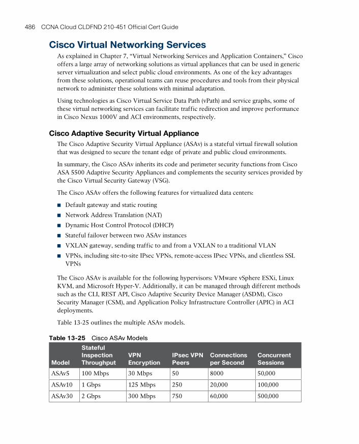
ptg17120290
486 CCNA Cloud CLDFND 210-451 Official Cert Guide
Cisco Virtual Networking ServicesAs explained in Chapter 7, “Virtual Networking Services and Application Containers,” Cisco offers a large array of networking solutions as virtual appliances that can be used in generic server virtualization and select public cloud environments. As one of the key advantages from these solutions, operational teams can reuse procedures and tools from their physical network to administer these solutions with minimal adaptation.
Using technologies as Cisco Virtual Service Data Path (vPath) and service graphs, some of these virtual networking services can facilitate traffic redirection and improve performance in Cisco Nexus 1000V and ACI environments, respectively.
Cisco Adaptive Security Virtual ApplianceThe Cisco Adaptive Security Virtual Appliance (ASAv) is a stateful virtual firewall solution that was designed to secure the tenant edge of private and public cloud environments.
In summary, the Cisco ASAv inherits its code and perimeter security functions from Cisco ASA 5500 Adaptive Security Appliances and complements the security services provided by the Cisco Virtual Security Gateway (VSG).
The Cisco ASAv offers the following features for virtualized data centers:
■ Default gateway and static routing
■ Network Address Translation (NAT)
■ Dynamic Host Control Protocol (DHCP)
■ Stateful failover between two ASAv instances
■ VXLAN gateway, sending traffic to and from a VXLAN to a traditional VLAN
■ VPNs, including site-to-site IPsec VPNs, remote-access IPsec VPNs, and clientless SSL VPNs
The Cisco ASAv is available for the following hypervisors: VMware vSphere ESXi, Linux KVM, and Microsoft Hyper-V. Additionally, it can be managed through different methods such as the CLI, REST API, Cisco Adaptive Security Device Manager (ASDM), Cisco Security Manager (CSM), and Application Policy Infrastructure Controller (APIC) in ACI deployments.
Table 13-25 outlines the multiple ASAv models.
Table 13-25 Cisco ASAv Models
Model
Stateful Inspection Throughput
VPNEncryption
IPsec VPN Peers
Connections per Second
Concurrent Sessions
ASAv5 100 Mbps 30 Mbps 50 8000 50,000
ASAv10 1 Gbps 125 Mbps 250 20,000 100,000
ASAv30 2 Gbps 300 Mbps 750 60,000 500,000
ptg17120290
13
Chapter 13: Cisco Cloud Infrastructure Portfolio 487
This virtual networking service deploys Smart Software Licensing , which provides automatic license activation when the virtual appliance is provisioned. After a successful installation, the Cisco ASAv self-registers with Cisco license servers in the cloud, allowing customers to monitor product entitlements through the Cisco Smart Software Manager.
NOTE You can find more information about the Cisco ASAv at http://www.cisco.com/go/asav.
Cisco Cloud Services Router 1000VThe Cisco Cloud Services Router (CSR) 1000V consists of a single-tenant router deployed as a virtual appliance. In essence, this virtual networking service brings to server virtualization and public cloud environments WAN functionalities such as
■ Secure VPN gateway
■ MPLS WAN termination
■ Data center interconnection with Layer 2 extension
■ Traffic control and redirection
Based on the industry-leading Cisco IOS-XE network operating system, the CSR 1000V enables network operational teams to transparently extend their WAN capabilities to cloud environments using the following hypervisors: VMware vSphere ESXi, Citrix XenServer, Microsoft Hyper-V, and Red Hat KVM. In addition, the Cisco CSR 1000V is supported on Amazon Web Services (AWS).
TIP You will find more information about CSR 1000V for AWS in the AWS Marketplace at https://aws.amazon.com/marketplace/pp/B00EV8VXG2.
The Cisco CSR 1000V licenses are based on throughput and feature set, and can be purchased for a term of 1 year, 3 years, or perpetually. At the time of this writing, the virtual networking service offers licenses for the following throughput maximum rates: 10 Mbps, 50 Mbps, 100 Mbps, 250 Mbps, 500 Mbps, 1 Gbps, 2.5 Gbps, 5 Gbps, and 10 Gbps.
NOTE After a throughput license is activated, the CSR 1000V instance will limit its aggre-gate bidirectional throughput to that stated value.
Table 13-26 describes the Cisco CSR 1000V feature set licenses and the functionalities they enable in an instance.
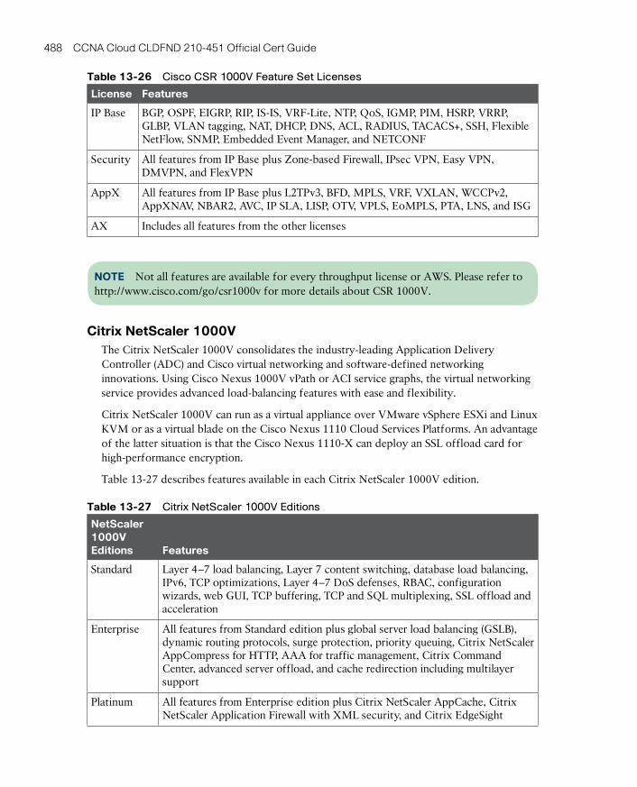
ptg17120290
488 CCNA Cloud CLDFND 210-451 Official Cert Guide
Table 13-26 Cisco CSR 1000V Feature Set Licenses
License Features
IP Base BGP, OSPF, EIGRP, RIP, IS-IS, VRF-Lite, NTP, QoS, IGMP, PIM, HSRP, VRRP, GLBP, VLAN tagging, NAT, DHCP, DNS, ACL, RADIUS, TACACS+, SSH, Flexible NetFlow, SNMP, Embedded Event Manager, and NETCONF
Security All features from IP Base plus Zone-based Firewall, IPsec VPN, Easy VPN, DMVPN, and FlexVPN
AppX All features from IP Base plus L2TPv3, BFD, MPLS, VRF, VXLAN, WCCPv2, AppXNAV, NBAR2, AVC, IP SLA, LISP, OTV, VPLS, EoMPLS, PTA, LNS, and ISG
AX Includes all features from the other licenses
NOTE Not all features are available for every throughput license or AWS. Please refer to http://www.cisco.com/go/csr1000v for more details about CSR 1000V.
Citrix NetScaler 1000VThe Citrix NetScaler 1000V consolidates the industry-leading Application Delivery Controller (ADC) and Cisco virtual networking and software-defined networking innovations. Using Cisco Nexus 1000V vPath or ACI service graphs, the virtual networking service provides advanced load-balancing features with ease and flexibility.
Citrix NetScaler 1000V can run as a virtual appliance over VMware vSphere ESXi and Linux KVM or as a virtual blade on the Cisco Nexus 1110 Cloud Services Platforms. An advantage of the latter situation is that the Cisco Nexus 1110-X can deploy an SSL offload card for high-performance encryption.
Table 13-27 describes features available in each Citrix NetScaler 1000V edition.
Table 13-27 Citrix NetScaler 1000V Editions
NetScaler 1000V Editions Features
Standard Layer 4–7 load balancing, Layer 7 content switching, database load balancing, IPv6, TCP optimizations, Layer 4–7 DoS defenses, RBAC, configuration wizards, web GUI, TCP buffering, TCP and SQL multiplexing, SSL offload and acceleration
Enterprise All features from Standard edition plus global server load balancing (GSLB), dynamic routing protocols, surge protection, priority queuing, Citrix NetScaler AppCompress for HTTP, AAA for traffic management, Citrix Command Center, advanced server offload, and cache redirection including multilayer support
Platinum All features from Enterprise edition plus Citrix NetScaler AppCache, Citrix NetScaler Application Firewall with XML security, and Citrix EdgeSight

ptg17120290
13
Chapter 13: Cisco Cloud Infrastructure Portfolio 489
Citrix NetScaler 1000V can be licensed according to its maximum allowed throughput. Available throughputs are 100 Mbps, 200 Mbps, 500 Mbps, 1 Gbps, 2 Gbps, 3 Gbps, 4 Gbps, and 5 Gbps.
NOTE The 5 Gbps license is only available when Citrix NetScaler is deployed as a virtual blade on Cisco Nexus 1110-X with SSL offload card.
As an illustration, Table 13-28 compares the maximum performance Citrix NetScaler 1000V achieves as a virtual appliance and as a virtual blade.
Table 13-28 Citrix NetScaler 1000V Performance Comparison
Performance Virtual Appliance (VMware vSphere ESXi or Linux KVM)
Cisco Nexus 1110-X with SSL Card
Maximum throughput 4 Gbps 5 Gbps
HTTP requests per second 100,000 325,000
SSL transactions per second (2048-bit key certificates)
750 32,000
SSL throughput 1 Gbps 5 Gbps
Compression throughput 0.75 Gbps 2.6 Gbps
NOTE You can find further details about Citrix NetScaler 1000V at http://www.cisco.com/go/ns1000v.
Cisco Virtual Wide-Area Application ServicesCisco Virtual Wide-Area Application Services (vWAAS) was one of the first WAN accelerators available as a virtual networking service. Both for server virtualization and private cloud environments, vWAAS can bring benefits such as
■ All features and compatibility with Cisco WAAS
■ Integration with Cisco Nexus 1000V through vPath
■ Caching high availability through external storage
■ Compatibility with VMware vSphere advanced features such as VMware High Availability, VMotion, and Storage VMotion
Table 13-29 describes the available licenses for vWAAS instances at the time of this writing.

ptg17120290
490 CCNA Cloud CLDFND 210-451 Official Cert Guide
Table 13-29 Cisco vWAAS Licenses
License Description
vWAAS-150 Supports 150 optimized connections
vWAAS-200 Supports 200 optimized connections
vWAAS-750 Supports 750 optimized connections
vWAAS-1300 Supports 1300 optimized connections
vWAAS-2500 Supports 2500 optimized connections
vWAAS-6000 Supports 6000 optimized connections
vWAAS-12000 Supports 12,000 optimized connections
vWAAS-50000 Supports 50,000 optimized connections
vCM-100N Manages up to 100 WAAS nodes
vCM-500N Manages up to 500 WAAS nodes
vCM-1000N Manages up to 1000 WAAS nodes
vCM-2000N Manages up to 2000 WAAS nodes
NOTE You can learn more about Cisco vWAAS at http://www.cisco.com/go/vwaas.
Virtual Security GatewayCisco Virtual Security Gateway (VSG) is a virtual appliance that provides trusted access to secure server virtualization and cloud networks. Cisco VSG ensures that security zones are controlled within server virtualization clusters without losing the flexibility and scalability of such environments.
Intrinsically linked to Cisco Nexus 1000V, Cisco VSG uses vPath technology to offload subsequent traffic to the virtual switch, after the first packet of the communication is analyzed.
In summary, Cisco VSG provides the following features:
■ Trusted access
■ Dynamic operation
■ Non-disruptive administration
■ VXLAN awareness
■ vPath service chaining to multiple virtual network services
VSG is available as a virtual appliance (VMware vSphere ESXi or Microsoft Hyper-V) or a virtual service blade on Cisco Nexus 1100 Cloud Services Platforms. The virtual networking service is licensed per server socket along with the Cisco Nexus 1000V advanced license.
At the time of this writing, a single VSG instance can support up to 256,000 concurrent connections and control up to 10,000 new connections per second.
NOTE For more information about Cisco VSG, please refer to http://www.cisco.com/go/vsg.

ptg17120290
13
Chapter 13: Cisco Cloud Infrastructure Portfolio 491
Exam Preparation Tasks
Review All the Key TopicsReview the most important topics in this chapter, denoted with a Key Topic icon in the outer margin of the page. Table 13-30 lists a reference of these key topics and the page number on which each is found.
Table 13-30 Key Topics for Chapter 13
Key Topic Element Description Page Number
Table 13-3 Cisco MDS 9000 license packages 461
Table 13-10 Cisco Nexus 5000 license packages 471
Table 13-11 Cisco Nexus 7000 and 7700 supervisor module characteristics
472
Table 13-15 Cisco Nexus 7000 and 7700 license packages 474
Table 13-18 Cisco Nexus 9000 license packages 478
Complete the Tables and Lists from MemoryPrint a copy of Appendix B, “Memory Tables” (found on the CD), or at least the section for this chapter, and complete the tables and lists from memory. Appendix C, “Answers to Memory Tables,” also on the CD, includes completed tables and lists so that you can check your work.
Define Key TermsDefine the following key terms from this chapter, and check your answers in the glossary:
director-class, virtual blade, oversubscription, Unified Port, supervisor module, fabric module, I/O module
ptg17120290
This chapter covers the following topics:
■ Modular Data Centers
■ FlexPod
■ Vblock
■ VSPEX
■ UCS Integrated Infrastructure for Red Hat OpenStack
This chapter covers the following exam objectives:
■ 5.6 Describe various integrated infrastructures
■ 5.6.a FlexPod (NetApp)■ 5.6.b VBlock (VCE)■ 5.6.c VSPEX (EMC)■ 5.6.d OpenBlock (Red Hat)

ptg17120290
CHAPTER 14
Integrated InfrastructuresCloud, the final frontier. In the last log of our 14-chapter mission, you will learn about the importance of standardized modules for data center design and operation. These infrastructure resources can be quickly consumed by end-user requests in cloud computing environments, so their operational teams must be well prepared to forecast and promptly respond to flash demands.
The adoption of predefined data center modules, also known as pools of devices (PODs), can greatly help reduce the complexity when a cloud needs to be scaled. With such intention, many organizations have developed their own infrastructure modules, according to their cloud demands and characteristics. Nevertheless, in an effort to reduce time spent on design, integration, and testing, Cisco and other IT vendors have cooperated to offer ready-to-go data center modules that are commonly referred to as integrated
infrastructures.
The CLDFND exam expects CCNA Cloud candidates to demonstrate knowledge about the main integrated infrastructures available in the market: FlexPod, Vblock, VSPEX, and OpenBlock (formally known as UCS Integrated Infrastructure for Red Hat OpenStack, or UCSO). To help you achieve this objective, this chapter addresses the concept of PODs, their main advantages for cloud computing scenarios, and the contrasts between custom PODs and prebuilt integrated infrastructures. Then, it delves into each one of these solutions to introduce their main differences and applicability.
“Do I Know This Already?” QuizThe “Do I Know This Already?” quiz allows you to assess whether you should read this entire chapter thoroughly or jump to the “Exam Preparation Tasks” section. If you are in doubt about your answers to these questions or your own assessment of your knowledge of the topics, read the entire chapter. Table 14-1 lists the major headings in this chapter and their corresponding “Do I Know This Already?” quiz questions. You can find the answers in Appendix A, “Answers to the Pre-Assessments and Quizzes.”
Table 14-1 “Do I Know This Already?” Section-to-Question Mapping
Foundation Topics Section Questions
Modular Data Centers 1–2
FlexPod 3–4
Vblock 5–6
VSPEX 7–8
UCS Integrated Infrastructure for Red Hat OpenStack 9–10
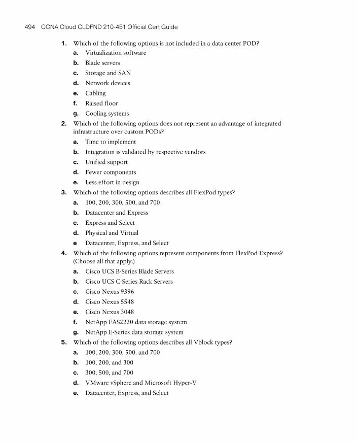
ptg17120290
494 CCNA Cloud CLDFND 210-451 Official Cert Guide
1. Which of the following options is not included in a data center POD?
a. Virtualization software
b. Blade servers
c. Storage and SAN
d. Network devices
e. Cabling
f. Raised floor
g. Cooling systems
2. Which of the following options does not represent an advantage of integrated infrastructure over custom PODs?
a. Time to implement
b. Integration is validated by respective vendors
c. Unified support
d. Fewer components
e. Less effort in design
3. Which of the following options describes all FlexPod types?
a. 100, 200, 300, 500, and 700
b. Datacenter and Express
c. Express and Select
d. Physical and Virtual
e Datacenter, Express, and Select
4. Which of the following options represent components from FlexPod Express? (Choose all that apply.)
a. Cisco UCS B-Series Blade Servers
b. Cisco UCS C-Series Rack Servers
c. Cisco Nexus 9396
d. Cisco Nexus 5548
e. Cisco Nexus 3048
f. NetApp FAS2220 data storage system
g. NetApp E-Series data storage system
5. Which of the following options describes all Vblock types?
a. 100, 200, 300, 500, and 700
b. 100, 200, and 300
c. 300, 500, and 700
d. VMware vSphere and Microsoft Hyper-V
e. Datacenter, Express, and Select
ptg17120290
14
Chapter 14: Integrated Infrastructures 495
6. Which of the following options represent components from Vblock System 740? (Choose all that apply.)
a. Cisco UCS B-Series Blade Servers
b. Cisco UCS C-Series Rack Servers
c. Cisco Nexus 9396
d. Cisco MDS 9148S
e. Cisco Nexus 3048
f. EMC VNX5400
g. EMC VMAX
h. Microsoft Windows 2012 Hyper-V
7. Which of the following options is not a Cisco solution for EMC VSPEX? (Choose all that apply.)
a. VMware vSphere 5.5 for 1000 VMs
b. UCS Mini Branch Office vSphere 5.5 for up to 100 VMs
c. Microsoft Private Cloud FastTrack 4.0
d. Hyper-V 2012 R2 for 300 VMs
e. Red Hat Enterprise Linux OpenStack
8. Which of the following options contain mandatory components from the Cisco Solution for VSPEX called Microsoft Private Cloud FastTrack 4.0? (Choose all that apply.)
a. Cisco UCS B-Series Blade Servers
b. Cisco UCS C-Series Rack Servers
c. Cisco Nexus 9396
d. Cisco MDS 9148S
e. Cisco Nexus 3048
f. EMC VNX Storage System
g. EMC VMAX Enterprise Data Systems Platform
h. Microsoft Windows 2012 Hyper-V
i. Microsoft System Center
9. Which of the following options represent hardware components of the UCS Integrated Infrastructure for Red Hat OpenStack? (Choose all that apply.)
a. Cisco UCS B-Series Blade Servers
b. Cisco UCS C-Series Rack Servers
c. Cisco Nexus 9372
d. Cisco MDS 9148S
e. Cisco Nexus 3048
f. Cisco UCS Invicta
g. Cisco Nexus 1000V for KVM
ptg17120290
496 CCNA Cloud CLDFND 210-451 Official Cert Guide
10. Which of the following options represent software components of the UCS Integrated Infrastructure for Red Hat OpenStack? (Choose all that apply.)
a. Red Hat Fedora
b. Red Hat Enterprise Linux OpenStack Platform
c. Cisco Nexus 1000V for KVM
d. Red Hat Ceph Storage
ptg17120290
14
Chapter 14: Integrated Infrastructures 497
Foundation Topics
Modular Data CentersA data center is certainly not a static structure, where a single project establishes its charac-teristics and capacity for the duration of its lifetime. Using an appropriate metaphor, a data center shares several similarities with a city, including its dynamism and changing pace.
Multiple factors commonly impose changes on a data center infrastructure, including
■ Resource exhaustion
■ Technological evolution
■ New applications requirements
■ Retrofits
■ Hardware end-of-support
From an architectural perspective, data center infrastructure teams can follow different approaches to implement such changes. Obviously, a complete destruction and rebuild is certainly the most expensive and disruptive method of data center evolution. Continuing our city comparison, such a radical approach would be equivalent to a mayor asking for the whole population to evacuate the city during public works. Therefore, to avoid business-critical application disruptions, data center architects usually follow an approach that breaks data infrastructure modifications into smaller pieces, introducing changes in a single partition of a data center and using it as a modular unit for scaling.
A data center facility offers several candidates for such atomic division, such as a server rack, a rack row, or even a whole data center room. However, regardless of which division is chosen, many architects realize that a strict uniform division of infrastructure always results in overused and underused units due to differences in application requirements.
Recently, a pure architectural concept has helped data center infrastructure teams to define modular units that can optimize efficiency, facilitate changes, and streamline scaling , as discussed next.
Pool of DevicesA pool of devices (POD) consists of an arrangement of infrastructure components that are integrated in a systematic way in order to improve modularity, predictability, and reuse in a data center facility. Within this rather broad definition, a data center POD may contain any or all of the following components:
■ Servers
■ Racks
■ Cabling
■ In-rack cooling systems
■ Network devices
■ Patch panels
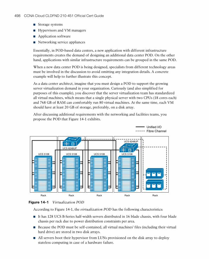
ptg17120290
498 CCNA Cloud CLDFND 210-451 Official Cert Guide
■ Storage systems
■ Hypervisors and VM managers
■ Application software
■ Networking service appliances
Essentially, in POD-based data centers, a new application with different infrastructure requirements creates the demand of designing an additional data center POD. On the other hand, applications with similar infrastructure requirements can be grouped in the same POD.
When a new data center POD is being designed, specialists from different technology areas must be involved in the discussion to avoid omitting any integration details. A concrete example will help to further illustrate this concept.
As a data center architect, imagine that you must design a POD to support the growing server virtualization demand in your organization. Curiously (and also simplified for purposes of this example), you discover that the server virtualization team has standardized all virtual machines, which means that a single physical server with two CPUs (18 cores each) and 768 GB of RAM can comfortably run 80 virtual machines. At the same time, each VM should have at least 20 GB of storage, preferably, on a disk array.
After discussing additional requirements with the networking and facilities teams, you propose the POD that Figure 14-1 exhibits.
Unified I/OFibre Channel
UCS 6248UP
UCS 5108
UCS 6248UP
Rack
UCS 5108
Rack
UCS 5108
Rack
UCS 5108
Rack Rack
Figure 14-1 Virtualization POD
According to Figure 14-1, the virtualization POD has the following characteristics:
■ It has 128 UCS B-Series half-width servers distributed in 16 blade chassis, with four blade chassis per rack due to power distribution constraints per area.
■ Because the POD must be self-contained, all virtual machines’ files (including their virtual hard drive) are stored in two disk arrays.
■ All servers boot their hypervisor from LUNs provisioned on the disk array to deploy stateless computing in case of a hardware failure.
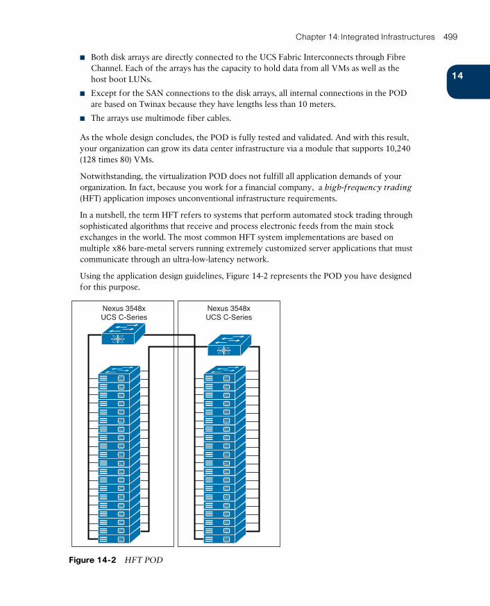
ptg17120290
14
Chapter 14: Integrated Infrastructures 499
■ Both disk arrays are directly connected to the UCS Fabric Interconnects through Fibre Channel. Each of the arrays has the capacity to hold data from all VMs as well as the host boot LUNs.
■ Except for the SAN connections to the disk arrays, all internal connections in the POD are based on Twinax because they have lengths less than 10 meters.
■ The arrays use multimode fiber cables.
As the whole design concludes, the POD is fully tested and validated. And with this result, your organization can grow its data center infrastructure via a module that supports 10,240 (128 times 80) VMs.
Notwithstanding, the virtualization POD does not fulfill all application demands of your organization. In fact, because you work for a financial company, a high-frequency trading (HFT) application imposes unconventional infrastructure requirements.
In a nutshell, the term HFT refers to systems that perform automated stock trading through sophisticated algorithms that receive and process electronic feeds from the main stock exchanges in the world. The most common HFT system implementations are based on multiple x86 bare-metal servers running extremely customized server applications that must communicate through an ultra-low-latency network.
Using the application design guidelines, Figure 14-2 represents the POD you have designed for this purpose.
Nexus 3548xUCS C-Series
Nexus 3548xUCS C-Series
Figure 14-2 HFT POD
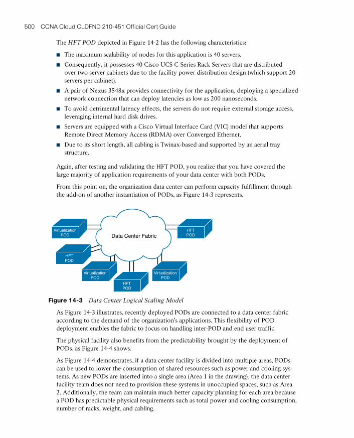
ptg17120290
500 CCNA Cloud CLDFND 210-451 Official Cert Guide
The HFT POD depicted in Figure 14-2 has the following characteristics:
■ The maximum scalability of nodes for this application is 40 servers.
■ Consequently, it possesses 40 Cisco UCS C-Series Rack Servers that are distributed over two server cabinets due to the facility power distribution design (which support 20 servers per cabinet).
■ A pair of Nexus 3548x provides connectivity for the application, deploying a specialized network connection that can deploy latencies as low as 200 nanoseconds.
■ To avoid detrimental latency effects, the servers do not require external storage access, leveraging internal hard disk drives.
■ Servers are equipped with a Cisco Virtual Interface Card (VIC) model that supports Remote Direct Memory Access (RDMA) over Converged Ethernet.
■ Due to its short length, all cabling is Twinax-based and supported by an aerial tray structure.
Again, after testing and validating the HFT POD, you realize that you have covered the large majority of application requirements of your data center with both PODs.
From this point on, the organization data center can perform capacity fulfillment through the add-on of another instantiation of PODs, as Figure 14-3 represents.
VirtualizationPOD
VirtualizationPOD
VirtualizationPOD
HFTPOD
HFTPOD
HFTPOD
Data Center Fabric
Figure 14-3 Data Center Logical Scaling Model
As Figure 14-3 illustrates, recently deployed PODs are connected to a data center fabric according to the demand of the organization’s applications. This flexibility of POD deployment enables the fabric to focus on handling inter-POD and end user traffic.
The physical facility also benefits from the predictability brought by the deployment of PODs, as Figure 14-4 shows.
As Figure 14-4 demonstrates, if a data center facility is divided into multiple areas, PODs can be used to lower the consumption of shared resources such as power and cooling sys-tems. As new PODs are inserted into a single area (Area 1 in the drawing), the data center facility team does not need to provision these systems in unoccupied spaces, such as Area 2. Additionally, the team can maintain much better capacity planning for each area because a POD has predictable physical requirements such as total power and cooling consumption, number of racks, weight, and cabling.
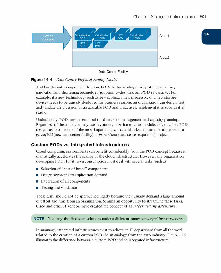
ptg17120290
14
Chapter 14: Integrated Infrastructures 501
HFTPOD
HFTPOD
Area 1
Data Center Facility
Area 2
VirtualizationPOD
VirtualizationPOD
HFTPOD
VirtualizationPOD
PowerCooling
Figure 14-4 Data Center Physical Scaling Model
And besides enforcing standardization, PODs foster an elegant way of implementing innovation and shortening technology adoption cycles, through POD versioning. For example, if a new technology (such as new cabling, a new processor, or a new storage device) needs to be quickly deployed for business reasons, an organization can design, test, and validate a 2.0 version of an available POD and proactively implement it as soon as it is ready.
Undoubtedly, PODs are a useful tool for data center management and capacity planning. Regardless of the name you may use in your organization (such as module, cell, or cube), POD design has become one of the most important architectural tasks that must be addressed in a greenfield (new data center facility) or brownfield (data center expansion) project.
Custom PODs vs. Integrated InfrastructuresCloud computing environments can benefit considerably from the POD concept because it dramatically accelerates the scaling of the cloud infrastructure. However, any organization developing PODs for its own consumption must deal with several tasks, such as
■ Selection of “best of breed” components
■ Design according to application demand
■ Integration of all components
■ Testing and validation
These tasks should not be approached lightly because they usually demand a large amount of effort and time from an organization. Sensing an opportunity to streamline these tasks, Cisco and other IT vendors have created the concept of an integrated infrastructure.
NOTE You may also find such solutions under a different name: converged infrastructures .
In summary, integrated infrastructures exist to relieve an IT department from all the work related to the creation of a custom POD. As an analogy from the auto industry, Figure 14-5 illustrates the difference between a custom POD and an integrated infrastructure.
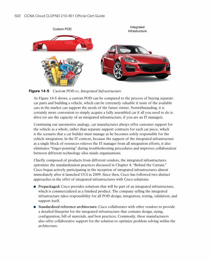
ptg17120290
502 CCNA Cloud CLDFND 210-451 Official Cert Guide
Custom PODIntegrated
Infrastructure
Figure 14-5 Custom POD vs. Integrated Infrastructure
As Figure 14-5 shows, a custom POD can be compared to the process of buying separate car parts and building a vehicle, which can be extremely valuable if none of the available cars in the market can support the needs of the future owner. Notwithstanding, it is certainly more convenient to simply acquire a fully assembled car if all you need to do is drive (or use the capacity of an integrated infrastructure, if you are an IT manager).
Continuing our automotive analogy, car manufactures always offer customer support for the vehicle as a whole, rather than separate support contracts for each car piece, which is the scenario that a car builder must manage as he becomes solely responsible for the vehicle integration. In the IT context, because the support of the integrated infrastructure as a single block of resources relieves the IT manager from all integration efforts, it also eliminates “finger-pointing” during troubleshooting procedures and improves collaboration between different technology silos inside organizations.
Chiefly composed of products from different vendors, the integrated infrastructures epitomize the standardization practices discussed in Chapter 4, “Behind the Curtain.” Cisco began actively participating in the inception of integrated infrastructures almost immediately after it launched UCS in 2009. Since then, Cisco has followed two distinct approaches in the offer of integrated infrastructures with Cisco solutions:
■ Prepackaged: Cisco provides solutions that will be part of an integrated infrastructure, which is commercialized as a finished product. The company selling the integrated infrastructure takes responsibility for all POD design, integration, testing, validation, and support itself.
■ Standardized reference architecture: Cisco collaborates with other vendors to provide a detailed blueprint for the integrated infrastructure that contains design, sizing, configuration, bill of materials, and best practices. Commonly, these manufacturers also offer collaborative support for the solution to optimize problem solving within the architecture.
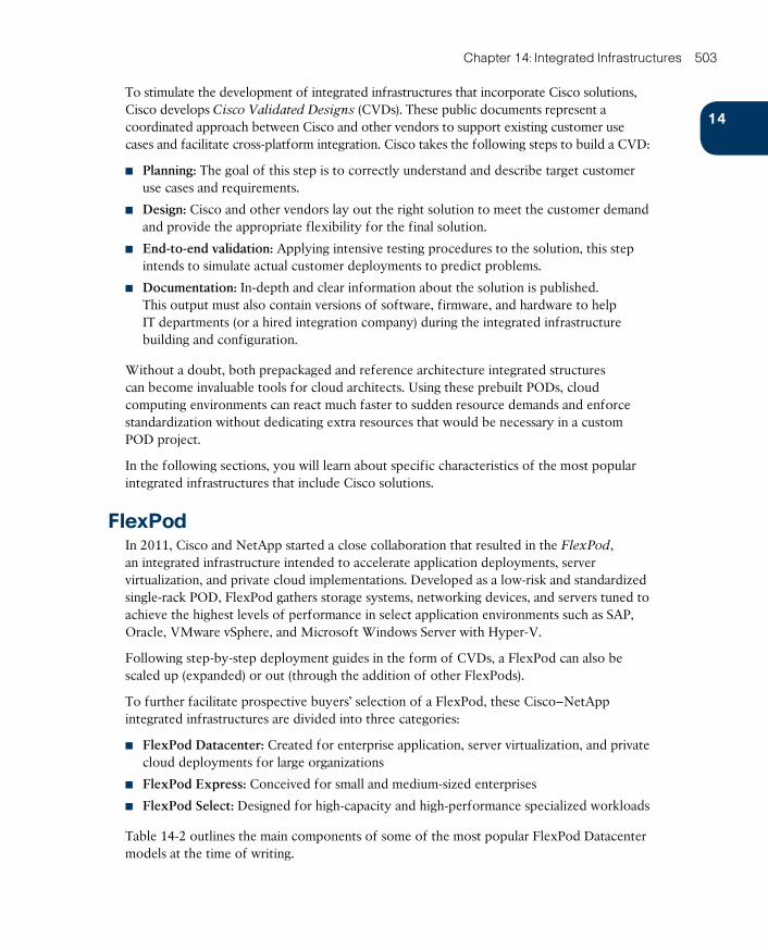
ptg17120290
14
Chapter 14: Integrated Infrastructures 503
To stimulate the development of integrated infrastructures that incorporate Cisco solutions, Cisco develops Cisco Validated Designs (CVDs) . These public documents represent a coordinated approach between Cisco and other vendors to support existing customer use cases and facilitate cross-platform integration. Cisco takes the following steps to build a CVD:
■ Planning: The goal of this step is to correctly understand and describe target customer use cases and requirements.
■ Design: Cisco and other vendors lay out the right solution to meet the customer demand and provide the appropriate flexibility for the final solution.
■ End-to-end validation: Applying intensive testing procedures to the solution, this step intends to simulate actual customer deployments to predict problems.
■ Documentation: In-depth and clear information about the solution is published. This output must also contain versions of software, firmware, and hardware to help IT departments (or a hired integration company) during the integrated infrastructure building and configuration.
Without a doubt, both prepackaged and reference architecture integrated structures can become invaluable tools for cloud architects. Using these prebuilt PODs, cloud computing environments can react much faster to sudden resource demands and enforce standardization without dedicating extra resources that would be necessary in a custom POD project.
In the following sections, you will learn about specific characteristics of the most popular integrated infrastructures that include Cisco solutions.
FlexPodIn 2011, Cisco and NetApp started a close collaboration that resulted in the FlexPod, an integrated infrastructure intended to accelerate application deployments, server virtualization, and private cloud implementations. Developed as a low-risk and standardized single-rack POD, FlexPod gathers storage systems, networking devices, and servers tuned to achieve the highest levels of performance in select application environments such as SAP, Oracle, VMware vSphere, and Microsoft Windows Server with Hyper-V.
Following step-by-step deployment guides in the form of CVDs, a FlexPod can also be scaled up (expanded) or out (through the addition of other FlexPods).
To further facilitate prospective buyers’ selection of a FlexPod, these Cisco–NetApp integrated infrastructures are divided into three categories:
■ FlexPod Datacenter: Created for enterprise application, server virtualization, and private cloud deployments for large organizations
■ FlexPod Express: Conceived for small and medium-sized enterprises
■ FlexPod Select: Designed for high-capacity and high-performance specialized workloads
Table 14-2 outlines the main components of some of the most popular FlexPod Datacenter models at the time of writing.
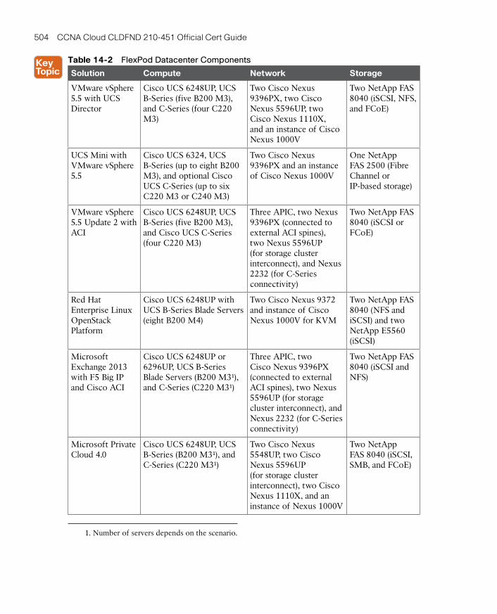
ptg17120290
504 CCNA Cloud CLDFND 210-451 Official Cert Guide
Table 14-2 FlexPod Datacenter Components
Solution Compute Network Storage
VMware vSphere 5.5 with UCS Director
Cisco UCS 6248UP, UCS B-Series (five B200 M3), and C-Series (four C220 M3)
Two Cisco Nexus 9396PX, two Cisco Nexus 5596UP, two Cisco Nexus 1110X, and an instance of Cisco Nexus 1000V
Two NetApp FAS 8040 (iSCSI, NFS, and FCoE)
UCS Mini with VMware vSphere 5.5
Cisco UCS 6324, UCS B-Series (up to eight B200 M3), and optional Cisco UCS C-Series (up to six C220 M3 or C240 M3)
Two Cisco Nexus 9396PX and an instance of Cisco Nexus 1000V
One NetApp FAS 2500 (Fibre Channel or IP-based storage)
VMware vSphere 5.5 Update 2 with ACI
Cisco UCS 6248UP, UCS B-Series (five B200 M3), and Cisco UCS C-Series (four C220 M3)
Three APIC, two Nexus 9396PX (connected to external ACI spines), two Nexus 5596UP (for storage cluster interconnect), and Nexus 2232 (for C-Series connectivity)
Two NetApp FAS 8040 (iSCSI or FCoE)
Red Hat Enterprise Linux OpenStack Platform
Cisco UCS 6248UP with UCS B-Series Blade Servers (eight B200 M4)
Two Cisco Nexus 9372 and instance of Cisco Nexus 1000V for KVM
Two NetApp FAS 8040 (NFS and iSCSI) and two NetApp E5560 (iSCSI)
Microsoft Exchange 2013 with F5 Big IP and Cisco ACI
Cisco UCS 6248UP or 6296UP, UCS B-Series Blade Servers (B200 M3¹), and C-Series (C220 M3¹)
Three APIC, two Cisco Nexus 9396PX (connected to external ACI spines), two Nexus 5596UP (for storage cluster interconnect), and Nexus 2232 (for C-Series connectivity)
Two NetApp FAS 8040 (iSCSI and NFS)
Microsoft Private Cloud 4.0
Cisco UCS 6248UP, UCS B-Series (B200 M3¹), and C-Series (C220 M3¹)
Two Cisco Nexus 5548UP, two Cisco Nexus 5596UP (for storage cluster interconnect), two Cisco Nexus 1110X, and an instance of Nexus 1000V
Two NetApp FAS 8040 (iSCSI, SMB, and FCoE)
1. Number of servers depends on the scenario.
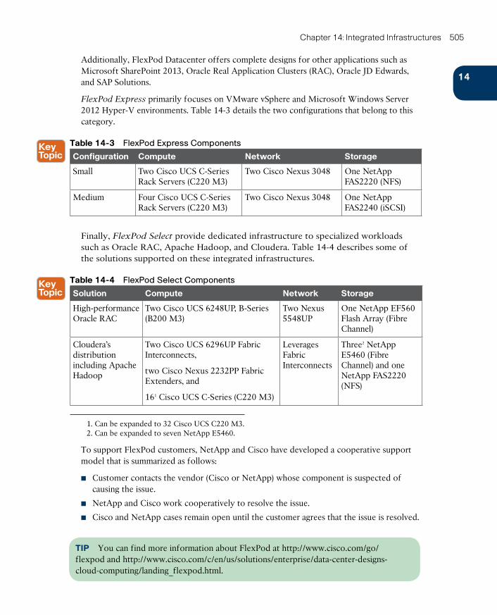
ptg17120290
14
Chapter 14: Integrated Infrastructures 505
Additionally, FlexPod Datacenter offers complete designs for other applications such as Microsoft SharePoint 2013, Oracle Real Application Clusters (RAC), Oracle JD Edwards, and SAP Solutions.
FlexPod Express primarily focuses on VMware vSphere and Microsoft Windows Server 2012 Hyper-V environments. Table 14-3 details the two configurations that belong to this category.
Table 14-3 FlexPod Express Components
Configuration Compute Network Storage
Small Two Cisco UCS C-Series Rack Servers (C220 M3)
Two Cisco Nexus 3048 One NetApp FAS2220 (NFS)
Medium Four Cisco UCS C-Series Rack Servers (C220 M3)
Two Cisco Nexus 3048 One NetApp FAS2240 (iSCSI)
Finally, FlexPod Select provide dedicated infrastructure to specialized workloads such as Oracle RAC, Apache Hadoop, and Cloudera. Table 14-4 describes some of the solutions supported on these integrated infrastructures.
Table 14-4 FlexPod Select Components
Solution Compute Network Storage
High-performance Oracle RAC
Two Cisco UCS 6248UP, B-Series (B200 M3)
Two Nexus 5548UP
One NetApp EF560 Flash Array (Fibre Channel)
Cloudera’s distribution including Apache Hadoop
Two Cisco UCS 6296UP Fabric Interconnects,
two Cisco Nexus 2232PP Fabric Extenders, and
161 Cisco UCS C-Series (C220 M3)
Leverages Fabric Interconnects
Three2 NetApp E5460 (Fibre Channel) and one NetApp FAS2220 (NFS)
1. Can be expanded to 32 Cisco UCS C220 M3.2. Can be expanded to seven NetApp E5460.
To support FlexPod customers, NetApp and Cisco have developed a cooperative support model that is summarized as follows:
■ Customer contacts the vendor (Cisco or NetApp) whose component is suspected of causing the issue.
■ NetApp and Cisco work cooperatively to resolve the issue.
■ Cisco and NetApp cases remain open until the customer agrees that the issue is resolved.
TIP You can find more information about FlexPod at http://www.cisco.com/go/flexpod and http://www.cisco.com/c/en/us/solutions/enterprise/data-center-designs-cloud-computing/landing_flexpod.html.
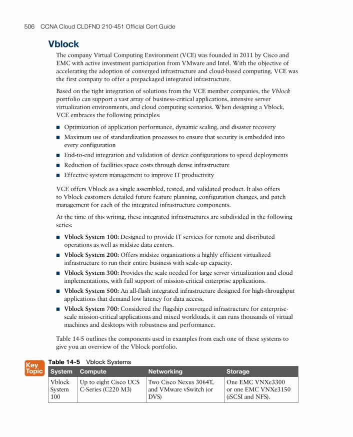
ptg17120290
506 CCNA Cloud CLDFND 210-451 Official Cert Guide
VblockThe company Virtual Computing Environment (VCE) was founded in 2011 by Cisco and EMC with active investment participation from VMware and Intel. With the objective of accelerating the adoption of converged infrastructure and cloud-based computing, VCE was the first company to offer a prepackaged integrated infrastructure.
Based on the tight integration of solutions from the VCE member companies, the Vblock portfolio can support a vast array of business-critical applications, intensive server virtualization environments, and cloud computing scenarios. When designing a Vblock, VCE embraces the following principles:
■ Optimization of application performance, dynamic scaling, and disaster recovery
■ Maximum use of standardization processes to ensure that security is embedded into every configuration
■ End-to-end integration and validation of device configurations to speed deployments
■ Reduction of facilities space costs through dense infrastructure
■ Effective system management to improve IT productivity
VCE offers Vblock as a single assembled, tested, and validated product. It also offers to Vblock customers detailed future feature planning, configuration changes, and patch management for each of the integrated infrastructure components.
At the time of this writing, these integrated infrastructures are subdivided in the following series:
■ Vblock System 100: Designed to provide IT services for remote and distributed operations as well as midsize data centers.
■ Vblock System 200: Offers midsize organizations a highly efficient virtualized infrastructure to run their entire business with scale-up capacity.
■ Vblock System 300: Provides the scale needed for large server virtualization and cloud implementations, with full support of mission-critical enterprise applications.
■ Vblock System 500: An all-flash integrated infrastructure designed for high-throughput applications that demand low latency for data access.
■ Vblock System 700: Considered the flagship converged infrastructure for enterprise-scale mission-critical applications and mixed workloads, it can runs thousands of virtual machines and desktops with robustness and performance.
Table 14-5 outlines the components used in examples from each one of these systems to give you an overview of the Vblock portfolio.
Table 14-5 Vblock Systems
System Compute Networking Storage
Vblock System 100
Up to eight Cisco UCS C-Series (C220 M3)
Two Cisco Nexus 3064T, and VMware vSwitch (or DVS)
One EMC VNXe3300 or one EMC VNXe3150 (iSCSI and NFS).
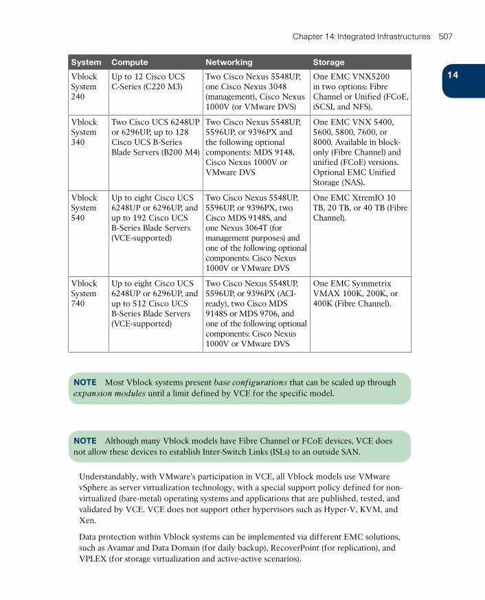
ptg17120290
14
Chapter 14: Integrated Infrastructures 507
System Compute Networking Storage
Vblock System 240
Up to 12 Cisco UCS C-Series (C220 M3)
Two Cisco Nexus 5548UP, one Cisco Nexus 3048 (management), Cisco Nexus 1000V (or VMware DVS)
One EMC VNX5200 in two options: Fibre Channel or Unified (FCoE, iSCSI, and NFS).
Vblock System 340
Two Cisco UCS 6248UP or 6296UP, up to 128 Cisco UCS B-Series Blade Servers (B200 M4)
Two Cisco Nexus 5548UP, 5596UP, or 9396PX and the following optional components: MDS 9148, Cisco Nexus 1000V or VMware DVS
One EMC VNX 5400, 5600, 5800, 7600, or 8000. Available in block-only (Fibre Channel) and unified (FCoE) versions. Optional EMC Unified Storage (NAS).
Vblock System 540
Up to eight Cisco UCS 6248UP or 6296UP, and up to 192 Cisco UCS B-Series Blade Servers (VCE-supported)
Two Cisco Nexus 5548UP, 5596UP, or 9396PX, two Cisco MDS 9148S, and one Nexus 3064T (for management purposes) and one of the following optional components: Cisco Nexus 1000V or VMware DVS
One EMC XtremIO 10 TB, 20 TB, or 40 TB (Fibre Channel).
Vblock System 740
Up to eight Cisco UCS 6248UP or 6296UP, and up to 512 Cisco UCS B-Series Blade Servers (VCE-supported)
Two Cisco Nexus 5548UP, 5596UP, or 9396PX (ACI-ready), two Cisco MDS 9148S or MDS 9706, and one of the following optional components: Cisco Nexus 1000V or VMware DVS
One EMC Symmetrix VMAX 100K, 200K, or 400K (Fibre Channel).
NOTE Most Vblock systems present base configurations that can be scaled up through expansion modules until a limit defined by VCE for the specific model.
NOTE Although many Vblock models have Fibre Channel or FCoE devices, VCE does not allow these devices to establish Inter-Switch Links (ISLs) to an outside SAN.
Understandably, with VMware’s participation in VCE, all Vblock models use VMware vSphere as server virtualization technology, with a special support policy defined for non-virtualized (bare-metal) operating systems and applications that are published, tested, and validated by VCE. VCE does not support other hypervisors such as Hyper-V, KVM, and Xen.
Data protection within Vblock systems can be implemented via different EMC solutions, such as Avamar and Data Domain (for daily backup), RecoverPoint (for replication), and VPLEX (for storage virtualization and active-active scenarios).
ptg17120290
508 CCNA Cloud CLDFND 210-451 Official Cert Guide
Software called VCE Vision Intelligent Operations manages all Vblock systems, providing discovery, identification, health monitoring, security, logging, event messaging, and validation of individual components. For easier integration with third-party developers, VCE Vision also offers an open application programming interface (API) and a Software Development Kit (SDK).
VCE Vision runs on the Vblock Advanced Management Pod (AMP) , an independent structure comprising Cisco UCS C-Series servers connected to all Vblock components through a Nexus 3000 Gigabit Ethernet switch. Concisely, AMP contains the following core management software:
■ VMware vCenter
■ Microsoft SQL Server
■ VMware vSphere Update Manager
■ Cisco Data Center Network Manager (DCNM)
■ EMC Unisphere
■ EMC PowerPath
■ EMC Secure Remote Support
■ Cisco Nexus 1000V for VMware vSphere Virtual Supervisor Module (VSM)
AMP may also include the following optional components: EMC RecoverPoint Deployment and Management, EMC Unisphere for VPLEX, EMC Data Protection Manager, and Cisco Secure Access Control Server (ACS).
Because a Vblock represents a single product, VCE consolidates all points of contact for any cross-system integration support. To further facilitate this support process, VCE embeds diagnostics and call-home functionalities into AMP. In addition, the company has built several joint labs dedicated to customer problem resolution.
TIP You can find more information about VCE Vblock at http://www.cisco.com/go/vblock and http://www.vce.com/products/converged/vblock/overview.
VSPEXVSPEX is an EMC program that provides integrated and fully tested integrated infrastructures for application, server virtualization, and private cloud deployments. Officially branded as VSPEX Proven Infrastructure, the program offers EMC storage products and software within a reference architecture that integrates server virtualization, computing, and networking solutions from many other manufacturers.
Through its CVDs, Cisco has released a series of tested and validated reference architectures that fully support EMC VSPEX specifications to achieve faster deployments, more simplicity, greater choice, higher efficiency, and lower implementation risk.
Although it is not an exhaustive list, Table 14-6 highlights some of these Cisco solutions for EMC VSPEX.
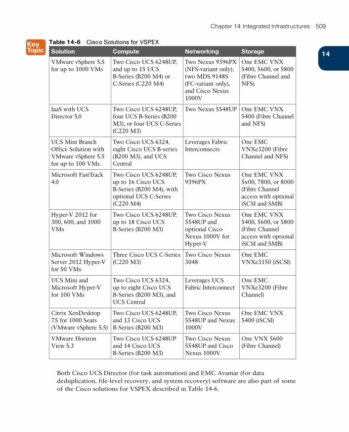
ptg17120290
14
Chapter 14: Integrated Infrastructures 509
Table 14-6 Cisco Solutions for VSPEX
Solution Compute Networking Storage
VMware vSphere 5.5 for up to 1000 VMs
Two Cisco UCS 6248UP, and up to 15 UCS B-Series (B200 M4) or C-Series (C220 M4)
Two Nexus 9396PX (NFS-variant only), two MDS 9148S (FC-variant only), and Cisco Nexus 1000V
One EMC VNX 5400, 5600, or 5800 (Fibre Channel and NFS)
IaaS with UCS Director 5.0
Two Cisco UCS 6248UP, four UCS B-Series (B200 M3), or four UCS C-Series (C220 M3)
Two Nexus 5548UP One EMC VNX 5400 (Fibre Channel and NFS)
UCS Mini Branch Office Solution with VMware vSphere 5.5 for up to 100 VMs
Two Cisco UCS 6324, eight Cisco UCS B-series (B200 M3), and UCS Central
Leverages Fabric Interconnects
One EMC VNXe3200 (Fibre Channel and NFS)
Microsoft FastTrack 4.0
Two Cisco UCS 6248UP, up to 16 Cisco UCS B-Series (B200 M4), with optional UCS C-Series (C220 M4)
Two Cisco Nexus 9396PX
One EMC VNX 5x00, 7800, or 8000 (Fibre Channel access with optional iSCSI and SMB)
Hyper-V 2012 for 300, 600, and 1000 VMs
Two Cisco UCS 6248UP, up to 18 Cisco UCS B-Series (B200 M3)
Two Cisco Nexus 5548UP and optional Cisco Nexus 1000V for Hyper-V
One EMC VNX 5400, 5600, or 5800 (Fibre Channel access with optional iSCSI and SMB)
Microsoft Windows Server 2012 Hyper-V for 50 VMs
Three Cisco UCS C-Series (C220 M3)
Two Cisco Nexus 3048
One EMC VNXe3150 (iSCSI)
UCS Mini and Microsoft Hyper-V for 100 VMs
Two Cisco UCS 6324, up to eight Cisco UCS B-Series (B200 M3), and UCS Central
Leverages UCS Fabric Interconnect
One EMC VNXe3200 (Fibre Channel)
Citrix XenDesktop 7.5 for 1000 Seats (VMware vSphere 5.5)
Two Cisco UCS 6248UP, and 13 Cisco UCS B-Series (B200 M3)
Two Cisco Nexus 5548UP and Nexus 1000V
One EMC VNX 5400 (iSCSI)
VMware Horizon View 5.3
Two Cisco UCS 6248UP and 14 Cisco UCS B-Series (B200 M3)
Two Cisco Nexus 5548UP and Cisco Nexus 1000V
One VNX 5600 (Fibre Channel)
Both Cisco UCS Director (for task automation) and EMC Avamar (for data deduplication, file-level recovery, and system recovery) software are also part of some of the Cisco solutions for VSPEX described in Table 14-6.
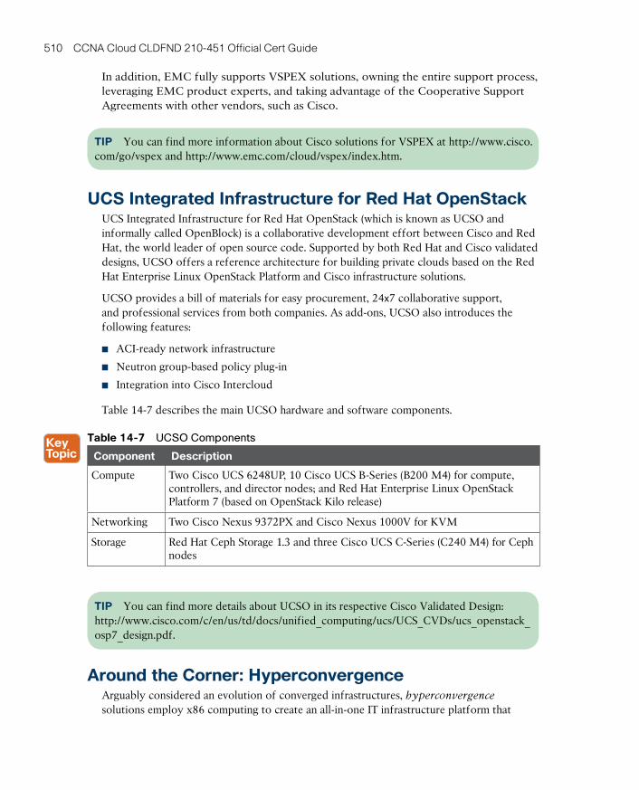
ptg17120290
510 CCNA Cloud CLDFND 210-451 Official Cert Guide
In addition, EMC fully supports VSPEX solutions, owning the entire support process, leveraging EMC product experts, and taking advantage of the Cooperative Support Agreements with other vendors, such as Cisco.
TIP You can find more information about Cisco solutions for VSPEX at http://www.cisco.com/go/vspex and http://www.emc.com/cloud/vspex/index.htm.
UCS Integrated Infrastructure for Red Hat OpenStackUCS Integrated Infrastructure for Red Hat OpenStack (which is known as UCSO and informally called OpenBlock) is a collaborative development effort between Cisco and Red Hat, the world leader of open source code. Supported by both Red Hat and Cisco validated designs, UCSO offers a reference architecture for building private clouds based on the Red Hat Enterprise Linux OpenStack Platform and Cisco infrastructure solutions.
UCSO provides a bill of materials for easy procurement, 24х7 collaborative support, and professional services from both companies. As add-ons, UCSO also introduces the following features:
■ ACI-ready network infrastructure
■ Neutron group-based policy plug-in
■ Integration into Cisco Intercloud
Table 14-7 describes the main UCSO hardware and software components.
Table 14-7 UCSO Components
Component Description
Compute Two Cisco UCS 6248UP, 10 Cisco UCS B-Series (B200 M4) for compute, controllers, and director nodes; and Red Hat Enterprise Linux OpenStack Platform 7 (based on OpenStack Kilo release)
Networking Two Cisco Nexus 9372PX and Cisco Nexus 1000V for KVM
Storage Red Hat Ceph Storage 1.3 and three Cisco UCS C-Series (C240 M4) for Ceph nodes
TIP You can find more details about UCSO in its respective Cisco Validated Design: http://www.cisco.com/c/en/us/td/docs/unified_computing/ucs/UCS_CVDs/ucs_openstack_osp7_design.pdf.
Around the Corner: HyperconvergenceArguably considered an evolution of converged infrastructures, hyperconvergence solutions employ x86 computing to create an all-in-one IT infrastructure platform that
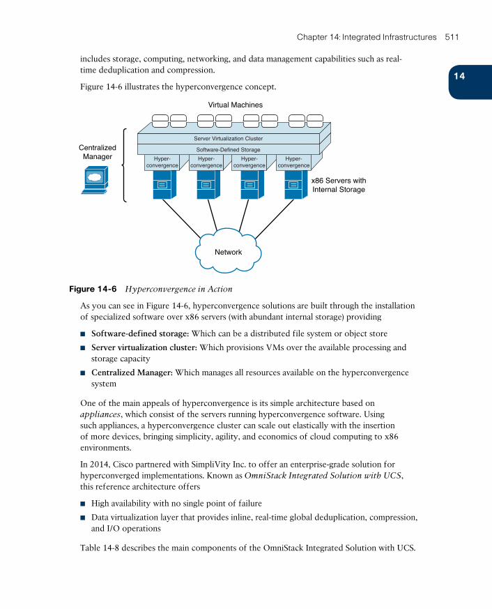
ptg17120290
14
Chapter 14: Integrated Infrastructures 511
includes storage, computing, networking, and data management capabilities such as real-time deduplication and compression.
Figure 14-6 illustrates the hyperconvergence concept.
Network
CentralizedManager Hyper-
convergenceHyper-
convergenceHyper-
convergenceHyper-
convergence
Virtual Machines
x86 Servers withInternal Storage
Server Virtualization Cluster
Software-Defined Storage
Figure 14-6 Hyperconvergence in Action
As you can see in Figure 14-6, hyperconvergence solutions are built through the installation of specialized software over x86 servers (with abundant internal storage) providing
■ Software-defined storage: Which can be a distributed file system or object store
■ Server virtualization cluster: Which provisions VMs over the available processing and storage capacity
■ Centralized Manager: Which manages all resources available on the hyperconvergence system
One of the main appeals of hyperconvergence is its simple architecture based on appliances , which consist of the servers running hyperconvergence software. Using such appliances, a hyperconvergence cluster can scale out elastically with the insertion of more devices, bringing simplicity, agility, and economics of cloud computing to x86 environments.
In 2014, Cisco partnered with SimpliVity Inc. to offer an enterprise-grade solution for hyperconverged implementations. Known as OmniStack Integrated Solution with UCS , this reference architecture offers
■ High availability with no single point of failure
■ Data virtualization layer that provides inline, real-time global deduplication, compression, and I/O operations
Table 14-8 describes the main components of the OmniStack Integrated Solution with UCS.
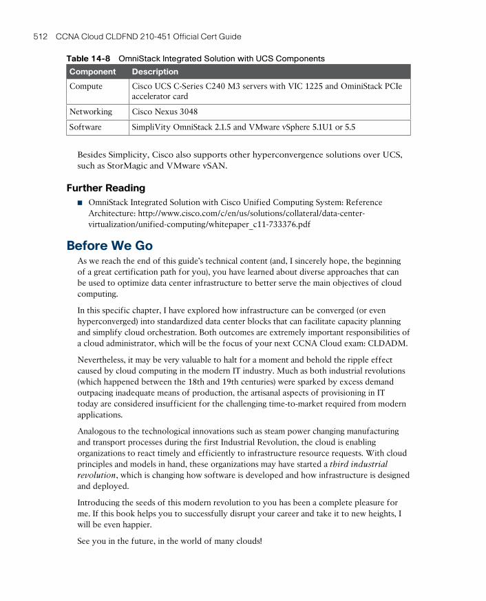
ptg17120290
512 CCNA Cloud CLDFND 210-451 Official Cert Guide
Table 14-8 OmniStack Integrated Solution with UCS Components
Component Description
Compute Cisco UCS C-Series C240 M3 servers with VIC 1225 and OminiStack PCIe accelerator card
Networking Cisco Nexus 3048
Software SimpliVity OmniStack 2.1.5 and VMware vSphere 5.1U1 or 5.5
Besides Simplicity, Cisco also supports other hyperconvergence solutions over UCS, such as StorMagic and VMware vSAN.
Further Reading■ OmniStack Integrated Solution with Cisco Unified Computing System: Reference
Architecture: http://www.cisco.com/c/en/us/solutions/collateral/data-center-virtualization/unified-computing/whitepaper_c11-733376.pdf
Before We GoAs we reach the end of this guide’s technical content (and, I sincerely hope, the beginning of a great certification path for you), you have learned about diverse approaches that can be used to optimize data center infrastructure to better serve the main objectives of cloud computing.
In this specific chapter, I have explored how infrastructure can be converged (or even hyperconverged) into standardized data center blocks that can facilitate capacity planning and simplify cloud orchestration. Both outcomes are extremely important responsibilities of a cloud administrator, which will be the focus of your next CCNA Cloud exam: CLDADM.
Nevertheless, it may be very valuable to halt for a moment and behold the ripple effect caused by cloud computing in the modern IT industry. Much as both industrial revolutions (which happened between the 18th and 19th centuries) were sparked by excess demand outpacing inadequate means of production, the artisanal aspects of provisioning in IT today are considered insufficient for the challenging time-to-market required from modern applications.
Analogous to the technological innovations such as steam power changing manufacturing and transport processes during the first Industrial Revolution, the cloud is enabling organizations to react timely and efficiently to infrastructure resource requests. With cloud principles and models in hand, these organizations may have started a third industrial
revolution, which is changing how software is developed and how infrastructure is designed and deployed.
Introducing the seeds of this modern revolution to you has been a complete pleasure for me. If this book helps you to successfully disrupt your career and take it to new heights, I will be even happier.
See you in the future, in the world of many clouds!
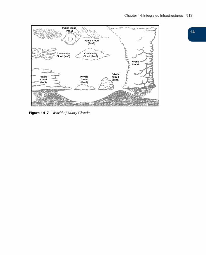
ptg17120290
14
Chapter 14: Integrated Infrastructures 513
Public Cloud(PaaS)
Public Cloud(SaaS)
CommunityCloud (SaaS)
CommunityCloud (IaaS)
PrivateCloud(IaaS)
PrivateCloud(PaaS)
PrivateCloud(SaaS)
HybridCloud
Figure 14-7 World of Many Clouds
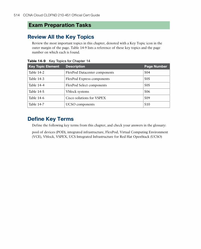
ptg17120290
514 CCNA Cloud CLDFND 210-451 Official Cert Guide
Exam Preparation Tasks
Review All the Key TopicsReview the most important topics in this chapter, denoted with a Key Topic icon in the outer margin of the page. Table 14-9 lists a reference of these key topics and the page number on which each is found.
Table 14-9 Key Topics for Chapter 14
Key Topic Element Description Page Number
Table 14-2 FlexPod Datacenter components 504
Table 14-3 FlexPod Express components 505
Table 14-4 FlexPod Select components 505
Table 14-5 Vblock systems 506
Table 14-6 Cisco solutions for VSPEX 509
Table 14-7 UCSO components 510
Define Key TermsDefine the following key terms from this chapter, and check your answers in the glossary:
pool of devices (POD), integrated infrastructure, FlexPod, Virtual Computing Environment (VCE), Vblock, VSPEX, UCS Integrated Infrastructure for Red Hat OpenStack (UCSO)

ptg17120290

ptg17120290

ptg17120290
CHAPTER 15
Final PreparationThe first 14 chapters of this book cover the technologies, protocols, design concepts, and considerations required to be prepared to pass the 210-451 CCNA Cloud CLDFND Exam. While these chapters supply the detailed information, most people need more preparation than a cover to cover reading can provide. This chapter details a set of tools and a study plan to help you complete your preparation for the exams.
This short chapter has two main sections. The first section lists the exam preparation tools useful at this point in the study process. The second section lists a suggested study plan now that you have completed all the earlier chapters in this book.
NOTE: Note that Appendixes B and C, “Memory Tables” and “Answers to Memory Tables,” respectively, also exist as soft-copy appendices on the Companion Website. See instructions in Introduction on how to access this site.
Tools for Final PreparationThis section lists some information about the available tools and how to access the tools.
Pearson Cert Practice Test Engine and QuestionsThe Companion Website includes the Pearson Cert Practice Test engine—software that displays and grades a set of exam-realistic multiple-choice questions. Using the Pearson Cert Practice Test engine, you can either study by going through the questions in Study Mode, or take a simulated (timed) CCNA Cloud CLDFND 210-451 exam.
The installation process requires two major steps: installing the software and then activat-ing the exam. The Companion Website has a recent copy of the Pearson IT Certification Practice Test engine. The practice exam (the database of exam questions) is not on this site.
NOTE: The cardboard sleeve in the back of this book includes a piece of paper. The paper lists the activation key for the practice exam associated with this book. Do not lose the activation key. On the opposite side of the paper from the activation code is a unique, one-time-use coupon code for the purchase of the CCNA Cloud CLDFND 210-451 Official Cert Guide, Premium Edition.
ptg17120290
518 CCNA Cloud CLDFND 210-451 Official Cert Guide
Install the SoftwareThe Pearson IT Certification Practice Test is a Windows-only desktop application. You can run it on a Mac using a Windows virtual machine, but it was built specifically for the PC platform. The minimum system requirements are as follows:
■ Windows 10, Windows 8.1, or Windows 7
■ Microsoft .NET Framework 4.0 Client
■ Pentium-class 1GHz processor (or equivalent)
■ 512MB RAM
■ 650MB disk space plus 50MB for each downloaded practice exam
■ Access to the Internet to register and download exam databases
The software installation process is routine as compared with other software installation pro-cesses. If you have already installed the Pearson IT Certification Practice Test software from another Pearson product, there is no need for you to reinstall the software. Simply launch the software on your desktop and proceed to activate the practice exam from this book by using the activation code included in the access code card sleeve in the back of the book.
The following steps outline the installation process:
Step 1 Download the exam practice test engine from the companion site.
Step 2 Respond to windows prompts as with any typical software installation process.
The installation process will give you the option to activate your exam with the activation code supplied on the paper in the cardboard sleeve. This process requires that you estab-lish a Pearson website login. You need this login to activate the exam, so please do register when prompted. If you already have a Pearson website login, there is no need to register again. Just use your existing login.
Activate and Download the Practice ExamOnce the exam engine is installed, you should then activate the exam associated with this book (if you did not do so during the installation process) as follows:
Step 1 Start the Pearson IT Certification Practice Test software from the Windows Start menu or from your desktop shortcut icon.
Step 2 To activate and download the exam associated with this book, from the My Products or Tools tab, click the Activate Exam button.
Step 3 At the next screen, enter the activation key from paper inside the cardboard sleeve in the back of the book. Once entered, click the Activate button.
Step 4 The activation process will download the practice exam. Click Next, and then click Finish.

ptg17120290
15
Chapter 15: Final Preparation 519
When the activation process completes, the My Products tab should list your new exam. If you do not see the exam, make sure that you have selected the My Products tab on the menu. At this point, the software and practice exam are ready to use. Simply select the exam and click the Open Exam button.
To update a particular exam you have already activated and downloaded, display the Tools tab and click the Update Products button. Updating your exams will ensure that you have the latest changes and updates to the exam data.
If you want to check for updates to the Pearson Cert Practice Test exam engine software, display the Tools tab and click the Update Application button. You can then ensure that you are running the latest version of the software engine.
Activating Other ExamsThe exam software installation process, and the registration process, has to happen only once. Then, for each new exam, only a few steps are required. For instance, if you buy another Pearson IT Certification Cert Guide, extract the activation code from the cardboard sleeve in the back of that book; you do not even need the exam engine at this point. From there, all you have to do is start the exam engine (if not still up and running) and perform Steps 2 through 4 from the previous list.
Premium Edition
In addition to the free practice exam, you can purchase additional exams with expanded functionality directly from Pearson IT Certification. The Premium Edition of this title contains an additional two full practice exams as well as an eBook (in both PDF and ePub format). In addition, the Premium Edition title also has remediation for each question to the specific part of the eBook that relates to that question.
Because you have purchased the print version of this title, you can purchase the Premium Edition at a deep discount. There is a coupon code in the cardboard sleeve that contains a one-time-use code as well as instructions for where you can purchase the Premium Edition.
To view the Premium Edition product page, go to: http://www.ciscopress.com/title/9780134141022.
The Cisco Learning NetworkCisco provides a wide variety of CCNA Cloud CLDFND preparation tools at a Cisco Systems website called the Cisco Learning Network. This site includes a large variety of exam preparation tools, including sample questions, forums on each Cisco exam, learning video games, and information about each exam.
To reach the Cisco Learning Network, go to www.cisco.com/go/learnnetspace, or just search for “Cisco Learning Network.” You will need to use the login you created at www.cisco.com. If you don’t have such a login, you can register for free. To register, simply go to www.cisco.com, click Register at the top of the page, and supply some information.
ptg17120290
520 CCNA Cloud CLDFND 210-451 Official Cert Guide
Memory TablesLike most Official Cert Guides from Cisco Press, this book purposefully organizes information into tables and lists for easier study and review. Rereading these tables can be very useful before the exam. However, it is easy to skim over the tables without paying attention to every detail, especially when you remember having seen the table’s contents when reading the chapter.
Instead of simply reading the tables in the various chapters, this book’s Appendices B and C give you another review tool. Appendix B lists partially completed versions of many of the tables from the book. You can open appendix B (available on the Companion Website) and print the appendix. For review, you can attempt to complete the tables. This exercise can help you focus on the review. It also exercises the memory connectors in your brain; plus it makes you think about the information without as much information, which forces a little more contemplation about the facts.
Appendix C, also a PDF located on the Companion Website, lists the completed tables to check yourself. You can also just refer to the tables as printed in the book.
Chapter-Ending Review ToolsChapters 1–14 each have several features in the Exam Preparation Tasks section at the end of the chapter. You might have already worked through these in each chapter. It can also be useful to use these tools again as you make your final preparations for the exam.
Suggested Plan for Final Review/StudyThis section lists a suggested study plan from the point at which you finish reading through Chapter 14, until you take the 210-451 CCNA Cloud CLDFND Exam. Certainly, you can ignore this plan, use it as is, or just take suggestions from it.
The plan uses five steps:
Step 1 Review Key Topics and DIKTA Questions: You can use the table that lists the key topics in each chapter, or just flip the pages looking for key topics. Also, reviewing the “Do I Know This Already?” (DIKTA) questions from the beginning of the chapter can be helpful for review.
Step 2 Complete Memory Tables: Open Appendix B and print the entire appendix, or print the tables by major part. Then complete the tables.
Step 3 Define Key Terms: Try to define the terms listed at the end of each chapter to identify areas you need more study.
Step 4 Use the Pearson Cert Practice Test engine to Practice: The Pearson Cert Practice Test engine can be used to study using a bank of unique exam-realistic questions available only with this book.
If you have decided to use Appendix D, “Study Planner,” to support your learning during the reading of all chapters, you can still benefit from it in your final review. In this case, you can use the “Second Date Completed” column to control the pace of each chapter review and dedicate special attention to the chapters whose “Goal Date” you have missed in your first reading (as signaled by the “First Date Completed” column).
ptg17120290
15
Chapter 15: Final Preparation 521
Using the Exam EngineThe Pearson Cert Practice Test engine includes a database of questions created specifically for this book. The Pearson Cert Practice Test engine can be used either in study mode or practice exam mode, as follows:
■ Study mode: Study mode is most useful when you want to use the questions for learning and practicing. In study mode, you can select options like randomizing the order of the questions and answers, automatically viewing answers to the questions as you go, testing on specific topics, and many other options.
■ Practice exam mode: This mode presents questions in a timed environment, providing you with a more exam-realistic experience. It also restricts your ability to see your score as you progress through the exam and view answers to questions as you are taking the exam. These timed exams not only allow you to study for the actual CCNA Cloud CLDFND 210-451 exam, they help you simulate the time pressure that can occur on the actual exam.
When doing your final preparation, you can use study mode, practice exam mode, or both. However, after you have seen each question a couple of times, you will likely start to remember the questions, and the usefulness of the exam database may go down. So, con-sider the following options when using the exam engine:
■ Use this question database for review. Use study mode to study the questions by chapter, just as with the other final review steps listed in this chapter. Plan on getting another exam (possibly from the Premium Edition) if you want to take additional simulated exams.
■ Save the question database, not using it for review during your review of each book part. Save it until the end, so you will not have seen the questions before. Then, use practice exam mode to simulate the exam.
Picking the correct mode from the exam engine’s user interface is pretty obvious. The follow-ing steps show how to move to the screen from which to select study or practice exam mode:
The steps are as follows:
Step 1 Click the My Products tab if you are not already in that screen.
Step 2 Select the exam you wish to use from the list of available exams.
Step 3 Click the Use button.
When you complete these actions, the engine should display a window from which you can choose Study Mode or Practice Exam Mode. When in study mode, you can further choose the book chapters, limiting the questions to those explained in the specified chap-ters of the book.
SummaryThe tools and suggestions listed in this chapter have been designed with one goal in mind: to help you develop the skills required to pass the CCNA Cloud CLDFND 210-451 exam. This book has been developed from the beginning to not just tell you the facts but also help you learn how to apply the facts. No matter what your experience level is leading up to tak-ing the exam, it is my hope that the broad range of preparation tools, and even the structure of the book, will help you pass the exam with ease. I truly hope you do well on the exam.

ptg17120290
ptg17120290
Aaccess layer Switches in a three-tier topology that are directly connected to servers and to a pair of aggregation switches.
Adapter Fabric Extender (Adapter-FEX) UCS feature that allows the creation of static vir-tual adapters within a UCS domain.
Adaptive Security Virtual Appliance (ASAv) Essentially the Cisco ASA firewall software ported into a virtual machine.
Advanced Technology Attachment (ATA) Block I/O access method standardized by the American National Standards Institute (ANSI). It defines multiple types of connections between x86 platforms (personal computers or servers) and internal storage devices.
aggregation layer Switches in a three-tier topology that are responsible for the communica-tion between different access switch pairs and the connection to the core tier of a data center network.
Anything as a Service (XaaS) Cloud computing offerings that are built through the combi-nation of multiple cloud services, which may include different providers and service models.
Application Centric Infrastructure (ACI) Cisco SDN solution that comprises a data center fabric built with Nexus 9000 switches running ACI Fabric OS, a cluster of Application Policy Infrastructure Controllers, and an ecosystem of integrated solutions.
Application Policy Infrastructure Controller (APIC) Network controller that is responsi-ble for provisioning policies to physical and virtual devices that belong to an ACI fabric, moni-toring the performance of the fabric, and interacting with administrators and applications.
application profile Models the connectivity requirements for all components of an applica-tion in an ACI fabric. It represents the logical container for EPGs and associated contracts.
application programming interface (API) Comprises a set of functions, variables, and data structures that enables software components to communicate with each other.
Application Virtual Switch (AVS) Cisco DVS controlled by APIC that works as an ACI vir-tual leaf.
automation Data center infrastructure initiative that eliminates manual procedures and intro-duces standardized operational procedures into software.
availability zone Independent failure domain (area impacted by a major system malfunction) within a single region.
Glossary
ptg17120290
524 basic input/output system (BIOS)
Bbasic input/output system (BIOS) Consists of nonvolatile memory that stores the very first application that should be executed when the computer is powered on.
blade server Server that is inserted in a blade chassis.
block Sequence of bytes, with a defined length (block size), that embodies the smallest con-tainer for data in any storage device.
boot order Defines the ordering of boot devices for a server to load its boot image.
bridge domain Represents a Layer 2 forwarding construct within a context in ACI.
Broad network access Cloud computing essential characteristic where Capabilities are avail-able over the network and accessed through standard mechanisms that promote use by heteroge-neous thin or thick client platforms (e.g., mobile phones, tablets, laptops, and workstations).
bus Any medium that provides higher-speed chipset connections to the CPU or to a dedi-cated processor.
Ccentral processing unit (CPU) The computer component carries out the majority of pro-cessing jobs and calculations in the system.
chargeback Expenditure process where service consumers pay for past cloud resource usage.
chipset Computer element that is responsible for the data exchange between the CPU and the majority of other components of an x86 server.
Cisco Integrated Management Controller (CIMC) It is an internal module built into the server motherboard, which is separate from the main server CPU to run a Cisco management firmware for the server.
Cisco Intercloud Cisco hybrid cloud strategy comprising an amalgam of cloud deploy-ments that includes enterprise private clouds, public clouds (such as Amazon Web Services and Microsoft Azure), Cisco Powered clouds from Cisco partners, and the company’s own public cloud (Cisco Intercloud Services).
Cisco Intercloud Fabric Stack of software that enables the centralized control of hybrid cloud resources within the Cisco Intercloud.
Cisco Nexus 1000V Cisco DVS that deploys common features and procedures from physi-cal network devices (Cisco Nexus Data Center switches) within multiple hypervisor architec-tures, such as VMware vSphere, Microsoft Hyper-V, and Linux KVM.
cloud broker Third-party company or professional that hires cloud computing services from a provider on behalf of a consumer corporation.
cloud bursting Capability of a hybrid cloud to migrate workloads and applications between two distinct cloud deployments.
ptg17120290
core layer 525
cloud infrastructure Comprises all software and hardware that the cloud software stack orchestrates and that can also be used in non-cloud data center environments.
cloud meter Software stack module that concretizes service measurement in a cloud com-puting deployment.
cloud orchestrator Software stack component that coordinates infrastructure resources according to user requests issued on the cloud portal.
cloud portal Software stack component responsible for interacting with external users and interfaces. It publishes cloud service catalogs, wizards for guided user “shopping,” interactive forms, approval workflows, status updates, usage information, and billing balances.
Cloud Services Router (CSR) Within the Cisco Intercloud Fabric solution, it provides rout-ing and other advanced network-based capabilities without requiring traffic to be redirected to the enterprise data center.
Cloud Services Router (CSR) 1000V Router running a version of IOS XE in a virtual machine.
cloud software stack Set of software modules developed exclusively to perform cloud-related operations, such as providing a service catalog to cloud consumers, provisioning requested resources, and keeping track of cloud resource usage.
Common Internet File System (CIFS) Proposed protocol that intended to establish an Internet standard for SMB in 1996.
community cloud Cloud deployment whose exclusive use is assigned to a specific commu-nity of organizations that share concerns such as mission, security requirements, and policies.
computation as a public utility Concept that advocated the offer of computing resources as a public utility, like water, electricity, and telephony.
consolidation Process that aims to break silos that exist in a data center infrastructure, grouping several instances of the same technology into a single shared resource.
Content Delivery Network (CDN) Service that allows data centers may save bandwidth resources and leverage the pervasive Internet presence of CDN service providers to optimally distribute content stored in files.
context ACI private network on a tenant that defines a separate IP space (Layer 3 domain) where all endpoints must have unique IP addresses. It can be compared to a Virtual Routing and Forwarding (VRF) instance.
contract Defines how EPGs can communicate with each other through traffic rules that include allowed protocols and Layer 4 ports in an ACI fabric.
control plane Class of elements of a network device that exchanges traffic with other devic-es to correctly control data plane elements.
core An individual processor within a single CPU chip.
core layer Switches in a three-tier topology that are responsible for the communication between different aggregation switch pairs and the connection of a data center network to edge routers connected to external networks.
ptg17120290
526 Data Center Bridging (DCB)
DData Center Bridging (DCB) Enhancements that allow data center Ethernet networks to deploy lossless transport, dynamic resource allocation, automated configuration of devices, and congestion notifications.
data plane Also known as forwarding plane, comprises all the elements of a network device that handle the transport of data packets between two or more ports.
DDR chip Double Data Rate memory chip that can provide two data exchanges at each clock cycle.
director-class Special Fibre Channel switches whose components are completely redundant in order to achieve 99.999 percent availability.
disk array Storage system that contains multiple disks that are managed as a scalable resource pool shared among several application environments.
disk controller Server component that manages the internal HDDs of a server as well as external drives.
distributed virtual switch (DVS) Generic name for a class of virtual switches that can stretch across multiple virtualization hosts as if they were deploying the same virtual network-ing device.
Eend-host mode Allows the UCS Fabric Interconnect to act as a NIC or HBA to the con-nected Ethernet or Fibre Channel switch, respectively.
endpoint Physical or virtual device that is (directly or indirectly) connected to an ACI fabric.
endpoint group (EPG) ACI logical construct gathering a collection of endpoints that are associated dynamically (for example, through the communication with a VM manager) or stati-cally (using a port or a VLAN, for example).
ESXi Popular Type-1 hypervisor from VMware.
Ethernet over MPLS (EoMPLS) Encapsulation technology that allows the emulation of an Ethernet connection (commonly referred to as pseudowire) between two ports on MPLS-enabled routers.
Ethernet Virtual Private Network (EVPN) A virtual Layer 2 domain created over a shared physical network.
ext2 Second extended filesystem; used in Linux for volume formatting. It was created in 1993 and is the default filesystem for many Linux versions.
ext3 Third extended filesystem; used in Linux for volume formatting. Introduced in 2001, it allows journaling.
ext4 Fourth extended filesystem; used in Linux for volume formatting. Released in 2008, it introduces many exclusive features such as multiblock allocation.
ptg17120290
firewall 527
Extensible Markup Language (XML) A flexible text format created to represent data exchanged between two or more entities on the Internet.
External Data Representation (XDR) Standardized data coding format that permits differ-ent computer systems to share data transmitted through NFS.
FFabric Extender (FEX) Device that works as a remote linecard managed by a parent switch, such as several Nexus models.
Fabric Interconnect UCS device that is responsible for running UCS Manager and providing I/O exchange for all servers in a UCS domain.
Fabric Login (FLOGI) Process that inserts a server HBA or storage port into a Fibre Channel fabric.
Fabric Data center network in which all of its devices behave as a single one.
fabric module Modular switch component that provides internal communication between I/O modules.
FabricPath Cisco Unified Fabric technology that allows the deployment of Layer 2 mul-tipath networks.
Fabric Shortest Path First (FSPF) Fibre Channel dynamic routing protocol.
FCoE Initialization Protocol (FIP) Protocol that is responsible for performing all kickstart operations to allow the exchange of FCoE frames between FCoE devices.
Fibre Channel Most popular protocol for enterprise and service provider storage-area net-works.
Fibre Channel Identifier (FCID) Represents logical addressing in Fibre Channel.
Fibre Channel over Ethernet (FCoE) Technology that allows the transport of Fibre Channel over a lossless Ethernet network.
file Set of contiguous data (and associated metadata) that is persistently saved on a storage device.
File Allocation Table (FAT) File system used in Linux and Windows for volume formatting.
file hosting Popular cloud service that provides external access to files.
file server Specialized computers to centrally store files.
File Transfer Protocol (FTP) Created at the dawn of the Internet (1971), FTP is an IETF-standardized file transfer protocol that runs over TCP using two different connections for con-trol and data exchange between client and server.
firewall Networking service that monitors and controls traffic between two (or more) differ-ent security zones based on security rules.

ptg17120290
528 FlexPod
FlexPod Reference architecture for integrated infrastructures developed by Cisco and NetApp.
formatting Operation to allow correct identification of file data and metadata in a block-based storage device.
G-HGroup-Based Policy (GBP) Similar to the ACI policy model, Neutron provisioning model that provides aggregated logical constructs (such as groups and policy rule sets) that can be eas-ily replicated and reused within an OpenStack deployment.
hard disk drive (HDD) Popular secondary storage device based on multiple platters (disks) spinning around a common axis at a constant speed.
HTTP Secure (HTTPS) Protocol that provides the encapsulation of HTTP traffic in a Secure Sockets Layer (SSL) connection.
hybrid cloud a composition of two or more distinct cloud infrastructures (private, commu-nity, or public) that remain unique entities, but are bound together by standardized or propri-etary technology that enables data and application portability.
Hypertext Transfer Protocol (HTTP) originally designed to transfer objects between web servers and browsers.
Hyper-V Popular Type-1 hypervisor from Microsoft.
hypervisor Software component that can create emulated hardware (including CPU, memo-ry, storage, networking, and peripherals) for the installation of a guest operating system.
hypervisor bypass Allows a virtual machine to fully control a physical NIC, instead of rely-ing on the hypervisor CPU processing to forward Ethernet frames through a virtual switch.
II/O consolidation Server connectivity approach that enables any type of I/O communication within a single type of physical connection.
I/O module Modular switch component that provides connectivity for external devices.
Infrastructure as a Service (IaaS) Cloud computing service model created for consumers who want pure processing, storage, networking, or other fundamental computing resources.
integrated development environment (IDE) A software tool designed for application development which contains a source code editor, automation tools, debuggers, programming language compilers or interpreters, and version control systems, among other development tools.
integrated infrastructure Prebuilt pool of devices fully designed by one or more compa-nies to expedite infrastructure deployment to their customers.
ptg17120290
measured service 529
Intercloud Extender (ICX) The Intercloud Fabric component that resides in the private loca-tion of an Intercloud Fabric connection, receiving traffic from standard VLANs and encrypting it when it is directed toward the public cloud.
Intercloud Fabric Director (ICFD) The central point of management and control for Intercloud Fabric resources.
Intercloud Switch (ICS) The Intercloud Fabric component that receives encrypted frames from ICX, decrypts them, and forwards them to ICF resources within the public cloud.
Internet Small Computer Systems Interface (iSCSI) Represents the encapsulation of SCSI traffic in a TCP connection.
iSCSI Qualified Name (IQN) Uniquely identifies an iSCSI initiator or target.
J-KJavaScript Object Notation (JSON) Format originally created to transmit data in the JavaScript programming language and now commonly used to express data exchanged between two applications.
kernel Central part of an operating system that has direct access to the computer hardware components, such as memory and CPU.
KVM Popular Type-1 open source hypervisor for Linux operating systems, formally known as Kernel-based Virtual Machine.
LLAN on Motherboard (LoM) Motherboard-integrated circuit that offers Ethernet connec-tion for a computer without the need of a network interface controller (NIC).
line of business (LoB) All resources within an organization that are directly related to one offered product or service.
Mmain memory Volatile storage mechanisms that can be directly accessed by the CPU, usu-ally have small capacity, and are faster when compared to other storage technologies.
Manila OpenStack project whose objective is to provide file-based storage.
measured service Cloud computing essential characteristic in which cloud systems auto-matically control and optimize resource use by leveraging a metering capability at some level of abstraction appropriate to the type of service (e.g., storage, processing, bandwidth, and active user accounts). Resource usage can be monitored, controlled, and reported, providing transparency for both the provider and consumer of the utilized service.
ptg17120290
530 Modular Layer 2 (ML2)
Modular Layer 2 (ML2) Neutron plug-in responsible for creating broadcast domains for Nova instances in generic Layer 2 devices.
motherboard Circuit panel that physically sustains all the computer components.
mount Operation that allows an NFS client to attach a remote directory tree (server) to its local file system.
multihop FCoE Data center network topology that allows the forwarding of FCoE traffic beyond a single layer of FCoE-enabled switches.
Multiprotocol Border Gateway Protocol (MP-BGP) Extensions for BGP that allow the protocol to carry information for multiple network layer protocols, including IP and Ethernet addresses.
multi-tenant Capability of a resource to support multiple tenants according to an accepted isolation technique.
Nnamespace Set of symbols and rules that are used to organize different objects into a struc-ture that assigns a distinct name to each object.
NAS head Specialized appliance that can build a NAS device from a disk array.
National Institute of Standards and Technologies (NIST) U.S. federal technology agency that works with industry to develop and apply technology, measurements, and standards.
NetScaler 1000V A vPath-compatible version of the Citrix NetScaler ADC running on a virtual machine.
network-attached storage (NAS) Specialized storage device for files.
network automation The use of orchestration software and the creation of workflows to deploy multiple standardized network procedures.
Network Basic Input/Output System (NetBIOS) Communication method that serves as a Layer 5 (session) protocol for SMB.
network controller System responsible for the complete configuration of managed network devices, offering a simpler view of the whole network for application developers.
Network File System (NFS) File access method created by Sun Microsystems in 1984 for its Solaris operating system. It is still used by many other Unix-based operating systems, such as Linux and FreeBSD, as their native file access method.
network programmability Characteristic of a network offering a set of tools that allows the development of computer programs for specific network operational tasks.
networking service Set of repetitive operations normally carried out by application servers (or client devices) but actually implemented on specialized network devices.
Neutron OpenStack core project responsible for providing Network as a Service (NaaS) in these environments.
ptg17120290
oversubscription 531
New Technology File System (NTFS) File system commonly used in Windows for volume formatting.
northbound protocol Describes the information exchange between a network program and a network controller.
Oobject Storage construct that contains data, a globally unique identifier, and both a variable and a flexible amount of metadata.
on-demand self-service Cloud computing essential characteristic that defines that a cloud consumer can unilaterally provision computing capabilities, such as server time and network storage, as needed automatically without requiring human interaction with each service pro-vider.
OpenDaylight Collaborative project, led by the Linux Foundation and with the participa-tion of multiple networking vendors, that intends to provide a framework for SDN and NfV applications and use cases, as well as an open controller for real-world deployments involving multiple network devices and southbound protocols.
OpenFlow Southbound protocol standardized by the Open Networking Foundation (ONF) that inserts entries into the flow table of OpenFlow network devices.
OpenStack Community development initiative to develop open source software to build public and private scalable clouds.
operating system Basic software that controls computer resources and provides common services for other computer programs.
OpFlex Open and extensible protocol designed to transfer object-based connectivity policies (in XML or JSON) between a network policy controller (APIC, for example) and physical and virtual devices such as switches and networking services.
orchestration Final step of evolution of data center infrastructure into cloud infrastructure, where the cloud software stack is programmed to receive end-user requests and execute work-flows over the automated infrastructure to fulfill such requests.
overlay Virtual data plane built on top of another network through encapsulation of packets and the establishment of tunnels. Some examples are Virtual eXtensible Local Area Network (VXLAN) and Network Virtualization using Generic Routing Encapsulation (NVGRE).
Overlay Transport Virtualization (OTV) Unified Fabric Layer 2 extension technology.
oversubscription Ratio between the potential maximum consumption of a resource and its actual capacity. In terms of switch I/O modules, it represents the sum of bandwidth of all ports divided by the bandwidth in connection to the switch fabric modules.

ptg17120290
532 permission
P-Qpermission Defines file and directory access restrictions according to users, computers, and user groups.
personal computer (PC) Relatively small and inexpensive microcomputer designed for the needs of an individual user.
Platform as a Service (PaaS) Cloud computing service model that offers to its consumers the capability to deploy their customized applications through cloud-provided programming languages and tools.
policy-based routing (PBR) A networking configuration that deploys routing based on IP packet headers that are different from the destination IP address.
pool of devices (POD) Arrangement of infrastructure components that are integrated in a systematic way in order to improve modularity, predictability, and reuse in a data center facil-ity.
Port Group VMware vSphere connectivity policy, which defines how a virtual switch han-dles traffic that belongs to a group of virtual network adapters, VMkernel interfaces, or physi-cal NICs.
port profile Configuration template that can be inherited by multiple interfaces on Nexus switches.
private cloud Cloud deployment that is used by a single organization.
public cloud Cloud deployment that is provisioned for open use by the general public.
Rrack server Computer server that is accommodated in a standard data center cabinet.
Rapid elasticity Cloud computing essential characteristic that states that capabilities can be elastically provisioned and released, in some cases automatically, to scale rapidly outward and inward commensurate with demand.
redundant array of independent disks (RAID) Data storage methods that aggregate data blocks from multiple HDDs to achieve storage high availability, increase capacity, and enhance I/O performance.
regulatory compliance standards Require the adherence of an organization to laws, regu-lations, guidelines, and specifications that are important for its industry and whose violations may result in legal consequences or dismissal from a community.
Remote Procedure Call (RPC) In NFS, it is a protocol that enables communication between different remote file access processes.
resource load balancing Capability of a server virtualization cluster to redistribute virtual machines among members to permit an optimized use of host resources.
ptg17120290
service provider 533
resource pooling Cloud computing essential characteristic that advocates that the provider’s computing resources are pooled to serve multiple consumers using a multi-tenant model, with different physical and virtual resources dynamically assigned and reassigned according to con-sumer demand.
RESTful API Application programming interface that adheres to the formal constraints pro-posed by Roy Thomas Fielding in his 2000 doctoral dissertation “Architectural Styles and the Design of Network-Based Software Architectures.”
SSAN boot Alternative method to booting from an internal HDD that enables a server to load its operating system using a LUN on a remote storage, simplifying hardware replacement if a critical component suffers any major malfunction.
secondary memory Storage devices that require I/O channels to transport data to the com-puter system processor. Such devices deploy nonvolatile data, have more storage capacity than primary memory, provide longer access times, and are also known as auxiliary memory.
Secure Copy Protocol (SCP) Network protocol that supports file transfers through an SSH (Secure Shell) connection in TCP port 22. SCP is generally installed by default in most Linux distributions.
server Software component that can accept requests from multiple clients, providing suit-able responses after processing these requests or accessing other servers. Also, dedicated hard-ware especially designed to host such components.
server load balancer (SLB) Network device that can receive application traffic and send it to a selected server according to a predefined load balancing policy.
Server Message Block (SMB) Client/server protocol used to request file services from server systems over a common network. Typically used by Microsoft Windows operating sys-tems.
service graph ACI construct that allows the fabric to steer traffic between two EPGs through a predefined sequence of networking services.
service insertion Network technique that enables traffic steering to a networking service.
service-level agreement (SLA) A signed agreement between a service provider and client organization that sets forth the expectations about the scope and quality of the service.
service profile UCS logical construct that groups all server configuration tasks into a single assignment, including several activities that are usually realized by non-server teams. It can be associated to server hardware that belongs to a UCS domain.
service profile template UCS logical construct that groups policies, identity pools, and other definitions (such as the number of vNICs and vHBAs) and that can promptly spawn mul-tiple service profiles sharing the same characteristics but using distinct identifiers.
service provider A company that offers specialized services to other organizations.
ptg17120290
534 sharding
sharding Data distribution method that allows all ACI-related information to be stored across active APIC appliances, enhancing performance and replication requirements.
share File, folder, or even a whole logical drive that can be shared through SMB sessions.
showback Cloud metering model that only presents a breakdown of resources used to whoever it may interest, for the purposes of relative usage comparison among users and their groups.
single-root I/O virtualization (SR-IOV) Allows a single PCIe I/O peripheral to emulate mul-tiple “lightweight” instances.
Small Computer Systems Interface (SCSI) Block I/O access method developed by the INCITS Technical Committee T10. It defines how data is transferred between computers and peripheral devices, including external storage systems.
socket Physical connectors that allow the insertion of multiple CPU chips on a single com-puter.
Software as a Service (SaaS) Cloud computing service model whose consumers want access to fully functional applications but do not want to manage or control the underlying hardware or software infrastructure.
Software-Defined Networking (SDN) Collective name for network modernization tech-nologies that intend to introduce characteristics such as automation and programmability into data center, campus, backbone, and wide-area networks.
solid-state drive (SSD) Non-mechanical storage device composed of integrated circuits that can persistently store data through power outages.
southbound protocol Defines all communication between a network controller and one of its controlled devices.
spine-leaf Data center network topology composed of two switch tiers, which are called leaf (connected to hosts and to all spines) and spine (connected to all leaf switches).
standardization Data center infrastructure initiative that intends to simplify provisioning and management through uniformity of resources and operational procedures.
storage-area network (SAN) dedicated network that interconnects computers to shared block-based storage systems.
subnet Classical IP subnet that must be associated to a bridge domain in an ACI fabric.
supervisor module Modular switch component that is responsible for the device control and management functions.
switch mode Allows the UCS Fabric Interconnect to run as a traditional Ethernet or Fibre Channel switch, respectively deploying Ethernet uplinks or Fibre Channel ISLs (respectively) to external switches.
ptg17120290
Virtual Application Cloud Segmentation (VACS) 535
Ttenant ACI policy repository that allows both administrative and traffic segregation from other tenants.
three-tier topology Traditional data center network topology composed of core, aggrega-tion, and access switch tiers.
time-sharing Technology that offered small slices of time of the mainframe resources to multiple different users.
Trivial File Transfer Protocol (TFTP) Protocol that requires a very simple client and is designed for boot and firmware loading during device initialization. Released in 1981, TFTP leverages UDP in the communication between client and server.
UUCS B-Series Cisco blade servers that are contained in the UCS B-Series Blade Server Chassis and managed by UCS Manager.
UCS Central Software that provides a centralized control panel for multiple UCS domains.
UCS C-Series Cisco rack-mountable devices that can optionally be added to a UCS domain.
UCS Integrated Infrastructure for Red Hat OpenStack (UCSO; aka OpenBlock) A col-laborative development effort between Cisco and Red Hat that offers a reference architecture, bill of materials, and 24х7 support for an OpenStack integrated infrastructure built with solu-tions from both companies.
UCS Manager Software that offers server administrators the following capabilities over a UCS domain: server provisioning, device discovery, inventory, configuration, diagnostics, monitoring, fault detection, auditing, and statistics collection.
Unified Fabric Network architecture established through devices based on the NX-OS network operating system (such as Cisco Nexus data center switches and MDS 9000). It has introduced several innovations to data center networks such as virtual device contexts, virtual PortChannels, Fabric Extenders, Overlay Transport Virtualization, and I/O consolidation.
Unified Port Nexus switch interface that can provide Ethernet (1/10 Gbps with FCoE) or Fibre Channel (8/4/2/1 Gbps) according to the inserted transceiver.
VVblock Integrated infrastructure developed and commercialized by VCE.
Virtual Application Cloud Segmentation (VACS) Cisco software package that automates installation, licensing, and configuration of virtual machines, virtual networking, and virtual ser-vices to enable isolated virtualized applications.
ptg17120290
536 virtual blade
virtual blade Applications, switch components, and virtual networking services that can be executed on Nexus 1110 Cloud Services Platforms.
Virtual Computing Environment (VCE) Company founded in 2011 by Cisco and EMC with active investment participation from VMware and Intel. VCE was the first company to commercialize a prepackaged integrated infrastructure in the market.
Virtual Data Path (vPath) Cisco protocol that allows transparent traffic steering between Nexus 1000V and compatible virtual networking services.
virtual device context (VDC) Logical partition of a switch that includes separation of the data, control, and management planes from other VDCs.
Virtual Ethernet Module (VEM) Assumes the role of an interface module (or line card) for a Nexus 1000V instance.
Virtual eXtensible LAN (VXLAN) A protocol that allows the encapsulation of Ethernet frames over UDP datagrams according to IETF RFC 7348.
virtual host bus adapter (vHBA) Represents how UCS Manager defines a physical Fibre Channel connection to a UCS server or a VIC-generated virtual adapter.
Virtual Interface Card (VIC) Cisco card that can create multiple virtual adapters directly in the server expansion bus.
Virtual Machine Fabric Extender (VM-FEX) Consolidates the networking infrastructure, enabling configuration, management, and monitoring of virtual machines and physical server connectivity in the same device.
Virtual Machine File System (VMFS) Default distributed file system for VMware ESXi implementations to format block-based volumes, such implementation may instead leverage NFS servers to store VM files.
virtual networking Collection of networking technologies that is responsible for virtual machine connectivity.
virtual networking service Networking service running on a virtual machine or on the hypervisor kernel.
virtual network interface controller (vNIC) Represents how UCS Manager defines a physi-cal Ethernet connection to a UCS server or a VIC-generated virtual adapter.
virtual PortChannel (vPC) Virtualization technique that allows a device to deploy aggrega-tion of connections to a pair of Nexus switches.
Virtual Private LAN Service (VPLS) A sophisticated Layer 2 extension technique that sup-ports multipoint connectivity among MPLS-enabled routers.
virtual private network (VPN) Set of technologies that allows the creation of logical net-works over a single shared physical network with the intention to satisfy varied purposes such as security and resource optimization.
Virtual Security Gateway (VSG) Cisco compute firewall for virtual networks based on Cisco Nexus 1000V. It also refers to the zone-based firewall that can be deployed to provide

ptg17120290
Web Cache Control Protocol (WCCP) 537
policy enforcement for communication between ICF-managed virtual machines and to protect inter-VM traffic in the provider cloud.
virtual storage-area network (VSAN) Set of N_Ports that share the same Fibre Channel fabric processes in a single physical SAN.
Virtual Supervisor Module (VSM) Assumes the role of a supervisor module for a Nexus 1000V instance.
Virtual Wide Area Application Services (vWAAS) Cisco appliance running on a virtual machine.
virtualization A set of technologies that creates transparent emulations of computing resources, producing benefits that were unavailable in their original physical form.
VM fault tolerance Virtualization feature that allows (almost) uninterrupted operation of a virtual machine even in the case of a host failure.
VM high availability Server virtualization feature that allows the automatic reinitialization of a virtual machine from a failed host on another member of the virtualization cluster.
VM live migration Server virtualization feature that enables the transfer of a virtual machine between two nodes with minimum interruption of the VM operations.
VM manager Software solution that can create and manage virtual machines on multiple physical servers running hypervisors.
volume Represents a logical disk offered to a server by a remote storage system such as a disk array.
VSAN trunking Capability of a Fibre Channel interface to transport traffic of more than one VSAN.
VSPEX Reference architecture for integrated infrastructures developed by EMC and many other manufacturers, including Cisco.
vSwitch Generically defines a software component that offers Layer 2 connectivity for vir-tual machines. When compared to distributed virtual switches, a vSwitch represents a virtual switch that only exists inside of a single virtualization host.
WWAN acceleration Networking service that deploys optimization algorithms to alleviate the effects of delay and bandwidth constriction on connections traversing a wide-area network.
Web Cache Control Protocol (WCCP) Cisco protocol created to steer HTTP sessions to web caches.

ptg17120290
538 Web Distributed Authoring and Versioning (WebDAV)
Web Distributed Authoring and Versioning (WebDAV) Protocol that allows users to cre-ate, read, update, and delete documents in a web server.
workflow Sequence of tasks that is organized to be carried out in order in a fast and stan-dardized way by an automation tool such as a cloud orchestrator.
World Wide Name (WWN) Represents physical addressing in Fibre Channel.
X-Zx86 Microarchitecture of computers that are direct descendants of the first generation of Intel-powered personal computers introduced in the early 1980s.
zone Subset of N_Ports from a fabric that is aware of each other, but not of devices outside the zone.
zone set Group of one or more zones that can be activated or deactivated with a single operation.

ptg17120290
APPENDIX A
Answers to Pre-Assessments and QuizzesChapter 1
1. d
2. d
3. e
4. b, e, and f
5. a
6. c
7. e
8. a, c, and f
9. a, b, and c
10. c
11. b and d
Chapter 21. a, b, d, and e
2. b
3. a and c
4. a and d
5. b, c, d, and e
6. c
7. b
8. e
9. a and d
Chapter 31. e
2. c
3. a, b, and c
4. a
5. b
6. b
7. a, b, and d
8. a, b, c, and d
9. a and d
10. d
Chapter 41. b, c, and d
2. d
3. b and e
Chapter 51. c
2. c
3. b and d
4. b and d
5. a, b, and c
6. a, d, and e
7. d
8. b
9. c
10. d

ptg17120290
540 CCNA Cloud CLDFND 210-451 Official Cert Guide
Chapter 61. c
2. a, b, d, and f
3. b, e, and f
4. a, c, e, and h
5. b and d
6. c
7. b, c, and e
8. c and d
9. a, b, and c
10. b and d
Chapter 71. c
2. a, b, d, and e
3. a and c
4. d
5. d
6. b, c, and d
7. a
8. a, d, and e
9. a, b, c, e, and f
10. a, c, and e
Chapter 81. c
2. c
3. d
4. c
5. b, c, and d
6. a, b, and c
7. b
8. d
9. d
10. c
11. c
12. b
Chapter 91. c
2. d
3. a
4. d
5. b
6. c
7. c
8. e
9. a
10. c
Chapter 101. d
2. b, c, and d
3. c
4. b
5. e
6. d
7. c
8. b and e
9. c
10. d
Chapter 111. e
2. b
3. a
4. a, b, d, and e
5. d
6. a
7. d
8. b
9. a
10. a, c, and d
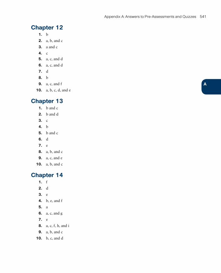
ptg17120290
A
Appendix A: Answers to Pre-Assessments and Quizzes 541
Chapter 121. b
2. a, b, and c
3. a and c
4. c
5. a, c, and d
6. a, c, and d
7. d
8. b
9. a, c, and f
10. a, b, c, d, and e
Chapter 131. b and c
2. b and d
3. c
4. b
5. b and c
6. d
7. e
8. a, b, and c
9. a, c, and e
10. a, b, and c
Chapter 141. f
2. d
3. e
4. b, e, and f
5. a
6. a, c, and g
7. e
8. a, c, f, h, and i
9. a, b, and c
10. b, c, and d

ptg17120290

ptg17120290
APPENDIX B
Memory TablesChapter 1Table 1-2 Traditional IT Challenges
Challenge Description
Low efficiency
High costs
Lack of agility
Table 1-3 Data Center Physical Components
Component Description
Provide electrical power for the data center in the case of a major failure in the main power source. These systems are generally powered by diesel and special batteries.
Allows physical access for data center operational teams and includes secu-rity measures to exclude everyone else.
Encases all devices that are responsible for the data center external communi-cation. For high-availability purposes, this room offers access to at least two telecommunication service providers.
Decrease the temperature of data center equipment such as servers, storage systems, and network switches to improve performance and avoid overheat-ing. These systems operate by recirculating air throughout the data center.
Physically support devices such as servers, storage systems, and network switches.
Creates an elevated structured floor to provide a hidden space for the accom-modation of mechanical, electrical, and networking material.
Table 1-5 NIST Cloud Criteria
Criterion Description
Classify clouds according to the nature of the service they provide to consum-ers (Infrastructure as a Service, Platform as a Service, or Software as a Service).
Classify cloud computing deployments according to who the cloud infrastruc-ture is provisioned for (public, private, community, or hybrid).
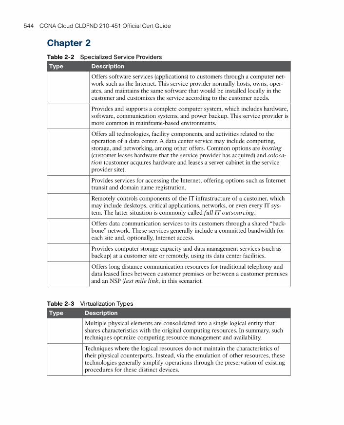
ptg17120290
544 CCNA Cloud CLDFND 210-451 Official Cert Guide
Chapter 2Table 2-2 Specialized Service Providers
Type Description
Offers software services (applications) to customers through a computer net-work such as the Internet. This service provider normally hosts, owns, oper-ates, and maintains the same software that would be installed locally in the customer and customizes the service according to the customer needs.
Provides and supports a complete computer system, which includes hardware, software, communication systems, and power backup. This service provider is more common in mainframe-based environments.
Offers all technologies, facility components, and activities related to the operation of a data center. A data center service may include computing, storage, and networking, among other offers. Common options are hosting (customer leases hardware that the service provider has acquired) and coloca-tion (customer acquires hardware and leases a server cabinet in the service provider site).
Provides services for accessing the Internet, offering options such as Internet transit and domain name registration.
Remotely controls components of the IT infrastructure of a customer, which may include desktops, critical applications, networks, or even every IT sys-tem. The latter situation is commonly called full IT outsourcing.
Offers data communication services to its customers through a shared “back-bone” network. These services generally include a committed bandwidth for each site and, optionally, Internet access.
Provides computer storage capacity and data management services (such as backup) at a customer site or remotely, using its data center facilities.
Offers long distance communication resources for traditional telephony and data leased lines between customer premises or between a customer premises and an NSP (last mile link, in this scenario).
Table 2-3 Virtualization Types
Type Description
Multiple physical elements are consolidated into a single logical entity that shares characteristics with the original computing resources. In summary, such techniques optimize computing resource management and availability.
Techniques where the logical resources do not maintain the characteristics of their physical counterparts. Instead, via the emulation of other resources, these technologies generally simplify operations through the preservation of existing procedures for these distinct devices.

ptg17120290
B
Appendix B: Memory Tables 545
Type Description
Characterized through the creation of independent logical partitions that emu-late the characteristics of a physical resource. In essence, such techniques enable resource usage efficiency.
Chapter 3Table 3-6 Private and Public Clouds Compared
Service Model Advantages Disadvantages
Public cloud
Private cloud
Table 3-7 Cisco Intercloud Principles
Principle Description
The “one-stop shop” approach definitely does not satisfy the understandable desire of many companies to choose services from different cloud providers. Cisco Intercloud frees organizations to provision and agnostically manage cloud services from its private cloud technology and chosen public infrastructure. Additionally, Cisco Powered cloud partners can act as cloud brokers for the offerings provided by the Cisco Intercloud Services or even other members of the Intercloud.
As IP routers were the foundation of the Internet, the basis of the Cisco Inter-cloud infrastructure is Cisco Intercloud Fabric (ICF), which essentially promotes integration between distinct cloud providers.
The Cisco Intercloud enables an easy and secure blending of on-premises appli-cations and public cloud applications through a rich ecosystem of SaaS and PaaS member cloud providers.
Cisco is committed to maintaining an open approach to the Intercloud, providing flexibility for customer hybrid cloud projects that require a high level of interop-erability with traditional data center technologies and public cloud offerings.
When moving critical data to a public cloud, an organization needs to maintain control over its data privacy, location, and compliance with regulations. Having a broad choice of cloud providers can help companies to achieve end-to-end security that spans from their internal network to cloud services they may have hired. Cisco Intercloud accomplishes this objective through agile security poli-cies that remain consistent regardless of the chosen provider.
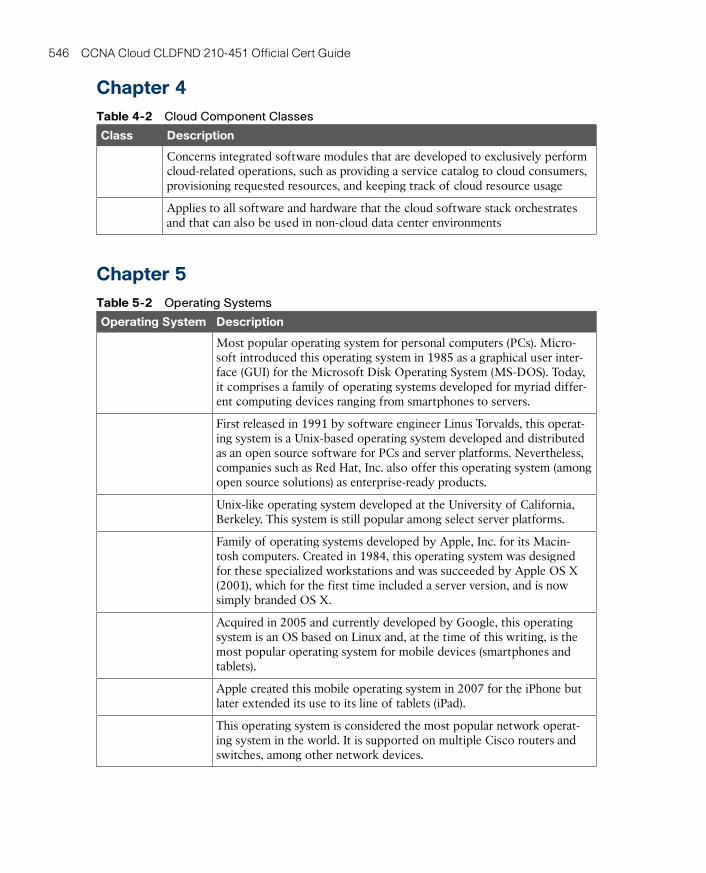
ptg17120290
546 CCNA Cloud CLDFND 210-451 Official Cert Guide
Chapter 4Table 4-2 Cloud Component Classes
Class Description
Concerns integrated software modules that are developed to exclusively perform cloud-related operations, such as providing a service catalog to cloud consumers, provisioning requested resources, and keeping track of cloud resource usage
Applies to all software and hardware that the cloud software stack orchestrates and that can also be used in non-cloud data center environments
Chapter 5Table 5-2 Operating Systems
Operating System Description
Most popular operating system for personal computers (PCs). Micro-soft introduced this operating system in 1985 as a graphical user inter-face (GUI) for the Microsoft Disk Operating System (MS-DOS). Today, it comprises a family of operating systems developed for myriad differ-ent computing devices ranging from smartphones to servers.
First released in 1991 by software engineer Linus Torvalds, this operat-ing system is a Unix-based operating system developed and distributed as an open source software for PCs and server platforms. Nevertheless, companies such as Red Hat, Inc. also offer this operating system (among open source solutions) as enterprise-ready products.
Unix-like operating system developed at the University of California, Berkeley. This system is still popular among select server platforms.
Family of operating systems developed by Apple, Inc. for its Macin-tosh computers. Created in 1984, this operating system was designed for these specialized workstations and was succeeded by Apple OS X (2001), which for the first time included a server version, and is now simply branded OS X.
Acquired in 2005 and currently developed by Google, this operating system is an OS based on Linux and, at the time of this writing, is the most popular operating system for mobile devices (smartphones and tablets).
Apple created this mobile operating system in 2007 for the iPhone but later extended its use to its line of tablets (iPad).
This operating system is considered the most popular network operat-ing system in the world. It is supported on multiple Cisco routers and switches, among other network devices.
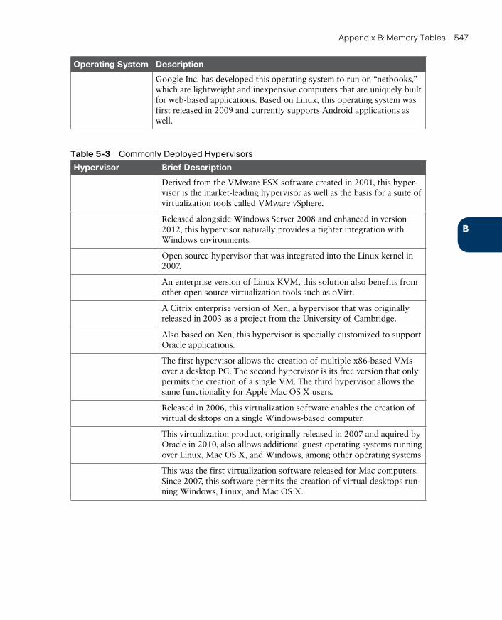
ptg17120290
B
Appendix B: Memory Tables 547
Operating System Description
Google Inc. has developed this operating system to run on “netbooks,” which are lightweight and inexpensive computers that are uniquely built for web-based applications. Based on Linux, this operating system was first released in 2009 and currently supports Android applications as well.
Table 5-3 Commonly Deployed Hypervisors
Hypervisor Brief Description
Derived from the VMware ESX software created in 2001, this hyper-visor is the market-leading hypervisor as well as the basis for a suite of virtualization tools called VMware vSphere.
Released alongside Windows Server 2008 and enhanced in version 2012, this hypervisor naturally provides a tighter integration with Windows environments.
Open source hypervisor that was integrated into the Linux kernel in 2007.
An enterprise version of Linux KVM, this solution also benefits from other open source virtualization tools such as oVirt.
A Citrix enterprise version of Xen, a hypervisor that was originally released in 2003 as a project from the University of Cambridge.
Also based on Xen, this hypervisor is specially customized to support Oracle applications.
The first hypervisor allows the creation of multiple x86-based VMs over a desktop PC. The second hypervisor is its free version that only permits the creation of a single VM. The third hypervisor allows the same functionality for Apple Mac OS X users.
Released in 2006, this virtualization software enables the creation of virtual desktops on a single Windows-based computer.
This virtualization product, originally released in 2007 and aquired by Oracle in 2010, also allows additional guest operating systems running over Linux, Mac OS X, and Windows, among other operating systems.
This was the first virtualization software released for Mac computers. Since 2007, this software permits the creation of virtual desktops run-ning Windows, Linux, and Mac OS X.

ptg17120290
548 CCNA Cloud CLDFND 210-451 Official Cert Guide
Chapter 6Table 6-2 VMware vSphere Interfaces
VMware vSphere Interfaces Description
Short for virtual machine network interface card, it represents the physical NICs for an ESXi hypervisor instance and performs the role of an uplink for a vSwitch or DVS. Exclusively for the VMware DVS, this interface is associated to an uplink Port Group.
Short for virtual network interface card, it embodies the emulation of a net-work adapter within a virtual machine. It can be associated to a standard Port Group (vSwitch) or distributed Port Group (DVS).
Short for virtual machine kernel network interface card, it is actually a virtual interface created in the ESXi kernel that is used for management purposes, IP storage access, and VM memory exchange during a live migration. It has an IP address and can also be associated to a standard Port Group (vSwitch) or a dis-tributed Port Group (DVS).
Table 6-4 Cisco Nexus 1000V Main Components
Nexus 1000V Component Description
This component assumes the role of a supervisor module for Nexus 1000V, controlling the interface modules and providing synchronization with a VM manager such as VMware vCenter. Deployed as a pair of VMs, a pair works as active-standby supervisors for a Nexus 1000V instance and is represented as modules 1 and 2.
Plays the role of an interface module (or line card) for Nexus 1000V and pro-vides connectivity for VMs running within a single virtualized host. These components are displayed as module 3 and forward on a Nexus 1000V instance.
VEM interface connected to physical NIC on a host. It follows the format X/Y, where X is the VEM module number and Y represents the NIC number following the order of connection.
It represents the Nexus 1000V interface connected to a VM vnic or a host vmknic. It uses an increasing number assigned by the VSM when a virtual interface is connected to Nexus 1000V.
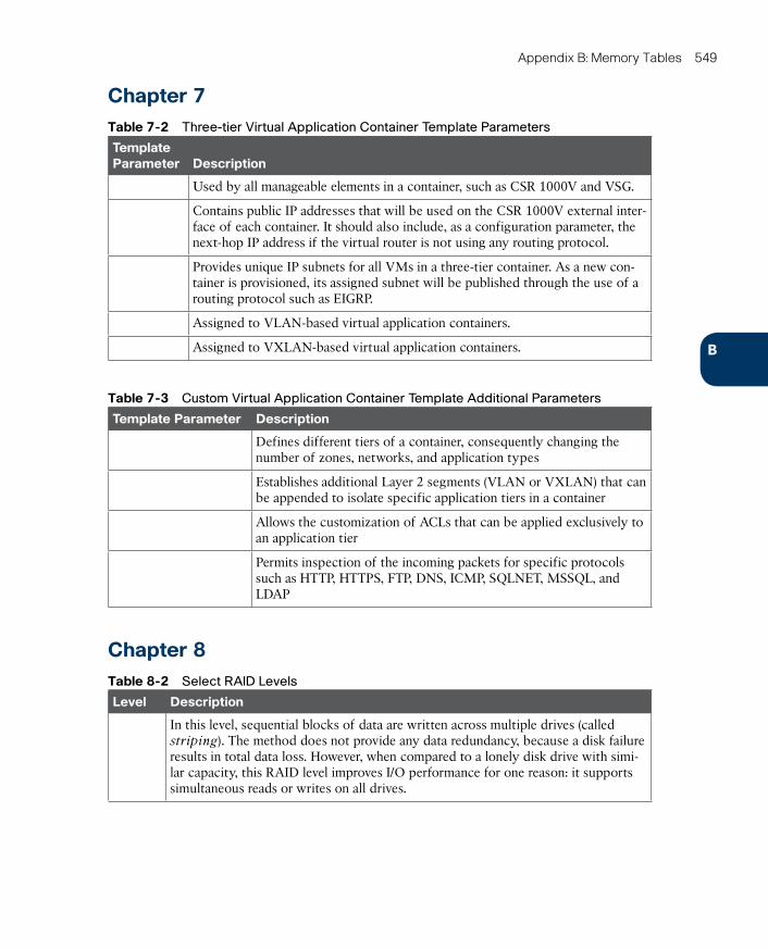
ptg17120290
B
Appendix B: Memory Tables 549
Chapter 7Table 7-2 Three-tier Virtual Application Container Template Parameters
Template Parameter Description
Used by all manageable elements in a container, such as CSR 1000V and VSG.
Contains public IP addresses that will be used on the CSR 1000V external inter-face of each container. It should also include, as a configuration parameter, the next-hop IP address if the virtual router is not using any routing protocol.
Provides unique IP subnets for all VMs in a three-tier container. As a new con-tainer is provisioned, its assigned subnet will be published through the use of a routing protocol such as EIGRP.
Assigned to VLAN-based virtual application containers.
Assigned to VXLAN-based virtual application containers.
Table 7-3 Custom Virtual Application Container Template Additional Parameters
Template Parameter Description
Defines different tiers of a container, consequently changing the number of zones, networks, and application types
Establishes additional Layer 2 segments (VLAN or VXLAN) that can be appended to isolate specific application tiers in a container
Allows the customization of ACLs that can be applied exclusively to an application tier
Permits inspection of the incoming packets for specific protocols such as HTTP, HTTPS, FTP, DNS, ICMP, SQLNET, MSSQL, and LDAP
Chapter 8Table 8-2 Select RAID Levels
Level Description
In this level, sequential blocks of data are written across multiple drives (called striping). The method does not provide any data redundancy, because a disk failure results in total data loss. However, when compared to a lonely disk drive with simi-lar capacity, this RAID level improves I/O performance for one reason: it supports simultaneous reads or writes on all drives.
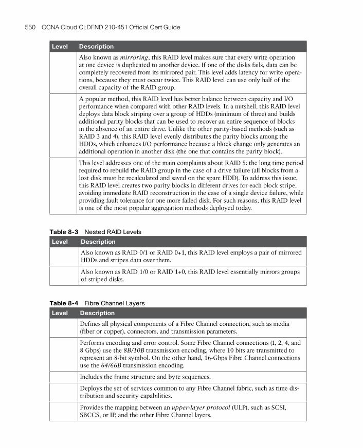
ptg17120290
550 CCNA Cloud CLDFND 210-451 Official Cert Guide
Level Description
Also known as mirroring, this RAID level makes sure that every write operation at one device is duplicated to another device. If one of the disks fails, data can be completely recovered from its mirrored pair. This level adds latency for write opera-tions, because they must occur twice. This RAID level can use only half of the overall capacity of the RAID group.
A popular method, this RAID level has better balance between capacity and I/O performance when compared with other RAID levels. In a nutshell, this RAID level deploys data block striping over a group of HDDs (minimum of three) and builds additional parity blocks that can be used to recover an entire sequence of blocks in the absence of an entire drive. Unlike the other parity-based methods (such as RAID 3 and 4), this RAID level evenly distributes the parity blocks among the HDDs, which enhances I/O performance because a block change only generates an additional operation in another disk (the one that contains the parity block).
This level addresses one of the main complaints about RAID 5: the long time period required to rebuild the RAID group in the case of a drive failure (all blocks from a lost disk must be recalculated and saved on the spare HDD). To address this issue, this RAID level creates two parity blocks in different drives for each block stripe, avoiding immediate RAID reconstruction in the case of a single device failure, while providing fault tolerance for one more failed disk. For such reasons, this RAID level is one of the most popular aggregation methods deployed today.
Table 8-3 Nested RAID Levels
Level Description
Also known as RAID 0/1 or RAID 0+1, this RAID level employs a pair of mirrored HDDs and stripes data over them.
Also known as RAID 1/0 or RAID 1+0, this RAID level essentially mirrors groups of striped disks.
Table 8-4 Fibre Channel Layers
Level Description
Defines all physical components of a Fibre Channel connection, such as media (fiber or copper), connectors, and transmission parameters.
Performs encoding and error control. Some Fibre Channel connections (1, 2, 4, and 8 Gbps) use the 8B/10B transmission encoding, where 10 bits are transmitted to represent an 8-bit symbol. On the other hand, 16-Gbps Fibre Channel connections use the 64/66B transmission encoding.
Includes the frame structure and byte sequences.
Deploys the set of services common to any Fibre Channel fabric, such as time dis-tribution and security capabilities.
Provides the mapping between an upper-layer protocol (ULP), such as SCSI, SBCCS, or IP, and the other Fibre Channel layers.
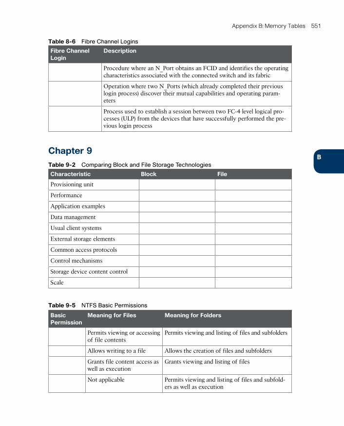
ptg17120290
B
Appendix B: Memory Tables 551
Table 8-6 Fibre Channel Logins
Fibre Channel Login
Description
Procedure where an N_Port obtains an FCID and identifies the operating characteristics associated with the connected switch and its fabric
Operation where two N_Ports (which already completed their previous login process) discover their mutual capabilities and operating param-eters
Process used to establish a session between two FC-4 level logical pro-cesses (ULP) from the devices that have successfully performed the pre-vious login process
Chapter 9Table 9-2 Comparing Block and File Storage Technologies
Characteristic Block File
Provisioning unit
Performance
Application examples
Data management
Usual client systems
External storage elements
Common access protocols
Control mechanisms
Storage device content control
Scale
Table 9-5 NTFS Basic Permissions
Basic Permission
Meaning for Files Meaning for Folders
Permits viewing or accessing of file contents
Permits viewing and listing of files and subfolders
Allows writing to a file Allows the creation of files and subfolders
Grants file content access as well as execution
Grants viewing and listing of files
Not applicable Permits viewing and listing of files and subfold-ers as well as execution
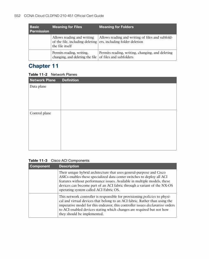
ptg17120290
552 CCNA Cloud CLDFND 210-451 Official Cert Guide
Basic Permission
Meaning for Files Meaning for Folders
Allows reading and writing of the file, including deleting the file itself
Allows reading and writing of files and subfold-ers, including folder deletion
Permits reading, writing, changing, and deleting the file
Permits reading, writing, changing, and deleting of files and subfolders
Chapter 11Table 11-2 Network Planes
Network Plane Definition
Data plane
Control plane
Table 11-3 Cisco ACI Components
Component Description
Their unique hybrid architecture that uses general-purpose and Cisco ASICs enables these specialized data center switches to deploy all ACI features without performance issues. Available in multiple models, these devices can become part of an ACI fabric through a variant of the NX-OS operating system called ACI Fabric OS.
This network controller is responsible for provisioning policies to physi-cal and virtual devices that belong to an ACI fabric. Rather than using the imperative model for this endeavor, this controller issues declarative orders to ACI-enabled devices stating which changes are required but not how they should be implemented.

ptg17120290
B
Appendix B: Memory Tables 553
Component Description
APIC handles the interaction with other solutions besides Nexus 9000 switches, which include Cisco Adaptive Security Appliances (ASA) fire-walls, Cisco Application Virtual Switch (AVS), VM managers such as VMware vCenter, Microsoft System Center Virtual Machine Manager (SCVMM), application delivery controllers from companies such as F5 and Citrix, and cloud orchestration systems such as OpenStack.
Table 11-4 ACI Logical Constructs
Object Description
Policy repository that allows both administrative and traffic segregation from other similar constructs. This construct may characterize different customers, business units, groups, or (rather conveniently) cloud tenants. ACI has predefined these constructs such as common (contains policies that are accessible to all these constructs), infrastructure (contains policies that govern infrastructure resources), and management (contains policies that control the operation of fabric management functions used for in-band and out-of-band configuration of fabric nodes).
Private network on a tenant, which defines a separate IP space (Layer 3 domain) where all endpoints must have unique IP addresses. This construct can be corre-lated to a Virtual Routing and Forwarding (VRF) instance on a traditional router. A tenant may deploy multiple of these constructs.
Represents a Layer 2 forwarding construct within the fabric and, for that reason, must belong to a context. It defines a unique MAC address space and flood domain (if flooding is enabled). A context may contain multiple of these constructs.
Classical IP subnet that must be associated to a bridge domain. A bridge domain must have at least one of these constructs and may incorporate multiple others.
Physical or virtual device that is (directly or indirectly) connected to an ACI fab-ric. This construct is characterized by IP and MAC addresses, location, and addi-tional attributes (such as version and patch level).
Logical construct gathering a collection of endpoints that are associated dynami-cally (for example, through communication with a VM manager) or statically (using a port or a VLAN, for example). By definition, this construct encompasses endpoints that share common policies.
Defines how EPGs can communicate with each other through traffic rules that include allowed protocols and Layer 4 ports. Without such construct, inter-EPG communication is disabled by default (whitelist behavior). Conversely, intra-EPG data transmission is always (implicitly) allowed. This construct can also con-trol the communication between EPGs from different tenants.
Models the connectivity requirements for all components of an application. It represents the logical container for EPGs and associated contracts.
Controls connectivity to networks that are external to the ACI fabric. They can be Layer 3 or Layer 2, depending on how these networks connect to a tenant pri-vate network. A tenant can connect to multiple of these constructs.
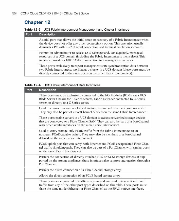
ptg17120290
554 CCNA Cloud CLDFND 210-451 Official Cert Guide
Chapter 12Table 12-3 UCS Fabric Interconnect Management and Cluster Interfaces
Port Description
A serial port that allows the initial setup or recovery of a Fabric Interconnect when the device does not offer any other connectivity option. This operation usually demands a PC with RS-232 serial connection and terminal emulation software.
Permits an administrator to access UCS Manager and, consequently, manage all resources of a UCS domain (including the Fabric Interconnects themselves). This interface provides a 1000BASE-T connection to a management network.
These ports exclusively transport management state synchronization data between two Fabric Interconnects working as a cluster in a UCS domain (these ports must be directly connected to the same ports on the other Fabric Interconnect).
Table 12-4 UCS Fabric Interconnect Data Interfaces
Port Description
These ports must be exclusively connected to the I/O Modules (IOMs) on a UCS Blade Server Chassis for B-Series servers, Fabric Extender connected to C-Series server, or directly to a C-Series server.
Used to connect servers in a UCS domain to a standard Ethernet-based network. They may also be part of a PortChannel defined on the same Fabric Interconnect.
These ports enable servers in a UCS domain to access networked storage devices that are connected to a Fibre Channel SAN. They can also be part of a PortChannel with other similar interfaces on the same Fabric Interconnect.
Used to carry storage-only FCoE traffic from the Fabric Interconnect to an upstream FCoE-capable switch. They may also be members of a PortChannel defined on the same Fabric Interconnect.
FCoE uplink port that can carry both Ethernet and FCoE-encapsulated Fibre Chan-nel traffic simultaneously. They can also be part of a PortChannel with similar ports on the same Fabric Interconnect.
Permits the connection of directly attached NFS or iSCSI storage devices. If sup-ported on the storage appliance, these interfaces also support aggregation through a PortChannel.
Permits the direct connection of a Fibre Channel storage array.
Allows the direct connection of an FCoE-based storage array.
These ports are connected to traffic analyzers and are used to transmit mirrored traffic from any of the other port types described on this table. These ports must share the same mode (Ethernet or Fibre Channel) as the SPAN source interfaces.
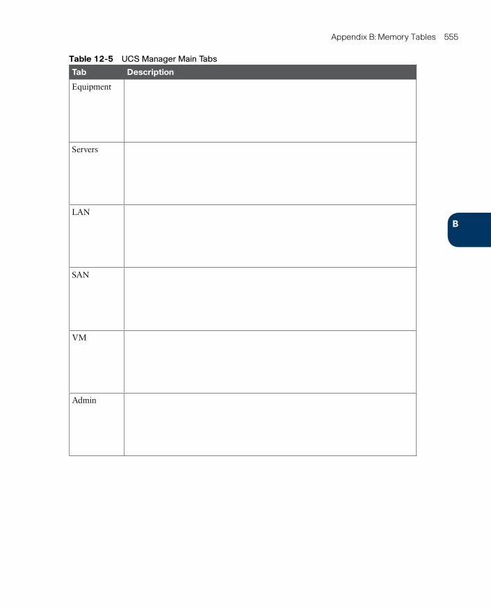
ptg17120290
B
Appendix B: Memory Tables 555
Table 12-5 UCS Manager Main Tabs
Tab Description
Equipment
Servers
LAN
SAN
VM
Admin
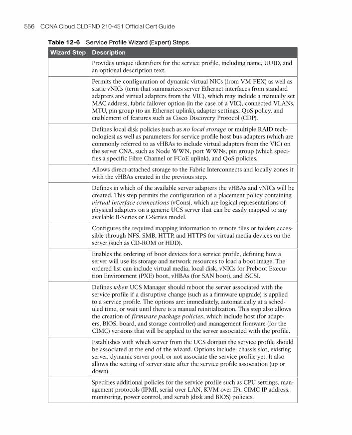
ptg17120290
556 CCNA Cloud CLDFND 210-451 Official Cert Guide
Table 12-6 Service Profile Wizard (Expert) Steps
Wizard Step Description
Provides unique identifiers for the service profile, including name, UUID, and an optional description text.
Permits the configuration of dynamic virtual NICs (from VM-FEX) as well as static vNICs (term that summarizes server Ethernet interfaces from standard adapters and virtual adapters from the VIC), which may include a manually set MAC address, fabric failover option (in the case of a VIC), connected VLANs, MTU, pin group (to an Ethernet uplink), adapter settings, QoS policy, and enablement of features such as Cisco Discovery Protocol (CDP).
Defines local disk policies (such as no local storage or multiple RAID tech-nologies) as well as parameters for service profile host bus adapters (which are commonly referred to as vHBAs to include virtual adapters from the VIC) on the server CNA, such as Node WWN, port WWNs, pin group (which speci-fies a specific Fibre Channel or FCoE uplink), and QoS policies.
Allows direct-attached storage to the Fabric Interconnects and locally zones it with the vHBAs created in the previous step.
Defines in which of the available server adapters the vHBAs and vNICs will be created. This step permits the configuration of a placement policy containing virtual interface connections (vCons), which are logical representations of physical adapters on a generic UCS server that can be easily mapped to any available B-Series or C-Series model.
Configures the required mapping information to remote files or folders acces-sible through NFS, SMB, HTTP, and HTTPS for virtual media devices on the server (such as CD-ROM or HDD).
Enables the ordering of boot devices for a service profile, defining how a server will use its storage and network resources to load a boot image. The ordered list can include virtual media, local disk, vNICs for Preboot Execu-tion Environment (PXE) boot, vHBAs (for SAN boot), and iSCSI.
Defines when UCS Manager should reboot the server associated with the service profile if a disruptive change (such as a firmware upgrade) is applied to a service profile. The options are: immediately, automatically at a sched-uled time, or wait until there is a manual reinitialization. This step also allows the creation of firmware package policies, which include host (for adapt-ers, BIOS, board, and storage controller) and management firmware (for the CIMC) versions that will be applied to the server associated with the profile.
Establishes with which server from the UCS domain the service profile should be associated at the end of the wizard. Options include: chassis slot, existing server, dynamic server pool, or not associate the service profile yet. It also allows the setting of server state after the service profile association (up or down).
Specifies additional policies for the service profile such as CPU settings, man-agement protocols (IPMI, serial over LAN, KVM over IP), CIMC IP address, monitoring, power control, and scrub (disk and BIOS) policies.
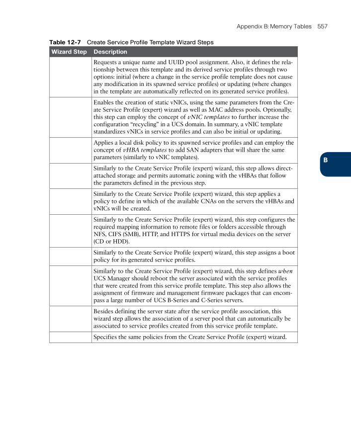
ptg17120290
B
Appendix B: Memory Tables 557
Table 12-7 Create Service Profile Template Wizard Steps
Wizard Step Description
Requests a unique name and UUID pool assignment. Also, it defines the rela-tionship between this template and its derived service profiles through two options: initial (where a change in the service profile template does not cause any modification in its spawned service profiles) or updating (where changes in the template are automatically reflected on its generated service profiles).
Enables the creation of static vNICs, using the same parameters from the Cre-ate Service Profile (expert) wizard as well as MAC address pools. Optionally, this step can employ the concept of vNIC templates to further increase the configuration “recycling” in a UCS domain. In summary, a vNIC template standardizes vNICs in service profiles and can also be initial or updating.
Applies a local disk policy to its spawned service profiles and can employ the concept of vHBA templates to add SAN adapters that will share the same parameters (similarly to vNIC templates).
Similarly to the Create Service Profile (expert) wizard, this step allows direct-attached storage and permits automatic zoning with the vHBAs that follow the parameters defined in the previous step.
Similarly to the Create Service Profile (expert) wizard, this step applies a policy to define in which of the available CNAs on the servers the vHBAs and vNICs will be created.
Similarly to the Create Service Profile (expert) wizard, this step configures the required mapping information to remote files or folders accessible through NFS, CIFS (SMB), HTTP, and HTTPS for virtual media devices on the server (CD or HDD).
Similarly to the Create Service Profile (expert) wizard, this step assigns a boot policy for its generated service profiles.
Similarly to the Create Service Profile (expert) wizard, this step defines when UCS Manager should reboot the server associated with the service profiles that were created from this service profile template. This step also allows the assignment of firmware and management firmware packages that can encom-pass a large number of UCS B-Series and C-Series servers.
Besides defining the server state after the service profile association, this wizard step allows the association of a server pool that can automatically be associated to service profiles created from this service profile template.
Specifies the same policies from the Create Service Profile (expert) wizard.

ptg17120290
558 CCNA Cloud CLDFND 210-451 Official Cert Guide
Chapter 13Table 13-3 Cisco MDS 9000 License Packages
License Main Features
Quality of Service (QoS), Inter-VSAN Routing (IVR), Extended BB_Credits, and FC Port Security
Multiple physical fabric management, historical performance monitoring and pre-diction, web client, and analysis reports
Table 13-10 Cisco Nexus 5000 License Packages
License Features
Fibre Channel, FCoE, and FCoE N_Port Virtualizer (NPV) features supported on eight ports
Multifabric management and historical reports for Fibre Channel and FCoE
FabricPath
FCoE NPV mode
Static routing, Routing Information Protocol version 2 (RIPv2), Hot-Standby Router Protocol (HSRP), Virtual Router Redundancy Protocol (VRRP), limited OSPF and EIGRP
Full EIGRP, OSFP, BGP, and VRF Lite
Fibre Channel and FCoE NPV features supported on any port
Virtual Machine Fabric Extender
Table 13-11 Cisco Nexus 7000 and 7700 Supervisor Module Characteristics
Model Number of VDCs Number of Fabric Extenders
Supervisor2
Supervisor2 Enhanced
Table 13-15 Cisco Nexus 7000 and 7700 License Packages
License Main Features
OSPF, BGP, IS-IS, Policy-Based Routing, Generic Routing Encapsulation (GRE), Protocol Independent Multicast (PIM), Multicast Source Discovery Protocol (MSDP), EIGRP, VXLAN, and BGP eVPN control plane
Virtual device contexts (VDCs)
Increments four VDC licenses that allow Supervisor 2 Enhanced module to sup-port eight VDCs
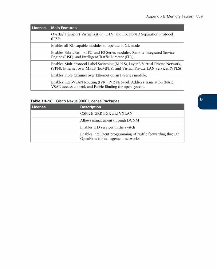
ptg17120290
B
Appendix B: Memory Tables 559
License Main Features
Overlay Transport Virtualization (OTV) and Locator/ID Separation Protocol (LISP)
Enables all XL-capable modules to operate in XL mode
Enables FabricPath on F2- and F3-Series modules, Remote Integrated Service Engine (RISE), and Intelligent Traffic Director (ITD)
Enables Multiprotocol Label Switching (MPLS), Layer 3 Virtual Private Network (VPN), Ethernet over MPLS (EoMPLS), and Virtual Private LAN Services (VPLS)
Enables Fibre Channel over Ethernet on an F-Series module.
Enables Inter-VSAN Routing (IVR), IVR Network Address Translation (NAT), VSAN access control, and Fabric Binding for open systems
Table 13-18 Cisco Nexus 9000 License Packages
License Description
OSPF, EIGRP, BGP, and VXLAN
Allows management through DCNM
Enables ITD services in the switch
Enables intelligent programming of traffic forwarding through OpenFlow for management networks

ptg17120290
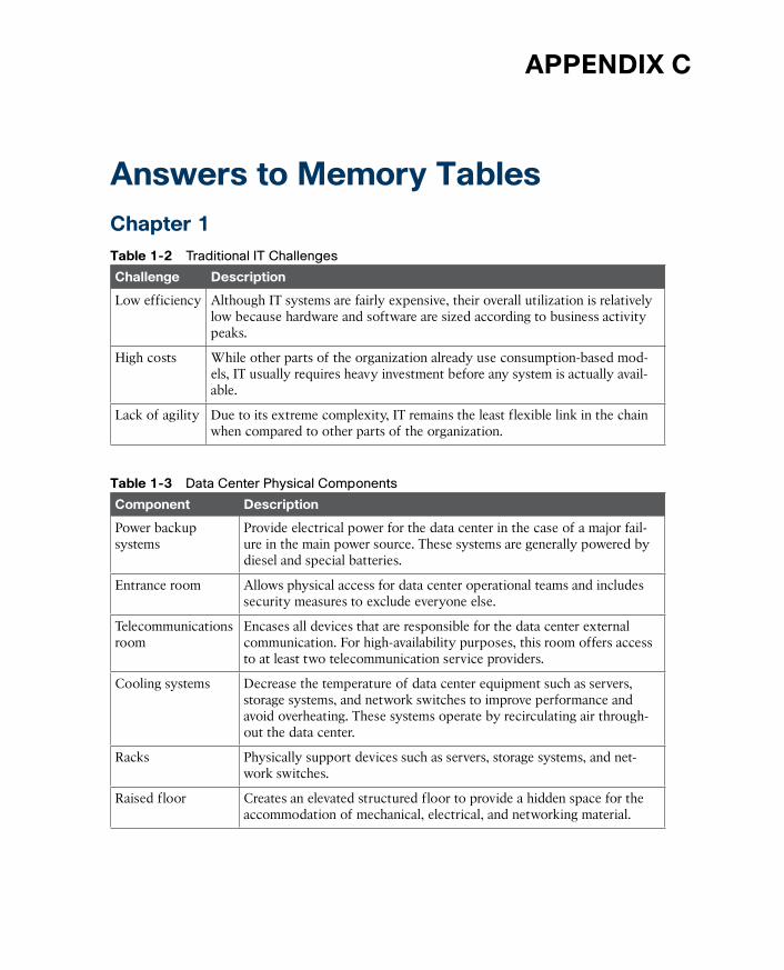
ptg17120290
APPENDIX C
Answers to Memory TablesChapter 1Table 1-2 Traditional IT Challenges
Challenge Description
Low efficiency Although IT systems are fairly expensive, their overall utilization is relatively low because hardware and software are sized according to business activity peaks.
High costs While other parts of the organization already use consumption-based mod-els, IT usually requires heavy investment before any system is actually avail-able.
Lack of agility Due to its extreme complexity, IT remains the least flexible link in the chain when compared to other parts of the organization.
Table 1-3 Data Center Physical Components
Component Description
Power backup systems
Provide electrical power for the data center in the case of a major fail-ure in the main power source. These systems are generally powered by diesel and special batteries.
Entrance room Allows physical access for data center operational teams and includes security measures to exclude everyone else.
Telecommunications room
Encases all devices that are responsible for the data center external communication. For high-availability purposes, this room offers access to at least two telecommunication service providers.
Cooling systems Decrease the temperature of data center equipment such as servers, storage systems, and network switches to improve performance and avoid overheating. These systems operate by recirculating air through-out the data center.
Racks Physically support devices such as servers, storage systems, and net-work switches.
Raised floor Creates an elevated structured floor to provide a hidden space for the accommodation of mechanical, electrical, and networking material.

ptg17120290
562 CCNA Cloud CLDFND 210-451 Official Cert Guide
Table 1-5 NIST Cloud Criteria
Criterion Description
Service models
Classify clouds according to the nature of the service they provide to consum-ers (Infrastructure as a Service, Platform as a Service, or Software as a Service).
Deployment models
Classify cloud computing deployments according to who the cloud infrastruc-ture is provisioned for (public, private, community, or hybrid).
Chapter 2Table 2-2 Specialized Service Providers
Type Description
Application service provider (ASP)
Offers software services (applications) to customers through a computer network such as the Internet. This service provider normally hosts, owns, operates, and maintains the same software that would be installed locally in the customer and customizes the service according to the customer needs.
Computer service provider (CSP)
Provides and supports a complete computer system, which includes hard-ware, software, communication systems, and power backup. This service provider is more common in mainframe-based environments.
Data center service provider (DCSP)
Offers all technologies, facility components, and activities related to the operation of a data center. A data center service may include computing, storage, and networking, among other offers. Common options are host-ing (customer leases hardware that the service provider has acquired) and colocation (customer acquires hardware and leases a server cabinet in the service provider site).
Internet service provider (ISP)
Provides services for accessing the Internet, offering options such as Inter-net transit and domain name registration.
Managed service provider (MSP)
Remotely controls components of the IT infrastructure of a customer, which may include desktops, critical applications, networks, or even every IT system. The latter situation is commonly called full IT outsourcing.
Network service provider (NSP)
Offers data communication services to its customers through a shared “backbone” network. These services generally include a committed band-width for each site and, optionally, Internet access.
Storage service provider (SSP)
Provides computer storage capacity and data management services (such as backup) at a customer site or remotely, using its data center facilities.
Telecommunica-tions service pro-vider (TSP)
Offers long distance communication resources for traditional telephony and data leased lines between customer premises or between a customer premises and an NSP (last mile link, in this scenario).

ptg17120290
C
Appendix C: Answers to Memory Tables 563
Table 2-3 Virtualization Types
Type Description
Pooling technologies
Multiple physical elements are consolidated into a single logical entity that shares characteristics with the original computing resources. In summary, such techniques optimize computing resource management and availability.
Abstraction technologies
Techniques where the logical resources do not maintain the characteristics of their physical counterparts. Instead, via the emulation of other resources, these technologies generally simplify operations through the preservation of existing procedures for these distinct devices.
Partitioning technologies
Characterized through the creation of independent logical partitions that emulate the characteristics of a physical resource. In essence, such techniques enable resource usage efficiency.
Chapter 3Table 3-6 Private and Public Clouds Compared
Service Model Advantages Disadvantages
Public cloud ■ OPEX model
■ Scale
■ Highly accessible
■ Shared resources
■ Less secure
■ Weaker control
Private cloud ■ Dedicated hardware
■ More secure
■ Customizable
■ CAPEX model
■ Less scalable
■ Standardized
Table 3-7 Cisco Intercloud Principles
Principle Description
Choice of consumption models
The “one-stop shop” approach definitely does not satisfy the understandable desire of many companies to choose services from different cloud providers. Cisco Intercloud frees organizations to provision and agnostically manage cloud services from its private cloud technology and chosen public infrastruc-ture. Additionally, Cisco Powered cloud partners can act as cloud brokers for the offerings provided by the Cisco Intercloud Services or even other mem-bers of the Intercloud.
Intercloud infrastructure
As IP routers were the foundation of the Internet, the basis of the Cisco Inter-cloud infrastructure is Cisco Intercloud Fabric (ICF), which essentially pro-motes integration between distinct cloud providers.
Intercloud applications
The Cisco Intercloud enables an easy and secure blending of on-premises applications and public cloud applications through a rich ecosystem of SaaS and PaaS member cloud providers.
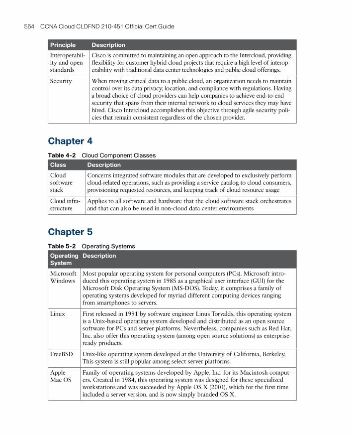
ptg17120290
564 CCNA Cloud CLDFND 210-451 Official Cert Guide
Principle Description
Interoperabil-ity and open standards
Cisco is committed to maintaining an open approach to the Intercloud, providing flexibility for customer hybrid cloud projects that require a high level of interop-erability with traditional data center technologies and public cloud offerings.
Security When moving critical data to a public cloud, an organization needs to maintain control over its data privacy, location, and compliance with regulations. Having a broad choice of cloud providers can help companies to achieve end-to-end security that spans from their internal network to cloud services they may have hired. Cisco Intercloud accomplishes this objective through agile security poli-cies that remain consistent regardless of the chosen provider.
Chapter 4Table 4-2 Cloud Component Classes
Class Description
Cloud software stack
Concerns integrated software modules that are developed to exclusively perform cloud-related operations, such as providing a service catalog to cloud consumers, provisioning requested resources, and keeping track of cloud resource usage
Cloud infra-structure
Applies to all software and hardware that the cloud software stack orchestrates and that can also be used in non-cloud data center environments
Chapter 5Table 5-2 Operating Systems
Operating System
Description
Microsoft Windows
Most popular operating system for personal computers (PCs). Microsoft intro-duced this operating system in 1985 as a graphical user interface (GUI) for the Microsoft Disk Operating System (MS-DOS). Today, it comprises a family of operating systems developed for myriad different computing devices ranging from smartphones to servers.
Linux First released in 1991 by software engineer Linus Torvalds, this operating system is a Unix-based operating system developed and distributed as an open source software for PCs and server platforms. Nevertheless, companies such as Red Hat, Inc. also offer this operating system (among open source solutions) as enterprise-ready products.
FreeBSD Unix-like operating system developed at the University of California, Berkeley. This system is still popular among select server platforms.
Apple Mac OS
Family of operating systems developed by Apple, Inc. for its Macintosh comput-ers. Created in 1984, this operating system was designed for these specialized workstations and was succeeded by Apple OS X (2001), which for the first time included a server version, and is now simply branded OS X.
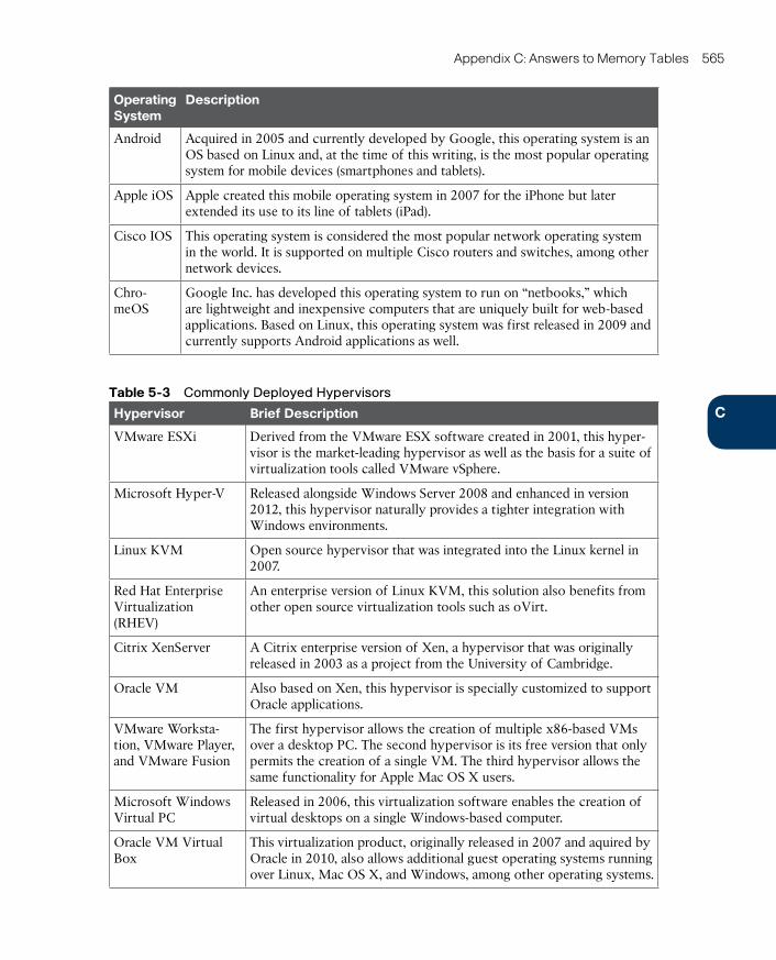
ptg17120290
C
Appendix C: Answers to Memory Tables 565
Operating System
Description
Android Acquired in 2005 and currently developed by Google, this operating system is an OS based on Linux and, at the time of this writing, is the most popular operating system for mobile devices (smartphones and tablets).
Apple iOS Apple created this mobile operating system in 2007 for the iPhone but later extended its use to its line of tablets (iPad).
Cisco IOS This operating system is considered the most popular network operating system in the world. It is supported on multiple Cisco routers and switches, among other network devices.
Chro-meOS
Google Inc. has developed this operating system to run on “netbooks,” which are lightweight and inexpensive computers that are uniquely built for web-based applications. Based on Linux, this operating system was first released in 2009 and currently supports Android applications as well.
Table 5-3 Commonly Deployed Hypervisors
Hypervisor Brief Description
VMware ESXi Derived from the VMware ESX software created in 2001, this hyper-visor is the market-leading hypervisor as well as the basis for a suite of virtualization tools called VMware vSphere.
Microsoft Hyper-V Released alongside Windows Server 2008 and enhanced in version 2012, this hypervisor naturally provides a tighter integration with Windows environments.
Linux KVM Open source hypervisor that was integrated into the Linux kernel in 2007.
Red Hat Enterprise Virtualization (RHEV)
An enterprise version of Linux KVM, this solution also benefits from other open source virtualization tools such as oVirt.
Citrix XenServer A Citrix enterprise version of Xen, a hypervisor that was originally released in 2003 as a project from the University of Cambridge.
Oracle VM Also based on Xen, this hypervisor is specially customized to support Oracle applications.
VMware Worksta-tion, VMware Player, and VMware Fusion
The first hypervisor allows the creation of multiple x86-based VMs over a desktop PC. The second hypervisor is its free version that only permits the creation of a single VM. The third hypervisor allows the same functionality for Apple Mac OS X users.
Microsoft Windows Virtual PC
Released in 2006, this virtualization software enables the creation of virtual desktops on a single Windows-based computer.
Oracle VM Virtual Box
This virtualization product, originally released in 2007 and aquired by Oracle in 2010, also allows additional guest operating systems running over Linux, Mac OS X, and Windows, among other operating systems.
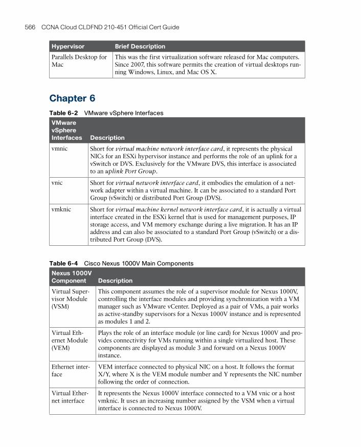
ptg17120290
566 CCNA Cloud CLDFND 210-451 Official Cert Guide
Hypervisor Brief Description
Parallels Desktop for Mac
This was the first virtualization software released for Mac computers. Since 2007, this software permits the creation of virtual desktops run-ning Windows, Linux, and Mac OS X.
Chapter 6Table 6-2 VMware vSphere Interfaces
VMware vSphere Interfaces Description
vmnic Short for virtual machine network interface card, it represents the physical NICs for an ESXi hypervisor instance and performs the role of an uplink for a vSwitch or DVS. Exclusively for the VMware DVS, this interface is associated to an uplink Port Group.
vnic Short for virtual network interface card, it embodies the emulation of a net-work adapter within a virtual machine. It can be associated to a standard Port Group (vSwitch) or distributed Port Group (DVS).
vmknic Short for virtual machine kernel network interface card, it is actually a virtual interface created in the ESXi kernel that is used for management purposes, IP storage access, and VM memory exchange during a live migration. It has an IP address and can also be associated to a standard Port Group (vSwitch) or a dis-tributed Port Group (DVS).
Table 6-4 Cisco Nexus 1000V Main Components
Nexus 1000V Component Description
Virtual Super-visor Module (VSM)
This component assumes the role of a supervisor module for Nexus 1000V, controlling the interface modules and providing synchronization with a VM manager such as VMware vCenter. Deployed as a pair of VMs, a pair works as active-standby supervisors for a Nexus 1000V instance and is represented as modules 1 and 2.
Virtual Eth-ernet Module (VEM)
Plays the role of an interface module (or line card) for Nexus 1000V and pro-vides connectivity for VMs running within a single virtualized host. These components are displayed as module 3 and forward on a Nexus 1000V instance.
Ethernet inter-face
VEM interface connected to physical NIC on a host. It follows the format X/Y, where X is the VEM module number and Y represents the NIC number following the order of connection.
Virtual Ether-net interface
It represents the Nexus 1000V interface connected to a VM vnic or a host vmknic. It uses an increasing number assigned by the VSM when a virtual interface is connected to Nexus 1000V.
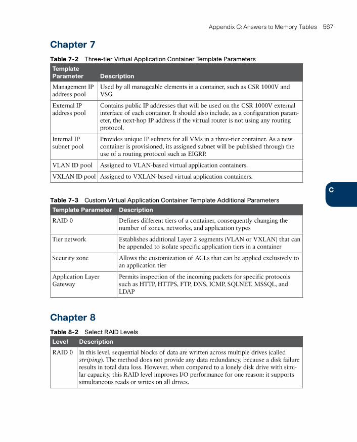
ptg17120290
C
Appendix C: Answers to Memory Tables 567
Chapter 7Table 7-2 Three-tier Virtual Application Container Template Parameters
Template Parameter Description
Management IP address pool
Used by all manageable elements in a container, such as CSR 1000V and VSG.
External IP address pool
Contains public IP addresses that will be used on the CSR 1000V external interface of each container. It should also include, as a configuration param-eter, the next-hop IP address if the virtual router is not using any routing protocol.
Internal IP subnet pool
Provides unique IP subnets for all VMs in a three-tier container. As a new container is provisioned, its assigned subnet will be published through the use of a routing protocol such as EIGRP.
VLAN ID pool Assigned to VLAN-based virtual application containers.
VXLAN ID pool Assigned to VXLAN-based virtual application containers.
Table 7-3 Custom Virtual Application Container Template Additional Parameters
Template Parameter Description
RAID 0 Defines different tiers of a container, consequently changing the number of zones, networks, and application types
Tier network Establishes additional Layer 2 segments (VLAN or VXLAN) that can be appended to isolate specific application tiers in a container
Security zone Allows the customization of ACLs that can be applied exclusively to an application tier
Application Layer Gateway
Permits inspection of the incoming packets for specific protocols such as HTTP, HTTPS, FTP, DNS, ICMP, SQLNET, MSSQL, and LDAP
Chapter 8Table 8-2 Select RAID Levels
Level Description
RAID 0 In this level, sequential blocks of data are written across multiple drives (called striping). The method does not provide any data redundancy, because a disk failure results in total data loss. However, when compared to a lonely disk drive with simi-lar capacity, this RAID level improves I/O performance for one reason: it supports simultaneous reads or writes on all drives.

ptg17120290
568 CCNA Cloud CLDFND 210-451 Official Cert Guide
Level Description
RAID 1 Also known as mirroring, this RAID level makes sure that every write operation at one device is duplicated to another device. If one of the disks fails, data can be completely recovered from its mirrored pair. This level adds latency for write opera-tions, because they must occur twice. This RAID level can use only half of the overall capacity of the RAID group.
RAID 5 A popular method, this RAID level has better balance between capacity and I/O performance when compared with other RAID levels. In a nutshell, this RAID level deploys data block striping over a group of HDDs (minimum of three) and builds additional parity blocks that can be used to recover an entire sequence of blocks in the absence of an entire drive. Unlike the other parity-based methods (such as RAID 3 and 4), this RAID level evenly distributes the parity blocks among the HDDs, which enhances I/O performance because a block change only generates an additional operation in another disk (the one that contains the parity block).
RAID 6 This level addresses one of the main complaints about RAID 5: the long time period required to rebuild the RAID group in the case of a drive failure (all blocks from a lost disk must be recalculated and saved on the spare HDD). To address this issue, this RAID level creates two parity blocks in different drives for each block stripe, avoiding immediate RAID reconstruction in the case of a single device failure, while providing fault tolerance for one more failed disk. For such reasons, this RAID level is one of the most popular aggregation methods deployed today.
Table 8-3 Nested RAID Levels
Level Description
RAID 01 Also known as RAID 0/1 or RAID 0+1, this RAID level employs a pair of mirrored HDDs and stripes data over them.
RAID 10 Also known as RAID 1/0 or RAID 1+0, this RAID level essentially mirrors groups of striped disks.
Table 8-4 Fibre Channel Layers
Level Description
FC-0 Defines all physical components of a Fibre Channel connection, such as media (fiber or copper), connectors, and transmission parameters.
FC-1 Performs encoding and error control. Some Fibre Channel connections (1, 2, 4, and 8 Gbps) use the 8B/10B transmission encoding, where 10 bits are transmitted to represent an 8-bit symbol. On the other hand, 16-Gbps Fibre Channel connections use the 64/66B transmission encoding.
FC-2 Includes the frame structure and byte sequences.
FC-3 Deploys the set of services common to any Fibre Channel fabric, such as time dis-tribution and security capabilities.
FC-4 Provides the mapping between an upper-layer protocol (ULP), such as SCSI, SBCCS, or IP, and the other Fibre Channel layers.

ptg17120290
C
Appendix C: Answers to Memory Tables 569
Table 8-6 Fibre Channel Logins
Fibre Channel Login
Description
Fabric Login (FLOGI)
Procedure where an N_Port obtains an FCID and identifies the operating characteristics associated with the connected switch and its fabric
Port Login (PLOGI)
Operation where two N_Ports (which already completed their previous login process) discover their mutual capabilities and operating param-eters
Process Login (PRLI)
Process used to establish a session between two FC-4 level logical pro-cesses (ULP) from the devices that have successfully performed the pre-vious login process
Chapter 9Table 9-2 Comparing Block and File Storage Technologies
Characteristic Block File
Provisioning unit Volume File
Performance Higher Lower
Application examples Anything, including files, data-bases, and proprietary data
Corporate files, operating sys-tem images, and VM templates
Data management More complex Simpler
Usual client systems Servers PCs and servers
External storage elements SANs and disk arrays NAS and NAS heads
Common access protocols Fibre Channel and iSCSI NFS and CIFS
Control mechanisms LUN masking and zoning File permissions
Storage device content control
None File metadata and hierarchical directory tree
Scale High Massive
Table 9-5 NTFS Basic Permissions
Basic Permission
Meaning for Files Meaning for Folders
Read Permits viewing or accessing of file contents
Permits viewing and listing of files and subfolders
Write Allows writing to a file Allows the creation of files and subfolders
Read & Execute
Grants file content access as well as execution
Grants viewing and listing of files

ptg17120290
570 CCNA Cloud CLDFND 210-451 Official Cert Guide
Basic Permission
Meaning for Files Meaning for Folders
List Folder Contents
Not applicable Permits viewing and listing of files and subfold-ers as well as execution
Modify Allows reading and writing of the file, including deleting the file itself
Allows reading and writing of files and subfold-ers, including folder deletion
Full Control Permits reading, writing, changing, and deleting the file
Permits reading, writing, changing, and deleting of files and subfolders
Chapter 11Table 11-2 Network Planes
Network Plane Definition
Data plane Comprehends all the elements that handle the transport of data packets between two or more ports on a network device. Also known as the for-warding plane, the data plane can be viewed as the “muscle” that offers forwarding capacity to a device.
Control plane Encompasses all elements that process traffic directed to the networking device itself. Dynamic routing protocols are an example of control plane processes. Leveraging the human body metaphor from the row above, the control plane can be considered the “brain” of a network device because it uses information received from a network administrator or other devices to correctly control the data plane elements.
Table 11-3 Cisco ACI Components
Component Description
Nexus 9000 switches
Their unique hybrid architecture that uses general-purpose and Cisco ASICs enables these specialized data center switches to deploy all ACI features without performance issues. Available in multiple models, these devices can become part of an ACI fabric through a variant of the NX-OS operating system called ACI Fabric OS.
Application Policy Infrastruc-ture Controller (APIC)
This network controller is responsible for provisioning policies to physi-cal and virtual devices that belong to an ACI fabric. Rather than using the imperative model for this endeavor, this controller issues declarative orders to ACI-enabled devices stating which changes are required but not how they should be implemented.
Ecosystem APIC handles the interaction with other solutions besides Nexus 9000 switches, which include Cisco Adaptive Security Appliances (ASA) fire-walls, Cisco Application Virtual Switch (AVS), VM managers such as VMware vCenter, Microsoft System Center Virtual Machine Manager (SCVMM), application delivery controllers from companies such as F5 and Citrix, and cloud orchestration systems such as OpenStack.
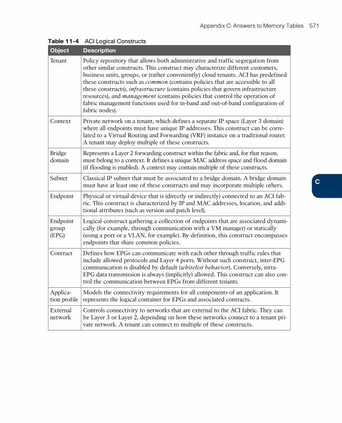
ptg17120290
C
Appendix C: Answers to Memory Tables 571
Table 11-4 ACI Logical Constructs
Object Description
Tenant Policy repository that allows both administrative and traffic segregation from other similar constructs. This construct may characterize different customers, business units, groups, or (rather conveniently) cloud tenants. ACI has predefined these constructs such as common (contains policies that are accessible to all these constructs), infrastructure (contains policies that govern infrastructure resources), and management (contains policies that control the operation of fabric management functions used for in-band and out-of-band configuration of fabric nodes).
Context Private network on a tenant, which defines a separate IP space (Layer 3 domain) where all endpoints must have unique IP addresses. This construct can be corre-lated to a Virtual Routing and Forwarding (VRF) instance on a traditional router. A tenant may deploy multiple of these constructs.
Bridge domain
Represents a Layer 2 forwarding construct within the fabric and, for that reason, must belong to a context. It defines a unique MAC address space and flood domain (if flooding is enabled). A context may contain multiple of these constructs.
Subnet Classical IP subnet that must be associated to a bridge domain. A bridge domain must have at least one of these constructs and may incorporate multiple others.
Endpoint Physical or virtual device that is (directly or indirectly) connected to an ACI fab-ric. This construct is characterized by IP and MAC addresses, location, and addi-tional attributes (such as version and patch level).
Endpoint group (EPG)
Logical construct gathering a collection of endpoints that are associated dynami-cally (for example, through communication with a VM manager) or statically (using a port or a VLAN, for example). By definition, this construct encompasses endpoints that share common policies.
Contract Defines how EPGs can communicate with each other through traffic rules that include allowed protocols and Layer 4 ports. Without such construct, inter-EPG communication is disabled by default (whitelist behavior). Conversely, intra-EPG data transmission is always (implicitly) allowed. This construct can also con-trol the communication between EPGs from different tenants.
Applica-tion profile
Models the connectivity requirements for all components of an application. It represents the logical container for EPGs and associated contracts.
External network
Controls connectivity to networks that are external to the ACI fabric. They can be Layer 3 or Layer 2, depending on how these networks connect to a tenant pri-vate network. A tenant can connect to multiple of these constructs.
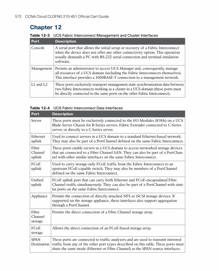
ptg17120290
572 CCNA Cloud CLDFND 210-451 Official Cert Guide
Chapter 12Table 12-3 UCS Fabric Interconnect Management and Cluster Interfaces
Port Description
Console A serial port that allows the initial setup or recovery of a Fabric Interconnect when the device does not offer any other connectivity option. This operation usually demands a PC with RS-232 serial connection and terminal emulation software.
Management Permits an administrator to access UCS Manager and, consequently, manage all resources of a UCS domain (including the Fabric Interconnects themselves). This interface provides a 1000BASE-T connection to a management network.
L1 and L2 These ports exclusively transport management state synchronization data between two Fabric Interconnects working as a cluster in a UCS domain (these ports must be directly connected to the same ports on the other Fabric Interconnect).
Table 12-4 UCS Fabric Interconnect Data Interfaces
Port Description
Server These ports must be exclusively connected to the I/O Modules (IOMs) on a UCS Blade Server Chassis for B-Series servers, Fabric Extender connected to C-Series server, or directly to a C-Series server.
Ethernet uplink
Used to connect servers in a UCS domain to a standard Ethernet-based network. They may also be part of a PortChannel defined on the same Fabric Interconnect.
Fibre Channel uplink
These ports enable servers in a UCS domain to access networked storage devices that are connected to a Fibre Channel SAN. They can also be part of a PortChan-nel with other similar interfaces on the same Fabric Interconnect.
FCoE uplink
Used to carry storage-only FCoE traffic from the Fabric Interconnect to an upstream FCoE-capable switch. They may also be members of a PortChannel defined on the same Fabric Interconnect.
Unified uplink
FCoE uplink port that can carry both Ethernet and FCoE-encapsulated Fibre Channel traffic simultaneously. They can also be part of a PortChannel with simi-lar ports on the same Fabric Interconnect.
Appliance Permits the connection of directly attached NFS or iSCSI storage devices. If supported on the storage appliance, these interfaces also support aggregation through a PortChannel.
Fibre Channel storage
Permits the direct connection of a Fibre Channel storage array.
FCoE storage
Allows the direct connection of an FCoE-based storage array.
SPAN Destination
These ports are connected to traffic analyzers and are used to transmit mirrored traffic from any of the other port types described on this table. These ports must share the same mode (Ethernet or Fibre Channel) as the SPAN source interfaces.
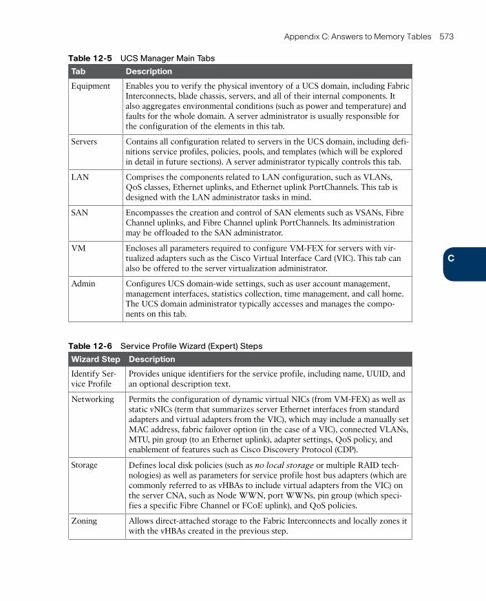
ptg17120290
C
Appendix C: Answers to Memory Tables 573
Table 12-5 UCS Manager Main Tabs
Tab Description
Equipment Enables you to verify the physical inventory of a UCS domain, including Fabric Interconnects, blade chassis, servers, and all of their internal components. It also aggregates environmental conditions (such as power and temperature) and faults for the whole domain. A server administrator is usually responsible for the configuration of the elements in this tab.
Servers Contains all configuration related to servers in the UCS domain, including defi-nitions service profiles, policies, pools, and templates (which will be explored in detail in future sections). A server administrator typically controls this tab.
LAN Comprises the components related to LAN configuration, such as VLANs, QoS classes, Ethernet uplinks, and Ethernet uplink PortChannels. This tab is designed with the LAN administrator tasks in mind.
SAN Encompasses the creation and control of SAN elements such as VSANs, Fibre Channel uplinks, and Fibre Channel uplink PortChannels. Its administration may be offloaded to the SAN administrator.
VM Encloses all parameters required to configure VM-FEX for servers with vir-tualized adapters such as the Cisco Virtual Interface Card (VIC). This tab can also be offered to the server virtualization administrator.
Admin Configures UCS domain-wide settings, such as user account management, management interfaces, statistics collection, time management, and call home. The UCS domain administrator typically accesses and manages the compo-nents on this tab.
Table 12-6 Service Profile Wizard (Expert) Steps
Wizard Step Description
Identify Ser-vice Profile
Provides unique identifiers for the service profile, including name, UUID, and an optional description text.
Networking Permits the configuration of dynamic virtual NICs (from VM-FEX) as well as static vNICs (term that summarizes server Ethernet interfaces from standard adapters and virtual adapters from the VIC), which may include a manually set MAC address, fabric failover option (in the case of a VIC), connected VLANs, MTU, pin group (to an Ethernet uplink), adapter settings, QoS policy, and enablement of features such as Cisco Discovery Protocol (CDP).
Storage Defines local disk policies (such as no local storage or multiple RAID tech-nologies) as well as parameters for service profile host bus adapters (which are commonly referred to as vHBAs to include virtual adapters from the VIC) on the server CNA, such as Node WWN, port WWNs, pin group (which speci-fies a specific Fibre Channel or FCoE uplink), and QoS policies.
Zoning Allows direct-attached storage to the Fabric Interconnects and locally zones it with the vHBAs created in the previous step.
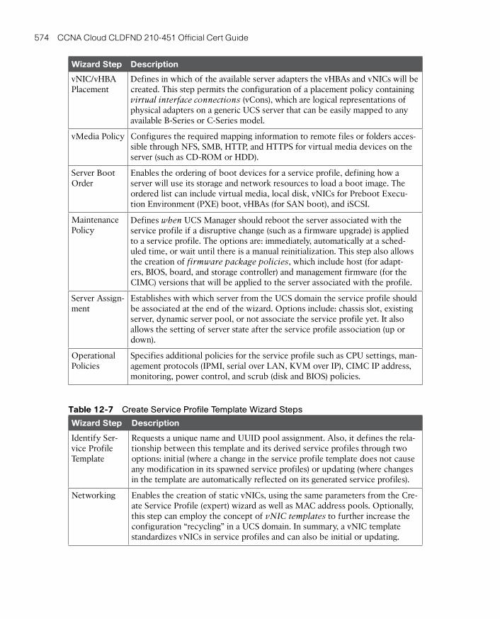
ptg17120290
574 CCNA Cloud CLDFND 210-451 Official Cert Guide
Wizard Step Description
vNIC/vHBA Placement
Defines in which of the available server adapters the vHBAs and vNICs will be created. This step permits the configuration of a placement policy containing virtual interface connections (vCons), which are logical representations of physical adapters on a generic UCS server that can be easily mapped to any available B-Series or C-Series model.
vMedia Policy Configures the required mapping information to remote files or folders acces-sible through NFS, SMB, HTTP, and HTTPS for virtual media devices on the server (such as CD-ROM or HDD).
Server Boot Order
Enables the ordering of boot devices for a service profile, defining how a server will use its storage and network resources to load a boot image. The ordered list can include virtual media, local disk, vNICs for Preboot Execu-tion Environment (PXE) boot, vHBAs (for SAN boot), and iSCSI.
Maintenance Policy
Defines when UCS Manager should reboot the server associated with the service profile if a disruptive change (such as a firmware upgrade) is applied to a service profile. The options are: immediately, automatically at a sched-uled time, or wait until there is a manual reinitialization. This step also allows the creation of firmware package policies, which include host (for adapt-ers, BIOS, board, and storage controller) and management firmware (for the CIMC) versions that will be applied to the server associated with the profile.
Server Assign-ment
Establishes with which server from the UCS domain the service profile should be associated at the end of the wizard. Options include: chassis slot, existing server, dynamic server pool, or not associate the service profile yet. It also allows the setting of server state after the service profile association (up or down).
Operational Policies
Specifies additional policies for the service profile such as CPU settings, man-agement protocols (IPMI, serial over LAN, KVM over IP), CIMC IP address, monitoring, power control, and scrub (disk and BIOS) policies.
Table 12-7 Create Service Profile Template Wizard Steps
Wizard Step Description
Identify Ser-vice Profile Template
Requests a unique name and UUID pool assignment. Also, it defines the rela-tionship between this template and its derived service profiles through two options: initial (where a change in the service profile template does not cause any modification in its spawned service profiles) or updating (where changes in the template are automatically reflected on its generated service profiles).
Networking Enables the creation of static vNICs, using the same parameters from the Cre-ate Service Profile (expert) wizard as well as MAC address pools. Optionally, this step can employ the concept of vNIC templates to further increase the configuration “recycling” in a UCS domain. In summary, a vNIC template standardizes vNICs in service profiles and can also be initial or updating.
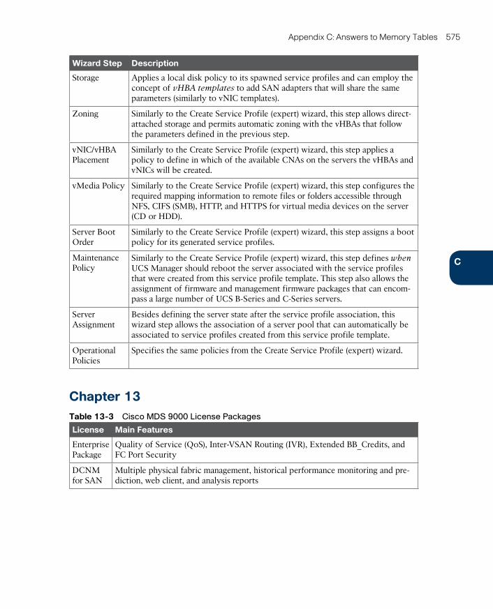
ptg17120290
C
Appendix C: Answers to Memory Tables 575
Wizard Step Description
Storage Applies a local disk policy to its spawned service profiles and can employ the concept of vHBA templates to add SAN adapters that will share the same parameters (similarly to vNIC templates).
Zoning Similarly to the Create Service Profile (expert) wizard, this step allows direct-attached storage and permits automatic zoning with the vHBAs that follow the parameters defined in the previous step.
vNIC/vHBA Placement
Similarly to the Create Service Profile (expert) wizard, this step applies a policy to define in which of the available CNAs on the servers the vHBAs and vNICs will be created.
vMedia Policy Similarly to the Create Service Profile (expert) wizard, this step configures the required mapping information to remote files or folders accessible through NFS, CIFS (SMB), HTTP, and HTTPS for virtual media devices on the server (CD or HDD).
Server Boot Order
Similarly to the Create Service Profile (expert) wizard, this step assigns a boot policy for its generated service profiles.
Maintenance Policy
Similarly to the Create Service Profile (expert) wizard, this step defines when UCS Manager should reboot the server associated with the service profiles that were created from this service profile template. This step also allows the assignment of firmware and management firmware packages that can encom-pass a large number of UCS B-Series and C-Series servers.
Server Assignment
Besides defining the server state after the service profile association, this wizard step allows the association of a server pool that can automatically be associated to service profiles created from this service profile template.
Operational Policies
Specifies the same policies from the Create Service Profile (expert) wizard.
Chapter 13Table 13-3 Cisco MDS 9000 License Packages
License Main Features
Enterprise Package
Quality of Service (QoS), Inter-VSAN Routing (IVR), Extended BB_Credits, and FC Port Security
DCNM for SAN
Multiple physical fabric management, historical performance monitoring and pre-diction, web client, and analysis reports
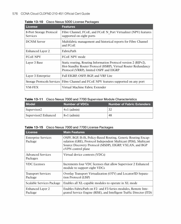
ptg17120290
576 CCNA Cloud CLDFND 210-451 Official Cert Guide
Table 13-10 Cisco Nexus 5000 License Packages
License Features
8-Port Storage Protocol Services
Fibre Channel, FCoE, and FCoE N_Port Virtualizer (NPV) features supported on eight ports
DCNM Server Multifabric management and historical reports for Fibre Channel and FCoE
Enhanced Layer 2 FabricPath
FCoE NPV FCoE NPV mode
Layer 3 Base Static routing, Routing Information Protocol version 2 (RIPv2), Hot-Standby Router Protocol (HSRP), Virtual Router Redundancy Protocol (VRRP), limited OSPF and EIGRP
Layer 3 Enterprise Full EIGRP, OSFP, BGP, and VRF Lite
Storage Protocols Services Fibre Channel and FCoE NPV features supported on any port
VM-FEX Virtual Machine Fabric Extender
Table 13-11 Cisco Nexus 7000 and 7700 Supervisor Module Characteristics
Model Number of VDCs Number of Fabric Extenders
Supervisor2 4+1 (admin) 32
Supervisor2 Enhanced 8+1 (admin) 48
Table 13-15 Cisco Nexus 7000 and 7700 License Packages
License Main Features
Enterprise Services Package
OSPF, BGP, IS-IS, Policy-Based Routing, Generic Routing Encap-sulation (GRE), Protocol Independent Multicast (PIM), Multicast Source Discovery Protocol (MSDP), EIGRP, VXLAN, and BGP eVPN control plane
Advanced Services Packages
Virtual device contexts (VDCs)
VDC Licenses Increments four VDC licenses that allow Supervisor 2 Enhanced module to support eight VDCs
Transport Services Package
Overlay Transport Virtualization (OTV) and Locator/ID Separa-tion Protocol (LISP)
Scalable Services Package Enables all XL-capable modules to operate in XL mode
Enhanced Layer 2 Package
Enables FabricPath on F2- and F3-Series modules, Remote Inte-grated Service Engine (RISE), and Intelligent Traffic Director (ITD)
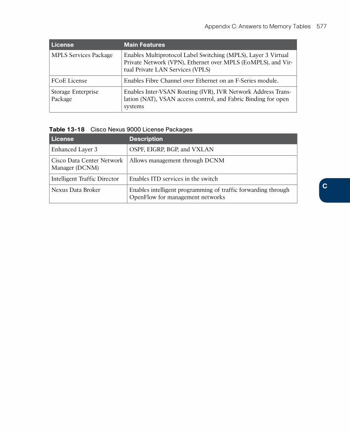
ptg17120290
C
Appendix C: Answers to Memory Tables 577
License Main Features
MPLS Services Package Enables Multiprotocol Label Switching (MPLS), Layer 3 Virtual Private Network (VPN), Ethernet over MPLS (EoMPLS), and Vir-tual Private LAN Services (VPLS)
FCoE License Enables Fibre Channel over Ethernet on an F-Series module.
Storage Enterprise Package
Enables Inter-VSAN Routing (IVR), IVR Network Address Trans-lation (NAT), VSAN access control, and Fabric Binding for open systems
Table 13-18 Cisco Nexus 9000 License Packages
License Description
Enhanced Layer 3 OSPF, EIGRP, BGP, and VXLAN
Cisco Data Center Network Manager (DCNM)
Allows management through DCNM
Intelligent Traffic Director Enables ITD services in the switch
Nexus Data Broker Enables intelligent programming of traffic forwarding through OpenFlow for management networks
ptg17120290
Symbols8.3 filenames, 273
32-bit architecture, 128
64-bit architecture, 128
AAAA (Authentication, Authorization,
and Accounting), 199
abstraction
definition of, 304
technologies, 37
as virtualization technique, 102
access model (cloud computing as), 12
access tier (three-tier design), 306
accessing
block storage, 233
ATA, 234-235
SCSI, 235-237
files, 269-270
remote files. See distributed file systems
ACI (Application Centric Infrastructure), 382
APIC in, 391
fabric management, 392-394
integration methods, 394-395
visibility, 395-396
architecture, 383-385
benefits of EPGs, 388-389
Cisco Nexus 9000 series switches, 475
contracts, 389-391
data plane, 396-397
integration with VM managers, 398
licensing, 478
policy model, 385-388
UCS versus, 451
ACI mode, 475
activating practice exam, 518
Active Directory, 284
Adapter FEX (Adapter Fabric Extender), 434
adapter policy (UCS), 442
Adaptive Security Virtual Appliance (ASAv), 181, 197-199, 486-487
ADC contexts, 211
ADCs (application delivery control-lers), 203-204
address learning (FabricPath), 351-352
addresses (Fibre Channel), 239-241
adjacency servers, 333
admin VDCs, 313
Advanced Management Pod (AMP), 508
Advanced Technology Attachment (ATA), 234-235
AFP (Apple Filing Protocol), 293
aggregation blocks, 306
aggregation groups, 232
aggregation tier (three-tier design), 306
Agile model (software development), 25
allocating resources (VDCs), 312-313
Amazon
Simple Storage Service (S3), 298
Index
ptg17120290
availability zones (IaaS) 579
Web Services (AWS)
example (IaaS), 39-42
history of cloud computing, 11
AMP (Advanced Management Pod), 508
Android, 124
anycast gateways, 359
Anything as a Service (XaaS), 52-53
AO (application optimization), 207
APIC in ACI fabric, 391
fabric management, 392-394
integration methods, 394-395
visibility, 395-396
APIs (application programming inter-faces)
benefits of, 105
CLI (command-line interface) versus, 106-111
definition of, 105
RESTful APIs, 111-115
Apple
Filing Protocol (AFP), 293
iOS, 124
Mac OS, 124
AppleTalk, 293
appliances, 511
Application Centric Infrastructure. See ACI
application-specific integrated circuit (ASIC) firmware, 373
Application Virtual Switch (AVS), 398
applications
containers as isolation design, 45
delivery controllers (ADCs), 203-204
hosting, 373
inspection, 199
isolation, 210
legacy support, 126
optimization (AO), 207
profiles (ACI), 386
programming interfaces. See APIs
service providers (ASPs), 32
arbitrated loop topology, 239
architecture
ACI, 383-385
cloud computing architecture
cloud meter, 97-99
cloud orchestrator, 94-97
cloud portal, 90-94
components of, 89-90
ICF (Cisco Intercloud Fabric), 74-76
UCS, 418-419
x86 microarchitecture, 411-414
ARPANET, 10, 20
ASAv (Adaptive Security Virtual Appliance), 181, 197-199, 486-487
ASDM (Adaptive Security Device Manager), 199
ASIC (application-specific integrated circuit) firmware, 373
ASPs (application service providers), 32
ASR 1000 routers as VXLAN gate-ways, 181
ASR 9000 routers as VXLAN gateways, 181
ATA (Advanced Technology Attachment), 234-235
ATAPI (ATA Packet Interface), 237
atomic inheritance, 164
authentication, 293
Authentication, Authorization, and Accounting (AAA), 199
automated networks, 370-371
automation phase (cloud implementation), 103-104
auxiliary memory, 224
availability, 304
availability zones (IaaS), 38-39
ptg17120290
580 AVS (Application Virtual Switch)
file storage versus, 270-271
HDDs (hard disk drives), 225
types of, 224
Block Storage as a Service, 259-260
blocks
definition of, 226
in ext2-formatted volumes, 274
groups
definition of, 274
types of, 275
boot partitions, 278
boot policy (UCS), 442
border leaves (ACI), 387
bridge domains, 308, 386
bridged interfaces (ACI), 387
bring your own device (BYOD), 71
broad network access, 20-21
Broadcast Alias service, 242
brownfield, 501
Buffer-to-Buffer Credits (BB_Credits), 241
bus (SCSI), 235
buses, 412
BYOD (bring your own device), 71
CC-Series rack servers, 482-483
C-Series servers (UCS), 430-432
cabling structure, 320
EoR (end-of-row) designs, 321-322
Fabric Extenders, 322-326
horizontal cabling, 320
MoR (middle-of-row) designs, 321-322
ToR (top-of-rack) designs, 320-321
AVS (Application Virtual Switch), 398
AWS (Amazon Web Services)
example (IaaS), 39-42
history of cloud computing, 11
BB-Series blade servers, 482
B-Series servers (UCS), 426-429
BaaS (Backup as a Service), 53
back-end disk array connections, 230
backbone cabling, 320
backup interfaces, 336
bandwidth starvation, 206
Barbican, 116
bare-metal hypervisors, 130
basic ATA command set, 234
BB_Credits (Buffer-to-Buffer Credits), 241
big data, 71
BIOS (basic input/output system), 413
BIOS policy (UCS), 442
blade chassis, 414
Blade Server Chassis (UCS 5100 series), 481
blade servers
Cisco UCS B-Series, 482
definition of, 414
provisioning, 416
UCS B-Series servers, 426-429
block storage. See also storage
accessing, 233
ATA, 234-235
SCSI, 235-237
cloud computing, 258
Block Storage as a Service, 259-260
infrastructure, 258-259
ptg17120290
Cisco 581
IOS, 124
Learning Network, 519
MDS 9000 series, 460-462
MDS 9148S, 460
MDS 9222i, 460
MDS 9250i, 460
MDS 9336S, 460
MDS 9700 series, 461
Metapod, 83
Nexus 1000V series switches, 161, 462-463
advanced features, 166-168
chassis switches versus, 162
components of, 161
as multi-hypervisor platform, 168-171
operational procedures, 163-164
port profiles, 164-166
standard VXLAN deployment, 177-179
Virtual Services Data Path (vPath), 192-193
as VXLAN gateways, 181
Nexus 1100 Cloud Services Platforms (CSPs), 463-464
Nexus 2000 series Fabric Extenders, 464-466
Nexus 3000 series switches, 466-469
Nexus 5000 series switches, 469-471
Nexus 7000 series switches, 471-474
Nexus 7700 Platform Switches, 472
Nexus 9000 series switches, 475-478
Nexus 9300 Platform Switches, 475
Nexus 9500 Platform Switches, 476-477
Nexus Data Center Switches, 462
Cisco Nexus 1000V series, 462-463
capacity
definition of, 225
of RAID groups, 231
CDBs (command descriptor blocks), 236
CDP (Cisco Discovery Protocol), 167
CEE (Converged Enhanced Ethernet), 338
central processing unit (CPU), 122, 411
Ceph, 298
chapter review tools, 520
chargeback, 97
chassis switches, 162
chattiness, 291
chipsets, 412
ChromeOS, 124
CIFS (Common Internet File System), 289
CIMC (Cisco Integrated Management Controller), 431-432
Cinder, 115, 259
Cisco
ACI. See ACI (Application Centric Infrastructure)
Adaptive Security Device Manager (ASDM), 199
Adaptive Security Virtual Appliance (ASAv), 181, 197-199, 486-487
Algo Boost, 468
Cloud Services Router (CSR) 1000V, 181, 199-201, 487-488
Discovery Protocol (CDP), 167
Integrated Management Controller (CIMC), 431-432
Intercloud, 70-73
Intercloud Fabric (ICF), 73-74
architecture, 74-76
services, 76-82
use cases, 83
ptg17120290
582 Cisco
Invicta, 483-484
M-Series modular servers, 484-485
Validated Designs (CVDs), 503
Virtual Application Cloud Segmentation (VACS), 212-216
Virtual Security Gateway (VSG), 75, 193-197, 490
Virtual Supervisor Module (VSM), 193
Virtual Wide Area Application Services (vWAAS), 207-208, 489-490
WebEx example (SaaS), 51-52
Wide Area Application Services (WAAS), 206-207
Citrix
NetScaler 1000V, 204-205, 488-489
XenServer, 129
classification of clouds, 22-24. See
also deployment models; services, models
Clean Slate Program, 367
Cleese, John, 368
CLI (command-line interface)
API (application programming inter-face) versus, 106-111
definition of, 105
clock generators, 412
cloning
service profiles (UCS), 443
virtual machines, 141
cloud computing
architecture
cloud meter, 97-99
cloud orchestrator, 94-97
cloud portal, 90-94
components of, 89-90
Cisco Nexus 1100 Cloud Services Platforms, 463-464
Cisco Nexus 2000 series Fabric Extenders, 464-466
Cisco Nexus 3000 series, 466-469
Cisco Nexus 5000 series, 469-471
Cisco Nexus 7000 series, 471-474
Cisco Nexus 9000 series, 475-478
Open SDN Controller, 380-381
Prime Data Center Network Manager (DCNM), 478-479
Prime Network Services Controller (PNSC), 193
Remote Integrated Services Engine (RISE), 217-218
Security Manager (CSM), 199
UCS
2200 series Fabric Extenders, 481
5100 series Blade Server Chassis, 481
6200 and 6300 series Fabric Interconnects, 480-481
B-Series blade servers, 482
C-Series rack servers, 482-483
Invicta, 483-484
M-Series modular servers, 484-485
Unified Computing System (UCS), 479-480
Blade Server Chassis, 481
B-Series blade servers, 482
C-Series rack servers, 482-483
Fabric Extenders, 481
Fabric Interconnects, 480-481
ptg17120290
communication methods 583
infrastructure, 90
meter, 97-99
orchestrator, 94-97
portal, 90-94
service models. See services, models
Service Router (CSR), 75
Service Router (CSR) 1000V, 181, 199-201, 487-488
services providers, 34-36
server virtualization and, 142
elasticity, 144
resource pooling, 143-144
self-service on demand, 142
software stack
cloud meter, 97-99
cloud orchestrator, 94-97
cloud portal, 90-94
definition of, 90
UCS and, 451-452
cloud-scale apps, 25
cluster software, 136
clusters, 133, 278
CMS (Conversational Monitor System), 126
collapsed-core topology, 249
colocation, 33
command descriptor blocks (CDBs), 236
command-line interface (CLI)
application programming interface (API) versus, 106-111
definition of, 105
Common Internet File System (CIFS), 289
communication methods
CLI versus API, 106-111
list of, 105
RESTful APIs, 111-115
block storage in, 258
Block Storage as a Service, 259-260
infrastructure, 258-259
brokers, 35, 52
bursting, 70
characteristics
broad network access, 20-21
elasticity, 16-17
list of, 3, 12
measured service, 19-20
multi-tenancy, 21-22
on-demand self-service, 14-16
resource pooling, 17-19
classification of clouds, 22-24
communication
CLI versus API, 106-111
list of, 105
RESTful APIs, 111-115
data center
network challenges, 366-367
role in, 12-14
definition of, 11-12
deployment models. See deployment models
file storage in
file hosting services, 294-295
infrastructure, 294
OpenStack Manila, 295-297
history of, 9-11
hype surrounding, 7-9
implementation (phases in), 99-100
automation, 103-104
consolidation, 100-101
orchestration, 104-105
standardization, 103
virtualization, 102
ptg17120290
584 community clouds
core-edge topology, 249
core tier (three-tier design), 306
cores, 411
cost model (service measurement), 97-99
cost risks (public clouds), 64-65
CP (Control Program), 126
CPU (central processing unit), 122, 411
credit-based flow control, 241
cross-switch PortChannels, 316
CSM (Cisco Security Manager), 199
CSPs (computer service providers), 33
CSR (Cisco Cloud Services Router) 1000V, 75, 181, 199-201, 487-488
custom virtual application container templates, 215
customer data handling, 34
CVDs (Cisco Validated Designs), 503
cylinders, 225
DD-Pieces, 231
D-Stripes, 231
DaaS (Desktop as a Service), 53
DAS (direct-attached storage), 235
data center bridging (DCB), 338-341
Data Center Bridging Exchange Protocol (DCBX), 340
Data Center Ethernet (DCE), 338
data center interconnections (DCIs)
Layer 2 extension challenges, 327-328
technologies for, 328-329
data center networks
ACI, 382
APIC in, 391
architecture, 383-385
benefits of EPGs, 388-389
contracts, 389-391
community clouds, 67-69
compliance standards, 68
computation as a public utility, 10
compute firewalls, 193
computer service providers (CSPs), 33
configurable networks, 369-370
configuration files (VMs), 131
configuration management software, 373
configuring
FabricPath, 352-354
OTV, 332-334
Congress, 116
connectivity policy (virtual switches), 155-156
consolidation (data centers), 100-101
constraints (RESTful APIs), 111
containers, 144
contexts (ACI), 386
contracts (ACI), 386, 389-391
control planes
definition of, 375
separation from data planes, 375-381
Control Program (CP), 126
control risks (public clouds), 63-64
converged access model (I/O consolida-tion), 347-348
converged aggregation model (I/O con-solidation), 348-349
Converged Enhanced Ethernet (CEE), 338
converged infrastructures. See integrat-ed infrastructures
converged networks, 336. See also I/O consolidation
convergence, 315
conversational MAC learning, 351
Conversational Monitor System (CMS), 126
core-aggregation-access topology, 306

ptg17120290
Data Redundancy Elimination (DRE) 585
OpenStack Neutron, 399-403
physical components, 13
role in cloud computing, 12-14
SDN
challenges of, 382-383
definition of, 367-369
separation of control and data planes, 375-381
software-based virtual overlays, 381-382
spine-leaf topologies, 356-358
switches (Cisco Nexus switches), 462
Cisco Nexus 1000V series, 462-463
Cisco Nexus 1100 Cloud Services Platforms, 463-464
Cisco Nexus 2000 series Fabric Extenders, 464-466
Cisco Nexus 3000 series, 466-469
Cisco Nexus 5000 series, 469-471
Cisco Nexus 7000 series, 471-474
Cisco Nexus 9000 series, 475-478
three-tier design, 305-307, 319
Unified Fabric. See Unified Fabric
VDCs
benefits, 309-310
creating, 310-311
definition of, 308-309
resource allocation, 312-313
VXLAN fabrics, 358-360
data center service providers (DCSPs), 33
data planes, 396-397
definition of, 375
separation from control planes, 375-381
Data Redundancy Elimination (DRE), 206
data plane, 396-397
fabric management, 392-394
integration methods, 394-395
integration with VM managers, 398
policy model, 385-388
visibility, 395-396
attributes of, 304
cabling structure, 320
EoR (end-of-row) designs, 321-322
Fabric Extenders, 322-326
horizontal cabling, 320
MoR (middle-of-row) designs, 321-322
ToR (top-of-rack) designs, 320-321
cloud computing challenges, 366-367
consolidation, 100-101
DCNM, 478-479
definition of, 12
FabricPath, 349-351
configuring, 352-354
MAC address learning, 351-352
STP and, 354-356
I/O consolidation, 336-337
data center bridging, 338-341
deploying, 343-346
designs, 346-349
Fibre Channel over Ethernet, 341-343
Layer 2 extensions
challenges, 327-328
DCI technologies for, 328-329
OTV, 329-335
scenarios for, 326-327
modular data centers, 497
custom PODs versus integrated infrastructures, 501-503
pool of devices (POD), 497-501

ptg17120290
586 data storage
cost risks, 64-65
definition of, 61
private clouds versus, 69
security risks, 62-63
Designate, 116
Desktop as a Service (DaaS), 53
devices
consolidation, 309
partitioning, 210
DevOps, 26
DHCP Snooping, 167
dialects (SMB), 289
direct-attached storage (DAS), 235
directories, 272
directors, 460-462
disaster avoidance, 139
Disaster Recovery as a Service (DRaaS), 53
disk arrays
components of, 229-230
connection types, 230
definition of, 229
dynamic disk pools, 230-231
disk controllers, 228-229
distributed file systems
definition of, 285
NFS, 286-289
open protocols, 293
SMB, 289-293
distributed Port Groups, 157
distributed virtual switches (DVSs), 157-158
DMZs (demilitarized zones), 310
Docker, 145
dockerfiles, 145
domains
groups, 450
UCS, 418-419
vPCs, 317
data storage, 224-225. See also block storage; file storage
databases, 271
Datagram Transport Layer Security (DTLS), 75
DCB (data center bridging), 338-341
DCBX (Data Center Bridging Exchange Protocol), 340
DCE (Data Center Ethernet), 338
DCIs (data center interconnections)
Layer 2 extension challenges, 327-328
technologies for, 328-329
DCNM (Cisco Prime Data Center Network Manager), 478-479
DCSPs (data center service providers), 33
DDR (Double Data Rate) RAM chips, 412
decommissioning, 367
dedicated process isolation design, 44
default VDCs, 310
DELETE actions, 113
demilitarized zones (DMZs), 310
deployment models
cloud services (phases in), 99-100
automation, 103-104
consolidation, 100-101
orchestration, 104-105
standardization, 103
virtualization, 102
community clouds, 67-69
definition of, 23, 57, 89
hybrid clouds, 69-70
Cisco Intercloud, 70-73
Cisco Intercloud Fabric. See ICF
I/O consolidation, 343-346
private clouds, 65-67, 83
public clouds
challenges of, 62
control risks, 63-64
ptg17120290
exam preparation 587
endpoint groups (EPGs)
benefits of, 388-389
definition of, 386
endpoints (ACI), 386
Enhanced Inter-Switch Link (EISL), 253
Enhanced Transmission Selection (ETS), 339-340
Enhanced VXLANs, 181-184
ENodes, 342
EoMPLS (Ethernet over Multi-protocol Label Switching), 328
EoR (end-of-row) designs, 321-322
EPGs (endpoint groups)
benefits of, 388-389
definition of, 386
ERSPAN (Encapsulated Remote SPAN), 167
ESXi, 129
EtherChannels, 315
Ethernet networks
link aggregation, 315-316
loops, 313-315
packet forwarding, 376-377
Ethernet over Multiprotocol Label Switching (EoMPLS), 328
ETS (Enhanced Transmission Selection), 339-340
EVPN VXLAN, 359
exam preparation
chapter review tools, 520
Cisco Learning Network, 519
memory tables, 519-520
Pearson Cert Practice Test engine
activating practice exam, 518
installing, 518
study mode versus practice exam mode, 520-521
Premium Edition, purchasing, 519
suggested study plan, 520
Double Data Rate (DDR) RAM chips, 412
double-indirect blocks, 276
downloading practice exam, 518
DRaaS (Disaster Recovery as a Service), 53
DRAM (dynamic RAM), 225
DRE (Data Redundancy Elimination), 206
drivers, 116
DTLS (Datagram Transport Layer Security), 75
dual-homed topologies, 325-326
DvNICs (dynamic vNICs), 434
DVSs (distributed virtual switches), 157-158
Dynamic ARP Inspection, 167
dynamic disk pools, 230-231
dynamic RAM (DRAM), 225
dynamic vNICs (DvNICs), 434
EEC2 (Elastic Compute Cloud), 11
edge-core-edge topology, 249
edge devices, 332
edge firewalls, 197
EE_Credits (End-to-End Credits), 241
EISL (Enhanced Inter-Switch Link), 253
Elastic Compute Cloud (EC2), 11
elasticity, 16-17, 144
embedded programming languages, 373
Encapsulated Remote SPAN (ERSPAN), 167
encapsulation (VXLANs), 173-177
end-host mode, 424
end-of-row (EoR) designs, 321-322
End-to-End Credits (EE_Credits), 241
ptg17120290
588 exchange-based load balancing
fan-out, 248
FAT (File Allocation Table), 278-280
fault isolation, 309
fault tolerance, 140-141
FC (Fibre Channel)
addresses, 239-241
definition of, 237
fabric services, 241-243
flow control, 241
FSPF protocol, 243-245
layers, 237-238
logins, 245-246
port types, 239
topologies, 238-239
zoning, 246-247
FCF (FCoE forwarder), 342
FCIDs (Fibre Channel Identifiers), 240
FCoE (Fibre Channel over Ethernet), 341-346
FCoE Initialization Protocol (FIP), 342
FCoE_LEP (FCoE link end-point), 342
FEXs (Fabric Extenders), 322-324
Cisco Nexus 2000 series, 464-466
Cisco UCS 2200 series, 481
topologies in, 325-326
Fibre Channel. See FC
Fibre Channel Identifiers (FCIDs), 240
Fibre Channel over Ethernet (FCoE), 341-346
Fielding, Roy Thomas, 111
File Allocation Table (FAT), 278-280
file storage
block storage versus, 270-271
in cloud computing
file hosting services, 294-295
infrastructure, 294
OpenStack Manila, 295-297
exchange-based load balancing, 244
expansion buses, 412
extended file systems, 274-278
ext2 (second), 274-278
ext3 (third), 276
ext4 (fourth), 276
Extensible Markup Language (XML), 109
Extensible Message and Presence Protocol (XMPP), 373
Extensible Virtual Switches (Microsoft), 159
External Data Representation (XDR), 286
external networks (ACI), 386
extranet, 21
Ffabric. See also FC (Fibre Channel)
definition of, 237, 241, 354
management with APIC, 392-394
services, 241-243
switches, 460-462
Fabric Controller service, 242
Fabric Extenders (FEXs), 322-324
Cisco Nexus 2000 series, 464-466
Cisco UCS 2200 series, 481
topologies in, 325-326
Fabric Interconnects, 418-424, 480-481
Fabric-Provided MAC Address (FPMA), 343
Fabric Shortest Path First (FSPF) pro-tocol, 243-245
FabricPath, 349-351
configuring, 352-354
MAC address learning, 351-352
STP and, 354-356
ptg17120290
GBP (Group-Based Policy) 589
firewall contexts, 211
flash drives, 260-261
flexibility, 304
FlexPod, 503-505
FlexPod Datacenter, 504-505
FlexPod Express, 505
FlexPod Select, 505
flooding, 173, 377
flow-based load balancing, 244
flow control
Fibre Channel, 241
PFC, 338-339
flow tables, 195, 376
folders, 273
Ford, Henry, 103
formatting file systems. See volume formatting
forwarding
in FabricPath, 350-351
packets, 376-377
planes, 375
policies, 193
fourth extended filesystem (ext4), 276
FPMA (Fabric-Provided MAC Address), 343
fragmentation, 279
frame forwarding, 350-351
FreeBSD, 124
front-end disk array connections, 230
FSPF (Fabric Shortest Path First) pro-tocol, 243-245
FTP (File Transfer Protocol), 293
full IT outsourcing, 33
Ggateways, 180-181
GBP (Group-Based Policy), 401
file systems
definition of, 271
distributed file systems, 285-293
namespaces, 272-274
permissions, 281-285
volume formatting, 274-281
locations of files, 269-270
file systems
definition of, 271
distributed file systems
definition of, 285
NFS, 286-289
open protocols, 293
SMB, 289-293
namespaces
definition of, 272
Linux naming rules, 272-273
Windows naming rules, 273-274
permissions
definition of, 281
Linux, 281-282
NTFS, 282-285
volume formatting
definition of, 274
extended filesystems, 274-278
FAT, 278-280
NTFS, 280-281
File Transfer Protocol (FTP), 293
files
definition of, 268
hosting services, 294-295
locations, 269-270
locking, 288
for virtual machines, 131-132
servers, 269
sharing, 269
FIP (FCoE Initialization Protocol), 342
ptg17120290
590 GET actions
hosting, 33
Howard, Luke, 22
HTTP (Hypertext Transfer Protocol), 111-112, 293
request parameters, 112
response parameters, 113
human-defined networking (HDN), 368
hybrid clouds, 69-70
Cisco Intercloud, 70-73
Cisco Intercloud Fabric (ICF), 73-74
architecture, 74-76
services, 76-82
use cases, 83
Hyper-V, 133-134
hyperconvergence, 510-512
Cisco Nexus 1000V for, 168-171
virtual networking, 158
hypervisors
architectures, 132
Linux KVM, 134-135
Microsoft Hyper-V, 133-134
multi-hypervisor environments, 135-136
VMware vSphere, 133
definition of, 129
non-VMware hypervisors, 168-171
types of, 129-130
virtual networking versus VMware solutions, 158-159
II/O consolidation, 336-337
data center bridging, 338-341
deploying, 343-346
designs, 346-349
Fibre Channel over Ethernet, 341-343
I/O modules
GET actions, 113
Glance, 115
Google Docs example (SaaS), 50-51
greenfield, 501
guest operating systems, 129
Hhard disk drives. See HDDs
hard zoning, 246
hardware-defined networking (HDN), 368
hardware port groups, 311
hash functions, 244
HBA (host bus adapter), 235
HDDs (hard disk drives)
definition of, 225-226
disk arrays, 229-231
RAID levels, 226-228
storage controllers, 228-229
volumes, 231-233
HDN (hardware-defined networking), 368
HDN (human-defined networking), 368
Heat, 115
HFT (high-frequency trading) POD, 499-500
high availability (virtual machines), 136-137
history of cloud computing, 9-11
horizontal cabling
definition of, 320
EoR (end-of-row) designs, 321-322
Fabric Extenders, 322-326
MoR (middle-of-row) designs, 321-322
ToR (top-of-rack) designs, 320-321
host bus adapter (HBA), 235
hosted hypervisors, 130
ptg17120290
IQN (iSCSI Qualified Name) 591
integrated development environments (IDEs), 44
Integrated Drive Electronics (IDE), 234
integrated infrastructures
custom PODs versus, 501-503
FlexPod, 503-505
hyperconvergence, 510-512
UCSO (OpenBlock), 510
Vblock, 506-508
VSPEX, 508-510
integration methods (ACI), 394-395
Inter-VSAN Routing (IVR), 256
Intercloud, 70-73
Intercloud Extender (ICX), 75
Intercloud Fabric. See ICF
Intercloud Fabric Director (ICFD), 74
Intercloud Fabric for Business, 74
Intercloud Fabric for Providers, 74
Intercloud Switch (ICS), 75
Intergalactic Computer Network, 10
internal interfaces (OTV), 332
internal storage, 123
Internet of Things (IoT), 71
Internet Protocol Security (IPsec), 10
Internet SCSI (iSCSI), 237, 256-258
Internet service providers (ISPs), 33
Internet Storage Name Service (iSNS), 258
intranet, 21
Invicta, 483-484
iOS, 124
IoT (Internet of Things), 71
IP multicast, 181-184
IP Source Guard, 167
IPS Stack, 29
IPsec (Internet Protocol Security), 10
IPTaaS (IP Telephony as a Service), 53
IQN (iSCSI Qualified Name), 257
Cisco Nexus 7000 series switches, 473
Cisco Nexus 7700 series switches, 473
Cisco Nexus 9500 Platform Switches, 477
comparison between Cisco Nexus 7000 and 7700 series switches, 474
IaaS (Infrastructure as a Service), 36-38
Amazon Web Services example, 39-42
challenges of, 37-38
regions and availability zones, 38-39
ICF (Cisco Intercloud Fabric), 73-74
architecture, 74-76
services, 76-82
use cases, 83
ICFD (Intercloud Fabric Director), 74
ICS (Intercloud Switch), 75
ICX (Intercloud Extender), 75
IDE (Integrated Drive Electronics), 234
IDEs (integrated development environ-ments), 44
index nodes (inodes), 274
infrastructure
cloud infrastructure, 90
block storage and, 258-259
file storage and, 294
preparation, 415-417
virtualization. See virtual networking
Infrastructure as a Service (IaaS), 36-38
Amazon Web Services example, 39-42
challenges of, 37-38
regions and availability zones, 38-39
inline appliances, 191
inodes, 274
insourcing, 33
installing Pearson Cert Practice Test engine, 518
ptg17120290
592 Ironic
Layer 2 multipathing
with FabricPath, 349-351
configuring, 352-354
MAC address learning, 351-352
STP and, 354-356
spine-leaf topologies, 356-358
VXLAN fabrics, 358-360
Layer 2 VXLAN gateways, 180
Layer 3 VXLAN gateways, 180
Lee, Stan, 378
licensing
Cisco MDS 9000 series, 461
Cisco Nexus 5000 series switches, 471
Cisco Nexus 7000 and 7700 series switches, 474
Cisco Nexus 9000 series switches, 478
Smart Software Licensing, 487
vWAAS, 490
Licklider, J. C. R., 10
link aggregation, 315-316
Link Aggregation Control Protocol (LACP), 316
Linux
Containers (LXC), 45, 144-145
definition of, 124
file naming rules, 272-273
KVM, 129, 134-135
Cisco Nexus 1000V for, 168-171
virtual networking, 159
permissions, 281-282
live migration, 137-139
live templates, 166
load balancing, 140
local disk configuration policy (UCS), 442
local files, 269
localization services (IaaS), 38-39
log files, 131
Ironic, 115, 453
iSCSI (Internet SCSI), 237, 256-258
iSNS (Internet Storage Name Service), 258
isolation designs (PaaS), 45
ISPs (Internet service providers), 33
IT departments
challenges, 8
cloud computing hype in, 7-9
IVR (Inter-VSAN Routing), 256
JJBODs (just a bunch of disks), 229
join interfaces (OTV), 332
JSON (JavaScript Object Notation), 109-111
Kkernel, 124-125
Keystone, 115
KVM (Kernel-based Virtual Machine), 129, 134-135
Cisco Nexus 1000V for, 168-171
virtual networking, 159
LLACP (Link Aggregation Control
Protocol), 316
lanes, 412
last mile links, 33
latency, 206, 225
Layer 2 extensions
challenges, 327-328
DCI technologies for, 328-329
OTV, 329-332
configuring, 332-334
site designs, 335
scenarios for, 326-327

ptg17120290
MTTR (mean time to recover) 593
mechanical actuators, 226
member ports, 317
memory, 122
buses, 412
controllers, 412
modules, 225
tables (exam preparation), 519-520
metadata, 268
mezzanine, 414
microarchitecture, 411-414
microkernel operating systems, 125
micro-segmentation, 197
Microsoft
Azure example (PaaS), 45-49
Hyper-V, 129, 133-134
Cisco Nexus 1000V for, 168-171
virtual networking, 158
Windows, 124
Windows Virtual PC, 129
middle-of-row (MoR) designs, 321-322
midplane, 476
mirroring, 227
Mistral, 116
Modifications of Clouds (Howard), 22
modular data centers, 497-503
modular servers, 484-485
monolithic operating systems, 125
MooreMs law, 126
MoR (middle-of-row) designs, 321-322
motherboards, 123, 413
mounting NFS servers, 287-288
MPLSoGRE (MPLS over Generic Routing Encapsulation), 328
M-Series modular servers, 484-485
MSPs (managed service providers), 33
MTBF (mean time between failures), 226
MTTR (mean time to recover), 34
logical constructs (ACI), 386-387
logical demilitarized zones (DMZs), 310
logical scaling model, 500
Login Server service, 242
loops (Ethernet networks), 313-315
LPC (low pin count) buses, 413
LUNs (logical unit numbers), 235, 254
LUs (logical units), 235
LXC (Linux Containers), 144-145
MMAC addresses
FabricPath, 351-352
FCoE communication, 343
learning process example, 174-176, 181-184
table depletion
addressing with VXLANs, 177
definition of, 172
Mac OS, 124
Magnum, 116
main memory, 122, 224
mainframe virtualization, 126-127
maintenance mode (virtual machines), 141
manageability, 304
managed service providers (MSPs), 33
management
consolidation, 418
interfaces, 336
planes, 375
Management Server service, 243
Manila, 116, 295-297
McCarthy, John, 10
mean time between failures (MTBF), 226
mean time to recover (MTTR), 34
measured service, 19-20
ptg17120290
594 multi-hypervisor environments
Network Services Header (NSH), 218
Network Virtualization using Generic Routing Encapsulation (NVGRE), 381
networking
adapters, 123
automated networks, 370-371
cloud computing access, 20-21
configurable networks, 369
containers, 210
controllers, 373-374
converged networks, 336
data center networks. See data center networks
Ethernet networks
link aggregation, 315-316
loops, 313-315
management (DCNM), 478-479
NMSs, 369-370
planes, 375-381
profiles, 169
programmable networks
definition of, 371-372
network controllers, 373-374
tools for, 372-373
types of, 21
virtual networking
challenges in server virtualiza-tion environments, 159-160
challenges of, 152-154, 308
Cisco Nexus 1000V. See Cisco Nexus, 1000V
definition of, 149
distributed virtual switches, 157-158
on non-VMware hypervisors, 158-159
virtual switches, 154-157
multi-hypervisor environments, 135-136
multi-instance, 22
multi-tenancy, 21-22
multi-user, 21
multicast OTV configuration, 333
multidestination trees, 351
multilayer directors, 460-462
multipathing, 258
multiprocessing, 411
NNaaS (Network as a Service), 399-403
Name Server service, 242
namespaces
definition of, 272
Linux naming rules, 272-273
Windows naming rules, 273-274
NAS (network-attached storage) devices
definition of, 269
NFS and, 289
SMB and, 292-293
National Institute of Standards and Technology (NIST), 12
native hypervisors, 130
NAT (Network Address Translation), 199
nested RAID levels, 228
NetScaler 1000V, 204-205
Network as a Service (NaaS), 399-403
network-attached storage (NAS) devic-es. See NAS devices
Network File System (NFS), 286-289
network interface card (NIC), 123
Network Lock Manager (NLM), 288
network management systems (NMSs), 369-370
network service providers (NSPs), 33
ptg17120290
Open Network Forum (ONF) 595
Nexus 9300 switches, 181
Nexus Series switches, 306. See also Unified Fabric
NFS (Network File System), 286-289
NIC (network interface card), 123
NIST (National Institute of Standards and Technology), 12
NLM (Network Lock Manager), 288
NMSs (network management systems), 369-370
nonvolatile RAM files (VMs), 131
Nova, 115, 135
NPIV (N_Port ID Virtualization), 250
N_Port ID Virtualization (NPIV), 250
N_Port Virtualization (NPV), 249
NP_Port (Node Proxy Port), 250
NPV (N_Port Virtualization), 249
NSH (Network Services Header), 218
NSPs (network service providers), 33
NTFS (New Technology File System), 280-285
NVGRE (Network Virtualization using Generic Routing Encapsulation), 381
.nvram file extension, 131
NX-OS mode, 475
Oobject storage, 297-298
ODL (OpenDaylight), 378-381
OmniStack Integrated Solution with UCS, 511
ONC RPC (Open Network Computing Remote Procedure Call), 286
on-demand, 14
on-demand self-service, 14-16
ONF (Open Network Forum), 378
Open Network Forum (ONF), 378
VLANs. See VLANs
VXLANs. See VXLANs
networking services
Cisco Wide Area Application Services (WAAS), 206-207
definition of, 187, 190
insertion innovations, 217-218
insertion in physical networks, 190-192
virtual networking services
application delivery controllers (ADCs), 203-204
Cisco Adaptive Security Virtual Appliance (ASAv), 197-199, 486-487
Cisco Cloud Services Router (CSR) 1000V, 199-201, 487-488
Cisco Virtual Security Gateway (VSG), 75, 193-197, 490
Cisco Virtual Wide Area Application Services (vWAAS), 207-208, 489-490
Citrix NetScaler 1000V, 204-205, 488-489
definition of, 190
server load balancers (SLBs), 201-203
virtual application containers, 210-217
Virtual Services Data Path (vPath), 192-193
vPath service chains, 208-210
Neutron, 115, 399-403
New Technology File System (NTFS), 280-285
Nexus 1000V. See Cisco, Nexus 1000V
Nexus 5600 switches, 181
Nexus 6000 switches, 181
ptg17120290
596 Open vSwitch (OVS)
overlays
interfaces, 332
OTV, 333
software-based virtual overlays, 381-382
oversubscription, 248
OVS (Open vSwitch), 159
OX_ID (Originator Exchange Identifier), 244
PPaaS (Platform as a Service), 43-49
packet forwarding, 376-377
Parallels Desktop for Mac, 129
parent partitions, 133
partitioning
definition of, 304
technologies, 37
as virtualization technique, 102
partitions, 274
PATA (Parallel Advanced Technology Attachment), 234
pathnames, 272
PBR (policy-based routing), 191
PCaaS (Private Cloud as a Service), 83
PCIe (PCI Express), 412
PCs (personal computers), 10
Pearson Certification Practice Test engine
activating practice exam, 518
installing, 518
study mode versus practice exam mode, 520-521
peer keepalive links, 318
peer links, 318
peers, 317
performance (SLAs), 34
Open vSwitch (OVS), 159
OpenBlock, 510
OpenDaylight (ODL), 378-381
OpenFlow, 375-378, 382-383
Open Network Computing Remote Procedure Call (ONC RPC), 286
OpenStack
Cinder, 115, 295
definition of, 115
Ironic, 453
Manila, 295-297
Neutron, 379-403
Nova, 135
services, list of, 115-116
Swift, 298
version naming conventions, 116
operating system–level virtualization, 144-145
operating systems. See OSs
OPEX (operational expenditure) model, 20
OpFlex, 394
Oracle VM, 129
Oracle VM Virtual Box, 129
orchestration phase (cloud implemen-tation), 104-105
orchestrators, 370-371
Originator Exchange Identifier (OX_ID), 244
OSs (operating systems)
definition of, 124-125
pre-OS installation settings, 417
types of, 124
OS X, 124
OTV (Overlay Transport Virtualization), 329-332
configuring, 332-334
site designs, 335
ptg17120290
Premium Edition 597
integrated infrastructures versus, 501-503
logical scaling model, 500
physical scaling model, 501
versioning, 501
virtualization POD, 498-499
point-to-point topologies, 238, 346
policies (UCS), 442-443
policy-based routing (PBR), 191
policy models (ACI), 385-388
pool of devices. See POD
pooling
definition of, 304
resources, 17-19
service profiles (UCS), 444-445
technologies, 37
as virtualization technique, 102
PortChannels, 244-245
definition of, 170, 316
in Cisco Nexus 1000V, 170
Port Group connectivity policy, 155-156
ports
classifications, 169
groups, 311
port profiles, 462
definition of, 164
in Cisco Nexus 1000V, 164-166
types, 239
POST actions, 113
power control policy (UCS), 442
power management, 141
PowerOn Auto Provisioning (POAP), 373
practice exam
activating, 518
study mode versus, 520-521
Premium Edition, 519
peripherals, 123
permissions
definition of, 281
Linux, 281-282
NTFS, 282-285
Persistent Lempel-Ziv (PLZ), 206
personal computers (PCs), 10
PFC (Priority-based Flow Control), 338-339
phases in cloud implementation, 99-100
automation, 103-104
consolidation, 100-101
orchestration, 104-105
standardization, 103
virtualization, 102
physical networks, 190-192
physical scaling model, 501
physical servers
infrastructure preparation, 415-417
OpenStack Ironic, 453
pre-OS installation settings, 417
UCS. See UCS
virtualization rate, 410-411
x86 microarchitecture, 411-414
Platform as a Service (PaaS), 43-49
plug-ins, 116
PLZ (Persistent Lempel-Ziv), 206
PNSC (Cisco Prime Network Services Controller), 193
POAP (PowerOn Auto Provisioning), 373
POD (pool of devices), 497-501
components, 497
definition of, 497
FlexPod, 503-505
HFT (high-frequency trading) POD, 499-500
ptg17120290
598 pre-OS installation settings
provisioning storage capacity, 232
public clouds
challenges of, 62
control risks, 63-64
cost risks, 64-65
definition of, 61
private clouds versus, 69
security risks, 62-63
public interfaces, 336
PUT actions, 113
QQCN (Quantized Congestion
Notification), 341
QoS (Quality of Service), 167
Quantum, 115, 399-403
Rrack-mountable servers
definition of, 413
provisioning, 415
UCS C-Series servers, 430-432
rack servers, 482-483
RAID (redundant array of independent disks), 226
challenges of, 230
groups
capacity of, 231
definition of, 226
levels, 227
nested levels, 228
RAID 0, 227
RAID 1, 227-228
RAID 5, 227
RAID 6, 228
RAID 10, 228
pre-OS installation settings, 417
primary storage, 224
principal switches, 243
Priority-based Flow Control (PFC), 338-339
Private Cloud as a Service (PCaaS), 83
private clouds, 65-67
definition of, 35
PCaaS (Private Cloud as a Service), 83
public clouds versus, 69
private interfaces, 336
private VLANs, 167
processors, 122
programmable networks
definition of, 371-372
network controllers, 373-374
tools for, 372-373
provisioning servers
infrastructure preparation, 415-417
OpenStack Ironic, 453
pre-OS installation settings, 417
UCS, 418-419
architecture, 418-419
B-Series servers, 426-429
cloning service profiles, 443
in cloud computing, 451-452
C-Series servers, 430-432
Fabric Interconnects, 419-424
policies, 442-443
pools, 444-445
service profiles, 436-442
templates, 445-449
UCS Central, 449-451
UCS Manager, 424-426
VIC adapters, 432-436
virtualization rate, 410-411
x86 microarchitecture, 411-414
ptg17120290
SCSI Architecture Model (SAM) 599
SS3 (Amazon Simple Storage Service),
11, 298
SaaS (Software as a Service), 49-52
Sahara, 116
Salesforce.com, 11
SAL (Service Abstraction Layer), 379
SAM (SCSI Architecture Model), 236
SANs (storage-area networks)
cloud computing, 258-259
iSCSI, 256-258
islands, 250-251
topologies, 247-250
VSANs, 251
terminology, 251-252
trunking, 253
use cases, 255-256
zoning, 254-255
SAS (Serial Attached SCSI), 236
SATA (Serial Advanced Technology Attachment), 234
SATA Tunneling Protocol (STP), 237
scalability
Cisco Nexus 1000V series switches, 463
definition of, 304
scaling system nodes (SSNs), 483
scaling system routers (SSRs), 483
SCP (Secure Copy Protocol), 293
scrub policy (UCS), 442
SCSI (Small Computer Systems Interface), 235-237
bus, 235
initiators, 235
iSCSI, 256-258
targets, 235
SCSI Architecture Model (SAM), 236
RAM (random-access memory), 123, 225
rapid elasticity, 17
Rapid Spanning Tree Protocol (RSTP), 315
RAS (reliability, availability, serviceability) features, 413
rationalization, 100
Red Hat Enterprise Virtualization (RHEV), 129
regions (IaaS), 38-39
regulatory compliance standards, 68
remote files, accessing. See distributed file systems
remote VPNs (virtual private networks), 198
Representational State Transfer (REST), 111
request parameters (HTTP), 112
reserved characters, 272-274
resources
allocation, 312-313
load balancing, 140
pooling, 17-19, 143-144
templates, 313
response parameters (HTTP), 113
REST (Representational State Transfer), 111
RESTful APIs, 111-115
reverse-proxy, 191
review tools (exam preparation), 520
RHEV (Red Hate Enterprise Virtualization), 129
RISE (Cisco Remote Integrated Services Engine), 217-218
root bridges, 315
root switches, 351
routed interfaces (ACI), 387
routers, 487-488
RSTP (Rapid Spanning Tree Protocol), 315

ptg17120290
600 SCSI identifier (SCSI ID)
physical servers
infrastructure preparation, 415-417
OpenStack Ironic, 453
pre-OS installation settings, 417
UCS. See UCS (Unified Computing System), 418
virtualization rate, 410-411
x86 microarchitecture, 411-414
pools, 444
virtualization
Cisco Nexus 1000V series switches, 462-463
cloud computing and, 142-144
definition of, 102
features, 136, 141-142
hypervisors. See hypervisors
mainframe virtualization, 126-127
networking challenges in, 159-160
resource load balancing, 140
virtualization rate, 410-411
virtual machine fault tolerance, 140-141
virtual machine high availability, 136-137
virtual machine live migration, 137-139
virtual machine managers, 132
virtual machines, 130-132
on x86 machines, 127-128
Service Abstraction Layer (SAL), 379
service-level agreements (SLAs), 34
services
chains, 208-210
graphs, 390
ICF (Cisco Intercloud Fabric), 76-82
SCSI identifier (SCSI ID), 235
SCSI Parallel Interface (SPI), 236
SDK (software development kit), 105
SDN (software-defined networking)
challenges of, 382-383
controllers, 376
definition of, 367-369
separation of control and data planes, 375-381
software-based virtual overlays, 381-382
SDNi (SDN Interface), 379
SDR (Single Data Rate) RAM chips, 412
second extended filesystem (ext2), 274-278
secondary storage, 224
sector clusters, 226
sectors, 225
Secure Copy Protocol (SCP), 293
Secure Sockets Layer (SSL), 10
security
authentication, 293
risks, 62-63
self-service, 14
self-service on demand, 142
Serial Advanced Technology Attachment (SATA), 234
Serial Attached SCSI (SAS), 236
serial over LAN policy (UCS), 443
Server Message Block (SMB), 289-293
Server-Provided MAC Address (SPMA), 343
servers
cluster software, 203
components of, 122-123
definition of, 122
load balancers (SLBs), 201-203
operating systems, 125

ptg17120290
SSNs (scaling system nodes) 601
site VLANs (OTV), 333
sites (OTV), 333
SLAs (service-level agreements), 34
SLBs (server load balancers), 201-203
Small Computer Systems Interface. See SCSI
Smart Software Licensing, 487
SMB (Server Message Block), 289-293
snapshots (virtual machines), 141
sockets, 412
Software as a Service (SaaS), 49-52
software-based virtual overlays, 381-383
software-defined networking. See SDN
software development kit (SDK), 105
software development models
Agile model, 25
DevOps, 26
waterfall model, 24-25
soft zoning, 246
solid-state drives (SSDs), 260-261
spanning tree, 314
Spanning Tree Protocol. See STP
SPAN (Switched Port Analyzer), 167
special characters (file naming rules)
Linux, 272
Windows, 274
spine-leaf topologies, 356-358
SPI (SCSI Parallel Interface), 236
SPMA (Server-Provided MAC Address), 343
SPs (service providers)
cloud services providers, 34-36
definition of, 32
types of, 32-33
SSDs (solid-state drives), 260-261
SSL (Secure Sockets Layer), 10
SSNs (scaling system nodes), 483
insertion
innovations in, 217-218
in physical networks, 190-192
with vPath, 192-193
models
definition of, 23, 89
IaaS, 36-42
PaaS, 43-49
PCaaS, 83
SaaS, 49-52
XaaS, 52-53
networking services. See networking services
OpenStack services, list of, 115-116
profiles (UCS), 436-437
building, 437-442
cloning, 443
policies in, 442-443
pools, 444-445
templates, 445-449
providers (SPs)
cloud services providers, 34-36
definition of, 32
types of, 32-33
shadow IT, 35
share-level authentication, 293
Shared Nothing Live migration, 139
shared process isolation design, 44
shares, 292
sharing files, 269, 391
showback, 97
Simple Storage Service (S3), 11
Single Data Rate (SDR) RAM chips, 412
single-layer topology, 249
site designs (OTV), 335
site-to-site VPNs (virtual private net-works), 198

ptg17120290
602 SSPs (storage service providers)
switch mode (Fabric Interconnect), 423-424
switched fabric topologies, 239
Switched Port Analyzer (SPAN), 167
switches
data center switches, 462
Cisco Nexus 1000V series, 462-463
Cisco Nexus 1100 Cloud Services Platforms, 463-464
Cisco Nexus 2000 series Fabric Extenders, 464-466
Cisco Nexus 3000 series, 466-469
Cisco Nexus 5000 series, 469-471
Cisco Nexus 7000 series, 471-474
Cisco Nexus 9000 series, 475-478
distributed virtual switches (DVSs), 157-158
fabric switches, 460-462
Nexus Series switches, 306. See also Unified Fabric
virtual switches, 154-157
Cisco Nexus 1000V. See Cisco, Nexus 1000V
distributed virtual switches versus, 157
synchronicity, 287
system buses, 412
Ttape libraries, 225
TCP Flow Optimization (TFO), 206
TE_Port (Trunk Expansion Port), 253
telecommunications service providers (TSPs), 33
templates
for service profiles (UCS), 445-449
of virtual machines, 141
SSPs (storage service providers), 33
SSRs (scaling system routers), 483
standalone mode (CIMC), 431-432
standardization phase (cloud implementation), 103
state, 287
stateless, 259, 287
storage
access interfaces, 336
block storage. See block storage
controllers, 123, 228-229
file storage. See file storage
object storage, 297-298
service providers (SSPs), 33
virtualizers, 233
volume, 102
storage-area networks. See SANs
STP (SATA Tunneling Protocol), 237
STP (Spanning Tree Protocol)
DCI challenges, 327-328
definition of, 314-315
diameter, 327
FabricPath and, 354-356
link aggregation, 315-316
straight-through topologies, 325
striping, 227
study mode (practice exam), 520-521
study plan (exam preparation), 520
subnets (ACI), 386
supervisor modules
Cisco MDS 9000 series, 461
Cisco Nexus 7000 and 7700 series switches, 472
Cisco Nexus 9500 series switches, 476
definition of, 461
swap memory files (VMs), 131
Swift, 115, 298
Switch ID field, 350
ptg17120290
unicast-based VXLANs 603
TSPs (telecommunications service pro-viders), 33
TTL (Time-to-Live), 314
Twinax cables, 321
Type-1 hypervisors, 130
Type-2 hypervisors, 130
UUCS (Unified Computing System), 407,
418-419, 479-480
architecture, 418-419
B-Series blade servers, 482
B-Series servers, 426-429
Blade Server Chassis, 481
C-Series rack servers, 482-483
C-Series servers, 430-432
Central, 449-451
in cloud computing, 451-452
Director, 371
Fabric Extenders, 481
Fabric Interconnects, 419-424, 480-481
integration with OpenStack Ironic, 453
Invicta, 260-261, 483-484
M-Series modular servers, 484-485
Manager, 424-426
Mini, 480
policies, 442-443
service profiles, 436-437
building, 437-442
cloning, 443
pools, 444-445
templates, 445-449
VIC adapters, 432-436
UCSO (UCS Integrated Infrastructure for Red Hat OpenStack), 510
UCS Utility OS (UUOS), 441
unicast-based VXLANs, 181-184
tenants, 21, 386
terminators, 235
tertiary storage, 224
TFO (TCP Flow Optimization), 206
TFTP (Trivial File Transfer Protocol), 293
thick provisioning, 232
thin provisioning, 233
third extended filesystem (ext3), 276
three-tier design (data center net-works), 305-307, 319
three-tier templates, 213
time-sharing, 10
Time-to-Live (TTL), 314
topologies
Fibre Channel, 238-239
Fabric Extender (FEX) designs, 325-326
SANs, 247-250
spine-leaf, 356-358
ToR (top-of-rack) designs, 320-321
tower servers, 413
tracks, 225
traffic
classes, 377
management for virtual machines. See virtual networking
steering, methods of, 190-192
transmission window, 206
TRILL (Transparent Interconnection of Lots of Links), 358
triple-indirect blocks, 276
Trivial File Transfer Protocol (TFTP), 293
tromboning, 328
Trove, 115
Trunk Expansion Port (TE_Port), 253
trunking, 253
TrustSec, 167
ptg17120290
604 unicast
user-level authentication, 293
users
isolation, 126
space, 125
UUOS (UCS Utility OS), 441
VVACS (Cisco Virtual Application
Cloud Segmentation), 212-216
Vblock, 506-508
VCE (Virtual Computing Environment), 506-508
VCE Vision Intelligent Operations, 508
vDCs (virtual data centers), 102
VDCs (virtual device contexts)
benefits, 309-310
creating, 310-311
definition of, 308-309
resource allocation, 312-313
vDS (vNetwork Distributed Switch), 398
VEM (Virtual Ethernet Module), 462
VF_Port (Virtual F_Port), 342
VIC (Virtual Interface Card) adapters, 432-436
virtual appliances, 168
virtual application containers, 92, 210-217
virtual application container templates, 212
Virtual Computing Environment (VCE), 506-508
virtual data centers (vDCs), 102
virtual device contexts. See VDCs
virtual disk files (VMs), 131
Virtual Ethernet Module (VEM), 462
Virtual eXtensible LANs. See VXLANs
Virtual Interface Card (VIC) adapters, 432-436
unicast
forwarding, 377
OTV configuration, 333-334
Unified Computing System. See UCS
Unified Fabric
Fabric Extenders, 322-326
FabricPath, 349-351
configuring, 352-354
MAC address learning, 351-352
STP and, 354-356
features of, 306
I/O consolidation, 336-337
data center bridging, 338-341
deploying, 343-346
designs, 346-349
Fibre Channel over Ethernet, 341-343
OTV, 329-332
configuring, 332-334
site designs, 335
spine-leaf topologies, 356-358
VDCs
benefits, 309-310
creating, 310-311
definition of, 308-309
resource allocation, 312-313
vPCs, 316
creating, 317-319
definition of, 317
in three-tier design, 319
VXLAN fabrics, 358-360
Unified Ports, 423, 469
uplinks, 154, 315
uptime, 34
use cases
ICF (Cisco Intercloud Fabric), 83
VSANs, 255-256

ptg17120290
Virtual Router Redundancy Protocol (VRRP) 605
Cisco Virtual Security Gateway (VSG), 75, 193-197, 490
Cisco Virtual Wide Area Application Services (vWAAS), 207-208
Cisco Virtual Wide-Area Application Services (vWAAS), 489-490
Citrix NetScaler 1000V, 204-205, 488-489
definition of, 190
server load balancers (SLBs), 201-203
virtual application containers, 210-217
Virtual Services Data Path (vPath), 192-193
vPath service chains, 208-210
virtual switches, 154-157
VLANs. See VLANs
VXLANs. See VXLANs
Virtual Network Switches (Microsoft), 158
Virtual Network Tag (VNTag), 324
Virtual PC, 129
virtual PortChannel Plus (vPC+), 355-356
virtual PortChannels (vPCs), 316
creating, 317-319
DCIs, 328
definition of, 317
in three-tier design, 319
Virtual Private Clouds (VPCs), 66
Virtual Private LAN Services (VPLS), 328
virtual private networks (VPNs)
ASAv capabilities, 198
history of cloud computing, 10
Virtual Router Redundancy Protocol (VRRP), 258
virtual local-area networks. See VLANs
Virtual Machine Communication Interface (VMCI), 131
Virtual Machine Control Program (VM-CP), 126
Virtual Machine Fabric Extender (VM-FEX), 434-436
virtual machines. See VMs
virtual networking
challenges in server virtualization envi-ronments, 159-160
challenges of, 152-154, 308
Cisco Nexus 1000V, 161
advanced features, 166-168
chassis switches versus, 162
components of, 161
as multi-hypervisor platform, 168-171
operational procedures, 163-164
port profiles, 164-166
standard VXLAN deployment, 177-179
Virtual Services Data Path (vPath), 192-193
as VXLAN gateways, 181
data center networks. See data center networks
definition of, 149
distributed virtual switches, 157-158
on non-VMware hypervisors, 158-159
services
application delivery controllers (ADCs), 203-204
Cisco Adaptive Security Virtual Appliance (ASAv), 197-199, 486-487
Cisco Cloud Services Router (CSR) 1000V, 199-201, 487-488
ptg17120290
606 Virtual Routing and Forwarding (VRF)
hosts, 130
infrastructure virtualization. See virtual networking
operating system–level virtualization, 144-145
POD, 498-499
servers
Cisco Nexus 1000V series switches, 462-463
cloud computing and, 142-144
features, 136, 141-142
hypervisors. See hypervisors
mainframe virtualization, 126-127
networking challenges in, 159-160
resource load balancing, 140
virtualization on x86 machines, 127-128
virtualization rate, 410-411
virtual machine fault tolerance, 140-141
virtual machine high availability, 136-137
virtual machine live migration, 137-139
virtual machine managers, 132
virtual machines, 130-132
types of, 37
workstations, 127
virtualization phase (cloud implementa-tion), 102
virtualized isolation design, 45
virtualized modular chassis, 323
Virtualized Multiservice Data Center (VMDC) reference architecture, 211
visibility (APIC), 395-396
VLANs (virtual local-area networks)
challenges of, 171-173, 177
Virtual Routing and Forwarding (VRF), 210, 307
Virtual Security Gateway (VSG), 75, 193-197, 490
virtual service blades (VSBs), 162, 463-464
Virtual Services Appliances (VSAs), 162
Virtual Services Data Path (vPath), 192-193
virtual storage-area networks. See VSANs
virtual STP bridges, 355
Virtual Supervisor Module (VSM), 193, 462
virtual switches, 154-157
Cisco Nexus 1000V, 161
advanced features, 166-168
chassis switches versus, 162
components of, 161
as multi-hypervisor platform, 168-171
operational procedures, 163-164
port profiles, 164-166
standard VXLAN deployment, 177-179
Virtual Services Data Path (vPath), 192-193
as VXLAN gateways, 181
distributed virtual switches versus, 157
Virtual Switch Update Manager (VSUM), 168
Virtual Tenant Network (VTN) coordi-nator, 379
virtual zones (vZones), 197
virtualization
classes of, 304
clusters, 132
data center network attribute, 304
definition of, 36, 125

ptg17120290
VPLS (Virtual Private LAN Services) 607
.vmdk file extension, 131
vmknic (virtual machine kernel network interface card), 158
vmnic (virtual machine network inter-face card), 157
VMware
ESXi, 129
Fusion, 129
Player, 129
virtualization on x86 machines, 127
virtual networking versus non-VMware hypervisors, 158-159
vNetwork Standard Switch (vSS), 154
vSphere, 129, 133, 157
Workstation, 129
.vmx file extension, 131
vNetwork Distributed Switch (vDS), 398
vnic (virtual network interface card), 158
VN_Port (Virtual N_Port), 342
VNTag (Virtual Network Tag), 324
volume formatting
definition of, 274
extended filesystems, 274-278
FAT, 278-280
NTFS, 280-281
volumes, 231-233
vPath (Virtual Services Data Path), 192-193, 208-210
vPCs (virtual PortChannels), 316
creating, 317-319
DCIs, 328
definition of, 317
in three-tier design, 319
VPCs (Virtual Private Clouds), 66
vPC+ (virtual PortChannel Plus), 355-356
VPLS (Virtual Private LAN Services), 328
definition of, 102, 153, 307
ID starvation
addressing with VXLANs, 177
definition of, 172
manipulation, 191
private VLANs, 167
provisioning
addressing with VXLANs, 177
definition of, 172
tagging, 154, 307
VXLAN gateways, 180-181
VM-CP (Virtual Machine Control Program), 126
VM-FEX (Virtual Machine Fabric Extender), 434-436
VM Manager (VMM), 193
ACI integration with, 398
definition of, 132
VMs (virtual machines)
cloning, 141
components of, 130-131
definition of, 130
fault tolerance, 140-141
files for, 131-132
high availability, 136-137
history of, 10, 126
live migration, 137-139
maintenance mode, 141
managers, 132
networking. See virtual networking
power management, 141
snapshots, 141
storage live migration, 259
templates, 141
VMCI (Virtual Machine Communication Interface), 131
VMDC (Virtualized Multiservice Data Center) reference architecture, 211
ptg17120290
608 VPNaaS (VPN as a Service)
addressing VLAN challenges, 177
benefits, 381
encapsulation, 173-177
as fabrics, 358-360
flooding, 177
gateways, 180-181
OTV versus, 331
standard deployment in Cisco Nexus 1000V, 177-179
tunnel endpoint (VTEP), 174
unicast-based VXLANs, 181-184
vZones (virtual zones), 197
WWAAS (Cisco Wide Area Application
Services), 206-207
WANs (wide-area networks)
acceleration, 206
Cisco Virtual Wide Area Application Services (vWAAS), 207-208
Cisco Wide Area Application Services (WAAS), 206-207
performance issues, 205-206
vWAAS, 489-490
waterfall model (software develop-ment), 24-25
WCCP (Web Cache Control Protocol), 191-192
web services, 105
well-known addresses, 242
Windows
definition of, 124
file naming rules, 273-274
permissions, 282-285
Virtual PC, 129
workflows
in cloud orchestrator, 95-97
definition of, 95
VPNaaS (VPN as a Service), 53
VPNs (virtual private networks)
ASAv capabilities, 198
history of cloud computing, 10
VRF (Virtual Routing and Forwarding), 210, 307
VRRP (Virtual Router Redundancy Protocol), 258
VSANs (virtual storage-area networks), 251
Manager, 251
terminology, 251-252
trunking, 253
use cases, 255-256
zoning, 254-255
VSAs (Virtual Services Appliances), 162
VSBs (virtual service blades), 162, 463-464
VSG (Cisco Virtual Security Gateway), 75, 193-197, 490
VSM (Cisco Virtual Supervisor Module), 193, 462
VSPEX, 508-510
vSphere, 129, 133, 157
vSS (VMware vNetwork Standard Switch), 154
VSUM (Virtual Switch Update Manager), 168
vSwitches, 154-157
.vswp file extension, 131
VTEP (VXLAN tunnel endpoint), 174
VTN (Virtual Tenant Network) coordinator, 379
vTracker feature, 167-168
vWAAS (Cisco Virtual Wide Area Application Services), 207-208, 489-490
VXLANs (Virtual eXtensible LANs), 171

ptg17120290
zoning 609
workstation virtualization, 127
WWNs (World Wide Names), 239-240
X-Yx86 machines, 127-128
x86 microarchitecture, 411-414
XaaS (Anything as a Service), 52-53
XDR (External Data Representation), 286
Xen, 159
XenServer, 129
XML (Extensible Markup Language), 109
XMPP (Extensible Message and Presence Protocol), 373
ZZaqar, 116
Zone Server service, 247
zone sets, 246
zoning
Fibre Channel, 246-247
VSANs, 254-255
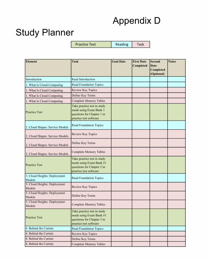
ptg17120290
Appendix DStudy Planner
Practice Test Reading Task
Element Task Goal Date First Date Completed
Second Date Completed (Optional)
Notes
Introduction Read Introduction
1. What Is Cloud Computing Read Foundation Topics
1. What Is Cloud Computing Review Key Topics
1. What Is Cloud Computing Define Key Terms
1. What Is Cloud Computing Complete Memory Tables
Practice Test
Take practice test in study mode using Exam Bank 1 questions for Chapter 1 in practice test software
2. Cloud Shapes: Service Models Read Foundation Topics
2. Cloud Shapes: Service Models Review Key Topics
2. Cloud Shapes: Service Models Define Key Terms
2. Cloud Shapes: Service Models Complete Memory Tables
Practice Test
Take practice test in study mode using Exam Bank #1 questions for Chapter 2 in practice test software
3. Cloud Heights: Deployment Models Read Foundation Topics
3. Cloud Heights: Deployment Models Review Key Topics
3. Cloud Heights: Deployment Models Define Key Terms
3. Cloud Heights: Deployment Models Complete Memory Tables
Practice Test
Take practice test in study mode using Exam Bank #1 questions for Chapter 3 in practice test software
4. Behind the Curtain Read Foundation Topics4. Behind the Curtain Review Key Topics 4. Behind the Curtain Define Key Terms4. Behind the Curtain Complete Memory Tables

ptg17120290
Practice Test
Take practice test in study mode using Exam Bank #1 questions for Chapter 4 in practice test software
5. Server Virtualization Read Foundation Topics5. Server Virtualization Review Key Topics 5. Server Virtualization Define Key Terms5. Server Virtualization Complete Memory Tables
Practice Test
Take practice test in study mode using Exam Bank #1 questions for Chapter 5 in practice test software
6. Infrastructure Virtualization Read Foundation Topics6. Infrastructure Virtualization Review Key Topics 6. Infrastructure Virtualization Define Key Terms6. Infrastructure Virtualization Complete Memory Tables
Practice Test
Take practice test in study mode using Exam Bank #1 questions for Chapter 6 in practice test software
7. Virtual Networking Services and Application Containers Read Foundation Topics
7. Virtual Networking Services and Application Containers Review Key Topics
7. Virtual Networking Services and Application Containers Define Key Terms
7. Virtual Networking Services and Application Containers Complete Memory Tables
Practice Test
Take practice test in study mode using Exam Bank #1 questions for Chapter 7 in practice test software
8. Block Storage Technologies Read Foundation Topics8. Block Storage Technologies Review Key Topics 8. Block Storage Technologies Define Key Terms8. Block Storage Technologies Complete Memory Tables
Practice Test
Take practice test in study mode using Exam Bank #1 questions for Chapter 8 in practice test software
9. File Storage Technologies Read Foundation Topics9. File Storage Technologies Review Key Topics 9. File Storage Technologies Define Key Terms9. File Storage Technologies Complete Memory Tables
Practice Test
Take practice test in study mode using Exam Bank #1 questions for Chapter 9 in practice test software
10. Network Architectures for the Data Center: Unified Fabric Read Foundation Topics
10. Network Architectures for the Data Center: Unified Fabric Review Key Topics
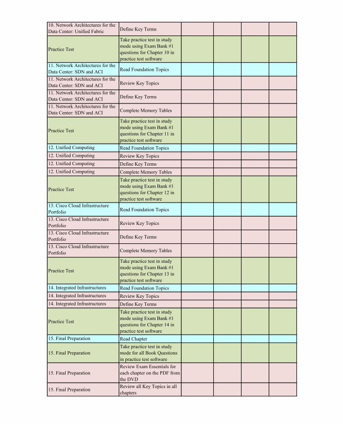
ptg17120290
10. Network Architectures for the Data Center: Unified Fabric Define Key Terms
Practice Test
Take practice test in study mode using Exam Bank #1 questions for Chapter 10 in practice test software
11. Network Architectures for the Data Center: SDN and ACI Read Foundation Topics
11. Network Architectures for the Data Center: SDN and ACI Review Key Topics
11. Network Architectures for the Data Center: SDN and ACI Define Key Terms
11. Network Architectures for the Data Center: SDN and ACI Complete Memory Tables
Practice Test
Take practice test in study mode using Exam Bank #1 questions for Chapter 11 in practice test software
12. Unified Computing Read Foundation Topics12. Unified Computing Review Key Topics 12. Unified Computing Define Key Terms12. Unified Computing Complete Memory Tables
Practice Test
Take practice test in study mode using Exam Bank #1 questions for Chapter 12 in practice test software
13. Cisco Cloud Infrastructure Portfolio Read Foundation Topics
13. Cisco Cloud Infrastructure Portfolio Review Key Topics
13. Cisco Cloud Infrastructure Portfolio Define Key Terms
13. Cisco Cloud Infrastructure Portfolio Complete Memory Tables
Practice Test
Take practice test in study mode using Exam Bank #1 questions for Chapter 13 in practice test software
14. Integrated Infrastructures Read Foundation Topics14. Integrated Infrastructures Review Key Topics 14. Integrated Infrastructures Define Key Terms
Practice Test
Take practice test in study mode using Exam Bank #1 questions for Chapter 14 in practice test software
15. Final Preparation Read Chapter
15. Final PreparationTake practice test in study mode for all Book Questions in practice test software
15. Final PreparationReview Exam Essentials for each chapter on the PDF from the DVD
15. Final Preparation Review all Key Topics in all chapters

ptg17120290
15. Final Preparation Complete all Memory Tables from Appendix C
15. Final PreparationTake practice test in practice exam mode using Exam Bank #1 questions for all chapters
15. Final PreparationTake practice test in practice exam mode using Exam Bank #2 questions for all chapters