civil - ptcul's
TRANSCRIPT
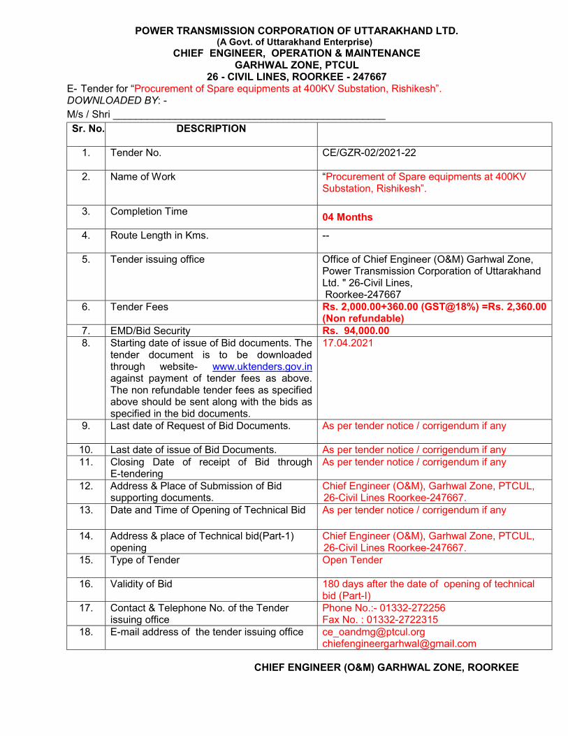
POWER TRANSMISSION CORPORATION OF UTTARAKHAND LTD. (A Govt. of Uttarakhand Enterprise)
CHIEF ENGINEER, OPERATION & MAINTENANCE GARHWAL ZONE, PTCUL
26 - CIVIL LINES, ROORKEE - 247667 E- Tender for “Procurement of Spare equipments at 400KV Substation, Rishikesh”. DOWNLOADED BY: -
M/s / Shri ________________________________________________
Sr. No. DESCRIPTION
1. Tender No.
CE/GZR-02/2021-22
2. Name of Work
“Procurement of Spare equipments at 400KV Substation, Rishikesh”.
3. Completion Time
04 Months
4. Route Length in Kms.
--
5. Tender issuing office Office of Chief Engineer (O&M) Garhwal Zone, Power Transmission Corporation of Uttarakhand Ltd. " 26-Civil Lines, Roorkee-247667
6. Tender Fees Rs. 2,000.00+360.00 (GST@18%) =Rs. 2,360.00 (Non refundable)
7. EMD/Bid Security Rs. 94,000.00 8. Starting date of issue of Bid documents. The
tender document is to be downloaded through website- www.uktenders.gov.in against payment of tender fees as above. The non refundable tender fees as specified above should be sent along with the bids as specified in the bid documents.
17.04.2021
9. Last date of Request of Bid Documents.
As per tender notice / corrigendum if any
10. Last date of issue of Bid Documents. As per tender notice / corrigendum if any 11. Closing Date of receipt of Bid through
E-tendering As per tender notice / corrigendum if any
12. Address & Place of Submission of Bid supporting documents.
Chief Engineer (O&M), Garhwal Zone, PTCUL, 26-Civil Lines Roorkee-247667.
13. Date and Time of Opening of Technical Bid As per tender notice / corrigendum if any
14. Address & place of Technical bid(Part-1) opening
Chief Engineer (O&M), Garhwal Zone, PTCUL, 26-Civil Lines Roorkee-247667.
15. Type of Tender
Open Tender
16. Validity of Bid
180 days after the date of opening of technical bid (Part-I)
17. Contact & Telephone No. of the Tender issuing office
Phone No.:- 01332-272256 Fax No. : 01332-2722315
18. E-mail address of the tender issuing office [email protected] [email protected]
CHIEF ENGINEER (O&M) GARHWAL ZONE, ROORKEE
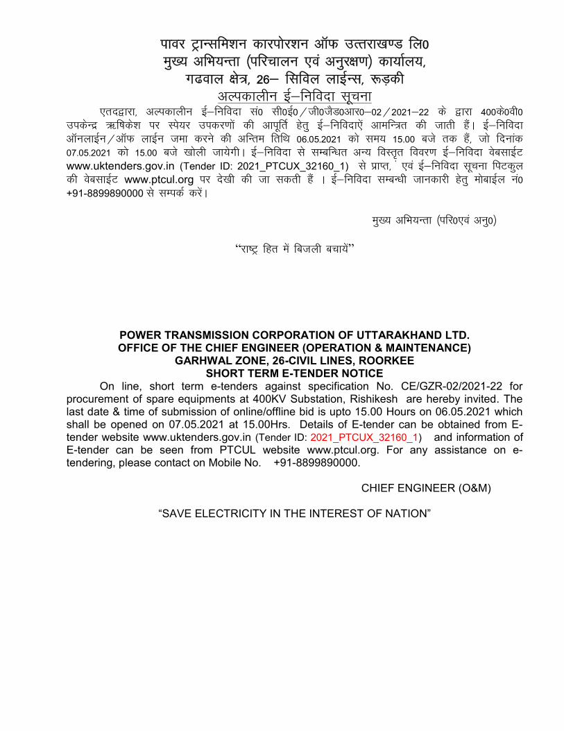
ikoj VªkUlfe”ku dkjiksj”ku vkWQ mRrjk[k.M fy0 eq[; vfHk;Urk ¼ifjpkyu ,oa vuqj{k.k½ dk;kZy;]
x<oky {ks=] 26& flfoy ykbZUl] :M+dh vYidkyhu bZ&fufonk lwpuk
,rn}kjk] vYidkyhu bZ&fufonk la0 lh0bZ0@th0tSM0vkj0&02@2021&22 ds }kjk 400ds0oh0 midsUnz _f’kds”k ij Lis;j midj.kksa dh vkiwfrZ gsrq bZ&fufonk,sa vkefU=r dh tkrh gSaA bZ&fufonk vkWuykbZu@vkWQ ykbZu tek djus dh vfUre frfFk 06-05-2021 dks le; 15-00 cts rd gSa] tks fnukad 07-05-2021 dks 15-00 cts [kksyh tk;sxhA bZ&fufonk ls lEcfU/kr vU; foLrr̀ fooj.k bZ&fufonk osclkbZV www.uktenders.gov.in (Tender ID: 2021_PTCUX_32160_1) ls izkIr] a ,oa bZ&fufonk lwpuk fiVdqy dh osclkbZV www.ptcul.org ij ns[kh dh tk ldrh gSa A bZ&fufonk lEcU/kh tkudkjh gsrq eksckbZy ua0 +91-8899890000 ls lEidZ djsaA
eq[; vfHk;Urk ¼ifj0,oa vuq0½
“jk"Vª fgr esa fctyh cpk;sa”
POWER TRANSMISSION CORPORATION OF UTTARAKHAND LTD. OFFICE OF THE CHIEF ENGINEER (OPERATION & MAINTENANCE)
GARHWAL ZONE, 26-CIVIL LINES, ROORKEE SHORT TERM E-TENDER NOTICE
On line, short term e-tenders against specification No. CE/GZR-02/2021-22 for procurement of spare equipments at 400KV Substation, Rishikesh are hereby invited. The last date & time of submission of online/offline bid is upto 15.00 Hours on 06.05.2021 which shall be opened on 07.05.2021 at 15.00Hrs. Details of E-tender can be obtained from E-tender website www.uktenders.gov.in (Tender ID: 2021_PTCUX_32160_1) and information of E-tender can be seen from PTCUL website www.ptcul.org. For any assistance on e-tendering, please contact on Mobile No. +91-8899890000. CHIEF ENGINEER (O&M)
“SAVE ELECTRICITY IN THE INTEREST OF NATION”
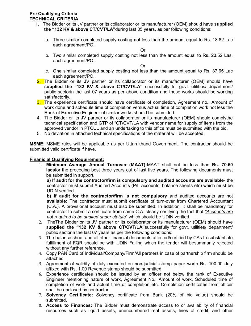
Pre Qualifying Criteria TECHNICAL CRITERIA
1. The Bidder or its JV partner or its collaborator or its manufacturer (OEM) should have supplied the “132 KV & above CT/CVT/LA”during last 05 years, as per following conditions:
a. Three similar completed supply costing not less than the amount equal to Rs. 18.82 Lac
each agreement/PO. Or
b. Two similar completed supply costing not less than the amount equal to Rs. 23.52 Las, each agreement/PO.
Or c. One similar completed supply costing not less than the amount equal to Rs. 37.65 Lac
each agreement/PO. 2. The Bidder or its JV partner or its collaborator or its manufacturer (OEM) should have
supplied the “132 KV & above CT/CVT/LA” successfully for govt. utilities/ department/ public sectorin the last 07 years as per above condition and these works should be working satisfactorily.
3. The experience certificate should have certificate of completion, Agreement no., Amount of work done and schedule time of completion versus actual time of completion work not less the Rank of Executive Engineer of similar works should be submitted.
4. The Bidder or its JV partner or its collaborator or its manufacturer (OEM) should complythe technical specification and GTP of “CT/CVT/LA with vendor name for supply of items from the approved vendor in PTCUL and an undertaking to this office must be submitted with the bid.
5. No deviation in attached technical specifications of the material will be accepted. MSME: MSME rules will be applicable as per Uttarakhand Government. The contractor should be submitted valid certificate if have. Finanicial Qualifying Requirement:
1. Minimum Average Annual Turnover (MAAT):MAAT shall not be less than Rs. 70.50 lacsfor the preceding best three years out of last five years. The following documents must be submitted in support. a) If audit for the contractor/firm is compulsory and audited accounts are available- the contractor must submit Audited Accounts (P/L accounts, balance sheets etc) which must be UDIN verified. b) If audit for the contractor/firm is not compulsory and audited accounts are not available: The contractor must submit certificate of turn-over from Chartered Accountant (C.A.). A provisional account must also be submitted. In addition, it shall be mandatory for contractor to submit a certificate from same C.A. clearly certifying the fact that “Accounts are not required to be audited under statute”.which should be UDIN verified.
2. TheThe Bidder or its JV partner or its collaborator or its manufacturer (OEM) should have supplied the “132 KV & above CT/CVT/LA”successfully for govt. utilities/ department/ public sectorin the last 07 years as per the following conditions:
3. The balance sheet and all other financial documents attested/certified by CAs to substantiate fulfillment of FQR should be with UDIN Failing which the tender will besummarily rejected without any further reference.
4. Copy PAN Card of Individual/Company/Firm/All partners in case of partnership firm should be attached
5. Agreement of validity of duly executed on non-judicial stamp paper worth Rs. 100.00 duly affixed with Rs. 1.00 Revenue stamp should be submitted.
6. Experience certificates should be issued by an officer not below the rank of Executive Engineer mentioning nature of work, Agreement No., Amount of work, Scheduled time of completion of work and actual time of completion etc. Completion certificates from officer shall be enclosed by contractor.
7. Solvency Certificate: Solvency certificate from Bank (20% of bid value) should be submitted.
8. Access to Finances: The Bidder must demonstrate access to or availability of financial resources such as liquid assets, unencumbered real assets, lines of credit, and other
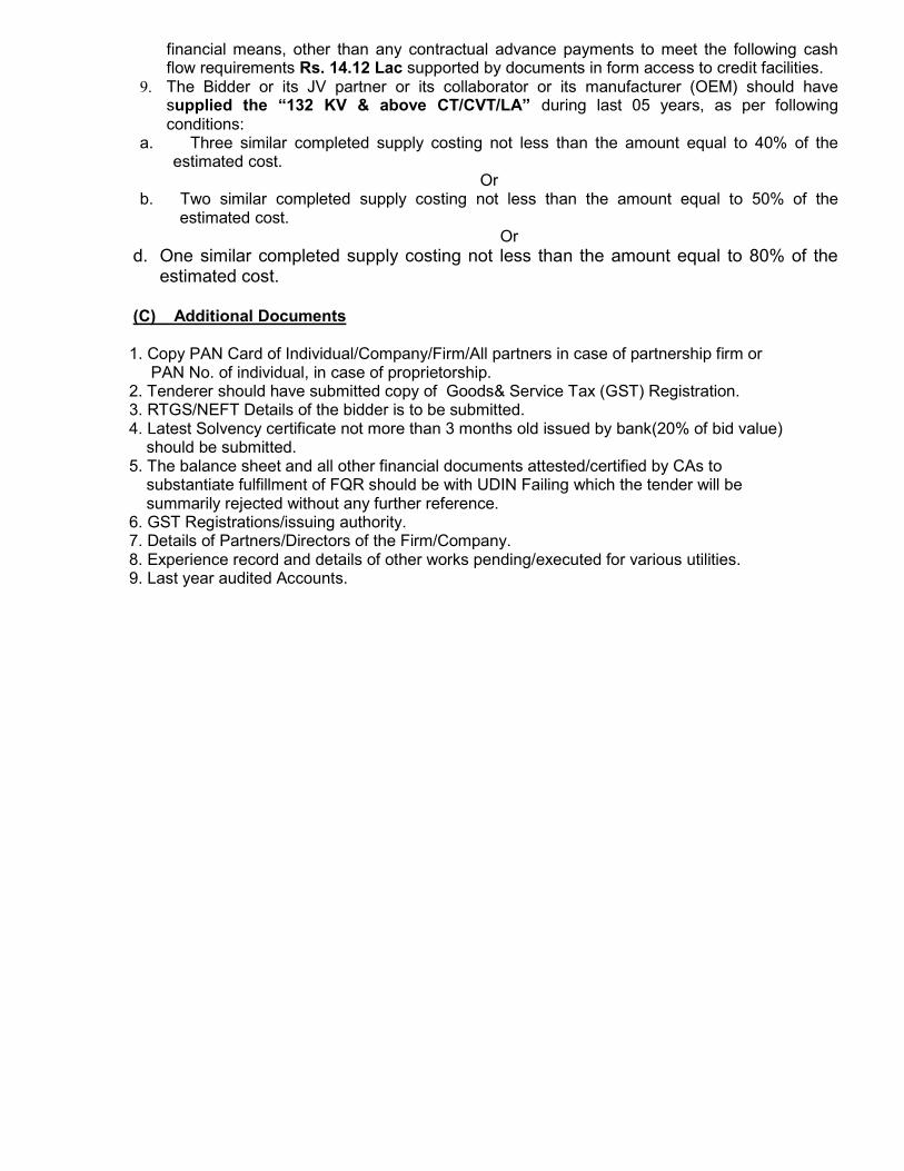
financial means, other than any contractual advance payments to meet the following cash flow requirements Rs. 14.12 Lac supported by documents in form access to credit facilities.
9. The Bidder or its JV partner or its collaborator or its manufacturer (OEM) should have supplied the “132 KV & above CT/CVT/LA” during last 05 years, as per following conditions:
a. Three similar completed supply costing not less than the amount equal to 40% of the estimated cost.
Or b. Two similar completed supply costing not less than the amount equal to 50% of the
estimated cost. Or
d. One similar completed supply costing not less than the amount equal to 80% of the estimated cost.
(C) Additional Documents 1. Copy PAN Card of Individual/Company/Firm/All partners in case of partnership firm or
PAN No. of individual, in case of proprietorship. 2. Tenderer should have submitted copy of Goods& Service Tax (GST) Registration. 3. RTGS/NEFT Details of the bidder is to be submitted. 4. Latest Solvency certificate not more than 3 months old issued by bank(20% of bid value)
should be submitted. 5. The balance sheet and all other financial documents attested/certified by CAs to
substantiate fulfillment of FQR should be with UDIN Failing which the tender will be summarily rejected without any further reference.
6. GST Registrations/issuing authority. 7. Details of Partners/Directors of the Firm/Company. 8. Experience record and details of other works pending/executed for various utilities. 9. Last year audited Accounts.
400 KV and 220 KV
INSTRUMENT TRANSFORMER
INSTRUMENT TRANSFORMERS
1.0 GENERAL 1.1 The instrument transformers and accessories shall conform to the latest version of
the standards specified below except to the extent explicitly modified in the specifications and shall be in accordance with requirements in Chapter-GTR
Current transformers IEC: 44-1 (or IS: 2705) Voltage transformers IEC: 186/358 (or IS: 3156) 1.2 The instrument transformers shall be complete with its terminal box and a common
marshalling box for a set of 3 instrument transformers. 1.3 The instrument transformer tank alongwith top metallics shall be hot dip galvanized. 1.4 The instrument transforms shall be designed for use in geographic and meteorological conditions as given in Chapter: GTR. 2.0 CONSTRUCTION FEATURES:
The features and constructional details of instrument transformers shall be in accordance with requirements stipulated hereunder:
2.1 Bushing/Insulators: a) Instrument transformers shall be of 420/245kV/145kV/33kV class, oil
filled/SF6 gas filled, with shaded porcelain/composite bushing/Insulators suitable for outdoor service and upright mounting on steel structure.
b) Bushing/Insulators shall conform to requirements stipulated in Chapter-GTR. The bushing/insulator for CT shall be one piece without any metallic flange joint.
c) Bushing shall be provided with oil filling and drain plugs, oil sight glass of CT and for electromagnetic unit of CVT, etc. The bushing/insulator of instrument transformer shall have cantilever strength of not less than 500kg, 350kg and 350kg for 420/245/145kV and 350 kg for 33kV Instrument transformers respectively or as per the value obtained vide Chapter-GTR, whichever is higher. Oil filling and drain plugs are not required with SF6 gas filled CT.
d) Instrument transformers shall be hermetically sealed units. Bidder/Manufacturer shall furnish details of the arrangements made for the sealing of instrument transformers alongwith the bid. Bidder/Manufacturer shall also furnish the details of site test to check the effectiveness of hermetic sealing for approval.
e) Polarity marks shall indelibly be marked on each instrument transformer and at the lead terminals at the associated terminal block.
2.2 Terminal box/Marshalling box: Terminal box shall conform to the requirements of Chapter-GTR. 2.3 Insulating Oil: a) Insulating oil to be used for instrument transformers shall be of EHV grade
and shall conform to IS: 335 (required for the first filling). b) The SF6 gas shall comply with IEC-60376, 60376A and 60376 B and shall
be suitable in all respects for use in the switchgear under operating conditions.
2.4 Name Plate:
Name plate shall conform to the requirements of IEC incorporating the year of manufacture. The rated current, extended current rating in case of current transformers and rated voltage, voltage factor in case of voltage transformers shall be clearly indicated on the name plate. The rated thermal current in case of CT shall also be marked on the name plate.
The intermediate voltage in case of capacitor voltage transformer shall be indicated on the name plate.
3.0 CURRENT TRANSFORMERS: a) Current transformers shall have single primary either ring type, or hair pin
type and suitably designed for bringing out the secondary terminals in a weather proof (IP-55) terminal box at the bottom. These secondary terminals shall be terminated to stud type non disconnecting terminal blocks inside the terminal box. In case “Bar primary” inverted type current transformers are offered the manufacturer will meet following additional requirements:
i) The secondaries shall be totally encased in metallic shielding providing a uniform equipotential surface for even electric field distribution.
ii) The lowest part of the insulation assembly shall be properly secured
to avoid any risk of damage due to transportation stresses.
iii) The upper part of insulating assembly resting on primary bar shall be properly secured to avoid any damage during transportation due to relative movement between insulating assembly & top dome.
iv) Nitrogen if used for hermetic sealing (in case of live tank design
should not come in direct contact with oil)
v) Bidder/Manufacturer shall recommend whether any special storage facility is required for spare CT.
b) Different ratios specified shall be achieved by secondary taps only and
primary reconnection shall not be accepted. c) Core lamination shall be of cold rolled gain oriented silicon steel or other
equivalent alloys. The cores used for protection shall produce undistorted secondary current under transient condition at all ratio with specified CT parameters.
d) The expansion chamber at the top of the porcelain insulators should be
suitable for expansion of oil. e) Facilities shall be provided at terminal blocks in the marshalling box for star
delta formation, short circuiting and grounding of CT secondary terminals. f) Current transformer’s guaranteed burdens and accuracy class are to be
intended as simultaneous for all cores. g) For 420/ kV class CTs, the rated extended primary current of the CT’s shall
be 200% of rated primary on all except 2000/1 tap ratio. On 2000/1 tap ratio, the rated extended primary current shall be 120. However, at 2000/1, the ratio the CT shall be thermally rated for 200% for 15 minutes and 120% continuous. For 245/145/33kV class CTs, the rated extended primary current shall be 120% (or 150% if applicable) on all cores of the CTs.
For 420 kV class CTs rated for 3000A, the rated extended primary current shall be 120% for 3000/1 tap ratio and 180% for 2000/1 tap ratio and 200% for lower tap ratio. The secondary winding shall be rated for 2A continuously. Further, the intermediate tappings at 3000-2000 and 2000-500 shall be suitable for using as 1000/1 and 1500/1 ratios.
h) For 420/245/145/33kV current transformer, characteristics shall be such as to provide satisfactory performance of burden ranging from 25% to 100% of rated burden over a range of 10% to 100% of rated current in case of metering CTs and up to the accuracy limit factor /knee point voltage in case of relaying CTs.
i) The current transformer shall be suitable for horizontal transportation. It shall be ensured that the CT is able to withstand all the stresses imposed on it while transporting and there shall be no damage in transit. The Contractor shall submit the details of packing design to the Purchaser for review.
j) For 245/145/33kV CTs the instruments security factor at all ratios shall be
less than five (5) for metering core. If any auxiliary CTs / reactor are used in the current transformers then all parameters specified shall have to be met treating auxiliary CTs as an integral part of the current transformer. The auxiliary CTs / reactor shall preferably be inbuilt construction of the CTs. In case these are to be mounted separately these shall be mounted in the central marshalling box suitably wired upto the terminal blocks.
k) The wiring diagram plate for the interconnections of three single phase CTs shall be provided inside the marshalling box.
l) The current transformation should be suitable for mounting on lattice support structure to be provided by the Contractor in accordance with stipulations of Chapter-GTR.
m) The CT shall be designed as to achieve the minimum risks of explosion in
service. Bidder/Manufacturer shall bring out in his offer, the measures taken to achieve this.
n) 420/245/145 kV current transformers shall be suitable for high speed auto
reclosing.
4.0 VOLTAGE TRANSFORMERS:
a) 420/245/145kV Voltage transformer shall be capacitor voltage divider type with electromagnetic units and shall be suitable for carrier coupling.
b) Voltage transformers secondaries shall be protected by HRC cartridge type
fuses for all the winding. In addition fuses shall be provided for the protection and metering windings for fuse monitoring scheme. The secondary terminals of the CVTs shall be terminated to the stud type non-disconnecting terminal blocks in the individual phase secondary boxes via the fuse.
c) CVTs shall be suitable for high frequency (HF) coupling required for power
line carrier communication. Carrier signal must be prevented from flowing into potential transformer (EMU) circuit by means of a RF choke/reactor suitable for effectively blocking the carrier signals over the entire carrier frequency range i.e 40 to 500 KHz. Details of the arrangement shall be furnished along with the bid. H.F. terminal of the CVT shall be brought out through a suitable bushing and shall be easily accessible for connection to the coupling filters of the carrier communication equipment, when utilized. Further, earthing link with fastener to be provided for HF terminal.
d) The electromagnetic unit comprising compensating reactor intermediate transformer and protective and damping device should have separate terminal box with the entire secondary terminal brought out.
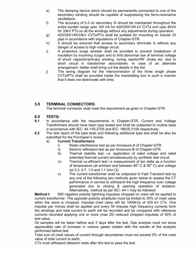
e) The damping device which should be permanently connected to one of the secondary winding should be capable of suppressing the ferro-resonance oscillations.
f) The accuracy of 0.2 on secondary III should be maintained throughout the entire burden range upto 100 VA for 420/245/145 kV CVTs and upto 40VA for 33kV PTs on all the windings without any adjustments during operation.
g) 420/245/145/33kV CVTs/PTs shall be suitable for mounting on tubular GI pipe in accordance with stipulations of Chapter-GTR.
h) It should be ensured that access to secondary terminals is without any danger of access to high voltage circuit.
i) A protective surge arrester shall be provided to prevent breakdown of insulation by incoming surges and to limit abnormal rise of terminal voltage of shunt capacitor/primary winding, tuning reactor/RF choke etc. due to short circuit in transformer secondaries. In case of an alternate arrangement, bidder shall bring out the details in the bid.
j) The wiring diagram for the interconnection of the three single phase CVTs/PTs shall be provided inside the marshalling box in such a manner that it does not deteriorate with time.
5.0 TERMINAL CONNECTORS:
The terminal connector shall meet the requirement as given in Chapter-GTR.
6.0 TESTS: 6.1 In accordance with the requirements in Chapter-GTR, Current and Voltage
Transformers should have been type tested and shall be subjected to routine tests in accordance with IEC: 44-1/IS:2705 and IEC: 186/IS:3156 respectively.
6.2 The test report of the type tests and following additional type test shall be also be submitted for the Purchaser’s review.
a) Current Transformers: i) Radio interference test as per Annexure-A of Chapter-GTR. ii) Seismic withstand test as per Annexure-B of Chapter-GTR. iii) Thermal stability test, i.e. application of rated voltage and rated
extended thermal current simultaneously by synthetic test circuit. iv) Thermal co-efficient test i.e measurement of tan delta as a function
of temperature (at ambient and between 800 C & 900 C) and voltage (at 0.3, 0.7, 1.0 and 1.1 Um/3).
v) The current transformer shall be subjected to Fast Transient test by any one of the following two methods given below to assess the CT performance in service to withstand the high frequency over voltage generated due to closing & opening operation of isolators. Alternatively, method as per IEC: 44-1 may be followed:
Method I: 600 negative polarity lightning impulses chopped on crest will be applied to current transformer. The opposite polarity amplitude must be limited to 50% of crest value when the wave is chopped. Impulse crest value will be 1000kVp of 420 kV CTs. One impulse per minute shall be applied and every 50 impulse high frequency currents form the windings and total current to earth will be recorded and be compared with reference currents recorded applying one or more (max 20) reduced chopped impulses of 50% of test value. Oil samples will be taken before and 3 days after the test. Gas analysis must not show appreciable rate of increase in various gases related with the results of the analysis performed before test. Total sum of crest values of current through secondaries must not exceed 5% of the crest value of total current to earth. CTs must withstand dielectric tests after this test to pass the test.
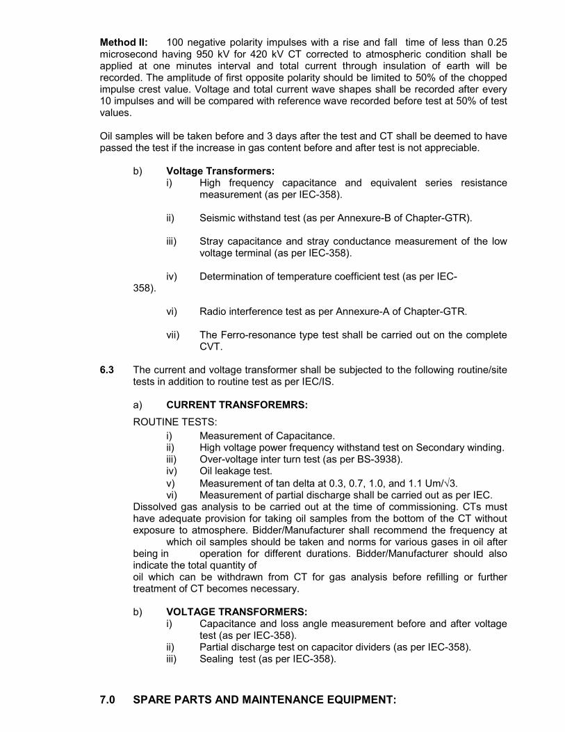
Method II: 100 negative polarity impulses with a rise and fall time of less than 0.25 microsecond having 950 kV for 420 kV CT corrected to atmospheric condition shall be applied at one minutes interval and total current through insulation of earth will be recorded. The amplitude of first opposite polarity should be limited to 50% of the chopped impulse crest value. Voltage and total current wave shapes shall be recorded after every 10 impulses and will be compared with reference wave recorded before test at 50% of test values. Oil samples will be taken before and 3 days after the test and CT shall be deemed to have passed the test if the increase in gas content before and after test is not appreciable. b) Voltage Transformers:
i) High frequency capacitance and equivalent series resistance measurement (as per IEC-358).
ii) Seismic withstand test (as per Annexure-B of Chapter-GTR).
iii) Stray capacitance and stray conductance measurement of the low
voltage terminal (as per IEC-358).
iv) Determination of temperature coefficient test (as per IEC- 358).
vi) Radio interference test as per Annexure-A of Chapter-GTR.
vii) The Ferro-resonance type test shall be carried out on the complete CVT.
6.3 The current and voltage transformer shall be subjected to the following routine/site
tests in addition to routine test as per IEC/IS. a) CURRENT TRANSFOREMRS:
ROUTINE TESTS:
i) Measurement of Capacitance. ii) High voltage power frequency withstand test on Secondary winding.
iii) Over-voltage inter turn test (as per BS-3938). iv) Oil leakage test. v) Measurement of tan delta at 0.3, 0.7, 1.0, and 1.1 Um/3.
vi) Measurement of partial discharge shall be carried out as per IEC. Dissolved gas analysis to be carried out at the time of commissioning. CTs must have adequate provision for taking oil samples from the bottom of the CT without exposure to atmosphere. Bidder/Manufacturer shall recommend the frequency at which oil samples should be taken and norms for various gases in oil after being in operation for different durations. Bidder/Manufacturer should also indicate the total quantity of oil which can be withdrawn from CT for gas analysis before refilling or further treatment of CT becomes necessary.
b) VOLTAGE TRANSFORMERS:
i) Capacitance and loss angle measurement before and after voltage test (as per IEC-358).
ii) Partial discharge test on capacitor dividers (as per IEC-358). iii) Sealing test (as per IEC-358).
7.0 SPARE PARTS AND MAINTENANCE EQUIPMENT:
The Bidder shall include in his proposal a list of spare parts to be required.
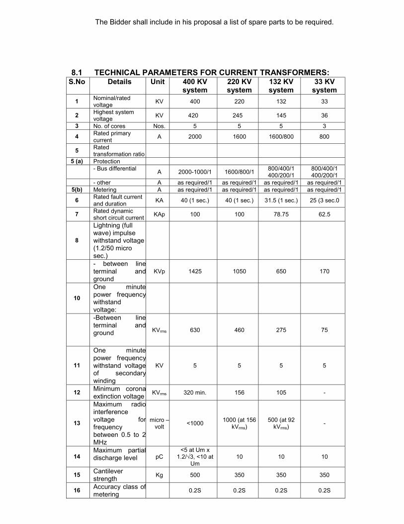
8.1 TECHNICAL PARAMETERS FOR CURRENT TRANSFORMERS:
S.No Details Unit 400 KV system
220 KV system
132 KV system
33 KV system
1 Nominal/rated voltage
KV 400 220 132 33
2 Highest system voltage
KV 420 245 145 36
3 No. of cores Nos. 5 5 5 3
4 Rated primary current
A 2000 1600 1600/800 800
5 Rated transformation ratio
5 (a) Protection
- Bus differential A 2000-1000/1 1600/800/1
800/400/1 400/200/1
800/400/1 400/200/1
- other A as required/1 as required/1 as required/1 as required/1 5(b) Metering A as required/1 as required/1 as required/1 as required/1
6 Rated fault current and duration
KA 40 (1 sec.) 40 (1 sec.) 31.5 (1 sec.) 25 (3 sec.0
7 Rated dynamic short circuit current
KAp 100 100 78.75 62.5
8
Lightning (full wave) impulse withstand voltage (1.2/50 micro sec.)
- between line terminal and ground
KVp 1425 1050 650 170
10
One minute power frequency withstand voltage:
-Between line terminal and ground KVrms 630 460 275 75
11
One minute power frequency withstand voltage of secondary winding
KV 5 5 5 5
12 Minimum corona extinction voltage
KVrms 320 min. 156 105 -
13
Maximum radio interference voltage for frequency between 0.5 to 2 MHz
micro –volt
<1000 1000 (at 156
kVrms) 500 (at 92
kVrms) -
14 Maximum partial discharge level pC
<5 at Um x 1.2/√3, <10 at
Um 10 10 10
15 Cantilever strength
Kg 500 350 350 350
16 Accuracy class of metering
0.2S 0.2S 0.2S 0.2S
CT ratios specified above are tentative actual Ct ratio to be supplied shall be decided during detail engineering.
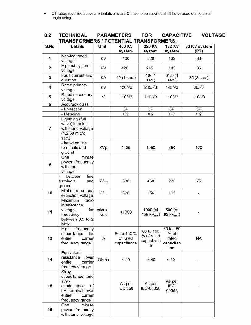
8.2 TECHNICAL PARAMETERS FOR CAPACITIVE VOLTAGE TRANSFORMERS / POTENTIAL TRANSFORMERS:
S.No Details Unit 400 KV system
220 KV system
132 KV system
33 KV system (PT)
1 Nominal/rated voltage
KV 400 220 132 33
2 Highest system voltage
KV 420 245 145 36
3 Fault current and duration
KA 40 (1 sec.) 40/ (1 sec.)
31.5 (1 sec.)
25 (3 sec.)
4 Rated primary voltage
KV 420/√3 245/√3 145/√3 36/√3
5 Rated secondary voltage
V 110/√3 110/√3 110/√3 110/√3
6 Accuracy class - Protection 3P 3P 3P 3P - Metering 0.2 0.2 0.2 0.2
7
Lightning (full wave) impulse withstand voltage (1.2/50 micro sec.)
- between line terminals and ground
KVp 1425 1050 650 170
9
One minute power frequency withstand voltage:
- between line terminals and ground
KVrms 630 460 275 75
10 Minimum corona extinction voltage
KVrms 320 156 105 -
11
Maximum radio interference voltage for frequency between 0.5 to 2 MHz
micro –volt
<1000 1000 (at
156 kVrms) 500 (at
92 kVrms) -
13
High frequency capacitance for entire carrier frequency range
% 80 to 150 %
of rated capacitance
80 to 150 % of rated capacitanc
e
80 to 150 % of rated
capacitance
NA
14
Equivalent resistance over entire carrier frequency range
Ohms < 40 < 40 < 40 -
15
Stray capacitance and stray conductance of LV terminal over entire carrier frequency range
As per
IEC:358 As per
IEC-60358
As per IEC-
60358 -
16 One minute power frequency withstand voltage
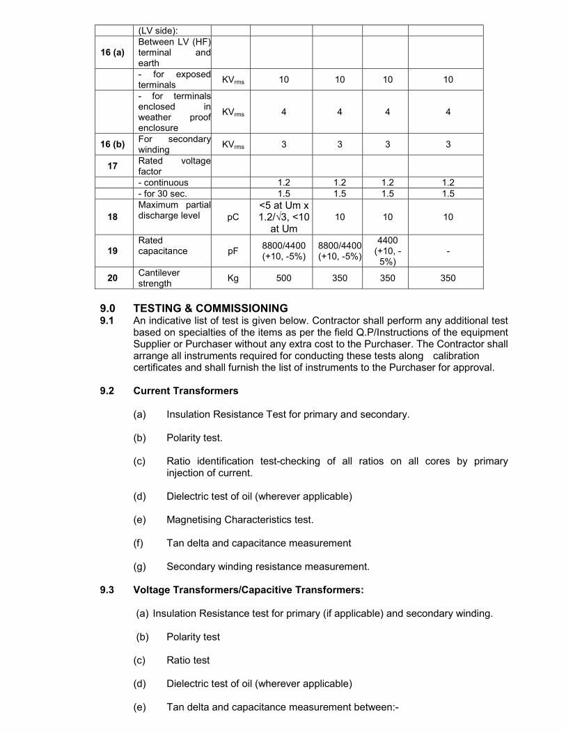
(LV side):
16 (a) Between LV (HF) terminal and earth
- for exposed terminals
KVrms 10 10 10 10
- for terminals enclosed in weather proof enclosure
KVrms 4 4 4 4
16 (b) For secondary winding
KVrms 3 3 3 3
17 Rated voltage factor
- continuous 1.2 1.2 1.2 1.2 - for 30 sec. 1.5 1.5 1.5 1.5
18 Maximum partial discharge level pC
<5 at Um x 1.2/√3, <10
at Um 10 10 10
19 Rated capacitance pF
8800/4400 (+10, -5%)
8800/4400 (+10, -5%)
4400 (+10, -
5%) -
20 Cantilever strength
Kg 500 350 350 350
9.0 TESTING & COMMISSIONING 9.1 An indicative list of test is given below. Contractor shall perform any additional test
based on specialties of the items as per the field Q.P/Instructions of the equipment Supplier or Purchaser without any extra cost to the Purchaser. The Contractor shall arrange all instruments required for conducting these tests along calibration certificates and shall furnish the list of instruments to the Purchaser for approval.
9.2 Current Transformers
(a) Insulation Resistance Test for primary and secondary.
(b) Polarity test.
(c) Ratio identification test-checking of all ratios on all cores by primary injection of current.
(d) Dielectric test of oil (wherever applicable) (e) Magnetising Characteristics test. (f) Tan delta and capacitance measurement (g) Secondary winding resistance measurement. 9.3 Voltage Transformers/Capacitive Transformers:
(a) Insulation Resistance test for primary (if applicable) and secondary winding.
(b) Polarity test (c) Ratio test (d) Dielectric test of oil (wherever applicable) (e) Tan delta and capacitance measurement between:-

(i) HV-HF point (ii) HF Point-Ground point of Intermediate Transformer.
(iii) HV-Ground point of Intermediate Transformer primary winding (f) Secondary winding resistance measurement.
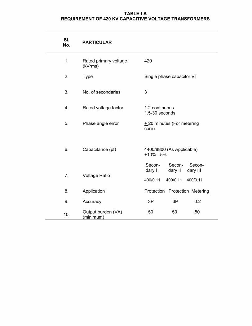
TABLE-I A REQUIREMENT OF 420 KV CAPACITIVE VOLTAGE TRANSFORMERS
Sl. No.
PARTICULAR
1. Rated primary voltage (kVrms)
420
2. Type Single phase capacitor VT
3. No. of secondaries 3
4. Rated voltage factor 1.2 continuous 1.5-30 seconds
5. Phase angle error + 20 minutes (For metering core)
6.
Capacitance (pf)
4400/8800 (As Applicable) +10% - 5% Secon- Secon- Secon- dary I dary II dary III
7.
Voltage Ratio
400/0.11 400/0.11 400/0.11
8.
Application
Protection Protection Metering
9. Accuracy 3P 3P 0.2
10. Output burden (VA) (minimum)
50 50 50
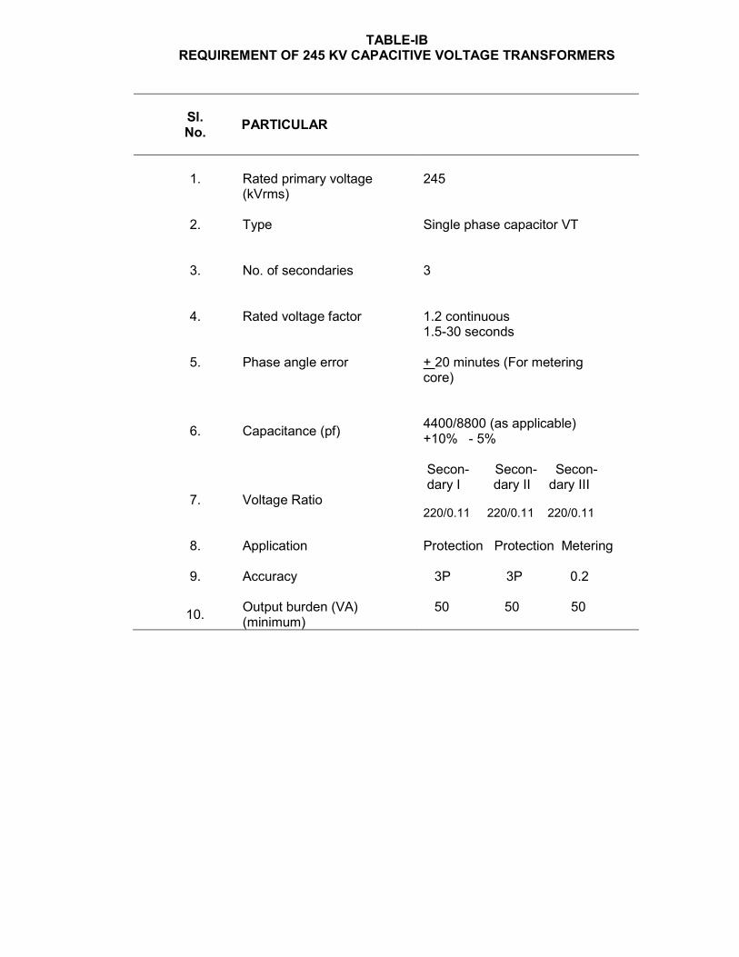
TABLE-IB REQUIREMENT OF 245 KV CAPACITIVE VOLTAGE TRANSFORMERS
Sl. No.
PARTICULAR
1. Rated primary voltage (kVrms)
245
2. Type Single phase capacitor VT
3. No. of secondaries 3
4. Rated voltage factor 1.2 continuous 1.5-30 seconds
5. Phase angle error + 20 minutes (For metering core)
6.
Capacitance (pf)
4400/8800 (as applicable) +10% - 5% Secon- Secon- Secon- dary I dary II dary III
7.
Voltage Ratio
220/0.11 220/0.11 220/0.11
8.
Application
Protection Protection Metering
9. Accuracy 3P 3P 0.2
10. Output burden (VA) (minimum)
50 50 50
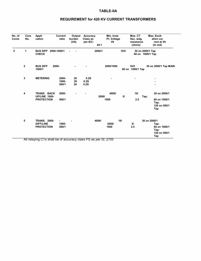
TABLE-IIA
REQUIREMENT for 420 KV CURRENT TRANSFORMERS
No. of Core Appli Current Output Accuracy Min. knee Max. CT Max. Excit- Cores No. cation ratio burden Class as Pt. Voltage Sec. wdg. ation cur
(VA) per IEC: Vk resistance rent at Vk 44-1 (ohms) (In mA)
5 1 BUS DIFF 2000-1000/1 - - 2000/1 10/5 30 on 2000/1 Tap
CHECK 60 on 1000/1 Tap
2 BUS DIFF 2000- - - 2000/1000 10/5 30 on 2000/1 Tap MAIN 1000/1 60 on 1000/1 Tap
3 METERING 2000- 20 0.2S - - -
1000- 20 0.2S - 500/1 20 0.2S -
4 TRANS BACK 2000- - - 4000/ 10/ 30 on 2000/1
UP/LINE 1000- 2000/ 5/ Tap; PROTECTION 500/1 1000 2.5 60 on 1000/1
Tap; 120 on 500/1 Tap
5 TRANS. 2000- - - 4000/ 10/ 30 on 2000/1
DIFF/LINE 1000- 2000/ 5/ Tap; PROTECTION 500/1 1000 2.5 60 on 1000/1
Tap; 120 on 500/1 Tap
All relaying CTs shall be of accuracy class PS as per IS: 2705
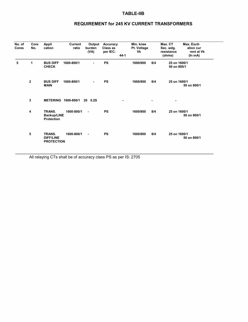
TABLE-IIB
REQUIREMENT for 245 KV CURRENT TRANSFORMERS
No. of Core Appli Current Output Accuracy Min. knee Max. CT Max. Excit- Cores No. cation ratio burden Class as Pt. Voltage Sec. wdg. ation cur
(VA) per IEC: Vk resistance rent at Vk 44-1 (ohms) (In mA)
5 1 BUS DIFF 1600-800/1 - PS 1600/800 8/4 25 on 1600/1
CHECK 50 on 800/1
2 BUS DIFF 1600-800/1 - PS 1600/800 8/4 25 on 1600/1 MAIN 50 on 800/1
3 METERING 1600-800/1 20 0.2S - - - 4 TRANS. 1600-800/1 - PS 1600/800 8/4 25 on 1600/1
Backup/LINE 50 on 800/1 Protection
5 TRANS. 1600-800/1 - PS 1600/800 8/4 25 on 1600/1 DIFF/LINE 50 on 800/1 PROTECTION
All relaying CTs shall be of accuracy class PS as per IS: 2705
SURGE ARRESTERS
1.0 GENERAL 1.1 The Surge arresters shall conform to IEC: 60099-4 except to the extent modified in
the specification and shall also be in accordance with requirements under Chapter-GTR.
400 KV SURGE ARRESTERS
1.2 Arresters shall be of hermetically sealed units, self supporting construction, suitable for mounting on tubular support structures to be supplied by the Contractor.
1.3 The Surge Arrestor shall be designed for use in the geographic and meteorological conditions as given in the Chapter-GTR.
2.0 DUTY REQUIREMENTS: a) The Surge arrester shall be of heavy duty station class and gapless type without any series or shunt gaps. b) The Surge arrester shall be capable of discharging over-voltage occurring during
switching of unloaded transformers, reactors and long lines. c) 420kV class arrester shall be capable for discharging of severe re-energization
switching surges on a 400kV, 450km long line with Surge impedence of 300 ohms and capacitance of 11986 nF/km and overvoltage factor of 2.3 p.u.
d) 420kV class arrester shall be capable of discharging energy equivalent to class 3 of IEC for a 420kV system on two successive operation followed immediately by 50Hz energization with a sequential voltage profile as specified below:
705 kVp for 3 peaks. 580 kVp for 0.1 Sec. 565 kVp for 1 Second 550 kVp for 10 Seconds.
e) 245/145kV class arrester shall be capable for discharging energy equivalent to class 3 of IEC for 245/145kV system on two successive operations.
f) The surge arresters shall be suitable for withstanding forces as defined in Chapter-
GTR. g) The reference current of the arresters shall be high enough to eliminate the
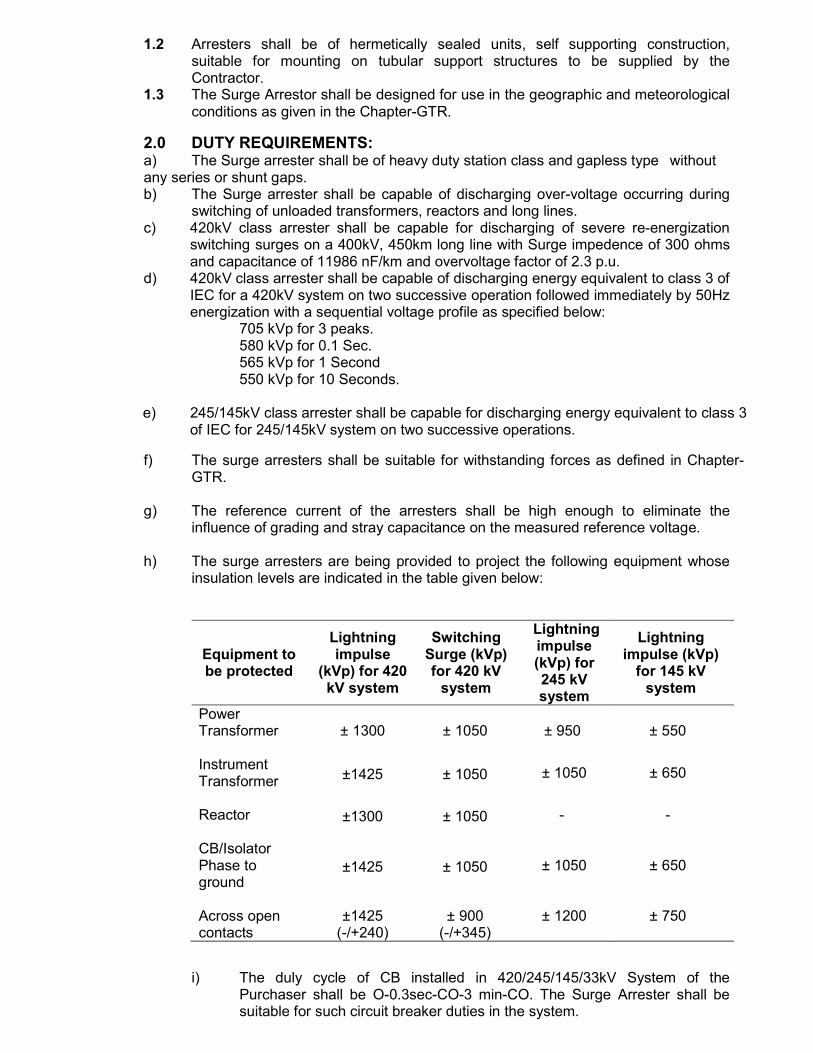
influence of grading and stray capacitance on the measured reference voltage. h) The surge arresters are being provided to project the following equipment whose
insulation levels are indicated in the table given below:
Equipment to be protected
Lightning impulse
(kVp) for 420 kV system
Switching Surge (kVp) for 420 kV
system
Lightning impulse (kVp) for 245 kV system
Lightning impulse (kVp)
for 145 kV system
Power Transformer
± 1300 ± 1050 ± 950 ± 550
Instrument Transformer
±1425
± 1050
± 1050
± 650
Reactor
±1300
± 1050
-
-
CB/Isolator Phase to ground
±1425
± 1050
± 1050
± 650
Across open contacts
±1425 (-/+240)
± 900 (-/+345)
± 1200
± 750
i) The duly cycle of CB installed in 420/245/145/33kV System of the
Purchaser shall be O-0.3sec-CO-3 min-CO. The Surge Arrester shall be suitable for such circuit breaker duties in the system.
3.0 CONSTRUCTIONAL FEATURES:
The features and constructional details of surge arresters shall be in accordance with requirement stipulated hereunder: a) The non-linear blocks shall be of sintered metal oxide material. These shall
be provided in such a way as to obtain robust construction, with excellent mechanical and electrical properties even after repeated operations.
b) The Surge arrester shall be fired with pressure relief devices suitable for preventing shattering of porcelain housing and providing path for flow of rated fault currents in the event of arrester failure. Details shall be furnished in the bids along with quality checks.
c) The arresters shall not fail due to arrester porcelain contamination. d) Seals shall be provided in such a way that these are always effectively
maintained even when discharging rated lightning current. e) Outer insulator shall be porcelain conforming to requirements stipulated in
Chapter-GTR. Terminal connectors shall conform to requirements stipulated under Chapter-GTR.
Porcelain housing shall be so coordinated that external flashover will not occur due to application of any impulse or switching surge voltage upto the maximum design value for arrester.
f) The end fitting shall be made of corrosion proof material and preferably be nonmagnetic.
g) The name plate shall conform to the requirements of IEC incorporating the year of manufacture.
h) The heat treatment cycle details along with necessary quality checks used for individual blocks alongwith insulation layer formed across each block are to be furnished. Metalizing coating thickness for reduced resistance between adjacent discs is to be furnished with additional information scheduled of bid proposal sheets alongwith procedure for checking the same. Details of thermal stability test for uniform distribution of current on individual disc is to be furnished.
j) The sealing arrangement of the Surge Arrester stacks shall be done incorporating grooved flanges with the O-rings/elliptical cross-section gaskets of Neoprene or Butyl rubber.
4.0 FITTING AND ACCESSORIES:
a) 390/216/120/33kV Arresters shall be complete with insulating base having provision for bolting to flat surface of structure.
b) Self contained discharge counters, suitable enclosed for outdoor use and requiring no auxiliary or battery supply for operation shall be provided for each single pole unit alongwith necessary connection. Suitable leakage current meters should also be supplied within the same enclosure. The reading of milliammeter and counters shall be visible through an inspection glass panel. The terminals shall be robust and of adequate size and shall be so located that incoming and outgoing connection are made with minimum possible bends.
c) Surge monitor consisting of discharge counters and milliammeters should be suitable to be mounted on support structure of the arrester and should be tested for IP66 degree of protection. The standard supporting structure for surge arrester should be provided with a mounting pad, for fixing the surge monitor. The surge monitor should be suitable for mounting on this standard mounting pad. Also all nuts, bolts, washers etc. required for fixing the surge monitor shall have to be supplied by the Contractor.
The arrangement for surge monitor enclosure fixing to the structure shall be at its rear / bottom. Connections between the surge arrester base and surge monitor shall be through a 2.0 meter long insulated standard cable. The cable shall be terminated at rear / bottom side of the surge monitor.
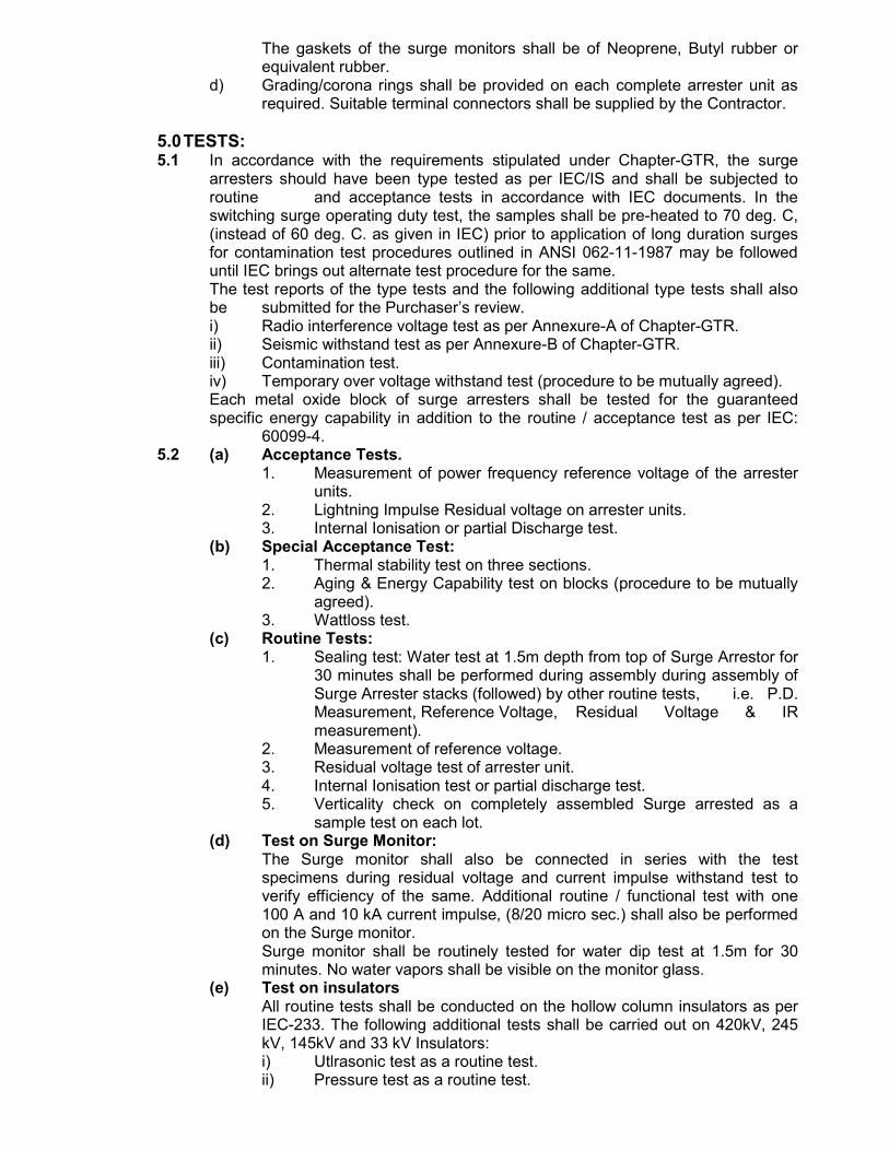
The gaskets of the surge monitors shall be of Neoprene, Butyl rubber or equivalent rubber.
d) Grading/corona rings shall be provided on each complete arrester unit as required. Suitable terminal connectors shall be supplied by the Contractor.
5.0 TESTS: 5.1 In accordance with the requirements stipulated under Chapter-GTR, the surge
arresters should have been type tested as per IEC/IS and shall be subjected to routine and acceptance tests in accordance with IEC documents. In the switching surge operating duty test, the samples shall be pre-heated to 70 deg. C, (instead of 60 deg. C. as given in IEC) prior to application of long duration surges for contamination test procedures outlined in ANSI 062-11-1987 may be followed until IEC brings out alternate test procedure for the same. The test reports of the type tests and the following additional type tests shall also be submitted for the Purchaser’s review. i) Radio interference voltage test as per Annexure-A of Chapter-GTR.
ii) Seismic withstand test as per Annexure-B of Chapter-GTR. iii) Contamination test.
iv) Temporary over voltage withstand test (procedure to be mutually agreed). Each metal oxide block of surge arresters shall be tested for the guaranteed specific energy capability in addition to the routine / acceptance test as per IEC: 60099-4.
5.2 (a) Acceptance Tests. 1. Measurement of power frequency reference voltage of the arrester
units. 2. Lightning Impulse Residual voltage on arrester units. 3. Internal Ionisation or partial Discharge test. (b) Special Acceptance Test: 1. Thermal stability test on three sections.
2. Aging & Energy Capability test on blocks (procedure to be mutually agreed).
3. Wattloss test. (c) Routine Tests:
1. Sealing test: Water test at 1.5m depth from top of Surge Arrestor for 30 minutes shall be performed during assembly during assembly of Surge Arrester stacks (followed) by other routine tests, i.e. P.D. Measurement, Reference Voltage, Residual Voltage & IR measurement).
2. Measurement of reference voltage. 3. Residual voltage test of arrester unit. 4. Internal Ionisation test or partial discharge test.
5. Verticality check on completely assembled Surge arrested as a sample test on each lot.
(d) Test on Surge Monitor: The Surge monitor shall also be connected in series with the test specimens during residual voltage and current impulse withstand test to verify efficiency of the same. Additional routine / functional test with one 100 A and 10 kA current impulse, (8/20 micro sec.) shall also be performed on the Surge monitor. Surge monitor shall be routinely tested for water dip test at 1.5m for 30 minutes. No water vapors shall be visible on the monitor glass.
(e) Test on insulators All routine tests shall be conducted on the hollow column insulators as per IEC-233. The following additional tests shall be carried out on 420kV, 245 kV, 145kV and 33 kV Insulators:
i) Utlrasonic test as a routine test. ii) Pressure test as a routine test.
iii) Bending load test in direction at 50% specified bending load as a routine test.
iv) Bending load test in 4 directions at 100% specified bending load as a sample test on each lot.
v) Burst pressure test as a sample test on each lot. 6.0 SPARE PARTS AND MAINTENANCE EQUIPMENT:
Bidder shall include in his proposal spare parts and maintenance equipment, as mentioned in Section-Project.
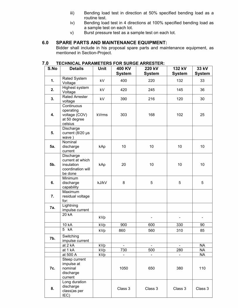
7.0 TECHNICAL PARAMETERS FOR SURGE ARRESTER:
S.No Details Unit 400 KV System
220 kV System
132 kV System
33 kV System
1. Rated System Voltage
kV 400 220 132 33
2. Highest system Voltage
kV 420 245 145 36
3. Rated Arrester voltage
kV 390 216 120 30
4.
Continuous operating voltage (COV) at 50 degree celsius
kVrms 303 168 102 25
5. Discharge current (8/20 µs wave )
5a. Nominal discharge current
kAp 10 10 10 10
5b.
Discharge current at which insulation coordination will be done
kAp 20 10 10 10
6. Minimum discharge capability
kJ/kV 8 5 5 5
7. Maximum residual voltage for:
7a. Lightning impulse current
20 kA
kVp
- - -
10 kA kVp 900 600 330 90
5 kA kVp 860 560 310 85
7b. Switching impulse current
at 2 kA kVp - - - NA at 1 kA kVp 730 500 280 NA at 500 A kVp - - - NA
7c.
Steep current impulse at nominal discharge current
1050 650 380 110
8.
Long duration discharge class(as per IEC)
Class 3 Class 3 Class 3 Class 3
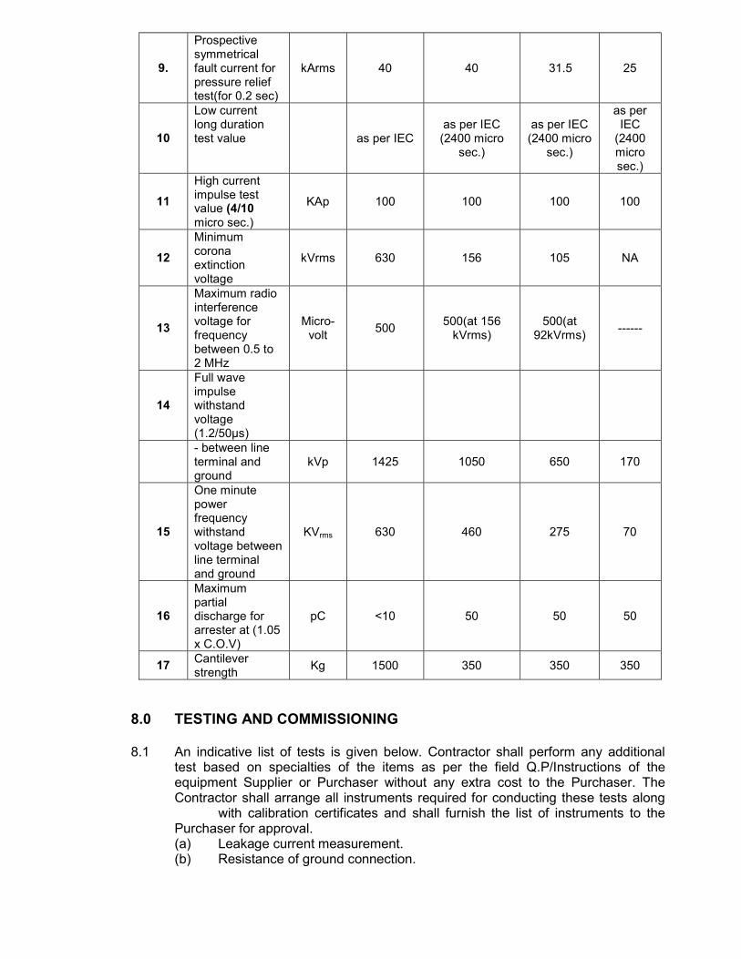
9.
Prospective symmetrical fault current for pressure relief test(for 0.2 sec)
kArms 40 40 31.5 25
10
Low current long duration test value as per IEC
as per IEC (2400 micro
sec.)
as per IEC (2400 micro
sec.)
as per IEC
(2400 micro sec.)
11
High current impulse test value (4/10 micro sec.)
KAp 100 100 100 100
12
Minimum corona extinction voltage
kVrms 630 156 105 NA
13
Maximum radio interference voltage for frequency between 0.5 to 2 MHz
Micro-volt
500 500(at 156
kVrms) 500(at
92kVrms) ------
14
Full wave impulse withstand voltage (1.2/50µs)
- between line terminal and ground
kVp 1425 1050 650 170
15
One minute power frequency withstand voltage between line terminal and ground
KVrms 630 460 275 70
16
Maximum partial discharge for arrester at (1.05 x C.O.V)
pC <10 50 50
50
17 Cantilever strength
Kg 1500 350 350 350
8.0 TESTING AND COMMISSIONING 8.1 An indicative list of tests is given below. Contractor shall perform any additional
test based on specialties of the items as per the field Q.P/Instructions of the equipment Supplier or Purchaser without any extra cost to the Purchaser. The Contractor shall arrange all instruments required for conducting these tests along with calibration certificates and shall furnish the list of instruments to the Purchaser for approval. (a) Leakage current measurement. (b) Resistance of ground connection.