cisco virtual infrastructure manager installation guide, 2.2.6
TRANSCRIPT

Cisco Virtual Infrastructure Manager Installation Guide, 2.2.6First Published: 2017-11-30
Americas HeadquartersCisco Systems, Inc.170 West Tasman DriveSan Jose, CA 95134-1706USAhttp://www.cisco.comTel: 408 526-4000 800 553-NETS (6387)Fax: 408 527-0883

© 2017 Cisco Systems, Inc. All rights reserved.

C O N T E N T S
C H A P T E R 1 Overview to Cisco NFVI 1
Overview to Cisco NFV Infrastructure 1
Overview to Cisco Virtual Infrastructure Manager 7
Features of Cisco VIM 7
Cisco NFVI Networking Overview 10
UCS C-Series Network Topologies 17
Cisco VIM Management Node Networking 22
IPv6 Support on Management Network 25
UCS C-Series and B-Series -Topologies 25
Cisco NFVI High Availability 28
Cisco NFVI Storage Node Overview 29
Overview to Cisco Virtual Topology System 30
Overview to Cisco NFVIMON 32
Overview to Cisco VIM Insight 34
Overview to NFVBench 35
Overview to ACI Plugin Integration 37
NCS-5500 as a ToR Option 38
Disk Management in VIM 2.2 38
OSD Maintenance 38
C H A P T E R 2 Cisco NFVI Installation Overview 41
Overview to Cisco NFVI Installation 41
C H A P T E R 3 Preparing for Installation on Servers Without Internet Access 45
Preparing to Install Cisco NFVI on Management Nodes Without Internet Access 45
C H A P T E R 4 Preparing for Cisco NFVI Installation 51
Installing the Cisco NFVI Hardware 51
Cisco Virtual Infrastructure Manager Installation Guide, 2.2.6 iii

Configuring ToR Switches for C-Series Pods 53
Configuring ToR Switches for UCS B-Series Pods 58
Preparing Cisco IMC and Cisco UCS Manager 59
Installing the Management Node 60
Setting Up the UCS C-Series Pod 62
Setting Up the UCS B-Series Pod 64
Configuring the Out-of-Band Management Switch 66
C H A P T E R 5 Installing Cisco VTS 67
Overview to Cisco VTS Installation in Cisco NFVI 67
Cisco VTS Usernames and Passwords in Cisco NFVI 69
System Requirements for VTC VM 70
System Requirements for VTSR VM 71
System Requirements for VTF 71
Supported Virtual Machine Managers 72
Supported Platforms 72
Installing Cisco VTS in a Cisco NFVI Environment 73
Installing VTC VM - Automatic Configuration Using ISO File 74
Installing VTC VM - Manual Configuration Using virt-manager 75
Installing VTC VM - Manual Configuration using VNC 77
Installing the VTSR VMs 78
Creating VTSR VM 78
Bringing up the KVM-based VTSR VM 78
Creating an ISO for IOS VTSR 79
Verifying Cisco VTS Installation in Cisco NFVI 81
Verifying VTC VM Installation 81
Verifying VTSR VM Installation 81
Troubleshooting VTF Registration 82
Configuring Cisco VTS and VTSR After Installation 82
Installing VTS in an HA Configuration 83
Completing the VTSR HA Configuration 88
Uninstalling VTC HA 88
Sample Cisco VTS Configurations for Cisco NFVI 88
C H A P T E R 6 Installing Cisco VIM 93
Cisco Virtual Infrastructure Manager Installation Guide, 2.2.6iv
Contents

Cisco VIM Installation Overview 93
Installing Cisco VIM 94
Cisco VIM Client Details 95
Cisco VIM Configuration Overview 98
Configuring ToR Automatically 98
Setting Up the Cisco VIM Data Configurations 99
Setting Up the ToR Configurations for B-series and C-series 99
Setting Up Server Level information for C-series with Intel NIC 101
Server Level Setup_data info for C-series with Intel NIC with SRIOV 101
Support for Custom Configuration 101
Setting Up ToR Configurations for NCS-5500 102
Intel NIC Support 103
Setting Up the Cisco VIM OpenStack Configurations 110
Cisco VIM Configurations for VPP/VLAN Installation 118
Cisco VIM Configurations for Cisco VTS Installation 118
Enabling ACI in Cisco VIM 119
Enabling NFVBench on Cisco VIM 123
NFV Host Configuration 125
Install Mode 125
Enabling NFVIMON on Cisco VIM 126
Installation of NFVIMON Dispatcher 126
Enabling or Disabling Autobackup of Management Node 127
Forwarding ELK logs to External Syslog Server 127
Configuring Additional VIM Administrators 128
Updating Cisco NFVI Software 128
Upgrading Cisco NFVI Software 129
C H A P T E R 7 Installing Cisco VIM Insight 131
Cisco VIM Insight with Internet Access 131
Installing Cisco VIM Insight without Internet Access 136
Cisco VIM Insight Post Bootstrap Validation Checks 139
VIM Insight UI Admin Login for Standalone Setup 143
VIM Insight Pod Admin Login for Standalone Setup 143
C H A P T E R 8 Installing Cisco VIM through Cisco VIM Insight 145
Cisco Virtual Infrastructure Manager Installation Guide, 2.2.6 v
Contents

Registering New Pod to Insight 145
Login to Insight as Pod Admin 147
The VIM Insight UI 147
Context Switching within Insight 154
Configuring OpenStack Installation 155
Post Installation Features for Active Blueprint 193
Monitoring the Pod 193
Cross Launching Horizon 194
NFVI Monitoring 194
Run VMTP 194
Run CloudPulse 195
Run NFV Bench 195
Fixed Rate Test 196
POD Management 196
System Update 197
Reconfiguring CIMC Password through Insight 197
Reconfiguring OpenStack Password 198
Reconfiguring OpenStack Services, TLS certs and ELK configurations 199
Reconfiguring Optional Services 199
Pod User Administration 200
Managing Users 201
Managing Roles 201
Managing Root CA Certificate 202
C H A P T E R 9 Verifying the Cisco NFVI Installation 203
Displaying Cisco NFVI Node IP Addresses 203
Verifying Cisco VIM Client CLI Availability 204
Displaying Cisco NFVI Logs 205
Accessing OpenStack API Endpoints 205
Assessing Cisco NFVI Health with CloudPulse 206
Displaying HAProxy Dashboard and ELK Stack Logs 208
Checking Cisco NFVI Pod and Cloud Infrastructure 208
Cisco Virtual Infrastructure Manager Installation Guide, 2.2.6vi
Contents

C H A P T E R 1Overview to Cisco NFVI
This section contains the following topics:
• Overview to Cisco NFV Infrastructure, page 1
• Overview to Cisco Virtual Infrastructure Manager, page 7
• Cisco NFVI Networking Overview, page 10
• UCS C-Series Network Topologies, page 17
• Cisco VIM Management Node Networking, page 22
• IPv6 Support on Management Network, page 25
• UCS C-Series and B-Series -Topologies, page 25
• Cisco NFVI High Availability, page 28
• Cisco NFVI Storage Node Overview, page 29
• Overview to Cisco Virtual Topology System, page 30
• Overview to Cisco NFVIMON, page 32
• Overview to Cisco VIM Insight, page 34
• Overview to NFVBench, page 35
• Overview to ACI Plugin Integration, page 37
• NCS-5500 as a ToR Option, page 38
• Disk Management in VIM 2.2, page 38
• OSD Maintenance, page 38
Overview to Cisco NFV InfrastructureCisco Network Function Virtualization Infrastructure (NFVI) provides the virtual layer and hardwareenvironment in which virtual network functions (VNFs) can operate. VNFs provide well-defined networkfunctions such as routing, intrusion detection, domain name service (DNS), caching, network address translation(NAT) and other network functions.While these network functions require a tight integration between network
Cisco Virtual Infrastructure Manager Installation Guide, 2.2.6 1

software and hardware in the past, the introduction to VNFs have helped decouple (losely couple) the softwarefrom the underlying hardware. The following figure shows the high-level NFVI architecture.
Figure 1: General NFV Infrastructure
Cisco NFVI features a virtual infrastructure layer (Cisco VIM) that embeds the Red Hat OpenStack Platform(OSP).Cisco VIM includes the Newton release of OpenStack, the open source cloud operating system thatcontrols large pools of compute, storage, and networking resources. Cisco VIM manages the OpenStackcompute, network, and storage services, and all NFVI management and control functions. Key Cisco NFVIroles include:
• Control (including Networking)
• Compute
• Storage
• Management (including logging, and monitoring)
Hardware used to create the Cisco NFVI pods include:
• Cisco UCS® C240 M4—Performs management and storage functions and services. Includes dedicatedCeph (UCS 240-M4) distributed object store and file system. (Only Red Hat Ceph is supported).
• Cisco UCS C220/240 M4—Performs control and compute services.
• Cisco UCS B200 M4 blades—Can be used instead of the UCS C220 for compute and control services.The B200 blades and C240Ceph server are connectedwith redundant Cisco Fabric Interconnectsmanagedby UCS Manager.
Cisco Virtual Infrastructure Manager Installation Guide, 2.2.62
Overview to Cisco NFVIOverview to Cisco NFV Infrastructure

The UCS C240 and C220 servers are M4 Small Form Factor (SFF) models where the computes can boot froma pair of HDDs or SSD. Each UCS C240, C220, and B200 has two 10 GE Cisco UCS Virtual Interface Cards.
The B-Series pod consists of Cisco UCS B200 M4 blades for the Cisco NFVI compute and controller nodeswith dedicated Ceph on a UCS C240 M4. The blades and the Ceph server are connected to redundant fabricinterconnects (FIs) managed by Cisco UCS Manager. When you install Cisco VIM on a B-Series pod, youcan dynamically allocate VLANs on the provider networks for both Virtio and SRIOV using the optionalCisco UCSManager plugin. The Cisco VIM installer performs bare metal installation and deploys OpenStackservices using Docker™ containers to allow for OpenStack services and pod management software updates.
The following table shows the functions, hardware, and services performed by Cisco NFVI nodes.
Table 1: Cisco NFVI Node Functions
ServicesHardwareNumberFunction
• Cisco VIM Installer
• Cobbler server
• Docker Registry
• ELK server
UCS C240M4 SFF with 8, 16, or 24 1.2TB HDDs (24 is recommended)
1Management
• Maria Database/Galera
• RabbitMQ
• HA Proxy/Keepalive
• Identity Service
• Image Service
• Compute management
• Network service
• Storage service
• Horizon dashboard
• Fluentd
• UCS C220/C240 M4 with two 1.2TB HDDs, or
• UCS B200 with two 1.2 TB HDDs
3Control
• Virtual Networking Service
• Compute service
• Fluentd
• UCS C220/C240 M4 with two 1.2TB HDDs, or 2x1.6 TB SSDs
• UCS B200 with two 1.2 TB HDDs
2+Compute
Cisco Virtual Infrastructure Manager Installation Guide, 2.2.6 3
Overview to Cisco NFVIOverview to Cisco NFV Infrastructure

ServicesHardwareNumberFunction
• Storage serviceSSD and HDD drives must be in a 1:5ratio per storage node. Storage nodeconfiguration options:
• UCS C240 M4 with two internalSSDs*, one external SSDs, and five1.2 TB HDDs, or
• UCS C240 M4, with two internalSSDs*, four SSDs and 20 1.2 TBHDDs
• For UMHC, UCS C240 M4, withtwo 1.2TB HDD for OS boot,one/2 SSDs and 5/10 1.2 TBHDDs
3 ormore
Storage
• Top of Rack servicesTop of Rack services are for limiteddeployment (for VIM running onC-series (Micropod) with Intel NIC andVPP as the mechanism driver).
Recommended N9K switch softwareversion:
• 7.0(3)I4(6)
• 7.0(3)I6(1).
or, NCS-5500 as TORs
2ToR
Internal SSD is the boot device for storage node.Note
You can use any ToR that supports virtual port channel. We recommend you to use N9K SKUs as TOR,so that they can take advantage of automated ToR configuration feature which is released as part of CiscoVIM.
Note
You can use the automated ToR configuration feature for NCS-5500.Note
Software applications that manage Cisco NFVI hosts and services include:
• Red Hat Enterprise Linux 7.4 with OpenStack Platform 10.0—Provides the core operating system withOpenStack capability. RHEL 7.4 and OPS 10.0 are installed on all Cisco NFVI UCS servers.
• Cisco Virtual Infrastructure Manager (VIM)—An OpenStack orchestration system that helps to deployand manage an OpenStack cloud offering from bare metal installation to OpenStack services, takinginto account hardware and software redundancy, security and monitoring. Cisco VIM includes theOpenStack Newton release with additional features and usability enhancements tested for functionality,scale, and performance.
• Cisco Insight—Deploys, provisions, and manages Cisco VIM on Cisco UCS servers.
Cisco Virtual Infrastructure Manager Installation Guide, 2.2.64
Overview to Cisco NFVIOverview to Cisco NFV Infrastructure

• Cisco UCS Manager—Used to perform certain management functions when UCS B200 blades areinstalled. Supported UCS Manager firmware versions are 2.2(5a) and above.
• Cisco IntegratedManagement Controller (IMC)-Provides embedded server management for Cisco UCSC-Series Rack Servers. Supported Cisco IMC firmware versions for fresh install of Cisco VIM 2.2 is:2.0(13i) or greater. Because of recent security fixes, we recommend you to move the CIMC to 2.0(13n)or higher. Prior to upgrade of Pod from CVIM 1.0 to CVIM 2.2, it is expected that users manuallyupgrade to 2.0(13n) or greater. Under no circumstances can the Cisco IMC version be running 3.0 series.
• CiscoVirtual Topology System (VTS)—is a standards-based, open, overlaymanagement and provisioningsystem for data center networks. It automates DC overlay fabric provisioning for physical and virtualworkloads. This is an optional service that is available through Cisco VIM.
• Cisco Virtual Topology Forwarder (VTF)—Included with VTS, VTF leverages Vector Packet Processing(VPP) to provide high performance Layer 2 and Layer 3 VXLAN packet forwarding.
Two Cisco VNF orchestration and management applications used with Cisco NFVI include:
• Cisco Network Services Orchestrator, enabled by Tail-f—Provides end-to-end orchestration spanningmultiple network domains to address NFVmanagement and orchestration (MANO) and software-definednetworking (SDN). (For information about Cisco NSO, see Network Services Orchestrator Solutions.)
• Cisco Elastic Services Controller—Provides a single point of control to manage all aspects of the NFVlife cycle for VNFs. ESC allows you to automatically instantiate, monitor, and elastically scale VNFsend-to-end. (For information about Cisco ESC, see the Cisco Elastic Services Controller Data Sheet.)
Figure 2: NFVI Architecture With Cisco NFVI, Cisco NSO, and Cisco ESC
At a high level the NFVI architecture includes a VNF Manager and the NFV Infrastructure.
Cisco Virtual Infrastructure Manager Installation Guide, 2.2.6 5
Overview to Cisco NFVIOverview to Cisco NFV Infrastructure

• Cisco Network Services Orchestrator
• Cisco Elastic Services Controller
1
Cisco NFVI:
• Cisco VIM +
• Cisco UCS and Cisco Nexus Hardware +
• Logging and Monitoring Software +
• Cisco Virtual Topology Services (optional) +
• Cisco Insight (optional)
2
For cloud networking, Cisco NFVI supports either Linux bridge over Virtual Extensible LAN (VXLAN) orOpen vSwitch over VLAN as the cloud network solution for both UCS B- and C-Series pods. However, theUCS B-Series pods using the Cisco UCS Manager plugin supports only OVS/VLAN as a tenant network.Both B-Series and C-Series deployments support provider networks over VLAN. In addition, in a C-seriespod, you can choose to run with augmented performance mechanism by replacing OVS/LB with VPP/VLAN(virtual packet processor). Also, in a C-series pod, you can choose to have the cloud integrated with VTC(virtual topology system), which is an SDN controller option.
The CiscoNFVI uses OpenStack services running inside containers with HAProxy load balancing and providinghigh availability to API and management network messaging. Transport Layer Security (TLS) protects theAPI network from external clients to the HAProxy. Cisco VIM installation also includes service assurance,OpenStack CloudPulse, built-in control, and data plane validation. Day two pod management allows you toadd and remove compute and Ceph nodes, and replace controller nodes. The Cisco VIM installation embedsall necessary RHEL licenses as long as you use the Cisco VIM BOM and the corresponding release artifacts.
The following illustration shows a detailed view of the Cisco NFVI architecture and the Cisco NFVI Installationflow.
Figure 3: Detailed Cisco NFVI Architecture View
Cisco Virtual Infrastructure Manager Installation Guide, 2.2.66
Overview to Cisco NFVIOverview to Cisco NFV Infrastructure

Overview to Cisco Virtual Infrastructure ManagerCisco Virtual Infrastructure Manager (VIM) 2.2 is a fully automated cloud lifecycle management system.VIM helps to bring up a fully functional cloud in hours, with integrated end-to-end control and data planeverification in place. Beyond day 0 cloud bring up and deployment, VIM offers fully automated day 1 to dayn cloud lifecycle management. These include capabilities such as pod scaling (expansion), software update,upgrade, or reconfigure parameters, consolidated logging with rotation and export, software update andupgrade. These have been implemented in line with the operational and security best practices of serviceproviders and enterprises.
The following figure provides the high-level overview of all day-0 and day-n items of Cisco VIM.
Figure 4: Cisco VIM Capability Overview
Features of Cisco VIMCisco VIM 2.2 is the only standalone fully automated cloud lifecycle manager offering from Cisco for privatecloud. The current version of VIM, integrates with Cisco C or B-series UCS servers and Cisco or Intel NIC.This document and its accompanying admin guide help the cloud administrators to setup and manage theprivate cloud. Listed in table is the summary of the feature set that is offered.
CommentsFeature Name
RHEL 7.4 with OSP 10 (Newton).OpenStack Version
1 UCS C220/B200 M4 controller or compute with Intel V3(Haswell).
2 UCSC240M4 controller or compute + Intel V4 (Broadwell).
Hardware Support Matrix
Cisco Virtual Infrastructure Manager Installation Guide, 2.2.6 7
Overview to Cisco NFVIOverview to Cisco Virtual Infrastructure Manager

1 Cisco VIC: VIC 1227, 1240, 1340, 1380.2 Intel NIC: X710, 520.
NIC support
1 Dedicated controller, compute and storage node (full-onPod).
2 Dedicated control, compute and storage (C-Series) noderunning on Cisco VIC, or Intel 710 X.
3 Dedicated control, compute and storage (B-Series) noderunning on Cisco NIC.
4 MICROPOD: Integrated (AIO) control, compute and storage(C-series) node running on Cisco VIC, or Intel 710 X.Micropod can also be optionally expanded to accommodate foradditional computes running with the same NIC type. Thiscan be done as a day-0 or day-1 activity.
5 Hyper-Converged: Dedicated control and compute nodes,with all storage acting as compute (C-series) nodes, runningon a combination of 1-Cisco VIC (1227) and 2x10GE 520or 2x40GE 710XL Intel NIC.
6 In a full-on (VIC based), or Hyper-Converged pod, computescan run either have a combination of 1-Cisco VIC (1227)and 2x10GE 520 or 2x40GE 710XL Intel NIC or 1-CiscoVIC(1227). The compute running pure Cisco VIC will not berunning SR-IOV .
POD Type
1 Nexus software version 7.0(3)I4(6) 7.0(3)I6(1)
2 Support of NCS-5500
3 UCS-FI-6296
ToR and FI support
1 Static IPv6 management assignment for servers.2 Support of IPv6 for NTP, DNS, LDAP and AD.
3 Support of IPv6 for Cloud API end point.
IPV6 Support for Management Network
OVS/VLAN, Linuxbridge/VXLAN, ACI/VLAN, VPP/VLAN(Fast Networking, Fast Data FD.io > VPP/VLAN, based on theFD.io VPP fast virtual switch).
Mechanism Drivers
VTS; ACI (ships in the night or with Unified ACI Plugin).SDN Controller Integration
Fully automated online or offline.Install Methodology
Cisco Virtual Infrastructure Manager Installation Guide, 2.2.68
Overview to Cisco NFVIFeatures of Cisco VIM

1 Compute: 40 Hosts (booting off 2x1.2TB HDD or 2x1.6TBSSD); Some computes can have SSD, while others can haveHDD
2 Ceph OSD: 20 hosts
Scale
1 Add or remove compute and Ceph nodes and replacecontroller.
2 Reconfiguration of passwords and selected optional services.3 Automated software update.
Automated Pod Life Cycle Management
Secure OS, RBAC, Network isolation, TLS, Source IP filtering,Keystone v3, Bandit, CSDL compliant, hardened OS, SELinux.
Change the CIMC password after post install for maintenanceand security.
Non-root login for Administrators.
Platform security
NUMA, CPU pinning, huge pages, SRIOV with Intel NIC.EPA
1 Redundancy at hardware and software level.2 Automated backup and restore of management node.
HA and Reliability
Single pane of glass in a single or multi instance (HA) mode:Supports multi-tenancy and manages multiple pods from oneinstance.
Unified Management Support
ELK integrated with external syslog for log offload.Central Logging
Cold migration and resizing.VIM Migration
Object store with SwiftStack, Block storage with Ceph.Storage
Third party integration with Zenoss (called NFVIMON).Monitoring
1 LDAP2 Active Directory (AD)
Support of External Auth System
Update of Cloud Software for bug fixes on the same release.Software Update
Seamless Upgrade of VIMManaged Pod from liberty to Newtonin connected and disconnected mode.
Software Upgrade
Ability to replace faulty disk(s) on the Pod node(s) without theneed for add/remove/replace node operation.
Disk maintenance for Pod Nodes
Cisco Virtual Infrastructure Manager Installation Guide, 2.2.6 9
Overview to Cisco NFVIFeatures of Cisco VIM

1 Open SourceData-plane PerformanceBenchmarking:VMTP(an open source data plane VM to VM performancebenchmarking tool), NFVBench (NFVI data plane andservice chain performance benchmarking tool).
2 Services Health Checks Integration: Cloudpulse andCloudsanity.
Integrated Test Tools
Cisco NFVI Networking OverviewCisco VIM supports installation on two different type of pods. The B-series and C-series offering supportsNICs that are from Cisco (called as Cisco VIC). You can choose the C-series pod to run in a pure Intel NICenvironment, and thereby obtain SRIOV support on the C-series pod. This section calls out the differencesin networking between the Intel NIC and Cisco VIC installations.
To achieve network level security and isolation of tenant traffic, Cisco VIM segments the various OpenStacknetworks. The Cisco NFVI network includes six different segments in the physical infrastructure (underlay).These segments are presented as VLANs on the Top-of-Rack (ToR) Nexus switches (except for the providernetwork) and as vNIC VLANs on Cisco UCS servers. You must allocate subnets and IP addresses to eachsegment. Cisco NFVI network segments include: API, external, management and provisioning, storage, tenantand provider.
API Segment
The API segment needs one VLAN and two IPv4 addresses (four if you are installing Cisco VTS) (not a fullsubnet) in an externally accessible subnet different from the subnets assigned to other Cisco NFVI segments.These IP addresses are used for:
• OpenStack API end points. These are configured within the control node HAProxy load balancer.
• Management node external connectivity.
• The Cisco Virtual Topology Services (VTS) (if included in your Cisco NFVI package) Virtual TopologyController (VTC) node (optional for VTS).
• VTC (optional for VTS).
External Segment
The external segment needs one VLAN to configure the OpenStack external network. Provide the VLANduring installation in the the Cisco NFVI setup_data.yaml file, but configure the actual subnet using theOpenStack API after the installation. Then use the external network to assign OpenStack floating IP addressesto VMs running on Cisco NFVI.
Management and Provisioning Segment
The management and provisioning segment needs one VLAN and one subnet with an address pool largeenough to accommodate all the current and future servers planned for the pod for initial provisioning (PXEboot Linux) and, thereafter, for all OpenStack internal communication. This VLAN and subnet can be localto Cisco NFVI for C-Series deployments. For B-Series pods, the UCS Manager IP and management networkmust be routable. You must statically configure Management IP addresses of Nexus switches and Cisco UCSserver Cisco IMC IP addresses, and not through DHCP. They must be through the API segment. Themanagement/provisioning subnet can be either internal to Cisco NFVI (that is, in a lab it can be a non-routable
Cisco Virtual Infrastructure Manager Installation Guide, 2.2.610
Overview to Cisco NFVICisco NFVI Networking Overview

subnet limited to Cisco NFVI only for C-Series pods), or it can be an externally accessible and routable subnet.All Cisco NFVI nodes (including the Cisco VTC node) need an IP address from this subnet.
Storage Segment
Cisco VIM has a dedicated storage network used for Ceph monitoring between controllers, data replicationbetween storage nodes, and data transfer between compute and storage nodes. The storage segment needs oneVLAN and /29 or larger subnet internal to Cisco NFVI to carry all Ceph replication traffic. All the participatingnodes in the pod, have IP addresses on this subnet.
Tenant Segment
The tenant segment needs one VLAN and a subnet large enough to manage pod tenant capacity internal toCisco NFVI to carry all tenant virtual network traffic. Only Cisco NFVI control and compute nodes have IPaddresses on this subnet. The VLAN/subnet can be local to Cisco NFVI.
Provider Segment
Provider networks are optional for Cisco NFVI operations but are often used for real VNF traffic. You canallocate one or more VLANs for provider networks after installation is completed from OpenStack.
Cisco NFVI renames interfaces based on the network type it serves. The segment Virtual IP (VIP) name isthe first letter of the segment name. Combined segments use the first character from each segment for theVIP, with the exception of provisioning whose interface VIP name is mx instead of mp to avoid ambiguitywith the provider network. The following table shows Cisco NFVI network segments, usage, and networkand VIP names.
Table 2: Cisco NFVI Networks
VIP NameNetwork NameUsageNetwork
mxManagement andprovisioning• OpenStack control
plane traffic.
• Application packagedownloads.
• Servermanagement;management nodeconnect to serverson this network.
• Host default route.
• PXE bootingservers during baremetal installations.
Management/Provisioning
Cisco Virtual Infrastructure Manager Installation Guide, 2.2.6 11
Overview to Cisco NFVICisco NFVI Networking Overview

VIP NameNetwork NameUsageNetwork
aapi• Clients connect toAPI network tointerface withOpenStack APIs.
• OpenStack Horizondashboard.
• Default gateway forHAProxy container.
• Integration withendpoints served bySwiftStack clusterfor native objectstorage, cinderbackup service orIdentity servicewithLDAP/AD.
API
ttenantVM to VM traffic. Forexample, VXLAN traffic.
Tenant
eexternalAccess to VMs usingfloating IP addresses.
External
sstorageTransit network forstorage back-end.
Storage traffic betweenVMs and Ceph nodes.
Storage
pproviderDirect access to existingnetwork infrastructure.
Provider Network
oaciinfraInternal ACI Network forPolicymanagement (onlyallowed when deployedwith ACI)
ACIINFRA
Cisco Virtual Infrastructure Manager Installation Guide, 2.2.612
Overview to Cisco NFVICisco NFVI Networking Overview

VIP NameNetwork NameUsageNetwork
br_apiVIM installer API• Administrator usesinstaller APInetwork to ssh tothe managementnode.
• Administratorconnects to installerAPI to interfacewith securedservices. Example:Kibana on themanagement node.
Installer API
For each C-series pod node, two vNICs are created using different ports and bonded for redundancy for eachnetwork. Each network is defined in setup_data.yaml using the naming conventions listed in the precedingtable. The VIP Name column provides the bonded interface name (for example, mx or a) while each vNICname has a 0 or 1 appended to the bonded interface name (for example, mx0, mx1, a0, a1).
The Cisco NFVI installer creates the required vNICs, host interfaces, bonds, and bridges with mappingscreated between all elements. The number and type of created vNICs, interfaces, bonds, and bridges dependon the Cisco NFVI role assigned to the UCS server. For example, the controller node has more interfaces thanthe compute or storage nodes. The following table shows the networks that are associated with each CiscoNFVI server role.
Table 3: Cisco NFVI Network-to-Server Role Mapping
Storage NodeCompute NodeController NodeManagement Node
++++Management/Provisioning
++ACIINFRA*
+API
++Tenant
+++Storage
+Provider
+External
Cisco Virtual Infrastructure Manager Installation Guide, 2.2.6 13
Overview to Cisco NFVICisco NFVI Networking Overview
*ACIINFRA is only applicable when using ACI as a mechanism driver.Note
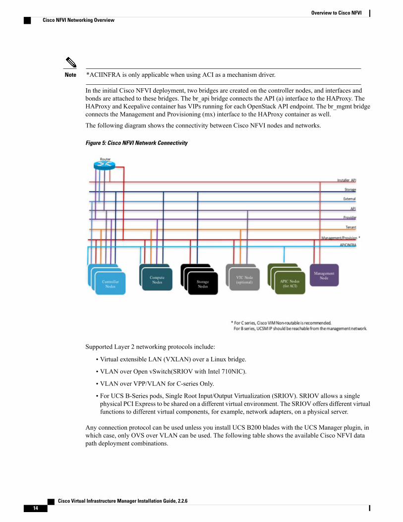
In the initial Cisco NFVI deployment, two bridges are created on the controller nodes, and interfaces andbonds are attached to these bridges. The br_api bridge connects the API (a) interface to the HAProxy. TheHAProxy and Keepalive container has VIPs running for each OpenStack API endpoint. The br_mgmt bridgeconnects the Management and Provisioning (mx) interface to the HAProxy container as well.
The following diagram shows the connectivity between Cisco NFVI nodes and networks.
Figure 5: Cisco NFVI Network Connectivity
Supported Layer 2 networking protocols include:
• Virtual extensible LAN (VXLAN) over a Linux bridge.
• VLAN over Open vSwitch(SRIOV with Intel 710NIC).
• VLAN over VPP/VLAN for C-series Only.
• For UCS B-Series pods, Single Root Input/Output Virtualization (SRIOV). SRIOV allows a singlephysical PCI Express to be shared on a different virtual environment. The SRIOV offers different virtualfunctions to different virtual components, for example, network adapters, on a physical server.
Any connection protocol can be used unless you install UCS B200 blades with the UCS Manager plugin, inwhich case, only OVS over VLAN can be used. The following table shows the available Cisco NFVI datapath deployment combinations.
Cisco Virtual Infrastructure Manager Installation Guide, 2.2.614
Overview to Cisco NFVICisco NFVI Networking Overview

Table 4: Cisco NFVI Data Path Deployment Combinations
MTU ValuesPCIPassthroughPorts
SRIOVfor VM
ProviderVirtualNetworkEncapsulation
TenantVirtualNetworkEncapsulation
MechanismDriver
Pod TypeNFVI PodType
90001500VLANVxLANVLAN
NoYesNoNoYesYesNoLinuxBridgeFull onUCSC-series
YesYesNoYes*YesNoYesOpenvswitchFull on, micro,HC
UCSC-series
YesYesNoNoYesNoYesVPPFull on, microUCSC-series
YesYesNoNoYesNoYesACIFull on, microUCSC-series
YesYesNo(exceptthroughDPDK)
NoYesYesNoVTF withVTC***
Full onUCSC-series
YesYesNoYesYesNoYesOpenvswitchFull onUCS B
Fullon: Indicates dedicated control, compute and ceph nodes.Note
Micro: Indicates converged control, compute and ceph nodes with expandable computes.
HC (Hyperconverged): Indicates dedicated control, compute, but all ceph nodes are compute nodes also.
*** VTF with VTC is only supported on C-series Cisco VIC.Note
Pod with Intel NICs In case of the pod having Intel NICs (X710), the networking is slightly different. Firstof all, the requirement is to have atleast two NICs (4x10G) single server, so that we can support NIC levelredundancy. Each NIC is connected to each ToR (connections explained later in the chapter). Since vNICsare not supported in the Intel card, the idea is to bond the physical interfaces at the host and then createsub-interfaces based on the segment VLAN. Lets call the two NIC cards as NIC_1 and NIC_2 and call theirfour ports as A, B, C, D. Unlike Cisco VIC based pod, the traffic here is classified into the following.
1 Control Plane.
2 Data plane (external, tenant and non-SRIOV provider network).3 SRIOV (optional for provider network); if SRIOV is used the Data plane network only carries external
and tenant network traffic.
Cisco Virtual Infrastructure Manager Installation Guide, 2.2.6 15
Overview to Cisco NFVICisco NFVI Networking Overview

Control Plane.
The control plane is responsible for carrying all the control and management traffic of the cloud. The trafficthat flows through control plane are:
1 Management/Provision.2 Storage
3 API
The control plane interface is created by bonding the NIC_1 A port with NIC_2 A port. The bonded interfacename is called as samx, indicating that it is carrying Storage, API, Management/Provision traffic (namingconvention is similar to Cisco VIC pod). The slave interfaces (physical interfaces) of the bonded interface arerenamed as samx0 and samx1. samx0 belongs to NIC_1 and samx1 belongs to NIC_2. Sub interfaces are thencarved out of this samx interface based on the Storage, API VLANs. The management/provision traffic willbe untagged/native VLAN in order to support pxe booting.
Data Plane
The data plane is responsible for carrying all the VM data traffic. The traffic that flows through the data planeare
• Tenant
• Provider
• External
The data plane is created by bonding the NIC_1 B port with NIC_2 B port. The bonded interface name herewould be pet, indicating that it is carrying Provider, External and Tenant traffic. The slave interfaces of thisbonded interface would be visible as pet0 and pet1. pet0 belongs to the NIC_1 and pet1 belongs to NIC_2.
In case of OVS/VLAN, the "pet" interface is used as it is (trunked to carry all the data VLANs) to the Openstackcloud, as all the tagging and untagging happens at the Openstack level. In case of Linux Bridge/VXLAN,there will be sub-interface for tenant VLAN to act as the VXLAN tunnel endpoint.
SRIOV
In case of Intel NIC pod, the third (and optionally the fourth) port from each NIC can be used for SRIOVtraffic. This is optional and is set/unset through a setup_data.yaml parameter. Unlike the control and dataplane interfaces, these interfaces are not bonded and hence there is no redundancy. Each SRIOV port can havemaximum of 32 Virtual Functions and the number of virtual function to be created are configurable throughthe setup_data.yaml. The interface names of the sriov will show up as sriov0 and sriov1 on each host, indicatingthat sriov0 belongs to NIC_1 C port and sriov1 belongs to NIC_2 C port.
In the case of Intel NIC testbeds, the following table summarizes the above discussion
Interface nameType of trafficUsageNetwork
samxStorage, API,Management/Provision
To carrycontrol/managementtraffic
Control Plane
petProvider, External,Tenant
To carry data trafficData Plane
sriov0, sriov1SRIOVTo carry SRIOV trafficSRIOV
Cisco Virtual Infrastructure Manager Installation Guide, 2.2.616
Overview to Cisco NFVICisco NFVI Networking Overview

The following table shows the interfaces that are present on each type of server (role based).
Storage NodeCompute NodeController NodeManagement Node
+Installer API
++++Control plane
++Data plane
+SRIOV
On an Intel testbed, all kind of OpenStack networks should be created using physnet1 as the physnetname.
Note
UCS C-Series Network TopologiesCisco NFVI UCS servers connect to the ToR switches using Cisco UCS dual-port Virtual Interface Cards(VICs). The VIC is an Enhanced Small Form-Factor Pluggable (SFP+) 10 Gigabit Ethernet and Fiber Channelover Ethernet (FCoE)-capable PCI Express (PCIe) card designed for Cisco UCS C-Series Rack Servers. Eachport connects to a different ToR using a Virtual Port Channel (VPC). Each VIC is configured with multiplevNICs that correspond to specific CiscoVIM networks. TheUCSCisco IMC port is connected to an out-of-band
Cisco Virtual Infrastructure Manager Installation Guide, 2.2.6 17
Overview to Cisco NFVIUCS C-Series Network Topologies

(OOB) Cisco management switch. The following figure shows the UCS C-Series pod Cisco NFVI host toToR topology.
Figure 6: UCS C-Series Host to ToR Topology
Cisco Virtual Infrastructure Manager Installation Guide, 2.2.618
Overview to Cisco NFVIUCS C-Series Network Topologies
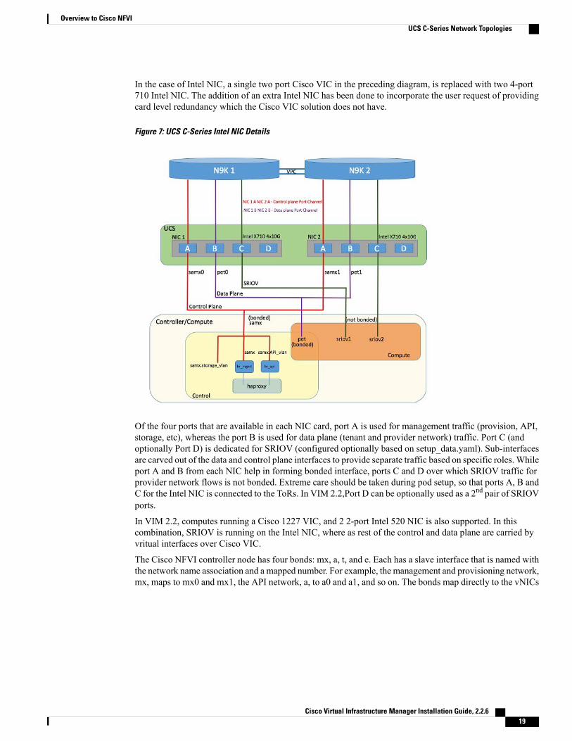
In the case of Intel NIC, a single two port Cisco VIC in the preceding diagram, is replaced with two 4-port710 Intel NIC. The addition of an extra Intel NIC has been done to incorporate the user request of providingcard level redundancy which the Cisco VIC solution does not have.
Figure 7: UCS C-Series Intel NIC Details
Of the four ports that are available in each NIC card, port A is used for management traffic (provision, API,storage, etc), whereas the port B is used for data plane (tenant and provider network) traffic. Port C (andoptionally Port D) is dedicated for SRIOV (configured optionally based on setup_data.yaml). Sub-interfacesare carved out of the data and control plane interfaces to provide separate traffic based on specific roles. Whileport A and B from each NIC help in forming bonded interface, ports C and D over which SRIOV traffic forprovider network flows is not bonded. Extreme care should be taken during pod setup, so that ports A, B andC for the Intel NIC is connected to the ToRs. In VIM 2.2,Port D can be optionally used as a 2nd pair of SRIOVports.
In VIM 2.2, computes running a Cisco 1227 VIC, and 2 2-port Intel 520 NIC is also supported. In thiscombination, SRIOV is running on the Intel NIC, where as rest of the control and data plane are carried byvritual interfaces over Cisco VIC.
The Cisco NFVI controller node has four bonds: mx, a, t, and e. Each has a slave interface that is named withthe network name association and a mapped number. For example, the management and provisioning network,mx, maps to mx0 and mx1, the API network, a, to a0 and a1, and so on. The bonds map directly to the vNICs
Cisco Virtual Infrastructure Manager Installation Guide, 2.2.6 19
Overview to Cisco NFVIUCS C-Series Network Topologies

that are automatically created on the controller node when it is deployed. The following figure shows thecontroller node network-to-bond-to-vNIC interface mapping.
Figure 8: Controller Node Network to Bond Mapping
The Cisco NFVI compute node has three bonds: mx, t, and p. Each has a slave interface that is named withthe network name association and a mapped number. For example, the provider network, p, maps to p0 andp1. The bonds map directly to the vNICs that are automatically created on the compute node when it isdeployed. The following figure shows the compute node network-to-bond-to-vNIC interfaces mapping.
Figure 9: Compute Node Network to Bond Mapping
Cisco Virtual Infrastructure Manager Installation Guide, 2.2.620
Overview to Cisco NFVIUCS C-Series Network Topologies
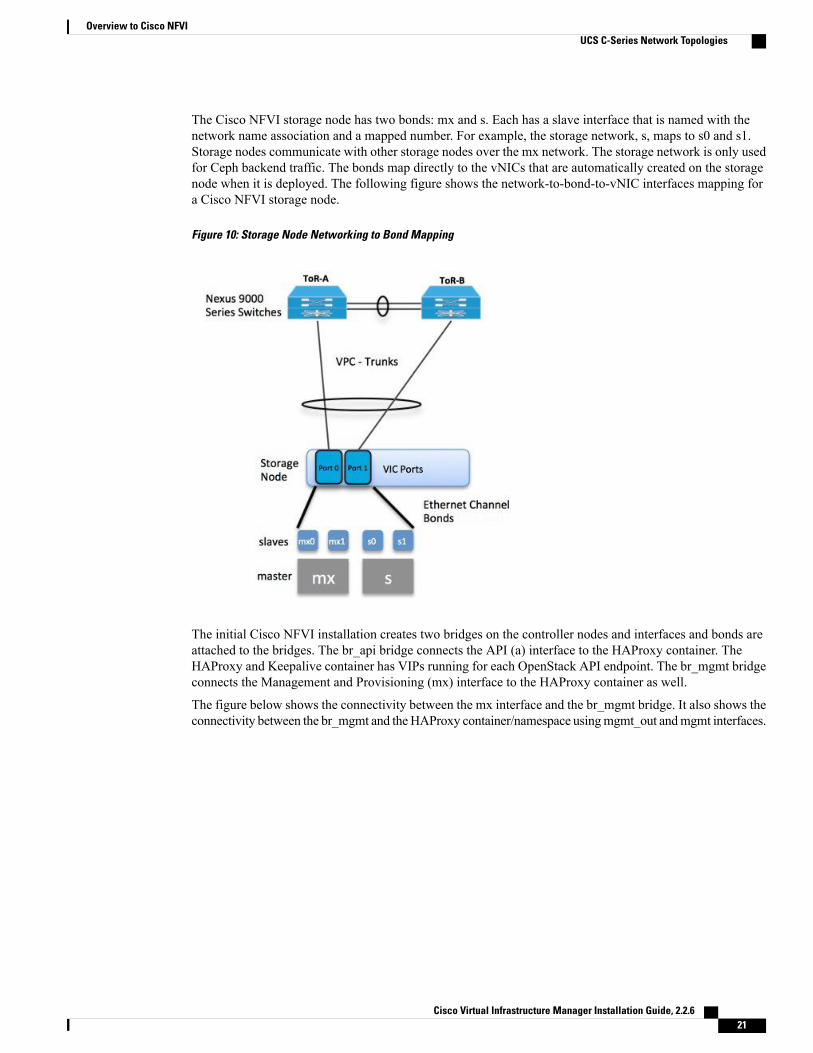
The Cisco NFVI storage node has two bonds: mx and s. Each has a slave interface that is named with thenetwork name association and a mapped number. For example, the storage network, s, maps to s0 and s1.Storage nodes communicate with other storage nodes over the mx network. The storage network is only usedfor Ceph backend traffic. The bonds map directly to the vNICs that are automatically created on the storagenode when it is deployed. The following figure shows the network-to-bond-to-vNIC interfaces mapping fora Cisco NFVI storage node.
Figure 10: Storage Node Networking to Bond Mapping
The initial Cisco NFVI installation creates two bridges on the controller nodes and interfaces and bonds areattached to the bridges. The br_api bridge connects the API (a) interface to the HAProxy container. TheHAProxy and Keepalive container has VIPs running for each OpenStack API endpoint. The br_mgmt bridgeconnects the Management and Provisioning (mx) interface to the HAProxy container as well.
The figure below shows the connectivity between the mx interface and the br_mgmt bridge. It also shows theconnectivity between the br_mgmt and theHAProxy container/namespace usingmgmt_out andmgmt interfaces.
Cisco Virtual Infrastructure Manager Installation Guide, 2.2.6 21
Overview to Cisco NFVIUCS C-Series Network Topologies

The figure shows the connectivity between the api interface and the br_api bridge as well as the link betweenthe br_mgmt bridge and the HAProxy container using api_out and mgmt_out interfaces.
Figure 11: Bridge and Network Namespace Layout
A sample routing table is shown below. br_api is the default route and br_mgmt is local to the pod.[root@c43-bot-mgmt ~]# ip routedefault via 172.26.233.193 dev br_api proto static metric 425172.26.233.0/25 dev br_mgmt proto kernel scope link src 172.26.233.104 metric 425172.26.233.192/26 dev br_api proto kernel scope link src 172.26.233.230 metric 425
[root@c43-bot-mgmt ~]# ip addr show br_api6: br_api: <BROADCAST,MULTICAST,UP,LOWER_UP> mtu 1500 qdisc noqueue state UP
link/ether 58:ac:78:5c:91:e0 brd ff:ff:ff:ff:ff:ffinet 172.26.233.230/26 brd 172.26.233.255 scope global br_api
valid_lft forever preferred_lft foreverinet6 fe80::2c1a:f6ff:feb4:656a/64 scope link
valid_lft forever preferred_lft forever
[root@c43-bot-mgmt ~]# ip addr show br_mgmt7: br_mgmt: <BROADCAST,MULTICAST,UP,LOWER_UP> mtu 1500 qdisc noqueue state UP
link/ether 58:ac:78:5c:e4:95 brd ff:ff:ff:ff:ff:ffinet 172.26.233.104/25 brd 172.26.233.127 scope global br_mgmt
valid_lft forever preferred_lft foreverinet6 fe80::403:14ff:fef4:10c5/64 scope link
valid_lft forever preferred_lft forever
Cisco VIM Management Node NetworkingIn Cisco VIM, the management node has two interfaces. One for API and the other for provisioning. Thiswas primarily done for security reasons so that internal podmanagement or control planemessages (RabbitMQ,Maria DB and so on) do not leak out, and hence reduce the attack vector to the pod. As the name indicates,the API interface is to access the VIM installer API and also is used to SSH to the management node. All
Cisco Virtual Infrastructure Manager Installation Guide, 2.2.622
Overview to Cisco NFVICisco VIM Management Node Networking

external services (installer API, Insight, ELK and so on) are password protected and hangs off the API interface.Default route of the management node points to the API interface.
The second interface, also called the provisioning interface is used to PXE boot the various nodes that constitutethe OpenStack pod. Typically, this is a non-routable interface reserved for OpenStack management traffic.
In the case of B-series pod, the networks between provisioning and the UCSM IP need to be routable. ProperACL should be applied in the upstream router so that other networks does not interfere with the provisioningnetwork. Depending on the overall deployment, the management node will also act as a jump-server to theOpenStack nodes. Listed figure is the high level layout of the Cisco VIM pod, along with the management-nodenetworking design.
Figure 12: Cisco VIM Management Node Networking
Cisco NFVI UCS C-Series management node physically connects to the network. Unlike other nodes, themanagement node does not use multiple vNICs corresponding to specific Cisco NFVI networks. Instead, itconnects to the management and API networks using two different physical connections. The managementnode connects to themanagement network using a Cisco two-port VICwith each port connecting to a differentToR switch in a VPC configuration. The Cisco VIC card utilizes the default vNICs, but requires the vNICsto be in trunk mode and the default VLAN set to the management network VLAN. The management nodeconnects to the API network using both one Gbps LAN On Motherboard (LOM) ports connected in a portchannel configuration. These ports can either connect to the Nexus 9000 Series switch in a VPC configuration,or to an operator-managed switch(es), depending on how the operator wants to segment their network. TheCisco IMC port can optionally be connected to an out-of-band management Catalyst switch.
Management node services, which are required to start the other topology nodes, listen on the managementnetwork and the traffic flowing over the vNICs. These services, as well as many of the other managementnetwork services, are unsecured. Secure management node services listen on the management node APInetwork, and their traffic flows over the LOM ports. This service division allows tenants to utilize tighter
Cisco Virtual Infrastructure Manager Installation Guide, 2.2.6 23
Overview to Cisco NFVICisco VIM Management Node Networking

network access control to the management network than the management node API network. The followingfigure shows the Cisco NFVI management node (UCS C-Series) API network connections.
Connecting Cisco IMC port to a Cisco OOB management switch is optional.Note
Figure 13: Management Node API Network Connections
Cisco Virtual Infrastructure Manager Installation Guide, 2.2.624
Overview to Cisco NFVICisco VIM Management Node Networking

IPv6 Support on Management NetworkUsers are transiting from IPv4 to IPv6 due to the limited number of available routable IPv4 networks. Todayin Cisco VIM, the management network is in IPv4. In Cisco VIM, the management network uses the defaultIPv4 route to reach external service like NTP, DNS, AD/LDAP, SwiftStack, etc if its not locally hosted.
With limited availability of IPv4 address-space, it can become a deployment hindrance for users who cannotprovide a routable IPv4 network or local/dual-home of their external services (AD/LDAP is an example whereits hosted in the corporate network and require routing to get to it).
IPv 4 is obligatory in Cisco VIM, as the provision network co-locates with management network (mx/samxinterface); for baremetal PXE install and Ansible orchestration.
As CEPH and OpenStack control plane communication are on the same management network, it is difficultto completely remove IPv4 from the management network. So we recommend you to run IPv4+IPv6 dualstack, in which IPv4 network can exist in a non-routable private network and IPv6 network can be in a routablesemi-private network. This satisfies both requirements of the CiscoVIM and the user's accessibility to theirexternal services.
In CiscoVIM 2.2, IPv6 addresses of the management network for servers and management node is staticallyallocated from a given pool. The external services, which support both IPv4 and/or IPv6 addresses, are DNS,NTP, AD/LDAP. Users, can run IPv4+IPv6 (optionally) as their cloud api end-point.
UCS C-Series and B-Series -TopologiesYou can deploy Cisco NFVI using a combination of Cisco C-Series and B-Series servers. The figure belowshows a high-level view of Cisco UCS C-Series and B-Series servers used in a Cisco NFVI deployment. TheC-Series management node is connected to the Nexus 9000 Series ToRs through the Cisco VIC in a VPCconfiguration. The UCS Fabric Interconnects (FIs) are connected to the ToRs and the UCS B-Series bladechassis is connected to the FIs. The C-Series storage nodes are connected to the ToRs as well. The networkingsegment layout discussed in Cisco NFVI Networking Overview, on page 10 is the same for a C-Series-onlyimplementation or the C-Series and B-Series design shown below with two exceptions:
• For the UCS B-Series, the Cisco UCS Manager IP address must be available to the Cisco NFVImanagement network. For UCS C-Series, this requirement is optional.
Cisco Virtual Infrastructure Manager Installation Guide, 2.2.6 25
Overview to Cisco NFVIIPv6 Support on Management Network

• The UCS Manager cluster and VIP connections are usually not attached to one of the Cisco NFVInetwork segments.
Figure 14: UCS B-Series Topology
For C-Series pods, each host has a 2x10 GE Cisco network card 1227 from which the installer creates twovNICs for each network to ensure the network topology has built-in redundancy. The provider network, ifneeded, is also created from the same network card. Each link of a given network type terminates to a uniqueNexus 9000 switch, which acts as the ToR. The Nexus 9000s are configured in VPC mode to ensure networkredundancy is built into the design from the beginning. The networking redundancy is extended to the
Cisco Virtual Infrastructure Manager Installation Guide, 2.2.626
Overview to Cisco NFVIUCS C-Series and B-Series -Topologies

management node, which has a redundant vNIC for the installer API andmanagement or provisioning networks.The figure shows the C-Series topology.
Figure 15: Cisco NFVI C-Series Topology
While the figure depicts UCS 220M4s as controller and compute, it also supports UCS 240M4s as controland compute nodes.
Cisco NFVI uses multiple networks and VLANs to isolate network segments. For the UCS C-Seriesmanagement and storage nodes, VLANs are trunked between the ToR switches and the Cisco VICs onthe C-Series nodes. For the UCS B-Series controllers and compute nodes, VLANs are trunked betweenthe ToR switches, the UCS Fabric Interconnects, and the B-Series blades. The figure shows the networksegments and how each node is attaches to them. The network segments are VLANs that are trunkedbetween the respective upstream switch/FI and the C-Series or B-Series node.
Note
Figure 16: Network and VLAN Layout for Combined C-Series and B-Series Installation
Cisco Virtual Infrastructure Manager Installation Guide, 2.2.6 27
Overview to Cisco NFVIUCS C-Series and B-Series -Topologies

Cisco NFVI High AvailabilityCisco NFVI high availability (HA) is provided by HAProxy, a single-threaded, event-driven, non-blockingengine combining a very fast I/O layer with a priority-based scheduler. HAProxy architecture is layered withbypass mechanisms at each level to ensure data does not reach higher levels than needed. Most processing isperformed in the kernel.
The following figure shows a detailed view of Cisco NFVI controllers connecting to the API andManagementand Provisioning network. It also shows how the bridges are configured and the roles of the HAProxy containerand network namespace. The dedicated HAProxy container network namespace was created to avoid splitdefault gateway problems. The namespace allows API segment ingress and egress traffic to have a differentdefault gateway than the one configured on each controller host for non-API traffic. In the illustration, twoof the three Cisco NFVI controllers have HAProxy containers as well as a dedicated Linux network namespace.(Cisco NFVI supports three HAProxy containers.)
In the figure, Control Node 1 is attached to the API network segment through the br_api bridge. The br_apibridge connects to the Linux network namespace where the HAProxy container has an interface mappedthrough the api < > api_out interface mapping shown in the previous figure. The HAProxy container has adefault gateway configured that points to the upstream API Layer 3 First Hop Redundancy Protocol (FHRP)VIP. This gateway is used for HAProxy container incoming and outgoing API traffic.
Outside traffic coming in through the API interface is routed into the API network. The traffic traverses thebr_api bridge, goes into the Linux network namespace and then the API VIP (based on IP address/port) thatis listening on the HAProxy container. The HAProxy container establishes a connection with the backendAPI endpoint (for example, the OpenStack Horizon dashboard) and the return traffic will pass back throughthe container and back out the API network following the default gateway for the container on the API network.All other non-API traffic such as the management access over SSH to the Cisco VIM controller will comeinto the management/provisioning network and access the node directly. Return traffic will use the host-leveldefault gateway configured on the Linux (RHEL) operating system.
Figure 17: HAProxy Control Node Flow
If an HA event occurs in a Cisco NFVI pod, Cisco VIM automatically shuts down machines by failing overservices. Examples include:
• For API servers, HAProxy automatically ensures that other redundant control services handle requests,avoiding the shutdown/terminated/non-responding one.
Cisco Virtual Infrastructure Manager Installation Guide, 2.2.628
Overview to Cisco NFVICisco NFVI High Availability

• For quorum services, such as Galera, the remaining members of the quorum continue to provide serviceand HAProxy ensures that new requests go to the remaining processes.
• For an active/standby process such as HAProxy, the system moves the endpoint IP to a standby copyand continues to operate.
All of these behaviors are automatic and do not require manual intervention. When the server is restarted, theservices automatically come into service and are added to the load balancing pool, joining their quorums orare added as backup services, depending on the service type.
While manual intervention is generally not needed, some specific failure scenarios (for example, Mariadb,rabbit ) can cause problems that require manual intervention. For example, if a complete network failureoccurs, the Galera and RabbitMQ clusters can go into three-way partition.While Cisco NFVI cluster is resilientto single-point failures, two switches failing simultaneously—something highly unlikely in long-runningsystems—can sometimes happen due to administrative error, in which case, manual intervention is needed.To repair the pod, the management node must be up and running and all the nodes accessible throughpassword-less SSH from the management node. From the installer<tagid> dir, execute:# ciscovim cluster-recovery
Control nodes will recover after the network partitions are resolved. After executing this command, controlnodes services should come back to working state. To make sure Nova services are good across the computenodes, execute the following command after sourcing /root/openstack-configs/openrc:# nova service-listTo check for the overall cloud status, execute the following:# cd installer-<tagid>/tools# ./cloud_sanity.py -c all
Cisco NFVI Storage Node OverviewBlock Storage
Cisco NFVI storage nodes utilize Ceph, an open source software for creating redundant, scalable data storageusing clusters of standardized servers to store petabytes of accessible data. OpenStack Object Storage is along-term storage system for large amounts of static data that can be retrieved, leveraged, and updated. It usesa distributed architecture with no central point of control, providing greater scalability, redundancy, andpermanence. Objects are written to multiple hardware devices, with the OpenStack software responsible forensuring data replication and integrity across the cluster. Storage clusters scale horizontally by adding newnodes. if a node fail, OpenStack replicates its content across other active storage nodes. Because Ceph usessoftware logic to ensure data replication and distribution across different devices, inexpensive commodityhard drives and servers can be used in lieu of more expensive equipment.
Cisco NFVI storage nodes include object storage devices (OSDs), hard disk drives (HDDs), and solid statedrives (SSDs). OSDs organize data into containers called objects that a user or application determines arerelated. The objects reside in a flat address space where they all exist at the same level and cannot be placedinside one another. Each OSD has a unique object identifier (OID) that allows the Cisco NFVI control nodeto retrieve it without knowing the physical location of the data it contains.
HDDs store and retrieve digital information using one or more rigid rapidly rotating disks coated with magneticmaterial. The disks are paired with magnetic heads arranged on a moving actuator arm, which read and writedata to the disk surfaces. Data is accessed in a random-access manner; individual data blocks can be storedor retrieved in any order and not only sequentially. HDDs are a type of non-volatile memory, retaining storeddata even when powered off.
Cisco Virtual Infrastructure Manager Installation Guide, 2.2.6 29
Overview to Cisco NFVICisco NFVI Storage Node Overview

SSDs are solid-state storage devices that use integrated circuit assemblies as memory to store data persistently.SSDs primarily use electronic interfaces compatible with traditional block input/output (I/O) hard disk drives,which permit simple replacements in common applications.
Cisco NFVI storage nodes are managed by the control node applications including Cephmonitoring dashboard,Glance, and Cinder. The Ceph monitoring dashboard provides a view into the overall storage node health.Glance virtualizes pools of block storage devices and provides a self-storage API to request and consumethose resources. Cinder is an OpenStack block storage service designed to present storage resources to theOpenStack compute node.
In 2.2 release of Cisco VIM, depending on the customer needs, the number of OSDs a pod can have is between3 and 20.
Object Storage
Cisco VIM provides an integration with SwiftStack, an object storage solution. In this case, the SwiftStackis installed and managed outside the Cisco VIM ahead of time, and the VIM orchestrator adds the relevantKeystone configuration to access the SwiftStack endpoint. In addition to Keystone integration, the Cinderservice is also configured to support backup of the volumes to SwiftStack object store. In the current integration,the SwiftStack endpoint has to be in a network routable to/from the CiscoVIM API network (as the VIM APIis the same as the Keystone public endpoint network). In the current release, because of limitations inSwiftStack, Cisco VIM is integrated only with KeystoneV2.
Overview to Cisco Virtual Topology SystemThe Cisco Virtual Topology System (VTS) is a standards-based, open, overlay management and provisioningsystem for data center networks. It automates data center overlay fabric provisioning for both physical andvirtual workloads.
Cisco VTS provides a network virtualization architecture and software-defined networking (SDN) frameworkthat meets multitenant data center cloud service requirements. It enables a policy-based approach for overlayprovisioning.
Cisco VTS automates network overlay provisioning and management tasks, integrates with OpenStack andsimplifies the management of heterogeneous network environments. Cisco VTS provides an embedded CiscoVTS GUI and a set of northbound Representational State Transfer (REST) APIs that can be consumed byorchestration and cloud management systems.
Cisco VTS architecture has two main components: the Policy Plane and the Control Plane. These performcore functions such as SDN control, resource allocation, and core management function.
• Policy Plane—Enables Cisco VTS to implement a declarative policy model that captures user intent andconverts it into specific device-level constructs. Cisco VTS includes a set of modular policy constructsthat can be organized into user-defined services for use cases across service provider and cloudenvironments. The policy constructs are exposed through REST APIs that can be consumed byorchestrators and applications to express user intent, or instantiated through the Cisco VTS GUI. Policymodels are exposed as system policies or service policies.
• Control Plane—Serves as the SDN control subsystem that programs the various data planes includingthe VTFs residing on the x86 servers, hardware leafs, DCI gateways. The control plane hosts the CiscoIOS XRv Software instance that provides route peering capabilities between the DCI gateways or to aBGP route reflector. (Cisco IOS XRv is the virtualized version of Cisco IOS XR Software.) The controlplane enables an MP-BGP EVPN-based control plane for VXLAN overlays originating from leafs orsoftware VXLAN tunnel endpoints (VTEPs)
Cisco Virtual Infrastructure Manager Installation Guide, 2.2.630
Overview to Cisco NFVIOverview to Cisco Virtual Topology System

The Cisco NFVI implementation of Cisco VTS includes the VTS Virtual Topology Forwarder (VTF). VTFprovides a Layer 2/Layer 3 (L2/L3) software switch that can act as a software VXLAN terminal endpoint(VTEP). VTF is a lightweight, multitenant software data plane designed for high performance packet processingon x86 servers. VTF uses Vector Packet Processing (VPP). VPP is a full-featured networking stack with asoftware forwarding engine. VTF leverages VPP and the Intel Data Path Development Kit (DPDK) for highperformance L2, L3, and VXLAN packet forwarding.
VTF allows Cisco VTS to terminate VXLAN tunnels on host servers by using the VTF as a software VXLANTunnel Endpoint (VTEP). Cisco VTS also supports hybrid overlays by stitching together physical and virtualendpoints into a single VXLAN segment.
The figure below shows the Cisco VTS architecture and high-level flow when installed in Cisco NFVI. CiscoVTS is installed on separate UCS servers, the Virtual Topology Controller plugin is installed on the controlnode, and the VTF is installed on the compute node.
1 The OpenStack user invokes the OpenStack Neutron API.
2 Neutron uses the VTS plugin and driver to make calls to the VTC REST API.
3 VTS control components interact with the VTF agent to carry out the corresponding dataplane setup.
4 During Cisco NFVI installation, the Cisco NFVI Installer installs the OpenStack Neutron VTC plugin anddriver on the Cisco NFVI controller node, and installs the VTF component (including VPP) on the CiscoNFVI compute node.
Figure 18: Cisco VTS in Cisco NFVI
Cisco Virtual Infrastructure Manager Installation Guide, 2.2.6 31
Overview to Cisco NFVIOverview to Cisco Virtual Topology System

The following illustration shows the Cisco NFVI networking after Cisco VTS is installed. The SDN controllernodes are an addition to the existing Cisco NFVI pod.
Figure 19: Cisco VTS Networking Inside Cisco NFVI
Overview to Cisco NFVIMONCisco VIM solution uses Cisco NFVI Monitor (NFVIMON) to monitor the health and performance of theNFVI. This includes monitoring both the physical and logical components of one or multiple NFVI pods. TheNFVIMON feature is enabled by Zenoss which provides for extensivemonitoring and collection of performancedata for various components of the cloud infrastructure including Cisco UCS blade and rack servers, serviceprofiles, Nexus top of rack switches, fabric interconnects, and also the OpenStack instances. The monitoringsystem is designed such that it can monitor single or multiple pods from a single management system.NFVIMON is integrated into Cisco VIM as an optional component. NFVIMON is enabled by extending thesetup_data.yaml file with relevant information. To enable NFVIMON refer to Enabling NFVIMON onCisco VIM, on page 126. Also, NFVIMON can be enabled on an existing pod, through the reconfigure option.
Cisco Virtual Infrastructure Manager Installation Guide, 2.2.632
Overview to Cisco NFVIOverview to Cisco NFVIMON

To reconfigure through Insight UI, refer Reconfiguring Optional Services, on page 199. Then, the pod isadded as a new VIM resource to be monitored in the Monitoring UI.
Figure 20: NFVIMON Architecture
The NFVIMON architecture supports monitoring of one or more Cisco VIM pods. There is no limit on thenumber of pods, but note that the setup supports up to 2600managed resources across pods, where a managedresource is a physical device, network device or virtual machine tracked from a monitoring perspective.
NFVIMON consists of four components: dispatcher, collector, resource manager (RM) and control-center(CC) with Cisco Zenpacks. As NVIFMON is a third party software, make sure its integration into VIM isloosely coupled and the VIM automation only deals with installing the minimal software piece (dispatcher)needed to monitor the pod. The installing of the other NFVIMON components (collector, resource manager(RM) and control-center (CC) with Cisco NFVI Zenpacks) are Cisco Advance Services led activity and thosesteps are outside the scope of the current install guide. Make sure that you have engaged with Cisco AdvanceServices on the planning, image information (of collector(CC) with Cisco NFVI Zenpacks and RM), andinstallation of the NFVIMON accessories along with its network requirements. You can start with one CiscoVIM pod (pod A in the picture) and two external nodes (one to host 2 Collector VMs and one for remotemanagement to host 1 control-center with Cisco Zenpacks and 2 RM VMs) of multiple pods.
Cisco VIM pods can be monitored at the time of installing with NFVIMON enabled, or by adding NFVIMONas a post install feature. Install the collectors manually in the external collector node, and now the pod is addedfor monitoring in the control center. Also, it should be noted that NFVIMON is only supported on a podrunning Keystone v2.
Cisco Virtual Infrastructure Manager Installation Guide, 2.2.6 33
Overview to Cisco NFVIOverview to Cisco NFVIMON

Overview to Cisco VIM InsightCiscoVIM Insight, a light-weight UI, is introduced in Cisco VIM to ease the deployment and managementof the NFVI platform. Also, Cisco VIM Insight offers a single pane of glass service to provide deploymentvisualization and to manage multiple Cisco VIM pods thereby reducing user-errors.
Cisco VIM Insight supports multi-tenancywith local RBAC support and is easily integrated with the CiscoVIMREST layer. The container based UI platform is loosely coupled, and can help manage multiple CiscoVIMpods right from day-0, or later in the lifecycle of the cloud.
Figure 21: Cisco VIM Insight Interaction with a Pod
The architecture of the CiscoVIM Insight is light-weight, hierarchical and scalable. While it introduces anease of management from the global UI, each local site is autonomous with localized toolsets. The GlobalUnified Management UI, provides ease of management with multi-site multi-pod capability for distributedNFV deployment at scale. Also, CiscoVIM Insight is designed to operate in HA as an option. The platform
Cisco Virtual Infrastructure Manager Installation Guide, 2.2.634
Overview to Cisco NFVIOverview to Cisco VIM Insight

is a modular, loosely coupled architecture, that will provide the capability to manage multiple pods, withRBAC support as shown in the figure .
Figure 22: Cisco VIM Insight Architecture
Overview to NFVBenchNFVBench is a containerized network benchmarking tool introduced in Cisco VIM, to bring consistentmethodology to measure network performance of the cloud. NFVBench is offered in a container that ispre-installed on the management node.
Figure 23: Order of steps performed in nfvbench test
The main goal of NFVBench is to measure cloud performance based on real cloud deployments and not onsynthetic, hypothetical lab test environment. Therefore, during the test, the packet path must traverse throughevery network element that participates in the production environment; that is traffic flows through switch(ToR) to v-switch on compute node, continues to VM representing any basic VNF in NFV deployment and
Cisco Virtual Infrastructure Manager Installation Guide, 2.2.6 35
Overview to Cisco NFVIOverview to NFVBench

comes back similar way on different ports. Network performance or throughput is computed based on sentand received traffic.
Figure 24: Packet path with two VNFs
Also it helps to verify network configuration and possible bottlenecks. Reports from NFVBench show datameasurements from every element in path, which makes it easier to detect configuration errors or potentialbottlenecks. NFVBench sends Layer2 or Layer3 packets generated by open-source traffic generator (TRex)already included in container. Advanced testing using NFVBench allows to conduct multi-chaining andmulti-flow testing. The multi-chaining testing enables to run multiple parallel independent packet paths at thesame time, while the multi-flow testing performs IP ranging in packet headers within every chain.
Figure 25: Multi-chaining example with two chains
NDR/PDR and Fixed Rate Tests
NDR/PDR Test: NFVBench offers a more advanced test (called the NDR/PDR test), provides informationabout network throughput using any of the standard defined packet sizes - 64B, IMIX, 1518B. NDR (No DropRate) value represents throughput at which no packets are dropped (this is in reality satisfied by less than0.001 % of packets being dropped). Similarly, PDR (Partial Drop Rate) represents throughput at which onlysmall number of packets is dropped (usually less than 0.1 % of packets sent).
Fixed Rate Test: NFVBench offers a simple test to run traffic at fixed rate, which verifies that every networkcomponent of packet path works properly. It is also very useful for identifying bottlenecks in the testenvironment. Traffic generator generates packets at fixed rate for period of time specified by user. From thestatistics collected, drop rates and latencies are computed and displayed.
Cisco Virtual Infrastructure Manager Installation Guide, 2.2.636
Overview to Cisco NFVIOverview to NFVBench

Both the NDR/PDRTest and Fixed Rate Test types of test provide good way of verifying network performanceof NFV solution.
Overview to ACI Plugin IntegrationThe following section gives you an overview of a typical architecture for an ACI fabric with an OpenStackdeployment. An ACI with OpenStack deployment consists of a Nexus 9000 Spine/Leaf topology, an APICcluster, a minimum of 3-node cluster of Controllers (which are also acting as the Neutron network node),andtwo or more compute nodes to host Virtual Machine (VM) instances.
An ACI External Routed Network connection as a Layer 3 connection outside of the fabric can be used toprovide connectivity outside the OpenStack cloud, as depicted in the following figure.
Figure 26: ACI with OpenStack Physical Topology
Basic ACI architecture can be obtained at documentation available in CCO.Note
In Cisco VIM 2.2, we have integrated the OpflexML2 plugin (in Unified mode) to manage the tenant VLANsdynamically, as VMs come and go in the cloud. By utilizing OpFlex, the policy model native to ACI can beextended all the way down into the virtual switches running on OpenStack Nova compute hosts. OpFlexextension to the compute host allowsACI to use Open vSwitch (OVS) to support commonOpenStack featuressuch as Source NAT (SNAT) and Floating IP in a distributed manner.
Cisco VIM 2.2 also extends the automation to include the day-0 ToR level configuration needed to work withACI, except for L3 out. The exception for L3 out was made because users can configure their upstreaminfrastructure in different ways.
Cisco Virtual Infrastructure Manager Installation Guide, 2.2.6 37
Overview to Cisco NFVIOverview to ACI Plugin Integration

Cisco VIM 2.2 has been validated against APIC 3.0, hence it is imperative to use APIC 3.0 version only.Note
NCS-5500 as a ToR OptionIn Cisco VIM 2.2.6 the support of NCS-5500 as an alternate to a Nexus TOR has been introduced. NCS-5500is an IOS XR based router, which is similar to Nexus switches. You can use the 48 10/25G ports or the 640/100G uplink ports model to implement NCS-5500. NCS-5500 uses the technology of bridge domain toconnect to the server. You can enable the Auto ToR configuration feature to support NCS -500 as ToR.NCS-5500 supports a micro-pod with additional computes running on Intel 710 NICs with no SR-IOV withmechanism driver of VPP.
Disk Management in VIM 2.2Cisco VIM 2.2 uses the disk-maintenance tool that gives the user the ability to check the status of all harddisk drives present in the running and operational mode in the following nodes:
• management node, and/or
• specific or all controller servers, and /or
• specific or all compute servers
Status of the disks such as online, offline, rebuilding helps you to identify which particular disks in whichslot have potentially gone bad and require to be physically replaced in the server. It can be run on servers thathave either a RAID controller or an SAS passthrough controller.
Once the disk(s) is physically replaced, Disk management tool can be used to add the new disk back into thesystem as part of the RAID system (recommended one server at a time).
Disk Maintenance tool is useful only when one or at most two (in RAID6) go bad and need to be replaced.Failure of more than one disks at a time puts the entire server in an irrecoverable state and at that pointthe server has to be necessarily replaced using remove and add operations through ciscovim.
Note
OSD MaintenanceOSD maintenance tool gives the user the ability to check the status of all OSDs and their correspondingphysical hard disk drives present in the running and operational storage nodes. The status of the OSDs isreported along with the HDD mapping.
OSD Maintenance tool helps you to identify the status of the OSD (Up/Down) and its corresponding harddisk drive slot in the server that requires to be physically replaced. OSD Maintenance tool can run on serversthat have either a RAID or an SAS passthrough controller.
Once the HDD to be physically replaced is identified, the same OSD tool can be used to first rebalance theceph tree, remove the OSD from the cluster and unmount the disk drive, in preparation for the disk removal.
Cisco Virtual Infrastructure Manager Installation Guide, 2.2.638
Overview to Cisco NFVINCS-5500 as a ToR Option

After the disk has been physically replaced, the tool can also be used to add the new disk back into the systemas part of the Ceph cluster and recreate the OSD (only one HDD/OSD at a time). It ensures that just to replacea bad HDD, it is not necessary to remove the ceph cluster from operation and then add it back throughremove-storage and add-storage options in ciscovim.
OSD tool in this release does not support the replacement of the internal OS drives and the external journaldrives, for which the user still needs to use add/remove of OSD nodes.
Note
Cisco Virtual Infrastructure Manager Installation Guide, 2.2.6 39
Overview to Cisco NFVIOSD Maintenance

Cisco Virtual Infrastructure Manager Installation Guide, 2.2.640
Overview to Cisco NFVIOSD Maintenance

C H A P T E R 2Cisco NFVI Installation Overview
The Cisco NFVI installation overview topic provides an installation map to guide you through the proceduresneeded to complete Cisco NFVI installation.
• Overview to Cisco NFVI Installation, page 41
Overview to Cisco NFVI InstallationCisco NFVI installation is divided into two processes:
• Preparation—Preparing the Cisco NFVI pod hardware and configuring all supporting applicationsincluding the Cisco Integrated Management Controller (IMC) and the Cisco UCS Manager.
• Installation—Installing the Cisco NFVI component applications includes: Cisco Virtual InfrastructureManager (VIM), Cisco Insight (Unified Management) and Cisco Virtual Topology System (VTS)including Virtual Topology Forwarder (VTF). The applications you install depend on your Cisco NFVIpackage.
The sequence in which you perform Cisco NFVI installations depends on the component applications youinstall. For example, if you are installing Cisco VTS, you will install VTC, before you install Cisco VIM orCisco Insight. If you are installing Cisco VIM Insight, you will begin the Cisco VIM Management Nodeinstallation, then install Insight and complete the Cisco VIM installation through Cisco VIM Insight. If youhave Cisco VIMwithout other Cisco NFVI applications, you only need to complete the Cisco VIM installationprocedure.
In addition to the sequence of Cisco NFVI component installations, two other considerations are important:
• Internet Access—Internet access is required to download the Cisco NFVI installation files from theCisco NFVI download site (cvim-registry.com). If your management node has Internet access, you candownload the files directly to it. If you do not have Internet access, you need an alternate server withinternet access so that you can download the installation files to a USB stick. You will then use the USBstick to copy the installation files to the management node.
• Cisco NFVI Configurations—Before you begin the Cisco NFVI installation, take time to familiarizeyourself with the parameters you will provision either during or immediately following Cisco NFVIinstallation. Configurations are provided in the setup_data.yaml file. If you are installing Cisco VIMand not Cisco VIM Insight, you enter the configurations directly into the setup_data.yaml file with ayaml editor. Examples of setup_data file (for C and B-series) are available at the openstack-configs
Cisco Virtual Infrastructure Manager Installation Guide, 2.2.6 41

directory in the target install directory in the management node. To see the Cisco NFVI data andOpenStack parameters you must run Setting Up the Cisco VIM Data Configurations, on page 99andSetting Up the Cisco VIM OpenStack Configurations, on page 110 . If you are installing Cisco VIMInsight, you can run Cisco NFVI using Insight UI wizard. For information, see Installing Cisco VIMInsight, on page 131
Installation procedures in this guide are designed for one of several Cisco NFVI license options:
• Cisco NFVI Basic—Includes Cisco Virtual Infrastructure Manager (VIM). Cisco VIM is an OpenStackNewton release software solution with additional features and usability enhancements tested forfunctionality, scale, and performance.
• Cisco NFVI Standard—Includes Cisco VIM and Cisco VIM Insight. Cisco VIM Insight deploys,provisions, and manages Cisco NFVI on Cisco UCS servers.
• Cisco NFVI with third party monitoring - Includes Cisco VIMwith or without Cisco VIM Insight basedon the preceding choice with monitoring of the pod through Zenoss.
• Optional Cisco NFVI Applications—Cisco Virtual Topology System(VTS) is an optional applicationthat can be installed with Cisco VIM by itself and with Cisco VIM Insight. Cisco VTS is astandards-based, open software-overlay management and provisioning system. It automates data centernetwork fabric provisioning for virtual and physical infrastructure.
The following table lists the procedures you will complete for each option. If you have purchased Cisco VIM,you need to perform additional manual installation procedures. If you purchased Cisco VIM and Insight, youcan performmany of the CiscoVIMmanual setup and configuration procedures though theUnifiedmanagementsystem also called VIM Insight. It should be noted that a cloud installed through Cisco VIM 2.2 from CLI,can be managed through Cisco VIM Insight later in the life-cycle. However, once the VIM Insight startsmanaging a cloud, we recommend you to continue using it to manage the cloud subsequently. Review thetable to make sure you fully understand the installation sequence before you begin.
NotesAudienceChapter Title#
Understanding the Cisco NFVI architecture andnetworking helps ensure a successful installation.
PodAdministrator
Overview to Cisco NFVI, onpage 1
1
Provides a map through the Installation Guidechapters.
PodAdministrator
Cisco NFVI InstallationOverview, on page 41
2
You must complete procedures in this chapter beforestarting Cisco NFVI installation.
PodAdministrator
Preparing for Cisco NFVIInstallation, on page 51
3
Complete this chapter only if your management nodedoes not have Internet access.
End usersPreparing for Installation onServers Without InternetAccess, on page 45
4
Complete only if your implementation includes CiscoVirtual Topology System. If yes, you install CiscoVTS before you install other Cisco NFVI applications.
End usersInstalling Cisco VTS, onpage 67
5
Cisco Virtual Infrastructure Manager Installation Guide, 2.2.642
Cisco NFVI Installation OverviewOverview to Cisco NFVI Installation

NotesAudienceChapter Title#
All users complete a portion of the Installing CiscoVIM procedure. Users with Cisco VIM Insight willproceed to the Cisco VIM Insight installation, whileusers with only Cisco VIM will complete the fullprocedure.
PodAdministrator
Installing Cisco VIM, onpage 93
6
Complete only if your implementation includes CiscoVIM Insight.
End usersInstalling Cisco VIM Insight,on page 131
7
Complete only if you have Cisco VIM Insight. In thisprocedure you will install and configure Cisco VIM.
End usersInstalling Cisco VIM throughCisco VIM Insight, on page145
8
Provides methods that you can use to verify the CiscoNFVI installation.
PodAdministrator
Verifying the Cisco NFVIInstallation, on page 203
9
Cisco Virtual Infrastructure Manager Installation Guide, 2.2.6 43
Cisco NFVI Installation OverviewOverview to Cisco NFVI Installation

Cisco Virtual Infrastructure Manager Installation Guide, 2.2.644
Cisco NFVI Installation OverviewOverview to Cisco NFVI Installation
C H A P T E R 3Preparing for Installation on Servers WithoutInternet Access
Complete the following procedure if your monitoring node does not have access to the Internet. In this case,you must download the Cisco NFVI installation files to a 64 GB (minimum) USB 2.0 stick on a stagingserver that has Internet access, then use the USB stick to copy the files to the management node. If yourmanagement node has Internet access, you can skip this chapter.
• Preparing to Install Cisco NFVI on Management Nodes Without Internet Access, page 45
Preparing to Install Cisco NFVI on Management Nodes WithoutInternet Access
The following procedure tells you how to download the Cisco NFVI installation files onto a USB stickmountedon a staging server with Internet access. You will then use the USB to load the Cisco NFVI installation filesonto the management node that does not have Internet access.
We recommend you to use Virtual Network Computing (VNC), other terminal multiplexer, or similarscreen sessions to complete these steps.
Note
Before You Begin
This procedure requires a CentOS 7 staging server (VM, laptop, or UCS server) with a 64 GB USB 2.0 stick.The staging server must have Internet access (wired access is recommended) to download the Cisco VIMinstallation files, which you will load onto the USB stick. You will then use the USB stick to load the installationfiles onto the management node. The installation files are over 25 GB in size; downloading them to the USBstick might take several hours depending on the speed of your Internet connection, so plan accordingly. Beforeyou begin, disable the CentOS sleep mode.
Step 1 On the staging server, use yum to install the following packages:
Cisco Virtual Infrastructure Manager Installation Guide, 2.2.6 45
• PyYAML (yum install PyYAML)
• python-requests (yum install python-requests)
Step 2 Connect to the Cisco VIM software download site using a web browser and login credentials provided by the accountrepresentative and download the getartifacts.py script from external registry:# download the new getartifacts.py file (see example below)curl -o getartifacts.pyhttps://username:[email protected]/mercury-releases/cvim22-rhel7-osp10/releases/<2.2.n>/getartifacts.py
curl -o getartifacts.py-checksum.txthttps://username:passwordcvim-registry.com/mercury-releases/cvim22-rhel7-osp10/releases/<2.2.n>//getartifacts.py-checksum.txt# calculate the checksum and verify that with one in getartifacts.py-checksum.txtsha512sum getartifacts.py
# Change the permission of getartificats.pychmod +x getartifacts.py
Step 3 Run getartifacts.py. The script formats the USB 2.0 stick and downloads the installation files. You must provide theregistry username and password, tag ID, and USB partition on the staging server.# cd <installer-xxx>/tools/# ./getartifacts.py -husage: getartifacts.py [-h] -t TAG -u USERNAME -p PASSWORD -d DRIVE
[--proxy PROXY] [--retry][--artifacts [ARTIFACTS [ARTIFACTS ...]]]
Script to pull container images en masse.
optional arguments:-h, --help show this help message and exit-t TAG, --tag TAG installer version to pull-u USERNAME, --username USERNAME
Registry username-p PASSWORD, --password PASSWORD
Registry password-d DRIVE, --drive DRIVE
Provide usb drive path--proxy PROXY https_proxy if needed--retry Try to complete a previous fetch--artifacts [ARTIFACTS [ARTIFACTS ...]]
Artifact List values(space separated): core insightall
This script pulls images from remote registry and copies the contents to usb drive
To identify the USB drive, execute the lsblk command before and after inserting the USB stick. The command displaysa list of available block devices. The output data will help you to find the USB drive location. Provide the entire drivepath in the –d option instead of any partition.For example:
sudo ./getartifacts.py -t <tag_id> -u <username> -p <password> -d </dev/sdc> [--artifacts…] [--proxyproxy.example.com] –
Cisco Virtual Infrastructure Manager Installation Guide, 2.2.646
Preparing for Installation on Servers Without Internet AccessPreparing to Install Cisco NFVI on Management Nodes Without Internet Access

For example: To download only the insight artifacts, execute the following command:
sudo ./getartifacts.py -t <tag_id> -u <username> -p <password> -d </dev/sdy/>-- artifacts insight
We recommend you not to remove the USB stick, while the synchronization is underway.
Note
Sometimes executing getartifacts.py errors out with the following message: stderr: mount: wrong fs type, badoption, bad superblock on /dev/sdy1, missing codepage or helper program, or other error. This typically pointsto a bad superblock and the mount fails. Reformatting the drive might help in this case, use the fsck commandto recover the drive: fsck.ext4 -pv /dev/sdc .
Note
Given the size of the artificats (>25G) we recommend you to execute this step over a wired internet connection.This step typically takes few hours to download and populate data on USB stick, depending on the internetconnectivity.
Note
The getartifacts.py script downloads the following:
• Core Packages
◦buildnode-K9.iso
◦mercury-installer.tar.gz
◦registry-2.3.1.tar.gz
• Optional: Unified Management Package called Insight
◦insight-K9.tar.gz
◦mariadb-app-K9.tar.gz
• Respective checksums
Step 4 Verify the integrity of the downloaded artifacts and the container images by running the following command:# create a directorysudo mkdir -p /mnt/Cisco
# /dev/sdc is the USB drive, same as supplied in getartifacts.py python scriptsudo mount /dev/sdc1 /mnt/Ciscocd /mnt/Cisco
# execute the test-usb help to look at the options./test-usb -h
usage: ./test-usb [-h] -- Show this program to check integrity of artifacts in this USB stick[-c] -- Check integrity of only core artifacts in this USB stick[-i] -- Check integrity of only insight artifacts in this USB stick[-a] -- Check integrity of all (core and insight) artifacts in this USB stick[-l] -- Location of artifacts
# execute the verification script./test-usb
# failures will be explicitly displayed on screen, sample success output below# sample output of ./test-usb execution with 2.2.x release#./test-usbINFO: Checking the integrity of this USB stick
Cisco Virtual Infrastructure Manager Installation Guide, 2.2.6 47
Preparing for Installation on Servers Without Internet AccessPreparing to Install Cisco NFVI on Management Nodes Without Internet Access

INFO: Checking artifact buildnode-K9.isoINFO: Checking artifact registry-2.3.1.tar.gzINFO: Checking required layers:INFO: 548 layer files passed checksum.
Following output shows the result when using –a option# ./test-usb -aINFO: Checking the integrity of this USB stickINFO: Checking artifact buildnode-K9.isoINFO: Checking artifact registry-2.3.1.tar.gzINFO: Checking artifact mariadb-app-K9.tar.gzINFO: Checking artifact haproxy-K9.tar.gzINFO: Checking artifact insight-K9.tar.gzINFO: Checking required layers:INFO: 548 layer files passed checksum.
If a failure occurs, an error message is displayed.
For example:
# ./test-usbINFO: Checking the integrity of this USB stickINFO: Checking artifact buildnode-K9.isoERROR: Checksum for artifact buildnode-K9.iso does not match ('SHA512 (buildnode-K9.iso) =96ec62a0932a0d69daf60acc6b8af2dc4e5eca132cd3781fc17a494592feb52a7f171eda25e59c0d326fbb09194eeda66036cbdc3870dafe74f59cf1f2dce225'!= 'SHA512 (buildnode-K9.iso) =a6a9e79fa08254e720a80868555679baeea2dd8f26a0360ad47540eda831617bea0514a117b12ee5f36415b7540afa112a1c904cd69e40d704a8f25d78867acf')INFO: Checking artifact registry-2.3.1.tar.gzERROR: Artifact registry-2.3.1.tar.gz is not presentINFO: Checking required layers:ERROR: Layer file sha256:002aa1f0fbdaea7ea25da1d906e732fe9a9b7458d45f8ef7216d1b4314e05207 has a badchecksumERROR: Layer file sha256:5be3293a81773938cdb18f7174bf595fe7323fdc018c715914ad41434d995799 has a badchecksumERROR: Layer file sha256:8009d9e798d9acea2d5a3005be39bcbfe77b9a928e8d6c84374768ed19c97059 has a badchecksumERROR: Layer file sha256:ea55b2fc29b95d835d16d7eeac42fa82f17e985161ca94a0f61846defff1a9c8 has a badchecksumINFO: 544 layer files passed checksum.
Step 5 To resolve download artifact failures, unmount the USB and run the getartifacts command again with the --retry option.sudo ./getartifacts.py -t <tag_id> -u <username> -p <password> -d </dev/sdc> --retry
Step 6 Mount the USB and then run the test-usb command to validate if all the files are downloaded:# /dev/sdc is the USB drive, same as supplied in get artifacts.py python scriptsudo mount /dev/sda1 /mnt/Ciscocd /mnt/Cisco
# execute the verification script./test-usb
# In case of failures the out of the above command will explicitly display the same on the screen
Step 7 After the USB integrity test finishes, unmount the USB stick by running the following command:sudo umount /mnt/Cisco
Cisco Virtual Infrastructure Manager Installation Guide, 2.2.648
Preparing for Installation on Servers Without Internet AccessPreparing to Install Cisco NFVI on Management Nodes Without Internet Access

Cisco Virtual Infrastructure Manager Installation Guide, 2.2.6 49
Preparing for Installation on Servers Without Internet AccessPreparing to Install Cisco NFVI on Management Nodes Without Internet Access

Cisco Virtual Infrastructure Manager Installation Guide, 2.2.650
Preparing for Installation on Servers Without Internet AccessPreparing to Install Cisco NFVI on Management Nodes Without Internet Access

C H A P T E R 4Preparing for Cisco NFVI Installation
Before you can install and configure Cisco NFVI, you must complete the following hardware and applicationpreparation procedures provided in the following topics.
• Installing the Cisco NFVI Hardware, page 51
• Configuring ToR Switches for C-Series Pods, page 53
• Configuring ToR Switches for UCS B-Series Pods , page 58
• Preparing Cisco IMC and Cisco UCS Manager, page 59
• Installing the Management Node, page 60
• Setting Up the UCS C-Series Pod, page 62
• Setting Up the UCS B-Series Pod, page 64
• Configuring the Out-of-Band Management Switch, page 66
Installing the Cisco NFVI HardwareThe Cisco UCS C-Series or B-Series hardware must be powered up, before you can install the CiscoVirtualization Infrastructure Manager (VIM). Depending upon the pod type, the CIMC connection or UCSMIP has to be configured ahead of time.The following table lists the UCS hardware options and networkconnectivity protocol that can be used with each, either virtual extensible LAN (VXLAN) over a Linux bridge,VLAN over OVS or VLAN over VPP. If Cisco Virtual Topology Services, an optional Cisco NFVI application,is installed, Virtual Topology Forwarder (VTF) can be used with VXLAN for tenants, and VLANs for providerson C-Series pods.
Table 5: Cisco NFVI Hardware and Network Connectivity Protocol
Network Connectivity ProtocolStorage NodeCompute andController Node
UCS Pod Type
VXLAN/Linux Bridge orOVS/VLANorVPP/VLAN, orACI/VLAN.
UCS C240 M4 (SFF) with twointernal SSDs.
UCS C220/240M4.C-Series
Cisco Virtual Infrastructure Manager Installation Guide, 2.2.6 51

Network Connectivity ProtocolStorage NodeCompute andController Node
UCS Pod Type
For tenants: VTF withVXLAN.
For providers: VLAN
UCS C240 M4 (SFF) with twointernal SSDs.
UCS C220/240M4.C-Series with CiscoVTS
OVS/VLAN or VPP/VLAN orACI/VLAN.
Not Applicable as its integratedwith Compute and Controller.
UCS 240 M4 with12 HDD and 2external SSDs. Podcan be expandedwith limitedcomputes. Each Podwill have 2x1.2 TBHDD
C-Series Micro Pod
OVS/VLANUCS C240 M4 (SFF) with 12HDD and two external SSDs,also acts a compute node.
UCS 240 M4.C-SeriesHyperconverged
VXLAN/Linux Bridge orOVS/VLAN.
UCS C240 M4 (SFF) with twointernal SSDs.
UCS B200 M4.B-Series
OVS/VLANUCS C240 M4 (SFF) with twointernal SSDs.
UCS B200 M4sB-Series with UCSManager Plugin
The storage nodes boot off two internal SSDs. It also has four external solid state drives (SSDs) forjournaling, which gives a 1:5 SSD-to-disk ratio (assuming a chassis filled with 20 spinning disks). EachC-Series pod has either a 2 port 10 GE Cisco vNIC 1227 card or 2 of 4 port Intel 710 X card. UCS M4blades only support Cisco 1340 and 1380 NICs. For more information about Cisco vNICs, see LAN andSAN Connectivity for a Cisco UCS Blade. Cisco VIM has a micro pod which works on Cisco VIC 1227or Intel NIC 710, with OVS/VLAN as the virtual network protocol. The micro pod supports customerswith a small, functional, but redundant cloud with capability of adding standalone computes to an existingpod. The current manifestation of the micro-pod works on Cisco VIC (1227) or Intel NIC 710, withOVS/VLAN of VPP/VLAN as the virtual network protocol.
Note
In addition, the Cisco Nexus 9372 or 93180YC, or 9396PX must be available to serve the Cisco NFVI ToRfunction .
After verifying that you have the required Cisco UCS servers and blades and the Nexus 93xx, install thehardware following procedures at the following links:
• Cisco UCS C220 M4 Server Installation and Service Guide
• Cisco UCS C240 M4 Server Installation and Service Guide
• Cisco UCS B200 Blade Server and Installation Note
• Cisco Nexus 93180YC,9396PX, 9372PS and 9372PX-E NX-OS Mode Switches Hardware InstallationGuide
Cisco Virtual Infrastructure Manager Installation Guide, 2.2.652
Preparing for Cisco NFVI InstallationInstalling the Cisco NFVI Hardware

The figure below shows a C-Series Cisco NFVI pod. Although the figure shows a full complement of UCSC220 compute nodes, the number of compute nodes can vary, depending on your implementation requirements.The UCS C220 control and compute nodes can be replaced with UCS 240 series. However in that case thenumber of computes fitting in one chassis system will be reduced by half.
Figure 27: Cisco NFVI C-Series Pod
The combination of UCS-220 and 240 within the compute and control nodes is not supported.Note
Configuring ToR Switches for C-Series PodsDuring installation, the Cisco VIM installer creates vNIC's on each of the two physical interfaces and createsa bond for the UCS C-Series pod. Before this occurs, you must manually configure the ToR switches to createa vPC with the two interfaces connected to each server. Use identical Cisco Nexus 9372 , or 93180YC, or9396PX switches for the ToRs. We recommend you to use the N9K TOR software versions for setup:7.0(3)I4(6) 7.0(3)I6(1).
Cisco Virtual Infrastructure Manager Installation Guide, 2.2.6 53
Preparing for Cisco NFVI InstallationConfiguring ToR Switches for C-Series Pods

Complete the following steps to create a vPC on a pair of Cisco Nexus ToR switches. The steps will use thefollowing topology as an example. Modify the configuration as it applies to your environment. In Cisco VIM,we have introduced a feature called auto-configuration of ToR (for N9K series only). This is an optionalfeature, and if you decide to take this route, the following steps can be skipped.
Figure 28: ToR Configuration Sample
Step 1 Change the vPC domain ID for your configuration. The vPC domain ID can be any number as long as it is unique. TheIP address on the other switch mgmt0 port is used for the keepalive IP. Change it to the IP used for your network.For the preceding example, the configuration would be:
ToR-A (mgmt0 is 172.18.116.185)feature vpcvpc domain 116peer-keepalive destination 172.18.116.186ToR-B (mgmt0 is 172.18.116.186)feature vpcvpc domain 116peer-keepalive destination 172.18.116.185
Cisco Virtual Infrastructure Manager Installation Guide, 2.2.654
Preparing for Cisco NFVI InstallationConfiguring ToR Switches for C-Series Pods

Because both switches are cabled identically, the remaining configuration is identical on both switches. In this example,topology Eth2/3 and Eth2/4 are connected to each other and combined into a port channel that functions as the vPC peerlink.
feature lacpinterface Ethernet2/3-4channel-group 116 mode activeinterface port-channel116switchport mode trunkvpc peer-link
Step 2 For each VLAN type, (mgmt_vlan, tenant_vlan_range, storage, api, external, provider), execute the following on eachToR:vlan <vlan_type>
no shut
Step 3 Configure all the interfaces connected to the servers to be members of the port channels. In the example, only ten interfacesare shown. But you must configure all interfaces connected to the server.
If interfaces have configurations from previous deployments, you can remove them by entering default interfaceEth1/1-10, then no interface Po1-10.
Note
1 For deployment with any mechanism driver on Cisco VIC
There will be no configuration differences among different roles (controllers/computes/storages). The sameconfiguration will apply to all interfaces.
interface Ethernet 1/1channel-group 1 mode activeinterface Ethernet 1/2channel-group 2 mode activeinterface Ethernet 1/3channel-group 3 mode activeinterface Ethernet 1/4channel-group 4 mode activeinterface Ethernet 1/5channel-group 5 mode activeinterface Ethernet 1/6channel-group 6 mode activeinterface Ethernet 1/7channel-group 7 mode activeinterface Ethernet 1/8channel-group 8 mode activeinterface Ethernet 1/9channel-group 9 mode activeinterface Ethernet 1/10channel-group 10 mode active
2 For deployment with OVS/VLAN or LinuxBridge on Intel VIC
The interface configuration will be the same as Cisco VIC case as shown in the preceding section. However, numberof switch interfaces configured will be more in the case of Intel NIC as we have dedicated control, and data physicalports participating in the case of Intel NIC. Also for SRIOV switchport, no port channel is configured, and theparticipating VLAN will be in trunk mode.
3 For deployment with VPP/VLAN or VTS on Intel VIC
Cisco Virtual Infrastructure Manager Installation Guide, 2.2.6 55
Preparing for Cisco NFVI InstallationConfiguring ToR Switches for C-Series Pods

In this case VPP/VLAN or VTS is used as the mechanism driver. The interface configuration varies based on theserver roles. Assume Ethernet1/1 to Ethernet1/3 are controller interfaces, Ethernet1/4 to Ethernet1/6 are storageinterfaces, and Ethernet1/7 to Ethernet1/10 are compute interfaces. The sample configurations will look like:
interface Ethernet 1/1channel-group 1 mode activeinterface Ethernet 1/2channel-group 2 mode activeinterface Ethernet 1/3channel-group 3 mode activeinterface Ethernet 1/4channel-group 4 mode activeinterface Ethernet 1/5channel-group 5 mode activeinterface Ethernet 1/6channel-group 6 mode activeinterface Ethernet 1/7channel-group 7interface Ethernet 1/8channel-group 8interface Ethernet 1/9channel-group 9interface Ethernet 1/10channel-group 10
When using VPP/VLAN with Intel NIC, specific care should be taken to ensure that LACP is turned off forthose port channels connected to the compute nodes that is port channel-group is not set to mode active. In thesample configurations given above this correspond to Ethernet 1/7 to 1/10"
Note
Step 4 Configure the port channel interface to be vPC, and trunk all VLANs. Skip the listen/learn in spanning tree transitions,and do not suspend the ports if they do not receive LACP packets. Also, configure it with large MTU of 9216 (this isimportant or else Ceph install will hang).The last configuration allows you to start the servers before the bonding is setup.
interface port-channel1-9shutdownspanning-tree port type edge trunkswitchport mode trunkswitchport trunk allowed vlan <mgmt_vlan, tenant_vlan_range, storage, api, external, provider>no lacp suspend-individualmtu 9216vpc <1-9>no shutdown
Step 5 Identify the port channel interface that connects to the management node on the ToR:interface port-channel10shutdownspanning-tree port type edge trunkswitchport mode trunkswitchport trunk allowed vlan <mgmt_vlan>no lacp suspend-individualvpc 10no shutdown
Cisco Virtual Infrastructure Manager Installation Guide, 2.2.656
Preparing for Cisco NFVI InstallationConfiguring ToR Switches for C-Series Pods

Step 6 Check the port channel summary status. The ports connected to the neighbor switch should be in (P) state. Before theserver installation, the server facing interfaces should be in (I) state. After installation, they should be in (P) state, whichmeans they are up and in port channel mode.gen-leaf-1# show port-channel summaryFlags: D - Down P - Up in port-channel (members)I - Individual H - Hot-standby (LACP only)s - Suspended r - Module-removedS - Switched R - RoutedU - Up (port-channel)M - Not in use. Min-links not met--------------------------------------------------------------------------------Group Port- Type Protocol Member PortsChannel--------------------------------------------------------------------------------1 Po1(SD) Eth LACP Eth1/1(I)2 Po2(SD) Eth LACP Eth1/2(I)3 Po3(SD) Eth LACP Eth1/3(I)4 Po4(SD) Eth LACP Eth1/4(I)5 Po5(SD) Eth LACP Eth1/5(I)6 Po6(SD) Eth LACP Eth1/6(I)7 Po7(SD) Eth LACP Eth1/7(I)8 Po8(SD) Eth LACP Eth1/8(I)9 Po9(SD) Eth LACP Eth1/9(I)10 Po10(SD) Eth LACP Eth1/10(I)116 Po116(SU) Eth LACP Eth2/3(P) Eth2/4(P)
Step 7 Enable automatic Cisco NX-OS errdisable state recovery:
errdisable recovery cause link-flaperrdisable recovery interval 30
Cisco NX-OS places links that flap repeatedly into errdisable state to prevent spanning tree convergence problems causedby non-functioning hardware. During Cisco VIM installation, the server occasionally triggers the link flap threshold, soenabling automatic recovery from this error is recommended.
errdisable recovery cause link-flaperrdisable recovery interval 30
Step 8 If you are installing Cisco Virtual Topology Systems, an optional Cisco NFVI application, enable jumbo packets andconfigure 9216 MTU on the port channel or Ethernet interfaces. For example:Port channel:
interface port-channel10switchport mode trunkswitchport trunk allowed vlan 80,323,680,860,2680,3122-3250mtu 9216vpc 10
Ethernet:
interface Ethernet1/25switchport mode trunkswitchport trunk allowed vlan 80,323,680,860,2680,3122-3250mtu 9216
Cisco Virtual Infrastructure Manager Installation Guide, 2.2.6 57
Preparing for Cisco NFVI InstallationConfiguring ToR Switches for C-Series Pods

Configuring ToR Switches for UCS B-Series PodsComplete the following steps to create a vPC on a pair of Cisco Nexus ToR switches for a UCS B-Series pod.The steps are similar to configuring ToR switches for C-Series pods, with some differences. In the steps, thetwo ToR switches are Storm-tor-1 (mgmt0 is 172.18.116.185), and Storm-tor-2 (mgmt0 is 172.18.116.186).Modify the configuration as it applies to your environment. If no multicast or QOS configuration is required,and Auto-configuration of TOR is chosen as an option, the steps listed below can be skipped.
Before You Begin
Step 1 Change the vPC domain ID for your configuration. The vPC domain ID can be any number as long as it is unique. TheIP address on the other switch mgmt0 port is used for the keepalive IP. Please change it to the IP used for your network.Storm-tor-1 (mgmt0 is 172.18.116.185)a)feature vpcvpc domain 116
peer-keepalive destination 172.18.116.186for each vlan_type (mgmt_vlan, tenant_vlan_range, storage, api, external, provider); # execute thefollowing for each vlan
vlan <vlan_type>no shut
vrf context managementip route 0.0.0.0/0 172.18.116.1
interface mgmt0vrf member managementip address 172.18.116.185/24
Storm-tor-2 (mgmt0 is 172.18.116.186)
feature vpcvpc domain 116
peer-keepalive destination 172.18.116.185for each vlan_type (mgmt_vlan, tenant_vlan_range, storage, api, external, provider); # execute thefollowing for each vlan
vlan <vlan_type>no shut
vrf context managementip route 0.0.0.0/0 172.18.116.1
interface mgmt0vrf member managementip address 172.18.116.186/24
Step 2 Since both switches are cabled identically, the rest of the configuration is identical on both switches. Configure all theinterfaces connected to the fabric interconnects to be in the VPC as well.feature lacpinterface port-channel1
description “to fabric interconnect 1”switchport mode trunkvpc 1
Cisco Virtual Infrastructure Manager Installation Guide, 2.2.658
Preparing for Cisco NFVI InstallationConfiguring ToR Switches for UCS B-Series Pods

interface port-channel2description “to fabric interconnect 2”switchport mode trunkvpc 2
interface Ethernet1/43description "to fabric interconnect 1"switchport mode trunkchannel-group 1 mode active
interface Ethernet1/44description "to fabric interconnect 2"switchport mode trunkchannel-group 2 mode active
Step 3 Create the port-channel interface on the ToR that is connecting to the management node:interface port-channel3
description “to management node”spanning-tree port type edge trunkswitchport mode trunkswitchport trunk allowed vlan <mgmt_vlan>no lacp suspend-individualvpc 3
interface Ethernet1/2description "to management node"switchport mode trunkchannel-group 3 mode active
Step 4 Enable jumbo frames for each ToR port-channel that connects to the Fabric Interconnects:interface port-channel<number>
mtu 9216
You must also enable jumbo frames in the setup_data.yaml file. See the UCS Manager Common AccessInformation for B-Series Pods topic in Setting Up the Cisco VIM Data Configurations, on page 99
Note
Preparing Cisco IMC and Cisco UCS ManagerCisco NFVI requires specific Cisco Integrated Management Controller (IMC) and Cisco UCS Managerfirmware versions and parameters. The Cisco VIM bare metal installation uses the Cisco IMC credentials toaccess the server Cisco IMC interface, which you will use to delete and create vNICS and to create bonds.Complete the following steps to verify Cisco IMC and UCS Manager are ready for Cisco NFVI installation:
Step 1 Verify that each Cisco UCS server has one of the following Cisco IMC firmware versions is running 2.0(13i) or greater(preferably 2.0(13n)). Cisco IMC version cannot be 3.0 series. The latest Cisco IMC ISO image can be downloaded from
Cisco Virtual Infrastructure Manager Installation Guide, 2.2.6 59
Preparing for Cisco NFVI InstallationPreparing Cisco IMC and Cisco UCS Manager

the Cisco Software Download site. For upgrade procedures, see the Cisco UCS C-Series Rack-Mount Server BIOSUpgrade Guide.
Step 2 For UCS B-Series pods, verify that the Cisco UCS Manager version is one of the following: 2.2(5a), 2.2(5b), 2.2(6c),2.2(6e), 3.1(c).
Step 3 For UCS C-Series pods, verify the following Cisco IMC information is added: IP address, username, and password.Step 4 For UCS B-Series pods, verify the following UCS Manager information is added: username, password, IP address, and
resource prefix. The resource prefix maximum length is 6. The provisioning network and the UCS Manager IP addressmust be connected.
Step 5 Verify that no legacy DHCP/Cobbler/PXE servers are connected to your UCS servers. If so, disconnect or disable theinterface connected to legacy DHCP, Cobbler, or PXE server. Also, delete the system from the legacy cobbler server.
Step 6 Verify Cisco IMC has NTP enabled and is set to the same NTP server and time zone as the operating system.
Installing the Management NodeThis procedures installs RHEL 7.4 with the following modifications:
• Hard disk drives are setup in RAID 6 configuration with one spare HDD for eight HDDs deployment,two spare HDDs for 9 to 16 HDDs deployment, or four spare HDDs for 17 to 24 HDDs deployment
• Networking—Two bridge interfaces are created, one for the installer API and one for provisioning. Eachbridge interface has underlying interfaces bonded together with 802.3ad. Provision interfaces are 10 GECisco VICs. API interfaces are 1 GE LOMs. If the NFVIBENCH, is palnned to be used, another 2xIntel520 or 4xIntel710 X is needed.
• The installer code is placed in /root/.
• SELinux is enabled on the management node for security.
Before You Begin
Verify that the Cisco NFVI management node where you plan to install the Red Hat for Enterprise Linux(RHEL) operating system is a Cisco UCS C240M4 Small Form Factor (SFF) with 8, 16 or 24 hard disk drives(HDDs). In addition, the management node must be connected to your enterprise NTP and DNS servers. Ifyour management node server does not meet these requirements, do not continue until you install a qualifiedUCS C240 server. Also, verify that the pod has MRAID card.
Step 1 Log into the Cisco NFVI management node.Step 2 Follow steps in Configuring the Server Boot Order to set the boot order to boot from Local HDD.Step 3 Follow steps in Cisco UCS Configure BIOS Parameters to set the following advanced BIOS settings:
• PCI ROM CLP—Disabled
• PCH SATA Mode—AHCI
• All Onboard LOM Ports—Enabled
• LOM Port 1 OptionROM—Disabled
Cisco Virtual Infrastructure Manager Installation Guide, 2.2.660
Preparing for Cisco NFVI InstallationInstalling the Management Node

• LOM Port 2 OptionROM—Disabled
• All PCIe Slots OptionROM—Enabled
• PCIe Slot:1 OptionROM—Enabled
• PCIe Slot:2 OptionROM—Enabled
• PCIe Slot: MLOM OptionROM—Disabled
• PCIe Slot:HBA OptionROM—Enabled
• PCIe Slot:FrontPcie1 OptionROM—Enabled
• PCIe Slot:MLOM Link Speed—GEN3
• PCIe Slot:Riser1 Link Speed—GEN3
• PCIe Slot:Riser2 Link Speed—GEN3
Step 4 Click Save Changes.Step 5 Add the management node vNICs to the provisioning VLAN to provide the management node with access to the
provisioning network:a) In the CIMC navigation area, click the Server tab and select Inventory.b) In the main window, click the Cisco VIC Adapters tab.c) Under Adapter Card, click the vNICs tab.d) Click the first vNIC and choose Properties.e) In the vNIC Properties dialog box, enter the provisioning VLAN in the Default VLAN field and click Save Changes.f) Repeat Steps a through e for the second vNIC.
Delete any additional vNICs configured on the UCS server beyond the two defaultones.
Note
Step 6 Download the Cisco VIM ISO image to your computer from the location provided to you by the account team.Step 7 In CIMC, launch the KVM console.Step 8 Mount the Cisco VIM ISO image as a virtual DVD.Step 9 Reboot the UCS server, then press F6 to enter the boot menu.Step 10 Select the KVM-mapped DVD to boot the Cisco VIM ISO image supplied with the install artifacts.Step 11 When the boot menu appears, select Install Cisco VIMManagement Node. This is the default selection, and will
automatically be chosen after the timeout.Step 12 At the prompts, enter the following parameters:
• Hostname—Enter the management node hostname (The hostname length must be 32 or less characters).
• API IPv4 address—Enter the management node API IPv4 address in CIDR (Classless Inter-Domain Routing)format. For example, 172.29.86.62/26
• API Gateway IPv4 address—Enter the API network default gateway IPv4 address.
• MGMT IPv4 address—Enter the management node MGMT IPv4 address in CIDR format. For example,10.30.118.69/26
• Prompt to enable static IPv6 address configuration—Enter 'yes' to continue input similar IPv6 address configurationfor API and MGMT network or 'no' to skip if IPv6 is not needed.
Cisco Virtual Infrastructure Manager Installation Guide, 2.2.6 61
Preparing for Cisco NFVI InstallationInstalling the Management Node

• API IPv6 address—Enter the management node API IPv6 address in CIDR (Classless Inter-Domain Routing)format. For example, 2001:c5c0:1234:5678:1001::5/8.
• Gateway IPv6 address—Enter the API network default gateway IPv6 address.
• MGMT IPv6 address—Enter the management node MGMT IPv6 address in CIDR format. For example,2001:c5c0:1234:5678:1002::5/80
• DNS server—Enter the DNS server IPv4 address or IPv6 address if static IPv6 address is enabled.
After you enter the management node IP addresses, the Installation options menu appears. Be careful when enteringoptions, below. In the installation menu, there are more options,only fill in the options listed below (option8 and 2) andleave everything else as it is. If there is problem to start the installation, enter"r" to refresh the Installation menu.
Step 13 In the Installation menu, select option 8 to enter the root password.Step 14 At the password prompts, enter the root password, then enter it again to confirm.Step 15 At the Installation Menu, select option 2 to enter the time zone.Step 16 At the Timezone settings prompt, enter the number corresponding to your time zone.Step 17 At the next prompt, enter the number for your region.Step 18 At the next prompt, choose the city, then confirm the time zone settings.Step 19 After confirming your time zone settings, enter b to start the installation.Step 20 After the installation is complete, press Return to reboot the server.Step 21 After the reboot, check the management node clock using the Linux date command to ensure the TLS certificates are
valid, for example:#dateMon Aug 22 05:36:39 PDT 2016
To set date:#date -s '2016-08-21 22:40:00'Sun Aug 21 22:40:00 PDT 2016
To check for date:#dateSun Aug 21 22:40:02 PDT 2016
Setting Up the UCS C-Series PodAfter you install the RHEL OS on the management node, perform the following steps to set up the Cisco UCSC-Series servers:
Step 1 Follow steps in Configuring the Server Boot Order to set the boot order to boot from Local HDD.Step 2 Follow steps in Configure BIOS Parameters to set the LOM, HBA, and PCIe slots to the following settings:
• CDN Support for VIC—Disabled
• PCI ROM CLP—Disabled
Cisco Virtual Infrastructure Manager Installation Guide, 2.2.662
Preparing for Cisco NFVI InstallationSetting Up the UCS C-Series Pod

• PCH SATA Mode—AHCI
• All Onboard LOM Ports—Enabled
• LOM Port 1 OptionROM—Disabled
• LOM Port 2 OptionROM—Disabled
• All PCIe Slots OptionROM—Enabled
• PCIe Slot:1 OptionROM—Enabled
• PCIe Slot:2 OptionROM—Enabled
• PCIe Slot: MLOM OptionROM—Enabled
• PCIe Slot:HBA OptionROM—Enabled
• PCIe Slot:N1 OptionROM—Enabled
• PCIe Slot:N2 OptionROM—Enabled
• PCIe Slot:HBA Link Speed—GEN3
• Additional steps need to be taken to setup C-series pod with Intel NIC. In the Intel NIC testbed, each C-series serverhas 2, 4-port Intel 710 NIC cards. Ports A, B and C for each Intel NIC card should be connected to the respectiveTOR. Also, ensure that the PCI slot in which the Intel NIC cards are inserted are enabled in the BIOS setting (BIOS> Configure BIOS >Advanced > LOM and PCI Slot Configuration -> All PCIe Slots OptionROM-Enabled andenable respective slots). To identify the slots, check the slot-id information under the Network-Adapter tab listedunder the Inventory link on the CIMC pane. All the Intel NIC ports should be displayed in the BIOS summary pageunder the Actual Boot Order pane, as IBA 40G Slot xyza with Device Type is set to PXE.
In case, the boot-order for the Intel NICs are not listed as above, the following one-time manual step needs to beexecuted to flash the Intel NIC x710 to enable PXE.
1 Boot each server with a CentOS image.2 Download Intel Ethernet Flash Firmware Utility (Preboot.tar.gz) for X710 from the above link for Linux platform:
https://www.intel.com/content/www/us/en/support/software/manageability-products/000005790.html.
Cisco Virtual Infrastructure Manager Installation Guide, 2.2.6 63
Preparing for Cisco NFVI InstallationSetting Up the UCS C-Series Pod

3 Copy downloaded PREBOOT.tar to UCS server having X710 card.
mkdir -p /tmp/Intel/tar xvf PREBOOT.tar -C /tmp/Intel/cd /tmp/Intel/cd APPS/BootUtil/Linux_x64chmod a+x bootutili64e./bootutili64e –h # help./bootutili64e # list out the current settings for NIC./bootutili64e -bootenable=pxe -allshutdown -r now# now go with PXE# Check result of the flash utility (watch out for PXE Enabled on 40GbE interface)
#./bootutil64e
Intel(R) Ethernet Flash Firmware UtilityBootUtil version 1.6.20.1Copyright (C) 2003-2016 Intel Corporation
Type BootUtil -? for help
Port Network Address Location Series WOL Flash Firmware Version==== =============== ======== ======= === ============================= =======1 006BF10829A8 18:00.0 Gigabit YES UEFI,CLP,PXE Enabled,iSCSI 1.5.532 006BF10829A8 18:00.1 Gigabit YES UEFI,CLP,PXE Enabled,iSCSI 1.5.533 3CFDFEA471F0 10:00.0 40GbE N/A UEFI,CLP,PXE Enabled,iSCSI 1.0.314 3CFDFEA471F1 10:00.1 40GbE N/A UEFI,CLP,PXE Enabled,iSCSI 1.0.315 3CFDFEA471F2 10:00.2 40GbE N/A UEFI,CLP,PXE,iSCSI -------6 3CFDFEA471F3 10:00.3 40GbE N/A UEFI,CLP,PXE,iSCSI -------7 3CFDFEA47130 14:00.0 40GbE N/A UEFI,CLP,PXE Enabled,iSCSI 1.0.318 3CFDFEA47131 14:00.1 40GbE N/A UEFI,CLP,PXE Enabled,iSCSI 1.0.319 3CFDFEA47132 14:00.2 40GbE N/A UEFI,CLP,PXE,iSCSI -------
10 3CFDFEA47133 14:00.3 40GbE N/A UEFI,CLP,PXE,iSCSI -------#
Setting Up the UCS B-Series PodAfter you install the RHEL OS on the management node, complete the following steps to configure a CiscoNFVI B-Series pod:
Step 1 Log in to Cisco UCS Manager, connect to the console of both fabrics and execute the following commands:Step 2 # connect local-mgmt
# erase configAll UCS configurations will be erased and system will reboot. Are you sure? (yes/no): yesRemoving all the configuration. Please wait….
Step 3 Go through the management connection and clustering wizards to configure Fabric A and Fabric B:
Cisco Virtual Infrastructure Manager Installation Guide, 2.2.664
Preparing for Cisco NFVI InstallationSetting Up the UCS B-Series Pod

Fabric Interconnect A
# connect local-mgmt# erase configEnter the configuration method. (console/gui) consoleEnter the setup mode; setup newly or restore from backup. (setup/restore) ? setupYou have chosen to setup a new Fabric interconnect. Continue? (y/n): yEnforce strong password? (y/n) [y]: nEnter the password for "admin":Confirm the password for "admin":Is this Fabric interconnect part of a cluster(select 'no' for standalone)? (yes/no) [n]: yesEnter the switch fabric (A/B) []: AEnter the system name: skull-fabricPhysical Switch Mgmt0 IPv4 address : 10.30.119.58Physical Switch Mgmt0 IPv4 netmask : 255.255.255.0IPv4 address of the default gateway : 10.30.119.1Cluster IPv4 address : 10.30.119.60Configure the DNS Server IPv4 address? (yes/no) [n]: yDNS IPv4 address : 172.29.74.154Configure the default domain name? (yes/no) [n]: yDefault domain name : ctocllab.cisco.com
Join centralized management environment (UCS Central)? (yes/no) [n]: n
Following configurations will be applied:Switch Fabric=ASystem Name=skull-fabricEnforced Strong Password=noPhysical Switch Mgmt0 IP Address=10.30.119.58Physical Switch Mgmt0 IP Netmask=255.255.255.0Default Gateway=10.30.119.1DNS Server=172.29.74.154Domain Name=ctocllab.cisco.comCluster Enabled=yesCluster IP Address=10.30.119.60NOTE: Cluster IP will be configured only after both Fabric Interconnects are initialized
Apply and save the configuration (select 'no' if you want to re-enter)? (yes/no): yesApplying configuration. Please wait..
Fabric Interconnect B
Enter the configuration method. (console/gui) ? console
Installer has detected the presence of a peer Fabric interconnect. This Fabric interconnect will beadded to the cluster. Continue (y/n) ? y
Enter the admin password of the peer Fabric interconnect:Connecting to peer Fabric interconnect... doneRetrieving config from peer Fabric interconnect... donePeer Fabric interconnect Mgmt0 IP Address: 10.30.119.58Peer Fabric interconnect Mgmt0 IP Netmask: 255.255.255.0Cluster IP address : 10.30.119.60Physical Switch Mgmt0 IPv4 address : 10.30.119.59
Cisco Virtual Infrastructure Manager Installation Guide, 2.2.6 65
Preparing for Cisco NFVI InstallationSetting Up the UCS B-Series Pod

Apply and save the configuration (select 'no' if you want to re-enter)? (yes/no): yesApplying configuration. Please wait.
Step 4 Configure the NTP:a) In UCS Manager navigation area, click the Admin tab.b) In the Filter drop-down list, choose Time Zone Management.c) In the main window under Actions, click Add NTP Server.d) In the Add NTP Server dialog box, enter the NTP hostname or IP address, then click OK.
Step 5 Following instructions in Cisco UCS Manager GUI Configuration Guide, Release 2.2, "Configuring Server Ports withthe Internal Fabric Manager" section, configure the Fabric Interconnect A and Fabric Interconnect B uplinks to the CiscoNFVI top of rack (ToR) switches as Uplink Ports, Server Ports, and Port Channels.
Step 6 Configure the downlinks to the B-Series server chassis as Server Ports.Step 7 Acknowledge all chassis.
Configuring the Out-of-Band Management SwitchThe Cisco VIM installer API and SSH bonded interface occurs on 1 GB Intel NICs that connect the CiscoNFVI management node and the Cisco Catalyst switch. Following is a sample configuration for creating aport channel on a Catalyst switch. Modify the configuration for your environment:interface GigabitEthernet0/39channel-group 2 mode activespeed 1000
interface GigabitEthernet0/40channel-group 2 mode activespeed 1000
interface Port-channel2switchport access vlan 165switchport mode access
Cisco Virtual Infrastructure Manager Installation Guide, 2.2.666
Preparing for Cisco NFVI InstallationConfiguring the Out-of-Band Management Switch

C H A P T E R 5Installing Cisco VTS
If your Cisco NFVI package includes Cisco Virtual Topology System, the following topics tell you how toinstall Cisco VTS for use with Cisco NFVI. The Cisco VTS installation procedures are customized for CiscoNFVI from the standard Cisco VTS 2.5.2 installation procedures located on the Cisco VTS product site. Youmust install Cisco VTS before you install Cisco VIM.
• Overview to Cisco VTS Installation in Cisco NFVI, page 67
• System Requirements for VTC VM, page 70
• System Requirements for VTSR VM, page 71
• System Requirements for VTF, page 71
• Supported Virtual Machine Managers, page 72
• Supported Platforms, page 72
• Installing Cisco VTS in a Cisco NFVI Environment, page 73
• Installing the VTSR VMs, page 78
• Verifying Cisco VTS Installation in Cisco NFVI, page 81
• Configuring Cisco VTS and VTSR After Installation, page 82
• Installing VTS in an HA Configuration, page 83
• Sample Cisco VTS Configurations for Cisco NFVI, page 88
Overview to Cisco VTS Installation in Cisco NFVIThe Cisco Virtual Topology System (VTS) is an overlay management and provisioning system for data centernetworks. It automates data center overlay fabric provisioning for both physical and virtual workloads. Itprovides a policy-based approach for overlay provisioning, and can be used for multitenant data centers forcloud services, including Cisco NFVI.
To install Cisco VTS with Cisco NFVI, you must manually install the Cisco VTS Virtual Topology Controller(VTC) and its VTSR VMs before you start the Cisco VIM installation. The VTC and VTSR VMs must berun on an independent pair of servers, that is, not on a Cisco NFVI control, compute, storage, or management
Cisco Virtual Infrastructure Manager Installation Guide, 2.2.6 67

node. You set up the networking on those servers as described below and outlined in the installation procedures.When you run the Cisco VIM installer, you will provide the VTC VIP and appropriate VTS credentials.
The following figure shows howCiscoVTSVirtual Topology Controller (VTC) and the VTSR virtual machines(VMs) connect to the Cisco NFVI networks.
Figure 29: Cisco VTS Connectivity to Cisco NFVI
The following table maps Cisco VTS network names to Cisco VIM network names.
Table 6: Cisco VTS to Cisco VIM Network Name Mapping
Cisco VIM Network NameCisco VTS Network NameCisco VTS VM
API (a)Management NetworkVTC
Management/Provision (mx)Underlay NetworkVTC
Management/Provision (mx)Management NetworkVTSR
Tenant (t)Underlay NetworkVTSR
The following table describes the required IP address allocations for VTS components.
Cisco Virtual Infrastructure Manager Installation Guide, 2.2.668
Installing Cisco VTSOverview to Cisco VTS Installation in Cisco NFVI

Table 7: Cisco VTS IP Address Allocations
DescriptionRequired Cisco VTS IP AddressesCisco VIM Network
Set up in the VTC config.iso andcluster.conf
3 total (1 VIP + 1 IP per VTCVM)API (a)
Set up in VTSR config.iso.
Note: VTS component IP addressescannot overlap with the pool rangesconfigured in the Cisco VIMsetup_data.yaml.
• 5 total—Three for VTC (oneVTC VIP and one IP perVTC VM)
• Two for VTSR: one IP perVTSR VM.
Management/Provisioning (mx)
Set up in VTSR config.iso
Note: The VTS component IPscannot overlap with pool rangesconfigured in the Cisco VIMsetup_data.yaml.
2 total—(one IP address VTSRVM.
Tenant (t)
The VTS IP distribution and setup mechanism are listed below.
VIM API network
• VTC1—api (a) network IP1 (associated through the VTC1 config ISO)
• VTC2—api (a) network IP2 (associated through the VTC2 config ISO)
• VTC VIP—api (a) network IP3 (associated through the HA step cluster.conf)
VIMManagement/Provisioning network
• VTC1—management/provisioning (mx) network IP1 (associated through the VTC1 config ISO)
• VTC2—management/provisioning (mx) network IP2 (associated through the VTC2 config ISO)
• VTC VIP—management/provisioning (mx) network IP3 (associated through the HA step cluster.conf)
• VTSR 1—management/provisioning (mx) network IP4 (associated through the VTSR-1 config ISO)
• VTSR 2—management/provisioning (mx) network IP5 (associated through the VTSR-2 config ISO)
VIM Tenant network:
• VTSR 1—tenant (t) network IP1 (associated through the VTSR-1 config ISO)
• VTSR 2—tenant (t) network IP2 (associated through the VTSR-2 config ISO)
Cisco VTS Usernames and Passwords in Cisco NFVIThe following table lists the Cisco VTS usernames and passwords that are deployed after you install CiscoVTS in Cisco NFVI.
Cisco Virtual Infrastructure Manager Installation Guide, 2.2.6 69
Installing Cisco VTSCisco VTS Usernames and Passwords in Cisco NFVI

Table 8: Cisco VTS Usernames and Passwords in Cisco NFVI
Description/CommentsValue RequirementsConfiguration Location
Used by VTF to register with theVTC / VTSR.
VTS_USERNAMEmust be admin
VTS_PASSWORD must matchVTC UI login password for theadmin user. Password must have aminimum of 8 characters and atleast one uppercase letter, one digit,and one special character.
The VTC_SSH_PASSWORD andVTC_SSH_USERNAME are sshcredentials to login to VTC VMs.
mercury:openstack-configs/setup_data.yaml
VTS_PARAMETERS:
VTS_USERNAME
VTS_PASSWORD
The following two parameters areoptional, only required ifVTS_DAY0 is enabled
VTC_SSH_PASSWORD
VTC_SSH_USERNAME
Configures VTC admin user initialpassword.
Must match the Cisco VIMsetup_data.yamlVTS_SSH_PASSWORDparameter.
VTC ISO config.txt :vts-adminPassword
SSH username/password for VTCVM
SSH username/password for VTCVM
VTC ISO config.txt :
AdministrativeUser
AdministrativePassword
VTSR VM SSHusername/password
The VTSR adds this in VTSInventory > Authorization Group> vtsgroup3 Device User Nameassociated with VTC admin user
VTSR ISO:
USERNAME
PASSWORD
System Requirements for VTC VMThe following table provides information about theminimum system requirements for the VTC virtual machine:
DetailsRequirement
48 GBDisk space
8CPU
16 GBMemory
Certified with Cisco UCS B-series, Cisco UCSC-series Rack Servers
Computing Host
Cisco Virtual Infrastructure Manager Installation Guide, 2.2.670
Installing Cisco VTSSystem Requirements for VTC VM

DetailsRequirement
• Red Hat Enterprise Linux 7.1 with KVMHypervisor
System Requirements for VTSR VMThe following table gives details about the minimum system requirements for the IOS XRv virtual machine:
The VTSR VM serves two purposes. It is required to enable VTS High Availability. It also acts as thecontrol plane for the VTF. You need to install VTSR only if you consider enabling High Availability orif you plan to have a VTF in your set up.
Note
DetailsRequirement
Primary disk must be 2 GB.Disk Space
6CPUs
48 GB RAMMemory
Certified with Cisco UCSB-series,Cisco UCS C-series Rack Servers
Computing Host
• RedHat Enterprise Linux 7.1with KVM
Hypervisor
System Requirements for VTFThe following table gives details about the minimum system requirements for the VTF virtual machine:
This section is applicable only if you have VTFs in your setup.Note
DetailsRequirement
8 GBDisk Space
2CPU Cores
16 GB RAMMemory
Cisco Virtual Infrastructure Manager Installation Guide, 2.2.6 71
Installing Cisco VTSSystem Requirements for VTSR VM

• RedHat Enterprise Linux 7.1with KVM
Hypervisor
Intel DPDK-supported NICServer network interface card (NIC)
Supported Virtual Machine ManagersCisco VTS can be installed on the following supported versions of VMMs:
• OpenStack
Supported PlatformsThe following tables provide information about the platforms that Cisco VTS support, and their roles.
VTS supports VXLAN overlays using the BGP EVPN control plane.Note
Platform SupportedRole
• Cisco Nexus 9300TX and 9300PX platformswitches
• Cisco Nexus 9332PQ and 93128TX switches
• Cisco Nexus 9200 platform switches
• Cisco Nexus 9500 platform switches
Top-of-rack (ToR) leaf switch
• Cisco Nexus 9300TX and 9300PX platformswitches
• Cisco Nexus 9500 platform switches
• Cisco Nexus 9200 platform switches
Data center spine
• Cisco Nexus 9300TX and 9300PX platformswitches
• Cisco Nexus 9500 platform switches
• Cisco Nexus 9200 platform switches
Border leaf
Cisco Virtual Infrastructure Manager Installation Guide, 2.2.672
Installing Cisco VTSSupported Virtual Machine Managers

• Cisco ASR 9000 Series Aggregation Servicesrouters
• Cisco Nexus 9300 platform switches
Data center interconnect (DCI)
• OpenStack Liberty on CentOS versions: 12.0.0;12.0.1; 12.0.
• OpenStack Newton on RHEL versions
• OpenStack Kilo versions: 2015.1.0; 2015.1.1;2015.1.2; 2015.1.3
Virtual machine manager (VMM)
• Red Hat Enterprise Linux 7.1 with KVMHypervisor
Cisco Virtual Topology Forwarder (VTF)Virtual forwarders
The following table lists the software images supported for the different devices.
Table 9: Software Images Supported
NX OS Release 7.0(3)I2(2c)Cisco Nexus 93xx
NX OS Release 7.0(3)I2(2c).Cisco Nexus 95xx
Cisco IOS XR Software Release 5.3.2 and later.Cisco ASR 9000
The following table lists the VPC modes supported for the different devices.If Cisco Nexus 9000 series ToR is not configured with vPC related configuration, including peer-link,also known as a multichassis etherChannel trunk (MCT), you must not configure feature vpc on theToR. This may bring loopback interface used for NVE to admin down state.
Note
Table 10: VPC Modes Supported
Server VPCCisco Nexus 93xx
Server VPCCisco Nexus 95xx
Installing Cisco VTS in a Cisco NFVI EnvironmentInstalling Cisco VTS inside Cisco NFVI involves installing the Virtual Topology Controller (VTC) VM. Youcan install the VTC VM using either the automatic or manual configuration options.
Cisco Virtual Infrastructure Manager Installation Guide, 2.2.6 73
Installing Cisco VTSInstalling Cisco VTS in a Cisco NFVI Environment
• To install the VTC VM using an ISO file (auto configuration), see Installing VTC VM - AutomaticConfiguration Using ISO File, on page 74.
• To install the VTC VM using the virt-manager application (manual configuration), see Installing VTCVM - Manual Configuration Using virt-manager, on page 75.
• To install the VTC VM using VNC (manual configuration), see Installing VTC VM - ManualConfiguration using VNC, on page 77
Installing VTC VM - Automatic Configuration Using ISO FileTo install a VTC VM and enable configuration using an ISO file, create a text file with the VM settings, wrapthe text file in an ISO file, and then attach the ISO file to the VM CD drive.
Step 1 Connect to the controller node via SSH, and copy the vtc.qcow2 file to /var/lib/libvirt/images/ folder.Step 2 Copy the vtc.sample.xml file to your controller. The Installing Cisco VTS in a Cisco NFVI Environment, on page 73
topic provides the file contents.Step 3 Create a config.txt file containing the following parameters:
Hostname=vtcManagementIPv4Method=StaticManagementIPv4Address= <VM's a-net IP address in a.b.c.d form>ManagementIPv4Netmask= <a-net IP mask in a.b.c.d form>ManagementIPv4Gateway= <a-net gateway IP address in a.b.c.d form>UnderlayIPv4Method=StaticUnderlayIPv4Address= <VM's mx-net IP address in a.b.c.d form>UnderlayIPv4Netmask=<mx-net IP mask in a.b.c.d form>DNSv4=<DNS server--ie. setup_data.yaml::NETWORKING['domain_name_servers'][0]>Domain=<domain name--ie. setup_data.yaml::NETWORKING['domain_name']>NTPv4=<NTP server--ie. setup_data.yaml::NETWORKING['ntp_servers'][0]>vts-adminPassword=<password for user 'admin'--setup_data.yaml::VTS_PARAMETERS['VTS_SSH_PASSWORD']>AdministrativeUser=<VM ssh login user--can be setup_data.yaml::VTS_PARAMETERS['VTS_USERNAME']>AdministrativePassword=<VM ssh login user--can be setup_data.yaml::VTS_PARAMETERS['VTS_SSH_PASSWORD']>ManagementIPv6Method: Unused by NFVIUnderlayIPv6Method: Ununsed by NFVI
config.txt file must have a blank line at theend.
Note
Before entering the VTS_PASSWORD, review Cisco VTS Usernames and Passwords in Cisco NFVI, on page69.
Note
Parameter descriptions:
• Hostname—The VM hostname.
• ManagementPv4Method—Whether to use DHCP or static addressing for the Cisco NFVI API network (a-net)interface (eth0).
• ManagementIPv4Address—The api (a) network IPv4 address of the VM (required only for static addressing).
• ManagementIPv4Netmask—The a network IPv4 net mask of the VM (required only for static addressing).
• ManagementIPv4Gateway—The a network API IPv4 gateway of the VM (required only for static addressing).
Cisco Virtual Infrastructure Manager Installation Guide, 2.2.674
Installing Cisco VTSInstalling VTC VM - Automatic Configuration Using ISO File

• UnderlayIPv4Method—Whether to use DHCP or static addressing for the Cisco NFVI management/provisioning(mx) network interface (eth1).
• UnderlayIPv4Address—The mx network IPv4 address of the VM (required only for static addressing).
• UnderlayIPv4Netmask—The mx network IPv4 net mask of the VM (required only for static addressing).
• DNSv4—DNS IPv4 address (required only for static addressing).
• Domain—DNS search domain (required only for static addressing).
• NTPv4—NTP IPv4 address or FQDN (required only for static addressing).
• vts-admin Password—Password for the vts-admin user. This should match the value insetup_data.yaml::VTS_PARAMETERS['VTS_PASSWORD'] or subsequently changed through the VTC UI tomatch the value in setup_data.yaml::VTS_PARAMETERS['VTS_PASSWORD']
• Administrative User—New administrative user for login using SSH.
• Administrative Password—Password for the new administrative user.
Step 4 Use mkisofs to create an ISO file, for example:mkisofs -o config.iso config.txt
Step 5 Create the VTC VM using following command:virsh create vtc.sample.xml
Installing VTC VM - Manual Configuration Using virt-managerTo install the VTC VM configuring it manually using the virt-manager application:
Step 1 Connect to the controller node via SSH, and copy the vtc.qcow2 file to /var/lib/libvirt/images/ folder.Step 2 Copy the Cisco NFVI vtc.sample.xml file to your controller. Modify it as per your setup. See Sample Cisco VTS
Configurations for Cisco NFVI, on page 88 for examples.Step 3 Create the VTC VM using following command:
virsh create vtc.sample.xml
Step 4 Run the command:virsh list --all
It should display:
Id Name State--------------------------------------------------2 VTC running
Step 5 Start virt-manager. Run:virt-manager
Step 6 After the virt-manager window opens, click the VTC VM to open up the VTC VM console.The console displays an installation wizard that takes you through the initial VTC VM configuration.
Cisco Virtual Infrastructure Manager Installation Guide, 2.2.6 75
Installing Cisco VTSInstalling VTC VM - Manual Configuration Using virt-manager

Step 7 Enter the following:For items that take multiple values, such as DNS and NTP, each value must be separated by aspace.
Note
• VTS Hostname
• DHCP / Static IP configuration for static IP
• Management IP address for VTC—This is the Cisco NFVI api (a) network IP address.
• Management IP Netmask (api network)
• Management Gateway address (api network)
• DNS Address—One of the DNS servers in setup_data.yaml::NETWORKING['domain_name_servers'
• DNS Search domain—-- setup_data.yaml::NETWORKING['domain_name']
• Underlay IP address—This is the IP address for Cisco NFVI management/provisioning (mx) network.
• Underlay IP Netmask (mx network)
• NTP address—One of the setup_data.yaml::NETWORKING['ntp_servers'] addresses
• Password change for user vts-admin—Enter the default user vts-admin password. The vts-admin user is used forpassword recovery and to revisit a configuration screen if you make a mistake or need to change the information.If you log in to the VTC VM using vts-admin username and password again, you will get the same dialog to gothrough the VTC VM setup again. The password must match the value insetup_data.yaml::VTS_PARAMETERS['VTS_PASSWORD'] or subsequently changed through the VTC UI tomatch the value in setup_data.yaml::VTS_PARAMETERS['VTS_PASSWORD']
Before entering the VTS_PASSWORD, reviewing Cisco VTS Usernames and Passwords in Cisco NFVI, on page69 is recommended.
• Administrator User—Enter administrative username and password. This username and password are used to loginto the VM via SSH.
• Password for administrator user
VTC VM reboots at this time. Wait for two minutes for the VTC VM to be up. You can ping the IP address given forVTC VM in the setup process to verify whether the VTC VM is up.
Step 8 SSH into VTC VM using the IP address, administrative username/password given in the setup process (not vts-adminuser).
Cisco Virtual Infrastructure Manager Installation Guide, 2.2.676
Installing Cisco VTSInstalling VTC VM - Manual Configuration Using virt-manager

Installing VTC VM - Manual Configuration using VNCIf the server where you will install VTC is in a remote location with network latency or low bandwidth, youcan use VNC to access the VTC VM and manually configure it using the CTC VM graphic console. To dothis:
Step 1 Connect to the controller node via SSH, and copy the vtc.qcow2 file to /var/lib/libvirt/images/ folder.Step 2 Copy the vtc.sample.xml file to your controller. Modify it as per your setup. The sample VTCXML file output is provided
in Sample Cisco VTS Configurations for Cisco NFVI, on page 88.Step 3 Replace the following sections of the vtc.sample.xml file:
<graphics type='spice' port='5900' autoport='yes' listen='127.0.0.1'><listen type='address' address='127.0.0.1'/>
</graphics>
with the following:
<graphics type='vnc' port='5900' autoport='yes' listen='0.0.0.0'><listen type='address' address='0.0.0.0'/>
</graphics>
Setting the listen address to 0.0.0.0 allows external clients to connect to the VNC port (5900). You will alsoneed to make sure that iptables configuration (if any) allows inbound TCP port 5900 connections.
Note
Step 4 Create the VTC VM using following command:virsh create vtc.sample.xml
You should now be able to use a VNC client to connect to the VTC VM graphic console and continue the setup.
Step 5 Enter the following:For items that take multiple values, such as DNS and NTP, use a space to separate eachvalue.
Note
• VTS Hostname
• DHCP/Static IP configuration for static IP
• Management IP address for VTC—This is the Cisco NFVI api (a) network IP address.
• Management IP Netmask (api network)
• Management Gateway address (api network)
• DNS Address—One of the DNS servers in setup_data.yaml::NETWORKING['domain_name_servers'
• DNS Search domain—-- setup_data.yaml::NETWORKING['domain_name']
• Underlay IP address—This is the IP address for Cisco NFVI management/provisioning (mx) network.
• Underlay IP Netmask (mx network)
• NTP address—One of the setup_data.yaml::NETWORKING['ntp_servers'] addresses
• Password change for user vts-admin—Enter the default user vts-admin password. The vts-admin user is used forpassword recovery and to revisit a configuration screen if you make a mistake or need to change the information.If you log into the VTC VM using vts-admin username and password again, you will get the same dialog to gothrough the VTC VM setup again. This should match the value insetup_data.yaml::VTS_PARAMETERS['VTS_PASSWORD'] or subsequently changed through the VTC UI tomatch the value in setup_data.yaml::VTS_PARAMETERS['VTS_PASSWORD']
Cisco Virtual Infrastructure Manager Installation Guide, 2.2.6 77
Installing Cisco VTSInstalling VTC VM - Manual Configuration using VNC

• Administrator User—Enter administrative username and password. This username and password are used to loginto the VM via SSH.
• Password for administrator user.
VTC VM reboots at this time. Wait for two minutes for the VTC VM to come up. You can ping the IP address given forVTC VM in the setup process to verify whether the VTC VM is up.
Step 6 SSH into VTC VM using the IP address, administrative username/password given in the setup process (not vts-adminuser).
Installing the VTSR VMsBefore you can install Cisco VTS for Cisco NFVI, you must install the VTSR VM and register it to VTS.VTSR VM is the control plane VM. Installing and registering the VTSR VM requires you to complete thefollowing procedures:
• Creating VTSR VM , on page 78
• Creating an ISO for IOS VTSR, on page 79
Creating VTSR VMThe VTSR VM is essential to the Virtual VTEP topology. The VTSR VM contains a nested VM so VTSRmust enable nesting.
Before You Begin
Youmust complete a VTS VM installation, and the VTCUI initial password must be changed to the passwordthat you will enter for Cisco VIM when you install Cisco VIM. This password is set in setup_data.yaml orthe Cisco VIM Insight.
Bringing up the KVM-based VTSR VM
Step 1 Create the VTSR VM XML referring the Cisco NFVI sample (VTSR.XML).Step 2 Generate an ISO file for the VTSR. See Creating an ISO for IOS VTSR, on page 79.Step 3 Create the VM using the XML.
virsh create VTSR.xml
Cisco Virtual Infrastructure Manager Installation Guide, 2.2.678
Installing Cisco VTSInstalling the VTSR VMs

Creating an ISO for IOS VTSRTo create an ISO file for VTSR:
Step 1 Create the system.cfg file based on the sample below.Verify that the configuration file has no spaces or extra characters.Note
Before you enter the VTS_USERNAME and VTS_PASSWORD, review Cisco VTSUsernames and Passwordsin Cisco NFVI, on page 69.
Note
# This is a sample VTSR configuration file# Copyright (c) 2015 cisco Systems
# Please protect the generated ISO, as it contains authentication data# in plain text.
#The following are the common configurations for VTSR# VTS Registration Information#VTS_ADDRESS should be VTS IP. Value has to be eithe IP or IP/mask.#VTS_ADDRESS is mandatoryVTS_ADDRESS=10.10.50.90# VTS_REGISTRATION_USERNAME used to login to VTS.VTS_REGISTRATION_USERNAME=admin# VTS_REGISTRATION_PASSWORD is in plaintext.VTS_REGISTRATION_PASSWORD="Cisco123!"# VTSR VM Admin user/passwordUSERNAME='cisco'PASSWORD='cisco123'
#The following are the XR configurations for XR Node1# VTSR VM Network Configuration for Node 1# NETWORK_IP_ADDRESS, NETWORK_IP_NETMASK, and NETWORK_IP_GATEWAY# are required to complete the setup. Netmask can be in the form of# "24" or "255.255.255.0"# The first network interface configured with the VTC VM will be used for# underlay connectivity; the second will be used for the management network.# For both the MGMT and UNDERLAY networks, a <net-name>_NETWORK_IP_GATEWAY# variable is mandatory; they are used for monitoring purposes.NODE1_MGMT_NETWORK_IP_ADDRESS="10.10.50.95"NODE1_MGMT_NETWORK_IP_NETMASK="255.255.255.0"NODE1_MGMT_NETWORK_IP_GATEWAY="10.10.50.1"NODE1_UNDERLAY_NETWORK_IP_ADDRESS="10.10.10.28"NODE1_UNDERLAY_NETWORK_IP_NETMASK="255.255.255.0"NODE1_UNDERLAY_NETWORK_IP_GATEWAY="10.10.10.1"# AUX network is optional#NODE1_AUX_NETWORK_IP_ADDRESS="169.254.20.100"#NODE1_AUX_NETWORK_IP_NETMASK="255.255.255.0"#NODE1_AUX_NETWORK_IP_GATEWAY="169.254.20.1"# XR HostnameNODE1_XR_HOSTNAME="VTSR-1"# Loopback IP and netmaskNODE1_LOOPBACK_IP_ADDRESS="88.8.8.8"
Cisco Virtual Infrastructure Manager Installation Guide, 2.2.6 79
Installing Cisco VTSCreating an ISO for IOS VTSR

NODE1_LOOPBACK_IP_NETMASK="255.255.255.255"
#The following are the XR configurations for XR Node2# If there is no HA then the following Node 2 configurations will remain commented and# will not be used and Node 1 configurations alone will be applied# For HA , the following Node 2 configurations has to be uncommented# VTSR VM Network Configuration for Node 2# NETWORK_IP_ADDRESS, NETWORK_IP_NETMASK, and NETWORK_IP_GATEWAY# are required to complete the setup. Netmask can be in the form of# "24" or "255.255.255.0"# The first network interface configured with the VTC VM will be used for# underlay connectivity; the second will be used for the management network.# For both the MGMT and UNDERLAY networks, a <net-name>_NETWORK_IP_GATEWAY# variable is mandatory; they are used for monitoring purposes.#NODE2_MGMT_NETWORK_IP_ADDRESS="10.10.50.96"#NODE2_MGMT_NETWORK_IP_NETMASK="255.255.255.0"#NODE2_MGMT_NETWORK_IP_GATEWAY="10.10.50.1"#NODE2_UNDERLAY_NETWORK_IP_ADDRESS="10.10.10.38"#NODE2_UNDERLAY_NETWORK_IP_NETMASK="255.255.255.0"#NODE2_UNDERLAY_NETWORK_IP_GATEWAY="10.10.10.1"# AUX network is optional# Although Aux network is optional it should be either present in both nodes# or not present in both nodes.# It cannot be present on Node1 and not present on Node2 and vice versa#NODE2_AUX_NETWORK_IP_ADDRESS="179.254.20.200"#NODE2_AUX_NETWORK_IP_NETMASK="255.255.255.0"#NODE2_AUX_NETWORK_IP_GATEWAY="179.254.20.1"# XR Hostname#NODE2_XR_HOSTNAME="VTSR-2"# Loopback IP and netmask#NODE2_LOOPBACK_IP_ADDRESS="98.8.8.8"#NODE2_LOOPBACK_IP_NETMASK="255.255.255.255"
Step 2 Copy your VTSR system.cfg files to the same path where the script resides. For example:admin:/opt/cisco/package/vts/bin$ ls -ltotal 1432-rwxr-xr-x 1 vts-admin vts-admin 4767 Sep 29 16:40 build_vts_config_iso.sh-rw-r--r-- 1 root root 1242 Sep 29 23:54 system.cfg
Step 3 Create the ISO file as shown below (you need to log in as root):root:/opt/cisco/package/vts/bin# ./build_vts_config_iso.sh vtsr system.cfg.Validating input.Generating ISO File. Done!
Step 4 Spawn the VTSR VM with the ISO connected to it.Step 5 Power on the VM.
In case you spawn a new VTSR VM later, it will come up with VTSR Day Zero configuration and get re-registered withthe VTC. Use the sync-to option available in the Config Sync feature to synchronize the configuration with the latestVTC configuration. See the Synchronizing Configuration section in thehttps://www.cisco.com/c/en/us/support/cloud-systems-management/virtual-topology-system-2-5/model.html for moreinformation on this feature.
Cisco Virtual Infrastructure Manager Installation Guide, 2.2.680
Installing Cisco VTSCreating an ISO for IOS VTSR

Verifying Cisco VTS Installation in Cisco NFVIThe following procedures provide information about how to verify the Cisco VTS installation in Cisco NFVI.
Verifying VTC VM InstallationTo verify VTC VM installation:
Step 1 Log into the VTC VM just created using the VTC VM console.
• If you installed the VTC VM in an RedHat KVM based-OpenStack environment, - telnet 0 <console-port> (Theconsole port is the Telnet port in the VTC.xml file.)
Step 2 Ping the Cisco NFVI api network gateway.If ping fails, verify the VM networking to the Cisco NFVI api network.
Step 3 For the VTC VM CLI, ping the Cisco NFVI management/provisioning (mx) network gateway.If ping fails, verify VM networking to the mx network.
Underlay network gateway is the switched virtual interface (SVI) created for IOSXRv and VTF on the leafwhere the controller is connected.
Note
Step 4 After a few minutes, verify whether the VTS UI is reachable by typing in the VTS api network IP in the browser.
Verifying VTSR VM InstallationTo verify VTSR VM installation:
Before You Begin
Ensure the tenant network (t) gateway and management network (mx) gateway are reachable from the VTSRserver.
Step 1 Log into the VTSR VM using the VTC VM console.
• If you installed the VTCVM in an RedHat KVMbased-OpenStack environment, use virt-manager or VNC consoleto log into the VM. See Installing VTC VM - Manual Configuration using VNC, on page 77
Step 2 Ping the Cisco NFVI tenant (t) network gateway IP address.In case ping fails, verify Cisco NFVI tenant network.
Step 3 Ping the VTC Cisco NFVI management/provisioning (mx) network IP address.
Cisco Virtual Infrastructure Manager Installation Guide, 2.2.6 81
Installing Cisco VTSVerifying Cisco VTS Installation in Cisco NFVI

In case ping fails, verify the mx network.
You should be able to ping the gateway IP address for both Cisco NFVI mx and t networks, as VTSR registersto the VTC using the VTC mx network IP address.
Note
Troubleshooting VTF RegistrationIf VTF registration issues arise, you can use the following commands to find the VTF registration logs oneach Cisco NFVI compute node:[root@devstack-71 neutron]# docker exec -it neutron_vtf_4269 bash[root@devstack-71 /]# cd /var/log/vpfa[root@devstack-71 vpfa]# lsvpfa_err.log vpfa_med.log vpfa_server.log vpfa_server_frequent.log vpfa_stdout.log
vpfa_freq.log vpfa_reg.log vpfa_server_errors.log vpfa_server_slow.log[root@devstack-71 vpfa]# tail vpfa_reg.log2016-06-23 02:47:22,860:INFO:VTF-REG: Sent PATCH {"vtf": {"username": "admin","vpp-client-name": "devstack-71", "ip": "34.34.34.5", "binding-host-name": "devstack-71","gateway-ip": "34.34.34.1", "local-mac": "00:3a:7d:6a:13:c9"}} tohttps://172.18.96.15:8888/api/running/cisco-vts/vtfs/vtf2016-06-23 02:47:23,050:INFO:VTF-REG-ERR: Failure:400!!!A successful log example is shown below:[root@devstack-71 vpfa]# tail vpfa_reg.log2016-06-23 15:27:57,338:INFO:AUTH: Successful Login - User: adminURI:/yang-api/datastore/interfaces Host:IPv4Address(TCP, '34.34.34.5', 21345) Method:GET2016-06-23 15:28:07,340:INFO:AUTH: Successful Login - User: adminURI:/yang-api/datastore/interfaces Host:IPv4Address(TCP, '34.34.34.5', 21345) Method:GETIf a VTF registration fails, check the following:
• IP network connectivity between the compute nodes and the VTC and VTSR VMs (Cisco NFVI tenantand management/provisioning networks)
• VTS_PARAMETERS—The VTS_USERNAME must be admin.
• The VTC and VTSR must be up and the VTS configurations must be applied. The VTSR must beregistered with VTC.
• Check that the VTS UI shows "vtsgroup3" in Inventory->Authorization Groups.
• Check that the VTC Admin Username is admin and Device Username is what was set forXRVR_USERNAME in the VTSR config ISO.
Configuring Cisco VTS and VTSR After InstallationThe following steps cover the Cisco VTS configurations you need to provision after installation.
Step 1 If you changed the Cisco VTS username/password when you configured the VTS HA configuration, continue with Step3. If not, log into the Cisco VTS GUI using the default username/password admin/admin.
Step 2 Change the Cisco VTS password using the UI Change Password tab.
Cisco Virtual Infrastructure Manager Installation Guide, 2.2.682
Installing Cisco VTSTroubleshooting VTF Registration

Before you enter the Cisco VTS password, review Cisco VTS Usernames and Passwords in Cisco NFVI, onpage 69.
Note
Step 3 Log into the VTC VM by running the following command:cd /opt/vts/binvts-cli.sh -applyTemplate vtsr-underlay-loopback-template
./vts-cli.sh -applyTemplate vtsr-underlay-loopback-template command is applyTemplate and templatename is vtsr-underlay-loopback-templateEnter device name: <hostname of vtsr>Enter loopback-interface: <loopback interface name>Enter ipaddress: <loopback interface ip>Enter netmask: <loopback interface netmask>
Similarly configure IGP config in VTSR
Step 4 Log into the VTC VM by running the following command:cd /opt/vts/binvts-cli.sh -applyTemplate vtsr-underlay-ospf-template
./vts-cli.sh -applyTemplate vtsr-underlay-ospf-template command is applyTemplate and template nameis vtsr-underlay-ospf-templateEnter device name: <hostname of vtsr>Enter process-name: <ospf process id >Enter router-id: <ospf router id>Enter area-address: <ospf area address>Enter physical-interface: <VTSR interface connected to NFVI t-network>Enter loopback-interface: <vtsr loopback interface>Enter default-cost: <ospf default >
Installing VTS in an HA ConfigurationComplete the following steps to install Cisco VTS in a Layer 2 HA configuration.
Step 1 Create two VTC VMs. (In the following steps, these will be referred to as VTC1 and VTC2.) When you create the VMs,reserve three IP addresses for each Cisco VIM network to which the VTCVMwill be connected as described in Overviewto Cisco VTS Installation in Cisco NFVI, on page 67.
Step 2 If you changed the initial VTC password in a previous installation step, proceed to Step 4. If not, log into the VTC GUIusing the default username/password admin/admin.
Step 3 Change the VTC password using the UI Change Password tab. See Cisco VTSUsernames and Passwords in Cisco NFVI,on page 69 for information about Cisco VTS usernames and passwords.
Step 4 Edit the cluster.conf file on VTC1 and VTC2 located in /opt/vts/etc/. Both VTCs must have identical information in thecluster.conf file. Parameters you will enter include:
• vip_public—VIP address used for the Cisco VIM API (a) network.
Cisco Virtual Infrastructure Manager Installation Guide, 2.2.6 83
Installing Cisco VTSInstalling VTS in an HA Configuration

• vip_private—VIP address used for VTS on the Cisco VIM management/provisioning (mx) network. Cisco VIMuses VTFs, so this field must be entered. The vip_private field is the VIP for the VTS master private interface
• master_name—Enter the name of the VTC you want to be the primary one in the HA configuration.
• master_ip—The master VTC IP address used for the Cisco NFVI API network.
• slave_name—Enter the name of the VTC you want to be the secondary one in the HA configuration.
• slave_ip—The secondary VTC IP address used for the Cisco NFVI API network.
• external_ip—The external IP address. This will come from the Cisco VIM setup_data.yaml file after you completethe Cisco VIM installation and the Cisco VIM Configurations for Cisco VTS Installation , on page 118 procedure.
###Virtual Ip of VTC Master on the public interface. Must fill in at least 1vip_public=vip_public_ipv6=
###VTC1 Information. Must fill in at least 1 ip addressmaster_name=master_ip=master_ipv6=
###VTC2 Information. Must fill in at least 1 ip addressslave_name=slave_ip=slave_ipv6=
###In the event that a network failure occurs evenly between the two routers, the cluster needs anoutside ip to determine where the failure lies###This can be any external ip such as your vmm ip or a dns but it is recommended to be a stable ipwithin your environment###Must fill in at least 1 ip addressexternal_ip=external_ipv6=
############################### Non-mandatory fields ###############################
###If you intend to use a virtual topology forwarder (VTF) in your environment, please fill in thevip for the underlay as well as the underlay gateway. Otherwise leave blank.###Virtual Ip of VTC Master on the private interface. You can fill in ipv4 configuration, ipv6, orboth if you use bothvip_private=private_gateway=
vip_private_ipv6=private_gateway_ipv6=
###If you have your vtc's in different subnets, xrvr will need to be configured to route traffic andthe below section needs to be filled in###If you have your vtc's on the same subnet, the below section should be skipped
Cisco Virtual Infrastructure Manager Installation Guide, 2.2.684
Installing Cisco VTSInstalling VTS in an HA Configuration

###Name of your vrf. Example: VTS_VIPvrf_name=
###Ip of your first Xrvr. Example: 11.1.1.5xrvr1_mgmt_ip=
###List of neighbors for xrvr1, separated by comma. Example: 11.1.1.1,11.1.1.2xrvr1_bgp_neighbors=xrvr1_bgp_neighbors_ipv6=
###Ip of your second Xrvr. Example: 12.1.1.5xrvr2_mgmt_ip=
###List of neighbors for xrvr2, separated by comma. Example: 12.1.1.1,12.1.1.2xrvr2_bgp_neighbors=xrvr2_bgp_neighbors_ipv6=
###Username for Xrvrxrvr_user=
###Xrvr ASN informationremote_ASN=local_ASN=
###Xrvr BGP informationbgp_keepalive=bgp_hold=
###Update source for Xrvr1 (i.e. loopback)xrvr1_update_source=
###Update source for Xrvr2 (i.e. loopback)xrvr2_update_source=
###Router BGP Id for Xrvr1xrvr1_router_id=
###Router BGP Id for Xrvr2xrvr2_router_id=
###XRVR1 namexrvr1_name=
###XRVR2 namexrvr2_name=
###If you plan on having your VTC's on different subnets and intend to use a virtual topology forwarder(VTF) in your environment,### please fill out the following fields. Otherwise, leave blank
###List of neighbors for xrvr1, separated by comma. Example: 2.2.2.2,2.2.2.3xrvr1_underlay_neighbors=xrvr1_underlay_neighbors_ipv6=
Cisco Virtual Infrastructure Manager Installation Guide, 2.2.6 85
Installing Cisco VTSInstalling VTS in an HA Configuration

###List of neighbors for xrvr2, separated by comma. Example: 3.3.3.2,3.3.3.3xrvr2_underlay_neighbors=xrvr2_underlay_neighbors_ipv6=
###Directly connected Tor information for Xrvr1xrvr1_directly_connected_device_ip=xrvr1_directly_connected_device_ipv6=xrvr1_directly_connected_device_user=xrvr1_directly_connected_device_neighbors=xrvr1_directly_connected_device_neighbors_ipv6=xrvr1_directly_connected_ospf=xrvr1_directly_connected_router_id=xrvr1_directly_connected_update_source=
###Directly connected Tor information for Xrvr2xrvr2_directly_connected_device_ip=xrvr2_directly_connected_device_user=xrvr2_directly_connected_device_neighbors=xrvr2_directly_connected_device_neighbors_ipv6=xrvr2_directly_connected_ospf=xrvr2_directly_connected_router_id=xrvr2_directly_connected_update_source=
###VPC Peer information if any. Otherwise leave blankxrvr1_vpc_peer_ip=xrvr1_vpc_peer_user=xrvr1_vpc_peer_ospf=xrvr1_vpc_peer_router_id=xrvr1_vpc_peer_update_source=
xrvr2_vpc_peer_ip=xrvr2_vpc_peer_user=xrvr2_vpc_peer_ospf=xrvr2_vpc_peer_router_id=xrvr2_vpc_peer_update_source=
###VTC Underlay Addressesvtc1_underlay=vtc2_underlay=vtc1_underlay_ipv6=vtc2_underlay_ipv6=
##Gateway of secondary L3 underlayvtc2_private_gateway=vtc2_private_gateway_ipv6=
Step 5 Execute the cluster installer script, cluster_install.sh, located in /opt/vts/bin/ on VTC1 and VTC2. Do not run the scriptuntil have completed Steps 1-5.admin@vtc1:/opt/vts/bin$ sudo ./cluster_install.sh[sudo] password for admin:Change made to ncs.conf file.Need to restart ncsCreated symlink from /etc/systemd/system/multi-user.target.wants/pacemaker.service to
Cisco Virtual Infrastructure Manager Installation Guide, 2.2.686
Installing Cisco VTSInstalling VTS in an HA Configuration

/lib/systemd/system/pacemaker.service.Created symlink from /etc/systemd/system/multi-user.target.wants/corosync.service to/lib/systemd/system/corosync.service.Please run cluster_install.sh on vtc2. Will wait until finished Both nodes are online.Configuring master Configuring Pacemaker resourcesMaster node configuration finishedHA cluster is installed
In order for HA to run, the cluster_install.sh script will also update /etc/hosts with the VTC information. If runon the node you specified as master, it will complete the basic cluster setup, then wait for the slave to complete.Once the slave is finished, the master will be able to finish the remainder of the setup.
When the cluster_install script is finished on the master, you can see both the public and private vip using 'ipaddr'. If you use VTFs, now that the VIP is up, both VTSRs will automatically complete their auto-registration.
Note
Step 6 Verify the HA Status:admin@vtc1:/opt/cisco/package/vtc/bin$ sudo crm statusLast updated: Wed May 4 00:00:28 2016Last change: Wed May 4 00:00:10 2016 via crm_attribute on vtc2Stack: corosyncCurrent DC: vtc2 (739533872) - partition with quorumVersion: 1.1.10-42f20632 Nodes configured4 Resources configured
Online: [ vtc1 vtc2 ]
ClusterIP (ocf::heartbeat:IPaddr2): Started vtc1Master/Slave Set: ms_vtc_ha [vtc_ha]
Masters: [ vtc1 ]Slaves: [ vtc2 ]
ClusterIP2 (ocf::heartbeat:IPaddr2): Started vtc1
admin@vtc1:/opt/cisco/package/vtc/bin$ sudo ip addr1: lo: <LOOPBACK,UP,LOWER_UP> mtu 65536 qdisc noqueue state UNKNOWN group default
link/loopback 00:00:00:00:00:00 brd 00:00:00:00:00:00inet 127.0.0.1/8 scope host lo
valid_lft forever preferred_lft foreverinet6 ::1/128 scope host
valid_lft forever preferred_lft forever2: eth0: <BROADCAST,MULTICAST,UP,LOWER_UP> mtu 1500 qdisc pfifo_fast state UP group default qlen1000
link/ether 52:54:00:00:bd:0f brd ff:ff:ff:ff:ff:ffinet 11.1.1.4/24 brd 11.1.1.255 scope global eth0
valid_lft forever preferred_lft foreverinet 11.1.1.2/32 brd 11.1.1.2 scope global eth0
valid_lft forever preferred_lft foreverinet6 2001:420:10e:2010:5054:ff:fe00:bd0f/64 scope global dynamic
valid_lft 2591955sec preferred_lft 604755secinet6 fe80::5054:ff:fe00:bd0f/64 scope link
valid_lft forever preferred_lft forever3: eth1: <BROADCAST,MULTICAST,UP,LOWER_UP> mtu 1500 qdisc pfifo_fast state UP group default qlen1000
link/ether 52:54:00:4c:11:13 brd ff:ff:ff:ff:ff:ff
Cisco Virtual Infrastructure Manager Installation Guide, 2.2.6 87
Installing Cisco VTSInstalling VTS in an HA Configuration

inet 15.15.15.4/24 brd 11.1.1.255 scope global eth1valid_lft forever preferred_lft forever
inet 15.15.15.20/32 brd 11.1.1.20 scope global eth1
Completing the VTSR HA ConfigurationComplete the following steps to set up the VTSR HA configuration:
Before You Begin
Ensure the tenant network (t) gateway and management network (mx) gateway are reachable from the VTSRserver.
Power on the 2 VTSR VM ' s as per the VTSR install step The VTSR VM will come up in active/active HA mode.
Uninstalling VTC HATomove VTC back to it's original pre-HA state, run the following script on both the active and standby nodes.sudo /opt/vts/bin/cluster_uninstall.sh
Sample Cisco VTS Configurations for Cisco NFVISample VTC VM libvert Domain Configuration<domain type='kvm' id='1332'><name>VTC-release2.1</name><uuid>5789b2bb-df35-4154-a1d3-e38cefc856a3</uuid><memory unit='KiB'>16389120</memory><currentMemory unit='KiB'>16388608</currentMemory><vcpu placement='static'>8</vcpu><resource><partition>/machine</partition>
</resource><os><type arch='x86_64' machine='pc-i440fx-rhel7.0.0'>hvm</type><boot dev='hd'/>
</os><features><acpi/><apic/><pae/>
</features><cpu mode='custom' match='exact'><model fallback='allow'>Westmere</model><feature policy='require' name='vmx'/>
</cpu><clock offset='utc'/><on_poweroff>destroy</on_poweroff><on_reboot>restart</on_reboot><on_crash>restart</on_crash>
Cisco Virtual Infrastructure Manager Installation Guide, 2.2.688
Installing Cisco VTSCompleting the VTSR HA Configuration

<devices><emulator>/usr/libexec/qemu-kvm</emulator><disk type='file' device='disk'><driver name='qemu' type='qcow2' cache='none'/><source file='/home/cisco/VTS2.1/vtc.qcow2'/><target dev='vda' bus='virtio'/><alias name='virtio-disk0'/><address type='pci' domain='0x0000' bus='0x00' slot='0x06' function='0x0'/>
</disk><controller type='usb' index='0'><alias name='usb0'/><address type='pci' domain='0x0000' bus='0x00' slot='0x01' function='0x2'/>
</controller><controller type='pci' index='0' model='pci-root'><alias name='pci.0'/>
</controller><controller type='virtio-serial' index='0'><alias name='virtio-serial0'/><address type='pci' domain='0x0000' bus='0x00' slot='0x05' function='0x0'/>
</controller><interface type='bridge'><mac address='52:54:00:5b:12:3a'/><source bridge='br-ex'/><virtualport type='openvswitch'><parameters interfaceid='263c1aa6-8f7d-46f0-b0a3-bdbdad40fe41'/>
</virtualport><target dev='vnet0'/><model type='virtio'/><alias name='net0'/><address type='pci' domain='0x0000' bus='0x00' slot='0x03' function='0x0'/>
</interface><interface type='bridge'><mac address='52:54:00:8d:75:75'/><source bridge='br-control'/><virtualport type='openvswitch'><parameters interfaceid='d0b0020d-7898-419e-93c8-15dd7a08eebd'/>
</virtualport><target dev='vnet1'/><model type='virtio'/><alias name='net1'/><address type='pci' domain='0x0000' bus='0x00' slot='0x0b' function='0x0'/>
</interface><serial type='tcp'><source mode='bind' host='127.0.0.1' service='4888'/><protocol type='telnet'/><target port='0'/><alias name='serial0'/>
</serial><console type='tcp'><source mode='bind' host='127.0.0.1' service='4888'/><protocol type='telnet'/><target type='serial' port='0'/><alias name='serial0'/>
</console><channel type='spicevmc'><target type='virtio' name='com.redhat.spice.0'/><alias name='channel0'/><address type='virtio-serial' controller='0' bus='0' port='1'/>
</channel><input type='mouse' bus='ps2'/><graphics type='spice' port='5900' autoport='yes' listen='127.0.0.1'><listen type='address' address='127.0.0.1'/>
</graphics><sound model='ich6'><alias name='sound0'/><address type='pci' domain='0x0000' bus='0x00' slot='0x04' function='0x0'/>
</sound><video><model type='qxl' ram='65536' vram='65536' heads='1'/><alias name='video0'/><address type='pci' domain='0x0000' bus='0x00' slot='0x02' function='0x0'/>
</video><memballoon model='virtio'>
Cisco Virtual Infrastructure Manager Installation Guide, 2.2.6 89
Installing Cisco VTSSample Cisco VTS Configurations for Cisco NFVI

<alias name='balloon0'/><address type='pci' domain='0x0000' bus='0x00' slot='0x07' function='0x0'/>
</memballoon></devices><seclabel type='dynamic' model='selinux' relabel='yes'><label>system_u:system_r:svirt_t:s0:c26,c784</label><imagelabel>system_u:object_r:svirt_image_t:s0:c26,c784</imagelabel>
</seclabel></domain>Sample VTSR VM libvirt Domain Configuration<domain type='kvm' id='20'><name>SAMPLE-VTSR-1</name><memory unit='GiB'>48</memory><cpu mode='host-passthrough'/><vcpu placement='static'>14</vcpu><resource><partition>/machine</partition>
</resource>
<os><type arch='x86_64' machine='pc-i440fx-rhel7.0.0'>hvm</type><boot dev='hd'/><boot dev='cdrom'/>
</os><features><acpi/><apic/><pae/>
</features><clock offset='localtime'/><on_poweroff>destroy</on_poweroff><on_reboot>restart</on_reboot><on_crash>restart</on_crash><devices><emulator>/usr/libexec/qemu-kvm</emulator>
<disk type='file' device='cdrom'><driver name='qemu'/><source file='/home/admin/VTS20/images/vtsr_node1_cfg.iso'/><target dev='hda' bus='ide'/><readonly/>
</disk>
<disk type='file' device='disk'><driver name='qemu' type='qcow2'/><source file='/home/admin/VTS20/images/vtsr.qcow2'/><target dev='vda' bus='virtio'/><alias name='virtio-disk0'/><address type='pci' domain='0x0000' bus='0x00' slot='0x09' function='0x0'/>
</disk>
<controller type='usb' index='0'><alias name='usb0'/><address type='pci' domain='0x0000' bus='0x00' slot='0x01' function='0x2'/>
</controller><controller type='ide' index='0'><alias name='ide0'/><address type='pci' domain='0x0000' bus='0x00' slot='0x01' function='0x1'/>
</controller><controller type='pci' index='0' model='pci-root'><alias name='pci.0'/>
</controller>
<interface type='bridge'><source bridge='br-ex'/><virtualport type='openvswitch'><parameters interfaceid='4ffa64df-0d57-4d63-b85c-78b17fcac60a'/>
</virtualport><target dev='vtsr-dummy-mgmt'/><model type='virtio'/><alias name='vnet1'/><address type='pci' domain='0x0000' bus='0x00' slot='0x02' function='0x0'/>
Cisco Virtual Infrastructure Manager Installation Guide, 2.2.690
Installing Cisco VTSSample Cisco VTS Configurations for Cisco NFVI

</interface>
<interface type='bridge'><source bridge='br-inst'/><virtualport type='openvswitch'><parameters interfaceid='4ffa64df-0d67-4d63-b85c-68b17fcac60a'/>
</virtualport><target dev='vtsr-dummy-2'/><model type='virtio'/><alias name='vnet1'/><address type='pci' domain='0x0000' bus='0x00' slot='0x03' function='0x0'/>
</interface>
<interface type='bridge'><source bridge='br-inst'/><virtualport type='openvswitch'><parameters interfaceid='4ffa64df-0f47-4d63-b85c-68b17fcac70a'/>
</virtualport><target dev='vtsr-dummy-3'/><model type='virtio'/><alias name='vnet1'/><address type='pci' domain='0x0000' bus='0x00' slot='0x04' function='0x0'/>
</interface>
<interface type='bridge'><source bridge='br-inst'/><virtualport type='openvswitch'><parameters interfaceid='4ffa64df-0d47-4d63-b85c-58b17fcac60a'/>
</virtualport><vlan><tag id='800'/>
</vlan><target dev='vtsr-gig-0'/><model type='virtio'/><alias name='vnet1'/><address type='pci' domain='0x0000' bus='0x00' slot='0x05' function='0x0'/>
</interface>
<interface type='bridge'><source bridge='br-ex'/><virtualport type='openvswitch'><parameters interfaceid='3ffa64df-0d47-4d63-b85c-58b17fcac60a'/>
</virtualport><target dev='vtsr-gig-1'/><model type='virtio'/><alias name='vnet1'/><address type='pci' domain='0x0000' bus='0x00' slot='0x06' function='0x0'/>
</interface>
<interface type='bridge'><source bridge='br-inst'/><virtualport type='openvswitch'><parameters interfaceid='a2f3e85a-4de3-4ca9-b3df-3277136c4054'/>
</virtualport><vlan><tag id='800'/>
</vlan><target dev='vtsr-gig-2'/><model type='virtio'/><alias name='vnet3'/><address type='pci' domain='0x0000' bus='0x00' slot='0x07' function='0x0'/>
</interface>
<serial type='pty'><source path='/dev/pts/0'/><target port='0'/><alias name='serial0'/>
</serial><console type='pty' tty='/dev/pts/0'><source path='/dev/pts/0'/><target type='serial' port='0'/>
Cisco Virtual Infrastructure Manager Installation Guide, 2.2.6 91
Installing Cisco VTSSample Cisco VTS Configurations for Cisco NFVI

<alias name='serial0'/></console><input type='tablet' bus='usb'><alias name='input0'/>
</input><input type='mouse' bus='ps2'/><graphics type='vnc' port='5900' autoport='yes' listen='0.0.0.0' keymap='en-us'><listen type='address' address='0.0.0.0'/>
</graphics><video><model type='cirrus' vram='9216' heads='1'/><alias name='video0'/><address type='pci' domain='0x0000' bus='0x00' slot='0x08' function='0x0'/>
</video><memballoon model='virtio'><alias name='balloon0'/><address type='pci' domain='0x0000' bus='0x00' slot='0x0a' function='0x0'/>
</memballoon></devices>
</domain>
Cisco Virtual Infrastructure Manager Installation Guide, 2.2.692
Installing Cisco VTSSample Cisco VTS Configurations for Cisco NFVI

C H A P T E R 6Installing Cisco VIM
The following topics tell you how to configure and install Cisco VIM:
• Cisco VIM Installation Overview, page 93
• Installing Cisco VIM, page 94
• Cisco VIM Client Details, page 95
• Cisco VIM Configuration Overview, page 98
• Updating Cisco NFVI Software, page 128
• Upgrading Cisco NFVI Software, page 129
Cisco VIM Installation OverviewBefore you can install Cisco Virtual Infrastructure Manager, complete the procedures in Preparing for CiscoNFVI Installation, on page 51. If your management node does not have Internet access, complete the Preparingto Install Cisco NFVI on Management Nodes Without Internet Access, on page 45procedure. The CiscoVIM installation procedure provides two methods for downloading and installing the Cisco VIM installationfiles, from USB stick prepared for installation, or from the Internet.
Completing these procedures ensures the Cisco NFVI network infrastructure is set up before the Cisco VIMinstallation. The bootstrap script is then kicked off, which downloads installer repository, installs Docker anddependencies and starts installer web service,
The Cisco VIM installer can then be launched. It validates the testbed configuration file (setup_data.yaml),creates new vNICs on the controller, compute, and dedicated storage nodes based on the configuration providedin the setup_data.yaml file. This is followed by the Preboot Execution Environment (PXE) boot of RHEL7.2onto the target nodes (control, compute and storage) through the Cobbler server set up on the managementnode. After the installation, the Cisco VIM installer performs common steps across all the Cisco NFVI nodes.
Next, Ceph related packages required for managing the cluster and creating OSD and monitor nodes areinstalled on the control and storage nodes. By default, the minimum three Ceph monitor nodes are installedat the host level on the control nodes. These serve as management nodes and have the administration keyring.Ceph configurations, such as ceph.conf and Ceph client keyrings files, are stored under /etc/ceph on eachcontroller. Each Ceph storage node associates an Object Storage Daemon (OSD) to a physical hard drive witha write journal on a separate SSD to support small block random I/O.
Cisco Virtual Infrastructure Manager Installation Guide, 2.2.6 93

The following illustration provides an overview to the Cisco VIM installation.
Figure 30: Cisco VIM Installation Flow
If you have Cisco Insight, you will complete only part of the Cisco VIM installation procedure and proceedto the Installing Cisco VIM Insight on page procedure followed by Installing Cisco VIM through Cisco VIMInsight, on page 145 to complete the configuration and setup of Cisco VIM using the Cisco VIM Insight. Ifyou do not have Cisco VIM Insight, you will configure Cisco VIM by editing the data_setup.yaml as describedin the Cisco VIM installation.
Installing Cisco VIMThis procedure allows you to install Cisco VIM on a Cisco NFVI management node:
Cisco Virtual Infrastructure Manager Installation Guide, 2.2.694
Installing Cisco VIMInstalling Cisco VIM

Before You Begin
• You need Cisco NFVI installation files download site credentials from your Cisco account representative.
• For Management nodes with NO Internet access, you need USB stick containing the Cisco NFVIinstallation files. To prepare the USB stick, see the Preparing to Install Cisco NFVI on ManagementNodes Without Internet Access, on page 45.
Step 1 If your management node does not have Internet access and you prepared a USB stick in Preparing to Install Cisco NFVIon Management Nodes Without Internet Access, on page 45, complete the following steps:a) Insert the USB stick into the management node drive.b) Run the import_artifacts.sh script to copy all artifacts onto the management node, for example:
cd ~/insight-<tag_id>/tools
./import_artifacts.sh
All the installation artifacts are copied to /var/cisco/artifacts/ on the management node
Step 2 If you are installing Cisco VIM Insight, navigate to Installing Cisco VIM Insight, on page 131 and complete the CiscoVIM Insight installation.If you are not installing Cisco VIM Insight, complete the following steps.
Step 3 Change to the installer directory by running the following command:cd ~/insight-<tag_id>
Step 4 Create a dir (for example, ~/Save/) to contain a copy of the setup_data.yaml file, the file that will configure Cisco NFVIfor your particular implementation.
Step 5 Change to the openstack-configs directory and copy the example Cisco VIM setup_data.yaml file into the directory youjust created:cd openstack-configs/cp setup_data.yaml.<C_or_B>_Series_EXAMPLE setup_data.yaml~/Save/setup_data.yaml
Step 6 With a yaml editor, modify the copied example setup_data.yaml file as the data setup file for your implementation. Thisincludes both Cisco NFVI data and OpenStack parameters. For details, see Cisco VIM Configuration Overview, onpage 98.
Step 7 Run the installation:ciscovim --setupfile ~/Save/setup_data.yaml runAfter the installation is complete, you can view the installation logs at /var/log/mercury.
Cisco VIM Client DetailsCisco VIM combines the CLI and API so that you can use the CLI or API installer transparently.
For a complete list of Cisco VIM REST API commands, see the Cisco NFVI Administrator Guide.Note
Cisco Virtual Infrastructure Manager Installation Guide, 2.2.6 95
Installing Cisco VIMCisco VIM Client Details
Before you use the Cisco VIMCLI, check that the API server is up and pointing to the right installer directory.You can execute the following command to validate the state of the API server and the installer directory itis referencing:# cd installer-<tagid>/tools#./restapi.py -a statusStatus of the REST API Server: active (running) since Thu 2016-08-18 09:15:39 UTC; 9h agoREST API launch directory: /root/installer-<tagid>/
Verify the server status is active and the restapi launch directory is the same the directory from where theinstallation is launched. If the installer directory, or the REST API state is not correct, go to the target installerdirectory and execute the following:# cd new-installer-<tagid>/tools#./restapi.py -a setup
Check if the REST API server is running from the correct target directory#./restapi.py -a statusStatus of the REST API Server: active (running) since Thu 2016-08-18 09:15:39 UTC; 9h agoREST API launch directory: /root/new-installer-<tagid>/The RESTAPI tool also provides the options to restart, tear down and reset password for the RESTAPI serveras listed:# ./restapi.py -–h
usage: restapi.py [-h] --action ACTION [--yes] [--verbose]
REST API setup helper
optional arguments:-h, --help show this help message and exit--action ACTION, -a ACTION
setup - Install and Start the REST API server.teardown - Stop and Uninstall the REST API server.restart - Restart the REST API server.regenerate-password - Regenerate the password for REST API server.reconfigure-tls - Reconfigure SSL certificates and key.upgrade - Upgrade to new workspace.reset-password - Reset the REST API password with user given
password.status - Check the status of the REST API server.
--yes, -y Skip the dialog. Yes to the action.--verbose, -v Perform the action in verbose mode.
If the REST API server is not running, executing ciscovim will show the following error message:# ciscovim –setupfile ~/Save/<setup_data.yaml> run
If the installer directory, or the REST API state is not correct or it is pointing to an incorrect REST API launchdirectory, go to the installer-<tagid>/tools dir and execute:# ./restapi.py -–action setup
To confirm that the Rest API server state and launch directory is correct, execute:# ./restapi.py -–action status
If you ran the REST API recovery step on an existing pod, run the following command to ensure that theREST API server continues to manage the existing pod:# ciscovim --setup_file <setup_data_file_path> --perform 7 -y
For an overview to the commands you can execute from the CLI, enter the following command:ciscovim --helpusage: ciscovim [--setupfile <setupdata_file>] <subcommand> ...
Command-line interface to the Cisco Virtualized manager
Cisco Virtual Infrastructure Manager Installation Guide, 2.2.696
Installing Cisco VIMCisco VIM Client Details

Positional arguments:<subcommand>run Perform/terminate an install operationinstall-status Status of installation of the Openstack cloudlist-steps List stepsadd-computes Add compute-nodes to the Openstack cloudadd-storage Add a storage-node to the Openstack cloudlist-nodes List the nodes in the Openstack cloudremove-computes Remove compute-nodes from the Openstack cloudremove-storage Remove a storage-node from the Openstack cloudreplace-controller Replace a controller in the Openstack cloudlist-openstack-configs List of Openstack configs that can be changed
using reconfigurelist-password-keys List of password keys that can be changed
using reconfigurereconfigure Reconfigure the Openstack cloudcluster-recovery Recover the Openstack cluster after a network
partition or power outagemgmtnode-health Show health of the Management nodecommit Commit an updaterollback Rollback an updateupdate Update the Openstack cloudupdate-status Status of the update operationupgrade Upgrade the Openstack cloudcheck-fernet-keys Check whether the fernet keys are successfully
synchronized across keystone nodesnfvbench Launch NFVBench Flowsnfvimon NFVI Monitoring / Zenoss management operationsperiod-rotate-fernet-keys Set the frequency of fernet keys rotation on
keystoneresync-fernet-keys Resynchronize the fernet keys across all the
keystone nodesrotate-fernet-keys Trigger rotation of the fernet keys on
keystoneclient-version Show Virtualized Infrastructure Manager
Versionversion Show Virtualized Infrastructure Manager
Versionhelp Display help about this program or one of its
subcommands.
Optional arguments:--setupfile <setupdata_file>
See "ciscovim help COMMAND" for help on a specific command.
To look at the help for a sub-command (e.g. run) execute the following:# ciscovim help runusage: ciscovim run [--join] [--perform <perform>] [--skip <skip>] [-y] Perform a installoperationOptional arguments:--join Join the installation process--perform <perform> Perform the following steps.--skip <skip> Skip the following steps.-y, --yes Yes option to skip steps without prompt [root@MercRegTB1 installer]#You can also run the installer in multiple smaller steps. To understand the steps involvedduring installationexecute the following command:# ciscovim list-stepsVirtualized Infrastructure Manager:===================================+-------------------------+--------------+| Operations | Operation ID |+-------------------------+--------------+| INPUT_VALIDATION | 1 || MGMTNODE_ORCHESTRATION | 2 || VALIDATION | 3 || BAREMETAL | 4 || COMMONSETUP | 5 || CEPH | 6 || ORCHESTRATION | 7 || VMTP | 8 |
Cisco Virtual Infrastructure Manager Installation Guide, 2.2.6 97
Installing Cisco VIMCisco VIM Client Details

+-------------------------+--------------+
To execute the installer in steps, include specific steps from above. For example:$ ciscovim run --perform 1,3 –ySimilarly, you can execute the installation using the skip option, where you explicitly indicate which optionsto skip. For example$ ciscovim run --skip 1,3 –y
When using the step-by-step installation, keep a track of what steps are already completed, or unpredictableresults might occur.
Note
While the install time varies from pod to pod, typical installation times through the Internet for a UCSC-serieswith three controller, nine compute, and three storage are listed in the following table.
Table 11:
Estimated TimeOperationOperation ID
6 minutesInput validation1
40 minutesManagement node orchestration2
30 secondsValidation (software and hardware)3
60 minutesBare metal install4
10 minutesCommon setup5
5 minutesCeph6
25 minutesOrchestration7
14 minutesVMTP (external and provider networks)8
Cisco VIM Configuration OverviewThe following topics provide a list of Cisco NFVI configurations you must enter in setup_data.yaml with ayaml editor. These configurations must be performed prior to running the Cisco VIM installation. If you areinstalling Cisco Insight, you will complete the Cisco VIM data and OpenStack configurations using VIMInsight as described in Installing Cisco VIM through Cisco VIM Insight, on page 145 .
Configuring ToR AutomaticallyCisco VIM 2.2, provides a complete automation of the cloud deployment. Cisco VIM, of this feature is toautomate day-0 configuration of N9xxx series Top of Rack(ToR ) switches. The feature is optional and onlyapplies to Pods that are running without ACI. For ToR switch details related to ACI, refer to the section,
Cisco Virtual Infrastructure Manager Installation Guide, 2.2.698
Installing Cisco VIMCisco VIM Configuration Overview
"Enabling ACI in Cisco VIM".The purpose is to automate Power-On Auto Provisioning (post-POAP)configuration on ToR offering of Cisco VIM, which constitutes of one or more pair of identical Cisco N9300series switches. The day-0 ToR automation configures the interfaces connected to the management (br_mgmt),control, compute, and storage nodes of the pod. In addition, it configures the VPC peer link interfaces forToR pairs. The automation handles both B and C-series pods. The automation includes configuration of theedge ports in the leaf switches off which the hosts hang-out and the VPC peer link between the switches. TheAuto-Configuration feature does not include the configuration of the spine switches, and the connectivitybetween the leaf and the spine; that is the upstream link of the spine switches that carry the external VLANconnectivity.
As the feature is a post-POAP automation provisioning, the management interface, vrf, and admin user needsto be pre-provisioned on each of the ToR switch. Also, ssh needs to be enabled in each ToRs. The recommendedN9K switch software versions are 7.0(3)I4(6) and 7.0(3)I6(1). Bootstraping the ToR image is still a manualprocess. The installer API interface (br_api) on the management node needs to be up and running, and thessh to the management node through SSH must be working. You should be able to access each of the ToRsthrough its management interface from the Cisco VIM management node using SSH.
Setting Up the Cisco VIM Data ConfigurationsThe Cisco VIM configuration file, setup_data.yaml, installs and configures the VIM deployment. Whencreating this file, take extreme care. Any change to this configuration after deployment, with the exception(example: NFVIMON, of adding and removing nodes etc) will cause a stack redeployment. Pay particularattention to the pod networking layout plan configured in setup_data.yaml because any future changes to itwill require the pod to be reinstalled.
If your configurations are correct, the installation will go smoothly. Cisco recommends using a YAML editoron Linux (PyCharm, Komodo or vi/vim with YAML plugin) to edit this file. Items shown in brown must bechanged to your specific testbed. Do not copy the examples shown below into your YAML file, because yourbrowser might render the characters differently. If you are using the Cisco VIM installer, you will not be ableto update the OpenStack config files (for example, ml2_conf.ini, and other files) directly. All OpenStackconfigurations must be in the setup_data.yaml file. This ensures that the installer has a view of the OpenStackdeployment, so that it can reliably perform later software updates and upgrades. This ensures a consistent andrepeatable installation, which is important. Key setup file parts are shown in the following sections.
Setting Up the ToR Configurations for B-series and C-seriesThe ToR configuration is driven through the mercury setup_data.yaml configuration. The information forautomated TOR configuration is provided in two parts in the setup_data.yaml file. The common informationis in the TORSWITCHINFO section, whereas the information on individual switch ports connected to specificnodes are under SERVERS section for C-seires, and UCSM-COMMON section for B-series., if the entireTORSWITCHINFO section is not provided or CONFIGURE_TORS attribute under TORSWITCHINFOthen all the ToR provisioning related steps will be skipped. The general ToR section contains attributes relatedto ToR connection, configuration for the management interface for the management node, and vPC peer detailsin case of ToR pairs.
The port-channel number for the vPC peer link interfaces, is derived from the Vpc domain. The ToRs arepaired with each other based on their corresponding vpc_peer_link addresses.
Note
TORSWITCHINFO:CONFIGURE_TORS: True
Cisco Virtual Infrastructure Manager Installation Guide, 2.2.6 99
Installing Cisco VIMSetting Up the Cisco VIM Data Configurations

SWITCHDETAILS:-
hostname: K09-n9k-a # mandatory for NFVbenchusername: admin # mandatory for NFVbenchpassword: <redacted> # mandatory for NFVbenchssh_ip: <a.b.c.d> # mandatory for NFVbenchssn_num: <xyz>vpc_peer_keepalive: <f.g.h.i>vpc_domain: <int>vpc_peer_port_info: <'eth1/45,eth1/46,eth1/47’>vpc_peer_vlan_info: <’NNNN,NNNN-NNNN’>br_mgmt_port_info: 'eth1/19'br_mgmt_po_info: <'NN'>-hostname: K09-n9k-b # mandatory for NFVbenchusername: admin # mandatory for NFVbenchpassword: <redacted> # mandatory for NFVbenchssh_ip: <f.g.h.i> # mandatory for NFVbenchssn_num: < xyz>vpc_peer_keepalive: < a.b.c.d>vpc_domain: <int>vpc_peer_port_info: <'eth1/45,eth1/46,eth1/47’>vpc_peer_vlan_info: <’NNNN,NNNN-NNNN’>br_mgmt_port_info: 'eth1/19'br_mgmt_po_info: <'NN'>
The attributes for vpc peer vlan info, vpc domain and br_mgmt_po_info have to match across the ToRs, andshould only be defined in only two of the TORs, where the management node is hanging off. The attributefor vpc_peer_vlan_info is optional. If it is not specified, it will derive a list of VLAN ids from the host/FIfacing interfaces and br_mgmt interface. Also, the attribute for ssn_num which represents the chassis serialnumber is optional.
The chassis serial number can be obtained by executing the following command on each of the ToRs:show license host-idIn the case of B-series, Cisco VIM configures the UCSMCOMMON section to declare the interfaceconfiguration under tor_info_fi and tor_info_fi_redundant for the FI.
ToR names need to match with names provided in the TORSWITCHINFO section.Note
UCSMCOMMON:ENABLE_QOS_FOR_PORT_PROFILE: true,ENABLE_QOS_POLICY: true,ENABLE_UCSM_PLUGIN: true,ucsm_ip: <p.q.r.s>,ucsm_password: <redacted>,ucsm_resource_prefix: c43b,ucsm_username: admin,
tor_info_fi: {po: 18, K09-n9k-a: eth1/17, K09-n9k-b: eth1/17}tor_info_fi_redundant: {po: 19, K09-n9k-a: eth1/19, K09-n9k-b: eth1/19}
In this example of B-Series, tor_info is not declared in the SERVERES section as all connectivity is throughthe FI (controller, compute, and storage) declared in the UCSCOMMON section. VLANs for the FI facinginterfaces are derived from the NETWORK segment ROLES for controller, compute, and storage nodes.
The SERVERS section declares the interface configurations for each of the controller, compute, and storagenodes under tor_info.SERVERS:controller-1:rack_info: {rack_id: rack43X}cimc_info: {cimc_ip: <ip_addr>}tor_info: {po: 5, B9-TOR-9K-1: eth1/5, B9-TOR-9K-2: eth1/5}
controller-2:rack_info: {rack_id: rack43Y}cimc_info: {cimc_ip: <ip_addr>}tor_info: {po: 7, B9-TOR-9K-1: eth1/7, B9-TOR-9K-2: eth1/7}
Cisco Virtual Infrastructure Manager Installation Guide, 2.2.6100
Installing Cisco VIMSetting Up the Cisco VIM Data Configurations

controller-3:rack_info: {rack_id: rack43Z}cimc_info: {cimc_ip: <ip_addr>}tor_info: {po: 9, B9-TOR-9K-1: eth1/9, B9-TOR-9K-2: eth1/9}
compute-1:rack_info: {rack_id: rack43}cimc_info: {cimc_ip: <ip_addr>}tor_info: {po: 11, B9-TOR-9K-1: eth1/11, B9-TOR-9K-2: eth1/11}
compute-2:rack_info: {rack_id: rack43}cimc_info: {cimc_ip: <ip_addr>}tor_info: {po: 13, B9-TOR-9K-1: eth1/13, B9-TOR-9K-2: eth1/13}
storage-1:rack_info: {rack_id: rack43}cimc_info: {cimc_ip: <ip_addr>}tor_info: {po: 14, B9-TOR-9K-1: eth1/14, B9-TOR-9K-2: eth1/14}
storage-2:rack_info: {rack_id: rack43}cimc_info: {cimc_ip: <ip_addr>}tor_info: {po: 15, B9-TOR-9K-1: eth1/15, B9-TOR-9K-2: eth1/15}
storage-3:rack_info: {rack_id: rack43}cimc_info: {cimc_ip: <ip_addr>}tor_info: {po: 16, B9-TOR-9K-1: eth1/16, B9-TOR-9K-2: eth1/16}
VLANS for host facing interfaces are derived fromNETWORK section based on the server ROLES definitionof each of the servers and their corresponding network profile roles assigned for each of the segments.
Setting Up Server Level information for C-series with Intel NIC
When the C-series pod is configured to run in a complete Intel NIC environment, the ToR configurations havean additional configuration ,that is, dp_tor_info section. Control plane and data plane traffic are broken outinto two separate interfaces with VLAN limiting applied on each of the control and data interfaces facingeach for the controller and compute nodes.
c43b-control-1:rack_info: {rack_id: rack43}
cimc_info: {cimc_ip: <ip_addr>}tor_info: {po: 9, K09-n9k-a: ‘eth1/9, eth1/12’}dp_tor_info: {po: 12, K09-n9k-a: ‘eth1/12, eth1/12’}
c43b-compute-1:rack_info: {rack_id: rack43}
cimc_info: {cimc_ip: <ip_addr>}tor_info: {po: 10, K09-n9k-a: ‘eth1/10, eth1/13’}dp_tor_info: {po: 13, K09-n9k-a: ‘eth1/13, eth1/13’}
Server Level Setup_data info for C-series with Intel NIC with SRIOV
When the C-series pod is configured to support SRIOVwith Intel NIC, a third interface is configured to allowSRIOV traffic for the compute nodes. Switchports configured for SRIOV are not placed in a port-channel.VLAN limiting is applied to this interface for all the data plane related VLAN IDs.c43b-compute-1:
rack_info: {rack_id: rack43}cimc_info: {cimc_ip: <ip_addr>}
tor_info: {po: 10, K09-n9k-a: ‘eth1/10, eth1/13’}dp_tor_info: {po: 13, K09-n9k-a: ‘eth1/13, eth1/13’}
sriov_tor_info: { K09-n9k-a: eth1/33, K09-n9k-b: eth1/33}
Support for Custom ConfigurationCustom Configuration is an optional procedure. The setup_data.yaml file has a section calledCUSTOM_CONFIG to support custom configuration. Under the CUSTOM_CONFIG section, raw CLI
Cisco Virtual Infrastructure Manager Installation Guide, 2.2.6 101
Installing Cisco VIMSetting Up the Cisco VIM Data Configurations

commands can be provided at the global, port channel, and switchport level. CUSTOM_CONFIG is appliedat the time of bootstrap and add-interfaces workflow steps.
For example: setup_data.yamlTORSWITCHINFO:CONFIGURE_TORS: trueCUSTOM_CONFIG:GLOBAL:[<’cli line 1’>,<’cli line 2’>,]
PORTCHANNEL:[<’cli line 1’>]
SWITCHPORT:[<’cli line 1’>,<’cli line 2’>,]
Setting Up ToR Configurations for NCS-5500
You can use the Auto-ToR configuration feature to setup NCS-5500. The mercury setup_data.yamlconfiguration file is used as an input file for the configuration.
The setup_data.yaml file contains the following three sections:
• TORSWITCHINFO: This section provides the general information.
• SERVERS section for C-series: This section provides the information on the switch ports that areconnected to the specific nodes. When the micro pod is configured to run in a complete Intel NICenvironment with NCS-5500 as the ToR, the SERVER level configurations include tor_info (for controlplane) and dp_tor_info (data plane) section. Control plane and data plane traffic are broken out into twoseparate interfaces with bridge domains applied on each of the control and data interfaces facing eachfor the controller and compute nodes.
•MULTI_SEGMENT_ROUTING_INFO: This section provides the information related to routing.
NCS-5500 supports a micro-pod with additional computes running on Intel 710 NICs with no SR-IOVwith mechanism driver of VPP.
The current release supports the use of two NCS-5500 for the pod.Note
The following code shows an example of the mercury setup_data.yaml configuration file for NCS-5500TORSWITCHINFO:CONFIGURE_TORS: true # MandatoryTOR_TYPE: NCS-5500 # Mandatory
SWITCHDETAILS:-hostname: <NCS-5500-1> # hostname of NCS-5500-1username: adminpassword: <ssh_password of NCS-5500-1>ssh_ip: <ssh_ip_address of NCS-5500-1>vpc_peer_keepalive: <ssh IP address of the peer NCS-5500-2>br_mgmt_port_info: <interface of which br_mgmt of management node is hanging of
NCS-5500-1>br_mgmt_po_info: <int; bundle Ethernet interface to pxe the management node>vpc_peer_port_info: <local interface to which peer NCS-5500 is connected>vpc_peer_port_address: <local address with mask for vpc_peer_port_info>isis_loopback_addr: <local isis loopback interface address without mask> # assumes
/32isis_net_entity_title: <isis network_entity_title>isis_prefix_sid: <int between 16000-1048575> # has to be unique in the ISIS domain
Cisco Virtual Infrastructure Manager Installation Guide, 2.2.6102
Installing Cisco VIMSetting Up the Cisco VIM Data Configurations

-hostname: <NCS-5500-2> # hostname of NCS-5500-2username: adminpassword: <ssh_password of NCS-5500-2>ssh_ip: <ssh_ip_address of NCS-5500-2>vpc_peer_keepalive: <ssh IP address of the peer NCS-5500-1>br_mgmt_port_info: <interface of which br_mgmt of management node is hanging of
NCS-5500-2>br_mgmt_po_info: <int; bundle Ethernet interface to pxe the management node>vpc_peer_port_info: <local interface to which peer NCS-5500 is connected>vpc_peer_port_address: <local address with mask for vpc_peer_port_info>isis_loopback_addr: <local isis loopback interface address without mask> # assumes
/32isis_net_entity_title: <isis network_entity_title>isis_prefix_sid: <int between 16000-1048575> # has to be unique in the ISIS domain
SERVER SECTION FOR C SERIES:a27-fretta-micro-1:cimc_info: {cimc_ip: 172.28.121.172}dp_tor_info: {NCS-5500-1: TenGigE0/0/0/1, NCS-5500-2: TenGigE0/0/0/1, po: 1}hardware_info: {VIC_slot: MLOM}rack_info: {rack_id: RackA}tor_info: {NCS-5500-1: TenGigE0/0/0/0, NCS-5500-2: TenGigE0/0/0/0, po: 2}
a27-fretta-micro-2:cimc_info: {cimc_ip: 172.28.121.174}dp_tor_info: {NCS-5500-1: TenGigE0/0/0/3, NCS-5500-2: TenGigE0/0/0/3, po: 3}hardware_info: {VIC_slot: MLOM}rack_info: {rack_id: RackB}tor_info: {NCS-5500-1: TenGigE0/0/0/2, NCS-5500-2: TenGigE0/0/0/2, po: 4}
a27-fretta-micro-3:cimc_info: {cimc_ip: 172.28.121.175}dp_tor_info: {NCS-5500-1: TenGigE0/0/0/5, NCS-5500-2: TenGigE0/0/0/5, po: 5}hardware_info: {VIC_slot: MLOM}rack_info: {rack_id: RackC}tor_info: {NCS-5500-1: TenGigE0/0/0/4, NCS-5500-2: TenGigE0/0/0/4, po: 6}
MULTI_SEGMENT_ROUTING_INFO:bgp_as_num: <1 to 65535>isis_area_tag: <string>loopback_name: <loopback<0-2147483647>>api_bundle_id: <1 to 65535>api_bridge_domain: <string> #Optional, only needed when br_api of mgmt node is also
going via NCS-5500; #this item and api_bundle_id are mutually exclusiveext_bridge_domain: <string> # user pre-provisions physical, bundle interface,
subinterface and external BD” for external uplink and providesexternal BD info in the setup_data
Intel NIC Support
Cisco VIM supports C-series pod running with either all Intel 710X NICs or Cisco VICs. In the case of IntelNIC, each server needs to have 2 of 4 port 710X cards. The orchestrator identifies the NIC support based onthe following INTEL_NIC_SUPPORT values:
• False-This is the default value. The orchestrator assumes that all the servers have Cisco VIC
• True-The orchestrator assumes that all the servers have Intel NIC.
To define the value, run the following command# INTEL_NIC_SUPPORT: <True or False>A C-series pod, running Intel NIC, also supports SRIOV. By Default, SRIOV is not supported. To enable,define a value in the range 1-32 (32 is maximum number of INTEL_SRIOV_VFS: <integer>.
Cisco Virtual Infrastructure Manager Installation Guide, 2.2.6 103
Installing Cisco VIMSetting Up the Cisco VIM Data Configurations

By default in the C-series pod running with Intel 710, 1 port (port #c) from each of the Intel NICs are usedfor SRIOV, but there might be some VNFs which need additional SRIOV ports to function. To meet thisrequirement, in VIM 2.2, an additional variable has been introduced in setup_data.yaml by which user caninclude a 2nd port (port d) of the Intel NIC for SRIOV.
To adjust the number of SRIOV ports, set the following option in the setup_data.yaml#INTEL_SRIOV_PHYS_PORTS: <2 or 4>The parameter, INTEL_SRIOV_PHYS_PORTS is optional, and if nothing is defined a value of 2 will beused. The only 2 integer values parameter takes is 2 or 4.
Intel NIC Support for SRIOV only
In Cisco VIM 2.2, we also support C-series pod running with 1 2-port Cisco VIC for control plane and 22-port Intel 520s for SRIOV (called VIC/NIC deployment). The orchestrator identifies the VIC/NIC supportbased on the following CISCO_VIC_INTEL_SRIOV values:
• False-This is the default value. The orchestrator assumes that all the servers have Cisco VIC.
• True-The orchestrator assumes that all the servers have Intel NIC.
To define the value, run the following command:# CISCO_VIC_INTEL_SRIOV: <True or False>A C-series pod, running Cisco VIC/Intel NIC (520), also supports SRIO V on the Intel 520 Nics . By Default,SRIOV is not supported. To enable, define a value in the range 1-63 (63 is maximum) number ofINTEL_SRIOV_VFS: <integer>
By default in the C-series pod running with Cisco VIC and Intel 520, the control plane runs on the Cisco VICports, and all the 4 ports from the 2 Intel 520 NICs are used for SRIOV. In the pods running withCISCO_VIC_INTEL_SRIOV enabled, some computes can run only with Cisco VIC without SRIOV optionpresent on it.
Remote Registry CredentialsREGISTRY_USERNAME: '<username>'REGISTRY_PASSWORD: '<password>'REGISTRY_EMAIL: '<[email protected]>'
Common CIMC Access Information for C-series PODCIMC-COMMON:cimc_username: "admin"cimc_password: <"cisco123">
UCSM Common Access Information for B-series PODUCSMCOMMON:ucsm_username: "admin"ucsm_password: <"cisco123">ucsm_ip: <"a.b.c.d">ucsm_resource_prefix: <"skull"> # max of 6 charsENABLE_UCSM_PLUGIN: <True> #optional; if True, Cisco-UCSM will be used, if not defined,default is FalseMRAID_CARD: <True or False>ENABLE_QOS_POLICY: True or False # only allowed if ENABLE_UCSM_PLUGIN is TrueENABLE_QOS_FOR_PORT_PROFILE: <True or False>
Cisco Virtual Infrastructure Manager Installation Guide, 2.2.6104
Installing Cisco VIMSetting Up the Cisco VIM Data Configurations

When you use Cisco UCS Manager to enable QOS Policy, remember that in certain NFV solutions guestVM (SRIOV) traffic must have heartbeat messages moving across the VMs at a higher priority. In thiscase the UCS Manager plugin uses a predefined QOS policy name, created by the installer, to attach tothe port profile. Cisco VIM does not change the QOS flags that UCS Manager provides by default. Youcan configure two types of QOS profiles: nfvi (default) or media. For NFV, VM heartbeat messages willhave a higher priority. For media, multicast traffic is prioritized on the tenant/provider network over othertypes of traffic such as SSH and HTTP. The QOS policy with UCS Manager is an optional feature. Bydefault this feature is not enabled.
Note
Configure Cobbler## Cobbler specific information.## kickstart: static values as listed below## cobbler_username: cobbler #username to access cobbler server; static value of Cobbler;not user configurable## admin_username: root # static value of root; not user configurable## admin_ssh_keys: This is a generated key which will be put on the hosts.## This is needed for the next install step, using Ansible.COBBLER:pxe_timeout: 45 # Optional parameter (in minutes); min of 30and max of 120, defaults to 45 minscobbler_username: cobbler # cobbler UI user; currently statically mapped to cobbler;
not user configurableadmin_username: root # cobbler admin user; currently statically mapped to root;
not user configurable#admin_password_hash should be the output from:# python -c "import crypt; print crypt.crypt('<plaintext password>')"admin_password_hash: <Please generate the admin pwd hash using the step above; verify theoutput starts with $6>admin_ssh_keys: # Optional parameter- ssh-rsa AAAAB3NzaC1yc2EAAAABIwAAAQEAoMrVHLwpDJX8j2DiE55WtJ5NWdiryP5+FjvPEZcjLdtdWaWA7W
dP6EBaeskmyyU9B8ZJr1uClIN/sT6yD3gw6IkQ73Y6bl1kZxu/ZlcUUSNY4RVjSAz52/oLKs6n3wqKnn7rQuLGEZDvXnyLbqMoxHdc4PDFWiGXdlg5DIVGigO9KUncPK cisco@cisco-serverkickstart: # not user configurablecontrol: ucs-b-and-c-series.kscompute: ucs-b-and-c-series.ksblock_storage: ucs-b-and-c-series.ks
Configure NetworkNETWORKING:domain_name: domain.example.com
#max of 4 NTP serversntp_servers:- <1.ntp.example.com>- <2.ntp.example2.com >
orntp_servers: ['2001:c5c0:1234:5678:1002::1', 15.0.0.254] <== support for IPv6 address#max of 3 DNS serversdomain_name_servers:- <a.b.c.d>
ordomain_name_servers: ['2001:c5c0:1234:5678:1002::5', 15.0.0.1] <== support for IPv6addresshttp_proxy_server: <a.b.c.d:port> # optional, needed if install is through internet, andthe pod is behind a proxyhttps_proxy_server: <a.b.c.d:port> # optional, needed if install is through internet, andthe pod is behind a proxyadmin_source_networks: # optional, host based firewall to white list admin's source IP- 10.0.0.0/8- 172.16.0.0/12
Cisco Virtual Infrastructure Manager Installation Guide, 2.2.6 105
Installing Cisco VIMSetting Up the Cisco VIM Data Configurations

External access to the management node is made through the IP address configured on the br_api interface.To provide additional security for this connection, the optional admin_source_networks parameter isprovided.When specified, access to administrator services is only allowed from the IP addresses specifiedon this list. Use this setting with care, since a misconfiguration can lock out an administrator from accessingthe management node through the network. Recovery can be made by logging in through the console andreconfiguring this setting.
Note
Define Network Segmentsnetworks:- # CIMC network section is applicable only for B-series
vlan_id: <107>subnet: <10.30.115.192/28> # true routable networkgateway: <10.30.115.193>pool:
- 10.30.115.194 to 10.30.115.206segments:
- cimcvlan_id: <108>
subnet: <10.30.116.192/28> # true routable networkgateway: <10.30.116.193>
ipv6_gateway: 2001:c5c0:1234:5678:1003::1 <== require if IPv6 OpenStack public API isenabledipv6_subnet: 2001:c5c0:1234:5678:1003::/80
segments:- api
-vlan_id: 3000subnet: 13.13.1.0/24gateway: 13.13.1.1pool:# specify the pool range in form of <start_ip> to <end_ip>, IPs without the "to"# will be treated as an individual IP and will be used for configuring
- 13.13.1.11 to 13.13.1.200
# optional, required if managemen_ipv6 is defined at server levelipv6_gateway: 2001:c5c0:1234:5678:1002::1ipv6_subnet: 2001:c5c0:1234:5678:1002::/80ipv6_pool: ['2001:c5c0:1234:5678:1002::11 to 2001:c5c0:1234:5678:1002::20']
segments: #management and provisioning will always be the same- management- provision
# OVS-VLAN requires VLAN-id as "None"# LinuxBridge-VXLAN requires valid VLAN-id-
vlan_id: <vlan_id or None>subnet: 14.13.1.0/24gateway: 14.13.1.1pool:- 14.13.1.11 to 14.13.1.254
segments:- tenant
-vlan_id: 3005subnet: 15.13.1.0/24gateway: 15.13.1.1pool:- 15.13.1.11 to 15.13.1.254
segments:- storage
# optional network "external"-vlan_id: <108>
Cisco Virtual Infrastructure Manager Installation Guide, 2.2.6106
Installing Cisco VIMSetting Up the Cisco VIM Data Configurations

segments:- external
# optional network "provider"; None for C-series, vlan range for B-series-vlan_id: "<None or 3200-3210>"
segments:- provider
Define Server Roles
In the Roles section, add the hostname of the servers and their corresponding roles. In the case of micro-pod,specify the same server names under control, compute, and ceph. Also, the number of servers under each rolehas to be three for micro-pod. One can optionally expand the micro-pod, to include additional computes. Inthe case of HC (Hyperconverged deployment), all storage nodes will act as compute nodes, but not vice-versa.ROLES: -> for PODTYPE: fulloncontrol:- Your_Controller_Server-1_HostName- Your_Controller_Server-2_HostName- Your_Controller_Server-3_HostName
compute:- Your_Compute_Server-1_HostName- Your_Compute_Server-2_HostName- ……- Your_Compute_Server-n_HostName
block_storage:- Your_Ceph_Server-1_HostName- Your_Ceph_Server-2_HostName- Your_Ceph_Server-3_HostName
object_storage:networker:ROLES: -> for PODTYPE: microcontrol:- Your_Server-1_HostName- Your_Server-2_HostName- Your_Server-3_HostName
compute:- Your_Server-1_HostName- Your_Server-2_HostName- Your_Server-3_HostName- Your_Server-4_HostName (optional expansion of computes)- Your_Server-5_HostName (optional expansion of computes)
block_storage:- Your_Server-1_HostName- Your_Server-2_HostName- Your_Server-3_HostName
object_storage:networker:
ROLES: -> for PODTYPE: UMHCcontrol:- Your_Controller_Server-1_HostName- Your_Controller_Server-2_HostName- Your_Controller_Server-3_HostNamecompute:- Your_Compute_Server-1_HostName- Your_Compute_Server-2_HostName- Your_HC_Server-1_HostName- Your_HC_Server-2_HostName- Your_HC_Server-3_HostNameblock_storage:- Your_HC_Server-1_HostName- Your_HC_Server-2_HostName- Your_HC_Server-3_HostName
object_storage:networker:
# Server common
Cisco Virtual Infrastructure Manager Installation Guide, 2.2.6 107
Installing Cisco VIMSetting Up the Cisco VIM Data Configurations

# Provide the username (default: root)SERVER_COMMON:
server_username: root
The maximum length of non-FQDN hostname is 32 characters. In this example, the length ofYour_Controller_Server-1_HostName hostname is 33 characters. So, change the hostname length to 32or less characters in both the ROLES and SERVERS section.
Note
Cisco VIM introduces a new topology type called micro-pod to address solutions that have requirements ofhigh availability, but with limited compute and storage needs. In this deployment model,the control, compute,and storage services reside on each of the three nodes that constitute the pod. Starting Cisco VIM 2.2.2, wesupport the expansion of themicro-pod to accommodatemore number of compute nodes. Each cloud applicationcan decide the type of pod needed based on their resource (mem, storage consumption) requirements. In CiscoVIM Release2.2, the micro-pod option supports only OVS/VLAN or VPP/VLAN with Cisco-VIC or Intel710 NICon a specific BOM. Also, ACI/VLAN is supported on micro-pod with Cisco-VIC.
To enable the micro-pod option, update the setup_data as follows:PODTYPE: microIn the same vein, if customers want to converge compute and storage nodes together, in Cisco VIMRelease2.2,the hyper-convergence (UMHC) option is supported as well. TheUMHCoption supports only OVS/VLANwitha combination of Cisco-VIC and Intel 520 NIC on a specific BOM.
To enable the hyper convergence (UMHC) option, update the setup_data as follows:
PODTYPE: UMHC
Define Servers - C-Series Pod Example
The UCS C-Series maximum host name length is 32 characters.Note
SERVERS:Your_Controller_Server-1_HostName:cimc_info: {'cimc_ip': '172.22.191.36'}rack_info: {'rack_id': 'RackA'}#hardware_info: {'VIC_slot': '7'} # optional; only needed if vNICs need to be created on aspecific slot, e.g. slot 7#management_ip: <static_ip from management pool> #optional, if defined for one server, hasto be defined for all nodes#management_ipv6: 2001:c5c0:1234:5678:1002::12 <== optional, allow manual static
IPv6 addressing#cimc username, password at a server level is only needed if it is different from the onedefined in the CIMC-COMMON sectionYour_Controller_Server-2_HostName:cimc_info: {'cimc_ip': '172.22.191.37', 'cimc_username': 'admin','cimc_password': 'abc123'}rack_info: {'rack_id': 'RackB'}
Your_Controller_Server-3_HostName:cimc_info: {'cimc_ip': '172.22.191.38'}rack_info: {'rack_id': 'RackC'}hardware_info: {'VIC_slot': '7'} # optional only if the user wants a specific VNIC to bechosen
Your_Storage_or_Compute-1_HostName:cimc_info: {'cimc_ip': '172.22.191.40'}rack_info: {'rack_id': 'RackA'}hardware_info: {'VIC_slot': '3'} # optional only if the user wants a specific VNIC to bechosen
.. .. similarly add more computes and 3 storage info
Cisco Virtual Infrastructure Manager Installation Guide, 2.2.6108
Installing Cisco VIMSetting Up the Cisco VIM Data Configurations

Cisco VIM installation requires that controller node Rack IDs be unique. The intent it to indicates thephysical rack location so that physical redundancy is provided within the controllers. If controller nodesare installed all in the same rack, you must assign a unique rack ID to prepare for future Cisco NFVIreleases that include rack redundancy. However, compute and storage nodes does not have rack IDrestrictions.
Note
Define Servers - B-Series Pod Example
For UCS B-Series servers, the maximum host name length is 16 characters.Note
SERVERS:Your_Controller_Server-1_HostName:rack_info: {'rack_id': 'rack2'}ucsm_info: {'server_type': 'blade','chassis_id': 1,'blade_id' : 1}Your_Controller_Server-2_HostName:rack_info: {'rack_id': 'rack3'}ucsm_info: {'server_type': 'blade','chassis_id': 2,'blade_id' : 1}Your_Controller_Server-3_HostName:rack_info: {'rack_id': 'rack4'}ucsm_info: {'server_type': 'blade','chassis_id': 2,'blade_id' : 4}#management_ip: <static_ip from management pool> #optional, if defined for one server,has to be defined for all nodesYour_Compute-1_HostName:rack_info: {'rack_id': 'rack2'}ucsm_info: {'server_type': 'blade','chassis_id': 2,'blade_id' : 2}.. add more computes as needed
Your_Storage-1_HostName:rack_info: {'rack_id': 'rack2'}ucsm_info: {'server_type': 'rack','rack-unit_id': 1}Your_Storage-2_HostName:rack_info: {'rack_id': 'rack3'}ucsm_info: {'server_type': 'rack','rack-unit_id': 2}Your_Storage-3_HostName:rack_info: {'rack_id': 'rack4'}ucsm_info: {'server_type': 'rack','rack-unit_id': 3}
# max # of chassis id: 24# max # of blade id: 8#max # of rack-unit_id: 96
Cisco VIM requires that controller Rack IDs be unique to indicate the physical rack location and providephysical redundancy for controllers. If your controllers are all in the same rack, you must still assign aunique rack ID to controllers to provide for future rack redundancy. Compute and storage nodes have noRack ID restrictions.
Note
Multiple VLAN Trunking with SRIOV using UCSM for UCS B-Series Pods
Cisco Virtual Infrastructure Manager Installation Guide, 2.2.6 109
Installing Cisco VIMSetting Up the Cisco VIM Data Configurations

Some NFV solutions require the guest VM single root I/O virtualization (SRIOV) to send and receive VLANtagged packets. Because the UCSM plugin in Cisco VIM creates the SR-IOV ports and attaches them to theguest VM, the port must be brought up in trunk mode. To support this, special network names are providedto the UCSM plugin at initialization. Each network supports a different set of application VLANs, which areincluded in the Cisco VIM configuration. When the port profile is created in UCSM, it checks to see if theport is created on one of the special neutron networks. If so, it adds the VLANs provided in the setup_data.yamlto the UCSM port profile. In effect, this allows the VM-FEX port to trunk all of the VLANs. A typicalconfiguration example in setup_data is shown below. This is an optional feature which, by default, is notenabled. If it is not enabled, the section shown below is absent. SRIOV with Multi-VLAN trunking is onlyavailable in the UCS B-Series pod enabled with UCSM plugin.SRIOV_MULTIVLAN_TRUNK:
- network_name1: 124, 2:3,9:13- network_name2: 4, 5:7, 8
#all the vlans listed are unique in the entire setup_data.yaml
Setting Up the Cisco VIM OpenStack ConfigurationsThe following sections provide examples of Cisco VIM OpenStack configurations in the setup_data.yamlfile. OpenStack Admin CredentialsADMIN_USER: <admin>ADMIN_TENANT_NAME: <admin tenant>OpenStack HAProxy and Virtual Router Redundancy Protocol Configurationexternal_lb_vip_address: An externally routable ip address in API neworkVIRTUAL_ROUTER_ID: vrrp_router_id #eg: 49 (range of 1-255)internal_lb_vip_address: <Internal IP address on mgmt network>#internal_lb_vip_ipv6_address: 2001:c5c0:1234:5678:1002::10 <== optional, enable IPv6 forOpenStack admin endpointOpenStack DNS Name Configuration
For web and REST interfaces, names are commonly used instead of IP addresses. You can set the optionalexternal_lb_vip_fqdn parameter to assign a name that resolves to the external_lb_vip_address. You mustconfigure the services to ensure the name and address match. Resolution can be made through DNS and theLinux /etc/hosts files, or through other options supported on your hosts. The Cisco VIM installer adds an entryto /etc/hosts on the management and other Cisco NFVI nodes to ensure that this resolution can be made fromwithin the pod. You must ensure the resolution can be made from any desired host outside the pod.external_lb_vip_fqdn: host or DNS name matching external_lb_vip_address#external_lb_vip_fqdn: <host or DNS name matching external_lb_vip_address>#external_lb_vip_ipv6_address: 2001:c5c0:1234:5678:1003::10 <== optional, enable IPv6 forOpenStack public endpointVIRTUAL_ROUTER_ID: <vrrp router id, eg:49>OpenStack TLS and HTTPS Configuration
Enabling TLS is important to ensure the Cisco VIM network is secure. TLS encrypts and authenticatescommunication to the cloud endpoints. When TLS is enabled, two additional pieces of information must beprovided to the installer: haproxy.pem and haproxy-ca-crt. These must be placed in the~/installer-xxxx/openstack-configs directory.
haproxy.pem is the server side certificate file in PEM format. It must include the server certificate, anyintermediate certificates, and the private key for the server. The common name of the certificate must matchthe external_lb_vip_address and/or the external_lb_vip_fqdn as configured in the setup_data.yaml file.haproxy-ca.crt is the certificate of the trusted certificate authority that signed the server side.
For production clouds, these certificates should be provided by a trusted third party CA according to yourcompany IT policy. For test or evaluation clouds, self-signed certificates can be used quickly enable TLS.For convenience, the installer includes a script that will create and install self-signed certificates
Cisco Virtual Infrastructure Manager Installation Guide, 2.2.6110
Installing Cisco VIMSetting Up the Cisco VIM OpenStack Configurations

Do not use the certificates generated by this tool for production. They are for test purposes only.Note
To use this tool, make the following changes to the setup data file, then run the tool:external_lb_vip_address: <IP address on external network>external_lb_vip_tls: Trueexternal_lb_vip_fqdn: host or DNS name matching external_lb_vip_address (if FQDN is needed)external_lb_vip_ipv6_address: 2001:c5c0:1234:5678:1003::10 <== optional, enable IPv6 forOpenStack public endpointTo run the tool, from the /working_dir/ directory, execute ./tools/tls_cert_gen.sh -fopenstack-configs/setup_data.yaml.
OpenStack Glance Configuration with Dedicated Ceph
For OpenStack Glance, the OpenStack image service, the dedicated Ceph object storage configuration is showbelow. Do not change it. The Ceph and Glance keys are generated during the Ceph installation step, so youdo not need to specify the keys in the setup_data.yaml file.STORE_BACKEND: ceph #supported as ‘ceph’ for ceph backend store; don’t changeOpenStack Cinder Configuration with Dedicated Ceph
For OpenStack Cinder, the OpenStack storage service, the dedicated Ceph object storage configuration isshow below. Do not change it. The Ceph and Cinder keys are generated during the Ceph installation step, soyou do not need to specify the keys in setup_data.yaml file. Use the vgs command to check your volumegroups available on your controller nodes. The controller nodes run the Cinder volume containers and holdthe volume groups for use by Cinder. If you have available disks and want to create a new volume group forCinder use the vgcreate command.VOLUME_DRIVER: cephOpenStack Nova Configuration
To reduce the boot time, the NOVA_BOOT_FROM parameter is set to local for Cisco VIM in the OpenStackNewton release.While this reduces the boot time, it does not provide Ceph back end redundancy. To overwriteit, you can set NOVA_BOOT_FROM to ceph.# Nova boot from CEPHNOVA_BOOT_FROM: <ceph> #optional
OpenStack Neutron Configuration
OpenStack Neutron configuration is shown below.# ML2 Conf – choose from either option 1 or option 2# option 1: LinuxBridge-VXLANMECHANISM_DRIVERS: linuxbridgeTENANT_NETWORK_TYPES: "VXLAN"Or## option 2: OVS VLANMECHANISM_DRIVERS: openvswitchTENANT_NETWORK_TYPES: "VLAN"# VLAN ranges can be one continuous range or comma separated discontinuous rangesTENANT_VLAN_RANGES: 3001:3100,3350:3400# Jumbo MTU functionality. Only in B series, OVS-VLAN# more info here [Mercury] Jumbo MTU feature in Mercury (B Series)# ENABLE_JUMBO_FRAMES: True
# for Provider networks, just specifying the provider in the segments under# the NETWORKING section is enough.# Note : use phys_prov as physical_network name when creating a provider network
Cisco Virtual Infrastructure Manager Installation Guide, 2.2.6 111
Installing Cisco VIMSetting Up the Cisco VIM OpenStack Configurations

When creating an external or provider network, use physical_network=phys_ext (need to be specified) orphysical_network=phys_prov (need to be specified), respectively.
Note
The JUMBO_MTU functionality is available only for OVS over VLAN in a UCS B-Series pod. In a VLANsetup, by default the MTU size is set to 1500 (1450 for VXLAN) and 8972 bytes. When JUMBO_MTU isenabled (with 28 bytes left for the header), the VLAN MTU will be 9000 and VXLAN will be 8950.
Cisco VIM also supports the installation of a handful of optional services, namely, Keystone v3 and Heat.OpenStack Heat is an orchestration service that allows you to spin up multiple instances, logical networks,and other cloud services in an automated fashion. To enable Heat, add the following Optional Services sectionin the setup_data.yaml file:# Optional Services:OPTIONAL_SERVICE_LIST:- heatTo disable Heat, remove the Optional Services section from the setup_data.yaml file. The Optional Servicessupport provides an infrastructure to support additional services in the future.
Auto-scaling is not supported in Cisco VIM, release 2.2.Note
To enhance the security portfolio andmulti-tenancy with the use of domains, the Keystone v3 support is addedin Cisco VIM release 2.2 from an authentication end-point. Keystone v2 and Keystone v3 are mutuallyexclusive; an administrator has to decide the authentication end-point during installation. By default, the VIMorchestrator picks keystone v2 as the authentication end-point.
To enable Keystone v3, add the following line under the optional services section.# Optional Services:OPTIONAL_SERVICE_LIST:- keystonev3LDAP/AD support with Keystone v3
With the introduction of Keystone v3, the OpenStack service authentication can now be delegated to anexternal LDAP/AD server. In Cisco VIM 2.2, this feature has been introduced optionally if the authorizationis done by Keystone v3.
The pre-requisite for enabling LDAP/AD integration is that the LDAP/AD endpoint should be reachable fromall the Controller nodes that run OpenStack Keystone Identity Service.
To avail the LDAP/AD support with Keystone v3 feature, add the following section to the setup_data duringthe installation of the pod:LDAP:
domain: <Domain specific name>user_objectclass: <objectClass for Users> # e.g organizationalPersongroup_objectclass: <objectClass for Groups> # e.g. groupOfNamesuser_tree_dn: '<DN tree for Users>' # e.g. 'ou=Users,dc=cisco,dc=com'group_tree_dn: '<DN tree for Groups>' # e.g. 'ou=Groups,dc=cisco,dc=com'suffix: '<suffix for DN>' # e.g. 'dc=cisco,dc=com'url: '<ldaps|ldap>://<fqdn|ip-address>:[port]'
e.g. 'ldap://172.26.233.104:389'e.g. 'ldap://172.26.233.104'e.g. 'ldaps://172.26.233.104'e.g. 'ldaps://172.26.233.104:636'e.g. 'ldap://fqdn:389'e.g. 'ldap://fqdn'e.g. 'ldaps://fqdn'e.g. 'ldaps://fqdn:636'
'<ldaps|ldap>://[<ip6-address>]:[port]'e.g. ldap://[2001:420:293:2487:d1ca:67dc:94b1:7e6c]:389 ---> note the mandatory
Cisco Virtual Infrastructure Manager Installation Guide, 2.2.6112
Installing Cisco VIMSetting Up the Cisco VIM OpenStack Configurations

"[.. ]" around the ipv6 address
user: '<DN of bind user>' # e.g. 'dc=admin,dc=cisco,dc=com'password: <password> # e.g. password of bind useruser_filter = (memberOf=CN=os-users,OU=OS-Groups,DC=mercury,DC=local)user_id_attribute = sAMAccountNameuser_name_attribute = sAMAccountNameuser_mail_attribute = mail # Optionalgroup_tree_dn = ou=OS-Groups,dc=mercury,dc=localgroup_name_attribute = sAMAccountName
The parameter values differ based on the Directory Service provider. For Example, OpenLDAP orMicrosoftActive Directory.
Note
Integrating identity with LDAP/AD over TLS: The automation supports keystone integration with LDAPover TLS. In order to enable TLS, the CA root certificate must be presented as part of the/root/openstack-configs/haproxy-ca.crt file. The url parameter within the LDAP stanza must be set to ldaps.
The url parameter supports the following format:url: '<ldaps | ldap>://<FQDN | IP-Address>:[port]’The protocol can be one of the following: ldap for non-ssl and ldaps when TLS has to be enabled.
The ldap host can be a fully-qualified domain name (FQDN) or an IPv4 or v6 address depending on how theSSL certificates are generated.
The port number is optional. If the port number is not provided, the ldap services are assumed to be runningon the default ports. For example, 389 for non-ssl and 636 for ssl. However, if these ports are not the defaultports, then the non-standard port numbers must be provided.
OpenStack Object Storage integration with Cisco VIM
Cisco VIM supports automated integration with a customer-managed object storage solution. The integrationpoints reside primarily in the OpenStack Identity (Keystone) component of Cisco VIM. In the Cisco VIM2.2, this integration is restricted to Keystone v2 only. It currently integrates with SwiftStack as the choice ofobject storage solution. The deployment assumes a customer-managed SwiftStack solution. Installation ofthe SwiftStack Controller/PACO cluster is out of scope of this document and customer should reach out tothe SwiftStack team for license and installation details. While OpenStack can support multiple endpoints fora given object-store service, the current setup in the context of automation supports a single Keystoneobject-store service per SwiftStack PACO cluster endpoint.
The current automation uses the admin role for authentication and authorization of SwiftStack users betweenthe Keystone SwiftStack tenant and SwiftStack account.
Pre-requisites
For a customer-managed deployment model, the minimum pre-requisites are:
• Youmust have a SwiftStack controller, Cluster deployedwith appropriate PAC (Proxy/Account/Container)and Object configured ahead of time.
• You must know the Swift endpoint of the PAC outward facing IP address, the corresponding adminuser, password and service tenant information at the time of configuring Keystone integration.
• The networking should be configured in such a way that the PAC outward facing IP address and thepod API network can talk to each other.The Keystone Auth and Keystone Auth Token middleware mustbe pre-configured in SwiftStack (see Keystone Configuration Requirements in SwiftStack, on page 114)
Cisco Virtual Infrastructure Manager Installation Guide, 2.2.6 113
Installing Cisco VIMSetting Up the Cisco VIM OpenStack Configurations

TheOpenStack controllers must have network reachability to the SwiftStack API endpoints, so that the Horizonand Cinder Backup service can talk to the SwiftStack endpoints.
Keystone Configuration Requirements in SwiftStack
To configure Keystone authorization, from the SwiftStack controller, choose the Cluster >Manage >Middleware > Keystone Auth option.
The reseller_prefix setting enables the Keystone Auth middleware invocation at the time of authentication.Note
Figure 31: Configuring Keystone
To configure Keystone Auth Token Support, from the SwiftStack controller, choose the Cluster >Manage>Middleware > Keystone Auth Token Support option.
Cisco Virtual Infrastructure Manager Installation Guide, 2.2.6114
Installing Cisco VIMSetting Up the Cisco VIM OpenStack Configurations

auth_uri is deprecated.Note
Figure 32: Keystone Auth
Usage in Cisco VIM
In order to support SwiftStack endpoint configuration, the following section needs to be configured in thesetup_data.yaml file.########################################### Optional Swift configuration section########################################### SWIFTSTACK: # Identifies the objectstore provider by name# cluster_api_endpoint: <IP address of PAC (proxy-account-container) endpoint># reseller_prefix: <Reseller_prefix configured in Swiftstack Keystone middleware E.g KEY_># admin_user: <admin user for swift to authenticate in keystone># admin_password: <swiftstack_admin_password># admin_tenant: <The service tenant corresponding to the Account-Container used bySwiftstack># protocol: <http or https> # protocol that swiftstack is running on topThe automation supports two modes of Integration with SwiftStack- Integration during fresh installation ofthe pod and a reconfigure option to add a SwiftStack endpoint to an existing pod running Cisco VIM 2.2.
In the fresh installation mode, the addition of the Optional Swift configuration section in the setup_data.yamlfile will automatically provision the following in Keystone:
• Keystone service for Object Store.
• Keystone endpoints for the Object Store service.
• A SwiftStack admin user with admin role in a SwiftStack tenant.
Integration Testing: In order to test if the Keystone integration has been successful, request a token for theconfigured swift user and tenant.
The output must contain a properly generated endpoint for the object-store service that points to the SwiftStackPAC cluster endpoint with the expected "reseller_prefix".
For example:
Cisco Virtual Infrastructure Manager Installation Guide, 2.2.6 115
Installing Cisco VIMSetting Up the Cisco VIM OpenStack Configurations

KEY_curl -d '{"auth":{"passwordCredentials":{"username": "<username>", "password":"<password>"},"tenantName":"<swift-tenant>"}}' -H "Content-type: application/json" < OS_AUTH_URL>/tokens
The output should list endpoints generated by Keystone for the object-store cluster endpoint of SwiftStackfor the user tenant (SwiftStack account).
A sample output snippet (all IP and Keys are just examples, they will vary from pod to pod):{
"access": {"metadata": {
"is_admin": 0,"roles": [
"33f4479e42eb43529ec14d3d744159e7"]
},"serviceCatalog": [{
"endpoints": [{
"adminURL": "http://10.30.116.252/v1","id": "3ca0f1fee75d4e2091c5a8e15138f78a","internalURL":
"http://10.30.116.252/v1/KEY_8cc56cbe99ae40b7b1eaeabb7984c77d","publicURL":
"http://10.30.116.252/v1/KEY_8cc56cbe99ae40b7b1eaeabb7984c77d","region": "RegionOne"
}],"endpoints_links": [],"name": "object-store","type": "object-store"
},......
Verify that the Keystone user has access to the SwiftStack cluster. Using the token generated preceding forthe swiftstack user and tenant, make a request to the SwiftStack cluster:curl -v -H "x-auth-token: <auth-token>"http://10.30.116.252/v1/KEY_8cc56cbe99ae40b7b1eaeabb7984c77dThis command displays all the containers (if present) for the SwiftStack tenant (account).
Integrating SwiftStack over TLS
Integrating SwiftStack over TLS: The automation supports SwiftStack integration over TLS. To enableTLS, the CA root certificate must be presented as part of the /root/openstack-configs/haproxy-ca.crt file. Theprotocol parameter within the SWIFTSTACK stanza must be set to https. As a pre-requisite, the SwiftStackcluster has to be configured to enable HTTPS connections for the SwiftStack APIs with termination at theproxy servers.
Cinder Volume Backup on SwiftStack
Cisco VIM, enables cinder service to be configured to backup its block storage volumes to the SwiftStackobject store. This feature is automatically configured if the SWIFTSTACK stanza is present in thesetup_data.yaml file. The mechanism to authenticate against SwiftStack during volume backups leveragesthe same keystone SwiftStack endpoint configured for use to manage objects. The default SwiftStack containerto manage cinder volumes within the Account (Keystone Tenant as specified by "admin_tenant") is currentlydefaulted to volumebackupsOnce configured, cinder backup service is enabled automatically as follows:cinder service-list+------------------+----------------+------+---------+-------+----------------------------+-----------------+| Binary | Host | Zone | Status | State | Updated_at| Disabled Reason |+------------------+----------------+------+---------+-------+----------------------------+-----------------+
Cisco Virtual Infrastructure Manager Installation Guide, 2.2.6116
Installing Cisco VIMSetting Up the Cisco VIM OpenStack Configurations

| cinder-backup | c43b-control-1 | nova | enabled | up | 2017-03-27T18:42:29.000000| - || cinder-backup | c43b-control-2 | nova | enabled | up | 2017-03-27T18:42:35.000000| - || cinder-backup | c43b-control-3 | nova | enabled | up | 2017-03-27T18:42:33.000000| - || cinder-scheduler | c43b-control-1 | nova | enabled | up | 2017-03-27T18:42:32.000000| - || cinder-scheduler | c43b-control-2 | nova | enabled | up | 2017-03-27T18:42:32.000000| - || cinder-scheduler | c43b-control-3 | nova | enabled | up | 2017-03-27T18:42:31.000000| - || cinder-volume | c43b-control-1 | nova | enabled | up | 2017-03-27T18:42:35.000000| - || cinder-volume | c43b-control-2 | nova | enabled | up | 2017-03-27T18:42:30.000000| - || cinder-volume | c43b-control-3 | nova | enabled | up | 2017-03-27T18:42:32.000000| - |+------------------+----------------+------+---------+-------+----------------------------+-----------------+
Backing up of an existing cinder volume.openstack volume list+--------------------------------------+--------------+-----------+------+-------------+| ID | Display Name | Status | Size | Attached to |+--------------------------------------+--------------+-----------+------+-------------+| f046ed43-7f5e-49df-bc5d-66de6822d48d | ss-vol-1 | available | 1 | |+--------------------------------------+--------------+-----------+------+-------------+
openstack volume backup create f046ed43-7f5e-49df-bc5d-66de6822d48d+-------+--------------------------------------+| Field | Value |+-------+--------------------------------------+| id | 42a20bd1-4019-4571-a2c0-06b0cd6a56fc || name | None |+-------+--------------------------------------+
openstack container show volumebackups+--------------+--------------------------------------+| Field | Value |+--------------+--------------------------------------+| account | KEY_9d00fa19a8864db1a5e609772a008e94 || bytes_used | 3443944 || container | volumebackups || object_count | 23 |+--------------+--------------------------------------+
swift list volumebackups
volume_f046ed43-7f5e-49df-bc5d-66de6822d48d/20170327185518/az_nova_backup_42a20bd1-4019-4571-a2c0-06b0cd6a56fc-00001volume_f046ed43-7f5e-49df-bc5d-66de6822d48d/20170327185518/az_nova_backup_42a20bd1-4019-4571-a2c0-06b0cd6a56fc-00002volume_f046ed43-7f5e-49df-bc5d-66de6822d48d/20170327185518/az_nova_backup_42a20bd1-4019-4571-a2c0-06b0cd6a56fc-00003volume_f046ed43-7f5e-49df-bc5d-66de6822d48d/20170327185518/az_nova_backup_42a20bd1-4019-4571-a2c0-06b0cd6a56fc-00004volume_f046ed43-7f5e-49df-bc5d-66de6822d48d/20170327185518/az_nova_backup_42a20bd1-4019-4571-a2c0-06b0cd6a56fc-00005volume_f046ed43-7f5e-49df-bc5d-66de6822d48d/20170327185518/az_nova_backup_42a20bd1-4019-4571-a2c0-06b0cd6a56fc-00006volume_f046ed43-7f5e-49df-bc5d-66de6822d48d/20170327185518/az_nova_backup_42a20bd1-4019-4571-a2c0-06b0cd6a56fc-00007volume_f046ed43-7f5e-49df-bc5d-66de6822d48d/20170327185518/az_nova_backup_42a20bd1-4019-4571-a2c0-06b0cd6a56fc-00008volume_f046ed43-7f5e-49df-bc5d-66de6822d48d/20170327185518/az_nova_backup_42a20bd1-4019-4571-a2c0-06b0cd6a56fc-00009volume_f046ed43-7f5e-49df-bc5d-66de6822d48d/20170327185518/az_nova_backup_42a20bd1-4019-4571-a2c0-06b0cd6a56fc-00010volume_f046ed43-7f5e-49df-bc5d-66de6822d48d/20170327185518/az_nova_backup_42a20bd1-4019-4571-a2c0-06b0cd6a56fc-00011volume_f046ed43-7f5e-49df-bc5d-66de6822d48d/20170327185518/az_nova_backup_42a20bd1-4019-4571-a2c0-06b0cd6a56fc-00012volume_f046ed43-7f5e-49df-bc5d-66de6822d48d/20170327185518/az_nova_backup_42a20bd1-4019-4571-a2c0-06b0cd6a56fc-00013volume_f046ed43-7f5e-49df-bc5d-66de6822d48d/20170327185518/az_nova_backup_42a20bd1-4019-4571-a2c0-06b0cd6a56fc-00014volume_f046ed43-7f5e-49df-bc5d-66de6822d48d/20170327185518/az_nova_backup_42a20bd1-4019-4571-a2c0-06b0cd6a56fc-00015volume_f046ed43-7f5e-49df-bc5d-66de6822d48d/20170327185518/az_nova_backup_42a20bd1-4019-4571-a2c0-06b0cd6a56fc-00016volume_f046ed43-7f5e-49df-bc5d-66de6822d48d/20170327185518/az_nova_backup_42a20bd1-4019-4571-a2c0-06b0cd6a56fc-00017volume_f046ed43-7f5e-49df-bc5d-66de6822d48d/20170327185518/az_nova_backup_42a20bd1-4019-4571-a2c0-06b0cd6a56fc-00018volume_f046ed43-7f5e-49df-bc5d-66de6822d48d/20170327185518/az_nova_backup_42a20bd1-4019-4571-a2c0-06b0cd6a56fc-00019volume_f046ed43-7f5e-49df-bc5d-66de6822d48d/20170327185518/az_nova_backup_42a20bd1-4019-4571-a2c0-06b0cd6a56fc-00020volume_f046ed43-7f5e-49df-bc5d-66de6822d48d/20170327185518/az_nova_backup_42a20bd1-4019-4571-a2c0-06b0cd6a56fc-00021volume_f046ed43-7f5e-49df-bc5d-66de6822d48d/20170327185518/az_nova_backup_42a20bd1-4019-4571-a2c0-06b0cd6a56fc_metadatavolume_f046ed43-7f5e-49df-bc5d-66de6822d48d/20170327185518/az_nova_backup_42a20bd1-4019-4571-a2c0-06b0cd6a56fc_sha256file
Cisco Virtual Infrastructure Manager Installation Guide, 2.2.6 117
Installing Cisco VIMSetting Up the Cisco VIM OpenStack Configurations
Cisco VIM Configurations for VPP/VLAN InstallationIf you are installing Cisco VIM with VPP/VLAN, the mechanism driver in the setup_yaml file should reflectthe same.
Cisco VPP/VLAN Mechanism Driver ConfigurationMECHANISM_DRIVERS: vppTENANT_NETWORK_TYPES: "VLAN"TENANT_VLAN_RANGES: <START>:<END> # arbitrary VLAN range***NFV_HOSTS: ALL
Cisco VIM Configurations for Cisco VTS InstallationIf you are installing Cisco VIMwith Cisco Virtual Topology Systems, youmust enter the Cisco VTS parametersin Cisco VIM the setup_yaml file.
Cisco VTS Mechanism Driver ConfigurationMECHANISM_DRIVERS: vtsTENANT_NETWORK_TYPES: "VLAN"TENANT_VLAN_RANGES: <START>:<END> # arbitrary VLAN range***ENABLE_JUMBO_FRAMES: True
VLAN range overlap on the physical network could occur if a hardware VTEP is configured on a top ofrack (ToR) switch. (VTEPs are Virtual Extensible Local Area Network (VXLAN) tunnel end points.)
Note
NFV ParametersNFV_HOSTS: ALL# Only enabled when NFV_HOSTS has an info########################################### Only 2 Values allowed is: 2M or 1G#VM_HUGEPAGE_SIZE: 2M or 1G
## Percentagae of huge pages assigned to VM## On NFV_HOSTS enabled hosts, VM memory can be a mix of regular pages and huge## pages. This setting will set the ratio. By default, all VM memories (100%)## will be huge pages.## Only input of type integer is allowed, in the range of 0-100 (including 0 and 100)#VM_HUGEPAGE_PERCENTAGE: 100
Networking ParametersNETWORKING:
...networks:... -vlan_id: <VLAN to carry VTS tenant traffic> # required for VTSsubnet: <subnet IP cidr>gateway: <tenant GW IP>pool:- "<begin tenant IP> to <end tenant IP>" # ***segments:- tenant
Cisco Virtual Infrastructure Manager Installation Guide, 2.2.6118
Installing Cisco VIMCisco VIM Configurations for VPP/VLAN Installation

The tenant network pool size needs to take into account the IP addresses that are statically assigned throughthe VTS VTSR VM bootstrap configuration. For more information , see the Installing Cisco VTS, onpage 67
Note
Cisco VTS ParametersVTS_PARAMETERS:VTS_USERNAME: 'admin' # Required to be 'admin'VTS_PASSWORD: <VTC UI password>VTS_NCS_IP: <VTC mx-net IP> # VTC mx-net VIP for VTC HA (cannot be in mx-net poolrange)VTC_SSH_USERNAME: '<vtc_ssh_username>' # Required parameter when VTS Day0 is enabled orrunning NFVbench and/or VMTPVTC_SSH_PASSWORD: '<vtc_ssh_password>' # Required parameter when VTS Day0 is enabled orrunning NFVbench and/or VMTP
VTS_Day0_PARAMETERS:VTS_2.5 mandates the VTC inventory generation and day0 configuration for VTF's tp register.without VTS_DAY0 the cloud will not be operational as VTF will not register to VTC. Henceall cloud operations will failThis is a boolean variable set as True or False. If set True, VTC day0 will be configuredby the CiscoVIM InstallerBy default values is 'False', i.e. if VTS_DAY0 is not set, the orchestrator will set itinternall to 'False'VTS_DAY0: '<True|False>'
The mx-net IP pool configuration must take into account the IP addresses that are allocated to the VTC(VTS_NCS_IP). For more information, see the Installing Cisco VTS, on page 67
Note
Enabling ACI in Cisco VIMCisco VIM 2.2 integrates the OpflexML2 plugin (in Unified mode) to manage the tenant VLANs dynamically,as VMs come and go in the cloud. In addition, Cisco VIM 2.2 supports the administrator driven automatedworkflow to provison the provider networks. In VIM 2.2, this is supported on a C-series based Fullon ormicropod running with Cisco VIC 1227.
VIM orchestrator configures the day-0 aspects of the ACI fabric, along with the OpflexML2 plugin integration.The only exception is the manual configuration of L3 out.
Before You Begin
As VIM 2.2, does the day-0 configuration of the ACI, following are the assumptions that VIM makes for theintegration to happen.
• Before the VIM installation the APIC 3.0 controllers running in a cluster of three should be installedand active.
• All spine and leaf switches are booted in ACI mode and discovered under Fabric Inventory. The numberof leaf switches cannot be changed after the initial install.
The IP address should be assigned to each device from the TEP_ADDRESS_POOL.
Cisco Virtual Infrastructure Manager Installation Guide, 2.2.6 119
Installing Cisco VIMEnabling ACI in Cisco VIM

• Network should be designed such that the management node and controllers are reachable to APICcontrollers.
• ACIINFRA a new networking segment is introduced for ACI policy management; ACIINFRA segmentshould not overlap with the VLANID across the infrastructure
• Tunnel end point address pool (TEP_ADDRESS_POOL) is set to ACI default at 10.0.0.0/16; care shouldbe taken not to assign this address space anywhere else in the cloud.
• Multicast address pool is set to ACI default at 225.0.0.0/15; care should be taken not to assign thisaddress space anywhere else in the cloud.
• ACIINFRA VLANID, the TEP_ADDRESS_POOL, and the multicast address pool are immutable forthe lifecycle of the infrastructure.
• Pre-provision of L3 out API network is done before the VIM install as listed:
◦Create installer tenant and VRF and provide the name of it in setup_data
◦Create L3out routed outside object and provide its name in the setup_data
◦Ensure, that this api-l3out must be associated to the tenant VRF.
The L3-out object for OpenStack API network needs to be consistently named tha is Name of the L3Outside object must be the same as the name provided for its corresponding External Network InstanceProfile. Example: if you provide api_l3out_network: api-l3out in setup_data, then your dn for the apinetwork should resolve to something like the following:cvim-installer-tenant|uni/tn-cvim-installer-tenant/out-api-l3out/instP-api-l3out.
Note
By default optimised DHCP and optimised metadata services are deployed with ACI integration.Note
Cisco Virtual Infrastructure Manager Installation Guide, 2.2.6120
Installing Cisco VIMEnabling ACI in Cisco VIM

The plugin automation configures DHCP and Metadata agents in optimized mode. There is no optionprovided in setup_data to change that setting in the current implementation.
Note
Run the following setup_data in the VIM to add a new APICINFO:APICINFO:
apic_hosts: '<ip1|host1>:[port], <ip2|host2>:[port], <ip3|host3>:[port]' # max of 3, min of1, not 2; reconfigurable
apic_username: # common across the 3;apic_password: # common across the 3;apic_system_id: # string max length of 8apic_resource_prefix: string e.g. cvim-1 # max length of 6apic_tep_address_pool: 10.0.0.0/16 # static todaymulticast_address_pool: 225.0.0.0/15 # static, todayapic_pod_id: <int> #All(int, Range(min=1, max=65535)),apic_installer_tenant: # String, max length 32apic_installer_vrf: # string (max length32) this is the VRF which is associated with the
pre-provisioned API L3outapi_l3out_network: # String, max length 32
# mgmt_l3out_network: # String, max length 32 (optional)NOTE: mgmt_l3out_network and mgmt_l3out_vrf MUST coexist together if defined# mgmt_l3out_vrf: # String, max length 32 (optional)NOTE: mgmt_l3out_network and mgmt_l3out_vrf MUST coexist together if defined
As the APIC manages the Leaf switches, its mandatory to define the Leaf switches in the following format:
TORSWITCHINFO: (mandatory)
SWITCHDETAILS:-hostname: <leaf-hostname-1>vpc_peer_keepalive: <leaf-hostname-2>vpc_domain: 1 # Must be unique across pairsbr_mgmt_port_info: 'eth1/27' # br_mgmt_* attributes must exist on at least one pairbr_mgmt_vlan_info: '3401'node_id: <int> # unique across switches
-hostname: <leaf-hostname-2>vpc_peer_keepalive: <leaf-hostname-1>vpc_domain: 1br_mgmt_port_info: 'eth1/27' # br_mgmt_* attributes must exist on at least one pairbr_mgmt_vlan_info: '3401'node_id: <int> # unique across switches-hostname: <leaf-hostname-3>vpc_peer_keepalive: <leaf-hostname-4>vpc_domain: 2 # Must be unique across pairsnode_id: <int> # unique across switches-hostname: <leaf-hostname-4>vpc_peer_keepalive: <leaf-hostname-3>
Cisco Virtual Infrastructure Manager Installation Guide, 2.2.6 121
Installing Cisco VIMEnabling ACI in Cisco VIM

vpc_domain: 2node_id: <int> # unique across switches-hostname: <leaf-hostname-5>node_id: <int> # unique across switchesbr_mgmt_port_info: 'eth1/27, eth1/30' # br_mgmt_* attributes must exist on at least one pair,
only if info is not in peerbr_mgmt_vlan_info: '3401'
Also as CVIM 2.2 orchestrator is doing the day-0 configuration of the ACI, the SERVERS section of the setup_dataneeds to be augmented to include the server and the switch port associations as listed below:
c32-control-1.cisco.com:cimc_info: {cimc_ip: 172.26.229.67}management_ip: 192.168.37.17rack_info: {rack_id: RackC}tor_info: {<leaf-hostname-1>: eth1/15, <leaf-hostname-2>: eth1/15}
c32-control-2.cisco.com:cimc_info: {cimc_ip: 172.26.229.68}management_ip: 192.168.37.18rack_info: {rack_id: RackC}tor_info: {<leaf-hostname-1>: eth1/16, <leaf-hostname-2>: eth1/16}
c32-control-3.cisco.com:cimc_info: {cimc_ip: 172.26.229.69}management_ip: 192.168.37.19rack_info: {rack_id: RackC}tor_info: {<leaf-hostname-1>: eth1/17, <leaf-hostname-2>: eth1/17}
c32-compute-1.cisco.com:cimc_info: {cimc_ip: 172.26.229.70}management_ip: 192.168.37.20rack_info: {rack_id: RackC}tor_info: {<leaf-hostname-3>: eth1/15, <leaf-hostname-4>: eth1/15}
Addtionally the mechanism_driver needs to be “aci” and ACINFRA section needs to be defined in thenetworks section.
MECHANISM_DRIVERS: aci TENANT_NETWORK_TYPES: "VLAN"TENANT_VLAN_RANGES: <START>:<END> # arbitrary VLAN range*** NFV
Networking Parameters
NETWORKING:networks:- segments: [aciinfra]vlan_id: user_defined_unique_vlan_id. This vlan should not overlap with any of the vlans defined
in setup data; new itemother segments same as OVS/VLAN.
Refer to the ACI documentation for usage of L3out external network that is consumed by VMTP below. Also,ensure that the L3 out routed configuration is provisioned in the ACI "common" tenant.
Note
We support execution of VMTP for external network with ACI in place. For the VMTP the NET_NAME key forEXT_NET needs to match the name of the L3out for external network
Cisco Virtual Infrastructure Manager Installation Guide, 2.2.6122
Installing Cisco VIMEnabling ACI in Cisco VIM

VMTP_VALIDATION:EXT_NET:NET_NAME: <name of L3out for the external network>
Support for Provider Networks in ACI
OpFlex plugin integration (3.0) does not currently support a fully automated workflow to provision Provider Networksin neutron. CVIM has provided a utility that will support provisioning neutron provider networks.
• After the installer has completed deployment, ensure that Fabric Access policies for the external link from theborder leaf switches have been created manually. This is the link that will carry the L2 traffic between the externalToRs and the border leaf switches. These may be configured as desired (direct PC, PC or VPC). This is typicallya one-time admin setup.
• Create a neutron network and subnet in the OpenStack tenant as usual. This is the provider subnet that will becarried through L2 into the fabric. Do not provide segmentation_id. Enable DHCP.
• Run the following command to provision the provider network in ACI:cd installer-<tagid>/tools./apic_create_provider_net.py –netid <neutron-provider-net-id> --staticpath<path-to-external-interface-on-borderleaf>--segmentationid <vlan-id> --tenantid <openstack-tenant-id>
Enabling NFVBench on Cisco VIMThis section describes how to setup and use NFVBench with Cisco VIM.
Once the pre-requisites for the management node hardware (Intel NIC) are met, add the NFVBenchconfigurations in the setup_data.yaml. By default, NFVBench configuration is not enabled in Cisco VIM 2.0.
Before You Begin
• NFVBench offering in Cisco VIM, requires a 10GE Intel NIC (Intel X710 NIC (4 x 10G) or Intel-520(2x10G)) to be installed on the management node.
• To interact with Intel NIC, TRex traffic generator uses DPDK interface, and makes use of hardwareinstead of just software to generate packets. This approach is more scalable and enables NFVBench toperform tests without software limitations.
Cisco Virtual Infrastructure Manager Installation Guide, 2.2.6 123
Installing Cisco VIMEnabling NFVBench on Cisco VIM

If your NIC has more than two ports, use the first two ports only. Connect the first port to the first ToR switch(order is given by setup_data.yaml) and the second port to the second TOR switch. In case of only one ToRswitch connect the first two ports to it as shown in the NFVBench Topology figure.
Figure 33: NFVBench topology setup
Step 1 To enable the NFVBench, set the following command:NFVBENCH:
enabled: True # True or Falsetor_info: {switch_a_hostname: ethx/y, switch_b_hostname: ethx/y} # mandatory
# tor_info: {switch_c_hostname: 'etha/b,ethx/y'} # use if there is only one TOR switchvtep_vlans: vlan_id1,vlan_id2 # mandatory only when mechanism driver is VTS, or tenant type is
VXLAN# nic_ports: int1,int2 # Optional input, indicates which 2 of the 4 ports in the 10 Gintel NIC ports on the on the management node is the NFVBENCH tool using to send and receivetraffic. If nothing is specified, the tool assumes its Port 1,2 i.e. the first 2 ports that will beus# Please refer to the VTS_PARAMETERS and TORSWITCHINFO if NFVbench is enabled# Required when mechanism driver is VTSVTS_PARAMETERS:
…VTS_NCS_IP: '<vtc_ssh_username>' # Required parameter when VTS enabledVTC_SSH_USERNAME: '<vtc_ssh_username>' # mandatory for NFVbenchVTC_SSH_PASSWORD: '<vtc_ssh_password>' # mandatory for NFVbench
# Minimal settings always required with NFVbenchTORSWITCHINFO:
CONFIGURE_TORS: True…SWITCHDETAILS:- hostname: <switch_a_hostname>username: adminpassword: <password>ssh_ip: <ssh access to the switch a
- hostname: <switch_b_hostname>username: admin
Cisco Virtual Infrastructure Manager Installation Guide, 2.2.6124
Installing Cisco VIMEnabling NFVBench on Cisco VIM

password: <password>ssh_ip: <ssh access to the switch b
The tor_info provides the information to configure the TOR switches. Two ports specified by interfaces will be configuredin trunk mode in the same port-channel po. NFVBench needs the login details to access ToR details and retrieve TX/RXcounters. Manual configuration is required if the 'CONFIGURE_TORS' is set to 'True'.
With VTS as mechanism driver additional settings are needed. NFVBench needs access to VTS NCS to perform cleanupafter it detaches traffic generator port fromVTS. Also a pair of VTEPVLANs is required for VLAN to VxLANmapping.Value can be any random VLAN ID. Note that vtep_vlans field is required if VxLAN is used as encapsulation withoutVTS.
Step 2 To do manual configuration on the ToRs, we recommend you to perform the following configurations:interface <port-channela>switchport mode trunkswitchport trunk allowed vlan <3000-3049>
interface Ethernetx/yswitchport mode trunkswitchport trunk allowed vlan <3000-3049>channel-group <a>
NFV Host ConfigurationNFV Host configuration describes how to configure NFV hosts and Cisco VIM monitoring.
Cisco VIM supports CPU pinning and huge page on the compute nodes. To enable non-uniform memoryaccess (NUMA), you can use ALL (case insensitive) to configure all compute nodes. For VTS andVPP/VLAN,only the value of ALL is allowed. For OVS/VLAN, alternatively, you can list the compute nodes whereNUMA must be enabled.# For VPP and VTS, only NFV_HOSTS: ALL is allowedNFV_HOSTS: ALLorNFV_HOSTS: ['compute-server-1']By default, hyper-threading is enabled across compute nodes in Cisco VIM. Based on certain VNFcharacteristics, Cisco VIM offers user the capability to disable hyper-threading across the pod on day-0. Youcan also disable it on a single compute node on day-n, updating the setup_data and doing remove or add ofcompute nodes (see Utilizing NUMA features in Cisco NFV Infrastructure section in the Cisco VIM 2.2Admin Guide for details on day-n operation). To disable hyper-threading, update the setup_data with thefollowing name or value pair before starting the installation.DISABLE_HYPERTHREADING: True or False; this is optional and default value is false.
NFV Host configuration does not support micro-pod.Note
Install ModeCisco VIM can be deployed on the setup in one of the following install modes:
1 Connected-In this mode, the setup must be connected to Internet to fetch artifacts and docker images.
Cisco Virtual Infrastructure Manager Installation Guide, 2.2.6 125
Installing Cisco VIMInstall Mode

2 Dis-connected: In this mode, Cisco VIM is not connected to Internet. The artifacts and docker images areloaded from USB device.
Based on the deployment type, select the install mode as connected or disconnected.# Install Mode: connected/disconnectedINSTALL_MODE: connected
Enabling NFVIMON on Cisco VIMThe Cisco VIM solution uses Cisco NFVI Monitor (NFVIMON) to monitor the health and performance ofthe NFVI. This includes monitoring both the physical and logical components of one or multiple NFVI pods.TheNFVIMON feature enables extensivemonitoring and collection of performance data for various componentsof the cloud infrastructure including Cisco UCS blade and rack servers, service profiles, Nexus top of rackswitches, fabric connections, and also the OpenStack instances. The monitoring system is designed such thatit can monitor single or multiple pods from a single management system. NFVIMON is enabled by extendingthe setup_data.yaml file with relevant information. Also, NFVIMON can be enabled on an existing pod,through the reconfigure option. Then, the pod is added as a VIM resource to be monitored in a Control Center.
NFVIMON consists of four components: dispatcher, collector, resource manager (RM), and control-centerwith Cisco Zenpacks (CZ). Integration of NFVIMON into VIM is loosely coupled and the VIM automationonly deals with installing the minimal software piece (dispatcher) needed to monitor the pod. The installingof the other NFVIMON components (collector, resourcemanager (RM) and control-center with Cisco Zenpacks(CZ), are outside the scope of the current install guide.
Before you Begin
Ensure that you have engaged with the account team for services engagement on the planning and installationof the NFVIMON accessories along with its network requirements. The image information of collector,ResourceManager (RM) and control-center with Cisco Zenpacks (CZ) is available only through Cisco AdvanceServices. At a high level, have a node designated to host a pair of collector VM for each pod, and a commonnode to host CC and RM VMs, which can aggregate and display monitoring information from multiple pods.
In terms of networking, the collectors VMs need to have two interfaces: an interface in br_mgmt of the VIM,and another interface that is routable, which can reach the VIM Installer REST API and the RM VMs. As thecollector VM is in an independent node, four IPs from the management network of the pod should bepre-planned and reserved. Install steps of the collector, resource manager (RM) and control-center with CiscoZenpacks (CZ) are Cisco advance services activities.
Installation of NFVIMON DispatcherThe dispatcher is the only component in NFVIMON that is managed by VIM orchestrator.While the dispatcheracts as a conduit to pass OpenStack information of the pod to the collectors, it is the Cisco Zenpack sitting inthe controller node, that gathers the node level information.
To enable dispatcher as part of the VIM Install, update the setup_data with the following information:
#Define the PODNAMEPODNAME: <PODNAME with no space>; ensure that this is unique across all the podsNFVIMON:MASTER: # Master Sectionadmin_ip: <IP address of Control Centre VM>
COLLECTOR: # Collector Sectionmanagement_vip: <VIP for ceilometer/dispatcher to use> #Should be unique across the VIM
Pod; Should be part of br_mgmt networkCollector_VM_Info:-hostname: <hostname of Collector VM 1>
Cisco Virtual Infrastructure Manager Installation Guide, 2.2.6126
Installing Cisco VIMEnabling NFVIMON on Cisco VIM

password: <password_for_collector_vm1> # max length of 32ccuser_password: <password from master for 'ccuser' (to be used for self monitoring)>
# max length of 32admin_ip: <ssh_ip_collector_vm1> # Should be reachable from br_api networkmanagement_ip: <mgmt_ip_collector_vm1> # Should be part of br_mgmt network
-hostname: <hostname of Collector VM 2>password: <password_for_collector_vm2> # max length of 32
ccuser_password: <password from master for 'ccuser' (to be used for self monitoring)># max length of 32
admin_ip: <ssh_ip_collector_vm2> # Should be reachable from br_api networkmanagement_ip: <mgmt_ip_collector_vm2> # Should be part of br_mgmt network
DISPATCHER:rabbitmq_username: admin # Pod specific user for dispatcher module in
ceilometer-collectorTo monitor ToR, ensure that the following TORSWITCHINFO sections are defined in the setup_data.yamlfile.TORSWITHCINFO:SWITCHDETAILS:-
hostname: <switch_a_hostname>: # Mandatory for NFVIMON if switch monitoring isneeded
username: <TOR switch username> # Mandatory for NFVIMON if switch monitoring isneeded
password: <TOR switch password> # Mandatory for NFVBENCH; Mandatory for NFVIMONif switch monitoring is needed
ssh_ip: <TOR switch ssh ip> # Mandatory for NFVIMON if switch monitoring isneeded
....-
hostname: <switch_b_hostname>: # Mandatory for NFVIMON if switch monitoring isneeded
username: <TOR switch username> # Mandatory for NFVIMON if switch monitoring isneeded
password: <TOR switch password> # Mandatory for NFVIMON if switch monitoring isneeded
ssh_ip: <TOR switch ssh ip> # Mandatory for NFVIMON if switch monitoring isneeded
....
TORSWITCH monitoring is disabled when running Cisco VIM with ACI plugin enabled.Note
Enabling or Disabling Autobackup of Management NodeCisco VIM 2.2 introduces the backup and recovery of the management node. By default, the feature is enabled.Auto-snapshots of the management node happens during pod management operation. You can disable theautobackup of the management node.
To enable or disable the management node, update the setup_data.yaml file as follows:# AutoBackup Configuration# Default is True#autobackup: <True or False>
Forwarding ELK logs to External Syslog ServerCisco VIM supports backup and recovery of the management node, to keep the process predictable and avoidloss of logs. The software supports the capability of forwarding the ELK logs to an external syslog server.
Cisco Virtual Infrastructure Manager Installation Guide, 2.2.6 127
Installing Cisco VIMEnabling or Disabling Autobackup of Management Node

Before launching the installation, update the setup_data.yaml file with the following information:##################################### SYSLOG EXPORT SETTINGS################################### SYSLOG_EXPORT_SETTINGS:remote_host: <Syslog_ipv4_or_v6_addr> # requiredprotocol : udp # defaults to udpfacility : <string> # required; possible values local[0-7]or userseverity : <string; suggested value: debug>port : <int>; # defaults, to 514clients : 'ELK' # defaults to ELK;# Please note other than the remote host info, most of the other info is not needed; Alsothe client list in 2.2 is restricted to ELK only
With this configuration, the ELK logs are exported to an external syslog server. You can add this configurationto a pod that is already up and running. For more details, refer to Forwarding ELK logs to External SyslogServer section in the admin guide.
Configuring Additional VIM AdministratorsCisco VIM supports management of VIM Administrators. VIM administrator has the permissions to login tothe management through SSH or the console using the configured password . Administrators have there ownaccounts.
Before launching the installation, update the setup_data.yaml file with the following information:vim_admins:- vim_admin_username: <username>vim_admin_password_hash: <sha512-password-hash>#
- vim_admin_username: <username>vim_admin_password_hash: <sha512-password-hash>
- vim_admin_username: <username>vim_admin_password_hash: <sha512-password-hash>
The value of password hash must be in the standard sha512 format.
With the preceding configuration, administrators will have access to a shell with system privileges on the managementnode.
Updating Cisco NFVI SoftwareThe Cisco VIM installer provides a mechanism to update all OpenStack services and some infrastructureservices such as RabbitMQ, MariaDB, HAProxy, and VMTP. Updating host-level packages and managementnode ELK and Cobbler containers are not supported. Updating Cisco NFVI software has minimal serviceimpact because the update runs serially, component-by-component, one node at a time. If errors occur duringan update, an automatic rollback will bring the cloud back to its previous state. After an update is completed,check for any functional cloud impacts. If everything is fine, you can then commit the update which clearsthe old containers from the system. Cisco recommends that you commit the update before you perform anyother pod management functions. Skipping the commit option might lead to double faults. If you see anyfunctional impact on the cloud, perform a manual rollback to start the old containers again.
Cisco Virtual Infrastructure Manager Installation Guide, 2.2.6128
Installing Cisco VIMConfiguring Additional VIM Administrators

Cisco NFVI software updates are not supported for registry related containers and authorized_keys. Also,after the management node repo containers are updated, they cannot be rolled back to the older versionsbecause this requires node packages to be deleted, which might destabilize the cloud.
Note
To prevent double faults, a cloud sanity check is done before the update is started, and another cloud sanitycheck is performed at the end of the update.
To complete the software update, perform the Installing Cisco VIM, on page 94. If your management nodedoes not have Internet, complete the Preparing to Install Cisco NFVI onManagement NodesWithout InternetAccess, on page 45 procedure first, then follow the Cisco VIM installation instructions. Differences betweena software update and regular Cisco VIM installation:
• You do not need to modify setup_data.yaml like you did during the first installation. In most cases, nomodifications are needed.
• You do not need to repeat the Cisco VIM Insight installation.
• Minor differences between NFVI software installation and updates are listed in the installation procedure.
After you complete the software update, you must commit it before you can perform any pod managementoperations. During software updates the following operations are locked: add/remove compute/storagenode, replace controllers, and rotate fernet key. Before you commit, you can roll back the update to returnthe node to its previous software version.
Note
For information about updating the Cisco NFVI software, see the Managing Cisco NFVI chapter in the CiscoNFV Infrastructure Administrator Guide, Release 2.2
Upgrading Cisco NFVI SoftwareCisco VIM's design allows the graceful upgrade of a cloud from version 1.0 (liberty based) to 2.2 (newtonbased). The seamless process upgrades both OpenStack and infrastructure services to the newer version. Asthe upgrade involves moving the kernel version (from RHEL 7.2 to 7.4), proper down-time should be plannedto upgrade the VIM cloud. The upgrade cause limited service impact, critical components such as controllerand storage nodes are upgrade serially, whereas compute nodes are upgraded in a bulk-and-batch manner.
As the OpenStack does not support the skipping of major releases during upgrade from liberty to newton, theVIM upgrade orchestrator internally moves the stack to mitaka as an intermediate step. As part of the upgrade,the REST API server managing the VIM orchestrator also gets upgraded. A script calledvim_upgrade_orchestrator.py is used to upgrade the cloud. Also, as part of the upgrade, automatic translation(from Liberty to Newton) of the setup_data.yaml happens so that it is compatible to the target release (2.2.0)version.
After you complete the software upgrade you will not be able to roll back to the prior release. Duringsoftware upgrade all pod management operations are blocked.
For information about upgrading the Cisco NFVI software, see the"Managing Cisco NFVI" chapter inthe Cisco NFV Infrastructure Administrator Guide, Release2.2.
Note
Cisco Virtual Infrastructure Manager Installation Guide, 2.2.6 129
Installing Cisco VIMUpgrading Cisco NFVI Software

Cisco Virtual Infrastructure Manager Installation Guide, 2.2.6130
Installing Cisco VIMUpgrading Cisco NFVI Software

C H A P T E R 7Installing Cisco VIM Insight
Cisco VIM 2.2 offers a unified management solution which will be available in the subsequent releases.
Cisco VIM Insight can be installed on two modes:
• Standalone/non-HA mode on a dedicated node to manage multiple VIM pods.
• Standalone/non-HA mode on the management node to manage a single VIM pods.
You can start installing in a Standalone/non-HA mode initially (on the management node of the pod) or astandalone (BOM) server. If VIM Insight is hosted on the node where the VIM management service of apod is running, ensure that the workspace for Insight is different from that of the installer. Rendition andmigration from one install mode to another is easy because the UI interacts to each pod through REST APIand very little RBAC information of the admin and user is kept in the database. As the UI interacts with theREST API, it is not necessary that the pod should be managed by Insight from day 0. You can register a pod,with an Insight instance after it is up and running.
Also, the UI has two types of Admin: UI Admin and Pod Admin. UI Admin is for the administrators whocan add more folks as UI Admin or Pod admin. Pod Admin has privileges only at the pod level, where as anUI Admin has privileges both at UI and pod level.
Complete the following procedure to install Cisco VIM Insight on the Cisco NFVI management node.
• Cisco VIM Insight with Internet Access, page 131
• Installing Cisco VIM Insight without Internet Access , page 136
• VIM Insight UI Admin Login for Standalone Setup, page 143
• VIM Insight Pod Admin Login for Standalone Setup, page 143
Cisco VIM Insight with Internet AccessComplete the following steps to install Cisco VIM Insight on the Cisco NFVI management node. As securityis paramount to pod management, the web-service hosting the single pane of glass is protected through TLS.Following are the steps to get the TLS certificate setup going.
You can select one of the following approaches for the TLS certificate configurations:
Cisco Virtual Infrastructure Manager Installation Guide, 2.2.6 131

1 Provide your own certificate: You can bring in your certificate on the management node and provide theabsolute path of .pem and CA certificate files in the insight_setup_data.yaml file. The path must be providedas a value for the key 'PEM_PATH' in the insight_setup_data.yaml file.
2 Generate a new certificate on the node: You can create a new certificate on the node by running thefollowing command: #./tls_insight_cert_gen.py -f<path_to_insight_setup_data.yaml>/insight_setup_data.yaml This script will search for the 'PEM_PATH'inside the insight_setup_data.yaml. As the path is not provided it will create a new certificate insideinstall-dir/openstack-configs.
Before You Begin
You must complete all Cisco NFVI preparation tasks described in Preparing for Cisco NFVI Installation ,and also the management node has to be installed as described Cisco VIM Management Node Networking.The procedure to bootstrap the node hosting the Insight is same as installing the buildnode.iso.
Step 1 Enter ip a to verify the br_mgmt and br_api interfaces are up and are bound to bond1 and bond0 respectively. For example:$ ip abr_api: <BROADCAST,MULTICAST,UP,LOWER_UP> mtu 1500 qdisc noqueue state UP link/ether 00:42:68:6f:79:f2brd ff:ff:ff:ff:ff:ffinet nnn.nnn.nnn.nnn/25 brd nnn.nnn.nnn.nnn scope global br_api valid_lft forever preferred_lftforeverinet6 fe80::3c67:7aff:fef9:6035/64 scope link valid_lft forever preferred_lft foreverbond1: <BROADCAST,MULTICAST,MASTER,UP,LOWER_UP> mtu 1500 qdisc noqueue master br_api state UPlink/ether 00:42:68:6f:79:f2 brd ff:ff:ff:ff:ff:ffbr_mgmt: <BROADCAST,MULTICAST,UP,LOWER_UP> mtu 1500 qdisc noqueue state UP link/ether 00:78:88:46:ee:6ebrd ff:ff:ff:ff:ff:ffinet nnn.nnn.nnn.nnn/24 brd nnn.nnn.nnn.nnn scope global br_mgmt valid_lft forever preferred_lftforeverinet6 fe80::278:88ff:fe46:ee6e/64 scope link valid_lft forever preferred_lft foreverbond0: <BROADCAST,MULTICAST,MASTER,UP,LOWER_UP> mtu 1500 qdisc noqueue master br_mgmt state UPlink/ether 00:78:88:46:ee:6e brd ff:ff:ff:ff:ff:ff
The br_mgmt and br_api interfaces are created when you install RHEL on the management node in Installingthe Management Node.
Note
Step 2 Run the following commands to copy the installer directory and the standalone insight_setup_data_yaml.a) Copy the installer dir to a another directory in /root/. The name of the new directory should start with Insight-tag_id.
# cd /root/# cp -pr installer-<tag_id> <Insight-tag_id>
b) Copy the Standalone insight_setup_data.yaml. Standalone_EXAMPLE file from the Insight-dir/openstack-configsto any other location on the management node or the BOM.# cp /root/Insight-<tag_id>/openstack-configs/insight_setup_data.yaml.Standalone_EXAMPLE /root/insight_setup_data.yaml
Step 3 Modify the insight setup data according to your requirements.#Configuration File:
########################################################## User Defined Configuration File.# Information in this file is specific to the user setup.
Cisco Virtual Infrastructure Manager Installation Guide, 2.2.6132
Installing Cisco VIM InsightCisco VIM Insight with Internet Access

########################################################
# This file is used as an inventory file to setup Insight Container.
######################################################## Registry credentials
#######################################################REGISTRY_USERNAME: '<username>'REGISTRY_PASSWORD: '<password>'
# Install Mode: connected/disconnected, Optional parameter; default is connectedINSTALL_MODE: connected
# https_proxy: <Name of the proxy server without https://> ; Optional Parameter for INSTALL_MODE# Needed for connected install only and not required for disconnected mode.
##################################################### Super Admin Username Password###################################################
# This User will be the default Super Admin of the System and can Grant Access to all other Usersgetting registered to PODs.# This is a mandatory field and is required to be filled every time.UI_ADMIN_USERNAME: '<username>'UI_ADMIN_EMAIL_ID: '<[email protected]>'
# Please define the mail server off which the Insight email alias works;# For example, outbound.cisco.com# Mandatory: Valid SMTP Server is required for sending mails to the customers.INSIGHT_SMTP_SERVER: <smtp.domain.com>#INSIGHT_SMTP_PORT: <port no.>#optional, defaults to 25, if undefined
# for Insight UI, customer needs to create a mailer, so that automated mails come from that alias;# For example, [email protected]# Mandatory: You need to create a valid email alias that would be responsible for sending emailnotification for Users and UI Admin.INSIGHT_EMAIL_ALIAS: <[email protected]># Optional: Insight Email Alias Password is required if log in on a SMTP server requiresauthentication.INSIGHT_EMAIL_ALIAS_PASSWORD: <password> #Optional
#TLS certificate path;#Absolute TLS certificate path, can also be generated using the script tls_insight_cert_gen.py locatedat# installer-<tagid>/insight/; if generated by: tls_insight_cert_gen.py, then entry of the info isoptional;# the script will copy the certs to installer-<tagid>/openstack-configs/ dirPEM_PATH: <abs_location_for_cert_path>
#If using tls_insight_cert_gen.py to create the cert, please define the following:CERT_IP_ADDR: <br_api of the insight node> # Mandatory
Cisco Virtual Infrastructure Manager Installation Guide, 2.2.6 133
Installing Cisco VIM InsightCisco VIM Insight with Internet Access

CERT_HOSTNAME: <Domain name for Cert> # OptionalAnd then execute:# cd installer-<tagid>/insight# ./tls_insight_cert_gen.py --file <absolute path of insight_setup_data.yaml>
The script will generate the certs at installer-<tagid>/openstack-configs/ dir
If bringing in a 3rd part Cert, skip the above step and define the followingCERT_IP_ADDR: <br_api of the insight node> # MandatoryCERT_HOSTNAME: <Domain name for Cert> # OptionalPEM_PATH in insight_setup_data.yaml, and go to step 4 instead of executing # ./tls_insight_cert_gen.py
As part of insight bootstrap the script will copy the certs to installer-<tagid>/openstack-configs/dir
Step 4 Save the edited insight_setup_data.yaml file.Step 5 Start the insight installation process.
$ cd /root/Insight-<tag_id>/insight/$./bootstrap_insight.py --helpusage: bootstrap_insight.py [-h] –-action ACTION
[--regenerate_secrets] [--setpassword][--file INSIGHTSETUPDATA] [--keep] [--verbose][--backupdir BACKUPDIR] [-y]
Insight install setup helper.
optional arguments:-h, --help show this help message and exit--action ACTION, -a ACTION
install - Install Insight UIinstall-status - Display Insight Install Statusreconfigure - reconfigure - Reconfigure Insight DB password,TLS Certificate, INSIGHT_SMTP_SERVER,INSIGHT_EMAIL_ALIAS_PASSWORD,INSIGHT_EMAIL_ALIAS, INSIGHT_SMTP_PORTupdate - Update Insight UIupdate-status - Display Insight Update Statusrollback - Rollback Insight UI updatecommit - Commit Insight UI updatebackup - Backup Insight UIuninstall - Uninstall Insight UI
--regenerate_secrets, -rSystem generated INSIGHT_DB_PASSWORD
--setpassword, -s User supplied INSIGHT_DB_PASSWORD,--file INSIGHTSETUPDATA, -f INSIGHTSETUPDATA
Location of insight_setup_data.yaml--keep, -k Preserve Insight artifacts during uninstall--verbose, -v Verbose on/off--backupdir BACKUPDIR, -b BACKUPDIR
Path to backup Insight-y, --yes Option to skip reconfigure or uninstall steps without prompt
Cisco Virtual Infrastructure Manager Installation Guide, 2.2.6134
Installing Cisco VIM InsightCisco VIM Insight with Internet Access

$ ./bootstrap_insight.py –a install –f </root/insight_setup_data.yaml>
VIM Insight install logs are at: /var/log/insight/bootstrap_insight/bootstrap_insight_<date>_<time>.log
Management Node Validations!+-------------------------------+--------+-------+| Rule | Status | Error |+-------------------------------+--------+-------+| Check Kernel Version | PASS | None || Check Ansible Version | PASS | None || Check Docker Version | PASS | None || Check Management Node Tag | PASS | None || Check Bond Intf. Settings | PASS | None || Root Password Check | PASS | None || Check Boot Partition Settings | PASS | None || Check LV Swap Settings | PASS | None || Check Docker Pool Settings | PASS | None || Check Home Dir Partition | PASS | None || Check Root Dir Partition | PASS | None || Check /var Partition | PASS | None || Check LVM partition | PASS | None || Check RHEL Pkgs Install State | PASS | None |+-------------------------------+--------+-------+
Insight standalone Input Validations!+-------------------------------------------+--------+-------+| Rule | Status | Error |+-------------------------------------------+--------+-------+| Insight standalone Schema Validation | PASS | None || Valid Key Check in Insight Setup Data | PASS | None || Duplicate Key Check In Insight Setup Data | PASS | None || Test Email Server for Insight | PASS | None |
Downloading VIM Insight Artifacts, will take time!!!
Cisco VIM Insight Installed successfully!+-----------------------+--------+---------------------------------------------------------+| Description | Status | Details |+-----------------------+--------+---------------------------------------------------------+| VIM Insight UI URL | PASS | https://<br_api:9000> || VIM UI Admin Email ID | PASS | Check for info @: <abs path of insight_setup_data.yaml> || | | || VIM UI Admin Password | PASS | Check for info @ /opt/cisco/insight/secrets.yaml || VIM Insight Workspace | PASS | /root/Insight-<tag_id>/insight/ |+-----------------------+--------+---------------------------------------------------------+
Cisco VIM Insight backup Info!+----------------------+-------+-------------------------------------------------------------------+| Description | Status| Details|+----------------------+-------+-------------------------------------------------------------------+| Insight backup Status| PASS | Backup done @|
Cisco Virtual Infrastructure Manager Installation Guide, 2.2.6 135
Installing Cisco VIM InsightCisco VIM Insight with Internet Access

| | | /var/cisco/insight_backup/insight_backup_<release_tag>_<date_time>|+----------------------+-------+-------------------------------------------------------------------+
Done with VIM Insight install!VIM Insight install logs are at: "/var/log/insight/bootstrap_insight/"
Logs of Insight Bootstrap will be generated at : /var/log/insight/bootstrap_insight/ on the managementnode. Log file name for Insight Bootstrap will be in the following format :bootstrap_insight_<date>_<time>.log. Only ten bootstrap Insight log files are displayed at a time.Once the bootstrap process is completed a summary table preceding provides the information of theUI URL and the corresponding login credentials. After first login, for security reasons, we recommendyou to change the Password.Insight autobackup takes place after an install and is located at default backup location/var/cisco/insight_backup;details of which is provided in the backup summary table.To add a new UI Admin in a setup that just got created, login to VIM insight and add a new UI adminuser from the Manage UI Admin Users menu. Without doing a fresh install (that is un-bootstrap,followed by bootstrap) of the insight application, the UI admin that was bootstrapped cannot bechanged.Refer Cisco VIM Insight Post Bootstrap Validation Checks section, to verify the bootstrap status ofCisco VIM Insight.
Installing Cisco VIM Insight without Internet AccessComplete the following steps to install Cisco VIM Insight on the Cisco NFVI management node.
Management Node setup (without Internet):
For many service providers, the infrastructure on which Management Node setup is run is air-gapped. Thispresents an additional dimension for the orchestrator to handle. To support install that is air-gapped, refer tothe section Preparing for Installation on Servers Without InternetAccess , and follow the steps to prepare64GUSB 2.0.
Before You Begin
You must complete all Cisco NFVI preparation tasks described in Preparing for Cisco NFVI Installation ,and the management node as described in Cisco VIM Management Node Networking .
Step 1 Enter ip a to verify the br_mgmt and br_api interfaces are up and are bound to bond1 and bond0. For example:$ ip abr_api: <BROADCAST,MULTICAST,UP,LOWER_UP> mtu 1500 qdisc noqueue state UP link/ether 00:42:68:6f:79:f2brd ff:ff:ff:ff:ff:ffinet nnn.nnn.nnn.nnn/25 brd nnn.nnn.nnn.nnn scope global br_api valid_lft forever preferred_lftforeverinet6 fe80::3c67:7aff:fef9:6035/64 scope link valid_lft forever preferred_lft foreverbond1: <BROADCAST,MULTICAST,MASTER,UP,LOWER_UP> mtu 1500 qdisc noqueue master br_api state UPlink/ether 00:42:68:6f:79:f2 brd ff:ff:ff:ff:ff:ff
Cisco Virtual Infrastructure Manager Installation Guide, 2.2.6136
Installing Cisco VIM InsightInstalling Cisco VIM Insight without Internet Access

br_mgmt: <BROADCAST,MULTICAST,UP,LOWER_UP> mtu 1500 qdisc noqueue state UP link/ether 00:78:88:46:ee:6ebrd ff:ff:ff:ff:ff:ffinet nnn.nnn.nnn.nnn/24 brd nnn.nnn.nnn.nnn scope global br_mgmt valid_lft forever preferred_lftforeverinet6 fe80::278:88ff:fe46:ee6e/64 scope link valid_lft forever preferred_lft foreverbond0: <BROADCAST,MULTICAST,MASTER,UP,LOWER_UP> mtu 1500 qdisc noqueue master br_mgmt state UPlink/ether 00:78:88:46:ee:6e brd ff:ff:ff:ff:ff:ff
The br_mgmt and br_api interfaces are created when you install RHEL on the management node in Installingthe Management Node.
Note
Step 2 Run the following commands to copy the installer directory and the standalone insight_setup_data_yaml.a) Copy the installer dir to a another directory in /root/. The name of the new directory should start with Insight-tag_id.
# cd /root/# cp –pr installer-<tag_id>Insight-<tag_id>
b) Copy the Standalone insight_setup_data.yaml.Standalone_EXAMPLE file from the Insight-dir/openstack-configsto any other location on the management node or the BOM.# cp /root/Insight-<tag_id>/openstack-configs/insight_setup_data.yaml.Standalone_EXAMPLE/root/insight_setup_data.yaml
Step 3 Modify the insight setup data according to the requirements. Refer to the insight_setup_data.yaml and cert generationas listed in step 5 of the preceding section.
Step 4 Save the edited insight_setup_data.yaml file.Step 5 Run Import Artifacts:
$ cd /root/insight-<tag_id>/tools./import_artifacts.sh
This verifies that /var/cisco/artifcats on the management node has the following Insight artifacts, along with the othercomponents 'insight-K9.tar', 'mariadb-app-K9.tar'.'
Step 6 Start the insight installation process.$ cd /root/Insight-<tag_id>/insight/$./bootstrap_insight.py --helpusage: bootstrap_insight.py [-h] --action ACTION
[--regenerate_secrets] [--setpassword][--file INSIGHTSETUPDATA] [--keep] [--verbose][--backupdir BACKUPDIR] [-y]
Insight install setup helper.
optional arguments:-h, --help show this help message and exit--action ACTION, -a ACTION
install - Install Insight UIinstall-status - Display Insight Install Statusreconfigure - reconfigure - Reconfigure Insight DB password,TLS Certificate, INSIGHT_SMTP_SERVER,INSIGHT_EMAIL_ALIAS_PASSWORD,INSIGHT_EMAIL_ALIAS, INSIGHT_SMTP_PORTupdate - Update Insight UIupdate-status - Display Insight Update Statusrollback - Rollback Insight UI update
Cisco Virtual Infrastructure Manager Installation Guide, 2.2.6 137
Installing Cisco VIM InsightInstalling Cisco VIM Insight without Internet Access

commit - Commit Insight UI updatebackup - Backup Insight UIuninstall - Uninstall Insight UI
--regenerate_secrets, -rSystem generated INSIGHT_DB_PASSWORD
--setpassword, -s User supplied INSIGHT_DB_PASSWORD,--file INSIGHTSETUPDATA, -f INSIGHTSETUPDATA
Location of insight_setup_data.yaml--keep, -k Preserve Insight artifacts during uninstall--verbose, -v Verbose on/off--backupdir BACKUPDIR, -b BACKUPDIR
Path to backup Insight-y, --yes Option to skip reconfigure or uninstall steps without prompt
$ ./bootstrap_insight.py –a install –f </root/insight_setup_data.yaml>
VIM Insight install logs are at: /var/log/insight/bootstrap_insight/bootstrap_insight_<date>_<time>.log
Management Node Validations!+-------------------------------+--------+-------+| Rule | Status | Error |+-------------------------------+--------+-------+| Check Kernel Version | PASS | None || Check Ansible Version | PASS | None || Check Docker Version | PASS | None || Check Management Node Tag | PASS | None || Check Bond Intf. Settings | PASS | None || Root Password Check | PASS | None || Check Boot Partition Settings | PASS | None || Check LV Swap Settings | PASS | None || Check Docker Pool Settings | PASS | None || Check Home Dir Partition | PASS | None || Check Root Dir Partition | PASS | None || Check /var Partition | PASS | None || Check LVM partition | PASS | None || Check RHEL Pkgs Install State | PASS | None |+-------------------------------+--------+-------+
Insight standalone Input Validations!+-------------------------------------------+--------+-------+| Rule | Status | Error |+-------------------------------------------+--------+-------+| Insight standalone Schema Validation | PASS | None || Valid Key Check in Insight Setup Data | PASS | None || Duplicate Key Check In Insight Setup Data | PASS | None || Test Email Server for Insight | PASS | None |+-------------------------------------------+--------+-------+
Setting up Insight, Kindly wait!!!
Cisco VIM Insight Installed successfully!+-----------------------+--------+---------------------------------------------------------+| Description | Status | Details |+-----------------------+--------+---------------------------------------------------------+
Cisco Virtual Infrastructure Manager Installation Guide, 2.2.6138
Installing Cisco VIM InsightInstalling Cisco VIM Insight without Internet Access

| VIM Insight UI URL | PASS | https://<br_api:9000> || VIM UI Admin Email ID | PASS | Check for info @: <abs path of insight_setup_data.yaml> || | | || VIM UI Admin Password | PASS | Check for info @ /opt/cisco/insight/secrets.yaml || VIM Insight Workspace | PASS | /root/Insight_<tag_id>/insight/ |+-----------------------+--------+---------------------------------------------------------+
Cisco VIM Insight backup Info!+----------------------+-------+-------------------------------------------------------------------+| Description | Status| Details|+----------------------+-------+-------------------------------------------------------------------+| Insight backup Status| PASS | Backup done @|| | | /var/cisco/insight_backup/insight_backup_<release_tag>_<date_time>|+----------------------+-------+-------------------------------------------------------------------+
Done with VIM Insight install!VIM Insight install logs are at: /var/log/insight/bootstrap_insight/
Logs of Insight Bootstrap will be generated at : /var/log/insight/bootstrap_insight/ on the managementnode. Log file name for Insight Bootstrap will be in the following format :bootstrap_insight_<date>_<time>.log. Only ten bootstrap Insight log files are displayed at a time.Once the bootstrap process is completed a summary table preceding provides the information of theUI URL and the corresponding login credentials. After first login, for security reasons, we recommendyou to change the Password.Insight autobackup takes place after an install and is located at default backup location/var/cisco/insight_backup;details of which is provided in the backup summary table.
To add a new UI Admin in a setup that just got created, login to VIM insight and add a new UI adminuser from the Manage UI Admin Users menu. Without doing a fresh install (that is un-bootstrap,followed by bootstrap) of the insight application, the UI admin that was bootstrapped with cannotbe changed.Refer Cisco VIM Insight Post Bootstrap Validation Checks section to verify the bootstrap status ofCisco VIM Insight.
Cisco VIM Insight Post Bootstrap Validation Checks1 After the VIM Insight bootstrap, you can view the status of Insight installation through install-status action
using bootstrap.$ cd /root/installer-<tag_id>/insight/$ ./bootstrap_insight.py –a install-status
Cisco VIM Insight Install Status!+-----------------------+--------+----------------------------------+| Description | Status | Details |+-----------------------+--------+----------------------------------+| VIM Insight Version | PASS | <release_tag> || VIM Insight UI URL | PASS | https://<br_api:9000> || VIM Insight Container | PASS | insight_<tag_id> || VIM Mariadb Container | PASS | mariadb_<tag_id> |
Cisco Virtual Infrastructure Manager Installation Guide, 2.2.6 139
Installing Cisco VIM InsightCisco VIM Insight Post Bootstrap Validation Checks

| VIM Insight Workspace | PASS | /root/installer-<tag_id>/insight |+-----------------------+--------+----------------------------------+
2 You can also verify if the Insight and Mysql containers are up or not by running the following command:$ docker ps -aCONTAINER ID IMAGECOMMAND CREATED STATUS NAMEScbe582706e50 cvim-registry.com/mercury-rhel7-osp10/insight:7434"/start.sh" 10 hours ago Up 10 hours insight_732168e3c3a19339 cvim-registry.com/mercury-rhel7-osp10/mariadb-app:7434"/usr/bin/my_init /ma" 10 hours ago Up 10 hours mariadb <tag-id>
3 Check the status of Insight by running the following command :$ systemctl status docker-insightdocker-insight.service - Insight Docker ServiceLoaded: loaded (/usr/lib/systemd/system/docker-insight.service; enabled; vendor preset:disabled)Active: active (running) since Fri 2017-04-07 13:09:25 PDT; 36s ago Main PID: 30768(docker-current)Memory: 15.2MCGroup: /system.slice/docker-insight.service└─30768 /usr/bin/docker-current start -a insight_<tag-id>
Apr 07 13:09:26 i11-tb2-ins-3 docker[30768]: Tables_in_rbacApr 07 13:09:26 i11-tb2-ins-3 docker[30768]: buildnode_masterApr 07 13:09:26 i11-tb2-ins-3 docker[30768]: permission_masterApr 07 13:09:26 i11-tb2-ins-3 docker[30768]: role_masterApr 07 13:09:26 i11-tb2-ins-3 docker[30768]: role_permissionApr 07 13:09:26 i11-tb2-ins-3 docker[30768]: user_masterApr 07 13:09:26 i11-tb2-ins-3 docker[30768]: user_roleApr 07 13:09:26 i11-tb2-ins-3 docker[30768]: user_sessionApr 07 13:09:26 i11-tb2-ins-3 docker[30768]: Starting the apache httpdApr 07 13:09:26 i11-tb2-ins-3 docker[30768]: AH00558: httpd: Could not reliably determinethe server's fully qualified domain name, using 2.2.2.6.Set the 'ServerName' directive gl... this messageHint: Some lines were ellipsized, use -l to show in full.
4 Check if the Insight is up by running the following command:$curl https://br_api:9000 -k (or --insecure)Your response of curl should show the DOCTYPE HTML:<!DOCTYPE html><!--[if lt IE 7]> <html lang="en" ng-app="myApp" class="no-js lt-ie9 lt-ie8 lt-ie7"><![endif]--><!--[if IE 7]> <html lang="en" ng-app="myApp" class="no-js lt-ie9 lt-ie8"><![endif]--><!--[if IE 8]> <html lang="en" ng-app="myApp" class="no-js lt-ie9"> <![endif]--><!--[if gt IE 8]><!--> <html lang="en" ng-app="mercuryInstaller" class="no-js"><!--<![endif]-->
<head><meta charset="utf-8"><meta http-equiv="X-UA-Compatible" content="IE=edge"><title>Cisco VIM Installer</title><meta name="description" content=""><meta name="viewport" content="width=device-width, initial-scale=1,
maximum-scale=1, user-scalable=0"/><link rel="stylesheet"
href="../static/lib/html5-boilerplate/dist/css/normalize.css"><link rel="stylesheet" href="../static/lib/html5-boilerplate/dist/css/main.css">
<link rel="stylesheet" href="../static/lib/bootstrap/bootstrap.min.css"><link rel="stylesheet" href="../static/lib/font-awesome/font-awesome.min.css"><!--<link
href="http://maxcdn.bootstrapcdn.com/font-awesome/4.1.0/css/font-awesome.min.css"rel="stylesheet">-->
<link rel="stylesheet" href="../static/lib/bootstrap/bootstrap-theme.min.css"><link rel="stylesheet" href="../static/lib/uigrid/ui-grid.min.css"><link rel="stylesheet" href="../static/lib/chart/angular-chart.min.css"><script
src="../static/lib/html5-boilerplate/dist/js/vendor/modernizr-2.8.3.min.js"></script><link rel="stylesheet" href="../static/css/app.css">
Cisco Virtual Infrastructure Manager Installation Guide, 2.2.6140
Installing Cisco VIM InsightCisco VIM Insight Post Bootstrap Validation Checks
<!--new dashboard css starts--><link rel="stylesheet" href="../static/css/dashboard.css"><!--new dashboard css end-->
</head><body class="skin-blue sidebar-collapse" ng-controller="DashboardCtrl"
id="ToggleNavbar"><div class="wrapper" id="wrapper">
<div class="content-wrapper" id="contentclass"><mi-header></mi-header><mi-left-side-navbar></mi-left-side-navbar><message-box> </message-box><div class=" viewheight" ng-view autoscroll="true"></div>
</div>
<mi-footer></mi-footer></div>
<!--new dashboard js starts--><script src="../static/lib/bootstrap/jquery.min.js"></script><script src="../static/lib/jquery/jquery-ui.js"></script><script src="../static/lib/bootstrap/progressbar.js"></script><!--new dashboard js ends--><script src="../static/lib/chart/Chart.min.js"></script><script src="../static/lib/bootstrap/bootstrap.min.js"></script><script src="../static/lib/angular/angular.js"></script><script src="../static/lib/chart/angular-chart.min.js"></script><script src="../static/lib/uigrid/angular-touch.js"></script><script src="../static/lib/uigrid/angular-animate.js"></script><script src="../static/lib/uigrid/csv.js"></script><script src="../static/lib/uigrid/pdfmake.js"></script><script src="../static/lib/uigrid/vfs_fonts.js"></script><script src="../static/lib/uigrid/ui-grid.js"></script><script src="../static/lib/angular/smart-table.min.js"></script><script src="../static/lib/angular-route/angular-route.js"></script><script src="../static/lib/angular-cookies/angular-cookies.js"></script><script src="../static/lib/angular/angular-translate.js"></script><script
src="../static/lib/angular/angular-translate-loader-static-files.min.js"></script><script
src="../static/lib/angular/angular-translate-storage-cookie.min.js"></script><script
src="../static/lib/angular/angular-translate-storage-local.min.js"></script><script src="../static/lib/yamltojson/yaml.js"></script><script src="../static/lib/yaml/js-yaml.min.js"></script><script src="../static/lib/d3/d3min.js"></script><script src="../static/utility/utility.js"></script><script src="../static/widgets/widgets.js"></script><script src="../static/app.js"></script><script src="../static/layout/layout.js"></script><script src="../static/login/login.js"></script><script src="../static/globals/globals.js"></script><script src="../static/dashboard/dashboard.js"></script><script src="../static/cloudpulse/cloudpulse.js"></script>
<script src="../static/blueprintsetup/physicalsetupwizard/ucsmcommon.js"></script>
<script src="../static/blueprintsetup/physicalsetupwizard/cimccommon.js"></script>
<script src="../static/vmtp/runvmtp.js"></script>
<script src="../static/blueprintsetup/physicalsetupwizard/networking.js"></script>
<scriptsrc="../static/blueprintsetup/physicalsetupwizard/serverandroles.js"></script>
<script src="../static/blueprintsetup/openstacksetupwizard/cephsetup.js"></script>
<scriptsrc="../static/blueprintsetup/openstacksetupwizard/cindersetup.js"></script>
<scriptsrc="../static/blueprintsetup/openstacksetupwizard/glancesetup.js"></script>
<script src="../static/blueprintsetup/openstacksetupwizard/haproxy.js"></script>
Cisco Virtual Infrastructure Manager Installation Guide, 2.2.6 141
Installing Cisco VIM InsightCisco VIM Insight Post Bootstrap Validation Checks

<scriptsrc="../static/blueprintsetup/openstacksetupwizard/keystonesetup.js"></script>
<script src="../static/blueprintsetup/openstacksetupwizard/swiftstack.js"></script>
<scriptsrc="../static/blueprintsetup/openstacksetupwizard/neutronsetup.js"></script>
<script src="../static/blueprintsetup/openstacksetupwizard/vmtpsetup.js"></script>
<scriptsrc="../static/blueprintsetup/physicalsetupwizard/physicalsetupwizard.js"></script>
<script src="../static/blueprintsetup/servicesSetupWizard/systemlog.js"></script>
<script src="../static/blueprintsetup/servicesSetupWizard/nfvbench.js"></script>
<scriptsrc="../static/blueprintsetup/servicesSetupWizard/servicesSetupWizard.js"></script>
<scriptsrc="../static/blueprintsetup/openstacksetupwizard/openstacksetupwizard.js"></script>
<script src="../static/blueprintsetup/blueprintsetup.js"></script><script src="../static/blueprintmanagement/blueprintmanagement.js"></script><script src="../static/topology/topology.js"></script><script src="../static/monitoring/monitoring.js"></script><script src="../static/horizon/horizon.js"></script><script src="../static/podmanagement/podmanagement.js"></script>
<script src="../static/blueprintsetup/openstacksetupwizard/tlssupport.js"></script>
<script src="../static/blueprintsetup/openstacksetupwizard/elksetup.js"></script>
<script src="../static/systemupdate/systemupdate.js"></script><script
src="../static/blueprintsetup/physicalsetupwizard/registrysetup.js"></script><script src="../static/registertestbed/registertestbed.js"></script><script src="../static/registersaas/registersaas.js"></script><script src="../static/useradministration/manageusers.js"></script><script src="../static/useradministration/rolemanagement.js"></script><script src="../static/saasadmindashboard/saasadmindashboard.js"></script><script src="../static/saasadmindashboard/buildnodes.js"></script><script src="../static/saasadmindashboard/buildnodeusers.js"></script><script src="../static/saasadmindashboard/managesaasuser.js"></script><script src="../static/saasadminusermanagement/saasadminusermgmt.js"></script>
<script src="../static/blueprintsetup/physicalsetupwizard/nfvisetup.js"></script>
<script src="../static/blueprintsetup/physicalsetupwizard/torswitch.js"></script>
<script src="../static/blueprintsetup/openstacksetupwizard/vtssetup.js"></script>
<script src="../static/rbacutilities/rbacutility.js"></script><script src="../static/forgotpassword/forgotpassword.js"></script>
<script src="../static/changepassword/changepassword.js"></script><script src="../static/passwordreconfigure/passwordreconfigure.js"></script><script
src="../static/openstackconfigreconfigure/openstackconfigreconfigure.js"></script><script
src="../static/reconfigureoptionalservices/reconfigureoptionalservices.js"></script></body>
5 VIM Insight Autobackup: Insight will invoke Insight Autobackup as a daemon process. Autobackup istaken as an incremental backups of database and /opt/cisco/insight/mgmt_certs dir if there is any change.
You can check the status of Insight Autobackup service:systemctl status insight-autobackupinsight-autobackup.service - Insight Autobackup Service
Loaded: loaded (/usr/lib/systemd/system/insight-autobackup.service; enabled; vendorpreset: disabled)
Active: active (running) since Mon 2017-09-04 05:53:22 PDT; 19h agoProcess: 21246 ExecStop=/bin/kill ${MAINPID} (code=exited, status=0/SUCCESS)Main PID: 21287 (python)Memory: 9.2MCGroup: /system.slice/insight-autobackup.service
└─21287 /usr/bin/python/var/cisco/insight_backup/insight_backup_2.1.10_2017-08-31_03:02:06/root
Cisco Virtual Infrastructure Manager Installation Guide, 2.2.6142
Installing Cisco VIM InsightCisco VIM Insight Post Bootstrap Validation Checks

/rohan/installer-10416/insight/playbooks/../insight_autobackup.py
Sep 04 05:53:22 F23-insight-4 systemd[1]: Started Insight Autobackup Service.Sep 04 05:53:22 F23-insight-4 systemd[1]: Starting Insight Autobackup Service...
VIM Insight UI Admin Login for Standalone SetupFor security reasons, the UI Admin need to login to the UI with which Insight has been bootstrapped, and addother users as UI Admin. UI Admin needs to add new users as Pod Admin.
Registration of UI Admin to Insight
Step 1 Enter the following address on the browser: https://<br_api>:9000.Step 2 Enter the Email ID and the Password. Email ID should be the one specified as 'UI_ADMIN_EMAIL_ID in
insight_setup_data.yaml during bootstrap. Password for UI Adminis generated at : /opt/cisco/insight/secrets.yaml andkey is 'UI_ADMIN_PASSWORD
Step 3 Click Login as UI Admin User. You will be redirected to Insight UI Admin Dashboard.
VIM Insight Pod Admin Login for Standalone SetupRegistration of Pod Admin to Insight:
Step 1 Login as Insight UI Admin.Step 2 Navigate toManage Pod Admin and click Add Pod Admin
Step 3 Enter a new email ID in Add Pod Admin pop-up.Step 4 Enter the username of the Pod Admin.Step 5 Click Save. User Registration mail is sent to a newly added Pod Admin with a token.Step 6 Click the URL with token and if token is valid then Pod Admin will be redirected to Insight-Update Password page.Step 7 Enter new password and then confirm the same password.Step 8 Click Submit.
Cisco Virtual Infrastructure Manager Installation Guide, 2.2.6 143
Installing Cisco VIM InsightVIM Insight UI Admin Login for Standalone Setup

Cisco Virtual Infrastructure Manager Installation Guide, 2.2.6144
Installing Cisco VIM InsightVIM Insight Pod Admin Login for Standalone Setup

C H A P T E R 8Installing Cisco VIM through Cisco VIM Insight
The VIM Insight has an UI admin, who has the privilege to manage the UI offering. The Insight UI admin,has the rights to add the right users as Pod administrators. Post bootstrap, the URL for the UI will be:https://br_api:9000.
The following topics helps you to install and configure Cisco Virtual Infrastructure Manager with VIMInsight:
• Registering New Pod to Insight , page 145
• Configuring OpenStack Installation, page 155
• Post Installation Features for Active Blueprint, page 193
Registering New Pod to InsightIn this step the User registers a new pod to Insight. Pod registration includes the following steps:
Before You Begin
Insight UI Admin needs to register a Pod Admin to allow the user to register a pod. Following are the stepsrequired for UI Admin to register a Pod Admin:
Step 1 Login as UI Admin and navigate toManage Pod Admin(s) page.Step 2 Click Add Pod Admin.Step 3 Enter the Email ID of the user.
a) If email is already registered then Username will be populated automatically.b) If not registered, an email would be sent to the user email ID.
Step 4 Navigate to https://br_api:9000.Step 5 Click the Register Management Node link.
a) Enter the Endpoint which is the br_api IP for the management node.Run time validation will check if the endpoint is already registered.
b) Give a Friendly name / tag for the particular management node.
Cisco Virtual Infrastructure Manager Installation Guide, 2.2.6 145

c) Enter the REST API Password. (REST Password is present on the Pod at "/opt/cisco/ui_config.json")d) Provide a brief description about the management node (Max 200 characters are allowed).e) Enter the Pod Admin's Email ID.
1 Run time validation will check if the entered Email ID belong to the Pod Admin.
2 If entered Email ID is not the Pod Admin's ID, then User is not registered as Pod Admin error is displayed.
3 If entered Email ID is the Pod Admin's ID, then User-Name is auto-populated.
4 Section to upload Management Node CA:
• Server certificate is located on management node at /var/www/mercury/mercury-ca.crt.You need to download the file from the management node to your local machine in order to uploadthis certificate file.
Note
• Validation to check the cert file size and extensions are handled.
• Click on Upload and Update button.
• If certificate file passes all the validation then a message would be visible "Uploaded Root CA Certificate).
Figure 34: Register Management Node
f) Click Register and management node health validation would take place.
1 If Management Node Validation fails due to invalid certificate, then Insight will delete the certificate from theuploaded path.
2 If Management Node Validation fails due to Password mismatch, then proper message for password mismatchwould be visible but certificate won't be deleted hence you can fix the password then go ahead with the Registration.
3 If Rest API service is down on the Management Node then error message "Installer REST API Service is notavailable" message would be visible.
Cisco Virtual Infrastructure Manager Installation Guide, 2.2.6146
Installing Cisco VIM through Cisco VIM InsightRegistering New Pod to Insight

Login to Insight as Pod AdminTo login to Insight as Pod Admin, follow these steps:
Step 1 Enter the registered Email ID.Step 2 Enter the valid password.Step 3 Click Login as POD.
After successful Sign in user will be redirected to theDashboard.
Note
The VIM Insight UIThe VIM Insight UI is divided into four parts:
1 Dashboard
Dashboard of the VIM Installer provides the user an intuitive view of monitoring deployment. Dashboardprovides a 3D view of 8 stages, which are present in the Installer CLI. The Carrousel displays the real-timestatus of the install steps, and it rotates automatically once an install stage is completed and a new installstage is started or scheduled. Dashboard maintains the pod state even when the User logs out. It will showthe most recent data available via the VIM REST API on the management node. Dashboard provides thefollowing rights to the administrator:
a Deployed Blueprint Details: Shows information about the current Blueprint (Active/In-Progress). Incase of an Inactive Blueprint, the table will be blank.
a Deployment Status: This tells the status of the Blueprint. There are 3 stages of a Blueprint : Active,in-progress and Failed. Incase of in-progress and Failed states, the stage name would be mentionedin Deployment Status which is a hyperlink. If you click on the stage name, the carrousel will directlyjump to that particular stage.
b Deployment Started at: This tells the time when the installation was started.
c Last Updated at: This tells the last updated time of the installation.
d Click Here to check logs: If you clickHere you will be redirected to the logs page in a new tab forwhich you will have to enter the RESTUsername and Password located at /opt/cisco/ui_config.jsonon the node. By default REST Username is "admin".
b PODOperation Details: Displays the status regarding all the POD Activities done POST Installationlike PODManagement, Re-generate Secrets, etc. Following are the information shared in PODOperationDetails table:
a Current Operation: Name of the Operation Running.
Cisco Virtual Infrastructure Manager Installation Guide, 2.2.6 147
Installing Cisco VIM through Cisco VIM InsightLogin to Insight as Pod Admin

b POD Operation Status: Status of the Operation.
c Operation Started at: Operation Start time.
d Last Updated at: Operation last update time.
c Blueprint Deployment Progress bar for a given POD: Shows the Blueprint success or failure statein percentage.
d Switch Between Management Nodes: Will be covered later in this chapter.
Figure 35: VIM Insight Dashboard
2 Pre-install
This section has two menus:
a Blueprint Setup: Blueprint is the YAML (setupdata) present in the Management node. There are twoways to create a Blueprint:
a Form based through the UI.
b Upload an existing YAML.
In case of manual creation the user has to fill in details for Initial setup, physical setup and OpenStack,which covers core and optional features like VMTP, NFVI Monitoring, Auto configuration of ToR,Optional services like Heat, Keystonev3 and so on. In case of upload of an existing YAML, the usercan just upload the file and click Upload to automatically populate all the corresponding fields in theUI. At any given point, one can initiate the offline validation of the entry, by clicking the OfflineValidate button, on the upper right hand corner in the Blueprint Setup menu.
Cisco Virtual Infrastructure Manager Installation Guide, 2.2.6148
Installing Cisco VIM through Cisco VIM InsightThe VIM Insight UI

Offline Validation will only take place if all the fields marked in Blueprint are filled and there are noclient side validations remaining. Even if they are the Offline Validation, pop up will show which fieldis missing.
Figure 36: Blueprint Creation
After filling all the details offline validation will take place, if successful, Save Blueprint option willbe enabled, else user will not be allowed to save the Blueprint. Click Save blueprint to be redirectedto Blueprint Management.
Figure 37: Blueprint Successful
Cisco Virtual Infrastructure Manager Installation Guide, 2.2.6 149
Installing Cisco VIM through Cisco VIM InsightThe VIM Insight UI

b Blueprint Management:Blueprint Management gives CRUD access to users for Blueprints in theSystem. A user can use following features in Blueprint Management:
Figure 38: Blueprint Management
a Delete Single or Multiple Blueprints which are in Inactive State.
b Edit Blueprint which are in Inactive State.
c Deploy Blueprint.
d Uninstall or Abort Blueprint.
e Preview and Download created Blueprint on local machine.
f Search Blueprint from created Blueprints.
3 Post-install.
This section is active only when a Blueprint is in active state; that is if the install is successful, hence day-noperations are allowed.
4 Topology.
Cisco Virtual Infrastructure Manager Installation Guide, 2.2.6150
Installing Cisco VIM through Cisco VIM InsightThe VIM Insight UI
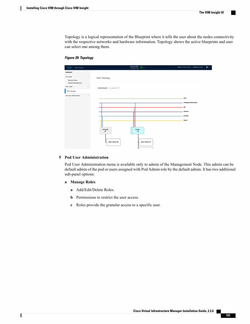
Topology is a logical representation of the Blueprint where it tells the user about the nodes connectivitywith the respective networks and hardware information. Topology shows the active blueprints and usercan select one among them.
Figure 39: Topology
5 Pod User Administration
Pod User Administration menu is available only to admin of the Management Node. This admin can bedefault admin of the pod or users assigned with Pod Admin role by the default admin. It has two additionalsub-panel options:
a Manage Roles:
a Add/Edit/Delete Roles.
b Permissions to restrict the user access.
c Roles provide the granular access to a specific user.
Cisco Virtual Infrastructure Manager Installation Guide, 2.2.6 151
Installing Cisco VIM through Cisco VIM InsightThe VIM Insight UI

d A role cannot be deleted directly if it is associated to an user.
Figure 40: Manage roles
b Manage Users:
a Add/Edit/Delete Users.
b List User name and Email ID for the users registered in the system.
c Roles associated to users.
d The current status of the user (Online and Offline user with Green and Red dot respectively).
e User registration status.
Cisco Virtual Infrastructure Manager Installation Guide, 2.2.6152
Installing Cisco VIM through Cisco VIM InsightThe VIM Insight UI

f Refresh button to get latest information about the users status.
Figure 41: Manage users
c Manage Root CA Certificate:
a Edit existing Root CA Certificate of the Management Node ( Location:/var/www/mercury/mercury-ca.crt)
b You can also download existing certificate from Insight.
c If invalid Certificate is uploaded through Insight then previous working state will be recoveredafter clicking the Upload button.
Cisco Virtual Infrastructure Manager Installation Guide, 2.2.6 153
Installing Cisco VIM through Cisco VIM InsightThe VIM Insight UI

d If Certificate is valid Management Node HEALTH check will be executed.
Figure 42: Manage Root CA Certificate
VIM Insight also have some extra features in the header:
1 User ID and Role - Indicates the User ID and Role of the current user.
2 Management Node Context Switching - User can switch between two or more nodes. (Right in the middlefor the header).
3 Management Node Name and IP Address: Indicates the name and IP address of the management node.4 User Profile - User can change the Password or Logout or change log level between Info and Debug.
Context Switching within InsightOne of the key features in VIM Insight, is that if you have permission for the node you can switch betweentwo or more pods. You can be a Admin for one or more pods, and a normal user for some other pod,simultaneously. Ability to access multiple pods, provides the user to maintain context and yet scale from apod management.
There are two ways that you can switch to another pod:
1 Context Switching Icon: Context Switching Icon is located at the middle of the UI header. ClickManagement Node Context Switching to access all available pods.
2 Switch BetweenManagement Nodes: Switch BetweenManagement Nodes is situated in the Dashboard.You can navigate to any pod by a single click. If the REST password provided during registration of theManagement node does not match the current REST Password for that particular node, the cloud icon atthe middle of the UI header will turn red instead of green. The Pod Admin/User can reach out to UI Adminand ask them to update the password for that node from Manage Nodes in Insight UI Admin Portal.
Cisco Virtual Infrastructure Manager Installation Guide, 2.2.6154
Installing Cisco VIM through Cisco VIM InsightContext Switching within Insight

Configuring OpenStack InstallationBefore You Begin
You need to create a Blueprint (B or C Series) to initiate OpenStack Installation through the VIM.
Step 1 In the Navigation pane, choose Pre-Install > Blueprint Setup.Step 2 To create a B Series Blueprint:
1 On the Blueprint Initial Setup page of the Cisco VIM Insight , complete the following fields:
DescriptionName
Enter blueprint configuration name.Blueprint Name field
Choose one of the following platform types:
• B-Series (By default) choose B series for thissection.
• C-Series
Platform Type drop-down list
Choose one of the following tenant network types:
• Linuxbridge/VXLAN
• OVS/VLAN
Tenant Network drop-down list
Choose one of the following pod types:
• Fullon(By Default)
• Micro
• UMHC
UMHC pod type is only supported forOVS/VLAN tenant type.
Note
Pod type micro is supported for OVS/VLAN,ACI/VLAN,VPP/VLAN.
Note
Pod Type drop-down list
Choose one of the following Ceph types:
• Dedicated
• Central (By Default) - Not supported in Production
Ceph Mode drop-down list
Cisco Virtual Infrastructure Manager Installation Guide, 2.2.6 155
Installing Cisco VIM through Cisco VIM InsightConfiguring OpenStack Installation

DescriptionName
Swiftstack, LDAP, Syslog Export Settings, Install Mode,TorSwitch Information, TLS, Nfvmon, Pod Name,VMTP, Nfvbench, Auto Backup, Heat, Keystone v3
If any one is selected, the corresponding section is visiblein various Blueprint sections.
By default all features are disabled except Auto Backup.
Optional Features and Services Checkbox
Click Browse button to import the existing yaml file.
If you have an existing B Series YAML file you can usethis feature to upload the file.
Insight will automatically fill in the fields and if anymandatory field is missed then it will be highlight it inthe respective section.
Import Existing YAML file
2 Click Physical Setup to navigate to theRegistry Setup configuration page. Fill in the following details for RegistrySetup:
DescriptionName
User-Name for Registry (Mandatory).Registry User Name text field
Password for Registry (Mandatory).Registry Password text field
Email ID for Registry (Mandatory).Registry Email text field
Once all mandatory fields are filled the Validation Check Registry Page will show a Green Tick.
3 Click UCSM Common Tab and complete the following fields:
DescriptionName
By default value is Admin.User name disabled field
Enter Password for UCSM Common (Mandatory).Password text field
Enter IP Address for UCSM Common(Mandatory).UCSM IP text field
Enter the resource prefix(Mandatory).Resource Prefix text field
Choose one of the following types:
• NFVI (Default)
• Media
QOS Policy Type drop-down
Cisco Virtual Infrastructure Manager Installation Guide, 2.2.6156
Installing Cisco VIM through Cisco VIM InsightConfiguring OpenStack Installation

DescriptionName
Select the Max VF Count.
<1-54> Maximum VF count 54, default is 20.
If VF performance is enabled we recommend you to keepMAX_VF_COUNT to 20 else may fail on some VICslike 1240.
Max VF Count text field
Default is false. Set to true to apply adaptor policy at VFlevel.
Enable VF Performance optional checkbox
Default is false.Enable Prov FI PIN optional checkbox
Enables JBOD mode to be set on disks. Applicable onlyif you have RAID controller configured on Storage C240Rack servers.
MRAID-CARD optional checkbox
Visible when Tenant Network type is OVS/VLANEnable UCSM Plugin optional checkbox
Visible only when UCSM Plugin is enabled. If UCSMPlugin is disabled then this option is set to False.
Enable QoS Policy optional checkbox
Visible only when UCSM Plugin is enabled.Enable QOS for Port Profile optional checkbox
Visible when UCSM Plugin is enabled. Enter the valuesfor network and vlans ranges. Grid can handle all CRUDoperations like Add, Delete, Edit and, Multiple Delete.
SRIOV Multi VLAN Trunk optional grid
4 Click Networking to advance to the networking section of the Blueprint:
DescriptionName
Enter the domain name (Mandatory).Domain Name field
If your configuration uses an HTTP proxy server, enterthe IP address of the server.
HTTP Proxy Server field
If your configuration uses an HTTPS proxy server, enterthe IP address of the server.
HTTPS Proxy Server field
Specifies the list of IP Address with Mask.IP Tables on Management Pods
Enter a maximum of four and minimum of one IPv4 and/or IPv6 addresses in the table.
NTP Server
Enter a maximum of three and minimum of one IPv4and/or IPv6 addresses.
Domain Name Server
Cisco Virtual Infrastructure Manager Installation Guide, 2.2.6 157
Installing Cisco VIM through Cisco VIM InsightConfiguring OpenStack Installation

DescriptionName
Network table
Cisco Virtual Infrastructure Manager Installation Guide, 2.2.6158
Installing Cisco VIM through Cisco VIM InsightConfiguring OpenStack Installation

DescriptionName
Network table is pre-populated with segments. To addNetworks you can either clear all the table using DeleteAll or click Edit icon for each segment and fill in thedetails.
You can add, edit, or delete network information in thetable:
• Click + to enter new entries (networks) to the table.
• Specify the following fields in the Edit Entry toNetworks dialog box.
DescriptionName
Enter the VLAN ID.VLAN field
For Segment - Provider,the VLAN ID value isalways "none".
You can select any onesegment from thedropdown list.
Segment drop-down list
• API
• Management/Provision
• Tenant
• CIMC
• Storage
• External
• Provider (optional)
Some segmentsdo not need some
Note
of the valueslisted in thepreceding points.
Enter the IPv4 address forthe subnet.
Subnet field
Enter IPv6 address. Thisfield will be available only
IPv6 Subnet field
forManagement provisionand API.
Cisco Virtual Infrastructure Manager Installation Guide, 2.2.6 159
Installing Cisco VIM through Cisco VIM InsightConfiguring OpenStack Installation

DescriptionName
DescriptionName
Gateway field Enter the IPv4 address forthe Gateway.
Enter IPv6 gateway. Thisfield will only availableonly for Managementprovision and APInetwork.
IPv6 Gateway field
Enter the pool informationin the required format, forexample: 10.30.1.1 or10.30.1.1 to 10.30.1.12
Pool field
Enter the pool informationin the required format, forexample:10.1.1.5-10.1.1.10,10.2.1.5-10.2.1.10
This field is only availablefor the Mgmt/Provision.
IPv6 Pool field
Click Save.
5 On the Servers and Roles page of the Cisco VIM Suite wizard, you will see a pre-populated table filled with Roles:Control, Compute and Block Storage (Only if CEPH Dedicated is selected in Blueprint Initial Setup.
DescriptionName
Enter the username of the server.Server User Name field
Default value is false. You can set it as true or false.Disable Hyperthreading
Cisco Virtual Infrastructure Manager Installation Guide, 2.2.6160
Installing Cisco VIM through Cisco VIM InsightConfiguring OpenStack Installation

DescriptionName
Enter the Cobbler details in the following fields:
DescriptionName
The default value is 45min.
This is an optionalparameter. Timeout isdisplayed in minutes, andits value ranges from 30 to120.
Cobbler Timeout field
Kickstart file for StorageNode.
Block Storage Kickstartfield
Enter the AdminPassword. Passwordshould be Alphanumeric.Password should containminimum 8 characters andmaximumof 32 characters.
Admin Password Hashfield
Enter the cobblerusername to access thecobbler server.
Cobbler Username field
Kickstart file for ControlNode.
Control Kickstart field
Kickstart file for ComputeNode.
Compute Kickstart field
Enter the admin usernameof the Cobbler.
Cobbler AdminUsername field
Cobbler
Cisco Virtual Infrastructure Manager Installation Guide, 2.2.6 161
Installing Cisco VIM through Cisco VIM InsightConfiguring OpenStack Installation

DescriptionName
Click Edit or + to add a new server and role to the table.
Enter a server nameServer Name
Choose Blade or Rackfrom the drop-down list.
Server Type drop-downlist
The Rack ID for theserver.
Rack ID
Enter a Chassis ID.Chassis ID
Enter a Rack Unit ID.If Rack is chosen, theRack Unit ID field isdisplayed.
Enter a Blade ID.If Blade is chosen, theBlade ID field isdisplayed.
If Server type is Bladethen select Control andCompute. If server isRack then select BlockStorage.
Select the Role from thedrop-down list.
It is an optional field but ifprovided for one serverthen it is mandatory toprovide details for otherServers as well.
Management IP
Enter the ManagementIPv6 Address.
Management IPv6
Click Save.
Add Entry to Servers and Roles
6 Click ToR Switch checkbox in Blueprint Initial Setup to enable the TOR SWITCH configuration page. It is anOptional section in Blueprint Setup but once all the fields are filled it is a part of the Blueprint.
DescriptionName
Enabling this checkbox, changes the configure ToR sectionfrom false to true.
Configure ToR optional checkbox.
Cisco Virtual Infrastructure Manager Installation Guide, 2.2.6162
Installing Cisco VIM through Cisco VIM InsightConfiguring OpenStack Installation

DescriptionName
Click (+) to add information for ToR Switch.
DescriptionName
ToR switch hostname.Hostname
ToR switch username.Username
Tor switch password.Password
ToR switch SSH IPAddress.SSH IP
ToR switch ssn num.SSN Num
Peer Management IP. Youdo not define if there is nopeer.
VPC Peer Keepalive
Do not define if peer isabsent.
VPC Domain
Interface for vpc peer ports.VPC Peer Port Info
Management interface ofmanagement node.
BRManagement Port Info
Port channel number formanagement interface ofmanagement node.
BR Management PO Info
ClickSave.
ToR Switch Information mandatory table.
Enter the Port Channel input.Port Channel field.On clicking save button, Add ToR Info Connectedto Fabric field will be visible.
Enter the Port number.Switch Name field.
7 Click OpenStack Setup tab to advance to the OpenStack Setup Configuration page.
8 On the OpenStack Setup page of the Cisco VIM Insight wizard, complete the following fields:
Cisco Virtual Infrastructure Manager Installation Guide, 2.2.6 163
Installing Cisco VIM through Cisco VIM InsightConfiguring OpenStack Installation

DescriptionName
Fill in the following details:
Enter IP address of ExternalVIP.
External VIP Addressfield
Enter IPv6 address ofExternal VIP.
ExternalVIPAddress IPv6field
Enter the Router ID for HA.Virtual Router ID field
Enter IPv6 address ofInternal IP.
Internal VIPAddress IPv6field
Enter IP address of InternalVIP.
Internal VIPAddress field
HA Proxy
Pre-populated field values. This option would always be true.
adminAdmin Username field
adminAdmin Tenant Name field
Keystone
Cisco Virtual Infrastructure Manager Installation Guide, 2.2.6164
Installing Cisco VIM through Cisco VIM InsightConfiguring OpenStack Installation

DescriptionName
This is available only when Keystone v3 and LDAP both areenabled under Optional Features and Services in BlueprintInitial Setup.
Enter name for Domainname.
Domain Name field
Enter a string as input.Object Class for Users field
Enter a string.Object Class forGroupsfield
Enter a string.Domain Name Tree forUsers field
Enter a string.Domain Name Tree forGroups field
Enter a string.Suffix for Domain Namefield
Enter a URL with endingport number.
URL field
Enter a string.DomainName of bind userfield
Enter Password as stringformat.
Password field
Enter filter name as string.User Filter field
Enter a string.User ID Attribute field
Enter a string.User Name Attribute field
Enter a string.User Mail Attribute field
Enter a string.Group Name Attributefield
LDAP (Only if Keystonev3 is enabled)
This option is only available with Keystonev3
Note
Cisco Virtual Infrastructure Manager Installation Guide, 2.2.6 165
Installing Cisco VIM through Cisco VIM InsightConfiguring OpenStack Installation

DescriptionName
Neutron fields would change on the basis ofTenant NetworkType Selection fromBlueprint Initial Setup. Following arethe options available for Neutron for OVS/VLAN:
Auto Filled based on theTenant Network Typeselected in the BlueprintInitial Setup page.
Tenant Network Typefield
Auto Filled based on theTenant Network Typeselected in Blueprint InitialSetup page.
Mechanism Drivers field
Auto filled with theCompute you added inServer and Roles.
If you select All in thissectionNFV_HOSTS:ALLwill be added to theBlueprint or you can selectone particular compute. ForEg:
NFV_HOSTS:compute-server-1,compute-server-2.
NFV Hosts field
List of ranges separated bycomma form start:end.
Tenant VLANRanges field
List of ranges separated bycomma form start:end.
Provider VLAN Rangesfield
2M or 1GVM Hugh Page Size(available forNFV_HOSTS option) field
Enable the checkboxEnable Jumbo Framesfield
For Tenant Network Type Linux Bridge everything remainsthe same but Tenant VLAN Ranges will be removed.
Neutron
Cisco Virtual Infrastructure Manager Installation Guide, 2.2.6166
Installing Cisco VIM through Cisco VIM InsightConfiguring OpenStack Installation

DescriptionName
Ceph has two pre-populated fields
• CEPHMode : By default Dedicated.
• NOVA Boot from: Drop Down selection. You canchoose Ceph or local.
CEPH
By default populated for CEPH Dedicated with StoreBackend value as CEPH.
GLANCE
By default Populated for CEPH Dedicated with VolumeDriver value as CEPH.
CINDER
Cisco Virtual Infrastructure Manager Installation Guide, 2.2.6 167
Installing Cisco VIM through Cisco VIM InsightConfiguring OpenStack Installation

DescriptionName
VMTPVMTP optional section will only be visible onceVMTP is selected from Blueprint Initial Setup.
Cisco Virtual Infrastructure Manager Installation Guide, 2.2.6168
Installing Cisco VIM through Cisco VIM InsightConfiguring OpenStack Installation

DescriptionName
Check one of the check boxes to specify a VMTP network:
• Provider Network
• External Network
For the Provider Network complete the following:
Enter the name for theexternal network.
Network Name field
Enter the Subnet forProvider Network.
Subnet field
Enter the starting floatingIPv4 address.
Network IP Start field
Enter the ending floatingIPv4 address.
Network IP End field
Enter the IPv4 address forthe Gateway.
Network Gatewayfield
Enter the DNS server IPv4address.
DNS Server field
Enter the segmentation ID.Segmentation ID field
For External Network fill in the following details:
Enter the name for theexternal network.
Network Name field
Enter the Subnet for ExternalNetwork.
Subnet field
Enter the starting floatingIPv4 address.
Network IP Start field
Enter the ending floatingIPv4 address.
Network IP End field
Enter the IPv4 address forthe Gateway.
Network Gateway field
Enter the DNS server IPv4address.
DNS Server field
Cisco Virtual Infrastructure Manager Installation Guide, 2.2.6 169
Installing Cisco VIM through Cisco VIM InsightConfiguring OpenStack Installation
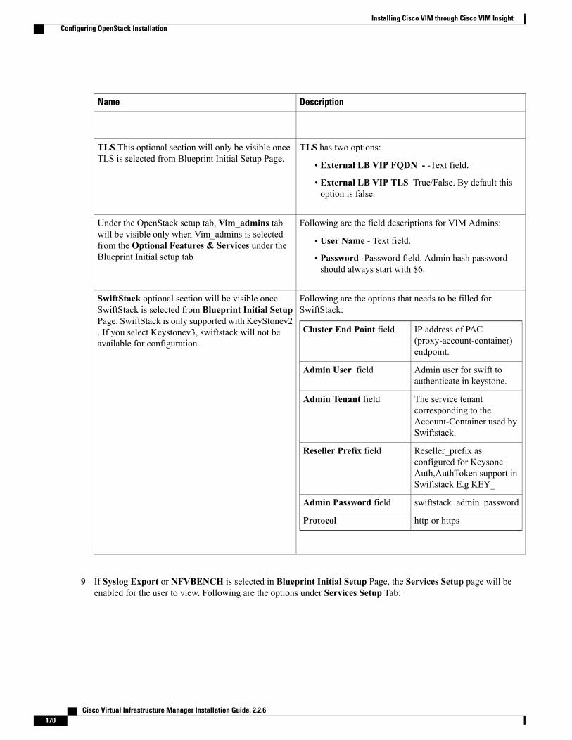
DescriptionName
TLS has two options:
• External LB VIP FQDN - -Text field.
• External LB VIP TLS True/False. By default thisoption is false.
TLS This optional section will only be visible onceTLS is selected from Blueprint Initial Setup Page.
Following are the field descriptions for VIM Admins:
• User Name - Text field.
• Password -Password field. Admin hash passwordshould always start with $6.
Under the OpenStack setup tab, Vim_admins tabwill be visible only when Vim_admins is selectedfrom the Optional Features & Services under theBlueprint Initial setup tab
Following are the options that needs to be filled forSwiftStack:
IP address of PAC(proxy-account-container)endpoint.
Cluster End Point field
Admin user for swift toauthenticate in keystone.
Admin User field
The service tenantcorresponding to theAccount-Container used bySwiftstack.
Admin Tenant field
Reseller_prefix asconfigured for KeysoneAuth,AuthToken support inSwiftstack E.g KEY_
Reseller Prefix field
swiftstack_admin_passwordAdmin Password field
http or httpsProtocol
SwiftStack optional section will be visible onceSwiftStack is selected from Blueprint Initial SetupPage. SwiftStack is only supported with KeyStonev2. If you select Keystonev3, swiftstack will not beavailable for configuration.
9 If Syslog Export or NFVBENCH is selected in Blueprint Initial Setup Page, the Services Setup page will beenabled for the user to view. Following are the options under Services Setup Tab:
Cisco Virtual Infrastructure Manager Installation Guide, 2.2.6170
Installing Cisco VIM through Cisco VIM InsightConfiguring OpenStack Installation

DescriptionName
Following are the options for Syslog Settings:
Enter Syslog IP address.Remote Host
Only UDP is supported.Protocol
Defaults to local5.Facility
Defaults to debug.Severity
Defaults to ELK.Clients
Defaults to 514 but can bemodified by the User.
Port
Syslog Export
NFVBENCH enable checkbox which by default is false.
Add ToR information connected to switch:
• Select a TOR Switch and enter the Switch name.
• Enter the port number. For example:eth1/5. VTEPVLANS(mandatory and needed only for VXLAN): Enter 2 differentVLANs for VLAN1 and VLAN2
• NIC Ports: INT1 and INT2 optional input. Enter the 2 portnumbers of the 4-port 10G Intel NIC at the managementnode used for NFVBench.
NFVBENCH
Step 3 To create a C Series Blueprint:
1 On the Blueprint Initial Setup page of the Cisco VIM Insight, complete the following fields:DescriptionName
Enter the name for the blueprint configuration.Blueprint Name field.
Choose one of the following platform types:
• B-Series (By default)
• C-Series ( Select C Series)
Platform Type drop-down list
Cisco Virtual Infrastructure Manager Installation Guide, 2.2.6 171
Installing Cisco VIM through Cisco VIM InsightConfiguring OpenStack Installation

DescriptionName
Choose one of the following tenant network types:
• Linux Bridge/VXLAN
• OVS/VLAN
• VTS/VLAN
• VPP/VLAN
• ACI/VLAN
when VTS/VLAN or ACI/VLAN is selectedthen respective tabs are available on Blueprintsetup.
Note
Tenant Network drop-down list
Choose one of the following pod type :
• Fullon(By Default)
• Micro
• UMHC
UMHC pod type is only supported forOVS/VLAN tenant type.
Note
Pod type micro is supported for OVS/VLAN,ACI/VLAN,VPP/VLAN.
Note
Pod Type drop-down list
Choose one of the following Ceph types:
• Dedicated (By Default)
• Central. Central is not supported in Production
Ceph Mode drop-down list
Swiftstack, LDAP, Syslog Export Settings, Install Mode,TorSwitch Information, TLS, NFVMON, Pod Name,VMTP, NFVBench, Autbackup, Heat, Keystone v3
If any one is selected, the corresponding section is visiblein various Blueprint sections.
By default all features are disabled except Auto Backup.
Optional and Services Features checkbox
If you have an existing C Series YAML file you can usethis feature to upload the file.
Insight will automatically fill in the fields and any missedmandatory field will be highlighted in the respectivesection.
Import Existing YAML file
2 Click Physical Setup to advance to the Registry Setup configuration page. Fill in the following details for RegistrySetup:
Cisco Virtual Infrastructure Manager Installation Guide, 2.2.6172
Installing Cisco VIM through Cisco VIM InsightConfiguring OpenStack Installation

DescriptionName
User-Name for Registry (Mandatory).Registry User Name text field
Password for Registry (Mandatory).Registry Password text field
Email ID for Registry (Mandatory).Registry Email text field
Once all the mandatory fields are filled the Validation Check Registry Page will be changed to a Green Tick.
3 Click CIMC Common Tab and complete the following fields:
DescriptionName
By default value is Admin.User Name disabled field
Enter Password for UCSM Common (Mandatory).Password text field
4 Click Networking to advance to the networking section of the Blueprint.
DescriptionName
Enter the domain name. (Mandatory)Domain Name field
If your configuration uses an HTTP proxy server, enterthe IP address of the server.
HTTP Proxy Server field
If your configuration uses an HTTPS proxy server, enterthe IP address of the server.
HTTPS Proxy Server field
Specifies the list of IP Address with Mask.IP Tables on Management Pods
Enter a maximum of four and minimum of one IPv4and/or IPv6 addresses in the table.
NTP Servers field
Enter a maximum of three and minimum of one IPv4and/or IPV6 addresses.
Domain Name Servers field
Cisco Virtual Infrastructure Manager Installation Guide, 2.2.6 173
Installing Cisco VIM through Cisco VIM InsightConfiguring OpenStack Installation

DescriptionName
Networks table
Cisco Virtual Infrastructure Manager Installation Guide, 2.2.6174
Installing Cisco VIM through Cisco VIM InsightConfiguring OpenStack Installation

DescriptionName
Network table is pre-populated with Segments. To addNetworks you can either clear all the table with Deleteall or click edit icon for each segment and fill in thedetails.
You can add, edit, or delete network information in thetable.
• Click Add (+) to add new entries (networks) to thetable.
• Specify the following fields in the Edit Entry toNetworks dialog:
DescriptionName
Enter the VLAN ID.VLAN field
For Segment - Provider,the VLAN ID value is'none'.
When you add/edit newsegment then following
Segment drop-down list
segments types areavailable in the form ofdropdown list and you canselect only one.
• API
• Management/provision
• Tenant
• Storage
• External
• Provider
• ACIINFRA
Aciinfra segmentis available only
Note
when ACI/VLANtenant type isselected)Depending uponthe segment someof the entriesbelow are notneeded. Please
Cisco Virtual Infrastructure Manager Installation Guide, 2.2.6 175
Installing Cisco VIM through Cisco VIM InsightConfiguring OpenStack Installation

DescriptionName
refer to theexample file inopenstack-configsdir for details.
Enter the IPv4 address forthe subnet.
Subnet field
Enter IPv6 Address. Thisfield will be available onlyforManagement provisionand API
IPv6 Subnet field
Enter the IPv4 address forthe Gateway.
Gateway field
Enter the IPv6 address forthe gateway. This willsupport for API andmanagement provision.
Gateway IPv6 field
Enter the pool informationin the required format, forexample:10.1.1.5-10.1.1.10,10.2.1.5-10.2.1.10
This field is available onlyfor the Mgmt/Provision,Storage, and Tenantsegments.
Pool field
Enter the pool informationin the required format. Forexample:10.1.1.5-10.1.1.10,10.2.1.5-10.2.1.10
IPv6 Pool field
Click Save.
5 On the Servers and Roles page of the Cisco VIM Suite wizard, a pre-populated table filled with Roles : Control,Compute and Block Storage (Only if CEPH Dedicated is selected in Blueprint Initial Setup is available.
DescriptionName
Enter the username of the Server.Server User Name field
Cisco Virtual Infrastructure Manager Installation Guide, 2.2.6176
Installing Cisco VIM through Cisco VIM InsightConfiguring OpenStack Installation

DescriptionName
Default value is false. You can set it as true or false.Disable Hyperthreading
Enter the Cobbler details in the following fields:
DescriptionName
The default value is 45 min.
This is an optionalparameter. Timeout isdisplayed in minutes, and itsvalue ranges from 30 to 120.
Cobbler Timeout field
Kickstart file for StorageNode.
Block Storage Kickstartfield
Enter the Admin Password.Password should beAlphanumeric. Passwordshould contain minimum 8characters and maximum of32 characters.
Admin Password Hashfield
Enter the cobbler usernameto access the cobbler server.
Cobbler Username field
Kickstart file for ControlNode.
Control Kickstart field
Kickstart file for ComputeNode.
Compute Kickstart field
Enter the admin usernameof the Cobbler.
CobblerAdminUsernamefield
Cobbler
Cisco Virtual Infrastructure Manager Installation Guide, 2.2.6 177
Installing Cisco VIM through Cisco VIM InsightConfiguring OpenStack Installation
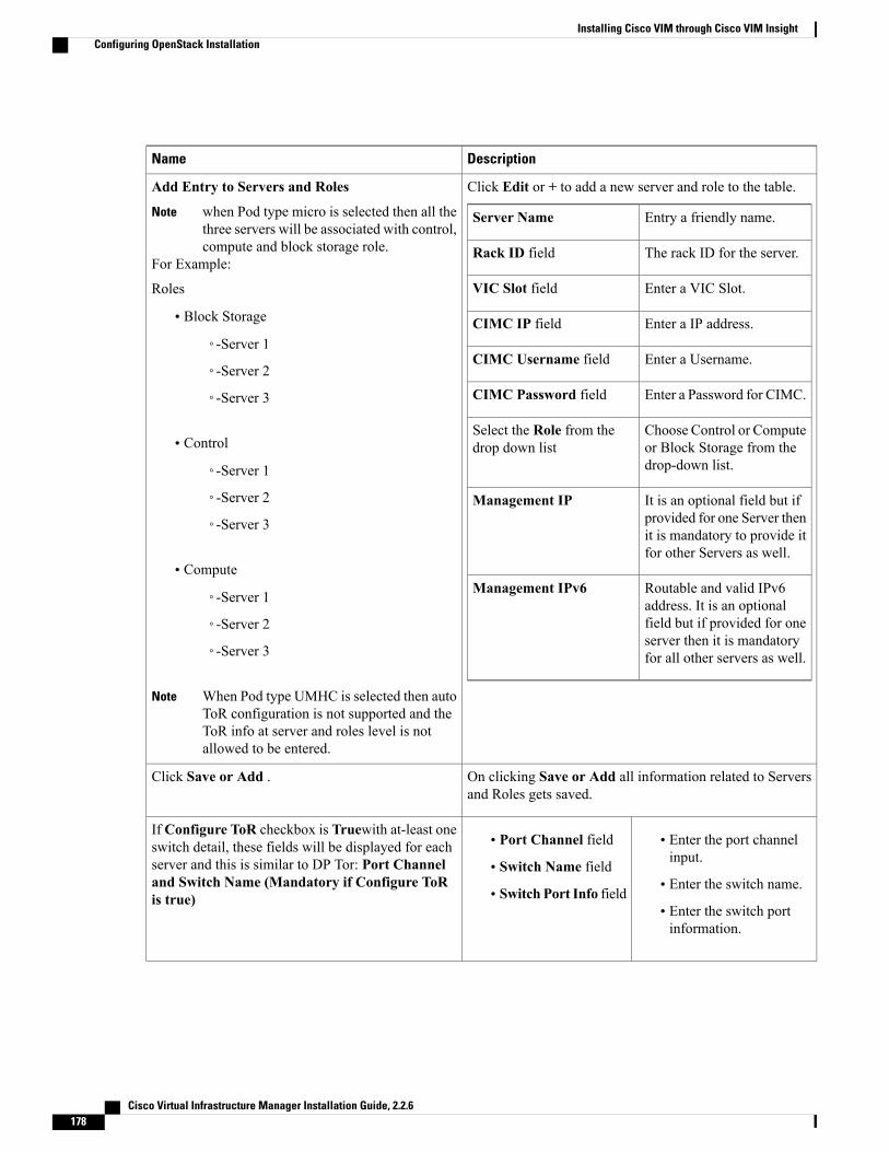
DescriptionName
Click Edit or + to add a new server and role to the table.
Entry a friendly name.Server Name
The rack ID for the server.Rack ID field
Enter a VIC Slot.VIC Slot field
Enter a IP address.CIMC IP field
Enter a Username.CIMC Username field
Enter a Password for CIMC.CIMC Password field
Choose Control or Computeor Block Storage from thedrop-down list.
Select the Role from thedrop down list
It is an optional field but ifprovided for one Server thenit is mandatory to provide itfor other Servers as well.
Management IP
Routable and valid IPv6address. It is an optionalfield but if provided for oneserver then it is mandatoryfor all other servers as well.
Management IPv6
Add Entry to Servers and Roles
when Pod type micro is selected then all thethree servers will be associated with control,compute and block storage role.
Note
For Example:
Roles
• Block Storage
◦-Server 1
◦-Server 2
◦-Server 3
• Control
◦-Server 1
◦-Server 2
◦-Server 3
• Compute
◦-Server 1
◦-Server 2
◦-Server 3
When Pod type UMHC is selected then autoToR configuration is not supported and theToR info at server and roles level is notallowed to be entered.
Note
On clicking Save or Add all information related to Serversand Roles gets saved.
Click Save or Add .
• Enter the port channelinput.
• Enter the switch name.
• Enter the switch portinformation.
• Port Channel field
• Switch Name field
• Switch Port Info field
If Configure ToR checkbox is Truewith at-least oneswitch detail, these fields will be displayed for eachserver and this is similar to DP Tor: Port Channeland Switch Name (Mandatory if Configure ToRis true)
Cisco Virtual Infrastructure Manager Installation Guide, 2.2.6178
Installing Cisco VIM through Cisco VIM InsightConfiguring OpenStack Installation

DescriptionName
• Enter the port channelinput.
• Enter the switch name.
• Enter the switch portinformation.
• Port Channel field
• Switch Name field
• Switch Port Info field
DP ToR (Only for Control and Compute) : Mandatoryif Intel NIC and Configure TOR is True.
• Enter the switch name.
• Enter the switch portinformation.
• Switch Name field
• Switch Port Info field
SRIOV TOR INFO (Only for Compute Nodes). Itis mandatory in server and roles if Intel NIC andConfigure TOR is True. Switch Name (Mandatoryif Configure ToR is true). This field appears onlywhen Intel NIC support is true, as Auto TOR configis not supported in VIC_NIC combo
For SRIOV support for Intel NIC. By Default, SRIOVsupport is disabled. To enable, define a value in the range #* 1-32when INTEL_NIC_SUPPORT is set True (X710MaxVFs = 32) # * 1-63 when CISCO_VIC_INTEL_SRIOV isset True (X520 Max VFs = 63)
Intel SRIOV VFS (valid for Intel NIC testbeds) andcan be integer.
In some cases the # of Physical SRIOV port needed is 4; tomeet that requirement, define the following: # this is optional,if nothing is defined code will assume it to be 2; the only 2integer values this parameter # takes is 2 or 4 and is truewhen INTEL_NIC_SUPPORT is True andINTEL_SRIOV_VFS is valid
INTEL_SRIOV_PHYS_PORTS (valid for Intel NICtest beds) and can be of value 2 or 4 (default is 2)
If all mandatory fields are filled click Save or Add to addinformation on Servers and Roles.
Click Save or Add .
Default value is false. You can set it as true or false.Disable Hyperthreading
Click Save
Maximum two ToR info needs to be configured for each connection type on each node (control, computeand block_storage node).
Note
If pod type UMHC is selected then CISCO_VIC_INTEL_SRIOV is enabled to be TRUE.Note
For Tenant type ACI/VLAN, port channel for each ToR port will not be available in servers and roles, asAPIC will automatically assign port-channel numbers.
Note
6 Click ToR Switch checkbox in Blueprint Initial Setup to enable the TOR SWITCH configuration page. It is anOptional section in Blueprint Setup but once all the fields are filled in then it will become a part of the Blueprint.
Cisco Virtual Infrastructure Manager Installation Guide, 2.2.6 179
Installing Cisco VIM through Cisco VIM InsightConfiguring OpenStack Installation

DescriptionName
Enabling this checkbox, changes the configure ToR section fromfalse to true.
Configure tor is true then ToR switch info maps in serversNote
Configure ToR optional checkbox.
If UMHC is selected as podtype,configure TOR is not allowed.
Note
Click (+) to add information for ToR Switch.
DescriptionName
ToR switch name.Name
ToR switch username.Username
ToR switch password.Password
ToR switch SSH IP.SSH IP
ToR switch ssn num.SSN Num
Peer Management IP. Youcannot define if there is nopeer.
VPC Peer Keepalive
Cannot define if there is nopeer.
VPC Domain
Interface for vpc peer ports.VPC Peer Port Info
VLAN ids for vpc peer ports(optional).
VPC Peer VLAN Info
Management interface of buildnode.
BR Management Port Info
Port channel number formanagement interface of buildnode.
BR Management PO Info
VLAN id for managementinterface of build node(access).
BRManagement VLAN info
ToR Switch Information mandatory table ifyou want to enter ToR information.
Click Save.
When tenant type ACI/VLAN is selected, the TOR switch information table differs and is mandatory.Note
Cisco Virtual Infrastructure Manager Installation Guide, 2.2.6180
Installing Cisco VIM through Cisco VIM InsightConfiguring OpenStack Installation

DescriptionName
Enabling this checkbox, changes the configure ToR section fromfalse to true.
Configure tor is true then ToR switch info maps in serversNote
Configure ToR optional checkbox.
If UMHC is selected as podtype,configure TOR is not allowed.
Note
Click (+) to add information for ToR Switch.
DescriptionName
ToR switch name.Name
ToR switch username.Username
ToR switch password.Password
ToR switch SSH IP.SSH IP
ToR switch ssn num.SSN Num
Peer Management IP. Youcannot define if there is nopeer.
VPC Peer Keepalive
Cannot define if there is nopeer.
VPC Domain
Interface for vpc peer ports.VPC Peer Port Info
VLAN ids for vpc peer ports(optional).
VPC Peer VLAN Info
Management interface of buildnode.
BR Management Port Info
Port channel number formanagement interface of buildnode.
BR Management PO Info
VLAN id for managementinterface of build node(access).
BRManagement VLAN info
ToR Switch Information mandatory table ifyou want to enter ToR information.
Click Save.
When the Tenant type ACI/VLAN is selected, the ToR switch information table differs and is mandatory.Note
Cisco Virtual Infrastructure Manager Installation Guide, 2.2.6 181
Installing Cisco VIM through Cisco VIM InsightConfiguring OpenStack Installation

DescriptionName
Is not checked, as by default ACI will configure the ToRs
ToR switch name.Host Name
Enter Peer must be existpair.
VPC Peer keep alive
Enter an integer.VPC Domain
Enter BR managementport info eg. Eth1/19,atleast one pair to be exist.
BR management portinfo
Entered integer must beunique.
Enter Node ID
Configure ToR
If TOR_TYPE is selected as NCS-5500, the TOR switch information table differs and is mandatory.Note
DescriptionName
Enabling this checkbox, changes the configure ToRsection from false to true.
Configure TOR is true then ToR switchinfomaps in servers.
Note
Configure ToR optional checkbox
If NSC-5500 is selected as TOR_TYPE,configure TOR is set as mandatory.
Note
Cisco Virtual Infrastructure Manager Installation Guide, 2.2.6182
Installing Cisco VIM through Cisco VIM InsightConfiguring OpenStack Installation

DescriptionName
Click (+) to add information for Fretta Switch.
DescriptionName
Enter the NCS-5500hostname.
Name
Enter the NCS-5500username.
User Name
Enter the NCS-5500password.
Password
Enter the NCS-5500 ssh IPAddress.
SSH IP
Peer management IP.VPC Peer Link
Port channel number formanagement interface ofbuild node.
BRManagementPO Info
VLAN id for managementinterface of build node(access).
BR Management VLANinfo
Interface for vpc peerports.
VPC Peer Port Info
Address for ISISexchange.
VPC Peer Port Address
ISIS loopack IP Address.ISIS Loopback Interfaceaddress
Enter a String.ISIS net entity title
Integer between 16000 to1048575.
ISIS prefix SID
If you want to enter Fretta details fill in the NCS-5500Information table.
When TOR-TYPE selected as NCS-5500 and 2 NCS-5500 are configured it is mandatory to configureMULTI_SEGMENT_ROUTING_INFO
DescriptionName
Integer between 1 to 65535.BGP AS Number field
Cisco Virtual Infrastructure Manager Installation Guide, 2.2.6 183
Installing Cisco VIM through Cisco VIM InsightConfiguring OpenStack Installation

DescriptionName
A valid string.ISIS Area Tagfield
Loopback Interface name.Loopback Interface namefield
Integer between 1 to 65535.API bundle IDfield
String (Optional, only needed when br_api of mgmt nodeis also going through NCS-5500; this item andapi_bundle_id are mutually exclusive).
API bridge domain field
A valid string (user pre-provisions physical, bundleinterface, sub-interface and external BD for externaluplink and provides external BD info setup_data).
EXT bridge domain field
7 Click OpenStack Setup Tab to advance to the OpenStack Setup Configuration page.
8 On the OpenStack Setup Configuration page of the Cisco VIM Insight wizard, complete the following fields:
DescriptionName
Fill in the following details:
Enter IP address of ExternalVIP.
External VIP Address field
Enter IPv6 address of ExternalVIP.
External VIP Address IPv6field
Enter the Router ID for HA.Virtual Router ID field
Enter IPv6 address of InternalIP.
Internal VIP Address IPv6field
Enter IP address of InternalVIP.
Internal VIP Address field
HA Proxy
Mandatory fields are pre-populated.
admin.Admin User Name
admin.Admin Tenant Name
Keystone
Cisco Virtual Infrastructure Manager Installation Guide, 2.2.6184
Installing Cisco VIM through Cisco VIM InsightConfiguring OpenStack Installation

DescriptionName
LDAP enable checkbox which by default is false, if LDAP isenabled on keystone.
Enter name for Domain name.Domain Name field
Enter a string as input.Object Class for Users field
Enter a string.Object Class for Groupsfield
Enter a string.DomainNameTree forUsersfield
Enter a string.Domain Name Tree forGroups field
Enter a string.Suffix forDomainName field
Enter a URL with ending portnumber.
URL field
Enter a string.Domain Name of Bind Userfield
Enter Password as stringformat.
Password field
Enter filter name as string.User Filter field
Enter a string.User ID Attribute field
Enter a string.User Name Attribute field
Enter a string.User Mail Attribute field
Enter a string.Group Name Attribute field
LDAP
Cisco Virtual Infrastructure Manager Installation Guide, 2.2.6 185
Installing Cisco VIM through Cisco VIM InsightConfiguring OpenStack Installation

DescriptionName
Neutron fields would change on the basis of Tenant NetworkType Selection from Blueprint Initial Setup. Following are theoptions available for Neutron for OVS/VLAN:
Auto Filled based on theTenant Network Type selectedin the Blueprint Initial Setuppage.
Tenant Network Type field
Auto Filled based on theTenant Network Type selectedin Blueprint Initial Setup page.
Mechanism Drivers field
Auto filled with the Computeyou added in Server and Roles.
If you select All in this sectionNFV_HOSTS: ALL will beadded to the Blueprint or youcan select one particularcompute. For Eg:
NFV_HOSTS:compute-server-1,compute-server-2.
NFV Hosts field
List of ranges separated bycomma form start:end.
Tenant VLAN Ranges field
List of ranges separated bycomma form start:end.
ProviderVLANRanges field
2M or 1GVM Hugh Page Size(available for NFV_HOSTSoption) field
Enable the checkboxEnable Jumbo Frames field
For Tenant Network Type Linux Bridge everything remains thesame but Tenant VLAN Ranges will be removed.
Neutron
Ceph has two pre-populated fields:
• CEPHMode : By default Dedicated.
• NOVA Boot: From drop down selection you can chooseCeph or local.
CEPH
Cisco Virtual Infrastructure Manager Installation Guide, 2.2.6186
Installing Cisco VIM through Cisco VIM InsightConfiguring OpenStack Installation

DescriptionName
By default Populated forCEPHDedicatedwith Store Backendvalue as CEPH.
GLANCE
By default Populated forCEPHDedicatedwithVolumeDrivervalue as CEPH.
CINDER
Cisco Virtual Infrastructure Manager Installation Guide, 2.2.6 187
Installing Cisco VIM through Cisco VIM InsightConfiguring OpenStack Installation

DescriptionName
VMTP optional section, this will be visible onlyif VMTP is selected fromBlueprint Initial Setup.For VTS tenant type Provider network is onlysupported.
Cisco Virtual Infrastructure Manager Installation Guide, 2.2.6188
Installing Cisco VIM through Cisco VIM InsightConfiguring OpenStack Installation

DescriptionName
Check one of the check boxes to specify a VMTP network:
• Provider Network
• External Network
For the Provider Network complete the following:
Enter the name for the externalnetwork.
Network Name field
Enter the Subnet for ProviderNetwork.
Subnet field
Enter the starting floating IPv4address.
Network IP Start field
Enter the ending floating IPv4address.
Network IP End field
Enter the IPv4 address for theGateway.
Network Gatewayfield
Enter the DNS server IPv4address.
DNS Server field
Enter the segmentation ID.Segmentation ID field
For External Network fill in the following details:
Enter the name for the externalnetwork.
Network Name field
Enter the starting floating IPv4address.
IP Start field
Enter the ending floating IPv4address.
IP End field
Enter the IPv4 address for theGateway.
Gateway field
Enter the DNS server IPv4address.
DNS Server field
Enter the Subnet for ExternalNetwork.
Subnet field
Cisco Virtual Infrastructure Manager Installation Guide, 2.2.6 189
Installing Cisco VIM through Cisco VIM InsightConfiguring OpenStack Installation

DescriptionName
TLS has two options:
• External LB VIP FQDN - Text Field.
• External LBVIP TLS - True/False. By default this optionis false.
TLS optional section, this will be visible only ifTLS is selected fromBlueprint Initial Setup Page.
Following are the options that needs to be filled for SwiftStack:
IP address of PAC(proxy-account-container)endpoint.
Cluster End Point
Admin user for swift toauthenticate in keystone.
Admin User
The service tenantcorresponding to theAccount-Container used bySwiftstack.
Admin Tenant
Reseller_prefix as configuredfor Keysone Auth,AuthTokensupport in Swiftstack E.gKEY_
Reseller Prefix
swiftstack_admin_passwordAdmin Password
http or httpsProtocol
SwiftStack optional section will be visible onlyif SwiftStack is selected from Blueprint InitialSetup Page. SwiftStack is only supported withKeyStonev2. If you select Keystonev3,swiftstack will not be available to configure.
When the Tenant type ACI/VLAN is selected then ACIINFO tab is available in blueprint setup.Note
Cisco Virtual Infrastructure Manager Installation Guide, 2.2.6190
Installing Cisco VIM through Cisco VIM InsightConfiguring OpenStack Installation

WhenACI/VLAN is selected then ToR switch from initial setup is mandatory.
DescriptionName
Note
Enter host input. Example:<ip1|host1>:[port] . max of 3, min of1, not 2;
APIC Hosts field
Enter a string format.apic_username field
Enter Password.apic_password filed
Enter input as string. Max length 8.apic_system_id field
Enter string max length 6.apic_resource_prefix field
Allowed only 10.0.0.0/16apic_tep_address_ pool field
Allowed only 225.0.0.0/15multiclass_address_pool field
Enter integer(1- 65535)apic_pod_id field
Enter String, max length 32apic_installer_tenant field
Enter String, max length 32apic_installer_vrf field
Enter String, max length 32api_l3out_network field
DescriptionNameNote
True or false default is false.VTS Day0 (checkbox)
Enter as string does not containspecial characters.
VTS User name
Enter passwordVTS Password
Enter IP Address format.VTS NCS IP
Enter a stringVTC SSH Username
Enter passwordVTC SHH Password
When Tenant Type is VTS/VLAN then VTS tab is available in blueprint setup.If vts day0 is enabled then SSH username and SSH password is mandatory.
If SSH_username is input present then SSH password is mandatory vice-versa
Note
Cisco Virtual Infrastructure Manager Installation Guide, 2.2.6 191
Installing Cisco VIM through Cisco VIM InsightConfiguring OpenStack Installation

9 If Syslog Export or NFVBENCH is selected in Blueprint Initial Setup Page, then Services Setup page will beenabled for user to view. Following are the options under Services Setup Tab:
DescriptionName
Following are the options for Syslog Settings:
Enter Syslog IP Address.Remote Host
Supports only UDP.Protocol
Defaults to local5.Facility
Defaults to debug.Severity
Defaults to ELK.Clients
Defaults to 514 but can be modified bythe User.
Port
Syslog Export
NFVBENCH enable checkbox by default isfalse.
Add ToR information connect to Switch:
• Select a TOR Switch and enter the Switch name.
• Enter the port number. For Example: eth1/5 . VTEP VLANS (mandatoryand needed only for VTS/VXLAN,): Enter 2 different VLANs for VLAN1and VLAN2.
• NIC Ports: INT1 and INT2 optional input. Enter the 2 port numbers of the4-port 10G Intel NIC at the management node used for NFVBench.
NFVBENCH
Step 4 Click Offlinevalidation, to initiate an offline validation of the Blueprint.Step 5 Blueprint can also be created using an Upload functionality:
• In Blueprint Initial Setup.
• Click Browse in the blueprint initial setup.
• Select the YAML file you want to upload.
• Click Select button.
• Clicking on load button in the Insight UI Application. All the fields present in the YAML file would be uploadedto the respective fields in UI.
• Enter the name of the Blueprint (Make sure you enter unique name while saving Blueprints. There would be notwo Blueprints with same name.)
Cisco Virtual Infrastructure Manager Installation Guide, 2.2.6192
Installing Cisco VIM through Cisco VIM InsightConfiguring OpenStack Installation

• Click Offline Validation.
• If all the mandatory fields in the UI are populated, then Offline Validation of the Blueprint will start else a pop upwould be visible which will inform which section of Blueprint Creation has a missing information error.
• On Validation Success of Blueprint Save Blueprint button will be enabled with Cancel button
• A pop up will be generated asking to initiate the deployment with Blueprint Name and the stages you need to run.
On Validation Failure of Blueprint Cancel button will be enabled.
Once theOfflinevalidation is successful, Save option will be enabled which will redirect you to the BlueprintManagementPage.
The wizard advances to the Blueprint Management page. On the Blueprint Management page you can select the recentlyadded Inactive Blueprint and click Install button which is disabled by default.
A pop up will be generated asking to initiate the deployment with Blueprint Name and the stages you need to run.
By default all stages are selected but you can also do an incremented install.
In case of Incremented Install you should select stages in the order. For Example: If you select Validation Stage thenthe 2nd stage Management Node Orchestration will be enabled. You cannot skip stages and run a deployment.
Once you click Proceed the Cloud Deployment would be initiated and the progress can be viewed from "Dashboard".
Once the Blueprint is in Active State, the Post-Install features listed in Navigation Bar will changed to Activestage.
Note
Post Installation Features for Active BlueprintThis option is only available to a pod, which is successfully deployed. There are multiple sub-links availableto manage the day-n operation of the pod. However, in many cases, Insight cross-launches the relevant services,thereby delegating the actual rendering to the individual services.
Monitoring the PodVIM 2.2 uses ELK (elasticsearch, logstash and Kibana) to monitor the OpenStack services, by cross-launchingthe Kibana dashboard.
To cross launch Kibana, complete the following instructions:
Step 1 In the Navigation pane, click POST-Install >Monitoring.The Authentication Required browser pop up is displayed.
Step 2 Enter the username as admin.Step 3 Enter the ELK_PASSWORD password obtained from /root/installer-<tagid>/openstack-configs/secrets.yaml in the
management node.Kibana is launched in an I-Frame
Cisco Virtual Infrastructure Manager Installation Guide, 2.2.6 193
Installing Cisco VIM through Cisco VIM InsightPost Installation Features for Active Blueprint

Click Click here to view Kibana logs in new tab link to view Kibana Logs in a newtab.
Note
Cross Launching HorizonHorizon is the canonical implementation of Openstack's Dashboard, which provides a web based user interfaceto OpenStack services including Nova, Swift and, Keystone.
Step 1 In the Navigation pane, click Post-Install > Horizon.Step 2 Click Click here to view Horizon logs in new tab.
You will be redirected to Horizon landing page in a new tab.
NFVI MonitoringNFVI monitoring is a Cross launch browser same as Horizon. NFVI monitoring link is available in the postinstall only if the setupdata has NFVI Monitoring configuration during the cloud deployment which basicallypings the monitoring and checks status of Collector VM1 Info and Collector VM2 Info.
Step 1 In the Navigationpane, click Post-Install >NFVI monitoring.Step 2 Click the link Click here to view NFVI monitoring..
You will be redirected to NFVI monitoring page
Run VMTPRun VMTP is divided in two sections:
• Results for Auto Run: This will show the results of VMTP which was run during cloud deployment(Blueprint Installation).
• Results for Manual Run: Here you have an option to run the VMTP on demand. To run VMTP ondemand just click Run VMTP button.
If VMTP stage was skipped/not-run during Blueprint Installation, this section of POSTInstall would be disabled for the user.
Note
Cisco Virtual Infrastructure Manager Installation Guide, 2.2.6194
Installing Cisco VIM through Cisco VIM InsightCross Launching Horizon
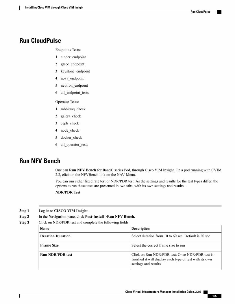
Run CloudPulseEndpoints Tests:
1 cinder_endpoint
2 glace_endpoint
3 keystone_endpoint
4 nova_endpoint
5 neutron_endpoint
6 all_endpoint_tests
Operator Tests:
1 rabbitmq_check
2 galera_check
3 ceph_check
4 node_check
5 docker_check
6 all_operator_tests
Run NFV BenchOne can Run NFV Bench for BandC series Pod, through Cisco VIM Insight. On a pod running with CVIM2.2, click on the NFVBench link on the NAV-Menu.
You can run either fixed rate test or NDR/PDR test. As the settings and results for the test types differ, theoptions to run these tests are presented in two tabs, with its own settings and results .
NDR/PDR Test
Step 1 Log-in to CISCO VIM Insight.Step 2 In the Navigation pane, click Post-Install >Run NFV Bench.Step 3 Click on NDR/PDR test and complete the following fields
DescriptionName
Select duration from 10 to 60 sec. Default is 20 secIteration Duration
Select the correct frame size to runFrame Size
Click on Run NDR/PDR test. Once NDR/PDR test isfinished it will display each type of test with its ownsettings and results.
Run NDR/PDR test
Cisco Virtual Infrastructure Manager Installation Guide, 2.2.6 195
Installing Cisco VIM through Cisco VIM InsightRun CloudPulse

Fixed Rate Test
Step 1 Log-in to CISCO VIM Insight.Step 2 In the Navigation pane, click Post-Install >Run NFV Bench.Step 3 Click Fixed rate test and complete the following fields.
DescriptionName
Rate: Select right configuration pps or bps from dropdown-list and enter values :
For pps: minimum: 2500pps; maximum: 14500000pps(=14.5Mpps); default: 1000000pps (=1Mpps)
For bps: minimum: 1400000bps; maximum:10000000000bps (=10Gbps); default: 1000000000(=1Gbps)
Rate
Select duration from 10-60Sec. Default is 20sec.Iteration Duration
Select the right frame size(64,IMIX,1518) to run.Frame Size
Click on Run Fixed rate test. Once Fixed rate test is finishedit will display each type of test with its own settings andresults.
Run Fixed rate test
POD ManagementOne of the key aspects of Cisco VIM is that it provides the ability for the admin to perform pod life-cyclemanagement from a hardware and software perspective. Nodes of a given pod corrupts at times and VIMprovides the ability to add, remove or replace nodes, based on the respective roles with some restrictions.
Cisco Virtual Infrastructure Manager Installation Guide, 2.2.6196
Installing Cisco VIM through Cisco VIM InsightPOD Management

Details of pod management will be listed in the admin guide, however as a summary the following operationsare allowed on a running pod:
Step 1 Add or Remove Storage Nodes: You can add one node at a time, given that we run Ceph as a distributed storage offering.Step 2 Add or Remove Computes Nodes: N-computes nodes can be replaced simultaneously; however at any given point, at
least one compute node should be active.Step 3 Replace Control Nodes: We do not support double fault scenarios, replacement of one controller at a time is supported.
System UpdateAs part of the lifecycle management of the cloud, VIM has the ability to bring in patches (bug fixes relatedto code, security, etc.), thereby providing the additional value of seamless cloud management from softwareperspective. Software update of the cloud is achieved by uploading a valid tar file following initiation of aSystem Update from the Insight as follows:
Step 1 In the Navigation pane, click Post-Install > System Update.Step 2 Click Browse button.Step 3 Select the valid tar file.Step 4 Click Open > Upload and Update .
Message stating System Update has been initiated will be displayed. Logs front-ended by hyperlink would be visible inthe section below before Update Logs to help see the progress of the update. During the software update, all other podmanagement activities will be disabled. Post-update, normal cloud management will commence.
Reconfiguring CIMC Password through InsightUpdate the cimc_password in the CIMC-COMMON section, and/or the individual cimc_password for eachserver and then run the update password option.
To update a password, you need to follow the password rules:
• Must contain at least one lower case letter.
• Must contain at least one upper case letter.
• Must contain at least one digit between 0 to 9.
• One of these special characters !$#@%^-_+=*&
• Your password has to be 8 to 14 characters long.
Before You Begin
You must have a C-series pod up and running with Cisco VIM to reconfigure CIMC password.
Cisco Virtual Infrastructure Manager Installation Guide, 2.2.6 197
Installing Cisco VIM through Cisco VIM InsightSystem Update

Reconfigure CIMC password section would be disabled if the pod is in failed state as indicated by ciscoviminstall-status.
Note
Step 1 Log-in to CISCO VIM Insight.Step 2 In the navigation pane, select Post-InstallStep 3 Click Reconfigure CIMC Password.Step 4 On the Reconfigure CIMC Password page of the Cisco VIM Insight, complete the following fields:
DescriptionName
CIMC_COMMON old password field cannot be edited.CIMC_COMMON old Password
Enter newCIMC-COMMON password. Password shouldbe alphanumeric according to the password rule.
CIMC-COMMON new Password
Old CIMC-COMMON password will be updated withnew CIMC-COMMON password.
Click Update Password
Reconfiguring OpenStack PasswordCisco VIM has been designed with security to accommodate customers' password policy.
There are two options to regenerate the Password:
1 Regenerate all passwords: Click the checkbox of Regenerate all passwords and click Set Password.This will automatically regenerate all passwords in alphanumeric format.
2 Regenerate single ormore password: If user wants to set a specific password for any service like Horizon'sADMIN_USER_PASSWORD they can add it by doing an inline edit. Double click on the filed underPassword and then enter the password which will enable Set Password button.
During the reconfiguration of password, all other pod management activities will be disabled. Post-update,normal cloud management will commence.
Note
Cisco Virtual Infrastructure Manager Installation Guide, 2.2.6198
Installing Cisco VIM through Cisco VIM InsightReconfiguring OpenStack Password

Reconfiguring OpenStack Services, TLS certs and ELK configurationsCisco VIM supports the reconfiguration of OpenStack log level services, TLS certificates, and ELKconfiguration. Listed below are the steps to reconfigure the OpenStack and other services:
Step 1 In the Navigation pane, click Post-Install > Reconfigure OpenStack Config.Step 2 Click on the specific item to be changed and updated; For TLS certificate it is the path to certificate location.Step 3 Enter Set Config and the process will commence.
During the reconfiguration process, all other pod management activities will be disabled. Post-update, normal cloudmanagement will commence.
Reconfiguring Optional ServicesCisco VIM offers optional services such as heat, migration to Keystone v3, NFVBench, NFVIMON and soon, that can be enabled as post-pod deployment. Optional services can be un-configured as post-deploymentin 2.2 feature. These services can be enabled in one-shot or selectively. Listed below are the steps to enableoptional services:
Step 1 In the Navigation pane, click Post-Install > Reconfigure Optional Services.Step 2 Choose the right service and update the fields with the right values.Step 3 Enter Reconfigure to commence the process.
During the reconfiguration process, all other pod management activities will be disabled. Post-update, normal cloudmanagement will commence. Once reconfigure is initiated than optional feature would be updated in active blueprint.If reconfigure of Optional Services fail in the time of reconfigure process then it is advised to contact CiscoTAC toresolve the situation through CLI.
All reconfigure operation feature contains repeated deployment true or false.Note
• Repeated re-deployment true - Feature can be re-deployed again.
• Repeated re-deployment false- Deployment of feature allowed onlyonce.
Deployment Status :
Repeated re-deployment OptionsOptional Features
TrueAPICINFO
FalseEXTERNAL_LB_VIP_FQDN
FalseEXTERNAL_LB_VIP_TLS
Cisco Virtual Infrastructure Manager Installation Guide, 2.2.6 199
Installing Cisco VIM through Cisco VIM InsightReconfiguring OpenStack Services, TLS certs and ELK configurations

Repeated re-deployment OptionsOptional Features
TrueINSTALL_MODE
TrueLDAP
TrueNETWORKING
FalseNFVBENCH
FalseNFVIMON
FalsePODNAME
TruePROVIDER_VLAN_RANGES
TrueSWIFTSTACK
FalseSYSLOG_EXPORT_SETTINGS
TrueTENANT_VLAN_RANGES
FalseTORSWITCHINFO
TrueVIM _ ADMINS
FalseVMTP
FalseVTS_PARAMETERS
`True
AUTOBACKUP
FalseHeat
FalseKeystone v3
TrueHTTP Proxy Server
TrueHTTPS Proxy Server
Pod User AdministrationCisco VIM Insight offers Users (Pod Admin(s) or Pod Users) to manage Users and roles associated with them.
Cisco Virtual Infrastructure Manager Installation Guide, 2.2.6200
Installing Cisco VIM through Cisco VIM InsightPod User Administration

Managing UsersTo add new User
Step 1 Click Login as POD User.Step 2 Navigate to POD User Administration.Step 3 ClickManage Users.Step 4 Click Add Users to add a new user.Step 5 Complete the following fields in the Add Users page of the Cisco VIM Insight:
Field DescriptionField Name
Enter the Email ID of the User.Email ID
Enter the User Name if the User is new. If the User is already registered to the Insight the User-Namegets auto-populated.
User Name
Select the Role from the drop-down list.Role
Step 6 Click Save.
Managing RolesTo create a new Role
Step 1 Click Login as POD User.Step 2 Navigate to PodUser Administration and clickManage Roles. By default you will see full-pod-access role in the table.Step 3 Click Add Role to create a new role.Step 4 Complete the following fields in the Add Roles page in Cisco VIM Insight:
Field DescriptionField Name
Enter the name of the role.Role
Enter the description of the role.Description
Check the Permission checkbox to select the permission.Permission
Step 5 Click Save. Once the Blueprint is in Active state all the permissions are same for C-series and B-series Pods other thanReconfigure CIMC Password which is missing for B-series Pod.
Cisco Virtual Infrastructure Manager Installation Guide, 2.2.6 201
Installing Cisco VIM through Cisco VIM InsightPod User Administration

Permissions are divided in granular level where viewing Dashboard is the default role that is implicitly addedwhile creating a role.
Note
Managing Root CA CertificateYou can update the CA Certificate during the registration of the POD. Once, logged in as POD User and ifyou have the permission to update the certificate you can view under POD User Administration>> ManageRoot CA Certificate.
To update the Certificate:
Step 1 Click Login as POD UserStep 2 Navigate to POD User Administration>>Manage Root CA certificate.Step 3 Click Browse and select the certificate that you want to upload.Step 4 Click Upload.
• If the certificate is Invalid, and does not matches with the certificate on the management node located at(var/www/mercury/mercury-ca.crt) then Insight will revert the certificate which was working previously.
• If the Certificate is valid, Insight will run a management node health check and then update the certificate with thelatest one.
The CA Certificate which is uploaded should be same as the one which is in the managementnode.
Note
Cisco Virtual Infrastructure Manager Installation Guide, 2.2.6202
Installing Cisco VIM through Cisco VIM InsightPod User Administration

C H A P T E R 9Verifying the Cisco NFVI Installation
The following topics provide quick methods for checking and assessing the Cisco NFVI installation.
• Displaying Cisco NFVI Node IP Addresses, page 203
• Verifying Cisco VIM Client CLI Availability, page 204
• Displaying Cisco NFVI Logs, page 205
• Accessing OpenStack API Endpoints, page 205
• Assessing Cisco NFVI Health with CloudPulse, page 206
• Displaying HAProxy Dashboard and ELK Stack Logs, page 208
• Checking Cisco NFVI Pod and Cloud Infrastructure, page 208
Displaying Cisco NFVI Node IP AddressesTo display the IP addresses for all Cisco NFVI nodes, enter the following command:# cd /root/openstack-configs[root @nfvi_management_node openstack-configs]# cat/root/installer/openstack-configs/mercury_servers_info
Sample output is shown below:Total nodes: 8Controller nodes: 3+---------------+---------------+------------+------------+-----------+---------+| Server | CIMC | Management | Provision | Tenant | Storage |+---------------+---------------+------------+------------+-----------+---------+| c44-control-1 | 172.26.233.54 | 10.21.1.25 | 10.21.1.25 | 10.2.2.22 | None || | | | | | || c44-control-3 | 172.26.233.56 | 10.21.1.27 | 10.21.1.27 | 10.2.2.24 | None || | | | | | || c44-control-2 | 172.26.233.55 | 10.21.1.28 | 10.21.1.28 | 10.2.2.25 | None || | | | | | |+---------------+---------------+------------+------------+-----------+---------+Compute nodes: 2+---------------+---------------+------------+------------+-----------+---------+| Server | CIMC | Management | Provision | Tenant | Storage |+---------------+---------------+------------+------------+-----------+---------+| c44-compute-1 | 172.26.233.57 | 10.21.1.26 | 10.21.1.26 | 10.2.2.23 | None || | | | | | || c44-compute-2 | 172.26.233.58 | 10.21.1.23 | 10.21.1.23 | 10.2.2.21 | None || | | | | | |+---------------+---------------+------------+------------+-----------+---------+
Cisco Virtual Infrastructure Manager Installation Guide, 2.2.6 203

Storage nodes: 3+---------------+---------------+------------+------------+--------+-----------+| Server | CIMC | Management | Provision | Tenant | Storage |+---------------+---------------+------------+------------+--------+-----------+| c44-storage-3 | 172.26.233.53 | 10.21.1.22 | 10.21.1.22 | None | 10.3.3.22 || | | | | | || c44-storage-2 | 172.26.233.52 | 10.21.1.24 | 10.21.1.24 | None | 10.3.3.23 || | | | | | || c44-storage-1 | 172.26.233.51 | 10.21.1.21 | 10.21.1.21 | None | 10.3.3.21 || | | | | | |+---------------+---------------+------------+------------+--------+-----------+[root@c44-top-mgmt openstack-configs]#
Verifying Cisco VIM Client CLI AvailabilityThe Cisco VIMClient CLI is very important for managing Cisco NFVI pods. After the Cisco NFVI installationis complete, verify that the Cisco VIM client is running and pointing to the right management node installerdirectory. Cisco NFVI provides a tool that you can use to check the REST API server status and directorywhere it is running.
To launch the tool, enter the following:# cd installer-<tagid>/tools#./restapi.py -a statusStatus of the REST API Server: active (running) since Thu 2016-08-18 09:15:39 UTC; 9h agoREST API launch directory: /root/installer-<tagid>/
Confirm that the server status is active and check that the REST API launch directory matches the directorywhere the installation is launched.
The RESTAPI command also provides options to launch, tear down, and reset the RESTAPI server passwordas listed below:# ./restapi.py -husage: restapi.py [-h] --action ACTION [--yes] [--verbose]
REST API setup helper
optional arguments:-h, --help show this help message and exit--action ACTION, -a ACTION
setup - Install and Start the REST API server.teardown - Stop and Uninstall the REST API
server.restart - Restart the REST API server.regenerate-password - Regenerate the password for
REST API server.reset-password - Reset the REST API password with
user given password.status - Check the status of the REST API server
--yes, -y Skip the dialog. Yes to the action.--verbose, -v Perform the action in verbose mode.
If the REST API server is not running, executing ciscovim displays the following error message:# cd installer-<tagid>/# ciscovim –setupfile ~/Save/<setup_data.yaml> run
If the installer directory or the REST API state is not correct or pointing to an incorrect REST API launchdirectory, go to the installer-<tagid>/tools dir and execute:# ./restapi.py –action setup
Confirm that the REST API server state and launch directory is correct:# ./restapi.py –action status
Cisco Virtual Infrastructure Manager Installation Guide, 2.2.6204
Verifying the Cisco NFVI InstallationVerifying Cisco VIM Client CLI Availability

If the REST API recovery step was run on an existing pod, run the following command to ensure that theREST API server continues to manage IT:
# cd installer-<tagid>/# ciscovim --setup_file <setup_data_file_path> --perform 7 -y
Detailed information about the Cisco NFVI REST API is provided in the Cisco Network FunctionVirtualization Infrastructure Administrator Guide.
Note
Displaying Cisco NFVI LogsCiscoNFVI installation logs are generated in themanagement node /var/log/mercury//<install_uuid>/ directory.The last 20 log directories are tarred and kept in this directory. The logs are archived (tar.gz file) after eachrun. The following table lists the Cisco NFVI installation steps and corresponding log files:
Table 12: Cisco NFVI Installation Logs
Log FileDescriptionStep
mercury_baremetal_install.logINPUT_VALIDATION1
mercury_buildorchestration.logMGMTNODE_ORCHESTRATION2
mercury_baremetal_install.logVALIDATION3
mercury_baremetal_install.logBAREMETAL4
mercury_os_install.logCOMMONSETUP5
mercury_ceph_install.logCEPH6
mercury_os_install.logORCHESTRATION7
noneVMTP8
Accessing OpenStack API EndpointsThe Cisco NFVI installer stores access credentials in the management node/root/installer-<tag-number>/openstack-configs/openrc. The external_lb_vip_address provided insetup_data.yaml is the IP address where OpenStack APIs are handled. An openrc example is shown below:export OS_AUTH_URL=http://172.26.233.139:5000/v2.0 orhttps://172.26.233.139:5000/v2.0 (if TLS is enabled)export OS_USERNAME=adminexport OS_PASSWORD=xyzabcdexport OS_TENANT_NAME=adminexport OS_REGION_NAME=RegionOne# For TLS, addexport OS_CACERT=/root/openstack-configs/haproxy-ca.crt
Cisco Virtual Infrastructure Manager Installation Guide, 2.2.6 205
Verifying the Cisco NFVI InstallationDisplaying Cisco NFVI Logs
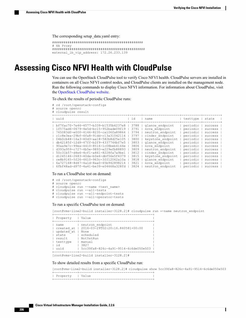
The corresponding setup_data.yaml entry:################################################ HA Proxy################################################external_lb_vip_address: 172.26.233.139
Assessing Cisco NFVI Health with CloudPulseYou can use the OpenStack CloudPulse tool to verify Cisco NFVI health. CloudPulse servers are installed incontainers on all Cisco NFVI control nodes, and CloudPulse clients are installed on the management node.Run the following commands to display Cisco NFVI information. For information about CloudPulse, visitthe OpenStack CloudPulse website.
To check the results of periodic CloudPulse runs:# cd /root/openstack-configs# source openrc# cloudpulse result+--------------------------------------+------+-------------------+----------+---------+| uuid | id | name | testtype | state |+--------------------------------------+------+-------------------+----------+---------+| bf7fac70-7e46-4577-b339-b1535b6237e8 | 3788 | glance_endpoint | periodic | success || 1f575ad6-0679-4e5d-bc15-952bade09f19 | 3791 | nova_endpoint | periodic | success || 765083d0-e000-4146-8235-ca106fa89864 | 3794 | neutron_endpoint | periodic | success || c1c8e3ea-29bf-4fa8-91dd-c13a31042114 | 3797 | cinder_endpoint | periodic | success || 04b0cb48-16a3-40d3-aa18-582b8d25e105 | 3800 | keystone_endpoint | periodic | success || db42185f-12d9-47ff-b2f9-4337744bf7e5 | 3803 | glance_endpoint | periodic | success || 90aa9e7c-99ea-4410-8516-1c08beb4144e | 3806 | nova_endpoint | periodic | success || d393a959-c727-4b5e-9893-e229efb88893 | 3809 | neutron_endpoint | periodic | success || 50c31b57-d4e6-4cf1-a461-8228fa7a9be1 | 3812 | cinder_endpoint | periodic | success || d1245146-2683-40da-b0e6-dbf56e5f4379 | 3815 | keystone_endpoint | periodic | success || ce8b9165-5f26-4610-963c-3ff12062a10a | 3818 | glance_endpoint | periodic | success || 6a727168-8d47-4a1d-8aa0-65b942898214 | 3821 | nova_endpoint | periodic | success || 6fbf48ad-d97f-4a41-be39-e04668a328fd | 3824 | neutron_endpoint | periodic | success |
To run a CloudPulse test on demand:# cd /root/openstack-configs# source openrc# cloudpulse run --name <test_name># cloudpulse run --all-tests# cloudpulse run --all-endpoint-tests# cloudpulse run --all-operator-tests
To run a specific CloudPulse test on demand:[root@vms-line2-build installer-3128.2]# cloudpulse run –-name neutron_endpoint+------------+--------------------------------------+| Property | Value |+------------+--------------------------------------+| name | neutron_endpoint || created_at | 2016-03-29T02:20:16.840581+00:00 || updated_at | None || state | scheduled || result | NotYetRun || testtype | manual || id | 3827 || uuid | 5cc39fa8-826c-4a91-9514-6c6de050e503 |+------------+--------------------------------------+[root@vms-line2-build installer-3128.2]#
To show detailed results from a specific CloudPulse run:[root@vms-line2-build installer-3128.2]# cloudpulse show 5cc39fa8-826c-4a91-9514-6c6de050e503+------------+--------------------------------------+| Property | Value |+------------+--------------------------------------+
Cisco Virtual Infrastructure Manager Installation Guide, 2.2.6206
Verifying the Cisco NFVI InstallationAssessing Cisco NFVI Health with CloudPulse

| name | neutron_endpoint || created_at | 2016-03-29T02:20:16+00:00 || updated_at | 2016-03-29T02:20:41+00:00 || state | success || result | success || testtype | manual || id | 3827 || uuid | 5cc39fa8-826c-4a91-9514-6c6de050e503 |+------------+--------------------------------------+
CloudPulse has two test sets: endpoint_scenario (runs as a cron or manually) and operator test (run manually).Endpoint tests include:
• nova_endpoint
• neutron_endpoint
• keystone_endpoint
• glance_endpoint
• cinder_endpoint
Operator tests include
• ceph_check
• docker_check
• galera_check
• node_check
• rabbitmq_check
The following table lists the operator tests you can perform with CloudPulse.
Table 13: CloudPulse Operator Tests
DescriptionTest
Executes the ceph -f json status command on the Ceph-mon nodes and parses theoutput. If the result of the output is not HEALTH_OK, the ceph_check reports anerror.
Ceph Check
Finds out if all Docker containers are in running state on all nodes and reports anerror if any containers are in the Exited state. The Docker check runs the command,docker ps -aq --filter 'status=exited',
Docker Check
Executes the command,mysql 'SHOWSTATUS, on the controller nodes and displaysthe status.
Galera Check
Checks if all the nodes in the system are up and online. It also compares the resultsof the Nova hypervisor list and determines whether all the compute nodes areavailable.
Node Check
Runs the command, rabbitmqctl cluster_status, on the controller nodes and findsout if the RabbitMQ cluster is in quorum. If nodes are offline, the rabbitmq_checkreports a failure.
RabbitMQ Check
Cisco Virtual Infrastructure Manager Installation Guide, 2.2.6 207
Verifying the Cisco NFVI InstallationAssessing Cisco NFVI Health with CloudPulse

Displaying HAProxy Dashboard and ELK Stack LogsYou can view the HAProxy dashboard at: http://< external_lb_vip_address >:1936 using the followingusername and password
• Username—haproxy
• Password—Value for HAPROXY_PASSWORD in/root/installer-<tag-number>/openstack-configs/secrets.yaml
You can use theKibana dashboard to view logs aggregated by Logstash at: http://<management_node_IP>:5601using the following username and password
• Username—admin
• Password—Value for ELK_PASSWORD in /root/installer-<tag-number>/openstack-configs/secrets.yaml
Checking Cisco NFVI Pod and Cloud InfrastructureTo test the Cisco NFVI pod and cloud infrastructure (host connectivity, basic mraiadb, rabbit, ceph clustercheck and RAID disks), you can use the cloud-sanity tool available on the management node. To execute,enter:
# cd installer-<tagid>/tools# ./cloud_sanity.py -–husage: cloud_sanity.py [-h] [--check CHECK][--list] [--verbose]cloud sanity helperoptional arguments:-h, --help show this help message andexit--check CHECK, -c CHECKall - Run all sanity checks. [defaultaction]control - Run controller sanitychecks.compute - Run compute sanity checks.cephmon - Run cephmon sanity checks.cephosd - Run cephosd sanity checks.management - Run Management node sanitychecks--list, -l List all the available sanitychecks.--verbose, -v Run the sanity in verbosemode.
To list the available cloud-sanity checks, execute:# ./cloud_sanity.py -l
Available sanity checks-----------------------
-----------------------1 - cloud-sanity : Management - Disk maintenance RAID Health2 - cloud-sanity : Management - Disk maintenance VD Health
Cisco Virtual Infrastructure Manager Installation Guide, 2.2.6208
Verifying the Cisco NFVI InstallationDisplaying HAProxy Dashboard and ELK Stack Logs

3 - cloud-sanity : Control - Ping All Controller Nodes4 - cloud-sanity : Control - Ping internal VIP5 - cloud-sanity : Control - Check Mariadb cluster size6 - cloud-sanity : Control - Check RabbitMQ is running7 - cloud-sanity : Control - Check RabbitMQ cluster status8 - cloud-sanity : Control - Check Nova service list9 - cloud-sanity : Control - Disk maintenance RAID Health10 - cloud-sanity : Control - Disk maintenance VD Health11 - cloud-sanity : Compute - Ping All Compute Nodes12 - cloud-sanity : Compute - Check Nova Hypervisor list13 - cloud-sanity : Compute - Disk maintenance RAID Health14 - cloud-sanity : Compute - Disk maintenance VD Health15 - cloud-sanity : CephMon - Check cephmon is running16 - cloud-sanity : CephMon - CEPH cluster check17 - cloud-sanity : CephMon - Check Ceph Mon status18 - cloud-sanity : CephMon - Check Ceph Mon results19 - cloud-sanity : CephOSD - Ping All Storage Nodes20 - cloud-sanity : CephOSD - Check OSD result with osdinfo21 - cloud-sanity : CephOSD - Check OSD result without osdinfo
Results for a test can be either passed, failed, or skipped. A skipped test indicates atest which couldn’t be run on this particalur PoD – i.e. a hardware RAID test is skipped ona node which doesn’t have hardware RAID.A successful compute node check is shown below:#./cloud_sanity.py -c computeExecuting Compute Cloud Sanity in quiet mode. This will take some time.
+---------+-----------------------------------------------------------+--------+| Role | Task | Result |+---------+-----------------------------------------------------------+--------+| Compute | Compute - Ping All Compute Nodes *********************** | PASSED || | | || Compute | Compute - Check Nova Hypervisor list ******************* | PASSED || | | |+---------+-----------------------------------------------------------+--------+[PASSED] Cloud Sanity Compute Checks Passed
A failure example is shown below:[root@MercTB1 tools]# ./cloud_sanity.py -c controlExecuting Control Cloud Sanity in quiet mode. This will take some time.
+---------+-----------------------------------------------------------+--------+| Role | Task | Result |+---------+-----------------------------------------------------------+--------+| Control | Control - Ping All Controller Nodes ******************** | PASSED || | | || Control | Control - Ping internal VIP **************************** | PASSED || | | || Control | Control - Check Mariadb cluster size ******************* | PASSED || | | || Control | Control - Check RabbitMQ is running ******************** | FAILED || | | |+---------+-----------------------------------------------------------+--------+[FAILED] FATAL ERROR occured when running sanity checks.[NOTE] One or more testcase[s] skipped. Use --list to see the complete list.
To view the details of a failure, use the v option as shown below:# ./cloud_sanity.py -c control -v
PLAY [Executes Cloud Sanity] **************************************************
GATHERING FACTS ***************************************************************ok: [7.7.7.15]ok: [7.7.7.11]ok: [7.7.7.14]
TASK: [cloud-sanity | Control - Ping All Controller Nodes] ********************changed: [7.7.7.15 -> localhost] => (item=7.7.7.15)changed: [7.7.7.15 -> localhost] => (item=7.7.7.11)changed: [7.7.7.15 -> localhost] => (item=7.7.7.14)
Cisco Virtual Infrastructure Manager Installation Guide, 2.2.6 209
Verifying the Cisco NFVI InstallationChecking Cisco NFVI Pod and Cloud Infrastructure

TASK: [cloud-sanity | Control - Ping internal VIP] ****************************changed: [7.7.7.15 -> localhost]
TASK: [cloud-sanity | Control - Check Mariadb cluster size] *******************changed: [7.7.7.11]changed: [7.7.7.15]changed: [7.7.7.14]
TASK: [cloud-sanity | Control - Check RabbitMQ is running] ********************failed: [7.7.7.11] => {"changed": true, "cmd": "docker ps -a | grep rabbit | grep Up | awk'{print $NF}' | cut -f2 -d '_'", "delta": "0:00:00.021044", "end": "2016-08-1823:45:34.838817", "failed": true, "failed_when_result": true, "rc": 0, "start": "2016-08-1823:45:34.817773", "stdout_lines": [], "warnings": []}changed: [7.7.7.15]changed: [7.7.7.14]
FATAL: all hosts have already failed -- aborting
PLAY RECAP ********************************************************************7.7.7.11 : ok=4 changed=3 unreachable=0 failed=17.7.7.14 : ok=5 changed=4 unreachable=0 failed=07.7.7.15 : ok=5 changed=4 unreachable=0 failed=0
[FAILED] FATAL ERROR occured when running sanity checks.[NOTE] One or more testcase[s] skipped. Use --list to see the complete list.
Cisco Virtual Infrastructure Manager Installation Guide, 2.2.6210
Verifying the Cisco NFVI InstallationChecking Cisco NFVI Pod and Cloud Infrastructure